Nexus 1500 Meter Modbus Manual V.1.06 E154703 Nx Man
Nexus 1500 Meter Mod.. Nexus 1500 Meter Modbus Protocol User Manual V.1.06_E154703
User Manual: Pdf E154703 Nx 1500 Modbus Man
Open the PDF directly: View PDF ![]() .
.
Page Count: 470 [warning: Documents this large are best viewed by clicking the View PDF Link!]
- Modbus Protocol and Register Map for the Nexus® 1500 Meter User Manual
- Warranty
- Table of Contents
- Chapter 1: Modbus Protocol Overview
- Chapter 2: Nexus® 1500 Meter Modbus Register Map
- Chapter 3: Communication Data Formats
- 3.1: Type F1
- 3.2: Type F2
- 3.3: Type F3
- 3.4: Type F4
- 3.6: Type F6
- 3.7: Type F7
- 3.8: Type F8
- 3.9: Type F9
- 3.10: Type F10
- 3.11: Type F11
- 3.12: Type F12
- 3.13: Type F13
- 3.14: Type F14
- 3.15: Type F15
- 3.16: Type F16
- 3.17: Type F17 Digital Input States in Digital Input Option Board
- 3.18: Type F18 Digital Input Option Board Input Accumulation/Cumulative Demand
- 3.19: Type F19
- 3.20: Type F20
- 3.21: Type F21
- 3.22: Type F22
- 3.23: Type F23
- 3.24: Type F24
- 3.25: Type F25
- 3.26: Type F26
- 3.27: Type F27
- 3.28: Type F28
- 3.29: Type F29
- 3.30: Type F30
- 3.31: Type F31
- 3.32: Type F32
- 3.33: Type F33
- 3.34: Type F34
- 3.35: Type F35
- 3.36: Type F36
- 3.37: Type F37
- 3.38: Type F38
- 3.39: Type F39
- 3.40: Type F40
- 3.41: Type F41
- 3.42: Type F42
- 3.43: Type F43
- 3.44: Type F44
- 3.46: Type F46
- 3.47: Type F47
- 3.48: Type F48
- 3.49: Type F49
- 3.50: Type F50
- 3.51: Type F51
- 3.52: Type F52
- 3.53: Type F53
- 3.54: Type F54
- 3.55: Type F55
- 3.56: Type F56
- 3.57: Type F57
- 3.58: Type F58
- 3.59: Type F59
- 3.60: Type F60
- 3.61: Type F61
- 3.62: Type F62
- 3.63: Type F63
- 3.64: Type F64
- 3.65: Type F65
- 3.66: Type F66
- 3.67: Type F67
- 3.68: Type F68
- 3.69: Type F73
- Chapter 4: Modbus Register Map Notes
- Chapter 5: Logs, Port Control and Updating Programmable Settings
- Chapter 6: Large Data Access (LDA) and Logging
- 6.1: Overview
- 6.2: LDA Overview
- 6.3: LDA Programming Examples
- 6.4: Notes on User Security Implementaion
- 6.5: File Access Command Details
- 6.6: Data Input and Output Transfer Window Size
- 6.7: Access Timeout
- 6.8: Downloading Logs using LDA
- Chapter 7: Nexus® 1500 Meter Programmable Settings Blocks
- 7.1: Communications Settings Block (45057-45074)
- 7.2: Limit Settings Block (45077-45204)
- 7.3: Historical Log Settings Block (45205-45464)
- 7.4: High Speed Inputs Settings Block (45501-45723)
- 7.6: External Digital Output Module Settings Block (45729-45808)
- 7.8: External Analog Output Module Settings Block (45813-45892)
- 7.9: External KYZ Output Module Settings Block (45893-45907)
- 7.10: CT & PT Ratio Settings Block (45909-45924)
- 7.11: Hookup and Time Settings Block (45925-45944)
- 7.12: Average Settings Block (45949-45952)
- 7.14: Device Label Settings Block (45969-45992)
- 7.15: Network Settings Block (45993-46016)
- 7.16: Block Window Average External Synchronization Block (46017)
- 7.17: Display Configuration Block (46018)
- 7.18: Energy Direction Clock (46019)
- 7.20: Full Scale Block (46021-46036)
- 7.21: External Module Software Interface Block (46053-46196)
- 7.22: External Module Port Assignment Block (46197-46206)
- 7.23: Manual Control Relay Block (46207-46208)
- 7.24: Internal Input Pulse Accumulation Scale Factor Block (46209-46325)
- 7.25: ISquaredT and VSquaredT Threshold Block (46326-46329)
- 7.26: Internal KYZ Settings Block (46330-46372)
- 7.27: Internal Input Pulse Accumulation Unit Label Block (46373-46420)
- 7.29: Limit Profile Label Block (46805-47060)
- 7.30: External Analog Output Module Channel Update Block (47061-47062)
- 7.31: Miscellaneous DNP Settings Block (47063-47104)
- 7.32: Custom DNP Definition Block for Analog Input (Object 30) (47105-47360)
- 7.33: Custom DNP Definition Block for Binary Counter (Object 20) (47361-47424)
- 7.34: Custom DNP Definition Block for Binary Input (Object 1) (47425-47456)
- 7.35: Custom DNP Definition Block for Binary Output (Object 10) (47457-47458)
- 7.36: Custom DNP Definition Block for Global Values (47459-47463)
- 7.40: External Digital Output Module Labels Block (49793-50176)
- 7.42: Customizable Modbus Map Settings Block
- 7.44: DNP LAN/WAN (51157-51195)
- 7.46: Customizable Modbus Map Format Block (51201-51712)
- 7.48: Waveform, Transient, and PQ Settings
- Chapter 8: Register Block Titles
- 8.1: Device Identification Block (00001-00080)
- 8.2: Real Time Block (00081-00089)
- 8.3: 1 Cycle Block (00090-00118)
- 8.4: Tenth Second Block (00119-00175)
- 8.5: One Second Block (00176-00235)
- 8.6: Thermal Average Block (00236-00295)
- 8.7: Maximum Block (00296-00396)
- 8.8: Minimum Block (00397-00497)
- 8.9: Maximum Time Stamp Block (00498-00737)
- 8.10: Minimum Time Stamp Block (00738-00977)
- 8.11: Energy Block (Secondary) (00978-01021)
- 8.12: Harmonic Magnitude Block(01022-01789)
- 8.13: Harmonic Phase Block (01790-02557)
- 8.14: THD/K-Factor Block (02558-02566)
- 8.15: Harmonic Time Stamp Block (02567-02590)
- 8.16: Phase Angle Block (02591-02604)
- 8.17: Block Window Average block (02605-02683)
- 8.18: Rolling Window/Predictive Rolling Window Block (02684-02768)
- 8.19: Limit Block (02769-02773)
- 8.21: Primary Accumulation Block (02842-02973)
- 8.22: Time of Use Period Time Stamp Block (02974-03040)
- 8.23: Time of Use Frozen Block (03041-03584)
- 8.24: Time of Use Frozen Total Block (03585-03652)
- 8.25: Time of Use Prior Month Register Block (03653-04196)
- 8.26: Time of Use Prior Month Total Block (04197-04264)
- 8.27: Time of Use Active Register Block (04265-04808)
- 8.28: Time of Use Active Total Block (04809-04876)
- 8.29: Time of Use Current Month Register Block (04877-05420)
- 8.30: Time of Use Current Month Total Block (05421-05488)
- 8.31: Time of Use Frozen Label Block (05489-05552)
- 8.32: Time of Use Prior Month Label Block (05553-05616)
- 8.33: Time of Use Active Label Block (05617-05680)
- 8.34: Time of Use Current Month Label Block (05681-06744)
- 8.35: Internal Input Pulse Accumulation Block (05745-05796)
- 8.36: Pulse Accumulation Block Window Average / Maximum Block (05797-05945)
- 8.37: Temperature (05946)
- 8.39: Limit Combination Block (05979-05980)
- 8.40: Relay Logic Block (05981-00614)
- 8.41: Reset Time Block (06015-06038)
- 8.42: Miscellaneous Flags Block (06039)
- 8.44: KYZ Output Accumulation Block (06097-06110)
- 8.46: Flicker Status Block (06114-06126)
- 8.47: Instantaneous Flicker Block (06127-06136)
- 8.48: Short Term flicker Block (06137-06186)
- 8.49: Long Term Flicker Block (06187-06236)
- 8.50: Additional Energy Block (06237-06392)
- 8.51: Energy and Pulses in the Interval Block (06393-06488)
- 8.52: Flicker Countdown Block (06489-06490)
- 8.53: Cumulative Demand Block (06491-06502)
- 8.54: Time of Use Active Cumulative Demand Block (06503-06538)
- 8.55: Time of Use Current Month Cumulative Demand Block (06539-06574)
- 8.56: TOU Active Continuous Cumulative Demand Block (06575-06610)
- 8.57: TOU Current Month Continuous Cumulative Demand Block (06611-06646)
- 8.58: Log Index Block (06647-06664)
- 8.59: Uncompensated and Q Block (06665-06670)
- 8.60: Scaled Energy Block (06908-07829)
- 8.61: Total Average Power Factor Block (07830-07859)
- 8.62: Reset Active Time of Use Time Stamp (07860-07863)
- 8.63: Negative Maximum Pulse Aggregation Average Block (07864-07895)
- 8.64: Scratchpad Block (08193-08320)
- 8.65: Master Device Data Block (08449-08704)
- 8.66: Customized Modbus Block (12289-14336)
- 8.67: Enhanced Factory Settings Block (16385-24576)
- 8.68: Enhanced Programmable Settings Block (24577-32768)
- 8.69: Time of Use Calendar Header Block (34817-34918)
- 8.70: Time of Use Calendar Block (34919-35800)
- 8.71: Time of Use Upload Calendar Block (36607-36736)
- 8.72: Historical Log 1 Snapshot Header (36865-36882)
- 8.73: Historical Log 2 Snapshot Header (36929-36946)
- 8.74: Limit Trigger Log Header (36993-37010)
- 8.75: Limit Snapshot Log Header (37057-37074)
- 8.76: Digital Input Log Header (37121-37138)
- 8.77: Digital Input Snapshot Log Header (37185-37202)
- 8.78: Digital Output Log Header (37249-37266)
- 8.79: Digital Output Snapshot Log Header (37313-37330)
- 8.80: Flicker Log Header (37377-37394)
- 8.81: Waveform Trigger Log Header (37441-37458)
- 8.82: System Event Log Header (37505-37522)
- 8.83: Waveform Samples Log Header (37569-37586)
- 8.84: PQ (CBEMA) Log Header (37633-37650)
- 8.86: External Device Information Block Header (37761-37778)
- 8.87: External Device Programming Block Header (37825-37842)
- 8.88: Device History Block Header (37889-37906)
- 8.89: Direct Memory Access Header (37953-37970)
- 8.90: Window Index Block (38145-38162)
- 8.91: Window Mode Block (38209-38226)
- 8.92: Window Block (38273-39424)
- 8.93: Auto Increment Window Block (39423-39488)
- 8.94: Alarm Block (40961-41105)
- 8.95: Port Control Block (41729-44544)
- 8.96: Energy Preset Block (44545-44549)
- 8.98: Action Block - Resetting Meter Registers (57345-57393)
- 8.99: Factory Calibration Block (60929-61026)
- 8.100: CTPT Compensation Calibration Block (61027-61124)
- 8.101: Calibration Modification Block (61185-61280)
- 8.102: Operational Communication Settings Block (65025-65040)
- 8.104: Device Identification Block 2 (65088-65280)
- 8.105: DSP Diagnostic Block (65281-65312)
- 8.106: Password Command (65328)
- Chapter 9: Nexus® Alternative Method for Downloading Logs
- Appendix A: Modbus Support Information
- Glossary

Modbus Protocol and
Register Map
FOR THE NEXUS® 1500 Meter
User Manual
E
Electro Industries/GaugeTech
1800 Shames Drive
Westbury, New York 11590
Tel: 516-334-0870 Fax: 516-338-4741
Sales@electroind.com www.electroind.com
“The Leader in Power Monitoring and Smart Grid Solutions”
Version 1.06
June 20, 2012
Doc # E154703 V.1.06


E Electro Industries/GaugeTech Doc # E154703 i
Modbus Protocol and Register Map for
the Nexus® 1500 Meter User Manual
Revision 1.06
Published by:
Electro Industries/GaugeTech
1800 Shames Drive
Westbury, NY 11590
All rights reserved. No part of this
publication may be reproduced or
transmitted in any form or by any
means, electronic or mechanical,
including photocopying, recording, or
information storage or retrieval
systems or any future forms of
duplication, for any purpose other than
the purchaser’s use, without the
expressed written permission of
Electro Industries/GaugeTech.
© 2012
Electro Industries/GaugeTech
Nexus® is a registered trademark of
Electro Industries/GaugeTech. The
distinctive shape, style, and appearance
of the Nexus® 1500 meter are
trademarks of Electro
Industries/GaugeTech. Communicator
EXT™ is a trademark of Electro
Industries/GaugeTech.

E Electro Industries/GaugeTech Doc # E154703 ii

E Electro Industries/GaugeTech Doc # E154703 iii
Customer Service and Support
Customer support is available 9:00 am to 4:30 pm, Eastern Standard Time, Monday through
Friday. Please have the model, serial number and a detailed problem description available. If the
problem concerns a particular reading, please have all meter readings available. When returning
any merchandise to EIG, a return materials authorization number is required. For customer or
technical assistance, repair or calibration, phone 516-334-0870 or fax 516-338-4741.
Product Warranty
Electro Industries/GaugeTech warrants all products to be free from defects in material and
workmanship for a period of four years from the date of shipment. During the warranty period,
we will, at our option, either repair or replace any product that proves to be defective.
To exercise this warranty, fax or call our customer-support department. You will receive prompt
assistance and return instructions. Send the instrument, transportation prepaid, to EIG at 1800
Shames Drive, Westbury, NY 11590. Repairs will be made and the instrument will be returned.
Limitation of Warranty
This warranty does not apply to defects resulting from unauthorized modification, misuse, or use
for any reason other than electrical power monitoring. The Nexus® 1500 meter is not a user-
serviceable product.
THIS WARRANTY IS IN LIEU OF ALL OTHER WARRANTIES, EXPRESSED OR
IMPLIED, INCLUDING ANY IMPLIED WARRANTY OF MERCHANTABILITY OR
FITNESS FOR A PARTICULAR PURPOSE. ELECTRO INDUSTRIES/GAUGETECH SHALL
NOT BE LIABLE FOR ANY INDIRECT, SPECIAL OR CONSEQUENTIAL DAMAGES
ARISING FROM ANY AUTHORIZED OR UNAUTHORIZED USE OF ANY ELECTRO
INDUSTRIES/GAUGETECH PRODUCT. LIABILITY SHALL BE LIMITED TO THE
ORIGINAL COST OF THE PRODUCT SOLD.

E Electro Industries/GaugeTech Doc # E154703 iv
Use of Products for Protection
Our products are not to be used for primary over-current protection. Any protection feature in our
products is to be used for alarm or secondary protection only.
Statement of Calibration
Our instruments are inspected and tested in accordance with specifications published by Electro
Industries/GaugeTech. The accuracy and a calibration of our instruments are traceable to the
National Institute of Standards and Technology through equipment that is calibrated at planned
intervals by comparison to certified standards.
Disclaimer
The information presented in this publication has been carefully checked for reliability; however,
no responsibility is assumed for inaccuracies. The information contained in this document is
subject to change without notice.
About Electro Industries/GaugeTech (EIG)
Founded in 1975 by engineer and inventor Dr. Samuel Kagan, EIG changed the face of power
monitoring forever with its first breakthrough innovation: an affordable, easy-to-use AC power
meter.
Thirty years since its founding, Electro Industries/GaugeTech, the leader in power monitoring and
control, continues to revolutionize the industry with the highest quality, cutting edge power
monitoring and control technology on the market today. An ISO 9001:2000 certified company,
EIG sets the industry standard for advanced power quality and reporting, revenue metering and
substation data acquisition and control. EIG products can be found on site at virtually all of
today's leading manufacturers, industrial giants and utilities.
EIG products are primarily designed, manufactured, tested and calibrated at our facility in
Westbury, New York.

E Electro Industries/GaugeTech Doc # E154703 v
Table of Contents
Chapter 1: Modbus Protocol Overview
1.1: Introduction 1-1
1.2: Communication Packets 1-1
1.3: Slave Address and Broadcast Request 1-1
1.4: Function Codes 1-2
1.4.1: Function Code 03—Read Holding Registers 1-2
1.4.2: Function Code 06—Preset Single Register 1-3
1.4.3: Function Code 10—Preset Multiple Registers 1-3
1.4.4: Data Starting Address 1-3
1.5: CRC (Error Checksum) Algorithm 1-4
1.6: Dead Time 1-5
1.7: Exception Response (Error Codes) 1-5
1.8: Modbus Extensions 1-6
1.8.1: Function Code 23H - Read Holding Registers Multiple Times 1-6
Chapter 2: Nexus® 1500 Meter Modbus Register Map
Device Identification Block MM-1
Real Time Block MM-1
1 Cycle Block MM-1
Tenth Second Block MM-1
One Second Block MM-2
Thermal Average Block MM-3
Maximum Block MM-4
Minimum Block MM-6
Maximum Time Stamp Block MM-7
Minimum Time Stamp Block MM-10
Energy Block (Secondary) MM-12
Harmonic Magnitude Block MM-12
Harmonic Phase Block MM-36
THD/K-Factor Block MM-60
Harmonic Time Stamp Block MM-61
Phase Angle Block MM-61
Block Window Average Block MM-61
Rolling Window/Predictive Rolling Window Block MM-62
Limit Block MM-63
Digital Input Option Board Block MM-63
Primary Accumulation Block MM-64
Time of Use Period Time Stamp Block MM-66
Time of Use Frozen Register 1 Block MM-66
Time of Use Frozen Register 2 Block MM-67
Time of Use Frozen Register 3 Block MM-67
Time of Use Frozen Register 4 Block MM-68
Time of Use Frozen Register 5 Block MM-68
Time of Use Frozen Register 6 Block MM-69
Time of Use Frozen Register 7 Block MM-69
Time of Use Frozen Register 8 Block MM-70
Time of Use Frozen Total Block MM-70
Time of Use Prior Month Register 1 Block MM-70

E Electro Industries/GaugeTech Doc # E154703 vi
Time of Use Prior Month Register 2 Block MM-71
Time of Use Prior Month Register 3 Block MM-71
Time of Use Prior Month Register 4 Block MM-72
Time of Use Prior Month Register 5 Block MM-72
Time of Use Prior Month Register 6 Block MM-73
Time of Use Prior Month Register 7 Block MM-73
Time of Use Prior Month Register 8 Block MM-74
Time of Use Prior Month Total Block MM-74
Time of Use Active Register 1 Block MM-74
Time of Use Active Register 2 Block MM-75
Time of Use Active Register 3 Block MM-75
Time of Use Active Register 4 Block MM-76
Time of Use Active Register 5 Block MM-76
Time of Use Active Register 6 Block MM-76
Time of Use Active Register 7 Block MM-77
Time of Use Active Register 8 Block MM-77
Time of Use Active Total Block MM-77
Time of Use Current Month Register 1 Block MM-78
Time of Use Current Month Register 2 Block MM-78
Time of Use Current Month Register 3 Block MM-79
Time of Use Current Month Register 4 Block MM-80
Time of Use Current Month Register 5 Block MM-80
Time of Use Current Month Register 6 Block MM-81
Time of Use Current Month Register 7 Block MM-81
Time of Use Current Month Register 8 Block MM-82
Time of Use Current Month Total Block MM-82
Time of Use Frozen Label Block MM-83
Time of Use Prior Month Label Block MM-83
Time of Use Active Label Block MM-83
Time of Use Current Month Label Block MM-83
Internal Input Pulse Accumulation Block MM-84
Pulse Accumulation Block Window Average/Maximum Block MM-84
Temperature MM-85
Analog Input Block MM-85
Limit Combination Block MM-86
Relay Logic Block MM-86
Reset Time Block MM-87
Miscellaneous Flags MM-87
KYZ Output Accumulation Block MM-87
Input Option Board Data Status Block MM-88
Flicker Status Block MM-88
Instantaneous Flicker Block MM-88
Short Term Flicker Block MM-88
Long Term Flicker Block MM-88
Additional Energy Block MM-89
Energy and Pulses in the Interval MM-91
Flicker Countdown Block MM-93
Cumulative Demand Block MM-93
Time of Use Active Cumulative Demand MM-93
Time of Use Current Month Cumulative Demand MM-94
Time of Use Active Continuous Cumulative Demand MM-94

E Electro Industries/GaugeTech Doc # E154703 vii
Time of Use Current Month Continuous Cumulative Demand MM-95
Uncompensated and Q Block MM-96
Scaled Energy Block MM-97
Total Average Power Factor Block MM-101
Reset Active TOU Time Stamp Block MM-101
Negative Maximum Pulse Aggregation Average Block MM-101
Additional Total Average Power Factor Block MM-102
Scratchpad Block MM-102
Master Device Data Blocks MM-102
Power Quality Test (EN50160/EN61000-4-30) Dynamic Readings Block MM-102
Power Quality Test (EN50160/EN61000-4-30) Harmonic Data Block MM-103
Power Quality Test (EN50160/EN61000-4-30) Current Week Test Block MM-105
Power Quality Test (EN50160/EN61000-4-30) Previous Week Test Block MM-108
Total Demand Distortion MM-112
Power Quality Test (EN50160/IEC61000-4-30) Extended Block MM-113
Frozen Energy Block MM-119
Frozen Energy - Secondary Energy Readings MM-119
Frozen Energy - Primary Energy Readings MM-121
Frozen Energy - Internal Input Pulse Accumulation Readings MM-122
Frozen Energy -KYZ Output Accumulation Readings MM-122
Frozen Energy -Scaled Energy Readings MM-123
Frozen Energy -Scaled Internal Input Pulse Accumulation Readings MM-124
Previous Block Window Average Block MM-125
Previous Rolling Window/Predictive Rolling Window Block MM-126
Previous Scaled Energy Block MM-127
One Second Three Phase Mean RMS Block MM-128
Block Window Max/Min and 10 Minute Mean THD Block MM-128
Customized Modbus Block MM-131
Nexus® Master Polling Data Block MM-131
Additional and Vpe Block MM-131
Block Window Max/Min Block, P-E MM-132
Enhanced Factory Settings Block MM-132
Enhanced Programmable Settings Block MM-132
Nexus® 15XX Interval Log Settings Block MM-133
Reserved MM-134
Reserved MM-134
Waveform Capture Rules MM-135
Waveform Transient MM-135
Waveform Transient Settings MM-136
Log Configuration Settings MM-137
Network Card #2 Settings (Part 1 of 2) MM-137
Network Card #2 Settings (Part 2 of 2) MM-138
Auto TFTP Download Settings MM-138
Email Client Settings MM-138
FTP Client Settings MM-138
GE Protocol (EGD) MM-138
DNP LAN/WAN MM-138
IEC61000-4-30 Block Settings MM-139
Voltage Boundary Hysteresis MM-139
Current Boundary Hysteresis MM-140
Voltage Boundary Interruptions MM-140

E Electro Industries/GaugeTech Doc # E154703 viii
Voltage Boundary Interruptions Hysteresis MM-140
Voltage Nominal MM-141
Reserved MM-141
Interharmonic Subgroup Magnitude Threshold MM-142
Harmonic Group Magnitude Threshold MM-143
Interharmonic Group Magnitude Threshold MM-145
Over-voltage (Phase to Earth) Threshold MM-146
Interval Maximum/Minimum Average MM-148
TOU Calendar Header Block MM-148
TOU Calendar Block MM-149
Time of Use Calendar Window 1 MM-148
Time of Use Calendar Window 2 MM-153
Time of Use Calendar Window 3 MM-158
Time of Use Calendar Window 4 MM-161
Time of Use Calendar Window 5 MM-164
Time of Use Calendar Window 6 MM-167
Time of Use Calendar Window 7 MM-167
Time of Use Upload Calendar Block MM-167
Dual Port Reading Block MM-168
Historical Log 1 Snapshot Header MM-168
Historical Log 2 Snapshot Header MM-168
Limit Trigger Log Header MM-168
Limit Snapshot Log Header MM-168
Digital Input Log Header MM-169
Digital Input Snapshot Log Header MM-169
Digital Output Log Header MM-169
Digital Output Snapshot Log Header MM-170
Flicker Log Header MM-170
Waveform Trigger Log Header MM-170
System Event Log Header MM-170
Transient Log Header MM-169
PQ (CBEMA) Log Header MM-171
External Device Info Block Header MM-171
External Device Programming Block Header MM-171
Device History Block Header MM-172
Direct Memory Access Header MM-172
Window Index Block MM-174
Window Mode Block MM-175
Window Block MM-175
Auto Increment Window Block MM-176
Historical Log 3 Snapshot Header MM-176
Historical Log 4 Snapshot Header MM-176
Historical Log 5 Snapshot Header MM-176
Historical Log 6 Snapshot Header MM-177
Historical Log 7 Snapshot Header MM-177
Historical Log 8 Snapshot Header MM-177
Event Triggered Log Snapshot Header MM-177
EN50160 Log Snapshot Header MM-178
Alarm Block MM-178
Port Control Block MM-178
DSP2 Channel Block MM-179

E Electro Industries/GaugeTech Doc # E154703 ix
Ethernet Speed and Link Status MM-179
DSP1 Diagnostic Block MM-179
Reserved MM-180
NVRAM Repair Block MM-180
Programmable Settings Block MM-180
Communications Settings Block MM-180
Limit Settings Block MM-181
Historical Log Settings Block MM-184
Waveform/CBEMA Settings Block MM-191
High Speed Input Settings Block MM-192
External Digital Output Module Settings Block MM-193
External Analog Output Module Settings Block MM-195
External KYZ Output Module Settings Block MM-197
CT & PT Ratio Settings Block MM-198
Hookup and Time Settings Block MM-198
Average Settings Block MM-198
Exception Profile Block MM-198
Device Label Settings Block MM-198
Network Settings Block MM-198
Block Window Average External Sync Block MM-199
Display Configuration Block MM-199
Energy Direction Block MM-199
Full Scale Block MM-199
External Module Software Interface Block MM-199
External Module Port Assignment Block MM-200
Manual Control Relay Block MM-200
Internal Pulse Accumulations Scale Factor Block MM-200
I2t and V2t Threshold Block MM-201
Internal KYZ Settings Block MM-201
Internal Input Pulse Accumulations Unit Label Block MM-202
Limit Profile Label Block MM-202
External Analog Output Module Channel Update Block MM-203
DNP Block MM-203
Miscellaneous DNP Settings Block MM-203
Custom DNP Definition Block for Analog Input (Object 30) MM-204
Custom DNP Definition Block for Binary Counter (Object 20) MM-204
Custom DNP Definition Block for Binary Input (Object 1) MM-204
Custom DNP Definition Block for Binary Output (Object 10) MM-204
Custom DNP Definition Block for Global Values MM-205
External Digital Output Module Labels Block MM-205
Reserved Block MM-207
Customizable Modbus Map Settings Block MM-207
Network Settings 10/100 Card MM-207
Auto TFTP Download Settings MM-207
Email Client Settings MM-207
DNP LAN/WAN MM-207
Customizable Modbus Map Format Block MM-208
Energy Scale Settings MM-208
Update Settings Block MM-209
12-Bit RTU Block MM-209
NVRAM Window MM-210

E Electro Industries/GaugeTech Doc # E154703 x
Action Block MM-210
Factory Calibration Block MM-212
CTPT Compensation Calibration Block MM-213
Calibration Modification Block MM-213
Display Parameter Block MM-214
FPGA Transient Block MM-215
DSP2 Info Block MM-215
DSP2 Data Export MM-215
Date/Time Format Settings MM-215
DSP1 Health Block MM-215
Installed Board Status Provided by PPC Block MM-216
Read and Write to PPC I/O Boards MM-216
DSP2 Channel Block 2 MM-217
Multicycle RMS Result Frame 10 cycles for 50Hz system,
12 Cycles for 60 Hz System MM-217
3 Second RMS Result Frame 150 cycles fir 50Hz system,
180 cycles for 60Hz system MM-221
General Meter Information Block MM-226
Operational Communication Settings Block MM-227
Diagnostic Block MM-228
Compact Flash Block MM-228
Device Identification Block 2 MM-228
196 Diagnostic Block MM-228
Password Block MM-229
Dynamic Configuration Block MM-229
Hardware Options Block MM-229
RTC Compensation Status Block MM-229
Tiny Encryption Input Block MM-229
Flash Control Block MM-230
Update Information Block MM-231
Meter Restart MM-231
Enhanced Serial Number MM-231
Input Registers - Current Unbalance MM-232
Chapter 3: Communication Data Formats
3.1: Type F1 Null Terminated ASCII String 3-1
3.2: Type F2 Fixed Length ASCII String 3-1
3.3: Type F3 Time Stamp 3-2
3.4: Type F4 Day of Week 3-2
3.5: Type F5 Reserved 3-2
3.6: Type F6 High Speed Input Delta and Current State 3-2
3.7: Type F7 Secondary Voltage, Current, VA, VAR, Wattage or Frequency 3-3
3.8: Type F8 Power Factor 3-4
3.9: Type F9 Angle 3-5
3.10: Type F10 Percentage 3-5
3.11: Type F11 Energy Counter (Packed BCD / Secondary) 3-6
3.12: Type F12 Energy Counter (Binary / Secondary) 3-6
3.13: Type F13 Phase Sequence 3-7
3.14: Type F14 Average Status 3-7
3.15: Type F15 Limit States 3-7
3.16: Type F16 Low Speed Input States 3-8

E Electro Industries/GaugeTech Doc # E154703 xi
3.17: Type F17 Reserved 3-9
3.18: Type F18 Reserved 3-9
3.19: Type F19 Energy Counter (Packed BCD / Primary) 3-10
3.20: Type F20 Energy Counter (Binary / Primary) 3-11
3.21: Type F21 Year 3-11
3.22: Type F22 TOU Profile per Day 3-11
3.23: Type F23 TOU Profile Status 3-12
3.24: Type F24 TOU Daily Profile Register Assignment 3-12
3.25: Type F25 TOU Profile Monthly End Day 3-13
3.26: Type F26 TOU Calendar DST Enable / Average Selection 3-13
3.27: Type F27 TOU Upload Calendar Window Sequence / Status 3-14
3.28: Type F28 TOU Upload Calendar Window ID 3-15
3.29: Type F29 TOU Upload Calendar Window Data 3-15
3.30: Type F30 TOU Upload Calendar Window Checksum 3-15
3.31: Type F31 TOU Calendar Selection 3-16
3.32: Type F32 TOU Calendar Header Status / Year Status 3-16
3.33: Type F33 Temperature 3-16
3.34: Type F34 Limit and Relay Logic States 3-17
3.35: Type F35 Relay Delays 3-17
3.36: Type F36 Desired Relay States 3-18
3.37: Type F37 Relays Pending Update 3-18
3.38: Type F38 Shadowed Relay States 3-19
3.39: Type F39 Confirmed Polled Relay States 3-19
3.40: Type F40 Valid Flags for Confirmed Relay States 3-20
3.41: Type F41 Locked Relays, Relays 1-16 3-20
3.42: Type F42 Locked Relay States 3-21
3.43: Type F43 Miscellaneous Flags 3-21
3.44: Type F44 Digital Input Option Board Data States 3-22
3.45: Type F45 Reserved 3-23
3.46: Type F46 High Byte of Modbus Register (Signed) 3-23
3.47: Type F47 High Byte of Modbus Register (Unsigned) 3-23
3.48: Type F48 Low Byte of Modbus Register (Signed) 3-23
3.49: Type F49 Low Byte of Modbus Register (Unsigned) 3-23
3.50: Type F49 Two-Byte (Signed) 3-24
3.51: Type F51 Two-Byte (Unsigned) 3-24
3.52: Type F52 Four-Byte (Signed) 3-24
3.53: Type F53 Four-Byte (Unsigned) 3-24
3.54: Type F54 Eight-Byte (Signed) 3-24
3.55: Type F55 Eight-Byte (Unsigned) 3-24
3.56: Type F56 Flicker Countdowns 3-24
3.57: Type F57 Accumulation in the Interval 3-25
3.58: Type F58 12-bit RTU Sanity Register 3-25
3.59: Type F59 12-bit RTU Current, Voltage, W, VAR 3-25
3.60: Type F60 Energy Counter 3-26
3.61: Type F61 12-bit RTU Frequency 3-26
3.62: Type F62 Scaled Pulse Accumulation, Aggregation or Average 3-27
3.63: Type F63 Log Index 3-28
3.64: Type F64 Scaled Energy 3-28
3.65: Type F65 Scaled Energy Setting 3-28
3.66: Type F66 TOU Upload Calendar Window Locked to Port 3-29
3.67: Type F67 K-Factor 3-30

E Electro Industries/GaugeTech Doc # E154703 xii
3.68: Type F68 Secondary 1 Cycle RMS voltage and Current 3-30
3.69: Type F73 Magnitude 3-30
Chapter 4: Modbus Register Map Notes
4.1: Modbus Register Map Notes 4-1
Chapter 5: Logs, Port Control and Updating Programmable Settings
5.1: Downloading Logs—Overview 5-1
5.1.1: Log Download Using Non-Increment Index Method 5-2
5.1.1.1: Steps for Downloading a Log 5-3
5.1.1.2: Downloading Time Stamps with Example 5-4
5.1.1.3: Downloading Records with Example 5-6
5.1.2: Log Download Using Auto-Increment Index Method 5-8
5.1.3: Log Download Using File System Access 5-10
5.2: Port Locking—Overview 5-10
5.2.1: Sequence for Port Locking 5-10
5.2.2: Transmission 5-10
5.2.3: Reception 5-11
5.2.4: Port Unlocking Sequence 5-11
5.3: Updating Programmable Settings 5-11
5.4: Modifications to Time of Use 5-13
5.5: Calibration Interface (Manual Adjustment, Direct Adjustment Interfaces) 5-15
Chapter 6: Nexus® 1500 Meter Log Formats
6.1: Log Formats Overview 6-1
6.2: Historical Log 1 Format 6-2
6.3: Historical Log 2 Format 6-3
6.4: Limit Log Format 6-4
6.5: Waveform Log Format 6-6
6.6: Transient Log Format 6-13
6.7: PQ (CBEMA) Log Format 6-16
6.8: Digital Input Log Format 6-17
6.9: Digital Input Snapshot Log Format 6-18
6.10: Flicker Log Format 6-21
6.11: System Event Log Format 6-22
Chapter 7: Nexus® 1500 Meter Programmable Settings Blocks
7.1: Communication Settings Block (45057-45074) 7-1
7.2: Limit Settings Block (45077-45204) 7-1
7.3: Historical Log Settings Block (45205-45464) 7-3
7.4: High Speed Inputs Settings Block (45501-45723) 7-3
7.5: Reserved (45725-45728) 7-4
7.6: External Digital Output Module Settings Block (45729-45808) 7-4
7.7: Reserved (45809-45812) 7-4
7.8: External Analog Output Module Settings Block (45813-45892) 7-4
7.9: External KYZ Output Module Settings Block (45893-45907) 7-4
7.10: CT and PT Ratio Settings Block (45909-45924) 7-4
7.11: Hookup and Time Settings Block (45925-45944) 7-5
7.12: Average Settings Block (45949-45952) 7-6
7.13: Exception Profile Block (45953-45968) 7-6
7.14: Device Label Settings Block (45969-45992) 7-7

E Electro Industries/GaugeTech Doc # E154703 xiii
7.15: Network Settings Block (45993-46016) 7-7
7.16: Block Window Average External Synchronization Block (46017) 7-8
7.17: Display Configuration Block (46018) 7-8
7.18: Energy Direction Block (46019) 7-8
7.19: Reserved (46020) 7-9
7.20: Full Scale Block (46021-46036) 7-9
7.21: External Module Software Interface Block (46053-46196) 7-9
7.22: External Module Port Assignment Block (46197-46206) 7-9
7.23: Manual Control Relay Block (46207-46208) 7-9
7.24: Internal Input Pulse Accumulation Scale Factor Block (46209-46325) 7-10
7.25: I2t and V2t Threshold Block (46326-46329) 7-10
7.26: Internal KYZ Settings Block (46330-46372) 7-11
7.27: Internal Input Pulse Accumulation Unit Label Block (46373-46420) 7-12
7.28: Reserved (46421-46804) 7-12
7.29: Limit Profile Label Block (46805-47060) 7-12
7.30: External Analog Output Module Channel Update Block (47061-47062) 7-12
7.31: Miscellaneous DNP Settings Block (47063-47104) 7-13
7.32: Custom DNP Definition Block for Analog Input (Object 30) (47105-47360) 7-14
7.33: Custom DNP Definition Block for Binary Counter (Object 20) (47361-47424) 7-15
7.34: Custom DNP Definition Block for Binary Input (Object 1) (47425-47456) 7-16
7.35: Custom DNP Definition Block for Binary Output (Object 10) (47457-47458) 7-16
7.36: Custom DNP Definition Block for Global Values (47459-47463) 7-17
7.37: Reserved (48641-48768) 7-17
7.38: Reserved (48769-49024) 7-17
7.39: Reserved (49025-497926 7-17
7.40: External Digital Output Module Labels Block (49793-50176) 7-17
7.41: Reserved (50177-50268) 7-17
7.42: Customizable Modbus Map Settings Block (50273-50784) 7-17
7.43: Reserved (50785-51154) 7-18
7.44: DNP LAN/WAN (51157-51195) 7-18
7.45: Reserved (51196-51200) 7-19
7.46: Customizable Modbus Map Format Block (51201-51712) 7-19
7.47: Reserved (51713-51738) 7-19
7.48: Waveform, Transient, and PQ Settings 7-19
Chapter 8: Register Block Titles (with Descriptions)
8.1: Device Identification Block (00001-00080) 8-1
8.2: Real Time Block (00081-00089) 8-1
8.3: 1 Cycle Block (00090-00118) 8-2
8.4: Tenth Second Block (00119-00175) 8-2
8.5: One Second Block (00176-00235) 8-3
8.6: Thermal Average Block (00236-00295) 8-3
8.7: Maximum Block (00296-00396) 8-3
8.8: Minimum Block (00397-00497) 8-3
8.9: Maximum Time Stamp Block (000498-00737) 8-3
8.10: Minimum Time Stamp Block (00738-00977) 8-3
8.11: Energy Block (Secondary) (00978-01021) 8-4
8.12: Harmonic Magnitude Block (01022-01789) 8-4
8.13: Harmonic Phase Block (01790-02557) 8-4
8.14: THD/K-Factor Block (02558-02566) 8-4
8.15: Harmonic Time Stamp Block (02567-02590) 8-4

E Electro Industries/GaugeTech Doc # E154703 xiv
8.16: Phase Angle Block (02591-02604) 8-4
8.17: Block Window Average Block (02605-02683) 8-4
8.18: Rolling Window/Predictive Rolling Window Block (02684-02768) 8-4
8.19: Limit Block (02769-02773) 8-5
8.20: Digital Input Block (02774-02841) 8-5
8.21: Primary Accumulation Block (02842-02973) 8-5
8.22: TOU Period Time Stamp Block (02974-03040) 8-5
8.23: TOU Frozen Block (03041-03584) 8-5
8.24: TOU Frozen Total Block (03585-03652) 8-5
8.25: TOU Prior Month Register Block (03653-04196) 8-6
8.26: TOU Prior Month Total Block (04197-04264) 8-6
8.27: TOU Active Register Block (04265-04808) 8-6
8.28: TOU Active Total Block (04809-04876) 8-6
8.29: TOU Current Month Register Block (04877-05420) 8-7
8.30: TOU Current Month Total Block (05421-05488) 8-7
8.31: TOU Frozen Label Block (05489-05552) 8-7
8.32: TOU Prior Month Label Block (05553-05616) 8-7
8.33: TOU Active Label Block (05617-05680) 8-7
8.34: TOU Current Month Label Block (05681-05744) 8-7
8.35: Internal Input Pulse Accumulation Block (05745-05796) 8-7
8.36: Pulse Accumulation Block Window Average/Max Block (05797-05945) 8-7
8.37: Temperature (05946) 8-8
8.38: Reserved Block (05947-05978) 8-8
8.39: Limit Combination Block (05979-06014) 8-8
8.40: Relay Logic Block (05980-06014) 8-8
8.41: Reset Time Block (06015-06038) 8-8
8.42: Miscellaneous Flags Block (06039) 8-8
8.43: Reserved (06040-06096) 8-9
8.44: KYZ Output Accumulation Block (06097-06110) 8-9
8.45: Input Module Data Status Block (06111-06113) 8-9
8.46: Flicker Status Block (06114-06126) 8-9
8.47: Instantaneous Flicker Block (06127-06136) 8-9
8.48: Short Term Flicker Block (06137-06186) 8-9
8.49: Long Term Flicker Block (06187-06236) 8-9
8.50: Additional Energy Block (06237-06392) 8-9
8.51: Energy & Pulses in the Interval Block (06393-06488) 8-10
8.52: Flicker Countdown Block (06489-06490) 8-10
8.53: Cumulative Demand Block (06491-06502) 8-10
8.54: Time of Use Active Cumulative Demand Block (06503-06538) 8-10
8.55: Time of Use Current Month Cumulative Demand Block (06539-06574) 8-10
8.56: Time of Use Active Continuous Cumulative Demand Block (06575-06610) 8-11
8.57: TOU Current Month Continuous Cumulative Demand Block (06611-06646) 8-11
8.58: Log Index Block (06647-06664) 8-11
8.59: Uncompensated & Q Block (06665-06670) 8-11
8.60: Scaled Energy Block (06908-07829) 8-11
8.61: Total Average Power Factor Block (07830-07859) 8-11
8.62: Reset Active TOU Time Stamp (07860-07863) 8-12
8.63: Negative Maximum Pulse Aggregation Avg Block (07864-07895) 8-12
8.64: Scratchpad Block (08193-08320) 8-12
8.65: Master Device Data Block (08449-08704) 8-12
8.66: Customized Modbus Block (12289-14336) 8-12

E Electro Industries/GaugeTech Doc # E154703 xv
8.67: Enhanced Factory Settings Block (16385-24576) 8-12
8.68: Enhanced Programmable Settings Block (24577-32768) 8-12
8.69: TOU Calendar Header Block (34817-34918) 8-12
8.70: TOU Calendar Block (34919-35800) 8-13
8.71: TOU Upload Calendar Block (36607-36736) 8-13
8.72: Historical Log 1 Snapshot Header (36865-36882) 8-13
8.73: Historical Log 2 Snapshot Header (36929-36946) 8-14
8.74: Limit Trigger Log Header (36993-37010) 8-14
8.75: Limit Snapshot Log Header (37057-37074) 8-14
8.76: Digital Input Log Header (37121-37138) 8-14
8.77: Digital Input Snapshot Log Header (37185-37202) 8-14
8.78: Digital Output Log Header (37249-37266) 8-14
8.79: Digital Output Snapshot Log Header (37313-37330) 8-14
8.80: Flicker Log Header (37377-37394) 8-15
8.81: Waveform Trigger Log Header (37441-37458) 8-15
8.82: System Event Log Header (37505-37522) 8-15
8.83: Waveform Samples Log Header (37569-37586) 8-16
8.84: PQ (CBEMA) Log Header (37633-37650) 8-16
8.85: Reset Log Header (37697-37714) 8-16
8.86: External Device Info Block Header (37761-37778) 8-16
8.87: External Device Programming Block Header (37825-37842) 8-16
8.88: Device History Block Header (37889-37906) 8-17
8.89: Direct Memory Access Header (37953-37970) 8-17
8.90: Window Index Block (38145-38162) 8-17
8.91: Window Mode Block (38209-38226) 8-19
8.92: Window Block (38273-39424) 8-21
8.93: Auto Increment Window Block (39423-39488) 8-22
8.94: Alarm Block (40961-41105) 8-24
8.95: Port Control Block (41729-44544) 8-27
8.96: Energy Preset Block (44545-44549) 8-29
8.97: 12-bit RTU Block (53249-53348) 8-29
8.98: Action Block (Resetting Meter Registers) (57345-57393) 8-30
8.99: Factory Calibration Block (60929-61026) 8-32
8.100: CTPT Compensation Calibration Block (61027-61124) 8-32
8.101: Calibration Modification Block (61185-61280) 8-32
8.102: Operational Communication Settings Block (65025-65040) 8-33
8.103: Diagnostic Block (65041-65042) 8-33
8.104: Device Identification Block 2 (65088-65280) 8-33
8.105: DSP Diagnostic Block (65281-65312) 8-34
8.106: Reserved Block (65316-65344) 8-34
8.107: Dynamic Configuration Block (65345-65349) 8-35
8.108: Hardware Options Block (65361-65368) 8-35
8.109: Flash Control Block (65409-65498) 8-38
8.110: Enhanced Serial Number (65533-65534) 8-38
8.111: Serial Number (65535-65536) 8-38
Appendix A: Modbus Support Information A-1
Glossary GL-1

E Electro Industries/GaugeTech Doc # E154703 xvi

E Electro Industries/GaugeTech Doc # E154703 1- 1
Chapter 1
Modbus Protocol Overview
1.1: Introduction
The Nexus® 1500 meter can communicate with other devices using the RTU transmission mode
of the AEG Modicon Modbus protocol. Communication is available through RS485.
RS485 communication supports multiple Nexus® meters connected on a
network. It is a two-wire connection operating up to 115200 baud, available on
the optional RS485 ports.
See the Nexus® 1500 Meter Installation and Operation Manual for wiring
details.
1.2: Communication Packets
Communication takes place between a Modbus Master and one or more Nexus® device Slaves.
The Master initiates all communication by transmitting an information packet called the “request”
to a specific Slave. The Slave replies with its own packet, called the “response”. A packet is a
serial string of 8-bit bytes consisting of the following:
Slave Address 1 byte
Function Code 1 byte
Data N bytes: high-ordered byte first, low-order byte second
CRC (RTU Error Checksum) 2 bytes
Dead Time 3.5 bytes transmission time
A single packet can transmit a maximum of 127 registers.
1.3: Slave Address and Broadcast Request
Each Slave device on a communication bus has its own unique address. Only the Slave
addressed by a Master will respond. The response packet returned to the Master will have
the same value in the Slave Address Field as the request packet. Addresses are
programmable and range from 1 to 247.
A Slave Address of 0 is a broadcast command that allows the Master to send the same
packet to all devices at once. All Slaves will obey the packet’s instructions, but none will
respond. The broadcast request feature is available only with function codes 6 and 10,
Preset Single Registers and Preset Multiple Registers, respectively. See Tables 1.3 and
1.4.
E Electro Industries/GaugeTech Doc # E154703 1- 2
1.4: Function Codes
A packet’s Function Code tells the addressed Slave what action to perform. The Nexus® 1500
meter supports the following Modbus Function Codes:
1.4.1: Function Code 03—Read Holding Registers
This function allows a Master station to read one or more parameter values (data registers) from a
Nexus® meter Slave. The data registers are 16-bit (two byte) values transmitted in “Big Indian”
format: high-ordered byte first, low-ordered byte second.
The Master device sends a packet defining a start register for the Slave and the number of
registers to read. The Slave responds with a packet containing the requested parameter values
within the range specified in the request.
In the following example, a Master device requests a Nexus® meter Slave at address 01H to
transmit two values beginning at Register 00001. The Slave replies with values 3031H and
3037H from Registers 00001 and 00002.
Table 1.2: Function Code 03 Example
Master Packet Slave Packet
Slave Address 01H Slave Address 01H
Function Code 03H Function Code 03H
Data Starting Address - Hi 00H Byte Count 04H
Data Starting Address - Lo 00H Data 1-Hi 30H
Number of Registers - Hi 00H Data 1-Lo 31H
Number of Registers - Lo 02H Data 2-Hi 30H
CRC-Lo C4H Data 2-Lo 37H
CRC-Hi 0BH CRC-Lo F1H
CRC-Hi 2AH
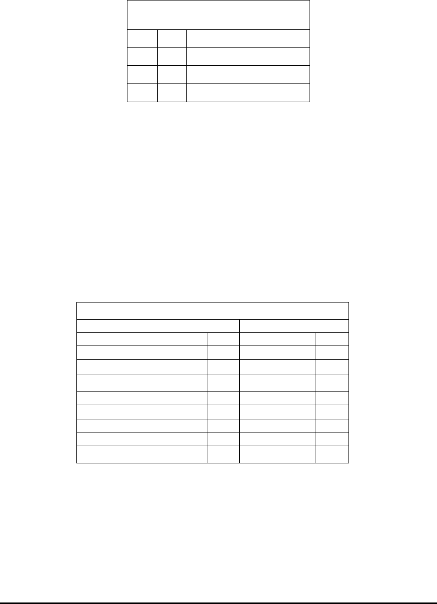
Table 1.1: Function Codes
Hex Dec Description
03H 3 Read Holding Registers
06H 6 Preset Single Register
10H 16 Preset Multiple Registers

E Electro Industries/GaugeTech Doc # E154703 1- 3
1.4.2: Function Code 06—Preset Single Register
This function allows a Master station to modify a single register in a Nexus® meter Slave. The
data registers are 16-bit (two byte) values transmitted high-ordered byte first, low-ordered byte
second.
In the following example, a Master device stores the value 0001H at Register 57346 in a Nexus®
meter Slave at address 01H.
Table 1.3: Function Code 6 Example
Master Packet Slave Packet
Slave Address 01H Slave Address 01H
Function Code 06H Function Code 06H
Data Starting Address- Hi E0H Data Starting Address - Hi E0H
Data starting Address-Lo 01H Data Starting Address-Lo 01H
Data-Hi 00H Data-Hi 00H
Data-Lo 01H Data-Lo 01H
CRC-Lo 2EH CRC-Lo 2EH
CRC-Hi 0AH CRC-Hi 0AH
1.4.3: Function Code 10—Preset Multiple Registers
This function allows a Master station to modify a group of consecutive registers in a Nexus®
meter Slave. Registers are 16-bit (two byte) values transmitted high-ordered byte first, low-
ordered byte second.
In the following example, a Master device stores the value 0001H at Register 57345, 0001H at
Register 57346 and 0001H at Register 57347 in a Nexus® meter Slave at address 01H.
1.4.4: Data Starting Address
Range in Hex: 0000H - FFFFH
Range in Decimal: 00001 - 65536
The Address in Chapter 2 (Nexus® Meter Modbus Register Map Excel Spreadsheet) is in
Decimal.
Example: For some SCADA Software, to read Holding Registers (1.4.1), Address
Format should be:
4(XXXXX) with the XXXXX being our Decimal Address.

E Electro Industries/GaugeTech Doc # E154703 1- 4
Table 1.4: Function Code 10 Example
Master Packet Slave Packet
Slave Address 01H Slave Address 01H
Function Code 06H Function Code 06H
Data Starting Address- Hi E0H Data Starting Address - Hi E0H
Data starting Address-Lo 01H Data Starting Address-Lo 01H
Number of Setpoints-Hi 00H Number of Setpoints-Hi 00H
Number of Setpoints-Lo 03H Number of Setpoints-Lo 03H
Byte Count 06H CRC-Lo E6H
Data #1-Hi 00H CRC-Hi 08H
Data #1-Lo 01H
Data #2-Lo 00H
Data #2-Hi 01H
Data #3-Lo 00H
Data #3-Hi 01H
CRC-Lo 4DH
CRC-Hi 46H
1.5: CRC (Error Checksum) Algorithm
The Cyclic Redundancy Check (CRC) field is an error checksum calculation that enables a Slave
device to determine if a request packet has been corrupted during transmission.
Every request packet transmitted from Master to Slave includes a special 16-bit value derived
from a CRC-16 algorithm performed on the packet’s contents. When a Nexus® meter Slave
receives a packet, it performs a CRC-16 calculation and compares the value with the one included
in the request packet. If the two values do not match, the Slave will ignore the packet.
Following is the pseudocode for calculating the 16-bit CRC:
Initialize a 16-bit register to FFFFH.
Initialize the generator polynomial to A001H.
FOR n=1 to # of bytes in packet
XOR nth data byte with the 16-bit register
FOR bits_shifted = 1 to 8
SHIFT 1 bit to the right
IF (bit shifted out EQUAL 1)
XOR generator polynomial with the 16-bit register and
store result in the 16-bit register
END IF
END FOR
END FOR
The resulting 16-bit register contains the CRC-16 checksum.
E Electro Industries/GaugeTech Doc # E154703 1- 5
1.6: Dead Time
A Nexus® meter Slave considers a transmission from a Master complete when it has received no
data for a period of 3.5 byte transmission times—approximately 7 ms at 4800 baud and 300
microseconds at 115200 baud. If the Master transmits any gaps between bytes that are longer than
this time period, the Slaves will perceive it as dead time.
At the conclusion of the dead time, all unaddressed Slaves begin listening for a new packet from
the Master.
1.7: Exception Response (Error Codes)
A Nexus® meter Slave will send its Master an Exception Response packet, if it has encountered
an invalid command or other problem while carrying out the Master’s instructions. The function
code of the response will have the most significant bit set. The Data field of the Exception
Response contains an Error Code specific to the type of problem.
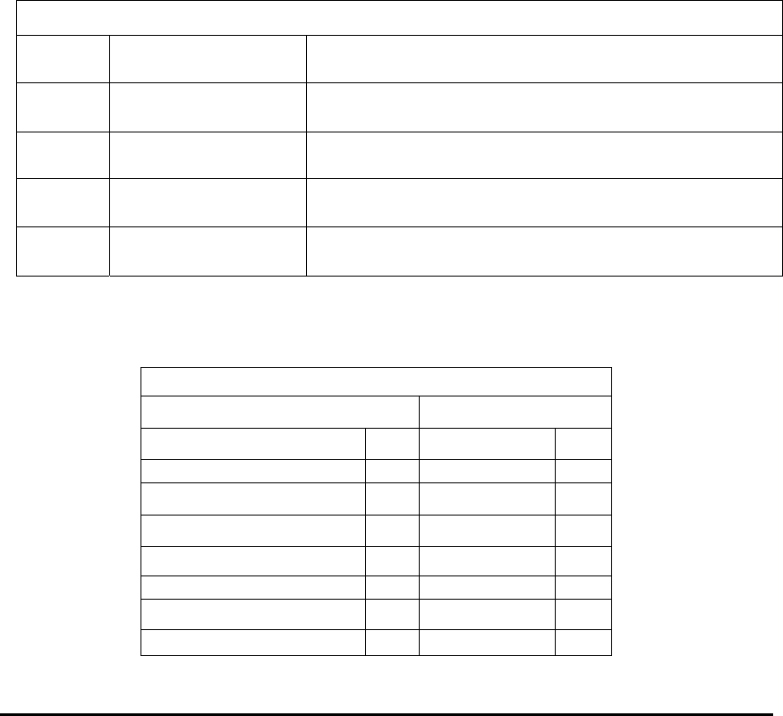
Table 1.5 lists the different Error Codes supported by the Nexus® 1500 meter.
Table 1.5: Exception Response (Error Codes)
Error
Code
Name Description
01 Illegal Function The Slave does not support the function code of the
transmitted request packet.
02 Illegal Data Address The Slave does not recognize the address in the data field
of the transmitted request packet.
03 Illegal Data Value The value referenced in the transmitted request packet is
not supported by the register on the Nexus® meter Slave.
06 Busy, Rejected Packet The Slave is busy performing a long operation and cannot
receive the request packet.
In the following example, a Master Device requests a Nexus® meter Slave at address 01H to
transmit the value at Register 00256. The Slave replies with an error, indicating that it is busy.
Table 1.6: Exception Response Example
Master Packet Slave Packet
Address 01H Address 01H
Function Code 03H Function Code 83H
Data Starting Address- Hi 01H Error Code 06H
Data starting Address-Lo 00H CRC-Lo C1H
Number of Registers-Hi 00H CRC-Hi 32H
Number of Registers-Lo 01H
CRC-Lo 85H
CRC-Hi F6H
E Electro Industries/GaugeTech Doc # E154703 1- 6
1.8: Modbus Extensions
Modbus Read Requests have a maximum size when using standard Modbus function. EI
developed Enhanced (Non-Standard) Modbus Read Requests to allow larger than standard
responses. This requires fewer requests and, is therefore, more efficient and total download time
is reduced.
This function is also more efficient with Log Retrieval. It allows the Network Card(s) to have
DNP communication with the main unit utilizing a Modbus connection.
The following are non-standard extensions to the Modbus Protocol. The Nexus® 1500 meter
supports the following additional Modbus Function Codes:
Modbus Extensions
Function Code
Hex Dec
Description
23H 35 Read Holding Registers Multiple Times
42H 66 Encapsulated DNP for LAN/WAN
1.8.1: Function Code 23H - Read Holding Registers Multiple Times
This function allows a Master station to read the binary contents of holding registers (4X
references) in the slave multiple times. Broadcast is not supported.
The Master device sends a packet defining the starting register, quantity of registers to be read
and the repeat count. Registers are addressed starting at zero: registers 1-16 are addressed as 0-
15.
Here is an example of a request to read registers 40108-40110 twice from slave device 17:
Function Code
Field Name Example (Hex)
Slave Address 11
Function Code 23
Data Starting Address-Hi 00
Data Starting Address-Lo 6B
Number of Registers-Hi 00
Number of Registers-Lo 03
Repeat Count 02
Error Check (LRC or CRC)
The register data in the response message are packed as two bytes per register, with the binary
contents right justified within each byte. For each register, the first byte contains the high order
bits and the second contains the low order bits.

E Electro Industries/GaugeTech Doc # E154703 1- 7
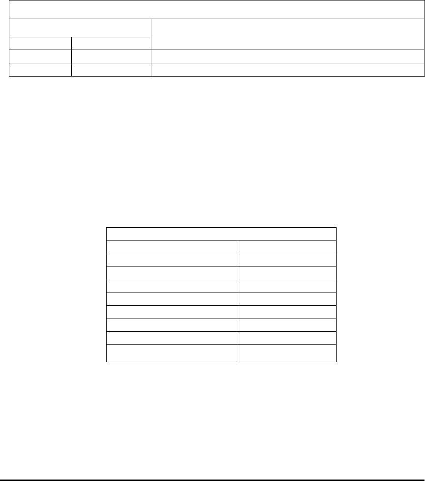
Data is scanned at the following maximum rates, depending on the repeat count:
Repeat Count RTU Framing ASCII Framing
1 509 Registers 253 Registers
2 254 Registers 126 Registers
3 169 Registers 84 Registers
4 127 Registers 63 Registers
5 101 Registers 50 Registers
6 84 Registers 42 Registers
7 72 Registers 36 Registers
The response is returned when the data is completely assembled.
Here is an example of a response to the data given earlier:
The contents of Register 40108 are shown as the two-byte values of 02 2B Hex or 555 Decimal.
The contents of Registers 40109 - 40110 are 00 00 and 00 64 Hex or 0 and 100 Decimal.
Function Code 23H Example (Response)
Field Name Example (Hex)
Slave Address 11
Function Code 23
Byte Count Hi 00
Byte Count Lo 0C
Data Hi (Register 40108, First Read) 02
Data Lo (Register 40108, First Read) 2B
Data Hi (Register 40109, First Read) 00
Data Lo (Register 40109, First Read) 00
Data Hi (Register 40110, First Read) 00
Data Lo (Register 40110, First Read) 64
Data Hi (Register 40108, Second Read) 02
Data Lo (Register 40108, Second Read) 2B
Data Hi (Register 40109, Second Read) 00
Data Lo (Register 40109, Second Read) 00
Data Hi (Register 40110, Second Read) 00
Data Lo (Register 40110, Second Read) 64
Error Check (LRC or CRC) --

E Electro Industries/GaugeTech Doc # E154703 1- 8

E Electro Industries/GaugeTech Doc # E154703 2- 1
Chapter 2
Nexus® 1500 Meter Modbus Register Map
The Nexus® 1500 meter Modbus Register Map begins on the following page.
One Second Readings use the One Second Block, Registers 00176-00235, described in
Section 8.5.
Resetting Maximums, Minimums, Energy Readings and/or Logs use the Action Block,
Registers 57345-57393, described in Section 8.71.
Time may be set in the Nexus® meter using the Real Time Block, Registers 00081-00089,
described in Section 8.2.
Chapter 8 offers descriptions of all the Nexus® 1500 meter Modbus Register Map’s Register
Block Titles and the Registers included in each block.
See Chapter 3 for a detailed description of Communication Formats referred to in the
Register Map’s “Type” column. See the Table of Contents for a list of the Register Map’s
“Types” and their page location in Chapter 3.
See Chapter 4 for an explanation of the Register Map’s “Notes” column.
See Chapter 5 for an explanation of Logs, Port Control and Updating Programmable Settings.
See Chapter 6 for an explanation of the Log Formats.
See Chapter 7 for an explanation of the Programmable Settings Blocks.

E Electro Industries/GaugeTech Doc # E154703 2- 2
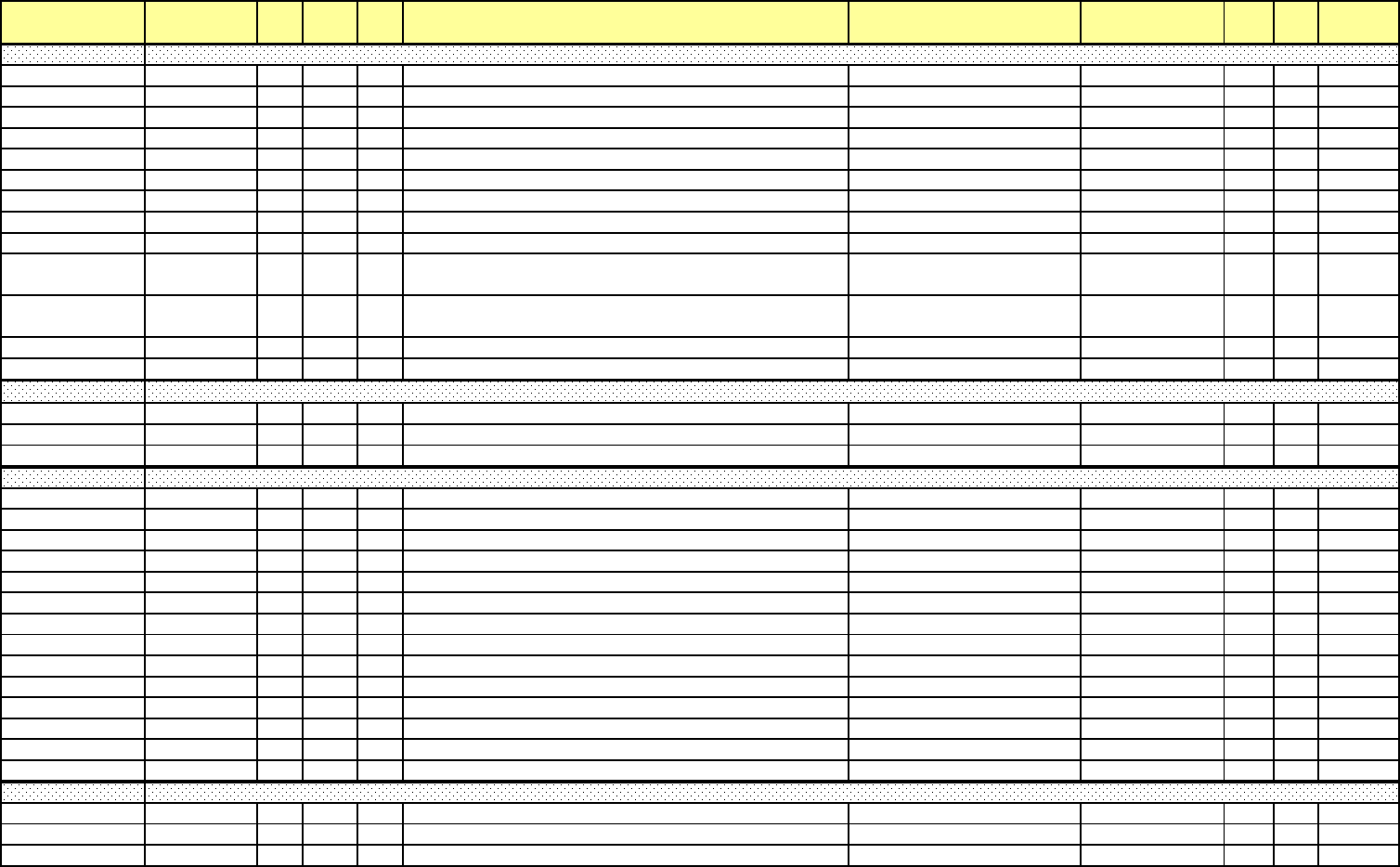
Addr. (hex) Address(4X) Line Pt DNP
Ob
j
Description Range Units Type R/W Notes
0000H-0007
H
00001-00008 0 0 Device Nam
e
F1
R
0008H-000F
H
00009-00016 1 0 Firmware Variation String 1 F1
R
0010H-0017
H
00017-00024 1 1 Firmware Variation String 2 F1
R
0018H-001F
H
00025-00032 1 2 Firmware Variation String 3 F1
R
0020H-0027
H
00033-00040 1 3 Firmware Variation String 4 F1
R
0028H-002F
H
00041-00048 1 4 Firmware Variation String 5 F1
R
0030H-0037
H
00049-00056 1 5 Firmware Variation String 6 F1
R
0038H-003F
H
00057-00064 1 6 Firmware Variation String 7 F1
R
0040H-0047
H
00065-00072 1 7 Firmware Variation String 8 F1
R
0048H-0049H 00073-00074 2 0
Nexus Comm Boot Version Number (Major). See also register
0xFD00-0xFD01 for Minor 9.9.9.9 / 0.0.0.0 0.0.0.1 version F2 R
004AH-004BH 00075-00076 3 0
Nexus Comm Run-Time Version Number (Major). See also
register 0xFD07-0xFD08 for Minor 9.9.9.9 / 0.0.0.0 0.0.0.1 version F2 R
004CH-004D
H
00077-00078 4 0 Nexus DSP Boot Version Numbe
r
9.9.9.9 / 0.0.0.0 0.0.0.1 version F2
R
004EH-004F
H
00079-00080 5 0 Nexus DSP Run-T
i
me Vers
i
on Num
b
e
r
9.9.9.9
/
0.0.0.0 0.0.0.1 vers
i
on F2
R
0050H-0053
H
00081-00084 6 0 50 On Time 12/31/9999 23:59:59.99 10 msec F3
R
1
0054H-0057
H
00085-00088 7 0 50 Current Time 12/31/9999 23:59:59.99 10 msec F3 R/
W
1, 2
0058H 00089 8 0 50 Current Day o
f
t
h
e Wee
k
Sun
d
ay - Satur
d
a
y
F4 R
/W
1, 2
0059H-005C
H
00090-0093 9 0 One cycle Block Time Stam
p
12/31/9999 23:59:59.99 10 msec F3
R
005DH-005E
H
00094-0095 10 0 One cycle Phase A-N Voltag
e
F68
R
005FH-0060
H
00096-0097 10 1 One cycle Phase B-N Voltag
e
F68
R
0061H-0062
H
00098-0099 10 2 One cycle Phase C-N Voltag
e
F68
R
0063H-0064
H
00100-0101 11 0 One cycle Vaux Voltag
e
F68
R
0065H-0066
H
00102-0103 12 0 One cycle Phase A Curren
t
F68
R
0067H-0068
H
00104-0105 12 1 One cycle Phase B Curren
t
F68
R
0069H-006A
H
00106-0107 12 2 One cycle Phase C Curren
t
F68
R
006BH-006C
H
00108-0109 13 0 One cycle Measured Neutral Current (Iaux) F68
R
006DH-006E
H
00110-0111 14 0 One cycle Phase A-B Voltag
e
F68
R
006FH-0070
H
00112-0113 14 1 One cycle Phase B-C Voltag
e
F68
R
0071H-0072
H
00114-0115 14 2 One cycle Phase A-C Voltag
e
F68
R
0073H-0074
H
00116-0117 15 0 One cycle Calculated Neutral Current (Ires) F68
R
0075H 00118 16 0 One cyc
l
e H
i
g
h
Spee
d
Input De
l
ta an
d
Current State F6
R
0076H-0079
H
00119-00122 17 0 50 Tenth second Block Time Stamp 12/31/9999 23:59:59.99 10 msec F3
R
1
007AH-007B
H
00123-00124 18 0 30 Tenth second Phase A-N Voltag
e
+32767 V / 0 V 1/ 65536 V sec F7
R
4
007CH-007D
H
00125-00126 18 1 30 Tenth second Phase B-N Voltag
e
+32767 V / 0 V 1/ 65536 V sec F7
R
4
Device Identification Block
Real Time Block
One Cycle Block
Tenth Second Block
e Electro Industries/GaugeTech Doc# E154703 MM-1

Addr. (hex) Address(4X) Line Pt DNP
Ob
j
Description Range Units Type R/W Notes
007EH-007F
H
00127-00128 18 2 30 Tenth second Phase C-N Voltag
e
+32767 V / 0 V 1/ 65536 V sec F7
R
4
0080H-0081
H
00129-00130 19 0 30 Tenth second Vaux Voltag
e
+ 32767 V / 0 V 1/ 65536 V sec F7
R
4
0082H-0083
H
00131-00132 20 0 30 Tenth second Phase A Current +32767 V / 0 V 1/ 65536 A sec F7
R
6
0084H-0085
H
00133-00134 20 1 30 Tenth second Phase B Current +32767 V / 0 V 1/ 65536 A sec F7
R
6
0086H-0087
H
00135-00136 20 2 30 Tenth second Phase C Current +32767 V / 0 V 1/ 65536 A sec F7
R
6
0088H-0089
H
00137-00138 21 0 30 Tenth second Measured Neutral Current +32767 V / 0 V 1/ 65536 A sec F7
R
008AH-008B
H
00139-00140 22 0 30 Tenth second Phase A-B Voltag
e
+32767 V / 0 V 1/ 65536 V sec F7
R
4
008CH-008D
H
00141-00142 22 1 30 Tenth second Phase B-C Voltag
e
+32767 V / 0 V 1/ 65536 V sec F7
R
4
008EH-008F
H
00143-00144 22 2 30 Tenth second Phase A-C Voltag
e
+32767 V / 0 V 1/ 65536 V sec F7
R
4
0090H-0091
H
00145-00146 23 0 30 Tenth second Phase A V
A
+32767 VA / 0 V
A
1/ 65536 VA sec F7
R
9
0092H-0093
H
00147-00148 23 1 30 Tenth second Phase B V
A
+32767 VA / 0 V
A
1/ 65536 VA sec F7
R
9
0094H-0095
H
00149-00150 23 2 30 Tenth second Phase C V
A
+32767 VA / 0 V
A
1/ 65536 VA sec F7
R
9
0096H-0097
H
00151-00152 24 0 30 Tenth second Three Phase VA +32767 VA / 0 V
A
1/ 65536 VA sec F7
R
9
0098H-0099
H
00153-00154 25 0 30 Tenth second Phase A VA
R
+32767 VAR / -32768 VA
R
1/ 65536 VAR sec F7
R
9
009AH-009B
H
00155-00156 25 1 30 Tenth second Phase B VA
R
+32767 VAR / -32768 VA
R
1/ 65536 VAR sec F7
R
9
009CH-009D
H
00157-00158 25 2 30 Tenth second Phase C VA
R
+32767 VAR / -32768 VA
R
1/ 65536 VAR sec F7
R
9
009EH-009F
H
00159-00160 26 0 30 Tenth second Three Phase VA
R
+32767 VAR / -32768 VA
R
1/ 65536 VAR sec F7
R
9
00A0H-00A1
H
00161-00162 27 0 30 Tenth second Phase A Watts +32767 W / -32768
W
1/ 65536 W sec F7
R
9
00A2H-00A3
H
00163-00164 27 1 30 Tenth second Phase B Watts +32767 W / -32768
W
1/ 65536 W sec F7
R
9
00A4H-00A5
H
00165-00166 27 2 30 Tenth second Phase C Watts +32767 W / -32768
W
1/ 65536 W sec F7
R
9
00A6H-00A7
H
00167-00168 28 0 30 Tenth second Three Phase Watts +32767 W / -32768
W
1/ 65536 W sec F7
R
9
00A8H-00A9
H
00169-00170 29 0 30 Tenth second Frequenc
y
+32767 Hz / 0 Hz 1/ 65536 Hz F7
R
00AA
H
00171 30 0 30 Tenth second Phase A Power Facto
r
3.999 / 0.000 0.001 PF F8
R
00AB
H
00172 30 1 30 Tenth second Phase B Power Facto
r
3.999 / 0.000 0.001 PF F8
R
00AC
H
00173 30 2 30 Tenth second Phase C Power Facto
r
3.999 / 0.000 0.001 PF F8
R
00AD
H
00174 31 0 30 Tenth second Three Phase Power Facto
r
3.999 / 0.000 0.001 PF F8
R
00AEH 00175 32 0 30
T
ent
h
secon
d
Ph
ase
A
-
N
V
o
l
tage to
A
ux
ili
ary
V
o
l
tage
Ph
ase
Angle + 180 / - 180 0.01 degree F9 R
00AFH-00B2
H
00176-00179 33 0 50 One second Block Time Stam
p
12/31/9999 23:59:59.99 10 msec F3
R
1
00B3H-00B4
H
00180-00181 34 0 30 One second Phase A-N Voltag
e
+ 32767 V / 0 V 1/ 65536 V sec F7
R
4
00B5H-00B6
H
00182-00183 34 1 30 One second Phase B-N Voltag
e
+ 32767 V / 0 V 1/ 65536 V sec F7
R
4
00B7H-00B8
H
00184-00185 34 2 30 One second Phase C-N Voltag
e
+ 32767 V / 0 V 1/ 65536 V sec F7
R
4
00B9H-00BA
H
00186-00187 35 0 30 One second Vaux Voltag
e
+ 32767 V / 0 V 1/ 65536 V sec F7
R
4
00BBH-00BC
H
00188-00189 36 0 30 One second Phase A Curren
t
+32767 A / 0
A
1/ 65536 A sec F7
R
6
00BDH-00BE
H
00190-00191 36 1 30 One second Phase B Current +32767 A / 0
A
1/ 65536 A sec F7
R
6
00BFH-00C0
H
00192-00193 36 2 30 One second Phase C Current +32767 A / 0
A
1/ 65536 A sec F7
R
6
00C1H-00C2
H
00194-00195 37 0 30 One second Measured Neutral Current +32767 A / 0
A
1/ 65536 A sec F7
R
00C3H-00C4
H
00196-00197 38 0 30 One second Calculated Neutral Current +32767 A / 0
A
1/ 65536 A sec F7
R
6
One Second Block
e Electro Industries/GaugeTech Doc# E154703 MM-2

Addr. (hex) Address(4X) Line Pt DNP
Ob
j
Description Range Units Type R/W Notes
00C5H-00C6
H
00198-00199 39 0 30 One second Phase A-B Voltag
e
+ 32767 V / 0 V 1/ 65536 V sec F7
R
4
00C7H-00C8
H
00200-00201 39 1 30 One second Phase B-C Voltag
e
+ 32767 V / 0 V 1/ 65536 V sec F7
R
4
00C9H-00CA
H
00202-00203 39 2 30 One second Phase C-A Voltag
e
+ 32767 V / 0 V 1/ 65536 V sec F7
R
4
00CBH-00CC
H
00204-00205 40 0 30 One second Phase A V
A
+ 32767 V / 0 V 1/ 65536 VA sec F7
R
9
00CDH-00CE
H
00206-00207 40 1 30 One second Phase B V
A
+32767 VA / 0 V
A
1/ 65536 VA sec F7
R
9
00CFH-00D0
H
00208-00209 40 2 30 One second Phase C V
A
+32767 VA / 0 V
A
1/ 65536 VA sec F7
R
9
00D1H-00D2
H
00210-00211 41 0 30 One second V
A
+32767 VA / 0 V
A
1/ 65536 VA sec F7
R
9
00D3H-00D4
H
00212-00213 42 0 30 One second Phase A VA
R
+32767 VAR / -32768 VA
R
1/ 65536 VAR sec F7
R
9
00D5H-00D6
H
00214-00215 42 1 30 One second Phase B VA
R
+32767 VAR / -32768 VA
R
1/ 65536 VAR sec F7
R
9
00D7H-00D8
H
00216-00217 42 2 30 One second Phase C VA
R
+32767 VAR / -32768 VA
R
1/ 65536 VAR sec F7
R
9
00D9H-00DA
H
00218-00219 43 0 30 One second Three VA
R
+32767 VAR / -32768 VA
R
1/ 65536 VAR sec F7
R
9
00DBH-00DC
H
00220-00221 44 0 30 One second Phase A Watts +32767 W / -32768
W
1/ 65536 W sec F7
R
9
00DDH-00DE
H
00222-00223 44 1 30 One second Phase B Watts +32767 W / -32768
W
1/ 65536 W sec F7
R
9
00DFH-00E0
H
00224-00225 44 2 30 One second Phase C Watts +32767 W / -32768
W
1/ 65536 W sec F7
R
9
00E1H-00E2
H
00226-00227 45 0 30 One second Watts +32767 W / -32768
W
1/ 65536 W sec F7
R
9
00E3H-00E4
H
00228-00229 46 0 30 One second Frequenc
y
+ 32767 Hz / 0 Hz 1/ 65536 Hz F7
R
00E5H 00230 47 0 30 One second Phase A Power Facto
r
3.999 / 0 0.001 PF F8
R
00E6H 00231 47 1 30 One second Phase B Power Facto
r
3.999 / 0 0.001 PF F8
R
00E7H 00232 47 2 30 One second Phase C Power Facto
r
3.999 / 0 0.001 PF F8
R
00E8H 00233 48 0 30 One second Three Phase Power Facto
r
3.999 / 0 0.001 PF F8
R
00E9H 00234 49 0 30 One second Voltage Imbalanc
e
+327.67% / -327.68% 0.01% F10
R
00EA
H
00235 49 1 30 One secon
d
Current Im
b
a
l
anc
e
+327.67%
/
-327.68% 0.01% F10
R
00EBH-00EE
H
00236-00239 50 0 50 Thermal Average Block Time Stam
p
12/31/9999 23:59:59.99 10 msec F3
R
1
00EFH-00F0
H
00240-00241 51 0 30 Thermal Average Phase A-N Voltage + 32767 V / 0 V 1/ 65536 V sec F7
R
4
00F1H-00F2
H
00242-00243 51 1 30 Thermal Average Phase B-N Voltage + 32767 V / 0 V 1/ 65536 V sec F7
R
4
00F3H-00F4
H
00244-00245 51 2 30 Thermal Average Phase C-N Voltage + 32767 V / 0 V 1/ 65536 V sec F7
R
4
00F7H-00F8
H
00248-00249 53 0 30 Thermal Average Phase A Current + 32767 A / 0 A 1/ 65536 A sec F7
R
6
00F9H-00FA
H
00250-00251 53 1 30 Thermal Average Phase B Current + 32767 A / 0 A 1/ 65536 A sec F7
R
6
00FBH-00FC
H
00252-00253 53 2 30 Thermal Average Phase C Current + 32767 A / 0 A 1/ 65536 A sec F7
R
6
00FDH-00FE
H
00254-00255 54 0 30 Thermal Average Measured Neutral Current + 32767 A / 0 A 1/ 65536 A sec F7
R
00FFH-0100
H
00256-00257 55 0 30 Thermal Average Calculated Neutral Current + 32767 A / 0 A 1/ 65536 A sec F7
R
6
0101H-0102
H
00258-00259 56 0 30 Thermal Average Phase A-B Voltage + 32767 V / 0 V 1/ 65536 V sec F7
R
4
0103H-0104
H
00260-00261 56 1 30 Thermal Average Phase B-C Voltage + 32767 V / 0 V 1/ 65536 V sec F7
R
4
0105H-0106
H
00262-00263 56 2 30 Thermal Average Phase C-A Voltage + 32767 V / 0 V 1/ 65536 V sec F7
R
4
0107H-0108
H
00264-00265 57 0 30 Thermal Average Phase A VA +32767 VA / 0 V
A
1/ 65536 VA sec F7
R
9
0109H-010A
H
00266-00267 57 1 30 Thermal Average Phase B VA +32767 VA / 0 V
A
1/ 65536 VA sec F7
R
9
010BH-010C
H
00268-00269 57 2 30 Thermal Average Phase C VA +32767 VA / 0 V
A
1/ 65536 VA sec F7
R
9
010DH-010E
H
00270-00271 58 0 30 Thermal Average VA +32767 VA / 0 V
A
1/ 65536 VA sec F7
R
9
Thermal Average Block
e Electro Industries/GaugeTech Doc# E154703 MM-3

Addr. (hex) Address(4X) Line Pt DNP
Ob
j
Description Range Units Type R/W Notes
010FH-0110
H
00272-00273 59 0 30 Thermal Average Phase A VAR +32767 VAR / -32768 VA
R
1/ 65536 VAR sec F7
R
9
0111H-0112
H
00274-00275 59 1 30 Thermal Average Phase B VAR +32767 VAR / -32768 VA
R
1/ 65536 VAR sec F7
R
9
0113H-0114
H
00276-00277 58 2 30 Thermal Average Phase C VAR +32767 VAR / -32768 VA
R
1/ 65536 VAR sec F7
R
9
0115H-0116
H
00278-00279 60 0 30 Thermal Average VAR +32767 VAR / -32768 VA
R
1/ 65536 VAR sec F7
R
9
0117H-0118
H
00280-00281 61 0 30 Thermal Average Phase A Watts +32767 W / -32768
W
1/ 65536 W sec F7
R
9
0119H-011A
H
00282-00283 61 1 30 Thermal Average Phase B Watts +32767 W / -32768
W
1/ 65536 W sec F7
R
9
011BH-011C
H
00284-00285 61 2 30 Thermal Average Phase C Watts +32767 W / -32768
W
1/ 65536 W sec F7
R
9
011DH-011E
H
00286-00287 62 0 30 Thermal Average Watts +32767 W / -32768
W
1/ 65536 W sec F7
R
9
011FH-0120
H
00288-00289 63 0 30 Thermal Average Frequency + 32767 Hz / 0 Hz 1/ 65536 Hz F7
R
0121H 00290 64 0 30 Thermal Average Phase A Power Factor 3.999 / 0 0.001 PF F8
R
0122H 00291 64 1 30 Thermal Average Phase B Power Factor 3.999 / 0 0.001 PF F8
R
0123H 00292 64 2 30 Thermal Average Phase C Power Factor 3.999 / 0 0.001 PF F8
R
0124H 00293 65 0 30 Thermal Average Power Factor 3.999 / 0 0.001 PF F8
R
0125H 00294 66 0 30 Thermal Average Voltage Imbalance +327.67% / -327.68% 0.01% F10
R
0126H 00295 66 1 30 T
h
erma
l
Average Current Im
b
a
l
ance +327.67%
/
-327.68% 0.01% F10
R
0127H-012A
H
00296-00299 67 0 50 Maximum Block Time Stamp 12/31/9999 23:59:59.99 10 msec F3
R
1
012BH-012C
H
00300-00301 68 0 30 Maximum Thermal Average Phase A-N Voltage + 32767 V / 0 V 1/ 65536 V sec F7
R
4
012DH-012E
H
00302-00303 68 1 30 Maximum Thermal Average Phase B-N Voltage + 32767 V / 0 V 1/ 65536 V sec F7
R
4
012FH-0130
H
00304-00305 68 2 30 Maximum Thermal Average Phase C-N Voltage + 32767 V / 0 V 1/ 65536 V sec F7
R
4
0133H-0134
H
00308-00309 70 0 30 Maximum Thermal Average Phase A Current + 32767 A / 0 A 1/ 65536 A sec F7
R
6
0135H-0136
H
00310-00311 70 1 30 Maximum Thermal Average Phase B Current + 32767 A / 0 A 1/ 65536 A sec F7
R
6
0137H-0138
H
00312-00313 70 2 30 Maximum Thermal Average Phase C Current + 32767 A / 0 A 1/ 65536 A sec F7
R
6
0139H-013A
H
00314-00315 71 0 30 Maximum Thermal Average Measured Neutral Current + 32767 A / 0 A 1/ 65536 A sec F7
R
013BH-013C
H
00316-00317 72 0 30 Maximum Thermal Average Calculated Neutral Current + 32767 A / 0 A 1/ 65536 A sec F7
R
6
013DH-013E
H
00318-00319 73 0 30 Maximum Thermal Average Phase A-B Voltage + 32767 V / 0 V 1/ 65536 V sec F7
R
4
013FH-0140
H
00320-00321 73 1 30 Maximum Thermal Average Phase B-C Voltage + 32767 V / 0 V 1/ 65536 V sec F7
R
4
0141H-0142
H
00322-00323 73 2 30 Maximum Thermal Average Phase C-A Voltage + 32767 V / 0 V 1/ 65536 V sec F7
R
4
0143H-0144
H
00324-00325 74 0 30 Maximum Thermal Average Phase A VA +32767 VA / 0 V
A
1/ 65536 VA sec F7
R
9
0145H-0146
H
00326-00327 74 1 30 Maximum Thermal Average Phase B VA +32767 VA / 0 V
A
1/ 65536 VA sec F7
R
9
0147H-0148
H
00328-00329 74 2 30 Maximum Thermal Average Phase C V
A
+32767 VA / 0 V
A
1/ 65536 VA sec F7
R
9
0149H-014A
H
00330-00331 75 0 30 Maximum Thermal Average VA +32767 VA / 0 V
A
1/ 65536 VA sec F7
R
9
014BH-014C
H
00332-00333 76 0 30 Maximum Thermal Average Phase A Positive VAR +32767 VAR / 0 VA
R
1/ 65536 VAR sec F7
R
9
014DH-014E
H
00334-00335 76 1 30 Maximum Thermal Average Phase B Positive VAR +32767 VAR / 0 VA
R
1/ 65536 VAR sec F7
R
9
014FH-0150
H
00336-00337 76 2 30 Maximum Thermal Average Phase C Positive VAR +32767 VAR / 0 VA
R
1/ 65536 VAR sec F7
R
9
0151H-0152
H
00338-00339 77 0 30 Maximum Thermal Average Positive VAR +32767 VAR / 0 VA
R
1/ 65536 VAR sec F7
R
9
0153H-0154
H
00340-00341 78 0 30 Maximum Thermal Average Phase A Negative VAR 0 VAR / -32768 VA
R
1/ 65536 VAR sec F7
R
9
0155H-0156
H
00342-00343 78 1 30 Maximum Thermal Average Phase B Negative VAR 0 VAR / -32768 VA
R
1/ 65536 VAR sec F7
R
9
0157H-0158
H
00344-00345 78 2 30 Maximum Thermal Average Phase C Negative VAR 0 VAR / -32768 VA
R
1/ 65536 VAR sec F7
R
9
Maximum Block
e Electro Industries/GaugeTech Doc# E154703 MM-4

Addr. (hex) Address(4X) Line Pt DNP
Ob
j
Description Range Units Type R/W Notes
0159H-015A
H
00346-00347 79 0 30 Maximum Thermal Average Negative VAR 0 VAR / -32768 VA
R
1/ 65536 VAR sec F7
R
9
015BH-015C
H
00348-00349 80 0 30 Maximum Thermal Average Phase A Watts Positive +32767 W / 0 W 1/ 65536 W sec F7
R
9
015DH-015E
H
00350-00351 80 1 30 Maximum Thermal Average Phase B Watts Positive +32767 W / 0 W 1/ 65536 W sec F7
R
9
015FH-0160
H
00352-00353 80 2 30 Maximum Thermal Average Phase C Watts Positive +32767 W / 0 W 1/ 65536 W sec F7
R
9
0161H-0162
H
00354-00355 81 0 30 Maximum Thermal Average Positive Watts +32767 W / 0 W 1/ 65536 W sec F7
R
9
0163H-0164
H
00356-00357 82 0 30 Maximum Thermal Average Phase A Watts Negative 0 W / -32768 W 1/ 65536 W sec F7
R
9
0165H-0166
H
00358-00359 82 1 30 Maximum Thermal Average Phase B Watts Negative 0 W / -32768 W 1/ 65536 W sec F7
R
9
0167H-0168
H
00360-00361 82 2 30 Maximum Thermal Average Phase C Watts Negative 0 W / -32768 W 1/ 65536 W sec F7
R
9
0169H-016A
H
00362-00363 83 0 30 Maximum Thermal Average Negative Watts 0 W / -32768 W 1/ 65536 W sec F7
R
9
016BH-016C
H
00364-00365 84 0 30 Maximum Thermal Average Frequency + 32767 Hz / 0 Hz 1/ 65536 Hz F7
R
016D
H
00366 85 0 30 Maximum Thermal Average Phase A Power Factor Quadrant 1 0.999 / 0 0.001 PF F8
R
016EH 00367 85 1 30 Maximum Thermal Average Phase B Power Factor Quadrant 1 0.999 / 0 0.001 PF F8
R
016FH 00368 85 2 30 Maximum Thermal Average Phase C Power Factor Quadrant 1 0.999 / 0 0.001 PF F8
R
0170H 00369 86 0 30 Maximum Thermal Average Power Factor Quadrant 1 0.999 / 0 0.001 PF F8
R
0171H 00370 87 0 30 Maximum Thermal Average Phase A Power Factor Quadrant 2 3.999 / 3.000 0.001 PF F8
R
0172H 00371 87 1 30 Maximum Thermal Average Phase B Power Factor Quadrant 2 3.999 / 3.000 0.001 PF F8
R
0173H 00372 87 2 30 Maximum Thermal Average Phase C Power Factor Quadrant 2 3.999 / 3.000 0.001 PF F8
R
0174H 00373 88 0 30 Maximum Thermal Average Power Factor Quadrant 2 3.999 / 3.000 0.001 PF F8
R
0175H 00374 89 0 30 Maximum Thermal Average Phase A Power Factor Quadrant 3 2.999 / 2.000 0.001 PF F8
R
0176H 00375 89 1 30 Maximum Thermal Average Phase B Power Factor Quadrant 3 2.999 / 2.000 0.001 PF F8
R
0177H 00376 89 2 30 Maximum Thermal Average Phase C Power Factor Quadrant 3 2.999 / 2.000 0.001 PF F8
R
0178H 00377 90 0 30 Maximum Thermal Average Power Factor Quadrant 3 2.999 / 2.000 0.001 PF F8
R
0179H 00378 91 0 30 Maximum Thermal Average Phase A Power Factor Quadrant 4 1.999 / 1.000 0.001 PF F8
R
017A
H
00379 91 1 30 Maximum Thermal Average Phase B Power Factor Quadrant 4 1.999 / 1.000 0.001 PF F8
R
017B
H
00380 91 2 30 Maximum Thermal Average Phase C Power Factor Quadrant 4 1.999 / 1.000 0.001 PF F8
R
017C
H
00381 92 0 30 Maximum Thermal Average Power Factor Quadrant 4 1.999 / 1.000 0.001 PF F8
R
017D
H
00382 93 0 30 Maximum Thermal Average Voltage Imbalance +327.67% / -327.68% 0.01% F10
R
017EH 00383 93 1 30 Maximum Thermal Average Current Imbalance +327.67% / -327.68% 0.01% F10
R
017FH 00384 94 0 30 Maximum THD Phase A-N / A-B Voltage +327.67% / -327.68% 0.01% F10
R
0180H 00385 94 1 30 Maximum THD Phase B-N / B-C Voltage +327.67% / -327.68% 0.01% F10
R
0181H 00386 94 2 30 Maximum THD Phase C-N / C-A Voltage +327.67% / -327.68% 0.01% F10
R
0182H 00387 95 0 30 Maximum THD Phase A Current +327.67% / -327.68% 0.01% F10
R
0183H 00388 95 1 30 Maximum THD Phase B Current +327.67% / -327.68% 0.01% F10
R
0184H 00389 95 2 30 Maximum THD Phase C Current +327.67% / -327.68% 0.01% F10
R
0185H 00390 96 0 30 Maximum K-Factor Phase A Current 327.67 / -327.68 0.01 F67
R
0186H 00391 96 1 30 Maximum K-Factor Phase B Current 327.67 / -327.68 0.01 F67
R
0187H 00392 96 2 30 Maximum K-Factor Phase C Current 327.67 / -327.68 0.01 F67
R
0188H-0189
H
00393-00394 97 0 30 Coincident Thermal Average VAR for Maximum Positive Wat
t
+32767 VAR / -32768 VA
R
1/ 65536 W sec F7
R
9
e Electro Industries/GaugeTech Doc# E154703 MM-5

Addr. (hex) Address(4X) Line Pt DNP
Ob
j
Description Range Units Type R/W Notes
018AH-018BH 00395-00396 97 1 30 Coincident Thermal Average VAR for Maximum Negative Watt +32767 VAR / -32768 VAR 1/ 65536 W sec F7 R 9
018CH-018F
H
00397-00400 98 0 50 Minimum Block Time Stamp 12/31/9999 23:59:59.99 10 msec F3
R
1
0190H-0191
H
00401-00402 99 0 30 Minimum Thermal Average Phase A-N Voltage + 32767 V / 0 V 1/ 65536 V sec F7
R
4
0192H-0193
H
00403-00404 99 1 30 Minimum Thermal Average Phase B-N Voltage + 32767 V / 0 V 1/ 65536 V sec F7
R
4
0194H-0195
H
00405-00406 99 2 30 Minimum Thermal Average Phase C-N Voltage + 32767 V / 0 V 1/ 65536 V sec F7
R
4
0198H-0199
H
00409-00410 101 0 30 Minimum Thermal Average Phase A Current + 32767 A / 0 A 1/ 65536 A sec F7
R
6
019AH-019B
H
00411-00412 101 1 30 Minimum Thermal Average Phase B Current + 32767 A / 0 A 1/ 65536 A sec F7
R
6
019CH-019D
H
00413-00414 101 2 30 Minimum Thermal Average Phase C Current + 32767 A / 0 A 1/ 65536 A sec F7
R
6
019EH-019F
H
00415-00416 102 0 30 Minimum Thermal Average Measured Neutral Current + 32767 A / 0 A 1/ 65536 A sec F7
R
01A0H-01A1
H
00417-00418 103 0 30 Minimum Thermal Average Calculated Neutral Current + 32767 A / 0 A 1/ 65536 A sec F7
R
6
01A2H-01A3
H
00419-00420 104 0 30 Minimum Thermal Average Phase A-B Voltage + 32767 V / 0 V 1/ 65536 V sec F7
R
4
01A4H-01A5
H
00421-00422 104 1 30 Minimum Thermal Average Phase B-C Voltage + 32767 V / 0 V 1/ 65536 V sec F7
R
4
01A6H-01A7
H
00423-00424 104 2 30 Minimum Thermal Average Phase C-A Voltage + 32767 V / 0 V 1/ 65536 V sec F7
R
4
01A8H-01A9
H
00425-00426 105 0 30 Minimum Thermal Average Phase A VA +32767 VA / 0 V
A
1/ 65536 VA sec F7
R
9
01AAH-01AB
H
00427-00428 105 1 30 Minimum Thermal Average Phase B VA +32767 VA / 0 V
A
1/ 65536 VA sec F7
R
9
01ACH-01AD
H
00429-00430 105 2 30 Minimum Thermal Average Phase C VA +32767 VA / 0 V
A
1/ 65536 VA sec F7
R
9
01AEH-01AF
H
00431-00432 106 0 30 Minimum Thermal Average VA +32767 VA / 0 V
A
1/ 65536 VA sec F7
R
9
01B0H-01B1
H
00433-00434 107 0 30 Minimum Thermal Average Phase A Positive VAR +32767 VAR / 0 VA
R
1/ 65536 VAR sec F7
R
9
01B2H-01B3
H
00435-00436 107 1 30 Minimum Thermal Average Phase B Positive VAR +32767 VAR / 0 VA
R
1/ 65536 VAR sec F7
R
9
01B4H-01B5
H
00437-00438 107 2 30 Minimum Thermal Average Phase C Positive VAR +32767 VAR / 0 VA
R
1/ 65536 VAR sec F7
R
9
01B6H-01B7
H
00439-00440 108 0 30 Minimum Thermal Average Positive VAR +32767 VAR / 0 VA
R
1/ 65536 VAR sec F7
R
9
01B8H-01B9
H
00441-00442 109 0 30 Minimum Thermal Average Phase A Negative VAR 0 VAR / -32768 VA
R
1/ 65536 VAR sec F7
R
9
01BAH-01BB
H
00443-00444 109 1 30 Minimum Thermal Average Phase B Negative VAR 0 VAR / -32768 VA
R
1/ 65536 VAR sec F7
R
9
01BCH-01BD
H
00445-00446 109 2 30 Minimum Thermal Average Phase C Negative VAR 0 VAR / -32768 VA
R
1/ 65536 VAR sec F7
R
9
01BEH-01BF
H
00447-00448 110 0 30 Minimum Thermal Average Negative VA
R
0 VAR / -32768 VA
R
1/ 65536 VAR sec F7
R
9
01C0H-01C1
H
00449-00450 111 0 30 Minimum Thermal Average Phase A Positive Watts +32767 W / 0 W 1/ 65536 W sec F7
R
9
01C2H-01C3
H
00451-00452 111 1 30 Minimum Thermal Average Phase B Positive Watts +32767 W / 0 W 1/ 65536 W sec F7
R
9
01C4H-01C5
H
00453-00454 111 2 30 Minimum Thermal Average Phase C Positive Watts +32767 W / 0 W 1/ 65536 W sec F7
R
9
01C6H-01C7
H
00455-00456 112 0 30 Minimum Thermal Average Positive Watts +32767 W / 0 W 1/ 65536 W sec F7
R
9
01C8H-01C9
H
00457-00458 113 0 30 Minimum Thermal Average Phase A Negative Watts 0 W / -32768 W 1/ 65536 W sec F7
R
9
01CAH-01CB
H
00459-00460 113 1 30 Minimum Thermal Average Phase B Negative Watts 0 W / -32768 W 1/ 65536 W sec F7
R
9
01CCH-01CD
H
00461-00462 113 2 30 Minimum Thermal Average Phase C Negative Watts 0 W / -32768 W 1/ 65536 W sec F7
R
9
01CEH-01CF
H
00463-00464 114 0 30 Minimum Thermal Average Negative Watts 0 W / -32768 W 1/ 65536 W sec F7
R
9
01D0H-01D1
H
00465-00466 115 0 30 Minimum Thermal Average Frequency + 32767 Hz / 0 Hz 1/ 65536 Hz F7
R
01D2
H
00467 116 0 30 Minimum Thermal Average Phase A Power Factor Quadrant 1 0.999 / 0 0.001 PF F8
R
01D3
H
00468 116 1 30 Minimum Thermal Average Phase B Power Factor Quadrant 1 0.999 / 0 0.001 PF F8
R
01D4
H
00469 116 2 30 Minimum Thermal Average Phase C Power Factor Quadrant 1 0.999 / 0 0.001 PF F8
R
Minimum Block
e Electro Industries/GaugeTech Doc# E154703 MM-6

Addr. (hex) Address(4X) Line Pt DNP
Ob
j
Description Range Units Type R/W Notes
01D5
H
00470 117 0 30 Minimum Thermal Average Power Factor Quadrant 1 0.999 / 0 0.001 PF F8
R
01D6H 00471 118 0 30 Minimum Thermal Average Phase A Power Factor Quadrant 2 3.999 / 3.000 0.001 PF F8 R
01D7
H
00472 118 1 30 Minimum Thermal Average Phase B Power Factor Quadrant 2 3.999 / 3.000 0.001 PF F8
R
01D8
H
00473 118 2 30 Minimum Thermal Average Phase C Power Factor Quadrant 2 3.999 / 3.000 0.001 PF F8
R
01D9
H
00474 119 0 30 Minimum Thermal Average Power Factor Quadrant 2 3.999 / 3.000 0.001 PF F8
R
01DA
H
00475 120 0 30 Minimum Thermal Average Phase A Power Factor Quadrant 3 2.999 / 2.000 0.001 PF F8
R
01DB
H
00476 120 1 30 Minimum Thermal Average Phase B Power Factor Quadrant 3 2.999 / 2.000 0.001 PF F8
R
01DC
H
00477 120 2 30 Minimum Thermal Average Phase C Power Factor Quadrant 3 2.999 / 2.000 0.001 PF F8
R
01DD
H
00478 121 0 30 Minimum Thermal Average Power Factor Quadrant 3 2.999 / 2.000 0.001 PF F8
R
01DE
H
00479 122 0 30 Minimum Thermal Average Phase A Power Factor Quadrant 4 1.999 / 1.000 0.001 PF F8
R
01DF
H
00480 122 1 30 Minimum Thermal Average Phase B Power Factor Quadrant 4 1.999 / 1.000 0.001 PF F8
R
01E0H 00481 122 2 30 Minimum Thermal Average Phase C Power Factor Quadrant 4 1.999 / 1.000 0.001 PF F8
R
01E1H 00482 123 0 30 Minimum Thermal Average Power Factor Quadrant 4 1.999 / 1.000 0.001 PF F8
R
01E2H 00483 124 0 30 Minimum Thermal Average Voltage Imbalance +327.67% / -327.68% 0.01% F10
R
01E3H 00484 124 1 30 Minimum Thermal Average Current Imbalance +327.67% / -327.68% 0.01% F10
R
01E4H 00485 125 0 30 Minimum THD Phase A-N Voltage / Phase A-B Voltag
e
+327.67% / -327.68% 0.01% F10
R
01E5H 00486 125 1 30 Minimum THD Phase B-N Voltage / Phase B-C Voltage +327.67% / -327.68% 0.01% F10
R
01E6H 00487 125 2 30 Minimum THD Phase C-N Voltage / Phase C-A Voltage +327.67% / -327.68% 0.01% F10
R
01E7H 00488 126 0 30 Minimum THD Phase A Current +327.67% / -327.68% 0.01% F10
R
01E8H 00489 126 1 30 Minimum THD Phase B Current +327.67% / -327.68% 0.01% F10
R
01E9H 00490 126 2 30 Minimum THD Phase C Current +327.67% / -327.68% 0.01% F10
R
01EA
H
00491 127 0 30 Minimum K-Factor Phase A Current 327.67 / -327.68 0.01 F67
R
01EB
H
00492 127 1 30 Minimum K-Factor Phase B Current 327.67 / -327.68 0.01 F67
R
01EC
H
00493 127 2 30 Minimum K-Factor Phase C Current 327.67 / -327.68 0.01 F67
R
01EDH-01EE
H
00494-00495 128 0 30 Coincident Thermal Average VAR for Minimum Positive Wat
t
+32767 VAR / -32768 VA
R
1/ 65536 W sec F7
R
9
01EFH-01F0
H
00496-00497 128 1 30 Co
i
nc
id
ent T
h
erma
l
Average VAR
f
or M
i
n
i
mum Negat
i
ve Wat
t
+32767 VAR
/
-32768 VA
R
1
/
65536 W sec F7
R
9
01F1H-01F4
H
00498-00501 129 0 50 Maximum Thermal Average Phase A-N Voltage Time Stam
p
12/31/9999 23:59:59.99 10 msec F3
R
1
01F5H-01F8
H
00502-00505 129 1 50 Maximum Thermal Average Phase B-N Voltage Time Stam
p
12/31/9999 23:59:59.99 10 msec F3
R
1
01F9H-01FC
H
00506-00509 129 2 50 Maximum Thermal Average Phase C-N Voltage Time Stam
p
12/31/9999 23:59:59.99 10 msec F3
R
1
01FDH-0200
H
00510-00513 129 3 50 Maximum Thermal Average Auxiliary Voltage Time Stam
p
12/31/9999 23:59:59.99 10 msec F3
R
1
0201H-0204
H
00514-00517 129 4 50 Maximum Thermal Average Phase A Current Time Stamp 12/31/9999 23:59:59.99 10 msec F3
R
1
0205H-0208
H
00518-00521 129 5 50 Maximum Thermal Average Phase B Current Time Stamp 12/31/9999 23:59:59.99 10 msec F3
R
1
0209H-020C
H
00522-00525 129 6 50 Maximum Thermal Average Phase C Current Time Stamp 12/31/9999 23:59:59.99 10 msec F3
R
1
020DH-0210H 00526-00529 129 7 50
Maximum Thermal Average Measured Neutral Current Time
Stamp 12/31/9999 23:59:59.99 10 msec F3 R 1
0211H-0214H 00530-00533 129 8 50
Maximum Thermal Average Calculated Neutral Current Time
Stamp 12/31/9999 23:59:59.99 10 msec F3 R 1
0215H-0218
H
00534-00537 129 9 50 Maximum Thermal Average Phase A-B Voltage Time Stam
p
12/31/9999 23:59:59.99 10 msec F3
R
1
Maximum Time Stamp Block
e Electro Industries/GaugeTech Doc# E154703 MM-7

Addr. (hex) Address(4X) Line Pt DNP
Ob
j
Description Range Units Type R/W Notes
0219H-021C
H
00538-00541 129 10 50 Maximum Thermal Average Phase B-C Voltage Time Stam
p
12/31/9999 23:59:59.99 10 msec F3
R
1
021DH-0220
H
00542-00545 129 11 50 Maximum Thermal Average Phase C-A Voltage Time Stam
p
12/31/9999 23:59:59.99 10 msec F3
R
1
0221H-0224
H
00546-00549 129 12 50 Maximum Thermal Average Phase A VA Time Stam
p
12/31/9999 23:59:59.99 10 msec F3
R
1
0225H-0228
H
00550-00553 129 13 50 Maximum Thermal Average Phase B VA Time Stam
p
12/31/9999 23:59:59.99 10 msec F3
R
1
0229H-022C
H
00554-00557 129 14 50 Maximum Thermal Average Phase C VA Time Stam
p
12/31/9999 23:59:59.99 10 msec F3
R
1
022DH-023
H
00558-00561 129 15 50 Maximum Thermal Average VA Time Stam
p
12/31/9999 23:59:59.99 10 msec F3
R
1
0231H-0234H 00562-00565 129 16 50 Maximum Thermal Average Phase A Positive VAR Time Stamp 12/31/9999 23:59:59.99 10 msec F3 R 1
0235H-0238H 00566-00569 129 17 50 Maximum Thermal Average Phase B Positive VAR Time Stamp 12/31/9999 23:59:59.99 10 msec F3 R 1
0239H-023CH 00570-00573 129 18 50 Maximum Thermal Average Phase C Positive VAR Time Stamp 12/31/9999 23:59:59.99 10 msec F3 R 1
023DH-0240
H
00574-00577 129 19 50 Maximum Thermal Average Positive VAR Time Stam
p
12/31/9999 23:59:59.99 10 msec F3
R
1
0241H-0244H 00578-00581 129 20 50
Maximum Thermal Average Phase A Negative VAR Time
Stamp 12/31/9999 23:59:59.99 10 msec F3 R 1
0245H-0248H 00582-00585 129 21 50
Maximum Thermal Average Phase B Negative VAR Time
Stamp 12/31/9999 23:59:59.99 10 msec F3 R 1
0249H-024CH 00586-00589 129 22 50
Maximum Thermal Average Phase C Negative VAR Time
Stamp 12/31/9999 23:59:59.99 10 msec F3 R 1
024DH-0250
H
00590-00593 129 23 50 Maximum Thermal Average Negative VAR Time Stam
p
12/31/9999 23:59:59.99 10 msec F3
R
1
0251H-0254H 00594-00597 129 24 50
Maximum Thermal Average Phase A Watts Positive Time
Stamp 12/31/9999 23:59:59.99 10 msec F3 R 1
0255H-0258H 00598-00601 129 25 50
Maximum Thermal Average Phase B Watts Positive Time
Stamp 12/31/9999 23:59:59.99 10 msec F3 R 1
0259H-025CH 00602-00605 129 26 50
Maximum Thermal Average Phase C Watts Positive Time
Stamp 12/31/9999 23:59:59.99 10 msec F3 R 1
025DH-0260
H
00606-00609 129 27 50 Maximum Thermal Average Positive Watts Time Stamp 12/31/9999 23:59:59.99 10 msec F3
R
1
0261H-0264H 00610-00613 129 28 50
Maximum Thermal Average Phase A Watts Negative Time
Stamp 12/31/9999 23:59:59.99 10 msec F3 R 1
0265H-0268H 00614-00617 129 29 50
Maximum Thermal Average Phase B Watts Negative Time
Stamp 12/31/9999 23:59:59.99 10 msec F3 R 1
0269H-026CH 00618-00621 129 30 50
Maximum Thermal Average Phase C Watts Negative Time
Stamp 12/31/9999 23:59:59.99 10 msec F3 R 1
026DH-0270
H
00622-00625 129 31 50 Maximum Thermal Average Negative Watts Time Stamp 12/31/9999 23:59:59.99 10 msec F3
R
1
0271H-0274
H
00626-00629 129 32 50 Maximum Thermal Average Frequency Time Stam
p
12/31/9999 23:59:59.99 10 msec F3
R
1
0275H-0278H 00630-00633 129 33 50
Maximum Thermal Average Phase A Power Factor Quadrant 1
Time Stamp 12/31/9999 23:59:59.99 10 msec F3 R 1
0279H-027C
H
00634-00637 129 34 50 Maximum Thermal Average Phase B Power Factor Quadrant 1 12/31/9999 23:59:59.99 10 msec F3
R
1
e Electro Industries/GaugeTech Doc# E154703 MM-8

Addr. (hex) Address(4X) Line Pt DNP
Ob
j
Description Range Units Type R/W Notes
027DH-0280H 00638-00641 129 35 50
Maximum Thermal Average Phase C Power Factor Quadrant 1
Time Stamp 12/31/9999 23:59:59.99 10 msec F3 R 1
0281H-0284
H
00642-00645 129 36 50 Maximum Thermal Average Power Factor Quadrant 1 12/31/9999 23:59:59.99 10 msec F3
R
1
0285H-0288H 00646-00649 129 37 50
Maximum Thermal Average Phase A Power Factor Quadrant 2
Time Stamp 12/31/9999 23:59:59.99 10 msec F3 R 1
0289H-028CH 00650-00653 129 38 50
Maximum Thermal Average Phase B Power Factor Quadrant 2
Time Stamp 12/31/9999 23:59:59.99 10 msec F3 R 1
028DH-0290H 00654-00657 129 39 50
Maximum Thermal Average Phase C Power Factor Quadrant 2
Time Stamp 12/31/9999 23:59:59.99 10 msec F3 R 1
0291H-0294H 00658-00661 129 40 50
Maximum Thermal Average Power Factor Quadrant 2 Time
Stamp 12/31/9999 23:59:59.99 10 msec F3 R 1
0295H-0298H 00662-00665 129 41 50
Maximum Thermal Average Phase A Power Factor Quadrant 3
Time Stamp 12/31/9999 23:59:59.99 10 msec F3 R 1
0299H-029CH 00666-00669 129 42 50
Maximum Thermal Average Phase B Power Factor Quadrant 3
Time Stamp 12/31/9999 23:59:59.99 10 msec F3 R 1
029DH-02A0H 00670-00673 129 43 50
Maximum Thermal Average Phase C Power Factor Quadrant 3
Time Stamp 12/31/9999 23:59:59.99 10 msec F3 R 1
02A1H-02A4H 00674-00677 129 44 50
Maximum Thermal Average Power Factor Quadrant 3 Time
Stamp 12/31/9999 23:59:59.99 10 msec F3 R 1
02A5H-02A8H 00678-00681 129 45 50
Maximum Thermal Average Phase A Power Factor Quadrant 4
Time Stamp 12/31/9999 23:59:59.99 10 msec F3 R 1
02A9H-02ACH 00682-00685 129 46 50
Maximum Thermal Average Phase B Power Factor Quadrant 4
Time Stamp 12/31/9999 23:59:59.99 10 msec F3 R 1
02ADH-02B0H 00686-00689 129 47 50
Maximum Thermal Average Phase C Power Factor Quadrant 4
Time Stamp 12/31/9999 23:59:59.99 10 msec F3 R 1
02B1H-02B4H 00690-00693 129 48 50
Maximum Thermal Average Power Factor Quadrant 4 Time
Stamp 12/31/9999 23:59:59.99 10 msec F3 R 1
02B5H-02B8
H
00694-00697 129 49 50 Maximum Thermal Average Voltage Imbalance Time Stam
p
12/31/9999 23:59:59.99 10 msec F3
R
1
02B9H-02BC
H
00698-00701 129 50 50 Maximum Thermal Average Current Imbalance Time Stam
p
12/31/9999 23:59:59.99 10 msec F3
R
1
02BDH-02C0
H
00702-00705 129 51 50 Maximum THD Phase A-N / A-B Voltage Time Stam
p
12/31/9999 23:59:59.99 10 msec F3
R
1
02C1H-02C4
H
00706-00709 129 52 50 Maximum THD Phase B-N / B-C Voltage Time Stamp 12/31/9999 23:59:59.99 10 msec F3
R
1
02C5H-02C8
H
00710-00713 129 53 50 Maximum THD Phase C-N / C-A Voltage Time Stam
p
12/31/9999 23:59:59.99 10 msec F3
R
1
02C9H-02CC
H
00714-00717 129 54 50 Maximum THD Phase A Current Time Stamp 12/31/9999 23:59:59.99 10 msec F3
R
1
02CDH-02D0
H
00718-00721 129 55 50 Maximum THD Phase B Current Time Stamp 12/31/9999 23:59:59.99 10 msec F3
R
1
02D1H-02D4
H
00722-00725 129 56 50 Maximum THD Phase C Current Time Stamp 12/31/9999 23:59:59.99 10 msec F3
R
1
02D5H-02D8
H
00726-00729 129 57 50 Maximum K-Factor Phase A Current Time Stamp 12/31/9999 23:59:59.99 10 msec F3
R
1
02D9H-02DC
H
00730-00733 129 58 50 Maximum K-Factor Phase B Current Time Stamp 12/31/9999 23:59:59.99 10 msec F3
R
1
02DDH-02E0
H
00734-00737 129 59 50 Max
i
mum K-Factor P
h
ase C Current T
i
me Stamp 12
/
31
/
9999 23:59:59.99 10 msec F3
R
1
Minimum Time Stamp Block
e Electro Industries/GaugeTech Doc# E154703 MM-9

Addr. (hex) Address(4X) Line Pt DNP
Ob
j
Description Range Units Type R/W Notes
02E1H-02E4
H
00738-00741 130 0 50 Minimum Thermal Average Phase A-N Voltage Time Stam
p
12/31/9999 23:59:59.99 10 msec F3
R
1
02E5H-02E8
H
00742-00745 130 1 50 Minimum Thermal Average Phase B-N Voltage Time Stam
p
12/31/9999 23:59:59.99 10 msec F3
R
1
02E9H-02EC
H
00746-00749 130 2 50 Minimum Thermal Average Phase C-N Voltage Time Stam
p
12/31/9999 23:59:59.99 10 msec F3
R
1
02EDH-02F0
H
00750-00753 130 3 50 Minimum Thermal Average Auxiliary Voltage Time Stam
p
12/31/9999 23:59:59.99 10 msec F3
R
1
02F1H-02F4
H
00754-00757 130 4 50 Minimum Thermal Average Phase A Current Time Stamp 12/31/9999 23:59:59.99 10 msec F3
R
1
02F5H-02F8
H
00758-00761 130 5 50 Minimum Thermal Average Phase B Current Time Stamp 12/31/9999 23:59:59.99 10 msec F3
R
1
02F9H-02FC
H
00762-00765 130 6 50 Minimum Thermal Average Phase C Current Time Stamp 12/31/9999 23:59:59.99 10 msec F3
R
1
02FDH-0300H 00766-00769 130 7 50
Minimum Thermal Average Measured Neutral Current Time
Stamp 12/31/9999 23:59:59.99 10 msec F3 R 1
0301H-0304H 00770-00773 130 8 50
Minimum Thermal Average Calculated Neutral Current Time
Stamp 12/31/9999 23:59:59.99 10 msec F3 R 1
0305H-0308
H
00774-00777 130 9 50 Minimum Thermal Average Phase A-B Voltage Time Stam
p
12/31/9999 23:59:59.99 10 msec F3
R
1
0309H-030C
H
00778-00781 130 10 50 Minimum Thermal Average Phase B-C Voltage Time Stam
p
12/31/9999 23:59:59.99 10 msec F3
R
1
030DH-0310
H
00782-00785 130 11 50 Minimum Thermal Average Phase C-A Voltage Time Stam
p
12/31/9999 23:59:59.99 10 msec F3
R
1
0311H-0314
H
00786-00789 130 12 50 Minimum Thermal Average Phase A VA Time Stam
p
12/31/9999 23:59:59.99 10 msec F3
R
1
0315H-0318
H
00790-00793 130 13 50 Minimum Thermal Average Phase B VA Time Stamp 12/31/9999 23:59:59.99 10 msec F3
R
1
0319H-031C
H
00794-00797 130 14 50 Minimum Thermal Average Phase C VA Time Stamp 12/31/9999 23:59:59.99 10 msec F3
R
1
031DH-0320
H
00798-00801 130 15 50 Minimum Thermal Average VA Time Stam
p
12/31/9999 23:59:59.99 10 msec F3
R
1
0321H-0324H 00802-00805 130 16 50 Minimum Thermal Average Phase A Positive VAR Time Stamp 12/31/9999 23:59:59.99 10 msec F3 R 1
0325H-0328H 00806-00809 130 17 50 Minimum Thermal Average Phase B Positive VAR Time Stamp 12/31/9999 23:59:59.99 10 msec F3 R 1
0329H-032CH 00810-00813 130 18 50 Minimum Thermal Average Phase C Positive VAR Time Stamp 12/31/9999 23:59:59.99 10 msec F3 R 1
032DH-0330
H
00814-00817 130 19 50 Minimum Thermal Average Positive VAR Time Stam
p
12/31/9999 23:59:59.99 10 msec F3
R
1
0331H-0334H 00818-00821 130 20 50
Minimum Thermal Average Phase A Negative VAR Time
Stamp 12/31/9999 23:59:59.99 10 msec F3 R 1
0335H-0338H 00822-00825 130 21 50
Minimum Thermal Average Phase B Negative VAR Time
Stamp 12/31/9999 23:59:59.99 10 msec F3 R 1
0339H-033CH 00826-00829 130 22 50
Minimum Thermal Average Phase C Negative VAR Time
Stamp 12/31/9999 23:59:59.99 10 msec F3 R 1
033DH-0340
H
00830-00833 130 23 50 Minimum Thermal Average Negative VAR Time Stam
p
12/31/9999 23:59:59.99 10 msec F3
R
1
0341H-0344H 00834-00837 130 24 50
Minimum Thermal Average Phase A Positive Watts Time
Stamp 12/31/9999 23:59:59.99 10 msec F3 R 1
0345H-0348H 00838-00841 130 25 50
Minimum Thermal Average Phase B Positive Watts Time
Stamp 12/31/9999 23:59:59.99 10 msec F3 R 1
0349H-034CH 00842-00845 130 26 50
Minimum Thermal Average Phase C Positive Watts Time
Stamp 12/31/9999 23:59:59.99 10 msec F3 R 1
034DH-0350
H
00846-00849 130 27 50 Minimum Thermal Average Positive Watts Time Stamp 12/31/9999 23:59:59.99 10 msec F3
R
1
e Electro Industries/GaugeTech Doc# E154703 MM-10

Addr. (hex) Address(4X) Line Pt DNP
Ob
j
Description Range Units Type R/W Notes
0351H-0354H 00850-00853 130 28 50
Minimum Thermal Average Phase A Negative Watts Time
Stamp 12/31/9999 23:59:59.99 10 msec F3 R 1
0355H-0358H 00854-00857 130 29 50
Minimum Thermal Average Phase B Negative Watts Time
Stamp 12/31/9999 23:59:59.99 10 msec F3 R 1
0359H-035CH 00858-00861 130 30 50
Minimum Thermal Average Phase C Negative Watts Time
Stamp 12/31/9999 23:59:59.99 10 msec F3 R 1
035DH-0360
H
00862-00865 130 31 50 Minimum Thermal Average Negative Watts Time Stamp 12/31/9999 23:59:59.99 10 msec F3
R
1
0361H-0364
H
00866-00869 130 32 50 Minimum Thermal Average Frequency Time Stam
p
12/31/9999 23:59:59.99 10 msec F3
R
1
0365H-0368H 00870-00873 130 33 50
Minimum Thermal Average Phase A Power Factor Quadrant 1
Time Stamp 12/31/9999 23:59:59.99 10 msec F3 R 1
0369H-036CH 00874-00877 130 34 50
Minimum Thermal Average Phase B Power Factor Quadrant 1
Time Stamp 12/31/9999 23:59:59.99 10 msec F3 R 1
036DH-0370H 00878-00881 130 35 50
Minimum Thermal Average Phase C Power Factor Quadrant 1
Time Stamp 12/31/9999 23:59:59.99 10 msec F3 R 1
0371H-0374H 00882-00885 130 36 50
Minimum Thermal Average Power Factor Quadrant 1 Time
Stamp 12/31/9999 23:59:59.99 10 msec F3 R 1
0375H-0378H 00886-00889 130 37 50
Minimum Thermal Average Phase A Power Factor Quadrant 2
Time Stamp 12/31/9999 23:59:59.99 10 msec F3 R 1
0379H-037CH 00890-00893 130 38 50
Minimum Thermal Average Phase B Power Factor Quadrant 2
Time Stamp 12/31/9999 23:59:59.99 10 msec F3 R 1
037DH-0380H 00894-00897 130 39 50
Minimum Thermal Average Phase C Power Factor Quadrant 2
Time Stamp 12/31/9999 23:59:59.99 10 msec F3 R 1
0381H-0384H 00898-00901 130 40 50
Minimum Thermal Average Power Factor Quadrant 2 Time
Stamp 12/31/9999 23:59:59.99 10 msec F3 R 1
0385H-0388H 00902-00905 130 41 50
Minimum Thermal Average Phase A Power Factor Quadrant 3
Time Stamp 12/31/9999 23:59:59.99 10 msec F3 R 1
0389H-038CH 00906-00909 130 42 50
Minimum Thermal Average Phase B Power Factor Quadrant 3
Time Stamp 12/31/9999 23:59:59.99 10 msec F3 R 1
038DH-0390H 00910-00913 130 43 50
Minimum Thermal Average Phase C Power Factor Quadrant 3
Time Stamp 12/31/9999 23:59:59.99 10 msec F3 R 1
0391H-0394H 00914-00917 130 44 50
Minimum Thermal Average Power Factor Quadrant 3 Time
Stamp 12/31/9999 23:59:59.99 10 msec F3 R 1
0395H-0398H 00918-00921 130 45 50
Minimum Thermal Average Phase A Power Factor Quadrant 4
Time Stamp 12/31/9999 23:59:59.99 10 msec F3 R 1
0399H-039CH 00922-00925 130 46 50
Minimum Thermal Average Phase B Power Factor Quadrant 4
Time Stamp 12/31/9999 23:59:59.99 10 msec F3 R 1
039DH-03A0H 00926-00929 130 47 50
Minimum Thermal Average Phase C Power Factor Quadrant 4
Time Stamp 12/31/9999 23:59:59.99 10 msec F3 R 1
e Electro Industries/GaugeTech Doc# E154703 MM-11

Addr. (hex) Address(4X) Line Pt DNP
Ob
j
Description Range Units Type R/W Notes
03A1H-03A4H 00930-00933 130 48 50
Minimum Thermal Average Power Factor Quadrant 4 Time
Stamp 12/31/9999 23:59:59.99 10 msec F3 R 1
03A5H-03A8
H
00934-00937 130 49 50 Minimum Thermal Average Voltage Imbalance Time Stam
p
12/31/9999 23:59:59.99 10 msec F3
R
1
03A9H-03AC
H
00938-00941 130 50 50 Minimum Thermal Average Current Imbalance Time Stamp 12/31/9999 23:59:59.99 10 msec F3
R
1
03ADH-03B0H 00942-00945 130 51 50
Minimum THD Phase A-N Voltage / Phase A-B Voltage Time
Stamp 12/31/9999 23:59:59.99 10 msec F3 R 1
03B1H-01B4H 00946-00949 130 52 50
Minimum THD Phase B-N Voltage / Phase B-C Voltage Time
Stamp 12/31/9999 23:59:59.99 10 msec F3 R 1
03B5H-03B8H 00950-00953 130 53 50
Minimum THD Phase C-N Voltage / Phase C-A Voltage Time
Stamp 12/31/9999 23:59:59.99 10 msec F3 R 1
03B9H-03BC
H
00954-00957 130 54 50 Minimum THD Phase A Current Time Stamp 12/31/9999 23:59:59.99 10 msec F3
R
1
03BDH-03C0
H
00958-00961 130 55 50 Minimum THD Phase B Current Time Stamp 12/31/9999 23:59:59.99 10 msec F3
R
1
03C1H-03C4
H
00962-00965 130 56 50 Minimum THD Phase C Current Time Stamp 12/31/9999 23:59:59.99 10 msec F3
R
1
03C5H-03C8
H
00966-00969 130 57 50 Minimum K-Factor Phase A Current Time Stamp 12/31/9999 23:59:59.99 10 msec F3
R
1
03C9H-03CC
H
00970-00973 130 58 50 Minimum K-Factor Phase B Current Time Stamp 12/31/9999 23:59:59.99 10 msec F3
R
1
03CDH-03D0
H
00974-00977 130 59 50 M
i
n
i
mum K-Factor P
h
ase C Current T
i
me Stamp 12
/
31
/
9999 23:59:59.99 10 msec F3
R
1
03D1H-03D4
H
00978-00981 131 0 50 Energy Block Time Stam
p
12/31/9999 23:59:59.99 10 msec F3
R
1
03D5H-03D8
H
00982-00985 132 0 20 VAhour (BCD
)
VA
h
1 V
A
HF11
R
03D9H-03DC
H
00986-00989 132 1 20 Positive VARhour (BCD
)
0 VAR
h
1 VA
R
HF11
R
03DDH-03E0H 00990-00993 132 2 20 Negative VARhour (BCD)
0 VARh / -
9,999,999,999,999,999 VARh 1 VARHF11 R
03E1H-03E4H 00994-00997 132 3 20 Positive Watthour (BCD)
+9,999,999,999,999,999 Wh / 0
Wh 1 WHF11 R
03E5H-03E8
H
00998-01001 132 4 20 Negat
i
ve Watt
h
our
(
BCD
)
0 W
h
/
-9,999,999,999,999,999 1
W
HF11
R
03E9H-03EC
H
01002-01005 133 0 20 VAhour (Binary
)
VA
h
1 V
A
HF12
R
03EDH-03F0
H
01006-01009 133 1 20 Positive VARhour (Binary
)
0 VAR
h
1 VA
R
HF12
R
03F1H-03F4
H
01010-01013 133 2 20 Negative VARhour (Binary
)
9,999,999,999,999,999 VARh 1 VA
R
HF12
R
03F5H-03F8H 01014-01017 133 3 20 Positive Watthour (Binary)
+9,999,999,999,999,999 Wh / 0
Wh 1 WHF12 R
03F9H-03FCH 01018-01021 133 4 20 Negative Watthour (Binary)
0
Wh
/
-
9
,
999
,
999
,
999
,
999
,
999
Wh 1 WHF12 R
03FDH 01022 134 0 30 Phase A-N / Phase A-B Voltage 0th Harmonic Magnitude +327.67% / -327.68% 0.01% F10 R
03FEH 01023 134 1 30 Phase A-N / Phase A-B Voltage 1st Harmonic Magnitude +327.67% / -327.68% 0.01% F10 R
03FFH 01024 134 2 30 Phase A-N / Phase A-B Voltage 2nd Harmonic Magnitude +327.67% / -327.68% 0.01% F10 R
0400H 01025 134 3 30 Phase A-N / Phase A-B Voltage 3rd Harmonic Magnitude +327.67% / -327.68% 0.01% F10 R
Energy Block (Secondary)
Harmonic Magnitude Block (IEC 61000-4-30 1.6 sec Update)
e Electro Industries/GaugeTech Doc# E154703 MM-12

Addr. (hex) Address(4X) Line Pt DNP
Ob
j
Description Range Units Type R/W Notes
0401H 01026 134 4 30 Phase A-N / Phase A-B Voltage 4th Harmonic Magnitude +327.67% / -327.68% 0.01% F10 R
0402H 01027 134 5 30 Phase A-N / Phase A-B Voltage 5th Harmonic Magnitude +327.67% / -327.68% 0.01% F10 R
0403H 01028 134 6 30 Phase A-N / Phase A-B Voltage 6th Harmonic Magnitude +327.67% / -327.68% 0.01% F10 R
0404H 01029 134 7 30 Phase A-N / Phase A-B Voltage 7th Harmonic Magnitude +327.67% / -327.68% 0.01% F10 R
0405H 01030 135 0 30 Phase A-N / Phase A-B Voltage 8th Harmonic Magnitude +327.67% / -327.68% 0.01% F10 R
0406H 01031 135 1 30 Phase A-N / Phase A-B Voltage 9th Harmonic Magnitude +327.67% / -327.68% 0.01% F10 R
0407H 01032 135 2 30 Phase A-N / Phase A-B Voltage 10th Harmonic Magnitude +327.67% / -327.68% 0.01% F10 R
0408H 01033 135 3 30 Phase A-N / Phase A-B Voltage 11th Harmonic Magnitude +327.67% / -327.68% 0.01% F10 R
0409H 01034 135 4 30 Phase A-N / Phase A-B Voltage 12th Harmonic Magnitude +327.67% / -327.68% 0.01% F10 R
040AH 01035 135 5 30 Phase A-N / Phase A-B Voltage 13th Harmonic Magnitude +327.67% / -327.68% 0.01% F10 R
040BH 01036 135 6 30 Phase A-N / Phase A-B Voltage 14th Harmonic Magnitude +327.67% / -327.68% 0.01% F10 R
040CH 01037 135 7 30 Phase A-N / Phase A-B Voltage 15th Harmonic Magnitude +327.67% / -327.68% 0.01% F10 R
040DH 01038 136 0 30 Phase A-N / Phase A-B Voltage 16th Harmonic Magnitude +327.67% / -327.68% 0.01% F10 R
040EH 01039 136 1 30 Phase A-N / Phase A-B Voltage 17th Harmonic Magnitude +327.67% / -327.68% 0.01% F10 R
040FH 01040 136 2 30 Phase A-N / Phase A-B Voltage 18th Harmonic Magnitude +327.67% / -327.68% 0.01% F10 R
0410H 01041 136 3 30 Phase A-N / Phase A-B Voltage 19th Harmonic Magnitude +327.67% / -327.68% 0.01% F10 R
0411H 01042 136 4 30 Phase A-N / Phase A-B Voltage 20th Harmonic Magnitude +327.67% / -327.68% 0.01% F10 R
0412H 01043 136 5 30 Phase A-N / Phase A-B Voltage 21st Harmonic Magnitude +327.67% / -327.68% 0.01% F10 R
0413H 01044 136 6 30 Phase A-N / Phase A-B Voltage 22nd Harmonic Magnitude +327.67% / -327.68% 0.01% F10 R
0414H 01045 136 7 30 Phase A-N / Phase A-B Voltage 23rd Harmonic Magnitude +327.67% / -327.68% 0.01% F10 R
0415H 01046 136 8 30 Phase A-N / Phase A-B Voltage 24th Harmonic Magnitude +327.67% / -327.68% 0.01% F10 R
0416H 01047 136 9 30 Phase A-N / Phase A-B Voltage 25th Harmonic Magnitude +327.67% / -327.68% 0.01% F10 R
0417H 01048 136 10 30 Phase A-N / Phase A-B Voltage 26th Harmonic Magnitude +327.67% / -327.68% 0.01% F10 R
0418H 01049 136 11 30 Phase A-N / Phase A-B Voltage 27th Harmonic Magnitude +327.67% / -327.68% 0.01% F10 R
0419H 01050 136 12 30 Phase A-N / Phase A-B Voltage 28th Harmonic Magnitude +327.67% / -327.68% 0.01% F10 R
041AH 01051 136 13 30 Phase A-N / Phase A-B Voltage 29th Harmonic Magnitude +327.67% / -327.68% 0.01% F10 R
041BH 01052 136 14 30 Phase A-N / Phase A-B Voltage 30th Harmonic Magnitude +327.67% / -327.68% 0.01% F10 R
041CH 01053 136 15 30 Phase A-N / Phase A-B Voltage 31st Harmonic Magnitude +327.67% / -327.68% 0.01% F10 R
041DH 01054 137 0 30 Phase A-N / Phase A-B Voltage 32nd Harmonic Magnitude +327.67% / -327.68% 0.01% F10 R
041EH 01055 137 1 30 Phase A-N / Phase A-B Voltage 33rd Harmonic Magnitude +327.67% / -327.68% 0.01% F10 R
041FH 01056 137 2 30 Phase A-N / Phase A-B Voltage 34th Harmonic Magnitude +327.67% / -327.68% 0.01% F10 R
0420H 01057 137 3 30 Phase A-N / Phase A-B Voltage 35th Harmonic Magnitude +327.67% / -327.68% 0.01% F10 R
e Electro Industries/GaugeTech Doc# E154703 MM-13

Addr. (hex) Address(4X) Line Pt DNP
Ob
j
Description Range Units Type R/W Notes
0421H 01058 137 4 30 Phase A-N / Phase A-B Voltage 36th Harmonic Magnitude +327.67% / -327.68% 0.01% F10 R
0422H 01059 137 5 30 Phase A-N / Phase A-B Voltage 37th Harmonic Magnitude +327.67% / -327.68% 0.01% F10 R
0423H 01060 137 6 30 Phase A-N / Phase A-B Voltage 38th Harmonic Magnitude +327.67% / -327.68% 0.01% F10 R
0424H 01061 137 7 30 Phase A-N / Phase A-B Voltage 39th Harmonic Magnitude +327.67% / -327.68% 0.01% F10 R
0425H 01062 137 8 30 Phase A-N / Phase A-B Voltage 40th Harmonic Magnitude +327.67% / -327.68% 0.01% F10 R
0426H 01063 137 9 30 Phase A-N / Phase A-B Voltage 41st Harmonic Magnitude +327.67% / -327.68% 0.01% F10 R
0427H 01064 137 10 30 Phase A-N / Phase A-B Voltage 42nd Harmonic Magnitude +327.67% / -327.68% 0.01% F10 R
0428H 01065 137 11 30 Phase A-N / Phase A-B Voltage 43rd Harmonic Magnitude +327.67% / -327.68% 0.01% F10 R
0429H 01066 137 12 30 Phase A-N / Phase A-B Voltage 44th Harmonic Magnitude +327.67% / -327.68% 0.01% F10 R
042AH 01067 137 13 30 Phase A-N / Phase A-B Voltage 45th Harmonic Magnitude +327.67% / -327.68% 0.01% F10 R
042BH 01068 137 14 30 Phase A-N / Phase A-B Voltage 46th Harmonic Magnitude +327.67% / -327.68% 0.01% F10 R
042CH 01069 137 15 30 Phase A-N / Phase A-B Voltage 47th Harmonic Magnitude +327.67% / -327.68% 0.01% F10 R
042DH 01070 137 16 30 Phase A-N / Phase A-B Voltage 48th Harmonic Magnitude +327.67% / -327.68% 0.01% F10 R
042EH 01071 137 17 30 Phase A-N / Phase A-B Voltage 49th Harmonic Magnitude +327.67% / -327.68% 0.01% F10 R
042FH 01072 137 18 30 Phase A-N / Phase A-B Voltage 50th Harmonic Magnitude +327.67% / -327.68% 0.01% F10 R
0430H 01073 137 19 30 Phase A-N / Phase A-B Voltage 51st Harmonic Magnitude +327.67% / -327.68% 0.01% F10 R
0431H 01074 137 20 30 Phase A-N / Phase A-B Voltage 52nd Harmonic Magnitude +327.67% / -327.68% 0.01% F10 R
0432H 01075 137 21 30 Phase A-N / Phase A-B Voltage 53rd Harmonic Magnitude +327.67% / -327.68% 0.01% F10 R
0433H 01076 137 22 30 Phase A-N / Phase A-B Voltage 54th Harmonic Magnitude +327.67% / -327.68% 0.01% F10 R
0434H 01077 137 23 30 Phase A-N / Phase A-B Voltage 55th Harmonic Magnitude +327.67% / -327.68% 0.01% F10 R
0435H 01078 137 24 30 Phase A-N / Phase A-B Voltage 56th Harmonic Magnitude +327.67% / -327.68% 0.01% F10 R
0436H 01079 137 25 30 Phase A-N / Phase A-B Voltage 57th Harmonic Magnitude +327.67% / -327.68% 0.01% F10 R
0437H 01080 137 26 30 Phase A-N / Phase A-B Voltage 58th Harmonic Magnitude +327.67% / -327.68% 0.01% F10 R
0438H 01081 137 27 30 Phase A-N / Phase A-B Voltage 59th Harmonic Magnitude +327.67% / -327.68% 0.01% F10 R
0439H 01082 137 28 30 Phase A-N / Phase A-B Voltage 60th Harmonic Magnitude +327.67% / -327.68% 0.01% F10 R
043AH 01083 137 29 30 Phase A-N / Phase A-B Voltage 61st Harmonic Magnitude +327.67% / -327.68% 0.01% F10 R
043BH 01084 137 30 30 Phase A-N / Phase A-B Voltage 62nd Harmonic Magnitude +327.67% / -327.68% 0.01% F10 R
043CH 01085 137 31 30 Phase A-N / Phase A-B Voltage 63rd Harmonic Magnitude +327.67% / -327.68% 0.01% F10 R
043DH 01086 138 0 30 Phase A-N / Phase A-B Voltage 64th Harmonic Magnitude +327.67% / -327.68% 0.01% F10 R
043EH 01087 138 1 30 Phase A-N / Phase A-B Voltage 65th Harmonic Magnitude +327.67% / -327.68% 0.01% F10 R
043FH 01088 138 2 30 Phase A-N / Phase A-B Voltage 66th Harmonic Magnitude +327.67% / -327.68% 0.01% F10 R
0440H 01089 138 3 30 Phase A-N / Phase A-B Voltage 67th Harmonic Magnitude +327.67% / -327.68% 0.01% F10 R
e Electro Industries/GaugeTech Doc# E154703 MM-14

Addr. (hex) Address(4X) Line Pt DNP
Ob
j
Description Range Units Type R/W Notes
0441H 01090 138 4 30 Phase A-N / Phase A-B Voltage 68th Harmonic Magnitude +327.67% / -327.68% 0.01% F10 R
0442H 01091 138 5 30 Phase A-N / Phase A-B Voltage 69th Harmonic Magnitude +327.67% / -327.68% 0.01% F10 R
0443H 01092 138 6 30 Phase A-N / Phase A-B Voltage 70th Harmonic Magnitude +327.67% / -327.68% 0.01% F10 R
0444H 01093 138 7 30 Phase A-N / Phase A-B Voltage 71st Harmonic Magnitude +327.67% / -327.68% 0.01% F10 R
0445H 01094 138 8 30 Phase A-N / Phase A-B Voltage 72nd Harmonic Magnitude +327.67% / -327.68% 0.01% F10 R
0446H 01095 138 9 30 Phase A-N / Phase A-B Voltage 73rd Harmonic Magnitude +327.67% / -327.68% 0.01% F10 R
0447H 01096 138 10 30 Phase A-N / Phase A-B Voltage 74th Harmonic Magnitude +327.67% / -327.68% 0.01% F10 R
0448H 01097 138 11 30 Phase A-N / Phase A-B Voltage 75th Harmonic Magnitude +327.67% / -327.68% 0.01% F10 R
0449H 01098 138 12 30 Phase A-N / Phase A-B Voltage 76th Harmonic Magnitude +327.67% / -327.68% 0.01% F10 R
044AH 01099 138 13 30 Phase A-N / Phase A-B Voltage 77th Harmonic Magnitude +327.67% / -327.68% 0.01% F10 R
044BH 01100 138 14 30 Phase A-N / Phase A-B Voltage 78th Harmonic Magnitude +327.67% / -327.68% 0.01% F10 R
044CH 01101 138 15 30 Phase A-N / Phase A-B Voltage 79th Harmonic Magnitude +327.67% / -327.68% 0.01% F10 R
044DH 01102 138 16 30 Phase A-N / Phase A-B Voltage 80th Harmonic Magnitude +327.67% / -327.68% 0.01% F10 R
044EH 01103 138 17 30 Phase A-N / Phase A-B Voltage 81st Harmonic Magnitude +327.67% / -327.68% 0.01% F10 R
044FH 01104 138 18 30 Phase A-N / Phase A-B Voltage 82nd Harmonic Magnitude +327.67% / -327.68% 0.01% F10 R
0450H 01105 138 19 30 Phase A-N / Phase A-B Voltage 83rd Harmonic Magnitude +327.67% / -327.68% 0.01% F10 R
0451H 01106 138 20 30 Phase A-N / Phase A-B Voltage 84th Harmonic Magnitude +327.67% / -327.68% 0.01% F10 R
0452H 01107 138 21 30 Phase A-N / Phase A-B Voltage 85th Harmonic Magnitude +327.67% / -327.68% 0.01% F10 R
0453H 01108 138 22 30 Phase A-N / Phase A-B Voltage 86th Harmonic Magnitude +327.67% / -327.68% 0.01% F10 R
0454H 01109 138 23 30 Phase A-N / Phase A-B Voltage 87th Harmonic Magnitude +327.67% / -327.68% 0.01% F10 R
0455H 01110 138 24 30 Phase A-N / Phase A-B Voltage 88th Harmonic Magnitude +327.67% / -327.68% 0.01% F10 R
0456H 01111 138 25 30 Phase A-N / Phase A-B Voltage 89th Harmonic Magnitude +327.67% / -327.68% 0.01% F10 R
0457H 01112 138 26 30 Phase A-N / Phase A-B Voltage 90th Harmonic Magnitude +327.67% / -327.68% 0.01% F10 R
0458H 01113 138 27 30 Phase A-N / Phase A-B Voltage 91st Harmonic Magnitude +327.67% / -327.68% 0.01% F10 R
0459H 01114 138 28 30 Phase A-N / Phase A-B Voltage 92nd Harmonic Magnitude +327.67% / -327.68% 0.01% F10 R
045AH 01115 138 29 30 Phase A-N / Phase A-B Voltage 93rd Harmonic Magnitude +327.67% / -327.68% 0.01% F10 R
045BH 01116 138 30 30 Phase A-N / Phase A-B Voltage 94th Harmonic Magnitude +327.67% / -327.68% 0.01% F10 R
045CH 01117 138 31 30 Phase A-N / Phase A-B Voltage 95th Harmonic Magnitude +327.67% / -327.68% 0.01% F10 R
045DH 01118 138 32 30 Phase A-N / Phase A-B Voltage 96th Harmonic Magnitude +327.67% / -327.68% 0.01% F10 R
045EH 01119 138 33 30 Phase A-N / Phase A-B Voltage 97th Harmonic Magnitude +327.67% / -327.68% 0.01% F10 R
045FH 01120 138 34 30 Phase A-N / Phase A-B Voltage 98th Harmonic Magnitude +327.67% / -327.68% 0.01% F10 R
0460H 01121 138 35 30 Phase A-N / Phase A-B Voltage 99th Harmonic Magnitude +327.67% / -327.68% 0.01% F10 R
e Electro Industries/GaugeTech Doc# E154703 MM-15

Addr. (hex) Address(4X) Line Pt DNP
Ob
j
Description Range Units Type R/W Notes
0461H 01122 138 36 30 Phase A-N / Phase A-B Voltage 100th Harmonic Magnitude +327.67% / -327.68% 0.01% F10 R
0462H 01123 138 37 30 Phase A-N / Phase A-B Voltage 101st Harmonic Magnitude +327.67% / -327.68% 0.01% F10 R
0463H 01124 138 38 30 Phase A-N / Phase A-B Voltage 102n
d
Harmonic Magnitude +327.67% / -327.68% 0.01% F10 R
0464H 01125 138 39 30 Phase A-N / Phase A-B Voltage 103r
d
Harmonic Magnitude +327.67% / -327.68% 0.01% F10 R
0465H 01126 138 40 30 Phase A-N / Phase A-B Voltage 104t
h
Harmonic Magnitude +327.67% / -327.68% 0.01% F10 R
0466H 01127 138 41 30 Phase A-N / Phase A-B Voltage 105t
h
Harmonic Magnitude +327.67% / -327.68% 0.01% F10 R
0467H 01128 138 42 30 Phase A-N / Phase A-B Voltage 106t
h
Harmonic Magnitude +327.67% / -327.68% 0.01% F10 R
0468H 01129 138 43 30 Phase A-N / Phase A-B Voltage 107th Harmonic Magnitude +327.67% / -327.68% 0.01% F10 R
0469H 01130 138 44 30 Phase A-N / Phase A-B Voltage 108th Harmonic Magnitude +327.67% / -327.68% 0.01% F10 R
046AH 01131 138 45 30 Phase A-N / Phase A-B Voltage 109th Harmonic Magnitude +327.67% / -327.68% 0.01% F10 R
046BH 01132 138 46 30 Phase A-N / Phase A-B Voltage 110th Harmonic Magnitude +327.67% / -327.68% 0.01% F10 R
046CH 01133 138 47 30 Phase A-N / Phase A-B Voltage 111th Harmonic Magnitude +327.67% / -327.68% 0.01% F10 R
046DH 01134 138 48 30 Phase A-N / Phase A-B Voltage 112th Harmonic Magnitude +327.67% / -327.68% 0.01% F10 R
046EH 01135 138 49 30 Phase A-N / Phase A-B Voltage 113th Harmonic Magnitude +327.67% / -327.68% 0.01% F10 R
046FH 01136 138 50 30 Phase A-N / Phase A-B Voltage 114th Harmonic Magnitude +327.67% / -327.68% 0.01% F10 R
0470H 01137 138 51 30 Phase A-N / Phase A-B Voltage 115th Harmonic Magnitude +327.67% / -327.68% 0.01% F10 R
0471H 01138 138 52 30 Phase A-N / Phase A-B Voltage 116th Harmonic Magnitude +327.67% / -327.68% 0.01% F10 R
0472H 01139 138 53 30 Phase A-N / Phase A-B Voltage 117th Harmonic Magnitude +327.67% / -327.68% 0.01% F10 R
0473H 01140 138 54 30 Phase A-N / Phase A-B Voltage 118th Harmonic Magnitude +327.67% / -327.68% 0.01% F10 R
0474H 01141 138 55 30 Phase A-N / Phase A-B Voltage 119th Harmonic Magnitude +327.67% / -327.68% 0.01% F10 R
0475H 01142 138 56 30 Phase A-N / Phase A-B Voltage 120th Harmonic Magnitude +327.67% / -327.68% 0.01% F10 R
0476H 01143 138 57 30 Phase A-N / Phase A-B Voltage 121st Harmonic Magnitude +327.67% / -327.68% 0.01% F10 R
0477H 01144 138 58 30 Phase A-N / Phase A-B Voltage 122nd Harmonic Magnitude +327.67% / -327.68% 0.01% F10 R
0478H 01145 138 59 30 Phase A-N / Phase A-B Voltage 123rd Harmonic Magnitude +327.67% / -327.68% 0.01% F10 R
0479H 01146 138 60 30 Phase A-N / Phase A-B Voltage 124th Harmonic Magnitude +327.67% / -327.68% 0.01% F10 R
047AH 01147 138 61 30 Phase A-N / Phase A-B Voltage 125th Harmonic Magnitude +327.67% / -327.68% 0.01% F10 R
047BH 01148 138 62 30 Phase A-N / Phase A-B Voltage 126th Harmonic Magnitude +327.67% / -327.68% 0.01% F10 R
047CH 01149 138 63 30 Phase A-N / Phase A-B Voltage 127th Harmonic Magnitude +327.67% / -327.68% 0.01% F10 R
047DH 01150 139 0 30 Phase B-N / Phase B-C Voltage 0th Harmonic Magnitude +327.67% / -327.68% 0.01% F10 R
047EH 01151 139 1 30 Phase B-N / Phase B-C Voltage 1st Harmonic Magnitude +327.67% / -327.68% 0.01% F10 R
047FH 01152 139 2 30 Phase B-N / Phase B-C Voltage 2nd Harmonic Magnitude +327.67% / -327.68% 0.01% F10 R
0480H 01153 139 3 30 Phase B-N / Phase B-C Voltage 3rd Harmonic Magnitude +327.67% / -327.68% 0.01% F10 R
0481H 01154 139 4 30 Phase B-N / Phase B-C Voltage 4th Harmonic Magnitude +327.67% / -327.68% 0.01% F10 R
e Electro Industries/GaugeTech Doc# E154703 MM-16

Addr. (hex) Address(4X) Line Pt DNP
Ob
j
Description Range Units Type R/W Notes
0482H 01155 139 5 30 Phase B-N / Phase B-C Voltage 5th Harmonic Magnitude +327.67% / -327.68% 0.01% F10 R
0483H 01156 139 6 30 Phase B-N / Phase B-C Voltage 6th Harmonic Magnitude +327.67% / -327.68% 0.01% F10 R
0484H 01157 139 7 30 Phase B-N / Phase B-C Voltage 7th Harmonic Magnitude +327.67% / -327.68% 0.01% F10 R
0485H 01158 140 0 30 Phase B-N / Phase B-C Voltage 8th Harmonic Magnitude +327.67% / -327.68% 0.01% F10 R
0486H 01159 140 1 30 Phase B-N / Phase B-C Voltage 9th Harmonic Magnitude +327.67% / -327.68% 0.01% F10 R
0487H 01160 140 2 30 Phase B-N / Phase B-C Voltage 10th Harmonic Magnitude +327.67% / -327.68% 0.01% F10 R
0488H 01161 140 3 30 Phase B-N / Phase B-C Voltage 11th Harmonic Magnitude +327.67% / -327.68% 0.01% F10 R
0489H 01162 140 4 30 Phase B-N / Phase B-C Voltage 12th Harmonic Magnitude +327.67% / -327.68% 0.01% F10 R
048AH 01163 140 5 30 Phase B-N / Phase B-C Voltage 13th Harmonic Magnitude +327.67% / -327.68% 0.01% F10 R
048BH 01164 140 6 30 Phase B-N / Phase B-C Voltage 14th Harmonic Magnitude +327.67% / -327.68% 0.01% F10 R
048CH 01165 140 7 30 Phase B-N / Phase B-C Voltage 15th Harmonic Magnitude +327.67% / -327.68% 0.01% F10 R
048DH 01166 141 0 30 Phase B-N / Phase B-C Voltage 16th Harmonic Magnitude +327.67% / -327.68% 0.01% F10 R
048EH 01167 141 1 30 Phase B-N / Phase B-C Voltage 17th Harmonic Magnitude +327.67% / -327.68% 0.01% F10 R
048FH 01168 141 2 30 Phase B-N / Phase B-C Voltage 18th Harmonic Magnitude +327.67% / -327.68% 0.01% F10 R
0490H 01169 141 3 30 Phase B-N / Phase B-C Voltage 19th Harmonic Magnitude +327.67% / -327.68% 0.01% F10 R
0491H 01170 141 4 30 Phase B-N / Phase B-C Voltage 20th Harmonic Magnitude +327.67% / -327.68% 0.01% F10 R
0492H 01171 141 5 30 Phase B-N / Phase B-C Voltage 21st Harmonic Magnitude +327.67% / -327.68% 0.01% F10 R
0493H 01172 141 6 30 Phase B-N / Phase B-C Voltage 22nd Harmonic Magnitude +327.67% / -327.68% 0.01% F10 R
0494H 01173 141 7 30 Phase B-N / Phase B-C Voltage 23rd Harmonic Magnitude +327.67% / -327.68% 0.01% F10 R
0495H 01174 141 8 30 Phase B-N / Phase B-C Voltage 24th Harmonic Magnitude +327.67% / -327.68% 0.01% F10 R
0496H 01175 141 9 30 Phase B-N / Phase B-C Voltage 25th Harmonic Magnitude +327.67% / -327.68% 0.01% F10 R
0497H 01176 141 10 30 Phase B-N / Phase B-C Voltage 26th Harmonic Magnitude +327.67% / -327.68% 0.01% F10 R
0498H 01177 141 11 30 Phase B-N / Phase B-C Voltage 27th Harmonic Magnitude +327.67% / -327.68% 0.01% F10 R
0499H 01178 141 12 30 Phase B-N / Phase B-C Voltage 28th Harmonic Magnitude +327.67% / -327.68% 0.01% F10 R
049AH 01179 141 13 30 Phase B-N / Phase B-C Voltage 29th Harmonic Magnitude +327.67% / -327.68% 0.01% F10 R
049BH 01180 141 14 30 Phase B-N / Phase B-C Voltage 30th Harmonic Magnitude +327.67% / -327.68% 0.01% F10 R
049CH 01181 141 15 30 Phase B-N / Phase B-C Voltage 31st Harmonic Magnitude +327.67% / -327.68% 0.01% F10 R
049DH 01182 142 0 30 Phase B-N / Phase B-C Voltage 32nd Harmonic Magnitude +327.67% / -327.68% 0.01% F10 R
049EH 01183 142 1 30 Phase B-N / Phase B-C Voltage 33rd Harmonic Magnitude +327.67% / -327.68% 0.01% F10 R
049FH 01184 142 2 30 Phase B-N / Phase B-C Voltage 34th Harmonic Magnitude +327.67% / -327.68% 0.01% F10 R
04A0H 01185 142 3 30 Phase B-N / Phase B-C Voltage 35th Harmonic Magnitude +327.67% / -327.68% 0.01% F10 R
04A1H 01186 142 4 30 Phase B-N / Phase B-C Voltage 36th Harmonic Magnitude +327.67% / -327.68% 0.01% F10 R
e Electro Industries/GaugeTech Doc# E154703 MM-17

Addr. (hex) Address(4X) Line Pt DNP
Ob
j
Description Range Units Type R/W Notes
04A2H 01187 142 5 30 Phase B-N / Phase B-C Voltage 37th Harmonic Magnitude +327.67% / -327.68% 0.01% F10 R
04A3H 01188 142 6 30 Phase B-N / Phase B-C Voltage 38th Harmonic Magnitude +327.67% / -327.68% 0.01% F10 R
04A4H 01189 142 7 30 Phase B-N / Phase B-C Voltage 39th Harmonic Magnitude +327.67% / -327.68% 0.01% F10 R
04A5H 01190 142 8 30 Phase B-N / Phase B-C Voltage 40th Harmonic Magnitude +327.67% / -327.68% 0.01% F10 R
04A6H 01191 142 9 30 Phase B-N / Phase B-C Voltage 41st Harmonic Magnitude +327.67% / -327.68% 0.01% F10 R
04A7H 01192 142 10 30 Phase B-N / Phase B-C Voltage 42nd Harmonic Magnitude +327.67% / -327.68% 0.01% F10 R
04A8H 01193 142 11 30 Phase B-N / Phase B-C Voltage 43rd Harmonic Magnitude +327.67% / -327.68% 0.01% F10 R
04A9H 01194 142 12 30 Phase B-N / Phase B-C Voltage 44th Harmonic Magnitude +327.67% / -327.68% 0.01% F10 R
04AAH 01195 142 13 30 Phase B-N / Phase B-C Voltage 45th Harmonic Magnitude +327.67% / -327.68% 0.01% F10 R
04ABH 01196 142 14 30 Phase B-N / Phase B-C Voltage 46th Harmonic Magnitude +327.67% / -327.68% 0.01% F10 R
04ACH 01197 142 15 30 Phase B-N / Phase B-C Voltage 47th Harmonic Magnitude +327.67% / -327.68% 0.01% F10 R
04ADH 01198 142 16 30 Phase B-N / Phase B-C Voltage 48th Harmonic Magnitude +327.67% / -327.68% 0.01% F10 R
04AEH 01199 142 17 30 Phase B-N / Phase B-C Voltage 49th Harmonic Magnitude +327.67% / -327.68% 0.01% F10 R
04AFH 01200 142 18 30 Phase B-N / Phase B-C Voltage 50th Harmonic Magnitude +327.67% / -327.68% 0.01% F10 R
04B0H 01201 142 19 30 Phase B-N / Phase B-C Voltage 51st Harmonic Magnitude +327.67% / -327.68% 0.01% F10 R
04B1H 01202 142 20 30 Phase B-N / Phase B-C Voltage 52nd Harmonic Magnitude +327.67% / -327.68% 0.01% F10 R
04B2H 01203 142 21 30 Phase B-N / Phase B-C Voltage 53rd Harmonic Magnitude +327.67% / -327.68% 0.01% F10 R
04B3H 01204 142 22 30 Phase B-N / Phase B-C Voltage 54th Harmonic Magnitude +327.67% / -327.68% 0.01% F10 R
04B4H 01205 142 23 30 Phase B-N / Phase B-C Voltage 55th Harmonic Magnitude +327.67% / -327.68% 0.01% F10 R
04B5H 01206 142 24 30 Phase B-N / Phase B-C Voltage 56th Harmonic Magnitude +327.67% / -327.68% 0.01% F10 R
04B6H 01207 142 25 30 Phase B-N / Phase B-C Voltage 57th Harmonic Magnitude +327.67% / -327.68% 0.01% F10 R
04B7H 01208 142 26 30 Phase B-N / Phase B-C Voltage 58th Harmonic Magnitude +327.67% / -327.68% 0.01% F10 R
04B8H 01209 142 27 30 Phase B-N / Phase B-C Voltage 59th Harmonic Magnitude +327.67% / -327.68% 0.01% F10 R
04B9H 01210 142 28 30 Phase B-N / Phase B-C Voltage 60th Harmonic Magnitude +327.67% / -327.68% 0.01% F10 R
04BAH 01211 142 29 30 Phase B-N / Phase B-C Voltage 61st Harmonic Magnitude +327.67% / -327.68% 0.01% F10 R
04BBH 01212 142 30 30 Phase B-N / Phase B-C Voltage 62nd Harmonic Magnitude +327.67% / -327.68% 0.01% F10 R
04BCH 01213 142 31 30 Phase B-N / Phase B-C Voltage 63rd Harmonic Magnitude +327.67% / -327.68% 0.01% F10 R
04BDH 01214 143 0 30 Phase B-N / Phase B-C Voltage 64th Harmonic Magnitude +327.67% / -327.68% 0.01% F10 R
04BEH 01215 143 1 30 Phase B-N / Phase B-C Voltage 65th Harmonic Magnitude +327.67% / -327.68% 0.01% F10 R
04BFH 01216 143 2 30 Phase B-N / Phase B-C Voltage 66th Harmonic Magnitude +327.67% / -327.68% 0.01% F10 R
04C0H 01217 143 3 30 Phase B-N / Phase B-C Voltage 67th Harmonic Magnitude +327.67% / -327.68% 0.01% F10 R
04C1H 01218 143 4 30 Phase B-N / Phase B-C Voltage 68th Harmonic Magnitude +327.67% / -327.68% 0.01% F10 R
e Electro Industries/GaugeTech Doc# E154703 MM-18

Addr. (hex) Address(4X) Line Pt DNP
Ob
j
Description Range Units Type R/W Notes
04C2H 01219 143 5 30 Phase B-N / Phase B-C Voltage 69th Harmonic Magnitude +327.67% / -327.68% 0.01% F10 R
04C3H 01220 143 6 30 Phase B-N / Phase B-C Voltage 70th Harmonic Magnitude +327.67% / -327.68% 0.01% F10 R
04C4H 01221 143 7 30 Phase B-N / Phase B-C Voltage 71st Harmonic Magnitude +327.67% / -327.68% 0.01% F10 R
04C5H 01222 143 8 30 Phase B-N / Phase B-C Voltage 72nd Harmonic Magnitude +327.67% / -327.68% 0.01% F10 R
04C6H 01223 143 9 30 Phase B-N / Phase B-C Voltage 73rd Harmonic Magnitude +327.67% / -327.68% 0.01% F10 R
04C7H 01224 143 10 30 Phase B-N / Phase B-C Voltage 74th Harmonic Magnitude +327.67% / -327.68% 0.01% F10 R
04C8H 01225 143 11 30 Phase B-N / Phase B-C Voltage 75th Harmonic Magnitude +327.67% / -327.68% 0.01% F10 R
04C9H 01226 143 12 30 Phase B-N / Phase B-C Voltage 76th Harmonic Magnitude +327.67% / -327.68% 0.01% F10 R
04CAH 01227 143 13 30 Phase B-N / Phase B-C Voltage 77th Harmonic Magnitude +327.67% / -327.68% 0.01% F10 R
04CBH 01228 143 14 30 Phase B-N / Phase B-C Voltage 78th Harmonic Magnitude +327.67% / -327.68% 0.01% F10 R
04CCH 01229 143 15 30 Phase B-N / Phase B-C Voltage 79th Harmonic Magnitude +327.67% / -327.68% 0.01% F10 R
04CDH 01230 143 16 30 Phase B-N / Phase B-C Voltage 80th Harmonic Magnitude +327.67% / -327.68% 0.01% F10 R
04CEH 01231 143 17 30 Phase B-N / Phase B-C Voltage 81st Harmonic Magnitude +327.67% / -327.68% 0.01% F10 R
04CFH 01232 143 18 30 Phase B-N / Phase B-C Voltage 82nd Harmonic Magnitude +327.67% / -327.68% 0.01% F10 R
04D0H 01233 143 19 30 Phase B-N / Phase B-C Voltage 83rd Harmonic Magnitude +327.67% / -327.68% 0.01% F10 R
04D1H 01234 143 20 30 Phase B-N / Phase B-C Voltage 84th Harmonic Magnitude +327.67% / -327.68% 0.01% F10 R
04D2H 01235 143 21 30 Phase B-N / Phase B-C Voltage 85th Harmonic Magnitude +327.67% / -327.68% 0.01% F10 R
04D3H 01236 143 22 30 Phase B-N / Phase B-C Voltage 86th Harmonic Magnitude +327.67% / -327.68% 0.01% F10 R
04D4H 01237 143 23 30 Phase B-N / Phase B-C Voltage 87th Harmonic Magnitude +327.67% / -327.68% 0.01% F10 R
04D5H 01238 143 24 30 Phase B-N / Phase B-C Voltage 88th Harmonic Magnitude +327.67% / -327.68% 0.01% F10 R
04D6H 01239 143 25 30 Phase B-N / Phase B-C Voltage 89th Harmonic Magnitude +327.67% / -327.68% 0.01% F10 R
04D7H 01240 143 26 30 Phase B-N / Phase B-C Voltage 90th Harmonic Magnitude +327.67% / -327.68% 0.01% F10 R
04D8H 01241 143 27 30 Phase B-N / Phase B-C Voltage 91st Harmonic Magnitude +327.67% / -327.68% 0.01% F10 R
04D9H 01242 143 28 30 Phase B-N / Phase B-C Voltage 92nd Harmonic Magnitude +327.67% / -327.68% 0.01% F10 R
04DAH 01243 143 29 30 Phase B-N / Phase B-C Voltage 93rd Harmonic Magnitude +327.67% / -327.68% 0.01% F10 R
04DBH 01244 143 30 30 Phase B-N / Phase B-C Voltage 94th Harmonic Magnitude +327.67% / -327.68% 0.01% F10 R
04DCH 01245 143 31 30 Phase B-N / Phase B-C Voltage 95th Harmonic Magnitude +327.67% / -327.68% 0.01% F10 R
04DDH 01246 143 32 30 Phase B-N / Phase B-C Voltage 96th Harmonic Magnitude +327.67% / -327.68% 0.01% F10 R
04DEH 01247 143 33 30 Phase B-N / Phase B-C Voltage 97th Harmonic Magnitude +327.67% / -327.68% 0.01% F10 R
04DFH 01248 143 34 30 Phase B-N / Phase B-C Voltage 98th Harmonic Magnitude +327.67% / -327.68% 0.01% F10 R
04E0H 01249 143 35 30 Phase B-N / Phase B-C Voltage 99th Harmonic Magnitude +327.67% / -327.68% 0.01% F10 R
04E1H 01250 143 36 30 Phase B-N / Phase B-C Voltage 100th Harmonic Magnitude +327.67% / -327.68% 0.01% F10 R
e Electro Industries/GaugeTech Doc# E154703 MM-19

Addr. (hex) Address(4X) Line Pt DNP
Ob
j
Description Range Units Type R/W Notes
04E2H 01251 143 37 30 Phase B-N / Phase B-C Voltage 101st Harmonic Magnitude +327.67% / -327.68% 0.01% F10 R
04E3H 01252 143 38 30 Phase B-N / Phase B-C Voltage 102nd Harmonic Magnitude +327.67% / -327.68% 0.01% F10 R
04E4H 01253 143 39 30 Phase B-N / Phase B-C Voltage 103rd Harmonic Magnitude +327.67% / -327.68% 0.01% F10 R
04E5H 01254 143 40 30 Phase B-N / Phase B-C Voltage 104th Harmonic Magnitude +327.67% / -327.68% 0.01% F10 R
04E6H 01255 143 41 30 Phase B-N / Phase B-C Voltage 105th Harmonic Magnitude +327.67% / -327.68% 0.01% F10 R
04E7H 01256 143 42 30 Phase B-N / Phase B-C Voltage 106th Harmonic Magnitude +327.67% / -327.68% 0.01% F10 R
04E8H 01257 143 43 30 Phase B-N / Phase B-C Voltage 107th Harmonic Magnitude +327.67% / -327.68% 0.01% F10 R
04E9H 01258 143 44 30 Phase B-N / Phase B-C Voltage 108th Harmonic Magnitude +327.67% / -327.68% 0.01% F10 R
04EAH 01259 143 45 30 Phase B-N / Phase B-C Voltage 109th Harmonic Magnitude +327.67% / -327.68% 0.01% F10 R
04EBH 01260 143 46 30 Phase B-N / Phase B-C Voltage 110th Harmonic Magnitude +327.67% / -327.68% 0.01% F10 R
04ECH 01261 143 47 30 Phase B-N / Phase B-C Voltage 111th Harmonic Magnitude +327.67% / -327.68% 0.01% F10 R
04EDH 01262 143 48 30 Phase B-N / Phase B-C Voltage 112th Harmonic Magnitude +327.67% / -327.68% 0.01% F10 R
04EEH 01263 143 49 30 Phase B-N / Phase B-C Voltage 113th Harmonic Magnitude +327.67% / -327.68% 0.01% F10 R
04EFH 01264 143 50 30 Phase B-N / Phase B-C Voltage 114th Harmonic Magnitude +327.67% / -327.68% 0.01% F10 R
04F0H 01265 143 51 30 Phase B-N / Phase B-C Voltage 115th Harmonic Magnitude +327.67% / -327.68% 0.01% F10 R
04F1H 01266 143 52 30 Phase B-N / Phase B-C Voltage 116th Harmonic Magnitude +327.67% / -327.68% 0.01% F10 R
04F2H 01267 143 53 30 Phase B-N / Phase B-C Voltage 117th Harmonic Magnitude +327.67% / -327.68% 0.01% F10 R
04F3H 01268 143 54 30 Phase B-N / Phase B-C Voltage 118th Harmonic Magnitude +327.67% / -327.68% 0.01% F10 R
04F4H 01269 143 55 30 Phase B-N / Phase B-C Voltage 119th Harmonic Magnitude +327.67% / -327.68% 0.01% F10 R
04F5H 01270 143 56 30 Phase B-N / Phase B-C Voltage 120th Harmonic Magnitude +327.67% / -327.68% 0.01% F10 R
04F6H 01271 143 57 30 Phase B-N / Phase B-C Voltage 121st Harmonic Magnitude +327.67% / -327.68% 0.01% F10 R
04F7H 01272 143 58 30 Phase B-N / Phase B-C Voltage 122nd Harmonic Magnitude +327.67% / -327.68% 0.01% F10 R
04F8H 01273 143 59 30 Phase B-N / Phase B-C Voltage 123rd Harmonic Magnitude +327.67% / -327.68% 0.01% F10 R
04F9H 01274 143 60 30 Phase B-N / Phase B-C Voltage 124th Harmonic Magnitude +327.67% / -327.68% 0.01% F10 R
04FAH 01275 143 61 30 Phase B-N / Phase B-C Voltage 125th Harmonic Magnitude +327.67% / -327.68% 0.01% F10 R
04FBH 01276 143 62 30 Phase B-N / Phase B-C Voltage 126th Harmonic Magnitude +327.67% / -327.68% 0.01% F10 R
04FCH 01277 143 63 30 Phase B-N / Phase B-C Voltage 127th Harmonic Magnitude +327.67% / -327.68% 0.01% F10 R
04FDH 01278 144 0 30 Phase C-N / Phase C-A Voltage 0th Harmonic Magnitude +327.67% / -327.68% 0.01% F10 R
04FEH 01279 144 1 30 Phase C-N / Phase C-A Voltage 1st Harmonic Magnitude +327.67% / -327.68% 0.01% F10 R
04FFH 01280 144 2 30 Phase C-N / Phase C-A Voltage 2nd Harmonic Magnitude +327.67% / -327.68% 0.01% F10 R
0500H 01281 144 3 30 Phase C-N / Phase C-A Voltage 3rd Harmonic Magnitude +327.67% / -327.68% 0.01% F10 R
0501H 01282 144 4 30 Phase C-N / Phase C-A Voltage 4th Harmonic Magnitude +327.67% / -327.68% 0.01% F10 R
e Electro Industries/GaugeTech Doc# E154703 MM-20

Addr. (hex) Address(4X) Line Pt DNP
Ob
j
Description Range Units Type R/W Notes
0502H 01283 144 5 30 Phase C-N / Phase C-A Voltage 5th Harmonic Magnitude +327.67% / -327.68% 0.01% F10 R
0503H 01284 144 6 30 Phase C-N / Phase C-A Voltage 6th Harmonic Magnitude +327.67% / -327.68% 0.01% F10 R
0504H 01285 144 7 30 Phase C-N / Phase C-A Voltage 7th Harmonic Magnitude +327.67% / -327.68% 0.01% F10 R
0505H 01286 145 0 30 Phase C-N / Phase C-A Voltage 8th Harmonic Magnitude +327.67% / -327.68% 0.01% F10 R
0506H 01287 145 1 30 Phase C-N / Phase C-A Voltage 9th Harmonic Magnitude +327.67% / -327.68% 0.01% F10 R
0507H 01288 145 2 30 Phase C-N / Phase C-A Voltage 10th Harmonic Magnitude +327.67% / -327.68% 0.01% F10 R
0508H 01289 145 3 30 Phase C-N / Phase C-A Voltage 11th Harmonic Magnitude +327.67% / -327.68% 0.01% F10 R
0509H 01290 145 4 30 Phase C-N / Phase C-A Voltage 12th Harmonic Magnitude +327.67% / -327.68% 0.01% F10 R
050AH 01291 145 5 30 Phase C-N / Phase C-A Voltage 13th Harmonic Magnitude +327.67% / -327.68% 0.01% F10 R
050BH 01292 145 6 30 Phase C-N / Phase C-A Voltage 14th Harmonic Magnitude +327.67% / -327.68% 0.01% F10 R
050CH 01293 145 7 30 Phase C-N / Phase C-A Voltage 15th Harmonic Magnitude +327.67% / -327.68% 0.01% F10 R
050DH 01294 146 0 30 Phase C-N / Phase C-A Voltage 16th Harmonic Magnitude +327.67% / -327.68% 0.01% F10 R
050EH 01295 146 1 30 Phase C-N / Phase C-A Voltage 17th Harmonic Magnitude +327.67% / -327.68% 0.01% F10 R
050FH 01296 146 2 30 Phase C-N / Phase C-A Voltage 18th Harmonic Magnitude +327.67% / -327.68% 0.01% F10 R
0510H 01297 146 3 30 Phase C-N / Phase C-A Voltage 19th Harmonic Magnitude +327.67% / -327.68% 0.01% F10 R
0511H 01298 146 4 30 Phase C-N / Phase C-A Voltage 20th Harmonic Magnitude +327.67% / -327.68% 0.01% F10 R
0512H 01299 146 5 30 Phase C-N / Phase C-A Voltage 21st Harmonic Magnitude +327.67% / -327.68% 0.01% F10 R
0513H 01300 146 6 30 Phase C-N / Phase C-A Voltage 22nd Harmonic Magnitude +327.67% / -327.68% 0.01% F10 R
0514H 01301 146 7 30 Phase C-N / Phase C-A Voltage 23rd Harmonic Magnitude +327.67% / -327.68% 0.01% F10 R
0515H 01302 146 8 30 Phase C-N / Phase C-A Voltage 24th Harmonic Magnitude +327.67% / -327.68% 0.01% F10 R
0516H 01303 146 9 30 Phase C-N / Phase C-A Voltage 25th Harmonic Magnitude +327.67% / -327.68% 0.01% F10 R
0517H 01304 146 10 30 Phase C-N / Phase C-A Voltage 26th Harmonic Magnitude +327.67% / -327.68% 0.01% F10 R
0518H 01305 146 11 30 Phase C-N / Phase C-A Voltage 27th Harmonic Magnitude +327.67% / -327.68% 0.01% F10 R
0519H 01306 146 12 30 Phase C-N / Phase C-A Voltage 28th Harmonic Magnitude +327.67% / -327.68% 0.01% F10 R
051AH 01307 146 13 30 Phase C-N / Phase C-A Voltage 29th Harmonic Magnitude +327.67% / -327.68% 0.01% F10 R
051BH 01308 146 14 30 Phase C-N / Phase C-A Voltage 30th Harmonic Magnitude +327.67% / -327.68% 0.01% F10 R
051CH 01309 146 15 30 Phase C-N / Phase C-A Voltage 31st Harmonic Magnitude +327.67% / -327.68% 0.01% F10 R
051DH 01310 147 0 30 Phase C-N / Phase C-A Voltage 32nd Harmonic Magnitude +327.67% / -327.68% 0.01% F10 R
051EH 01311 147 1 30 Phase C-N / Phase C-A Voltage 33rd Harmonic Magnitude +327.67% / -327.68% 0.01% F10 R
051FH 01312 147 2 30 Phase C-N / Phase C-A Voltage 34th Harmonic Magnitude +327.67% / -327.68% 0.01% F10 R
0520H 01313 147 3 30 Phase C-N / Phase C-A Voltage 35th Harmonic Magnitude +327.67% / -327.68% 0.01% F10 R
0521H 01314 147 4 30 Phase C-N / Phase C-A Voltage 36th Harmonic Magnitude +327.67% / -327.68% 0.01% F10 R
e Electro Industries/GaugeTech Doc# E154703 MM-21

Addr. (hex) Address(4X) Line Pt DNP
Ob
j
Description Range Units Type R/W Notes
0522H 01315 147 5 30 Phase C-N / Phase C-A Voltage 37th Harmonic Magnitude +327.67% / -327.68% 0.01% F10 R
0523H 01316 147 6 30 Phase C-N / Phase C-A Voltage 38th Harmonic Magnitude +327.67% / -327.68% 0.01% F10 R
0524H 01317 147 7 30 Phase C-N / Phase C-A Voltage 39th Harmonic Magnitude +327.67% / -327.68% 0.01% F10 R
0525H 01318 147 8 30 Phase C-N / Phase C-A Voltage 40th Harmonic Magnitude +327.67% / -327.68% 0.01% F10 R
0526H 01319 147 9 30 Phase C-N / Phase C-A Voltage 41st Harmonic Magnitude +327.67% / -327.68% 0.01% F10 R
0527H 01320 147 10 30 Phase C-N / Phase C-A Voltage 42nd Harmonic Magnitude +327.67% / -327.68% 0.01% F10 R
0528H 01321 147 11 30 Phase C-N / Phase C-A Voltage 43rd Harmonic Magnitude +327.67% / -327.68% 0.01% F10 R
0529H 01322 147 12 30 Phase C-N / Phase C-A Voltage 44th Harmonic Magnitude +327.67% / -327.68% 0.01% F10 R
052AH 01323 147 13 30 Phase C-N / Phase C-A Voltage 45th Harmonic Magnitude +327.67% / -327.68% 0.01% F10 R
052BH 01324 147 14 30 Phase C-N / Phase C-A Voltage 46th Harmonic Magnitude +327.67% / -327.68% 0.01% F10 R
052CH 01325 147 15 30 Phase C-N / Phase C-A Voltage 47th Harmonic Magnitude +327.67% / -327.68% 0.01% F10 R
052DH 01326 147 16 30 Phase C-N / Phase C-A Voltage 48th Harmonic Magnitude +327.67% / -327.68% 0.01% F10 R
052EH 01327 147 17 30 Phase C-N / Phase C-A Voltage 49th Harmonic Magnitude +327.67% / -327.68% 0.01% F10 R
052FH 01328 147 18 30 Phase C-N / Phase C-A Voltage 50th Harmonic Magnitude +327.67% / -327.68% 0.01% F10 R
0530H 01329 147 19 30 Phase C-N / Phase C-A Voltage 51st Harmonic Magnitude +327.67% / -327.68% 0.01% F10 R
0531H 01330 147 20 30 Phase C-N / Phase C-A Voltage 52nd Harmonic Magnitude +327.67% / -327.68% 0.01% F10 R
0532H 01331 147 21 30 Phase C-N / Phase C-A Voltage 53rd Harmonic Magnitude +327.67% / -327.68% 0.01% F10 R
0533H 01332 147 22 30 Phase C-N / Phase C-A Voltage 54th Harmonic Magnitude +327.67% / -327.68% 0.01% F10 R
0534H 01333 147 23 30 Phase C-N / Phase C-A Voltage 55th Harmonic Magnitude +327.67% / -327.68% 0.01% F10 R
0535H 01334 147 24 30 Phase C-N / Phase C-A Voltage 56th Harmonic Magnitude +327.67% / -327.68% 0.01% F10 R
0536H 01335 147 25 30 Phase C-N / Phase C-A Voltage 57th Harmonic Magnitude +327.67% / -327.68% 0.01% F10 R
0537H 01336 147 26 30 Phase C-N / Phase C-A Voltage 58th Harmonic Magnitude +327.67% / -327.68% 0.01% F10 R
0538H 01337 147 27 30 Phase C-N / Phase C-A Voltage 59th Harmonic Magnitude +327.67% / -327.68% 0.01% F10 R
0539H 01338 147 28 30 Phase C-N / Phase C-A Voltage 60th Harmonic Magnitude +327.67% / -327.68% 0.01% F10 R
053AH 01339 147 29 30 Phase C-N / Phase C-A Voltage 61st Harmonic Magnitude +327.67% / -327.68% 0.01% F10 R
053BH 01340 147 30 30 Phase C-N / Phase C-A Voltage 62nd Harmonic Magnitude +327.67% / -327.68% 0.01% F10 R
053CH 01341 147 31 30 Phase C-N / Phase C-A Voltage 63rd Harmonic Magnitude +327.67% / -327.68% 0.01% F10 R
053DH 01342 148 0 30 Phase C-N / Phase C-A Voltage 64th Harmonic Magnitude +327.67% / -327.68% 0.01% F10 R
053EH 01343 148 1 30 Phase C-N / Phase C-A Voltage 65th Harmonic Magnitude +327.67% / -327.68% 0.01% F10 R
053FH 01344 148 2 30 Phase C-N / Phase C-A Voltage 66th Harmonic Magnitude +327.67% / -327.68% 0.01% F10 R
0540H 01345 148 3 30 Phase C-N / Phase C-A Voltage 67th Harmonic Magnitude +327.67% / -327.68% 0.01% F10 R
0541H 01346 148 4 30 Phase C-N / Phase C-A Voltage 68th Harmonic Magnitude +327.67% / -327.68% 0.01% F10 R
e Electro Industries/GaugeTech Doc# E154703 MM-22

Addr. (hex) Address(4X) Line Pt DNP
Ob
j
Description Range Units Type R/W Notes
0542H 01347 148 5 30 Phase C-N / Phase C-A Voltage 69th Harmonic Magnitude +327.67% / -327.68% 0.01% F10 R
0543H 01348 148 6 30 Phase C-N / Phase C-A Voltage 70th Harmonic Magnitude +327.67% / -327.68% 0.01% F10 R
0544H 01349 148 7 30 Phase C-N / Phase C-A Voltage 71st Harmonic Magnitude +327.67% / -327.68% 0.01% F10 R
0545H 01350 148 8 30 Phase C-N / Phase C-A Voltage 72nd Harmonic Magnitude +327.67% / -327.68% 0.01% F10 R
0546H 01351 148 9 30 Phase C-N / Phase C-A Voltage 73rd Harmonic Magnitude +327.67% / -327.68% 0.01% F10 R
0547H 01352 148 10 30 Phase C-N / Phase C-A Voltage 74th Harmonic Magnitude +327.67% / -327.68% 0.01% F10 R
0548H 01353 148 11 30 Phase C-N / Phase C-A Voltage 75th Harmonic Magnitude +327.67% / -327.68% 0.01% F10 R
0549H 01354 148 12 30 Phase C-N / Phase C-A Voltage 76th Harmonic Magnitude +327.67% / -327.68% 0.01% F10 R
054AH 01355 148 13 30 Phase C-N / Phase C-A Voltage 77th Harmonic Magnitude +327.67% / -327.68% 0.01% F10 R
054BH 01356 148 14 30 Phase C-N / Phase C-A Voltage 78th Harmonic Magnitude +327.67% / -327.68% 0.01% F10 R
054CH 01357 148 15 30 Phase C-N / Phase C-A Voltage 79th Harmonic Magnitude +327.67% / -327.68% 0.01% F10 R
054DH 01358 148 16 30 Phase C-N / Phase C-A Voltage 80th Harmonic Magnitude +327.67% / -327.68% 0.01% F10 R
054EH 01359 148 17 30 Phase C-N / Phase C-A Voltage 81st Harmonic Magnitude +327.67% / -327.68% 0.01% F10 R
054FH 01360 148 18 30 Phase C-N / Phase C-A Voltage 82nd Harmonic Magnitude +327.67% / -327.68% 0.01% F10 R
0550H 01361 148 19 30 Phase C-N / Phase C-A Voltage 83rd Harmonic Magnitude +327.67% / -327.68% 0.01% F10 R
0551H 01362 148 20 30 Phase C-N / Phase C-A Voltage 84th Harmonic Magnitude +327.67% / -327.68% 0.01% F10 R
0552H 01363 148 21 30 Phase C-N / Phase C-A Voltage 85th Harmonic Magnitude +327.67% / -327.68% 0.01% F10 R
0553H 01364 148 22 30 Phase C-N / Phase C-A Voltage 86th Harmonic Magnitude +327.67% / -327.68% 0.01% F10 R
0554H 01365 148 23 30 Phase C-N / Phase C-A Voltage 87th Harmonic Magnitude +327.67% / -327.68% 0.01% F10 R
0555H 01366 148 24 30 Phase C-N / Phase C-A Voltage 88th Harmonic Magnitude +327.67% / -327.68% 0.01% F10 R
0556H 01367 148 25 30 Phase C-N / Phase C-A Voltage 89th Harmonic Magnitude +327.67% / -327.68% 0.01% F10 R
0557H 01368 148 26 30 Phase C-N / Phase C-A Voltage 90th Harmonic Magnitude +327.67% / -327.68% 0.01% F10 R
0558H 01369 148 27 30 Phase C-N / Phase C-A Voltage 91st Harmonic Magnitude +327.67% / -327.68% 0.01% F10 R
0559H 01370 148 28 30 Phase C-N / Phase C-A Voltage 92nd Harmonic Magnitude +327.67% / -327.68% 0.01% F10 R
055AH 01371 148 29 30 Phase C-N / Phase C-A Voltage 93rd Harmonic Magnitude +327.67% / -327.68% 0.01% F10 R
055BH 01372 148 30 30 Phase C-N / Phase C-A Voltage 94th Harmonic Magnitude +327.67% / -327.68% 0.01% F10 R
055CH 01373 148 31 30 Phase C-N / Phase C-A Voltage 95th Harmonic Magnitude +327.67% / -327.68% 0.01% F10 R
055DH 01374 148 32 30 Phase C-N / Phase C-A Voltage 96th Harmonic Magnitude +327.67% / -327.68% 0.01% F10 R
055EH 01375 148 33 30 Phase C-N / Phase C-A Voltage 97th Harmonic Magnitude +327.67% / -327.68% 0.01% F10 R
055FH 01376 148 34 30 Phase C-N / Phase C-A Voltage 98th Harmonic Magnitude +327.67% / -327.68% 0.01% F10 R
0560H 01377 148 35 30 Phase C-N / Phase C-A Voltage 99th Harmonic Magnitude +327.67% / -327.68% 0.01% F10 R
0561H 01378 148 36 30 Phase C-N / Phase C-A Voltage 100th Harmonic Magnitude +327.67% / -327.68% 0.01% F10 R
e Electro Industries/GaugeTech Doc# E154703 MM-23

Addr. (hex) Address(4X) Line Pt DNP
Ob
j
Description Range Units Type R/W Notes
0562H 01379 148 37 30 Phase C-N / Phase C-A Voltage 101st Harmonic Magnitude +327.67% / -327.68% 0.01% F10 R
0563H 01380 148 38 30 Phase C-N / Phase C-A Voltage 102nd Harmonic Magnitude +327.67% / -327.68% 0.01% F10 R
0564H 01381 148 39 30 Phase C-N / Phase C-A Voltage 103rd Harmonic Magnitude +327.67% / -327.68% 0.01% F10 R
0565H 01382 148 40 30 Phase C-N / Phase C-A Voltage 104th Harmonic Magnitude +327.67% / -327.68% 0.01% F10 R
0566H 01383 148 41 30 Phase C-N / Phase C-A Voltage 105th Harmonic Magnitude +327.67% / -327.68% 0.01% F10 R
0567H 01384 148 42 30 Phase C-N / Phase C-A Voltage 106th Harmonic Magnitude +327.67% / -327.68% 0.01% F10 R
0568H 01385 148 43 30 Phase C-N / Phase C-A Voltage 107th Harmonic Magnitude +327.67% / -327.68% 0.01% F10 R
0569H 01386 148 44 30 Phase C-N / Phase C-A Voltage 108th Harmonic Magnitude +327.67% / -327.68% 0.01% F10 R
056AH 01387 148 45 30 Phase C-N / Phase C-A Voltage 109th Harmonic Magnitude +327.67% / -327.68% 0.01% F10 R
056BH 01388 148 46 30 Phase C-N / Phase C-A Voltage 110th Harmonic Magnitude +327.67% / -327.68% 0.01% F10 R
056CH 01389 148 47 30 Phase C-N / Phase C-A Voltage 111th Harmonic Magnitude +327.67% / -327.68% 0.01% F10 R
056DH 01390 148 48 30 Phase C-N / Phase C-A Voltage 112th Harmonic Magnitude +327.67% / -327.68% 0.01% F10 R
056EH 01391 148 49 30 Phase C-N / Phase C-A Voltage 113th Harmonic Magnitude +327.67% / -327.68% 0.01% F10 R
056FH 01392 148 50 30 Phase C-N / Phase C-A Voltage 114th Harmonic Magnitude +327.67% / -327.68% 0.01% F10 R
0570H 01393 148 51 30 Phase C-N / Phase C-A Voltage 115th Harmonic Magnitude +327.67% / -327.68% 0.01% F10 R
0571H 01394 148 52 30 Phase C-N / Phase C-A Voltage 116th Harmonic Magnitude +327.67% / -327.68% 0.01% F10 R
0572H 01395 148 53 30 Phase C-N / Phase C-A Voltage 117th Harmonic Magnitude +327.67% / -327.68% 0.01% F10 R
0573H 01396 148 54 30 Phase C-N / Phase C-A Voltage 118th Harmonic Magnitude +327.67% / -327.68% 0.01% F10 R
0574H 01397 148 55 30 Phase C-N / Phase C-A Voltage 119th Harmonic Magnitude +327.67% / -327.68% 0.01% F10 R
0575H 01398 148 56 30 Phase C-N / Phase C-A Voltage 120th Harmonic Magnitude +327.67% / -327.68% 0.01% F10 R
0576H 01399 148 57 30 Phase C-N / Phase C-A Voltage 121st Harmonic Magnitude +327.67% / -327.68% 0.01% F10 R
0577H 01400 148 58 30 Phase C-N / Phase C-A Voltage 122nd Harmonic Magnitude +327.67% / -327.68% 0.01% F10 R
0578H 01401 148 59 30 Phase C-N / Phase C-A Voltage 123rd Harmonic Magnitude +327.67% / -327.68% 0.01% F10 R
0579H 01402 148 60 30 Phase C-N / Phase C-A Voltage 124th Harmonic Magnitude +327.67% / -327.68% 0.01% F10 R
057AH 01403 148 61 30 Phase C-N / Phase C-A Voltage 125th Harmonic Magnitude +327.67% / -327.68% 0.01% F10 R
057BH 01404 148 62 30 Phase C-N / Phase C-A Voltage 126th Harmonic Magnitude +327.67% / -327.68% 0.01% F10 R
057CH 01405 148 63 30 Phase C-N / Phase C-A Voltage 127th Harmonic Magnitude +327.67% / -327.68% 0.01% F10 R
057DH 01406 149 0 30 Phase A Current 0th Harmonic Magnitude +327.67% / -327.68% 0.01% F10 R
057EH 01407 149 1 30 Phase A Current 1st Harmonic Magnitude +327.67% / -327.68% 0.01% F10 R
057FH 01408 149 2 30 Phase A Current 2nd Harmonic Magnitude +327.67% / -327.68% 0.01% F10 R
0580H 01409 149 3 30 Phase A Current 3rd Harmonic Magnitude +327.67% / -327.68% 0.01% F10 R
0581H 01410 149 4 30 Phase A Current 4th Harmonic Magnitude +327.67% / -327.68% 0.01% F10 R
e Electro Industries/GaugeTech Doc# E154703 MM-24

Addr. (hex) Address(4X) Line Pt DNP
Ob
j
Description Range Units Type R/W Notes
0582H 01411 149 5 30 Phase A Current 5th Harmonic Magnitude +327.67% / -327.68% 0.01% F10 R
0583H 01412 149 6 30 Phase A Current 6th Harmonic Magnitude +327.67% / -327.68% 0.01% F10 R
0584H 01413 149 7 30 Phase A Current 7th Harmonic Magnitude +327.67% / -327.68% 0.01% F10 R
0585H 01414 150 0 30 Phase A Current 8th Harmonic Magnitude +327.67% / -327.68% 0.01% F10 R
0586H 01415 150 1 30 Phase A Current 9th Harmonic Magnitude +327.67% / -327.68% 0.01% F10 R
0587H 01416 150 2 30 Phase A Current 10th Harmonic Magnitude +327.67% / -327.68% 0.01% F10 R
0588H 01417 150 3 30 Phase A Current 11th Harmonic Magnitude +327.67% / -327.68% 0.01% F10 R
0589H 01418 150 4 30 Phase A Current 12th Harmonic Magnitude +327.67% / -327.68% 0.01% F10 R
058AH 01419 150 5 30 Phase A Current 13th Harmonic Magnitude +327.67% / -327.68% 0.01% F10 R
058BH 01420 150 6 30 Phase A Current 14th Harmonic Magnitude +327.67% / -327.68% 0.01% F10 R
058CH 01421 150 7 30 Phase A Current 15th Harmonic Magnitude +327.67% / -327.68% 0.01% F10 R
058DH 01422 151 0 30 Phase A Current 16th Harmonic Magnitude +327.67% / -327.68% 0.01% F10 R
058EH 01423 151 1 30 Phase A Current 17th Harmonic Magnitude +327.67% / -327.68% 0.01% F10 R
058FH 01424 151 2 30 Phase A Current 18th Harmonic Magnitude +327.67% / -327.68% 0.01% F10 R
0590H 01425 151 3 30 Phase A Current 19th Harmonic Magnitude +327.67% / -327.68% 0.01% F10 R
0591H 01426 151 4 30 Phase A Current 20th Harmonic Magnitude +327.67% / -327.68% 0.01% F10 R
0592H 01427 151 5 30 Phase A Current 21st Harmonic Magnitude +327.67% / -327.68% 0.01% F10 R
0593H 01428 151 6 30 Phase A Current 22nd Harmonic Magnitude +327.67% / -327.68% 0.01% F10 R
0594H 01429 151 7 30 Phase A Current 23rd Harmonic Magnitude +327.67% / -327.68% 0.01% F10 R
0595H 01430 151 8 30 Phase A Current 24th Harmonic Magnitude +327.67% / -327.68% 0.01% F10 R
0596H 01431 151 9 30 Phase A Current 25th Harmonic Magnitude +327.67% / -327.68% 0.01% F10 R
0597H 01432 151 10 30 Phase A Current 26th Harmonic Magnitude +327.67% / -327.68% 0.01% F10 R
0598H 01433 151 11 30 Phase A Current 27th Harmonic Magnitude +327.67% / -327.68% 0.01% F10 R
0599H 01434 151 12 30 Phase A Current 28th Harmonic Magnitude +327.67% / -327.68% 0.01% F10 R
059AH 01435 151 13 30 Phase A Current 29th Harmonic Magnitude +327.67% / -327.68% 0.01% F10 R
059BH 01436 151 14 30 Phase A Current 30th Harmonic Magnitude +327.67% / -327.68% 0.01% F10 R
059CH 01437 151 15 30 Phase A Current 31st Harmonic Magnitude +327.67% / -327.68% 0.01% F10 R
059DH 01438 152 0 30 Phase A Current 32nd Harmonic Magnitude +327.67% / -327.68% 0.01% F10 R
059EH 01439 152 1 30 Phase A Current 33rd Harmonic Magnitude +327.67% / -327.68% 0.01% F10 R
059FH 01440 152 2 30 Phase A Current 34th Harmonic Magnitude +327.67% / -327.68% 0.01% F10 R
05A0H 01441 152 3 30 Phase A Current 35th Harmonic Magnitude +327.67% / -327.68% 0.01% F10 R
05A1H 01442 152 4 30 Phase A Current 36th Harmonic Magnitude +327.67% / -327.68% 0.01% F10 R
e Electro Industries/GaugeTech Doc# E154703 MM-25

Addr. (hex) Address(4X) Line Pt DNP
Ob
j
Description Range Units Type R/W Notes
05A2H 01443 152 5 30 Phase A Current 37th Harmonic Magnitude +327.67% / -327.68% 0.01% F10 R
05A3H 01444 152 6 30 Phase A Current 38th Harmonic Magnitude +327.67% / -327.68% 0.01% F10 R
05A4H 01445 152 7 30 Phase A Current 39th Harmonic Magnitude +327.67% / -327.68% 0.01% F10 R
05A5H 01446 152 8 30 Phase A Current 40th Harmonic Magnitude +327.67% / -327.68% 0.01% F10 R
05A6H 01447 152 9 30 Phase A Current 41st Harmonic Magnitude +327.67% / -327.68% 0.01% F10 R
05A7H 01448 152 10 30 Phase A Current 42nd Harmonic Magnitude +327.67% / -327.68% 0.01% F10 R
05A8H 01449 152 11 30 Phase A Current43rd Harmonic Magnitude +327.67% / -327.68% 0.01% F10 R
05A9H 01450 152 12 30 Phase A Current 44th Harmonic Magnitude +327.67% / -327.68% 0.01% F10 R
05AAH 01451 152 13 30 Phase A Current 45th Harmonic Magnitude +327.67% / -327.68% 0.01% F10 R
05ABH 01452 152 14 30 Phase A Current 46th Harmonic Magnitude +327.67% / -327.68% 0.01% F10 R
05ACH 01453 152 15 30 Phase A Current 47th Harmonic Magnitude +327.67% / -327.68% 0.01% F10 R
05ADH 01454 152 16 30 Phase A Current 48th Harmonic Magnitude +327.67% / -327.68% 0.01% F10 R
05AEH 01455 152 17 30 Phase A Current 49th Harmonic Magnitude +327.67% / -327.68% 0.01% F10 R
05AFH 01456 152 18 30 Phase A Current 50th Harmonic Magnitude +327.67% / -327.68% 0.01% F10 R
05B0H 01457 152 19 30 Phase A Current 51st Harmonic Magnitude +327.67% / -327.68% 0.01% F10 R
05B1H 01458 152 20 30 Phase A Current 52nd Harmonic Magnitude +327.67% / -327.68% 0.01% F10 R
05B2H 01459 152 21 30 Phase A Current 53rd Harmonic Magnitude +327.67% / -327.68% 0.01% F10 R
05B3H 01460 152 22 30 Phase A Current 54th Harmonic Magnitude +327.67% / -327.68% 0.01% F10 R
05B4H 01461 152 23 30 Phase A Current 55th Harmonic Magnitude +327.67% / -327.68% 0.01% F10 R
05B5H 01462 152 24 30 Phase A Current 56th Harmonic Magnitude +327.67% / -327.68% 0.01% F10 R
05B6H 01463 152 25 30 Phase A Current 57th Harmonic Magnitude +327.67% / -327.68% 0.01% F10 R
05B7H 01464 152 26 30 Phase A Current 58th Harmonic Magnitude +327.67% / -327.68% 0.01% F10 R
05B8H 01465 152 27 30 Phase A Current 59th Harmonic Magnitude +327.67% / -327.68% 0.01% F10 R
05B9H 01466 152 28 30 Phase A Current 60th Harmonic Magnitude +327.67% / -327.68% 0.01% F10 R
05BAH 01467 152 29 30 Phase A Current 61st Harmonic Magnitude +327.67% / -327.68% 0.01% F10 R
05BBH 01468 152 30 30 Phase A Current 62nd Harmonic Magnitude +327.67% / -327.68% 0.01% F10 R
05BCH 01469 152 31 30 Phase A Current 63rd Harmonic Magnitude +327.67% / -327.68% 0.01% F10 R
05BDH 01470 153 0 30 Phase A Current 64th Harmonic Magnitude +327.67% / -327.68% 0.01% F10 R
05BEH 01471 153 1 30 Phase A Current 65th Harmonic Magnitude +327.67% / -327.68% 0.01% F10 R
05BFH 01472 153 2 30 Phase A Current 66th Harmonic Magnitude +327.67% / -327.68% 0.01% F10 R
05C0H 01473 153 3 30 Phase A Current 67th Harmonic Magnitude +327.67% / -327.68% 0.01% F10 R
05C1H 01474 153 4 30 Phase A Current 68th Harmonic Magnitude +327.67% / -327.68% 0.01% F10 R
e Electro Industries/GaugeTech Doc# E154703 MM-26

Addr. (hex) Address(4X) Line Pt DNP
Ob
j
Description Range Units Type R/W Notes
05C2H 01475 153 5 30 Phase A Current 69th Harmonic Magnitude +327.67% / -327.68% 0.01% F10 R
05C3H 01476 153 6 30 Phase A Current 70th Harmonic Magnitude +327.67% / -327.68% 0.01% F10 R
05C4H 01477 153 7 30 Phase A Current 71st Harmonic Magnitude +327.67% / -327.68% 0.01% F10 R
05C5H 01478 153 8 30 Phase A Current 72nd Harmonic Magnitude +327.67% / -327.68% 0.01% F10 R
05C6H 01479 153 9 30 Phase A Current 73rd Harmonic Magnitude +327.67% / -327.68% 0.01% F10 R
05C7H 01480 153 10 30 Phase A Current 74th Harmonic Magnitude +327.67% / -327.68% 0.01% F10 R
05C8H 01481 153 11 30 Phase A Current 75th Harmonic Magnitude +327.67% / -327.68% 0.01% F10 R
05C9H 01482 153 12 30 Phase A Current 76th Harmonic Magnitude +327.67% / -327.68% 0.01% F10 R
05CAH 01483 153 13 30 Phase A Current 77th Harmonic Magnitude +327.67% / -327.68% 0.01% F10 R
05CBH 01484 153 14 30 Phase A Current 78th Harmonic Magnitude +327.67% / -327.68% 0.01% F10 R
05CCH 01485 153 15 30 Phase A Current 79th Harmonic Magnitude +327.67% / -327.68% 0.01% F10 R
05CDH 01486 153 16 30 Phase A Current 80th Harmonic Magnitude +327.67% / -327.68% 0.01% F10 R
05CEH 01487 153 17 30 Phase A Current 81st Harmonic Magnitude +327.67% / -327.68% 0.01% F10 R
05CFH 01488 153 18 30 Phase A Current 82nd Harmonic Magnitude +327.67% / -327.68% 0.01% F10 R
05D0H 01489 153 19 30 Phase A Current 83rd Harmonic Magnitude +327.67% / -327.68% 0.01% F10 R
05D1H 01490 153 20 30 Phase A Current 84th Harmonic Magnitude +327.67% / -327.68% 0.01% F10 R
05D2H 01491 153 21 30 Phase A Current 85th Harmonic Magnitude +327.67% / -327.68% 0.01% F10 R
05D3H 01492 153 22 30 Phase A Current 86th Harmonic Magnitude +327.67% / -327.68% 0.01% F10 R
05D4H 01493 153 23 30 Phase A Current 87th Harmonic Magnitude +327.67% / -327.68% 0.01% F10 R
05D5H 01494 153 24 30 Phase A Current 88th Harmonic Magnitude +327.67% / -327.68% 0.01% F10 R
05D6H 01495 153 25 30 Phase A Current 89th Harmonic Magnitude +327.67% / -327.68% 0.01% F10 R
05D7H 01496 153 26 30 Phase A Current 90th Harmonic Magnitude +327.67% / -327.68% 0.01% F10 R
05D8H 01497 153 27 30 Phase A Current 91st Harmonic Magnitude +327.67% / -327.68% 0.01% F10 R
05D9H 01498 153 28 30 Phase A Current 92nd Harmonic Magnitude +327.67% / -327.68% 0.01% F10 R
05DAH 01499 153 29 30 Phase A Current 93rd Harmonic Magnitude +327.67% / -327.68% 0.01% F10 R
05DBH 01500 153 30 30 Phase A Current 94th Harmonic Magnitude +327.67% / -327.68% 0.01% F10 R
05DCH 01501 153 31 30 Phase A Current 95th Harmonic Magnitude +327.67% / -327.68% 0.01% F10 R
05DDH 01502 153 32 30 Phase A Current 96th Harmonic Magnitude +327.67% / -327.68% 0.01% F10 R
05DEH 01503 153 33 30 Phase A Current 97th Harmonic Magnitude +327.67% / -327.68% 0.01% F10 R
05DFH 01504 153 34 30 Phase A Current 98th Harmonic Magnitude +327.67% / -327.68% 0.01% F10 R
05E0H 01505 153 35 30 Phase A Current 99th Harmonic Magnitude +327.67% / -327.68% 0.01% F10 R
05E1H 01506 153 36 30 Phase A Current 100th Harmonic Magnitude +327.67% / -327.68% 0.01% F10 R
e Electro Industries/GaugeTech Doc# E154703 MM-27

Addr. (hex) Address(4X) Line Pt DNP
Ob
j
Description Range Units Type R/W Notes
05E2H 01507 153 37 30 Phase A Current 101st Harmonic Magnitude +327.67% / -327.68% 0.01% F10 R
05E3H 01508 153 38 30 Phase A Current 102nd Harmonic Magnitude +327.67% / -327.68% 0.01% F10 R
05E4H 01509 153 39 30 Phase A Current 103rd Harmonic Magnitude +327.67% / -327.68% 0.01% F10 R
05E5H 01510 153 40 30 Phase A Current 104th Harmonic Magnitude +327.67% / -327.68% 0.01% F10 R
05E6H 01511 153 41 30 Phase A Current 105th Harmonic Magnitude +327.67% / -327.68% 0.01% F10 R
05E7H 01512 153 42 30 Phase A Current 106th Harmonic Magnitude +327.67% / -327.68% 0.01% F10 R
05E8H 01513 153 43 30 Phase A Current 107th Harmonic Magnitude +327.67% / -327.68% 0.01% F10 R
05E9H 01514 153 44 30 Phase A Current 108th Harmonic Magnitude +327.67% / -327.68% 0.01% F10 R
05EAH 01515 153 45 30 Phase A Current 109th Harmonic Magnitude +327.67% / -327.68% 0.01% F10 R
05EBH 01516 153 46 30 Phase A Current 110th Harmonic Magnitude +327.67% / -327.68% 0.01% F10 R
05ECH 01517 153 47 30 Phase A Current 111th Harmonic Magnitude +327.67% / -327.68% 0.01% F10 R
05EDH 01518 153 48 30 Phase A Current 112th Harmonic Magnitude +327.67% / -327.68% 0.01% F10 R
05EEH 01519 153 49 30 Phase A Current 113th Harmonic Magnitude +327.67% / -327.68% 0.01% F10 R
05EFH 01520 153 50 30 Phase A Current 114th Harmonic Magnitude +327.67% / -327.68% 0.01% F10 R
05F0H 01521 153 51 30 Phase A Current 115th Harmonic Magnitude +327.67% / -327.68% 0.01% F10 R
05F1H 01522 153 52 30 Phase A Current 116th Harmonic Magnitude +327.67% / -327.68% 0.01% F10 R
05F2H 01523 153 53 30 Phase A Current 117th Harmonic Magnitude +327.67% / -327.68% 0.01% F10 R
05F3H 01524 153 54 30 Phase A Current 118th Harmonic Magnitude +327.67% / -327.68% 0.01% F10 R
05F4H 01525 153 55 30 Phase A Current 119th Harmonic Magnitude +327.67% / -327.68% 0.01% F10 R
05F5H 01526 153 56 30 Phase A Current 120th Harmonic Magnitude +327.67% / -327.68% 0.01% F10 R
05F6H 01527 153 57 30 Phase A Current 121st Harmonic Magnitude +327.67% / -327.68% 0.01% F10 R
05F7H 01528 153 58 30 Phase A Current 122nd Harmonic Magnitude +327.67% / -327.68% 0.01% F10 R
05F8H 01529 153 59 30 Phase A Current 123rd Harmonic Magnitude +327.67% / -327.68% 0.01% F10 R
05F9H 01530 153 60 30 Phase A Current 124th Harmonic Magnitude +327.67% / -327.68% 0.01% F10 R
05FAH 01531 153 61 30 Phase A Current 125th Harmonic Magnitude +327.67% / -327.68% 0.01% F10 R
05FBH 01532 153 62 30 Phase A Current 126th Harmonic Magnitude +327.67% / -327.68% 0.01% F10 R
05FCH 01533 153 63 30 Phase A Current 127th Harmonic Magnitude +327.67% / -327.68% 0.01% F10 R
05FDH 01534 154 0 30 Phase B Current 0th Harmonic Magnitude +327.67% / -327.68% 0.01% F10 R
05FEH 01535 154 1 30 Phase B Current 1st Harmonic Magnitude +327.67% / -327.68% 0.01% F10 R
05FFH 01536 154 2 30 Phase B Current 2nd Harmonic Magnitude +327.67% / -327.68% 0.01% F10 R
0600H 01537 154 3 30 Phase B Current 3rd Harmonic Magnitude +327.67% / -327.68% 0.01% F10 R
0601H 01538 154 4 30 Phase B Current 4th Harmonic Magnitude +327.67% / -327.68% 0.01% F10 R
e Electro Industries/GaugeTech Doc# E154703 MM-28

Addr. (hex) Address(4X) Line Pt DNP
Ob
j
Description Range Units Type R/W Notes
0602H 01539 154 5 30 Phase B Current 5th Harmonic Magnitude +327.67% / -327.68% 0.01% F10 R
0603H 01540 154 6 30 Phase B Current 6th Harmonic Magnitude +327.67% / -327.68% 0.01% F10 R
0604H 01541 154 7 30 Phase B Current 7th Harmonic Magnitude +327.67% / -327.68% 0.01% F10 R
0605H 01542 155 0 30 Phase B Current 8th Harmonic Magnitude +327.67% / -327.68% 0.01% F10 R
0606H 01543 155 1 30 Phase B Current 9th Harmonic Magnitude +327.67% / -327.68% 0.01% F10 R
0607H 01544 155 2 30 Phase B Current 10th Harmonic Magnitude +327.67% / -327.68% 0.01% F10 R
0608H 01545 155 3 30 Phase B Current 11th Harmonic Magnitude +327.67% / -327.68% 0.01% F10 R
0609H 01546 155 4 30 Phase B Current 12th Harmonic Magnitude +327.67% / -327.68% 0.01% F10 R
060AH 01547 155 5 30 Phase B Current 13th Harmonic Magnitude +327.67% / -327.68% 0.01% F10 R
060BH 01548 155 6 30 Phase B Current 14th Harmonic Magnitude +327.67% / -327.68% 0.01% F10 R
060CH 01549 155 7 30 Phase B Current 15th Harmonic Magnitude +327.67% / -327.68% 0.01% F10 R
060DH 01550 156 0 30 Phase B Current 16th Harmonic Magnitude +327.67% / -327.68% 0.01% F10 R
060EH 01551 156 1 30 Phase B Current 17th Harmonic Magnitude +327.67% / -327.68% 0.01% F10 R
060FH 01552 156 2 30 Phase B Current 18th Harmonic Magnitude +327.67% / -327.68% 0.01% F10 R
0610H 01553 156 3 30 Phase B Current 19th Harmonic Magnitude +327.67% / -327.68% 0.01% F10 R
0611H 01554 156 4 30 Phase B Current 20th Harmonic Magnitude +327.67% / -327.68% 0.01% F10 R
0612H 01555 156 5 30 Phase B Current 21st Harmonic Magnitude +327.67% / -327.68% 0.01% F10 R
0613H 01556 156 6 30 Phase B Current 22nd Harmonic Magnitude +327.67% / -327.68% 0.01% F10 R
0614H 01557 156 7 30 Phase B Current 23rd Harmonic Magnitude +327.67% / -327.68% 0.01% F10 R
0615H 01558 156 8 30 Phase B Current 24th Harmonic Magnitude +327.67% / -327.68% 0.01% F10 R
0616H 01559 156 9 30 Phase B Current 25th Harmonic Magnitude +327.67% / -327.68% 0.01% F10 R
0617H 01560 156 10 30 Phase B Current 26th Harmonic Magnitude +327.67% / -327.68% 0.01% F10 R
0618H 01561 156 11 30 Phase B Current 27th Harmonic Magnitude +327.67% / -327.68% 0.01% F10 R
0619H 01562 156 12 30 Phase B Current 28th Harmonic Magnitude +327.67% / -327.68% 0.01% F10 R
061AH 01563 156 13 30 Phase B Current 29th Harmonic Magnitude +327.67% / -327.68% 0.01% F10 R
061BH 01564 156 14 30 Phase B Current 30th Harmonic Magnitude +327.67% / -327.68% 0.01% F10 R
061CH 01565 156 15 30 Phase B Current 31st Harmonic Magnitude +327.67% / -327.68% 0.01% F10 R
061DH 01566 157 0 30 Phase B Current 32nd Harmonic Magnitude +327.67% / -327.68% 0.01% F10 R
061EH 01567 157 1 30 Phase B Current 33rd Harmonic Magnitude +327.67% / -327.68% 0.01% F10 R
061FH 01568 157 2 30 Phase B Current 34th Harmonic Magnitude +327.67% / -327.68% 0.01% F10 R
0620H 01569 157 3 30 Phase B Current 35th Harmonic Magnitude +327.67% / -327.68% 0.01% F10 R
0621H 01570 157 4 30 Phase B Current 36th Harmonic Magnitude +327.67% / -327.68% 0.01% F10 R
e Electro Industries/GaugeTech Doc# E154703 MM-29

Addr. (hex) Address(4X) Line Pt DNP
Ob
j
Description Range Units Type R/W Notes
0622H 01571 157 5 30 Phase B Current 37th Harmonic Magnitude +327.67% / -327.68% 0.01% F10 R
0623H 01572 157 6 30 Phase B Current 38th Harmonic Magnitude +327.67% / -327.68% 0.01% F10 R
0624H 01573 157 7 30 Phase B Current 39th Harmonic Magnitude +327.67% / -327.68% 0.01% F10 R
0625H 01574 157 8 30 Phase B Current 40th Harmonic Magnitude +327.67% / -327.68% 0.01% F10 R
0626H 01575 157 9 30 Phase B Current 41st Harmonic Magnitude +327.67% / -327.68% 0.01% F10 R
0627H 01576 157 10 30 Phase B Current 42nd Harmonic Magnitude +327.67% / -327.68% 0.01% F10 R
0628H 01577 157 11 30 Phase B Current43rd Harmonic Magnitude +327.67% / -327.68% 0.01% F10 R
0629H 01578 157 12 30 Phase B Current 44th Harmonic Magnitude +327.67% / -327.68% 0.01% F10 R
062AH 01579 157 13 30 Phase B Current 45th Harmonic Magnitude +327.67% / -327.68% 0.01% F10 R
062BH 01580 157 14 30 Phase B Current 46th Harmonic Magnitude +327.67% / -327.68% 0.01% F10 R
062CH 01581 157 15 30 Phase B Current 47th Harmonic Magnitude +327.67% / -327.68% 0.01% F10 R
062DH 01582 157 16 30 Phase B Current 48th Harmonic Magnitude +327.67% / -327.68% 0.01% F10 R
062EH 01583 157 17 30 Phase B Current 49th Harmonic Magnitude +327.67% / -327.68% 0.01% F10 R
062FH 01584 157 18 30 Phase B Current 50th Harmonic Magnitude +327.67% / -327.68% 0.01% F10 R
0630H 01585 157 19 30 Phase B Current 51st Harmonic Magnitude +327.67% / -327.68% 0.01% F10 R
0631H 01586 157 20 30 Phase B Current 52nd Harmonic Magnitude +327.67% / -327.68% 0.01% F10 R
0632H 01587 157 21 30 Phase B Current 53rd Harmonic Magnitude +327.67% / -327.68% 0.01% F10 R
0633H 01588 157 22 30 Phase B Current 54th Harmonic Magnitude +327.67% / -327.68% 0.01% F10 R
0634H 01589 157 23 30 Phase B Current 55th Harmonic Magnitude +327.67% / -327.68% 0.01% F10 R
0635H 01590 157 24 30 Phase B Current 56th Harmonic Magnitude +327.67% / -327.68% 0.01% F10 R
0636H 01591 157 25 30 Phase B Current 57th Harmonic Magnitude +327.67% / -327.68% 0.01% F10 R
0637H 01592 157 26 30 Phase B Current 58th Harmonic Magnitude +327.67% / -327.68% 0.01% F10 R
0638H 01593 157 27 30 Phase B Current 59th Harmonic Magnitude +327.67% / -327.68% 0.01% F10 R
0639H 01594 157 28 30 Phase B Current 60th Harmonic Magnitude +327.67% / -327.68% 0.01% F10 R
063AH 01595 157 29 30 Phase B Current 61st Harmonic Magnitude +327.67% / -327.68% 0.01% F10 R
063BH 01596 157 30 30 Phase B Current 62nd Harmonic Magnitude +327.67% / -327.68% 0.01% F10 R
063CH 01597 157 31 30 Phase B Current 63rd Harmonic Magnitude +327.67% / -327.68% 0.01% F10 R
063DH 01598 158 0 30 Phase B Current 64th Harmonic Magnitude +327.67% / -327.68% 0.01% F10 R
063EH 01599 158 1 30 Phase B Current 65th Harmonic Magnitude +327.67% / -327.68% 0.01% F10 R
063FH 01600 158 2 30 Phase B Current 66th Harmonic Magnitude +327.67% / -327.68% 0.01% F10 R
0640H 01601 158 3 30 Phase B Current 67th Harmonic Magnitude +327.67% / -327.68% 0.01% F10 R
0641H 01602 158 4 30 Phase B Current 68th Harmonic Magnitude +327.67% / -327.68% 0.01% F10 R
e Electro Industries/GaugeTech Doc# E154703 MM-30

Addr. (hex) Address(4X) Line Pt DNP
Ob
j
Description Range Units Type R/W Notes
0642H 01603 158 5 30 Phase B Current 69th Harmonic Magnitude +327.67% / -327.68% 0.01% F10 R
0643H 01604 158 6 30 Phase B Current 70th Harmonic Magnitude +327.67% / -327.68% 0.01% F10 R
0644H 01605 158 7 30 Phase B Current 71st Harmonic Magnitude +327.67% / -327.68% 0.01% F10 R
0645H 01606 158 8 30 Phase B Current 72nd Harmonic Magnitude +327.67% / -327.68% 0.01% F10 R
0646H 01607 158 9 30 Phase B Current 73rd Harmonic Magnitude +327.67% / -327.68% 0.01% F10 R
0647H 01608 158 10 30 Phase B Current 74th Harmonic Magnitude +327.67% / -327.68% 0.01% F10 R
0648H 01609 158 11 30 Phase B Current 75th Harmonic Magnitude +327.67% / -327.68% 0.01% F10 R
0649H 01610 158 12 30 Phase B Current 76th Harmonic Magnitude +327.67% / -327.68% 0.01% F10 R
064AH 01611 158 13 30 Phase B Current 77th Harmonic Magnitude +327.67% / -327.68% 0.01% F10 R
064BH 01612 158 14 30 Phase B Current 78th Harmonic Magnitude +327.67% / -327.68% 0.01% F10 R
064CH 01613 158 15 30 Phase B Current 79th Harmonic Magnitude +327.67% / -327.68% 0.01% F10 R
064DH 01614 158 16 30 Phase B Current 80th Harmonic Magnitude +327.67% / -327.68% 0.01% F10 R
064EH 01615 158 17 30 Phase B Current 81st Harmonic Magnitude +327.67% / -327.68% 0.01% F10 R
064FH 01616 158 18 30 Phase B Current 82nd Harmonic Magnitude +327.67% / -327.68% 0.01% F10 R
0650H 01617 158 19 30 Phase B Current 83rd Harmonic Magnitude +327.67% / -327.68% 0.01% F10 R
0651H 01618 158 20 30 Phase B Current 84th Harmonic Magnitude +327.67% / -327.68% 0.01% F10 R
0652H 01619 158 21 30 Phase B Current 85th Harmonic Magnitude +327.67% / -327.68% 0.01% F10 R
0653H 01620 158 22 30 Phase B Current 86th Harmonic Magnitude +327.67% / -327.68% 0.01% F10 R
0654H 01621 158 23 30 Phase B Current 87th Harmonic Magnitude +327.67% / -327.68% 0.01% F10 R
0655H 01622 158 24 30 Phase B Current 88th Harmonic Magnitude +327.67% / -327.68% 0.01% F10 R
0656H 01623 158 25 30 Phase B Current 89th Harmonic Magnitude +327.67% / -327.68% 0.01% F10 R
0657H 01624 158 26 30 Phase B Current 90th Harmonic Magnitude +327.67% / -327.68% 0.01% F10 R
0658H 01625 158 27 30 Phase B Current 91st Harmonic Magnitude +327.67% / -327.68% 0.01% F10 R
0659H 01626 158 28 30 Phase B Current 92nd Harmonic Magnitude +327.67% / -327.68% 0.01% F10 R
065AH 01627 158 29 30 Phase B Current 93rd Harmonic Magnitude +327.67% / -327.68% 0.01% F10 R
065BH 01628 158 30 30 Phase B Current 94th Harmonic Magnitude +327.67% / -327.68% 0.01% F10 R
065CH 01629 158 31 30 Phase B Current 95th Harmonic Magnitude +327.67% / -327.68% 0.01% F10 R
065DH 01630 158 32 30 Phase B Current 96th Harmonic Magnitude +327.67% / -327.68% 0.01% F10 R
065EH 01631 158 33 30 Phase B Current 97th Harmonic Magnitude +327.67% / -327.68% 0.01% F10 R
065FH 01632 158 34 30 Phase B Current 98th Harmonic Magnitude +327.67% / -327.68% 0.01% F10 R
0660H 01633 158 35 30 Phase B Current 99th Harmonic Magnitude +327.67% / -327.68% 0.01% F10 R
0661H 01634 158 36 30 Phase B Current 100th Harmonic Magnitude +327.67% / -327.68% 0.01% F10 R
e Electro Industries/GaugeTech Doc# E154703 MM-31

Addr. (hex) Address(4X) Line Pt DNP
Ob
j
Description Range Units Type R/W Notes
0662H 01635 158 37 30 Phase B Current 101st Harmonic Magnitude +327.67% / -327.68% 0.01% F10 R
0663H 01636 158 38 30 Phase B Current 102nd Harmonic Magnitude +327.67% / -327.68% 0.01% F10 R
0664H 01637 158 39 30 Phase B Current 103rd Harmonic Magnitude +327.67% / -327.68% 0.01% F10 R
0665H 01638 158 40 30 Phase B Current 104th Harmonic Magnitude +327.67% / -327.68% 0.01% F10 R
0666H 01639 158 41 30 Phase B Current 105th Harmonic Magnitude +327.67% / -327.68% 0.01% F10 R
0667H 01640 158 42 30 Phase B Current 106th Harmonic Magnitude +327.67% / -327.68% 0.01% F10 R
0668H 01641 158 43 30 Phase B Current 107th Harmonic Magnitude +327.67% / -327.68% 0.01% F10 R
0669H 01642 158 44 30 Phase B Current 108th Harmonic Magnitude +327.67% / -327.68% 0.01% F10 R
066AH 01643 158 45 30 Phase B Current 109th Harmonic Magnitude +327.67% / -327.68% 0.01% F10 R
066BH 01644 158 46 30 Phase B Current 110th Harmonic Magnitude +327.67% / -327.68% 0.01% F10 R
066CH 01645 158 47 30 Phase B Current 111th Harmonic Magnitude +327.67% / -327.68% 0.01% F10 R
066DH 01646 158 48 30 Phase B Current 112th Harmonic Magnitude +327.67% / -327.68% 0.01% F10 R
066EH 01647 158 49 30 Phase B Current 113th Harmonic Magnitude +327.67% / -327.68% 0.01% F10 R
066FH 01648 158 50 30 Phase B Current 114th Harmonic Magnitude +327.67% / -327.68% 0.01% F10 R
0670H 01649 158 51 30 Phase B Current 115th Harmonic Magnitude +327.67% / -327.68% 0.01% F10 R
0671H 01650 158 52 30 Phase B Current 116th Harmonic Magnitude +327.67% / -327.68% 0.01% F10 R
0672H 01651 158 53 30 Phase B Current 117th Harmonic Magnitude +327.67% / -327.68% 0.01% F10 R
0673H 01652 158 54 30 Phase B Current 118th Harmonic Magnitude +327.67% / -327.68% 0.01% F10 R
0674H 01653 158 55 30 Phase B Current 119th Harmonic Magnitude +327.67% / -327.68% 0.01% F10 R
0675H 01654 158 56 30 Phase B Current 120th Harmonic Magnitude +327.67% / -327.68% 0.01% F10 R
0676H 01655 158 57 30 Phase B Current 121st Harmonic Magnitude +327.67% / -327.68% 0.01% F10 R
0677H 01656 158 58 30 Phase B Current 122nd Harmonic Magnitude +327.67% / -327.68% 0.01% F10 R
0678H 01657 158 59 30 Phase B Current 123rd Harmonic Magnitude +327.67% / -327.68% 0.01% F10 R
0679H 01658 158 60 30 Phase B Current 124th Harmonic Magnitude +327.67% / -327.68% 0.01% F10 R
067AH 01659 158 61 30 Phase B Current 125th Harmonic Magnitude +327.67% / -327.68% 0.01% F10 R
067BH 01660 158 62 30 Phase B Current 126th Harmonic Magnitude +327.67% / -327.68% 0.01% F10 R
067CH 01661 158 63 30 Phase B Current 127th Harmonic Magnitude +327.67% / -327.68% 0.01% F10 R
067DH 01662 159 0 30 Phase C Current 0th Harmonic Magnitude +327.67% / -327.68% 0.01% F10 R
067EH 01663 159 1 30 Phase C Current 1st Harmonic Magnitude +327.67% / -327.68% 0.01% F10 R
067FH 01664 159 2 30 Phase C Current 2nd Harmonic Magnitude +327.67% / -327.68% 0.01% F10 R
0680H 01665 159 3 30 Phase C Current 3rd Harmonic Magnitude +327.67% / -327.68% 0.01% F10 R
0681H 01666 159 4 30 Phase C Current 4th Harmonic Magnitude +327.67% / -327.68% 0.01% F10 R
e Electro Industries/GaugeTech Doc# E154703 MM-32

Addr. (hex) Address(4X) Line Pt DNP
Ob
j
Description Range Units Type R/W Notes
0682H 01667 159 5 30 Phase C Current 5th Harmonic Magnitude +327.67% / -327.68% 0.01% F10 R
0683H 01668 159 6 30 Phase C Current 6th Harmonic Magnitude +327.67% / -327.68% 0.01% F10 R
0684H 01669 159 7 30 Phase C Current 7th Harmonic Magnitude +327.67% / -327.68% 0.01% F10 R
0685H 01670 160 0 30 Phase C Current 8th Harmonic Magnitude +327.67% / -327.68% 0.01% F10 R
0686H 01671 160 1 30 Phase C Current 9th Harmonic Magnitude +327.67% / -327.68% 0.01% F10 R
0687H 01672 160 2 30 Phase C Current 10th Harmonic Magnitude +327.67% / -327.68% 0.01% F10 R
0688H 01673 160 3 30 Phase C Current 11th Harmonic Magnitude +327.67% / -327.68% 0.01% F10 R
0689H 01674 160 4 30 Phase C Current 12th Harmonic Magnitude +327.67% / -327.68% 0.01% F10 R
068AH 01675 160 5 30 Phase C Current 13th Harmonic Magnitude +327.67% / -327.68% 0.01% F10 R
068BH 01676 160 6 30 Phase C Current 14th Harmonic Magnitude +327.67% / -327.68% 0.01% F10 R
068CH 01677 160 7 30 Phase C Current 15th Harmonic Magnitude +327.67% / -327.68% 0.01% F10 R
068DH 01678 161 0 30 Phase C Current 16th Harmonic Magnitude +327.67% / -327.68% 0.01% F10 R
068EH 01679 1 30 Phase C Current 17th Harmonic Magnitude +327.67% / -327.68% 0.01% F10 R
068FH 01680 161 2 30 Phase C Current 18th Harmonic Magnitude +327.67% / -327.68% 0.01% F10 R
0690H 01681 161 3 30 Phase C Current 19th Harmonic Magnitude +327.67% / -327.68% 0.01% F10 R
0691H 01682 161 4 30 Phase C Current 20th Harmonic Magnitude +327.67% / -327.68% 0.01% F10 R
0692H 01683 161 5 30 Phase C Current 21st Harmonic Magnitude +327.67% / -327.68% 0.01% F10 R
0693H 01684 161 6 30 Phase C Current 22nd Harmonic Magnitude +327.67% / -327.68% 0.01% F10 R
0694H 01685 161 7 30 Phase C Current 23rd Harmonic Magnitude +327.67% / -327.68% 0.01% F10 R
0695H 01686 161 8 30 Phase C Current 24th Harmonic Magnitude +327.67% / -327.68% 0.01% F10 R
0696H 01687 161 9 30 Phase C Current 25th Harmonic Magnitude +327.67% / -327.68% 0.01% F10 R
0697H 01688 161 10 30 Phase C Current 26th Harmonic Magnitude +327.67% / -327.68% 0.01% F10 R
0698H 01689 161 11 30 Phase C Current 27th Harmonic Magnitude +327.67% / -327.68% 0.01% F10 R
0699H 01690 161 12 30 Phase C Current 28th Harmonic Magnitude +327.67% / -327.68% 0.01% F10 R
069AH 01691 161 13 30 Phase C Current 29th Harmonic Magnitude +327.67% / -327.68% 0.01% F10 R
069BH 01692 161 14 30 Phase C Current 30th Harmonic Magnitude +327.67% / -327.68% 0.01% F10 R
069CH 01693 161 15 30 Phase C Current 31st Harmonic Magnitude +327.67% / -327.68% 0.01% F10 R
069DH 01694 162 0 30 Phase C Current 32nd Harmonic Magnitude +327.67% / -327.68% 0.01% F10 R
069EH 01695 162 1 30 Phase C Current 33rd Harmonic Magnitude +327.67% / -327.68% 0.01% F10 R
069FH 01696 162 2 30 Phase C Current 34th Harmonic Magnitude +327.67% / -327.68% 0.01% F10 R
06A0H 01697 162 3 30 Phase C Current 35th Harmonic Magnitude +327.67% / -327.68% 0.01% F10 R
06A1H 01698 162 4 30 Phase C Current 36th Harmonic Magnitude +327.67% / -327.68% 0.01% F10 R
e Electro Industries/GaugeTech Doc# E154703 MM-33

Addr. (hex) Address(4X) Line Pt DNP
Ob
j
Description Range Units Type R/W Notes
06A2H 01699 162 5 30 Phase C Current 37th Harmonic Magnitude +327.67% / -327.68% 0.01% F10 R
06A3H 01700 162 6 30 Phase C Current 38th Harmonic Magnitude +327.67% / -327.68% 0.01% F10 R
06A4H 01701 162 7 30 Phase C Current 39th Harmonic Magnitude +327.67% / -327.68% 0.01% F10 R
06A5H 01702 162 8 30 Phase C Current 40th Harmonic Magnitude +327.67% / -327.68% 0.01% F10 R
06A6H 01703 162 9 30 Phase C Current 41st Harmonic Magnitude +327.67% / -327.68% 0.01% F10 R
06A7H 01704 162 10 30 Phase C Current 42nd Harmonic Magnitude +327.67% / -327.68% 0.01% F10 R
06A8H 01705 162 11 30 Phase C Current43rd Harmonic Magnitude +327.67% / -327.68% 0.01% F10 R
06A9H 01706 162 12 30 Phase C Current 44th Harmonic Magnitude +327.67% / -327.68% 0.01% F10 R
06AAH 01707 162 13 30 Phase C Current 45th Harmonic Magnitude +327.67% / -327.68% 0.01% F10 R
06ABH 01708 162 14 30 Phase C Current 46th Harmonic Magnitude +327.67% / -327.68% 0.01% F10 R
06ACH 01709 162 15 30 Phase C Current 47th Harmonic Magnitude +327.67% / -327.68% 0.01% F10 R
06ADH 01710 162 16 30 Phase C Current 48th Harmonic Magnitude +327.67% / -327.68% 0.01% F10 R
06AEH 01711 162 17 30 Phase C Current 49th Harmonic Magnitude +327.67% / -327.68% 0.01% F10 R
06AFH 01712 162 18 30 Phase C Current 50th Harmonic Magnitude +327.67% / -327.68% 0.01% F10 R
06B0H 01713 162 19 30 Phase C Current 51st Harmonic Magnitude +327.67% / -327.68% 0.01% F10 R
06B1H 01714 162 20 30 Phase C Current 52nd Harmonic Magnitude +327.67% / -327.68% 0.01% F10 R
06B2H 01715 162 21 30 Phase C Current 53rd Harmonic Magnitude +327.67% / -327.68% 0.01% F10 R
06B3H 01716 162 22 30 Phase C Current 54th Harmonic Magnitude +327.67% / -327.68% 0.01% F10 R
06B4H 01717 162 23 30 Phase C Current 55th Harmonic Magnitude +327.67% / -327.68% 0.01% F10 R
06B5H 01718 162 24 30 Phase C Current 56th Harmonic Magnitude +327.67% / -327.68% 0.01% F10 R
06B6H 01719 162 25 30 Phase C Current 57th Harmonic Magnitude +327.67% / -327.68% 0.01% F10 R
06B7H 01720 162 26 30 Phase C Current 58th Harmonic Magnitude +327.67% / -327.68% 0.01% F10 R
06B8H 01721 162 27 30 Phase C Current 59th Harmonic Magnitude +327.67% / -327.68% 0.01% F10 R
06B9H 01722 162 28 30 Phase C Current 60th Harmonic Magnitude +327.67% / -327.68% 0.01% F10 R
06BAH 01723 162 29 30 Phase C Current 61st Harmonic Magnitude +327.67% / -327.68% 0.01% F10 R
06BBH 01724 162 30 30 Phase C Current 62nd Harmonic Magnitude +327.67% / -327.68% 0.01% F10 R
06BCH 01725 162 31 30 Phase C Current 63rd Harmonic Magnitude +327.67% / -327.68% 0.01% F10 R
06BDH 01726 163 0 30 Phase C Current 64th Harmonic Magnitude +327.67% / -327.68% 0.01% F10 R
06BEH 01727 163 1 30 Phase C Current 65th Harmonic Magnitude +327.67% / -327.68% 0.01% F10 R
06BFH 01728 163 2 30 Phase C Current 66th Harmonic Magnitude +327.67% / -327.68% 0.01% F10 R
06C0H 01729 163 3 30 Phase C Current 67th Harmonic Magnitude +327.67% / -327.68% 0.01% F10 R
06C1H 01730 163 4 30 Phase C Current 68th Harmonic Magnitude +327.67% / -327.68% 0.01% F10 R
e Electro Industries/GaugeTech Doc# E154703 MM-34

Addr. (hex) Address(4X) Line Pt DNP
Ob
j
Description Range Units Type R/W Notes
06C2H 01731 163 5 30 Phase C Current 69th Harmonic Magnitude +327.67% / -327.68% 0.01% F10 R
06C3H 01732 163 6 30 Phase C Current 70th Harmonic Magnitude +327.67% / -327.68% 0.01% F10 R
06C4H 01733 163 7 30 Phase C Current 71st Harmonic Magnitude +327.67% / -327.68% 0.01% F10 R
06C5H 01734 163 8 30 Phase C Current 72nd Harmonic Magnitude +327.67% / -327.68% 0.01% F10 R
06C6H 01735 163 9 30 Phase C Current 73rd Harmonic Magnitude +327.67% / -327.68% 0.01% F10 R
06C7H 01736 163 10 30 Phase C Current 74th Harmonic Magnitude +327.67% / -327.68% 0.01% F10 R
06C8H 01737 163 11 30 Phase C Current 75th Harmonic Magnitude +327.67% / -327.68% 0.01% F10 R
06C9H 01738 163 12 30 Phase C Current 76th Harmonic Magnitude +327.67% / -327.68% 0.01% F10 R
06CAH 01739 163 13 30 Phase C Current 77th Harmonic Magnitude +327.67% / -327.68% 0.01% F10 R
06CBH 01740 163 14 30 Phase C Current 78th Harmonic Magnitude +327.67% / -327.68% 0.01% F10 R
06CCH 01741 163 15 30 Phase C Current 79th Harmonic Magnitude +327.67% / -327.68% 0.01% F10 R
06CDH 01742 163 16 30 Phase C Current 80th Harmonic Magnitude +327.67% / -327.68% 0.01% F10 R
06CEH 01743 163 17 30 Phase C Current 81st Harmonic Magnitude +327.67% / -327.68% 0.01% F10 R
06CFH 01744 163 18 30 Phase C Current 82nd Harmonic Magnitude +327.67% / -327.68% 0.01% F10 R
06D0H 01745 163 19 30 Phase C Current 83rd Harmonic Magnitude +327.67% / -327.68% 0.01% F10 R
06D1H 01746 163 20 30 Phase C Current 84th Harmonic Magnitude +327.67% / -327.68% 0.01% F10 R
06D2H 01747 163 21 30 Phase C Current 85th Harmonic Magnitude +327.67% / -327.68% 0.01% F10 R
06D3H 01748 163 22 30 Phase C Current 86th Harmonic Magnitude +327.67% / -327.68% 0.01% F10 R
06D4H 01749 163 23 30 Phase C Current 87th Harmonic Magnitude +327.67% / -327.68% 0.01% F10 R
06D5H 01750 163 24 30 Phase C Current 88th Harmonic Magnitude +327.67% / -327.68% 0.01% F10 R
06D6H 01751 163 25 30 Phase C Current 89th Harmonic Magnitude +327.67% / -327.68% 0.01% F10 R
06D7H 01752 163 26 30 Phase C Current 90th Harmonic Magnitude +327.67% / -327.68% 0.01% F10 R
06D8H 01753 163 27 30 Phase C Current 91st Harmonic Magnitude +327.67% / -327.68% 0.01% F10 R
06D9H 01754 163 28 30 Phase C Current 92nd Harmonic Magnitude +327.67% / -327.68% 0.01% F10 R
06DAH 01755 163 29 30 Phase C Current 93rd Harmonic Magnitude +327.67% / -327.68% 0.01% F10 R
06DBH 01756 163 30 30 Phase C Current 94th Harmonic Magnitude +327.67% / -327.68% 0.01% F10 R
06DCH 01757 163 31 30 Phase C Current 95th Harmonic Magnitude +327.67% / -327.68% 0.01% F10 R
06DDH 01758 163 32 30 Phase C Current 96th Harmonic Magnitude +327.67% / -327.68% 0.01% F10 R
06DEH 01759 163 33 30 Phase C Current 97th Harmonic Magnitude +327.67% / -327.68% 0.01% F10 R
06DFH 01760 163 34 30 Phase C Current 98th Harmonic Magnitude +327.67% / -327.68% 0.01% F10 R
06E0H 01761 163 35 30 Phase C Current 99th Harmonic Magnitude +327.67% / -327.68% 0.01% F10 R
06E1H 01762 163 36 30 Phase C Current 100th Harmonic Magnitude +327.67% / -327.68% 0.01% F10 R
e Electro Industries/GaugeTech Doc# E154703 MM-35

Addr. (hex) Address(4X) Line Pt DNP
Ob
j
Description Range Units Type R/W Notes
06E2H 01763 163 37 30 Phase C Current 101st Harmonic Magnitude +327.67% / -327.68% 0.01% F10 R
06E3H 01764 163 38 30 Phase C Current 102nd Harmonic Magnitude +327.67% / -327.68% 0.01% F10 R
06E4H 01765 163 39 30 Phase C Current 103rd Harmonic Magnitude +327.67% / -327.68% 0.01% F10 R
06E5H 01766 163 40 30 Phase C Current 104th Harmonic Magnitude +327.67% / -327.68% 0.01% F10 R
06E6H 01767 163 41 30 Phase C Current 105th Harmonic Magnitude +327.67% / -327.68% 0.01% F10 R
06E7H 01768 163 42 30 Phase C Current 106th Harmonic Magnitude +327.67% / -327.68% 0.01% F10 R
06E8H 01769 163 43 30 Phase C Current 107th Harmonic Magnitude +327.67% / -327.68% 0.01% F10 R
06E9H 01770 163 44 30 Phase C Current 108th Harmonic Magnitude +327.67% / -327.68% 0.01% F10 R
06EAH 01771 163 45 30 Phase C Current 109th Harmonic Magnitude +327.67% / -327.68% 0.01% F10 R
06EBH 01772 163 46 30 Phase C Current 110th Harmonic Magnitude +327.67% / -327.68% 0.01% F10 R
06ECH 01773 163 47 30 Phase C Current 111th Harmonic Magnitude +327.67% / -327.68% 0.01% F10 R
06EDH 01774 163 48 30 Phase C Current 112th Harmonic Magnitude +327.67% / -327.68% 0.01% F10 R
06EEH 01775 163 49 30 Phase C Current 113th Harmonic Magnitude +327.67% / -327.68% 0.01% F10 R
06EFH 01776 163 50 30 Phase C Current 114th Harmonic Magnitude +327.67% / -327.68% 0.01% F10 R
06F0H 01777 163 51 30 Phase C Current 115th Harmonic Magnitude +327.67% / -327.68% 0.01% F10 R
06F1H 01778 163 52 30 Phase C Current 116th Harmonic Magnitude +327.67% / -327.68% 0.01% F10 R
06F2H 01779 163 53 30 Phase C Current 117th Harmonic Magnitude +327.67% / -327.68% 0.01% F10 R
06F3H 01780 163 54 30 Phase C Current 118th Harmonic Magnitude +327.67% / -327.68% 0.01% F10 R
06F4H 01781 163 55 30 Phase C Current 119th Harmonic Magnitude +327.67% / -327.68% 0.01% F10 R
06F5H 01782 163 56 30 Phase C Current 120th Harmonic Magnitude +327.67% / -327.68% 0.01% F10 R
06F6H 01783 163 57 30 Phase C Current 121st Harmonic Magnitude +327.67% / -327.68% 0.01% F10 R
06F7H 01784 163 58 30 Phase C Current 122nd Harmonic Magnitude +327.67% / -327.68% 0.01% F10 R
06F8H 01785 163 59 30 Phase C Current 123rd Harmonic Magnitude +327.67% / -327.68% 0.01% F10 R
06F9H 01786 163 60 30 Phase C Current 124th Harmonic Magnitude +327.67% / -327.68% 0.01% F10 R
06FAH 01787 163 61 30 Phase C Current 125th Harmonic Magnitude +327.67% / -327.68% 0.01% F10 R
06FBH 01788 163 62 30 Phase C Current 126th Harmonic Magnitude +327.67% / -327.68% 0.01% F10 R
06FCH 01789 163 63 30 Phase C Current 127t
h
Harmonic Magnitude +327.67% / -327.68% 0.01% F10 R
06FDH 01790 164 0 30 Phase A-N / Phase A-B Voltage 0th Harmonic Phase +180 degree / -180 degree 0.01 degree F9 R
06FEH 01791 164 1 30 Phase A-N / Phase A-B Voltage 1st Harmonic Phase +180 degree / -180 degree 0.01 degree F9 R
06FFH 01792 164 2 30 Phase A-N / Phase A-B Voltage 2nd Harmonic Phase +180 degree / -180 degree 0.01 degree F9 R
0700H 01793 164 3 30 Phase A-N / Phase A-B Voltage 3rd Harmonic Phase +180 degree / -180 degree 0.01 degree F9 R
0701H 01794 164 4 30 Phase A-N / Phase A-B Voltage 4th Harmonic Phase +180 degree / -180 degree 0.01 degree F9 R
Harmonic Phase Block
e Electro Industries/GaugeTech Doc# E154703 MM-36

Addr. (hex) Address(4X) Line Pt DNP
Ob
j
Description Range Units Type R/W Notes
0702H 01795 164 5 30 Phase A-N / Phase A-B Voltage 5th Harmonic Phase +180 degree / -180 degree 0.01 degree F9 R
0703H 01796 164 6 30 Phase A-N / Phase A-B Voltage 6th Harmonic Phase +180 degree / -180 degree 0.01 degree F9 R
0704H 01797 164 7 30 Phase A-N / Phase A-B Voltage 7th Harmonic Phase +180 degree / -180 degree 0.01 degree F9 R
0705H 01798 165 0 30 Phase A-N / Phase A-B Voltage 8th Harmonic Phase +180 degree / -180 degree 0.01 degree F9 R
0706H 01799 165 1 30 Phase A-N / Phase A-B Voltage 9th Harmonic Phase +180 degree / -180 degree 0.01 degree F9 R
0707H 01800 165 2 30 Phase A-N / Phase A-B Voltage 10th Harmonic Phase +180 degree / -180 degree 0.01 degree F9 R
0708H 01801 165 3 30 Phase A-N / Phase A-B Voltage 11th Harmonic Phase +180 degree / -180 degree 0.01 degree F9 R
0709H 01802 165 4 30 Phase A-N / Phase A-B Voltage 12th Harmonic Phase +180 degree / -180 degree 0.01 degree F9 R
070AH 01803 165 5 30 Phase A-N / Phase A-B Voltage 13th Harmonic Phase +180 degree / -180 degree 0.01 degree F9 R
070BH 01804 165 6 30 Phase A-N / Phase A-B Voltage 14th Harmonic Phase +180 degree / -180 degree 0.01 degree F9 R
070CH 01805 165 7 30 Phase A-N / Phase A-B Voltage 15th Harmonic Phase +180 degree / -180 degree 0.01 degree F9 R
070DH 01806 166 0 30 Phase A-N / Phase A-B Voltage 16th Harmonic Phase +180 degree / -180 degree 0.01 degree F9 R
070EH 01807 166 1 30 Phase A-N / Phase A-B Voltage 17th Harmonic Phase +180 degree / -180 degree 0.01 degree F9 R
070FH 01808 166 2 30 Phase A-N / Phase A-B Voltage 18th Harmonic Phase +180 degree / -180 degree 0.01 degree F9 R
0710H 01809 166 3 30 Phase A-N / Phase A-B Voltage 19th Harmonic Phase +180 degree / -180 degree 0.01 degree F9 R
0711H 01810 166 4 30 Phase A-N / Phase A-B Voltage 20th Harmonic Phase +180 degree / -180 degree 0.01 degree F9 R
0712H 01811 166 5 30 Phase A-N / Phase A-B Voltage 21st Harmonic Phase +180 degree / -180 degree 0.01 degree F9 R
0713H 01812 166 6 30 Phase A-N / Phase A-B Voltage 22nd Harmonic Phase +180 degree / -180 degree 0.01 degree F9 R
0714H 01813 166 7 30 Phase A-N / Phase A-B Voltage 23rd Harmonic Phase +180 degree / -180 degree 0.01 degree F9 R
0715H 01814 166 8 30 Phase A-N / Phase A-B Voltage 24th Harmonic Phase +180 degree / -180 degree 0.01 degree F9 R
0716H 01815 166 9 30 Phase A-N / Phase A-B Voltage 25th Harmonic Phase +180 degree / -180 degree 0.01 degree F9 R
0717H 01816 166 10 30 Phase A-N / Phase A-B Voltage 26th Harmonic Phase +180 degree / -180 degree 0.01 degree F9 R
0718H 01817 166 11 30 Phase A-N / Phase A-B Voltage 27th Harmonic Phase +180 degree / -180 degree 0.01 degree F9 R
0719H 01818 166 12 30 Phase A-N / Phase A-B Voltage 28th Harmonic Phase +180 degree / -180 degree 0.01 degree F9 R
071AH 01819 166 13 30 Phase A-N / Phase A-B Voltage 29th Harmonic Phase +180 degree / -180 degree 0.01 degree F9 R
071BH 01820 166 14 30 Phase A-N / Phase A-B Voltage 30th Harmonic Phase +180 degree / -180 degree 0.01 degree F9 R
071CH 01821 166 15 30 Phase A-N / Phase A-B Voltage 31st Harmonic Phase +180 degree / -180 degree 0.01 degree F9 R
071DH 01822 167 0 30 Phase A-N / Phase A-B Voltage 32nd Harmonic Phase +180 degree / -180 degree 0.01 degree F9 R
071EH 01823 167 1 30 Phase A-N / Phase A-B Voltage 33rd Harmonic Phase +180 degree / -180 degree 0.01 degree F9 R
071FH 01824 167 2 30 Phase A-N / Phase A-B Voltage 34th Harmonic Phase +180 degree / -180 degree 0.01 degree F9 R
0720H 01825 167 3 30 Phase A-N / Phase A-B Voltage 35th Harmonic Phase +180 degree / -180 degree 0.01 degree F9 R
0721H 01826 167 4 30 Phase A-N / Phase A-B Voltage 36th Harmonic Phase +180 degree / -180 degree 0.01 degree F9 R
e Electro Industries/GaugeTech Doc# E154703 MM-37

Addr. (hex) Address(4X) Line Pt DNP
Ob
j
Description Range Units Type R/W Notes
0722H 01827 167 5 30 Phase A-N / Phase A-B Voltage 37th Harmonic Phase +180 degree / -180 degree 0.01 degree F9 R
0723H 01828 167 6 30 Phase A-N / Phase A-B Voltage 38th Harmonic Phase +180 degree / -180 degree 0.01 degree F9 R
0724H 01829 167 7 30 Phase A-N / Phase A-B Voltage 39th Harmonic Phase +180 degree / -180 degree 0.01 degree F9 R
0725H 01830 167 8 30 Phase A-N / Phase A-B Voltage 40th Harmonic Phase +180 degree / -180 degree 0.01 degree F9 R
0726H 01831 167 9 30 Phase A-N / Phase A-B Voltage 41st Harmonic Phase +180 degree / -180 degree 0.01 degree F9 R
0727H 01832 167 10 30 Phase A-N / Phase A-B Voltage 42nd Harmonic Phase +180 degree / -180 degree 0.01 degree F9 R
0728H 01833 167 11 30 Phase A-N / Phase A-B Voltage 43rd Harmonic Phase +180 degree / -180 degree 0.01 degree F9 R
0729H 01834 167 12 30 Phase A-N / Phase A-B Voltage 44th Harmonic Phase +180 degree / -180 degree 0.01 degree F9 R
072AH 01835 167 13 30 Phase A-N / Phase A-B Voltage 45th Harmonic Phase +180 degree / -180 degree 0.01 degree F9 R
072BH 01836 167 14 30 Phase A-N / Phase A-B Voltage 46th Harmonic Phase +180 degree / -180 degree 0.01 degree F9 R
072CH 01837 167 15 30 Phase A-N / Phase A-B Voltage 47th Harmonic Phase +180 degree / -180 degree 0.01 degree F9 R
072DH 01838 167 16 30 Phase A-N / Phase A-B Voltage 48th Harmonic Phase +180 degree / -180 degree 0.01 degree F9 R
072EH 01839 167 17 30 Phase A-N / Phase A-B Voltage 49th Harmonic Phase +180 degree / -180 degree 0.01 degree F9 R
072FH 01840 167 18 30 Phase A-N / Phase A-B Voltage 50th Harmonic Phase +180 degree / -180 degree 0.01 degree F9 R
0730H 01841 167 19 30 Phase A-N / Phase A-B Voltage 51st Harmonic Phase +180 degree / -180 degree 0.01 degree F9 R
0731H 01842 167 20 30 Phase A-N / Phase A-B Voltage 52nd Harmonic Phase +180 degree / -180 degree 0.01 degree F9 R
0732H 01843 167 21 30 Phase A-N / Phase A-B Voltage 53rd Harmonic Phase +180 degree / -180 degree 0.01 degree F9 R
0733H 01844 167 22 30 Phase A-N / Phase A-B Voltage 54th Harmonic Phase +180 degree / -180 degree 0.01 degree F9 R
0734H 01845 167 23 30 Phase A-N / Phase A-B Voltage 55th Harmonic Phase +180 degree / -180 degree 0.01 degree F9 R
0735H 01846 167 24 30 Phase A-N / Phase A-B Voltage 56th Harmonic Phase +180 degree / -180 degree 0.01 degree F9 R
0736H 01847 167 25 30 Phase A-N / Phase A-B Voltage 57th Harmonic Phase +180 degree / -180 degree 0.01 degree F9 R
0737H 01848 167 26 30 Phase A-N / Phase A-B Voltage 58th Harmonic Phase +180 degree / -180 degree 0.01 degree F9 R
0738H 01849 167 27 30 Phase A-N / Phase A-B Voltage 59th Harmonic Phase +180 degree / -180 degree 0.01 degree F9 R
0739H 01850 167 28 30 Phase A-N / Phase A-B Voltage 60th Harmonic Phase +180 degree / -180 degree 0.01 degree F9 R
073AH 01851 167 29 30 Phase A-N / Phase A-B Voltage 61st Harmonic Phase +180 degree / -180 degree 0.01 degree F9 R
073BH 01852 167 30 30 Phase A-N / Phase A-B Voltage 62nd Harmonic Phase +180 degree / -180 degree 0.01 degree F9 R
073CH 01853 167 31 30 Phase A-N / Phase A-B Voltage 63rd Harmonic Phase +180 degree / -180 degree 0.01 degree F9 R
073DH 01854 168 0 30 Phase A-N / Phase A-B Voltage 64th Harmonic Phase +180 degree / -180 degree 0.01 degree F9 R
073EH 01855 168 1 30 Phase A-N / Phase A-B Voltage 65th Harmonic Phase +180 degree / -180 degree 0.01 degree F9 R
073FH 01856 168 2 30 Phase A-N / Phase A-B Voltage 66th Harmonic Phase +180 degree / -180 degree 0.01 degree F9 R
0740H 01857 168 3 30 Phase A-N / Phase A-B Voltage 67th Harmonic Phase +180 degree / -180 degree 0.01 degree F9 R
0741H 01858 168 4 30 Phase A-N / Phase A-B Voltage 68th Harmonic Phase +180 degree / -180 degree 0.01 degree F9 R
e Electro Industries/GaugeTech Doc# E154703 MM-38

Addr. (hex) Address(4X) Line Pt DNP
Ob
j
Description Range Units Type R/W Notes
0742H 01859 168 5 30 Phase A-N / Phase A-B Voltage 69th Harmonic Phase +180 degree / -180 degree 0.01 degree F9 R
0743H 01860 168 6 30 Phase A-N / Phase A-B Voltage 70th Harmonic Phase +180 degree / -180 degree 0.01 degree F9 R
0744H 01861 168 7 30 Phase A-N / Phase A-B Voltage 71st Harmonic Phase +180 degree / -180 degree 0.01 degree F9 R
0745H 01862 168 8 30 Phase A-N / Phase A-B Voltage 72nd Harmonic Phase +180 degree / -180 degree 0.01 degree F9 R
0746H 01863 168 9 30 Phase A-N / Phase A-B Voltage 73rd Harmonic Phase +180 degree / -180 degree 0.01 degree F9 R
0747H 01864 168 10 30 Phase A-N / Phase A-B Voltage 74th Harmonic Phase +180 degree / -180 degree 0.01 degree F9 R
0748H 01865 168 11 30 Phase A-N / Phase A-B Voltage 75th Harmonic Phase +180 degree / -180 degree 0.01 degree F9 R
0749H 01866 168 12 30 Phase A-N / Phase A-B Voltage 76th Harmonic Phase +180 degree / -180 degree 0.01 degree F9 R
074AH 01867 168 13 30 Phase A-N / Phase A-B Voltage 77th Harmonic Phase +180 degree / -180 degree 0.01 degree F9 R
074BH 01868 168 14 30 Phase A-N / Phase A-B Voltage 78th Harmonic Phase +180 degree / -180 degree 0.01 degree F9 R
074CH 01869 168 15 30 Phase A-N / Phase A-B Voltage 79th Harmonic Phase +180 degree / -180 degree 0.01 degree F9 R
074DH 01870 168 16 30 Phase A-N / Phase A-B Voltage 80th Harmonic Phase +180 degree / -180 degree 0.01 degree F9 R
074EH 01871 168 17 30 Phase A-N / Phase A-B Voltage 81st Harmonic Phase +180 degree / -180 degree 0.01 degree F9 R
074FH 01872 168 18 30 Phase A-N / Phase A-B Voltage 82nd Harmonic Phase +180 degree / -180 degree 0.01 degree F9 R
0750H 01873 168 19 30 Phase A-N / Phase A-B Voltage 83rd Harmonic Phase +180 degree / -180 degree 0.01 degree F9 R
0751H 01874 168 20 30 Phase A-N / Phase A-B Voltage 84th Harmonic Phase +180 degree / -180 degree 0.01 degree F9 R
0752H 01875 168 21 30 Phase A-N / Phase A-B Voltage 85th Harmonic Phase +180 degree / -180 degree 0.01 degree F9 R
0753H 01876 168 22 30 Phase A-N / Phase A-B Voltage 86th Harmonic Phase +180 degree / -180 degree 0.01 degree F9 R
0754H 01877 168 23 30 Phase A-N / Phase A-B Voltage 87th Harmonic Phase +180 degree / -180 degree 0.01 degree F9 R
0755H 01878 168 24 30 Phase A-N / Phase A-B Voltage 88th Harmonic Phase +180 degree / -180 degree 0.01 degree F9 R
0756H 01879 168 25 30 Phase A-N / Phase A-B Voltage 89th Harmonic Phase +180 degree / -180 degree 0.01 degree F9 R
0757H 01880 168 26 30 Phase A-N / Phase A-B Voltage 90th Harmonic Phase +180 degree / -180 degree 0.01 degree F9 R
0758H 01881 168 27 30 Phase A-N / Phase A-B Voltage 91st Harmonic Phase +180 degree / -180 degree 0.01 degree F9 R
0759H 01882 168 28 30 Phase A-N / Phase A-B Voltage 92nd Harmonic Phase +180 degree / -180 degree 0.01 degree F9 R
075AH 01883 168 29 30 Phase A-N / Phase A-B Voltage 93rd Harmonic Phase +180 degree / -180 degree 0.01 degree F9 R
075BH 01884 168 30 30 Phase A-N / Phase A-B Voltage 94th Harmonic Phase +180 degree / -180 degree 0.01 degree F9 R
075CH 01885 168 31 30 Phase A-N / Phase A-B Voltage 95th Harmonic Phase +180 degree / -180 degree 0.01 degree F9 R
075DH 01886 168 32 30 Phase A-N / Phase A-B Voltage 96th Harmonic Phase +180 degree / -180 degree 0.01 degree F9 R
075EH 01887 168 33 30 Phase A-N / Phase A-B Voltage 97th Harmonic Phase +180 degree / -180 degree 0.01 degree F9 R
075FH 01888 168 34 30 Phase A-N / Phase A-B Voltage 98th Harmonic Phase +180 degree / -180 degree 0.01 degree F9 R
0760H 01889 168 35 30 Phase A-N / Phase A-B Voltage 99th Harmonic Phase +180 degree / -180 degree 0.01 degree F9 R
0761H 01890 168 36 30 Phase A-N / Phase A-B Voltage 100th Harmonic Phase +180 degree / -180 degree 0.01 degree F9 R
e Electro Industries/GaugeTech Doc# E154703 MM-39

Addr. (hex) Address(4X) Line Pt DNP
Ob
j
Description Range Units Type R/W Notes
0762H 01891 168 37 30 Phase A-N / Phase A-B Voltage 101st Harmonic Phase +180 degree / -180 degree 0.01 degree F9 R
0763H 01892 168 38 30 Phase A-N / Phase A-B Voltage 102nd Harmonic Phase +180 degree / -180 degree 0.01 degree F9 R
0764H 01893 168 39 30 Phase A-N / Phase A-B Voltage 103rd Harmonic Phase +180 degree / -180 degree 0.01 degree F9 R
0765H 01894 168 40 30 Phase A-N / Phase A-B Voltage 104th Harmonic Phase +180 degree / -180 degree 0.01 degree F9 R
0766H 01895 168 41 30 Phase A-N / Phase A-B Voltage 105th Harmonic Phase +180 degree / -180 degree 0.01 degree F9 R
0767H 01896 168 42 30 Phase A-N / Phase A-B Voltage 106th Harmonic Phase +180 degree / -180 degree 0.01 degree F9 R
0768H 01897 168 43 30 Phase A-N / Phase A-B Voltage 107th Harmonic Phase +180 degree / -180 degree 0.01 degree F9 R
0769H 01898 168 44 30 Phase A-N / Phase A-B Voltage 108th Harmonic Phase +180 degree / -180 degree 0.01 degree F9 R
076AH 01899 168 45 30 Phase A-N / Phase A-B Voltage 109th Harmonic Phase +180 degree / -180 degree 0.01 degree F9 R
076BH 01900 168 46 30 Phase A-N / Phase A-B Voltage 110th Harmonic Phase +180 degree / -180 degree 0.01 degree F9 R
076CH 01901 168 47 30 Phase A-N / Phase A-B Voltage 111th Harmonic Phase +180 degree / -180 degree 0.01 degree F9 R
076DH 01902 168 48 30 Phase A-N / Phase A-B Voltage 112th Harmonic Phase +180 degree / -180 degree 0.01 degree F9 R
076EH 01903 168 49 30 Phase A-N / Phase A-B Voltage 113th Harmonic Phase +180 degree / -180 degree 0.01 degree F9 R
076FH 01904 168 50 30 Phase A-N / Phase A-B Voltage 114th Harmonic Phase +180 degree / -180 degree 0.01 degree F9 R
0770H 01905 168 51 30 Phase A-N / Phase A-B Voltage 115th Harmonic Phase +180 degree / -180 degree 0.01 degree F9 R
0771H 01906 168 52 30 Phase A-N / Phase A-B Voltage 116th Harmonic Phase +180 degree / -180 degree 0.01 degree F9 R
0772H 01907 168 53 30 Phase A-N / Phase A-B Voltage 117th Harmonic Phase +180 degree / -180 degree 0.01 degree F9 R
0773H 01908 168 54 30 Phase A-N / Phase A-B Voltage 118th Harmonic Phase +180 degree / -180 degree 0.01 degree F9 R
0774H 01909 168 55 30 Phase A-N / Phase A-B Voltage 119th Harmonic Phase +180 degree / -180 degree 0.01 degree F9 R
0775H 01910 168 56 30 Phase A-N / Phase A-B Voltage 120th Harmonic Phase +180 degree / -180 degree 0.01 degree F9 R
0776H 01911 168 57 30 Phase A-N / Phase A-B Voltage 121st Harmonic Phase +180 degree / -180 degree 0.01 degree F9 R
0777H 01912 168 58 30 Phase A-N / Phase A-B Voltage 122nd Harmonic Phase +180 degree / -180 degree 0.01 degree F9 R
0778H 01913 168 59 30 Phase A-N / Phase A-B Voltage 123rd Harmonic Phase +180 degree / -180 degree 0.01 degree F9 R
0779H 01914 168 60 30 Phase A-N / Phase A-B Voltage 124th Harmonic Phase +180 degree / -180 degree 0.01 degree F9 R
077AH 01915 168 61 30 Phase A-N / Phase A-B Voltage 125th Harmonic Phase +180 degree / -180 degree 0.01 degree F9 R
077BH 01916 168 62 30 Phase A-N / Phase A-B Voltage 126th Harmonic Phase +180 degree / -180 degree 0.01 degree F9 R
077CH 01917 168 63 30 Phase A-N / Phase A-B Voltage 127th Harmonic Phase +180 degree / -180 degree 0.01 degree F9 R
077DH 01918 169 0 30 Phase B-N / Phase B-C Voltage 0th Harmonic Phase +180 degree / -180 degree 0.01 degree F9 R
077EH 01919 169 1 30 Phase B-N / Phase B-C Voltage 1st Harmonic Phase +180 degree / -180 degree 0.01 degree F9 R
077FH 01920 169 2 30 Phase B-N / Phase B-C Voltage 2nd Harmonic Phase +180 degree / -180 degree 0.01 degree F9 R
0780H 01921 169 3 30 Phase B-N / Phase B-C Voltage 3rd Harmonic Phase +180 degree / -180 degree 0.01 degree F9 R
0781H 01922 169 4 30 Phase B-N / Phase B-C Voltage 4th Harmonic Phase +180 degree / -180 degree 0.01 degree F9 R
e Electro Industries/GaugeTech Doc# E154703 MM-40

Addr. (hex) Address(4X) Line Pt DNP
Ob
j
Description Range Units Type R/W Notes
0782H 01923 169 5 30 Phase B-N / Phase B-C Voltage 5th Harmonic Phase +180 degree / -180 degree 0.01 degree F9 R
0783H 01924 169 6 30 Phase B-N / Phase B-C Voltage 6th Harmonic Phase +180 degree / -180 degree 0.01 degree F9 R
0784H 01925 169 7 30 Phase B-N / Phase B-C Voltage 7th Harmonic Phase +180 degree / -180 degree 0.01 degree F9 R
0785H 01926 170 0 30 Phase B-N / Phase B-C Voltage 8th Harmonic Phase +180 degree / -180 degree 0.01 degree F9 R
0786H 01927 170 1 30 Phase B-N / Phase B-C Voltage 9th Harmonic Phase +180 degree / -180 degree 0.01 degree F9 R
0787H 01928 170 2 30 Phase B-N / Phase B-C Voltage 10th Harmonic Phase +180 degree / -180 degree 0.01 degree F9 R
0788H 01929 170 3 30 Phase B-N / Phase B-C Voltage 11th Harmonic Phase +180 degree / -180 degree 0.01 degree F9 R
0789H 01930 170 4 30 Phase B-N / Phase B-C Voltage 12th Harmonic Phase +180 degree / -180 degree 0.01 degree F9 R
078AH 01931 170 5 30 Phase B-N / Phase B-C Voltage 13th Harmonic Phase +180 degree / -180 degree 0.01 degree F9 R
078BH 01932 170 6 30 Phase B-N / Phase B-C Voltage 14th Harmonic Phase +180 degree / -180 degree 0.01 degree F9 R
078CH 01933 170 7 30 Phase B-N / Phase B-C Voltage 15th Harmonic Phase +180 degree / -180 degree 0.01 degree F9 R
078DH 01934 171 0 30 Phase B-N / Phase B-C Voltage 16th Harmonic Phase +180 degree / -180 degree 0.01 degree F9 R
078EH 01935 171 1 30 Phase B-N / Phase B-C Voltage 17th Harmonic Phase +180 degree / -180 degree 0.01 degree F9 R
078FH 01936 171 2 30 Phase B-N / Phase B-C Voltage 18th Harmonic Phase +180 degree / -180 degree 0.01 degree F9 R
0790H 01937 171 3 30 Phase B-N / Phase B-C Voltage 19th Harmonic Phase +180 degree / -180 degree 0.01 degree F9 R
0791H 01938 171 4 30 Phase B-N / Phase B-C Voltage 20th Harmonic Phase +180 degree / -180 degree 0.01 degree F9 R
0792H 01939 171 5 30 Phase B-N / Phase B-C Voltage 21st Harmonic Phase +180 degree / -180 degree 0.01 degree F9 R
0793H 01940 171 6 30 Phase B-N / Phase B-C Voltage 22nd Harmonic Phase +180 degree / -180 degree 0.01 degree F9 R
0794H 01941 171 7 30 Phase B-N / Phase B-C Voltage 23rd Harmonic Phase +180 degree / -180 degree 0.01 degree F9 R
0795H 01942 171 8 30 Phase B-N / Phase B-C Voltage 24th Harmonic Phase +180 degree / -180 degree 0.01 degree F9 R
0796H 01943 171 9 30 Phase B-N / Phase B-C Voltage 25th Harmonic Phase +180 degree / -180 degree 0.01 degree F9 R
0797H 01944 171 10 30 Phase B-N / Phase B-C Voltage 26th Harmonic Phase +180 degree / -180 degree 0.01 degree F9 R
0798H 01945 171 11 30 Phase B-N / Phase B-C Voltage 27th Harmonic Phase +180 degree / -180 degree 0.01 degree F9 R
0799H 01946 171 12 30 Phase B-N / Phase B-C Voltage 28th Harmonic Phase +180 degree / -180 degree 0.01 degree F9 R
079AH 01947 171 13 30 Phase B-N / Phase B-C Voltage 29th Harmonic Phase +180 degree / -180 degree 0.01 degree F9 R
079BH 01948 171 14 30 Phase B-N / Phase B-C Voltage 30th Harmonic Phase +180 degree / -180 degree 0.01 degree F9 R
079CH 01949 171 15 30 Phase B-N / Phase B-C Voltage 31st Harmonic Phase +180 degree / -180 degree 0.01 degree F9 R
079DH 01950 172 0 30 Phase B-N / Phase B-C Voltage 32nd Harmonic Phase +180 degree / -180 degree 0.01 degree F9 R
079EH 01951 172 1 30 Phase B-N / Phase B-C Voltage 33rd Harmonic Phase +180 degree / -180 degree 0.01 degree F9 R
079FH 01952 172 2 30 Phase B-N / Phase B-C Voltage 34th Harmonic Phase +180 degree / -180 degree 0.01 degree F9 R
07A0H 01953 172 3 30 Phase B-N / Phase B-C Voltage 35th Harmonic Phase +180 degree / -180 degree 0.01 degree F9 R
07A1H 01954 172 4 30 Phase B-N / Phase B-C Voltage 36th Harmonic Phase +180 degree / -180 degree 0.01 degree F9 R
e Electro Industries/GaugeTech Doc# E154703 MM-41

Addr. (hex) Address(4X) Line Pt DNP
Ob
j
Description Range Units Type R/W Notes
07A2H 01955 172 5 30 Phase B-N / Phase B-C Voltage 37th Harmonic Phase +180 degree / -180 degree 0.01 degree F9 R
07A3H 01956 172 6 30 Phase B-N / Phase B-C Voltage 38th Harmonic Phase +180 degree / -180 degree 0.01 degree F9 R
07A4H 01957 172 7 30 Phase B-N / Phase B-C Voltage 39th Harmonic Phase +180 degree / -180 degree 0.01 degree F9 R
07A5H 01958 172 8 30 Phase B-N / Phase B-C Voltage 40th Harmonic Phase +180 degree / -180 degree 0.01 degree F9 R
07A6H 01959 172 9 30 Phase B-N / Phase B-C Voltage 41st Harmonic Phase +180 degree / -180 degree 0.01 degree F9 R
07A7H 01960 172 10 30 Phase B-N / Phase B-C Voltage 42nd Harmonic Phase +180 degree / -180 degree 0.01 degree F9 R
07A8H 01961 172 11 30 Phase B-N / Phase B-C Voltage 43rd Harmonic Phase +180 degree / -180 degree 0.01 degree F9 R
07A9H 01962 172 12 30 Phase B-N / Phase B-C Voltage 44th Harmonic Phase +180 degree / -180 degree 0.01 degree F9 R
07AAH 01963 172 13 30 Phase B-N / Phase B-C Voltage 45th Harmonic Phase +180 degree / -180 degree 0.01 degree F9 R
07ABH 01964 172 14 30 Phase B-N / Phase B-C Voltage 46th Harmonic Phase +180 degree / -180 degree 0.01 degree F9 R
07ACH 01965 172 15 30 Phase B-N / Phase B-C Voltage 47th Harmonic Phase +180 degree / -180 degree 0.01 degree F9 R
07ADH 01966 172 16 30 Phase B-N / Phase B-C Voltage 48th Harmonic Phase +180 degree / -180 degree 0.01 degree F9 R
07AEH 01967 172 17 30 Phase B-N / Phase B-C Voltage 49th Harmonic Phase +180 degree / -180 degree 0.01 degree F9 R
07AFH 01968 172 18 30 Phase B-N / Phase B-C Voltage 50th Harmonic Phase +180 degree / -180 degree 0.01 degree F9 R
07B0H 01969 172 19 30 Phase B-N / Phase B-C Voltage 51st Harmonic Phase +180 degree / -180 degree 0.01 degree F9 R
07B1H 01970 172 20 30 Phase B-N / Phase B-C Voltage 52nd Harmonic Phase +180 degree / -180 degree 0.01 degree F9 R
07B2H 01971 172 21 30 Phase B-N / Phase B-C Voltage 53rd Harmonic Phase +180 degree / -180 degree 0.01 degree F9 R
07B3H 01972 172 22 30 Phase B-N / Phase B-C Voltage 54th Harmonic Phase +180 degree / -180 degree 0.01 degree F9 R
07B4H 01973 172 23 30 Phase B-N / Phase B-C Voltage 55th Harmonic Phase +180 degree / -180 degree 0.01 degree F9 R
07B5H 01974 172 24 30 Phase B-N / Phase B-C Voltage 56th Harmonic Phase +180 degree / -180 degree 0.01 degree F9 R
07B6H 01975 172 25 30 Phase B-N / Phase B-C Voltage 57th Harmonic Phase +180 degree / -180 degree 0.01 degree F9 R
07B7H 01976 172 26 30 Phase B-N / Phase B-C Voltage 58th Harmonic Phase +180 degree / -180 degree 0.01 degree F9 R
07B8H 01977 172 27 30 Phase B-N / Phase B-C Voltage 59th Harmonic Phase +180 degree / -180 degree 0.01 degree F9 R
07B9H 01978 172 28 30 Phase B-N / Phase B-C Voltage 60th Harmonic Phase +180 degree / -180 degree 0.01 degree F9 R
07BAH 01979 172 29 30 Phase B-N / Phase B-C Voltage 61st Harmonic Phase +180 degree / -180 degree 0.01 degree F9 R
07BBH 01980 172 30 30 Phase B-N / Phase B-C Voltage 62nd Harmonic Phase +180 degree / -180 degree 0.01 degree F9 R
07BCH 01981 172 31 30 Phase B-N / Phase B-C Voltage 63rd Harmonic Phase +180 degree / -180 degree 0.01 degree F9 R
07BDH 01982 173 0 30 Phase B-N / Phase B-C Voltage 64th Harmonic Phase +180 degree / -180 degree 0.01 degree F9 R
07BEH 01983 173 1 30 Phase B-N / Phase B-C Voltage 65th Harmonic Phase +180 degree / -180 degree 0.01 degree F9 R
07BFH 01984 173 2 30 Phase B-N / Phase B-C Voltage 66th Harmonic Phase +180 degree / -180 degree 0.01 degree F9 R
07C0H 01985 173 3 30 Phase B-N / Phase B-C Voltage 67th Harmonic Phase +180 degree / -180 degree 0.01 degree F9 R
07C1H 01986 173 4 30 Phase B-N / Phase B-C Voltage 68th Harmonic Phase +180 degree / -180 degree 0.01 degree F9 R
e Electro Industries/GaugeTech Doc# E154703 MM-42

Addr. (hex) Address(4X) Line Pt DNP
Ob
j
Description Range Units Type R/W Notes
07C2H 01987 173 5 30 Phase B-N / Phase B-C Voltage 69th Harmonic Phase +180 degree / -180 degree 0.01 degree F9 R
07C3H 01988 173 6 30 Phase B-N / Phase B-C Voltage 70th Harmonic Phase +180 degree / -180 degree 0.01 degree F9 R
07C4H 01989 173 7 30 Phase B-N / Phase B-C Voltage 71st Harmonic Phase +180 degree / -180 degree 0.01 degree F9 R
07C5H 01990 173 8 30 Phase B-N / Phase B-C Voltage 72nd Harmonic Phase +180 degree / -180 degree 0.01 degree F9 R
07C6H 01991 173 9 30 Phase B-N / Phase B-C Voltage 73rd Harmonic Phase +180 degree / -180 degree 0.01 degree F9 R
07C7H 01992 173 10 30 Phase B-N / Phase B-C Voltage 74th Harmonic Phase +180 degree / -180 degree 0.01 degree F9 R
07C8H 01993 173 11 30 Phase B-N / Phase B-C Voltage 75th Harmonic Phase +180 degree / -180 degree 0.01 degree F9 R
07C9H 01994 173 12 30 Phase B-N / Phase B-C Voltage 76th Harmonic Phase +180 degree / -180 degree 0.01 degree F9 R
07CAH 01995 173 13 30 Phase B-N / Phase B-C Voltage 77th Harmonic Phase +180 degree / -180 degree 0.01 degree F9 R
07CBH 01996 173 14 30 Phase B-N / Phase B-C Voltage 78th Harmonic Phase +180 degree / -180 degree 0.01 degree F9 R
07CCH 01997 173 15 30 Phase B-N / Phase B-C Voltage 79th Harmonic Phase +180 degree / -180 degree 0.01 degree F9 R
07CDH 01998 173 16 30 Phase B-N / Phase B-C Voltage 80th Harmonic Phase +180 degree / -180 degree 0.01 degree F9 R
07CEH 01999 173 17 30 Phase B-N / Phase B-C Voltage 81st Harmonic Phase +180 degree / -180 degree 0.01 degree F9 R
07CFH 02000 173 18 30 Phase B-N / Phase B-C Voltage 82nd Harmonic Phase +180 degree / -180 degree 0.01 degree F9 R
07D0H 02001 173 19 30 Phase B-N / Phase B-C Voltage 83rd Harmonic Phase +180 degree / -180 degree 0.01 degree F9 R
07D1H 02002 173 20 30 Phase B-N / Phase B-C Voltage 84th Harmonic Phase +180 degree / -180 degree 0.01 degree F9 R
07D2H 02003 173 21 30 Phase B-N / Phase B-C Voltage 85th Harmonic Phase +180 degree / -180 degree 0.01 degree F9 R
07D3H 02004 173 22 30 Phase B-N / Phase B-C Voltage 86th Harmonic Phase +180 degree / -180 degree 0.01 degree F9 R
07D4H 02005 173 23 30 Phase B-N / Phase B-C Voltage 87th Harmonic Phase +180 degree / -180 degree 0.01 degree F9 R
07D5H 02006 173 24 30 Phase B-N / Phase B-C Voltage 88th Harmonic Phase +180 degree / -180 degree 0.01 degree F9 R
07D6H 02007 173 25 30 Phase B-N / Phase B-C Voltage 89th Harmonic Phase +180 degree / -180 degree 0.01 degree F9 R
07D7H 02008 173 26 30 Phase B-N / Phase B-C Voltage 90th Harmonic Phase +180 degree / -180 degree 0.01 degree F9 R
07D8H 02009 173 27 30 Phase B-N / Phase B-C Voltage 91st Harmonic Phase +180 degree / -180 degree 0.01 degree F9 R
07D9H 02010 173 28 30 Phase B-N / Phase B-C Voltage 92nd Harmonic Phase +180 degree / -180 degree 0.01 degree F9 R
07DAH 02011 173 29 30 Phase B-N / Phase B-C Voltage 93rd Harmonic Phase +180 degree / -180 degree 0.01 degree F9 R
07DBH 02012 173 30 30 Phase B-N / Phase B-C Voltage 94th Harmonic Phase +180 degree / -180 degree 0.01 degree F9 R
07DCH 02013 173 31 30 Phase B-N / Phase B-C Voltage 95th Harmonic Phase +180 degree / -180 degree 0.01 degree F9 R
07DDH 02014 173 32 30 Phase B-N / Phase B-C Voltage 96th Harmonic Phase +180 degree / -180 degree 0.01 degree F9 R
07DEH 02015 173 33 30 Phase B-N / Phase B-C Voltage 97th Harmonic Phase +180 degree / -180 degree 0.01 degree F9 R
07DFH 02016 173 34 30 Phase B-N / Phase B-C Voltage 98th Harmonic Phase +180 degree / -180 degree 0.01 degree F9 R
07E0H 02017 173 35 30 Phase B-N / Phase B-C Voltage 99th Harmonic Phase +180 degree / -180 degree 0.01 degree F9 R
07E1H 02018 173 36 30 Phase B-N / Phase B-C Voltage 100th Harmonic Phase +180 degree / -180 degree 0.01 degree F9 R
e Electro Industries/GaugeTech Doc# E154703 MM-43

Addr. (hex) Address(4X) Line Pt DNP
Ob
j
Description Range Units Type R/W Notes
07E2H 02019 173 37 30 Phase B-N / Phase B-C Voltage 101st Harmonic Phase +180 degree / -180 degree 0.01 degree F9 R
07E3H 02020 173 38 30 Phase B-N / Phase B-C Voltage 102nd Harmonic Phase +180 degree / -180 degree 0.01 degree F9 R
07E4H 02021 173 39 30 Phase B-N / Phase B-C Voltage 103rd Harmonic Phase +180 degree / -180 degree 0.01 degree F9 R
07E5H 02022 173 40 30 Phase B-N / Phase B-C Voltage 104th Harmonic Phase +180 degree / -180 degree 0.01 degree F9 R
07E6H 02023 173 41 30 Phase B-N / Phase B-C Voltage 105th Harmonic Phase +180 degree / -180 degree 0.01 degree F9 R
07E7H 02024 173 42 30 Phase B-N / Phase B-C Voltage 106th Harmonic Phase +180 degree / -180 degree 0.01 degree F9 R
07E8H 02025 173 43 30 Phase B-N / Phase B-C Voltage 107th Harmonic Phase +180 degree / -180 degree 0.01 degree F9 R
07E9H 02026 173 44 30 Phase B-N / Phase B-C Voltage 108th Harmonic Phase +180 degree / -180 degree 0.01 degree F9 R
07EAH 02027 173 45 30 Phase B-N / Phase B-C Voltage 109th Harmonic Phase +180 degree / -180 degree 0.01 degree F9 R
07EBH 02028 173 46 30 Phase B-N / Phase B-C Voltage 110th Harmonic Phase +180 degree / -180 degree 0.01 degree F9 R
07ECH 02029 173 47 30 Phase B-N / Phase B-C Voltage 111th Harmonic Phase +180 degree / -180 degree 0.01 degree F9 R
07EDH 02030 173 48 30 Phase B-N / Phase B-C Voltage 112th Harmonic Phase +180 degree / -180 degree 0.01 degree F9 R
07EEH 02031 173 49 30 Phase B-N / Phase B-C Voltage 113th Harmonic Phase +180 degree / -180 degree 0.01 degree F9 R
07EFH 02032 173 50 30 Phase B-N / Phase B-C Voltage 114th Harmonic Phase +180 degree / -180 degree 0.01 degree F9 R
07F0H 02033 173 51 30 Phase B-N / Phase B-C Voltage 115th Harmonic Phase +180 degree / -180 degree 0.01 degree F9 R
07F1H 02034 173 52 30 Phase B-N / Phase B-C Voltage 116th Harmonic Phase +180 degree / -180 degree 0.01 degree F9 R
07F2H 02035 173 53 30 Phase B-N / Phase B-C Voltage 117th Harmonic Phase +180 degree / -180 degree 0.01 degree F9 R
07F3H 02036 173 54 30 Phase B-N / Phase B-C Voltage 118th Harmonic Phase +180 degree / -180 degree 0.01 degree F9 R
07F4H 02037 173 55 30 Phase B-N / Phase B-C Voltage 119th Harmonic Phase +180 degree / -180 degree 0.01 degree F9 R
07F5H 02038 173 56 30 Phase B-N / Phase B-C Voltage 120th Harmonic Phase +180 degree / -180 degree 0.01 degree F9 R
07F6H 02039 173 57 30 Phase B-N / Phase B-C Voltage 121st Harmonic Phase +180 degree / -180 degree 0.01 degree F9 R
07F7H 02040 173 58 30 Phase B-N / Phase B-C Voltage 122nd Harmonic Phase +180 degree / -180 degree 0.01 degree F9 R
07F8H 02041 173 59 30 Phase B-N / Phase B-C Voltage 123rd Harmonic Phase +180 degree / -180 degree 0.01 degree F9 R
07F9H 02042 173 60 30 Phase B-N / Phase B-C Voltage 124th Harmonic Phase +180 degree / -180 degree 0.01 degree F9 R
07FAH 02043 173 61 30 Phase B-N / Phase B-C Voltage 125th Harmonic Phase +180 degree / -180 degree 0.01 degree F9 R
07FBH 02044 173 62 30 Phase B-N / Phase B-C Voltage 126th Harmonic Phase +180 degree / -180 degree 0.01 degree F9 R
07FCH 02045 173 63 30 Phase B-N / Phase B-C Voltage 127th Harmonic Phase +180 degree / -180 degree 0.01 degree F9 R
07FDH 02046 174 0 30 Phase C-N / Phase C-A Voltage 0th Harmonic Phase +180 degree / -180 degree 0.01 degree F9 R
07FEH 02047 174 1 30 Phase C-N / Phase C-A Voltage 1st Harmonic Phase +180 degree / -180 degree 0.01 degree F9 R
07FFH 02048 174 2 30 Phase C-N / Phase C-A Voltage 2nd Harmonic Phase +180 degree / -180 degree 0.01 degree F9 R
0800H 02049 174 3 30 Phase C-N / Phase C-A Voltage 3rd Harmonic Phase +180 degree / -180 degree 0.01 degree F9 R
0801H 02050 174 4 30 Phase C-N / Phase C-A Voltage 4th Harmonic Phase +180 degree / -180 degree 0.01 degree F9 R
e Electro Industries/GaugeTech Doc# E154703 MM-44

Addr. (hex) Address(4X) Line Pt DNP
Ob
j
Description Range Units Type R/W Notes
0802H 02051 174 5 30 Phase C-N / Phase C-A Voltage 5th Harmonic Phase +180 degree / -180 degree 0.01 degree F9 R
0803H 02052 174 6 30 Phase C-N / Phase C-A Voltage 6th Harmonic Phase +180 degree / -180 degree 0.01 degree F9 R
0804H 02053 174 7 30 Phase C-N / Phase C-A Voltage 7th Harmonic Phase +180 degree / -180 degree 0.01 degree F9 R
0805H 02054 175 0 30 Phase C-N / Phase C-A Voltage 8th Harmonic Phase +180 degree / -180 degree 0.01 degree F9 R
0806H 02055 175 1 30 Phase C-N / Phase C-A Voltage 9th Harmonic Phase +180 degree / -180 degree 0.01 degree F9 R
0807H 02056 175 2 30 Phase C-N / Phase C-A Voltage 10th Harmonic Phase +180 degree / -180 degree 0.01 degree F9 R
0808H 02057 175 3 30 Phase C-N / Phase C-A Voltage 11th Harmonic Phase +180 degree / -180 degree 0.01 degree F9 R
0809H 02058 175 4 30 Phase C-N / Phase C-A Voltage 12th Harmonic Phase +180 degree / -180 degree 0.01 degree F9 R
080AH 02059 175 5 30 Phase C-N / Phase C-A Voltage 13th Harmonic Phase +180 degree / -180 degree 0.01 degree F9 R
080BH 02060 175 6 30 Phase C-N / Phase C-A Voltage 14th Harmonic Phase +180 degree / -180 degree 0.01 degree F9 R
080CH 02061 175 7 30 Phase C-N / Phase C-A Voltage 15th Harmonic Phase +180 degree / -180 degree 0.01 degree F9 R
080DH 02062 176 0 30 Phase C-N / Phase C-A Voltage 16th Harmonic Phase +180 degree / -180 degree 0.01 degree F9 R
080EH 02063 176 1 30 Phase C-N / Phase C-A Voltage 17th Harmonic Phase +180 degree / -180 degree 0.01 degree F9 R
080FH 02064 176 2 30 Phase C-N / Phase C-A Voltage 18th Harmonic Phase +180 degree / -180 degree 0.01 degree F9 R
0810H 02065 176 3 30 Phase C-N / Phase C-A Voltage 19th Harmonic Phase +180 degree / -180 degree 0.01 degree F9 R
0811H 02066 176 4 30 Phase C-N / Phase C-A Voltage 20th Harmonic Phase +180 degree / -180 degree 0.01 degree F9 R
0812H 02067 176 5 30 Phase C-N / Phase C-A Voltage 21st Harmonic Phase +180 degree / -180 degree 0.01 degree F9 R
0813H 02068 176 6 30 Phase C-N / Phase C-A Voltage 22nd Harmonic Phase +180 degree / -180 degree 0.01 degree F9 R
0814H 02069 176 7 30 Phase C-N / Phase C-A Voltage 23rd Harmonic Phase +180 degree / -180 degree 0.01 degree F9 R
0815H 02070 176 8 30 Phase C-N / Phase C-A Voltage 24th Harmonic Phase +180 degree / -180 degree 0.01 degree F9 R
0816H 02071 176 9 30 Phase C-N / Phase C-A Voltage 25th Harmonic Phase +180 degree / -180 degree 0.01 degree F9 R
0817H 02072 176 10 30 Phase C-N / Phase C-A Voltage 26th Harmonic Phase +180 degree / -180 degree 0.01 degree F9 R
0818H 02073 176 11 30 Phase C-N / Phase C-A Voltage 27th Harmonic Phase +180 degree / -180 degree 0.01 degree F9 R
0819H 02074 176 12 30 Phase C-N / Phase C-A Voltage 28th Harmonic Phase +180 degree / -180 degree 0.01 degree F9 R
081AH 02075 176 13 30 Phase C-N / Phase C-A Voltage 29th Harmonic Phase +180 degree / -180 degree 0.01 degree F9 R
081BH 02076 176 14 30 Phase C-N / Phase C-A Voltage 30th Harmonic Phase +180 degree / -180 degree 0.01 degree F9 R
081CH 02077 176 15 30 Phase C-N / Phase C-A Voltage 31st Harmonic Phase +180 degree / -180 degree 0.01 degree F9 R
081DH 02078 177 0 30 Phase C-N / Phase C-A Voltage 32nd Harmonic Phase +180 degree / -180 degree 0.01 degree F9 R
081EH 02079 177 1 30 Phase C-N / Phase C-A Voltage 33rd Harmonic Phase +180 degree / -180 degree 0.01 degree F9 R
081FH 02080 177 2 30 Phase C-N / Phase C-A Voltage 34th Harmonic Phase +180 degree / -180 degree 0.01 degree F9 R
0820H 02081 177 3 30 Phase C-N / Phase C-A Voltage 35th Harmonic Phase +180 degree / -180 degree 0.01 degree F9 R
0821H 02082 177 4 30 Phase C-N / Phase C-A Voltage 36th Harmonic Phase +180 degree / -180 degree 0.01 degree F9 R
e Electro Industries/GaugeTech Doc# E154703 MM-45

Addr. (hex) Address(4X) Line Pt DNP
Ob
j
Description Range Units Type R/W Notes
0822H 02083 177 5 30 Phase C-N / Phase C-A Voltage 37th Harmonic Phase +180 degree / -180 degree 0.01 degree F9 R
0823H 02084 177 6 30 Phase C-N / Phase C-A Voltage 38th Harmonic Phase +180 degree / -180 degree 0.01 degree F9 R
0824H 02085 177 7 30 Phase C-N / Phase C-A Voltage 39th Harmonic Phase +180 degree / -180 degree 0.01 degree F9 R
0825H 02086 177 8 30 Phase C-N / Phase C-A Voltage 40th Harmonic Phase +180 degree / -180 degree 0.01 degree F9 R
0826H 02087 177 9 30 Phase C-N / Phase C-A Voltage 41st Harmonic Phase +180 degree / -180 degree 0.01 degree F9 R
0827H 02088 177 10 30 Phase C-N / Phase C-A Voltage 42nd Harmonic Phase +180 degree / -180 degree 0.01 degree F9 R
0828H 02089 177 11 30 Phase C-N / Phase C-A Voltage 43rd Harmonic Phase +180 degree / -180 degree 0.01 degree F9 R
0829H 02090 177 12 30 Phase C-N / Phase C-A Voltage 44th Harmonic Phase +180 degree / -180 degree 0.01 degree F9 R
082AH 02091 177 13 30 Phase C-N / Phase C-A Voltage 45th Harmonic Phase +180 degree / -180 degree 0.01 degree F9 R
082BH 02092 177 14 30 Phase C-N / Phase C-A Voltage 46th Harmonic Phase +180 degree / -180 degree 0.01 degree F9 R
082CH 02093 177 15 30 Phase C-N / Phase C-A Voltage 47th Harmonic Phase +180 degree / -180 degree 0.01 degree F9 R
082DH 02094 177 16 30 Phase C-N / Phase C-A Voltage 48th Harmonic Phase +180 degree / -180 degree 0.01 degree F9 R
082EH 02095 177 17 30 Phase C-N / Phase C-A Voltage 49th Harmonic Phase +180 degree / -180 degree 0.01 degree F9 R
082FH 02096 177 18 30 Phase C-N / Phase C-A Voltage 50th Harmonic Phase +180 degree / -180 degree 0.01 degree F9 R
0830H 02097 177 19 30 Phase C-N / Phase C-A Voltage 51st Harmonic Phase +180 degree / -180 degree 0.01 degree F9 R
0831H 02098 177 20 30 Phase C-N / Phase C-A Voltage 52nd Harmonic Phase +180 degree / -180 degree 0.01 degree F9 R
0832H 02099 177 21 30 Phase C-N / Phase C-A Voltage 53rd Harmonic Phase +180 degree / -180 degree 0.01 degree F9 R
0833H 02100 177 22 30 Phase C-N / Phase C-A Voltage 54th Harmonic Phase +180 degree / -180 degree 0.01 degree F9 R
0834H 02101 177 23 30 Phase C-N / Phase C-A Voltage 55th Harmonic Phase +180 degree / -180 degree 0.01 degree F9 R
0835H 02102 177 24 30 Phase C-N / Phase C-A Voltage 56th Harmonic Phase +180 degree / -180 degree 0.01 degree F9 R
0836H 02103 177 25 30 Phase C-N / Phase C-A Voltage 57th Harmonic Phase +180 degree / -180 degree 0.01 degree F9 R
0837H 02104 177 26 30 Phase C-N / Phase C-A Voltage 58th Harmonic Phase +180 degree / -180 degree 0.01 degree F9 R
0838H 02105 177 27 30 Phase C-N / Phase C-A Voltage 59th Harmonic Phase +180 degree / -180 degree 0.01 degree F9 R
0839H 02106 177 28 30 Phase C-N / Phase C-A Voltage 60th Harmonic Phase +180 degree / -180 degree 0.01 degree F9 R
083AH 02107 177 29 30 Phase C-N / Phase C-A Voltage 61st Harmonic Phase +180 degree / -180 degree 0.01 degree F9 R
083BH 02108 177 30 30 Phase C-N / Phase C-A Voltage 62nd Harmonic Phase +180 degree / -180 degree 0.01 degree F9 R
083CH 02109 177 31 30 Phase C-N / Phase C-A Voltage 63rd Harmonic Phase +180 degree / -180 degree 0.01 degree F9 R
083DH 02110 178 0 30 Phase C-N / Phase C-A Voltage 64th Harmonic Phase +180 degree / -180 degree 0.01 degree F9 R
083EH 02111 178 1 30 Phase C-N / Phase C-A Voltage 65th Harmonic Phase +180 degree / -180 degree 0.01 degree F9 R
083FH 02112 178 2 30 Phase C-N / Phase C-A Voltage 66th Harmonic Phase +180 degree / -180 degree 0.01 degree F9 R
0840H 02113 178 3 30 Phase C-N / Phase C-A Voltage 67th Harmonic Phase +180 degree / -180 degree 0.01 degree F9 R
0841H 02114 178 4 30 Phase C-N / Phase C-A Voltage 68th Harmonic Phase +180 degree / -180 degree 0.01 degree F9 R
e Electro Industries/GaugeTech Doc# E154703 MM-46

Addr. (hex) Address(4X) Line Pt DNP
Ob
j
Description Range Units Type R/W Notes
0842H 02115 178 5 30 Phase C-N / Phase C-A Voltage 69th Harmonic Phase +180 degree / -180 degree 0.01 degree F9 R
0843H 02116 178 6 30 Phase C-N / Phase C-A Voltage 70th Harmonic Phase +180 degree / -180 degree 0.01 degree F9 R
0844H 02117 178 7 30 Phase C-N / Phase C-A Voltage 71st Harmonic Phase +180 degree / -180 degree 0.01 degree F9 R
0845H 02118 178 8 30 Phase C-N / Phase C-A Voltage 72nd Harmonic Phase +180 degree / -180 degree 0.01 degree F9 R
0846H 02119 178 9 30 Phase C-N / Phase C-A Voltage 73rd Harmonic Phase +180 degree / -180 degree 0.01 degree F9 R
0847H 02120 178 10 30 Phase C-N / Phase C-A Voltage 74th Harmonic Phase +180 degree / -180 degree 0.01 degree F9 R
0848H 02121 178 11 30 Phase C-N / Phase C-A Voltage 75th Harmonic Phase +180 degree / -180 degree 0.01 degree F9 R
0849H 02122 178 12 30 Phase C-N / Phase C-A Voltage 76th Harmonic Phase +180 degree / -180 degree 0.01 degree F9 R
084AH 02123 178 13 30 Phase C-N / Phase C-A Voltage 77th Harmonic Phase +180 degree / -180 degree 0.01 degree F9 R
084BH 02124 178 14 30 Phase C-N / Phase C-A Voltage 78th Harmonic Phase +180 degree / -180 degree 0.01 degree F9 R
084CH 02125 178 15 30 Phase C-N / Phase C-A Voltage 79th Harmonic Phase +180 degree / -180 degree 0.01 degree F9 R
084DH 02126 178 16 30 Phase C-N / Phase C-A Voltage 80th Harmonic Phase +180 degree / -180 degree 0.01 degree F9 R
084EH 02127 178 17 30 Phase C-N / Phase C-A Voltage 81st Harmonic Phase +180 degree / -180 degree 0.01 degree F9 R
084FH 02128 178 18 30 Phase C-N / Phase C-A Voltage 82nd Harmonic Phase +180 degree / -180 degree 0.01 degree F9 R
0850H 02129 178 19 30 Phase C-N / Phase C-A Voltage 83rd Harmonic Phase +180 degree / -180 degree 0.01 degree F9 R
0851H 02130 178 20 30 Phase C-N / Phase C-A Voltage 84th Harmonic Phase +180 degree / -180 degree 0.01 degree F9 R
0852H 02131 178 21 30 Phase C-N / Phase C-A Voltage 85th Harmonic Phase +180 degree / -180 degree 0.01 degree F9 R
0853H 02132 178 22 30 Phase C-N / Phase C-A Voltage 86th Harmonic Phase +180 degree / -180 degree 0.01 degree F9 R
0854H 02133 178 23 30 Phase C-N / Phase C-A Voltage 87th Harmonic Phase +180 degree / -180 degree 0.01 degree F9 R
0855H 02134 178 24 30 Phase C-N / Phase C-A Voltage 88th Harmonic Phase +180 degree / -180 degree 0.01 degree F9 R
0856H 02135 178 25 30 Phase C-N / Phase C-A Voltage 89th Harmonic Phase +180 degree / -180 degree 0.01 degree F9 R
0857H 02136 178 26 30 Phase C-N / Phase C-A Voltage 90th Harmonic Phase +180 degree / -180 degree 0.01 degree F9 R
0858H 02137 178 27 30 Phase C-N / Phase C-A Voltage 91st Harmonic Phase +180 degree / -180 degree 0.01 degree F9 R
0859H 02138 178 28 30 Phase C-N / Phase C-A Voltage 92nd Harmonic Phase +180 degree / -180 degree 0.01 degree F9 R
085AH 02139 178 29 30 Phase C-N / Phase C-A Voltage 93rd Harmonic Phase +180 degree / -180 degree 0.01 degree F9 R
085BH 02140 178 30 30 Phase C-N / Phase C-A Voltage 94th Harmonic Phase +180 degree / -180 degree 0.01 degree F9 R
085CH 02141 178 31 30 Phase C-N / Phase C-A Voltage 95th Harmonic Phase +180 degree / -180 degree 0.01 degree F9 R
085DH 02142 178 32 30 Phase C-N / Phase C-A Voltage 96th Harmonic Phase +180 degree / -180 degree 0.01 degree F9 R
085EH 02143 178 33 30 Phase C-N / Phase C-A Voltage 97th Harmonic Phase +180 degree / -180 degree 0.01 degree F9 R
085FH 02144 178 34 30 Phase C-N / Phase C-A Voltage 98th Harmonic Phase +180 degree / -180 degree 0.01 degree F9 R
0860H 02145 178 35 30 Phase C-N / Phase C-A Voltage 99th Harmonic Phase +180 degree / -180 degree 0.01 degree F9 R
0861H 02146 178 36 30 Phase C-N / Phase C-A Voltage 100th Harmonic Phase +180 degree / -180 degree 0.01 degree F9 R
e Electro Industries/GaugeTech Doc# E154703 MM-47

Addr. (hex) Address(4X) Line Pt DNP
Ob
j
Description Range Units Type R/W Notes
0862H 02147 178 37 30 Phase C-N / Phase C-A Voltage 101st Harmonic Phase +180 degree / -180 degree 0.01 degree F9 R
0863H 02148 178 38 30 Phase C-N / Phase C-A Voltage 102nd Harmonic Phase +180 degree / -180 degree 0.01 degree F9 R
0864H 02149 178 39 30 Phase C-N / Phase C-A Voltage 103rd Harmonic Phase +180 degree / -180 degree 0.01 degree F9 R
0865H 02150 178 40 30 Phase C-N / Phase C-A Voltage 104th Harmonic Phase +180 degree / -180 degree 0.01 degree F9 R
0866H 02151 178 41 30 Phase C-N / Phase C-A Voltage 105th Harmonic Phase +180 degree / -180 degree 0.01 degree F9 R
0867H 02152 178 42 30 Phase C-N / Phase C-A Voltage 106th Harmonic Phase +180 degree / -180 degree 0.01 degree F9 R
0868H 02153 178 43 30 Phase C-N / Phase C-A Voltage 107th Harmonic Phase +180 degree / -180 degree 0.01 degree F9 R
0869H 02154 178 44 30 Phase C-N / Phase C-A Voltage 108th Harmonic Phase +180 degree / -180 degree 0.01 degree F9 R
086AH 02155 178 45 30 Phase C-N / Phase C-A Voltage 109th Harmonic Phase +180 degree / -180 degree 0.01 degree F9 R
086BH 02156 178 46 30 Phase C-N / Phase C-A Voltage 110th Harmonic Phase +180 degree / -180 degree 0.01 degree F9 R
086CH 02157 178 47 30 Phase C-N / Phase C-A Voltage 111th Harmonic Phase +180 degree / -180 degree 0.01 degree F9 R
086DH 02158 178 48 30 Phase C-N / Phase C-A Voltage 112th Harmonic Phase +180 degree / -180 degree 0.01 degree F9 R
086EH 02159 178 49 30 Phase C-N / Phase C-A Voltage 113th Harmonic Phase +180 degree / -180 degree 0.01 degree F9 R
086FH 02160 178 50 30 Phase C-N / Phase C-A Voltage 114th Harmonic Phase +180 degree / -180 degree 0.01 degree F9 R
0870H 02161 178 51 30 Phase C-N / Phase C-A Voltage 115th Harmonic Phase +180 degree / -180 degree 0.01 degree F9 R
0871H 02162 178 52 30 Phase C-N / Phase C-A Voltage 116th Harmonic Phase +180 degree / -180 degree 0.01 degree F9 R
0872H 02163 178 53 30 Phase C-N / Phase C-A Voltage 117th Harmonic Phase +180 degree / -180 degree 0.01 degree F9 R
0873H 02164 178 54 30 Phase C-N / Phase C-A Voltage 118th Harmonic Phase +180 degree / -180 degree 0.01 degree F9 R
0874H 02165 178 55 30 Phase C-N / Phase C-A Voltage 119th Harmonic Phase +180 degree / -180 degree 0.01 degree F9 R
0875H 02166 178 56 30 Phase C-N / Phase C-A Voltage 120th Harmonic Phase +180 degree / -180 degree 0.01 degree F9 R
0876H 02167 178 57 30 Phase C-N / Phase C-A Voltage 121st Harmonic Phase +180 degree / -180 degree 0.01 degree F9 R
0877H 02168 178 58 30 Phase C-N / Phase C-A Voltage 122nd Harmonic Phase +180 degree / -180 degree 0.01 degree F9 R
0878H 02169 178 59 30 Phase C-N / Phase C-A Voltage 123rd Harmonic Phase +180 degree / -180 degree 0.01 degree F9 R
0879H 02170 178 60 30 Phase C-N / Phase C-A Voltage 124th Harmonic Phase +180 degree / -180 degree 0.01 degree F9 R
087AH 02171 178 61 30 Phase C-N / Phase C-A Voltage 125th Harmonic Phase +180 degree / -180 degree 0.01 degree F9 R
087BH 02172 178 62 30 Phase C-N / Phase C-A Voltage 126th Harmonic Phase +180 degree / -180 degree 0.01 degree F9 R
087CH 02173 178 63 30 Phase C-N / Phase C-A Voltage 127th Harmonic Phase +180 degree / -180 degree 0.01 degree F9 R
087DH 02174 179 0 30 Phase A Current 0th Harmonic Phase +180 degree / -180 degree 0.01 degree F9 R
087EH 02175 179 1 30 Phase A Current 1st Harmonic Phase +180 degree / -180 degree 0.01 degree F9 R
087FH 02176 179 2 30 Phase A Current 2nd Harmonic Phase +180 degree / -180 degree 0.01 degree F9 R
0880H 02177 179 3 30 Phase A Current 3rd Harmonic Phase +180 degree / -180 degree 0.01 degree F9 R
0881H 02178 179 4 30 Phase A Current 4th Harmonic Phase +180 degree / -180 degree 0.01 degree F9 R
e Electro Industries/GaugeTech Doc# E154703 MM-48

Addr. (hex) Address(4X) Line Pt DNP
Ob
j
Description Range Units Type R/W Notes
0882H 02179 179 5 30 Phase A Current 5th Harmonic Phase +180 degree / -180 degree 0.01 degree F9 R
0883H 02180 179 6 30 Phase A Current 6th Harmonic Phase +180 degree / -180 degree 0.01 degree F9 R
0884H 02181 179 7 30 Phase A Current 7th Harmonic Phase +180 degree / -180 degree 0.01 degree F9 R
0885H 02182 180 0 30 Phase A Current 8th Harmonic Phase +180 degree / -180 degree 0.01 degree F9 R
0886H 02183 180 1 30 Phase A Current 9th Harmonic Phase +180 degree / -180 degree 0.01 degree F9 R
0887H 02184 180 2 30 Phase A Current 10th Harmonic Phase +180 degree / -180 degree 0.01 degree F9 R
0888H 02185 180 3 30 Phase A Current 11th Harmonic Phase +180 degree / -180 degree 0.01 degree F9 R
0889H 02186 180 4 30 Phase A Current 12th Harmonic Phase +180 degree / -180 degree 0.01 degree F9 R
088AH 02187 180 5 30 Phase A Current 13th Harmonic Phase +180 degree / -180 degree 0.01 degree F9 R
088BH 02188 180 6 30 Phase A Current 14th Harmonic Phase +180 degree / -180 degree 0.01 degree F9 R
088CH 02189 180 7 30 Phase A Current 15th Harmonic Phase +180 degree / -180 degree 0.01 degree F9 R
088DH 02190 181 0 30 Phase A Current 16th Harmonic Phase +180 degree / -180 degree 0.01 degree F9 R
088EH 02191 181 1 30 Phase A Current 17th Harmonic Phase +180 degree / -180 degree 0.01 degree F9 R
088FH 02192 181 2 30 Phase A Current 18th Harmonic Phase +180 degree / -180 degree 0.01 degree F9 R
0890H 02193 181 3 30 Phase A Current 19th Harmonic Phase +180 degree / -180 degree 0.01 degree F9 R
0891H 02194 181 4 30 Phase A Current 20th Harmonic Phase +180 degree / -180 degree 0.01 degree F9 R
0892H 02195 181 5 30 Phase A Current 21st Harmonic Phase +180 degree / -180 degree 0.01 degree F9 R
0893H 02196 181 6 30 Phase A Current 22nd Harmonic Phase +180 degree / -180 degree 0.01 degree F9 R
0894H 02197 181 7 30 Phase A Current 23rd Harmonic Phase +180 degree / -180 degree 0.01 degree F9 R
0895H 02198 181 8 30 Phase A Current 24th Harmonic Phase +180 degree / -180 degree 0.01 degree F9 R
0896H 02199 181 9 30 Phase A Current 25th Harmonic Phase +180 degree / -180 degree 0.01 degree F9 R
0897H 02200 181 10 30 Phase A Current 26th Harmonic Phase +180 degree / -180 degree 0.01 degree F9 R
0898H 02201 181 11 30 Phase A Current 27th Harmonic Phase +180 degree / -180 degree 0.01 degree F9 R
0899H 02202 181 12 30 Phase A Current 28th Harmonic Phase +180 degree / -180 degree 0.01 degree F9 R
089AH 02203 181 13 30 Phase A Current 29th Harmonic Phase +180 degree / -180 degree 0.01 degree F9 R
089BH 02204 181 14 30 Phase A Current 30th Harmonic Phase +180 degree / -180 degree 0.01 degree F9 R
089CH 02205 181 15 30 Phase A Current 31st Harmonic Phase +180 degree / -180 degree 0.01 degree F9 R
089DH 02206 182 0 30 Phase A Current 32nd Harmonic Phase +180 degree / -180 degree 0.01 degree F9 R
089EH 02207 182 1 30 Phase A Current 33rd Harmonic Phase +180 degree / -180 degree 0.01 degree F9 R
089FH 02208 182 2 30 Phase A Current 34th Harmonic Phase +180 degree / -180 degree 0.01 degree F9 R
08A0H 02209 182 3 30 Phase A Current 35th Harmonic Phase +180 degree / -180 degree 0.01 degree F9 R
08A1H 02210 182 4 30 Phase A Current 36th Harmonic Phase +180 degree / -180 degree 0.01 degree F9 R
e Electro Industries/GaugeTech Doc# E154703 MM-49

Addr. (hex) Address(4X) Line Pt DNP
Ob
j
Description Range Units Type R/W Notes
08A2H 02211 182 5 30 Phase A Current 37th Harmonic Phase +180 degree / -180 degree 0.01 degree F9 R
08A3H 02212 182 6 30 Phase A Current 38th Harmonic Phase +180 degree / -180 degree 0.01 degree F9 R
08A4H 02213 182 7 30 Phase A Current 39th Harmonic Phase +180 degree / -180 degree 0.01 degree F9 R
08A5H 02214 182 8 30 Phase A Current 40th Harmonic Phase +180 degree / -180 degree 0.01 degree F9 R
08A6H 02215 182 9 30 Phase A Current 41st Harmonic Phase +180 degree / -180 degree 0.01 degree F9 R
08A7H 02216 182 10 30 Phase A Current 42nd Harmonic Phase +180 degree / -180 degree 0.01 degree F9 R
08A8H 02217 182 11 30 Phase A Current43rd Harmonic Phase +180 degree / -180 degree 0.01 degree F9 R
08A9H 02218 182 12 30 Phase A Current 44th Harmonic Phase +180 degree / -180 degree 0.01 degree F9 R
08AAH 02219 182 13 30 Phase A Current 45th Harmonic Phase +180 degree / -180 degree 0.01 degree F9 R
08ABH 02220 182 14 30 Phase A Current 46th Harmonic Phase +180 degree / -180 degree 0.01 degree F9 R
08ACH 02221 182 15 30 Phase A Current 47th Harmonic Phase +180 degree / -180 degree 0.01 degree F9 R
08ADH 02222 182 16 30 Phase A Current 48th Harmonic Phase +180 degree / -180 degree 0.01 degree F9 R
08AEH 02223 182 17 30 Phase A Current 49th Harmonic Phase +180 degree / -180 degree 0.01 degree F9 R
08AFH 02224 182 18 30 Phase A Current 50th Harmonic Phase +180 degree / -180 degree 0.01 degree F9 R
08B0H 02225 182 19 30 Phase A Current 51st Harmonic Phase +180 degree / -180 degree 0.01 degree F9 R
08B1H 02226 182 20 30 Phase A Current 52nd Harmonic Phase +180 degree / -180 degree 0.01 degree F9 R
08B2H 02227 182 21 30 Phase A Current 53rd Harmonic Phase +180 degree / -180 degree 0.01 degree F9 R
08B3H 02228 182 22 30 Phase A Current 54th Harmonic Phase +180 degree / -180 degree 0.01 degree F9 R
08B4H 02229 182 23 30 Phase A Current 55th Harmonic Phase +180 degree / -180 degree 0.01 degree F9 R
08B5H 02230 182 24 30 Phase A Current 56th Harmonic Phase +180 degree / -180 degree 0.01 degree F9 R
08B6H 02231 182 25 30 Phase A Current 57th Harmonic Phase +180 degree / -180 degree 0.01 degree F9 R
08B7H 02232 182 26 30 Phase A Current 58th Harmonic Phase +180 degree / -180 degree 0.01 degree F9 R
08B8H 02233 182 27 30 Phase A Current 59th Harmonic Phase +180 degree / -180 degree 0.01 degree F9 R
08B9H 02234 182 28 30 Phase A Current 60th Harmonic Phase +180 degree / -180 degree 0.01 degree F9 R
08BAH 02235 182 29 30 Phase A Current 61st Harmonic Phase +180 degree / -180 degree 0.01 degree F9 R
08BBH 02236 182 30 30 Phase A Current 62nd Harmonic Phase +180 degree / -180 degree 0.01 degree F9 R
08BCH 02237 182 31 30 Phase A Current 63rd Harmonic Phase +180 degree / -180 degree 0.01 degree F9 R
08BDH 02238 183 0 30 Phase A Current 64th Harmonic Phase +180 degree / -180 degree 0.01 degree F9 R
08BEH 02239 183 1 30 Phase A Current 65th Harmonic Phase +180 degree / -180 degree 0.01 degree F9 R
08BFH 02240 183 2 30 Phase A Current 66th Harmonic Phase +180 degree / -180 degree 0.01 degree F9 R
08C0H 02241 183 3 30 Phase A Current 67th Harmonic Phase +180 degree / -180 degree 0.01 degree F9 R
08C1H 02242 183 4 30 Phase A Current 68th Harmonic Phase +180 degree / -180 degree 0.01 degree F9 R
e Electro Industries/GaugeTech Doc# E154703 MM-50

Addr. (hex) Address(4X) Line Pt DNP
Ob
j
Description Range Units Type R/W Notes
08C2H 02243 183 5 30 Phase A Current 69th Harmonic Phase +180 degree / -180 degree 0.01 degree F9 R
08C3H 02244 183 6 30 Phase A Current 70th Harmonic Phase +180 degree / -180 degree 0.01 degree F9 R
08C4H 02245 183 7 30 Phase A Current 71st Harmonic Phase +180 degree / -180 degree 0.01 degree F9 R
08C5H 02246 183 8 30 Phase A Current 72nd Harmonic Phase +180 degree / -180 degree 0.01 degree F9 R
08C6H 02247 183 9 30 Phase A Current 73rd Harmonic Phase +180 degree / -180 degree 0.01 degree F9 R
08C7H 02248 183 10 30 Phase A Current 74th Harmonic Phase +180 degree / -180 degree 0.01 degree F9 R
08C8H 02249 183 11 30 Phase A Current 75th Harmonic Phase +180 degree / -180 degree 0.01 degree F9 R
08C9H 02250 183 12 30 Phase A Current 76th Harmonic Phase +180 degree / -180 degree 0.01 degree F9 R
08CAH 02251 183 13 30 Phase A Current 77th Harmonic Phase +180 degree / -180 degree 0.01 degree F9 R
08CBH 02252 183 14 30 Phase A Current 78th Harmonic Phase +180 degree / -180 degree 0.01 degree F9 R
08CCH 02253 183 15 30 Phase A Current 79th Harmonic Phase +180 degree / -180 degree 0.01 degree F9 R
08CDH 02254 183 16 30 Phase A Current 80th Harmonic Phase +180 degree / -180 degree 0.01 degree F9 R
08CEH 02255 183 17 30 Phase A Current 81st Harmonic Phase +180 degree / -180 degree 0.01 degree F9 R
08CFH 02256 183 18 30 Phase A Current 82nd Harmonic Phase +180 degree / -180 degree 0.01 degree F9 R
08D0H 02257 183 19 30 Phase A Current 83rd Harmonic Phase +180 degree / -180 degree 0.01 degree F9 R
08D1H 02258 183 20 30 Phase A Current 84th Harmonic Phase +180 degree / -180 degree 0.01 degree F9 R
08D2H 02259 183 21 30 Phase A Current 85th Harmonic Phase +180 degree / -180 degree 0.01 degree F9 R
08D3H 02260 183 22 30 Phase A Current 86th Harmonic Phase +180 degree / -180 degree 0.01 degree F9 R
08D4H 02261 183 23 30 Phase A Current 87th Harmonic Phase +180 degree / -180 degree 0.01 degree F9 R
08D5H 02262 183 24 30 Phase A Current 88th Harmonic Phase +180 degree / -180 degree 0.01 degree F9 R
08D6H 02263 183 25 30 Phase A Current 89th Harmonic Phase +180 degree / -180 degree 0.01 degree F9 R
08D7H 02264 183 26 30 Phase A Current 90th Harmonic Phase +180 degree / -180 degree 0.01 degree F9 R
08D8H 02265 183 27 30 Phase A Current 91st Harmonic Phase +180 degree / -180 degree 0.01 degree F9 R
08D9H 02266 183 28 30 Phase A Current 92nd Harmonic Phase +180 degree / -180 degree 0.01 degree F9 R
08DAH 02267 183 29 30 Phase A Current 93rd Harmonic Phase +180 degree / -180 degree 0.01 degree F9 R
08DBH 02268 183 30 30 Phase A Current 94th Harmonic Phase +180 degree / -180 degree 0.01 degree F9 R
08DCH 02269 183 31 30 Phase A Current 95th Harmonic Phase +180 degree / -180 degree 0.01 degree F9 R
08DDH 02270 183 32 30 Phase A Current 96th Harmonic Phase +180 degree / -180 degree 0.01 degree F9 R
08DEH 02271 183 33 30 Phase A Current 97th Harmonic Phase +180 degree / -180 degree 0.01 degree F9 R
08DFH 02272 183 34 30 Phase A Current 98th Harmonic Phase +180 degree / -180 degree 0.01 degree F9 R
08E0H 02273 183 35 30 Phase A Current 99th Harmonic Phase +180 degree / -180 degree 0.01 degree F9 R
08E1H 02274 183 36 30 Phase A Current 100th Harmonic Phase +180 degree / -180 degree 0.01 degree F9 R
e Electro Industries/GaugeTech Doc# E154703 MM-51

Addr. (hex) Address(4X) Line Pt DNP
Ob
j
Description Range Units Type R/W Notes
08E2H 02275 183 37 30 Phase A Current 101st Harmonic Phase +180 degree / -180 degree 0.01 degree F9 R
08E3H 02276 183 38 30 Phase A Current 102nd Harmonic Phase +180 degree / -180 degree 0.01 degree F9 R
08E4H 02277 183 39 30 Phase A Current 103rd Harmonic Phase +180 degree / -180 degree 0.01 degree F9 R
08E5H 02278 183 40 30 Phase A Current 104th Harmonic Phase +180 degree / -180 degree 0.01 degree F9 R
08E6H 02279 183 41 30 Phase A Current 105th Harmonic Phase +180 degree / -180 degree 0.01 degree F9 R
08E7H 02280 183 42 30 Phase A Current 106th Harmonic Phase +180 degree / -180 degree 0.01 degree F9 R
08E8H 02281 183 43 30 Phase A Current 107th Harmonic Phase +180 degree / -180 degree 0.01 degree F9 R
08E9H 02282 183 44 30 Phase A Current 108th Harmonic Phase +180 degree / -180 degree 0.01 degree F9 R
08EAH 02283 183 45 30 Phase A Current 109th Harmonic Phase +180 degree / -180 degree 0.01 degree F9 R
08EBH 02284 183 46 30 Phase A Current 110th Harmonic Phase +180 degree / -180 degree 0.01 degree F9 R
08ECH 02285 183 47 30 Phase A Current 111th Harmonic Phase +180 degree / -180 degree 0.01 degree F9 R
08EDH 02286 183 48 30 Phase A Current 112th Harmonic Phase +180 degree / -180 degree 0.01 degree F9 R
08EEH 02287 183 49 30 Phase A Current 113th Harmonic Phase +180 degree / -180 degree 0.01 degree F9 R
08EFH 02288 183 50 30 Phase A Current 114th Harmonic Phase +180 degree / -180 degree 0.01 degree F9 R
08F0H 02289 183 51 30 Phase A Current 115th Harmonic Phase +180 degree / -180 degree 0.01 degree F9 R
08F1H 02290 183 52 30 Phase A Current 116th Harmonic Phase +180 degree / -180 degree 0.01 degree F9 R
08F2H 02291 183 53 30 Phase A Current 117th Harmonic Phase +180 degree / -180 degree 0.01 degree F9 R
08F3H 02292 183 54 30 Phase A Current 118th Harmonic Phase +180 degree / -180 degree 0.01 degree F9 R
08F4H 02293 183 55 30 Phase A Current 119th Harmonic Phase +180 degree / -180 degree 0.01 degree F9 R
08F5H 02294 183 56 30 Phase A Current 120th Harmonic Phase +180 degree / -180 degree 0.01 degree F9 R
08F6H 02295 183 57 30 Phase A Current 121st Harmonic Phase +180 degree / -180 degree 0.01 degree F9 R
08F7H 02296 183 58 30 Phase A Current 122nd Harmonic Phase +180 degree / -180 degree 0.01 degree F9 R
08F8H 02297 183 59 30 Phase A Current 123rd Harmonic Phase +180 degree / -180 degree 0.01 degree F9 R
08F9H 02298 183 60 30 Phase A Current 124th Harmonic Phase +180 degree / -180 degree 0.01 degree F9 R
08FAH 02299 183 61 30 Phase A Current 125th Harmonic Phase +180 degree / -180 degree 0.01 degree F9 R
08FBH 02300 183 62 30 Phase A Current 126th Harmonic Phase +180 degree / -180 degree 0.01 degree F9 R
08FCH 02301 183 63 30 Phase A Current 127th Harmonic Phase +180 degree / -180 degree 0.01 degree F9 R
08FDH 02302 184 0 30 Phase B Current 0th Harmonic Phase +180 degree / -180 degree 0.01 degree F9 R
08FEH 02303 184 1 30 Phase B Current 1st Harmonic Phase +180 degree / -180 degree 0.01 degree F9 R
08FFH 02304 184 2 30 Phase B Current 2nd Harmonic Phase +180 degree / -180 degree 0.01 degree F9 R
0900H 02305 184 3 30 Phase B Current 3rd Harmonic Phase +180 degree / -180 degree 0.01 degree F9 R
0901H 02306 184 4 30 Phase B Current 4th Harmonic Phase +180 degree / -180 degree 0.01 degree F9 R
e Electro Industries/GaugeTech Doc# E154703 MM-52

Addr. (hex) Address(4X) Line Pt DNP
Ob
j
Description Range Units Type R/W Notes
0902H 02307 184 5 30 Phase B Current 5th Harmonic Phase +180 degree / -180 degree 0.01 degree F9 R
0903H 02308 184 6 30 Phase B Current 6th Harmonic Phase +180 degree / -180 degree 0.01 degree F9 R
0904H 02309 184 7 30 Phase B Current 7th Harmonic Phase +180 degree / -180 degree 0.01 degree F9 R
0905H 02310 185 0 30 Phase B Current 8th Harmonic Phase +180 degree / -180 degree 0.01 degree F9 R
0906H 02311 185 1 30 Phase B Current 9th Harmonic Phase +180 degree / -180 degree 0.01 degree F9 R
0907H 02312 185 2 30 Phase B Current 10th Harmonic Phase +180 degree / -180 degree 0.01 degree F9 R
0908H 02313 185 3 30 Phase B Current 11th Harmonic Phase +180 degree / -180 degree 0.01 degree F9 R
0909H 02314 185 4 30 Phase B Current 12th Harmonic Phase +180 degree / -180 degree 0.01 degree F9 R
090AH 02315 185 5 30 Phase B Current 13th Harmonic Phase +180 degree / -180 degree 0.01 degree F9 R
090BH 02316 185 6 30 Phase B Current 14th Harmonic Phase +180 degree / -180 degree 0.01 degree F9 R
090CH 02317 185 7 30 Phase B Current 15th Harmonic Phase +180 degree / -180 degree 0.01 degree F9 R
090DH 02318 186 0 30 Phase B Current 16th Harmonic Phase +180 degree / -180 degree 0.01 degree F9 R
090EH 02319 186 1 30 Phase B Current 17th Harmonic Phase +180 degree / -180 degree 0.01 degree F9 R
090FH 02320 186 2 30 Phase B Current 18th Harmonic Phase +180 degree / -180 degree 0.01 degree F9 R
0910H 02321 186 3 30 Phase B Current 19th Harmonic Phase +180 degree / -180 degree 0.01 degree F9 R
0911H 02322 186 4 30 Phase B Current 20th Harmonic Phase +180 degree / -180 degree 0.01 degree F9 R
0912H 02323 186 5 30 Phase B Current 21st Harmonic Phase +180 degree / -180 degree 0.01 degree F9 R
0913H 02324 186 6 30 Phase B Current 22nd Harmonic Phase +180 degree / -180 degree 0.01 degree F9 R
0914H 02325 186 7 30 Phase B Current 23rd Harmonic Phase +180 degree / -180 degree 0.01 degree F9 R
0915H 02326 186 8 30 Phase B Current 24th Harmonic Phase +180 degree / -180 degree 0.01 degree F9 R
0916H 02327 186 9 30 Phase B Current 25th Harmonic Phase +180 degree / -180 degree 0.01 degree F9 R
0917H 02328 186 10 30 Phase B Current 26th Harmonic Phase +180 degree / -180 degree 0.01 degree F9 R
0918H 02329 186 11 30 Phase B Current 27th Harmonic Phase +180 degree / -180 degree 0.01 degree F9 R
0919H 02330 186 12 30 Phase B Current 28th Harmonic Phase +180 degree / -180 degree 0.01 degree F9 R
091AH 02331 186 13 30 Phase B Current 29th Harmonic Phase +180 degree / -180 degree 0.01 degree F9 R
091BH 02332 186 14 30 Phase B Current 30th Harmonic Phase +180 degree / -180 degree 0.01 degree F9 R
091CH 02333 186 15 30 Phase B Current 31st Harmonic Phase +180 degree / -180 degree 0.01 degree F9 R
091DH 02334 187 0 30 Phase B Current 32nd Harmonic Phase +180 degree / -180 degree 0.01 degree F9 R
091EH 02335 187 1 30 Phase B Current 33rd Harmonic Phase +180 degree / -180 degree 0.01 degree F9 R
091FH 02336 187 2 30 Phase B Current 34th Harmonic Phase +180 degree / -180 degree 0.01 degree F9 R
0920H 02337 187 3 30 Phase B Current 35th Harmonic Phase +180 degree / -180 degree 0.01 degree F9 R
0921H 02338 187 4 30 Phase B Current 36th Harmonic Phase +180 degree / -180 degree 0.01 degree F9 R
e Electro Industries/GaugeTech Doc# E154703 MM-53

Addr. (hex) Address(4X) Line Pt DNP
Ob
j
Description Range Units Type R/W Notes
0922H 02339 187 5 30 Phase B Current 37th Harmonic Phase +180 degree / -180 degree 0.01 degree F9 R
0923H 02340 187 6 30 Phase B Current 38th Harmonic Phase +180 degree / -180 degree 0.01 degree F9 R
0924H 02341 187 7 30 Phase B Current 39th Harmonic Phase +180 degree / -180 degree 0.01 degree F9 R
0925H 02342 187 8 30 Phase B Current 40th Harmonic Phase +180 degree / -180 degree 0.01 degree F9 R
0926H 02343 187 9 30 Phase B Current 41st Harmonic Phase +180 degree / -180 degree 0.01 degree F9 R
0927H 02344 187 10 30 Phase B Current 42nd Harmonic Phase +180 degree / -180 degree 0.01 degree F9 R
0928H 02345 187 11 30 Phase B Current43rd Harmonic Phase +180 degree / -180 degree 0.01 degree F9 R
0929H 02346 187 12 30 Phase B Current 44th Harmonic Phase +180 degree / -180 degree 0.01 degree F9 R
092AH 02347 187 13 30 Phase B Current 45th Harmonic Phase +180 degree / -180 degree 0.01 degree F9 R
092BH 02348 187 14 30 Phase B Current 46th Harmonic Phase +180 degree / -180 degree 0.01 degree F9 R
092CH 02349 187 15 30 Phase B Current 47th Harmonic Phase +180 degree / -180 degree 0.01 degree F9 R
092DH 02350 187 16 30 Phase B Current 48th Harmonic Phase +180 degree / -180 degree 0.01 degree F9 R
092EH 02351 187 17 30 Phase B Current 49th Harmonic Phase +180 degree / -180 degree 0.01 degree F9 R
092FH 02352 187 18 30 Phase B Current 50th Harmonic Phase +180 degree / -180 degree 0.01 degree F9 R
0930H 02353 187 19 30 Phase B Current 51st Harmonic Phase +180 degree / -180 degree 0.01 degree F9 R
0931H 02354 187 20 30 Phase B Current 52nd Harmonic Phase +180 degree / -180 degree 0.01 degree F9 R
0932H 02355 187 21 30 Phase B Current 53rd Harmonic Phase +180 degree / -180 degree 0.01 degree F9 R
0933H 02356 187 22 30 Phase B Current 54th Harmonic Phase +180 degree / -180 degree 0.01 degree F9 R
0934H 02357 187 23 30 Phase B Current 55th Harmonic Phase +180 degree / -180 degree 0.01 degree F9 R
0935H 02358 187 24 30 Phase B Current 56th Harmonic Phase +180 degree / -180 degree 0.01 degree F9 R
0936H 02359 187 25 30 Phase B Current 57th Harmonic Phase +180 degree / -180 degree 0.01 degree F9 R
0937H 02360 187 26 30 Phase B Current 58th Harmonic Phase +180 degree / -180 degree 0.01 degree F9 R
0938H 02361 187 27 30 Phase B Current 59th Harmonic Phase +180 degree / -180 degree 0.01 degree F9 R
0939H 02362 187 28 30 Phase B Current 60th Harmonic Phase +180 degree / -180 degree 0.01 degree F9 R
093AH 02363 187 29 30 Phase B Current 61st Harmonic Phase +180 degree / -180 degree 0.01 degree F9 R
093BH 02364 187 30 30 Phase B Current 62nd Harmonic Phase +180 degree / -180 degree 0.01 degree F9 R
093CH 02365 187 31 30 Phase B Current 63rd Harmonic Phase +180 degree / -180 degree 0.01 degree F9 R
093DH 02366 188 0 30 Phase B Current 64th Harmonic Phase +180 degree / -180 degree 0.01 degree F9 R
093EH 02367 188 1 30 Phase B Current 65th Harmonic Phase +180 degree / -180 degree 0.01 degree F9 R
093FH 02368 188 2 30 Phase B Current 66th Harmonic Phase +180 degree / -180 degree 0.01 degree F9 R
0940H 02369 188 3 30 Phase B Current 67th Harmonic Phase +180 degree / -180 degree 0.01 degree F9 R
0941H 02370 188 4 30 Phase B Current 68th Harmonic Phase +180 degree / -180 degree 0.01 degree F9 R
e Electro Industries/GaugeTech Doc# E154703 MM-54

Addr. (hex) Address(4X) Line Pt DNP
Ob
j
Description Range Units Type R/W Notes
0942H 02371 188 5 30 Phase B Current 69th Harmonic Phase +180 degree / -180 degree 0.01 degree F9 R
0943H 02372 188 6 30 Phase B Current 70th Harmonic Phase +180 degree / -180 degree 0.01 degree F9 R
0944H 02373 188 7 30 Phase B Current 71st Harmonic Phase +180 degree / -180 degree 0.01 degree F9 R
0945H 02374 188 8 30 Phase B Current 72nd Harmonic Phase +180 degree / -180 degree 0.01 degree F9 R
0946H 02375 188 9 30 Phase B Current 73rd Harmonic Phase +180 degree / -180 degree 0.01 degree F9 R
0947H 02376 188 10 30 Phase B Current 74th Harmonic Phase +180 degree / -180 degree 0.01 degree F9 R
0948H 02377 188 11 30 Phase B Current 75th Harmonic Phase +180 degree / -180 degree 0.01 degree F9 R
0949H 02378 188 12 30 Phase B Current 76th Harmonic Phase +180 degree / -180 degree 0.01 degree F9 R
094AH 02379 188 13 30 Phase B Current 77th Harmonic Phase +180 degree / -180 degree 0.01 degree F9 R
094BH 02380 188 14 30 Phase B Current 78th Harmonic Phase +180 degree / -180 degree 0.01 degree F9 R
094CH 02381 188 15 30 Phase B Current 79th Harmonic Phase +180 degree / -180 degree 0.01 degree F9 R
094DH 02382 188 16 30 Phase B Current 80th Harmonic Phase +180 degree / -180 degree 0.01 degree F9 R
094EH 02383 188 17 30 Phase B Current 81st Harmonic Phase +180 degree / -180 degree 0.01 degree F9 R
094FH 02384 188 18 30 Phase B Current 82nd Harmonic Phase +180 degree / -180 degree 0.01 degree F9 R
0950H 02385 188 19 30 Phase B Current 83rd Harmonic Phase +180 degree / -180 degree 0.01 degree F9 R
0951H 02386 188 20 30 Phase B Current 84th Harmonic Phase +180 degree / -180 degree 0.01 degree F9 R
0952H 02387 188 21 30 Phase B Current 85th Harmonic Phase +180 degree / -180 degree 0.01 degree F9 R
0953H 02388 188 22 30 Phase B Current 86th Harmonic Phase +180 degree / -180 degree 0.01 degree F9 R
0954H 02389 188 23 30 Phase B Current 87th Harmonic Phase +180 degree / -180 degree 0.01 degree F9 R
0955H 02390 188 24 30 Phase B Current 88th Harmonic Phase +180 degree / -180 degree 0.01 degree F9 R
0956H 02391 188 25 30 Phase B Current 89th Harmonic Phase +180 degree / -180 degree 0.01 degree F9 R
0957H 02392 188 26 30 Phase B Current 90th Harmonic Phase +180 degree / -180 degree 0.01 degree F9 R
0958H 02393 188 27 30 Phase B Current 91st Harmonic Phase +180 degree / -180 degree 0.01 degree F9 R
0959H 02394 188 28 30 Phase B Current 92nd Harmonic Phase +180 degree / -180 degree 0.01 degree F9 R
095AH 02395 188 29 30 Phase B Current 93rd Harmonic Phase +180 degree / -180 degree 0.01 degree F9 R
095BH 02396 188 30 30 Phase B Current 94th Harmonic Phase +180 degree / -180 degree 0.01 degree F9 R
095CH 02397 188 31 30 Phase B Current 95th Harmonic Phase +180 degree / -180 degree 0.01 degree F9 R
095DH 02398 188 32 30 Phase B Current 96th Harmonic Phase +180 degree / -180 degree 0.01 degree F9 R
095EH 02399 188 33 30 Phase B Current 97th Harmonic Phase +180 degree / -180 degree 0.01 degree F9 R
095FH 02400 188 34 30 Phase B Current 98th Harmonic Phase +180 degree / -180 degree 0.01 degree F9 R
0960H 02401 188 35 30 Phase B Current 99th Harmonic Phase +180 degree / -180 degree 0.01 degree F9 R
0961H 02402 188 36 30 Phase B Current 100th Harmonic Phase +180 degree / -180 degree 0.01 degree F9 R
e Electro Industries/GaugeTech Doc# E154703 MM-55

Addr. (hex) Address(4X) Line Pt DNP
Ob
j
Description Range Units Type R/W Notes
0962H 02403 188 37 30 Phase B Current 101st Harmonic Phase +180 degree / -180 degree 0.01 degree F9 R
0963H 02404 188 38 30 Phase B Current 102nd Harmonic Phase +180 degree / -180 degree 0.01 degree F9 R
0964H 02405 188 39 30 Phase B Current 103rd Harmonic Phase +180 degree / -180 degree 0.01 degree F9 R
0965H 02406 188 40 30 Phase B Current 104th Harmonic Phase +180 degree / -180 degree 0.01 degree F9 R
0966H 02407 188 41 30 Phase B Current 105th Harmonic Phase +180 degree / -180 degree 0.01 degree F9 R
0967H 02408 188 42 30 Phase B Current 106th Harmonic Phase +180 degree / -180 degree 0.01 degree F9 R
0968H 02409 188 43 30 Phase B Current 107th Harmonic Phase +180 degree / -180 degree 0.01 degree F9 R
0969H 02410 188 44 30 Phase B Current 108th Harmonic Phase +180 degree / -180 degree 0.01 degree F9 R
096AH 02411 188 45 30 Phase B Current 109th Harmonic Phase +180 degree / -180 degree 0.01 degree F9 R
096BH 02412 188 46 30 Phase B Current 110th Harmonic Phase +180 degree / -180 degree 0.01 degree F9 R
096CH 02413 188 47 30 Phase B Current 111th Harmonic Phase +180 degree / -180 degree 0.01 degree F9 R
096DH 02414 188 48 30 Phase B Current 112th Harmonic Phase +180 degree / -180 degree 0.01 degree F9 R
096EH 02415 188 49 30 Phase B Current 113th Harmonic Phase +180 degree / -180 degree 0.01 degree F9 R
096FH 02416 188 50 30 Phase B Current 114th Harmonic Phase +180 degree / -180 degree 0.01 degree F9 R
0970H 02417 188 51 30 Phase B Current 115th Harmonic Phase +180 degree / -180 degree 0.01 degree F9 R
0971H 02418 188 52 30 Phase B Current 116th Harmonic Phase +180 degree / -180 degree 0.01 degree F9 R
0972H 02419 188 53 30 Phase B Current 117th Harmonic Phase +180 degree / -180 degree 0.01 degree F9 R
0973H 02420 188 54 30 Phase B Current 118th Harmonic Phase +180 degree / -180 degree 0.01 degree F9 R
0974H 02421 188 55 30 Phase B Current 119th Harmonic Phase +180 degree / -180 degree 0.01 degree F9 R
0975H 02422 188 56 30 Phase B Current 120th Harmonic Phase +180 degree / -180 degree 0.01 degree F9 R
0976H 02423 188 57 30 Phase B Current 121st Harmonic Phase +180 degree / -180 degree 0.01 degree F9 R
0977H 02424 188 58 30 Phase B Current 122nd Harmonic Phase +180 degree / -180 degree 0.01 degree F9 R
0978H 02425 188 59 30 Phase B Current 123rd Harmonic Phase +180 degree / -180 degree 0.01 degree F9 R
0979H 02426 188 60 30 Phase B Current 124th Harmonic Phase +180 degree / -180 degree 0.01 degree F9 R
097AH 02427 188 61 30 Phase B Current 125th Harmonic Phase +180 degree / -180 degree 0.01 degree F9 R
097BH 02428 188 62 30 Phase B Current 126th Harmonic Phase +180 degree / -180 degree 0.01 degree F9 R
097CH 02429 188 63 30 Phase B Current 127th Harmonic Phase +180 degree / -180 degree 0.01 degree F9 R
097DH 02430 189 0 30 Phase C Current 0th Harmonic Phase +180 degree / -180 degree 0.01 degree F9 R
097EH 02431 189 1 30 Phase C Current 1st Harmonic Phase +180 degree / -180 degree 0.01 degree F9 R
097FH 02432 189 2 30 Phase C Current 2nd Harmonic Phase +180 degree / -180 degree 0.01 degree F9 R
0980H 02433 189 3 30 Phase C Current 3rd Harmonic Phase +180 degree / -180 degree 0.01 degree F9 R
0981H 02434 189 4 30 Phase C Current 4th Harmonic Phase +180 degree / -180 degree 0.01 degree F9 R
e Electro Industries/GaugeTech Doc# E154703 MM-56

Addr. (hex) Address(4X) Line Pt DNP
Ob
j
Description Range Units Type R/W Notes
0982H 02435 189 5 30 Phase C Current 5th Harmonic Phase +180 degree / -180 degree 0.01 degree F9 R
0983H 02436 189 6 30 Phase C Current 6th Harmonic Phase +180 degree / -180 degree 0.01 degree F9 R
0984H 02437 189 7 30 Phase C Current 7th Harmonic Phase +180 degree / -180 degree 0.01 degree F9 R
0985H 02438 190 0 30 Phase C Current 8th Harmonic Phase +180 degree / -180 degree 0.01 degree F9 R
0986H 02439 190 1 30 Phase C Current 9th Harmonic Phase +180 degree / -180 degree 0.01 degree F9 R
0987H 02440 190 2 30 Phase C Current 10th Harmonic Phase +180 degree / -180 degree 0.01 degree F9 R
0988H 02441 190 3 30 Phase C Current 11th Harmonic Phase +180 degree / -180 degree 0.01 degree F9 R
0989H 02442 190 4 30 Phase C Current 12th Harmonic Phase +180 degree / -180 degree 0.01 degree F9 R
098AH 02443 190 5 30 Phase C Current 13th Harmonic Phase +180 degree / -180 degree 0.01 degree F9 R
098BH 02444 190 6 30 Phase C Current 14th Harmonic Phase +180 degree / -180 degree 0.01 degree F9 R
098CH 02445 190 7 30 Phase C Current 15th Harmonic Phase +180 degree / -180 degree 0.01 degree F9 R
098DH 02446 191 0 30 Phase C Current 16th Harmonic Phase +180 degree / -180 degree 0.01 degree F9 R
098EH 02447 191 1 30 Phase C Current 17th Harmonic Phase +180 degree / -180 degree 0.01 degree F9 R
098FH 02448 191 2 30 Phase C Current 18th Harmonic Phase +180 degree / -180 degree 0.01 degree F9 R
0990H 02449 191 3 30 Phase C Current 19th Harmonic Phase +180 degree / -180 degree 0.01 degree F9 R
0991H 02450 191 4 30 Phase C Current 20th Harmonic Phase +180 degree / -180 degree 0.01 degree F9 R
0992H 02451 191 5 30 Phase C Current 21st Harmonic Phase +180 degree / -180 degree 0.01 degree F9 R
0993H 02452 191 6 30 Phase C Current 22nd Harmonic Phase +180 degree / -180 degree 0.01 degree F9 R
0994H 02453 191 7 30 Phase C Current 23rd Harmonic Phase +180 degree / -180 degree 0.01 degree F9 R
0995H 02454 191 8 30 Phase C Current 24th Harmonic Phase +180 degree / -180 degree 0.01 degree F9 R
0996H 02455 191 9 30 Phase C Current 25th Harmonic Phase +180 degree / -180 degree 0.01 degree F9 R
0997H 02456 191 10 30 Phase C Current 26th Harmonic Phase +180 degree / -180 degree 0.01 degree F9 R
0998H 02457 191 11 30 Phase C Current 27th Harmonic Phase +180 degree / -180 degree 0.01 degree F9 R
0999H 02458 191 12 30 Phase C Current 28th Harmonic Phase +180 degree / -180 degree 0.01 degree F9 R
099AH 02459 191 13 30 Phase C Current 29th Harmonic Phase +180 degree / -180 degree 0.01 degree F9 R
099BH 02460 191 14 30 Phase C Current 30th Harmonic Phase +180 degree / -180 degree 0.01 degree F9 R
099CH 02461 191 15 30 Phase C Current 31st Harmonic Phase +180 degree / -180 degree 0.01 degree F9 R
099DH 02462 192 0 30 Phase C Current 32nd Harmonic Phase +180 degree / -180 degree 0.01 degree F9 R
099EH 02463 192 1 30 Phase C Current 33rd Harmonic Phase +180 degree / -180 degree 0.01 degree F9 R
099FH 02464 192 2 30 Phase C Current 34th Harmonic Phase +180 degree / -180 degree 0.01 degree F9 R
09A0H 02465 192 3 30 Phase C Current 35th Harmonic Phase +180 degree / -180 degree 0.01 degree F9 R
09A1H 02466 192 4 30 Phase C Current 36th Harmonic Phase +180 degree / -180 degree 0.01 degree F9 R
e Electro Industries/GaugeTech Doc# E154703 MM-57

Addr. (hex) Address(4X) Line Pt DNP
Ob
j
Description Range Units Type R/W Notes
09A2H 02467 192 5 30 Phase C Current 37th Harmonic Phase +180 degree / -180 degree 0.01 degree F9 R
09A3H 02468 192 6 30 Phase C Current 38th Harmonic Phase +180 degree / -180 degree 0.01 degree F9 R
09A4H 02469 192 7 30 Phase C Current 39th Harmonic Phase +180 degree / -180 degree 0.01 degree F9 R
09A5H 02470 192 8 30 Phase C Current 40th Harmonic Phase +180 degree / -180 degree 0.01 degree F9 R
09A6H 02471 192 9 30 Phase C Current 41st Harmonic Phase +180 degree / -180 degree 0.01 degree F9 R
09A7H 02472 192 10 30 Phase C Current 42nd Harmonic Phase +180 degree / -180 degree 0.01 degree F9 R
09A8H 02473 192 11 30 Phase C Current43rd Harmonic Phase +180 degree / -180 degree 0.01 degree F9 R
09A9H 02474 192 12 30 Phase C Current 44th Harmonic Phase +180 degree / -180 degree 0.01 degree F9 R
09AAH 02475 192 13 30 Phase C Current 45th Harmonic Phase +180 degree / -180 degree 0.01 degree F9 R
09ABH 02476 192 14 30 Phase C Current 46th Harmonic Phase +180 degree / -180 degree 0.01 degree F9 R
09ACH 02477 192 15 30 Phase C Current 47th Harmonic Phase +180 degree / -180 degree 0.01 degree F9 R
09ADH 02478 192 16 30 Phase C Current 48th Harmonic Phase +180 degree / -180 degree 0.01 degree F9 R
09AEH 02479 192 17 30 Phase C Current 49th Harmonic Phase +180 degree / -180 degree 0.01 degree F9 R
09AFH 02480 192 18 30 Phase C Current 50th Harmonic Phase +180 degree / -180 degree 0.01 degree F9 R
09B0H 02481 192 19 30 Phase C Current 51st Harmonic Phase +180 degree / -180 degree 0.01 degree F9 R
09B1H 02482 192 20 30 Phase C Current 52nd Harmonic Phase +180 degree / -180 degree 0.01 degree F9 R
09B2H 02483 192 21 30 Phase C Current 53rd Harmonic Phase +180 degree / -180 degree 0.01 degree F9 R
09B3H 02484 192 22 30 Phase C Current 54th Harmonic Phase +180 degree / -180 degree 0.01 degree F9 R
09B4H 02485 192 23 30 Phase C Current 55th Harmonic Phase +180 degree / -180 degree 0.01 degree F9 R
09B5H 02486 192 24 30 Phase C Current 56th Harmonic Phase +180 degree / -180 degree 0.01 degree F9 R
09B6H 02487 192 25 30 Phase C Current 57th Harmonic Phase +180 degree / -180 degree 0.01 degree F9 R
09B7H 02488 192 26 30 Phase C Current 58th Harmonic Phase +180 degree / -180 degree 0.01 degree F9 R
09B8H 02489 192 27 30 Phase C Current 59th Harmonic Phase +180 degree / -180 degree 0.01 degree F9 R
09B9H 02490 192 28 30 Phase C Current 60th Harmonic Phase +180 degree / -180 degree 0.01 degree F9 R
09BAH 02491 192 29 30 Phase C Current 61st Harmonic Phase +180 degree / -180 degree 0.01 degree F9 R
09BBH 02492 192 30 30 Phase C Current 62nd Harmonic Phase +180 degree / -180 degree 0.01 degree F9 R
09BCH 02493 192 31 30 Phase C Current 63rd Harmonic Phase +180 degree / -180 degree 0.01 degree F9 R
09BDH 02494 193 0 30 Phase C Current 64th Harmonic Phase +180 degree / -180 degree 0.01 degree F9 R
09BEH 02495 193 1 30 Phase C Current 65th Harmonic Phase +180 degree / -180 degree 0.01 degree F9 R
09BFH 02496 193 2 30 Phase C Current 66th Harmonic Phase +180 degree / -180 degree 0.01 degree F9 R
09C0H 02497 193 3 30 Phase C Current 67th Harmonic Phase +180 degree / -180 degree 0.01 degree F9 R
09C1H 02498 193 4 30 Phase C Current 68th Harmonic Phase +180 degree / -180 degree 0.01 degree F9 R
e Electro Industries/GaugeTech Doc# E154703 MM-58

Addr. (hex) Address(4X) Line Pt DNP
Ob
j
Description Range Units Type R/W Notes
09C2H 02499 193 5 30 Phase C Current 69th Harmonic Phase +180 degree / -180 degree 0.01 degree F9 R
09C3H 02500 193 6 30 Phase C Current 70th Harmonic Phase +180 degree / -180 degree 0.01 degree F9 R
09C4H 02501 193 7 30 Phase C Current 71st Harmonic Phase +180 degree / -180 degree 0.01 degree F9 R
09C5H 02502 193 8 30 Phase C Current 72nd Harmonic Phase +180 degree / -180 degree 0.01 degree F9 R
09C6H 02503 193 9 30 Phase C Current 73rd Harmonic Phase +180 degree / -180 degree 0.01 degree F9 R
09C7H 02504 193 10 30 Phase C Current 74th Harmonic Phase +180 degree / -180 degree 0.01 degree F9 R
09C8H 02505 193 11 30 Phase C Current 75th Harmonic Phase +180 degree / -180 degree 0.01 degree F9 R
09C9H 02506 193 12 30 Phase C Current 76th Harmonic Phase +180 degree / -180 degree 0.01 degree F9 R
09CAH 02507 193 13 30 Phase C Current 77th Harmonic Phase +180 degree / -180 degree 0.01 degree F9 R
09CBH 02508 193 14 30 Phase C Current 78th Harmonic Phase +180 degree / -180 degree 0.01 degree F9 R
09CCH 02509 193 15 30 Phase C Current 79th Harmonic Phase +180 degree / -180 degree 0.01 degree F9 R
09CDH 02510 193 16 30 Phase C Current 80th Harmonic Phase +180 degree / -180 degree 0.01 degree F9 R
09CEH 02511 193 17 30 Phase C Current 81st Harmonic Phase +180 degree / -180 degree 0.01 degree F9 R
09CFH 02512 193 18 30 Phase C Current 82nd Harmonic Phase +180 degree / -180 degree 0.01 degree F9 R
09D0H 02513 193 19 30 Phase C Current 83rd Harmonic Phase +180 degree / -180 degree 0.01 degree F9 R
09D1H 02514 193 20 30 Phase C Current 84th Harmonic Phase +180 degree / -180 degree 0.01 degree F9 R
09D2H 02515 193 21 30 Phase C Current 85th Harmonic Phase +180 degree / -180 degree 0.01 degree F9 R
09D3H 02516 193 22 30 Phase C Current 86th Harmonic Phase +180 degree / -180 degree 0.01 degree F9 R
09D4H 02517 193 23 30 Phase C Current 87th Harmonic Phase +180 degree / -180 degree 0.01 degree F9 R
09D5H 02518 193 24 30 Phase C Current 88th Harmonic Phase +180 degree / -180 degree 0.01 degree F9 R
09D6H 02519 193 25 30 Phase C Current 89th Harmonic Phase +180 degree / -180 degree 0.01 degree F9 R
09D7H 02520 193 26 30 Phase C Current 90th Harmonic Phase +180 degree / -180 degree 0.01 degree F9 R
09D8H 02521 193 27 30 Phase C Current 91st Harmonic Phase +180 degree / -180 degree 0.01 degree F9 R
09D9H 02522 193 28 30 Phase C Current 92nd Harmonic Phase +180 degree / -180 degree 0.01 degree F9 R
09DAH 02523 193 29 30 Phase C Current 93rd Harmonic Phase +180 degree / -180 degree 0.01 degree F9 R
09DBH 02524 193 30 30 Phase C Current 94th Harmonic Phase +180 degree / -180 degree 0.01 degree F9 R
09DCH 02525 193 31 30 Phase C Current 95th Harmonic Phase +180 degree / -180 degree 0.01 degree F9 R
09DDH 02526 193 32 30 Phase C Current 96th Harmonic Phase +180 degree / -180 degree 0.01 degree F9 R
09DEH 02527 193 33 30 Phase C Current 97th Harmonic Phase +180 degree / -180 degree 0.01 degree F9 R
09DFH 02528 193 34 30 Phase C Current 98th Harmonic Phase +180 degree / -180 degree 0.01 degree F9 R
09E0H 02529 193 35 30 Phase C Current 99th Harmonic Phase +180 degree / -180 degree 0.01 degree F9 R
09E1H 02530 193 36 30 Phase C Current 100th Harmonic Phase +180 degree / -180 degree 0.01 degree F9 R
e Electro Industries/GaugeTech Doc# E154703 MM-59

Addr. (hex) Address(4X) Line Pt DNP
Ob
j
Description Range Units Type R/W Notes
09E2H 02531 193 37 30 Phase C Current 101st Harmonic Phase +180 degree / -180 degree 0.01 degree F9 R
09E3H 02532 193 38 30 Phase C Current 102nd Harmonic Phase +180 degree / -180 degree 0.01 degree F9 R
09E4H 02533 193 39 30 Phase C Current 103rd Harmonic Phase +180 degree / -180 degree 0.01 degree F9 R
09E5H 02534 193 40 30 Phase C Current 104th Harmonic Phase +180 degree / -180 degree 0.01 degree F9 R
09E6H 02535 193 41 30 Phase C Current 105th Harmonic Phase +180 degree / -180 degree 0.01 degree F9 R
09E7H 02536 193 42 30 Phase C Current 106th Harmonic Phase +180 degree / -180 degree 0.01 degree F9 R
09E8H 02537 193 43 30 Phase C Current 107th Harmonic Phase +180 degree / -180 degree 0.01 degree F9 R
09E9H 02538 193 44 30 Phase C Current 108th Harmonic Phase +180 degree / -180 degree 0.01 degree F9 R
09EAH 02539 193 45 30 Phase C Current 109th Harmonic Phase +180 degree / -180 degree 0.01 degree F9 R
09EBH 02540 193 46 30 Phase C Current 110th Harmonic Phase +180 degree / -180 degree 0.01 degree F9 R
09ECH 02541 193 47 30 Phase C Current 111th Harmonic Phase +180 degree / -180 degree 0.01 degree F9 R
09EDH 02542 193 48 30 Phase C Current 112th Harmonic Phase +180 degree / -180 degree 0.01 degree F9 R
09EEH 02543 193 49 30 Phase C Current 113th Harmonic Phase +180 degree / -180 degree 0.01 degree F9 R
09EFH 02544 193 50 30 Phase C Current 114th Harmonic Phase +180 degree / -180 degree 0.01 degree F9 R
09F0H 02545 193 51 30 Phase C Current 115th Harmonic Phase +180 degree / -180 degree 0.01 degree F9 R
09F1H 02546 193 52 30 Phase C Current 116th Harmonic Phase +180 degree / -180 degree 0.01 degree F9 R
09F2H 02547 193 53 30 Phase C Current 117th Harmonic Phase +180 degree / -180 degree 0.01 degree F9 R
09F3H 02548 193 54 30 Phase C Current 118th Harmonic Phase +180 degree / -180 degree 0.01 degree F9 R
09F4H 02549 193 55 30 Phase C Current 119th Harmonic Phase +180 degree / -180 degree 0.01 degree F9 R
09F5H 02550 193 56 30 Phase C Current 120th Harmonic Phase +180 degree / -180 degree 0.01 degree F9 R
09F6H 02551 193 57 30 Phase C Current 121st Harmonic Phase +180 degree / -180 degree 0.01 degree F9 R
09F7H 02552 193 58 30 Phase C Current 122nd Harmonic Phase +180 degree / -180 degree 0.01 degree F9 R
09F8H 02553 193 59 30 Phase C Current 123rd Harmonic Phase +180 degree / -180 degree 0.01 degree F9 R
09F9H 02554 193 60 30 Phase C Current 124th Harmonic Phase +180 degree / -180 degree 0.01 degree F9 R
09FAH 02555 193 61 30 Phase C Current 125th Harmonic Phase +180 degree / -180 degree 0.01 degree F9 R
09FBH 02556 193 62 30 Phase C Current 126th Harmonic Phase +180 degree / -180 degree 0.01 degree F9 R
09FCH 02557 193 63 30 Phase C Current 127t
h
Harmonic Phase +180 degree / -180 degree 0.01 degree F9 R
09FD
H
02558 194 0 30 Phase A-N / Phase A-B Voltage TH
D
+327.67% / -327.68% 0.01% F10
R
09FE
H
02559 195 0 30 Phase B-N / Phase B-C Voltage THD +327.67% / -327.68% 0.01% F10
R
09FFH 02560 196 0 30 Phase C-N / Phase C-A Voltage TH
D
+327.67% / -327.68% 0.01% F10
R
0A00
H
02561 197 0 30 Phase A Current THD +327.67% / -327.68% 0.01% F10
R
0A01
H
02562 198 0 30 Phase B Current THD +327.67% / -327.68% 0.01% F10
R
0A02
H
02563 199 0 30 Phase C Current THD +327.67% / -327.68% 0.01% F10
R
THD/K-Factor Block
e Electro Industries/GaugeTech Doc# E154703 MM-60

Addr. (hex) Address(4X) Line Pt DNP
Ob
j
Description Range Units Type R/W Notes
0A03
H
02564 200 0 30 Phase A Current K-Facto
r
327.67 / -327.68 0.01 F67
R
0A04
H
02565 201 0 30 Phase B Current K-Factor 327.67 / -327.68 0.01 F67
R
0A05
H
02566 202 0 30 P
h
ase C Current K-Factor 327.67
/
-327.68 0.01 F67
R
0A06H-0A09
H
02567-02570 203 0 50 Phase A-N / Phase A-B Voltage Harmonic Time Stam
p
12/31/9999 23:59:59.99 10 msec F3
R
1
0A0AH-0A0D
H
02571-02574 204 0 50 Phase B-N / Phase B-C Voltage Harmonic Time Stamp 12/31/9999 23:59:59.99 10 msec F3
R
1
0A0EH-0A11
H
02575-02578 205 0 50 Phase C-N / Phase C-A Voltage Harmonic Time Stam
p
12/31/9999 23:59:59.99 10 msec F3
R
1
0A12H-0A15
H
02579-02582 206 0 50 Phase A Current Harmonic Time Stamp 12/31/9999 23:59:59.99 10 msec F3
R
1
0A16H-0A19
H
02583-02586 207 0 50 Phase B Current Harmonic Time Stamp 12/31/9999 23:59:59.99 10 msec F3
R
1
0A1AH-0A1D
H
02587-02590 208 0 50 P
h
ase C Current Harmon
i
c T
i
me Stamp 12
/
31
/
9999 23:59:59.99 10 msec F3
R
1
0A1EH-0A21
H
02591-02594 209 0 50 Phase Angle Block Time Stam
p
12/31/9999 23:59:59.99 10 msec F3
R
1
0A22
H
02595 210 0 30 Phase Angle Phase A-N Voltag
e
+180 degree / -180 degree 0.01 degree F9
R
0A23
H
02596 210 1 30 Phase Angle Phase B-N Voltage +180 degree / -180 degree 0.01 degree F9
R
0A24
H
02597 210 2 30 Phase Angle Phase C-N Voltage +180 degree / -180 degree 0.01 degree F9
R
0A25
H
02598 211 0 30 Phase Angle Phase A Current +180 degree / -180 degree 0.01 degree F9
R
0A26
H
02599 211 1 30 Phase Angle Phase B Current +180 degree / -180 degree 0.01 degree F9
R
0A27
H
02600 211 2 30 Phase Angle Phase C Current +180 degree / -180 degree 0.01 degree F9
R
0A28
H
02601 212 0 30 Phase Angle Phase A-B Voltage +180 degree / -180 degree 0.01 degree F9
R
0A29
H
02602 212 1 30 Phase Angle Phase B-C Voltage +180 degree / -180 degree 0.01 degree F9
R
0A2A
H
02603 212 2 30 Phase Angle Phase C-A Voltage +180 degree / -180 degree 0.01 degree F9
R
0A2B
H
02604 213 0 30 Vo
l
tage P
h
ase Sequence F13
R
0A2CH-0A2F
H
02605-02608 214 0 50 Block Window Average Block Time Stam
p
12/31/9999 23:59:59.99 10 msec F3
R
1
0A30
H
02609 215 0 30 Block Window Average Statu
s
F14
R
0A31H-0A32
H
02610-02611 216 0 30 Block Window Average V
A
+32767 VA / 0 V
A
1/ 65536 VA sec F7
R
9
0A33H-0A34
H
02612-02613 216 1 30 Block Window Average VA
R
+32767 VAR / -32768 VA
R
1/ 65536 VAR sec F7
R
9
0A35H-0A36
H
02614-02615 216 2 30 Block Window Average Wat
t
+32767 W / -32768
W
1/ 65536 W sec F7
R
9
0A37H-0A38
H
02616-02617 217 0 30 Maximum Block Window Average V
A
+32767 VA / 0 V
A
1/ 65536 VA sec F7
R
9
0A39H-0A3A
H
02618-02619 217 1 30 Maximum Block Window Average Positive VA
R
+32767 VAR / 0 VA
R
1/ 65536 VAR sec F7
R
9
0A32BH-0A3CH 02620-02621 217 2 30 Maximum Block Window Average Negative VAR 0 VAR / -32768 VAR 1/ 65536 VAR sec F7 R 9
0A3DH-0A3EH 02622-02623 217 3 30 Maximum Block Window Average Positive Watt +32767 W /0 W 1/ 65536 W sec F7 R 9
0A3FH-0A40
H
02624-02625 217 4 30 Maximum Block Window Average Negative Wat
t
0 W / -32768 W 1/ 65536 W sec F7
R
9
0A41H-0A42
H
02626-02627 218 0 30 Minimum Block Window Average V
A
+32767 VA / 0 V
A
1/ 65536 VA sec F7
R
9
0A43H-0A44H 02628-02629 218 1 30 Minimum Block Window Average Positive VAR +32767 VAR / 0 VAR 1/ 65536 VAR sec F7 R 9
0A45H-0A46H 02630-02631 218 2 30 Minimum Block Window Average Negative VAR 0 VAR / -32768 VAR 1/ 65536 VAR sec F7 R 9
0A47H-0A48H 02632-02633 218 3 30 Minimum Block Window Average Positive Watt +32767 W /0 W 1/ 65536 W sec F7 R 9
0A49H-0A4AH 02634-02635 218 4 30 Minimum Block Window Average Negative Watt 0 W / -32768 W 1/ 65536 W sec F7 R 9
Block Window Average Block
Harmonic Time Stamp Block
Phase Angle Block
e Electro Industries/GaugeTech Doc# E154703 MM-61

Addr. (hex) Address(4X) Line Pt DNP
Ob
j
Description Range Units Type R/W Notes
0A4BH-0A4CH 02636-02637 219 0 30 Watt +32767 VAR / -32768 VAR 1/ 65536 VAR sec F7 R 9
0A4DH-0A4EH 02638-02639 219 1 30 Negative Watt +32767 VAR / -32768 VAR 1/ 65536 VAR sec F7 R 9
0A4FH-0A50H 02640-02641 219 2 30
Coincident Block Window Average VAR for Minimum Positive
Watt +32767 VAR / -32768 VAR 1/ 65536 VAR sec F7 R 9
0A51H-0A52H 02642-02643 219 3 30
Coincident Block Window Average VAR for Minimum
Negative Watt +32767 VAR / -32768 VAR 1/ 65536 VAR sec F7 R 9
0A53H-0A56
H
02644-02647 220 0 50 Maximum Block Window Average VA Time Stam
p
12/31/9999 23:59:59.99 10 msec F3
R
1
0A57H-0A5A
H
02648-02651 220 1 50 Maximum Block Window Average Positive VAR Time Stam
p
12/31/9999 23:59:59.99 10 msec F3
R
1
0A5BH-0A5E
H
02652-02655 220 2 50 Maximum Block Window Average Negative VAR Time Stam
p
12/31/9999 23:59:59.99 10 msec F3
R
1
0A5FH-0A62
H
02656-02659 220 3 50 Maximum Block Window Average Positive Watt Time Stam
p
12/31/9999 23:59:59.99 10 msec F3
R
1
0A63H-0A66
H
02660-02663 220 4 50 Maximum Block Window Average Negative Watt Time Stam
p
12/31/9999 23:59:59.99 10 msec F3
R
1
0A67H-0A6A
H
02664-02667 221 0 50 Minimum Block Window Average VA Time Stam
p
12/31/9999 23:59:59.99 10 msec F3
R
1
0A6BH-0A6E
H
02668-02671 221 1 50 Minimum Block Window Average Positive VAR Time Stam
p
12/31/9999 23:59:59.99 10 msec F3
R
1
0A6FH-0A72
H
02672-02675 221 2 50 Minimum Block Window Average Negative VAR Time Stam
p
12/31/9999 23:59:59.99 10 msec F3
R
1
0A73H-0A76
H
02676-02679 221 3 50 Minimum Block Window Average Positive Watt Time Stam
p
12/31/9999 23:59:59.99 10 msec F3
R
1
0A77H-0A7A
H
02680-02683 221 4 50 M
i
n
i
mum B
l
oc
k
W
i
n
d
ow Average Negat
i
ve Watt T
i
me Stam
p
12
/
31
/
9999 23:59:59.99 10 msec F3
R
1
0A7BH-0A7E
H
02684-02687 222 0 50 Rolling Window Average Block Time Stam
p
12/31/9999 23:59:59.99 10 msec F3
R
1
0A7F
H
02688 223 0 30 Rolling Window Average Statu
s
F14
R
0A80H-0A81
H
02689-02690 224 0 30 Predictive Rolling Window Average V
A
+32767 VA / 0 V
A
1/ 65536 VA sec F7
R
9
0A82H-0A83
H
02691-02692 224 1 30 Predictive Rolling Window Average VA
R
+32767 VAR / -32768 VA
R
1/ 65536 VAR sec F7
R
9
0A84H-0A85
H
02693-02694 224 2 30 Predictive Rolling Window Average
W
+32767 W / -32768
W
1/ 65536 W sec F7
R
9
0A86H-0A87
H
02695-02696 225 0 30 Rolling Window Average V
A
+32767 VA / 0 V
A
1/ 65536 VA sec F7
R
9
0A88H-0A89
H
02697-02698 225 1 30 Rolling Window Average VA
R
+32767 VAR / -32768 VA
R
1/ 65536 VAR sec F7
R
9
0A8AH-0A8B
H
02699-02700 225 2 30 Rolling Window Average
W
+32767 W / -32768
W
1/ 65536 W sec F7
R
9
0A8CH-0A8D
H
02701-02702 226 0 30 Maximum Rolling Window Average V
A
+32767 VA / 0 V
A
1/ 65536 VA sec F7
R
9
0A8EH-0A8F
H
02703-02704 226 1 30 Maximum Rolling Window Average Positive VA
R
+32767 VAR / 0 VA
R
1/ 65536 VAR sec F7
R
9
0A910H-0A91
H
02705-02706 226 2 30 Maximum Rolling Window Average Negative VA
R
0 VAR / -32768 VA
R
1/ 65536 VAR sec F7
R
9
0A92H-0A93
H
02707-02708 226 3 30 Maximum Rolling Window Average Positive Wat
t
+32767 W /0 W 1/ 65536 W sec F7
R
9
0A94H-0A95
H
02709-02710 226 4 30 Maximum Rolling Window Average Negative Wat
t
0 W / -32768 W 1/ 65536 W sec F7
R
9
0A96H-0A97
H
02711-02712 227 0 30 Minimum Rolling Window Average V
A
+32767 VA / 0 V
A
1/ 65536 VA sec F7
R
9
0A98H-0A99
H
02713-02714 227 1 30 Minimum Rolling Window Average Positive VA
R
+32767 VAR / 0 VA
R
1/ 65536 VAR sec F7
R
9
0A9AH-0A9B
H
02715-02716 227 2 30 Minimum Rolling Window Average Negative VA
R
0 VAR / -32768 VA
R
1/ 65536 VAR sec F7
R
9
0A9CH-0A9D
H
02717-02718 227 3 30 Minimum Rolling Window Average Positive Wat
t
+32767 W /0 W 1/ 65536 W sec F7
R
9
0A9EH-0A9F
H
02719-02720 227 4 30 Minimum Rolling Window Average Negative Wat
t
0 W / -32768 W 1/ 65536 W sec F7
R
9
0AA0H-0AA1H 02721-02722 228 0 30
Coincident Rolling Window Average VAR for Maximum
Positive Watt +32767 VAR / -32768 VAR 1/ 65536 VAR sec F7 R 9
0AA2H-0AA3H 02723-02724 228 1 30
Coincident Rolling Window Average VAR for Maximum
Negative Watt +32767 VAR / -32768 VAR 1/ 65536 VAR sec F7 R 9
Rolling Window/Predictive Rolling Window Block
e Electro Industries/GaugeTech Doc# E154703 MM-62

Addr. (hex) Address(4X) Line Pt DNP
Ob
j
Description Range Units Type R/W Notes
0AA4H-0AA5H 02725-02726 228 2 30
Coincident Rolling Window Average VAR for Minimum
Positive Watt +32767 VAR / -32768 VAR 1/ 65536 VAR sec F7 R 9
0AA6H-0AA7H 02727-02728 228 3 30
Coincident Rolling Window Average VAR for Minimum
Negative Watt +32767 VAR / -32768 VAR 1/ 65536 VAR sec F7 R 9
0AA8H-0AAB
H
02729-02732 229 0 50 Maximum Rolling Window Average VA Time Stam
p
12/31/9999 23:59:59.99 10 msec F3
R
1
0AACH-0AAF
H
02733-02736 229 1 50 Maximum Rolling Window Average Positive VAR Time Stam
p
12/31/9999 23:59:59.99 10 msec F3
R
1
0AB0H-0AB3H 02737-02740 229 2 50 Maximum Rolling Window Average Negative VAR Time Stamp 12/31/9999 23:59:59.99 10 msec F3 R 1
0AB4H-0AB7
H
02741-02744 229 3 50 Maximum Rolling Window Average Positive Watt Time Stam
p
12/31/9999 23:59:59.99 10 msec F3
R
1
0AB8H-0ABB
H
02745-02748 229 4 50 Maximum Rolling Window Average Negative Watt Time Stam
p
12/31/9999 23:59:59.99 10 msec F3
R
1
0ABCH-0ABF
H
02749-02752 230 0 50 Minimum Rolling Window Average VA Time Stam
p
12/31/9999 23:59:59.99 10 msec F3
R
1
0AC0H-0AC3
H
02753-02756 230 1 50 Minimum Rolling Window Average Positive VAR Time Stam
p
12/31/9999 23:59:59.99 10 msec F3
R
1
0AC4H-0AC7
H
02757-02760 230 2 50 Minimum Rolling Window Average Negative VAR Time Stam
p
12/31/9999 23:59:59.99 10 msec F3
R
1
0AC8H-0ACB
H
02761-02764 230 3 50 Minimum Rolling Window Average Positive Watt Time Stam
p
12/31/9999 23:59:59.99 10 msec F3
R
1
0ACCH-0ACF
H
02765-02768 230 4 50 M
i
n
i
mum Ro
lli
ng W
i
n
d
ow Average Negat
i
ve Watt T
i
me Stam
p
12
/
31
/
9999 23:59:59.99 10 msec F3
R
1
0AD0
H
02769 231 0-15 1 Limit States, Value 1 Comparisons, 1-16 F15
R
0AD1
H
02770 231 16-31 1 Limit States, Value 1 Comparisons, 17-32 F15
R
0AD2
H
02771 232 0-15 1 Limit States, Value 2 Comparisons, 1-16 F15
R
0AD3
H
02772 232 16-31 1 Limit States, Value 2 Comparisons, 17-32 F15
R
0AD4
H
02773 233 0-7 1 Low Spee
d
(
Interna
l)
Input
s
F16
R
0AD5H 2774 234 0-7 1
Bits in the most significant byte are associated with channel 1 to
8 from 1st option board (slot 3): LSB=channel 1, MSB=channel
8. Least significant byte is undefined. F17 R
0AD6H-0AD7
H
2775-2776 235 0 20 Accumulator channel 01 from 1st option board (slot 3). 4,294,967,295/0 F18
R
0AD8H-0AD9
H
2777-2778 235 1 20 Accumulator channel 02 from 1st option board (slot 3). 4,294,967,295/0 F18
R
0ADAH-0ADB
H
2779-2780 235 2 20 Accumulator channel 03 from 1st option board (slot 3). 4,294,967,295/0 F18
R
0ADCH-0ADD
H
2781-2782 235 3 20 Accumulator channel 04 from 1st option board (slot 3). 4,294,967,295/0 F18
R
0ADEH-0ADF
H
2783-2784 235 4 20 Accumulator channel 05 from 1st option board (slot 3). 4,294,967,295/0 F18
R
0AE0H-0AE1
H
2785-2786 235 5 20 Accumulator channel 06 from 1st option board (slot 3). 4,294,967,295/0 F18
R
0AE2H-0AE3
H
2787-2788 235 6 20 Accumulator channel 07 from 1st option board (slot 3). 4,294,967,295/0 F18
R
0AE4H-0AE5
H
2789-2790 235 7 20 Accumulator channel 08 from 1st option board (slot 3). 4,294,967,295/0 F18
R
0AE6H 2791 236 0-7 1
Bits in the most significant byte are associated with channel 9 to
16 from 1st option board (slot 3): LSB=channel 9,
MSB=channel 16. Least significant byte is undefined. F17 R
0AE7H-0AE8
H
2792-2793 237 0 20 Accumulator channel 09 from 1st option board (slot 3). 4,294,967,295/0 F18
R
0AE9H-0AEA
H
2794-2795 237 1 20 Accumulator channel 10 from 1st option board (slot 3). 4,294,967,295/0 F18
R
0AEBH-0AEC
H
2796-2797 237 2 20 Accumulator channel 11 from 1st option board (slot 3). 4,294,967,295/0 F18
R
Digital Input Option Board Block
Limit Block
e Electro Industries/GaugeTech Doc# E154703 MM-63

Addr. (hex) Address(4X) Line Pt DNP
Ob
j
Description Range Units Type R/W Notes
0AEDH-0AEE
H
2798-2799 237 3 20 Accumulator channel 12 from 1st option board (slot 3). 4,294,967,295/0 F18
R
0AEFH-0AF0
H
2800-2801 237 4 20 Accumulator channel 13 from 1st option board (slot 3). 4,294,967,295/0 F18
R
0AF1H-0AF2
H
2802-2803 237 5 20 Accumulator channel 14 from 1st option board (slot 3). 4,294,967,295/0 F18
R
0AF3H-0AF4
H
2804-2805 237 6 20 Accumulator channel 15 from 1st option board (slot 3). 4,294,967,295/0 F18
R
0AF5H-0AF6
H
2806-2807 237 7 20 Accumulator channel 16 from 1st option board (slot 3). 4,294,967,295/0 F18
R
0AF7H 2808 238 0-7 1
Bits in the most significant byte are associated with channel 17
to 24 from 2nd option board (slot 4): LSB=channel 17,
MSB=channel 24. Least significant byte is undefined. F17 R
0AF8H-0AF9
H
2809-2810 239 0 20 Accumulator channel 17 from 2nd option board (slot 4). 4,294,967,295/0 F18
R
0AFAH-0AFB
H
2811-2812 239 1 20 Accumulator channel 18 from 2nd option board (slot 4). 4,294,967,295/0 F18
R
0AFCH-0AFD
H
2813-2814 239 2 20 Accumulator channel 19 from 2nd option board (slot 4). 4,294,967,295/0 F18
R
0AFEH-0AFF
H
2815-2816 239 3 20 Accumulator channel 20 from 2nd option board (slot 4). 4,294,967,295/0 F18
R
0B00H-0B01
H
2817-2818 239 4 20 Accumulator channel 21 from 2nd option board (slot 4). 4,294,967,295/0 F18
R
0B02H-0B03
H
2819-2820 239 5 20 Accumulator channel 22 from 2nd option board (slot 4). 4,294,967,295/0 F18
R
0B04H-0B05
H
2821-2822 239 6 20 Accumulator channel 23 from 2nd option board (slot 4). 4,294,967,295/0 F18
R
0B06H-0B07
H
2823-2824 239 7 20 Accumulator channel 24 from 2nd option board (slot 4). 4,294,967,295/0 F18
R
0B08H 2825 240 0-7 1
Bits in the most significant byte are associated with channel 25
to 32 from 2nd option board (slot 4): LSB=channel 25,
MSB=channel 32. Least significant byte is undefined. F17 R
0B09H-0B0A
H
2826-2827 241 0 20 Accumulator channel 25 from 2nd option board (slot 4). 4,294,967,295/0 F18
R
0B0BH-0B0C
H
2828-2829 241 1 20 Accumulator channel 26 from 2nd option board (slot 4). 4,294,967,295/0 F18
R
0B0DH-0B0E
H
2830-2831 241 2 20 Accumulator channel 27 from 2nd option board (slot 4). 4,294,967,295/0 F18
R
0B0FH-0B10
H
2832-2833 241 3 20 Accumulator channel 28 from 2nd option board (slot 4). 4,294,967,295/0 F18
R
0B11H-0B12
H
2834-2835 241 4 20 Accumulator channel 29 from 2nd option board (slot 4). 4,294,967,295/0 F18
R
0B13H-0B14
H
2836-2837 241 5 20 Accumulator channel 30 from 2nd option board (slot 4). 4,294,967,295/0 F18
R
0B15H-0B16
H
2838-2839 241 6 20 Accumulator channel 31 from 2nd option board (slot 4). 4,294,967,295/0 F18
R
0B17H-0B18
H
2840-2841 241 7 20 Accumu
l
ator c
h
anne
l
32
f
rom 2n
d
opt
i
on
b
oar
d
(
s
l
ot 4
)
. 4,294,967,295
/
0 F18
R
0B19H-0B1C
H
02842-02845 242 0 50 Primary Accumulation Block Time Stam
p
12/31/9999 23:59:59.99 10 msec F3
R
1
0B1DH-0B20H 02846-02849 243 0 20 Positive Watthour (Quadrant 1 + 4)
+9,999,999,999,999,999 Wh / 0
Wh 1 WHF19 R
0B21H-0B24H 02850-02853 243 1 20
VAhour while Positive Watthour and Positive VARhour
(Quadrant 1)
+9,999,999,999,999,999 VAh / 0
VAh 1 VAHF19 R
0B25H-0B28H 02854-02857 243 2 20 Positive VARhour while Positive Watthour (Quadrant 1)
+9,999,999,999,999,999 VARh /
0 VARh 1 VARHF19 R
0B29H-0B2CH 02858-02861 243 3 20
Vahour while Positive Watthour and Negative VARhour
(Quadrant 4)
+9,999,999,999,999,999 VAh / 0
VAh 1 VAHF19 R
Primary Accumulation Block
e Electro Industries/GaugeTech Doc# E154703 MM-64

Addr. (hex) Address(4X) Line Pt DNP
Ob
j
Description Range Units Type R/W Notes
0B2DH-0B30H 02862-02865 243 4 20 Negative VARhour while Positive Watthour (Quadrant 4)
0 VARh / -
9,999,999,999,999,999 VARh 1 VARHF19 R
0B31H-0B34H 02866-02869 243 5 20 Negative Watthour (Quadrant 2 + 3)
0 Wh / -9,999,999,999,999,999
Wh 1 WHF19 R
0B35H-0B38H 02870-02873 243 6 20
VAhour while Negative Watthour and Positive VARhour
(Quadrant 2)
+9,999,999,999,999,999 VAh / 0
VAh 1 VAHF19 R
0B39H-0B3CH 02874-02877 243 7 20 Positive VARhour while Negative Watthour (Quadrant 2)
+9,999,999,999,999,999 VARh /
0 VARh 1 VARHF19 R
0B3DH-0B40H 02878-02881 243 8 20
Vahour while Negative Watthour and Negative VARhour
(Quadrant 3)
+9,999,999,999,999,999 VAh / 0
VAh 1 VAHF19 R
0B41H-0B44H 02882-02885 243 9 20 Negative VARhour while Negative Watthour (Quadrant 3)
0 VARh / -
9,999,999,999,999,999 VARh 1 VARHF19 R
0B45H-0B48H 02886-02889 244 0 20 Positive Watthour (Quadrant 1 + 4)
+9,999,999,999,999,999 Wh / 0
Wh 1 WHF20 R
0B49H-0B4CH 02890-02893 244 1 20
VAhour while Positive Watthour and Positive VARhour
(Quadrant 1)
+9,999,999,999,999,999 VAh / 0
VAh 1 WHF20 R
0B4DH-0B50H 02894-02897 244 2 20 Positive VARhour while Positive Watthour (Quadrant 1)
+9,999,999,999,999,999 VARh /
0 VARh 1 VAHF20 R
0B51H-0B54H 02898-02901 244 3 20
Vahour while Positive Watthour and Negative VARhour
(Quadrant 4)
+9,999,999,999,999,999 VAh / 0
VAh 1 VAHF20 R
0B55H-0B58H 02902-02905 244 4 20 Negative VARhour while Positive Watthour (Quadrant 4)
0 VARh / -
9,999,999,999,999,999 VARh 1 VARHF20 R
0B59H-0B5CH 02906-02909 244 5 20 Negative Watthour (Quadrant 2 + 3)
0 Wh / -9,999,999,999,999,999
Wh 1 WHF20 R
0B5DH-0B60H 02910-02913 244 6 20
VAhour while Negative Watthour and Positive VARhour
(Quadrant 2)
+9,999,999,999,999,999 VAh / 0
VAh 1 VAHF20 R
0B61H-0B64H 02914-02917 244 7 20 Positive VARhour while Negative Watthour (Quadrant 2)
+9,999,999,999,999,999 VARh /
0 VARh 1 VARHF20 R
0B65H-0B68H 02918-02921 244 8 20
Vahour while Negative Watthour and Negative VARhour
(Quadrant 3)
+9,999,999,999,999,999 VAh / 0
VAh 1 VAHF20 R
0B69H-0B6CH 02922-02925 244 9 20 Negative VARhour while Negative Watthour (Quadrant 3)
0 VARh / -
9,999,999,999,999,999 VARh 1 VARHF20 R
0B6DH-0B70H 02926-02929 245 0 20 I2t Phase A +9,999,999,999,999,999 I2t / 0 1 I2t F19 R
0B71H-0B74H 02930-02933 245 1 20 I2t Phase B +9,999,999,999,999,999 I2t / 0 1 I2t F19 R
0B75H-0B78H 02934-02937 245 2 20 I2t Phase C +9,999,999,999,999,999 I2t / 0 1 I2t F19 R
0B79H-0B7CH 02938-02941 245 3 20 V2t Phase A +9,999,999,999,999,999 V2t / 0 1 V2t F19 R
0B7DH-0B80H 02942-02945 245 4 20 V2t Phase B +9,999,999,999,999,999 V2t / 0 1 V2t F19 R
e Electro Industries/GaugeTech Doc# E154703 MM-65

Addr. (hex) Address(4X) Line Pt DNP
Ob
j
Description Range Units Type R/W Notes
0B81H-0B84H 02946-02949 245 5 20 V2t Phase C +9,999,999,999,999,999 V2t / 0 1 V2t F19 R
0B85H-0B88H 02950-02953 246 0 20 I2t Phase A +9,999,999,999,999,999 I2t / 0 1 I2t F20 R
0B89H-0B8CH 02954-02957 246 1 20 I2t Phase B +9,999,999,999,999,999 I2t / 0 1 I2t F20 R
0B8DH-0B90H 02958-02961 246 2 20 I2t Phase C +9,999,999,999,999,999 I2t / 0 1 I2t F20 R
0B91H-0B94H 02962-02965 246 3 20 V2t Phase A +9,999,999,999,999,999 V2t / 0 1 V2t F20 R
0B95H-0B98H 02966-02969 246 4 20 V2t Phase B +9,999,999,999,999,999 V2t / 0 1 V2t F20 R
0B99H-0B9CH 02970-02973 246 5 20 V2t Phase C +9,999,999,999,999,999 V2t / 0 1 V2t F20 R
0B9D
H
02974 247 0 30 Time of Use Status F14
R
0B9EH-0BA1
H
02975-02978 248 0 50 Time of Use Frozen Start Time 12/31/9999 23:59:59.99 10 msec F3
R
1
0BA2H-0BA5
H
02979-02982 248 1 50 Time of Use Frozen End Tim
e
12/31/9999 23:59:59.99 10 msec F3
R
1
0BA6H-0BA9
H
02983-02986 248 2 50 Time of Use Prior Month Start Time 12/31/9999 23:59:59.99 10 msec F3
R
1
0BAAH-0BAD
H
02987-02990 248 3 50 Time of Use Prior Month End Time 12/31/9999 23:59:59.99 10 msec F3
R
1
0BAEH-0BB1
H
02991-02994 248 4 50 Time of Use Active Start Time 12/31/9999 23:59:59.99 10 msec F3
R
1
0BB2H-0BB5
H
02995-02998 248 5 50 Time of Use Active End Tim
e
12/31/9999 23:59:59.99 10 msec F3
R
1
0BB6H-0BB9
H
02999-03002 248 6 50 Time of Use Current Month Start Time 12/31/9999 23:59:59.99 10 msec F3
R
1
0BBAH-0BBD
H
03003-03006 248 7 50 Time of Use Current Month End Time 12/31/9999 23:59:59.99 10 msec F3
R
1
0BBE
H
03007 249 0 30 Time of Use Frozen / Prior Month Average Selec
t
0BBF
H
03008 249 1 30 Time of Use Active / Current Month Average Selec
t
0BC0H-0BC1
H
03009-03010 250 0 30 Time of Use Frozen CT Ratio Numerato
r
0BC2H-0BC3
H
03011-03012 250 1 30 Time of Use Frozen CT Ratio Denominato
r
0BC4H-0BC5
H
03013-03014 250 2 30 Time of Use Frozen PT Ratio Numerato
r
0BC6H-0BC7
H
03015-03016 250 3 30 Time of Use Frozen PT Ratio Denominato
r
0BC8H-0BC9
H
03017-03018 250 4 30 Time of Use Prior Month CT Ratio Numerato
r
0BCAH-0BCB
H
03019-03020 250 5 30 Time of Use Prior Month CT Ratio Denominato
r
0BCCH-0BCD
H
03021-03022 250 6 30 Time of Use Prior Month PT Ratio Numerato
r
0BCEH-0BCF
H
03023-03024 250 7 30 Time of Use Prior Month PT Ratio Denominato
r
0BD0H-0BD1
H
03025-03026 250 8 30 Time of Use Active CT Ratio Numerato
r
0BD2H-0BD3
H
03027-03028 250 9 30 Time of Use Active CT Ratio Denominato
r
0BD4H-0BD5
H
03029-03030 250 10 30 Time of Use Active PT Ratio Numerato
r
0BD6H-0BD7
H
03031-03032 250 11 30 Time of Use Active PT Ratio Denominato
r
0BD8H-0BD9
H
03033-03034 250 12 30 Time of Use Current Month CT Ratio Numerator
0BDAH-0BDB
H
03035-03036 250 13 30 Time of Use Current Month CT Ratio Denominato
r
0BDCH-0BDD
H
03037-03038 250 14 30 Time of Use Current Month PT Ratio Numerator
0BDEH-0BDF
H
03039-03040 250 15 30 T
i
me o
f
Use Current Mont
h
PT Rat
i
o Denom
i
nato
r
0C08H-0C09H 03081-03082 252 0 30 TOU Frozen Reg 1 Peak Demand Rec. Watt (Quadrant 1 + 4) +32767 Watt / 0 Watt 1/ 65536 W sec F7 R 9
Time of Use Period Time Stamp Block
Time of Use Frozen Register 1 Block
e Electro Industries/GaugeTech Doc# E154703 MM-66

Addr. (hex) Address(4X) Line Pt DNP
Ob
j
Description Range Units Type R/W Notes
0C0AH-0C0BH 03083-03084 252 1 30 TOU Frozen Reg 1 Peak Demand Del. Watt (Quadrant 2 + 3) 0 Watt / -32768 Watt 1/ 65536 W sec F7 R 9
0C0CH-0C0DH 03085-03086 252 2 30 TOU Frozen Reg 1 Peak Demand Rec. VAR (Quadrant 1 + 2) +32767 VAR / 0 VAR 1/ 65536 VAR sec F7 R 9
0C0EH-0C0FH 03087-03088 252 3 30 TOU Frozen Reg 1 Peak Demand Del. VAR (Quadrant 3 + 4) 0 VAR / -32768 VAR 1/ 65536 VAR sec F7 R 9
0C10H-0C11
H
03089-03090 253 0 30 TOU Frozen Reg 1 Coin. Dmd. VAR to Peak Dmd. Rec. Wat
t
+32767 VAR/ -32768 VA
R
1/ 65536 VAR sec F7
R
9
0C12H-0C13
H
03091-03092 253 1 30 TOU Frozen Reg 1 Coin. Dmd. VAR to Peak Dmd. Del. Wat
t
+32767 VAR / -32768 VA
R
1/ 65536 VAR sec F7
R
9
0C14H-0C17H 03093-03096 254 0 50
TOU Frozen Reg 1 Peak Demand Rec. Watt (Q 1 + 4) Time
Stamp 12/31/9999 23:59:59.99 10 msec F3 R 1
0C18H-0C1BH 03097-03100 254 1 50
TOU Frozen Reg 1 Peak Demand Del. Watt (Q 2 + 3) Time
Stamp 12/31/9999 23:59:59.99 10 msec F3 R 1
0C1CH-0C1FH 03101-03104 254 2 50
TOU Frozen Reg 1 Peak Demand Rec. VAR (Q 1 + 2) Time
Stamp 12/31/9999 23:59:59.99 10 msec F3 R 1
0C20H-0C23H 03105-03108 254 3 50
TOU
F
rozen
R
eg
1
P
ea
k
D
eman
d
D
e
l
.
VAR
(Q
3
+
4)
Ti
me
Stamp 12/31/9999 23:59:59.99 10 msec F3 R 1
0C4CH-0C4DH 03149-03150 256 0 30 TOU Frozen Reg 2 Peak Demand Rec. Watt (Quadrant 1 + 4) +32767 Watt / 0 Watt 1/ 65536 W sec F7 R 9
0C4EH-0C4FH 03151-03152 256 1 30 TOU Frozen Reg 2 Peak Demand Del. Watt (Quadrant 2 + 3) 0 Watt / -32768 Watt 1/ 65536 W sec F7 R 9
0C50H-0C51H 03153-03154 256 2 30 TOU Frozen Reg 2 Peak Demand Rec. VAR (Quadrant 1 + 2) +32767 VAR / 0 VAR 1/ 65536 VAR sec F7 R 9
0C52H-0C53H 03155-03156 256 3 30 TOU Frozen Reg 2 Peak Demand Del. VAR (Quadrant 3 + 4) 0 VAR / -32768 VAR 1/ 65536 VAR sec F7 R 9
0C54H-0C55
H
03157-03158 257 0 30 TOU Frozen Reg 2 Coin. Dmd. VAR to Peak Dmd. Rec. Wat
t
+32767 VAR/ -32768 VA
R
1/ 65536 VAR sec F7
R
9
0C56H-0C57
H
03159-03160 257 1 30 TOU Frozen Reg 2 Coin. Dmd. VAR to Peak Dmd. Del. Wat
t
+32767 VAR / -32768 VA
R
1/ 65536 VAR sec F7
R
9
0C58H-0C5BH 03161-03164 258 0 50
TOU Frozen Reg 2 Peak Demand Rec. Watt (Q 1 + 4) Time
Stamp 12/31/9999 23:59:59.99 10 msec F3 R 1
0C5CH-0C5FH 03165-03168 258 1 50
TOU Frozen Reg 2 Peak Demand Del. Watt (Q 2 + 3) Time
Stamp 12/31/9999 23:59:59.99 10 msec F3 R 1
0C60H-0C63H 03169-03172 258 2 50
TOU Frozen Reg 2 Peak Demand Rec. VAR (Q 1 + 2) Time
Stamp 12/31/9999 23:59:59.99 10 msec F3 R 1
0C64H-0C67H 03173-03176 258 3 50
TOU
F
rozen
R
eg
2
P
ea
k
D
eman
d
D
e
l
.
VAR
(Q
3
+
4)
Ti
me
Stamp 12/31/9999 23:59:59.99 10 msec F3 R 1
0C90H-0C91H 03217-03218 260 0 30 TOU Frozen Reg 3 Peak Demand Rec. Watt (Quadrant 1 + 4) +32767 Watt / 0 Watt 1/ 65536 W sec F7 R 9
0C92H-0C93H 03219-03220 260 1 30 TOU Frozen Reg 3 Peak Demand Del. Watt (Quadrant 2 + 3) 0 Watt / -32768 Watt 1/ 65536 W sec F7 R 9
0C94H-0C95H 03221-03222 260 2 30 TOU Frozen Reg 3 Peak Demand Rec. VAR (Quadrant 1 + 2) +32767 VAR / 0 VAR 1/ 65536 VAR sec F7 R 9
0C96H-0C97H 03223-03224 260 3 30 TOU Frozen Reg 3 Peak Demand Del. VAR (Quadrant 3 + 4) 0 VAR / -32768 VAR 1/ 65536 VAR sec F7 R 9
0C98H-0C99
H
03225-03226 261 0 30 TOU Frozen Reg 3 Coin. Dmd. VAR to Peak Dmd. Rec. Wat
t
+32767 VAR/ -32768 VA
R
1/ 65536 VAR sec F7
R
9
0C9AH-0C9B
H
03227-03228 261 1 30 TOU Frozen Reg 3 Coin. Dmd. VAR to Peak Dmd. Del. Wat
t
+32767 VAR / -32768 VA
R
1/ 65536 VAR sec F7
R
9
Time of Use Frozen Register 2 Block
Time of Use Frozen Reg 3 Block
e Electro Industries/GaugeTech Doc# E154703 MM-67
Addr. (hex) Address(4X) Line Pt DNP
Ob
j
Description Range Units Type R/W Notes
0C9CH-0C9FH 03229-03232 262 0 50
TOU Frozen Reg 3 Peak Demand Rec. Watt (Q 1 + 4) Time
Stamp 12/31/9999 23:59:59.99 10 msec F3 R 1
0CA0H-0CA3H 03233-03236 262 1 50
TOU Frozen Reg 3 Peak Demand Del. Watt (Q 2 + 3) Time
Stamp 12/31/9999 23:59:59.99 10 msec F3 R 1
0CA4H-0CA7H 03237-03240 262 2 50
TOU Frozen Reg 3 Peak Demand Rec. VAR (Q 1 + 2) Time
Stamp 12/31/9999 23:59:59.99 10 msec F3 R 1
0CA8H-0CABH 03241-03244 262 3 50
TOU
F
rozen
R
eg
3
P
ea
k
D
eman
d
D
e
l
.
VAR
(Q
3
+
4)
Ti
me
Stamp 12/31/9999 23:59:59.99 10 msec F3 R 1
0CD4H-0CD5H 03285-03286 264 0 30 TOU Frozen Reg 4 Peak Demand Rec. Watt (Quadrant 1 + 4) +32767 Watt / 0 Watt 1/ 65536 W sec F7 R 9
0CD6H-0CD7H 03287-03288 264 1 30 TOU Frozen Reg 4 Peak Demand Del. Watt (Quadrant 2 + 3) 0 Watt / -32768 Watt 1/ 65536 W sec F7 R 9
0CD8H-0CD9H 03289-03290 264 2 30 TOU Frozen Reg 4 Peak Demand Rec. VAR (Quadrant 1 + 2) +32767 VAR / 0 VAR 1/ 65536 VAR sec F7 R 9
0CDAH-0CDBH 03291-03292 264 3 30 TOU Frozen Reg 4 Peak Demand Del. VAR (Quadrant 3 + 4) 0 VAR / -32768 VAR 1/ 65536 VAR sec F7 R 9
0CDCH-0CDD
H
03293-03294 265 0 30 TOU Frozen Reg 4 Coin. Dmd. VAR to Peak Dmd. Rcv. Wat
t
+32767 VAR/ -32768 VA
R
1/ 65536 VAR sec F7
R
9
0CDEH-0CDF
H
03295-03296 265 1 30 TOU Frozen Reg 4 Coin. Dmd. VAR to Peak Dmd. Dlv. Wat
t
+32767 VAR / -32768 VA
R
1/ 65536 VAR sec F7
R
9
0CE0H-0CE3H 03297-03300 266 0 50
TOU Frozen Reg 4 Peak Demand Rec. Watt (Q 1 + 4) Time
Stamp 12/31/9999 23:59:59.99 10 msec F3 R 1
0CE4H-0CE7H 03301-03304 266 1 50
TOU Frozen Reg 4 Peak Demand Del. Watt (Q 2 + 3) Time
Stamp 12/31/9999 23:59:59.99 10 msec F3 R 1
0CE8H-0CEBH 03305-03308 266 2 50
TOU Frozen Reg 4 Peak Demand Rec. VAR (Q 1 + 2) Time
Stamp 12/31/9999 23:59:59.99 10 msec F3 R 1
0CECH-0CEFH 03309-03312 266 3 50
TOU
F
rozen
R
eg
4
P
ea
k
D
eman
d
D
e
l
.
VAR
(Q
3
+
4)
Ti
me
Stamp 12/31/9999 23:59:59.99 10 msec F3 R 1
0D18H-0D19H 03353-03354 268 0 30 TOU Frozen Reg 5 Peak Demand Rec. Watt (Quadrant 1 + 4) +32767 Watt / 0 Watt 1/ 65536 W sec F7 R 9
0D1AH-0D1BH 03355-03356 268 1 30 TOU Frozen Reg 5 Peak Demand Del. Watt (Quadrant 2 + 3) 0 Watt / -32768 Watt 1/ 65536 W sec F7 R 9
0D1CH-0D1DH 03357-03358 268 2 30 TOU Frozen Reg 5 Peak Demand Rec. VAR (Quadrant 1 + 2) +32767 VAR / 0 VAR 1/ 65536 VAR sec F7 R 9
0D1EH-0D1FH 03359-03360 268 3 30 TOU Frozen Reg 5 Peak Demand Del. VAR (Quadrant 3 + 4) 0 VAR / -32768 VAR 1/ 65536 VAR sec F7 R 9
0D20H-0D21
H
03361-03362 269 0 30 TOU Frozen Reg 5 Coin. Dmd. VAR to Peak Dmd. Rec. Wat
t
+32767 VAR/ -32768 VA
R
1/ 65536 VAR sec F7
R
9
0D22H-0D23
H
03363-03364 269 1 30 TOU Frozen Reg 5 Coin. Dmd. VAR to Peak Dmd. Del. Wat
t
+32767 VAR / -32768 VA
R
1/ 65536 VAR sec F7
R
9
0D24H-0D27H 03365-03368 270 0 50
TOU Frozen Reg 5 Peak Demand Rec. Watt (Q 1 + 4) Time
Stamp 12/31/9999 23:59:59.99 10 msec F3 R 1
0D28H-0D2BH 03369-03372 270 1 50
TOU Frozen Reg 5 Peak Demand Del. Watt (Q 2 + 3) Time
Stamp 12/31/9999 23:59:59.99 10 msec F3 R 1
Time of Use Frozen Reg 5 Block
Time of Use Frozen Reg 4 Block
e Electro Industries/GaugeTech Doc# E154703 MM-68

Addr. (hex) Address(4X) Line Pt DNP
Ob
j
Description Range Units Type R/W Notes
0D2CH-0D2FH 03373-03376 270 2 50
TOU Frozen Reg 5 Peak Demand Rec. VAR (Q 1 + 2) Time
Stamp 12/31/9999 23:59:59.99 10 msec F3 R 1
0D30H-0D33H 03377-03380 270 3 50
TOU
F
rozen
R
eg
5
P
ea
k
D
eman
d
D
e
l
.
VAR
(Q
3
+
4)
Ti
me
Stamp 12/31/9999 23:59:59.99 10 msec F3 R 1
0D5CH-0D5DH 03421-03422 272 0 30 TOU Frozen Reg 6 Peak Demand Rec. Watt (Quadrant 1 + 4) +32767 Watt / 0 Watt 1/ 65536 W sec F7 R 9
0D5EH-0D5FH 03423-03424 272 1 30 TOU Frozen Reg 6 Peak Demand Del. Watt (Quadrant 2 + 3) 0 Watt / -32768 Watt 1/ 65536 W sec F7 R 9
0D60H-0D61H 03425-03426 272 2 30 TOU Frozen Reg 6 Peak Demand Rec . VAR (Quadrant 1 + 2) +32767 VAR / 0 VAR 1/ 65536 VAR sec F7 R 9
0D62H-0D63H 03427-03428 272 3 30 TOU Frozen Reg 6 Peak Demand Del. VAR (Quadrant 3 + 4) 0 VAR / -32768 VAR 1/ 65536 VAR sec F7 R 9
0D64H-0D65
H
03429-03430 273 0 30 TOU Frozen Reg 6 Coin. Dmd. VAR to Peak Dmd. Rec. Wat
t
+32767 VAR/ -32768 VA
R
1/ 65536 VAR sec F7
R
9
0D66H-0D67
H
03431-03432 273 1 30 TOU Frozen Reg 6 Coin. Dmd. VAR to Peak Dmd. Del. Wat
t
+32767 VAR / -32768 VA
R
1/ 65536 VAR sec F7
R
9
0D68H-0D6BH 03433-03436 274 0 50
TOU Frozen Reg 6 Peak Demand Rec. Watt (Q 1 + 4) Time
Stamp 12/31/9999 23:59:59.99 10 msec F3 R 1
0D6CH-0D6FH 03437-03440 274 1 50
TOU Frozen Reg 6 Peak Demand Del. Watt (Q 2 + 3) Time
Stamp 12/31/9999 23:59:59.99 10 msec F3 R 1
0D70H-0D73H 03441-03444 274 2 50
TOU Frozen Reg 6 Peak Demand Rec. VAR (Q 1 + 2) Time
Stamp 12/31/9999 23:59:59.99 10 msec F3 R 1
0D74H-0D77H 03445-03448 274 3 50
TOU
F
rozen
R
eg
6
P
ea
k
D
eman
d
D
e
l
.
VAR
(Q
3
+
4)
Ti
me
Stamp 12/31/9999 23:59:59.99 10 msec F3 R 1
0DA0H-0DA1H 03489-03490 276 0 30 TOU Frozen Reg 7 Peak Demand Rec. Watt (Quadrant 1 + 4) +32767 Watt / 0 Watt 1/ 65536 W sec F7 R 9
0DA2H-0DA3H 03491-03492 276 1 30 TOU Frozen Reg 7 Peak Demand Del . Watt (Quadrant 2 + 3) 0 Watt / -32768 Watt 1/ 65536 W sec F7 R 9
0DA4H-0DA5H 03493-03494 276 2 30 TOU Frozen Reg 7 Peak Demand Rec. VAR (Quadrant 1 + 2) +32767 VAR / 0 VAR 1/ 65536 VAR sec F7 R 9
0DA6H-0DA7H 03495-03496 276 3 30 TOU Frozen Reg 7 Peak Demand Del. VAR (Quadrant 3 + 4) 0 VAR / -32768 VAR 1/ 65536 VAR sec F7 R 9
0DA8H-0DA9
H
03497-03498 277 0 30 TOU Frozen Reg 7 Coin. Dmd. VAR to Peak Dmd. Rec. Wat
t
+32767 VAR/ -32768 VA
R
1/ 65536 VAR sec F7
R
9
0DAAH-0DAB
H
03499-03500 277 1 30 TOU Frozen Reg 7 Coin. Dmd. VAR to Peak Dmd. Del. Wat
t
+32767 VAR / -32768 VA
R
1/ 65536 VAR sec F7
R
9
0DACH-0DAFH 03501-03504 278 0 50
TOU Frozen Reg 7 Peak Demand Rec. Watt (Q 1 + 4) Time
Stamp 12/31/9999 23:59:59.99 10 msec F3 R 1
0DB0H-0DB3H 03505-03508 278 1 50
TOU Frozen Reg 7 Peak Demand Del. Watt (Q 2 + 3) Time
Stamp 12/31/9999 23:59:59.99 10 msec F3 R 1
0DB4H-0DB7H 03509-03512 278 2 50
TOU Frozen Reg 7 Peak Demand Rec. VAR (Q 1 + 2) Time
Stamp 12/31/9999 23:59:59.99 10 msec F3 R 1
0DB8H-0DBBH 03513-03516 278 3 50
TOU
F
rozen
R
eg
7
P
ea
k
D
eman
d
D
e
l
.
VAR
(Q
3
+
4)
Ti
me
Stamp 12/31/9999 23:59:59.99 10 msec F3 R 1
Time of Use Frozen Reg 6 Block
Time of Use Frozen Reg 7 Block
Time of Use Frozen Reg 8 Block
e Electro Industries/GaugeTech Doc# E154703 MM-69
Addr. (hex) Address(4X) Line Pt DNP
Ob
j
Description Range Units Type R/W Notes
0DE4H-0DE5H 03557-03558 280 0 30 TOU Frozen Reg 8 Peak Demand Rec. Watt (Quadrant 1 + 4) +32767 Watt / 0 Watt 1/ 65536 W sec F7 R 9
0DE6H-0DE7H 03559-03560 280 1 30 TOU Frozen Reg 8 Peak Demand Del. Watt (Quadrant 2 + 3) 0 Watt / -32768 Watt 1/ 65536 W sec F7 R 9
0DE8H-0DE9H 03561-03562 280 2 30 TOU Frozen Reg 8 Peak Demand Rec. VAR (Quadrant 1 + 2) +32767 VAR / 0 VAR 1/ 65536 VAR sec F7 R 9
0DEAH-0DEBH 03563-03564 280 3 30 TOU Frozen Reg 8 Peak Demand Del. VAR (Quadrant 3 + 4) 0 VAR / -32768 VAR 1/ 65536 VAR sec F7 R 9
0DECH-0DED
H
03565-03566 281 0 30 TOU Frozen Reg 8 Coin. Dmd. VAR to Peak Dmd. Rec. Wat
t
+32767 VAR/ -32768 VA
R
1/ 65536 VAR sec F7
R
9
0DEEH-0DEF
H
03567-03568 281 1 30 TOU Frozen Reg 8 Coin. Dmd. VAR to Peak Dmd. Del. Wat
t
+32767 VAR / -32768 VA
R
1/ 65536 VAR sec F7
R
9
0DF0H-0DF3H 03569-03572 282 0 50
TOU Frozen Reg 8 Peak Demand Rec. Watt (Q 1 + 4) Time
Stamp 12/31/9999 23:59:59.99 10 msec F3 R 1
0DF4H-0DF7H 03573-03576 282 1 50
TOU Frozen Reg 8 Peak Demand Del. Watt (Q 2 + 3) Time
Stamp 12/31/9999 23:59:59.99 10 msec F3 R 1
0DF8H-0DFBH 03577-03580 282 2 50
TOU Frozen Reg 8 Peak Demand Rec. VAR (Q 1 + 2) Time
Stamp 12/31/9999 23:59:59.99 10 msec F3 R 1
0DFCH-0DFFH 03581-03584 282 3 50
TOU
F
rozen
R
eg
8
P
ea
k
D
eman
d
D
e
l
.
VAR
(Q
3
+
4)
Ti
me
Stamp 12/31/9999 23:59:59.99 10 msec F3 R 1
0E28H-0E29H 03625-03626 284 0 30 TOU Frozen Total Peak Demand Rec. Watt (Quadrant 1 + 4) +32767 Watt / 0 Watt 1/ 65536 W sec F7 R 9
0E2AH-0E2BH 03627-03628 284 1 30 TOU Frozen Total Peak Demand Del. Watt (Quadrant 2 + 3) 0 Watt / -32768 Watt 1/ 65536 W sec F7 R 9
0E2CH-0E2DH 03629-03630 284 2 30 TOU Frozen Total Peak Demand Rec. VAR (Quadrant 1 + 2) +32767 VAR / 0 VAR 1/ 65536 VAR sec F7 R 9
0E2EH-0E2FH 03631-03632 284 3 30 TOU Frozen Total Peak Demand Del. VAR (Quadrant 3 + 4) 0 VAR / -32768 VAR 1/ 65536 VAR sec F7 R 9
0E30H-0E31
H
03633-03634 285 0 30 TOU Frozen Total Coin. Dmd. VAR to Peak Dmd. Rec. Wat
t
+32767 VAR/ -32768 VA
R
1/ 65536 VAR sec F7
R
9
0E32H-0E33
H
03635-03636 285 1 30 TOU Frozen Total Coin. Dmd. VAR to Peak Dmd. Del. Wat
t
+32767 VAR / -32768 VA
R
1/ 65536 VAR sec F7
R
9
0E34H-0E37H 03637-03640 286 0 50
TOU Frozen Total Peak Demand Rec. Watt (Q 1 + 4) Time
Stamp 12/31/9999 23:59:59.99 10 msec F3 R 1
0E38H-0E3BH 03641-03644 286 1 50
TOU Frozen Total Peak Demand Del. Watt (Q 2 + 3) Time
Stamp 12/31/9999 23:59:59.99 10 msec F3 R 1
0E3CH-0E3FH 03645-03648 286 2 50
TOU Frozen Total Peak Demand Rec. VAR (Q 1 + 2) Time
Stamp 12/31/9999 23:59:59.99 10 msec F3 R 1
0E40H-0E43H 03649-03652 286 3 50
TOU
F
rozen
T
ota
l
P
ea
k
D
eman
d
D
e
l
.
VAR
(Q
3
+
4)
Ti
me
Stamp 12/31/9999 23:59:59.99 10 msec F3 R 1
0E6CH-0E6DH 03693-03694 288 0 30
TOU Prior Month Reg 1 Peak Demand Rcv. Watt (Quadrant 1 +
4) +32767 Watt / 0 Watt 1/ 65536 W sec F7 R 9
0E6EH-0E6FH 03695-03696 288 1 30
TOU Prior Month Reg 1 Peak Demand Dlv. Watt (Quadrant 2 +
3) 0 Watt / -32768 Watt 1/ 65536 W sec F7 R 9
Time of Use Frozen Total Block
Time of Use Prior Month Reg 1 Block
e Electro Industries/GaugeTech Doc# E154703 MM-70

Addr. (hex) Address(4X) Line Pt DNP
Ob
j
Description Range Units Type R/W Notes
0E70H-0E71H 03697-03698 288 2 30
TOU Prior Month Reg 1 Peak Demand Rcv. VAR (Quadrant 1 +
2) +32767 VAR / 0 VAR 1/ 65536 VAR sec F7 R 9
0E72H-0E73H 03699-03700 288 3 30
TOU Prior Month Reg 1 Peak Demand Dlv. VAR (Quadrant 3 +
4) 0 VAR / -32768 VAR 1/ 65536 VAR sec F7 R 9
0E74H-0E75H 03701-03702 289 0 30
TOU Prior Month Reg 1 Coin. Dmd. VAR to Peak Dmd. Rcv.
Watt +32767 VAR/ -32768 VAR 1/ 65536 VAR sec F7 R 9
0E76H-0E77H 03703-03704 289 1 30
TOU Prior Month Reg 1 Coin. Dmd. VAR to Peak Dmd. Dlv.
Watt +32767 VAR / -32768 VAR 1/ 65536 VAR sec F7 R 9
0E78H-0E7B
H
03705-03708 290 0 50 TOU Prior Month Reg 1 Peak Demand Rec. Watt (Q 1 + 4) 12/31/9999 23:59:59.99 10 msec F3
R
1
0E7CH-0E7F
H
03709-03712 290 1 50 TOU Prior Month Reg 1 Peak Demand Del. Watt (Q 2 + 3) 12/31/9999 23:59:59.99 10 msec F3
R
1
0E80H-0E83
H
03713-03716 290 2 50 TOU Prior Month Reg 1 Peak Demand Rec. VAR (Q 1 + 2) 12/31/9999 23:59:59.99 10 msec F3
R
1
0E84H
-
0E87H
03717
-
03720
290
3
50
TOU
P
r
i
or
M
ont
h
R
eg
1
P
ea
k
D
eman
d
D
e
l
.
VAR
(Q
3
+
4)
12/31/9999
23
:
59
:
59
.
99
10
msec
F3
R
1
0EB0H-0EB1H 03761-03762 292 0 30
TOU Prior Month Reg 2 Peak Demand Rec. Watt (Quadrant 1 +
4) +32767 Watt / 0 Watt 1/ 65536 W sec F7 R 9
0EB2H-0EB3H 03763-03764 292 1 30
TOU Prior Month Reg 2 Peak Demand Del. Watt (Quadrant 2 +
3) 0 Watt / -32768 Watt 1/ 65536 W sec F7 R 9
0EB4H-0EB5H 03765-03766 292 2 30
TOU Prior Month Reg 2 Peak Demand Rec. VAR (Quadrant 1 +
2) +32767 VAR / 0 VAR 1/ 65536 VAR sec F7 R 9
0EB6H-0EB7H 03767-03768 292 3 30
TOU Prior Month Reg 2 Peak Demand Del. VAR (Quadrant 3 +
4) 0 VAR / -32768 VAR 1/ 65536 VAR sec F7 R 9
0EB8H-0EB9H 03769-03770 293 0 30
TOU Prior Month Reg 2 Coin. Dmd. VAR to Peak Dmd. Rec.
Watt +32767 VAR/ -32768 VAR 1/ 65536 VAR sec F7 R 9
0EBAH-0EBBH 03771-03772 293 1 30
TOU Prior Month Reg 2 Coin. Dmd. VAR to Peak Dmd. Del.
Watt +32767 VAR / -32768 VAR 1/ 65536 VAR sec F7 R 9
0EBCH-0EBF
H
03773-03776 294 0 50 TOU Prior Month Reg 2 Peak Demand Rec. Watt (Q 1 + 4) 12/31/9999 23:59:59.99 10 msec F3
R
1
0EC0H-0EC3
H
03777-03780 294 1 50 TOU Prior Month Reg 2 Peak Demand Del. Watt (Q 2 + 3) 12/31/9999 23:59:59.99 10 msec F3
R
1
0EC4H-0EC7
H
03781-03784 294 2 50 TOU Prior Month Reg 2 Peak Demand Rec. VAR (Q 1 + 2) 12/31/9999 23:59:59.99 10 msec F3
R
1
0EC8H
-
0ECBH
03785
-
03788
294
3
50
TOU
P
r
i
or
M
ont
h
R
eg
2
P
ea
k
D
eman
d
D
e
l
.
VAR
(Q
3
+
4)
12/31/9999
23
:
59
:
59
.
99
10
msec
F3
R
1
0EF4H-0EF5H 03829-03830 296 0 30
TOU Prior Month Reg 3 Peak Demand Rec. Watt (Quadrant 1 +
4) +32767 Watt / 0 Watt 1/ 65536 W sec F7 R 9
0EF6H-0EF7H 03831-03832 296 1 30
TOU Prior Month Reg 3 Peak Demand Del. Watt (Quadrant 2 +
3) 0 Watt / -32768 Watt 1/ 65536 W sec F7 R 9
0EF8H-0EF9H 03833-03834 296 2 30
TOU Prior Month Reg 3 Peak Demand Rec. VAR (Quadrant 1 +
2) +32767 VAR / 0 VAR 1/ 65536 VAR sec F7 R 9
0EFAH-0EFBH 03835-03836 296 3 30
TOU Prior Month Reg 3 Peak Demand Del. VAR (Quadrant 3 +
4) 0 VAR / -32768 VAR 1/ 65536 VAR sec F7 R 9
Time of Use Prior Month Reg 2 Block
Time of Use Prior Month Reg 3 Block
e Electro Industries/GaugeTech Doc# E154703 MM-71

Addr. (hex) Address(4X) Line Pt DNP
Ob
j
Description Range Units Type R/W Notes
0EFCH-0EFDH 03837-03838 297 0 30
TOU Prior Month Reg 3 Coin. Dmd. VAR to Peak Dmd. Rec.
Watt +32767 VAR/ -32768 VAR 1/ 65536 VAR sec F7 R 9
0EFEH-0EFFH 03839-03840 297 1 30
TOU Prior Month Reg 3 Coin. Dmd. VAR to Peak Dmd. Del.
Watt +32767 VAR / -32768 VAR 1/ 65536 VAR sec F7 R 9
0F00H-0F03
H
03841-03844 298 0 50 TOU Prior Month Reg 3 Peak Demand Rec. Watt (Q 1 + 4) 12/31/9999 23:59:59.99 10 msec F3
R
1
0F04H-0F07
H
03845-03848 298 1 50 TOU Prior Month Reg 3 Peak Demand Del. Watt (Q 2 + 3) 12/31/9999 23:59:59.99 10 msec F3
R
1
0F08H-0F0B
H
03849-03852 298 2 50 TOU Prior Month Reg 3 Peak Demand Rec. VAR (Q 1 + 2) 12/31/9999 23:59:59.99 10 msec F3
R
1
0F0CH
-
0F0FH
03853
-
03856
298
3
50
TOU
P
r
i
or
M
ont
h
R
eg
3
P
ea
k
D
eman
d
D
e
l
.
VAR
(Q
3
+
4)
12/31/9999
23
:
59
:
59
.
99
10
msec
F3
R
1
0F38H-0F39H 03897-03898 300 0 30
TOU Prior Month Reg 4 Peak Demand Rec. Watt (Quadrant 1 +
4) +32767 Watt / 0 Watt 1/ 65536 W sec F7 R 9
0F3AH-0F3BH 03899-03900 300 1 30
TOU Prior Month Reg 4 Peak Demand Del . Watt (Quadrant 2
+ 3) 0 Watt / -32768 Watt 1/ 65536 W sec F7 R 9
0F3CH-0F3DH 03901-03902 300 2 30
TOU Prior Month Reg 4 Peak Demand Rec. VAR (Quadrant 1 +
2) +32767 VAR / 0 VAR 1/ 65536 VAR sec F7 R 9
0F3EH-0F3FH 03903-03904 300 3 30
TOU Prior Month Reg 4 Peak Demand Del. VAR (Quadrant 3 +
4) 0 VAR / -32768 VAR 1/ 65536 VAR sec F7 R 9
0F40H-0F41H 03905-03906 301 0 30
TOU Prior Month Reg 4 Coin. Dmd. VAR to Peak Dmd. Rec.
Watt +32767 VAR/ -32768 VAR 1/ 65536 VAR sec F7 R 9
0F42H-0F43H 03907-03908 301 1 30
TOU Prior Month Reg 4 Coin. Dmd. VAR to Peak Dmd. Del.
Watt +32767 VAR / -32768 VAR 1/ 65536 VAR sec F7 R 9
0F44H-0F47
H
03909-03912 302 0 50 TOU Prior Month Reg 4 Peak Demand Rec. Watt (Q 1 + 4) 12/31/9999 23:59:59.99 10 msec F3
R
1
0F48H-0F4B
H
03913-03916 302 1 50 TOU Prior Month Reg 4 Peak Demand Del. Watt (Q 2 + 3) 12/31/9999 23:59:59.99 10 msec F3
R
1
0F4CH-0F4F
H
03917-03920 302 2 50 TOU Prior Month Reg 4 Peak Demand Rec. VAR (Q 1 + 2) 12/31/9999 23:59:59.99 10 msec F3
R
1
0F50H
-
0F53H
03921
-
03924
302
3
50
TOU
P
r
i
or
M
ont
h
R
eg
4
P
ea
k
D
eman
d
D
e
l
.
VAR
(Q
3
+
4)
12/31/9999
23
:
59
:
59
.
99
10
msec
F3
R
1
0F7CH-0F7DH 03965-03966 304 0 30
TOU Prior Month Reg 5 Peak Demand Rec. Watt (Quadrant 1 +
4) +32767 Watt / 0 Watt 1/ 65536 W sec F7 R 9
0F7EH-0F7FH 03967-03968 304 1 30
TOU Prior Month Reg 5 Peak Demand Del . Watt (Quadrant 2
+ 3) 0 Watt / -32768 Watt 1/ 65536 W sec F7 R 9
0F80H-0F81H 03969-03970 304 2 30
TOU Prior Month Reg 5 Peak Demand Rec. VAR (Quadrant 1 +
2) +32767 VAR / 0 VAR 1/ 65536 VAR sec F7 R 9
0F82H-0F83H 03971-03972 304 3 30
TOU Prior Month Reg 5 Peak Demand Del. VAR (Quadrant 3 +
4) 0 VAR / -32768 VAR 1/ 65536 VAR sec F7 R 9
0F84H-0F85H 03973-03974 305 0 30
TOU Prior Month Reg 5 Coin. Dmd. VAR to Peak Dmd. Rec.
Watt +32767 VAR/ -32768 VAR 1/ 65536 VAR sec F7 R 9
0F86H-0F87H 03975-03976 305 1 30
TOU Prior Month Reg 5 Coin. Dmd. VAR to Peak Dmd. Del.
Watt +32767 VAR / -32768 VAR 1/ 65536 VAR sec F7 R 9
0F88H-0F8B
H
03977-03980 306 0 50 TOU Prior Month Reg 5 Peak Demand Rec. Watt (Q 1 + 4) 12/31/9999 23:59:59.99 10 msec F3
R
1
Time of Use Prior Month Reg 4 Block
Time of Use Prior Month Reg 5 Block
e Electro Industries/GaugeTech Doc# E154703 MM-72

Addr. (hex) Address(4X) Line Pt DNP
Ob
j
Description Range Units Type R/W Notes
0F8CH-0F8F
H
03981-03984 306 1 50 TOU Prior Month Reg 5 Peak Demand Del. Watt (Q 2 + 3) 12/31/9999 23:59:59.99 10 msec F3
R
1
0F90H-0F93
H
03985-03988 306 2 50 TOU Prior Month Reg 5 Peak Demand Rec. VAR (Q 1 + 2) 12/31/9999 23:59:59.99 10 msec F3
R
1
0F94H
-
0F97H
03989
-
03992
306
3
50
TOU
P
r
i
or
M
ont
h
R
eg
5
P
ea
k
D
eman
d
D
e
l
.
VAR
(Q
3
+
4)
12/31/9999
23
:
59
:
59
.
99
10
msec
F3
R
1
0FC0H-0FC1H 04033-04034 308 0 30
TOU Prior Month Reg 6 Peak Demand Rec. Watt (Quadrant 1 +
4) +32767 Watt / 0 Watt 1/ 65536 W sec F7 R 9
0FC2H-0FC3H 04035-04036 308 1 30
TOU Prior Month Reg 6 Peak Demand Del. Watt (Quadrant 2 +
3) 0 Watt / -32768 Watt 1/ 65536 W sec F7 R 9
0FC4H-0FC5H 04037-04038 308 2 30
TOU Prior Month Reg 6 Peak Demand Rec . VAR (Quadrant 1
+ 2) +32767 VAR / 0 VAR 1/ 65536 VAR sec F7 R 9
0FC6H-0FC7H 04039-04040 308 3 30
TOU Prior Month Reg 6 Peak Demand Del. VAR (Quadrant 3 +
4) 0 VAR / -32768 VAR 1/ 65536 VAR sec F7 R 9
0FC8H-0FC9H 04041-04042 309 0 30
TOU Prior Month Reg 6 Coin. Dmd. VAR to Peak Dmd. Rec .
Watt +32767 VAR/ -32768 VAR 1/ 65536 VAR sec F7 R 9
0FCAH-0FCBH 04043-04044 309 1 30
TOU Prior Month Reg 6 Coin. Dmd. VAR to Peak Dmd. Del.
Watt +32767 VAR / -32768 VAR 1/ 65536 VAR sec F7 R 9
0FCCH-0FCF
H
04045-04048 310 0 50 TOU Prior Month Reg 6 Peak Demand Rec. Watt (Q 1 + 4) 12/31/9999 23:59:59.99 10 msec F3
R
1
0FD0H-0FD3
H
04049-04052 310 1 50 TOU Prior Month Reg 6 Peak Demand Del. Watt (Q 2 + 3) 12/31/9999 23:59:59.99 10 msec F3
R
1
0FD4H-0FD7
H
04053-04056 310 2 50 TOU Prior Month Reg 6 Peak Demand Rec. VAR (Q 1 + 2) 12/31/9999 23:59:59.99 10 msec F3
R
1
0FD8H
-
0FDBH
04057
-
04060
310
3
50
TOU
P
r
i
or
M
ont
h
R
eg
6
P
ea
k
D
eman
d
D
e
l
.
VAR
(Q
3
+
4)
12/31/9999
23
:
59
:
59
.
99
10
msec
F3
R
1
1004H-1005H 04101-04102 312 0 30
TOU Prior Month Reg 7 Peak Demand Rec. Watt (Quadrant 1 +
4) +32767 Watt / 0 Watt 1/ 65536 W sec F7 R 9
1006H-1007H 04103-04104 312 1 30
TOU Prior Month Reg 7 Peak Demand Del. Watt (Quadrant 2 +
3) 0 Watt / -32768 Watt 1/ 65536 W sec F7 R 9
1008H-1009H 04105-04106 312 2 30
TOU Prior Month Reg 7 Peak Demand Rec. VAR (Quadrant 1 +
2) +32767 VAR / 0 VAR 1/ 65536 VAR sec F7 R 9
100AH-100BH 04107-04108 312 3 30
TOU Prior Month Reg 7 Peak Demand Del. VAR (Quadrant 3 +
4) 0 VAR / -32768 VAR 1/ 65536 VAR sec F7 R 9
100CH-100DH 04109-04110 313 0 30
TOU Prior Month Reg 7 Coin. Dmd. VAR to Peak Dmd. Rec.
Watt +32767 VAR/ -32768 VAR 1/ 65536 VAR sec F7 R 9
100EH-100FH 04111-04112 313 1 30
TOU Prior Month Reg 7 Coin. Dmd. VAR to Peak Dmd. Del.
Watt +32767 VAR / -32768 VAR 1/ 65536 VAR sec F7 R 9
1010H-1013
H
04113-04116 314 0 50 TOU Prior Month Reg 7 Peak Demand Rec. Watt (Q 1 + 4) 12/31/9999 23:59:59.99 10 msec F3
R
1
1014H-1017
H
04117-04120 314 1 50 TOU Prior Month Reg 7 Peak Demand Del. Watt (Q 2 + 3) 12/31/9999 23:59:59.99 10 msec F3
R
1
1018H-101B
H
04121-04124 314 2 50 TOU Prior Month Reg 7 Peak Demand Rec. VAR (Q 1 + 2) 12/31/9999 23:59:59.99 10 msec F3
R
1
101CH
-
101FH
04125
-
04128
314
3
50
TOU
P
r
i
or
M
ont
h
R
eg
7
P
ea
k
D
eman
d
D
e
l
.
VAR
(Q
3
+
4)
12/31/9999
23
:
59
:
59
.
99
10
msec
F3
R
1
Time of Use Prior Month Reg 8 Block
Time of Use Prior Month Reg 6 Block
Time of Use Prior Month Reg 7 Block
e Electro Industries/GaugeTech Doc# E154703 MM-73

Addr. (hex) Address(4X) Line Pt DNP
Ob
j
Description Range Units Type R/W Notes
1048H-1049H 04169-04170 316 0 30
TOU Prior Month Reg 8 Peak Demand Rec. Watt (Quadrant 1 +
4) +32767 Watt / 0 Watt 1/ 65536 W sec F7 R 9
104AH-104BH 04171-04172 316 1 30
TOU Prior Month Reg 8 Peak Demand Del. Watt (Quadrant 2 +
3) 0 Watt / -32768 Watt 1/ 65536 W sec F7 R 9
104CH-104DH 04173-04174 316 2 30
TOU Prior Month Reg 8 Peak Demand Rec. VAR (Quadrant 1 +
2) +32767 VAR / 0 VAR 1/ 65536 VAR sec F7 R 9
104EH-104FH 04175-04176 316 3 30
TOU Prior Month Reg 8 Peak Demand Del. VAR (Quadrant 3 +
4) 0 VAR / -32768 VAR 1/ 65536 VAR sec F7 R 9
1050H-1051H 04177-04178 317 0 30
TOU Prior Month Reg 8 Coin. Dmd. VAR to Peak Dmd. Rec.
Watt +32767 VAR/ -32768 VAR 1/ 65536 VAR sec F7 R 9
1052H-1053H 04179-04180 317 1 30
TOU Prior Month Reg 8 Coin. Dmd. VAR to Peak Dmd. Del.
Watt +32767 VAR / -32768 VAR 1/ 65536 VAR sec F7 R 9
1054H-1057
H
04181-04184 318 0 50 TOU Prior Month Reg 8 Peak Demand Rec. Watt (Q 1 + 4) 12/31/9999 23:59:59.99 10 msec F3
R
1
1058H-105B
H
04185-04188 318 1 50 TOU Prior Month Reg 8 Peak Demand Del. Watt (Q 2 + 3) 12/31/9999 23:59:59.99 10 msec F3
R
1
105CH-105F
H
04189-04192 318 2 50 TOU Prior Month Reg 8 Peak Demand Rec. VAR (Q 1 + 2) 12/31/9999 23:59:59.99 10 msec F3
R
1
1060H
-
1063H
04193
-
04196
318
3
50
TOU
P
r
i
or
M
ont
h
R
eg
8
P
ea
k
D
eman
d
D
e
l
.
VAR
(Q
3
+
4)
12/31/9999
23
:
59
:
59
.
99
10
msec
F3
R
1
108CH-108DH 04237-04238 320 0 30
TOU Prior Month Total Peak Demand Rec. Watt (Quadrant 1 +
4) +32767 Watt / 0 Watt 1/ 65536 W sec F7 R 9
108EH-108FH 04239-04240 320 1 30
TOU Prior Month Total Peak Demand Del. Watt (Quadrant 2 +
3) 0 Watt / -32768 Watt 1/ 65536 W sec F7 R 9
1090H-1091H 04241-04242 320 2 30
TOU Prior Month Total Peak Demand Rec. VAR (Quadrant 1 +
2) +32767 VAR / 0 VAR 1/ 65536 VAR sec F7 R 9
1092H-1093H 04243-04244 320 3 30
TOU Prior Month Total Peak Demand Del. VAR (Quadrant 3 +
4) 0 VAR / -32768 VAR 1/ 65536 VAR sec F7 R 9
1094H-1095
H
04245-04246 321 0 30 TOU Prior Month Total Coin. Dmd. VAR to Peak Dmd. Rec. +32767 VAR/ -32768 VA
R
1/ 65536 VAR sec F7
R
9
1096H-1097
H
04247-04248 321 1 30 TOU Prior Month Total Coin. Dmd. VAR to Peak Dmd. Del. +32767 VAR / -32768 VA
R
1/ 65536 VAR sec F7
R
9
1098H-109B
H
04249-04252 322 0 50 TOU Prior Month Total Peak Demand Rec. Watt (Q 1 + 4) 12/31/9999 23:59:59.99 10 msec F3
R
1
109CH-109F
H
04253-04256 322 1 50 TOU Prior Month Total Peak Demand Del. Watt (Q 2 + 3) Time 12/31/9999 23:59:59.99 10 msec F3
R
1
10A0H-10A3
H
04257-04260 322 2 50 TOU Prior Month Total Peak Demand Rec. VAR (Q 1 + 2) 12/31/9999 23:59:59.99 10 msec F3
R
1
10A4H
-
10A7H
04261
-
04264
322
3
50
TOU
P
r
i
or
M
ont
h
T
ota
l
P
ea
k
D
eman
d
D
e
l
.
VAR
(Q
3
+
4)
12/31/9999
23
:
59
:
59
.
99
10
msec
F3
R
1
10D0H-10D1
H
04305-04306 324 0 30 TOU Active Reg 1 Peak Demand Rec. Watt (Quadrant 1 + 4) +32767 Watt / 0 Watt 1/ 65536 W sec F7
R
9
10D2H-10D3
H
04307-04308 324 1 30 TOU Active Reg 1 Peak Demand Del. Watt (Quadrant 2 + 3) 0 Watt / -32768 Watt 1/ 65536 W sec F7
R
9
10D4H-10D5
H
04309-04310 324 2 30 TOU Active Reg 1 Peak Demand Rec. VAR (Quadrant 1 + 2
)
+32767 VAR / 0 VA
R
1/ 65536 VAR sec F7
R
9
10D6H-10D7
H
04311-04312 324 3 30 TOU Active Reg 1 Peak Demand Del. VAR (Quadrant 3 + 4) 0 VAR / -32768 VA
R
1/ 65536 VAR sec F7
R
9
10D8H-10D9
H
04313-04314 325 0 30 TOU Active Reg 1 Coin. Dmd. VAR to Peak Dmd. Rec . Wat
t
+32767 VAR/ -32768 VA
R
1/ 65536 VAR sec F7
R
9
10DAH-10DB
H
04315-04316 325 1 30 TOU Active Reg 1 Coin. Dmd. VAR to Peak Dmd. Del. Wat
t
+32767 VAR / -32768 VA
R
1/ 65536 VAR sec F7
R
9
Time of Use Prior Month Total Block
Time of Use Active Reg 1 Block
e Electro Industries/GaugeTech Doc# E154703 MM-74
Addr. (hex) Address(4X) Line Pt DNP
Ob
j
Description Range Units Type R/W Notes
10DCH-10DFH 04317-04320 326 0 50
TOU Active Reg 1 Peak Demand Rec. Watt (Q 1 + 4) Time
Stamp 12/31/9999 23:59:59.99 10 msec F3 R 1
10E0H-10E3H 04321-04324 326 1 50
TOU Active Reg 1 Peak Demand Del. Watt (Q 2 + 3) Time
Stamp 12/31/9999 23:59:59.99 10 msec F3 R 1
10E4H-10E7H 04325-04328 326 2 50
TOU Active Reg 1 Peak Demand Rec. VAR (Q 1 + 2) Time
Stamp 12/31/9999 23:59:59.99 10 msec F3 R 1
10E8H-10EBH 04329-04332 326 3 50
TOU
A
ct
i
ve
R
eg
1
P
ea
k
D
eman
d
D
e
l
.
VAR
(Q
3
+
4)
Ti
me
Stamp 12/31/9999 23:59:59.99 10 msec F3 R 1
1114H-1115
H
04373-04374 328 0 30 TOU Active Reg 2 Peak Demand Rec. Watt (Quadrant 1 + 4) +32767 Watt / 0 Watt 1/ 65536 W sec F7
R
9
1116H-1117
H
04375-04376 328 1 30 TOU Active Reg 2 Peak Demand Del. Watt (Quadrant 2 + 3) 0 Watt / -32768 Watt 1/ 65536 W sec F7
R
9
1118H-1119
H
04377-04378 328 2 30 TOU Active Reg 2 Peak Demand Rec. VAR (Quadrant 1 + 2
)
+32767 VAR / 0 VA
R
1/ 65536 VAR sec F7
R
9
111AH-111B
H
04379-04380 328 3 30 TOU Active Reg 2 Peak Demand Del. VAR (Quadrant 3 + 4) 0 VAR / -32768 VA
R
1/ 65536 VAR sec F7
R
9
111CH-111D
H
04381-04382 329 0 30 TOU Active Reg 2 Coin. Dmd. VAR to Peak Dmd. Rec. Wat
t
+32767 VAR/ -32768 VA
R
1/ 65536 VAR sec F7
R
9
111EH-111F
H
04383-04384 329 1 30 TOU Active Reg 2 Coin. Dmd. VAR to Peak Dmd. Del. Wat
t
+32767 VAR / -32768 VA
R
1/ 65536 VAR sec F7
R
9
1120H-1123H 04385-04388 330 0 50
TOU Active Reg 2 Peak Demand Rec. Watt (Q 1 + 4) Time
Stamp 12/31/9999 23:59:59.99 10 msec F3 R 1
1124H-1127H 04389-04392 330 1 50
TOU Active Reg 2 Peak Demand Del. Watt (Q 2 + 3) Time
Stamp 12/31/9999 23:59:59.99 10 msec F3 R 1
1128H-112BH 04393-04396 330 2 50
TOU Active Reg 2 Peak Demand Rec. VAR (Q 1 + 2) Time
Stamp 12/31/9999 23:59:59.99 10 msec F3 R 1
112CH-112FH 04397-04400 330 3 50
TOU
A
ct
i
ve
R
eg
2
P
ea
k
D
eman
d
D
e
l
.
VAR
(Q
3
+
4)
Ti
me
Stamp 12/31/9999 23:59:59.99 10 msec F3 R 1
1158H-1159
H
04441-04442 332 0 30 TOU Active Reg 3 Peak Demand Rec. Watt (Quadrant 1 + 4) +32767 Watt / 0 Watt 1/ 65536 W sec F7
R
9
115AH-115B
H
04443-04444 332 1 30 TOU Active Reg 3 Peak Demand Del. Watt (Quadrant 2 + 3) 0 Watt / -32768 Watt 1/ 65536 W sec F7
R
9
115CH-115D
H
04445-04446 332 2 30 TOU Active Reg 3 Peak Demand Rec. VAR (Quadrant 1 + 2
)
+32767 VAR / 0 VA
R
1/ 65536 VAR sec F7
R
9
115EH-115F
H
04447-04448 332 3 30 TOU Active Reg 3 Peak Demand Del. VAR (Quadrant 3 + 4) 0 VAR / -32768 VA
R
1/ 65536 VAR sec F7
R
9
1160H-1161
H
04449-04450 333 0 30 TOU Active Reg 3 Coin. Dmd. VAR to Peak Dmd. Rec. Wat
t
+32767 VAR/ -32768 VA
R
1/ 65536 VAR sec F7
R
9
1162H-1163
H
04451-04452 333 1 30 TOU Active Reg 3 Coin. Dmd. VAR to Peak Dmd. Del. Wat
t
+32767 VAR / -32768 VA
R
1/ 65536 VAR sec F7
R
9
1164H-1167H 04453-04456 334 0 50
TOU Active Reg 3 Peak Demand Rec. Watt (Q 1 + 4) Time
Stamp 12/31/9999 23:59:59.99 10 msec F3 R 1
1168H-116BH 04457-04460 334 1 50
TOU Active Reg 3 Peak Demand Del. Watt (Q 2 + 3) Time
Stamp 12/31/9999 23:59:59.99 10 msec F3 R 1
116CH-116FH 04461-04464 334 2 50
TOU Active Reg 3 Peak Demand Rec. VAR (Q 1 + 2) Time
Stamp 12/31/9999 23:59:59.99 10 msec F3 R 1
1170H-1173H 04465-04468 334 3 50
TOU
A
ct
i
ve
R
eg
3
P
ea
k
D
eman
d
D
e
l
.
VAR
(Q
3
+
4)
Ti
me
Stamp 12/31/9999 23:59:59.99 10 msec F3 R 1
Time of Use Active Reg 3 Block
Time of Use Active Reg 4 Block
Time of Use Active Reg 2 Block
e Electro Industries/GaugeTech Doc# E154703 MM-75

Addr. (hex) Address(4X) Line Pt DNP
Ob
j
Description Range Units Type R/W Notes
119CH-119D
H
04509-04510 336 0 30 TOU Active Reg 4 Peak Demand Rec. Watt (Quadrant 1 + 4) +32767 Watt / 0 Watt 1/ 65536 W sec F7
R
9
119EH-119F
H
04511-04512 336 1 30 TOU Active Reg 4 Peak Demand Del. Watt (Quadrant 2 + 3) 0 Watt / -32768 Watt 1/ 65536 W sec F7
R
9
11A0H-11A1
H
04513-04514 336 2 30 TOU Active Reg 4 Peak Demand Rec. VAR (Quadrant 1 + 2
)
+32767 VAR / 0 VA
R
1/ 65536 VAR sec F7
R
9
11A2H-11A3
H
04515-04516 336 3 30 TOU Active Reg 4 Peak Demand Del. VAR (Quadrant 3 + 4) 0 VAR / -32768 VA
R
1/ 65536 VAR sec F7
R
9
11A4H-11A5
H
04517-04518 337 0 30 TOU Active Reg 4 Coin. Dmd. VAR to Peak Dmd. Rec. Wat
t
+32767 VAR/ -32768 VA
R
1/ 65536 VAR sec F7
R
9
11A6H-11A7
H
04519-04520 337 1 30 TOU Active Reg 4 Coin. Dmd. VAR to Peak Dmd. Del. Wat
t
+32767 VAR / -32768 VA
R
1/ 65536 VAR sec F7
R
9
11A8H-11ABH 04521-04524 338 0 50
TOU Active Reg 4 Peak Demand Rec. Watt (Q 1 + 4) Time
Stamp 12/31/9999 23:59:59.99 10 msec F3 R 1
11ACH-11AFH 04525-04528 338 1 50
TOU Active Reg 4 Peak Demand Del. Watt (Q 2 + 3) Time
Stamp 12/31/9999 23:59:59.99 10 msec F3 R 1
11B0H-11B3H 04529-04532 338 2 50
TOU Active Reg 4 Peak Demand Rec. VAR (Q 1 + 2) Time
Stamp 12/31/9999 23:59:59.99 10 msec F3 R 1
11B4H-11B7H 04533-04536 338 3 50
TOU
A
ct
i
ve
R
eg
4
P
ea
k
D
eman
d
D
e
l
.
VAR
(Q
3
+
4)
Ti
me
Stamp 12/31/9999 23:59:59.99 10 msec F3 R 1
11E0H-11E1
H
04577-04578 340 0 30 TOU Active Reg 5 Peak Demand Rec. Watt (Quadrant 1 + 4) +32767 Watt / 0 Watt 1/ 65536 W sec F7
R
9
11E2H-11E3
H
04579-04580 340 1 30 TOU Active Reg 5 Peak Demand Del. Watt (Quadrant 2 + 3) 0 Watt / -32768 Watt 1/ 65536 W sec F7
R
9
11E4H-11E5
H
04581-04582 340 2 30 TOU Active Reg 5 Peak Demand Rec. VAR (Quadrant 1 + 2
)
+32767 VAR / 0 VA
R
1/ 65536 VAR sec F7
R
9
11E6H-11E7
H
04583-04584 340 3 30 TOU Active Reg 5 Peak Demand Del. VAR (Quadrant 3 + 4) 0 VAR / -32768 VA
R
1/ 65536 VAR sec F7
R
9
11E8H-11E9
H
04585-04586 341 0 30 TOU Active Reg 5 Coin. Dmd. VAR to Peak Dmd. Rec. Wat
t
+32767 VAR/ -32768 VA
R
1/ 65536 VAR sec F7
R
9
11EAH-11EB
H
04587-04588 341 1 30 TOU Active Reg 5 Coin. Dmd. VAR to Peak Dmd. Del. Wat
t
+32767 VAR / -32768 VA
R
1/ 65536 VAR sec F7
R
9
11ECH-11EFH 04589-04592 342 0 50
TOU Active Reg 5 Peak Demand Rec. Watt (Q 1 + 4) Time
Stamp 12/31/9999 23:59:59.99 10 msec F3 R 1
11F0H-11F3H 04593-04596 342 1 50
TOU Active Reg 5 Peak Demand Del. Watt (Q 2 + 3) Time
Stamp 12/31/9999 23:59:59.99 10 msec F3 R 1
11F4H-11F7H 04597-04600 342 2 50
TOU Active Reg 5 Peak Demand Rec. VAR (Q 1 + 2) Time
Stamp 12/31/9999 23:59:59.99 10 msec F3 R 1
11F8H-11FBH 04601-04604 342 3 50
TOU
A
ct
i
ve
R
eg
5
P
ea
k
D
eman
d
D
e
l
.
VAR
(Q
3
+
4)
Ti
me
Stamp 12/31/9999 23:59:59.99 10 msec F3 R 1
1224H-1225
H
04645-04646 344 0 30 TOU Active Reg 6 Peak Demand Rec. Watt (Quadrant 1 + 4) +32767 Watt / 0 Watt 1/ 65536 W sec F7
R
9
1226H-1227
H
04647-04648 344 1 30 TOU Active Reg 6 Peak Demand Del. Watt (Quadrant 2 + 3) 0 Watt / -32768 Watt 1/ 65536 W sec F7
R
9
1228H-1229
H
04649-04650 344 2 30 TOU Active Reg 6 Peak Demand Rec. VAR (Quadrant 1 + 2
)
+32767 VAR / 0 VA
R
1/ 65536 VAR sec F7
R
9
122AH-122B
H
04651-04652 344 3 30 TOU Active Reg 6 Peak Demand Del. VAR (Quadrant 3 + 4) 0 VAR / -32768 VA
R
1/ 65536 VAR sec F7
R
9
122CH-122D
H
04653-04654 345 0 30 TOU Active Reg 6 Coin. Dmd. VAR to Peak Dmd. Rec. Wat
t
+32767 VAR/ -32768 VA
R
1/ 65536 VAR sec F7
R
9
122EH-122F
H
04655-04656 345 1 30 TOU Active Reg 6 Coin. Dmd. VAR to Peak Dmd. Del. Wat
t
+32767 VAR / -32768 VA
R
1/ 65536 VAR sec F7
R
9
1230H-1233H 04657-04660 346 0 50
TOU Active Reg 6 Peak Demand Rec. Watt (Q 1 + 4) Time
Stamp 12/31/9999 23:59:59.99 10 msec F3 R 1
Time of Use Active Reg 5 Block
Time of Use Active Reg 6 Block
e Electro Industries/GaugeTech Doc# E154703 MM-76
Addr. (hex) Address(4X) Line Pt DNP
Ob
j
Description Range Units Type R/W Notes
1234H-1237H 04661-04664 346 1 50
TOU Active Reg 6 Peak Demand Del. Watt (Q 2 + 3) Time
Stamp 12/31/9999 23:59:59.99 10 msec F3 R 1
1238H-123BH 04665-04668 346 2 50
TOU Active Reg 6 Peak Demand Rec. VAR (Q 1 + 2) Time
Stamp 12/31/9999 23:59:59.99 10 msec F3 R 1
123CH-123FH 04669-04672 346 3 50
TOU
A
ct
i
ve
R
eg
6
P
ea
k
D
eman
d
D
e
l
.
VAR
(Q
3
+
4)
Ti
me
Stamp 12/31/9999 23:59:59.99 10 msec F3 R 1
1268H-1269
H
04713-04714 348 0 30 TOU Active Reg 7 Peak Demand Rec. Watt (Quadrant 1 + 4) +32767 Watt / 0 Watt 1/ 65536 W sec F7
R
9
126AH-126B
H
04715-04716 348 1 30 TOU Active Reg 7 Peak Demand Del. Watt (Quadrant 2 + 3) 0 Watt / -32768 Watt 1/ 65536 W sec F7
R
9
126CH-126D
H
04717-04718 348 2 30 TOU Active Reg 7 Peak Demand Rec. VAR (Quadrant 1 + 2
)
+32767 VAR / 0 VA
R
1/ 65536 VAR sec F7
R
9
126EH-126F
H
04719-04720 348 3 30 TOU Active Reg 7 Peak Demand Del. VAR (Quadrant 3 + 4) 0 VAR / -32768 VA
R
1/ 65536 VAR sec F7
R
9
1270H-1271
H
04721-04722 349 0 30 TOU Active Reg 7 Coin. Dmd. VAR to Peak Dmd. Rec. Wat
t
+32767 VAR/ -32768 VA
R
1/ 65536 VAR sec F7
R
9
1272H-1273
H
04723-04724 349 1 30 TOU Active Reg 7 Coin. Dmd. VAR to Peak Dmd. Del. Wat
t
+32767 VAR / -32768 VA
R
1/ 65536 VAR sec F7
R
9
1274H-1277H 04725-04728 350 0 50
TOU Active Reg 7 Peak Demand Rec. Watt (Q 1 + 4) Time
Stamp 12/31/9999 23:59:59.99 10 msec F3 R 1
1278H-127BH 04729-04732 350 1 50
TOU Active Reg 7 Peak Demand Del. Watt (Q 2 + 3) Time
Stamp 12/31/9999 23:59:59.99 10 msec F3 R 1
127CH-127FH 04733-04736 350 2 50
TOU Active Reg 7 Peak Demand Rec. VAR (Q 1 + 2) Time
Stamp 12/31/9999 23:59:59.99 10 msec F3 R 1
1280H-1283H 04737-04740 350 3 50
TOU
A
ct
i
ve
R
eg
7
P
ea
k
D
eman
d
D
e
l
.
VAR
(Q
3
+
4)
Ti
me
Stamp 12/31/9999 23:59:59.99 10 msec F3 R 1
12ACH-12AD
H
04781-04782 352 0 30 TOU Active Reg 8 Peak Demand Rec. Watt (Quadrant 1 + 4) +32767 Watt / 0 Watt 1/ 65536 W sec F7
R
9
12AEH-12AF
H
04783-04784 352 1 30 TOU Active Reg 8 Peak Demand Del. Watt (Quadrant 2 + 3) 0 Watt / -32768 Watt 1/ 65536 W sec F7
R
9
12B0H-12B1
H
04785-04786 352 2 30 TOU Active Reg 8 Peak Demand Rec. VAR (Quadrant 1 + 2
)
+32767 VAR / 0 VA
R
1/ 65536 VAR sec F7
R
9
12B2H-12B3
H
04787-04788 352 3 30 TOU Active Reg 8 Peak Demand Del. VAR (Quadrant 3 + 4) 0 VAR / -32768 VA
R
1/ 65536 VAR sec F7
R
9
12B4H-12B5
H
04789-04790 353 0 30 TOU Active Reg 8 Coin. Dmd. VAR to Peak Dmd. Rec. Wat
t
+32767 VAR/ -32768 VA
R
1/ 65536 VAR sec F7
R
9
12B6H-12B7
H
04791-04792 353 1 30 TOU Active Reg 8 Coin. Dmd. VAR to Peak Dmd. Del. Wat
t
+32767 VAR / -32768 VA
R
1/ 65536 VAR sec F7
R
9
12B8H-12BBH 04793-04796 354 0 50
TOU Active Reg 8 Peak Demand Rec. Watt (Q 1 + 4) Time
Stamp 12/31/9999 23:59:59.99 10 msec F3 R 1
12BCH-12BFH 04797-04800 354 1 50
TOU Active Reg 8 Peak Demand Del. Watt (Q 2 + 3) Time
Stamp 12/31/9999 23:59:59.99 10 msec F3 R 1
12C0H-12C3H 04801-04804 354 2 50
TOU Active Reg 8 Peak Demand Rec. VAR (Q 1 + 2) Time
Stamp 12/31/9999 23:59:59.99 10 msec F3 R 1
12C4H-12C7H 04805-04808 354 3 50
TOU
A
ct
i
ve
R
eg
8
P
ea
k
D
eman
d
D
e
l
.
VAR
(Q
3
+
4)
Ti
me
Stamp 12/31/9999 23:59:59.99 10 msec F3 R 1
12F0H-12F1
H
04849-04850 356 0 30 TOU Active Total Peak Demand Rec. Watt (Quadrant 1 + 4) +32767 Watt / 0 Watt 1/ 65536 W sec F7
R
9
12F2H-12F3
H
04851-04852 356 1 30 TOU Active Total Peak Demand Del. Watt (Quadrant 2 + 3) 0 Watt / -32768 Watt 1/ 65536 W sec F7
R
9
Time of Use Active Reg 7 Block
Time of Use Active Reg 8 Block
Time of Use Active Total Block
e Electro Industries/GaugeTech Doc# E154703 MM-77

Addr. (hex) Address(4X) Line Pt DNP
Ob
j
Description Range Units Type R/W Notes
12F4H-12F5
H
04853-04854 356 2 30 TOU Active Total Peak Demand Rec. VAR (Quadrant 1 + 2) +32767 VAR / 0 VA
R
1/ 65536 VAR sec F7
R
9
12F6H-12F7
H
04855-04856 356 3 30 TOU Active Total Peak Demand Del. VAR (Quadrant 3 + 4) 0 VAR / -32768 VA
R
1/ 65536 VAR sec F7
R
9
12F8H-12F9
H
04857-04858 357 0 30 TOU Active Total Coin. Dmd. VAR to Peak Dmd. Rec. Wat
t
+32767 VAR/ -32768 VA
R
1/ 65536 VAR sec F7
R
9
12FAH-12FB
H
04859-04860 357 1 30 TOU Active Total Coin. Dmd. VAR to Peak Dmd. Del. Wat
t
+32767 VAR / -32768 VA
R
1/ 65536 VAR sec F7
R
9
12FCH-12FFH 04861-04864 358 0 50
TOU Active Total Peak Demand Rec. Watt (Q 1 + 4) Time
Stamp 12/31/9999 23:59:59.99 10 msec F3 R 1
1300H-1303H 04865-04868 358 1 50
TOU Active Total Peak Demand Del. Watt (Q 2 + 3) Time
Stamp 12/31/9999 23:59:59.99 10 msec F3 R 1
1304H-1307H 04869-04872 358 2 50
TOU Active Total Peak Demand Rec. VAR (Q 1 + 2) Time
Stamp 12/31/9999 23:59:59.99 10 msec F3 R 1
1308H-130BH 04873-04876 358 3 50
TOU
A
ct
i
ve
T
ota
l
P
ea
k
D
eman
d
D
e
l
.
VAR
(Q
3
+
4)
Ti
me
Stamp 12/31/9999 23:59:59.99 10 msec F3 R 1
1334H-1335H 04917-04918 360 0 30
TOU Current Month Reg 1 Peak Demand Rec. Watt (Quadrant
1 + 4) +32767 Watt / 0 Watt 1/ 65536 W sec F7 R 9
1336H-1337H 04919-04920 360 1 30
TOU Current Month Reg 1 Peak Demand Del. Watt (Quadrant
2 + 3) 0 Watt / -32768 Watt 1/ 65536 W sec F7 R 9
1338H-1339H 04921-04922 360 2 30
TOU Current Month Reg 1 Peak Demand Rec. VAR (Quadrant
1 + 2) +32767 VAR / 0 VAR 1/ 65536 VAR sec F7 R 9
133AH-133BH 04923-04924 360 3 30
TOU Current Month Reg 1 Peak Demand Del. VAR (Quadrant
3 + 4) 0 VAR / -32768 VAR 1/ 65536 VAR sec F7 R 9
133CH-133DH 04925-04926 361 0 30
TOU Current Month Reg 1 Coin. Dmd. VAR to Peak Dmd. Rec.
Watt +32767 VAR/ -32768 VAR 1/ 65536 VAR sec F7 R 9
133EH-133FH 04927-04928 361 1 30
TOU Current Month Reg 1 Coin. Dmd. VAR to Peak Dmd. Del.
Watt +32767 VAR / -32768 VAR 1/ 65536 VAR sec F7 R 9
1340H-1343H 04929-04932 362 0 50
TOU Current Month Reg 1 Peak Demand Rec. Watt (Q 1 + 4)
Time Stamp 12/31/9999 23:59:59.99 10 msec F3 R 1
1344H-1347H 04933-04936 362 1 50
TOU Current Month Reg 1 Peak Demand Del. Watt (Q 2 + 3)
Time Stamp 12/31/9999 23:59:59.99 10 msec F3 R 1
1348H-134BH 04937-04940 362 2 50
TOU Current Month Reg 1 Peak Demand Rec. VAR (Q 1 + 2)
Time Stamp 12/31/9999 23:59:59.99 10 msec F3 R 1
134CH-134FH 04941-04944 362 3 50
TOU
C
urrent
M
ont
h
R
eg
1
P
ea
k
D
eman
d
D
e
l
.
VAR
(Q
3
+
4)
Time Stamp 12/31/9999 23:59:59.99 10 msec F3 R 1
1378H-1379H 04985-04986 364 0 30
TOU Current Month Reg 2 Peak Demand Rec. Watt (Quadrant
1 + 4) +32767 Watt / 0 Watt 1/ 65536 W sec F7 R 9
137AH-137BH 04987-04988 364 1 30
TOU Current Month Reg 2 Peak Demand Del. Watt (Quadrant
2 + 3) 0 Watt / -32768 Watt 1/ 65536 W sec F7 R 9
Time of Use Current Month Reg 2 Block
Time of Use Current Month Reg 1 Block
e Electro Industries/GaugeTech Doc# E154703 MM-78

Addr. (hex) Address(4X) Line Pt DNP
Ob
j
Description Range Units Type R/W Notes
137CH-137DH 04989-04990 364 2 30
TOU Current Month Reg 2 Peak Demand Rec. VAR (Quadrant
1 + 2) +32767 VAR / 0 VAR 1/ 65536 VAR sec F7 R 9
137EH-137FH 04991-04992 364 3 30
TOU Current Month Reg 2 Peak Demand Del. VAR (Quadrant
3 + 4) 0 VAR / -32768 VAR 1/ 65536 VAR sec F7 R 9
1380H-1381H 04993-04994 365 0 30
TOU Current Month Reg 2 Coin. Dmd. VAR to Peak Dmd. Rec.
Watt +32767 VAR/ -32768 VAR 1/ 65536 VAR sec F7 R 9
1382H-1383H 04995-04996 365 1 30
TOU Current Month Reg 2 Coin. Dmd. VAR to Peak Dmd. Del.
Watt +32767 VAR / -32768 VAR 1/ 65536 VAR sec F7 R 9
1384H-1387H 04997-05000 366 0 50
TOU Current Month Reg 2 Peak Demand Rec. Watt (Q 1 + 4)
Time Stamp 12/31/9999 23:59:59.99 10 msec F3 R 1
1388H-138BH 05001-05004 366 1 50
TOU Current Month Reg 2 Peak Demand Del. Watt (Q 2 + 3)
Time Stamp 12/31/9999 23:59:59.99 10 msec F3 R 1
138CH-138FH 05005-05008 366 2 50
TOU Current Month Reg 2 Peak Demand Rec. VAR (Q 1 + 2)
Time Stamp 12/31/9999 23:59:59.99 10 msec F3 R 1
1390H-1393H 05009-05012 366 3 50
TOU
C
urrent
M
ont
h
R
eg
2
P
ea
k
D
eman
d
D
e
l
.
VAR
(Q
3
+
4)
Time Stamp 12/31/9999 23:59:59.99 10 msec F3 R 1
13BCH-13BDH 05053-05054 368 0 30
TOU Current Month Reg 3 Peak Demand Rec. Watt (Quadrant
1 + 4) +32767 Watt / 0 Watt 1/ 65536 W sec F7 R 9
13BEH-13BFH 05055-05056 368 1 30
TOU Current Month Reg 3 Peak Demand Del. Watt (Quadrant
2 + 3) 0 Watt / -32768 Watt 1/ 65536 W sec F7 R 9
13C0H-13C1H 05057-05058 368 2 30
TOU Current Month Reg 3 Peak Demand Rec. VAR (Quadrant
1 + 2) +32767 VAR / 0 VAR 1/ 65536 VAR sec F7 R 9
13C2H-13C3H 05059-05060 368 3 30
TOU Current Month Reg 3 Peak Demand Del. VAR (Quadrant
3 + 4) 0 VAR / -32768 VAR 1/ 65536 VAR sec F7 R 9
13C4H-13C5H 05061-05062 369 0 30
TOU Current Month Reg 3 Coin. Dmd. VAR to Peak Dmd. Rec.
Watt +32767 VAR/ -32768 VAR 1/ 65536 VAR sec F7 R 9
13C6H-13C7H 05063-05064 369 1 30
TOU Current Month Reg 3 Coin. Dmd. VAR to Peak Dmd. Del.
Watt +32767 VAR / -32768 VAR 1/ 65536 VAR sec F7 R 9
13C8H-13CBH 05065-05068 370 0 50
TOU Current Month Reg 3 Peak Demand Rec. Watt (Q 1 + 4)
Time Stamp 12/31/9999 23:59:59.99 10 msec F3 R 1
13CCH-13CFH 05069-05072 370 1 50
TOU Current Month Reg 3 Peak Demand Del. Watt (Q 2 + 3)
Time Stamp 12/31/9999 23:59:59.99 10 msec F3 R 1
13D0H-13D3H 05073-05076 370 2 50
TOU Current Month Reg 3 Peak Demand Rec. VAR (Q 1 + 2)
Time Stamp 12/31/9999 23:59:59.99 10 msec F3 R 1
13D4H-13D7H 05077-05080 370 3 50
TOU
C
urrent
M
ont
h
R
eg
3
P
ea
k
D
eman
d
D
e
l
.
VAR
(Q
3
+
4)
Time Stamp 12/31/9999 23:59:59.99 10 msec F3 R 1
Time of Use Current Month Reg 3 Block
Time of Use Current Month Reg 4 Block
e Electro Industries/GaugeTech Doc# E154703 MM-79

Addr. (hex) Address(4X) Line Pt DNP
Ob
j
Description Range Units Type R/W Notes
1400H-1401H 05121-05122 372 0 30
TOU Current Month Reg 4 Peak Demand Rec. Watt (Quadrant
1 + 4) +32767 Watt / 0 Watt 1/ 65536 W sec F7 R 9
1402H-1403H 05123-05124 372 1 30
TOU Current Month Reg 4 Peak Demand Del. Watt (Quadrant
2 + 3) 0 Watt / -32768 Watt 1/ 65536 W sec F7 R 9
1404H-1405H 05125-05126 372 2 30
TOU Current Month Reg 4 Peak Demand Rec. VAR (Quadrant
1 + 2) +32767 VAR / 0 VAR 1/ 65536 VAR sec F7 R 9
1406H-1407H 05127-05128 372 3 30
TOU Current Month Reg 4 Peak Demand Del. VAR (Quadrant
3 + 4) 0 VAR / -32768 VAR 1/ 65536 VAR sec F7 R 9
1408H-1409H 05129-05130 373 0 30
TOU Current Month Reg 4 Coin. Dmd. VAR to Peak Dmd. Rec.
Watt +32767 VAR/ -32768 VAR 1/ 65536 VAR sec F7 R 9
140AH-140BH 05131-05132 373 1 30
TOU Current Month Reg 4 Coin. Dmd. VAR to Peak Dmd. Del.
Watt +32767 VAR / -32768 VAR 1/ 65536 VAR sec F7 R 9
140CH-140FH 05133-05136 374 0 50
TOU Current Month Reg 4 Peak Demand Rec. Watt (Q 1 + 4)
Time Stamp 12/31/9999 23:59:59.99 10 msec F3 R 1
1410H-1413H 05137-05140 374 1 50
TOU Current Month Reg 4 Peak Demand Del. Watt (Q 2 + 3)
Time Stamp 12/31/9999 23:59:59.99 10 msec F3 R 1
1414H-1417H 05141-05144 374 2 50
TOU Current Month Reg 4 Peak Demand Rec. VAR (Q 1 + 2)
Time Stamp 12/31/9999 23:59:59.99 10 msec F3 R 1
1418H-141BH 05145-05148 374 3 50
TOU
C
urrent
M
ont
h
R
eg
4
P
ea
k
D
eman
d
D
e
l
.
VAR
(Q
3
+
4)
Time Stamp 12/31/9999 23:59:59.99 10 msec F3 R 1
1444H-1445H 05189-05190 376 0 30
TOU Current Month Reg 5 Peak Demand Rec. Watt (Quadrant
1 + 4) +32767 Watt / 0 Watt 1/ 65536 W sec F7 R 9
1446H-1447H 05191-05192 376 1 30
TOU Current Month Reg 5 Peak Demand Del. Watt (Quadrant
2 + 3) 0 Watt / -32768 Watt 1/ 65536 W sec F7 R 9
1448H-1449H 05193-05194 376 2 30
TOU Current Month Reg 5 Peak Demand Rec. VAR (Quadrant
1 + 2) +32767 VAR / 0 VAR 1/ 65536 VAR sec F7 R 9
144AH-144BH 05195-05196 376 3 30
TOU Current Month Reg 5 Peak Demand Del. VAR (Quadrant
3 + 4) 0 VAR / -32768 VAR 1/ 65536 VAR sec F7 R 9
144CH-144DH 05197-05198 377 0 30
TOU Current Month Reg 5 Coin. Dmd. VAR to Peak Dmd. Rec.
Watt +32767 VAR/ -32768 VAR 1/ 65536 VAR sec F7 R 9
144EH-144FH 05199-05200 377 1 30
TOU Current Month Reg 5 Coin. Dmd. VAR to Peak Dmd. Del.
Watt +32767 VAR / -32768 VAR 1/ 65536 VAR sec F7 R 9
1450H-1453H 05201-05204 378 0 50
TOU Current Month Reg 5 Peak Demand Rec. Watt (Q 1 + 4)
Time Stamp 12/31/9999 23:59:59.99 10 msec F3 R 1
1454H-1457H 05205-05208 378 1 50
TOU Current Month Reg 5 Peak Demand Del. Watt (Q 2 + 3)
Time Stamp 12/31/9999 23:59:59.99 10 msec F3 R 1
1458H-145BH 05209-05212 378 2 50
TOU Current Month Reg 5 Peak Demand Rec. VAR (Q 1 + 2)
Time Stamp 12/31/9999 23:59:59.99 10 msec F3 R 1
Time of Use Current Month Reg 5 Block
e Electro Industries/GaugeTech Doc# E154703 MM-80

Addr. (hex) Address(4X) Line Pt DNP
Ob
j
Description Range Units Type R/W Notes
145CH-145FH 05213-05216 378 3 50
TOU
C
urrent
M
ont
h
R
eg
5
P
ea
k
D
eman
d
D
e
l
.
VAR
(Q
3
+
4)
Time Stamp 12/31/9999 23:59:59.99 10 msec F3 R 1
1488H-1489H 05257-05258 380 0 30
TOU Current Month Reg 6 Peak Demand Rec. Watt (Quadrant
1 + 4) +32767 Watt / 0 Watt 1/ 65536 W sec F7 R 9
148AH-148BH 05259-05260 380 1 30
TOU Current Month Reg 6 Peak Demand Del. Watt (Quadrant
2 + 3) 0 Watt / -32768 Watt 1/ 65536 W sec F7 R 9
148CH-148DH 05261-05262 380 2 30
TOU Current Month Reg 6 Peak Demand Rec. VAR (Quadrant
1 + 2) +32767 VAR / 0 VAR 1/ 65536 VAR sec F7 R 9
148EH-148FH 05263-05264 380 3 30
TOU Current Month Reg 6 Peak Demand Del. VAR (Quadrant
3 + 4) 0 VAR / -32768 VAR 1/ 65536 VAR sec F7 R 9
1490H-1491H 05265-05266 381 0 30
TOU Current Month Reg 6 Coin. Dmd. VAR to Peak Dmd. Rec.
Watt +32767 VAR/ -32768 VAR 1/ 65536 VAR sec F7 R 9
1492H-1493H 05267-05268 381 1 30
TOU Current Month Reg 6 Coin. Dmd. VAR to Peak Dmd. Del.
Watt +32767 VAR / -32768 VAR 1/ 65536 VAR sec F7 R 9
1494H-1497H 05269-05272 382 0 50
TOU Current Month Reg 6 Peak Demand Rec. Watt (Q 1 + 4)
Time Stamp 12/31/9999 23:59:59.99 10 msec F3 R 1
1498H-149BH 05273-05276 382 1 50
TOU Current Month Reg 6 Peak Demand Del. Watt (Q 2 + 3)
Time Stamp 12/31/9999 23:59:59.99 10 msec F3 R 1
149CH-149FH 05277-05280 382 2 50
TOU Current Month Reg 6 Peak Demand Rec. VAR (Q 1 + 2)
Time Stamp 12/31/9999 23:59:59.99 10 msec F3 R 1
14A0H-14A3H 05281-05284 382 3 50
TOU
C
urrent
M
ont
h
R
eg
6
P
ea
k
D
eman
d
D
e
l
.
VAR
(Q
3
+
4)
Time Stamp 12/31/9999 23:59:59.99 10 msec F3 R 1
14CCH-14CDH 05325-05326 384 0 30
TOU Current Month Reg 7 Peak Demand Rec. Watt (Quadrant
1 + 4) +32767 Watt / 0 Watt 1/ 65536 W sec F7 R 9
14CEH-14CFH 05327-05328 384 1 30
TOU Current Month Reg 7 Peak Demand Del. Watt (Quadrant
2 + 3) 0 Watt / -32768 Watt 1/ 65536 W sec F7 R 9
14D0H-14D1H 05329-05330 384 2 30
TOU Current Month Reg 7 Peak Demand Rec. VAR (Quadrant
1 + 2) +32767 VAR / 0 VAR 1/ 65536 VAR sec F7 R 9
14D2H-14D3H 05331-05332 384 3 30
TOU Current Month Reg 7 Peak Demand Del. VAR (Quadrant
3 + 4) 0 VAR / -32768 VAR 1/ 65536 VAR sec F7 R 9
14D4H-14D5H 05333-05334 385 0 30
TOU Current Month Reg 7 Coin. Dmd. VAR to Peak Dmd. Rec.
Watt +32767 VAR/ -32768 VAR 1/ 65536 VAR sec F7 R 9
14D6H-14D7H 05335-05336 385 1 30
TOU Current Month Reg 7 Coin. Dmd. VAR to Peak Dmd. Del.
Watt +32767 VAR / -32768 VAR 1/ 65536 VAR sec F7 R 9
14D8H-14DBH 05337-05340 386 0 50
TOU Current Month Reg 7 Peak Demand Rec. Watt (Q 1 + 4)
Time Stamp 12/31/9999 23:59:59.99 10 msec F3 R 1
Time of Use Current Month Reg 6 Block
Time of Use Current Month Reg 7 Block
e Electro Industries/GaugeTech Doc# E154703 MM-81

Addr. (hex) Address(4X) Line Pt DNP
Ob
j
Description Range Units Type R/W Notes
14DCH-14DFH 05341-05344 386 1 50
TOU Current Month Reg 7 Peak Demand Del. Watt (Q 2 + 3)
Time Stamp 12/31/9999 23:59:59.99 10 msec F3 R 1
14E0H-14E3H 05345-05348 386 2 50
TOU Current Month Reg 7 Peak Demand Rec. VAR (Q 1 + 2)
Time Stamp 12/31/9999 23:59:59.99 10 msec F3 R 1
14E4H-14E7H 05349-05352 386 3 50
TOU
C
urrent
M
ont
h
R
eg
7
P
ea
k
D
eman
d
D
e
l
.
VAR
(Q
3
+
4)
Time Stamp 12/31/9999 23:59:59.99 10 msec F3 R 1
1510H-1511H 05393-05394 388 0 30
TOU Current Month Reg 8 Peak Demand Rec. Watt (Quadrant
1 + 4) +32767 Watt / 0 Watt 1/ 65536 W sec F7 R 9
1512H-1513H 05395-05396 388 1 30
TOU Current Month Reg 8 Peak Demand Del. Watt (Quadrant
2 + 3) 0 Watt / -32768 Watt 1/ 65536 W sec F7 R 9
1514H-1515H 05397-05398 388 2 30
TOU Current Month Reg 8 Peak Demand Rec. VAR (Quadrant
1 + 2) +32767 VAR / 0 VAR 1/ 65536 VAR sec F7 R 9
1516H-1517H 05399-05400 388 3 30
TOU Current Month Reg 8 Peak Demand Del. VAR (Quadrant
3 + 4) 0 VAR / -32768 VAR 1/ 65536 VAR sec F7 R 9
1518H-1519H 05401-05402 389 0 30
TOU Current Month Reg 8 Coin. Dmd. VAR to Peak Dmd. Rec.
Watt +32767 VAR/ -32768 VAR 1/ 65536 VAR sec F7 R 9
151AH-151BH 05403-05404 389 1 30
TOU Current Month Reg 8 Coin. Dmd. VAR to Peak Dmd. Del.
Watt +32767 VAR / -32768 VAR 1/ 65536 VAR sec F7 R 9
151CH-151FH 05405-05408 390 0 50
TOU Current Month Reg 8 Peak Demand Rec. Watt (Q 1 + 4)
Time Stamp 12/31/9999 23:59:59.99 10 msec F3 R 1
1520H-1523H 05409-05412 390 1 50
TOU Current Month Reg 8 Peak Demand Del. Watt (Q 2 + 3)
Time Stamp 12/31/9999 23:59:59.99 10 msec F3 R 1
1524H-1527H 05413-05416 390 2 50
TOU Current Month Reg 8 Peak Demand Rec. VAR (Q 1 + 2)
Time Stamp 12/31/9999 23:59:59.99 10 msec F3 R 1
1528H-152BH 05417-05420 390 3 50
TOU
C
urrent
M
ont
h
R
eg
8
P
ea
k
D
eman
d
D
e
l
.
VAR
(Q
3
+
4)
Time Stamp 12/31/9999 23:59:59.99 10 msec F3 R 1
1554H-1555H 05461-05462 392 0 30
TOU Current Month Total Peak Demand Rec. Watt (Quadrant 1
+ 4) +32767 Watt / 0 Watt 1/ 65536 W sec F7 R 9
1556H-1557H 05463-05464 392 1 30
TOU Current Month Total Peak Demand Del. Watt (Quadrant 2
+ 3) 0 Watt / -32768 Watt 1/ 65536 W sec F7 R 9
1558H-1559H 05465-05466 392 2 30
TOU Current Month Total Peak Demand Rec. VAR (Quadrant 1
+ 2) +32767 VAR / 0 VAR 1/ 65536 VAR sec F7 R 9
155AH-155BH 05467-05468 392 3 30
TOU Current Month Total Peak Demand Del. VAR (Quadrant 3
+ 4) 0 VAR / -32768 VAR 1/ 65536 VAR sec F7 R 9
155CH-155DH 05469-05470 393 0 30
TOU Current Month Total Coin. Dmd. VAR to Peak Dmd. Rec.
Watt +32767 VAR/ -32768 VAR 1/ 65536 VAR sec F7 R 9
Time of Use Current Month Reg 8 Block
Time of Use Current Month Total Block
e Electro Industries/GaugeTech Doc# E154703 MM-82

Addr. (hex) Address(4X) Line Pt DNP
Ob
j
Description Range Units Type R/W Notes
155EH-155FH 05471-05472 393 1 30
TOU Current Month Total Coin. Dmd. VAR to Peak Dmd. Del.
Watt +32767 VAR / -32768 VAR 1/ 65536 VAR sec F7 R 9
1560H-1563H 05473-05476 394 0 50
TOU Current Month Total Peak Demand Rec. Watt (Q 1 + 4)
Time Stamp 12/31/9999 23:59:59.99 10 msec F3 R 1
1564H-1567H 05477-05480 394 1 50
TOU Current Month Total Peak Demand Del. Watt (Q 2 + 3)
Time Stamp 12/31/9999 23:59:59.99 10 msec F3 R 1
1568H-156BH 05481-05484 394 2 50
TOU Current Month Total Peak Demand Rec. VAR (Q 1 + 2)
Time Stamp 12/31/9999 23:59:59.99 10 msec F3 R 1
156CH-156FH 05485-05488 394 3 50
TOU
C
urrent
M
ont
h
T
ota
l
P
ea
k
D
eman
d
D
e
l
.
VAR
(Q
3
+
4)
Time Stamp 12/31/9999 23:59:59.99 10 msec F3 R 1
1570H-1577
H
05489-05496 395 0 TOU Frozen Reg 1 Labe
l
F2
R
1578H-157F
H
05497-05504 395 1 TOU Frozen Reg 2 Labe
l
F2
R
1580H-1587
H
05505-05512 395 2 TOU Frozen Reg 3 Labe
l
F2
R
1588H-158F
H
05513-05520 395 3 TOU Frozen Reg 4 Labe
l
F2
R
1590H-1597
H
05521-05528 395 4 TOU Frozen Reg 5 Labe
l
F2
R
1598H-159F
H
05529-05536 395 5 TOU Frozen Reg 6 Labe
l
F2
R
15A0H-15A7
H
05537-05544 395 6 TOU Frozen Reg 7 Labe
l
F2
R
15A8H-15AF
H
05545-05552 395 7 TOU Frozen Reg 8 La
b
e
l
F2
R
15B0H-15B7
H
05553-05560 396 0 TOU Prior Month Reg 1 Label F2
R
15B8H-15BF
H
05561-05568 396 1 TOU Prior Month Reg 2 Label F2
R
15C0H-15C7
H
05569-05576 396 2 TOU Prior Month Reg 3 Label F2
R
15C8H-15CF
H
05577-05584 396 3 TOU Prior Month Reg 4 Label F2
R
15D0H-15D7
H
05585-05592 396 4 TOU Prior Month Reg 5 Label F2
R
15D8H-15DF
H
05593-05600 396 5 TOU Prior Month Reg 6 Label F2
R
15E0H-15E7
H
05601-05608 396 6 TOU Prior Month Reg 7 Label F2
R
15E8H-15EF
H
05609-05616 396 7 TOU Pr
i
or Mont
h
Reg 8 La
b
e
l
F2
R
15F0H-15F7
H
05617-05624 397 0 TOU Active Reg 1 Labe
l
F2
R
15F8H-15FF
H
05625-05632 397 1 TOU Active Reg 2 Labe
l
F2
R
1600H-1607
H
05633-05640 397 2 TOU Active Reg 3 Labe
l
F2
R
1608H-160F
H
05641-05648 397 3 TOU Active Reg 4 Labe
l
F2
R
1610H-1617
H
05649-05656 397 4 TOU Active Reg 5 Labe
l
F2
R
1618H-161F
H
05657-05664 397 5 TOU Active Reg 6 Labe
l
F2
R
1620H-1627
H
05665-05672 397 6 TOU Active Reg 7 Labe
l
F2
R
1628H-162F
H
05673-05680 397 7 TOU Act
i
ve Reg 8 La
b
e
l
F2
R
1630H-1637
H
05681-05688 398 0 TOU Current Month Reg 1 Label F2
R
Time of Use Frozen Label Block
Time of Use Prior Month Label Block
Time of Use Active Label Block
Time of Use Current Month Label Block
e Electro Industries/GaugeTech Doc# E154703 MM-83

Addr. (hex) Address(4X) Line Pt DNP
Ob
j
Description Range Units Type R/W Notes
1638H-163F
H
05689-05696 398 1 TOU Current Month Reg 2 Label F2
R
1640H-1647
H
05697-05704 398 2 TOU Current Month Reg 3 Label F2
R
1648H-164F
H
05705-05712 398 3 TOU Current Month Reg 4 Label F2
R
1650H-1657
H
05713-05720 398 4 TOU Current Month Reg 5 Label F2
R
1658H-165F
H
05721-05728 398 5 TOU Current Month Reg 6 Label F2
R
1660H-1667
H
05729-05736 398 6 TOU Current Month Reg 7 Label F2
R
1668H-166F
H
05737-05744 398 7 TOU Current Mont
h
Reg 8 La
b
e
l
F2
R
1670H-1673
H
05745-05748 399 0 50 Internal Input Pulse Accumulation Block Time Stam
p
12/31/9999 23:59:59.99 10 msec F3
R
1
1674H-1677
H
05749-05752 400 0 20 Pulse Accumulation Internal Input 1 +/- 9,223,372,036,854,776,808 1 Unit F62
R
1678H-167B
H
05753-05756 400 1 20 Pulse Accumulation Internal Input
2
+/- 9,223,372,036,854,776,808 1 Unit F62
R
167CH-167F
H
05757-05760 400 2 20 Pulse Accumulation Internal Input 3 +/- 9,223,372,036,854,776,808 1 Unit F62
R
1680H-1683
H
05761-05764 400 3 20 Pulse Accumulation Internal Input
4
+/- 9,223,372,036,854,776,808 1 Unit F62
R
1684H-1687
H
05765-05768 400 4 20 Pulse Accumulation Internal Input 5 +/- 9,223,372,036,854,776,808 1 Unit F62
R
1688H-168B
H
05769-05772 400 5 20 Pulse Accumulation Internal Input
6
+/- 9,223,372,036,854,776,808 1 Unit F62
R
168CH-168F
H
05773-05776 400 6 20 Pulse Accumulation Internal Input
7
+/- 9,223,372,036,854,776,808 1 Unit F62
R
1690H-1693
H
05777-05780 400 7 20 Pulse Accumulation Internal Input 8 +/- 9,223,372,036,854,776,808 1 Unit F62
R
1694H-1697
H
05781-05784 401 0 20 Pulse Accumulation Aggregation
1
+/- 9,223,372,036,854,776,808 1 Unit F62
R
1698H-169B
H
05785-05788 401 1 20 Pulse Accumulation Aggregation
2
+/- 9,223,372,036,854,776,808 1 Unit F62
R
169CH-169F
H
05789-05792 401 2 20 Pulse Accumulation Aggregation
3
+/- 9,223,372,036,854,776,808 1 Unit F62
R
16A0H-16A3
H
05793-05796 401 3 20 Pu
l
se Accumu
l
at
i
on Aggregat
i
on
4
+
/
- 9,223,372,036,854,776,808 1 Un
i
t F62
R
16A4H-16A7H 05797-05800 402 0 50
Pulse Accumulation Block Window Average / Maximum Block
Time Stamp 12/31/9999 23:59:59.99 10 msec F3 R 1
16A8H 05801 403 0 30
Pulse Accumulation Block Window Average / Maximum Block
Status F14 R
16A9H-16AC
H
05802-05805 404 0 20 Block Window Average Internal Input
1
+/- 9,223,372,036,854,776,808 1 Unit F62
R
16ADH-16B0
H
05806-05809 404 1 20 Block Window Average Internal Input
2
+/- 9,223,372,036,854,776,808 1 Unit F62
R
16B1H-16B4
H
05810-05813 404 2 20 Block Window Average Internal Input
3
+/- 9,223,372,036,854,776,808 1 Unit F62
R
16B5H-16B8
H
05814-05817 404 3 20 Block Window Average Internal Input
4
+/- 9,223,372,036,854,776,808 1 Unit F62
R
16B9H-16BC
H
05818-05821 404 4 20 Block Window Average Internal Input
5
+/- 9,223,372,036,854,776,808 1 Unit F62
R
16BDH-16C0
H
05822-05825 404 5 20 Block Window Average Internal Input
6
+/- 9,223,372,036,854,776,808 1 Unit F62
R
16C1H-16C4
H
05826-05829 404 6 20 Block Window Average Internal Input
7
+/- 9,223,372,036,854,776,808 1 Unit F62
R
16C5H-16C8
H
05830-05833 404 7 20 Block Window Average Internal Input
8
+/- 9,223,372,036,854,776,808 1 Unit F62
R
16C9H-16CC
H
05834-05837 405 0 20 Block Window Average Aggregation
1
+/- 9,223,372,036,854,776,808 1 Unit F62
R
16CDH-16D0
H
05838-05841 405 1 20 Block Window Average Aggregation
2
+/- 9,223,372,036,854,776,808 1 Unit F62
R
16D1H-16D4
H
05842-05845 405 2 20 Block Window Average Aggregation
3
+/- 9,223,372,036,854,776,808 1 Unit F62
R
16D5H-16D8
H
05846-05849 405 3 20 Block Window Average Aggregation
4
+/- 9,223,372,036,854,776,808 1 Unit F62
R
16D9H-16DC
H
05850-05853 406 0 20 Maximum Block Window Average Internal Input
1
+/- 9,223,372,036,854,776,808 1 Unit F62
R
Pulse Accumulation Block Window Average / Maximum Block
Internal Input Pulse Accumulation Block
e Electro Industries/GaugeTech Doc# E154703 MM-84

Addr. (hex) Address(4X) Line Pt DNP
Ob
j
Description Range Units Type R/W Notes
16DDH-16E0
H
05854-05857 406 1 20 Maximum Block Window Average Internal Input
2
+/- 9,223,372,036,854,776,808 1 Unit F62
R
16E1H-16E4
H
05858-05861 406 2 20 Maximum Block Window Average Internal Input
3
+/- 9,223,372,036,854,776,808 1 Unit F62
R
16E5H-16E8
H
05862-05865 406 3 20 Maximum Block Window Average Internal Input
4
+/- 9,223,372,036,854,776,808 1 Unit F62
R
16E9H-16EC
H
05866-05869 406 4 20 Maximum Block Window Average Internal Input
5
+/- 9,223,372,036,854,776,808 1 Unit F62
R
16EDH-16F0
H
05870-05873 406 5 20 Maximum Block Window Average Internal Input
6
+/- 9,223,372,036,854,776,808 1 Unit F62
R
16F1H-16F4
H
05874-05877 406 6 20 Maximum Block Window Average Internal Input
7
+/- 9,223,372,036,854,776,808 1 Unit F62
R
16F5H-16F8
H
05878-05881 406 7 20 Maximum Block Window Average Internal Input
8
+/- 9,223,372,036,854,776,808 1 Unit F62
R
16F9H-16FC
H
05882-05885 407 0 20 Maximum Block Window Average Aggregation
1
+/- 9,223,372,036,854,776,808 1 Unit F62
R
16FDH-1700
H
05886-05889 407 1 20 Maximum Block Window Average Aggregation
2
+/- 9,223,372,036,854,776,808 1 Unit F62
R
1701H-1704
H
05890-05893 407 2 20 Maximum Block Window Average Aggregation
3
+/- 9,223,372,036,854,776,808 1 Unit F62
R
1705H-1708
H
05894-05897 407 3 20 Maximum Block Window Average Aggregation
4
+/- 9,223,372,036,854,776,808 1 Unit F62
R
1709H-170C
H
05898-05901 408 0 50 Maximum Block Window Average Internal Input 1 Time Stam
p
12/31/9999 23:59:59.99 10 msec F3
R
1
170DH-1710
H
05902-05905 408 1 50 Maximum Block Window Average Internal Input 2 Time Stam
p
12/31/9999 23:59:59.99 10 msec F3
R
1
1711H-1714
H
05906-05909 408 2 50 Maximum Block Window Average Internal Input 3 Time Stam
p
12/31/9999 23:59:59.99 10 msec F3
R
1
1715H-1718
H
05910-05913 408 3 50 Maximum Block Window Average Internal Input 4 Time Stam
p
12/31/9999 23:59:59.99 10 msec F3
R
1
1719H-171C
H
05914-05917 408 4 50 Maximum Block Window Average Internal Input 5 Time Stam
p
12/31/9999 23:59:59.99 10 msec F3
R
1
171DH-1720
H
05918-05921 408 5 50 Maximum Block Window Average Internal Input 6 Time Stam
p
12/31/9999 23:59:59.99 10 msec F3
R
1
1721H-1724
H
05922-05925 408 6 50 Maximum Block Window Average Internal Input 7 Time Stam
p
12/31/9999 23:59:59.99 10 msec F3
R
1
1725H-1728
H
05926-05929 408 7 50 Maximum Block Window Average Internal Input 8 Time Stam
p
12/31/9999 23:59:59.99 10 msec F3
R
1
1729H-172C
H
05930-05933 409 0 50 Maximum Block Window Average Aggregation 1 Time Stam
p
12/31/9999 23:59:59.99 10 msec F3
R
1
172DH-1730
H
05934-05937 409 1 50 Maximum Block Window Average Aggregation 2 Time Stam
p
12/31/9999 23:59:59.99 10 msec F3
R
1
1731H-1734
H
05938-05941 409 2 50 Maximum Block Window Average Aggregation 3 Time Stam
p
12/31/9999 23:59:59.99 10 msec F3
R
1
1735H-1738
H
05942-05945 409 3 50 Max
i
mum B
l
oc
k
W
i
n
d
ow Average Aggregat
i
on 4 T
i
me Stam
p
12
/
31
/
9999 23:59:59.99 10 msec F3
R
1
1739H 05946 410 0 30 Nexus Interna
l
Temperature +3276.7 C
/
-3276.8 C 0.1
d
egree C F33
173AH 05947 411 0 30 Analog Input 1, Module 1 +327.67% / -327.68% 0.01% F10 R
173BH 05948 411 1 30 Analog Input 2, Module 1 +327.67% / -327.68% 0.01% F10 R
173CH 05949 411 2 30 Analog Input 3, Module 1 +327.67% / -327.68% 0.01% F10 R
173DH 05950 411 3 30 Analog Input 4, Module 1 +327.67% / -327.68% 0.01% F10 R
173EH 05951 411 4 30 Analog Input 5, Module 1 +327.67% / -327.68% 0.01% F10 R
173FH 05952 411 5 30 Analog Input 6, Module 1 +327.67% / -327.68% 0.01% F10 R
1740H 05953 411 6 30 Analog Input 7, Module 1 +327.67% / -327.68% 0.01% F10 R
1741H 05954 411 7 30 Analog Input 8, Module 1 +327.67% / -327.68% 0.01% F10 R
1742H 05955 412 0 30 Analog Input 1, Module 2 +327.67% / -327.68% 0.01% F10 R
1743H 05956 412 1 30 Analog Input 2, Module 2 +327.67% / -327.68% 0.01% F10 R
Temperature
Analog Input Block
e Electro Industries/GaugeTech Doc# E154703 MM-85

Addr. (hex) Address(4X) Line Pt DNP
Ob
j
Description Range Units Type R/W Notes
1744H 05957 412 2 30 Analog Input 3, Module 2 +327.67% / -327.68% 0.01% F10 R
1745H 05958 412 3 30 Analog Input 4, Module 2 +327.67% / -327.68% 0.01% F10 R
1746H 05959 412 4 30 Analog Input 5, Module 2 +327.67% / -327.68% 0.01% F10 R
1747H 05960 412 5 30 Analog Input 6, Module 2 +327.67% / -327.68% 0.01% F10 R
1748H 05961 412 6 30 Analog Input 7, Module 2 +327.67% / -327.68% 0.01% F10 R
1749H 05962 412 7 30 Analog Input 8, Module 2 +327.67% / -327.68% 0.01% F10 R
174AH 05963 413 0 30 Analog Input 1, Module 3 +327.67% / -327.68% 0.01% F10 R
174BH 05964 413 1 30 Analog Input 2, Module 3 +327.67% / -327.68% 0.01% F10 R
174CH 05965 413 2 30 Analog Input 3, Module 3 +327.67% / -327.68% 0.01% F10 R
174DH 05966 413 3 30 Analog Input 4, Module 3 +327.67% / -327.68% 0.01% F10 R
174EH 05967 413 4 30 Analog Input 5, Module 3 +327.67% / -327.68% 0.01% F10 R
174FH 05968 413 5 30 Analog Input 6, Module 3 +327.67% / -327.68% 0.01% F10 R
1750H 05969 413 6 30 Analog Input 7, Module 3 +327.67% / -327.68% 0.01% F10 R
1751H 05970 413 7 30 Analog Input 8, Module 3 +327.67% / -327.68% 0.01% F10 R
1752H 05971 414 0 30 Analog Input 1, Module 4 +327.67% / -327.68% 0.01% F10 R
1753H 05972 414 1 30 Analog Input 2, Module 4 +327.67% / -327.68% 0.01% F10 R
1754H 05973 414 2 30 Analog Input 3, Module 4 +327.67% / -327.68% 0.01% F10 R
1755H 05974 414 3 30 Analog Input 4, Module 4 +327.67% / -327.68% 0.01% F10 R
1756H 05975 414 4 30 Analog Input 5, Module 4 +327.67% / -327.68% 0.01% F10 R
1757H 05976 414 5 30 Analog Input 6, Module 4 +327.67% / -327.68% 0.01% F10 R
1758H 05977 414 6 30 Analog Input 7, Module 4 +327.67% / -327.68% 0.01% F10 R
1759H 05978 414 7 30 Analog Input 8, Module 4 +327.67% / -327.68% 0.01% F10 R
175A
H
05979 415 0-15 1 Limit States, Combinations, 1-16 F34
R
175B
H
05980 415 16-31 1 L
i
m
i
t States, Com
bi
nat
i
ons, 17-32 F34
R
175CH-175F
H
05981-05984 416 0 50 Relay Logic block Time Stam
p
12/31/9999 12:00:00 A
M
10 msec F3
R
1760H 5985 417 0-15 1 Relay Logic States, Input 1, Relays 1-1
6
F34
R
1761H 5986 418 0-15 1 Relay Logic States, Input 2, Relays 1-1
6
F34
R
1762H 5987 419 0-15 1 Relay Logic States, Input 3, Relays 1-1
6
F34
R
1763H 5988 420 0-15 1 Relay Logic States, Input 4, Relays 1-1
6
F34
R
1764H 5989 421 0-15 1 Relay Logic States, Input 5, Relays 1-1
6
F34
R
1765H 5990 422 0-15 1 Relay Logic States, Input 6, Relays 1-1
6
F34
R
Limit Combination Block
Relay Logic Block
e Electro Industries/GaugeTech Doc# E154703 MM-86

Addr. (hex) Address(4X) Line Pt DNP
Ob
j
Description Range Units Type R/W Notes
1766H 5991 423 0-15 1 Relay Logic States, Input 7, Relays 1-1
6
F34
R
1767H 5992 424 0-15 1 Relay Logic States, Input 8, Relays 1-1
6
F34
R
1768H 5993 425 0-15 1 Relay Logic States, Gate A, Relays 1-1
6
F34
R
1769H 5994 426 0-15 1 Relay Logic States, Gate B, Relays 1-1
6
F34
R
176A
H
5995 427 0-15 1 Relay Logic States, Gate C, Relays 1-1
6
F34
R
176B
H
5996 428 0-15 1 Rela
y
Logic States, Gate D, Relays 1-16 F34
R
176C
H
5997 429 0-15 1 Relay Logic States, Gate E, Relays 1-1
6
F34
R
176D
H
5998 430 0-15 1 Relay Logic States, Gate F, Relays 1-1
6
F34
R
176EH 5999 431 0-15 1 Relay Logic States, Gate G, Relays 1-16
9
F34
R
176FH 6000 432 0-1 30 Delay Timer, Relay 1/Relay
2
F35
R
1770H 6001 432 2-3 30 Delay Timer, Relay 3/Relay
4
F35
R
1771H 6002 432 4-5 30 Delay Timer, Relay 5/Relay
6
F35
R
1772H 6003 432 6-7 30 Delay Timer, Relay 7/Relay 8 F35
R
1773H 6004 432 8-9 30 Delay Timer, Relay 9/Relay 1
0
F35
R
1774H 6005 432 10-11 30 Delay Timer, Relay 11/Relay 1
2
F35
R
1775H 6006 432 12-13 30 Delay Timer, Relay 13/Relay 1
4
F35
R
1776H 6007 432 14-15 30 Delay Timer, Relay 15/Relay 1
6
F35
R
1777H 6008 433 0-15 1 Desired Relay States, Relays 1-16 F36
R
1778H 6009 434 0-15 1 Relays Pending Updates, Relays 1-16 F37
R
1779H 6010 435 0-15 1 Shadowed Relay States, Relays 1-16 F38
R
177A
H
6011 436 0-15 10 Confirmed Polled Relay States, Relays 1-16 F39
R
177B
H
6012 437 0-15 1 Valid Flags for Confirmed Relay States, Relays 1-16 F40
R
177C
H
6013 438 0-15 1 Locked Relays, Relays 1-1
6
F41
R
177D
H
6014 439 0-15 1 Loc
k
e
d
Re
l
ays States, Re
l
ays 1-1
6
F42
R
177EH-1781
H
06015-06018 440 0 50 Reset Time Block Time Stamp 12/31/9999 23:59:59.99 10 msec F3
R
1
1782H-1785
H
06019-06022 440 1 50 Reset Maximum Time Stamp 12/31/9999 23:59:59.99 10 msec F3
R
1
1786H-1789
H
06023-06026 440 2 50 Reset Minimum Time Stamp 12/31/9999 23:59:59.99 10 msec F3
R
1
178AH-178D
H
06027-06030 440 3 50 Reset Energy Time Stamp 12/31/9999 23:59:59.99 10 msec F3
R
1
178EH-1791
H
06031-06034 440 4 50 Reset Current Month TOU Time Stamp 12/31/9999 23:59:59.99 10 msec F3
R
1
1792H-1795
H
06035-06038 440 5 50 Reset Pu
l
se Accumu
l
at
i
ons
/
Aggregat
i
ons T
i
me Stamp
s
12
/
31
/
9999 23:59:59.99 10 msec F3
R
1
1796H 06039 441 0-15 1
b
8:Programmable User Threshol
d
1797H-17CF
H
06040-06096 442 0 50 Reserve
d
12
/
31
/
9999 23:59:59.99 10 msec F3
17D0H-17D3
H
06097-06100 447 0 50 KYZ Output Accumulation Block Time Stam
p
12/31/9999 23:59:59.99 F3
17D4H-17D5
H
06101-06102 448 0 20 KYZ Output Accumulation, Relay 1/Pulse 1 LE
D
4,294,967,295 / 0 F18
R
17D6H-17D7
H
06103-06104 448 1 20 KYZ Output Accumulation, Relay 2/Pulse 2 LE
D
4,294,967,295 / 0 F18
R
17D8H-17D9
H
06105-06106 448 2 20 KYZ Output Accumulation, Relay 3 4,294,967,295 / 0 F18
R
Reset Time Block
Miscellaneous Flags
KYZ Output Accumulation Block
e Electro Industries/GaugeTech Doc# E154703 MM-87
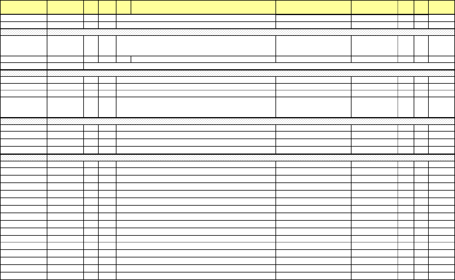
Addr. (hex) Address(4X) Line Pt DNP
Ob
j
Description Range Units Type R/W Notes
17DAH-17DB
H
06107-06108 448 3 20 KYZ Output Accumulation, Relay
4
4,294,967,295 / 0 F18
R
17DCH-17DD
H
06109-06110 448 4 20 Reserve
d
4,294,967,295
/
0 F18
R
17DEH 06111 449 0-1 1
MSB first
Bit 15 – 1st Option board (Slot 3) status valid
Bit 14 – 2nd Option board (Slot 4) status valid F44 R
17DFH 06112 450 0-15 1 Reserved F45 R
17E0H 06113 Reserved
17E1H-17E4H 06114-06117 451 0 50 Flicker Status Block Time Stamp 12/31/9999 23:59:59.99 F3
17E5H-17E8H 06118-06121 452 0 50 Flicker Start Time 12/31/9999 23:59:59.99 F3
17E9H-17ECH 06122-06125 452 1 50 Flicker End Time 12/31/9999 23:59:59.99 F3
17EDH 06126 453 0 30
Flicker Status - value = 0100 means available or running, and
value = 0000 means not available or stopped.
R
17EEH-17F1H 06127-06130 454 0 50 Instantaneous Flicker Block Time 12/31/9999 23:59:59.99 F3
17F2H-17F3H 06131-06132 455 0 30 Instantaneous Flicker VAN +32767 / 0 1/ 65536 F7 R
17F4H-17F5H 06133-06134 455 1 30 Instantaneous Flicker VBN +32767 / 0 1/ 65536 F7 R
17F6H-17F7H 06135-06136 455 2 30 Instantaneous Flicker VCN +32767 / 0 1/ 65536 F7 R
17F8H-17FBH 06137-06140 456 0 50 Short Term Flicker Block Time 12/31/9999 23:59:59.99 F3
17FCH-17FDH 06141-06142 457 0 30 Short Term Flicker VAN +32767 / 0 1/ 65536 F7 R
17FEH-17FFH 06143-06144 457 1 30 Short Term Flicker VBN +32767 / 0 1/ 65536 F7 R
1800H-1801H 06145-06146 457 2 30 Short Term Flicker VCN +32767 / 0 1/ 65536 F7 R
1802H-1803H 06147-06148 458 0 30 Maximum Short Term Flicker VAN +32767 / 0 1/ 65536 F7 R
1804H-1805H 06149-06150 458 1 30 Maximum Short Term Flicker VBN +32767 / 0 1/ 65536 F7 R
1806H-1807H 06151-06152 458 2 30 Maximum Short Term Flicker VCN +32767 / 0 1/ 65536 F7 R
1808H-1809H 06153-06154 459 0 30 Minimum Short Term Flicker VAN +32767 / 0 1/ 65536 F7 R
180AH-180BH 06155-06156 459 1 30 Minimum Short Term Flicker VBN +32767 / 0 1/ 65536 F7 R
180CH-180DH 06157-06158 459 2 30 Minimum Short Term Flicker VCN +32767 / 0 1/ 65536 F7 R
180EH-1811H 06159-06162 460 0 50 Short Term Flicker Interval End Time Stamp 12/31/9999 23:59:59.99 F3
1812H-1815H 06163-06166 461 0 50 Maximum Short Term Flicker VAN Time Stamp 12/31/9999 23:59:59.99 F3
1816H-1819H 06167-06170 461 1 50 Maximum Short Term Flicker VBN Time Stamp 12/31/9999 23:59:59.99 F3
181AH-181DH 06171-06174 461 2 50 Maximum Short Term Flicker VCN Time Stamp 12/31/9999 23:59:59.99 F3
181EH-1821H 06175-06178 462 0 50 Minimum Short Term Flicker VAN Time Stamp 12/31/9999 23:59:59.99 F3
1822H-1825H 06179-06182 462 1 50 Minimum Short Term Flicker VBN Time Stamp 12/31/9999 23:59:59.99 F3
Flicker Status Block
Input Option Board Data Status Block
Instantaneous Flicker Block
Short Term Flicker Block
e Electro Industries/GaugeTech Doc# E154703 MM-88

Addr. (hex) Address(4X) Line Pt DNP
Ob
j
Description Range Units Type R/W Notes
1826H
-
1829H
06183
-
06186
462
2
50
Minimum Short Term Flicker VCN Time Stamp
12/31/9999
23
:
59
:
59
.
99
F3
182AH-182D
H
06187-06190 463 0 50 Long Term Flicker Block Tim
e
12/31/9999 23:59:59.99 F3
182EH-182F
H
06191-06192 464 0 30 Long Term Flicker VAN +32767 / 0 1/ 65536 F7
R
1830H-1831
H
06193-06194 464 1 30 Long Term Flicker VBN +32767 / 0 1/ 65536 F7
R
1832H-1833
H
06195-06196 464 2 30 Long Term Flicker VCN +32767 / 0 1/ 65536 F7
R
1834H-1835
H
06197-06198 465 0 30 Maximum Long Term Flicker VAN +32767 / 0 1/ 65536 F7
R
1836H-1837
H
06199-06200 465 1 30 Maximum Long Term Flicker VBN +32767 / 0 1/ 65536 F7
R
1838H-1839
H
06201-06202 465 2 30 Maximum Long Term Flicker VCN +32767 / 0 1/ 65536 F7
R
183AH-183B
H
06203-06204 466 0 30 Minimum Long Term Flicker VAN +32767 / 0 1/ 65536 F7
R
183CH-183D
H
06205-06206 466 1 30 Minimum Long Term Flicker VBN +32767 / 0 1/ 65536 F7
R
183EH-183F
H
06207-06208 466 2 30 Minimum Long Term Flicker VCN +32767 / 0 1/ 65536 F7
R
1840H-1843
H
06209-06212 467 0 50 Long Term Flicker Interval End Time Stam
p
12/31/9999 23:59:59.99 F3
1844H-1847
H
06213-06216 468 0 50 Maximum Long Term Flicker VAN Time Stamp 12/31/9999 23:59:59.99 F3
1848H-184B
H
06217-06220 468 1 50 Maximum Long Term Flicker VBN Time Stamp 12/31/9999 23:59:59.99 F3
184CH-184F
H
06221-06224 468 2 50 Maximum Long Term Flicker VCN Time Stamp 12/31/9999 23:59:59.99 F3
1850H-1853
H
06225-06228 469 0 50 Minimum Long Term Flicker VAN Time Stamp 12/31/9999 23:59:59.99 F3
1854H-1857
H
06229-06232 469 1 50 Minimum Long Term Flicker VBN Time Stamp 12/31/9999 23:59:59.99 F3
1858H
-
185BH
06233
-
06236
469
2
50
Minimum Long Term Flicker
V
CN Time Stamp
12/31/9999
23
:
59
:
59
.
99
F3
185CH-185F
H
06237-06240 470 0 50 Additional Energy Block Tim
e
12/31/9999 23:59:59.99 F3
1860H-1863H 06241-06244 471 0 Quadrant 1 Watthour, Secondary
+9,999,999,999,999,999 WH / 0
WH 1 WHF11 R
1864H-1867H 06245-06248 471 1 Quadrant 4 Watthour, Secondary
+9,999,999,999,999,999 WH / 0
WH 1 WHF11 R
1868H-186BH 06249-06252 471 2 Quadrant 2 Watthour, Secondary
+9,999,999,999,999,999 WH / 0
WH 1 WHF11 R
186CH-186FH 06253-06256 471 3 Quadrant 3 Watthour, Secondary
+9,999,999,999,999,999 WH / 0
WH 1 WHF11 R
1870H-1873H 06257-06260 472 0 Quadrant 1 Vahour, Secondary
+9,999,999,999,999,999 VAh / 0
VAh 1 VAHF11 R
1874H-1877H 06261-06264 472 1 Quadrant 1 VARhour, Secondary
+9,999,999,999,999,999 VARh /
0 VARh 1 VARHF11 R
1878H-187BH 06265-06268 472 2 Quadrant 4 Vahour, Secondary
+9,999,999,999,999,999 VAh / 0
VAh 1 VAHF11 R
Long Term Flicker Block
Additional Energy Block
e Electro Industries/GaugeTech Doc# E154703 MM-89

Addr. (hex) Address(4X) Line Pt DNP
Ob
j
Description Range Units Type R/W Notes
187CH-187FH 06269-06272 472 3 Quadrant 4 VARhour, Secondary
+9,999,999,999,999,999 VARh /
0 VARh 1 VARHF11 R
1880H-1883H 06273-06276 472 4 Quadrant 2 Vahour, Secondary
+9,999,999,999,999,999 VAh / 0
VAh 1 VAHF11 R
1884H-1887H 06277-06280 472 5 Quadrant 2 VARhour, Secondary
+9,999,999,999,999,999 VARh /
0 VARh 1 VARHF11 R
1888H-188BH 06281-06284 472 6 Quadrant 3 Vahour, Secondary
+9,999,999,999,999,999 VAh / 0
VAh 1 VAHF11 R
188CH-188FH 06285-06288 472 7 Quadrant 3 VARhour, Secondary
+9,999,999,999,999,999 VARh /
0 VARh 1 VARHF11 R
1890H-1893H 06289-06292 473 0 Quadrant 1 Watthour, Primary
+9,999,999,999,999,999 WH / 0
WH 1 WHF19 R
1894H-1897H 06293-06296 473 1 Quadrant 4 Watthour, Primary
+9,999,999,999,999,999 WH / 0
WH 1 WHF19 R
1898H-189BH 06297-06300 473 2 Quadrant 2 Watthour, Primary
+9,999,999,999,999,999 WH / 0
WH 1 WHF19 R
189CH-189FH 06301-06304 473 3 Quadrant 3 Watthour, Primary
+9,999,999,999,999,999 WH / 0
WH 1 WHF19 R
18A0H-18A3H 06305-06308 474 0 Total Vahour (Quadrants 1+2+3+4), Primary
+9,999,999,999,999,999 VAh / 0
VAh 1 VAHF19 R
18A4H-18A7H 06309-06312 474 1 Positive VARhour (Quadrants 1+2), Primary
+9,999,999,999,999,999 VARh /
0 VARh 1 VARHF19 R
18A8H-18ABH 06313-06316 474 2 Negative VARhour (Quadrants 3+4), Primary
+9,999,999,999,999,999 VARh /
0 VARh 1 VARHF19 R
18ACH-18AFH 06317-06320 475 0 20 Quadrant 1 Watthour, Secondary
+9,999,999,999,999,999 WH / 0
WH 1 WHF12 R
18B0H-18B3H 06321-06324 475 1 20 Quadrant 4 Watthour, Secondary
+9,999,999,999,999,999 WH / 0
WH 1 WHF12 R
18B4H-18B7H 06325-06328 475 2 20 Quadrant 2 Watthour, Secondary
+9,999,999,999,999,999 WH / 0
WH 1 WHF12 R
18B8H-18BBH 06329-06332 475 3 20 Quadrant 3 Watthour, Secondary
+9,999,999,999,999,999 WH / 0
WH 1 WHF12 R
18BCH-18BFH 06333-06336 476 0 20 Quadrant 1 Vahour, Secondary
+9,999,999,999,999,999 VAh / 0
VAh 1 VAHF12 R
18C0H-18C3H 06337-06340 476 1 20 Quadrant 1 VARhour, Secondary
+9,999,999,999,999,999 VARh /
0 VARh 1 VARHF12 R
18C4H-18C7H 06341-06344 476 2 20 Quadrant 4 Vahour, Secondary
+9,999,999,999,999,999 VAh / 0
VAh 1 VAHF12 R
e Electro Industries/GaugeTech Doc# E154703 MM-90

Addr. (hex) Address(4X) Line Pt DNP
Ob
j
Description Range Units Type R/W Notes
18C8H-18CBH 06345-06348 476 3 20 Quadrant 4 VARhour, Secondary
+9,999,999,999,999,999 VARh /
0 VARh 1 VARHF12 R
18CCH-18CFH 06349-06352 476 4 20 Quadrant 2 Vahour, Secondary
+9,999,999,999,999,999 VAh / 0
VAh 1 VAHF12 R
18D0H-18D3H 06353-06356 476 5 20 Quadrant 2 VARhour, Secondary
+9,999,999,999,999,999 VARh /
0 VARh 1 VARHF12 R
18D4H-18D7H 06357-06360 476 6 20 Quadrant 3 Vahour, Secondary
+9,999,999,999,999,999 VAh / 0
VAh 1 VAHF12 R
18D8H-18DBH 06361-06364 476 7 20 Quadrant 3 VARhour, Secondary
+9,999,999,999,999,999 VARh /
0 VARh 1 VARHF12 R
18DCH-18DFH 06365-06368 477 0 20 Quadrant 1 Watthour, Primary
+9,999,999,999,999,999 WH / 0
WH 1 WHF20 R
18E0H-18E3H 06369-06372 477 1 20 Quadrant 4 Watthour, Primary
+9,999,999,999,999,999 WH / 0
WH 1 WHF20 R
18E4H-18E7H 06373-06376 477 2 20 Quadrant 2 Watthour, Primary
+9,999,999,999,999,999 WH / 0
WH 1 WHF20 R
18E8H-18EBH 06377-06380 477 3 20 Quadrant 3 Watthour, Primary
+9,999,999,999,999,999 WH / 0
WH 1 WHF20 R
18ECH-18EFH 06381-06384 478 0 20 Total Vahour (Quadrants 1+2+3+4), Primary
+9,999,999,999,999,999 VAh / 0
VAh 1 VAHF20 R
18F0H-18F3H 06385-06388 478 1 20 Positive VARhour (Quadrants 1+2), Primary
+9,999,999,999,999,999 VARh /
0 VARh 1 VARHF20 R
18F4H-18F7H 06389-06392 478 2 20 Negative VARhour (Quadrants 3+4), Primary
+9
,
999
,
999
,
999
,
999
,
999
VARh
/
0 VARh 1 VARHF20 R
18F8H-18FB
H
06393-06396 479 0 50 Energy and Pulses in the Interval Block Time Stamp 12/31/9999 23:59:59.99 F3
18FC
H
06397 480 0 30 Total Vahour (Quadrants 1+2+3+4) in the Interval, Secondar
y
65,535 / 0 1 VAHF57
R
18FD
H
06398 480 1 30 Positive VARhour (Quadrants 1+2) in the Interval, Secondar
y
65,535 / 0 1 VARHF57
R
18FE
H
06399 480 2 30 Negative VARhour (Quadrants 3+4) in the Interval, Secondar
y
65,535 / 0 1 VARHF57
R
18FFH 06400 480 3 30 Positive Watthour (Quadrants 1+4) in the Interval, Secondary 65,535 / 0 1 WHF57
R
1900H 06401 480 4 30 Negative Watthour (Quadrants 2+3) in the Interval, Secondary 65,535 / 0 1 WHF57
R
1901H-1902
H
06402-06403 481 0 30 Positive Watthour (Quadrants 1+4) in the Interval, Primary 4,294,967,295 / 0 1 WHF18
R
1903H-1904
H
06404-06405 481 1 30 Quadrant 1 Vahour in the Interval, Primary 4,294,967,295 / 0 1 VAHF18
R
1905H-1906
H
06406-06407 481 2 30 Quadrant 1 VARhour in the Interval, Primar
y
4,294,967,295 / 0 1 VARHF18
R
1907H-1908
H
06408-06409 481 3 30 Quadrant 4 Vahour in the Interval, Primary 4,294,967,295 / 0 1 VAHF18
R
1909H-190A
H
06410-06411 481 4 30 Quadrant 4 VARhour in the Interval, Primar
y
4,294,967,295 / 0 1 VARHF18
R
190BH-190C
H
06412-06413 481 5 30 Negative Watthour (Quadrants 2+3) in the Interval, Primary 4,294,967,295 / 0 1 WHF18
R
Energy and Pulses in the Interval
e Electro Industries/GaugeTech Doc# E154703 MM-91

Addr. (hex) Address(4X) Line Pt DNP
Ob
j
Description Range Units Type R/W Notes
190DH-190E
H
06414-06415 481 6 30 Quadrant 2 Vahour in the Interval, Primary 4,294,967,295 / 0 1 VAHF18
R
190FH-1910
H
06416-06417 481 7 30 Quadrant 2 VARhour in the Interval, Primar
y
4,294,967,295 / 0 1 VARHF18
R
1911H-1912
H
06418-06419 481 8 30 Quadrant 3 Vahour in the Interval, Primary 4,294,967,295 / 0 1 VAHF18
R
1913H-1914
H
06420-06421 481 9 30 Quadrant 3 VARhour in the Interval, Primar
y
4,294,967,295 / 0 1 VARHF18
R
1915H-1916H 06422-06423 482 0 30 I2t Phase A in the Interval, Primary 4,294,967,295 / 0 1 I2t F18 R
1917H-1918H 06424-06425 482 1 30 I2t Phase B in the Interval, Primary 4,294,967,295 / 0 1 I2t F18 R
1919H-191AH 06426-06427 482 2 30 I2t Phase C in the Interval, Primary 4,294,967,295 / 0 1 I2t F18 R
191BH-191CH 06428-06429 482 3 30 V2t Phase A in the interval, Primary 4,294,967,295 / 0 1 V2t F18 R
191DH-191EH 06430-06431 482 4 30 V2t Phase B in the Interval, Primary 4,294,967,295 / 0 1 V2t F18 R
191FH-1920H 06432-06433 482 5 30 V2t Phase C in the Interval, Primary 4,294,967,295 / 0 1 V2t F18 R
1921H-1922
H
06434-06435 483 0 30 Pulse Accumulation, Internal Input 1 in the Interval, Scaled 4,294,967,295 / 0 1 Unit F18
R
1923H-1924
H
09436-06437 483 1 30 Pulse Accumulation, Internal Input 2 in the Interval, Scaled 4,294,967,295 / 0 1 Unit F18
R
1925H-1926
H
06438-06439 483 2 30 Pulse Accumulation, Internal Input 3 in the Interval, Scaled 4,294,967,295 / 0 1 Unit F18
R
1927H-1928
H
06440-06441 483 3 30 Pulse Accumulation, Internal Input 4 in the Interval, Scaled 4,294,967,295 / 0 1 Unit F18
R
1929H-192A
H
06442-06443 483 4 30 Pulse Accumulation, Internal Input 5 in the Interval, Scaled 4,294,967,295 / 0 1 Unit F18
R
192BH-192C
H
06444-06445 483 5 30 Pulse Accumulation, Internal Input 6 in the Interval, Scaled 4,294,967,295 / 0 1 Unit F18
R
192DH-192E
H
06446-06447 483 6 30 Pulse Accumulation, Internal Input 7 in the Interval, Scaled 4,294,967,295 / 0 1 Unit F18
R
192FH-1930
H
06448-06449 483 7 30 Pulse Accumulation, Internal Input 8 in the Interval, Scaled 4,294,967,295 / 0 1 Unit F18
R
1931H-1932
H
06450-06451 484 0 30 Pulse Aggregation 1 in the Interval, Scale
d
4,294,967,295 / 0 1 Unit F18
R
1933H-1934
H
06452-06453 484 1 30 Pulse Aggregation 2 in the Interval, Scale
d
4,294,967,295 / 0 1 Unit F18
R
1935H-1936
H
06454-06455 484 2 30 Pulse Aggregation 3 in the Interval, Scale
d
4,294,967,295 / 0 1 Unit F18
R
1937H-1938
H
06456-06457 484 3 30 Pulse Aggregation 4 in the Interval, Scale
d
4,294,967,295 / 0 1 Unit F18
R
1939H 06458 485 0 30 Quadrant 1 Watthour in the Interval, Secondary 65,535 / 0 1 WHF57
R
193A
H
06459 485 1 30 Quadrant 4 Watthour in the Interval, Secondary 65,535 / 0 1 WHF57
R
193B
H
06460 485 2 30 Quadrant 2 Watthour in the Interval, Secondary 65,535 / 0 1 WHF57
R
193C
H
06461 485 3 30 Quadrant 3 Watthour in the Interval, Secondary 65,535 / 0 1 WHF57
R
193D
H
06462 486 0 30 Quadrant 1 Vahour in the Interval, Secondar
y
65,535 / 0 1 VAHF57
R
193EH 06463 486 1 30 Quadrant 1 VARhour in the Interval, Secondar
y
65,535 / 0 1 VARHF57
R
193FH 06464 486 2 30 Quadrant 4 Vahour in the Interval, Secondar
y
65,535 / 0 1 VAHF57
R
1940H 06465 486 3 30 Quadrant 4 VARhour in the Interval, Secondar
y
65,535 / 0 1 VARHF57
R
1941H 06466 486 4 30 Quadrant 2 Vahour in the Interval, Secondar
y
65,535 / 0 1 VAHF57
R
1942H 06467 486 5 30 Quadrant 2 VARhour in the Interval, Secondar
y
65,535 / 0 1 VARHF57
R
1943H 06468 486 6 30 Quadrant 3 Vahour in the Interval, Secondar
y
65,535 / 0 1 VAHF57
R
1944H 06469 486 7 30 Quadrant 3 VARhour in the Interval, Secondar
y
65,535 / 0 1 VARHF57
R
1945H-1946
H
06470-06471 487 0 30 Quadrant 1 Watthour in the Interval, Primary 4,294,967,295 / 0 1 WHF18
R
1947H-1948
H
06472-06473 487 1 30 Quadrant 4 Watthour in the Interval, Primary 4,294,967,295 / 0 1 WHF18
R
e Electro Industries/GaugeTech Doc# E154703 MM-92

Addr. (hex) Address(4X) Line Pt DNP
Ob
j
Description Range Units Type R/W Notes
1949H-194A
H
06474-06475 487 2 30 Quadrant 2 Watthour in the Interval, Primary 4,294,967,295 / 0 1 WHF18
R
194BH-194C
H
06476-06477 487 3 30 Quadrant 3 Watthour in the Interval, Primary 4,294,967,295 / 0 1 WHF18
R
194DH-194E
H
06478-06479 488 0 30 Total Vahour (Quadrants 1+2+3+4) in the Interval, Primary 4,294,967,295 / 0 1 VAHF18
R
194FH-1950
H
06480-06481 488 1 30 Positive VARhour (Quadrants 1+2) in the Interval, Primary 4,294,967,295 / 0 1 VARHF18
R
1951H-1952
H
06482-06483 488 2 30 Negative VARhour (Quadrants 3+4) in the Interval, Primar
y
4,294,967,295 / 0 1 VA
R
HF18
R
1953H 06484 489 0 30 KYZ Pulse Output in the Interval, Relay 1 - Pulse 1 65,535 / 0 1 pulse F57
R
1954H 06485 489 1 30 KYZ Pulse Output in the Interval, Relay 2 - Pulse 2 65,535 / 0 1 pulse F57
R
1955H 06486 489 2 30 KYZ Pulse Output in the Interval, Relay 3 65,535 / 0 1 pulse F57
R
1956H 06487 489 3 30 KYZ Pulse Output in the Interval, Relay 4 65,535 / 0 1 pulse F57
R
1957H 06488 489 4 30 Reserve
d
65,535
/
0 1 pu
l
se F57
R
1958H 06489 490 0 30 Short Term Flicker Countdow
n
65,535 / 0 1 secon
d
F56
R
1959H 06490 490 1 30 Long Term F
li
c
k
er Count
d
ow
n
65,535
/
0 1 secon
d
F56
R
195AH-195D
H
06491-06494 491 0 50 Cumulative Demand Block Time Stamp 12/31/9999 23:59:59.99 F3
R
195EH-195F
H
06495-06496 492 0 30 Positive Watt (Quadrants 1+4) Cumulative Demand 4,294,967,295 / 0 F18
R
1960H-1961
H
06497-06498 492 1 30 Negative Watt (Quadrants 2+3) Cumulative Demand 4,294,967,295 / 0 F18
R
1962H-1963
H
06499-06500 493 0 30 Positive Watt (Quadrants 1+4) Continuous Cumulative Demand 4,294,967,295 / 0 F18
R
1964H-1965H 06501-06502 493 1 30
N
egat
i
ve
W
att
(Q
ua
d
rants
2
+
3)
C
ont
i
nuous
C
umu
l
at
i
ve
Demand 4,294,967,295 / 0 F18 R
1966H-1967
H
06503-06504 494 0 30 TOU Active Reg0 Cumulative Demand Q1 + Q4 Wat
t
4,294,967,295 / 0 F18
R
1968H-1969
H
06505-06506 494 1 30 TOU Active Reg0 Cumulative Demand Q2 + Q3 Wat
t
4,294,967,295 / 0 F18
R
196AH-196B
H
06507-06508 494 2 30 TOU Active Reg1 Cumulative Demand Q1 + Q4 Wat
t
4,294,967,295 / 0 F18
R
196CH-196D
H
06509-06510 494 3 30 TOU Active Reg1 Cumulative Demand Q2 + Q3 Wat
t
4,294,967,295 / 0 F18
R
196EH-196F
H
06511-06512 494 4 30 TOU Active Reg2 Cumulative Demand Q1 + Q4 Wat
t
4,294,967,295 / 0 F18
R
1970H-1971
H
06513-06514 494 5 30 TOU Active Reg2 Cumulative Demand Q2 + Q3 Wat
t
4,294,967,295 / 0 F18
R
1972H-1973
H
06515-06516 494 6 30 TOU Active Reg3 Cumulative Demand Q1 + Q4 Wat
t
4,294,967,295 / 0 F18
R
1974H-1975
H
06517-06518 494 7 30 TOU Active Reg3 Cumulative Demand Q2 + Q3 Wat
t
4,294,967,295 / 0 F18
R
1976H-1977
H
06519-06520 494 8 30 TOU Active Reg4 Cumulative Demand Q1 + Q4 Wat
t
4,294,967,295 / 0 F18
R
1978H-1979
H
06521-06522 494 9 30 TOU Active Reg4 Cumulative Demand Q2 + Q3 Wat
t
4,294,967,295 / 0 F18
R
197AH-197B
H
06523-06524 494 10 30 TOU Active Reg5 Cumulative Demand Q1 + Q4 Wat
t
4,294,967,295 / 0 F18
R
197CH-197D
H
06525-06526 494 11 30 TOU Active Reg5 Cumulative Demand Q2 + Q3 Wat
t
4,294,967,295 / 0 F18
R
197EH-197F
H
06527-06528 494 12 30 TOU Active Reg6 Cumulative Demand Q1 + Q4 Wat
t
4,294,967,295 / 0 F18
R
1980H-1981
H
06529-06530 494 13 30 TOU Active Reg6 Cumulative Demand Q2 + Q3 Wat
t
4,294,967,295 / 0 F18
R
1982H-1983
H
06531-06532 494 14 30 TOU Active Reg7 Cumulative Demand Q1 + Q4 Wat
t
4,294,967,295 / 0 F18
R
1984H-1985
H
06533-06534 494 15 30 TOU Active Reg7 Cumulative Demand Q2 + Q3 Wat
t
4,294,967,295 / 0 F18
R
1986H-1987
H
06535-06536 494 16 30 TOU Active Total Cumulative Demand Q1 + Q4 Wat
t
4,294,967,295 / 0 F18
R
Flicker Countdown Block
Cumulative Demand Block
Time of Use Active Cumulative Demand
e Electro Industries/GaugeTech Doc# E154703 MM-93

Addr. (hex) Address(4X) Line Pt DNP
Ob
j
Description Range Units Type R/W Notes
1988H-1989
H
06537-06538 494 17 30 TOU Act
i
ve Tota
l
Cumu
l
at
i
ve Deman
d
Q2 + Q3 Wat
t
4,294,967,295
/
0 F18
R
198AH-198B
H
06539-06540 495 0 30 TOU Current Month Reg0 Cumulative Demand Q1 + Q4 Watt 4,294,967,295 / 0 F18
R
198CH-198D
H
06541-06542 495 1 30 TOU Current Month Reg0 Cumulative Demand Q2 + Q3 Watt 4,294,967,295 / 0 F18
R
198EH-198F
H
06543-06544 495 2 30 TOU Current Month Reg1 Cumulative Demand Q1 + Q4 Watt 4,294,967,295 / 0 F18
R
1990H-1991
H
06545-06546 495 3 30 TOU Current Month Reg1 Cumulative Demand Q2 + Q3 Watt 4,294,967,295 / 0 F18
R
1992H-1993
H
06547-06548 495 4 30 TOU Current Month Reg2 Cumulative Demand Q1 + Q4 Watt 4,294,967,295 / 0 F18
R
1994H-1995
H
06549-06550 495 5 30 TOU Current Month Reg2 Cumulative Demand Q2 + Q3 Watt 4,294,967,295 / 0 F18
R
1996H-1997
H
06551-06552 495 6 30 TOU Current Month Reg3 Cumulative Demand Q1 + Q4 Watt 4,294,967,295 / 0 F18
R
1998H-1999
H
06553-06554 495 7 30 TOU Current Month Reg3 Cumulative Demand Q2 + Q3 Watt 4,294,967,295 / 0 F18
R
199AH-199B
H
06555-06556 495 8 30 TOU Current Month Reg4 Cumulative Demand Q1 + Q4 Watt 4,294,967,295 / 0 F18
R
199CH-199D
H
06557-06558 495 9 30 TOU Current Month Reg4 Cumulative Demand Q2 + Q3 Watt 4,294,967,295 / 0 F18
R
199EH-199F
H
06559-06560 495 10 30 TOU Current Month Reg5 Cumulative Demand Q1 + Q4 Watt 4,294,967,295 / 0 F18
R
19A0H-19A1
H
06561-06562 495 11 30 TOU Current Month Reg5 Cumulative Demand Q2 + Q3 Watt 4,294,967,295 / 0 F18
R
19A2H-19A3
H
06563-06564 495 12 30 TOU Current Month Reg6 Cumulative Demand Q1 + Q4 Watt 4,294,967,295 / 0 F18
R
19A4H-19A5
H
06565-06566 495 13 30 TOU Current Month Reg6 Cumulative Demand Q2 + Q3 Watt 4,294,967,295 / 0 F18
R
19A6H-19A7
H
06567-06568 495 14 30 TOU Current Month Reg7 Cumulative Demand Q1 + Q4 Watt 4,294,967,295 / 0 F18
R
19A8H-19A9
H
06569-06570 495 15 30 TOU Current Month Reg7 Cumulative Demand Q2 + Q3 Watt 4,294,967,295 / 0 F18
R
19AAH-19AB
H
06571-06572 495 16 30 TOU Current Month Total Cumulative Demand Q1 + Q4 Watt 4,294,967,295 / 0 F18
R
19ACH-19AD
H
06573-06574 495 17 30 TOU Current Mont
h
Tota
l
Cumu
l
at
i
ve Deman
d
Q2 + Q3 Watt 4,294,967,295
/
0 F18
R
19AEH-19AFH 06575-06576 496 0 30
TOU Active Reg0 Continuous Cumulative Demand Q1 + Q4
Watt 4,294,967,295 / 0 F18 R
19B0H-19B1H 06577-06578 496 1 30
TOU Active Reg0 Continuous Cumulative Demand Q2 + Q3
Watt 4,294,967,295 / 0 F18 R
19B2H-19B3H 06579-06580 496 2 30
TOU Active Reg1 Continuous Cumulative Demand Q1 + Q4
Watt 4,294,967,295 / 0 F18 R
19B4H-19B5H 06581-06582 496 3 30
TOU Active Reg1 Continuous Cumulative Demand Q2 + Q3
Watt 4,294,967,295 / 0 F18 R
19B6H-19B7H 06583-06584 496 4 30
TOU Active Reg2 Continuous Cumulative Demand Q1 + Q4
Watt 4,294,967,295 / 0 F18 R
19B6H019B7H
-
19B8H-19B9H 06585-06586 496 5 30
TOU Active Reg2 Continuous Cumulative Demand Q2 + Q3
Watt 4,294,967,295 / 0 F18 R
19BAH-19BBH 06587-06588 496 6 30
TOU Active Reg3 Continuous Cumulative Demand Q1 + Q4
Watt 4,294,967,295 / 0 F18 R
19BCH-19BDH 06589-06590 496 7 30
TOU Active Reg3 Continuous Cumulative Demand Q2 + Q3
Watt 4,294,967,295 / 0 F18 R
19BEH-19BFH 06591-06592 496 8 30
TOU Active Reg4 Continuous Cumulative Demand Q1 + Q4
Watt 4,294,967,295 / 0 F18 R
Time of Use Current Month Cumulative Demand
Time of Use Active Continuous Cumulative Demand
e Electro Industries/GaugeTech Doc# E154703 MM-94

Addr. (hex) Address(4X) Line Pt DNP
Ob
j
Description Range Units Type R/W Notes
19C0H-19C1H 06593-06594 496 9 30
TOU Active Reg4 Continuous Cumulative Demand Q2 + Q3
Watt 4,294,967,295 / 0 F18 R
19C2H-19C3H 06595-06596 496 10 30
TOU Active Reg5 Continuous Cumulative Demand Q1 + Q4
Watt 4,294,967,295 / 0 F18 R
19C4H-19C5H 06597-06598 496 11 30
TOU Active Reg5 Continuous Cumulative Demand Q2 + Q3
Watt 4,294,967,295 / 0 F18 R
19C6H-19C7H 06599-06600 496 12 30
TOU Active Reg6 Continuous Cumulative Demand Q1 + Q4
Watt 4,294,967,295 / 0 F18 R
19C8H-19C9H 06601-06602 496 13 30
TOU Active Reg6 Continuous Cumulative Demand Q2 + Q3
Watt 4,294,967,295 / 0 F18 R
19CAH-19CBH 06603-06604 496 14 30
TOU Active Reg7 Continuous Cumulative Demand Q1 + Q4
Watt 4,294,967,295 / 0 F18 R
19CCH-19CDH 06605-06606 496 15 30
TOU Active Reg7 Continuous Cumulative Demand Q2 + Q3
Watt 4,294,967,295 / 0 F18 R
19CEH-19CFH 06607-06608 496 16 30
TOU Active Total Continuous Cumulative Demand Q1 + Q4
Watt 4,294,967,295 / 0 F18 R
19D0H-19D1H 06609-06610 496 17 30
TOU
A
ct
i
ve
T
ota
l
C
ont
i
nuous
C
umu
l
at
i
ve
D
eman
d
Q2
+
Q3
Watt 4,294,967,295 / 0 F18 R
19D2H-19D3H 06611-06612 497 0 30
TOU Current Month Reg0 Continuous Cumulative Demand Q1
+ Q4 Watt 4,294,967,295 / 0 F18 R
19D4H-19D5H 06613-06614 497 1 30
TOU Current Month Reg0 Continuous Cumulative Demand Q2
+ Q3 Watt 4,294,967,295 / 0 F18 R
19D6H-19D7H 06615-06616 497 2 30
TOU Current Month Reg1 Continuous Cumulative Demand Q1
+ Q4 Watt 4,294,967,295 / 0 F18 R
19D8H-19D9H 06617-06618 497 3 30
TOU Current Month Reg1 Continuous Cumulative Demand Q2
+ Q3 Watt 4,294,967,295 / 0 F18 R
19DAH-19DBH 06619-06620 497 4 30
TOU Current Month Reg2 Continuous Cumulative Demand Q1
+ Q4 Watt 4,294,967,295 / 0 F18 R
19DCH-19DDH 06621-06622 497 5 30
TOU Current Month Reg2 Continuous Cumulative Demand Q2
+ Q3 Watt 4,294,967,295 / 0 F18 R
19DEH019DFH 06623-06624 497 6 30
TOU Current Month Reg3 Continuous Cumulative Demand Q1
+ Q4 Watt 4,294,967,295 / 0 F18 R
19E0H-19E1H 06625-06626 497 7 30
TOU Current Month Reg3 Continuous Cumulative Demand Q2
+ Q3 Watt 4,294,967,295 / 0 F18 R
19E2H-19E3H 06627-06628 497 8 30
TOU Current Month Reg4 Continuous Cumulative Demand Q1
+ Q4 Watt 4,294,967,295 / 0 F18 R
19E4H-19E5H 06629-06630 497 9 30
TOU Current Month Reg4 Continuous Cumulative Demand Q2
+ Q3 Watt 4,294,967,295 / 0 F18 R
Time of Use Current Month Continuous Cumulative Demand
e Electro Industries/GaugeTech Doc# E154703 MM-95

Addr. (hex) Address(4X) Line Pt DNP
Ob
j
Description Range Units Type R/W Notes
19E6H-19E7H 06631-06632 497 10 30
TOU Current Month Reg5 Continuous Cumulative Demand Q1
+ Q4 Watt 4,294,967,295 / 0 F18 R
19E8H-19E9H 06633-06634 497 11 30
TOU Current Month Reg5 Continuous Cumulative Demand Q2
+ Q3 Watt 4,294,967,295 / 0 F18 R
19EAH-19EBH 06635-06636 497 12 30
TOU Current Month Reg6 Continuous Cumulative Demand Q1
+ Q4 Watt 4,294,967,295 / 0 F18 R
19ECH-19EDH 06637-06638 497 13 30
TOU Current Month Reg6 Continuous Cumulative Demand Q2
+ Q3 Watt 4,294,967,295 / 0 F18 R
19EEH-19EFH 06639-06640 497 14 30
TOU Current Month Reg7 Continuous Cumulative Demand Q1
+ Q4 Watt 4,294,967,295 / 0 F18 R
19F0H-19F1H 06641-06642 497 15 30
TOU Current Month Reg7 Continuous Cumulative Demand Q2
+ Q3 Watt 4,294,967,295 / 0 F18 R
19F2H-19F3H 06643-06644 497 16 30
TOU Current Month Total Continuous Cumulative Demand Q1
+ Q4 Watt 4,294,967,295 / 0 F18 R
19F4H-19F5H 06645-06646 497 17 30
TOU
C
urrent
M
ont
h
T
ota
l
C
ont
i
nuous
C
umu
l
at
i
ve
D
eman
d
Q2
+ Q3 Watt 4,294,967,295 / 0 F18 R
1A08H-1A0D
H
06665-06670 500 0-2 30 Uncompensated One second Phase A-C V
A
+32767 VA / 0 V
A
1/65536 VA sec F7
1A0EH-1A0F
H
06671-06672 501 0 30 Uncompensated One second V
A
+32767 VA / 0 V
A
1/65536 VA sec F7
1A10H-1A15
H
06673-06678 502 0-2 30 Uncompensated One second Phase A-C VA
R
+32767 VAR / - 32768 VA
R
1/65536 VAR se
c
F7
1A16H-1A17
H
06679-06680 503 0 30 Uncompensated One second VA
R
+32767 VAR / - 32768 VA
R
1/65536 VAR se
c
F7
1A18H-1A1D
H
06681-06686 504 0-2 30 Uncompensated One second Phase A-C
W
+32767 W / - 32768 W 1/65536 W sec F7
1A1EH-1A1F
H
06687-06688 505 0 30 Uncompensated One second
W
+32767 W / - 32768 W 1/65536 W sec F7
1A20H-1A23H 06689-06692 506 0 20 Uncompensated VAh, secondary BCD
9,999,999,999,999,999 VAh / 0
VAh 1 VAh F11
1A24H-1A2BH 06693-06700 506 1-2 20 Uncompensated +/- VARh, secondary BCD
9,999,999,999,999,999 VARh /
0 VARh 1 VARh F11
1A2CH-1A33H 06701-06708 506 3-4 20 Uncompensated +/- Wh, seconary BCD
9,999,999,999,999,999 Wh / 0
Wh 1 Wh F11
1A34H-1A47
H
06709-06728 507 0-4 20 Uncompensated Energy, secondary, binar
y
9,999,999,999,999,999 / 0 1 F12
1A48H-1A5B
H
06729-06748 508 0-4 20 Uncompensated Energy, primary BC
D
9,999,999,999,999,999 / 0 1 F19
1A5CH-1A6F
H
06749-06768 509 0-4 20 Uncompensated Energy, primary binar
y
9,999,999,999,999,999 / 0 1 F20
1A70H-1A74
H
06769-06773 510 0-4 30 Uncompensated Energy in the Interval, secondar
y
65,535 / 0 1 F47
1A75H-1A7E
H
06774-06783 511 0-4 30 Uncompensated Energy in the Interval, primar
y
4,294,967,295 / 0 1 F18
1A7FH-1A84
H
06784-06789 512 0-2 30 One second Phase A-C
Q
+32767 Q / -32768 Q 1/65536 Q sec F7
1A85H-1A86
H
06790-06791 513 0 30 One second Q +32767 Q / -32768 Q 1/65536 Q sec F7
1A87H-1A88
H
06792-06793 514 0 30 Thermal Average
Q
+32767 Q / -32768 Q 1/65536 Q sec F7
1A89H-1A8C
H
06794-06797 515 0-1 30 Maximum Thermal Average +/-
Q
+32767 Q / -32768 Q 1/65536 Q sec F7
1A8DH-1A90
H
06798-06801 516 0-1 30 Minimum Thermal Average +/-
Q
+32767 Q / -32768 Q 1/65536 Q sec F7
Uncompensated and Q Block
e Electro Industries/GaugeTech Doc# E154703 MM-96

Addr. (hex) Address(4X) Line Pt DNP
Ob
j
Description Range Units Type R/W Notes
1A91H-1A98
H
06802-06809 517 0-1 50 Maximum Thermal Average +/- Q Time Stamps 12/31/9999 23:59:59.99 F3
1A99H-1AA0
H
06810-06817 518 0-1 50 Minimum Thermal Average +/- Q Time Stamps 12/31/9999 23:59:59.99 F3
1AA1H-1AA8
H
06818-06825 519 0-1 20 +/- Qh, secondary BC
D
9,999,999,999,999,999 Qh / 0 1 Qh F11
1AA9H-1AB0
H
06826-06833 520 0-1 20 +/- Qh, secondary binar
y
9,999,999,999,999,999 Qh / 0 1 Qh F12
1AB1H-1AB8
H
06834-06841 521 0-1 20 +/- Qh, primary BC
D
9,999,999,999,999,999 Qh / 0 1 Qh F19
1AB9H-1AC0
H
06842-06849 522 0-1 20 +/- Qh, primary binar
y
9,999,999,999,999,999 Qh / 0 1 Qh F20
1AC1H-1AC2
H
06850-06851 523 0-1 30 +/- Qh in the Interval, secondar
y
65,535 / 0 1 F47
1AC3H-1AC6
H
06852-06855 524 0-1 30 +/- Qh in the Interval, primary 4,294,967,295 / 0 1 F18
1AC7H-1AC8
H
06856-06857 525 0 30 Block Window Average
Q
+32767 Q / -32768 Q 1/65536 Q sec F7
1AC9H-1ACC
H
06858-06861 526 0-1 30 Maximum Block Window Average +/-
Q
+32767 Q / -32768 Q 1/65536 Q sec F7
1ACDH-1AD0
H
06862-06865 527 0-1 30 Minimum Block Window Average +/-
Q
+32767 Q / -32768 Q 1/65536 Q sec F7
1AD1H-1AD8
H
06866-06873 528 0-1 50 Maximum Block Window Average +/- Q Time Stamp
s
12/31/9999 23:59:59.99 F3
1AD9H-1AE0
H
06874-06881 529 0-1 50 Minimum Block Window Average +/- Q Time Stamp
s
12/31/9999 23:59:59.99 F3
1AE1H-1AE2
H
06882-06883 530 0 30 Rolling Window Average
Q
+32767 Q / -32768 Q 1/65536 Q sec F7
1AE3H-1AE6
H
06884-06887 531 0-1 30 Maximum Rolling Window Average +/-
Q
+32767 Q / -32768 Q 1/65536 Q sec F7
1AE7H-1AEA
H
06888-06891 532 0-1 30 Minimum Rolling Window Average +/-
Q
+32767 Q / -32768 Q 1/65536 Q sec F7
1AEBH-1AF2
H
06892-06899 533 0-1 50 Maximum Rolling Window Average +/- Q Time Stamp
s
12/31/9999 23:59:59.99 F3
1AF3H-1AFA
H
06900-06907 534 0-1 50 M
i
n
i
mum Ro
lli
ng W
i
n
d
ow Average +
/
- Q T
i
me Stamp
s
12
/
31
/
9999 23:59:59.99 F3
1AFBH-1AFE
H
06908-06911 535 0 50 Scaled Energy Block Timestam
p
12/31/9999 23:59:59.99 F3
1AFFH-1B00H 06912-06913 536 0 20 Total VAh (Quadrant 1+2+3+4) Scaled Primary
variable (9999 through
999999999 / 0) variable 106 - 10-7 F64
1B01H-1B02H 06914-06915 536 1 20 Positive VARh (Quadrant 1+2) Scaled Priamry
variable (9999 through
999999999 / 0) variable 106 - 10-7 F64
1B03H-1B04H 06916-06917 536 2 20 Negative VARh (Quadrant 3+4) Scaled Primary
variable (9999 through
999999999 / 0) variable 106 - 10-7 F64
1B05H-1B06H 06918-06919 537 0 20 Positive Wh (Quadrant 1+4) Scaled Primary
variable (9999 through
999999999 / 0) variable 106 - 10-7 F64
1B07H-1B08H 06920-06921 537 1 20 Quadrant 1 VAh Scaled Primary
variable (9999 through
999999999 / 0) variable 106 - 10-7 F64
1B09H-1B0AH 06922-06923 537 2 20 Quadrant 1 VARh Scaled Primary
variable (9999 through
999999999 / 0) variable 106 - 10-7 F64
1B0BH-1B0CH 06924-06925 537 3 20 Quadrant 4 VAh Scaled Primary
variable (9999 through
999999999 / 0) variable 106 - 10-7 F64
1B0DH-1B0EH 06926-06927 537 4 20 Quadrant 4 VARh Scaled Primary
variable (9999 through
999999999 / 0) variable 106 - 10-7 F64
1B0FH-1B10H 06928-06929 537 5 20 Negative Wh (Quadrant 2+3) Scaled Primary
variable (9999 through
999999999 / 0) variable 106 - 10-7 F64
Scaled Energy Block
e Electro Industries/GaugeTech Doc# E154703 MM-97

Addr. (hex) Address(4X) Line Pt DNP
Ob
j
Description Range Units Type R/W Notes
1B11H-1B12H 06930-06931 537 6 20 Quadrant 2 VAh Scaled Primary
variable (9999 through
999999999 / 0) variable 106 - 10-7 F64
1B13H-1B14H 06932-06933 537 7 20 Quadrant 2 VARh Scaled Primary
variable (9999 through
999999999 / 0) variable 106 - 10-7 F64
1B15H-1B16H 06934-06935 537 8 20 Quadrant 3 VAh Scaled Primary
variable (9999 through
999999999 / 0) variable 106 - 10-7 F64
1B17H-1B18H 06936-06937 537 9 20 Quadrant 3 VARh Scaled Primary
variable (9999 through
999999999 / 0) variable 106 - 10-7 F64
1B19H-1B1AH 06938-06939 538 0 20 I2t Phase A Scaled Priamry
variable (9999 through
999999999 / 0) variable 106 - 10-7 F64
1B1BH-1B1CH 06940-06941 538 1 20 I2t Phase B Scaled Primary
variable (9999 through
999999999 / 0) variable 106 - 10-7 F64
1B1DH-1B1EH 06942-06943 538 2 20 I2t Phase C Scaled Primary
variable (9999 through
999999999 / 0) variable 106 - 10-7 F64
1B1FH-1B20H 06944-06945 538 3 20 V2t Phase A Scaled Primary
variable (9999 through
999999999 / 0) variable 106 - 10-7 F64
1B21H-1B22H 06946-06947 538 4 20 V2t Phase B Scaled Primary
variable (9999 through
999999999 / 0) variable 106 - 10-7 F64
1B23H-1B24H 06948-06949 538 5 20 V2t Phase C Scaled Primary
variable (9999 through
999999999 / 0) variable 106 - 10-7 F64
1B25H-1B26H 06950-06951 539 0 20 Quadrant 1 Wh Scaled Primary
variable (9999 through
999999999 / 0) variable 106 - 10-7 F64
1B27H-1B28H 06952-06953 539 1 20 Quadrant 4 Wh Scaled Primary
variable (9999 through
999999999 / 0) variable 106 - 10-7 F64
1B29H-1B2AH 06954-06955 539 2 20 Quadrant 2 Wh Scaled Primary
variable (9999 through
999999999 / 0) variable 106 - 10-7 F64
1B2BH-1B2CH 06956-06957 539 3 20 Quadrant 3 Wh Scaled Primary
variable (9999 through
999999999 / 0) variable 106 - 10-7 F64
1B2DH-1B2EH 06958-06959 450 0 20 Uncompensated Total VAh, Scaled Primary
variable (9999 through
999999999 / 0) variable 106 - 10-7 F64
1B2FH-1B32H 06960-06963 540 1-2 20 Uncompensated +/- VARh Scaled Primary
variable (9999 through
999999999 / 0) variable 106 - 10-7 F64
1B33H-1B36H 06964-06967 540 3-4 20 Uncompensated +/- Wh Scaled Primary
variable (9999 through
999999999 / 0) variable 106 - 10-7 F64
1B37H-1B3AH 06968-06971 541 0-1 20 +/- Qh Scaled Primary
variable (9999 through
999999999 / 0) variable 106 - 10-7 F64
1B3BH-1B4E
H
06972-06991 542 0 20 Reserve
d
1B4FH-1B5EH 06992-07007 543 0-7 20 Pulse Accumulation Inputs 1-8, Scaled
variable (9999 through
999999999 / 0) variable 106 - 10-7 F64
e Electro Industries/GaugeTech Doc# E154703 MM-98

Addr. (hex) Address(4X) Line Pt DNP
Ob
j
Description Range Units Type R/W Notes
1B5FH-1B66H 07008-07015 544 0-3 20 Pulse Aggregations 1-4, Scaled
variable (9999 through
999999999 / 0) variable 106 - 10-7 F64
1B67H-1B68H 07016-07017 545 0 20 TOU Frozen Reg0 Positive Wh (Quadrant 1+4) Scaled Primary
variable (9999 through
999999999 / 0) variable 106 - 10-7 F64
1B69H-1B6AH 07018-07019 545 1 20 TOU Frozen Reg0 Quadrant 1 VAh Scaled Primary
variable (9999 through
999999999 / 0) variable 106 - 10-7 F64
1B6BH-1B6CH 07020-07021 545 2 20 TOU Frozen Reg0 Quadrant 1 VARh Scaled Primary
variable (9999 through
999999999 / 0) variable 106 - 10-7 F64
1B6DH-1B6EH 07022-07023 545 3 20 TOU Frozen Reg0 Quadrant 4 VAh Scaled Primary
variable (9999 through
999999999 / 0) variable 106 - 10-7 F64
1B6FH-1B70H 07024-07025 545 4 20 TOU Frozen Reg0 Quadrant 4 VARh Scaled Primary
variable (9999 through
999999999 / 0) variable 106 - 10-7 F64
1B71H-1B72H 07026-07027 545 5 20 TOU Frozen Reg0 Negative Wh (Quadrant 2+3) Scaled Primary
variable (9999 through
999999999 / 0) variable 106 - 10-7 F64
1B73H-1B74H 07028-07029 545 6 20 TOU Frozen Reg0 Quadrant 2 VAh Scaled Primary
variable (9999 through
999999999 / 0) variable 106 - 10-7 F64
1B75H-1B76H 07030-07031 545 7 20 TOU Frozen Reg0 Quadrant 2 VARh Scaled Primary
variable (9999 through
999999999 / 0) variable 106 - 10-7 F64
1B77H-1B78H 07032-07033 545 8 20 TOU Frozen Reg0 Quadrant 3 VAh Scaled Primary
variable (9999 through
999999999 / 0) variable 106 - 10-7 F64
1B79H-1B7AH 07034-07035 545 9 20 TOU Frozen Reg0 Quadrant 3 VARh Scaled Primary
variable (9999 through
999999999 / 0) variable 106 - 10-7 F64
1B7BH-1B8EH 07036-07055 546 0-9 20 TOU Frozen Reg1 Energy Scaled Primary
variable (9999 through
999999999 / 0) variable 106 - 10-7 F64
1B8FH-1C06H 07056-07175
547-
552 0-9 20 TOU Frozen Reg2-Reg7 Energy Scaled Primary
variable (9999 through
999999999 / 0) variable 106 - 10-7 F64
1C07H-1C1AH 07176-07195 553 0-9 20 TOU Frozen Total Energy Scaled Primary
variable (9999 through
999999999 / 0) variable 106 - 10-7 F64
1C1BH-1CCEH 07196-07375
554-
562 0-9 20 TOU Prior Month Reg0-Reg7 & Total Energy Scaled Primary
variable (9999 through
999999999 / 0) variable 106 - 10-7 F64
1CCFH-1D82H 07376-07555
563-
571 0-9 20 TOU Active Reg0-Reg7 & Total Energy Scaled Primary
variable (9999 through
999999999 / 0) variable 106 - 10-7 F64
1D83H-1E36H 07556-07735
572-
580 0-9 20 TOU Current Month Reg0-Reg7 & Total Energy Scaled Primary
variable (9999 through
999999999 / 0) variable 106 - 10-7 F64
1E37H-1E3B
H
07736-07740 581 0-9 30 TOU Frozen Scaled Energy Setting
s
F65
1E3CH-1E40
H
07741-07745 582 0-9 30 TOU Prior Month Scaled Energy Setting
s
F65
1E41H-1E42H 07746-07747 583 0 30 Total VAh (Quadrant 1+2+3+4) in the Interval, Scaled Primary
variable (9999 through
999999999 / 0) variable 106 - 10-7 F64
e Electro Industries/GaugeTech Doc# E154703 MM-99

Addr. (hex) Address(4X) Line Pt DNP
Ob
j
Description Range Units Type R/W Notes
1E43H-1E44H 07748-07749 583 1 30 Positive VARh (Quadrant 1+2) in the Interval, Scaled Primary
variable (9999 through
999999999 / 0) variable 106 - 10-7 F64
1E45H-1E46H 07750-07751 583 2 30 Negative VARh (Quadrant 3+4) in the Interval, Scaled Primary
variable (9999 through
999999999 / 0) variable 106 - 10-7 F64
1E47H-1E48H 07752-07753 584 0 30 Positive Wh (Quadrant 1+4) in the Interval, Scaled Primary
variable (9999 through
999999999 / 0) variable 106 - 10-7 F64
1E49H-1E4AH 07754-07755 584 1 30 Quadrant 1 VAh in the Interval, Scaled Primary
variable (9999 through
999999999 / 0) variable 106 - 10-7 F64
1E4BH-1E4CH 07756-07757 584 2 30 Quadrant 1 VARh in the Interval, Scaled Primary
variable (9999 through
999999999 / 0) variable 106 - 10-7 F64
1E4DH-1E4EH 07758-07759 584 3 30 Quadrant 4 VAh in the Interval, Scaled Primary
variable (9999 through
999999999 / 0) variable 106 - 10-7 F64
1E4FH-1E50H 07760-07761 584 4 30 Quadrant 4 VARh in the Interval, Scaled Primary
variable (9999 through
999999999 / 0) variable 106 - 10-7 F64
1E51H-1E52H 07762-07763 584 5 30 Negative Wh (Quadrant 2+3) in the Interval, Scaled Primary
variable (9999 through
999999999 / 0) variable 106 - 10-7 F64
1E53H-1E54H 07764-07765 584 6 30 Quadrant 2 VAh in the Interval, Scaled Primary
variable (9999 through
999999999 / 0) variable 106 - 10-7 F64
1E55H-1E56H 07766-07767 584 7 30 Quadrant 2 VARh in the Interval, Scaled Primary
variable (9999 through
999999999 / 0) variable 106 - 10-7 F64
1E57H-1E58H 07768-07769 584 8 30 Quadrant 3 VAh in the Interval, Scaled Primary
variable (9999 through
999999999 / 0) variable 106 - 10-7 F64
1E59H-1E5AH 07770-07771 584 9 30 Quadrant 3 VARh in the Interval, Sclaed Primary
variable (9999 through
999999999 / 0) variable 106 - 10-7 F64
1E5BH-1E5CH 07772-07773 585 0 30 I2t Phase A in the Interval, Scaled Primary
variable (9999 through
999999999 / 0) variable 106 - 10-7 F64
1E5DH-1E5EH 07774-07775 585 1 30 I2t Phase B in the Interval, Scaled Primary
variable (9999 through
999999999 / 0) variable 106 - 10-7 F64
1E5FH-1E60H 07776-07777 585 2 30 I2t Phase C in the Interval, Sclaed Primary
variable (9999 through
999999999 / 0) variable 106 - 10-7 F64
1E61H-1E62H 07778-07779 585 3 30 V2t Phase A in the Interval, Scaled Primary
variable (9999 through
999999999 / 0) variable 106 - 10-7 F64
1E63H-1E64H 07780-07781 585 4 30 V2t Phase B in the Interval, Scaled Primary
variable (9999 through
999999999 / 0) variable 106 - 10-7 F64
1E65H-1E66H 07782-07783 585 5 30 V2t Phase C in the Interval, Scaled Primary
variable (9999 through
999999999 / 0) variable 106 - 10-7 F64
1E67H-1E68H 07784-07785 586 0 30 Quadrant 1 Wh in the Interval, Scaled Primary
variable (9999 through
999999999 / 0) variable 106 - 10-7 F64
e Electro Industries/GaugeTech Doc# E154703 MM-100
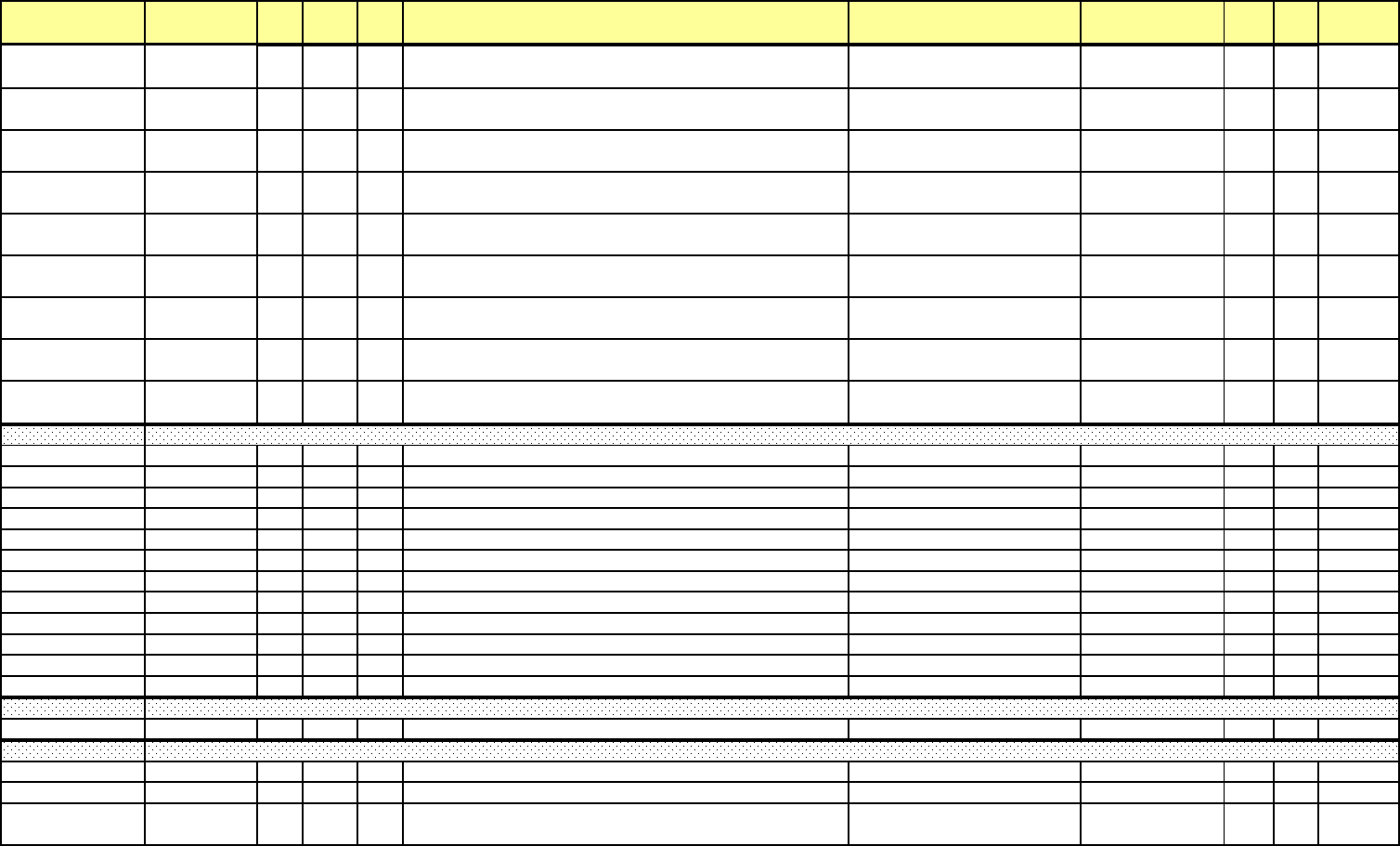
Addr. (hex) Address(4X) Line Pt DNP
Ob
j
Description Range Units Type R/W Notes
1E69H-1E6AH 07786-07787 586 1 30 Quadrant 4 Wh in the Interval, Scaled Primary
variable (9999 through
999999999 / 0) variable 106 - 10-7 F64
1E6BH-1E6CH 07788-07789 586 2 30 Quadrant 2 Wh in the Interval, Sclaed Primary
variable (9999 through
999999999 / 0) variable 106 - 10-7 F64
1E6DH-1E6EH 07790-07791 586 3 30 Quadrant 3 Wh in the Interval, Scaled Primary
variable (9999 through
999999999 / 0) variable 106 - 10-7 F64
1E6FH-1E70H 07792-07793 587 0 30
Uncompensated Total VAh (Q 1+2+3+4) in the Interval, Scaled
Primary
variable (9999 through
999999999 / 0) variable 106 - 10-7 F64
1E71H-1E74H 07794-07797 587 1-2 30 Uncompensated +/- VARh in the Interval, Scaled Primary
variable (9999 through
999999999 / 0) variable 106 - 10-7 F64
1E75H-1E78H 07798-07801 587 3-4 30 Uncompensated +/- Wh in the Interval, Scaled Primary
variable (9999 through
999999999 / 0) variable 106 - 10-7 F64
1E79H-1E7CH 07802-07805 588 0-1 30 +/- Qh in the Interval, Scaled Primary
variable (9999 through
999999999 / 0) variable 106 - 10-7 F64
1E7DH-1E8CH 07806-07821 589 0-7 30 Pulse Accumulation Inputs 1-8 in the Interval, Scaled
variable (9999 through
999999999 / 0) variable 106 - 10-7 F64
1E8DH-1E94H 07822-07829 590 0-3 30 Pulse Aggregations 1-4 in the Interval, Scaled
var
i
a
bl
e
(9999
t
h
roug
h
999999999 / 0) variable 106 - 10-7 F64
1E95H-1E98
H
07830-07833 591 0 50 Total Average Power Factor Block Timestam
p
12/31/9999 23:59:59.99 F3
R
1E99H 07834 592 0 30 Total Average Power Factor Q1
4
1.000 / 0 0.001 PF F8
R
1E9A
H
07835 592 1 30 Total Average Power Factor Q2
3
1.000 / 0 0.001 PF F8
R
1E9B
H
07836 593 0 30 Maximum Total Average Power Factor Q1
4
1.000 / 0 0.001 PF F8
R
1E9C
H
07837 593 1 30 Maximum Total Average Power Factor Q2
3
1.000 / 0 0.001 PF F8
R
1E9D
H
07838 594 0 30 Minimum Total Average Power Factor Q1
4
1.000 / 0 0.001 PF F8
R
1E9E
H
07839 594 1 30 Minimum Total Average Power Factor Q23 1.000 / 0 0.001 PF F8
R
1E9FH-1EA2
H
07840-07843 595 0 50 Maximum Total Average Power Factor Q14 Timestam
p
12/31/9999 23:59:59.99 F3
R
1EA3H-1EA6
H
07844-07847 595 1 50 Maximum Total Average Power Factor Q23 Timestam
p
12/31/9999 23:59:59.99 F3
R
1EA7H-1EAA
H
07848-07851 596 0 50 Minimum Total Average Power Factor Q14 Timestam
p
12/31/9999 23:59:59.99 F3
R
1EABH-1EAE
H
07852-07855 596 1 50 Minimum Total Average Power Factor Q23 Timestam
p
12/31/9999 23:59:59.99 F3
R
1EAFH-1EB2
H
07856-07859 597 0 50 Tota
l
Average Power Factor Reset T
i
mestam
p
12
/
31
/
9999 23:59:59.99 F3
R
1EB3H-1EB6
H
07860-07863 598 0 50 Reset Act
i
ve TOU T
i
me Stamp 12
/
31
/
9999 23:59:59.99 F3
R
1EB7H-1EBA
H
07864-07867 599 0 30 Negative Maximum Block Window Average Aggregation
1
0 /- 9,223,372,036,854,776,808 1 Unit F62
R
1EBBH-1EC6
H
07868-07879 599 1-3 30 Negative Maximum Block Window Average Aggregation 2-
4
0 /- 9,223,372,036,854,776,808 1 Unit F62
R
1EC7H-1ECAH 07880-07883 600 0 50
Negative Maximum Block Window Average Aggregation 1
Time Stamp 12/31/9999 23:59:59.99 10 msec F3 R
Negative Maximum Pulse Aggregation Average Block
Reset Active TOU Time Stamp
Total Average Power Factor Block
e Electro Industries/GaugeTech Doc# E154703 MM-101

Addr. (hex) Address(4X) Line Pt DNP
Ob
j
Description Range Units Type R/W Notes
1ECBH-1ED6H 07884-07895 600 1-3 50
N
egat
i
ve
M
ax
i
mum
Bl
oc
k
Wi
n
d
ow
A
verage
A
ggregat
i
on
2
-
4
Time Stamp 12/31/9999 23:59:59.99 10 msec F3 R
1ED7H-1EDAH 07896-07899 601 0 20 Initial Wh Q14 (Primary, Binary)
9,999,999,999,999,999 Wh / 0
Wh 1 Wh F20 R
1EDBH-1EDEH 07900-07903 601 1 20 Initial WH Q23 (Primary, Binary)
9,999,999,999,999,999 Wh / 0
Wh 1 Wh F20 R
1EDFH-1EE2H 07904-07907 601 2 20 Initial VAh Q14 (Primary, Binary)
9,999,999,999,999,999 VAh / 0
VAh 1 VAh F20 R
1EE3H-1EE6H 07908-07911 601 3 20 Initial VAh Q23 (Primary, Binary)
9,999,999,999,999,999 VAh / 0
VAh 1 VAh F20 R
1EE7H-1EEAH 07912-07915 602 0 20 Accumlated Wh Q14 (Primary, Binary)
9,999,999,999,999,999 Wh / 0
Wh 1 Wh F20 R
1EEBH-1EEEH 07916-07919 602 1 20 Accumlated Wh Q23 (Primary, Binary)
9,999,999,999,999,999 Wh / 0
Wh 1 Wh F20 R
1EEFH-1EF2H 07920-07923 602 2 20 Accumulated VAh Q14 (Primary, Binary)
9,999,999,999,999,999 VAh / 0
VAh 1 VAh F20 R
1EF3H-1EF6H 07924-07927 602 3 20 Accumulated VAh Q23, (Primary, Binary)
9
,
999
,
999
,
999
,
999
,
999
VAh
/
0
VAh 1 VAh F20 R
2000H-207F
H
08193-08320 Scratc
h
pa
d
Reg
i
sters
2100H-21FF
H
08449-08704
2200H-2203
H
08705-08708 603 0 Dynamic Readings Block Time Stam
p
12/31/9999 23:59:59.99 10 msec F3
R
2204H-2205
H
08709-08710 604 0 Sym Comp Voltage Magnitude 3 Sec - zero sequenc
e
MSB: Integer, LSB: Fractio
n
F7
R
2206H-2207
H
08711-08712 604 1 Sym Comp Voltage Magnitude 3 Sec - positive sequenc
e
MSB: Integer, LSB: Fractio
n
F7
R
2208H-2209
H
08713-08714 604 2 Sym Comp Voltage Magnitude 3 Sec - negative sequenc
e
MSB: Integer, LSB: Fractio
n
F7
R
220A
H
08715 605 0 Sym Comp Voltage Phase 3 Sec - zero sequenc
e
+327.67 / -327.68 0.01 degree F10
R
220B
H
08716 605 1 Sym Comp Voltage Phase 3 Sec - positive sequenc
e
+327.67 / -327.68 0.01 degree F10
R
220C
H
08717 605 2 Sym Comp Voltage Phase 3 Sec - negative sequenc
e
+327.67 / -327.68 0.01 degree F10
R
220DH-220E
H
08718-08719 606 0 10 sec Ave Fre
q
+32767Hz / 0H
z
1/65536H
z
F7
R
220FH-2210
H
08720-08721 607 0 10 min Ave RMS Van/ab +32767 Vsec / 0 Vsec 1/65536 Vsec F7
R
2211H-2212
H
08722-08723 607 1 10 min Ave RMS Vbn/b
c
+32767 Vsec / 0 Vsec 1/65536 Vsec F7
R
2213H-2214
H
08724-08725 607 2 10 min Ave RMS Vcn/c
a
+32767 Vsec / 0 Vsec 1/65536 Vsec F7
R
2215H-2216
H
08726-08727 608 0 Sym Comp Voltage Magnitude 10 Min - zero sequenc
e
MSB: Integer, LSB: Fractio
n
F7
R
2217H-2218
H
08728-08729 608 1 Sym Comp Voltage Magnitude 10 Min - positive sequenc
e
MSB: Integer, LSB: Fractio
n
F7
R
2219H-221A
H
08730-08731 608 2 Sym Comp Voltage Magnitude 10 Min - negative sequenc
e
MSB: Integer, LSB: Fractio
n
F7
R
221B
H
08732 609 0 10 min Ave Sym Comp Magnitude, Neg/Pos *100
%
+327.67% / 0% 0.01%
R
Scratchpad Block
Additional Total Average Power Factor Block
Power Quality Test (EN-50160/IEC61000-4-30) Dynamic Readings Block
Master Device Data Block
e Electro Industries/GaugeTech Doc# E154703 MM-102

Addr. (hex) Address(4X) Line Pt DNP
Ob
j
Description Range Units Type R/W Notes
221C
H
08733 610 0 Status (OK 1/ Error 0) / reserved
R
221DH-2220
H
08734-08737 611 0 Harmonic Data Block Time Stam
p
12/31/9999 23:59:59.99 10 msec F3
R
2221H 08738 612 0 10 min Ave Van/ab Harmonic %, 2nd orde
r
+327.67% / -327.68% 0.01% F10
R
2222H 08739 612 1 10 min Ave Van/ab Harmonic %, 3rd order +327.67% / -327.68% 0.01% F10
R
2223H 08740 612 2 10 min Ave Van/ab Harmonic %, 4th order +327.67% / -327.68% 0.01% F10
R
2224H 08741 612 3 10 min Ave Van/ab Harmonic %, 5th order +327.67% / -327.68% 0.01% F10
R
2225H 08742 612 4 10 min Ave Van/ab Harmonic %, 6th order +327.67% / -327.68% 0.01% F10
R
2226H 08743 612 5 10 min Ave Van/ab Harmonic %, 7th order +327.67% / -327.68% 0.01% F10
R
2227H 08744 612 6 10 min Ave Van/ab Harmonic %, 8th order +327.67% / -327.68% 0.01% F10
R
2228H 08745 612 7 10 min Ave Van/ab Harmonic %, 9th order +327.67% / -327.68% 0.01% F10
R
2229H 08746 612 8 10 min Ave Van/ab Harmonic %, 10th order +327.67% / -327.68% 0.01% F10
R
222A
H
08747 612 9 10 min Ave Van/ab Harmonic %, 11th order +327.67% / -327.68% 0.01% F10
R
222B
H
08748 612 10 10 min Ave Van/ab Harmonic %, 12th order +327.67% / -327.68% 0.01% F10
R
222C
H
08749 612 11 10 min Ave Van/ab Harmonic %, 13th order +327.67% / -327.68% 0.01% F10
R
222D
H
08750 612 12 10 min Ave Van/ab Harmonic %, 14th order +327.67% / -327.68% 0.01% F10
R
222EH 08751 612 13 10 min Ave Van/ab Harmonic %, 15th order +327.67% / -327.68% 0.01% F10
R
222FH 08752 612 14 10 min Ave Van/ab Harmonic %, 16th order +327.67% / -327.68% 0.01% F10
R
2230H 08753 612 15 10 min Ave Van/ab Harmonic %, 17th order +327.67% / -327.68% 0.01% F10
R
2231H 08754 612 16 10 min Ave Van/ab Harmonic %, 18th order +327.67% / -327.68% 0.01% F10
R
2232H 08755 612 17 10 min Ave Van/ab Harmonic %, 19th order +327.67% / -327.68% 0.01% F10
R
2233H 08756 612 18 10 min Ave Van/ab Harmonic %, 20th order +327.67% / -327.68% 0.01% F10
R
2234H 08757 612 19 10 min Ave Van/ab Harmonic %, 21st order +327.67% / -327.68% 0.01% F10
R
2235H 08758 612 20 10 min Ave Van/ab Harmonic %, 22nd orde
r
+327.67% / -327.68% 0.01% F10
R
2236H 08759 612 21 10 min Ave Van/ab Harmonic %, 23th order +327.67% / -327.68% 0.01% F10
R
2237H 08760 612 22 10 min Ave Van/ab Harmonic %, 24th order +327.67% / -327.68% 0.01% F10
R
2238H 08761 612 23 10 min Ave Van/ab Harmonic %, 25th order +327.67% / -327.68% 0.01% F10
R
2239H 08762 613 0 10 min Ave Vbn/bc Harmonic %, 2nd orde
r
+327.67% / -327.68% 0.01% F10
R
223A
H
08763 613 1 10 min Ave Vbn/bc Harmonic %, 3rd orde
r
+327.67% / -327.68% 0.01% F10
R
223B
H
08764 613 2 10 min Ave Vbn/bc Harmonic %, 4th orde
r
+327.67% / -327.68% 0.01% F10
R
223C
H
08765 613 3 10 min Ave Vbn/bc Harmonic %, 5th orde
r
+327.67% / -327.68% 0.01% F10
R
223D
H
08766 613 4 10 min Ave Vbn/bc Harmonic %, 6th orde
r
+327.67% / -327.68% 0.01% F10
R
223EH 08767 613 5 10 min Ave Vbn/bc Harmonic %, 7th orde
r
+327.67% / -327.68% 0.01% F10
R
223FH 08768 613 6 10 min Ave Vbn/bc Harmonic %, 8th orde
r
+327.67% / -327.68% 0.01% F10
R
2240H 08769 613 7 10 min Ave Vbn/bc Harmonic %, 9th orde
r
+327.67% / -327.68% 0.01% F10
R
2241H 08770 613 8 10 min Ave Vbn/bc Harmonic %, 10th orde
r
+327.67% / -327.68% 0.01% F10
R
2242H 08771 613 9 10 min Ave Vbn/bc Harmonic %, 11th orde
r
+327.67% / -327.68% 0.01% F10
R
2243H 08772 613 10 10 min Ave Vbn/bc Harmonic %, 12th orde
r
+327.67% / -327.68% 0.01% F10
R
2244H 08773 613 11 10 min Ave Vbn/bc Harmonic %, 13th orde
r
+327.67% / -327.68% 0.01% F10
R
Power Quality Test (EN-50160/IEC61000-4-30) Harmonic Data Block
e Electro Industries/GaugeTech Doc# E154703 MM-103

Addr. (hex) Address(4X) Line Pt DNP
Ob
j
Description Range Units Type R/W Notes
2245H 08774 613 12 10 min Ave Vbn/bc Harmonic %, 14th orde
r
+327.67% / -327.68% 0.01% F10
R
2246H 08775 613 13 10 min Ave Vbn/bc Harmonic %, 15th orde
r
+327.67% / -327.68% 0.01% F10
R
2247H 08776 613 14 10 min Ave Vbn/bc Harmonic %, 16th orde
r
+327.67% / -327.68% 0.01% F10
R
2248H 08777 613 15 10 min Ave Vbn/bc Harmonic %, 17th orde
r
+327.67% / -327.68% 0.01% F10
R
2249H 08778 613 16 10 min Ave Vbn/bc Harmonic %, 18th orde
r
+327.67% / -327.68% 0.01% F10
R
224A
H
08779 613 17 10 min Ave Vbn/bc Harmonic %, 19th orde
r
+327.67% / -327.68% 0.01% F10
R
224B
H
08780 613 18 10 min Ave Vbn/bc Harmonic %, 20th orde
r
+327.67% / -327.68% 0.01% F10
R
224C
H
08781 613 19 10 min Ave Vbn/bc Harmonic %, 21st orde
r
+327.67% / -327.68% 0.01% F10
R
224D
H
08782 613 20 10 min Ave Vbn/bc Harmonic %, 22nd orde
r
+327.67% / -327.68% 0.01% F10
R
224EH 08783 613 21 10 min Ave Vbn/bc Harmonic %, 23th orde
r
+327.67% / -327.68% 0.01% F10
R
224FH 08784 613 22 10 min Ave Vbn/bc Harmonic %, 24th orde
r
+327.67% / -327.68% 0.01% F10
R
2250H 08785 613 23 10 min Ave Vbn/bc Harmonic %, 25th orde
r
+327.67% / -327.68% 0.01% F10
R
2251H 08786 614 0 10 min Ave Vcn/ca Harmonic %, 2nd orde
r
+327.67% / -327.68% 0.01% F10
R
2252H 08787 614 1 10 min Ave Vcn/ca Harmonic %, 3rd orde
r
+327.67% / -327.68% 0.01% F10
R
2253H 08788 614 2 10 min Ave Vcn/ca Harmonic %, 4th orde
r
+327.67% / -327.68% 0.01% F10
R
2254H 08789 614 3 10 min Ave Vcn/ca Harmonic %, 5th orde
r
+327.67% / -327.68% 0.01% F10
R
2255H 08790 614 4 10 min Ave Vcn/ca Harmonic %, 6th orde
r
+327.67% / -327.68% 0.01% F10
R
2256H 08791 614 5 10 min Ave Vcn/ca Harmonic %, 7th orde
r
+327.67% / -327.68% 0.01% F10
R
2257H 08792 614 6 10 min Ave Vcn/ca Harmonic %, 8th orde
r
+327.67% / -327.68% 0.01% F10
R
2258H 08793 614 7 10 min Ave Vcn/ca Harmonic %, 9th orde
r
+327.67% / -327.68% 0.01% F10
R
2259H 08794 614 8 10 min Ave Vcn/ca Harmonic %, 10th orde
r
+327.67% / -327.68% 0.01% F10
R
225A
H
08795 614 9 10 min Ave Vcn/ca Harmonic %, 11th orde
r
+327.67% / -327.68% 0.01% F10
R
225B
H
08796 614 10 10 min Ave Vcn/ca Harmonic %, 12th orde
r
+327.67% / -327.68% 0.01% F10
R
225C
H
08797 614 11 10 min Ave Vcn/ca Harmonic %, 13th orde
r
+327.67% / -327.68% 0.01% F10
R
225D
H
08798 614 12 10 min Ave Vcn/ca Harmonic %, 14th orde
r
+327.67% / -327.68% 0.01% F10
R
225EH 08799 614 13 10 min Ave Vcn/ca Harmonic %, 15th orde
r
+327.67% / -327.68% 0.01% F10
R
225FH 08800 614 14 10 min Ave Vcn/ca Harmonic %, 16th orde
r
+327.67% / -327.68% 0.01% F10
R
2260H 08801 614 15 10 min Ave Vcn/ca Harmonic %, 17th orde
r
+327.67% / -327.68% 0.01% F10
R
2261H 08802 614 16 10 min Ave Vcn/ca Harmonic %, 18th orde
r
+327.67% / -327.68% 0.01% F10
R
2262H 08803 614 17 10 min Ave Vcn/ca Harmonic %, 19th orde
r
+327.67% / -327.68% 0.01% F10
R
2263H 08804 614 18 10 min Ave Vcn/ca Harmonic %, 20th orde
r
+327.67% / -327.68% 0.01% F10
R
2264H 08805 614 19 10 min Ave Vcn/ca Harmonic %, 21st orde
r
+327.67% / -327.68% 0.01% F10
R
2265H 08806 614 20 10 min Ave Vcn/ca Harmonic %, 22nd orde
r
+327.67% / -327.68% 0.01% F10
R
2266H 08807 614 21 10 min Ave Vcn/ca Harmonic %, 23th orde
r
+327.67% / -327.68% 0.01% F10
R
2267H 08808 614 22 10 min Ave Vcn/ca Harmonic %, 24th orde
r
+327.67% / -327.68% 0.01% F10
R
2268H 08809 614 23 10 min Ave Vcn/ca Harmonic %, 25th orde
r
+327.67% / -327.68% 0.01% F10
R
2269H 08810 615 0 10 min Ave Van/ab THD % +327.67% / -327.68% 0.01% F10
R
226A
H
08811 615 1 10 min Ave Vbn/bc THD
%
+327.67% / -327.68% 0.01% F10
R
226B
H
08812 615 2 10 min Ave Vcn/ca THD
%
+327.67%
/
-327.68% 0.01% F10
R
e Electro Industries/GaugeTech Doc# E154703 MM-104

Addr. (hex) Address(4X) Line Pt DNP
Ob
j
Description Range Units Type R/W Notes
226CH-226F
H
08813-08816 616 0 Current Week Test Block Time Stamp 12/31/9999 23:59:59.99 10 msec F3
R
2270H-2273
H
08817-08820 616 1 Current Week Test Start Time 12/31/9999 23:59:59.99 10 msec F3
R
2274H-2277
H
08821-08824 616 2 Current Week Test End Time 12/31/9999 23:59:59.99 10 msec F3
R
2278H-2279
H
08825-08826 617 0 Fast Voltage Fluctuation Coun
t
4,294,967,295 / 0 1 unit F53
R
227A
H
08827 618 0 Mains Frequency Coun
t
65,535 / 0 1 unit F51
R
227B
H
08828 618 1 10 min Ave Coun
t
65,535 / 0 1 unit F51
R
227C
H
08829 618 2 Flicker PLT Coun
t
65,535 / 0 1 unit F51
R
227D
H
08830 619 0 10 sec Ave Freq Bin0, Freq < 42.5(51.0) Hz 65,535 / 0 1 unit F51
R
227EH 08831 619 1 10 sec Ave Freq Bin1, 42.5(51.0) Hz <= Freq < 47(56.4) Hz 65,535 / 0 1 unit F51
R
227FH 08832 619 2 10 sec Ave Freq Bin2, 47(56.4) Hz <= Freq < 49(58.8) Hz 65,535 / 0 1 unit F51
R
2280H 08833 619 3 10 sec Ave Freq Bin3, 49(58.8) Hz <= Freq < 49.5(59.4) Hz 65,535 / 0 1 unit F51
R
2281H 08834 619 4 10 sec Ave Freq Bin4, 49.5(59.4) Hz <= Freq < 50(60.0) Hz 65,535 / 0 1 unit F51
R
2282H 08835 619 5 10 sec Ave Freq Bin5, 50(60.0) Hz <= Freq < 50.5(60.6) Hz 65,535 / 0 1 unit F51
R
2283H 08836 619 6 10 sec Ave Freq Bin6, 50.5(60.6) Hz <= Freq < 51(61.2) Hz 65,535 / 0 1 unit F51
R
2284H 08837 619 7 10 sec Ave Freq Bin7, 51(61.2) Hz <= Freq < 52(62.4) Hz 65,535 / 0 1 unit F51
R
2285H 08838 619 8 10 sec Ave Freq Bin8, 52(62.4) Hz <= Freq < 57.5(69.0) Hz 65,535 / 0 1 unit F51
R
2286H 08839 619 9 10 sec Ave Freq Bin9, 57.5(69.0) <= Freq 65,535 / 0 1 unit F51
R
2287H 08840 620 0 10 min Ave Van/ab RMS Bin0, V < 85% 65,535 / 0 1 unit F51
R
2288H 08841 620 1 10 min Ave Van/ab RMS Bin1, 85% <= V < 90% 65,535 / 0 1 unit F51
R
2289H 08842 620 2 10 min Ave Van/ab RMS Bin2, 90% <= V < 100% 65,535 / 0 1 unit F51
R
228A
H
08843 620 3 10 min Ave Van/ab RMS Bin3, 100% <= V < 110% 65,535 / 0 1 unit F51
R
228B
H
08844 620 4 10 min Ave Van/ab RMS Bin4, 110% <= V 65,535 / 0 1 unit F51
R
228C
H
08845 621 0 10 min Ave Vbn/bc RMS Bin0, V < 85% 65,535 / 0 1 unit F51
R
228D
H
08846 621 1 10 min Ave Vbn/bc RMS Bin1, 85% <= V < 90% 65,535 / 0 1 unit F51
R
228EH 08847 621 2 10 min Ave Vbn/bc RMS Bin2, 90% <= V < 100% 65,535 / 0 1 unit F51
R
228FH 08848 621 3 10 min Ave Vbn/bc RMS Bin3, 100% <= V < 110% 65,535 / 0 1 unit F51
R
2290H 08849 621 4 10 min Ave Vbn/bc RMS Bin4, 110% <= V 65,535 / 0 1 unit F51
R
2291H 08850 622 0 10 min Ave Vcn/ca RMS Bin0, V < 85% 65,535 / 0 1 unit F51
R
2292H 08851 622 1 10 min Ave Vcn/ca RMS Bin1, 85% <= V < 90% 65,535 / 0 1 unit F51
R
2293H 08852 622 2 10 min Ave Vcn/ca RMS Bin2, 90% <= V < 100% 65,535 / 0 1 unit F51
R
2294H 08853 622 3 10 min Ave Vcn/ca RMS Bin3, 100% <= V < 110% 65,535 / 0 1 unit F51
R
2295H 08854 622 4 10 min Ave Vcn/ca RMS Bin4, 110% <= V 65,535 / 0 1 unit F51
R
2296H-2297
H
08855-08856 623 0 Fast Voltage Van/an Bin0, V < 90 % 4,294,967,295 / 0 1 unit F53
R
2298H-2299
H
08857-08858 623 1 Fast Voltage Van/an Bin1, 90% <= V < 95 % 4,294,967,295 / 0 1 unit F53
R
229AH-229B
H
08859-08860 623 2 Fast Voltage Van/an Bin2, 95% <= V < 100 % 4,294,967,295 / 0 1 unit F53
R
229CH-229D
H
08861-08862 623 3 Fast Voltage Van/an Bin3, 100% <= V < 105 % 4,294,967,295 / 0 1 unit F53
R
229EH-229F
H
08863-08864 623 4 Fast Voltage Van/an Bin4, 105% <= V < 110 % 4,294,967,295 / 0 1 unit F53
R
22A0H-22A1
H
08865-08866 623 5 Fast Voltage Van/an Bin5, 110% <= V 4,294,967,295 / 0 1 unit F53
R
Power Quality Test (EN-50160/IEC61000-4-30) Current Week Test Block
e Electro Industries/GaugeTech Doc# E154703 MM-105

Addr. (hex) Address(4X) Line Pt DNP
Ob
j
Description Range Units Type R/W Notes
22A2H-22A3
H
08867-08868 624 0 Fast Voltage Vbn/bc Bin0, V < 90 % 4,294,967,295 / 0 1 unit F53
R
22A4H-22A5
H
08869-08870 624 1 Fast Voltage Vbn/bc Bin1, 90% <= V < 95 % 4,294,967,295 / 0 1 unit F53
R
22A6H-22A7
H
08871-08872 624 2 Fast Voltage Vbn/bc Bin2, 95% <= V < 100 % 4,294,967,295 / 0 1 unit F53
R
22A8H-22A9
H
08873-08874 624 3 Fast Voltage Vbn/bc Bin3, 100% <= V < 105 % 4,294,967,295 / 0 1 unit F53
R
22AAH-22AB
H
08875-08876 624 4 Fast Voltage Vbn/bc Bin4, 105% <= V < 110 % 4,294,967,295 / 0 1 unit F53
R
22ACH-22AD
H
08877-08878 624 5 Fast Voltage Vbn/bc Bin5, 110% <= V 4,294,967,295 / 0 1 unit F53
R
22AEH-22AF
H
08879-08880 625 0 Fast Voltage Vcn/ca Bin0, V < 90 % 4,294,967,295 / 0 1 unit F53
R
22B0H-22B1
H
08881-08882 625 1 Fast Voltage Vcn/ca Bin1, 90% <= V < 95 % 4,294,967,295 / 0 1 unit F53
R
22B2H-22B3
H
08883-08884 625 2 Fast Voltage Vcn/ca Bin2, 95% <= V < 100 % 4,294,967,295 / 0 1 unit F53
R
22B4H-22B5
H
08885-08886 625 3 Fast Voltage Vcn/ca Bin3, 100% <= V < 105 % 4,294,967,295 / 0 1 unit F53
R
22B6H-22B7
H
08887-08888 625 4 Fast Voltage Vcn/ca Bin4, 105% <= V < 110 % 4,294,967,295 / 0 1 unit F53
R
22B8H-22B9
H
08889-08890 625 5 Fast Voltage Vcn/ca Bin5, 110% <= V 4,294,967,295 / 0 1 unit F53
R
22BA
H
08891 626 0 Flicker PLT Van/ab Bin0, PLT <1 65,535 / 0 1 unit F51
R
22BB
H
08892 626 1 Flicker PLT Van/ab Bin1, PLT >=1 65,535 / 0 1 unit F51
R
22BC
H
08893 626 2 Flicker PLT Vbn/bc Bin0, PLT <1 65,535 / 0 1 unit F51
R
22BD
H
08894 626 3 Flicker PLT Vbn/bc Bin1, PLT >=1 65,535 / 0 1 unit F51
R
22BE
H
08895 626 4 Flicker PLT Vcn/ca Bin0, PLT <1 65,535 / 0 1 unit F51
R
22BF
H
08896 626 5 Flicker PLT Vcn/ca Bin1, PLT >=1 65,535 / 0 1 unit F51
R
22C0
H
08897 627 0 Fund. Sym. Comp. Bin0 (- Seq. Mag < 2% of +Seq. Mag.) 65,535 / 0 1 unit F51
R
22C1
H
08898 627 1 Fund. Sym. Comp. Bin1 (2% <= -Seq.Mag. < 3% of +Seq. Mag.
)
65,535 / 0 1 unit F51
R
22C2
H
08899 627 2 Fund. Sym. Comp. Bin2 (-Seq. Mag. >= 3% of +Seq. Mag.) 65,535 / 0 1 unit F51
R
22C3
H
08900 628 0 10 min Ave Van/ab 2nd Harm bin, >= 2.0% 65,535 / 0 1 unit F51
R
22C4
H
08901 628 1 10 min Ave Van/ab 3nd Harm bin, >= 5.0% 65,535 / 0 1 unit F51
R
22C5
H
08902 628 2 10 min Ave Van/ab 4th Harm bin, >= 1.0% 65,535 / 0 1 unit F51
R
22C6
H
08903 628 3 10 min Ave Van/ab 5th Harm bin, >= 6.0% 65,535 / 0 1 unit F51
R
22C7
H
08904 628 4 10 min Ave Van/ab 6th Harm bin, >= 0.5% 65,535 / 0 1 unit F51
R
22C8
H
08905 628 5 10 min Ave Van/ab 7th Harm bin, >= 1.5% 65,535 / 0 1 unit F51
R
22C9
H
08906 628 6 10 min Ave Van/ab 8th Harm bin, >= 0.5% 65,535 / 0 1 unit F51
R
22CA
H
08907 628 7 10 min Ave Van/ab 9th Harm bin, >= 1.5% 65,535 / 0 1 unit F51
R
22CB
H
08908 628 8 10 min Ave Van/ab 10th Harm bin, >= 0.5% 65,535 / 0 1 unit F51
R
22CC
H
08909 628 9 10 min Ave Van/ab 11th Harm bin, >= 3.5% 65,535 / 0 1 unit F51
R
22CD
H
08910 628 10 10 min Ave Van/ab 12th Harm bin, >= 0.5% 65,535 / 0 1 unit F51
R
22CE
H
08911 628 11 10 min Ave Van/ab 13th Harm bin, >= 3.0% 65,535 / 0 1 unit F51
R
22CF
H
08912 628 12 10 min Ave Van/ab 14th Harm bin, >= 0.5% 65,535 / 0 1 unit F51
R
22D0
H
08913 628 13 10 min Ave Van/ab 15th Harm bin, >= 0.5% 65,535 / 0 1 unit F51
R
22D1
H
08914 628 14 10 min Ave Van/ab 16th Harm bin, >= 0.5% 65,535 / 0 1 unit F51
R
22D2
H
08915 628 15 10 min Ave Van/ab 17th Harm bin, >= 2.0% 65,535 / 0 1 unit F51
R
22D3
H
08916 628 16 10 min Ave Van/ab 18th Harm bin, >= 0.5% 65,535 / 0 1 unit F51
R
22D4
H
08917 628 17 10 min Ave Van/ab 19th Harm bin, >= 1.5% 65,535 / 0 1 unit F51
R
e Electro Industries/GaugeTech Doc# E154703 MM-106

Addr. (hex) Address(4X) Line Pt DNP
Ob
j
Description Range Units Type R/W Notes
22D5
H
08918 628 18 10 min Ave Van/ab 20th Harm bin, >= 0.5% 65,535 / 0 1 unit F51
R
22D6
H
08919 628 19 10 min Ave Van/ab 21st Harm bin, >= 0.5% 65,535 / 0 1 unit F51
R
22D7
H
08920 628 20 10 min Ave Van/ab 22nd Harm bin, >= 0.5% 65,535 / 0 1 unit F51
R
22D8
H
08921 628 21 10 min Ave Van/ab 23rd Harm bin, >= 1.5% 65,535 / 0 1 unit F51
R
22D9
H
08922 628 22 10 min Ave Van/ab 24th Harm bin, >= 0.5% 65,535 / 0 1 unit F51
R
22DA
H
08923 628 23 10 min Ave Van/ab 25th Harm bin, >= 1.5% 65,535 / 0 1 unit F51
R
22DB
H
08924 629 0 10 min Ave Vbn/bc 2nd Harm bin, >= 2.0% 65,535 / 0 1 unit F51
R
22DC
H
08925 629 1 10 min Ave Vbn/bc 3nd Harm bin, >= 5.0% 65,535 / 0 1 unit F51
R
22DD
H
08926 629 2 10 min Ave Vbn/bc 4th Harm bin, >= 1.0% 65,535 / 0 1 unit F51
R
22DE
H
08927 629 3 10 min Ave Vbn/bc 5th Harm bin, >= 6.0% 65,535 / 0 1 unit F51
R
22DF
H
08928 629 4 10 min Ave Vbn/bc 6th Harm bin, >= 0.5% 65,535 / 0 1 unit F51
R
22E0H 08929 629 5 10 min Ave Vbn/bc 7th Harm bin, >= 1.5% 65,535 / 0 1 unit F51
R
22E1H 08930 629 6 10 min Ave Vbn/bc 8th Harm bin, >= 0.5% 65,535 / 0 1 unit F51
R
22E2H 08931 629 7 10 min Ave Vbn/bc 9th Harm bin, >= 1.5% 65,535 / 0 1 unit F51
R
22E3H 08932 629 8 10 min Ave Vbn/bc 10th Harm bin, >= 0.5% 65,535 / 0 1 unit F51
R
22E4H 08933 629 9 10 min Ave Vbn/bc 11th Harm bin, >= 3.5% 65,535 / 0 1 unit F51
R
22E5H 08934 629 10 10 min Ave Vbn/bc 12th Harm bin, >= 0.5% 65,535 / 0 1 unit F51
R
22E6H 08935 629 11 10 min Ave Vbn/bc 13th Harm bin, >= 3.0% 65,535 / 0 1 unit F51
R
22E7H 08936 629 12 10 min Ave Vbn/bc 14th Harm bin, >= 0.5% 65,535 / 0 1 unit F51
R
22E8H 08937 629 13 10 min Ave Vbn/bc 15th Harm bin, >= 0.5% 65,535 / 0 1 unit F51
R
22E9H 08938 629 14 10 min Ave Vbn/bc 16th Harm bin, >= 0.5% 65,535 / 0 1 unit F51
R
22EA
H
08939 629 15 10 min Ave Vbn/bc 17th Harm bin, >= 2.0% 65,535 / 0 1 unit F51
R
22EB
H
08940 629 16 10 min Ave Vbn/bc 18th Harm bin, >= 0.5% 65,535 / 0 1 unit F51
R
22EC
H
08941 629 17 10 min Ave Vbn/bc 19th Harm bin, >= 1.5% 65,535 / 0 1 unit F51
R
22ED
H
08942 629 18 10 min Ave Vbn/bc 20th Harm bin, >= 0.5% 65,535 / 0 1 unit F51
R
22EE
H
08943 629 19 10 min Ave Vbn/bc 21st Harm bin, >= 0.5% 65,535 / 0 1 unit F51
R
22EF
H
08944 629 20 10 min Ave Vbn/bc 22nd Harm bin, >= 0.5% 65,535 / 0 1 unit F51
R
22F0H 08945 629 21 10 min Ave Vbn/bc 23rd Harm bin, >= 1.5% 65,535 / 0 1 unit F51
R
22F1H 08946 629 22 10 min Ave Vbn/bc 24th Harm bin, >= 0.5% 65,535 / 0 1 unit F51
R
22F2H 08947 629 23 10 min Ave Vbn/bc 25th Harm bin, >= 1.5% 65,535 / 0 1 unit F51
R
22F3H 08948 630 0 10 min Ave Vcn/ca 2nd Harm bin, >= 2.0% 65,535 / 0 1 unit F51
R
22F4H 08949 630 1 10 min Ave Vcn/ca 3nd Harm bin, >= 5.0% 65,535 / 0 1 unit F51
R
22F5H 08950 630 2 10 min Ave Vcn/ca 4th Harm bin, >= 1.0% 65,535 / 0 1 unit F51
R
22F6H 08951 630 3 10 min Ave Vcn/ca 5th Harm bin, >= 6.0% 65,535 / 0 1 unit F51
R
22F7H 08952 630 4 10 min Ave Vcn/ca 6th Harm bin, >= 0.5% 65,535 / 0 1 unit F51
R
22F8H 08953 630 5 10 min Ave Vcn/ca 7th Harm bin, >= 1.5% 65,535 / 0 1 unit F51
R
22F9H 08954 630 6 10 min Ave Vcn/ca 8th Harm bin, >= 0.5% 65,535 / 0 1 unit F51
R
22FA
H
08955 630 7 10 min Ave Vcn/ca 9th Harm bin, >= 1.5% 65,535 / 0 1 unit F51
R
22FB
H
08956 630 8 10 min Ave Vcn/ca 10th Harm bin, >= 0.5% 65,535 / 0 1 unit F51
R
e Electro Industries/GaugeTech Doc# E154703 MM-107

Addr. (hex) Address(4X) Line Pt DNP
Ob
j
Description Range Units Type R/W Notes
22FC
H
08957 630 9 10 min Ave Vcn/ca 11th Harm bin, >= 3.5% 65,535 / 0 1 unit F51
R
22FD
H
08958 630 10 10 min Ave Vcn/ca 12th Harm bin, >= 0.5% 65,535 / 0 1 unit F51
R
22FE
H
08959 630 11 10 min Ave Vcn/ca 13th Harm bin, >= 3.0% 65,535 / 0 1 unit F51
R
22FFH 08960 630 12 10 min Ave Vcn/ca 14th Harm bin, >= 0.5% 65,535 / 0 1 unit F51
R
2300H 08961 630 13 10 min Ave Vcn/ca 15th Harm bin, >= 0.5% 65,535 / 0 1 unit F51
R
2301H 08962 630 14 10 min Ave Vcn/ca 16th Harm bin, >= 0.5% 65,535 / 0 1 unit F51
R
2302H 08963 630 15 10 min Ave Vcn/ca 17th Harm bin, >= 2.0% 65,535 / 0 1 unit F51
R
2303H 08964 630 16 10 min Ave Vcn/ca 18th Harm bin, >= 0.5% 65,535 / 0 1 unit F51
R
2304H 08965 630 17 10 min Ave Vcn/ca 19th Harm bin, >= 1.5% 65,535 / 0 1 unit F51
R
2305H 08966 630 18 10 min Ave Vcn/ca 20th Harm bin, >= 0.5% 65,535 / 0 1 unit F51
R
2306H 08967 630 19 10 min Ave Vcn/ca 21st Harm bin, >= 0.5% 65,535 / 0 1 unit F51
R
2307H 08968 630 20 10 min Ave Vcn/ca 22nd Harm bin, >= 0.5% 65,535 / 0 1 unit F51
R
2308H 08969 630 21 10 min Ave Vcn/ca 23rd Harm bin, >= 1.5% 65,535 / 0 1 unit F51
R
2309H 08970 630 22 10 min Ave Vcn/ca 24th Harm bin, >= 0.5% 65,535 / 0 1 unit F51
R
230A
H
08971 630 23 10 min Ave Vcn/ca 25th Harm bin, >= 1.5% 65,535 / 0 1 unit F51
R
230B
H
08972 631 0 10 min Ave Van/ab THD % bin, > 8% 65,535 / 0 1 unit F51
R
230C
H
08973 631 1 10 min Ave Vbn/bc THD % bin, > 8% 65,535 / 0 1 unit F51
R
230D
H
08974 631 2 10 min Ave Vcn/ca THD % bin, > 8% 65,535 / 0 1 unit F51
R
230EH 08975 632 0 Freq % for Sync System bin (-1% < f < +1%) 65,535 / 0 1 unit F51
R
230FH 08976 632 1 Freq % for Sync System bin (-6% < f < +4%) 65,535 / 0 1 unit F51
R
2310H 08977 632 2 Freq % for No Sync System bin (-2% < f < +2%
)
65,535 / 0 1 unit F51
R
2311H 08978 632 3 Freq % for No Sync System bin (-15% < f < +15%
)
65,535 / 0 1 unit F51
R
2312H 08979 633 0 FVF % for Van/ab bins (-5% < fvf < +5%) 65,535 / 0 1 unit F51
R
2313H 08980 633 1 FVF % for Vbn/bc bins (-5% < fvf < +5%) 65,535 / 0 1 unit F51
R
2314H 08981 633 2 FVF % for Vcn/ca bins (-5% < fvf < +5%) 65,535 / 0 1 unit F51
R
2315H 08982 633 3 FVF % for Van/ab bins (-10% < fvf < +10%) 65,535 / 0 1 unit F51
R
2316H 08983 633 4 FVF % for Vbn/bc bins (-10% < fvf < +10%) 65,535 / 0 1 unit F51
R
2317H 08984 633 5 FVF % for Vcn/ca bins (-10% < fvf < +10%) 65,535 / 0 1 unit F51
R
2318H 08985 634 0 LSVF % for Van/ab bins (-10% < lsvf < +10%) 65,535 / 0 1 unit F51
R
2319H 08986 634 1 LSVF % for Vbn/bc bins (-10% < lsvf < +10%) 65,535 / 0 1 unit F51
R
231AH 08987 634 2 LSVF % for Vcn/ca bins (-10% < lsvf < +10%) 65,535 / 0 1 unit F51
R
231B
H
08988 634 3 LSVF % for Van/ab bins (-15% < lsvf < +10%) 65,535 / 0 1 unit F51
R
231C
H
08989 634 4 LSVF % for Vbn/bc bins (-15% < lsvf < +10%) 65,535 / 0 1 unit F51
R
231D
H
08990 634 5 LSVF % for Vcn/ca bins (-15% < lsvf < +10%) 65,535 / 0 1 unit F51
R
231EH 08991 635 0,1 Status Byte 0 / Status Byte 1
R
231FH 08992 635 2,3 Status Byte 2 / Status Byte 3
R
2320H 08993 635 4,5 Status Byte 4 / Status Byte 5
R
2321H-2324
H
08994-08997 636 0 Previous Week Test Block Time Stamp 12/31/9999 23:59:59.99 10 msec F3
R
Power Quality Test (EN-50160/IEC61000-4-30) Previous Week Block
e Electro Industries/GaugeTech Doc# E154703 MM-108

Addr. (hex) Address(4X) Line Pt DNP
Ob
j
Description Range Units Type R/W Notes
2325H-2328
H
08998-09001 636 1 Previous Week Test Start Time 12/31/9999 23:59:59.99 10 msec F3
R
2329H-232C
H
09002-09005 636 2 Previous Week Test End Time 12/31/9999 23:59:59.99 10 msec F3
R
232DH-232E
H
09006-09007 637 0 Fast Voltage Fluctuation Coun
t
4,294,967,295 / 0 1 unit F53
R
232FH 09008 638 0 Mains Frequency Coun
t
65,535 / 0 1 unit F51
R
2330H 09009 638 1 10 min Ave Coun
t
65,535 / 0 1 unit F51
R
2331H 09010 638 2 Flicker PLT Coun
t
65,535 / 0 1 unit F51
R
2332H 09011 639 0 10 sec Ave Freq Bin0, Freq < 42.5(51.0) Hz 65,535 / 0 1 unit F51
R
2333H 09012 639 1 10 sec Ave Freq Bin1, 42.5(51.0) Hz <= Freq < 47(56.4) Hz 65,535 / 0 1 unit F51
R
2334H 09013 639 2 10 sec Ave Freq Bin2, 47(56.4) Hz <= Freq < 49(58.8) Hz 65,535 / 0 1 unit F51
R
2335H 09014 639 3 10 sec Ave Freq Bin3, 49(58.8) Hz <= Freq < 49.5(59.4) Hz 65,535 / 0 1 unit F51
R
2336H 09015 639 4 10 sec Ave Freq Bin4, 49.5(59.4) Hz <= Freq < 50(60.0) Hz 65,535 / 0 1 unit F51
R
2337H 09016 639 5 10 sec Ave Freq Bin5, 50(60.0) Hz <= Freq < 50.5(60.6) Hz 65,535 / 0 1 unit F51
R
2338H 09017 639 6 10 sec Ave Freq Bin6, 50.5(60.6) Hz <= Freq < 51(61.2) Hz 65,535 / 0 1 unit F51
R
2339H 09018 639 7 10 sec Ave Freq Bin7, 51(61.2) Hz <= Freq < 52(62.4) Hz 65,535 / 0 1 unit F51
R
233A
H
09019 639 8 10 sec Ave Freq Bin8, 52(62.4) Hz <= Freq < 57.5(69.0) Hz 65,535 / 0 1 unit F51
R
233B
H
09020 639 9 10 sec Ave Freq Bin9, 57.5(69.0) <= Freq 65,535 / 0 1 unit F51
R
233C
H
09021 640 0 10 min Ave Van/ab RMS Bin0, V < 85% 65,535 / 0 1 unit F51
R
233D
H
09022 640 1 10 min Ave Van/ab RMS Bin1, 85% <= V < 90% 65,535 / 0 1 unit F51
R
233EH 09023 640 2 10 min Ave Van/ab RMS Bin2, 90% <= V < 100% 65,535 / 0 1 unit F51
R
233FH 09024 640 3 10 min Ave Van/ab RMS Bin3, 100% <= V < 110% 65,535 / 0 1 unit F51
R
2340H 09025 640 4 10 min Ave Van/ab RMS Bin4, 110% <= V 65,535 / 0 1 unit F51
R
2341H 09026 641 0 10 min Ave Vbn/bc RMS Bin0, V < 85% 65,535 / 0 1 unit F51
R
2342H 09027 641 1 10 min Ave Vbn/bc RMS Bin1, 85% <= V < 90% 65,535 / 0 1 unit F51
R
2343H 09028 641 2 10 min Ave Vbn/bc RMS Bin2, 90% <= V < 100% 65,535 / 0 1 unit F51
R
2344H 09029 641 3 10 min Ave Vbn/bc RMS Bin3, 100% <= V < 110% 65,535 / 0 1 unit F51
R
2345H 09030 641 4 10 min Ave Vbn/bc RMS Bin4, 110% <= V 65,535 / 0 1 unit F51
R
2346H 09031 642 0 10 minAve Vcn/ca RMS Bin0, V < 85% 65,535 / 0 1 unit F51
R
2347H 09032 642 1 10 minAve Vcn/ca RMS Bin1, 85% <= V < 90% 65,535 / 0 1 unit F51
R
2348H 09033 642 2 10 minAve Vcn/ca RMS Bin2, 90% <= V < 100% 65,535 / 0 1 unit F51
R
2349H 09034 642 3 10 minAve Vcn/ca RMS Bin3, 100% <= V < 110% 65,535 / 0 1 unit F51
R
234AH 09035 642 4 10 minAve Vcn/ca RMS Bin4, 110% <= V 65,535 / 0 1 unit F51
R
234BH-234C
H
06036-09037 643 0 Fast Voltage Van/an Bin0, V < 90 % 4,294,967,295 / 0 1 unit F53
R
234DH-234E
H
09038-09039 643 1 Fast Voltage Van/an Bin1, 90% <= V < 95 % 4,294,967,295 / 0 1 unit F53
R
234FH-2350
H
09040-09041 643 2 Fast Voltage Van/an Bin2, 95% <= V < 100 % 4,294,967,295 / 0 1 unit F53
R
2351H-2352
H
09042-09043 643 3 Fast Voltage Van/an Bin3, 100% <= V < 105 % 4,294,967,295 / 0 1 unit F53
R
2353H-2354
H
09044-09045 643 4 Fast Voltage Van/an Bin4, 105% <= V < 110 % 4,294,967,295 / 0 1 unit F53
R
2355H-2356
H
09046-09047 643 5 Fast Voltage Van/an Bin5, 110% <= V 4,294,967,295 / 0 1 unit F53
R
2357H-2358
H
09048-09049 644 0 Fast Voltage Vbn/bc Bin0, V < 90 % 4,294,967,295 / 0 1 unit F53
R
2359H-235A
H
09050-09051 644 1 Fast Voltage Vbn/bc Bin1, 90% <= V < 95 % 4,294,967,295 / 0 1 unit F53
R
e Electro Industries/GaugeTech Doc# E154703 MM-109

Addr. (hex) Address(4X) Line Pt DNP
Ob
j
Description Range Units Type R/W Notes
235BH-235C
H
09052-09053 644 2 Fast Voltage Vbn/bc Bin2, 95% <= V < 100 % 4,294,967,295 / 0 1 unit F53
R
235DH-235E
H
09054-09055 644 3 Fast Voltage Vbn/bc Bin3, 100% <= V < 105 % 4,294,967,295 / 0 1 unit F53
R
235FH-2360
H
09056-09057 644 4 Fast Voltage Vbn/bc Bin4, 105% <= V < 110 % 4,294,967,295 / 0 1 unit F53
R
2361H-2362
H
09058-09059 644 5 Fast Voltage Vbn/bc Bin5, 110% <= V 4,294,967,295 / 0 1 unit F53
R
2363H-2364
H
09060-09061 645 0 Fast Voltage Vcn/ca Bin0, V < 90 % 4,294,967,295 / 0 1 unit F53
R
2365H-2366
H
09062-09063 645 1 Fast Voltage Vcn/ca Bin1, 90% <= V < 95 % 4,294,967,295 / 0 1 unit F53
R
2367H-2368
H
09064-09065 645 2 Fast Voltage Vcn/ca Bin2, 95% <= V < 100 % 4,294,967,295 / 0 1 unit F53
R
2369H-236A
H
09066-09067 645 3 Fast Voltage Vcn/ca Bin3, 100% <= V < 105 % 4,294,967,295 / 0 1 unit F53
R
236BH-236C
H
09068-09069 645 4 Fast Voltage Vcn/ca Bin4, 105% <= V < 110 % 4,294,967,295 / 0 1 unit F53
R
236DH-236E
H
09070-09071 645 5 Fast Voltage Vcn/ca Bin5, 110% <= V 4,294,967,295 / 0 1 unit F53
R
236FH 09072 646 0 Flicker PLT Van/ab Bin0, PLT <1 65,535 / 0 1 unit F51
R
2370H 09073 646 1 Flicker PLT Van/ab Bin1, PLT >=1 65,535 / 0 1 unit F51
R
2371H 09074 646 2 Flicker PLT Vbn/bc Bin0, PLT <1 65,535 / 0 1 unit F51
R
2372H 09075 646 3 Flicker PLT Vbn/bc Bin1, PLT >=1 65,535 / 0 1 unit F51
R
2373H 09076 646 4 Flicker PLT Vcn/ca Bin0, PLT <1 65,535 / 0 1 unit F51
R
2374H 09077 646 5 Flicker PLT Vcn/ca Bin1, PLT >=1 65,535 / 0 1 unit F51
R
2375H 09078 647 0 Fund. Sym. Comp. Bin0 (- Seq. Mag < 2% of +Seq. Mag.) 65,535 / 0 1 unit F51
R
2376H 09079 647 1 Fund. Sym. Comp. Bin1 (2% <= -Seq.Mag. < 3% of +Seq. Mag.
)
65,535 / 0 1 unit F51
R
2377H 09080 647 2 Fund. Sym. Comp. Bin2 (-Seq. Mag. >= 3% of +Seq. Mag.) 65,535 / 0 1 unit F51
R
2378H 09081 648 0 10 min Ave Van/ab 2nd Harm bin, >= 2.0% 65,535 / 0 1 unit F51
R
2379H 09082 648 1 10 min Ave Van/ab 3nd Harm bin, >= 5.0% 65,535 / 0 1 unit F51
R
237A
H
09083 648 2 10 min Ave Van/ab 4th Harm bin, >= 1.0% 65,535 / 0 1 unit F51
R
237B
H
09084 648 3 10 min Ave Van/ab 5th Harm bin, >= 6.0% 65,535 / 0 1 unit F51
R
237C
H
09085 648 4 10 min Ave Van/ab 6th Harm bin, >= 0.5% 65,535 / 0 1 unit F51
R
237D
H
09086 648 5 10 min Ave Van/ab 7th Harm bin, >= 1.5% 65,535 / 0 1 unit F51
R
237EH 09087 648 6 10 min Ave Van/ab 8th Harm bin, >= 0.5% 65,535 / 0 1 unit F51
R
237FH 09088 648 7 10 min Ave Van/ab 9th Harm bin, >= 1.5% 65,535 / 0 1 unit F51
R
2380H 09089 648 8 10 min Ave Van/ab 10th Harm bin, >= 0.5% 65,535 / 0 1 unit F51
R
2381H 09090 648 9 10 min Ave Van/ab 11th Harm bin, >= 3.5% 65,535 / 0 1 unit F51
R
2382H 09091 648 10 10 min Ave Van/ab 12th Harm bin, >= 0.5% 65,535 / 0 1 unit F51
R
2383H 09092 648 11 10 min Ave Van/ab 13th Harm bin, >= 3.0% 65,535 / 0 1 unit F51
R
2384H 09093 648 12 10 min Ave Van/ab 14th Harm bin, >= 0.5% 65,535 / 0 1 unit F51
R
2385H 09094 648 13 10 min Ave Van/ab 15th Harm bin, >= 0.5% 65,535 / 0 1 unit F51
R
2386H 09095 648 14 10 min Ave Van/ab 16th Harm bin, >= 0.5% 65,535 / 0 1 unit F51
R
2387H 09096 648 15 10 min Ave Van/ab 17th Harm bin, >= 2.0% 65,535 / 0 1 unit F51
R
2388H 09097 648 16 10 min Ave Van/ab 18th Harm bin, >= 0.5% 65,535 / 0 1 unit F51
R
2389H 09098 648 17 10 min Ave Van/ab 19th Harm bin, >= 1.5% 65,535 / 0 1 unit F51
R
238A
H
09099 648 18 10 min Ave Van/ab 20th Harm bin, >= 0.5% 65,535 / 0 1 unit F51
R
238B
H
09100 648 19 10 min Ave Van/ab 21st Harm bin, >= 0.5% 65,535 / 0 1 unit F51
R
e Electro Industries/GaugeTech Doc# E154703 MM-110

Addr. (hex) Address(4X) Line Pt DNP
Ob
j
Description Range Units Type R/W Notes
238C
H
09101 648 20 10 min Ave Van/ab 22nd Harm bin, >= 0.5% 65,535 / 0 1 unit F51
R
238D
H
09102 648 21 10 min Ave Van/ab 23rd Harm bin, >= 1.5% 65,535 / 0 1 unit F51
R
238EH 09103 648 22 10 min Ave Van/ab 24th Harm bin, >= 0.5% 65,535 / 0 1 unit F51
R
238FH 09104 648 23 10 min Ave Van/ab 25th Harm bin, >= 1.5% 65,535 / 0 1 unit F51
R
2390H 09105 649 0 10 min Ave Vbn/bc 2nd Harm bin, >= 2.0% 65,535 / 0 1 unit F51
R
2391H 09106 649 1 10 min Ave Vbn/bc 3nd Harm bin, >= 5.0% 65,535 / 0 1 unit F51
R
2392H 09107 649 2 10 min Ave Vbn/bc 4th Harm bin, >= 1.0% 65,535 / 0 1 unit F51
R
2393H 09108 649 3 10 min Ave Vbn/bc 5th Harm bin, >= 6.0% 65,535 / 0 1 unit F51
R
2394H 09109 649 4 10 min Ave Vbn/bc 6th Harm bin, >= 0.5% 65,535 / 0 1 unit F51
R
2395H 09110 649 5 10 min Ave Vbn/bc 7th Harm bin, >= 1.5% 65,535 / 0 1 unit F51
R
2396H 09111 649 6 10 min Ave Vbn/bc 8th Harm bin, >= 0.5% 65,535 / 0 1 unit F51
R
2397H 09112 649 7 10 min Ave Vbn/bc 9th Harm bin, >= 1.5% 65,535 / 0 1 unit F51
R
2398H 09113 649 8 10 min Ave Vbn/bc 10th Harm bin, >= 0.5% 65,535 / 0 1 unit F51
R
2399H 09114 649 9 10 min Ave Vbn/bc 11th Harm bin, >= 3.5% 65,535 / 0 1 unit F51
R
239A
H
09115 649 10 10 min Ave Vbn/bc 12th Harm bin, >= 0.5% 65,535 / 0 1 unit F51
R
239B
H
09116 649 11 10 min Ave Vbn/bc 13th Harm bin, >= 3.0% 65,535 / 0 1 unit F51
R
239C
H
09117 649 12 10 min Ave Vbn/bc 14th Harm bin, >= 0.5% 65,535 / 0 1 unit F51
R
239D
H
09118 649 13 10 min Ave Vbn/bc 15th Harm bin, >= 0.5% 65,535 / 0 1 unit F51
R
239EH 09119 649 14 10 min Ave Vbn/bc 16th Harm bin, >= 0.5% 65,535 / 0 1 unit F51
R
239FH 09120 649 15 10 min Ave Vbn/bc 17th Harm bin, >= 2.0% 65,535 / 0 1 unit F51
R
23A0
H
09121 649 16 10 min Ave Vbn/bc 18th Harm bin, >= 0.5% 65,535 / 0 1 unit F51
R
23A1
H
09122 649 17 10 min Ave Vbn/bc 19th Harm bin, >= 1.5% 65,535 / 0 1 unit F51
R
23A2
H
09123 649 18 10 min Ave Vbn/bc 20th Harm bin, >= 0.5% 65,535 / 0 1 unit F51
R
23A3
H
09124 649 19 10 min Ave Vbn/bc 21st Harm bin, >= 0.5% 65,535 / 0 1 unit F51
R
23A4
H
09125 649 20 10 min Ave Vbn/bc 22nd Harm bin, >= 0.5% 65,535 / 0 1 unit F51
R
23A5
H
09126 649 21 10 min Ave Vbn/bc 23rd Harm bin, >= 1.5% 65,535 / 0 1 unit F51
R
23A6
H
09127 649 22 10 min Ave Vbn/bc 24th Harm bin, >= 0.5% 65,535 / 0 1 unit F51
R
23A7
H
09128 649 23 10 min Ave Vbn/bc 25th Harm bin, >= 1.5% 65,535 / 0 1 unit F51
R
23A8
H
09129 650 0 10 min Ave Vcn/ca 2nd Harm bin, >= 2.0% 65,535 / 0 1 unit F51
R
23A9
H
09130 650 1 10 min Ave Vcn/ca 3nd Harm bin, >= 5.0% 65,535 / 0 1 unit F51
R
23AA
H
09131 650 2 10 min Ave Vcn/ca 4th Harm bin, >= 1.0% 65,535 / 0 1 unit F51
R
23AB
H
09132 650 3 10 min Ave Vcn/ca 5th Harm bin, >= 6.0% 65,535 / 0 1 unit F51
R
23AC
H
09133 650 4 10 min Ave Vcn/ca 6th Harm bin, >= 0.5% 65,535 / 0 1 unit F51
R
23AD
H
09134 650 5 10 min Ave Vcn/ca 7th Harm bin, >= 1.5% 65,535 / 0 1 unit F51
R
23AE
H
09135 650 6 10 min Ave Vcn/ca 8th Harm bin, >= 0.5% 65,535 / 0 1 unit F51
R
23AF
H
09136 650 7 10 min Ave Vcn/ca 9th Harm bin, >= 1.5% 65,535 / 0 1 unit F51
R
23B0
H
09137 650 8 10 min Ave Vcn/ca 10th Harm bin, >= 0.5% 65,535 / 0 1 unit F51
R
23B1
H
09138 650 9 10 min Ave Vcn/ca 11th Harm bin, >= 3.5% 65,535 / 0 1 unit F51
R
23B2
H
09139 650 10 10 min Ave Vcn/ca 12th Harm bin, >= 0.5% 65,535 / 0 1 unit F51
R
e Electro Industries/GaugeTech Doc# E154703 MM-111

Addr. (hex) Address(4X) Line Pt DNP
Ob
j
Description Range Units Type R/W Notes
23B3
H
09140 650 11 10 min Ave Vcn/ca 13th Harm bin, >= 3.0% 65,535 / 0 1 unit F51
R
23B4
H
09141 650 12 10 min Ave Vcn/ca 14th Harm bin, >= 0.5% 65,535 / 0 1 unit F51
R
23B5
H
09142 650 13 10 min Ave Vcn/ca 15th Harm bin, >= 0.5% 65,535 / 0 1 unit F51
R
23B6
H
09143 650 14 10 min Ave Vcn/ca 16th Harm bin, >= 0.5% 65,535 / 0 1 unit F51
R
23B7
H
09144 650 15 10 min Ave Vcn/ca 17th Harm bin, >= 2.0% 65,535 / 0 1 unit F51
R
23B8
H
09145 650 16 10 min Ave Vcn/ca 18th Harm bin, >= 0.5% 65,535 / 0 1 unit F51
R
23B9
H
09146 650 17 10 min Ave Vcn/ca 19th Harm bin, >= 1.5% 65,535 / 0 1 unit F51
R
23BA
H
09147 650 18 10 min Ave Vcn/ca 20th Harm bin, >= 0.5% 65,535 / 0 1 unit F51
R
23BB
H
09148 650 19 10 min Ave Vcn/ca 21st Harm bin, >= 0.5% 65,535 / 0 1 unit F51
R
23BC
H
09149 650 20 10 min Ave Vcn/ca 22nd Harm bin, >= 0.5% 65,535 / 0 1 unit F51
R
23BD
H
09150 650 21 10 min Ave Vcn/ca 23rd Harm bin, >= 1.5% 65,535 / 0 1 unit F51
R
23BE
H
09151 650 22 10 min Ave Vcn/ca 24th Harm bin, >= 0.5% 65,535 / 0 1 unit F51
R
23BF
H
09152 650 23 10 min Ave Vcn/ca 25th Harm bin, >= 1.5% 65,535 / 0 1 unit F51
R
23C0
H
09153 651 0 10 min Ave Van/ab THD % bin, > 8% 65,535 / 0 1 unit F51
R
23C1
H
09154 651 1 10 min Ave Vbn/bc THD % bin, > 8% 65,535 / 0 1 unit F51
R
23C2
H
09155 651 2 10 min Ave Vcn/ca THD % bin, > 8% 65,535 / 0 1 unit F51
R
23C3
H
09156 652 0 Freq % for Sync System bin (-1% < f < +1%) 65,535 / 0 1 unit F51
R
23C4
H
09157 652 1 Freq % for Sync System bin (-6% < f < +4%) 65,535 / 0 1 unit F51
R
23C5
H
09158 652 2 Freq % for No Sync System bin (-2% < f < +2%
)
65,535 / 0 1 unit F51
R
23C6
H
09159 652 3 Freq % for No Sync System bin (-15% < f < +15%
)
65,535 / 0 1 unit F51
R
23C7
H
09160 653 0 FVF % for Van/ab bins (-5% < fvf < +5%) 65,535 / 0 1 unit F51
R
23C8
H
09161 653 1 FVF % for Vbn/bc bins (-5% < fvf < +5%) 65,535 / 0 1 unit F51
R
23C9
H
09162 653 2 FVF % for Vcn/ca bins (-5% < fvf < +5%) 65,535 / 0 1 unit F51
R
23CA
H
09163 653 3 FVF % for Van/ab bins (-10% < fvf < +10%) 65,535 / 0 1 unit F51
R
23CB
H
09164 653 4 FVF % for Vbn/bc bins (-10% < fvf < +10%) 65,535 / 0 1 unit F51
R
23CC
H
09165 653 5 FVF % for Vcn/ca bins (-10% < fvf < +10%) 65,535 / 0 1 unit F51
R
23CD
H
09166 654 0 LSVF % for Van/ab bins (-10% < lsvf < +10%) 65,535 / 0 1 unit F51
R
23CE
H
09167 654 1 LSVF % for Vbn/bc bins (-10% < lsvf < +10%) 65,535 / 0 1 unit F51
R
23CF
H
09168 654 2 LSVF % for Vcn/ca bins (-10% < lsvf < +10%) 65,535 / 0 1 unit F51
R
23D0
H
09169 654 3 LSVF % for Van/ab bins (-15% < lsvf < +10%) 65,535 / 0 1 unit F51
R
23D1
H
09170 654 4 LSVF % for Vbn/bc bins (-15% < lsvf < +10%) 65,535 / 0 1 unit F51
R
23D2
H
09171 654 5 LSVF % for Vcn/ca bins (-15% < lsvf < +10%) 65,535 / 0 1 unit F51
R
23D3
H
09172 655 0,1 Status Byte 0 / Status Byte 1
R
23D4
H
09173 655 2,3 Status Byte 2 / Status Byte 3
R
23D5
H
09174 655 4,5 Status Byte 4 / Status Byte 5
R
23D6
H
09175 656 0 TDD Phase A-N / Phase A-B Voltag
e
+327.67% / -327.68% 0.01% F10
R
23D7
H
09176 657 0 TDD Phase B-N / Phase B-C Voltage +327.67% / -327.68% 0.01% F10
R
23D8
H
09177 658 0 TDD Phase C-N / Phase C-A Voltag
e
+327.67% / -327.68% 0.01% F10
R
Total Demand Distortion (TDD)
e Electro Industries/GaugeTech Doc# E154703 MM-112

Addr. (hex) Address(4X) Line Pt DNP
Ob
j
Description Range Units Type R/W Notes
23D9
H
09178 659 0 TDD Phaes A Current +327.67% / -327.68% 0.01% F10
R
23DA
H
09179 660 0 TDD Phaes B Current +327.67% / -327.68% 0.01% F10
R
23DB
H
09180 661 0 TDD Phase C Current +327.67% / -327.68% 0.01% F10
R
23DCH-23DE
H
09181-09183 662 0-2 Maximum TDD Voltag
e
+327.67% / -327.68% 0.01% F10
R
23DFH-23E1
H
09184-09186 663 0-2 Maximum TDD Current +327.67% / -327.68% 0.01% F10
R
23E2H-23E4
H
09187-09189 664 0-2 Minimum TDD Voltag
e
+327.67% / -327.68% 0.01% F10
R
23E5H-23E7
H
09190-09192 665 0-2 Minimum TDD Current +327.67% / -327.68% 0.01% F10
R
23E8H-23FF
H
09193-09216 666 0-5 Maximum TDD Timestamps 12/31/9999 23:59:59.99 10 msec F3
R
1
2400H-2417
H
09217-09240 667 0-5 Minimum TDD Timestamps 12/31/9999 23:59:59.99 10 msec F3
R
1
2A00H-2A01
H
10753-10754 Rapid Voltage Change Count +/-4% Van/ab Bin 0 -2147483648 / +2147483647 1 F53
2A02H-2A03
H
10755-10756 Rapid Voltage Change Count +/-4% Vbn/bc Bin 1 -2147483648 / +2147483647 1 F53
2A04H-2A05
H
10757-10758 Rapid Voltage Change Count +/-4% Vcn/ca Bin 2 -2147483648 / +2147483647 1 F53
2A06H-2A07H 10759-10760
Rapid Voltage Change Count Between +/-4% and +/-6% Van/ab
Bin 0 -2147483648 / +2147483647 1 F53
2A08H-2A09H 10761-10762
Rapid Voltage Change Count Between +/-4% and +/-6% Vbn/bc
Bin 1 -2147483648 / +2147483647 1 F53
2A0AH-2A0BH 10763-10764
Rapid Voltage Change Count Between +/-4% and +/-6% Vcn/ca
Bin 2 -2147483648 / +2147483647 1 F53
2A0CH-2A0D
H
10765-10766 Supply Voltage Unbalance, Bin 0, 0%<=n<=2% -2147483648 / +2147483647 1 F53
2A0EH-2A0F
H
10767-10768 Supply Voltage Unbalance, Bin 1, 2%<n<=3% -2147483648 / +2147483647 1 F53
2A10H-2A11
H
10769-10770 Supply Voltage Unbalance, Bin 2, 3%<n -2147483648 / +2147483647 1 F53
2A12H-2A13
H
10771-10772 3sec Mains Signaling Voltage, Van/Vab, Bin 0, <=Threshold -2147483648 / +2147483647 1 F53
2A14H-2A15
H
10773-10774 3sec Mains Signaling Voltage, Van/Vab, Bin 1, >Threshold -2147483648 / +2147483647 1 F53
2A16H-2A17
H
10775-10776 3sec Mains Signaling Voltage, Vbn/Vbc, Bin 0, <=Threshold -2147483648 / +2147483647 1 F53
2A18H-2A19
H
10777-10778 3sec Mains Signaling Voltage, Vbn/Vbc, Bin 1, >Threshold -2147483648 / +2147483647 1 F53
2A1AH-2A1B
H
10779-10780 3sec Mains Signaling Voltage, Vcn/Vca, Bin 0, <=Threshold -2147483648 / +2147483647 1 F53
2A1CH-2A1D
H
10781-10782 3sec Mains Signaling Voltage, Vcn/Vca, Bin 1, >Threshold -2147483648 / +2147483647 1 F53
2A1EH-2A1FH 10783-10784
Dips and Interruptions, Van/Vab, Bin 0, >=85% and <90%,
<=1sec -2147483648 / +2147483647 1 F53
2A20H-2A21H 10785-10786
Dips and Interruptions, Van/Vab, Bin 1, >=70% and <85%,
<=1sec -2147483648 / +2147483647 1 F53
2A22H-2A23H 10787-10788
Dips and Interruptions, Van/Vab, Bin 2, >=60% and <70%,
<=1sec -2147483648 / +2147483647 1 F53
2A24H-2A25H 10789-10790
Dips and Interruptions, Van/Vab, Bin 3 >=50% and <60%,
<=1sec -2147483648 / +2147483647 1 F53
2A26H-2A27H 10791-10792
Dips and Interruptions, Van/Vab, Bin 4, >=40% and <50%,
<=1sec -2147483648 / +2147483647 1 F53
Power Quality Test (EN-50160/IEC61000-4-30) Extended Block
e Electro Industries/GaugeTech Doc# E154703 MM-113

Addr. (hex) Address(4X) Line Pt DNP
Ob
j
Description Range Units Type R/W Notes
2A28H-2A29H 10793-10794
Dips and Interruptions, Van/Vab, Bin 5, >=30% and <40%,
<=1sec -2147483648 / +2147483647 1 F53
2A2AH-2A2BH 10795-10796
Dips and Interruptions, Van/Vab, Bin 6, >=20% and <30%,
<=1sec -2147483648 / +2147483647 1 F53
2A2CH-2A2DH 10797-10798
Dips and Interruptions, Van/Vab, Bin 7, >=15% and <20%,
<=1sec -2147483648 / +2147483647 1 F53
2A2EH-2A2FH 10799-10800
Dips and Interruptions, Van/Vab, Bin 8, >=10% and <15%,
<=1sec -2147483648 / +2147483647 1 F53
2A30H-2A31H 10801-10802
Dips and Interruptions, Van/Vab, Bin 9, >=1% and <10%,
<=1sec -2147483648 / +2147483647 1 F53
2A32H-2A33
H
10803-10804 Dips and Interruptions, Van/Vab, Bin 10, <1%, 1sec<=180sec -2147483648 / +2147483647 1 F53
2A34H-2A35H 10805-10806
Dips and Interruptions, Van/Vab, Bin 0, >=85% and <90%,
1sec<=180sec -2147483648 / +2147483647 1 F53
2A36H-2A37H 10807-10808
Dips and Interruptions, Van/Vab, Bin 1, >=70% and <85%,
1sec<=180sec -2147483648 / +2147483647 1 F53
2A38H-2A39H 10809-10810
Dips and Interruptions, Van/Vab, Bin 2, >=60% and <70%,
1sec<=180sec -2147483648 / +2147483647 1 F53
2A3AH-2A3BH 10811-10812
Dips and Interruptions, Van/Vab, Bin 3, >=50% and <60%,
1sec<=180sec -2147483648 / +2147483647 1 F53
2A3CH-2A3DH 10813-10814
Dips and Interruptions, Van/Vab, Bin 4, >=40% and <50%,
1sec<=180sec -2147483648 / +2147483647 1 F53
2A3EH-2A3FH 10815-10816
Dips and Interruptions, Van/Vab, Bin 5, >=30% and <40%,
1sec<=180sec -2147483648 / +2147483647 1 F53
2A40H-2A41H 10817-10818
Dips and Interruptions, Van/Vab, Bin 6, >=20% and <30%,
1sec<=180sec -2147483648 / +2147483647 1 F53
2A42H-2A43H 10819-10820
Dips and Interruptions, Van/Vab, Bin 7, >=15% and <20%,
1sec<=180sec -2147483648 / +2147483647 1 F53
2A44H-2A45H 10821-10822
Dips and Interruptions, Van/Vab, Bin 8, >=10% and <15%,
1sec<=180sec -2147483648 / +2147483647 1 F53
2A46H-2A47H 10823-10824
Dips and Interruptions, Van/Vab, Bin 9, >=1% and <10%,
1sec<=180sec -2147483648 / +2147483647 1 F53
2A48H-2A49
H
10825-10826 Dips and Interruptions, Van/Vab, Bin 10, <1%, 1sec<=180sec -2147483648 / +2147483647 1 F53
2A4AH-2A4BH 10827-10828
Dips and Interruptions, Van/Vab, Bin 0, >=85% and <=90%,
>180sec -2147483648 / +2147483647 1 F53
2A4CH-2A4DH 10829-10830
Dips and Interruptions, Van/Vab, Bin 1, >=70% and <85%,
>180sec -2147483648 / +2147483647 1 F53
2A4EH-2A4FH 10831-10832
Dips and Interruptions, Van/Vab, Bin 2, >=60% and <70%,
>180sec -2147483648 / +2147483647 1 F53
e Electro Industries/GaugeTech Doc# E154703 MM-114

Addr. (hex) Address(4X) Line Pt DNP
Ob
j
Description Range Units Type R/W Notes
2A50H-2A51H 10833-10834
Dips and Interruptions, Van/Vab, Bin 3, >=50% and <60%,
>180sec -2147483648 / +2147483647 1 F53
2A52H-2A53H 10835-10836
Dips and Interruptions, Van/Vab, Bin 4, >=40% and <50%,
>180sec -2147483648 / +2147483647 1 F53
2A54H-2A55H 10837-10838
Dips and Interruptions, Van/Vab, Bin 5, >=30% and <40%,
>180sec -2147483648 / +2147483647 1 F53
2A56H-2A57H 10839-10840
Dips and Interruptions, Van/Vab, Bin 6, >=20% and <30%,
>180sec -2147483648 / +2147483647 1 F53
2A58H-2A58H 10841-10842
Dips and Interruptions, Van/Vab, Bin 7, >=15% and <20%,
>180sec -2147483648 / +2147483647 1 F53
2A5AH-2A5BH 10843-10844
Dips and Interruptions, Van/Vab, Bin 8, >=10% and <15%,
>180sec -2147483648 / +2147483647 1 F53
2A5CH-2A5DH 10845-10846
Dips and Interruptions, Van/Vab, Bin 9, >=1% and <10%,
>180sec -2147483648 / +2147483647 1 F53
2A5EH-2A5F
H
10847-10848 Dips and Interruptions, Van/Vab, Bin 10,<1%, >180sec -2147483648 / +2147483647 1 F53
2A60H-2A61H 10849-10850
Dips and Interruptions, Vbn/Vbc, Bin 0, >=85% and <90%,
<=1sec -2147483648 / +2147483647 1 F53
2A62H-2A63H 10851-10852
Dips and Interruptions, Vbn/Vbc, Bin 1, >=70% and <85%,
<=1sec -2147483648 / +2147483647 1 F53
2A64H-2A65H 10853-10854
Dips and Interruptions, Vbn/Vbc, Bin 2, >=60% and <70%,
<=1sec -2147483648 / +2147483647 1 F53
2A66H-2A67H 10855-10856
Dips and Interruptions, Vbn/Vbc, Bin 3 >=50% and <60%,
<=1sec -2147483648 / +2147483647 1 F53
2A68H-2A69H 10857-10858
Dips and Interruptions, Vbn/Vbc, Bin 4, >=40% and <50%,
<=1sec -2147483648 / +2147483647 1 F53
2A6AH-2A6BH 10859-10860
Dips and Interruptions, Vbn/Vbc, Bin 5, >=30% and <40%,
<=1sec -2147483648 / +2147483647 1 F53
2A6CH-2A6DH 10861-10862
Dips and Interruptions, Vbn/Vbc, Bin 6, >=20% and <30%,
<=1sec -2147483648 / +2147483647 1 F53
2A6EH-2A6FH 10863-10864
Dips and Interruptions, Vbn/Vbc, Bin 7, >=15% and <20%,
<=1sec -2147483648 / +2147483647 1 F53
2A70H-2A71H 10865-10866
Dips and Interruptions, Vbn/Vbc, Bin 8, >=10% and <15%,
<=1sec -2147483648 / +2147483647 1 F53
2A72H-2A73H 10867-10868
Dips and Interruptions, Vbn/Vbc, Bin 9, >=1% and <10%,
<=1sec -2147483648 / +2147483647 1 F53
2A74H-2A75
H
10869-10870 Dips and Interruptions, Vbn/Vbc, Bin 10, <1%, 1sec<=180sec -2147483648 / +2147483647 1 F53
2A76H-2A77H 10871-10872
Dips and Interruptions, Vbn/Vbc, Bin 0, >=85% and <90%,
1sec<=180sec -2147483648 / +2147483647 1 F53
e Electro Industries/GaugeTech Doc# E154703 MM-115

Addr. (hex) Address(4X) Line Pt DNP
Ob
j
Description Range Units Type R/W Notes
2A78H-2A79H 10873-10874
Dips and Interruptions, Vbn/Vbc, Bin 1, >=70% and <85%,
1sec<=180sec -2147483648 / +2147483647 1 F53
2A7AH-2A7BH 10875-10876
Dips and Interruptions, Vbn/Vbc, Bin 2, >=60% and <70%,
1sec<=180sec -2147483648 / +2147483647 1 F53
2A7CH-2A7DH 10877-10878
Dips and Interruptions, Vbn/Vbc, Bin 3, >=50% and <60%,
1sec<=180sec -2147483648 / +2147483647 1 F53
2A7EH-2A7FH 10879-10880
Dips and Interruptions, Vbn/Vbc, Bin 4, >=40% and <50%,
1sec<=180sec -2147483648 / +2147483647 1 F53
2A80H-2A81H 10881-10882
Dips and Interruptions, Vbn/Vbc, Bin 5, >=30% and <40%,
1sec<=180sec -2147483648 / +2147483647 1 F53
2A82H-2A83H 10883-10884
Dips and Interruptions, Vbn/Vbc, Bin 6, >=20% and <30%,
1sec<=180sec -2147483648 / +2147483647 1 F53
2A84H-2A85H 10885-10886
Dips and Interruptions, Vbn/Vbc, Bin 7, >=15% and <20%,
1sec<=180sec -2147483648 / +2147483647 1 F53
2A86H-2A87H 10887-10888
Dips and Interruptions, Vbn/Vbc, Bin 8, >=10% and <15%,
1sec<=180sec -2147483648 / +2147483647 1 F53
2A88H-2A89H 10889-10890
Dips and Interruptions, Vbn/Vbc, Bin 9, >=1% and <10%,
1sec<=180sec -2147483648 / +2147483647 1 F53
2A8AH-2A8B
H
10891-10892 Dips and Interruptions, Vbn/Vbc, Bin 10, <1%, 1sec<=180sec -2147483648 / +2147483647 1 F53
2A8CH-2A8DH 10893-10894
Dips and Interruptions, Vbn/Vbc, Bin 0, >=85% and <=90%,
>180sec -2147483648 / +2147483647 1 F53
2A8EH-2A8FH 10895-10896
Dips and Interruptions, Vbn/Vbc, Bin 1, >=70% and <85%,
>180sec -2147483648 / +2147483647 1 F53
2A90H-2A91H 10897-10898
Dips and Interruptions, Vbn/Vbc, Bin 2, >=60% and <70%,
>180sec -2147483648 / +2147483647 1 F53
2A92H-2A93H 10899-10900
Dips and Interruptions, Vbn/Vbc, Bin 3, >=50% and <60%,
>180sec -2147483648 / +2147483647 1 F53
2A94H-2A95H 10901-10902
Dips and Interruptions, Vbn/Vbc, Bin 4, >=40% and <50%,
>180sec -2147483648 / +2147483647 1 F53
2A96H-2A97H 10903-10904
Dips and Interruptions, Vbn/Vbc, Bin 5, >=30% and <40%,
>180sec -2147483648 / +2147483647 1 F53
2A98H-2A99H 10905-10906
Dips and Interruptions, Vbn/Vbc, Bin 6, >=20% and <30%,
>180sec -2147483648 / +2147483647 1 F53
2A9AH-2A9BH 10907-10908
Dips and Interruptions, Vbn/Vbc, Bin 7, >=15% and <20%,
>180sec -2147483648 / +2147483647 1 F53
2A9CH-2A9DH 10909-10910
Dips and Interruptions, Vbn/Vbc, Bin 8, >=10% and <15%,
>180sec -2147483648 / +2147483647 1 F53
2A9EH-2A9FH 10911-10912
Dips and Interruptions, Vbn/Vbc, Bin 9, >=1% and <10%,
>180sec -2147483648 / +2147483647 1 F53
e Electro Industries/GaugeTech Doc# E154703 MM-116

Addr. (hex) Address(4X) Line Pt DNP
Ob
j
Description Range Units Type R/W Notes
2AA0H-2AA1
H
10913-10914 Dips and Interruptions, Vbn/Vbc, Bin 10,<1%, >180sec -2147483648 / +2147483647 1 F53
2AA2H-2AA3H 10915-10916
Dips and Interruptions, Vcn/Vca, Bin 0, >=85% and <90%,
<=1sec -2147483648 / +2147483647 1 F53
2AA4H-2AA5H 10917-10918
Dips and Interruptions, Vcn/Vca, Bin 1, >=70% and <85%,
<=1sec -2147483648 / +2147483647 1 F53
2AA6H-2AA7H 10919-10920
Dips and Interruptions, Vcn/Vca, Bin 2, >=60% and <70%,
<=1sec -2147483648 / +2147483647 1 F53
2AA8H-2AA9H 10921-10922
Dips and Interruptions, Vcn/Vca, Bin 3 >=50% and <60%,
<=1sec -2147483648 / +2147483647 1 F53
2AAAH-2AABH 10923-10924
Dips and Interruptions, Vcn/Vca, Bin 4, >=40% and <50%,
<=1sec -2147483648 / +2147483647 1 F53
2AACH-2AADH 10925-10926
Dips and Interruptions, Vcn/Vca, Bin 5, >=30% and <40%,
<=1sec -2147483648 / +2147483647 1 F53
2AAEH-2AAFH 10927-10928
Dips and Interruptions, Vcn/Vca, Bin 6, >=20% and <30%,
<=1sec -2147483648 / +2147483647 1 F53
2AB0H-2AB1H 10929-10930
Dips and Interruptions, Vcn/Vca, Bin 7, >=15% and <20%,
<=1sec -2147483648 / +2147483647 1 F53
2AB2H-2AB3H 10931-10932
Dips and Interruptions, Vcn/Vca, Bin 8, >=10% and <15%,
<=1sec -2147483648 / +2147483647 1 F53
2AB4H-2AB5H 10933-10934
Dips and Interruptions, Vcn/Vca, Bin 9, >=1% and <10%,
<=1sec -2147483648 / +2147483647 1 F53
2AB6H-2AB7
H
10935-10936 Dips and Interruptions, Vcn/Vca, Bin 10, <1%, 1sec<=180sec -2147483648 / +2147483647 1 F53
2AB8H-2AB9H 10937-10938
Dips and Interruptions, Vcn/Vca, Bin 0, >=85% and <90%,
1sec<=180sec -2147483648 / +2147483647 1 F53
2ABAH-2ABBH 10939-10940
Dips and Interruptions, Vcn/Vca, Bin 1, >=70% and <85%,
1sec<=180sec -2147483648 / +2147483647 1 F53
2ABCH-2ABDH 10941-10942
Dips and Interruptions, Vcn/Vca, Bin 2, >=60% and <70%,
1sec<=180sec -2147483648 / +2147483647 1 F53
2ABEH-2ABFH 10943-10944
Dips and Interruptions, Vcn/Vca, Bin 3, >=50% and <60%,
1sec<=180sec -2147483648 / +2147483647 1 F53
2AC0H-2AC1H 10945-10946
Dips and Interruptions, Vcn/Vca, Bin 4, >=40% and <50%,
1sec<=180sec -2147483648 / +2147483647 1 F53
2AC2H-2AC3H 10947-10948
Dips and Interruptions, Vcn/Vca, Bin 5, >=30% and <40%,
1sec<=180sec -2147483648 / +2147483647 1 F53
2AC4H-2AC5H 10949-10950
Dips and Interruptions, Vcn/Vca, Bin 6, >=20% and <30%,
1sec<=180sec -2147483648 / +2147483647 1 F53
2AC6H-2AC7H 10951-10952
Dips and Interruptions, Vcn/Vca, Bin 7, >=15% and <20%,
1sec<=180sec -2147483648 / +2147483647 1 F53
e Electro Industries/GaugeTech Doc# E154703 MM-117

Addr. (hex) Address(4X) Line Pt DNP
Ob
j
Description Range Units Type R/W Notes
2AC8H-2AC9H 10953-10954
Dips and Interruptions, Vcn/Vca, Bin 8, >=10% and <15%,
1sec<=180sec -2147483648 / +2147483647 1 F53
2ACAH-2ACBH 10955-10956
Dips and Interruptions, Vcn/Vca, Bin 9, >=1% and <10%,
1sec<=180sec -2147483648 / +2147483647 1 F53
2ACCH-2ACD
H
10957-10958 Dips and Interruptions, Vcn/Vca, Bin 10, <1%, 1sec<=180sec -2147483648 / +2147483647 1 F53
2ACEH-2ACFH 10959-10960
Dips and Interruptions, Vcn/Vca, Bin 0, >=85% and <=90%,
>180sec -2147483648 / +2147483647 1 F53
2AD0H-2AD1H 10961-10962
Dips and Interruptions, Vcn/Vca, Bin 1, >=70% and <85%,
>180sec -2147483648 / +2147483647 1 F53
2AD2H-2AD3H 10963-10964
Dips and Interruptions, Vcn/Vca, Bin 2, >=60% and <70%,
>180sec -2147483648 / +2147483647 1 F53
2AD04-2AD5H 10965-10966
Dips and Interruptions, Vcn/Vca, Bin 3, >=50% and <60%,
>180sec -2147483648 / +2147483647 1 F53
2AD6H-2AD7H 10967-10968
Dips and Interruptions, Vcn/Vca, Bin 4, >=40% and <50%,
>180sec -2147483648 / +2147483647 1 F53
2AD8H-2AD9H 10969-10970
Dips and Interruptions, Vcn/Vca, Bin 5, >=30% and <40%,
>180sec -2147483648 / +2147483647 1 F53
2ADAH-2ADBH 10971-10972
Dips and Interruptions, Vcn/Vca, Bin 6, >=20% and <30%,
>180sec -2147483648 / +2147483647 1 F53
2ADCH-2ADDH 10973-10974
Dips and Interruptions, Vcn/Vca, Bin 7, >=15% and <20%,
>180sec -2147483648 / +2147483647 1 F53
2ADEH-2ADFH 10975-10976
Dips and Interruptions, Vcn/Vca, Bin 8, >=10% and <15%,
>180sec -2147483648 / +2147483647 1 F53
2AE0H-2AE1H 10977-10978
Dips and Interruptions, Vcn/Vca, Bin 9, >=1% and <10%,
>180sec -2147483648 / +2147483647 1 F53
2AE2H-2AE3
H
10979-10980 Dips and Interruptions, Vcn/Vca, Bin 10,<1%, >180sec -2147483648 / +2147483647 1 F53
2AE4H-2AE5
H
10981-10982 Overvoltae Vne, Bin 0, >set%, <=1sec -2147483648 / +2147483647 1 F53
2AE6H-2AE7
H
10983-10984 Overvoltae Vne, Bin 1, >set%, 1sec<=5sec -2147483648 / +2147483647 1 F53
2AE8H-2AE9
H
10985-10986 Overvoltae Vne, Bin 2, >set%, >5sec -2147483648 / +2147483647 1 F53
2AEAH-2AEB
H
10987-10988 Overvoltae Vae, Bin 0, >set%, <=1sec -2147483648 / +2147483647 1 F53
2AECH-2AED
H
10989-10990 Overvoltae Vae, Bin 1, >set%, 1sec<=5sec -2147483648 / +2147483647 1 F53
2AEEH-2AEF
H
10991-10992 Overvoltae Vae, Bin 2, >set%, >5sec -2147483648 / +2147483647 1 F53
2AF0H-2AF1
H
10993-10994 Overvoltae Vbe, Bin 0, >set%, <=1sec -2147483648 / +2147483647 1 F53
2AF2H-2AF3
H
10995-10996 Overvoltae Vbe, Bin 1, >set%, 1sec<=5sec -2147483648 / +2147483647 1 F53
2AF4H-2AF5
H
10997-10998 Overvoltae Vbe, Bin 2, >set%, >5sec -2147483648 / +2147483647 1 F53
2AF6H-2AF7
H
10999-11000 Overvoltae Vce, Bin 0, >set%, <=1sec -2147483648 / +2147483647 1 F53
2AF8H-2AF9
H
11001-11002 Overvoltae Vce, Bin 1, >set%, 1sec<=5sec -2147483648 / +2147483647 1 F53
2AFAH-2AFB
H
11003-11004 Overvoltae Vce, Bin 2, >set%, >5sec -2147483648 / +2147483647 1 F53
2AFCH-2AFD
H
11005-11006 Total Voltage Unbalance Coun
t
-2147483648 / +2147483647 1 F53
e Electro Industries/GaugeTech Doc# E154703 MM-118

Addr. (hex) Address(4X) Line Pt DNP
Ob
j
Description Range Units Type R/W Notes
2AFEH-2AFF
H
11007-11008 Total THD/Harmonics Coun
t
-2147483648 / +2147483647 1 F53
2B00H-2B01
H
11009-11010 Total Mains Signaling Voltage Coun
t
-2147483648 / +2147483647 1 F53
2B02H-2B03
H
11011-11012 Rapid Voltage Change Beyond +/-10% Van/ab Bin 1 -2147483648 / +2147483647 1 F53
2B04H-2B05
H
11013-11014 Rapid Voltage Change Beyond +/-10% Vbn/bc Bin
2
-2147483648 / +2147483647 1 F53
2B06H-2B07
H
11015-11016 Rapid Voltage Change Beyond +/-10% Vcn/ca Bin
3
-2147483648 / +2147483647 1 F53
2B08H-2B09
H
11017-11018 Rapid Voltage Change Beyond +/-6% Van/ab Bin 1 -2147483648 / +2147483647 1 F53
2B0AH-2B0B
H
11019-11020 Rapid Voltage Change Beyond +/-6% Vbn/bc Bin
2
-2147483648 / +2147483647 1 F53
2B0CH-2B0D
H
11021-11022 Rapid Voltage Change Beyond +/-6% Vcn/ca Bin
3
-2147483648 / +2147483647 1 F53
2B0EH-2B0F
H
11023-11024 Freq Bin 0, Sync, -1%<=f<=+1%, Count
s
-2147483648 / +2147483647 1 F53
2B10H-2B11
H
11025-11026 Freq Bin 1, Sync, -6%<=f<=+4%, Count
s
-2147483648 / +2147483647 1 F53
2B12H-2B13
H
11027-11028 Freq Bin 2, Sync, -2%<=f<=+2%, Count
s
-2147483648 / +2147483647 1 F53
2B14H-2B15
H
11029-11030 Freq Bin 3, Sync, -15%<=f<=+15%, Count
s
-2147483648 / +2147483647 1 F53
2B16H-2B17
H
11031-11032 Rapid Voltage Change +/-5% Van/ab Bin 0, Counts -2147483648 / +2147483647 1 F53
2B18H-2B19
H
11033-11034 Rapid Voltage Change +/-5% Vbn/bc Bin 1, Counts -2147483648 / +2147483647 1 F53
2B1AH-2B1B
H
11035-11036 Rapid Voltage Change +/-5% Vcn/ca Bin 2, Counts -2147483648 / +2147483647 1 F53
2B1CH-2B1DH 11037-11038
Rapid Voltage Change Between +/-5% and +/-10% Van/ab Bin
0, Counts -2147483648 / +2147483647 1 F53
2B1EH-2B1FH 11039-11040
Rapid Voltage Change Between +/-5% and +/-10% Vbn/bc Bin
1, Counts -2147483648 / +2147483647 1 F53
2B20H-2B21H 11041-11042
Rapid Voltage Change Between +/-5% and +/-10% Vcn/ca Bin
2, Counts -2147483648 / +2147483647 1 F53
2B22H-2B23H 11043-11044
Supply Voltage Variation (10min Mean) +/-10% Van/ab Bin 0,
Counts -2147483648 / +2147483647 1 F53
2B24H-2B25H 11045-11046
Supply Voltage Variation (10min Mean) +/-10% Vbn/bc Bin 1,
Counts -2147483648 / +2147483647 1 F53
2B26H-2B27H 11047-11048
Supply Voltage Variation (10min Mean) +/-10% Vcn/ca Bin 2,
Counts -2147483648 / +2147483647 1 F53
2B28H-2B29H 11049-11050
Supply Voltage Variation (10min Mean) +/-10% Van/ab Bin 0,
Counts -2147483648 / +2147483647 1 F53
2B2AH-2B2BH 11051-11052
Supply Voltage Variation (10min Mean) +/-10% Vbn/bc Bin 1,
Counts -2147483648 / +2147483647 1 F53
2B2CH-2B2DH 11053-11054
Supply Voltage Variation (10min Mean) +/-10% Vcn/ca Bin 2,
Counts -2147483648 / +2147483647 1 F53
2C00H-2C03
H
11265-11268 900 0 Frozen Energy Block Time Stam
p
12
/
31
/
9999 23:59:59.99 10 msec F3
R
2C04H-2C07H 11269-11272 901 0 VA hour (Quadrant 1+2+3+4), Secondary
+9,999,999,999,999,999 VAh / 0
VAh 1 VAHF12 R
Frozen Energy Block
Frozen Energy - Secondary Energy Readings
e Electro Industries/GaugeTech Doc# E154703 MM-119

Addr. (hex) Address(4X) Line Pt DNP
Ob
j
Description Range Units Type R/W Notes
2C08H-2C0BH 11273-11276 901 1 VAR hour (Quadrant 1+2), Secondary
+9,999,999,999,999,999 VARh /
0 VARh 1 VARHF12 R
2C0CH-2C0FH 11277-11280 901 2 VAR hour (Quadrant 2+3), Secondary
0 VARh / -
9,999,999,999,999,999 VARh 1 VARHF12 R
2C10H-2C13H 11281-11284 901 3 Watt hour (Quadrant 1+4) , Secondary
+9,999,999,999,999,999 Wh / 0
Wh 1 WHF12 R
2C14H-2C17H 11285-11288 901 4 Watt hour (Quadrant 2+3), Secondary
0 Wh / -9,999,999,999,999,999
Wh 1 WHF12 R
2C18H-2C1BH 11289-11292 901 5 VA hour (Quadrant 1), Secondary
+9,999,999,999,999,999 VAh / 0
VAh 1 VAHF20 R
2C1CH-2C1FH 11293-11296 901 6 VAR hour (Quadrant 1), Secondary
+9,999,999,999,999,999 VARh /
0 VARh 1 VARHF12 R
2C20H-2C23H 11297-11300 901 7 VA hour (Quadrant 4), Secondary
+9,999,999,999,999,999 VAh / 0
VAh 1 VAHF12 R
2C2CH-2C27H 11301-11304 901 8 VAR hour (Quadrant 4), Secondary
+9,999,999,999,999,999 VARh /
0 VARh 1 VARHF12 R
2C28H-2C2BH 11305-11308 901 9 VA hour (Quadrant 2), Secondary
+9,999,999,999,999,999 VAh / 0
VAh 1 VAHF12 R
2C2CH-2C2FH 11309-11312 901 10 VAR hour (Quadrant 2), Secondary
+9,999,999,999,999,999 VARh /
0 VARh 1 VARHF12 R
2C30H-2C33H 11313-11316 901 11 VA hour (Quadrant 3), Secondary
+9,999,999,999,999,999 VAh / 0
VAh 1 VAHF12 R
2C34H-2C37H 11317-11320 901 12 VAR hour (Quadrant 3), Secondary
+9,999,999,999,999,999 VARh /
0 VARh 1 VARHF12 R
2C38H-2C3BH 11321-11324 901 13 I2t Phase A, Secondary +9,999,999,999,999,999 I2t / 0 1 I2t F12 R
2C3CH-2C3FH 11325-11328 901 14 I2t Phase B, Secondary +9,999,999,999,999,999 I2t / 0 1 I2t F12 R
2C40H-2C43H 11329-11332 901 15 I2t Phase C, Secondary +9,999,999,999,999,999 I2t / 0 1 I2t F12 R
2C44H-2C47H 11333-11336 901 16 V2t Phase A, Secondary +9,999,999,999,999,999 V2t / 0 1 V2t F12 R
2C48H-2C4BH 11337-11340 901 17 V2t Phase B, Secondary +9,999,999,999,999,999 V2t / 0 1 V2t F12 R
2C4CH-2C4FH 11341-11344 901 18 V2t Phase C, Secondary +9,999,999,999,999,999 V2t / 0 1 V2t F12 R
2C50H-2C53H 11345-11348 901 19 Watt hour (Quadrant 1), Secondary
+9,999,999,999,999,999 WH / 0
WH 1 WHF12 R
2C54H-2C57H 11349-11352 901 20 Watt hour (Quadrant 4), Secondary
+9,999,999,999,999,999 WH / 0
WH 1 WHF12 R
2C58H-2C5BH 11353-11356 901 21 Watt hour (Quadrant 2), Secondary
+9,999,999,999,999,999 WH / 0
WH 1 WHF12 R
e Electro Industries/GaugeTech Doc# E154703 MM-120

Addr. (hex) Address(4X) Line Pt DNP
Ob
j
Description Range Units Type R/W Notes
2C5CH-2C5FH 11357-11360 901 22 Watt hour (Quadrant 3), Secondary
+9,999,999,999,999,999 WH / 0
WH 1 WHF12 R
2C60H-2C63
H
11361-11364 901 23 VA hour (Quadrant 1+2+3+4), Uncompensated, Secondary 9,999,999,999,999,999 / 0 1 F12
2C64H-2C67
H
11365-11368 901 24 VAR hour (Quadrant 1+2), Uncompensated, Secondary 9,999,999,999,999,999 / 0 1 F12
2C68H-2C6B
H
11369-11372 901 25 VAR hour (Quadrant 3+4), Uncompensated , Secondary 9,999,999,999,999,999 / 0 1 F12
2C6CH-2C6F
H
11373-11376 901 26 Watt hour (Quadrant 1+4), Uncompensated, Secondary 9,999,999,999,999,999 / 0 1 F12
2C70H-2C73
H
11377-11380 901 27 Watt hour (Quadrant 2+3), Uncompensated , Secondary 9,999,999,999,999,999 / 0 1 F12
2C74H-2C77
H
11381-11384 901 28 Q hour, positive, Secondary 9,999,999,999,999,999 Qh / 0 1 Qh F12
2C78H-2C7B
H
11385-11388 901 29 Q
h
our, negat
i
ve, Secon
d
ary 9,999,999,999,999,999 Q
h
/
0 1 Q
h
F12
2C7CH-2C7FH 11389-11392 902 0 VA hour (Quadrant 1+2+3+4), Primary
+9,999,999,999,999,999 VAh / 0
VAh 1 VAHF20 R
2C80H-2C83H 11393-11396 902 1 VAR hour (Quadrant 1+2), Primary
+9,999,999,999,999,999 VARh /
0 VARh 1 VARHF20 R
2C84H-2C87H 11397-11400 902 2 VAR hour (Quadrant 2+3), Primary
+9,999,999,999,999,999 VARh /
0 VARh 1 VARHF20 R
2C88H-2C8BH 11401-11404 902 3 Watt hour (Quadrant 1+4) , Primary
+9,999,999,999,999,999 Wh / 0
Wh 1 WHF20 R
2C8CH-2C8FH 11405-11408 902 4 VA hour (Quadrant 1), Primary
+9,999,999,999,999,999 VAh / 0
VAh 1 WHF20 R
2C90H-2C93H 11409-11412 902 5 VAR hour (Quadrant 1), Primary
+9,999,999,999,999,999 VARh /
0 VARh 1 VAHF20 R
2C94H-2C97H 11413-11416 902 6 VA hour (Quadrant 4), Primary
+9,999,999,999,999,999 VAh / 0
VAh 1 VAHF20 R
2C98H-2C9BH 11417-11420 902 7 VAR hour (Quadrant 4), Primary
0 VARh / -
9,999,999,999,999,999 VARh 1 VARHF20 R
2C9CH-2C9FH 11421-11424 902 8 Watt hour (Quadrant 2+3), Primary
0 Wh / -9,999,999,999,999,999
Wh 1 WHF20 R
2CA0H-2CA3H 11425-11428 902 9 VA hour (Quadrant 2), Primary
+9,999,999,999,999,999 VAh / 0
VAh 1 VAHF20 R
2CA4H-2CA7H 11429-11432 902 10 VAR hour (Quadrant 2), Primary
+9,999,999,999,999,999 VARh /
0 VARh 1 VARHF20 R
2CA8H-2CABH 11433-11436 902 11 VA hour (Quadrant 3), Primary
+9,999,999,999,999,999 VAh / 0
VAh 1 VAHF20 R
2CACH-2CAFH 11437-11440 902 12 VAR hour (Quadrant 3), Primary
0 VARh / -
9,999,999,999,999,999 VARh 1 VARHF20 R
2CB0H-2CB3H 11441-11444 902 13 I2t Phase A, Primary +9,999,999,999,999,999 I2t / 0 1 I2t F20 R
Frozen Energy - Primary Energy Readings
e Electro Industries/GaugeTech Doc# E154703 MM-121

Addr. (hex) Address(4X) Line Pt DNP
Ob
j
Description Range Units Type R/W Notes
2CB4H-2CB7H 11445-11448 902 14 I2t Phase B, Primary +9,999,999,999,999,999 I2t / 0 1 I2t F20 R
2CB8H-2CBBH 11449-11452 902 15 I2t Phase C, Primary +9,999,999,999,999,999 I2t / 0 1 I2t F20 R
2CBCH-2CBFH 11453-11456 902 16 V2t Phase A, Primary +9,999,999,999,999,999 V2t / 0 1 V2t F20 R
2CC0H-2CC3H 11457-11460 902 17 V2t Phase B, Primary +9,999,999,999,999,999 V2t / 0 1 V2t F20 R
2CC4H-2CC7H 11461-11464 902 18 V2t Phase C, Primary +9,999,999,999,999,999 V2t / 0 1 V2t F20 R
2CC8H-2CCBH 11465-11468 902 19 Watt hour (Quadrant 1), Primary
+9,999,999,999,999,999 WH / 0
WH 1 WHF20 R
2CCCH-2CCFH 11469-11472 902 20 Watt hour (Quadrant 4), Primary
+9,999,999,999,999,999 WH / 0
WH 1 WHF20 R
2CD0H-2CD3H 11473-11476 902 21 Watt hour (Quadrant 2), Primary
+9,999,999,999,999,999 WH / 0
WH 1 WHF20 R
2CD4H-2CD7H 11477-11480 902 22 Watt hour (Quadrant 3), Primary
+9,999,999,999,999,999 WH / 0
WH 1 WHF20 R
2CD8H-2CDB
H
11481-11484 902 23 VA hour (Quadrant 1+2+3+4), Uncompensated, Primary 9,999,999,999,999,999 / 0 1 F20
2CDCH-2CDF
H
11485-11488 902 24 VAR hour (Quadrant 1+2), Uncompensated, Primary 9,999,999,999,999,999 / 0 1 F20
2CE0H-2CE3
H
11489-11492 902 25 VAR hour (Quadrant 3+4), Uncompensated , Primary 9,999,999,999,999,999 / 0 1 F20
2CE4H-2CE7
H
11493-11496 902 26 Watt hour (Quadrant 1+4), Uncompensated, Primary 9,999,999,999,999,999 / 0 1 F20
2CE8H-2CEB
H
11497-11500 902 27 Watt hour (Quadrant 2+3), Uncompensated , Primary 9,999,999,999,999,999 / 0 1 F20
2CECH-2CEF
H
11501-11504 902 28 Q hour, positive, Primary 9,999,999,999,999,999 Qh / 0 1 Qh F20
2CF0H-2CF3
H
11515-11508 902 29 Q
h
our, negat
i
ve, Pr
i
mary 9,999,999,999,999,999 Q
h
/
0 1 Q
h
F20
2CF4H-2CF7
H
11509-11512 903 0 Pulse Accumulation Internal Input 1 +/- 9,223,372,036,854,776,808 1 Unit F62
R
2CF8H-2CFB
H
11513-11516 903 1 Pulse Accumulation Internal Input
2
+/- 9,223,372,036,854,776,808 1 Unit F62
R
2CFCH-2CFF
H
11517-11520 903 2 Pulse Accumulation Internal Input 3 +/- 9,223,372,036,854,776,808 1 Unit F62
R
2D00H-2D03
H
11521-11524 903 3 Pulse Accumulation Internal Input
4
+/- 9,223,372,036,854,776,808 1 Unit F62
R
2D04H-2D07
H
11525-11528 903 4 Pulse Accumulation Internal Input 5 +/- 9,223,372,036,854,776,808 1 Unit F62
R
2D08H-2D0B
H
11529-11532 903 5 Pulse Accumulation Internal Input
6
+/- 9,223,372,036,854,776,808 1 Unit F62
R
2D0CH-2D0F
H
11533-11536 903 6 Pulse Accumulation Internal Input
7
+/- 9,223,372,036,854,776,808 1 Unit F62
R
2D10H-2D13
H
11537-11540 903 7 Pulse Accumulation Internal Input 8 +/- 9,223,372,036,854,776,808 1 Unit F62
R
2D14H-2D17
H
11541-11544 903 8 Pulse Accumulation Aggregation
1
+/- 9,223,372,036,854,776,808 1 Unit F62
R
2D18H-2D1B
H
11545-11548 903 9 Pulse Accumulation Aggregation
2
+/- 9,223,372,036,854,776,808 1 Unit F62
R
2D1CH-2D1F
H
11549-11552 903 10 Pulse Accumulation Aggregation
3
+/- 9,223,372,036,854,776,808 1 Unit F62
R
2D20H-2D23
H
11553-11556 903 11 Pu
l
se Accumu
l
at
i
on Aggregat
i
on
4
+
/
- 9,223,372,036,854,776,808 1 Un
i
t F62
R
2D24H-2D25
H
11557-11558 904 0 KYZ Output Accumulation, Relay 1 - Pulse 1 4,294,967,295 / 0 F18
R
2D26H-2D27
H
11559-11560 904 1 KYZ Output Accumulation, Relay 2 - Pulse 2 4,294,967,295 / 0 F18
R
2D28H-2D29
H
11561-11562 904 2 KYZ Output Accumulation, Relay 3 4,294,967,295 / 0 F18
R
Frozen Energy - KYZ Output Accumulation Readings
Frozen Energy - Internal Input Pulse Accumulation Readings
e Electro Industries/GaugeTech Doc# E154703 MM-122

Addr. (hex) Address(4X) Line Pt DNP
Ob
j
Description Range Units Type R/W Notes
2D2AH-2D2B
H
11563-11564 904 3 KYZ Output Accumulation, Relay
4
4,294,967,295 / 0 F18
R
2D2CH-2D2D
H
11565-11566 904 4 Reserve
d
4,294,967,295
/
0 F18
R
2D2EH-2D2FH 11567-11568 905 0 VA hour (Quadrant 1+2+3+4), Scaled Primary
variable (9999 through
999999999 / 0) variable 106 - 10-7 F64
2D30H-2D31H 11569-11570 905 1 VAR hour (Quadrant 1+2), Scaled Primary
variable (9999 through
999999999 / 0) variable 106 - 10-7 F64
2D32H-2D33H 11571-11572 905 2 VAR hour (Quadrant 2+3), Scaled Primary
variable (9999 through
999999999 / 0) variable 106 - 10-7 F64
2D34H-2D35H 11573-11574 905 3 Watt hour (Quadrant 1+4) , Scaled Primary
variable (9999 through
999999999 / 0) variable 106 - 10-7 F64
2D36H-2D37H 11575-11576 905 4 VA hour (Quadrant 1), Scaled Primary
variable (9999 through
999999999 / 0) variable 106 - 10-7 F64
2D38H-2D39H 11577-11578 905 5 VAR hour (Quadrant 1), Scaled Primary
variable (9999 through
999999999 / 0) variable 106 - 10-7 F64
2D3AH-2D3BH 11579-11580 905 6 VA hour (Quadrant 4), Scaled Primary
variable (9999 through
999999999 / 0) variable 106 - 10-7 F64
2D3CH-2D3DH 11581-11582 905 7 VAR hour (Quadrant 4), Scaled Primary
variable (9999 through
999999999 / 0) variable 106 - 10-7 F64
2D3EH-2D3FH 11583-11584 905 8 Watt hour (Quadrant 2+3), Scaled Primary
variable (9999 through
999999999 / 0) variable 106 - 10-7 F64
2D40H-2D41H 11585-11586 905 9 VA hour (Quadrant 2), Scaled Primary
variable (9999 through
999999999 / 0) variable 106 - 10-7 F64
2D42H-2D43H 11597-11588 905 10 VAR hour (Quadrant 2), Scaled Primary
variable (9999 through
999999999 / 0) variable 106 - 10-7 F64
2D44H-2D45H 11589-11590 905 11 VA hour (Quadrant 3), Scaled Primary
variable (9999 through
999999999 / 0) variable 106 - 10-7 F64
2D46H-2D47H 11591-11592 905 12 VAR hour (Quadrant 3), Scaled Primary
variable (9999 through
999999999 / 0) variable 106 - 10-7 F64
2D48H-2D49H 11593-11594 905 13 I2t Phase A, Scaled Primary
variable (9999 through
999999999 / 0) variable 106 - 10-7 F64
2D4AH-2D4BH 11595-11596 905 14 I2t Phase B, Scaled Primary
variable (9999 through
999999999 / 0) variable 106 - 10-7 F64
2D4CH-2D4DH 11597-11598 905 15 I2t Phase C, Scaled Primary
variable (9999 through
999999999 / 0) variable 106 - 10-7 F64
2D4EH-2D4FH 11599-11600 905 16 V2t Phase A, Scaled Primary
variable (9999 through
999999999 / 0) variable 106 - 10-7 F64
2D50H-2D51H 11601-11602 905 17 V2t Phase B, Scaled Primary
variable (9999 through
999999999 / 0) variable 106 - 10-7 F64
Frozen Energy - Scaled Energy Readings
e Electro Industries/GaugeTech Doc# E154703 MM-123

Addr. (hex) Address(4X) Line Pt DNP
Ob
j
Description Range Units Type R/W Notes
2D52H-2D53H 11603-11604 905 18 V2t Phase C, Scaled Primary
variable (9999 through
999999999 / 0) variable 106 - 10-7 F64
2D54H-2D55H 11605-11606 905 19 Watt hour (Quadrant 1), Scaled Primary
variable (9999 through
999999999 / 0) variable 106 - 10-7 F64
2D56H-2D57H 11607-11608 905 20 Watt hour (Quadrant 4), Scaled Primary
variable (9999 through
999999999 / 0) variable 106 - 10-7 F64
2D58H-2D59H 11609-11610 905 21 Watt hour (Quadrant 2), Scaled Primary
variable (9999 through
999999999 / 0) variable 106 - 10-7 F64
2D5AH-2D5BH 11611-11612 905 22 Watt hour (Quadrant 3), Scaled Primary
variable (9999 through
999999999 / 0) variable 106 - 10-7 F64
2D5CH-2D5DH 11613-11614 905 23 VA hour (Quadrant 1+2+3+4), Uncompensated, Scaled Primary
variable (9999 through
999999999 / 0) variable 106 - 10-7 F64
2D5EH-2D5FH 11615-11616 905 24 VAR hour (Quadrant 1+2), Uncompensated, Scaled Primary
variable (9999 through
999999999 / 0) variable 106 - 10-7 F64
2D60H-2D61H 11617-11618 905 25 VAR hour (Quadrant 3+4), Uncompensated , Scaled Primary
variable (9999 through
999999999 / 0) variable 106 - 10-7 F64
2D62H-2D63H 11619-11620 905 26 Watt hour (Quadrant 1+4), Uncompensated, Scaled Primary
variable (9999 through
999999999 / 0) variable 106 - 10-7 F64
2D64H-2D65H 11621-11622 905 27 Watt hour (Quadrant 2+3), Uncompensated , Scaled Primary
variable (9999 through
999999999 / 0) variable 106 - 10-7 F64
2D66H-2D67H 11623-11624 905 28 Q hour, positive, Scaled Primary
variable (9999 through
999999999 / 0) variable 106 - 10-7 F64
2D68H-2D69H 11625-11626 905 29 Q hour, negative, Scaled Scaled Primary
var
i
a
bl
e
(9999
t
h
roug
h
999999999 / 0) variable 106 - 10-7 F64
2D6AH-2D6BH 11627-11628 906 0 Pulse Accumulation Inputs 1, Scaled
variable (9999 through
999999999 / 0) variable 106 - 10-7 F64
2D6CH-2D6DH 11629-11630 906 1 Pulse Accumulation Inputs 2, Scaled
variable (9999 through
999999999 / 0) variable 106 - 10-7 F64
2D6EH-2D6FH 11631-11632 906 2 Pulse Accumulation Inputs 3, Scaled
variable (9999 through
999999999 / 0) variable 106 - 10-7 F64
2D70H-2D71H 11633-11634 906 3 Pulse Accumulation Inputs 4, Scaled
variable (9999 through
999999999 / 0) variable 106 - 10-7 F64
2D72H-2D73H 11635-11636 906 4 Pulse Accumulation Inputs 5, Scaled
variable (9999 through
999999999 / 0) variable 106 - 10-7 F64
2D74H-2D75H 11637-11638 906 5 Pulse Accumulation Inputs 6, Scaled
variable (9999 through
999999999 / 0) variable 106 - 10-7 F64
2D76H-2D77H 11639-11640 906 6 Pulse Accumulation Inputs 7, Scaled
variable (9999 through
999999999 / 0) variable 106 - 10-7 F64
Frozen Energy - Scaled Internal Input Pulse Accumulation Readings
e Electro Industries/GaugeTech Doc# E154703 MM-124

Addr. (hex) Address(4X) Line Pt DNP
Ob
j
Description Range Units Type R/W Notes
2D78H-2D79H 11641-11642 906 7 Pulse Accumulation Inputs 8, Scaled
variable (9999 through
999999999 / 0) variable 106 - 10-7 F64
2D7AH-2D7BH 11643-11644 906 8 Pulse Aggregations 1, Scaled
variable (9999 through
999999999 / 0) variable 106 - 10-7 F64
2D7CH-2D7DH 11645-11646 906 9 Pulse Aggregations 2, Scaled
variable (9999 through
999999999 / 0) variable 106 - 10-7 F64
2D7EH-2D7FH 11647-11648 906 10 Pulse Aggregations 3, Scaled
variable (9999 through
999999999 / 0) variable 106 - 10-7 F64
2D80H-2D81H 11649-11650 906 11 Pulse Aggregations 4, Scaled
var
i
a
bl
e
(9999
t
h
roug
h
999999999 / 0) variable 106 - 10-7 F64
2D82H-2D83
H
11651-11652 907 0 30 Previous Maximum Block Window Average V
A
+32767 VA / 0 V
A
1/ 65536 VA sec F7
R
9
2D84H-2D85
H
11653-11654 907 1 30 Previous Maximum Block Window Average Positive VA
R
+32767 VAR / 0 VA
R
1/ 65536 VAR sec F7
R
9
2D86H-2D87
H
11655-11656 907 2 30 Previous Maximum Block Window Average Negative VA
R
0 VAR / -32768 VA
R
1/ 65536 VAR sec F7
R
9
2D88H-2D89
H
11657-11658 907 3 30 Previous Maximum Block Window Average Positive Wat
t
+32767 W /0 W 1/ 65536 W sec F7
R
9
2D8AH-2D8B
H
11659-11660 907 4 30 Previous Maximum Block Window Average Negative Wat
t
0 W / -32768 W 1/ 65536 W sec F7
R
9
2D8CH-2D8D
H
11661-11662 908 0 30 Previous Minimum Block Window Average V
A
+32767 VA / 0 V
A
1/ 65536 VA sec F7
R
9
2D8EH-2D8F
H
11663-11664 908 1 30 Previous Minimum Block Window Average Positive VA
R
+32767 VAR / 0 VA
R
1/ 65536 VAR sec F7
R
9
2D90H-2D91
H
11665-11666 908 2 30 Previous Minimum Block Window Average Negative VA
R
0 VAR / -32768 VA
R
1/ 65536 VAR sec F7
R
9
2D92H-2D93
H
11667-11668 908 3 30 Previous Minimum Block Window Average Positive Wat
t
+32767 W /0 W 1/ 65536 W sec F7
R
9
2D94H-2D95
H
11669-11670 908 4 30 Previous Minimum Block Window Average Negative Wat
t
0 W / -32768 W 1/ 65536 W sec F7
R
9
2D96H-2D97H 11671-11672 909 0 30
Coin. Block Window Average VAR for Previous Maximum
Positive Watt +32767 VAR / -32768 VAR 1/ 65536 VAR sec F7 R 9
2D98H-2D99H 11673-11674 909 1 30
Coin. Block Window Average VAR for Previous Maximum
Negative Watt +32767 VAR / -32768 VAR 1/ 65536 VAR sec F7 R 9
2D9AH-2D9BH 11675-11676 909 2 30
Coin. Block Window Average VAR for Previous Minimum
Positive Watt +32767 VAR / -32768 VAR 1/ 65536 VAR sec F7 R 9
2D9CH-2D9DH 11677-11678 909 3 30
Coin. Block Window Average VAR for Previous Minimum
Negative Watt +32767 VAR / -32768 VAR 1/ 65536 VAR sec F7 R 9
2D9EH-2DA1
H
11679-11682 910 0 50 Previous Maximum Block Window Average VA Time Stam
p
12/31/9999 23:59:59.99 10 msec F3
R
1
2DA2H-2DA5
H
11683-11686 910 1 50 Previous Maximum Block Window Average Positive VAR Time 12/31/9999 23:59:59.99 10 msec F3
R
1
2DA6H-2DA9H 11687-11690 910 2 50 Time Stamp 12/31/9999 23:59:59.99 10 msec F3 R 1
2DAAH-2DADH 11691-11694 910 3 50
Previous Maximum Block Window Average Positive Watt Time
Stamp 12/31/9999 23:59:59.99 10 msec F3 R 1
2DAEH-2DB1
H
11695-11698 910 4 50 Previous Maximum Block Window Average Negative Watt 12/31/9999 23:59:59.99 10 msec F3
R
1
2DB2H-2DB5
H
11699-11702 911 0 50 Previous Minimum Block Window Average VA Time Stam
p
12/31/9999 23:59:59.99 10 msec F3
R
1
2DB6H-2DB9H 11703-11706 911 1 50
Previous Minimum Block Window Average Positive VAR Time
Stamp 12/31/9999 23:59:59.99 10 msec F3 R 1
2DBAH-2DBD
H
11707-11710 911 2 50 Previous Minimum Block Window Average Negative VAR 12/31/9999 23:59:59.99 10 msec F3
R
1
Previous Block Window Average Block
e Electro Industries/GaugeTech Doc# E154703 MM-125

Addr. (hex) Address(4X) Line Pt DNP
Ob
j
Description Range Units Type R/W Notes
2DBEH-2DC1H 11711-11714 911 3 50
Previous Minimum Block Window Average Positive Watt Time
Stamp 12/31/9999 23:59:59.99 10 msec F3 R 1
2DC2H-2DC5H 11715-11718 911 4 50 Stamp 12/31/9999 23:59:59.99 10 msec F3 R 1
2DC6H-2DC9
H
11719-11722 912 0-1 30 Previous Maximum Block Window Average +/-
Q
+32767 Q / -32768 Q 1/65536 Q sec F7
2DCAH-2DCD
H
11723-11726 913 0-1 30 Previous Minimum Thermal Average +/-
Q
+32767 Q / -32768 Q 1/65536 Q sec F7
2DCEH-2DD5
H
11727-11734 914 0-1 50 Previous Maximum Thermal Average +/- Q Time Stamp
s
12/31/9999 23:59:59.99 F3
2DD6H-2DDD
H
11735-11742 915 0-1 50 Prev
i
ous M
i
n
i
mum T
h
erma
l
Average +
/
- Q T
i
me Stamps 12
/
31
/
9999 23:59:59.99 F3
2DDEH-2DDF
H
11743-11744 916 0 30 Previous Maximum Rolling Window Average V
A
+32767 VA / 0 V
A
1/ 65536 VA sec F7
R
9
2DE0H-2DE1
H
11745-11746 916 1 30 Previous Maximum Rolling Window Average Positive VA
R
+32767 VAR / 0 VA
R
1/ 65536 VAR sec F7
R
9
2DE2H-2DE3
H
11747-11748 916 2 30 Previous Maximum Rolling Window Average Negative VA
R
0 VAR / -32768 VA
R
1/ 65536 VAR sec F7
R
9
2DE4H-2DE5
H
11749-11750 916 3 30 Previous Maximum Rolling Window Average Positive Wat
t
+32767 W /0 W 1/ 65536 W sec F7
R
9
2DE6H-2DE7
H
11751-11752 916 4 30 Previous Maximum Rolling Window Average Negative Wat
t
0 W / -32768 W 1/ 65536 W sec F7
R
9
2DE8H-2DE9
H
11753-11754 917 0 30 Previous Minimum Rolling Window Average V
A
+32767 VA / 0 V
A
1/ 65536 VA sec F7
R
9
2DEAH-2DEB
H
11755-11756 917 1 30 Previous Minimum Rolling Window Average Positive VA
R
+32767 VAR / 0 VA
R
1/ 65536 VAR sec F7
R
9
2DECH-2DED
H
11757-11758 917 2 30 Previous Minimum Rolling Window Average Negative VA
R
0 VAR / -32768 VA
R
1/ 65536 VAR sec F7
R
9
2DEEH-2DEF
H
11759-11760 917 3 30 Previous Minimum Rolling Window Average Positive Wat
t
+32767 W /0 W 1/ 65536 W sec F7
R
9
2DF0H-2DF1
H
11761-11762 917 4 30 Previous Minimum Rolling Window Average Negative Wat
t
0 W / -32768 W 1/ 65536 W sec F7
R
9
2DF2H-2DF3H 11763-11764 918 0 30
Coin. Rolling Window Average VAR for Previous Maximum
Positive Watt +32767 VAR / -32768 VAR 1/ 65536 VAR sec F7 R 9
2DF4H-2DF5H 11765-11766 918 1 30
Coin. Rolling Window Average VAR for Previous Maximum
Negative Watt +32767 VAR / -32768 VAR 1/ 65536 VAR sec F7 R 9
2DF6H-2DF7H 11767-11768 918 2 30
Coin. Rolling Window Average VAR for Previous Minimum
Positive Watt +32767 VAR / -32768 VAR 1/ 65536 VAR sec F7 R 9
2DF8H-2DF9H 11769-11770 918 3 30
Coin. Rolling Window Average VAR for Previous Minimum
Negative Watt +32767 VAR / -32768 VAR 1/ 65536 VAR sec F7 R 9
2DFAH-2DFD
H
11771-11774 919 0 50 Previous Maximum Rolling Window Average VA Time Stam
p
12/31/9999 23:59:59.99 10 msec F3
R
1
2DFEH-2E01
H
11775-11778 919 1 50 Previous Maximum Rolling Window Average Positive VAR 12/31/9999 23:59:59.99 10 msec F3
R
1
2E02H-2E05
H
11779-11782 919 2 50 Previous Maximum Rolling Window Average Negative VAR 12/31/9999 23:59:59.99 10 msec F3
R
1
2E06H-2E09
H
11783-11786 919 3 50 Previous Maximum Rolling Window Average Positive Watt 12/31/9999 23:59:59.99 10 msec F3
R
1
2E0AH-2E0D
H
11787-11790 919 4 50 Previous Maximum Rolling Window Average Negative Watt 12/31/9999 23:59:59.99 10 msec F3
R
1
2E0EH-2E11
H
11791-11794 920 0 50 Previous Minimum Rolling Window Average VA Time Stam
p
12/31/9999 23:59:59.99 10 msec F3
R
1
2E12H-2E15
H
11795-11798 920 1 50 Previous Minimum Rolling Window Average Positive VAR 12/31/9999 23:59:59.99 10 msec F3
R
1
2E16H-2E19
H
11799-11802 920 2 50 Previous Minimum Rolling Window Average Negative VAR 12/31/9999 23:59:59.99 10 msec F3
R
1
2E1AH-2E1D
H
11803-11806 920 3 50 Previous Minimum Rolling Window Average Positive Watt 12/31/9999 23:59:59.99 10 msec F3
R
1
2E1EH-2E21
H
11807-11810 920 4 50 Previous Minimum Rolling Window Average Negative Watt 12/31/9999 23:59:59.99 10 msec F3
R
1
2E22H-2E25
H
11811-11814 921 0-1 30 Previous Maximum Rolling Window Average +/-
Q
+32767 Q / -32768 Q 1/65536 Q sec F7
2E26H-2E29
H
11815-11818 922 0-1 30 Previous Minimum Rolling Window Average +/-
Q
+32767 Q / -32768 Q 1/65536 Q sec F7
Previous Rolling Window/Predictive Rolling Window Block
e Electro Industries/GaugeTech Doc# E154703 MM-126

Addr. (hex) Address(4X) Line Pt DNP
Ob
j
Description Range Units Type R/W Notes
2E2AH-2E31H 11819-11826 923 0-1 50
Previous Maximum Rolling Window Average +/- Q Time
Stamps 12/31/9999 23:59:59.99 F3
2E32H-2E39H 11827-11834 924 0-1 50
P
rev
i
ous
Mi
n
i
mum
R
o
lli
ng
Wi
n
d
ow
A
verage +
/
-
Q
Ti
me
Stamps 12/31/9999 23:59:59.99 F3
2E3AH-2E3BH 11835-11836 925 0 20 Previous Total VAh (Quadrant 1+2+3+4) Scaled Primary
variable (9999 through
999999999 / 0) variable 106 - 10-7 F64
2E3CH-2E3DH 11837-11838 925 1 20 Previous Positive VARh (Quadrant 1+2) Scaled Priamry
variable (9999 through
999999999 / 0) variable 106 - 10-7 F64
2E3EH-2E3FH 11839-11840 925 2 20 Prevoius Negative VARh (Quadrant 3+4) Scaled Primary
variable (9999 through
999999999 / 0) variable 106 - 10-7 F64
2E40H-2E41H 11841-11842 926 0 20 Previous Positive Wh (Quadrant 1+4) Scaled Primary
variable (9999 through
999999999 / 0) variable 106 - 10-7 F64
2E42H-2E43H 11843-11844 926 1 20 Previous Quadrant 1 VAh Scaled Primary
variable (9999 through
999999999 / 0) variable 106 - 10-7 F64
2E44H-2E45H 11845-11846 926 2 20 Previous Quadrant 1 VARh Scaled Primary
variable (9999 through
999999999 / 0) variable 106 - 10-7 F64
2E46H-2E47H 11847-11848 926 3 20 Previous Quadrant 4 VAh Scaled Primary
variable (9999 through
999999999 / 0) variable 106 - 10-7 F64
2E48H-2E49H 11849-11850 926 4 20 Previous Quadrant 4 VARh Scaled Primary
variable (9999 through
999999999 / 0) variable 106 - 10-7 F64
2E4AH-2E4BH 11851-11852 926 5 20 Previous Negative Wh (Quadrant 2+3) Scaled Primary
variable (9999 through
999999999 / 0) variable 106 - 10-7 F64
2E4CH-2E4DH 11853-11854 926 6 20 Previous Quadrant 2 VAh Scaled Primary
variable (9999 through
999999999 / 0) variable 106 - 10-7 F64
2E4EH-2E4FH 11855-11856 926 7 20 Previous Quadrant 2 VARh Scaled Primary
variable (9999 through
999999999 / 0) variable 106 - 10-7 F64
2E50H-2E51H 11857-11858 926 8 20 Previous Quadrant 3 VAh Scaled Primary
variable (9999 through
999999999 / 0) variable 106 - 10-7 F64
2E52H-2E53H 11859-11860 926 9 20 Previous Quadrant 3 VARh Scaled Primary
variable (9999 through
999999999 / 0) variable 106 - 10-7 F64
2E54H-2E55H 11861-11862 927 0 20 Prevoius I2t Phase A Scaled Priamry
variable (9999 through
999999999 / 0) variable 106 - 10-7 F64
2E56H-2E57H 11863-11864 927 1 20 Previous I2t Phase B Scaled Primary
variable (9999 through
999999999 / 0) variable 106 - 10-7 F64
2E58H-2E59H 11865-11866 927 2 20 Previous I2t Phase C Scaled Primary
variable (9999 through
999999999 / 0) variable 106 - 10-7 F64
2E5AH-2E5BH 11867-11868 927 3 20 Previous V2t Phase A Scaled Primary
variable (9999 through
999999999 / 0) variable 106 - 10-7 F64
Previous Scaled Energy Block
e Electro Industries/GaugeTech Doc# E154703 MM-127

Addr. (hex) Address(4X) Line Pt DNP
Ob
j
Description Range Units Type R/W Notes
2E5CH-2E5DH 11869-11870 927 4 20 Previous V2t Phase B Scaled Primary
variable (9999 through
999999999 / 0) variable 106 - 10-7 F64
2E5EH-2E5FH 11871-11872 927 5 20 Previous V2t Phase C Scaled Primary
variable (9999 through
999999999 / 0) variable 106 - 10-7 F64
2E60H-2E61H 11873-11874 928 0 20 Previous Quadrant 1 Wh Scaled Primary
variable (9999 through
999999999 / 0) variable 106 - 10-7 F64
2E62H-2E63H 11875-11876 928 1 20 Previous Quadrant 4 Wh Scaled Primary
variable (9999 through
999999999 / 0) variable 106 - 10-7 F64
2E64H-2E65H 11877-11878 928 2 20 Previous Quadrant 2 Wh Scaled Primary
variable (9999 through
999999999 / 0) variable 106 - 10-7 F64
2E66H-2E67H 11879-11880 928 3 20 Prevoius Quadrant 3 Wh Scaled Primary
variable (9999 through
999999999 / 0) variable 106 - 10-7 F64
2E68H-2E69H 11881-11882 929 0 20 Prevoius Uncompensated Total VAh, Scaled Primary
variable (9999 through
999999999 / 0) variable 106 - 10-7 F64
2E6AH-2E6DH 11883-11886 929 1-2 20 Previous Uncompensated +/- VARh Scaled Primary
variable (9999 through
999999999 / 0) variable 106 - 10-7 F64
2E6EH-2E71H 11887-11890 929 3-4 20 Previous Uncompensated +/- Wh Scaled Primary
variable (9999 through
999999999 / 0) variable 106 - 10-7 F64
2E72H-2E75H 11891-11894 930 0-1 20 Previous +/- Qh Scaled Primary
var
i
a
bl
e
(9999
t
h
roug
h
999999999 / 0) variable 106 - 10-7 F64
2E76H-2E77
H
11895-11896 931 0 30 One Second Three Phase Mean RMS Vpn + 32767 V / 0 V 1/ 65536 V sec F7
R
2E78H-2E79
H
11897-11898 932 0 30 One Second Three Phase Mean RMS Amp + 32767 A / 0 A 1/ 65536 A sec F7
R
2E7AH-2E7B
H
11899-11900 933 0 30 One Secon
d
T
h
ree P
h
ase Mean RMS Vpp + 32767 V
/
0 V 1
/
65536 V sec F7
R
2E7CH-2E7FH 11901-11904 934 0 50
Block Window Max/Min and 10 Minute Mean THD Block
Timestamp 12/31/9999 23:59:59.99 F3
2E80H-2E83
H
11905-11908 934 1 50 Block Window Max./Min Interval 1 Timestamp 12/31/9999 23:59:59.99 F3
2E84H-2E87
H
11909-11912 934 2 50 Block Window Max/Min Interval 2 Timestamp 12/31/9999 23:59:59.99 F3
2E88H-2E8BH 11913-11916 934 3 50
Block Window Max Interval 1 Three Phase Mean RMS Vpn
Timestamp 12/31/9999 23:59:59.99 F3
2E8CH-2E8FH 11917-11920 934 4 50
Block Window Max Interval 1 Three Phase Mean RMS Amp
Timestamp 12/31/9999 23:59:59.99 F3
2E90H-2E93H 11921-11924 934 5 50
Block Window Max Interval 1 Three Phase Mean RMS Vpp
Timestamp 12/31/9999 23:59:59.99 F3
2E94H-2E97
H
11925-11928 934 6 50 Block Window Max Interval 1 VAR Q1+2 Timestam
p
12/31/9999 23:59:59.99 F3
2E98H-2E9B
H
11929-11932 934 7 50 Block Window Max Interval 1 VAR Q3+4 Timestam
p
12/31/9999 23:59:59.99 F3
2E9CH-2E9F
H
11933-11936 934 8 50 Block Window Max Interval 1 W Q1+4 Timestam
p
12/31/9999 23:59:59.99 F3
2EA0H-2EA3
H
11937-11940 934 9 50 Block Window Max Interval 1 W Q2+3 Timestam
p
12/31/9999 23:59:59.99 F3
One Second Three Phase Mean RMS Block
Block Window Max/Min and 10 Minute Mean THD Block
e Electro Industries/GaugeTech Doc# E154703 MM-128

Addr. (hex) Address(4X) Line Pt DNP
Ob
j
Description Range Units Type R/W Notes
2EA4H-2EA7H 11941-11944 934 10 50
Block Window Max Interval 2 Three Phase Mean RMS Vpn
Timestamp 12/31/9999 23:59:59.99 F3
2EA8H-2EABH 11945-11948 934 11 50
Block Window Max Interval 2 Three Phase Mean RMS Amp
Timestamp 12/31/9999 23:59:59.99 F3
2EACH-2EAFH 11949-11952 934 12 50
Block Window Max Interval 2 Three Phase Mean RMS Vpp
Timestamp 12/31/9999 23:59:59.99 F3
2EB0H-2EB3
H
11953-11956 934 13 50 Block Window Max Interval 2 VAR Q1+2 Timestam
p
12/31/9999 23:59:59.99 F3
2EB4H-2EB7
H
11957-11960 934 14 50 Block Window Max Interval 2 VAR Q3+4 Timestam
p
12/31/9999 23:59:59.99 F3
2EB8H-2EBB
H
11961-11964 934 15 50 Block Window Max Interval 2 W Q1+4 Timestam
p
12/31/9999 23:59:59.99 F3
2EBCH-2EBF
H
11965-11968 934 16 50 Block Window Max Interval 2 W Q2+3 Timestam
p
12/31/9999 23:59:59.99 F3
2EC0H-2EC3H 11969-11972 934 17 50
Block Window Min Interval 1 Three Phase Mean RMS Vpn
Timestamp 12/31/9999 23:59:59.99 F3
2EC4H-2EC7H 11973-11976 934 18 50
Block Window Min Interval 1 Three Phase Mean RMS Amp
Timestamp 12/31/9999 23:59:59.99 F3
2EC8H-2ECBH 11977-11980 934 19 50
Block Window Min Interval 1 Three Phase Mean RMS Vpp
Timestamp 12/31/9999 23:59:59.99 F3
2ECCH-2ECF
H
11981-11984 934 20 50 Block Window Min Interval 1 VAR Q1+2 Timestam
p
12/31/9999 23:59:59.99 F3
2ED0H-2ED3
H
11985-11988 934 21 50 Block Window Min Interval 1 VAR Q3+4 Timestam
p
12/31/9999 23:59:59.99 F3
2ED4H-2ED7
H
11989-11992 934 22 50 Block Window Min Interval 1 W Q1+4 Timestam
p
12/31/9999 23:59:59.99 F3
2ED8H-2EDB
H
11993-11996 934 23 50 Block Window Min Interval 1 W Q2+3 Timestam
p
12/31/9999 23:59:59.99 F3
2EDCH-2EDFH 11997-12000 934 24 50
Block Window Min Interval 2 Three Phase Mean RMS Vpn
Timestamp 12/31/9999 23:59:59.99 F3
2EE0H-2EE3H 12001-12004 934 25 50
Block Window Min Interval 2 Three Phase Mean RMS Amp
Timestamp 12/31/9999 23:59:59.99 F3
2EE4H-2EE7H 12005-12008 934 26 50
Block Window Min Interval 2 Three Phase Mean RMS Vpp
Timestamp 12/31/9999 23:59:59.99 F3
2EE8H-2EEB
H
12009-12012 934 27 50 Block Window Min Interval 2 VAR Q1+2 Timestam
p
12/31/9999 23:59:59.99 F3
2EECH-2EEF
H
12013-12016 934 28 50 Block Window Min Interval 2 VAR Q3+4 Timestam
p
12/31/9999 23:59:59.99 F3
2EF0H-2EF3
H
12017-12020 934 29 50 Block Window Min Interval 2 W Q1+4 Timestam
p
12/31/9999 23:59:59.99 F3
2EF4H-2EF7
H
12021-12024 934 30 50 Block Window Min Interval 2 W Q2+3 Timestam
p
12/31/9999 23:59:59.99 F3
2EF8H-2EFB
H
12025-12028 934 31 50 10 Minute Mean THD Timestamp 12/31/9999 23:59:59.99 F3
2EFC
H
12029 935 0 30 10 Minute Mean THD Van/Vab +327.67% / -327.68% 0.01% F10
R
2EFD
H
12030 935 1 30 10 Minute Mean THD Vbn/Vbc +327.67% / -327.68% 0.01% F10
R
2EFE
H
12031 935 2 30 10 Minute Mean THD Vcn/Vca +327.67% / -327.68% 0.01% F10
R
2EFF
H
12032 936 0 30 10 Minute Mean THD Ia +327.67% / -327.68% 0.01% F10
R
2F00H 12033 936 1 30 10 Minute Mean THD Ib +327.67% / -327.68% 0.01% F10
R
2F01H 12034 936 2 30 10 Minute Mean THD Ic +327.67% / -327.68% 0.01% F10
R
2F02H-2F03
H
12035-12036 937 0 30 Block Window Max Interval 1 Mean Vp
n
+ 32767 V / 0 V 1/ 65536 V sec F7
R
5
2F04H-2F05
H
12037-12038 938 0 30 Block Window Max Interval 1 Mean Am
p
+ 32767 A / 0 A 1/ 65536 A sec F7
R
6
e Electro Industries/GaugeTech Doc# E154703 MM-129

Addr. (hex) Address(4X) Line Pt DNP
Ob
j
Description Range Units Type R/W Notes
2F06H-2F07
H
12039-12040 939 0 30 Block Window Max Interval 1 Mean Vp
p
+ 32767 V / 0 V 1/ 65536 V sec F7
R
5
2F08H-2F09
H
12041-12042 940 0 30 Block Window Max Interval 1 VAR Q1+
2
+32767 VAR / 0 VA
R
1/ 65536 VAR sec F7
R
9
2F0AH-2F0B
H
12043-12044 940 1 30 Block Window Max Interval 1 VAR Q3+
4
0 VAR / -32768 VA
R
1/ 65536 VAR sec F7
R
9
2F0CH-2F0D
H
12045-12046 940 2 30 Block Window Max Interval 1 W Q1+
4
+32767 W /0 W 1/ 65536 W sec F7
R
9
2F0EH-2F0F
H
12047-12048 940 3 30 Block Window Max Interval 1 W Q2+
3
0 W / -32768 W 1/ 65536 W sec F7
R
9
2F10H-2F11
H
12049-12050 941 0 30 Block Window Max Interval 2 Mean Vp
n
+ 32767 V / 0 V 1/ 65536 V sec F7
R
5
2F12H-2F13
H
12051-12052 942 0 30 Block Window Max Interval 2 Mean Am
p
+ 32767 A / 0 A 1/ 65536 A sec F7
R
6
2F14H-2F15
H
12053-12054 943 0 30 Block Window Max Interval 2 Mean Vp
p
+ 32767 V / 0 V 1/ 65536 V sec F7
R
5
2F16H-2F17
H
12055-12056 944 0 30 Block Window Max Interval 2 VAR Q1+
2
+32767 VAR / 0 VA
R
1/ 65536 VAR sec F7
R
9
2F18H-2F19
H
12057-12058 944 1 30 Block Window Max Interval 2 VAR Q3+
4
0 VAR / -32768 VA
R
1/ 65536 VAR sec F7
R
9
2F1AH-2F1B
H
12059-12060 944 2 30 Block Window Max Interval 2 W Q1+
4
+32767 W /0 W 1/ 65536 W sec F7
R
9
2F1CH-2F1D
H
12061-12062 944 3 30 Block Window Max Interval 2 W Q2+
3
0 W / -32768 W 1/ 65536 W sec F7
R
9
2F1EH-2F1F
H
12063-12064 945 0 30 Block Window Min Interval 1 Mean Vp
n
+ 32767 V / 0 V 1/ 65536 V sec F7
R
5
2F20H-2F21
H
12065-12066 946 0 30 Block Window Min Interval 1 Mean Am
p
+ 32767 A / 0 A 1/ 65536 A sec F7
R
6
2F22H-2F23
H
12067-12068 947 0 30 Block Window Min Interval 1 Mean Vpp + 32767 V / 0 V 1/ 65536 V sec F7
R
5
2F24H-2F25
H
12069-12070 948 0 30 Block Window Min Interval 1 VAR Q1+
2
+32767 VAR / 0 VA
R
1/ 65536 VAR sec F7
R
9
2F26H-2F27
H
12071-12072 948 1 30 Block Window Min Interval 1 VAR Q3+
4
0 VAR / -32768 VA
R
1/ 65536 VAR sec F7
R
9
2F28H-2F29
H
12073-12074 948 2 30 Block Window Min Interval 1 W Q1+
4
+32767 W /0 W 1/ 65536 W sec F7
R
9
2F2AH-2F2B
H
12075-12076 948 3 30 Block Window Min Interval 1 W Q2+3 0 W / -32768 W 1/ 65536 W sec F7
R
9
2F2CH-2F2D
H
12077-12078 949 0 30 Block Window Min Interval 2 Mean Vp
n
+ 32767 V / 0 V 1/ 65536 V sec F7
R
5
2F2EH-2F2F
H
12079-12080 950 0 30 Block Window Min Interval 2 Mean Am
p
+ 32767 A / 0 A 1/ 65536 A sec F7
R
6
2F30H-2F31
H
12081-12082 951 0 30 Block Window Min Interval 2 Mean Vpp + 32767 V / 0 V 1/ 65536 V sec F7
R
5
2F32H-2F33
H
12083-12084 952 0 30 Block Window Min Interval 2 VAR Q1+
2
+32767 VAR / 0 VA
R
1/ 65536 VAR sec F7
R
9
2F34H-2F35
H
12085-12086 952 1 30 Block Window Min Interval 2 VAR Q3+
4
0 VAR / -32768 VA
R
1/ 65536 VAR sec F7
R
9
2F36H-2F37
H
12087-12088 952 2 30 Block Window Min Interval 2 W Q1+
4
+32767 W /0 W 1/ 65536 W sec F7
R
9
2F38H-2F39
H
12089-12090 952 3 30 Block Window Min Interval 2 W Q2+3 0 W / -32768 W 1/ 65536 W sec F7
R
9
2F3AH-2F3D
H
12091-12094 953 0 50 Block Window Max Interval 1 Overall VAR Timestam
p
12/31/9999 23:59:59.99 F3
2F3EH-2F41
H
12095-12098 953 1 50 Block Window Max Interval 1 Overall W Timestam
p
12/31/9999 23:59:59.99 F3
2F42H-2F45
H
12099-12102 953 2 50 Block Window Max Interval 2 Overall VAR Timestam
p
12/31/9999 23:59:59.99 F3
2F46H-2F49
H
12103-12106 953 3 50 Block Window Max Interval 2 Overall W Timestam
p
12/31/9999 23:59:59.99 F3
2F4AH-2F4D
H
12107-12110 953 4 50 Block Window Min Interval 1 Overall VAR Timestam
p
12/31/9999 23:59:59.99 F3
2F4EH-2F51
H
12111-12114 953 5 50 Block Window Min Interval 1 Overall W Timestam
p
12/31/9999 23:59:59.99 F3
2F52H-2F55
H
12115-12118 953 6 50 Block Window Min Interval 2 Overall VAR Timestam
p
12/31/9999 23:59:59.99 F3
2F56H-2F59
H
12119-12122 953 7 50 Block Window Min Interval 2 Overall W Timestam
p
12/31/9999 23:59:59.99 F3
2F5AH-2F5B
H
12123-12124 954 0 30 Block Window Max Interval 1 Overall VA
R
+32767 VAR / -32768 VA
R
1/ 65536 VAR sec F7
R
9
2F5CH-2F5D
H
12125-12126 954 1 30 Block Window Max Interval 1 Overall
W
+32767 W / -32768
W
1/ 65536 W sec F7
R
9
2F5EH-2F5F
H
12127-12128 954 2 30 Block Window Max Interval 2 Overall VA
R
+32767 VAR / -32768 VA
R
1/ 65536 VAR sec F7
R
9
2F60H-2F61
H
12129-12130 954 3 30 Block Window Max Interval 2 Overall
W
+32767 W / -32768
W
1/ 65536 W sec F7
R
9
2F62H-2F63
H
12131-12132 954 4 30 Block Window Min Interval 1 Overall VA
R
+32767 VAR / -32768 VA
R
1/ 65536 VAR sec F7
R
9
e Electro Industries/GaugeTech Doc# E154703 MM-130
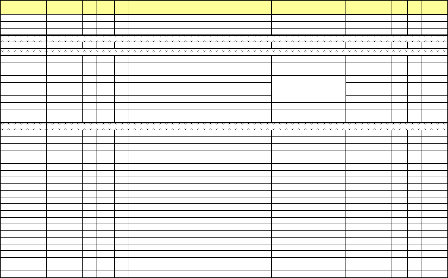
Addr. (hex) Address(4X) Line Pt DNP
Ob
j
Description Range Units Type R/W Notes
2F64H-2F65
H
12133-12134 954 5 30 Block Window Min Interval 1 Overall
W
+32767 W / -32768
W
1/ 65536 W sec F7
R
9
2F66H-2F67
H
12135-12136 954 6 30 Block Window Min Interval 2 Overall VA
R
+32767 VAR / -32768 VA
R
1/ 65536 VAR sec F7
R
9
2F68H-2F69
H
12137-12138 954 7 30 B
l
oc
k
W
i
n
d
ow M
i
n Interva
l
2 Overa
ll
W
+32767 W
/
-32768
W
1
/
65536 W sec F7
R
9
3000H-37FF
H
12289-14336 Custom
i
ze
d
Mo
db
us Rea
di
ng
s
R
3800H-387F
H
14337-14464 1216 0-127 Nexus master database 65535 / 0 F51
R
3800H-387F
H
14337-14464 1217 0-63 Nexus master database 4,294,967,295 / 0 F53
R
3801H-387E
H
14338-14463 1218 0-62 Nexus master database 4,294,967,295 / 0 F53
R
3800H-387F
H
14337-14464 1219 0-31 Nexus master database 18,446,744,073,709,551,615 / 0 F55
R
3801H-387C
H
14338-14461 1220 0-30 Nexus master database 18,446,744,073,709,551,615 / 0 F55
R
3802H-387D
H
14339-14462 1221 0-30 Nexus master database 18,446,744,073,709,551,615 / 0 F55
R
3803H-387E
H
14340-14463 1222 0-30 Nexus master database 18,446,744,073,709,551,615 / 0 F55
R
3880H-3883
H
14465-14468 Nexus master poll time 12/31/9999 23:59:59.99 F3
R
3884H-388B
H
14469-14476 1223 0-127 Nexus master data polling status Bits, bit value 1=data valid F51
R
2
388CH-390B
H
14477-14604 1224 0-127 Nexus master
d
ata po
lli
ng
f
a
il
e
d
count 65535
/
0 1 F51
R
2
3A00H-3A01
H
14849-14850 1200 0 Tenth sec Phase A-E Voltag
e
+32767 V / 0 V 1/ 65536 V sec F7
R
4
3A02H-3A03
H
14851-14852 1200 1 Tenth sec Phase B-E Voltage +32767 V / 0 V 1/ 65536 V sec F7
R
4
3A04H-3A05
H
14853-14854 1200 2 Tenth sec Phase C-E Voltage +32767 V / 0 V 1/ 65536 V sec F7
R
4
3A06H-3A07
H
14855-14856 1200 3 Tenth sec Phase N-E Voltage +32767 V / 0 V 1/ 65536 V sec F7
R
4
3A08H-3A09
H
14857-14858 1201 0 One sec Phase A-E Voltag
e
+32767 V / 0 V 1/ 65536 V sec F7
R
4
3A0AH-3A0B
H
14859-14860 1201 1 One sec Phase B-E Voltage +32767 V / 0 V 1/ 65536 V sec F7
R
4
3A0CH-3A0D
H
14861-14862 1201 2 One sec Phase C-E Voltage +32767 V / 0 V 1/ 65536 V sec F7
R
4
3A0EH-3A0F
H
14863-14864 1201 3 One sec Phase N-E Voltag
e
+32767 V / 0 V 1/ 65536 V sec F7
R
4
3A10H-3A11
H
14865-14866 1202 0 Thermal Average Phase A-E Voltag
e
+32767 V / 0 V 1/ 65536 V sec F7
R
4
3A12H-3A13
H
14867-14868 1202 1 Thermal Average Phase B-E Voltag
e
+32767 V / 0 V 1/ 65536 V sec F7
R
4
3A14H-3A15
H
14869-14870 1202 2 Thermal Average Phase C-E Voltag
e
+32767 V / 0 V 1/ 65536 V sec F7
R
4
3A16H-3A17
H
14871-14872 1202 3 Thermal Average Phase N-E Voltag
e
+32767 V / 0 V 1/ 65536 V sec F7
R
4
3A18H-3A19
H
14873-14874 1203 0 Maximum Thermal Average Phase A-E Voltag
e
+32767 V / 0 V 1/ 65536 V sec F7
R
4
3A1AH-3A1B
H
14875-14876 1203 1 Maximum Thermal Average Phase B-E Voltag
e
+32767 V / 0 V 1/ 65536 V sec F7
R
4
3A1CH-3A1D
H
14877-14878 1203 2 Maximum Thermal Average Phase C-E Voltag
e
+32767 V / 0 V 1/ 65536 V sec F7
R
4
3A1EH-3A1F
H
14879-14880 1203 3 Maximum Thermal Average Phase N-E Voltag
e
+32767 V / 0 V 1/ 65536 V sec F7
R
4
3A20H-3A21
H
14881-14882 1204 0 Minimum Thermal Average Phase A-E Voltag
e
+32767 V / 0 V 1/ 65536 V sec F7
R
4
3A22H-3A23
H
14883-14884 1204 1 Minimum Thermal Average Phase B-E Voltag
e
+32767 V / 0 V 1/ 65536 V sec F7
R
4
3A24H-3A25
H
14885-14886 1204 2 Minimum Thermal Average Phase C-E Voltag
e
+32767 V / 0 V 1/ 65536 V sec F7
R
4
3A26H-3A27
H
14887-14888 1204 3 Minimum Thermal Average Phase N-E Voltag
e
+32767 V / 0 V 1/ 65536 V sec F7
R
4
3A28H-3A2B
H
14889-14892 1205 0 Maximum Thermal Average Phase A-E Voltage Time Stam
p
12/31/9999 23:59:59.99 10 msec F3
R
1
3A2CH-3A2F
H
14893-14896 1205 1 Maximum Thermal Average Phase B-E Voltage Time Stam
p
12/31/9999 23:59:59.99 10 msec F3
R
1
Customized Modbus Block
Nexus Master Polling Data Block
Additional and Vpe Block
e Electro Industries/GaugeTech Doc# E154703 MM-131
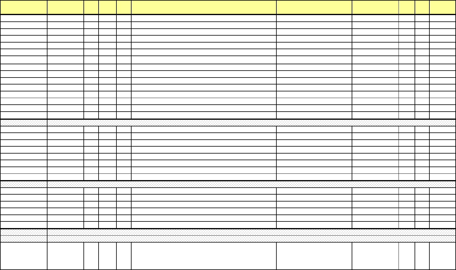
Addr. (hex) Address(4X) Line Pt DNP
Ob
j
Description Range Units Type R/W Notes
3A30H-3A33
H
14897-14900 1205 2 Maximum Thermal Average Phase C-E Voltage Time Stam
p
12/31/9999 23:59:59.99 10 msec F3
R
1
3A34H-3A37
H
14901-14904 1205 3 Maximum Thermal Average Phase N-E Voltage Time Stam
p
12/31/9999 23:59:59.99 10 msec F3
R
1
3A38H-3A3B
H
14905-14908 1206 0 Minimum Thermal Average Phase A-E Voltage Time Stam
p
12/31/9999 23:59:59.99 10 msec F3
R
1
3A3CH-3A3F
H
14909-14912 1206 1 Minimum Thermal Average Phase B-E Voltage Time Stam
p
12/31/9999 23:59:59.99 10 msec F3
R
1
3A40H-3A43
H
14913-14916 1206 2 Minimum Thermal Average Phase C-E Voltage Time Stam
p
12/31/9999 23:59:59.99 10 msec F3
R
1
3A44H-3A47
H
14917-14920 1206 3 Minimum Thermal Average Phase N-E Voltage Time Stam
p
12/31/9999 23:59:59.99 10 msec F3
R
1
3A48H-3A49H 14921-14922 1207 0 Tenth sec Calculated Neutral Current +65536 A2 / 0 A21/65536 A2 sec F5 R 3, 6, 8
3A4AH-3A4B
H
14923-14924 1208 0 Tenth sec residual Voltage +32767 V / 0 V 1/ 65536 V sec F7
R
4
3A4CH-3A4D
H
14925-14926 1209 0 One sec residual Voltage +32767 V / 0 V 1/ 65536 V sec F7
R
4
3A4EH-3A4F
H
14927-14928 1210 0 Thermal average residual voltage +32767 V / 0 V 1/ 65536 V sec F7
R
4
3A50H-3A51
H
14929-14930 1211 0 Maximum Thermal Average residual voltage +32767 V / 0 V 1/ 65536 V sec F7
R
4
3A52H-3A53
H
14931-14932 1212 0 Minimum Thermal Average residual voltage +32767 V / 0 V 1/ 65536 V sec F7
R
4
3A54H-3A57
H
14933-14936 1213 0 Maximum Thermal Average residual Voltage Time Stamp 12/31/9999 23:59:59.99 10 msec F3
R
1
3A58H-3A5B
H
14937-14940 1214 0 Maximum Thermal Average residual Voltage Time Stamp 12/31/9999 23:59:59.99 10 msec F3
R
1
3A5CH-3A5D
H
14941-14942 1215 0 One sec Aux Frequenc
y
3A5EH-3A5F
H
14943-14944 1225 0 Block Window Max Interval 1 Voltage P-
E
+32767 V / 0 V 1/ 65536 V sec F7
R
3A60H-3A61
H
14945-14946 1225 1 Block Window Max Interval 2 Voltage P-
E
+32767 V / 0 V 1/ 65536 V sec F7
R
3A62H-3A63
H
14947-14948 1225 2 Block Window Min Interval 1 Voltage P-
E
+32767 V / 0 V 1/ 65536 V sec F7
R
3A64H-3A65
H
14949-14950 1225 3 Block Window Min Interval 2 Voltage P-
E
+32767 V / 0 V 1/ 65536 V sec F7
R
3A66H-3A69
H
14951-14954 1226 0 Block Window Max Interval 1 Voltage P-E Time Stamp 12/31/9999 23:59:59.99 10 msec F3
R
3A6AH-3A6D
H
14955-14958 1226 1 Block Window Max Interval 2 Voltage P-E Time Stamp 12/31/9999 23:59:59.99 10 msec F3
R
3A6EH-3A71
H
14959-14962 1226 2 Block Window Min Interval 1 Voltage P-E Time Stamp 12/31/9999 23:59:59.99 10 msec F3
R
3A72H-3A75
H
14963-14966 1226 3 B
l
oc
k
W
i
n
d
ow M
i
n Interva
l
2 Vo
l
tage P-E T
i
me Stamp 12
/
31
/
9999 23:59:59.99 10 msec F3
R
4000H-4007
H
16385-16392 Hardware Options (16 bytes)
R
4008H-400B
H
16393-16396 Serial Numbers (8 bytes, binary numbers)
R
400CH-400F
H
16397-16400 Reserve
d
R
4010H-4017
H
16401-16408 OEM Model String
R
4018H-403F
H
16408-16448 Reserve
d
R
4040H-5FFF
H
16449-24576 Un
d
e
fi
ne
d
R
6000H-61FFH 24577-25088
Group Label[0]
Group Label[1]
...
Group Label[127]
Nexus 15xx Master RTU (Function Code 0x03 Only) Group Labels
Enhanced Factory Settings Block
Enhanced Programmable Settings Block 2 (Range: 6000H-7FFFH)
Block Window Max/Min Block, P-E
e Electro Industries/GaugeTech Doc# E154703 MM-132
Addr. (hex) Address(4X) Line Pt DNP
Ob
j
Description Range Units Type R/W Notes
6200H-63FFH 25089-25600
Item Label[0]
Item Label[1]
...
Item Label[127]
6400H-64FFH 25601-25856
Item Descriptor[0]
Item Descriptor[1]
...
Item Descriptor[127]
6500H-65FFH 25857-26112
It
em
Li
m
it[0]
S
e
t
po
i
n
t
1
Item Limit[0] Setpoint 2
Item Limit[1] Setpoint 1
Item Limit[1] Setpoint 2
...
Item Limit[31] Setpoint 1
Item Limit[31] Setpoint 2
6600H-67FF
H
26111-26624 Undefine
d
6800H-6FFF
H
26625-28672 Reserve
d
7000H-707FH 28673-28800
Interval Log 3 Item[0]: Line, Pointe
r
Interval Log 3 Item[1]: Line, Pointer
...
Interval Lo
g
3 Item
[
63
]
: Line
,
Pointer
7080H-70FFH 28801-28928
Interval Log 4 Item[0]: Line, Pointe
r
Interval Log 4 Item[1]: Line, Pointer
...
Interval Lo
g
4 Item
[
63
]
: Line
,
Pointer
7100H-717FH 28929-29056
Interval Log 5 Item[0]: Line, Pointe
r
Interval Log 5 Item[1]: Line, Pointer
...
Interval Lo
g
5 Item
[
63
]
: Line
,
Pointer
7180H-71FFH 29057-29184
Interval Log 6 Item[0]: Line, Pointe
r
Interval Log 6 Item[1]: Line, Pointer
...
Interval Lo
g
6 Item
[
63
]
: Line
,
Pointer
7200H-727FH 29185-29312
Interval Log 7 Item[0]: Line, Pointe
r
Interval Log 7 Item[1]: Line, Pointer
...
Interval Lo
g
7 Item
[
63
]
: Line
,
Pointer
Nexus 15xx Interval Log Settings Block
e Electro Industries/GaugeTech Doc# E154703 MM-133
Addr. (hex) Address(4X) Line Pt DNP
Ob
j
Description Range Units Type R/W Notes
7280H-72FFH 29313-29440
Interval Log 8 Item[0]: Line, Pointe
r
Interval Log 8 Item[1]: Line, Pointer
...
Interval Lo
g
8 Item
[
63
]
: Line
,
Pointer
7300H
H
29441 Interval Log 3 Interva
l
7301H
H
29442 Interval Log 4 Interva
l
7302H
H
29443 Interval Log 3 Record Siz
e
7303H
H
29444 Interval Log 4 Record Siz
e
7304H
H
29445 Interval Log 5 Interva
l
7305H
H
29446 Interval Log 6 Interva
l
7306H
H
29447 Interval Log 5 Record Siz
e
7307H
H
29448 Interval Log 6 Record Siz
e
7308H
H
29449 Interval Log 7 Interva
l
7309H
H
29450 Interval Log 8 Interva
l
730AH
H
29451 Interval Log 7 Record Siz
e
730BH
H
29452 Interval Log 8 Record Siz
e
730CH-748B
H
29453-29836 Reserve
d
748CH-750BH 29837-29964
Event Triggered Log Item[0]: Line, Pointe
r
Event Triggered Log Item[1]: Line, Pointer
...
Event Tri
gg
ered Lo
g
Item
[
63
]
: Line
,
Pointer
750CH-754B
H
29965-30028 Reserve
d
754CH 30029
MSB
Byte[1]: Event Triggered Log Internal Input ID
B
y
te
[
0
]
: Reserve
d
754DH 30030
MSB
Byte[1]: Reserved
Byte[0]: Event Triggered Log Enabled
754EH 30031 Event Triggered Log Recording Spee
d
754FH 30032 Event Triggered Log Recoding Duratio
n
7550H 30033 Event Triggered Log Record Siz
e
7551H 30034 Event Triggered Log Multiple Sequenc
e
7552H-7553
H
30035-30036 Reserve
d
7554H-756B
H
3003730060 Reserve
d
756CH-756F
H
30061-30064 Reserve
d
Waveform Voltage Envolope Wave Shape Threshold
Waveform Current Change of Rate Threshold
Waveform Capture Rules
e Electro Industries/GaugeTech Doc# E154703 MM-134

Addr. (hex) Address(4X) Line Pt DNP
Ob
j
Description Range Units Type R/W Notes
7570H-7571H 30065-30066
Waveform Capture Window Amoun
t
0 = 1 capture
1 = 2 capture
...
65535 = 65536 capture
>65535 = 1 ca
p
ture
7572H-7573
H
30067-30068 Reserve
d
7574H 30069
Waveform samples/cycles @60H
z
0 = 16
1 = 32
2 = 64
3 = 128
4 = 256
5 = 512
6 = 1024
>6= 1024
7575H 30070
MSB
Byte[1]: Waveform Pre Trigger (>=1 <=179)
Byte[0]: Waveform Post Trigger (>=1 <=179
7576H 30071
Waveform Digital Input Triggers (MSB
)
Byte[1]: Undefined
Byte[0]: Bit [7] = Input 8
Bit [6] = Input 7
Bit [5] = Input 6
Bit [4] = Input 5
Bit [3] = Input 4
Bit [2] = Input 3
Bit [1] = Input 2
Bi
t
[0
]
= In
put
1
7577H 30072 Reserve
d
7578H 30073 Voltage A Threshold % of full scale +6553.5% / -6553.5% 0.1%
7579H 30074 Voltage B Threshold % of full scale +6553.5% / -6553.5% 0.1%
757A
H
30075 Voltage C Threshold % of full scale +6553.5% / -6553.5% 0.1%
Waveform Transient
e Electro Industries/GaugeTech Doc# E154703 MM-135
Addr. (hex) Address(4X) Line Pt DNP
Ob
j
Description Range Units Type R/W Notes
757BH 30076
Mode/Enable(MSB)
Bit[15]-Bit[11]: Reserved
Bit[10]: Transien Enable - Channel Vc
Bit[9]: Transien Enable - Channel Vb
Bit[8]: Transien Enable - Channel Va
Bit[7]-Bit[2]: Reserved
Bit[1]: Transient Mode: 0=PH-N, 1=PH-PH
Bit
[
0
]
: Transient Mode: 0=Disabled
,
1=Enabled
757C
H
30077 Number Maximum of Channel
757D
H
30078 Channel 1 Number
757EH 30079 Channel 2 Number
757FH 30080 Channel 3 Number
7580H 30081 Channel 4 Number
7581H 30082 Channel 5 Number
7582H 30083 Channel 6 Number
7583H 30084 Channel 7 Number
7584H 30085 Channel 8 Number
7585H 30086 Channel 9 Number
7586H 30087 Channel 10 Number
7587H 30088 Channel 11 Number
7588H 30089 Channel 12 Number
7589H 30090 Channel 13 Number
758A
H
30091 Channel 14 Number
758B
H
30092 Channel 15 Number
758C
H
30093 Channel 16 Number
758DH-758E
H
30094-30095 Power Quality Enable
758FH 30096
Transient Waveform Trigger (MSB)
Bit[15]-Bit[6]: Reserved
Bit[5]: Transient Waveform Trigger Enable - Channel Vca
Bit[4]: Transient Waveform Trigger Enable - Channel Vbc
Bit[3]: Transient Waveform Trigger Enable - Channel Vab
Bit[2]: Transient Waveform Trigger Enable - Channel Vcn
Bit[1]: Transient Waveform Trigger Enable - Channel Vbn
Bit[0]: Transient Waveform Trigger Enable - Channel Van
0=Enable
,
1=Disable
Waveform Transient Settings
Log Configuration Settings
e Electro Industries/GaugeTech Doc# E154703 MM-136

Addr. (hex) Address(4X) Line Pt DNP
Ob
j
Description Range Units Type R/W Notes
7590H-7591H 30097-30098
Log Mod
e
0 = Maximum Number of 1Mbyte files allowed
>0 Not define
d
7592H-7593
H
30099-30100 System Events Log Siz
e
4,294,967,295 / 0 1 F53 R/
W
7594H-7595
H
30101-30102 Interval Log 1 Log Siz
e
4,294,967,295 / 0 1 F53 R/
W
7596H-7597
H
30103-30104 Interval Log 2 Log Siz
e
4,294,967,295 / 0 1 F53 R/
W
7598H-7599
H
30105-30106 Interval Log 3 Log Siz
e
4,294,967,295 / 0 1 F53 R/
W
759AH-759B
H
30107-30108 Interval Log 4 Log Siz
e
4,294,967,295 / 0 1 F53 R/
W
759CH-759D
H
30109-30110 Interval Log 5 Log Siz
e
4,294,967,295 / 0 1 F53 R/
W
759EH-759F
H
30111-30112 Interval Log 6 Log Siz
e
4,294,967,295 / 0 1 F53 R/
W
75A0H-75A1
H
30113-30114 Interval Log 7 Log Siz
e
4,294,967,295 / 0 1 F53 R/
W
75A2H-75A3
H
30115-30116 Interval Log 8 Log Siz
e
4,294,967,295 / 0 1 F53 R/
W
75A4H-75A5
H
30117-30118 Event Triggered Log Siz
e
4,294,967,295 / 0 1 F53 R/
W
75A6H-75A7
H
30119-30120 Sequence of Event (Limits) Log Siz
e
4,294,967,295 / 0 1 F53 R/
W
75A8H-75A9
H
30121-30122 Digital Input Log Siz
e
4,294,967,295 / 0 1 F53 R/
W
75AAH-75AB
H
30123-30124 Digital Output Log Siz
e
4,294,967,295 / 0 1 F53 R/
W
75ACH-75AD
H
30125-13126 Flicker Log Siz
e
4,294,967,295 / 0 1 F53 R/
W
75AEH-75AF
H
30127-30128 Waveform Log Siz
e
4,294,967,295 / 0 1 F53 R/
W
75B0H-75B1
H
30129-30130 Power Quality Log Siz
e
4,294,967,295 / 0 1 F53 R/
W
75B2H-75B3
H
30131-30132 Transients Log Size 4,294,967,295 / 0 1 F53 R/
W
75B4H-75FF
H
30133-30208 Reserve
d
7600H-7601
H
30209-30210 IP Addres
s
7602H-7603
H
30211-30212 Subnet Mask
7604H-7605
H
30213-30214 Default Gatewa
y
7606H 30215
MSB
Byte[1]: Port 2 Baud Rate
B
y
te
[
0
]
: Gatewa
y
Dela
y
7607H 30216
MSB
Byte[1]: Mode
B
y
te
[
0
]
: Mode
2
7608H-760F
H
30217-30224 Computer Nam
e
7610H-7611
H
30225-30226 DNS Server 1 IP Address
7612H-7613
H
30227-30228 DNS Server 2 IP Address
7614H-7615
H
30229-30230 Server / Service Enable Bits
7616H 30231 Email Port Number
7617H 30232 FTP Port Numbe
r
7618H-7621
H
30233-30242 Reserve
d
Network Card #2 Settings (Part 1 of 2)
Network Card #2 Settings (Part 2 of 2)
e Electro Industries/GaugeTech Doc# E154703 MM-137
Addr. (hex) Address(4X) Line Pt DNP
Ob
j
Description Range Units Type R/W Notes
7622H 30243
Email Mode (MSB)
Bit[15]: 0=authenicantion on; 1=authentication off
Bit
[
14
]
~Bit
[
0
]
= Not define
d
7623H-7663
H
30244-30308 Reserve
d
7664H-7683
H
30309-30340 Email Server IP Address/name
7684H-76A3
H
30341-30372 Administrator Email Address
76A4H-76C3
H
30373-30404 Email Replay Address
76C4H-76E3
H
30405-30436 Email Subject Text
76E4H-76F3
H
30437-30452 Email username
76F4H-7703
H
30453-30468 Email Passwor
d
7704H-7713
H
30469-30484 Username
7714H-7723
H
30485-30500 Passwor
d
7724H-7763
H
30501-30567 Startup Path/Directory
7764H-7783
H
30565-30596 Server IP Address/Nam
e
7784H-7785
H
30597-30598 IP Addres
s
7786H 30599 Update Interval(1=100msec to 65000=6500 seconds
)
7787H 30600
MSB
Byte[1]: Connection Type (0=broadsact, 1=multicast, 2=unicast)
Byte[0]: Options (Bit[0]: 1=Use IP as Producer ID, 0=Use User
Defined)
7788H-7789
H
30601-30602 User Producer I
D
778AH-778B
H
30603-30604 Reserve
d
778CH-778DH 30605-30606
MSB
Byte[3]: Mode(0=disabled, 1=standard settings, 2=user settings,
3>= disabled)
Byte[2]: Bitmap (Bit[7]: TCP Enable, Bit[6]=UDP enable,
Bit[5]: Validate Ports, Bit[4]: UDP Defined Port)
Byte[1]: UDP Address
Byte[0]: Validate IP
778EH 30607 TCP Listen Por
t
778FH 30608 UDP Listen Por
t
7790H-7791
H
30609-30610 Valid IP Address #1
7792H-7793
H
30611-30612 Valid IP Address #2
7794H-7795
H
30613-30614 Valid IP Address #3
7796H-7797
H
30615-30616 Valid IP Address #4
GE Protocol (EGD)
DNP LAN/WAN
Email Client Settings
FTP Client Settings
e Electro Industries/GaugeTech Doc# E154703 MM-138

Addr. (hex) Address(4X) Line Pt DNP
Ob
j
Description Range Units Type R/W Notes
7798H-7799
H
30617-30618 Valid IP Subnet Mask #1
779AH-779B
H
30619-30620 Valid IP Subnet Mask #2
779CH-779D
H
30621-30622 Valid IP Subnet Mask #3
779EH-779F
H
30623-30624 Valid IP Subnet Mask #4
77A0H-77A3
H
30625-30628 Valid TCP Start Ports
77A4H-77A7
H
30629-30632 Valid TCP End Ports
77A8H-77AB
H
30633-30636 Valid UDP Start Ports
77ACH-77AF
H
30637-30640 Valid UDP End Ports
77B0H-77B1
H
30641-30642 Valid Multicast Group Address
77B2
H
30643 Valid UDP Respond Por
t
77B3
H
30644 Device Addres
s
77B4H-77FF
H
30645-30720 Reserve
d
7800H 30721 Phase A-N Voltage Sag Setpoin
t
0% / +65535% 0.01% F10
R
7801H 30722 Phase B-N Voltage Sag Setpoin
t
0% / +65535% 0.01% F10
R
7802H 30723 Phase C-N Voltage Sag Setpoin
t
0% / +65535% 0.01% F10
R
7803H 30724 Phase A-B Voltage Sag Setpoin
t
0% / +65535% 0.01% F10
R
7804H 30725 Phase B-C Voltage Sag Setpoin
t
0% / +65535% 0.01% F10
R
7805H 30726 Phase C-A Voltage Sag Setpoin
t
0% / +65535% 0.01% F10
R
7806H 30727 Phase X-N Voltage Sag Setpoin
t
0% / +65535% 0.01% F10
R
7807H 30728 Phase N-E Voltage Sag Setpoin
t
0% / +65535% 0.01% F10
R
7808H 30729 Phase A-E Voltage Sag Setpoin
t
0% / +65535% 0.01% F10
R
7809H 30730 Phase B-E Voltage Sag Setpoin
t
0% / +65535% 0.01% F10
R
780A
H
30731 Phase C-E Voltage Sag Setpoin
t
0% / +65535% 0.01% F10
R
780B
H
30732 Phase X-E Voltage Sag Setpoin
t
0% / +65535% 0.01% F10
R
780C
H
30733 Phase A-N Voltage Swell Setpoin
t
0% / +65535% 0.01% F10
R
780D
H
30734 Phase B-N Voltage Swell Setpoint 0% / +65535% 0.01% F10
R
780EH 30735 Phase C-N Voltage Swell Setpoint 0% / +65535% 0.01% F10
R
780FH 30736 Phase A-B Voltage Swell Setpoin
t
0% / +65535% 0.01% F10
R
7810H 30737 Phase B-C Voltage Swell Setpoint 0% / +65535% 0.01% F10
R
7811H 30738 Phase C-A Voltage Swell Setpoin
t
0% / +65535% 0.01% F10
R
7812H 30739 Phase X-N Voltage Swell Setpoint 0% / +65535% 0.01% F10
R
7813H 30740 Phase N-E Voltage Swell Setpoint 0% / +65535% 0.01% F10
R
7814H 30741 Phase A-E Voltage Swell Setpoin
t
0% / +65535% 0.01% F10
R
7815H 30742 Phase B-E Voltage Swell Setpoint 0% / +65535% 0.01% F10
R
7816H 30743 Phase C-E Voltage Swell Setpoint 0% / +65535% 0.01% F10
R
7817H 30744 Phase X-E Voltage Swell Setpoint 0% / +65535% 0.01% F10
R
IEC 61000-4-30: Block Settings
Current Boundary Hysteresis
Voltage Boundary Hysteresis
e Electro Industries/GaugeTech Doc# E154703 MM-139

Addr. (hex) Address(4X) Line Pt DNP
Ob
j
Description Range Units Type R/W Notes
7818H 30745 Phase A Current Sag Setpoint 0% / +65535% 0.01% F10
R
7819H 30746 Phase B Current Sag Setpoint 0% / +65535% 0.01% F10
R
781A
H
30747 Phase C Current Sag Setpoint 0% / +65535% 0.01% F10
R
781B
H
30748 Phase X Current Sag Setpoint 0% / +65535% 0.01% F10
R
781C
H
30749 Phase A Current Swell Setpoint 0% / +65535% 0.01% F10
R
781D
H
30750 Phase B Current Swell Setpoint 0% / +65535% 0.01% F10
R
781EH 30751 Phase C Current Swell Setpoint 0% / +65535% 0.01% F10
R
781FH 30752 P
h
ase X Current Swe
ll
Setpo
i
nt 0%
/
+65535% 0.01% F10
R
7820H 30753 Phase A-N Voltage Setpoin
t
0% / +65535% 0.01% F10
R
7821H 30754 Phase B-N Voltage Setpoin
t
0% / +65535% 0.01% F10
R
7822H 30755 Phase C-N Voltage Setpoin
t
0% / +65535% 0.01% F10
R
7823H 30756 Phase A-B Voltage Setpoin
t
0% / +65535% 0.01% F10
R
7824H 30757 Phase B-C Voltage Setpoin
t
0% / +65535% 0.01% F10
R
7825H 30758 Phase C-A Voltage Setpoin
t
0% / +65535% 0.01% F10
R
7826H 30759 Phase X-N Voltage Setpoin
t
0% / +65535% 0.01% F10
R
7827H 30760 Phase N-E Voltage Setpoin
t
0% / +65535% 0.01% F10
R
7828H 30761 Phase A-E Voltage Setpoin
t
0% / +65535% 0.01% F10
R
7829H 30762 Phase B-E Voltage Setpoin
t
0% / +65535% 0.01% F10
R
7829H 30763 Phase C-E Voltage Setpoin
t
0% / +65535% 0.01% F10
R
782B
H
30764 Phase X-E Voltage Setpoin
t
0% / +65535% 0.01% F10
R
782C
H
30765 Phase A-N Voltage Setpoin
t
0% / +65535% 0.01% F10
R
782D
H
30766 Phase B-N Voltage Setpoin
t
0% / +65535% 0.01% F10
R
782EH 30767 Phase C-N Voltage Setpoin
t
0% / +65535% 0.01% F10
R
782FH 30768 Phase A-B Voltage Setpoin
t
0% / +65535% 0.01% F10
R
7830H 30769 Phase B-C Voltage Setpoin
t
0% / +65535% 0.01% F10
R
7831H 30770 Phase C-A Voltage Setpoin
t
0% / +65535% 0.01% F10
R
7832H 30771 Phase X-N Voltage Setpoin
t
0% / +65535% 0.01% F10
R
7833H 30772 Phase N-E Voltage Setpoin
t
0% / +65535% 0.01% F10
R
7834H 30773 Phase A-E Voltage Setpoin
t
0% / +65535% 0.01% F10
R
7835H 30774 Phase B-E Voltage Setpoin
t
0% / +65535% 0.01% F10
R
7836H 30775 Phase C-E Voltage Setpoin
t
0% / +65535% 0.01% F10
R
7837H 30776 Phase X-E Voltage Setpoin
t
0% / +65535% 0.01% F10
R
7838H 30777 Phase A-N Voltag
e
0% / +65535% 0.01% F10
R
7839H 30778 Phase B-N Voltag
e
0% / +65535% 0.01% F10
R
783A
H
30779 Phase C-N Voltag
e
0% / +65535% 0.01% F10
R
783B
H
30780 Phase A-B Voltag
e
0% / +65535% 0.01% F10
R
Voltage Boundary Interruptions
Voltage Boundary Interruptions Hysteresis
Voltage Nominal
e Electro Industries/GaugeTech Doc# E154703 MM-140

Addr. (hex) Address(4X) Line Pt DNP
Ob
j
Description Range Units Type R/W Notes
783C
H
30781 Phase B-C Voltag
e
0% / +65535% 0.01% F10
R
783D
H
30782 Phase C-A Voltag
e
0% / +65535% 0.01% F10
R
783EH-783F
H
30783-30784 Reserve
d
0% / +65535% 0.01% F10
R
7840H 30785 Order #0 0% / +65535% 0.01% F10
R
7841H 30786 Order #1 0% / +65535% 0.01% F10
R
7842H 30787 Order #2 0% / +65535% 0.01% F10
R
7843H 30788 Order #3 0% / +65535% 0.01% F10
R
7844H 30789 Order #4 0% / +65535% 0.01% F10
R
7845H 30790 Order #5 0% / +65535% 0.01% F10
R
7846H 30791 Order #6 0% / +65535% 0.01% F10
R
7847H 30792 Order #7 0% / +65535% 0.01% F10
R
7848H 30793 Order #8 0% / +65535% 0.01% F10
R
7849H 30794 Order #9 0% / +65535% 0.01% F10
R
784A
H
30795 Order #10 0% / +65535% 0.01% F10
R
784B
H
30796 Order #11 0% / +65535% 0.01% F10
R
784C
H
30797 Order #12 0% / +65535% 0.01% F10
R
784D
H
30798 Order #13 0% / +65535% 0.01% F10
R
784EH 30799 Order #14 0% / +65535% 0.01% F10
R
784FH 30800 Order #15 0% / +65535% 0.01% F10
R
7850H 30801 Order #16 0% / +65535% 0.01% F10
R
7851H 30802 Order #17 0% / +65535% 0.01% F10
R
7852H 30803 Order #18 0% / +65535% 0.01% F10
R
7853H 30804 Order #19 0% / +65535% 0.01% F10
R
7854H 30805 Order #20 0% / +65535% 0.01% F10
R
7855H 30806 Order #21 0% / +65535% 0.01% F10
R
7856H 30807 Order #22 0% / +65535% 0.01% F10
R
7857H 30808 Order #23 0% / +65535% 0.01% F10
R
7858H 30809 Order #24 0% / +65535% 0.01% F10
R
7859H 30810 Order #25 0% / +65535% 0.01% F10
R
785A
H
30811 Order #26 0% / +65535% 0.01% F10
R
785B
H
30812 Order #27 0% / +65535% 0.01% F10
R
785C
H
30813 Order #28 0% / +65535% 0.01% F10
R
785D
H
30814 Order #29 0% / +65535% 0.01% F10
R
785EH 30815 Order #30 0% / +65535% 0.01% F10
R
785FH 30816 Order #31 0% / +65535% 0.01% F10
R
7860H 30817 Order #32 0% / +65535% 0.01% F10
R
7861H 30818 Order #33 0% / +65535% 0.01% F10
R
7862H 30819 Order #34 0% / +65535% 0.01% F10
R
Reserved
e Electro Industries/GaugeTech Doc# E154703 MM-141

Addr. (hex) Address(4X) Line Pt DNP
Ob
j
Description Range Units Type R/W Notes
7863H 30820 Order #35 0% / +65535% 0.01% F10
R
7864H 30821 Order #36 0% / +65535% 0.01% F10
R
7865H 30822 Order #37 0% / +65535% 0.01% F10
R
7866H 30823 Order #38 0% / +65535% 0.01% F10
R
7867H 30824 Order #39 0% / +65535% 0.01% F10
R
7868H 30825 Order #40 0% / +65535% 0.01% F10
R
7869H 30826 Order #41 0% / +65535% 0.01% F10
R
786A
H
30827 Order #42 0% / +65535% 0.01% F10
R
786B
H
30828 Order #43 0% / +65535% 0.01% F10
R
786C
H
30829 Order #44 0% / +65535% 0.01% F10
R
786D
H
30830 Order #45 0% / +65535% 0.01% F10
R
786EH 30831 Order #46 0% / +65535% 0.01% F10
R
786FH 30832 Order #47 0% / +65535% 0.01% F10
R
7870H 30833 Order #48 0% / +65535% 0.01% F10
R
7871H 30834 Order #49 0% / +65535% 0.01% F10
R
7872H 30835 Order #50 0% / +65535% 0.01% F10
R
7873H 30836 Order #51 0% / +65535% 0.01% F10
R
7874H 30837 Order #0 0% / +65535% 0.01% F10
R
7875H 30838 Order #1 0% / +65535% 0.01% F10
R
7876H 30839 Order #2 0% / +65535% 0.01% F10
R
7877H 30840 Order #3 0% / +65535% 0.01% F10
R
7878H 30841 Order #4 0% / +65535% 0.01% F10
R
7879H 30842 Order #5 0% / +65535% 0.01% F10
R
787A
H
30843 Order #6 0% / +65535% 0.01% F10
R
787B
H
30844 Order #7 0% / +65535% 0.01% F10
R
787C
H
30845 Order #8 0% / +65535% 0.01% F10
R
787D
H
30846 Order #9 0% / +65535% 0.01% F10
R
787EH 30847 Order #10 0% / +65535% 0.01% F10
R
787FH 30848 Order #11 0% / +65535% 0.01% F10
R
7880H 30849 Order #12 0% / +65535% 0.01% F10
R
7881H 30850 Order #13 0% / +65535% 0.01% F10
R
7882H 30851 Order #14 0% / +65535% 0.01% F10
R
7883H 30852 Order #15 0% / +65535% 0.01% F10
R
7884H 30853 Order #16 0% / +65535% 0.01% F10
R
7885H 30854 Order #17 0% / +65535% 0.01% F10
R
7886H 30855 Order #18 0% / +65535% 0.01% F10
R
7887H 30856 Order #19 0% / +65535% 0.01% F10
R
7888H 30857 Order #20 0% / +65535% 0.01% F10
R
Interharmonic Subgroup Magnitude Threshould
e Electro Industries/GaugeTech Doc# E154703 MM-142

Addr. (hex) Address(4X) Line Pt DNP
Ob
j
Description Range Units Type R/W Notes
7889H 30858 Order #21 0% / +65535% 0.01% F10
R
788A
H
30859 Order #22 0% / +65535% 0.01% F10
R
788B
H
30860 Order #23 0% / +65535% 0.01% F10
R
788C
H
30861 Order #24 0% / +65535% 0.01% F10
R
788D
H
30862 Order #25 0% / +65535% 0.01% F10
R
788EH 30863 Order #26 0% / +65535% 0.01% F10
R
788FH 30864 Order #27 0% / +65535% 0.01% F10
R
7890H 30865 Order #28 0% / +65535% 0.01% F10
R
7891H 30866 Order #29 0% / +65535% 0.01% F10
R
7892H 30867 Order #30 0% / +65535% 0.01% F10
R
7893H 30868 Order #31 0% / +65535% 0.01% F10
R
7894H 30869 Order #32 0% / +65535% 0.01% F10
R
7895H 30870 Order #33 0% / +65535% 0.01% F10
R
7896H 30871 Order #34 0% / +65535% 0.01% F10
R
7897H 30872 Order #35 0% / +65535% 0.01% F10
R
7898H 30873 Order #36 0% / +65535% 0.01% F10
R
7899H 30874 Order #37 0% / +65535% 0.01% F10
R
789A
H
30875 Order #38 0% / +65535% 0.01% F10
R
789B
H
30876 Order #39 0% / +65535% 0.01% F10
R
789C
H
30877 Order #40 0% / +65535% 0.01% F10
R
789D
H
30878 Order #41 0% / +65535% 0.01% F10
R
789EH 30879 Order #42 0% / +65535% 0.01% F10
R
789FH 30880 Order #43 0% / +65535% 0.01% F10
R
78A0
H
30881 Order #44 0% / +65535% 0.01% F10
R
78A1
H
30882 Order #45 0% / +65535% 0.01% F10
R
78A2
H
30883 Order #46 0% / +65535% 0.01% F10
R
78A3
H
30884 Order #47 0% / +65535% 0.01% F10
R
78A4
H
30885 Order #48 0% / +65535% 0.01% F10
R
78A5
H
30886 Order #49 0% / +65535% 0.01% F10
R
78A6
H
30887 Order #50 0% / +65535% 0.01% F10
R
78A7
H
30888 Order #51 0% / +65535% 0.01% F10
R
78A8
H
30889 Order #0 0% / +65535% 0.01% F10
R
78A9
H
30890 Order #1 0% / +65535% 0.01% F10
R
78AA
H
30891 Order #2 0% / +65535% 0.01% F10
R
78AB
H
30892 Order #3 0% / +65535% 0.01% F10
R
78AC
H
30893 Order #4 0% / +65535% 0.01% F10
R
78AD
H
30894 Order #5 0% / +65535% 0.01% F10
R
78AE
H
30895 Order #6 0% / +65535% 0.01% F10
R
Harmonic Group Magnitude Threshould
e Electro Industries/GaugeTech Doc# E154703 MM-143

Addr. (hex) Address(4X) Line Pt DNP
Ob
j
Description Range Units Type R/W Notes
78AF
H
30896 Order #7 0% / +65535% 0.01% F10
R
78B0
H
30897 Order #8 0% / +65535% 0.01% F10
R
78B1
H
30898 Order #9 0% / +65535% 0.01% F10
R
78B2
H
30899 Order #10 0% / +65535% 0.01% F10
R
78B3
H
30900 Order #11 0% / +65535% 0.01% F10
R
78B4
H
30901 Order #12 0% / +65535% 0.01% F10
R
78B5
H
30902 Order #13 0% / +65535% 0.01% F10
R
78B6
H
30903 Order #14 0% / +65535% 0.01% F10
R
78B7
H
30904 Order #15 0% / +65535% 0.01% F10
R
78B8
H
30905 Order #16 0% / +65535% 0.01% F10
R
78B9
H
30906 Order #17 0% / +65535% 0.01% F10
R
78BA
H
30907 Order #18 0% / +65535% 0.01% F10
R
78BB
H
30908 Order #19 0% / +65535% 0.01% F10
R
78BC
H
30909 Order #20 0% / +65535% 0.01% F10
R
78BD
H
30910 Order #21 0% / +65535% 0.01% F10
R
78BE
H
30911 Order #22 0% / +65535% 0.01% F10
R
78BF
H
30912 Order #23 0% / +65535% 0.01% F10
R
78C0
H
30913 Order #24 0% / +65535% 0.01% F10
R
78C1
H
30914 Order #25 0% / +65535% 0.01% F10
R
78C2
H
30915 Order #26 0% / +65535% 0.01% F10
R
78C3
H
30916 Order #27 0% / +65535% 0.01% F10
R
78C4
H
30917 Order #28 0% / +65535% 0.01% F10
R
78C5
H
30918 Order #29 0% / +65535% 0.01% F10
R
78C6
H
30919 Order #30 0% / +65535% 0.01% F10
R
78C7
H
30920 Order #31 0% / +65535% 0.01% F10
R
78C8
H
30921 Order #32 0% / +65535% 0.01% F10
R
78C9
H
30922 Order #33 0% / +65535% 0.01% F10
R
78CA
H
30923 Order #34 0% / +65535% 0.01% F10
R
78CB
H
30924 Order #35 0% / +65535% 0.01% F10
R
78CC
H
30925 Order #36 0% / +65535% 0.01% F10
R
78CD
H
30926 Order #37 0% / +65535% 0.01% F10
R
78CE
H
30927 Order #38 0% / +65535% 0.01% F10
R
78CF
H
30928 Order #39 0% / +65535% 0.01% F10
R
78D0
H
30929 Order #40 0% / +65535% 0.01% F10
R
78D1
H
30930 Order #41 0% / +65535% 0.01% F10
R
78D2
H
30931 Order #42 0% / +65535% 0.01% F10
R
78D3
H
30932 Order #43 0% / +65535% 0.01% F10
R
78D4
H
30933 Order #44 0% / +65535% 0.01% F10
R
78D5
H
30934 Order #45 0% / +65535% 0.01% F10
R
e Electro Industries/GaugeTech Doc# E154703 MM-144

Addr. (hex) Address(4X) Line Pt DNP
Ob
j
Description Range Units Type R/W Notes
78D6
H
30935 Order #46 0% / +65535% 0.01% F10
R
78D7
H
30936 Order #47 0% / +65535% 0.01% F10
R
78D8
H
30937 Order #48 0% / +65535% 0.01% F10
R
78D9
H
30938 Order #49 0% / +65535% 0.01% F10
R
78DA
H
30939 Order #50 0% / +65535% 0.01% F10
R
78DB
H
30940 Order #51 0% / +65535% 0.01% F10
R
78DC
H
30941 Order #0 0% / +65535% 0.01% F10
R
78DD
H
30942 Order #1 0% / +65535% 0.01% F10
R
78DE
H
30943 Order #2 0% / +65535% 0.01% F10
R
78DF
H
30944 Order #3 0% / +65535% 0.01% F10
R
78E0H 30945 Order #4 0% / +65535% 0.01% F10
R
78E1H 30946 Order #5 0% / +65535% 0.01% F10
R
78E2H 30947 Order #6 0% / +65535% 0.01% F10
R
78E3H 30948 Order #7 0% / +65535% 0.01% F10
R
78E4H 30949 Order #8 0% / +65535% 0.01% F10
R
78E5H 30950 Order #9 0% / +65535% 0.01% F10
R
78E6H 30951 Order #10 0% / +65535% 0.01% F10
R
78E7H 30952 Order #11 0% / +65535% 0.01% F10
R
78E8H 30953 Order #12 0% / +65535% 0.01% F10
R
78E9H 30954 Order #13 0% / +65535% 0.01% F10
R
78EA
H
30955 Order #14 0% / +65535% 0.01% F10
R
78EB
H
30956 Order #15 0% / +65535% 0.01% F10
R
78EC
H
30957 Order #16 0% / +65535% 0.01% F10
R
78ED
H
30958 Order #17 0% / +65535% 0.01% F10
R
78EE
H
30959 Order #18 0% / +65535% 0.01% F10
R
78EF
H
30960 Order #19 0% / +65535% 0.01% F10
R
78F0H 30961 Order #20 0% / +65535% 0.01% F10
R
78F1H 30962 Order #21 0% / +65535% 0.01% F10
R
78F2H 30963 Order #22 0% / +65535% 0.01% F10
R
78F3H 30964 Order #23 0% / +65535% 0.01% F10
R
78F4H 30965 Order #24 0% / +65535% 0.01% F10
R
78F5H 30966 Order #25 0% / +65535% 0.01% F10
R
78F6H 30967 Order #26 0% / +65535% 0.01% F10
R
78F7H 30968 Order #27 0% / +65535% 0.01% F10
R
78F8H 30969 Order #28 0% / +65535% 0.01% F10
R
78F9H 30970 Order #29 0% / +65535% 0.01% F10
R
78FA
H
30971 Order #30 0% / +65535% 0.01% F10
R
78FB
H
30972 Order #31 0% / +65535% 0.01% F10
R
Interharmonic Group Magnitude Threshould
e Electro Industries/GaugeTech Doc# E154703 MM-145
Addr. (hex) Address(4X) Line Pt DNP
Ob
j
Description Range Units Type R/W Notes
78FC
H
30973 Order #32 0% / +65535% 0.01% F10
R
78FD
H
30974 Order #33 0% / +65535% 0.01% F10
R
78FE
H
30975 Order #34 0% / +65535% 0.01% F10
R
78FFH 30976 Order #35 0% / +65535% 0.01% F10
R
7900H 30977 Order #36 0% / +65535% 0.01% F10
R
7901H 30978 Order #37 0% / +65535% 0.01% F10
R
7902H 30979 Order #38 0% / +65535% 0.01% F10
R
7903H 30980 Order #39 0% / +65535% 0.01% F10
R
7904H 30981 Order #40 0% / +65535% 0.01% F10
R
7905H 30982 Order #41 0% / +65535% 0.01% F10
R
7906H 30983 Order #42 0% / +65535% 0.01% F10
R
7907H 30984 Order #43 0% / +65535% 0.01% F10
R
7908H 30985 Order #44 0% / +65535% 0.01% F10
R
7909H 30986 Order #45 0% / +65535% 0.01% F10
R
790A
H
30987 Order #46 0% / +65535% 0.01% F10
R
790B
H
30988 Order #47 0% / +65535% 0.01% F10
R
790C
H
30989 Order #48 0% / +65535% 0.01% F10
R
790D
H
30990 Order #49 0% / +65535% 0.01% F10
R
790EH 30991 Order #50 0% / +65535% 0.01% F10
R
790FH 30992 Order #51 0% / +65535% 0.01% F10
R
7910H 30993 Threshold Enable Channel # F108 R
7911H 30994 Mains Signalling Threshold 0% / +65535% 0.01% F10 R
7912H 30995 Mains Signalling Interharmonics Bin Start Number
7913H-791FH 30996-31008 Mains Signalling Interharmonics Bin Start Number
7920H 31009 Phase N-E Voltage Setpoin
t
0.00 / +655.35 Volts
R
7921H 31010 Phase A-E Voltage Setpoin
t
0.00 / +655.35 Volts
R
7922H 31011 Phase B-E Voltage Setpoin
t
0.00 / +655.35 Volts
R
7923H 31012 Phase C-E Voltage Setpoin
t
0.00 / +655.35 Volts
R
7924H 31013
MSB
Byte[1]: Allowed Long Interruption in a Year.
Range from 0 to 100. Values>100 are equal to 100.
Byte[0]: Rapid Voltage Change Data Source
0 = 10/12 Cycles Update RMS
1 = 1 Cycles Update RMS
2~255 = 10/12 C
y
cles U
p
date RMS
R
Overvoltage (Phase to Earth) Threshold
e Electro Industries/GaugeTech Doc# E154703 MM-146

Addr. (hex) Address(4X) Line Pt DNP
Ob
j
Description Range Units Type R/W Notes
7925H 31014
MSB
Byte[1]: Supply Voltage Unbalance Upper Limit.
0 = Less than or equal to 2%
1 = Less than or equal to 3%
2~255 = Less than or equal to 2%
Byte[0]: Voltage Dip Concern Threshold Phase A
see detail on modbus re
g
ister below
R
7926H 31015
MSB
Byte[1]: Voltage Dip Concern Threshold Phase B
Byte[0]: Voltage Dip Concern Threshold Phase C
0 = Greater than or equal to 10%
1 = Greater than or equal to 15%
2 = Greater than or equal to 20%
3 = Greater than or equal to 30%
4 = Greater than or equal to 40%
5 = Greater than or equal to 50%
6 = Greater than or equal to 60%
7 = Greater than or equal to 70%
8 = Greater than or equal to 85%
9
~
255
=
Greater than or equal to 85%
R
7927H 31016
MSB
Byte[1]: First Day of Week
0 = Sunday
1 = Monday
2~255 = Sunday
B
y
te
[
0
]
: Not Define
d
R
7928H 31017 Sliding Reference Usr Sag/Swell Enable for Voltage F77 R
7929H 31018 Sliding Reference Usr Sag/Swell Enable for Current F78 R
Interval Maximum/Minimum/Average
e Electro Industries/GaugeTech Doc# E154703 MM-147

Addr. (hex) Address(4X) Line Pt DNP
Ob
j
Description Range Units Type R/W Notes
792AH 31019
MSB
Byte[1]: Interval
0 = Interval from Interval log 3
1 = Interval from Interval log 4
2 = Interval from Interval log 5
3 = Interval from Interval log 6
4 = Interval from Interval log 7
5 = Interval from Interval log 8
byte[0]: Readings
0 = 1 cycle (DSP2 channel 142)
1 = 10/12 cycle (DSP2 channel 130)
2 = 3 seconds (DSP2 channel 131)
3
=
10 minute (DSP2 channel 131)
R
792BH-7FFF 31021-32768 Not Defined R
8800H-8803
H
34817-34820 TOU Calendar Year 1 Modification Time Stamp 12/31/9999 23:59:59.99 10 msec F3
R
1
8804H 34821 TOU Calendar Year 1 Calendar Year 9999 1 yea
r
F21
R
8805H-8808
H
34822-34825 TOU Calendar Year 2 Modification Time Stamp 12/31/9999 23:59:59.99 10 msec F3
R
1
8809H 34826 TOU Calendar Year 2 Calendar Year 9999 1 yea
r
F21
R
880AH-880D
H
34827-34830 TOU Calendar Year 3 Modification Time Stamp 12/31/9999 23:59:59.99 10 msec F3
R
1
880EH 34831 TOU Calendar Year 3 Calendar Year 9999 1 yea
r
F21
R
880FH-8812
H
34832-34835 TOU Calendar Year 4 Modification Time Stamp 12/31/9999 23:59:59.99 10 msec F3
R
1
8813H 34836 TOU Calendar Year 4 Calendar Year 9999 1 yea
r
F21
R
8814H-8817
H
34837-34840 TOU Calendar Year 5 Modification Time Stamp 12/31/9999 23:59:59.99 10 msec F3
R
1
8818H 34841 TOU Calendar Year 5 Calendar Year 9999 1 yea
r
F21
R
8819H-C
H
34842-34845 TOU Calendar Year 6 Modification Time Stamp 12/31/9999 23:59:59.99 10 msec F3
R
1
881D
H
34846 TOU Calendar Year 6 Calendar Year 9999 1 yea
r
F21
R
881EH-8821
H
34847-34850 TOU Calendar Year 7 Modification Time Stamp 12/31/9999 23:59:59.99 10 msec F3
R
1
8822H 34851 TOU Calendar Year 7 Calendar Year 9999 1 yea
r
F21
R
8823H-8826
H
34852-34855 TOU Calendar Year 8 Modification Time Stamp 12/31/9999 23:59:59.99 10 msec F3
R
1
8827H 34856 TOU Calendar Year 8 Calendar Year 9999 1 yea
r
F21
R
8828H-882B
H
34857-34860 TOU Calendar Year 9 Modification Time Stamp 12/31/9999 23:59:59.99 10 msec F3
R
1
882C
H
34861 TOU Calendar Year 9 Calendar Year 9999 1 yea
r
F21
R
882DH-8830
H
34862-34865 TOU Calendar Year 10 Modification Time Stamp 12/31/9999 23:59:59.99 10 msec F3
R
1
8831H 34866 TOU Calendar Year 10 Calendar Year 9999 1 yea
r
F21
R
8832H-8835
H
34867-34870 TOU Calendar Year 11 Modification Time Stamp 12/31/9999 23:59:59.99 10 msec F3
R
1
8836H 34871 TOU Calendar Year 11 Calendar Year 9999 1 yea
r
F21
R
8837H-883A
H
34872-34875 TOU Calendar Year 12 Modification Time Stamp 12/31/9999 23:59:59.99 10 msec F3
R
1
883B
H
34876 TOU Calendar Year 12 Calendar Year 9999 1 yea
r
F21
R
Time of Use Calendar Header Block
e Electro Industries/GaugeTech Doc# E154703 MM-148

Addr. (hex) Address(4X) Line Pt DNP
Ob
j
Description Range Units Type R/W Notes
883CH-883F
H
34877-34880 TOU Calendar Year 13 Modification Time Stamp 12/31/9999 23:59:59.99 10 msec F3
R
1
8840H 34881 TOU Calendar Year 13 Calendar Year 9999 1 yea
r
F21
R
8841H-8844
H
34882-34885 TOU Calendar Year 14 Modification Time Stamp 12/31/9999 23:59:59.99 10 msec F3
R
1
8845H 34886 TOU Calendar Year 14 Calendar Year 9999 1 yea
r
F21
R
8846H-8849
H
34887-34890 TOU Calendar Year 15 Modification Time Stamp 12/31/9999 23:59:59.99 10 msec F3
R
1
884A
H
34891 TOU Calendar Year 15 Calendar Year 9999 1 yea
r
F21
R
884BH-884E
H
34892-34895 TOU Calendar Year 16 Modification Time Stamp 12/31/9999 23:59:59.99 10 msec F3
R
1
884FH 34896 TOU Calendar Year 16 Calendar Year 9999 1 yea
r
F21
R
8850H-8853
H
34897-34900 TOU Calendar Year 17 Modification Time Stamp 12/31/9999 23:59:59.99 10 msec F3
R
1
8854H 34901 TOU Calendar Year 17 Calendar Year 9999 1 yea
r
F21
R
8855H-8858
H
34902-34905 TOU Calendar Year 18 Modification Time Stamp 12/31/9999 23:59:59.99 10 msec F3
R
1
8859H 34906 TOU Calendar Year 18 Calendar Year 9999 1 yea
r
F21
R
885AH-885D
H
34907-34910 TOU Calendar Year 19 Modification Time Stamp 12/31/9999 23:59:59.99 10 msec F3
R
1
885EH 34911 TOU Calendar Year 19 Calendar Year 9999 1 yea
r
F21
R
885FH-8862
H
34912-34915 TOU Calendar Year 20 Modification Time Stamp 12/31/9999 23:59:59.99 10 msec F3
R
1
8863H 34916 TOU Calendar Year 20 Calendar Year 9999 1 yea
r
F21
R
8864H 34917 TOU Calendar Year Selection F31 R/
W
8865H 34918 TOU Ca
l
en
d
ar Hea
d
er Status
/
Year Se
l
ect
i
on Status F32
R
8866H-8869
H
34919-34922 TOU Calendar Year 1 Modification Time Stamp 12/31/9999 23:59:59.99 10 msec F3
R
1
886A
H
34923 TOU Calendar Year 1 Calendar Year 9999 1 yea
r
F21
R
886B
H
34924 TOU Calendar Year 1 Jan 1 / Jan 2 Profile 15-15 / 0-0 F22
R
886C
H
34925 TOU Calendar Year 1 Jan 3 / Jan 4 Profile 15-15 / 0-0 F22
R
886D
H
34926 TOU Calendar Year 1 Jan 5 / Jan 6 Profile 15-15 / 0-0 F22
R
886EH 34927 TOU Calendar Year 1 Jan 7 / Jan 8 Profile 15-15 / 0-0 F22
R
886FH 34928 TOU Calendar Year 1 Jan 9 / Jan 10 Profile 15-15 / 0-0 F22
R
8870H 34929 TOU Calendar Year 1 Jan 11 / Jan 12 Profile 15-15 / 0-0 F22
R
8871H 34930 TOU Calendar Year 1 Jan 13 / Jan 14 Profile 15-15 / 0-0 F22
R
8872H 34931 TOU Calendar Year 1 Jan 15 / Jan 16 Profile 15-15 / 0-0 F22
R
8873H 34932 TOU Calendar Year 1 Jan 17 / Jan 18 Profile 15-15 / 0-0 F22
R
8874H 34933 TOU Calendar Year 1 Jan 19 / Jan 20 Profile 15-15 / 0-0 F22
R
8875H 34934 TOU Calendar Year 1 Jan 21 / Jan 22 Profile 15-15 / 0-0 F22
R
8876H 34935 TOU Calendar Year 1 Jan 23 / Jan 24 Profile 15-15 / 0-0 F22
R
8877H 34936 TOU Calendar Year 1 Jan 25 / Jan 26 Profile 15-15 / 0-0 F22
R
8878H 34937 TOU Calendar Year 1 Jan 27 / Jan 28 Profile 15-15 / 0-0 F22
R
8879H 34938 TOU Calendar Year 1 Jan 29 / Jan 30 Profile 15-15 / 0-0 F22
R
887A
H
34939 TOU Calendar Year 1 Jan 31 / Feb 1 Profile 15-15 / 0-0 F22
R
887B
H
34940 TOU Calendar Year 1 Feb 2 / Feb 3 Profile 15-15 / 0-0 F22
R
Time of Use Calendar Bloc
k
Time of Use Calendar Window 1
e Electro Industries/GaugeTech Doc# E154703 MM-149

Addr. (hex) Address(4X) Line Pt DNP
Ob
j
Description Range Units Type R/W Notes
887C
H
34941 TOU Calendar Year 1 Feb 4 / Feb 5 Profile 15-15 / 0-0 F22
R
887D
H
34942 TOU Calendar Year 1 Feb 6 / Feb 7 Profile 15-15 / 0-0 F22
R
887EH 34943 TOU Calendar Year 1 Feb 8 / Feb 9 Profile 15-15 / 0-0 F22
R
887FH 34944 TOU Calendar Year 1 Feb 10 / Feb 11 Profile 15-15 / 0-0 F22
R
8880H 34945 TOU Calendar Year 1 Feb 12 / Feb 13 Profile 15-15 / 0-0 F22
R
8881H 34946 TOU Calendar Year 1 Feb 14 / Feb 15 Profile 15-15 / 0-0 F22
R
8882H 34947 TOU Calendar Year 1 Feb 16 / Feb 17 Profile 15-15 / 0-0 F22
R
8883H 34948 TOU Calendar Year 1 Feb 18 / Feb 19 Profile 15-15 / 0-0 F22
R
8884H 34949 TOU Calendar Year 1 Feb 20 / Feb 21 Profile 15-15 / 0-0 F22
R
8885H 34950 TOU Calendar Year 1 Feb 22 / Feb 23 Profile 15-15 / 0-0 F22
R
8886H 34951 TOU Calendar Year 1 Feb 24 / Feb 25 Profile 15-15 / 0-0 F22
R
8887H 34952 TOU Calendar Year 1 Feb 26 / Feb 27 Profile 15-15 / 0-0 F22
R
8888H 34953 TOU Calendar Year 1 Feb 28 / Mar 1 (Feb 28) Profile 15-15 / 0-0 F22
R
8889H 34954 TOU Calendar Year 1 Mar 2 (Mar 1) / Mar 3 (Mar 2) Profile 15-15 / 0-0 F22
R
888A
H
34955 TOU Calendar Year 1 Mar 4 (Mar 3) / Mar 5 (Mar 4) Profile 15-15 / 0-0 F22
R
888B
H
34956 TOU Calendar Year 1 Mar 6 (Mar 5) / Mar 7 (Mar 6) Profile 15-15 / 0-0 F22
R
888C
H
34957 TOU Calendar Year 1 Mar 8 (Mar 7) / Mar 9 (Mar 8) Profile 15-15 / 0-0 F22
R
888DH 34958
TOU Calendar Year 1 Mar 10 (Mar 9) / Mar 11 (Mar 10)
Profile 15-15 / 0-0 F22 R
888EH 34959
TOU Calendar Year 1 Mar 13 (Mar 11) / Mar 13 (Mar 12)
Profile 15-15 / 0-0 F22 R
888FH 34960
TOU Calendar Year 1 Mar 14 (Mar 13) / Mar 15 (Mar 14)
Profile 15-15 / 0-0 F22 R
8890H 34961
TOU Calendar Year 1 Mar 16 (Mar 15) / Mar 17 (Mar 16)
Profile 15-15 / 0-0 F22 R
8891H 34962
TOU Calendar Year 1 Mar 18 (Mar 17) / Mar 19 (Mar 18)
Profile 15-15 / 0-0 F22 R
8892H 34963
TOU Calendar Year 1 Mar 20 (Mar 19) / Mar 21 (Mar 20)
Profile 15-15 / 0-0 F22 R
8893H 34964
TOU Calendar Year 1 Mar 22 (Mar 21) / Mar 23 (Mar 22)
Profile 15-15 / 0-0 F22 R
8894H 34965
TOU Calendar Year 1 Mar 24 (Mar 23) / Mar 25 (Mar 24)
Profile 15-15 / 0-0 F22 R
8895H 34966
TOU Calendar Year 1 Mar 26 (Mar 25) / Mar 27 (Mar 26)
Profile 15-15 / 0-0 F22 R
8896H 34967
TOU Calendar Year 1 Mar 28 (Mar 27) / Mar 29 (Mar 28)
Profile 15-15 / 0-0 F22 R
8897H 34968
TOU Calendar Year 1 Mar 30 (Mar 29) / Mar 31 (Mar 30)
Profile 15-15 / 0-0 F22 R
e Electro Industries/GaugeTech Doc# E154703 MM-150

Addr. (hex) Address(4X) Line Pt DNP
Ob
j
Description Range Units Type R/W Notes
8898H 34969 TOU Calendar Year 1 Apr 1 (Mar 31) / Apr 2 (Apr 1) Profile 15-15 / 0-0 F22
R
8899H 34970 TOU Calendar Year 1 Apr 3 (Apr 2) / Apr 4 (Apr 3) Profile 15-15 / 0-0 F22
R
889A
H
34971 TOU Calendar Year 1 Apr 5 (Apr 4) / Apr 6 (Apr 5) Profile 15-15 / 0-0 F22
R
889B
H
34972 TOU Calendar Year 1 Apr 7 (Apr 6) / Apr 8 (Apr 7) Profile 15-15 / 0-0 F22
R
889C
H
34973 TOU Calendar Year 1 Apr 9 (Apr 8) / Apr 10 (Apr 9) Profile 15-15 / 0-0 F22
R
889DH 34974 TOU Calendar Year 1 Apr 11 (Apr 10) / Apr 12 (Apr 11) Profile 15-15 / 0-0 F22 R
889EH 34975 TOU Calendar Year 1 Apr 13 (Apr 12) / Apr 14 (Apr 13) Profile 15-15 / 0-0 F22 R
889FH 34976 TOU Calendar Year 1 Apr 15 (Apr 14) / Apr 16 (Apr 15) Profile 15-15 / 0-0 F22 R
88A0H 34977 TOU Calendar Year 1 Apr 17 (Apr 16) / Apr 18 (Apr 17) Profile 15-15 / 0-0 F22 R
88A1H 34978 TOU Calendar Year 1 Apr 19 (Apr 18) / Apr 20 (Apr 19) Profile 15-15 / 0-0 F22 R
88A2H 34979 TOU Calendar Year 1 Apr 21 (Apr 20) / Apr 22 (Apr 21) Profile 15-15 / 0-0 F22 R
88A3H 34980 TOU Calendar Year 1 Apr 23 (Apr 22) / Apr 24 (Apr 23) Profile 15-15 / 0-0 F22 R
88A4H 34981 TOU Calendar Year 1 Apr 25 (Apr 24) / Apr 26 (Apr 25) Profile 15-15 / 0-0 F22 R
88A5H 34982 TOU Calendar Year 1 Apr 27 (Apr 26) / Apr 28 (Apr 27) Profile 15-15 / 0-0 F22 R
88A6H 34983 TOU Calendar Year 1 Apr 29 (Apr 28) / Apr 30 (Apr 29) Profile 15-15 / 0-0 F22 R
88A7
H
34984 TOU Calendar Year 1 May 1 (Apr 30) / May 2 (May 1) Profile 15-15 / 0-0 F22
R
88A8
H
34985 TOU Calendar Year 1 May 3 (May 2) / May 4 (May 3) Profile 15-15 / 0-0 F22
R
88A9
H
34986 TOU Calendar Year 1 May 5 (May 4) / May 6 (May 5) Profile 15-15 / 0-0 F22
R
88AA
H
34987 TOU Calendar Year 1 May 7 (May 6) / May 8 (May 7) Profile 15-15 / 0-0 F22
R
88ABH 34988 TOU Calendar Year 1 May 9 (May 8) / May 10 (May 9) Profile 15-15 / 0-0 F22 R
88ACH 34989
TOU Calendar Year 1 May 11 (May 10) / May 12 (May 11)
Profile 15-15 / 0-0 F22 R
88ADH 34990
TOU Calendar Year 1 May 13 (May 12) / May 14 (May 13)
Profile 15-15 / 0-0 F22 R
88AEH 34991
TOU Calendar Year 1 May 15 (May 14) / May 16 (May 15)
Profile 15-15 / 0-0 F22 R
88AFH 34992
TOU Calendar Year 1 May 17 (May 16) / May 18 (May 17)
Profile 15-15 / 0-0 F22 R
e Electro Industries/GaugeTech Doc# E154703 MM-151

Addr. (hex) Address(4X) Line Pt DNP
Ob
j
Description Range Units Type R/W Notes
88B0H 34993
TOU Calendar Year 1 May 19 (May 18) / May 20 (May 19)
Profile 15-15 / 0-0 F22 R
88B1H 34994
TOU Calendar Year 1 May 21 (May 20) / May 22 (May 21)
Profile 15-15 / 0-0 F22 R
88B2H 34995
TOU Calendar Year 1 May 23 (May 22) / May 24 (May 23)
Profile 15-15 / 0-0 F22 R
88B3H 34996
TOU Calendar Year 1 May 25 (May 24) / May 26 (May 25)
Profile 15-15 / 0-0 F22 R
88B4H 34997
TOU Calendar Year 1 May 27 (May 26) / May 28 (May 27)
Profile 15-15 / 0-0 F22 R
88B5H 34998
TOU Calendar Year 1 May 29 (May 28) / May 30 (May 29)
Profile 15-15 / 0-0 F22 R
88B6H 34999
TOU Calendar Year 1 May 31 (May 30) / Jun 1 (May 31)
Profile 15-15 / 0-0 F22 R
88B7
H
35000 TOU Calendar Year 1 Jun 2 (Jun 1) / Jun 3 (Jun 2) Profile 15-15 / 0-0 F22
R
88B8
H
35001 TOU Calendar Year 1 Jun 4 (Jun 3) / Jun 5 (Jun 4) Profile 15-15 / 0-0 F22
R
88B9
H
35002 TOU Calendar Year 1 Jun 6 (Jun 5) / Jun 7 (Jun 6) Profile 15-15 / 0-0 F22
R
88BA
H
35003 TOU Calendar Year 1 Jun 8 (Jun 7) / Jun 9 (Jun 8) Profile 15-15 / 0-0 F22
R
88BB
H
35004 TOU Calendar Year 1 Jun 10 (Jun 9) / Jun 11 (Jun 10) Profile 15-15 / 0-0 F22
R
88BC
H
35005 TOU Calendar Year 1 Jun 13 (Jun 11) / Jun 13 (Jun 12) Profile 15-15 / 0-0 F22
R
88BD
H
35006 TOU Calendar Year 1 Jun 14 (Jun 13) / Jun 15 (Jun 14) Profile 15-15 / 0-0 F22
R
88BE
H
35007 TOU Calendar Year 1 Jun 16 (Jun 15) / Jun 17 (Jun 16) Profile 15-15 / 0-0 F22
R
88BF
H
35008 TOU Calendar Year 1 Jun 18 (Jun 17) / Jun 19 (Jun 18) Profile 15-15 / 0-0 F22
R
88C0
H
35009 TOU Calendar Year 1 Jun 20 (Jun 19) / Jun 21 (Jun 20) Profile 15-15 / 0-0 F22
R
88C1
H
35010 TOU Calendar Year 1 Jun 22 (Jun 21) / Jun 23 (Jun 22) Profile 15-15 / 0-0 F22
R
88C2
H
35011 TOU Calendar Year 1 Jun 24 (Jun 23) / Jun 25 (Jun 24) Profile 15-15 / 0-0 F22
R
88C3
H
35012 TOU Calendar Year 1 Jun 26 (Jun 25) / Jun 27 (Jun 26) Profile 15-15 / 0-0 F22
R
88C4
H
35013 TOU Calendar Year 1 Jun 28 (Jun 27) / Jun 29 (Jun 28) Profile 15-15 / 0-0 F22
R
88C5
H
35014 TOU Calendar Year 1 Jun 30 (Jun 29) / Jul 1 (Jun 30) Profile 15-15 / 0-0 F22
R
88C6
H
35015 TOU Calendar Year 1 Jul 2 (Jul 1) / Jul 3 (Jul 2) Profile 15-15 / 0-0 F22
R
88C7
H
35016 TOU Calendar Year 1 Jul 4 (Jul 3) / Jul 5 (Jul 4) Profile 15-15 / 0-0 F22
R
88C8
H
35017 TOU Calendar Year 1 Jul 6 (Jul 5) / Jul 7 (Jul 6) Profile 15-15 / 0-0 F22
R
88C9
H
35018 TOU Calendar Year 1 Jul 8 (Jul 7) / Jul 9 (Jul 8) Profile 15-15 / 0-0 F22
R
88CA
H
35019 TOU Calendar Year 1 Jul 10 (Jul 9) / Jul 11 (Jul 10) Profile 15-15 / 0-0 F22
R
88CB
H
35020 TOU Calendar Year 1 Jul 13 (Jul 11) / Jul 13 (Jul 12) Profile 15-15 / 0-0 F22
R
88CC
H
35021 TOU Calendar Year 1 Jul 14 (Jul 13) / Jul 15 (Jul 14) Profile 15-15 / 0-0 F22
R
88CD
H
35022 TOU Calendar Year 1 Jul 16 (Jul 15) / Jul 17 (Jul 16) Profile 15-15 / 0-0 F22
R
88CE
H
35023 TOU Calendar Year 1 Jul 18 (Jul 17) / Jul 19 (Jul 18) Profile 15-15 / 0-0 F22
R
88CF
H
35024 TOU Calendar Year 1 Jul 20 (Jul 19) / Jul 21 (Jul 20) Profile 15-15 / 0-0 F22
R
e Electro Industries/GaugeTech Doc# E154703 MM-152

Addr. (hex) Address(4X) Line Pt DNP
Ob
j
Description Range Units Type R/W Notes
88D0
H
35025 TOU Calendar Year 1 Jul 22 (Jul 21) / Jul 23 (Jul 22) Profile 15-15 / 0-0 F22
R
88D1
H
35026 TOU Calendar Year 1 Jul 24 (Jul 23) / Jul 25 (Jul 24) Profile 15-15 / 0-0 F22
R
88D2
H
35027 TOU Calendar Year 1 Jul 26 (Jul 25) / Jul 27 (Jul 26) Profile 15-15 / 0-0 F22
R
88D3
H
35028 TOU Calendar Year 1 Jul 28 (Jul 27) / Jul 29 (Jul 28) Profile 15-15 / 0-0 F22
R
88D4
H
35029 TOU Calendar Year 1 Jul 30 (Jul 29) / Jul 31 (Jul 30) Profile 15-15 / 0-0 F22
R
88D5
H
35030 TOU Calendar Year 1 Aug 1 (Jul 31) / Aug 2 (Aug 1) Profile 15-15 / 0-0 F22
R
88D6
H
35031 TOU Calendar Year 1 Aug 3 (Aug 2) / Aug 4 (Aug 3) Profil
e
15-15 / 0-0 F22
R
88D7
H
35032 TOU Calendar Year 1 Aug 5 (Aug 4) / Aug 6 (Aug 5) Profil
e
15-15 / 0-0 F22
R
88D8
H
35033 TOU Calendar Year 1 Aug 7 (Aug 6) / Aug 8 (Aug 7) Profil
e
15-15 / 0-0 F22
R
88D9
H
35034 TOU Calendar Year 1 Aug 9 (Aug 8) / Aug 10 (Aug 9) Profil
e
15-15 / 0-0 F22
R
88DAH 35035
TOU Calendar Year 1 Aug 11 (Aug 10) / Aug 12 (Aug 11)
Profile 15-15 / 0-0 F22 R
88DBH 35036
TOU Calendar Year 1 Aug 13 (Aug 12) / Aug 14 (Aug 13)
Profile 15-15 / 0-0 F22 R
88DCH 35037
TOU Calendar Year 1 Aug 15 (Aug 14) / Aug 16 (Aug 15)
Profile 15-15 / 0-0 F22 R
88DDH 35038
TOU Calendar Year 1 Aug 17 (Aug 16) / Aug 18 (Aug 17)
Profile 15-15 / 0-0 F22 R
88DEH 35039
TOU Calendar Year 1 Aug 19 (Aug 18) / Aug 20 (Aug 19)
Profile 15-15 / 0-0 F22 R
88DFH 35040
TOU Calendar Year 1 Aug 21 (Aug 20) / Aug 22 (Aug 21)
Profile 15-15 / 0-0 F22 R
88E0H 35041
TOU Calendar Year 1 Aug 23 (Aug 22) / Aug 24 (Aug 23)
Profile 15-15 / 0-0 F22 R
88E1H 35042
TOU Calendar Year 1 Aug 25 (Aug 24) / Aug 26 (Aug 25)
Profile 15-15 / 0-0 F22 R
88E2H 35043
TOU Calendar Year 1 Aug 27 (Aug 26) / Aug 28 (Aug 27)
Profile 15-15 / 0-0 F22 R
88E3H 35044
TOU
C
a
l
en
d
ar
Y
ear
1
A
ug
29
(A
ug
28)
/
A
ug
30
(A
ug
29)
Profile 15-15 / 0-0 F22 R
88E4H 35045 TOU Calendar Year 1 Aug 31 (Aug 30) / Sep 1 (Aug 31) Profile 15-15 / 0-0 F22 R
88E5H 35046 TOU Calendar Year 1 Sep 2 (Sep 1) / Sep 3 (Sep 2) Profile 15-15 / 0-0 F22
R
88E6H 35047 TOU Calendar Year 1 Sep 4 (Sep 3) / Sep 5 (Sep 4) Profile 15-15 / 0-0 F22
R
88E7H 35048 TOU Calendar Year 1 Sep 6 (Sep 5) / Sep 7 (Sep 6) Profile 15-15 / 0-0 F22
R
88E8H 35049 TOU Calendar Year 1 Sep 8 (Sep 7) / Sep 9 (Sep 8) Profile 15-15 / 0-0 F22
R
88E9H 35050 TOU Calendar Year 1 Sep 10 (Sep 9) / Sep 11 (Sep 10) Profile 15-15 / 0-0 F22
R
Time of Use Calendar Window 2
e Electro Industries/GaugeTech Doc# E154703 MM-153

Addr. (hex) Address(4X) Line Pt DNP
Ob
j
Description Range Units Type R/W Notes
88EAH 35051 TOU Calendar Year 1 Sep 13 (Sep 11) / Sep 13 (Sep 12) Profile 15-15 / 0-0 F22 R
88EBH 35052 TOU Calendar Year 1 Sep 14 (Sep 13) / Sep 15 (Sep 14) Profile 15-15 / 0-0 F22 R
88ECH 35053 TOU Calendar Year 1 Sep 16 (Sep 15) / Sep 17 (Sep 16) Profile 15-15 / 0-0 F22 R
88EDH 35054 TOU Calendar Year 1 Sep 18 (Sep 17) / Sep 19 (Sep 18) Profile 15-15 / 0-0 F22 R
88EEH 35055 TOU Calendar Year 1 Sep 20 (Sep 19) / Sep 21 (Sep 20) Profile 15-15 / 0-0 F22 R
88EFH 35056 TOU Calendar Year 1 Sep 22 (Sep 21) / Sep 23 (Sep 22) Profile 15-15 / 0-0 F22 R
88F0H 35057 TOU Calendar Year 1 Sep 24 (Sep 23) / Sep 25 (Sep 24) Profile 15-15 / 0-0 F22 R
88F1H 35058 TOU Calendar Year 1 Sep 26 (Sep 25) / Sep 27 (Sep 26) Profile 15-15 / 0-0 F22 R
88F2H 35059 TOU Calendar Year 1 Sep 28 (Sep 27) / Sep 29 (Sep 28) Profile 15-15 / 0-0 F22 R
88F3H 35060 TOU Calendar Year 1 Sep 30 (Sep 29) / Oct 1 (Sep 30) Profile 15-15 / 0-0 F22
R
88F4H 35061 TOU Calendar Year 1 Oct 2 (Oct 1) / Oct 3 (Oct 2) Profile 15-15 / 0-0 F22
R
88F5H 35062 TOU Calendar Year 1 Oct 4 (Oct 3) / Oct 5 (Oct 4) Profile 15-15 / 0-0 F22
R
88F6H 35063 TOU Calendar Year 1 Oct 6 (Oct 5) / Oct 7 (Oct 6) Profile 15-15 / 0-0 F22
R
88F7H 35064 TOU Calendar Year 1 Oct 8 (Oct 7) / Oct 9 (Oct 8) Profile 15-15 / 0-0 F22
R
88F8H 35065 TOU Calendar Year 1 Oct 10 (Oct 9) / Oct 11 (Oct 10) Profile 15-15 / 0-0 F22
R
88F9H 35066 TOU Calendar Year 1 Oct 13 (Oct 11) / Oct 13 (Oct 12) Profile 15-15 / 0-0 F22 R
88FAH 35067 TOU Calendar Year 1 Oct 14 (Oct 13) / Oct 15 (Oct 14) Profile 15-15 / 0-0 F22 R
88FBH 35068 TOU Calendar Year 1 Oct 16 (Oct 15) / Oct 17 (Oct 16) Profile 15-15 / 0-0 F22 R
88FCH 35069 TOU Calendar Year 1 Oct 18 (Oct 17) / Oct 19 (Oct 18) Profile 15-15 / 0-0 F22 R
88FDH 35070 TOU Calendar Year 1 Oct 20 (Oct 19) / Oct 21 (Oct 20) Profile 15-15 / 0-0 F22 R
88FEH 35071 TOU Calendar Year 1 Oct 22 (Oct 21) / Oct 23 (Oct 22) Profile 15-15 / 0-0 F22 R
88FFH 35072 TOU Calendar Year 1 Oct 24 (Oct 23) / Oct 25 (Oct 24) Profile 15-15 / 0-0 F22 R
e Electro Industries/GaugeTech Doc# E154703 MM-154

Addr. (hex) Address(4X) Line Pt DNP
Ob
j
Description Range Units Type R/W Notes
8900H 35073 TOU Calendar Year 1 Oct 26 (Oct 25) / Oct 27 (Oct 26) Profile 15-15 / 0-0 F22 R
8901H 35074 TOU Calendar Year 1 Oct 28 (Oct 27) / Oct 29 (Oct 28) Profile 15-15 / 0-0 F22 R
8902H 35075 TOU Calendar Year 1 Oct 30 (Oct 29) / Oct 31 (Oct 30) Profile 15-15 / 0-0 F22 R
8903H 35076 TOU Calendar Year 1 Nov 1 (Oct 31) / Nov 2 (Nov 1) Profile 15-15 / 0-0 F22
R
8904H 35077 TOU Calendar Year 1 Nov 3 (Nov 2) / Nov 4 (Nov 3) Profil
e
15-15 / 0-0 F22
R
8905H 35078 TOU Calendar Year 1 Nov 5 (Nov 4) / Nov 6 (Nov 5) Profil
e
15-15 / 0-0 F22
R
8906H 35079 TOU Calendar Year 1 Nov 7 (Nov 6) / Nov 8 (Nov 7) Profil
e
15-15 / 0-0 F22
R
8907H 35080 TOU Calendar Year 1 Nov 9 (Nov 8) / Nov 10 (Nov 9) Profil
e
15-15 / 0-0 F22
R
8908H 35081
TOU Calendar Year 1 Nov 11 (Nov 10) / Nov 12 (Nov 11)
Profile 15-15 / 0-0 F22 R
8909H 35082
TOU Calendar Year 1 Nov 13 (Nov 12) / Nov 14 (Nov 13)
Profile 15-15 / 0-0 F22 R
890AH 35083
TOU Calendar Year 1 Nov 15 (Nov 14) / Nov 16 (Nov 15)
Profile 15-15 / 0-0 F22 R
890BH 35084
TOU Calendar Year 1 Nov 17 (Nov 16) / Nov 18 (Nov 17)
Profile 15-15 / 0-0 F22 R
890CH 35085
TOU Calendar Year 1 Nov 19 (Nov 18) / Nov 20 (Nov 19)
Profile 15-15 / 0-0 F22 R
890DH 35086
TOU Calendar Year 1 Nov 21 (Nov 20) / Nov 22 (Nov 21)
Profile 15-15 / 0-0 F22 R
890EH 35087
TOU Calendar Year 1 Nov 23 (Nov 22) / Nov 24 (Nov 23)
Profile 15-15 / 0-0 F22 R
890FH 35088
TOU Calendar Year 1 Nov 25 (Nov 24) / Nov 26 (Nov 25)
Profile 15-15 / 0-0 F22 R
8910H 35089
TOU Calendar Year 1 Nov 27 (Nov 26) / Nov 28 (Nov 27)
Profile 15-15 / 0-0 F22 R
8911H 35090
TOU Calendar Year 1 Nov 29 (Nov 28) / Nov 30 (Nov 29)
Profile 15-15 / 0-0 F22 R
8912H 35091 TOU Calendar Year 1 Dec 1 (Nov 31) / Dec 2 (Dec 1) Profile 15-15 / 0-0 F22
R
8913H 35092 TOU Calendar Year 1 Dec 3 (Dec 2) / Dec 4 (Dec 3) Profile 15-15 / 0-0 F22
R
8914H 35093 TOU Calendar Year 1 Dec 5 (Dec 4) / Dec 6 (Dec 5) Profile 15-15 / 0-0 F22
R
8915H 35094 TOU Calendar Year 1 Dec 7 (Dec 6) / Dec 8 (Dec 7) Profile 15-15 / 0-0 F22
R
8916H 35095 TOU Calendar Year 1 Dec 9 (Dec 8) / Dec 10 (Dec 9) Profile 15-15 / 0-0 F22
R
8917H 35096
TOU Calendar Year 1 Dec 11 (Dec 10) / Dec 12 (Dec 11)
Profile 15-15 / 0-0 F22 R
e Electro Industries/GaugeTech Doc# E154703 MM-155

Addr. (hex) Address(4X) Line Pt DNP
Ob
j
Description Range Units Type R/W Notes
8918H 35097
TOU Calendar Year 1 Dec 13 (Dec 12) / Dec 14 (Dec 13)
Profile 15-15 / 0-0 F22 R
8919H 35098
TOU Calendar Year 1 Dec 15 (Dec 14) / Dec 16 (Dec 15)
Profile 15-15 / 0-0 F22 R
891AH 35099
TOU Calendar Year 1 Dec 17 (Dec 16) / Dec 18 (Dec 17)
Profile 15-15 / 0-0 F22 R
891BH 35100
TOU Calendar Year 1 Dec 19 (Dec 18) / Dec 20 (Dec 19)
Profile 15-15 / 0-0 F22 R
891CH 35101
TOU Calendar Year 1 Dec 21 (Dec 20) / Dec 22 (Dec 21)
Profile 15-15 / 0-0 F22 R
891DH 35102
TOU Calendar Year 1 Dec 23 (Dec 22) / Dec 24 (Dec 23)
Profile 15-15 / 0-0 F22 R
891EH 35103
TOU Calendar Year 1 Dec 25 (Dec 24) / Dec 26 (Dec 25)
Profile 15-15 / 0-0 F22 R
891FH 35104
TOU Calendar Year 1 Dec 27 (Dec 26) / Dec 28 (Dec 27)
Profile 15-15 / 0-0 F22 R
8920H 35105
TOU Calendar Year 1 Dec 29 (Dec 28) / Dec 30 (Dec 29)
Profile 15-15 / 0-0 F22 R
8921H 35106 TOU Calendar Year 1 Dec 31 (Dec 30) / (Dec 31) Profile 15-15 / 0-0 F22
R
8922H 35107 TOU Calendar Year 1 Profile 1 Status F23
R
8923H 35108 TOU Calendar Year 1 Profile 1 Register for 00:00, 00:15, 00:30 7-7-7-7 / 0-0-0-
0
F24
R
8924H 35109 TOU Calendar Year 1 Profile 1 Register for 01:00, 01:15, 01:30 7-7-7-7 / 0-0-0-
0
F24
R
8925H 35110 TOU Calendar Year 1 Profile 1 Register for 02:00, 02:15, 02:30 7-7-7-7 / 0-0-0-
0
F24
R
8926H 35111 TOU Calendar Year 1 Profile 1 Register for 03:00, 03:15, 03:30 7-7-7-7 / 0-0-0-
0
F24
R
8927H 35112 TOU Calendar Year 1 Profile 1 Register for 04:00, 04:15, 04:30 7-7-7-7 / 0-0-0-
0
F24
R
8928H 35113 & 05:45 7-7-7-7 / 0-0-0-0 F24 R
8929H 35114 TOU Calendar Year 1 Profile 1 Register for 06:00, 06:15, 06:30 7-7-7-7 / 0-0-0-
0
F24
R
892A
H
35115 TOU Calendar Year 1 Profile 1 Register for 07:00, 07:15, 07:30 7-7-7-7 / 0-0-0-
0
F24
R
892B
H
35116 TOU Calendar Year 1 Profile 1 Register for 08:00, 08:15, 08:30 7-7-7-7 / 0-0-0-
0
F24
R
892C
H
35117 TOU Calendar Year 1 Profile 1 Register for 09:00, 09:15, 09:30 7-7-7-7 / 0-0-0-
0
F24
R
892D
H
35118 TOU Calendar Year 1 Profile 1 Register for 10:00, 10:15, 10:30 7-7-7-7 / 0-0-0-
0
F24
R
892EH 35119 TOU Calendar Year 1 Profile 1 Register for 11:00, 11:15, 11:30 7-7-7-7 / 0-0-0-
0
F24
R
892FH 35120 TOU Calendar Year 1 Profile 1 Register for 12:00, 12:15, 12:30 7-7-7-7 / 0-0-0-
0
F24
R
8930H 35121 TOU Calendar Year 1 Profile 1 Register for 13:00, 13:15, 13:30 7-7-7-7 / 0-0-0-
0
F24
R
8931H 35122 TOU Calendar Year 1 Profile 1 Register for 14:00, 14:15, 14:30 7-7-7-7 / 0-0-0-
0
F24
R
8932H 35123 TOU Calendar Year 1 Profile 1 Register for 15:00, 15:15, 15:30 7-7-7-7 / 0-0-0-
0
F24
R
8933H 35124 TOU Calendar Year 1 Profile 1 Register for 16:00, 16:15, 16:30 7-7-7-7 / 0-0-0-
0
F24
R
8934H 35125 TOU Calendar Year 1 Profile 1 Register for 17:00, 17:15, 17:30 7-7-7-7 / 0-0-0-
0
F24
R
8935H 35126 TOU Calendar Year 1 Profile 1 Register for 18:00, 18:15, 18:30 7-7-7-7 / 0-0-0-
0
F24
R
e Electro Industries/GaugeTech Doc# E154703 MM-156

Addr. (hex) Address(4X) Line Pt DNP
Ob
j
Description Range Units Type R/W Notes
8936H 35127 TOU Calendar Year 1 Profile 1 Register for 19:00, 19:15, 19:30 7-7-7-7 / 0-0-0-
0
F24
R
8937H 35128 TOU Calendar Year 1 Profile 1 Register for 20:00, 20:15, 20:30 7-7-7-7 / 0-0-0-
0
F24
R
8938H 35129 TOU Calendar Year 1 Profile 1 Register for 21:00, 21:15, 21:30 7-7-7-7 / 0-0-0-
0
F24
R
8939H 35130 TOU Calendar Year 1 Profile 1 Register for 22:00, 22:15, 22:30 7-7-7-7 / 0-0-0-
0
F24
R
893A
H
35131 TOU Calendar Year 1 Profile 1 Register for 23:00, 23:15, 23:30 7-7-7-7 / 0-0-0-
0
F24
R
893B
H
35132 TOU Calendar Year 1 Profile 2 Status F23
R
893C
H
35133 TOU Calendar Year 1 Profile 2 Register for 00:00, 00:15, 00:30 7-7-7-7 / 0-0-0-
0
F24
R
893D
H
35134 TOU Calendar Year 1 Profile 2 Register for 01:00, 01:15, 01:30 7-7-7-7 / 0-0-0-
0
F24
R
893EH 35135 TOU Calendar Year 1 Profile 2 Register for 02:00, 02:15, 02:30 7-7-7-7 / 0-0-0-
0
F24
R
893FH 35136 TOU Calendar Year 1 Profile 2 Register for 03:00, 03:15, 03:30 7-7-7-7 / 0-0-0-
0
F24
R
8940H 35137 TOU Calendar Year 1 Profile 2 Register for 04:00, 04:15, 04:30 7-7-7-7 / 0-0-0-
0
F24
R
8941H 35138 TOU Calendar Year 1 Profile 2 Register for 05:00, 05:15, 05:30 7-7-7-7 / 0-0-0-
0
F24
R
8942H 35139 TOU Calendar Year 1 Profile 2 Register for 06:00, 06:15, 06:30 7-7-7-7 / 0-0-0-
0
F24
R
8943H 35140 TOU Calendar Year 1 Profile 2 Register for 07:00, 07:15, 07:30 7-7-7-7 / 0-0-0-
0
F24
R
8944H 35141 TOU Calendar Year 1 Profile 2 Register for 08:00, 08:15, 08:30 7-7-7-7 / 0-0-0-
0
F24
R
8945H 35142 TOU Calendar Year 1 Profile 2 Register for 09:00, 09:15, 09:30 7-7-7-7 / 0-0-0-
0
F24
R
8946H 35143 TOU Calendar Year 1 Profile 2 Register for 10:00, 10:15, 10:30 7-7-7-7 / 0-0-0-
0
F24
R
8947H 35144 TOU Calendar Year 1 Profile 2 Register for 11:00, 11:15, 11:30 7-7-7-7 / 0-0-0-
0
F24
R
8948H 35145 TOU Calendar Year 1 Profile 2 Register for 12:00, 12:15, 12:30 7-7-7-7 / 0-0-0-
0
F24
R
8949H 35146 TOU Calendar Year 1 Profile 2 Register for 13:00, 13:15, 13:30 7-7-7-7 / 0-0-0-
0
F24
R
894A
H
35147 TOU Calendar Year 1 Profile 2 Register for 14:00, 14:15, 14:30 7-7-7-7 / 0-0-0-
0
F24
R
894B
H
35148 TOU Calendar Year 1 Profile 2 Register for 15:00, 15:15, 15:30 7-7-7-7 / 0-0-0-
0
F24
R
894C
H
35149 TOU Calendar Year 1 Profile 2 Register for 16:00, 16:15, 16:30 7-7-7-7 / 0-0-0-
0
F24
R
894D
H
35150 TOU Calendar Year 1 Profile 2 Register for 17:00, 17:15, 17:30 7-7-7-7 / 0-0-0-
0
F24
R
894EH 35151 TOU Calendar Year 1 Profile 2 Register for 18:00, 18:15, 18:30 7-7-7-7 / 0-0-0-
0
F24
R
894FH 35152 TOU Calendar Year 1 Profile 2 Register for 19:00, 19:15, 19:30 7-7-7-7 / 0-0-0-
0
F24
R
8950H 35153 TOU Calendar Year 1 Profile 2 Register for 20:00, 20:15, 20:30 7-7-7-7 / 0-0-0-
0
F24
R
8951H 35154 TOU Calendar Year 1 Profile 2 Register for 21:00, 21:15, 21:30 7-7-7-7 / 0-0-0-
0
F24
R
8952H 35155 TOU Calendar Year 1 Profile 2 Register for 22:00, 22:15, 22:30 7-7-7-7 / 0-0-0-
0
F24
R
8953H 35156 TOU Calendar Year 1 Profile 2 Register for 23:00, 23:15, 23:30 7-7-7-7 / 0-0-0-
0
F24
R
8954H 35157 TOU Calendar Year 1 Profile 3 Status F23
R
8955H 35158 TOU Calendar Year 1 Profile 3 Register for 00:00, 00:15, 00:30 7-7-7-7 / 0-0-0-
0
F24
R
8956H 35159 TOU Calendar Year 1 Profile 3 Register for 01:00, 01:15, 01:30 7-7-7-7 / 0-0-0-
0
F24
R
8957H 35160 TOU Calendar Year 1 Profile 3 Register for 02:00, 02:15, 02:30 7-7-7-7 / 0-0-0-
0
F24
R
8958H 35161 TOU Calendar Year 1 Profile 3 Register for 03:00, 03:15, 03:30 7-7-7-7 / 0-0-0-
0
F24
R
8959H 35162 TOU Calendar Year 1 Profile 3 Register for 04:00, 04:15, 04:30 7-7-7-7 / 0-0-0-
0
F24
R
895A
H
35163 TOU Calendar Year 1 Profile 3 Register for 05:00, 05:15, 05:30 7-7-7-7 / 0-0-0-
0
F24
R
895B
H
35164 TOU Calendar Year 1 Profile 3 Register for 06:00, 06:15, 06:30 7-7-7-7 / 0-0-0-
0
F24
R
895C
H
35165 TOU Calendar Year 1 Profile 3 Register for 07:00, 07:15, 07:30 7-7-7-7 / 0-0-0-
0
F24
R
e Electro Industries/GaugeTech Doc# E154703 MM-157

Addr. (hex) Address(4X) Line Pt DNP
Ob
j
Description Range Units Type R/W Notes
895D
H
35166 TOU Calendar Year 1 Profile 3 Register for 08:00, 08:15, 08:30 7-7-7-7 / 0-0-0-
0
F24
R
895EH 35167 TOU Calendar Year 1 Profile 3 Register for 09:00, 09:15, 09:30 7-7-7-7 / 0-0-0-
0
F24
R
895FH 35168 TOU Calendar Year 1 Profile 3 Register for 10:00, 10:15, 10:30 7-7-7-7 / 0-0-0-
0
F24
R
8960H 35169 TOU Calendar Year 1 Profile 3 Register for 11:00, 11:15, 11:30 7-7-7-7 / 0-0-0-
0
F24
R
8961H
35170
TOU
C
a
l
en
d
ar
Y
ear
1
P
ro
fil
e
3
R
eg
i
ster
f
or
12
:
00
,
12
:
15
,
12
:
30
7
-
7
-
7
-
7
/
0
-
0
-
0
-
0
F24
R
8962H 35171 TOU Calendar Year 1 Profile 3 Register for 13:00, 13:15, 13:30 7-7-7-7 / 0-0-0-
0
F24
R
8963H 35172 TOU Calendar Year 1 Profile 3 Register for 14:00, 14:15, 14:30 7-7-7-7 / 0-0-0-
0
F24
R
8964H 35173 TOU Calendar Year 1 Profile 3 Register for 15:00, 15:15, 15:30 7-7-7-7 / 0-0-0-
0
F24
R
8965H 35174 TOU Calendar Year 1 Profile 3 Register for 16:00, 16:15, 16:30 7-7-7-7 / 0-0-0-
0
F24
R
8966H 35175 TOU Calendar Year 1 Profile 3 Register for 17:00, 17:15, 17:30 7-7-7-7 / 0-0-0-
0
F24
R
8967H 35176 TOU Calendar Year 1 Profile 3 Register for 18:00, 18:15, 18:30 7-7-7-7 / 0-0-0-
0
F24
R
8968H 35177 TOU Calendar Year 1 Profile 3 Register for 19:00, 19:15, 19:30 7-7-7-7 / 0-0-0-
0
F24
R
8969H 35178 TOU Calendar Year 1 Profile 3 Register for 20:00, 20:15, 20:30 7-7-7-7 / 0-0-0-
0
F24
R
896A
H
35179 TOU Calendar Year 1 Profile 3 Register for 21:00, 21:15, 21:30 7-7-7-7 / 0-0-0-
0
F24
R
896B
H
35180 TOU Calendar Year 1 Profile 3 Register for 22:00, 22:15, 22:30 7-7-7-7 / 0-0-0-
0
F24
R
896C
H
35181 TOU Calendar Year 1 Profile 3 Register for 23:00, 23:15, 23:30 7-7-7-7 / 0-0-0-
0
F24
R
896D
H
35182 TOU Calendar Year 1 Profile 4 Status F23
R
896EH 35183 TOU Calendar Year 1 Profile 4 Register for 00:00, 00:15, 00:30 7-7-7-7 / 0-0-0-
0
F24
R
896FH 35184 TOU Calendar Year 1 Profile 4 Register for 01:00, 01:15, 01:30 7-7-7-7 / 0-0-0-
0
F24
R
8970H 35185 TOU Calendar Year 1 Profile 4 Register for 02:00, 02:15, 02:30 7-7-7-7 / 0-0-0-
0
F24
R
8971H 35186 TOU Calendar Year 1 Profile 4 Register for 03:00, 03:15, 03:30 7-7-7-7 / 0-0-0-
0
F24
R
8972H 35187 TOU Calendar Year 1 Profile 4 Register for 04:00, 04:15, 04:30 7-7-7-7 / 0-0-0-
0
F24
R
8973H 35188 TOU Calendar Year 1 Profile 4 Register for 05:00, 05:15, 05:30 7-7-7-7 / 0-0-0-
0
F24
R
8974H 35189 TOU Calendar Year 1 Profile 4 Register for 06:00, 06:15, 06:30 7-7-7-7 / 0-0-0-
0
F24
R
8975H 35190 TOU Calendar Year 1 Profile 4 Register for 07:00, 07:15, 07:30 7-7-7-7 / 0-0-0-
0
F24
R
8976H 35191 TOU Calendar Year 1 Profile 4 Register for 08:00, 08:15, 08:30 7-7-7-7 / 0-0-0-
0
F24
R
8977H 35192 TOU Calendar Year 1 Profile 4 Register for 09:00, 09:15, 09:30 7-7-7-7 / 0-0-0-
0
F24
R
8978H 35193 TOU Calendar Year 1 Profile 4 Register for 10:00, 10:15, 10:30 7-7-7-7 / 0-0-0-
0
F24
R
8979H 35194 TOU Calendar Year 1 Profile 4 Register for 11:00, 11:15, 11:30 7-7-7-7 / 0-0-0-
0
F24
R
897A
H
35195 TOU Calendar Year 1 Profile 4 Register for 12:00, 12:15, 12:30 7-7-7-7 / 0-0-0-
0
F24
R
897B
H
35196 TOU Calendar Year 1 Profile 4 Register for 13:00, 13:15, 13:30 7-7-7-7 / 0-0-0-
0
F24
R
897C
H
35197 TOU Calendar Year 1 Profile 4 Register for 14:00, 14:15, 14:30 7-7-7-7 / 0-0-0-
0
F24
R
897D
H
35198 TOU Calendar Year 1 Profile 4 Register for 15:00, 15:15, 15:30 7-7-7-7 / 0-0-0-
0
F24
R
897EH 35199 TOU Calendar Year 1 Profile 4 Register for 16:00, 16:15, 16:30 7-7-7-7 / 0-0-0-
0
F24
R
897FH 35200 TOU Calendar Year 1 Profile 4 Register for 17:00, 17:15, 17:30 7-7-7-7 / 0-0-0-
0
F24
R
8980H 35201 TOU Calendar Year 1 Profile 4 Register for 18:00, 18:15, 18:30 7-7-7-7 / 0-0-0-
0
F24
R
8981H 35202 TOU Calendar Year 1 Profile 4 Register for 19:00, 19:15, 19:30 7-7-7-7 / 0-0-0-
0
F24
R
8982H 35203 TOU Calendar Year 1 Profile 4 Register for 20:00, 20:15, 20:30 7-7-7-7 / 0-0-0-
0
F24
R
Time of Use Calendar Window 3
e Electro Industries/GaugeTech Doc# E154703 MM-158

Addr. (hex) Address(4X) Line Pt DNP
Ob
j
Description Range Units Type R/W Notes
8983H 35204 TOU Calendar Year 1 Profile 4 Register for 21:00, 21:15, 21:30 7-7-7-7 / 0-0-0-
0
F24
R
8984H 35205 TOU Calendar Year 1 Profile 4 Register for 22:00, 22:15, 22:30 7-7-7-7 / 0-0-0-
0
F24
R
8985H 35206 TOU Calendar Year 1 Profile 4 Register for 23:00, 23:15, 23:30 7-7-7-7 / 0-0-0-
0
F24
R
8986H 35207 TOU Calendar Year 1 Profile 5 Status F23
R
8987H 35208 TOU Calendar Year 1 Profile 5 Register for 00:00, 00:15, 00:30 7-7-7-7 / 0-0-0-
0
F24
R
8988H 35209 TOU Calendar Year 1 Profile 5 Register for 01:00, 01:15, 01:30 7-7-7-7 / 0-0-0-
0
F24
R
8989H 35210 TOU Calendar Year 1 Profile 5 Register for 02:00, 02:15, 02:30 7-7-7-7 / 0-0-0-
0
F24
R
898A
H
35211 TOU Calendar Year 1 Profile 5 Register for 03:00, 03:15, 03:30 7-7-7-7 / 0-0-0-
0
F24
R
898B
H
35212 TOU Calendar Year 1 Profile 5 Register for 04:00, 04:15, 04:30 7-7-7-7 / 0-0-0-
0
F24
R
898C
H
35213 TOU Calendar Year 1 Profile 5 Register for 05:00, 05:15, 05:30 7-7-7-7 / 0-0-0-
0
F24
R
898D
H
35214 TOU Calendar Year 1 Profile 5 Register for 06:00, 06:15, 06:30 7-7-7-7 / 0-0-0-
0
F24
R
898EH 35215 TOU Calendar Year 1 Profile 5 Register for 07:00, 07:15, 07:30 7-7-7-7 / 0-0-0-
0
F24
R
898FH 35216 TOU Calendar Year 1 Profile 5 Register for 08:00, 08:15, 08:30 7-7-7-7 / 0-0-0-
0
F24
R
8990H 35217 TOU Calendar Year 1 Profile 5 Register for 09:00, 09:15, 09:30 7-7-7-7 / 0-0-0-
0
F24
R
8991H 35218 TOU Calendar Year 1 Profile 5 Register for 10:00, 10:15, 10:30 7-7-7-7 / 0-0-0-
0
F24
R
8992H 35219 TOU Calendar Year 1 Profile 5 Register for 11:00, 11:15, 11:30 7-7-7-7 / 0-0-0-
0
F24
R
8993H 35220 TOU Calendar Year 1 Profile 5 Register for 12:00, 12:15, 12:30 7-7-7-7 / 0-0-0-
0
F24
R
8994H 35221 TOU Calendar Year 1 Profile 5 Register for 13:00, 13:15, 13:30 7-7-7-7 / 0-0-0-
0
F24
R
8995H 35222 TOU Calendar Year 1 Profile 5 Register for 14:00, 14:15, 14:30 7-7-7-7 / 0-0-0-
0
F24
R
8996H 35223 TOU Calendar Year 1 Profile 5 Register for 15:00, 15:15, 15:30 7-7-7-7 / 0-0-0-
0
F24
R
8997H 35224 TOU Calendar Year 1 Profile 5 Register for 16:00, 16:15, 16:30 7-7-7-7 / 0-0-0-
0
F24
R
8998H 35225 TOU Calendar Year 1 Profile 5 Register for 17:00, 17:15, 17:30 7-7-7-7 / 0-0-0-
0
F24
R
8999H 35226 TOU Calendar Year 1 Profile 5 Register for 18:00, 18:15, 18:30 7-7-7-7 / 0-0-0-
0
F24
R
899A
H
35227 TOU Calendar Year 1 Profile 5 Register for 19:00, 19:15, 19:30 7-7-7-7 / 0-0-0-
0
F24
R
899B
H
35228 TOU Calendar Year 1 Profile 5 Register for 20:00, 20:15, 20:30 7-7-7-7 / 0-0-0-
0
F24
R
899C
H
35229 TOU Calendar Year 1 Profile 5 Register for 21:00, 21:15, 21:30 7-7-7-7 / 0-0-0-
0
F24
R
899D
H
35230 TOU Calendar Year 1 Profile 5 Register for 22:00, 22:15, 22:30 7-7-7-7 / 0-0-0-
0
F24
R
899EH 35231 TOU Calendar Year 1 Profile 5 Register for 23:00, 23:15, 23:30 7-7-7-7 / 0-0-0-
0
F24
R
899FH 35232 TOU Calendar Year 1 Profile 6 Status F23
R
89A0
H
35233 TOU Calendar Year 1 Profile 6 Register for 00:00, 00:15, 00:30 7-7-7-7 / 0-0-0-
0
F24
R
89A1
H
35234 TOU Calendar Year 1 Profile 6 Register for 01:00, 01:15, 01:30 7-7-7-7 / 0-0-0-
0
F24
R
89A2
H
35235 TOU Calendar Year 1 Profile 6 Register for 02:00, 02:15, 02:30 7-7-7-7 / 0-0-0-
0
F24
R
89A3
H
35236 TOU Calendar Year 1 Profile 6 Register for 03:00, 03:15, 03:30 7-7-7-7 / 0-0-0-
0
F24
R
89A4
H
35237 TOU Calendar Year 1 Profile 6 Register for 04:00, 04:15, 04:30 7-7-7-7 / 0-0-0-
0
F24
R
89A5
H
35238 TOU Calendar Year 1 Profile 6 Register for 05:00, 05:15, 05:30 7-7-7-7 / 0-0-0-
0
F24
R
89A6
H
35239 TOU Calendar Year 1 Profile 6 Register for 06:00, 06:15, 06:30 7-7-7-7 / 0-0-0-
0
F24
R
89A7
H
35240 TOU Calendar Year 1 Profile 6 Register for 07:00, 07:15, 07:30 7-7-7-7 / 0-0-0-
0
F24
R
89A8
H
35241 TOU Calendar Year 1 Profile 6 Register for 08:00, 08:15, 08:30 7-7-7-7 / 0-0-0-
0
F24
R
89A9
H
35242 TOU Calendar Year 1 Profile 6 Register for 09:00, 09:15, 09:30 7-7-7-7 / 0-0-0-
0
F24
R
e Electro Industries/GaugeTech Doc# E154703 MM-159

Addr. (hex) Address(4X) Line Pt DNP
Ob
j
Description Range Units Type R/W Notes
89AA
H
35243 TOU Calendar Year 1 Profile 6 Register for 10:00, 10:15, 10:30 7-7-7-7 / 0-0-0-
0
F24
R
89AB
H
35244 TOU Calendar Year 1 Profile 6 Register for 11:00, 11:15, 11:30 7-7-7-7 / 0-0-0-
0
F24
R
89AC
H
35245 TOU Calendar Year 1 Profile 6 Register for 12:00, 12:15, 12:30 7-7-7-7 / 0-0-0-
0
F24
R
89AD
H
35246 TOU Calendar Year 1 Profile 6 Register for 13:00, 13:15, 13:30 7-7-7-7 / 0-0-0-
0
F24
R
89AE
H
35247 TOU Calendar Year 1 Profile 6 Register for 14:00, 14:15, 14:30 7-7-7-7 / 0-0-0-
0
F24
R
89AF
H
35248 TOU Calendar Year 1 Profile 6 Register for 15:00, 15:15, 15:30 7-7-7-7 / 0-0-0-
0
F24
R
89B0
H
35249 TOU Calendar Year 1 Profile 6 Register for 16:00, 16:15, 16:30 7-7-7-7 / 0-0-0-
0
F24
R
89B1
H
35250 TOU Calendar Year 1 Profile 6 Register for 17:00, 17:15, 17:30 7-7-7-7 / 0-0-0-
0
F24
R
89B2
H
35251 TOU Calendar Year 1 Profile 6 Register for 18:00, 18:15, 18:30 7-7-7-7 / 0-0-0-
0
F24
R
89B3
H
35252 TOU Calendar Year 1 Profile 6 Register for 19:00, 19:15, 19:30 7-7-7-7 / 0-0-0-
0
F24
R
89B4
H
35253 TOU Calendar Year 1 Profile 6 Register for 20:00, 20:15, 20:30 7-7-7-7 / 0-0-0-
0
F24
R
89B5
H
35254 TOU Calendar Year 1 Profile 6 Register for 21:00, 21:15, 21:30 7-7-7-7 / 0-0-0-
0
F24
R
89B6
H
35255 TOU Calendar Year 1 Profile 6 Register for 22:00, 22:15, 22:30 7-7-7-7 / 0-0-0-
0
F24
R
89B7
H
35256 TOU Calendar Year 1 Profile 6 Register for 23:00, 23:15, 23:30 7-7-7-7 / 0-0-0-
0
F24
R
89B8
H
35257 TOU Calendar Year 1 Profile 7 Status F23
R
89B9
H
35258 TOU Calendar Year 1 Profile 7 Register for 00:00, 00:15, 00:30 7-7-7-7 / 0-0-0-
0
F24
R
89BA
H
35259 TOU Calendar Year 1 Profile 7 Register for 01:00, 01:15, 01:30 7-7-7-7 / 0-0-0-
0
F24
R
89BB
H
35260 TOU Calendar Year 1 Profile 7 Register for 02:00, 02:15, 02:30 7-7-7-7 / 0-0-0-
0
F24
R
89BC
H
35261 TOU Calendar Year 1 Profile 7 Register for 03:00, 03:15, 03:30 7-7-7-7 / 0-0-0-
0
F24
R
89BD
H
35262 TOU Calendar Year 1 Profile 7 Register for 04:00, 04:15, 04:30 7-7-7-7 / 0-0-0-
0
F24
R
89BE
H
35263 TOU Calendar Year 1 Profile 7 Register for 05:00, 05:15, 05:30 7-7-7-7 / 0-0-0-
0
F24
R
89BF
H
35264 TOU Calendar Year 1 Profile 7 Register for 06:00, 06:15, 06:30 7-7-7-7 / 0-0-0-
0
F24
R
89C0
H
35265 TOU Calendar Year 1 Profile 7 Register for 07:00, 07:15, 07:30 7-7-7-7 / 0-0-0-
0
F24
R
89C1
H
35266 TOU Calendar Year 1 Profile 7 Register for 08:00, 08:15, 08:30 7-7-7-7 / 0-0-0-
0
F24
R
89C2
H
35267 TOU Calendar Year 1 Profile 7 Register for 09:00, 09:15, 09:30 7-7-7-7 / 0-0-0-
0
F24
R
89C3
H
35268 TOU Calendar Year 1 Profile 7 Register for 10:00, 10:15, 10:30 7-7-7-7 / 0-0-0-
0
F24
R
89C4
H
35269 TOU Calendar Year 1 Profile 7 Register for 11:00, 11:15, 11:30 7-7-7-7 / 0-0-0-
0
F24
R
89C5
H
35270 TOU Calendar Year 1 Profile 7 Register for 12:00, 12:15, 12:30 7-7-7-7 / 0-0-0-
0
F24
R
89C6
H
35271 TOU Calendar Year 1 Profile 7 Register for 13:00, 13:15, 13:30 7-7-7-7 / 0-0-0-
0
F24
R
89C7
H
35272 TOU Calendar Year 1 Profile 7 Register for 14:00, 14:15, 14:30 7-7-7-7 / 0-0-0-
0
F24
R
89C8
H
35273 TOU Calendar Year 1 Profile 7 Register for 15:00, 15:15, 15:30 7-7-7-7 / 0-0-0-
0
F24
R
89C9
H
35274 TOU Calendar Year 1 Profile 7 Register for 16:00, 16:15, 16:30 7-7-7-7 / 0-0-0-
0
F24
R
89CA
H
35275 TOU Calendar Year 1 Profile 7 Register for 17:00, 17:15, 17:30 7-7-7-7 / 0-0-0-
0
F24
R
89CB
H
35276 TOU Calendar Year 1 Profile 7 Register for 18:00, 18:15, 18:30 7-7-7-7 / 0-0-0-
0
F24
R
89CC
H
35277 TOU Calendar Year 1 Profile 7 Register for 19:00, 19:15, 19:30 7-7-7-7 / 0-0-0-
0
F24
R
89CD
H
35278 TOU Calendar Year 1 Profile 7 Register for 20:00, 20:15, 20:30 7-7-7-7 / 0-0-0-
0
F24
R
89CE
H
35279 TOU Calendar Year 1 Profile 7 Register for 21:00, 21:15, 21:30 7-7-7-7 / 0-0-0-
0
F24
R
89CF
H
35280 TOU Calendar Year 1 Profile 7 Register for 22:00, 22:15, 22:30 7-7-7-7 / 0-0-0-
0
F24
R
89D0
H
35281 TOU Calendar Year 1 Profile 7 Register for 23:00, 23:15, 23:30 7-7-7-7 / 0-0-0-
0
F24
R
e Electro Industries/GaugeTech Doc# E154703 MM-160

Addr. (hex) Address(4X) Line Pt DNP
Ob
j
Description Range Units Type R/W Notes
89D1
H
35282 TOU Calendar Year 1 Profile 8 Status F23
R
89D2
H
35283 TOU Calendar Year 1 Profile 8 Register for 00:00, 00:15, 00:30 7-7-7-7 / 0-0-0-
0
F24
R
89D3
H
35284 TOU Calendar Year 1 Profile 8 Register for 01:00, 01:15, 01:30 7-7-7-7 / 0-0-0-
0
F24
R
89D4
H
35285 TOU Calendar Year 1 Profile 8 Register for 02:00, 02:15, 02:30 7-7-7-7 / 0-0-0-
0
F24
R
89D5
H
35286 TOU Calendar Year 1 Profile 8 Register for 03:00, 03:15, 03:30 7-7-7-7 / 0-0-0-
0
F24
R
89D6
H
35287 TOU Calendar Year 1 Profile 8 Register for 04:00, 04:15, 04:30 7-7-7-7 / 0-0-0-
0
F24
R
89D7
H
35288 TOU Calendar Year 1 Profile 8 Register for 05:00, 05:15, 05:30 7-7-7-7 / 0-0-0-
0
F24
R
89D8
H
35289 TOU Calendar Year 1 Profile 8 Register for 06:00, 06:15, 06:30 7-7-7-7 / 0-0-0-
0
F24
R
89D9
H
35290 TOU Calendar Year 1 Profile 8 Register for 07:00, 07:15, 07:30 7-7-7-7 / 0-0-0-
0
F24
R
89DA
H
35291 TOU Calendar Year 1 Profile 8 Register for 08:00, 08:15, 08:30 7-7-7-7 / 0-0-0-
0
F24
R
89DB
H
35292 TOU Calendar Year 1 Profile 8 Register for 09:00, 09:15, 09:30 7-7-7-7 / 0-0-0-
0
F24
R
89DC
H
35293 TOU Calendar Year 1 Profile 8 Register for 10:00, 10:15, 10:30 7-7-7-7 / 0-0-0-
0
F24
R
89DD
H
35294 TOU Calendar Year 1 Profile 8 Register for 11:00, 11:15, 11:30 7-7-7-7 / 0-0-0-
0
F24
R
89DE
H
35295 TOU Calendar Year 1 Profile 8 Register for 12:00, 12:15, 12:30 7-7-7-7 / 0-0-0-
0
F24
R
89DFH
35296
TOU
C
a
l
en
d
ar
Y
ear
1
P
ro
fil
e
8
R
eg
i
ster
f
or
13
:
00
,
13
:
15
,
13
:
30
7
-
7
-
7
-
7
/
0
-
0
-
0
-
0
F24
R
89E0H 35297 TOU Calendar Year 1 Profile 8 Register for 14:00, 14:15, 14:30 7-7-7-7 / 0-0-0-
0
F24
R
89E1H 35298 TOU Calendar Year 1 Profile 8 Register for 15:00, 15:15, 15:30 7-7-7-7 / 0-0-0-
0
F24
R
89E2H 35299 TOU Calendar Year 1 Profile 8 Register for 16:00, 16:15, 16:30 7-7-7-7 / 0-0-0-
0
F24
R
89E3H 35300 TOU Calendar Year 1 Profile 8 Register for 17:00, 17:15, 17:30 7-7-7-7 / 0-0-0-
0
F24
R
89E4H 35301 TOU Calendar Year 1 Profile 8 Register for 18:00, 18:15, 18:30 7-7-7-7 / 0-0-0-
0
F24
R
89E5H 35302 TOU Calendar Year 1 Profile 8 Register for 19:00, 19:15, 19:30 7-7-7-7 / 0-0-0-
0
F24
R
89E6H 35303 TOU Calendar Year 1 Profile 8 Register for 20:00, 20:15, 20:30 7-7-7-7 / 0-0-0-
0
F24
R
89E7H 35304 TOU Calendar Year 1 Profile 8 Register for 21:00, 21:15, 21:30 7-7-7-7 / 0-0-0-
0
F24
R
89E8H 35305 TOU Calendar Year 1 Profile 8 Register for 22:00, 22:15, 22:30 7-7-7-7 / 0-0-0-
0
F24
R
89E9H 35306 TOU Calendar Year 1 Profile 8 Register for 23:00, 23:15, 23:30 7-7-7-7 / 0-0-0-
0
F24
R
89EA
H
35307 TOU Calendar Year 1 Profile 9 Status F23
R
89EB
H
35308 TOU Calendar Year 1 Profile 9 Register for 00:00, 00:15, 00:30 7-7-7-7 / 0-0-0-
0
F24
R
89EC
H
35309 TOU Calendar Year 1 Profile 9 Register for 01:00, 01:15, 01:30 7-7-7-7 / 0-0-0-
0
F24
R
89ED
H
35310 TOU Calendar Year 1 Profile 9 Register for 02:00, 02:15, 02:30 7-7-7-7 / 0-0-0-
0
F24
R
89EE
H
35311 TOU Calendar Year 1 Profile 9 Register for 03:00, 03:15, 03:30 7-7-7-7 / 0-0-0-
0
F24
R
89EF
H
35312 TOU Calendar Year 1 Profile 9 Register for 04:00, 04:15, 04:30 7-7-7-7 / 0-0-0-
0
F24
R
89F0H 35313 TOU Calendar Year 1 Profile 9 Register for 05:00, 05:15, 05:30 7-7-7-7 / 0-0-0-
0
F24
R
89F1H 35314 TOU Calendar Year 1 Profile 9 Register for 06:00, 06:15, 06:30 7-7-7-7 / 0-0-0-
0
F24
R
89F2H 35315 TOU Calendar Year 1 Profile 9 Register for 07:00, 07:15, 07:30 7-7-7-7 / 0-0-0-
0
F24
R
89F3H 35316 TOU Calendar Year 1 Profile 9 Register for 08:00, 08:15, 08:30 7-7-7-7 / 0-0-0-
0
F24
R
89F4H 35317 TOU Calendar Year 1 Profile 9 Register for 09:00, 09:15, 09:30 7-7-7-7 / 0-0-0-
0
F24
R
89F5H 35318 TOU Calendar Year 1 Profile 9 Register for 10:00, 10:15, 10:30 7-7-7-7 / 0-0-0-
0
F24
R
89F6H 35319 TOU Calendar Year 1 Profile 9 Register for 11:00, 11:15, 11:30 7-7-7-7 / 0-0-0-
0
F24
R
Time of Use Calendar Window 4
e Electro Industries/GaugeTech Doc# E154703 MM-161

Addr. (hex) Address(4X) Line Pt DNP
Ob
j
Description Range Units Type R/W Notes
89F7H 35320 TOU Calendar Year 1 Profile 9 Register for 12:00, 12:15, 12:30 7-7-7-7 / 0-0-0-
0
F24
R
89F8H 35321 TOU Calendar Year 1 Profile 9 Register for 13:00, 13:15, 13:30 7-7-7-7 / 0-0-0-
0
F24
R
89F9H 35322 TOU Calendar Year 1 Profile 9 Register for 14:00, 14:15, 14:30 7-7-7-7 / 0-0-0-
0
F24
R
89FA
H
35323 TOU Calendar Year 1 Profile 9 Register for 15:00, 15:15, 15:30 7-7-7-7 / 0-0-0-
0
F24
R
89FB
H
35324 TOU Calendar Year 1 Profile 9 Register for 16:00, 16:15, 16:30 7-7-7-7 / 0-0-0-
0
F24
R
89FC
H
35325 TOU Calendar Year 1 Profile 9 Register for 17:00, 17:15, 17:30 7-7-7-7 / 0-0-0-
0
F24
R
89FD
H
35326 TOU Calendar Year 1 Profile 9 Register for 18:00, 18:15, 18:30 7-7-7-7 / 0-0-0-
0
F24
R
89FE
H
35327 TOU Calendar Year 1 Profile 9 Register for 19:00, 19:15, 19:30 7-7-7-7 / 0-0-0-
0
F24
R
89FFH 35328 TOU Calendar Year 1 Profile 9 Register for 20:00, 20:15, 20:30 7-7-7-7 / 0-0-0-
0
F24
R
8A00
H
35329 TOU Calendar Year 1 Profile 9 Register for 21:00, 21:15, 21:30 7-7-7-7 / 0-0-0-
0
F24
R
8A01
H
35330 TOU Calendar Year 1 Profile 9 Register for 22:00, 22:15, 22:30 7-7-7-7 / 0-0-0-
0
F24
R
8A02
H
35331 TOU Calendar Year 1 Profile 9 Register for 23:00, 23:15, 23:30 7-7-7-7 / 0-0-0-
0
F24
R
8A03
H
35332 TOU Calendar Year 1 Profile 10 Status F23
R
8A04
H
35333 TOU Calendar Year 1 Profile 10 Register for 00:00, 00:15, 7-7-7-7 / 0-0-0-
0
F24
R
8A05
H
35334 TOU Calendar Year 1 Profile 10 Register for 01:00, 01:15, 7-7-7-7 / 0-0-0-
0
F24
R
8A06
H
35335 TOU Calendar Year 1 Profile 10 Register for 02:00, 02:15, 7-7-7-7 / 0-0-0-
0
F24
R
8A07
H
35336 TOU Calendar Year 1 Profile 10 Register for 03:00, 03:15, 7-7-7-7 / 0-0-0-
0
F24
R
8A08
H
35337 TOU Calendar Year 1 Profile 10 Register for 04:00, 04:15, 7-7-7-7 / 0-0-0-
0
F24
R
8A09
H
35338 TOU Calendar Year 1 Profile 10 Register for 05:00, 05:15, 7-7-7-7 / 0-0-0-
0
F24
R
8A0A
H
35339 TOU Calendar Year 1 Profile 10 Register for 06:00, 06:15, 7-7-7-7 / 0-0-0-
0
F24
R
8A0B
H
35340 TOU Calendar Year 1 Profile 10 Register for 07:00, 07:15, 7-7-7-7 / 0-0-0-
0
F24
R
8A0C
H
35341 TOU Calendar Year 1 Profile 10 Register for 08:00, 08:15, 7-7-7-7 / 0-0-0-
0
F24
R
8A0D
H
35342 TOU Calendar Year 1 Profile 10 Register for 09:00, 09:15, 7-7-7-7 / 0-0-0-
0
F24
R
8A0E
H
35343 TOU Calendar Year 1 Profile 10 Register for 10:00, 10:15, 7-7-7-7 / 0-0-0-
0
F24
R
8A0F
H
35344 TOU Calendar Year 1 Profile 10 Register for 11:00, 11:15, 7-7-7-7 / 0-0-0-
0
F24
R
8A10
H
35345 TOU Calendar Year 1 Profile 10 Register for 12:00, 12:15, 7-7-7-7 / 0-0-0-
0
F24
R
8A11
H
35346 TOU Calendar Year 1 Profile 10 Register for 13:00, 13:15, 7-7-7-7 / 0-0-0-
0
F24
R
8A12
H
35347 TOU Calendar Year 1 Profile 10 Register for 14:00, 14:15, 7-7-7-7 / 0-0-0-
0
F24
R
8A13
H
35348 TOU Calendar Year 1 Profile 10 Register for 15:00, 15:15, 7-7-7-7 / 0-0-0-
0
F24
R
8A14
H
35349 TOU Calendar Year 1 Profile 10 Register for 16:00, 16:15, 7-7-7-7 / 0-0-0-
0
F24
R
8A15
H
35350 TOU Calendar Year 1 Profile 10 Register for 17:00, 17:15, 7-7-7-7 / 0-0-0-
0
F24
R
8A16
H
35351 TOU Calendar Year 1 Profile 10 Register for 18:00, 18:15, 7-7-7-7 / 0-0-0-
0
F24
R
8A17
H
35352 TOU Calendar Year 1 Profile 10 Register for 19:00, 19:15, 7-7-7-7 / 0-0-0-
0
F24
R
8A18
H
35353 TOU Calendar Year 1 Profile 10 Register for 20:00, 20:15, 7-7-7-7 / 0-0-0-
0
F24
R
8A19
H
35354 TOU Calendar Year 1 Profile 10 Register for 21:00, 21:15, 7-7-7-7 / 0-0-0-
0
F24
R
8A1A
H
35355 TOU Calendar Year 1 Profile 10 Register for 22:00, 22:15, 7-7-7-7 / 0-0-0-
0
F24
R
8A1B
H
35356 TOU Calendar Year 1 Profile 10 Register for 23:00, 23:15, 7-7-7-7 / 0-0-0-
0
F24
R
8A1C
H
35357 TOU Calendar Year 1 Profile 11 Status F23
R
8A1D
H
35358 TOU Calendar Year 1 Profile 11 Register for 00:00, 00:15, 7-7-7-7 / 0-0-0-
0
F24
R
e Electro Industries/GaugeTech Doc# E154703 MM-162

Addr. (hex) Address(4X) Line Pt DNP
Ob
j
Description Range Units Type R/W Notes
8A1E
H
35359 TOU Calendar Year 1 Profile 11 Register for 01:00, 01:15, 7-7-7-7 / 0-0-0-
0
F24
R
8A1F
H
35360 TOU Calendar Year 1 Profile 11 Register for 02:00, 02:15, 7-7-7-7 / 0-0-0-
0
F24
R
8A20
H
35361 TOU Calendar Year 1 Profile 11 Register for 03:00, 03:15, 7-7-7-7 / 0-0-0-
0
F24
R
8A21
H
35362 TOU Calendar Year 1 Profile 11 Register for 04:00, 04:15, 7-7-7-7 / 0-0-0-
0
F24
R
8A22
H
35363 TOU Calendar Year 1 Profile 11 Register for 05:00, 05:15, 7-7-7-7 / 0-0-0-
0
F24
R
8A23
H
35364 TOU Calendar Year 1 Profile 11 Register for 06:00, 06:15, 7-7-7-7 / 0-0-0-
0
F24
R
8A24
H
35365 TOU Calendar Year 1 Profile 11 Register for 07:00, 07:15, 7-7-7-7 / 0-0-0-
0
F24
R
8A25
H
35366 TOU Calendar Year 1 Profile 11 Register for 08:00, 08:15, 7-7-7-7 / 0-0-0-
0
F24
R
8A26
H
35367 TOU Calendar Year 1 Profile 11 Register for 09:00, 09:15, 7-7-7-7 / 0-0-0-
0
F24
R
8A27
H
35368 TOU Calendar Year 1 Profile 11 Register for 10:00, 10:15, 7-7-7-7 / 0-0-0-
0
F24
R
8A28
H
35369 TOU Calendar Year 1 Profile 11 Register for 11:00, 11:15, 7-7-7-7 / 0-0-0-
0
F24
R
8A29
H
35370 TOU Calendar Year 1 Profile 11 Register for 12:00, 12:15, 7-7-7-7 / 0-0-0-
0
F24
R
8A2A
H
35371 TOU Calendar Year 1 Profile 11 Register for 13:00, 13:15, 7-7-7-7 / 0-0-0-
0
F24
R
8A2B
H
35372 TOU Calendar Year 1 Profile 11 Register for 14:00, 14:15, 7-7-7-7 / 0-0-0-
0
F24
R
8A2C
H
35373 TOU Calendar Year 1 Profile 11 Register for 15:00, 15:15, 7-7-7-7 / 0-0-0-
0
F24
R
8A2D
H
35374 TOU Calendar Year 1 Profile 11 Register for 16:00, 16:15, 7-7-7-7 / 0-0-0-
0
F24
R
8A2E
H
35375 TOU Calendar Year 1 Profile 11 Register for 17:00, 17:15, 7-7-7-7 / 0-0-0-
0
F24
R
8A2F
H
35376 TOU Calendar Year 1 Profile 11 Register for 18:00, 18:15, 7-7-7-7 / 0-0-0-
0
F24
R
8A30
H
35377 TOU Calendar Year 1 Profile 11 Register for 19:00, 19:15, 7-7-7-7 / 0-0-0-
0
F24
R
8A31
H
35378 TOU Calendar Year 1 Profile 11 Register for 20:00, 20:15, 7-7-7-7 / 0-0-0-
0
F24
R
8A32
H
35379 TOU Calendar Year 1 Profile 11 Register for 21:00, 21:15, 7-7-7-7 / 0-0-0-
0
F24
R
8A33
H
35380 TOU Calendar Year 1 Profile 11 Register for 22:00, 22:15, 7-7-7-7 / 0-0-0-
0
F24
R
8A34
H
35381 TOU Calendar Year 1 Profile 11 Register for 23:00, 23:15, 7-7-7-7 / 0-0-0-
0
F24
R
8A35
H
35382 TOU Calendar Year 1 Profile 12 Status F23
R
8A36
H
35383 TOU Calendar Year 1 Profile 12 Register for 00:00, 00:15, 7-7-7-7 / 0-0-0-
0
F24
R
8A37
H
35384 TOU Calendar Year 1 Profile 12 Register for 01:00, 01:15, 7-7-7-7 / 0-0-0-
0
F24
R
8A38
H
35385 TOU Calendar Year 1 Profile 12 Register for 02:00, 02:15, 7-7-7-7 / 0-0-0-
0
F24
R
8A39
H
35386 TOU Calendar Year 1 Profile 12 Register for 03:00, 03:15, 7-7-7-7 / 0-0-0-
0
F24
R
8A3A
H
35387 TOU Calendar Year 1 Profile 12 Register for 04:00, 04:15, 7-7-7-7 / 0-0-0-
0
F24
R
8A3B
H
35388 TOU Calendar Year 1 Profile 12 Register for 05:00, 05:15, 7-7-7-7 / 0-0-0-
0
F24
R
8A3C
H
35389 TOU Calendar Year 1 Profile 12 Register for 06:00, 06:15, 7-7-7-7 / 0-0-0-
0
F24
R
8A3D
H
35390 TOU Calendar Year 1 Profile 12 Register for 07:00, 07:15, 7-7-7-7 / 0-0-0-
0
F24
R
8A3E
H
35391 TOU Calendar Year 1 Profile 12 Register for 08:00, 08:15, 7-7-7-7 / 0-0-0-
0
F24
R
8A3F
H
35392 TOU Calendar Year 1 Profile 12 Register for 09:00, 09:15, 7-7-7-7 / 0-0-0-
0
F24
R
8A40
H
35393 TOU Calendar Year 1 Profile 12 Register for 10:00, 10:15, 7-7-7-7 / 0-0-0-
0
F24
R
8A41
H
35394 TOU Calendar Year 1 Profile 12 Register for 11:00, 11:15, 7-7-7-7 / 0-0-0-
0
F24
R
8A42
H
35395 TOU Calendar Year 1 Profile 12 Register for 12:00, 12:15, 7-7-7-7 / 0-0-0-
0
F24
R
8A43
H
35396 TOU Calendar Year 1 Profile 12 Register for 13:00, 13:15, 7-7-7-7 / 0-0-0-
0
F24
R
8A44
H
35397 TOU Calendar Year 1 Profile 12 Register for 14:00, 14:15, 7-7-7-7 / 0-0-0-
0
F24
R
e Electro Industries/GaugeTech Doc# E154703 MM-163

Addr. (hex) Address(4X) Line Pt DNP
Ob
j
Description Range Units Type R/W Notes
8A45
H
35398 TOU Calendar Year 1 Profile 12 Register for 15:00, 15:15, 7-7-7-7 / 0-0-0-
0
F24
R
8A46
H
35399 TOU Calendar Year 1 Profile 12 Register for 16:00, 16:15, 7-7-7-7 / 0-0-0-
0
F24
R
8A47
H
35400 TOU Calendar Year 1 Profile 12 Register for 17:00, 17:15, 7-7-7-7 / 0-0-0-
0
F24
R
8A48
H
35401 TOU Calendar Year 1 Profile 12 Register for 18:00, 18:15, 7-7-7-7 / 0-0-0-
0
F24
R
8A49
H
35402 TOU Calendar Year 1 Profile 12 Register for 19:00, 19:15, 7-7-7-7 / 0-0-0-
0
F24
R
8A4A
H
35403 TOU Calendar Year 1 Profile 12 Register for 20:00, 20:15, 7-7-7-7 / 0-0-0-
0
F24
R
8A4B
H
35404 TOU Calendar Year 1 Profile 12 Register for 21:00, 21:15, 7-7-7-7 / 0-0-0-
0
F24
R
8A4C
H
35405 TOU Calendar Year 1 Profile 12 Register for 22:00, 22:15, 7-7-7-7 / 0-0-0-
0
F24
R
8A4D
H
35406 TOU Calendar Year 1 Profile 12 Register for 23:00, 23:15, 7-7-7-7 / 0-0-0-
0
F24
R
8A4E
H
35407 TOU Calendar Year 1 Profile 13 Status F23
R
8A4F
H
35408 TOU Calendar Year 1 Profile 13 Register for 00:00, 00:15, 7-7-7-7 / 0-0-0-
0
F24
R
8A50
H
35409 TOU Calendar Year 1 Profile 13 Register for 01:00, 01:15, 7-7-7-7 / 0-0-0-
0
F24
R
8A51
H
35410 TOU Calendar Year 1 Profile 13 Register for 02:00, 02:15, 7-7-7-7 / 0-0-0-
0
F24
R
8A52
H
35411 TOU Calendar Year 1 Profile 13 Register for 03:00, 03:15, 7-7-7-7 / 0-0-0-
0
F24
R
8A53
H
35412 TOU Calendar Year 1 Profile 13 Register for 04:00, 04:15, 7-7-7-7 / 0-0-0-
0
F24
R
8A54
H
35413 TOU Calendar Year 1 Profile 13 Register for 05:00, 05:15, 7-7-7-7 / 0-0-0-
0
F24
R
8A55
H
35414 TOU Calendar Year 1 Profile 13 Register for 06:00, 06:15, 7-7-7-7 / 0-0-0-
0
F24
R
8A56
H
35415 TOU Calendar Year 1 Profile 13 Register for 07:00, 07:15, 7-7-7-7 / 0-0-0-
0
F24
R
8A57
H
35416 TOU Calendar Year 1 Profile 13 Register for 08:00, 08:15, 7-7-7-7 / 0-0-0-
0
F24
R
8A58
H
35417 TOU Calendar Year 1 Profile 13 Register for 09:00, 09:15, 7-7-7-7 / 0-0-0-
0
F24
R
8A59
H
35418 TOU Calendar Year 1 Profile 13 Register for 10:00, 10:15, 7-7-7-7 / 0-0-0-
0
F24
R
8A5A
H
35419 TOU Calendar Year 1 Profile 13 Register for 11:00, 11:15, 7-7-7-7 / 0-0-0-
0
F24
R
8A5B
H
35420 TOU Calendar Year 1 Profile 13 Register for 12:00, 12:15, 7-7-7-7 / 0-0-0-
0
F24
R
8A5C
H
35421 TOU Calendar Year 1 Profile 13 Register for 13:00, 13:15, 7-7-7-7 / 0-0-0-
0
F24
R
8A5DH
35422
TOU
C
a
l
en
d
ar
Y
ear
1
P
ro
fil
e
13
R
eg
i
ster
f
or
14
:
00
,
14
:
15
,
7
-
7
-
7
-
7
/
0
-
0
-
0
-
0
F24
R
8A5E
H
35423 TOU Calendar Year 1 Profile 13 Register for 15:00, 15:15, 7-7-7-7 / 0-0-0-
0
F24
R
8A5F
H
35424 TOU Calendar Year 1 Profile 13 Register for 16:00, 16:15, 7-7-7-7 / 0-0-0-
0
F24
R
8A60
H
35425 TOU Calendar Year 1 Profile 13 Register for 17:00, 17:15, 7-7-7-7 / 0-0-0-
0
F24
R
8A61
H
35426 TOU Calendar Year 1 Profile 13 Register for 18:00, 18:15, 7-7-7-7 / 0-0-0-
0
F24
R
8A62
H
35427 TOU Calendar Year 1 Profile 13 Register for 19:00, 19:15, 7-7-7-7 / 0-0-0-
0
F24
R
8A63
H
35428 TOU Calendar Year 1 Profile 13 Register for 20:00, 20:15, 7-7-7-7 / 0-0-0-
0
F24
R
8A64
H
35429 TOU Calendar Year 1 Profile 13 Register for 21:00, 21:15, 7-7-7-7 / 0-0-0-
0
F24
R
8A65
H
35430 TOU Calendar Year 1 Profile 13 Register for 22:00, 22:15, 7-7-7-7 / 0-0-0-
0
F24
R
8A66
H
35431 TOU Calendar Year 1 Profile 13 Register for 23:00, 23:15, 7-7-7-7 / 0-0-0-
0
F24
R
8A67
H
35432 TOU Calendar Year 1 Profile14 Status F23
R
8A68
H
35433 TOU Calendar Year 1 Profile 14 Register for 00:00, 00:15, 7-7-7-7 / 0-0-0-
0
F24
R
8A69
H
35434 TOU Calendar Year 1 Profile 14 Register for 01:00, 01:15, 7-7-7-7 / 0-0-0-
0
F24
R
8A6A
H
35435 TOU Calendar Year 1 Profile 14 Register for 02:00, 02:15, 7-7-7-7 / 0-0-0-
0
F24
R
Time of Use Calendar Window 5
e Electro Industries/GaugeTech Doc# E154703 MM-164

Addr. (hex) Address(4X) Line Pt DNP
Ob
j
Description Range Units Type R/W Notes
8A6B
H
35436 TOU Calendar Year 1 Profile 14 Register for 03:00, 03:15, 7-7-7-7 / 0-0-0-
0
F24
R
8A6C
H
35437 TOU Calendar Year 1 Profile 14 Register for 04:00, 04:15, 7-7-7-7 / 0-0-0-
0
F24
R
8A6D
H
35438 TOU Calendar Year 1 Profile 14 Register for 05:00, 05:15, 7-7-7-7 / 0-0-0-
0
F24
R
8A6E
H
35439 TOU Calendar Year 1 Profile 14 Register for 06:00, 06:15, 7-7-7-7 / 0-0-0-
0
F24
R
8A6F
H
35440 TOU Calendar Year 1 Profile 14 Register for 07:00, 07:15, 7-7-7-7 / 0-0-0-
0
F24
R
8A70
H
35441 TOU Calendar Year 1 Profile 14 Register for 08:00, 08:15, 7-7-7-7 / 0-0-0-
0
F24
R
8A71
H
35442 TOU Calendar Year 1 Profile 14 Register for 09:00, 09:15, 7-7-7-7 / 0-0-0-
0
F24
R
8A72
H
35443 TOU Calendar Year 1 Profile 14 Register for 10:00, 10:15, 7-7-7-7 / 0-0-0-
0
F24
R
8A73
H
35444 TOU Calendar Year 1 Profile 14 Register for 11:00, 11:15, 7-7-7-7 / 0-0-0-
0
F24
R
8A74
H
35445 TOU Calendar Year 1 Profile 14 Register for 12:00, 12:15, 7-7-7-7 / 0-0-0-
0
F24
R
8A75
H
35446 TOU Calendar Year 1 Profile 14 Register for 13:00, 13:15, 7-7-7-7 / 0-0-0-
0
F24
R
8A76
H
35447 TOU Calendar Year 1 Profile 14 Register for 14:00, 14:15, 7-7-7-7 / 0-0-0-
0
F24
R
8A77
H
35448 TOU Calendar Year 1 Profile 14 Register for 15:00, 15:15, 7-7-7-7 / 0-0-0-
0
F24
R
8A78
H
35449 TOU Calendar Year 1 Profile 14 Register for 16:00, 16:15, 7-7-7-7 / 0-0-0-
0
F24
R
8A79
H
35450 TOU Calendar Year 1 Profile 14 Register for 17:00, 17:15, 7-7-7-7 / 0-0-0-
0
F24
R
8A7A
H
35451 TOU Calendar Year 1 Profile 14 Register for 18:00, 18:15, 7-7-7-7 / 0-0-0-
0
F24
R
8A7B
H
35452 TOU Calendar Year 1 Profile 14 Register for 19:00, 19:15, 7-7-7-7 / 0-0-0-
0
F24
R
8A7C
H
35453 TOU Calendar Year 1 Profile 14 Register for 20:00, 20:15, 7-7-7-7 / 0-0-0-
0
F24
R
8A7D
H
35454 TOU Calendar Year 1 Profile 14 Register for 21:00, 21:15, 7-7-7-7 / 0-0-0-
0
F24
R
8A7E
H
35455 TOU Calendar Year 1 Profile 14 Register for 22:00, 22:15, 7-7-7-7 / 0-0-0-
0
F24
R
8A7F
H
35456 TOU Calendar Year 1 Profile 14 Register for 23:00, 23:15, 7-7-7-7 / 0-0-0-
0
F24
R
8A80
H
35457 TOU Calendar Year 1 Profile 15 Status F23
R
8A81
H
35458 TOU Calendar Year 1 Profile 15 Register for 00:00, 00:15, 7-7-7-7 / 0-0-0-
0
F24
R
8A82
H
35459 TOU Calendar Year 1 Profile 15 Register for 01:00, 01:15, 7-7-7-7 / 0-0-0-
0
F24
R
8A83
H
35460 TOU Calendar Year 1 Profile 15 Register for 02:00, 02:15, 7-7-7-7 / 0-0-0-
0
F24
R
8A84
H
35461 TOU Calendar Year 1 Profile 15 Register for 03:00, 03:15, 7-7-7-7 / 0-0-0-
0
F24
R
8A85
H
35462 TOU Calendar Year 1 Profile 15 Register for 04:00, 04:15, 7-7-7-7 / 0-0-0-
0
F24
R
8A86
H
35463 TOU Calendar Year 1 Profile 15 Register for 05:00, 05:15, 7-7-7-7 / 0-0-0-
0
F24
R
8A87
H
35464 TOU Calendar Year 1 Profile 15 Register for 06:00, 06:15, 7-7-7-7 / 0-0-0-
0
F24
R
8A88
H
35465 TOU Calendar Year 1 Profile 15 Register for 07:00, 07:15, 7-7-7-7 / 0-0-0-
0
F24
R
8A89
H
35466 TOU Calendar Year 1 Profile 15 Register for 08:00, 08:15, 7-7-7-7 / 0-0-0-
0
F24
R
8A8A
H
35467 TOU Calendar Year 1 Profile 15 Register for 09:00, 09:15, 7-7-7-7 / 0-0-0-
0
F24
R
8A8B
H
35468 TOU Calendar Year 1 Profile 15 Register for 10:00, 10:15, 7-7-7-7 / 0-0-0-
0
F24
R
8A8C
H
35469 TOU Calendar Year 1 Profile 15 Register for 11:00, 11:15, 7-7-7-7 / 0-0-0-
0
F24
R
8A8D
H
35470 TOU Calendar Year 1 Profile 15 Register for 12:00, 12:15, 7-7-7-7 / 0-0-0-
0
F24
R
8A8E
H
35471 TOU Calendar Year 1 Profile 15 Register for 13:00, 13:15, 7-7-7-7 / 0-0-0-
0
F24
R
8A8F
H
35472 TOU Calendar Year 1 Profile 15 Register for 14:00, 14:15, 7-7-7-7 / 0-0-0-
0
F24
R
8A90
H
35473 TOU Calendar Year 1 Profile 15 Register for 15:00, 15:15, 7-7-7-7 / 0-0-0-
0
F24
R
8A91
H
35474 TOU Calendar Year 1 Profile 15 Register for 16:00, 16:15, 7-7-7-7 / 0-0-0-
0
F24
R
e Electro Industries/GaugeTech Doc# E154703 MM-165

Addr. (hex) Address(4X) Line Pt DNP
Ob
j
Description Range Units Type R/W Notes
8A92
H
35475 TOU Calendar Year 1 Profile 15 Register for 17:00, 17:15, 7-7-7-7 / 0-0-0-
0
F24
R
8A93
H
35476 TOU Calendar Year 1 Profile 15 Register for 18:00, 18:15, 7-7-7-7 / 0-0-0-
0
F24
R
8A94
H
35477 TOU Calendar Year 1 Profile 15 Register for 19:00, 19:15, 7-7-7-7 / 0-0-0-
0
F24
R
8A95
H
35478 TOU Calendar Year 1 Profile 15 Register for 20:00, 20:15, 7-7-7-7 / 0-0-0-
0
F24
R
8A96
H
35479 TOU Calendar Year 1 Profile 15 Register for 21:00, 21:15, 7-7-7-7 / 0-0-0-
0
F24
R
8A97
H
35480 TOU Calendar Year 1 Profile 15 Register for 22:00, 22:15, 7-7-7-7 / 0-0-0-
0
F24
R
8A98
H
35481 TOU Calendar Year 1 Profile 15 Register for 23:00, 23:15, 7-7-7-7 / 0-0-0-
0
F24
R
8A99
H
35482 TOU Calendar Year 1 Profile 16 Status F23
R
8A9A
H
35483 TOU Calendar Year 1 Profile 16 Register for 00:00, 00:15, 7-7-7-7 / 0-0-0-
0
F24
R
8A9B
H
35484 TOU Calendar Year 1 Profile 16 Register for 01:00, 01:15, 7-7-7-7 / 0-0-0-
0
F24
R
8A9C
H
35485 TOU Calendar Year 1 Profile 16 Register for 02:00, 02:15, 7-7-7-7 / 0-0-0-
0
F24
R
8A9D
H
35486 TOU Calendar Year 1 Profile 16 Register for 03:00, 03:15, 7-7-7-7 / 0-0-0-
0
F24
R
8A9E
H
35487 TOU Calendar Year 1 Profile 16 Register for 04:00, 04:15, 7-7-7-7 / 0-0-0-
0
F24
R
8A9F
H
35488 TOU Calendar Year 1 Profile 16 Register for 05:00, 05:15, 7-7-7-7 / 0-0-0-
0
F24
R
8AA0
H
35489 TOU Calendar Year 1 Profile 16 Register for 06:00, 06:15, 7-7-7-7 / 0-0-0-
0
F24
R
8AA1
H
35490 TOU Calendar Year 1 Profile 16 Register for 07:00, 07:15, 7-7-7-7 / 0-0-0-
0
F24
R
8AA2
H
35491 TOU Calendar Year 1 Profile 16 Register for 08:00, 08:15, 7-7-7-7 / 0-0-0-
0
F24
R
8AA3
H
35492 TOU Calendar Year 1 Profile 16 Register for 09:00, 09:15, 7-7-7-7 / 0-0-0-
0
F24
R
8AA4
H
35493 TOU Calendar Year 1 Profile 16 Register for 10:00, 10:15, 7-7-7-7 / 0-0-0-
0
F24
R
8AA5
H
35494 TOU Calendar Year 1 Profile 16 Register for 11:00, 11:15, 7-7-7-7 / 0-0-0-
0
F24
R
8AA6
H
35495 TOU Calendar Year 1 Profile 16 Register for 12:00, 12:15, 7-7-7-7 / 0-0-0-
0
F24
R
8AA7
H
35496 TOU Calendar Year 1 Profile 16 Register for 13:00, 13:15, 7-7-7-7 / 0-0-0-
0
F24
R
8AA8
H
35497 TOU Calendar Year 1 Profile 16 Register for 14:00, 14:15, 7-7-7-7 / 0-0-0-
0
F24
R
8AA9
H
35498 TOU Calendar Year 1 Profile 16 Register for 15:00, 15:15, 7-7-7-7 / 0-0-0-
0
F24
R
8AAA
H
35499 TOU Calendar Year 1 Profile 16 Register for 16:00, 16:15, 7-7-7-7 / 0-0-0-
0
F24
R
8AAB
H
35500 TOU Calendar Year 1 Profile 16 Register for 17:00, 17:15, 7-7-7-7 / 0-0-0-
0
F24
R
8AAC
H
35501 TOU Calendar Year 1 Profile 16 Register for 18:00, 18:15, 7-7-7-7 / 0-0-0-
0
F24
R
8AAD
H
35502 TOU Calendar Year 1 Profile 16 Register for 19:00, 19:15, 7-7-7-7 / 0-0-0-
0
F24
R
8AAE
H
35503 TOU Calendar Year 1 Profile 16 Register for 20:00, 20:15, 7-7-7-7 / 0-0-0-
0
F24
R
8AAF
H
35504 TOU Calendar Year 1 Profile 16 Register for 21:00, 21:15, 7-7-7-7 / 0-0-0-
0
F24
R
8AB0
H
35505 TOU Calendar Year 1 Profile 16 Register for 22:00, 22:15, 7-7-7-7 / 0-0-0-
0
F24
R
8AB1
H
35506 TOU Calendar Year 1 Profile 16 Register for 23:00, 23:15, 7-7-7-7 / 0-0-0-
0
F24
R
8AB2
H
35507 TOU Calendar Year 1 Monthly End Day Jan & Feb 30-28 (29) / 1-1 F25
R
8AB3
H
35508 TOU Calendar Year 1 Monthly End Day Mar & Ap
r
31-30 / 1-1 F25
R
8AB4
H
35509 TOU Calendar Year 1 Monthly End Day May & Ju
n
31-30 / 1-1 F25
R
8AB5
H
35510 TOU Calendar Year 1 Monthly End Day Jul & Au
g
31-31 / 1-1 F25
R
8AB6
H
35511 TOU Calendar Year 1 Monthly End Day Sep & Oc
t
30-31 / 1-1 F25
R
8AB7
H
35512 TOU Calendar Year 1 Monthly End Day Nov & De
c
30-31 / 1-1 F25
R
8AB8H-8ABF
H
35513-35520 TOU Calendar Year 1 Profile 1 Label F1
R
e Electro Industries/GaugeTech Doc# E154703 MM-166

Addr. (hex) Address(4X) Line Pt DNP
Ob
j
Description Range Units Type R/W Notes
8AC0H-8AC7
H
35521-35528 TOU Calendar Year 1 Profile 2 Label F1
R
8AC8H-8ACF
H
35529-35536 TOU Calendar Year 1 Profile 3 Label F1
R
8AD0H-8AD7
H
35537-35544 TOU Calendar Year 1 Profile 4 Label F1
R
8AD8H-8ADB
H
35545-35548 TOU Ca
l
en
d
ar Year 1 Pro
fil
e 5 La
b
e
l
(
Part
i
a
l)
F1
R
8ADCH-8ADF
H
35549-35552 TOU Calendar Year 1 Profile 5 Label (Partial) F1
R
8AE0H-8AE7
H
35553-35560 TOU Calendar Year 1 Profile 6 Label F1
R
8AE8H-8AEF
H
35561-35568 TOU Calendar Year 1 Profile 7 Label F1
R
8AF0H-8AF7
H
35569-35576 TOU Calendar Year 1 Profile 8 Label F1
R
8AF8H-8AFF
H
35577-35584 TOU Calendar Year 1 Profile 9 Label F1
R
8B00H-8B07
H
35585-35592 TOU Calendar Year 1 Profile 10 Label F1
R
8B08H-8B0F
H
35593-35600 TOU Calendar Year 1 Profile 11 Label F1
R
8B10H-8B17
H
35601-35608 TOU Calendar Year 1 Profile 12 Label F1
R
8B18H-8B1F
H
35609-35616 TOU Calendar Year 1 Profile 13 Label F1
R
8B20H-8B27
H
35617-35624 TOU Calendar Year 1 Profile 14 Label F1
R
8B28H-8B2F
H
35625-35632 TOU Calendar Year 1 Profile 15 Label F1
R
8B30H-8B37
H
35633-35640 TOU Calendar Year 1 Profile 16 Label F1
R
8B38H-8B3F
H
35641-35648 TOU Calendar Year 1 Reg 1 Label F1
R
8B40H-8B47
H
35649-35656 TOU Calendar Year 1 Reg 2 Label F1
R
8B48H-8B4F
H
35657-35664 TOU Calendar Year 1 Reg 3 Label F1
R
8B50H-8B57
H
35665-35672 TOU Calendar Year 1 Reg 4 Label F1
R
8B58H-8B59
H
35673-35674 TOU Ca
l
en
d
ar Year 1 Reg 5 La
b
e
l
(
Part
i
a
l)
F1
R
8B5AH-8B5F
H
35675-35680 TOU Calendar Year 1 Reg 5 Label (Partial) F1
R
8B60H-8B67
H
35681-35688 TOU Calendar Year 1 Reg 6 Label F1
R
8B68H-8B6F
H
35689-35696 TOU Calendar Year 1 Reg 7 Label F1
R
8B70H-8B77
H
35697-35704 TOU Calendar Year 1 Reg 8 Label F1
R
8B78H-8B7B
H
35705-35708 TOU Calendar Year 1 Start Date Season 1 12/31/9999 23:59:59.99 10 msec F3
R
1
8B7CH-8B7F
H
35709-35712 TOU Calendar Year 1 Start Date Season 2 12/31/9999 23:59:59.99 10 msec F3
R
1
8B80H-8B83
H
35713-35716 TOU Calendar Year 1 Start Date Season 3 12/31/9999 23:59:59.99 10 msec F3
R
1
8B84H-8B87
H
35737-35720 TOU Calendar Year 1 Start Date Season 4 12/31/9999 23:59:59.99 10 msec F3
R
1
8B88H-8B8B
H
35721-35724 TOU Calendar Year 1 Start Date Daylight Savings Time 12/31/9999 23:59:59.99 10 msec F3
R
1
8B8CH-8B8F
H
35725-35728 TOU Calendar Year 1 End Date Daylight Savings Time 12/31/9999 23:59:59.99 10 msec F3
R
1
8B90
H
35729 TOU Calendar Year 1 DST Enable / Average Selection F26
R
8B91H 35730 Clear on New Period/ Freeze Period Selection Ch5
8B92
H
35731 Weekly Freeze Day of Week/ Freeze Hou
r
Ch5
8B93H-8BD7
H
35732-35800 TOU Ca
l
en
d
ar Year 1 Un
d
e
fi
ne
d
R
8EFE
H
36607 TOU Upload Calendar Window Locked to Por
t
F66 R/
W
Time of Use Calendar Window 6
Time of Use Upload Calendar Block
Time of Use Calendar Window 7
e Electro Industries/GaugeTech Doc# E154703 MM-167

Addr. (hex) Address(4X) Line Pt DNP
Ob
j
Description Range Units Type R/W Notes
8EFF
H
36608 TOU Upload Calendar Window Sequence/Status F27
R
8F00H 36609 TOU Upload Calendar Window I
D
14 / 1 F28 R/
W
8F01H-8F7E
H
36610-36735 TOU Upload Calendar Window Dat
a
F29 R/
W
8F7FH 36736 TOU Up
l
oa
d
Ca
l
en
d
ar W
i
n
d
ow C
h
ec
k
su
m
F30 R
/W
8F80H-8FBF
H
36737-36800 128
b
ytes o
f
Dua
l
Port Rea
di
ngs are ava
il
a
bl
e at t
h
ese reg
i
sters 128
b
ytes
R
9000H-9001
H
36865-36866 Historical Log 1 Snapshot Memory Siz
e
4,294,967,295 bytes / 0 bytes 1 byte
R
9002H 36867 Historical Log 1 Snapshot Record Siz
e
65535 bytes / 0 bytes 1 byte
R
9003H 36868 Historical Log 1 Snapshot First Inde
x
record 65535 / record 0 1 recor
d
R
9004H 36869 Historical Log 1 Snapshot Last Inde
x
record 65535 / record 0 1 recor
d
R
9005H-9008
H
36870-36873 Historical Log 1 Snapshot First Time Stamp 12/31/9999 23:59:59.99 10 msec
R
9009H-900C
H
36874-36877 Historical Log 1 Snapshot Last Time Stamp 12/31/9999 23:59:59.99 10 msec
R
900DH-9010
H
36878-36881 Historical Log 1 Snapshot Valid Bitmap
R
9011H 36882 Historical Log 1 Max Record
s
65535 records / 0 records 1 recor
d
R
9012H 36883 H
i
stor
i
ca
l
Log 1 Reset Status
9040H-9041
H
36929-36930 Historical Log 2 Snapshot Memory Siz
e
4,294,967,295 bytes / 0 bytes 1 byte
R
9042H 36931 Historical Log 2 Snapshot Record Siz
e
65535 bytes / 0 bytes 1 byte
R
9043H 36932 Historical Log 2 Snapshot First Inde
x
record 65535 / record 0 1 recor
d
R
9044H 36933 Historical Log 2 Snapshot Last Inde
x
record 65535 / record 0 1 recor
d
R
9045H-9048
H
36934-36937 Historical Log 2 Snapshot First Time Stamp 12/31/9999 23:59:59.99 10 msec
R
9049H-904C
H
36938-36941 Historical Log 2 Snapshot Last Time Stamp 12/31/9999 23:59:59.99 10 msec
R
904DH-9050
H
36942-36945 Historical Log 2 Snapshot Valid Bitmap
R
9051H 36946 Historical Log 2 Max Record
s
65535 records / 0 records 1 recor
d
R
9052H 36947 H
i
stor
i
ca
l
Log 2 Reset Status
9080H-9081
H
36993-36994 Limit Trigger Log Memory Siz
e
4,294,967,295 bytes / 0 bytes 1 byte
R
9082H 36995 Limit Trigger Log Record Siz
e
65535 bytes / 0 bytes 1 byte
R
9083H-9084
H
36996-36997 Limit Trigger Log First Inde
x
record 65535 / record 0 1 recor
d
R
9085H-9086
H
36998-36999 Limit Trigger Log Last Inde
x
record 65535 / record 0 1 recor
d
R
9087H-908A
H
37000-37003 Limit Trigger Log First Time Stamp 12/31/9999 23:59:59.99 10 msec
R
908BH-908E
H
37004-37007 Limit Trigger Log Last Time Stam
p
12/31/9999 23:59:59.99 10 msec
R
908FH-9092
H
37008-37011 Limit Trigger Log Valid Bitma
p
R
9093H-9094
H
37012-37013 Limit Trigger Log Max Record
s
65535 records / 0 records 1 recor
d
R
9095H-9096
H
37014-37015 Limit Trigger Log Records in Lo
g
65535 records / 0 records 1 recor
d
R
9097H 37016 L
i
m
i
t Tr
i
gger Reset Status
90C0H-90C1
H
37057-37058 Limit Snapshot Log Memory Siz
e
4,294,967,295 bytes / 0 bytes 1 byte
R
Dual Port Reading Block
Historical Log 1 Snapshot Header
Limit Trigger Log Header
Historical Log 2 Snapshot Header
Limit Snapshot Log Header
e Electro Industries/GaugeTech Doc# E154703 MM-168

Addr. (hex) Address(4X) Line Pt DNP
Ob
j
Description Range Units Type R/W Notes
90C2
H
37059 Limit Snapshot Log Record Siz
e
65535 bytes / 0 bytes 1 byte
R
90C3H-90C4
H
37060-37061 Limit Snapshot Log First Inde
x
record 65535 / record 0 1 recor
d
R
90C5H-90C1
H
37062-37063 Limit Snapshot Log Last Inde
x
record 65535 / record 0 1 recor
d
R
90C7H-90CA
H
37064-37067 Limit Snapshot Log First Time Stamp 12/31/9999 23:59:59.99 10 msec
R
90CBH-90CE
H
37068-37071 Limit Snapshot Log Last Time Stam
p
12/31/9999 23:59:59.99 10 msec
R
90CFH-90D2
H
37072-37075 Limit Snapshot Log Valid Bitma
p
R
90D3H-90D4
H
37076-37077 Limit Snapshot Log Max Record
s
65535 records / 0 records 1 recor
d
R
90D5H-90D6
H
37078-37079 L
i
m
i
t Snaps
h
ot Log Recor
d
s
i
n Lo
g
65535 recor
d
s
/
0 recor
d
s 1 recor
d
R
9100H-9101
H
37121-37122 Digital Input Log Memory Siz
e
4,294,967,295 bytes / 0 bytes 1 byte
R
9102H 37123 Digital Input Log Record Siz
e
65535 bytes / 0 bytes 1 byte
R
9103H-9104
H
37124-37125 Digital Input Log First Inde
x
record 65535 / record 0 1 recor
d
R
9105H-9106
H
37126-37127 Digital Input Log Last Inde
x
record 65535 / record 0 1 recor
d
R
9107H-910A
H
37128-37131 Digital Input Log First Time Stamp 12/31/9999 23:59:59.99 10 msec
R
910BH-910E
H
37132-37135 Digital Input Log Last Time Stam
p
12/31/9999 23:59:59.99 10 msec
R
910FH-9112
H
37136-37139 Digital Input Log Valid Bitmap
R
9113H-9114
H
37140-37141 Digital Input Log Max Record
s
65535 records / 0 records 1 recor
d
R
9115H-9116
H
37142-37143 Digital Input Log Records in Lo
g
65535 records / 0 records 1 recor
d
R
9117H 37144 D
i
g
i
ta
l
Input Log Reset Status
9140H-9141
H
37185-37186 Digital Input Snapshot Log Memory Siz
e
4,294,967,295 bytes / 0 bytes 1 byte
R
9142H 37187 Digital Input Snapshot Log Record Siz
e
65535 bytes / 0 bytes 1 byte
R
9143H-9144
H
37188-37289 Digital Input Snapshot Log First Inde
x
record 65535 / record 0 1 recor
d
R
9145H-9146
H
37190-37191 Digital Input Snapshot Log Last Inde
x
record 65535 / record 0 1 recor
d
R
9147H-914A
H
37192-37195 Digital Input Snapshot Log First Time Stamp 12/31/9999 23:59:59.99 10 msec
R
914BH-914E
H
37196-37199 Digital Input Snapshot Log Last Time Stam
p
12/31/9999 23:59:59.99 10 msec
R
914FH-9152
H
37200-37203 Digital Input Snapshot Log Valid Bitmap
R
9153H-9154
H
37204-37205 Digital Input Snapshot Log Max Record
s
65535 records / 0 records 1 recor
d
R
9155H-9156
H
37206-37207 D
i
g
i
ta
l
Input Snaps
h
ot Log Recor
d
s
i
n Lo
g
65535 recor
d
s
/
0 recor
d
s 1 recor
d
R
9180H-9181
H
37249-37250 Digital Output Log Memory Siz
e
4,294,967,295 bytes / 0 bytes 1 byte
R
9182H 37251 Digital Output Log Record Siz
e
65535 bytes / 0 bytes 1 byte
R
9183H-9184
H
37252-37253 Digital Output Log First Inde
x
record 65535 / record 0 1 recor
d
R
9185H-9186
H
37254-37255 Digital Output Log Last Inde
x
record 65535 / record 0 1 recor
d
R
9187H-918A
H
37256-37259 Digital Output Log First Time Stamp 12/31/9999 23:59:59.99 10 msec
R
918BH-918E
H
37260-37263 Digital Output Log Last Time Stamp 12/31/9999 23:59:59.99 10 msec
R
918FH-9192
H
37264-37267 Digital Output Log Valid Bitmap
R
9193H-9194
H
37268-37269 Digital Output Log Max Record
s
65535 records / 0 records 1 recor
d
R
9195H-9196
H
37270-37271 Digital Output Log Records in Lo
g
65535 records / 0 records 1 recor
d
R
Digital Input Log Header
Digital Input Snapshot Log Header
Digital Output Log Header
e Electro Industries/GaugeTech Doc# E154703 MM-169

Addr. (hex) Address(4X) Line Pt DNP
Ob
j
Description Range Units Type R/W Notes
9197H 37272 D
i
g
i
ta
l
Output Log Reset Status
91C0H-91C1
H
37313-37314 Digital Output Snapshot Log Memory Siz
e
4,294,967,295 bytes / 0 bytes 1 byte
R
91C2
H
37315 Digital Output Snapshot Log Record Siz
e
65535 bytes / 0 bytes 1 byte
R
91C3H-91C4
H
37316-37317 Digital Output Snapshot Log First Index record 65535 / record 0 1 recor
d
R
91C5H-91C6
H
37318-37319 Digital Output Snapshot Log Last Inde
x
record 65535 / record 0 1 recor
d
R
91C7H-91CA
H
37320-37323 Digital Output Snapshot Log First Time Stamp 12/31/9999 23:59:59.99 10 msec
R
91CBH-91CE
H
37324-37327 Digital Output Snapshot Log Last Time Stamp 12/31/9999 23:59:59.99 10 msec
R
91CFH-91D2
H
37328-37331 Digital Output Snapshot Log Valid Bitmap
R
91D3H-91D4
H
37332-37333 Digital Output Snapshot Log Max Records 65535 records / 0 records 1 recor
d
R
91D5H-91D6
H
37334-37335 D
i
g
i
ta
l
Output Snaps
h
ot Log Recor
d
s
i
n Lo
g
65535 recor
d
s
/
0 recor
d
s 1 recor
d
R
9200H-9201
H
37377-37378 Flicker Log Memory Siz
e
4,294,967,295 bytes / 0 bytes 1 byte
R
9202H 37379 Flicker Log Record Siz
e
65535 bytes / 0 bytes 1 byte
R
9203H-9204
H
37380-37381 Flicker Log First Inde
x
record 65535 / record 0 1 recor
d
R
9205H-9206
H
37382-37383 Flicker Log Last Inde
x
record 65535 / record 0 1 recor
d
R
9207H-920A
H
37384-37387 Flicker Log First Time Stamp 12/31/9999 23:59:59.99 10 msec
R
920BH-920E
H
37388-37391 Flicker Log Last Time Stam
p
12/31/9999 23:59:59.99 10 msec
R
920FH-9212
H
37392-37395 Flicker Log Valid Bitmap
R
9213H-9214
H
37396-37397 Flicker Log Max Record
s
65535 records / 0 records 1 recor
d
R
9215H-9216
H
37398-37399 Flicker Log Records in Lo
g
65535 records / 0 records 1 recor
d
R
9217H 37400 F
li
c
k
er Log Reset Status
9240H-9241
H
37441-37442 Waveform Trigger Log Memory Siz
e
4,294,967,295 bytes / 0 bytes 1 byte
R
9242H 37443 Waveform Trigger Log Reset Statu
s
9243H-9244
H
37444-37445 Waveform Trigger Log First Inde
x
record 65535 / record 0 1 recor
d
R
9245H-9246
H
37446-37447 Waveform Trigger Log Last Inde
x
record 65535 / record 0 1 recor
d
R
9247H-924A
H
37448-37451 Waveform Trigger Log First Time Stam
p
12/31/9999 23:59:59.99 10 msec
R
924BH-924E
H
37452-37455 Waveform Trigger Log Last Time Stam
p
12/31/9999 23:59:59.99 10 msec
R
924FH-9252
H
37456-37459 Waveform Trigger Log Valid Bitma
p
R
9253H-9254
H
37460-37461 Waveform Trigger Log Max Record
s
65535 records / 0 records 1 recor
d
R
9255H-9256
H
37462-37463 Waveform Trigger Log Records in Lo
g
65535 records / 0 records 1 recor
d
R
9257H-9258
H
37464-37465 Wave
f
orm Tr
i
gger Log Recor
d
S
i
z
e
65535 recor
d
s
/
0
b
ytes 1 recor
d
R
9280H-9281
H
37505-37506 System Event Log Memory Siz
e
4,294,967,295 bytes / 0 bytes 1 byte
R
9282H 37507 System Event Log Record Siz
e
65535 bytes / 0 bytes 1 byte
R
9283H 37508 System Event Log First Inde
x
record 65535 / record 0 1 recor
d
R
9284H 37509 System Event Log Last Inde
x
record 65535 / record 0 1 recor
d
R
9285H-9288
H
37510-37513 System Event Log First Time Stam
p
12/31/9999 23:59:59.99 10 msec
R
Digital Output Snapshot Log Header
Flicker Log Header
Waveform Trigger Log Header
System Event Log Header
e Electro Industries/GaugeTech Doc# E154703 MM-170

Addr. (hex) Address(4X) Line Pt DNP
Ob
j
Description Range Units Type R/W Notes
9289H-928C
H
37514-37517 System Event Log Last Time Stam
p
12/31/9999 23:59:59.99 10 msec
R
928DH-9290
H
37518-37521 System Event Log Valid Bitma
p
R
9291H-9292
H
37522-37523 System Event Log Max Record
s
65535 records / 0 records 1 recor
d
R
9293H-9294
H
37524-37525 System Event Log Records in Lo
g
65535 records / 0 records 1 recor
d
R
9295H 37526 System Event Log Reset Statu
s
92C0H-92C1
H
37569-37570 Transient Log Memory Siz
e
4,294,967,295 bytes / 0 bytes 1 byte
R
92C2
H
37571 Transient Log Reset Status
92C3H-92C4
H
37572-37573 Transient Log First Index record 65535 / record 0 1 recor
d
R
92C5H-92C6
H
37574-37575 Transient Log Last Inde
x
record 65535 / record 0 1 recor
d
R
92C7H-92CA
H
37576-37579 Transient Log First Time Stamp 12/31/9999 23:59:59.99 10 msec
R
92CBH-92CE
H
37580-37583 Transient Log Last Time Stamp 12/31/9999 23:59:59.99 10 msec
R
92CFH-92D2
H
37584-37587 Transient Log Valid Bitmap
R
92D3H-92D4
H
37588-37589 Transient Log Max Record
s
65535 records / 0 records 1 recor
d
R
92D5H-92D6
H
37590-37591 Transient Log Records in Lo
g
65535 records / 0 records 1 recor
d
R
92D7H-92D8
H
37592-37593 Trans
i
ent Log Recor
d
S
i
z
e
65535 recor
d
s
/
0
b
ytes 1 recor
d
R
9300H-9301
H
37633-37634 PQ (CBEMA) Log Memory Siz
e
4,294,967,295 bytes / 0 bytes 1 byte
R
9302H 37635 PQ (CBEMA) Log Record Siz
e
65535 records / 0 bytes 1 recor
d
R
9303H-9304
H
37636-37637 PQ (CBEMA) Log First Inde
x
record 65535 / record 0 1 recor
d
R
9305H-9306
H
37638-37639 PQ (CBEMA) Log Last Inde
x
record 65535 / record 0 1 recor
d
R
9307H-930A
H
37640-37643 PQ (CBEMA) Log First Time Stam
p
12/31/9999 23:59:59.99 10 msec
R
930BH-930E
H
37644-37647 PQ (CBEMA) Log Last Time Stam
p
12/31/9999 23:59:59.99 10 msec
R
93CFH-93D2
H
37648-37651 PQ (CBEMA) Log Valid Bitma
p
R
93D3H-93D4
H
37652-37653 PQ (CBEMA) Log Max Record
s
65535 records / 0 records 1 recor
d
R
93D5H-93D6
H
37654-37655 PQ (CBEMA) Log Records in Lo
g
65535 records / 0 records 1 recor
d
R
93D7
H
37656 PQ
(
CBEMA
)
Log Reset Statu
s
9380H-9381
H
37761-37762 External Device Info Block Memory Siz
e
4,294,967,295 bytes / 0 bytes 1 byte
R
9382H 37763 External Device Info Block Record Siz
e
65535 bytes / 0 bytes 1 byte
R
9383H 37764 External Device Info Block First Inde
x
record 65535 / record 0 1 recor
d
R
9384H 37765 External Device Info Block Last Inde
x
record 65535 / record 0 1 recor
d
R
9385H-9388
H
37766-37769 External Device Info Block First Time Stam
p
12/31/9999 23:59:59.99 10 msec
R
9389H-938C
H
37770-37773 External Device Info Block Last Time Stam
p
12/31/9999 23:59:59.99 10 msec
R
938DH-9390
H
37774-37777 External Device Info Block Valid Bitma
p
R
9391H 37778 Externa
l
Dev
i
ce In
f
o B
l
oc
k
Max Recor
ds
65535 recor
d
s
/
0 recor
d
s 1 recor
d
R
93C0H-93C1
H
37825-37826 External Device Programming Block Memory Siz
e
4,294,967,295 bytes / 0 bytes 1 byte
R
93C2
H
37827 External Device Programming Block Record Siz
e
65535 bytes / 0 bytes 1 byte
R
External Device Programming Block Header
Transient Log Header
PQ (CBEMA) Log Header
External Device Info Block Header
e Electro Industries/GaugeTech Doc# E154703 MM-171
Addr. (hex) Address(4X) Line Pt DNP
Ob
j
Description Range Units Type R/W Notes
93C3
H
37828 External Device Programming Block First Inde
x
record 65535 / record 0 1 recor
d
R
93C4
H
37829 External Device Programming Block Last Inde
x
record 65535 / record 0 1 recor
d
R
93C5H-93C8
H
37830-37833 External Device Programming Block First Time Stamp 12/31/9999 23:59:59.99 10 msec
R
93C9H-93CC
H
37834-37837 External Device Programming Block Last Time Stam
p
12/31/9999 23:59:59.99 10 msec
R
93CDH-93D0
H
37838-37841 External Device Programming Block Valid Bitma
p
R
93D1
H
37842 Externa
l
Dev
i
ce Programm
i
ng B
l
oc
k
Max Recor
ds
65535 recor
d
s
/
0 recor
d
s 1 recor
d
R
9400H-9401
H
37889-37890 Device History Block Memory Size - oBsole
t
4,294,967,295 bytes / 0 bytes 1 byte
R
9402H 37891 Device History Block Record Siz
e
65535 bytes / 0 bytes 1 byte
R
9403H 37892 Device History Block First Inde
x
record 65535 / record 0 1 recor
d
R
9404H 37893 Device History Block Last Inde
x
record 65535 / record 0 1 recor
d
R
9405H-9408
H
37894-37897 Device History Block First Time Stam
p
12/31/9999 23:59:59.99 10 msec
R
9409H-940C
H
37898-37901 Device History Block Last Time Stam
p
12/31/9999 23:59:59.99 10 msec
R
940DH-9410
H
37902-37905 Device History Block Valid Bitma
p
R
9411H 37906 Dev
i
ce H
i
story B
l
oc
k
Max Recor
ds
65535 recor
d
s
/
0 recor
d
s 1 recor
d
R
9440H-9441
H
37953-37954 Direct Memory Access Memory Size Obsolet
e
4,294,967,295 bytes / 0 bytes 1 byte
R
9442H 37955 Direct Memory Access Record Siz
e
65535 bytes / 0 bytes 1 byte
R
9443H 37956 Direct Memory Access First Inde
x
record 65535 / record 0 1 recor
d
R
9444H 37957 Direct Memory Access Last Inde
x
record 65535 / record 0 1 recor
d
R
9445H-9448
H
37958-37961 Direct Memory Access First Time Stam
p
12/31/9999 23:59:59.99 10 msec
R
9449H-944C
H
37962-37965 Direct Memory Access Last Time Stam
p
12/31/9999 23:59:59.99 10 msec
R
944DH-9450
H
37966-37969 Direct Memory Access Valid Bitma
p
R
9451H 37970 Direct Memory Access Max Record
s
65535 records / 0 records 1 recor
d
R
9452H 37971
D
e
b
ug
U
p
d
ate
B
u
ff
er
R
eg
i
ste
r
Bit 0[LSB] – 0= disable update/save buffer into the file, 1=
enable update/save buffer into the file
Bit 1 – update buffer (this bit is read 0 all time)
Bit 2-15 - undefined R/W
Device History Block Header
Direct Memory Access Header
e Electro Industries/GaugeTech Doc# E154703 MM-172

Addr. (hex) Address(4X) Line Pt DNP
Ob
j
Description Range Units Type R/W Notes
9453H 37972
0x00000 – Time of the last update
0x00001 - General SIU, window 1 / Touch screen description
window 1
0x00002 – General SIU, window 2 / Touch screen last
data/index window 1
0x00003 - Memory Controller, window 1 / Touch screen raw
data window 1
0x00004 – Memory Controller, window 2 / Touch screen raw
data window 2
0x00005 - Memory Controller, window 3 / Touch screen scaled
data window 1
0x00006 - Memory Controller, window 4 / Touch screen scaled
data window 2
0x00007 – Interrupt Controller, window 1 / Touch screen serial
input buffer window 1
0x00008 – Interrupt Controller, window 2 / Touch screen serial
input buffer window 2
0x00009 – Input/Output Port, window 1 / Touch screen serial
input buffer window 3
0x0000A – Input/Output Port, window 2 / Touch screen serial
input buffer window 4
0x0000B – Input/Output Port, window 3 / Touch screen serial
input buffer window 5
0x0000C – SCC1 / Touch screen serial input buffer window 6
0x0000D – SCC3 / Touch screen undefined R/W
9454-94B7H 37973-38072
D
e
b
ug
I
n
f
ormat
i
on
Wi
n
d
ow
R
eg
i
ste
r
Returns up to 100 registers (200 bytes) of debug information,
where the meaning and formats of each byte in the window
depends on the selection in debug information selection
register (0x9453) R
e Electro Industries/GaugeTech Doc# E154703 MM-173

Addr. (hex) Address(4X) Line Pt DNP
Ob
j
Description Range Units Type R/W Notes
94B8H 38073
D
e
b
ug
I
n
f
orma
ti
on
S
e
l
ec
ti
on
R
eg
i
s
t
er
(i
ncremen
t)
This register is related to debug information selection
register (0x9453). It is read only, and when read,
returns the same value that reading 0x9553 would
return. However, reading this register increments
the debug information selection value after the value
has been reported, effecting subsequent reads of 0x9453,
the window 0x9454-0x94B7, and 0x94B8 itself.
R
94B9H 38074
SRAM block number: Set the SRAM block number that it is
going to be retrieved. W
94BAH 38075
D
e
b
ug ena
bl
e
d
an
d
mo
d
e :
It
can
b
e se
t
wr
iti
ng
i
n
t
o
thi
s reg
i
s
t
er.
The lower byte set the enabled (when it is xx00 the debug is
disabled and when it is xxx01 the debug is enabled). The higher
byte set the debug mode, which kind of data is going to
reported/updated (when it is set to 00xx NX1500_1.dbg file is
reported/update when it is set to 01xx NX1500_2.dbg file is
reported or updated. W
94FFH 38144
Indicates
the
path
where
in
our
system
the
pause/running
dummy files, which are used during the log download proccess,
are saved. 0 = \C\SYSTEM\LOGS\RUNNING\
\C\SYSTEM\LOGS\PAUSED\
1 = \I\RUNNING\
\I\PAUSED\
2 = \vf\RUNNING\
\vf\PAUSED\
R
9500H 38145 Window Index for Historical Log
1
record 65535 / record 0 1 recor
d
R/
W
9501H 38146 Window Index for Historical Log
2
record 65535 / record 0 1 recor
d
R/
W
9502H 38147 Window Index for Limit Trigger Lo
g
record 65535 / record 0 1 recor
d
R/
W
9503H 38148 Window Index for Limit Snapshot Lo
g
record 65535 / record 0 1 recor
d
R/
W
9504H 38149 Window Index for Digital Input Lo
g
record 65535 / record 0 1 recor
d
R/
W
9505H 38150 Window Index for Digital Input Snapshot Lo
g
record 65535 / record 0 1 recor
d
R/
W
9506H 38151 Window Index for Digital Output Lo
g
record 65535 / record 0 1 recor
d
R/
W
9507H 38152 Window Index for Digital Output Snapshot Lo
g
record 65535 / record 0 1 recor
d
R/
W
9508H 38153 Window Index for Flicker Lo
g
record 65535 / record 0 1 recor
d
R/
W
9509H 38154 Window Index for Waveform Trigger Lo
g
record 65535 / record 0 1 recor
d
R/
W
950A
H
38155 Window Index for System Event Lo
g
record 65535 / record 0 1 recor
d
R/
W
Window Index Block
e Electro Industries/GaugeTech Doc# E154703 MM-174

Addr. (hex) Address(4X) Line Pt DNP
Ob
j
Description Range Units Type R/W Notes
950B
H
38156 Window Index for Waveform Sample Lo
g
record 65535 / record 0 1 recor
d
R/
W
950C
H
38157 Window Index for PQ (CBEMA) Lo
g
record 65535 / record 0 1 recor
d
R/
W
950D
H
38158 Window Index for Reset Lo
g
record 65535 / record 0 1 recor
d
R/
W
950EH 38159 Window Index for External Device Info Bloc
k
record 65535 / record 0 1 recor
d
R/
W
950FH 38160 Window Index for External Device Programming Block
s
record 65535 / record 0 1 recor
d
R/
W
9510H 38161 Window Index for Device History Bloc
k
record 65535 / record 0 1 recor
d
R/
W
9511H 38162 W
i
n
d
ow In
d
ex
f
or D
i
rect Memory Acces
s
recor
d
65535
/
recor
d
0 1 recor
d
R
/W
9540H 38209 Window Mode for Historical Log 1 R/
W
Ch.5
9541H 38210 Window Mode for Historical Log
2
R/
W
Ch.5
9542H 38211 Window Mode for Limit Trigger Lo
g
R/
W
Ch.5
9543H 38212 Window Mode for Limit Snapshot Lo
g
R/
W
Ch.5
9544H 38213 Window Mode for Digital Input Lo
g
R/
W
Ch.5
9545H 38214 Window Mode for Digital Input Snapshot Lo
g
R/
W
Ch.5
9546H 38215 Window Mode for Digital Output Lo
g
R/
W
Ch.5
9547H 38216 Window Mode for Digital Output Snapshot Lo
g
R/
W
Ch.5
9548H 38217 Window Mode for Flicker Lo
g
R/
W
Ch.5
9549H 38218 Window Mode for Waveform Trigger Lo
g
R/
W
Ch.5
954A
H
38219 Window Mode for System Event Lo
g
R/
W
Ch.5
954B
H
38220 Window Mode for Waveform Samples Lo
g
R/
W
Ch.5
954C
H
38221 Window Mode for PQ (CBEMA) Lo
g
R/
W
Ch.5
954D
H
38222 Window Mode for Reset Lo
g
R/
W
Ch.5
954EH 38223 Window Mode for External Device Info Bloc
k
R/
W
Ch.5
954FH 38224 Window Mode for External Device Programming Block
s
R/
W
Ch.5
9550H 38225 Window Mode for Device History Bloc
k
R/
W
Ch.5
9551H 38226 W
i
n
d
ow Mo
d
e
f
or D
i
rect Memory Acces
s
R
/W
C
h
.5
9580H-95BF
H
38273-38336 Historical Log 1 Windo
w
R
Ch.5
95C0H-95FF
H
38337-38400 Historical Log 2 Windo
w
R
Ch.5
9600H-963F
H
38401-38464 Limit Trigger Log Windo
w
R
Ch.5
9640H-967F
H
38465-38528 Limit Snapshot Log Windo
w
R
Ch.5
9680H-96BF
H
38529-38592 Digital Input Log Windo
w
R
Ch.5
96C0H-96FF
H
38593-38656 Digital Input Snapshot Log Windo
w
R
Ch.5
9700H-973F
H
38657-38720 Digital Output Log Windo
w
R
Ch.5
9740H-977F
H
38721-38784 Digital Output Snapshot Log Windo
w
R
Ch.5
9780H-97BF
H
38785-38848 Flicker Log Windo
w
R
Ch.5
97C0H-97FF
H
38849-38912 Waveform Trigger Log Windo
w
R
Ch.5
9800H-983F
H
38913-38976 System Event Log Windo
w
R
Ch.5
9840H-987F
H
38977-39040 Waveform Samples Log Windo
w
R
Ch.5
Window Mode Block
Window Block
e Electro Industries/GaugeTech Doc# E154703 MM-175

Addr. (hex) Address(4X) Line Pt DNP
Ob
j
Description Range Units Type R/W Notes
9880H-98BF
H
39041-39104 PQ (CBEMA) Log Windo
w
R
Ch.5
98C0H-98FF
H
39105-39168 Reset Log Windo
w
R
Ch.5
9900H-993F
H
39169-39232 External Device Info Block Windo
w
R
Ch.5
9940H-997F
H
39233-39296 External Device Programming Block Windo
w
R
Ch.5
9980H-99BF
H
39297-39360 Dev
i
ce H
i
story B
l
oc
k
W
i
n
d
o
w
R
C
h
.5
99FE
H
39423 Auto Increment Configuratio
n
R
Ch.5
99FFH 39424 Auto Increment Window Inde
x
R
Ch.5
9A00H-9A3F
H
39425-39488 Auto Increment Log W
i
n
d
o
w
R
C
h
.5
9E00H-9E01
H
40449-40450 Historical Log 3 Snapshot Memory Siz
e
4,294,967,295 bytes / 0 bytes 1 byte
R
9E02H 40451 Historical Log 3 Snapshot Record Siz
e
65535 bytes / 0 bytes 1 byte
R
9E03H-9E04
H
40452-40453 Historical Log 3 Snapshot First Inde
x
record 65535 / record 0 1 recor
d
R
9E05H-9E06
H
40454-40455 Historical Log 3 Snapshot Last Inde
x
record 65535 / record 0 1 recor
d
R
9E07H-9E0A
H
40456-40459 Historical Log 3 Snapshot First Time Stamp 12/31/9999 23:59:59.99 10 msec
R
9E0BH-9E0E
H
40460-40463 Historical Log 3 Snapshot Last Time Stamp 12/31/9999 23:59:59.99 10 msec
R
9E0FH-9E12
H
40464-40467 Historical Log 3 Snapshot Valid Bitmap
R
9E13H-9E14
H
40468-40469 Historical Log 3 Max Record
s
65535 records / 0 records 1 recor
d
R
9E15H-9E16
H
40470-40471 Historical Log 3 Records in Lo
g
65535 records / 0 records 1 recor
d
R
9E17H 40472 H
i
stor
i
ca
l
Log 3 Reset Status
9E40H-9E41
H
40513-40514 Historical Log 4 Snapshot Memory Siz
e
4,294,967,295 bytes / 0 bytes 1 byte
R
9E42H 40515 Historical Log 4 Snapshot Record Siz
e
65535 bytes / 0 bytes 1 byte
R
9E43H-9E44
H
40516-40517 Historical Log 4 Snapshot First Inde
x
record 65535 / record 0 1 recor
d
R
9E45H-9E46
H
40518-40519 Historical Log 4 Snapshot Last Inde
x
record 65535 / record 0 1 recor
d
R
9E47H-9E4A
H
40520-40523 Historical Log 4 Snapshot First Time Stamp 12/31/9999 23:59:59.99 10 msec
R
9E4BH-9E4E
H
40524-40527 Historical Log 4 Snapshot Last Time Stamp 12/31/9999 23:59:59.99 10 msec
R
9E4FH-9E52
H
40528-40531 Historical Log 4 Snapshot Valid Bitmap
R
9E53H-9E54
H
40532-40533 Historical Log 4 Max Record
s
65535 records / 0 records 1 recor
d
R
9E55H-9E56
H
40534-40535 Historical Log 4 Records in Lo
g
65535 records / 0 records 1 recor
d
R
9E57H 40536 H
i
stor
i
ca
l
Log 4 Reset Status
9E80H-9E81
H
40577-40578 Historical Log 5 Snapshot Memory Siz
e
4,294,967,295 bytes / 0 bytes 1 byte
R
9E82H 40579 Historical Log 5 Snapshot Record Siz
e
65535 bytes / 0 bytes 1 byte
R
9E83H-9E84
H
40580-40581 Historical Log 5 Snapshot First Inde
x
record 65535 / record 0 1 recor
d
R
9E85H-9E86
H
40582-40583 Historical Log 5 Snapshot Last Inde
x
record 65535 / record 0 1 recor
d
R
9E87H-9E8A
H
40584-40587 Historical Log 5 Snapshot First Time Stamp 12/31/9999 23:59:59.99 10 msec
R
9E8BH-9E8E
H
40588-40591 Historical Log 5 Snapshot Last Time Stamp 12/31/9999 23:59:59.99 10 msec
R
9E8FH-9E92
H
40592-40595 Historical Log 5 Snapshot Valid Bitmap
R
Historical Log 4 Snapshot Header
Historical Log 5 Snapshot Header
Historical Log 3 Snapshot Header
Auto Increment Window Block
e Electro Industries/GaugeTech Doc# E154703 MM-176

Addr. (hex) Address(4X) Line Pt DNP
Ob
j
Description Range Units Type R/W Notes
9E93H-9E94
H
40596-40597 Historical Log 5 Max Record
s
65535 records / 0 records 1 recor
d
R
9E95H-9E96
H
40598-40599 Historical Log 5 Records in Lo
g
65535 records / 0 records 1 recor
d
R
9E97H 40600 H
i
stor
i
ca
l
Log 5 Reset Status
9EC0H-9EC1
H
40641-40642 Historical Log 6 Snapshot Memory Siz
e
4,294,967,295 bytes / 0 bytes 1 byte
R
9EC2
H
40643 Historical Log 6 Snapshot Record Siz
e
65535 bytes / 0 bytes 1 byte
R
9EC3H-9EC4
H
40644-40645 Historical Log 6 Snapshot First Inde
x
record 65535 / record 0 1 recor
d
R
9EC5H-9EC6
H
40646-40647 Historical Log 6 Snapshot Last Inde
x
record 65535 / record 0 1 recor
d
R
9EC7H-9ECA
H
40648-40651 Historical Log 6 Snapshot First Time Stamp 12/31/9999 23:59:59.99 10 msec
R
9ECBH-9ECE
H
40652-40655 Historical Log 6 Snapshot Last Time Stamp 12/31/9999 23:59:59.99 10 msec
R
9ECFH-9ED2
H
40656-40659 Historical Log 6 Snapshot Valid Bitmap
R
9ED3H-9ED4
H
40660-40661 Historical Log 6 Max Record
s
65535 records / 0 records 1 recor
d
R
9ED5H-9ED6
H
40662-40663 Historical Log 6 Records in Lo
g
65535 records / 0 records 1 recor
d
R
9ED7
H
40664 H
i
stor
i
ca
l
Log 6 Reset Status
9F00H-9F01
H
40705-40706 Historical Log 7 Snapshot Memory Siz
e
4,294,967,295 bytes / 0 bytes 1 byte
R
9F02H 40707 Historical Log 7 Snapshot Record Siz
e
65535 bytes / 0 bytes 1 byte
R
9F03H-9F04
H
40708-40709 Historical Log 7 Snapshot First Inde
x
record 65535 / record 0 1 recor
d
R
9F05H-9F06
H
40710-40711 Historical Log 7 Snapshot Last Inde
x
record 65535 / record 0 1 recor
d
R
9F07H-9F0A
H
40712-40715 Historical Log 7 Snapshot First Time Stamp 12/31/9999 23:59:59.99 10 msec
R
9F0BH-9F0E
H
40716-40719 Historical Log 7 Snapshot Last Time Stamp 12/31/9999 23:59:59.99 10 msec
R
9F0FH-9F12
H
40720-40723 Historical Log 7 Snapshot Valid Bitmap
R
9F13H-9F14
H
40724-40725 Historical Log 7 Max Record
s
65535 records / 0 records 1 recor
d
R
9F15H-9F16
H
40726-40726 Historical Log 7 Records in Lo
g
65535 records / 0 records 1 recor
d
R
9F17H 40728 H
i
stor
i
ca
l
Log 7 Reset Status
9F40H-9F41
H
40769-40770 Historical Log 8 Snapshot Memory Siz
e
4,294,967,295 bytes / 0 bytes 1 byte
R
9F42H 40771 Historical Log 8 Snapshot Record Siz
e
65535 bytes / 0 bytes 1 byte
R
9F43H-9F44
H
40772-40773 Historical Log 8 Snapshot First Inde
x
record 65535 / record 0 1 recor
d
R
9F45H-9F46
H
40774-40775 Historical Log 8 Snapshot Last Inde
x
record 65535 / record 0 1 recor
d
R
9F47H-9F4A
H
40776-40779 Historical Log 8 Snapshot First Time Stamp 12/31/9999 23:59:59.99 10 msec
R
9F4BH-9F4E
H
40780-40783 Historical Log 8 Snapshot Last Time Stamp 12/31/9999 23:59:59.99 10 msec
R
9F4FH-9F52
H
40784-40787 Historical Log 8 Snapshot Valid Bitmap
R
9F53H-9F54
H
40788-40789 Historical Log 8 Max Record
s
65535 records / 0 records 1 recor
d
R
9F55H-9F56
H
40790-40791 Historical Log 8 Records in Lo
g
65535 records / 0 records 1 recor
d
R
9F57H 40792 H
i
stor
i
ca
l
Log 8 Reset Status
9F80H-9F81
H
40833-40834 Event Triggered Log Snapshot Memory Siz
e
4,294,967,295 bytes / 0 bytes 1 byte
R
9F82H 40835 Event Triggered Log Snapshot Record Siz
e
65535 bytes / 0 bytes 1 byte
R
Event Triggered Log Snapshot Header
Historical Log 6 Snapshot Header
Historical Log 7 Snapshot Header
Historical Log 8 Snapshot Header
e Electro Industries/GaugeTech Doc# E154703 MM-177

Addr. (hex) Address(4X) Line Pt DNP
Ob
j
Description Range Units Type R/W Notes
9F83H-9F84
H
40836-40837 Event Triggered Log Snapshot First Inde
x
record 65535 / record 0 1 recor
d
R
9F85H-9F86
H
40838-40839 Event Triggered Log Snapshot Last Inde
x
record 65535 / record 0 1 recor
d
R
9F87H-9F8A
H
40840-40843 Event Triggered Log Snapshot First Time Stamp 12/31/9999 23:59:59.99 10 msec
R
9F8BH-9F8E
H
40844-40847 Event Triggered Log Snapshot Last Time Stam
p
12/31/9999 23:59:59.99 10 msec
R
9F8FH-9F92
H
40848-40851 Event Triggered Log Snapshot Valid Bitma
p
R
9F93H-9F94
H
40852-40853 Event Triggered Log Max Record
s
65535 records / 0 records 1 recor
d
R
9F95H-9F96
H
40854-40855 Event Triggered Log Records in Lo
g
65535 records / 0 records 1 recor
d
R
9F97H 40856 Event Triggered Log Reset Status
9FC0H-9FC1
H
40897-40898 EN50160 Log Snapshot Memory Siz
e
4,294,967,295 bytes / 0 bytes 1 byte
R
9FC2
H
40899 EN50160 Log Snapshot Record Siz
e
65535 bytes / 0 bytes 1 byte
R
9FC3H-9FC4
H
40900-40901 EN50160 Log Snapshot First Inde
x
record 65535 / record 0 1 recor
d
R
9FC5H-9FC6
H
40902-40903 EN50160 Log Snapshot Last Inde
x
record 65535 / record 0 1 recor
d
R
9FC7H-9FCA
H
40904-40907 EN50160 Log Snapshot First Time Stamp 12/31/9999 23:59:59.99 10 msec
R
9FCBH-9FCE
H
40908-40911 EN50160 Log Snapshot Last Time Stam
p
12/31/9999 23:59:59.99 10 msec
R
9FCFH-9FD2
H
40912-40915 EN50160 Log Snapshot Valid Bitma
p
R
9FD3H-9FD4
H
40916-40917 EN50160 Log Max Record
s
65535 records / 0 records 1 recor
d
R
9FD5H-9FD6
H
40918-40919 EN50160 Log Records in Lo
g
65535 records / 0 records 1 recor
d
R
9FD7
H
40920 EN50160 Log Reset Status
A000
H
40961 Last Alar
m
R
A010H-A08F
H
40977-41104 Last Alarm Snapsho
t
R
A090
H
41105 Latc
h
e
d
Except
i
on F
l
a
g
65535 except
i
ons
/
0 except
i
ons 1 except
i
o
n
R
A300
H
41729 Port Control Comman
d
W
Ch.5
A301H-A303
H
41730-41732 Port Control Lock State
s
R
Ch.5
A304
H
41733 Port Control Pointer RecIn Comm 4 (I/O
)
b
yte 511 / byte 0 1 byte R/
W
Ch.5
A305
H
41734 Port Control Pointer RecOut Comm 4 (I/O
)
b
yte 511 / byte 0 1 byte R/
W
Ch.5
A306
H
41735 Port Control Pointer TrmIn Comm 4 (I/O
)
b
yte 511 / byte 0 1 byte R/
W
Ch.5
A307
H
41736 Port Control Pointer TrmOut Comm 4 (I/O
)
b
yte 511 / byte 0 1 byte R/
W
Ch.5
A308
H
41737 Port Control Pointer RecIn Comm
3
b
yte 511 / byte 0 1 byte R/
W
Ch.5
A309
H
41738 Port Control Pointer RecOut Comm 3
b
yte 511 / byte 0 1 byte R/
W
Ch.5
A30A
H
41739 Port Control Pointer TrmIn Comm
3
b
yte 511 / byte 0 1 byte R/
W
Ch.5
A30B
H
41740 Port Control Pointer TrmOut Comm 3
b
yte 511 / byte 0 1 byte R/
W
Ch.5
A30C
H
41741 Port Control Pointer RecIn Comm
2
b
yte 511 / byte 0 1 byte R/
W
Ch.5
A30D
H
41742 Port Control Pointer RecOut Comm
2
b
yte 511 / byte 0 1 byte R/
W
Ch.5
A30E
H
41743 Port Control Pointer TrmIn Comm
2
b
yte 511 / byte 0 1 byte R/
W
Ch.5
A30F
H
41744 Port Control Pointer TrmOut Comm
2
b
yte 511 / byte 0 1 byte R/
W
Ch.5
A310
H
41745 Port Control Pointer RecIn Comm 1 (232/485
)
b
yte 511 / byte 0 1 byte R/
W
Ch.5
EN50160 Log Snapshot Header
Alarm Block
Port Control Block
e Electro Industries/GaugeTech Doc# E154703 MM-178
Addr. (hex) Address(4X) Line Pt DNP
Ob
j
Description Range Units Type R/W Notes
A311
H
41746 Port Control Pointer RecOut Comm 1 (232/485)
b
yte 511 / byte 0 1 byte R/
W
Ch.5
A312
H
41747 Port Control Pointer TrmIn Comm 1 (232/485
)
b
yte 511 / byte 0 1 byte R/
W
Ch.5
A313
H
41748 Port Control Pointer TrmOut Comm 1 (232/485)
b
yte 511 / byte 0 1 byte R/
W
Ch.5
A314
H
41749 Port Control Pointer RecIn Comm 5 (DIAG
)
b
yte 511 / byte 0 1 byte R/
W
Ch.5
A315
H
41750 Port Control Pointer RecOut Comm 5 (DIAG
)
b
yte 511 / byte 0 1 byte R/
W
Ch.5
A316
H
41751 Port Control Pointer TrmIn Comm 5 (DIAG
)
b
yte 511 / byte 0 1 byte R/
W
Ch.5
A317
H
41752 Port Control Pointer TrmOut Comm 5 (DIAG
)
b
yte 511 / byte 0 1 byte R/
W
Ch.5
A318
H
41753 Port and Buffer Selectio
n
R/
W
Ch.5
A400H-A5FF
H
41985-42496 Commun
i
cat
i
on Bu
ff
e
r
R
/W
C
h
.5
A600H-A9FF
H
42497-43520 C
h
anne
l
132, 133, 134,135
AA6A 43627 Ethernet 1, bit mask 0x0008, 1=Auto-Negotiation(should always
be 1), 0=manual. bit maxk 0x0002, 1=100Mb, 0=10Mb. bit
mask 0x0001, 1=full duplex, 0=half duplex. 0xFFFF is invalid
value.
F51 R
AA6B 43628 Ethernet 1, bit mask 0x0004, 1=link is up, 0=link is down.
0xFFFF is invalid value.
F51 R
AA6C 43629 Ethernet 2, bit mask 0x0008, 1=Auto-Negotiation(should always
be 1), 0=manual. bit maxk 0x0002, 1=100Mb, 0=10Mb. bit
mask 0x0001, 1=full duplex, 0=half duplex. 0xFFFF is invalid
value.
F51 R
AA6D 43630
E
t
h
ernet
2
,
bi
t mas
k
0
x
0004
,
1
=
li
n
k
i
s up,
0
=
li
n
k
i
s
d
own.
0xFFFF is invalid value.
F51 R
ADC0H-ADC3
H
44481-44484 RMS Diagnostic Block Time Stam
p
R
ADC4
H
44485 Number of samples in Tenth sec reading
ADC5H-ADC6
H
44486-44487 Offset Phase A-E Voltag
e
R
ADC7H-ADC8
H
44488-44489 Offset Phase B-E Voltag
e
R
ADC9H-ADCA
H
44490-44491 Offset Phase C-E Voltag
e
R
ADCBH-ADCC
H
44492-44493 Offset Phase N-E Voltag
e
R
ADCDH-ADCE
H
44494-44495 Offset Phase A Current
ADCFH-ADD0
H
44496-44497 Offset Phase B Current
ADD1H-ADD2
H
44498-44499 Offset Phase C Current
ADD3H-ADD4
H
44500-44501 Offset Phase X Current
ADD5
H
44502 Cal Delta Phase A-E Voltage
ADD6
H
44503 Cal Delta Phase B-E Voltage
ADD7
H
44504 Cal Delta Phase C-E Voltage
ADD8
H
44505 Cal Delta Phase N-E Voltage
DSP1 Diagnostic Block
DSP2 Channel Block
Ethernet Speed and Link Status
e Electro Industries/GaugeTech Doc# E154703 MM-179
Addr. (hex) Address(4X) Line Pt DNP
Ob
j
Description Range Units Type R/W Notes
ADD9
H
44506 Cal Delta Phase A Current
ADDA
H
44507 Cal Delta Phase B Current
ADDB
H
44508 Cal Delta Phase C Current
ADDC
H
44509 Cal Delta Phase D Current
ADDDH-ADDE
H
44510-44511 Gain Phase A-E Voltag
e
ADDFH-ADE0
H
44512-44513 Gain Phase B-E Voltage
ADE1H-ADE2
H
44514-44515 Gain Phase C-E Voltage
ADE3H-ADE4
H
44516-44517 Gain Phase N-E Voltage
ADE5H-ADE6
H
44518-44519 Gain Phase A Current
ADE7H-ADE8
H
44520-44521 Gain Phase B Current
ADE9H-ADEA
H
44522-44523 Gain Phase C Current
ADEBH-ADEC
H
44524-44525 Gain Phase X Current
ADED
H
44526 Phase Compensation
A
ADEE
H
44527 Phase Compensation B
ADEF
H
44528 Phase Compensation C
ADF0H-ADF1
H
44529-44530 DC Phase A-E Voltag
e
ADF2H-ADF3
H
44531-44532 DC Phase B-E Voltag
e
ADF4H-ADF5
H
44533-44534 DC Phase C-E Voltag
e
ADF6H-ADF7
H
44535-44536 DC Phase N-E Voltag
e
ADF8H-ADF9
H
44537-44538 DC Phase A Current
ADFAH-ADFB
H
44539-44540 DC Phase B Current
ADFCH-ADFD
H
44541-44542 DC Phase C Current
ADFEH-ADFF
H
44543-44544 DC P
h
ase X Current
AE00H-AE03
H
44545-44548 Reserve
d
R/
W
AE04
H
44549 Reserve
d
R
/W
AF00H-AFFF
H
44801-45056 Not use
d
B000
H
45057 Address, Port 4 (I/O)
R
B001
H
45058 Protocol & Baud Rate, Port 4 (I/O)
R
B002
H
45059 Parity & Stop Bits, Port 4 (I/O)
R
B003
H
45060 Data Bits & Response Delay, Port 4(I/O)
R
B004
H
45061 Address, Port 3
R
B005
H
45062 Protocol & Baud Rate, Port 3
R
B006
H
45063 Parity & Stop Bits, Port 3
R
B007
H
45064 Data Bits & Response Delay, Port 3
R
Reserved
NVRAM Repair Block
Programmable Settings Block 1 (Range: B000H - CFFFH)
Communication Settings Block
e Electro Industries/GaugeTech Doc# E154703 MM-180

Addr. (hex) Address(4X) Line Pt DNP
Ob
j
Description Range Units Type R/W Notes
B008
H
45065 Address, Port 2
R
B009
H
45066 Protocol & Baud Rate, Port 2
R
B00A
H
45067 Parity & Stop Bits, Port 2
R
B00B
H
45068 Data Bits & Response Delay, Port 2
R
B00C
H
45069 Address, Port 1 (232/485)
R
B00D
H
45070 Protocol & Baud Rate, Port 1 (232/485)
R
B00E
H
45071 Parity & Stop Bits, Port 1 (232/485)
R
B00F
H
45072 Data Bits & Response Delay, Port 1 (232/485)
R
B010
H
45073 Port 4 (I/O) Mode / Port 3 Mode
R
B011
H
45074 Port 2 Mode / Port 1 Mode
R
B012
H
45075 Event Triggered inf
o
B013
H
45076 Event Tr
i
ggere
d
t
i
mer
B014
H
45077 Line Number, Limit 1
R
B015
H
45078 Point Number and SAB, Limit 1
R
B016
H
45079 Value 1, Limit 1
R
B017
H
45080 Value 2, Limit 1
R
B018
H
45081 Line Number, Limit 2
R
B019
H
45082 Point Number and SAB, Limit 2
R
B01A
H
45083 Value 1, Limit 2
R
B01B
H
45084 Value 2, Limit 2
R
B01C
H
45085 Line Number, Limit 3
R
B01D
H
45086 Point Number and SAB, Limit 3
R
B01E
H
45087 Value 1, Limit 3
R
B01F
H
45088 Value 2, Limit 3
R
B020
H
45089 Line Number, Limit 4
R
B021
H
45090 Point Number and SAB, Limit 4
R
B022
H
45091 Value 1, Limit 4
R
B023
H
45092 Value 2, Limit 4
R
B024
H
45093 Line Number, Limit 5
R
B025
H
45094 Point Number and SAB, Limit 5
R
B026
H
45095 Value 1, Limit 5
R
B027
H
45096 Value 2, Limit 5
R
B028
H
45097 Line Number, Limit 6
R
B029
H
45098 Point Number and SAB, Limit 6
R
B02A
H
45099 Value 1, Limit 6
R
B02B
H
45100 Value 2, Limit 6
R
B02C
H
45101 Line Number, Limit 7
R
B02D
H
45102 Point Number and SAB, Limit 7
R
Limit Settings Block
e Electro Industries/GaugeTech Doc# E154703 MM-181

Addr. (hex) Address(4X) Line Pt DNP
Ob
j
Description Range Units Type R/W Notes
B02E
H
45103 Value 1, Limit 7
R
B02F
H
45104 Value 2, Limit 7
R
B030
H
45105 Line Number, Limit 8
R
B031
H
45106 Point Number and SAB, Limit 8
R
B032
H
45107 Value 1, Limit 8
R
B033
H
45108 Value 2, Limit 8
R
B034
H
45109 Line Number, Limit 9
R
B035
H
45110 Point Number and SAB, Limit 9
R
B036
H
45111 Value 1, Limit 9
R
B037
H
45112 Value 2, Limit 9
R
B038
H
45113 Line Number, Limit 10
R
B039
H
45114 Point Number and SAB, Limit 10
R
B03A
H
45115 Value 1, Limit 10
R
B03B
H
45116 Value 2, Limit 10
R
B03C
H
45117 Line Number, Limit 11
R
B03D
H
45118 Point Number and SAB, Limit 11
R
B03E
H
45119 Value 1, Limit 11
R
B03F
H
45120 Value 2, Limit 11
R
B040
H
45121 Line Number, Limit 12
R
B041
H
45122 Point Number and SAB, Limit 12
R
B042
H
45123 Value 1, Limit 12
R
B043
H
45124 Value 2, Limit 12
R
B044
H
45125 Line Number, Limit 13
R
B045
H
45126 Point Number and SAB, Limit 13
R
B046
H
45127 Value 1, Limit 13
R
B047
H
45128 Value 2, Limit 13
R
B048
H
45129 Line Number, Limit 14
R
B049
H
45130 Point Number and SAB, Limit 14
R
B04A
H
45131 Value 1, Limit 14
R
B04B
H
45132 Value 2, Limit 14
R
B04C
H
45133 Line Number, Limit 15
R
B04D
H
45134 Point Number and SAB, Limit 15
R
B04E
H
45135 Value 1, Limit 15
R
B04F
H
45136 Value 2, Limit 15
R
B050
H
45137 Line Number, Limit 16
R
B051
H
45138 Point Number and SAB, Limit 16
R
B052
H
45139 Value 1, Limit 16
R
B053
H
45140 Value 2, Limit 16
R
B054
H
45141 Line Number, Limit 17
R
e Electro Industries/GaugeTech Doc# E154703 MM-182

Addr. (hex) Address(4X) Line Pt DNP
Ob
j
Description Range Units Type R/W Notes
B055
H
45142 Point Number and SAB, Limit 17
R
B056
H
45143 Value 1, Limit 17
R
B057
H
45144 Value 2, Limit 17
R
B058
H
45145 Line Number, Limit 18
R
B059
H
45146 Point Number and SAB, Limit 18
R
B05A
H
45147 Value 1, Limit 18
R
B05B
H
45148 Value 2, Limit 18
R
B05C
H
45149 Line Number, Limit 19
R
B05D
H
45150 Point Number and SAB, Limit 19
R
B05E
H
45151 Value 1, Limit 19
R
B05F
H
45152 Value 2, Limit 19
R
B060
H
45153 Line Number, Limit 20
R
B061
H
45154 Point Number and SAB, Limit 20
R
B062
H
45155 Value 1, Limit 20
R
B063
H
45156 Value 2, Limit 20
R
B064
H
45157 Line Number, Limit 21
R
B065
H
45158 Point Number and SAB, Limit 21
R
B066
H
45159 Value 1, Limit 21
R
B067
H
45160 Value 2, Limit 21
R
B068
H
45161 Line Number, Limit 22
R
B069
H
45162 Point Number and SAB, Limit 22
R
B06A
H
45163 Value 1, Limit 22
R
B06B
H
45164 Value 2, Limit 22
R
B06C
H
45165 Line Number, Limit 23
R
B06D
H
45166 Point Number and SAB, Limit 23
R
B06E
H
45167 Value 1, Limit 23
R
B06F
H
45168 Value 2, Limit 23
R
B070
H
45169 Line Number, Limit 24
R
B071
H
45170 Point Number and SAB, Limit 24
R
B072
H
45171 Value 1, Limit 24
R
B073
H
45172 Value 2, Limit 24
R
B074
H
45173 Line Number, Limit 25
R
B075
H
45174 Point Number and SAB, Limit 25
R
B076
H
45175 Value 1, Limit 25
R
B077
H
45176 Value 2, Limit 25
R
B078
H
45177 Line Number, Limit 26
R
B079
H
45178 Point Number and SAB, Limit 26
R
B07A
H
45179 Value 1, Limit 26
R
B07B
H
45180 Value 2, Limit 26
R
e Electro Industries/GaugeTech Doc# E154703 MM-183

Addr. (hex) Address(4X) Line Pt DNP
Ob
j
Description Range Units Type R/W Notes
B07C
H
45181 Line Number, Limit 27
R
B07D
H
45182 Point Number and SAB, Limit 27
R
B07E
H
45183 Value 1, Limit 27
R
B07F
H
45184 Value 2, Limit 27
R
B080
H
45185 Line Number, Limit 28
R
B081
H
45186 Point Number and SAB, Limit 28
R
B082
H
45187 Value 1, Limit 28
R
B083
H
45188 Value 2, Limit 28
R
B084
H
45189 Line Number, Limit 29
R
B085
H
45190 Point Number and SAB, Limit 29
R
B086
H
45191 Value 1, Limit 29
R
B087
H
45192 Value 2, Limit 29
R
B088
H
45193 Line Number, Limit 30
R
B089
H
45194 Point Number and SAB, Limit 30
R
B08A
H
45195 Value 1, Limit 30
R
B08B
H
45196 Value 2, Limit 30
R
B08C
H
45197 Line Number, Limit 31
R
B08D
H
45198 Point Number and SAB, Limit 31
R
B08E
H
45199 Value 1, Limit 31
R
B08F
H
45200 Value 2, Limit 31
R
B090
H
45201 Line Number, Limit 32
R
B091
H
45202 Point Number and SAB, Limit 32
R
B092
H
45203 Value 1, Limit 32
R
B093
H
45204 Va
l
ue 2, L
i
m
i
t 32
R
B094
H
45205 Line Number, Historical Log 1, Parameter 1
R
B095
H
45206 Point Number, Historical Log 1, Parameter 1
R
B096
H
45207 Line Number, Historical Log 1, Parameter 2
R
B097
H
45208 Point Number, Historical Log 1, Parameter 2
R
B098
H
45209 Line Number, Historical Log 1, Parameter 3
R
B099
H
45210 Point Number, Historical Log 1, Parameter 3
R
B09A
H
45211 Line Number, Historical Log 1, Parameter 4
R
B09B
H
45212 Point Number, Historical Log 1, Parameter 4
R
B09C
H
45213 Line Number, Historical Log 1, Parameter 5
R
B09D
H
45214 Point Number, Historical Log 1, Parameter 5
R
B09E
H
45215 Line Number, Historical Log 1, Parameter 6
R
B09F
H
45216 Point Number, Historical Log 1, Parameter 6
R
B0A0
H
45217 Line Number, Historical Log 1, Parameter 7
R
B0A1
H
45218 Point Number, Historical Log 1, Parameter 7
R
Historical Log Settings Block
e Electro Industries/GaugeTech Doc# E154703 MM-184

Addr. (hex) Address(4X) Line Pt DNP
Ob
j
Description Range Units Type R/W Notes
B0A2
H
45219 Line Number, Historical Log 1, Parameter 8
R
B0A3
H
45220 Point Number, Historical Log 1, Parameter 8
R
B0A4
H
45221 Line Number, Historical Log 1, Parameter 9
R
B0A5
H
45222 Point Number, Historical Log 1, Parameter 9
R
B0A6
H
45223 Line Number, Historical Log 1, Parameter 10
R
B0A7
H
45224 Point Number, Historical Log 1, Parameter 10
R
B0A8
H
45225 Line Number, Historical Log 1, Parameter 11
R
B0A9
H
45226 Point Number, Historical Log 1, Parameter 11
R
B0AA
H
45227 Line Number, Historical Log 1, Parameter 12
R
B0AB
H
45228 Point Number, Historical Log 1, Parameter 12
R
B0AC
H
45229 Line Number, Historical Log 1, Parameter 13
R
B0AD
H
45230 Point Number, Historical Log 1, Parameter 13
R
B0AE
H
45231 Line Number, Historical Log 1, Parameter 14
R
B0AF
H
45232 Point Number, Historical Log 1, Parameter 14
R
B0B0
H
45233 Line Number, Historical Log 1, Parameter 15
R
B0B1
H
45234 Point Number, Historical Log 1, Parameter 15
R
B0B2
H
45235 Line Number, Historical Log 1, Parameter 16
R
B0B3
H
45236 Point Number, Historical Log 1, Parameter 16
R
B0B4
H
45237 Line Number, Historical Log 1, Parameter 17
R
B0B5
H
45238 Point Number, Historical Log 1, Parameter 17
R
B0B6
H
45239 Line Number, Historical Log 1, Parameter 18
R
B0B7
H
45240 Point Number, Historical Log 1, Parameter 18
R
B0B8
H
45241 Line Number, Historical Log 1, Parameter 19
R
B0B9
H
45242 Point Number, Historical Log 1, Parameter 19
R
B0BA
H
45243 Line Number, Historical Log 1, Parameter 20
R
B0BB
H
45244 Point Number, Historical Log 1, Parameter 20
R
B0BC
H
45245 Line Number, Historical Log 1, Parameter 21
R
B0BD
H
45246 Point Number, Historical Log 1, Parameter 21
R
B0BE
H
45247 Line Number, Historical Log 1, Parameter 22
R
B0BF
H
45248 Point Number, Historical Log 1, Parameter 22
R
B0C0
H
45249 Line Number, Historical Log 1, Parameter 23
R
B0C1
H
45250 Point Number, Historical Log 1, Parameter 23
R
B0C2
H
45251 Line Number, Historical Log 1, Parameter 24
R
B0C3
H
45252 Point Number, Historical Log 1, Parameter 24
R
B0C4
H
45253 Line Number, Historical Log 1, Parameter 25
R
B0C5
H
45254 Point Number, Historical Log 1, Parameter 25
R
B0C6
H
45255 Line Number, Historical Log 1, Parameter 26
R
B0C7
H
45256 Point Number, Historical Log 1, Parameter 26
R
B0C8
H
45257 Line Number, Historical Log 1, Parameter 27
R
e Electro Industries/GaugeTech Doc# E154703 MM-185

Addr. (hex) Address(4X) Line Pt DNP
Ob
j
Description Range Units Type R/W Notes
B0C9
H
45258 Point Number, Historical Log 1, Parameter 27
R
B0CA
H
45259 Line Number, Historical Log 1, Parameter 28
R
B0CB
H
45260 Point Number, Historical Log 1, Parameter 28
R
B0CC
H
45261 Line Number, Historical Log 1, Parameter 29
R
B0CD
H
45262 Point Number, Historical Log 1, Parameter 29
R
B0CE
H
45263 Line Number, Historical Log 1, Parameter 30
R
B0CF
H
45264 Point Number, Historical Log 1, Parameter 30
R
B0D0
H
45265 Line Number, Historical Log 1, Parameter 31
R
B0D1
H
45266 Point Number, Historical Log 1, Parameter 31
R
B0D2
H
45267 Line Number, Historical Log 1, Parameter 32
R
B0D3
H
45268 Point Number, Historical Log 1, Parameter 32
R
B0D4
H
45269 Line Number, Historical Log 1, Parameter 33
R
B0D5
H
45270 Point Number, Historical Log 1, Parameter 33
R
B0D6
H
45271 Line Number, Historical Log 1, Parameter 34
R
B0D7
H
45272 Point Number, Historical Log 1, Parameter 34
R
B0D8
H
45273 Line Number, Historical Log 1, Parameter 35
R
B0D9
H
45274 Point Number, Historical Log 1, Parameter 35
R
B0DA
H
45275 Line Number, Historical Log 1, Parameter 36
R
B0DB
H
45276 Point Number, Historical Log 1, Parameter 36
R
B0DC
H
45277 Line Number, Historical Log 1, Parameter 37
R
B0DD
H
45278 Point Number, Historical Log 1, Parameter 37
R
B0DE
H
45279 Line Number, Historical Log 1, Parameter 38
R
B0DF
H
45280 Point Number, Historical Log 1, Parameter 38
R
B0E0
H
45281 Line Number, Historical Log 1, Parameter 39
R
B0E1
H
45282 Point Number, Historical Log 1, Parameter 39
R
B0E2
H
45283 Line Number, Historical Log 1, Parameter 40
R
B0E3
H
45284 Point Number, Historical Log 1, Parameter 40
R
B0E4
H
45285 Line Number, Historical Log 1, Parameter 41
R
B0E5
H
45286 Point Number, Historical Log 1, Parameter 41
R
B0E6
H
45287 Line Number, Historical Log 1, Parameter 42
R
B0E7
H
45288 Point Number, Historical Log 1, Parameter 42
R
B0E8
H
45289 Line Number, Historical Log 1, Parameter 43
R
B0E9
H
45290 Point Number, Historical Log 1, Parameter 43
R
B0EA
H
45291 Line Number, Historical Log 1, Parameter 44
R
B0EB
H
45292 Point Number, Historical Log 1, Parameter 44
R
B0EC
H
45293 Line Number, Historical Log 1, Parameter 45
R
B0ED
H
45294 Point Number, Historical Log 1, Parameter 45
R
B0EE
H
45295 Line Number, Historical Log 1, Parameter 46
R
B0EF
H
45296 Point Number, Historical Log 1, Parameter 46
R
e Electro Industries/GaugeTech Doc# E154703 MM-186

Addr. (hex) Address(4X) Line Pt DNP
Ob
j
Description Range Units Type R/W Notes
B0F0
H
45297 Line Number, Historical Log 1, Parameter 47
R
B0F1
H
45298 Point Number, Historical Log 1, Parameter 47
R
B0F2
H
45299 Line Number, Historical Log 1, Parameter 48
R
B0F3
H
45300 Point Number, Historical Log 1, Parameter 48
R
B0F4
H
45301 Line Number, Historical Log 1, Parameter 49
R
B0F5
H
45302 Point Number, Historical Log 1, Parameter 49
R
B0F6
H
45303 Line Number, Historical Log 1, Parameter 50
R
B0F7
H
45304 Point Number, Historical Log 1, Parameter 50
R
B0F8
H
45305 Line Number, Historical Log 1, Parameter 51
R
B0F9
H
45306 Point Number, Historical Log 1, Parameter 51
R
B0FA
H
45307 Line Number, Historical Log 1, Parameter 52
R
B0FB
H
45308 Point Number, Historical Log 1, Parameter 52
R
B0FC
H
45309 Line Number, Historical Log 1, Parameter 53
R
B0FD
H
45310 Point Number, Historical Log 1, Parameter 53
R
B0FE
H
45311 Line Number, Historical Log 1, Parameter 54
R
B0FF
H
45312 Point Number, Historical Log 1, Parameter 54
R
B100
H
45313 Line Number, Historical Log 1, Parameter 55
R
B101
H
45314 Point Number, Historical Log 1, Parameter 55
R
B102
H
45315 Line Number, Historical Log 1, Parameter 56
R
B103
H
45316 Point Number, Historical Log 1, Parameter 56
R
B104
H
45317 Line Number, Historical Log 1, Parameter 57
R
B105
H
45318 Point Number, Historical Log 1, Parameter 57
R
B106
H
45319 Line Number, Historical Log 1, Parameter 58
R
B107
H
45320 Point Number, Historical Log 1, Parameter 58
R
B108
H
45321 Line Number, Historical Log 1, Parameter 59
R
B109
H
45322 Point Number, Historical Log 1, Parameter 59
R
B10A
H
45323 Line Number, Historical Log 1, Parameter 60
R
B10B
H
45324 Point Number, Historical Log 1, Parameter 60
R
B10C
H
45325 Line Number, Historical Log 1, Parameter 61
R
B10D
H
45326 Point Number, Historical Log 1, Parameter 61
R
B10E
H
45327 Line Number, Historical Log 1, Parameter 62
R
B10F
H
45328 Point Number, Historical Log 1, Parameter 62
R
B110
H
45329 Line Number, Historical Log 1, Parameter 63
R
B111
H
45330 Point Number, Historical Log 1, Parameter 63
R
B112
H
45331 Line Number, Historical Log 1, Parameter 64
R
B113
H
45332 Point Number, Historical Log 1, Parameter 64
R
B114
H
45333 Line Number, Historical Log 2, Parameter 1
R
B115
H
45334 Point Number, Historical Log 2, Parameter 1
R
B116
H
45335 Line Number, Historical Log 2, Parameter 2
R
e Electro Industries/GaugeTech Doc# E154703 MM-187

Addr. (hex) Address(4X) Line Pt DNP
Ob
j
Description Range Units Type R/W Notes
B117
H
45336 Point Number, Historical Log 2, Parameter 2
R
B118
H
45337 Line Number, Historical Log 2, Parameter 3
R
B119
H
45338 Point Number, Historical Log 2, Parameter 3
R
B11A
H
45339 Line Number, Historical Log 2, Parameter 4
R
B11B
H
45340 Point Number, Historical Log 2, Parameter 4
R
B11C
H
45341 Line Number, Historical Log 2, Parameter 5
R
B11D
H
45342 Point Number, Historical Log 2, Parameter 5
R
B11E
H
45343 Line Number, Historical Log 2, Parameter 6
R
B11F
H
45344 Point Number, Historical Log 2, Parameter 6
R
B120
H
45345 Line Number, Historical Log 2, Parameter 7
R
B121
H
45346 Point Number, Historical Log 2, Parameter 7
R
B122
H
45347 Line Number, Historical Log 2, Parameter 8
R
B123
H
45348 Point Number, Historical Log 2, Parameter 8
R
B124
H
45349 Line Number, Historical Log 2, Parameter 9
R
B125
H
45350 Point Number, Historical Log 2, Parameter 9
R
B126
H
45351 Line Number, Historical Log 2, Parameter 10
R
B127
H
45352 Point Number, Historical Log 2, Parameter 10
R
B128
H
45353 Line Number, Historical Log 2, Parameter 11
R
B129
H
45354 Point Number, Historical Log 2, Parameter 11
R
B12A
H
45355 Line Number, Historical Log 2, Parameter 12
R
B12B
H
45356 Point Number, Historical Log 2, Parameter 12
R
B12C
H
45357 Line Number, Historical Log 2, Parameter 13
R
B12D
H
45358 Point Number, Historical Log 2, Parameter 13
R
B12E
H
45359 Line Number, Historical Log 2, Parameter 14
R
B12F
H
45360 Point Number, Historical Log 2, Parameter 14
R
B130
H
45361 Line Number, Historical Log 2, Parameter 15
R
B131
H
45362 Point Number, Historical Log 2, Parameter 15
R
B132
H
45363 Line Number, Historical Log 2, Parameter 16
R
B133
H
45364 Point Number, Historical Log 2, Parameter 16
R
B134
H
45365 Line Number, Historical Log 2, Parameter 17
R
B135
H
45366 Point Number, Historical Log 2, Parameter 17
R
B136
H
45367 Line Number, Historical Log 2, Parameter 18
R
B137
H
45368 Point Number, Historical Log 2, Parameter 18
R
B138
H
45369 Line Number, Historical Log 2, Parameter 19
R
B139
H
45370 Point Number, Historical Log 2, Parameter 19
R
B13A
H
45371 Line Number, Historical Log 2, Parameter 20
R
B13B
H
45372 Point Number, Historical Log 2, Parameter 20
R
B13C
H
45373 Line Number, Historical Log 2, Parameter 21
R
B13D
H
45374 Point Number, Historical Log 2, Parameter 21
R
e Electro Industries/GaugeTech Doc# E154703 MM-188

Addr. (hex) Address(4X) Line Pt DNP
Ob
j
Description Range Units Type R/W Notes
B13E
H
45375 Line Number, Historical Log 2, Parameter 22
R
B13F
H
45376 Point Number, Historical Log 2, Parameter 22
R
B140
H
45377 Line Number, Historical Log 2, Parameter 23
R
B141
H
45378 Point Number, Historical Log 2, Parameter 23
R
B142
H
45379 Line Number, Historical Log 2, Parameter 24
R
B143
H
45380 Point Number, Historical Log 2, Parameter 24
R
B144
H
45381 Line Number, Historical Log 2, Parameter 25
R
B145
H
45382 Point Number, Historical Log 2, Parameter 25
R
B146
H
45383 Line Number, Historical Log 2, Parameter 26
R
B147
H
45384 Point Number, Historical Log 2, Parameter 26
R
B148
H
45385 Line Number, Historical Log 2, Parameter 27
R
B149
H
45386 Point Number, Historical Log 2, Parameter 27
R
B14A
H
45387 Line Number, Historical Log 2, Parameter 28
R
B14B
H
45388 Point Number, Historical Log 2, Parameter 28
R
B14C
H
45389 Line Number, Historical Log 2, Parameter 29
R
B14D
H
45390 Point Number, Historical Log 2, Parameter 29
R
B14E
H
45391 Line Number, Historical Log 2, Parameter 30
R
B14F
H
45392 Point Number, Historical Log 2, Parameter 30
R
B150
H
45393 Line Number, Historical Log 2, Parameter 31
R
B151
H
45394 Point Number, Historical Log 2, Parameter 31
R
B152
H
45395 Line Number, Historical Log 2, Parameter 32
R
B153
H
45396 Point Number, Historical Log 2, Parameter 32
R
B154
H
45397 Line Number, Historical Log 2, Parameter 33
R
B155
H
45398 Point Number, Historical Log 2, Parameter 33
R
B156
H
45399 Line Number, Historical Log 2, Parameter 34
R
B157
H
45400 Point Number, Historical Log 2, Parameter 34
R
B158
H
45401 Line Number, Historical Log 2, Parameter 35
R
B159
H
45402 Point Number, Historical Log 2, Parameter 35
R
B15A
H
45403 Line Number, Historical Log 2, Parameter 36
R
B15B
H
45404 Point Number, Historical Log 2, Parameter 36
R
B15C
H
45405 Line Number, Historical Log 2, Parameter 37
R
B15D
H
45406 Point Number, Historical Log 2, Parameter 37
R
B15E
H
45407 Line Number, Historical Log 2, Parameter 38
R
B15F
H
45408 Point Number, Historical Log 2, Parameter 38
R
B160
H
45409 Line Number, Historical Log 2, Parameter 39
R
B161
H
45410 Point Number, Historical Log 2, Parameter 39
R
B162
H
45411 Line Number, Historical Log 2, Parameter 40
R
B163
H
45412 Point Number, Historical Log 2, Parameter 40
R
B164
H
45413 Line Number, Historical Log 2, Parameter 41
R
e Electro Industries/GaugeTech Doc# E154703 MM-189

Addr. (hex) Address(4X) Line Pt DNP
Ob
j
Description Range Units Type R/W Notes
B165
H
45414 Point Number, Historical Log 2, Parameter 41
R
B166
H
45415 Line Number, Historical Log 2, Parameter 42
R
B167
H
45416 Point Number, Historical Log 2, Parameter 42
R
B168
H
45417 Line Number, Historical Log 2, Parameter 43
R
B169
H
45418 Point Number, Historical Log 2, Parameter 43
R
B16A
H
45419 Line Number, Historical Log 2, Parameter 44
R
B16B
H
45420 Point Number, Historical Log 2, Parameter 44
R
B16C
H
45421 Line Number, Historical Log 2, Parameter 45
R
B16D
H
45422 Point Number, Historical Log 2, Parameter 45
R
B16E
H
45423 Line Number, Historical Log 2, Parameter 46
R
B16F
H
45424 Point Number, Historical Log 2, Parameter 46
R
B170
H
45425 Line Number, Historical Log 2, Parameter 47
R
B171
H
45426 Point Number, Historical Log 2, Parameter 47
R
B172
H
45427 Line Number, Historical Log 2, Parameter 48
R
B173
H
45428 Point Number, Historical Log 2, Parameter 48
R
B174
H
45429 Line Number, Historical Log 2, Parameter 49
R
B175
H
45430 Point Number, Historical Log 2, Parameter 49
R
B176
H
45431 Line Number, Historical Log 2, Parameter 50
R
B177
H
45432 Point Number, Historical Log 2, Parameter 50
R
B178
H
45433 Line Number, Historical Log 2, Parameter 51
R
B179
H
45434 Point Number, Historical Log 2, Parameter 51
R
B17A
H
45435 Line Number, Historical Log 2, Parameter 52
R
B17B
H
45436 Point Number, Historical Log 2, Parameter 52
R
B17C
H
45437 Line Number, Historical Log 2, Parameter 53
R
B17D
H
45438 Point Number, Historical Log 2, Parameter 53
R
B17E
H
45439 Line Number, Historical Log 2, Parameter 54
R
B17F
H
45440 Point Number, Historical Log 2, Parameter 54
R
B180
H
45441 Line Number, Historical Log 2, Parameter 55
R
B181
H
45442 Point Number, Historical Log 2, Parameter 55
R
B182
H
45443 Line Number, Historical Log 2, Parameter 56
R
B183
H
45444 Point Number, Historical Log 2, Parameter 56
R
B184
H
45445 Line Number, Historical Log 2, Parameter 57
R
B185
H
45446 Point Number, Historical Log 2, Parameter 57
R
B186
H
45447 Line Number, Historical Log 2, Parameter 58
R
B187
H
45448 Point Number, Historical Log 2, Parameter 58
R
B188
H
45449 Line Number, Historical Log 2, Parameter 59
R
B189
H
45450 Point Number, Historical Log 2, Parameter 59
R
B18A
H
45451 Line Number, Historical Log 2, Parameter 60
R
B18B
H
45452 Point Number, Historical Log 2, Parameter 60
R
e Electro Industries/GaugeTech Doc# E154703 MM-190

Addr. (hex) Address(4X) Line Pt DNP
Ob
j
Description Range Units Type R/W Notes
B18C
H
45453 Line Number, Historical Log 2, Parameter 61
R
B18D
H
45454 Point Number, Historical Log 2, Parameter 61
R
B18E
H
45455 Line Number, Historical Log 2, Parameter 62
R
B18F
H
45456 Point Number, Historical Log 2, Parameter 62
R
B190
H
45457 Line Number, Historical Log 2, Parameter 63
R
B191
H
45458 Point Number, Historical Log 2, Parameter 63
R
B192
H
45459 Line Number, Historical Log 2, Parameter 64
R
B193
H
45460 Point Number, Historical Log 2, Parameter 64
R
B194
H
45461 Snapshot Interval, Historical Log 1 3600/0 1 secon
d
R
B195
H
45462 Snapshot Interval, Historical Log
2
3600/0 1 secon
d
R
B196
H
45463 Record Size, Historical Log 1
R
B197
H
45464 Recor
d
S
i
ze, H
i
stor
i
ca
l
Log
2
R
B198
H
45465 Phase A-N Voltage Below Setpoin
t
+327.67% / -327.68% 0.01%
R
B199
H
45466 Phase B-N Voltage Below Setpoin
t
+327.67% / -327.68% 0.01%
R
B19A
H
45467 Phase C-N Voltage Below Setpoin
t
+327.67% / -327.68% 0.01%
R
B19B
H
45468 Phase A-B Voltage Below Setpoin
t
+327.67% / -327.68% 0.01%
R
B19C
H
45469 Phase B-C Voltage Below Setpoin
t
+327.67% / -327.68% 0.01%
R
B19D
H
45470 Phase C-A Voltage Below Setpoin
t
+327.67% / -327.68% 0.01%
R
B19E
H
45471 Phase X-N Voltage Below Setpoin
t
+327.67% / -327.68% 0.01%
R
B19F
H
45472 Phase N-E Voltage Below Setpoin
t
+327.67% / -327.68% 0.01%
R
B1A0
H
45473 Phase A-E Voltage Below Setpoin
t
+327.67% / -327.68% 0.01%
R
B1A1
H
45474 Phase B-E Voltage Below Setpoin
t
+327.67% / -327.68% 0.01%
R
B1A2
H
45475 Phase C-E Voltage Below Setpoin
t
+327.67% / -327.68% 0.01%
R
B1A3
H
45476 Phase X-E Voltage Below Setpoin
t
+327.67% / -327.68% 0.01%
R
B1A4
H
45477 Phase A-N Voltage Below Setpoin
t
+327.67% / -327.68% 0.01%
R
B1A5
H
45478 Phase B-N Voltage Above Setpoin
t
+327.67% / -327.68% 0.01%
R
B1A6
H
45479 Phase C-N Voltage Above Setpoin
t
+327.67% / -327.68% 0.01%
R
B1A7
H
45480 Phase A-B Voltage Above Setpoin
t
+327.67% / -327.68% 0.01%
R
B1A8
H
45481 Phase B-C Voltage Above Setpoin
t
+327.67% / -327.68% 0.01%
R
B1A9
H
45482 Phase C-A Voltage Above Setpoin
t
+327.67% / -327.68% 0.01%
R
B1AA
H
45483 Phase X-N Voltage Above Setpoin
t
+327.67% / -327.68% 0.01%
R
B1AB
H
45484 Phase N-E Voltage Above Setpoin
t
+327.67% / -327.68% 0.01%
R
B1AC
H
45485 Phase A-E Voltage Above Setpoin
t
+327.67% / -327.68% 0.01%
R
B1AD
H
45486 Phase B-E Voltage Above Setpoin
t
+327.67% / -327.68% 0.01%
R
B1AE
H
45487 Phase C-E Voltage Above Setpoin
t
+327.67% / -327.68% 0.01%
R
B1AF
H
45488 Phase X-E Voltage Above Setpoin
t
+327.67% / -327.68% 0.01%
R
B1B0
H
45489 Phase A Current Below Setpoint
B1B1
H
45490 Phase B Current Below Setpoint
Waveform/CBEMA Settings Block
e Electro Industries/GaugeTech Doc# E154703 MM-191

Addr. (hex) Address(4X) Line Pt DNP
Ob
j
Description Range Units Type R/W Notes
B1B2
H
45491 Phase C Current Below Setpoint
B1B3
H
45492 Phase X Current Below Setpoint
B1B4
H
45493 Phase A Current Above Setpoin
t
B1B5
H
45494 Phase B Current Above Setpoin
t
B1B6
H
45495 Phase C Current Above Setpoin
t
B1B7
H
45496 Phase X Current Above Setpoin
t
B1B8
H
45497 Voltage RMS Sag/Swell
B1B9
H
45498 Voltage Wave shap
e
B1BA
H
45499 Current RMS Sag/Swell
B1BB
H
45500 Current RMS C
h
ng RO
R
B1BCH-B1C3
H
45501-45508 Input 1 Name
R
B1C4H-B1CB
H
45509-45516 Input 1 Open Label
R
B1CCH-B1D3
H
45517-45524 Input 1 Close Label
R
B1D4H-B1D5
H
45525-45526 Input 1 Value
R
B1D6
H
45527 Input 1 Mode
R
B1D7
H
45528 Reserve
d
B1D8H-B1DF
H
45529-45536 Input 2 Name
R
B1E0H-B1E7
H
45537-45544 Input 2 Open Label
R
B1E8H-B1EF
H
45545-45552 Input 2 Close Label
R
B1F0H-B1F1
H
45553-45554 Input 2 Value
R
B1F2
H
45555 Input 2 Mode
R
B1F3
H
45556 Reserve
d
B1F4H-B1FB
H
45557-45564 Input 3 Name
R
B1FCH-B203
H
45565-45572 Input 3 Open Label
R
B204H-B20B
H
45573-45580 Input 3 Close Label
R
B20CH-B20D
H
45581-45582 Input 3 Value
R
B20E
H
45583 Input 3 Mode
R
B20F
H
45584 Reserve
d
B210H-B217
H
45585-45592 Input 4 Name
R
B218H-B21F
H
45593-45600 Input 4 Open Label
R
B220H-B227
H
45601-45608 Input 4 Close Label
R
B228H-B229
H
45609-45610 Input 4 Value
R
B22A
H
45611 Input 4 Mode
R
B22B
H
45612 Reserve
d
B22CH-B233
H
45613-45620 Input 5 Name
R
B234H-B23B
H
45621-45628 Input 5 Open Label
R
B23CH-B243
H
45629-45636 Input 5 Close Label
R
B244H-B245
H
45637-45638 Input 5 Value
R
High Speed Input Settings Block
e Electro Industries/GaugeTech Doc# E154703 MM-192

Addr. (hex) Address(4X) Line Pt DNP
Ob
j
Description Range Units Type R/W Notes
B246
H
45639 Input 5 Mode
R
B247
H
45640 Reserve
d
B248H-B24F
H
45641-45648 Input 6 Name
R
B250H-B257
H
45649-45656 Input 6 Open Label
R
B258H-B25F
H
45657-45664 Input 6 Close Label
R
B260H-B261
H
45665-45666 Input 6 Value
R
B262
H
45667 Input 6 Mode
R
B263
H
45668 Reserve
d
B264H-B26B
H
45669-45676 Input 7 Name
R
B26CH-B273
H
45677-45684 Input 7 Open Label
R
B274H-B27B
H
45685-45692 Input 7 Close Label
R
B27CH-B27D
H
45693-45694 Input 7 Value
R
B27E
H
45695 Input 7 Mode
R
B27F
H
45696 Reserve
d
B280H-B287
H
45697-45704 Input 8 Name
R
B288H-B28F
H
45705-45712 Input 8 Open Label
R
B290H-B297
H
45713-45720 Input 8 Close Label
R
B298H-B299
H
45721-45722 Input 8 Value
R
B29A
H
45723 Input 8 Mode
R
B29B
H
45724 Reserve
d
R
B29CH-B29F
H
45725-45728 Reserve
d
R
B2A0
H
45729 Address, External Digital Output Module 1
R
B2A1H-B2A3
H
45730-45732 Reserve
d
B2A4
H
45733 Line Number, Relay 1, External Digital Output Module 1
R
B2A5
H
45734 Point Number, Relay 1, External Digtial Output Module 1
R
B2A6
H
45735 Line Number, Relay 2, External Digital Output Module 1
R
B2A7
H
45736 Point Number, Relay 2, External Digtial Output Module 1
R
B2A8
H
45737 Line Number, Relay 3, External Digital Output Module 1
R
B2A9
H
45738 Point Number, Relay 3, External Digtial Output Module 1
R
B2AA
H
45739 Line Number, Relay 4, External Digital Output Module 1
R
B2AB
H
45740 Point Number, Relay 4, External Digtial Output Module 1
R
B2AC
H
45741 Line Number, Relay 5, External Digital Output Module 1
R
B2AD
H
45742 Point Number, Relay 5, External Digtial Output Module 1
R
B2AE
H
45743 Line Number, Relay 6, External Digital Output Module 1
R
B2AF
H
45744 Point Number, Relay 6, External Digtial Output Module 1
R
B2B0
H
45745 Line Number, Relay 7, External Digital Output Module 1
R
B2B1
H
45746 Point Number, Relay 7, External Digtial Output Module 1
R
B2B2
H
45747 Line Number, Relay 8, External Digital Output Module 1
R
External Digital Output Module Settings Block
e Electro Industries/GaugeTech Doc# E154703 MM-193

Addr. (hex) Address(4X) Line Pt DNP
Ob
j
Description Range Units Type R/W Notes
B2B3
H
45748 Point Number, Relay 8, External Digtial Output Module 1
R
B2B4
H
45749 Address, External Digital Output Module 2
R
B2B5H-B2B7
H
45750-45752 Reserve
d
B2B8
H
45753 Line Number, Relay 1, External Digital Output Module 2
R
B2B9
H
45754 Point Number, Relay 1, External Digtial Output Module 2
R
B2BA
H
45755 Line Number, Relay 2, External Digital Output Module 2
R
B2BB
H
45756 Point Number, Relay 2, External Digtial Output Module 2
R
B2BC
H
45757 Line Number, Relay 3, External Digital Output Module 2
R
B2BD
H
45758 Point Number, Relay 3, External Digtial Output Module 2
R
B2BE
H
45759 Line Number, Relay 4, External Digital Output Module 2
R
B2BF
H
45760 Point Number, Relay 4, External Digtial Output Module 2
R
B2C0
H
45761 Line Number, Relay 5, External Digital Output Module 2
R
B2C1
H
45762 Point Number, Relay 5, External Digtial Output Module 2
R
B2C2
H
45763 Line Number, Relay 6, External Digital Output Module 2
R
B2C3
H
45764 Point Number, Relay 6, External Digtial Output Module 2
R
B2C4
H
45765 Line Number, Relay 7, External Digital Output Module 2
R
B2C5
H
45766 Point Number, Relay 7, External Digtial Output Module 2
R
B2C6
H
45767 Line Number, Relay 8, External Digital Output Module 2
R
B2C7
H
45768 Point Number, Relay 8, External Digtial Output Module 2
R
B2C8
H
45769 Address, External Digital Output Module 3
R
B2C9H-B2CB
H
45770-45772 Reserve
d
B2CC
H
45773 Line Number, Relay 1, External Digital Output Module 3
R
B2CD
H
45774 Point Number, Relay 1, External Digtial Output Module 3
R
B2CE
H
45775 Line Number, Relay 2, External Digital Output Module 3
R
B2CF
H
45776 Point Number, Relay 2, External Digtial Output Module 3
R
B2D0
H
45777 Line Number, Relay 3, External Digital Output Module 3
R
B2D1
H
45778 Point Number, Relay 3, External Digtial Output Module 3
R
B2D2
H
45779 Line Number, Relay 4, External Digital Output Module 3
R
B2D3
H
45780 Point Number, Relay 4, External Digtial Output Module 3
R
B2D4
H
45781 Line Number, Relay 5, External Digital Output Module 3
R
B2D5
H
45782 Point Number, Relay 5, External Digtial Output Module 3
R
B2D6
H
45783 Line Number, Relay 6, External Digital Output Module 3
R
B2D7
H
45784 Point Number, Relay 6, External Digtial Output Module 3
R
B2D8
H
45785 Line Number, Relay 7, External Digital Output Module 3
R
B2D9
H
45786 Point Number, Relay 7, External Digtial Output Module 3
R
B2DA
H
45787 Line Number, Relay 8, External Digital Output Module 3
R
B2DB
H
45788 Point Number, Relay 8, External Digtial Output Module 3
R
B2DC
H
45789 Address, External Digital Output Module 4
R
B2DDH-B2DF
H
45790-45792 Reserve
d
e Electro Industries/GaugeTech Doc# E154703 MM-194

Addr. (hex) Address(4X) Line Pt DNP
Ob
j
Description Range Units Type R/W Notes
B2E0
H
45793 Line Number, Relay 1, External Digital Output Module 4
R
B2E1
H
45794 Point Number, Relay 1, External Digtial Output Module 4
R
B2E2
H
45795 Line Number, Relay 2, External Digital Output Module 4
R
B2E3
H
45796 Point Number, Relay 2, External Digtial Output Module 4
R
B2E4
H
45797 Line Number, Relay 3, External Digital Output Module 4
R
B2E5
H
45798 Point Number, Relay 3, External Digtial Output Module 4
R
B2E6
H
45799 Line Number, Relay 4, External Digital Output Module 4
R
B2E7
H
45800 Point Number, Relay 4, External Digtial Output Module 4
R
B2E8
H
45801 Line Number, Relay 5, External Digital Output Module 4
R
B2E9
H
45802 Point Number, Relay 5, External Digtial Output Module 4
R
B2EA
H
45803 Line Number, Relay 6, External Digital Output Module 4
R
B2EB
H
45804 Point Number, Relay 6, External Digtial Output Module 4
R
B2EC
H
45805 Line Number, Relay 7, External Digital Output Module 4
R
B2ED
H
45806 Point Number, Relay 7, External Digtial Output Module 4
R
B2EE
H
45807 Line Number, Relay 8, External Digital Output Module 4
R
B2EF
H
45808 Point Number, Relay 8, External Digtial Output Module 4
R
B2F0H-B2F3
H
45809-45812 Reserve
d
R
B2F4
H
45813 Address, External Analog Output Module 1
R
B2F5H-B2F7
H
45814-45816 Reserve
d
B2F8
H
45817 Line Number, Relay 1, External Analog Output Module 1
R
B2F9
H
45818 Point Number, Relay 1, External Digtial Output Module 1
R
B2FA
H
45819 Line Number, Relay 2, External Analog Output Module 1
R
B2FB
H
45820 Point Number, Relay 2, External Digtial Output Module 1
R
B2FC
H
45821 Line Number, Relay 3, External Analog Output Module 1
R
B2FD
H
45822 Point Number, Relay 3, External Digtial Output Module 1
R
B2FE
H
45823 Line Number, Relay 4, External Analog Output Module 1
R
B2FF
H
45824 Point Number, Relay 4, External Digtial Output Module 1
R
B300
H
45825 Line Number, Relay 5, External Analog Output Module 1
R
B301
H
45826 Point Number, Relay 5, External Digtial Output Module 1
R
B302
H
45827 Line Number, Relay 6, External Analog Output Module 1
R
B303
H
45828 Point Number, Relay 6, External Digtial Output Module 1
R
B304
H
45829 Line Number, Relay 7, External Analog Output Module 1
R
B305
H
45830 Point Number, Relay 7, External Digtial Output Module 1
R
B306
H
45831 Line Number, Relay 8, External Analog Output Module 1
R
B307
H
45832 Point Number, Relay 8, External Digtial Output Module 1
R
B308
H
45833 Address, External Analog Output Module 2
R
B309H-B30B
H
45834-45836 Reserve
d
B30C
H
45837 Line Number, Relay 1, External Analog Output Module 2
R
External Analog Output Module Settings Block
e Electro Industries/GaugeTech Doc# E154703 MM-195

Addr. (hex) Address(4X) Line Pt DNP
Ob
j
Description Range Units Type R/W Notes
B32D
H
45870 Point Number, Relay 1, External Digtial Output Module 2
R
B30E
H
45839 Line Number, Relay 2, External Analog Output Module 2
R
B30F
H
45840 Point Number, Relay 2, External Digtial Output Module 2
R
B310
H
45841 Line Number, Relay 3, External Analog Output Module 2
R
B311
H
45842 Point Number, Relay 3, External Digtial Output Module 2
R
B312
H
45843 Line Number, Relay 4, External Analog Output Module 2
R
B313
H
45844 Point Number, Relay 4, External Digtial Output Module 2
R
B314
H
45845 Line Number, Relay 5, External Analog Output Module 2
R
B315
H
45846 Point Number, Relay 5, External Digtial Output Module 2
R
B316
H
45847 Line Number, Relay 6, External Analog Output Module 2
R
B317
H
45848 Point Number, Relay 6, External Digtial Output Module 2
R
B318
H
45849 Line Number, Relay 7, External Analog Output Module 2
R
B319
H
45850 Point Number, Relay 7, External Digtial Output Module 2
R
B31A
H
45851 Line Number, Relay 8, External Analog Output Module 2
R
B31B
H
45852 Point Number, Relay 8, External Digtial Output Module 2
R
B31C
H
45853 Address, External Analog Output Module 3
R
B31DH-B31F
H
45854-45856 Reserve
d
B320
H
45857 Line Number, Relay 1, External Analog Output Module 3
R
B321
H
45858 Point Number, Relay 1, External Digtial Output Module 3
R
B322
H
45859 Line Number, Relay 2, External Analog Output Module 3
R
B323
H
45860 Point Number, Relay 2, External Digtial Output Module 3
R
B324
H
45861 Line Number, Relay 3, External Analog Output Module 3
R
B325
H
45862 Point Number, Relay 3, External Digtial Output Module 3
R
B326
H
45863 Line Number, Relay 4, External Analog Output Module 3
R
B327
H
45864 Point Number, Relay 4, External Digtial Output Module 3
R
B328
H
45865 Line Number, Relay 5, External Analog Output Module 3
R
B329
H
45866 Point Number, Relay 5, External Digtial Output Module 3
R
B32A
H
45867 Line Number, Relay 6, External Analog Output Module 3
R
B32B
H
45868 Point Number, Relay 6, External Digtial Output Module 3
R
B32C
H
45869 Line Number, Relay 7, External Analog Output Module 3
R
B32D
H
45870 Point Number, Relay 7, External Digtial Output Module 3
R
B32E
H
45871 Line Number, Relay 8, External Analog Output Module 3
R
B32F
H
45872 Point Number, Relay 8, External Digtial Output Module 3
R
B330
H
45873 Address, External Analog Output Module 4
R
B331H-B333
H
45874-45876 Reserve
d
B334
H
45877 Line Number, Relay 1, External Analog Output Module 4
R
B335
H
45878 Point Number, Relay 1, External Digtial Output Module 4
R
B336
H
45879 Line Number, Relay 2, External Analog Output Module 4
R
B337
H
45880 Point Number, Relay 2, External Digtial Output Module 4
R
e Electro Industries/GaugeTech Doc# E154703 MM-196

Addr. (hex) Address(4X) Line Pt DNP
Ob
j
Description Range Units Type R/W Notes
B338
H
45881 Line Number, Relay 3, External Analog Output Module 4
R
B339
H
45882 Point Number, Relay 3, External Digtial Output Module 4
R
B33A
H
45883 Line Number, Relay 4, External Analog Output Module 4
R
B33B
H
45884 Point Number, Relay 4, External Digtial Output Module 4
R
B33C
H
45885 Line Number, Relay 5, External Analog Output Module 4
R
B33D
H
45886 Point Number, Relay 5, External Digtial Output Module 4
R
B33E
H
45887 Line Number, Relay 6, External Analog Output Module 4
R
B33F
H
45888 Point Number, Relay 6, External Digtial Output Module 4
R
B340
H
45889 Line Number, Relay 7, External Analog Output Module 4
R
B341
H
45890 Point Number, Relay 7, External Digtial Output Module 4
R
B342
H
45891 Line Number, Relay 8, External Analog Output Module 4
R
B343
H
45892 Po
i
nt Num
b
er, Re
l
ay 8, Externa
l
D
i
gt
i
a
l
Output Mo
d
u
l
e 4
R
B344
H
45893 Address, External KYZ Output Module 1
R
B345H 45894
Energy Assignement, Relay 1-2, External KYZ Output Module
1 R
B346H 45895
Energy Assignement, Relay 3-4, External KYZ Output Module
1 R
B347
H
45896 Reserve
d
B348
H
45897 Address, External KYZ Output Module 2
R
B349H 45898
Energy Assignement, Relay 1-2, External KYZ Output Module
2 R
B34AH 45899
Energy Assignement, Relay 3-4, External KYZ Output Module
2 R
B34B
H
45900 Reserve
d
B34C
H
45901 Address, External KYZ Output Module 3
R
B34DH 45902
Energy Assignement, Relay 1-2, External KYZ Output Module
3 R
B34EH 45903
Energy Assignement, Relay 3-4, External KYZ Output Module
3 R
B34F
H
45904 Reserve
d
B350
H
45905 Address, External KYZ Output Module 4
R
B351H 45906
Energy Assignement, Relay 1-2, External KYZ Output Module
4 R
B352H 45907
Energy Assignement, Relay 3-4, External KYZ Output Module
4 R
B353
H
45908 Reserve
d
B354H-B355
H
45909-45910 Phase Current CT Ratio Numerator +999,999.99 / +0.01 1/100 A pri
R
CT & PT Ratio Settings Block
External KYZ Output Module Settings Block
e Electro Industries/GaugeTech Doc# E154703 MM-197

Addr. (hex) Address(4X) Line Pt DNP
Ob
j
Description Range Units Type R/W Notes
B356H-B357
H
45911-45912 Phase Current CT Ratio Denominator +999,999.99 / +0.01 1/100 A sec
R
B358H-B359
H
45913-45914 Measured Neutral Current CT Ratio Numerator +999,999.99 / +0.01 1/100 A pri
R
B35AH-B35B
H
45915-45916 Measured Neutral Current CT Ratio Denominator +999,999.99 / +0.01 1/100 A sec
R
B35CH-B35D
H
45917-45918 Phase Voltage PT Ratio Numerato
r
+999,999.99 / +0.01 1/100 V pri
R
B35EH-B35F
H
45919-45920 Phase Voltage PT Ratio Denominato
r
+999,999.99 / +0.01 1/100 V sec
R
B360H-B361
H
45921-45922 Auxiliary Voltage PT Ratio Numerato
r
+999,999.99 / +0.01 1/100 V pri
R
B362H-B363
H
45923-45924 Aux
ili
ary Vo
l
tage PT Rat
i
o Denom
i
nato
r
+999,999.99
/
+0.01 1
/
100 V sec
R
B364
H
45925 Hooku
p
R
B365
H
45926 Frequency & Time Zone Hour Selectio
n
R
B366
H
45927 Time Zone Half Hour & Daylight Savings Time Enabl
e
R
B367
H
45928 Transformer Loss Compensation (TLC) & Internal KYZ For
m
R
B368
H
45929 Reserve
d
R
B369H-B36B
H
45930-45932 Daylight Savings Time Star
t
R
B36C
H
45933 Reserve
d
R
B36DH-B36F
H
45934-45936 Daylight Savings Time En
d
R
B370H-B371
H
45937-45938 % Loss of Watts due to Iron (TLC
)
R
B372H-B373
H
45939-45940 % Loss of Watts due to Copper (TLC
)
R
B374H-B375
H
45941-45942 % Loss of VAR due to Iron (TLC
)
R
B376H-B377
H
45943-45944 % Loss of VAR due to Copper (TLC
)
R
B378H-B37B
H
45945-45948 Pr
i
mary Hour Rea
di
ng Ro
ll
ove
r
B37C
H
45949 Thermal and Block Averaging Time Interva
l
65535 / 0 1 secon
d
R
B37D
H
45950 Rolling Averaging Sub-Interva
l
65535 / 0 1 secon
d
R
B37E
H
45951 Predictive Rolling Window Averag
e
100.00 / 0 0.01 %
R
B37F
H
45952 Ro
lli
ng Su
b
-Interva
l
s
/
T
i
me o
f
Use Log Ena
ble
1~255
/
not use
d
R
B380H-B387
H
45953-45960 Limits
R
B388H-B389
H
45961-45962 External Inputs
R
B38A
H
45963 Reserve
d
B38B
H
45964 Digital Inputs
R
B38CH-B38D
H
45965-45966 Device Internal Chang
e
R
B38EH-B38F
H
45967-45968 Externa
l
D
i
g
i
ta
l
Input Mo
d
e
R
B390H-B397
H
45969-45976 Meter Designation
R
B398H-B39F
H
45977-45984 Auxiliary Voltage Label (1250 only
)
R
B3A0H-B3A7
H
45985-45992 Measure
d
Neutra
l
Current La
b
e
l
R
B3A8H-B3A9
H
45993-45994 IP Addres
s
R
Exception Profile Block
Network Settings Block
Hookup and Time Settings Block
Average Settings Block
Device Label Settings Block
e Electro Industries/GaugeTech Doc# E154703 MM-198

Addr. (hex) Address(4X) Line Pt DNP
Ob
j
Description Range Units Type R/W Notes
B3AAH-B3AB
H
45995-45996 Subnet Mask
R
B3ACH-B3AD
H
45997-45998 Default Gatewa
y
R
B3AE
H
45999 Port 2 Baud Rate / Gateway Dela
y
R
B3AF
H
46000 Mode/ Mode 2
R
B3B0H-B3B7
H
46001-46008 Computer Nam
e
R
B3B8H-B3B9
H
46009-46010 DNS Server 1 IP Address
R
B3BAH-B3BB
H
46011-46012 DNS Server 2 IP Address
B3BCH-B3BD
H
46013-46014 Server / Service Enable Bits
B3BE
H
46015 Email Port Number
B3BF
H
46016 FTP Port Num
b
e
r
B3C0
H
46017 BWA Sync
h
Ena
bl
e
/
BWA Sync
h
Mas
k
R
B3C1
H
46018 D
i
sp
l
ay Con
fi
gurat
i
o
n
R
B3C2
H
46019 Received Energy Direction/Power Factor labelin
g
R
B3C3
H
46020 Reserve
d
B3C4H-B3C5
H
46021-46022 Full Scale Phase Current 65535 / 0 1 / 65536
R
B3C6H-B3C7
H
46023-46024 Full Scale Measured Neutral Current 65535 / 0 1 / 65536
R
B3C8H-B3C9
H
46025-46026 Full Scale Phase-to-Neutral Voltage 65535 / 0 1 / 65536
R
B3CAH-B3CB
H
46027-46028 Full Scale Auxiliary Voltage 65535 / 0 1 / 65536
R
B3CCH-B3CD
H
46029-46030 Full Scale Phase-To-Phase Voltag
e
65535 / 0 1 / 65536
R
B3CEH-B3CF
H
46031-46032 Full Scale Phase Power 65535 / 0 1 / 65536
R
B3D0H-B3D1
H
46033-46034 Full Scale Total Power 65535 / 0 1 / 65536
R
B3D2H-B3D3
H
46035-46036 Full Scale Frequenc
y
65535 / 0 1 / 65536
R
B3D4H-B3D5
H
46037-46038 Full Scale Phase-To-Earth Voltage
B3D6H-B3D7
H
46039-46040 Full Scale XE Voltage
B3D8H-B3D9
H
46041-46042 Full Scale NE Voltage
B3DAH-B3E3
H
46043-46052 Reserve
d
B3E4
H
46053 External Module 1 & 2 Type
R
B3E5
H
46054 External Module 3 & 4 Type
R
B3E6
H
46055 External Module 5 & 6 Type
R
B3E7
H
46056 External Module 7 & 8 Type
R
B3E8
H
46057 External Module 9 & 10 Type
R
B3E9
H
46058 External Module 11 & 12 Type
R
B3EA
H
46059 External Module 13 & 14 Type
R
B3EB
H
46060 External Module 15 & 16 Type
R
Display Configuration Block
Energy Direction Block
External Module Software Interface Block
Full Scale Block
Block Window Average External Synchronization Block
e Electro Industries/GaugeTech Doc# E154703 MM-199

Addr. (hex) Address(4X) Line Pt DNP
Ob
j
Description Range Units Type R/W Notes
B3EC
H
46061 External Module 1 & 2 Slot
R
B3ED
H
46062 External Module 3 & 4 Slot
R
B3EE
H
46063 External Module 5 & 6 Slot
R
B3EF
H
46064 External Module 7 & 8 Slot
R
B3F0
H
46065 External Module 9 & 10 Slot
R
B3F1
H
46066 External Module 11 & 12 Slot
R
B3F2
H
46067 External Module 13 & 14 Slot
R
B3F3
H
46068 External Module 15 & 16 Slot
R
B3F4H-B3FB
H
46069-46076 External Module 1 Label
R
B3FCH-B403
H
46077-46084 External Module 2 Label
R
B404H-B40B
H
46085-46092 External Module 3 Label
R
B40CH-B413
H
46093-46100 External Module 4 Label
R
B414H-B41B
H
46101-46108 External Module 5 Label
R
B41CH-B423
H
46109-46116 External Module 6 Label
R
B424H-B24B
H
46117-46124 External Module 7 Label
R
B24CH-B433
H
46125-46132 External Module 8 Label
R
B434H-B43B
H
46133-46140 External Module 9 Label
R
B43CH-B443
H
46141-46148 External Module 10 Label
R
B444H-B44B
H
46149-46156 External Module 11 Label
R
B44CH-B453
H
46157-46164 External Module 12 Label
R
B454H-B45B
H
46165-46172 External Module 13 Label
R
B45CH-B463
H
46173-46180 External Module 14 Label
R
B464H-B46B
H
46181-46188 External Module 15 Label
R
B46CH-B473
H
46189-46196 Externa
l
Mo
d
u
l
e 16 La
b
e
l
R
B474H-B475
H
46197 Reserve
d
R
B476
H
46199 Digital Output Module 1 & 2 Port Assignment
R
B477
H
46200 Digital Output Module 3 & 4 Port Assignment
R
B478H-B479
H
46201 Reserve
d
R
B47A
H
46203 Analog Output Module 1 & 2 Port Assignmen
t
R
B47B
H
46204 Analog Output Module 3 & 4 Port Assignmen
t
R
B47C
H
46205 KYZ Output Module 1 & 2 Port Assignment
R
B47D
H
46206 KYZ Output Mo
d
u
l
e 3 & 4 Port Ass
i
gnment
R
B47E
H
46207 Manual Control Relay Settings
R
B47F
H
46208 F
li
c
k
er Log
/
Reserve
d
R
B480H-B481
H
46209-46210 Internal Input 1 Pulse Accumulation Scale Facto
r
4294967295 / 0
R
B482H-B483
H
46211-46212 Internal Input 2 Pulse Accumulation Scale Facto
r
4294967295 / 0
R
Internal Input Pulse Accumulation Scale Factor Block
External Module Port Assignment Block
Manual Control Relay Block
e Electro Industries/GaugeTech Doc# E154703 MM-200

Addr. (hex) Address(4X) Line Pt DNP
Ob
j
Description Range Units Type R/W Notes
B484H-B485
H
46213-46214 Internal Input 3 Pulse Accumulation Scale Facto
r
4294967295 / 0
R
B486H-B487
H
46215-46216 Internal Input 4 Pulse Accumulation Scale Facto
r
4294967295 / 0
R
B488H-B489
H
46217-46218 Internal Input 5 Pulse Accumulation Scale Facto
r
4294967295 / 0
R
B48AH-B48B
H
46219-46220 Internal Input 6 Pulse Accumulation Scale Facto
r
4294967295 / 0
R
B48CH-B48D
H
46221-46222 Internal Input 7 Pulse Accumulation Scale Facto
r
4294967295 / 0
R
B48EH-B48F
H
46223-46224 Internal Input 8 Pulse Accumulation Scale Facto
r
4294967295 / 0
R
B490H 46225 Internal Input 1 & 2 Pulse Accumulation Aggregator Assignment R
B491H 46226 Internal Input 3 & 4 Pulse Accumulation Aggregator Assignment R
B492H 46227 Internal Input 5 & 6 Pulse Accumulation Aggregator Assignment R
B493H 46228 Internal Input 7 & 8 Pulse Accumulation Aggregator Assignment R
B494H-B49B
H
46229-46236 Internal Input 1 Pulse Accumulation Labe
l
R
B49CH-B4A3
H
46237-46244 Internal Input 2 Pulse Accumulation Labe
l
R
B4A4H-B4AB
H
46245-46252 Internal Input 3 Pulse Accumulation Labe
l
R
B4ACH-B4B3
H
46253-46260 Internal Input 4 Pulse Accumulation Labe
l
R
B4B4H-B4BB
H
46261-46268 Internal Input 5 Pulse Accumulation Labe
l
R
B4BCH-B4C3
H
46269-46276 Internal Input 6 Pulse Accumulation Labe
l
R
B4C4H-B4CB
H
46277-46284 Internal Input 7 Pulse Accumulation Labe
l
R
B4CCH-B4D3
H
46285-46292 Internal Input 8 Pulse Accumulation Labe
l
R
B4D4H-B4DB
H
46293-46300 Internal Input Pulse Aggregation 1 Labe
l
R
B4DCH-B4E3
H
46301-46308 Internal Input Pulse Aggregation 2 Labe
l
R
B4E4H-B4EB
H
46309-46316 Internal Input Pulse Aggregation 3 Labe
l
R
B4ECH-B4F3
H
46317-46324 Internal Input Pulse Aggregation 4 Labe
l
R
B4F4
H
46325 Nexus Watt
h
our Se
l
ect
i
on
/
Aggregat
i
on Ass
i
gnmen
t
R
B4F5H-B4F6H 46326-46327 I2t Threshold R
B4F7H-B4F8H 46328-46329 V2t Threshold R
B4F9
H
46330 Internal KYZ Pulse Width (Relay 1-Pulse 1/ Relay 2-Pulse 2)
R
B4FA
H
46331 Internal KYZ Pulse Width (Relay 3/ Relay 4)
R
B4FB
H
46332 Reserved / Internal KYZ Channel Select (Relay 1-Pulse 1)
R
B4FC
H
46333 Internal KYZ Channel Select (Relay 2-Pulse 2/ Relay 3)
R
B4FD
H
46334 Internal KHZ Channel Select (Relay 4/ Reserved)
R
B4FEH-B4FF
H
46335-46336 Internal KYZ Watthour Per Pulse (Relay 1-Pulse 1)
R
B500H-B501
H
46337-46338 Internal KYZ Watthour Per Pulse (Relay 2-Pulse 2)
R
I
2
t and V
2
t Threshold Block
Internal KYZ Settings Block
e Electro Industries/GaugeTech Doc# E154703 MM-201

Addr. (hex) Address(4X) Line Pt DNP
Ob
j
Description Range Units Type R/W Notes
B502H-B503
H
46339-46340 Internal KYZ Watthour Per Pulse (Relay 3)
R
B504H-B505
H
46341-46342 Internal KYZ Watthour Per Pulse (Relay 4)
R
B506H-B507
H
46343-46344 Reserve
d
R
B508
H
46345 Internal KYZ enable/ End of Interval Pulse enable
R
B509
H
46346 End of Interval Pulse (Relay, Width)
R
B50A
H
46347 Cold Load Delay / Cumulative Demand Setting
s
R
B50B
H
46348 Short Term Flicker Interval / Long Term Flicker Interva
l
R
B50C
H
46349 Flicker Voltage Adaptor Leve
l
R
B50D
H
46350 Flicker Base Frequency/Min power of
f
R
B50E
H
46351 Block Average Cont
.
B50F
H
46352 Accum Mode/Reserve
d
B510H-B523
H
46353-46372 Reserve
d
R
B524H-B527
H
46373-46376 Internal Input 1 Pulse Accumulation Unit Labe
l
R
B528H-B52B
H
46377-46380 Internal Input 2 Pulse Accumulation Unit Labe
l
R
B52CH-B52F
H
46381-46384 Internal Input 3 Pulse Accumulation Unit Labe
l
R
B530H-B533
H
46385-46388 Internal Input 4 Pulse Accumulation Unit Labe
l
R
B534H-B537
H
46389-46392 Internal Input 5 Pulse Accumulation Unit Labe
l
R
B538H-B53B
H
46393-46396 Internal Input 6 Pulse Accumulation Unit Labe
l
R
B53CH-B53F
H
46397-46400 Internal Input 7 Pulse Accumulation Unit Labe
l
R
B540H-B543
H
46401-46404 Internal Input 8 Pulse Accumulation Unit Labe
l
R
B544H-B547
H
46405-46408 Internal Input Pulse Aggregation 1 Unit Labe
l
R
B548H-B54B
H
46409-46412 Internal Input Pulse Aggregation 2 Unit Labe
l
R
B54CH-B54F
H
46413-46416 Internal Input Pulse Aggregation 3 Unit Labe
l
R
B550H-B553
H
46417-46420 Internal Input Pulse Aggregation 4 Unit Labe
l
R
B554H-B6D3
H
46421-46804 Reserve
d
R
B6D4H-B6DB
H
46805-46812 Limit 1 Label
R
ch.7
B6DCH-B6E3
H
46813-46820 Limit 2 Label
R
ch.7
B6E4H-B6EB
H
46821-46828 Limit 3 Label
R
ch.7
B6ECH-B6F3
H
46829-46836 Limit 4 Label
R
ch.7
B6F4H-B6FB
H
46837-46844 Limit 5 Label
R
ch.7
B6FCH-B703
H
46845-46852 Limit 6 Label
R
ch.7
B704H-B70B
H
46853-46860 Limit 7 Label
R
ch.7
B70CH-B713
H
46861-46868 Limit 8 Label
R
ch.7
B714H-B71B
H
46869-46876 Limit 9 Label
R
ch.7
B71CH-B723
H
46877-46884 Limit 10 Label
R
ch.7
B724H-B72B
H
46885-46892 Limit 11 Label
R
ch.7
B72CH-B733
H
46893-46900 Limit 12 Label
R
ch.7
Limit Profile Label Block
Internal Input Pulse Accumulation Unit Label Block
e Electro Industries/GaugeTech Doc# E154703 MM-202
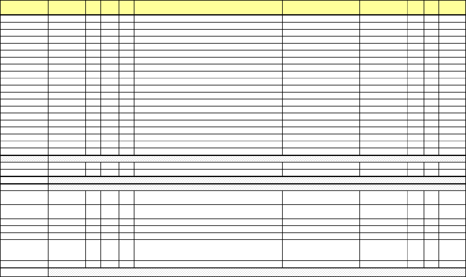
Addr. (hex) Address(4X) Line Pt DNP
Ob
j
Description Range Units Type R/W Notes
B734H-B73B
H
46901-46908 Limit 13 Label
R
ch.7
B73CH-B743
H
46909-46916 Limit 14 Label
R
ch.7
B744H-B74B
H
46917-46924 Limit 15 Label
R
ch.7
B74CH-B753
H
46925-46932 Limit 16 Label
R
ch.7
B754H-B75B
H
46933-46940 Limit 17 Label
R
ch.7
B75CH-B763
H
46941-46948 Limit 18 Label
R
ch.7
B764H-B76B
H
46949-46956 Limit 19 Label
R
ch.7
B76CH-B773
H
46957-46964 Limit 20 Label
R
ch.7
B774H-B77B
H
46965-46972 Limit 21 Label
R
ch.7
B77CH-B783
H
46973-46980 Limit 22 Label
R
ch.7
B784H-B78B
H
46981-46988 Limit 23 Label
R
ch.7
B78CH-B793
H
46989-46996 Limit 24 Label
R
ch.7
B794H-B79B
H
46997-47004 Limit 25 Label
R
ch.7
B79CH-B7A3
H
47005-47012 Limit 26 Label
R
ch.7
B7A4H-B7AB
H
47213-47020 Limit 27 Label
R
ch.7
B7ACH-B7B3
H
47021-47028 Limit 28 Label
R
ch.7
B7B4H-B7BB
H
47029-47036 Limit 29 Label
R
ch.7
B7BCH-B7C3
H
47037-47044 Limit 30 Label
R
ch.7
B7C4H-B7CB
H
47045-47052 Limit 31 Label
R
ch.7
B7CCH-B7D3
H
47053-47060 L
i
m
i
t 32 La
b
e
l
R
c
h
.7
B7D4
H
47061 Module 1/ Module 2
R
B7D5
H
47062 Mo
d
u
l
e 3
/
Mo
d
u
l
e 4
R
B7D6H 47063 MSB: Scale for Analog Output of Average Pulse Accumulation
LSB: Com
p
ressed DNP Ma
pp
in
g
R
B7D7H 47064
MSB: Energy in the interval
LSB: DNP Time synchronization R
B7D8
H
47065 DNP Time Synchronization Time Interval
R
B7D9
H
47066 Bit 13(Choice of Class 0 poll between Object 20 and Object 21),
R
B7DAH-B7DD
H
47067-47070 DNP Freeze Date & Time 12/31/9999 23:59:59.99 10 msec F3
R
B7DEH 47071
DNP Freeze Interval
MSB: Hour
LSB: Minute
R
B7DFH-B7FF
H
47072-47104 Reserve
d
Custom DNP Definition Block for Analog Input (Object 30)
Miscellaneous DNP Settings Block
DNP Bloc
k
External Analog Output Module Channel Update Block
e Electro Industries/GaugeTech Doc# E154703 MM-203
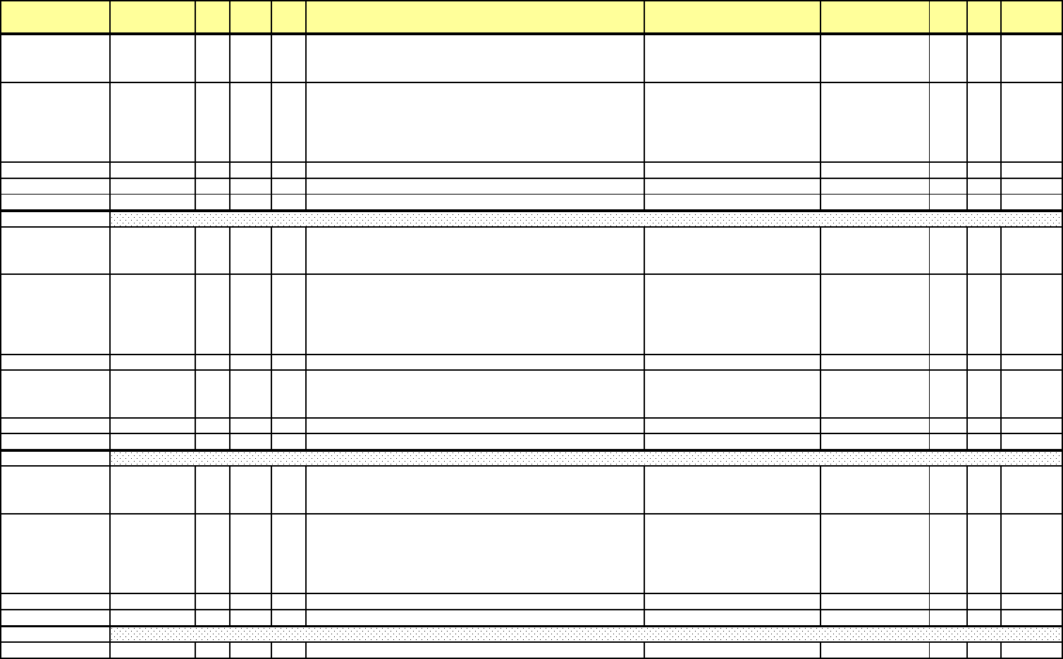
Addr. (hex) Address(4X) Line Pt DNP
Ob
j
Description Range Units Type R/W Notes
B800H 47105
Point 0: Line Number
Line Number from an analog input readings, such as 34 (One
second Phase-Neutron Volta
g
e U
p
date
)
R
B801H 47106
Point 0:
MSB: Point Number
Point Number from an analog input readings, such as 0 (Phase A
-
N Voltage from One secod phase-neutron voltage)
LSB: Scalin
g
R
B802
H
47107 Point 0: Deadband -328% / +328% 0.01%
R
B803
H
47108
(
One second Phase A-N Volta
ge
R
B804H-B8FF
H
47109-47360 Po
i
nt 1 - Po
i
nt 63
B900H 47361
Point 0: Line Number
Line Number from an accumulation readings, such as 537
(
Ener
gy
Scaled
)
R
B901H 47362
Point 0:
MSB: Point Number
Point Number from an accumulation readings, such as 0
(Positive Wh (Quadrant 1+4) from Energy Scaled)
LSB: Scalin
g
R
B902H-B903
H
47363-47364 Point 0: Delta values for Event to occu
r
R
B904H 47365
Point 0:
MSB: Class Assignment (8 bit bitmap)
LSB: Reserve
d
R
B905H-B907
H
47366-47368 Point 0, reserved
B908H-B93F
H
47369-47424 Po
i
nt 1 - Po
i
nt 8
B940H 47425
Point 0-7: Line Number
Line Number from a binary input readings, such as 233 (Low
S
p
eed
(
Internal
)
In
p
uts
)
R
B941H 47426
Point 0-7:
MSB: Point Number
Point Number from a binary input readings, such as 0 (Input 1
from Low Speed (Internal) Inputs)
LSB: Class Assi
g
nment
(
8 bit bitma
p)
R
B942H-B943
H
47427-47428 Point 0-7: Reserve
d
B944H-B95F
H
47429-47456 Po
i
nt 8-15 - Po
i
nt 57-64
B960
H
47457 Relay: Enable/Disable
R
Custom DNP Definition Block for Binary Output (Object 10)
Custom DNP Definition Block for Binary Input (Object 1)
Custom DNP Definition Block for Binary Counter (Object 20)
e Electro Industries/GaugeTech Doc# E154703 MM-204

Addr. (hex) Address(4X) Line Pt DNP
Ob
j
Description Range Units Type R/W Notes
B961
H
47458 Reset: Ena
bl
e
/
D
i
sa
bl
e
R
B962H 47459
Choice Of Variation 0:
MSB: For Binary Input (Object 1)
LSB: For Binar
y
In
p
ut Chan
g
e
(
Ob
j
ect 2
)
R
B963H 47460
Choice Of Variation 0:
MSB: For Binary Counter (Object 20)
LSB: For Frozen Counter
(
Ob
j
ect 21
)
R
B964H 47461
Choice Of Variation 0:
MSB: For Counter Change Event (Object 22)
LSB: For Frozen Counter Event
(
Ob
j
ect 23
)
R
B965H 47462
Choice Of Variation 0:
MSB: For Analog Input (Object 30)
LSB: For Frozen Analo
g
In
p
ut
(
Ob
j
ect 31
)
R
B966H 47463
Choice Of Variation 0:
MSB: For Analog Change Event (Object 32)
LSB: For Frozen Analo
g
Event
(
Ob
j
ect 33
)
R
B967H 47464 MSB: Custom 16-bit Scaling Enable
LSB: Reserve
d
R
B968H-B969H 47465 Scale for Ia, b, c, n +32767 A / 0 A 1/ 65536 A sec F7 R
B96AH-B96BH 47466 Scale for Iaux +32767 A / 0 A 1/ 65536 A sec F7 R
B96CH-B96DH 47467 Scale for Van, bn, cn +32767 V / 0 V 1/ 65536 V sec F7 R
B96EH-B96FH\ 47468 Scale for Vaux +32767 V / 0 V 1/ 65536 V sec F7 R
B970H-B971H 47469 Scale for Vab, bc, ca +32767 V / 0 V 1/ 65536 V sec F7 R
B972H-B973H 47470 Scale for Power a, b, c +32767 W / -32768 W 1/ 65536 W sec F7 R
B974H-B975H 47471 Scale for Total Power +32767 W / -32768 W 1/ 65536 W sec F7 R
B976H-B977H 47472 Scale for Frequency (High End) +32767 Hz / -32768 Hz 1/ 65536 Hz F7 R
B978H-B979H 47473 Scale for Frequency (Low End) +32767 Hz / -32768 Hz 1/ 65536 Hz F7 R
B97AH-BDFFH 47474-48640 Reserved
BE00H-C27F
H
48641-49792 Reserve
d
C280H-C287
H
49793-49800 Module 1 Relay Label 1
R
C288H-C28F
H
49801-49808 Module 1 Relay Label 2
R
C290H-C297
H
49809-49816 Module 1 Relay Label 3
R
C298H-C29F
H
49817-49824 Module 1 Relay Label 4
R
C2A0H-C2A7
H
49825-49832 Module 2 Relay Label 1
R
Custom DNP Definition Block for Global Values
External Digital Output Module Labels Block
e Electro Industries/GaugeTech Doc# E154703 MM-205

Addr. (hex) Address(4X) Line Pt DNP
Ob
j
Description Range Units Type R/W Notes
C2A8H-C2AF
H
49833-49840 Module 2 Relay Label 2
R
C2B0H-C2B7
H
49841-49848 Module 2 Relay Label 3
R
C2B8H-C2BF
H
49849-49856 Module 2 Relay Label 4
R
C2C0H-C2C7
H
49857-49864 Module 3 Relay Label 1
R
C2C8H-C2CF
H
49865-49872 Module 3 Relay Label 2
R
C2D0H-C2D7
H
49873-49880 Module 3 Relay Label 3
R
C2D8H-C2DF
H
49881-49888 Module 3 Relay Label 4
R
C2E0H-C2E7
H
49889-49896 Module 4 Relay Label 1
R
C2E8H-C2EF
H
49897-49904 Module 4 Relay Label 2
R
C2F0H-C2F7
H
49905-49912 Module 4 Relay Label 3
R
C2F8H-C2FF
H
49913-49920 Module 4 Relay Label 4
R
C300H-C307
H
49921-49928 Module 1 Relay Common Shorted to Normally Closed Label
1
R
C308H-C30F
H
49929-49936 Module 1 Relay Common Shorted to Normally Closed Label
2
R
C310H-C317
H
49937-49944 Module 1 Relay Common Shorted to Normally Closed Label
3
R
C318H-C31F
H
49945-49952 Module 1 Relay Common Shorted to Normally Closed Label
4
R
C320H-C327
H
49953-49960 Module 2 Relay Common Shorted to Normally Closed Label
1
R
C328H-C32F
H
49961-49968 Module 2 Relay Common Shorted to Normally Closed Label
2
R
C330H-C337
H
49969-49976 Module 2 Relay Common Shorted to Normally Closed Label
3
R
C338H-C33F
H
49977-49984 Module 2 Relay Common Shorted to Normally Closed Label
4
R
C340H-C347
H
49985-49992 Module 3 Relay Common Shorted to Normally Closed Label
1
R
C348H-C34F
H
49993-50000 Module 3 Relay Common Shorted to Normally Closed Label
2
R
C350H-C357
H
50001-50008 Module 3 Relay Common Shorted to Normally Closed Label
3
R
C358H-C35F
H
50009-50016 Module 3 Relay Common Shorted to Normally Closed Label
4
R
C360H-C367
H
50017-50024 Module 4 Relay Common Shorted to Normally Closed Label
1
R
C368H-C36F
H
50025-50032 Module 4 Relay Common Shorted to Normally Closed Label
2
R
C370H-C377
H
50033-50040 Module 4 Relay Common Shorted to Normally Closed Label
3
R
C378H-C37F
H
50041-50048 Module 4 Relay Common Shorted to Normally Closed Label
4
R
C380H-C387
H
50049-50056 Module 1 Relay Common Shorted to Normally Opened Label
1
R
C388H-C38F
H
50057-50064 Module 1 Relay Common Shorted to Normally Opened Label
2
R
C390H-C397
H
50065-50072 Module 1 Relay Common Shorted to Normally Opened Label
3
R
C398H-C39F
H
50073-50080 Module 1 Relay Common Shorted to Normally Opened Label
4
R
C3A0H-C3A7
H
50081-50088 Module 2 Relay Common Shorted to Normally Opened Label
1
R
C3Q8H-C3AF
H
50089-50096 Module 2 Relay Common Shorted to Normally Opened Label
2
R
C3B0H-C3B7
H
50097-50104 Module 2 Relay Common Shorted to Normally Opened Label
3
R
C3B8H-C3BF
H
50105-50112 Module 2 Relay Common Shorted to Normally Opened Label
4
R
C3C0H-C3C7
H
50113-50120 Module 3 Relay Common Shorted to Normally Opened Label
1
R
C3C8H-C3CF
H
50121-50128 Module 3 Relay Common Shorted to Normally Opened Label
2
R
C3D0H-C3D7
H
50129-50136 Module 3 Relay Common Shorted to Normally Opened Label
3
R
C3D8H-C3DF
H
50137-50144 Module 3 Relay Common Shorted to Normally Opened Label
4
R
e Electro Industries/GaugeTech Doc# E154703 MM-206

Addr. (hex) Address(4X) Line Pt DNP
Ob
j
Description Range Units Type R/W Notes
C3E0H-C3E7
H
50145-50152 Module 4 Relay Common Shorted to Normally Opened Label
1
R
C3E8H-C3EF
H
50153-50160 Module 4 Relay Common Shorted to Normally Opened Label
2
R
C3F0H-C3F7
H
50161-50168 Module 4 Relay Common Shorted to Normally Opened Label
3
R
C3F8H-C3FF
H
50169-50176 Mo
d
u
l
e 4 Re
l
ay Common S
h
orte
d
to Norma
ll
y Opene
d
La
b
e
l
4
R
C400H-C45F
H
50177-50272 Reserve
d
C460H-C461
H
50273-50274 Line 1, Point 1
R
C462H-C65F
H
50275-50784 L
i
ne 2, Po
i
nt 2 - L
i
ne 256, Po
i
nt 256
R
C660
H
50785 Enable/ Disable
C661
H
50786 TFTP Por
t
C662H-C663
H
50787-50788 Client IP
C664H-C665
H
50789-50790 Server I
P
C666H-C667
H
50791-50792 Default Gatewa
y
C668H-C669
H
50793-50794 Subnet Mask
C66A
H
50795 Email Mode
C66B
H
50796 FTP Downloa
d
C66CH-C6AB
H
50797-50860 Down
l
oa
d
F
il
ename
(
128 Bytes
)
C6ACH-C6CB
H
50861-50892 Email Server IP Addres / Name (64 bytes)
C6CCH-C6EBH 50893-50924
Nxs Comm Email Processing Service IP Address / Name (64
bytes)
C6ECH-C70B
H
50925-50956 Return / Reply Address (64 bytes)
C70CH-C72B
H
50957-50988 Email Subject Text (64 Bytes)
C72CH-C73B
H
50989-51004 Email Username (32 Bytes)
C73CH-C74B
H
51005-51020 Email Password (32 Bytes)
C74CH-C7CB
H
51021-51148 Reserve
d
C7CCH-C7D3
H
51149-51156 Reserve
d
C7D4H 51157
MSB: Mode
LSB: Bitmap Set R
C7D5H 51158
MSB: UDP Addressing
LSB: Validate Source IPs R
C7D6
H
51159 TCP Listen Por
t
R
C7D7
H
51160 UDP Listen Por
t
R
C7D8H-C7D9
H
51161-51162 Valid IP Address 1
R
C7DAH-C7DB
H
51163-51164 Valid IP Address 2
R
Reserved Block
Auto TFTP Download Settings
Network Settings 10/100 Card
Customizable Modbus Map Settings Block
DNP LAN/WAN
Email Client settings
e Electro Industries/GaugeTech Doc# E154703 MM-207

Addr. (hex) Address(4X) Line Pt DNP
Ob
j
Description Range Units Type R/W Notes
C7DCH-C7DD
H
51165-61166 Valid IP Address 3
R
C7DEH-C7DF
H
51167-51168 Valid IP Address 4
R
C7E0H-C7E1
H
51169-51170 Valid IP Subnet Mask 1
R
C7E2H-C7E3
H
51171-51172 Valid IP Subnet Mask 2
R
C7E4H-C7E5
H
51173-51174 Valid IP Subnet Mask 3
R
C7E6H-C7E7
H
51175-51176 Valid IP Subnet Mask 4
R
C7E8H-C7EB
H
51177-51180 TCP Starting Valid Client Ports
R
C7ECH-C7EF
H
51181-51184 TCP Ending Valid Client Ports
R
C7F0H-C7F3
H
51185-51188 UDP Starting Valid Client Ports
R
C7F4H-C7F7
H
51189-51192 UDP Ending Valid Client Ports
R
C7F8H-C7F9
H
51193-51194 Reserve
d
C7FA
H
51195 UDP Respond Por
t
R
C7FB
H
Device Addres
s
R
C7FCH-C7FF
H
51196-51200 Reserve
d
C800
H
51201 Custom Modbus Point 1 Style / Forma
t
R
C801
H
51202 Custom Modbus Point 1 Unit / Special
C802H-C9FF
H
51203-51712 Custom Mo
db
us Po
i
nts 2-256 Sty
l
e
/
Format an
d
Un
i
t
/
Spec
i
a
l
R
CA00
H
51713 Q1234 VAh/ Q12 VAR
h
F65
CA01
H
51714 Q34 VARh/ Q14 W
h
F65
CA02
H
51715 Q1 VAh/ Q1 VAR
h
F65
CA03
H
51716 Q4 VAh/ Q4 VAR
h
F65
CA04
H
51717 Q23 Wh/ Q2 VA
h
F65
CA05
H
51718 Q2 VARh/ Q3 VA
h
F65
CA06H 51719 Q3 VARh/ I2t Phase A F65
CA07H 51720 I2t Phase B/ I2t Phase C F65
CA08H 51721 V2t Phase A/ V2t Phase B F65
CA09H 51722 V2t Phase C/ Q1 Wh F65
CA0A
H
51723 Q4 Wh/ Q2 W
h
F65
CA0B
H
51724 Q3 Wh/ Q1234 VAh, Uncompensate
d
F65
CA0C
H
51725 Q12 VARh, Uncompensated/ Q34 VARh, Uncompensate
d
F65
CA0D
H
51726 Q14 Wh, Uncompensated/ Q23 Wh, Uncompensate
d
F65
CA0E
H
51727 +Oh/ -O
h
F65
CA0F
H
51728 Q14 Wh Test Mode/ Q1 VAh Test Mode F65
CA10
H
51729 Q1 VARh Test Mode/ Q4 VAh Test Mod
e
F65
CA11
H
51730 Q4 VARh Test Mode/ Q23 Wh Test Mode F65
CA12
H
51731 Q2 VAh Test Mode/ Q2 VARh Test Mod
e
F65
Energy Scale Settings
Customizable Modbus Map Format Block
e Electro Industries/GaugeTech Doc# E154703 MM-208

Addr. (hex) Address(4X) Line Pt DNP
Ob
j
Description Range Units Type R/W Notes
CA13
H
51732 Q3 VAh Test Mode/ Q3 VARh Test Mod
e
F65
CA14
H
51733 Pulse Accumulation, Input 1/ Pulse Accumulation Input
2
F65
CA15
H
51734 Pulse Accumulation, Input 3/ Pulse Accumulation Input
4
F65
CA16
H
51735 Pulse Accumulation, Input 5/ Pulse Accumulation Input
6
F65
CA17
H
51736 Pulse Accumulation, Input 7/ Pulse Accumulation Input
8
F65
CA18
H
51737 Pulse Aggregation 1/ Pulse Aggregation
2
F65
CA19
H
51738 Pulse Aggregation 3/ Pulse Aggregation
4
F65
CA1AH 51739
SYNCH connection (Yes/No 1-255/0) / FVF change per day (1
-
50)
CA1B
H
51740 Reserve
d
CA1C
H
51741 TDD Reference Voltag
e
F7
CA1D
H
51742 TDD Reference Curren
t
F7
CA1EH-CA94
H
51743-51861 Reserve
d
CA95H-CEEF
H
51861-52976 Reserve
d
CEF0H-CF6F
H
52977-53104 User Memo Field (256 bytes)
CF70H-CFEF
H
53105-53232 Name of User Who Last Updated the Profile (256 bytes)
CFF0
H
53233 Device Profile Version (Year)
CFF1
H
53234 Device Profile Version (Month/ Day
)
CFF2
H
53235 Device Profile Version (Build)
CFF3
H
53236 Pro Software I
D
CFF4H-CFF5
H
53237-53238 Electro Industries Device Type (Base Unit)
CFF6
H
53239 Electro Industries Device Type (Option 1/ Option 2)
CFF7
H
53240 Electro Industries Device Type (Option 3/ Option 4)
CFF8
H
53241 Update Programming Software Version Number (Major)
CFF9
H
53242 Update Programming Software Version Number (Minor)
CFFA
H
53243 Update Programming Software Version Number (Revision
)
CFFBH-CFFE
H
53244-53247 Update Time
R
CFFF
H
53248 Programma
bl
e Sett
i
ngs B
l
oc
k
C
h
ec
k
su
m
R
D000
H
53249 Sanity Rregiste
r
F58
R
D001
H
53250 Phase A Current +5 A / 0
A
5 / 2048 A sec F59
R
D002
H
53251 Phase B Current +5 A / 0
A
5 / 2048 A sec F59
R
D003
H
53252 Phase C Current +5 A / 0
A
5 / 2048 A sec F59
R
D004
H
53253 Phase A-N Voltag
e
+150 V / 0 V 150 / 2048 V sec F59
R
D005
H
53254 Phase B-N Voltag
e
+150 V / 0 V 150 / 2048 V sec F59
R
D006
H
53255 Phase C-N Voltag
e
+150 V / 0 V 150 / 2048 V sec F59
R
D007
H
53256 Total Watt +1500 W / -1500
W
1500 / 2048 W sec F59
R
12-Bit RTU Block
Update Settings Block
e Electro Industries/GaugeTech Doc# E154703 MM-209

Addr. (hex) Address(4X) Line Pt DNP
Ob
j
Description Range Units Type R/W Notes
D008H 53257 Total VAR +1500 VAR / -1500 VAR
1500 / 2048 VAR
sec F59 R
D009
H
53258 Phase A Watt +1500 W / -1500
W
1500 / 2048 W sec F59
R
D00A
H
53259 Phase B Watt +1500 W / -1500
W
1500 / 2048 W sec F59
R
D00B
H
53260 Phase C Watt +1500 W / -1500
W
1500 / 2048 W sec F59
R
D00CH 53261 Phase A VAR +1500 VAR / -1500 VAR
1500 / 2048 VAR
sec F59 R
D00DH 53262 Phase B VAR +1500 VAR / -1500 VAR
1500 / 2048 VAR
sec F59 R
D00EH 53263 Phase C VAR +1500 VAR / -1500 VAR
1500 / 2048 VAR
sec F59 R
D00FH-D010
H
53264-53265 Reserve
d
D011
H
53266 Computed Neutral Current +5 A / 0
A
5 / 2048 A sec F59
R
D012H-D013
H
53267-53268 Positive Watthou
r
+99,999,999 kWh / 0 kWh 1 kWh pri F60
R
D014H-D015
H
53269-53270 Negative Watthou
r
0 kWh / +99,999,999 kWh 1 kWh pri F60
R
D016H-D017
H
53271-53272 Positive VARhou
r
+99,999,999 kVARh / 0 kVAR
h
1 kVARh pri F60
R
D018H-D019
H
53273-53274 Negative VARhou
r
0 kVARh / +99,999,999 kVAR
h
1 kVARh pri F60
R
D01A
H
53275 Frequenc
y
45 Hz / 75 Hz 30 / 4096 Hz F61
R
D01BH-D062
H
53276-53347 Reserve
d
D063
H
53348 Energy Rese
t
W
D800H-DFFF
H
55296-57344 NVRAM rea
di
ngs
(
D
i
agnost
i
c Purpose on
l
y
)
E000H 57345 Log Rese
t
W
Ch.5
E001H 57346 Maximum Reset
W
E002H 57347 Minimum Reset
W
E003H 57348 Energy Rese
t
W
E004H 57349 Calibrate 120 V R/
W
E005H 57350 Calibrate 150 mA R/
W
E006H 57351 Calibrate 250 mA R/
W
E007H 57352 Calibrate 500 mA R/
W
E008H 57353 Calibrate 1 A R/
W
E009H 57354 Calibrate 2.5 A R/
W
E00A
H
57355 Calibrate 5 A R/
W
E00B
H
57356 Calibrate Automatic R/
W
E00C
H
57357 Calibrate +1 A Phase R/
W
E00D
H
57358 Calibrate -1 A Phase R/
W
E00E
H
57359 Calibrate +1 B Phase R/
W
E00F
H
57360 Calibrate -1 B Phase R/
W
NVRAM Window
Action Block
e Electro Industries/GaugeTech Doc# E154703 MM-210

Addr. (hex) Address(4X) Line Pt DNP
Ob
j
Description Range Units Type R/W Notes
E010H 57361 Calibrate +1 C Phase R/
W
E011H 57362 Calibrate -1 C Phase R/
W
E012H 57363 Calibrate +1 Aux Phase R/
W
E013H 57364 Calibrate -1 Aux Phase R/
W
E014H 57365 Start Calibration Mode R/
W
E015H 57366 Calibrate Manual Gain Adjustment R/
W
E016H 57367 Activate first time CTPT Compensatio
n
R/
W
E017H 57368 Calibrate Manual Phase Adjustment R/
W
E018H 57369 Calibrate Multiplier 1x R/
W
E019H 57370 Calibrate Multiplier 10x R/
W
E01A
H
57371 Calibrate References R/
W
E01B
H
57372 Reset DSP1 R/
W
E01C
H
57373 Calibrate Phase at 500 mA R/
W
E01D
H
57374 Calibrate Phase at 1 A R/
W
E01E
H
57375 Calibrate Phase at 5 A R/
W
E01F
H
57376 Calibrate Phase at 10 A R/
W
E020H 57377 Calibrate Phase at 2.5 A R/
W
E021H 57378 Preload CTPT compensation value
s
R/
W
E022H 57379 25 mA Current Calibration Request Flag
E023H 57380 Internal KYZ Enable R/
W
E024H 57381 Flicker Enable R/
W
E025H 57382 Undefine
d
R/
W
E026H 57383 Calibrate Waveform 120
V
R/
W
E027H 57384 Calibrate Waveform - 5
A
R/
W
E028H 57385 Calibrate Waveform - DC Offse
t
R/
W
E029H 57386 Reset Time Of Use Current Month R/
W
E02A
H
57387 Manual Waveform Capture
W
E02B
H
57388 Reset Internal Input Accumulations and Aggregation
s
R/
W
E02C
H
57389 Override Data not yet Valid Bloc
k
W
E02D
H
57390 Refresh External IO Header Informatio
n
R/
W
E02E
H
57391 Refresh External IO Programming Informatio
n
W
E02F
H
57392 Relay Locking Relay Selectio
n
R/
W
E030H 57393 Relay Locking Action Selectio
n
R/
W
E033H 57396 Reset KYZ Output Accumulation
s
W
E034H 57397 Reset Cumulative Demand
W
E035H 57398 Reset Historical Log 1
W
E036H 57399 Reset Historical Log 2
W
E037H 57400 Reset Sequence of Events Lo
g
W
E038H 57401 Reset Digital Input Lo
g
W
e Electro Industries/GaugeTech Doc# E154703 MM-211

Addr. (hex) Address(4X) Line Pt DNP
Ob
j
Description Range Units Type R/W Notes
E039H 57402 Reset Digital Output Log
W
E03A
H
57403 Reset Flicker Lo
g
W
E03B
H
57404 Reset Waveform Lo
g
W
E03C
H
57405 Reset PQ Lo
g
W
E03D
H
57406 Reset System Event Lo
g
W
E03E
H
57407 Reset Total Average Power Facto
r
W
E03F
H
57408 Reset Time of Use Active Registers
W
E044H 57413
Power Quality Test (EN-50160/IEC61000-4-30) Re-Start/ Reset
Flag W
E047H 57416 Copy Dual Port readings to Dual Port Reading Bloc
k
W
E048H 57417 Calibrate Phase at 150 mA
E049H 57418 Calibrate Phase at 250 mA R/
W
E04A
H
57398 Reset Historical Log 3
W
E04B
H
57399 Reset Historical Log 4
E04C
H
57400 Reset Historical Log 5
E04D
H
57401 Reset Historical Log 6
E04E
H
57402 Reset Historical Log 7
E04F
H
57403 Reset Historical Log 8
E050H 57404 Reset Event Triggered Lo
g
E051H 57405 Reset Transient Log
E052H 57406 Lock Log, write some value different 0x0000 lock all logs to lo
g
E080H 57473 Reserved R/
W
E081H 57474 Reserved -672 / +672 sec / month R/
W
E082H 57475 Reserve
d
R
/W
EE00H-EE03
H
60929-60932 Factory Calibration Block Timestam
p
R
EE04H-EE07
H
60933-60936 Factory Calibration Timestamp
R
EE08H-EE09
H
60937-60938 Gain factor for Va
n
R
EE0AH-EE0F
H
60939-60944 Gain factors for Vbn, Vcn, Vx
n
R
EE10H-EE11
H
60945-60946 Gain Factor for Ia 150 m
A
R
EE12H-EE13
H
60947-60948 Gain Factor for Ia 250 m
A
R
EE14H-EE15
H
60949-60950 Gain Factor for Ia 500 m
A
R
EE16H-EE17
H
60951-60952 Gain Factor for Ia 1
A
R
EE18H-EE19
H
50953-60954 Gain Factor for Ia 2.5
A
R
EE1AH-EE1B
H
60955-60956 Gain Factor for Ia 5
A
R
EE1CH-EE27
H
60957-60968 Gain factors for I
b
R
EE1CH-EE3F
H
60969-60992 Gain factors for Ic, I
x
R
EE40
H
60993 Unuse
d
R
EE41
H
60994 Phase Compensation for Phase A 500 m
A
R
Factory Calibration Block
e Electro Industries/GaugeTech Doc# E154703 MM-212

Addr. (hex) Address(4X) Line Pt DNP
Ob
j
Description Range Units Type R/W Notes
EE42
H
60995 Phase Compensation for Phase A 1
A
R
EE43
H
60996 Phase Compensation for Phase A 2.5
A
R
EE44
H
60997 Phase Compensation for Phase A 5
A
R
EE45
H
60998 Phase Compensation for Phase A 10
A
R
EE46H-EE4A
H
60999-61003 Phase Compensation for Phase B
R
EE4BH-EE4F
H
61004-61008 Phase Compensation for Phase C
R
EE50H-EE60
H
61009-61025 Unuse
d
R
EE61
H
61026 Ca
lib
rat
i
on C
h
ec
k
sum
R
EE62H-EE65
H
61027-61030 CTPT Compensation Calibration Block Timestamp
R
EE66H-EE69
H
61031-61034 CTPT Compensation Calibration Timestamp
R
EE6AH-EE6B
H
61035-61036 Gain factor for Va
n
R
EE6CH-EE71
H
61037-61042 Gain factors for Vbn, Vcn, Vx
n
R
EE72H-EE73
H
61043-61044 Gain Factor for Ia 150 m
A
R
EE74H-EE75
H
61045-61046 Gain Factor for Ia 250 m
A
R
EE76H-EE77
H
61047-61048 Gain Factor for Ia 500 m
A
R
EE78H-EE79
H
61049-61050 Gain Factor for Ia 1
A
R
EE7AH-EE7B
H
61051-61052 Gain Factor for Ia 2.5
A
R
EE7CH-EE7D
H
61053-61054 Gain Factor for Ia 5
A
R
EE7EH-EE89
H
61055-61066 Gain factors for I
b
R
EE8AH-EEA1
H
61067-61090 Gain factors for Ic, I
x
R
EEA2
H
61091 Unuse
d
R
EEA3
H
61092 Phase Compensation for Phase A 500 m
A
R
EEA4
H
61093 Phase Compensation for Phase A 1
A
R
EEA5
H
61094 Phase Compensation for Phase A 2.5
A
R
EEA6
H
61095 Phase Compensation for Phase A 5
A
R
EEA7
H
61096 Phase Compensation for Phase A 10
A
R
EEA8H-EEAC
H
61097-61101 Phase Compensation for Phase B
R
EEADH-EEB1
H
61102-61106 Phase Compensation for Phase C
R
EEB2H-EEC2
H
61107-61123 Unuse
d
R
EEC3
H
61124 Ca
lib
rat
i
on C
h
ec
k
sum
R
EF00
H
61185 Calibration Modification Selection R/
W
EF01H-EF04
H
61186-61189 Calibration Timestamp R/
W
EF05H-EF06
H
61190-61191 Gain factor for Va
n
R/
W
EF07H-EF0C
H
61192-61197 Gain factors for Vbn, Vcn, Vx
n
R/
W
EF0DH-EF0E
H
61198-61199 Gain Factor for Ia 150 m
A
R/
W
EF0FH-EF10
H
61200-61201 Gain Factor for Ia 250 m
A
R/
W
EF11H-EF12
H
61202-61203 Gain Factor for Ia 500 m
A
R/
W
Calibration Modification Block
CTPT Compensation Calibration Block
e Electro Industries/GaugeTech Doc# E154703 MM-213
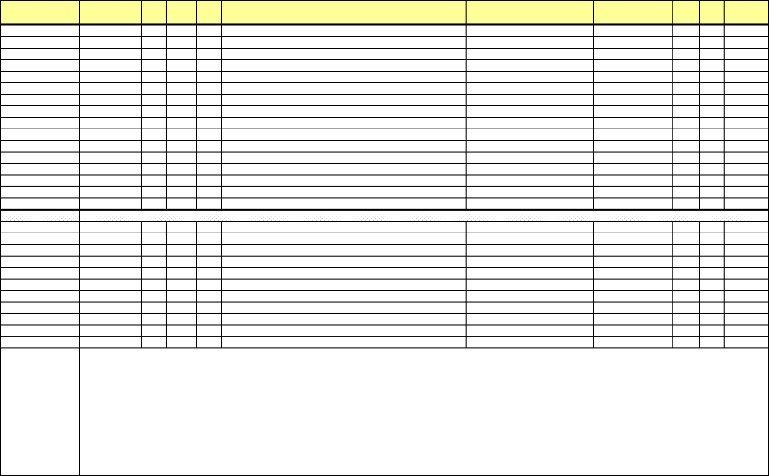
Addr. (hex) Address(4X) Line Pt DNP
Ob
j
Description Range Units Type R/W Notes
EF13H-EF14
H
61204-61205 Gain Factor for Ia 1
A
R/
W
EF15H-EF16
H
61206-61207 Gain Factor for Ia 2.5
A
R/
W
EF17H-EF18
H
61208-61209 Gain Factor for Ia 5
A
R/
W
EF19H-EF24
H
61210-61221 Gain factors for I
b
R/
W
EF25H-EF3C
H
61222-61245 Gain factors for Ic, I
x
R/
W
EF3D
H
61246 Unuse
d
R/
W
EF3E
H
61247 Phase Compensation for Phase A 500 m
A
R/
W
EF3F
H
61248 Phase Compensation for Phase A 1
A
R/
W
EF40
H
61249 Phase Compensation for Phase A 2.5
A
R/
W
EF41
H
61250 Phase Compensation for Phase A 5
A
R/
W
EF42
H
61251 Phase Compensation for Phase A 10
A
R/
W
EF43H-EF47
H
61252-61256 Phase Compensation for Phase B R/
W
EF48H-EF4C
H
61257-61261 Phase Compensation for Phase C R/
W
EF4DH-EF5D
H
61262-61278 Unuse
d
R/
W
EF5E
H
61279 Calibration Checksum R/
W
EF5F
H
61280 Ca
lib
rat
i
on Mo
difi
cat
i
on C
h
ec
k
su
m
R
/W
EF60
H
61281 contrast, low byte, AND with 0x00FF
EF61
H
61282 volume, low byte, AND with 0x00F
F
EF62
H
61283
b
ackligh
t
EF63
H
61284 calibration, upper left corner X
EF64
H
61285 calibration, upper left corner Y
EF65
H
61286 calibration, upper right corner X
EF66
H
61287 calibration, upper right corner Y
EF67
H
61288 calibration, lower left corner X
EF68
H
61289 calibration, lower left corner Y
EF69
H
61290 calibration, lower right corner X
EF6A
H
61291 calibration, lower right corner Y
EF6BH 61292
LCD
staus/command
Register
Bit 0[LSB] - The front panel push button is not pressed=0
The front panel push button is pressed=1
Bit 1 - Written in this register with this bit set to 1 cause the
screen jump to calibration screen.
If this bit is set to 0, nothing happen
Bit 2 - written in this register with this bit set to 1 cause the
meter send a command to the touch
screen controller to read firmware version and vendor
ID.
Bit 3-15 - undefined
Display Parameter Block
e Electro Industries/GaugeTech Doc# E154703 MM-214
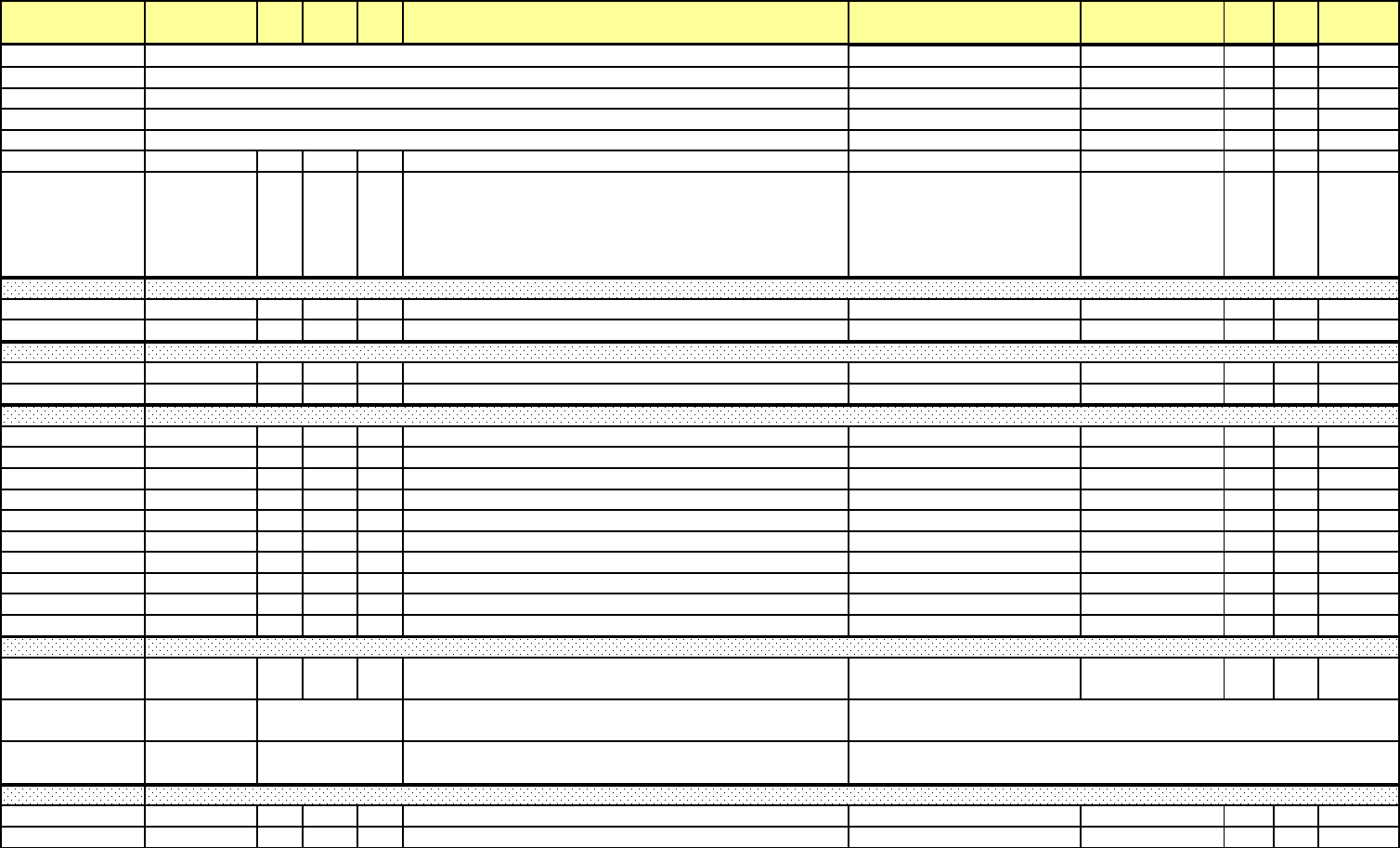
Addr. (hex) Address(4X) Line Pt DNP
Ob
j
Description Range Units Type R/W Notes
EF6CH-EF6
D
61293-61294 Touch screen controller version. 9.9.9.9 / 0.0.0.0 0.0.0.1 version F2
R
EF6E
H
61295 Touch screen last raw x
EF6F
H
61296 Touch screen last raw
y
EF70
H
61297 Touch screen last scaled x
EF71
H
61298 Touch screen last scaled
y
EF72
H
61299 Touch screen controller verndor I
D
EF73H 61300
MSB
-
Di
sp
l
ay
R
o
t
a
ti
on:
0 = 0 degree; 1=90 degree; 2=180 degree; 3=270 degree
LSB - Display Language:
1 = English; 2 = Chinese; 3 = Herbrew; 4 = Portuguese; 5 =
Spanish; 6 = French
EF7CH-EF7E
H
61309-61311 Threshol
d
EF7F
H
61312 Mo
d
e
EF80H-EFFF
H
61313-61440 Variation string
F000H-F269
H
61441-62058 Reserve
d
F600H 62977 Request Group I
D
F601H 62978 Request Item I
D
F602H 62979-62980 IP Addres
s
F604H 62981 Port I
D
F605H 62982-62983 Count down time
F607H 62984 Comman
d
F608H 62985-62989 Start time
F60D
H
62990-62991 Sequence numbe
r
F60FH 62992 Frame versio
n
F610H-F61F
H
62993-63008 Request
li
st
F678H 63097
MSB = Date format (Default = 0)
LSB = Time format (Default = 0) W
F679H 63098
MSB = Date separator (Default = '-')
LSB = Time separator (Default = ':') W
F67AH 63099
MSB
=
D
ate
Y
ear separator
(Fi
xe
d
at
SP)
LSB = reserved W
F680H 63105 Health Block Pos Update Sequence Numbe
r
R
F681H-F684
H
63106-63109 Health Block Time Stamp
R
FPGA Transient Block
DSP2 Info Block
Date/Time Format Settings
DSP2 Data Export
DSP1 Health Block
e Electro Industries/GaugeTech Doc# E154703 MM-215
Addr. (hex) Address(4X) Line Pt DNP
Ob
j
Description Range Units Type R/W Notes
F685H 63110
Health Status (High byte) - Health Block Boot from Scratch
Count(Low byte) R
F686H 63111
Health Block Boot from Run Count(High byte) - Health Block
Boot Init Count(Low byte) R
F687H 63112
Health Block Boot Self Reset Count(High byte)-Health Block
Boot Reset Request Count(Low byte) R
F688H 63113 Health Block Boot No Main Loop Cse
c
R
F689H 63114 Health Block Boot No Flash Activity Cse
c
R
F68AH 63115
Health Block Run Init Count(High byte)-Health Block Run Self
Reset Count(Low byte) R
F68BH 63116
Health Block Run Reset Request Count(High byte)-Health
Block Process Status Sec(Low byte) R
F68CH 63117
Health Block Run Process Status Csec(High byte) -
Unused(Low byte) R
F68D
H
63118 Health Block Checksu
m
R
F68E
H
63119 Hea
l
t
h
B
l
oc
k
Pre Up
d
ate Sequence Num
b
er
R
F690H 63121 Coun
t
R
F691H-F692
H
63122-63123 Board index 1 hardware ID
R
F693H 63124 Board index 1 status
R
F694H-F6F0
H
63125-63217 Boar
d
i
n
d
ex 2-32
h
ar
d
ware ID an
d
status
R
F700H 63233 I2C Status
F701H 63234 I2C Comman
d
F702H-F703
H
63235-63236 I2C Hardware I
D
F704H 63237 I2C Device Addres
s
F705H 63238 I2C Windows Inde
x
F706H 63239 I2C Data Lengt
h
F707H 63240 I2C Data Checksu
m
F708H-F747
H
63241-63304 I2C W
i
n
d
o
w
F7FFH 63488
The
less
significant
bytte
of
this
register
indicates
the
jump
setting for Ethernet option board :
Bit1 Bit0
0 0 -> undefined
0 1 -> NTFI
1 0 -> NTRJ
1 1 -> NTWF
R
Meter I2C Interface
Installed Board Status provided by Meter
e Electro Industries/GaugeTech Doc# E154703 MM-216

Addr. (hex) Address(4X) Line Pt DNP
Ob
j
Description Range Units Type R/W Notes
F800H-F803
H
63489-63492 Multicycle Update RTC Timestamp 12/31/9999 23:59:59.99 10 msec E
R
F804H-F805
H
63493-63494 Multicycle RMS Phase A-N Voltag
e
-32767.999/+32767.999 Volts F
R
F806H-F807
H
63495-63496 Multicycle RMS Phase B-N Voltag
e
-32767.999/+32767.999 Volts F
R
F808H-F809
H
63497-63498 Multicycle RMS Phase C-N Voltag
e
-32767.999/+32767.999 Volts F
R
F80AH-F80B
H
63499-63500 Multicycle RMS Phase A-B Voltag
e
-32767.999/+32767.999 Volts F
R
F80CH-F80D
H
63501-63502 Multicycle RMS Phase B-C Voltag
e
-32767.999/+32767.999 Volts F
R
F80EH-F80F
H
63503-63504 Multicycle RMS Phase C-A Voltage -32767.999/+32767.999 Volts F
R
F810H-F811
H
63505-63506 Multicycle RMS Phase X-N Voltag
e
-32767.999/+32767.999 Volts F
R
F812H-F813
H
63507-63508 Multicycle RMS Vres Voltag
e
-32767.999/+32767.999 Volts F
R
F814H-F815
H
63509-63510 Multicycle RMS Ires Curren
t
-32767.999/+32767.999 Amp
s
F
R
F816H-F817
H
63511-63512 Multicycle RMS Phase A-E Voltag
e
-32767.999/+32767.999 Volts F
R
F818H-F819
H
63513-63514 Multicycle RMS Phase B-E Voltag
e
-32767.999/+32767.999 Volts F
R
F81AH-F81B
H
63515-63516 Multicycle RMS Phase C-E Voltag
e
-32767.999/+32767.999 Volts F
R
F81CH-F81D
H
63517-63518 Multicycle RMS Phase X-E Voltag
e
-32767.999/+32767.999 Volts F
R
F81EH-F81F
H
63519-63520 Multicycle RMS Phase N-E Voltag
e
-32767.999/+32767.999 Volts F
R
F820H-F821
H
63521-63522 Multicycle RMS Phase A Current -32767.999/+32767.999 Amp
s
F
R
F822H-F823
H
63523-63524 Multicycle RMS Phase B Current -32767.999/+32767.999 Amp
s
F
R
F824H-F825
H
63525-63526 Multicycle RMS Phase C Current -32767.999/+32767.999 Amp
s
F
R
F826H-F827
H
63527-63528 Multicycle RMS Phase X Current -32767.999/+32767.999 Amp
s
F
R
F828H-F829
H
63529-63530 Multicycle MEAN Phase A-N Voltag
e
-32767.999/+32767.999 Volts F
R
F82AH-F82B
H
63531-63532 Multicycle MEAN Phase B-N Voltag
e
-32767.999/+32767.999 Volts F
R
F82CH-F82D
H
63533-63534 Multicycle MEAN Phase C-N Voltag
e
-32767.999/+32767.999 Volts F
R
F82EH-F82F
H
63535-63536 Multicycle MEAN Phase A-B Voltag
e
-32767.999/+32767.999 Volts F
R
F830H-F831
H
63537-63538 Multicycle MEAN Phase B-C Voltag
e
-32767.999/+32767.999 Volts F
R
F832H-F833
H
63539-63540 Multicycle MEAN Phase C-A Voltag
e
-32767.999/+32767.999 Volts F
R
F834H-F835
H
63541-63542 Multicycle MEAN Phase X-N Voltag
e
-32767.999/+32767.999 Volts F
R
F836H-F837
H
63543-63544 Multicycle MEAN Vres Voltag
e
-32767.999/+32767.999 Volts F
R
F838H-F839
H
63545-63546 Multicycle MEAN Ires Curren
t
-32767.999/+32767.999 Amp
s
F
R
F83AH-F83B
H
63547-63548 Multicycle MEAN Phase A-E Voltag
e
-32767.999/+32767.999 Volts F
R
F83CH-F83D
H
63549-63550 Multicycle MEAN Phase B-E Voltag
e
-32767.999/+32767.999 Volts F
R
F83EH-F83F
H
63551-63552 Multicycle MEAN Phase C-E Voltag
e
-32767.999/+32767.999 Volts F
R
F840H-F841
H
63553-63554 Multicycle MEAN Phase X-E Voltag
e
-32767.999/+32767.999 Volts F
R
F842H-F843
H
63555-63556 Multicycle MEAN Phase N-E Voltag
e
-32767.999/+32767.999 Volts F
R
F844H-F845
H
63557-63558 Multicycle MEAN Phase A Curren
t
-32767.999/+32767.999 Amp
s
F
R
F846H-F847
H
63559-63560 Multicycle MEAN Phase B Curren
t
-32767.999/+32767.999 Amp
s
F
R
F848H-F849
H
63561-63562 Multicycle MEAN Phase C Curren
t
-32767.999/+32767.999 Amp
s
F
R
F84AH-F84B
H
63563-63564 Multicycle MEAN Phase X Curren
t
-32767.999/+32767.999 Amp
s
F
R
DSP2 Channel Block 2
Multicycle RMS Result Frame 10cycles for 50Hz sytem, 12cycles for 60HZ sytem
e Electro Industries/GaugeTech Doc# E154703 MM-217

Addr. (hex) Address(4X) Line Pt DNP
Ob
j
Description Range Units Type R/W Notes
F84CH-F84D
H
63565-63566 1st reference chanel 0.2sec frequenc
y
0/+32767.999 H
z
F
R
F84EH-F84F
H
63567-63568 2nd reference chanel 0.2sec frequenc
y
0/+32767.999 H
z
F
R
F850H-F851
H
63569-63570 3rd reference chanel 0.2sec frequenc
y
0/+32767.999 H
z
F
R
F852H-F853
H
63571-63572 4th reference chanel 0.2sec frequenc
y
0/+32767.999 H
z
F
R
F854H-F854
H
63573-63574 5th reference chanel 0.2sec frequenc
y
0/+32767.999 H
z
F
R
F856H 63575
1st frequency reference channel, multicycle completed point
timeframe number 0/+65535 G R
F857H 63576
2nd frequency reference channel, multicycle completed point
timeframe number 0/+65535 G R
F858H 63577
3rd frequency reference channel, multicycle completed point
timeframe number 0/+65535 G R
F859H 63578
4th frequency reference channel, multicycle completed point
timeframe number 0/+65535 G R
F85AH 63579
5th frequency reference channel, multicycle completed point
timeframe number 0/+65535 G R
F85BH 63580
1st frequency reference channel, multicycle completed point
index number 0/+65535 G R
F85CH 63581
2nd frequency reference channel, multicycle completed point
index number 0/+65535 G R
F85DH 63582
3rd frequency reference channel, multicyclecompleted point
index number 0/+65535 G R
F85EH 63583
4th frequency reference channel, multicycle completed point
index number 0/+65535 G R
F85FH 63584
5th frequency reference channel, multicycle completed point
index number 0/+65535 G R
F860H-F861
H
63585-63586 Fundamental phase angle Phase A-N Voltage -327.67/+327.67 degree 0.01 degree B E
F862H-F863
H
63587-63588 Fundamental phase angle Phase B-N Voltage -327.67/+327.67 degree 0.01 degree B E
F864H-F865
H
63589-63590 Fundamental phase angle Phase C-N Voltage -327.67/+327.67 degree 0.01 degree B E
F866H-F867
H
63591-63592 Fundamental phase angle Phase A-B Voltage -327.67/+327.67 degree 0.01 degree B E
F868H-F869
H
63593-63594 Fundamental phase angle Phase B-C Voltage -327.67/+327.67 degree 0.01 degree B E
F86AH-F86B
H
63595-63596 Fundamental phase angle Phase C-A Voltage -327.67/+327.67 degree 0.01 degree B E
F86CH-F86D
H
63597-63598 Fundamental phase angle Phase X-N Voltage -327.67/+327.67 degree 0.01 degree B E
F86EH-F86F
H
63599-63600 Fundamental phase angle Vres Voltage -327.67/+327.67 degree 0.01 degree B E
F870H-F871
H
63601-63602 Fundamental phase angle Ires Current -327.67/+327.67 degree 0.01 degree B E
F872H-F873
H
63603-63604 Fundamental phase angle Phase A-E Voltage -327.67/+327.67 degree 0.01 degree B E
F874H-F875
H
63605-63606 Fundamental phase angle Phase B-E Voltage -327.67/+327.67 degree 0.01 degree B E
F876H-F877
H
63607-63608 Fundamental phase angle Phase C-E Voltage -327.67/+327.67 degree 0.01 degree B E
F878H-F879
H
63609-63610 Fundamental phase angle Phase X-E Voltage -327.67/+327.67 degree 0.01 degree B E
F87AH-F87B
H
63611-63612 Fundamental phase angle Phase N-E Voltage -327.67/+327.67 degree 0.01 degree B E
e Electro Industries/GaugeTech Doc# E154703 MM-218

Addr. (hex) Address(4X) Line Pt DNP
Ob
j
Description Range Units Type R/W Notes
F87CH-F87D
H
63613-63614 Fundamental phase angle Phase A Current -327.67/+327.67 degree 0.01 degree B E
F87EH-F87F
H
63615-63616 Fundamental phase angle Phase B Current -327.67/+327.67 degree 0.01 degree B E
F880H-F881
H
63617-63618 Fundamental phase angle Phase C Current -327.67/+327.67 degree 0.01 degree B E
F882H-F883
H
63619-63620 Fundamental phase angle Phase X Current -327.67/+327.67 degree 0.01 degree B E
F884H-F885
H
63621-63622 Multicycle Fundamental RMS Phase A-N Voltag
e
-32767.999/+32767.999 Volts F
R
F886H-F887
H
63623-63624 Multicycle Fundamental RMS Phase B-N Voltag
e
-32767.999/+32767.999 Volts F
R
F888H-F889
H
63625-63626 Multicycle Fundamental RMS Phase C-N Voltag
e
-32767.999/+32767.999 Volts F
R
F88AH-F88B
H
63627-63628 Multicycle Fundamental RMS Phase A-B Voltag
e
-32767.999/+32767.999 Volts F
R
F88CH-F88D
H
63629-63630 Multicycle Fundamental RMS Phase B-C Voltag
e
-32767.999/+32767.999 Volts F
R
F88EH-F88F
H
63631-63632 Multicycle Fundamental RMS Phase C-A Voltag
e
-32767.999/+32767.999 Volts F
R
F890H-F891
H
63633-63634 Multicycle Fundamental RMS Phase X-N Voltag
e
-32767.999/+32767.999 Volts F
R
F892H-F893
H
63635-63636 Multicycle Fundamental RMS Vres Voltage -32767.999/+32767.999 Volts F
R
F894H-F895
H
63637-63638 Multicycle Fundamental RMS Ires Current -32767.999/+32767.999 Amp
s
F
R
F896H-F897
H
63639-63640 Multicycle Fundamental RMS Phase A-E Voltag
e
-32767.999/+32767.999 Volts F
R
F898H-F899
H
63641-63642 Multicycle Fundamental RMS Phase B-E Voltage -32767.999/+32767.999 Volts F
R
F89AH-F89B
H
63643-63644 Multicycle Fundamental RMS Phase C-E Voltage -32767.999/+32767.999 Volts F
R
F89CH-F89D
H
63645-63646 Multicycle Fundamental RMS Phase X-E Voltage -32767.999/+32767.999 Volts F
R
F89EH-F89F
H
63647-63648 Multicycle Fundamental RMS Phase N-E Voltage -32767.999/+32767.999 Volts F
R
F8A0H-F8A1
H
63649-63650 Multicycle Fundamental RMS Phase A Current -32767.999/+32767.999 Amp
s
F
R
F8A2H-F8A3
H
63651-63652 Multicycle Fundamental RMS Phase B Current -32767.999/+32767.999 Amp
s
F
R
F8A4H-F8A5
H
63653-63654 Multicycle Fundamental RMS Phase C Current -32767.999/+32767.999 Amp
s
F
R
F8A6H-F8A7
H
63655-63656 Multicycle Fundamental RMS Phase X Current -32767.999/+32767.999 Amp
s
F
R
F8A8
H
63657 Symm Comp Phase (Voltage PN) - Zero Sequenc
e
-327.67/+327.67 degree 0.01 degree B E
F8A9
H
63658 Symm Comp Phase (Voltage PN) - Pos Sequenc
e
-327.67/+327.67 degree 0.01 degree B E
F8AA
H
63659 Symm Comp Phase (Voltage PN) - Neg Sequenc
e
-327.67/+327.67 degree 0.01 degree B E
F8AB
H
63660 ref channel update timestamp 0/4294967295 H
R
F8ACH-F8AD
H
63661-63662 0.2sec Symm Comp Mag (Voltage PN) - Zero Sequenc
e
-32767.999/+32767.999 Volts F
R
F8AEH-F8AF
H
63663-63664 0.2sec Symm Comp Mag (Voltage PN) - Pos Sequenc
e
-32767.999/+32767.999 Volts F
R
F8B0H-F8B1
H
63665-63666 0.2sec Symm Comp Mag (Voltage PN) - Neg Sequenc
e
-32767.999/+32767.999 Volts F
R
F8B2H-F8B3
H
63667-63668 0.2sec Symm Comp Phase (Voltage PN) - Zero Sequenc
e
-327.67/+327.67% 0.01%
A
R
F8B4H-F8B5
H
63669-63670 0.2sec Symm Comp Phase (Voltage PN) - Pos Sequenc
e
-327.67/+327.67% 0.01%
A
R
F8B6H-F8B7
H
63671-63672 0.2sec Symm Comp Phase (Voltage PN) - Neg Sequenc
e
-327.67/+327.67% 0.01%
A
R
F8B8H-F8B9
H
63673-63674 Zero-Crossing Angle channel V1 -327.67/+327.67 degree 0.01 degree B E
F8BAH-F8BB
H
63675-63676 Zero-Crossing Angle channel V
2
-327.67/+327.67 degree 0.01 degree B E
F8BCH-F8BD
H
63677-63678 Zero-Crossing Angle channel V
3
-327.67/+327.67 degree 0.01 degree B E
F8BEH-F8BF
H
63679-63680 Zero-Crossing Angle channel V
4
-327.67/+327.67 degree 0.01 degree B E
F8C0H-F8C1
H
63681-63682 Zero-Crossing Angle channel V
5
-327.67/+327.67 degree 0.01 degree B E
F8C2
H
63683 Zero-Crossing Delay channel V1 -327.67/+327.67 degree 0.01 degree B E
F8C3
H
63684 Zero-Crossing Delay channel V
2
-327.67/+327.67 degree 0.01 degree B E
e Electro Industries/GaugeTech Doc# E154703 MM-219

Addr. (hex) Address(4X) Line Pt DNP
Ob
j
Description Range Units Type R/W Notes
F8C4
H
63685 Zero-Crossing Delay channel V
3
-327.67/+327.67 degree 0.01 degree B E
F8C5
H
63686 Zero-Crossing Delay channel V
4
-327.67/+327.67 degree 0.01 degree B E
F8C6
H
63687 Zero-Crossing Delay channel V
5
-327.67/+327.67 degree 0.01 degree B E
F8C7
H
63688 Default Zero-Crossing Dela
y
-327.67/+327.67 degree 0.01 degree B E
F8C8
H
63689 Underdeviation Phase A-N Voltag
e
-327.67/+327.67% 0.01%
A
R
F8C9
H
63690 Underdeviation Phase B-N Voltag
e
-327.67/+327.67% 0.01%
A
R
F8CA
H
63691 Underdeviation Phase C-N Voltag
e
-327.67/+327.67% 0.01%
A
R
F8CB
H
63692 Underdeviation Phase A-B Voltag
e
-327.67/+327.67% 0.01%
A
R
F8CC
H
63693 Underdeviation Phase B-C Voltag
e
-327.67/+327.67% 0.01%
A
R
F8CD
H
63694 Underdeviation Phase C-A Voltag
e
-327.67/+327.67% 0.01%
A
R
F8CE
H
63695 Overdeviation Phase A-N Voltag
e
-327.67/+327.67% 0.01%
A
R
F8CF
H
63696 Overdeviation Phase B-N Voltag
e
-327.67/+327.67% 0.01%
A
R
F8D0
H
63697 Overdeviation Phase C-N Voltag
e
-327.67/+327.67% 0.01%
A
R
F8D1
H
63698 Overdeviation Phase A-B Voltag
e
-327.67/+327.67% 0.01%
A
R
F8D2
H
63699 Overdeviation Phase B-C Voltag
e
-327.67/+327.67% 0.01%
A
R
F8D3
H
63700 Overdeviation Phase C-A Voltag
e
-327.67/+327.67% 0.01%
A
R
F8D4H-F8D5
H
63701-63702 Multicycle update timestamp 0/4294967295 H
R
F8D6
H
63703 Flagging Multicycle RMS Phase A-N Voltag
e
I
R
F8D7
H
63704 Flagging Multicycle RMS Phase B-N Voltag
e
I
R
F8D8
H
63705 Flagging Multicycle RMS Phase C-N Voltag
e
I
R
F8D9
H
63706 Flagging Multicycle RMS Phase A-B Voltag
e
I
R
F8DA
H
63707 Flagging Multicycle RMS Phase B-C Voltag
e
I
R
F8DB
H
63708 Flagging Multicycle RMS Phase C-A Voltag
e
I
R
F8DCH-F8E1
H
63709-63714 Reserve
d
F8E2
H
63715 Underdeviation 3sec Phase A-N Voltag
e
-327.67/+327.67% 0.01%
A
R
F8E3
H
63716 Underdeviation 3sec Phase B-N Voltag
e
-327.67/+327.67% 0.01%
A
R
F8E4
H
63717 Underdeviation 3sec Phase C-N Voltag
e
-327.67/+327.67% 0.01%
A
R
F8E5
H
63718 Underdeviation 3sec Phase A-B Voltag
e
-327.67/+327.67% 0.01%
A
R
F8E6
H
63719 Underdeviation 3sec Phase B-C Voltag
e
-327.67/+327.67% 0.01%
A
R
F8E7
H
63720 Underdeviation 3sec Phase C-A Voltag
e
-327.67/+327.67% 0.01%
A
R
F8E8
H
63721 Overdeviation 3sec Phase A-N Voltag
e
-327.67/+327.67% 0.01%
A
R
F8E9
H
63722 Overdeviation 3sec Phase B-N Voltag
e
-327.67/+327.67% 0.01%
A
R
F8EA
H
63723 Overdeviation 3sec Phase C-N Voltag
e
-327.67/+327.67% 0.01%
A
R
F8EB
H
63724 Overdeviation 3sec Phase A-B Voltag
e
-327.67/+327.67% 0.01%
A
R
F8EC
H
63725 Overdeviation 3sec Phase B-C Voltag
e
-327.67/+327.67% 0.01%
A
F8ED
H
63726 Overdeviation 3sec Phase C-A Voltag
e
-327.67/+327.67% 0.01%
A
R
F8EE
H
63727 3sec Uunbalance Counte
r
0/65536 G
F8EF
H
63728 3sec Deviation Counte
r
0/65537 G
F8F0H 63729 Phase Sequence J
e Electro Industries/GaugeTech Doc# E154703 MM-220

Addr. (hex) Address(4X) Line Pt DNP
Ob
j
Description Range Units Type R/W Notes
F8F1H 63730
0.2 sec RMS Phase A-N Voltage (Change comparing to previous
value) -327.67/+327.67% 0.01% A R
F8F2H 63731
0.2 sec RMS Phase B-N Voltage (Change comparing to previous
value) -327.67/+327.67% 0.01% A R
F8F3H 63732
0.2 sec RMS Phase C-N Voltage (Change comparing to previous
value) -327.67/+327.67% 0.01% A R
F8F4H 63733
0.2 sec RMS Phase A-B Voltage (Change comparing to previous
value) -327.67/+327.67% 0.01% A R
F8F5H 63734
0.2 sec RMS Phase B-C Voltage (Change comparing to previous
value) -327.67/+327.67% 0.01% A R
F8F6H 63735
0.2 sec RMS Phase C-A Voltage (Change comparing to previous
value) -327.67/+327.67% 0.01% A R
F8F7H 63736
0.2 sec RMS Phase A Current (Change comparing to previous
value) -327.67/+327.67% 0.01% A R
F8F8H 63737
0.2 sec RMS Phase B Current (Change comparing to previous
value) -327.67/+327.67% 0.01% A R
F8F9H 63738
0.2 sec RMS Phase C Current (Change comparing to previous
value) -327.67/+327.67% 0.01% A R
F8FAH-F8FB
H
63739-63740 Reserve
d
F8FCH-F8FF
H
63741-63744 Mu
l
t
i
cyc
l
e Up
d
ate RTC T
i
mestamp 12
/
31
/
9999 23:59:59.99 10 msec E
R
F900H-F903
H
63745-63748 3 sec Update RTC Timestamp 12/31/9999 23:59:59.99 10 msec E
R
F904H-F905
H
63749-63750 3 sec RMS Phase A-N Voltag
e
-32767.999/+32767.999 Volts F
R
F906H-F907
H
63751-63752 3 sec RMS Phase B-N Voltage -32767.999/+32767.999 Volts F
R
F908H-F909
H
63753-63754 3 sec RMS Phase C-N Voltage -32767.999/+32767.999 Volts F
R
F90AH-F90B
H
63755-63756 3 sec RMS Phase A-B Voltag
e
-32767.999/+32767.999 Volts F
R
F90CH-F90D
H
63757-63758 3 sec RMS Phase B-C Voltage -32767.999/+32767.999 Volts F
R
F90EH-F90F
H
63759-63760 3 sec RMS Phase C-A Voltag
e
-32767.999/+32767.999 Volts F
R
F910H-F911
H
63761-63762 3 sec RMS Phase X-N Voltage -32767.999/+32767.999 Amp
s
F
R
F912H-F913
H
63763-63764 3 sec RMS Vres Voltage -32767.999/+32767.999 Volts F
R
F914H-F915
H
63765-63766 3 sec RMS Ires Current -32767.999/+32767.999 Amp
s
F
R
F916H-F917
H
63767-63768 3 sec RMS Phase A-E Voltag
e
-32767.999/+32767.999 Volts F
R
F918H-F919
H
63769-63770 3 sec RMS Phase B-E Voltage -32767.999/+32767.999 Volts F
R
F91AH-F91B
H
63771-63772 3 sec RMS Phase C-E Voltage -32767.999/+32767.999 Volts F
R
F91CH-F91D
H
63773-63774 3 sec RMS Phase X-E Voltage -32767.999/+32767.999 Volts F
R
F91EH-F91F
H
63775-63776 3 sec RMS Phase N-E Voltage -32767.999/+32767.999 Volts F
R
F920H-F921
H
63777-63778 3 sec RMS Phase A Current -32767.999/+32767.999 Amp
s
F
R
F922H-F923
H
63779-63780 3 sec RMS Phase B Current -32767.999/+32767.999 Amp
s
F
R
F924H-F925
H
63781-63782 3 sec RMS Phase C Current -32767.999/+32767.999 Amp
s
F
R
3second RMS Result Frame 150cycles for 50Hz sytem, 180cycles for 60HZ sytem
e Electro Industries/GaugeTech Doc# E154703 MM-221

Addr. (hex) Address(4X) Line Pt DNP
Ob
j
Description Range Units Type R/W Notes
F926H-F927
H
63783-63784 3 sec RMS Phase X Current -32767.999/+32767.999 Amp
s
F
R
F928H-F929
H
63785-63786 3 sec MEAN Phase A-N Voltag
e
-32767.999/+32767.999 Volts F
R
F92AH-F92B
H
63787-63788 3 sec MEAN Phase B-N Voltag
e
-32767.999/+32767.999 Volts F
R
F92CH-F92D
H
63789-63790 3 sec MEAN Phase C-N Voltag
e
-32767.999/+32767.999 Volts F
R
F92EH-F92F
H
63791-63792 3 sec MEAN Phase A-B Voltag
e
-32767.999/+32767.999 Volts F
R
F930H-F931
H
63793-63794 3 sec MEAN Phase B-C Voltag
e
-32767.999/+32767.999 Volts F
R
F932H-F933
H
63795-63796 3 sec MEAN Phase C-A Voltag
e
-32767.999/+32767.999 Volts F
R
F934H-F935
H
63797-63798 3 sec MEAN Phase X-N Voltag
e
-32767.999/+32767.999 Volts F
R
F936H-F937
H
63799-63800 3 sec MEAN Vres Voltag
e
-32767.999/+32767.999 Volts F
R
F938H-F939
H
63801-63802 3 sec MEAN Ires Curren
t
-32767.999/+32767.999 Amp
s
F
R
F93AH-F93B
H
63803-63804 3 sec MEAN Phase A-E Voltag
e
-32767.999/+32767.999 Volts F
R
F93CH-F93D
H
63805-63806 3 sec MEAN Phase B-E Voltag
e
-32767.999/+32767.999 Volts F
R
F93EH-F93F
H
63807-63808 3 sec MEAN Phase C-E Voltag
e
-32767.999/+32767.999 Volts F
R
F940H-F941
H
63809-63810 3 sec MEAN Phase X-E Voltag
e
-32767.999/+32767.999 Volts F
R
F942H-F943
H
63811-63812 3 sec MEAN Phase N-E Voltag
e
-32767.999/+32767.999 Volts F
R
F944H-F945
H
63813-63814 3 sec MEAN Phase A Curren
t
-32767.999/+32767.999 Amp
s
F
R
F946H-F947
H
63815-63816 3 sec MEAN Phase B Current -32767.999/+32767.999 Amp
s
F
R
F948H-F949
H
63817-63818 3 sec MEAN Phase C Current -32767.999/+32767.999 Amp
s
F
R
F94AH-F94B
H
63819-63820 3 sec MEAN Phase X Current -32767.999/+32767.999 Amp
s
F
R
F94C
H
63821 1st frequency reference channel, 3s completed point timeframe 0/+65535 G
R
F94D
H
63822 2nd frequency reference channel, 3s completed point timeframe 0/+65535 G
R
F94E
H
63823 3rd frequency reference channel, 3s completed point timeframe 0/+65535 G
R
F94FH 63824 4th frequency reference channel, 3s completed point timeframe 0/+65535 G
R
F950H 63825 5th frequency reference channel, 3s completed point timeframe 0/+65535 G
R
F951H 63826 1st frequency reference channel, 3s completed point index 0/+65535 G
R
F952H 63827 2nd frequency reference channel, 3s completed point index 0/+65535 G
R
F953H 63828 3rd frequency reference channel, 3s completed point index 0/+65535 G
R
F954H 63829 4th frequency reference channel, 3s completed point index 0/+65535 G
R
F955H 63830 5th frequency reference channel, 3s completed point index 0/+65535 G
R
F956H-F959
H
63831-63834 10 min Update RTC Timestamp 12/31/9999 23:59:59.99 10 msec E
R
F95AH-F95B
H
63835-63836 10 min RMS Phase A-N Voltag
e
-32767.999/+32767.999 Volts F
R
F95CH-F95D
H
63837-63838 10 min RMS Phase B-N Voltage -32767.999/+32767.999 Volts F
R
F95EH-F95F
H
63839-63840 10 min RMS Phase C-N Voltage -32767.999/+32767.999 Volts F
R
F960H-F961
H
63841-63842 10 min RMS Phase A-B Voltag
e
-32767.999/+32767.999 Volts F
R
F962H-F963
H
63843-63844 10 min RMS Phase B-C Voltage -32767.999/+32767.999 Volts F
R
F964H-F965
H
63845-63846 10 min RMS Phase C-A Voltag
e
-32767.999/+32767.999 Volts F
R
F966H-F967
H
63847-63848 10 min RMS Phase X-N Voltage -32767.999/+32767.999 Volts F
R
F968H-F969
H
63849-63850 10 min RMS Vres Voltage -32767.999/+32767.999 Volts F
R
F96AH-F96B
H
63851-63852 10 min RMS Ires Current -32767.999/+32767.999 Amp
s
F
R
e Electro Industries/GaugeTech Doc# E154703 MM-222

Addr. (hex) Address(4X) Line Pt DNP
Ob
j
Description Range Units Type R/W Notes
F96CH-F96D
H
63853-63854 10 min RMS Phase A-E Voltag
e
-32767.999/+32767.999 Volts F
R
F96EH-F96F
H
63855-63856 10 min RMS Phase B-E Voltage -32767.999/+32767.999 Volts F
R
F970H-F971
H
63857-63858 10 min RMS Phase C-E Voltage -32767.999/+32767.999 Volts F
R
F972H-F973
H
63859-63860 10 min RMS Phase X-E Voltage -32767.999/+32767.999 Volts F
R
F974H-F975
H
63861-63862 10 min RMS Phase N-E Voltage -32767.999/+32767.999 Volts F
R
F976H-F977
H
63863-63864 10 min RMS Phase A Current -32767.999/+32767.999 Amp
s
F
R
F978H-F979
H
63865-63866 10 min RMS Phase B Current -32767.999/+32767.999 Amp
s
F
R
F97AH-F97B
H
63867-63868 10 min RMS Phase C Current -32767.999/+32767.999 Amp
s
F
R
F97CH-F97D
H
63869-63870 10 min RMS Phase X Current -32767.999/+32767.999 Amp
s
F
R
F97EH 63871
1st frequency reference channel, 10min completed point
timeframe number 0/+65535 G R
F97FH 63872
2nd frequency reference channel, 10min completed point
timeframe number 0/+65535 G R
F980H 63873
3rd frequency reference channel, 10min completed point
timeframe number 0/+65535 G R
F981H 63874
4th frequency reference channel, 10min completed point
timeframe number 0/+65535 G R
F982H 63875
5th frequency reference channel, 10min completed point
timeframe number 0/+65535 G R
F983H 63876
1st frequency reference channel, 10min completed point index
number 0/+65535 G R
F984H 63877
2nd frequency reference channel, 10min completed point index
number 0/+65535 G R
F985H 63878
3rd frequency reference channel, 10min completed point index
number 0/+65535 G R
F986H 63879
4th frequency reference channel, 10min completed point index
number 0/+65535 G R
F987H 63880
5th frequency reference channel, 10min completed point index
number 0/+65535 G R
F988H-F98B
H
63881-63884 2 hour Update RTC Timestamp 12/31/9999 23:59:59.99 10 msec E
R
F98CH-F98D
H
63885-63886 2 hour RMS Phase A-N Voltag
e
-32767.999/+32767.999 Volts F
R
F98EH-F98F
H
63887-63888 2 hour RMS Phase B-N Voltage -32767.999/+32767.999 Volts F
R
F990H-F991
H
63889-63890 2 hour RMS Phase C-N Voltage -32767.999/+32767.999 Volts F
R
F992H-F993
H
63891-63892 2 hour RMS Phase A-B Voltag
e
-32767.999/+32767.999 Volts F
R
F994H-F995
H
63893-63894 2 hour RMS Phase B-C Voltage -32767.999/+32767.999 Volts F
R
F996H-F997
H
63895-63896 2 hour RMS Phase C-A Voltag
e
-32767.999/+32767.999 Volts F
R
F998H-F999
H
63897-63898 2 hour RMS Phase X-N Voltage -32767.999/+32767.999 Volts F
R
F99AH-F99B
H
63899-63900 2 hour RMS Vres Voltage -32767.999/+32767.999 Volts F
R
F99CH-F99D
H
63901-63902 2 hour RMS Ires Current -32767.999/+32767.999 Amp
s
F
R
e Electro Industries/GaugeTech Doc# E154703 MM-223

Addr. (hex) Address(4X) Line Pt DNP
Ob
j
Description Range Units Type R/W Notes
F99EH-F99F
H
63903-63904 2 hour RMS Phase A-E Voltag
e
-32767.999/+32767.999 Volts F
R
F9A0H-F9A1
H
63905-63906 2 hour RMS Phase B-E Voltage -32767.999/+32767.999 Volts F
R
F9A2H-F9A3
H
63907-63908 2 hour RMS Phase C-E Voltage -32767.999/+32767.999 Volts F
R
F9A4H-F9A5
H
63909-63910 2 hour RMS Phase X-E Voltage -32767.999/+32767.999 Volts F
R
F9A6H-F9A7
H
63911-63912 2 hour RMS Phase N-E Voltage -32767.999/+32767.999 Volts F
R
F9A8H-F9A9
H
63913-63914 2 hour RMS Phase A Current -32767.999/+32767.999 Amp
s
F
R
F9AAH-F9AB
H
63915-63916 2 hour RMS Phase B Current -32767.999/+32767.999 Amp
s
F
R
F9ACH-F9AD
H
63917-63918 2 hour RMS Phase C Current -32767.999/+32767.999 Amp
s
F
R
F9AEH-F9AF
H
63919-63920 2 hour RMS Phase X Current -32767.999/+32767.999 Amp
s
F
R
F9B0H 63921
1st frequency reference channel, 2hour completed point
timeframe number 0/+65535 G R
F9B1H 63922
2nd frequency reference channel, 2hour completed point
timeframe number 0/+65535 G R
F9B2H 63923
3rd frequency reference channel, 2hour completed point
timeframe number 0/+65535 G R
F9B3H 63924
4th frequency reference channel, 2hour completed point
timeframe number 0/+65535 G R
F9B4H 63925
5th frequency reference channel, 2hour completed point
timeframe number 0/+65535 G R
F9B5H 63926
1st frequency reference channel, 2hour completed point index
number 0/+65535 G R
F9B6H 63927
2nd frequency reference channel, 2hour completed point index
number 0/+65535 G R
F9B7H 63928
3rd frequency reference channel, 2hour completed point index
number 0/+65535 G R
F9B8H 63929
4th frequency reference channel, 2hour completed point index
number 0/+65535 G R
F9B9H 63930
5th frequency reference channel, 2hour completed point index
number 0/+65535 G R
F9BAH-F9BB
H
63931-63932 3sec update timestamp 0/4294967295 H
R
F9BCH-F9BD
H
63933-63934 10min update timestamp 0/4294967295 H
R
F9BEH-F9BF
H
63935-63936 2hour update timestamp 0/4294967295 H
R
F9C0
H
63937 Flagging 3sec RMS Phase A-N Voltag
e
I
R
F9C1
H
63938 Flagging 3sec RMS Phase B-N Voltag
e
I
R
F9C2
H
63939 Flagging 3sec RMS Phase C-N Voltag
e
I
R
F9C3
H
63940 Flagging 3sec RMS Phase A-B Voltag
e
I
R
F9C4
H
63941 Flagging 3sec RMS Phase B-C Voltag
e
I
R
F9C5
H
63942 Flagging 3sec RMS Phase C-A Voltag
e
I
R
F9C6
H
63943 Flagging 10min RMS Phase A-N Voltag
e
I
R
e Electro Industries/GaugeTech Doc# E154703 MM-224

Addr. (hex) Address(4X) Line Pt DNP
Ob
j
Description Range Units Type R/W Notes
F9C7
H
63944 Flagging 10min RMS Phase B-N Voltag
e
I
R
F9C8
H
63945 Flagging 10min RMS Phase C-N Voltag
e
I
R
F9C9
H
63946 Flagging 10min RMS Phase A-B Voltag
e
I
R
F9CA
H
63947 Flagging 10min RMS Phase B-C Voltag
e
I
R
F9CB
H
63948 Flagging 10min RMS Phase C-A Voltag
e
I
R
F9CC
H
63949 Flagging 2hour RMS Phase A-N Voltag
e
I
R
F9CD
H
63950 Flagging 2hour RMS Phase B-N Voltag
e
I
R
F9CE
H
63951 Flagging 2hour RMS Phase C-N Voltag
e
I
R
F9CF
H
63952 Flagging 2hour RMS Phase A-B Voltag
e
I
R
F9D0
H
63953 Flagging 2hour RMS Phase B-C Voltag
e
I
R
F9D1
H
63954 Flagging 2hour RMS Phase C-A Voltag
e
I
R
F9D2H-F9DD
H
63955-63966 Reserve
d
F9DE
H
63967 Underdeviation 10min RMS Phase A-N Voltag
e
-327.67/+327.67% 0.01%
A
R
F9DF
H
63968 Underdeviation 10min RMS Phase B-N Voltage -327.67/+327.67% 0.01%
A
R
F9E0
H
63969 Underdeviation 10min RMS Phase C-N Voltage -327.67/+327.67% 0.01%
A
R
F9E1
H
63970 Underdeviation 10min RMS Phase A-B Voltag
e
-327.67/+327.67% 0.01%
A
R
F9E0
H
63971 Underdeviation 10min RMS Phase B-C Voltage -327.67/+327.67% 0.01%
A
R
F9E3
H
63972 Underdeviation 10min RMS Phase C-A Voltag
e
-327.67/+327.67% 0.01%
A
R
F9E4
H
63973 Overderdeviation 10min RMS Phase A-N Voltag
e
-327.67/+327.67% 0.01%
A
R
F9E5
H
63974 Overderdeviation 10min RMS Phase B-N Voltag
e
-327.67/+327.67% 0.01%
A
R
F9E6
H
63975 Overderdeviation 10min RMS Phase C-N Voltag
e
-327.67/+327.67% 0.01%
A
R
F9E7
H
63976 Overderdeviation 10min RMS Phase A-B Voltag
e
-327.67/+327.67% 0.01%
A
R
F9E8
H
63977 Overderdeviation 10min RMS Phase B-C Voltage -327.67/+327.67% 0.01%
A
R
F9E9
H
63978 Overderdeviation 10min RMS Phase C-A Voltag
e
-327.67/+327.67% 0.01%
A
R
F9EA
H
63979 Underdeviation 2hour RMS Phase A-N Voltag
e
-327.67/+327.67% 0.01%
A
R
F9EB
H
63980 Underdeviation 2hour RMS Phase B-N Voltag
e
-327.67/+327.67% 0.01%
A
R
F9EC
H
63981 Underdeviation 2hour RMS Phase C-N Voltag
e
-327.67/+327.67% 0.01%
A
R
F9ED
H
63982 Underdeviation 2hour RMS Phase A-B Voltag
e
-327.67/+327.67% 0.01%
A
R
F9EE
H
63983 Underdeviation 2hour RMS Phase B-C Voltag
e
-327.67/+327.67% 0.01%
A
R
F9EF
H
63984 Underdeviation 2hour RMS Phase C-A Voltag
e
-327.67/+327.67% 0.01%
A
R
F9F0H 63985 Overderdeviation 2hour RMS Phase A-N Voltag
e
-327.67/+327.67% 0.01%
A
R
F9F1H 63986 Overderdeviation 2hour RMS Phase B-N Voltag
e
-327.67/+327.67% 0.01%
A
R
F9F2H 63987 Overderdeviation 2hour RMS Phase C-N Voltag
e
-327.67/+327.67% 0.01%
A
R
F9F3H 63988 Overderdeviation 2hour RMS Phase A-B Voltag
e
-327.67/+327.67% 0.01%
A
R
F9F4H 63989 Overderdeviation 2hour RMS Phase B-C Voltag
e
-327.67/+327.67% 0.01%
A
R
F9F5H 63990 Overderdeviation 2hour RMS Phase C-A Voltag
e
-327.67/+327.67% 0.01%
A
R
F9F6H 63991 10min RMS Counte
r
0/65535 G
R
F9F7H 63992 10min Uunbalance Counte
r
0/65536 G
R
F9F8H 63993 10min Deviation Counte
r
0/65537 G
R
e Electro Industries/GaugeTech Doc# E154703 MM-225
Addr. (hex) Address(4X) Line Pt DNP
Ob
j
Description Range Units Type R/W Notes
F9F9H 63994 2hour RMS Counte
r
0/65538 G
R
F9FA
H
63995 2hour Uunbalance Counte
r
0/65539 G
R
F9FB
H
63996 2hour Deviation Counte
r
0/65540 G
R
F9FCH-F9FF
H
63997-63998 2 hour Update RTC Timestamp 12/31/9999 23:59:59.99 10 msec E
R
FA00H-FAFF
H
64001-64256 waveform RMS, DSP2 channel 137
FB20H-FBFF
H
64289-64312 waveform capture diagnostic inf
o
FC00H-FC33
H
64513-64564 wave
f
orm ca
lib
rat
i
o
n
FD00H-FD01H 64769-64770
information COMM runtime firmware build (Minor). See also
register 0x0048-0x0049 for Major
FD02H-FD06
H
64771-64775 information DS
P
FD07H-FD08H 64776-64777
information COMM BOOT firmware build (Minor). See also
register 0x004A-0x004B for Major
FD40
H
64833 FPGA sport status
FD41H-FD42
H
64834-64835 COMM runtime total number of start
R
FD43H-FD44
H
64836-64837 COMM runtime watchdog coun
t
R
FD45
H
64838 COMM-DSP1 param update counte
r
R
FD46
H
64839 COMM-FPGA load counte
r
R
FD47
H
64840 COMM-DSP1 param update counter
A
R
FD48H 64841
Modbus TCP (1st/2nd Ethernet Board) connection status:
lsb bit-0 is for 1st connection, 0=connection used or N/A,
1=connection is free. R
General Meter Information Block
e Electro Industries/GaugeTech Doc# E154703 MM-226
Addr. (hex) Address(4X) Line Pt DNP
Ob
j
Description Range Units Type R/W Notes
FD49H 64842
Modbus TCP (2nd Ethernet Board/TBD) connection status:
lsb bit-0 is for 1st connection, 0=connection used or N/A,
1=connection is free. R
FD4AH-FD4BH 64843-64844
Indicates if the logs are paused/running. 0 means log are
running otherwise logs are paused.
Bit 0[LSB]0 = Historical 1
Bit 1 = Historical 2
Bit 2 = Sequence of Event (Limit)
Bit 3 = Digital Input
Bit 4 = Digital Output
Bit 5 = Flicker
Bit 6 = Waveform
Bit 7 = System Events
Bit 8 = Transients
Bit 9 = PQ
Bit 10 = Interval Log 3
Bit 11 = Interval Log 4
Bit 12 = Interval Log 5
Bit 13 = Interval Log 6
Bit 14 = Interval Log 7
Bit 15 = Interval Log 8
Bit 16 = Event Triggered
Bit 17 = EN50160
FD50H-FD51
H
64849-64850 EN50160 Invalid Setting Code, bits.
FD80H-FDFF
H
64897-65024 Processor I
d
ent
ifi
cat
i
on
s
FE00
H
65025 Operational Address, Port 4 (I/O)
R
FE01
H
65026 Operational Protocol & Baud Rate, Port 4 (I/O)
R
FE02
H
65027 Operational Parity & Stop Bits, Port 4 (I/O)
R
FE03
H
65028 Operational Data Bits & Response Delay, Port 4(I/O)
R
FE04
H
65029 Operational Address, Port 3
R
FE05
H
65030 Operational Protocol & Baud Rate, Port 3
R
FE06
H
65031 Operational Parity & Stop Bits, Port 3
R
FE07
H
65032 Operational Data Bits & Response Delay, Port 3
R
FE08
H
65033 Operational Address, Port 2
R
FE09
H
65034 Operational Protocol & Baud Rate, Port 2
R
FE0A
H
65035 Operational Parity & Stop Bits, Port 2
R
FE0B
H
65036 Operational Data Bits & Response Delay, Port 2
R
Operational Communication Settings Block
e Electro Industries/GaugeTech Doc# E154703 MM-227

Addr. (hex) Address(4X) Line Pt DNP
Ob
j
Description Range Units Type R/W Notes
FE0C
H
65037 Operational Address, Port 1 (232/485)
R
FE0D
H
65038 Operational Protocol & Baud Rate, Port 1 (232/485)
R
FE0E
H
65039 Operational Parity & Stop Bits, Port 1 (232/485)
R
FE0F
H
65040 Operat
i
ona
l
Data B
i
ts & Response De
l
ay, Port 1
(
232
/
485
)
R
FE10H-FE12
H
65041-65043 Data Va
lid
B
i
ts
R
FE13H-FE16
H
65044-65047 Size (MSB)
FE17H-FE20H 65048-65057
Serial Number: ASCII, right justified, with no null string
terminator
FE21H-FE24
H
65058-65061 FAT Type: ASCII, right justified, with no null string terminato
r
FE25H-FE38H 65062-65081
Model Number: ASCII, left justified, with no null string
terminator
FE39H-FE3E
H
65082-65087 Reserve
d
FE3F
H
65088 FPGA Versio
n
R
FE40H-FE47
H
65089-65096 Nexus Comm Boot Firmware Variation String 1 F1
R
FE48H-FE4F
H
65097-65104 Nexus Comm Boot Firmware Variation String 2 F1
R
FE50H-FE57
H
65105-65112 Nexus Comm Boot Firmware Variation String 3 F1
R
FE58H-FE5F
H
65113-65120 Nexus Comm Boot Firmware Variation String 4 F1
R
FE60H-FE67
H
65121-65128 Nexus Comm Boot Firmware Variation String 5 F1
R
FE68H-FE6F
H
65129-65136 Nexus Comm Boot Firmware Variation String 6 F1
R
FE70H-FE77
H
65137-65144 Nexus Comm Boot Firmware Variation String 7 F1
R
FE78H-FE7F
H
65145-65152 Nexus Comm Boot Firmware Variation String 8 F1
R
FE80H-FE87
H
65153-65160 Nexus DSP Boot Firmware Variation String 1 F1
R
FE88H-FE8F
H
65161-65168 Nexus DSP Boot Firmware Variation String 2 F1
R
FE90H-FE97
H
65168-65176 Nexus DSP Boot Firmware Variation String 3 F1
R
FE98H-FE9F
H
65177-65184 Nexus DSP Boot Firmware Variation String 4 F1
R
FEA0H-FEA7
H
65185-65192 Nexus DSP Boot Firmware Variation String 5 F1
R
FEA8H-FEAF
H
65193-65200 Nexus DSP Boot Firmware Variation String 6 F1
R
FEB0H-FEB7
H
65201-65208 Nexus DSP Boot Firmware Variation String 7 F1
R
FEB8H-FEBF
H
65209-65216 Nexus DSP Boot Firmware Variation String 8 F1
R
FEC0H-FEC7
H
65217-65224 Nexus DSP Run-Time Firmware Variation String 1 F1
R
FEC8H-FECF
H
65225-65232 Nexus DSP Run-Time Firmware Variation String 2 F1
R
FED0H-FED7
H
65233-65240 Nexus DSP Run-Time Firmware Variation String 3 F1
R
FED8H-FEDF
H
65241-65248 Nexus DSP Run-Time Firmware Variation String 4 F1
R
FEE0H-FEE7
H
65249-65256 Nexus DSP Run-Time Firmware Variation String 5 F1
R
FEE8H-FEEF
H
65257-65264 Nexus DSP Run-Time Firmware Variation String 6 F1
R
FEF0H-FEF7
H
65265-65272 Nexus DSP Run-Time Firmware Variation String 7 F1
R
Device Identification Block 2
Diagnostic Block
Compact Flash Block
e Electro Industries/GaugeTech Doc# E154703 MM-228

Addr. (hex) Address(4X) Line Pt DNP
Ob
j
Description Range Units Type R/W Notes
FEF8H-FEFF
H
65273-65280 Nexus DSP Run-T
i
me F
i
rmware Var
i
at
i
on Str
i
ng 8 F1
R
FF00H-FF1F
H
65281-65312 DSP D
i
agnost
ic
R
FF23H-FF27H 65316-65320 Level 1/Level 2 User Password Fixed Length String W Ch.8.106
FF28H 65321 Level 1/Level 2 Password State Enumeratio
n
R
Ch.8.106
FF29H 65322 Sealing Switch State Enumeratio
n
R
Ch.8.106
FF2A-FF2C 65323-65325 Reserved Enumeration R
FF2D
H
65326 Level 1/Level 2 Password Loc
k
Enumeratio
n
R/
W
Ch.8.106
FF2E
H
65327 Password Sequence/Status Enumeratio
n
R
Ch.8.106
FF2F
H
65328 Password Command Enumeratio
n
R/
W
Ch.8.106
FF30H-FF32
H
65329-65331 Reserve
d
FF33H-FF37
H
65332-65336 New Password
A
Fixed Length String
W
Ch.8.106
FF38H-FF3A
H
65337-65339 Reserve
d
FF3BH-FF3F
H
65340-65344 New Passwor
d
BF
i
xe
d
Lengt
h
Str
i
ng
W
C
h
.8.106
FF40H 65345 NVRAM Configuratio
n
R
FF41H 65346
Current Time State: Time Source, DST, Coldload Status.
b7:IRIG-B, b6:DST,b5:Line Sync,b4:Coldload, Yes/No 1/0 R
FF42H 65347 Network Car
d
R
FF43H 65348 Reserve
d
FF44H 65349 Sealing Switch Installed Enumeratio
n
R
FF45H 65350 Vsw
i
tc
h
state
R
FF50H 65361 Form / 4 KYZ
R
FF51H 65362 Com Port 4 / Com Port 3
R
FF52H 65363 Com Port 2 / Com Port 1
R
FF53H 65364 1 Amp / 300 V
R
FF54H 65365 Reserve
d
R
FF55H 65366 OEM model/ Freq Range (Software use only)
R
FF56H 65367 Reserve
d
R
FF57H 65368 Reserve
d
R
FF60H 65377 Reserved
R
FF61H 65378 Reserved
R
FF62H 65379 Reserved 0 / +672 sec / month
R
FF63H 65380 Reserve
d
-672
/
+672 sec
/
mont
h
R
Dynamic Configuration Block
196 Diagnostic Block
Hardware Options Block
Reserved Status Block
Tiny Encryption Input Block
Password Block
e Electro Industries/GaugeTech Doc# E154703 MM-229
Addr. (hex) Address(4X) Line Pt DNP
Ob
j
Description Range Units Type R/W Notes
FF68H-FF6F
H
65385-65392 T
i
ny Encrypt
i
on Input Reg
i
ster
s
R
/W
FF80H 65409
"Nexus Comm Operation Indicator (B15-B0). The fourth bit is
used to indicate if the meter is either in boot (set to 1) or
runtime mode (set to 0). The bits into this register have different
meaning, depends which mode the meter is.
Bit 0 [LSB] COMM error (checksum/not found/read). (N/A to
RUNTIME).
Bit 1 Programmable Setting error (checksum/not
found/read).
Bit 2 CF not found/discovered
Bit 3 Forced be into boot mode using default
communication setting. (N/A to RUNTIME).
Bit 4 Indicating is in COMM boot or Runtime, 1=in boot,
0= in runtime
Bit 5 FPGA firmware error (checksum/loading/not
found/read).
Bit 6 DSP2 firmware error (checksum/not found/read).
Bit 7 Generic memory test failed. (N/A to RUNTIME).
Bit 8 COMM internal memory test failed. (N/A to
RUNTIME).
Bit 9 File system failed. (N/A to RUNTIME).
Bit 10 Logging stopped due to invalid log folder/files R
FF81H 65410
Nexus Comm FLASH Sequence & Status / FLASH
Command(WR) R
FF82H 65411 FLASH Locked Por
t
R/
W
Ch.5
FF83H 65412 Nexus Comm FLASH Code Checksu
m
65535 / 0 1 R/
W
FF84H 65413 Nexus Comm FLASH Programmable Settings Checksu
m
65535 / 0 1 R/
W
FF85H 65414
Nexus DSP Operation Indicator (Read only in Runtime):
COMM's initial DSP1 health status value is 0x8000, where the
bit-15 is undefined/unused by DSP1. COMM uses this bit to
indicate it has not received valid health status value from DSP1
after a startup. Once this bit is cleared, it could not be set again
until a new system restart.
R
FF86H 65415 Nexus DSP FLASH Sequence & Status / FLASH Comman
d
R
FF87H 65416 Nexus DSP FLASH Code Checksu
m
65535 / 0 1 R/
W
FF88H 65417 Port To Port Communications, RS-485 Port
2
R/
W
FF89H 65418 Port To Port Communications, RS-485 Port 1 R/
W
Flash Control Block
e Electro Industries/GaugeTech Doc# E154703 MM-230
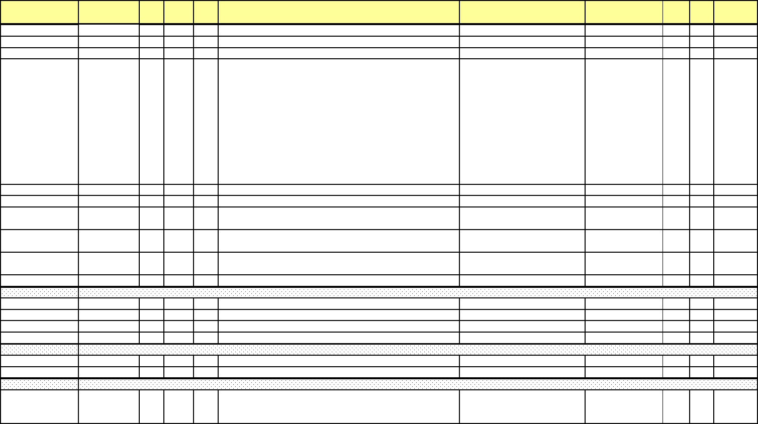
Addr. (hex) Address(4X) Line Pt DNP
Ob
j
Description Range Units Type R/W Notes
FF8A
H
65419 Port To Port Communications, USB serial R/
W
FF8B
H
65420 Port To Port Communications, Optica
l
R/
W
FF8C
H
65421 Port To Port Communications, Reserve
d
R/
W
FF90H-FF91H 65425-65426
Additional
meter
status
bits
(Available
when
Bit
15
on
0xFF80
register is set).
1st 4-bytes group.
Bit 31[MSB] = 1 (Invalid waveform calibration)
Bit 30 = 1 (Invalid profile settings for PQ/Waveform)
Possible error conditions
1) Waveform capture sample per cycle rate is invalid
2) Sample reduction factor does not match sample per cycle
3) Mismatch between transfer channels and transient setting
Bit 29 = 1 (Invalid NV Memory)
Bit 28-0 = Not defined
FF92H-FFAF
H
65427-65456 Additional meter status bits: 2nd/16th 4-bytes group.
FFB0H-FFBF
H
65457-65472 Meter Reserved
FFDCH 65501
DSP Boot FLASH Manufacturer ID/ Device ID (Boot Mode
Only)
FFDDH 65502
DSP Run FLASH Manufacturer ID/ Device ID (Boot Mode
Only)
FFDEH 65503
DSP Boot & Run FLASH Sector Protect Status (Boot Mode
Only) W
FFDF
H
65504 DSP Boot & Run FLASH c
hi
p test resu
l
ts
(
Boot Mo
d
e On
l
y
)
W
FFE0
H
65505 Update status
FFE1
H
65506 Update error code
FFE2H-FFE5
H
65507-65510 file data time
FFE6
H
65511
fil
e c
h
ec
k
su
m
FFFA
H
65531 Complete Meter Restart Command - write 0x0001
FFFB
H
65532 Reserve
d
FFFCH-FFFFH 65533-65536 Meter Serial Number 9,999,999,999,999,999 / 0 1 R
16-digit
Packed
BCD
Meter Serial Number
Meter Restart
Update Information Block
e Electro Industries/GaugeTech Doc# E154703 MM-231

Addr. (hex) Address(3X) Line Pt DNP
Obj Description Range Units Type R/W Notes
8606H-8607H 34311-34312 10309 0 3 sec Symm Comp Mag (Current PN) - Zero Sequence -32767.999/+32767.999 Amp F73 R
8608H-8609H 34313-34314 10309 1 3 sec Symm Comp Mag (Current PN) - Pos Sequence -32767.999/+32767.999 Amp F73 R
860AH-860BH 34315-34316 10309 2 3 sec Symm Comp Mag (Current PN) - Neg Sequence -32767.999/+32767.999 Amp F73 R
860CH-860DH 34317-34318 10310 0 10 min Symm Comp Mag (Current PN) - Zero Sequence -32767.999/+32767.999 Amp F73 R
860EH-860FH 34319-34320 10310 1 10 min Symm Comp Mag (Current PN) - Pos Sequence -32767.999/+32767.999 Amp F73 R
8610H-8611H 34321-34322 10310 2 10 min Symm Comp Mag (Current PN) - Neg Sequence -32767.999/+32767.999 Amp F73 R
8612H 34323 10311 0 3 sec Symm Comp Phase (Current PN) - Zero Sequence -32767.999/+32767.999 Amp F73 R
8613H 34324 10311 1 3 sec Symm Comp Phase (Current PN) - Pos Sequence -32767.999/+32767.999 Amp F73 R
8614H 34325 10311 2 3 sec Symm Comp Phase (Current PN) - Neg Sequence -32767.999/+32767.999 Amp F73 R
8615H 34326 10312 0 10 min Symm Comp Phase (Current PN) - Zero Sequence -32767.999/+32767.999 Amp F73 R
8616H 34327 10312 1 10 min Symm Comp Phase (Current PN) - Pos Sequence -32767.999/+32767.999 Amp F73 R
8617H 34328 10312 2 10 min Symm Comp Phase (Current PN) - Neg Sequence -32767.999/+32767.999 Amp F73 R
8618H-8619H 34329-34330 10313 0 3 sec Symm Comp Ratio (Current PN) - Zero Sequence -327.67/+327.67 0.01% F10 R
861AH-861BH 34331-34332 10313 1 3 sec Symm Comp Ratio (Current PN) - Neg Sequence -327.67/+327.67 0.01% F10 R
861CH-861DH 34333-34334 10313 2 3 sec Symm Comp Ratio (Current PP) - Neg Sequence -327.67/+327.67 0.01% F10 R
861EH-861FH 34335-34336 10314 0 10 min Symm Comp Ratio (Current PN) - Zero Sequence -327.67/+327.67 0.01% F10 R
8620H-8621H 34337-34338 10314 1 10 min Symm Comp Ratio (Current PN) - Neg Sequence -327.67/+327.67 0.01% F10 R
8622H-8623H 34339-34340 10314 2 10 min Symm Comp Ratio (Current PP) - Neg Sequence -327.67/+327.67 0.01% F10 R
8624H-8625H 34341-34342 10315 0 2 hour Symm Comp Ratio (Current PN) - Zero Sequence -327.67/+327.67 0.01% F10 R
8626H-8627H 34343-34344 10315 1 2 hour Symm Comp Ratio (Current PN) - Neg Sequence -327.67/+327.67 0.01% F10 R
8628H-8629H 34345-34346 10315 2 2 hour Symm Comp Ratio (Current PP) - Neg Sequence -327.67/+327.67 0.01% F10 R
e Electro Industries/GaugeTech Doc# E154703 MM-232
The map below is from the Input Registers of the Modbus Map.
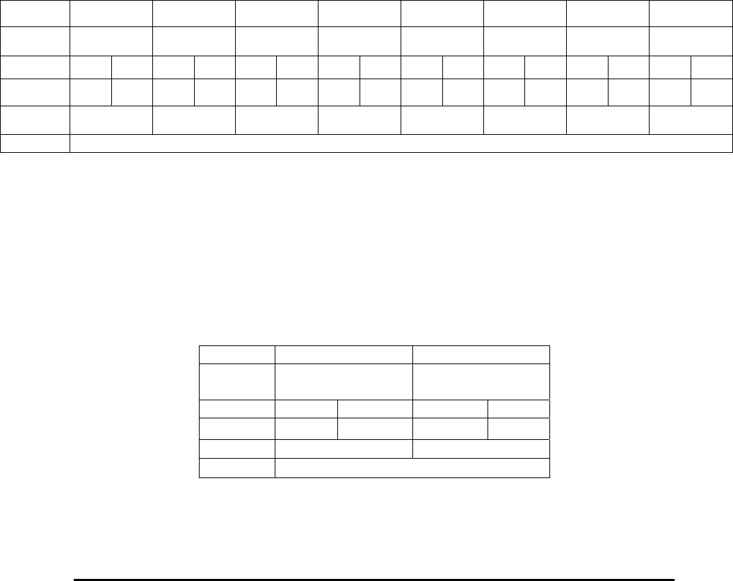
E Electro Industries/GaugeTech Doc # E154703 3- 1
Chapter 3
Communication Data Formats
This chapter expands upon information listed in the Nexus® 1500 meter’s Modbus Register Map
(Chapter 2). Section Headings (F1, F2, etc) refer to the value in the Register Map’s “Type”
column.
3.1: Type F1 Null Terminated ASCII String
Length: Depends on the reading.
Each register contains two bytes. Each byte stands for an ASCII character. The
printable portion of the string is terminated with a Null character (ASCII 00H).
Any characters after the terminating Null are ignored.
Example:
Registers 00001 – 00008, the Device Name, might contain the following data:
Address 00001 00002 00003 00004 00005 00006 00007 00008
Value 3031H 3037H 2043H 6578H 7573H 2031H 3530H 3200H
Bytes 30H 31H 30H 37H 20H 43H 65H 78H 75H 73H 20H 31H 35H 30H 30H 00H
ASCII ‘0’ ‘1’ ‘0’ ‘7’ “ ‘N’ ‘e’ ‘x’ ‘u’ ‘s’ “ ‘1’ ‘5’ ‘0’ ‘0’ Null
Register “01” “07” “N” “ex” “us" “1” “50” “0”
String “0107 Nexus 1500”
3.2: Type F2 Fixed Length ASCII String
Length: Depends on the reading.
Each register contains two bytes. Each byte stands for an ASCII character. All
bytes are significant. There is no terminating character.
Example:
Registers 00073 – 00074, the Nexus® Comm Boot Version Number, might contain the
following data:
Address 00073 00074
Value
3030H
3134H
Bytes 30H 30H 31H 31H
ASCII ‘0’ ‘0’ ‘1’ ‘1’
Register “00” “14”
String “0014”
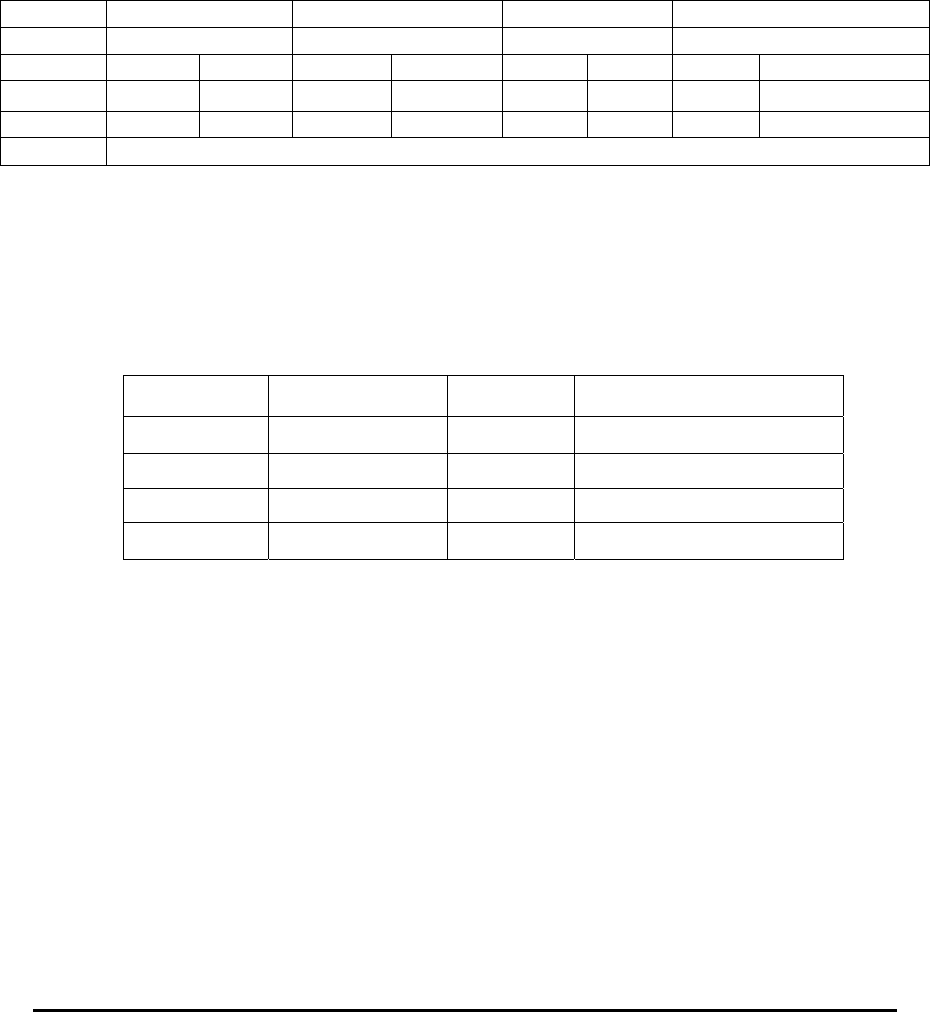
E Electro Industries/GaugeTech Doc # E154703 3- 2
3.3: Type F3 Time Stamp
Length: 4 Registers (8 bytes)
Each register contains two bytes. Each byte contains a binary number
representing up to two digits in a part of date and time. The units for each byte
are century, year, month, date, hour, minute, second and 10 millisecond. Hour is
in 24-hour form, 00H = 0 = 12 AM, 01H = 1 = 1 AM, …, 0BH = 11 = 11 AM,
0CH = 12 = 12 PM, 0DH = 13 = 1 PM, …, 17H = 23 = 11 PM.
Example:
Registers 00081 – 00084, On Time, might contain the following data:
3.4: Type F4 Day of Week
Length: 1 Register (2 bytes)
This register contains a 16-bit number, associated with the days of the week as
follows:
Value Day of the Week Value Day of the Week
0001H Sunday
0005H Thursday
0002H Monday
0006H Friday
0003H Tuesday
0007H Saturday
0004H Wednesday
3.5: Type F5 Not used by the Nexus® 1500 meter
3.6: Type F6 High Speed Input Delta and Current State
Length: 1 Register (2 bytes)
This register has two bytes. Each byte has eight bits. The bits in each byte are
associated with the 8 High Speed Inputs, the least significant bit with Input 1,
through to the most significant bit with Input 8.
The most significant byte contains Delta information about High Speed Inputs;
the least significant byte contains the Current State of the High Speed Inputs. For
Delta bits, a bit value of 1 means one or more were noticed on this input during
the last cycle, a bit value of 0 means no changes were noticed on this input during
the last cycle. For Current State bits, a bit value of 1 means the input is open, a bit
value of 0 means the input is closed.
Address 00081 00082 00083 00084
Value 1404H 0619H 0913H 3056H
Bytes 14H 04H 06H 19H 09H 13H 30H 56H
Decimal 20 04 6 25 9 19 48 86
Unit Century Year Month Date Hour Minute Second 10 Millisecond
Date June 25, 2004 9:19:48:86 AM
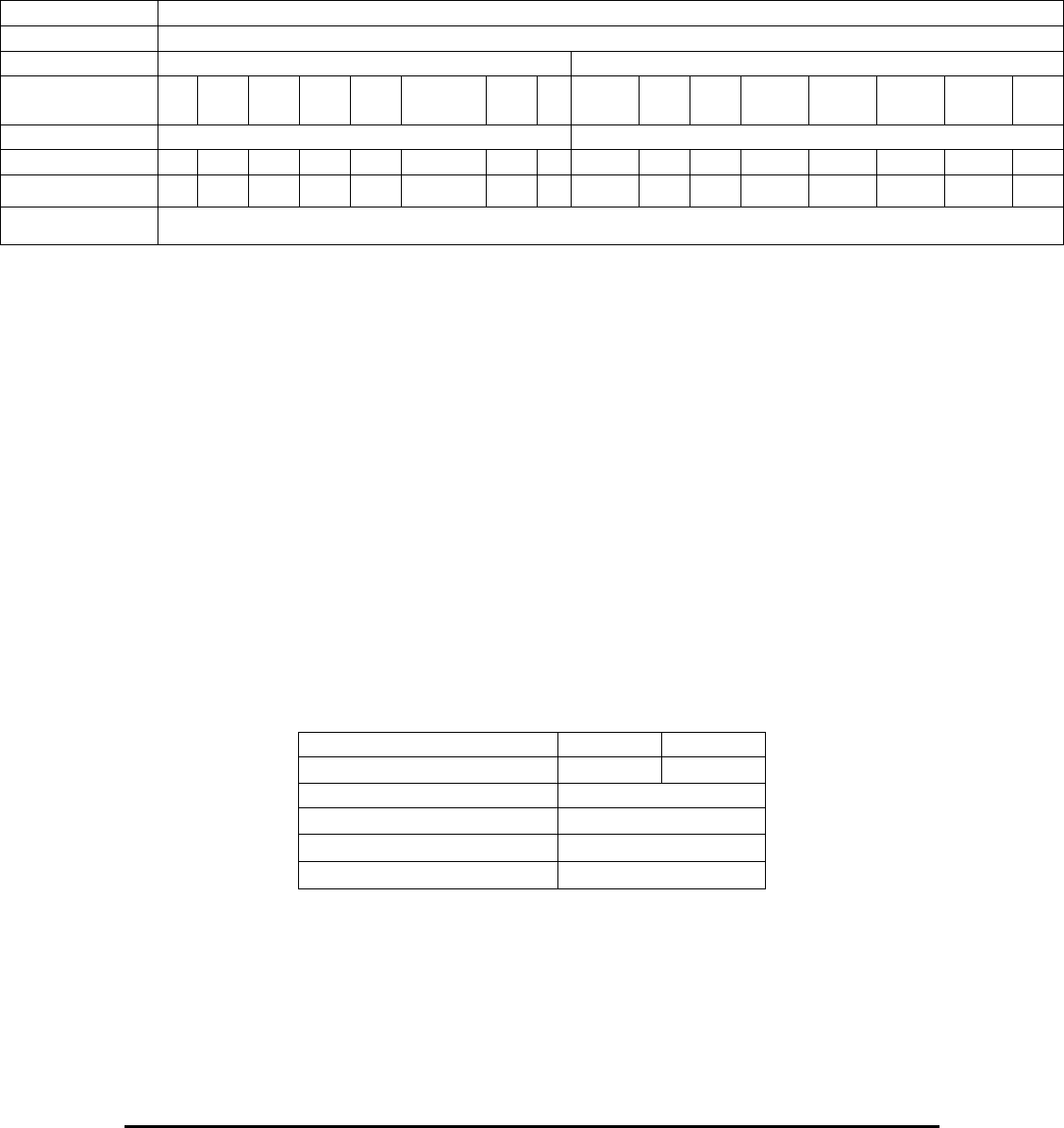
E Electro Industries/GaugeTech Doc # E154703 3- 3
Example:
Register 00118, 1 cycle High Speed Input Delta and Current State, might contain the
following data.
3.7: Type F7 Secondary Voltage, Current, VA, VAR, Watts, Hz or Flicker
Length: 2 Registers (4 bytes)
Range: +32767 / -32768
Unit: 1/65536 V, A, VA, VAR, W or Hz
The registers together contain a four-byte signed (2's compliment) integer.
Positive values have the most significant bit clear, and have the same magnitude
as an unsigned integer. Negative values have the most significant bit set. The
magnitude of a negative value is found by complimenting (inverting) all of the
bits and adding 1.
Example:
Registers 00153 – 00154, Tenth second Phase A VAR might contain the following data:
Register 00153 – 00154, Tenth second Phase A VAR, might contain the following data:
Address 00118
Value 0461H
Bytes 04H 61H
0 0 0 0 0 1 0 0
0
1
1 0 0 0 0 1
High Speed Input Delta High Speed Input Current State
8 7 6 5 4 3 2 1 8 7 6 5 4 3 2 1
Meaning _ _ _ _ _
Change _ _ Clsd Opn Opn Clsd Clsd Clsd Clsd Opn
Interpretation Inputs 7, 6, and ,and 1 are now open and Input 3 changed state at least once during the last cycle.
Address 00153 00154
Value 0001H 4000H
4-byte signed integer (Hex) 00014000H
Most significant bit 0
4-byte integer (Decimal) +81920
1/65536 VAR Secondary +1.25 VAR secondary
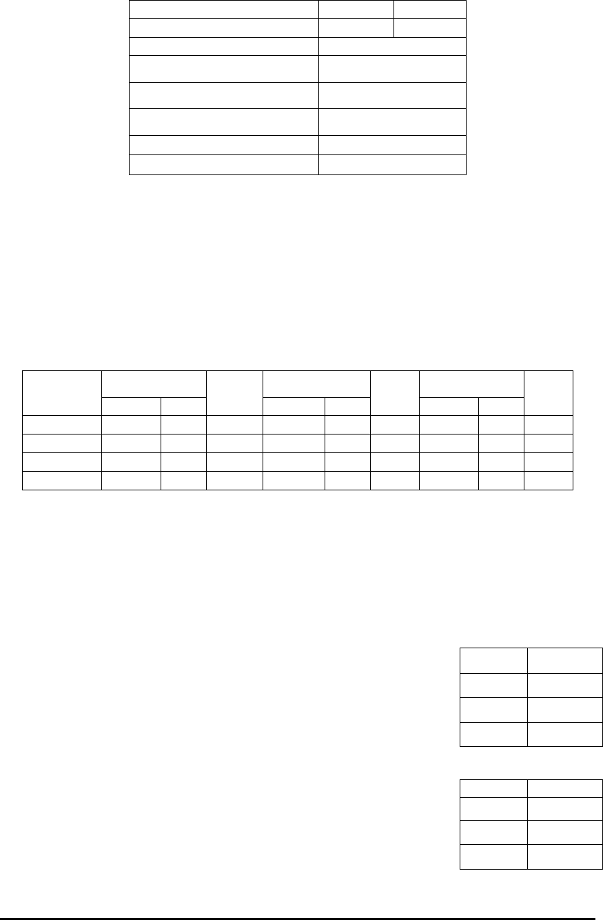
E Electro Industries/GaugeTech Doc # E154703 3- 4
3.8: Type F8 Power Factor
Length: 1 Register (2 bytes)
Range: 3.999 / 0.000
Unit: 0.001 PF
This register contains a 16 bit unsigned number. This number varies from 0000H
– 0F9FH, or 0 to 3999 in decimal. This representation allows for expressing
Power Factor from 0 to 1 in the four quadrants, as follows:
Value Value Value
Quadrant
Hex Dec
PF
Hex Dec
PF
Hex Dec
PF
1 0000H 0 0.0000 01F4H 500 0.500 03E7H 999 0.999
4 03E8H 1000 1.000 05DCH 1500 0.500 07CFH 1999 0.001
3 07D0H 2000 0.0000 09c4h 2500 0.500 0bb7h 2999 0.999
2 0bb8h 3000 1.000 0dach 3500 0.500 0f9fh 3999 0.001
Application of sign and lead/lag labels (is 9CFH -0.500 Lead or +0.500 Lag) depends on the
Programmable Setting called Power Factor Labeling, located in Register 46019, described in
Section 7.19.
Example:
Register 00171, Tenth second Phase A Power Factor, might
contain the data shown on the right:
Example:
Register 00171, Tenth second Phase A Power Factor, might
contain the data: shown on the right:
Address 00153 00154
Value FFFEH C000H
4-byte signed integer (Hex) FFFEC000H
Most significant bit 1
Compliment 00013FFFH
Increment 00014000H
4-byte integer (Decimal) -81920
1/65536 VAR Secondary -1.25 VAR secondary
Address 00171
Value 0C10H
Decimal 3088
PF Q2, 0.912
Address 00171
Value 0390H
Decimal 912
PF Q1, 0.912
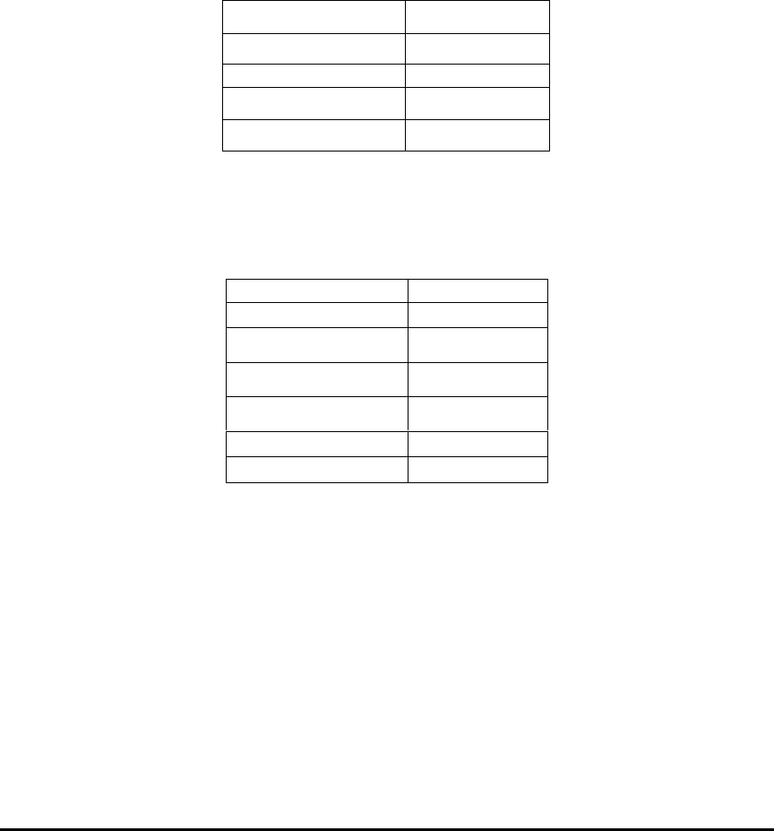
E Electro Industries/GaugeTech Doc # E154703 3- 5
3.9: Type F9 Angle
Length: 1 Register (2 byte)
Range: +180 / -180
Unit: 0.01 degree
This register contains a 16-bit signed (2's compliment) number. Positive values
have the most significant bit clear, and have the same magnitude as an unsigned
integer. Negative values have the most significant bit set. The magnitude of a
negative value is found by complimenting (inverting) all of the bits and adding 1.
Example:
Register 00175, Tenth second Phase A-N Voltage to Auxiliary Voltage Phase Angle,
might contain the following data:
Example:
Register 00175, Tenth second Phase A-N Voltage to Auxiliary Voltage Phase Angle,
might contain the following data.
3.10: Type F10 Percentage
Length: 1 Register (2 bytes)
Range: +327.67% / - 327.68%
Unit: 0.01%
This register contains a 16-bit signed (2's compliment) number. Positive values
have the most significant bit clear, and have the same magnitude as an unsigned
integer. Negative values have the most significant bit set. The magnitude of a
negative value is found by complimenting (inverting) all of the bits and adding 1.
Example:
Register 00234, One second Voltage Imbalance, might contain the following data:
Address 00175
Value 08BBH
Most significant bit 0
Decimal +2235
Angle +22.35 Degrees
Address 00175
Value F745H
Most significant bit 1
Compliment 08BAH
Increment 08BBH
Decimal -2235
Angle -22.35 Degrees
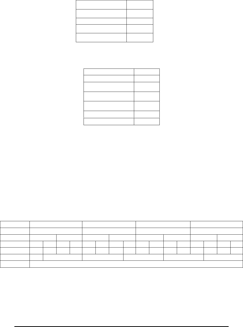
E Electro Industries/GaugeTech Doc # E154703 3- 6
Example:
Register 00234, One second Voltage Imbalance, might contain the following data:
3.11: Type F11 Energy Counter (Packed BCD / Secondary)
Length: 4 Registers (8 bytes)
Range: 9,999,999,999,999,999 / 0 VAh, VARh or Wh secondary
Unit: 1 VAh, VARh or Wh secondary
These registers contain 8 bytes of Packed BCD. Each register contains 2 bytes.
Each byte contains 2 nibbles. Each nibble represents a decimal digit from 0-9. All
together, there are 16 nibbles, and therefore a 16-digit decimal number can be
represented.
Example:
Registers 00982 – 00985, VAhour, might contain the following data:
3.12: Type F12 Energy Counter (Binary / Secondary)
Length: 4 Registers (8 bytes)
Range: 9,999,999,999,999,999 / 0 VAh, VARh or Wh secondary
Unit: 1 VAh, VARh or Wh secondary
Address 00234
Value 08BBH
Most significant bit 0
Decimal +2235
Percent +22.35 %
Address 00234
Value F745H
Most significant bit 1
Compliment 08BAH
Increment 08BBH
Decimal -2235
Percent -22.35 %
Address 00982 00983 00984 00985
Value 000H 0001H 0534H 1284H
Bytes 00H 00H 00H 01H 05H 34H 12H 84H
Nibbles 0H 0H 0H 0H 0H 0H 0H 1H 0H 5H 3H 4H 1H 2H 8H 4H
Digit 0 0 0 0 0 0 0 1 0 5 3 4 1 2 8 4
Unit P T G M k
VAh 105,341,284 VAh secondary
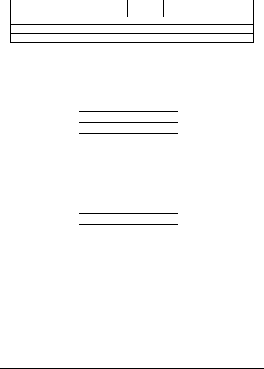
E Electro Industries/GaugeTech Doc # E154703 3- 7
These registers contain an 8-byte unsigned integer.
Example:
Registers 01002-01005, VAhour, might contain the following data:
3.13: Type F13 Phase Sequence
Length: 1 Register (2 bytes)
This register contains a 16-bit unsigned integer, associated with the Phase
Sequence as follows:
Value (Hex) Phase Sequence
0000H A-B-C
0001H C-B-A
3.14: Type F14 Average Status
Length: 1 Register (2 bytes)
This register contains a 16-bit unsigned integer, associated with the Average
Status as follows:
Value (Hex) Average Status
0000H Not yet available
0001H Available
This is the Status Register for Block Window Average (02605-02683) and
Rolling Window Average (02684-02768).
If a value is not yet computed by the Nexus® device, the Status value will be
zero. When the value is zero, Communicator EXT software displays asterisks for
values.
In Modbus, a value will be returned based on the type of reading.
Negative Maximums and Positive Minimums return: 7FFFFFFFH or
2,147,483,647.
Positive Maximums and Negative Minimums return: 80000000H or +/-
2,147,483,647.
No Timestamp will be assigned to the reading.
3.15: Type F15 Limit States
Length: 1 Register (2 bytes)
Address 01002 01003 01004 01005
Value 0000H 0000H 0647H 6164H
8-byte unsigned integer (Hex) 0000000006476164H
Decimal 105341284
VAh 105,341,284 VAh secondary
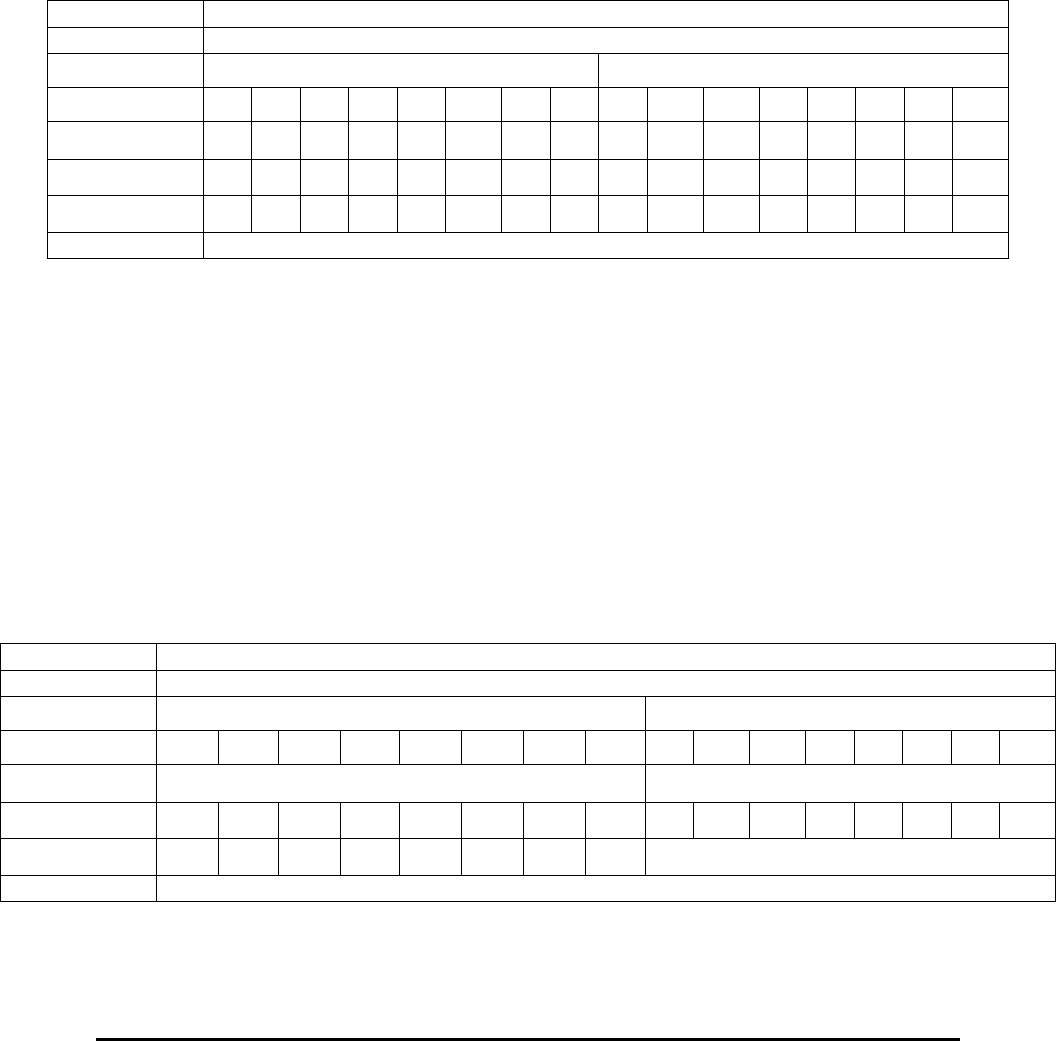
E Electro Industries/GaugeTech Doc # E154703 3- 8
This register has two bytes. Each byte has eight bits. The bits in these bytes are
associated with the 16 Limits, the most significant bit of the most significant byte
with Limit 1 (or 17), through to the least significant bit of the least significant byte
with Limit 16 (or 32).
A bit value of 1 means that the particular limit has been passed, while a bit value
of 0 means that the particular limit has not been passed.
Example:
Register 02769, Limit States, Value 1 Comparison, 1–16, might contain the following
data:
3.16: Type F16 Low Speed Input States
Length: 1 Register (2 bytes)
This register has two bytes. Each byte has eight bits. The bits in the most
significant byte are associated with the eight Status Inputs, the most significant bit
with input 8, through to the least significant bit with Input 1. The least significant
byte is undefined.
A bit value of 1 means the input is open; a bit value of 0 means the input is
closed.
Example:
Register 02773, Low Speed Input States, might contain the following data:
Address 02769
Value 0461H
Bytes 04H 61H
Bits 0 0 0 0 0 1 0 0 0 1 1 0 0 0 0 1
Points 0 1 2 3 4 5 6 7 8 9 10 11 12 13 14 15
Limit 1 2 3 4 5 6 7 8 9 10 11 12 13 14 15 16
Passed No No No No No Yes No No No Yes Yes No No No No Yes
Interpretation Limits 6, 10, 11, and 16 are currently passed; all others are not passed.
Address 02773
Value 5100H
Bytes 51H 00H
Bits 0 1 0 1 0 0 0 1 0 0 0 0 0 0 0 0
Undefined
Input 8 7 6 5 4 3 2 1 8 7 6 5 4 3 2 1
Meaning Clsd Opn Clsd Opn Clsd Clsd Clsd Opn
Interpretation Inputs 7, 5, and 1 are open; all other inputs are closed.
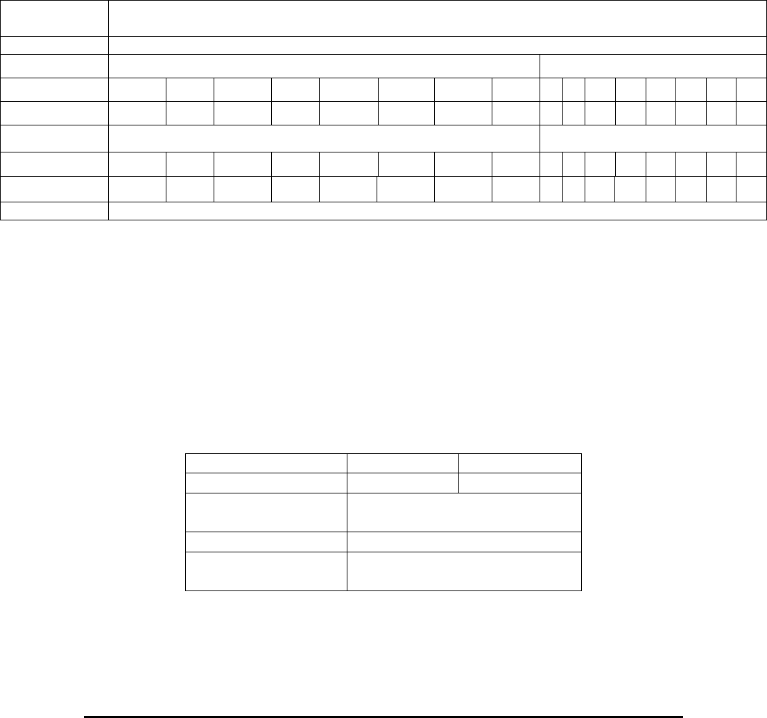
E Electro Industries/GaugeTech Doc # E154703 3- 9
3.17: Type F17 Digital Input States in Digital Input Option Board
Length: 1 Register (2 bytes)
This register has two bytes. Each byte has eight bits. The bits in the Most significant byte
are associated with the eight Digital Inputs in a Digital Input Option board, the most
significant bit with input 8, through to the least significant bit with Input 1. The least
significant byte is undefined.
A bit value of 1 means the input is open; a bit value of 0 means the input is closed.
Example: Register 0AD5H, Digital Input States, Digital Input Option board in Slot 3, might
contain the following data:
3.18: Type F18 Digital Input Option Board Input Accumulation /
Cumulative Demand
Length 2 Registers (4 bytes)
Range 4,294,967,295/0
Unit Accumulated Transitions, Accumulated Primary Watts
These registers contain a 4 byte unsigned integer.
Example:
Registers 0AD6H-0AD7H, Input Accumulation 1, Digital Input Option Board in slot 3, might
contain the following data:
Addr (Hex) 0AD6H 0AD7H
Value 0647H 6164H
4 byte unsigned
integer
06476164H
Decimal 105341284
Accumulated
Transitions
105,341,284 Accumulated
Transitions
Address
(Hex)
0AD5H
Value 5100H
Bytes 51H 00H
Bits 0 0 0 0 0 0 0 0 0 1 0 1 0 0 0 1
Point 0 1 2 3 4 5 6 7 8 9 10 11 12 13 14 15
Digital Input States Undefined
Input 8 7 6 5 4 3 2 1
Meaning Closed Open Closed Open Closed Closed Closed Open
Interpretation Inputs 7, 5 and 1 are open; all other inputs are closed.
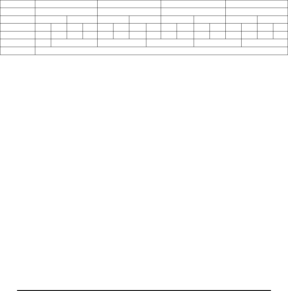
E Electro Industries/GaugeTech Doc # E154703 3- 10
3.19: Type F19 Energy Counter (Packed BCD / Primary)
Length: 4 Registers (8 bytes)
Range: 9,999,999,999,999,999/0 VAh, VARh or Wh primary
1 VAh, VARh or Wh primary
These registers contain 8 bytes of Packed BCD. Each register contains 2 bytes.
Each byte contains 2 nibbles. Each nibble represents a decimal digit from 0-9.
All together, there are 16 nibbles. Therefore, a 16-digit decimal number can be
represented.
Example:
Register 02850-02853, VAhour, might contain the following data:
Address 02850 02851 02852 02853
Value 000H 0001H 0534H 1284H
Bytes 00H 00H 00H 01H 05H 34H 12H 84H
Nibbles 0H 0H 0H 0H 0H 0H 0H 1H 0H 5H 3H 4H 1H 2H 8H 4H
Digit 0 0 0 0 0 0 0 1 0 5 3 4 1 2 8 4
Unit P T G M k
VAh 105,341,284 VAh primary
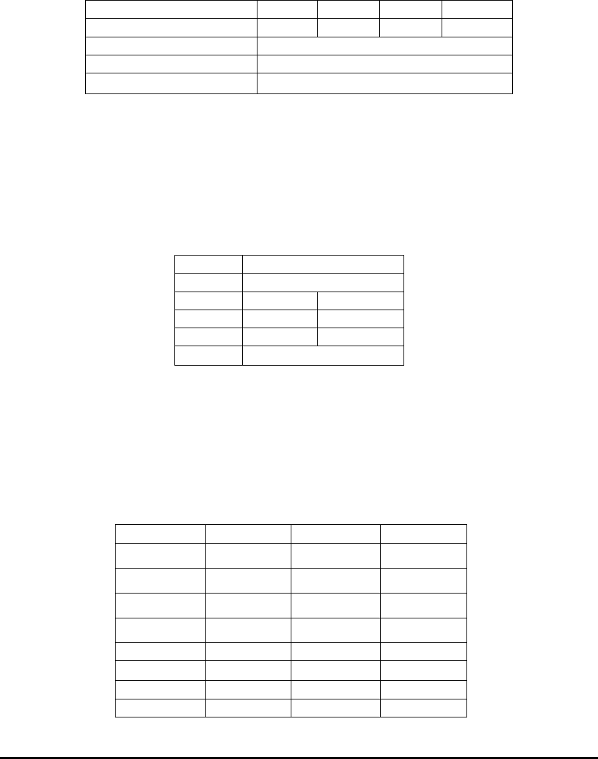
E Electro Industries/GaugeTech Doc # E154703 3- 11
3.20: Type F20 Energy Counter (Binary / Primary)
Length: 4 Registers (8 bytes)
Range: 9,999,999,999,999,999/0 VAh, VARh or Wh primary
1 VAh, VARh or Wh primary
These registers contain an 8-byte unsigned integer.
Example:
Register 02898-02901, VAhour, might contain the following data:
Address 02898 02899 02900 02901
Value 0000H 0000H 0647H 6164H
8-byte unsigned integer 0000000006476164H
Decimal 105341284
VAh 105,341,284 VAh primary
3.21: Type F21 Year
Length: 1 Register (2 bytes)
Each byte contains a binary number representing up to two digits in a part of a
year. The units for each byte are century and year.
Example:
Register 34821, TOU Calendar Year 1 Calendar Year, might contain the following data:
Address 34821
Value 1363H
Bytes 13H 63H
Decimal 19 99
Unit Century Year
Date 1999
3.22: Type F22 TOU Profile per Day
Length: 1 Register (2 bytes)
Each byte stands for a different day of the year. Days are listed in calendar order,
including the allowance for a leap year. Each byte contains an enumeration
indicating which TOU Profile to use for that day. The enumerations are as
follows:
Value(Hex) Profile Value(Hex) Profile
00H Profile1 08H Profile9
01H Profile2 09H Profile10
02H Profile2 010H Profile11
03H Profile3 011H Profile12
04H Profile4 012H Profile13
05H Profile5 013H Profile14
06H Profile6 014H Profile15
07H Profile7 015H Profile16
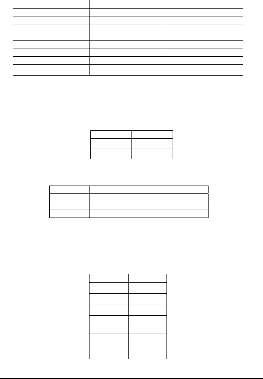
E Electro Industries/GaugeTech Doc # E154703 3- 12
Example:
Register 34954, TOU Calendar Year 1 Mar 2 (Mar1) / Mar 3 (Mar 2), might contain the
following data:
Address 34954
Value 0305H
Bytes 03H 05H
Decimal 3 5
Meaning Profile 3 Profile 5
Day March 4 March 5
Day (Leap Year) March 3 March 4
Meaning Profile 3 on March 4 Profile 5 on March 5
Meaning (Leap Year) Profile 3 on March 3 Profile 5 on March 4
3.23: Type F23 TOU Profile Status
Length: 1 Register (2 bytes)
This register contains an enumeration indicating the Status of the Profile. The
enumeration is as follows:
Example:
Register 35107, TOU Calendar Year 1 Profile 1 Status, might contain the following data:
Address 35107
Value 0001H
Decimal 1
Meaning TOU Year 1 Profile 1 is programmed
3.24: Type F24 TOU Daily Profile Register Assignment
Length: 1 Register (2 bytes)
Each register contains 2 bytes. Each byte contains 2 nibbles. Each nibble
contains an enumeration indicating which TOU Register is to be used during the
indicated 15-minute period. The enumerations are as follows:
Value(Hex) Register
0H Register1
1H Register2
2H Register3
3H Register4
4H Register5
5H Register6
6H Register7
7H Register8
Value (Hex) Status
00H Not Used
01H Programmed
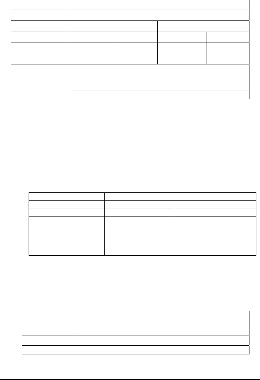
E Electro Industries/GaugeTech Doc # E154703 3- 13
Example:
Register 35108, TOU Calendar Year 1 Profile 1 for 00:00, 00:15, 00;30 & 00:45, might
contain the following data:
Address 35108
Value 1234H
Bytes 12H 34H
Nibbles 1H 2H 3H 4H
Decimal 1 2 3 4
Period 00:00-00:14 00:15-00:29 00:30-00:44 00:45-00:59
Profile 1 from 00:00-00:14
Profile 2 from 00:15-00:29
Profile 3 from 00:30-00:44
Meaning
Profile 4 from 00:45-00:59
3.25: Type F25 TOU Profile Monthly End Day
Length: 1 Register (2 bytes)
Each byte stands for a different month of the year. Each byte contains a binary
number indicating what the last day of the monthly billing cycle should be for that
month. Billing periods are up to and including the end day.
Example:
Register 35507, TOU Calendar Year 1 Monthly End Day Jan & Feb, might contain the
following data:
Address 35507
Value 0E0FH
Bytes 0EH 0FH
Decimal 14 15
Month January February
Day Jan 14 Jan 15
Meaning Billing months run through January 14, from January
15 through February 15 and start on February 16.
3.26: Type F26 TOU Calendar DST Enable / Average Selection
Length: 1 Register (2 bytes)
The first byte contains an enumeration indicating whether Daylight Savings Time
is enabled for TOU computations. The enumeration is as follows:
Value (Hex) Selection
00H Daylight Savings Time is disabled.
01H Daylight Savings Time is enabled with default parameters.
02H Daylight Savings Time is enabled with custom parameters.
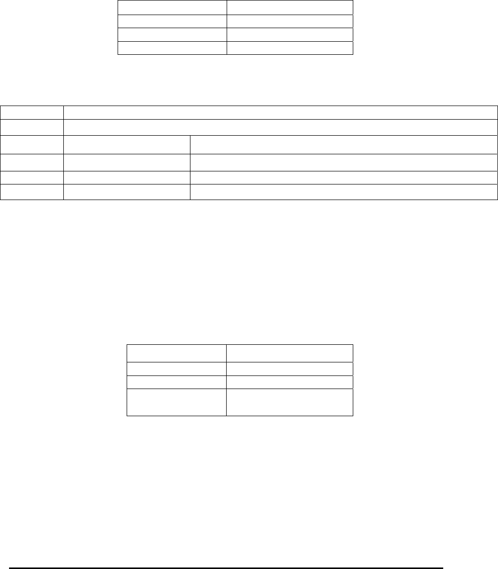
E Electro Industries/GaugeTech Doc # E154703 3- 14
The default parameters are to start on the first Sunday in April at 01:59:59.999
and to end on the last Sunday in October at 01:59:59.999. Custom parameters
means to use of the dates programmed in the Start and End Date Daylight Savings
Time registers from the appropriate TOU Calendar Year.
The second byte contains an enumeration indicating which form of average is to
be used for Peak and Coincident Demand functions. The enumeration is as
follows:
Value (Hex) Average
00H Block Window Average
01H Rolling window Average
02H Cumulative Demand
Example:
Register 35729, TOU Calendar Year0 DST Enable / Average Selection, might contain the
following data:
Address 35729
Value 0001H
Bytes 00H 01H
Decimal 0 1
Purpose DST Enabled Average Selection
Meaning DST Disabled for TOU Rolling Window Averages for TOU Peak and Coincident Demand
3.27: Type F27 TOU Upload Calendar Window Sequence / Status
Length: 1 Register (2 bytes)
The first byte contains an unsigned integer acting as a sequence number for
actions involving the Time of Use Upload Calendar Block. The sequence number
increments with action performed.
The second byte contains an enumeration indicating the status of the last action
involving the Time of Use Upload Calendar Block. The enumeration is as
follows:
Value (Hex) Status
00H Action failed.
01H Action passed.
02H Action is not yet finished.
Example:
Register 36608, TOU Upload Calendar Window Sequence / Status, might contain the
following data:
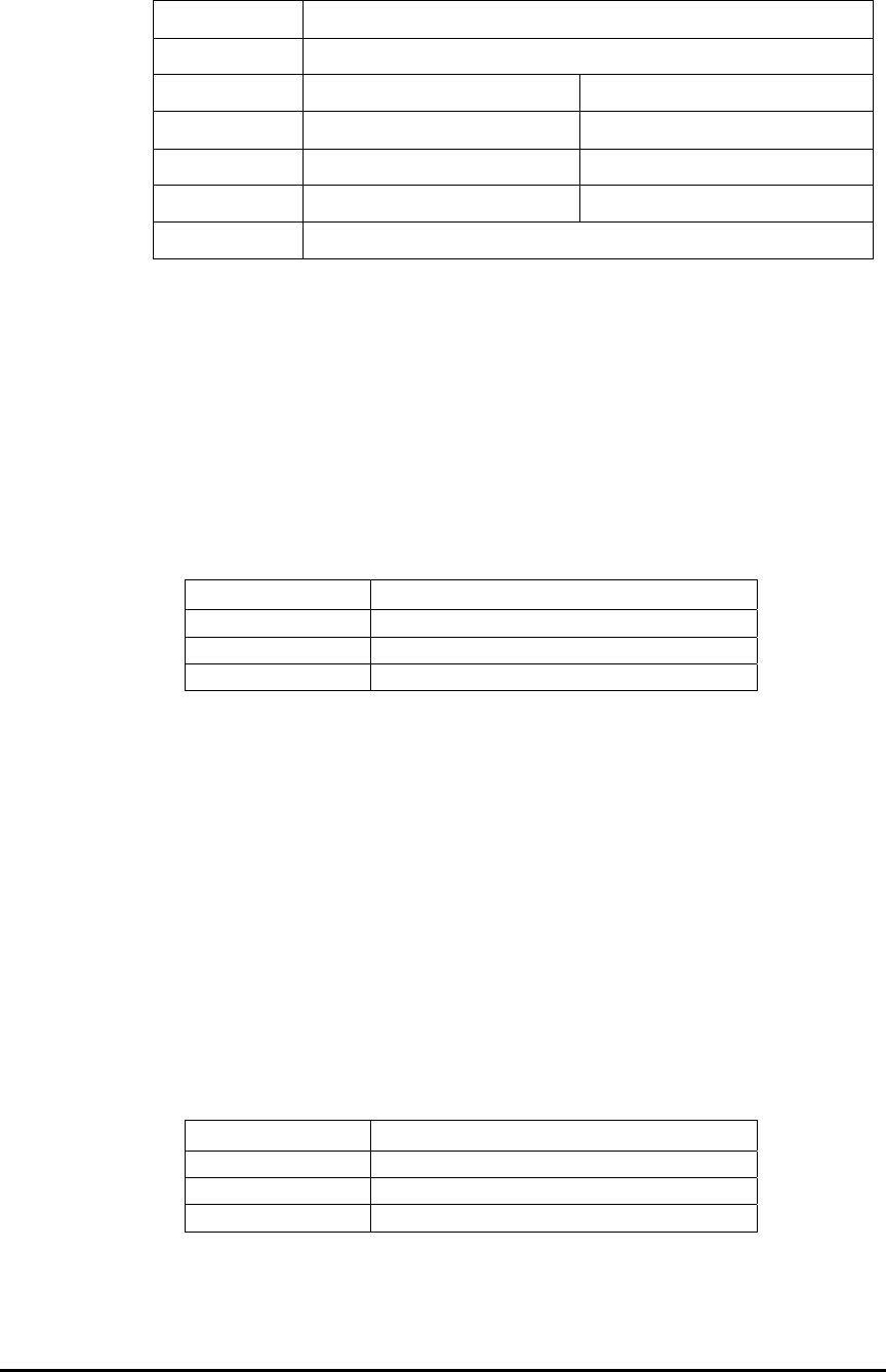
E Electro Industries/GaugeTech Doc # E154703 3- 15
Address 36608
Value 4202H
Bytes 42H 02H
Decimal 66 2
Purpose Sequence Status
Meaning Sequence #66 Unfinished
Meaning Sequence #66 is unfinished.
3.28: Type F28 TOU Upload Calendar Window ID
Length: 1 Register (2 bytes)
Range: 1 - 14
This register contains an enumeration indicating which TOU Calendar Window
is being uploaded through the Upload Window. The values 1 - 14 indicate
Windows 1 - 14.
Example:
Register 36609, TOU Upload Calendar Window ID, might contain the following data:
Address 36609
Value 0DH
Decimal 13
Meaning Window 13
3.29: Type F29 TOU Upload Calendar Window Data
Length: 1 Register (2 bytes)
This register contains data intended to update a portion of the TOU Calendar.
3.30: Type F30 TOU Upload Calendar Window Checksum
Length: 1 Register (2 bytes)
This register contains an unsigned integer which is the checksum for the rest of
the TOU Upload Calendar Window.
Example:
Register 36736, TOU Upload Calendar Window Checksum, might contain the following
data:
Address 36736
Value 3245H
Decimal 12869
Meaning Checksum is 12869.
E Electro Industries/GaugeTech Doc # E154703 3- 16
3.31: Type F31 TOU Calendar Selection
Length: 1 Register (2 bytes)
This register is used to indicate the TOU Calendar Year desired to be loaded into
the TOU Calendar Window. The enumeration is as follows:
Value (Hex) Year
0000H Year 1
0001H Year 2
0002H-0013H Year 3 - Year 20
0014H-FFFH Undefined
3.32: Type F32 TOU Calendar Header Status / Year Status
Length: 1 Register (2 bytes)
The first byte indicates the status of the TOU Calendar Header Block. The
second byte indicates the status of the requested TOU Calendar Year. The
enumeration for each byte is as follows:
Value (Hex) Year
00H Action failed.
01H Action passed.
02H Action is not yet finished.
3.33: Type F33 Temperature
Length: 1 Register (2 bytes)
Range: +327.67 C / - 327.68 C
Unit: 0.01 degree C
This register contains a 16-bit signed (2’s compliment) number. Positive values
have the most significant bit clear and have the same magnitude as an unsigned
integer. Negative values have the most significant bit set. The magnitude of a
negative value is found by complimenting (inverting) all of the bits and adding 1.
Example:
Register 05946, meter’s Internal Temperature, might contain the following data:
Address 05946
Value 08BBH
Most significant bit 0
Decimal +2235
Celsius +22.35 degree C
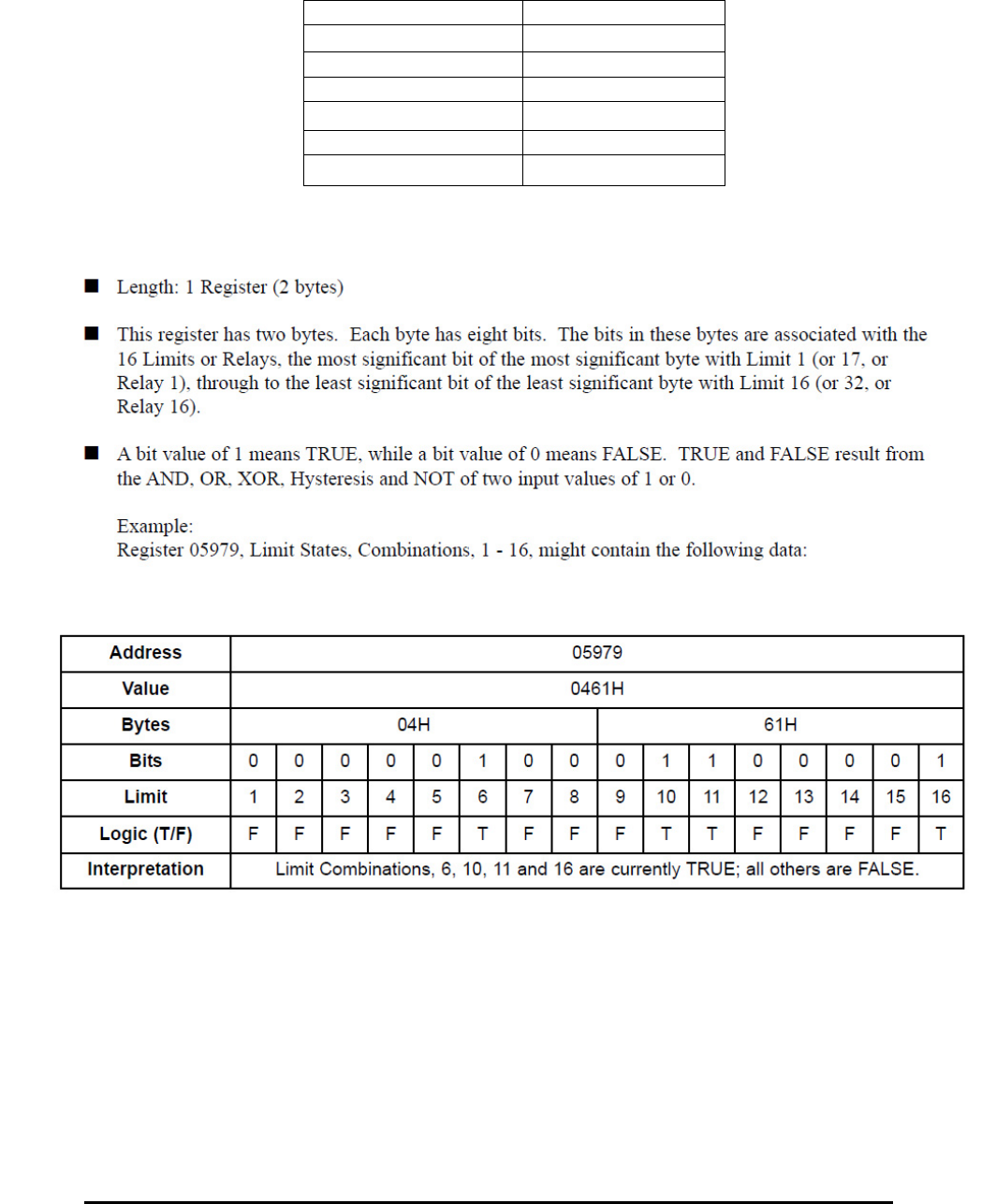
E Electro Industries/GaugeTech Doc # E154703 3- 17
Register 05946, meter’s Internal Temperature, might contain the following data:
Address 05946
Value F745H
Most significant bit 1
Compliment 08BAH
Increment 08BBH
Decimal 12235
Celsius 122.35 degree C
3.34: Type F34 Limit and Relay Logic States
3.35: Type F35 Relay Delays
Length: 1/2 Register (1 byte) (2 per Register)
This register has two bytes. Each byte contains an unsigned integer which is a count-
down delay. A relay logic tree must be stable for the duration of the delay before
triggering a relay. Delays are preloaded when the Gate G value changes. They are
decremented every pass thereafter, until they reach zero.
Example:
Register 06000, Delay Timer, Relay 1 / Relay 2, might contain the following data:
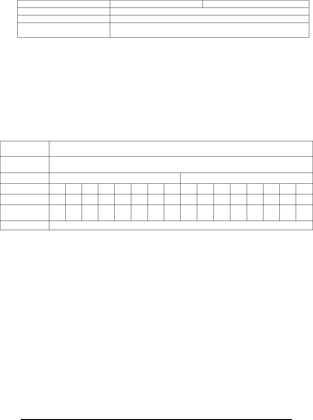
E Electro Industries/GaugeTech Doc # E154703 3- 18
Address 04H 00H
Value 0400H
Bytes 06000
Interpretation Relay 1 has 4 seconds of delay remaining, Relay 2 has no delay
remaining.
3.36: Type F36 Desired Relay States
Length: 1 Register (1 bytes)
This register has two bytes. Each byte has eight bits. The bits in these bytes are associated
with the 16 Relays, the most significant bit of the most significant byte with Relay 1,
through the least significant bit of the least significant byte with Relay 16.
A bit value of 1 means the relay should be energized (connected to Normal Open); a bit
value of 0 means the relay should be de-energized (connected to Normal Close). These
are states pending transmission to the relays.
Example:
Register 06008, Desired Relay States, Relays 1-16, might contain the following data:
3.37: Type F37 Relays Pending Update
Length: 1 Register (2 bytes)
This register has two bytes. Each byte has eight bits. The bits in these bytes are associated
with the 16 Relays, the most significant byte with Relay 1 through to the least significant
bit of the least significant byte with Relay 16.
A bit value of 1 means the physical relay needs to be updated, a bit value of 0 means the
physical relay does not need to be updated.
Example:
Register 06009, Relays Pending Updates 1-16, might contain the following data:
Address 06008
Value 0461H
Bytes 04H 61H
Bits 0 0 0 0 0 1 0 0 0 1 1 0 0 0 0 1
Limit 1 2 3 4 5 6 7 8 9 10 11 12 13 14 15 16
State
(NO/NC)
NC NC NC NC NC NO NC NC NC NO NO NC NC NC NC NO
Interpretation Relays 6, 10, 11 and 16 should be energized; all others de-energized.
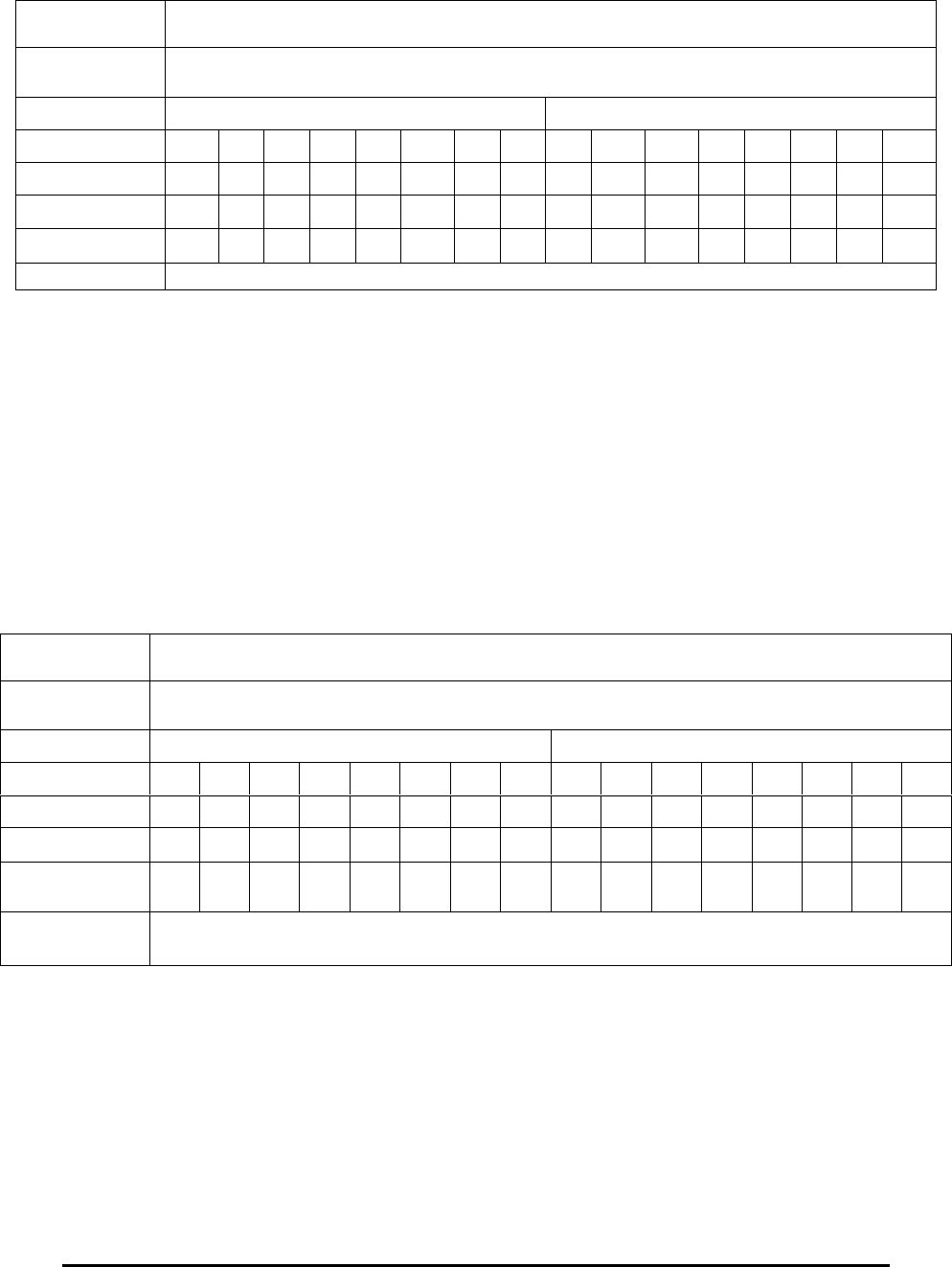
E Electro Industries/GaugeTech Doc # E154703 3- 19
3.38: Type F38 Shadowed Relay States
Length: 1 Register (2 bytes)
This register has two bytes. Each byte has eight bits. The bits in these bytes are associated
with the 16 Relays, the most significant byte with Relay 1 through to the least significant
bit of the least significant byte with Relay 16.
A bit value of 1 means the relay is supposed to be energized (connected to Normal
Open), a bit value of 0 means the relay is supposed to be de-energized (connected to
Normal Close). These states have not necessarily been confirmed by polling the relay
device.
Example:
Register 06010, Shadowed Relay States 1-16, might contain the following data:
3.39: Type F39 Confirmed Polled Relay States
Length: 1 Register (2 bytes)
This register has two bytes. Each byte has eight bits. The bits in these bytes are associated
with the 16 Relays, the most significant byte with Relay 1 through to the least significant
bit of the least significant byte with Relay 16.
A bit value of 1 means the relay was energized (connected to Normal Open) when last
polled, a bit value of 0 means the relay was de-energized (connected to Normal Close)
when last polled. These states may not be current on the relays, since operations may
have occurred since the last poll.
Address 06009
Value 0461H
Bytes 04H 61H
Bits 0 0 0 0 0 1 0 0 0 1 1 0 0 0 0 1
Point 0 1 2 3 4 5 6 7 8 9 10 11 12 13 14 15
Relay 1 2 3 4 5 6 7 8 9 10 11 12 13 14 15 16
Update? Yes Yes Yes Yes Yes
Interpretation Relays 6, 10, 11 and 16 need to be updated, all others are in their correct states.
Address 060010
Value 0461H
Bytes 04H 61H
Bits 0 0 0 0 0 1 0 0 0 1 0 0 0 0 0 0
Point 0 1 2 3 4 5 6 7 8 9 10 11 12 13 14 15
Relay 1 2 3 4 5 6 7 8 9 10 11 12 13 14 15 16
State
(NO/NC)
NC NC NC NC NC NO NC NC NC NO NC NC NC NC NC NC
Interpretation Relays 6 and 10 are supposed to be energized, all others de-energized, not
necessarily confirmed.
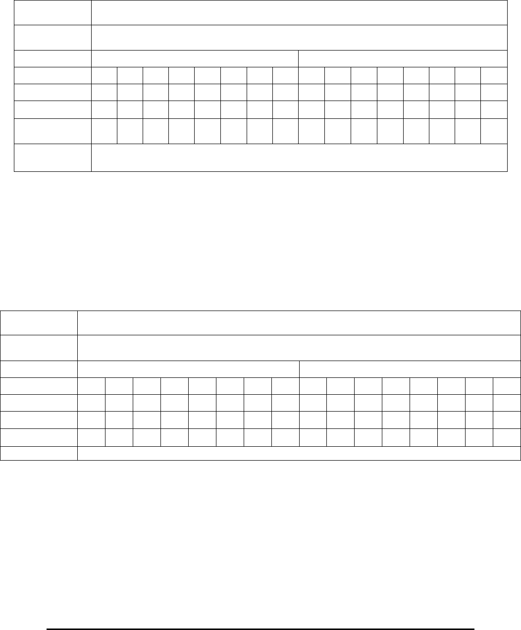
E Electro Industries/GaugeTech Doc # E154703 3- 20
Example:
Register 06011, Confirmed Polled Relay States 1-16, might contain the following data:
3.40: Type F40 Valid Flags for Confirmed Relay States
Length: 1 Register (2 bytes)
This register has two bytes. Each byte has eight bits. The bits in these bytes are associated
with the 16 Relays, the most significant byte with Relay 1 through to the least significant
bit of the least significant byte with Relay 16.
A bit value of 1 means the confirmed states in Confirmed Polled Relay States register
(06011) are valid, a bit value of 0 means the confirmed states have not yet been polled.
Example:
Register 06012, Valid Flags for Confirmed Relay States, might contain the following data:
3.41: Type F41 Locked Relays, Relays 1-16
Length: 1 Register (2 bytes)
This register has two bytes. Each byte has eight bits. The bits in these bytes are associated
with the 16 Relays, the most significant byte with Relay 1 through to the least significant
bit of the least significant byte with Relay 16.
A bit value of 1 means the relay has been locked, overriding the Relay Logic Tree for this
relay. A bit value of 0 means the relay is operating normally according to the Relay Logic
Tree.
Example:
Register 06013, Locked Relays, Relays 1-16, might contain the following data:
Address 060011
Value 0461H
Bytes 04H 61H
Bits 0 0 0 0 0 1 0 0 0 1 1 0 0 0 0 1
Point 0 1 2 3 4 5 6 7 8 9 10 11 12 13 14 15
Relay 1 2 3 4 5 6 7 8 9 10 11 12 13 14 15 16
State
(NO/NC)
NC NC NC NC NC NO NC NC NC NO NO NC NC NC NC NO
Interpretation Relays 6 ,10, 11, and 16 were energized when last polled, all others were de-
energized.
Address 060012
Value FFF0H
Bytes FFH F0H
Bits 1 1 1 1 1 1 1 1 1 1 1 1 0 0 0 0
Point 0 1 2 3 4 5 6 7 8 9 10 11 12 13 14 15
Relay 1 2 3 4 5 6 7 8 9 10 11 12 13 14 15 16
Valid? Yes Yes Yes Yes Yes Yes Yes Yes Yes Yes Yes Yes Yes Yes Yes Yes
Interpretation Confirmed states for Relays 13-16 have not yet been polled and are not yet valid.
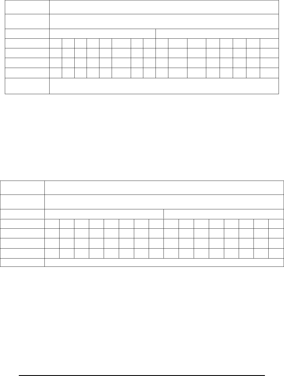
E Electro Industries/GaugeTech Doc # E154703 3- 21
3.42: Type F42 Locked Relay States
Length: 1 Register (2 bytes)
This register has two bytes. Each byte has eight bits. The bits in these bytes are associated
with the 16 Relays, the most significant byte with Relay 1 through to the least significant
bit of the least significant byte with Relay 16.
These bits are valid only if the relays have been selected for locking, as reported in the
Locked Relays register, 06013.
A bit value of 1 means the relay is locked energized (connected to Normal Open). A bit
value of 0 means the relay is locked de-energized (connected to Normal Close).
Example:
Register 06014, Locked Relay States, Relays 1-16, might contain the following data:
3.43: Type F43 Miscellaneous Flags
Length 1 Register (2 bytes)
This register has two bytes. Each byte has eight bits. The bits in these bytes are
associated with various miscellaneous functions as follows.
Address 060013
Value 0461H
Bytes 04H 61H
Bits 0 0 0 0 0 1 0 0 0 1 1 0 0 0 0 1
Point 0 1 2 3 4 5 6 7 8 9 10 11 12 13 14 15
Relay 1 2 3 4 5 6 7 8 9 10 11 12 13 14 15 16
Locked? Lock Lock Lock Lock
Interpretation Relays 6, 10, 11, and 16 are locked; all other relays are under control of the
RelayLogic tree.
Address 060014
Value 0461H
Bytes 04H 61H
Bits 0 0 0 0 0 1 0 0 0 1 1 0 0 0 0 1
Point 0 1 2 3 4 5 6 7 8 9 10 11 12 13 14 15
Relay 1 2 3 4 5 6 7 8 9 10 11 12 13 14 15 16
NO/NC NC NC NC NC NC NO NC NC NC NO NO NC NC NC NC NO
Interpretation Relays 6, 10, 11, and 16 are energized, all others are de-energized if they are locked.
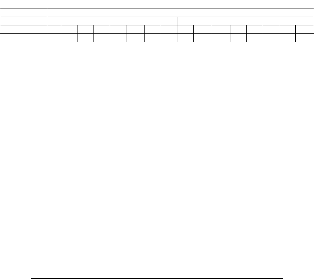
E Electro Industries/GaugeTech Doc # E154703 3- 22
Bit Point Meaning
15 (MSB) 0 RTC Clock Battery Status
14 1 User Set Current Threshold in use
13 2 DSP1 Internal Failure
12 3 Device Profile Changed before current meter start
11 4 reserved
10 5 Clock date/time changed by user
9 6 DST active
8-1 7-14 Undefined
0 (LSB) 15 Undefined
Example:
Register 1796H, Miscellaneous Flags, might contain the following data:
Addr (Hex) 1796H
Value 8000H
Bytes 80H 00H
Bits 1 0 0 0 0 0 0 0 0 0 0 0 0 0 0 0
Point 0 1 2 3 4 5 6 7 8 9 10 11 12 13 14 15
Interpretation Battery is Low.
3.44: Type F44 Digital Input Option Board Data States
Length 1 Register (2 bytes)
This register has two bytes. Each byte has eight bits. The bits in these bytes are
associated with the status of the data received from Digital Input Option Board as
follows:.
Bit Point Meaning
15 (MSB) 0 Status of Data from Digital Input Option Board in slot 3
(Modbus Register 0AD5H)
14 1 Status of Data from Digital Input Option Board in slot 4
(Modbus Register 0AE6H)
13-0 (LSB) Undefined
Digital Input Option Board Data Status –A bit value of 0 means that the data from this Digital
Input option board is not yet valid; either the board is not present or has not yet been polled.
A bit value of 1 means that the data from this Digital Input option board has been polled at
least once and is valid.
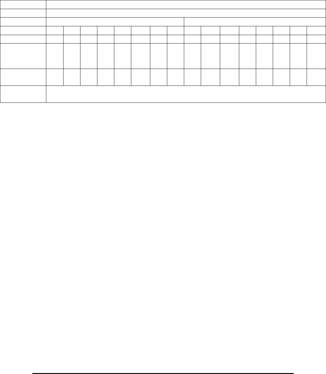
E Electro Industries/GaugeTech Doc # E154703 3- 23
Example:
Register 17DEH, Digital Input Option Board Data States, might contain the following data:
Addr (Hex) 17DEH
Value 8000H
Bytes 80H 00H
Bits 1 0 0 0 0 0 0 0 0 0 0 0 0 0 0 0
Point 0 1
Digital Input
Option
Boards
1 2
Status O
K
- - -
Interpretatio
n
Data from Digital Input Option Board in slot 3 (Register 0AD5H) are valid,
data from Digital Input Option Board in slot 4 are not valid
3.45: Type F45 is not used by the Nexus® 1500 meter
3.46: Type F46 High Byte of Modbus Register (Signed)
Length: 1 byte
High Byte of Modbus Register, Signed
Range: +127 / -128
Unit: 1
3.47: Type F47 High Byte of Modbus Register (Unsigned)
Length: 1 byte
High Byte of Modbus Register, Unsigned
Range: 255 / 0
Unit: 1
3.48: Type F48 Low Byte of Modbus Register (Signed)
Length: 1 byte
Low Byte of Modbus Register, Signed
Range: +127 / -128
Unit: 1
3.49: Type F49 Low Byte of Modbus Register (Unsigned)
Length: 1 byte
Low Byte of Modbus Register, Unsigned
Range: 255 / 0
Unit: 1

E Electro Industries/GaugeTech Doc # E154703 3- 24
3.50: Type F50 Two-Byte (Signed)
Length: 2 bytes
Two-Byte, Signed
Range: +32,767 / -32,768
Unit: 1
3.51: Type F51 Two-Byte (Unsigned)
Length: 2 bytes
Two-Byte, Unsigned
Range: 65,535 / 0
Unit: 1
3.52: Type F52 Four-Byte (Signed)
Length: 4 bytes
Four-Byte, Signed
Range: +2,147,483,647 / -2,147,483,648
Unit: 1
3.53: Type F53 Four-Byte (Unsigned)
Length: 4 bytes
Four-Byte, Unsigned
Range: 4,294,967,295 / 0
Unit: 1
3.54: Type F54 Eight-Byte (Signed)
Length: 8 bytes
Eight-Byte, Signed
Range: +9,223,372,036,854,775,807 / -9,223,372,036,854,775,808
Unit: 1
3.55: Type F55 Eight-Byte (Unsigned)
Length: 8 bytes
Eight-Byte, Unsigned
Range: 18,446,744,073,709,551,615 / 0
Unit: 1
3.56: Type F56 Flicker Countdowns
Length: 1 Register (2 bytes)
Range: 65,535 / 0 seconds
Unit: 1 second
This register contains an unsigned integer which is count-down in seconds until
the end of a Flicker interval, Short Term or Long Term.
Example:
Register 06489, Short Term Flicker Countdown, might contain the following data:
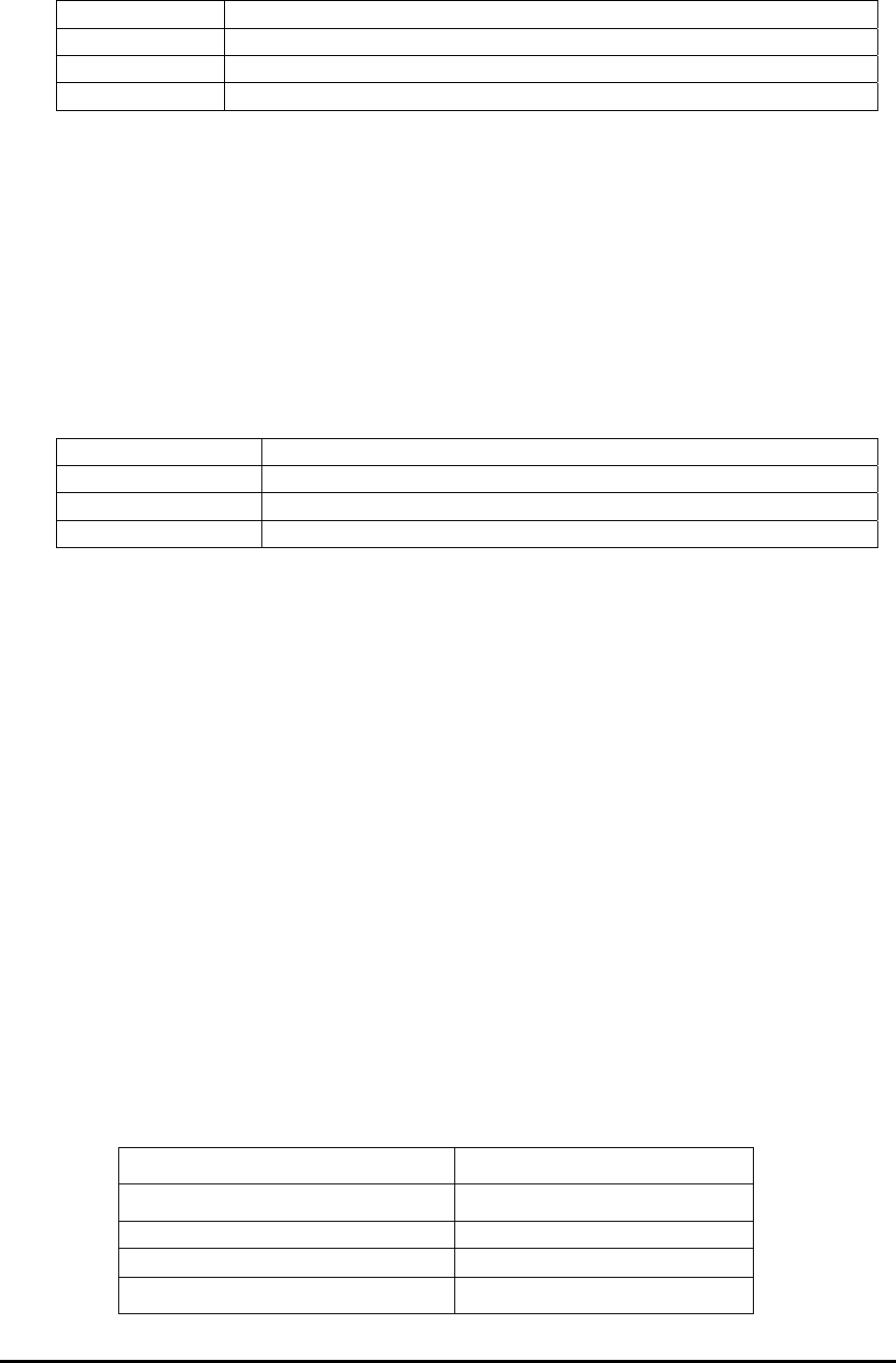
E Electro Industries/GaugeTech Doc # E154703 3- 25
Address 06489
Value 0400H
Decimal 1024
Interpretation 1024 seconds remain until the next Short Term Flicker is computed.
3.57: Type F57 Accumulation in the Interval
Length: 1 Register (2 bytes)
Range: 465,535 / 0
Unit: VAh, VARh, Wh secondary or pulses
These registers contain a 2-byte unsigned integer.
Example:
Register 06397, Total VA hour (Quadrants 1+2+3+4) in the Interval, Secondary, might
contain the following data:
Address 06937
Value 0647H
Decimal 1607
VAh Secondary 1607 VAh Secondary
3.58: Type F58 12-bit RTU Sanity Register
Length: 1 Register
This register indicates the status of the meter. A normally functioning meter
reports a value of 0x00000 or 0. Any non-zero value indicates that the unit is
operating improperly.
3.59: Type F59 12-bit RTU Current, Voltage, W, VAR
Length: 1 Register (2 bytes)
Range: +5A / 0 A, + 150V / 0 V, +1500 W, VAR / -1500 W, VAR
Unit: 5 / 2048 A, 150/2048 V, 1500 / 2048 W, VAR
Each register contains a 16-bit integer. Positive values have the most significant
bit clear and have the same magnitude as an unsigned integer. Negative values
have the most significant bit set. The magnitude of a negative value is found by
complementing (inverting) all of the bits and adding 1. The 16-bit integers have
been constrained to the bounds of a signed 12-bit integer, +2047 through -2048.
Example:
Register 53250, Phase A Current, might contain the following data:
Address 53250
Value (Hex) 0400H
12-bit Signed Integer (Hex) 400H
Most Significant Bit 0
12-bit Signed Integer (Decimal) +1024
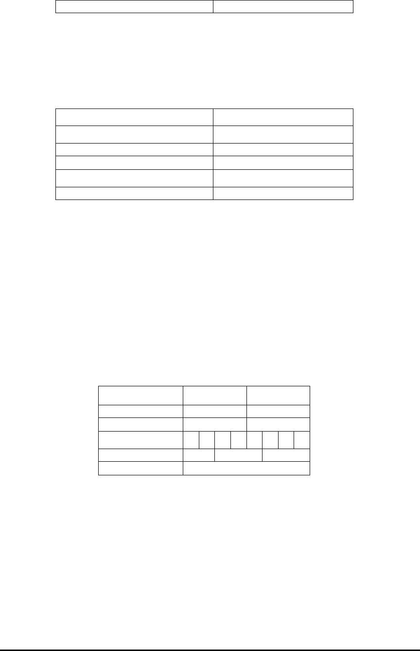
E Electro Industries/GaugeTech Doc # E154703 3- 26
5/2048 A sec 2.500 A sec
Register 53256, Total Watt, might contain the following data:
Address 53256
Value (Hex) FC00H
12-bit Signed Integer (Hex) C00H
Most Significant Bit 1
12-bit Signed Integer (Decimal) -1024
150-0/2048 W sec -750 W sec
3.60: Type F60 Energy Counter
Length: 2 Registers (4 bytes)
Range: +99,999,999 / 0 or 0 / -99,999,999 kWh, kVARh
Unit: 1 kWh, kVARh
Each pair of registers represents an Energy Counter in primary. Each register
contains a value from 0 to 9,999 (0x00000 - 0x0270F), representing 4 digits of an
Energy Counter. The first register is in units of 10’s of MegaWatthour or Mega
VARhour. The second register is in units of kilo Watthour or kilo VARhour.
Combined, the pair of registers report up to 100 GWh primary of energy.
Example:
Registers 53267-53268, Positive Watthour, might contain the following data:
Address 53267 53268
Value (Hex) 04D2H 162EH
Value (Decimal) 1234 5678
Digit 12345678
Unit G M k
kWH Primary 12,345,678 kWh primary
3.61: Type F61 12-bit RTU Frequency
Length: 1 Register (2 bytes)
Range: 75 Hz / 45 Hz
Unit: 30 / 4096 Hz
This register contains a 16-bit unsigned integer. The 16-bit integer has been
constrained to the bounds of an unsigned 12-bit integer, 4095 to 0. The
Frequency represented by this register is offset by 45 Hz.
Example:
Register 53250, Phase A Current, might contain the following data:
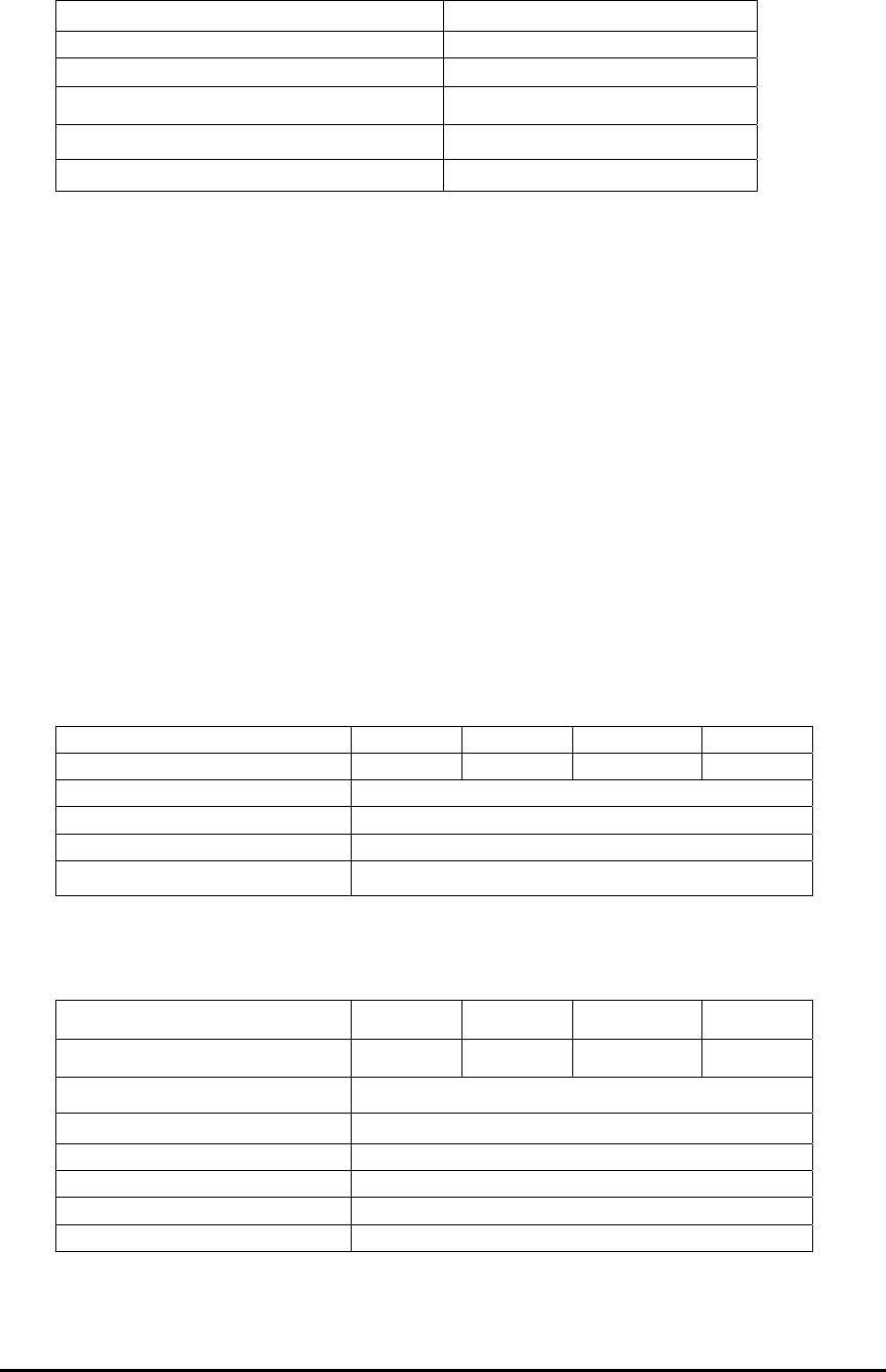
E Electro Industries/GaugeTech Doc # E154703 3- 27
Address 53250
Value (Hex) 0810H
12-bit Unsigned Integer (Hex) 810H
12-bit Unsigned Integer (Decimal) +2058
30/4096 A sec 15.073 Hz
+45 Hz Offset 60.073 Hz
3.62: Type F62 Scaled Pulse Accumulation, Aggregation or Average
Length: 4 Registers (8 bytes)
Range: +9,223,372,036,854,776,807 / -9,223,372,036,854,776,808
Unit: 1 Unit
This register contains an 8-byte signed (2’s complement) number. Positive
values have the most significant bit clear and have the same magnitude as an
unsigned integer. Negative values have the most significant bit set. The
magnitude of a negative value is found by complementing (inverting) all of the
bits and adding 1.
Type F62 does not use the multiplier from the Energy Scale Settings from the
Nexus® meter’s Device Profile. It uses the multiplier from the Nexus® meter’s
Internal Input Pulse Accumulations Setup screen (Device Profile > Revenue &
Energy Settings > Pulse Accumulations).
Example:
Registers 05834 - 05837, Block Window Average Aggregation 1, might contain the
following data:
Address 05834 05835 05836 05837
Value (Hex) 0000H 0000H 0001H 2345H
8 byte Signed Integer (Hex) 000000000001245H
Most Significant Bit 0
Decimal +74565
Accumulated Transitions +74,565 Units
Registers 05834-05837, Block Window Average Aggregation 1, might contain the
following data:
Address 05834 05835 05836 05837
Value (Hex) FFFFH FFFFH FFFEH DCBBH
8 byte Signed Integer (Hex) FFFFFFFFFFFEDCBBH
Most Significant Bit 1
Complement 0000000000012345H
Increment 0000000000012345H
Decimal -74565
Accumulated Transitions -74,565 Units
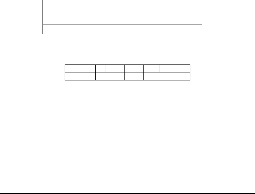
E Electro Industries/GaugeTech Doc # E154703 3- 28
3.63: Type F63 Log Index
Length: 1 Register (2 bytes)
Range: 65,535 / 0
Unit: 1 Unit
This register contains a 2-byte MSB unsigned integer, which represents the First
or Last Index for a given Log. First Indexes represent the Index of the First
(Oldest) record in a log. Last Indexes represent the Index of the Last (Newest)
record in a log. The value of 0x0FFFF for the Last Index indicates that the log is
empty.
3.64: Type F64 Scaled Energy
Length: 2 Registers (4 bytes)
Range: 99 / 0 through 999,999,999 / 0 (variable, 2-9 digits)
Unit: 10-7 through 106 units (variable)
This register contains an 4-byte signed integer. The range and resolution of a
given reading is controlled by programmable Energy Scale Settings, which
govern both the range of the reading (from 2 to 9 digits) and the units of the
reading (from 7 decimal places of Wh (10-7) to no decimal places of MWh (106).
Refer to Type F65 for a description of the Scaled Energy Programmable Setting
(Device Profile > Revenue & Energy Settings > Energy Scaling).
Example:
Registers 06912-06913, Total VAh (Quadrant 1+2+3+4) Scaled Primary, might contain
the following data:
Address 06912 06913
Value 075BH CD15H
4-byte Hex 075HCD15H
Decimal 123,456,789
o If the Programmable Settings indicated 5 decimal places of WH, then the
interpreted value would be 1,234.56789 Wh.
o If the Programmable Settings indicated 0 decimal places of MWh, then
the interpreted value would be 123,456,789 MWh.
3.65: Type F65 Scaled Energy Setting
Length: 1/2 a Register (1 byte)
Each register contains 2 bytes. Each byte contains settings for a base quantity.
The format of a byte is as follows:
Bit 7 6 5 4 3 2 1 0
Meaning Digits Unit Decimal Places
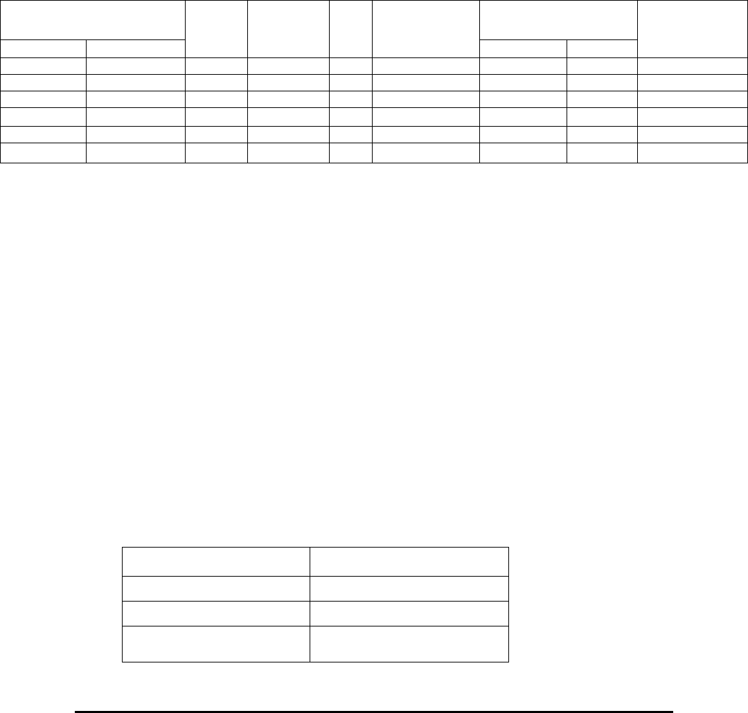
E Electro Industries/GaugeTech Doc # E154703 3- 29
o Digits is a 3-bit field, which is offset by 2 to represent from 2 to 9
displayable digits.
o Unit is a 2-bit field, where the values from 0 to 2 represent units of Wh
(100), k (103) and M (106). The value 3 is undefined and is treated the
same as 2, signifying M (106).
o Decimal Places is a 3-bit field, where the bits represent from 0 to 7 decimal
places.
Examples:
For the following, the Q1234 VAh has a current value internally of
123,456,789.0123 VAh.
Register CA00H Reading in Register
1AFFH-1B00H
Hex Binary
Digits
Unit
D.P.
Pattern
Hex Decimal
Display
20xxH 001 00 000 3 VAh, 100 0 xxxVAh 000003 789 789VAh
8BxxH 100 01 011 6 kVAh, 103 3 xxx.xxx kVAh 0006F855H 456789 456.789 kVAh
88xxH 100 01 000 6 kVAh, 103 0 Xxxxxx kVAh 0001E240H 123456 123,456 kVAh
93xxH 100 10 011 6 MVAh, 106 3 xxx.xxx MVAh 0001E240H 123456 123,456 MVAh
72xxH 011 10 010 5 MVAh, 106 2 xxx.xx MVAh 00003039H 12345 123.45 MVAh
C2xxH 110 00 010 8 VAh, 100 2 xxxxxx.xx VAh 02B90135H 45678901 456,789.01 VAh
The Scaled Energy Programmable Setting can be accessed by clicking:
Device Profile > Revenue & Energy Settings > Energy Scaling.
3.66: Type F66 TOU Upload Calendar Window Locked to Port
Length: 1 Register (2 bytes)
When read, this register contains an enumeration indicating to which port the
TOU Upload Calendar Window is locked. The enumeration is as follows:
0x00000 Port 4 (I/O)
0x00001 Port 3
0x00002 Port 2
0x00003 Port 1 (RS232/RS485)
0x00004 Diagnostic Port
0x000FF Not locked to any port
Writing the value 0x00000 to this register requests the TOU Upload Calendar
Window to be locked to that port.
Example:
Register 36607, TOU Upload Calendar Window Locked to Port, might contain the following
data:
Address 36607
Value 0002H
Decimal 2
Meaning TOU Calendar Upload
Window is Locked to Port 2.
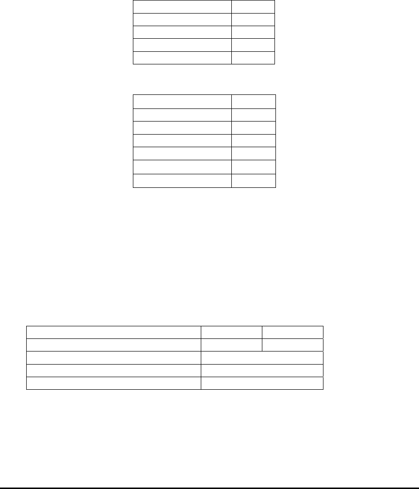
E Electro Industries/GaugeTech Doc # E154703 3- 30
3.67: Type F67 K-Factor
Length: 1 Register (2 bytes)
Range: +327.67 / - 327.68
Unit: 0.01
This register contains a 16-bit signed (2's complement) number. Positive values
have the most significant bit clear and have the same magnitude as an unsigned
integer. Negative values have the most significant bit set. The magnitude of a
negative value is found by complementing (inverting) all of the bits and adding 1.
Example:
Register 00390, Maximum K-Factor Phase A Current, might contain the following data:
Address 00390
Value (Hex) 08BBH
Most significant bit 0
Decimal +2235
K-Factor +22.35
Register 0185H, Maximum K-Factor Phase A Current, might contain the following data:
Address 00390
Value (Hex) F745H
Most significant bit 1
Complement 08BAH
Increment 08BBH
Decimal -2235
K-Factor -22.35
3.68: Type F68 Secondary 1 Cycle RMS Voltage and Current
Length: 2 Registers (4 bytes)
Range: 4,294,967,295 V, A / 0 V, A
Unit: 1/65536 V, A
These registers form a 4-byte unsigned integer in which the first register contains the LSB word.
Example:
Address 0x005D 0x005E
Value 0xE6D7 0x0077
4-byte unsigned integer(Hex) 0x0077E6D7
4-byte unsigned integer (Decimal) 7,857,879
1/65536 V secondary 119.902
3.69: Type F73 Magnitude
Length: 2 Register (4 Byte)
Order: Least significant word first
Range: -32767.999/+32767.999
Unit: Volts/Degree/Hz

E Electro Industries/GaugeTech Doc # E154703 3- 31
Examples:
Fraction Word (least
significant)
Integer Word (most
significant)
Value 4000H 0001H
4-byte signed integer,
most significant first
00014000H
Most significant bit 0
4-byte integer (Decimal) +81920
1/65536 +1.250
Fraction Word (least
significant)
Integer Word (most
significant)
Value C000H FFFEH
4-byte signed integer,
most significant first
FFFEC000H
Most significant bit 1
Compliment
00013FFFH
Increment
00014000H
4-byte integer (Decimal) -81920
1/65536 -1.250

E Electro Industries/GaugeTech Doc # E154703 3- 32

E Electro Industries/GaugeTech Doc # E154703 4- 1
Chapter 4
Modbus Register Map Notes
4.1: Modbus Register Map Notes
The information in this chapter refers to the Modbus Register Map’s “Notes” column. Chapter 2
contains the Modbus Map.
1) Time information can be supplied from one of two different sources, an internal Real
Time Clock or an external GPS Clock. The internal Real Time Clock is a chip containing
its own battery, which is used to maintain the passage of time when the Nexus™ unit is
without operational power. It is similar to those used in PCs and it reports time accurate
to the second. The external GPS clock is supported through an IRIG-B connection,
allowing synchronization and accuracy to the hundredth of a second (10 milliseconds).
2) These registers, when read, always report the time as reported by the Nexus™ unit, either
from the internal Real Time Clock or the external GPS Clock. Values written here for
the purpose of updating the internal Real Time Clock are not read back.
3) These values are calculated by the Nexus™ 1500 meter’s DSP2 Processor, as part of the
Waveform Capture function. These values are only calculated if the meter has Waveform
Logging Capability.
4) Phase Voltages are in secondary Volts. To convert this value into primary Volts,
multiply by the Phase Voltage PT Ratio, composed of the Phase Voltage PT Ratio
Numerator and Denominator (Registers 45917 - 45918 and 45919 - 45920).
5) Auxiliary Voltage is in secondary Volts. To convert this value into primary Volts,
multiply by the Auxiliary Voltage PT Ratio, composed of the Auxiliary Voltage PT Ratio
Numerator and Denominator (Registers 45921 - 45922 and 45923 - 45924).
6) Phase and Calculated Neutral Currents are in secondary Amps. To convert this value into
primary Amps, multiply by the Phase Current CT Ratio, composed of the Phase Current
CT Ratio Numerator and Denominator (Registers 45909 - 45910 and 45911 - 45912).
7) Not used.
8) Measured Neutral is the RMS produced by samples from a CT around the Neutral Line
and connected to the Neutral current terminals of the meter. Calculated Neutral is the
RMS produced by adding the three Phase Current samples together and treating the result
as a sample of the neutral line.
9) VA, VAR and Watts are in secondary. To convert this value into primary VA, VAR or
Watts, multiply by the Phase Voltage PT Ratio, composed of the Phase Voltage PT Ratio
Numerator and Denominator (Registers 45916 - 45917 and 45918 - 45919) and by the

E Electro Industries/GaugeTech Doc # E154703 4- 2
Phase Current CT Ratio, composed of the Phase Current CT Ratio Numerator and
Denominator (Registers 45909- 45910 and 45911 - 45912).
10) Not used.

E Electro Industries/Gauge Tech Doc# E154703 5-1
Chapter 5
Logs, Port Control and Updating
Programmable Settings
(For Serial Download of Historical Logs)
5.1: Downloading Logs - Overview
There are three methods for downloading logs from the Nexus®1500 meter: non-increment
index, auto-increment index and file system access.
Each of the Nexus® meter’s ports act independently, allowing multiple Modbus Masters
access to all the retrievable data in a Nexus® meter Slave.
Log Memory Allocation (Quotas): The log storage area on the file system is restricted to a pre-
defined size. Within that pre-defined size, files of a fixed size (1MByte) are built. The user is
able to assign how many files each log will get; however, the System Events log, and Historical
logs 1 and 2 have a maximum size of 1 and 8 MBytes, respectively, in order to maintain
backwards compatibility. A log with no file assigned to is disabled and will not run.
Memory Gap Engine: To avoid the oldest record being overwritten during the download log
process when the log is in pause mode, %5 of the memory allocated for the log will be empty
(unused) during the normal operation. When the download process starts in a paused log, that
reserved memory is used to save new records. If the process is fast enough, the download process
can finish without dropping any records. On the other hand, if the download process is slow, the
gap can be completely filled and then new records will be dropped (not saved).
Log Reset: This Register (located at 57345) when written to, causes all logs to be cleared. This
action should be performed only under the following circumstances:
- When the programmable settings are modified such that data already in the logs is
invalidated. For example, any modifications involving the record size or organization
of the contents of a snapshot would require the logs to be cleared of any previous
data. (This action should be performed automatically by Communicator EXT
software.)
- Either via the Reset screen on the display, or the Reset Device Parameters screen
from Communicator EXT software. If Password Protection has been enabled, a
second level password is required for performing the reset.
Downloading any log involves the following types of Registers:
Log Snapshot Header: Header blocks for the different logs begin at Register 36865: This block
of Registers holds the following information about the log:
- Memory Size: 4-byte unsigned integers representing the amount of memory, in bytes,
allocated to the log.
- Record Size: an unsigned integer representing the size, in bytes, of a record in the
log.
- First Index: an unsigned integer representing the index of the first (oldest) record in
the log.
- Last Index: an unsigned integer representing the index of the last (newest) record in
the log. The value FFFFH indicates that the log is empty.

E Electro Industries/Gauge Tech Doc# E154703 5-2
- First Time Stamp: These Registers hold the time stamp from the first (oldest) record
in:
Byte Range Description
0 0 – 255 century
1 0 – 99 year
2 1 – 12 month
3 1 – 31 day
4 0 – 23 hour
5 0 – 59 minute
6 0 – 59 second
7 0 – 99 centisecond
- Last Time Stamp: These Registers hold the time stamp from the last (newest) record
in the Log. The byte order and description are the same for the first time stamp.
- Valid Bitmap: These Registers hold the bit flags indicating whether the Nexus®
Slave recognizes the lines in the Historical Log Settings block (the block beginning at
Register 45204). The first bit represents the validity of the last Data Pointer in the
Historical Log Settings. A value of 1 means the Data Pointer is acceptable and can be
stored. A value of 0 means that the Data Pointer is invalid or unrecognized and
cannot be stored.
- Max Records: an unsigned integer representing the total number of records the log is
capable of holding. In order to maintain a one-for-one relationship in parallel logs
(Sequence of Events State and Sequence of Events Snapshot logs, for example), the
maximum number of records that a log can store is defined by the log that holds the
fewest records. Logs capable of holding more records are restricted.
5.1.1 Log Download Using Non-increment Index Method
Backwards Compatibility: This method is applied only to the System Event log and Historical
logs 1 and 2. Downloading the backwards compatible logs involves the following types of
Registers.
A Modbus Master uses a Log window consisting of 64 Registers to retrieve logs from a
Nexus® 1500 meter Slave. A log is divided into numbered sections called Indexes, which are
transferred through the Log Window in sequence.
Window Index tells the Modbus Master which 128-byte section of the log the Window is using
to retrieve the log. The block of Window Index Registers for the different logs begin at 38145.
When the Modbus Master writes a new value to the Window Index, a new section of the log
will fill the Window. For example, when the Index is 0000H, the first 128 bytes of the log are
available in the Window; when the Index is 0001H, the second 128 bytes of the log are
available in the Window, and so on. The designation “first 128 bytes of the log” is a physical
description based on the absolute addresses of the memory allocated to the log. The first
(oldest) record in the log may not be located at the beginning of the log.
- When a value other than FFFFH is written to the Window Index, the Index is updated
and the log is paused. A 30-second timer is initiated on these writes. Should the
timer expire (a new index is not written within 30 seconds), the log will continue
logging.
- Should multiple ports access the same log simultaneously, the log will pause while
any 30-second timer is running. The log will continue logging only when all ports
time-out.

E Electro Industries/Gauge Tech Doc# E154703 5-3
- When read, the Window Index returns the number of the Index currently in use by
the Window. When written, the Window Index sets a new Index for the Window to
retrieve the log.
Window Mode defines the two available modes the Window may use to retrieve a log;
Download Mode and Time Stamp Mode. The Window Mode block begins at Register 38209.
- Download Mode: In Download Mode, the Log Window accesses consecutive, 128-
byte blocks of the log. For example, when the Window Index is 0000H, the first 128
bytes of the log are available in the Window; when the Index is 0001H, the second
128 bytes of the log are available in the Window. The designation “first 128 bytes of
the log” is a physical description based on the absolute addresses of the memory
allocated to the log. The first (oldest) record in the log may not be located at the
beginning of the log.
- Time Stamp Mode:. In Time Stamp Mode, the Log Window accesses the time stamps
of the records, in blocks of 16 time stamps at a time. When the Window Index is
0000H, the time stamps of the first 16 records (records 0–15) in the log are available
in the Window; when the Window Index is 0001H, the time stamps of the second 16
records (records 16–31) in the log are available in the Window, and so on. The
designation “first 128 bytes of the log” is a physical description based on the absolute
addresses of the memory allocated to the log. The first (oldest) record in the log may
not be located at the beginning of the log.
Log Window: The Log Window is a 64-register, 128-byte view of a log. The Window Index
defines which part of a log is currently available in the Window. Log Windows begin at
Register 38273.
5.1.1.1: Steps for Downloading a Log
The following steps outline the process for downloading a log. Details and examples for
downloading time stamps and records follow in Sections 5.1.1.2 and 5.1.1.3.
1. Read the Nexus® meter’s Programmable Settings Block (Registers 45057–53248).
This information will be used to interpret the data retrieved from the log.
2. Pause the log by writing an initial, non-FFFFH value to the Log Window Index
Register.
3. Read and store the Log Header information.
4. Determine the starting Window Index and Window offset.
5. Determine the largest Window Index and Window offset.
6. Determine the ending Window Index and Window offset.
7. Set the Window Mode to Download Mode.
8. Set the Log Window Index to the starting Window Index.
9. Read the Window from starting offset to the end of the Window.
10. Increment the Window Index.
11. Read the Window from beginning to end.

E Electro Industries/Gauge Tech Doc# E154703 5-4
12. Repeat steps 10 and 11 until the largest or ending Window Index is reached.
- If the largest is reached, go to step 13.
- If the ending is reached, go to step 15.
13. Read Window from beginning up to (but not including) the largest offset.
14. Set Window Index to 0. Go to step 12.
15. Read Window from the beginning up to (but not including) the ending offset.
5.1.1.2: Downloading Time Stamps with Examples
The following steps detail the process for downloading time stamps from a log, using values
from Historical Log 1 as an example.
1. Read the Nexus® meter’s Programmable Settings Block (Registers 45057–53248).
2. Pause the log by writing an initial, non-FFFFH value to the Historical Log 1 Window
Index Register.
Example: Write 0000H to the Window Index for Historical Log 1, Register
38145.
3. Read and store the Historical Log 1 Header information.
Example: Historical Log 1 Snapshot Header
Address Description Example Value
36865–36866 Historical Log 1 Snapshot Memory Size 1851392
36867 Historical Log 1 Snapshot Record Size 64
36868 Historical Log 1 Snapshot First Index 501
36869 Historical Log 1 Snapshot Last Index 500
36870–36873 Historical Log 1 Snapshot First Time Stamp 7/10/99 12:32:00.000
36874–36877 Historical Log 1 Snapshot Last Time Stamp 7/30/99 14:40:00.000
35878–36881 Historical Log 1 Snapshot Valid Bitmap FFFC 0000
36882 Historical Log 1 Snapshot Max Records 28928
4. Determine the starting Window Index and starting Window Offset using these
formulas:
Starting Window Index = Int([8 x First Index]/128).
Starting Window Offset = (8 x First Index) % 128.
Example:
Starting Window Index: Int (8 x 501/128) = Int (31.3125) = 31.
Starting Window Offset: (8 x 501) % 128 = 40.
5. Determine the largest Window Index and the largest Window Offset using these
formulas:
Largest Window Index = Int ([8 x Max Records]/128).
Largest Window Offset = (8 x Max Records) % 128.
Example:
Largest Window Index = Int([8 x 28928]/128) = Int(1808) = 1808
Largest Window Offset = (8 x 28928) % 128 = 0
6. Determine the ending Window Index and the ending Window Offset using these
formulas:
Ending Window Index = Int([8 x {Last Index + 1}]/128)

E Electro Industries/Gauge Tech Doc# E154703 5-5
Ending Window Offset = (8 x [Last Index +1]) % 128
Example:
Ending Window Index = Int([8 x {500 + 1}]/128 = Int(31.3125) = 31
Ending Window Offset = (8 x [500 + 1]) % 128 = 40
7. Set the Window Mode to Download Mode by writing the Timestamp Mode code
(0001H) to the Log Window Mode Register.
Example:
Write the value 0001H to the Window Mode for Historical Log 1,
Register 38209.
8. Set the Window Index to the Starting Window Index.
Example:
Write the value 31 (001FH) to the Interval 1 Log Window Index,
Register 38145.
9. Read Window from starting offset to end of Window:
Starting offset = First Register of Window + (starting Window offset/2).
Example:
38273 + (40/2) = 38293
Read from 38293 – 38336.
10. Increment the Window Index.
Example:
Write the value 32 (0020H) to the Historical Log 1 Window Index,
Register 38145.
11. Read the Window from beginning to end.
Example:
Read the Historical Log 1 Window from Register 38273 to 38336.
12. Repeat steps 10 and 11 until the Largest or Ending Window Index is reached.
- If the Largest Window Index is reached, go to step 13.
- If the Ending Window Index is reached, go to step 15.
Example:
If Window Index = 1808, go to step 13. If Window Index = 31, go to step
15.
13. Read Window from beginning up to (but not including) the Largest Offset.
Largest Offset = First Register of Window + (largest Window offset/2).
Example: (Index = 1808).
38273 + (0/2) = 38273.
Read from 38273 up to 38273; therefore, read nothing.
14. Set Window Index to 0. Go to step 12.
Example:
Write the value 0 (0000H) to the Window Index Historical Log 1,
Register 38145.
15. Read Window from the beginning up to (but not including) the Ending Offset.
Ending Offset = First Register of Window + (Ending Window Offset/2).
Example: (Index = 31).

E Electro Industries/Gauge Tech Doc# E154703 5-6
38273 +40/2 = 38293.
Read from 38273 up to (but not including) 38293; therefore, read 38273
– 38292.
5.1.1.3: Downloading Records with Examples
The following steps detail the process for downloading records from a log, using values from
an Historical Log 1 as an example.
1. Read the Nexus® meter’s Programmable Settings Block (Registers 45057–53248).
2. Pause the log by writing an initial, non-FFFFH value to the Log Window Index
Register.
Example: Write 0000H to the Window Index for Historical Log 1, Register
38145.
3. Read and store the Log Header information.
Example: Historical Log 1 Log Snapshot Header
Address Description Example Value
36865–36866 Historical Log 1 Snapshot
Memory Size 1851392
36867 Historical Log 1 Snapshot
Record Size 64
36868 Historical Log 1 Snapshot
First Index 501
36869 Historical Log 1 Snapshot
Last Index 500
36870–36873 Historical Log 1 Snapshot
First Timestamp 7/10/99 12:32:00.000
36874–36877 Historical Log 1 Snapshot
Last Timestamp 7/30/99 14:40:00.000
36878–36881 Historical Log 1 Snapshot
Valid Bitmap FFFC 0000
36882 Historical Log 1 Snapshot
Max Records 28928
4. Determine the starting Window Index and starting Window Offset using these
formulas:
Starting Window Index = Int([Record Size x First Index]/128).
Starting Window Offset = (Record Size x First Index) % 128.
Example:
Starting Window Index: Int(64 x 501/128) = Int (250.5) = 250.
Starting Window offset: (64 x 501) % 128 = 64.
5. Determine the largest Window Index and the largest Window Offset using these
formulas:
Largest Window Index = Int([Record Size x Max Records]/128).
Largest Window Offset = (Record Size x Max Records) % 128.
Example:
Largest Window Index = Int([64 x 28928]/128) = Int(14464) = 14464.
Largest Window Offset = (64 x 28928) % 128 = 0.
6. Determine the ending Window Index and the ending Window offset using these
formulas:
Ending Window Index = Int([Record Size x {Last Index + 1}]/128).

E Electro Industries/Gauge Tech Doc# E154703 5-7
Ending Window Offset = (Record Size x [Last Index +1]) % 128.
Example:
Ending Window Index = Int([64 x {500 + 1}]/128 = Int(250.5) = 250.
Ending Window Offset = (64 x [500 + 1]) % 128 = 64.
7. Set the Window Mode to Download Mode by writing the Download Mode code
(0000H) to the Log Window Mode Register.
Example:
Write the value 0000H to the Window Mode for Historical Log 1,
Register 38209.
8. Set the Window Index to the Starting Window Index.
Example:
Write the value 250 (00FAH) to the Historical Log 1 Window Index,
Register 38145.
9. Read Window from starting offset to end of Window:
Starting offset = First Register of Window + (starting Window offset/2).
Example:
38273 + (64/2) = 38305.
Read from 38305 – 38356.
10. Increment the Window Index.
Example:
Write the value 251 (00FBH) to the Historical Log 1 Window Index,
Register 38145.
11. Read the Window from beginning to end.
Example:
Read the Historical Log 1 Window from Register 38273 to 38336.
12. Repeat steps 10 and 11 until the largest or ending Window Index is reached.
- If the largest Window Index is reached, go to step 13.
- If the ending Window Index is reached, go to step 15.
Example:
If Window Index = 14464, go to step 13.
If Window Index = 250, go to step 15.
13. Read Window from beginning up to (but not including) the Largest Offset.
Largest Offset = First Register of Window + (Largest Window Offset/2).
Example: (Index = 14464).
38273 + (0/2) = 38273.
Read from 38273 up to 38273; therefore, read nothing.
14. Set Window Index to 0. Go to step 12.
Example:
Write the value 0 (0000H) to the Window Index Historical Log 1,
Register 38145.
15. Read Window from the beginning up to (but not including) the ending offset.
Ending offset = First Register of Window + (ending Window offset/2).
Example: (Index = 250).
38273 + 64/2 = 38305.

E Electro Industries/Gauge Tech Doc# E154703 5-8
Read from 38272 up to (but not including) 38304; therefore, read 38273
– 38304.
5.1.2: Log Download Using Auto-Increment Index Method
Auto Incrementing Interface
Auto Increment Configuration (Register 39423, 0x099FE)
When read, this register returns the configuration in use (shown on the next page) by the Auto
Increment Log Window to access logs on this port. When written, this register sets the
configuration used by the Auto Increment Log Window to access logs on this port. Each port
accesses a separate, independent configuration through this register, allowing all four ports to
access logs with different configurations.
The least significant byte indicates which log is being accessed, as shown below:
0x000 Historical Log 1
0x001 Historical Log 2
0x00A System Event Log
0x00E-0x0FF Undefined
The most significant byte defines the following modes, Paused Download Mode (0x000), and
Running Download Mode (0x001).
In Paused Download mode (0x000), the log being accessed is paused - new records are not
added to the log while it is paused.
In Running Download mode (0x001), the log being accessed is not paused - new records may
be added to the log. When downloading in this mode, it is possible that records may be
overwritten before, or even during, access to that record.
Auto Increment Window Index (0x099FF)
When read, this register returns the index used by the Auto Increment Log Window to access
logs on this port. When written, this register sets the index used by the Auto Increment Log
Window to access logs on this port. Each port accesses a separate, independent index through
this register, allowing all four ports to access different areas of logs at the same time.
When read, the index is incremented before being returned in the Modbus response. If the
Auto Increment Mode is Paused Download Mode (0x001xx in register 0x099FE), the
appropriate log is paused, preventing the addition of new records while the log is being
accessed. A 30-second timer is initiated on these reads. Should the timer run out (the index is
not incremented/read in 30 seconds), the appropriate log will be allowed to continue logging.
Should multiple ports access the same log simultaneously, the log will be paused while either
30-second timer is running; the log will be allowed to continue logging only when ports time-
out.
Auto Increment Log Window (0x09A3F)
These registers are a 128-byte window into a log, as specified in the Auto Increment
Configuration (register 0x099FE). Depending on the Auto Increment Window Index, a
different 128-byte area of a log can be accessed.

E Electro Industries/Gauge Tech Doc# E154703 5-9
Download using Auto Increment Window Sequence
1. Software should select the appropriate Download mode and log through the Auto
Increment Configuration register (0x000xx or 0x001xx to register 0x099FE).
2. Software should read the appropriate Header Information.
3. Software should initialize the window index by writing a value 1 less than the desired
starting index to the Auto Increment Window Index register.
Example: To start at window 0, write:
0x0FFFF to Register 0x099FF.)
4. Software should store the Historical Log 1 Header Information.
5. Software should read the Auto Increment Window Index and Auto Increment Log
Window (Registers 0x099FF-0x09A3F).
6. Software should verify the expected value for the Auto Increment Window Index.
7. Software should store the first 128 bytes of the log from the Auto Increment Log
Window.
Repeat steps 5-7 until the desired amount of the log has been read and stored. The
Number of Reads of the Window can be determined by dividing the Total Memory in the
Log (registers 0x09000 -0x09001) by the Window Size (128 bytes).
Download using Auto Increment Window Sequence and Function Code 35
1. Software should select the appropriate Download mode and log through the Auto
Increment Configuration register (0x000xx or 0x001xx to register 0x099FE).
2. Software should read the appropriate Header Information.
3. Software should initialize the window index by writing a value 1 less then the desired
starting index to the Auto Increment Window Index register (to start at window 0,
write 0x0FFFF to register 0x099FF).
4. Software should store the Historical Log 1 Header Information.
5. Software should read the Auto Increment Window Index and Auto Increment Log
Window (registers 0x099FF-0x09A3F) n times using the non-standard Modbus
Function Code 35 (0x023) Read Holding Registers Multiple Times.
6. Software should verify the expected values for the Auto Increment Window Index.
7. Software should store the each 128 bytes of the log from the Auto Increment Log
Window.
Repeat steps 5-7 until the desired amount of the log has been read and stored. The
number of Reads of the Window can be determined by dividing the Total Memory in the
Log (registers 0x09000 -0x09001) by the Window Size (128 bytes), and again by
dividing by the Number of Repeats being used with Function Code 35.

E Electro Industries/Gauge Tech Doc# E154703 5-10
5.1.3: Log Download Using File System Access
This method applies to all logs. It uses the modbus customized function code 0x45 where a
series of defined command can be sent to retrieve the log. During the download log process,
the log is paused when a paused dummy file is read. Each log has its own paused dummy file.
To set the log back to run, a running dummy file should be read. Each log has its own running
dummy file. See Chapter 6 for additional details on downloading logs.
5.2: Port Locking - Overview
At times it may be necessary for a Master connected to one port of a Nexus® meter to
communicate directly to a Slave device connected to a different port of the same meter. For
example, software on a computer connected to one port of a Nexus® meter might need to
change settings on an external device connected to another port of the meter. To accommodate
this need, the following steps allow a Master to control the Transmit and Receive buffers of
another port.
To prevent contention, only one Master at a time may control a given port. This is referred to
as “Locking a Port”. If Port 1 is controlling Port 4, no other ports may control Port 4 until Port
1 is finished.
5.2.1: Sequence for Port Locking
To lock a port, follow the steps below:
1. Determine the port to which the Modbus Master is currently attached: Register 65411.
2. Determine that the desired port is currently unlocked: Registers 41730 – 41732.
3. Write to lock the desired port: write 0100H – 0104H to Register 41729.
4. Verify that the port is successfully locked: Registers 41730 – 41732.
5. Read the current states of the pointers: 41733 – 41752.
5.2.2: Transmission
1. Decide which transmit buffer to use: Registers 43265, 43521, 43777, 44033, 44289.
2. Find the current position of the TrmIn pointer: Registers 41735, 41739, 41743, 41747,
41751.
3. Add bytes to the transmit buffer starting at the position indexed by the TrmIn pointer
up to the position before that indexed by the TrmOut pointer.
4. Write the new value for the TrmIn pointer (the position after the last byte added) to the
TrmIn pointer.

E Electro Industries/Gauge Tech Doc# E154703 5-11
5.2.3: Reception
1. Decide which receive buffer to use: 41985, 42241, 42497, 42753, 43009.
2. Find the current position of the RecOut pointer: 41734, 41738, 41742, 41746, 41750.
3. Read bytes starting at the position after that indexed by the RecOut pointer, up to the
position beore the position indexed by the RecIn pointer.
4. Write the new value for the RecOut pointer (the position of the last byte read) to the
RecOut pointer.
5.2.4: Port Unlocking Sequence
To unlock a port, follow the steps below:
1. Empty the receive buffer (RecOut written so it is the position before RecIn).
2. Write to unlock the desired port: write 0200H – 0204H to Register 41729.
3. Verify that the port is successfully unlocked: Registers 41730 – 41732.
5.3: Updating Programmable Settings
1. Build the binary programmable settings block to update to the meter. All 32k of
programmable settings must be updated.
1. The programmable settings are broken into two blocks, Block 1 and Block 2, each
16384 bytes in size.
2. Compute the CRC16 on the first 16382 bytes of Block 1. We do not include the last
two bytes, as this is where the checksum is stored.
3. Continue computing the checksum (using the previously computed checksum as the
seed), on all 16384 bytes of Block 2.
4. Place the computed checksum into the last two bytes of Block 1.
2. If Level 2 Password Protection is enabled, send the Level 2 password to allow updating
the Programmable Settings. If Sealing switch is enabled, press the Sealing switch.
3. If any changes were made to the Programmable Settings which affect the logs, the logs
should be cleared.
1. Lock the logs to prevent them from being updated until the meter is reset. Write
0xABCD to register 0xE052.
2. Write 0xFFFF to the register listed below to reset that log.
All Logs 0xE000
Historical 1 0xE035
Historical 2 0xE036
Sequence of Events 0xE037
Digital Input 0xE038
Digital Output 0xE039
Flicker 0xE03A
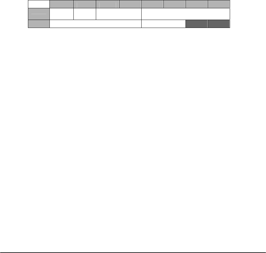
E Electro Industries/Gauge Tech Doc# E154703 5-12
Waveform 0xE03B
PQ 0xE03C
Historical 3 0xE04A
Historical 4 0xE04B
Historical 5 0xE04C
Historical 6 0xE04D
Historical 7 0xE04E
Historical 8 0xE04F
Event Triggered 0xE050
Transient 0xE051
4. Write the Programmable Settings Data. Note: All 32k of data must be written for the
Programmable Settings to be updated.
1. Write Block 1 for 16384 bytes starting at register 0xB000.
2. Write Block 2 for 16384 bytes starting at register 0x6000.
5. Wait for the meter to finish storing the Programmable Settings.
1. Read the Programmable Settings Update Status registers. 7 registers starting at
0xFFE0.
offset 0 1 2 3 4 5 6 7
0x00
Match
(MSB)
Mode
(LSB) Error Code Time Stamp
0x08 Time Stamp Checksum
Match Indicates if the RAM and Stored programmable settings match.
0 indicates a match, 1 indicates no match.
Mode Indicates if the meter is in the process of updating the
programmable settings. 0 indicates the process is idle, otherwise
an update is in progress.
Error Code
0 No Error
1 Internal Global Flag not set
2 Buffer not ready
3 Bad Checksum
4 Internal Checks Failed
5 Could not write file header
6 Data Write Error
Timestamp Nexus 8 byte timestamp
Checksum Checksum of the stored programmable settings.
2. If the Status Mode indicates that the update is idle, check that Match indicates that
the ram and file copies match, and that Error Code indicates No Error. If so,
Programmable Settings have successfully been updated, and you may continue.
3. Otherwise, check the Status Error Code.
1. If an error is indicated, exit the update.
2. If no error is indicated, continue waiting.
6. If logs were reset at the beginning of the process, wait for all logs to finish resetting
before continuing.
1. Query the Log Status register for each of the Logs.
Historical 1 0x9012
Historical 2 0x9052
Historical 3 0x9E17

E Electro Industries/Gauge Tech Doc# E154703 5-13
Historical 4 0x9E57
Historical 5 0x9E97
Historical 6 0x9ED7
Historical 7 0x9F17
Historical 8 0x9F57
Event Triggered 0x9F97
Sequence of Events 0x9097 (aka, Limits, Alarms)
Digital Inputs 0x9117
Digital Outputs 0x9197
Flicker 0x9217
Waveform 0x9242
PQ 0x9317
System Events 0x9295
Transient 0x92C2
2. Wait until all status registers read 0.
7. Send the command to Reset the meter. Programmable Settings do not take effect until
the Meter has been Reset. The Reset command is protected by Level 2 password and the
Sealing switch, if those are enabled. The meter will not process Reset command if it’s in
the middle of processing a programmable settings update.
1. Send 0x0001 to register 0xFFFA.
2. Wait at least 30 seconds for the device to restart.
NOTE: See the Programming flowchart beginning on page 5-19.
5.4: Modifications to Time of Use for Nexus® 1500 meter
In the past, Time of Use has provided delta values computed at two time rates - Monthly and
Seasonally. The following modifications are provided in the Nexus® 1500 meter.
- The functionality of what had been the Current Season/Prior Season registers is being
altered to provide the options of Seasonal, Monthly, Weekly, Daily or Hourly
behavior. As such, the registers will no longer be called Current Season or Prior
Season. Depending on the storage rate chosen, the "Current Season" will be referred
to as the "Active Season", "Active Week", etc, while the "Prior Season" will be
referred to as the "Frozen Season", "Frozen Week", etc. This will not change the
operation of the "Current Month" or "Prior Month" registers, which will continue to
operate according to the Monthly Billing Dates entered in the Time of Use calendar.
- Additionally, a new capability is being added to the behavior of both the Current
Month and Active registers when a new period starts. In the previous
implementation, the Current Month or Current Season registers are cleared at the start
of a new month or season. This is being altered to allow the option of not clearing at
the start of a new period.
- The following settings are being added to the Time of Use Calendars:
Register Meaning
35730 (0x08B91) Clear on new period / Freeze Period Selection
35731 (0x08B92) Weekly Freeze day of week / Freeze Hour
Clear on New Period / Freeze Period Selection
The most significant byte indicates whether the Current Monthly and Active registers should
clear when a new period starts. The value 0x000 indicates that they should clear, compatible

E Electro Industries/Gauge Tech Doc# E154703 5-14
with the previous implementation, while the values 0x001 - 0x0FF indicate that they should
continue the Current Month or Active registers where the Prior Month or Frozen registers left
off.
The least significant byte indicates the period to use for the Active and Frozen registers (what
had been the Current and Previous Season registers).
Value Meaning
0x000 Seasonal
0x001 Weekly
0x002 Daily
0x003 Hourly
0x004-0x0FF Undefined, behaves as Seasonal
Seasonal operation freezes the Active registers at the selected hour of the day four times a year.
The hour to freeze at is entered as the Freeze Hour, described below, while the four days to
freeze at are the previously defined Season Start Times.
Weekly operation freezes the Active registers at the selected hour of the day once a week. The
hour to freeze at is entered as the Freeze Hour, described below, while the day of the week
(Sunday, Tuesday, etc.) is entered as the Weekly Freeze day of week, also described below.
Daily operation freezes the Active registers at the selected hour of the day once a day. The
hour to freeze at is entered as the Freeze Hour, described below.
Hourly Operation freezes the Active registers once an hour at the top of the hour.
Weekly Freeze Day of Week / Freeze Hour
The most significant byte indicates the day of the week to freeze the Active registers if
configured for Weekly freezes. Legal values are from 1-7 (0x001 - 0x007), indicating
operation on Sunday through Saturday. All other values will cause operation on Sunday.
The least significant byte indicates the hour of the day at which to freeze the Active registers if
configured for Seasonal, Monthly, Weekly or Daily freezes. Valid values are from 0-23
(0x000 - 0x017), indicating from midnight through 11 PM. All other values cause operation at
midnight. All freezes take place at the top of the selected hour.

Electro Industries/GaugeTech
E154703 5-15
5.5:
Calibration
Interface
QManual Adjustment Interface
Decimal Hex
Dual Port
Address Name
Modbus Register
Address
57349 0x0E004 0x00083 Select Voltage 120V Gain (240V if 300V Option)
57350 0x0E005 0x00084 Select Current 150mA Gain (30mA if Class 2 Option)
57351 0x0E006 0x00085 Select Current 250mA Gain (50mA if Class 2 Option)
57352 0x0E007 0x00086 Select Current 500mA Gain (100mA if Class 2 Option)
57353 0x0E008 0x00087 Select Current 1A Gain (200mA if Class 2 Option)
57354 0x0E009 0x00088 Select Current 2.5A Gain (200mA if Class 2 Option)
57355 0x0E00A 0x00089 Select Current 5A Gain (1A if Class 2 Option)
57356 0x0E00B 0x0008A Autocalibrate the above gain point on all phases
57357 0x0E00C 0x0008B Increment selected calibration value for A Phase
57358 0x0E00D 0x0008C Decrement selected calibration value for A Phase
57359 0x0E00E 0x0008D Increment selected caliabration value for B Phase
57360 0x0E00F 0x0008E Decrement selected calibration value for B Phase
57361 0x0E010 0x0008F Increment selected calibration value for C Phase
57362 0x0E011 0x00090 Decrement selected calibration value for C Phase
57363 0x0E012 0x00091 Increment selected calibration value for X Phase
57364 0x0E013 0x00092 Decrement selected calibration value for X Phase
57365 0x0E014 0x00093 Enter Calibration Mode
57366 0x0E015 0x00094 Manual Calibration of Gains
57367 First Time CTPT Compensation selection
0x0E016 0x00095
57368 0x0E017 0x00096 Manual Calibration of Phase Compensation
57369 0x0E018 0x00097 Increment/Decrement by 1 count
57370 0x0E019 0x00098 Increment/Decrement by 10 counts
57371 0x0E01A 0x00099 Manual Reference Calibration
57372 0x0E01B 0x0009A Calibration Status Reset
57373 0x0E01C 0x0009B Select Current 500mA Phase Compensation (100mA if Class 2)
57374 0x0E01D 0x0009C Select Current 1A Phase Compensation (200mA if Class 2)
57375 0x0E01E 0x0009D Select Current 5A Phase Compensation (1A if Class 2)
57376 0x0E01F 0x0009E Select Current 10A Phase Compensation (2A if Class 2)
57377 0x0E020 0x0009F Select Current 2.5A Phase Compensation (500mA if Class 2)
57378 0x0E021 0x000A0 Preload CTPT Compensation with Initial Calibration Values

Electro Industries/GaugeTech
E154703 5-16
In the dual port, activation of a function is performed by the communication processor writing the
value 0x0AA to a given location. When acknowledged, the location is cleared to the value 0x055.
Through communication, activation of a function is performed by issuing a write (the value is
unimportant) to a given Modbus register. When acknowledged, the register will read 0x00055.
In order to modify any calibration information, it is necessary to enter Calibration Mode.
Calibration Mode is entered by writing to Modbus Address 57365 (0x0E014), which starts a 30
second timer. While in Calibration Mode, bit 3 of the 196 Health Status register is set. It is only
while in Calibration Mode that all of the other above features will operate. This register can either
be written to prior to each and every above listed action, or continuously at a rate more frequent
than every 30 seconds.
The Manual Reference Calibration instructs the meter to test the voltage levels provided by the
reference chip. This is used to adjust for gradual changes in offset and gain as a function of time or
temperature. Reference Calibrations are automatically performed every 12 hours, or when the
internal temperature changes by more than 1.5 degrees C after at least 15 minutes from the previous
reference calibration.
The meter contains two sets of calibration tables - a Factory Table, and a Customer Configurable
Table for CTPT Compensation. Operation with CTPT Compensation can only take place if CTPT
Compensation is enabled in the Programmable Settings and if a valid CTPT Compensation
Calibration has been performed; otherwise, the factory calibration is used. If the CTPT
Compensation factors are being used, then bit 4 of the 196 Health Status register is set.
In order to perform the first CTPT Compensation Calibration procedure, the Programmable Setting
must be enabled and Modbus Register 57365 (0x0E014) must be written. This activates CTPT
Compensation Calibration, even though a valid calibration has not yet been performed. Next,
Initial Values must be provided by writing to Modbus Register 57367 (0x0E016).
The Autocalibration of Gains is performed by selecting a Range and initiating Autocalibration.
First, the appropriate inputs should be applied to the meter. Then the appropriate Range should be
selected by writing to Modbus Register 57349-57355 (0x0E004-0x0E00A). Finally, Autocalibration
should be initiated by writing to Modbus Register 57356 (0x0E00B).
Manual Adjustment of Calibration Values is performed by selecting Gain vs. Phase Compensation,
indicating whether Adjustment should be 1 count or 10, selecting a Range and then by indicating
which Phase should be incremented or decremented. First, either Gain or Phase Compensation
Adjustment should be selected by writing to Register 57366 (0x0E015) or 57368 (0x0E017). Next,
1 or 10 count Adjustments should be selected by writing to Register 57369 (0x0E018) or 57370
(0x0E019). Then the appropriate Range should be selected by writing to Modbus Register 57349-
57355 (0x0E004-0x0E00A) or 57373-57377 (0x0E01C-0x0E020). Finally, indicate which Phase is
being adjusted and in which direction by writing to Modbus register 57357-57364 (0x0E00C-
0x0E013).
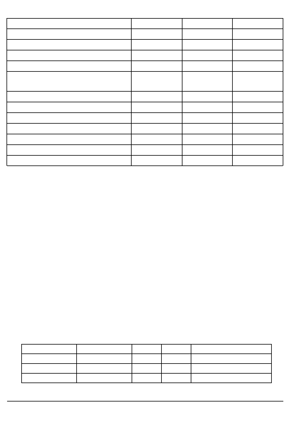
Electro Industries/GaugeTech
E154703 5-17
QDirect Adjustment Interface
Calibration data can be read and modified using the above registers.
Factory Calibration and CT/PT Compensation Calibration are available in the above blocks.
The Block Timestamp indicates when the data you are reading was last refreshed for viewing.
The Calibration Timestamp indicates when calibration information was last modified. This is either
updated automatically when manual adjustments are performed, or is provided as part of the block
when direct adjustments are performed.
The Calibration Checksum is a CRC16 checksum computed over all calibration information from
the Calibration Timestamp through to the last unused byte before the Calibration Checksum. It is
either automatically computed when manual adjustments are performed, or is provided as part of the
block when direct adjustments are performed.
When performing a direct adjustment, in addition to providing a properly checksummed table of
calibration data, a selection indicating whether the table should update the Factory calibration or the
CT/PT calibration needs to be provided. This selection should be 0x00000 for Factory Calibration
and 0x00100 for CT/PT Compensation. To verify the selection, a Block Checksum must be
computed from the Calibration Modification Selection through to the Calibration Checksum.
QVoltage Gain Factor: 4 byte signed LSB values with 15 bits of fraction that are used as a
multiplicative factor.
CTPT Read Modification
Block Timestamp
Factory Read
60929-60932 61027-61030
Calibration Modification Selection 61185
Calibration Timestamp 60933-60936 61030-61034 61186-61189
Gain Factors VAN, VBN, VCN, VXN 60937-60944 61035-61042 61190-61197
Gain Factor IA, 150mA, 250mA, 500mA, 1A,
2.5A, 5A 60945-60956 61043-61054 61198-61209
Gain Factors IB, IC, INM 60957-60992 61055-61090 61210-61245
Unused 60993 61091 61246
Phase Comp IA, 500mA, 1A, 2.5A, 5A, 10A 60994-60998 61092-61096 61247-61251
Phase Comp IB, IC60999-61025 61097-61106 61252-61278
Unused 61009-61025 61107-61123 61262-61278
Calibration Checksum 61026 61124 61279
Block Checksum 61280
As Stored (LSB) MSB Decimal Scaled Meaning
0x000800000 0x000008000 32768 1.00000 x*1.00 (unity)
0x0CC8C0000 0x000008CCC 36044 1.09998 x*1.10 (magnification 10%)
0x033730000 0x000007333 29491 0.89999 x*0.90 (diminution 10%)
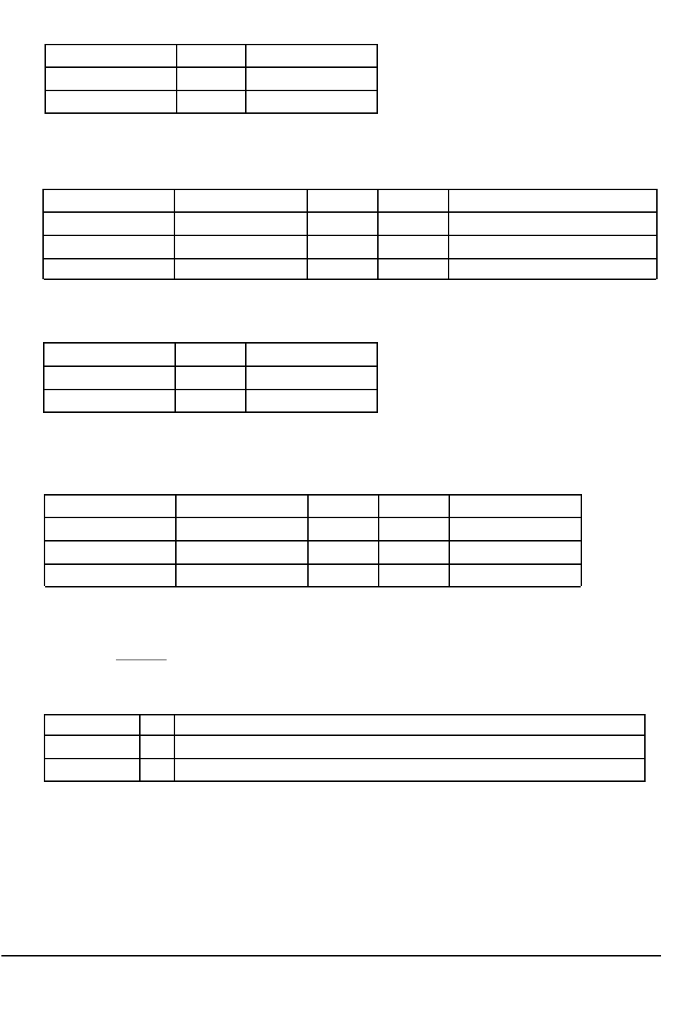
Electro Industries/GaugeTech
E154703 5-18
QTo increase/decrease a voltage reading by y percent, multiply the gain factor by (100 + y)/100.
QCurrent Gain Factors: 4-byte signed LSB values with 16 bits of fraction that are used as a
divisive factor.
QTo increase/decrease a current reading by y percent, multiply the gain factor by 100 (100 + y).
QPhase Compensation Factors: 2 -byte signed LSB values in units of 0.01” of additive Power
Factor shift.
QTo increase/decrease power at 600 in Quadrant 1 by y percent, modify the Phse Compensation by
Change by y Multiply by
Increase 2% +2 102/100 = 1.02
Decrease 5% -5 95/100 = 0.95
As Stored (LSB) MSB Decimal Scaled Meaning
0x000000100 0x000010000 65536 1.00000 x/1.00 (unity)
0x0711C0100 0x00000E8BA 59578 0.90909 x/0.90909 (magnification 10%)
0x0711C0100 0x000011C71 72817 1.11110 x/1.11110 (diminution 10%)
Multiply byChange by y
Increase 2% +2 100/102 = 0.98039
Decrease 5% -5 100/95 = 1.05263
As Stored (LSB) MSB Decimal Scaled Meaning
0x00000 0x00000 0 0.00 No Phase Shift
0x00200 0x00002 2 0.02 +0.020PF Shift
0x0FEFF 0x0FFFE -2 -0.02 -0.020PF Shift
01
50
60 cos 100 y
−
⎡⎤
−⎢⎥
+
⎣⎦
Change by y Modified by
Increase 2%
Decrease 5%
+2
-2
600-cos-1 (50/102) = 600-cos-1 (0.49020) = 600-60.65 0= -0.650
600-cos-1 (50/95) = 600-cos-1 (0.52632) =600-58.240= +1.760
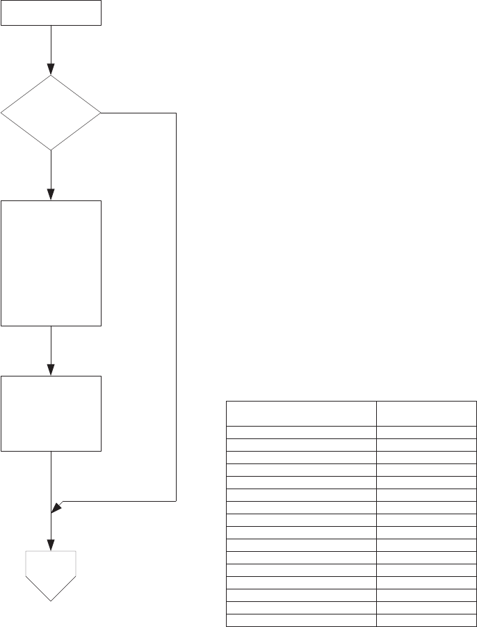
1H[XV3URJUDPPDEOH6HWWLQJV8SGDWH (Page 1)
1RWH)RUWKLVGRFXPHQWDOO0RGEXV5HJLVWHUVDUH+ROGLQJ5HJLVWHUV
&OHDULQJ/RJV
6HQGWKH/RFN
FRPPDQGWR
SUHYHQWORJVIURP
VWDUWLQJEHIRUHWKH
V\VWHPLVUHVHW
:ULWH[$%&'WR
5HJLVWHU(
6HQGWKH
FRPPDQGVWR
&OHDU\RXU
VHOHFWHGORJV
7R3DJH
<HV
1R
6WDUW
7KLVLVWKHIORZFKDUWRIWKHSURFHGXUHXVHGWRSODFHXSGDWHGSURJUDPPDEOH
VHWWLQJVLQWRWKHGHYLFHXVLQJVWDQGDUG0RGEXV+ROGLQJUHJLVWHUIXQFWLRQV
7R&OHDURU5HVHWDOOORJVH[FOXGLQJWKH6\VWHP(YHQW
/RJ
:ULWH[))))WR+ROGLQJ5HJLVWHU[(
+ROGLQJ5HJLVWHU/RJ
[(+LVWRULFDO
[(6HTXHQFHRI(YHQWV
[(+LVWRULFDO
[('LJLWDO,QSXW
[('LJLWDO2XWSXW
[($)OLFNHU
[(%:DYHIRUP
[(&34
[($+LVWRULFDO
[(%+LVWRULFDO
[(&+LVWRULFDO
[('+LVWRULFDO
[((+LVWRULFDO
[()+LVWRULFDO
[((YHQW7ULJJHUHG
[(7UDQVLHQW
7R&OHDURU5HVHWDVSHFLILF/RJ
:ULWH[))))WRWKH+ROGLQJ5HJLVWHU
DVVRFLDWHGZLWKWKH/RJVKRZQLQWKHWDEOH
EHORZ5HY
Doc# E154703 5-19
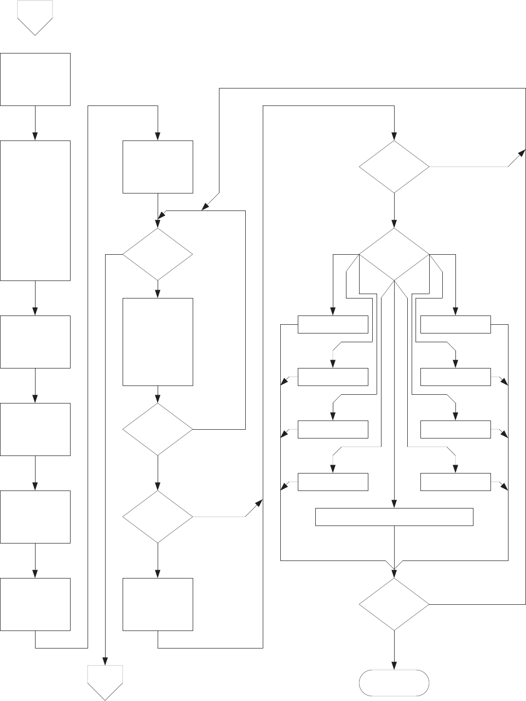
1H[XV3URJUDPPDEOH6HWWLQJV8SGDWH (Page 2)
&RPSXWHWKH
&KHFNVXPRQWKH
ILUVWE\WHVRI
WKH3URJUDPPDEOH
6HWWLQJV
6NLSSLQJWKHQH[W
E\WHVDQGXVLQJ
WKHFKHFNVXP
YDOXHIURPWKHODVW
VWHSDVWKHLQLWLDO
FKHFNVXPYDOXH
FRQWLQXHWKH
FKHFNVXP
FDOFXODWLRQRYHU
WKHQH[W
E\WHV
6SOLWWKH
3URJUDPPDEOH
VHWWLQJVLQWR
E\WHDUUD\V
:ULWHWKH)LUVW
E\WHV
VWDUWLQJDW0RGEXV
5HJLVWHU[%
3XWWKH&KHFNVXP
LQWRE\WHV
DQG]HUR
EDVHG$UUD\
:ULWHWKH6HFRQG
E\WHV
VWDUWLQJDW0RGEXV
5HJLVWHU[
6HWH[LWORRS
)DOVH
([LWORRS"
7UXH
)DOVH
*HW7KH
3URJUDPPDEOH
6HWWLQJV8SGDWH
6WDWXV5HDG
UHJLVWHUVVWDUWLQJ
DW0RGEXV
5HJLVWHU[))(
8SGDWH0RGH"
8SGDWHLQ
3URJUHVV
,GOH
5DPDQG)LOH
FRSLHV0DWFK
<HV
1R
6HWH[LWORRS
7UXH
(UURU)RXQG"
,QWHUQDO*OREDOIODJ
QRWVHW %XIIHUQRWUHDG\
1R
<HV
(UURU&RGH"
7R3DJH
%DG&KHFNVXP ,QWHUQDO&KHFNV
)DLOHG
&RXOGQRWZULWHILOH
KHDGHU 'DWD:ULWH(UURU
5HWULHV
([FHHGHG
1R
<HV
$ERUW
1RWH)RUWKLVGRFXPHQWDOO0RGEXV5HJLVWHUVDUH+ROGLQJ5HJLVWHUV
)URP
3DJH
5HDGEDFNFKHFN
IDLOHG
5HDGEDFN
VHWWLQJVIDLOHG
&RPSDFW)ODVKXWLOLW\IXQFWLRQUXQQLQJ
XSGDWHRSHUDWLRQUHIXVHGLQFRPSOHWH
5HY
Doc# E154703 5-20
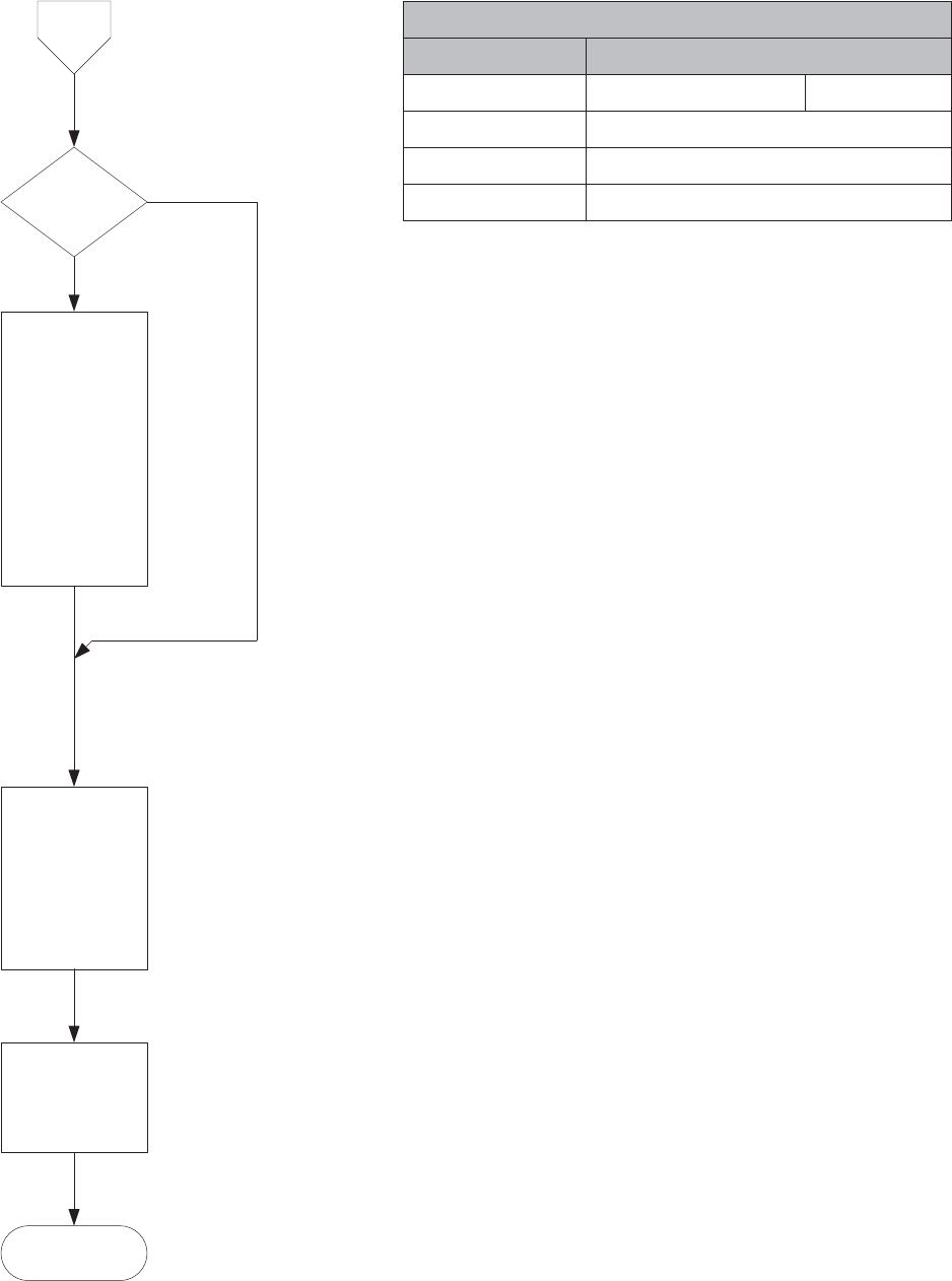
)URP
3DJH
6HQGUHVHW
FRPPDQGVR
FKDQJHVZLOOEH
XVHG
:ULWH[WR
0RGEXV+ROGLQJ
5HJLVWHU[)))$
1H[XV3URJUDPPDEOH6HWWLQJV8SGDWH (Page 3)
:DLWDWOHDVW
6HFRQGVIRU
'HYLFHWR5HVWDUW
'RQH
5DPDQG)LOH0DWFK06%
)LOHDQG5$0FRSLHVPDWFK
)LOHDQG5$0FRSLHVGRQRWPDWFK
0RGH/6%
,GOHXSGDWHQRWLQSURJUHVV
1RW8SGDWHLQSURJUHVV
(UURU&RGH
1R(UURU
,QWHUQDO*OREDOIODJQRWVHW
%XIIHUQRWUHDG\
%DG&KHFNVXP
,QWHUQDO&KHFNV)DLOHG
&RXOGQRWZULWHILOHKHDGHU
'DWD:ULWH(UURU
*UHDWHUWKDQQRWGHILQHG
7LPH6WDPS
6HH1H[XV7LPH6WDPSIRUPDWLQWKH0RGEXV0DQXDO
)LOH&KHFNVXP
&KHFNVXPRIWKHILOHFRQWDLQLQJWKHSURJUDPPDEOH
VHWWLQJVVWRUHGRQWKHFRPSDFWIODVK
1RWH)RUWKLVGRFXPHQWDOOFKHFNVXPVXVH&5&DVGHILQHGLQWKH0RGEXV5783URWRFRO
:DLWIRU/RJVWKDW
ZHUHVHOHFWHGWR
EHFOHDUHGRQ
3DJHWREH
FOHDUHG4XHU\
WKH/RJ5HVHW
6WDWXV5HJLVWHUV
RIORJVWKDWZDV
FOHDUHGXQWLODOO
UHWXUQLQGLFDWLQJ
WKH\KDYHEHHQ
FOHDUHG
/RJV&OHDULQJ"
<HV
1R
Programmable Settings Update Status Registers (0xFFE0 to 0xFFE6)
[))( 5DPDQG)LOH0DWFK06% 0RGH/6%
[))( (UURU&RGH
+ROGLQJ5HJLVWHUV
[))( [))( 7LPH6WDPS
'HVFULSWLRQ
[))( )LOH&KHFNVXP
+LVWRULFDO [
+LVWRULFDO [
+LVWRULFDO [(
+LVWRULFDO [(
+LVWRULFDO [(
+LVWRULFDO [('
+LVWRULFDO [)
+LVWRULFDO [)
(YHQW7ULJJHUHG [)
6HTXHQFH2I(YHQWV [/LPLWV
'LJLWDO,QSXWV [
'LJLWDO2XWSXWV [
)OLFNHU [
:DYHIRUP [
34 [
6\VWHP(YHQWV [
7UDQVLHQW [&
/RJ5HVHW6WDWXV5HJLVWHUV
5HDGEDFNFKHFNIDLOHG$VN:HL:DQJIRUDUHDOGHILQLWLRQ
5HDGEDFNVHWWLQJVIDLOHG$VN:HL:DQJIRUDUHDOGHILQLWLRQ
&)8WLOLW\IXQFWLRQUXQQLQJXSGDWHRSHUDWLRQUHIXVHGLQFRPSOHWH$VN:HL:DQJ
IRUDUHDOGHILQLWLRQ
Doc# E154703
5-21

e Electro Industries/GaugeTech Doc# E154703 5-22

E Electro Industries/GaugeTech Doc # E154703 6-1
Chapter 6:
Large Data Access (LDA) and Downloading Logs
6.1: Overview
This chapter explains how to access large amounts of data from the Nexus® 1500 meter. Such
large amounts of data can consist of a file or files from a file system, file or files stored in RAM
or any kind of flash memory device, or dynamic data generated by the Modbus device. A set of
specific commands must be used to download large amounts of data. These commands are
referred to as Large Data Access, or LDA.
In addition to explaining LDA, this chapter explains how to download Nexus® 1500 meter logs
using LDA.
NOTE: This is the recommended procedure for downloading logs from the Nexus® 1500 meter.
All of the logs except for the System Event log and Historical logs 1 and 2 must be downloaded
using this procedure. For backward compatibility, you can still download the System Event log
and Historical logs 1 and 2 with the serial method (see Chapter 9). We recommend you use the
LDA procedure, though, as it is faster and able to handle larger amounts of data than the serial
method.
6.1.1. Reference Documents
You may find it useful to refer to the following documents:
Modicon Modbus Protocol Reference Guide: PI-MBUS-300 Rev. J
Modbus-IDA MODBUS Application Protocol Specification V1.1b
The Nexus® 1500 Meter Modbus Register Map (in this manual)
Communicator EXT 3.0 User Manual
6.2: LDA Overview
The Modbus protocol was designed for use with discrete values, not files. The Modbus protocols
supported by LDA are:
Modbus ASCII
Modbus RTU
Modbus TCP
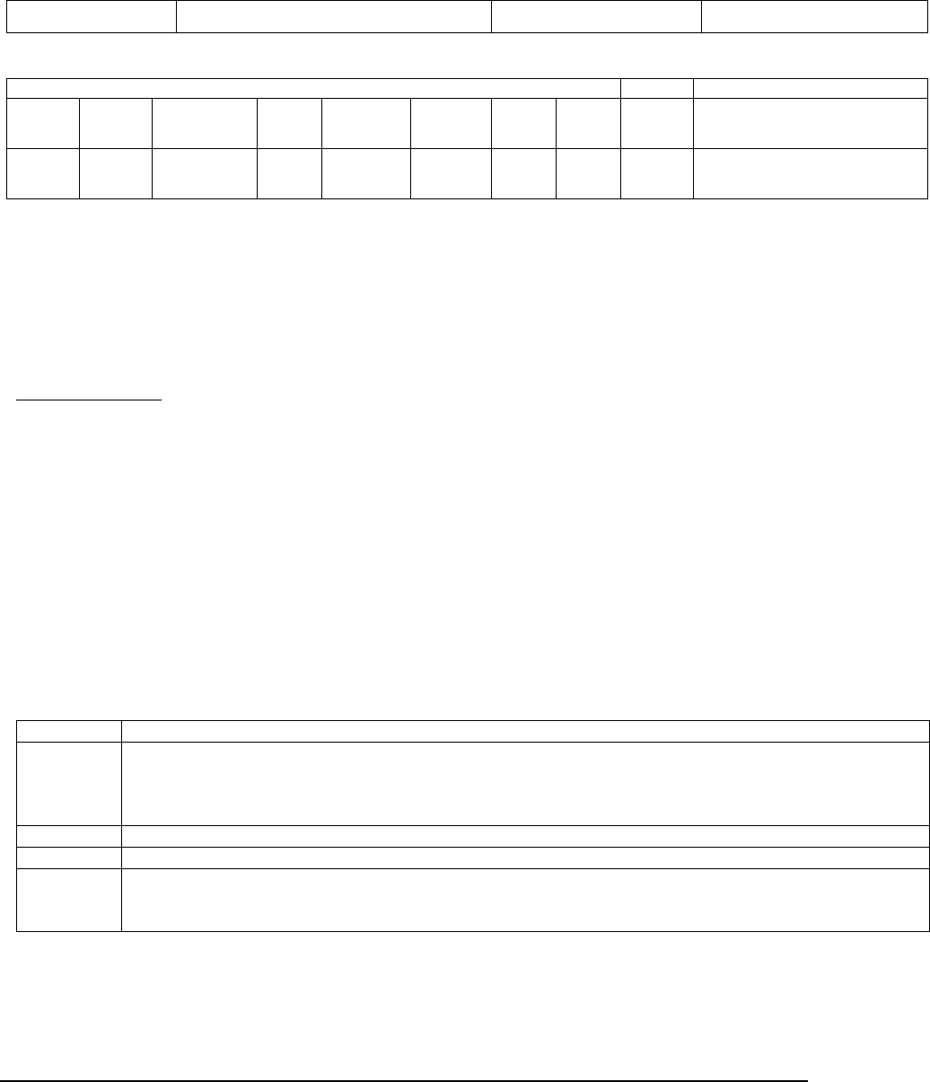
E Electro Industries/GaugeTech Doc # E154703 6-2
6.2.1: Modbus Interface for LDA
Standard Modbus Exception Response is supported by LDA. For example, if a device has an
exception response, such as the device does not support this LDA request at function code 0x45,
the response message will be:
Device Address Custom Function Code with msb bit set Exception Code Checksum
The base Modbus message format for Large Data Access via Modbus Protocols is:
Frame Header
Device
Address
Custom
Function
Code
Frame Length User
Flags
User
Command
Code
User Sub-
Command
Code
Status
Code
User
Data
Length
User
Data
Checksum (optional)
1 Byte 1 Byte,
0x45
2 Bytes
(MSB format)
4 Bytes
(MSB
format)
4 Bytes
(MSB
format)
4 Bytes
(MSB
format)
4 Bytes
(MSB
format)
4 Bytes
(MSB
format)
X Bytes 1 Byte for LRC in Modbus ASCII,
2 Bytes for CRC in Modbus RTU,
none for Modbus TCP
Since the user data section is optional, the minimum frame length is 1+1+2+4+4+4+4+4=24
bytes.
The request and response message format are the same for the first 24 bytes. The user data section
is optional and only used for certain commands. For example, the user data section could contain
readable text messages, a firmware file for firmware updates, or a file from the file system.
Field Descriptions
Device Address
Standard Modbus device address
Custom Function Code
A designated Modbus Function Code to identify this message; contains custom data and format.
Use 0x45 in hex, 69 in decimal.
Frame Length
Length of this Modbus message - it’s the sum of 1+1+2+4+4+4+4+4+[user data length in this
frame]. The maximum user data length in a frame is 1408 bytes.
User Flag Details
Bits 31 to 0, where bit 31 is the most significant bit.
Flag Bits Description
31 ACK flag. Used when user data needs to be transferred in multiple frames. For sender, the first frame with
user data transferred does not set the ACK flag, but additional frames transferred with user data will need the
ACK flag set. For the receiving party, the request command with this ACK flag set must be sent to the
sender.
30 Last user data transfer. Set by sender in the last user data transfer frame.
29 Indicates file or directory for command code 34, 35, 36. 0=file, 1=directory.
28 File read cache status. When set, file read is cached by the device which can improve performance.
Current implementation has only one cached channel on Modbus TCP connection on a first come, first
served basis.

E Electro Industries/GaugeTech Doc # E154703 6-3
User Command Code Details
Primary user defined command code. An enumeration of user defined features and functions.
Command Code Description
1 Device ID Device returned ID string in user data field.
2 Device Reset, meter
hardware reset.
User must log on first.
4 Firmware Update For request message, user sends firmware file in the user data field for
up to 1408 bytes; user sets the firmware file total length in the user data
length field.
For response message, ACK flag will be set.
For additional requests, user sets the ACK flag; user set additional user
data in user data field (up to 1408 bytes).
5 Abort transmission Terminate multi-framed data transfer.
6 Get current data output
transfer window size
Data output transfer window size is configurable by user. The default
value is 1408.
7 Set current data output
transfer window size
User configurable. Valid value ranges from 64 to 1408, in increments of
64.
10 User Security Status User log on sequence is Username first, followed by Password. Wrong
sequence will terminate the logon process.
11 Send Username XOR masked username with 0x45, 'E', in user data field.
12 Send Password XOR mask for password with 0x49, 'I', in user data field.
13 Logoff Device will clear security privileges for the current connection.
20 Firmware update status With current status code and text message.
21 Firmware info Firmware information in text.
30 Change Directory Allows the changing of the current directory to a different one.
31 Get Current Directory Returns the complete path and the current directory.
32 List Directory Contents Returns the contents of the current directory.
33 Create Directory Creates a directory in the file system in a writeable directory.
34 Delete File/Directory Deletes a file or an empty directory from the file system.
35 Rename File/Directory From Renames a file or a directory from.
36 Rename File/Directory To Renames a file or a directory to.
37 Read File Reads bytes from a file.
38 Write File Writes bytes to a file.
39 Get File Details Returns the file details (Size, Date & Time, and file attributes).
40 Close File Closes the file.
41 Get a file's CRC32 checksum Gets a file's CRC32 checksum.
65536 Reserved
65537 Reserved
65538 .. 65600 Reserved
User Sub-Command Code
When sending data in a multi-framed process, sequence number will be used and placed in the
user sub-command code field. The sequence number for the first frame in a multi-framed transfer
will be 0 and additional frame sequence numbers will be 1 and so on.
User Sub-Command Code
Sequence Number, 4 Bytes, MSB.

E Electro Industries/GaugeTech Doc # E154703 6-4
Status Code
Set by the receiving end of data transfer. User should always check the status code when
processing a response message.
Status Code Description
0 Device did not respond, this is an error condition.
0x00AA Completed Successfully.
0x00BB Busy or in process.
0x00FA Failed.
0x00FF Not Authorized.
0x0100 Data Not found.
0x0101 Command Code not supported.
0x0102 Invalid frame length.
0x0103 Invalid user data length.
0x0104 User data length larger than set.
0x0105 User data receive buffer not ready.
0x0106 User data receive error.
0x0107 Firmware update data transfer done.
0x0108 Firmware update data transfer failed.
0x0109 User logged on.
0x010A User logged off.
0x010B Firmware update in process.
0x010C Firmware update failed.
0x010D Firmware update done.
0x010E Firmware update idle.
0x010F User security privilege restricted.
0x0110 User security setting was changed, need to log on again.
0x0111 File or Directory does not exist.
0x0112 Already in the root.
0x0113 Directory already exists.
0x0114 Permission denied.
0x0115 Name is invalid.
0x0116 File in use by another process.
0x0117 Directory is not empty.
0x0118 Handle does not exist.
0x0119 Invalid Handle.
0x011A File Seek invalid.
0x011B Byte count invalid.
0x011C Handle in use.
0x011D Disk full.
0x011E File Open Error.
0x011F File size is 0.
0x0120 Missed write frame with sequence number 1.
0x0121 Invalid write sequence number.
0x0122 Invalid command between read write file operation.
0x0123 File access error while processing file checksum command.
0x0124 File read error while processing file read command.
0x0125 File write error while processing file write command.
User Data Length
Exact size of user data in number of bytes. If there is no user data in the message, this number is
0.

E Electro Industries/GaugeTech Doc # E154703 6-5
User Data
Contains user specific data. If User Data Length field value is 0, then user data section does not
exist. For multi-framed data transfers, the user must send the data in the fixed length window
except for the last frame. For example, if the user data is 4096 bytes and the transfer window size
is 1408 byte, the user could send it in 3 frames, in the sizes of 1408+1408+1280, respectively.
Checksum
Contains the checksum for this Modbus message: 1 Byte for LRC in Modbus ASCII, 2 Bytes for
CRC in Modbus RTU, none for Modbus TCP.
6.3: LDA Programming Examples
6.3.1: Example 1 - Update Firmware
a) Software sends request device ID command
01 45 00 18 00 00 00 00 00 00 00 01 00 00 00 00 00 00 00 00 00 00 00 00
Device should return
01 45 00 2E 00 00 00 00 00 00 00 01 00 00 00 00 00 00 00 AA [xx.xx.xx.xx, 4
bytes, Device ID string length] [n bytes, actual Device ID string]
b) Software should verify the returned message for correct device ID.
c) Software sends username command with XOR encoded username to device.
d) Software sends password command with XOR encoded password to device.
e) Software sends user security status command to device. In addition, software should
verify the returned message for user logged on status code.
f) Software sends the first frame with user data in the user data field. Software should
determine what the user data transfer window size is and then fill the user data field up to
that number. For example, if the firmware data is 4096 bytes and the transfer window
size is 1408 byte, software could send it in 3 frames, in the sizes of 1408+1408+1280,
respectively.
Software should set the following:
- clear bit 31 in the user flags field.
- clear bit 30 in the user flags field.
- Set user command code 4, for firmware update.
- Set user sub-command field to 0.
- Set the total firmware length in the user data length field.
Device will return the following, with a success status code.
01 45 00 18 80 00 00 00 00 00 00 04 00 00 00 00 00 00 00 AA 00 00 00 00
g) Software then sends the additional frames with additional user data in the user data field.
Software should set the following:
- set bit 31 in the user flags field, ACK bit.
- set bit 30 in the user flags field only if the frame is the last frame.
- Set user command code 4, for firmware update.
- Set a sequence number in the user sub-command field, starting with 1, then
incrementing for each additional frame sent.
- Set the user data size in the user data length field. Using above example with
firmware data of 4096 and transfer window size of 1408, the value in user data length
field will be 1408 and 1280 for transfer frames with sequence numbers 1 and 2.

E Electro Industries/GaugeTech Doc # E154703 6-6
Device will return the following, with a success status code and user send sequence
number.
01 45 00 18 80 00 00 00 00 00 00 04 00 00 00 01 00 00 00 AA 00 00 00 00
for frame with sequence 1.
01 45 00 18 80 00 00 00 00 00 00 04 00 00 00 02 00 00 00 AA 00 00 00 00
for frame with sequence 2.
h) When the user has sent all the firmware data to the device and the device has correctly
received all the data, usually on the last frame the device returns with the "Firmware
update data transfer done" status code. Then the device starts parsing, checking and
updating the firmware process.
i) Software should send the Firmware update status command to the device and check the
returned firmware update status code.
j) After the firmware status code is changed to Firmware update done, software should send
the Firmware info command to the device and show the returned firmware information to
the user for confirmation.
k) If everything is OK, the software should give the user the option to reset the device by
sending the Device Reset command.
6.3.2: Example 2 - Read a Log File from the Nexus® 1500 Meter's File
System
a) Software sends username command with XOR encoded username to the device,
assuming a user name of 9 characters.
01 45 00 21 00 00 00 00 00 00 00 0B 00 00 00 00 00 00 00 00 00 00 00 09
[xx..(total 9 bytes)]
Device Response if the request is valid:
01 45 00 18 00 00 00 00 00 00 00 0B 00 00 00 00 00 00 00 AA 00 00 00 00
b) Software sends password command with XOR encoded password to device, assuming a
password of 9 characters.
01 45 00 21 00 00 00 00 00 00 00 0C 00 00 00 00 00 00 00 00 00 00 00 09
[xx..(total 9 bytes)]
Device Response if the request is valid:
01 45 00 18 00 00 00 00 00 00 00 0C 00 00 00 00 00 00 00 AA 00 00 00 00
c) Software sends user security status command to the device. In addition, software should
verify the returned message for "user logged on" status code.
User Request:
01 45 00 18 00 00 00 00 00 00 00 0A 00 00 00 00 00 00 00 00 00 00 00 00
Device Response: User logged On.
01 45 00 27 00 00 00 00 00 00 00 0A 00 00 00 00 00 00 01 09 00 00 00 0F
55 73 65 72 20 6C 6F 67 67 65 64 20 4F 6E 2E
d) Software sends Read File command with '\C\LOGS\00000000.BIN' in the user data field.
01 45 00 2D 00 00 00 00 00 00 00 25 00 00 00 00 00 00 00 00 00 00 00 15
5C 43 5C 4C 4F 47 53 5C 30 30 30 30 30 30 30 30 2E 42 49 4E 20
e) Assuming use of default transfer size of 1408 bytes, the device responds with the
following:
- Set the first 1408 bytes of the file in the user data field.

E Electro Industries/GaugeTech Doc # E154703 6-7
- Set sequence 0 in the user sub-command field.
- Set 1024*1024 in the user data length field.
- Set 0xAA in the status code field.
- Clear bit 30 in the user flags field, last frame bit.
01 45 05 98 80 00 00 00 00 00 00 25 00 00 00 00 00 00 00 AA 00 10 00 00
[xx.. (total 1408 bytes of data)]
f) Software sends additional Read File commands with the following:
- Set bit 31 in the user flags field, ACK bit.
- Set sequence 1 in the user sub-command field.
01 45 00 18 80 00 00 00 00 00 00 25 00 00 00 01 00 00 00 00 00 00 00 00
g) The device responds with the following:
- Set the additional 1408 bytes of the file in the user data field.
- Set user requested sequence number in the user sub-command field.
- Set 1408 in the user data length field.
- Set 0xAA in the status code field.
- Clear bit 30 in the user flags field, last frame bit.
01 45 05 98 80 00 00 00 00 00 00 25 00 00 00 01 00 00 00 AA 00 00 05 80
[xx.. (total 1408 bytes of data)]
h) Repeating the process in step (f) and step (g), software increments the sequence number
by 1. When the device responds for the last frame, the device returns the following:
- Set the last 1024 byte of the file in the user data field.
- Set user requested sequence number in the user sub-command field, which should be
744.
- Set 1024 in the user data length field.
- Set 0xAA in the status code field.
- Set bit 30 in the user flags field, last frame bit.
Last Device Response:
01 45 04 18 C0 00 00 00 00 00 00 25 00 00 02 E8 00 00 00 AA 00 00 04 00
[xx.. (total 1024 bytes of data)]
i) Software should receive a total of 1024*1024 bytes file.
j) Software should send close file command to device.
User Request:
01 45 00 18 00 00 00 00 00 00 00 28 00 00 00 00 00 00 00 00 00 00 00 00
Device Response:
01 45 00 18 00 00 00 00 00 00 00 28 00 00 00 00 00 00 00 AA 00 00 00 00
6.4: Notes on User Security Implementation
The Nexus® 1500 meter has its own security features, in particular the multi-level access code,
which can be accessed via Modbus function codes 0x03, 0x06 and 0x010. It also has the
extended password features with 8 additional user accounts with configurable access privileges.
The user security features addressed in this document are only for accessing the areas set by the
user access privileges. For more information on meter security features, see the Nexus® 1500
Installation and Operation Manual and the Communicator EXT User Manual.

E Electro Industries/GaugeTech Doc # E154703 6-8
6.5: File Access Command Details
Change Directory
Software should set the following in the frame sent to the device:
- Set user command code 30.
- Set the desired directory name in user data field, such as LOGS or .. for changing one
directory level up.
- Set the directory name length in user data length field
Software receives a status code in the returned frame. If the command was processed
successfully by the device, the current directory and path in the device for this connection
is changed accordingly.
Get Current Directory
Software should set the following in the frame sent to the device:
- Set user command code 31.
- Clear the user data field and user data length field.
Software receives a status code in the returned frame. If the command was processed
successfully by the device, the current directory name is in the user data field with the
directory name length set in the user data length field.
List Directory Contents
Software should set the following in the frame sent to the device:
- Set user command code 32.
- Clear the user data field and user data length field.
Software receives a status code in the returned frame. If the command was processed
successfully by the device, the directory contents are in the user data field with the
content length set in the user data length field. If the directory content's size is larger
than the data output transfer window size, then the data needs to be transferred in
multiple frames.
To request additional frames, software should set the following in the frame sent to the
device:
- Set bit 31 in the user flags field.
- Set user command code 32.
- Clear the user data field and user data length field.
In response to software's additional request, the device will set and send the following:
- Set bit 31 in the user flags field.
- Set bit 30 only if the frame is the last frame to hold user data.
- Set user command code 32.
- A sequence number starting at 1 and incremented by 1 for each additional frame in
user sub-command code field.
- A status code.
The format for directory contents is as follows:
111111111122222222223333333333444444444455555555
0123456789012345678901234567890123456789012345678901234567

E Electro Industries/GaugeTech Doc # E154703 6-9
[Acc RWX] [Fileln] YYYY-MM-DD HH:mm:ss [Fname 8.3]{CR}{LF}
[Acc RWX] File Permissions:
The permissions have 4 flags:
d : The entry is a directory.
r : The entry has read permissions.
w : The entry has write permissions.
x : The entry has executed permissions.
As a reference, the rwx's are clustered into 3 groups:
-rwx------ : The permissions for the owner of this file.
----rwx--- : The permissions for the group of the owner of this
file. (Nexus 1500 will display ----r-----).
-------rwx : The permissions for everyone else. (Nexus 1500 will
only display -------r--).
[Fileln] File length: Fixed number of characters, 8 digits, space padded,
right justified.
[Fname 8.3] Filename conforming to the 8.3 file naming convention
{CR}{LF} Line terminator
Create Directory
Software should set the following in the frame sent to the device:
- Set user command code 33.
- Set the desired new directory name in the user data field, such as UserData.
- Set the directory name length in the user data length field.
Software receives a status code in the returned frame.
Delete File/Directory
Software should set the following in the frame sent to the device:
- Set user command code 34.
- Set the desired file name or directory name to delete in the user data field, such as
UserData.
- Set the file name or directory name length in the user data length field.
Software receives a status code in the returned frame.
Rename File/Directory
Rename From
Software should set the following in the frame sent to the device:
- Set user command code 35.
- Set the desired file name or directory name to rename in the user data field, such as
UserData.
- Set the file name or directory name length in the user data length field.
Software receives a status code in the returned frame.
Rename To
Software should set the following in the frame sent to the device:
- Set user command code 36.
- Set the desired new file name or directory name in the user data field, such as
UserData.
- Set the file name or directory name length in the user data length field.

E Electro Industries/GaugeTech Doc # E154703 6-10
Software receives a status code in the returned frame.
Read File
Software should set the following in the frame sent to the device:
- Set user command code 37.
- Set the desired file name in the user data field, such as UserFile.txt.
- Set the file name length in the user data length field.
Software receives a status code in the returned frame. If the command was processed
successfully by the device, the file contents will be in the user data field with the total file
length set in the user data length field. If the file content's size is larger than the data
output transfer window size, then the data needs to be transferred in multiple frames. A
sequence number starting at 0 in the user sub-command code field for the first frame.
To request additional frames, software should set the following in the frame sent to the
device:
- Set bit 31 in the user flags field.
- Set user command code 37.
- Clear the user data field and the user data length field.
- A sequence number starting at 1 and incremented by 1 for each additional frame in
user sub-command code field.
In response to software's additional request, the device will set and send the following:
- Set bit 31 in the user flags field.
- Set bit 30 only if the frame is the last frame to hold user data.
- Set user command code 37.
- A sequence number set in the user sub-command code field, which should match the
sequence number in the request frame.
- A status code.
To perform the equivalent of a File Seek operation, the user should use the sequence
number in the read request for additional frames. By setting a different sequence number
in the read request, the user could randomly access any part of the file after the first read
request, in chunks the size of the Data Output Transfer Window.
Write File
Software should set the following in the frame sent to the device:
- Clear bit 31 in the user flags field.
- Set user command code 38.
- Set the desired file name in the user data field, such as UserFile.txt.
- Set the file name length in the user data length field.
- A sequence number 0 in the user sub-command code field.
Software will receive a status code in the returned frame. If the command was processed
successfully by the device, then the software should set the following in the frame sent to
the device:
- Set bit 31 in the user flags field.
- Set bit 30 only if the frame is the last frame to hold user data.
- Set user command code 38.
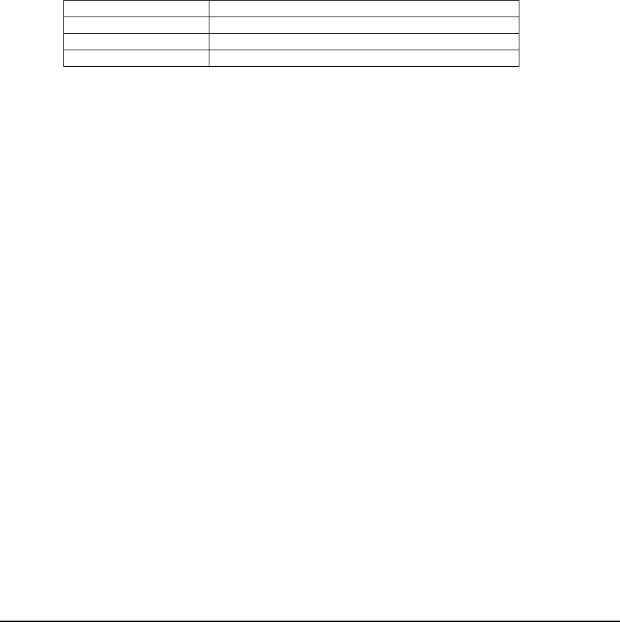
E Electro Industries/GaugeTech Doc # E154703 6-11
- A sequence number starting at 1 and incremented by 1 for each additional frame in
the user sub-command code field.
- Set the desired file data in the user data field, for up to the 1408 bytes.
For recovery during a write operation, if the returned status code is 0x121 (Invalid write
sequence number), the user can resend the command. For all other status code with
errors, the user should attempt to send the close file command, pause, and then send the
write file command again as a whole new operation.
File Details
A comma separated text block holds the file detail information; the format is:
[Size], [Modified Time Stamp, YYYY-MM-DD HH:MM:SS], [Attributes]
For example:
3743, 2008-05-04 15:12:27, False
Property Description
Size Actual size of the file in bytes
Modified Time Stamp Time file was last modified
Attributes Read only
File Close
Software should send this file close command at the beginning of a new read/write and at
the end of the current read/write. For write, we only support sequential write, which
means no jumping between each write. For read, non-sequential read is also supported,
which means after the first request, the software could ask for any part of the file.
Because of this, firmware needs the file close command to signal a termination of the
read/write process.
Software should set the following in the frame sent to the device:
- Set user command code 40.
Software receives a status code in the returned frame.
Get a File's CRC32 checksum
This command causes the device to compute a given file's CRC32 checksum and return
the result to the user. Software should send this command with the specified file name in
the user data field and set the file name length in the user data length field. The file name
can contain the full path, or just the file name if the Change Directory command is sent
separately, before this command is sent. On successful completion of the task, the
computed CRC32 checksum is returned in the return message's user data section with the
user data length field set to 4, for a 4 bytes unsigned long value in MSB format. The
returned status code could be 0x00AA, 0x010F, 0x011E, 0x011F.
In addition, when the user send this command, the user could also set a working buffer
size value in User Sub-Command Code field for the meter to use. The valid value range
for the Nexus® 1500 meter is from 128 (if the setting is below 128) to 1048576 (if the
setting is above 1048576). The recommended value is 4096.
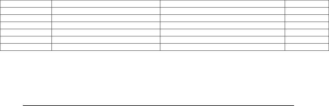
E Electro Industries/GaugeTech Doc # E154703 6-12
6.6: Data Input and Output Transfer Window Size
This window's default size is 1408 bytes, which allows the user to set a window for receiving
larger data from the device. For example, if the data size if 4k(4-1024) bytes, with a default
transfer window size of 1408 bytes, the data needs to be transferred out in 3 frames in the size of
1408, 1408, and 1280 bytes, respectively. If the transfer window size is set at 64, then the data
needs to be transferred out in 64 frames in the size of 64 bytes each.
Get current data output transfer window size
Software should set the following in the frame sent to the device:
- Set user command code 6.
- Clear user sub-command code field.
Software receives a status code in the returned frame and the current data output transfer
window size will be in the user sub-command code field.
Set current data output transfer window size
Software should set the following in the frame sent to the device:
- Set user command code 7.
- Set the current data output transfer window size in the user sub-command code field.
Valid values for Nexus® 1500 are 64 to 1408 bytes, in increments of 64 bytes.
Software receives a status code in the returned frame and the current data output transfer
window size will be in the user sub-command code field.
Limitation with Modbus ASCII protocol
Because the communication buffer size in the Nexus® 1500 meter used with Modbus
ASCII protocol is about 1500 ASCII characters, the maximum size of the data in the user
data field should be limited to 704 bytes, or 1408 ASCII characters.
Input Transfer Window Size
Input Transfer Window Size is dictated in the first sent frame's data size, and the
maximum data size for each additional frame cannot be larger than the data size in the
first frame. The maximum data size is 1408 bytes. We recommended using the data size
window in increments of 64 bytes.
For example, the sender has the option to send the data using the following options.
NOTE: Because the communication buffer size in a Nexus® 1500 meter with Modbus ASCII
protocol is about 1500 ASCII characters, the maximum size for user data to be put in to the user
data field is 704 bytes, or 1408 ASCII characters.
Total Size (Bytes) Send Data Size in the 1s
t
Frame (Bytes) Send Data Size in the Additional Frames (Bytes) Total Transfers
2816 1408 1408 2
2816 704 704, 704, 704. 4
2816 640 640, 640, 640, 256. 5
2816 64 64, 64, …., 64. 44
1024 1024 Not Applicable 1
12 12 Not Applicable 1

E Electro Industries/GaugeTech Doc # E154703 6-13
6.7: Access Timeout
A general access timeout is applied to commands that require log on. The timeout value is fixed
at 5 minutes. The timeout value is initiated at the time a user logs on via Modbus LDA and
refreshed each time a valid Modbus LDA request is received while the user is logged on.
In Modbus LDA, a timeout expires when the following occurs:
a) The meter security setting is changed.
b) The user logs off.
6.8: Downloading Logs using LDA
6.8.1: Log Interface Files
All settings, states, and data records related to logging are accessible as files through the Modbus
LDA interface. The files which are important to log retrieval and interpretation are as follows:
6.8.1.1: Programmable Settings
\C\SYSTEM\NX1500.nps
The programmable settings file contains most of the configurable settings used for retrieving the
logs and interpreting them. The important ones for retrieval are listed here, as well as a quick
overview of the settings useful for log interpretation. See Chapter 7 for more details.
6.8.1.1.1: Log Block Assignments
The amount of memory assigned to any particular log is configurable by the user, and
affects where in the file system the log retrieval looks for the log’s records. See Chapter
7 for details of using these settings with the logs. Each log is assigned a number of
‘blocks’, which controls the number of files used to store the records, and which exact
files are used for each log.
6.8.1.1.2: Log Item Assignments
Each of the Interval logs, as well as the Digital Input, Digital Output, and Limit logs,
store a configurable set of log items with their records. Each item has the following sub-
items, used to determine its format:
- Line, Point : Combined, line and point describe which of the meter’s items is being
stored in the log.
- Size : The number of bytes used by this item. This will be used later to determine
where in the log record each item is.
- FType : The data type of the item. See Chapter 3 for a description of FTypes.
Each log has its own log item configuration list, with the exception of the Digital Input
and Output logs. The Digital Input log uses Interval 1’s items, and the Digital Output log
uses the Limit log’s items.
6.8.1.1.3: Waveform Settings
See Chapter 7 for details of these settings.

E Electro Industries/GaugeTech Doc # E154703 6-14
6.8.1.2: Meter ID File
\I\METERID.BIN
The Meter ID file contains information about the meter, including current state info, and
configurations.
Field Size Description Setting
Header 16 ASCII, padding
with space “METER ID FILE ”
Version 2 The version
number. Major – Minor (1.7)
Log status 4
Indicates if the
logs are
paused/running.
0 means log are running otherwise logs are paused.
Bit 0[LSB] = Historical 1
Bit 1 = Historical 2
Bit 2 = Sequence of Event (Limit)
Bit 3 = Digital Input
Bit 4 = Digital Output
Bit 5 = Flicker
Bit 6 = Waveform
Bit 7 = System Events
Bit 8 = Transients
Bit 9 = PQ
Bit 10 = Interval Log 3
Bit 11 = Interval Log 4
Bit 12 = Interval Log 5
Bit 13 = Interval Log 6
Bit 14 = Interval Log 7
Bit 15 = Interval Log 8
Bit 16 = Event Triggered
Log drop
record 4
Indicates if the
logs stop logging
allowing dropping
records because
the download
process is slow
than saving record
process.
0 means does not drop record otherwise drop
records.
The sequence is the same as Log Status.
Dummy 1
This enumeration
indicates the path
in our system
where the
pause/running
dummy files,
which are used
during the log
download
process, are
saved.
0 = \C\SYSTEM\LOGS\RUNNING\
\C\SYSTEM\LOGS\PAUSED\
1 = \I\RUNNING\
\I\PAUSED\
2 = \vf\RUNNING\
\vf\PAUSED\
Reserved 5
Meter ID 16 ASCII

E Electro Industries/GaugeTech Doc # E154703 6-15
Meter Serial
Number 8
Comm Boot
Version 4 ASCII
CF size 8
Compact size in
byte, the MSB
byte first
CF serial
Number 20
serial number in
ASCCI, right
justified, with no
null string
terminator
CF FAT type 8
the file system
type, with no null
string terminator
Comm Run
Version 4 ASCII
Comm Run
Build 4 ASCII
Comm state 2
DSP1 Boot 4 ASCII
DSP1 Run 4 ASCII
DSP1 State 2
DSP2 Run
type 2
DSP2 Run 4
DSP2 Run
ID 4
FPGA
Version 2
Time 8
Nexus 12xx time
stamp definition.
The time that the
file was
generated/updated
Log Reset
Status 4
Informs if a
specific log will
be reset.
The sequence is the same as Log Status.
Reserved 6
Current
Range 1
0x000 - Standard Nexus 1500 (Class 20, Nominal
20Amp)
0x001 - Class 2 Nexus 1500 (Nominal 1Amp)
0x002-0x0FF Undefined, treated as Standard Nexus
1500
Reserved 1
Sealing
Switch 1
0x000 No Sealing Switch
0x001 Sealing Switch installed
0x002-0x0FF Undefined, treated as No Sealing
Switch
Reserved 1

E Electro Industries/GaugeTech Doc # E154703 6-16
OEM Model 1
0x000 Standard Nexus identification
0x001 OEM Model String
0x002-0x0FF Undefined, treated as Standard Nexus
identification.
Reserved 1
Temperature
sensor type 1
0x000 Resolution at 0.5 °C.
0x001 Resolution at 0.0625 °C.
0x002-0x0FF Undefined treated as Resolution at
0.5 °C.
Reserved 19
OEM Model
String 16 ASCII
Reserved 80
V-switch 2
Option
board: State 4
Indicates if the
slot has some
board installed. If
the installed board
has good bio-byte
checksum and it is
in proper slot, the
board is
recognized
otherwise it is not
recognized.
Bit 00-07[LSB] = slot 1
Bit 08-15 = slot 2
Bit 16-23 = slot 3
Bit 24-31 = slot 4
= 0x00 – No Board installed
= 0x01 – Board Installed and Recognized
= 0x02 – Board Installed and Not Recognized
Option
board: Type 16
Indicates the
board type if it is
installed and
recognized
Bit 00-31[LSB] = slot 1
Bit 32-63 = slot 2
Bit 64-95 = slot 3
Bit 96-127 = slot 4
= 00 – 2 – N/A
= 03 – RS485-2/Pulso Out-4
= 04 – Ether2/TP
= 05 – Ether2/Fiber
= 06 – Ether2/Wi-Fi
= 07 – N/A
= 08 – Relay Out
= 09 – N/A
= 10 – Ether2/Combo
= 11 – Digital Input Option board
= 12 – Analog Input Option Board
Reserved 16090
Footer ASCII “**ID”

E Electro Industries/GaugeTech Doc # E154703 6-17
6.8.1.3: Log Headers
\I\INT1.BIN
\I\INT2.BIN
\I\INT3.BIN
\I\INT4.BIN
\I\INT5.BIN
\I\INT6.BIN
\I\INT7.BIN
\I\INT8.BIN
\I\ET.BIN
\I\LIMIT.BIN
\I\DIGIN.BIN
\I\DIGOUT.BIN
\I\FLICKER.BIN
\I\SYSEVENT.BIN
\I\WAVEFORM.BIN
\I\PQ.BIN
\I\TRANS.BIN
The Log Header files contain statistics on each of the individual logs, including oldest and newest
records, number of records, record sizes, and memory allocated. It’s primary use is for
determining the validity of the data being retrieved, and for finding the position of each record in
the log files.
Field Size Description
Record Size 4 [uint] The size of a record in bytes. All records must
have the same size.
Oldest
Timestamp
8 [nexus8_time] The timestamp of the oldest record.
Reserved 4
Oldest External
Index
4 [uint] The external index of the oldest record.
Oldest Internal
Index
4 [uint] The internal index of the oldest record.
Newest
Timestamp
8 [nexus8_time] The timestamp of the newest record.
Reserved 4
Newest External
Index
4 [uint] The external index of the newest record.
Newest Internal
Index
4 [uint] The internal index of the newest record.
Record Count 4 [uint] The number of records stored in this log.
Memory
Allocated
4 [uint] The amount of memory allocated to this log, in
bytes.
Valid Bitmap 8 Bitmap indicating the validity of each item in the
log. Only useful for logs which contain a
configurable number of items, such as Interval 1.
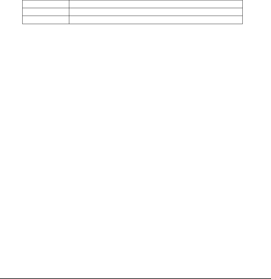
E Electro Industries/GaugeTech Doc # E154703 6-18
6.8.1.4: Paused/Running Files
The log paused files are command files which signal to the device that the user is beginning a log
retrieval session, and that the log indexes should be frozen for the specified log. This does not
prevent the recording of new records, which continues until the physical maximum number of
records is reached. At this point logging for that log is stopped, until the log retrieval session is
concluded. This is done to prevent records from being overwritten while they are being retrieved,
which results in log corruption.
Likewise, the log running files are command files which signal to the device that the user is
ending a log retrieval session, and that the log indexes should be unfrozen for the specified log.
If the running file is never triggered for a paused log, after a period of inactivity the device will
automatically un-pause the log.
Paused/Running commands are triggered by just reading the respective file for that log. They
have no actual content.
The location of the paused and running files is dependent on the firmware, but can be determined
from the ‘Dummy’ field of the MeterID file. The root locations will be one of the following:
0 \C\SYSTEM\LOGS\RUNNING, PAUSED
1 \I\RUNNING, PAUSED
2 \vf\RUNNING, PAUSED
The file locations would then be:
[ROOT]\INT1.BIN
[ROOT]\INT2.BIN
[ROOT]\INT3.BIN
[ROOT]\INT4.BIN
[ROOT]\INT5.BIN
[ROOT]\INT6.BIN
[ROOT]\INT7.BIN
[ROOT]\INT8.BIN
[ROOT]\ET.BIN
[ROOT]\LIMIT.BIN
[ROOT]\DIGIN.BIN
[ROOT]\DIGOUT.BIN
[ROOT]\FLICKER.BIN
[ROOT]\SYSEVENT.BIN
[ROOT]\WAVEFORM.BIN
[ROOT]\PQ.BIN
[ROOT]\TRANS.BIN
6.8.1.5: Log Data Files
The files allocated for the logs are located in the \C\Logs directory, and are named
XXXXXXXX.bin, where x is the file index, and is (left) zero padded. So for example, file 172
would be \C\Logs\00000172.BIN.
6.8.1.5.1: File Format
Each log record is formatted specifically to that log, however the overall format
of each file is generic across all logs. Each record is fixed at the same size, for
that log. Each log contains R records, of which each file contains N log records,
each of size M. Each record in the file is packed towards the start of the file,

E Electro Industries/GaugeTech Doc # E154703 6-19
such that the Ith record in the file is M*I bytes from the beginning of the file. If
N*M < 1MB, such that the remaining space is < M, that space is ignored, and the
next sequential record is placed at the beginning of the next sequential file.
In other words, when a record is written to the file, it is placed directly after the
previous record. If writing the entire record would push the record off the end of
the file, then the record is started at the beginning of the next file: This assures
that no records cross file boundaries.
When all records allocated for this log have been written to, the number of records equals
the max number of records and the log is considered full. At this point, the log “rolls
over”, and the next record is written at the beginning of the log. Logging then continues
from that point in the files, overwriting old records.
The records of each log are identified by two indices: The external index, and the
internal index.
The external index is the record's physical location in the files. The first record of the
first file is always external index 0, the next record is 1, and so on. This is significant
because the external indices are used to locate the first and last records to retrieve in the
files.
The internal index is the unique id for each record. This index always increments when a
record is stored, even if the log has rolled over, or been reset. This allows each record to
be identified sequentially relative to each other. However, since this value is stored in the
record itself, it is only useful once you’ve actually retrieved the record.
6.8.1.5.2: Record Format
Each record is composed of two parts: A record header, and a record data part. The
record header is 8 bytes, and has the following format:
Field Size Description
Internal Index 4 [int] The internal index of the record. Note this
value rolls over at 231.
Time Delta 2 [short] Delta in centiseconds of the given
timestamp from when the record was
actually recorded.
Reserved 2
Records can sometimes be recorded up to a second after they were triggered for
recording. This can result in a record timestamp which is not exactly when it is expected
to be. For interval logs, the timestamp of each record is adjusted to the proper interval:
this is done to support record parsing which requires that the record timestamps be when
they are expected to be. However, to maintain the accuracy of the timestamp, the time
delta provides the number of centiseconds the timestamp was adjusted.
The record data part is unique to each log. Below is a list of rules which are unique to
each log. Details for the logs are given later in the chapter.
System Event: The System Event log is fixed at 1 log file, to be backward compatible
with Modbus log retrieval (see Chapter 9). The System Event is always the first log file,
as it should never be reset, and must always be available to diagnose issues with the
system.

E Electro Industries/GaugeTech Doc # E154703 6-20
Interval 1,2: The first two interval logs are constrained to be backward compatible with
Modbus log retrieval (see Chapter 9). These logs are capped at 8 log files or 8MB.
Additionally, to maintain backward compatibility, the number of records is capped at
32767: Note that this affects how record indices and the max number of records is
computed. The size of the record is the configured size for that log, in the programmable
settings.
Interval 3-8, Event Triggered: The size of the record is the configured size for that log,
in the programmable settings.
Limit: The Limit record contains the limit details, followed by N log items, taken from
the Limit profile. The size of the record is the sum of the details size and the size of each
of the log items.
Digital Input: The Digital Input record contains the Digital Input details, followed by N
log items, taken from Interval 1’s profile. The size of the record is the sum of the details
and all the log items.
Digital Output: The Digital Output record contains the Digital Output details, followed
by N log items, taken from the Limit profile. The size of the record is the sum of the
details and all the log items.
Waveform: The Waveform record contains a record header, followed by the samples,
and RMS details. Because the number of sample blocks is dynamic, the record size is
fixed at the max size, determined from the log header. The actual size of the data in the
record is determined by the record’s header.
Additionally, note that due to the 1MB size limitation on records, sampling rates greater
than 128 have a reduced maximum number of records.
PQ: No special details.
Transient: The Transient record contains a record header, followed by samples, and
RMS details. This works the same as the Waveform record.
6.8.1.5.3: Record Location
To determine the location of a record given its external index, you must determine the
arrangement of records in the files. To do this, you need to determine the first file for
that log, then the record in the file, and the offset from that. Below is the basic algorithm:
file_size = 1MB;
//the number of records which fit into a single file. Since records must
// evenly fit into a file, any extra space is discarded
records_per_file = file_size / header.record_size;
//get the file number which contains the first record. This is a sum of the
// previous log sizes.
first_file_num = sum_log_blocks(log);
//the number of files in use by this log. This should agree with the block
// allocation.
num_files = header.memory_allocated / file_size;
//maximum number of records we can record given our allocation.

E Electro Industries/GaugeTech Doc # E154703 6-21
max_records = records_per_file * num_files;
//special case for the Interval 1 and 2 logs, which are capped at 32k, and
// thus don't follow the above rule.
if(log == INT1 || log == INT2)
if(max_records > 32767)
max_records = 32767;
//The results. file_num is the file which contains the record,
// and file_offset is the byte offset in that file.
file_num = (external_index / records_per_file) + first_file_num;
file_offset = (external_index % records_per_file) * record_size;
To determine the first file, you sum the blocks allocated to each of the logs prior to it:
//determine which file contains the first record of a specified log
int sum_log_blocks(log)
{
//sum each of the log sizes. The sizes come from the block allocation in
// the programmable settings
sum[0] = 0; //system event
sum[1] = system_events + sum[0]; //hist 1
sum[2] = hist_1 + sum[1]; //hist 2
sum[3] = hist_2 + sum[2]; //hist 3
sum[4] = hist_3 + sum[3]; //hist 4
sum[5] = hist_4 + sum[4]; //hist 5
sum[6] = hist_5 + sum[5]; //hist 6
sum[7] = hist_6 + sum[6]; //hist 7
sum[8] = hist_7 + sum[7]; //hist 8
sum[9] = hist_8 + sum[8]; //event
sum[10] = evt_triggered + sum[9]; //limit
sum[11] = limit_log + sum[10]; //di
sum[12] = di_log + sum[11]; //do
sum[13] = do_log + sum[12]; //flicker
sum[14] = flicker_log + sum[13]; //waveform
sum[15] = waveform_log + sum[14]; //pq
sum[16] = pq_log + sum[15]; //transient
return sum[log];
}
6.8.2: Additional Data Types
Fraction Integer
A 4 byte value used to represent a fractional number. To compute the value, take the
integer portion as a signed 2 byte integer (short), and the fractional part as an unsigned
integer (ushort). Divide the fractional part by 65536, and add it to the integer part. For
example:
0x03260078
Fractional: 0x0326 = 806

E Electro Industries/GaugeTech Doc # E154703 6-22
Integer: 0x0078 = 120
Result: 120 + (806/65536) = 120.012298
Nexus µs Time
A 10 byte timestamp, where the first 8 bytes are the standard Nexus® meter 8 timestamp.
The centisecond field is ignored, and bytes 8 and 9 are a ushort that describes the
milliseconds, where 9999 = 999.9ms. For example:
0x200C01010A2100001357
2012/01/01 10:33:00.4951
6.8.3: Log Retrieval Procedure
6.8.3.1: Overview
Log Retrieval is done in three steps:
1. The status of the logs is retrieved to determine what records can be, and need to be,
retrieved. This information will also help in determining how to retrieve the logs
later.
2. The logs are downloaded, using the information gathered in step 1. This involves
logging on to the meter, pausing each log in question, retrieving the files for those logs,
un- pausing the logs, and logging out.
3. The logs which have been retrieved are interpreted. This can be done at the same time
as retrieval, but many logs require multiple records to understand what is going on
(e.g., PQ). Additionally, since the entire file needs to be downloaded via Modbus
LDA, waiting to interpret them till the end is more convenient. See Section 6.8.5 for
details on log interpretation.
6.8.3.2: Procedure
The following procedure assumes that the specific logs, and the range of records in them,
has already been determined.
1. Connect
A single connection should be maintained for the entire length of a single log retrieval
session. This is because the meter maintains state information tied to the connection, and
when the connection is dropped, so is the state information. This primarily applies to log
retrieval via network (TCP).
Because of this, if the connection is dropped during a log retrieval session, the entire
retrieval procedure must be restarted, including logon and status retrieval. Records which
have already been retrieved successfully do not need to be retrieved again however.
Because serial (RS485) connections are connectionless, they are a special case. On serial
connections, you must always un-pause and logout when done with log retrieval.
2. Logon
Before any Modbus LDA commands will allow retrieving files, you must log on to the
meter. You must use one of the 8 usernames and passwords configured through the
meter’s Extended Security if security is enabled.
If security is disabled, you must still logon, using the username ‘anonymous’ and the
password ‘anonymous’. Note that the username and password are case sensitive.
3. Retrieve Status Files
Programmable Settings

E Electro Industries/GaugeTech Doc # E154703 6-23
The first file to retrieve is the programmable settings. You will use this later to
determine what files to retrieve, and how to interpret the records. If the blocks
assigned to the log in question is zero, then it cannot be retrieved.
Meter ID
Next retrieve the meter ID file. You will use this to determine how to retrieve
the files.
4. Retrieve Each Log
The procedure for retrieving the records for a log is the same for most logs (with the
exception of EN50160 - see Section 6.8.4). The only difference is in the interpretation
of the records.
a. Retrieve Log Header:
For each log, the log header file is retrieved first, to determine the layout of the
records in the files, and the size of the records for interpretation.
After retrieving the file, the following values should be checked for error
conditions. If any error condition is found, then log retrieval for that log should
be stopped, and continued with the next log.
- Number of Records : If the number of records is zero, then there is nothing to
retrieve, and any files retrieved will only contain garbage.
- Time Range : If retrieving for a range of time, and the oldest and newest
timestamps do not contain the range of time requested, then there is no reason
to retrieve the files.
- Internal Index Range : If retrieving for a fixed range of internal indices, and the
internal index range does not contain the range of indices requested, then there
is no reason to retrieve the files.
- Record Size : If the record size does not match the expected size, then this
indicates that there may be a problem with the programmable settings for that
log. This can be confirmed for the Interval, Limit, and Digital Input/Output
logs by comparing the valid bitmap to the list of log items from the
programmable settings.
- Memory Allocated : If the memory allocated is zero, then there is nothing to
retrieve. If the memory allocated does not agree with the blocks allocated
(adjusted for scale), then there may be a problem with the configuration. Log
Retrieval should be aborted, and the programmable settings verified: if the
blocks allocated do not agree with the actual allocation, you will be unable to
successfully determine which files contain which log.
5. Pause Log
Once you determine that you want to retrieve the log, pause log recording by reading
the pause file. This prevents log recording from changing the indices during retrieval,
and prevent records from being overwritten while you retrieve them.
NOTES:
The meter employs an extra log buffering space, used when the log is paused.
This allows log recording to actually continue while the log is paused: only the
indices are kept static. Once this buffer space is used up however, no more
records are logged until the log is un-paused. For this reason, it is important to
keep log retrieval sessions as short as possible, and to always un-pause the log
when done.
It is possible, especially for fast recording logs, that between retrieving the log
header and pausing the log, the header has changed. In these cases it helps to
retrieve the header a second time after you pause the log to have the most up to
date values.

E Electro Industries/GaugeTech Doc # E154703 6-24
6. Retrieve each log file
The first step in retrieving the log files is determining what files to actually retrieve.
The simplest way to do this is just to retrieve every file for that log. This however, is
inefficient when you don’t want every record, or the log is not yet full.
By External Record Index
To retrieve logs by external record index, first determine what file contains that
index, using the method given for Record Location (p. 6-20). Retrieve that file,
and copy out the record. To optimize this, you can keep track of what files
you’ve retrieved during this retrieval session. If the record you want is
contained in one of the files you’ve already retrieved, use that file. Repeat this
for each record you want to retrieve.
Following is the basic algorithm for retrieving by record index:
for(i=first_index; i<last_index; i++)
{
get file_num and file_offset, where i is the external index
//if we already have the file local, just get the record from there
if(retrieved_files.Contains(file_num))
record = get_record(retrieved_files[file_num], file_offset);
else
{
//otherwise, we need to retrieve the specified log file
file = retrieve_file(file_num);
//store it for later
retrieved_files[file_num] = file;
record = get_record(retrieved_files[file_num], file_offset);
}
do something with the record
}
7. Un-pause Log
As soon as you are done retrieving the log files, the log must be un-paused by reading
the running file. This allows log recording to continue normally, preventing any gaps
in the data.
NOTE: Pausing and un-pausing logs adds log retrieval entries to the System Event
log. For this reason, logs should not be paused if no records are to be retrieved (thus
the reason you check the log header before pausing the log).
8. Logout
When you are done retrieving all the logs, you need to log out from the meter. This
cleans up any resources associated with log retrieval.

E Electro Industries/GaugeTech Doc # E154703 6-25
6.8.4: EN50160 Information
The EN50160 weekly and yearly data is stored in a different format than the other log's data.
Each week and year is stored in its own XML file, named after the week and the year it describes.
Retrieval of this log is as simple as just downloading the file in question.
NOTE: The week and year files are only generated once the meter’s current time has passed the
end of that period. All of the currently collected information is kept in the ‘current’ files. Once
the end of the period has passed, the current data is stored, and a new set of current data is begun.
The side effect of this is that changing the meter’s time can result in a week or year file
containing less or more intervals than expected. The total counts and date ranges should always
be checked when interpreting the EN50160 data files.
6.8.4.1: EN50160 Week Filename
Each EN50160 week file is named by the year, and the week of that year, of the data it
contains. The format of the filename is ‘YYYY_W##.XML’, where ‘YYYY’ is the year
(for example ‘2012’), and ‘##’ is the week of that year. So for example, the 3rd week of
2012 would be ‘2012_W03.XML’.
To compute the week and year number for any given day, month, and year, use the
following algorithm:
//Obtain Julian day number: with year, month and day values
Const_a = (14 - month)/12
Const_y = year + 4800 - Const_a
Const_m = month + 12 * Const_a - 3
julian_day = day + (153 * Const_m + 2) / 5 + Const_y * 365 +
Const_y / 4 - Const_y / 100 + Const_y / 400 – 32045
//Obtain week number
Obtain julian_day with year, month and day values
Const_1 = (((julian_day + 31741 -
(julian_day mod 7)) mod 146097) mod 36524) mod 1461
Const_2 = Const_1 / 1460
Const_3 = ((Const_1 - Const_2) mod 365 ) + Const_2
week_num = Const_3 / 7 + 1
set initial year adjust flag=0
if week_num >=2 AND month=1 AND (week_num=52 OR week_num=53) then
set year adjust flag = -1
if week_num <2 AND month=12 then
set year adjust flag to = +1
//Adjustment for First Day of Week (FDOW) is Sunday, WN=week number
if current day of week (CDOW) is Sunday
if year adjust flag = -1
if month=1 and day are 1, 2, or 3, then
set WN=1, set year adjust flag = 0
if year adjust flag = 0
if month=12 and day are 29, 30, or 31, then
set WN=1, set year adjust flag = +1
else
set WN=WN+1

E Electro Industries/GaugeTech Doc # E154703 6-26
if current day of week (CDOW) is not Sunday
if month=12
if day=30 and CDOW=Mon OR
day=31 and CDOW=Mon OR Tue Then
set WN=WN+1, set year adjust flag = +1
if day=29 and CDOW=Mon OR
day=30 and CDOW=Tue OR
day=31 and CDOW=Wed Then
set WN=53, set year adjust flag = 0
if month=1
if day=1 and CDOW=Fri OR Sat OR
day=2 and CDOW=Sat Then
set year adjust flag = -1
if day=1 and CDOW=Thr OR
day=2 and CDOW=Fri OR
day=3 and CDOW=Sat Then
set WN=53, set year adjust flag = -1
Final year value = year + (year adjust flag)
6.8.4.2: EN50160 Year Filename
Each EN0160 year file is named by the year of the data it contains. The format of the
filename is ‘YYYY.XML’, where ‘YYYY’ is the year. So for example, 2012 would be
‘2012.XML’.
6.8.4.3: List Week and Year Files
\C\EN50160
All of the EN50160 files are stored in the ‘\\C\EN50160’ directory. To retrieve all of the
weeks and years generated, simply list all of the files contained within the directory, and
retrieve each one.
NOTE: The ‘current’ files, and files with a 0000 year, can be ignored.
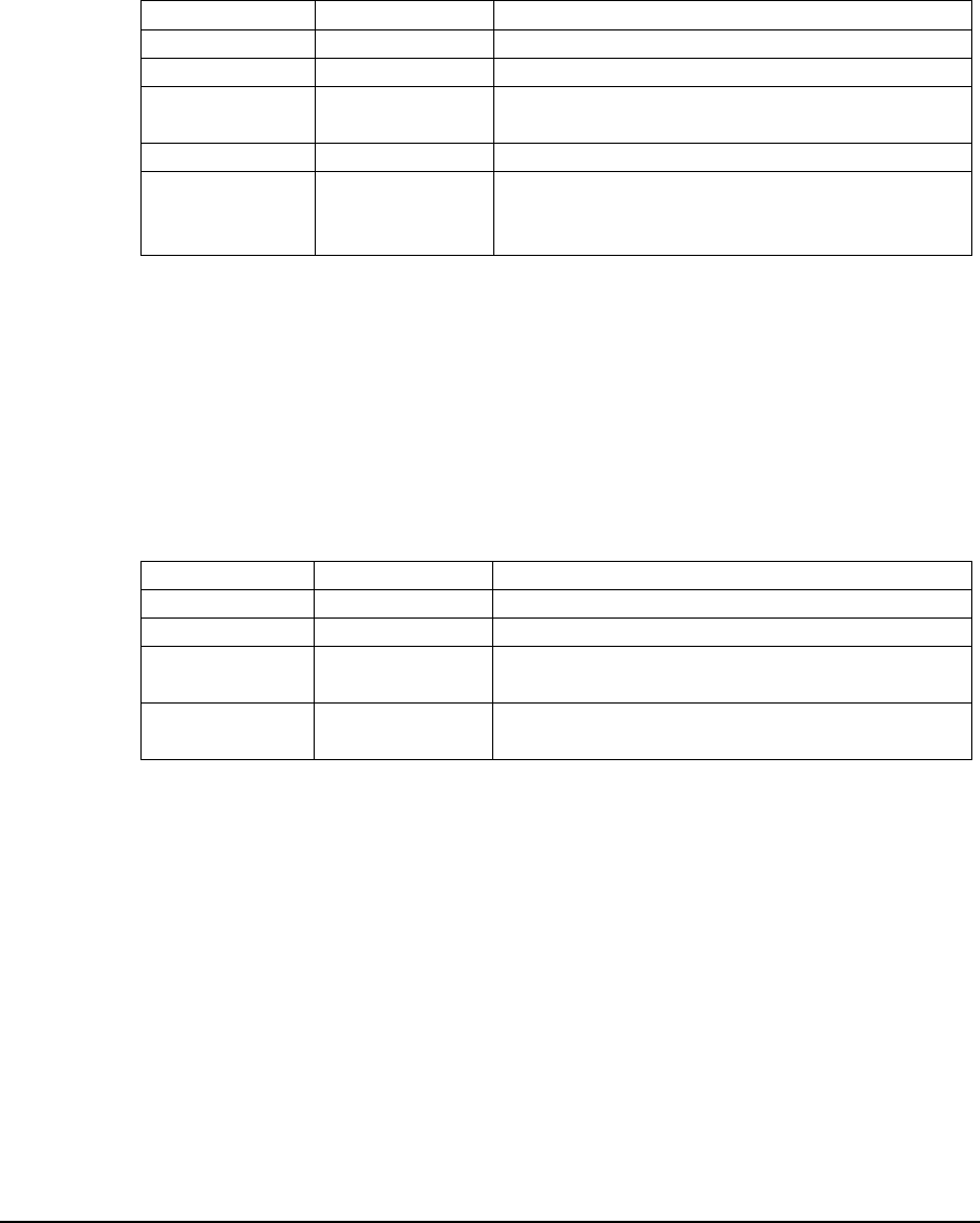
E Electro Industries/GaugeTech Doc # E154703 6-27
6.8.5: Log Interpretation
6.8.5.1: System Events Log
The System Events Log stores events which affect the operation of the meter, including power
events, time changes, log retrieval, settings changes, and firmware changes.
Record Format
Field Size Description
Record Index 4 (uint) The internal index of the record.
Reserved 4
Timestamp 8
[nexus8_time]
The time of the event.
Record Type 1 The type of the event.
Record Details 7 Data about the event. Note that some records
require more than one record, and data may be
split across multiple records.
When an event is paired with a second record (such as the log retrieval event, via Ethernet), the
sequence of the records will be indicated by a record sequence field. For example, in the Log
Retrieval record, byte 12 (byte 3 of the record details) will be set to 0 for the first half of the
record, and 1 for the second. The second record should always be the record sequentially after the
first record; however, always check that the event type and record sequence numbers concur.
6.8.5.2: Interval Logs 1-8, Event Triggered
Record Format
Field Size Description
Record Index 4 (uint) The internal index of the record.
Reserved 4
Timestamp 8
[nexus8_time]
The time of the event.
Record Data N A list of the log items configured in the
programmable settings.
The exact size of the record is determined by the configuration of the log in the programmable
settings. The size includes the 8 bytes for the timestamp.
NOTE: The size follows the size configuration for the log, not the sum of the items configured.
Any space which is not filled by log items will be garbage, and should be ignored. For Interval
logs 1 and 2, this size is an enumerator, so the records will always be a power of two in size (see
Chapter 9). For Interval logs 3-8 and the Event Triggered logs, the size can be specified as any
size greater than 8 (to account for the timestamp), up to a maximum size of 512 bytes.
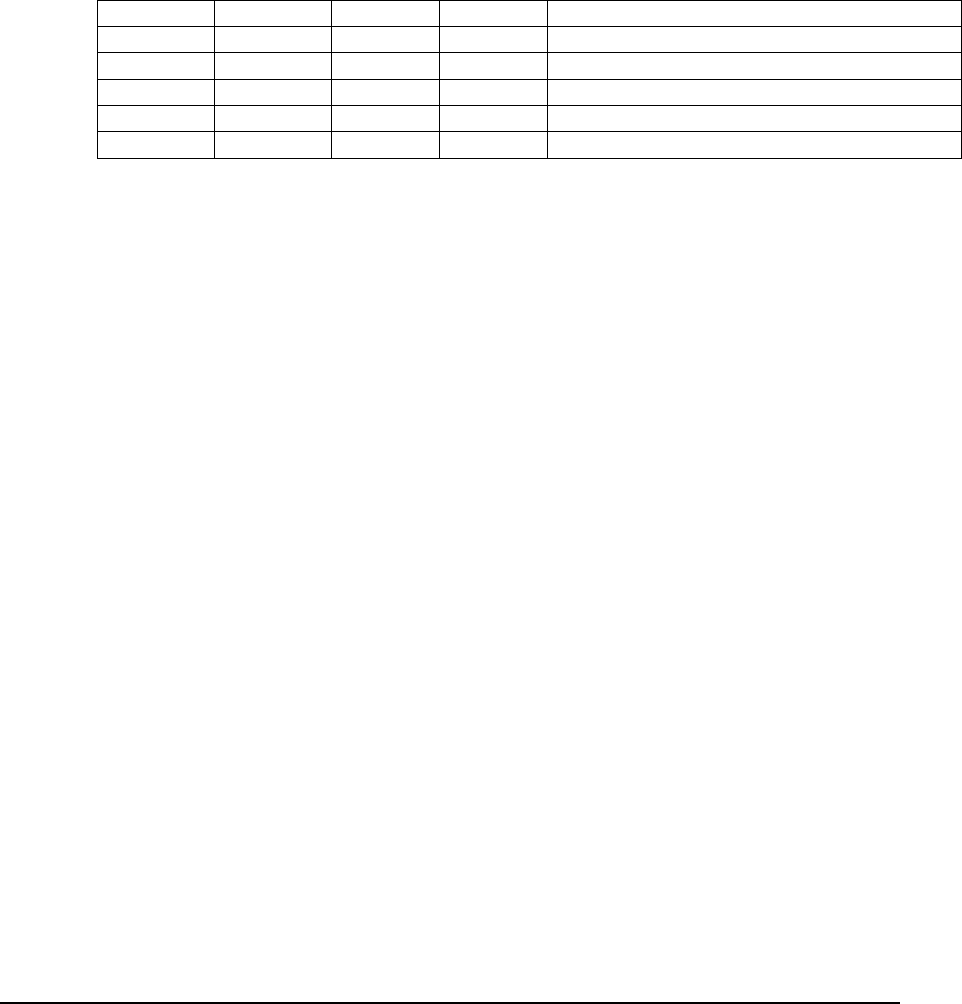
E Electro Industries/GaugeTech Doc # E154703 6-28
Item Interpretation
To interpret the contents of the record data, first determine the list of items configured in
the programmable settings. While the location of the settings is different for each log,
they all use the same settings types.
Each log item is composed of 4 values: Line (Pointer), Point (Index), Size, and FType.
Size and FType can be determined from Line and Point, but are included in the
programmable settings for convenience during log interpretation.
The list of log items is determined by looking at each item in the programmable settings.
Any 'invalid' items are set with a Line value of 0 or 0xFFFF.
For example, if there are the following items:
Line Point Size FType Name (Not part of prog.set.)
34 0 4 7 One Sec Volts A-N
34 1 4 7 One Sec Volts B-N
34 2 4 7 One Sec Volts C-N
0xFFFF 0 0xFF 0xFF Invalid Item
36 0 4 7 One Sec Current A
The record will contain 4 log items: Volts A, B, C, and One Sec Current A. The invalid
item is ignored.
Next, determine what record items are valid, by comparing each item against the
matching position in the valid bit flags from the log header. If the valid flags say that it is
not valid, then the item cannot be parsed, and should be ignored.
The size and offset in the record data is determined by summing the previous items. So
for example, Volts A-N will be at offset 0, Volts B-N will be at offset 4, Volts C-N
will be at offset 8, and One Sec Current A will be offset at 12.
See Chapter 3 for details on converting FType items.

E Electro Industries/GaugeTech Doc # E154703 6-29
6.8.5.3: Limit Log
The Limit Log records an entry every time limit values monitored by the meter change their state.
The log records information about the limits, such as the specific limit which was triggered, and a
snapshot of the items configured in the programmable settings for the Limit Log.
Record Format
The Limit Log is composed of two parts: A details header, followed by the snapshot of
log items. The details header is fixed in size (40 bytes), and has the following values:
Field Size Description
Record Index 4 (uint) The internal index of the record.
Reserved 4
Timestamp 8
(nexus8_time)
The time of the limit event. Note that the MSB bit
(bit 7) is used to indicate that this record is not
continuous with the previous record, and state
changes may be missing. This will primarily
happen during a reset or power loss.
Current States for Value 1 4 (bitmap) The current states of each of the 32 limits for Value
1. Limits are left to right, so the 31st bit is limit 1,
and the 0th bit is limit 32. If the bit is set to 1, then
the limit is exceeded.
Current States for Value 2 4 (bitmap) The current states of each of the 32 limits for Value
2. Bit order is the same as current states for value 1.
If the bit is set to 1, then the limit is exceeded.
Delta States for Value 1 4 (bitmap) The change of the states for each of the 32 limits for
Value 1, since the last limit event. Bit order is the
same as current states for value 1. If the bit is set to
1, then the limit has changed.
Delta States for Value 2 4 (bitmap) The change of the states for each of the 32 limits for
Value 2, since the last limit event. Bit order is the
same as current states for value 1. If the bit is set to
1, then the limit has changed.
Current States for
Comparison
4 (bitmap) The combination of the current states of Value 1 and
2, for each of the 32 limits. Bit order is the same as
current states for value 1. If the bit is set to 1, then
the combination is true.
Delta States for
Comparison
4 (bitmap) The change of the states for each of the comparison
states, for each of the 32 limits. Bit order is the
same as current states for value 1. If the bit is set to
1, then the state has changed.
The remaining data in the record is the snapshots for the limits. These follow the same
format and rules as the Interval records, using the Limit Items from the programmable
settings as its item list.
Item Interpretation
The item descriptions are from the meter’s programmable settings, Limit Items.

E Electro Industries/GaugeTech Doc # E154703 6-30
Limit Event Analysis
The Limit Records only indicate a change in state of the limits. To determine
information about the overall limit events, you have to analyze the sequence of the limit
records.
To determine the pair of records which match for an event, defined as the limit going out,
then coming back in, start with a record that indicates that the limit in question is going
out. This is a record in which the delta state for the limit is 1, and the current state is 1.
To find the matching event end record, search forward in time in the records until a
record is found where the delta state for the limit is 1, and the current state is 0. Note that
you need to check the continuous bit in the timestamp of each record: If any record is
found to be non-continuous, then the state changes may be lost, and any end record found
may not match with the original record.
6.8.5.4: Digital Input Log
The Digital Input log records an entry every time the digital inputs change state. The log records
the states of each input at the time of the record, along with a snapshot of the items configured in
the programmable settings for the limit log.
The digital inputs monitored by this log include the built-in inputs, as well as the two optional
digital input cards.
Record Format
The Digital Input log is composed of two parts: A details header, followed by the
snapshot of the log items. The details header is fixed in size (16 bytes), and has the
following values:
Field Size Description
Record Index 4 (uint) The internal index of the record.
Reserved 4
Timestamp 8 (nexus8_time) The time of the event. Note that the MSB bit (bit 7) is
used to indicate that this record is not continuous with
the previous record, and state changes may be missing.
This will primarily happen during a reset or power loss.
Built-in Input States 1 (bitmap) The states of the built-in digital inputs. Inputs are
mapped MSB, so bit 7 is input 8, and bit 0 is input 1.
Option Board 1 input
states 1-8
1 (bitmap) The states of option board 1’s digital inputs 1-8. Inputs
are mapped MSB, so bit 7 is input 8, and bit 0 is input 1.
Option Board 1 input
states 9-16
1 (bitmap) The states of option board 1’s digital inputs 9-16.
Inputs are mapped MSB, so bit 7 is input 16, and bit 0 is
input 9.
Option Board 2 input
states 1-8
1 (bitmap) The states of option board 2’s digital inputs 1-8. Inputs
are mapped MSB, so bit 7 is input 8, and bit 0 is input 1.
Option Board 2 input
states 9-16
1 (bitmap) The states of option board 2’s digital inputs 9-16.
Inputs are mapped MSB, so bit 7 is input 16, and bit 0 is
input 9.
Valid Flags 1 (bitmap) Indicates which of the input states are valid.
Bit 7 – Option Board 1
Bit 6 – Option Board 2
If the bit is not set, ignore the states.

E Electro Industries/GaugeTech Doc # E154703 6-31
The remaining data in the record is the snapshots for the digital inputs. These follow the
same format and rules as the Interval records, using the Limit log items from the
programmable settings as its item list.
Item Interpretation
Parsing the snapshot items is the same as the Interval log items. See the Item
Interpretation section for the Interval logs.
Digital Input Event Analysis
The Digital Input records only store the current states of the inputs. To determine
information about overall input events, you have to analyze the sequence of the digital
input records. This may not be necessary, as the inputs can be used just for state changes,
rather than ‘in’ and ‘out’ conditions.
As the Digital Input record does not indicate state change information (deltas), sequential
records must be compared to determine when the state changed. Note that you need to
check the continuous bit in the timestamp of each record: If any record is found to be
non-continuous, then the exact time of the state changing may be lost.
To determine the pair of records which match for an event, defined as the digital input
entering a state, then transitioning back to the original state, start with a record that has
just entered the desired state. This is a record for which the input state is in the desired
‘out’ state, and the previous record has the input in the opposite state.
To find the matching event return record, search forward in time in the records until a
record is found where the input state is the opposite of the start record. Remember to
check the continuous bit in the timestamp.
The Option Board states should be ignored if the valid flags indicate they are invalid.
6.8.5.5: Digital Output Log
The meter's Digital outputs (Relays) can be made up of options boards and external module
relays. The meter can accept up to 2 relay option boards. There are 6 relays on each relay board,
for a total of 12 relays if both boards are installed. Relay indices 1 to 6 are for the relays in the
first relay board. Relay indices 7 to 12 are for the relays in the seconds relay board. The meter
can accept just one external module which has 4 relays. The meter can be configured to handle up
to 16 relays total, between relay option boards and the external module. The table below shows
the possible arrangements.
Arrangements Options boards External Module
1 No option board Relays 13 to 16
(Module 4)
2 1st Option Board (Slot 3):
Relays 1 to 6
Relays 13 to 16
(Module 4)
3 2nd Option Board (Slot 4):
Relays 7 to 12
Relays 13 to 16
(Module 4)
4 1st and 2nd Option Boards:
Relays 1 to 12
Relays 13 to 16
(Module 4)
5 1st and 2nd Option Boards:
Relays 1 to 12
No external relay
module

E Electro Industries/GaugeTech Doc # E154703 6-32
The Digital Output State Log stores records in order to document the stages used when changing
states of Digital outputs (Relays). Records are recorded for four reasons – When the delay at the
end of a Relay Logic Tree is finished, indicating that a relay needs to change state; when a
communication port requests a relay lock or unlock; when the command is transmitted to the
external device; and when the response is returned from the external device.
Record Format
Field Size Description
Record Index 4 (uint) The internal index of the record.
Reserved 4
Timestamp 8 (nexus8_time) The time of the event.
Stage 1 Indicates the stage, or reason, for the record. The stages
are as follows:
0x001, Stage 1, ElectroLogic or communication
command now desires to change the state of one or more
relays.
0x002, Stage 2, Command is being transmitted to one
or multiple relay.
0x003, Stage 3, Confirmation has been received from a
command that was sent.
Relay Valid 2 Indicates whether information about a relay is valid or
not. Option boards or module, which are unused, or
which are not responding to communication, are not
valid. A bit value of 0 indicates that information for this
relay is not yet valid; a bit value of 1 Indicates that
information for this relay is valid.
Bit 15 is the most significant bit.
The bits are formatted as following bits:
15 to 10: 1st Option Card, relay index 1 to 6
9 to 4: 2nd Option Card, relay index 7 to 12
3 to 0: External Relay Module, relay index 13 to 16
Relay Logic
Trees Inputs
States
16 Each byte represents the inputs in a Relay Logic Tree
for one relay. Byte 1 to 16 represent for relay 1 to 16.
Each bit represents the state of an input into a Relay
Logic Tree. The bits 7 to 0, represent the input 1 to 8
for each relay.
Bit 7 is the most significant bit.
A bit value of 0 indicates a false input value; a bit value
of 1 indicates a true input value. These values are
retrieved before the possible NOT on inputs that are a
possible programmable setting.
Relay Logic
Trees Gates
Output
16 Each byte represents the gate outputs in a Relay Logic
Tree for one relay. Byte 1 to 16 represent for relay 1 to
16.
Each bit represents the state of a gate output in a Relay
Logic Tree. The bits 7 to 0, represent the Gate A to
Gate G.
A bit value of 0 indicates a false output value; a bit
value of 1 indicates a true output value.

E Electro Industries/GaugeTech Doc # E154703 6-33
Current Relays
Locked
2 Each bit indicates whether a relay is locked or unlocked.
A bit value of 0 indicates the relay is not locked; a bit
value of 1 indicates the relay is locked.
Bit 15 is the most significant bit.
The bits are:
15 to 10: 1st Option Card, relay index 1 to 6
9 to 4: 2nd Option Card, relay index 7 to 12
3 to 0: External Relay Module, relay index 13 to 16
Previous
Relays Locked
2 Each bit indicates whether a relay was previously locked
or unlocked. A bit value of 0 indicates the relay was not
locked; a bit value of 1 indicates the relay was locked.
Bit 15 is the most significant bit.
The bits are:
15 to 10: 1st Option Card, relay index 1 to 6
9 to 4: 2nd Option Card, relay index 7 to 12
3 to 0: External Relay Module, relay index 13 to 16
Desired Relay
States
2 Each bit indicates the desired state of the relay. If the
relay is locked, as indicated in the previous 2 bytes, then
this is the state the relay should be locked to. If the
relay is unlocked, then this is the state that the relay
should be in as indicated by the Relay Logic Tree for
this relay. A bit value of 0 indicates de-energized, or
connected to Normal Close; a bit value of 1 indicates
energized, or connected to Normal Open.
Bit 15 is the most significant bit.
The bits are:
15 to 10: 1st Option Card, relay index 1 to 6
9 to 4: 2nd Option Card, relay index 7 to 12
3 to 0: External Relay Module, relay index 13 to 16
Command
Sent
2 Indicates that a command has begun to be sent to an
option board/external module to change the state of a
relay
The first byte indicates which relay the command is
being sent to:
0x000-0x005 1st Option Board, Relay 1-6
0x006-0x00B 2nd Option Board, Relay 7-12
0x00C-0x00F External Module, Relay 13-16
other No command sent
The second byte indicates whether the command being
sent was to energize or de-energize the relay. A value of
0x000 indicates the relay command was to de-energize
the relay; any other value indicates the command was to
energize the relay.
Change
Success
2 Each bit indicates successfully changed relay states, as
recorded by the reception of the response from the relay
option board or external module, in the same order as
above. A bit value of 0 indicates the relay is de-
energized, or connected to Normal Close; a bit value of

E Electro Industries/GaugeTech Doc # E154703 6-34
1 indicates the relay is energized, or connected to
Normal Open.
Bit 15 is the most significant bit.
The bits are:
15 to 10: 1st Option Card, relay index 1 to 6
9 to 4: 2nd Option Card, relay index 7 to 12
3 to 0: External Relay Module, relay index 13 to 16
Reserved 13
Snapshot n bytes The remaining data in the record is the snapshots for the
digital output. These follow the same format and rules
as the Limit log record, using the Limit Items from the
programmable settings as its item list.
Item Interpretation
Parsing the snapshot items is the same as the Limit log items. See the Item Interpretation
section for the Limit log.
Digital Output Event Analysis
Each Digital Output record only stores one type of event/command for one or multiple
digital outputs (relays) at one of the 3 possible stages. To determine information about
overall digital output events, you have to analyze the sequence of the digital output
records.
A relay channel should be ignored if the valid flag indicates it’s invalid.
A complete cycle of a relay change event should include records for all 3 stages. The
duration of such event can be computed from the time difference between stage 1 and
stage 3 records.
6.8.5.6: Waveform Log
The Waveform Log records the RMS details of the input channels when a configured waveform
limit is exceeded, if an input state changes, or if a capture was manually triggered. The details
include the analysis of the RMS data, the states during that cycle, and the samples on the input
channels.
NOTE: Different versions of the waveform record have different formats. The version field of
the header should always be checked before parsing the rest of the record.
Record Format
The Waveform record is composed of 4 parts: A details header, the samples block, the
RMS info block, and the footer. Every capture can be a different size record, so the
details header is used to determine how to parse the rest of the record. The footer is used
to confirm that record has been properly parsed.
The details header is fixed in size (1024 bytes), and v8 has the following fields:

E Electro Industries/GaugeTech Doc # E154703 6-35
Waveform Header Details
Fields Size Description
Record Index 4 (uint) The internal index of the record.
Record Format Version 2 (uint) The record format version. The format documented here is
v8.
Header Size 4 (uint) The size of the header.
Record Total Size 4 (uint) The total size of the record. Note that this is the used size,
not the reserved size, so may be smaller than the record size
specified in the header. This value – 16 should be the
beginning of the footer.
Sample Section Offset 4 (uint) Offset from the beginning of the record to the samples block.
RMS Section Offset 4 (uint) Offset from the beginning of the record to the RMS block.
Digital Input Mask 2 (bitmap) The digital inputs which have been configured in the
programmable settings to trigger waveform captures.
Capture Number 4 (uint) The index of the record in the capture when waveform is
configured to record multiple records per capture. This
number will be recorded sequentially decreasing, so for 5
records per capture, the first will be 5, the second 4, down to
1.
First RMS block
Timestamp
8 (nexus8_time) The timestamp of the first RMS block in the capture.
Reserved 12
Usr Voltage Flags 2 (bitmap) The list of voltage channels which have been configured in
the programmable settings to trigger waveform captures
according to the Usr rules.
Usr Current Flags 2 (bitmap) The list of current channels which have been configured in
the programmable settings to trigger waveform captures
according to the Usr rules.
Sample Reduction
Factor
2 (ushort) At sample rates lower than 1024 samples per cycle, samples
are interlaced together. This factor indicates how to de-
interlace them.
Sample Block Size per
Channel
4 (uint) The size of a sample block for a single channel. This is used
to parse the sample data.
RMS Block Size 4 (uint) The size of the RMS block.
Number of Sample
Blocks per Channel
2 (ushort) The number of sample blocks. This is used to compute the
overall number of samples.
Number of RMS
Blocks
2 (ushort) The number of RMS blocks.
Contiguous 1 (byte) A value of 1 indicates that this waveform is contiguous with
the previous record. This will often happen when a
waveform trigger occurs while a previous waveform is still
being recorded. When this happens, the trigger will be in the
previous record.
Reserved 3
Manual Triggered 2 (ushort) A value of 1 indicates this capture was manually triggered,
and not because of a waveform limit or input event.
Reserved 4
Trigger Sample Block
Time Counter
4 (uint) The time counter of the RMS Block which contains the
trigger for this waveform. Used to determine which samples

E Electro Industries/GaugeTech Doc # E154703 6-36
and RMS block contains the trigger.
Trigger block
Timestamp
10
(nexus_µs_time)
The timestamp of the end of the RMS block that contains the
trigger.
Reserved 2
Trigger RMS Block 196 (RMS Data
Block)
Contains information on the waveform states at the time of
the trigger. See below for details on the block.
Waveform Setup Info 316 (Waveform
Setup Block)
Describes how the waveform triggers and captures were
configured, as well as providing information about the meter.
See below for details on the block.
Firmware Ids 148 (Firmware
Info Block)
Contains identification information from the firmware that
describes what features are supports. See below for details
on the block.
RMS Data Block
Fields Byte Size Description
1cycle Logical Van RMS 0 4 (fraction integer) Van RMS computed from the physical
RMS.
1cycle Logical Vbn RMS 4 4 (fraction integer)
1cycle Logical Vcn RMS 8 4 (fraction integer)
1cycle Logical Vab RMS 12 4 (fraction integer)
1cycle Logical Vbc RMS 16 4 (fraction integer)
1cycle Logical Vca RMS 20 4 (fraction integer)
1cycle Logical Vxn RMS 24 4 (fraction integer)
1cycle Logical Vres RMS 28 4 (fraction integer)
1cycle Logical Ires RMS 32 4 (fraction integer)
1cycle Physical Vae RMS 36 4 (fraction integer) Raw Vae RMS computed directly from
the inputs.
1cycle Physical Vbe
RMS
40 4 (fraction integer)
1cycle Physical Vce RMS 44 4 (fraction integer)
1cycle Physical Vxe
RMS
48 4 (fraction integer)
1cycle Physical Vne
RMS
52 4 (fraction integer)
1cycle Physical Ia RMS 56 4 (fraction integer)
1cycle Physical Ib RMS 60 4 (fraction integer)
1cycle Physical Ic RMS 64 4 (fraction integer)
1cycle Physical Ix RMS 68 4 (fraction integer)
1cycle Physical Van
Mean
72 2 (ushort)
1cycle Physical Vbn
Mean
74 2 (ushort)
1cycle Physical Vcn
Mean
76 2 (ushort)
1cycle Physical Vab
Mean
78 2 (ushort)
1cycle Physical Vbc
Mean
80 2 (ushort)

E Electro Industries/GaugeTech Doc # E154703 6-37
1cycle Physical Vca
Mean
82 2 (ushort)
1cycle Physical Vxn
Mean
84 2 (ushort)
1cycle Physical Vres
Mean
86 2 (ushort)
1cycle Physical Ires
Mean
88 2 (ushort)
1cycle Physical Vae
Mean
90 2 (ushort)
1cycle Physical Vbe
Mean
92 2 (ushort)
1cycle Physical Vce
Mean
94 2 (ushort)
1cycle Physical Vxe
Mean
96 2 (ushort)
1cycle Physical Vne
Mean
98 2 (ushort)
1cycle Physical Ia Mean 100 2 (ushort)
1cycle Physical Ib Mean 102 2 (ushort)
1cycle Physical Ic Mean 104 2 (ushort)
1cycle Physical Ix Mean 106 2 (ushort)
Period Count 108 2 (ushort) (60.000*1024)/ref_frequency. This is
the number of samples used to compute
the cycle data.
Cycle Count 110 2 (ushort) Incrementing number of cycles, used for
cycle identification.
reserved 112 2
Reference Sample Index 114 2 (ushort) Index of the specific sample in the
matching sample block which is the last
sample this RMS block describes. This
sample is always assuming a 1024
sampling rate, and needs to be scaled
appropriately when being applied to a
sample block at a lower sampling rate.
Absolute Sample Index 116 2 (ushort) Absolute index for the sample which
marks the end of the RMS block. Rolls
over at 65536.
High Speed Input
Transitions
118 2 (bitmap) Bit flag which indicate if the state of the
high speed inputs have changed since the
last RMS block, where a bit of 1
indicates a transition occurred. Bit 0 is
channel 0, bit 1 is channel 1, and so on.
High Speed Input States 120 2 (bitmap) Bit flag which indicate the current state
of the high speed inputs, where a bit of 1
indicates open, and 0 indicates closed.
Bit 0 is channel 0, bit 1 is channel 1, and
so on.
DSP2 Firmware Type 122 2 (String) ‘DE' for debug, 'RE' for release
DSP2 Firmware Version 124 4 (String) Byte 0 is version letter, bytes 1-3 are the

E Electro Industries/GaugeTech Doc # E154703 6-38
version number.
DSP2 Firmware ID 128 4 (uint) Debug id for the dsp2 firmware.
Waveform voltage RMS
sag flags
132 2 (bitmap) Bit flags which indicate if the Voltage
RMS was below the waveform sag
threshold during the period of the RMS
Block. See Table 1 (Waveform Voltage
Bit Flags) for bits.
Waveform voltage RMS
swell flags
134 2 (bitmap) Bit flags which indicate if the Voltage
RMS was above the waveform swell
threshold during the period of the RMS
Block. See Table 1 (Waveform Voltage
Bit Flags) for bits.
reserved 136 2
Transient pos over-range
flags
138 2 (bitmap) Indicates a positive transient which
exceeded the configured threshold
occurred. See Table 2 (Transient Bit
Flags) for bits.
Transient neg over-range
flags
140 2 (bitmap) Indicates a negative transient which
exceeded the configured threshold
occurred. See Table 2 (Transient Bit
Flags) for bits.
Transient pos peak
sample index ch1
142 2 (ushort) The sample index of the peak positive
transient to occur on channel 1 (Van or
Vab).
Transient pos peak
sample index ch2
144 2 (ushort) The sample index of the peak positive
transient to occur on channel 2 (Vbn or
Vbc).
Transient pos peak
sample index ch3
146 2 (ushort) The sample index of the peak positive
transient to occur on channel 3 (Vcn or
Vca).
Transient neg peak
sample index ch1
148 2 (ushort) The sample index of the peak negative
transient to occur on channel 1 (Van or
Vab).
Transient neg peak
sample index ch2
150 2 (ushort) The sample index of the peak negative
transient to occur on channel 2 (Vbn or
Vbc).
Transient neg peak
sample index ch3
152 2 (ushort) The sample index of the peak negative
transient to occur on channel 3 (Vcn or
Vca).
Transient pos peak
sample value ch1
154 2 (ushort) The peak positive transient value to
occur on channel 1 (Van or Vab).
Multiply by (1800/255) to get Secondary
value.
Transient pos peak
sample value ch2
156 2 (ushort) The peak positive transient value to
occur on channel 2 (Vbn or Vbc).
Multiply by (1800/255) to get Secondary
value.
Transient pos peak
sample value ch3
158 2 (ushort) The peak positive transient value to
occur on channel 3 (Vcn or Vca).
Multiply by (1800/255) to get Secondary

E Electro Industries/GaugeTech Doc # E154703 6-39
value.
Transient neg peak
sample value ch1
160 2 (ushort) The peak negative transient value to
occur on channel 1 (Van or Vab).
Multiply by (1800/255) to get Secondary
value.
Transient neg peak
sample value ch2
162 2 (ushort) The peak negative transient value to
occur on channel 2 (Vbn or Vbc).
Multiply by (1800/255) to get Secondary
value.
Transient neg peak
sample value ch3
164 2 (ushort) The peak negative transient value to
occur on channel 3 (Vcn or Vca).
Multiply by (1800/255) to get Secondary
value.
Transient pos peak
sample duration ch1
166 2 (ushort) Duration of the peak positive transient to
occur on channel 1 (Van or Vab).
Multiply by 18.18 nanoseconds to get
time.
Transient pos peak
sample duration ch2
168 2 (ushort) Duration of the peak positive transient to
occur on channel 2 (Vbn or Vbc).
Multiply by 18.18 nanoseconds to get
time.
Transient pos peak
sample duration ch3
170 2 (ushort) Duration of the peak positive transient to
occur on channel 3 (Vcn or Vca).
Multiply by 18.18 nanoseconds to get
time.
Transient neg peak
sample duration ch1
172 2 (ushort) Duration of the peak negative transient to
occur on channel 1 (Van or Vab).
Multiply by 18.18 nanoseconds to get
time.
Transient neg peak
sample duration ch2
174 2 (ushort) Duration of the peak negative transient to
occur on channel 2 (Vbn or Vbc).
Multiply by 18.18 nanoseconds to get
time.
Transient neg peak
sample duration ch3
176 2 (ushort) Duration of the peak negative transient to
occur on channel 3 (Vcn or Vca).
Multiply by 18.18 nanoseconds to get
time.
Waveform current RMS
sag flags
178 2 (bitmap) Bit flags which indicate if the Current
RMS was below the waveform sag
threshold during the period of the RMS
Block. See Table 3 (Waveform Current
Bit Flags) for bits.
Waveform current RMS
swell flags
180 2 (bitmap) Bit flags which indicate if the Current
RMS was above the waveform swell
threshold during the period of the RMS
Block. See Table 3 (Waveform Current
Bit Flags) for bits.
reserved 182 2
Waveform voltage RMS 184 2 (bitmap) Bit flag which indicates if the state of the
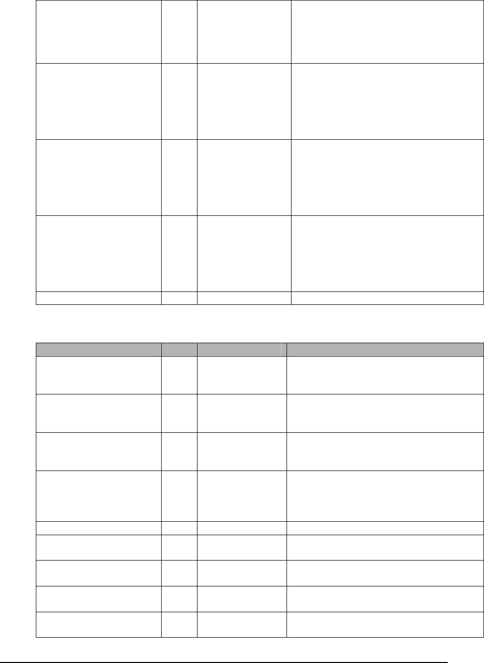
E Electro Industries/GaugeTech Doc # E154703 6-40
sag transitions waveform voltage sags have changed
since the last RMS block, where a bit of
1 indicates a transition has occurred. See
Table 1 (Waveform Voltage Bit Flags)
for bits.
Waveform voltage RMS
swell transitions
186 2 (bitmap) Bit flag which indicates if the state of the
waveform voltage swells have changed
since the last RMS block, where a bit of
1 indicates a transition has occurred. See
Table 1 (Waveform Voltage Bit Flags)
for bits.
Waveform current RMS
sag transitions
188 2 (bitmap) Bit flag which indicates if the state of the
waveform current sags have changed
since the last RMS block, where a bit of
1 indicates a transition has occurred. See
Table 3 (Waveform Current Bit Flags)
for bits.
Waveform current RMS
swell transitions
190 2 (bitmap) Bit flag which indicates if the state of the
waveform current swells have changed
since the last RMS block, where a bit of
1 indicates a transition has occurred. See
Table 3 (Waveform Current Bit Flags)
for bits.
reserved 192 4
Waveform Setup Block
Name Byte Size Description
Reference Frequency 0 4 (fraction
integer)
0.2 second updated frequency at the time
of capture, used as a reference for other
calculations.
Meter Hookup 4 2 (ushort) Hookup Configuration, from
Programmable Settings. See T4 (Meter
Hookup) for details.
Transient Type 6 2 (ushort) Transient Configuration.
bit 0: 0=enable, 1=disable
bit 1: 0=VPN, 1=VPP
Frequency Type 8 2 (ushort) The frequency mode the meter is
configured for.
1: 60Hz
0: 50Hz
reserved 10 2
Physical Vae Cal Gain
value
12 2 (ushort) The gain value for Vae. Calibration
value.
Physical Vbe Cal Gain
value
16 2 (ushort)
Physical Vce Cal Gain
value
20 2 (ushort)
Physical Vxe Cal Gain
value
24 2 (ushort)

E Electro Industries/GaugeTech Doc # E154703 6-41
Physical Vne Cal Gain
value
28 2 (ushort)
Physical Ia Cal Gain
value
32 2 (ushort)
Physical Ib Cal Gain
value
36 2 (ushort)
Physical Ic Cal Gain
value
40 2 (ushort)
Physical Ix Cal Gain
value
44 2 (ushort)
Physical Vae Cal Offset
value
48 2 (ushort) The offset value for Vae. Calibration
Value.
Physical Vbe Cal Offset
value
50 2 (ushort)
Physical Vce Cal Offset
value
52 2 (ushort)
Physical Vxe Cal Offset
value
54 2 (ushort)
Physical Vne Cal Offset
value
56 2 (ushort)
Physical Ia Cal Offset
value
58 2 (ushort)
Physical Ib Cal Offset
value
60 2 (ushort)
Physical Ic Cal Offset
value
62 2 (ushort)
Physical Ix Cal Offset
value
64 2 (ushort)
reserved 66 2
Waveform Voltage
Enabled
68 2 (bitmap) Indicates which for which voltage
channels waveform sag/swell comparison
is enabled on. See Table 1 (Waveform
Voltage Bit Flags) for details.
reserved 70 2
Waveform Current
Enabled
72 2 (bitmap) Indicates which for which current
channels waveform sag/swell comparison
is enabled on. See Table 3 (Waveform
Current Bit Flags) for details.
reserved 74 2
Waveform Van RMS sag
threshold
76 4 (fraction
integer)
Secondary voltage value used as the sag
threshold.
Waveform Vbn RMS sag
threshold
80 4 (fraction
integer)
Secondary voltage value used as the sag
threshold.
Waveform Vcn RMS sag
threshold
84 4 (fraction
integer)
Secondary voltage value used as the sag
threshold.
Waveform Vab RMS sag
threshold
88 4 (fraction
integer)
Secondary voltage value used as the sag
threshold.
Waveform Vbc RMS sag
threshold
92 4 (fraction
integer)
Secondary voltage value used as the sag
threshold.
Waveform Vca RMS sag 96 4 (fraction Secondary voltage value used as the sag

E Electro Industries/GaugeTech Doc # E154703 6-42
threshold integer) threshold.
Waveform Vxn RMS sag
threshold
100 4 (fraction
integer)
Secondary voltage value used as the sag
threshold.
Waveform Vne RMS sag
threshold
104 4 (fraction
integer)
Secondary voltage value used as the sag
threshold.
Waveform Vae RMS sag
threshold
108 4 (fraction
integer)
Secondary voltage value used as the sag
threshold.
Waveform Vbe RMS sag
threshold
112 4 (fraction
integer)
Secondary voltage value used as the sag
threshold.
Waveform Vce RMS sag
threshold
116 4 (fraction
integer)
Secondary voltage value used as the sag
threshold.
Waveform Vxe RMS sag
threshold
120 4 (fraction
integer)
Secondary voltage value used as the sag
threshold.
Waveform Van RMS
swell threshold
124 4 (fraction
integer)
Secondary voltage value used as the swell
threshold.
Waveform Vbn RMS
swell threshold
128 4 (fraction
integer)
Secondary voltage value used as the swell
threshold.
Waveform Vcn RMS
swell threshold
132 4 (fraction
integer)
Secondary voltage value used as the swell
threshold.
Waveform Vab RMS
swell threshold
136 4 (fraction
integer)
Secondary voltage value used as the swell
threshold.
Waveform Vbc RMS
swell threshold
140 4 (fraction
integer)
Secondary voltage value used as the swell
threshold.
Waveform Vca RMS
swell threshold
144 4 (fraction
integer)
Secondary voltage value used as the swell
threshold.
Waveform Vxn RMS
swell threshold
148 4 (fraction
integer)
Secondary voltage value used as the swell
threshold.
Waveform Vne RMS
swell threshold
152 4 (fraction
integer)
Secondary voltage value used as the swell
threshold.
Waveform Vae RMS
swell threshold
156 4 (fraction
integer)
Secondary voltage value used as the swell
threshold.
Waveform Vbe RMS
swell threshold
160 4 (fraction
integer)
Secondary voltage value used as the swell
threshold.
Waveform Vce RMS
swell threshold
164 4 (fraction
integer)
Secondary voltage value used as the swell
threshold.
Waveform Vxe RMS
swell threshold
168 4 (fraction
integer)
Secondary voltage value used as the swell
threshold.
reserved 172 48
Waveform Ia RMS sag
threshold
220 4 (fraction
integer)
Secondary current value used as the sag
threshold.
Waveform Ib RMS sag
threshold
224 4 (fraction
integer)
Secondary current value used as the sag
threshold.
Waveform Ic RMS sag
threshold
228 4 (fraction
integer)
Secondary current value used as the sag
threshold.
Waveform Ix RMS sag
threshold
232 4 (fraction
integer)
Secondary current value used as the sag
threshold.
Waveform Ia RMS swell
threshold
236 4 (fraction
integer)
Secondary current value used as the swell
threshold.
Waveform Ib RMS swell
threshold
240 4 (fraction
integer)
Secondary current value used as the swell
threshold.

E Electro Industries/GaugeTech Doc # E154703 6-43
Waveform Ic RMS swell
threshold
244 4 (fraction
integer)
Secondary current value used as the swell
threshold.
Waveform Ix RMS swell
threshold
248 4 (fraction
integer)
Secondary current value used as the swell
threshold.
reserved 252 16
Transient Channel
Enables
268 2 (bitmap) Bit flags which indicate which waveform
channels are configured for transient
capture. See Table 5 (Transient
Channels).
reserved 270 2
Number of waveform
channels
272 2 (ushort) Number of waveform channels configured
for capture. Max 15. See Table 1
(Waveform Voltage Bit Flags) and
Waveform channels table on page 6-46
for details.
Channel 1 ID 274 2 (ushort) The waveform channel being stored.
Channel 2 ID 276 2 (ushort)
Channel 3 ID 278 2 (ushort)
Channel 4 ID 280 2 (ushort)
Channel 5 ID 282 2 (ushort)
Channel 6 ID 284 2 (ushort)
Channel 7 ID 286 2 (ushort)
Channel 8 ID 288 2 (ushort)
Channel 9 ID 290 2 (ushort)
Channel 10 ID 292 2 (ushort)
Channel 11 ID 294 2 (ushort)
Channel 12 ID 296 2 (ushort)
Channel 13 ID 298 2 (ushort)
Channel 14 ID 300 2 (ushort)
Channel 15 ID 302 2 (ushort)
Waveform Sample Rate 304 2 (ushort) The sample rate divider.
0: full sample rate (1024)
2: 1/2 of full sample rate (512)
4: (256)
8: (128)
16: (64)
32: (32)
64: 1/64 of full sample rate (16)
reserved 306 10
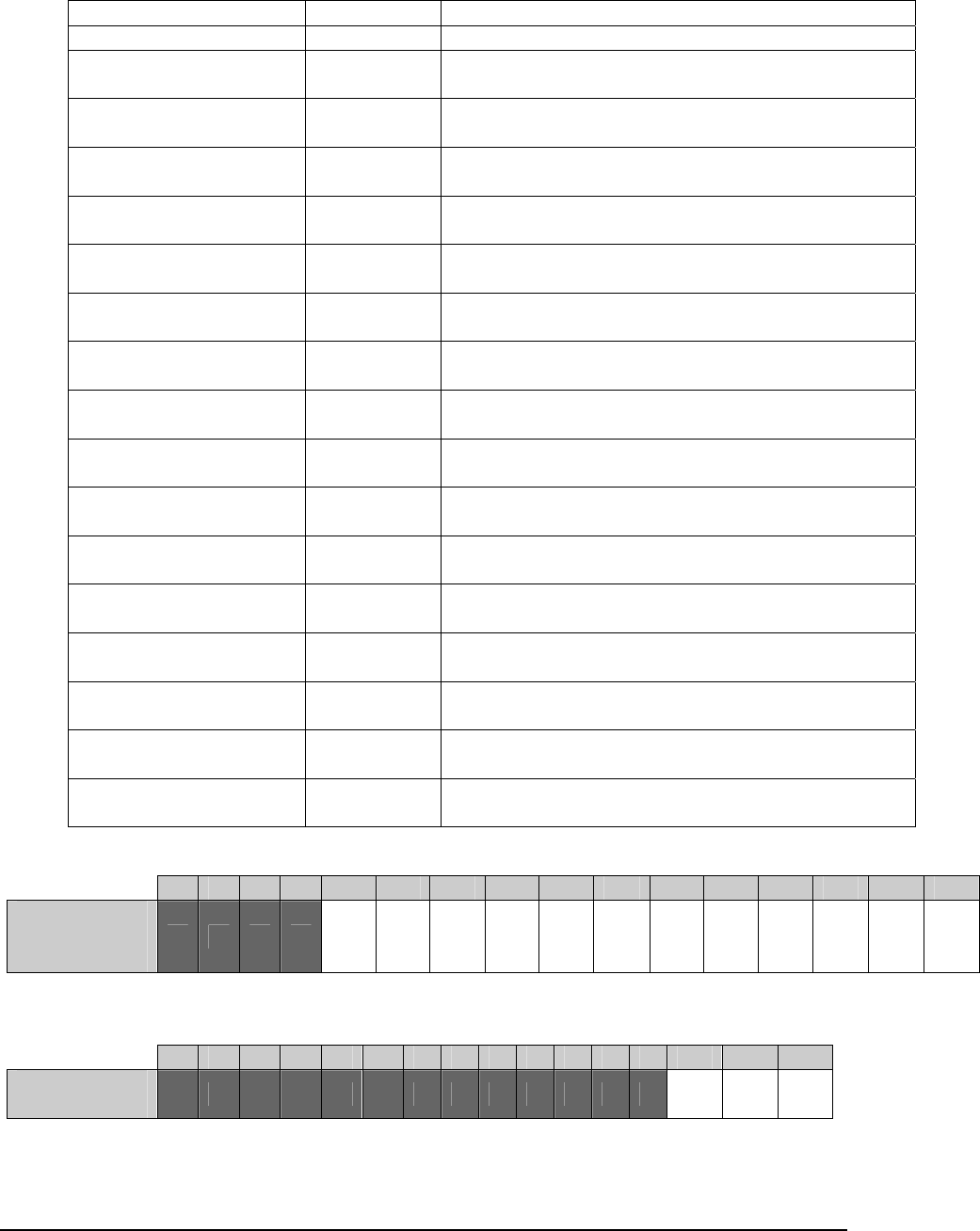
E Electro Industries/GaugeTech Doc # E154703 6-44
Firmware Info Block
Fields Size Description
Reserved 20
Variation 0 16 (string) Variation string, using to identify features of the
current firmware.
Variation 1 16 (string) Variation string, using to identify features of the
current firmware.
Variation 2 16 (string) Variation string, using to identify features of the
current firmware.
Variation 3 16 (string) Variation string, using to identify features of the
current firmware.
Variation 4 16 (string) Variation string, using to identify features of the
current firmware.
Variation 5 16 (string) Variation string, using to identify features of the
current firmware.
Variation 6 16 (string) Variation string, using to identify features of the
current firmware.
Variation 7 16 (string) Variation string, using to identify features of the
current firmware.
Variation 8 16 (string) Variation string, using to identify features of the
current firmware.
Variation 9 16 (string) Variation string, using to identify features of the
current firmware.
Variation 10 16 (string) Variation string, using to identify features of the
current firmware.
Variation 11 16 (string) Variation string, using to identify features of the
current firmware.
Variation 12 16 (string) Variation string, using to identify features of the
current firmware.
Variation 13 16 (string) Variation string, using to identify features of the
current firmware.
Variation 14 16 (string) Variation string, using to identify features of the
current firmware.
Variation 15 16 (string) Variation string, using to identify features of the
current firmware.
Waveform Reference Tables
T1 15 14 13 12 11 10 9 8 7 6 5 4 3 2 1 0
Waveform
Voltage Bit
Flags
Vxe Vce Vbe Vae Vne Vxn Vca Vbc Vab Vcn Vbn Van
T2 15 14 13 12 11 10 9 8 7 6 5 4 3 2 1 0
Transient Bit
Flags Vcn Vbn Van
NOTE: When Transient is configured for Phase to Phase, Van becomes Vab, Vbn becomes Vbc,
and Vcn becomes Vca.
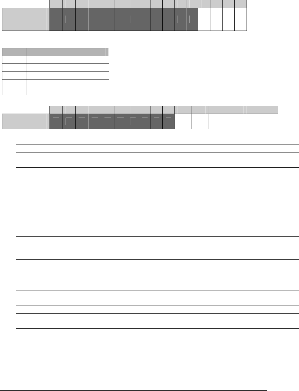
E Electro Industries/GaugeTech Doc # E154703 6-45
T5 15 14 13 12 11 10 9 8 7 6 5 4 3 2 1 0
Transient
Channels Vca Vbc Vab Vcn Vbn Van
Samples Section
Fields Byte Size Description
Section ID 0 16 (string) Tag id for the block, to ensure you’ve parsed the record
correctly. Must be “**WaveSample****"
Sample Blocks 16 The sample blocks, rotating through the channel list for
each sample block time counter.
Sample Block
Fields Byte Size Description
Sample Block Time
Counter
0 4 (uint) The time counter of this sample block. Each sample
block gets a sequentially increasing index, used to cross
reference with the RMS Data Blocks that describe it.
Reserved 4 12
Sample 0 16 2 (short) Each waveform sample is a signed 16bit raw value. See
p. 6-48 and Appendix A for information on how to scale
this value to secondary and primary.
Sample 1 18 2 (short)
…
Sample N 16 +
(N*2)
2 (short) The number of samples in a sample block is determined
from the waveform details header.
Waveform RMS Data Block Section
Fields Byte Size Description
Section ID 0 16 (string) Tag id for the block, to ensure you’ve parsed the record
correctly. Must be "**WaveRMS*******"
Waveform RMS Data
Blocks
16 The RMS blocks.
T3 15 14 13 12 11 10 9 8 7 6 5 4 3 2 1 0
Waveform
Current Bit
Flags
Ix Ic Ib Ia
T4 – Meter Hookup
Value Hookup
0 4 Wire WYE
1 3 Wire Delta 3 CT
2 3 Wire Delta 2 CT
3 4 Wire WYE 2.5 element
4 4 Wire Delta Ground

E Electro Industries/GaugeTech Doc # E154703 6-46
Waveform RMS Data Block
Fields Byte Size Description
Sample Block Time
Counter
0 4 (uint) The time counter of this RMS block. This is used to
determine which sample block this RMS block
describes. Note that this time counter is for the LAST
sample block: It may also describe sample blocks before
that (up to the previous RMS block).
Block Timestamp 4 10
(nexus_µs_
time)
The time of the end of this RMS block. See p. 6-49 for
instructions on determining the exact time of the RMS
block.
Reserved 14 2
RMS Data Block 16 196 (RMS
data block)
Contains information on the waveform states and RMS
values during this block.
Waveform Channels
The following channels can be used for waveform capture:
Channel Name ID Scale Factor
Volts AN 0 Logical Voltage
Volts BN 1 Logical Voltage
Volts CN 2 Logical Voltage
Volts AB 3 Logical Voltage
Volts BC 4 Logical Voltage
Volts CA 5 Logical Voltage
Volts XN 6 Logical Voltage
Volts Residual 7 Logical Voltage Residual
Current Residual 8 Logical Current Residual
Volts AE 32 Physical Voltage
Volts BE 33 Physical Voltage
Volts CE 34 Physical Voltage
Volts XE 35 Physical Voltage
Volts NE 36 Physical Voltage
Current A 37 Physical Current
Current B 38 Physical Current
Current C 39 Physical Current
Current X 40 Physical Current
Waveform Transient 0 77 Waveform Combine
Waveform Transient 1 78 Waveform Combine
Waveform Transient 2 79 Waveform Combine
High Speed Inputs 80 N/A

E Electro Industries/GaugeTech Doc # E154703 6-47
Samples
To parse the waveform samples, you must first extract the samples section of the
record. The size of the section can be determined by:
Bytes_per_block = (512 / sample_reduction_factor) + 16
Num_blocks = Num_channels * num_blocks_per_channel
Size = (num_blocks * (bytes_per_block)) + 16
Next, break up each of the sample blocks using the bytes per block. Finally, assign the
blocks to each channel sequentially, rotating through the channels. So:
WaveformSampleBlock sample_block;
//channel samples is a sequential list of samples for a channel
ChannelSamples[] channels;
int channel_index = 0;
//iterate over all the sample blocks
for(int i=0; i<num_blocks; i++)
{
copy bytes_per_block to sample_block
//add the samples to the channel
channels[channel_index].AddBlock(sample_block);
//rotate the channel index
channel_index = (channel_index + 1) % num_channels;
}
For example, if there are 3 channels, the sample blocks would be arranged in the record
as:
1A
1B
1C
2A
2B
2C
...
If two captures are contiguous, the samples can be combined to form a single waveform.
This will occur when multiple record per capture is selected in the programmable
settings, or if a trigger occurs while a waveform is already being captured. The time
counters for the last sample block of the first capture, and the first sample block of the
second, should be sequential. If they are not, then the captures are not continuous, and
the samples lists cannot be combined.

E Electro Industries/GaugeTech Doc # E154703 6-48
Now, you have all the sequential samples for each channel. However, these samples are
raw counts. They still need to be converted to secondary. For the voltage and current
channels, this is done by multiplying the raw value by the associated scale factors for that
channel. The scale factors are:
Factor Name Scalar
Logical Voltage 0.098401062
Logical Voltage Residual 0.196802124
Physical Voltage 0.049200531
Logical Current Residual 20A 0.012363048
Logical Current Residual 2A 0.001960812
Physical Current 20A 0.003090762
Physical Current 2A 0.000495203
Peak Transient 14.0625
Waveform Combine 0.098401062
See the table in Appendix A for which factor applies to which channel.
Finally, you multiply by the CT/PT ratio to get primary. So, for example, if you are
dealing with the Volts AN channel (which uses the Logical Voltage scalar), and have a
PT ratio of 1440/120, you get the following results:
Raw Secondary Primary
407 40.04923 4805.908
1018 100.1723 12020.67
1487 146.3224 17558.69
1749 172.1035 20652.41
1693 166.593 19991.16
1361 133.9238 16070.86
851 83.7393 10048.72
215 21.15623 2538.747
-453 -44.57568 -5349.082
-1052 -103.5179 -12422.15
-1468 -144.4528 -17334.33
-1654 -162.7554 -19530.64
-1623 -159.7049 -19164.59
-1382 -135.9903 -16318.83
-888 -87.38014 -10485.62
-253 -24.89547 -2987.456
NOTE: The above information only applies to voltage and current. The high speed
inputs (channel 80) are stored as a bitmap of the 8 inputs, where a bit value of 1
indicates open, and a bit value of 0 indicates closed. Bit 0 is input 1, bit 1 is input 2, and
so on. So for example:

E Electro Industries/GaugeTech Doc # E154703 6-49
Understanding the Data
Computing RMS Block Timestamps
The timestamp of the RMS blocks is the end of the sample block during which it occurs.
Since the RMS block may be completed during the middle of a sample block, this time
may not be the exact time of the RMS block. To compute the block’s actual time, adjust
the timestamp by the sample offset from the end of the block * the time per sample.
Time per sample is always (1000ms / (60 * 1024)). For Example:
Block Timestamp: 2012/04/13 17:42:16.3044
Ref Sample Index: 218
Time Per Sample: (1000ms / (60*1024)) = apx 0.016276ms
True End of Block Time: Block Time – ((256-218) * 0.016276)
304.4-0.618488
2012/04/13 17:42:16.30378
You can then use the same method to determine the start time of the RMS block. This is
how the time of the first sample in the capture is determined. All you do is subtract the
time for 256 samples from the time of the RMS block. Using the above block as an
example:
Beginning of Block Time: Block Time – (256 * 0.016276)
304.4-4.166656
2012/04/13 17:42:16.30023
Trigger Causes
Waveform captures can be triggered off of multiple causes. When these causes happen in
the same RMS block time, only one capture will be taken, but the RMS trigger block
details indicate all of the causes.
When a trigger happens while another capture is currently being performed, (but after the
initial triggering cycle), a second capture will be initiated after the first capture has
finished. This capture will be considered ‘contiguous’, and the samples and RMS blocks
between the two captures should be continuous. Additionally, the trigger in the second
capture will refer to the first capture. This is done to ensure that the configured post-
cycle’s (in the programmable settings) are always captured.
Raw Input 1 Input 2 Input 3 Input 4 Input 5 Input 6 Input 7 Input 8
0x7F Open Open Open Open Open Open Open Closed
0xBF Open Open Open Open Open Open Closed Open
0xDF Open Open Open Open Open Closed Open Open
0xEF Open Open Open Open Closed Open Open Open
0xF7 Open Open Open Closed Open Open Open Open
0xFB Open Open Closed Open Open Open Open Open

E Electro Industries/GaugeTech Doc # E154703 6-50
Sag/Swell
Sags and Swells can be determined by comparing the current states and
transitions in the triggering RMS block. If the transitions flags indicate
that a change has occurred (set to 1), then the current state will tell you
what kind of transition occurred. For example (Assuming looking at the
voltage swells):
Current States Transitions Causes
0x0005 0x0001 Volts AN Swell
0xFFFE 0x0005 Volts CN Swell, Volts AN Return to Normal
While multiple captures, or just the states in the RMS blocks, could be
analyzed for information about overall events, this information is
duplicated in the PQ logs, and will be described there.
High Speed Input Trigger
Similar to the Sags/Swells, input triggers can be determined by
comparing the High Speed Input current states and transitions in the
triggering RMS block. If the transitions flags indicate that a change has
occurred (set to 1), then the current state will tell you what kind of
transition occurred.
Manual Trigger: Waveform captures which have been manually
triggered can be detected by looking at the Manual Triggered flag in
the record header. If this is set, then the capture was due to a manual
trigger, and the other causes can be ignored.
Trigger Time: Waveform captures are triggered by the RMS block
which detects a change in condition. As such, the time of the trigger
is considered to be the time of the triggering RMS block.
Waveform Start Time
Most of the timestamps in the waveform capture are based on the RMS block times.
However, a capture may have multiple sample blocks before the first RMS block. To
determine the exact time of the first sample (the start of the waveform), determine the
number of samples before the first RMS block, and multiply that by the time per sample.
For example:
First Sample Block TTC: 5105
First RMS Block TTC: 5106
First RMS Block Time: 2012/04/13 17:42:16.3044
Time Per Sample: (1000ms / (60*1024)) = apx 0.016276ms
Samples to Offset: 256 * (First_RMS_Block – First_Sample_Block) + 1
256 * (5106 – 5105 + 1) = 512
Time of first sample: First RMS Block Time - (Samples to offset * time per sample)
2012/04/13 17:42:16.3044 – (512 * 0.016276)
2012/04/13 17:42:16.29607
NOTE: We offset by two sample blocks, because the first sample block was not the same
as the first RMS block. Also, as the TTC (Time Counter) can rollover, keep that in mind

E Electro Industries/GaugeTech Doc # E154703 6-51
when computing the samples to offset: The first sample block time counter may be
greater than the RMS block time counter in this case.
6.8.5.7: PQ Log
The PQ Log records in response to surges and sags of configured waveform channels, transient
events, and digital input events. The information it provides allows the calculation of duration
and magnitude of the surges and sags, as well as information for locating the start and end of the
event in waveform and transient captures.
NOTE: Different versions of the waveform record have different formats. The version field of
the header should always be checked before parsing the rest of the record.
Record Format
The PQ record is composed of two sections: A details header, and the RMS block from
the cycle of the PQ event. The details header contains a version field, to determine the
format of the header. Version 4 of the PQ record is documented here, and is 572 bytes in
size.
Details Header
Fields Size Description
Record Index 4 (uint) The internal index of the record.
Contiguous 1 (Boolean) Indicates if the record is possible to be contiguous with
the previous record. Non-contiguous records indicate
that some state changes may have been missed. The
primary reason non-contiguous records is a meter restart.
0 Contiguous
1 Not Contiguous
Reserved 5
Record Format Version 2 (ushort) The record format version. The format documented here
is v4.
Sample Block Time Counter 4 (ushort) The time counter of the RMS Block in which this PQ
event occurred. Used to synchronize between waveform
captures and the PQ event.
Event Timestamp 10
(nexus_µs_time)
The timestamp of the end of the RMS block which
contained this PQ event.
Reserved 2
RMS Data Block 196 (RMS data
block)
Contains information on the waveform states at the time
of the PQ event. See pp. 6-45 - 6-46.
Digital Input Mask 2 (bitmap) The digital inputs which have been configured in the
programmable settings to trigger PQ events.
Usr Voltage Flags 2 (bitmap) The list of voltage channels which have been configured
in the programmable settings to trigger PQ events
according to the Usr rules.
Usr Current Flags 2 (bitmap) The list of current channels which have been configured
in the programmable settings to trigger waveform
captures according to the Usr rules.
Waveform Setup Info 316 (Waveform
Setup Block)
Describes how the waveform triggers and captures were
configured, as well as providing information about the
meter.

E Electro Industries/GaugeTech Doc # E154703 6-52
Understanding the Data
PQ Event Timestamp
Trigger Cause
All triggers which occur during a single RMS block (apx. 4.1ms) will be combined into a
single PQ record. To determine which events triggered the record, each of the conditions
should be tested.
Waveform Sag/Swell Event
Waveform Sag/Swell events can be determined by comparing the current state and
transitions for the sags and swells, across multiple PQ events. To determine information
about the overall Sag/Swell event, you have analyze the sequence of PQ records.
To determine the pair of records which match for an event, defined as the Sag/Swell
condition going out of limit, then coming back in, start with a record that indicates that
the condition in question is going out. This is a record in which the Sag or Swell
transition state is 1, and the current state is 1 for that channel.
The find the matching event end record, search forward in time in the records until a
record is found where the delta state for the condition is 1, and the current state is 0.
NOTE: You need to check the contiguous flag in the header: if any record is found to be
non-contiguous, then the state changes may be log, and any end record found may not
match the original record.
High Speed Input Event
Input triggered events can be determined by comparing the High Speed Input current
states and the transitions for the PQ event. If the transitions flags indicate that a change
has occurred (set to 1), then the current state will tell you what kind of transition
occurred.
If the duration a High Speed input is in a specific state is required, follow the same
instructions as for sag/swell events.
Transient Event
Transient triggered events can be determined by checking the transient positive and
negative over-range flags. If the flag indicates that a transient has occurred on that
channel (set to 1), then a transient event occurred during the RMS block this PQ record
covers.
Event Duration
The duration for an event requires first determining the start and end record for that
event. Then, simply subtract the timestamp of the start record from the end record. For
example:
Start Record Time: 2012/04/13 17:42:16.3044
End Record Time: 2012/04/13 17:42:17.8242
Duration: 1.5198 seconds
NOTE: This only applies to sag/swell events, and paired high speed input events. As
transients never span more than one RMS block, duration of transient events is
determined by the recorded duration value (see Transient Log section on the next page).

E Electro Industries/GaugeTech Doc # E154703 6-53
Linking to a Waveform
To link a PQ event to the waveform capture of the same event, compare the sample block
time counter for the PQ event to trigger sample block time counters of the waveform
captures. The matching time counter is the matching capture.
6.8.5.8: Transient Log
The Transient log takes a record when the raw voltage inputs exceed the configured transient
limits. The record combines a PQ record of the transient event, and the waveform samples
around the event.
Because the duration of a transient may be shorter than the sampling interval on the input (and
thus not influence the actual value), the samples stored in the waveform data are replaced with the
peak transient values.
While multiple transients may be detected during an RMS block, only the information about the
peak positive, and peak negative, transients are stored.
NOTES:
Different versions of the waveform record have different formats. The version field of
the header should always be checked before parsing the rest of the record.
When transients are enabled, the channels assigned to the waveform must be the transient
equivalent channels. These channels replace the samples with the peak transient
exception values (when they occur). The important thing to note about this is that both
waveform captures and transient captures use the same channels, so all waveform
captures with transients enabled will contain these sample replacements.
Transients are triggered by comparing each value in the input against the configured
threshold. This value should be configured high enough so as not to clip the top of the
standard waveform samples.
Record Format
The Transient Record is composed of three sections: The details header, the waveform
samples around the event, and the details of the transient event.
Fields Byte Size Description
Record Index 0 4 (uint) The internal index of the record.
Reserved 4 6
Record Format Version 10 2 (ushort) The record format version.
Sample Block Time Counter 12 4 (uint) The time counter of the RMS Block in which
this Transient event occurred. Used to
synchronize between the samples and the RMS
block.
Event Timestamp 16 10
(nexus_µs_ti
me)
The timestamp of the end of the RMS block
which contains this Transient Event.
Reserved 26 2
Event RMS Block 28 196 (RMS
data block)
Contains information on the waveform and
transient states at the time of the event.
Digital Input Mask 224 2 (bitmap) The digital inputs which have been configured
in programmable settings to trigger waveform
events.
Reserved 226 30

E Electro Industries/GaugeTech Doc # E154703 6-54
Waveform Sample Block 0 256 516
(waveform
sample
block)
The waveform samples around the time of the
transient event. 6 sample blocks are always
captured, at a sampling rate of 1024 samples per
cycle, which means each sample block has 256
samples. This is approximately 1.5 cycles at a
nominal 60hz.
NOTE: The samples for the transient events will
be replaced with the peak exception value.
Waveform Sample Block 1 772 516
(waveform
sample
block)
Waveform Sample Block 2 1288 516
(waveform
sample
block)
Waveform Sample Block 3 1804 516
(waveform
sample
block)
Waveform Sample Block 4 2320 516
(waveform
sample
block)
Waveform Sample Block 5 2836 516
(waveform
sample
block)
Transient Details Block 0 3352 64 (transient
details block)
The transient details for each of the sample
blocks captured. By comparing the time
counter of these blocks against the event’s time
counter, you can determine which block
triggered the event.
Transient Details Block 1 3416 64 (transient
details block)
Transient Details Block 2 3480 64 (transient
details block)
Transient Details Block 3 3544 64 (transient
details block)
Transient Details Block 4 3608 64 (transient
details block)
Transient Details Block 5 3672 64 (transient
details block)
Sample Block Time Counter 0 4 (uint) The time counter of this transient block. This is
used to determine which sample block this
transient block describes.
Block Timestamp 4 10
(nexus_µs_ti
me)
The tie of the end of this transient block.

E Electro Industries/GaugeTech Doc # E154703 6-55
Reserved 14 2
Reserved 16 6
Transient pos over-range
flags
22 2 (bitmap) Indicates a positive transient which exceeded
the configured threshold occurred. See Table 2
(Transient Bit Flags) for bits.
Transient neg over-range
flags
24 2 (bitmap) Indicates a negative transient which exceeded
the configured threshold occurred. See Table 2
(Transient Bit Flags)for bits.
Transient pos peak sample
index ch1
26 2 (ushort) The sample index of the peak positive transient
to occur on channel 1 (Van or Vab).
Transient pos peak sample
index ch2
28 2 (ushort) The sample index of the peak positive transient
to occur on channel 2 (Vbn or Vbc).
Transient pos peak sample
index ch3
30 2 (ushort) The sample index of the peak positive transient
to occur on channel 3 (Vcn or Vca).
Transient neg peak sample
index ch1
32 2 (ushort) The sample index of the peak negative transient
to occur on channel 1 (Van or Vab).
Transient neg peak sample
index ch2
34 2 (ushort) The sample index of the peak negative transient
to occur on channel 2 (Vbn or Vbc).
Transient neg peak sample
index ch3
36 2 (ushort) The sample index of the peak negative transient
to occur on channel 3 (Vcn or Vca).
Transient pos peak sample
value ch1
38 2 (ushort) The peak positive transient value to occur on
channel 1 (Van or Vab). Multiply by
(1800/255) to get Secondary value.
Transient pos peak sample
value ch2
40 2 (ushort) The peak positive transient value to occur on
channel 2 (Vbn or Vbc). Multiply by
(1800/255) to get Secondary value.
Transient pos peak sample
value ch3
42 2 (ushort) The peak positive transient value to occur on
channel 3 (Vcn or Vca). Multiply by
(1800/255) to get Secondary value.
Transient neg peak sample
value ch1
44 2 (ushort) The peak negative transient value to occur on
channel 1 (Van or Vab). Multiply by
(1800/255) to get Secondary value.
Transient neg peak sample
value ch2
46 2 (ushort) The peak negative transient value to occur on
channel 2 (Vbn or Vbc). Multiply by
(1800/255) to get Secondary value.
Transient neg peak sample
value ch3
48 2 (ushort) The peak negative transient value to occur on
channel 3 (Vcn or Vca). Multiply by
(1800/255) to get Secondary value.
Transient pos peak sample
duration ch1
50 2 (ushort) Duration of the peak positive transient to occur
on channel 1 (Van or Vab). Multiply by 18.18
nanoseconds to get time.
Transient pos peak sample
duration ch2
52 2 (ushort) Duration of the peak positive transient to occur
on channel 2 (Vbn or Vbc). Multiply by 18.18
nanoseconds to get time.
Transient pos peak sample
duration ch3
54 2 (ushort) Duration of the peak positive transient to occur
on channel 3 (Vcn or Vca). Multiply by 18.18
nanoseconds to get time.
Transient neg peak sample
duration ch1
56 2 (ushort) Duration of the peak negative transient to occur
on channel 1 (Van or Vab). Multiply by 18.18
nanoseconds to get time.

E Electro Industries/GaugeTech Doc # E154703 6-56
Transient neg peak sample
duration ch2
58 2 (ushort) Duration of the peak negative transient to occur
on channel 2 (Vbn or Vbc). Multiply by 18.18
nanoseconds to get time.
Transient neg peak sample
duration ch3
60 2 (ushort) Duration of the peak negative transient to occur
on channel 3 (Vcn or Vca). Multiply by 18.18
nanoseconds to get time.
Reserved 62 2
Samples
Sample parsing is done the same as waveform record sample parsing. The major
differences are that there are no contiguous captures, the sample rate is fixed at 1024
samples per cycle, and there are always 6 blocks.
NOTE: To see the transients in the waveform samples, the waveform channel ids need
to be set to the transient channel id’s. These samples have a much larger range then the
standard waveform samples, which results in lower resolution in the waveform.
However, each sample in which a transient occurred will be replaced with the peak (abs
max of the positive and negative values) transient value.
Understanding the Data
Trigger Cause
Multiple transients that exceed the transient threshold for that channel may be detected
during a single RMS block, but only the peak positive and peak negative sample are
recorded.
Peak positive is defined as the max value; peak negative is defined as the min value.
NOTE: That means that this does not necessarily follow the wave-shape of the input. A
positive peak may occur during the waveform trough, and a negative peak may occur
during the waveform crest.
The cause of the transient event can be determined by looking at the over-range flags for
the triggering RMS block. There may be multiple causes.
NOTE: Only one transient capture may occur every 200ms, so it is worth looking at the
6 transient details blocks to detect rapidly occurring transient events (apx 25ms).
Peak Transient Time
The time of each specific transient can be determined by modifying the RMS block
timestamp (the event timestamp for the trigger) by the sample index of the transient
For example:
Event Time: 2012/04/13 17:42:16.3044
Transient Event: Volts AN Positive Peak
Sample Index: 73
Transient Time: time - (256-73)* 0.016276ms
2012/ 04/13 17:42:16.30142
Transient Duration
The duration of a specific transient can be determined by multiplying the duration value
of the transient by the transient tick time (18.18 nanoseconds). For example:
Transient Tick Time: 18.18 nanoseconds
Transient Duration Value: 5

E Electro Industries/GaugeTech Doc # E154703 6-57
Transient Duration: 90.9 nanoseconds
NOTE: A transient’s duration is limited to one sample’s time (apx 16µs). Any transient
which exceeds this is considered to be multiple transients.
Transient Value
The secondary value of a specific transient can be determined by multiplying the peak
value of the transient by the Peak Transient scalar factor (See Appendix A for a Table of
scaling factors).
Transient Scalar Factor: 14.0625
Transient Peak Value: 53
Transient Secondary Value: 745.3125 volts
6.8.5.9: EN50160
The Nexus® 1500 meter's EN50160 implementation is based on the official EN50160-2007
specification, with exceptions where the following items are not supported:
1) Transient over-voltages between live conductors and earth
2) Interharmonic voltage
EN50160 Reporting Items: Summary of EN50160-2007
Item # Name EN50160 Spec Ref 4.x.x/5.x.x
1 Power Frequency, sync x.1
1 Power Frequency, no sync x.1
2 Magnitude of supply voltage x.2
3 Supply Voltage Variations x.3.x
4 Single rapid voltage change(Low Voltage supply)/Magnitude
of rapid voltage Changes(Medium Voltage supply)
x.4.1
5 Flicker x.4.2
6 Supply Voltage Dips x.5
7 Short Interruption of Supply Voltage x.6
8 Long Interruption of Supply Voltage x.7
9 Temporary power frequency over-voltages between live
conductors and earth
x.8
10* Transient over-voltages between live conductors and earth x.9
11 Supply voltage unbalance x.10
12 Harmonic voltage x.11
13* Interharmonic voltage x.12
14 Mains signaling voltage on the supply voltage x.13
* Not supported by the Nexus® 1500 meter

E Electro Industries/GaugeTech Doc # E154703 6-58
Archived Week/Year Data in XML Format
Each XML contains the report data for current week, past weekly and yearly.
Tags Attributes Descriptions Reporting
Item # Examples
EN50160_REPORT XML file start and end tags <EN50160_ REPORT >,
</EN50160_ REPORT >
Dev_Info Name User assigned meter name <Dev_Info
Name="Meter_1"
Type="Nexus 1500"
Serial_Number="123456789
0 Runtime=0001.0002" />
Type Factory defined device names:
Nexus 1500
or
user defined device names
Serial_Number Device serial number
Runtime Device runtime firmware version,
4 digit version (major) and 4 digit
build (minor)
HookUp Wye,
Delta 3 CTs,
Delta 2 CTs,
2.5 Element
4 Wire Delta
45S: Wye, 2 CTs
Frequency 50Hz or 60Hz
Supply_Type Low Voltage or Medium Voltage
Profile_DateTime Last modified date/time in device
profile
YYYY-MM-SS HH:MM:SS
Profile_Key Device profile check sum
Voltage_Full_Scale_PN Phase to neutral full scale, shown
in primary
Voltage_Full_Scale_PP Phase to phase full scale, shown
in primary
Nominal_Voltage User set value, shown in
secondary
Mains_Signaling_Threshold User set threshold
Over_Voltage_AE_Threshold User set threshold
Over_Voltage_BE_Threshold User set threshold
Over_Voltage_CE_Threshold User set threshold
Allowed_Long_Interruptions_
In_Year
User set value
Rapid_Voltage_Change_Data_
Source
1 cycle updated RMS
10/12 cycles updated RMS
Unbalance_Upper_Limit 2%
3%
Voltage_A_Dip_Concern User set threshold
Voltage_B_Dip_Concern User set threshold
Voltage_C_Dip_Concern User set threshold
Synchronous_Connection Yes or No
Allowed_Rapid_Voltage_Chan
ges_In_Day
User set allowed Rapid Voltage
Changes per day in devie profile
Allowed_Rapid_Voltage_Chan
ges_In_Week
User set allowed Rapid Voltage
Changes per day in devie profile *
7
Allowed_Rapid_Voltage_Chan
ges_In_Year
User set allowed Rapid Voltage
Changes per day in devie profile *
[number of days in the year of the
report start date/time]
Data_Info Version File format version, single
number

E Electro Industries/GaugeTech Doc # E154703 6-59
Type Available types are:
Current Week
Current Year
Weekly
Yearly
Start Report start date/time, local time,
24 hour, time zone.
Day of week, "Sun", "Mon",
"Tue", "Wed", "Thu", "Fri", "Sat"
Month, "Jan", "Feb", "Mar",
"Apr", "May", "Jun", "Jul",
"Aug", "Sep", "Oct", "Nov",
"Dec"
Thu, 27 May 2010 12:00:39
-0400
End Report end date/time, local time,
24 hour, time zone.
Day of week, "Sun", "Mon",
"Tue", "Wed", "Thu", "Fri", "Sat"
Month, "Jan", "Feb", "Mar",
"Apr", "May", "Jun", "Jul",
"Aug", "Sep", "Oct", "Nov",
"Dec"
Thu, 27 May 2010 12:00:39
-0400
FDOW First day of week. "Sun" or
"Mon".
Start_V1 Report start date/time, short
format
YYYY-MM-DD
HH:MM:SS
End_V1 Report end date/time, short format YYYY-MM-DD
HH:MM:SS
Report_Message Code Operation status in HEX format. 0x80000000
Settings Valid or Invalid. Based on
operation status bit 12.
Messages Any messages the meter provides
regarding this report, such as
warning messages.
Invalid_Setting_Code Invalid setting code in HEX
format.
Report_Status Sec_x1 NA, Pass or Fail, Power
Frequency
Sec_x2 NA, Magnitude of supply voltage
Sec_x3 NA, Pass or Fail, Supply Voltage
Variations
Sec_x4_1 NA, Pass, Fail, or Concern, rapid
voltage changes
Sec_x4_2 NA, Pass or Fail, Flicker
Sec_x5 NA, Pass or Fail, Supply Voltage
Dips
Sec_x6 NA, Pass or Fail, Short
Interruption of Supply Voltage
Sec_x7 NA, Pass or Fail, Long
Interruption of Supply Voltage
Sec_x8 NA, Pass or Fail, Temporary
power frequency over-voltages
between live conductors and earth
Sec_x9 NA, Transient over-voltages
between live conductors and earth
Sec_x10 NA, Pass or Fail, Supply voltage
unbalance
Sec_x11 NA, Pass or Fail, Harmonic
Voltage
Sec_x12 NA, Interharmonic Voltage
Sec_x13 NA, Pass or Fail, Mains signaling
voltage on the supply voltage
Total_Count Rapid_Voltage Rapid Voltage Change Count 4
Mains_Frequency Mains Frequency Count 1
Ten_min_Mean 10 Minute Mean RMS Count 3

E Electro Industries/GaugeTech Doc # E154703 6-60
Flicker_PLTs Flicker PLT Count 5
Unbalance Voltage unbalance count 11
THDs THD/Harmonic count 12
Mains_Signaling Mains signaling voltage count 14
Ten_sec_Mean_Fre
q
Bin0 10Sec mean Freq Bin 0,
f<42.5(51.0), 15%
1 <10sec_Mean_Freq
Bin0="0" Bin1="1"
Bin2="2" Bin3="3"
Bin4="4" Bin5="5"
Bin6="6" Bin7="7"
Bin8="8" Bin9="9"
Bin10="10" />
Bin1 10Sec mean Freq Bin 1,
42.5(51.0)<=f<47(56.4), 15%-6%
1
Bin2 10Sec mean Freq Bin 2,
47(56.4)<=f<49(58.8), 6%-2%
1
Bin3 10Sec mean Freq Bin 3,
49(58.8)<=f<49.5(59.4), 2%-1%
1
Bin4 10Sec mean Freq Bin 4,
49.5(59.4)<=f<50(60), 1%-0%
1
Bin5 10Sec mean Freq Bin 5,
50(60)<=f<50.5(60.6), 0%-1%
1
Bin6 10Sec mean Freq Bin 6,
50.5(60.6)<=f<51(61.2), 1%-2%
1
Bin7 10Sec mean Freq Bin 7,
51(61.2)<=f<52(62.4), 2%-6%
1
Bin8 10Sec mean Freq Bin 8,
52(62.4)<=f<=57.5(69), 6%-15%
1
Bin9 10Sec mean Freq Bin 9,
57.5(69)<f, 15%
1
Ten_min_Mean_Va
_RMS
Bin0 10min mean Van/ab RMS Bin 0,
<85%
3
Bin1 10min mean Van/ab RMS Bin 1,
85%<=V<90%
3
Bin2 10min mean Van/ab RMS Bin 2,
90%<=V<100%
3
Bin3 10min mean Van/ab RMS Bin 3,
100%<=V<=110%
3
Bin4 10min mean Van/ab RMS Bin 4,
110%<V
3
Ten_min_Mean_Vb
_RMS
Bin0 10min mean Vbn/bc RMS Bin 0,
<85%
3
Bin1 10min mean Vbn/bc RMS Bin 1,
85%<=V<90%
3
Bin2 10min mean Vbn/bc RMS Bin 2,
90%<=V<100%
3
Bin3 10min mean Vbn/bc RMS Bin 3,
100%<=V<=110%
3
Bin4 10min mean Vbn/bc RMS Bin 4,
110%<V
3
Ten_min_Mean_Vc
_RMS
Bin0 10min mean Vcn/ca RMS Bin 0,
<85%
3
Bin1 10min mean Vcn/ca RMS Bin 1,
85%<=V<90%
3
Bin2 10min mean Vcn/ca RMS Bin 2,
90%<=V<100%
3
Bin3 10min mean Vcn/ca RMS Bin 3,
100%<=V<=110%
3
Bin4 10min mean Vcn/ca RMS Bin 4,
110%<V
3
Rapid_Voltage_Va Bin0 Rapid Voltage Change Van/ab
Bin 0, V<-10%
4
Bin1 Rapid Voltage Change Van/ab
Bin 1, -10%<=V<-5%
4
Bin2 Rapid Voltage Change Van/ab
Bin 2, -5%<=V<0%
4
Bin3 Rapid Voltage Change Van/ab
Bin 3, 0%<=V<+5%
4
Bin4 Rapid Voltage Change Van/ab 4

E Electro Industries/GaugeTech Doc # E154703 6-61
Bin 4, +5%<=V<=+10%
Bin5 Rapid Voltage Change Van/ab
Bin 5, +10%<V
4
Rapid_Voltage_Vb Bin0 Rapid Voltage Change Vbn/bc
Bin 0, V<-10%
4
Bin1 Rapid Voltage Change Vbn/bc
Bin 1, -10%<=V<-5%
4
Bin2 Rapid Voltage Change Vbn/bc
Bin 2, -5%<=V<0%
4
Bin3 Rapid Voltage Change Vbn/bc
Bin 3, 0%<=V<+5%
4
Bin4 Rapid Voltage Change Vbn/bc
Bin 4, +5%<=V<=+10%
4
Bin5 Rapid Voltage Change Vbn/bc
Bin 5, +10%<V
4
Rapid_Voltage_Vc Bin0 Rapid Voltage Change Vcn/ca
Bin 0, V<-10%
4
Bin1 Rapid Voltage Change Vcn/ca
Bin 1, -10%<=V<-5%
4
Bin2 Rapid Voltage Change Vcn/ca
Bin 2, -5%<=V<0%
4
Bin3 Rapid Voltage Change Vcn/ca
Bin 3, 0%<=V<+5%
4
Bin4 Rapid Voltage Change Vcn/ca
Bin 4, +5%<=V<=+10%
4
Bin5 Rapid Voltage Change Vcn/ca
Bin 5, +10%<V
4
PLT_Va Bin0 PLT Van/ab Bin 0, <=1 5
Bin1 PLT Van/ab Bin 1, >1 5
PLT_Vb Bin0 PLT Vbn/bc Bin 0, <=1 5
Bin1 PLT Vbn/bc Bin 1, >1 5
PLT_Vc Bin0 PLT Vcn/ca Bin 0, <=1 5
Bin1 PLT Vcn/ca Bin 1, >1 5
Ten_min_Avg_Va_
Harm
H2 10 min Ave Van/ab 2nd Harm
bin, >2.0%
12
H3 10 min Ave Van/ab 3nd Harm
bin, >5.0%
12
H4 10 min Ave Van/ab 4th Harm bin,
>1.0%
12
H5 10 min Ave Van/ab 5th Harm bin,
>6.0%
12
H6 10 min Ave Van/ab 6th Harm bin,
>0.5%
12
H7 10 min Ave Van/ab 7th Harm bin,
>1.5%
12
H8 10 min Ave Van/ab 8th Harm bin,
>0.5%
12
H9 10 min Ave Van/ab 9th Harm bin,
>1.5%
12
H10 10 min Ave Van/ab 10th Harm
bin, >0.5%
12
H11 10 min Ave Van/ab 11th Harm
bin, >3.5%
12
H12 10 min Ave Van/ab 12th Harm
bin, >0.5%
12
H13 10 min Ave Van/ab 13th Harm
bin, >3.0%
12
H14 10 min Ave Van/ab 14th Harm
bin, >0.5%
12
H15 10 min Ave Van/ab 15th Harm
bin, >0.5%
12
H16 10 min Ave Van/ab 16th Harm
bin, >0.5%
12
H17 10 min Ave Van/ab 17th Harm
bin, >2.0%
12

E Electro Industries/GaugeTech Doc # E154703 6-62
H18 10 min Ave Van/ab 18th Harm
bin, >0.5%
12
H19 10 min Ave Van/ab 19th Harm
bin, >1.5%
12
H20 10 min Ave Van/ab 20th Harm
bin, >0.5%
12
H21 10 min Ave Van/ab 21st Harm
bin, >0.5%
12
H22 10 min Ave Van/ab 22nd Harm
bin, >0.5%
12
H23 10 min Ave Van/ab 23rd Harm
bin, >1.5%
12
H24 10 min Ave Van/ab 24th Harm
bin, >0.5%
12
H25 10 min Ave Van/ab 25th Harm
bin, >1.5%
12
Ten_min_Avg_Vb_
Harm
H2 10 min Ave Vbn/bc 2nd Harm
bin, >2.0%
12
H3 10 min Ave Vbn/bc 3nd Harm
bin, >5.0%
12
H4 10 min Ave Vbn/bc 4th Harm bin,
>1.0%
12
H5 10 min Ave Vbn/bc 5th Harm bin,
>6.0%
12
H6 10 min Ave Vbn/bc 6th Harm bin,
>0.5%
12
H7 10 min Ave Vbn/bc 7th Harm bin,
>1.5%
12
H8 10 min Ave Vbn/bc 8th Harm bin,
>0.5%
12
H9 10 min Ave Vbn/bc 9th Harm bin,
>1.5%
12
H10 10 min Ave Vbn/bc 10th Harm
bin, >0.5%
12
H11 10 min Ave Vbn/bc 11th Harm
bin, >3.5%
12
H12 10 min Ave Vbn/bc 12th Harm
bin, >0.5%
12
H13 10 min Ave Vbn/bc 13th Harm
bin, >3.0%
12
H14 10 min Ave Vbn/bc 14th Harm
bin, >0.5%
12
H15 10 min Ave Vbn/bc 15th Harm
bin, >0.5%
12
H16 10 min Ave Vbn/bc 16th Harm
bin, >0.5%
12
H17 10 min Ave Vbn/bc 17th Harm
bin, >2.0%
12
H18 10 min Ave Vbn/bc 18th Harm
bin, >0.5%
12
H19 10 min Ave Vbn/bc 19th Harm
bin, >1.5%
12
H20 10 min Ave Vbn/bc 20th Harm
bin, >0.5%
12
H21 10 min Ave Vbn/bc 21st Harm
bin, >0.5%
12
H22 10 min Ave Vbn/bc 22nd Harm
bin, >0.5%
12
H23 10 min Ave Vbn/bc 23rd Harm
bin, >1.5%
12
H24 10 min Ave Vbn/bc 24th Harm
bin, >0.5%
12
H25 10 min Ave Vbn/bc 25th Harm
bin, >1.5%
12
Ten_min_Avg_Vc_
Harm
H2 10 min Ave Vcn/ca 2nd Harm
bin, >2.0%
12
H3 10 min Ave Vcn/ca 3nd Harm
bin, >5.0%
12

E Electro Industries/GaugeTech Doc # E154703 6-63
H4 10 min Ave Vcn/ca 4th Harm bin,
>1.0%
12
H5 10 min Ave Vcn/ca 5th Harm bin,
>6.0%
12
H6 10 min Ave Vcn/ca 6th Harm bin,
>0.5%
12
H7 10 min Ave Vcn/ca 7th Harm bin,
>1.5%
12
H8 10 min Ave Vcn/ca 8th Harm bin,
>0.5%
12
H9 10 min Ave Vcn/ca 9th Harm bin,
>1.5%
12
H10 10 min Ave Vcn/ca 10th Harm
bin, >0.5%
12
H11 10 min Ave Vcn/ca 11th Harm
bin, >3.5%
12
H12 10 min Ave Vcn/ca 12th Harm
bin, >0.5%
12
H13 10 min Ave Vcn/ca 13th Harm
bin, >3.0%
12
H14 10 min Ave Vcn/ca 14th Harm
bin, >0.5%
12
H15 10 min Ave Vcn/ca 15th Harm
bin, >0.5%
12
H16 10 min Ave Vcn/ca 16th Harm
bin, >0.5%
12
H17 10 min Ave Vcn/ca 17th Harm
bin, >2.0%
12
H18 10 min Ave Vcn/ca 18th Harm
bin, >0.5%
12
H19 10 min Ave Vcn/ca 19th Harm
bin, >1.5%
12
H20 10 min Ave Vcn/ca 20th Harm
bin, >0.5%
12
H21 10 min Ave Vcn/ca 21st Harm
bin, >0.5%
12
H22 10 min Ave Vcn/ca 22nd Harm
bin, >0.5%
12
H23 10 min Ave Vcn/ca 23rd Harm
bin, >1.5%
12
H24 10 min Ave Vcn/ca 24th Harm
bin, >0.5%
12
H25 10 min Ave Vcn/ca 25th Harm
bin, >1.5%
12
Ten_min_Mean_T
HDs_Above
Va 10min mean Van/ab THD > 8% 12
Vb 10min mean Vbn/bc THD > 8% 12
Vc 10min mean Vcn/ca THD > 8% 12
Freq_Sync Bin0 Freq Bin 0, sync, -1%<=f<=+1% 1
Bin1 Freq Bin 1, sync, -6%<=f<=+4% 1
Bin0_pct Bin 0, % of total count 1
Bin1_pct Bin 1, % of total count 1
Freq_NoSync Bin0 Freq Bin 2, no sync, -
2%<=f<=+2%
1
Bin1 Freq Bin 3, no sync, -
15%<=f<=+15%
1
Bin0_pct Bin 0, % of total count 1
Bin1_pct Bin 1, % of total count 1
Rapid_Voltage_5pc
t
Va Rapid Voltage Change +/-5%
Van/ab Bin 0
4
Vb Rapid Voltage Change +/-5%
Vbn/bc Bin 1
4
Vc Rapid Voltage Change +/-5%
Vcn/ca Bin 2
4
Rapid_Voltage_10p
ct
Va Rapid Voltage Change between
+/-5% and +/-10% Van/ab Bin 0
4
Vb Rapid Voltage Change between
+/-5% and +/-10% Vbn/bc Bin 1
4

E Electro Industries/GaugeTech Doc # E154703 6-64
Vc Rapid Voltage Change between
+/-5% and +/-10% Vcn/ca Bin 2
4
Voltage_Variations
_10pct
Va Supply Voltage Variations (10min
mean) +/-10% Van/ab Bin 0
3
Vb Supply Voltage Variations (10min
mean) +/-10% Vbn/bc Bin 1
3
Vc Supply Voltage Variations (10min
mean) +/-10% Vcn/ca Bin 2
3
Va_pct % of total count 3
Vb_pct % of total count 3
Vc_pct % of total count 3
Voltage_Variations
_15_10pct
Va Supply Voltage Variations (10min
mean) -15%/+10/% Van/ab Bin 0
3
Vb Supply Voltage Variations (10min
mean) -15%/+10/% Vbn/bc Bin 1
3
Vc Supply Voltage Variations (10min
mean) -15%/+10/% Vcn/ca Bin 2
3
Va_pct % of total count 3
Vb_pct % of total count 3
Vc_pct % of total count 3
Rapid_Voltage_4pc
t
Va Rapid Voltage Change +/-4%
Van/ab Bin 0
4
Vb Rapid Voltage Change +/-4%
Vbn/bc Bin 1
4
Vc Rapid Voltage Change +/-4%
Vcn/ca Bin 2
4
Rapid_Voltage_6pc
t
Va Rapid Voltage Change between
+/-4% and +/-6% Van/ab Bin 0
4
Vb Rapid Voltage Change between
+/-4% and +/-6% Vbn/bc Bin 1
4
Vc Rapid Voltage Change between
+/-4% and +/-6% Vcn/ca Bin 2
4
Supply_Voltage_U
nbalance
Bin0 Supply voltage unbalance, bin 0,
0%<=n<=2%
11
Bin1 Supply voltage unbalance, bin 1,
2%<n<=3%
11
Bin2 Supply voltage unbalance, bin 2,
3%<n
11
Mains_Signaling Va_Below 3sec mains signaling voltage,
Van/Vab, bin 0, <=threshold
14
Va_Above 3sec mains signaling voltage,
Van/Vab, bin 1, >threshold
14
Vb_Below 3sec mains signaling voltage,
Vbn/Vbc, bin 0, <=threshold
14
Vb_Above 3sec mains signaling voltage,
Vbn/Vbc, bin 1, >threshold
14
Vc_Below 3sec mains signaling voltage,
Vcn/Vca, bin 0, <=threshold
14
Vc_Above 3sec mains signaling voltage,
Vcn/Vca, bin 1, >threshold
14
Dips_Va_1sec Bin0 Dips and interruptions, Van/Vab,
bin 0, >=85% and <90%, <=1sec
6, 7, 8
Bin1 Dips and interruptions, Van/Vab,
bin 1, >=70% and <85%, <=1sec
6, 7, 8
Bin2 Dips and interruptions, Van/Vab,
bin 2, >=60% and <70%, <=1sec
6, 7, 8
Bin3 Dips and interruptions, Van/Vab,
bin 3, >=50% and <60%, <=1sec
6, 7, 8
Bin4 Dips and interruptions, Van/Vab,
bin 4, >=40% and <50%, <=1sec
6, 7, 8
Bin5 Dips and interruptions, Van/Vab,
bin 5, >=30% and <40%, <=1sec
6, 7, 8
Bin6 Dips and interruptions, Van/Vab,
bin 6, >=20% and <30%, <=1sec
6, 7, 8
Bin7 Dips and interruptions, Van/Vab,
bin 7, >=15% and <20%, <=1sec
6, 7, 8
Bin8 Dips and interruptions, Van/Vab,
bin 8, >=10% and <15%, <=1sec
6, 7, 8

E Electro Industries/GaugeTech Doc # E154703 6-65
Bin9 Dips and interruptions, Van/Vab,
bin 9, >=1% and <10%, <=1sec
6, 7, 8
Bin10 Dips and interruptions, Van/Vab,
bin 10, <1%, 1sec<=180sec
6, 7, 8
Dips_Va_180sec Bin0 Dips and interruptions, Van/Vab,
bin 0, >=85% and <90%,
1sec<=180sec
6, 7, 8
Bin1 Dips and interruptions, Van/Vab,
bin 1, >=70% and <85%,
1sec<=180sec
6, 7, 8
Bin2 Dips and interruptions, Van/Vab,
bin 2, >=60% and <70%,
1sec<=180sec
6, 7, 8
Bin3 Dips and interruptions, Van/Vab,
bin 3, >=50% and <60%,
1sec<=180sec
6, 7, 8
Bin4 Dips and interruptions, Van/Vab,
bin 4, >=40% and <50%,
1sec<=180sec
6, 7, 8
Bin5 Dips and interruptions, Van/Vab,
bin 5, >=30% and <40%,
1sec<=180sec
6, 7, 8
Bin6 Dips and interruptions, Van/Vab,
bin 6, >=20% and <30%,
1sec<=180sec
6, 7, 8
Bin7 Dips and interruptions, Van/Vab,
bin 7, >=15% and <20%,
1sec<=180sec
6, 7, 8
Bin8 Dips and interruptions, Van/Vab,
bin 8, >=10% and <15%,
1sec<=180sec
6, 7, 8
Bin9 Dips and interruptions, Van/Vab,
bin 9, >=1% and <10%,
1sec<=180sec
6, 7, 8
Bin10 Dips and interruptions, Van/Vab,
bin 10, <1%, 1sec<=180sec
6, 7, 8
Dips_Va_Above_1
80sec
Bin0 Dips and interruptions, Van/Vab,
bin 0, >=85% and <=90%,
>180sec
6, 7, 8
Bin1 Dips and interruptions, Van/Vab,
bin 1, >=70% and <85%, >180sec
6, 7, 8
Bin2 Dips and interruptions, Van/Vab,
bin 2, >=60% and <70%, >180sec
6, 7, 8
Bin3 Dips and interruptions, Van/Vab,
bin 3, >=50% and <60%, >180sec
6, 7, 8
Bin4 Dips and interruptions, Van/Vab,
bin 4, >=40% and <50%, >180sec
6, 7, 8
Bin5 Dips and interruptions, Van/Vab,
bin 5, >=30% and <40%, >180sec
6, 7, 8
Bin6 Dips and interruptions, Van/Vab,
bin 6, >=20% and <30%, >180sec
6, 7, 8
Bin7 Dips and interruptions, Van/Vab,
bin 7, >=15% and <20%, >180sec
6, 7, 8
Bin8 Dips and interruptions, Van/Vab,
bin 8, >=10% and <15%, >180sec
6, 7, 8
Bin9 Dips and interruptions, Van/Vab,
bin 9, >=1% and <10%, >180sec
6, 7, 8
Bin10 Dips and interruptions, Van/Vab,
bin 10, <1%, >180sec
6, 7, 8
Dips_Vb_1sec Bin0 Dips and interruptions, Vbn/Vbc,
bin 0, >=85% and <90%, <=1sec
6, 7, 8
Bin1 Dips and interruptions, Vbn/Vbc,
bin 1, >=70% and <85%, <=1sec
6, 7, 8
Bin2 Dips and interruptions, Vbn/Vbc,
bin 2, >=60% and <70%, <=1sec
6, 7, 8
Bin3 Dips and interruptions, Vbn/Vbc,
bin 3, >=50% and <60%, <=1sec
6, 7, 8
Bin4 Dips and interruptions, Vbn/Vbc, 6, 7, 8

E Electro Industries/GaugeTech Doc # E154703 6-66
bin 4, >=40% and <50%, <=1sec
Bin5 Dips and interruptions, Vbn/Vbc,
bin 5, >=30% and <40%, <=1sec
6, 7, 8
Bin6 Dips and interruptions, Vbn/Vbc,
bin 6, >=20% and <30%, <=1sec
6, 7, 8
Bin7 Dips and interruptions, Vbn/Vbc,
bin 7, >=15% and <20%, <=1sec
6, 7, 8
Bin8 Dips and interruptions, Vbn/Vbc,
bin 8, >=10% and <15%, <=1sec
6, 7, 8
Bin9 Dips and interruptions, Vbn/Vbc,
bin 9, >=1% and <10%, <=1sec
6, 7, 8
Bin10 Dips and interruptions, Vbn/Vbc,
bin 10, <1%, 1sec<=180sec
6, 7, 8
Dips_Vb_180sec Bin0 Dips and interruptions, Vbn/Vbc,
bin 0, >=85% and <90%,
1sec<=180sec
6, 7, 8
Bin1 Dips and interruptions, Vbn/Vbc,
bin 1, >=70% and <85%,
1sec<=180sec
6, 7, 8
Bin2 Dips and interruptions, Vbn/Vbc,
bin 2, >=60% and <70%,
1sec<=180sec
6, 7, 8
Bin3 Dips and interruptions, Vbn/Vbc,
bin 3, >=50% and <60%,
1sec<=180sec
6, 7, 8
Bin4 Dips and interruptions, Vbn/Vbc,
bin 4, >=40% and <50%,
1sec<=180sec
6, 7, 8
Bin5 Dips and interruptions, Vbn/Vbc,
bin 5, >=30% and <40%,
1sec<=180sec
6, 7, 8
Bin6 Dips and interruptions, Vbn/Vbc,
bin 6, >=20% and <30%,
1sec<=180sec
6, 7, 8
Bin7 Dips and interruptions, Vbn/Vbc,
bin 7, >=15% and <20%,
1sec<=180sec
6, 7, 8
Bin8 Dips and interruptions, Vbn/Vbc,
bin 8, >=10% and <15%,
1sec<=180sec
6, 7, 8
Bin9 Dips and interruptions, Vbn/Vbc,
bin 9, >=1% and <10%,
1sec<=180sec
6, 7, 8
Bin10 Dips and interruptions, Vbn/Vbc,
bin 10, <1%, 1sec<=180sec
6, 7, 8
Dips_Vb_Above_1
80sec
Bin0 Dips and interruptions, Vbn/Vbc,
bin 0, >=85% and <90%, >180sec
6, 7, 8
Bin1 Dips and interruptions, Vbn/Vbc,
bin 1, >=70% and <85%, >180sec
6, 7, 8
Bin2 Dips and interruptions, Vbn/Vbc,
bin 2, >=60% and <70%, >180sec
6, 7, 8
Bin3 Dips and interruptions, Vbn/Vbc,
bin 3, >=50% and <60%, >180sec
6, 7, 8
Bin4 Dips and interruptions, Vbn/Vbc,
bin 4, >=40% and <50%, >180sec
6, 7, 8
Bin5 Dips and interruptions, Vbn/Vbc,
bin 5, >=30% and <40%, >180sec
6, 7, 8
Bin6 Dips and interruptions, Vbn/Vbc,
bin 6, >=20% and <30%, >180sec
6, 7, 8
Bin7 Dips and interruptions, Vbn/Vbc,
bin 7, >=15% and <20%, >180sec
6, 7, 8
Bin8 Dips and interruptions, Vbn/Vbc,
bin 8, >=10% and <15%, >180sec
6, 7, 8
Bin9 Dips and interruptions, Vbn/Vbc,
bin 9, >=1% and <10%, >180sec
6, 7, 8
Bin10 Dips and interruptions, Vbn/Vbc,
bin 10, <1%, >180sec
6, 7, 8
Dips_Vc_1sec Bin0 Dips and interruptions, Vcn/Vca, 6, 7, 8

E Electro Industries/GaugeTech Doc # E154703 6-67
bin 0, >=85% and <90%, <=1sec
Bin1 Dips and interruptions, Vcn/Vca,
bin 1, >=70% and <85%, <=1sec
6, 7, 8
Bin2 Dips and interruptions, Vcn/Vca,
bin 2, >=60% and <70%, <=1sec
6, 7, 8
Bin3 Dips and interruptions, Vcn/Vca,
bin 3, >=50% and <60%, <=1sec
6, 7, 8
Bin4 Dips and interruptions, Vcn/Vca,
bin 4, >=40% and <50%, <=1sec
6, 7, 8
Bin5 Dips and interruptions, Vcn/Vca,
bin 5, >=30% and <40%, <=1sec
6, 7, 8
Bin6 Dips and interruptions, Vcn/Vca,
bin 6, >=20% and <30%, <=1sec
6, 7, 8
Bin7 Dips and interruptions, Vcn/Vca,
bin 7, >=15% and <20%, <=1sec
6, 7, 8
Bin8 Dips and interruptions, Vcn/Vca,
bin 8, >=10% and <15%, <=1sec
6, 7, 8
Bin9 Dips and interruptions, Vcn/Vca,
bin 9, >=1% and <10%, <=1sec
6, 7, 8
Bin10 Dips and interruptions, Vcn/Vca,
bin 10, <1%, 1sec<=180sec
6, 7, 8
Dips_Vc_180sec Bin0 Dips and interruptions, Vcn/Vca,
bin 0, >=85% and <90%,
1sec<=180sec
6, 7, 8
Bin1 Dips and interruptions, Vcn/Vca,
bin 1, >=70% and <85%,
1sec<=180sec
6, 7, 8
Bin2 Dips and interruptions, Vcn/Vca,
bin 2, >=60% and <70%,
1sec<=180sec
6, 7, 8
Bin3 Dips and interruptions, Vcn/Vca,
bin 3, >=50% and <60%,
1sec<=180sec
6, 7, 8
Bin4 Dips and interruptions, Vcn/Vca,
bin 4, >=40% and <50%,
1sec<=180sec
6, 7, 8
Bin5 Dips and interruptions, Vcn/Vca,
bin 5, >=30% and <40%,
1sec<=180sec
6, 7, 8
Bin6 Dips and interruptions, Vcn/Vca,
bin 6, >=20% and <30%,
1sec<=180sec
6, 7, 8
Bin7 Dips and interruptions, Vcn/Vca,
bin 7, >=15% and <20%,
1sec<=180sec
6, 7, 8
Bin8 Dips and interruptions, Vcn/Vca,
bin 8, >=10% and <15%,
1sec<=180sec
6, 7, 8
Bin9 Dips and interruptions, Vcn/Vca,
bin 9, >=1% and <10%,
1sec<=180sec
6, 7, 8
Bin10 Dips and interruptions, Vcn/Vca,
bin 10, <1%, 1sec<=180sec
6, 7, 8
Dips_Vc_Above_1
80sec
Bin0 Dips and interruptions, Vcn/Vca,
bin 0, >=85% and <90%, >180sec
6, 7, 8
Bin1 Dips and interruptions, Vcn/Vca,
bin 1, >=70% and <85%, >180sec
6, 7, 8
Bin2 Dips and interruptions, Vcn/Vca,
bin 2, >=60% and <70%, >180sec
6, 7, 8
Bin3 Dips and interruptions, Vcn/Vca,
bin 3, >=50% and <60%, >180sec
6, 7, 8
Bin4 Dips and interruptions, Vcn/Vca,
bin 4, >=40% and <50%, >180sec
6, 7, 8
Bin5 Dips and interruptions, Vcn/Vca,
bin 5, >=30% and <40%, >180sec
6, 7, 8
Bin6 Dips and interruptions, Vcn/Vca,
bin 6, >=20% and <30%, >180sec
6, 7, 8
Bin7 Dips and interruptions, Vcn/Vca, 6, 7, 8

E Electro Industries/GaugeTech Doc # E154703 6-68
bin 7, >=15% and <20%, >180sec
Bin8 Dips and interruptions, Vcn/Vca,
bin 8, >=10% and <15%, >180sec
6, 7, 8
Bin9 Dips and interruptions, Vcn/Vca,
bin 9, >=1% and <10%, >180sec
6, 7, 8
Bin10 Dips and interruptions, Vcn/Vca,
bin 10, <1%, >180sec
6, 7, 8
Overvoltage_Vne_
Above
Bin0 Overvoltage Vne, bin 0, >set%,
<=1sec
9
Bin1 Overvoltage Vne, bin 1, >set%,
1sec<=5sec
9
Bin2 Overvoltage Vne, bin 2, >set%,
>5sec
9
Overvoltage_Vae_
Above
Bin0 Overvoltage Vae, bin 0, >set%,
<=1sec
9
Bin1 Overvoltage Vae, bin 1, >set%,
1sec<=5sec
9
Bin2 Overvoltage Vae, bin 2, >set%,
>5sec
9
Overvoltage_Vbe_
Above
Bin0 Overvoltage Vbe, bin 0, >set%,
<=1sec
9
Bin1 Overvoltage Vbe, bin 1, >set%,
1sec<=5sec
9
Bin2 Overvoltage Vbe, bin 2, >set%,
>5sec
9
Overvoltage_Vce_
Above
Bin0 Overvoltage Vce, bin 0, >set%,
<=1sec
9
Bin1 Overvoltage Vce, bin 1, >set%,
1sec<=5sec
9
Bin2 Overvoltage Vce, bin 2, >set%,
>5sec
9
Rapid_Voltage_Ab
ove_10pct
Va Rapid Voltage change beyond +/-
10% Van/ab Bin 0
4 Not part of the total rapid
voltage change count
Vb Rapid Voltage change beyond +/-
10% Vbn/bc Bin 1
4 Not part of the total rapid
voltage change count
Vc Rapid Voltage change beyond +/-
10% Vcn/ca Bin 2
4 Not part of the total rapid
voltage change count
Rapid_Voltage_Ab
ove_6pct
Va Rapid Voltage change beyond +/-
6% Van/ab Bin 0
4 Not part of the total rapid
voltage change count
Vb Rapid Voltage change beyond +/-
6% Vbn/bc Bin 1
4 Not part of the total rapid
voltage change count
Vc Rapid Voltage change beyond +/-
6% Vcn/ca Bin 2
4 Not part of the total rapid
voltage change count
Rapid_Voltage_Ran
ge_5pct
Va_pct Rapid Voltage change +/-5%
Van/ab Bin 0, % of total count
4 Not part of the spec
Vb_pct Rapid Voltage change +/-5%
Vbn/bc Bin 1, % of total count
4 Not part of the spec
Vc_pct Rapid Voltage change +/-5%
Vcn/ca Bin 2, % of total count
4 Not part of the spec
Rapid_Voltage_Ran
ge_10pct
Va_pct Rapid Voltage change +/-10%
Van/ab Bin 0, % of total count
4 Not part of the spec
Vb_pct Rapid Voltage change +/-10%
Vbn/bc Bin 1, % of total count
4 Not part of the spec
Vc_pct Rapid Voltage change +/-10%
Vcn/ca Bin 2, % of total count
4 Not part of the spec

E Electro Industries/GaugeTech Doc # E154703 6-69
Invalid Report Due to Conflicting Settings and Standards
When conflicting settings were present in meter's device profile, that may cause the
EN50160 report file to be invalid. User should be aware of such settings and the result
caused by them. A warning message is provided in the report file and a status bit is
provided in the Operation Status Bits. The following settings in meter device profile
could cause the report to be invalid. An invalid setting code is available in report file,
with the corresponding bit set to indicate a problem.
Fixed RMS was not enabled for voltage channels in meter's waveform capture
setup, code bit 0x00000001.
IEC 61000-4-30 Hysteresis set points were not 0, code bit 0x00000002. When
user pressed the Auto Configure button in device profile setup for EN50160/IEC
61000-4-30, software may overwrite the setting to 0s in device profile. If users
need to re-do the Auto Configuration, first they have to enable log 7 & 8 in
EN50160/IEC 61000-4-30 setup, then press the Auto Configure button again.
Any changes to the hysteresis settings after press Auto Configure button may
cause these settings to be none 0s, such as visiting the PQ/waveform setup screen
where software may overwrite the settings with a minimum of 2%.
Below(sag) settings for voltage channels RMS in meter's Waveform capture were
not at 90%. Code bit 0x00000004.
Flicker long term PLT interval not set at 2 hours/120 minutes. Code bit
0x00000008. Meter may overwrite the PLT interval to 2 hours/120 minutes if
the setting in device profile was not at 10/20/60/120 minutes, so you may not see
meter reporting this as a problem.
Mains Signaling Threshold is below or equal to 1%. Code bit 0x00000010. Any
small percentage setting may cause meter to compute false value. Also, such
small setting is invalid in this meter, based on the frequency and threshold values
in EN 50160-2007 specification document, section 4.13 Figure 1 and section 5.13
Figure 2.
Data Maximum Value
The maximum value for data type F51(unsigned integer, 2 bytes) is 65535.
The maximum value for data type F53(unsigned integer, 4 bytes) is 4294967295.
Meter will not rollover the value when the maximum count is reached.
Criteria for Report Status: Pass, Fail, Concern, N/A
Power Frequency
Status: N/A (if Total Mains Frequency Count is 0), Pass or Fail.
The percentage value was computed internally when meter received new
frequency value from DSP2.
Type Values from XML File for Pass Status
Synchronous All of the following:
(Freq_Sync, Bin0_pct) >= 99.5% (based on Freq_Sync,
Bin0/ Total_Count, Mains_Frequency)
(Freq_Sync, Bin1_pct) = 100% (based on Freq_Sync,
Bin1/ Total_Count, Mains_Frequency)
None Synchronous All of the following:
(Freq_NoSync, Bin0_pct) >= 99.5% (based on
Freq_NoSync, Bin0 / Total_Count, Mains_Frequency)
(Freq_NoSync, Bin1_pct) = 100% (based on
Freq_NoSync, Bin1 / Total_Count, Mains_Frequency)

E Electro Industries/GaugeTech Doc # E154703 6-70
Magnitude of supply voltage
Status: N/A
Software setups the meter to log the 10 minutes mean RMS values, later software
downloads the trend data and displays the data in report.
Supply Voltage Variations
Status: N/A (if Total 10 Minute Mean RMS Count is 0), Pass or Fail.
Values from XML File for Pass Status
Low Voltage,
<=1kV
All of the following:
(Voltage_Variations_10pct, Va) / (Total_Count, Ten_min_Mean)
>= 0.95
(Voltage_Variations_10pct, Vb) / (Total_Count, Ten_min_Mean)
>= 0.95
(Voltage_Variations_10pct, Vc) / (Total_Count, Ten_min_Mean)
>= 0.95
(Voltage_Variations_15_10pct, Va) = (Total_Count,
Ten_min_Mean)
(Voltage_Variations_15_10pct, Vb) = (Total_Count,
Ten_min_Mean)
(Voltage_Variations_15_10pct, Vc) = (Total_Count,
Ten_min_Mean)
Medium
Voltage,
1kV<MV<35kV
All of the following:
(Voltage_Variations_10pct, Va) / (Total_Count, Ten_min_Mean)
>= 0.95
(Voltage_Variations_10pct, Vb) / (Total_Count, Ten_min_Mean)
>= 0.95
(Voltage_Variations_10pct, Vc) / (Total_Count, Ten_min_Mean)
>= 0.95
Rapid Voltage Change
Status: N/A (if Total Rapid Voltage Count is 0), Concern, Pass or Fail.
A user added threshold value was used in addition to the EN50160-2007
docum ent.
Values from XML File
Low Voltage,
<=1kV
Fail: any of the following
(Rapid_Voltage_Above_10pct, Va) > 0
(Rapid_Voltage_Above_10pct, Vb) > 0
(Rapid_Voltage_Above_10pct, Vc) > 0
Week Report: (Sum of Rapid_Voltage_10pct, Va, Vb, Vc) >
Allowed_Rapid_Voltage_Changes_In_Week
Year Report: (Sum of Rapid_Voltage_10pct, Va, Vb, Vc) >
Allowed_Rapid_Voltage_Changes_In_Year
Concern: all of the following
(Rapid_Voltage_Above_10pct, Va) = 0
(Rapid_Voltage_Above_10pct, Vb) = 0
(Rapid_Voltage_Above_10pct, Vc) = 0
Week Report: (Sum of Rapid_Voltage_10pct, Va, Vb, Vc) > 0 and
<= Allowed_Rapid_Voltage_Changes_In_Week
Year Report: (Sum of Rapid_Voltage_10pct, Va, Vb, Vc) > 0 and <=
Allowed_Rapid_Voltage_Changes_In_Year
Pass: all of the following
(Rapid_Voltage_Above_10pct, Va) = 0
(Rapid_Voltage_Above_10pct, Vb) = 0
(Rapid_Voltage_Above_10pct, Vc) = 0
Week Report: (Sum of Rapid_Voltage_10pct, Va, Vb, Vc) = 0
Year Report: (Sum of Rapid_Voltage_10pct, Va, Vb, Vc) = 0
Medium
Voltage,
1kV<MV<35kV
Fail: any of the following
(Rapid_Voltage_Above_6pct, Va) > 0
(Rapid_Voltage_Above_6pct, Vb) > 0
(Rapid_Voltage_Above_6pct, Vc) > 0
Week Report: (Sum of Rapid_Voltage_6pct, Va, Vb, Vc) >
Allowed_Rapid_Voltage_Changes_In_Week

E Electro Industries/GaugeTech Doc # E154703 6-71
Year Report: (Sum of Rapid_Voltage_6pct, Va, Vb, Vc) >
Allowed_Rapid_Voltage_Changes_In_Year
Concern: all of the following
(Rapid_Voltage_Above_6pct, Va) = 0
(Rapid_Voltage_Above_6pct, Vb) = 0
(Rapid_Voltage_Above_6pct, Vc) = 0
Week Report: (Sum of Rapid_Voltage_6pct, Va, Vb, Vc) > 0 and <=
Allowed_Rapid_Voltage_Changes_In_Week
Year Report: (Sum of Rapid_Voltage_6pct, Va, Vb, Vc) > 0 and <=
Allowed_Rapid_Voltage_Changes_In_Year
Pass: all of the following
(Rapid_Voltage_Above_6pct, Va) = 0
(Rapid_Voltage_Above_6pct, Vb) = 0
(Rapid_Voltage_Above_6pct, Vc) = 0
Week Report: (Sum of Rapid_Voltage_6pct, Va, Vb, Vc) = 0
Year Report: (Sum of Rapid_Voltage_6pct, Va, Vb, Vc) = 0
Flicker
Status: N/A (if Total Flicker PLTs Count is 0), Pass or Fail.
Values from XML File for Pass Status
All of the following:
(PLT_Va, Bin0) / (Total_Count, Flicker_PLTs) >=
0.95
(PLT_Vb, Bin0) / (Total_Count, Flicker_PLTs) >=
0.95
(PLT_Vc, Bin0) / (Total_Count, Flicker_PLTs) >=
0.95
Supply Voltage Dips
Status: Pass or Fail.
A user added threshold value was used in addition to the EN50160-2007
docum ent.
Values from XML File for Pass Status
All of the following: X=0 to 9, depends on the dip concern setting. For
example, if dip concern is set to 90%, X would be 0, for range of >=1% and
<90%. If dip concern is set to 15%, X would be 8, for range of >=1% and
<15%.
(Dips_Va_1sec, BinX to Bin9) = 0
(Dips_Va_180sec, BinX to Bin9) = 0
(Dips_Va_Above_180sec, BinX to Bin9) = 0
(Dips_Vb_1sec, BinX to Bin9) = 0
(Dips_Vb_180sec, BinX to Bin9) = 0
(Dips_Vb_Above_180sec, BinX to Bin9) = 0
(Dips_Vc_1sec, BinX to Bin9) = 0
(Dips_Vc_180sec, BinX to Bin9) = 0
(Dips_Vc_Above_180sec, BinX to Bin9) = 0
Short Interruption of Supply Voltage
Status: Pass or Fail.
Values from XML File for Pass Status
All of the follwing:
(Dips_Va_1sec, Bin10) = 0
(Dips_Va_180sec, Bin10) = 0
(Dips_Vb_1sec, Bin10) = 0
(Dips_Vb_180sec, Bin10) = 0
(Dips_Vc_1sec, Bin10) = 0
(Dips_Vc_180sec, Bin10) = 0

E Electro Industries/GaugeTech Doc # E154703 6-72
Long Interruption of Supply Voltage
Status: Pass or Fail.
A user added threshold value was used in addition to the EN50160-2007
docum ent.
Values from XML File for Pass Status
All of the following:
(Dips_Va_Above_180sec, Bin10) <= Allowed_Long_Interruptions_In_Year
(max at 100)
(Dips_Vb_Above_180sec, Bin10) <= Allowed_Long_Interruptions_In_Year
(max at 100)
(Dips_Vc_Above_180sec, Bin10) <= Allowed_Long_Interruptions_In_Year
(max at 100)
Temporary power frequency over-voltages between live conductors and
earth
Status: Pass or Fail.
Values from XML File for Pass Status
All of the following:
(Overvoltage_Vae_Above, Bin0) = 0
(Overvoltage_Vae_Above, Bin1) = 0
(Overvoltage_Vae_Above, Bin2) = 0
(Overvoltage_Vbe_Above, Bin0) = 0
(Overvoltage_Vbe_Above, Bin1) = 0
(Overvoltage_Vbe_Above, Bin2) = 0
(Overvoltage_Vce_Above, Bin0) = 0
(Overvoltage_Vce_Above, Bin1) = 0
(Overvoltage_Vce_Above, Bin2) = 0
Transient over-voltages between live conductors and earth
Status: N/A, not supported in meter.
Supply voltage unbalance
Status: N/A (if Total Unbalance Count is 0), Pass or Fail.
A user added threshold value was used in addition to the EN50160-2007
docum ent.
Values from XML File for Pass Status
Unbalance Upper Limit = 2%:
(Supply_Voltage_Unbalance, Bin0) / (Total_Count, Unbalance) >=
0.95
Unbalance Upper Limit = 3%:
(Sum of Supply_Voltage_Unbalance, Bin0 and Bin1) / (Total_Count,
Unbalance) >= 0.95
Harmonic Voltage
Status: N/A (if Total THDs Count is 0), Pass or Fail.
Values from XML File for Pass Status
All of the following:
(Ten_min_Mean_THDs_Above, Va) = 0
(Ten_min_Mean_THDs_Above, Vb) = 0
(Ten_min_Mean_THDs_Above, Vc) = 0
(Ten_min_Avg_Va_Harm, H2 to H25) / (Total_Count, THDs) <= 0.05
(Ten_min_Avg_Vb_Harm, H2 to H25) / (Total_Count, THDs) <= 0.05
(Ten_min_Avg_Vc_Harm, H2 to H25) / (Total_Count, THDs) <= 0.05
Interharmonic Voltage
Status: N/A, not supported in meter.

E Electro Industries/GaugeTech Doc # E154703 6-73
Mains signaling voltage on the supply voltage
Status: N/A (if Total Mains Signaling Count is 0), Pass or Fail.
Values from XML File for Pass Status
All of the following:
(Mains_Signaling, Va_Below) / (Total_Count, Mains_Signaling) >= 0.99
(Mains_Signaling, Vb_Below) / (Total_Count, Mains_Signaling) >= 0.99
(Mains_Signaling, Vc_Below) / (Total_Count, Mains_Signaling) >= 0.99

E Electro Industries/GaugeTech Doc # E154703 6-74
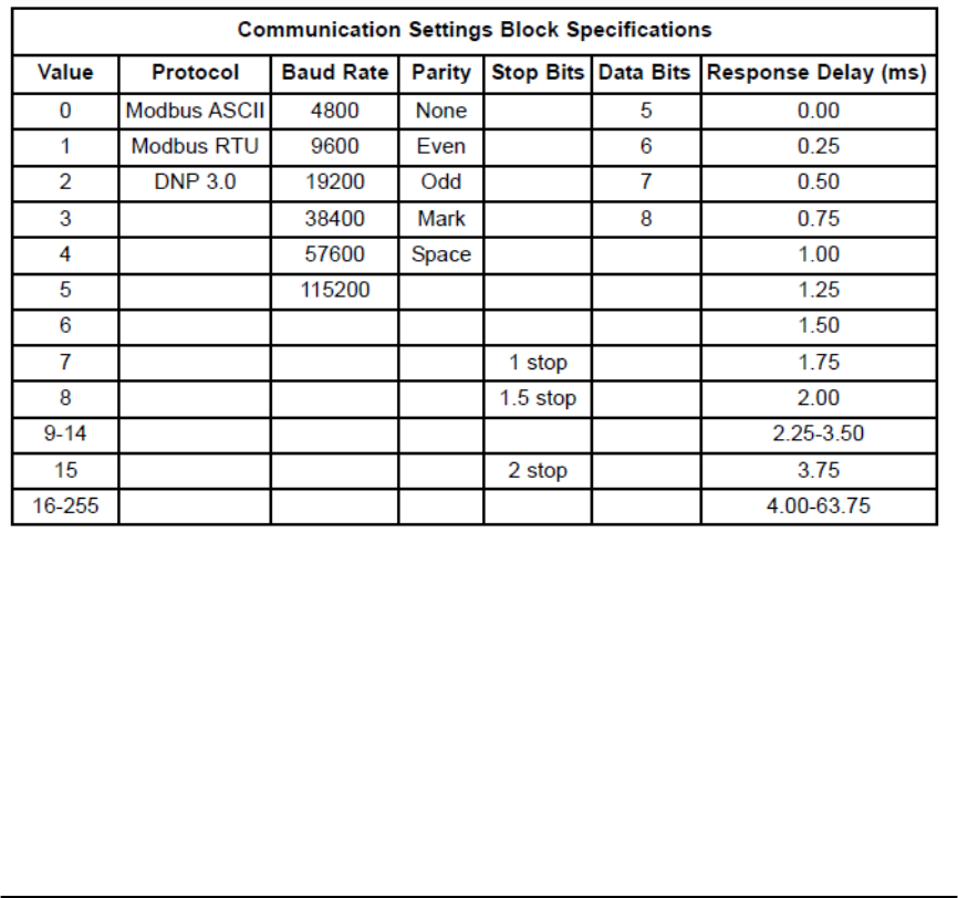
E Electro Industries/Gauge Tech Doc# E154703 7-1
Chapter 7
Nexus®1500 Meter Programmable Settings Blocks
Chapter 2 contains the Nexus® 1500 meter’s Modbus Register Map. This chapter gives
a detailed description of each of the Programmable Settings Blocks.
7.1: Communication Settings Block (45057-45074)
Device Address - 2 bytes, unsigned integer, ranging from 0000H to FFFFH
Protocol - 1 byte, unsigned integer.
Baud Rate - 1 byte, unsigned integer.
Parity - 1 byte, unsigned integer.
Stop Bits - 1 byte, unsigned integer.
Data Bits - 1 byte, unsigned integer.
Response Delay - 1 byte, unsigned integer.
Port Mode - 1 byte, unsigned integer. The value 1 means Master; value 0 means Slave.
Port 1 is always a Slave.
7.2: Limit Settings Block (45077-45204)
Limit Comparisons - Internal Representations
A Nexus® meter has 32 Limits Objects.
Each Limit Object performs two independent comparisons with a selected computed
value and combines them into a combined output. Information needed to perform these
actions: channel identification, comparison values, comparison directions and
combination type.

E Electro Industries/Gauge Tech Doc# E154703 7-2
Channel identification is performed by referencing the internal data table of the meter, by
specifying the Line Number and Point Number for a particular value. For example: to
monitor 1 second VAN values, use Line 34, Point 0; 1 second VBN, use Line 34, Point 1;
1 second IA, use Line 36, Point 0; Thermal Average VAN, use Line 51, Point 0. To leave
a Limit unassigned, use Line 65535, any point.
Comparison values are entered using percentages relative to the programmed full scales
of the system. For VAN, the phase-to-neutral Voltage Full Scale would be referenced. If
it is programmed to 120.0 V secondary with a phase voltage PT of 120:1, then a
comparison of 13.2 kV primary would be a limit of 108 V secondary or 90.00% of the
Full Scale. A 90.00% comparison for IA with a phase Current Full Scale of 5.0 A
secondary and a phase current CT of 2000:5 would be a comparison of 4.5 A secondary
or 1800 A primary. Negative percentages would be used where appropriate (Watts,
VAR, etc.). Special cases like PF and KF would depend on fixed internal Full Scales.
Human interfaces could represent this in terms of quadrature and angle, instead of the
internal percentage representation.
Each comparison has a direction associated with it - Above or Below. A 90.00%
comparison could be for above 90.00% or below 90.00%.
Finally, each limit object is able to produce a third output which is a combination of the
two comparisons. This combination could be an AND, OR, NAND, NOR, XOR or
Hysteresis. So, a user can produce a band of between 40.00% and 80.00% by combining
above 40.00% AND below 80.00%; over 110.00%/under 90.00% alarms by combining
above 110.00% OR below 90.00%, on after over 110.00%, off after below 90.00% by
combining above 110.00% and below 90.00% with Hysteresis.
The structure for a combination is :
2 byte Line Number
1 byte Point Number
1 byte Direction and Combination (SAB)
2 byte Comparison 1 Percentage (Value 1)
2 byte Comparison 2 Percentage (Value 2)
Total of 8 bytes per Limit Object, total of 256 bytes for 32 Limit Objects.
The structure for the Direction and Combination byte is:
Bits 7-5 Unused, set to 0
Bit 4 Negate combination (AND -> NAND, etc.)
Bits 3-2 00 = AND combination
01 = OR combination
10 = XOR combination
11 = Hysteresis combination
Bit 1 0 = Comparison 2 is below
1 = Comparison 2 is above
Bit 0 0 = Comparison 1 is below
1 = Comparison 1 is above
Hysteresis combination uses comparison 1 to set the combination, and comparison 2 to
clear the combination. If both inputs are asserted, comparison 1 has priority. The usual
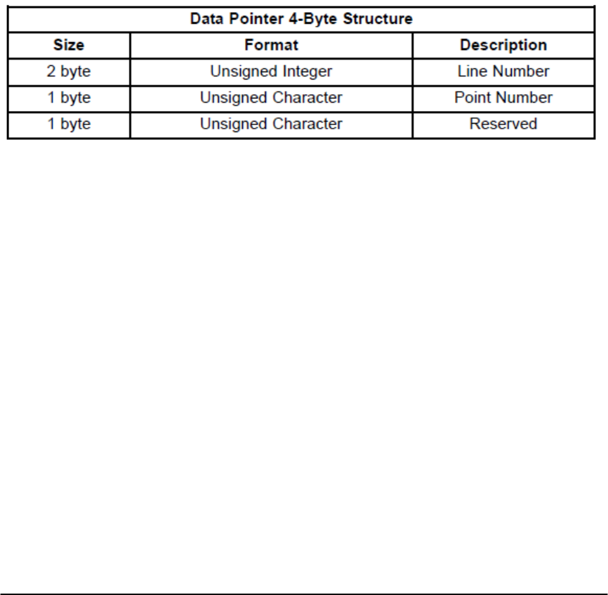
E Electro Industries/Gauge Tech Doc# E154703 7-3
arrangement would be to program comparison 1 to above a large value and comparison 2
to below a small value. When the monitored value goes above comparison 1, the
combination will be set to a 1, until the monitored value goes below comparison 2, when
the combination will be cleared to a 0.
Poll-able information would consist of:
32 bits Comparison 1 states for 32 limits
32 bits Comparison 2 states for 32 limits
32 bits Combination states for 32 limits
Total of 96 bits (12 bytes)
7.3 Historical Log Settings Block (45205-45464)
Historical Log 1 Data Pointers (45205 - 45332), Historical Log 2 Data Pointers (45333 - 45460).
These registers indicate which information to include in a record in the Historical Log.
Each Data Pointer has the following 4 (four) byte structure:
A Line Number is an index into the Communication Table. Example: Line Number 11 is
for the 12th line in the Communication Table, 0.1 second Phase-to-Neutral Voltages.
Data Pointers with Line Numbers greater than the number of lines in the table are
ignored.
A Point Number is an index into a Line in the Communication Table. Example: Point
Number 1 is for the second entry in a Line. Line Number 11, Point Number 1 is the 2nd
in the 12th line, 0.1 second VBN. Data Pointers with Point Numbers greater than the
number of points for the line are ignored.
Snapshot Interval for Historical Log 1 (45361), for Historical Log 2 (45462).
One register, 2 byte unsigned integers ranged from 0 to 3600.
The unit is 1 Second.
Historical Log 1 Record Size (45463), Historical Log 2 Record Size (45464).
This register is an enumeration for the size of a record in the Historical Log. The valid
values are:
0x00004 = 16 byte records
0x00000 = 32 byte records
0x00001 = 64 byte records
0x00002 = 128 byte records
0x00003 = 256 byte records
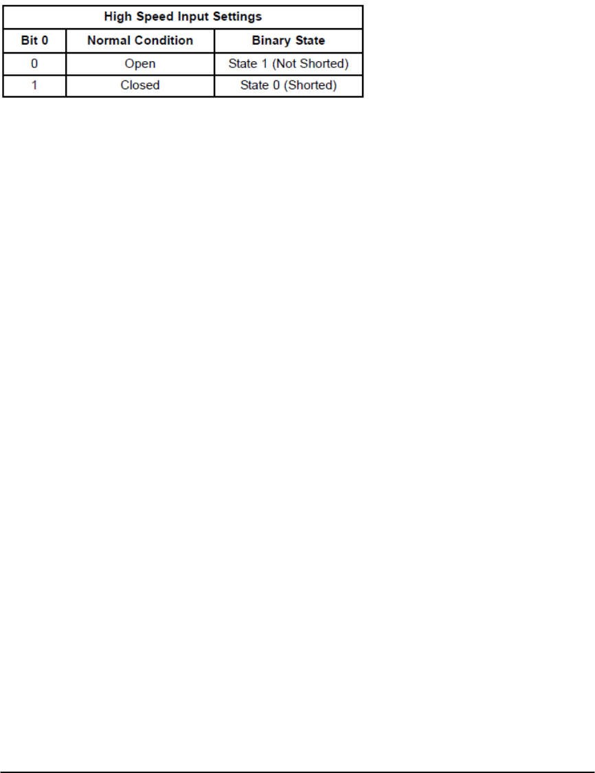
E Electro Industries/Gauge Tech Doc# E154703 7-4
7.4: High Speed Inputs Settings Block (45501-45723)
Input Name - 8 registers, 16 bytes, 16 characters for the name.
Input Open Label - 8 registers, 16 bytes, 16 characters for label, Not Shorted, State 1.
Input Closed Label - 8 registers, 16 bytes, 16 characters for label, Shorted, State 0.
Input Value - 2 registers, currently not used.
Input Mode - Bit 0 will define the normal condition of the input.
7.5: Registers 45724-45728 are not used by the Nexus® 1500 meter
7.6: External Digital Output Module Settings Block (45729-45808)
Up to 4 External Digital Output Modules can be addressed in this block.
Address - 2 bytes, unsigned integers.
A value of 0x0FFFF for an address indicates that this device is unused.
Line Number - 2 bytes, unsigned integers.
Point Number - 1 byte, unsigned integers.
Line Number and Point Number will point which limit is going to be used for the relay of
the External Digital Output Module.
7.7: Registers 45809-45812 are not used by the Nexus® 1500 meter
7.8: External Analog Output Module Settings Block (45813-45892)
Up to 4 External Analog Output Modules can be addressed in this block.
Address - 2 bytes, unsigned integers.
A value of 0x0FFFF for an address indicates that this device is unused.
Line Number - 2 bytes, unsigned integers.
Point Number - 1 byte, unsigned integers.
Line Number and Point Number will point which limit is going to be used for each output
of the External Analog Output Module.
7.9: External KYZ Output Module Settings Block (45893-45907)
Up to 4 External KYZ Output Modules can be addressed in this block.
Address - 2 bytes, unsigned integers.
A value of 0x0FFFF for an address indicates that this device is unused.
The energy assignments are as follows:
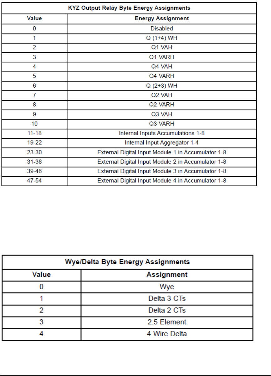
E Electro Industries/Gauge Tech Doc# E154703 7-5
7.10: CT & PT Ratio Settings Block (45909-45924)
Address - 2 registers, 4 bytes, unsigned integers.
Primary numbers and secondary numbers are in these blocks for the proper ratios.
7.11: Hookup and Time Settings Block (45925-45944)
Hookup - 1 register, 2 bytes.
High byte - Configuration Bits. Voltage selection.
When bit 0 is cleared, 150V.
When bit 0 is set, 300V.
Low byte - Wye/Delta selection.
Frequency - currently not used.
Time Zone - 1 register, 2 bytes. Signed integer. The zone descriptor value varies from -
13 to +13. The zone descriptor value 0 represents Greenwich Mean Time.
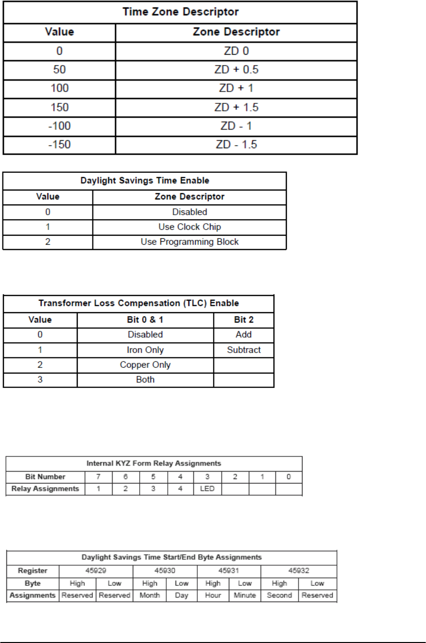
E Electro Industries/Gauge Tech Doc# E154703 7-6
Daylight Savings Time Enable - 1 byte, unsigned integer.
Transformer Loss Compensation (TLC) Enable - 1 byte, unsigned integer.
Internal KYZ Form - 1 byte bit map.
Refer to the Internal KYZ Settings Block (46330) for more detail.
A bit value of 0 = Form C = Pulse of the relay.
A bit value of 1 = Form A = Transition of the relay.
Daylight Savings Time Start/End.
Address - 4 registers, 8 bytes. Each byte has unsigned integer values (example
below).
% Loss of Watt or VAR
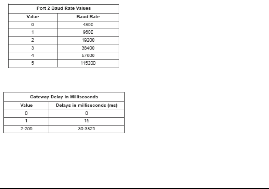
E Electro Industries/Gauge Tech Doc# E154703 7-7
Address - 2 registers, 4 bytes, 2 bytes for integers and 2 bytes for fractions.
7.12: Average Settings Block (45949-45952)
Thermal and Block Averaging Time Interval: 1 register, 2 bytes unsigned integer. The
unit is in 1 second.
Rolling Average Sub-Interval: 1 register, 2 bytes unsigned integer.
Predictive Rolling Window Average: 1 register, 2 bytes unsigned integer.
Number of Sliding Windows - 1 byte, unsigned integer.
Time of Use Log Enable - currently not used.
7.13: Exception Profile Block (45953-45968)
This block is not yet defined.
7.14: Device Label Settings Block (45969-45992)
Meter Designation - 8 registers, 16 bytes Hex ASCII.
Auxiliary Voltage Label - 8 registers, 16 bytes Hex ASCII.
Measured Neutral Current Label - 8 registers, 16 bytes Hex ASCII.
7.15: Network Settings Block (45993-46016)
IP Address - 2 registers, 4 bytes. Each byte has unsigned integer value.
Subnet Mask - 2 registers, 4 bytes. Each byte has unsigned integer value.
Default Gateway - 2 registers, 4 bytes. Each byte has unsigned integer value.
Port 2 Baud Rate - 1 byte, unsigned integer.
Gateway Delay - 1 byte, unsigned integers.
Mode 1 - Network Mode 1. 1 register, only High Byte is used.
Bit 7: IP Address Resolution
A bit value of 1 means use DHCP server.
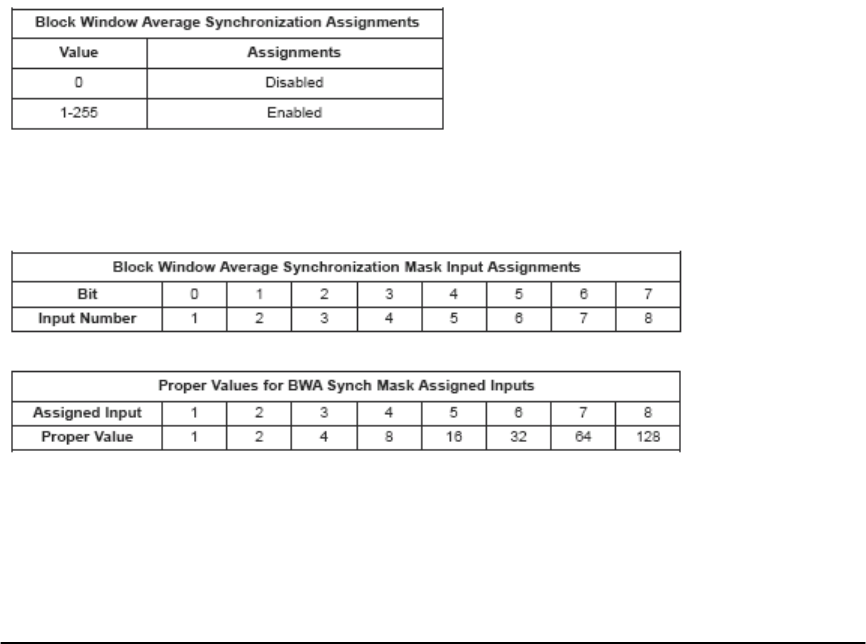
E Electro Industries/Gauge Tech Doc# E154703 7-8
A bit value of 0 means use IP address of
NEXUS/EEPROM.
Bits 0-6: Reserved
· Computer Name - 8 registers, 16 bytes Hex ASCII.
· Server IP Address - 2 registers, 4 bytes. Each byte has unsigned integer values.
Mode 2 - Network Mode 2. 1 byte.
Bit 7: IP Address Resolution
A bit value of 0 means use IP address of
NEXUS/EEPROM.
Bits 0-6: Reserved
· DNS Server 1 IP Address - 2 registers, 4 bytes. Each byte has unsigned integer
values.
· DNS Server 2 IP Address - 2 registers, 4 bytes. Each byte has unsigned integer
values.
· Server / Service Enable Bits - 32 Bits - Reserved for future use.
· The next 4 bytes are undefined.
7.16: Block Window Average External Synchronization Block (46017)
BWA Synch Enable - 1 byte.
Instead of using the time interval, the Nexus® meter can calculate the Thermal
and Block average when the pulse is detected on one of the High Speed Inputs.
BWA Synch Mask - 1 byte. Only one input can be selected at a time. That means only
one of the 8 bits can be set at a time.
Proper Value for each Assigned Input:
7.17: Display Configuration Block (46018)
1 register, 2 bytes.
Bit 15: Only applies to the voltage reading.
A bit value of 1 = Primary voltage displayed.
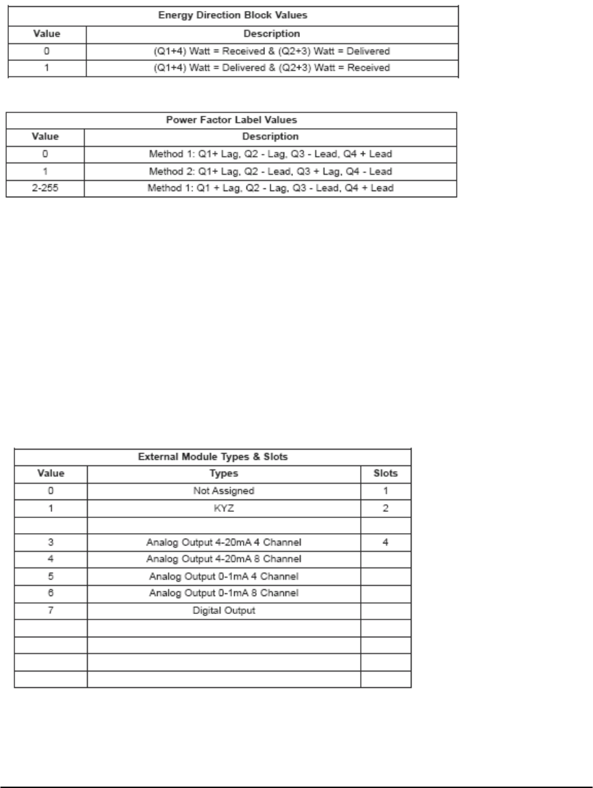
E Electro Industries/Gauge Tech Doc# E154703 7-9
A bit value of 0 = Secondary voltage displayed.
Bit 0-14: Reserved.
7.18: Energy Direction Block (46019)
Received Energy Direction - 1 register, High byte only.
Power Factor Labeling - 1 register, Low Byte only.
7.19: Register 46020 is not used by the Nexus® 1500 Meter
7.20: Full Scale Block (46021-46036)
2 registers, 4 bytes - 2 bytes integers and 2 bytes fraction values.
7.21: External Module Software Interface Block (46053-46196)
External Module Types - 1 byte value, unsigned integer.
External Module Slots - 1 byte value, unsigned integer.
External Module Label - 8 registers, 16 bytes. Hex ASCII.
7.22: External Module Port Assignment Block (46197-46206)
Port Assignment bytes are enumerated as in the following table:
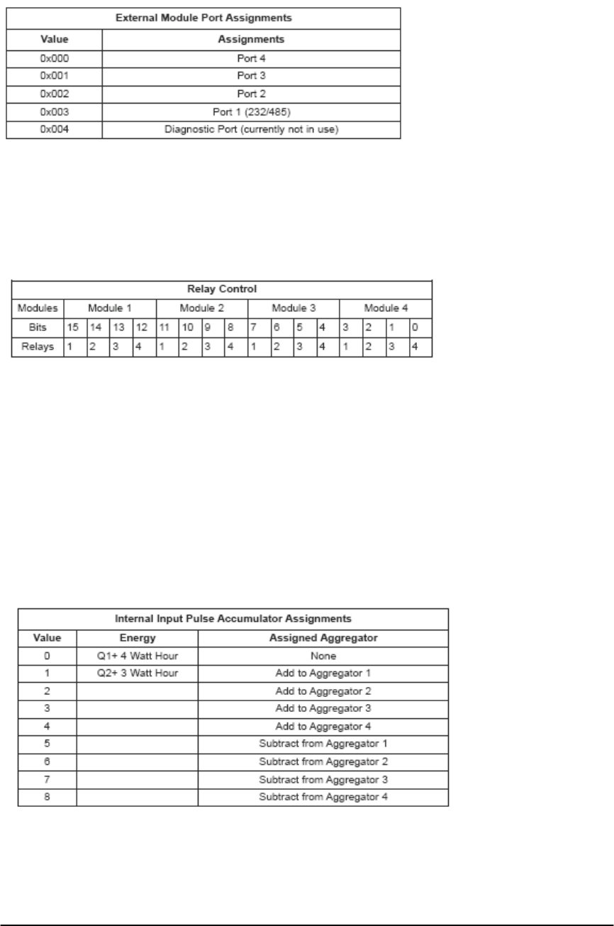
E Electro Industries/Gauge Tech Doc# E154703 7-10
7.23: Manual Control Relay Block (46207-46208)
Manual Control Relay Settings: 1 register, 2 bytes.
Up to four Relay Output Modules can be attached to a Nexus® meter. A Total of
16 Relays can be controlled. The table below indicates which bit controls which relay.
A bit value of 1 means Manual Relay Control Only.
A bit value of 0 means ElectroLogic and Manual Relay Control.
Flicker Log - Reserved for future use.
7.24: Internal Input Pulse Accumulation Scale Factor Block (46209-
46325)
Scale Factors - 2 registers, 4 bytes unsigned integers.
Aggregator Assignments - 1 byte unsigned integers.
Pulse Accumulation Labels - 8 registers, 16 bytes. Hex ASCII.
Nexus® Meter Watt hour Selection - 1 byte unsigned integer.
Aggregation Assignment - 1 byte unsigned integer.
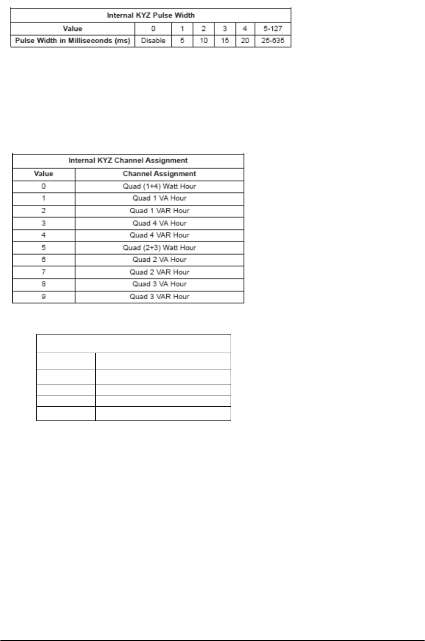
E Electro Industries/Gauge Tech Doc# E154703 7-11
7.25: I2t and V2t Threshold Block (46326-46329)
I squared T - 2 registers, 4 bytes. 2-byte integers, 2-byte fractions. Secondary Current
Value.
V squared T - 2 registers, 4 bytes. 2-byte integers, 2-byte fractions. Secondary Volt
Value.
7.26: Internal KYZ Settings Block (46330-46372)
Internal KYZ Enable Assignment
Bit Assignment
Bit 7 Relay 1/Pulse 1 LED
Bit 6 Relay 2/Pulse 2 LED
Bit 5 Relay 3
Bit 4 Relay 4
Internal KYZ Pulse Width - 1 byte, unsigned integer.
Internal KYZ Channel Assignment - 1 byte, unsigned integer.
Internal KYZ Watt Hour per pulse - 2 registers, 4 bytes, 2 byte integer, 2 byte fraction.
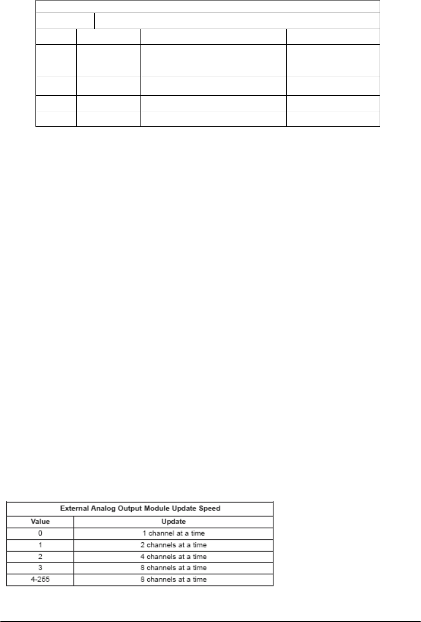
E Electro Industries/Gauge Tech Doc# E154703 7-12
End of Interval Pulse
Byte
Value Enable Relay Width (milliseconds)
0 Disable Pulse Internal Relay 1/Pulse 1 LED 5ms
1 Enable Pulse Internal Relay 2/Pulse 2 LED 10ms
2 Internal Relay 3 15ms
3 Internal Relay 4 20ms
4-126 25ms-635ms
Internal KYZ Enable - 1 byte.
A bit value of 1 = KYZ is enabled.
A bit value of 0 = KYZ is disabled.
End of Interval Pulse - The meter can generate a pulse upon completion of a block
window interva1. This pulse is generated on one of the relays and the pulse width is
selectable.
7.27: Internal Input Pulse Accumulation Unit Label Block (46373-46420)
4 registers, 8 bytes. These labels are used to describe the units a pulse represents. Units
are usually one word and are 8 characters or less.
Examples of Units: Gallons, BTUs, Liters, Wh, kWh, VAh, etc.
7:28: Registers 46421-46804 are not used by the Nexus® 1500 Meter.
7.29: Limit Profile Label Block (46805-47060)
8 registers, 16 bytes. 16 characters
7.30: External Analog Output Module Channel Update Block (47061-
47062)
This block is added to improve the update speed of what is sent to the External Analog
Output Modules from the meter. Not all channels of the External Analog Output Module might
be in use. The value indicates the number of External Analog Output Module channels that are
refreshed per Modbus message. In the older versions of External Analog Output Modules, only
one channel update was possible at a time.
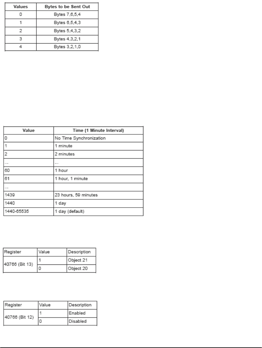
E Electro Industries/Gauge Tech Doc# E154703 7-13
7.31: Miscellaneous DNP Settings Block (47063-47104)
Scale for Analog Output of Average Pulse Accumulation - 1 byte unsigned integer.
Pulse accumulation values are 8-byte. But the Analog Output Module can accept 4-byte
quantity. Therefore, only 4 bytes out of 8 bytes will be sent to Analog Output Module. This
register decides which 4 bytes will be sent out.
Energy in the Interval - 1 byte unsigned Integer. This is the Interval Time for Energy in
the Interval. Unit is in minutes. Range is from 60 to 0.
DNP Time Synchronization Enable - 1 byte. Register Address 47064 (Lower Byte).
A value of 1 means that DNP Time Synchronization is enabled
A value of 0 means that DNP Time Synchronization is disabled
DNP Time Synchronization Time Interval - 1 register, 2 bytes. Register Address 47065.
Bitmap
Bit 13: Choice of Class 0 poll between Object 20 and Object 21
Bit 12: Enable DNP Freeze Schedule
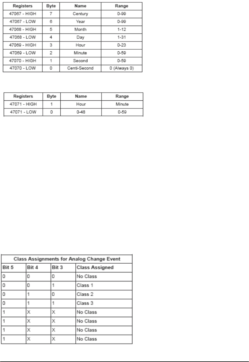
E Electro Industries/Gauge Tech Doc# E154703 7-14
DNP Freeze Date & Time - 4 registers, 8 bytes.
DNP Freeze Interval - 1 register, 2 bytes.
7.32: Custom DNP Definition Block for Analog Input (Object 30) (47105-
47360)
Line number: 2-byte unsigned integer
Line number and Point number will indicate the Analog Input value to be used
for one of the point in Object 30.
Point number: 1-byte unsigned integer
Reserved: 1 byte. Reserved for future use.
DeadBand: 2-byte signed number (Percentage)
Range: +327.67% 327.6/ 8% -
Unit: 0.01%
If the Current Analog Value is different from the Previous value by more than
Deadband percentage, the meter will generate Analog Change Event value if it is assigned to any
Class.
Class assignments (Currently only bits 5,4 and 3 are used): 8-bit bitmap
When bit 5 is set, the Analog Change Event value will not be generated.
When bit 5 is clear, bit 4 and bit 3 will assign the Analog Change Event value to
a Class.
Reserved: 1 byte. Reserved for future use.
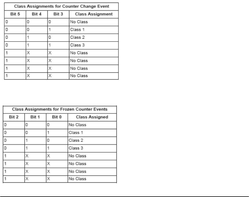
E Electro Industries/Gauge Tech Doc# E154703 7-15
7.33: Custom DNP Definition Block for Binary Counter (Object 20)
(47361-47424)
Line number: 2-byte unsigned integer
Line number and Point number will indicate the Binary Counter value to be used
for one of the point in Object 20.
Point number: 1-byte unsigned integer
Scaling: 1-byte unsigned integer
Range: 0-15
The meter has an 8-byte Binary Counter Value, while DNP can only give a 4-
byte value. By using this scaling, the user can get the proper range of data. The scaling value
represents the power of 10.
Delta Values: 4-byte unsigned integer
If the Current Binary Counter value is different from the Previous value more
than Delta values, the Counter Change Event value will be generated if it is assigned to a Class.
Class assignments (Currently bits 5,4,3,2,1 and 0 are used): 8-bit bitmap
When bit 5 is set, the Counter Change Event value will not be generated.
When bit 5 is clear, bit 4 and bit 3 will assign the Counter Change Event value to
a Class.
When bit 2 is set, the Frozen Counter Event value will not be generated.
When bit 2 is clear, bit 1 and bit 0 will assign the Frozen Counter Event value to
a Class.
Reserved: 7 bytes. Reserved for future use.
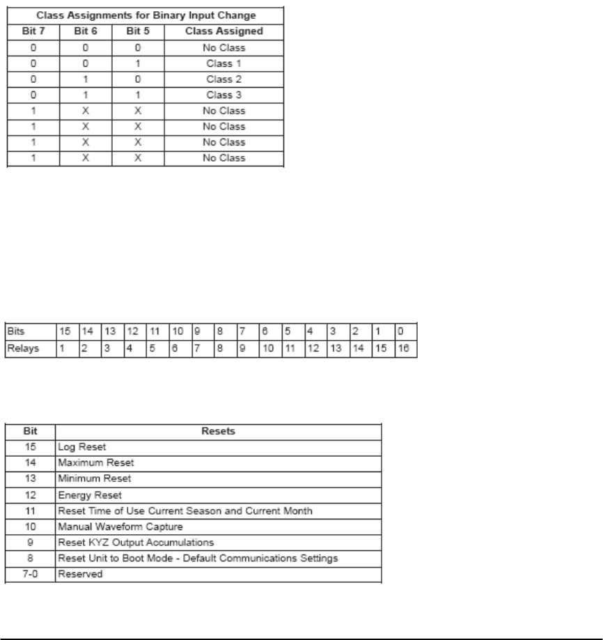
E Electro Industries/Gauge Tech Doc# E154703 7-16
7.34: Custom DNP Definition Block for Binary Input (Object 1) (47425-
47456)
Line number: 2-byte unsigned integer
Line number and Point number indicate the Binary Input value used for 8 points
in Object 1.
Point number: 1-byte unsigned integer
Class Assignments: 8-bit bitmap (1 byte). Bit 7, 6 and 5 will assign the Binary Input
Change value to a Class. Bit 4 to bit 0 are not used.
Reserved: 4 bytes. Reserved for future use.
7.35: Custom DNP Definition Block for Binary Output (Object 10)
(47457-47458)
Enable / Disable Relays (1-16) (2 bytes):
0: Relay disabled
1: Relay enabled
Enable / Disable Resets (17-24) (1 byte):
0: Reset disabled
1: Reset enabled

E Electro Industries/Gauge Tech Doc# E154703 7-17
7.36: Custom DNP Definition Block for Global Values (47459-47463)
When the master requests data from the object, it can specify the variation in the request
so the master can get the data formatted for its use. When the master asks for Variation 0, the
slave meter can respond with any variation(s). This Programmable Setting holds the variations
available for a Variation 0 request.
7.37: Registers 48641-48768 are not used by the Nexus® 1500 Meter.
7.38: Registers 48769-49024 are not used by the Nexus® 1500 Meter.
7.39: Registers 49025-49792 are not used by the Nexus® 1500 Meter.
7.40: External Digital Output Module Labels Block (49793-50176)
8 registers, 16 bytes.
Each relay, normally open, and normally closed can be named with 16
characters.
They are 4 of each and up to 4 modules.
7.41: Registers 50177-50268 are not used by the Nexus® 1500 meter.
7.42: Customizable Modbus Map Settings Block.
Using this block, you can customize up to 256 readings. All the readings that are
customized in this block can be seen in the Customized Modbus Map Window Block (12289).
Line Number - 2 bytes.
Point Number - 1 byte.
Reserved - 1 byte. Currently not used.
You can select any Register or Group of Registers that has a Line Number and a Point
Number from the Modbus Register Map. Those selections are used to create a customized grid of
up to 256 readings in the Communicator EXT Device Profile.
Example:
In order to read 1 Cycle Phase A-N Voltage as Item Number 1 on your Customized
Modbus Map, you would enter for Item 1:
Line Number 10 and Point Number 0.Refer to the Communicator Ext User Manual for
details on the creation of your Customized Modbus Map.

E Electro Industries/Gauge Tech Doc# E154703 7-18
7.43: Registers 50785-51154 are not used by the Nexus® 1500 Meter.
7.44: DNP LAN/WAN (51157-51195)
DNP LAN/WAN Bitmap
7
6
5
4
3
2
1
0
Mode - 1 byte unsigned integer.
Bitmap Set - 8-bit bitmap.
Bit 7: TCP Enable
A value of 0 means DNP over TCP listening point disabled.
A value of 1 means DNP over TCP listening point enabled.
Bit 6: UDP Enable
A value of 0 means DNP over UDP end point disabled.
A value of 1 means DNP over UDP end point enabled.
Bit 5: Validate Client Point
A value of 0 means No validation and any port is accepted.
A value of 1 means Validate connections against the first 1-4 entries.
Bit 4: UDP Response Behavior
A value of 0 means Respond to Client Port.
A value of 1 means Respond to programmed UDP respond port.
Bit 3 to Bit 0: Reserved
UDP Addressing - 1 byte unsigned integer.
Validate Connection Count - 1 byte unsigned integer.
TCP Listen Port - Two byte unsigned integer. TCP listening port.
UDP Listen Port - Two byte unsigned integer. UDP listening port.
Valid IP Address 1,2,3,4 - Four 4 byte IP address. Each byte is 1 unsigned
integer. These are IP addresses for validating TCP connections and UDP
datagram s.
Valid IP Subnet Mask 1,2,3,4 - Four 4 byte IP address. Each byte is unsigned
integer. These are IP subnet masks for validating TCP connections and UDP
datagram s.
TCP Starting Valid Client Ports - Four 2 byte unsigned integers. These are
Starting Client ports for validating TCP connections.
TCP Ending Valid Client Ports - Four 2 byte unsigned integers. These are
Ending Client ports for validating TCP connections.
UDP Starting Valid Client Ports - Four 2 byte unsigned integers. These are
Starting Client ports for validating UDP datagrams.
UDP Ending Valid Client Ports - Four 2 byte unsigned integers. These are
Ending Client ports for validating UDP datagrams
Multicast Group Address - Reserved for future use.

E Electro Industries/Gauge Tech Doc# E154703 7-19
UDP Respond Port - 2 byte unsigned integer. A value of 0 means respond to
Client port. A value of 1 means respond to programmed UDP response port.
7.45: Registers 51196-51200 are not used by the Nexus® 1500 Meter.
7.46: Customizable Modbus Map Format Block (51201-51712)
Using this block, you can customize up to 256 readings. All the readings that are
customized in this block can be seen in the Customized Modbus Map Window Block
(12289).
· Line Number - 2 bytes.
· Point Number - 1 byte.
· Reserved - 1 byte. Currently not used.
You can select any Register or Group of Registers that has a Line Number and a Point
Number from the Nexus® Modbus Register Map. Those selections are used to create a
customized grid of up to 256 readings in the meter’s Communicator EXT Device Profile.
Example: In order to read 1 Cycle Phase A-N Voltage as Item Number 1 on your
Customized Modbus Map, you would enter for Item 1: Line Number 10 and Point
Number 0.
Refer to the Communicator EXT User Manual for details on creating a Customized
Modbus Map.
7.47: Registers 51713-51738 are not used by the Nexus® 1500 Meter.
7.48: Waveform, Transient, and PQ Settings
RMS Set Points
The Set Points control at what RMS voltage or current above or below the Full Scale
value a waveform capture or PQ event occurs. The values are given in percentage of Full
Scale, where each count is equal to 0.01%. So for example:
Voltage P-N Full Scale: 120v
Set Point Value: 11070
Set Point Percentage: 110.70%
RMS Set Point: 132.84v
Each Set Point value is a 2 byte signed integer. The Below Set Point is used to
configure sag detection, and the Above Set Point is used to configure swell detection.
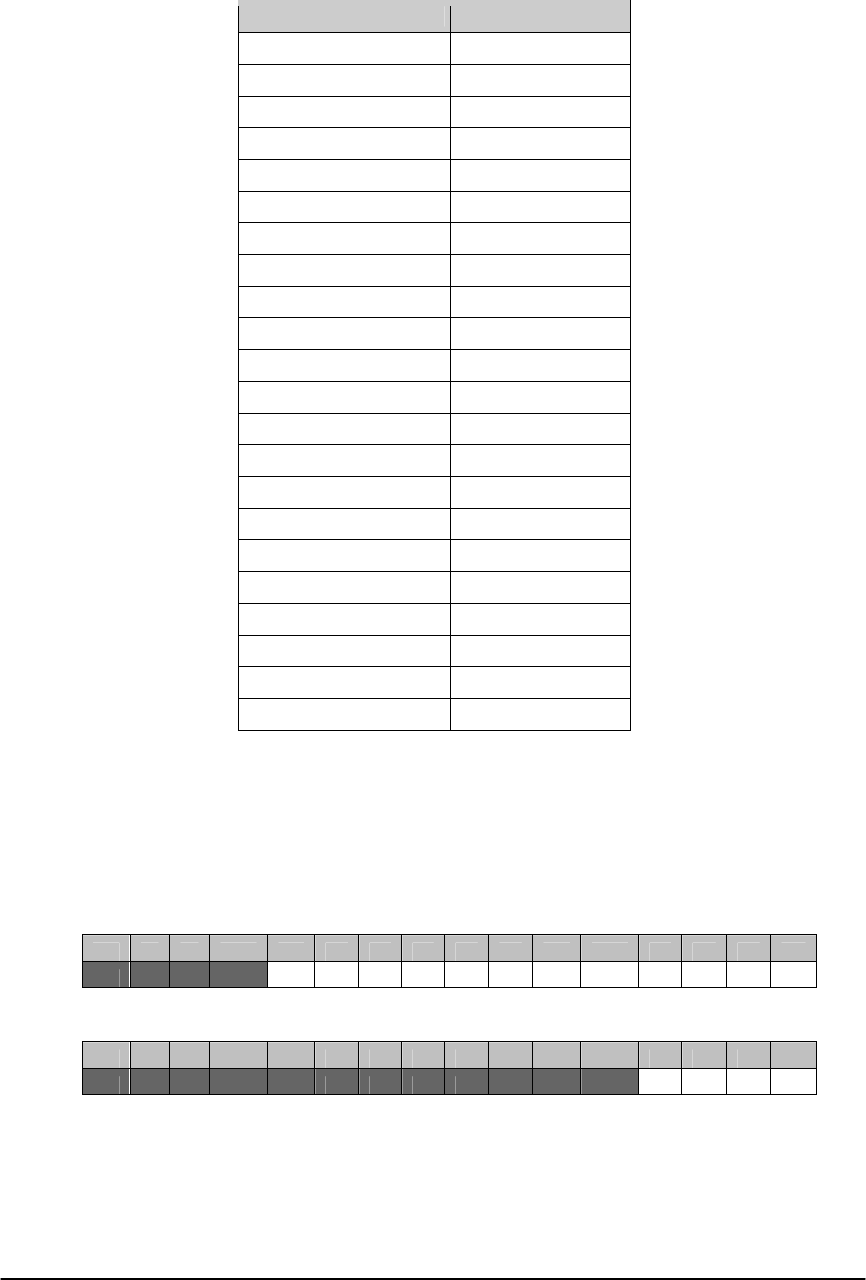
E Electro Industries/Gauge Tech Doc# E154703 7-20
Below is the table of Set Points:
Set Point Modbus Address
Volts AN Below 0xB198
Volts BN Below 0xB199
Volts CN Below 0xB19A
Volts AB Below 0xB19B
Volts BC Below 0xB19C
Volts CA Below 0xB19D
Volts XN Below 0xB19E
Volts AN Above 0xB1A4
Volts BN Above 0xB1A5
Volts CN Above 0xB1A6
Volts AB Above 0xB1A7
Volts BC Above 0xB1A8
Volts CA Above 0xB1A9
Volts XN Above 0xB1AA
IA Below 0xB1B0
IB Below 0xB1B1
IC Below 0xB1B2
IN Below 0xB1B3
IA Above 0xB1B4
IB Above 0xB1B5
IC Above 0xB1B6
IN Above 0xB1B7
Note: registers 0x7928 – 0x7929 must be set to zero for the Set Points to work.
RMS Waveform Sag and Swell Limit Enables
Enables or disables waveform capture on the specified channel for sags and swells. A
value of 1 enables capture for sags and swells, a value of 0 disables capture. Both sags and
swells must be enabled together.
Voltage Enables (register 0xB1B8)
Bit # 15 14 13 12 11 10 9 8 7 6 5 4 3 2 1 0
XE CE BE AE NE XN CA BC AB CN BN AN
Current Enables (register 0xB1BA)
Bit # 15 14 13 12 11 10 9 8 7 6 5 4 3 2 1 0
N C B A
Waveform Capture Count (register 0x7570-0x7571)
Controls the number of records captured when a waveform event occurs. Since the
maximum size of a single waveform record is 180 cycles (apx 3 seconds at a nominal
60hz), to perform a larger capture you need to capture multiple records. The value is + 1,
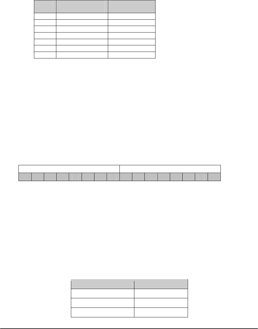
E Electro Industries/Gauge Tech Doc# E154703 7-21
so a value of 0 results in 1 record, a value of 10 results in 11 records, and so on. The
maximum number of captures is 65525.
Waveform Capture Sample Rate (register 0x7574)
Controls the number of samples per nominal 60hz cycle stored in the waveform
capture. Decreasing this can decrease the size of the record, allowing more captures.
Additionally, the maximum number of Cycles per Capture is affected by the sample rate, as
shown below:
Value Samples per 1/60th
of a second Maximum Cycles
per capture
0 16 180
1 32 180
2 64 180
3 128 180
4 256 120
5 512 60
6 1024 40
CompressionFactor(0x758C)mustbesettomatch.
Pre-Trigger Cycles (register 0x7575 – High Byte)
The number of cycles to be included in the waveform capture from prior to the
triggering cycle. Must be between 1 and 179, and the sum of pre and post triggers must be
<= the Max Cycles controlled by Sample Rate.
Post-Trigger Cycles (register 0x7575 – Low Byte)
The number of cycles to be included in the waveform capture after the triggering cycle.
Must be between 1 and the Max Cycles – Pre-Trigger.
Internal Input Trigger Enables (register 0x7576)
Enables or disables waveform and pq capture on internal input triggers. A value of 1
enables triggers on that input, a value of 0 disables triggers on that input.
Waveform Trigger Enable Power Quality Trigger Enable
1 2 3 4 5 6 7 8 1 2 3 4 5 6 7 8
Transient Set Points (register 0x7578 - 0x757A)
The Transient Set Points control at what voltage magnitude a Transient capture will be
triggered. Note that Transients are triggered by the sample value, not the cycle RMS. As
such, the minimum allowed value for WYE hookup is 250%, and for DELTA hookup is
144.2%. The values are given in percentage of Full Scale, where each count is equal to
0.1%. So for example:
Voltage P-N Full Scale: 120v
Set Point Value: 3100
Set Point Percentage: 310.0%
Voltage Set Point: 372v
Each Set Point value is a 2 byte signed integer. Set Points are applied to both Positive
and Negative Triggers. Below is the table of Set Points:
Set Point Modbus Address
Volts A 0x7578
Volts B 0x7579
Volts C 0x757A
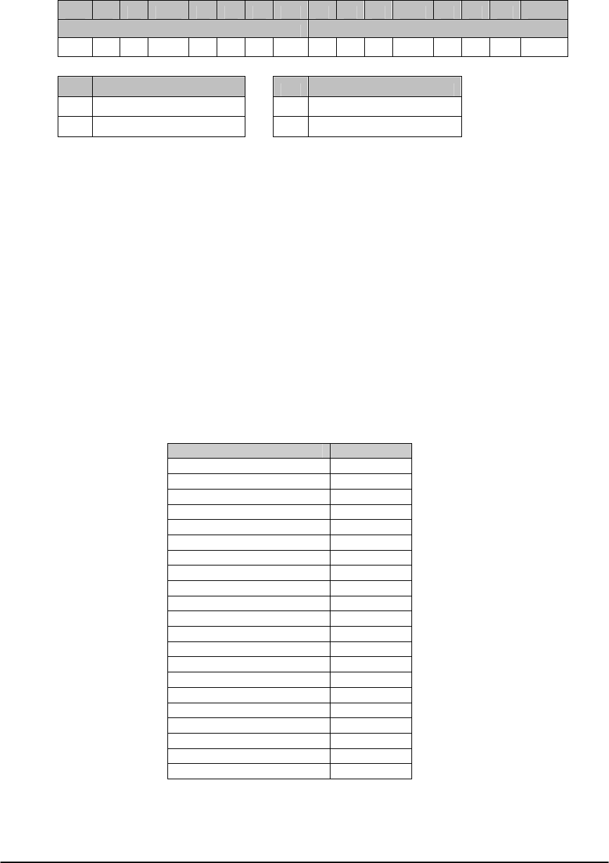
E Electro Industries/Gauge Tech Doc# E154703 7-22
Transient Enable Settings (register 0x757B)
Controls which channels Transients are triggered on.
Bit # 15 14 13 12 11 10 9 8 7 6 5 4 3 2 1 0
Channel Enables Modes
VC VB VA M1 M0
M1 Transient Mode M0 Transient Enable
0 Phase to Neutral 0 Disabled
1 Phase to Phase 1 Enabled
Channel Enables controls which channels Transients are triggered on.
Transient Mode controls if the Phase to Neutral Voltages are used, or if the Phase to
Phase voltages are used. Only one may be selected.
Transient Enable controls if Transient Capture is enabled at all. Note that if transients
are enabled, the waveform channels selected (Waveform Channel List) must use the
Transient Voltage channels (77-79).
Waveform Channel Selection Count (register 0x757C)
The number of channels to be included in a waveform capture. This doesn't have to be
the same number of trigger channels.
Waveform Channel Selection List (register 0x757D - 0x758B)
The list of channels to be included in a waveform capture. Up to 15 channels may be
selected, though the first channel must always be Channel 80 (High Speed Inputs). The list
of channels do not have to be the same as the trigger channels. Each channel is a 2 byte
ID, shown below:
Channel Name Channel ID
High Speed Inputs 80
Volts AN 0
Volts BN 1
Volts CN 2
Volts AB 3
Volts BC 4
Volts CA 5
Volts XN 6
Volts NE 36
Volts AE 32
Volts BE 33
Volts CE 34
IA 37
IB 38
IC 39
IN 40
Volts Residual 7
I Residual 8
Transient Volts AN/AB 77
Transient Volts BN/BC 78
Transient Volts CN/CA 79
Note: If Transients are enabled, the Transient Voltage channels (77-79) must be
selected over the regular Waveform Voltage channels (0-5).
Waveform Compression Factor (register 0x758C)
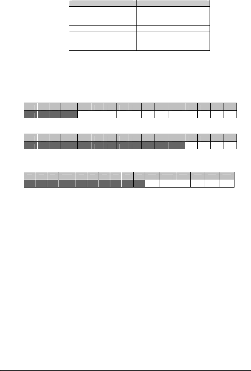
E Electro Industries/Gauge Tech Doc# E154703 7-23
Must be set to match the Waveform Sample Rate.
Compression Factor Value Samples per 1/60th of a second
0 16
1 32
2 64
3 128
4 256
5 512
6 1024
PQ Trigger Enables (register 0x758D - 0x758E)
Enables or disables PQ Event triggering on individual channels. A value of 1 enables
triggering, a value of 0 disables triggering.
Voltage PQ Enables (register 0x758D)
Bit # 15 14 13 12 11 10 9 8 7 6 5 4 3 2 1 0
XE CE BE AE NE XN CA BC AB CN BN AN
Current PQ Enables (register 0x758D)
Bit # 15 14 13 12 11 10 9 8 7 6 5 4 3 2 1 0
N C B A
Transient Waveform Trigger Enables (register 0x758F)
Must match Transient Enable Settings.
Bit # 15 14 13 12 11 10 9 8 7 6 5 4 3 2 1 0
Vca Vbc Vab Vcn Vbn Van
Return Hysteresis Set Points (register 0x7800 - 0x781F)
Configures when a sag or swell event is considered to have returned to normal. For PQ
Events, this triggers the return to normal event, signifying the end of a PQ Event.
Hysteresis values are given as a percentage adjustment to the Set Point, where each
count is equal to 0.01% of Full Scale, offset towards nominal from the Set Point. This
Hysteresis value will always be closer to the full scale value then the Set Point. Negative
values are not allowed. For example, with swells:
Swell Set Point: 110.0%
Swell Hysteresis: 2.0%
Return Point: 108.0%
For example, with sags:
Sag Set Point: 90.0%
Sag Hysteresis: 2.0%
Return Point: 92.0%
E Electro Industries/Gauge Tech Doc# E154703 7-24
Each Set Point value is a 2 byte signed integer. A value of 0% disables Hysteresis.
Set Point Modbus Address
Volts AN Below 0x7800
Volts BN Below 0x7801
Volts CN Below 0x7802
Volts AB Below 0x7803
Volts BC Below 0x7804
Volts CA Below 0x7805
Volts XN Below 0x7806
Volts AN Above 0x780C
Volts BN Above 0x780D
Volts CN Above 0x780E
Volts AB Above 0x780F
Volts BC Above 0x7810
Volts CA Above 0x7811
Volts XN Above 0x7812
IA Below 0x7818
IB Below 0x7819
IC Below 0x781A
IN Below 0x781B
IA Above 0x781C
IB Above 0x781D
IC Above 0x781E
IN Above 0x781F
USR Enables (register 0x7928 - 0x7929)
Both registers must be set to zero for Waveform Set Points to operate.
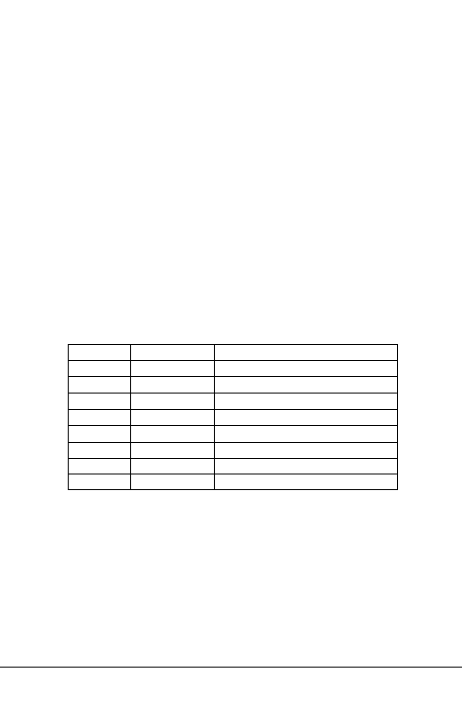
Electro Industries/Gauge Tech
Doc# E154703 8-1
Chapter 8
Register
Block
Titles
QThis chapter expands upon information listed in the Nexus®1500 meter’s Modbus Register Map
(Chapter 2). “Register Block Titles” refers to a Register or Group of Registers in the Register Map
that serve a particular purpose or function. Refer to the Table of Contents to find additional details
and descriptions of the Modbus Register Map and to Appendix A for the Channel/Scaling Factor table.
8.1:
Device
Indentification
Block
(00001-000080)
QDescription: Registers included in this block: Device Name, Firmware Variation Strings 0-7,
Nexus®Communicator Boot Version Number, Nexus®Communicator Run-Time Version Number,
Nexus®DSP Boot Version Number, Nexus®DSP Run-Time Version Number. (See 3.1, 3.2.)
8.2:
Real
Time
Block
(00081-000089)
QDescription: Registers included in this block: On Time, Current Time, Current Day of the Week.
(See 3.3, 3.4.)
On Time (00081-00084)
These Registers keep the Time of the meter when it is turned on. The format of the Registers
follows the table below. Byte 0 indicates the high byte of the Register 00081 and the byte 7
indicates the low byte of Register 00084. These Registers are for Read Only.
Current Time (00085-00088)
These Registers keep the Current Time of the meter. These values are kept by an internal battery
even when the meter is off. The format of the Registers follows the table above.
Current Day of the Week (00089)
This Register keeps the Current Day of the Week. The format follows the table on the next page.
0 0-255
Byte Range Description
Century
1 0-99 Year
2 1-12 Month
3 1-31 Day
4 0-23 Hour
5 0-59 Minute
6 Second
7 0-99 Centisecond
0-59

Electro Industries/Gauge Tech
Doc# E154703 8-2
QExample: Resetting the Time on a meter.
For May 20, Century is 20 (14H). Year is 02. Month is 05. Day is 20 (14H). Hour is 15 (0FH).
Minute is 45 (2DH). Second is 00. Centisecond is 00. Day is 0002H.
The following data is sent to the Nexus®meter address 1. Registers 00085 through 00089 are
written sequentially in one request. Register 00089, Current Day of the Week, must be included in
the request. (Refer to Chapter 1 for Function Code 1.)
0110005400050A140205140F2D00000002B44A
01 - Meter Address
10 - Function Code
0054 - Starting Address
0005 - Number of Registers
0A - Number of Bytes
140205140F2D00000002 - Actual data for Time and Date
B44A - Two-byte CRC Checksum
8.3:
1
Cycle
Block
(00090-000118)
QDescription: 1 Cycle Registers included in this block: Block Time Stamp, Phase A-N, B-N, C-N,
Aux Voltage, Phase A, B, C Current, Measured Neutral Current, Calculated Neutral Current, Phase
A-B, B-C, C-A Voltage, High Speed Input Delta and Current State. (See 3.3, 3.5, 3.6.)
Type F68 Secondary 1 Cycle RMS Voltage and Current
Length: 2 Register (4 bytes)
Range: 4,294,967,295 V,A / 0 V,A
Unit: 1/65536 V, A
These registers together are a four-byte unsigned integer where the first register contains the LSB
word.
Example:
Address: 0x005D – 0x005E
Value: 0xE6D7 – 0x0077
4-byte unsigned integer (Hex): 0x0077E6D7
4-byte integer (decimal):7,857,879
1/65536 V secondary: 119.902v
8.4:
Tenth
Second
Block
(00119-000175)
QDescription: Tenth Second Registers included in this block: Block Time Stamp, Phase A-N, B-N,
C-N, Aux Voltage, Phase A, B, C Current, Measured Neutral Current, Phase A-B, B-C, C-A Voltage,
Phase A, B, C VA, Three Phase VA, Phase A, B, C VAR, Three Phase VAR, Phase A, B, C Watts,
Value Day of Week
0001H Sunday
0002H Monday
0003H Tuesday
0004H Wednesday
0005H Thursday
0006H Friday
0007H Saturday

Electro Industries/Gauge Tech
Doc# E154703 8-3
Three Phase Watts, Frequency, Phase A, B, C Power Factor, Three Phase Power Factor, Phase A-N
Voltage to Aux Voltage Phase Angle. (See 3.3, 3.7, 3.8, 3.9.)
8.5:
One
Second
Block
(00176-000235)
QDescription: One Second Registers included in this block: Block Time Stamp, Phase A-N, B-N,
C-N, Aux Voltage, Phase A, B, C Current, Measured Neutral Current, Calculated Neutral Current,
Phase A-B, B-C, C-A Voltage, Phase A, B, C VA, VA, Phase A, B, C VAR, Three Phase VAR, Phase
A, B, C Watts, Three Phase Watts, Frequency, Phase A, B, C Power Factor, Three Phase Power
Factor, Voltage Imbalance, Current Imbalance. (See 3.3, 3.7, 3.8, 3.10.)
8.6:
Thermal
Average
Block
(00236-000295)
QDescription: Thermal Average Registers included in this block: Block Time Stamp, Phase A-N,
B-N, C-N, Aux Voltage, Phase A, B, C Current, Measured Neutral Current, Calculated Neutral
Current, Phase A-B, B-C, C-A Voltage, Phase A, B, C VA, VA, Phase A, B, C VAR, VAR, Phase A,
B, C Watts, Watts, Freq, Phase A, B, C PF, PF, Voltage, Current Imbalance. (See 3.3, 3.7, 3.8, 3.10.)
8.7:
Maximum
Block
(00296-000396)
QDescription: Maximum (Thermal Average) Registers included in this block: Block Time Stamp,
Phase A-N, B-N, C-N, Aux Voltage, Phase A, B, C Current, Measured Neutral Current, Calculated
Neutral Current, Phase A-B, B-C, C-A Voltage, Phase A, B, C VA, VA, Phase A, B, C Positive VAR,
Positive VAR, Phase A, B, C Negative VAR, Negative VAR, Phase A, B, C Positive Watts, Positive
Watts, Phase A, B, C Negative Watts, Negative Watts, Freq, Phase A, B, C PF Quadrants 1, 2, 3, 4,
PF Quadrants 1, 2, 3, 4, Voltage Imbalance, Current Imbalance, THD Phase A-N /A-B, B-N /B-C,
C-N/C-A Voltage, THD Phase A, B, C Current, K-Factor Phase A, B, C Current, Coincident
Thermal Average VAR for Max Pos Watt, Max Neg Watt. (See 3.3, 3.7, 3.8, 3.10.)
8.8:
Minimum
Block
(00397-000497)
QDescription: Minimum (Thermal Average) Registers included in this block: All of the Registers for
Maximum Block but for Minimum Block. (See 3.3, 3.7, 3.8, 3.10.)
8.9:
Maximum
Time
Stamp
Block
(00498-000737)
QDescription: Maximum (Thermal Average) Time Stamp Registers included in this block: Phase
A-N, B-N, C-N, Aux Voltage, Phase A, B, C Current, Measured Neutral Current, Calculated Neutral
Current, Phase A-B, B-C, C-A Voltage, Phase A, B, C VA, VA, Phase A, B, C Positive VAR,
Positive VAR, Phase A, B, C Negative VAR, Negative VAR, Phase A, B, C Positive Watts, Positive
Watts, Phase A, B, C Negative Watts, Negative Watts, Freq, Phase A, B, C PF Quadrants 1, 2, 3, 4,
PF Quadrants 1, 2, 3, 4, Voltage Imbalance, Current Imbalance, THD Phase A-N/A-B, B-N/B-C,
C-N/C-A Voltage, THD Phase A, B, C Current, K-Factor Phase A, B, C Current. (See 3.3.)
8.10:
Minimum
Time
Stamp
Block
(00738-000977)
QDescription: Minimum (Thermal Average) Time Stamp Registers included in this block: All of the
Registers for Maximum Time Stamp Block but for Minimum Block. (See 3.3.)

Electro Industries/Gauge Tech
Doc# E154703 8-4
8.11:
Energy
Block
(Secondary)
(00978-001021)
QDescription: Energy Registers included in this block: Time Stamp, VAhour, Positive, Negative
VARhour, Positive , Negative Watthour. (See 3.3, 3.11, 3.12.)
8.12:
Harmonic
Magnitude
Block
(01022-001789)
QDescription: Harmonic Magnitude Registers included in this block: Phase A-N/A-B, B-N/B-C,
C-N/C-A Voltage for 0th through 127th Harmonic Magnitude, Phase A, B, C Current for 0th through
127th Harmonic Magnitude. (See 3.10.)
8.13:
Harmonic
Phase
Block
(01790-002557)
QDescription: Harmonic Phase Registers included in this block: Phase A-N/A-B, B-N/B-C,
C-N/C-A Voltage for 0th through 127th Harmonic Phase, Phase A, B, C Current for 0th through 127th
Harmonic Phase. (See 3.9.)
8.14:
THD/K-FFactor
Block
(02558-002566)
QDescription: THD/K-Factor Registers included in this block: Phase A-N/A-B, B-N/B-C,
C-N/C-A Voltage THD, Phase A, B, C Current THD, Phase A, B, C Current K-Factor. (See 3.10.)
8.15:
Harmonic
Time
Stamp
Block
(02567-002590)
QDescription: Harmonic Time Stamp Registers included in this block: Phase A-N/A-B, B-N/B-C,
C-N/C-A Voltage, Phase A, B, C Current. (See 3.3.)
8.16:
Phase
Angle
Block
(02591-002604)
QDescription: Phase Angle Registers included in this block: Time Stamp, Phase A-N, B-N, C-N
Voltage, Phase A, B, C Current, Phase A-B, B-C, C-A Voltage, Volt Phase Seq. (See 3.3, 3.9, 3.13.)
8.17:
Block
Window
Average
Block
(02605-002683)
QDescription: Block Window Average Registers included in this block: Time Stamp, Status, VA,
VAR, Watt, Maximum VA, Positive VAR, Negative VAR, Positive Watt, Negative Watt, Minimum
VA, Positive VAR, Negative VAR, Positive Watt, Negative Watt, Coincident VAR for Max Positive
Watt, Neg Watt, Coincident VAR for Min Positive Watt, Neg Watt, VA Time Stamp, Time Stamp for
Pos VAR, Neg VAR, Pos Watt, Neg Watt, Minimum VA Time Stamp, Time Stamp for Minimum Pos
VAR, Neg VAR, Pos Watt, Neg Watt. (See 3.3, 3.7, 3.14.)
8.18: Rolling Window/Predictive Rolling Window Block (02684-002768)
QDescription: Rolling Window/Predictive Rolling Average Registers included in this block: Time
Stamp, Status, Predictive VA, VAR, Watt, VA, VAR, Watt, Maximum VA, Positive VAR, Negative
VAR, Positive Watt, Negative Watt, Min VA, Positive VAR, Negative VAR, Positive Watt, Negative
Watt, Coincident VAR for Max Positive Watt, Neg Watt, Coincident VAR for Min Positive Watt,
Neg Watt, VA Time Stamp, Time Stamp for Pos VAR, Neg VAR, Pos Watt, Neg Watt, Min VA Time
Stamp, Time Stamp for Min Pos VAR, Neg VAR, Pos Watt, Neg Watt. (See 3.3, 3.7, 3.14.)

Electro Industries/Gauge Tech
Doc# E154703 8-5
8.19:
Limit
Block
(02769-002773)
QDescription: Limit Registers included in this block: Limit States, Value 1 Comparisons, 1-16,
17-32, Limits States, Value 2 Comparisons, 1-16, 17-32, Low Speed Inputs. (See 3.15, 3.16.)
8.20:
Registers
02774-002841
are
not
used
by
the
Nexus®1500
meter.
8.21:
Primary
Accumulation
Block
(02842-002973)
QDescription: Primary Accumulation Registers included in this block: Time Stamp, Rec Watthour
(Q1+4), VAhour while Rec Watthour and Neg VARhour (Q1), Negative VARhour while Rec
Watthour (Q1), VAhour while Rec Watthour and Pos VARhour (Q4), Pos VARhour while Rec
Watthour (Q4), Delivered Watthour (Q2+3), VAhour while Del Watthour (Q2), VAhour while Del
Watthour and Pos VARhour (Q3), Positive VARhour while Del Watthour (Q3), Received Watthour
(Q1+4), VAhour while Rec Watthour and Neg VARhour (Q1), Neg VARhour while Rec Watthour
(Q1), VAhour while Rec Watthour and Pos VARhour (Q4), Pos VARhour while Rec Watthour (Q4),
Delivered Watthour (Q2+3), VAhour while Del Watthour and Neg VARhour (Q2), Neg VARhour
while Del Watthour (Q2), VAhour while Del Watthour and Pos VARhour (Q3), Pos VARhour while
Del Watthour (Q3), I2t Phase A, B, C, V2t Phase A, B, C. (See 3.3, 3.19. 3.20.)
8.22:
Time
of
Use
Period
Time
Stamp
Block
(02974-003040)
QDescription: Time of Use Period Time Stamp Registers included in this block: Status, Prior Season
Start Time, End Time, Prior Month Start Time, End Time, Current Season Start Time, End Time,
Current Month Start Time, End Time, CT and PT Ratio Numerator for Prior Season, Prior Month,
Current Season, Current Month, CT and PT Ratio Denominator for Prior Season, Prior Month,
Current Season, Current Month. (See 3.3, 3.14.)
8.23:
Time
of
Use
Frozen
Block
(03041-003584)
QDescription: Time of Use Frozen Registers included in all blocks: Received Watthour (Q1+4),
VAhour (Q1), VARhour (Q1), VAhour (Q4), VARhour (Q4), Delivered Watthour (Q2+3), VAhour
(Q2), VARhour (Q2), VAhour (Q3), VARhour (Q3), Peak Demand Rec Watt (Q1+4), Del Watt
(Q2+3), Rec VAR (Q1+2), Del VAR (Q3+4), Coin. Demand VAR to Peak Demand Rec Watt, Del
Watt, Peak Demand Rec Watt (Q1+4) Time Stamp, Del Watt (Q2+3) Time Stamp, Peak Demand
Rec VAR (Q1+2) Time Stamp, Del VAR (Q3+4) Time Stamp. (See 3.3, 3.7, 3.20.)
Register 1 Block (03041)
Register 2 Block (03109)
Register 3 Block (03177)
Register 4 Block (03245)
Register 5 Block (03313)
Register 6 Block (03381)
Register 7 Block (03449)
Register 8 Block (03517)
8.24:
Time
of
Use
Frozen
Total
Block
(03585-003652)
QDescription: Time of Use Frozen Total Registers included in this block: Totals for all Registers
above.

Electro Industries/Gauge Tech
Doc# E154703 8-6
8.25:
Time
of
Use
Prior
Month
Register
Block
(03653-004196)
QDescription: Time of Use Prior Month Registers included in all blocks: Received Watthour (Q1+4),
VAhour (Q1), VARhour (Q1), VAhour (Q4), VARhour (Q4), Delivered Watthour (Q2+3), VAhour
(Q2), VARhour (Q2), VAhour (Q3), VARhour (Q3), Peak Demand Rec Watt (Q1+4), Del Watt
(Q2+3), Rec VAR (Q1+2), Del VAR (Q3+4), Coin. Demand VAR to Peak Demand Rec Watt, Del
Watt, Peak Demand Rec Watt (Q1+4) Time Stamp, Del Watt (Q2+3) Time Stamp, Peak Demand
Rec VAR (Q1+2) Time Stamp, Del VAR (Q3+4) Time Stamp. (See 3.3, 3.7, 3.20.)
Register 1 Block (03653)
Register 2 Block (03721)
Register 3 Block (03789)
Register 4 Block (03857)
Register 5 Block (03925)
Register 6 Block (03993)
Register 7 Block (04061)
Register 8 Block (04129)
8.26:
Time
of
Use
Prior
Month
Total
Block
(04197-004264)
QDescription: Time of Use Prior Month Total Registers included in this block: Totals for all Registers
above.
8.27:
Time
of
Use
Active
Register
Block
(04265-004808)
QDescription: Time of Use Active Registers included in all blocks: Received Watthour (Q1+4),
VAhour (Q1), VARhour (Q1), VAhour (Q4), VARhour (Q4), Delivered Watthour (Q2+3), VAhour
(Q2), VARhour (Q2), VAhour (Q3), VARhour (Q3), Peak Demand Rec Watt (Q1+4), Del Watt
(Q2+3), Rec VAR (Q1+2), Del VAR (Q3+4), Coin. Demand VAR to Peak Demand Rec Watt, Del
Watt, Peak Demand Rec Watt (Q1+4) Time Stamp, Del Watt (Q2+3) Time Stamp, Peak Demand
Rec VAR (Q1+2) Time Stamp, Del VAR (Q3+4) Time Stamp. (See 3.3, 3.7, 3.20.)
Register 1 Block (04265)
Register 2 Block (04333)
Register 3 Block (04401)
Register 4 Block (04469)
Register 5 Block (04537)
Register 6 Block (04605)
Register 7 Block (04673)
Register 8 Block (04741)
8.28:
Time
of
Use
Active
Total
Block
(04809-004876)
QDescription: Time of Use Active Total Registers included in this block: Totals for all Registers
above.

Electro Industries/Gauge Tech
Doc# E154703 8-7
8.29:
Time
of
Use
Current
Month
Register
Block
(04877-005420)
QDescription: Time of Use Current Month Registers included in all blocks: Received Watthour
(Q1+4), VAhour (Q1), VARhour (Q1), VAhour (Q4), VARhour (Q4), Delivered Watthour (Q2+3),
VAhour (Q2), VARhour (Q2), VAhour (Q3), VARhour (Q3), Peak Demand Rec Watt (Q1+4), Del
Watt (Q2+3), Rec VAR (Q1+2), Del VAR (Q3+4), Coin. Demand VAR to Peak Demand Rec Watt,
Del Watt, Peak Demand Rec Watt (Q1+4) Time Stamp, Del Watt (Q2+3) Time Stamp, Peak Demand
Rec VAR (Q1+2) Time Stamp, Del VAR (Q3+4) Time Stamp. (See 3.3, 3.7, 3.20.)
Register 1 Block (04877)
Register 2 Block (04945)
Register 3 Block (05013)
Register 4 Block (05081)
Register 5 Block (05149)
Register 6 Block (05217)
Register 7 Block (05285)
Register 8 Block (05353)
8.30:
Time
of
Use
Current
Month
Total
Block
(05421-005488)
QDescription: Time of Use Current Month Total Registers included in this block: Totals for all
Registers above.
8.31:
Time
of
Use
Frozen
Label
Block
(05489-005552)
QDescription: Time of Use Frozen Label Registers included in this block: Reg. Labels 1-8.
8.32:
Time
of
Use
Prior
Month
Label
Block
(05553-005616)
QDescription: TOU Prior Month Label Registers in this block: Register Labels 1-8. (See 3.2.)
8.33: Time of Use Active Label Block (05617-005680)
QDescription: TOU Active Label Registers in this block: Register Labels 1-8. (See 3.2.)
8.34:
Time
of
Use
Current
Month
Label
Block
(05681-005744)
QDescription: TOU Current Month Label Registers in this block: Register Labels 1-8. (See 3.2.)
8.35:
Internal
Input
Pulse
Accumulation
Block
(05745-005796)
QDescription: Internal Input Pulse Accumulation Registers included in this block: Time Stamp,
Scaled Pulse Accumulations Internal Inputs 1-8, Scaled Pulse Accumulations 1-4. (See 3.3, 3.40.)
8.36:
Pulse
Accumulation
Block
Window
Average
/
Maximum
Block
(05797-
05945)
QDescription: Pulse Accumulation Block Window Average / Maximum Registers included in this
block: Time Stamp, Status, Average Internal Inputs 1-8, Average Aggregation 1-4, Maximum
Average Internal Inputs 1-8, Maximum Average Aggregation 1-4, Maximum Internal Input Time
Stamp 1-8, Maximum Average Aggregation Time Stamp 1-4. (See 3.3, 3.14, 3.40.)
e Electro Industries/GaugeTech Doc# E154703 8-8
8.37: Temperature (05946)
Description: Nexus® meter’s Internal Temperature Register is in this block. (See
3.33.)
8.38: Registers 05947-005978 are not used by the Nexus®1500
meter.
8.39: Limit Combination Block (05979-05980)
Description: Limit Combination Registers included in this block: Limit States,
Combinations 1-16,17-32. (See 3.15.)
8.40: Relay Logic Block (05981-06014)
(See 3.34).
8.41: Reset Time Block (06015-06038)
Description: Reset Time Registers included in this block: Time Stamp, Max Time
Stamp, MinTime Stamp, Energy Time Stamp, Current Season / Month TOU Time Stamp.
(See 3.3.)
8.42: Miscellaneous Flags Block (06039)
Description: The Miscellaneous Flags Register has 2 bytes. Each byte has eight bits.
The bits in these bytes are associated with various miscellaneous functions as follows:
Bit Point Meaning
15 (MSB) 0 NVRAM Battery Status1
4-1 1-14 Undefined
0 (LSB) 15 Undefined
NVRAM Battery Status
A value of ‘0’indicates that the battery is OK; a value of ‘1’indicates that the battery is
not OK. Battery Status is reevaluated on power up and approximately every 24 hours
after power up. Example: Register 06039, Miscellaneous Flags, might contain the data in
the table below.

e Electro Industries/GaugeTech Doc# E154703 8-9
8.43: Registers 06040-06096 are not used by the Nexus® 1500 meter.
8.44: KYZ Output Accumulation Block (06097-06110)
Description: KYZ Output Accumulation Registers included in this block: KYZ Output
Accumulation Block Time Stamp, KYZ Output Accumulation Relay 1/Pulse 1 LED, KYZ Output
Accumulation Relay 2/Pulse 2 LED, KYZ Output Accumulation Relay 3, KYZ Output
Accumulation Relay 4. (See 3.3, 3.18.)
8.45: Registers 06111-06113 are not used by the Nexus® 1500 meter.
8.46: Flicker Status Block (06114-06126)
Description: Flicker Status Registers included in this block: Flicker Status Block Time Stamp,
Flicker Start Time, Flicker End Time, Flicker Status. (See 3.3, 3.14.)
8.47: Instantaneous Flicker Block (06127-06136)
Description: Instantaneous Flicker Registers included in this block: Instantaneous Flicker Block
Time, Instantaneous Flicker VAN, VBN, VCN. (See 3.3, 3.7.)
8.48: Short Term Flicker Block (06137-06186)
Description: Short Term Flicker Registers included in this block: Short Term Flicker Block
Time, Short Term Flicker VAN, VBN, VCN, Maximum Short Term Flicker VAN, VBN, VCN, Minimum
Short Term Flicker VAN, VBN, VCN, Short Term Interval End Time Stamp, Max Short Term Flicker
VAN, VBN, VCN Time Stamps, Min Short Term Flicker VAN, VBN, VCN Time Stamps. (See 3.3, 3.7.)
8.49: Long Term Flicker Block (06187-06236)
Description: Long Term Flicker Registers included in this block: Long Term Flicker Block
Time,
Long Term Flicker VAN, VBN, VCN, Maximum Long Term Flicker VAN, VBN, VCN, Minimum Long
Term
Flicker VAN, VBN, VCN, Long Term Interval End Time Stamp, Maximum Long Term Flicker VAN,
VBN,
VCN Time Stamps, Minimum Long Term Flicker VAN, VBN, VCN Time Stamps. (See 3.3, 3.7.)
8.50: Additional Energy Block (06237-06392)
Description: Additional Energy Registers included in this block: Additional Energy Block
Time, Quadrants 1, 4, 2, 3 Watthour Secondary, Quadrant 1 Vahour, VARhour Secondary,
Quadrant 4 Vahour, VARhour Secondary, Quadrant 2 Vahour, VARhour Secondary, Quadrant 3
Vahour, VARhour Secondary, Quadrants 1, 4, 2, 3 Watthour Primary, Total Vahour Primary
(Quadrants 1+2+3+4), Positive VARhour (Quadrants 1+2) Primary, Negative VARhour
(Quadrants 3+4) Primary, Negative VARhour Primary, Quadrant 1, 4, 2, 3 Watthour Secondary,
Quadrant 1 Vahour, VARhour Secondary, Quadrant 4 Vahour, VARhour Secondary, Quadrant 2
Vahour, VARhour Secondary, Quadrant 3 Vahour, VARhour Secondary, Quadrants 1, 4, 2, 3
Watthour Primary, Total Vahour (Quadrants 1+2+3+4) Primary, Positive VARhour (Quadrants
1+2) Primary, Negative VARhour (Quadrants 3+4) Primary. (See 3.3, 3.19, 3.20.)

e Electro Industries/GaugeTech Doc# E154703 8-10
8.51: Energy and Pulses in the Interval Block (06393-006488)
Description: Energy and Pulses in the Interval Registers included in this block: Energy and
Pulses in the Interval Block Time Stamp, Total Vahour (Quadrants 1+2+3+4) in the Interval
Secondary, Positive VARhour (Quadrants 1+2) in the Interval Secondary, Negative VARhour
(Quadrants 3+4) in the Interval Secondary, Positive Watthour (Quadrants 1+4) in the Interval
Secondary, Negative Watthour (Quadrants 2+3) in the Interval Secondary, Positive Watthour
(Quadrants 1+4) in the Interval Secondary, Negative Watthour (Quadrants 2+3) in the Interval
Secondary, Positive Watthour (Quadrants 1+4) in the Interval Primary, Quadrant 1 Vahour,
VARhour in the Interval Primary, Quadrant 4 Vahour, VARhour in the Interval Primary,
Negative Watthour (Quadrants 2+3) in the Interval Primary, Quadrant 2 Vahour, VARhour in the
Interval Primary, Quadrant 3 Vahour,VARhour in the Interval Primary, I2t Phase A, B, C in the
Interval Primary, V2t Phases A, B, C in the Interval Primary, Pulse Accumulation Internal Inputs
1-8 in the Interval Scaled, Pulse Accumulation 1-4 in the Interval Scaled, Quadrants 1, 4, 2, 3
Watthour in the Interval Secondary, Quadrant 1 Vahour, VARhour in the Interval Secondary,
Quadrant 4 Vahour, VARhour in the Interval Secondary, Quadrant 2 Vahour, VARhour in the
Interval Secondary, Quadrant 3 Vahour, VARhour in the Interval Secondary, Quadrants 1, 4, 2, 3
Watthour in the Interval Primary, Total Vahour(Quadrants 1+2+3+4) in the Interval Primary,
Positive VARhour (Quadrants 1+2) in the Interval Primary, Negative VARhour (Quadrants 3+4)
in the Interval Primary, KYZ Pulse Output in the Interval Relays 1-4, Pulse 1 and 2 LEDs. (See
3.3, 3.18, 3.57.)
8.52: Flicker Countdown Block (06489-006490)
Description: Flicker Countdown Registers included in this block: Short Term Flicker
Countdown, Long Term Flicker Countdown. (See 3.56.)
8.53: Cumulative Demand Block (06491-006502)
Description: Cumulative Demand Registers included in this block: Cumulative Demand
Block Time Stamp, Positive Watt (Quadrants 1+4) Cumulative Demand, Negative Watt
(Quadrants 2+3) Cumulative Demand, Positive Watt (Quadrants 1+4) Continuous Cumulative
Demand, Negative Watt(Quadrants 2+3) Continuous Cumulative Demand. (See 3.3, 3.18.)
8.54: Time of Use Active Cumulative Demand Block (06503-006538)
Description: Time of Use Active Cumulative Demand Registers included in this block:
TOU Active Register 0-7 Cumulative Demand Q1 + Q4 Watt and Q2 + Q3 Watt, TOU Active
Totals Cumulative Demand Q1 + Q4 and Q2 + Q3 Watt. (See 3.18.)
8.55: Time of Use Current Month Cumulative Demand Block
(06539-006574
Description: Time of Use Current Month Cumulative Demand Registers included in this
block: TOU Current Month Register 0-7 Cumulative Demand Q1 + Q4 Watt and Q2 + Q3 Watt,
TOU Current Month Totals Cumulative Demand Q1 + Q4 and Q2 + Q3 Watt. (See 3.18.)

Electro Industries/Gauge Tech
Doc# E154703 8-11
8.56:
TOU
Active
Continuous
Cumulative
Demand
Block
(06575-006610)
QDescription: Time of Use Active Continuous Cumulative Demand Registers included in this block:
TOU Active Register 0-7 Continuous Cumulative Demand Q1 + Q4 Watt and Q2 + Q3 Watt, TOU
Active Totals Continuous Cumulative Demand Q1 + Q4 and Q2 + Q3 Watt. (See 3.18.)
8.57:
TOU
Current
Month
Continuous
Cumulative
Demand
Block
(06611-
06646)
QDescription: Time of Use Current Month Continuous Cumulative Demand Registers included in
this block: TOU Current Month Register 0-7 Continuous Cumulative Demand Q1 + Q4 Watt and
Q2 + Q3 Watt, TOU Current Month Totals Continuous Cumulative Demand Q1 + Q4 and Q2 + Q3
Watt. (See 3.18.)
8.58:
Log
Index
Block
(06647-006664)
QDescription: This register contains a 2-byte MSB unsigned integer, which represents the First of
Last Index for a given Log. First Indexes represent the Index of the First (Oldest) record in a log.
Last Indexes represent the Index of the Last (Newest) record in a log. The value of 0x0FFFF for the
Last Index indicates that the log is empty.
8.59:
Uncompensated
and
Q
Block
(06665-006670)
QDescription: Uncompensated register readings are the readings to which Transformer Loss
Compensation is not applied. Q Hour readigns are 60 degree-shifted hour readings from Watt hour
readings. VAR hour readings are 90 degree-shifted hour readings from Watt hour readings.
8.60:
Scaled
Energy
Block
(06908-007829)
QDescription: Energy readings in Nexus®meters have Watt-hour, VAR-hour and VA-hour as base
units. In the real world, kilo-, mega- and giga- units are used more frequently. Therefore, Nexus®
meters have scaled energy readings. This scale can be modified using Communicator EXT software.
Length 2 Registers (4 bytes)
Range 99 / 0 through 999,999,999 / 0 (variable, 2-9 digits)
Unit 10-7 through 106units (variable)
This register contains a 4-byte MSB signed integer. The range and resolution of a given reading is
controlled by programmable Scaled Energy Settings, which govern both the Range of the reading
(from 2 to 9 digits) and the Units of the reading (from 7 decimal places of Wh (10-7) to no decimal
places of MWh (106). NOTE: See section 3.64 and 3.65 for details.
8.61:
Total
Average
Power
Factor
Block
(07830-007859)
QDescription: This block keeps the Total Average Power Factor Values. Power Factor Values can be
calculated using Watt, VAR and VA. Total Average Power Factor values will be calculated by Wh,
VAR and VAh.

Electro Industries/Gauge Tech
Doc# E154703 8-12
8.62:
Reset
Active
Time
of
Use
Time
Stamp
(07860-007863)
QDescription: This register holds the Time Stamp when Active TOU Time is reset. The format
follows the Time Stamp F3, section 3.3.
8.63:
Negative
Maximum
Pulse
Aggregation
Average
Block
(07864-007895)
QDescription: Negative Maximum Average Aggregation 1-4 and Negative Maximum Average
Aggregation Time Stamp 1-4 registers are included in this block. Maximum Average Aggregation
1-4 registers in Pulse Accumulation Block Window Average/Maximum Block (05797-05945) will
hold only positive values.
8.64:
Scratchpad
Block
(08193
-
08320)
QDescription: Scratchpad Registers 08193 - 08320 included in this block. The 128 Registers in the
Scratchpad Block are for temporary storage of information. At the user’s discretion, data may be
written to Registers and then read back.
Example: Using one port, write energy readings from other devices. Those energy readings can be
read through another port.
8.65: Master Device Data Block (08449-008704)
QDescription: These registers are used as a Scratch Pad between the Software and the Network Card
or Modem Card. These registers are not for polling by the users.
8.66:
Customized
Modbus
Block
(12289-114336)
QDescription: All the readings in the Customizable Modbus Map Settings Block (50273) can be read
in this block. The format of the readings follows each individually assigned reading.
8.67:
Enhanced
Factory
Settings
Block
(16385-224576)
QDescription: These registers are reserved for future additional factory settings information.
Currently, nothing is defined in these registers.
8.68:
Enhanced
Programmable
Settings
Block
(24577-332768)
QDescription: These registers are reserved for future additional Programmable Settings information.
Currently, nothing is defined in these registers.
8.69: Time of Use Calendar Header Block (34817-334918)
QDescription: TOU Calendar Registers included in this block: Modification Time Stamp & Cal Year
for Years 1-20, Header Status, Year Selection Status. (See 3.3, 3.21, 3.31, 3.32.)
Electro Industries/Gauge Tech
Doc# E154703 8-13
8.70:
Time
of
Use
Calendar
Block
(34919-335800)
QDescription: Time of Use Calendar Registers included in all blocks: Modification Time Stamp,
Calendar Year, Profile for 2-Day Segments for the Whole Calendar Year (Jan1/Jan2 Profile), Profile
Status, Profile Register for
8.71:
Time
of
Use
Upload
Calendar
Block
(36607-336736)
QDescription: Time of Use Upload Calendar Window Registers included in this block: Locked to
Port, Sequence Status, ID, Data, Checksum. (See 3.27 - 3.30, 3.43.)
8.72:
Historical
Log
1
Snapshot
Header
(36865-336882)
QDescription: Historical Log 1 Snapshot Registers included in this block:
Memory Size
4-byte unsigned integers representing the amount of memory, in bytes, allocated to the log.
Record Size
2-byte integers representing the size, in bytes, of a record in the log.
First Index
2-byte unsigned integers representing the index of the first (oldest) record in the log.
Last Index
2-byte unsigned integers representing the index of the last (newest) record in the log. The value
0x0FFFF indicates that the log is empty.
First Time Stamp
These Registers (8 bytes) hold the time stamp from the first (oldest) record in the log.
Last Time Stamp
These Registers hold the Time Stamp from the last (newest) record in the log. The byte order and
description are the same as for the First Time Stamp.
Byte Range Description
0 0-255 Century
1 0-99 Year
2 1-12 Month
3 1-31 Day
4 0-23 Hour
5 0-59 Minute
6 0-59 Second
7 0-99 Centisecond
Time Stamp Bytes

Electro Industries/Gauge Tech
Doc# E154703 8-14
Valid Bitmap
These Registers hold the bit flags indicating whether the Nexus recognizes the lines in the Historical
Log Settings Block (the block at Register 45205). The first bit represents the validity of the Data
Pointer in the Historical Log Settings. A value of 1 means the Data Pointer is acceptable and can be
stored. A value of 0 means that the Data Pointer is invalid or unrecognized and not able to be
stored.
Max Records
2-byte unsigned integer representing the total number of records the log is capable of holding. In
order to maintain a one-for-one relationship in parallel logs, the maximum number of records that a
log can store is defined by the log that holds the fewest records. Logs capable of holding more
records are restricted.
8.73:
Historical
Log
2
Snapshot
Header
(36929-336946)
QDescription: Historical Log 2 Snapshot Registers included in this block: The same as Log 1 above.
8.74:
Limit
Trigger
Log
Header
(36993-337010)
QDescription: Limit Trigger Log Registers included in this block:
Valid Bitmap
These Registers hold the bit flags indicating whether the meter recognizes the lines in the Limit
Settings Block (the block at Register 45077). The first bit represents the validity of the Data Pointer
in the Limit Settings. A value of 1 means the Data Pointer is acceptable and can be stored. A value
of 0 means that the Data Pointer is invalid or unrecognized and not able to be stored. Only 32 bits
are used. See Registers 36865 to 36882 for other registers.
8.75:
Limit
Snapshot
Log
Header
(37057-337074)
QDescription: Limit Snapshot Log Registers included in this block: See Registers 36865-36882 and
36993-37010.
8.76:
Digital
Input
Log
Header
(37121-337138)
QDescription: Digital Input Log Registers included in this block: See Registers 36865-36882.
8.77: Digital Input Snapshot Log Header (37185-337202)
QDescription: Digital Input Snapshot Log Registers included in this block: See Regs. 36865-36882.
8.78:
Digital
Output
Log
Header
(37249-337266)
QDescription: Digital Output Log Registers included in this block: See Registers 36865-36882.
8.79:
Digital
Output
Snapshot
Log
Header
(37313-337330)
QDescription: Digital Output Snapshot Log Registers included in this block: See Registers 36865-
36882.
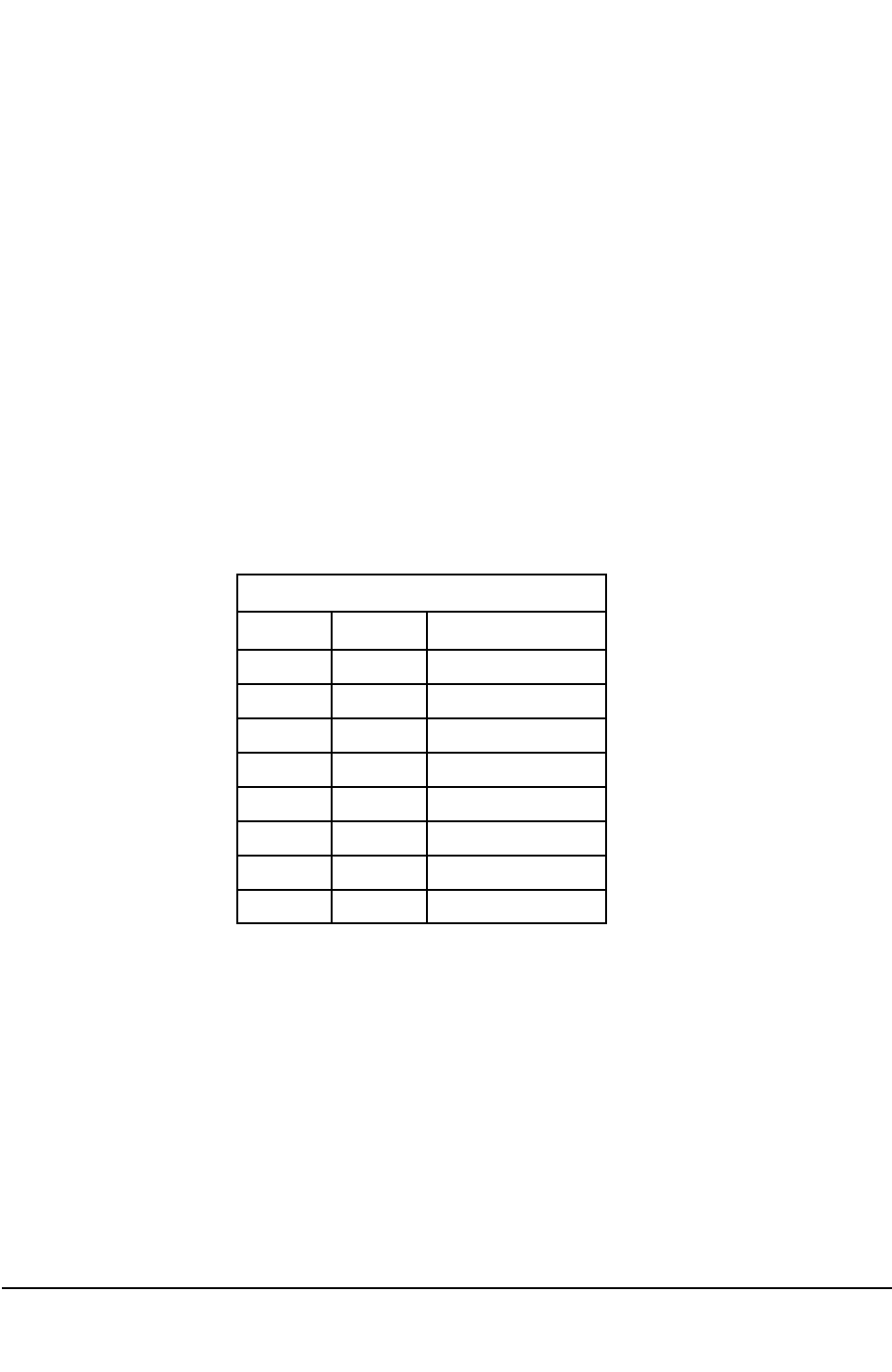
Electro Industries/GaugeTech
E154703 8-15
8.80:
Flicker
Log
Header
(37377-337394)
Description: Currently not used.
8.81:
Waveform
Trigger
Log
Header
(37441-337458)
Description: Waveform Trigger Log Registers included in this block: See Registers 36865-36882.
8.82:
System
Event
Log
Header
(37505-337522)
Memory Size: 4-byte unsigned integers representing the amount of memory, in bytes, allocated to
the log.
Record Size: 2-byte unsigned integers representing the size, in bytes, of a record in the log.
First Index: 2-byte unsigned integers representing the Index of the First (Oldest) record in the log.
Last Index: 2-byte unsigned integers representing the Index of the Last (Newest) record in the log.
The value 0x0FFFF indicates that the log is empty.
First Time Stamp: These registers (8 bytes) hold the Time Stamp from the First (Oldest) record in
the log.
Last Time Stamp: These registers hold the Time Stamp from the Last (Newest) Record in the log.
The byte order and description are the same as for the First Time Stamp.
Valid Bitmap: Undefined.
Max Records: A 2-byte unsigned integer represents the total number of records the log is capable
of holding. In order to maintain a one-for-one relationship in parallel logs, the maximum number of
records that a log can hold is defined by the log that holds the fewest records. Logs capable of hold-
ing more records are restricted.
Byte Range Description
0 0-255 Century
1 0-99 Year
2 1-12 Month
3 1-31 Day
4 0-23 Hour
5 0-59 Minute
6 0-59 Second
7 0-99 Centisecond
Time Stamp Bytes

Electro Industries/GaugeTech
Doc# E154703 8-16
8.83:
Waveform
Samples
Log
Header
(37569-337586)
Description: Waveform Samples Log Registers included in this block: See Registers 36865-36882.
8.84:
PQ
(CBEMA)
Log
Header
(37633-337650)
Description: PQ (CBEMA) Log Registers included in this block: See Registers 36865-36882.
8.85:
Registers
37697-337714
are
not
used
by
the
Nexus®
1500
Meter
8.86:
External
Device
Information
Block
Header
(37761-337778)
Description: External Device Information Registers included in this block:
Memory Size: A 4-byte unsigned integer representing the amount of memory, in bytes, allocated to
External Device Information Blocks. This memory is allocated from RAM, not NVRAM.
Record Size: An unsigned integer representing the size, in bytes, of an External Device Info Block.
First Index: An unsigned integer representing the Index of the First External Device Info Block.
Last Index: An unsigned integer representing the Index of the Last External Device Info Block.
First Time Stamp: Since External Device Info Blocks are not recorded sequentially, these
Registers have no meaning.
Last Time Stamp: Since External Device Info Blocks are not recorded sequentially, these Registers
have no meaning.
Valid Bitmap: These Registers hold the bit flags to indicate the validity of individual External
Device Info Blocks. The first bit (high order bit in Register 37774) represents the validity of the
First External Device Info Block. The last bit (lowest order bit in Register 37777) represents the
validity of the Last External Device Info Block. A value of 1 means that the External Device was
found and the meter successfully received all of the Info Block for the External Device. A value of
0 means that the External Device was not found, or errors have occurred while trying to retrieve the
Info Block or that no device is programmed for this slot.
Max Records: This Register holds an unsigned integer representing the total number of records
the log can hold.
8.87:
External
Device
Programming
Block
Header
(37825-337842)
Description: External Device Programming Registers included in this block:
Memory Size: These Registers are a 4-byte unsigned integer representing the amount of memory,
in bytes, allocated to External Device Programming Blocks. This memory is allocated from RAM,
not NVRAM.
Record Size: This Register is an unsigned integer representing the size, in bytes, of an External
Device Programming Block.

Electro Industries/GaugeTech
Doc# E154703 8-17
First Index: An unsigned integer representing the Index of the First External Device Programming
Block.
Last Index: An unsigned integer representing the Index of the Last External Device Programming
Block.
First Time Stamp: Since External Device Programming Blocks are not recorded sequentially,
these Registers have no meaning.
Last Time Stamp: Since External Device Programming Blocks are not recorded sequentially,
these Registers have no meaning.
Valid Bitmap: These Registers hold the bit flags to indicate the validity of individual External
Device Programming Blocks. The first bit (high order bit in Register 37838) represents the validity
of the First External Device Programming Block. The last bit (lowest order bit in Register 37841)
represents the validity of the Last External Device Programming Block. A value of 1 means that
the External Device was found and the meter successfully received all of the Programming Block
for the External Device. A value of 0 means that the External Device was not found, or errors have
occurred while trying to retrieve the Programming Block or that no device is programmed for this
slot.
Max Records: This Register holds an unsigned integer representing the total number of records
the log is capable of holding.
8.88:
Device
History
Block
Header
(37889-337906)
Description: Device History Block currently not used.This Register holds an unsigned integer
representing the total number of records the log is capable of holding.
8.89:
Direct
Memory
Access
Header
(37953-337970)
Description: Direct Memory Access currently not used.
8.90:
Window
Index
Block
(38145-338162)
Description: Window Index Registers included in this block:
Historical Log 1 (38145): When read, this Register returns the Window Index for Historical Log 1
to access Historical Log 1 on this port. When written, this Register sets the Index used by the
Historical Log 1 Window to access Historical Log 1 on this port. Each port accesses a separate,
independent index through this Register, allowing all four ports to access different areas of
Historical Log 1 at the same time.
When a value other than 0x0FFFF is written to this Register, the index is updated. If the Window
Mode for this log indicates a Paused Mode (0x00000 or 0x00001 in Register 38209), Historical
Log 1 is paused, preventing the addition of new records while the log is being accessed. A 30-sec-
ond timer is initiated on these writes. Should the timer run out (a new index is not written within
30 seconds), Historical Log 1 will be allowed to continue logging.
When a value of 0x0FFFF is written to this Register, it signifies that the port is finished accessing
Historical Log 1, the 30-second timer is canceled and Historical Log 1 will be allowed to continue
logging.

Electro Industries/GaugeTech
Doc# E154703 8-18
Should multiple ports access the same log simultaneously, the log will be paused while either
30-second timer is running. The log will be allowed to continue logging only when both ports
time-out or write 0x0FFFF to their Index Register.
Historical Log 2 (38146): When read, this Register returns the Window Index for Historical Log 2
to access Historical Log 2 on this port. Functionality follows the Historical Log 1 Window Index
(38145).
Limit Trigger Log (38147): When read, this Register returns the Index used by the Limit Trigger
Log Window to access Limit Trigger Log on this port. Functionality follows the Historical Log 1
Window Index (38145).
Limit Snapshot Log (38148): When read, this Register returns the Index used by the Limit
Snapshot Log Window to access Limit Snapshot Log on this port. Functionality follows the
Historical Log 1 Window Index (38145).
Digital Input Log (38149): When read, this Register returns the Index used by the Digital Input
Log Window to access Digital Input Log on this port. Functionality follows the Historical Log 1
Window Index (38145).
Digital Input Snapshot Log (38150): When read, this Register returns the Index used by the
Digital Input Snapshot Log Window to access Digital Input Snapshot Log on this port.
Functionality follows the Historical Log 1 Window Index (38145).
Digital Output Log (38151): When read, this Register returns the Index used by the Digital
Output Log Window to access Digital Output Log on this port. Functionality follows the Historical
Log 1 Window Index (38145).
Digital Output Snapshot Log (38152): When read, this Register returns the Index used by the
Digital Output Snapshot Log Window to access Digital Output Snapshot Log on this port.
Functionality follows the Historical Log 1 Window Index (38145).
Flicker Log (38153): When read, this Register returns the Index used by the Flicker Log Window
to access Flicker Log on this port. Functionality follows the Historical Log 1 Window Index
(38145).
Waveform Trigger Log (38154): When read, this Register returns the Index used by the
Waveform Trigger Log Window to access Waveform Trigger Log on this port. Functionality
follows the Historical Log 1 Window Index (38145).
Register 38155 is not currently used.
Waveform Samples Log (38156): When read, this Register returns the Index used by the
Waveform Samples Log Window to access Waveform Samples Log on this port. Functionality
follows the Historical Log 1 Window Index (38145).
PQ Log (38157): When read, this Register returns the Index used by the PQ Log Window to
access PQ Log on this port. Functionality follows the Historical Log 1 Window Index (38145).

Electro Industries/GaugeTech
Doc# E154703 8-19
External Device Info Block (38159): When read, this Register returns the Index used by the
External Device Info Block Window to access External Device Info Blocks on this port. When
written, this Register sets the Index used by the External Device Info Block Window to access
External Device Info Blocks on this port. Each port accesses a separate, independent index through
this Register, allowing all four ports to access different External Device Info Blocks at the same
time.
External Device Programming Block (38160): When read, this Register returns the Index used
by the External Device Programming Block Window to access External Device Programming
Blocks on this port. When written, this Register sets the Index used by the External Device
Programming Block Window to access External Device Programming Blocks on this port. Each
port accesses a separate, independent index through this Register, allowing all four ports to access
different External Device Programming Blocks at the same time.
Device History Block (38160) - Currently not used.
Direct Memory Access (38161) - Currently not used.
8.91:
Window
Mode
Block
(38209-338226)
Description: Window Mode Registers included in this block:
Historical Log 1 (38209): When read, this Register returns the Mode used by the Historical Log 1
Window to access Historical Log 1 on this port. When written, this Register sets the Mode used by
the Historical Log 1 Window to access Historical Log 1 on this port. Each port accesses a separate,
independent Mode through this Register, allowing all four ports to access Historical Log 1 in
different modes.
Currently, the Mode Register defines the following Modes: Paused Download Mode (0x00000),
Paused Time Stamp Mode (0x00001), Running Download Mode (0x00002) and Running Time
Stamp Mode (0x00003).
In Download Modes (0x00000 and 0x00002), the Historical Log 1 Window accesses consecutive
128-byte blocks of the Historical Log 1. When the Index = 0x00000, the first 128 bytes of the log
are readable in the window; when the Index = 0x00001, the second 128 bytes of the log are
readable in the window, and so on.
The designation “first 128 bytes of the log” is a physical description based on the absolute address-
es of the memory allocated to the log. The first (oldest) record in the log may not be located at the
beginning of the log.
In Time Stamp Modes (0x00001 and 0x00003), the Historical Log 1 Window accesses the Time
Stamps of the records in the Historical Log 1 in blocks of 16 Time Stamps at a time. When the
Index = 0x00000, the Time Stamps of the first 16 records (records 0-15) in the log are readable in
the window; when the Index = 0x00001, the Time Stamps of the second 16 records (records 16-31)
in the log are readable in the window, and so on.

Electro Industries/GaugeTech
Doc# E154703 8-20
The designation “first 16 records of the log” is a physical description based on the absolute
addresses of the memory allocated to the log. The first (oldest) record in the log may not be locat-
ed at the beginning of the log.
In Paused Modes (0x00000 and 0x00001), the log being accessed is paused and new records are
not added to the log while it is paused.
In Running Modes (0x00002 and 0x00003), the log being accessed is not paused and new records
may be added to the log. When downloading in these modes, it is possible the records may be
overwritten before or during the downloading of records.
Historical Log 2 (38210): When read, this Register returns the Mode in use by the Historical Log
2 Window to access Historical Log 2 on this port. Functionality follows the Historical Log 1
Window Mode (38209).
Limit Trigger Log (38211): When read, this Register returns the Mode in use by the Limit Trigger
Log Window to access Limit Trigger Log on this port. Functionality follows the Historical Log 1
Window Mode (38209).
Limit Snapshot Log (38212): When read, this Register returns the Mode in use by the Limit
Snapshot Log Window to access Limit Snapshot Log on this port. Functionality follows the
Historical Log 1 Window Mode (38209).
Digital Input Log (38213): When read, this Register returns the Mode in use by the Digital Input
Log Window to access Digital Input Log on this port. Functionality follows the Historical Log 1
Window Mode (38209).
Digital Input Snapshot Log (38214): When read, this Register returns the Mode in use by the
Digital Input Snapshot Log Window to access Digital Input Snapshot Log on this port.
Functionality follows the Historical Log 1 Window Mode (38209).
Digital Output Log (38215): When read, this Register returns the Mode in use by the Digital
Output Log Window to access Digital Output Log on this port. Functionality follows the Historical
Log 1 Window Mode (38209).
Digital Output Snapshot Log (38216): When read, this Register returns the Mode used by the
Digital Output Snapshot Log Window to access Digital Output Snapshot Log on this port.
Functionality follows Historical Log 1 Window Mode (38209).
Flicker Log (38217): When read, this Register returns the Mode in use by the Flicker Log
Window to access Flicker Log on this port. Functionality follows the Historical Log 1 Window
Mode (38209).
Waveform Trigger Log (38218): When read, this Register returns the Mode in use by the
Waveform Trigger Log Window to access Waveform Trigger Log on this port. Functionality
follows Historical Log 1 Window Mode (38209).

Electro Industries/GaugeTech
E154703 8-21
Register 38219 is currently not used.
Waveform Samples Log (38220): When read, this Register returns the Mode in use by the
Waveform Samples Log Window to access Waveform Samples Log on this port. Functionality
follows Historical Log 1 Window Mode (38209).
PQ Log (38221): When read, this Register returns the Mode in use by the PQ Log Window to
access PQ Log on this port. Functionality follows the Historical Log 1 Window Mode (38209).
Register 38209 is currently not used..
External Device Info Block (38223) - Currently not used.
External Device Programming Block (38224) - Currently not used.
Device History Block (38225) - Currently not used.
Direct Memory Access (38226) - Currently not used.
8.92:
Window
Block
(38273-339424)
Description: Window Registers included in this block:
Historical Log 1 (38273-38336): These Registers are a 128-byte window into the Historical Log
1. The particular 128-bytes that are accessed are dependent on the Historical Log 1 window index.
Historical Log 2 (38337-38400): These Registers are a 128-byte window into the Historical Log
2. The particular 128-bytes that are accessed are dependent on the Historical Log 2 window index.
Limit Trigger Log (38401-38464): These Registers are a 128-byte window into the Limit Trigger
Log. The particular 128-bytes that are accessed are dependent on the Limit Trigger Log window
index.
Limit Snapshot Log (38465-38528): These Registers are a 128-byte window into the Limit
Snapshot Log. The particular 128-bytes that are accessed are dependent on the Limit Snapshot Log
window index.
Digital Input Log (38529-38592): These Registers are a 128-byte window into the Digital Input
Log. The particular 128-bytes that are accessed are dependent on the Digital Input Log window
index.
Digital Input Snapshot Log (38593-38656): These Registers are a 128-byte window into the
Digital Input Snapshot Log. The particular 128-bytes that are accessed are dependent on the Digital
Input Snapshot Log window index
.

Electro Industries/GaugeTech
Doc# E154703 8-22
Digital Output Log (38657-38720): These Registers are a 128-byte window into the Digital
Output Log. The particular 128-bytes that are accessed are dependent on the Digital Output Log
window index.
Digital Output Snapshot Log (38721-38784): These Registers are a 128-byte window into the
Digital Output Snapshot Log. The particular 128-bytes that are accessed are dependent on the
Digital Output Snapshot Log window index.
Flicker Log (38785-38848): These Registers are a 128-byte window into the Flicker Log. The
particular 128-bytes that are accessed are dependent on the Flicker Log window index.
Waveform Trigger Log (38849-38912): These Registers are a 128-byte window into the
Waveform Trigger Log. The particular 128-bytes that are accessed are dependent on the Waveform
Trigger Log window index.
System Event Log Window (38913-38976):These registers are a 128-byte window into the
System Events Log. The particular 128-bytes that are accessed are dependent on the System Events
Log window index.
Waveform Samples Log (38977-39040): These Registers are a 128-byte window into the
Waveform Samples Log. The particular 128-bytes that are accessed are dependent on the
Waveform Samples Log window index.
PQ Log (39041-39104): These Registers are a 128-byte window into the PQ Log. The particular
128-bytes that are accessed are dependent on the PQ Log window index.
External Device Info Block Window (39169-39232): These Registers are a 128-byte window
into the External Device Info Blocks. The particular 128-bytes that are accessed are dependent on
the External Device Info Blocks window index. (See Chapter 5.)
External Device Info Block Window (39233-39296): These Registers are a 128-byte window
into the External Device Programming Blocks. The particular 128-bytes that are accessed are
dependent on the External Device Programming Blocks window index. (See Chapter 5.)
Device History Block (39297-39360) - Currently not used.
Direct Memory Access (39361-39424) - Currently not used.
8.93:
Auto
Increment
Window
Block
(39423-339488)
Auto Increment Configuration - 1 Register, 2 bytes.
When read, this register returns the configuration in use by the Auto Increment Log Window,
below, to access logs on this port. When written, this register sets the configuration used by the
Auto Increment Log Window, below, to access logs on this port. Each port accesses a separate,
independent configuration through this register allowing all four ports to access logs with different
configurations.

Electro Industries/GaugeTech
Doc# E154703 8-23
The least significant byte indicates which log is being accessed. The appropriate values are:
0x000 Historical Log 1
0x001 Historical Log 2
0x002 Sequence of Events State Log
0x003 Sequence of Events Snapshot Log
0x004 Digital Input State Log
0x005 Digital Input Snapshot Log
0x006 Digital Output State Log
0x007 Digital Output Snapshot Log
0x008 Flicker Log
0x009 Waveform Trigger Log
0x00A System Event Log
0x00B Waveform Sample Log
0x00C PQ Log
0x00D-0x0FF Undefined
The most significant byte defines the following modes: Paused Download Mode (0x000) and
Running Download Modde (0x001).
In Paused Download mode (0x000), the log being accessed is paused - new records are not added
to the log while it is paused.
In Running Download mode (0x001), the log being accessed is not paused - new records may be
added to the log. When downloading in this mode, it is possible that records may be overwritten
before, or even during, access to that record.
Auto Increment Window Index - 1 register, 2 bytes.
When read, this register returns the index used by the Auto Increment Log Window, below, to
access logs on this port. When written, this register sets the index used by the Auto Increment Log
Window, below, to access logs on this port. Each port accesses a separate, independent index
through this register, allowing all four ports to access different areas of logs at the same time.
When read, the index is incremented before being returned in the Modbus response. If the Auto
Increment Mode is Paused Download mode (0x001xx in register 39423, 0x099FE), the appropriate
log is paused, preventing the addition of new records while the log is being accessed. A 30-second
timer is initiated on these reads. Should the timer run out (the index is not incremented/read in 30
seconds), the appropriate log will be allowed to continue logging.
When a value of 0x0FFFF is written to this register, this signifies that the port is finished accessing
the appropriate log, and the 30-second timer is canceled and the appropriate log will be allowed to
continue logging.
Should multiple ports access the same log simultaneously, the log will be paused while either 30-
second timer is running; the log will be allowed to continue logging only when both ports time-out
or write 0x0FFFF to their index register.
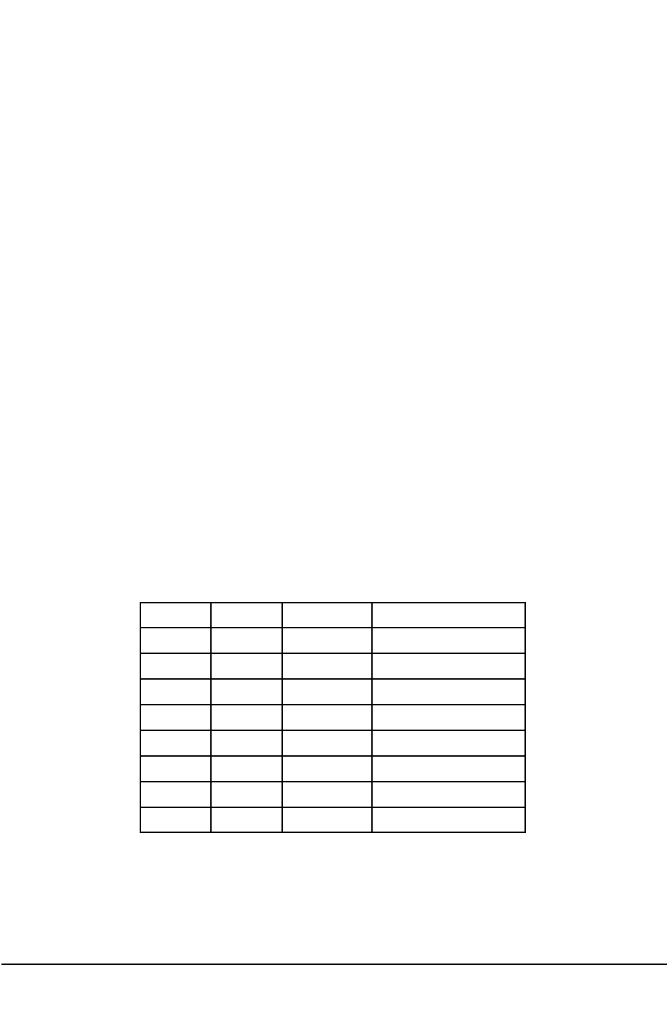
Electro Industries/GaugeTech
Doc# E154703 8-24
Auto Increment Log Window - 64 registers, 128 bytes.
These registers are a 128-byte window into a log, as specified in the Auto Increment Configuration
(register 39423, 0x099FE). Depending on the Auto Increment Window Index, a different 128-byte
area of a log can be accessed.
See section 5.1.4: Downloading Logs with Auto Index and Modbus Extensions for the usage of
these registers.
8.94: Alarm Block (40961-441105)
Description: Window Registers included in this block:
Last Alarm (40961-40976): These Registers keep the latest Limit Trigger Log, which records
information about the limits. The log records which limits are currently exceeded and which limits
have just changed. The 16 Registers contain 32 bytes. The record format is the same as the Limit
Trigger Log Format.
The first eight bytes are the Time Stamp. The format of the Time Stamp is:
Byte Format Range Description
0 Binary 0-99 Century
1 Binary 0-99 Year
2 Binary 1-12 Month
3 Binary 1-31 Day
4 Binary 0-23 Hour
5 Binary 0-59 Minute
6 Binary 0-59 Second
7 Binary 0-99+MSB Centisecond

Electro Industries/GaugeTech
Doc# E154703 8-25
An additional piece of information is contained in the centisecond byte. The most significant bit
indicates whether Limit Trigger monitoring was continuous between the last record and this record.
If the bit is 1, then this is the first record recorded after a power-down, reset or download and all
unfinished durations prior to this record are lost. If the bit is 0, then recording was continuous
between the last record and this one.
The next four bytes are a bitmap for the Current State of the Value 1 Comparisons of the Limits.
The first bit (the most significant bit of the first byte) is the Current State of the 1st Limit’s Value 1
Comparison. The last bit (the least significant bit of the fourth byte) is the Current State of the
32nd Limit’s Value 1 Comparison. A bit value of 1 means that the Comparison is exceeded (less
than or equal to Value 1 for a below limit; greater than Value 1 for an above limit), a bit value of 0
means the Comparison is not exceeded (greater than Value 1 for a below limit; less than or equal to
Value 1 for an above limit).
The next four bytes are the same bitmap as above, but for the Current State of the Value 2
Comparisons of the Limits.
The next four bytes are a bitmap for the Delta of the Value 1 Comparisons of the Limits. The order
of the bits is the same as above. A bit value of 1 means that the State of the Value 1 Comparison
changed since the last alarm occurred; a bit value of 0 means that the State of the Value 1
Comparison did not change since the last alarm.
The next four bytes are the same bitmap as above, but for the Delta of the Value 2 Comparisons of
the Limits.
The next four bytes are a bitmap for the Current State of the Combinations of the Limits. The first
bit (the most significant bit of the first byte) is the Current State of the 1st Limit’s Combination of
the Value 1 Comparison and the Value 2 Comparison. The last bit (the least significant bit of the
fourth byte) is the Current State of the 32nd Limit’s Combination of the Value 1 Comparison and
the Value 2 Comparison. A bit value of 1 means that the Combination is true; a bit value of 0
means that the Combination is false.
The last four bytes are the same bitmap as above, but for the Delta of the Combination of the
Limits.
Last Alarm Snapshot (40977-41104)
The Registers store the latest Limit Snapshot Log.
The record formats are also explained in Chapter 6.
Record Format: A Record contains 32, 64, 128 or 256 bytes, depending on how many channels
have limits assigned to them. The first eight bytes in each Record are the Time Stamp. The format
of the Time Stamp is shown below.
The remaining bytes are the values monitored by Limits (45077-45204). If the first Data Pointer is
requesting VBN, a 4-byte value, then the next 4 bytes in the Record is VBN. This continues, Data
Pointer for Data Pointer, until all Data Pointers have been satisfied, or the number of bytes is equal
to the Historical Log 1 Record Size.
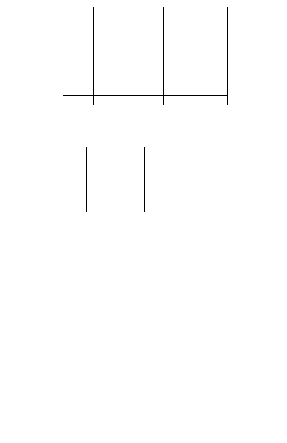
Electro Industries/GaugeTech
Doc# E154703 8-26
Limit Data Pointers (45077-45204): These Registers indicate which values are being monitored
by Limits. Each Data Pointer has the following 8-byte structure:
A Line Number is an index into the Communication Table. Example: Line Number 11 is for the
12th Line in the Communication Table, 0.1 Second Phase-to-Neutral Voltages. Data Pointers with
Line Numbers greater than the number of lines in the table are ignored.
A Point Number is an index into a Line in the Communication Table. Example: Point Number 1 is
for the second entry in a Line. Line Number 11, Point Number 1 is the 2nd in the 12th line, 0.1
Second VBN. Data Pointers with Point Numbers greater than the number of points for the line are
ignored.
Latched Exception Flag (41105): This Register tells you how many Limit Triggers have occurred
since the last time the Registers were checked. This Register is Read Only.
Example: Two Limit Exceptions occurred. Read the Register from Port 1; you will notice 2 Limit
Exceptions returned. Later, two more Limit Exceptions occurred. Read the Register again. From
Port 1, you will notice 2 Limit Exceptions returned. From Port 2, you will notice 4 Limit
Exceptions returned. Limit Exceptions are incremented so that you have a history of Limit
Exceptions in the Ports.
Byte Format Range Description
0 Binary 0-99 Century
1 Binary 0-99 Year
2 Binary 1-12 Month
3 Binary 1-31 Day
4 Binary 0-23 Hour
5 Binary 0-59 Minute
6 Binary 0-59 Second
7 Binary 0-99+MSB Centisecond
Size Format Description
2-byte Unsigned Integer Line Number
1-byte Unsigned Char Point Number
1-byte Unsigned Char Limit Mode
2-byte Unsigned Integer Comparison 1 Value
2-byte Unsigned Integer Comparison 2 Value
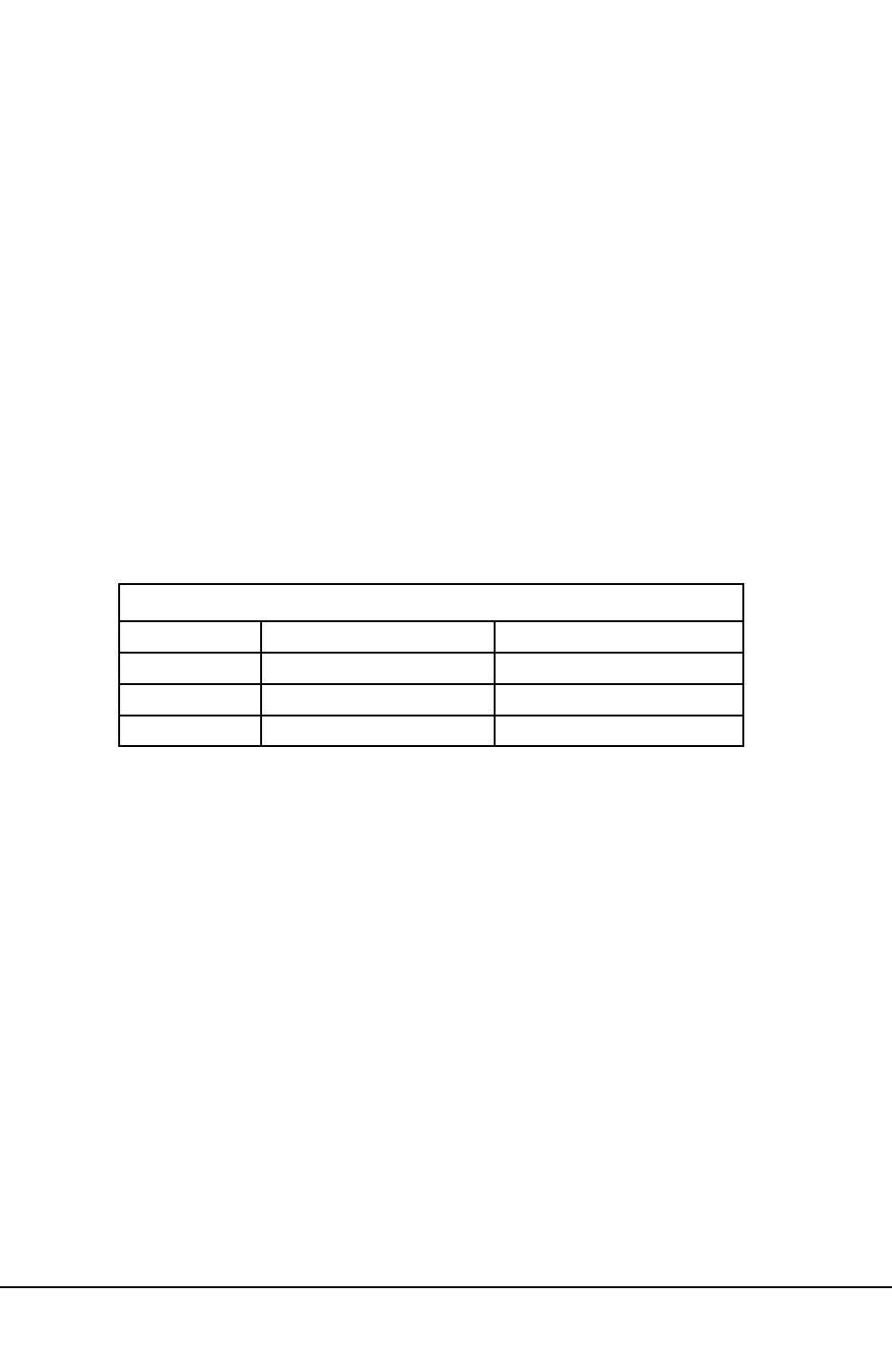
Electro Industries/Gauge Tech
Doc# E154703 8-27
8.95:
Port
Control
Block
(41729-444544)
QDescription: Port Control Registers included in this block (see Chapter 5):
Port Control Command (41729): When written, this Register receives commands meant to control
the ports. Valid commands are:
0x00100 = Lock Port 4 (I/O) for my use
0x00101 = Lock Port 3 for my use
0x00102 = Lock Port 2 for my use
0x00103 = Lock Port 1 (232/485) for my use
0x00104 = Lock the Diagnostic Port for my use (currently not use)
0x00200 = Unlock Port 4
0x00201 = Unlock Port 3
0x00202 = Unlock Port 2
0x00203 = Unlock Port 1
0x00204 = Unlock the Diagnostic Port (currently not used)
You cannot lock your own port. You cannot lock a port that is already locked. A port can only be
unlocked by the port that locked it originally.
Lock States (41730-41732): These Registers contain 6 bytes. The first five bytes contain codes
indicating whether a port is locked by another port or not.
Initially, these bytes read as 0x0FF. When a port requests that another port be locked to its use
(0x00100 - 0x00104 to Register 41731), these bytes will read with one of the following codes,
indicating which port is the locked owner of which port:
0x000 = Locked by Port 4 (I/O)
0x001 = Locked by Port 3
0x002 = Locked by Port 2
0x003 = Locked by Port 1 (232/485)
0x004 = Locked by the Diagnostic Port (currently not used)
0x0FF = Unlocked
Pointers (41733-41752): These Registers, when read, return the values of the pointers controlling
the Communication Buffers in the Nexus®device. They are unsigned integers and represent the
indexes of the series of bytes that are the Receive and Transmit Circular Buffers. Since the buffers
are 512 bytes long, valid values should range from 0x00000 to 0x001FF.
The order of the Registers is:
Register High Byte Low Byte
41731 Port 4 (I/O) Port 3
41732 Port 2 Port 1 (232/485)
41733 Diagnostic Port Unused
Port Control Lock States
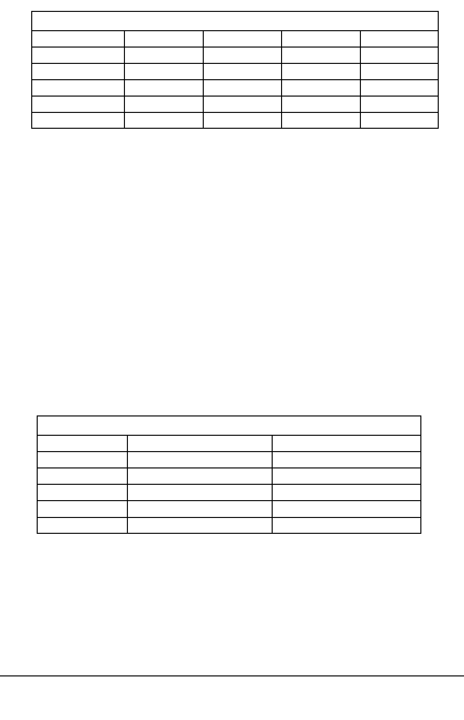
Electro Industries/Gauge Tech
Doc# E154703 8-28
ReceiveIn indexes the location where the next received character will be placed in the Receive
Buffer by the interrupt routine. ReceiveOut indexes the location where the next character should be
removed from the Receive Buffer by the parsing routine. TransmitIn indexes the location where the
next character to be transmitted should be placed by the communication generation routine.
TransmitOut indexes the location of the next character to be transmitted by the interrupt
routine.
The Receive Buffer is empty if RecIn = (RecOut+1) Mod 512. The Receive Buffer is full if RecIn =
RecOut. The Transmit Buffer is empty if TrmIn = TrmOut. The Transmit Buffer is full if TrmOut =
TrmIn+1) Mod 512.
When a port is locked, its pointers may be modified by the locking port.
When a TransmitIn Register is written, that causes the interrupt routines to transmit characters in the
Transmit Buffer from TransmitIn to TransmitOut.
Receive and Transmit Buffers (41985-44544): These Registers, when read, return the contents of
the appropriate Receive and Transmit Buffers. Each buffer is 256 Registers (512 bytes) long. The
order of the buffers is:
Port ReceiveIn ReceiveOut TransmitIn TransmitOut
Port 4 (I/O) 41733 41734 41735 41736
Port 3 41737 41738 41739 41740
Port 2 41741 41742 41743 41744
Port 1 (232/485) 41745 41746 41747 41748
Diagnostic Port 41749 41750 41751 41752
Port Control Pointers
Port TransmitReceive
Port 4 (I/O) 41985-42240 43265-43520
Port 3 42241-42496 43521-43776
Port 2 42497-42752 43777-44032
Port 1 (232/485) 42753-43008 44033-44288
Diagnostic Port 43009-43264 44289-44544
Receive and Transmit Buffers

Electro Industries/Gauge Tech
Doc# E154703 8-29
8.96:
Energy
Preset
Block
(44545-444549)
QDescription: Energy readings can be preset by Communicator Ext 3.0 software.
Preset Energy Value: 4 Registers, 8 bytes. These registers hold the energy readings that will be
used by the software for certain Energy Applications.
Preset Energy Selection / Status: 1 Register, 2 bytes. This register indicates which energy is to be
preset by the software.
8.97:
Registers
53249-553348
are
not
used
by
the
Nexus®1500
meter

Electro Industries/Gauge Tech
Doc# E154703 8-30
8.98:
Action
Block
-
Resetting
Meter
Registers
(57345-557393)
Most of the Registers in the Action Block are used to perform an action or reset a meter Register.
Unless otherwise stated, the action is performed when a value, any value, is written to that Register.
Example: In order to Reset Maximum Value in Meter Address 1, any value, such as ‘1’ (0x00001)
should be written to Register 57346 (0x0E001). The appropriate Modbus RTU command for this
example would be: 01 06 E001 0001 2E0A (See Chapter 1 for Modbus protocol overview.)
QDescription: Action Registers included in this block:
Log Reset (57345): This Register, when written with any value, causes all logs to be cleared. This
action should be performed only under the following two circumstances:
1. When the Programmable Settings are modified, such that data already in the logs is invalidated.
For Example, any modifications involving the record size or organization of the contents of a
snapshot would require the logs to be cleared of any previous data.
2. When the Run-Time Code is upgraded, resulting in one of the following:
Redefinition of the layout or meaning of the Programmable Settings.
Altered behavior or capabilities of the logs.
NOTE: Log Reset should be performed automatically by the software in either case and should not
be an action directly available to the user. (See Chapter 5.)
Maximum Reset (57346): This Register, when written with any value, causes all Maximum Values
to be cleared.
Minimum Reset (57347): This Register, when written with any value, causes all Minimum Values
to be cleared.
Energy Reset (57348): This Register, when written with any value, causes all Energy Values to be
cleared.
Registers for the Meter Calibration (57349-57377): These Registers are for factory use only.
Meter’s Calibrations are done through these Registers.
Registers 57380-57382: These Registers are no longer used. Internal KYZ Enable, Internal KYZ
Minimum Pulse Width, Internal KYZ Pulses/Whr sec are obsolete.
Waveform Calibration (57383-57384): Waveform Calibration should be performed when wave-
form sampling is running at rates of 16, 32, 64 or 128 samples per cycle. Waveform Calibration
should not be performed when waveform sampling is running at 256 or 512 samples per cycle. If
the unit needs waveform recalibration and is running at 256 or 512 samples per cycle, reprogram the
meter to one of the other sampling rates, recalibrate, then return the unit to its original sampling rate.
Voltage Calibration (57383): When written, the Register initiates a calibration of the Voltage
Channels of the Waveform Capture section of the meter’s Main Unit. An accurate and stable 60Hz
sinusoial voltage input should be applied to all voltage channels of the unit prior to the writing of
this Register. Phase relationships between the voltage channels are immaterial. The magnitude of
the signal should be as follows:
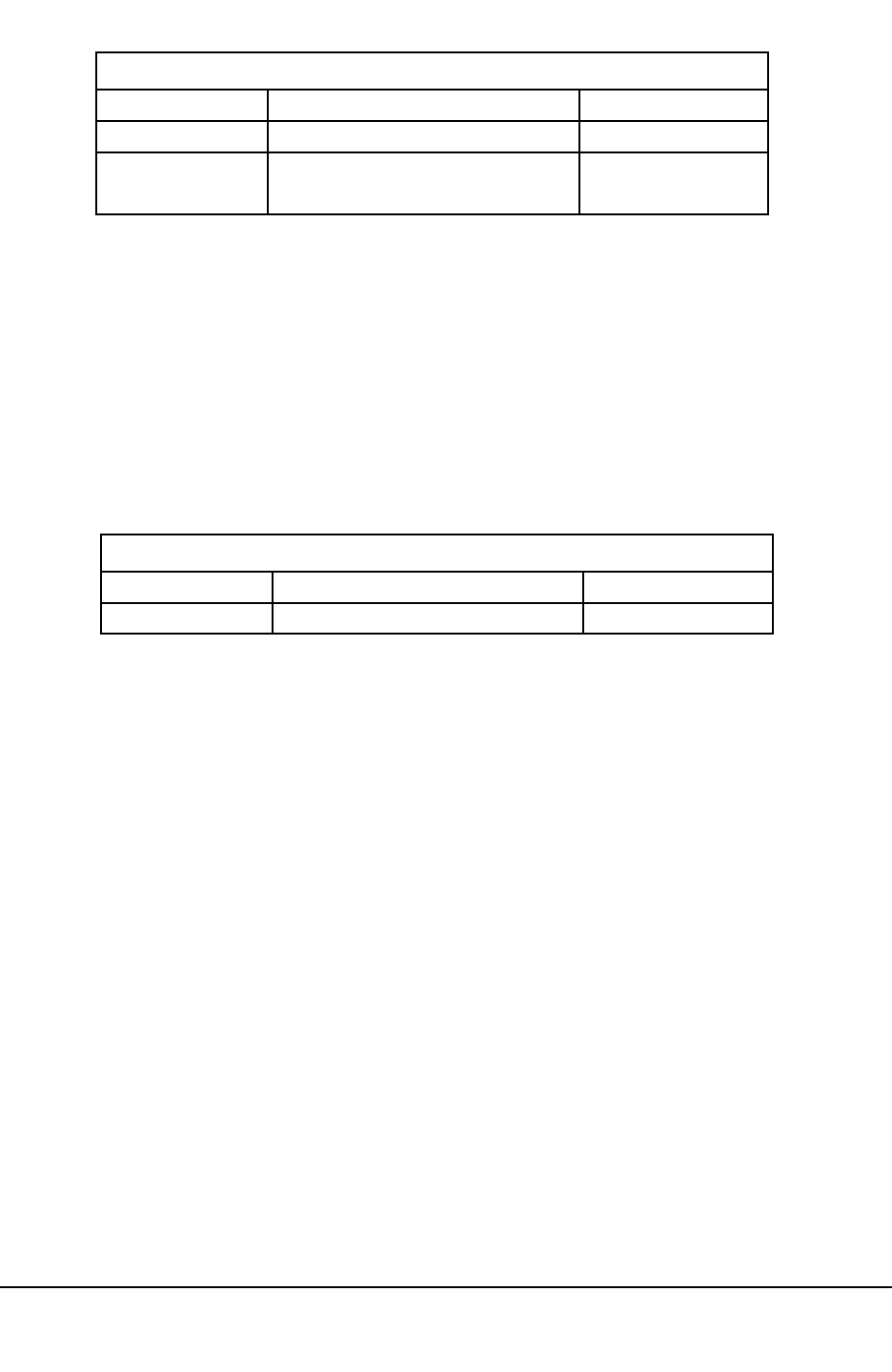
Electro Industries/Gauge Tech
Doc# E154703 8-31
When read, this Register returns the state of the Voltage Calibration. A value of 0x00000 means that
Voltage Calibration is not taking place. Any other value indicates that Voltage Calibration is taking
place. The 120 V Input should be maintained until this Register reads 0x00000, which should take
up to 20 seconds, depending on the Programmable Settings.
Current Calibration (57384): When written, this Register initiates a calibration of the Current
Channels of the Waveform Capture section of the meter’s Main Unit. An accurate and stable 60Hz
sinusoial voltage input should be applied to all current channels of the unit prior to the writing of
this register. Phase relationships between the current channels are immaterial. The magnitude of the
signal should be as follows:
When read, this Register returns the State of the Current Calibration. A value of 0x00000 means
that Current Calibration is not taking place. Any other value indicates that Voltage Calibration is
taking place. The 120 V Input should be maintained until this Register reads 0x00000, which
should take up to 20 seconds, depending on the Programmable Settings.
Calibration Waveform - DC Offset (57385): This Register is currently not used.
Reset Time of Use Current Season and Current Month (57386): When written, Time of Use
Current Season and Current Month will reset.
Manual Waveform Capture (57387): When written, the unit captures a waveform.
Reset Internal Input Accumulations and Aggregations (57388): When written, Internal Input
Accumulations and Aggregations will reset.
Override Data not yet Valid Block (57389): This Register is for diagnostics of communication
between two microprocessors in the meter.
Meter Model Input RMS
1500 Meter Standard (5Amp) Current Input 5A RMS
Current Calibration Inputs
Meter Model Input RMS
1500 Meter Standard (120 V) Voltage Input 120 V RMS
Voltage Calibration Inputs
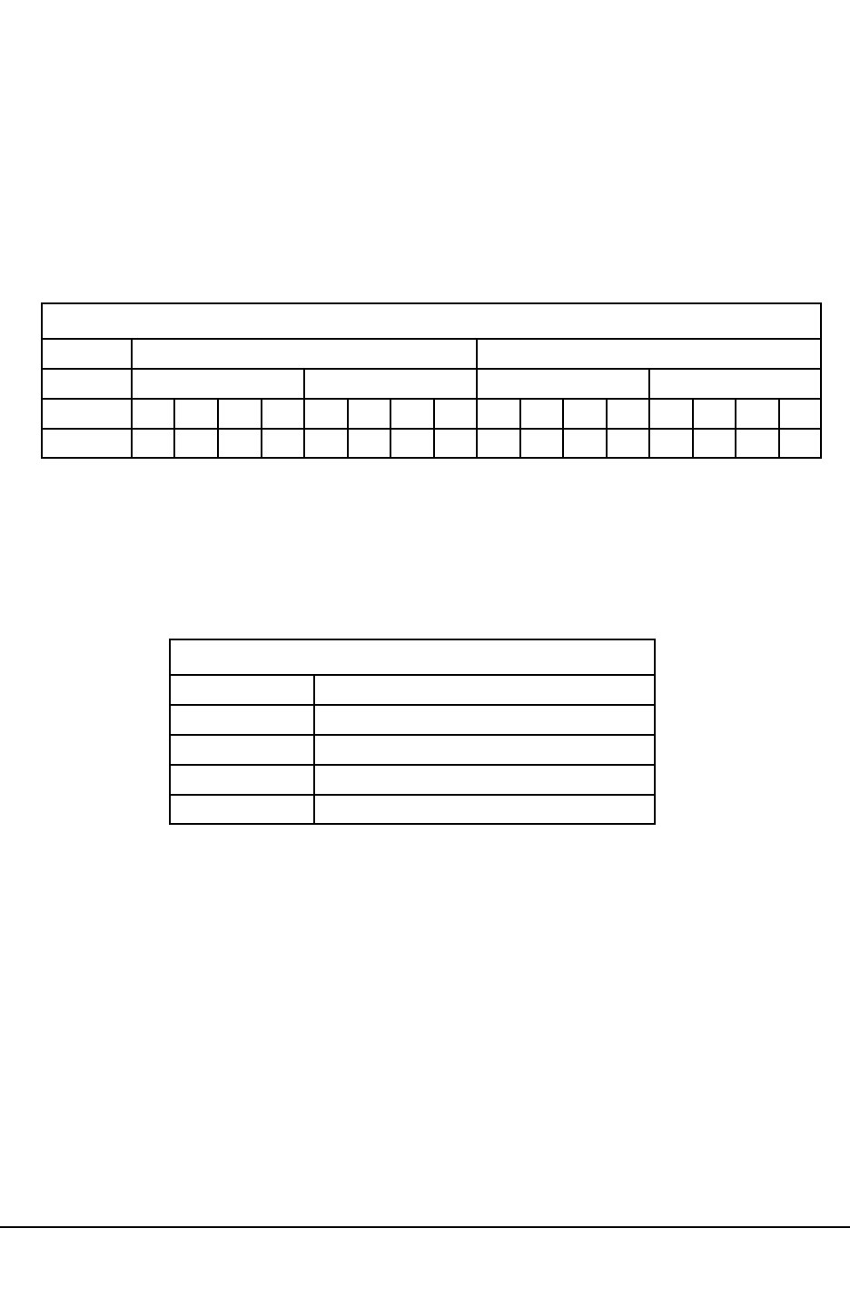
Electro Industries/Gauge Tech
Doc# E154703 8-32
Refresh External I/O Header Information (57390): This Register, when written, causes all
External Devices to be polled for their Information Blocks.
Refresh External I/O Programming Information (57391): This Register, when written, causes all
External Devices to be polled for their Programming Blocks.
Relay Locking Relay Selection (57392): This Register and Register 57392 will manually change
the External Digital Output Modules’ Relays. Using Register 57392, the user can select relays to be
locked by Register 57393. A bit value of 1 means that the relay will be affected by the value on the
Action Selection Register (57393).A bit value of 0 means that the relay will not be affected by the
value on the Action Selection Register (57393).
Relay Locking Action Selection (57393): This Register will lock or unlock the relays of the
External Digital Output Modules in Relay Selection Register 57392. Relays in the Selection
Register (57392) with a bit value of 1 can be locked or unlocked by this Register. The Register is a
2-byte unsigned integer.
8.99:
Factory
Calibration
Block
(60929-661026)
QDescription: Refer to section 5.5 for details.
8.100:
CTPT
Compensation
Calibration
Block
(61027-661124)
QDescription: Refer to section 5.5 for details.
8.101:
Calibration
Modification
Block
(61185-661280)
QDescription: Refer to section 5.5 for details.
Byte
3
High Byte Low Byte
Module Module 2Module 1
12 4 312 4
Module 3 Module 4
312 4 312 4
Bit
Relay
15 14 13 12 11 10 9 8 7 6 5 4 3 2 1 0
Relay Locking Relay Selection Register (57392)
Value Description
0 Lock common to N.C. (Normally Closed)
1 Lock common to N.O. (Normally Open)
2 Unlock
3-65535 Not used
Relay Locking Action Selection Values
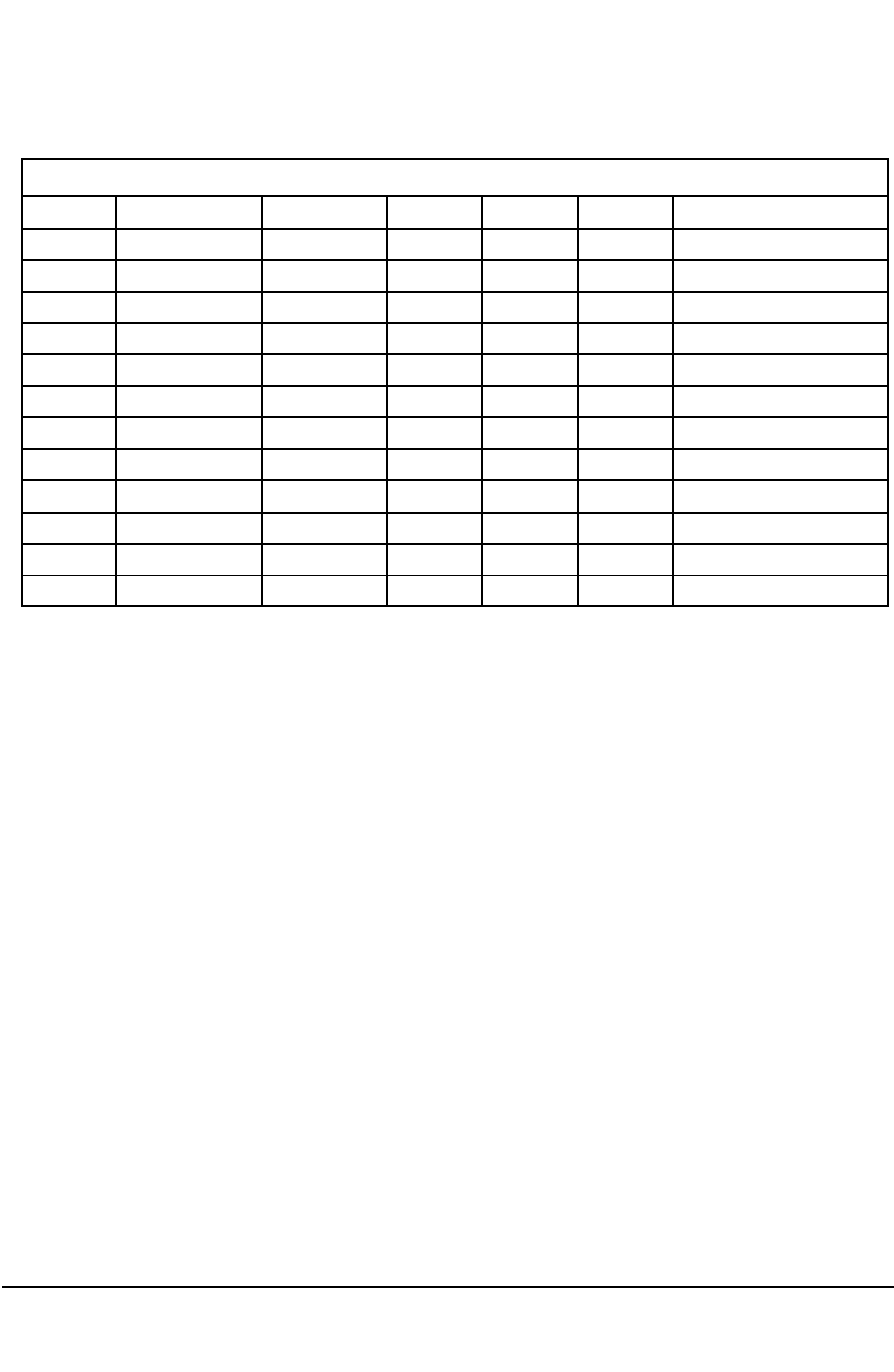
Electro Industries/Gauge Tech
Doc# E154703 8-33
8.102:
Operational
Communication
Settings
Block
(65025-665040)
These Registers keep the valid Communication Settings for all four ports. The Communication
Settings Block (45057) in the Programmable Settings Block might have the wrong values if they
were interrupted while the meter was being updated.
QDescription: Operational Communication Settings Registers included in this block:
Device Address - 2 bytes, unsigned integer, ranging from 0 to 0xFFFF.
Protocol - 1 byte, unsigned integer.
Baud Rate - 1 byte, unsigned integer.
Parity - 1 byte, unsigned integer.
Stop Bits - 1 byte, unsigned integer.
Data Bits - 1 byte, unsigned integer.
Response Delay - 1 byte, unsigned integer.
8.103:
Registers
65041-665042
are
not
used
by
the
Nexus®1500
meter
8.104:
Device
Identification
Block
2
(65088-665280)
QDescription: Device Identification Registers included in this block:
196 Xilinx Version / 320 Xilinx Version (65088)
Each number is represented by a 1-byte integer.
Firmware Variation Strings (65089-65280)
Eight Registers each and Null Terminated ASCII Strings (Terminating Null (ASCII 00H) at the end
of the string). (See 3.1.)
Value Protocol Baud Rate Parity Stop Bits Data Bits Response Delay (ms)
0 Modbus ASCII 4800 None 5 0.00
1 Modbus RTU 9600 Even 6 0.25
2 DNP 3.0 19200 Odd 7 0.50
3 38400 Mark 8 0.75
4 57600 Space 1.00
5 115200 1.25
6 1.50
7 1 stop 1.75
8 1.5 stop 2.00
9-14 2.25-3.50
15 2 stop 3.75
16-255 4.00-63.75
Operational Communication Settings

Electro Industries/Gauge Tech
Doc# E154703 8-34
8.105:
DSP
Diagnostic
Block
(65281-665312)
QDescription: DSP Diagnostic Registers are for internal use only. These Registers are not for
customer use. These Registers are READ ONLY and cannot be written.
8.106:
Password
Command
(65328)
QDescription:This Register contains and enumeration that tells the device what action to take. The
enumeration is as follows:
0x00000 Set Level 1 Password
0x00001 Set Level 2 Password
0x00002 Enable Password Protection
0x00003 Disable Password Protection
0x00004 Enable Sealing Switch Protection
0x00005 Disable Sealing Switch Protection
0x00006 - Set Network User 1 User Name and Password
0x00007 - Set Network User 2 User Name and Password
0x00008 - Set Network User 3 User Name and Password
0x00009 - Set Network User 4 User Name and Password
0x0000A - Set Network User 5 User Name and Password
0x0000B - Set Network User 6 User Name and Password
0x0000C - Set Network User 7 User Name and Password
0x0000D - Set Network User 8 User Name and Password
0x0000E - Set Network User 1 Privileges
0x0000F - Set Network User 2 Privileges
0x00010 - Set Network User 3 Privileges
0x00011 - Set Network User 4 Privileges
0x00012 - Set Network User 5 Privileges
0x00013 - Set Network User 6 Privileges
0x00014 - Set Network User 7 Privileges
0x00015 - Set Network User 8 Privileges
0x00016 - Read Network User 1 user Name and Privileges
0x00017 - Read Network User 2 user Name and Privileges
0x00018 - Read Network User 3 user Name and Privileges
0x00019 - Read Network User 4 user Name and Privileges All successful commands set access
back to Level 0, revoking the 2-minute timer of any active password.

Electro Industries/Gauge Tech
Doc# E154703 8-35
QNew Password A (65332-65336)
New Password B (65340-65344)
For setting Level 1 & Level 2 passwords:
These registers are written to in order to set the Level 1 or Level 2 Password. The same password
should be written to both sets of registers; a new password will be accepted only if the values
written to both sets of registers agree. After filling in both sets of registers, the Password Command
register should be written with the command indicating which password is being updated.
Passwords must be 10 bytes long - consistent padding with extra characters must be performed.
Acceptable Passwords should consist of the ASCII characters ‘ ‘ (0x020), ‘0’-‘9’ (0x030-0x039),
‘A’-‘Z’ (0x041-0x05A). Attempts to set a password with illegal characters will fail. If a password is
shorter than 10 bytes should be padded with SPACE (0x020) characters at the end.
For setting network user name, password and privileges:
For setting network user name and password, software should send user name to New Password A
field, and password to New Password B field. Software should always set none-zero length to user
name and password fields. If username or password is shorter than 10 bytes, then software should
padded it with NULL (0x0) characters at the end.
For setting network user privileges, software should send it to New Password A field, with unde-
fined bit fields set to 0s.
For reading network user name and privileges, the user must gain Level 2 password access to the
meter and then issue the read network username & privileges command. Tthe meter will place the
user name in New Password A field and user privileges in New Password B field for software to
read. The user cannot read the network password. The byte values in New Password A and New
Password B fields are encoded. If the user does not have sufficient access rights or if the password
command sequence entered is not correct, the user will read 0's for New Password A and New
Password B fields.
8.107:
Registers
65345-665349
are
not
used
by
the
Nexus®1500
meter
8.108:
Registers
65361-665368
are
not
used
by
the
Nexus®1500
meter

Electro Industries/Gauge Tech
Doc# E154703 8-36

E Electro Industries/Gauge Tech Doc# E154703 9-1
Chapter 9
Alternative Method for Downloading Logs
9.1: Overview
The preferred and recommended method for downloading logs from the Nexus® 1500 meter is
using LDA, as explained in Chapter 6. For backward compatibility, the System Events Log and
historical logs 1 and 2 can be downloaded using the serial method. This chapter contains
information for doing so.
9.2: Historical Log 1 Format
Profile Information is in the Programmable Settings Block.
Historical Log 1: Historical Log 1 will fill to its total allocated memory. The number of records
possible in the log is the total memory allocated divided by the record size (size of an
Historical Log snapshot).
Historical Log 1 Record Size: (45463)
This Register is an enumeration for the size of a record in the Historical log. The valid values
are:
0x00000 = 32 byte records
0x00001 = 64 byte records
0x00002 = 128 byte records
0x00003 = 256 byte records
0x00004 = 16 byte records
Historical Log 1 Data Pointers: (45205-45332)
These Registers indicate which information to include in a record in the Historical log. Each
Data Pointer has the following 4 (four) byte structure:
Size Format Description
2 byte unsigned int Line Number
1 byte unsigned char Point number
1 byte unsigned char Reserved
A Line Number is an index into the Communication Table. Example - Line Number 11 is for
the 12th line in the Communication Table, 0.1 second Phase-to-Neutral Voltages. Data
Pointers with Line Numbers greater than the number of lines in the table are ignored.
A Point Number is an index into the Communication Table.
Example: Point Number 1 is for the second entry in a Line. Line Number 11, Point Number 1
is the second in the twelfth line, 0.1 second VBN. Data Pointers with Point Numbers greater
than the number of points for the line are ignored.

E Electro Industries/Gauge Tech Doc# E154703 9-2
Record Format: A Record contains as many bytes as specified by the Historical Log 1 Record
Size Field in the Programmable Settings Block (45463). The first eight bytes in each record is
the Time Stamp. The format of the Time Stamp is:
Byte Format Range Description
0 binary 0 – 99 century
1 binary 0 – 99 year
2 binary 1 – 12 month
3 binary 1 – 31 day
4 binary 0 – 23 hour
5 binary 0 – 59 minute
6 binary 0 – 59 second
7 binary 0 – 100 centisecond
If the Historical record was recorded after powering up or the log was reset, the record does not
contain information covering a full interval and the most significant bit of the second’s byte
will be set.
If the Historical record was recorded after time was adjusted, the record might contain more or
less than a full interval’s worth of data. If time is advanced within the current interval, or
advanced or rolled back to outside the current interval, the record contains less than a full
interval’s worth of data and the most significant bit of the minute byte will be set. If time is
rolled back within the same interval, the record contains more than a full interval’s worth of
data and the bit before the most significant bit (bit 6) of the minute byte will be set.
The remaining bytes are the values requested by the Historical Log 1 Data Pointers (45205-
45332). If the first Data Pointer is requesting VBN a 4 byte value, then the next 4 bytes in the
Record are VBN. This continues, Data Pointer for Data Pointer, until all Data Pointers have
been satisfied, or the number of bytes is equal to the Historical Log 1 Record Size.
9.3: Historical Log 2 Format
Profile Information is in the Programming Settings Block.
Historical Log 2: Historical Log 2 will fill to its total allocated memory. The number of records
possible in Historical Log 2 is the total memory allocated divided by the sum of record size
(size of Historical Log snapshot) and the 8 bytes record header.
Historical Log 2 Record Size: (45464)
This Register is an enumeration for the size of a record in the Historical Log. The valid values
are:
0x00000 = 32 byte records
0x00001 = 64 byte records
0x00002 = 128 byte records
0x00003 = 256 byte records
0x00004 = 16 byte records
Historical Log 2 Log Data Pointers: (45333-45460)
These Registers indicate which information to include in a record in the Historical Log. Each
Data Pointer has the following 4 (four) byte structure:

E Electro Industries/Gauge Tech Doc# E154703 9-3
Size Format Description
2 byte unsigned int Line Number
1 byte unsigned char Point number
1 byte unsigned char Reserved
A Line Number is an index into the Communication Table. Example - Line Number 11 is for
the 12th line in the Communication Table, 0.1 second Phase-to-Neutral Voltages. Data
Pointers with Line Numbers greater than the number of lines in the table are ignored.
A Point Number is an index into the Communication Table.
Example: Point Number 1 is for the second entry in a Line. Line Number 11, Point Number 1
is the second in the twelfth line, 0.1 second VBN. Data Pointers with Point Numbers greater
than the number of points for the line are ignored.
Record Format: A Record contains as many bytes as specified by the Historical Log 2 Record
Size Field in the Programmable Settings Block (45464). The first eight bytes in each record is
the Time Stamp. The format of the Time Stamp is:
Byte Format Range Description
0 binary 0 – 99 century
1 binary 0 – 99 year
2 binary 1 – 12 month
3 binary 1 – 31 day
4 binary 0 – 23 hour
5 binary 0 – 59 minute
6 binary 0 – 59 second
7 binary 0 – 100 centisecond
If the Historical record was recorded after powering up or the log was reset, the record does not
contain information covering a full interval and the most significant bit of the second’s byte
will be set.
If the Historical record was recorded after time was adjusted, the record might contain more or
less than a full interval’s worth of data. If time is advanced within the current interval, or
advanced or rolled back to outside the current interval, the record contains less than a full
interval’s worth of data and the most significant bit of the minute byte will be set. If time is
rolled back within the same interval, the record contains more than a full interval’s worth of
data and the bit before the most significant bit (bit 6) of the minute byte will be set.
If the Historical Log 2 Time of Use Enable byte (45952) is disabled, the remaining bytes are
the values requested by the Historical Log 2 Data Pointers (45333-45460). If the first Data
Pointer is requesting VBN a 4 byte value, then the next 4 bytes in the Record are VBN. This
continues, Data Pointer for Data Pointer, until all Data Pointers have been satisfied, or the
number of bytes is equal to the Historical Log 2 Record Size.

E Electro Industries/Gauge Tech Doc# E154703 9-4
9.4: System Event Log Format
The System Event Log stores events which affect the operation of the meter, including power
events, time changes, log retrieval, and firmware changes. The full list is given below.
Record Format: The System Event record is 16 bytes.
[Timestamp] 8 bytes, Nexus Timestamp
[Record Type] 1 byte
[Record Details] 7 bytes
Event Table - see next page.
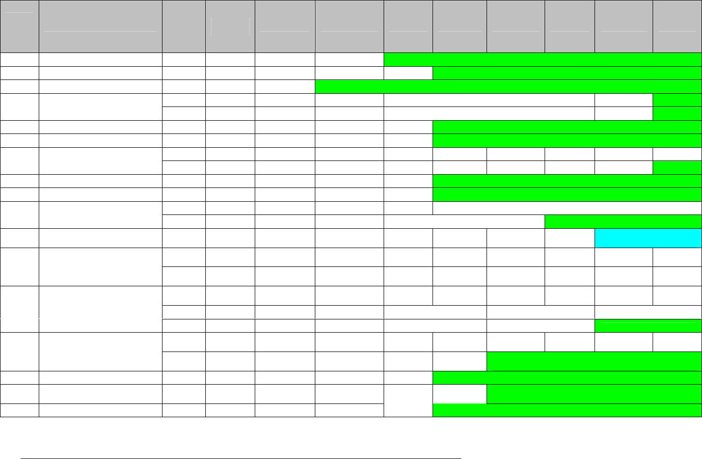
E Electro Industries/Gauge Tech Doc# E154703 9-5
Event
Type
ID System Event Type Record
Sequence Bytes 0 to
7 Byte 8 Byte 9 Byte 10 Byte 11 Byte 12 Byte 13 Byte 14 Byte 15
0x000 Run Time Status (Power) First TimeStamp Event Type ID Details Undefined
0x001 Password First TimeStamp Event Type ID Action Port ID Undefined
0x002 Change Programmable Settings First TimeStamp Event Type ID Undefined
First TimeStamp Event Type ID Firmware ID Current Major Version Rec Sequence Undefined
0x003 Change Firmware
Second TimeStamp Event Type ID Firmware ID Current Minor Version Rec Sequence Undefined
0x004 Change Time First TimeStamp Event Type ID Part changed Port ID Undefined
0x005 Test Mode First TimeStamp Event Type ID Action Port ID Undefined
First TimeStamp Event Type ID Action Log ID Port ID Rec Sequence Protocol IP Byte 1 IP Byte 2
0x006 Log Retrieval
Second TimeStamp Event Type ID Action Log ID Port ID Rec Sequence IP Byte 3 IP Byte 4 Undefined
0x007 Feature Reset First TimeStamp Event Type ID Item ID Port ID Undefined
0x008 System Initialization problem First TimeStamp Event Type ID Problem Type Prob Detail Undefined
First TimeStamp Event Type ID Rec Sequence Port ID Old Serial Number MSB Part
0x009 Change meter serial number
Second TimeStamp Event Type ID Rec Sequence Old Serial Number LSB Part Undefined
0x00A Bio-Block First TimeStamp Event Type ID Rec Sequence Block ID
Update
Order Port ID Reason = 1 Not Used
First TimeStamp Event Type ID Rec Sequence
Block ID =
2
Update
Order Port ID Reason = 2 MAC Byte 1
MAC Byte
2
0x00A Bio-Block (Ether Board 1)
Second TimeStamp Event Type ID Rec Sequence
Block ID =
2
Update
Order MAC B3
MAC Byte
4 MAC Byte 5
MAC Byte
6
First TimeStamp Event Type ID Rec Sequence
Block ID =
3
Update
Order Port ID
Reason >=
2 Contrast Volume
Second TimeStamp Event Type ID Rec Sequence LCD Turnoff Timeout X Left Coordinate X Right Coordinate
0x00A Bio-Block (Front Panel Board)
Third TimeStamp Event Type ID Rec Sequence Y Top Coordinate Y Bottom Coordinate Undefined
First TimeStamp Event Type ID Rec Sequence
Block ID =
8 Upd Order Port ID Reason = 2 Cal Status Cal Error
0x00A Bio-Block (Digital Board)
Second TimeStamp Event Type ID Rec Sequence
F Tst
Status Fin Tst Error Undefined
0x00B VSwitch First TimeStamp Event Type ID V-Switch Value Port ID Undefined
0x00C Security First TimeStamp Event Type ID Action Port ID
User Acc
Idx Undefined
0x00D Clock Compensation First TimeStamp Event Type ID Enabled/Disabled Port ID Undefined

E Electro Industries/Gauge Tech Doc# E154703 9-6
Run Time Status - Power Record
The first byte of the sub-fields indicates whether power was lost or regained at the recorded
time:
0x000 Run Time was stopped (power loss, boot mode, etc.). The timestamp record is that
recorded before the meter be turned off.
0x001 Run Time has started.
0x002 Run Time is active (all readings have initialized, polling, logging limits, etc. are enabled)
0x003-0x0FF Undefined
The remaining 6 bytes of the sub-fields are undefined.
Password Record
The Password System Event record is stored when the administrative password is used or
changed. See Security Record for changes in the individual user accounts.
The first byte of the sub-fields indicates what action occurred at the recorded time:
0x000 Password Protection was Enabled.
0x001 Password Protection was Disabled.
0x002 The Level 1 Password was changed.
0x003 The Level 2 Password was changed.
0x004 Level 1 access was granted.
0x005 Level 2 access was granted.
0x006 An invalid password was supplied.
0x007-0x0FF Undefined
The second byte of the sub-fields indicates what port was used for the action:
0x000 internal use
0x001 PORT 1 – IR/OPTICAL PORT
0x002 LCD touch screen
0x003 ETHERNET 1
0x004 ETHERNET 2
0x005 PORT 3- RS485 – master or slave
0x006 reserved, N/A
0x007 USB only, N/A for UART
0x008 PORT 4 – RS485, master or slave
0x009 PORT 2 – UART, USB serial
0x00A-0x0FF Undefined
The remaining 5 bytes of the sub-fields are undefined.
Change Programmable Settings
The 7 bytes of the sub-fields are undefined.
The first byte of the sub-fields indicates which copy was successfully created and saved. If all
bits are zero no copy was successfully created/saved:
Bit 0 (Less significant bit) = 1 (First copy OK)
Bit 1 (Less significant bit) = 1 (Second copy OK)
Bit 2 (Less significant bit) = 1 (Third copy OK)
Bit 3-7 = Not defined
The 6 bytes of the sub-fields are undefined.
Change Firmware
This event type can generate up two consecutives records.
The first byte of the sub-fields indicates which firmware has been changed:
0x000 Comm Run Time
0x001 DSP 1 Run Time
0x002 Comm Boot
0x003 FPGA
0x004 DSP2 Run Time
0x005-0x0FF Undefined

E Electro Industries/Gauge Tech Doc# E154703 9-7
The next 4 bytes of the sub-fields indicates the current major/minor version number of the
changed firmware. They major/minor version is left leading with space/zeros. (For FPGA the
minor firmware version will be just into the second and third byte)
The sixth byte of the sub-fields indicates the record sequence.
0x000 no extra record (for firmware that does not have minor version number)
0x001 the first record of the sequence, it contains the major version number
0x002 the second record of the sequence, it contains the minor version number
The seventh byte of the sub-fields is undefined
Change Time
This record is used to indicate manual changes of the time of the meter, as performed via
communication commands. Automatic functions, such as IRIG-B or Daylight Savings, are
not indicated by this record.
The first byte of the sub-fields indicates which part of the time change this record shows:
0x000 Old Time – The time stamp is the old time of the meter.
0x001 New Time – The time stamp is the new time of the meter.
0x002 Old Time – Auto correction, time stamp before correction was made. Internally used, so
next byte should be 0.
0x003 New Time – Auto correction, corrected time stamp.
0x004-0x0FF Undefined
The second byte of the sub-fields indicates what port was used to change the time:
0x000 internal use
0x001 PORT 1 – IR/OPTICAL PORT
0x002 LCD touch screen
0x003 ETHERNET 1
0x004 ETHERNET 2
0x005 PORT 3- RS485 – master or slave
0x006 reserved, N/A
0x007 USB only, N/A for UART
0x008 PORT 4 – RS485, master or slave
0x009 PORT 2 – UART, USB serial
0x00A-0x0FF Undefined
The remaining 5 bytes of the sub-fields are undefined.
Log Download
When logs are retrieved, the action is recorded in the system event log. When retrieving logs
over Ethernet, two records are generated to record the ip address of the software doing the
retrieval. When retrieving logs otherwise, only one record is recorded.
FIRST RECORD
The first byte indicates the log download action:
0x000 Download Started, Log records while downloading
0x001 Download Started, Log Paused while downloading
0x002 Download Ended.
0x003 Download Ended, dropped records. (Log download using file system access)
The second byte of the sub-fields indicates which Log was being downloaded:
0x000 Interval 1 Log
0x001 Interval 2 Log
0x002 Limit Log
0x003 n/a
0x004 Digital Input Log
0x005 n/a

E Electro Industries/Gauge Tech Doc# E154703 9-8
0x006 Digital Output Log
0x007 n/a
0x008 Flicker Log
0x009 Waveform Log
0x00A System Event Log
0x00B Transient Log
0x00C PQ Log
0x00D Reset Log – NOT SUPPORTED
0x00E Interval Log 3 Log
0x00F Interval Log 4 Log
0x010 Interval Log 5 Log
0x011 Interval Log 6 Log
0x012 Interval Log 7 Log
0x013 Interval Log 8 Log
0x014 Event triggered Log
0x015-0x0FF Undefined
The third byte of the sub-fields indicates what port was used to download the log:
0x000 internal use
0x001 PORT 1 – IR/OPTICAL PORT
0x002 LCD touch screen
0x003 ETHERNET 1
0x004 ETHERNET 2
0x005 PORT 3- RS485 – master or slave
0x006 reserved, N/A
0x007 USB only, N/A for UART
0x008 PORT 4 – RS485, master or slave
0x009 PORT 2 – UART, USB serial
0x00A-0x0FF Undefined
The fourth byte of the sub-fields indicates the sequence number: (Ethernet only)
0x000 first record
0x001 second record
The fifth byte of the sub-fields indicates the protocol: (Ethernet only)
0x000 MODBUS TCP
0x001 FTP
The remaining 2 bytes of the sub-fields are the first two bytes of the client IP address
SECOND RECORD
The first fourth bytes of the sub-fields are defined as into the first record.
The fifth and sixth bytes of the sub-fields are the last bytes of the client IP address
The remaining 1 byte of the sub-fields is undefined
Feature Reset
A Feature Reset System Event record occurs when a log or accumulator is reset by an
external request.
The first byte indicates what feature was being reset:
0x000 All Logs Reset
0x001 Maximum Reset
0x002 Minimum Reset
0x003 Energy Reset
0x004 Time of Use Current Month
0x005 Internal Input Accumulations and Aggregations
0x006 KYZ Output Accumulations
0x007 Cumulative Demand
0x008 Interval 1 Log Reset
0x009 Interval 2 Log Reset
0x00A Limit Log Reset

E Electro Industries/Gauge Tech Doc# E154703 9-9
0x00B Digital Input Log Reset
0x00C Digital Output Log Reset
0x00D Flicker Log Reset
0x00E Waveform Log Reset
0x00F PQ Log Reset
0x010 System Event Log Reset
0x011 Total Average Power Factor Reset
0x012 Time of Use Active registers
0x013 Test Mode – NOT SUPPORTED
0x014 Interval 3 Log Reset
0x015 Interval 4 Log Reset
0x016 Interval 5 Log Reset
0x017 Interval 6 Log Reset
0x018 Interval 7 Log Reset
0x019 Interval 8 Log Reset
0x01A Event triggered Log Reset
0x01B Transient Log Reset
0x01C EN50160 data reset
0x01D EN50160 report reset
0x01E EN50160 log reset
0x01F EN50160 data preset
The second byte of the sub-fields indicates what port was used to request the reset.
0x000 internal use
0x001 PORT 1 – IR/OPTICAL PORT
0x002 LCD touch screen
0x003 ETHERNET 1
0x004 ETHERNET 2
0x005 PORT 3- RS485 – master or slave
0x006 reserved, N/A
0x007 USB only, N/A for UART
0x008 PORT 4 – RS485, master or slave
0x009 PORT 2 – UART, USB serial
0x00A-0x0FF Undefined
The remaining 5 bytes of the sub-fields are undefined.
System Initialization Problem
The System Initialization System Event records when the meter detected a problem during
bootup.
The first byte indicates the problem type:
0x000 Log Initialization
0x001-0x0FF Undefined
The second byte of the sub-fields indicates the reason of the problem.
Bit (0x01) The log folder into the compact flash has a bad layout: files are out of order, files are
missed, file have wrong size, directories exist into that folder
Bit 2 (0x02) The memory allocated is bigger than the memory available
Bit 3 (0x04) The log folder and the system event log file was created
Bit 4 (0x08) Some log files are missed then they are created (This bit should not be set, excepted for
special runtime version that allows creating log files)
Bit 5 (0x10) The log files are out of order (This bit should not be set, excepted for special runtime
version that allows creating log files)
Bit 6 (0x20) There were extra log files in the end of the log folder and they were deleted (This bit
should not be set, excepted for special runtime version that allows creating log files)
Bit 7 (0x40) There were extra files into the log folder (This bit should not be set, excepted for special
runtime version that allows creating log files)
The remaining 5 bytes of the sub-fields are undefined.

E Electro Industries/Gauge Tech Doc# E154703 9-10
Change Meter Serial Number
This event generates two consecutives records.
FIRST RECORD:
The first byte of the sub-fields indicates the sequence number.
0x000 first record
0x001 second record
The second byte of the sub-fields indicates what port was used to change the serial number:
0x000 internal use
0x001 PORT 1 – IR/OPTICAL PORT
0x002 LCD touch screen
0x003 ETHERNET 1
0x004 ETHERNET 2
0x005 PORT 3- RS485 – master or slave
0x006 reserved, N/A
0x007 USB only, N/A for UART
0x008 PORT 4 – RS485, master or slave
0x009 PORT 2 – UART, USB serial
0x00A-0x0FF Undefined
The remaining 5 bytes of the sub-fields are used to save the 5 most significant bytes of the
old meter serial number.
SECOND RECORD
The first byte of the sub-fields indicates the sequence number.
0x001 second record
The second, third and fourth bytes of the sub-fields are used to save the 3 less significant byte
of the old meter serial number
The remaining 3 bytes of the sub-fields are undefined
V-switch
A V-Switch system event record indicates the changing of the V-switch of the meter.
The first byte indicates the value of the v-switch to be updated to.
The second byte of the sub-fields indicates what port was used for the action:
0x000 internal use
0x001 PORT 1 – IR/OPTICAL PORT
0x002 LCD touch screen
0x003 ETHERNET 1
0x004 ETHERNET 2
0x005 PORT 3- RS485 – master or slave
0x006 reserved, N/A
0x007 USB only, N/A for UART
0x008 PORT 4 – RS485, master or slave
0x009 PORT 2 – UART, USB serial
0x00A-0x0FF Undefined
The remaining 5 bytes of the sub-fields are undefined.
Security
A Security System Event record occur when a security change occurs, such as changing a
username or password used to log onto the meter. See Password Record for changes in the
administrative password.
The first byte of the sub-fields indicates what action occurred at the recorded time:
0x000 Sealing switch enabled
0x001 Sealing switch disabled.

E Electro Industries/Gauge Tech Doc# E154703 9-11
0x002 Network username/password changed.
0x003 Network privileges changed
0x004-0x0FF Undefined
The second byte of the sub-fields indicates what port was used for the action:
0x000 internal use
0x001 PORT 1 – IR/OPTICAL PORT
0x002 LCD touch screen
0x003 ETHERNET 1
0x004 ETHERNET 2
0x005 PORT 3- RS485 – master or slave
0x006 reserved, N/A
0x007 USB only, N/A for UART
0x008 PORT 4 – RS485, master or slave
0x009 PORT 2 – UART, USB serial
0x00A-0x0FF Undefined
The third byte of the sub-fields is just valid for actions 0x002-0x003 and indicates the user
account number
0x000 n/a
0x001 user account 1
0x002 user account 2
0x003 user account 3
0x004 user account 4
0x005 user account 5
0x006 user account 6
0x007 user account 7
0x008 user account 8
The remaining 4 bytes of the sub-fields are undefined.
Clock Compensation
The first byte indicate if the clock compensation was enabled or disabled:
0x000 Disabled
0x001 Enabled
The second byte of the sub-fields indicates what port was used for the action:
0x000 internal use
0x001 PORT 1 – IR/OPTICAL PORT
0x002 LCD touch screen
0x003 ETHERNET 1
0x004 ETHERNET 2
0x005 PORT 3- RS485 – master or slave
0x006 reserved, N/A
0x007 USB only, N/A for UART
0x008 PORT 4 – RS485, master or slave
0x009 PORT 2 – UART, USB serial
0x00A-0x0FF Undefined
The remaining 5 bytes of the sub-fields are undefined.

E Electro Industries/Gauge Tech Doc# E154703 9-12
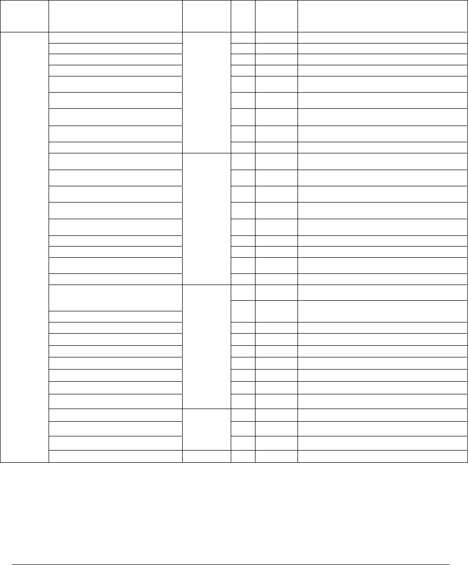
E Electro Industries/Gauge Tech Doc# E154703 A-1
Appendix A
Modbus Support Information
A.1: Channel/Scaling Factor Table
Data
Type
Channel Name Channel
Offset
Ind
ex
Channel
Number
Scaling Factor
Logical Raw Sample of Van 0 0 32768 ADC count =3223.92 V
Logical Raw Sample of Vbn 1 1 32768 ADC count = 3223.92 V
Logical Raw Sample of Vcn 2 2 32768 ADC count = 3223.92 V
Logical Raw Sample of Vab 3 3 32768 ADC count = 3223.92 V
Logical Raw Sample of Vbc 4 4 32768 ADC count = 3223.92 V
Logical Raw Sample of Vca 5 5 32768 ADC count = 3223.92 V
Logical Raw Sample of Vxn 6 6 32768 ADC count = 3223.92 V
Logical Raw Sample of Vres 7 7 32768 ADC count = 6447.84 V
Logical Raw Sample of Ires
0
8 8 32768 ADC count = 400 A
Physical Raw Sample of Vae 0 32 32768 ADC count = 1611.96 V
Physical Raw Sample of Vbe 1 33 32768 ADC count = 1611.96 V
Physical Raw Sample of Vce 2 34 32768 ADC count = 1611.96 V
Physical Raw Sample of Vxe 3 35 32768 ADC count = 1611.96 V
Physical Raw Sample of Vne 4 36 32768 ADC count = 1611.96 V
Physical Raw Sample of Ia 5 37 32768 ADC count = 100 A
Physical Raw Sample of Ib 6 38 32768 ADC count = 100 A
Physical Raw Sample of Ic 7 39 32768 ADC count = 100 A
Physical Raw Sample of Ix
32
8 40 32768 ADC count = 100 A
0 68 1 count = 18.18 ns Duration of transient Van
Peak of transient Van
1 69 256 ADC count = 1800 V
Flags of transient Van 2 70
Duration of Transient Vbn 3 71 1 count = 18.18 ns
Peak of transient Vbn 4 72 256 ADC count = 1800 V
Flags of transient Vbn 5 73
Duaration of transient Vcn 6 74 1 count = 18.18 ns
Peak of transient Vcn 7 75 256 ADC count = 1800 V
Flags of transient Vcn
68
8 76
Waveform Transient Combine 0 77 32768 ADC count = 3223.92 V
Waveform Transient Combine 1 78 32768 ADC count = 3223.92 V
Waveform Transient Combine 2
77 2 79 32768 ADC count = 3223.92 V
Samples
High speed input samples 80

E Electro Industries/Gauge Tech Doc# E154703 A-2

Electro Industries/Gauge Tech
Doc# E154703 GL-1
Glossary
0.1 Second Values: These values are the RMS values of the indicated quantity as calculated after
approximately 50 milliseconds (3 cycles) of sampling.
1 Second Values: These values are the RMS values of the indicated quantity as calculated after
one second (60 cycles) of sampling.
Alarm: An event or condition in a meter that can cause a trigger or call-back to occur.
Annunciator: A short label that identifies particular quantities or values displayed, for example
kWh.
Average (Current): When applied to current values (amps) the average is a calculated value that
corresponds to the thermal average over a specified time interval. The interval
is specified by the user in the meter profile. The interval is typically 15 minutes.
So, Average Amps is the thermal average of amps over the previous 15-minute
interval. The thermal average rises to 90% of the actual value in each time
interval. For example, if a constant 100amp load is applied, the thermal average
will indicate 90 amps after one time interval, 99 amps after two time intervals
and 99.9 amps after three time intervals.
Average (Input Pulse When applied to Input Pulse Accumulations, the “Average” refers to the block
Accumulations): (fixed) window average value of the input pulses.
Average (Power): When applied to power values (watts, VARs, VA), the average is a calculated
value that corresponds to the thermal average over a specified time interval. The
interval is specified by the user in the meter profile. The interval is typically 15
minutes. So, the Average Watts is the thermal average of watts over the
previous 15-minute interval. The thermal average rises to 90% of the actual
value in each time interval. For example, if a constant 100kW load is applied,
the thermal average will indicate 90kW after one time interval, 99kW after two
time intervals and 99.9kW after three time intervals.
Bit: A unit of computer information equivalent to the result of a choice between two
alternatives (Yes/No, On/Off, for example).
Or, the physical representation of a bit by an electrical pulse whose presence or
absence indicates data.
Binary: Relating to a system of numbers having 2 as its base (digits 0 and 1).
Block Window Avg: The Block (Fixed) Window Average is the average power calculated over a
(Power) user-set time interval, typically 15 minutes. This calculated average corresponds
to the demand calculations performed by most electric utilities in monitoring
user power demand. (See Rolling Window Average.)

Electro Industries/Gauge Tech
Doc# E154703 GL-2
Byte: A group of 8 binary digits processed as a unit by a computer (or device) and
used especially to represent an alphanumeric character.
CBEMA Curve: A voltage quality curve established originally by the Computer Business
Equipment Manufacturers Association. The CBEMA Curve defines voltage
disturbances that could cause malfunction or damage in microprocessor devices.
The curve is characterized by voltage magnitude and the duration which the
voltage is outside of tolerance. (See ITIC Curve.)
Channel: The storage of a single value in each interval in a load profile.
CRC Field: Cyclic Redundancy Check Field (Modbus communication) is an error checksum
calculation that enables a Slave device to determine if a request packet from a
Master device has been corrupted during transmission. If the calculated value
does not match the value in the request packet, the Slave ignores the request.
CT (Current) Ratio: A Current Transformer Ratio is used to scale the value of the current from a
secondary value up to the primary side of an instrument tranformer.
Demand: The average value of power or a similar quantity over a specified period of
time.
Demand Interval: A specified time over which demand is calculated.
Display: User-configurable visual indication of data in a meter.
DNP 3.0: A robust, non-proprietary protocol based on existing open standards. DNP 3.0
is used to operate between various systems in electric and other utility industries
and SCADA networks.
EEPROM: Nonvolatile memory. Electrically Erasable Programmable Read Only Memory
that retains its data during a power outage without need for a battery. Also
refers to meter’s FLASH memory.
Energy Register: Programmable record that monitors any energy quantity. Example: Watthours,
VARhours, VAhours.
Ethernet: A type of LAN network connection that connects two or more devices on a
common communications backbone. An Ethernet LAN consists of at least one
hub device (the network backbone) with multiple devices connected to it in a
star configuration. The most common versions of Ethernet in use are 10BaseT
or 100BaseT as defined in IEE standards. However, several other versions of
Ethernet are also available.
Exception Response: Error Code (Modbus communication) transmitted in a packet from the Slave to
the Master if the Slave has encountered an invalid command or other problem.
Form: Wiring and Hookup configuration for the NexusTM meter.

Electro Industries/Gauge Tech
Doc# E154703 GL-3
Harmonics: Measuring values of the fundamental current and voltage and percent of the
fundamental.
Integer: Any of the natural numbers, the negatives of those numbers or zero.
Invalid Register: In the Nexus® meter’s Modbus Map there are gaps between Registers. For
example, the next Register after 08320 is 34817. Any unmapped Register
is said to be invalid.
ITIC Curve: An updated version of the CBEMA Curve that reflects further study into the
performance of microprocessor devices. The curve consists of a series of steps
but still defines combinations of voltage magnitude and duration that will cause
malfunction or damage.
Ke: kWh per pulse; i.e. the energy.
kWh: kilowatt hours; kW x demand interval in hours.
KYZ Output: Output where the rate of changes between 1 and 0 reflects the magnitude of a
metered quantity.
LCD: Liquid Crystal Display.
LED: Light Emitting Diode.
Master Device: In Modbus communication, a Master Device initiates and controls all
information transfer in the form of a Request Packet to a Slave Device. The
Slave reponds to each request.
Maximum Demand: The largest demand calculated during any interval over a billing period.
Modbus ASCII: Alternate version of the Modbus protocol that utilizes a different data transfer
format. This version is not dependent upon strict timing, as is the RTU version.
This is the best choice for telecommunications applications (via modems).
Modbus RTU: The most common form of Modbus protocol. Modbus RTU is an open protocol
spoken by many field devices to enable devices from multiple vendors to
communicate in a common language. Data is transmitted in a timed binary
format, providing increased throughput and therefore, increased performance.
Network: A communications connection between two or more devices to enable those
devices to send and receive data to one another. In most applications, the
network will be either a serial type or a LAN type.

Electro Industries/Gauge Tech
Doc# E154703 GL-4
NVRAM: Non-volatile Random Access Memory is able to keep the stored values in
memory even during the loss of circuit or control power. High speed NVRAM
is used in the Nexus®meter to gather measured information and to insure that
no information is lost.
Optical Port: A meter port that facilitates infrared communication. Using an ANSI C12.13
Type II magnetic optical communications coupler and an RS232 cable from the
coupler to a PC, the meter can be programmed with Communicator EXT
software.
Packet: A short fixed-length section of data that is transmitted as a unit. Example: a
serial string of 8-bit bytes.
Percent (%) THD: Percent Total Harmonic Distortion.
Protocol: A language that will be spoken between two or more devices connected on a
network.
PT Ratio: Potential Transformer Ratio used to scale the value of the voltage to the primary
side of an instrument transformer. Also referred to as VT Ratio.
Pulse: The closing and opening of the circuit of a two-wire pulse system or the
alternate closing and opening of one side and then the other of a three-wire
system (which is equal to two pulses).
Quadrant: Watt and VAR flow is typically represented usng an X-Y coordinate system.
(Programmable The four corners of the X-Y plane are referred to as quadrants. Most power
Values and Factors applications label the right hand corner as the first quadrant and number the
on the Nexus® Meter) remaining quadrants in a counter-clockwise rotation. Following are the
positions of the quadrants: 1st - upper right, 2nd - upper left, 3rd - lower left
and 4th - lower right. Power flow is generally positive in quadrants 1 and 4.
VAR flow is positive in quadrants 1 and 2. The most common load conditions
are: Quadrant 1 - power flow positive, VAR flow positive, inductive load,
lagging or positive power factor; Quadrant 2 - power flow negative, VAR flow
positive, capacitive load, leading or negative power factor.
Register: An entry or record that stores a small amount of data.
Register Rollover: A point at which a Register reaches its maximum value and rolls over to zero.
Reset: Logs are cleared or new (or default) values are sent to counters or timers.
Rolling Window The Rolling (Sliding) Window Average is the average power calculated over a
Average (Power): user-set time interval that is derived from a specified number of sub-intervals,
each of a specified time. For example, the average is calculated over a
15-minute interval by calculating the sum of the average of three consecutive
5-minute intervals. This demand calculation methodology has been adopted by
several utilities to prevent customer manipulation of kW demand by simply
spreading peak demand across two intervals.

Electro Industries/Gauge Tech
Doc# E154703 GL-5
RS232: A type of serial network connection that connects two devices to enable
communication between devices. An RS232 connection connects only two
points. Distance between devices is typically limited to fairly short runs.
Current standards recommend a maximum of 50 feet but some users have had
success with runs up to 100 feet. Communications speed is typically in the
range of 1200 bits per second to 57,600 bits per second. RS232
communication can be accomplished using the Optical Port of a meter.
RS485: A type of serial network connection that connects two or more devices to enable
communication between the devices. An RS485 connection allows
multi-drop communication from one to many points. Distance between devices
is typically limited to around 2,000 to 3,000 wire feet. Communications speed
is typically in the range of 120 bits per second to 115,000 bits per second.
Sag: A voltage quality event during which the RMS voltage is lower than normal for
a period of time, typically from 1/2 cycle to 1 minute.
Secondary Rated: Any Register or pulse output that does not use any CT or VT Ratio.
Serial Port: The type of port used to directly interface with a PC.
Slave Device: In Modbus communication, a Slave Device only receives a Request Packet from
a Master Device and responds to the request. A Slave Device cannot initiate
communication.
Swell: A voltage quality event during which the RMS voltage is higher than normal for
a period of time, typically from 1/2 cycle to 1 minute.
TDD: The Total Demand Distortion of the current waveform. The ratio of the root
- sum-square value of the harmonic current to the maximum demand load
current.
THD: Total Harmonic Distortion is the combined effect of all harmonics measured in a
voltage or current. The THD number is expressed as a percent of the
fundamental. For example, a 3% THD indicates that the magnitude of all
harmonic distortion measured equals 3% of the magnitude of the fundamental
60Hz quantity.
Time Stamp: A stored representation of the time of an event. Time Stamp can include year,
month, day, hour, minute and second and Daylight Savings Time indication.
TOU: Time of Use.
Voltage Imbalance: The ratio of the voltage on a phase to the average voltage on all phases.

Electro Industries/Gauge Tech
Doc# E154703 GL-6
Voltage Quality Event: An instance of abnormal voltage on a phase. The events the meter will track
include sags, swells, interruptions and imbalances.
VT Ratio: The Voltage Transformer Ratio is used to scale the value of the voltage to the
primary side of an instrument transformer. Also referred to as PT Ratio.
Voltage, Vab: Vab, Vbc, Vca are all Phase-to-Phase voltage measurements. These voltages are
measured between the three phase voltage inputs to the meter.
Voltage, Van: Van, Vbn, Vcn are all Phase-to-Neutral voltages applied to the monitor. These
voltages are measured between the phase voltage inputs and Vn input to the
meter. Technologically, these voltages can be “measured” even when the meter
is in a Delta configuration and there is no connection to the Vn input. However,
in this configuration, these voltages have limited meaning and are typically not
reported.
