ETP4830 A1 Embedded Power User Manual
User Manual: Pdf
Open the PDF directly: View PDF ![]() .
.
Page Count: 68
- About This Document
- Contents
- 1 Safety Precautions
- 2 Overview
- 3 Components
- 4 Installation
- 4.1 Installing a Subrack
- 4.2 Installing Components
- 4.3 Installing Cables
- 4.3.1 Connecting the Ground Cable
- 4.3.2 (Optional) Installing Dry Contact Signal Cables
- 4.3.3 Connecting the Communications Cable
- 4.3.4 Connecting the DC Load Cable
- 4.3.5 Connecting the Battery Cable
- 4.3.6 Connecting the 230 V AC Single-Phase of TN 400 V Net or TT 400 V Net Input Power Cable
- 4.3.7 Connecting the Dual-Live of IT 230 V Net or TN 208 V Net AC Input Power Cable
- 5 Verifying the Installation
- 6 Commissioning
- 6.1 Connecting the AC Power Supply
- 6.2 Setting the Display Language
- 6.3 Setting the Date and Time
- 6.4 Setting System Type
- 6.5 Setting Battery Parameters
- 6.6 (Optional) Setting DC Parameters
- 6.7 (Optional) Setting Hibernation Parameters
- 6.8 (Optional) Setting Alarm Parameters
- 6.9 (Optional) Setting Communications Parameters
- 6.10 Connecting the Battery Supply
- 7 Maintenance
- 7.1 Routine Maintenance
- 7.2 Rectifying Common Faults
- 7.2.1 Mains Failure
- 7.2.2 AC Over Volt
- 7.2.3 AC Under Volt
- 7.2.4 DC Over Volt
- 7.2.5 DC Under Volt
- 7.2.6 Amb. Over Temp
- 7.2.7 Amb. Under Temp
- 7.2.8 Batt Over Temp
- 7.2.9 Batt Under Temp
- 7.2.10 Batt Chg. Overcur.
- 7.2.11 Load Loop Break
- 7.2.12 Batt Loop Trip
- 7.2.13 Batt Off
- 7.2.14 Door Alarm
- 7.2.15 Water Alarm
- 7.2.16 Smoke Alarm
- 7.2.17 Rect Fault
- 7.2.18 Rect Protection
- 7.2.19 Single Rect Fault
- 7.2.20 Multi-Rect. Fault
- 7.2.21 Rect Comm Fault
- 7.3 Identifying Faults
- 7.4 Replacing Components
- A Technical Specifications
- B Acronyms and Abbreviations

ETP4830-A1 Embedded Power
User Manual
Issue
10
Date
2017-08-08
HUAWEI TECHNOLOGIES CO., LTD.

Issue 10 (2017-08-08)
Huawei Proprietary and Confidential
Copyright © Huawei Technologies Co., Ltd.
i
Copyright © Huawei Technologies Co., Ltd. 2017. All rights reserved.
No part of this document may be reproduced or transmitted in any form or by any means without prior
written consent of Huawei Technologies Co., Ltd.
Trademarks and Permissions
and other Huawei trademarks are trademarks of Huawei Technologies Co., Ltd.
All other trademarks and trade names mentioned in this document are the property of their respective
holders.
Notice
The purchased products, services and features are stipulated by the contract made between Huawei and
the customer. All or part of the products, services and features described in this document may not be
within the purchase scope or the usage scope. Unless otherwise specified in the contract, all statements,
information, and recommendations in this document are provided "AS IS" without warranties, guarantees or
representations of any kind, either express or implied.
The information in this document is subject to change without notice. Every effort has been made in the
preparation of this document to ensure accuracy of the contents, but all statements, information, and
recommendations in this document do not constitute a warranty of any kind, express or implied.
Huawei Technologies Co., Ltd.
Address:
Huawei Industrial Base
Bantian, Longgang
Shenzhen 518129
People's Republic of China
Website:
http://e.huawei.com
ETP4830-A1 Embedded Power
User Manual
About This Document
Issue 10 (2017-08-08)
Huawei Proprietary and Confidential
Copyright © Huawei Technologies Co., Ltd.
ii
About This Document
Purpose
This document describes the DC power system in terms of product overview, components,
installation, commissioning, and maintenance. This document also describes operations for
the site monitoring unit (SMU) and rectifiers.
The figures provided in this document are for reference only.
Intended Audience
This document is intended for:
- Sales specialist
- Technical support personnel
- Maintenance personnel
Symbol Conventions
The symbols that may be found in this document are defined as follows.
Symbol
Description
Indicates an imminently hazardous situation which, if not avoided,
will result in death or serious injury.
Indicates a potentially hazardous situation which, if not avoided,
could result in death or serious injury.
Indicates a potentially hazardous situation which, if not avoided,
may result in minor or moderate injury.
Indicates a potentially hazardous situation which, if not avoided,
could result in equipment damage, data loss, performance
deterioration, or unanticipated results.
NOTICE is used to address practices not related to personal injury.
Calls attention to important information, best practices and tips.
NOTE is used to address information not related to personal injury,
equipment damage, and environment deterioration.

ETP4830-A1 Embedded Power
User Manual
About This Document
Issue 10 (2017-08-08)
Huawei Proprietary and Confidential
Copyright © Huawei Technologies Co., Ltd.
iii
Change History
Changes between document issues are cumulative. The latest document issue contains all the
changes made in earlier issues.
Issue 10 (2017-08-08)
Modified section "2.3 Configuration".
Modified section "4.3.5 Connecting the Battery Cable".
Issue 09 (2016-01-28)
Chapter 4 Installation
Added section "4.3.7 Connecting the Dual-Live of IT 230 V Net or TN 208 V Net AC Input
Power Cable".
Issue 08 (2014-10-30)
Chapter 6 Commissioning
Added section "6.5 Setting Battery Parameters".
Issue 07 (2014-07-18)
Chapter 6 Commissioning
Modified "6.5 Setting Battery Parameters".
Added section "6.6 (Optional) Setting DC Parameters".
Issue 06 (2014-02-20)
Chapter 4 Installation
Added section "4.3.2 (Optional) Installing Dry Contact Signal Cables".
Chapter 6 Commissioning
Added section "6.4 Setting System Type".
Issue 05 (2013-07-02)
Add the configuration of R4815G1, SMU01A and SMU01C.
Issue 04 (2013-05-07)
Optimized the content of the document, including standardizing the terminology and
improving the accuracy of the description
Issue 03 (2013-04-18)
Modify operating temperature, input voltageand output voltage.
Issue 02 (2012-12-03)
Port description is modified.

ETP4830-A1 Embedded Power
User Manual
About This Document
Issue 10 (2017-08-08)
Huawei Proprietary and Confidential
Copyright © Huawei Technologies Co., Ltd.
iv
Issue 01 (2012-05-11)
This issue is the first official release.

ETP4830-A1 Embedded Power
User Manual
Contents
Issue 10 (2017-08-08)
Huawei Proprietary and Confidential
Copyright © Huawei Technologies Co., Ltd.
v
Contents
About This Document .................................................................................................................... ii
1 Safety Precautions ......................................................................................................................... 1
1.1 General Safety .............................................................................................................................................................. 1
1.2 Electrical Safety ............................................................................................................................................................ 2
1.3 Battery Safety ............................................................................................................................................................... 3
1.4 Cable Layout ................................................................................................................................................................. 4
1.5 Mechanical Safety ........................................................................................................................................................ 5
2 Overview ......................................................................................................................................... 7
2.1 Introduction .................................................................................................................................................................. 7
2.2 Features ......................................................................................................................................................................... 7
2.3 Configuration ................................................................................................................................................................ 8
3 Components ................................................................................................................................... 9
3.1 Appearance ................................................................................................................................................................... 9
3.2 Rectifier ........................................................................................................................................................................ 9
3.3 SMU ........................................................................................................................................................................... 11
3.3.1 SMU01A .................................................................................................................................................................. 11
3.3.2 SMU01B .................................................................................................................................................................. 15
3.3.3 SMU01C .................................................................................................................................................................. 18
4 Installation.................................................................................................................................... 22
4.1 Installing a Subrack .................................................................................................................................................... 22
4.2 Installing Components ................................................................................................................................................ 23
4.2.1 Installing an SMU .................................................................................................................................................... 23
4.2.2 Installing a Rectifier ................................................................................................................................................ 23
4.3 Installing Cables ......................................................................................................................................................... 24
4.3.1 Connecting the Ground Cable .................................................................................................................................. 24
4.3.2 (Optional) Installing Dry Contact Signal Cables ..................................................................................................... 24
4.3.3 Connecting the Communications Cable ................................................................................................................... 25
4.3.4 Connecting the DC Load Cable ............................................................................................................................... 27
4.3.5 Connecting the Battery Cable .................................................................................................................................. 28
4.3.6 Connecting the 230 V AC Single-Phase of TN 400 V Net or TT 400 V Net Input Power Cable ............................ 28
4.3.7 Connecting the Dual-Live of IT 230 V Net or TN 208 V Net AC Input Power Cable ............................................ 29

ETP4830-A1 Embedded Power
User Manual
Contents
Issue 10 (2017-08-08)
Huawei Proprietary and Confidential
Copyright © Huawei Technologies Co., Ltd.
vi
5 Verifying the Installation .......................................................................................................... 30
5.1 Checking Hardware Installation ................................................................................................................................. 30
5.2 Checking Electrical Connections ................................................................................................................................ 30
5.3 Checking Cable Installation ........................................................................................................................................ 30
6 Commissioning............................................................................................................................ 31
6.1 Connecting the AC Power Supply .............................................................................................................................. 31
6.2 Setting the Display Language ..................................................................................................................................... 32
6.3 Setting the Date and Time ........................................................................................................................................... 32
6.3.1 SMU01A .................................................................................................................................................................. 32
6.3.2 SMU01B and SMU01C ........................................................................................................................................... 32
6.4 Setting System Type ................................................................................................................................................... 33
6.5 Setting Battery Parameters .......................................................................................................................................... 33
6.5.1 SMU01A .................................................................................................................................................................. 33
6.5.2 SMU01B and SMU01C ........................................................................................................................................... 33
6.6 (Optional) Setting DC Parameters .............................................................................................................................. 34
6.7 (Optional) Setting Hibernation Parameters ................................................................................................................. 34
6.7.1 SMU01A .................................................................................................................................................................. 34
6.7.2 SMU01B and SMU01C ........................................................................................................................................... 35
6.8 (Optional) Setting Alarm Parameters .......................................................................................................................... 35
6.8.1 SMU01A .................................................................................................................................................................. 35
6.8.2 SMU01B and SMU01C ........................................................................................................................................... 36
6.9 (Optional) Setting Communications Parameters ......................................................................................................... 36
6.9.1 SMU01A .................................................................................................................................................................. 36
6.10 Connecting the Battery Supply ................................................................................................................................. 41
7 Maintenance ................................................................................................................................. 43
7.1 Routine Maintenance .................................................................................................................................................. 43
7.2 Rectifying Common Faults ......................................................................................................................................... 44
7.2.1 Mains Failure ........................................................................................................................................................... 44
7.2.2 AC Over Volt ........................................................................................................................................................... 44
7.2.3 AC Under Volt ......................................................................................................................................................... 44
7.2.4 DC Over Volt ........................................................................................................................................................... 45
7.2.5 DC Under Volt ......................................................................................................................................................... 45
7.2.6 Amb. Over Temp ...................................................................................................................................................... 45
7.2.7 Amb. Under Temp .................................................................................................................................................... 46
7.2.8 Batt Over Temp ........................................................................................................................................................ 46
7.2.9 Batt Under Temp ...................................................................................................................................................... 47
7.2.10 Batt Chg. Overcur. ................................................................................................................................................. 47
7.2.11 Load Loop Break ................................................................................................................................................... 47
7.2.12 Batt Loop Trip........................................................................................................................................................ 48
7.2.13 Batt Off .................................................................................................................................................................. 48
7.2.14 Door Alarm ............................................................................................................................................................ 48

ETP4830-A1 Embedded Power
User Manual
Contents
Issue 10 (2017-08-08)
Huawei Proprietary and Confidential
Copyright © Huawei Technologies Co., Ltd.
vii
7.2.15 Water Alarm ........................................................................................................................................................... 49
7.2.16 Smoke Alarm ......................................................................................................................................................... 49
7.2.17 Rect Fault ............................................................................................................................................................... 49
7.2.18 Rect Protection ....................................................................................................................................................... 50
7.2.19 Single Rect Fault .................................................................................................................................................... 50
7.2.20 Multi-Rect. Fault .................................................................................................................................................... 50
7.2.21 Rect Comm Fault ................................................................................................................................................... 51
7.3 Identifying Faults ........................................................................................................................................................ 51
7.3.1 Identifying Rectifier Faults ...................................................................................................................................... 51
7.3.2 Identifying SMU Faults ........................................................................................................................................... 52
7.4 Replacing Components ............................................................................................................................................... 53
7.4.1 Replacing a Rectifier ............................................................................................................................................... 53
7.4.2 Replacing an SMU ................................................................................................................................................... 54
A Technical Specifications ........................................................................................................... 56
B Acronyms and Abbreviations .................................................................................................. 60

ETP4830-A1 Embedded Power
User Manual
1 Safety Precautions
Issue 10 (2017-08-08)
Huawei Proprietary and Confidential
Copyright © Huawei Technologies Co., Ltd.
1
1 Safety Precautions
1.1 General Safety
- Ensure that the product is used in an environment that meets the product design
specifications such as the grid power, input voltage, temperature, and humidity. Using
the product in an incompatible environment may cause malfunctions, damage
components, or invalidate the warranty.
- Follow the precautions and special safety instructions provided by Huawei when
operating this product. Personnel who plan to install or maintain Huawei equipment must
receive thorough product training, understand all necessary safety precautions, and be
able to correctly perform all operations. Huawei will not be liable for any consequences
that are caused by the violation of general safety regulations and equipment usage safety
standards.
- The upstream power distribution box for the cabinet should be equipped with a
protection switch that has the same specifications as or higher specifications than the
input switch of the cabinet.
- Comply with local laws and regulations. The safety instructions in this document are
only supplemental to local laws and regulations.
- Do not operate the product or handle cables during thunderstorms.
- Do not expose the equipment to flammable or explosive gas or smoke. Keep batteries
away from strong infrared radiation, organic solvents, and corrosive gas.
- Do not use water to clean the product's internal or external electrical components.
- To avoid electric shock, do not connect safety extra-low voltage (SELV) circuits to
telecommunication network voltage (TNV) circuits.
- Do not place any irrelevant objects on batteries.
- Before using the product, remove any conductors such as jewelry or watches.
- Use insulated tools for all operations that involve electrical connections.
- Bolts should be tightened with a torque wrench and marked using red or blue color.
Installation personnel mark tightened bolts in blue. Quality inspection personnel confirm
if the bolts are tightened and then mark them in red.
- Follow specified procedures during installation and maintenance. Do not attempt to alter
the product or deviate from the recommended installation procedures without prior
consent from the manufacturer.
- Disconnect the AC power supply before maintaining AC power distribution.

ETP4830-A1 Embedded Power
User Manual
1 Safety Precautions
Issue 10 (2017-08-08)
Huawei Proprietary and Confidential
Copyright © Huawei Technologies Co., Ltd.
2
- Measure contact point voltage with a multimeter before handling a conductor surface or
terminal. Ensure that the contact point has no voltage or the voltage is within the
specified range.
- When installing or removing power cables, ensure that the corresponding circuits are
disconnected to prevent electric arcs or sparks.
- If AC input power cables need to be routed from the top, bend the cables in a U shape
outside the cabinet and then route them into the cabinet.
- Performing maintenance or replacing components may interrupt power to the loads if
batteries are not connected or the battery reserve is insufficient. Ensure that the switches
for primary loads are in the ON position and do not turn off the battery switch and the
AC input switch at the same time.
- Cables stored at subzero temperatures must be stored at room temperature for at least 24
hours before they are laid out.
- Perform routine maintenance as described in this manual; replace faulty components at
the earliest.
- After maintenance is completed, lock cabinet doors and seal cable holes to prevent
rodents from entering the cabinet.
1.2 Electrical Safety
Grounding
- When installing a device, install the ground cable first. When uninstalling a device,
remove the ground cable last.
- Before operating a device, ensure that the device is properly grounded. Ensure that the
ground cable is installed securely (the ground resistance should be less than 0.1 ohm).
Inappropriate grounding may cause device damage and personal injury.
AC and DC Power
- The power system is powered by high-voltage power sources. Direct or indirect contact
(through damp objects) with high-voltage power sources may result in serious injury or
death.
- Non-standard and improper operations may result in fire or electric shocks.
- Before making electrical connections, turn off the protection switch on the upstream
device to cut the power supply.
- Before connecting the AC power supply, ensure that electrical connections are complete.
- Before connecting cables to loads or battery cables, check cable and terminal polarities
to prevent reverse connections.

ETP4830-A1 Embedded Power
User Manual
1 Safety Precautions
Issue 10 (2017-08-08)
Huawei Proprietary and Confidential
Copyright © Huawei Technologies Co., Ltd.
3
ESD
- To prevent electrostatic-sensitive components from being damaged by static from human
bodies, wear a grounded electrostatic discharge (ESD) wrist strap or ESD gloves when
touching circuit boards.
- When holding a board, hold its edge without touching any components, especially chips.
- Package boards with ESD packaging materials before storing or transporting them.
Liquid Prevention
- Do not place the product in areas prone to water leakage, such as near air conditioner
vents, ventilation vents, or feeder windows of the equipment room.
- Ensure that there is no condensation inside the product or equipment room.
- Ensure that no liquid enters the product. Otherwise, short circuits will occur and may
result in serious injury or death.
- If any liquid is detected inside the product, immediately disconnect the power supply and
contact the administrator.
1.3 Battery Safety
Before installing, operating, or maintaining the batteries, read the battery manufacturer's
safety instructions. Observe the safety precautions provided in this section, which are
supplemental to the safety instructions provided by the battery manufacturer.
Basic Requirements
- Avoid skin contact with battery electrolyte. Before handling batteries, wear goggles,
rubber gloves, and protective clothing.
- When handling a battery, ensure that its electrodes always point upward. Do not tilt or
overturn batteries.
- Before installing or maintaining batteries, switch off the battery circuit breaker or
remove the battery fuse.
- Install batteries in a dry, clean, and ventilated environment that is free from sources of
ignition. Do not expose batteries to sunlight or water.
- Ensure that the load-bearing capacity of the floor in the installation area is sufficient.
Install additional supports if required.
- Secure battery cables to the torque specified in the battery documentation. Loose
connections will result in excessive voltage drop or cause batteries to burn out in the case
of excessive current.
- Ensure that battery cables do not come in contact with water.
Battery Short Circuit
ETP4830-A1 Embedded Power
User Manual
1 Safety Precautions
Issue 10 (2017-08-08)
Huawei Proprietary and Confidential
Copyright © Huawei Technologies Co., Ltd.
4
High short circuit currents or electric shocks can cause equipment damage, personal injury, or
death.
To prevent short circuit or electric shock, disconnect the batteries before performing any
operation or maintenance.
Flammable Gas
- Do not use unsealed lead-acid batteries.
- Lead-acid batteries emit flammable gas. Therefore, place and secure lead-acid batteries
horizontally to prevent fire or corrosion.
Store lead-acid batteries in a place with good ventilation, and take fire safety precautions.
Battery Leakage
High temperatures may result in battery distortion, damage, and electrolyte overflow.
If the battery temperature is higher than 60°C, battery electrolyte may overflow. If the
electrolyte overflows, wear goggles, rubber gloves, and protective clothing and absorb the
leaking electrolyte using sodium bicarbonate (NaHCO3) or sodium carbonate (Na2CO3). Do
not transport or move batteries if there is an electrolyte leakage.
Battery Overdischarge
After connecting the batteries, remove the battery fuse or turn the battery circuit breaker OFF
and then power on the power system. This prevents battery overdischarge. After the power
system is on, replace the battery fuse or turn the battery circuit breaker ON.
1.4 Cable Layout
- When routing cables, ensure that a sufficient distance exists between the cables and the
DC busbar, shunt, and fuse. This prevents damage to the insulation layer of the cables.
- Route and bind signal cables and power cables separately.
- Ensure that cables meet the VW-1 testing requirements.
- Do not route cables behind the air exhaust vents of rectifiers in the cabinet.
- Ensure that all cables are securely bound.
ETP4830-A1 Embedded Power
User Manual
1 Safety Precautions
Issue 10 (2017-08-08)
Huawei Proprietary and Confidential
Copyright © Huawei Technologies Co., Ltd.
5
1.5 Mechanical Safety
Hoisting Devices
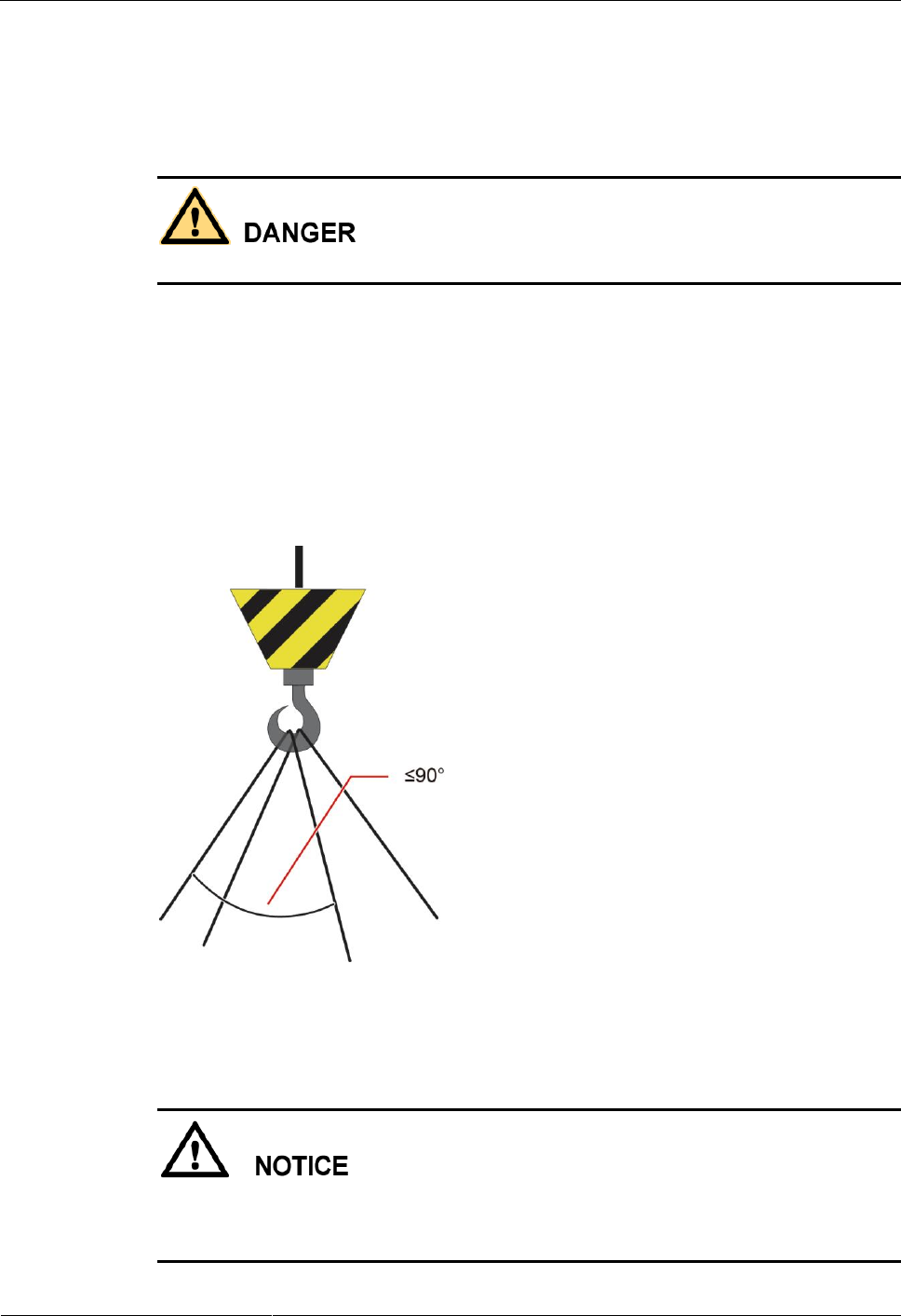
Do not walk under hoisted objects.
- Only trained and qualified personnel should perform hoisting operations.
- Check that all hoisting tools are available and in good condition.
- Before hoisting objects, ensure that hoisting tools are firmly fixed onto a load-bearing
object or wall.
- Ensure that the angle formed by each hoisting cable is less than 90 degrees.
- If metal hoisting cables are used, place protective pads between the cables and the
cabinet to prevent scratches to the cabinet surface.
Figure 1-1 Hoisting heavy objects
Drilling Holes
Do not drill holes into a cabinet without permission. Incorrect drilling operations may affect
the electromagnetic shielding of the cabinet and damage cables inside. Metal shavings from
drilling may short-circuit boards inside the cabinet.
ETP4830-A1 Embedded Power
User Manual
1 Safety Precautions
Issue 10 (2017-08-08)
Huawei Proprietary and Confidential
Copyright © Huawei Technologies Co., Ltd.
6
- Before drilling holes into a cabinet, wear goggles and protective gloves. Remove cables
from inside the cabinet.
- After drilling, clean up any metal shavings that have accumulated inside or outside the
cabinet.
Moving Heavy Objects
- Only trained personnel are allowed to move heavy objects.
- Wear protective gloves and shoes before moving heavy objects.
- Be cautious to prevent injury when moving heavy objects.
- At least two people are required to move heavy objects.
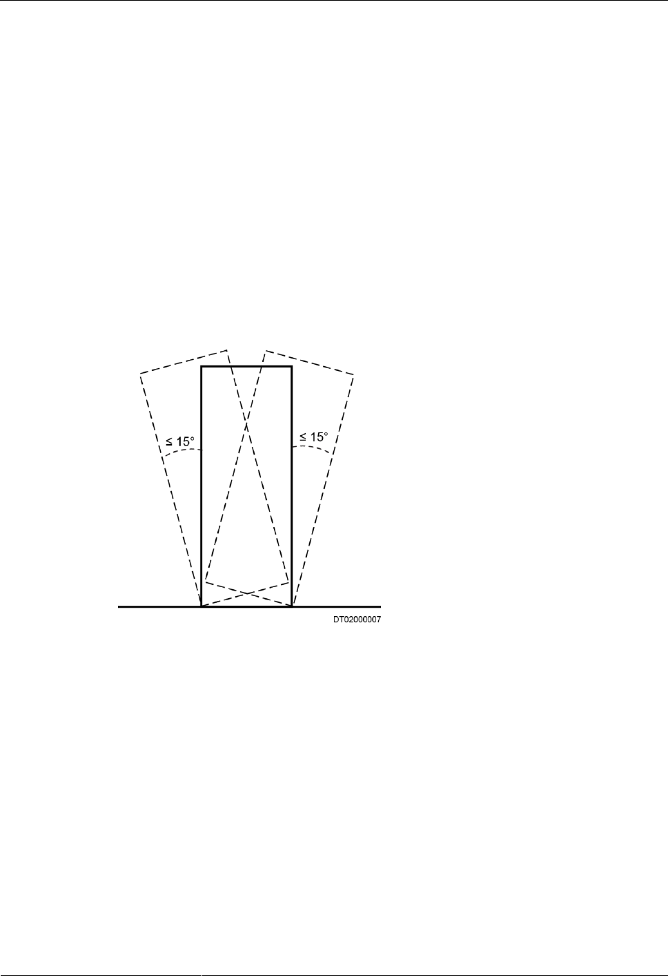
- When you transport cabinets, ensure that there is no excessive tilt and no sudden jolt.
The maximum allowed tilt angle when loading and unloading a cabinet is 15 degrees.
Secure the cabinet to a pallet truck before you transport it.
- When you move a cabinet, ensure that it does not bump into other objects or fall down.
Figure 1-2 Transportation gradient

ETP4830-A1 Embedded Power
User Manual
2 Overview
Issue 10 (2017-08-08)
Huawei Proprietary and Confidential
Copyright © Huawei Technologies Co., Ltd.
7
2 Overview
2.1 Introduction
The ETP4830-A1 is a box-type power system that supplies power for -48 V DC
communications equipment. It uses 15 A rectifiers and provides a maximum output current of
30 A.
2.2 Features
The ETP4830-A1 has the following features:
- Supports a wide voltage range of 85 V AC to 300 V AC.
- Provides comprehensive battery management.
- The SMU01A communicates with Huawei Network Ecosystem (NetEco) and third-party
element management systems (EMSs) over various security protocols, such as the
Simple Network Management Protocol (SNMP) and Hypertext Transfer Protocol Secure
(HTTPS), featuring flexible networking. It provides WebUI and implements remote
unattended management.
- The SMU01B connects to the U2000 over Huawei master/slave protocols.
- Displays information on a liquid crystal display (LCD) and provides buttons for
operations.
- Supports electronic labels.
- Rectifiers and the site monitoring unit (SMU) are hot-swappable.
- Allows high-efficiency and standard-efficiency rectifiers with the same capacity to
coexist.
- The rectifier power factor is 0.99.

ETP4830-A1 Embedded Power
User Manual
2 Overview
Issue 10 (2017-08-08)
Huawei Proprietary and Confidential
Copyright © Huawei Technologies Co., Ltd.
8
2.3 Configuration
Table 2-1 ETP4830-A1 configuration
Item
Configuration
PDU
AC input
230 V AC single-phase three-wire (L, N), compatible with
230 V AC dual-live-wire (L, L)
DC power
distribution
Battery fuse
One 20 A
Load fuse
Two 20 A
SMU
The following SMUs are supported:
- One SMU01A
- One SMU01B
- One SMU01C
Rectifier
The following rectifiers are supported:
- One to two R4815G1s
- One to two R4815N1s
NOTE
- The R4815G1 and R4815N1 can be installed together.
ETP4830-A1 Embedded Power
User Manual
3 Components
Issue 10 (2017-08-08)
Huawei Proprietary and Confidential
Copyright © Huawei Technologies Co., Ltd.
9
3 Components
3.1 Appearance
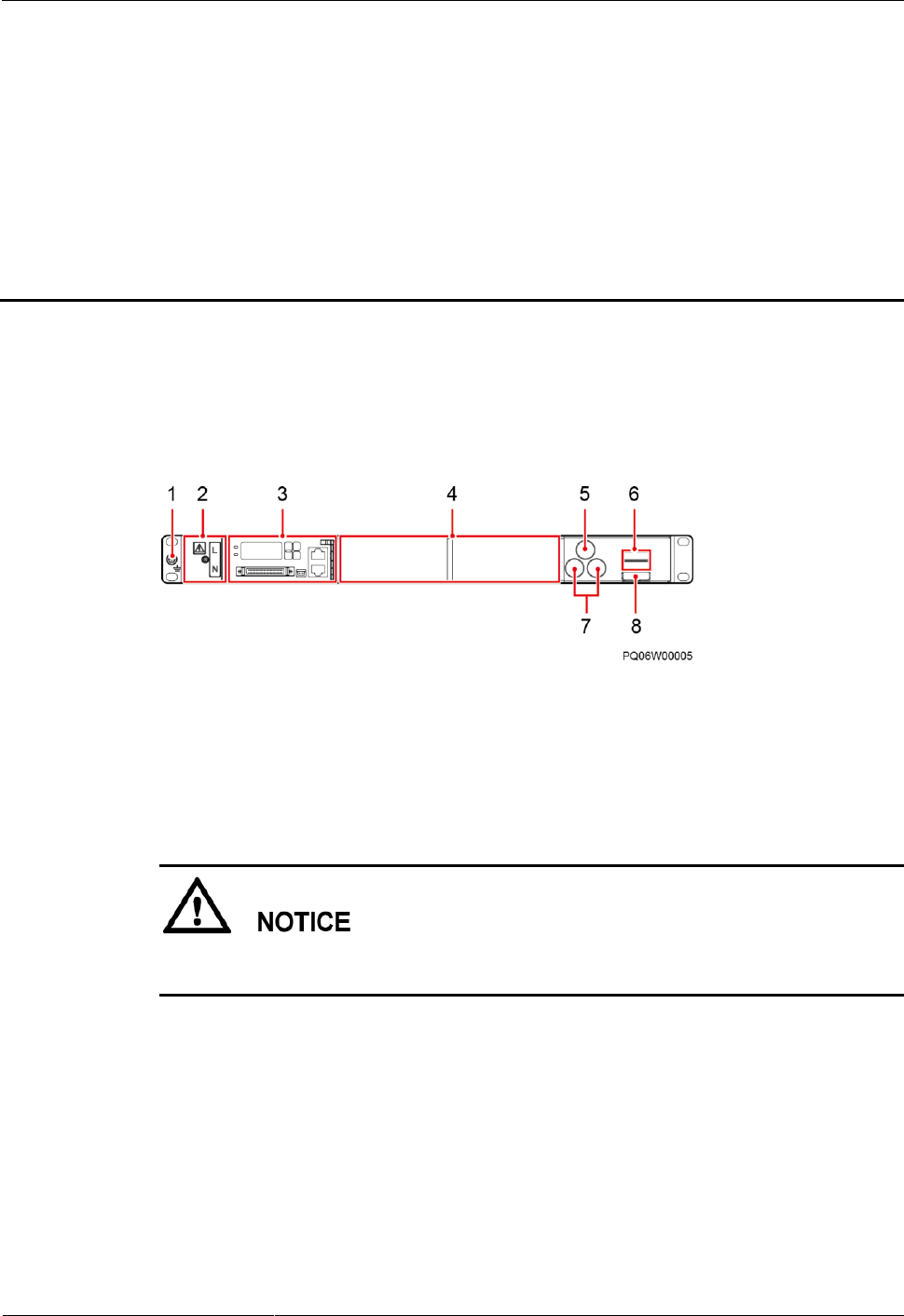
Figure 3-1 Appearance
(1) Ground screw
(2) AC input terminals
(behind the cover)
(3) Space for the SMU
(4) Space for rectifiers
(5) Battery fuse
(6) DC output terminals
(7) Load fuses
(8) Battery wiring terminal
Do not mix up the slots for installing the SMU and rectifier. Otherwise, the SMU and rectifier
may be damaged.
3.2 Rectifier
Rectifiers convert AC input into stable DC output.
ETP4830-A1 Embedded Power
User Manual
3 Components
Issue 10 (2017-08-08)
Huawei Proprietary and Confidential
Copyright © Huawei Technologies Co., Ltd.
10
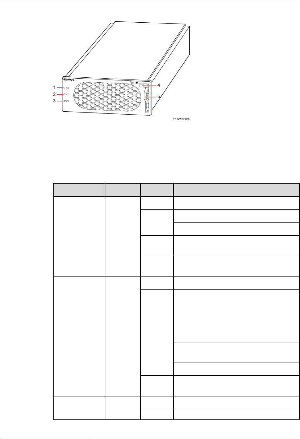
Figure 3-2 Rectifier
(1) Run indicator
(2) Alarm indicator
(3) Fault indicator
(4) Locking latch
(5) Handle
Table 3-1 Rectifier indicator description
Indicator
Color
Status
Description
Run indicator
Green
Steady on
The rectifier has an AC power input.
Off
The rectifier has no AC power input.
The rectifier is faulty.
Blinking
at 0.5 Hz
The rectifier is being queried.
Blinking
at 4 Hz
The rectifier is loading an application
program.
Alarm indicator
Yellow
Off
No alarm has been generated.
Steady on
- The rectifier has generated an alarm for
power limiting due to ambient
overtemperature.
- The rectifier has generated an alarm for
shutdown due to ambient overtemperature
or undertemperature.
The rectifier is protecting itself against AC
input overvoltage or undervoltage.
The rectifier is hibernating.
Blinking
at 0.5 Hz
The communication between the rectifier and
the SMU has been interrupted.
Fault indicator
Red
Off
The rectifier is running properly.
Steady on
The rectifier has been locked out due to
ETP4830-A1 Embedded Power
User Manual
3 Components
Issue 10 (2017-08-08)
Huawei Proprietary and Confidential
Copyright © Huawei Technologies Co., Ltd.
11
Indicator
Color
Status
Description
output overvoltage.
The rectifier has no output due to an internal
fault.
3.3 SMU
3.3.1 SMU01A
Appearance
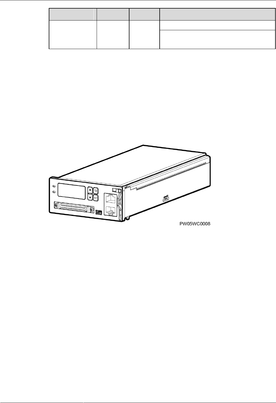
Figure 3-3 SMU01A appearance
ETP4830-A1 Embedded Power
User Manual
3 Components
Issue 10 (2017-08-08)
Huawei Proprietary and Confidential
Copyright © Huawei Technologies Co., Ltd.
12
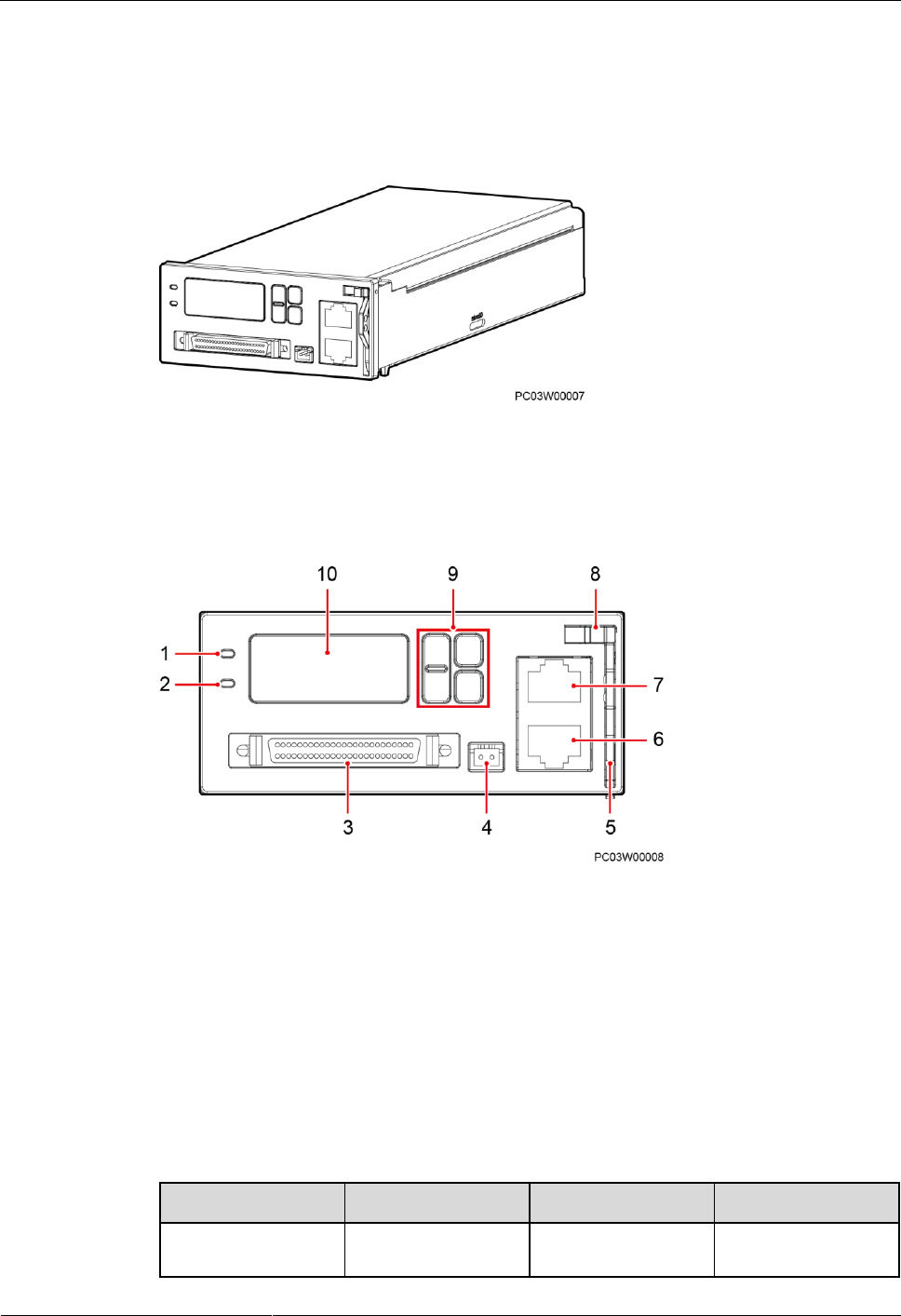
Panel
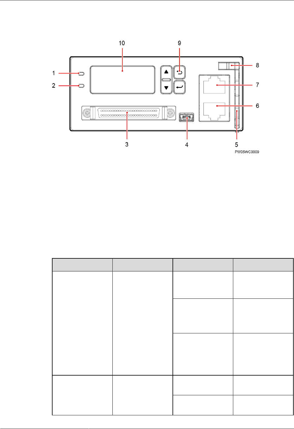
Figure 3-4 SMU01A panel
(1) Run indicator
(2) Alarm indicator
(3) DB50 port
(4) USB port (reserved)
(5) Handle
(6) RS485/RS232 port
(7) COM port
(8) Locking latch
(9) Buttons
(10) LCD
Indicators
Table 3-2 Indicator description
Name
Color
Status
Description
Running status
indicator
Green
Off
The SMU01A is
faulty or has no DC
input.
Blinking at 0.5 Hz
The SMU01A runs
properly and
communicates with
the host properly.
Blinking at 4 Hz
The SMU01A runs
properly but does
not communicate
with the host
properly.
Alarm indicator
Red
Off
No critical or major
alarm is generated.
Steady on
A critical or major
alarm is generated.
ETP4830-A1 Embedded Power
User Manual
3 Components
Issue 10 (2017-08-08)
Huawei Proprietary and Confidential
Copyright © Huawei Technologies Co., Ltd.
13
Buttons
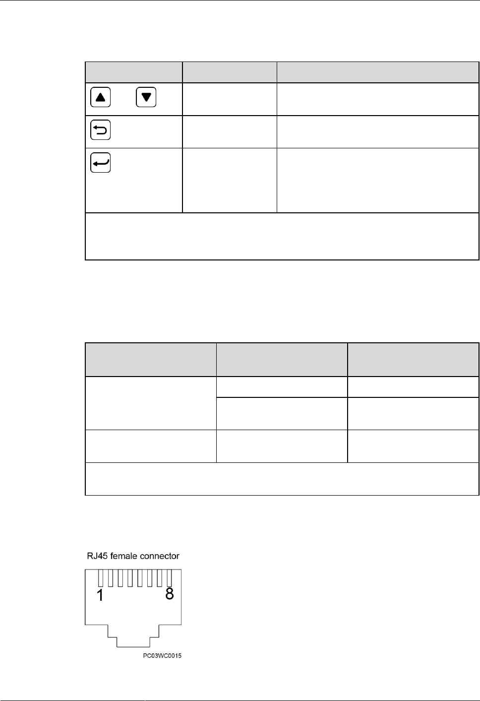
Table 3-3 Button description
Button
Name
Description
and
Up and down
Go to the previous or next menu item and
select a value.
Back
Return to the previous menu without saving
the settings.
Enter
- Enter the main menu from the standby
screen.
- Enter a submenu from the main menu.
- Save the menu settings.
NOTE
- The LCD backlight turns off if no button is pressed for 5 minutes.
- Re-login is required if no button is pressed for 8 minutes.
Communications Ports
Table 3-4 Communications port description
Port
Communications Mode
Communications
Parameter
COM
FE
Autonegotiation
RS485/RS232
Baud rate: 9600 bit/s or
19,200 bit/s
RS485/RS232
RS485/RS232
Baud rate: 9600 bit/s or
19,200 bit/s
NOTE
All ports are protected by a security mechanism.
Figure 3-5 Communications port

ETP4830-A1 Embedded Power
User Manual
3 Components
Issue 10 (2017-08-08)
Huawei Proprietary and Confidential
Copyright © Huawei Technologies Co., Ltd.
14
Table 3-5 describes the pins in the COM port used as an FE port. Table 3-6 describes the pins
in the COM port used as an RS485/RS232 port.
Table 3-5 Pins in the COM port (used as an FE port)
Pin
Signal
Description
1
TX+
Sends data over FE.
2
TX-
3
RX+
Receives data over FE.
6
RX-
4, 5, 7, 8
Reserved
N/A
Table 3-6 Pins in the RS485/RS232 port
Pin
Signal
Description
1
TX+
Sends data over RS485.
2
TX-
4
RX+
Receives data over RS485.
5
RX-
3
RX232
Receives data over RS232.
7
TX232
Sends data over RS232.
6
PGND
Protective grounding.
8
Reserved
N/A
ETP4830-A1 Embedded Power
User Manual
3 Components
Issue 10 (2017-08-08)
Huawei Proprietary and Confidential
Copyright © Huawei Technologies Co., Ltd.
15
3.3.2 SMU01B
Appearance
Figure 3-6 SMU01B
Panel
Figure 3-7 SMU01B panel
(1) Run indicator
(2) Alarm indicator
(3) DB50 port
(4) Battery temperature sensor port
(5) Handle
(6) RS485/RS232 port
(7) COM port
(8) Locking latch
(9) Four buttons
(10) Liquid crystal display (LCD)
Indicators
Table 3-7 Indicator description
Name
Color
Status
Description
Running status
Green
Off
The SMU01B is
faulty or has no
ETP4830-A1 Embedded Power
User Manual
3 Components
Issue 10 (2017-08-08)
Huawei Proprietary and Confidential
Copyright © Huawei Technologies Co., Ltd.
16
Name
Color
Status
Description
indicator
power input.
Blinking at 0.5 Hz
The SMU01B runs
properly and
communicates with
the host properly.
Blinking at 4 Hz
The SMU01B runs
properly but does
not communicate
with the host
properly.
Alarm indicator
Red
Off
No critical or major
alarm is generated.
Steady on
A critical or major
alarm is generated.
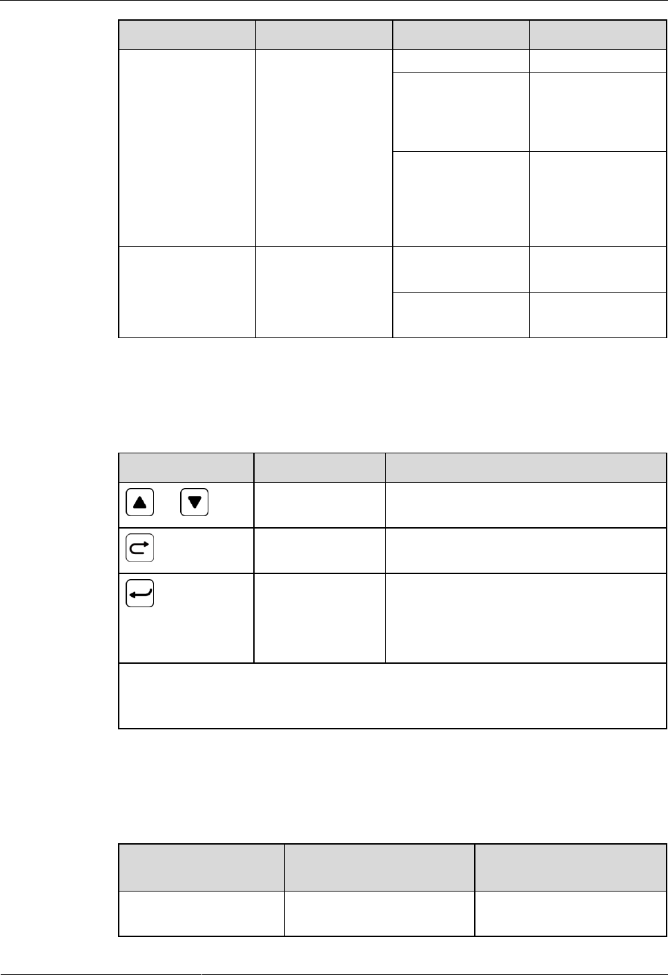
Buttons
Table 3-8 Button description
Button
Name
Description
or
Up or Down
Allows you to view menu items and set the
value of a menu item.
Back
Returns to the previous menu without saving
the settings.
Enter
- Enters the main menu from the standby
screen.
- Enters a submenu from the main menu.
- Saves the menu settings.
NOTE
- The LCD screen becomes dark if no button is pressed within 5 minutes.
- You need to log in again if no button is pressed within 8 minutes.
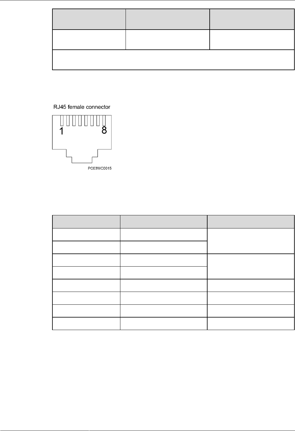
Communications Ports
Table 3-9 Communications ports
Port
Communications Mode
Communications
Parameters
COM
RS485/RS232
Baud rate: 9600 bits/s or
19,200 bits/s
ETP4830-A1 Embedded Power
User Manual
3 Components
Issue 10 (2017-08-08)
Huawei Proprietary and Confidential
Copyright © Huawei Technologies Co., Ltd.
17
Port
Communications Mode
Communications
Parameters
RS485/RS232
RS485/RS232
Baud rate: 9600 bits/s or
19,200 bits/s
NOTE
All the preceding ports are protected by a security mechanism.
Figure 3-8 Communications port
Table 3-10 describes the pins in the COM port and RS485/RS232 port.
Table 3-10 Pins in the RS485/RS232 port
Pin
Signal
Description
1
TX+
Sends data over RS485.
2
TX-
4
RX+
Receives data over RS485.
5
RX-
3
RX232
Receives data over RS232.
7
TX232
Sends data over RS232.
6
PGND
Protective grounding.
8
Reserved
N/A
ETP4830-A1 Embedded Power
User Manual
3 Components
Issue 10 (2017-08-08)
Huawei Proprietary and Confidential
Copyright © Huawei Technologies Co., Ltd.
18
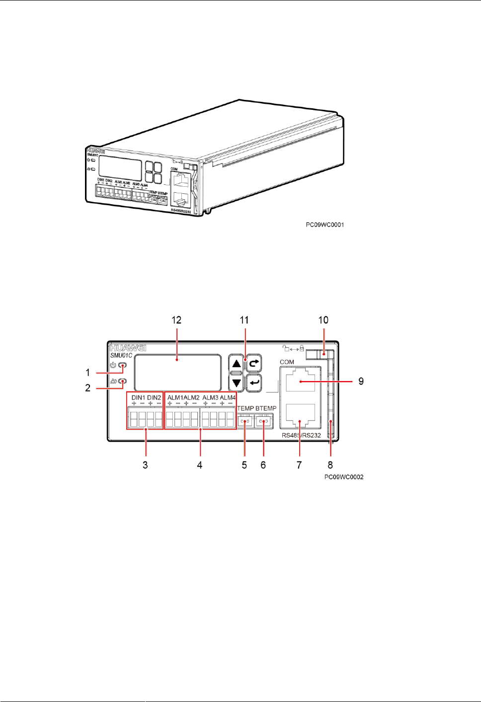
3.3.3 SMU01C
Appearance
Figure 3-9 SMU01C
Panel
Figure 3-10 SMU01C panel
(1) Run indicator
(2) Alarm indicator
(3) Dry contact input ports
(4) Dry contact output
ports
(5) Ambient temperature
sensor port
(6) Battery temperature
sensor port
(7) RS485/RS232 port
(8) Handle
(9) COM port
(10) Locking latch
(11) Four buttons
(12) Liquid crystal display
(LCD)

ETP4830-A1 Embedded Power
User Manual
3 Components
Issue 10 (2017-08-08)
Huawei Proprietary and Confidential
Copyright © Huawei Technologies Co., Ltd.
19
Indicators
Table 3-11 Indicator description
Name
Color
Status
Description
Running status
indicator
Green
Off
The SMU01C is
faulty or has no DC
input.
Blinking at 0.5 Hz
The SMU01C runs
properly and
communicates with
the host properly.
Blinking at 4 Hz
The SMU01C runs
properly but does
not communicate
with the host
properly.
Alarm indicator
Red
Off
No critical or major
alarm is generated.
Steady on
A critical or major
alarm is generated.
Buttons
Table 3-12 Button description
Button
Name
Description
or
Up or Down
Allows you to view menu items and set the
value of a menu item.
Back
Returns to the previous menu without saving
the settings.
Enter
- Enters the main menu from the standby
screen.
- Enters a submenu from the main menu.
- Saves the menu settings.
NOTE
- The LCD screen becomes dark if no button is pressed within 5 minutes.
- You need to log in again if no button is pressed within 8 minutes.

ETP4830-A1 Embedded Power
User Manual
3 Components
Issue 10 (2017-08-08)
Huawei Proprietary and Confidential
Copyright © Huawei Technologies Co., Ltd.
20
Dry contact ports
Table 3-13 Dry contact ports description
Port Type
Silk-screen
Description
Default Alarms
Dry contact
input port
DIN1
Dry contact
input 1
Reserved
DIN2
Dry contact
input 2
Reserved
Dry contact
output port
ALM1
Dry contact
output 1
Major Alarm
Mains Fault, DC Over Volt, DC Under
Volt, Batt Off, Batt Loop Trip, Rect
Fault, Load Fuse Trip
ALM2
Dry contact
output 2
Minor Alarm
AC Over Volt, AC Under Volt, Amb.
Over Temp1, Amb. Under Temp1, Batt
Over Temp, Batt Under Temp, Rect
Protect, Rect Comm Fail, Batt Over Curr,
Dig. Input1 ALM, Dig. Input2 ALM,
Batt Discharge
ALM3
Dry contact
output 3
Reserved
ALM4
Dry contact
output 4
Reserved
Communications Ports
Table 3-14 Communications ports
Port
Communications Mode
Communications
Parameters
COM
RS485/RS232
Baud rate: 9600 bits/s or
19,200 bits/s
RS485/RS232
RS485/RS232
Baud rate: 9600 bits/s or
19,200 bits/s
NOTE
- The COM ports and RS485/RS232 ports work in active/standby mode. Either of them is at work.
- The RS485 and RS232 serial ports are mutually exclusive.
ETP4830-A1 Embedded Power
User Manual
3 Components
Issue 10 (2017-08-08)
Huawei Proprietary and Confidential
Copyright © Huawei Technologies Co., Ltd.
21
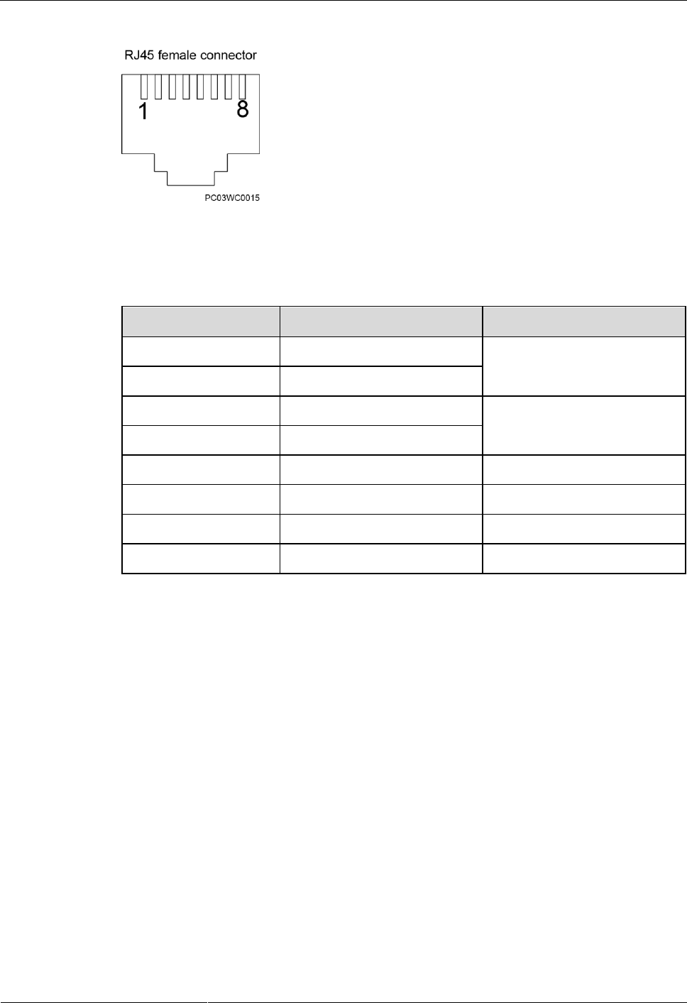
Figure 3-11 Communications port
Table 3-15 describes the pins in the COM port and RS485/RS232 port.
Table 3-15 Pins in the RS485/RS232 port
Pin
Signal
Description
1
TX+
Sends data over RS485.
2
TX-
4
RX+
Receives data over RS485.
5
RX-
3
RX232
Receives data over RS232.
7
TX232
Sends data over RS232.
6
PGND
Protective grounding.
8
Reserved
N/A
ETP4830-A1 Embedded Power
User Manual
4 Installation
Issue 10 (2017-08-08)
Huawei Proprietary and Confidential
Copyright © Huawei Technologies Co., Ltd.
23
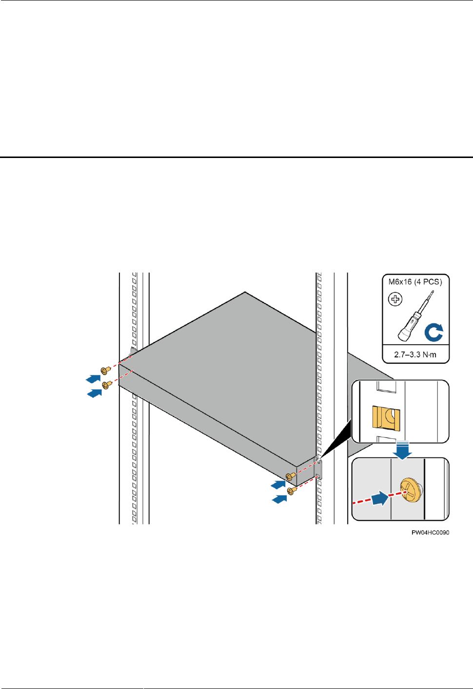
4.2 Installing Components
4.2.1 Installing an SMU
Procedure
Step 1 Push the locking latch towards the left, and pull out the handle.
Step 2 Slide the SMU into the subrack along the guide rail, push in the handle, and then push the
locking latch towards the right.
Figure 4-2 Installing an SMU
----End
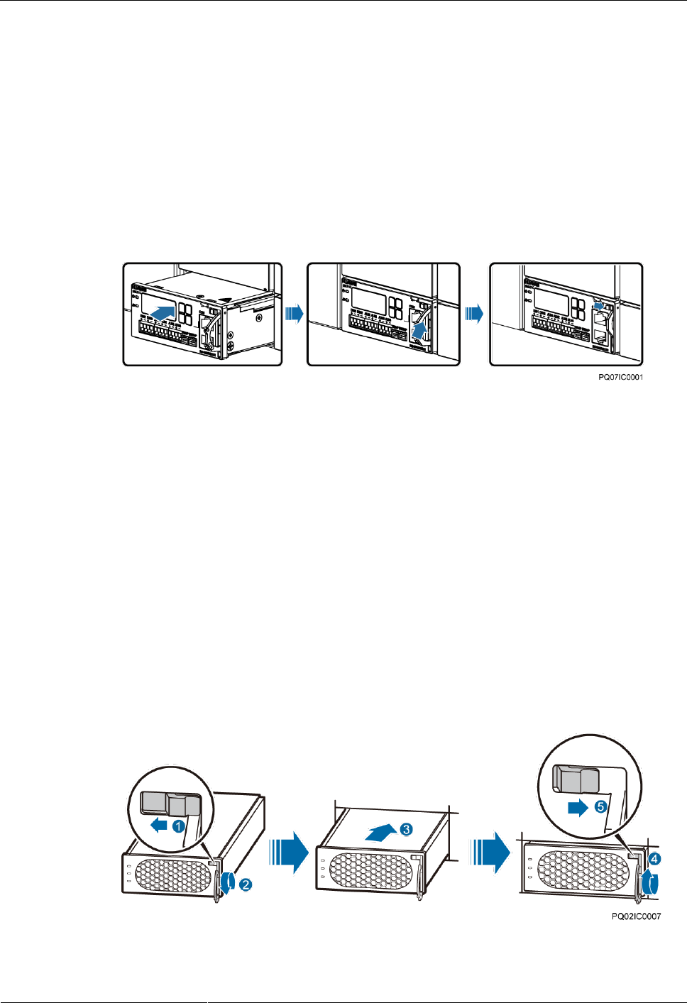
4.2.2 Installing a Rectifier
Procedure
Step 1 Push the locking latch towards the left.
Step 2 Draw the handle downwards.
Step 3 Insert the rectifier into the slot and slide the rectifier into the subrack along the guide rails.
Step 4 Push the handle upwards.
Step 5 Push the locking latch towards the right to secure the handle.
Figure 4-3 Installing a rectifier
----End
ETP4830-A1 Embedded Power
User Manual
4 Installation
Issue 10 (2017-08-08)
Huawei Proprietary and Confidential
Copyright © Huawei Technologies Co., Ltd.
24
4.3 Installing Cables
- Ensure that the upstream AC input circuit breaker is OFF, and attach warning labels such
as "Do not operate."
- Before installing cables, switch all the circuit breakers to OFF and remove the fuses that
need to connect to cables.
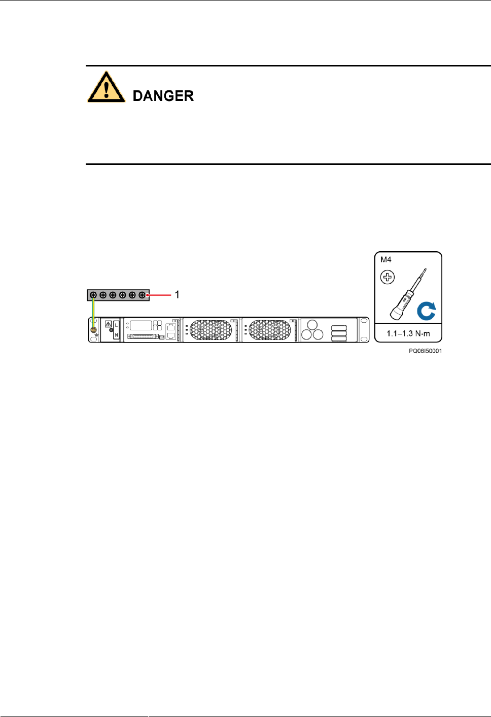
4.3.1 Connecting the Ground Cable
Figure 4-4 shows how to connect the ground cable (an M4 OT terminal is used for the cable).
Figure 4-4 Connecting the ground cable
(1) Ground bar
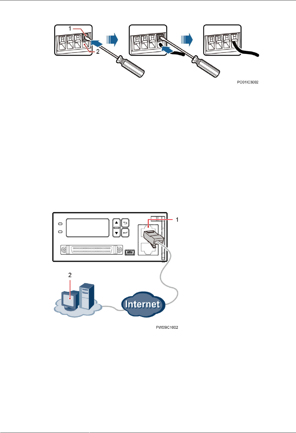
4.3.2 (Optional) Installing Dry Contact Signal Cables
Procedure
Step 1 Press the contact plate using a flat-head screwdriver to flip the metal spring inside each dry
contact.
Step 2 Connect the signal cables to the corresponding dry contacts.
Step 3 Remove the flat-head screwdriver and check that the signal cables are connected securely.
ETP4830-A1 Embedded Power
User Manual
4 Installation
Issue 10 (2017-08-08)
Huawei Proprietary and Confidential
Copyright © Huawei Technologies Co., Ltd.
25
Figure 4-5 Installing a dry contact signal cable
(1) Contact plate
(2) Dry contact port
----End
4.3.3 Connecting the Communications Cable
Connecting a Communications Cable to the SMU01A
Connect a communications cable to the COM port on the SMU01A when you use the Web UI,
NetEco, or SNMP to remotely manage the power supply system, as shown in Figure 4-6.
Figure 4-6 Connecting a communications cable to the SMU01A COM port
(1) COM port
(2) Remote management
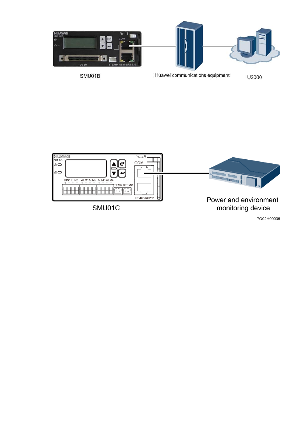
Connecting a Communications Cable to the SMU01B
Connect the COM port on the SMU01B to the corresponding serial port on the Huawei access
network communications equipment using a communications cable when you use the U2000
network management system to remotely manage the power supply system, as shown in
Figure 4-7.
ETP4830-A1 Embedded Power
User Manual
4 Installation
Issue 10 (2017-08-08)
Huawei Proprietary and Confidential
Copyright © Huawei Technologies Co., Ltd.
26
Figure 4-7 Connecting a communications cable to the SMU01B COM port
Installing SMU01C Communications Cables
If the power system connects to a power and environment monitoring device, connect a
communications cable to the COM port on the SMU01C.
Figure 4-8 Connecting the SMU01C and the power and environment monitoring device
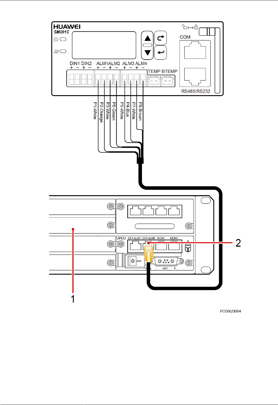
Alarm signals of the power system can be uploaded over dry contacts. Connect dry contact
signal cable to the EXT-ALM0 port on the BBU.
ETP4830-A1 Embedded Power
User Manual
4 Installation
Issue 10 (2017-08-08)
Huawei Proprietary and Confidential
Copyright © Huawei Technologies Co., Ltd.
27
Figure 4-9 Connecting the SMU01C and the BBU
(1) BBU
(2) EXT-ALM0 port
4.3.4 Connecting the DC Load Cable
Procedure
Step 1 Connect the DC load cable.
ETP4830-A1 Embedded Power
User Manual
4 Installation
Issue 10 (2017-08-08)
Huawei Proprietary and Confidential
Copyright © Huawei Technologies Co., Ltd.
28
Figure 4-10 Connecting the load cable
----End
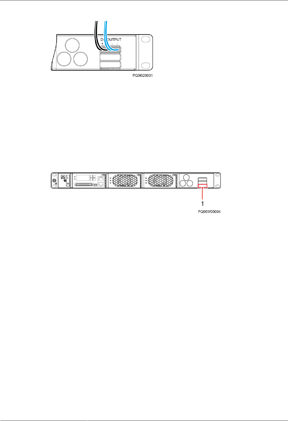
4.3.5 Connecting the Battery Cable
The following figure shows the wiring terminal for the battery cable. The battery cable is
installed in the same way as a load cable. For details, see 4.3.4 Connecting the DC Load
Cable.
Figure 4-11 Battery wiring terminal
(1) Battery wiring terminal
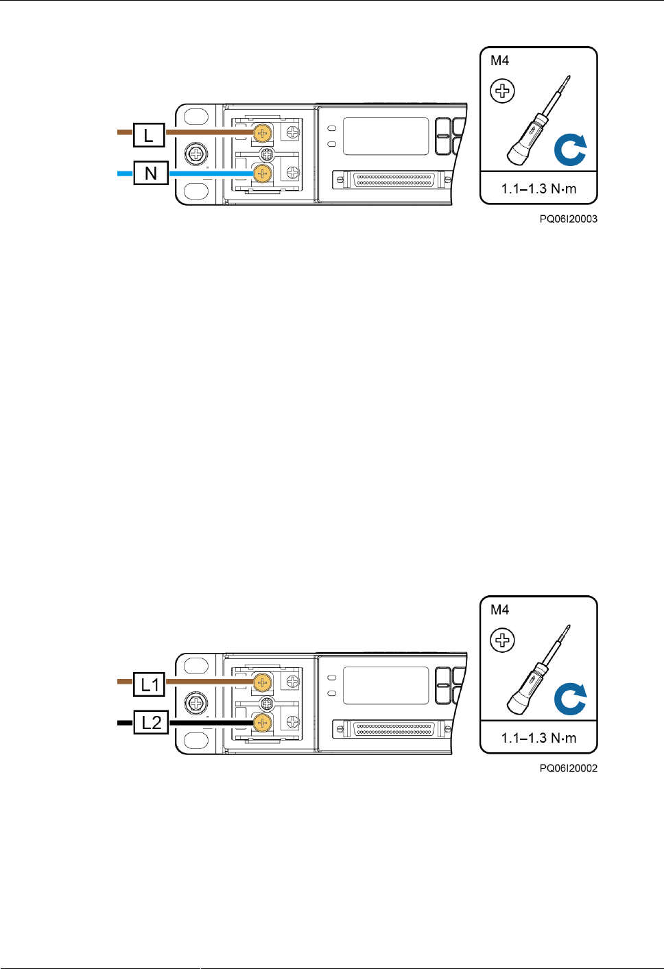
4.3.6 Connecting the 230 V AC Single-Phase of TN 400 V Net or
TT 400 V Net Input Power Cable
Procedure
Step 1 Remove the protective cover over AC input terminals.
Step 2 Connect the neutral wire (an M4 OT terminal is used for the cable) to the wiring terminal
marked as N.
Step 3 Connect the live wire (an M4 OT terminal is used for the cable) to the wiring terminal marked
as L.
ETP4830-A1 Embedded Power
User Manual
4 Installation
Issue 10 (2017-08-08)
Huawei Proprietary and Confidential
Copyright © Huawei Technologies Co., Ltd.
29
Figure 4-12 Connecting the single-phase AC input power cable
Step 4 Reinstall the protective cover.
----End
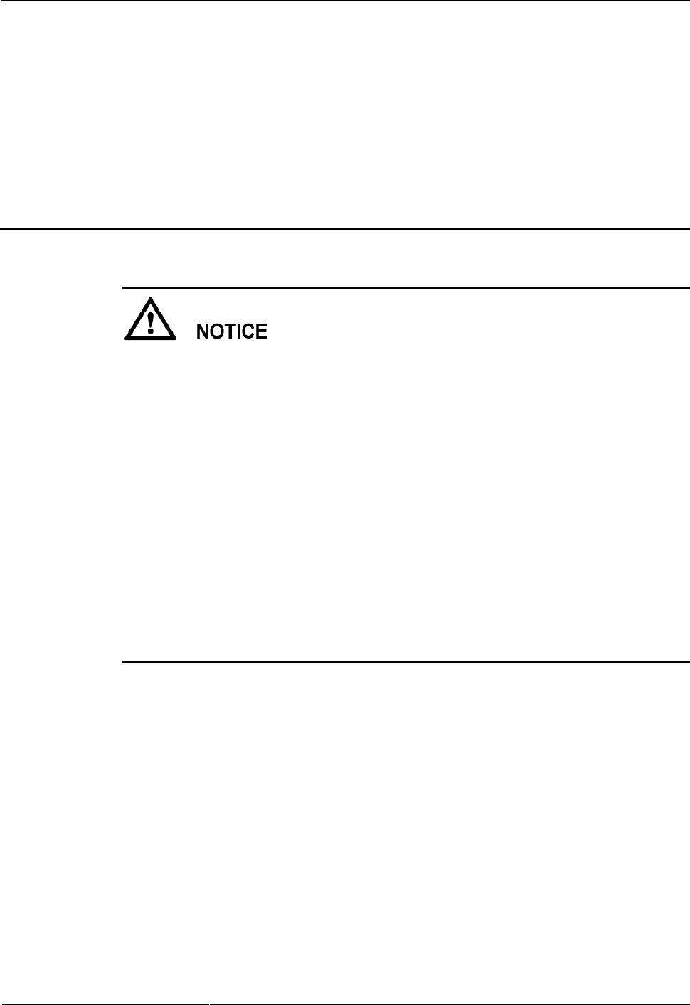
4.3.7 Connecting the Dual-Live of IT 230 V Net or TN 208 V Net
AC Input Power Cable
Procedure
Step 1 Remove the protective cover over AC input terminals.
Step 2 Connect the L1 wire (an M4 OT terminal is used for the cable) to the wiring terminal marked
as L.
Step 3 Connect the L2 wire (an M4 OT terminal is used for the cable) to the wiring terminal marked
as N.
Figure 4-13 Connecting the dual-live wire AC input power cable
Step 4 Reinstall the protective cover.
----End

ETP4830-A1 Embedded Power
User Manual
5 Verifying the Installation
Issue 10 (2017-08-08)
Huawei Proprietary and Confidential
Copyright © Huawei Technologies Co., Ltd.
30
5 Verifying the Installation
5.1 Checking Hardware Installation
- Check that all screws, especially those used for electrical connections, are secured.
Check that flat washers and spring washers are installed properly.
- Check that rectifiers are completely inserted into their respective slots and properly
locked.
5.2 Checking Electrical Connections
- Check that all circuit breakers are OFF or all fuses are disconnected.
- Check that flat washers and spring washers are securely installed for all OT terminals
and that all the OT terminals are intact and properly connected.
- Check that batteries are correctly installed and that battery cables are correctly connected,
and not short circuits exist.
- Check that input and output power cables and ground cables are correctly connected, and
not short circuits exist.
5.3 Checking Cable Installation
- Check that all cables are securely connected.
- Check that all cables are arranged neatly and bound properly to their nearest cable ties,
and are not twisted or overly bent.
- Check that cable labels are properly and securely attached in the same direction.
ETP4830-A1 Embedded Power
User Manual
6 Commissioning
Issue 10 (2017-08-08)
Huawei Proprietary and Confidential
Copyright © Huawei Technologies Co., Ltd.
31
6 Commissioning
- Performing commissioning procedure provided in this chapter may result in power failure
or alarms. Inform the alarm center before commencing the procedure and after completing
the procedure.
- Commissioning should be performed by trained personnel according to the commissioning
instructions provided in this chapter.
- Commissioning is performed with the power on. Before you perform commissioning,
remove any conductors such as jewelry or watches, stand on dry insulating material, and
use insulated tools.
- During commissioning, do not establish contact between electrical points that have
different electric currents.
- Check that the status of a unit or component meets requirements before turning on its
switch.
- If you are maintaining or servicing equipment and do not want others to perform any
operation, attach the label "Currently being serviced. Do not switch on." to the equipment.
- During commissioning, shut down the power system immediately if any fault is detected.
Rectify the fault, start the power system, and proceed with the commissioning.
6.1 Connecting the AC Power Supply
Procedure
Step 1 Check whether the voltage between the input terminals of the upstream AC input circuit
breaker is the same as the local voltage. If not, ask professionals to rectify the fault.
Step 2 Switch on the upstream AC input circuit breaker.
Step 3 Check the Run indicator (green) on the rectifier panel. If it is steady on, the rectifier is
successfully powered on.
Step 4 Check the Run indicator (green) and LCD on the SMU panel. If the indicator is blinking and
the LCD is on, the SMU is successfully powered on.
----End
ETP4830-A1 Embedded Power
User Manual
6 Commissioning
Issue 10 (2017-08-08)
Huawei Proprietary and Confidential
Copyright © Huawei Technologies Co., Ltd.
32
6.2 Setting the Display Language
After powering on the SMU, press or on the LCD to select a display language. Then
press to enter the standby screen.
If an undesired language is selected, reinstall and restart the SMU and then select the desired language.
6.3 Setting the Date and Time
6.3.1 SMU01A
Set the date and time for the SMU01A as required.
Table 6-1 Date and time parameters for the SMU01A
Main Menu
Second-Level
Menu
Third-Level
Menu
Default Value
Settings
Settings
System Para
Set Date
-
Local date
Set Time
-
Local time
Set Time Zone
GMT+08:00
Local time zone
The preset user name for the SMU01A is admin, and the preset password is 001.
6.3.2 SMU01B and SMU01C
Set the time and date for the SMU01B and SMU01C as required.
Table 6-2 Time and date parameters for the SMU01B and SMU01C
Main Menu
Second-Level
Menu
Third-Level
Menu
Default Value
Setting
Settings
System Settings
Date
-
Local date
Time
-
Local time
- The preset user name of SMU01B is admin, and the preset password is 00200.
- The preset user name of SMU01C is admin, and the preset password is 000001.
ETP4830-A1 Embedded Power
User Manual
6 Commissioning
Issue 10 (2017-08-08)
Huawei Proprietary and Confidential
Copyright © Huawei Technologies Co., Ltd.
33
6.4 Setting System Type
If the SMU01A is configured, set the system type based on the actual situation, as described
in Table 6-3. If the SMU01B or SMU01C is configured, you do not need to reset the system
type.
Table 6-3 Setting system type
Main Menu
Second-Level
Menu
Third-level
Menu
Default Value
Setting Value
Settings
Site Summary
System Type
Standard
ETP4830
6.5 Setting Battery Parameters
If battery parameters are incorrectly set, batteries will wear out earlier than necessary. Set the
parameters strictly according to requirements.
6.5.1 SMU01A
Set Qty of Battery to 1, set Rated Capacity to the total capacity of battery strings, and set
Charge Coef as required.
Table 6-4 Battery parameters for the SMU01A
Main Menu
Second-Level
Menu
Default Value
Settings
Quick Settings
Qty of Battery
1
1
Rated Capacity
65 Ah
Battery string
capacity
Charge Coef
0.15 C10
Range: 0.05
C10-0.25 C10
6.5.2 SMU01B and SMU01C
Set Battery String to 1, set Capacity to the total capacity of battery strings, and set Charge
Coef as required.

ETP4830-A1 Embedded Power
User Manual
6 Commissioning
Issue 10 (2017-08-08)
Huawei Proprietary and Confidential
Copyright © Huawei Technologies Co., Ltd.
34
Table 6-5 Battery parameters for the SMU01B and SMU01C
Main Menu
Second-Level
Menu
Third-Level
Menu
Default Value
Setting
Settings
Batt Settings
Battery String
1
1
Capacity
40 Ah
Battery string
capacity
Charge Coef
0.15 C10
Range: 0.05
C10-0.25 C10
6.6 (Optional) Setting DC Parameters
Set DC parameters as required.
Table 6-6 DC parameters
Main Menu
Second-Level
Menu
Third-Level
Menu
Default Value
Range
Settings
DC Settings
FC Volt
53.5 V
47.0-56.5 V (≤
BC Volt)
BC Volt
56.5 V
53.5-57.0 V
(FC Volt ≤ BC
Volt ≤ DC Over
Volt – 1 V)
Over Volt
58.0 V
58.0-60.0 V
Under Volt
45.0 V
43.1-51.5 V
BLVD Enable
Yes
Yes, No
BLVD Volt
43.0 V
38.0-44.9 V
6.7 (Optional) Setting Hibernation Parameters
6.7.1 SMU01A
Set Rect Redund Ena to Enable if you need to use the intelligent hibernation function of the
rectifiers.

ETP4830-A1 Embedded Power
User Manual
6 Commissioning
Issue 10 (2017-08-08)
Huawei Proprietary and Confidential
Copyright © Huawei Technologies Co., Ltd.
35
Table 6-7 Hibernation parameter for the SMU01A
Main Menu
Second-Level
Menu
Third-Level
Menu
Default Value
Setting
Settings
PSU Summary
Rect Redund
Ena
Disable
Enable
6.7.2 SMU01B and SMU01C
Set Sleep Enable to Yes if you need to use the intelligent hibernation function of the
rectifiers.
Table 6-8 Hibernation parameter for the SMU01B and SMU01C
Main Menu
Second-Level
Menu
Third-Level
Menu
Default Value
Setting
Settings
Rect Settings
Sleep Enable
No
Yes
6.8 (Optional) Setting Alarm Parameters
6.8.1 SMU01A
Set the following alarm parameters as required if you need to enable the alarm function or
modify the alarm severity and relay association.
Table 6-9 Alarm parameters for the SMU01A
Main
Menu
Second-
Level
Menu
Third-
Level
Menu
Fourth-
Level
Menu
Default
Value
Settings
Settings
Alarm
Setting
Site
Summary
Internal
Fault
NOTE
The
Internal
Fault alarm
is used as an
example.
Enable
Set the parameter
as required.
MA
Set the parameter
as required.
None
Set the parameter
as required.
Site
Summary
DO (1-8)
Alarm Act
-
Close
Set the parameter
as required.
DI (1-8)
Alarm
-
Close
Set the parameter
as required.

ETP4830-A1 Embedded Power
User Manual
6 Commissioning
Issue 10 (2017-08-08)
Huawei Proprietary and Confidential
Copyright © Huawei Technologies Co., Ltd.
36
6.8.2 SMU01B and SMU01C
Set the following alarm parameters as required if you need to enable the alarm function or
modify the alarm severity and relay association.
Table 6-10 Alarm parameters for the SMU01B and SMU01C
Main
Menu
Second-
Level
Menu
Third-
Level
Menu
Fourth-
Level
Menu
Default
Value
Setting
Settings
Alarm
Setting
Alarm
Severity
AC Volt
Low/High
NOTE
Take the AC
Over Volt
alarm as an
example.
Major
Set the
parameter as
required.
Digital
Alarm
Digital No. 1
NOTE
Take Digital No. 1 as an example.
Mode
High
Set the
parameter as
required.
Relay Relate
AC Volt Low/High (Alarm)
NOTE
Take the AC Volt Low/High alarm as an
example.
Relate Relay
None
Set the
parameter as
required.
Default type
NC
Set the
parameter as
required.
6.9 (Optional) Setting Communications Parameters
6.9.1 SMU01A
Setting Parameters Before Using WebUI
Before you use the WebUI to remotely manage the SMU01A, set the required IP parameters.
Procedure
Step 1 Apply to the site or equipment room network administrator for a fixed IP address.

ETP4830-A1 Embedded Power
User Manual
6 Commissioning
Issue 10 (2017-08-08)
Huawei Proprietary and Confidential
Copyright © Huawei Technologies Co., Ltd.
37
Step 2 Set the IP address, subnet mask, and gateway address on the SMU's LCD.
Table 6-11 IP parameters
Main Menu
Second-Level
Menu
Default Value
Settings
Quick Settings
IP Address
192.168.0.10
Set this parameter
according to the
address assigned by
the network
administrator.
Subnet mask
255.255.255.0
Set this parameter
according to the
address assigned by
the network
administrator.
Gateway
192.168.0.1
Set this parameter
according to the
address assigned by
the network
administrator.
----End
Setting Parameters Before Using NetEco
Before you use the NetEco to perform remote management, set the required parameters.
Procedure
Step 1 Apply to the site or equipment room network administrator for a fixed IP address.
Step 2 Set IP Address, Subnet Mask, and Gateway on the SMU's LCD.
Table 6-12 IP parameters
Main Menu
Second-Level
Menu
Default Value
Settings
Quick Settings
IP Address
192.168.0.10
Set this parameter
according to the
address assigned by
the network
administrator.
Subnet Mask
255.255.255.0
Set this parameter
according to the
address assigned by
the network
administrator.

ETP4830-A1 Embedded Power
User Manual
6 Commissioning
Issue 10 (2017-08-08)
Huawei Proprietary and Confidential
Copyright © Huawei Technologies Co., Ltd.
38
Main Menu
Second-Level
Menu
Default Value
Settings
Gateway
192.168.0.1
Set this parameter
according to the
address assigned by
the network
administrator.
Step 3 Set the IP addresses and ports for the active and standby servers of the NetEco on the SMU's
LCD.
Table 6-13 NetEco parameters
Main
Menu
Second-
Level
Menu
Third-Level
Menu
Default Value
Settings
Settings
Comm Para
NetEco Main
IP
58.251.159.136
Set an IP address for the
active NetEco server.
NetEco Bak IP
58.251.159.136
Set an IP address for the
standby NetEco server.
NetEco Port
31220
Set a port for the NetEco.
----End
Setting Parameters Before SNMP Management
Before you use SNMP to perform remote management, set the required parameters.
Procedure
Step 1 Apply to the site or equipment room network administrator for a fixed IP address.
Step 2 Set the IP address, subnet mask, and gateway on the LCD, as described in Table 6-14.
Table 6-14 IP parameters
Main Menu
Second-Level
Menu
Default Value
Setting
Quick Settings
IP Address
192.168.0.10
Set this parameter
according to the
address assigned by
the network
administrator.
Subnet mask
255.255.255.0
Set this parameter
according to the
address assigned by
ETP4830-A1 Embedded Power
User Manual
6 Commissioning
Issue 10 (2017-08-08)
Huawei Proprietary and Confidential
Copyright © Huawei Technologies Co., Ltd.
39
Main Menu
Second-Level
Menu
Default Value
Setting
the network
administrator.
Gateway
192.168.0.1
Set this parameter
according to the
address assigned by
the network
administrator.
Step 3 Connect the network port on your PC to the FE port on the SMU.
The SMU has only one FE port. Remove the existing network cable from the FE port before
you perform step 3 and reconnect the network cable after you finish setting the parameters.
Step 4 Set the PC IP address in the same network segment as the SMU IP address set in step 2.
Assume that the SMU IP address is 192.168.0.10 and its subnet mask is 255.255.255.0. Set
the PC IP address to 192.168.0.11 and its subnet mask to 255.255.255.0.
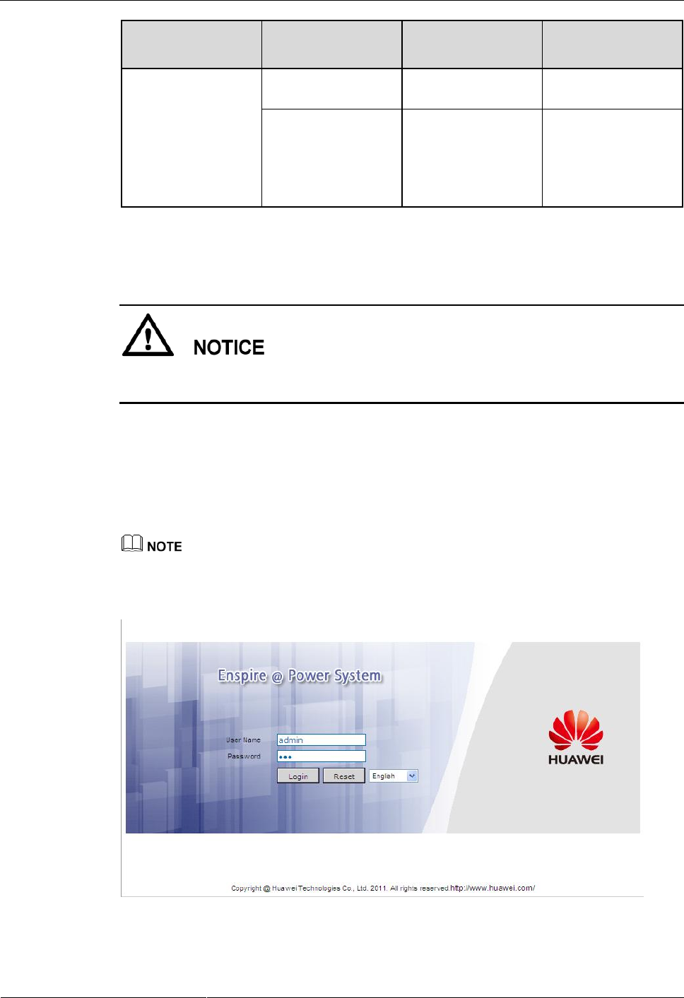
Step 5 Enter the SMU IP address in the address box on the PC. Log in to the WebUI on the login
page shown in Figure 6-1.
The default user name is admin, and the default password is 001.
Figure 6-1 WebUI login page
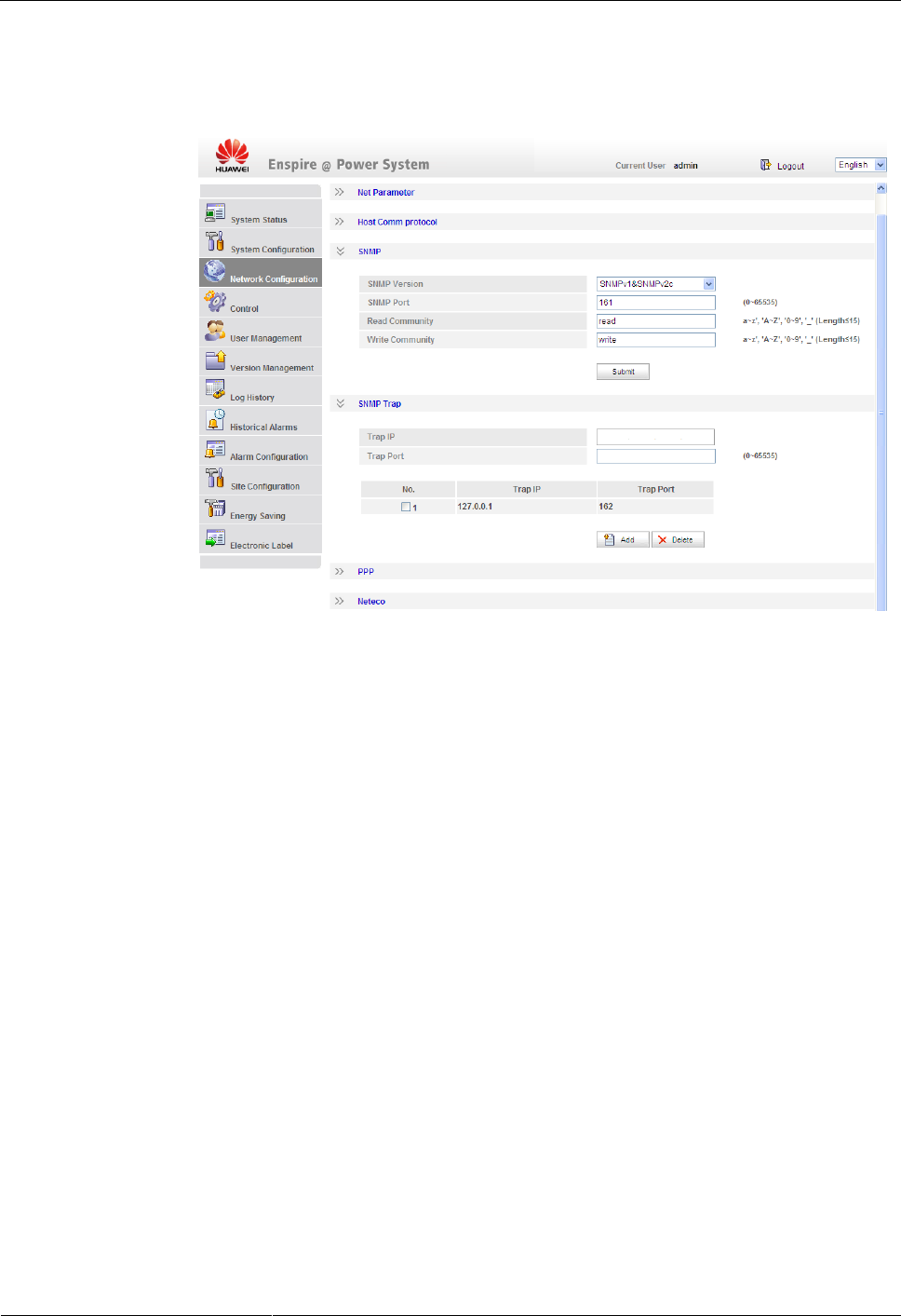
Step 6 On the Network Configuration page, select SNMP.
ETP4830-A1 Embedded Power
User Manual
6 Commissioning
Issue 10 (2017-08-08)
Huawei Proprietary and Confidential
Copyright © Huawei Technologies Co., Ltd.
40
1. If the SNMP version is SNMPv1 or SNMPv2c, set SNMP Port, Read Community, and
Write Community, as shown in Figure 6-2.
Figure 6-2 SNMPv1 and SNMPv2c parameters
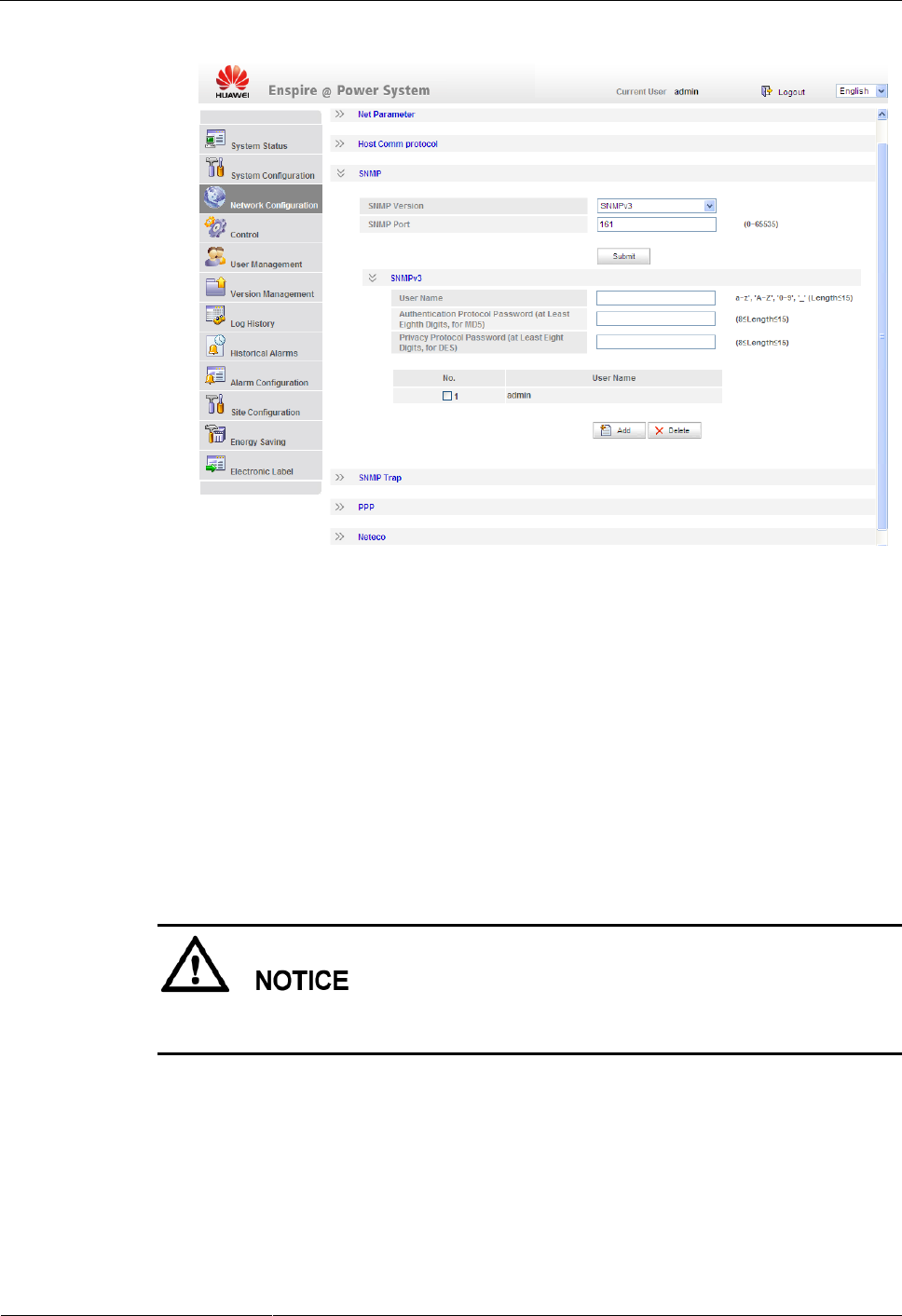
2. If the SNMP version is SNMPv3, set User Name, Authentication Protocol Password,
and Privacy Protocol Password, as shown in Figure 6-3.
ETP4830-A1 Embedded Power
User Manual
6 Commissioning
Issue 10 (2017-08-08)
Huawei Proprietary and Confidential
Copyright © Huawei Technologies Co., Ltd.
41
Figure 6-3 SNMPv3 parameters
Step 7 Set the SNMP trap destination address and trap port.
Step 8 Upload the MIB libraries HUAWEI-MIB.mib and HUAWEI-SITE-MONITOR-MIB.mib
to the NMS.
----End
6.10 Connecting the Battery Supply
Prerequisites
To avoid damage to batteries, reinstall the battery fuse only after correctly setting the battery
parameters for the monitoring unit.
Procedure
Step 1 Switch off the AC circuit breaker for the upper-level device, and then reinstall the battery
fuse.
Step 2 Switch on the AC circuit breaker for the upper-level device, and then reinstall the load fuses.
Step 3 Check whether the battery voltage and system output voltage are the same as the voltages
displayed on the SMU LCD. If not, ask the technical support personnel to rectify the fault.

ETP4830-A1 Embedded Power
User Manual
6 Commissioning
Issue 10 (2017-08-08)
Huawei Proprietary and Confidential
Copyright © Huawei Technologies Co., Ltd.
42
Step 4 Set the battery and load circuit breakers based on the site requirements.
Step 5 Observe the power system for 15 minutes. If no alarm is generated on the SMU LCD, the
voltage and current for batteries and loads are normal. In this case, clean and leave the site.
----End

ETP4830-A1 Embedded Power
User Manual
7 Maintenance
Issue 10 (2017-08-08)
Huawei Proprietary and Confidential
Copyright © Huawei Technologies Co., Ltd.
43
7 Maintenance
7.1 Routine Maintenance
Routine maintenance is required periodically based on the site requirements. The
recommended maintenance interval is six months. If any fault is detected, rectify it in time.
Table 7-1 Routine maintenance checklist
Item
Maintenance Content
Check That
Check
Method
Repair When
Measures
Electrical
connection
The AC input
voltage is
normal.
Using a
multimeter
The AC input
voltage exceeds
the threshold.
For details, see
7.2 Rectifying
Common Faults
and 7.3
Identifying
Faults.
The output
voltage is
normal.
The battery low
voltage
disconnection
(BLVD) or load
low voltage
disconnection
(LLVD) voltage
exceeds the
threshold.
Preventive
inspection
The indicators
are normal.
Visual
observation
Alarms are
generated.
Grounding
inspection
The connection
between the
ground point
and the ground
bar in the
cabinet is
normal.
Using a
multimeter
The resistance
between the
ground point
and the ground
bar is greater
than 0.1 ohm.
Secure or
replace the
ground cable.

ETP4830-A1 Embedded Power
User Manual
7 Maintenance
Issue 10 (2017-08-08)
Huawei Proprietary and Confidential
Copyright © Huawei Technologies Co., Ltd.
44
7.2 Rectifying Common Faults
7.2.1 Mains Failure
Possible Causes
- The AC input power cable is faulty.
- The upstream AC input circuit breaker is OFF.
- The power grid is faulty.
Measures
1. Check whether the AC input cable is loose. If so, secure the AC input cable.
2. Check whether the upstream AC input circuit breaker is OFF. If so, handle the fault
which caused the AC input circuit breaker to turn OFF and then switch on the circuit
breaker.
3. Check whether the AC input voltage is lower than 50 V AC. If so, handle the power grid
fault.
7.2.2 AC Over Volt
Possible Causes
- The AC overvoltage alarm threshold is incorrectly set on the SMU.
- The power grid is faulty.
Measures
1. Check whether the AC overvoltage alarm threshold is correctly set. If not, set the
threshold to the correct value.
2. Check whether the AC input voltage exceeds the AC overvoltage alarm threshold (280 V
AC by default). If so, handle the AC input fault.
7.2.3 AC Under Volt
Possible Causes
- The AC undervoltage alarm threshold is incorrectly set on the SMU.
- The power grid is faulty.
Measures
1. Check whether the AC undervoltage alarm threshold is correctly set. If not, set the
threshold to the correct value.
2. Check whether the AC input voltage is below the AC undervoltage alarm threshold (180
V AC by default). If so, handle the AC input fault.

ETP4830-A1 Embedded Power
User Manual
7 Maintenance
Issue 10 (2017-08-08)
Huawei Proprietary and Confidential
Copyright © Huawei Technologies Co., Ltd.
45
7.2.4 DC Over Volt
Possible Causes
- The DC overvoltage alarm threshold is incorrectly set on the SMU.
- The power system voltage has been manually set to a very high value.
- Rectifiers are faulty.
Measures
1. Check whether the DC overvoltage alarm threshold (58 V DC by default) is correctly set.
If not, set the threshold to the correct value.
2. Check whether the system voltage has been manually set to a very high value. If so,
check with other maintenance personnel whether the voltage can be changed to a normal
value.
3. Remove the rectifiers one by one and check whether the alarm is cleared. If the alarm
still exists, reinstall the rectifier. If the alarm is cleared, replace the rectifier.
7.2.5 DC Under Volt
Possible Causes
- An AC power failure has occurred.
- The DC undervoltage alarm threshold is incorrectly set on the SMU.
- The system configuration is incorrect.
- The power system voltage has been manually set to a very low value.
- Rectifiers are faulty.
Measures
1. Check whether an AC power failure has occurred. If so, rectify the fault to restore the
AC power supply.
2. Check whether the DC undervoltage alarm threshold (45 V DC by default) is correctly
set. If not, set the threshold to the correct value.
3. Check whether the load current is greater than the present power system capacity. If so,
expand the power system capacity or reduce the load power.
4. Check whether the system voltage has been manually set to a very low value. If so,
check with other maintenance personnel whether the voltage can be changed to a normal
value.
5. Check whether faulty rectifiers have resulted in insufficient power system capacity for
the loads. If so, replace the faulty rectifiers.
7.2.6 Amb. Over Temp
This alarm is generated only for the power system that has ambient temperature sensors installed.
Possible Causes
- The ambient overtemperature alarm threshold is not set properly on the SMU.

ETP4830-A1 Embedded Power
User Manual
7 Maintenance
Issue 10 (2017-08-08)
Huawei Proprietary and Confidential
Copyright © Huawei Technologies Co., Ltd.
46
- The temperature control system is faulty in the cabinet where the ambient temperature
sensor is located.
- The ambient temperature sensor is faulty.
Measures
1. Check whether the ambient temperature alarm threshold (50°C by default) is properly set
on the SMU. If no, adjust it based on site requirements.
2. Check whether the temperature control system in the cabinet is faulty. If yes, rectify the
fault. The alarm is cleared when the cabinet temperature falls within the allowed range.
3. Check whether the ambient temperature sensor is faulty. If yes, replace the temperature
sensor.
7.2.7 Amb. Under Temp
This alarm is generated only for the power system that has ambient temperature sensors installed.
Possible Causes
- The ambient undertemperature alarm threshold is not set properly on the SMU.
- The temperature control system is faulty in the cabinet where the ambient temperature
sensor is located.
- The ambient temperature sensor is faulty.
Measures
1. Check whether the ambient undertemperature alarm threshold (0°C by default) is
properly set on the SMU. If no, adjust it based on site requirements.
2. Check whether the temperature control system in the cabinet is faulty. If yes, rectify the
fault. The alarm is cleared when the cabinet temperature falls within the allowed range.
3. Check whether the ambient temperature sensor is faulty. If yes, replace the ambient
temperature sensor.
7.2.8 Batt Over Temp
This alarm is generated only for the power system that has battery temperature sensor installed.
Possible Causes
- The battery overtemperature alarm threshold is not set properly on the SMU.
- The battery temperature controlling system is faulty.
- The battery temperature sensor is faulty.
Measures
1. Check whether the battery overtemperature alarm threshold (50°C by default) is properly
set. If no, adjust it to a proper value.
2. Check whether the battery temperature controlling system is faulty. If yes, rectify the
fault. The alarm is cleared when the battery temperature falls within the allowed range.

ETP4830-A1 Embedded Power
User Manual
7 Maintenance
Issue 10 (2017-08-08)
Huawei Proprietary and Confidential
Copyright © Huawei Technologies Co., Ltd.
47
3. Check whether the battery temperature sensor is faulty. If yes, replace the temperature
sensor.
7.2.9 Batt Under Temp
This alarm is generated only for the power system that has battery temperature sensor installed.
Possible Causes
- The battery undertemperature alarm threshold is not set properly on the SMU.
- The battery temperature controlling system is faulty.
- The battery temperature sensor is faulty.
Measures
1. Check whether the battery undertemperature alarm threshold (0°C by default) is properly
set. If no, adjust it to a proper value.
2. Check whether the battery temperature controlling system is faulty. If yes, rectify the
fault. The alarm is cleared when the battery temperature falls within the allowed range.
3. Check whether the battery temperature sensor is faulty. If yes, replace the temperature
sensor.
7.2.10 Batt Chg. Overcur.
Possible Causes
- Rectifier communication is interrupted.
- SMU connections are loose.
- The SMU is faulty.
Measures
1. Check whether an alarm has been generated for interrupted rectifier communication. If
so, remove the rectifier, reinstall it, and check whether the alarm is cleared. If the alarm
still exists, replace the rectifier.
2. Remove the SMU, reinstall it, and check whether the alarm is cleared. If the alarm still
exists, replace the SMU.
7.2.11 Load Loop Break
Possible Causes
- The load circuit breaker has tripped or the load fuse has blown.
- The load circuit breaker or the fuse detection cable is disconnected.
Measures
1. Check whether the load circuit breaker has tripped or the load fuse has blown. If so,
locate and rectify the circuit fault, and then switch on the circuit breaker or replace the
fuse.

ETP4830-A1 Embedded Power
User Manual
7 Maintenance
Issue 10 (2017-08-08)
Huawei Proprietary and Confidential
Copyright © Huawei Technologies Co., Ltd.
48
2. Check whether the load circuit breaker or fuse detection cable is disconnected. If so,
reconnect it.
7.2.12 Batt Loop Trip
Possible Causes
- The battery circuit breaker or fuse detection cable is loosely connected.
- The battery circuit breaker has tripped or the battery fuse has blown.
- The contactor is faulty.
Measures
1. Check whether the battery circuit breaker or fuse detection cable is loosely connected. If
so, reconnect the cable.
2. Check whether the battery circuit breaker has tripped or the battery fuse has blown. If so,
rectify the battery loop fault and then switch on the circuit breaker or replace the fuse.
3. Manually switch on or switch off the battery contactor and check whether the battery
current changes accordingly. If not, replace the contactor.
7.2.13 Batt Off
Possible Causes
- An AC power failure occurs.
- Batteries are manually disconnected.
- The battery disconnection voltage is set too high on the SMU.
- Rectifiers are faulty.
- The system configuration is not proper.
Measures
1. Check whether an AC power failure occurs. If yes, resume the AC power supply.
2. Check whether batteries are manually disconnected. If yes, confirm the reason of the
manual disconnection, and reconnect the batteries after the operation.
3. Check whether the battery disconnection voltage (43 V DC by default)is set too high on
the SMU. If yes, adjust it to a proper value.
4. Check whether the power system capacity is insufficient for the loads due to rectifier
failures. If yes, replace the faulty rectifier.
5. Check whether the load current is greater than the current power system capacity. If yes,
expand the power system capacity or reduce the load power.
7.2.14 Door Alarm
This alarm is generated only for the power system that has door status sensor installed.
Possible Causes
- The cabinet doors are open.
- The door status sensor is faulty.

ETP4830-A1 Embedded Power
User Manual
7 Maintenance
Issue 10 (2017-08-08)
Huawei Proprietary and Confidential
Copyright © Huawei Technologies Co., Ltd.
49
Measures
1. Close cabinet doors.
2. Check whether the door status sensor is faulty. If yes, replace the door status sensor.
7.2.15 Water Alarm
This alarm is generated only for the power system that has a water sensor installed.
Possible Causes
- There is water inside the cabinet.
- The water sensor is faulty.
Measures
1. Check whether there is water inside the cabinet. If so, remove the water with dry cotton
or other tools and then locate and rectify the fault.
2. Check whether the water sensor is faulty. If the water sensor is faulty, replace it.
7.2.16 Smoke Alarm
This alarm is generated only for the power system that has a smoke sensor installed.
Possible Causes
- There is smoke inside the cabinet.
- The smoke sensor is faulty.
Measures
1. Check whether there is smoke inside the cabinet. If so, disconnect the power supply from
the cabinet, handle the fault, and then restart the system and clear the alarm on the SMU.
2. Check whether the smoke sensor is faulty. If the smoke sensor is faulty, replace it.
7.2.17 Rect Fault
Possible Causes
- Rectifier connections are loose.
- A rectifier is faulty.
Measures
1. Check the Fault indicator on the rectifier panel. If it is steady red, remove the rectifier,
and then reinstall it after the indicator turns off.
2. If the alarm persists, replace the rectifier.

ETP4830-A1 Embedded Power
User Manual
7 Maintenance
Issue 10 (2017-08-08)
Huawei Proprietary and Confidential
Copyright © Huawei Technologies Co., Ltd.
50
7.2.18 Rect Protection
Possible Causes
- The rectifier input voltage is too high.
- The rectifier input voltage is too low.
- The ambient temperature is too high.
- The rectifier is abnormal.
Measures
1. Check whether the AC input voltage exceeds the upper threshold for rectifier working
voltage. If so, locate and rectify the power supply fault and restore the power supply.
2. Check whether the AC input voltage is below the lower threshold for rectifier working
voltage. If so, locate and rectify the power supply fault and restore the power supply.
3. Check whether the ambient temperature is higher than the maximum operating
temperature of the rectifier. If so, locate and rectify the temperature control system fault.
4. Remove the rectifier that has generated the alarm and reinstall it after the indicator turns
off. If the alarm persists, replace the rectifier.
7.2.19 Single Rect Fault
Possible Causes
- The subrack or slot connector is faulty.
- A rectifier is faulty.
- The SMU is faulty.
Measures
1. Remove the rectifier and check whether the slot connector is damaged or deformed. If so,
repair or replace the slot connector or the entire subrack.
2. Reinstall the rectifier. If the alarm persists, replace the rectifier.
3. Restart the SMU. If the alarm persists, replace the SMU.
7.2.20 Multi-Rect. Fault
Possible Causes
- The subrack or slot connectors are faulty.
- Rectifiers are faulty.
- The SMU is faulty.
Measures
1. Remove the rectifiers and check whether the slot connectors are damaged or deformed. If
so, repair or replace the slot connectors or the entire subrack.
2. Reinstall the rectifiers. If the alarm persists, replace the rectifiers.
3. Restart the SMU. If the alarm persists, replace the SMU.

ETP4830-A1 Embedded Power
User Manual
7 Maintenance
Issue 10 (2017-08-08)
Huawei Proprietary and Confidential
Copyright © Huawei Technologies Co., Ltd.
51
7.2.21 Rect Comm Fault
Possible Causes
- A rectifier has been removed.
- Rectifier connections are loose.
- A rectifier is faulty.
Measures
1. Check whether a rectifier has been removed. If so, reinstall it.
2. If the rectifier is in position, remove the rectifier and reinstall it.
3. If the alarm persists, replace the rectifier.
7.3 Identifying Faults
7.3.1 Identifying Rectifier Faults
Table 7-2 Identifying rectifier faults
Symptom
Possible Cause
Corrective Measures
The Run indicator (green)
is off.
There is no AC input, or
the rectifier is faulty.
Check whether the AC input
is normal. If the AC input is
normal, replace the rectifier.
If the AC input is normal and
the green indicators on all
rectifiers are off, replace the
AC/DC power distribution
subrack.
The Run indicator (green)
is blinking (0.5 Hz).
The rectifier is being
queried manually.
Exit the query status. The Run
indicator becomes steady on
again.
The Run indicator (green)
is blinking (4 Hz).
Software is being loaded.
After software finishes
loading, the indicator will
stop blinking, without any
user action required.
The Alarm indicator
(yellow) is steady on.
- The rectifier is
protecting itself against
overtemperature.
- The rectifier is
protecting itself against
AC input overvoltage or
undervoltage.
- The rectifier is faulty.
- If the ambient temperature
is higher than the upper
threshold, lower the
ambient temperature.
- If the air intake or exhaust
vent is blocked, remove
the blockage.
- If the AC input is
abnormal, ask
maintenance personnel for
the mains supply to rectify

ETP4830-A1 Embedded Power
User Manual
7 Maintenance
Issue 10 (2017-08-08)
Huawei Proprietary and Confidential
Copyright © Huawei Technologies Co., Ltd.
52
Symptom
Possible Cause
Corrective Measures
the fault.
- If the fault persists, the
rectifier may be faulty.
Replace the faulty
rectifier.
The Alarm indicator
(yellow) is blinking.
Communication between
the rectifier and the SMU is
interrupted.
Clean the edge connector of
the faulty rectifier. If the
Alarm indicator is still
blinking, check the SMU and
the AC/DC power distribution
subrack.
The Fault indicator (red) is
steady on.
The rectifier is protecting
itself against output
overvoltage.
- If a single rectifier is
locked, remove the
rectifier that is indicating
the fault, and then power
on the rectifier after the
indicator turns off. If
overvoltage still occurs,
replace the rectifier.
- If multiple rectifiers are
locked, remove all
rectifiers and reinstall
them one by one to locate
the faulty rectifiers.
Replace the faulty
rectifiers.
The rectifier has no output
due to an internal fault.
Replace the faulty rectifier.
7.3.2 Identifying SMU Faults
Table 7-3 Identifying SMU faults
Symptom
Cause
Corrective Measures
The Run indicator (green) is
off.
There is no input.
- Check whether the green
indicators on rectifiers
are steady on. If so, the
input to the power
subrack is normal.
- Reseat the SMU. If the
fault persists, replace the
SMU.
The Run indicator (green) is
blinking fast.
The SMU has failed to
communicate with the host.
Check whether
communication between the
SMU and the host is normal.
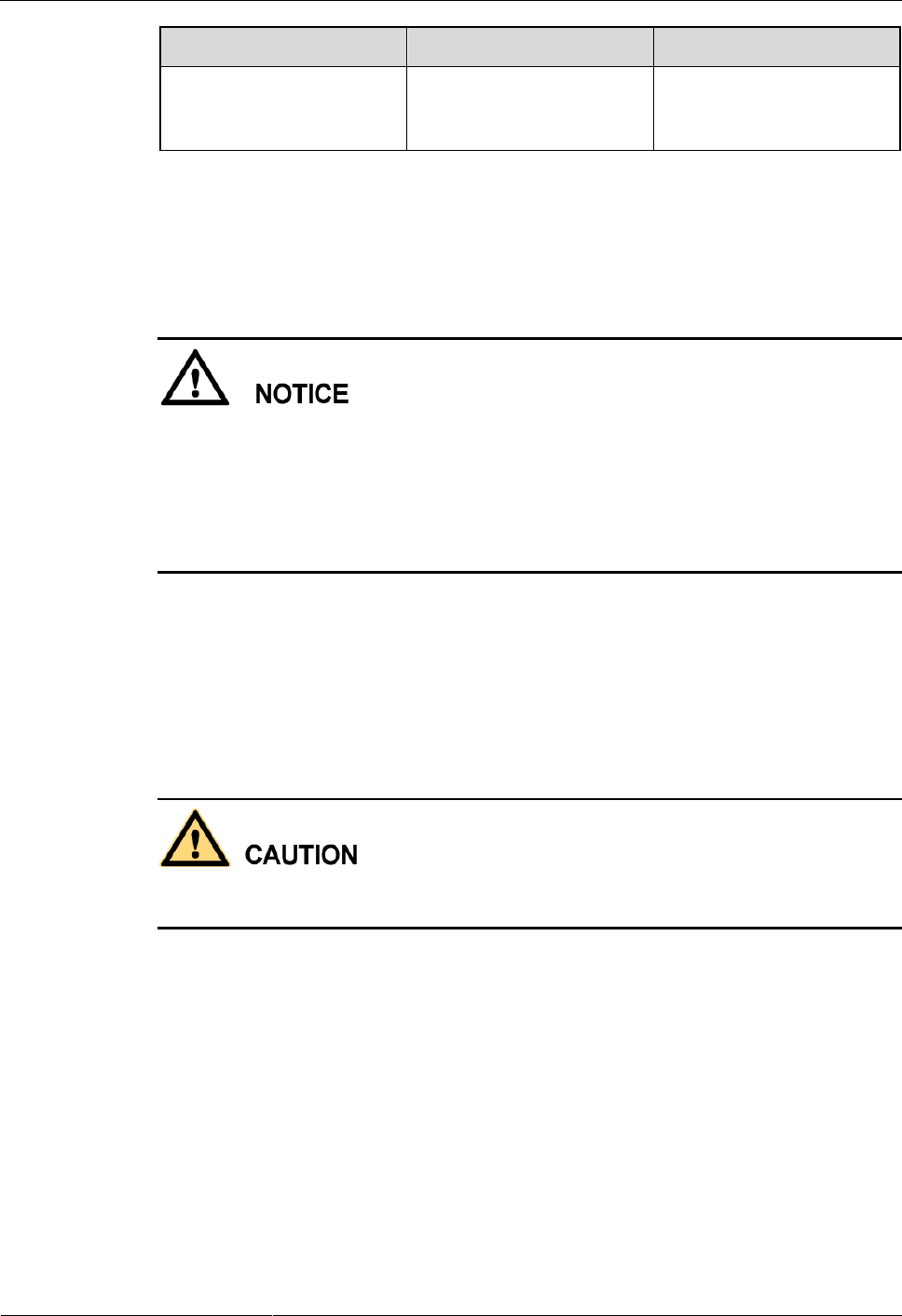
ETP4830-A1 Embedded Power
User Manual
7 Maintenance
Issue 10 (2017-08-08)
Huawei Proprietary and Confidential
Copyright © Huawei Technologies Co., Ltd.
53
Symptom
Cause
Corrective Measures
The Alarm indicator (red) is
steady on.
A major or critical alarm has
been generated.
Query the active alarm on
the host or SMU LCD to
identify the fault.
7.4 Replacing Components
- Performing maintenance or replacing components may interrupt power to the loads if
battery reserve is insufficient. Ensure that the switches for primary loads are in the ON
position and do not turn off the battery switch and the AC input switch at the same time.
- Obtain prior written consent from the customer if load disconnection is required.
- Do not perform maintenance on rainy days. Otherwise, rain water can enter the system and
damage devices and components.
7.4.1 Replacing a Rectifier
Prerequisites
- Protective gloves and the cabinet door key are available.
- The new rectifier is intact.
To prevent burns, exercise caution when removing a rectifier because the rectifier may be hot
as a result of continuous operation.
Procedure
Step 1 Wear protective gloves.
Step 2 Push the locking latch on the right side of the panel towards the left.
Step 3 Gently draw the handle outwards, and then remove the rectifier from the subrack, as shown in
Figure 7-1.
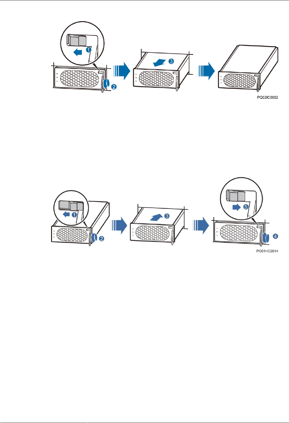
ETP4830-A1 Embedded Power
User Manual
7 Maintenance
Issue 10 (2017-08-08)
Huawei Proprietary and Confidential
Copyright © Huawei Technologies Co., Ltd.
54
Figure 7-1 Removing a rectifier
Step 4 Push the locking latch on the new rectifier towards the left, and pull out the handle.
Step 5 Place the new rectifier at the entry of the correct slot.
Step 6 Gently slide the rectifier into the slot along the guide rails until it is engaged. Close the handle,
and push the locking latch towards the right to lock the handle, as shown in Figure 7-2.
Figure 7-2 Installing a rectifier
Step 7 Remove the protective gloves.
----End
Follow-up Procedure
Pack the removed component and send it to the local Huawei warehouse.
7.4.2 Replacing an SMU
Prerequisites
- You have obtained an ESD wrist strap, a pair of protective gloves, an ESD box or bag.
- The new rectifier is intact.
Procedure
Step 1 Push the locking latch towards the left.
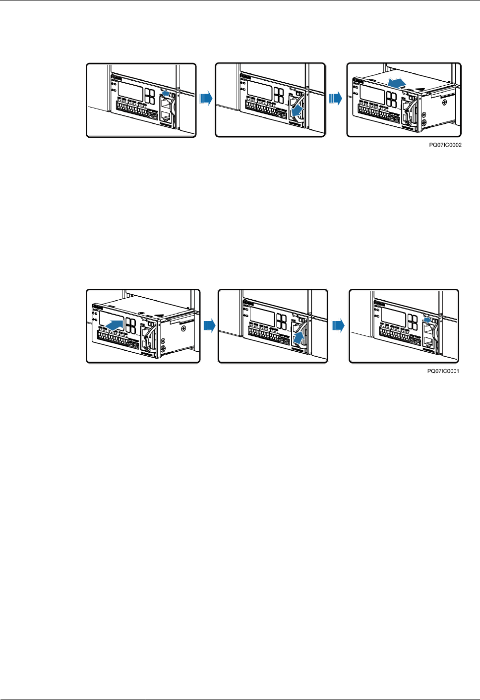
ETP4830-A1 Embedded Power
User Manual
7 Maintenance
Issue 10 (2017-08-08)
Huawei Proprietary and Confidential
Copyright © Huawei Technologies Co., Ltd.
55
Step 2 Draw the handle outwards to remove the SMU, as shown in Figure 7-3.
Figure 7-3 Removing an SMU
Step 3 Insert a new SMU into the slot, push the locking latch towards the left, and pull out the
handle.
Step 4 Slide the SMU into the subrack slowly along the guide rail, push in the handle, and then push
the locking latch towards the right.
Step 5 Reset SMU parameters.
Figure 7-4 Installing an SMU
----End
Follow-up Procedure
Pack the removed component and have it sent to the local Huawei warehouse.
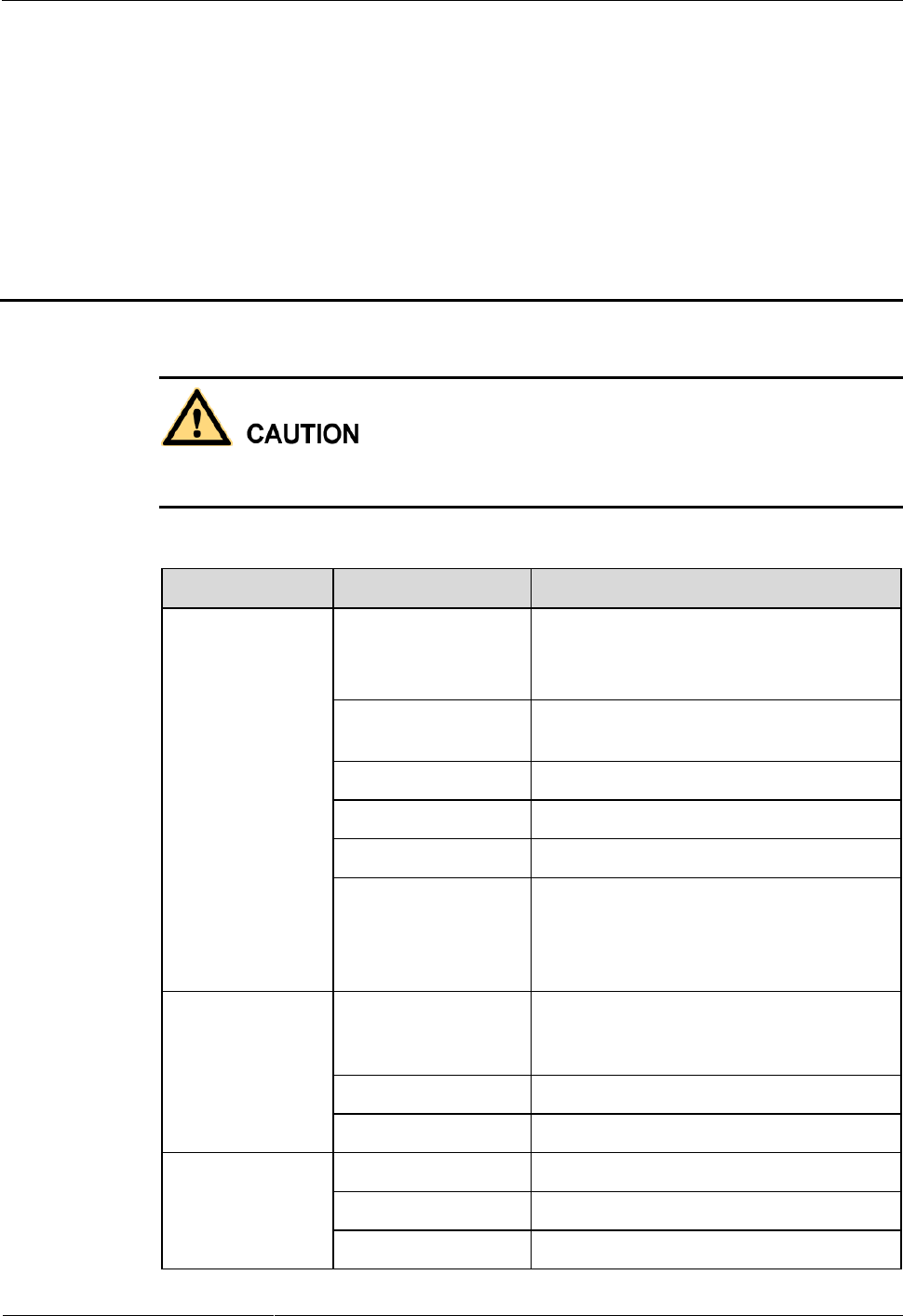
ETP4830-A1 Embedded Power
User Manual
A Technical Specifications
Issue 10 (2017-08-08)
Huawei Proprietary and Confidential
Copyright © Huawei Technologies Co., Ltd.
56
A Technical Specifications
This is Class A Product. In a domestic environment this product may cause radio interference;
therefore, the user is require to take appropriate measures.
Table A-1 Technical Specifications
Category
Item
Specifications
Environmental
conditions
Operating temperature
-40ºC to +70ºC
NOTE
The system can run for 8 hours at 70ºC.
Transportation
temperature
-40ºC to +70ºC
Storage temperature
-40ºC to +70ºC
Operating humidity
5%–95% RH (non-condensing)
Storage humidity
5%–95% RH (non-condensing)
Altitude
0-4000 m
When the altitude ranges from 2000 m to
4000 m, the operating temperature decreases
by 1ºC for each additional 200 m.
AC input
Input mode
230 V AC single-phase three-wire (L, N),
compatible with 230 V AC dual-live-wire
(L, L)
Input frequency
45–66 Hz (rated frequency: 50/60 Hz)
Power factor
≥ 0.99 (100% load)
DC output
Output voltage range
-42 V DC- -58 V DC
Default output voltage
-53.5 V DC
Maximum output
2000 W

ETP4830-A1 Embedded Power
User Manual
A Technical Specifications
Issue 10 (2017-08-08)
Huawei Proprietary and Confidential
Copyright © Huawei Technologies Co., Ltd.
57
Category
Item
Specifications
power
Regulated voltage
precision
≤ ±0.6%
Peak-to-peak noise
voltage
≤ 200 mV (0–20 MHz)
AC input
protection
AC input overvoltage
protection threshold
Overvoltage protection is performed when
the single-phase AC input voltage exceeds
the AC input overvoltage protection
threshold (300 V AC by default).
AC input overvoltage
recovery threshold
When the voltage is restored to 290 V AC,
the output resumes.
AC input
undervoltage
protection threshold
Undervoltage protection is performed when
the single-phase AC input voltage is below
the AC input undervoltage protection
threshold (80 V AC by default).
AC input
undervoltage recovery
threshold
When the voltage is restored to 85 V AC,
the output resumes.
DC output
protection
DC output
overvoltage protection
threshold
-58.5 V DC to -60.5 V DC
Rectifier
Efficiency
- R4815G1: Highest efficiency: ≥ 96%
≥ 95% (220 V AC, 40%-100% load)
- R4815N1: Highest efficiency: ≥ 94%
≥ 93% (220 V AC, 30%-100% load)
Output Power
- R4815G1: 870 W (input voltage range:
176-300 V AC) 435 W (input voltage
range: 85-175 V AC, linearly derated)
- R4815N1: 1000 W (input voltage range:
176-300 V AC) 470 W (input voltage
range: 85-175 V AC, linearly derated)
Output soft start
At the moment when the rectifier is
powered on, the output voltage rises slowly.
Overvoltage
protection
-58.5 V DC to -60.5 V DC
1. If the overvoltage occurs inside the
rectifier due to a fault, the rectifier
experiences a latch-off.
2. If the output voltage is higher than -63 V
DC and lasts for more than 500 ms, the
rectifier experiences a latch-off.
EMC
Conducted Emission
(CE)
Input port: CISPR 22/EN 55022 Class B
Output port: CISPR 22/EN 55022 Class A

ETP4830-A1 Embedded Power
User Manual
A Technical Specifications
Issue 10 (2017-08-08)
Huawei Proprietary and Confidential
Copyright © Huawei Technologies Co., Ltd.
58
Category
Item
Specifications
Radiated emission
(RE)
CISPR 22/EN 55022 Class B
Harmonic
IEC 61000-3-2
Fluctuation and
blinking
IEC 61000-3-3
ESD
Enclosure port: Contact discharge voltage: 6
kV (Class B); air discharge voltage: 8 kV
(Class B);
Signal port: Contact discharge voltage: 2 kV
(Class R)
Electrical fast
transient (EFT)
The voltage at signal ports is 1 kV, and the
voltage at the power ports is 2 kV (criterion
B).
Radiated
susceptibility (RS)
Level 3; criterion: A; field strength: 10 V/m
Conducted
susceptibility (CS)
Signal port: 3 V (criterion A); power port:
10 V
SURGE
- (For the AC power port) differential
mode: ±2 kV; common mode: ±4 kV
(criterion B)
- (For the DC power port) differential
mode: ±2 kV/2 ohms; common mode: ±2
kV/12 ohms, ±4 kV/12 ohms (+48 V and
PE are short-circuited); isolation
protection enabled, criterion B
- (For internal signal cables) differential
mode: ±0.5 kV; common mode: ±1 kV;
waveform: 8/20(1.2/50) µs, criterion B
- (For external signal cables) differential
mode: ±2 kV; common mode: ±4 kV;
waveform: 8/20(1.2/50) µs, criterion B
DIP
EN61000-4-11
Others
Safety and regulatory
design
Complies with IEC/EN60950-1/GB 4943
and passes TUV and CE.
Mean time between
failures (MTBF)
250,000 hours
Structure
Dimensions (H x W x
D)
43.6 mm x 442 mm x 255 mm
Weight
≤10 kg (with rectifiers)
Protection level
IP20
Installation mode
Adapts to 19-inch cabinets and ETSI

ETP4830-A1 Embedded Power
User Manual
A Technical Specifications
Issue 10 (2017-08-08)
Huawei Proprietary and Confidential
Copyright © Huawei Technologies Co., Ltd.
59
Category
Item
Specifications
cabinets by using different types of
mounting ears
Maintenance mode
Maintained from the front

ETP4830-A1 Embedded Power
User Manual
B Acronyms and Abbreviations
Issue 10 (2017-08-08)
Huawei Proprietary and Confidential
Copyright © Huawei Technologies Co., Ltd.
60
B Acronyms and Abbreviations
E
EMC
electromagnetic compatibility
I
IEC
International Electrotechnical Commission
IP
Internet Protocol
L
LCD
liquid crystal display
P
PDU
Power Distribution Unit
PE
protective earth
S
SMU
site monitoring unit
T
TCP
Transmission Control Protocol
U
USB
Universal Serial Bus
