Raspberry Pi User Guide Eben Upton, Gareth Halfacree Wiley (2013)
Eben%20Upton%2C%20Gareth%20Halfacree-Raspberry%20Pi%20User%20Guide-Wiley%20(2013)
User Manual: Pdf
Open the PDF directly: View PDF ![]() .
.
Page Count: 314 [warning: Documents this large are best viewed by clicking the View PDF Link!]
- About the Authors
- Table of Contents
- Introduction
- Part I: Connecting the Board
- Part II: Building a Media Centre, Productivity Machine or Web Server
- Part III: Programming with the Raspberry Pi
- Part IV: Hardware Hacking
- Part V: Appendixes
- Index
Raspberry Pi®
User Guide
2nd Edition

Raspberry Pi®
User Guide
2nd Edition
Eben Upton and Gareth Halfacree
is edition rst published 2014
© 2014 Eben Upton and Gareth Halfacree
Registered oce
John Wiley & Sons Ltd., e Atrium, Southern Gate, Chichester, West Sussex, PO19 8SQ, United Kingdom
For details of our global editorial oces, for customer services and for information about how to apply for permission to
reuse the copyright material in this book please see our website at www.wiley.com.
e right of the authors to be identied as the authors of this work has been asserted in accordance with the Copyright,
Designs and Patents Act 1988.
All rights reserved. No part of this publication may be reproduced, stored in a retrieval system, or transmitted, in any form
or by any means, electronic, mechanical, photocopying, recording or otherwise, except as permitted by the UK Copyright,
Designs and Patents Act 1988, without the prior permission of the publisher.
Wiley also publishes its books in a variety of electronic formats. Some content that appears in print may not be available in
electronic books.
Designations used by companies to distinguish their products are often claimed as trademarks. All brand names and prod-
uct names used in this book are trade names, service marks, trademarks or registered trademarks of their respective own-
ers. e publisher is not associated with any product or vendor mentioned in this book. is publication is designed to
provide accurate and authoritative information in regard to the subject matter covered. It is sold on the understanding that
the publisher is not engaged in rendering professional services. If professional advice or other expert assistance is required,
the services of a competent professional should be sought.
Trademarks: Wiley and the Wiley logo are trademarks or registered trademarks of John Wiley & Sons, Inc. and/or its
aliates in the United States and/or other countries, and may not be used without written permission. Raspberry Pi and
the Raspberry Pi logo are registered trademarks of the Raspberry Pi Foundation. All other trademarks are the property of
their respective owners. John Wiley & Sons, Ltd. is not associated with any product or vendor mentioned in the book.
Google Drive™ is a registered trademark of Google™.
A catalogue record for this book is available from the British Library.
ISBN 978-1-118-79548-4 (Pbk); ISBN 978-1-118-79546-0 (ePDF); ISBN 978-1-118-79547-7 (ePub)
Set in 10 pt. Chaparral Pro by Indianapolis Composition Services
Printed simultaneously in Great Britain and the United States
Editorial and Production
VP Consumer and Technology
Publishing Director
Michelle Leete
Associate Director–Book Content
Management
Martin Tribe
Associate Publisher
Chris Webb
Executive Commissioning Editor
Craig Smith
Senior Project Editor
Sara Shlaer
Copy Editor
Kathryn Duggan, Grace Fairley
Technical Editors
Omer Kilic
Mike Cook
Russell Davis
Editorial Manager
Jodi Jensen
Editorial Assistant
Annie Sullivan
Marketing
Associate Marketing Director
Louise Breinholt
Marketing Manager
Lorna Mein
Marketing Assistant
Polly omas
Composition Services
Compositor
Erin Zeltner
Proofreader
Wordsmith Editorial
Indexer:
Potomac Indexing, LLC
Publisher’s Acknowledgements
Some of the people who helped bring this book to market include the following:
For Liz, who made it all possible.
—Eben
For my father, the enthusiastic past,
and my daughter, the exciting future.
—Gareth
About the Authors
Eben Upton is a founder and trustee of the Raspberry Pi Foundation, and serves as its
Executive Director. He is responsible for the overall software and hardware architecture of
the Raspberry Pi, and for the Foundation’s relationships with its key suppliers and custom-
ers. In an earlier life, he founded two successful mobile games and middleware companies,
Ideaworks 3d Ltd. and Podfun Ltd., and held the post of Director of Studies for Computer
Science at St John’s College, Cambridge. He holds a BA, a PhD and an MBA from the
University of Cambridge.
In his day job, Eben works for Broadcom as an ASIC architect and general troublemaker.
Gareth Halfacree is a freelance technology journalist and the co-author of the Raspberry Pi
User Guide alongside project co-founder Eben Upton. Formerly a system administrator working
in the education sector, Gareth’s passion for open source projects has followed him from one
career to another, and he can often be seen reviewing, documenting or even contributing to
projects including GNU/Linux, LibreOce, Fritzing and Arduino. He is also the creator of
the Sleepduino and Burnduino open hardware projects, which extend the capabilities of the
Arduino electronics prototyping system. A summary of his current work can be found at
http://freelance.halfacree.co.uk.
Table of Contents
Introduction ......................................... 1
Programming Is Fun! .........................................................1
A Bit of History ..............................................................3
So What Can You Do with the Raspberry Pi? .....................................8
Part I: Connecting the Board
CHAPTER 1
Meet the Raspberry Pi ................................. 13
A Trip Around the Board .....................................................14
Model A ...................................................................16
Model B ...................................................................17
A History of Model B PCB Revisions ...........................................18
Revision 1 ...............................................................18
Revision 2 ...............................................................18
A Bit of Background .........................................................18
ARM versus x86 ..........................................................19
Windows versus Linux ....................................................20
CHAPTER 2
Getting Started with the Raspberry Pi ...................... 21
Connecting a Display ........................................................22
Composite Video .........................................................22
HDMI Video .............................................................23
DSI Video ...............................................................24
Connecting Audio ...........................................................24
Connecting a Keyboard and Mouse ............................................25
Installing NOOBS on an SD Card ..............................................27
Connecting External Storage ..................................................28
Connecting the Network .....................................................29
Wired Networking ........................................................30
Wireless Networking ......................................................31
Connecting Power ........................................................32
Installing the Operating System ...............................................33
Installing Using NOOBS ...................................................33
Installing Manually .......................................................35
xRASPBERRY PI USER GUIDE, 2ND EDITION
CHAPTER 3
Linux System Administration ............................ 41
Linux: An Overview .........................................................42
Linux Basics ................................................................44
Introducing Raspbian ........................................................45
About Raspbian’s Parent, Debian ...........................................49
Alternatives to Raspbian. . . . . . . . . . . . . . . . . . . . . . . . . . . . . . . . . . . . . . . . . . . . . . . . . . . 49
Using External Storage Devices ...............................................50
Creating a New User Account .................................................51
File System Layout ..........................................................52
Logical Layout ...........................................................53
Physical Layout ..........................................................54
Installing and Uninstalling Software ...........................................55
Obtaining Software from the Pi Store .......................................55
Obtaining Software from Elsewhere .........................................57
Finding the Software You Want ............................................58
Installing Software ........................................................59
Uninstalling Software .....................................................61
Upgrading Software .......................................................61
Shutting the Pi Down Safely ..................................................62
CHAPTER 4
Troubleshooting..................................... 63
Keyboard and Mouse Diagnostics .............................................64
Power Diagnostics ...........................................................65
Display Diagnostics .........................................................67
Boot Diagnostics ............................................................68
Network Diagnostics ........................................................68
e Emergency Kernel .......................................................71
CHAPTER 5
Network Conguration ................................. 73
Wired Networking ..........................................................74
Wireless Networking ........................................................77
Installing Firmware .......................................................78
Connecting to a Wireless Network via wpa_gui ...............................82
Connecting to a Wireless Network via the Terminal ...........................85
xi
TABLE OF CONTENTS
CHAPTER 6
The Raspberry Pi Software Conguration Tool ................ 93
Running the Tool ...........................................................94
e Setup Options Screen ....................................................95
1 Expand Filesystem ......................................................95
2 Change User Password. . . . . . . . . . . . . . . . . . . . . . . . . . . . . . . . . . . . . . . . . . . . . . . . . . . 96
3 Enable Boot to Desktop ..................................................96
4 Internationalisation Options .............................................97
5 Enable Camera .........................................................99
6 Add to Rastrack .........................................................99
7 Overclock .............................................................100
8 Advanced Options .....................................................101
9 About raspi-cong .....................................................105
CHAPTER 7
Advanced Raspberry Pi Conguration..................... 107
Editing Conguration Files via NOOBS .......................................108
Hardware Settings—cong.txt ...............................................110
Modifying the Display ....................................................111
Boot Options ...........................................................114
Overclocking the Raspberry Pi .............................................114
Disabling L2 Cache .........................................................118
Enabling Test Mode .....................................................119
Memory Partitioning .......................................................119
Software Settings—cmdline.txt ..............................................120
Part II: Building a Media Centre, Productivity Machine
or Web Server
CHAPTER 8
The Pi as a Home Theatre PC ........................... 125
Playing Music at the Console ................................................126
Dedicated HTPC with Raspbmc ..............................................128
Streaming Internet Media ................................................129
Streaming Local Network Media ...........................................131
Conguring Raspbmc ....................................................133
xii RASPBERRY PI USER GUIDE, 2ND EDITION
CHAPTER 9
The Pi as a Productivity Machine ........................ 135
Using Cloud-Based Apps ....................................................136
Using LibreOce ..........................................................139
Image Editing with e Gimp ................................................141
CHAPTER 10
The Pi as a Web Server............................... 145
Installing a LAMP Stack .....................................................146
Installing WordPress .......................................................150
Part III: Programming with the Raspberry Pi
CHAPTER 11
An Introduction to Scratch ............................. 157
Introducing Scratch ........................................................158
Example 1: Hello World .....................................................159
Example 2: Animation and Sound ............................................162
Example 3: A Simple Game ..................................................165
Robotics and Sensors .......................................................171
Sensing with the PicoBoard ...............................................171
Robotics with LEGO .....................................................171
Further Reading ...........................................................172
CHAPTER 12
An Introduction to Python............................. 173
Introducing Python ........................................................174
Example 1: Hello World .....................................................174
Example 2: Comments, Inputs, Variables and Loops ............................180
Example 3: Gaming with pygame .............................................184
Example 4: Python and Networking ..........................................193
Further Reading ...........................................................199
xiii
TABLE OF CONTENTS
Part IV: Hardware Hacking
CHAPTER 13
Learning to Hack Hardware ............................ 203
Electronic Equipment .......................................................204
Reading Resistor Colour Codes ...............................................206
Sourcing Components ......................................................208
Online Sources ..........................................................208
Oine Sources ..........................................................209
Hobby Specialists ........................................................209
Moving Up From the Breadboard .............................................210
A Brief Guide to Soldering ...................................................213
CHAPTER 14
The GPIO Port ..................................... 219
Identifying Your Board Revision ..............................................220
GPIO Pinout Diagrams ......................................................220
GPIO Features .............................................................222
UART Serial Bus .........................................................222
I2C Bus .................................................................223
SPI Bus ................................................................223
Using the GPIO Port in Python ..............................................223
GPIO Output: Flashing an LED ............................................224
GPIO Input: Reading a Button .............................................228
CHAPTER 15
The Raspberry Pi Camera Module ........................ 233
Why Use the Camera Module? ...............................................234
Installing the Camera Module ................................................235
Enabling Camera Mode .....................................................238
Capturing Stills ............................................................239
Recording Video ...........................................................242
Command-Line Time-Lapse Photography .....................................243
xiv RASPBERRY PI USER GUIDE, 2ND EDITION
CHAPTER 16
Add-on Boards..................................... 249
Ciseco Slice of Pi ...........................................................250
Adafruit Prototyping Pi Plate ................................................254
Fen Logic Gertboard ........................................................257
Part V: Appendixes
APPENDIX A
Python Recipes ..................................... 265
Raspberry Snake (Chapter 12, Example 3) .....................................266
IRC User List (Chapter 12, Example 4) ........................................268
GPIO Input and Output (Chapter 14) .........................................270
APPENDIX B
Camera Module Quick Reference ........................ 271
Shared Options ............................................................272
Raspistill Options ..........................................................275
Raspivid Options ...........................................................276
Raspiyuv Options ..........................................................276
APPENDIX C
HDMI Display Modes ................................. 277
Index............................................ 283
Introduction
“CHILDREN TODAY ARE digital natives”, said a man I got talking to at a reworks party
last year. “I don’t understand why you’re making this thing. My kids know more about set-
ting up our PC than I do.”
I asked him if they could program, to which he replied: “Why would they want to? e com-
puters do all the stu they need for them already, don’t they? Isn’t that the point?”
As it happens, plenty of kids today aren’t digital natives. We have yet to meet any of these
imagined wild digital children, swinging from ropes of twisted-pair cable and chanting war
songs in nicely parsed Python. In the Raspberry Pi Foundation’s educational outreach work, we
do meet a lot of kids whose entire interaction with technology is limited to closed platforms
with graphical user interfaces (GUIs) that they use to play movies, do a spot of word-processed
homework and play games. ey can browse the web, upload pictures and video, and even
design web pages. (ey’re often better at setting the satellite TV box than Mum or Dad, too.)
It’s a useful toolset, but it’s shockingly incomplete, and in a country where 20 percent of house-
holds still don’t have a computer in the home, even this toolset is not available to all children.
Despite the most fervent wishes of my new acquaintance at the reworks party, computers
don’t program themselves. We need an industry full of skilled engineers to keep technology
moving forward, and we need young people to be taking those jobs to ll the pipeline as older
engineers retire and leave the industry. But there’s much more to teaching a skill like pro-
grammatic thinking than breeding a new generation of coders and hardware hackers. Being
able to structure your creative thoughts and tasks in complex, non-linear ways is a learned
talent, and one that has huge benets for everyone who acquires it, from historians to
designers, lawyers and chemists.
Programming Is Fun!
It’s enormous, rewarding, creative fun. You can create gorgeous intricacies, as well as (much
more gorgeous, in my opinion) clever, devastatingly quick and deceptively simple-looking
routes through, under and over obstacles. You can make stu that’ll have other people looking
on jealously, and that’ll make you feel wonderfully smug all afternoon. In my day job, where I
design the sort of silicon chips that we use in the Raspberry Pi as a processor and work on the
low-level software that runs on them, I basically get paid to sit around all day playing. What
could be better than equipping people to be able to spend a lifetime doing that?
RASPBERRY PI USER GUIDE, SECOND EDITION
2
It’s not even as if we’re coming from a position where children don’t want to get involved in
the computer industry. A big kick up the backside came a few years ago, when we were mov-
ing quite slowly on the Raspberry Pi project. All the development work on Raspberry Pi was
done in the spare evenings and weekends of the Foundation’s trustees and volunteers—
we’re a charity, so the trustees aren’t paid by the Foundation, and we all have full-time jobs
to pay the bills. is meant that occasionally, motivation was hard to come by when all I
wanted to do in the evening was slump in front of the Arrested Development boxed set with a
glass of wine. One evening, when not slumping, I was talking to a neighbour’s nephew about
the subjects he was taking for his General Certicate of Secondary Education (GCSE, the
British system of public examinations taken in various subjects from the age of about 16),
and I asked him what he wanted to do for a living later on.
“I want to write computer games”, he said.
“Awesome. What sort of computer do you have at home? I’ve got some programming books
you might be interested in.”
“A Wii and an Xbox.”
On talking with him a bit more, it became clear that this perfectly smart kid had never done
any real programming at all; that there wasn’t any machine that he could program in the
house; and that his information and communication technology (ICT) classes—where he
shared a computer and was taught about web page design, using spreadsheets and word pro-
cessing—hadn’t really equipped him to use a computer even in the barest sense. But com-
puter games were a passion for him (and there’s nothing peculiar about wanting to work on
something you’re passionate about). So that was what he was hoping the GCSE subjects he’d
chosen would enable him to do. He certainly had the artistic skills that the games industry
looks for, and his maths and science marks weren’t bad. But his schooling had skirted around
any programming—there were no Computing options on his syllabus, just more of the same
ICT classes, with its emphasis on end users rather than programming. And his home interac-
tions with computing meant that he stood a vanishingly small chance of acquiring the skills
he needed in order to do what he really wanted to do with his life.
is is the sort of situation I want to see the back of, where potential and enthusiasm is
squandered to no purpose. Now, obviously, I’m not monomaniacal enough to imagine that
simply making the Raspberry Pi is enough to eect all the changes that are needed. But I do
believe that it can act as a catalyst. We’re already seeing big changes in the UK schools’ cur-
riculum, where Computing is arriving on the syllabus and ICT is being reshaped, and we’ve
seen a massive change in awareness of a gap in our educational and cultural provision for
kids just in the short time since the Raspberry Pi was launched.
INTRODUCTION 3
Too many of the computing devices a child will interact with daily are so locked down that they
can’t be used creatively as a tool—even though computing is a creative subject. Try using your
iPhone to act as the brains of a robot, or getting your PS3 to play a game you’ve written. Sure,
you can program the home PC, but there are signicant barriers in doing that which a lot of
children don’t overcome: the need to download special software, and having the sort of parents
who aren’t worried about you breaking something that they don’t know how to x. And plenty
of kids aren’t even aware that doing such a thing as programming the home PC is possible. ey
think of the PC as a machine with nice clicky icons that give you an easy way to do the things
you need to do so you don’t need to think much. It comes in a sealed box, which Mum and Dad
use to do the banking and which will cost lots of money to replace if something goes wrong!
e Raspberry Pi is cheap enough to buy with a few weeks’ pocket money, and you probably
have all the equipment you need to make it work: a TV, an SD card that can come from an old
camera, a mobile phone charger, a keyboard and a mouse. It’s not shared with the family; it
belongs to the kid; and it’s small enough to put in a pocket and take to a friend’s house. If
something goes wrong, it’s no big deal—you just swap out a new SD card and your Raspberry
Pi is factory-new again. And all the tools, environments and learning materials that you need
to get started on the long, smooth curve to learning how to program your Raspberry Pi are
right there, waiting for you as soon as you turn it on.
A Bit of History
I started work on a tiny, aordable, bare-bones computer about seven years ago, when I was
a Director of Studies in Computer Science at Cambridge University. I’d received a degree at
the University Computer Lab as well as studying for a PhD while teaching there, and over
that period, I’d noticed a distinct decline in the skillset of the young people who were apply-
ing to read Computer Science at the Lab. From a position in the mid-1990s, when 17-year-
olds wanting to read Computer Science had come to the University with a grounding in
several computer languages, knew a bit about hardware hacking, and often even worked in
assembly language, we gradually found ourselves in a position where, by 2005, those kids
were arriving having done some HTML—with a bit of PHP and Cascading Style Sheets if you
were lucky. ey were still fearsomely clever kids with lots of potential, but their experience
with computers was entirely dierent from what we’d been seeing before.
e Computer Science course at Cambridge includes about 60 weeks of lecture and seminar
time over three years. If you’re using the whole rst year to bring students up to speed, it’s
harder to get them to a position where they can start a PhD or go into industry over the next
two years. e best undergraduates—the ones who performed the best at the end of their
three-year course—were the ones who weren’t just programming when they’d been told to
for their weekly assignment or for a class project. ey were the ones who were programming

RASPBERRY PI USER GUIDE, SECOND EDITION
4
in their spare time. So the initial idea behind the Raspberry Pi was a very parochial one with
a very tight (and pretty unambitious) focus: I wanted to make a tool to get the small number
of applicants to this small university course a kick start. My colleagues and I imagined we’d
hand out these devices to schoolkids at open days, and if they came to Cambridge for an
interview a few months later, we’d ask what they’d done with the free computer we’d given
them. ose who had done something interesting would be the ones that we’d be interested
in having in the program. We thought maybe we’d make a few hundred of these devices, or
best case, a lifetime production run of a few thousand.
Of course, once work was seriously underway on the project, it became obvious that there was
a lot more we could address with a cheap little computer like this. What we started with is a
long way indeed from the Raspberry Pi you see today. I began by soldering up the longest piece
of breadboard you can buy at Maplin with an Atmel chip at our kitchen table, and the rst
crude prototypes used cheap microcontroller chips to drive a standard-denition TV set
directly. With only 512 K of RAM, and a few MIPS of processing power, these prototypes were
very similar in performance to the original 8-bit microcomputers. It was hard to imagine these
machines capturing the imaginations of kids used to modern games consoles and iPads.
ere had been discussions at the University Computer Lab about the general state of com-
puter education, and when I left the Lab for a non-academic job in the industry, I noticed
that I was seeing the same issues in young job applicants as I’d been seeing at the University.
So I got together with my colleagues Dr Rob Mullins and Professor Alan Mycroft (two col-
leagues from the Computer Lab), Jack Lang (who lectures in entrepreneurship at the
University), Pete Lomas (a hardware guru) and David Braben (a Cambridge games industry
leading light with an invaluable address book), and over beers (and, in Jack’s case, cheese and
wine), we set up the Raspberry Pi Foundation—a little charity with big ideas.
Why “Raspberry Pi”?
We get asked a lot where the name “Raspberry Pi” came from. Bits of the name came from
different trustees. It’s one of the very few successful bits of design by committee I’ve seen, and
to be honest, I hated it at rst. (I have since come to love the name, because it works really
well—but it took a bit of getting used to since I’d been calling the project the “ABC Micro” in my
head for years.) It’s “Raspberry” because there’s a long tradition of fruit names in computer
companies (besides the obvious, there are the old Tangerine and Apricot computers—and we
like to think of the Acorn as a fruit as well). “Pi” is a mangling of “Python”, which we thought
early on in development would be the only programming language available on a much less
powerful platform than the Raspberry Pi we ended up with. As it happens, we still recommend
Python as our favourite language for learning and development, but there is a world of other
language options you can explore on the Raspberry Pi too.
INTRODUCTION 5
In my new role as a chip architect at Broadcom, a big semiconductor company, I had access to
inexpensive but high-performing hardware produced by the company with the intention of
being used in very high-end mobile phones—the sort with the HD video and the 14-mega-
pixel cameras. I was amazed by the dierence between the chips you could buy for $10 as a
small developer, and what you could buy as a cell-phone manufacturer for roughly the same
amount of money: general purpose processing, 3D graphics, video and memory bundled into
a single BGA package the size of a ngernail. ese microchips consume very little power,
and have big capabilities. ey are especially good at multimedia, and were already being
used by set-top box companies to play high-denition video. A chip like this seemed the
obvious next step for the shape the Raspberry Pi was taking, so I worked on taping out a low-
cost variant that had an ARM microprocessor on board and could handle the processing
grunt we needed.
We felt it was important to have a way to get kids enthusiastic about using a Raspberry Pi
even if they didn’t feel very enthusiastic about programming. In the 1980s, if you wanted to
play a computer game, you had to boot up a box that went “bing” and fed you a command
prompt. It required typing a little bit of code just to get started, and most users didn’t ever go
beyond that—but some did, and got beguiled into learning how to program by that little bit
of interaction. We realised that the Raspberry Pi could work as a very capable, very tiny, very
cheap modern media centre, so we emphasised that capability to suck in the unwary—with
the hope that they’d pick up some programming while they’re at it.
After about ve years’ hard grind, we had created a very cute prototype board, about the size
of a thumb drive. We included a permanent camera module on top of the board to demon-
strate the sort of peripherals that can easily be added (there was no camera when we launched
because it brought the price up too much, but we’ve now made a separate, cheap camera
module available for photography projects), and brought it along to a number of meetings
with the BBC’s R&D department. ose of us who grew up in the UK in the 1980s had
learned a lot about 8-bit computing from the BBC Microcomputer and the ecosystem that
had grown up around it—with BBC-produced books, magazines and TV programmes—so I’d
hoped that they might be interested in developing the Raspberry Pi further. But as it turned
out, something has changed since we were kids: various competition laws in the UK and the
EU meant that “the Beeb” couldn’t become involved in the way we’d hoped. In a last-ditch
attempt to get something organised with them, we ditched the R&D department idea and
David (he of the giant address book) organised a meeting with Rory Cellan-Jones, a senior
tech journalist, in May 2011. Rory didn’t hold out much hope for partnership with the BBC,
but he did ask if he could take a video of the little prototype board with his phone, to put on
his blog.
RASPBERRY PI USER GUIDE, SECOND EDITION
6
e next morning, Rory’s video had gone viral, and I realised that we had accidentally prom-
ised the world that we’d make everybody a $25 computer.
While Rory went o to write another blog post on exactly what it is that makes a video go
viral, we went o to put our thinking caps on. at original, thumb-drive-sized prototype
didn’t t the bill: with the camera included as standard, it was way too expensive to meet the
cost model we’d suggested (the $25 gure came from my statement to the BBC that the
Raspberry Pi should cost around the same as a text book, and is a splendid demonstration of
the fact that I had no idea how much text books cost these days), and the tiny prototype
model didn’t have enough room around its periphery for all the ports we needed to make it
as useable as we wanted it to be. So we spent a year working on engineering the board to
lower cost as much as possible while retaining all the features we wanted (engineering cost
down is a harder job than you might think), and to get the Raspberry Pi as useable as possible
for people who might not be able to aord much in the way of peripherals.
We knew we wanted the Raspberry Pi to be used with TVs at home, just like the ZX Spectrum
in the 1980s, saving the user the cost of a monitor. But not everybody has access to an
HDMI television, so we added a composite port to make the Raspberry Pi work with an old
cathode-ray television instead since SD cards are cheap and easy to nd. We decided against
microSD as the storage medium, because the little ngernail-sized cards are so imsy in the
hands of children and so easy to lose. And we went through several iterations of power sup-
ply, ending up with a micro USB cable. Recently, micro USB became the standard charger
cable for mobile telephones across the EU (and it’s becoming the standard everywhere),
which means the cables are becoming more and more ubiquitous, and in many cases, people
already have them at home.
By the end of 2011, with a projected February release date, it was becoming obvious to us
that things were moving faster, and demand was higher, than we were ever going to be able
to cope with. e initial launch was always aimed at developers, with the educational launch
planned for later in 2012. We had a small number of very dedicated volunteers, but we
needed the wider Linux community to help us prepare a software stack and iron out any
early-life niggles with the board before releasing into the educational market. We had enough
capital in the Foundation to buy the parts for and build 10,000 Raspberry Pis over a period
of a month or so, and we thought that the people in the community who would be interested
in an early board would come to around that number. Fortunately and unfortunately, we’d
been really successful in building a big online community around the device, and interest
wasn’t limited to the UK, or to the educational market. Ten thousand was looking less and
less realistic.

INTRODUCTION 7
We blog something interesting about the device at www.raspberrypi.org at least once
every day. Come and join in the conversation!
ere were 100,000 people on our mailing list wanting a Raspberry Pi—and they all put an
order in on day one! Not surprisingly, this brought up a few issues.
First o, there are the inevitable paper cuts you’re going to get boxing up 100,000 little com-
puters and mailing them out—and the fact was that we had absolutely no money to hire
people to do this for us. We didn’t have a warehouse—we had Jack’s garage. ere was no
way we could raise the money to build 100,000 units at once—we’d envisaged making them
in batches of 2,000 every couple of weeks, which, with this level of interest, was going to take
so long that the thing would be obsolete before we managed to full all the orders. Clearly,
manufacturing and distribution were something we were going to have to give up on and
Our Community
The Raspberry Pi community is one of the things we’re proudest of. We started with a very
bare-bones blog at www.raspberrypi.org just after Rory’s May 2011 video, and put up a
forum on the same website shortly after that. That forum now has more than 60,000 mem-
bers—between them they’ve contributed nearly 400,000 posts of wit and wisdom about
the Raspberry Pi. If there’s any question, no matter how abstruse, that you want to ask
about the Raspberry Pi or about programming in general, someone there will have the
answer (if it’s not in this book, you’ll nd it in the forums).
Part of my job at Raspberry Pi involves giving talks to hacker groups, computing confer-
ences, teachers, programming collectives and the like, and there’s always someone in the
audience who has talked to me or to my wife Liz (who runs the community) on the Raspberry
Pi website—and some of these people have become good friends of ours. The Raspberry
Pi website gets more than one request every single second of the day.
There are now hundreds of fan sites out there. There’s also a fan magazine called The
MagPi (a free download from www.themagpi.com), which is produced monthly by com-
munity members, with type-in listings, lots of articles, project guides, tutorials and more.
Type-in games in magazines and books provided an easy route into programming for me—
my earliest programming experience with the BBC Micro was of modifying a type-in heli-
copter game to add enemies and pick-ups.

RASPBERRY PI USER GUIDE, SECOND EDITION
8
hand over to somebody else who already had the infrastructure and capital to do that, so we
got in touch with element14 and RS Components, both UK microelectronics suppliers with
worldwide businesses, and contracted with them to do the actual manufacture and distribu-
tion side of things worldwide so we could concentrate on development and the Raspberry Pi
Foundation’s charitable goals.
Demand on the rst day was still so large that RS and element14’s websites both crashed for
most of the day—at one point in the day, element14 were getting seven orders a second, and
for a couple of hours on February 29, Google showed more searches were made worldwide
for “Raspberry Pi” than were made for “Lady Gaga”. We made and sold more than a million
Raspberry Pis in the rst year of business, making Raspberry Pi the fastest-growing com-
puter company in the world, ever. ings aren’t slowing down: we sell more than 100,000 Pis
every month. If we’d stuck with our original plans, we’d have made 100 or so of these devices
for University open days, and that would have been it.
NOTE The rst production Pis were made in Chinese factories, but in the last year we have managed
to repatriate all of the production to the UK. Your Raspberry Pi is now made in South Wales,
in an area of the country with a proud manufacturing heritage, but few remaining factories.
Amazingly, it costs us the same to manufacture in Wales as it did in China, and we’re able to
do that manufacture without a language or cultural barrier, and with the ability to jump in the
car and be on the factory oor in a few hours if necessary.
ere is nothing that aects the blood pressure quite like accidentally ending up running a
large computer company!
So What Can You Do with the Raspberry Pi?
is book explores a number of things you can do with your Raspberry Pi, from controlling
hardware with Python, to using it as a media centre, setting up camera projects, or building
games in Scratch. e beauty of the Raspberry Pi is that it’s just a very tiny general-purpose
computer (which may be a little slower than you’re used to for some desktop applications,
but much better at some other stu than a regular PC), so you can do anything you could do
on a regular computer with it. In addition, the Raspberry Pi has powerful multimedia and 3D
graphics capabilities, so it has the potential to be used as a games platform, and we very
much hope to see more people starting to write games for it.
INTRODUCTION 9
We think physical computing—building systems using sensors, motors, lights and micro-
controllers—is something that gets overlooked in favour of pure software projects in a lot of
instances, and it’s a shame, because physical computing is massive fun. To the extent that
there was any children’s computing movement when we began this project, it was a physical
computing movement. e LOGO turtles that represented physical computing when we
were kids are now ghting robots, quadcopters or parent-sensing bedroom doors, and we
love it. However, the lack of General Purpose Input/Output (GPIO) on home PCs is a real
handicap for many people getting started with robotics projects. e Raspberry Pi exposes
GPIO so you can get to work straight away.
I keep being surprised by ideas the community comes up with which wouldn’t have crossed
my mind in a thousand years: the Australian school meteor-tracking project; the Boreatton
Scouts in the UK and their robot, which is controlled via an electroencephalography headset
(the world’s rst robot controlled by Scouting brain waves); the family who are building a
robot vacuum cleaner; Manuel, the talking Christmas moose. And I’m a real space cadet, so
reading about the people sending Raspberry Pis into near-earth orbit on rockets and balloons
gives me goosebumps.
In the rst edition of this book, I said that success for us would be another 1,000 people
every year taking up Computer Science at the university level in the UK. at would not only
be benecial for the country, the software and hardware industries, and the economy; but it
would be even more benecial for every one of those 1,000 people, who, I hope, discover that
there’s a whole world of possibilities and a great deal of fun to be had out there. We’ve gotten
greedy now: I’d like to see that sort of statistic replicated in many more countries across the
developed world, and to see something similar starting to happen in the developing world.
We’ve been immensely proud to see Raspberry Pi labs spring up in the most unlikely places,
like a village lab in a part of Cameroon with no electricity network where the Pis run o solar
power, generators and batteries, or a school high in the mountains in Bhutan.
Building a robot when you’re a kid can take you to places you never imagined—I know
because it happened to me!
—Eben Upton
RASPBERRY PI USER GUIDE, SECOND EDITION
10
Part I
Connecting the
Board
Chapter 1 Meet the Raspberry Pi
Chapter 2 Getting Started with Raspberry Pi
Chapter 3 Linux System Administration
Chapter 4 Troubleshooting
Chapter 5 Network Conguration
Chapter 6 e Raspberry Pi Software Conguration Tool
Chapter 7 Advanced Raspberry Pi Conguration
Chapter 1
Meet the Raspberry Pi
PART I CONNECTING THE BOARD
14
YOUR RASPBERRY PI board is a miniature marvel, packing considerable computing power
into a footprint no larger than a credit card. It’s capable of some amazing feats, but there are
a few things you need to know before you plunge head-rst into the bramble patch.
TIPIf you’re eager to get started, skip to the next chapter to nd out how to connect your
Raspberry Pi to a display, keyboard and mouse, install an operating system, and jump straight
in to using the Pi.
A Trip Around the Board
e Raspberry Pi is currently available as two dierent models, known as the Model A and
the Model B. While there are dierences, with the Model A sacricing some functionality in
order to reduce its cost and power requirements, both share plenty of similarities that you’ll
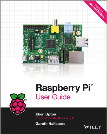
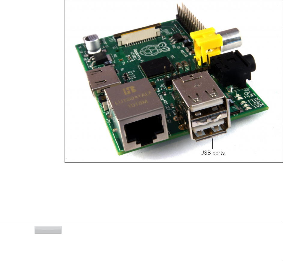
learn about in this chapter. Figure 1-1 shows a Raspberry Pi Model B.
F -:
e Raspberry Pi
board
CHAPTER 1 MEET THE RASPBERRY PI 15
In the centre of all Raspberry Pi boards is a square semiconductor, more commonly known as
an integrated circuit or chip. is is the Broadcom BCM2835 system-on-chip (SoC) module,
which provides the Pi with its general-purpose processing, graphics rendering and input/
output capabilities. Stacked on top of that chip is another semiconductor, which provides
the Pi with memory for temporary storage of data while it’s running programs. is type of
memory is known as random access memory (RAM), as the computer can read from or write to
any part of the memory at any time. RAM is volatile, meaning that anything stored in the
memory is lost when the Pi loses power or is switched o.
Above and below the SoC are the Pi’s video outputs. e silver (bottom) connector is a High
Denition Multimedia Interface (HDMI) port, the same type of connector found on media players
and many satellite and cable set-top boxes. When connected to a modern TV or monitor, the
HDMI port provides high-resolution video and digital audio. e yellow (top) connector is a com-
posite video port, which is designed for connection to older TVs that don’t have an HDMI socket.
e video quality is lower than is available via HDMI, and there’s no audio; instead, audio is pro-
vided as an analogue signal on the 3.5mm audio jack to the right of the composite video socket.
e pins to the top-left of the Pi compose the general-purpose input-output (GPIO) header,
which can be used to connect the Pi to other hardware. e most common use for this port is
to connect an add-on board. A selection of these is described in Chapter 16, “Add-on Boards”.
e GPIO port is extremely powerful, but it’s fragile; when handling the Pi, always take care
to avoid touching these pins, and never connect anything to them while the Pi is switched
on.
e plastic and metal connector below the GPIO port is the Display Serial Interface (DSI) port,
for connecting digitally driven at-panel display systems. ese are rarely used except by
professional embedded developers, as the HDMI port is more exible. A second plastic and
metal connector, found to the right of the HDMI port, is the Camera Serial Interface (CSI)
port, which provides a high-speed connection to the Raspberry Pi Camera Module or other
Pi-compatible CSI-connected camera system. For more details on the CSI port, see Chapter
15, “e Raspberry Pi Camera Module”.
To the very bottom-left of the board is the Pi’s power socket. is is a micro-USB socket, the
same type found on most modern smartphones and tablets. Connecting a micro-USB cable
to a suitable power adapter, detailed in Chapter 2, “Getting Started with the Raspberry Pi”,
switches the Raspberry Pi on; unlike a desktop or laptop computer, the Pi doesn’t have a
power switch and will start immediately when power is connected.
On the underside of the Raspberry Pi board on the left-hand side is an SD card slot. A Secure
Digital (SD) memory card provides storage for the operating system, programs, data and other
les, and is non-volatile; unlike the volatile RAM, it will retain its information even when power

PART I CONNECTING THE BOARD
16
is lost. In Chapter 2, “Getting Started with the Raspberry Pi”, you’ll learn how to prepare an SD
card for use with the Pi, including installing an operating system in a process known as ashing.
e right-hand edge of the Pi will have dierent connectors depending on which model of
Raspberry Pi you have, the Model A or the Model B. Above these is a series of Light Emitting
Diodes (LEDs), the top two of which—marked ACT and PWR and providing an activity noti-
cation and power notication respectively—are present on all boards.
Model A
e least expensive of the Raspberry Pis, the Model A shown in Figure 1-2 is designed to be
aordable yet exible. As well as its lower cost compared to the Model B, the Model A draws
less power and is a good choice for projects that use solar, wind or battery power. Although the
Model A’s BCM2835 SoC is just as powerful as the one found on the Model B, it comes with
half the memory at 256MB. is is an important consideration when deciding which model to
buy, as it can make more complex applications run slowly—in particular, those applications
that turn the Pi into a server, as described in Chapter 10, “e Pi as a Web Server”.
F -:
A Raspberry Pi
Model A
CHAPTER 1 MEET THE RASPBERRY PI 17
e Model A has only a single port on its right-hand edge, a Universal Serial Bus (USB) port.
is is the same type of port found on desktop and laptop computers, and allows the Pi to be
connected to almost any USB-compatible peripheral. Most commonly, the USB port is used
to connect a keyboard for interacting with the Pi. If you also want to use a mouse at the same
time, you’ll need to buy a USB hub to add more ports to the Model A, or alternatively, a key-
board with built-in mouse functionality.
Model B
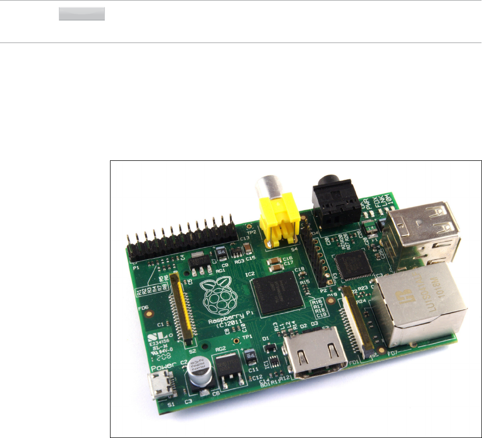
e Raspberry Pi Model B shown in Figure 1-3 is more expensive than the Model A, but
comes with considerable advantages. Internally, it includes twice the memory at 512MB,
while externally there are additional ports not available on the lower-cost model. For many
users, the Model B is a worthwhile investment; only those with particular requirements of
weight, space or power draw should consider the Model A for general-purpose use.
F -:
A Raspberry Pi
Model B
PART I CONNECTING THE BOARD
18
e Model B has two USB ports on the right-hand edge of the board, providing connectivity
for a keyboard and mouse, and still leaving two spare ports for additional accessories such as
external storage devices or hardware interfaces. Additionally, it includes an Ethernet port for
connecting the Pi to a wired network; this allows the Pi to access the Internet, and allows
other devices on the network to access the Pi—providing, that is, they know the username
and password or the Pi has been set up as a server as described in Chapter 10, “e Pi as a
Web Server”.
A History of Model B PCB Revisions
Although the Raspberry Pi Model B currently has 512MB of memory and two USB ports, this
wasn’t always the case. e Model B available today is known as Revision 2, as it is the second
board to be made with the Model B designation. If you have bought a Raspberry Pi Model B
second-hand, or purchased it some time ago, you may have a Revision 1 board, which has a
few dierences.
Revision 1
e original Raspberry Pi Model B, the Revision 1 board has just 256MB of RAM. It also has
a slightly dierent GPIO header, which looks identical to those of later revisions but has
certain features assigned to dierent pins, as explained in Chapter 14, “e GPIO Port”. is
is the most important dierence: all other Raspberry Pi revisions and models share the same
GPIO layout, so if you have an original Model B Revision 1 you may need to adjust instruc-
tions and programs before they can be used successfully.
Revision 2
Introduced shortly before the launch of the Model A, the Raspberry Pi Revision 2 includes
double the memory of the original at 512MB. It also introduces the new, standardised GPIO
header shared with the Model A. An extra header, which is also present on Model A boards,
marked P5 and located just below the GPIO header, is a sure sign that a Model B is the newer
Revision 2.
A Bit of Background
Before heading into Chapter 2, “Getting Started with the Raspberry Pi”, it’s a good idea to famil-
iarise yourself with some background details of the Pi and its creation. While the Pi is usable as
a general-purpose computer, capable of performing the same tasks as any desktop, laptop or
server—albeit more slowly—it is designed as a single-board computer aimed at hobbyists and
educational use, and as such diers from a “normal” computer in a couple of important ways.
CHAPTER 1 MEET THE RASPBERRY PI 19
ARM versus x86
e processor at the heart of the Raspberry Pi system is the Broadcom BCM2835 SoC multi-
media processor. is means that the vast majority of the system’s components, including
its central and graphics processing units along with the audio and communications hard-
ware, are built onto that single component hidden beneath the memory chip at the centre of
the board.
It’s not just this SoC design that makes the BCM2835 dierent to the processor found in
your desktop or laptop, however. It also uses a dierent instruction set architecture (ISA),
known as ARM.
Developed by Acorn Computers back in the late 1980s, the ARM architecture is a relatively
uncommon sight in the desktop world. Where it excels, however, is in mobile devices: the
phone in your pocket almost certainly has at least one ARM-based processing core hidden
away inside. Its combination of a simple reduced instruction set computing (RISC) architecture
and low power draw make it the perfect choice over desktop chips with high power demands
and complex instruction set computing (CISC) architectures.
e ARM-based BCM2835 is the secret of how the Raspberry Pi is able to operate on just the
5V 1A power supply provided via the onboard micro-USB port. It’s also the reason why you
won’t nd any metal heat sinks on the device: the chip’s low power draw directly translates
into very little waste heat, even during complicated processing tasks.
It does mean, however, that the Raspberry Pi isn’t compatible with traditional PC software.
e majority of software for desktops and laptops is built with the x86 instruction set archi-
tecture in mind, as found in processors from the likes of AMD, Intel and VIA. As a result, it
won’t run on the ARM-based Raspberry Pi.
e BCM2835 uses a generation of ARM’s processor design known as ARM11, which in turn
is designed around a version of the instruction set architecture known as ARMv6. is is
worth remembering: ARMv6 is a lightweight and powerful architecture, but has a rival in the
more advanced ARMv7 architecture used by the ARM Cortex family of processors. Software
developed for ARMv7, like software developed for x86, is sadly not compatible with the
Raspberry Pi’s BCM2835—although developers can usually convert the software to make it
suitable, a process known as porting.
at’s not to say you’re going to be restricted in your choices. As you’ll discover later in the
book, there is plenty of software available for the ARMv6 instruction set and, as the Raspberry
Pi’s popularity continues to grow, that will only increase. In this book, you’ll also learn how to
create your own software for the Pi even if you have no experience with programming.
PART I CONNECTING THE BOARD
20
Windows versus Linux
Another important dierence between the Raspberry Pi and your desktop or laptop, other
than the size and price, is the operating system—the software that allows you to control the
computer.
e majority of desktop and laptop computers available today run one of two operating systems:
Microsoft Windows or Apple OS X. Both platforms are closed source, created in a secretive
environment using proprietary techniques.
ese operating systems are known as closed source because of the nature of their source code,
the computer-language recipe that tells the system what to do. In closed-source software, this
recipe is kept a closely guarded secret. Users are able to obtain the nished software, but never
to see how it’s made.
e Raspberry Pi, by contrast, is designed to run an operating system called GNU/Linux—
hereafter referred to simply as Linux. Unlike Windows or OS X, Linux is open source: it’s pos-
sible to download the source code for the entire operating system and make whatever
changes you desire. Nothing is hidden, and all changes are made in full view of the public.
is open source development ethos has allowed Linux to be altered quickly to run on the
Raspberry Pi. At the time of this writing, several versions of Linux—known as distributions—
have been ported to the Raspberry Pi’s BCM2835 chip, including Raspbian, Pidora and Arch
Linux.
e dierent distributions cater to dierent needs, but they all have something in common:
they’re all open source. ey’re also all, by and large, compatible with each other: software
written on a Debian system will usually operate perfectly well on Arch Linux, and vice versa.
Linux isn’t exclusive to the Raspberry Pi. Hundreds of dierent distributions are available for
desktops, laptops and even mobile devices; even Google’s popular Android platform is devel-
oped on top of a Linux core. If you nd that you enjoy the experience of using Linux on the
Raspberry Pi, you could consider adding it to other computing devices you use as well. It will
happily coexist with your current operating system, allowing you to enjoy the benets of
both while giving you a familiar environment when your Pi is unavailable.
As with the dierence between ARM and x86, there’s a key point to make about the practical
dierence between Windows and OS X and Linux: software written specically for Windows
or OS X won’t run on Linux. ankfully, there are plenty of compatible alternatives for the
overwhelming majority of common software products—better still, the majority are free to
use and as open source as the operating system itself, and can even be installed on both
Windows and OS X to provide a familiar experience across all three platforms.
Chapter 2
Getting Started with
the Raspberry Pi

PART I CONNECTING THE BOARD
22
NOW THAT YOU have a basic understanding of how the Raspberry Pi diers from other
computing devices, it’s time to get started. If you’ve just received your Pi, take it out of its
protective anti-static bag and place it on a at, non-conductive surface before continuing
with this chapter.
To use your Pi, you’ll need some extra peripherals. A display will allow you to see what you’re
doing, while a keyboard and mouse will be your input devices. In this chapter, you’ll learn
how to connect these to the Pi, along with a network connection in the case of the Model B.
You’ll also learn how to download and install an operating system for the Pi.
Your Mileage May Vary
The information and instructions in this book give you all you need to get your Raspberry Pi
up and running and to make the most of its capabilities. Be aware that some of the software
for the Raspberry Pi is evolving so quickly that what you see on your screen may differ
slightly from some of the images in the book, as new features and options become
available.
Connecting a Display
Before you can start using your Raspberry Pi, you’re going to need to connect a display. e
Pi supports three dierent video outputs: composite video, HDMI video and DSI video.
Composite video and HDMI video are readily accessible to the end user, as described in this
section, while DSI video requires some specialised hardware.
Composite Video
Composite video, available via the yellow-and-silver port at the top of the Pi known as an
RCA phono connector (see Figure 2-1), is designed for connecting the Raspberry Pi to older
display devices. As the name suggests, the connector creates a composite of the colours
found within an image—red, green and blue—and sends it down a single wire to the display
device, typically an old cathode-ray tube (CRT) TV.
When no other display device is available, a composite video connection will get you started
with the Pi. e quality isn’t great, however. Composite video connections are signicantly
more prone to interference, lack clarity and run at a limited resolution, meaning that you can
t fewer icons and lines of text on the screen at once.

CHAPTER 2 GETTING STARTED WITH THE RASPBERRY PI 23
Figure 2-1:
e yellow RCA
phono
connector, for
composite video
output
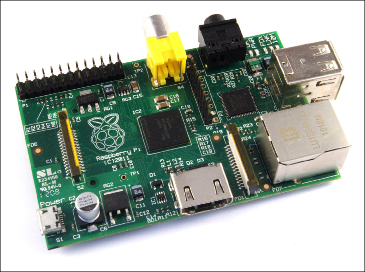
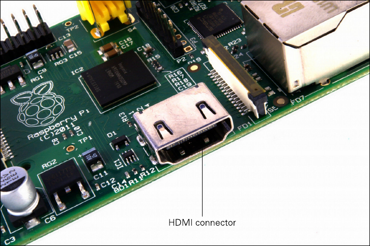
HDMI Video
A better quality picture can be obtained using the High Denition Multimedia Interface (HDMI)
connector, the only port found on the bottom of the Pi (see Figure 2-2). Unlike the analogue
composite connection, the HDMI port provides a high-speed digital connection for pixel-
perfect pictures on both computer monitors and high-denition TV sets. Using the HDMI
port, a Pi can display images at the Full HD 1920x1080 resolution of most modern HDTV
sets. At this resolution, signicantly more detail is available on the screen.
If you’re hoping to use the Pi with an existing computer monitor, you may nd that your
display doesn’t have an HDMI input. at’s not a disaster: the digital signals present on the
HDMI cable map to a common computer monitor standard called Digital Video Interconnect
(DVI). By purchasing an HDMI-to-DVI cable, you’ll be able to connect the Pi’s HDMI port to
a monitor with DVI-D connectivity.
If your monitor has a VGA input—a D-shaped connector with 15 pins, typically coloured
silver and blue—the Raspberry Pi can’t connect to it directly. To use this type of monitor,
you will need to purchase what is known as an adapter dongle; look for models that convert
HDMI to VGA and specically mention Raspberry Pi compatibility when making a purchase,
and simply connect the HDMI end to the Pi and your VGA monitor cable to the other end of
the dongle.
PART I CONNECTING THE BOARD
24
Figure 2-2:
e silver HDMI
connector, for
high-denition
video output
DSI Video
e nal video output on the Pi can be found above the SD card slot on the top of the printed
circuit board—it’s a small ribbon connector protected by a layer of plastic. is is for a video
standard known as Display Serial Interface (DSI), which is used in the at-panel displays of
tablets and smartphones. Displays with a DSI connector are rarely available for retail pur-
chase, and are typically reserved for engineers looking to create a compact, self-contained
system. A DSI display can be connected by inserting a ribbon cable into the matched connec-
tor on the Pi, but for beginners, the use of a composite or HDMI display is recommended.
Connecting Audio
If you’re using the Raspberry Pi’s HDMI port, audio is simple: when properly congured, the
HDMI port carries both the video signal and a digital audio signal. is means that you can
connect a single cable to your display device to enjoy both sound and pictures.
Assuming you’re connecting the Pi to a standard HDMI display, there’s very little to do at
this point. For now, it’s enough simply to connect the cable.

CHAPTER 2 GETTING STARTED WITH THE RASPBERRY PI 25
If you’re using the Pi with a DVI-D monitor via an adapter or cable, audio will not be included.
is highlights the main dierence between HDMI and DVI: while HDMI can carry audio
signals, DVI cannot and is instead used exclusively for video signals.
For those with DVI-D monitors, or those using the composite video output, a black 3.5 mm
audio jack located on the top edge of the Pi next to the yellow phono connector provides ana-
logue audio (see Figure 2-1). is is the same connector used for headphones and micro-
phones on consumer audio equipment, and it’s wired in exactly the same way. If you want,
you can simply connect a pair of headphones to this port for quick access to audio.
TIP
While headphones can be connected directly to the Raspberry Pi, you may nd the volume a little
lacking. If possible, connect a pair of powered speakers instead. The amplier inside will help boost
the signal to a more audible level, while many will also provide a physical volume control.
If you’re looking for something more permanent, you can either use standard PC speakers
that have a 3.5 mm connector or buy some adapter cables. For composite video users, a 3.5
mm to RCA phono cable is useful. is provides the two white-and-red RCA phono connec-
tions that sit alongside the video connection, each carrying a channel of the stereo audio
signal to the TV.
For those connecting the Pi to an amplier or stereo system, you’ll either need a 3.5 mm to
RCA phono cable or a 3.5 mm to 3.5 mm cable, depending on what spare connections you
have on your system. Both cable types are readily and cheaply available at consumer elec-
tronics shops, or can be purchased even cheaper from online retailers such as Amazon.
Connecting a Keyboard and Mouse
Now that you’ve got your Raspberry Pi’s output devices sorted, it’s time to think about input.
At a bare minimum, you’re going to need a keyboard, and for the majority of users, a mouse
or trackball is a necessity too.
First, some bad news: if you’ve got a keyboard and mouse with a PS/2 connector—a round
plug with a horseshoe-shaped array of pins—then you’re going to have to go out and buy a
replacement. e old PS/2 connection has been superseded, and the Pi expects your periph-
erals to be connected over the Universal Serial Bus (USB) port. An alternative is to buy a USB
to PS/2 adapter, although be aware that some particularly old keyboards may not operate
correctly through such an adapter.
Depending on whether you purchased the Model A or Model B, you’ll have either one or two
USB ports available on the right side of the Pi (see Figure 2-3). If you’re using a Model B, you
PART I CONNECTING THE BOARD
26
can connect the keyboard and mouse directly to these ports. If you’re using a Model A, you’ll
need to purchase an external USB hub in order to connect two USB devices simultaneously.
Figure 2-3:
e Raspberry Pi
Model B’s two
USB ports
A USB hub is a good investment for any Pi user: even if you’ve got a Model B, you’ll use up
both your available ports just connecting your keyboard and mouse, leaving nothing free for
additional devices such as an external optical drive, storage device or joystick. Make sure you
buy a powered USB hub: passive models are cheaper and smaller, but lack the ability to run
current-hungry devices like CD drives and external hard drives.
TIPIf you want to reduce the number of power sockets in use, connect the Raspberry Pi’s USB
power lead to your powered USB hub. This way, the Pi can draw its power directly from the hub,
rather than needing its own dedicated power socket and mains adapter. This will only work on
hubs with a power supply capable of providing 700mA to the Pi’s USB port—more than will be
available on cheaper hub models—along with whatever power is required by other peripherals.
Connecting the keyboard and mouse is as simple as plugging them into the USB ports, either
directly in the case of a Model B or via a USB hub in the case of a Model A.

CHAPTER 2 GETTING STARTED WITH THE RASPBERRY PI 27
Installing NOOBS on an SD Card
e Raspberry Pi Foundation supplies a software tool for the Pi known as New Out-Of-Box
Software, or NOOBS. is tool, is intended to make it as easy as possible to get started with
using the Pi, and is available pre-installed on SD cards bundled with Raspberry Pi boards as
well as separately and as a free download. It provides a selection of dierent operating sys-
tems for installation on the Pi, along with tools for changing its conguration.
If you have purchased an SD card with NOOBS already installed on it, you need do nothing
at this stage. If not, download the latest version of the NOOBS software from the Raspberry
Pi Foundation at www.raspberrypi.org/downloads. Note that this is a large le, and
can take some considerable time to download; if you are on a capped Internet connection of
around 1 GB a month, you will be unable to download the le. In this case, invest in an SD
card with NOOBS preloaded from any Raspberry Pi-carrying retailer.
To use NOOBS, you’ll need an SD card of at least 4 GB capacity, and preferably at least 8 GB to
give you room to install additional software as you use the Pi. You’ll also need an existing com-
puter with an SD card reader, either built-in as with some models of laptop or an add-on device.
To begin, insert the SD card into the card reader. If you have previously used your SD card with
another device, such as a digital camera or games console, follow the link on the Raspberry Pi
Downloads page to the SD Card Association’s formatting tool and use this to format the SD
card, preparing it for the installation. If the card is new, you can safely skip this step.
e NOOBS software is provided as a Zip archive. is is a le format where the data is compressed,
so that it takes up less space and is quicker to download. Double-clicking on the le should be
A Note on Storage
As you’ve probably noticed, the Raspberry Pi doesn’t have a traditional hard drive. Instead, it
uses a Secure Digital (SD) memory card, a solid-state storage system typically used in digital
cameras. Almost any SD card will work with the Raspberry Pi, but because it holds the entire
operating system, you need a card with at least 4 GB in capacity to store all the required les.
SD cards with the operating system preloaded are available from the ofcial Raspberry Pi
Store as well as with numerous other sites on the Internet. If you’ve purchased one of
these, or received it in a bundle with your Pi, you can simply plug it into the SD card slot on
the bottom side of the left-hand edge.
Some SD cards work better than others, with some models refusing to work at all with the
Raspberry Pi. For an up-to-date list of SD card models known to work with the Pi, visit the
eLinux Wiki page at http://www.elinux.org/RPi_SD_cards.
PART I CONNECTING THE BOARD
28
enough to open it on most operating systems; if not, download an archive utility like 7Zip
(www.7-zip.org) and try again.
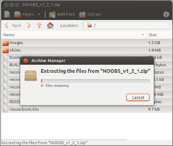
When you have opened the le, use your archive software’s extract or copy function to transfer
the les from within the archive to your SD card (see Figure 2-4). is can take some time to
complete, thanks to the number and size of the les involved. Be patient, and when the extrac-
tion has nished and the activity light—if applicable—has gone o, use your operating sys-
tem’s Eject option to remove the SD card, and then insert the card into the Pi’s SD card slot.
Figure 2-4:
Extracting
NOOBS to the
SD card
Connecting External Storage
While the Raspberry Pi uses an SD card for its main storage device—known as a boot
device—you may nd that you run into space limitations quite quickly. Although large SD
cards holding 32 GB, 64 GB or more are available, they are often prohibitively expensive.
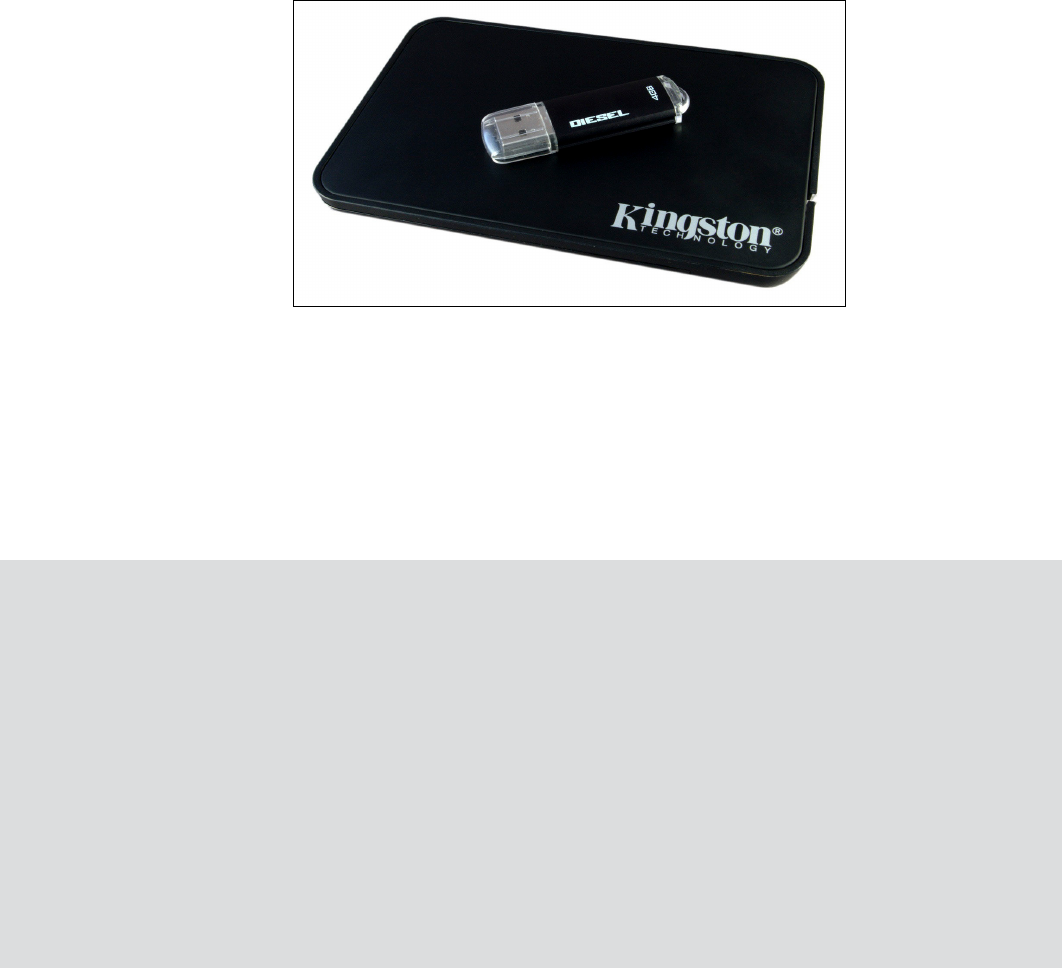
ankfully, there are devices that provide an additional hard drive capacity to any computer when
connected via a USB cable. Known as USB Mass Storage (UMS) devices, these can be physical hard
drives, solid-state drives (SSDs) or even portable pocket-sized ash drives (see Figure 2-5).
e majority of USB Mass Storage devices can be read by the Pi, whether or not they have
existing content. In order for the Pi to be able to access these devices, their drives must be
CHAPTER 2 GETTING STARTED WITH THE RASPBERRY PI 29
mounted—a process you will learn in Chapter 3, “Linux System Administration”. For now,
it’s enough to connect the drives to the Pi in readiness.
Figure 2-5:
Two USB Mass
Storage devices:
a pen drive and
an external hard
drive
Connecting the Network
While the majority of these setup instructions are equally applicable to both the Raspberry Pi
Model A and the Model B, networking is a special exception. To keep the component count—
and therefore the cost—as low as possible, the Model A doesn’t feature any onboard net-
working. ankfully, that doesn’t mean you can’t network the Model A, only that you’ll need
some additional equipment to do so.
Networking the Model A
To give the Model A the same networking capabilities as its more expensive Model B coun-
terpart, you’ll need a USB-connected Ethernet adapter. This connects to a free USB port on
the Raspberry Pi or a connected hub, and provides a wired Ethernet connection with an
RJ45 connector, the same as is available on the Model B.
A 10/100 USB Ethernet adapter—with the numbers referring to its two-speed mode, 10 Mb/s and
100 Mb/s—can be purchased from online retailers for very little money. When buying an Ethernet
adapter, be sure to check that Linux is listed as a supported operating system. There are a few
models that only work with Microsoft Windows and are incompatible with the Raspberry Pi.
Don’t be tempted to go for a gigabit-class adapter, which may be referred to as a 10/100/1000
USB Ethernet adapter. Standard USB ports, as used on the Raspberry Pi, can’t cope with the
speed of a gigabit Ethernet connection, and you’ll see no benet from the more expensive
adapter.

PART I CONNECTING THE BOARD
30
Wired Networking
To get your Raspberry Pi on the network, you’ll need to connect an RJ45 Ethernet patch cable
between the Pi and a switch, router or hub. If you don’t have a router or hub, you can get
your desktop or laptop talking to the Pi by connecting the two directly together with a patch
cable.
Usually, connecting two network clients together in this way requires a special cable, known
as a crossover cable. In a crossover cable, the receive and transmit pairs are swapped so that
the two devices are prevented from talking over each other—a task usually handled by a
network switch or hub.
e Raspberry Pi is cleverer than that, however. e RJ45 port on the side of the Pi (see
Figure 2-6) includes a feature known as auto-MDI, which allows it to recongure itself auto-
matically. As a result, you can use any RJ45 cable—crossover or not—to connect the Pi to
the network, and it will adjust its conguration accordingly.
Figure 2-6:
e Raspberry Pi
Model B’s
Ethernet port
TIP
CHAPTER 2 GETTING STARTED WITH THE RASPBERRY PI 31
If you do connect the Pi directly to a PC or laptop, you won’t be able to connect out onto the
Internet by default. To do so, you’ll need to congure your PC to bridge the wired Ethernet
port and another (typically wireless) connection. Doing so is outside the scope of this book,
but if you are completely unable to connect the Pi to the Internet in any other way, you can
try searching your operating system’s help le for “bridge network” to nd more guidance.
With a cable connected, the Pi will automatically receive the details it needs to access the
Internet when it loads its operating system through the Dynamic Host Conguration Protocol
(DHCP). is assigns the Pi an Internet Protocol (IP) address on your network, and tells it the
gateway it needs to use to access the Internet (typically the IP address of your router or
modem).
For some networks, there is no DHCP server to provide the Pi with an IP address. When con-
nected to such a network, the Pi will need manual conguration. You’ll learn more about this
in Chapter 5, “Network Conguration”.
Wireless Networking
Current Raspberry Pi models don’t feature any form of wireless network capability onboard,
but—as with adding wired Ethernet to the Model A—it’s possible to add Wi-Fi support to
any Pi using a USB wireless adapter (see Figure 2-7).
Figure 2-7:
Two USB
wireless
adapters,
suitable for use
with the
Raspberry Pi
PART I CONNECTING THE BOARD
32
Using such a device, the Pi can connect to a wide range of wireless networks, including those
running on the latest 802.11n high-speed standard. Before purchasing a USB wireless
adapter, check the following:
❍ Ensure that Linux is listed as a supported operating system. Some wireless adapters
are provided with drivers for Windows and OS X only, making them incompatible with
the Raspberry Pi. A list of Wi-Fi adapters known to work with the Raspberry Pi can be
found on the following website: http://elinux.org/RPi_USB_Wi-Fi_
Adapters.
❍ Ensure that your Wi-Fi network type is supported by the USB wireless adapter. e
network type will be listed in the specications as a number followed by a letter. If your
network type is 802.11a, for example, an 802.11g wireless adapter won’t work.
❍ Check the frequencies supported by the card. Some wireless network standards, like
802.11a, support more than one frequency. If a USB wireless adapter is designed to
work on a 2.4GHz network, it won’t connect to a 5GHz network.
❍ Check the encryption type used by your wireless network. Most modern USB wireless
adapters support all forms of encryption, but if you’re buying a second-hand or older
model, you may nd it won’t connect to your network. Common encryption types
include the outdated WEP and more modern WPA and WPA2.
Conguration of the wireless connection is done within Linux, so for now it’s enough simply
to connect the adapter to the Pi (ideally through a powered USB hub). You’ll learn how to
congure the connection in Chapter 5, “Network Conguration”.
Connecting Power
e Raspberry Pi is powered by the small micro-USB connector found on the lower left side of
the circuit board. is connector is the same as is found on the majority of smartphones and
many tablet devices.
Many chargers designed for smartphones will work with the Raspberry Pi, but not all. e Pi
is more power-hungry than most micro-USB devices, and requires up to 700 mA of current
in order to operate. Some chargers can only supply up to 500 mA, causing intermittent prob-
lems in the Pi’s operation (see Chapter 4, “Troubleshooting”).
Connecting the Pi to the USB port on a desktop or laptop computer is possible, but not rec-
ommended. As with smaller chargers, the USB ports on a computer can’t provide the power
CHAPTER 2 GETTING STARTED WITH THE RASPBERRY PI 33
required for the Pi to work properly. Connect the micro-USB power supply only when you are
ready to start using the Pi. With no power button on the device, it will start working the
instant power is connected.
To safely turn the Raspberry Pi o, issue a shutdown command at the console or terminal by
typing:
sudo shutdown -h now
For more information on using the terminal, see Chapter 3, “Linux System Administration”.
If you have prepared or purchased your SD card with the NOOBS tool, as described earlier in this
chapter, the Pi will load this tool and wait for your instructions; if not, powering the Pi on with a
blank SD card will result in a blank screen or a coloured test pattern. In this case, switch o the
power and remove the SD card before following the manual installation instructions from the
following section, “Installing the Operating System”.
Installing the Operating System
If you purchased your Raspberry Pi with a bundled SD card featuring a preloaded operating
system, or followed the instructions for installing NOOBS earlier in this chapter, you can
simply insert the card into the SD card slot on the underside of the Pi. If you bought the Pi by
itself, you will need to install an operating system on the SD card before the Pi is ready
to use.
Installing Using NOOBS
If you have installed NOOBS on your SD card, or purchased an SD card with NOOBS pre-
installed, powering on the Raspberry Pi will display a menu (see Figure 2-8). is menu pro-
vides a list of operating systems suitable for the Pi, any one (or more) of which can be
installed. You can also choose to change the interface language by clicking the arrow next to
Language at the bottom of the screen, or choose a dierent keyboard layout using the arrow
next to Keyboard.
If this is your rst time running NOOBS on that SD card, there will be a delay while the SD
card’s partition is resized to make room for your chosen operating system; do not unplug the
Pi’s power while this is in progress, as you will risk damaging your SD card.
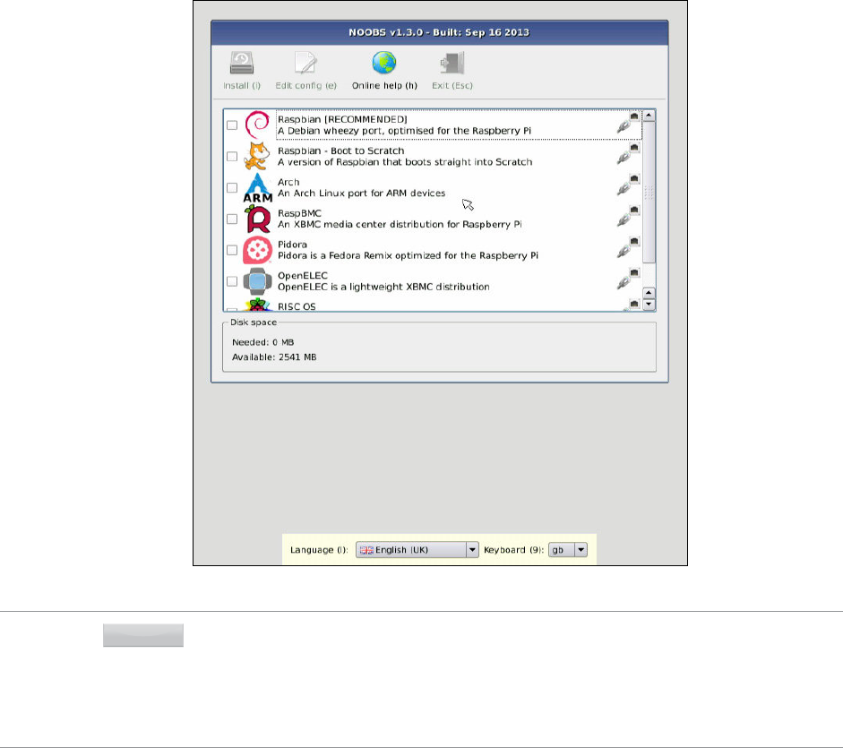
PART I CONNECTING THE BOARD
34
Figure 2-8:
e NOOBS
operating
system menu
TIPIf you see only a blank screen, but the Pi’s ACT and PWR lights are on, you may need to choose a
different display mode. Press 1 on the keyboard for standard HDMI mode, 2 for a ‘safe’ mode with
a lower resolution, 3 if you are using the composite port in a PAL region or 4 if you are using the
composite port in an NTSC region. If you’re not sure which is suitable, try all the options until you
nd one that works for you. The chosen display mode will also be passed to the installed operating
system automatically.
Using the keyboard or mouse, browse through the list of operating systems and click on the
box by its name to mark it for installation. Note that you can install multiple operating sys-
tems if your SD card is large enough: simply tick two or more operating systems from the list.
For beginners, we recommend the Raspbian operating system. e remainder of this book
will be written with Raspbian in mind, but much of what you’ll learn is applicable to almost
any Linux-based operating system both on the Pi and on other devices.
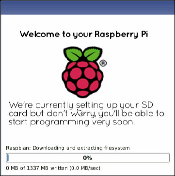
CHAPTER 2 GETTING STARTED WITH THE RASPBERRY PI 35
To begin the installation process, click the Install icon at the top-left of the menu and, when
asked, conrm that the SD card can be overwritten when asked. As with installing NOOBS
itself, this process can take a long time to complete; be patient, watch the progress bar and
slideshow (see Figure 2-9) and don’t remove the power cable or SD card from the Pi until it is
nished. When the operating system is installed, click the OK button to reboot and load your
chosen operating system.
Figure 2-9:
Installing an
operating
system via
NOOBS
If you have installed more than one operating system, NOOBS will bring up a menu asking
which one to boot: if you don’t make a choice, the last operating system chosen—or the rst
in the list, if you haven’t booted into an OS before—will automatically boot after 10 seconds.
For more information on using NOOBS after the operating system is installed, to either
install a dierent operating system or to change the Pi’s various settings, see Chapter 7,
“Advanced Raspberry Pi Conguration”.
Installing Manually
Installing an operating system manually is a more complicated procedure than using the
NOOBS tool, but is sometimes preferable. By installing the software manually—a process
known as ashing—you can choose to install operating systems that aren’t available through
NOOBS or newer versions that the tool doesn’t yet have available.
To prepare a blank SD card for use with the Raspberry Pi, you’ll need to ash an operating
system onto the card, using your desktop or laptop computer. While this is slightly more
complicated than simply dragging and dropping les onto the card, it shouldn’t take more
than a few minutes to complete.

PART I CONNECTING THE BOARD
36
First, you’ll need to decide which Linux distribution you would like to use with your Raspberry
Pi. Each has its advantages and disadvantages. Don’t worry if you change your mind later
and want to try a dierent version of Linux: an SD card can be ashed again with a new oper-
ating system at any point, and if you choose you can have multiple cards each with a dier-
ent operating system installed.
e most up-to-date list of Linux releases compatible with the Pi is available from the
Raspberry Pi website at http://www.raspberrypi.org/downloads.
e Foundation provides BitTorrent links for each distribution. ese are small les that can
be used with BitTorrent software to download the les from other users. Using these links is
an ecient and fast way to distribute large les, and keeps the Foundation’s download serv-
ers from becoming overloaded.
To use a BitTorrent link, you’ll need to have a compatible client installed. If you don’t already have
a BitTorrent client installed, download one and install it before trying to download the Raspberry
Pi Linux distribution. One client for Windows, OS X and Linux is µTorrent, available from
http://www.utorrent.com/downloads.
Which distribution you choose to download is up to you. Instructions in the rest of the book will
be based on the Raspbian Raspberry Pi distribution, a good choice for beginners. Where possible,
we’ll give you instructions for other distributions as well.
Linux distributions for the Raspberry Pi are provided as a single image le, compressed to make it
faster to download. Once you’ve downloaded the Zip archive (a compressed le, which takes less
time to download than the uncompressed les would) for your chosen distribution, you’ll need to
decompress it somewhere on your system. In most operating systems, you can simply double-
click the le to open it, and then choose Extract or Unzip to retrieve the contents.
After you’ve decompressed the archive, you’ll end up with two separate les. e le ending in
sha1 is a hash, which can be used to verify that the download hasn’t been corrupted in transit.
e le ending in img contains an exact copy of an SD card set up by the distribution’s creators in
a way that the Raspberry Pi understands. is is the le that needs to be ashed to the SD card.
WARNING In the following instructions, you’ll be using a software utility called dd. Used incorrectly, dd
will happily write the image to your main hard drive, erasing your operating system and all
your stored data. Make sure you read the instructions in each section thoroughly and note the
device address of your SD card carefully. Read twice, write once!
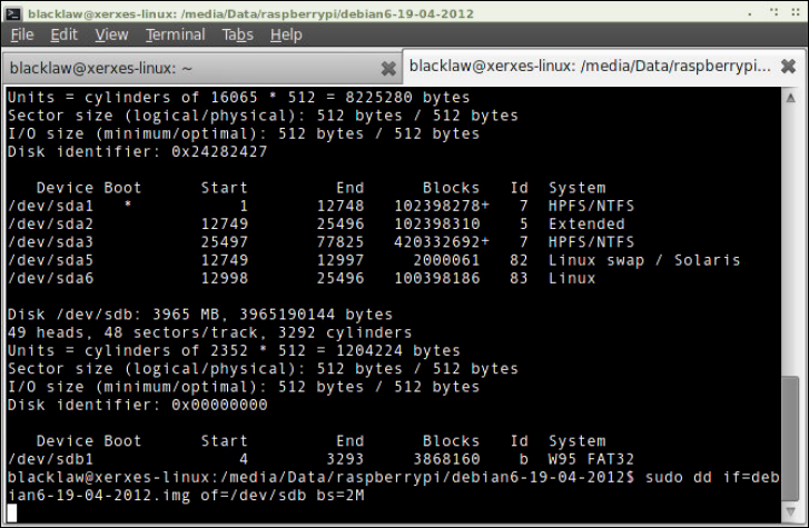
CHAPTER 2 GETTING STARTED WITH THE RASPBERRY PI 37
Flashing from Linux
If your current PC is running a variant of Linux already, you can use the dd command to write the
contents of the image le out to the SD card. is is a text-interface program operated from the
command prompt, known as a terminal in Linux parlance. Follow these steps to ash the SD card:
1. Open a terminal from your distribution’s applications menu.
2. Plug your blank SD card into a card reader connected to the PC.
3. Type sudo fdisk -l to see a list of disks. Find the SD card by its size, and note the
device address: /dev/sdX, where X is a letter identifying the storage device. Some
systems with integrated SD card readers may use the alternative format /dev/
mmcblkX—if this is the case, remember to change the target in the following instruc-
tions accordingly.
4. Use cd to change to the directory with the .img le you extracted from the Zip archive.
5. Type sudo dd if=imagefilename.img of=/dev/sdX bs=2M to write the le
imagefilename.img to the SD card connected to the device address from step 3.
Replace imagefilename.img with the actual name of the le extracted from the Zip
archive. is step takes a while, so be patient! During ashing, nothing will be shown
on the screen until the process is fully complete (see Figure 2-10).
Figure 2-10:
Flashing the SD
card using the
dd command
in Linux
PART I CONNECTING THE BOARD
38
Flashing from OS X
If your current computer is a Mac running Apple OS X, you’ll be pleased to hear that things are
just as simple as with Linux. anks to a similar ancestry, OS X and Linux both contain the dd
utility, which you can use to ash the system image to your blank SD card as follows:
1. Select Utilities from the Application menu, and then click on the Terminal application.
2. Plug your blank SD card into a card reader connected to the Mac.
3. Type diskutil list to see a list of disks. Find the SD card by its size, and note the
device address (/dev/diskX, where X is a letter identifying the storage device).
4. If the SD card has been automatically mounted and is displayed on the desktop, type
diskutil unmountdisk /dev/diskX to unmount it before proceeding.
5. Use cd to change to the directory with the .img le you extracted from the Zip archive.
6. Type dd if=imagefilename.img of=/dev/diskX bs=2m to write the le
imagefilename.img to the SD card connected to the device address from step 3.
Replace imagefilename.img with the actual name of the le extracted from the Zip
archive. is step takes a while, so be patient!
Flashing from Windows
If your current PC is running Windows, things are slightly trickier than with Linux or OS X.
Windows does not have a utility like dd, so some third-party software is required to get the image
le ashed onto the SD card. Although it’s possible to install a Windows-compatible version of
dd, there is an easier way: the Image Writer for Windows. Designed specically for creating USB
or SD card images of Linux distributions, this features a simple graphical user interface that
makes the creation of a Raspberry Pi SD card straightforward.
e latest version of Image Writer for Windows can be found at the ocial website:
https://sourceforge.net/projects/win32diskimager/. Follow these steps to
download, install and use the Image Writer for Windows software to prepare the SD card for
the Pi:
1. Click the green Download button to download the Image Writer for Windows Zip le,
and extract it to a folder on your computer.
2. Plug your blank SD card into a card reader connected to the PC.
3. Double-click the Win32DiskImager.exe le to open the program, and click the blue
folder icon to open a le browse dialogue box.

CHAPTER 2 GETTING STARTED WITH THE RASPBERRY PI 39
4. Browse to the imagefilename.img le you extracted from the distribution archive,
replacing imagefilename.img with the actual name of the le extracted from the Zip
archive, and then click the Open button.
5. Select the drive letter corresponding to the SD card from the Device drop-down dialogue
box. If you’re unsure which drive letter to choose, open My Computer or Windows Explorer
to check.
6. Click the Write button to ash the image le to the SD card. is process takes a while,
so be patient!
WARNING
No matter which operating system you’re writing from, it’s important to ensure you leave the
SD card connected until the image has been completely written. If you don’t, you may nd
that Pi doesn’t boot when the SD card is connected. If this happens, start the process again.
When the image has been ashed onto the SD card, remove it from the computer and insert it
into the Raspberry Pi’s SD card slot, located underneath the circuit board. The SD card should
be inserted with the label facing away from the board and pushed fully home to ensure a good
connection.
Chapter 3
Linux System Administration
PART I CONNECTING THE BOARD
42
THE MAJORITY OF modern Linux distributions are user-friendly, with a graphical user
interface (GUI) that provides an easy way to perform common tasks. It is, however, quite dif-
ferent to both Windows and OS X, so if you’re going to get the most out of your Raspberry Pi,
you’ll need a quick primer in using the operating system.
Linux: An Overview
As briey explained in Chapter 1, “Meet the Raspberry Pi”, Linux is an open source project
that was originally founded to produce a kernel that would be free for anyone to use. e
kernel is the heart of an operating system, and handles the communication between the user
and the hardware.
Although only the kernel itself is rightly called Linux, the term is often used to refer to a col-
lection of dierent open source projects from a variety of companies. ese collections come
together to form dierent avours of Linux, known as distributions.
e original version of Linux was combined with a collection of tools created by a group
called GNU. e resulting system, known as GNU/Linux, was basic but powerful. Unlike
many mainstream operating systems of the era, it oered facilities like multiple user accounts
where several users can share a single computer. at’s something rival closed-source operat-
ing systems have taken on board, with both Windows and OS X now supporting multiple
user accounts on the same system. It’s also still present in Linux, and provides security and
protection for the operating system.
In Linux, you’ll spend most of your time running a restricted user account. is doesn’t mean
you’re being limited in what you can do; instead, it prevents you from accidentally doing
something that will break the software on your Raspberry Pi. It also prevents viruses and
other malware from infecting the system by locking down access to critical system les and
directories.
Before you can get started, it’s worth becoming familiar with some of the terms and concepts
used in the world of Linux, as dened in Table 3-1. Even if you’re experienced with other
operating systems, it’s a good idea to review this table before booting up your Pi for the rst
time.

CHAPTER 3 LINUX SYSTEM ADMINISTRATION 43
Table 3-1 The Quick Linux Glossary
Term/Concept Denition
Bash e most popular shell choice, used in the majority of Linux distributions.
Bootloader Software responsible for loading the Linux kernel. e most common is GRUB.
Console A version of the terminal that is always available, and the rst thing you see on
the Pi.
Desktop
environment
Software to make the GUI look pretty. GNOME and KDE are popular desktop
environments.
Directory e Linux term for what Windows calls folders, where les are stored.
Distribution A particular version of Linux. Pidora, Arch and Raspbian are distributions.
Executable A le that can be run as a program. Linux les must be marked executable in
order to run.
EXT2/3/4 e EXTended le system, the most common le system used in Linux.
File system e way a hard drive or other storage device is formatted so it’s ready for le
storage.
GNOME One of the most common Linux desktop environments.
GNU A free software project, which provides many of the tools used in Linux distri-
butions.
GRUB e GRand Unied Bootloader, created by GNU and used to load the Linux
kernel.
GUI A graphical user interface, in which the user operates the computer via a
mouse or touch.
KDE Another extremely popular Linux desktop environment.
Linux Properly, the kernel used by GNU/Linux. Popularly, an open source operating
system.
Live CD A Linux distribution provided as a CD or DVD, which doesn’t require installation.
Package A collection of les required to run an application, typically handled by the
package manager.
Package manager A tool for keeping track of, and installing new, software.
Partition A section of a hard drive that is ready to have a le system applied to it for
storage.
Root e main user account in Linux, equivalent to the Windows administrator
account. Also called the superuser.
Shell A text-based command prompt, loaded in a terminal.
sudo A program that allows restricted users to run a command as the root user.
Superuser See Root.
Terminal A text-based command prompt in which the user interacts with a shell program.
X11 e X Window system, a package that provides a graphical user interface (GUI).

PART I CONNECTING THE BOARD
44
Linux Basics
Although there are hundreds of dierent Linux distributions available, they all share a com-
mon set of tools known as commands. ese tools, which are operated via the terminal, are
analogous to similar tools on Windows and OS X. To get started, you’ll need to learn the fol-
lowing commands:
❍ ls—Short for listing, ls provides a list of the contents of the current directory.
Alternatively, it can be called with the directory to be listed as an argument. As an
example, typing ls /home will provide a list of the contents of /home, regardless of
your current directory. e Windows equivalent is dir.
❍ cd—An initialism of change directory, cd allows you to navigate your way through the
le system. Typing cd on its own puts you back in your home directory. Typing the
command along with the name of the directory you wish to move to, by contrast,
switches to that directory. Note that directories can be absolute or relative: cd boot
will move you to the directory called boot under your current directory, but cd /
boot will move you straight to the /boot directory wherever you are.
❍ mv—e move command has two purposes in Linux: it allows a le to be moved from
one directory to another, and it also allows les to be renamed. at latter feature may
seem out of place, but in Linux terms, the le is being moved from one name to
another. e command is called as mv oldfile newfile.
❍ rm—Short for remove, rm deletes les. Any le—or list of les—provided after the
command name will be deleted. e Windows equivalent is del, and the two share a
common requirement that care should be taken to ensure the right le is deleted.
The Terminal and the GUI
As in OS X and Windows, there are typically two main ways to achieve a given goal in Linux:
through the graphical user interface (GUI) and through the command line (known in Linux
parlance as the console or the terminal).
The appearance of various Linux distributions can be quite different, depending on the desk-
top environment in use. In this book, the recommended Raspbian distribution is used, but
most of the commands you will be learning are entered at the terminal and are typically the
same across all distributions.
Where other distributions differ, you will be given alternative methods of achieving the
same goals.

CHAPTER 3 LINUX SYSTEM ADMINISTRATION 45
❍ rmdir—By itself, rm cannot usually remove directories. As a result, rmdir is provided
to delete directories once they have been emptied of les by rm.
❍ mkdir—e opposite of rmdir, the mkdir command creates new directories. For
example, typing mkdir myfolder at the terminal will create a new directory called
myfolder under the current working directory. As with cd, directories provided to
the command can be relative or absolute.
Introducing Raspbian
Raspbian is the name given to a customised variant of the popular Debian Linux distribu-
tion. Debian is one of the longest-running Linux distributions, and concentrates on high
compatibility and excellent performance even on modest hardware—making it a great part-
ner for the Raspberry Pi. Raspbian takes Debian as its base, or parent distribution, and adds
custom tools and software to make using the Raspberry Pi as easy as possible.
To keep the download size to a minimum, the Raspberry Pi image for Raspbian includes only
a subset of the software you’d nd on a regular desktop version. is includes tools for
browsing the web, programming in Python and using the Pi with a GUI. Additional software
can be quickly installed through the use of the distribution’s package manager, apt, or pur-
chased through the Raspberry Pi Store link on the desktop. Raspbian includes a desktop
environment known as the Lightweight X11 Desktop Environment (LXDE). Designed to oer
an attractive user interface using the X Window System software, LXDE provides a familiar
point-and-click interface that will be immediately accessible to anyone who has used
Windows, OS X or other GUI-based operating systems in the past.
TIP
The GUI doesn’t load by default in most Raspberry Pi distributions, and Raspbian is no
exception. To quickly load it and leave the text-based console behind, log in, type startx
and then press the Enter key. To return to the console, while leaving the GUI running in the
background, hold down Ctrl + Alt and press F1 before releasing all three keys.
If you’re using the recommended Raspbian distribution, you’ll nd that you have plenty of
preinstalled software to get started. While hardly an exhaustive example of the software
available for the Pi, which numbers in the thousands of packages, it’s a good introduction to
precisely what the system can do.
e software provided with the Raspbian distribution is split into themed categories. To view
these categories, left-click the menu icon, the arrow located on the bottom-left of the screen
in LXDE (see Figure 3-1).
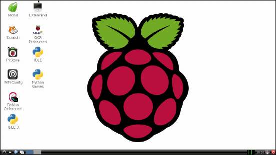
PART I CONNECTING THE BOARD
46
F -:
e LXDE
desktop, as
loaded on the
Raspbian
distribution on a
Raspberry Pi
e following lists describe the software packages, grouped by category. ere is also a cate-
gory not covered here, dubbed “Other”, into which numerous system tools are grouped. If
you have installed a program and can’t nd it anywhere else, try the Other menu.
Accessories
❍ Debian Reference—A built-in reference guide, this provides a detailed explanation of
the Debian Linux distribution and how programmers can contribute to its develop-
ment.
❍ File Manager—e PCManFM le manager provides a graphical browser for les
stored on the Pi or any connected storage device.
❍ Galculator—An open source scientic calculator, oering a variety of functions for
both quick and complex sums.
❍ Image Viewer—e GPicView lets you view images, such as those from a digital cam-
era or on a connected storage device.
❍ Leafpad—is is a simple text editor, which is useful for making quick notes or writ-
ing simple programs.
❍ LXTerminal—is LXDE terminal package allows you to use the Linux command line
in a window without leaving the graphical user interface.
❍ Root Terminal—Similar to LXTerminal, the Root Terminal automatically logs you in
as the root superuser account in order to carry out system maintenance tasks unavail-
able to a regular user account.
❍ Xarchiver—If you need to create or extract compressed les, such as Zip archives, this
is the tool for the job.
CHAPTER 3 LINUX SYSTEM ADMINISTRATION 47
Education
❍ Scratch—A graphical programming language aimed at young children. You’ll learn
more about Scratch and its capabilities in Chapter 11, “An Introduction to Scratch”.
❍ Squeak—e platform on which Scratch runs. You will rarely need to use this menu
entry, and should instead use the Scratch entry above.
Internet
❍ Dillo—One of the fastest web browsers available for the Pi, but somewhat basic com-
pared to Midori.
❍ Midori—A fast yet lightweight web browser, Midori is equivalent to Internet Explorer
in Windows or Safari on OS X.
❍ Midori Private Browsing—Clicking on this menu entry loads the Midori web browser
in private mode, meaning that sites you visit aren’t saved into the browser’s history.
❍ NetSurf Web Browser—An alternative to Midori, NetSurf can perform better on cer-
tain types of web page. Trying both will allow you to experiment and nd the one that
works best for you.
❍ wps_gui—A graphical user interface for conguring a Raspberry Pi with optional USB
Wireless Adapter to connect to a Wireless Protected System (WPS) encrypted network.
Programming
❍ IDLE—An integrated development environment (IDE) written specically for Python.
You’ll learn more about using IDLE to write your own Python programs in Chapter 12,
“An Introduction to Python”.
❍ IDLE 3—Clicking this entry loads IDLE congured to use the newer Python 3 pro-
gramming language, rather than the default Python 2.7 language. Both are largely
compatible with each other, but some programs may require features of Python 3.
❍ Scratch—is shortcut opens the Scratch educational language, and is the same as the
Scratch entry found in the Education category. Either can be used to start the program.
❍ Squeak—As with Scratch, this is a duplicate of the shortcut found in the Education cate-
gory. You will rarely want to click this directly, and should instead use the Scratch shortcut.
System Tools
❍ Task Manager—A tool for checking the amount of free memory available on the Pi
and the current workload of the processor, and for closing programs that have crashed
or are otherwise unresponsive.

PART I CONNECTING THE BOARD
48
Preferences
❍ Customise Look and Feel—A toolkit for adjusting the appearance of the GUI, includ-
ing the style and colour of windows.
❍ Desktop Session Settings—A tool for changing how the system works when the
user is logged in, including what programs are automatically loaded and which
window manager—the software that draws the borders and title bars of windows—
is used.
❍ Keyboard and Mouse—A tool for adjusting input devices. If your keyboard is typing
the wrong characters for certain keys, or your mouse is too sensitive, the settings can
be altered here.
❍ Monitor Settings—e resolution that the monitor or TV connected to the Pi runs at
can be altered here, although advanced changes require modication of conguration
les. You’ll learn about this in Chapter 7, “Advanced Raspberry Pi Conguration”.
❍ Openbox Conguration Manager—e LXDE GUI uses a desktop environment
called Openbox, which can be adjusted here. Using this tool, you can apply new themes
to change the GUI’s appearance, or alter how certain aspects of the interface operate.
❍ Preferred Applications—A tool for changing which applications are opened for par-
ticular le types. If you choose to use an alternative web browser, the system default
can be changed here.
Finding Help
Linux is designed to be as user-friendly as possible to new users, even at the terminal com-
mand prompt. Although you’ll learn the most common ways to use each command in this
chapter, not every option will be covered—to do so would require a much larger book.
If you nd yourself stuck, or if you want to learn more about any of the tools that are dis-
cussed in the following pages, there’s a command you should learn: man.
Each Linux application comes with a help le known as a man page—short for “manual
page”. It provides background on the software as well as details on what its options do and
how to use them.
To access the man page for a given tool, just type man followed by the command name. To
see the man page for ls, a tool for listing the contents of directories, just type man ls.
CHAPTER 3 LINUX SYSTEM ADMINISTRATION 49
About Raspbian’s Parent, Debian
Raspbian is based on one of the original Linux distributions, Debian. Named after its creator and
his girlfriend—Ian and Deb—Debian is a popular distribution in its own right. It is common in
the world of open source software, however, for projects to start up based on rening, customis-
ing or tweaking existing projects in a process known as forking. Raspbian is a fork of Debian, but
it isn’t alone: Ubuntu Linux from Canonical is also based on Debian, while Linux Mint, one of
the most popular distributions for desktops and laptops, is based in turn on Ubuntu.
is process of forking and forking again is something unique to open source software. With
a closed-source package, like Microsoft Windows, it’s not possible to customise it to your
individual requirements. is is one of the biggest strengths of open source software, and is
brilliantly demonstrated by the ease with which Raspbian was tailored to the requirements
of the Raspberry Pi.
Alternatives to Raspbian
While Raspbian is the recommended Linux distribution for the Raspberry Pi, there are alter-
natives. e most popular are available from the Raspberry Pi Foundation’s Downloads page
at http://www.raspberrypi.org/downloads, and most can be installed easily using
NOOBS, as described in Chapter 2, “Getting Started with the Raspberry Pi”.
Next to Raspbian, the most common distributions installed are RaspBMC and OpenELEC,
which both turn the Pi into a dedicated home theatre system, as demonstrated in Chapter 8,
“e Pi as a Home eatre PC”. e next most popular is Pidora, a distribution based on the
Fedora Linux project, which, in turn, has Red Hat as its parent distribution. Finally, Arch
Linux is designed for those already familiar with Linux; unlike the others in the list, it doesn’t
include a graphical user interface by default.
One entry in the NOOBS list is not a variant of Linux at all: RiscOS. Originally produced by
Acorn Computers in the late 1980s for its Archimedes range of personal computers—which,
like the Raspberry Pi, were based on an ARM processor—RiscOS is a fast, easy-to-use operat-
ing system with a clean appearance to its graphical user interface. While the breakup of
Acorn in 1998 saw the popularity of RiscOS decline, the platform still has its fans, who were
quick to add support for the Raspberry Pi.
Running RiscOS on the Raspberry Pi results in an environment that is signicantly more
responsive than any of the other operating systems on oer, thanks to its origins as a plat-
form designed specically for the ARM instruction set architecture. Sadly, that speed comes
at a cost: RiscOS can only run applications written specically for RiscOS, of which there are
far fewer than those written for Linux.

PART I CONNECTING THE BOARD
50
Using External Storage Devices
e Pi’s SD card, which stores all the various Pi les and directories, isn’t very big. e largest
available SD card at the time of writing is 256 GB, which is tiny compared to the 4,000 GB (4
TB) available from the largest full-size desktop hard drives.
If you’re using your Pi to play back video les (see Chapter 8, “e Pi as a Home eatre PC”)
you’ll likely need more storage than you can get from an SD card. As you learned in Chapter 1,
“Meet the Raspberry Pi”, it’s possible to connect USB Mass Storage (UMS) devices to the Pi
in order to gain access to more storage space.
Before these external devices are accessible, however, the operating system needs to know
about them. In Linux, this process is known as mounting. If you’re running a version of Linux
with a desktop environment loaded—like the recommended Raspbian distribution’s LXDE,
loaded from the console with the startx command—this process is automatic. Simply con-
nect the device to a free USB port on the Pi or a USB hub, and the device and its contents will
immediately be accessible (see Figure 3-2).
F -:
LXDE
automatically
mounting a USB
mass storage
device
From the console, things are only slightly more dicult. To make a device accessible to Linux
when the desktop environment isn’t loaded, follow these steps:
TIPWhere you see a ↵ symbol, this means the command has been split over multiple lines due to
the size of the book’s pages. Enter the command as a single line, continuing to type for each
line that ends in a ↵ and only pressing Enter at the very end of the command.

CHAPTER 3 LINUX SYSTEM ADMINISTRATION 51
1. Connect the USB storage device to the Pi, either directly or through a connected
USB hub.
2. Type sudo fdisk -l to get a list of drives connected to the Pi, and nd the USB
storage device by size. Note the device name: /dev/sdXN, where X is the drive letter and N
is the partition number. If it is the only device connected to the Pi, this will be /dev/sda1.
3. Before the USB storage device is accessible, Linux needs a mount point for it. Create
this by typing sudo mkdir /media/externaldrive.
4. Currently, the device is only accessible to the root user. To make it accessible to all
users, type the following as a single line:
sudo chgrp -R users /media/externaldrive && ↵
sudo chmod -R g+w /media/externaldrive
5. Type the following command to mount the USB storage device to gain access to the
device and its contents:
sudo mount /dev/sdXN /media/externaldrive -o=rw
Creating a New User Account
Unlike many desktop operating systems, which were originally designed for use by a single
individual, Linux is at heart a social operating system designed to accommodate numerous
users. By default, Raspbian is congured with two user accounts: pi, which is the normal user
account, and root, which is a superuser account with additional permissions.
TIP
Don’t be tempted to log in as root all the time. Using a nonprivileged user account, you’re
protected against accidentally wrecking your operating system and from the ravages of viruses
and other malware downloaded from the Internet.
While it’s certainly possible for you to use the pi account, it’s better if you create your own
dedicated user account. Further accounts can also be created, for any friends or family mem-
bers who might want to use the Pi.
Creating a new account on the Pi is straightforward, and is roughly the same on all distribu-
tions, except for the username and password used to log in to the Pi initially. Just follow
these steps:
1. Log in to the Pi using the existing user account (user name pi and password rasp-
berry if you’re using the recommended Raspbian distribution).

PART I CONNECTING THE BOARD
52
2. Type the following as a single line with no spaces after any of the commas:
sudo useradd -m -G adm,dialout,cdrom,audio,plugdev,users, ↵
lpadmin,sambashare,vchiq,powerdev username
is creates a new, blank user account.
3. To set a password on the new account, type sudo passwd username followed by
the new password when prompted.
To explain what just happened: the command sudo tells the operating system that the com-
mand you’re typing should be run as if you were logged in as the root account. e useradd
command says you want to create a new user account. e -m section—known as a ag or an
option—tells the useradd program to create a home directory where the new user can store
his or her les. e big list following the -G ag is the list of groups of which the user should
be a member.
Users and Groups
In Linux, each user has three main attributes: their User ID (UID), their Group ID (GID) and a
list of supplementary group memberships. A user can be a member of as many groups as
he or she pleases, although only one of these can be the user’s primary group. This is usu-
ally a self-named group matching the user name.
Group membership is important. While users can be granted direct access to les and
devices on the system, it’s more common for a user to receive access to these via group
membership. The group audio, for example, grants all members the ability to access the
Pi’s sound playback hardware. Without that membership, the user won’t be listening to any
music.
To see a user’s group memberships, type groups username at the terminal. If you use
this on the default user pi, you’ll see the list of groups any new member should join to make
use of the Pi. This is where the information used in step 2 of the preceding procedure was
found.
File System Layout
e content of the SD card is known as its le system and is split into multiple sections, each
with a particular purpose. Although it’s not necessary for you to understand what each sec-
tion does in order to use the Raspberry Pi, it can be helpful background knowledge should
anything go wrong.

CHAPTER 3 LINUX SYSTEM ADMINISTRATION 53
Logical Layout
e way Linux deals with drives, les, folders and devices is somewhat dierent to other
operating systems. Instead of having multiple drives labelled with a letter, everything appears
as a branch beneath what is known as the root le system.
If you log in to the Pi and type ls / you’ll see various directories displayed (see Figure 3-3).
Some of these are areas of the SD card for storing les, while others are virtual directories for
accessing dierent portions of the operating system or hardware.
F -:
A directory
listing for the
Pi’s root le
system
e directories visible on the default Raspbian distribution are as follows:
❍ boot—is contains the Linux kernel and other packages needed to start the Pi.
❍ bin—Operating system-related binary les, like those required to run the GUI, are
stored here.
❍ dev—is is a virtual directory, which doesn’t actually exist on the SD card. All the
devices connected to the system—including storage devices, the sound card and the
HDMI port—can be accessed from here.
PART I CONNECTING THE BOARD
54
❍ etc—is stores miscellaneous conguration les, including the list of users and their
encrypted passwords.
❍ home—Each user gets a subdirectory beneath this directory to store all their personal
les.
❍ lib—is is a storage space for libraries, which are shared bits of code required by
numerous dierent applications.
❍ lost+found—is is a special directory where le fragments are stored if the system
crashes.
❍ media—is is a special directory for removable storage devices, like USB memory
sticks or external CD drives.
❍ mnt—is folder is used to manually mount storage devices, such as external hard drives.
❍ opt—is stores optional software that is not part of the operating system itself. If
you install new software to your Pi, it will usually go here.
❍ proc—is is another virtual directory, containing information about running pro-
grams, which are known in Linux as processes.
❍ selinux—Files related to Security Enhanced Linux, a suite of security utilities originally
developed by the US National Security Agency.
❍ sbin—is stores special binary les, primarily used by the root (superuser) account
for system maintenance.
❍ sys—is directory is where special operating system les are stored.
❍ tmp—Temporary les are stored here automatically.
❍ usr—is directory provides storage for user-accessible programs.
❍ var—is is a virtual directory that programs use to store changing values or variables.
Physical Layout
Although the preceding list is how the le system appears to the Linux operating system, it’s
not how it’s laid out on the SD card itself. For the default Raspbian distribution, the SD card is
organised into two main sections, known as partitions because they split the device into dier-
ent areas in much the same way as the chapters of this book help to organise its contents.
e rst partition on the disk is a small (approximately 75 MB) partition formatted as VFAT,
the same partition format used by Microsoft Windows for removable drives. is is mounted,
or made accessible, by Linux in the /boot directory and contains all the les required to
congure the Raspberry Pi and to load Linux itself.
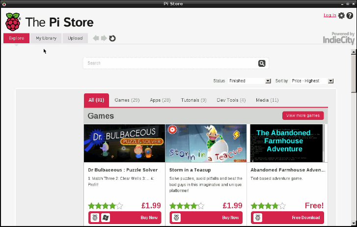
CHAPTER 3 LINUX SYSTEM ADMINISTRATION 55
e second partition is far larger and formatted as EXT4, a native Linux le system designed
for high-speed access and data safety. is partition contains the main chunk of the distribu-
tion. All the programs, the desktop, the users’ les and any software that you install yourself
are stored here. is takes up the bulk of the SD card.
Installing and Uninstalling Software
e default software installed with the Raspbian distribution is enough to get you started, but
chances are you’re going to want to customise your Pi according to your own requirements.
Obtaining Software from the Pi Store
Installing new software onto the Pi is simple, thanks to the inclusion of the Raspberry Pi
Store. is is a custom shopfront where Pi programmers can oer their software for quick
download and installation. To get started, double-click the Pi Store icon on the desktop. e
window that appears provides access to all software currently available through the Pi Store
(see Figure 3-4).
F -:
e Pi Store
main window
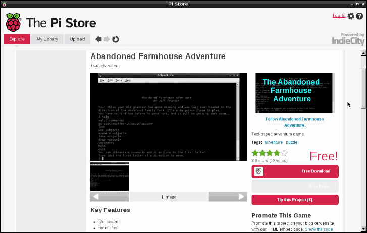
PART I CONNECTING THE BOARD
56
Software on the Pi Store is split into categories, ranging from games to tutorials and even
media like videos, books and magazines. Clicking on a category across the top will show the
software from that category in a grid, which can be scrolled using the keyboard or mouse.
Clicking on a piece of software will provide access to more information and a download link
to automatically install the software (see Figure 3-5).
F -:
Viewing
software in the
Pi Store
Before software can be installed, however, you will need to register for an account. e Pi Store
is run by digital distribution specialist IndieCity; if you already have an account on IndieCity’s
own website, you can use this by clicking the Log In option at the top right of the Pi Store win-
dow and entering your email address and password. If not, when you try to download any
software you will be asked to register: simply click the Register button and ll in your email
address, followed by typing a password for your account in the two boxes provided.
Some software on the Pi Store requires payment. If this is the case, attempting to install the
software will prompt you for your name, address and payment details. ese details are
transmitted across an encrypted connection, meaning that they cannot be seen during transit,
and used by the Pi Store’s operator IndieCity to take payment for the item. Once payment
has been made, the software can be downloaded as normal.
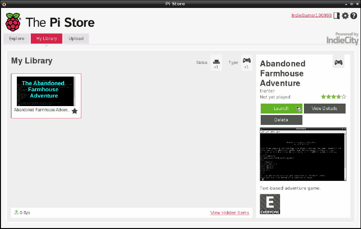
CHAPTER 3 LINUX SYSTEM ADMINISTRATION 57
All software you install through the Pi Store is placed in the My Library section (see Figure 3-6).
is provides an easy way to uninstall software, or to install software that you have previously
used but since removed. Downloads are tied to your account; if you log in to the Pi Store on a
dierent Raspberry Pi, you can use the My Library to quickly nd and install your favourite
software.
F -:
e Pi Store My
Library screen
As you learn to use the Raspberry Pi, and especially if you’re learning to program, you may
nd yourself writing software of your own. Whether it’s a game, a productivity application or
even a tutorial, you can quickly and easily list it for download on the Pi Store by clicking the
Upload option and lling in the form that appears.
If you have any trouble with the Pi Store, either for downloading software or publishing your
own, click the question mark icon at the top right of the window to access help.
Obtaining Software from Elsewhere
For a larger selection of packages, the Raspbian distribution includes a tool called apt, which
is a powerful package manager. Packages are what Linux calls a piece of software, or a collec-
tion of dierent pieces of software designed to work together.

PART I CONNECTING THE BOARD
58
Although apt is designed to be operated from the command line, it’s very user-friendly and
easy to learn. ere are GUIs for apt, such as the popular Synaptic Package Manager, but
they often struggle to run on the Pi due to the lack of memory. As a result, we recommend
that software be installed at the terminal.
Other Distributions
Raspbian, in common with most Debian-based distributions, uses a tool called apt as the
package manager. It’s not the only tool out there, and other distributions make different
choices. Pidora, for example, uses the pacman tool.
Pacman is no more difcult to use than apt, but its syntax (the way it expects you to phrase
instructions to install new software or remove existing software) is different. For instruc-
tions on how to use pacman instead of apt, type man pacman at the Pidora terminal.
Other distributions may use the yum package manager. If you’re trying a distribution that
uses yum, simply type man yum at the terminal for instructions.
A package manager’s job is to keep track of all the software installed on the system. It doesn’t
just install new software—it also keeps tabs on what is currently installed, allows old soft-
ware to be removed and installs updates as they become available.
Package management is one of the areas where Linux diers greatly from operating systems
like Windows or OS X. Although it’s possible to manually download new software to install,
it’s far more common to use the built-in package management tools instead.
TIPBefore trying to install new software or upgrade existing software, you need to make sure
the apt cache is up to date. To do this, simply type the command sudo apt-get update.
Finding the Software You Want
e rst step to installing a new piece of software is to nd out what it’s called. e easiest
way to do this is to search the cache of available software packages. is cache is a list of all
the software available to install via apt, stored on Internet servers known as repositories.
e apt software includes a utility for managing this cache, called apt-cache. Using this
software, it’s possible to run a search on all the available software packages for a particular
word or phrase.
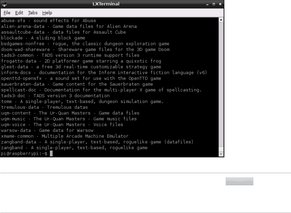
CHAPTER 3 LINUX SYSTEM ADMINISTRATION 59
For example, to nd a game to play, you can type the following command:
apt-cache search game
at tells apt-cache to search its list of available software for anything that has the word
“game” in its title or description. For common search terms, you can end up with quite a list
(see Figure 3-7), so try to be as specic as you can.
F -:
e last few
results for an
apt-cache
“game” search
TIP
If your search term brings up too many different packages to see on a single screen display,
you can tell Linux that you want it to pause on each screenful by piping the output of apt-
cache through a tool called less. Simply change the command to apt-cache search
game | less and use the cursor keys to scroll through the list. Press the letter Q on the
keyboard to exit.
Installing Software
Once you know the name of the package you want to install, switch to the apt-get com-
mand in order to install it. Installing software is a privilege aorded only to the root user, as

PART I CONNECTING THE BOARD
60
it aects all users of the Raspberry Pi. As a result, the commands will need to be prefaced
with sudo to tell the operating system that it should be run as the root user.
For example, to install the package nethack-console (a console-based randomly generated
role-playing game), you would simply use the install command with apt-get as follows:
sudo apt-get install nethack-console
Some packages rely on other packages in order to operate. A programming language may
depend on a compiler, a game engine on graphics les, or an audio player on codecs for play-
ing back dierent formats. ese are known in Linux terms as dependencies.
Dependencies are one of the biggest reasons for using a package manager like apt rather
than installing software manually. If a package depends on other packages, apt will auto-
matically nd them (see Figure 3-8) and prepare them for installation. If this happens, you’ll
be shown a prompt asking whether you want to continue. If you do, type the letter Y and
press the Enter key.
F -:
Apt listing the
dependencies
for the
OpenOce.org
package
CHAPTER 3 LINUX SYSTEM ADMINISTRATION 61
Uninstalling Software
If you decide you no longer want a piece of software, apt-get also includes a remove com-
mand that cleanly uninstalls the package along with any dependencies that are no longer
required. When you’re using a smaller SD card with the Pi, the ability to try out software and
quickly remove it is extremely useful.
To remove nethack-console, simply open the terminal and type the following command:
sudo apt-get remove nethack-console
e remove command has a more powerful brother in the form of the purge command.
Like remove, the purge command gets rid of software you no longer require. Where
remove leaves the software’s conguration les intact, however, purge removes every-
thing. If you’ve got yourself into a mess customising a particular package and it no longer
works, purge is the command to use. For example, to purge nethack-console, you would
just type this:
sudo apt-get purge nethack-console
Upgrading Software
In addition to installing and uninstalling packages, apt can be used to keep them up to date.
Upgrading a package through apt ensures that you’ve received the latest updates, bug xes
and security patches.
Before trying to upgrade a package, make sure the apt cache is as fresh as possible by run-
ning an update:
sudo apt-get update
When upgrading software, you have two choices: you can upgrade everything on the system
at once or upgrade individual programs. If you just want to keep your distribution updated,
the former is achieved by typing the following:
sudo apt-get upgrade
To upgrade an individual package, simply tell apt to install it again. For example, to install a
nethack-console upgrade, you would type this:
sudo apt-get install nethack-console

PART I CONNECTING THE BOARD
62
If the package is already installed, apt will treat it as an in-place upgrade. If you’re already
running the latest version available, apt will simply tell you it cannot upgrade the software,
and will then exit.
TIPFor more information on package management with apt—in particular, how certain packages
can be “kept back” and excluded from upgrades—type man apt at the terminal.
Shutting the Pi Down Safely
Although the Pi doesn’t have a power switch like a traditional computer, that doesn’t mean that
you can simply pull the power cable out when you’re nished. Even when it doesn’t appear to
be doing anything, the Pi is often reading from or writing to the SD card, and if it loses power
while this is happening the contents of the card can become corrupt and unreadable.
To shut down using the terminal, type the following command:
sudo shutdown -h now
e Pi will close all open applications, prompting you to save any open les if you haven’t
done so already, and shut itself down, at which point the screen will go black and the ACT
light will switch o. Once the light has gone o, it’s safe to remove the micro-USB cable or
switch the Pi o at the wall.
When you want to switch the Pi back on, or if you accidentally shut the Pi down without
meaning to, simply reconnect the power and it will start to boot automatically.
Chapter 4
Troubleshooting
PART I CONNECTING THE BOARD
64
SOMETIMES, THINGS DON’T go entirely smoothly. e more complex the device, the
more complex the problems that can occur—and the Pi is an extremely complex device
indeed.
ankfully, many of the most common problems are straightforward to diagnose and x. In
this chapter, we’ll look at some of the most common reasons for the Pi to misbehave and
how to x them.
Keyboard and Mouse Diagnostics
Perhaps the most common problem that users experience with the Raspberry Pi is when the
keyboard repeats certain characters. For example, if the command startx appears onscreen
as sttttttttttartxxxxxxxxxxxx, it will, understandably, fail to work when the Enter
key is pressed.
ere are typically two reasons why a USB keyboard fails to operate correctly when con-
nected to the Raspberry Pi: it’s drawing too much power, or its internal chipset is conicting
with the USB circuitry on the Pi.
Check the documentation for your keyboard, or the label on its underside, to see if it has a
power rating given in milliamps (mA). is is how much power the keyboard attempts to draw
from the USB port when it’s in use.
e Pi’s USB ports have a component called a polyfuse connected to them, which protects the
Pi in the event that a device attempts to draw too much power. When this polyfuse is tripped,
it causes the USB port to shut o, at around 150 mA. If your keyboard draws anywhere
around that much power, it may operate strangely—or not at all. is can be a problem for
keyboards that have built-in LED lighting, which require far more power to operate than a
standard keyboard.
If you nd that your USB keyboard may be drawing too much power, try connecting it to a
powered USB hub instead of directly to the Pi. is will allow the keyboard to draw its power
from the hub’s power supply unit, instead of from the Pi itself. Alternatively, swap the key-
board out for a model with lower power demands. e repeating-letter problem may also be
traced to an inadequate power supply for the Pi itself, which is addressed in the next section,
“Power Diagnostics”.

CHAPTER 4 TROUBLESHOOTING 65
e issue of compatibility, sadly, is harder to diagnose. While the overwhelming majority of
keyboards work just ne with the Pi, a small number exhibit strange symptoms. ese range
from intermittent response, the repeating-letter syndrome or even crashes that prevent the
Pi from operating. Sometimes, these issues don’t appear until other USB devices are con-
nected to the Pi. If your keyboard was working ne until another USB device, in particular a
USB wireless adapter, was connected, you may have an issue of incompatibility.
If possible, try swapping the keyboard out for another model. If the new keyboard works,
your old one may be incompatible with the Pi. For a list of known-compatible keyboards,
visit the eLinux wiki at http://elinux.org/RPi_USB_Keyboards.
e same advice on checking compatibility in advance applies to problems with the mouse:
the majority of USB mice and trackballs work ne, but some exhibit incompatibility with the
Pi’s own USB circuitry. is usually results in symptoms like a jerky or unresponsive mouse
pointer, but it can sometimes lead to the Pi failing to load or crashing at random intervals. If
you’re looking to buy a new mouse, an up-to-date list of models known to work with the Pi is
available at the eLinux wiki site at http://elinux.org/RPi_USB_Mouse_devices.
Power Diagnostics
Many problems with the Raspberry Pi can be traced to an inadequate power supply. e
Model A requires a 5 V supply capable of providing a 500 mA current, while the Model B’s
extra components bump up the current requirement to 700 mA. Not all USB power adapters
are designed to oer this much power, even if their labelling claims otherwise.
TIP
The formal USB standard states that devices should draw no more than 500 mA, with even
that level of power only available to the device following a process called negotiation. Because
the Pi doesn’t negotiate for power, it’s unlikely that it will work if you connect it to the USB
ports on a desktop or laptop computer.
If you’re having intermittent problems with your Pi—particularly if it works until you con-
nect something to a USB port or start a processor-intensive operation like playing video—
the chances are that the power supply in use is inadequate. e Pi provides a relatively easy
way to check if this is the case in the form of two voltage test points.
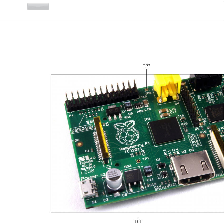
PART I CONNECTING THE BOARD
66
To use the voltage test points, you’ll need a voltmeter or multimeter with direct current (DC)
voltage measuring capabilities. If your meter has multiple inputs for dierent voltages, use
an appropriate setting.
WARNING Avoid touching the test probes to anything not labelled as a test point. It’s possible to bridge
the 5 V supply that comes in to the Pi to the internal 3.3 V supply, creating a short circuit which
can damage the device. Be especially careful around exposed header pins.
e two test points are small, copper-clad holes known as vias, which are connected to the
Pi’s 5 V and ground circuits. Put the positive (red) meter probe on TP1, located to the left of
the board just above a small black component called a regulator labelled RG2. Connect the
black (negative) meter probe to TP2, located between the copper GPIO pins and the yellow-
and-silver RCA phono connector at the top-left of the board (see Figure 4-1).
F -:
e two voltage
test points,
labelled TP1 and
TP2, on a
Raspberry Pi
Model B
Revision 1
CHAPTER 4 TROUBLESHOOTING 67
e reading on the voltmeter should be somewhere between 4.8 V and 5 V. If it’s lower than
4.8 V, this indicates that the Pi is not being provided with enough power. Try swapping the
USB adapter for a dierent model, and check that the label says it can supply 700 mA or
more. A model rated at 1A is recommended, but beware of cheap models—they sometimes
have inaccurate labelling, and fail to supply the promised current. Genuine branded mobile
phone chargers rarely have this problem, but cheap unbranded devices—often sold as
compatible adapters—should be avoided
If your voltmeter reads a negative number, don’t worry: this just means you’ve got the posi-
tive and negative probes in the wrong place. Either swap them around or just ignore the
negative sign when noting your reading.
Display Diagnostics
Although the Pi is designed to work with almost any HDMI, DVI or composite video display
device, it simply may not work as expected when you plug it in. For example, you may nd
that your picture is shifted to the side or not fully displayed, or is only visible as a postage-
stamp-sized cut-out in the middle of the screen or in black-and-white—or even missing
entirely.
First, check the type of device to which the Pi is connected. is is especially important when
you’re using the composite RCA connection to plug the Pi into a TV. Dierent countries use
dierent standards for TV video, meaning that a Pi congured for one country may not work
in another. is is the usual explanation for a Pi showing black-and-white video. You’ll learn
how to adjust this setting in Chapter 7, “Advanced Raspberry Pi Conguration”.
When you use the HDMI output, the display type is usually automatically detected. If you’re
using an HDMI to DVI adapter to plug the Pi into a computer monitor, this occasionally goes
awry. Common symptoms include snow-like static, missing picture portions or no display at
all. To x this, note the resolution and refresh rate of your connected display, and then jump
to Chapter 7, “Advanced Raspberry Pi Conguration”, to nd out how to set these manually.
Another issue is a too-large or too-small image, either missing portions at the edge of the
screen or sitting in the middle of a large black border. is is caused by a setting known as
overscan, which is used when the Pi is connected to TVs to avoid printing to portions of the
display which may be hidden under a bezel. As with other display-related settings, you will
learn how to adjust—or even completely disable—overscan in Chapter 7.
PART I CONNECTING THE BOARD
68
Boot Diagnostics
e most common cause for a Pi to fail to boot is a problem with the SD card. Unlike a desk-
top or laptop computer, the Pi relies on les stored on the SD card for everything. If Pi can’t
talk to the card, it won’t display anything on the screen or show any signs of life at all.
If your Pi’s power light glows when you connect the micro-USB power supply, but nothing
else happens and the OK light remains dark, you have an SD card problem. First, ensure that
the card works when you connect it to a PC, and that it shows the partitions and les
expected of a well-ashed card. (For more details, see Chapter 3, “Linux System
Administration”, particularly the section titled “File System Layout” in that chapter.)
If the card works on a PC but not in the Pi, it may be a compatibility problem. Some SD
cards—especially high-speed cards marked as Class 10 on their labelling—don’t operate cor-
rectly when connected to the Pi’s onboard SD card reader. A list of cards known to be com-
patible with the Pi can be found on the eLinux wiki at http://elinux.org/RPi_SD_cards.
Sadly, if you have an incompatible card, you will probably need to replace it with a dierent
card in order for the Pi to work. As the Pi’s software base is developed, however, work is
being carried out to ensure that a wider range of cards operate correctly with the Pi. Before
giving up on a high-speed card completely, check to see if an updated version of your chosen
Linux distribution is available. (See Chapter 1, “Meet the Raspberry Pi”, for more informa-
tion about distributions.)
If you’ve been changing the speed of your Raspberry Pi by overclocking (see Chapter 6, “e
Raspberry Pi Software Conguration Tool”), this can also stop it from booting correctly. To
temporarily disable the overclock and run the Pi at its default speed, hold down the Shift key
as you turn the Pi on.
Network Diagnostics
e most useful tool for diagnosing network problems is ifconfig. If you’re using a wire-
less network connection, jump to Chapter 5, “Network Conguration”, for information on a
similar tool for those devices. Otherwise, read on.
Designed to provide information on connected network ports, ifconfig is a powerful tool
for controlling and conguring the Pi’s network ports. For its most basic usage, simply type
the tool’s name in the terminal:
ifconfig
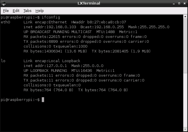
CHAPTER 4 TROUBLESHOOTING 69
Called in this manner, ifconfig provides information on all the network ports it can nd
(see Figure 4-2). For the standard Raspberry Pi Model B, there are two ports: the physical
Ethernet port on the right side of the board, and a virtual loopback interface that allows pro-
grams on the Pi to talk to each other.
F -:
e output of
ifconfig on
a Raspberry Pi
Model B
e output of ifconfig is split into the following sections:
❍ Link encap—e type of encapsulation used by the network, which on the Model B will
either read Ethernet for the physical network port or Local Loopback for the vir-
tual loopback adaptor.
❍ Hwaddr—e Media Access Control (MAC) address of the network interface, written in
hexadecimal. is is unique for every device on the network, and each Pi has its own
MAC address, which is set at the factory.
❍ inet addr—e internet protocol (IP) address of the network interface. is is how you
nd the Pi on the network if you’re using it to run a network-accessible service, such as
a web server or le server.
PART I CONNECTING THE BOARD
70
❍ Bcast—e broadcast address for the network to which the Pi is connected. Any trac
sent to this address will be received by every device on the network.
❍ Mask—e network mask, which controls the maximum size of the network to which
the Pi is connected. For most home users, this will read 255.255.255.0.
❍ MTU—e maximum transmission unit size, which is how big a single packet of data
can be before the system needs to split it into multiple packets.
❍ RX—is section provides feedback on the received network trac, including the
number of errors and dropped packets recorded. If you start to see errors appearing in
this section, there’s something wrong with the network.
❍ TX—is provides the same information as the RX section, but for transmitted pack-
ets. Again, any errors recorded here indicate a problem with the network.
❍ collisions—If two systems on the network try to talk at the same time, you get a colli-
sion which requires them to retransmit their packets. Small numbers of collisions
aren’t a problem, but a large number here indicates a network issue.
❍ txqueuelen—e length of the transmission queue, which will usually be set to 1000
and rarely needs changing.
❍ RX bytes, TX bytes—A summary of the amount of trac the network interface has
passed.
If you’re having problems with the network on the Pi, you should rst try to disable and then
re-enable the network interface. e easiest way to do this is with two tools called ifup and
ifdown.
If the network is up, but not working correctly—for example, if ifconfig doesn’t list any-
thing in the inet addr section—start by disabling the network port. From the terminal,
type the following command:
sudo ifdown eth0
Once the network is disabled, make sure that the cable is inserted tightly at both ends, and
that whatever network device the Pi is connected to (hub, switch or router) is powered on
and working. en bring the interface back up again with the following command:
sudo ifup eth0
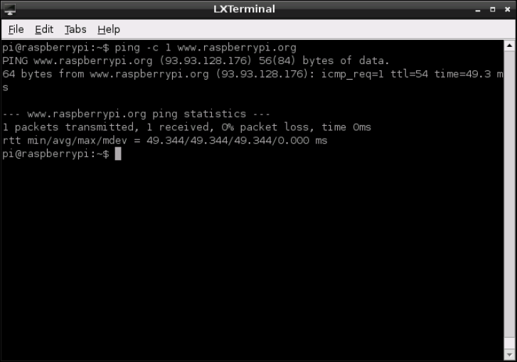
CHAPTER 4 TROUBLESHOOTING 71
You can test the networking by using the ping command, which sends data to a remote
computer and waits for a response. If everything’s working, you should see the same response
as shown in Figure 4-3. If not, you may need to manually congure your network settings,
which you’ll learn how to do in Chapter 5, “Network Conguration”.
F -:
e result of a
successful test
of the network,
using the ping
command
The Emergency Kernel
e Linux kernel is the heart of the operating system that drives the Pi. It’s responsible for
everything from making sure that you can access your les to allowing programs to talk to
other programs.
When switched on, your Pi will load the normal, default kernel. ere’s also a second kernel
included in most distributions, which sits unused. is is the emergency kernel, and as the
name suggests, it is typically used only when the normal kernel isn’t working.
PART I CONNECTING THE BOARD
72
It’s highly unlikely that you’ll ever need to boot a Pi using the emergency kernel, but it’s
worth learning how to do so just in case. is is especially important if you’re upgrading your
kernel or are using a new and potentially poorly tested distribution. Sometimes, newly
released software can have bugs which aren’t spotted before its release. When encountering
strange errors after upgrading, the emergency kernel can be used to narrow down the prob-
lem to the new kernel version.
e Linux kernel is a single le located in the /boot directory called kernel.img. When
the Pi is rst switched on and begins to load the operating system, it looks for this le, and if
the le is missing, the Pi won’t work. e emergency kernel is a second le, again in the /
boot directory, called kernel_emergency.img.
e emergency kernel is, in most cases, almost identical to the standard kernel. When
changes are made to the standard kernel, to boost performance or add new features for
example, the emergency kernel is left unaltered. is way, if the changes to the standard
kernel cause stability problems, a user can simply tell the Pi to load the emergency kernel
instead.
ere are two ways to boot into the emergency kernel, and both require the use of a PC and
an SD card reader if the Pi can’t boot. Otherwise, the following steps can be carried out on
the Pi itself.
e easiest way to boot the emergency kernel is to rename the existing kernel.img le to
kernel.img.bak, and then rename the kernel_emergency.img le to kernel.img.
When the Pi loads, it will now load the emergency kernel by default. To go back to the stan-
dard kernel, simply reverse the process: rename kernel.img to kernel_emergency.img
and kernel.img.bak to kernel.img.
An alternative method to load the emergency kernel is to edit the cmdline.xt le (located
in the /boot directory) by adding the following entry at the end of the existing command
line:
kernel=kernel_emergency.img
is tells the Pi that it should load the kernel named kernel_emergency.img instead of
the usual kernel.img. Reversing the process is as simple as opening cmdline.txt again
and removing the entry.
You’ll learn more about cmdline.txt and how it aects the operation of the Raspberry Pi
in Chapter 7, “Advanced Raspberry Pi Conguration”.
Chapter 5
Network Configuration
PART I CONNECTING THE BOARD
74
FOR MOST USERS, conguring the Raspberry Pi’s network is as easy as plugging a cable
into the Model B’s Ethernet port—or a USB Ethernet adapter, in the case of the Model A. For
others, however, the network requires manual conguration.
If you know that your network doesn’t have a Dynamic Host Conguration Protocol (DHCP)
server—a system that tells the Pi and other devices on the network how they should con-
nect—or if you want to use a USB wireless adapter with the Pi, read on.
Wired Networking
In some instances, in order for the Pi’s network to operate correctly you may need to cong-
ure it manually. Normally, the network in a home, school or oce has a DHCP server that
tells the Pi and other devices on the network how they should connect. Some networks don’t
have a DHCP server, however, and need to be set up manually.
e list of network interfaces, along with information about how they should be congured,
is stored in a le called interfaces located in the folder /etc/network. is is a le only
the root user can edit, because removing a network interface from this list will cause it to stop
working.
From the terminal, you can edit this le using a variety of dierent text editors. For simplic-
ity, the nano text editor should be used for this process. Open the le for editing with the
following command:
sudo nano /etc/network/interfaces
Nano is a powerful yet lightweight text editor, with a simple user interface (see Figure 5-1).
You can move your cursor around the document with the arrow keys, save the le by holding
down the CTRL key and pressing O, and quit by holding down the CTRL key and pressing X.
e line you need to edit for manual conguration starts with iface eth0 inet. Delete
dhcp from the end of this line and replace it with static, press Enter to start a new line,
and then ll in the remaining details in the following format with a tab at the start of each
line:
[Tab] address xxx.xxx.xxx.xxx
[Tab] netmask xxx.xxx.xxx.xxx
[Tab] gateway xxx.xxx.xxx.xxx
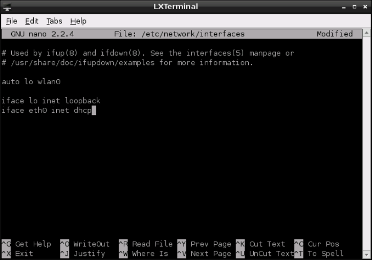
CHAPTER 5 NETWORK CONFIGURATION 75
F -:
Editing /etc/
network/
interfaces
with nano
Make sure that you press the Tab key at the start of each line, and don’t actually type [Tab].
e x characters in the conguration lines represent network addresses you’ll need to enter.
For address, you should enter the static IP address that you want to assign to the Pi. For
netmask, you should enter the network mask—which controls the size of the connected
network—in what is known as dotted-quad format. If you’re using a home network, this is
typically 255.255.255.0. For gateway, you should enter the IP address of your router or
cable modem.
As an example, the settings for a common home network would look like this:
iface eth0 inet static
[Tab] address 192.168.0.10
[Tab] netmask 255.255.255.0
[Tab] gateway 192.168.0.254
When you’ve nished editing the le, press CTRL + O to save it, and then press CTRL + X to
leave nano and return to the terminal. To use your new network settings, restart the net-
working service by typing the following:
sudo /etc/init.d/networking restart
PART I CONNECTING THE BOARD
76
If you need to return to automatic settings via DHCP, you need to edit the interfaces le
again and delete the address, netmask and gateway settings. Replace static with dhcp
at the end of the iface line, and then restart the networking service again.
Setting a manual IP address isn’t quite enough to get your Pi connected to the outside world.
Computers on modern networks have both a numerical address identier—known as an IP
address—and a hostname or domain name. It’s this latter, friendly name that allows you
simply to type www.raspberrypi.org into your browser, instead of trying to remember
93.93.128.176.
A system called a Domain Name Service (DNS) server is responsible for looking up the friendly
names you supply and converting them into the numbers required to access the system. It
operates much like an automated telephone directory. Before you’ll be able to access Internet-
connected systems via their domain names, you’ll need to tell the Pi which DNS servers to use.
e list of DNS servers, known as nameservers in Linux parlance, is stored in /etc/resolv.
conf. When the system gets its details through DHCP, this le is automatically lled in; but
when you set an address manually, you need to provide the addresses of the nameservers on
your network. Normally, this would be the address of your router as found in the gateway
line from the interfaces le (described earlier in this chapter).
To set the nameservers, open the le with nano by typing the following command at the
terminal:
sudo nano /etc/resolv.conf
Add each nameserver on a separate line, prefaced with nameserver and a space. As an
example, the resolv.conf conguration for a network that uses Google’s publicly accessi-
ble nameservers to resolve domain names would appear like this:
nameserver 8.8.8.8
nameserver 8.8.4.4
You’ll notice that the nameserver addresses need to be supplied as IP addresses, rather than
domain names. If you provided domain names instead, the Pi would enter an innite loop of
trying to nd a nameserver to ask how it can nd the nameservers.
Save the le by pressing CTRL + O, and then quit nano by pressing CTRL + X. Restart the
networking interface by typing the following:
sudo /etc/init.d/networking restart
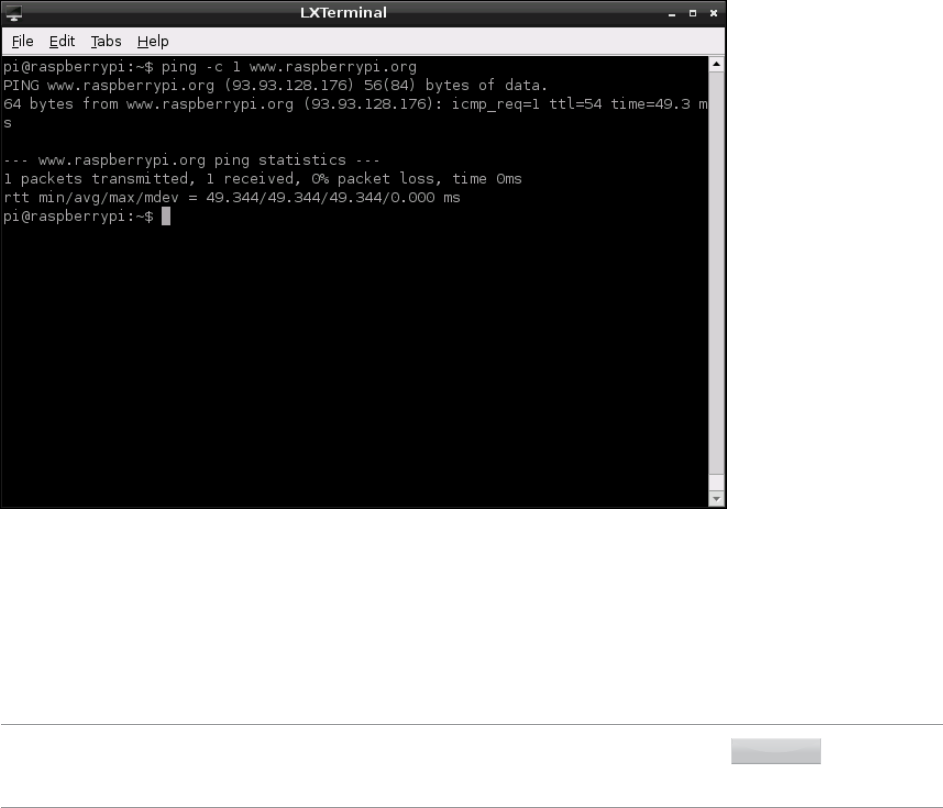
CHAPTER 5 NETWORK CONFIGURATION 77
en test the settings by either opening a web browser or using the following ping com-
mand (see Figure 5-2):
ping -c 1 www.raspberrypi.org
F -:
A successful test
of networking
on the
Raspberry Pi
Model B
Wireless Networking
Although no current models of the Raspberry Pi include Wi-Fi networking hardware onboard,
it’s possible to add wireless connectivity with a simple USB Wi-Fi adapter. However, you will
need to congure the adapter before you can use it to get your Pi online.
TIP
USB Wi-Fi adapters are very power-hungry. If you connect one directly to the Pi’s USB port,
it may not work. Instead, connect a powered USB hub to the Pi, and then insert the Wi-Fi
adapter into that.
PART I CONNECTING THE BOARD
78
Before you start to set up the wireless interface, you’ll need to know the Service Set Identier
(SSID)—also known as the network name—of the wireless router to which you want to con-
nect, along with the type of encryption in use and the password required. You’ll also need to
know what type of wireless network it is. A USB adapter designed for 802.11a Wi-Fi may not
connect to an 802.11g network, and vice versa.
Installing Firmware
In order for the USB wireless adapter to be addressed by the system, a software bundle
known as a rmware is required. While some distributions include a selection of the most
common Wi-Fi rmware installed by default, others do not. Raspbian includes most com-
mon wireless rmware packages, and if this is the operating system you are using you can
skip ahead to the section on “Connecting to a Wireless Network via wpa_gui”; otherwise,
read on for instructions on installing rmware packages.
In order to download the rmware les, the Pi must be connected to the Internet. If you can
spare a wired port on your router or gateway for a few minutes, that’s not a problem. However,
if wireless is your only way of getting online, you’ll need to manually download the rmware
installation package on a dierent computer, and then transfer it across to the Pi by either
copying it to the Pi’s SD card or connecting an external storage device such as a USB ash drive.
To nd the correct rmware le to download, you’ll need to know what type of wireless
adapter you have. Although various companies sell branded USB wireless adapters, the num-
ber of companies that actually manufacture the components is a lot smaller. Several dier-
ent manufacturers may use the same type of chip inside their USB wireless adapters, making
them all compatible with the same rmware. As a result, the labelling on a device or its pack-
aging is not enough to know which rmware you should install. Instead, you’ll need to con-
nect the device to the Pi and check the kernel ring buer for error messages. If you’ve already
connected the wireless adapter as instructed in Chapter 2, “Getting Started with the
Raspberry Pi”, you can continue. If not, connect the adapter now.
e kernel ring buer is a special portion of memory used by the Linux kernel to store its
human-readable output. It’s an important part of the Linux operating system: the text
ashes by too quickly to read while the Pi boots, so it’s critical that users are able to view the
messages at a later date to read errors and diagnose problems.
With the adapter connected but no wireless rmware packages installed, the kernel will print a
series of error messages to the ring buer. To read these messages, you can use the dmesg com-
mand to print the contents of the buer to the screen. At the terminal, or at the console if you
haven’t loaded the desktop environment, simply type the following command to view the buer:
dmesg
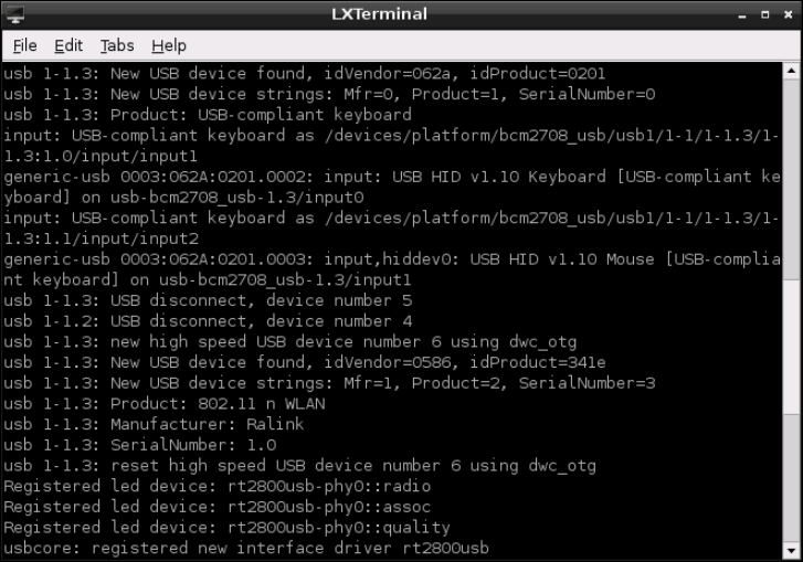
CHAPTER 5 NETWORK CONFIGURATION 79
is will print out the entire kernel ring buer, which will contain all messages output by the
kernel since the Pi was switched on. If the Pi has been running a while, that can be a lot of
text. To locate error messages particular to the wireless adapter, it can help to send the out-
put of dmesg through a tool called grep. Using grep, you can search through the buer for
text relating to missing rmware. By piping the output of dmesg through grep with a search
term, things become signicantly clearer. Type the following at the terminal:
dmesg -t | grep ^usb
e | symbol is known as a pipe, and it tells Linux to send the output of one program—which
would normally go to a le or the screen—to the input of another. Multiple programs can be
chained this way. In this example, grep is being told to search through the output of
dmesg—the screens full of text from the earlier command—for any use of the term usb at
the start of the line (denoted by the ^ character).
e exact output of that search will depend on the manufacturer of your USB wireless
adapter. In Figure 5-3, the output is shown with a Zyxel NWD2015 Wireless USB Adapter
connected to the Pi.
F -:
Searching the
kernel ring
buer for usb
with a Zyxel
wireless adapter
connected

PART I CONNECTING THE BOARD
80
e important part of this output is the line that reads Manufacturer. In the case of the
example Zyxel NWD2105, this reads Ralink, which is the company that makes the actual
chip found inside Zyxel USB wireless adapter. It’s this company’s rmware that must be
installed for the wireless adapter to work.
TIPIf you couldn’t nd anything using usb as a search term, you can try the same command using
the search term firmware, wlan or wireless. If you still can’t see anything useful, type
lsusb for a list of all USB devices connected to the system.
Using the manufacturer name from dmesg, search for the rmware les using the
apt-cache search tool introduced earlier in this chapter. For the example Zyxel NWD2015
adapter, the apt-cache command would be:
apt-cache search ralink
If apt-cache fails to nd the rmware, you may need to make a guess based on the rm-
ware packages in the following list. Don’t worry if you install the wrong one—any rmware
can be quickly uninstalled using apt-get remove, and having multiple rmware packages
does no harm. e following wireless rmware packages are available in the recommended
Raspbian distribution on the Raspberry Pi:
❍ atmel-rmware—for devices based on the Atmel AT76C50X chipset
❍ rmware-atheros—for devices based on Atheros chipsets
❍ rmware-brcm80211—for devices based on Broadcom chipsets
❍ rmware-intelwimax—for devices based on Intel’s WiMAX chipsets
❍ rmware-ipw2x00—for Intel Pro Wireless adapters (including 2100, 2200 and 2915)
❍ rmware-iwlwi—for other Intel wireless adapters (including 3945, 4965 and the
5000 series)
❍ rmware-ralink—for devices based on Ralink chipsets
❍ rmware-realtek—for devices based on Realtek chipsets
❍ zd1211-rmware—for devices based on the ZyDAS 1211 chipset

CHAPTER 5 NETWORK CONFIGURATION 81
e rmware for the example Zyxel wireless adapter is provided by the firmware-ralink
package in this list. is package can be installed using apt-get, but only while the Pi is
connected to the Internet through its wired Ethernet port or a USB Ethernet adapter.
When connected, install the rmware by typing the following:
sudo apt-get install firmwarepackage
Replace firmwarepackage in this command with the name of the package that you found
by using apt-cache. For the example Zyxel NWD2105, the full command would be sudo
apt-get install firmware-ralink.
Installing Wireless Firmware Ofine
If you can’t connect the Pi to the Internet using any method other than a wireless connec-
tion, you’ll need to download the rmware on a different computer. In a web browser, load
a search engine and type the name of the rmware package followed by the name of the
distribution you’re using and its version.
If you’re using the recommend Raspbian distribution, the rmware for the Ralink RT2x00
chipset from the example can be found by searching for firmware-ralink debian
wheezy. The search will lead you to a package le to download. In the case of Debian and
Raspbian, this is a .deb le. For Pidora, the same rmware is provided as a .rpm le.
Download this le, and then copy it to the Pi’s SD card in the /home/pi directory, or onto
a USB ash drive or other external storage device. Load the Pi, and then when it is time to
install the rmware, replace the package name with the name of the le you downloaded.
For the example Zyxel NWD2105 card, the command would be the following:
sudo apt-get install firmware-ralink_0.35_all.deb
With the rmware installed, disconnect the USB wireless adapter and reconnect it to the Pi.
is will restart the kernel’s search for the rmware les, which it will now be able to nd.
ese les will remain in place, and load automatically when the USB wireless adapter is con-
nected. You will only have to perform the installation process once.
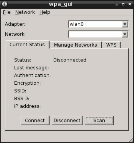
PART I CONNECTING THE BOARD
82
Connecting to a Wireless Network via wpa_gui
e simplest way to connect to a wireless network from the Raspberry Pi is to use the
wpa_gui tool. is provides a graphical user interface for software that would otherwise
require the use of the terminal, and is accessed from the desktop by double-clicking on the
icon labelled WiFi Cong.
e main wpa_gui window has two drop-down lists, labelled Adapter and Network (see
Figure 5-4). e rst should be already lled with your wireless network dongle’s identier,
wlan0. If you have more than one dongle connected, you can click on the arrow to choose
which you are conguring; if nothing is listed, turn back a few pages and make sure the rm-
ware for your dongle is correctly installed.
F -:
e wpa_gui
application
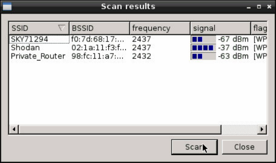
CHAPTER 5 NETWORK CONFIGURATION 83
Finding a wireless network is a process known as scanning, which in wpa_gui is activated by
clicking the Scan button at the bottom-right of the window. is will pop up a second win-
dow, showing the results of the scan (see Figure 5-5). Look through the list to nd the name
of your wireless network—which, hopefully, will also be the strongest in the list, as shown by
the signal column—and double-click on its entry.
F -:
Choosing a
wireless network
in wpa_gui
e window that appears when you double-click on a network asks for several dierent set-
tings, which will depend on the type of network to which you are trying to connect (see
Figure 5-6). For an unencrypted network—which is a bad thing to be running as it allows
anybody within range to use your network—wpa_gui will require no additional settings;
just click the Add button at the bottom.
If your network uses encryption, you will need to choose the type of encryption, using the
Authentication and Encryption drop-down lists. In most cases, wpa_gui will have selected
these values automatically. If so, simply type in the password—known as a pre-shared key—
in the box labelled PSK and click Add . If the network encryption is Wired Equivalent Privacy
(WEP) rather than the more secure Wireless Protected Access (WPA) type, you will need to ll
in at least one key in the WEP keys section. If you use an authenticated enterprise network,
you can also add the details of your identity, password and encryption certicate, but most
home users will not need these elds.

PART I CONNECTING THE BOARD
84
F -:
Adding a
network to
wpa_gui
If your network includes a Wi-Fi Protected Setup (WPS) option, you can click the WPS button at the
bottom-left of the window to perform a one-click setup. Simply press the WPS button on your
router or access point, and then click the WPS button in wpa_gui to connect automatically.
When you have lled in the details of your network, click Add. is will close the window and
return you to the main wpa_gui window—but now the Network drop-down should have
an entry, named after your wireless access point. At this point, wpa_gui will automatically
connect you to the wireless network and an IP address should appear at the bottom of the
screen (see Figure 5-7).
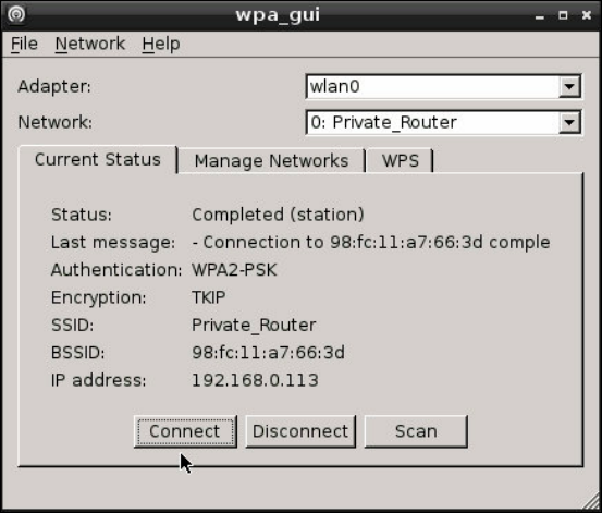
CHAPTER 5 NETWORK CONFIGURATION 85
F -:
Connected to a
wireless network
via wpa_gui
If you need to connect to a dierent network in the future, simply start the process again
from the beginning. Connecting to a new network won’t cause wpa_gui to forget the old
network; both will appear in the drop-down list, and you can connect to any network in
range simply by choosing it from the list, once congured.
You can also use wpa_gui to disconnect from a wireless network without having to remove
the wireless dongle physically. Simply click the Disconnect button at the bottom of the main
window and after a few seconds your Pi should be removed from the network. To reconnect,
click the Connect button.
Connecting to a Wireless Network via the Terminal
If you are running your Pi without a graphical user interface, you can also connect to wireless
networks at the terminal or console. First, check that the USB wireless adapter is working as
it should by using the iwlist command to scan for nearby wireless access points. is list
will probably be larger than a single screen, so pipe the command’s output through less to
pause after each screenful, like this:
sudo iwlist scan | less

PART I CONNECTING THE BOARD
86
is command will return a list of all the wireless networks reachable from the Pi, together
with their details (see Figure 5-8). If you receive an error message at this point—in particu-
lar, one that claims the network or interface is down—check that you have installed the cor-
rect rmware, and that the USB wireless adapter is connected to a powered USB hub.
F -:
Scanning for
wireless
networks with
iwlist
You can check the current status of the network using the iwconfig command. Like
ifconfig, the iwconfig command allows you to check the status of a network interface
and issue conguration commands. Unlike ifconfig, however, iwconfig is specically
designed for wireless networks and includes specic features for this. Type the command
name at the terminal as follows:
iwconfig
e output of iwconfig, as shown in Figure 5-9, is split into the following sections:
❍ Interface Name—Each device has its own interface name, as with wired networks. If
the interface is a wireless connection, additional details will be shown. e default
name for a Pi’s wireless connection is wlan0.
CHAPTER 5 NETWORK CONFIGURATION 87
❍ Standard—e IEEE 802.11 wireless standards have a variety of dierent types, dis-
tinguished by a letter sux. is section lists the standards supported by the USB
wireless adapter. For the example adapter, this reads IEEE 802.11bgn for the net-
work types it can address.
❍ ESSID—e SSID of the network to which the adapter is connected. If the adapter is
not currently connected to a network, this will read off/any.
❍ Mode—e mode that the adapter is currently operating in, which will be one of the
following:
•
Managed—A standard wireless network, with clients connecting to access
points. is is the mode used for almost all home and business networks.
•
Ad-Hoc—A device-to-device wireless network, with no access points.
•
Monitor—A special mode in which the card listens out for all trac whether or
not it is the addressee. is mode is typically used in network troubleshooting for
capturing wireless network trac.
•
Repeater—A special mode that forces a wireless card to forward trac on to
other network clients, to boost signal strength.
•
Secondary—A subset of the Repeater mode, which forces the wireless card to act
as a backup repeater.
❍ Access Point—e address of the access point to which the wireless adapter is cur-
rently connected. If the adapter isn’t connected to a wireless access point, this will read
Not-Associated.
❍ Tx-Power—e transmission power of the wireless adapter. e number displayed
here indicates the strength of the signal that the adapter is sending: the higher the
number, the stronger the signal.
❍ Retry—e current setting for the wireless adapter’s transmission retry, used on con-
gested networks. is does not normally need changing, and some cards won’t allow it
to be changed.
❍ RTS—e adapter’s current setting for Ready To Send and Clear To Send (RTS/CTS)
handshaking, used on busy networks to prevent collisions. is is normally set by the
access point on connection.
❍ Fragment—e maximum fragment size, used on busy networks to split packets up
into multiple fragments. is is normally set by the access point on connection.
❍ Power Management—e current status of the adapter’s power management function-
ality, which reduces the device’s power demands when the wireless network is idle. is has
little eect on the Pi, but is typically enabled for battery-powered devices like a laptop.
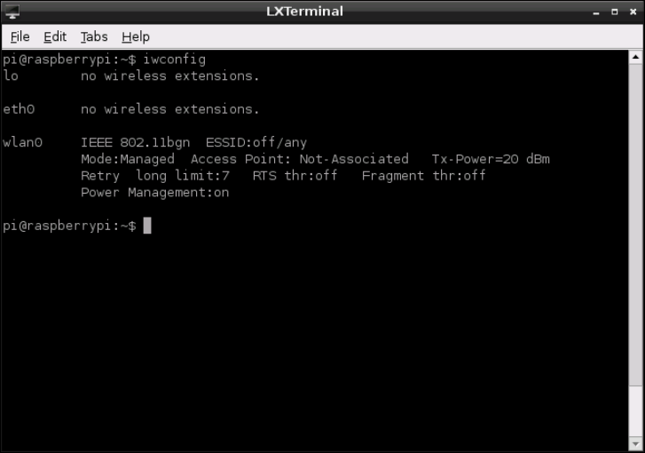
PART I CONNECTING THE BOARD
88
F -:
e output of
iwconfig
when not
connected to a
wireless network
To connect the Pi to a wireless network, you will need to add some lines into the /etc/net-
work/interfaces le. (For full details on how this le is laid out, see the “Wired
Networking” section earlier in this chapter.)
First, open the le in the nano text editor:
sudo nano /etc/network/interfaces
At the bottom of the le, create a new entry for the USB wireless adapter that reads as fol-
lows (see Figure 5-10):
auto wlan0
iface wlan0 inet dhcp
wpa-conf /etc/wpa.conf
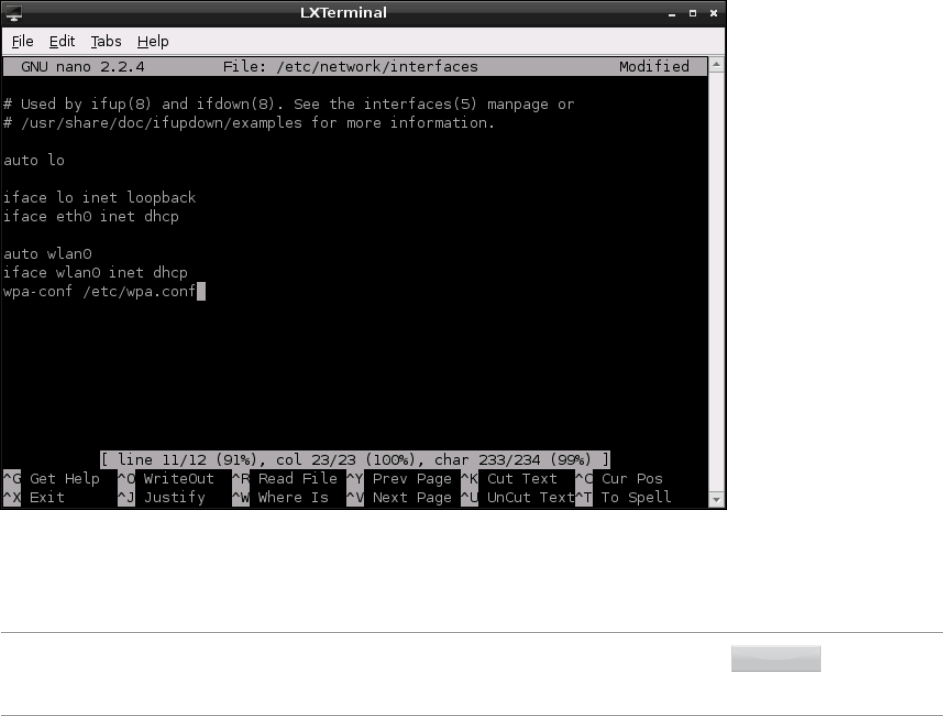
CHAPTER 5 NETWORK CONFIGURATION 89
F -:
Editing the
interfaces
le for wireless
network access
Once the entry is in place, save the le by pressing CTRL + O and then quit nano with
CTRL + X.
TIP
The device ID of wlan0 is correct if this is the rst wireless device you’ve set up on your Pi. If
it isn’t, the number at the end will be different. Type iwconfig to see a current list of wireless
devices, and change the lines in the preceding code example accordingly.
e last line of the interfaces le makes reference to a conguration le, wpa.conf,
which does not yet exist. is le is used by a tool known as wpasupplicant, designed to
provide Linux with an easy way to connect to networks secured with Wireless Protected Access
(WPA) encryption.
Using wpasupplicant, you can connect the Pi to almost any wireless network—regardless
of whether it’s protected by WPA or its newer replacement WPA2—in both Advanced
Encryption Standard (AES) and Temporal Key Integrity Protocol (TKIP) modes. Despite its
name, wpasupplicant also allows connection to wireless networks using the older Wired
Equivalent Privacy (WEP) encryption standard.

PART I CONNECTING THE BOARD
90
e wpasupplicant program stores its conguration in a le called wpa.conf, located in
the /etc directory. To begin conguring the Pi for wireless access, rst open a new blank le
for editing by typing the following:
sudo nano /etc/wpa.conf
Enter the following two lines, which, again, are the same for any wireless network type.
Replace Your_SSID with the SSID for the wireless network to which you want to connect,
and then nish the le with the lines that match your network’s encryption type:
network={
[Tab] ssid=”Your_SSID”
At this point in the conguration le, the details required dier depending on the type of
wireless network you are conguring. e following subsections provide instructions for
completing the conguration for unencrypted, WEP and WPA networks.
No Encryption
If your wireless network has no encryption in place, nish the wpa.conf le as follows:
[Tab] key_mgmt=NONE
}
Save the le with CTRL + O, and then exit nano with CTRL + X.
WEP Encryption
If your wireless network uses WEP encryption, nish the wpa.conf le as follows:
[Tab] key_mgmt=NONE
[Tab] wep_key0=”Your_WEP_Key”
}
Replace Your_WEP_Key with the ASCII key for your wireless network’s WEP encryption.
Save the le with CTRL + O, and then exit nano with CTRL + X.
TIPWEP encryption is extremely insecure. Readily available software can break the encryption on
a WEP-protected network in just a few minutes, allowing a third party to use your network. If
you’re still running WEP, consider switching to WPA or WPA2 for better security.
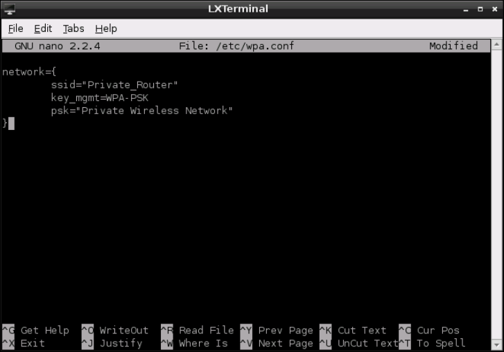
CHAPTER 5 NETWORK CONFIGURATION 91
WPA/WPA2 Encryption
If your wireless network uses WPA or WPA2 encryption, nish the wpa.conf le as follows:
[Tab] key_mgmt=WPA-PSK
[Tab] psk=”Your_WPA_Key”
}
Replace Your_WPA_Key with the pass phrase for your wireless network’s encryption. Figure 5-11
shows an example conguration for a wireless network with the SSID “Private_Router” and
the WPA pass phrase “Private Wireless Network”. Save the le with CTRL + O, and then
exit nano with CTRL + X.
F -:
Editing the
wpa.conf
le for a WPA-
protected
network
Connecting to the Wireless Network
e Pi’s wireless networking is now congured, and will begin the next time the Pi is
restarted. To start the wireless network without rebooting, type the following:
sudo ifup wlan0

PART I CONNECTING THE BOARD
92
To make sure that the network is operational, unplug the Pi’s Ethernet cable (if attached)
and type the following:
ping -c 1 www.raspberrypi.org
TIPIf you start having problems with your Pi following the installation of a USB wireless adapter,
it could be due to a conict with other USB devices. Some adapter models are known to
cause problems with certain USB keyboards. For an up-to-date list of adapters that are known
to be good, as well as those that are known to cause conicts, visit www.element14.com/
community/docs/DOC-44703/l/raspberry-pi-wifi-adapter-testing or the
eLinux wiki at http://elinux.org/RPi_USB_Wi-Fi_Adapters.
Chapter 6
The Raspberry Pi Software
Configuration Tool

PART I CONNECTING THE BOARD
94
THE RASPBERRY PI is designed to be as controllable as possible, through the editing of
conguration les found in the /boot directory of the SD card. For beginners, these les can
seem dauntingly complex—although, with a little time, they soon give up their secrets—but
without them some of the more advanced features of the Pi are unavailable.
e Raspberry Pi Software Conguration Tool, raspi-config, is designed to solve this
problem. Oering access to the majority of common conguration tasks through a simple,
menu-based interface, raspi-config makes it easy for newcomers to adjust system per-
formance, change the memory split, alter overscan settings or simply change the keyboard
layout at the console.
At the time of writing, raspi-config is exclusive to the Raspbian Linux distribution. Work
is in progress to bring the tool’s functionality to other operating systems but for now it is
recommended that beginners stick with the well-supported Raspbian platform in order to
take advantage of this most useful of conguration tools.
WARNING Although raspi-config is designed to be safe, some settings—in particular the overclock
option—can leave your Raspberry Pi unable to boot. Make sure you read each section in this
chapter carefully before you use raspi-config to make any changes to your Raspberry Pi.
Running the Tool
e Raspberry Pi Software Conguration Tool edits a number of les that are important to
the running of the Raspberry Pi. As a result, the tool can only be run as the root user, using
the sudo command. To load the tool, type the following command:
sudo raspi-config
If you receive an error message stating that the command is not recognised, it means that
you don’t have raspi-config installed. is is usually the result of using an outdated ver-
sion of Raspbian. To update your Pi, either download the latest release from the Raspberry Pi
website or run the following command:
sudo apt-get update && sudo apt-get upgrade
e text-based menu of raspi-config is navigated using the cursor keys: the Up and Down
arrow keys move the red selection band through the available options, while the Left and Right
arrow keys move between the option list and the Select and Finish buttons below it.
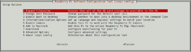
CHAPTER 6 THE RASPBERRY PI SOFTWARE CONFIGURATION TOOL 95
e Enter key is used to activate an option when it is highlighted by the red band. e default
action is always Select, so if you’ve highlighted an option in the menu, there’s no need to
press the Right arrow key to choose Select before pressing the Enter key.
Some of the options in raspi-config take a short while to run, particularly the Update
and Expand Filesystem options. During this time, it’s important to ensure that you don’t
unplug the Pi; doing so can leave you with a damaged le system, which will mean reinstall-
ing your operating system from scratch.
The Setup Options Screen
e initial menu presented by raspi-config is the Setup Options screen (see Figure 6-1),
which provides access to most of the basic functionality of the tool. If you’ve launched the
tool by accident, simply press the Right arrow key twice followed by Enter to exit back to the
console or terminal. Otherwise, choose the option corresponding to the feature you’re trying
to enable or change, as per the following descriptions.
Figure 6-1:
e raspi-
config Setup
Options screen
1 Expand Filesystem
e rst option, Expand Filesystem, oers the capability to grow the Raspbian le system to
take up the full space available on the SD card. When you rst install Raspbian, it asks you
whether or not you wish to do this when it rst boots; as a result, you should only ever need
to choose this option if you’ve cloned your installation to a larger SD card.
To run the lesystem expansion, make sure the red highlight bar is on the Expand Filesystem
option and hit Enter. e raspi-config menu will disappear and a series of console mes-
sages will appear on the screen. Once the initial resize has nished, press Enter to dismiss
the message that appears about rebooting the Pi, and then press the Right arrow key twice
followed by Enter to exit the tool. When prompted, press Enter to reboot the Pi.
PART I CONNECTING THE BOARD
96
When the Pi reboots, it will perform the remainder of the lesystem expansion. On larger or
slower cards, this can take a little time. It’s important that the Pi is not disturbed during this
process because if the power is lost, the Pi’s lesystem can be corrupted. If this happens, you
will lose any les you have stored on the Pi’s SD card and will need to reinstall your operating
system from scratch. e card itself, however, will not be damaged.
2 Change User Password
By default, Raspbian includes a single non-root user account named pi. is account is used
for the day-to-day operation of the Pi, and comes with the default password raspberry.
Although this is ne for private use, if you have your Pi on a publicly-accessible network—
including a Wi-Fi hotspot or other Internet connection—it’s a good idea to change at least
the password, if not the username, to improve security.
While it’s possible to change the password manually using the passwd command (see
Chapter 3, “Linux System Administration” for details), beginners may nd it easier to change
the password using raspi-config. Highlight this option by moving the red bar with the
cursor keys and then press Enter. When prompted, enter a new password and then conrm
the change by entering the password again. To exit raspi-config, press the Right arrow
key twice followed by Enter.
3 Enable Boot to Desktop
Normally, Raspbian loads into the text-based command line interface known as the console.
It does this to ensure that the Pi is ready to use as quickly as possible, and also to save mem-
ory. Many common uses of the Pi—including using it as a web server or recording video or
still images with the Raspberry Pi Camera Module—work ne at the console without the
need to load the desktop graphical user interface.
If you use your Pi as a general-purpose computer, however, you may nd it annoying that
you need to type startx to load the desktop environment. Choosing the Enable Boot to
Desktop option with the cursor keys and pressing Enter will prompt you as to whether the Pi
should boot straight into the desktop or not. If you choose Yes with the cursor keys and
press Enter, the graphical interface will load as soon as the Pi has nished booting—the
equivalent of typing startx every time it loads. If you choose No, the usual text-based con-
sole will load instead.
When you have made your choice, press the Right arrow key twice followed by Enter to exit
raspi-config.
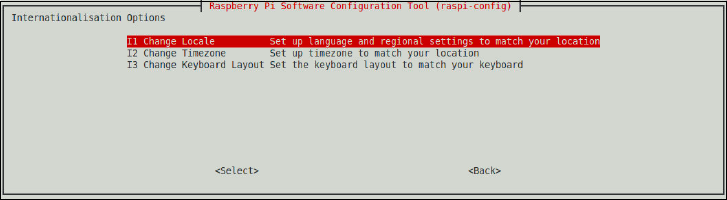
CHAPTER 6 THE RASPBERRY PI SOFTWARE CONFIGURATION TOOL 97
4 Internationalisation Options
is menu option provides a way for users in countries other than the UK to congure the Pi
for their needs (see Figure 6-2). By default, Raspbian sets itself to use UK English language
settings, time zone settings and keyboard layout. Users in other countries will nd that cer-
tain keys on their keyboards don’t type the right characters, particularly those using non-
QWERTY keyboard layouts such as AZERTY or QWERTZ.
Figure 6-2:
e raspi-
config
Internationalisa-
tion Options
screen
Use the cursor keys to select the Internationalisation Options choice and press Enter. is
loads a submenu that provides access to three dierent location-based settings: Change
Locale, Change Timezone and Change Keyboard Layout.
I1 Change Locale
is option, selected with the cursor keys and Enter, provides a list of all the languages avail-
able to the Pi. e list is extensive and includes most common languages. Use the cursor keys
to scroll through the list that appears, and press the spacebar to put a * symbol next to the
language or languages you would like to use.
Each language is named in a particular way: the rst two characters represent the language
name based on the International Organisation for Standardisation’s two-letter identier.
Next comes an underscore, followed by another two characters that represent the country-
specic identier for that language. e prex en_GB, for example, species the variant of
English used in Great Britain; en_US, by contrast, is English as used in the United States of
America.
Following the language and country identier is a string that shows the character encoding
used by the language. Most languages will have more than one option here, but the majority
of users will only need to select one: the UTF-8. is species the Unicode Transformation
Format 8-bit encoding—the most common and compatible encoding standard.

PART I CONNECTING THE BOARD
98
When you have chosen your locales, press Enter to conrm the changes and select your
default. is allows you to have multiple locales installed at the same time without diculty,
although be aware that each locale will take up space on the Pi’s SD card. Choose a default
locale with the cursor keys, and conrm your selection with the Enter key.
If you have selected multiple locales, the change may take some time to complete. When the
raspi-config menu reappears, choose Finish with the cursor keys and press Enter to exit.
TIPChanging the locale of the system won’t translate all applications into your native language.
Where a translation is available, it will be used; otherwise, English text will be displayed as
the default. Changing the locale will also have no effect on command names: echo will still be
called echo, for example, regardless of your locale.
I2 Change Timezone
e system clock of the Raspberry Pi is set to Greenwich Mean Time by default. If you live in
a dierent time zone, this means your Pi will be displaying the wrong time. Choosing the
Change Timezone menu option with the cursor keys and pressing Enter will present you
with a third menu, listing geographic areas like the Indian Ocean, the US and Europe. Use
the cursor keys to select your local area and then press Enter.
e next screen displays a list of cities or regions in that area. Scroll through the list with the
cursor keys and press Enter to select your city. If your city does not appear in the list, choose
the closest city geographically, or your country’s capital city if no other city is listed. When
you have conrmed your change, press the Right arrow key twice to choose Finish and press
Enter to quit raspi-config.
I3 Change Keyboard Layout
is is one of the most important options in the internationalisation menu, allowing you to
alter the expected layout of your keyboard. By default, the Pi is congured to expect a British
English keyboard in the standard QWERTY layout. If you use a dierent keyboard, choose
this option with the cursor keys and press Enter to load the keyboard layout selection menu.
Using the cursor keys, choose the layout that corresponds to your particular keyboard and
activate it with the Enter key. When you have been returned to the main Setup Options
menu, press the Right arrow key twice followed by Enter to quit raspi-config.
CHAPTER 6 THE RASPBERRY PI SOFTWARE CONFIGURATION TOOL 99
5 Enable Camera
is option should be used only if you have a Raspberry Pi Camera Module (see Chapter 15,
“e Raspberry Pi Camera Module”) installed in your system. Choose the Enable Camera
option with the cursor keys, press Enter, and then press Enter again to conrm the change.
is will ensure that your Pi is congured to use the Camera Module, including downloading
and installing the companion software if required.
If you remove the Camera Module from your Raspberry Pi, choose the Enable Camera menu
option with the cursor keys, press Enter, and then use the Right arrow key to select No
before pressing Enter again. Although this isn’t strictly speaking required—having the
Raspberry Pi congured for a camera that isn’t connected will do no harm—it can help to
keep things tidy.
Note that you will need to ensure that your Pi has at least 128MB available to the graphics
processing unit (GPU) in order to use the Camera Module for video recording; see the section
“A3 Memory Split” later in this chapter for how to congure this option.
6 Add to Rastrack
Rastrack is an interactive map of Raspberry Pi created by Ryan Walmsley. It is designed to
help enthusiasts in close proximity to nd each other, and to demonstrate areas of the world
that have a large concentration of Raspberry Pi users. e service is voluntary and is not con-
nected with the Raspberry Pi Foundation.
To appear on the Rastrack map, a Raspberry Pi must be registered. is is an optional pro-
cess, and if you have any concerns about privacy you can skip it without losing any features
or functionality. If you would like your Pi to appear on the map, however, choose the Add to
Rastrack option with the cursor keys and press Enter. Note that you will need an Internet
connection to continue.
Press Enter to conrm you have read the message that appears, then enter your name—or a
nickname—followed by Enter. Enter an email address next, followed by Enter again to add
your Raspberry Pi to the map. You don’t need to give your location because the software uses
your Internet connection to place your Pi on the map. It will not give your exact location at
street level, but it will show others roughly where in the world you and your Pi are located.
Finally, press Enter to return to the main raspi-config screen, press the Right arrow key
twice and then Enter to quit the tool and return to the console or terminal. To see the map,
visit the website at rastrack.co.uk.
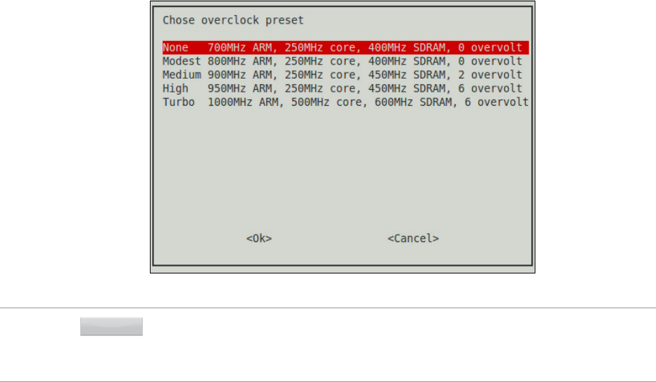
PART I CONNECTING THE BOARD
100
7 Overclock
Overclocking refers to the process of running a device at a speed higher than its manufactur-
ers intended. e Raspberry Pi’s BCM2835 processor can be run above its default speed of
700MHz to boost the performance of the system. Such performance comes at a price, how-
ever, in that the chip will run hotter than before, will draw more power and may suer from
a shorter lifespan than a Pi running at its default speed.
Although it’s possible to alter the performance of the BCM2835 processor manually (see
Chapter 7, “Advanced Raspberry Pi Conguration”) the safest way is to use raspi-config.
is limits you to a selection of precongured overclock settings (see Figure 6-3) that are
known to be safe for use with most Raspberry Pis.
Figure 6-3:
e pre-set
overclock
options included
in raspi-
config
WARNING While the overclock settings available to raspi-config are reasonably safe and will not harm
your warranty, not all Raspberry Pis can reach the top speeds. If you nd your Pi is unstable—
particularly if you are experiencing les on the SD card becoming corrupt—drop down to the
setting below the one you’re currently using, or return the Pi to its default 700MHz speed.
To overclock your Raspberry Pi, highlight the Overclock option with the cursor keys and
press Enter. Carefully read the message that appears and then press Enter to conrm that
you wish to continue. If you have changed your mind, you can just press Enter as soon as the
next screen appears to keep the stock speed of the Raspberry Pi intact.
CHAPTER 6 THE RASPBERRY PI SOFTWARE CONFIGURATION TOOL 101
If you want to try overclocking your Pi, use the cursor keys to select an option from one of
the pre-set overclocks that appear on the next screen: None, Modest, Medium, High and
Turbo. Almost all Raspberry Pi models should be able to use the Modest setting, which sim-
ply increases the processor’s clock speed to 800MHz. Many will be able to use Medium,
which increases the voltage applied to the processor to reach 900MHz and additionally
increases the memory speed from 400MHz to 450MHz.
e remaining two settings may not work on all Raspberry Pi models. e BCM2835 proces-
sor is a complex circuit that will dier in its ability to be overclocked from unit to unit —even
two Pis from the same batch. e High setting increases the speed to 950MHz but requires
signicantly more voltage than Medium or Modest to do so, which means more heat output
and a lower lifespan for the processor. e Turbo setting increases the processor to 1000MHz
while also doubling the graphics clock to 500MHz and increasing the memory clock to
600MHz. is oers the best performance, but has been linked to SD card corruption—
where les become unreadable—on certain Raspberry Pi models.
If you wish to make use of the Turbo mode, make sure you have backed up any important
les stored on the Pi beforehand. If you do start to have problems, drop down to the High
setting or lower and your Pi should return to normal.
When you have made your selection, press the Enter key and then press the Enter key again
to reboot the Pi at its new speed.
If you select a speed higher than the Pi can accept, it may not boot correctly. If you nd your
Pi loads to a black screen or constantly restarts itself without prompting you to log in, you
have chosen too high a speed. Hold down the Shift key on the keyboard; this will temporarily
bypass the overclocking setting, loading the Pi at its stock speed. Once the Pi has booted,
release the Shift key and log in, then load raspi-config and enter the Overclock menu to
choose a more conservative setting.
8 Advanced Options
Choosing the Advanced Options entry with the cursor keys and pressing Enter will load the
Advanced Options menu (see Figure 6-4), which provides access to additional settings not
found on the Setup Options menu. If you enter this menu by mistake, you can go back by
pressing the Right arrow key twice followed by Enter to return to the main Setup Options
menu.
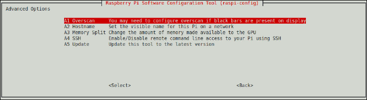
PART I CONNECTING THE BOARD
102
Figure 6-4:
e raspi-
config
Advanced
Options screen
A1 Overscan
Many TV sets feature overscan, which means the visible picture area is slightly smaller than
the transmitted picture. In broadcast TV, this is often used to hide additional data such as
time code information but in computing, it can result in the edges of the display becoming
hidden. By contrast, using a TV signal with a modern monitor can reveal the previously hid-
den edges with their additional data.
You may need to adjust the overscan for one of two reasons: the image from your Pi is sur-
rounded by black bars, in which case the overscan needs to be reduced or disabled altogether;
or the image from your Pi extends beyond the visible edges of your screen, in which case the
overscan needs to be increased. e latter is most common when using the Pi’s composite
video output (see Chapter 2, “Getting Started with the Raspberry Pi”) with an older TV set.
To adjust the overscan setting, highlight the Overscan option with the cursor keys and press
Enter. A menu will appear asking whether the overscan should be enabled or disabled. If you
are using a monitor or TV using the Pi’s HDMI port, choose Disable by pressing Enter; other-
wise, press the Right arrow key to select Enable and conrm with the Enter key. To exit
raspi-config, press the Right arrow key twice to highlight Finish and press Enter. You
will be prompted to reboot to apply the new setting; conrm with Enter.
e Overscan menu in raspi-config only allows you to enable or disable the setting; to
control the size of the overscan to maximise the visible screen area on an old TV, see Chapter
7, “Advanced Raspberry Pi Conguration”.
A2 Hostname
A system’s hostname is the name it uses to identify itself on the network. When you use the
console or terminal on the Pi, you’ll see the hostname as part of the prompt that accepts your
CHAPTER 6 THE RASPBERRY PI SOFTWARE CONFIGURATION TOOL 103
command. Hostnames should be unique, which can cause a problem if you have more than
one Raspberry Pi on your network. You can change a Pi’s hostname at any time using the
Hostname option of raspi-config’s Advanced Options menu, selected by highlighting it
with the cursor keys and pressing the Enter key.
When you access the Hostname setting, raspi-config will inform you of the rules of a
hostname. Because hostnames adhere to an international standard, known as a request for
comments or RFC, certain characters aren’t allowed: a hostname should only contain letters
and numbers, and can include hyphens as long as they aren’t at the beginning or end.
Conrm you’ve read this message by pressing Enter.
Using the Backspace key, delete the current hostname in the box that appears and type in
your new choice. You can opt for a descriptive hostname such as “living-room-pi” or name
your devices based on a theme such as “bladerunner” for science ction lms. When you
have chosen your name, press Enter to conrm. To exit raspi-config, press the Right
arrow key twice to highlight Finish and press Enter. You’ll be prompted to reboot the Pi;
press Enter to conrm.
A3 Memory Split
Depending on your Raspberry Pi model, you will have either 512MB or 256MB of memory
available to the system. is memory is split between the BCM2835 chip’s general-purpose
processor, known as the central processing unit (CPU), and the graphics processor, known as
the graphics processing unit (GPU). By default, 128MB of memory is reserved for the GPU
while the remainder is given over to the CPU.
If you’re not using the graphics processor, such as when the Pi is used as a web server with no
display connected, you can reduce the amount of memory reserved for the GPU using the
Memory Split option in raspi-config. Highlight this option with the cursor keys and
press Enter to load the menu.
Using the Backspace key, delete the current value listed in the box that appears and enter a
new choice. e minimum you should give to the GPU to ensure proper operation is 16MB,
which should be entered simply as the number 16. If you have a Raspberry Pi model with
512MB of memory, you can increase the split to 256MB, which may improve performance
when using the GPU to render complex 3D scenes in games.
You can choose other values but you should restrict this to doubling the value at each step:
for example, 16MB can be increased to 32MB, 32MB to 64MB, 64MB to 128MB and so on.
PART I CONNECTING THE BOARD
104
Choosing an uneven value, such as 17MB, will not harm the Pi but may result in a dierent
value being used than the one selected.
When you have chosen a memory split, press the Enter key to conrm. To apply the setting,
exit raspi-config by pressing the Right arrow key twice followed by Enter, and then press
Enter again to conrm that you want the Pi to reboot.
A4 SSH
e Secure Shell, also known as SSH, is a way of accessing the Raspberry Pi’s terminal over the
network. It’s most commonly used when running the Pi as a standalone server, as it doesn’t
require you to have a keyboard or monitor attached. SSH allows the user to access the text-
based terminal, and also to transfer les to or from the Pi.
Some users may wish to improve the security of their Pi by turning this feature o. Highlight
the SSH option using the cursor keys and press the Enter key. In the window that appears,
choose either Enable or Disable to turn SSH on or o. Even if you don’t need it, it’s a good
idea to keep SSH enabled for future troubleshooting; a better way of improving security is to
ensure that you have changed the password for the pi user.
A5 Update
e Update menu option ensures that you are running the very latest version of raspi-
config. e tool is updated frequently as new features are enabled on the Pi or dierent
settings added to the menu, so it’s always a good idea to ensure that your version is up
to date.
Choosing this menu option with the cursor keys and pressing Enter will begin the update
process. is requires an Internet connection to complete, so if you are using a Raspberry Pi
Model A you will need to connect a USB network adapter to continue.
Note that this option will only update raspi-config, not any other aspect of the system.
To update everything, including raspi-config, see the instructions in Chapter 3, “Linux
System Administration”.
When the update has completed, exit raspi-config by pressing the Right arrow key twice
followed by the Enter key.
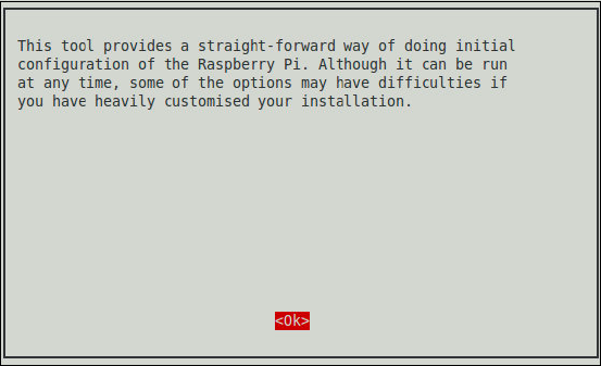
CHAPTER 6 THE RASPBERRY PI SOFTWARE CONFIGURATION TOOL 105
9 About raspi-cong
e nal menu option available in raspi-config simply introduces the tool. Choosing this
option with the cursor keys and pressing Enter will launch a window explaining the purpose
of the tool (see Figure 6-5) and will make no changes to the system. e message can be dis-
missed by pressing Enter, and raspi-config can be closed by pressing the Right arrow key
twice followed by the Enter key.
Figure 6-5:
About the
raspi-
config
software tool
Chapter 7
Advanced Raspberry Pi
Configuration

108 PART I CONNECTING THE BOARD
OWING TO ITS origins in embedded computing, the BCM2835 chip at the heart of the
Raspberry Pi doesn’t have anything like a PC’s Basic Input-Output System (BIOS) menu where
various low-level system settings can be congured. Instead, it relies on text les containing
conguration strings that are loaded by the chip when the power is switched on.
Before taking a look at the various options available in these les—config.txt and cmd-
line.txt—a word of warning: changing some of these settings away from their defaults
can result in a Pi that doesn’t boot until the les are reverted, in the best case, and can
physically damage the system, in the worst case. ese potentially dangerous settings will be
highlighted with warnings in this chapter.
TIPIf you’re using the Raspbian distribution, the easiest way of changing the majority of settings
is to use the raspi-config utility (see Chapter 6, “The Raspberry Pi Software Conguration
Tool”). These instructions are provided for those on other distributions or who would prefer to
do things manually.
Editing Conguration Files via NOOBS
If you have edited your conguration les in such a way that your operating system no lon-
ger boots, the easiest way to restore them is to use the NOOBS software (see Chapter 2,
“Getting Started with the Raspberry Pi”). If your operating system was installed via NOOBS,
you can use the tool to edit the conguration les; if you installed your operating system
manually, you will need to remove the SD card and use a second computer to edit the les.
To load NOOBS after you have used it to install your operating system, hold down the Shift
key as you apply power to the Pi. is will bypass the loading of the operating system and
instead boot into NOOBS, but with a new option: the Edit Cong button at the top of the
menu (see Figure 7-1).
Clicking the Edit Cong button (or pressing the E key) will load a text editor window with the
two conguration les—config.txt and cmdline.txt—pre-loaded (see Figure 7-2). You
can make changes as described in this chapter in the text editor with your keyboard and mouse,
and click the OK button at the bottom-right to save your changes to the SD card. When you’ve
nished making changes, click Exit on the main window to reboot the Pi with its new settings.
TIPIf you have a Raspberry Pi Model B that is connected to the Internet, you can also click the
Online Help button or press the H key on the keyboard to load a web browser that will take
you to the Raspberry Pi Forums. This is an invaluable resource if your Pi isn’t working properly,
allowing you to nd help or post a question to get your Pi computing back on track.
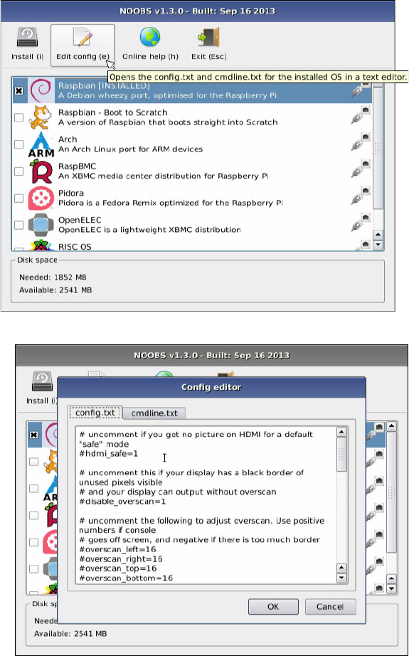
CHAPTER 7 ADVANCED RASPBERRY PI CONFIGURATION 109
Figure 7-1:
e Edit Cong
button in
NOOBS
Figure 7-2:
Editing
conguration
les in NOOBS
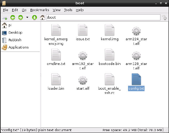
110 PART I CONNECTING THE BOARD
Hardware Settings—cong.txt
e Pi’s hardware is controlled by settings contained in a le called config.txt, which is located
in the /boot directory (see Figure 7-3). is le tells the Pi how to set up its various inputs and
outputs, and at what speed the BCM2835 chip and its connected memory module should run.
Figure 7-3:
e contents of
the /boot
directory, with
config.txt
highlighted
If you’re having problems with graphics output, such as the image not lling the screen or
spilling over the edge, config.txt is where you’ll be able to x it. Normally, the le is
empty or, on some distributions, simply not present; this just means that the Pi will operate
using its pre-set defaults. If you want to make changes and the le isn’t there, just create a
new text le called config.txt and ll in the settings you want to change.
e config.txt le can control almost all aspects of the Pi’s hardware, with the exception
of the way the central processing unit (CPU) and graphics processing unit (GPU) sections of
the BCM2835 apportion the memory. You’ll learn how to alter that split in the “Memory
Partitioning” section, later in this chapter.
e config.txt le is only read when the system rst starts up. Any changes made while
the Pi is running won’t take eect until the system is restarted, or switched o and back on
again. In the event that the changes are unwanted, simply deleting the le from the /boot
directory should be enough to restore the defaults once more. If the Pi won’t boot with your
new settings, just remove the SD card and delete config.txt from the boot partition on
another PC, and then reinsert the card into the Pi and try again.

CHAPTER 7 ADVANCED RASPBERRY PI CONFIGURATION 111
Modifying the Display
Usually, the Raspberry Pi will detect the type of display that’s connected and alter its settings
accordingly. Sometimes, however, this automatic detection doesn’t work. is is often the
case when a Raspberry Pi from one country is connected to an older TV from another coun-
try. If you connect your Pi to your TV and there’s nothing to see, you may need to override
these defaults.
Various settings in the config.txt le can be used to improve or alter the video output.
ese settings, and their possible values, are described in the following list.
WARNING
Manually adjusting the High Denition Multimedia Interface (HDMI) or composite video output
settings can leave your Pi unable to communicate with your monitor. It’s usually best to use
the automatically detected settings, unless you’re unable to see a picture in the rst place.
❍ overscan_left—is setting moves the picture inwards a set number of pixels to com-
pensate for a TV’s overscan. If the text on the Pi is disappearing o the edge of the screen,
adjusting the overscan will x it. Values should be given as the number of pixels to skip.
❍ overscan_right—is setting does the same job as overscan_left, but on the
right side of the screen.
❍ overscan_top—Again, this setting ignores a certain number of pixels, but this time
on the top of the screen.
❍ overscan_bottom—is setting can be used to skip a number of pixels from the bot-
tom of the display. Typically, the values for all the overscan_ settings would be the
same, creating a regular border around the display.
❍ disable_overscan—If you use a monitor or TV via HDMI, you may nd that your
image has a black border around it. To get rid of this border, any default overscan set-
tings can be disabled by setting this value to 1.
❍ framebuer_width—is value is measured in pixels, and adjusting it will change
the width of the console. If text appears too small on your screen, try changing this to
a lower value than the default width of the connected display.
❍ framebuer_height—is setting aects the size of the console in the same way as
framebuffer_width, but vertically rather than horizontally.
❍ framebuer_depth—Controls the colour depth of the console in bits per pixel. e
default is 16 bits per pixel, which gives 65,536 colours. Other values, including 8 bits
per pixel (256 colours), 24 bits per pixel (around 16.7 million colours) and 32 bits per
pixel (around 1 billion colours) are valid, but may cause graphical corruption.
112 PART I CONNECTING THE BOARD
❍ framebuer_ignore_alpha—Set to 1, this value disables the alpha channel, which
controls transparency in the console. Disabling the alpha channel is not normally
required, but it may correct graphical corruption caused when setting framebuffer_
depth to 32 bits per pixel.
❍ sdtv_mode—is value aects the analogue composite video output of the Pi, adjust-
ing it to operate in various countries. By default, the Pi uses the North American ver-
sion of the NTSC video standard; users in other countries may need to change this
value to get a picture on an analogue TV. Possible values are:
• 0—NTSC, the North American video standard
• 1—NTSC-J, the Japanese video standard
• 2—PAL, the video standard for the UK and other countries
• 3—PAL-M, the Brazilian video standard
❍ sdtv_aspect—Controls the aspect ratio of the analogue composite output. If the pic-
ture looks stretched or squished, alter this to correspond to your TV’s aspect ratio.
Possible values are:
• 1—4:3 aspect ratio, common on older sets
• 2—14:9 aspect ratio, common for smaller widescreen TVs
• 3—16:9 aspect ratio, common for modern widescreen TVs
❍ hdmi_mode—In addition to setting the video mode for the analogue composite out-
put, it’s also possible to override automatic resolution detection on the HDMI port.
is is handy if you want to run your Pi at a lower resolution than the display’s native
resolution in order to make things more readable from a distance. Appendix C, “HDMI
Display Modes”, lists the possible values for this setting.
❍ hdmi_drive—It’s also possible to alter the voltage output by the HDMI port. is is
important when you’re using an HDMI to DVI adapter, because HDMI and DVI volt-
ages dier slightly. If you nd that your picture is snowy or blown out with too bright
an image, try altering this setting. Possible values are:
• 1—DVI output voltages. In this mode, no audio is included on the HDMI cable.
• 2—HDMI output voltages. In this mode, audio is included on the HDMI cable.
❍ hdmi_force_hotplug—Forces the Raspberry Pi to use the HDMI port, even if it
doesn’t detect a connected display. A value of 0 allows the Pi to attempt to detect the
display, while a value of 1 forces the Pi to use HDMI regardless.
CHAPTER 7 ADVANCED RASPBERRY PI CONFIGURATION 113
❍ hdmi_group—Sets the HDMI group mode to CEA or DMT. You should change this
setting according to the display type you’re trying to connect, before using hdmi_mode
to control the output resolution and frequency. e two possible values are:
• 1—Sets the HDMI group to that dened by the Consumer Electronics Association
of America (CEA). Use this setting when the Pi is connected to a high-denition
television (HDTV) over HDMI and use the rst settings list from Appendix C,
“HDMI Display Modes”.
• 2—Sets the HDMI group to that dened by the Video Electronics Standards
Association (VESA) in the Display Monitor Timings (DMT) specication. Use this
setting when the Pi is connected to a computer monitor over DVI and use the
second settings list from Appendix C, “HDMI Display Modes”.
❍ hdmi_safe—Forces the Pi to use a pre-set collection of HDMI settings designed to
provide maximum compatibility with displays connected to the HDMI port. Setting
this to a value of 1 is the equivalent of setting hdmi_force_hotpug=1, config_
hdmi_boost=4, hdmi_group=1, hdmi_mode=1 and disable_overscan=0.
❍ cong_hdmi_boost—Some monitors require more power on the HDMI output to
operate. If your picture looks snowy, try increasing this value in stages from 1 (for
short cables) to 7 (for long cables).
Each option in config.txt should be on its own line, with the option name followed by an
equals sign (=) and then the required value. For example, to tell the Pi to use a PAL-format
analogue TV with a 4:3 aspect ratio and a 20-pixel overscan on all sides, put the following
lines into config.txt:
sdtv_mode=2
sdtv_aspect=1
overscan_left=20
overscan_right=20
overscan_top=20
overscan_bottom=20
To tell the Pi to use a DVI display through the HDMI port in the 720p60 format with no
overscan at all, use the following values instead:
hdmi_group=1
hdmi_mode=4
hdmi_drive=1
disable_overscan=1

114 PART I CONNECTING THE BOARD
For the changes to take eect, the Pi must be restarted. If you nd that your changes have
disabled the Pi’s video output on your monitor, simply insert the SD card into another com-
puter and either modify the config.txt le with new settings or delete it altogether to
restore the defaults.
Boot Options
e config.txt le can also be used to control how Linux is loaded on the Raspberry Pi.
Although the most common method for controlling the loading of the Linux kernel is to use
a separate le called cmdline.txt (which you’ll learn about later in this chapter), it is pos-
sible to use just config.txt. e following options control the boot process:
❍ disable_commandline_tags—is tells the start.elf module that loads rst dur-
ing the Pi’s boot process to skip lling in memory locations past 0x100 before loading
the Linux kernel. is option should not be disabled, as doing so can cause Linux to
load incorrectly and crash.
❍ cmdline—e command line parameters to be passed to the Linux kernel. is can be
used in place of the cmdline.txt le, usually found in the /boot directory.
❍ kernel—e name of the kernel le to be loaded. is can be used as a way to load the
emergency kernel (see Chapter 4, “Troubleshooting”).
❍ ramfsle—e name of the initial RAM le system (RAMFS) to be loaded. is should
rarely be modied, unless you’ve built a new initial le system with which to experiment.
❍ init_uart_baud—e speed of the serial console, in bits per second. e default is
115200, but lower values may improve the connection if the Pi is used with an older
hardware serial terminal.
Overclocking the Raspberry Pi
e config.txt le not only controls the graphics outputs of the Pi’s BCM2835 processor
but also enables you to control the chip in other ways. In particular, it allows you to alter the
speed at which the chip runs, increasing its performance at the expense of the part’s lifes-
pan—a process known as overclocking.
WARNING Adjusting any of the settings listed in this section can result in damage to your Pi. In particular,
changing settings corresponding to memory, GPU or CPU voltages will set a fuse in the chip,
which invalidates the Raspberry Pi’s warranty even if the setting is returned to normal before any
damage is done. Damage caused when using these settings will not be put right by the Raspberry
Pi Foundation or by the retailer from whom you purchased your Pi. If in doubt, don’t alter these
settings: the performance gains through overclocking are rarely worth the risk to the Pi.
CHAPTER 7 ADVANCED RASPBERRY PI CONFIGURATION 115
e BCM2835 multimedia processor at the heart of the Pi is a system-on-chip (SoC) design
split into two main parts: the graphics processor (GPU) and the central processor (CPU).
Simply put, the CPU handles all the day-to-day processing tasks while the GPU handles
drawing things on the screen, in both 2D and 3D.
Using config.txt, you can overclock one or both parts of the BCM2835. You can also
increase the speed at which the memory module—located on top of the chip in a package-
on-package (PoP) mounting format—operates.
Boosting the operating frequency of these components results in a small increase in the Pi’s
performance: an increase to the GPU’s clock frequency means that 3D graphics (such as
game graphics) will render at a faster pace, and video will be decoded quicker for smoother
playback; and increasing the CPU’s clock frequency will boost overall performance of the
device, as will increasing the memory’s frequency.
e reason the Pi isn’t provided with higher operating speeds in the rst place is related to
the chip’s lifespan. e BCM2835 is rated by its manufacturer, Broadcom, to operate at a
speed of 700 MHz. Increasing the speed above this ocially rated level may work, but it will
also have a deleterious eect on the lifespan of the chip. Unlike a desktop processor, SoC
designs rarely have much headroom for overclocking.
Overclocking Settings
If you’re willing to take the risk of breaking the Pi—a process known as bricking in embedded
device circles—for the sake of a small performance gain, there are settings in config.txt
that can help. e following settings control performance of the Pi’s SoC:
❍ arm_freq—Sets the core clock frequency of the CPU portion of the BCM2835, for a
boost in general-purpose performance. e default speed is 700 MHz.
❍ gpu_freq—Sets the clock frequency of the GPU portion of the BCM2835, for a boost
in graphics performance across all operations. e default speed is 250 MHz.
Additionally, you can adjust individual portions of the GPU’s hardware using the fol-
lowing options:
•
core_freq—Sets the core clock frequency of the GPU, leaving the other frequen-
cies alone, to improve overall GPU performance. e default speed is 250 MHz.
•
h264_freq—Sets the clock frequency of the GPU’s hardware video decoder to
improve playback of H.264 video data. e default speed is 250 MHz.
116 PART I CONNECTING THE BOARD
• isp_freq—Sets the clock frequency of the image sensor pipeline, for improving
the capture rate of connected video hardware (such as a camera). e default
speed is 250 MHz.
• v3d_freq—Sets the clock frequency of the GPU’s 3D rendering hardware, for a
boost in visualisation and gaming performance. e default speed is 250 MHz.
❍ sdram_freq—Sets the clock speed of the random access memory (RAM) chip on the Pi,
to give the entire system a small increase in performance. e default speed is 400 MHz.
❍ init_uart_clock—Sets the default clock speed of the Universal Asynchronous Receiver/
Transmitter (UART), used to control the serial console. e default is 3000000, which
sets a speed of 3 MHz. Altering this is likely to have little eect beyond corrupting the
output of the serial console.
❍ init_emmc_clock—Sets the default clock speed of the SD card controller. e default
is 80000000, which sets a speed of 80 MHz. Increasing this value can result in faster
reading and writing from the SD card, but can also lead to data corruption.
As an example, to overclock the CPU to 800 MHz, the GPU to 280 MHz and the RAM to 420
MHz, enter the following options into config.txt, one per line:
arm_freq=800
gpu_freq=280
sdram_freq=420
As with adjusting the display conguration, any changes made regarding overclocking won’t
take eect until the Pi is restarted. To return the settings to normal, you can either delete the
entire config.txt le or—if you’re using it to control the display settings as well—simply
delete the lines that deal with overclocking, and then restart the Pi.
If you have overclocked your Pi and it no longer boots, either place the SD card into another
computer to edit the conguration and then try again, or hold down the Shift key while the
Pi boots to temporarily disable your new settings and run the Pi at its normal clock speed.
Overvoltage Settings
If you’re overclocking your Pi, you will eventually hit a brick wall past which the device won’t
go. e precise point at which the Pi won’t reliably overclock depends on the individual
device, due to natural variations in the chip introduced during the manufacturing stage. For
some users, this limit may be as low as 800 MHz; others may nd that they can push their Pi
as high as 1 GHz (1,000 MHz) without issue.

CHAPTER 7 ADVANCED RASPBERRY PI CONFIGURATION 117
If you want to eke a little more performance out of your Pi, there is a way to potentially boost
this upper limit: a process known as overvoltage or overvolting. e Pi’s BCM2835 system-on-
chip processor and the associated memory module usually run at 1.2 V. It’s possible, although
potentially inadvisable, to override this default and force the components to run at higher or
lower voltages. Boosting the voltage means boosting the signal within the chip, making it
more likely to hit higher speeds—it also means that the chip runs hotter, reducing its lifes-
pan dramatically compared to overclocking alone.
WARNING
Setting any of the voltage options in config.txt causes a fuse within the BCM2835 to trip
in a way that cannot be reset. It’s a foolproof way to tell if someone has been attempting to
overclock the chip outside its rated specications, and renders your warranty null and void—
even if the cause of failure is unrelated to overclocking. If you return a Pi for replacement under
warranty and the fuse is tripped, it will not be replaced. Do not attempt to overvolt a Pi that you
cannot afford to replace yourself.
Unlike the previously described settings, which are provided in config.txt as absolute
values, the voltage adjustment is carried out using values relative to the Pi’s stock 1.2 V set-
ting. For each whole number above zero, the voltage is increased by 0.025 V from stock. For
each whole number below zero, the voltage is decreased by 0.025 V from stock.
e voltage adjustment settings have upper and lower limits of 8 and -16, equivalent to 0.2
V above stock voltage or 1.4 V absolute and 0.4 V below stock voltage or 0.8 V absolute. e
voltage must be adjusted in whole numbers, and it cannot be adjusted below 0.8 V (-16) or
above 1.4 V (8.)
e following settings are accessible from config.txt:
❍ over_voltage—Adjusts the BCM2835’s core voltage. Values are given as a whole
number (an integer) corresponding to 0.025 V above or below the default value (0,)
with a lower limit of -16 and an upper limit of 8.
❍ over_voltage_sdram—Adjusts the voltage given to the memory chip on the Pi. As with
over_voltage, values are given as a whole number corresponding to 0.025 V above or
below the stock (0,) with a lower limit of -16 and an upper limit of 8. Additionally, you
can adjust voltages for individual memory components using the following options:
• over_voltage_sdram_c—Adjusts the voltage given to the memory controller.
Acceptable values are the same as with over_voltage_sdram.
• over_voltage_sdram_i—Adjusts the voltage given to the memory’s input/output
(I/O) system. Acceptable values are the same as with over_voltage_sdram.
• over_voltage_sdram_p—Adjusts the voltage given to the memory’s physical layer
(PHY) components. Acceptable values are the same as with over_voltage_sdram.
118 PART I CONNECTING THE BOARD
As an example, the following lines entered into config.txt will give the BCM2835 a small
boost of 0.05 V to 1.25 V and the memory chip a bigger boost of 0.1 V to 1.3 V:
over_voltage=2
over_voltage_sdram=4
As with other settings, deleting the lines from config.txt or deleting the le itself will
return things to normal. Unlike the other settings in this section, however, the evidence will
remain in the form of a blown fuse in the BCM2835, rendering the Pi’s warranty null and
void even after the default settings are restored.
Disabling L2 Cache
e Pi’s BCM2835 SoC processor has 128 KB of Layer 2 cache memory onboard. Although
this memory is small, it’s extremely fast. It’s used to temporarily store—or cache—data
and instructions between the slower main memory and the processor itself to improve
performance.
Because of the BCM2835’s origins as a multimedia processor targeted at set-top boxes, this
L2 cache is designed to be used by the GPU portion of the chip alone. Unlike a traditional
processor, the CPU doesn’t have any L2 cache of its own.
Using config.txt, you can tell the BCM2835 to allow or disallow its CPU portion access to
the L2 cache memory. In some cases, this can improve performance. In other cases it can
harm performance, due to the physical location of the cache being a relatively long distance
away from the CPU section of the chip and closer to the GPU.
Use of the L2 cache memory also requires a Linux distribution that has been compiled with
the cache memory in mind. Raspbian is one such distribution, and comes with the L2 cache
enabled for improved performance. It should be left this way, and only disabled if it causes
problems with alternative operating systems.
To switch the L2 cache o for CPU access, simply add the following line to the config.txt
le:
disable_l2cache=1
As with all config.txt settings, the system must be rebooted before the change will take
place. To enable the CPU’s access to the cache memory, replace the 1 with a 0.

CHAPTER 7 ADVANCED RASPBERRY PI CONFIGURATION 119
Enabling Test Mode
is nal option in config.txt is one the overwhelming majority of Pi users won’t need to
touch, but it is included here for completeness: test mode. Used during production of the
Raspberry Pi at the factory, the test mode—combined with special hardware used to electri-
cally check the board—allows the factory sta to make sure the Pi is operating as it should.
WARNING
Enabling test mode won’t do any permanent damage, but the Pi won’t boot into its operating
system until the mode is disabled again and the power to the Pi is switched off and back on.
If you’re curious to see what the Pi looks like to factory sta, you can enable test mode by
entering the following option into the config.txt le:
test_mode=1
As with other config.txt settings, test mode won’t be enabled until the Pi is restarted.
Test mode can be disabled again by removing the line in config.txt, deleting the le alto-
gether, or replacing the 1 with a 0.
Memory Partitioning
Although the Raspberry Pi has either a 256 MB or 512 MB memory chip, that memory can
be apportioned to the hardware in a variety of ways. e BCM2835 is split into two main
sections: the general-purpose CPU and the graphics-oriented GPU. Both of these sections
require memory to operate, meaning that the 256 MB or 512 MB of memory on the
Raspberry Pi needs to be shared between the two.
e typical split is chosen by the maintainers of the Linux distribution installed on the Pi.
Some choose to provide 128MB to the GPU, ensuring that the graphics hardware can per-
form to its fullest potential. Others allow the CPU to have a larger share in order to improve
general-purpose performance.
Previously, the memory split was controlled by using dierent versions of a rmware le
called start.elf, where dierent les were used to supply dierent amounts of memory
to the CPU. ese les have now been replaced by a single line in config.txt, which can be
edited to control the memory split.
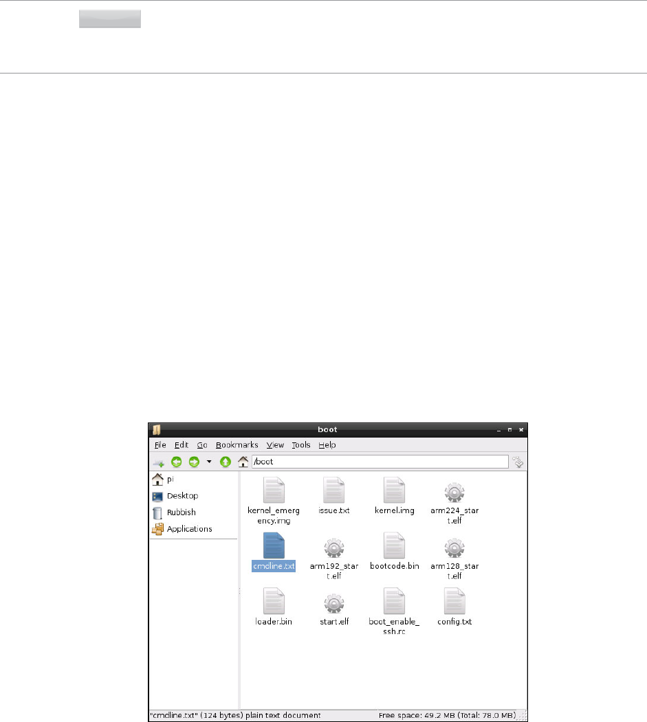
120 PART I CONNECTING THE BOARD
WARNING Applications that do heavy graphics work, such as 3D games and high-denition video playback
software, typically need 128 MB of memory for the GPU. Reducing this can result in a dramatic
drop in performance. The Raspberry Pi Camera Module is unable to record video with less than
128 MB of graphics memory.
e memory split is changed by editing config.txt as with other hardware settings, and
editing or inserting the line marked gpu_mem. is line tells the Pi how much of the total
memory—256 MB on the Model A, 512 MB on the Model B—should be given to the GPU,
with the remainder going to the CPU.
e value can be set to 16 MB as a minimum, or 128 MB as a maximum. e setting should
be adjusted in 16 MB increments and written without the MB sux—giving possible values
of 16, 32, 48, 64, 80, 96, 112 and 128. To give the GPU the minimum 16 MB of memory, for
example, edit the line as follows:
gpu_mem=16
Software Settings—cmdline.txt
In addition to config.txt, which controls various features of the Pi’s hardware, there’s another
important text le in the /boot directory: cmdline.txt (see Figure 7-4). is le contains what
is known as the kernel mode line—options passed to the Linux kernel as the Pi boots up.
Figure 7-4:
e cmdline.
txt le in
/boot
CHAPTER 7 ADVANCED RASPBERRY PI CONFIGURATION 121
In a Linux-based desktop or laptop, these options are normally passed to the kernel by a tool
known as a bootloader, which has its own conguration le. On the Pi, the options are simply
entered directly into cmdline.txt to be read by the Pi at startup.
Almost any kernel option supported by Linux can be entered into the cmdline.txt le, to
alter things like the appearance of the console or which kernel is loaded. As an example, here
is the cmdline.txt le from the Raspbian distribution, which should be written in the le
as one continuous line:
dwc_otg.lpm_enable=0 console=ttyAMA0,115200 ↵
kgdboc=ttyAMA0,115200 console=tty1 root=/dev/mmcblk0p2 ↵
rootfstype=ext4 rootwait
e rst option, dwg_otc.lpm_enable, tells the Pi to disable the On-e-Go (OTG) mode
of its USB controller, to prevent problems that can occur when the functionality is enabled
without proper support in the operating system. e majority of Linux distributions for the
Pi disable this mode.
e console option tells Linux that it should create a serial console—device ttyAMA0—
and at what speed it should operate. In most cases, the speed should be left at the default of
115,200 bps (bits per second). If the Pi is being used to communicate with older devices, this
can be reduced accordingly.
e kgdboc kernel option enables debugging of the Linux kernel over the serial console cre-
ated using the console parameter. For most users, this is unnecessary. For developers, hav-
ing access to kernel debugging over a serial connection is most useful. Many distributions
leave this enabled just in case.
e second console entry creates the device tty1, which is the text-lled screen you see
when you rst boot the Pi. Without this entry, you wouldn’t be able to use the Pi without
connecting something to the serial console created by the rst console option.
e root option tells the Linux kernel where it can nd its root le system, containing all the
les and directories required for the system to operate. In the case of the default Raspbian dis-
tribution, this is on the second partition of the SD card—device mmcblk0p2. is option can
be altered to address an external storage device connected over USB, which can speed up the
operation of the Pi considerably compared to having the root le system stored on the SD card.
In addition to telling the kernel where to nd its root le system, it also needs to know what
format the partition was created in. Because Linux supports a variety of dierent le sys-
tems, the rootfstype option specically tells the Raspbian distribution to use an EXT4 le
system.
122 PART I CONNECTING THE BOARD
Finally, the rootwait parameter tells the kernel that it should not try to boot the system
any further until the device containing the root le system is available. Without this option,
the Pi can get stuck as it begins to boot before the relatively slow SD card is fully ready for
access.
With the exception of the dwc_otg setting, none of these kernel parameters are unique to
the Pi. e bootloader conguration of any Linux distribution will include a list of options
very similar to those of cmdline.txt.
Typically, you should leave the cmdline.txt le alone. It’s created by the distribution
maintainers specically for that version of Linux, and may dier from one distribution to
the next. Entries that work on Pidora may not work on Raspbian, and vice versa. e options
available to cmdline.txt depend on what kernel the distribution is using and what fea-
tures were included when the kernel was built.
If you’re a kernel developer, you can use cmdline.txt to pass parameters for enabling or
disabling new functionality that you’ve compiled into the kernel. As with config.txt, any
changes require a reboot to take eect.
Part II
Building a
Media Centre,
Productivity
Machine or
Web Server
Chapter 8 e Pi as a Home eatre PC
Chapter 9 e Pi as a Productivity Machine
Chapter 10 e Pi as a Web Server
Chapter 8
The Pi as a Home Theatre PC

126 PART II BUILDING A MEDIA CENTRE, PRODUCTIVITY MACHINE OR WEB SERVER
ONE OF THE most popular tasks for a Pi to carry out is that of a home theatre PC, or HTPC.
e Broadcom BCM2835 at the Pi’s heart is specically designed as a multimedia power-
house, originally developed for use in HTPCs.
e graphics portion of the BCM2835 system-on-chip (SoC) design, a Broadcom VideoCore
IV module, is capable of full-speed high-denition video playback using the popular H.264
format. e chip is also able to play back audio les in a variety of formats, both through the
analogue 3.5 mm audio output and digitally via the HDMI port.
e small size, low power draw and silent operation combine to make the Pi a tempting
device for home theatre enthusiasts. A variety of distributions and software packages
designed to turn the Pi into a user-friendly home theatre PC have appeared since its launch,
but you don’t necessarily need to give up your existing operating system to get started.
Playing Music at the Console
If you’re a developer, you will likely spend most of your time at the Pi’s console. With the major-
ity of music playback software being aimed at desktop use, it can be a quiet experience—but it
doesn’t have to be.
e Pi supports a powerful text-based music playback package called moc (which stands for
music on console). Unlike other tools (such as LXMusic), moc can be installed and used even
when there is no graphical user interface (GUI) installed on the Pi.
To get started, install the moc package from your distribution’s repositories. For the Raspbian
distribution, this is as simple as typing the following command at the console or in a terminal
window:
sudo apt-get install moc
TIPSome distributions already have another tool called moc, which has nothing to do with audio
playback. If you nd that installing moc doesn’t give you the result you’re expecting, try
substituting mocp as the package name.
If you spend a lot of time outside of the graphical user interface and working at the console,
moc is a great choice for music playback. Unlike other tools, it runs in the background, mean-
ing there’s no interruption to your music if you start doing something else.
To load moc, the command is mocp rather than moc. e reason for this is that there’s
another tool which uses the command moc, so a dierent name was chosen to prevent the
operating system from getting confused between the two packages.
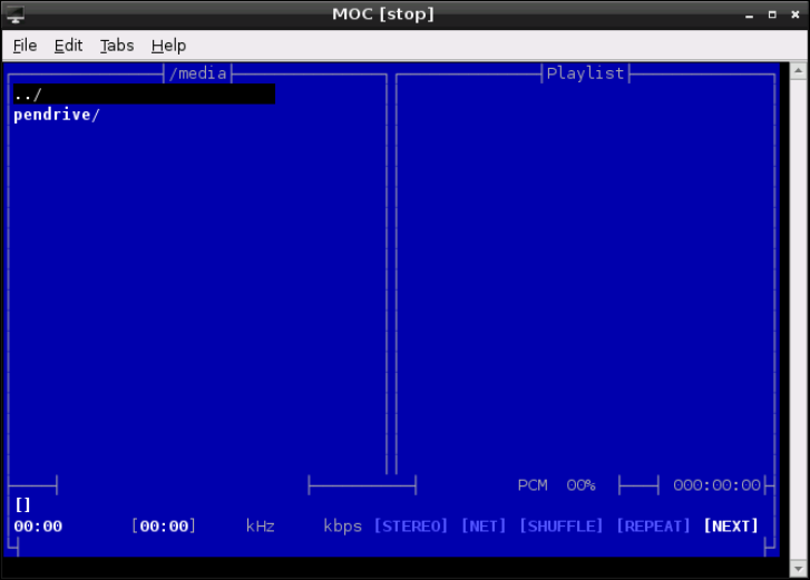
CHAPTER 8 THE PI AS A HOME THEATRE PC 127
To get started, just enter the console—or a terminal window if you’re using a desktop
environment—and type the following:
mocp
e standard mocp interface is split into two panes (see Figure 8-1). e left pane is a le
browser, which allows you to look for music to play. e cursor keys scroll up and down the list,
while the Enter key starts playback from the currently highlighted song. If you press Enter on a
directory name, the browser will enter that directory, while pressing it at the ../ entry at the
top of the list goes back one directory level. e right pane shows the current playlist.
Figure 8-1:
e standard
interface of the
mocp console-
based music
player
Where the power of mocp becomes apparent is when you exit the application by pressing the Q
key. If mocp is in the middle of playing back music, it will continue to do so even as you use the
console or terminal window for other tasks. Running the mocp command again will restore the
interface, allowing you to change songs, pause or stop playback. You can also control mocp directly
from the terminal, without having to use the interface. Running the mocp command with ags—
the options that follow a command, prexed with a hyphen character—allow you to start, stop,
pause, skip and otherwise change the playback without having to go into the software.

128 PART II BUILDING A MEDIA CENTRE, PRODUCTIVITY MACHINE OR WEB SERVER
e most commonly used mocp ags are the following:
❍ -s—Stop the current playback
❍ -G—Pause playback, or resume playback if currently paused
❍ -f—Skip to the next song in the directory or playlist
❍ -r—Return to the previous song in the directory or playlist
❍ -i—Print information on the current song to the terminal or console
❍ -x—Stop playback and quit mocp altogether
For more information on controlling mocp, type man mocp.
Dedicated HTPC with Raspbmc
Being able to play music on the Raspberry Pi is one thing, but the BCM2835 can do much
more than that. Using its VideoCore IV GPU, it can decode and play back Full HD 1080p
H.264 video, making the Pi a powerful media centre machine in a tiny package and with
incredibly low power demands.
To get the most from the Pi as a home theatre PC, however, some additional software is
required. is software can be installed in the Raspbian distribution, but there’s an easier
way to get started: switching to the Raspbmc distribution.
Raspbmc, created by Sam Nazarko, is a distribution aimed specically at turning the Raspberry Pi
into a fully featured media centre system, complete with video and music playback, photo viewing
and Internet streaming capabilities. It’s based on the popular Xbmc distribution, which has been
chosen by several device manufacturers to power their commercial set-top box systems.
If you’re planning on making use of the Pi’s high-denition video output and H.264 decod-
ing capabilities in your home theatre setup, Raspbmc is an excellent choice and no more
complicated to get up and running on the Pi than any other Linux distribution. First, down-
load the installer from the ocial website at http://www.raspbmc.com/download/.
is is the easiest way to get Raspbmc up and running. Installers for Linux, OS X and
Windows are provided which automatically download the image le for Raspbmc and write it
to an SD card connected to the system. Although you can also download an image le and
use the instructions from Chapter 1, “Meet the Raspberry Pi”, it’s not necessary to do so.
WARNING If you already have an SD card you use with the Pi, be aware that installing Raspbmc on it
will delete the contents of the card. Back up any les you want to keep, or if you want to be
able to switch between the two distributions, buy a second SD card specically for Raspbmc
use or install it alongside Raspbian using the NOOBS tool described in Chapter 2, “Getting
Startedwith the Raspberry Pi”.

CHAPTER 8 THE PI AS A HOME THEATRE PC 129
When the Raspbmc installer has nished, insert the SD card into the Pi and re-connect the
power supply—but make sure the Ethernet cable is connected as well, because Raspbmc
needs to download some data from the Internet when it rst loads. e initial load of
Raspbmc can take 10 or 15 minutes to complete as it downloads updates and partitions the
SD card, but subsequent loads are signicantly faster. Don’t panic if the rst boot hangs at
the Formatting Partitions stage—a long pause here is normal.
When loaded, Raspbmc automatically starts the Xbmc service (see Figure 8-2). is provides
a custom user interface specically designed for living-room use. Everything is accessible
through the keyboard or mouse, with large and easily readable text and categorised menus to
make it easier to nd things. You can also purchase infrared remote controls, which come
with a receiver that plugs into the Pi’s USB port and a transmitter that allows for a true home
theatre experience with no bulky keyboard or trailing wires.
Figure 8-2:
e Xbmc home
screen, loaded
by Raspbmc
Streaming Internet Media
By default, Xbmc is congured to play only les it can nd on the Raspberry Pi itself. If you
choose Add-ons from beneath the Video menu, you’ll be able to add some impressive Internet
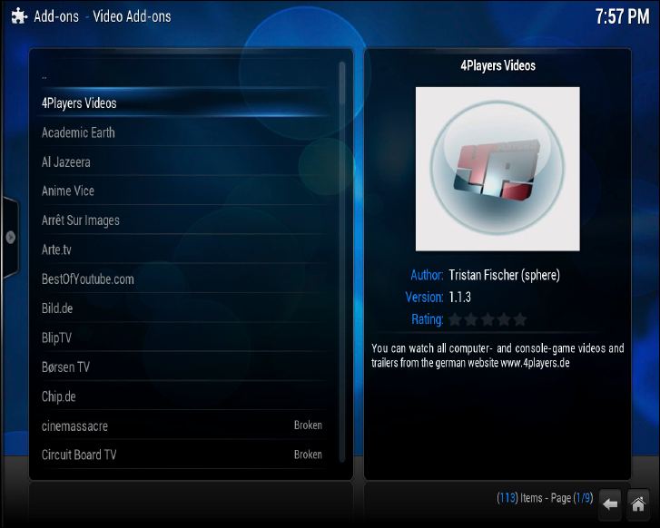
130 PART II BUILDING A MEDIA CENTRE, PRODUCTIVITY MACHINE OR WEB SERVER
streaming capabilities to the device, including access to various TV channels and Internet-
only streaming services. After clicking Add-ons, choose Get More to access the full list of
compatible plug-ins (see Figure 8-3).
Figure 8-3:
Adding new
video add-ons in
Raspbmc
Scroll through the list with the mouse or cursor keys, and click on an entry or press the Enter
key to access more information. To install an add-on, just click Install from the pop-up infor-
mation box that appears when you click on an entry in the list. is will download the add-on
from the Internet and automatically install it into Xbmc. Watch out for add-ons listed as
Broken—these have been reported as not working correctly, and should not be installed
until the problem is xed by the add-on developer.
After you nish choosing and installing video add-ons, click the Home button in the bottom-
right corner of the screen to return to the main Xbmc interface. Now click on the word Video
in the centre of the screen or press Enter, and then choose Video Add-ons from the options
that appear. is provides access to your installed add-ons. Click on one to download a list of
les for viewing. If an add-on has various categories, it will download those categories rst—
in this case, click on an individual category to see the les it contains (see Figure 8-4).
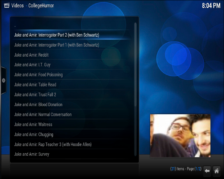
CHAPTER 8 THE PI AS A HOME THEATRE PC 131
Figure 8-4: A
list of videos
available
through the
CollegeHumor
Xbmc add-on
Similar add-ons are available under the Music and Video menus, and operate in the same
way. Using these add-ons, you can view picture content and stream audio content from sites
such as Flickr, Picasa, e Big Picture, Grooveshark, Sky.fm and SoundCloud.
Streaming Local Network Media
e Xbmc software supports the Universal Plug and Play (UPnP) media streaming standard,
allowing it to connect to a range of devices on your home network. UPnP support is included
in most modern mobile phones, games consoles and network-attached storage (NAS) devices
for sharing and streaming videos, music and pictures. Many laptops and desktops also come
with support for UPnP or the closely linked Digital Living Network Alliance (DLNA) stan-
dard—check your documentation to nd out how to enable this feature on your own devices.
Xbmc isn’t just limited to UPnP connections, however—the software can also connect to
network servers running the Network File System (NFS) standard common to Unix-based sys-
tems, the Server Message Block (SMB) standard common to Windows servers and the Zeroconf
standard common to OS X devices. No matter what network-attached device you use to store
your media content, it’s likely that Xbmc will support at least one way of connecting to it.
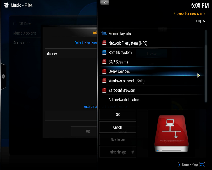
132 PART II BUILDING A MEDIA CENTRE, PRODUCTIVITY MACHINE OR WEB SERVER
To congure Xbmc to connect to a server on your home network, choose the media type—
Video, Music or Pictures—and click the Add Source option. In the window that appears,
choose Browse to retrieve a list of source types (see Figure 8-5). ese source types include
local drives connected to the Raspberry Pi, which are highlighted with a blue icon, as well as
network devices, which are highlighted with a red icon. Choose the type of server you’re try-
ing to connect to from the list, and then click on the server that appears.
Figure 8-5:
Choosing a
network source
in Xbmc
If the server you select has multiple folders available—such as folders for dierent genres,
artists, albums or le types—select the folder you want Xbmc to connect to and click the OK
button. is will return you to the Add Source screen (see Figure 8-6) with the required infor-
mation lled in. If additional details are required—such as a user name and password for a
protected server—you’ll need to ll these in before clicking OK.
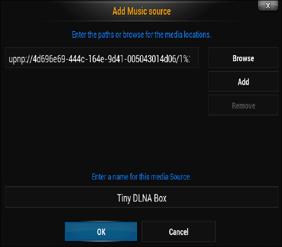
CHAPTER 8 THE PI AS A HOME THEATRE PC 133
Figure 8-6:
Adding a UPnP
music source to
Xbmc
You can also use the same menu to add an external hard drive as a source to Xbmc by select-
ing its entry in the initial list. Most external drives will appear automatically, and do not
need to be added explicitly—you only need to add a drive as a source if its contents do not
appear in Xbmc’s menus.
Conguring Raspbmc
e Programs menu on the home screen provides access to the Raspbmc Settings menu
(shown in Figure 8-7) where network settings, software upgrade settings and various system
settings can be adjusted. Normally, this menu can be ignored—however, if you’re having
problems connecting to the Internet or the Raspbmc system is continuously crashing, the
Programs menu can provide important tools for resolving the issue.
Clicking the Raspbmc Settings option under the Programs menu will open a window with
three tabs. e rst tab allows you to adjust the network settings, including disabling DHCP
and setting a manual network conguration (see Chapter 5, “Network Conguration”, for
more details). If you needed to set the Raspberry Pi to use a manual network conguration in
other distributions, this is the place to do the same in Raspbmc.
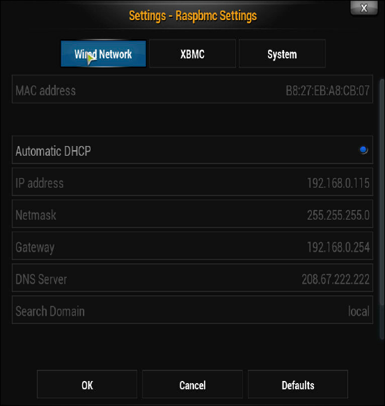
134 PART II BUILDING A MEDIA CENTRE, PRODUCTIVITY MACHINE OR WEB SERVER
Figure 8-7:
Conguring
Raspbmc in the
Settings menu
e second tab, marked XBMC, allows you to install the nightly build of the XBMC software.
e nightly build is so called because it is created from the program’s source code automati-
cally every night, and contains the latest changes made by the software’s developers. As a
result, it can have xes for any bugs you may encounter—but it can also have untested
changes that may make matters worse. is same screen allows you to switch between dier-
ent versions of XMBC, making it easy to test the nightly build and return to the default ver-
sion if a problem is found.
Finally, the System tab allows you to set a new password for the pi user account to secure
Raspbmc for network access. As with the general-purpose Raspbian distribution, this pass-
word is set to raspberry by default. e System tab also allows you to disable automatic
upgrading of the Raspbmc software. is should be left enabled where possible, as it will
ensure you get the latest security and bug xes delivered automatically, but if you’re on a
per-megabyte metered Internet connection, you can disable the feature.
Chapter 9
The Pi as a Productivity
Machine

136 PART II BUILDING A MEDIA CENTRE, PRODUCTIVITY MACHINE OR WEB SERVER
THE FLEXIBILITY OF the Raspberry Pi makes it a good choice as a low-power general-
purpose desktop computer. Although it will never reach the same levels of performance as a
standard desktop or laptop, its low cost and environmentally friendly power consumption
help to make up for any problems with occasionally sluggish performance.
Although the Raspberry Pi-specic Raspbian distribution provided on the ocial website
doesn’t include any of the usual productivity software you might expect of a general-purpose
PC—such as a word processor, spreadsheet or image editing—this software can be installed
via the apt-get command. You can also skip the local installation and use cloud-based soft-
ware through the web browser, which can oer improved performance over locally installed
packages at the cost of exibility and advanced functionality.
Using either of the methods described in this chapter—locally installed applications or
cloud-based services—the Pi can be used as a day-to-day machine for oce and school work,
while not harming its usability as a platform for programming and experimentation.
TIPIf you’re planning to use the Pi as a pure productivity machine, it’s a good idea to reserve more
of the memory for general-purpose use and less for the graphics processor. To learn how to
change this split, see Chapter 6, “The Raspberry Pi Software Conguration Tool”.
Using Cloud-Based Apps
If you use your Pi connected to the Internet the majority of the time, either through the Model
B’s integrated Ethernet port or a USB wired or wireless adapter on the Model A, cloud-based
software oers a powerful yet lightweight means of using oce-centric software on the Pi.
Cloud-based software is so called because it doesn’t live locally on your computer like a regu-
lar piece of software. Instead, it’s stored on powerful servers located in data centres through-
out the world and accessed over the Internet using a web browser. By tapping into the
processing and storage capabilities of a far more powerful remote server, it’s possible for the
Pi to work on more complicated documents and tasks without slowing down.
Cloud-based software has other advantages over locally installed applications, too. Any given
cloud-based application will look the same on any given device, and many of these applica-
tions include mobile-oriented versions designed for access from smartphones and tablets.
Files are also stored on the remote servers, making them accessible from any device without
taking up any room on the Pi’s SD card.
Cloud-based applications aren’t perfect, however. ey typically lag behind their locally
installed counterparts in functionality, and often lack advanced features or support fewer le
CHAPTER 9 THE PI AS A PRODUCTIVITY MACHINE 137
formats. ey are also inaccessible when no Internet connection is available, making them a
poor choice for users with unreliable connections.
If you think that the improved performance and saved space on your Pi’s SD card is worth
the trade-o, continue reading. If not, skip to the next section of this chapter to learn how to
install LibreOce.org, an open-source oce suite equivalent to Microsoft Oce.
e most popular cloud-based oce suites are the following:
❍ Google Drive—Run by the search and advertising giant Google, Google Drive (for-
merly known as Google Docs) includes a word processor, a spreadsheet and a presenta-
tion tool (see Figure 9-1). Corporate users can also sign up for a Google Apps account,
which provides improved functionality. If you have a Gmail web-based email
account, it will automatically work for Google Drive. You can access the service at
http://docs.google.com.
❍ Zoho—With ve million registered users, Zoho is another popular choice. As with
Google Drive, a word processor, a spreadsheet and a presentation package are included,
but Zoho also oers enhanced business-centric features like a wiki-based knowledge
base system, web conferencing, nancial management and even customer relationship
management. Many of the advanced features, however, require a paid account. You
can access the service at http://www.zoho.com.
❍ Oce 365—If you’re a Microsoft Oce user, Oce 365 is a great choice. Based on
the same user interface as the current editions of the Microsoft Oce suite for desk-
tops, Oce 365 is powerful and exible. Unlike Zoho and Google Drive, Oce 365 has
no free user level and requires a monthly subscription. Additionally, some features
won’t work when the software is accessed from a Linux computer. You can subscribe
to the service at http://office365.microsoft.com.
❍ inkFree Online—A web-based interface to the Hancom inkFree Oce software,
inkFree Online oers word processing, spreadsheet and presentation software for
free, with 1 GB of storage. e system also ties in to inkFree Mobile for tablets and
smartphones, as well as the enterprise-targeted inkFree Server software. You can
subscribe to the service at http://online.thinkfree.com.
Unfortunately, many of these web-based services require a browser more capable than Midori,
which is provided as the default with the recommended Raspbian distribution. As a result, you’ll
have to install a dierent browser in order to make use of any of these packages. e following
instructions are for installing the Chromium browser, which is an open-source project on which
Google’s Chrome browser is based. Its relatively lightweight memory usage makes Chromium a
good choice for the Pi. If you’re running the Pidora distribution, which comes with Mozilla Firefox
as its default browser, you can skip these instructions and proceed to the next section.
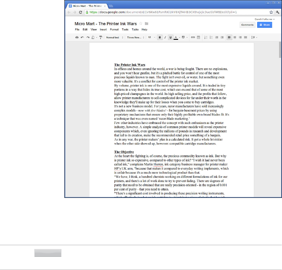
138 PART II BUILDING A MEDIA CENTRE, PRODUCTIVITY MACHINE OR WEB SERVER
F -:
Google Drive
running in
Chromium on
the Raspberry Pi
To install the Chromium browser under Raspbian, open a terminal and type the following:
sudo apt-get install chromium-browser
TIPMake sure you install the chromium-browser package, and not the chromium package—
the latter is a top-down shoot-’em-up arcade game, and although it’s fun, it won’t help you in
your quest to use cloud-based ofce suites on your Pi!

CHAPTER 9 THE PI AS A PRODUCTIVITY MACHINE 139
With Chromium installed, using a cloud-based oce suite is as simple as visiting the site,
signing up for an account—providing your credit card details in the case of premium services
like Microsoft Oce 365—and logging in. If you nd performance slow, changing the mem-
ory partitioning to give the ARM processor a larger share can help. Chapter 6, “e Raspberry
Pi Software Conguration Tool”, has full instructions for how to do this.
Using LibreOfce
If you would prefer not to use a cloud-based service, the alternative is to install LibreOce.
Designed as an open-source, cross-platform alternative to the popular Microsoft Oce suite
and based on the OpenOce.org project, LibreOce is powerful and oers just as much
functionality as its closed-source inspiration.
at functionality comes at a cost, however. e LibreOce package is large, taking up nearly
400 MB of space on the Pi’s SD card once all the dependencies are included. at can be a
problem: in its default setup, the recommended Raspbian distribution has less free space
available on the SD card than LibreOce requires. (For more information on the partition
layout of the Raspbian distribution, see the “File System Layout” section in Chapter 3, “Linux
System Administration”.)
If you want to install LibreOce, you’ll need a 4 GB or larger SD card. You’ll also need to
resize the root lesystem to make use of the SD card’s free space. For instructions on doing
this, see Chapter 6, “e Raspberry Pi Software Conguration Tool”. Make sure you perform
this task before continuing with this chapter, or you’ll nd your Pi’s SD card running out of
space before you can use LibreOce.
With enough free space on the SD card, installing LibreOce is no more complex than
installing any other package. Although it comes bundled with a great deal of additional pack-
ages, a single metapackage takes care of everything and installs the software with a single
command. Open a terminal window and type the following:
sudo apt-get install libreoffice
TIP
If you receive error messages saying les are missing when you’re installing software like
LibreOfce, the package cache is likely out of date. Run the command sudo apt-get update
to refresh the cache, and then try again. (See Chapter 3, “Linux System Administration” , for
more details.)
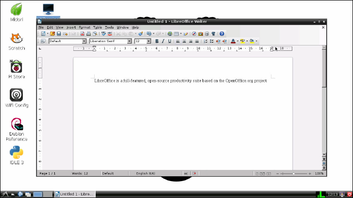
140 PART II BUILDING A MEDIA CENTRE, PRODUCTIVITY MACHINE OR WEB SERVER
When installed, LibreOce will appear as a series of entries in the Applications Menu in the
Pi’s desktop environment. ese entries are as follows:
❍ LibreOce—e main application, which provides links to the individual sections of
the suite
❍ LibreOce Calc—e spreadsheet application, equivalent to Microsoft Excel
❍ LibreOce Draw—A vector illustration application, designed for drawing high-
quality scalable images for use as clipart in other LibreOce programs
❍ LibreOce Impress—e presentation application, equivalent to Microsoft PowerPoint
❍ LibreOce Math—A small yet powerful package designed to make it easy to create and
edit scientic formulae and equations for embedding in other LibreOce programs
❍ LibreOce Writer—e word processor application, equivalent to Microsoft Word
(see Figure 9-2)
F -:
LibreOce
Writer running
on the
Raspberry Pi
By default, LibreOce saves and loads les in a format known as the Open Document Format
(ODF). is is a standards-based, royalty-free le format supported by the majority of oce
suite packages—including newer versions of Microsoft Oce.
When saving a le in LibreOce, you can change the format using a drop-down menu in the
Save As dialogue. Under File Type, you can select a variety of formats, including several that are
fully compatible with older versions of Microsoft Oce. When you’re sharing les created on
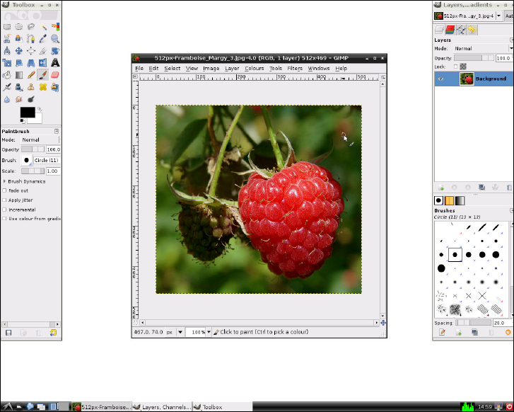
CHAPTER 9 THE PI AS A PRODUCTIVITY MACHINE 141
the Pi in LibreOce with users of older software, remember to change the format to ensure
that everyone can open the les. Alternatively, you could convince them to install LibreOce
themselves, which is available free for Linux, Windows and OS X.
Image Editing with The Gimp
LibreOce is a powerful piece of software, but one area where it lacks is in image editing.
Although LibreOce Draw is a powerful tool for illustrative work, unfortunately, you can’t
use it to touch up digital photographs. ese are known as bitmapped images, and are very
dierent to the vector images Draw is designed to edit.
For image editing, one of the most powerful tools available for Linux is the GNU Image
Manipulation Program, usually referred to as e Gimp. e Gimp is one of the most popular
projects in open source, because it oers powerful features for editing bitmapped images
with a user interface that is similar to the interface that’s used by the commercial Adobe
Photoshop package (see Figure 9-3).
F -:
e Gimp
running on the
Raspberry Pi
142 PART II BUILDING A MEDIA CENTRE, PRODUCTIVITY MACHINE OR WEB SERVER
e Gimp is not installed by default in most Raspberry Pi distributions, so you’ll have to con-
nect your Pi to the Internet and install it through the package management system (see
Chapter 3, “Linux System Administration”, for details). e Gimp takes up quite a lot of
space on the SD card—although not as much as LibreOce—so make sure you have enough
free space before installing it.
To install e Gimp, open a terminal window and type the following:
sudo apt-get install gimp
e Gimp can take a little while to get used to, because its user interface uses three dierent
windows rather than just one. By default, the window on the left contains the Toolbox; the
window on the right displays the Layers, Channels and Gradients options; and the middle
window displays the image you’re currently editing. If you open more than one image, you’ll
get more than one main window—but still only one each of the Toolbox and the Layers,
Channels and Gradients windows.
By default, e Gimp User Manual is not installed. For the Pi, this is a good thing: the Gimp is
a powerful tool, and its user manual takes up a not inconsiderable amount of space on the
SD card. If you try to access the manual by pressing the F1 key or choosing Help from the
Help menu, you’ll be prompted to read an online, web-based version instead. Click the Read
Online button to open the user manual in your browser.
e Gimp is a very powerful utility and uses a lot of memory. As a result, it runs relatively
slowly on the Raspberry Pi—although it is denitely usable. Be patient with it, especially if
you’re opening large photographs from a digital camera. It may help to increase the amount
of system memory available (see Chapter 6, “e Raspberry Pi Software Conguration Tool”,
for more details on how this is achieved).
When saving les in e Gimp, you can use a variety of le formats. If you’re planning on
coming back to the le and doing more editing, you should use e Gimp’s default XCF le
format. is keeps important metadata intact, uses lossless compression to maximise image
quality and supports images comprised of multiple layers.
If you’re planning on uploading your image to the Internet or otherwise sharing it with oth-
ers, a more portable format like JPG or PNG is recommended. To change the format of the
le, choose the Export option from the File menu rather than the Save option (see Figure
9-4). is allows you to choose the le format from a wide variety of le types.
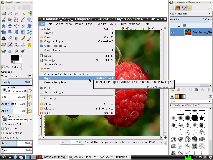
CHAPTER 9 THE PI AS A PRODUCTIVITY MACHINE 143
F -:
Exporting a le
from e Gimp
Chapter 10
The Pi as a Web Server

146 PART II BUILDING A MEDIA CENTRE, PRODUCTIVITY MACHINE OR WEB SERVER
ALTHOUGH THE PI is signicantly less powerful than most devices you would nd in a
data centre, that doesn’t mean that it can’t act as a useful server in a home or business envi-
ronment. Despite a small amount of memory and relatively underpowered processor, the
Pi’s low power draw and silent running makes it a great choice for serving low-trac simple
pages to a local network or even out onto the Internet.
A large proportion of modern web servers run a combination of Linux, Apache, MySQL
and PHP—commonly referred to as a LAMP stack. Linux provides the underlying operating
system; MySQL the database back-end; Apache the web server; and PHP a scripting language
for dynamic pages. Using a LAMP-based server, you can run some quite complex packages
ranging from content management systems like WordPress to interactive forums like phpBB.
All of this is possible with the Raspberry Pi, so long as you don’t expect performance similar
to that of a powerful commercial server.
TIPWeb servers work best with plenty of memory. To ensure maximum performance, switch the Pi’s
memory partitioning to reserve just 16 MB or 32 MB for the GPU (see Chapter 6, “The Raspberry
Pi Software Conguration Tool”) and don’t run a graphical user interface (GUI) at the same time.
Installing a LAMP Stack
If you’re running the recommended Raspbian distribution for the Raspberry Pi, you’re already
one-quarter of the way to having a fully operational LAMP stack—specically, you’ve already got
the Linux portion installed. e next step is to install the missing components: Apache, MySQL
and PHP. At the terminal or console, type the following commands to install these packages:
sudo apt-get update
sudo apt-get install apache2 php5 php5-mysql mysql-server
is will prompt the apt package manager (see Chapter 3, “Linux System Administration”)
to nd a number of dependencies required to get a fully functional LAMP stack running (see
Figure 10-1). ese packages and their dependencies take up a lot of room on the Pi’s SD
card—around 113 MB in total—so if you haven’t resized the root partition on the SD card,
turn to Chapter 6, “e Raspberry Pi Software Conguration Tool”, for instructions on how
to expand the root partition.
Installation of the full LAMP stack can take quite some time on the Pi. Don’t panic if the
system appears to freeze for a minute or two; the installation should continue normally
after. Partway through the installation process, MySQL will prompt you for a password (see
Figure 10-2). Make sure you pick a secure password, as this protects the MySQL database—
which, depending on what your web server is designed to do, can store user names, payment
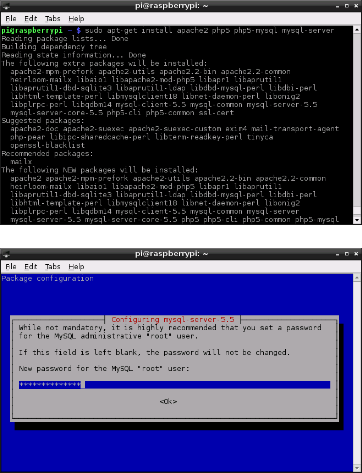
CHAPTER 10 THE PI AS A WEB SERVER 147
details and other personally identiable information. Also make sure you pick a password
you can remember! You’ll be asked to conrm the password—to check for typing errors—
and then the installation will continue.
Figure 10-1:
Installing the
LAMP stack on
Raspbian
Figure 10-2:
Choosing a
password for
MySQL
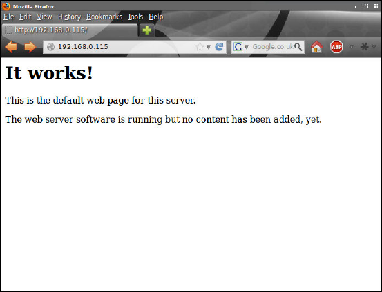
148 PART II BUILDING A MEDIA CENTRE, PRODUCTIVITY MACHINE OR WEB SERVER
When the software installation has nished, both the MySQL and Apache servers—known
in Linux parlance as daemons—will be running in the background. To check that the server is
working correctly, use another computer on the network to connect to the Raspberry Pi
using a web browser. In the address bar, type the IP address of the Pi to display the default
Apache installation page (see Figure 10-3). If you’re not sure what IP address the Pi is using,
type ifconfig at the terminal and look for the IP address listed in the eth0 section, or the
section corresponding to the network adapter in use on your Pi if you’re not using the Model
B’s built-in Ethernet port. For more information on checking and adjusting network settings
on the Pi, see Chapter 5, “Network Conguration”.
Figure 10-3:
Connecting to
the Pi’s Apache
server using a
web browser
e nal step is to conrm that the PHP scripting module is loaded correctly in Apache. is
module is important: because it allows the Apache web server to run PHP scripts to serve
dynamic content. Without a working PHP module—or an alternative module for another
scripting language like Python—Apache is only able to serve static pages. To test the Apache
PHP module, create a new PHP script le using the following command, typed as a single line:
sudo sh -c ‘echo “<?php phpinfo(); ?>” > ↵
/var/www/phptest.php’
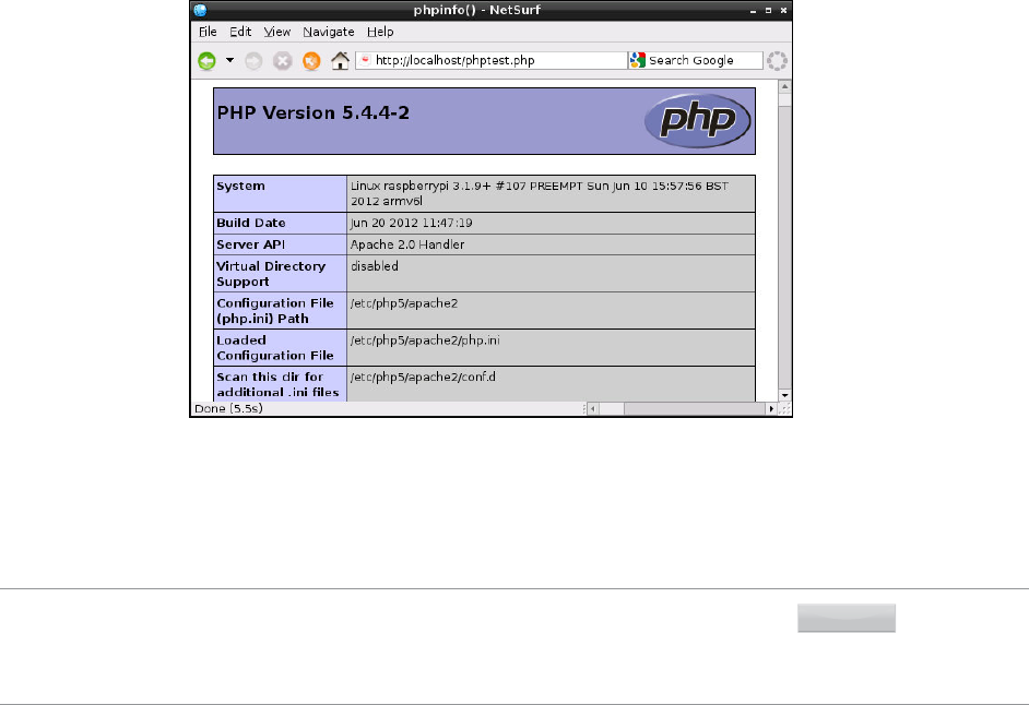
CHAPTER 10 THE PI AS A WEB SERVER 149
is command creates a new le called phptest.php in the /var/www directory. is le
tells PHP to create an information page for diagnostic purposes. Visit this using either a
browser on another computer by typing http://ipaddress/phptest.php (replacing
ipaddress with the IP address of the Raspberry Pi) or on the Pi itself by typing http://
localhost/phptest.php into the address bar (see Figure 10-4).
Figure 10-4:
Testing Apache’s
PHP module on
the Raspberry Pi
When you’ve nished testing, remove the phptest.php le with the following command:
sudo rm /var/www/phptest.php
TIP
Although Apache is the most common web server, there are others. If you nd the performance
of Apache too slow, experiment with lighttpd—a lightweight web server designed to use less
memory than Apache. It can be installed under Raspbian with the command sudo apt-get
install lighttpd.
With the LAMP stack installed and working, you can now create your own websites that will
be served by the Pi. As long as the sites aren’t too complex, and don’t receive too many simul-
taneous users, the Pi should be able to cope with the task admirably—and the device’s small
size and extremely low power draw more than make up for any slowdown should your site
become popular.
150 PART II BUILDING A MEDIA CENTRE, PRODUCTIVITY MACHINE OR WEB SERVER
By default, les for the web server are stored in the /var/www folder, which is writeable only
by the root user. To adjust where Apache looks for its les—to move the website onto more
capacious external storage, for example—edit the text le 000-default found in the folder
/etc/apache2/sites-enabled. For more information on conguring Apache, PHP and
MySQL, type the following commands at the terminal or console:
man apache2
man php5
man mysql
Installing WordPress
One of the most popular blogging platforms around, WordPress is an open-source project
that aims to give users a simple yet powerful platform to create attractive, interactive web-
sites. WordPress is built on a base of PHP and JavaScript, and oers an attractive web-based
interface for creating rich websites. For example, some of the most popular news sites in the
world are built on a customised WordPress platform.
To install WordPress on the Raspberry Pi, type the following command at the terminal or console:
sudo apt-get install wordpress
Like the LAMP stack, WordPress comes with a selection of dependencies (see Figure 10-5).
You’ll need to make sure you have around 37 MB of free space on the Pi’s SD card for the full
installation, in addition to the 113 MB required for the LAMP stack. If you have enough free
space, type Y to continue the installation process.
When WordPress has nished installing, its default installation directory—/usr/share/
wordpress—needs to be linked into the /var/www directory in order for Apache to see the
les. Type the following command at the terminal:
sudo ln -s /usr/share/wordpress /var/www/wordpress
Linking a le or directory is dierent to moving: the les for WordPress now exist in both /
usr/share and /var/www simultaneously, without taking up any extra space on the Pi’s
SD card. If you’ve told Apache to use a dierent directory for the default website, change the
linking command accordingly. Next, run the WordPress MySQL conguration script using
the following command, typed as a single line:
sudo bash /usr/share/doc/wordpress/examples/setup-mysql ↵
-n wordpress localhost
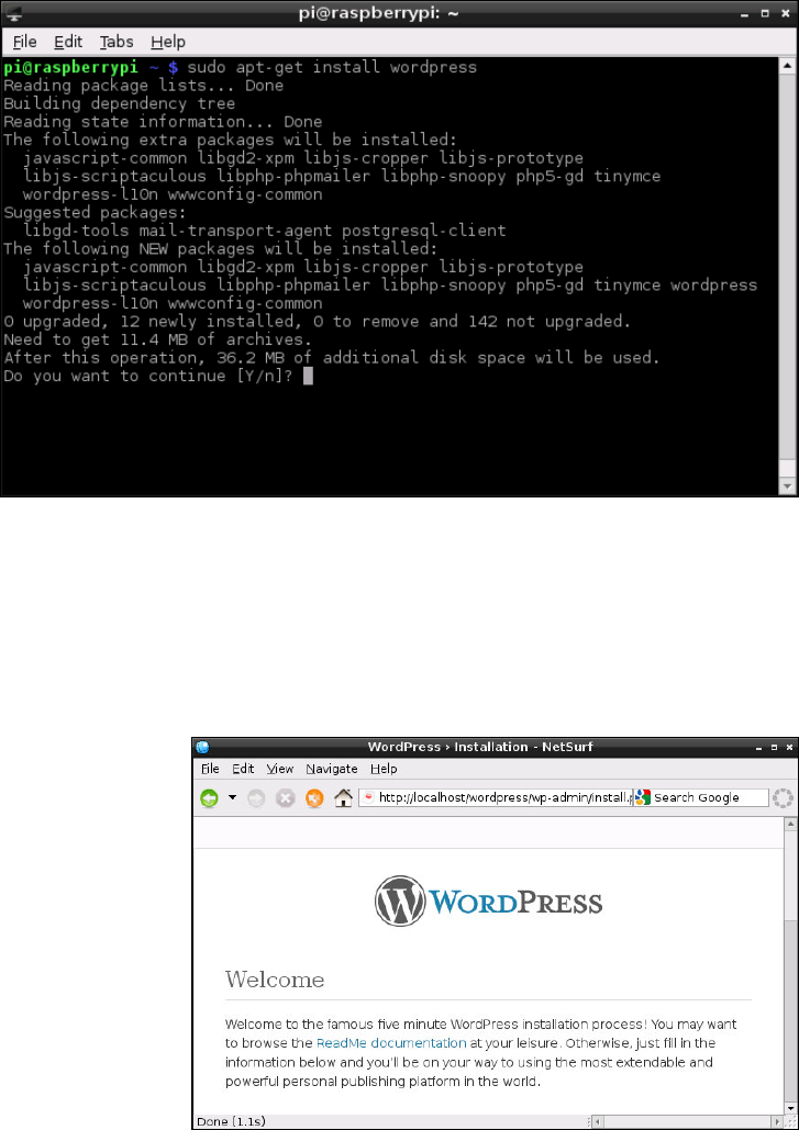
CHAPTER 10 THE PI AS A WEB SERVER 151
Figure 10-5:
Installing
WordPress on
the Raspberry Pi
is adds a new database into MySQL, installed as part of the LAMP stack, for WordPress to
use. is database stores your user accounts, posts, comments and other details. Once this
script has completed, you’ll be told to visit http://localhost in a browser on the
Raspberry Pi to continue the installation. is instruction is slightly incorrect: the address
you need to visit to nish the WordPress installation is http://localhost/wordpress
(see Figure 10-6).
Figure 10-6:
Conguring
WordPress in
the NetSurf web
browser

152 PART II BUILDING A MEDIA CENTRE, PRODUCTIVITY MACHINE OR WEB SERVER
Fill in the form that loads in the web browser, picking a descriptive name for your site and
setting a secure—but memorable—password for your user. Be sure to change the Username
eld from admin to something else in order to make it more secure. When you have lled in
all the elds, click the Install WordPress button at the bottom of the page.
e installation process will take a minute or two to complete, and then a new page conrm-
ing the successful installation of WordPress will load in the browser. To start using
WordPress, click the Log In button at the bottom of this page to log into WordPress with the
user name and password you chose at the earlier screen (see Figure 10-7).
Figure 10-7:
Logging in to
WordPress on
the Raspberry Pi
Before you can access WordPress from another computer, you’ll need to create an additional
conguration le. is is created by linking the existing conguration le—set up for local
access—using the following command, typed as a single line:
sudo ln -s /etc/wordpress/config-localhost.php ↵
/etc/wordpress/config-ipaddress.php
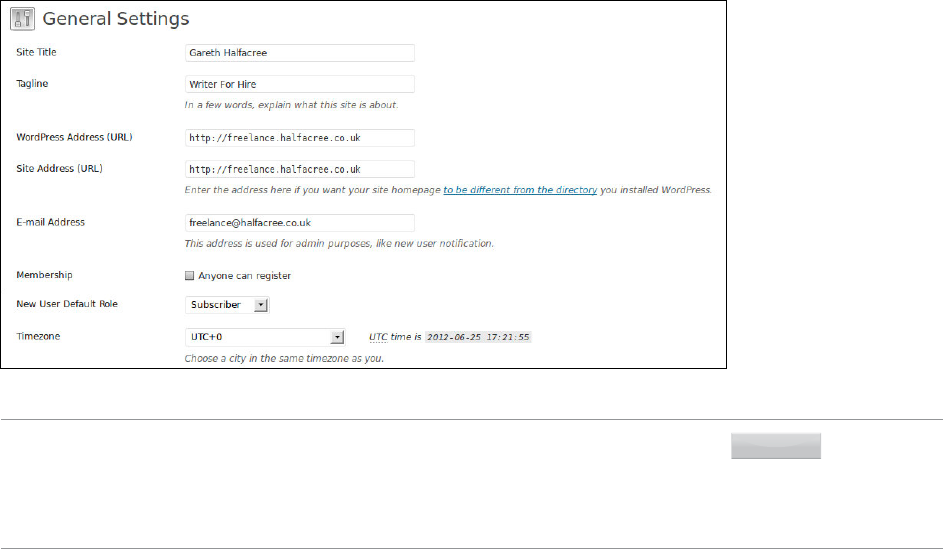
CHAPTER 10 THE PI AS A WEB SERVER 153
Replace ipaddress in this code with the IP address of your Raspberry Pi. If you’ve given the
Raspberry Pi a hostname in DNS, you can also create a conguration le for that hostname
using the same command, but replacing ipaddress with the chosen hostname. If you do
not have a hostname, simply use the Pi’s IP address. For example, the command for a Pi on
IP address 192.168.0.115 would be as follows:
sudo ln -s /etc/wordpress/config-localhost.php ↵
/etc/wordpress/config-192.168.0.115.php
To complete conguration for external access, choose General from the Settings menu that’s
located on the left side of the WordPress Dashboard, and change the URL to match either
the IP address of the Pi or the chosen hostname (see Figure 10-8).
Figure 10-8:
Altering the
URL in the
WordPress
General Settings
menu
TIP
WordPress is very memory intensive. For best results, use the Pi as a headless server, which
is a system that runs without a graphical user interface loaded. Then use a web browser on
another computer connected to the network to access the WordPress Dashboard at http://
ipaddress/wordpress/wp-login.php. Accessing the WordPress Dashboard directly on
the Pi can result in a very long wait!
154 PART II BUILDING A MEDIA CENTRE, PRODUCTIVITY MACHINE OR WEB SERVER
e WordPress software includes an automatic update feature, which ensures that your
installation is running the latest version. Because of its popularity, WordPress is often the
target of malware attacks, and frequent updates are released to patch security holes or add
new features. However, when installed via APT, WordPress lacks the permissions required to
keep itself up-to-date. To correct this, type the following command at the terminal:
sudo chown -R www-data /usr/share/wordpress
is gives the www-data user—the account used by the Apache web server—the rights to
change les located in the /usr/share/wordpress folder. is will allow automatic
upgrading to operate when chosen from the WordPress Dashboard.
For more information on using WordPress, visit the ocial website at http://www.
wordpress.org.
Part III
Programming
with the
Raspberry Pi
Chapter 11 An Introduction to Scratch
Chapter 12 An Introduction to Python
Chapter 11
An Introduction to Scratch
PART III PROGRAMMING WITH THE RASPBERRY PI
158
SO FAR IN this book, you’ve learned a lot about how to use programs that other people have
written on your Raspberry Pi. e chief goal of the Raspberry Pi project is to get people writ-
ing their own programs, however—and not just adults. e Raspberry Pi Foundation is
working to get the device adopted as an educational tool for all age ranges.
A key requirement for reaching that goal is ensuring that young children can experience the
joy of creating their own software, rather than just consuming other people’s code. e secret
to this is Scratch.
Introducing Scratch
Created by the Lifelong Kindergarten group at the Massachusetts Institute of Technology
Media Lab in 2006 as an oshoot of the Squeak and Smalltalk languages, Scratch takes the
core concepts of programming and makes them accessible to all. Long-winded typing—tiring
and dull for younger children—is replaced with a simple jigsaw-like drag-and-drop environ-
ment, which nevertheless encourages programmatic thinking and introduces the core con-
cepts used by all programming languages.
Ocially considered a program for ages eight and above, but accessible to even younger pro-
grammers with a little help and guidance, Scratch is deceptively powerful. Behind its colour-
ful and mouse-driven user interface is a programming language that includes impressive
multimedia functionality. It should come as no surprise then that, of the more than two-
and-a-half million Scratch projects shared by users of the software on the ocial website, the
majority are games.
Encouraging children to learn how to make their own games can be a great way of sneaking a
little learning into their playtimes. Scratch’s friendly user interface and excellent handling of
core concepts mean that children are unlikely to get frustrated by a sudden steep learning
curve. Better still, the concepts learned in Scratch oer an excellent foundation for progres-
sion to a more exible language like Python (see Chapter 12, “An Introduction to Python”).
Even before moving on to another language, Scratch oers more than just a framework for
games. It can be used to create interactive presentations and cartoons, as well as interfaces
with external sensors and motors through the use of add-on hardware such as the PicoBoard
and the LEGO WeDo robotics kit.
e recommended Raspbian distribution for the Raspberry Pi comes with the latest version
of the Scratch development environment pre-loaded, so if you’ve been following the recom-
mendations throughout this book you’re ready to start. If you’re using a dierent operating
system, visit the ocial Scratch website at http://scratch.mit.edu to download the
software—and you can nd versions for Windows and Apple’s OS X in the same place.
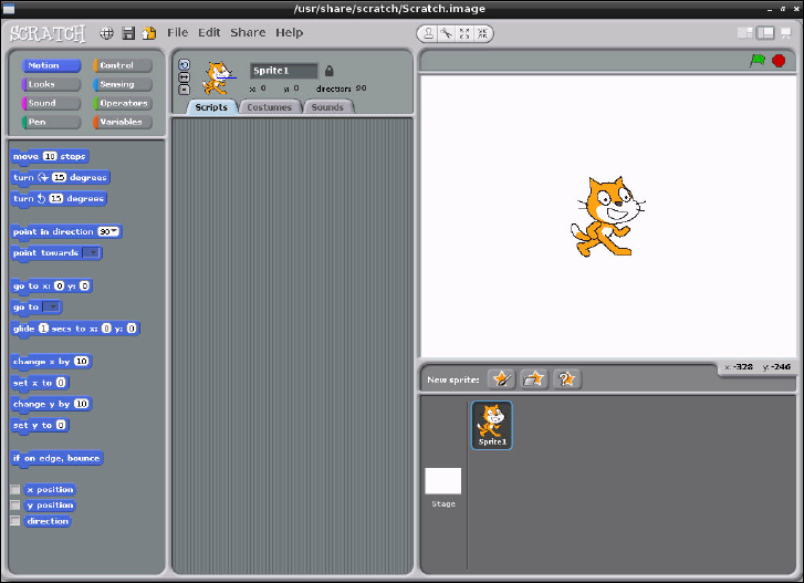
CHAPTER 11 AN INTRODUCTION TO SCRATCH 159
Example 1: Hello World
When learning a new programming language, it’s traditional to start with a very basic pro-
gram: one that displays a single line of text. is is typically referred to as a Hello World
program, and it’s the rst step towards learning how to create your own programs.
Unlike a traditional programming language, Scratch doesn’t expect the user to memorise the
names of instructions like print or inkey$. Instead, almost everything is done by dragging
and dropping blocks of code and arranging them into a logical pattern.
To begin, load Scratch by double-clicking its icon on the desktop or clicking on its entry in
the Programming menu. After a few seconds, the main Scratch interface will appear (see
Figure 11-1). If it’s o-centre or small, click the Maximise button—the middle of the three
window control buttons on the right side of the top title bar—to ll the screen.
F -:
e main
Scratch
interface, shown
running on the
Raspberry Pi
e Scratch interface is split into multiple panes. At the left is the block palette, which holds all
the dierent code blocks you can use to create a program. A list of objects in the program,
known as sprites, appears at the bottom-right along with a control for the stage on which the
sprites appear. e stage itself is at the top-right of the window, which is where you will see the
program running. Finally, the middle of the window is where the program itself is constructed.
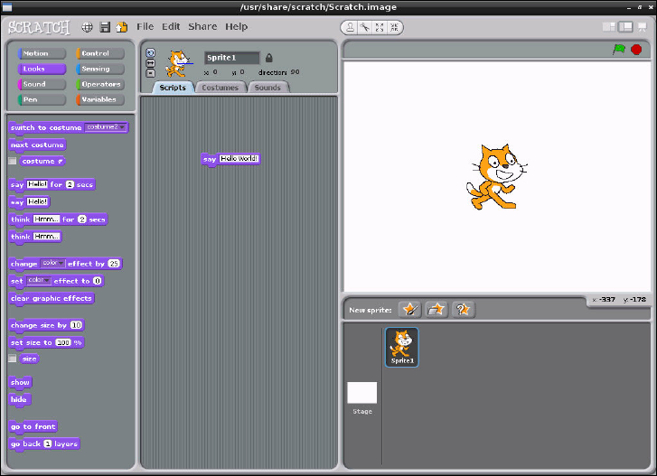
PART III PROGRAMMING WITH THE RASPBERRY PI
160
To get the user started, a new Scratch project already includes a blank stage and a single
sprite. What it lacks is a program, so clicking the green ag icon at the top-right of the win-
dow achieves nothing, because Scratch doesn’t yet know what you want it to do.
For the Hello World program, you’ll need to change the blocks palette at the left of the screen
to the Looks mode by clicking on its button. Partway down the list of Looks blocks is one
that reads say Hello!—click this block and drag it into the empty space in the middle of
the window labelled Scripts. To obey the decades of tradition behind this type of program,
you can also click on the block where it says Hello! and customise it to read Hello World!
if you so desire (see Figure 11-2).
F -:
e rst block
placed in a
Scratch program
If you click the green ag again, the program still does nothing. at’s because although
Scratch knows that it is supposed to make the cat sprite say something, it doesn’t know
when. e event requires a trigger block, which can be found in the Control section of the
block palette.
Enter this section now by clicking Control, and then drag the top entry—marked when
[flag icon] clicked—and place it just above the purple say brick (see Figure 11-3). If
you drop it close enough, it should automatically join to the existing brick like a jigsaw piece.

CHAPTER 11 AN INTRODUCTION TO SCRATCH 161
F -: A
Control block
joined to a
Looks block in
Scratch
is concept of connecting multiple bricks together is the heart of Scratch. If you look at the
Control brick you just placed, you’ll see there’s no connecting hole at the top. is means
that you can’t stack another brick on top, because this Control brick is designed to trigger a
series of other bricks directly and must come at the start of a stack. e bottom of the say
brick, meanwhile, has a connector that ts into the top of other bricks, which indicates that
more bricks can be placed underneath.
With the two bricks in place, click the green ag icon at the top-right of the screen again. is
time, a speech bubble will appear from the cat’s mouth (see Figure 11-4), and the Hello
World program is complete.
Before moving on to the next example, take the time to save your work using the File menu.
Scratch is designed to have a single project open at a time, so if you create a new blank le,
the current le will be closed to make room. Don’t worry if you forget about this when you go
to create a new le—if there are unsaved changes in the existing le, Scratch will prompt you
to save these changes before closing it.
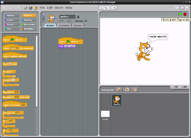
PART III PROGRAMMING WITH THE RASPBERRY PI
162
F -:
e Hello World
program
executing in
Scratch
Example 2: Animation and Sound
While Hello World is a very traditional example, it’s not particularly interesting. It also fails
to show o the true power of Scratch, which lies in its impressive multimedia capabilities
and sprite-handling system. is system is particularly well suited to simple animations,
which can form the basis of an interactive game.
To begin, start a new project in Scratch by either loading the program afresh or choosing
New from the File menu. As with any starter project, Scratch will provide a default sprite—
it’s this sprite that you will be controlling.
To control a simple animation in Scratch, you use the Motion section of the blocks palette.
When you start a new project, this is the default palette. Drag the block labelled move 10
steps to the Scripts area. As its name suggests, this block tells the selected sprite to move
10 steps in the direction it is currently facing. e default sprite in Scratch is always started
facing directly to the right—thus, the move 10 steps block will move the sprite 10 steps
to the right.
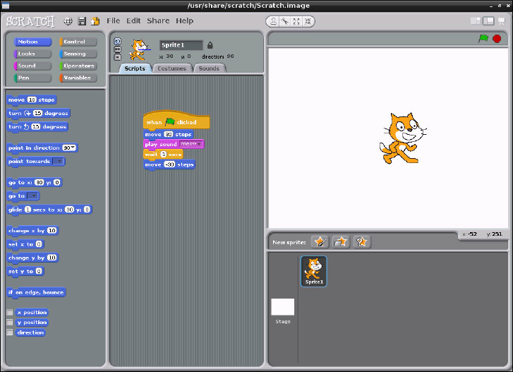
CHAPTER 11 AN INTRODUCTION TO SCRATCH 163
Ten steps isn’t a very large value, so click on the value 10 and change it to 30. e block
should then read move 30 steps. An animation of a cat moving to the right of the stage
isn’t that interesting, however, so switch to the Sound block palette and drag the play
sound meow block to the Scripts area and link it beneath the existing move block. To keep
the cat in this position for a while, add in a wait 1 secs block from the Control block pal-
ette. Without this, the sprite will appear to ick quickly between its starting position and the
target position.
To make it so the program can be run multiple times without the cat sprite disappearing o
the edge of the stage, add another move 10 steps block beneath the play sound block
and modify it to read move -30 steps. Scratch will happily allow you to use negative g-
ures like this: if a value of 30 makes the sprite move a certain distance to the right, -30 will
make it move the exact same distance in the opposite direction.
Finally, add the when [flag icon] clicked block from the Control block palette to the
top of the Script area’s stack of blocks to complete the program as shown in Figure 11-5.
Clicking the green ag icon on the top-right of the screen will trigger the program—make
sure you’ve got speakers or headphones connected to the Pi for the full eect!
Figure 11-5:
e completed
animation
program in
Scratch
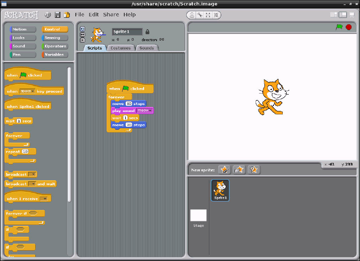
PART III PROGRAMMING WITH THE RASPBERRY PI
164
is simple animation program can be extended in a variety of ways. Using the New Sprite
option just below the stage on the right side of the Scratch window allows the programmer to
add more sprites that can move and play sounds independently. Adding in the say block
from the rst example—or the similar think block, which creates a thought bubble rather
than a speech bubble—allows for the creation of an animated comic strip.
More importantly, even this simple example teaches important programming concepts:
despite being a mere ve blocks long, it covers sprite movement in positive and negative
distances, sound playback and the concept of delays in a program. To introduce yet another
concept—at the risk of driving yourself insane with repetitive noises—try adding a for-
ever block from the Control block palette (see Figure 11-6). is adds a loop to the program,
causing it to run through its list forever—or at least until the noise becomes too much and
you click the red stop button at the top of the stage!
Figure 11-6:
Adding an
innite loop to
the simple
Scratch
animation
CHAPTER 11 AN INTRODUCTION TO SCRATCH 165
Example 3: A Simple Game
Using Scratch for simple animation is one thing, but the software also allows users to read
inputs from the keyboard to introduce interactivity. By combining some simple animation
controls to the previously described program, you can create a simple game—and, at the
same time, introduce the concepts of sprite collision, if statements and input.
For this example, start a new Scratch project—remembering to save the previous example, if
you haven’t already done so—and begin by dragging a move 10 steps block to the Scripts
area. is time, rather than telling the code blocks to execute when the ag icon is clicked, go
to the Control block palette and drag a when space key pressed block above the move
block.
As the name suggests, the when space key pressed block looks for input from the
user—in this instance, the spacebar being pressed—and uses that as the trigger for execut-
ing a list of blocks. e block works at any time—if you press the spacebar now, the sprite
will obey its instructions and move 10 steps to the right.
e when space key pressed block also diers from the when [flag icon] clicked
block in another important way: it can be customised. Click the down-arrow button next to
the word space to see a list of all the keys the block can watch, and then select right
arrow from the list to change the block into a when right arrow key pressed block.
A game in which the player can move in only one direction isn’t much fun, so drag a new
when space key pressed block into the Scripts area. is can’t link to the existing block
list—you can only have a single trigger block—so start a new list somewhere further down.
As before, use the down-arrow button next to the word space to customise the block, turn-
ing it into a when left arrow key pressed block. Finally, switch the block palette back
to Motion mode and connect a move 10 steps block beneath the new when left arrow
key pressed block before changing it to read move -10 steps.
If you press the left and right arrow keys now, you’ll see that the cat moves according to your
input (see Figure 11-7): pressing the left arrow moves the cat 10 steps to the left (although,
as far as Scratch is concerned, it’s moving minus 10 steps to the right), and pressing the right
arrow moves the cat 10 steps to the right.
Now that the sprite can be moved by the player, it’s time to give the sprite something to do.
As this is just a very simple game, the goal should also be simple: to collect some food. Click
the Choose New Sprite From File button, found in the middle of the three buttons above the
Sprite palette at the bottom-right of the Scratch window.
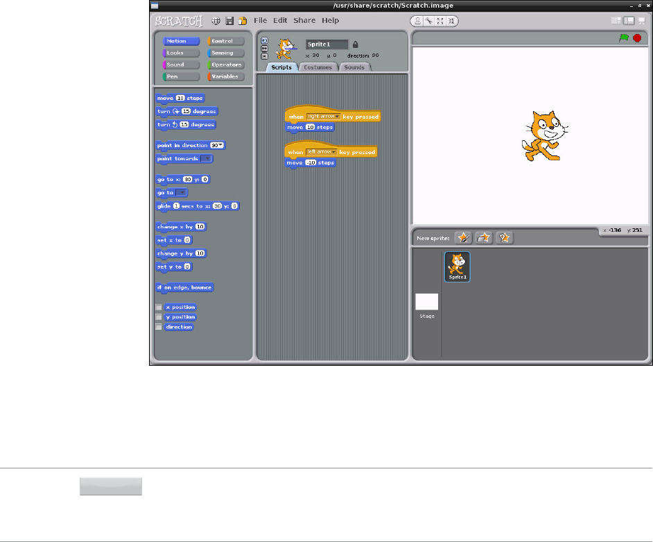
PART III PROGRAMMING WITH THE RASPBERRY PI
166
F -:
Using input
blocks to control
the motion of a
sprite in Scratch
A dialogue box will appear asking you to pick a sprite: double-click on the ings folder, and
then double-click on the Cheesy-Pus sprite (shown in Figure 11-8). is will place the sprite
as a new entry in the Sprite palette, giving you a new object to control in the game.
TIPThe Scratch language is naturally multi-threaded and partially object-oriented. This means that
each object in the program, including sprites, can have its own code attached, and that each
section of code runs simultaneously and independently of any other block. Used properly,
these features enable you to create some quite complex programs.
By default, any sprite added into a Scratch project will appear in the dead centre of the stage.
As a result, this obscures the existing cat sprite. Click on the new sprite and drag it to the
right of the cat to x the problem.
With the bowl of Cheesy-Pus moved, it’s still too large for our anthropomorphic two-legged
cat to eat. Click the Shrink Sprite button, which is located at the top-right of the stage area
and looks like four arrows pointing inwards. If you’re not sure which one it is, hover the
mouse pointer over each icon for a short description of what it does.
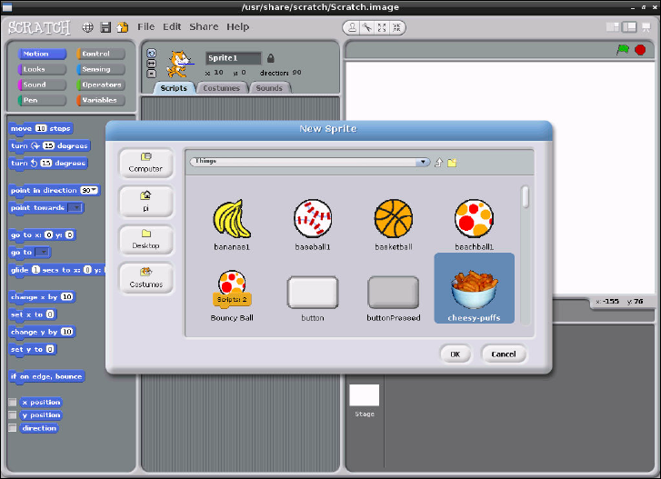
CHAPTER 11 AN INTRODUCTION TO SCRATCH 167
F -:
Adding the
Cheesy-Pus
sprite to the
Scratch game
project
Clicking the Shrink Sprite button—or the Grow Sprite button, which does exactly the oppo-
site—changes the mouse cursor into a duplicate of the button’s icon. Using this new cursor,
click on the Cheesy-Pus sprite to shrink it. Keep clicking, and the sprite will continue to
shrink. Once it’s a sensible-looking size, click anywhere outside of the stage area to return
the mouse cursor to normal. You can then drag the bowl closer to the right edge of the stage,
if you so choose.
Try using the arrow keys on the keyboard to move the cat sprite towards the Cheesy-Pus sprite
now. As you can see, when the two sprites meet, nothing happens. at’s because the program
doesn’t contain any instructions for what to do when the two sprites overlap—known as a sprite
collision—so it doesn’t do anything. is can be rectied with a new type of block: a Sensing block.
With the Cheesy-Pus sprite currently active (its image should appear at the top of the
Scripts pane, but if it doesn’t, just double-click the sprite on the stage), switch the Blocks
palette into Sensing mode by clicking the Sensing button. From the Sensing palette, drag a
touching ? block into the Scripts pane.
Like the when space key pressed block used to control the cat sprite’s motion, the
touching ? block can be customised. Click the down-arrow button next to the question

PART III PROGRAMMING WITH THE RASPBERRY PI
168
mark, and choose Sprite1 (the cat sprite) from the list. is block will now be activated when
the two sprites collide.
TIPYou can name a sprite by clicking on the box next to its image in the Scripts pane and typing
in a name. Giving the sprites sensible names—such as Cat, CheesyPuffs, and so forth—
makes it signicantly easier to track what’s going on in the program.
Look at the shape of the touching Sprite1? block. As you can see, it has no jigsaw-like
connectors on the top or the bottom, and it’s shaped like a diamond—the same shape used
for a decision point in a owchart. at’s no accident: the majority of the Sensing blocks
need to be embedded in a Control block in order to operate.
Switch the Blocks palette to Control mode, and look for the if block—it’s shaped like a
squished and bumpy letter C. Note that the if block has a diamond-shaped indentation—
the same shape as the touching Sprite1? block. Drag the if block onto the Scripts pane,
and then drag the touching Sprite1? block onto its diamond-shaped indentation. e
result is a two-coloured block that now reads if touching Sprite1?.
is represents an if conditional in the program: when this point is reached, any code located
within its connes will be executed if and only if the condition is met. In this case, the condi-
tion is that Sprite2 is being touched by Sprite1. With the use of and, or and not logic blocks
from the Operators block palette, some quite complex scenarios can be accommodated.
Boolean Logic
Named for George Boole, Boolean logic or Boolean algebra is a key concept to understand-
ing how computers work. In Scratch, Boolean logic is implemented in three Operators
bricks: and, or and not.
The and operator requires that two inputs—in Scratch’s case, Sensing blocks—are both
true before its own output will be true. If either or both of its inputs is false, its own output
will be false; only when both inputs are true will the output be true. You can use this opera-
tor to check to see if a sprite is touching two other sprites, as an example.
The or operator requires that one or the other of its two inputs are true. If either input is
true, the operator’s output will also be true. This is a handy way of re-using code: if you have
multiple sprites that are lethal to the player sprite, a single block of code can be used with
the or operator to trigger when any of the enemy sprites are touched.
Finally, the not operator is known as an inverter: whatever its single input is, it outputs the
opposite. If its input is false, then the output is true; if the input is true, then the output is false.
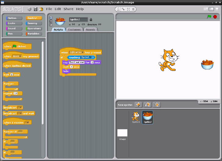
CHAPTER 11 AN INTRODUCTION TO SCRATCH 169
From the Looks block palette, drag a say Hello! For 2 secs block into the centre of the
if touching Sprite1? conditional. Change the text to read Don’t eat me!, and then
add a wait 1 secs Control block, changing the value to 2. Add a when space key
pressed block to the top, changing the value to read when right arrow key pressed.
Finally, drag a hide block from the Looks palette to the bottom of the loop to end up with
the block list that’s shown in Figure 11-9.
F -:
Controlling the
Cheesy-Pus
with a Scratch
if block
Double-click the cat sprite on the stage to return to editing its scripts. e script you created
for the Cheesy-Pus sprite will disappear, but don’t worry—it’s still saved but only appears
when you’re editing that particular sprite.
Drag another if block from the Control palette along with another touching ? sensing
block, and this time, change the Sensing block so both blocks together read if touching
Sprite2?. Into this block, insert a wait 1 secs Control block with the value changed to
2 and a say Hello! for 2 secs Looks block with the message changed to read Yum-
yum-yum!. Finally, drag the whole stacked block up so it connects to the bottom of the
existing when right arrow key pressed block, beneath the move 10 steps block.
e nal code for the cat sprite should look like the blocks in Figure 11-10.
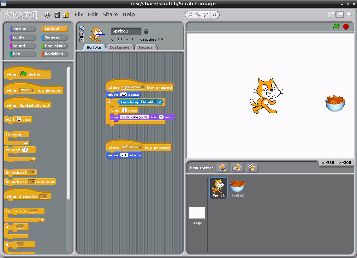
PART III PROGRAMMING WITH THE RASPBERRY PI
170
F -:
e completed
code for the
simple Scratch
game’s cat sprite
If you move the cat towards the Cheesy-Pus with the right-arrow key on the keyboard, the
game starts. When the cat reaches the Cheesy-Pus, the dialogue exchange takes place and
the bowl should disappear.
Although this example is eective for introducing some important programming concepts,
it’s hardly the best way the game could be coded. Scratch includes a message broadcast system
that allows code attached to one object to communicate with code attached to another,
which enables you to create much neater collision results that don’t rely on carefully timed
pauses in order to make sense.
To experiment with broadcasting, try using the broadcast and when I receive blocks
from the Control palette. A message created for a broadcast block in any object can trigger
code in any other object using the when I receive ag, meaning you can use it to link
multiple objects and their code together.
CHAPTER 11 AN INTRODUCTION TO SCRATCH 171
Robotics and Sensors
In addition to purely software-based inputs and outputs, it’s also possible to tie Scratch into
external hardware using sensor boards and robotics systems. anks to its multithreaded
nature and powerful inter-process messaging system, Scratch can be used to create a surpris-
ingly advanced robotics engine and is by far the easiest way to place a Raspberry Pi at the
heart of a simple robot.
Unlike Python, which is a more powerful but signicantly more complex programming lan-
guage, Scratch can’t make use of the Raspberry Pi’s GPIO port to communicate with external
hardware. As a result, it needs some additional equipment before it can interact with the
physical world.
Sensing with the PicoBoard
Designed by the SparkFun electronics company, the PicoBoard is an add-on module that
connects to a computer running Scratch and provides a variable slider input, a light sensor, a
button, a sound sensor and four pairs of alligator clips that can be used to monitor external
electrical devices.
ere are currently two types of PicoBoard: the original model, which uses a serial connec-
tion, and its replacement, which uses a USB connection. e latter is supported by the
Raspberry Pi. Simply connect it to a free USB port or a port on a USB hub connected to the
Pi, restart Scratch, and you’ll be able to use its various functions within the Scratch interface.
Details on the PicoBoard can be found at http://www.sparkfun.com/products/
10311.
Robotics with LEGO
In addition to add-in sensor modules, it’s possible to control an external robotics system
through Scratch. e LEGO Education WeDo robotics kit is designed to connect motors,
distance sensors and speed sensors to a computer—all of which can be controlled using spe-
cialised blocks found in Scratch.
For children, the WeDo kit is an excellent way to get started with robotics: the components
clip together just like regular LEGOs, and there are no risks of receiving an electric shock
should anything be badly connected. e WeDo kit boasts compatibility with regular LEGO
and LEGO Technik kits, too, meaning it’s possible to build large projects quickly and easily.
More information on using a LEGO Education WeDo kit with Scratch can be found at
http://info.scratch.mit.edu/WeDo.
PART III PROGRAMMING WITH THE RASPBERRY PI
172
Further Reading
Although this chapter serves as a brief introduction to Scratch, it’s far from exhaustive. It’s
also a little verbose for younger readers, who tend to learn more quickly when their lessons
are accompanied by lots of colour pictures.
e Support section of the ocial Scratch website, hosted by MIT at http://info.
scratch.mit.edu/support, includes a link to a Getting Started Guide in PDF format.
e guide describes how to work with Scratch in a colourful, child-friendly manner, and is a
great educational tool. is learning experience can be enhanced even further when com-
bined with Scratch Cards, which are downloadable ash cards containing explanations for
each of the block types found in Scratch.
MIT also runs a user forum for Scratch, allowing enthusiasts of the software to learn together
and share solutions for common problems. Membership is free, and the site works well using
the Midori web browser included in the Raspbian distribution for the Raspberry Pi. e
forums can be accessed at http://scratch.mit.edu/discuss/.
e easiest way to advance your Scratch skills, however, is to play. e name Scratch has its
roots in turntablism: when a DJ spins a record, the needle creates a scratching sound. Just as
DJs remix existing songs into something new, Scratch enthusiasts are encouraged to submit
their creations to the ocial website for others to download, examine, modify and remix.
e ocial Scratch site currently hosts more than 2.5 million Scratch programs, making it a
perfect source for learning how Scratch is being used to create projects and for sharing your
own ideas with others. A list of the most recently shared projects can be found at http://
scratch.mit.edu/explore/.
Chapter 12
An Introduction to Python
PART III PROGRAMMING WITH THE RASPBERRY PI
174
THE RASPBERRY PI gets the rst half of its name from a long-standing tradition of using
fruit to name new computing systems—from classic microcomputers like the Acorn, Apricot
and Tangerine to more recognisably modern brands including Apple and BlackBerry—but
the second half comes courtesy of the Python programming language.
Introducing Python
Flexible and powerful, Python was originally developed in the late 1980s at the National
Research Institute for Mathematics and Computer Science by Guido van Rossum as a succes-
sor to the ABC language. Since its introduction, Python has grown in popularity thanks to
what is seen as a clear and expressive syntax developed with a focus on ensuring that code is
readable.
Python is a high-level language. is means that Python code is written in largely recognisable
English, providing the Pi with commands in a manner that is quick to learn and easy to fol-
low. is is in marked contrast to low-level languages, like assembler, which are closer to how
the computer “thinks” but almost impossible for a human to follow without experience. e
high-level nature and clear syntax of Python make it a valuable tool for anyone who wants to
learn to program. It is also the language that is recommended by the Raspberry Pi Foundation
for those looking to progress from the simple Scratch (described in Chapter 11, “An
Introduction to Scratch”) to more “hands-on” programming.
Python is published under an open-source licence, and is freely available for Linux, OS X and
Windows computer systems. is cross-platform support means that software written using
Python on the Pi can be used on computers running almost any other operating system as
well—except where the program makes use of Pi-specic hardware such as the GPIO Port.
To learn how Python can be used to address this port, see Chapter 13, “Learning to Hack
Hardware”.
Example 1: Hello World
As you learned in Chapter 11, “An Introduction to Scratch”, the easiest way to learn a new
programming language is to create a project that prints “Hello World!” on the screen. In
Scratch, you just had to drag and drop bricks of prewritten code, but in Python, you need to
write this program entirely by hand.
A Python project is, at heart, nothing more than a text le containing written instructions
for the computer to follow. is le can be created using any text editor. For example, if you
enjoy working at the console or in a terminal window, you can use nano; if you prefer a
graphical user interface (GUI), you can use Leafpad. Another alternative is to use an
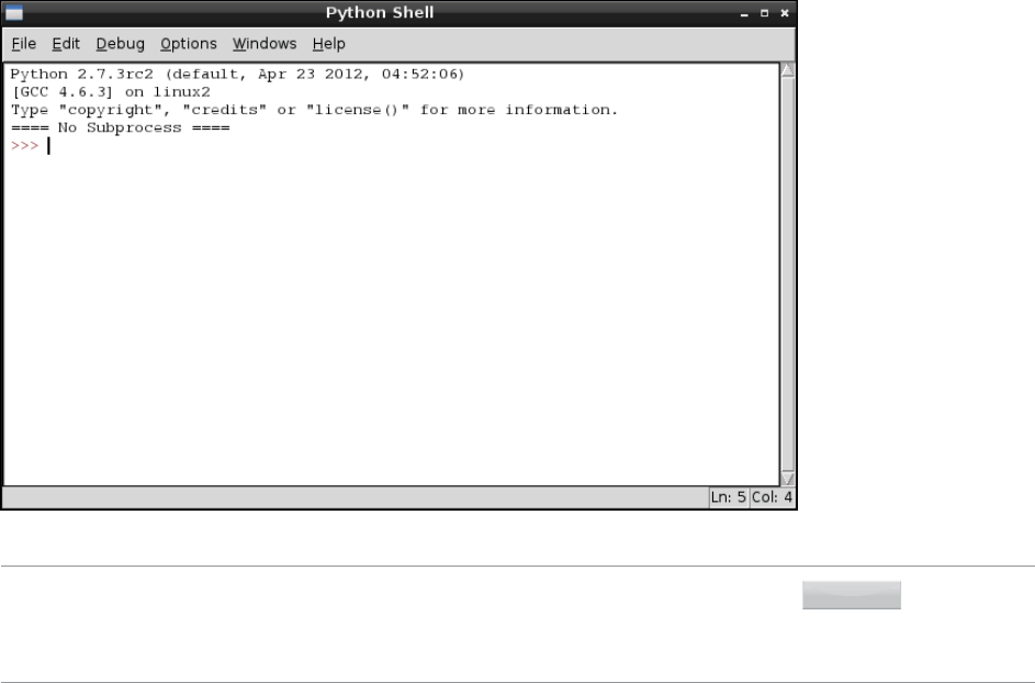
CHAPTER 12 AN INTRODUCTION TO PYTHON 175
integrated development environment (IDE) such as IDLE, which provides Python-specic
functionality that’s missing from a standard text editor, including syntax checking, debug-
ging facilities and the ability to run your program without having to leave the editor. is
chapter gives you instructions on how to create Python les using IDLE, but of course, the
IDE program that you choose to use for programming is up to you. e chapter also includes
instructions for running your created les directly from the terminal, which can be used in
conjunction with any text editor or other IDE.
To begin the Hello World project, open IDLE from the Programming menu in the Raspbian
distribution’s desktop environment. If you’re not using IDLE, create a blank document in
your favourite text editor and skip the rest of this paragraph. By default, IDLE opens up in
Python shell mode (see Figure 12-1), so anything you type in the initial window will be imme-
diately executed. To open a new Python project which can be executed later, click on the File
menu and choose New Window to open a blank le.
F -:
e IDLE
Python Shell
window
TIP
Choosing IDLE 3 from the Programming menu instead of IDLE loads the Python 3.0 version.
This uses a subtly different form of the language, or syntax, which can cause problems with
programs written for Python 2. The examples in this chapter are all written with Python 2 in
mind, so be sure to load IDLE and not IDLE 3.
PART III PROGRAMMING WITH THE RASPBERRY PI
176
It’s good practice to start all Python programs with a line known as a shebang, which gets its
name from the # and ! characters at the beginning of the line. is line tells the operating
system where it should look for the Python les. Although this is not entirely necessary for
programs that will be run from within IDLE or will call Python explicitly at the terminal, it is
required for programs that are run directly by calling the program’s lename.
To ensure the program runs regardless of where the Python executable is installed, the rst
line of your program should read as follows:
#!/usr/bin/env python
is line tells the operating system to look at the $PATH environment variable—which is
where Linux stores the location of les that can be executed as programs—for the location of
Python, which should work on any Linux distribution used on the Pi. e $PATH variable
contains a list of directories where executable les are stored and is used to nd programs
when you type their name at the console or in a terminal window.
To achieve the goal of printing out a message, you should use Python’s print command. As
its name suggests, this command prints text to an output device—by default, to the console
or terminal window from which the program is being executed. Its usage is simple: any text
following the word print and placed between quotation marks will be printed to the stan-
dard output device. Enter the following line in your new project:
print “Hello, World!”
e nal program should look like this:
#!/usr/bin/env python
print “Hello, World!”
If you’re creating the example program in IDLE rather than a plain text editor, you’ll notice
that the text is multicoloured (see Figure 12-2, where colours are represented as diering
shades of grey in the print edition). is is a feature known as syntax highlighting and is a
feature of IDEs and the more-advanced text editing tools. Syntax highlighting changes the
colour of sections of the text according to their function in order to make the program easier
to understand at a glance. It also makes it easy to spot so-called syntax errors caused by for-
getting to put an end-quote in a print command or forgetting to comment out a remark.
For this short example, syntax highlighting isn’t necessary—but in larger programs, it can be
an invaluable tool for nding errors.
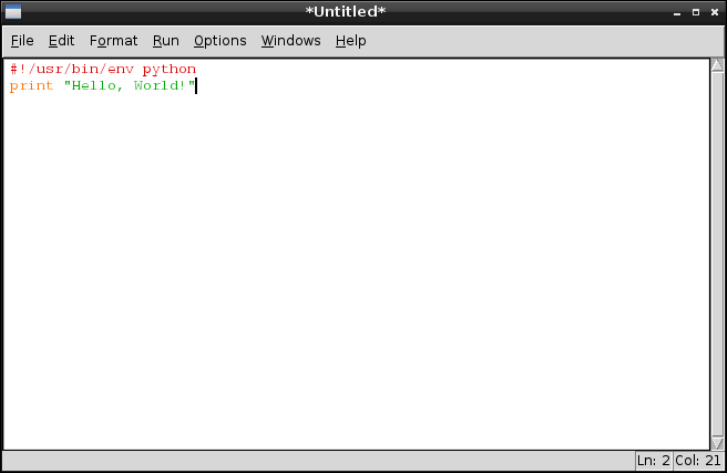
CHAPTER 12 AN INTRODUCTION TO PYTHON 177
F -:
Syntax
highlighting
in IDLE
Before you run your program, save it as helloworld.py using the File menu. If you’re
using IDLE, the le will be given the extension .py automatically. If you’re using a text edi-
tor, be sure to type .py at the end of the lename (not .txt) when you save it. is exten-
sion indicates that the le contains Python code—although Python is clever enough to run
the program even if it’s saved with a dierent le extension.
How you run the le will depend on whether you’re using IDLE or a text editor. In IDLE,
simply choose Run Module from the Run menu, or press the F5 key on the keyboard. is
will switch IDLE back to the Python shell window and run the program. You should then see
the message Hello, World! appear onscreen in blue (see Figure 12-3). If not, check your
syntax—in particular, check that you have quotation marks at both the beginning and end of
the message on the print line.
If you created the helloworld.py program in a text editor, you’ll need to open a terminal
window from the Accessories menu on the desktop. If you saved the le anywhere except
your home directory, you’ll also have to use the cd command to change to that directory (see
Chapter 3, “Linux System Administration”). Once you’re in the right directory, you can run
your program by typing the following:
python helloworld.py
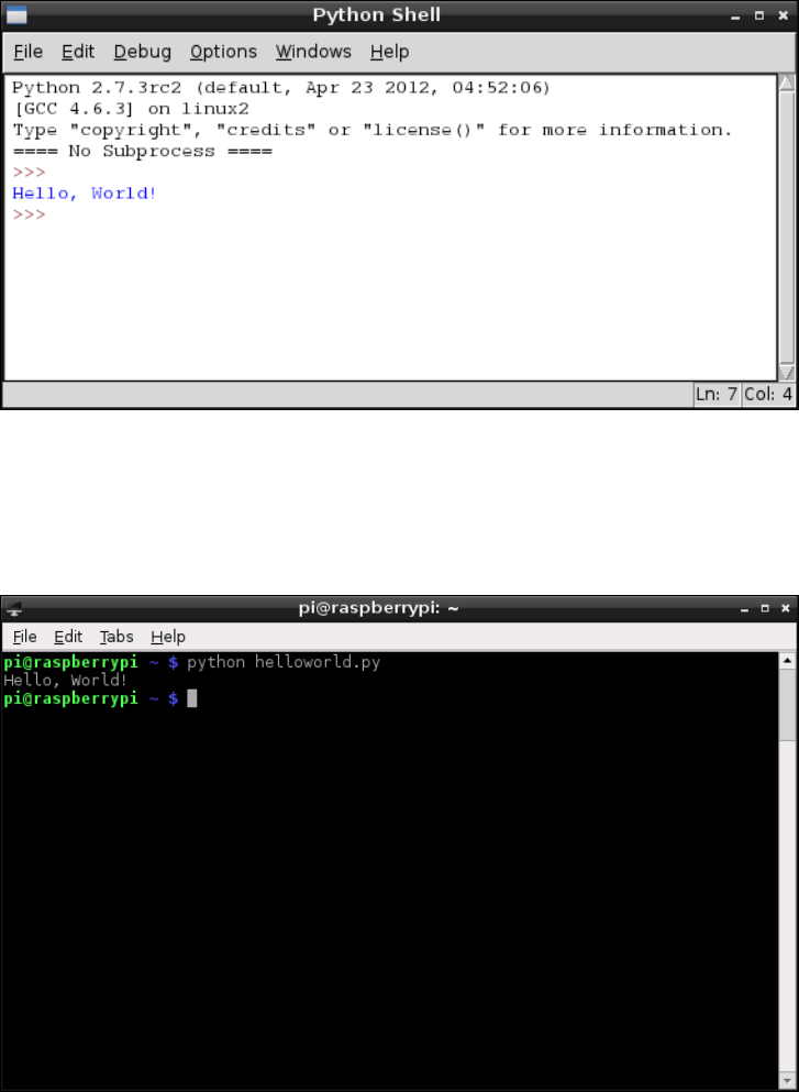
PART III PROGRAMMING WITH THE RASPBERRY PI
178
F -:
Running
helloworld.
py in IDLE
is tells the operating system to run Python and then load the helloworld.py le for
execution. Unlike the Python shell in IDLE, Python will quit when it reaches the end of the
le and return you to the terminal. e result, however, is the same: the message Hello,
World! is printed to the standard output (see Figure 12-4).
F -:
Running
helloworld.
py at the
terminal

CHAPTER 12 AN INTRODUCTION TO PYTHON 179
Making Python Programs Executable
Normally, the only way to run a Python program is to tell the Python software to open the
le. With the shebang line at the top of the le, however, it’s possible to execute the le
directly without having to call Python rst. This can be a useful way of making your own
tools that can be executed at the terminal: once copied into a location in the system’s
$PATH environment variable, the Python program can be called simply by typing its name.
First, you need to tell Linux that the Python le should be marked as executable—an attribute
that means the le is a program. To protect the system from malware being downloaded
from the Internet this attribute isn’t automatically set, since only les that are marked as exe-
cutable will run. To make the helloworld.py le executable, use the chmod command
(described in detail in Chapter 3, “Linux System Administration”) by typing the following:
chmod +x helloworld.py
Now try running the program directly by typing the following:
./helloworld.py
Despite the fact that you didn’t call the Python program, the helloworld.py program
should run just the same as if you’d typed python helloworld.py. The program can
only be run by calling it with its full location—/home/pi/helloworld.py—or from the
current directory by using ./ as the location. To make the le accessible in the same way
as any other terminal command, it needs to be copied to /usr/local/bin with the fol-
lowing command:
sudo cp helloworld.py /usr/local/bin/
The sudo prex is required because, for security reasons, non-privileged users cannot write to
the /usr/local/bin directory. With the helloworld.py le located in /usr/local/bin,
which is included in the $PATH variable, it can be executed from any directory by simply typing
its name. Try changing to a different directory, and then run the program by typing the following:
helloworld.py
To make your custom-made programs seem more like native utilities, you can rename them
to remove the .py le extension. To change the helloworld.py program in this way, just
type the following line at the terminal as a single line:
sudo mv /usr/local/bin/helloworld.py ↵
/usr/local/bin/helloworld
Once renamed, the program can be run simply by typing helloworld at the terminal or
console.
PART III PROGRAMMING WITH THE RASPBERRY PI
180
Example 2: Comments, Inputs,
Variables and Loops
Although the Hello World program is a useful, gentle introduction to a language, it’s not ter-
ribly exciting. By its nature, it covers only the basics and fails to introduce some of the con-
cepts required for creating useful or interesting programs. e next example, however, uses
some of the basic tools required to make interactive programs in Python.
As in Example 1, begin by opening a new blank document in IDLE or your text editor, and
then start the program with the following shebang line:
#!/usr/bin/env python
As previously discussed, this line isn’t strictly necessary unless the program is going to be
made executable, but it does no harm and is a good habit to develop.
Next, add a comment to the program to provide context if you need to open the le at a later
date. Note that this needs to be entered as a single line, as with all code lines that end in a ↵
symbol:
# Example 2: A Python program from the ↵
Raspberry Pi User Guide
In Python, anything following a hash symbol—with the exception of the shebang line—is
treated as a comment. When a comment is found, Python ignores it and skips to the next
line. Commenting your code is good practice: although you might know what a particular
section of code does now, things might not be so clear when you open the le again six
months down the line. Comments also help make code more maintainable, and if you decide
to share your code with other people, your comments help them understand what each sec-
tion is supposed to do. For simple programs, it’s not strictly necessary to include com-
ments—but as with adding the shebang line, it’s a very good habit to get in to. Comments
can be on their own line, as with the preceding comment, or at the end of a line, in which
case Python will run the code line up until it reaches the hash symbol.
Next, ask the user for his or her name using the following line:
userName = raw_input(“What is your name? “)

CHAPTER 12 AN INTRODUCTION TO PYTHON 181
is small line actually achieves quite a lot. e rst part, userName =, tells Python to cre-
ate a new variable—a location for storing a piece of information—called userName. e
equals symbol tells Python that the variable should be set to whatever follows. However, in
this case what follows isn’t just a piece of information, but another command: raw_input.
is is a tool designed to accept string (text) input from the keyboard, and allows for a mes-
sage to be printed to the default output so the user knows what to type. is helps keep the
program simple—without the ability to print a prompt telling the user what to type, a sec-
ond line with a print command would be required. Remember to leave a space at the end of
the prompt; otherwise, the user’s input will begin immediately after the question mark.
WARNING
When asking the user to type in text, always use raw_input. This provides security that the
input command alone does not—if you just use input, a user may inject his or her own code
into your program and have it crash or work contrary to your intentions.
With the user’s name now stored safely in the userName variable, the program can begin to
get clever. Welcome the user using the following line:
print “Welcome to the program,”, userName
is line demonstrates a secondary function of the print command introduced in Example
1: the ability to print out the contents of variables. is print command is split into two:
the rst section prints everything between the two quotation marks, and the second comma
tells print that more should be printed to the same line. Simply typing the variable name
userName is enough for Python to know that it should print the contents of that variable,
resulting in a message customised to the user’s own name.
is example program is going to take the form of a simple but friendly calculator. Unlike
Example 1, it will continue to run until the user tells it otherwise. is is achieved using a
loop, just as in Scratch. Begin the loop by typing the following two lines:
goAgain = 1
while goAgain == 1:
e rst line creates a new variable called goAgain and sets it to 1. e second line begins the
loop, and tells Python that while the goAgain variable is equal to 1, it should continue to
loop through the following code. As the next few lines are written, they will need to be indented
by inserting four spaces at the start of each line. ese spaces tell Python which lines are part of
the loop and which lines are outside the loop. If you’re using IDLE, the spaces will be inserted
automatically; if you’re using a text editor, remember to insert the spaces manually.

PART III PROGRAMMING WITH THE RASPBERRY PI
182
In its most basic form, a calculator takes two numbers as input and performs a mathematical
operation on them. To make your calculator work, rst take the two numbers from the user
with the following lines:
firstNumber = int(raw_input(“Type the first number: “))
secondNumber = int(raw_input(“Type the second number: “))
ese lines not only use the raw_input instruction to ask for two numbers, but they also use
int. Short for integer, the int instruction tells Python to treat input as a number rather than a
string. Obviously, this is important for a calculator program since it won’t be calculating words.
With the two numbers stored as variables, the program can perform its calculations. Type
the following lines, which add, subtract and multiply the two numbers and send the output
to the user:
print firstNumber, “added to”, secondNumber, “equals”, ↵
firstNumber + secondNumber
print firstNumber, “minus”, secondNumber, “equals”, ↵
firstNumber - secondNumber
print firstNumber, “multiplied by”, secondNumber, “equals”, ↵
firstNumber * secondNumber
Notice that while the addition and subtraction operations use the expected plus and minus
symbols, multiplication uses the * symbol. Also notice that there are no formatting spaces
between the quotation marks. is is because Python automatically adds spaces where required
Why ==?
Previously, you’ve been using a single equals symbol to set the value of variables. The
while loop, however, uses two. Using two equals symbols next to each other performs an
evaluation, which compares a variable’s value to whatever follows. A single equals symbol
instead sets the variable to the value that follows.
There are other evaluations as well as the double-equals, which is only true if the variable
matches the given value exactly: > means greater than, < means less than, >= means
greater than or equal to, <= means less than or equal to, and != means not equal to.
Using these evaluation symbols, you can control the ow of a program according to the
rules of Boolean logic. For more information on Boolean logic, see Chapter 11, “An
Introduction to Scratch”.
CHAPTER 12 AN INTRODUCTION TO PYTHON 183
when it prints integers and strings together. Finally, note that there is no division operation
(which would be indicated with the / symbol). is is because the example calculator program
uses integers, which can only be whole numbers, with no decimal places or fractions allowed.
Although the calculation part of the program is now complete, it will run forever because
there is currently nothing to tell Python when it’s time to exit the loop. To provide the user
with a way to exit the program, add the following line:
goAgain = int(raw_input(“Type 1 to enter more numbers, ↵
or any other number to quit: “))
is allows the user to change the goAgain variable, which controls the while loop. If the
user enters the number 1, the goAgain variable is still equal to 1 and the loop will run again.
However, if the user enters any other number, the evaluation is no longer true (goAgain is
no longer equal to 1), and the loop will end.
e nished program should look like this, remembering that anything marked with ↵
should be entered onto a single line:
#!/usr/bin/env python
# Example 2: A Python program from the Raspberry Pi User Guide
userName = raw_input(“What is your name? “)
print “Welcome to the program,”, userName
goAgain = 1
while goAgain == 1:
firstNumber = int(raw_input(“Type the first number: “))
secondNumber = int(raw_input(“Type the second number: “))
print firstNumber, “added to”, secondNumber, “equals”, ↵
firstNumber + secondNumber
print firstNumber, “minus”, secondNumber, “equals”, ↵
firstNumber - secondNumber
print firstNumber, “multiplied by”, secondNumber, “equals”, ↵
firstNumber * secondNumber
goAgain = int(raw_input(“Type 1 to enter more numbers, or ↵
any other number to quit: “))
Save the program as calculator.py, and run it by choosing Run Module from the Run
menu in IDLE or by typing python calculator.py at the terminal. Enter your user name
when prompted, and then provide the numbers that you want to calculate (see Figure 12-5)
until you get bored and then type anything other than 1 to exit the program.
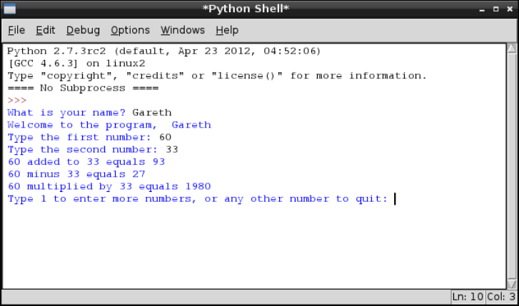
PART III PROGRAMMING WITH THE RASPBERRY PI
184
Figure 12-5:
Running
calculator.
py in IDLE
For more short programs that introduce important Python concepts, visit the ocial Python
Simple Programs wiki page at http://wiki.python.org/moin/SimplePrograms.
Example 3: Gaming with pygame
To illustrate the power of Python, this example creates a fully functional arcade game based
on the classic game of Snake or Nibbles. To accomplish this, it uses an external Python library
called pygame.
Originally written by Pete Shinners, pygame is a collection of python modules designed to
add new functionality to the language—functionality specically designed to make it easy to
write a game in Python. Each pygame module provides a function required by a modern
game, including sound, graphics and even networking support. Although it’s possible to
write a game in Python without using pygame, it’s a lot easier if you take advantage of the
code already written in the pygame library.
Before you can write a pygame program, you need to install the pygame library. If you’re
using the recommended Raspbian distribution, this is as simple as typing the following at
the console or terminal:
sudo apt-get install python-pygame
CHAPTER 12 AN INTRODUCTION TO PYTHON 185
For other distributions, the pygame source les can be downloaded from the ocial pygame
website at http://www.pygame.org/download.shtml. Instructions for installation
are provided on the same page.
Starting a pygame program is the same as starting any other Python project. Open a new blank
document in either IDLE or a text editor, and add the following shebang line to the top:
#!/usr/bin/env python
Next you need to tell Python that this program uses the pygame modules. To do this, you use
an import instruction, which tells Python to load an external module (another Python le)
and make it accessible from the current program. Type the following two lines to import the
necessary modules into your new project:
import pygame, sys, time, random
from pygame.locals import *
e rst line imports the main pygame module along with the Python modules sys, time
and random, which will also be used in this program. Typically, a module must then be called
by typing its name followed by a full stop and the name of the instruction from within the
module, but the second line in the preceding code tells Python to load all the instructions
from the pygame.locals module as though they’re native instructions. As a result, you
will need to do less typing when using these instructions. Other module names—such as
pygame.clock, which is separate to pygame.locals—will still need to be typed in full.
Enter the next two lines to set up pygame so it’s ready to use in the example program:
pygame.init()
fpsClock = pygame.time.Clock()
e rst line tells pygame to initialise itself, and the second line sets up a new variable called
fpsClock, which will be used to control the speed of the game. Next, set up a new pygame
display surface—the canvas onto which in-game objects will be drawn—with the following
two lines:
playSurface = pygame.display.set_mode((640, 480))
pygame.display.set_caption(‘Raspberry Snake’)
Next, you should dene some colours for the program to use. Although this step isn’t strictly
necessary, it again saves on typing: if you want to set a particular object to be red, you
can simply use the redColour variable rather than having to call the pygame.Color
PART III PROGRAMMING WITH THE RASPBERRY PI
186
instruction and remember the three colour values for red, green and blue. To dene the
colours for this example program, type the following lines:
redColour = pygame.Color(255, 0, 0)
blackColour = pygame.Color(0, 0, 0)
whiteColour = pygame.Color(255, 255, 255)
greyColour = pygame.Color(150, 150, 150)
e next few lines initialise some of the game’s variables so they’re ready for use. is is an impor-
tant step, because if these variables are left blank when the game begins, Python won’t know what
to do. Don’t worry about what each variable does for now—just type in the following lines:
snakePosition = [100,100]
snakeSegments = [[100,100],[80,100],[60,100]]
raspberryPosition = [300,300]
raspberrySpawned = 1
direction = ‘right’
changeDirection = direction
Notice that three of the variables—snakePosition, snakeSegments and raspberry-
Position—are set to a list of comma-separated values. is causes Python to create the
variables as lists—a number of dierent values stored in a single variable name. Later, you’ll
see how you can access individual values stored in a list.
Next, you need to dene a new function—a fragment of Python code which can be called
upon later in the program. Functions are useful for avoiding code repetition and making the
program easier to understand. If you have a particular set of instructions that are needed at
multiple points in the same program, using def to create a function means you’ll only have
to type them once—and only have to change them in a single place if you alter the program
later. Type the following lines to dene the gameOver function:
def gameOver():
gameOverFont = pygame.font.Font ↵
(‘freesansbold.ttf’, 72)
gameOverSurf = gameOverFont.render ↵
(‘Game Over’, True, greyColour)
gameOverRect = gameOverSurf.get_rect()
gameOverRect.midtop = (320, 10)
playSurface.blit(gameOverSurf, gameOverRect)
pygame.display.flip()
time.sleep(5)
pygame.quit()
sys.exit()
CHAPTER 12 AN INTRODUCTION TO PYTHON 187
As with loops, the code for a function should be indented. Every line after the def instruc-
tion should have four spaces at the start—if you’re using IDLE, these spaces will be inserted
automatically, but if you’re using a text editor, you will need to insert the spaces yourself.
After the nal line of the function—sys.exit()—you can stop indenting.
e gameOver function uses a selection of pygame’s commands to perform a simple task:
write the words Game Over to the screen in a large font, pause for 5 seconds, and then quit
both pygame and Python itself. It may seem strange to set up the instructions for quitting
the game before the game has even begun, but functions should always be dened before
they are called. Python won’t execute these instructions until it is told to do so using the
newly created gameOver instruction.
With the beginning of the program complete, it’s time to start the main section. is takes
place in an innite loop—a while loop that never exits. is is so that the game can con-
tinue to run until the player dies by hitting a wall or eating his or her own tail. Begin the main
loop with the following line:
while True:
Without anything to evaluate, Python will check to see if True is true. Because that’s always
the case, the loop will continue to run forever—or, at least until you tell Python to quit out
of the loop by calling the gameOver function.
Continue the program with the following lines, paying attention to the indentation levels:
for event in pygame.event.get():
if event.type == QUIT:
pygame.quit()
sys.exit()
elif event.type == KEYDOWN:
e rst line, which comes right after the while loop begins, should be indented four spaces—
but it’s a loop of its own, using a for instruction to check for pygame events like key presses. As a
result, the line under that needs to be indented an additional four spaces for a total of eight—but
that line, too, is a loop, using an if instruction to check whether the user has pressed a key. As a
result, the next line—pygame.quit()—is indented an additional four spaces for a total of 12
spaces. is logical progression of indentation tells Python where each loop begins and ends,
which is important: if the wrong number of spaces is used, the program won’t work correctly. is
is why using a development environment like IDLE, which attempts to automatically indent code
where required, can be easier than using a plain text editor to create Python programs.
An if loop tells Python to check to see if a particular evaluation is true. e rst check, if
event.type == QUIT, tells Python to execute the indented code below if pygame reports
PART III PROGRAMMING WITH THE RASPBERRY PI
188
a QUIT message (which happens when the user presses the Escape key). e two lines
beneath that should be familiar from the gameOver function: they tell pygame and Python
to close down and exit.
e line beginning elif is used to extend if loops. Short for else if, an elif instruction is
evaluated when a previous if instruction was found to be false. In this case, the elif
instruction is used to see if pygame is reporting a KEYDOWN event, which is returned when
the user is pressing a key on the keyboard. As with the if instruction, code to be executed
when an elif is true should be indented by an additional four spaces plus whatever inden-
tation the elif instruction itself has. Type the following lines to give the elif instruction
something to do when the user presses a key:
if event.key == K_RIGHT or event.key == ord(‘d’):
changeDirection = ‘right’
if event.key == K_LEFT or event.key == ord(‘a’):
changeDirection = ‘left’
if event.key == K_UP or event.key == ord(‘w’):
changeDirection = ‘up’
if event.key == K_DOWN or event.key == ord(‘s’):
changeDirection = ‘down’
if event.key == K_ESCAPE:
pygame.event.post(pygame.event.Event(QUIT))
ese instructions modify the value of the changeDirection variable, used to control the
direction the player’s snake is travelling during the game. Using or with an if statement
allows more than one evaluation to be made. In this case, it provides two ways of controlling
the snake: the player can use the cursor keys, or the W, A, S and D keys to make the snake go
up, right, down or left. Until a key is pressed, the snake travels to the right according to the
value set for changeDirection at the start of the program.
If you look back at the variables you initialised at the start of the program, you’ll see that
there’s another variable called direction. is is used alongside changeDirection to see
if the instruction the user has given is valid. e snake should not be allowed to turn imme-
diately back on itself—if it does, the snake dies and the game is over. To prevent this from
happening, the direction requested by the player—stored in changeDirection—is com-
pared to the current direction in which the snake is travelling—stored in direction. If
they are opposite directions, the instruction is ignored and the snake continues in the same
direction as before. Type the following lines to set up the comparisons:
if changeDirection == ‘right’ and not direction == ‘left’:
direction = changeDirection
CHAPTER 12 AN INTRODUCTION TO PYTHON 189
if changeDirection == ‘left’ and not direction == ‘right’:
direction = changeDirection
if changeDirection == ‘up’ and not direction == ‘down’:
direction = changeDirection
if changeDirection == ‘down’ and not direction == ‘up’:
direction = changeDirection
With the user’s input checked to make sure it makes sense, the snake—which appears on the
screen as a series of blocks—can be moved. During each turn, the snake moves a distance equal
to the size of one of its blocky segments. With each segment measuring 20 pixels, you can tell
pygame to move the snake a single segment in any direction. Type in the following code:
if direction == ‘right’:
snakePosition[0] += 20
if direction == ‘left’:
snakePosition[0] -= 20
if direction == ‘up’:
snakePosition[1] -= 20
if direction == ‘down’:
snakePosition[1] += 20
e += and -= operators are used to change the value of a variable by a certain amount: += sets
the variable to its previous value plus the new value, while -= sets the variable to its previous
value minus the new value. By way of example, snakePosition[0] += 20 is a shorthand way
of writing snakePosition[0] = snakePosition[0] + 20. e number in square brackets
following the snakePosition variable name is the position in the list being aected: the rst
value in the snakePosition list stores the snake’s position along the X axis, while the second
value stores the position along the Y axis. Python begins counting at zero, so the X axis is con-
trolled with snakePosition[0] and the Y axis with snakePosition[1]. If the list were lon-
ger, additional entries could be aected by increasing the number: [2], [3] and so on.
Although the snakePosition list is always two values long, another list created at the start
of the program is not: snakeSegments. is list stores the location of the snake’s body,
behind the head. As the snake eats raspberries and grows longer, this list increases in size
and provides the diculty in the game: as the player progresses, it becomes harder to avoid
hitting the body of the snake with the head. If the head hits the body, the snake dies and the
game is over. Type the following line to make the snake’s body grow:
snakeSegments.insert(0,list(snakePosition))
PART III PROGRAMMING WITH THE RASPBERRY PI
190
is uses the insert instruction to insert a new value into the snakeSegments list: the
current position of the snake. Each time Python reaches this line, it will increase the length
of the snake’s body by one segment, and locate that segment at the current position of the
snake’s head. To the player, it will look as though the snake is growing. However, you only
want this to happen when the snake eats a raspberry—otherwise the snake will just grow
and grow. Type the following lines:
if snakePosition[0] == raspberryPosition[0] ↵
and snakePosition[1] == raspberryPosition[1]:
raspberrySpawned = 0
else:
snakeSegments.pop()
e rst instruction checks the X and Y coordinates of the snake’s head to see if it matches
the X and Y coordinates of the raspberry—the target the player is chasing. If the values
match, the raspberry is considered to have been eaten by the snake—and the raspber-
rySpawned variable is set to 0. e else instruction tells Python what to do if the raspberry
has not been eaten: pop the earliest value from the snakeSegments list.
e pop instruction is simple but clever: it returns the oldest value from the list but also
removes it, making the list one item shorter. In the case of the snakeSegment list, it tells
Python to delete the portion of the snake’s body farthest away from the head. To the player,
it will look as though the entire snake has moved without growing—in reality, it grew at one
end and shrank at the other. Because of the else statement, the pop instruction only runs
when a raspberry has not been eaten. If a raspberry has been eaten, the last entry in the list
doesn’t get deleted—so the snake grows in size by one segment.
At this point in the program, it’s possible that the player has eaten a raspberry. A game in
which only a single raspberry is available is boring, so type the following lines to add a new
raspberry back to the playing surface if the player has eaten the existing raspberry:
if raspberrySpawned == 0:
x = random.randrange(1,32)
y = random.randrange(1,24)
raspberryPosition = [int(x*20),int(y*20)]
raspberrySpawned = 1
is section of code checks to see if the raspberry has been eaten by testing if the raspber-
rySpawned variable is set to 0, and if so, the code picks a random location on the playing
surface using the random module you imported at the start of the program. is location is
then multiplied by the size of a snake’s segment—20 pixels wide and 20 pixels tall—to give
CHAPTER 12 AN INTRODUCTION TO PYTHON 191
Python a place on the playing eld to position the new raspberry. It’s important that the
location of the raspberry is set randomly: this prevents the player from learning where the
raspberry will appear next. Finally, the raspberrySpawned variable is set back to 1, to
make sure that there will only be a single raspberry on the playing surface at any given time.
Now you have the code required to make the snake move and grow, and cause raspberries to
be eaten and created—a process known in gaming as respawning. However, nothing is being
drawn to the screen. Type the following lines:
playSurface.fill(blackColour)
for position in snakeSegments:
pygame.draw.rect(playSurface,whiteColour,Rect ↵
(position[0], position[1], 20, 20)) ↵
pygame.draw.rect(playSurface,redColour,Rect ↵
(raspberryPosition[0], raspberryPosition[1], 20, 20))
pygame.display.flip()
ese lines tell pygame to ll in the background of the playing surface in black, draw the
snake’s head and body segments in white, and nally, draw a raspberry in red. e last line,
pygame.display.flip(), tells pygame to update the screen—without this instruction,
items will be invisible to the player. Every time you nish drawing objects onto the screen,
remember to use pygame.display.flip() so the user can see the changes.
Currently, it’s impossible for the snake to die. A game where the player can never die would
rapidly get boring, so enter the following lines to set up some scenarios for the snake’s death:
if snakePosition[0] > 620 or snakePosition[0] < 0:
gameOver()
if snakePosition[1] > 460 or snakePosition[1] < 0:
gameOver()
e rst if statement checks to see if the snake has gone o the playing surface vertically,
while the second if statement checks if the snake has gone o the playing surface horizon-
tally. In either case, it’s bad news for the snake: the gameOver function, dened earlier in
the program, is called to print a message to the screen and quit the game. e snake should
also die if its head hits any portion of its body, so add the following lines:
for snakeBody in snakeSegments[1:]:
if snakePosition[0] == snakeBody[0] and ↵
snakePosition[1] == snakeBody[1]:
gameOver()
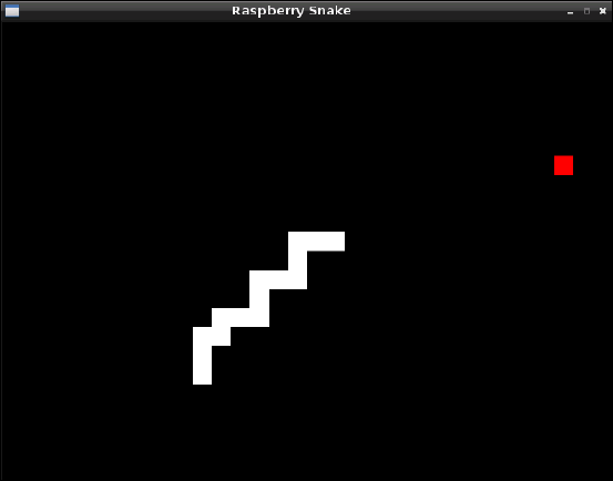
PART III PROGRAMMING WITH THE RASPBERRY PI
192
e for statement runs through each of the snake segments’ locations, from the second list
entry to the end of the list, and compares it to the current position of the snake’s head. It’s
important to start the comparison at the second entry using snakeSegments[1:] and not
the rst. e rst entry is always set to the position of the head, and starting the comparison
here would result in instant death for the snake as soon as the game begins.
Finally, all that is required for the game to be complete is to control the speed using the
fpsClock variable. Without the variable, which you created at the start of the program, the
game would run too quickly to play. Type in the following line to nish the program:
fpsClock.tick(20)
If you think the game is too easy or too slow, you can increase this number; or if the game is
too hard or too fast, decrease the number. Save the program as raspberrysnake.py, and
run it either by using IDLE’s Run Module option in the Run menu or from the terminal by
typing python raspberrysnake.py. e game will start as soon as it has loaded (see
Figure 12-6), so make sure you’re ready!
Figure 12-6:
Playing
Raspberry Snake
on the
Raspberry Pi
A full copy of the program listing for Raspberry Snake is included in Appendix A, “Python
Recipes”, and on the Raspberry Pi User Guide website at www.wiley.com/go/raspber-
rypiuserguide2e. Downloading the source code from the website will save you some typ-
ing, but entering the code by hand is a good way of ensuring that you understand what each
CHAPTER 12 AN INTRODUCTION TO PYTHON 193
section does. In addition to the functions used in Raspberry Snake, pygame provides lots of
features not used in this program, including audio playback, sprite handling for better graph-
ics and mouse control. e best place to learn about pygame’s more-advanced functions is on
the ocial website, http://www.pygame.org/wiki/tutorials, where you can down-
load tutorials and example programs to get a handle on how things work.
Example 4: Python and Networking
So far, you have learned how Python can be used to create standalone programs, but the
language can also be used to create programs that communicate with the outside world over
a computer’s network connection. is next example, written by Tom Hudson, oers a brief
glimpse of these possibilities with a tool for monitoring the users connected to an Internet
Relay Chat (IRC) channel.
As usual, create a new project in IDLE or a text editor and enter the shebang line along with
a comment describing the purpose of the program:
#!/usr/bin/env python
# IRC Channel Checker, written for the ↵
Raspberry Pi User Guide by Tom Hudson
Next, import the modules required by the program—sys, socket and time—with the fol-
lowing line:
import sys, socket, time
You used the sys and time modules previously in the Raspberry Snake program, but you
have not yet used socket. e socket module provides Python with the ability to open,
close, read from and write to network sockets—giving Python programs rudimentary net-
working capabilities. It’s the socket module that provides this example with its ability to
connect to a remote IRC server.
ere are some constants needed for this program to operate. Constants are like variables in
that they can have values assigned to them—but unlike variables, the value in a constant
shouldn’t change. To help dierentiate a constant from a variable, it’s good practice to use all-
capital letters for their names—that way it’s easy to see at glance whether a particular section
of the code is using a constant or a variable. Type the following two lines into the program:
RPL_NAMREPLY = ‘353’
RPL_ENDOFNAMES = ‘366’
PART III PROGRAMMING WITH THE RASPBERRY PI
194
ese are IRC status codes, provided by the server to indicate when particular operations have
completed. ese are used by the program to know when it has received the required list of
names from the IRC server. Next, set up the variables for the server connection by entering
the following lines:
irc = {
‘host’ : ‘chat.freenode.net’,
‘port’ : 6667,
‘channel’ : ‘#raspiuserguide’,
‘namesinterval’ : 5
}
e rst line tells Python to create a dict data type. Short for dictionary, this allows multiple
variables to be stored in a single master variable—in this case, irc. ese individual vari-
ables can then be recalled later in the program. Although you could write this program with-
out using dicts to store variables, it would make the program signicantly more dicult to
read. e dict begins with the opening curly brace, and ends with the closing curly brace on
the nal line.
e host variable should be set to the fully qualied domain name (FQDN) of the IRC server
to which the program will connect. In this example, chat.freenode.net is used, but if
you want to customise the program to use a dierent server, change the domain name here.
e port variable tells the program which network port IRC is running on, which will usually
be 6667. e channel variable tells Python which channel to join in order to monitor the
users, while namesinterval controls how long the program waits to refresh the list of
users, measured in seconds.
Set up a second dict to store the user-specic variables by typing in the following lines:
user = {
‘nick’ : ‘botnick’,
‘username’ : ‘botuser’,
‘hostname’ : ‘localhost’,
‘servername’ : ‘localhost’,
‘realname’ : ‘Raspberry Pi Names Bot’
}
As with irc, all these variables are stored within a dict called user to make it clear which
variables pertain to which section. e nick variable should be set to the IRC nickname the
program will use. Don’t use your usual nickname if you’re planning to connect to the IRC
server at the same time; instead, try appending -bot to the end of your name to make it
CHAPTER 12 AN INTRODUCTION TO PYTHON 195
clear that the user is a program rather than a real person. Do the same with username, and
ll in the realname variable with a descriptive message about whom the bot belongs to. e
hostname and servername variables can be left set to localhost, or altered to match
your Internet address.
e socket module requires the user to create a socket object. is object provides network
connectivity to the rest of the program. Create the socket object by typing in the following
line:
s = socket.socket(socket.AF_INET, socket.SOCK_STREAM)
Next, you need to tell the program to try connecting to the IRC server specied in the vari-
ables at the start of the program. Type the following lines:
print ‘Connecting to %(host)s:%(port)s...’ % irc
try:
s.connect((irc[‘host’], irc[‘port’]))
except socket.error:
print ‘Error connecting to IRC server ↵
%(host)s:%(port)s’ % irc
sys.exit(1)
e try and except commands are included in this code for error handling. If the system
fails to connect to the server—because the Pi isn’t connected to the Internet, for example, or
because the server is down for maintenance—the program will print an error message and
gracefully exit. e s.connect line tells the socket module to try connecting to the IRC
server, using the host and port variables held in the irc dict.
If the program doesn’t quit from the exception, it has successfully connected to the IRC
server. Before you can get a list of names in a channel, however, you need to identify yourself
to the server and issue some commands using the send function of the socket module.
Type the following lines into the program:
s.send(‘NICK %(nick)s\r\n’ % user)
s.send(‘USER %(username)s %(hostname)s ↵
%(servername)s :%(realname)s\r\n’ % user)
s.send(‘JOIN %(channel)s\r\n’ % irc)
s.send(‘NAMES %(channel)s\r\n’ % irc)
e send function works in almost exactly the same way as the print function, except that
instead of printing to the standard output—usually the terminal window or console—it
PART III PROGRAMMING WITH THE RASPBERRY PI
196
sends the output through the network connection. In this case, the program is sending
strings of text to the IRC server and telling it to register the program using the nickname
held in the nick variable and the user details held in the username, hostname, server-
name and realname variables. Next, the program sends the command to join the channel
specied in the channel variable, and nally, it sends the command to receive the list of
users in that channel. Although this example is tailored to IRC, the same basic principle can
be used to issue commands to any network service—with modications, this program could
be used to list the les on an FTP server, or unread emails on a POP3 server.
Receiving data from the socket is a little more complicated. First, you need to create an
empty string variable that will act as the receive buer, holding data from the server as it’s
received until it can be processed. Initialise the buer by typing in the following line:
read_buffer = ‘‘
Note that there are two single quotes after the equals sign, not one double quote.
Next, create an empty list, which will be used to store the names of users, by typing the fol-
lowing line:
names = []
e list data type is the same as you used to store the locations in the Raspberry Snake game.
Unlike a normal variable, it can store multiple values—in this case, the names of users pres-
ent in the IRC channel.
e next step is to create an innite loop, during which the program will continuously query
the server for user names and print them to the screen. Start the loop by typing:
while True:
read_buffer += s.recv(1024)
e rst line of the loop, following while True:, tells the socket module to receive 1,024
bytes (1 KB) of data from the IRC server and place it into the read_buffer variable. Because
the += operator is used, rather than just =, the received data will be appended to anything
already in the buer. e value of 1024 bytes is more or less arbitrary.
e next step is to split the buer into individual lines of text, using the following program
lines:
lines = read_buffer.split(‘\r\n’)
read_buffer = lines.pop();
CHAPTER 12 AN INTRODUCTION TO PYTHON 197
e rst line sets the lines variable to a full line of text from the receive buer by using the
split function to nd end of line characters—signied by \r\n. ese characters only occur at
the end of a line, so when the buer has been split in this way you know that lines contains
only full-line responses from the server. e pop instruction in the second line makes sure that
only full lines are removed from the read_buffer: because responses from the server are
read in 1 KB chunks, it’s likely that at any given time the buer will contain only fractions of a
line. When that’s the case, the fraction is left in the buer ready to receive the remainder of the
line the next time the loop runs and the next 1 KB chunk is received from the server.
At this point, the lines variable contains a list of full responses—full lines—received from the
server. Type the following to process these lines and nd the names of channel participants:
for line in lines:
response = line.rstrip().split(‘ ‘, 3)
response_code = response[1]
if response_code == RPL_NAMREPLY:
names_list = response[3].split(‘:’)[1]
names += names_list.split(‘ ‘)
is runs through every line found in the lines variable, and looks for the numerical IRC
response code provided by the server. Although there are plenty of dierent response codes,
this program is only interested in the two dened as constants at the start of the program:
353, which means a list of names follows, and 366, which means the list has ended. e if
statement looks for the rst of these responses, and then uses the split function to retrieve
these names and add them to the names list.
Now, the names list contains all the names received from the server in response to the pro-
gram’s query. is may not be all the names, however: until the 366 response, which signals
the end of the member names, is received, the list is incomplete. at is why the last line—
names += names_list.split(‘ ‘)—is appending the newly received names to the
existing list, rather than blanking it out entirely: each time that section of the code runs, the
program is only likely to have received a sub-section of the entire member list. To tell Python
what to do when the full list has been received, enter the following lines:
if response_code == RPL_ENDOFNAMES:
# Display the names
print ‘\r\nUsers in %(channel)s:’ % irc
for name in names:
print name
names = []
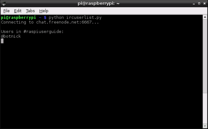
PART III PROGRAMMING WITH THE RASPBERRY PI
198
is tells Python that when the 366 response has been received, it should print out the now-
complete list of names to the standard output before blanking the names list again. is last
line—names = []—is important: without it, each time the loop runs it will add users’
names to the list even though they already exist from an earlier run.
Finally, nish the program by entering the following lines:
time.sleep(irc[‘namesinterval’])
s.send(‘NAMES %(channel)s\r\n’ % irc)
is tells Python to wait the namesinterval number of seconds before sending another
request for user names and beginning the loop again. Be careful to set namesinterval to a
reasonable value—if the IRC server receives too many requests in too short a space of time,
it may forcibly disconnect you for ooding.
Save the program as ircuserlist.py, and run it either by using IDLE’s Run Module
option in the Run menu or from the terminal by typing python ircuserlist.py. When
the program rst runs, it may take a while to connect to the server; once connected, how-
ever, the list of names (see Figure 12-7) should refresh quickly. To quit the program, press
CRTL + C.
F -:
Using Python to
list users in an
IRC channel
CHAPTER 12 AN INTRODUCTION TO PYTHON 199
A full copy of the program listing for the IRC user list is included in Appendix A, “Python
Recipes”, and on the Raspberry Pi User Guide website at www.wiley.com/go/
raspberrypiuserguide2e. Downloading the source code from the website will save you
some typing, but entering the code by hand is a good way of ensuring that you understand
what each section does.
Further Reading
I hope this chapter has given you a taste of what you can do with Python. It’s far from exhaus-
tive—to do the language full justice would take a considerably larger book. However, there
are plenty of resources out there for learning more about the Python language, including the
following:
❍ e ocial Beginner’s Guide to Python, which you can access at http://wiki.
python.org/moin/BeginnersGuide.
❍ A free, interactive tutorial that runs entirely in your browser is available for download
at http://www.learnpython.org/.
❍ Zed A. Shaw’s Learn Python e Hard Way (Shavian Publishing, 2012) oers great
insight into best-practice coding for Python, and despite the name, it’s suitable for
beginners. is book is commercially available, or you can read it for free at http://
learnpythonthehardway.org/.
❍ Although somewhat outdated and since replaced by Dive Into Python 3 (APRESS, 2009),
Dive Into Python by Mark Pilgrim (APRESS, 2004) does a good job of addressing the
basics of writing programs in Python. It’s available for free download at http://www.
diveintopython.net/ or for purchase in printed format from all good booksellers.
❍ If you prefer hands-on learning with other interested individuals, a list of local Python
User Groups—sometimes called PIGgies—can be found at http://wiki.python.
org/moin/LocalUserGroups.
❍ For learning pygame, Al Sweigart’s book Making Games with Python & Pygame
(CreateSpace, 2012) is a great introduction with practical examples. You can purchase
the hardcopy book or downloaded it for free at http://inventwithpython.com/.
Part IV
Hardware
Hacking
Chapter 13 Learning to Hack Hardware
Chapter 14 e GPIO Port
Chapter 15 e Raspberry Pi Camera Module
Chapter 16 Add-on Boards
Chapter 13
Learning to Hack Hardware
PART IV HARDWARE HACKING
204
IN EARLIER CHAPTERS, you learned how the Raspberry Pi can be turned into a exible plat-
form for running a variety of software. In this, it’s not alone: any desktop or laptop can run the
same software, and in many cases run it far faster than the Pi’s low-power processor can manage.
e Pi has another trick up its sleeve, though, which places it above and beyond the capabili-
ties of the average PC: its 26-pin general-purpose input-output (GPIO) port, located on the top-
left of the Pi’s printed circuit board.
e GPIO enables the Pi to communicate with other components and circuits, and allows it
to act as a controller in a larger electronic circuit. rough the GPIO port, it’s possible to have
the Pi sense temperatures, move servos and talk to other computing devices using a variety
of dierent protocols including Serial Peripheral Interface (SPI) and Inter-Integrated Circuit
(I²C). Chapter 14, “e GPIO Port”, provides details on working with the GPIO pins.
Before you can get begin building circuits to use with the Pi’s GPIO port, however, you’re
going to need some additional equipment and to understand some of the language sur-
rounding the world of electronics.
Electronic Equipment
To start building circuits that can be controlled by the Pi’s GPIO port, you’ll need various
components and tools. e following list provides a sample shopping list for getting started
with electronics:
❍ Breadboard—An electronic breadboard provides a grid of holes spaced at 2.54 mm
intervals into which components can be inserted and removed. Below each grid is a
series of electrical contacts, which allow components in the same row to be connected
together without wires. A breadboard is a valuable tool for electronics work, because it
allows you to quickly make mock-up circuits that can be modied without needing to
be soldered or desoldered.
❍ Wires—While a breadboard allows some components to be joined without wiring,
you’ll still need wires to connect one row to another. ese are known as jumper wires,
and if you’re working on a breadboard, it’s a good idea to get solid-core wire rather
than stranded-core wire. Solid-core wire is easier to insert into the breadboard’s holes
compared to stranded. It’s also helpful to get various colours, so you can colour-code
each connection according to its purpose.
❍ Resistors—e vast majority of electrical circuits make use of components called
resistors, and the example projects in this chapter are no exception. Resistors are mea-
sured in ohms, written as the symbol Ω. Always try to have a handful each of a variety
of common values: 2.2 KΩ, 10 KΩ, and 68Ω are good values to start with. Some retail-
ers carry resistor kits, which include a wide range of useful values.
CHAPTER 13 LEARNING TO HACK HARDWARE 205
❍ Push-buttons—A very common input component, a push-button completes an electri-
cal circuit when pushed. At the most basic level, a keyboard is little more than a collec-
tion of push-buttons. If you’re designing a circuit to provide a simple input to the Pi,
pick the button labelled momentary switch.
❍ LEDs—Light-emitting diodes (LEDs) are the most common output device in existence.
An LED lights up when voltage is applied, giving you visual feedback on whether a pin
on the Pi’s GPIO port is high or low. When you’re buying LEDs for use with the Pi, opt
for low-power ones. e GPIO port isn’t that powerful, and high-current LEDs—such
as bright-white or bright-blue models—will require an external power supply and an
extra component known as a transistor.
Additionally, if you’re planning on making something more permanent once you’ve nished
your breadboard prototype (which you’ll learn about later in this chapter), you’ll also need
the following:
❍ Stripboard—is can be thought of as a single-use breadboard. As with breadboards,
holes are arranged in a 2.54 mm grid. Unlike breadboards, the components need to be
soldered into place—after which you’ve got a permanent electronic circuit.
❍ Soldering iron—When you need to connect a component permanently into a circuit,
you need to solder it. You don’t have to spend a fortune on a soldering iron, but if your
budget stretches to a temperature-controlled model, it’s a wise investment. Make sure
any soldering iron you buy has a small, pointed tip—chisel-tip irons aren’t suitable for
delicate electronic work.
❍ Solder—Your soldering iron needs solder. Solder is a mixture of conductive metals
mixed with a cleaning substance known as ux. Make sure the solder you buy is suit-
able for electronics work—thick, plumbing solder is cheap but may damage delicate
circuits, because it requires too much heat to melt.
❍ Stand and sponge—It’s important to have somewhere to put the hot soldering iron
when it’s not in use, and a way of cleaning the tip of the iron while you’re using it.
Some soldering irons come with a stand with a built-in cleaning sponge—if yours
didn’t, buy a separate stand-and-sponge set.
❍ Side cutters—rough-hole components have long legs, which are left sticking out
after you’ve soldered them in place. Side cutters allow you to cleanly and quickly trim
these excess legs without damaging the solder joint.
❍ Tweezers—Electronics components can be small and ddly, and a good pair of twee-
zers is invaluable. If you’re thinking of using surface-mount components, instead of
the easier-to-solder through-hole components, tweezers are an absolute necessity—
without tweezers, you’ll burn your ngers if you try to hold the component and solder
it at the same time!
PART IV HARDWARE HACKING
206
❍ Work stand—Commonly referred to as helping hands, these are weighted stands with
clamps or clips that hold the item to be soldered in place. Some work stands include an
integrated magnifying glass for delicate work, while the most expensive work stands
add a light to help illuminate the work area.
❍ Multimeter—Multimeters are test meters that have multiple functions including
voltage, resistance and capacitance measurement, along with continuity testing for
nding breaks in circuits. Although a multimeter is not an absolute necessity, it can be
extremely useful for diagnosing issues with circuits. Professional multimeter units can
be quite expensive, but a simple model is fairly inexpensive and is a sound investment
for anyone getting started in electronics.
❍ Desoldering wick—Mistakes happen, but they don’t have to be permanent. A desol-
dering wick is a braided metal tape that can be placed over a solder joint and heated,
pulling the solder away from the component and into the wick. With practice, it’s pos-
sible to use a desoldering wick to salvage components from discarded electronic equip-
ment—a handy way to gather common components cheaply.
Reading Resistor Colour Codes
Most electronic components are clearly labelled. For example, capacitors will have their capac-
itance, measured in farads, printed directly on them, while crystals will have their frequency
likewise marked.
e major exception is a resistor, which typically has no writing on its surface. Instead, the
resistance value in ohms is calculated from the colour bands that adorn the resistor’s surface.
Learning to decode these bands is an important skill for a hardware hacker to learn, because
once a resister is removed from its packaging, the only way to gure out its value is to use a
multimeter, which is an awkward and slow measuring tool for this particular job.
ankfully, the resistor colour codes follow a logical pattern. Figure 13-1 shows a typical
four-band resistor. A high-resolution colour version of this diagram is available on the
Raspberry Pi User Guide website at www.wiley.com/go/raspberrypiuserguide2e. e
rst two bands are assigned a colour that equates to a resistance value in ohms. e third
band is the multiplier, by which the rst two numbers are multiplied to arrive at the actual
resistance value. e nal band indicates the tolerance of the resistor, or how accurate it is. A
resistor with a lower tolerance will be closer to its marked value than a resistor with a higher
tolerance, but you’ll pay more for the component.
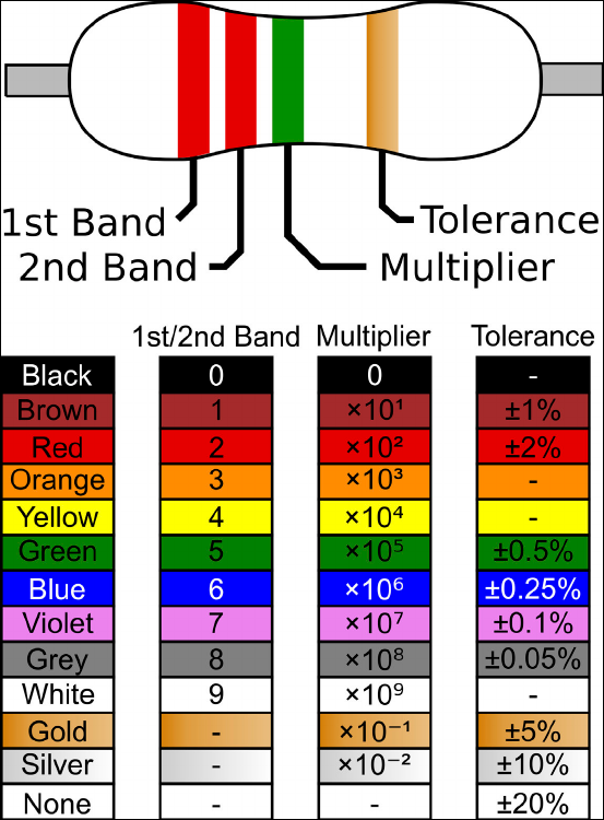
CHAPTER 13 LEARNING TO HACK HARDWARE 207
Figure 13-1:
A four-band
resistor and the
decoding table
for its colour
code
To read the example resistor, rst take the two resistance bands starting from the left: these
are coloured red and red. Red, on the table included in Figure 13-1, equates to the value 2, so
the initial reading is 22. e next band is green, which is the multiplier and equates to 105 or
100,000 (10 followed by ve zeros). Multiplying 22 by 100,000 equals 2,200,000, which is
the resistance value in ohms: 2,200,000 Ω.
ere are 1,000 ohms in a kiloohm, and 1,000 kiloohms in a megaohm. us, 2,200,000 Ω
would typically be written as 2,2 MΩ. e nal band, located on the right side of the resistor,
is gold and details the tolerance, or accuracy, of the resistor, which is plus or minus 5 percent
in the example shown in Figure 13-1.
PART IV HARDWARE HACKING
208
ere are also ve-band resistors. You read these in the same way as a four-band resistor,
except that the rst three bands oer resistance gures, the fourth the multiplier, and the
fth the tolerance.
Sourcing Components
If you haven’t dabbled in electronics before, it can be dicult to nd components and tools.
ankfully, there are plenty of online and oine sources that specialise in the hard-to-nd
components you might need to complete your project.
Online Sources
Two of the largest retailers of electronic components and tools in the world are RS Components
and Farnell. Both operate oces and warehouses across the world, and both have a substan-
tial selection of hardware from which to choose. Chances are you’re familiar with at least one
of the two retailers. At the time of this writing, RS Components and Farnell were the only
two companies licensed to produce the Raspberry Pi hardware by the Raspberry Pi
Foundation, so unless you’re reading this book while considering the purchase of a Raspberry
Pi, you’ll have ordered the device from one of the two.
Both RS Components and Farnell focus on business-to-business transactions, meaning that
their main source of income is from electronics companies buying large quantities of compo-
nents. However, both will happily allow consumers to register with their respective web
stores and place orders as small as individual components.
When you’re placing small orders, be aware that there may be additional charges incurred. RS
Components charges for its next-day delivery service, and while the charge is quite reason-
able for larger orders, it can cost signicantly more than the components being purchased
for smaller orders. On the other hand, Farnell doesn’t charge for next-day delivery but does
mandate a minimum total value for orders placed through its website.
Depending on where you live, you may be able to reserve items for collection at one of RS
Components’ or Farnell’s trade counters. is saves on the cost of postage and gets you the
goods faster, but it may not be an option at your location. e websites for both retailers can
be found here:
RS Components: http://www.rs-online.com
Farnell: http://www.farnell.com
CHAPTER 13 LEARNING TO HACK HARDWARE 209
Ofine Sources
You may nd that you need a component immediately, and even next-day delivery would not be
soon enough. Or you may only need a single resistor or a small length of wire and can’t justify a
high delivery cost or minimum order value for one of the online retailers. ankfully, there are
brick-and-mortar stores that specialise in electronic components. Although there are not as many
of these types of stores as in previous decades, most major towns and cities will include at least
one physical shop that stocks the most commonly required tools and components.
In the UK, the most popular chain of electronic component shops is Maplin Electronics.
Established in Essex in 1972, the company has grown from a small mail-order outlet to
include 187 stores across the UK. Inhabitants of most cities will nd themselves within reach
of a Maplin Electronics store, which can be a handy source of hardware if you’re running low
on common parts.
Maplin Electronics also oers a mail-order and click-and-reserve service through its website,
but beware its business-to-consumer focus. Many components are signicantly more expen-
sive when ordered from Maplin than from RS Components or Premier Farnell, because the
company relies on mark-up rather than high-volume trade to make a prot.
In the US and other countries, Radio Shack remains the most popular chain of electronics
stores. Founded in 1921 and boasting over 7,150 stores across the world, the company
stocks a wide selection of common electronic components and tools that can be purchased in
person or ordered for delivery through its website.
As with Maplin Electronics in the UK, Radio Shack is a business-to-consumer operation. As a result,
buyers can expect to pay more for components purchased at Radio Shack than the same parts
ordered from RS Components or Farnell. However, the large number of Radio Shack stores make
it a convenient choice for buyers who are in a hurry or who are looking for one-o items.
Both Maplin and Radio Shack also have the advantage of being staed by people to whom
you can speak. Many employees of both companies have signicant knowledge in electron-
ics, and are happy to oer advice and assistance if you’re unsure of what parts you need for a
given project. e websites for both retailers can be found here:
Maplin Electronics: http://www.maplin.co.uk
Radio Shack: http://www.radioshack.com
Hobby Specialists
In addition to the major chains, there are smaller companies that specialise in working with
hobbyists. Although their selection is dwarfed by those of the larger chains, it’s typically hand-
picked and comes with the personal recommendation of the people behind the company.
PART IV HARDWARE HACKING
210
Many of these hobby shops sprang up in the wake of the Arduino, an open-source project to
create an educational-friendly microcontroller prototyping platform. With the Raspberry Pi
appealing to much the same audience as the Arduino—albeit for very dierent tasks—the
majority are investigating support for the Pi in addition to their existing product lines.
Buying from a hobby specialist has several advantages. If the products are sold as working
with the Pi, then they’ve been tested for that specic reason—taking much of the guesswork
out of the equation. Several companies also design their own add-on hardware for various
platforms, with the Pi being no exception. ese devices, designed to address a need in the
community, may include additional ports and/or extra hardware, or can otherwise extend
the functionality of the target device.
In the UK, one of the most popular hobby specialists is oomlout. Founded by open-source
enthusiasts working with Arduino hardware, it’s an excellent source of add-on kits as well as
common components including push-buttons, displays and transistors. Unlike the larger
retailers, oomlout equips its components with all necessary extras—such as pull-up resistors
for the push-buttons—and a circuit schematic for easy assembly. Where possible, sample
source code is also provided to get you up and running as quickly as possible.
In the US, Adafruit oers a similar service. Founded with the intention of making open-
source add-ons for the Arduino boards, Adafruit oers a wide selection of components and
kits—including one of the rst add-on boards designed specically for the Raspberry Pi (see
Chapter 16, “Add-on Boards”, for more details).
e websites for both retailers can be found here:
oomlout: http://oomlout.co.uk/
Adafruit: http://www.adafruit.com
Moving Up From the Breadboard
As the previous examples in this chapter have shown, breadboards are excellent for quickly
creating prototype circuits for experimentation. ey’re fast and reusable, and they don’t
damage components.
However, breadboards also have some disadvantages. ey’re bulky, expensive, and prone to
loose connections—which can result in critical components falling out, especially while the
breadboard is being transported from place to place. Figure 13-2 demonstrates this perfectly:
despite best eorts, the push-button component is only loosely secured in the breadboard,
and is likely to fall out if the circuit is handled roughly.
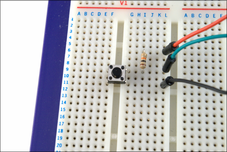
CHAPTER 13 LEARNING TO HACK HARDWARE 211
Figure 13-2:
A sample
breadboard
circuit, with
loose-tting
components
is, among other reasons, is why the Raspberry Pi itself is built on a printed circuit board
(PCB) rather than a breadboard—although the breadboard method was certainly used in the
early days of prototyping the device. It’s possible to print and etch your own PCBs at home,
but there is a simpler intermediate step you can take: using stripboard to create permanent
stand-alone circuits.
At rst glance, stripboard looks similar to breadboard, because its surface is covered in small
holes at 2.54 mm spacing. Unlike a breadboard, however, there’s no clever mechanism for
ensuring that electronic components placed into these holes stay in place—instead, you’ll
have to solder them onto the stripboard. Stripboard is often referred to by the trade name
Veroboard, which is a trademark of Vero Technologies in the UK and Pixel Print in Canada.
Creating a stripboard circuit has many advantages over using a breadboard. A sheet of strip-
board is signicantly cheaper than an equivalently sized breadboard, and it can be snapped
to size for smaller circuits. is also allows a single, large piece of stripboard to be used in the
creation of several smaller, independent circuits.
Because components are soldered onto stripboard, it’s also signicantly more robust than a
breadboard prototype. A stripboard circuit can be carried around from place to place with
little risk that one of its components will become dislodged and lost. Figure 13-3 shows a
piece of stripboard ipped to show the copper tracks on its underside.
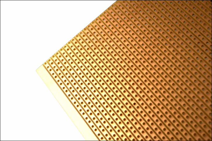
PART IV HARDWARE HACKING
212
Figure 13-3:
e copper
tracks on the
underside of a
piece of
stripboard
Stripboard is extremely easy to use, which makes it a great stepping-stone to custom circuit
board design and manufacturing. However, you should be aware of the following before you
buy stripboard:
❍ ere are dierent types of stripboard. Some stripboards have copper tracks on the
underside, which go all the way across a row or down a column, while other stripboards
are split into two separate rows with a gap in the middle like a breadboard. Yet another
type of stripboard, often called a project board, has no copper tracks at all and requires
the use of wires to join components together electrically.
❍ Stripboard can be made in dierent thicknesses and with dierent materials, and one
type of stripboard may be more suited to a particular project than another. For exam-
ple, a heatproof stripboard is good for a circuit that is going to be in a high-tempera-
ture environment, while thicker stripboard should be used for circuits that may be
exposed to rough handling.
❍ To make the component layout on a stripboard neater, it’s possible to break the tracks
on the underside to separate components electrically. is avoids wasted board space
and is an absolute necessity in more complex circuits—but to achieve the neatest
results, you’ll need a small hand-held tool called a track cutter. Remember to add that to
your shopping list if you’re planning on using stripboard, although a small drill bit can
also be used.

CHAPTER 13 LEARNING TO HACK HARDWARE 213
ere are also some tricks to handling stripboard that, if ignored, can make things harder
than they have any reason to be:
❍ e copper tracks on the underside of stripboard are not usually coated in any way. As
you touch the tracks, you will tarnish the copper and make it dicult to solder. Avoid
touching the underside of stripboard unless you’re going to use it immediately; if it’s
too late, get some steel wool and give the copper a gentle brush to remove the corro-
sion before attempting to solder.
❍ Unlike a printed circuit board, stripboard has no solder mask—a substance that pre-
vents solder from going anywhere it isn’t supposed to. As a result, soldering is some-
what trickier than it is on a PCB—it’s all too easy to accidentally join tracks together
with too-large a blob of solder. If this happens, use your desoldering wick to remove
the excess solder and try again.
❍ e holes in stripboard make it easy to snap into custom sizes, but leave the edges
ragged. After snapping stripboard, take the time to le down the edges before assem-
bling your circuit. Make sure you wear a face-mask when doing this, because the dust
from stripboard isn’t particularly healthy to breathe.
A Brief Guide to Soldering
Having a soldering iron is one thing, but you also need to know how to use it. Soldering, like
any skill, takes practice to become procient. If you follow the tips in this section and keep
practising, you’ll be creating clean, tidy solder joins in no time.
WARNING
This may seem obvious, but it’s worth pointing out: soldering irons get extremely hot during
use. Make sure you don’t touch any exposed metal surface, even away from the tip, and be
careful where you put the iron down. If possible, buy an iron with a stand, or obtain a separate
heatproof stand. Never leave a hot iron unattended, and if you drop an iron, don’t be tempted
to try to catch it!
Soldering works by melting a small quantity of metal to form a join between two compo-
nents. If you turn the Raspberry Pi over, you’ll see plenty of evidence of this. All the larger
components are connected using what’s called through-hole soldering, where the components’
leads are passed through holes in the printed circuit board and then soldered into place.
Smaller components are attached via surface-mount soldering.
Solder isn’t pure metal—it also contains a substance called ux, which is designed to etch
away any tarnish on the surfaces to be soldered in order to ensure as clean a join as possible.
Most electronic solder includes three to ve cores of ux. You can also buy ux separately as
a paste or in liquid form, although for most hobby soldering, this isn’t necessary.
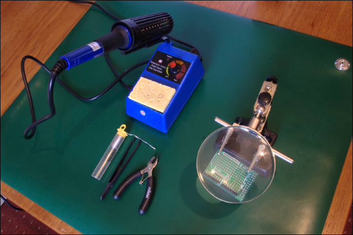
PART IV HARDWARE HACKING
214
When you’re starting a soldering project, make sure you have a clean, well-lit workspace. Also
make sure the area is well ventilated. Solder fumes aren’t very healthy, and while they’re
extremely unlikely to build up to dangerous levels in low-volume hobby soldering, it’s still a
good idea to keep exposure to a minimum.
In addition, you should protect the work surface in some way. It’s not uncommon for small
blobs of molten solder to fall, which can burn and mark tables. You can purchase an anti-
static workmat (see Figure 13-4 for an example), but a glossy magazine works just as well.
Don’t be tempted to use a few sheets of cheap newspaper—solder can burn through thin
paper before it cools.
Figure 13-4:
An example
soldering work
area, with a
protective
antistatic
workmat
If you’re doing delicate, close-up work, you should wear protective glasses. Sometimes the
boiling ux inside the solder can cause it to spit upwards, and if it hits you in the eye, you’ll
be in for a world of pain.
Don’t let these warnings put you o soldering, however. Although solder is extremely hot, it
cools quickly and burns are not only rare but nearly always inconsequential. Respect the
equipment, but don’t fear it.
With your work surface chosen and protected, lay out your equipment. e iron should be
placed on the side of your dominant hand, and positioned so that the cable isn’t trailing

CHAPTER 13 LEARNING TO HACK HARDWARE 215
across your work area. Make sure you can move the iron freely before plugging it in. If the
cable gets caught on something, you may end up burning yourself.
Dampen your soldering sponge with water—it should be damp, but not dripping wet. is is
important: the damp sponge will be used to clean the iron, and if it’s dry, it will burn and may
damage the iron’s delicate tip.
It will take a few minutes for the soldering iron to reach its operating temperature. If you’ve
purchased a temperature-controlled iron, this will normally be indicated either by a light that
switches on or o to indicate the temperature has been reached or by a numerical tempera-
ture read-out. (See the operating manual that came with your soldering iron to nd out how
temperatures are indicated on it.)
Once the operating temperature has been reached, it’s time to prepare the soldering iron
using a process known as tinning. Follow these steps:
1. Push the tip of the solder against the tip of the iron, allowing a small amount to melt
onto the iron. Be careful not to melt too much onto the iron: not only is this a waste of
solder, but it can cause excess solder to fall onto the work area.
2. Wipe the tip of the iron onto the sponge. If it hisses and spits, the sponge is too wet;
allow it to cool, then remove it from the stand and wring it out.
3. Keep wiping the tip of the iron until it is coated in a silver layer of solder (see
Figure 13-5). If necessary, apply more solder to the tip.
Figure 13-5:
A soldering iron
tip that is in the
process of being
tinned with
solder
PART IV HARDWARE HACKING
216
is process of tinning the tip protects it against damage and ensures that it will eciently trans-
fer heat onto the surfaces to be soldered. Failure to properly tin the iron’s tip is one of the most
common causes of bad solder joints. You may need to repeat this process more than once if you’re
soldering a lot of connections, and you’ll need to do it again at the end of the soldering session. In
general, if the tip of the soldering iron loses its shiny coating, repeat the tinning process.
With the iron prepared, it’s time to start soldering. Place the items to be soldered—such as a
printed circuit board and the legs of a component—into the work stand, and ensure that
you’ve got a good view. Extend a length of solder from the container or reel, and begin to
solder the components using these basic steps:
1. If you’re soldering through-hole components into a printed circuit board, stripboard or
similar through-hole board, place the legs of the component through the holes and
bend them outwards so the component doesn’t fall out when the board is ipped over.
2. With the board secured in the work stand, push the tip of the iron against both the
component and the copper contact on the board. It’s important that the iron touches
both items: if the iron is only in contact with one, the nished joint will be bad.
3. It takes only a few seconds for the area to heat up. Count to three, and then push the
solder against the component and copper contact (see Figure 13-6). If the solder
doesn’t melt, withdraw it, count a couple of seconds more, and then try again. If it still
doesn’t melt, try repositioning the soldering iron.
4. As the solder ows, you’ll see it drawn down into the hole in the board. is is an indi-
cation that the area is hot enough for a good solder join. If the solder oats, it indicates
that the area is not yet hot enough.
5. Remove the solder from the join rst, followed by the iron. (If you remove the iron
rst, the solder will harden and leave your spool of solder stuck to the contact!)
If all went well, you’ll be left with a solid solder join that will last for many years. If not, don’t
be disheartened—just press the iron against the join to reow the solder, and use the desol-
dering wick if you need to clean up a spill or any excess. A perfect solder joint should have a
shape somewhat like a volcano, rising up from the surface of the board to meet the leg of the
component.
Never leave the iron in contact with the parts for more than a few seconds. is is especially
important when soldering heat-sensitive components like integrated circuits, which can
be damaged by prolonged contact with a hot soldering iron. If you’re using a temperature-
controlled solder station, make sure the temperature is set to an appropriate level for the
solder being used (check the solder’s packaging or data sheet for details).
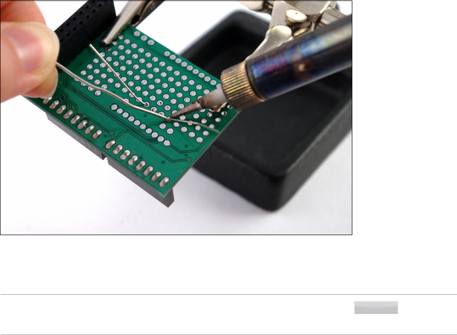
CHAPTER 13 LEARNING TO HACK HARDWARE 217
Figure 13-6:
Soldering a
through-hole
component into
a printed circuit
board
When you’ve nished, remember to re-tin the tip of the iron. If you don’t, the tip may corrode
in storage and need to be replaced signicantly sooner than would otherwise be the case.
TIP
Remember to heat both surfaces with the iron. Heating only one surface results in what is
known as a dry joint or cold joint, where the solder is not properly mated to one surface. Over
time, these joints will fail and need to be re-soldered.
As with any skill, soldering takes practice. Many electronics shops sell kits that include a
printed circuit board and a selection of components, which you can use to practice soldering
through-hole components. Some add-on boards for the Raspberry Pi are also provided in kit
form and require soldering, including the Slice of Pi from Ciseco. You’ll learn about these in
Chapter 16, “Add-on Boards”.
Chapter 14
The GPIO Port

PART IV HARDWARE HACKING
220
THE RASPBERRY PI’S general-purpose input-output (GPIO) port is located on the top-left of
the printed circuit board, labelled P1. It’s a 26-pin port, tted with two rows of 13 male 2.54
mm headers at the factory. e spacing of these headers is particularly important: 2.54 mm
pin spacing (0.1 inches in imperial measurements) is a very common sight in electronics and
is the standard spacing for prototyping platforms that include stripboards and breadboards.
Identifying Your Board Revision
e pin layout of the Raspberry Pi’s GPIO port diers slightly depending on what revision of
the board you own. All Model As and recent Model Bs have a common pin layout; the origi-
nal Model B, however, has a slightly dierent layout.
Before using the GPIO port for a hardware project, be sure you know which model of Raspberry
Pi you have. If you have a Model A, you can use the rst diagram in this chapter; if you have a
Model B, you will need to use the rst diagram—unless it’s an original Revision 1 model.
e easiest way to spot a Model B Revision 1 board is to look at the top side of the board, just
underneath the GPIO pins themselves: where a Revision 2 board has two rows of four copper-
plated holes, the Revision 1 is solid. Another method is to see how much memory is available:
the Model B Revision 1 had just 256 MB of memory, compared to 512MB on Revision 2 boards.
For more details on the board revisions and how to tell them apart, see Chapter 1, “Meet the
Raspberry Pi”.
GPIO Pinout Diagrams
Each pin of the GPIO port has its own purpose, with several pins working together to form
particular circuits. e layout of the GPIO port can be seen in Figure 14-1.
e GPIO port is the same across both the Raspberry Pi Model A and the Model B Revision 2.
If you have one of the original Raspberry Pi Model B Revision 1 boards—and if you do, con-
gratulations on having a collector’s item—then the pins available on the GPIO port are subtly
dierent. ese details can be seen in Figure 14-2.
TIPIf you’re not sure which revision of the Raspberry Pi you have, and thus which pinout applies
to your board, load IDLE and type import RPi.GPIO as GPIO followed by GPIO.RPI_
REVISION to return the revision number.
Pin numbers for the GPIO port are split into two rows, with the bottom row taking the odd
numbers and the top row the even numbers. It’s important to keep this in mind when working
with the Pi’s GPIO port: most other devices use a dierent system for numbering pins, and
because there are no markings on the Pi itself, it’s easy to get confused as to which pin is which.
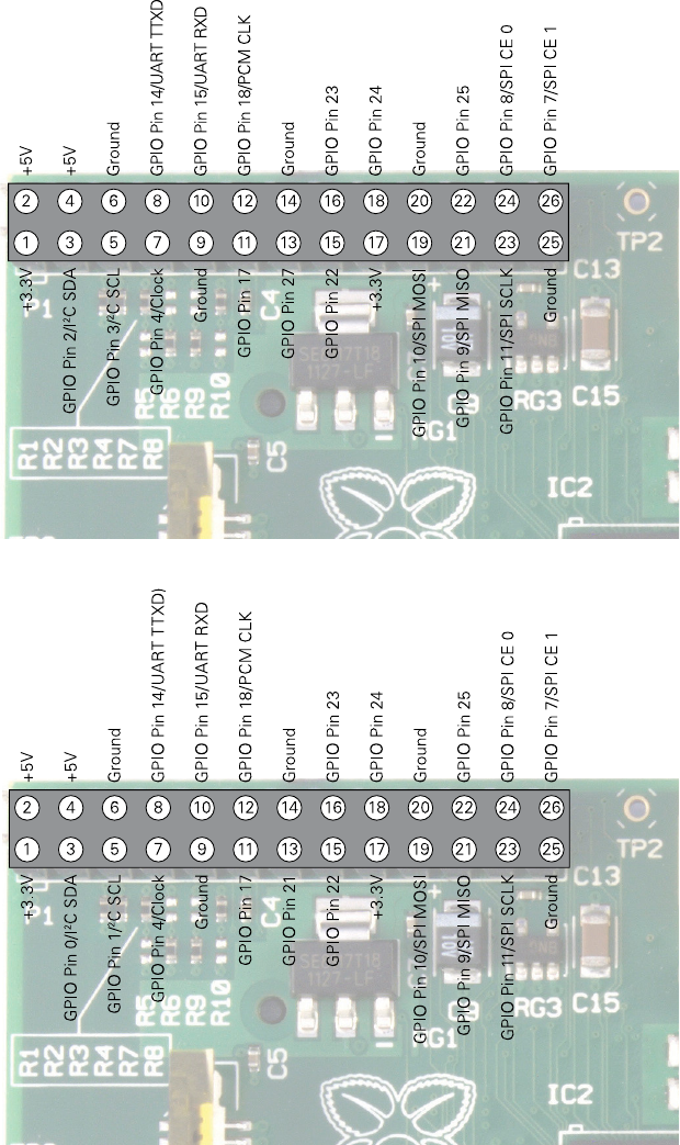
CHAPTER 14 THE GPIO PORT 221
Figure 14-1:
e Raspberry
Pi’s GPIO port
and its pin
denitions
Figure 14-2:
e original
Raspberry Pi
Model B
Revision 1 GPIO
pinout

PART IV HARDWARE HACKING
222
Although the Pi’s GPIO port provides a 5 V power supply, tapped from the incoming power
on the micro-USB hub, on Pin 2, the Pi’s internal workings are based on 3.3 V logic. is
means that the components on the Pi work from a 3.3 V power supply. If you’re planning on
creating a circuit that will interface with the Pi through its GPIO port, make sure you are
using components compatible with 3.3 V logic or are passing the circuit through a voltage
regulator before it reaches the Pi.
WARNING Connecting a 5 V supply to any pin on the Raspberry Pi’s GPIO port, or directly shorting either of
the power supply pins (Pin 1 and Pin 2) to any other pin will result in damage to the Pi. Because
the port is wired directly to pins on the Broadcom BCM2835 SoC processor, you will not be able
to repair any damage you do to it. Always be extra careful when working around the GPIO port.
GPIO Features
e GPIO port provides eight pins for general-purpose use by default: Pin 7, Pin 11, Pin 12,
Pin 13, Pin 15, Pin 16, Pin 18 and Pin 22. ese pins can be toggled between two states: high,
where they are providing a positive voltage of 3.3 V; and low, where they are equal to ground
or 0 V. is equates to the 1 and 0 of binary logic, and can be used to turn other components
on or o. You’ll learn more about this later in the chapter.
WARNING The Pi’s internal logic operates at 3.3 V. This is in contrast to many common microcontroller
devices, such as the popular Arduino and its variants, which typically operate at 5 V. Devices
designed for the Arduino may not work with the Pi unless a level translator or optical isolator
is used between the two. Likewise, connecting pins on a 5 V microcontroller directly to the
Raspberry Pi’s GPIO port will not work and may permanently damage the Pi.
In addition to these general-purpose pins, the GPIO port has pins dedicated to particular
buses. ese buses are described in the following subsections.
UART Serial Bus
e Universal Asynchronous Receiver/Transmitter (UART) serial bus provides a simple two-wire
serial interface. When a serial port is congured in the cmdline.txt le (as described in
Chapter 7, “Advanced Raspberry Pi Conguration”), it’s this serial bus that is used as the port
for the messages. Connecting the Pi’s UART serial bus to a device capable of displaying the
data will reveal messages from the Linux kernel. If you’re having trouble getting the Pi to
boot, this can be a handy diagnostic tool—especially if nothing is showing on the display.
e UART serial bus can be accessed on Pins 8 and 10, with Pin 8 carrying the transmit signal
and Pin 10 carrying the receive signal. e speed can be set in the cmdline.txt le, and is
usually 115,200 bits per second (bps).
CHAPTER 14 THE GPIO PORT 223
I2C Bus
As the name suggests, the Inter-Integrated Circuit (I²C) bus is designed to provide communica-
tions between multiple integrated circuits (ICs). In the case of the Pi, one of those integrated
circuits is the Broadcom BCM2835 SoC processor at the heart of the system. ese pins
include access to pull-up resistors located on the Pi, meaning no external resistors are required
to access the I2C functionality.
e I2C bus can be accessed on Pins 3 and 5, with Pin 3 providing the Serial Data Line (SDA)
signal and Pin 5 providing the Serial Clock (SCL) signal. e I2C bus available on these pins is
actually only one of two provided by the BCM2835 chip itself, and is known as I2C0. e
second, I2C1, is terminated at resistors on the Raspberry Pi circuit board itself and is not
available for general-purpose use.
SPI Bus
e Serial Peripheral Interface (SPI) bus is a synchronous serial bus designed primarily for in-
system programming (ISP) of microcontrollers and other devices. Unlike the UART and I²C
buses, it’s a four-wire bus with multiple Chip Select lines, which allow it to communicate with
more than one target device.
e Pi’s SPI bus is available on Pins 19, 21 and 23, with a pair of Chip Select lines on Pin 24
and Pin 26. Pin 19 provides the SPI Master Output, Slave Input (MOSI) signal; Pin 21 provides
the SPI Master Input, Slave Output (MISO) signal; Pin 23 provides the Serial Clock (SLCK) used
to synchronise communication; and Pins 24 and 26 provide the Chip Select signals for up to
two independent slave devices.
Although additional buses are present in the Raspberry Pi’s BCM2835 SoC processor, they
are not brought out to the GPIO port and are thus unavailable for use.
Using the GPIO Port in Python
With the theory out of the way, it’s time to get practical. In this section, you’ll l learn how to
construct and program two simple electronic circuits that demonstrate how to use the GPIO
port for input and output.
As you saw in Chapter 12, “An Introduction to Python”, Python is a friendly yet powerful
programming language. It’s not, however, the perfect choice for every scenario. Although it
works ne for the simple circuits you’ll be creating in this chapter, it does not oer what is
known as deterministic real-time operation. For the majority of users, this doesn’t matter; if
you’re planning on using the Pi at the heart of a nuclear reactor or a complex robotics plat-
form, however, you may want to investigate a lower-level language such as C++ or even
assembler running on a dedicated real-time microcontroller.

PART IV HARDWARE HACKING
224
If true real-time operation is required for your project, the Pi may be a bad choice. Instead,
consider using a microcontroller platform such as the popular open-source Arduino, or one
of the MSP430 family of microcontrollers from Texas Instruments. Both of these devices
can interface with the Pi either through the GPIO header or over USB, and provide a special-
ised real-time environment for control and sensing.
GPIO Output: Flashing an LED
For the rst example, you’ll need to build a simple circuit consisting of an LED and a resistor.
e LED will provide visual conrmation that the Pi’s GPIO port is doing what your Python
program tells it to do, and the resistor will limit the current drawn by the LED to protect it
from burning out.
Calculating Limiting Resistor Values
An LED needs a current limiting resistor to protect it from burning out. Without a resistor, an LED
will likely only work for a short time before failing and needing to be replaced. Knowing a resistor
is required is one thing, but it’s also important to pick the right resistor for the job. Too high a
value and the LED will be extremely dim or fail to light at all; too low a value and it will burn out.
To calculate the resistor value required, you will need to know the forward current of your
LED. This is the maximum current the LED can draw before being damaged, and is measured
in milliamps (mA). You’ll also need to know the forward voltage of the LED. This latter value,
measured in volts, should be 3.3 V or lower—any higher, and the LED will require an external
power supply and a switching device known as a transistor before it will work with the Pi.
The easiest way to work out how large a resistor is required is with the formula R=(V-
F)/I, where R is resistance in ohms, V is the voltage applied to the LED, F is the forward
voltage of the LED and I is the maximum forward current of the LED in amps (with a thou-
sand mA to the amp).
Taking a typical red LED with a forward current of 25 mA and a forward voltage of 1.7 V, and
powering it using the 3.3 V supplied by the Pi’s GPIO port, you can calculate the resistor
needed as (3.3 – 1.7) / 0.025 = 64. Thus, a resistor of 64 Ω or higher will protect
the LED. These gures rarely come out to match the common resistor values as sold, so
when you’re choosing a resistor, always round up to ensure the LED is protected. The near-
est commonly available value is 68 Ω, which will adequately protect the LED.
If you don’t know the forward voltage and forward current of your LEDs (for example, if the
LEDs did not come with documentation or were salvaged from scrap electronics), err on the
side of caution and t a reasonably large resistor. If the LED is too dim, you can revise
downwards—but it’s impossible to repair an LED that has been blown.

CHAPTER 14 THE GPIO PORT 225
To assemble the circuit, you’ll need a breadboard, two jumper wires, an LED and an appropri-
ate current-limiting resistor (as described in the “Calculating Limiting Resistor Values” side-
bar). Although it’s possible to assemble the circuit without a breadboard by twisting wires
together, a breadboard is a sound investment and makes assembling and disassembling pro-
totype circuits straightforward.
Assuming the use of a breadboard, assemble the circuit in the following manner to match
Figure 14-3:
1. Insert the LED into the breadboard so that the long leg (the anode) is in one row and
the shorter leg (the cathode) is in another. If you put the LED’s legs into the same row,
it won’t work.
2. Insert one leg of the resistor into the same row as the LED’s shorter leg, and the other
resistor leg into an empty row. e direction in which the resistor’s legs are placed
doesn’t matter, as a resistor is a non-polarised (direction-insensitive) device.
3. Using a jumper wire, connect Pin 11 of the Raspberry Pi’s GPIO port (or the corre-
sponding pin on an interface board connected to the GPIO port) to the same row as
the long leg of the LED.
4. Using another jumper wire, connect Pin 6 of the Raspberry Pi’s GPIO port (or the cor-
responding pin on an interface board connected to the GPIO port) to the row that
contains only one leg of the resistor and none of the LED’s legs.
WARNING
Be very careful when connecting wires to the Raspberry Pi’s GPIO port. As discussed earlier in
the chapter, you may do serious damage to the Pi if you connect the wrong pins.
At this point, nothing will happen. at’s perfectly normal: by default, the Raspberry Pi’s
GPIO pins are switched o. If you want to check your circuit immediately, move the wire
from Pin 11 to Pin 1 to make the LED light up. Be careful not to connect it to Pin 2, though:
a current-limiting resistor suitable for a 3.3 V power supply will be inadequate to protect the
LED when connected to 5 V. Remember to move the wire back to Pin 11 before continuing.
To make the LED do something useful, start a new Python project. As with the projects in
Chapter 12, “An Introduction to Python”, you can use a plain text editor or the IDLE soft-
ware included in the recommended Raspbian distribution for this project as well.
Before you can use the Raspberry Pi GPIO port from Python, you’ll need to import a library
into your Python project. Accordingly, start the le with the following line:
import RPi.GPIO as GPIO

PART IV HARDWARE HACKING
226
Figure 14-3:
A breadboard
circuit for a
simple LED
output
Remember that Python is case-sensitive, so be sure to type RPi.GPIO exactly as it appears.
To allow Python to understand the concept of time (in other words, to make the LED blink,
rather than just turning it on and o), you’ll also need to import the time module. Add the
following line to the project:
import time
With the libraries imported, it’s time to address the GPIO ports. e GPIO library makes it easy to
address the general-purpose ports through the instructions GPIO.output and GPIO.input,
but before you can use them, you’ll need to set the GPIO library in board mode—which numbers
the pins according to their physical position on the Raspberry Pi—and initialise the pins as either
inputs or outputs. In this example, Pin 11 is an output, so add the following line to the project:
GPIO.setmode(GPIO.BOARD)
GPIO.setup(11, GPIO.OUT)
CHAPTER 14 THE GPIO PORT 227
e last line tells the GPIO library that Pin 11 on the Raspberry Pi’s GPIO port should be set
up as an output. If you were controlling additional devices, you could add more GPIO.setup
lines into the project. For now, however, one will suce.
With the pin congured as an output, you can switch its 3.3 V supply on and o in a simple
demonstration of binary logic. e instruction GPIO.output(11, True) will turn the pin
on, while GPIO.output(11, False) switches it o again. e pin will remember its last
state, so if you only give the command to turn the pin on and then exit your Python pro-
gram, the pin will remain on until told otherwise.
Although you could just add GPIO.output(11, True) to the Python project to switch the
pin on, it’s more interesting to make it blink. First, add the following line to create an innite
loop in the program:
while True:
Next, add the following lines to switch the pin on, wait two seconds, and then switch it o
again before waiting another two seconds. Make sure each line starts with four spaces, to
signify that it is part of the innite while loop:
GPIO.output(11, True)
time.sleep(2)
GPIO.output(11, False)
time.sleep(2)
e nished program should look like this (see Figure 14-4):
import RPi.GPIO as GPIO
import time
GPIO.setmode(GPIO.BOARD)
GPIO.setup(11, GPIO.OUT)
while True:
GPIO.output(11, True)
time.sleep(2)
GPIO.output(11, False)
time.sleep(2)
Save the le as gpiooutput.py. If you’re using a Python development environment such
as SPE, don’t try to run the program from within the editor. Most Raspberry Pi Linux distri-
butions restrict the use of the GPIO port to the root user, so the program will need to be run
using the command sudo python gpiooutput.py at the terminal to get it started. If all
has gone well, you should see the LED begin to blink on and o at regular intervals—and
you’ve created your rst home-made output device for the Pi.

PART IV HARDWARE HACKING
228
Figure 14-4:
e
gpiooutput.
py program,
being edited in
nano, and
waiting for its
nal line
If things don’t work, don’t panic. First, check all your connections. e holes in a breadboard
are quite small, and it’s easy to think you’ve inserted a component into one row only to nd
it’s actually in another. Next, check that you’ve connected the circuit to the right pins on the
GPIO port—with no labelling on the Pi itself, mistakes are unfortunately easy to make.
Finally, double-check your components—if the forward voltage of your LED is higher than
3.3 V or if your current limiting resistor is too large, the LED won’t light up.
Although this example is basic, it’s a good demonstration of some fundamental concepts. To
extend its functionality, the LED could be replaced with a buzzer to make an audible alert, or
a servo or motor as part of a robotics platform. e code used to activate and deactivate the
GPIO pin can be integrated into other programs, causing an LED to come on when new email
arrives or a ag to be raised when a friend has joined an IRC channel.
GPIO Input: Reading a Button
Being able to use the GPIO as an output is undeniably useful, but it becomes signicantly
more so when you can combine that with one or more inputs. In the following example,
you’ll see how to connect a push-button switch to another pin on the GPIO port and read its
status in Python.
CHAPTER 14 THE GPIO PORT 229
If you’ve already built the GPIO output example, you can either disconnect that from your Pi
or leave it connected—this example uses dierent pins, so both can co-exist quite happily. If
you do leave the previous example connected, make sure to use dierent rows on the bread-
board for the new components or you’ll nd things don’t work quite as planned.
Build the circuit as follows, matching Figure 14-5:
1. Insert the push-button switch into the breadboard. Most switches have either two or
four legs. You only need worry about two of the legs in the circuit. If the button has
four legs, they’ll be set up in in pairs: check the push-button’s data sheet to nd out
which legs are paired together.
2. Connect a 10 KΩ resistor to the same row as one of the push-button’s legs and an
unused row. is is a pull-up resistor, and will provide the Pi with a reference voltage
so it knows when the button has been pressed.
3. Connect the unused leg of the pull-up resistor to Pin 1 of the Raspberry Pi’s GPIO port.
is provides the 3.3 V reference voltage.
4. Connect the unused leg of the push-button switch to Pin 6 of the Raspberry Pi’s GPIO
port. is provides the ground connection.
5. Finally, connect Pin 12 of the Raspberry Pi’s GPIO port to the other leg of the push-
button switch in the same row as the 10 KΩ resistor. Your breadboard should now
look like Figure 14-5.
e circuit you just built creates a situation whereby the input pin, which in this instance is
Pin 12 of the Raspberry Pi’s GPIO port, is constantly high thanks to the pull-up resistor con-
nected to a 3.3 V supply. When the push-button is pressed, the circuit is grounded and becomes
low, providing the cue for your Python program to know that the button has been activated.
You may wonder why the resistor is required at all, and why the switch does not simply con-
nect Pin 12 to Pin 6 or Pin 1 directly. While this is possible, it creates what is known as a
oating pin, which is a pin that doesn’t know whether it’s high or low. As a result, the circuit
will act as though the button is being pressed even when it isn’t, and may fail to detect the
button being pressed even when it is.
Open a new Python le, either in a text editor or using one of the Python integrated develop-
ment environments (IDEs) available on the Raspberry Pi. To begin, you will need to import
the same GPIO library as in the previous GPIO output example:
import RPi.GPIO as GPIO

PART IV HARDWARE HACKING
230
Figure 14-5:
e example
breadboard
layout for a
simple push-
button input
You don’t need to import the time library, because this example doesn’t need any timing
instructions. Instead, you can get right to enabling board mode and setting up Pin 12 as an
input. is is done in the same way as setting a pin as an output, with just the nal part of
the instruction changed accordingly:
GPIO.setmode(GPIO.BOARD)
GPIO.setup(12, GPIO.IN)
If you’re not using Pin 12 for this, make sure you change the pin number in the preceding
instruction.
CHAPTER 14 THE GPIO PORT 231
As with the previous example, the next step is to create an innite loop that constantly
checks the input pin to see if it’s been brought low (in other words, if it’s been pressed). Begin
the loop with the following code line:
while True:
Reading the status of an input pin is very similar to setting the status of an output pin, with
one exception: before you can do anything useful with the resulting value, you’ll need to
store it in a variable. e following instruction tells Python to create a new variable called
input_value (as described in Chapter 12, “An Introduction to Python”) and set it to the
current value of Pin 12:
input_value = GPIO.input(12)
Although the program could be executed now and work, it doesn’t do anything useful. To
make sure you know what’s going on, add the following print instruction to get feedback:
if input_value == False:
print(“The button has been pressed.”)
while input_value == False:
input_value = GPIO.input(12)
e last two lines—the second while and the second input_value, an embedded loop—are
important. Even on the Raspberry Pi’s processor, which is relatively underpowered when
compared to high-performance desktop and laptop processors, Python runs very quickly.
is embedded loop tells Python to keep checking the status of Pin 12 until it’s no longer
low, at which point it knows the button has been released. Without this loop, the program
will loop while the button is being pressed—and no matter how quick your reexes, you’ll
see the message printed to the screen multiple times, which is misleading.
e nal program should look like this:
import RPi.GPIO as GPIO
GPIO.setmode(GPIO.BOARD)
GPIO.setup(12, GPIO.IN)
while True:
input_value = GPIO.input(12)
if input_value == False:
print(“The button has been pressed.”)
while input_value == False:
input_value = GPIO.input(12)
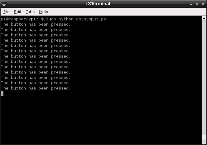
PART IV HARDWARE HACKING
232
Save the le as gpioinput.py, and then execute it from the terminal with sudo python
gpioinput.py. At rst, nothing will happen—but if you press the push-button switch, the
program will print the message from line seven to the terminal (see Figure 14-6). Release the
button and press it again, and the message will be repeated.
Figure 14-6:
e output
of the
gpioinput.
py program
As with the previous input example, this is a deceptively simple program that can be used for
many purposes. In addition to being able to read when a switch is pressed, the same code can
be used to read when the pins of a separate device—such as a sensor or external microcon-
troller—have been pulled high or low.
By extending the code to look for multiple push-buttons, each on an individual GPIO pin, you
could even create a simple four-button game controller. For example, you could combine the
preceding code with the Raspberry Snake game from Chapter 12, “An Introduction to Python”,
to turn the Raspberry Pi into a simple games console. You can also combine both input and
output examples into a single program, which waits for the button to be pushed and then turns
on the LED by sending the output pin high. To ensure that you’ve understood the concepts in
this section, try creating that combined program now. If you get stuck, or you want to check
your method, turn to Appendix A, “Python Recipes”, for a sample solution.
Chapter 15
The Raspberry Pi Camera
Module
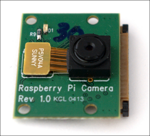
PART IV HARDWARE HACKING
234
DESIGNED BY ENGINEERS working for the Raspberry Pi Foundation, the Raspberry Pi
Camera Module is the most compact way of adding the ability to record still images and
video to your project. Designed to connect to the Camera Serial Interface (CSI) of the Raspberry
Pi, the Camera Module measures just 25 mm on its longest edge and weighs just 3 grammes
(see Figure 15-1).
Figure 15-1:
e Raspberry Pi
Camera Module,
pictured without
its ribbon cable
Since its release, the Camera Module has found a place in projects ranging from simple home
security systems to more complex computer vision experiments that track a user’s face or hand
gestures. e module has even reached near-space, as the result of photography projects that
tether a Raspberry Pi to a weather balloon and release it to gather high-altitude images.
e camera module is built around a ve-megapixel sensor of a type commonly used in
smartphones, located behind a xed-focus lens. e module works in tandem with the
Raspberry Pi’s graphics processor to ensure that high-resolution video and stills can be cap-
tured smoothly without overloading the Pi’s main processor or requiring too much memory.
Why Use the Camera Module?
If you have no need to capture images or video, you don’t need the Camera Module. It’s an
optional extra, and the Pi works just ne without one. It’s also possible to add vision to your
Pi using alternative products, such as webcams, that connect to a free USB port.
CHAPTER 15 THE RASPBERRY PI CAMERA MODULE 235
e Pi has only a limited number of USB ports, however, and these are often used for more
critical functions such as a keyboard, mouse or wireless network adapter. is is particularly
important in the Raspberry Pi Model A, which has just one USB port available for use.
e ocial Camera Module has other advantages over a traditional webcam: it draws consid-
erably less power, meaning it doesn’t strain the Raspberry Pi’s power supply or drain the
batteries in a portable or solar-powered project; it oers image capture at a resolution of up
to ve megapixels, and video capture at a Full HD resolution and 30 frames per second; and
it is considerably smaller than USB-connected cameras.
e Camera Module is compatible with all models and revisions of Raspberry Pi, so if you
haven’t decided whether you’ll need a camera in your project, don’t worry; you can pick up
any Pi model now and add the Camera Module at a later date.
Installing the Camera Module
e Raspberry Pi Camera Module, like the Raspberry Pi itself, is supplied as a bare circuit board.
Although this is reasonably robust, you must take care when handling it so as not to damage
any of its components, particularly the plastic lens located over the camera sensor itself.
e Camera Module connects to the Pi through a ribbon cable, a thin, semi-rigid cable that
should be inserted into the Raspberry Pi’s CSI connector. When you receive the camera, one
end of the cable will already be inserted into the module itself; one side of the other end is
coloured blue and the other side has visible silver contacts. ese contacts connect to pins in
the Pi’s CSI connector, transferring power and data between the Pi and the Camera Module.
e CSI connector is labelled S5 and is located towards the right-hand side of the board, near
where the USB ports are located (see Figure 15-2). e CSI connector of a Raspberry Pi Model
B is located just to the left of the Ethernet port; on a Model A, it is found in the same place,
just to the left of the gap on the board below the USB ports. Some models may have the CSI
connector covered by a protective piece of plastic lm; you should peel this o before you try
to install the camera.
ere’s a similar-looking connector located to the left side of the Raspberry Pi. is is the
Display Serial Interface (DSI) connector, and is designed for connecting the Pi to liquid crystal
display panels. e two ports aren’t interchangeable; if you connect the camera to the DSI
port rather than the CSI port, it won’t work.
Before inserting the cable, small lugs on either side of the connector must be gently lifted.
is can be done with your ngernails without needing any tool, but be careful: they should
lift easily and stop moving once they’re a couple of millimetres above the rest of the CSI con-
nector (see Figure 15-3).
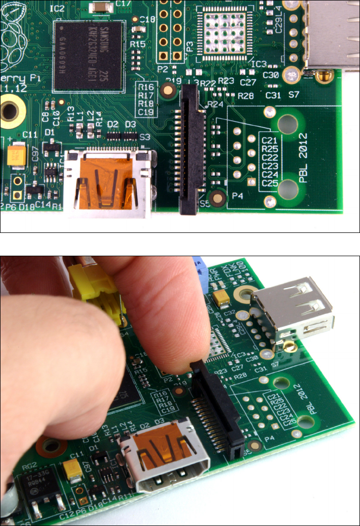
PART IV HARDWARE HACKING
236
Figure 15-2:
e Raspberry
Pi’s CSI
connector,
pictured on a
Model A
Figure 15-3:
Raising the lugs
of the CSI
connector, prior
to inserting the
ribbon cable
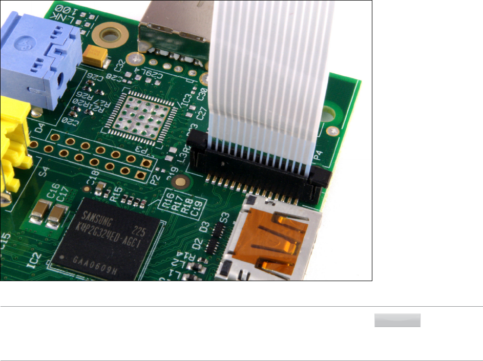
CHAPTER 15 THE RASPBERRY PI CAMERA MODULE 237
Insert the free end of the ribbon cable into the CSI port, making sure that the silver contacts
are facing towards the left of the Pi and the blue portion of the cable to the right. Gently push
the cable home, making sure not to bend it, and then push the lugs back down to secure it in
place (see Figure 15-4). When properly inserted, the cable should be coming out of the con-
nector perfectly straight and should withstand a gentle tug; don’t pull it too hard while test-
ing this, however, as it can be damaged.
Figure 15-4:
e Camera
Module’s ribbon
cable, securely
inserted into the
CSI connector
WARNING
The ribbon cable included with the Raspberry Pi Camera Module is reasonably robust and will
prove reliable even in daily use. It is, however, susceptible to damage if folded. When inserting
the cable or moving the camera, be sure not to fold the ribbon cable back on itself. If you do
damage your ribbon cable, replacements are available from most Pi stockists.
When using the Camera Module with a Raspberry Pi case, it is usually necessary to thread
the ribbon cable through a thin slot or in between layers of plastic. Some cases are not
directly compatible with the Camera Module; in these cases, you may need to leave the lid of
the case o in order to route the ribbon cable. Position the Camera Module with the ribbon
cable at the bottom; if this isn’t possible, a software option to ip the captured image upside
down is described later in this chapter.
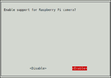
PART IV HARDWARE HACKING
238
e nal step in the camera’s physical installation is to remove the small, protective piece of
plastic lm found over the lens. is can simply be peeled o and discarded by pulling gently
upwards on the tab that extends out from the lens. Although it’s tempting to leave it in place
to protect the lens, this will give everything you capture an unpleasant blue hue.
Enabling Camera Mode
e software to drive the Raspberry Pi Camera Module is included in the Raspbian distribu-
tion by default. If you’re using a particularly old release, you may nd that the les are miss-
ing; if so, update your system using the following command at the terminal or console (see
Chapter 3, “Linux System Administration” for details):
sudo apt-get update && sudo apt-get upgrade
You will need to change some system settings in order for the Camera Module to work cor-
rectly, however. In particular, recording video requires that the graphics processing portion
of the Pi’s BCM2835 processor has at least 128MB of memory available; with any less than
that, still image capturing will work but video recording will fail. For details on how to change
this split, see Chapter 6, “e Raspberry Pi Software Conguration Tool”.
e easiest way of ensuring that your Pi is camera-ready is to use the Raspberry Pi Software
Conguration Tool raspi-config. At the terminal, type the following command to load
the tool:
sudo raspi-config
In the menu that appears, select option 5—Enable Camera—using the cursor keys and
Enter. Choose Enable in the screen that appears and press Enter again (see Figure 15-5). If
Camera Mode was disabled previously, you will be prompted to reboot the Pi; conrm this by
pressing Enter.
Figure 15-5:
Enabling
Camera Mode in
the Raspberry Pi
Software
Conguration
Tool raspi-
config

CHAPTER 15 THE RASPBERRY PI CAMERA MODULE 239
TIP
If you can’t nd a camera option in raspi-config, you may be running an outdated version.
Use the sudo apt-get update && sudo apt-get upgrade command to update your
software, then reboot the Pi and try running raspi-config again.
Once the Pi has rebooted, your Camera Module will be ready to use.
An optional nal step, if you would like to view captured images from the Raspbian console
without having to load the graphical user interface, is to install the framebuer image viewer
fbi. To do this, type the following command:
sudo apt-get install fbi
To view images using the tool (see Figure 15-6) simply type the command followed by the
name of the image:
fbi imagename.jpg
Figure 15-6:
Viewing
captured images
using the fbi
package
To quit fbi, press the Q or Escape key.
Capturing Stills
e best way to test that the camera is working correctly is to try capturing an image. e
Camera Module uses a custom software package called raspistill to capture still images,

PART IV HARDWARE HACKING
240
which are saved, by default, in the Joint Photographers Expert Group (JPEG) le format—the
same format used by most digital cameras and smartphones.
e software for the Raspberry Pi camera is run from the terminal or console. For best
results, run the software at the console without using the startx command to load the
graphical user interface (see Chapter 3, “Linux System Administration” for details).
e raspistill command accepts a number of optional arguments that control settings
such as the horizontal and vertical resolution of the captured image, the exposure mode of
the camera, the le type saved, and the level of compression applied to the nal image. If
these options are left out of the command, defaults will be used.
To test the camera, simply run the raspistill application at the console by typing its
name as the command:
raspistill -o testcapture.jpg
is will show a ve-second live preview (see Figure 15-7) during which time a red light on
the front of the camera will illuminate. is is an activity light, designed to provide conrma-
tion that the camera is working. If you wave your ngers in front of the camera during this
ve-second period, you’ll see them appear in the preview window on-screen. When the ve
seconds is up, the light will extinguish and the preview window will disappear.
Figure 15-7:
e
raspistill
capture
application
showing a live
preview image

CHAPTER 15 THE RASPBERRY PI CAMERA MODULE 241
TIP
Sometimes the position of the Camera Module’s cable makes it difcult to place the camera
the right way up. If your preview appears upside-down, use the -vf (vertical ip) option to
correct the image. Just add the option to the command line along with any other options you
are using.
When the preview has nished, the -o (output) option will save a JPEG le with the name test-
capture.jpg. When using the -o option, you can change the type of le saved with -e.
Currently supported le types include bitmap (BMP), Portable Network Graphics (PNG) and Graphic
Interchange Format (GIF) images. To save a PNG, for example, use the following command:
raspistill -o testcapture.png -e png
Altering png to read bmp, gif or jpg allows access to the other supported formats. If you
forget the -e option, a le will still be saved but regardless of its extension the content will
be JPEG data.
Another pair of commonly used options adjusts the width and height of the captured image.
is is good for capturing low-resolution stills as part of a computer vision project, or simply
to save space.
e width of the captured image is adjusted with the -w option, while the height is adjusted
with -h. ese options are most commonly used together, to set the overall resolution of the
image. To capture an image of 1,920 pixels wide by 1,080 pixels high—the same resolution
as a Full HD high-denition TV or Blu-ray lm—type the following command:
raspistill -w 1920 -h 1080 -o fullhdcapture.jpg
e nal basic option to know is -t, which controls the preview time-out. By default,
raspistill shows a ve-second live preview before capturing an image; the -t option
overrides this default. e required delay should be specied in milliseconds. To capture an
image after a 10-second delay, use the following command:
raspistill -t 10000 -o tensecondcapture.jpg
To disable the delay and capture immediately—a useful trick if you’re running the software
from a shell script, as demonstrated later in this chapter—use a value of 0 as in the following
command:
raspistill -t 0 -o instantcapture.jpg
PART IV HARDWARE HACKING
242
e lename after the output (-o) option can be anything you want it to be, with the preced-
ing commands merely using example lenames. When writing the lename, always be sure
to add the extension appropriate to your le type: .jpg for JPEG images, .png for Portable
Network Graphics, .bmp for bitmap images and .gif for the Graphics Interchange Format.
For a full description of all options available to raspistill, turn to Appendix B, “Camera
Module Quick Reference”. Alternatively, type the following command to see a list of options:
raspistill --help
Recording Video
Just as there is a dedicated application for capturing still images through the Raspberry Pi
Camera Module, there is another for capturing video: raspivid. Using raspivid is very
similar to using raspistill, but there are several dierences you’ll need to know before
forging ahead.
e most important dierence between raspivid and raspistill is in the -t option: in
raspistill, the -t option provided the time-out for the preview before the image was
captured; in raspivid, the -t option provides a limit for the overall length of the recorded
video. If a value of 0 is given, the video will record forever—rapidly lling your SD card or
external storage device.
As with raspistill, the default for the -t option is ve seconds. So, to check the camera
is working and record a short video, you can simply type the command’s name along with the
-o (output) option and a lename:
raspivid -o defaultvideo.h264
is records a ve-second video and saves it as in a format known as h.264. Unlike
raspistill, there is no option to save the le in a dierent format: raspivid uses the
hardware acceleration available in the Pi’s BCM2835 processor to do the recording, and only
h.264 is supported as a capture format.
If you play the video back, you’ll nd that there’s no sound. Unfortunately, the Raspberry Pi
does not include a microphone input. Although it’s possible to record audio by connecting
certain USB microphones or sound cards, this will need to be captured using separate soft-
ware and combined with the video le later using a video editing package.

CHAPTER 15 THE RASPBERRY PI CAMERA MODULE 243
Other options supported by raspistill are also supported by raspivid. For example, to
set the width and height of the recorded video to 1,920x1,080—Full HD—use the -w and
-h options as in the following command:
raspivid -w 1920 -h 1080 -o fullhdvideo.h264
To record a longer video, adjust the -t option by specifying your required length of video in
milliseconds. To record a minute of video, type the following command:
raspivid -t 6000 -o minutelongvideo.h264
TIP
Although h.264 is a reasonably efcient video format, recording at high resolutions can take up
considerable disk space. If you’re recording longer videos, be sure that you have enough free
space on your SD card or consider connecting a USB storage device like an external hard drive.
You can read more options for raspivid in Appendix B, “Camera Module Quick Reference”
or see a list of available options with the following command:
raspivid --help
Command-Line Time-Lapse Photography
So far, you’ve learned the basics of how to use the Raspberry Pi Camera Module—now it’s
time to nd a practical use for the project. e key advantage of the Raspberry Pi over a
dumb network-connected camera is the capability to be easily programmed for dierent
tasks. In this example, you can turn your Raspberry Pi and connected Camera Module into a
time-lapse photography system.
e raspistill program comes with an option for enabling a time-lapse mode, -tl, which
continuously captures pictures according to a customisable delay in milliseconds. is fea-
ture is designed for when raspistill is called by an external program, such as a web server
or video streamer, and will overwrite the output le each time a new picture is taken.
To use raspistill in traditional time-lapse photography, where a new le is created each
time, you’ll need a way of driving raspistill externally. is could be a Python program, a
dedicated application or even a web server thread, but the easiest way is to use a process
known as shell scripting.
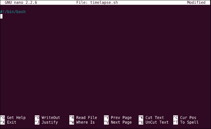
PART IV HARDWARE HACKING
244
A shell script is simply a collection of commands, each exactly as you would type them at the
console or terminal. Each command is run in order, from top to bottom, but it’s also possible
to use loops as in programming languages like Scratch and Python (see Chapter 11, “An
Introduction to Scratch” and Chapter 12, “An Introduction to Python” for more details).
Coupled with the shell’s ability to chain multiple programs together, shell scripting is a pow-
erful tool.
To start a shell script, simply create a new text le in your current directory with the follow-
ing command:
nano timelapse.sh
e extension .sh is traditionally used for shell scripts, although it’s not strictly necessary.
Using a le extension like this helps you to remember the dierence between a shell script
and an executable program, so it’s certainly recommended.
At the top of the le (see Figure 15-8) enter a line that tells the operating system to interpret
the commands using the default Bash shell:
#!/bin/bash
Figure 15-8:
Editing the
timelapse.
sh script in the
nano editor
CHAPTER 15 THE RASPBERRY PI CAMERA MODULE 245
Although other shells are available, Bash is the default for most modern Linux distributions
and oers a good mix of guaranteed compatibility and advanced features. Everything after
this line will be run by the operating system as a command just as though you had typed it at
the terminal yourself. e exception is comment lines, which are preceded by a # symbol;
these lines contain notes that help you remember why the script is written in a particular
way, or how to use the script. It’s good practice to include comment lines in your shell scripts,
although the script will run ne without them.
So that you know what the script is supposed to do when you nd the le a few months from
now, make the next line a comment explaining the script’s purpose:
# Captures time-lapse images using the raspistill application
Remember to put the # symbol at the start of the line, or the shell will try to run the com-
ment as a command.
Next is to set up a loop that will ensure the script continues to run after the rst photograph
has been taken. Enter the following two lines to start the loop:
while true
do
Note that the second line, do, is indented by typing four spaces at the start; this helps visu-
ally illustrate that the code that appears below is part of the loop. Unlike Python, which
requires indentation, shell scripts can be written without any code being indented—but it
makes the code signicantly harder to read and understand. Like comments, indentation is
an optional but highly recommended step.
Next, set up the lename that will be saved by entering the following line:
filename=`date +%Y%m%dT%H%M%S`.jpg
is is a somewhat complex instruction that tells the shell to take the output of the date
command and enter it into a variable called filename. e ` symbol, known as a backtick,
tells the shell to execute the date command; without these symbols, found at either end of
the command, the shell would ignore the instruction and treat it as just a string of text.
e date command, as you may have guessed, allows you to nd out what the current date and
time is on the system. Following the + symbol is a series of instructions on how the date should
be printed: %Y gives the year in four-digit form, %m the month in two-digit form, %d the day in
two-digit form, and %H, %M and %S give the time in 24-hour format hours, minutes and seconds.

PART IV HARDWARE HACKING
246
After the nal backtick is .jpg. is completes the lename, telling the shell script to save
the image le in the international date format with the extension of a JPEG le. If you cap-
ture an image at exactly two in the afternoon on 17th January 2015, for example, the le-
name would be 20150117140000.jpg. Because it takes longer than a second for the
camera to take a picture, and there will be a delay later in the shell script, this guarantees that
each picture has a unique lename and nothing will be overwritten.
Using the international date format has an added bonus: if you sort the list alphabetically or
numerically, your pictures will be sorted from oldest to newest. If you’d prefer a dierent
lename format, however, simply change the order in the command.
WARNING The date command pulls time information from the system clock. When connected to a
network, the Raspberry Pi uses the Network Time Protocol (NTP) to nd the current time, but
the Model A cannot do this unless you connect a USB network adapter. In this case, the date
in the lename will be wrong unless you manually set a date before running the script.
With the lename set, it’s time to tell the script to run raspistill. You can use any options
you like here, so long as you remember to set the output lename. To capture a Full HD still,
enter the following line:
raspistill -w 1920 -h 1080 -t 0 -o $filename
e $ symbol before filename tells the shell that you’re addressing the filename variable
set in the previous line. It’s important to include this symbol, as without it the script will write
a single le called filename, which will be overwritten every time a new image is captured.
It’s always a good idea to get feedback from your scripts, so you know when they’re running.
An easy way to do this is to have the script print status messages to the terminal or console,
using the echo command. Enter the next line as follows:
echo Image captured
Next, add a delay to the script by using the sleep command. is requires a value in sec-
onds, rather than the milliseconds expected by raspistill and raspivid. To take a pic-
ture every 30 seconds, enter the following line:
sleep 30
Finally, close the loop by entering the last line of the script (see Figure 15-9):
done
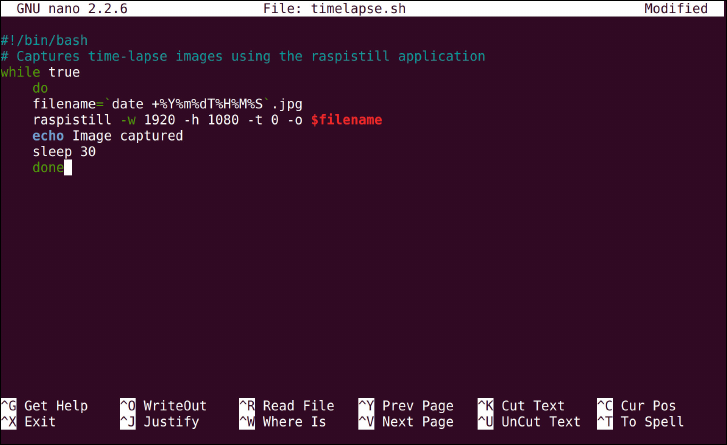
CHAPTER 15 THE RASPBERRY PI CAMERA MODULE 247
Figure 15-9:
e complete
timelapse.
sh script, in the
nano text
editor
Although this brings the script to a close, the loop used is known as an innite loop: the
instruction while true at the start tells the script to run through the loop until true
becomes false, or 1 becomes 0. Because this can never happen, the script runs forever—
taking an image every 30 seconds.
Save the le by pressing Ctrl + O, and then change the le’s permissions to make it executable
with the following command:
chmod +x timelapse.sh
For more information on le permissions, see Chapter 3, “Linux System Administration”.
Finally, run the script with the following command:
./timelapse.sh
e script will immediately take a picture and print the status message “Image captured” to
the console (see Figure 15-10). After 30 seconds, it will take another picture; after another
30 seconds, a third. is will continue forever, or until your SD card is lled with images. To
exit the script, press Ctrl + C.
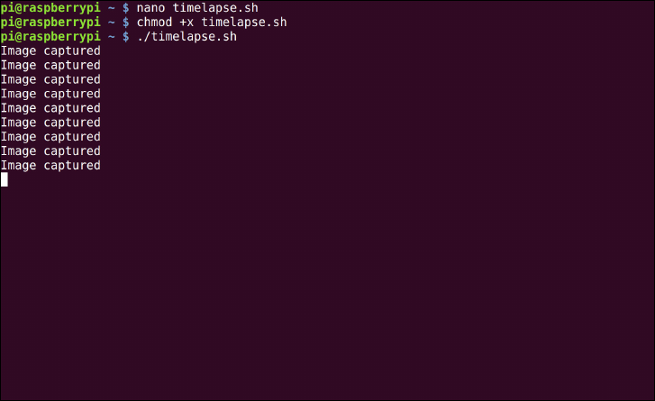
PART IV HARDWARE HACKING
248
Figure 15-10:
e
timelapse.
sh script,
running on a
Raspberry Pi
Model B
Time-lapse photography is often used to compress a long or complex task into an entertain-
ing video. Commercial time-lapse photography rigs, which can be extremely expensive, are
often used to lm the growth of plants, the construction or buildings or the ow of trac. A
Raspberry Pi running this script can do all of these things, but at a fraction of the cost.
e images you’ve captured can be transformed into a video, either using video editing soft-
ware or the ffmpeg tool. While ffmpeg can be run on the Raspberry Pi itself, it’s a resource-
hungry program that will take a considerable time to run if you have a large number of
high-resolution images to convert. If you have the patience do the conversion on the Pi itself,
install ffmpeg with the following command:
sudo apt-get install ffmpeg
en convert the images by typing:
ffmpeg -r 1 -i *.jpg timelapse.mp4
is will create a video with images showing at a rate of one per second, or 30 times faster
than real-time, from all JPEG images found in the current directory. To speed the video up
still further, you can adjust the -r option: -r 10 will show 10 images per second, -r 20 20
images per second and so forth. e nished video can then be shared directly, or uploaded
to a video streaming site like YouTube or Vimeo.
Chapter 16
Add-on Boards
PART IV HARDWARE HACKING
250
ALTHOUGH YOU CAN use the Raspberry Pi’s general-purpose input-output (GPIO) header
directly, as you learned in Chapter 13, “Learning to Hack Hardware”, a much better idea is to
use a specialist prototyping board. Prototyping boards are add-on boards designed to sit
between your project and the Raspberry Pi, and range from the relatively simple—such as
Ciseco’s Slice of Pi—to the complex and powerful Gertboard.
At their most basic, add-on boards simply provide easier access to the Raspberry Pi’s GPIO
pins. is may mean they can be connected to a breadboard easier, or are spaced further
apart and labelled to make connecting other devices simpler. Some boards include circuitry
to connect specic add-on devices, such as a small XBee wireless transceiver, and still others
provide a small surface onto which you can solder your own components to make a custom
board.
e hardware market is constantly and rapidly changing, and the Raspberry Pi Foundation
continues to encourage developers to create more add-on devices. It would be impossible to
create an exhaustive list of all the add-on boards available or planned for release in the near
future, but in this chapter, you’ll learn about three of the most common boards and how they
can be used.
Ciseco Slice of Pi
e most basic of boards, Ciseco’s Slice of Pi (see Figure 16-1) is nevertheless useful. Supplied
in kit form, Slice of Pi features a small prototyping area, a space for an XBee wireless module
and full access to the Raspberry Pi’s GPIO pins.
e compact Slice of Pi is designed to be connected directly to the GPIO headers on the top
of the Raspberry Pi, with the rest of the board covering part of the Pi’s surface—but not
extending beyond the edges of the board nor obscuring any commonly used ports. e Slice
of Pi does, however, sit over the DSI video output connector. In most cases where this
connector is used, the ribbon cable can be routed underneath the Slice of Pi board without
trouble.
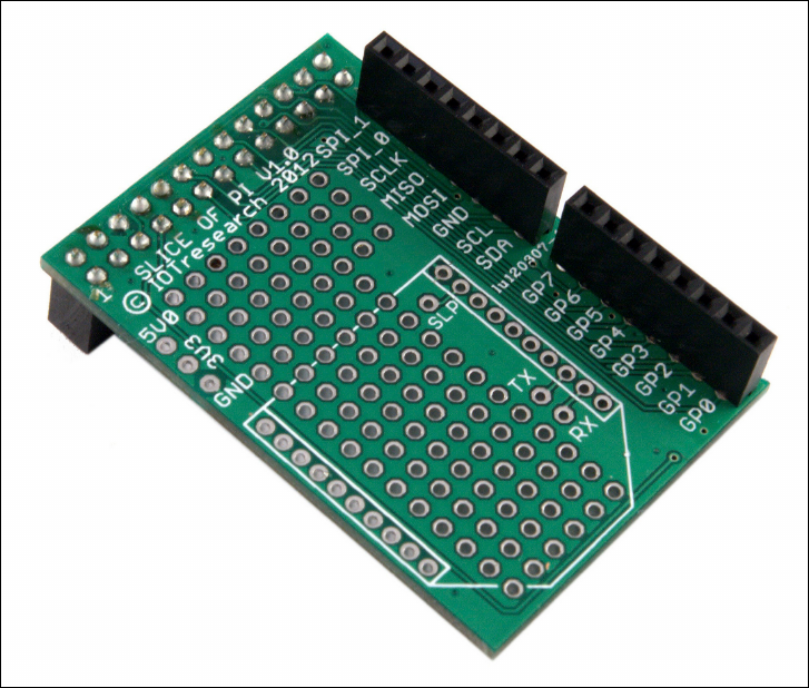
CHAPTER 16 ADDON BOARDS 251
Figure 16-1:
e Ciseco Slice
of Pi
e primary advantages of using the low-cost Slice of Pi rather than just connecting directly
to the Pi’s GPIO header are the labelling on the circuit board, which the GPIO header lacks,
and the use of female headers. ese allow you to use male-to-male jumper leads or even just
lengths of trimmed wire to connect the board to a breadboard (as shown in Figure 16-2) or
other circuit board—or even to connect components directly into the headers. e Pi’s male
headers, in contrast, require the use of specialised male-to-female jumper leads.
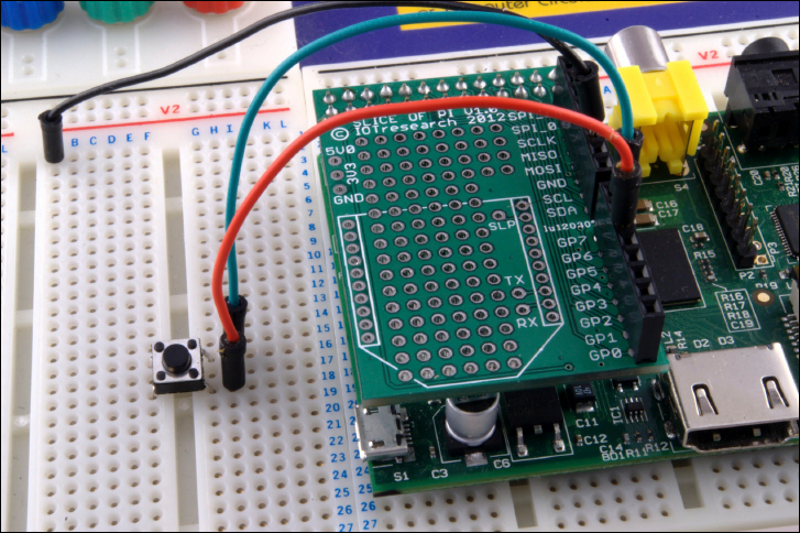
PART IV HARDWARE HACKING
252
Figure 16-2:
Connecting the
Slice of Pi to a
breadboard
e Slice of Pi also oers a small amount of protection for the Pi. e use of female headers
means it’s harder to accidentally short-circuit two pins, and the spacing of the headers—with
the eight general-purpose pins brought to one header and the other specialised pins brought to
another—makes wiring mistakes less likely. More importantly, the Slice of Pi doesn’t provide
direct access to any of the pins labelled as Do Not Connect (see Chapter 13, “Learning to Hack
Hardware”), so there’s less risk of damaging the Pi with a wrong connection.
e connections for an XBee wireless interface could also prove useful if you are considering
using the Pi in an embedded computing project. When combined with a compatible trans-
ceiver—such as an XBee, RF-BEE or RN-XV module—it allows for wireless access to the Pi’s
UART serial port. Such access could be used to read sensor details from the Pi, take control of
the Pi’s software or even control a Pi-powered robot from a remote location.
Finally, the prototyping area provides an alternative to breadboards or stripboards for
smaller circuit designs. If you are considering developing a small add-on module for the
Raspberry Pi, such as a sensor board for reading temperatures or detecting moisture, the
required components can be soldered directly to the Slice of Pi. anks to the low cost of the
board, this provides an easy way to create bespoke add-on modules for the Pi that are entirely
self-contained, with no wiring required—just connect the Slice of Pi to the Raspberry Pi’s
GPIO port and the device is ready to go (see Figure 16-3).
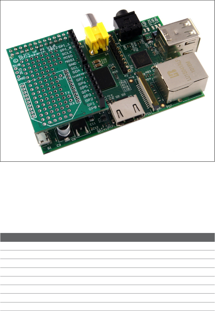
CHAPTER 16 ADDON BOARDS 253
Figure 16-3:
e Slice of Pi,
connected to the
Pi’s GPIO port
e disadvantage of the Slice of Pi lies in its simplicity. Its compact size means that it is unsuitable
for the creation of larger or more complex prototypes, and while the header layout provides some
protection against short circuits, there’s no protection against the use of 5 V components that can
damage the Pi’s 3.3 V logic circuits. e labelling is also dierent to that used to typically describe
the Raspberry Pi’s GPIO pins, which can lead to confusion when using a GPIO library not written
with the Slice of Pi in mind. Table 16-1 provides a mapping from one labelling system to another.
Table 16-1: Slice of Pi GPIO Mappings
Physical Pin Number Ofcial Designation Slice of Pi Label
7 GPIO Pin 4 (or General Purpose Clock 0) GP7
11 GPIO Pin 17 GP0
12 GPIO Pin 18 GP1
13 GPIO Pin 27 (21 on Revision 1 boards) GP2
15 GPIO Pin 22 GP3
16 GPIO Pin 23 GP4
18 GPIO Pin 24 GP5
22 GPIO Pin 25 GP6
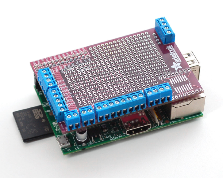
PART IV HARDWARE HACKING
254
e Slice of Pi is available from Ciseco’s web shop at http://shop.ciseco.co.uk/
slice-of-pi/.
Adafruit Prototyping Pi Plate
e Prototyping Pi Plate by Adafruit is based around the same general principle as Ciseco’s
Slice of Pi. e add-on is provided in kit form, and oers you a prototyping surface along
with easy access to the Pi’s GPIO pins (see Figure 16-4). Unlike the Slice of Pi, however, the
Prototyping Pi Plate is a full-coverage board built to the same size as the Pi itself. As a result,
the plate oers a much larger area to work with than the Slice of Pi, allowing for larger cir-
cuits to be constructed. e Prototyping Plate also features 3.5 mm screw terminals for con-
necting the pins, making it easy to use ordinary wire to make strong temporary
connections—although 2.54 mm holes for male or female headers are also provided should
you want to use those instead.
Figure 16-4:
e Adafruit
Prototyping Pi
Plate
CHAPTER 16 ADDON BOARDS 255
e design and layout of the Prototyping Pi Plate will be familiar to anyone who has used an
Arduino microcontroller. An add-on board with the same footprint as the target device,
designed to connect to on-board headers and sit above the surface of the original board is a
common sight in the Arduino world, where such add-on boards are known as shields. e
idea for the Prototyping Pi Plate, in fact, comes from Adafruit’s self-designed Protoshield
add-on for the Arduino.
As a full-coverage add-on board, the Pi Plate is designed to connect to the GPIO header and
cover the entire surface of the Pi. is positioning above the Pi can make it dicult to access
the DSI video output and MIPI CSI-2 camera input connectors, although longer ribbon cables
should route beneath the Pi Plate without trouble. If you’re planning to use an add-on cam-
era module (see Chapter 15, “e Raspberry Pi Camera Module”) or DSI-connected display,
be sure to check the length of ribbon cable provided before planning your project around the
Pi Plate.
e prototyping surface of the Pi Plate is split into two, with both halves oering through-
hole construction in common 2.54 mm spacing. e rst half of the prototyping surface is
set up in a similar way to a breadboard: copper tracks on the underside link rows together,
and a central bus in the middle provides common power and ground connectivity. e sec-
ond half of the prototyping surface does not have such tracks, allowing more custom circuits
to be constructed. Overall, the surface provided for circuit creation is signicantly larger
than that of the Slice of Pi, making the Pi Plate suitable for more-complex projects. It addi-
tionally oers an SOIC surface, designed for soldering a surface-mount component for parts
that aren’t available in through-hole format.
anks to its large size, you can also use the Pi Plate with a quarter-size breadboard (sold in
the Adafruit shop as a “tiny breadboard”). is small, two-section breadboard comes with a
self-adhesive foam backing and can be stuck to the top of the Pi Plate over the prototyping
area (see Figure 16-5). Doing so means that it’s impossible to use the prototyping area to
make a permanent circuit, but the combination oers a self-contained add-on for rapid tem-
porary prototyping of smaller circuits.
As with the Slice of Pi, the Prototyping Pi Plate is at heart a basic device. e kit contains no
active components, but simply headers, terminals and the board itself. As a result, it pro-
vides little extra protection for the Pi’s GPIO ports beyond making it more dicult to acci-
dentally short-circuit two connections. Unlike the Slice of Pi, the Pi Plate provides access to
all 26 of the Pi’s GPIO header pins—meaning that you could accidentally connect things to
the pins marked as Do Not Connect on the GPIO header diagram (see Chapter 13, “Learning
to Hack Hardware”). As with connecting things to these pins directly, this is inadvisable and
can result in permanent damage to the Pi.
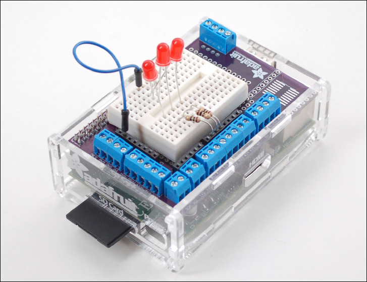
PART IV HARDWARE HACKING
256
Figure 16-5:
A Pi Plate with a
quarter-size
breadboard
Perhaps the biggest reason for choosing a Pi Plate over the Slice of Pi is its clever design.
Once connected to the GPIO header on the Pi, there is little reason to remove it unless you
need access to the DSI or MIPI CSI-2 camera connectors. Because it only increases the height
of the Pi, rather than the width or length, and because it includes the screw terminals for
side-on access to GPIO pins, it’s also compatible with a surprising number of Raspberry Pi
cases (see Figure 16-6). If you’re planning to use the Pi and Pi Plate combination with a case,
however, be sure to check that the case can be adjusted for height or has access to the GPIO
port through its lid.
You can purchase the Prototyping Pi Plate Kit from Adafruit at http://www.adafruit.
com/products/801.

CHAPTER 16 ADDON BOARDS 257
Figure 16-6:
e Pi Plate
connected to a
cased Raspberry
Pi
Fen Logic Gertboard
Properly termed the Raspberry Pi I/O Extension, the Gertboard (shown in Figure 16-7) is
named for its inventor, Gert van Loo. An employee of Broadcom and a member of the team
that designed the BCM2835 SoC processor at the heart of the Raspberry Pi, van Loo created
the Gertboard as a way of unlocking some of the power of the chip hidden by the Pi’s overall
design and providing a powerful and versatile platform for electronic tinkering.
Unlike the Slice of Pi and Prototyping Pi Plate, the Gertboard is an active add-on board with
numerous components designed to extend the functionality of the Pi. e Gertboard pro-
vides 12 buered IO ports with status LEDs, three push-button switches, six open collector
drivers, a 48 V 4 A motor controller, a two-channel digital to analogue converter (DAC) and a
two-channel analogue to digital converter (ADC). Additionally, the Gertboard has support for
an additional 28-pin microcontroller, such as the Atmel ATmega328 used in the Arduino
prototyping system, which can be inserted into a socket on the Gertboard and programmed
directly from the Raspberry Pi.
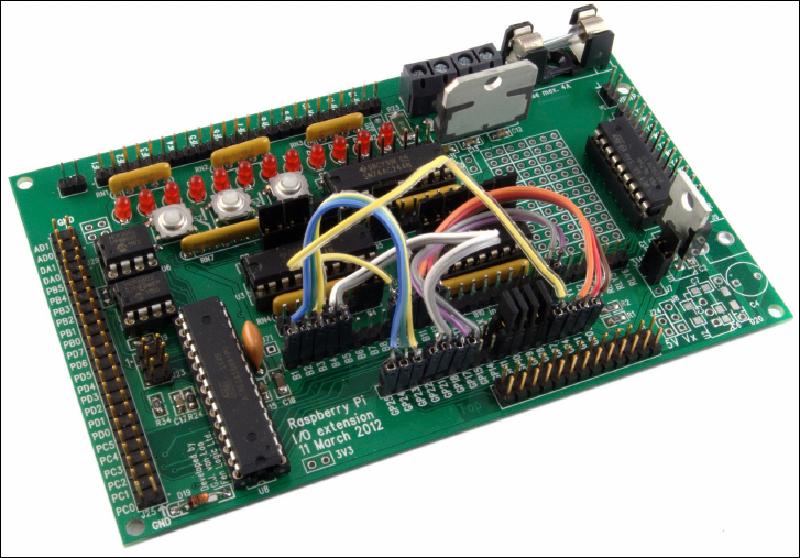
PART IV HARDWARE HACKING
258
Figure 16-7:
e Gertboard,
designed by
Gert van Loo
As the list of features indicates, the Gertboard is a powerful and complex device. Its exibil-
ity makes it a great choice for more complex projects—but that same complexity aects its
size. e Gertboard is almost two-and-a-half times larger than the Raspberry Pi itself, mak-
ing it both the most powerful and the largest add-on board for the Pi available at the time of
writing. To counteract its size, the Gertboard connects to the Pi through a ribbon cable ter-
minated in male sockets (see Figure 16-8). is cable allows the Gertboard to sit away from
the Pi, or to be mounted in a project permanently yet still be quickly detached from the Pi if
necessary.
Perhaps the most important feature of the Gertboard is the protection it oers to the Pi.
Using a 3.3 V regulator, the Gertboard is designed to prevent the Pi’s GPIO port from receiv-
ing voltages it cannot handle. Like the Slice of Pi, it also attempts to restrict access to the six
pins labelled Do Not Connect as well as the 3.3 V and 5 V pins to help prevent accidental
shorting. Although care must be taken while wiring up circuits, following the instructions
included in the Gertboard’s user manual guarantees the Pi’s safety.
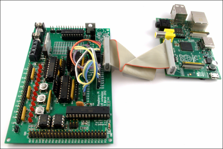
CHAPTER 16 ADDON BOARDS 259
Figure 16-8:
e Gertboard
connected to a
Raspberry Pi
e motor controller functionality of the Gertboard makes it easy to integrate the Pi into a
robotics project. It’s suitable for motors of up to 48 V at 4 A, which is easily powerful enough
to drive a small robot vehicle. Sadly, the motor is not included as standard with the Gertboard.
Instead, you are asked to supply your own controller—with the L6203 package being recom-
mended—if motor control forms part of your project. With the motor controller soldered
into place, the Gertboard can be used to control surprisingly powerful motors either through
instructions received from the Pi itself or from the optional Atmel microcontroller module.
Figure 16-9 shows an example circuit that’s using the Gertboard to drive a 12 V motor from
a battery pack power supply.
For project building, the Gertboard oers signicantly more functionality than a bare
Raspberry Pi. e 12 buered IO ports, located at the top of the board, can be congured as
inputs or outputs and provide more connectivity than the seven or eight general-purpose IO
pins provided on the Pi’s own GPIO port. e inclusion of LEDs, which indicate when a pin is
high or low, helps with both circuit troubleshooting and electronics education, making it
easy to see what the various inputs and outputs are doing at any given time.
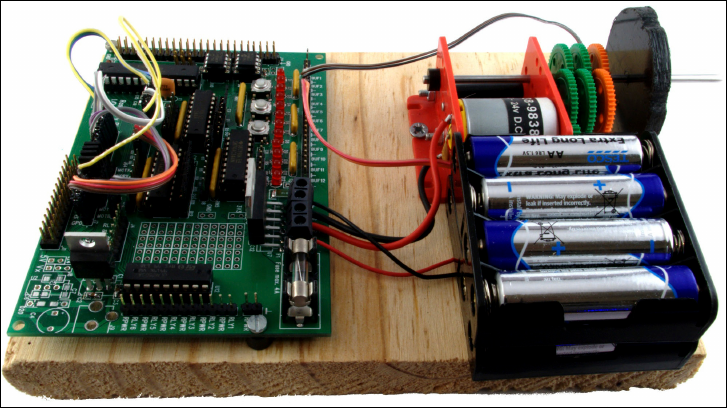
PART IV HARDWARE HACKING
260
Figure 16-9:
Using the
Gertboard
motor controller
For sensing or feedback projects, the Gertboard’s ADC and DAC components are handy addi-
tions. Unlike the GPIO pins on the Pi itself, which can only receive and send digital signals, the
Gertboard includes two ADC and two DAC connections. e ADC pins, located on the upper-
left of the Gertboard, allow analogue components to be converted into digital signals compati-
ble with the Pi. As an example, Figure 16-10 shows how you can use the ADC pins to read the
status of a potentiometer—a component which varies its resistance according to the position of
a slider or knob. is circuit could be used to control the Pi’s volume in a media centre applica-
tion, or to alter the speed of an attached motor. e DAC pins provide the opposite functional-
ity, taking a digital signal from the Pi and converting it to analogue. is could drive a speaker
to create audio, or alter the speed of a motor or the brightness of an LED.
For more complex projects, the Gertboard provides an open collector driver, which uses tran-
sistors to switch on and o devices that have dierent power requirements to the 3.3 V used
by the Gertboard or that draw a large amount of current and require an external power sup-
ply to operate. e open collector driver can control the power supplies of up to six devices
simultaneously without requiring any hardware. is gives the Gertboard a large amount of
exibility—although transistors or relays can be used with passive add-on boards like the
Prototyping Pi Plate to achieve the same goal.
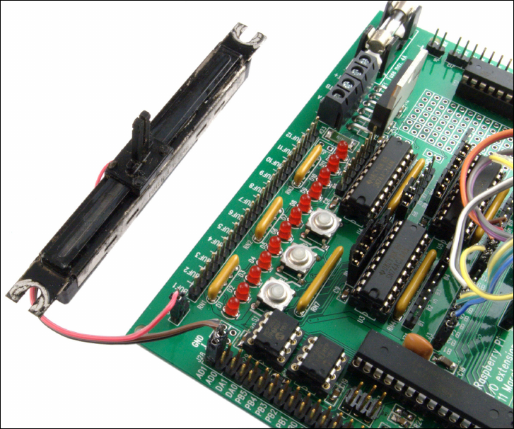
CHAPTER 16 ADDON BOARDS 261
Figure 16-10:
Connecting a
potentiometer
to the
Gertboard’s
ADC pins
Finally, the Gertboard provides access to a 28-pin microcontroller, which can be tted to a
socket located on the board itself. When tted, the Gertboard can be wired to address either
the Raspberry Pi’s GPIO port or the microcontroller, or a combination of the two. e
Gertboard is designed to operate with an Atmel ATmega168 or ATmega328 microcon-
troller—the same type of microcontroller used in the Arduino prototyping project. When
tted, you can write programs for the Gertboards’ ATmega microcontroller in the Atmel IDE,
giving the Pi a useful level of compatibility with the wide array of existing ATmega-targeted
software available to download. It also gives the Pi the ability to address external hardware in
a real-time manner, with the microcontroller taking over responsibility for hardware inter-
facing and simply providing feedback to the Pi.
PART IV HARDWARE HACKING
262
e Gertboard is a very advanced device, and isn’t suitable for every project. For many simple
uses, a cheaper passive add-on board like the Slice of Pi will usually be enough. However, for
in-depth experimentation of just what is possible with the Raspberry Pi’s BC2835 processor
and/or to ensure that you’ll be able to interface almost any hardware with your Pi, it’s a great
choice and a powerful extension to the Pi’s already impressive abilities.
e Gertboard is available through Farnell at http://www.farnell.com/.
Part V
Appendixes
Appendix A Python Recipes
Appendix B Camera Module Quick Reference
Appendix C HDMI Display Modes
Appendix A
Python Recipes
PART V APPENDIXES
266
THE FOLLOWING RECIPES provide the program code for Example 3 and Example 4 in
Chapter 12, “An Introduction to Python”, and a sample solution for the combined input-output
program suggested in Chapter 14, “e GPIO Port”. Each recipe is also available for download
from the Raspberry Pi User Guide website at www.wiley.com/go/raspberrypiuser
guide2e. If you’re typing the code in by hand, look out for the ↵ symbol: this indicates that
the line is wrapped due to space constraints in the book. If you see the symbol at the end of a
line, don’t press Enter until you reach the end of a line that doesn’t have a symbol present.
Raspberry Snake (Chapter 12, Example 3)
#!/usr/bin/env python
# Raspberry Snake
# Written by Gareth Halfacree for the Raspberry Pi User Guide
import pygame, sys, time, random
from pygame.locals import *
pygame.init()
fpsClock = pygame.time.Clock()
playSurface = pygame.display.set_mode((640, 480))
pygame.display.set_caption(‘Raspberry Snake’)
redColour = pygame.Color(255, 0, 0)
blackColour = pygame.Color(0, 0, 0)
whiteColour = pygame.Color(255, 255, 255)
greyColour = pygame.Color(150, 150, 150)
snakePosition = [100,100]
snakeSegments = [[100,100],[80,100],[60,100]]
raspberryPosition = [300,300]
raspberrySpawned = 1
direction = ‘right’
changeDirection = direction
def gameOver():
gameOverFont = pygame.font.Font(‘freesansbold.ttf’, 72)
gameOverSurf = gameOverFont.render ↵
(‘Game Over’, True, greyColour)
gameOverRect = gameOverSurf.get_rect()
gameOverRect.midtop = (320, 10)
playSurface.blit(gameOverSurf, gameOverRect)
pygame.display.flip()
APPENDIX A PYTHON RECIPES 267
time.sleep(5)
pygame.quit()
sys.exit()
while True:
for event in pygame.event.get():
if event.type == QUIT:
pygame.quit()
elif event.type == KEYDOWN:
if event.key == K_RIGHT or event.key == ord(‘d’):
changeDirection = ‘right’
if event.key == K_LEFT or event.key == ord(‘a’):
changeDirection = ‘left’
if event.key == K_UP or event.key == ord(‘w’):
changeDirection = ‘up’
if event.key == K_DOWN or event.key == ord(‘s’):
changeDirection = ‘down’
if event.key == K_ESCAPE:
pygame.event.post(pygame.event.Event(QUIT))
if changeDirection == ‘right’ and not direction == ‘left’:
direction = changeDirection
if changeDirection == ‘left’ and not direction == ‘right’:
direction = changeDirection
if changeDirection == ‘up’ and not direction == ‘down’:
direction = changeDirection
if changeDirection == ‘down’ and not direction == ‘up’:
direction = changeDirection
if direction == ‘right’:
snakePosition[0] += 20
if direction == ‘left’:
snakePosition[0] -= 20
if direction == ‘up’:
snakePosition[1] -= 20
if direction == ‘down’:
snakePosition[1] += 20
snakeSegments.insert(0,list(snakePosition))
if snakePosition[0] == raspberryPosition[0] and ↵
snakePosition[1] == raspberryPosition[1]:
raspberrySpawned = 0
else:
snakeSegments.pop()
if raspberrySpawned == 0:
x = random.randrange(1,32)
y = random.randrange(1,24)
PART V APPENDIXES
268
raspberryPosition = [int(x*20),int(y*20)]
raspberrySpawned = 1
playSurface.fill(blackColour)
for position in snakeSegments:
pygame.draw.rect(playSurface,whiteColour,Rect ↵
(position[0], position[1], 20, 20))
pygame.draw.rect(playSurface,redColour,Rect ↵
(raspberryPosition[0], raspberryPosition[1], 20, 20))
pygame.display.flip()
if snakePosition[0] > 620 or snakePosition[0] < 0:
gameOver()
if snakePosition[1] > 460 or snakePosition[1] < 0:
for snakeBody in snakeSegments[1:]:
if snakePosition[0] == snakeBody[0] and ↵
snakePosition[1] == snakeBody[1]:
gameOver()
fpsClock.tick(30)
IRC User List (Chapter 12, Example 4)
#!/usr/bin/env python
# IRC User List
# Written by Tom Hudson for the Raspberry Pi User Guide
# http://tomhudson.co.uk/
import sys, socket, time
RPL_NAMREPLY = ‘353’
RPL_ENDOFNAMES = ‘366’
irc = {
‘host’: ‘chat.freenode.net’,
‘port’: 6667,
‘channel’: ‘#raspiuserguide’,
‘namesinterval’: 5
}
user = {
‘nick’: ‘botnick’,
‘username’: ‘botuser’,
APPENDIX A PYTHON RECIPES 269
‘hostname’: ‘localhost’,
‘servername’: ‘localhost’,
‘realname’: ‘Raspberry Pi Names Bot’
}
s = socket.socket(socket.AF_INET, socket.SOCK_STREAM)
print ‘Connecting to %(host)s:%(port)s...’ % irc
try:
s.connect((irc[‘host’], irc[‘port’]))
except socket.error:
print ‘Error connecting to IRC server ↵
%(host)s:%(port)s’ % irc
sys.exit(1)
s.send(‘NICK %(nick)s\r\n’ % user)
s.send(‘USER %(username)s %(hostname)s %(servername)s : ↵
%(realname)s\r\n’ % user)
s.send(‘JOIN %(channel)s\r\n’ % irc)
s.send(‘NAMES %(channel)s\r\n’ % irc)
read_buffer = ‘’
names = []
while True:
read_buffer += s.recv(1024)
lines = read_buffer.split(‘\r\n’)
read_buffer = lines.pop();
for line in lines:
response = line.rstrip().split(‘ ‘, 3)
response_code = response[1]
if response_code == RPL_NAMREPLY:
names_list = response[3].split(‘:’)[1]
names += names_list.split(‘ ‘)
if response_code == RPL_ENDOFNAMES:
print ‘\r\nUsers in %(channel)s:’ % irc
for name in names:
print name
names = []
time.sleep(irc[‘namesinterval’])
s.send(‘NAMES %(channel)s\r\n’ % irc)
PART V APPENDIXES
270
GPIO Input and Output (Chapter 14)
#!/usr/bin/env python
# Raspberry Pi GPIO Input/Output example
# Written by Gareth Halfacree for the Raspberry Pi User Guide
import RPi.GPIO as GPIO
GPIO.setmode(GPIO.BOARD)
GPIO.setup(11, GPIO.OUT)
GPIO.setup(12, GPIO.IN)
GPIO.output(11, False)
while True:
input_value = GPIO.input(12)
if input_value == False:
print “The button has been pressed. Lighting LED.”
GPIO.output(11, True)
while input_value == False:
input_value = GPIO.input(12)
print “The button has been released. Extinguishing LED.”
if input_value == True:
GPIO.output(11, False)
Appendix B
Raspberry Pi Camera Module
Quick Reference
PART V APPENDIXES
272
THE RASPBERRY PI Camera Module comes with software designed to capture still images
and videos, each of which has a variety of options that can control the nal output. Options
for raspistill, raspiyuv and raspivid are included in this appendix. For more
information, see Chapter 15, “e Raspberry Pi Camera Module”.
Shared Options
e following options, listed in alphabetical order, are shared between raspistill,
raspiyuv and raspivid. For application-specic options, see the individual
raspistill, raspiyuv and raspivid entries later in this appendix.
❍ -? or --help (Help)—Displays all options and their uses.
❍ -awb or --awb (Automatic White Balance)—Sets the colour temperature of the cap-
tured image or video according to one of a series of pre-set congurations. If your
image or video appears blue or orange, try adjusting this option rst. Possible values
for this option are: off, auto, sun, cloud, shade, tungsten, fluorescent,
incandescent, flash, horizon.
❍ -br or --brightness (Brightness)—Adjusts the brightness of the captured image or
video. Possible values for this option are whole numbers ranging from 0 (minimum
brightness) to 100 (maximum brightness).
❍ -cfx or --colfx (Colour Eects)—Allows the user to adjust the YUV colour space for
ne-grained control of the nal image. Values should be given as U:V, where U controls
the chrominance and V the luminance. A value of 128:128 will result in a greyscale
image.
❍ -co or --contrast (Contrast)—Adjusts the contrast of the captured image or video.
Possible values for this option are whole numbers ranging from -100 (minimum con-
trast) to 100 (maximum contrast).
❍ -d or --demo (Demonstration Mode)—e -d option runs either raspistill or
raspivid in demonstration mode, which displays a preview that cycles through vari-
ous camera options. In this mode, no image is captured—even if you specify an output
le using the --output option.
❍ -ev or --ev (Exposure Value)—Allows the camera to increase or decrease its exposure
value, brightening or darkening the captured image or video. Unlike the brightness
and contrast settings, this aects the actual capturing of the image or video. Possible
values are -10 to 10, with 0 being the default.
APPENDIX B RASPBERRY PI CAMERA MODULE QUICK REFERENCE 273
❍ -ex or --exposure (Exposure Mode)—Sets the camera’s automatic exposure setting,
which controls how long the camera spends capturing an individual image or frame
and is largely a factor of available light or the speed of the subject: fast-moving objects
need a short exposure time in order to remain in focus, while low-light shooting
demands a long exposure time. Possible values for this option are off, auto, night,
nightpreview, backlight, spotlight, sports, snow, beach, verylong,
fixedfps, antishake, fireworks.
❍ -f or --fullscreen (Fullscreen Preview)—Makes the preview image ll the screen,
overriding any other preview option you may have set.
❍ -h or --height (Height)—Species the height, or vertical resolution, of the captured
image or video. is should be set to the desired height in pixels; for example, a Full
HD capture would require a height value of 1080. e minimum value is 64; the maxi-
mum depends on whether video or still images are being captured.
❍ -hf or --hip (Horizontal Flip)—Flips the captured image or video along its horizon-
tal axis, as though it has been viewed in a mirror.
❍ -ifx or --imxfx (Image Eects)—Enables one of a number of precongured special
eects on the image or video. Possible values for this option are none, negative,
solarise, sketch, denoise, emboss, oilpaint, hatch, gpen, pastel,
watercolour, film, blur, saturation, colourswap, washedout, posterise,
colourpoint, colourbalance, cartoon, whiteboard, blackboard. ese
settings can be seen in action using the Demonstration Mode option.
❍ -ISO or --ISO (ISO Sensitivity)—Sets the camera’s sensitivity to light. A lower ISO
value provides a clearer image, but requires longer exposures; a higher ISO value can
shoot at very low exposure times to capture fast-moving or badly lit subjects, but cre-
ates a ‘noisier’ image.
❍ -mm or --metering (Metering Mode)—Sets the light metering mode for image or
video capture, which controls the automatic exposure, white balance, and ISO sensitiv-
ity options. Possible values for this option are average, spot, backlit, matrix.
❍ -n or --nopreview (No Preview)—Does not display a preview window while captur-
ing; not required when using a timeout value of 0.
❍ -o or --output (Output File)—Sets the name of the le to be saved. e value for this
option can be either a lename, in which case the le will be created in the current direc-
tory, or an absolute path. If you are using raspistill or raspivid along with another
application that expects image data through standard input, you can divert the image or
video through standard output using a hyphen (-) character as the lename.
PART V APPENDIXES
274
❍ -op or --opacity (Preview Opacity)—Controls how transparent the preview window
appears. Possible values are any whole number from 0 to 255, where 0 is completely
transparent and thus invisible and 255 is completely visible. Using a value around 128
allows you to see the live preview, but also read the text behind the preview.
❍ -p or --preview (Preview Window Control)—Sets the size of the preview window,
and where it appears. e value should be given as X,Y,W,H where X and Y are the pixel
co-ordinates where the window’s top-left corner should be drawn, and W and H the
width and height of the preview window in pixels.
❍ -rot or --rotation (Rotate Capture)—Rotates the captured image or video through
any arbitrary angle. Values for this option should be given as a whole number of clock-
wise degrees, where 0 is no rotation and 359 the maximum possible rotation.
❍ -sa or --saturation (Saturation)—Adjusts the colour saturation of the captured
image or video. Possible values for this option are whole numbers ranging from -100
(minimum saturation) to 100 (maximum saturation.)
❍ -sh or --sharpness (Sharpness)—Adjusts the sharpness of the captured image or
video. Possible values for this option are whole numbers ranging from -100 (minimum
sharpness) to 100 (maximum sharpness.)
❍ -t or --timeout (Capture Timeout)—Controls the timeout, in milliseconds, that the pre-
view window will appear. While shared between the tools, the action of the --timeout
option is dierent: in raspistill, the --timeout option will set the time until the
picture is captured; in raspivid, the option will set the time for which video will be
recorded. A value of 0 in raspistill captures an image immediately; a value of 0 in
raspivid continues to record indenitely.
❍ -v or --verbose (Verbose Messaging)—Verbose mode tells the capture application
to output as much detail of what it is doing as possible to the console or terminal. is
is usually only used for debugging errors in the software, as it allows the user to see at
what point the capture fails.
❍ -vf or --vip (Vertical Flip)—Flips the image through the vertical axis. Most com-
monly used when the camera cannot be positioned the correct way up, with the con-
necting ribbon cable exiting from the bottom. If the camera is at an angle other than
upside down, try using the rotation option to control the nal captured image.
❍ -vs or --vstab (Video Stabilisation)—Attempts to correct for the camera’s sensor
shaking. Commonly used when the Raspberry Pi or its Camera Module is held in the
hand, or attached to a robot, vehicle or other moving platform.
APPENDIX B RASPBERRY PI CAMERA MODULE QUICK REFERENCE 275
❍ -w or --width (Width)—Species the width, or horizontal resolution, of the captured
image or video. is should be set to the desired width in pixels; for example, a Full HD
capture would require a width value of 1920. e minimum value is 64; the maximum
depends on whether a still image or a video is being captured.
Raspistill Options
Designed to capture still images, raspistill has some specic options that do not apply
to raspivid. ese options are listed below.
❍ -e or --encoding (Encoding Format)—Sets the format of the output image. is
does not aect the le extension of the output le, which must be changed manually
using the --output option. Possible values for this option are jpg, bmp, gif, png.
❍ -q or --quality (JPEG Quality)—Sets the compression level of the saved JPEG, and has
no eect when using any other encoding format. e lower the value, the smaller the
nal image le; a value of 100 will provide the best possible quality, while a value of 0 will
provide the smallest le size. A value of 90 is a good trade-o between size and quality.
❍ -r or --raw (Save Bayer Data)—Saves the output of the camera’s Bayer colour lter
as metadata in the JPEG image, and has no eect when using any other encoding for-
mat. is extra data, the output of the camera’s sensor without interpolation, can be
used in image editing applications to reconstruct a higher quality or more detailed
image, but is not normally required.
❍ -th or -–thumb (umbnail Settings)—Sets the size and quality of the thumbnail
saved with JPEG images, and has no eect when used with any other encoding format.
e value should be given as X:Y:Q, where X is the width, Y the height and Q the JPEG
quality from 0 to 100 of the thumbnail.
❍ -tl or --timelapse (Timelapse Mode)—Puts raspistill into timelapse mode,
where images will be captured at a set interval. Most useful when using raspistill
with a script or third-party application by setting the Output le to the standard out-
put with a hyphen (-) character; when used with a lename in the --output option,
the le will be overwritten every time a new image is captured. e value for this option
should be the delay between captures in milliseconds.
❍ -x or --exif (EXIF Tag)—Allows custom Exchangable Image File Format (EXIF) tags
to be written to a JPEG image, and has no eect when used with any other encoding
formats. Tags should be formatted as ‘key=value’ with one possible example being set-
ting the name of the photographer using -x ‘Author=Gareth Halfacree’.
PART V APPENDIXES
276
Raspivid Options
Designed to capture moving images, raspivid has some specic options that do not apply
to raspistill. ese options are listed below.
❍ -b or --bitrate (Encoding Bitrate)—Sets the bitrate of the captured video, in bits per
second (BPS.) e higher the bitrate, the higher the quality of the nished video—but
the larger the le size. Unless you have a specic requirement from your video, this
should typically be left at the default setting.
❍ -e or --penc (Encoding Preview)—Uses the preview window to show video frames after
they have been passed through the encoder, rather than before. Provides an accurate pre-
view of the nal video, and most commonly used when tweaking the Encoding Bitrate.
❍ -fps or –-framerate (Video Framerate)—Sets the framerate of the captured video,
in frames per second. Higher gures give smoother motion, while lower gures take up
less disk space. Recording at a rate above 30 frames per second, which can be turned
into slow-motion video with a video editing application, will likely only work at lower
resolutions (set with the --width and --height options).
❍ -g or --intra (Intra Refresh Period)—Sets how often a key frame, also known as an
intra-coded picture or I frame, should be captured. A key frame is an entire image,
rather than the changes recorded since the last image. More frequent key frames can
result in higher quality video when recording rapidly changing scenes, but will result in
larger le sizes.
Raspiyuv Options
Raspiyuv is an application designed to capture one of two specic formats of colour
image—YUV or RGB. Most users will be better o using raspistill, which outputs into
image formats ready for use; those who plan to edit their images further after capture, how-
ever, may nd raspiyuv a useful tool.
Most raspiyuv options are the same as found on raspistill with the following exception:
❍ -rgb or --rgb (Capture RGB)—Sets raspiyuv to capture red, green, blue (RGB)
pixel data rather than the chrominance and luminance normally used.
Appendix C
HDMI Display Modes

PART V APPENDIXES
278
YOU CAN USE the values in Table C-1 and Table C-2 with the hdmi_mode option in con-
fig.txt to alter the HDMI video output stream. For more information, see Chapter 7,
“Advanced Raspberry Pi Conguration”.
Table C-1 HDMI Group 1 (CEA)
Value Description
1 VGA (640x480)
2 480p 60Hz
3 480p 60Hz (16:9 aspect ratio)
4 720p 60Hz
5 1080i 60Hz
6 480i 60Hz
7 480i 60Hz (16:9 aspect ratio)
8 240p 60Hz
9 240p 60Hz (16:9 aspect ratio)
10 480i 60Hz (Pixel quadrupling enabled)
11 480i 60Hz (Pixel quadrupling enabled) (16:9 aspect ratio)
12 240p 60Hz (Pixel quadrupling enabled)
13 240p 60Hz (Pixel quadrupling enabled) (16:9 aspect ratio)
14 480p 60Hz (Pixel doubling enabled)
15 480p 60Hz (Pixel doubling enabled) (16:9 aspect ratio)
16 1080p 60Hz
17 576p 50Hz
18 576p 50Hz (16:9 aspect ratio)
19 720p 50Hz
20 1080i 50Hz
21 576i 50Hz
22 576i 50Hz (16:9 aspect ratio)
23 288p 50Hz
24 288p 50Hz (16:9 aspect ratio)
25 576i 50Hz (Pixel quadrupling enabled)
26 576i 50Hz (Pixel quadrupling enabled) (16:9 aspect ratio)
27 288p 50Hz (Pixel quadrupling enabled)

APPENDIX B HDMI DISPLAY MODES 279
Value Description
28 288p 50Hz (Pixel quadrupling enabled) (16:9 aspect ratio)
29 576p 50Hz (Pixel doubling enabled)
30 576p 50Hz (Pixel doubling enabled) (16:9 aspect ratio)
31 1080p 50Hz
32 1080p 24Hz
33 1080p 25Hz
34 1080p 30Hz
35 480p 60Hz (Pixel quadrupling enabled)
36 480p 60Hz (Pixel quadrupling enabled) (16:9 aspect ratio)
37 576p 50Hz (Pixel quadrupling enabled)
38 576p 50Hz (Pixel quadrupling enabled) (16:9 aspect ratio)
39 1080i 50Hz (Reduced blanking)
40 1080i 100Hz
41 720p 100Hz
42 576p 100Hz
43 576p 100Hz (16:9 aspect ratio)
44 576i 100Hz
45 576i 100Hz (16:9 aspect ratio)
46 1080i 120Hz
47 720p 120Hz
48 480p 120Hz
49 480p 120Hz (16:9 aspect ratio)
50 480i 120Hz
51 480i 120Hz (16:9 aspect ratio)
52 576p 200Hz
53 576p 200Hz (16:9 aspect ratio)
54 576i 200Hz
55 576i 200Hz (16:9 aspect ratio)
56 480p 24Hz0
57 480p 24Hz0 (16:9 aspect ratio)
58 480i 240Hz
59 480i 240Hz (16:9 aspect ratio)

PART V APPENDIXES
280
Table C-2 HDMI Group 2 (DMT)
Value Description
1 640×350 85Hz
2 640×400 85Hz
3 720×400 85Hz
4 640×480 60Hz
5 640×480 72Hz
6 640×480 75Hz
7 640×480 85Hz
8 800×600 56Hz
9 800×600 60Hz
10 800×600 72Hz
11 800×600 75Hz
12 800×600 85Hz
13 800×600 120Hz
14 848×480 60Hz
15 1024×768 43Hz, incompatible with the Raspberry Pi
16 1024×768 60Hz
17 1024×768 70Hz
18 1024×768 75Hz
19 1024×768 85Hz
20 1024×768 120Hz
21 1152×864 75Hz
22 1280×768 (Reduced blanking)
23 1280×768 60Hz
24 1280×768 75Hz
25 1280×768 85Hz
26 1280×768 120Hz (Reduced blanking)
27 1280×800 (Reduced blanking)
28 1280×800 60Hz
29 1280×800 75Hz
30 1280×800 85Hz
31 1280×800 120Hz (Reduced blanking)
32 1280×960 60Hz
33 1280×960 85Hz

APPENDIX B HDMI DISPLAY MODES 281
Value Description
34 1280×960 120Hz (Reduced blanking)
35 1280×1024 60Hz
36 1280×1024 75Hz
37 1280×1024 85Hz
38 1280×1024 120Hz (Reduced blanking)
39 1360×768 60Hz
40 1360×768 120Hz (Reduced blanking)
41 1400×1050 (Reduced blanking)
42 1400×1050 60Hz
43 1400×1050 75Hz
44 1400×1050 85Hz
45 1400×1050 120Hz (Reduced blanking)
46 1440×900 (Reduced blanking)
47 1440×900 60Hz
48 1440×900 75Hz
49 1440×900 85Hz
50 1440×900 120Hz (Reduced blanking)
51 1600×1200 60Hz
52 1600×1200 65Hz
53 1600×1200 70Hz
54 1600×1200 75Hz
55 1600×1200 85Hz
56 1600×1200 120Hz (Reduced blanking)
57 1680×1050 (Reduced blanking)
58 1680×1050 60Hz
59 1680×1050 75Hz
60 1680×1050 85Hz
61 1680×1050 120Hz (Reduced blanking)
62 1792×1344 60Hz
63 1792×1344 75Hz
64 1792×1344 120Hz (Reduced blanking)
65 1856×1392 60Hz
66 1856×1392 75Hz
continued

PART V APPENDIXES
282
Table C-2 continued
Value Description
67 1856×1392 120Hz (Reduced blanking)
68 1920×1200 (Reduced blanking)
69 1920×1200 60Hz
70 1920×1200 75Hz
71 1920×1200 85Hz
72 1920×1200 120Hz (Reduced blanking)
73 1920×1440 60Hz
74 1920×1440 75Hz
75 1920×1440 120Hz (Reduced blanking)
76 2560×1600 (Reduced blanking)
77 2560×1600 60Hz
78 2560×1600 75Hz
79 2560×1600 85Hz
80 2560×1600 120Hz (Reduced blanking)
81 1366×768 60Hz
82 1920×1080 (1080p) 60Hz
83 1600×900 (Reduced blanking)
84 2048×1152 (Reduced blanking)
85 1280×720 (720p) 60Hz
86 1366×768 (Reduced blanking)
Index
SYMBOLS
* (asterisk), Python, 182
` (backtick) symbol, 245
$ (dollar) symbol, 246
== (double-equals) evaluation, Python, 182
= (equals sign) evaluation, Python, 182
> (greater than) evaluation, Python, 182
>= (greater than or equal to) evaluation, Python,
182
# (hash), Python, 180
< (less than) evaluation, Python, 182
<= (less than or equal to) evaluation, Python, 182
- (minus) symbol, Python, 182
-= (minus equals) operator, Python, 189
!= (not equal to) evaluation, Python, 182
| (pipe), 79
+ (plus) symbol, Python, 182
+= (plus equals) operator, Python, 189
#! (shebang), Python, 176
A
access point, iwconfig command
output, 87
Acorn Computers, 19, 49, 174
activity notication, 16
Adafruit (website), 210, 256
Adafruit Prototyping Pi Plate, 254–257
add-on boards
Adafruit Prototyping Pi Plate, 254–257
Ciseco Slice of Pi, 250–254
Fen Logic Gertboard, 257–262
ad-hoc (mode), iwconfig command output,
87
AES (Advanced Encryption Standard) mode,
WPA, 89
alpha channel, 112
and operator, 168
animations, Scratch, 162–164
antistatic workmat, 214
Apache servers, 146–150
Apple OS X, compared to Linux, 20
apt tool, 57–58
apt-cache utility, 58–59, 80
apt-get command, 59–62, 146
ARM architecture, 19
arm_freq setting, config.txt le, 115
asterisk (*) operator, multiplication,
Python, 182
audio
connecting, 15, 24–25
programming, 162–164
recording, 242
auto-MDI feature, 30
B
backtick (`) symbol, 245
Bash, 43, 245
bcast, ifconfig tool output, 70
Beginner’s Guide to Python (website), 199
bin directory, 53, 179
bitmap (BMP) le format, 241
bitmapped images, 141
BitTorrent, 36
block palette, Scratch, 159
BMP (bitmap) le format, 241
Boole, George (mathematician), 168
Boolean logic, 168, 182
boot directory, 53
booting
to desktop, 96
from emergency kernel, 71–72
load GUI, 96
options, 114
troubleshooting, 39, 101, 108
bootloader, 43, 121
Braben, David (programmer), 4, 5
RASPBERRY PI USER GUIDE, 2ND EDITION
284
breadboards
disadvantages, 210–211
GPIO input example, Python, 228–232, 270
GPIO output example, Python, 223–228, 270
overview, 204
quarter-size, 255
brick-and-mortar electronics stores, 209
bricking, 115
bricks, Scratch, 161
broadcast address, 70
broadcast block, Scratch, 170
Broadcom BCM2835 system-on-chip (SoC)
multimedia processor
architecture, 19
buses, 222–223
memory partition, 103–104, 119–120
overclocking, 68, 100–101, 114–116
overview, 15
Broadcom VideoCore IV module, 126
buers, Python, 196
buses, 222–223
business-to-business, dened, 208
business-to-consumer, dened, 209
C
cache, searching, 58–59
Calc, LibreOce, 140
calculator.py program, 182–184
Camera Module
CSI ports, 15
enabling, 99, 238–239
installing, 235–238
overview, 234
software options, 272–276
still photography, 239–242
time-lapse photography, 243–248
USB webcams, advantages over, 235
video photography, 242–243
Camera Serial Interface (CSI) ports, 15
capacitors, 206
cd command, 44
Cellan-Jones, Rory (journalist), 5–6
central processing unit (CPU), 103–104,
119–120
changeDirection variable, Python, 188
channel variable, Python, 194
children
LEGO robotics kits, 171
programming opportunities, lack, 1–3
Scratch programming software, 158–172
chmod command, 179
chown command, 154
Chromium browser, 137–139
circuit building
breadboards, 204, 210–211, 225–232,
255, 270
equipment, 204–206
GPIO port, 204, 220–232
resistor colour codes, 206–208
soldering, 213–217
sourcing components, 208–210
stripboard, 211–213
CISC (complex instruction set computing), 19
Ciseco Slice of Pi, 250–254
Ciseco Slice of Pi (website), 254
Class 10 SD cards, 68
Clear To Send (CTS) handshaking, 87
cloud-based apps, 136–139
cmdline option, config.txt le, 114
cmdline.txt le
editing via NOOBS, 108
load emergency kernel, 72
software settings, 120–122
cold joints, 217
collisions, 70
collisions, ifconfig tool output, 70
colour codes, resistors, 206–208
comic strips, creating in Scratch, 164
comment lines, 245
comments, Python, 180
compatible devices
keyboards and mice, 65
SD cards, 27, 68
USB wireless adapters, 32, 92
complex instruction set computing (CISC), 19
components, sourcing, 208–210
composite video, 15, 22–23, 25
compression, data, 27
config_hdmi_boost setting, config.
txt le, 113
INDEX 285
config.txt le
boot options, 114
capabilities, 110
display settings, 111–114
editing via NOOBS, 108
L2 cache, 118
memory partitioning, 119–120
overclocking, 114–116
overvoltage, 116–118
test mode, 119
conguration, using raspi-config
about screen, 105
boot to desktop, 96
change hostname, 102–103
change user password, 96
enable camera mode, 99, 238
lesystem expansion, 95–96
internationalisation, 97–98
memory partition, 103–104
overclock, 100–101
overscan, 102
Rastrack, 99
running, 94–95
SSH, 104
update, 104
connections
audio, 15
Ethernet, 18, 29
GPIO, 204, 220–222
peripherals, 15
power, 15, 26, 32–33
console, 43
console option, cmdline.txt le, 121
constants, 193
core_freq setting, config.txt le, 115
corrosion, removing, 213
cp command, 179
CPU (central processing unit), 103–104,
119–120
crossover cable, 30
crystals, 206
CSI (Camera Serial Interface) ports, 15
CTS (Clear To Send) handshaking, 87
current limiting resistors, 224
D
daemons, 148
data storage, 27
date command, raspistill package,
245–246
dd command, 36, 37, 38
Debian distribution, 49
Debian Reference guide, 46
delays, programs, 164
dependencies, 60
desktop environment, dened, 43
desktop session settings, Raspbian, 48
desoldering wicks, 206
deterministic real-time operation, 223
dev directory, 53
device speed
config.txt settings, 114–116
temporarily disable, 68
using raspi-config tool, 100–101
devices, compatible
keyboards and mice, 65
SD cards, 27, 68
USB wireless adapters, 32, 92
DHCP (Dynamic Host Conguration Protocol),
31, 74–77
diagnostics
blank screen, 34
boot diagnostics, 68
booting, 39, 101, 108
displays, 67
emergency kernel, 71–72
graphics output, 110
help le, 48
keyboards and mice, 64–65
missing les on software install, 139
network, 68–71
power supply, 65–67
USB wireless adapters, 92
dict data types, Python, 194
Digital Living Network Alliance (DLNA)
standards, 131
Digital Video Interconnect (DVI) monitors,
23, 25
Dillo, 47
direction variable, Python, 188–189
RASPBERRY PI USER GUIDE, 2ND EDITION
286
directories, 43, 53–54, 150. See also specic
directories
disable_commandline_tags setting,
config.txt le, 114
disable_l2cache=1 option, config.txt
le, 118
disable_overscan setting, config.txt
le, 111
diskutil command, 38
display modes, 34
Display Serial Interface (DSI), 15, 24, 235
displays
composite video, 22–23
DSI video, 24
HDMI video, 23–24
settings, 48, 111–114
troubleshooting, 67
distributions, Linux
denition, 43
overview, 20
popular, 49
Raspbian, 34–39, 45–48
Raspbmc, 128–134
upgrading, 61
Dive Into Python (Pilgrim), 199
DLNA (Digital Living Network Alliance)
standards, 131
dmesg command, 78–79
DNS (Domain Name Service) servers
setting, 76
dollar ($) symbol, 246
Domain Name Service (DNS) servers
setting, 76
dotted-quad format, 75
double-equals (==) evaluation, Python, 182
Draw, LibreOce, 140
dropped packets, 70
dry joints, 217
DSI (Display Serial Interface), 15, 24, 235
DVI (Digital Video Interconnect) monitors,
23, 25
dwg_otc.lpm_enable option, cmdline.
txt le, 121
Dynamic Host Conguration Protocol (DHCP),
31, 74–77
E
-e option, camera, 241
electronic components, sourcing, 208–210
element14 (website), 92
elif instruction, Python, 188
eLinux Wiki (website)
keyboard and mouse compatibility list, 65
SD card compatibility list, 27, 68
USB wireless adapter compatibility list,
32, 92
else instruction, Python, 190
embedded loop, 231
emergency kernel, 71–72
encapsulation, 69
encrypted connection, dened, 56
encryption, network, 83–85
end of line characters, Python, 197
equals (=) evaluation, Python, 182
error handling, Python, 195
ESSID, iwconfig command output, 87
etc directory, 54
Ethernet adapters, 29
Ethernet ports, 18
evaluation symbols, Python, 182
except command, Python, 195
executable, 43, 247
exit loop, Python, 183
EXT2/3/4 partition, 43, 55
external storage, 28–29, 50–51
F
-f ag, 128
farads, 206
Farnell (website), 208, 262
fbi package, 239
fdisk command, 37
Fen Logic Gertboard, 257–262
ffmpeg tool, 248
le fragments, location, 54
le system
denition, 43
expansion, 95–96
layout, 52–55
rmware, USB Wi-Fi adapter, 78–81
INDEX 287
ashing, software
downloads, 35–36
from Linux, 37
from OS X, 38
from Windows, 38–39
oating pins, 229
ooding, 198
ux, 205, 213
for instruction block, pygame, 187
forever block, Scratch, 164
forking, 49
forward current, 224
forward voltage, 224
fpsClock variable, pygame, 185
fpsClock variable, Python, 192
fragment, iwconfig command output, 87
framebuer image viewer, 239
framebuffer_depth setting, config.
txt le, 111
framebuffer_height setting, config.
txt le, 111
framebuffer_ignore_alpha setting,
config.txt le, 112
framebuffer_width setting, config.
txt le, 111
frequency, crystal, 206
fullhdcapture.jpg, camera module, 241
functions, Python, 186
G
-G ag, 52, 128
Galculator, 46
gameOver function, 186–187
games, programming, 165–170, 184–193, 232
general-purpose input-output (GPIO) port
capabilities, 204
connections, 15
damage due to careless connections,
222, 225
features, 222–223
Input program example, Python,
228–232, 270
Model B Revisions, compared, 18, 220
Output program example, Python,
223–228, 270
pinout diagrams, 220–222
Gertboard, 257–262
GIF (Graphic Interchange Format) le
format, 241
e Gimp (GNU Image Manipulation Program),
141–143
GNOME desktop environment, 43
GNU Image Manipulation Program (e Gimp),
141–143
GNU/Linux
basic commands, 44–45
Debian distribution, 49
distributions, 36
ashing SD cards, 37
glossary, 43
installing, 33–39
kernel, 71–72
OS X, compared to, 20
overview, 42–43
popular distributions, 49
Raspbian distribution, 34–39, 45–48
Windows, compared to, 20
goAgain command, 181, 183
Google Drive, 137
GPicView, 46
GPIO (general-purpose input-output) port
capabilities, 204
connections, 15
damage due to careless connections, 222, 225
features, 222–223
Input program example, Python, 228–232,
270
Model B Revisions, compared, 18, 220
Output program example, Python,
223–228, 270
pinout diagrams, 220–222
GPIO.input instruction, Python, 226
gpioinput.py program, 228–232, 270
GPIO.output instruction, Python, 226
gpiooutput.py program, 223–228, 270
gpu_freq setting, config.txt le, 115
GRand Unied Bootloader (GRUB), 43
Graphic Interchange Format (GIF) le
format, 241
graphical user interface (GUI), 42, 43, 96, 146
RASPBERRY PI USER GUIDE, 2ND EDITION
288
graphics processing unit (GPU)
memory partition, 103–104, 119–120
greater than (>) evaluation, Python, 182
greater than or equal to (>=) evaluation,
Python, 182
green ag icon, Scratch, 160, 163
grep tool, 79
groups, 52
GRUB (GRand Unied Bootloader), 43
GUI (graphical user interface), 42, 43, 96, 146
H
-h (height) option, camera, 241, 243
h.264 video le format, 242
h264_freq setting, config.txt le, 115
hardware hacking
breadboards, 204, 210–211, 225–232,
255, 270
equipment, 204–206
GPIO port, 204, 220–232
resistor colour codes, 206–208
soldering, 213–217
sourcing components, 208–210
stripboard, 211–213
hardware settings
boot options, 114
disabling L2 cache, 118
display, 67, 111–114
editing config.txt le, 110–120
overclocking, 68, 100–101, 114–116
overvoltage, 116–118
test mode, 119
hash (#) symbol, 36, 180
HDMI (High Denition Multimedia Interface)
audio connections, 24
display modes, 278–282
display settings, 67, 113
input adapters, 23
ports, 15
troubleshooting, 67
hdmi_drive setting, config.txt le, 112
hdmi_force_hotplug setting, config.
txt le, 112
hdmi_group setting, config.txt le, 113
hdmi_mode setting, config.txt le, 112
hdmi_safe setting, config.txt le, 113
HDTV (high-denition television), 67, 113. See
also HDMI (High Denition Multimedia
Interface)
headless server, 153
Hello World example, 159–162, 174–178
helloworld.py le, 177
help le, 48
helping hands weighted stands, 206
High Denition Multimedia Interface (HDMI)
audio connections, 24
display modes, 278–282
display settings, 67, 113
input adapters, 23
ports, 15
troubleshooting, 67
high-denition photo resolution, 241
high-denition television (HDTV), 67, 113. See
also HDMI (High Denition Multimedia
Interface)
high-level languages, 174
hobby specialist stores, 209–210
home directory, 54
home theatre PC (HTPC), Pi as, 126–134
host variable, Python, 194
hostname, changing, 102–103
hostname variable, Python, 195
HTPC (home theatre PC), Pi as, 126–134
Hudson, Tom (programmer), 193
hwaddr, ifconfig tool output, 69
I
-i ag, 128
I2C (Inter-Integrated Circuit), 204, 223
ifconfig tool, 68–71
ICs (integrated circuits), 223
IDE (integrated development environment),
174–175
IDLE, 47, 175
if block, Scratch, 168
if conditionals, 168
if loops, 187–188
ifdown command, 70
ifup command, 70
INDEX 289
image editing, 141–143
Image Writer for Windows (website), 38
import command, 185, 220
Impress, LibreOce, 140
IndieCity, 56
inet addr, ifconfig tool output, 69
innite loop, 247
infrared remote controls, 129
init_emmc_clock setting, config.txt
le, 116
init_uart_baud option, config.txt le,
114
init_uart_clock option, config.txt
le, 116
input command, 181
insert instruction, Python, 190
install command, 60
instantcapture.jpg, camera
module, 241
instruction set architecture (ISA), 19
in-system programming (ISP), 223
int instruction, 182
integers, 183
integrated circuits (ICs), 223
integrated development environment (IDE),
174–175
interface name, iwconfig command
output, 86
interfaces le, 74–77, 88–89
Inter-Integrated Circuit (I2C), 204, 223
Internet Protocol (IP) address, 31, 69
Internet Relay Chat (IRC), 193–199
Invent With Python (website), 199
inverter, 168
IP (Internet Protocol) address, 31, 69
IP addresses, manual network setup, 74–75
IRC (Internet Relay Chat), 193–199
IRC User List, 268–269
irc variable, Python, 194
ircuserlist.py program, 193–199
ISA (instruction set architecture), 19
ISP (in-system programming), 223
isp_freq setting, config.txt le, 116
iwconfig command, 86
iwlist command, 85
J
JPEG/JPG (Joint Photographers Expert Group)
le format, 142, 240
jumper leads, 251
jumper wires, 204
K
KDE desktop environment, 43
kernel
cmdline.txt le options, 121–122
denition, 42
mode, 120
ring buer, 78–79
kernel option, config.txt le, 114
kernel_emergency.img le, 72
kernel.img le, 72
keyboard layout, 98
keyboards, 25–26, 48, 64–65
kgdboc option, cmdline.txt le, 121
kiloohms, 207
L
L2 cache, 118
LAMP stack, 146–150
Lang, Jack (entrepreneur), 4
language options, 97–98
Layer 2 cache memory, 118
leads, jumper, 251
Leafpad, 46
Learn Python (website), 199
Learn Python e Hard Way (Shaw), 199
LEDs (light-emitting diodes), 16, 205, 223–228
LEGO Education WeDo kits (website), 171
LEGO robotics, 171
less than (<) evaluation, Python, 182
less than or equal to (<=) evaluation,
Python, 182
less tool, 59, 85
level translator, 222
lib directory, 54
libraries, 54
LibreOce suite, 139–141
light-emitting diodes (LEDs), 16, 205, 223–228
lighttpd web server, 149
limiting resistor values, calculating, 224
lines variable, Python, 197
RASPBERRY PI USER GUIDE, 2ND EDITION
290
link encap, ifconfig tool output, 69
linking les or directories, 150
Linux
basic commands, 44–45
Debian distribution, 49
distributions, 36
ashing SD cards, 37
glossary, 43
installing, 33–39
kernel, 71–72
OS X, compared to, 20
overview, 42–43
popular distributions, 49
Raspbian distribution, 34–39, 45–48
Windows, compared to, 20
lists, pygame variables, 186
live CD, 43
ln command, 150
localhost variable, Python, 195
Lomas, Pete (engineer), 4
look and feel, Raspbian, 48
loopback interface, 69
loops, Python
calculator program, 181
exiting, 183
innite, 231, 247
time-lapse photography program, 243–248
loops, Scratch, 164
lost+found directory, 54
low-level languages, 174
ls command, 44
lsusb command, 80
LXTerminal, 46
M
-m ag, 52
mA (milliamps), dened, 64
MAC (Media Access Control) address, 69
e MagPi (website), 7
Making Games with Python & Pygame
(Sweigart), 199
man command, 48
managed (mode), iwconfig command
output, 87
Maplin Electronics (website), 209
mask, ifconfig tool output, 70
Math, LibreOce, 140
maximum transmission unit, 70
media, streaming, 129–132
Media Access Control (MAC) address, 69
media directory, 54
megaohms, 207
memory
Layer 2 cache, 118
Model A, 16
partition, 103–104, 119–120
RAM, 15, 16, 17
volatile and non-volatile, compared, 15
message broadcast system, 170
metadata, 142
metapackage, 139
Microsoft Windows, compared to Linux, 20
micro-USB connector, 15, 32
Midori, 47
milliamps (mA), dened, 64
minus equal (-=) operator, Python, 189
minus (-) operator, Python, 182
MISO (SPI Master Input, Slave Output)
signal, 223
MIT Scratch information (website), 172
mkdir command, 45
mmcblk0p2 device, 121
mnt directory, 54
moc (music on console) tool, 126–128
mocp command, 126–128
mode, iwconfig command output, 87
Model A, 16, 29, 220
Model B, 17, 18, 220
modules, Python, dened, 184
momentary switch buttons, 205
monitor (mode), iwconfig command
output, 87
monitors
composite video, 22–23
DSI video, 24
HDMI video, 23–24
settings, 48, 111–114
troubleshooting, 67
MOSI (SPI Master Output, Slave Input)
signal, 223
mounting external devices, 50–51
mouse, 25–26, 48, 64–65
move 10 steps block, Scratch, 162
INDEX 291
MTU, ifconfig tool output, 70
Mullins, Rob (computer scientist), 4
multimeter, 66, 206
multiplier colour band, 206
multi-threaded programming language, 166
music on console (moc) tool, 126–128
music playback, 126–128
µTorrent (website), 36
mv command, 44
My Library, 57
Mycroft, Alan (professor), 4
MySQL servers, 146–150
N
nameservers, setting, 76
namesinterval variable, Python, 194
nano text editor, 74–77
NAS (networked-attached storage) devices, 131
Nazarko, Sam (programmer), 128
negative values, Scratch, 163
negotiation, power levels, 65
NetSurf Web Browser, 47
Network File System (NFS) standard, 131
network masks, 70, 75
network name (SSID), 78, 87
Network Time Protocol (NTP), 246
networked-attached storage (NAS) devices, 131
networking
conguration, 74–77
encryption, 90–91
errors, 70
interfaces, 74–77
Model A, 29
restart service, 75, 76
trac, 70
troubleshooting, 68–71, 92
using Python to communicate, 193–199
networking, wired
connecting, 30–31
Model A, 29
troubleshooting, 68–71
networking, wireless
connecting via terminal, 85–92
installing rmware, 78–81
scanning, 83
start without rebooting, 91
USB Wi-Fi adapters, 31–32, 77–78, 92
wpa_gui tool, 82–85
New Out-Of-Box Software (NOOBS), 27–28,
33–35, 108–109
NFS (Network File System) standard, 131
nick variable, Python, 194
nightly build, XBMC, 134
non-volatility, dened, 15
NOOBS (New Out-Of-Box Software), 27–28,
33–35, 108–109
not equal to (!=) evaluation, Python, 182
not operator, 168
NTP (Network Time Protocol), 246
NTSC video standard, 34, 112
NTSC-J video standard, 112
O
-o (output) option, camera, 241, 242
object-oriented programming language, 166
objects, socket, Python, 195
ODF (Open Document Format), 140
off/any, iwconfig command output, 87
Oce 365, 137
ohms, 204
online electronics stores, 208
On-e-Go (OTG) mode, USB controller, 121
oomlout (website), 210
Open Document Format (ODF), 140
Openbox Conguration Manager, 48
OpenELEC distribution, 49
OpenOce suite, 139–141
operating speed, 68, 100–101, 114–116
operating systems. See also Linux
closed and open source, compared, 20
installing, NOOBS, 27–28, 33–35
manual install (ashing), 35–39
opt directory, 54
optical isolator, 222
or operator, 168
OS X
Linux, compared to, 20
SD cards, ashing from, 38
OTG (On-e-Go) mode, USB controller, 121
overclocking
config.txt settings, 114–116
temporarily disable, 68
using raspi-config tool, 100–101
overscan settings, 67, 102, 111
overscan_bottom setting, config.txt
le, 111
RASPBERRY PI USER GUIDE, 2ND EDITION
292
overscan_left setting, config.txt
le, 111
overscan_right setting, config.txt le,
111
overscan_top setting, config.txt
le, 111
over_voltage setting, config.txt
le, 117–118
overvoltage settings, config.txt le,
116–118
over_voltage_sdram settings, config.
txt le, 117–118
P
package, dened, 43
package managers, 43, 57–58
pacman tool, 58
PAL video standard, 34, 112
PAL-M video standard, 112
partitions, 43, 54–55
passwd command, 52, 96
passwords
changing user, 96
MySQL, 147–148
Raspbmc distribution, 134
WordPress, 152
$PATH environment variable, 176
PCB (printed circuit board), 211
PCManFM le manager, 46
performance
overclocking, 68, 100–101, 114–116
overvoltage, 116–118
peripherals
audio, 15, 24–25
displays, 22–24, 67, 111–114
infrared remote controls, 129
keyboards, 25–26, 64–65
mouse, 25–26, 64–65
ports, 15
power supply, 32–33, 65–67
photography
editing with e Gimp, 142–143
still, 239–242
time-lapse, 243–248
video, 242–243
PHP scripting module, 148–150
phptest.php le, 148–149
physical layout, 54–55
pi normal user account, 51
Pi Store, 55–57
PicoBoard (website), 171
PicoBoard sensing, 171
Pidora distribution, 49
PIGgies (Python User Groups) (website), 199
Pilgrim, Mark (author)
Dive Into Python, 199
ping command, 71, 77
pipe symbol, 79
pipe (|) symbol, 79
piping, 59
play sound meow block, Scratch, 163
plus equal (+=) operator, Python, 189
plus (+) operator, Python, 182
PNG le format, 142
PNG (Portable Network Graphics) le
format, 241
polyfuses, tripped, 64
pop instruction, Python, 190, 197
port variable, Python, 194
Portable Network Graphics (PNG) le
format, 241
porting, software, 19
ports
audio, 15
Ethernet, 18, 29
GPIO, 204, 220–222
peripherals, 15
power, 15, 26, 32–33
potentiometer, 260
power
notication, 16
shutting down safely, 33, 62
sockets, 15
supply, 32–33, 65–67
power management, iwconfig command
output, 87
pre-shared key, 83
preview time-out, camera, 241
print command, 176, 181
printed circuit board (PCB), 211
proc directory, 54
processes, dened, 54
INDEX 293
productivity software
cloud-based apps, 136–139
e Gimp, 141–143
LibreOce suite, 139–141
programming skills, need for, 1–3
project board, 212
protocols, 204
prototyping boards, 254–262
PS/2 connectors, 25
pull-up resistors, 223
purge command, 61
push-button controllers, 232
push-buttons, 205
.py le extension, 177, 179
pygame, 184–193
pygame (website), 193
pygame.Color instructions, 186
pygame.locals module, 185
Python
calculator program, 182–184
comments, 180
communicating over networks, 193–199
further reading, 199
Hello World example, 174–178
interactive programs, 180–184
loops, 181
making programs executable, 179
overview, 174
pygame, 184–193
shell mode, 175
using GPIO port, 223–232
variables, 181
Python Simple Programs wiki (website), 184
Python User Groups (PIGgies) (website), 199
R
-r ag, 128
-r option, 248
Radio Shack (website), 209
RAM (random access memory), 15, 16, 17
ramfsfile option, config.txt le, 114
random access memory (RAM), 15, 16, 17
random module, Python, 185
Raspberry Pi
camera module, 234–248
community, 7–8
damage due to careless GPIO connections,
222, 225
history, 3–8
Linux distributions, 20, 36, 49, 61
Model A, 16–17
Model B, 17–18
mounting external devices, 50–51
need for, 1–3
overview, 14–16
potential of, 8–9
power supply, 15, 26, 32–33
productivity software, 136–143
Raspbian distribution, 34–39, 45–48
Raspbmc distribution, 128–134
warranty, 117, 118
as web server, 146–154
website, 7
Raspberry Pi Conguration Tool (raspi-
config), 96–105, 238
Raspberry Pi Foundation (website), 27
Raspberry Pi User Guide (website), 192, 199,
206, 266
Raspberry Snake game, 184–193, 266–268
raspberrysnake.py program, 184–193
Raspbian distribution
alternatives, 49
installing, 34–39
overview, 45
preferences, 48
software packages, 46–48
Raspbmc distribution, 49
installation and setup, 128–129
Internet media, streaming, 129–131
local network media, streaming, 131–133
settings, 133–134
raspi-config tool
about screen, 105
boot to desktop, 96
change hostname, 102–103
change user password, 96
enable camera mode, 99, 238
lesystem expansion, 95–96
internationalisation, 97–98
memory partition, 103–104
overclock, 100–101
overscan, 102
Rastrack, 99
RASPBERRY PI USER GUIDE, 2ND EDITION
294
running, 94–95
SSH, 104
update, 104
raspistill package
le extensions, 241
lenames, 242
ip images, 241
options, 272–275
test camera, 239–240
time-lapse mode, 243–248
raspivid package, 242–243, 272–275, 276
raspiyuv package, 272–275, 276
Rastrack (website), 99
raw_input command, 181
RCA phono connector, 22–23, 25
Ready To Send (RTS) handshaking, 87
realname variable, Python, 195
receive buer, Python, 196
reduced instruction set computing (RISC), 19
region settings, display, 34, 67, 112
regulators, 66
remove command, 61
repeater (mode), iwconfig command
output, 87
repositories, dened, 58
request for comments (RFC) hostname
standards, 103
resistor kits, 204
resistors, 204, 206–208
resolution, video, 22
respawning, Python, 191
retry, iwconfig command output, 87
ribbon cables, 235, 237
RiscOS, 49
RJ45 Ethernet patch cable, 30
rm command, 44
rmdir command, 45
robotics, 171, 259
root le system, 53, 121
root option, cmdline.txt le, 121
Root Terminal, 46
root user account, 43, 51, 59–60
rootfstype option, cmdline.txt le, 121
rootwait option, cmdline.txt le, 122
RS Components (website), 208
RTS, iwconfig command output, 87
RTS (Ready To Send) handshaking, 87
RX, ifconfig tool output, 70
RX bytes, TX bytes, ifconfig tool
output, 70
S
-s ag, 128
safety, soldering, 213, 214
say brick, Scratch, 160
say Hello! block, Scratch, 160
say Hello! for 2 secs block, Scratch,
169
sbin directory, 54
scanning, for wireless networks, 83
SCL (Serial Clock) signal, 223
Scratch
animations and sound, 162–164
further reading, 172
games, 165–170
Hello World example, 159–162
LEGO robotics, 171
overview, 47, 158
sensing with PicoBoard, 171
Scratch (website), 158, 172
screw terminals, 254
SD (Secure Digital) memory cards, 15, 27, 68
SDA (Serial Data Line) signal, 223
sdram_freq setting, config.txt le, 116
sdtv_aspect setting, config.txt le, 112
sdtv_mode setting, config.txt le, 112
searching, 59
secondary (mode), iwconfig command
output, 87
Secure Digital (SD) memory cards, 15, 27, 68
Secure Shell (SSH) settings, 104
Security Enhanced Linux, 54
selinux directory, 54
send function, Python, 195
sensing block, Scratch, 167
Serial Clock (SCL) signal, 223
Serial Data Line (SDA) signal, 223
Serial Peripheral Interface (SPI), 204, 223
Server Message Block (SMB) standard, 131
servername variable, Python, 195
Service Set Identier (SSID), 78, 87
settings, raspi-config tool, 95–105
7Zip (website), 28
INDEX 295
Shaw, Zed A. (author)
Learn Python e Hard Way, 199
shebang (#!), 176
shell, 43
shell scripting, 243–248
Shinners, Pete (programmer), 184
shutdown command, 33, 62
side cutters, 205
single-board computer, 18–20
sleep command, 246
Smalltalk programming language, 158
socket module, Python, 193, 195
software
accessories, Raspbian, 46
nding, 58–59
ashing, 35–39
framebuer image viewer, 239
IDLE/IDLE 3, 47
installing, 59–60
missing les on install, 139
NOOBS, 27–28, 33–35, 108–109
PC (x86) incompatibility, 19
from Pi Store, 55–57
preferences, Raspian, 48
productivity, 136–143
raspistill, 239–248, 272–275
raspivid, 242–243, 272–275, 276
raspiyuv, 272–275, 276
Scratch, 47, 158–172
task manager, Raspian, 47
uninstalling, 61
upgrading, 61–62
web browsers, 47
wps_gui, 47
SOIC surface, 255
soldering
irons, 205, 215–216
safety, 213–214
sound, programming in Scratch, 162–164
source code, dened, 20
SparkFun electronics company (website), 171
speech bubbles, Scratch, 160–161, 164
SPI (Serial Peripheral Interface), 204, 223
SPI Master Input, Slave Output (MISO)
signal, 223
SPI Master Output, Slave Input (MOSI)
signal, 223
split function, Python, 197
sponge, soldering, 205, 215
spreadsheets, 140
sprites, Scratch
adding speech or thought bubbles,
160–161, 164
broadcasting messages, 170
collisions, 167
interface pane, 159
moving, 162–163, 165
naming, 168
playing sounds, 163
resizing, 166–167
Squeak programming language, 47, 158
SSH (Secure Shell) settings, 104
SSID (Service Set Identier), 78, 87
stage, Scratch, 159
stand, soldering iron, 205
standard, iwconfig command output, 87
start.elf module, 114, 119
startx command, 50
status codes, IRC, 193–194
still photography, 239–242
storage system, 27, 28–29
streaming Internet media with Xbmc, 129–131
streaming local network media with Xbmc, 131–
132
string input, 181
stripboards, 205, 210–213
sudo command, 43, 52, 60
superuser, 43, 51, 59–60
surface-mount soldering, 213
Sweigart, Al (author)
Making Games with Python & Pygame, 199
syntax, 175
syntax errors, 176
syntax highlighting, 176
sys directory, 54
sys module, Python, 185
T
-t (time-out) option, camera, 241, 242
Task Manager, Raspbian, 47
Temporal Key Integrity Protocol (TKIP) mode,
WPA, 89
tensecondcapture.jpg, camera
module, 241
RASPBERRY PI USER GUIDE, 2ND EDITION
296
terminal
connecting to wireless network, 85–92
denition, 37, 43, 44
GUI packages, 46
running Python programs, 177–178
test mode, 119
test points, voltage, 65–66
testcapture.jpg, camera module, 241
think block, Scratch, 164
inkFree Online, 137
thought bubbles, Scratch, 164
3.5mm audio jack, 15, 25
through-hole soldering, 213
time module, Python, 185, 226
time-lapse photography, 243–248
timelapse.sh script, raspistill
package, 244
timezone options, 98
tinning, 215–216
TKIP (Temporal Key Integrity Protocol) mode,
WPA, 89
-tl (time-lapse mode), raspistill package,
243
tmp directory, 54
tolerance, resistors, 206
touching ? block, Scratch, 167–168
track cutters, 212
transistors, 205, 224
transmission queue, 70
trigger blocks, Scratch, 160
troubleshooting
blank screen, 34
boot diagnostics, 68
booting, 39, 101, 108
displays, 67
emergency kernel, 71–72
graphics output, 110
help le, 48
keyboards and mice, 64–65
missing les on software install, 139
network, 68–71
power supply, 65–67
USB wireless adapters, 92
try command, Python, 195
ttyAMA0 serial console, 121
TVs
composite video, 22–23
DSI video, 24
HDMI video, 23–24
settings, 48, 111–114
troubleshooting, 67
tweezers, 205
TX, ifconfig tool output, 70
tx-power, iwconfig command output, 87
txqueuelen, ifconfig tool output, 70
U
UART (Universal Asynchronous Receiver/
Transmitter) serial bus, 116, 222
UMS (USB Mass Storage) devices, 28–29
Universal Plug and Play (UPnP) media streaming
standard, 131
Universal Serial Bus (USB)
external hub, 26
Model A, 17
Model B, 18
On-e-Go (OTG) mode, 121
to PS/2 adapter, 25
wireless adapters, 92
updates
raspi-config tool, 104
WordPress, 154
upgrade command, 61
upgrading, 61–62
UPnP (Universal Plug and Play) media streaming
standard, 131
Upton, Liz (Raspberry Pi community
manager), 7
USB (Universal Serial Bus)
external hub, 26
Model A, 17
Model B, 18
On-e-Go (OTG) mode, 121
to PS/2 adapter, 25
wireless adapters, 92
USB Mass Storage (UMS) devices, 28–29
user accounts, 51–52
useradd program, 51–52
userName = command, 181
username variable, Python, 195
usernames, WordPress, 152
usr directory, 54
INDEX 297
V
v3d_freq setting, config.txt le, 116
van Loo, Gert (inventor), 257
var directory, 54
variables, Python, 181, 194
var/www folder, 150
vector images, 140, 141
Veroboard, 211
-vf (vertical ip) option, camera, 241
VFAT partition, 54
VGA adapter dongle, 23
vias, 66
video
connecting, 22–24
playback performance, 115–116
recording, 242–243
virtual directories, 53–54
volatility, dened, 15
voltage regulator, 222
voltage test points, checking, 65–66
voltmeter, 66
W
-w (width) option, camera, 241, 243
wait 1 secs block, Scratch, 163
Walmsley, Ryan (Rastrack creator), 99
warranty, 117
web browsers, 47, 137
web server, using Pi as
installing LAMP stack, 146–147
testing PHP scripting module, 148–149
testing server, 148
using WordPress, 150–154
webcams, 235
WeDo robotics kit, LEGO (website), 171
WEP (Wired Equivalent Privacy) network
encryption, 83, 89, 90
when [flag icon] clicked entry,
Scratch, 160, 163
when I receive block, Scratch, 170
when left arrow key pressed
block, 165
when right arrow key pressed
block, 165
when space key pressed block,
Scratch, 165
Wi-Fi. See wireless networking
Wi-Fi Protected Setup (WPS) network
option, 84
Windows
Linux, compared to, 20
SD cards, ashing from, 38
Wired Equivalent Privacy (WEP) network
encryption, 83, 89, 90
wired networking
connecting, 30–31
Model A, 29
troubleshooting, 68–71
wireless networking
connecting via terminal, 85–92
installing rmware, 78–81
scanning, 83
start without rebooting, 91
USB Wi-Fi adapters, 31–32, 77–78, 92
wpa_gui tool, 82–85
Wireless Protected Access (WPA) network
encryption, 83, 91
wires, jumper, 204
word processors, 140
WordPress, 150–154
WordPress (website), 154
work stands, 206
WPA (Wireless Protected Access) network
encryption, 83, 91
wpa.conf le, 90
wpa_gui tool, 82–85
wpasupplicant tool, 89–91
wps_gui package, 47
Writer, LibreOce, 140
www folder, 150
X
-x ag, 128
X11, 43
x86 instruction set architecture, incompatibility
of, 19
Xarchiver, 46
XBee wireless interface, 252
XBMC builds, 134
Xbmc service, 128–132
XCF le format, 142
RASPBERRY PI USER GUIDE, 2ND EDITION
298
Y
yum tool, 58
Z
Zeroconf standard, 131
000-default le, 150
Zip archive, dened, 27, 36
Zoho, 137
