Effects Extensions Guide Extension
Effects%20Extension%20Guide
Effects%20Extension%20Guide
Effects%20Extension%20Guide
Effects%20Extension%20Guide
Effects%20Extension%20Guide
User Manual: Pdf
Open the PDF directly: View PDF ![]() .
.
Page Count: 144 [warning: Documents this large are best viewed by clicking the View PDF Link!]
- Contents
- Introduction
- Auxiliary Effect Slots
- Effects
- Filters
- Source Extensions
- Listener Extensions
- Context Extensions
- Programming the Effects Extension
- Environmental Audio Programming Techniques
- Performance and Optimization
- Programmers Reference
- Auxiliary Effect Slot Object
- Effect Object
- Filter Object
- Source Object Extensions
- Listener Object Extensions
- Context Object Extensions
- Appendix 1 – Effect property descriptions
- EAX Reverb
- Reverb Density
- Reverb Diffusion
- Reverb Gain, Reverb Gain HF and Reverb Gain LF
- Decay Time, Decay HF Ratio and Decay LF Ratio
- Reflections Gain and Reflections Delay
- Reflections Pan
- Late Reverb Gain and Late Reverb Delay
- Late Reverb Pan
- Echo Time, Echo Depth
- Modulation Time, Modulation Depth
- HF Reference, LF Reference
- Room Rolloff Factor
- Air Absorption Gain HF
- Decay HF Limit
- Standard Reverb
- Chorus
- Distortion
- Echo
- Flanger
- Frequency Shifter
- Vocal Morpher
- Pitch Shifter
- Ring Modulator
- Auto-Wah
- Compressor
- Equalizer
- EAX Reverb
- Appendix 2 - Designing Environmental effects for interactive applications
- Creative End-User Software License Agreement for Software Development Kit

1/144
Effects Extension Guide

2/144
Revision History
1.0 March 2006 Daniel Peacock and Peter Harrison
1.1 July 2006 Daniel Peacock, Peter Harrison,
Andrea D’Orta, Valery Carpentier,
Edward Cooper
Copyright and Trademarks
©2006 Creative Technology Limited. All rights reserved. Creative, Sound Blaster, and the Creative logo are
registered trademarks, and Environmental Audio, EAX, and the Environmental Audio Extensions logo are
trademarks of Creative Technology Ltd. in the United States and/or other countries.
All other brands and product names listed are trademarks or registered trademarks of their respective
holders.
Licensing
Please refer to the End User License Agreement ("EULA") for this SDK. Agreement to the terms and
conditions of the EULA was required to download and use this OpenAL-EFX SDK. The EULA is also
included in this document for ease of reference. In order to redistribute the OpenAL32.dll and other
components of OpenAL, you must download and agree to the OpenAL License included in the installer. A
copy of this OpenAL License is also included in this document. If there are further questions on legal issues,
please contact your Creative representative or email devrelgaming@creativelabs.com.
OpenAL License
NO WARRANTY
ANY USE BY YOU OF THE SOFTWARE IS AT YOUR OWN RISK. THE SOFTWARE IS
PROVIDED FOR USE "AS IS" WITHOUT WARRANTY OF ANY KIND. TO THE MAXIMUM
EXTENT PERMITTED BY LAW, CREATIVE DISCLAIMS ALL WARRANTIES OF ANY KIND,
EITHER EXPRESS OR IMPLIED, INCLUDING, WITHOUT LIMITATION, IMPLIED
WARRANTIES OR CONDITIONS OF MERCHANTABILITY OR FITNESS FOR A PARTICULAR
PURPOSE. CREATIVE IS NOT OBLIGATED TO PROVIDE ANY UPDATES OR UPGRADES TO THE
SOFTWARE.
No other entity or person is authorized to expand or alter this warranty or any other provisions herein.
Creative does not warrant that the functions contained in the Software will meet your requirements or that
the operation of the Software will be uninterrupted or error-free or free from malicious code. For purposes of
this paragraph, "malicious code" means any program code designed to contaminate other computer
programs or computer data, consume computer resources, modify, destroy, record, or transmit data, or in
some other fashion usurp the normal operation of the computer, computer system, or computer network,
including viruses, Trojan horses, droppers, worms, logic bombs, and the like.
You assume full responsibility for the selection of the Software to achieve your intended results, and for the
downloading, use and results obtained from the Software. You also assume the entire risk as it applies to
the quality and performance of the Software.
IN NO EVENT WILL CREATIVE'S LIABILITY TO YOU OR ANY OTHER PERSON EVER
EXCEED THE AMOUNT PAID BY YOU TO USE THE SOFTWARE, REGARDLESS OF THE FORM
OF THE CLAIM.
3/144
Contents
CONTENTS ............................................................................................................................... 3
INTRODUCTION ....................................................................................................................... 8
Environmental Audio.............................................................................................................. 8
Reverberation..................................................................................................................... 8
Primary Reflections ............................................................................................................ 8
Secondary Reflections ....................................................................................................... 9
Reverb................................................................................................................................ 9
Multi-Environment Modeling............................................................................................. 10
Panning Environments ..................................................................................................... 11
Environmental Filtering ........................................................................................................ 12
Sound Obstruction............................................................................................................ 12
Sound Occlusion .............................................................................................................. 13
Sound Exclusion............................................................................................................... 14
OpenAL’s architecture for 3D audio..................................................................................... 15
Effects Extension.............................................................................................................. 16
Effects Extension objects ................................................................................................. 17
Vendor-specific effects..................................................................................................... 18
AUXILIARY EFFECT SLOTS ................................................................................................. 19
EFFECTS ................................................................................................................................ 20
FILTERS.................................................................................................................................. 21
SOURCE EXTENSIONS ......................................................................................................... 22
Enabling a Source Auxiliary Send.................................................................................... 22
Disabling a Source Auxiliary Send................................................................................... 22
Enabling a Source Filter................................................................................................... 22
Disabling a Source Filter .................................................................................................. 22
Enhanced 3D Spatialization Modeling Properties............................................................ 22
LISTENER EXTENSIONS....................................................................................................... 24
CONTEXT EXTENSIONS ....................................................................................................... 25
PROGRAMMING THE EFFECTS EXTENSION..................................................................... 26
Tutorial 1: Initializing OpenAL and the Effects Extension ................................................ 27
Tutorial 2: Creating Auxiliary Effect Slots, Effects, and Filters......................................... 29
Tutorial 3: Attaching an Effect to an Auxiliary Effect Slot................................................. 31
Tutorial 4: Configuring Source Auxiliary Sends................................................................ 32
Tutorial 5: Attaching Filters to Sources ............................................................................ 33
Tutorial 6: Source Properties............................................................................................ 34
Tutorial 7: Listener Properties .......................................................................................... 35
ENVIRONMENTAL AUDIO PROGRAMMING TECHNIQUES .............................................. 36
Creating a single environment world with the Effects Extension ......................................... 36
Creating a multi-environment world with the Effects Extension........................................... 36
Environmental Zones ....................................................................................................... 37
Apertures between environmental zones......................................................................... 37
Source to listener direct path............................................................................................ 37
Low-detail models and shared systems........................................................................... 38
Multi-environment run-time management algorithm ............................................................ 38
Reverb and Reflection Panning Algorithm........................................................................... 40
Orientation........................................................................................................................ 41
Magnitude......................................................................................................................... 41
4/144
PERFORMANCE AND OPTIMIZATION................................................................................. 44
Hardware vs. Software audio............................................................................................... 44
Solutions for optimisation..................................................................................................... 44
Audio frame rate............................................................................................................... 44
PROGRAMMERS REFERENCE ............................................................................................ 46
Auxiliary Effect Slot Object................................................................................................... 46
Management Functions.................................................................................................... 46
Property Functions ........................................................................................................... 46
Query Property Functions ................................................................................................ 46
Properties ......................................................................................................................... 46
alGenAuxiliaryEffectSlots................................................................................................. 47
alDeleteAuxiliaryEffectSlots ............................................................................................. 48
alIsAuxiliaryEffectSlot....................................................................................................... 49
alAuxiliaryEffectSlot[i,iv,f,fv] ............................................................................................. 50
alGetAuxiliaryEffectSlot[i,iv,f,fv]........................................................................................ 52
AL_EFFECTSLOT_EFFECT............................................................................................ 54
AL_EFFECTSLOT_GAIN................................................................................................. 55
AL_EFFECTSLOT_AUXILIARY_SEND_AUTO............................................................... 56
Effect Object......................................................................................................................... 57
Management Functions.................................................................................................... 57
Property Functions ........................................................................................................... 57
Query Property Functions ................................................................................................ 57
Properties ......................................................................................................................... 57
alGenEffects..................................................................................................................... 58
alDeleteEffects .................................................................................................................59
alIsEffect........................................................................................................................... 60
alEffect[i,iv,f,fv] ................................................................................................................. 61
alGetEffect[i,iv,f,fv] ........................................................................................................... 63
AL_EFFECT_TYPE.......................................................................................................... 65
AL_EFFECT_PARAMETER_NAME................................................................................ 66
Filter Object.......................................................................................................................... 70
Management Functions.................................................................................................... 70
Property Functions ........................................................................................................... 70
Query Property Functions ................................................................................................ 70
Properties ......................................................................................................................... 70
alGenFilters ...................................................................................................................... 71
alDeleteFilters................................................................................................................... 72
alIsFilter............................................................................................................................ 73
alFilter[i,iv,f,fv]................................................................................................................... 74
alGetFilter[i,iv,f,fv]............................................................................................................. 76
AL_FILTER_TYPE ........................................................................................................... 78
AL_FILTER_PARAMETER_NAME.................................................................................. 79
Source Object Extensions.................................................................................................... 80
Properties ......................................................................................................................... 80
AL_DIRECT_FILTER ....................................................................................................... 81
AL_AUXILIARY_SEND_FILTER...................................................................................... 82
AL_AIR_ABSORPTION_FACTOR .................................................................................. 83
AL_ROOM_ROLLOFF_FACTOR .................................................................................... 84
AL_CONE_OUTER_GAINHF .......................................................................................... 85
AL_DIRECT_FILTER_GAINHF_AUTO ........................................................................... 86
AL_AUXILIARY_SEND_FILTER_GAIN_AUTO............................................................... 87
AL_AUXILIARY_SEND_FILTER_GAINHF_AUTO.......................................................... 88
Listener Object Extensions .................................................................................................. 89
Properties ......................................................................................................................... 89
AL_METERS_PER_UNIT ................................................................................................ 90
5/144
Context Object Extensions................................................................................................... 91
Properties ......................................................................................................................... 91
ALC_EFX_MAJOR_VERSION......................................................................................... 92
ALC_EFX_MINOR_VERSION ......................................................................................... 93
ALC_MAX_AUXILIARY_SENDS ..................................................................................... 94
APPENDIX 1 – EFFECT PROPERTY DESCRIPTIONS ........................................................ 95
EAX Reverb ......................................................................................................................... 95
Reverb Density................................................................................................................. 95
Reverb Diffusion............................................................................................................... 95
Reverb Gain, Reverb Gain HF and Reverb Gain LF ....................................................... 95
Decay Time, Decay HF Ratio and Decay LF Ratio.......................................................... 96
Reflections Gain and Reflections Delay........................................................................... 97
Reflections Pan ................................................................................................................ 97
Late Reverb Gain and Late Reverb Delay ....................................................................... 98
Late Reverb Pan .............................................................................................................. 98
Echo Time, Echo Depth ................................................................................................... 99
Modulation Time, Modulation Depth ................................................................................ 99
HF Reference, LF Reference ......................................................................................... 100
Room Rolloff Factor ....................................................................................................... 100
Air Absorption Gain HF .................................................................................................. 101
Decay HF Limit............................................................................................................... 101
Standard Reverb................................................................................................................ 101
Reverb Density............................................................................................................... 101
Reverb Diffusion............................................................................................................. 101
Reverb Gain and Reverb Gain HF................................................................................. 102
Decay Time and Decay HF Ratio................................................................................... 102
Reflections Gain and Reflections Delay......................................................................... 103
Late Reverb Gain and Late Reverb Delay ..................................................................... 103
Room Rolloff Factor ....................................................................................................... 104
Air Absorption Gain HF .................................................................................................. 104
Decay HF Limit............................................................................................................... 105
Chorus................................................................................................................................ 105
Chorus Waveform .......................................................................................................... 105
Chorus Phase................................................................................................................. 105
Chorus Rate ................................................................................................................... 105
Chorus Depth ................................................................................................................. 106
Chorus Feedback........................................................................................................... 106
Chorus Delay.................................................................................................................. 106
Distortion ............................................................................................................................ 106
Distortion Edge............................................................................................................... 107
Distortion Gain................................................................................................................ 107
Distortion Low Pass Cutoff............................................................................................. 107
Distortion EQ Center ...................................................................................................... 107
Distortion EQ Bandwidth ................................................................................................ 107
Echo ................................................................................................................................... 108
Echo Delay ..................................................................................................................... 108
Echo LR Delay ............................................................................................................... 108
Echo Damping................................................................................................................ 108
Echo Feedback .............................................................................................................. 108
Echo Spread................................................................................................................... 108
Flanger ............................................................................................................................... 109
Flanger Waveform.......................................................................................................... 109
Flanger Phase ................................................................................................................ 109
Flanger Rate................................................................................................................... 109
Flanger Depth................................................................................................................. 109
6/144
Flanger Feedback .......................................................................................................... 110
Flanger Delay ................................................................................................................. 110
Frequency Shifter...............................................................................................................110
Frequency Shifter Frequency......................................................................................... 110
Frequency Shifter Left Direction..................................................................................... 110
Frequency Shifter Right Direction .................................................................................. 111
Vocal Morpher.................................................................................................................... 111
Vocal Morpher Phoneme A and Vocal Morpher Phoneme B......................................... 112
Vocal Morpher Phoneme A and Vocal Morpher Phoneme B coarse tuning.................. 112
Vocal Morpher Waveform............................................................................................... 112
Vocal Morpher Rate ....................................................................................................... 112
Pitch Shifter........................................................................................................................ 113
Pitch Shifter Coarse Tune .............................................................................................. 113
Pitch Shifter Fine Tune................................................................................................... 113
Ring Modulator................................................................................................................... 113
Ring Modulator Frequency............................................................................................. 113
Ring Modulator High-pass Cutoff................................................................................... 113
Ring Modulator Waveform.............................................................................................. 114
Auto-Wah ........................................................................................................................... 114
Auto-Wah Attack Time ................................................................................................... 114
Auto-Wah Release Time ................................................................................................ 114
Auto-Wah Resonance .................................................................................................... 114
Auto-Wah Peak Gain...................................................................................................... 115
Compressor........................................................................................................................ 115
Compressor.................................................................................................................... 115
Equalizer ............................................................................................................................ 115
Equalizer Low Gain ........................................................................................................ 115
Equalizer Low Cutoff ...................................................................................................... 115
Equalizer Mid 1 Gain...................................................................................................... 116
Equalizer Mid 1 Center................................................................................................... 116
Equalizer Mid 1 Width .................................................................................................... 116
Equalizer Mid 2 Gain...................................................................................................... 116
Equalizer Mid 2 Center................................................................................................... 116
Equalizer Mid 2 Width .................................................................................................... 116
Equalizer High Gain ....................................................................................................... 117
Equalizer High Cutoff ..................................................................................................... 117
APPENDIX 2 - DESIGNING ENVIRONMENTAL EFFECTS FOR INTERACTIVE
APPLICATIONS....................................................................................................................118
Introduction ........................................................................................................................ 118
Designing and using Environmental Reverb effects.......................................................... 118
Definition: Environmental Reverb presets...................................................................... 118
Reverb Effect Parameters.............................................................................................. 119
A note on distance balancing ......................................................................................... 120
Approaches to designing Reverb Effects....................................................................... 120
Static Modelling.................................................................................................................. 120
Conclusion......................................................................................................................123
Surface Reflectivity ............................................................................................................123
Surface Reflectivity at different frequencies ...................................................................... 126
Conclusion......................................................................................................................128
Wall configuration ..............................................................................................................128
Small Rooms...................................................................................................................... 130
Static Dependencies ...................................................................................................... 130
Dynamic Modelling............................................................................................................. 131
Localising Reflections and Reverb................................................................................. 131
Dynamic Dependencies ................................................................................................. 132
7/144
Additional Properties.......................................................................................................... 132
Pitch modulation effects ................................................................................................. 132
Distance Controls........................................................................................................... 133
Designing and Using Environmental Filtering effects ........................................................ 134
Obstruction .....................................................................................................................135
Occlusion........................................................................................................................ 136
Exclusion ........................................................................................................................ 137
Applying muffling effects in real time.............................................................................. 137
Additional source specific enhancements.......................................................................... 138
3D Source Controls........................................................................................................ 138
CREATIVE END-USER SOFTWARE LICENSE AGREEMENT FOR SOFTWARE
DEVELOPMENT KIT ............................................................................................................ 140
8/144
Introduction
OpenAL is the most popular and effective programming interface for the development of
interactive 3D audio. Today, many hardware manufacturers, platform holders and middleware
providers are creating audio renderering technologies that conform to the OpenAL specs. This
allows applications developers to write their audio systems using OpenAL, safe in the knowledge
that their work will be re-usable across most major platforms.
Although OpenAL provides a number of sophisticated 3D aural effects such as distance based
roll-off, directivity and Doppler Shift, it lacks some very important environmental effects:
reverberation, reflections, and sound occlusion or obstruction by intervening objects. Without
these environmental effects, a listener can tell the direction of each sound source, but has a more
difficult time pin-pointing how far away the sources are. Also, the listener has no idea of the
environment where the sources are located. This is where the Effects Extensions come in by
adding environmental audio and filtering to OpenAL.
Environmental Audio
Consider a sword clanked in a small padded cell. It should sound very different to the same sword
clanked in a large cathedral, and it is reverberation that tells the story. Or consider a scream coming
from the next room. The occluded (muffled) quality of the scream tells you there’s a wall in between
you and the screamer. Without these environmental effects, the listener cannot pinpoint how far away
the sources are and has no idea of the environment where the sources are located. The Sound
sources are naked and lack warmth — the aural equivalent of a visual world without shadows, haze,
and independent light sources.
Environmental Audio gives the gamer an audible indication of the characteristics of their surroundings.
Reverb effects can provide the listener with sonic cues to differentiate between locations and reinforce
the feeling of immersion, and environmental filtering allows architectural features of the environment to
be modelled aurally.
Reverberation
Reverb and reflections combine to add a visceral realism to the 3D aural environment, an often
subliminal context that can give an emotional depth to the 3D world of the player. This works even
when the visual component of the 3D world is out of sight. Think, for example, of a single candle next
to a pond of water in dark surroundings. When a drop of water hits the pond and you hear long and
luscious reverberation on the plink of the drop, your mind senses the vast cavern surrounding the pond
even though you can’t see it.
In order to recreate these effects, we need to consider how reverb and reflections are created and how
they can alter our perception of the environment:
Primary Reflections
Consider a simple room with floor walls and a ceiling. When a listener hears a noise in this
environment, as well as the direct sound, the listener also hears a reflection of the sound source from
each of the walls as well as from the floor and the ceiling. Each of these one-bounce reflections is
called a primary reflection or a first-order reflection. Two-bounce reflections are called secondary
reflections or second-order reflections.
9/144
Although the primary reflections reach the listener’s ears a split second later than the direct sound, the
brain integrates these reflections with the direct sound because their content is similar and they follow
closely in time. The integrated sound seems louder than the direct sound alone, and it may take on
some tonal coloration. If the reflector is far off, the reflection comes much later and sounds like a
separate sound source: an echo.
Sound modifications added by primary reflections are environmental audio cues: they give the brain
some indications of the immediate surroundings of the listener or the source. A strong and immediate
primary reflection, for example, tells the brain that the walls in the environment are close. The change
in tonal colouration may also tell the brain something about the reflective quality of the wall — whether it
is highly reflective or somewhat absorptive, muting the reflections. However, the brain cannot tell exact
room geometry from primary reflection cues (or from the subsequent reflections and reverberation).
If the listener or the sound source moves within the room, the primary reflection cues change: the
perceived sound (which has integrated the direct sound and the primary reflections) changes its quality
and relative volume. This continuous change provides the brain with more specific information about
the locations of reflecting walls. (This reinforcement through continuous cue changes is much like the
way that a moving sound source’s direct positional audio cues reinforce the sense of the source’s
location.)
Secondary Reflections
Now let us consider the simple room we just looked at and follow the reflections further. Primary
reflections are reflected from the walls, floor, and ceiling, creating a larger number of secondary
reflections. Each secondary reflection is reflected twice between the source and the ears, and is likely
to overlap with other reflections at the ears of the listener. These reflections are less specular than the
primary reflections; that is, they do not resemble the direct-path sound as closely as the primary
reflections do, and they lose much of the sense of specific location that primary reflections have. That
is because they typically overlap each other and because each time the sound is reflected and
transmitted through the air, it loses some of its clarity and becomes more and more diffuse (or
“smeared”). This is particularly true if the walls are not highly reflective, are irregularly textured, or both.
Secondary reflections are also lower in amplitude than primary reflections because they follow later and
there is always some sound absorption in reflection and transmission. The brain integrates secondary
reflections with the direct sound as it does primary reflections and uses them as further environmental
audio cues. These reflections contain less specific information about the environment because they
have been reflected twice, and have lost clarity.
Reverb
Following the sound in the room even further, we see that secondary reflections can have reflections of
their own, and these reflections have reflections, and so on until the final reflections of reflections are so
diminished in volume that they are inaudible. A sound source’s full set of reflections in a room is
incredibly complex. Remember, too, that each reflection loses specularity. A good visual analogy is to
imagine dropping a bar of soap into a bathtub. The first ripples are clear, but as they reflect and re-
reflect from the sides of the tub, they create more and more smaller sets of ripples until finally the
surface of the water has no discernible waves, just a choppy surface all over.
The merging of distinct sound reflections into an overall sonic wash is exactly what happens to sound
reflections after the first- and second-order reflections. As each reflection loses specularity, the overall
effect is a sound tail that provides information about the general quality of the room, not its specific
components. This sound tail is most commonly called reverberation.
The brain does not try to pick out distinct reflections within reverberation. It instead perceives the
quality of the reverberation as a whole and integrates it with the first- and second-order reflections to
10/144
provide yet more of an environmental cue. The length and the loudness of the reverberation tell the
brain quite a bit about room size and the reflective quality of the walls. The more reflective the walls are
and the larger the room, the longer the reverberation lasts. The more reflective the walls are and the
smaller the room, the louder the reverberation.
By controlling reverb parameters such as room size, reverb level, reflections level, air absorption,
reverberation decay time etc, a sound designer can accurately simulate many different types of
environment.
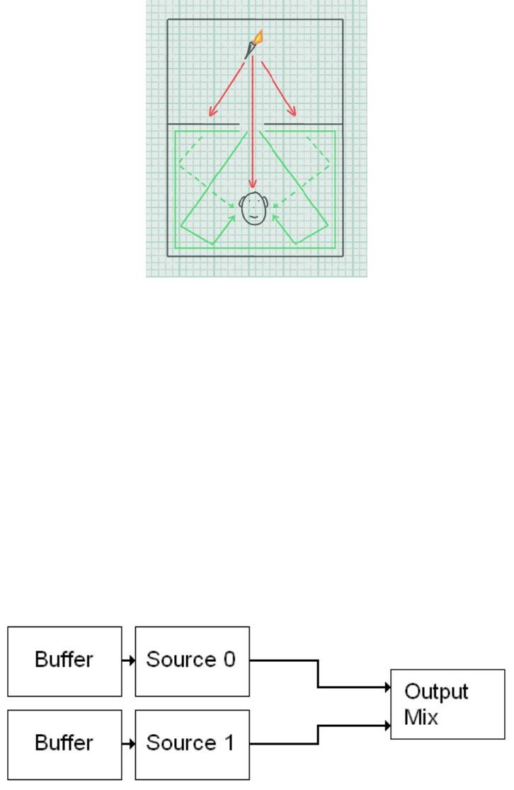
Multi-Environment Modeling
If you are only using one reverb, there is no way to audibly indicate the presence of acoustically
different spaces until the listener enters them. When the listener moves from one distinct acoustic
space to another, you have to switch the reverb to reflect the environment the listener has entered.
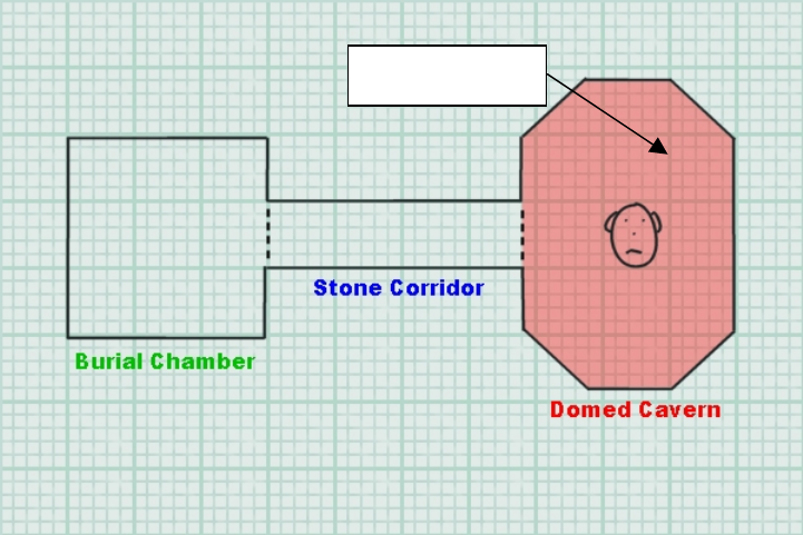
Figure 1 – With only one reverb, only the listener’s environment can be modeled
A multi-environment implementation using more than one reverb can provide a more realistic
experience by enabling the user to hear acoustic information from rooms other than the one occupied
by the listener.
With only one reverb, if the player walks around the Domed Cavern in Figure 1, the sounds of the
player’s footsteps and breathing will be affected by the appropriate environmental reverb, hinting at the
lofty proportions of the Cavern. So how can multi-environments enhance an application’s sound-
scape? It becomes clearer when other rooms are also populated with sound sources
Add to our scenario the sound of flaming torches burning in the Stone Corridor. Without multi-
environments, the best we can do is to apply some Environment filtering effects to muffle the sound if
Listener’s environment
11/144
the opening between the Corridor and the Cavern is blocked or if the flaming torch is instead audible
through the opening.
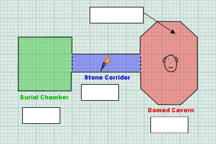
Figure 2 – Multiple reverbs allow all three environments to be rendered simultaneously
But in real life, as well as hearing the direct path of sound from the flaming torch to the listener’s ear, the
listener will also perceive some reflected sound with the acoustic signature of the source’s own
environment – the Stone Corridor. Of course, sounds generated inside the listener’s environment, the
Domed Cavern, will be reflected by the walls, generating that room’s own acoustic effect too. The
flaming torch probably will also contribute to the reverberation in the Domed Cavern. And what’s more,
intervening walls and obstacles will modify each of these components of sound!
With the multi-environment model, environmental reverbs can be rendered for both locations, and
filtering effects applied to correctly muffle direct and reflected sound.
In addition to having multiple reverbs, you need to be able to set the directivity of each reverb as after
all, if the outputs from each environmental reverb effect were simultaneously presented as being evenly
spread around the listener’s head, the mix of reflected sounds would make little sense; the extra
information produced by the simulation of different acoustic environments would be extremely hard to
discern. This is achieved by panning environments:
Panning Environments
When the listener hears reflected sound emanating from environments other than his or her own, the
location of each external environment needs to be indicated.
For this reason, the Effects Extension’s EAX Reverb effect includes parameters that allow you to set
the directional panning of initial reflections and late reverberation decay. These panning parameters
control both the perceived direction and the “divergence” of the reflections and reverberation. The
“divergence” control allows for variation from diffuse surrounding reflections to reflections focused in a
chosen direction.
Listener’s environment
Environment 2
Environment 3
Environment 1
12/144
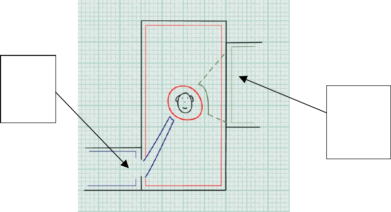
Figure 3– Navigating environments
By setting these parameters in real time, and altering the level of wet sound, you can imply a direction
and distance relating the corresponding environment to the listener.
The application should identify the location of other environments currently being rendered. If an
opening exists in the geometry, making a clear path between another environment and the listener’s,
the panning parameters for the other environments should be set, making it seem as though the
reflected sound is reaching the listener’s ears from that opening. If no direct path exists, the nearby
environment should simply be panned and occluded to give the impression that the origin is the
adjoining wall.
This technique can also be used in an application that only assigns one reverb to simulate
environmental sound, to imply the existence and location of particularly acoustically reflective features
in the world.
Environmental Filtering
Environmental filtering enhances the realism of an environment by simulating the way architectural
features such as walls and pillars might block and absorb sound. Sound sources which are hidden
behind a pillar or a wall are perceived very differently from sound sources which have an un-obstructed
path to the listener’s ears. The muffling effects can reinforce the visual perception of these features,
representing obstacles of different thickness and materials by varying the attenuation and filtering
applied to sounds passing through them.
There are three different types of scenario that would cause a sound source to be perceived differently
by a listener: Obstruction, Occlusion and Exclusion.
Sound Obstruction
Let us imagine the scenario where an acoustically opaque column is placed in the middle of a room,
between the sound source and the listener. The direct-path sound wave can only reach the listener by
transmission through the obstacle or by diffraction around the obstacle. In both cases, it will be partially
or completely muffled. That muffling effect is called obstruction.
This
environment
reaches the
listener
through the
doorway
This
environment
reaches the
listener
through the
adjoining wall

13/144
Figure 4– Obstruction: When an object in a room separates sound from listener, obstruction occurs. In this example, the direct-path
sound is muffled through a partially transmissive obstacle or medium.
Sound waves can bend around obstacles that are smaller than their wavelength - this phenomenon is
called sound diffraction. The result of sound diffraction is that the listener hears a direct sound source
with the high frequencies filtered out. This is because the lower frequency sound, with greater
wavelength, can bend around larger obstacles than higher frequency sound. The amount of muffling
(attenuation of higher frequencies) due to diffraction depends on the amount of deviation from a straight
propagation path: the larger the angle that the direct path (shortest path) must make to go around the
obstacle, the stronger the muffling effect.
The tonal effect of transmission through the obstacle or diffraction around an obstacle is similar
because materials are typically less transmissive at high frequencies that at low frequencies: in both
cases, the direct-path sound is low-pass filtered. However, there is a difference between the two
phenomena in the apparent position of the sound source. When there is substantial transmission
throughout the obstacle, the sound still seems to come essentially from the same direction as if there
were no obstacle. In the case of diffraction, the sound seems to come for the edge of the obstacle
where the shortest sound path is diffracted.
Because reflected sound waves go around the obstruction for the most part, the obstruction typically
blocks only a tiny part of the sound source’s reflections and reverberation. These audio cues remain
essentially constant with or without the obstruction. The muffling effect of obstruction is essentially
confined in the direct sound. The lack of (or muffled) direct sound in combination with normal
reflections and reverberation informs the brain that the source is located behind an obstacle.
Sound Occlusion
We now split the rooms, so that the sound source is in one room and the listener is in the adjacent
room. Source and listener are completely separated by a wall so there is no direct air connection
between them. Any sounds that pass from source to listener must pass through the wall, which muffles
the sounds. This is called occlusion. It differs from obstruction in that obstruction does have open
(although indirect) air space between source and listener.
14/144
Figure 5 – Occlusion: When a full wall separates the sound source from the listener, it occludes the sound.
The wall that divides the sound source and the listener acts as a big filter. Direct sound waves from the
source (along with accompanying reflections and reverberation) hit the wall and are passed through to
the other side, where they radiate into the listener’s room. As the sounds pass through the wall, they’re
all altered—typically their high-frequency components are filtered out, leaving a very muffled result.
The direct sound wave ("first wave front") passing through the wall contributes to the reflected sound in
the destination environment.
When the brain hears a muffled sound source along with muffled reflections and reverberation, it can
recognize that the source is located behind a wall or other acoustically transmissive material. This is
unlike an obstructed source, where the direct sound is muffled but the reflections and reverberation are
not. The quality of the muffling tells the brain something about the construction of the wall — whether it
is dense, thin, solid, soft, and so on.
Sound Exclusion
Taking the two rooms in which we explained occlusion, we can now make an opening in the wall that
separated listener from source, for example a doorway. Source and listener are still separated by the
wall, but there is an opening allowing the sound to enter the room and, in certain positions, the direct
path between the source and listener is clear.
15/144
Figure 6 - When an opening breaks the wall separating the sound from the listener, the direct path is clear but the sound remains
excluded from the listener's room.
When there is a direct path, a new scenario is defined – exclusion. In this situation, the direct sound is
not muffled, but the source can only radiate a small amount of energy into the listener’s room through
the opening. The amount of reflected sound perceived by the listener from this source’s environment
depends on the size of the opening and on the distance from the source to the opening. The direct
sound wave passing through the opening contributes to the reverb in the destination environment.
The location of the listener can be such that an obstacle blocks the direct path from the source to the
listener (that could be the wall separating the two rooms or some other obstacle located in the listener’s
room). In that case, there is a combination of exclusion (reducing the reflected sound in the listener’s
room) and obstruction (muffling the direct-path sound).
OpenAL’s architecture for 3D audio
OpenAL establishes a simple and robust framework for the processing and rendering of
interactive 3D audio. The diagram below shows the fundamentals of OpenAL’s processing
architecture.
Figure 7 - Basic OpenAL architecture
As you can see, the signal flow is rudimentary. Buffer objects contain sample data. Source
objects represent playback voices, either 3D (mono point sources for 3D positioning) or 2D, and
allow the programmer to control basic properties such as attenuation, position and orientation. A
Buffer is attached to a source for playback. The renderer will take care of applying 3D
16/144
virtualization techniques according to the Source’s position, and mixing together all the playing
Sources.
This architecture is perfectly adequate for the implementation of a real-time 3D sound scene. But
no provision is made in this model for advanced processing. Examples of processing techniques
required for interactive audio include:-
• Per-source environmental filtering (occlusion, obstruction)
• Auxiliary effect sends (e.g. environmental reverb)
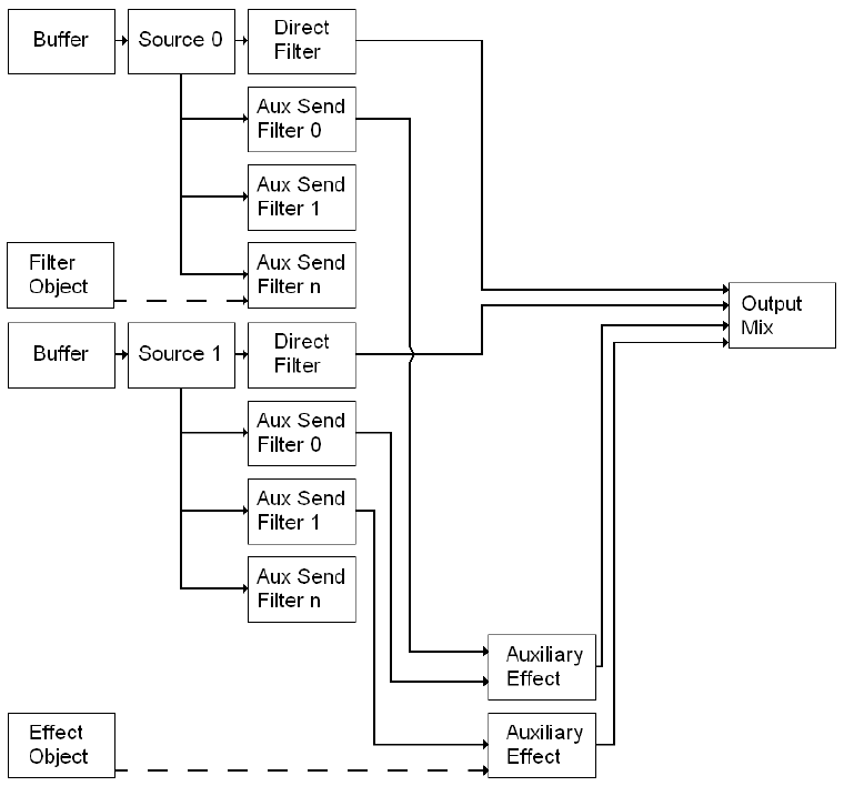
Effects Extension
The Effects Extension is designed to provide a generic, cross-platform framework for adding
advanced DSP effects to OpenAL. The diagram below illustrates the capabilities of the
processing framework established under the OpenAL Effects Extension.
Figure 8 - OpenAL with Effects Extension architecture
This framework offers the OpenAL programmer two new ways to process audio. Firstly, Sources
can be processed through filters. Secondly, Auxiliary Effect Sends are introduced, so that effects
processing can be applied to groups of Sources. The output of the Auxiliary Effects is fed into the
final mix. You’ll notice that it is possible to filter Sources as they are fed into each Auxiliary Effect.
17/144
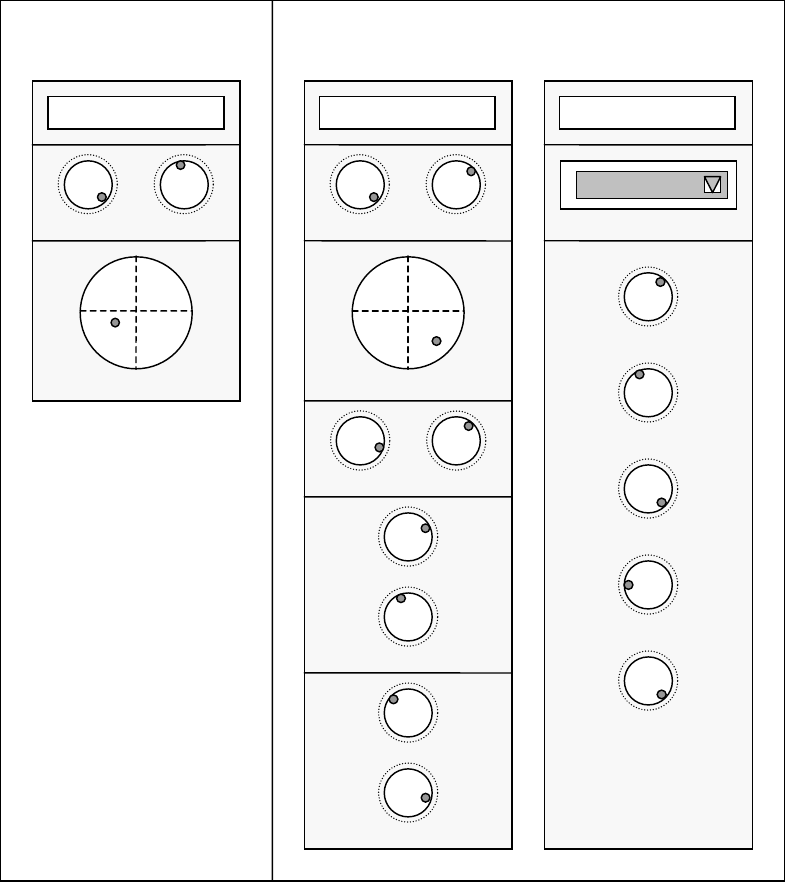
A good analogy here is with a traditional studio mixing desk. OpenAL on its own would map to a
very simple mixing desk. Each channel strip will have minimal controls – volume, 3D or stereo
pan, plus also pitch (frequency). There are no auxiliary buses. In contrast, the equivalent mixer
for OpenAL with Effects Extension has an arbitrary number of auxiliary effects buses, into which
you can patch a variety of effects processors with adjustable parameters. On the channel strip, a
filter control is added. There are also adjustable sends to each auxiliary bus, each with a filter
control as well.
Figure 9 - Mixing desk analogy - OpenAL vs OpenAL with Effects Extension
Effects Extension objects
The Effects Extensions introduce a number of new objects to OpenAL. These new objects will be
described in depth later on, but in summary they are:
Auxiliary Effect Slot
Channel #
x
Volume
3D Pan
3D Pan
Aux Send 1 Level
Aux Send 1 Filter
Direct Filte
r
Aux Send
n
Level
Aux Send
n
Filter
Effect T
y
pe
Effect
Parameters
Parameter 1
Parameter 2
Parameter 3
Parameter 4
“OpenAL” mixer “OpenAL with Effects Extension” mixer
Pitch
Volume
Pitch
Reverb
Direct Level
Parameter
m
Channel #
x
A
ux Send #
y
18/144
An Auxiliary Effect Slot object represents an effect that can be fed with a mix of audio from
selected Sources. The effect type and settings for the processor are determined by the attached
Effect Object. In our mixing console analogy, this is the rack-mount slot where an effects
processor can be patched into the mixer’s auxiliary send.
Effect Objects
Effects objects consist of the parameters required to define an Auxiliary Effect, i.e. effect type
(reverb, chorus, etc…), plus values for each of the parameters that control the effect.
Filter Objects
A filter object contains the information needed to set up a filter. I.e. the filter type (low-pass, high-
pass, etc…), and values for any settings such as filter amount, cut-off etc… Filter objects can be
used to filter the direct path (dry signal) of a Source, or used to filter the send path (wet signal) to
any of the Auxiliary Effect Slots.
Source, Listener and Context Object Extensions
The Effects Extension also adds a number of new properties to the existing OpenAL objects.
Vendor-specific effects
Different OpenAL devices may support different effect types, including effects additional to the
standard ones described here.

19/144
Auxiliary Effect Slots
Auxiliary Effect Slots are essentially containers for DSP Effects. They are positioned at the end
of the signal processing graph which means that the output of an Auxiliary Effect Slot is sent
directly to the final output mix. Multiple OpenAL Sources can send to the same Effect Slot,
however there are limitations on the number of different Effect Slots that one Source can feed
simultaneously (see ALC_MAX_AUXILIARY_SENDS).
Auxiliary Effect Slots need to be generated by the application using alGenAuxiliaryEffectSlots,
and should be destroyed using alDeleteAuxiliaryEffectSlots when no longer required. They are
identified by an ID in the same way that OpenAL Sources and Buffers are identified.
The Effects Extension does not impose any limits on the number of Auxiliary Effects Slots that
can be created, so the application should expect that different OpenAL devices will support
varying numbers of Auxiliary Effects Slots (and differing numbers of Auxiliary Sends from each
Source). Tutorial 2 shows how to generate Effects Slots and check that they are successfully
created.
Effects are loaded into Auxiliary Effect Slots by attaching Effect Objects to them. The Effect
Object stores the type of effect and the values for all the parameters of that effect. When an
Effect Object is attached to an Auxiliary Effect Slot, a check is made to see if that effect type is
already loaded in the slot. If not, the appropriate effect will be loaded. Once the effect is loaded
into the slot, the parameter data for the effect (stored in the Effect Object) will be applied to the
actual device effect. An application should check that the Effect attaching operation is
successful, because some OpenAL devices may have resource limitations that mean that not all
Effect types can be loaded into all Auxiliary Effect Slots. Tutorial 3 shows how to attach an Effect
to an Auxiliary Effect Slot.
Changing a parameter value in the Effect Object after it has been attached to the Auxiliary Effect
Slot will not affect the effect in the effect slot. To update the parameters of the effect in the effect
slot, an application must update the parameters of an Effect object and then re-attach it to the
Auxiliary Effect Slot.
To unload an Effect from an Auxiliary Effect Slot the application should attach the empty Effect
object define: AL_EFFECT_NULL.
Finally, an application can control the output level of an Auxiliary Effect Slot using
AL_EFFECTSLOT_GAIN and enable or disable automatic send adjustment using
AL_EFFECTSLOT_AUXILIARY_SEND_AUTO.
For a complete list of Auxiliary Effect Slot related functions and properties please refer to the
Auxiliary Effect Slot Object section.

20/144
Effects
Effect objects are containers for audio Effects. The Effect object stores the type of effect and a
list of values for the parameters for that effect. The Effect object can therefore be used to store
‘presets’ for different effects, e.g. an Effect object could contain a reverb effect with a set of
parameters that can be used to model a Bathroom environment, or a reverb effect with a set of
parameters that can be used to model a Cave environment, or an echo effect with a set of
parameters that can be used to model a Canyon.
Effect objects need to be generated by the application using alGenEffects, and should be
destroyed using alDeleteEffects when no longer required. They are identified by an ID in the
same way that OpenAL Sources and Buffers are identified.
The Effects Extension does not impose any limits on the number of Effects that can be created,
however different OpenAL devices will support different effect types.
After generating an Effect object the application must tell the Effect what type of Effect it should
store (see AL_EFFECT_TYPE). If this is successful, the application can set the values for each
of the parameters supported by the effect. This is done using the alEffect[i,iv,f,fv] function calls.
Tutorial 2 shows how to generate Effects and check that they are successfully created. It also
shows how to set the type of effect stored in the Effect object and how to update the parameters
of that effect.
In order to hear the results of an Effect it must be loaded into an Auxiliary Effect Slot (see Tutorial
3). Once loaded into an effect slot any Sources that have been configured to send to that effect
slot will automatically start to feed the effect (see Tutorial 4).
Changing a parameter value in the Effect Object after it has been attached to the Auxiliary Effect
Slot will not affect the effect in the effect slot. To update the parameters of the effect in the effect
slot, an application must update the parameters of an Effect object and then re-attach it to the
Auxiliary Effect Slot.
For a complete list of Effect related functions and properties please refer to the Effect Object
section.

21/144
Filters
Filter objects are containers for audio Filters. The Filter object stores the type of filter and a list of
values for the parameters for that filter. The Filter object can therefore be used to store ‘presets’
for different filters, e.g. a Filter object could contain a low-pass filter with a set of parameters that
can be used to model sound passing through a concrete wall, or a band-pass filter with a set of
parameters that can be used to model transmission of audio over a telephone.
Filter objects need to be generated by the application using alGenFilters, and should be
destroyed using alDeleteFilters when no longer required. They are identified by an ID in the
same way that OpenAL Sources and Buffers are identified.
The Effects Extension does not impose any limits on the number of Filters that can be created,
however different OpenAL devices will support different filter types.
After generating a Filter object the application must tell the Filter what type of filter it should store
(see AL_FILTER_TYPE). If this is successful, the application can set the values for each of the
parameters supported by the filter. This is done using the alFilter[i,iv,f,fv] function calls. Tutorial
2 shows how to generate Filters and check that they are successfully created. It also shows how
to set the type of filter stored in the Filter object and how to update the parameters of that filter.
Filter objects can be used in two different ways; to filter an OpenAL Source, or to filter the send
from an OpenAL Source to an Auxiliary Effect Slot. When a filter object is attached to a Source
as a Direct Filter (using alSourcei with the property AL_DIRECT_FILTER), filtering is applied to
the direct (dry) signal of the Source only. When a filter object is attached to a Source as an
Auxiliary Send Filter (using alSource3i with the property AL_AUXILIARY_SEND_FILTER),
filtering is applied to the signal being sent to the Auxiliary Effect Slot. Tutorial 5 shows the two
different ways of using Filter objects.
Changing a parameter value in the Filter Object after it has been attached to a Source will not
affect the Source. To update the filter(s) used on a Source, an application must update the
parameters of a Filter object and then re-attach it to the Source.
For a complete list of Filter related functions and properties please refer to the Filter Object
section.

22/144
Source Extensions
To integrate Effect Extension functionality into OpenAL a number of new Source properties have
been added. These properties allow Sources to use Filters, Effects, and Auxiliary Effect Slot
objects. In addition a number of properties have been added to enhance the 3D spatialization
model of OpenAL.
Enabling a Source Auxiliary Send
In order for a Source to feed an Effect that has been loaded into an Auxiliary Effect Slot the
application must configure one of the Source’s auxiliary sends. This process involves setting 3
variables – the destination Auxiliary Effect Slot ID, the Auxiliary Send number, and an optional
Filter ID.
The ID of the Auxiliary Effect Slot is simply the value returned from a successful call to
alGenAuxiliaryEffectSlots.
The Auxiliary Send number identifies which of the Source’s Auxiliary Sends is being used to send
to the specified Auxiliary Effect Slot. The number of Auxiliary Sends available on each Source is
OpenAL device dependent (see ALC_MAX_AUXILIARY_SENDS).
If an application wishes to filter the send from the Source to the Auxiliary Effect Slot it can provide
a valid Filter ID. If no filtering is required this value should be set to AL_FILTER_NULL.
The alSource3i function call is used to pass the values to OpenAL using the property
AL_AUXILIARY_SEND_FILTER. Tutorial 4 shows how to configure the Auxiliary Sends on a
Source.
Disabling a Source Auxiliary Send
To disable a particular Auxiliary Send from a Source, the application should configure that send
number to send to the null Auxiliary Effect Slot. Tutorial 4 shows how to disable an Auxiliary
Send.
Enabling a Source Filter
To apply filtering on the direct-path (dry signal) of a Source, a Filter object can be attached to the
Source using alSourcei with the property AL_DIRECT_FILTER and passing in a Filter ID.
Tutorial 5 shows how to attach a filter to a Source.
Disabling a Source Filter
To remove a Filter from a Source, the application should attach the null Filter object to the Source
using alSourcei with the property AL_DIRECT_FILTER. Tutorial 5 shows how to remove a filter
from a Source.
Enhanced 3D Spatialization Modeling Properties
The amount of Air Absorption applied to each OpenAL Source can be adjusted using the
AL_AIR_ABSORPTION_FACTOR property.
If an application is using Cone parameters on Sources, then an additional property available
through the Effects Extensions called AL_CONE_OUTER_GAINHF allows the application to
control a low-pass filter that is applied when the source is facing away from the listener.

23/144
The amount of attenuation applied to the Source’s auxiliary send level can be adjusted using the
AL_ROOM_ROLLOFF_FACTOR property. This property is disabled if the Auxiliary Effect Slot
property AL_EFFECTSLOT_AUXILIARY_SEND_AUTO is set to AL_FALSE.
AL_DIRECT_FILTER_GAINHF_AUTO is used to enable or disable the attenuation of high-
frequencies in the Source’s direct (dry) path based on the setting of
AL_CONE_OUTER_GAINHF.
AL_AUXILIARY_SEND_FILTER_GAIN_AUTO is used to enable or disable attenuation of
reflected sound based on the source-listener distance and the source’s orientation.
AL_AUXILIARY_SEND_FILTER_GAINHF_AUTO is used to enable or disable high-frequency
attenuation of reflected sound based on source orientation and the AL_CONE_OUTER_GAINHF
setting.

24/144
Listener Extensions
To integrate Effect Extension technology into OpenAL one new property was added to the
OpenAL Listener object. This property simply allows the application to provide unit information to
the Effects Extension so that distance related properties such as Air Absorption are applied
correctly.
The distance unit being used by the application should be set using a call to alListenerf with the
property AL_METERS_PER_UNIT. If the application is using centimeters for distance units, then
this property should be set to 0.01 so that the amount of air absorption applied is not 100 times
too great!

25/144
Context Extensions
The Effect Extension adds a few new properties to the OpenAL Context object. The most
important property is the number of Auxiliary Sends that are available on each OpenAL Source.
The other properties are for querying for the version of the Effects Extension supported by
OpenAL.
The ALC_MAX_AUXILIARY_SENDS property is used to hint to the OpenAL Context (at Context
creation time) the maximum number of Auxiliary Sends desired on each Source. It is not
guaranteed that the desired number of sends will be available, so an application should query this
property after creating the context using alcGetIntergerv. Tutorial 1 shows how to initialize
OpenAL and the Effect Extension including requesting and querying the number of Auxiliary
Sends per Source.
Auxiliary sends on a source are identified by their 0 based indices. As an example if a Source has
2 Auxiliary Sends then they are referred to as Send 0 and Send 1. More information on how to
access and control Auxiliary Sends on a Source is given in the Source Extensions section.
The ALC_EFX_MAJOR_VERSION and ALC_EFX_MINOR_VERSION properties are used to
query for the version of the Effect Extension supported. An application should use the OpenAL
function alcGetIntegerv to retrieve the values for these properties.
26/144
Programming the Effects Extension
This section introduces you to the techniques required to access the features of the Effects
Extension. The following tutorials illustrate how to use the functionality of the Effect Extension.

27/144
Tutorial 1: Initializing OpenAL and the Effects Extension
Shows how to initialize OpenAL and query for the Effect Extension. The source code also
illustrates how to use the Context Creation hint ALC_MAX_AUXILIARY_SENDS to request the
number of Auxiliary Sends available on each Source (and how to check the actual number
available). Finally the code shows how to retrieve the pointers to the Effects Extension functions.
ALCdevice *pDevice = NULL;
ALCcontext *pContext = NULL;
ALint attribs[4] = { 0 };
ALCint iSends = 0;
/* Open default OpenAL device */
pDevice = alcOpenDevice(NULL);
if (!pDevice)
return;
/* Query for Effect Extension */
if (alcIsExtensionPresent(pDevice, "ALC_EXT_EFX") == AL_FALSE)
return;
printf("EFX Extension found!\n");
/* Use Context creation hint to request 4 Auxiliary */
/* Sends per Source */
attribs[0] = ALC_MAX_AUXILIARY_SENDS;
attribs[1] = 4;
pContext = alcCreateContext(pDevice, attribs);
if (!pContext)
return;
/* Activate the context */
alcMakeContextCurrent(pContext);
/* Retrieve the actual number of Aux Sends */
/* available on each Source */
alcGetIntegerv(pDevice, ALC_MAX_AUXILIARY_SENDS, 1, &iSends);

28/144
printf("Device supports %d Aux Sends per Source\n", iSends);
/* Get the Effect Extension function pointers */
alGenEffects=(LPALGENEFFECTS)
alGetProcAddress("alGenEffects");
alDeleteEffects=(LPALDELETEEFFECTS)
alGetProcAddress("alDeleteEffects");
alIsEffect=(LPALISEFFECT)
alGetProcAddress("alIsEffect");
/* ... */
/* Check function pointers are valid */
if (!(alGenEffects && alDeleteEffects && alIsEffect))
return;
/* EFX available and ready to be used ! */

29/144
Tutorial 2: Creating Auxiliary Effect Slots, Effects, and Filters
Shows how to create Auxiliary Effect Slots, Effects and Filters and check for errors. It also shows
how to set Effect types and parameters, and Filter types and parameters.
ALuint uiEffectSlot[4] = { 0 };
ALuint uiEffect[2] = { 0 };
ALuint uiFilter[1] = { 0 };
ALuint uiLoop;
/* Try to create 4 Auxiliary Effect Slots */
alGetError();
for (uiLoop = 0; uiLoop < 4; uiLoop++)
{
alGenAuxiliaryEffectSlots(1, &uiEffectSlot[uiLoop]);
if (alGetError() != AL_NO_ERROR)
break;
}
printf("Generated %d Aux Effect Slots\n", uiLoop);
/* Try to create 2 Effects */
for (uiLoop = 0; uiLoop < 2; uiLoop++)
{
alGenEffects(1, &uiEffect[uiLoop]);
if (alGetError() != AL_NO_ERROR)
break;
}
printf("Generated %d Effects\n", uiLoop);
/* Set first Effect Type to Reverb and change Decay Time */
alGetError();
if (alIsEffect(uiEffect[0]))
{
alEffecti(uiEffect[0], AL_EFFECT_TYPE, AL_EFFECT_REVERB);
if (alGetError() != AL_NO_ERROR)
printf("Reverb Effect not supported\n");
else

30/144
alEffectf(uiEffect[0], AL_REVERB_DECAY_TIME, 5.0f);
}
/* Set second Effect Type to Flanger and change Phase */
alGetError();
if (alIsEffect(uiEffect[1]))
{
alEffecti(uiEffect[1],AL_EFFECT_TYPE,AL_EFFECT_FLANGER);
if (alGetError() != AL_NO_ERROR)
printf("Flanger effect not support\n");
else
alEffecti(uiEffect[1], AL_FLANGER_PHASE, 180);
}
/* Try to create a Filter */
alGetError();
alGenFilters(1, &uiFilter[0]);
if (alGetError() == AL_NO_ERROR)
printf("Generated a Filter\n");
if (alIsFilter(uiFilter[0]))
{
/* Set Filter type to Low-Pass and set parameters */
alFilteri(uiFilter[0],AL_FILTER_TYPE,AL_FILTER_LOWPASS);
if (alGetError() != AL_NO_ERROR)
printf("Low Pass Filter not supported\n");
else
{
alFilterf(uiFilter[0], AL_LOWPASS_GAIN, 0.5f);
alFilterf(uiFilter[0], AL_LOWPASS_GAINHF, 0.5f);
}
}

31/144
Tutorial 3: Attaching an Effect to an Auxiliary Effect Slot
Shows how to load an Effect into an Auxiliary Effect Slot.and check for errors.
/* Attach Effect to Auxiliary Effect Slot */
/* uiEffectSlot[0] is the ID of an Aux Effect Slot */
/* uiEffect[0] is the ID of an Effect */
alAuxiliaryEffectSloti(uiEffectSlot[0],
AL_EFFECTSLOT_EFFECT, uiEffect[0]);
if (alGetError() == AL_NO_ERROR)
printf("Successfully loaded effect into effect slot\n");

32/144
Tutorial 4: Configuring Source Auxiliary Sends
Shows how to configure the Auxiliary Sends on a Source to feed different Auxiliary Effect Slots.
/* Configure Source Auxiliary Effect Slot Sends */
/* uiEffectSlot[0] and uiEffectSlot[1] are Auxiliary */
/* Effect Slot IDs */
/* uiEffect[0] is an Effect ID */
/* uiFilter[0] is a Filter ID */
/* uiSource is a Source ID */
/* Set Source Send 0 to feed uiEffectSlot[0] without */
/* filtering */
alSource3i(uiSource,AL_AUXILIARY_SEND_FILTER, uiEffectSlot[0],
0, NULL);
if (alGetError() != AL_NO_ERROR)
printf("Failed to configure Source Send 0\n");
/* Set Source Send 1 to feed uiEffectSlot[1] with */
/* filter uiFilter[0] */
alSource3i(uiSource,AL_AUXILIARY_SEND_FILTER, uiEffectSlot[1],
1, uiFilter[0]);
if (alGetError() != AL_NO_ERROR)
printf("Failed to configure Source Send 1\n");
/* Disable Send 0 */
alSource3i(uiSource,AL_AUXILIARY_SEND_FILTER,
AL_EFFECTSLOT_NULL, 0, NULL);
if (alGetError() != AL_NO_ERROR)
printf("Failed to disable Source Send 0\n");
/* Disable Send 1 */
alSource3i(uiSource,AL_AUXILIARY_SEND_FILTER,
AL_EFFECTSLOT_NULL, 1, NULL);
if (alGetError() != AL_NO_ERROR)
printf("Failed to disable Source Send 1\n");

33/144
Tutorial 5: Attaching Filters to Sources
Shows how Filters can be used on Sources to filter the direct signal (dry path) and also the send
signal (wet path).
/* Filter 'uiSource', a generated Source */
alSourcei(uiSource, AL_DIRECT_FILTER, uiFilter[0]);
if (alGetError() == AL_NO_ERROR)
{
printf("Successfully applied a direct path filter\n");
/* Remove filter from 'uiSource' */
alSourcei(uiSource, AL_DIRECT_FILTER, AL_FILTER_NULL);
if (alGetError() == AL_NO_ERROR)
printf("Successfully removed direct filter\n");
}
/* Filter the Source send 0 from 'uiSource' to */
/* Auxiliary Effect Slot uiEffectSlot[0] */
/* using Filter uiFilter[0] */
alSource3i(uiSource,AL_AUXILIARY_SEND_FILTER,
uiEffectSlot[0], 0, uiFilter[0]);
if (alGetError() == AL_NO_ERROR)
{
printf("Successfully applied aux send filter\n");
/* Remove Filter from Source Auxiliary Send */
alSource3i(uiSource,AL_AUXILIARY_SEND_FILTER,
uiEffectSlot[0], 0, AL_FILTER_NULL);
if (alGetError() == AL_NO_ERROR)
printf("Successfully removed filter\n");
}

34/144
Tutorial 6: Source Properties
Shows how to set Effects Extension specific Source properties.
/* Set Source Cone Outer Gain HF value */
alSourcef(uiSource, AL_CONE_OUTER_GAINHF, 0.5f);
if (alGetError() == AL_NO_ERROR)
printf("Successfully set cone outside gain filter\n");/*

35/144
Tutorial 7: Listener Properties
Shows how to set Effects Extension specific Listener properties.
/* Set distance units to be in feet*/
alListenerf(AL_METERS_PER_UNIT, 0.3f);
if (alGetError() == AL_NO_ERROR)
printf("Successfully set distance units\n");
36/144
Environmental Audio Programming Techniques
This section looks at the Effects Extension from a higher-level perspective – from the point of view of
integrating environmental effects into the rest of the application.
In an application scenario, the program logic and interaction with the user should provide the audio
engine with sufficient information to adjust the configuration of effects in real-time. For an application
with multiple environment support, the mechanisms needed to maintain a lifelike acoustic simulation
are not trivial.
This section covers all these aspects of application design, giving you the knowledge to make sure your
Effects Extension application is robust and efficient, and most importantly sounds great! The
information which follows is not necessarily a recipe for the perfect audio implementation. Rather it is a
set of suggestions, inspired by Creative’s experiences working with a large number of commercial 3D
audio projects.
Creating a single environment world with the Effects
Extension
Basic hardware and the “Generic Software” device can render one environmental effect (usually
reverb).
Using only one auxiliary effect slot, updating the effect according to the environment is simple.
Environmental zones can be created in an associated tool such as a level editor, and effect settings
defined by the sound designer. Obstruction tests can be performed using ray-casting to determine if
any objects are in between the Source and the Listener. Occlusion can be used whenever the Source
and Listener are in different environments with no line-of-sight between them. Exclusion can be used
when the Source and Listener are in different environments but there is a line-of-sight between them.
When changing environment, it may be beneficial to interpolate parameters in order to avoid audible
popping sounds in the effect.
Creating a multi-environment world with the Effects
Extension
The ability to render several audio effects at once on supported hardware allows the developer to
simulate a world containing multiple environments, with the auxiliary effects slots rendering different
effects for environments likely to be heard by the listener. Designing a mechanism to correctly update
all the effects properties for an accurate multi-environment simulation is not trivial; a number of tasks
are involved. An environmental audio management layer must:
- Ensure that the listener’s environment is always being correctly rendered.
- Ensure that the nearby environments most likely to be audible are being correctly rendered in other
available auxiliary effects slots.
- Ensure that each source is feeding the correct auxiliary effects slots.
- Ensure that each effect is correctly localised, to correspond with the location of its environment in
the game world.
37/144
These are in addition to the environmental audio management tasks associated with a single-
environment simulation. These include checking the status of occlusion, exclusion and obstruction on
each sound source in order to update the filter effects.
The exact manner in which the user interaction, application logic and world geometry influence the
audio engine is very much specific to each individual project. However, there is a general set of
principles that will apply in most instances.
Environmental Zones
Correctly applying environmental audio involves establishing the interaction between the listener and
sound sources in the virtual world, and the various environments that surround the listener and
sources. The most common approach to managing environmental data is to separate the world’s
geometry into environmental zones. Each zone represents a separate acoustic enclosure in the world.
The environmental audio management layer should be able to reference the co-ordinates for the
listener and each sound source. Given any set of co-ordinates, it should be possible to uniquely
identify the environmental zone in which the co-ordinates exist. Typically, a set of parameters for an
effect will be associated with each unique zone identifier. This means that, for example, given co-
ordinates showing the listener’s position, it is simple to retrieve the set of effect parameters for the
listener’s zone.
Data structures such as binary search partition trees offer efficient solutions for storing and retrieving
environmental zone data. The work of creating effect parameter sets for each zone would commonly
be undertaken by an audio designer, using an off-line tool.
The ability to separate world geometry into discrete zones, and reference a unique zone identifier from
a given set of co-ordinates also helps when determining whether a sound should have occlusion effects
applied. If it is detected that a source is in a different zone to the listener, then it is likely that some
occlusion will be applied. The amount of occlusion applied when sound travels between two zones
could be calculated dynamically at run-time. Or again, this data could be prepared by an audio
designer or pre-calculated algorithmically ‘off-line’ and stored in a look-up table.
Apertures between environmental zones
To work with more advanced environmental audio techniques such as exclusion and multiple
environments, identifying ‘apertures’ or ‘portals’ between environmental zones is essential. An aperture
can be defined as the area where a clear-air opening between two environmental zones exists, for
example a doorway or window.
In a multiple environment system where three environments are being rendered, it is important that the
two non-listener environments are correctly localised. If an aperture exists between the listener’s zone
and a secondary zone, then the secondary zone’s reverb should be perceived to be emitting from the
aperture. For information on localising environmental reverb effects, see Reverb and Reflection
Panning Algorithm.
Aperture data can also be used to add an extra degree of realism to occluded sounds. If a sound has
been found to exist in an environment zone adjacent to the listener’s, then the direct line between the
sound source and the listener can be calculated. If this line intersects an aperture, then the sound
should have exclusion applied instead of occlusion, because although the source and listener are in
different environments the direct sound is not blocked.
Source to listener direct path
Efficiently determining whether a sound source should have an obstruction effect applied can be a
tricky process. However, correctly used obstruction effects add a great deal to 3D audio in terms of
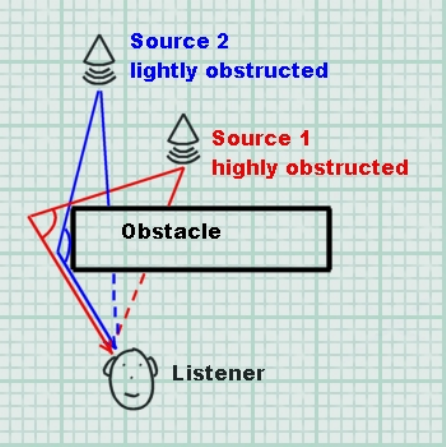
38/144
realism. In a similar manner to exclusion, this can be achieved by calculating the direct line between
the source and the listener, this time checking whether it intersects any world geometry.
A potential optimisation is to assume that only a sound that is in the same environmental zone as the
listener can possibly be obstructed. This pre-supposes that an occlusion effect applied to a sound from
other environmental zones will mask any subsequent obstruction effect, not strictly a true assumption in
the real world.
Pre-generating and storing axis-aligned bounding boxes which identify any potential obstruction (e.g.
pillar, statue) within an environmental zone helps to increase efficiency greatly, but at the expense of
some accuracy.
In real life, the diffraction of sound waves around an object means that the nearer the direct line
between obstructed source and listener comes to the edge of the obstacle, the less filtering and
attenuation takes place. So, to make obstruction effects sound even more natural, it is helpful to
dynamically calculate the amount of obstruction to be applied according to the angle of incidence
between the source, the edge of the obstruction, and the listener
Figure 3 shows how the amount of obstruction varies with the angle around the obstacle.
Figure 10- Variable amounts of obstruction
Low-detail models and shared systems
A significant performance optimisation for environmental data management is to utilise a low detail
model of world geometry for audio calculations. As is often the case, the best efficiency gain comes
when sharing geometry calculations with other application systems. For example, AI, collision-
detection and physics systems often involve low-detail geometrical models and similar mechanisms
and calculations to those described above.
Multi-environment run-time management algorithm
Simulation of multiple environments is a key aim in the design of the Effects Extension SDK. Creative’s
engineers have proposed a general algorithm for environmental audio data management in a multiple-
environment implementation. The following represents an example of how the effects-related audio
program flow might work for a game. In the following pseudo-code ‘n’ represents the maximum
39/144
number of simultaneous environments that can be rendered (for example, that would be 4 on Sound
Blaster X-Fi and 2 on Sound Blaster Audigy).
Each audio frame:
Step 1: Update Environments
If listener position has changed then:
Find the (n-1) closest environments to the listener (listener
environment is always rendered):
• Option 1: Based on radius or priorities assigned to each
environment zone
• Option 2: Based on distance from Listener to centre of
environment
• Option 3: Based on environment’s closest aperture
Update FX Slots
For each Auxiliary Effect slot not rendering one
of the chosen ‘n’ environments, set the Auxiliary slot
gain to 0 (silence) and load one of the chosen
environment Reverb settings into it.
For each Auxiliary Effect slot set appropriate Pan and
Reverb gain levels (based on listener orientation and
distance from listener to environment).
Else if listener orientation has changed then:
For each auxiliary effect slot set appropriate pan and
reverb gain levels (based on listener orientation and
distance from listener to environment).
Step 2: Update sources
For every source:
If source environment has changed or listener position changed
then:
If source environment == listener environment then :
Activate source send 0 to the auxiliary effect slot
rendering the listener environment without filtering.
Deactivate source send 1.
Check for obstruction and add filtering to direct path
if necessary.
Else:
Activate source send 0 to the auxiliary effect slot
rendering the listener environment and add filtering
(occlusion).
If the source environment is being rendered then:
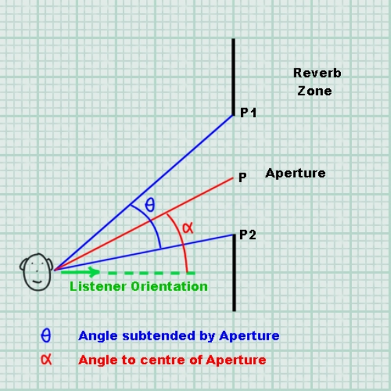
40/144
Activate source send 1 to the auxiliary effect slot
rendering the source environment.
Else:
Deactivate source send 1.
Set all auxiliary effect slots gain to 1.
Reverb and Reflection Panning Algorithm
The EAX Reverb effect exposes complete control over the early reflections and the late reverberation,
including parameters that control the spatial distribution of these separate parts.
The spatial distribution of the early reflections is controlled by using a single vector that indicates the
direction of the reflections, while its magnitude controls how focused the reflections are toward this
direction. A vector of magnitude 0 (the default) creates reflections that come evenly from all directions,
whereas a vector of magnitude 1.0 is highly focused to a particular point. The spatial distribution of the
late reverb is controlled in the same way, using a separate vector.
Both vectors are interpreted in the co-ordinate system of the user, without taking into account the
orientation of the 3D listener. For example, setting the reverb pan to (0.0, 0.0, 0.7) means that the
reverb is panned to the front speakers, whereas a vector of (0.0, 0.0, -0.7) pans the reverb to the rear
speakers.
Figure 11 - Example scenario for effects panning
41/144
Assume the Listener position is stored in the vector vListenerPos, the orientation in vListenerOri, the
centre of the aperture (P) in vAperture, and the aperture corners (P1 and P2) in vApertureLeftSide and
vApertureRightSide.
All angles and trigonometric functions are using radians.
Orientation
In order to compute the orientation for the Reflections and Reverb pan vectors it is necessary to know
the orientation of the listener, and the desired location of the environment. In Figure 3, the reverb on
the other side of the aperture should be panned to the centre of the aperture, point P on the diagram.
To translate P to the “user-relative” position required by the Reflections and Reverb Pan vectors, the
vector LP should be inversely rotated by the angle between the listener orientation and the straight-
ahead vector (0,0,1).
To calculate this angle, take the dot product of the Listener Orientation (should already be normalized)
and (0,0,1). Since several terms cancel out, the angle is simply: -
Angle = arccos (vListenerOri.z).
If the Listener is facing to the left of straight ahead then the angle should be negated: -
if (vListenerOri.x < 0)
Angle = -Angle
The vector LP is defined as: -
LP.x = vAperture.x – vListenerPos.x
LP.y = vAperture.y – vListenerPos.y
LP.z = vAperture.z – vListenerPos.z
So, the Vector can be calculated by rotating LP by –Angle: -
Pan.x = (LP.x * cos(-Angle)) + (LP.z * sin(-Angle))
Pan.y = 0
Pan.z = (LP.x * -sin(-Angle)) + (LP.z * cos(-Angle)
The resulting Pan vector is a “user-relative” vector pointing to the location where the reverb should be
panned. This vector should be normalized, and then multiplied by the magnitude calculated in the next
step.
Magnitude
The magnitude of the Reflection and Reverb pan vectors indicate how focused the reflected sound
should be. To compute the magnitude, the angle subtended by the aperture (θ in the diagram) needs
to be calculated.
The vectors LP1 and LP2 are defined as: -

42/144
LP1.x = vApertureLeftSide.x – vListenerPos.x
LP1.y = vApertureLeftSide.y – vListenerPos.y
LP1.z = vApertureLeftSide.z – vListenerPos.z
LP2.x = vApertureRightSide.x – vListenerPos.x
LP2.y = vApertureRightSide.y – vListenerPos.y
LP2.z = vApertureRightSide.z – vListenerPos.z
After LP1 and LP2 have been normalized, the angle is computed.
θ = arccos((LP1.x * LP2.x) + (LP1.y * LP2.y) + (LP1.z * LP2.z));
The magnitude of the Vector can be calculated using the following formula: -
Magnitude = (2.0f * sin (θ / 2.0)) / θ
Assuming Pan is a normalized vector, the Reflections and Reverb vectors should be set to: -
Pan.x = Pan.x * Magnitude
Pan.y = Pan.y * Magnitude
Pan.z = Pan.z * Magnitude
Angle (θ) Degrees Angle (θ) Radians Magnitude
0 0 1.0
45 π / 4 0.97
90 π / 2 0.90
180 π 0.637
270 3 π / 2 0.3
360 2 π 0
Table 1 - magnitude values for different panning focus angles
43/144
In addition to controlling the position and focus of the early reflections and late reverb, the overall
volume can be attenuated to indicate the distance between the listener and the acoustically reverberant
environment.
44/144
Performance and Optimization
Over recent years, advanced 3D sound technologies like hardware DSP effects and 3D sound buffers
have gained a reputation for hogging the processor and causing performance problems. However, a
close understanding of the potential bottlenecks in 3D sound programming will enable the developer to
avoid inefficient use of hardware resources. Effects coding techniques are inextricably linked with
hardware 3D sound management, so this section will deal with both of these topics together. With a
few key optimisations, implementing hardware OpenAL 3D sound with effects extension support in
your project won’t burn unnecessary CPU time or cause excessive slowdown to the frame rate.
Hardware vs. Software audio
A standard software 3D audio renderer such as the ‘generic software’ device generally employs simple
algorithms to simulate 3D spatialization using stereo panning and attenuation. On a PC system with a
modern CPU, multiple audio streams can be panned, balanced and mixed together with a fraction of
the available computing resources. However, processing effects in software is a resource hungry task
and only a limited amount of effects can be used simultaneously. Software mixers typically update at a
relatively slow rate, maybe 40 times per second, thus introducing up to 25 milliseconds of latency.
Changes to audio, for instance setting a new listener position or orientation, or playing and stopping
sound buffers, will only be effective to a resolution of 25ms.
Hardware 3D sound renderers, such as the ‘generic hardware’ device or native devices, on the other
hand, spatialize sounds over several speakers with sophisticated multi-speaker panning algorithms, or
intensive HRTF processing on headphone and stereo playback systems. A typical hardware
accelerator will respond immediately to changes in audio, so that all 3D sources will be instantly
affected by any change in the listener’s position or orientation. New sound sources will typically begin
playing straight away. On Creative hardware, when using effects extensions, the hardware audio
accelerator is additionally performing complex audio processing such as filtering and digital
reverberation. Rendering up to 128 equivalent 3D voices with effects in software would be prohibitively
CPU intensive, even on today’s fastest processors.
So when comparing audio performance between software and hardware 3D audio renderers, one must
bear in mind the quality of the results. That said, much of the work in hardware 3D sound is carried out
on the soundcard’s own dedicated audio processor. The low level processing which does take up CPU
cycles is comparatively simple.
Solutions for optimisation
Updating positions, effects parameters such as panning, send levels or adding filters to an application
can be CPU consuming tasks, most of the cost being at the application level. It is possible to propose
techniques to lower CPU cost. The solutions involve cutting down the update frequency, and avoiding
redundant updates.
Audio frame rate
Establishing an independent audio frame rate is a crucial performance technique that can potentially
halve the CPU time spent on 3D audio updates. The human eye detects visual changes at a very high
resolution, hence a high graphical frame rate is desirable – graphical updates should ideally occur at
around 60 frames per second to give good smooth visuals.
Many developers update their 3D sound scene each time the screen is refreshed. However, human
ears do not require such frequent updates to 3D sound positioning. In fact, a rate of 30 positional
updates per second is more than adequate to preserve convincing 3D audio. Note that although sound

45/144
positioning doesn’t require updates over 30Hz, some properties such as sound playback frequency,
popular for simulating vehicle engine speed, could need more frequent updates.
On the other hand, some effect settings such as environmental reverb, which can be more expensive
to modify, actually require an even lower update rate, as low as 10 to 15Hz. One exception to this is
the Reflections and Reverb pan vectors, which if being used to localize secondary environments,
should be updated as often as the Listener position and orientation.
Application property Suggested update rate
Graphical scene Typically 60 Hz+
Sound playback frequency for pitch adjustments on sound sources 60 Hz
3D listener Position / Orientation 30 Hz
3D sound source position / directivity 30 Hz
Reverb / reflections panning vectors 30 Hz
Reverberations parameter adjustments 15 Hz
Table 2 - Optimum update rates for different 3D audio properties
So, developing techniques to limit the frequency of positional audio updates to each source and the
listener to pre-determined rates will save plenty of CPU cycles. Table 2 shows optimum independent
rates for updating resolution-critical settings.

46/144
Programmers Reference
Auxiliary Effect Slot Object
Management Functions
To handle the creation, deletion, and verification of Auxiliary Effect Slot objects the following
functions are supplied:
Version Function Name Purpose
1.0 alGenAuxiliaryEffectSlots Create n Auxiliary Effect Slot objects
1.0 alDeleteAuxiliaryEffectSlots Delete n Auxiliary Effect Slots objects
1.0 alIsAuxiliaryEffectSlot Validate an Auxiliary Effect Slot identifier
Property Functions
Auxiliary Effect Slot properties are set using the following functions:
Version Function Name Purpose
1.0 alAuxiliaryEffectSloti Set integer property
1.0 alAuxiliaryEffectSlotiv Set integer array property
1.0 alAuxiliaryEffectSlotf Set floating point property
1.0 alAuxiliaryEffectSlotfv Set floating point array property
Query Property Functions
An application can query properties of the Auxiliary Effect Slot object using the following
functions:
Version Function Name Purpose
1.0 alGetAuxiliaryEffectSloti Retrieve an integer property
1.0 alGetAuxiliaryEffectSlotiv Retrieve an integer array property
1.0 alGetAuxiliaryEffectSlotf Retrieve a floating point property
1.0 alGetAuxiliaryEffectSlotfv Retrieve a floating point array property
Properties
To manipulate properties of the Auxiliary Effect Slot the following values are defined:
Version Property Range Default
1.0 AL_EFFECTSLOT_EFFECT Effect object id AL_EFFECT_NULL
1.0 AL_EFFECTSLOT_GAIN 0.0 to 1.0 1.0
1.0 AL_EFFECTSLOT_AUXILIARY_SEND_AUTO AL_TRUE or
AL_FALSE AL_TRUE
47/144
alGenAuxiliaryEffectSlots
The alGenAuxiliaryEffectSlots function is used to create one or more Auxiliary Effect Slots.
The number of slots that can be created will be dependant upon the Open AL device used.
ALvoid alGenAuxiliaryEffectSlots(
ALsizei n,
ALuint* auxiliaryeffectslots
);
Parameters
n
Number of Auxiliary Effect Slots to be created.
auxiliaryeffectslots
Pointer addressing sufficient memory to store n Effect Slot object identifiers.
Possible Error States
State Problem(s)
AL_OUT_OF_MEMORY Not enough resources to complete request
AL_INVALID_OPERATION Operation cannot be completed at this time
AL_INVALID_VALUE Bad value passed to function
Version Requirements
Effects extension version 1.0
Remarks
An application should check the OpenAL error state after making this call to determine if the
Effect Slot was successfully created. If the function call fails then none of the requested Effect
Slots are created.
A good strategy for creating any OpenAL object is to use a for-loop and generate one object each
loop iteration and then check for an error condition. If an error is set then the loop can be broken
and the application can determine if sufficient resources are available.
See also
alDeleteAuxiliaryEffectSlots, alIsAuxiliaryEffectSlot

48/144
alDeleteAuxiliaryEffectSlots
The alDeleteAuxiliaryEffectSlots function is used to delete and free resources for Auxiliary
Effect Slots previously created with alGenAuxiliaryEffectSlots.
ALvoid alDeleteAuxiliaryEffectSlots(
ALsizei n,
ALuint* auxiliaryeffectslots
);
Parameters
n
Number of Auxiliary Effect Slots to be deleted.
auxiliaryeffectslots
Pointer to n Effect Slot object identifiers.
Possible Error States
State Problem(s)
AL_INVALID_NAME An unknown object identifier was found
AL_INVALID_OPERATION Operation cannot be completed at this time
AL_INVALID_VALUE Bad value passed to function
Version Requirements
Effects extension version 1.0
Remarks
None.
See also
alGenAuxiliaryEffectSlots, alIsAuxiliaryEffectSlot

49/144
alIsAuxiliaryEffectSlot
The alIsAuxiliaryEffectSlot function is used to determine if an object identifier is a valid Auxiliary
Effect Slot object.
ALboolean alIsAuxiliaryEffectSlot(
ALuint auxiliaryeffectslot
);
Parameters
auxiliaryeffectslot
Effect Slot object identifier to validate.
Returns
AL_TRUE if the identifier is a valid Auxiliary Effect Slot, AL_FALSE otherwise.
Version Requirements
Effects extension version 1.0
Remarks
None.
See also
alGenAuxiliaryEffectSlots, alDeleteAuxiliaryEffectSlots

50/144
alAuxiliaryEffectSlot[i,iv,f,fv]
The alAuxiliaryEffectSlot[i,iv,f,fv] functions are used to set properties on Auxiliary Effect Slot
objects.
ALvoid alAuxiliaryEffectSloti(
ALuint auxiliaryeffectslot,
ALenum param,
ALint iValue
);
ALvoid alAuxiliaryEffectSlotiv(
ALuint auxiliaryeffectslot,
ALenum param,
ALint* piValues
);
ALvoid alAuxiliaryEffectSlotf(
ALuint auxiliaryeffectslot,
ALenum param,
ALfloat flValue
);
ALvoid alAuxiliaryEffectSlotfv(
ALuint auxiliaryeffectslot,
ALenum param,
ALfloat* pflValues
);
Parameters
auxiliaryeffectslot
Auxiliary Effect Slot object identifier.
param
Auxiliary Effect Slot property to set.
iValue
Integer value
piValues
Pointer to array of integer values
flValue
51/144
Floating point value
pflValues
Pointer to array of floating point values
Possible Error States
State Problem(s)
AL_INVALID_NAME An unknown object identifier was found
AL_INVALID_ENUM An unknown property identifier was found
AL_INVALID_OPERATION Operation cannot be completed at this time
AL_INVALID_VALUE Bad value passed to function
Version Requirements
Effects extension version 1.0
Remarks
The result of these functions is determined by the property enumeration value. The available
properties that can be set include:
Version Property Range Default
1.0 AL_EFFECTSLOT_EFFECT Effect object id AL_EFFECT_NULL
1.0 AL_EFFECTSLOT_GAIN 0.0 to 1.0 1.0
1.0 AL_EFFECTSLOT_AUXILIARY_SEND
_AUTO
AL_TRUE or
AL_FALSE
AL_TRUE
See also
alGetAuxiliaryEffectSlot[i,iv,f,fv]

52/144
alGetAuxiliaryEffectSlot[i,iv,f,fv]
The alGetAuxiliaryEffectSlot[i,iv,f,fv] functions are used to retrieve properties on Auxiliary
Effect Slot objects.
ALvoid alGetAuxiliaryEffectSloti(
ALuint auxiliaryeffectslot,
ALenum param,
ALint* piValue
);
ALvoid alGetAuxiliaryEffectSlotiv(
ALuint auxiliaryeffectslot,
ALenum param,
ALint* piValues
);
ALvoid alGetAuxiliaryEffectSlotf(
ALuint auxiliaryeffectslot,
ALenum param,
ALfloat* pflValue
);
ALvoid alGetAuxiliaryEffectSlotfv(
ALuint auxiliaryeffectslot,
ALenum param,
ALfloat* pflValues
);
Parameters
auxiliaryeffectslot
Auxiliary Effect Slot object identifier.
param
Auxiliary Effect Slot property to retrieve.
piValue
Address where integer value will be stored.
piValues
Address where the array of integers will be stored.
pflValue
53/144
Address where floating point value will be stored.
pflValues
Address where the array of floating point values will be stored.
Possible Error States
State Problem(s)
AL_INVALID_NAME An unknown object identifier was found
AL_INVALID_ENUM An unknown property identifier was found
AL_INVALID_OPERATION Operation cannot be completed at this time
AL_INVALID_VALUE Bad value passed to function
Version Requirements
Effects extension version 1.0
Remarks
The result of these functions is determined by the property enumeration value. The available
properties that can be retrieved include:
Version Property Range Default
1.0 AL_EFFECTSLOT_EFFECT {Effect object id} AL_EFFECT_NULL
1.0 AL_EFFECTSLOT_GAIN 0.0 to 1.0 1.0
1.0 AL_EFFECTSLOT_AUXILIARY_SEND
_AUTO
AL_TRUE or
AL_FALSE
AL_TRUE
See also
alAuxiliaryEffectSlot[i,iv,f,fv]

54/144
AL_EFFECTSLOT_EFFECT
Version Property Range Default
1.0 AL_EFFECTSLOT_EFFECT {Effect object id} AL_EFFECT_NULL
The AL_EFFECTSLOT_EFFECT property is used to attach an Effect object to the Auxiliary
Effect Slot object. After the attachment, the Auxiliary Effect Slot object will contain the effect type
and have the same effect parameters that were stored in the Effect object. Any Sources feeding
the Auxiliary Effect Slot will immediate feed the new effect type and new effect parameters.
Example: Create an Auxiliary Effect Slot and attaching an Effect.
ALuint uiEffectSlot; /* Storage for effect slot object ID.*/
ALuint uiEffect; /* Storage for effect object ID.*/
/* Generate an Aux Effect Slot */
alGenAuxiliaryEffectSlots(1, &uiEffectSlot);
/* Generate an Effect and set its type to reverb */
alGenEffects(1, &uiEffect);
alEffecti(uiEffect, AL_EFFECT_TYPE, AL_EFFECT_REVERB);
/* Attach Effect to Aux Effect Slot */
alAuxiliaryEffectSloti(uiEffectSlot,
AL_EFFECTSLOT_EFFECT, uiEffect);

55/144
AL_EFFECTSLOT_GAIN
Version Property Range Default
1.0 AL_EFFECTSLOT_GAIN 0.0 to 1.0 1.0
The AL_EFFECTSLOT_GAIN property is used to specify an output level for the Auxiliary Effect
Slot. Setting the gain to 0.0 mutes the output.
Example: Setting Auxiliary Slot Gain
/* Storage for effect slot object ID.*/
ALuint uiEffectSlot;
/* Generate an Aux Effect Slot */
alGenAuxiliaryEffectSlots(1, &uiEffectSlot);
/* Set Aux Effect Slot Gain to 0.5*/
alAuxiliaryEffectSlotf(uiEffectSlot,
AL_EFFECTSLOT_GAIN, 0.5f);

56/144
AL_EFFECTSLOT_AUXILIARY_SEND_AUTO
Version Property Range Default
1.0 AL_EFFECTSLOT_AUXILIARY_SEND_AUTO
AL_TRUE or
AL_FALSE AL_TRUE
The AL_EFFECTSLOT_AUXILIARY_SEND_AUTO property is used to enable or disable
automatic send adjustments based on the physical positions of the sources and the listener.
This property should be enabled when an application wishes to use a reverb effect to simulate the
environment surrounding a listener or a collection of Sources.
Example: Setting the Auxiliary Slot Send Auto Flag
/* Storage for effect slot object ID.*/
ALuint uiEffectSlot;
/* Generate an Aux Effect Slot */
alGenAuxiliaryEffectSlots(1, &uiEffectSlot);
/* Set Aux Effect Slot Send Auto flag to true */
alAuxiliaryEffectSloti(uiEffectSlot,
AL_EFFECTSLOT_AUXILIARY_SEND_AUTO, AL_TRUE);
57/144
Effect Object
Management Functions
To handle the creation, deletion, and verification of Effect Objects the following functions are
supplied:
Version Function Name Purpose
1.0 alGenEffects Create n Effect objects
1.0 alDeleteEffects Delete n Effect objects
1.0 alIsEffect Validate an Effect identifier
Property Functions
Effect Object properties are set using the following functions:
Version Function Name Purpose
1.0 alEffecti Set integer property
1.0 alEffectiv Set integer array property
1.0 alEffectf Set floating point property
1.0 alEffectfv Set floating point array property
Query Property Functions
An application can query properties of the Effect Object using the following functions:
Version Function Name Purpose
1.0 alGetEffecti Retrieve an integer property
1.0 alGetEffectiv Retrieve an integer array property
1.0 alGetEffectf Retrieve a floating point property
1.0 alGetEffectfv Retrieve a floating point array property
Properties
To manipulate properties of the Effect the following values are defined:
Version Property Range Default
1.0 AL_EFFECT_TYPE EffectType Enum AL_EFFECT_NULL
1.0 AL_EFFECT_PARAMETER_NAME Variable Variable

58/144
alGenEffects
The alGenEffects function is used to create one or more Effect objects. An Effect object stores
an effect type and a set of parameter values to control that Effect. In order to use an Effect it
must be attached to an Auxiliary Effect Slot object.
ALvoid alGenEffects(
ALsizei n,
ALuint* effects
);
Parameters
n
Number of Effects to be created.
effects
Pointer addressing sufficient memory to store n Effect object identifiers.
Possible Error States
State Problem(s)
AL_OUT_OF_MEMORY Not enough resources to complete request
AL_INVALID_OPERATION Operation cannot be completed at this time
AL_INVALID_VALUE Bad value passed to function
Version Requirements
Effects extension version 1.0
Remarks
After creation an Effect has no type (AL_EFFECT_NULL), so before it can be used to store a set
of parameters, the application must specify what type of effect should be stored in the object,
using alEffecti.
See also
alDeleteEffects, alIsEffect, alEffecti

59/144
alDeleteEffects
The alDeleteEffects function is used to delete and free resources for Effect objects previously
created with alGenEffects.
ALvoid alDeleteEffects(
ALsizei n,
ALuint* effects
);
Parameters
n
Number of Effects to be deleted.
effects
Pointer to n Effect object identifiers.
Possible Error States
State Problem(s)
AL_INVALID_NAME An unknown object identifier was found
AL_INVALID_OPERATION Operation cannot be completed at this time
AL_INVALID_VALUE Bad value passed to function
Version Requirements
Effects extension version 1.0
Remarks
None.
See also
alGenEffects, alIsEffect

60/144
alIsEffect
The alIsEffect function is used to determine if an object identifier is a valid Effect object.
ALboolean alIsEffect(
ALuint effect
);
Parameters
effect
Effect identifier to validate.
Returns
AL_TRUE if the identifier is a valid Effect, AL_FALSE otherwise.
Version Requirements
Effects extension version 1.0
Remarks
None.
See also
alGenEffects, alDeleteEffects

61/144
alEffect[i,iv,f,fv]
The alEffect[i,iv,f,fv] functions are used to set properties on Effect objects.
ALvoid alEffecti(
ALuint effect,
ALenum param,
ALint iValue
);
ALvoid alEffectiv(
ALuint effect,
ALenum param,
ALint* piValues
);
ALvoid alEffectf(
ALuint effect,
ALenum param,
ALfloat flValue
);
ALvoid alEffectfv(
ALuint effect,
ALenum param,
ALfloat* pflValues
);
Parameters
effect
Effect object identifier.
param
Effect property to set.
iValue
Integer value
piValues
Pointer to array of integer values
flValue
Floating point value

62/144
pflValues
Pointer to array of floating point values
Possible Error States
State Problem(s)
AL_INVALID_NAME An unknown object identifier was found
AL_INVALID_ENUM An unknown property identifier was found
AL_INVALID_OPERATION Operation cannot be completed at this time
AL_INVALID_VALUE Bad value passed to function
Version Requirements
Effects extension version 1.0
Remarks
The result of these functions is determined by the property enumeration value. The available
properties that can be set include:
Version Property Range Default
1.0 AL_EFFECT_TYPE EffectType Enum AL_EFFECT_NULL
1.0 AL_EFFECT_PARAMETER_NAME Variable Variable
See also
alGetEffect[i,iv,f,fv]

63/144
alGetEffect[i,iv,f,fv]
The alGetEffect[i,iv,f,fv] functions are used to retrieve properties from Effect objects.
ALvoid alGetEffecti(
ALuint effect,
ALenum param,
ALint* piValue
);
ALvoid alGetEffectiv(
ALuint effect,
ALenum param,
ALint* piValues
);
ALvoid alGetEffectf(
ALuint effect,
ALenum param,
ALfloat* pflValue
);
ALvoid alGetEffectfv(
ALuint effect,
ALenum param,
ALfloat* pflValues
);
Parameters
effect
Effect object identifier.
param
Effect property to retrieve.
piValue
Address where integer value will be stored.
piValues
Address where the array of integers will be stored.
pflValue
Address where floating point value will be stored.
64/144
pflValues
Address where the array of floating point values will be stored.
Possible Error States
State Problem(s)
AL_INVALID_NAME An unknown object identifier was found
AL_INVALID_ENUM An unknown property identifier was found
AL_INVALID_OPERATION Operation cannot be completed at this time
AL_INVALID_VALUE Bad value passed to function
Version Requirements
Effects extension version 1.0
Remarks
The result of these functions is determined by the property enumeration value. The available
properties that can be retrieved include:
Version Property Range Default
1.0 AL_EFFECT_TYPE EffectType Enum AL_EFFECT_NULL
1.0 AL_EFFECT_PARAMETER_NAME Variable Variable
See also
alEffect[i,iv,f,fv]

65/144
AL_EFFECT_TYPE
Version Property Range Default
1.0 AL_EFFECT_TYPE EffectType Enum AL_EFFECT_NULL
The AL_EFFECT_TYPE is used to set the type of effect represented by the Effect object. When
an Effect Object is first created it is of type AL_EFFECT_NULL. A NULL effect is an effect that
has no parameters and does nothing. The following effect type values are defined:
Version Effect Type Value
1.0 AL_EFFECT_NULL 0x0000
1.0 AL_EFFECT_EAXREVERB 0x8000
1.0 AL_EFFECT_REVERB 0x0001
1.0 AL_EFFECT_CHORUS 0x0002
1.0 AL_EFFECT_DISTORTION 0x0003
1.0 AL_EFFECT_ECHO 0x0004
1.0 AL_EFFECT_FLANGER 0x0005
1.0 AL_EFFECT_FREQUENCY_SHIFTER 0x0006
1.0 AL_EFFECT_VOCAL_MORPHER 0x0007
1.0 AL_EFFECT_PITCH_SHIFTER 0x0008
1.0 AL_EFFECT_RING_MODULATOR 0x0009
1.0 AL_EFFECT_AUTOWAH 0x000A
1.0 AL_EFFECT_COMPRESSOR 0x000B
1.0 AL_EFFECT_EQUALIZER 0x000C
An application can set the effect type using the alEffecti function. Below is a code example
showing how an effect object is created using alGenEffects, and its type set using alEffecti with
the AL_EFFECT_TYPE property:
ALuint uiEffect; /* Storage for effect object ID.*/
/* Generate an effect ID and then set its type to reverb. Setting
the effect type sets all parameters to default values.*/
alGenEffects(1, &uiEffect);
alEffecti(uiEffect, AL_EFFECT_TYPE, AL_EFFECT_REVERB);
When the effect type has been set, the effect parameters will set to their default values.
An application can retrieve the effect type from an Effect Object using the alGetEffecti function.
Alint iEffectType; /* Storage for effect type retrieved */
alGetEffecti(uiEffect, AL_EFFECT_TYPE, &iEffectType);
66/144
AL_EFFECT_PARAMETER_NAME
The Effect object can store many different types of audio effects, each with their own set of
parameters types and ranges. The parameters of these effects are all set using the generic
alEffect[i,iv,f,fv] function calls. This section details the names and parameters of the effects that
may be available on an Effects Extension v.1.0 capable device.
AL_EFFECT_NULL
As previously described an effect object with an effect type of AL_EFFECT_NULL has no
parameters and does nothing. This effect type is used when an Effect Object is initially created.
Attach a NULL effect to an auxiliary effect slot to unload any effect that might be occupying the
slot and free the associated resources. Attempting to set a parameter value on a NULL effect will
result in an error condition being set.
AL_EFFECT_EAXREVERB
Version Parameter Name Units Range Default
1.0 AL_EAXREVERB_DENSITY [0.0, 1.0] 1.0
1.0 AL_EAXREVERB_DIFFUSION [0.0, 1.0] 1.0
1.0 AL_EAXREVERB_GAIN [0.0, 1.0] 0.32
1.0 AL_EAXREVERB_GAINHF [0.0, 1.0] 0.89
1.0 AL_EAXREVERB_GAINLF [0.0, 1.0] 0.0
1.0 AL_EAXREVERB_DECAY_TIME Seconds [0.1, 20] 1.49
1.0 AL_EAXREVERB_DECAY_HFRATIO [0.1, 2.0] 0.83
1.0 AL_EAXREVERB_DECAY_LFRATIO [0.1, 2.0] 1.0
1.0 AL_EAXREVERB_REFLECTIONS_GAIN [0.0, 3.16] 0.05
1.0 AL_EAXREVERB_REFLECTIONS_DELAY Seconds [0.0, 0.3] 0.007
1.0 AL_EAXREVERB_REFLECTIONS_PAN Vector
[[-1.0, -1.0, -1.0],
[1.0, 1.0, 1.0]] [0.0, 0.0, 0.0]
1.0 AL_EAXREVERB_LATE_REVERB_GAIN [0.0, 10.0] 1.26
1.0 AL_EAXREVERB_LATE_REVERB_DELAY Seconds [0.0, 0.1] 0.011
1.0 AL_EAXREVERB_LATE_REVERB_PAN Vector
[[-1.0, -1.0, -1.0],
[1.0, 1.0, 1.0]] [0.0, 0.0, 0.0]
1.0 AL_EAXREVERB_ECHO_TIME [0.075, 0.25] 0.25
1.0 AL_EAXREVERB_ECHO_DEPTH [0.0, 1.0] 0.0
1.0 AL_EAXREVERB_MODULATION_TIME [0.04, 4.0] 0.25
1.0 AL_EAXREVERB_MODULATION_DEPTH [0.0, 1.0] 0.0
1.0 AL_EAXREVERB_AIR_ABSORPTION_GAINHF [0.892,1.0] 0.994
1.0 AL_EAXREVERB_HFREFERENCE Hz [1000.0 20000.0] 5000.0
1.0 AL_EAXREVERB_LFREFERENCE Hz [20.0, 1000.0] 250.0
1.0 AL_EAXREVERB_ROOM_ROLLOFF_FACTOR [0.0. 10.0] 0.0
1.0 AL_EAXREVERB_DECAYHF_LIMIT ON / OFF
[AL_FALSE,
AL_TRUE] AL_TRUE
AL_EFFECT_REVERB
Version Parameter Name Units Range Default
1.0 AL_REVERB_DENSITY [0.0, 1.0] 1.0
1.0 AL_REVERB_DIFFUSION [0.0, 1.0] 1.0
67/144
1.0 AL_REVERB_GAIN [0.0, 1.0] 0.32
1.0 AL_REVERB_GAINHF [0.0, 1.0] 0.89
1.0 AL_REVERB_DECAY_TIME Seconds [0.1, 20] 1.49
1.0 AL_REVERB_DECAY_HFRATIO [0.1, 2.0] 0.83
1.0 AL_REVERB_REFLECTIONS_GAIN [0.0, 3.16] 0.05
1.0 AL_REVERB_REFLECTIONS_DELAY Seconds [0.0, 0.3] 0.007
1.0 AL_REVERB_LATE_REVERB_GAIN [0.0, 10.0] 1.26
1.0 AL_REVERB_LATE_REVERB_DELAY Seconds [0.0, 0.1] 0.011
1.0 AL_REVERB_AIR_ABSORPTION_GAINHF [0.892,1.0] 0.994
1.0 AL_REVERB_ROOM_ROLLOFF_FACTOR [0.0. 10.0] 0.0
1.0 AL_REVERB_DECAY_HFLIMIT ON / OFF [AL_FALSE, AL_TRUE] AL_TRUE
AL_EFFECT_CHORUS
Version Parameter Name Units Range Default
1.0 AL_CHORUS_WAVEFORM Sin, Triangle
[AL_CHORUS_WAVEFORM_SINUSOID,
AL_CHORUS_WAVEFORM_TRIANGLE] Triangle
1.0 AL_CHORUS_PHASE Degrees [-180, 180] 90
1.0 AL_CHORUS_RATE Hz [0.0, 10.0] 1.1
1.0 AL_CHORUS_DEPTH [0.0, 1.0] 0.1
1.0 AL_CHORUS_FEEDBACK [-1.0, 1.0] 0.25
1.0 AL_CHORUS_DELAY Seconds [0.0, 0.016] 0.016
AL_EFFECT_DISTORTION
Version Parameter Name Units Range Default
1.0 AL_DISTORTION_EDGE [0.0, 1.0] 0.2
1.0 AL_DISTORTION_GAIN [0.01, 1.0] 0.05
1.0 AL_DISTORTION_LOWPASS_CUTOFF Hz [80.0, 24000] 8000
1.0 AL_DISTORTION_EQCENTER Hz [80.0, 24000] 3600
1.0 AL_DISTORTION_EQBANDWIDTH Hz [80.0, 24000] 3600
AL_EFFECT_ECHO
Version Parameter Name Units Range Default
1.0 AL_ECHO_DELAY Seconds [0.0, 0.207] 0.1
1.0 AL_ECHO_LRDELAY Seconds [0.0, 0.404] 0.1
1.0 AL_ECHO_DAMPING [0.0, 0.99] 0.5
1.0 AL_ECHO_FEEDBACK [0.0, 1.0] 0.5
1.0 AL_ECHO_SPREAD [-1.0, 1.0] -1.0
AL_EFFECT_FLANGER
Version Parameter Name Units Range Default
1.0 AL_FLANGER_WAVEFORM Sin, Triangle [AL_FLANGER_WAVEFORM_SINUSOID, Triangle
68/144
AL_FLANGER_WAVEFORM_TRIANGLE]
1.0 AL_FLANGER_PHASE [-180, 180] 0
1.0 AL_FLANGER_RATE [0.0, 10.0] 0.27
1.0 AL_FLANGER_DEPTH [0.0, 1.0] 1.0
1.0 AL_FLANGER_FEEDBACK [-1.0, 1.0] -0.5
1.0 AL_FLANGER_DELAY Seconds [0.0, 0.004] 0.002
AL_EFFECT_FREQUENCY_SHIFTER
Version Parameter Name Units Range Default
1.0 AL_FREQUENCY_SHIFTER_FREQUENCY Hz
[0.0,
24000.0] 0.0
1.0 AL_FREQUENCY_SHIFTER_LEFT_DIRECTION
Down,
Up,
Off
[0, 2] 0
1.0 AL_FREQUENCY_SHIFTER_RIGHT_DIRECTION
Down,
Up,
Off
[0, 2] 0
AL_EFFECT_VOCAL_MORPHER
Version Parameter Name Units Range Default
1.0 AL_VOCAL_MORPHER_PHONEMEA Phoneme
Type [0, 29] 0
1.0 AL_VOCAL_MORPHER_PHONEMEB Phoneme
Type [0, 29] 10
1.0 AL_VOCAL_MORPHER_PHONEMEA_COARSE_TUNING Semitones [-24,
24] 0
1.0 AL_VOCAL_MORPHER_PHONEMEB_COARSE_TUNING Semitones [-24,
24] 0
1.0 AL_VOCAL_MORPHER_WAVEFORM
Sin,
Triangle,
Saw
[0, 2] 0
1.0 AL_VOCAL_MORPHER_RATE Hz
[0.0,
10.0] 1.41
AL_EFFECT_PITCH_SHIFTER
Version Parameter Name Units Range Default
1.0 AL_PITCH_SHIFTER_COARSE_TUNE Semitones [-12, 12] 12
1.0 AL_PITCH_SHIFTER_FINE_TUNE Cents [-50, 50] 0
AL_EFFECT_RING_MODULATOR
Version Parameter Name Units Range Default
1.0 AL_RING_MODULATOR_FREQUENCY Hz
[0.0,
8000.0] 440.0
1.0 AL_RING_MODULATOR_HIGHPASS_CUTOFF Hz [0.0.
24000.0] 800.0
1.0 AL_RING_MODULATOR_WAVEFORM
Sin,
Saw,
Square
[0, 2] 0
69/144
AL_EFFECT_AUTOWAH
Version Parameter Name Units Range Default
1.0 AL_AUTOWAH_ATTACK_TIME Sec [0.0001, 1.0] 0.06
1.0 AL_AUTOWAH_RELEASE_TIME Sec [0.0001, 1.0] 0.06
1.0 AL_AUTOWAH_RESONANCE [2.0, 1000.0] 1000.0
1.0 AL_AUTOWAH_PEAK_GAIN [0.00003, 31621.0] 11.22
AL_EFFECT_COMPRESSOR
Version Parameter Name Units Range Default
1.0 AL_COMPRESSOR_ONOFF On, Off [0, 1] 1
AL_EFFECT_EQUALIZER
Version Parameter Name Units Range Default
1.0 AL_EQUALIZER_LOW_GAIN [0.126, 7.943] 1.0
1.0 AL_EQUALIZER_LOW_CUTOFF Hz [50.0, 800.0] 200.0
1.0 AL_EQUALIZER_MID1_GAIN [0.126, 7.943] 1.0
1.0 AL_EQUALIZER_MID1_CENTER Hz [200.0, 3000.0] 500.0
1.0 AL_EQUALIZER_MID1_WIDTH [0.01, 1.0] 1.0
1.0 AL_EQUALIZER_MID2_GAIN [0.126, 7.943] 1.0
1.0 AL_EQUALIZER_MID2_CENTER [1000.0, 8000.0] 3000.0
1.0 AL_EQUALIZER_MID2_WIDTH [0.01, 1.0] 1.0
1.0 AL_EQUALIZER_HIGH_GAIN [0.126, 7.943] 1.0
1.0 AL_EQUALIZER_HIGH_CUTOFF Hz [4000.0, 16000.0] 6000.0

70/144
Filter Object
Management Functions
To handle the creation, deletion, and verification of Filter Objects the following functions are
supplied:
Version Function Name Purpose
1.0 alGenFilters Create n Filter objects
1.0 alDeleteFilters Delete n Filter objects
1.0 alIsFilter Validate a Filter identifier
Property Functions
Filter Object properties are set using the following functions:
Version Function Name Purpose
1.0 alFilteri Set integer property
1.0 alFilteriv Set integer array property
1.0 alFilterf Set floating point property
1.0 alFilterfv Set floating point array property
Query Property Functions
An application can query properties of the Filter Object using the following functions:
Version Function Name Purpose
1.0 alGetFilteri Retrieve an integer property
1.0 alGetFilteriv Retrieve an integer array property
1.0 alGetFilterf Retrieve a floating point property
1.0 alGetFilterfv Retrieve a floating point array property
Properties
To manipulate properties of the Filter the following values are defined:
Version Property Range Default
1.0 AL_FILTER_TYPE FilterType Enum AL_FILTER_NULL
1.0 AL_FILTER_PARAMETER_NAME Variable Variable
71/144
alGenFilters
The alGenFilters function is used to create one or more Filter objects. A Filter object stores a
filter type and a set of parameter values to control that Filter. Filter objects can be attached to
Sources as Direct Filters or Auxiliary Send Filters.
ALvoid alGenFilters(
ALsizei n,
ALuint* filters
);
Parameters
n
Number of Filters to be created.
filters
Pointer addressing sufficient memory to store n Filter object identifiers.
Possible Error States
State Problem(s)
AL_OUT_OF_MEMORY Not enough resources to complete request
AL_INVALID_OPERATION Operation cannot be completed at this time
AL_INVALID_VALUE Bad value passed to function
Version Requirements
Effects extension version 1.0
Remarks
After creation a Filter has no type (AL_FILTER_NULL), so before it can be used to store a set of
parameters, the application must specify what type of filter should be stored in the object, using
alFilteri.
See also
alDeleteFilters, alIsFilter, alFilteri

72/144
alDeleteFilters
The alDeleteFilters function is used to delete and free resources for Filter objects previously
created with alGenFilters.
ALvoid alDeleteFilters(
ALsizei n,
ALuint* filters
);
Parameters
n
Number of Filters to be deleted.
filters
Pointer to n Filter object identifiers.
Possible Error States
State Problem(s)
AL_INVALID_NAME An unknown object identifier was found
AL_INVALID_OPERATION Operation cannot be completed at this time
AL_INVALID_VALUE Bad value passed to function
Version Requirements
Effects extension version 1.0
Remarks
None.
See also
alGenFilters, alIsFilter

73/144
alIsFilter
The alIsFilter function is used to determine if an object identifier is a valid Filter object.
ALboolean alIsFilter(
ALuint filter
);
Parameters
filter
Effect identifier to validate.
Returns
AL_TRUE if the identifier is a valid Filter, AL_FALSE otherwise.
Version Requirements
Effects extension version 1.0
Remarks
None.
See also
alGenFilters, alDeleteFilters

74/144
alFilter[i,iv,f,fv]
The alFilter[i,iv,f,fv] functions are used to set properties on Filter objects.
ALvoid alFilteri(
ALuint filter,
ALenum param,
ALint iValue
);
ALvoid alFilteriv(
ALuint filter,
ALenum param,
ALint* piValues
);
ALvoid alFilterf(
ALuint filter,
ALenum param,
ALfloat flValue
);
ALvoid alFilterfv(
ALuint filter,
ALenum param,
ALfloat* pflValues
);
Parameters
filter
Filter object identifier.
param
Effect property to set.
iValue
Integer value
piValues
Pointer to array of integer values
flValue
Floating point value

75/144
pflValues
Pointer to array of floating point values
Possible Error States
State Problem(s)
AL_INVALID_NAME An unknown object identifier was found
AL_INVALID_ENUM An unknown property identifier was found
AL_INVALID_OPERATION Operation cannot be completed at this time
AL_INVALID_VALUE Bad value passed to function
Version Requirements
Effects extension version 1.0
Remarks
The result of these functions is determined by the property enumeration value. The available
properties that can be set include:
Version Property Range Default
1.0 AL_FILTER_TYPE FilterType Enum AL_FILTER_NULL
1.0 AL_FILTER_PARAMETER_NAME Variable Variable
See also
alGetFilter[i,iv,f,fv]

76/144
alGetFilter[i,iv,f,fv]
The alGetFilter[i,iv,f,fv] functions are used to retrieve properties from Filter objects.
ALvoid alGetFilteri(
ALuint filter,
ALenum param,
ALint* piValue
);
ALvoid alGetFilteriv(
ALuint filter,
ALenum param,
ALint* piValues
);
ALvoid alGetFilterf(
ALuint filter,
ALenum param,
ALfloat* pflValue
);
ALvoid alGetFilterfv(
ALuint filter,
ALenum param,
ALfloat* pflValues
);
Parameters
filter
Filter object identifier.
param
Effect property to retrieve.
piValue
Address where integer value will be stored.
piValues
Address where the array of integers will be stored.
pflValue
Address where floating point value will be stored.

77/144
pflValues
Address where the array of floating point values will be stored.
Possible Error States
State Problem(s)
AL_INVALID_NAME An unknown object identifier was found
AL_INVALID_ENUM An unknown property identifier was found
AL_INVALID_OPERATION Operation cannot be completed at this time
AL_INVALID_VALUE Bad value passed to function
Version Requirements
Effects extension version 1.0
Remarks
The result of these functions is determined by the property enumeration value. The available
properties that can be retrieved include:
Version Property Range Default
1.0 AL_FILTER_TYPE FilterType Enum AL_FILTER_NULL
1.0 AL_FILTER_PARAMETER_NAME Variable Variable
See also
alFilter[i,iv,f,fv]

78/144
AL_FILTER_TYPE
Version Property Range Default
1.0 AL_FILTER_TYPE FilterType Enum AL_FILTER_NULL
The AL_FILTER_TYPE is used to set the type of filter represented by the Filter object. When a
Filter object is first created it is of type AL_FILTER_NULL. A NULL filter is a filter that has no
parameters and does nothing. The following filter type values are defined:
Version Effect Type Value
1.0 AL_FILTER_NULL 0x0000
1.0 AL_FILTER_LOWPASS 0x0001
1.0 AL_FILTER_HIGHPASS 0x0002
1.0 AL_FILTER_BANDPASS 0x0003
An application can set the filter type using the alFilteri function. Below is a code example showing
how a Filter object is created using alGenFilters, and its type set using alFilteri with the
AL_FILTER_TYPE property:
ALuint uiFilter; /* Storage for filter object ID.*/
/* Generate a filter ID and then set its type to low-pass.
Setting the filter type sets all parameters to default values.*/
alGenFilters(1, &uiFilter);
alFilteri(uiFilter, AL_FILTER_TYPE, AL_FILTER_LOWPASS);
When the filter type has been set, the filter parameters will be set to their default values.
An application can retrieve the filter type from a Filter object using the alGetFilteri function.
Alint iFilterType; /* Storage for filter type retrieved */
alGetFilteri(uiFilter, AL_FILTER_TYPE, &iFilterType);

79/144
AL_FILTER_PARAMETER_NAME
The Filter object can store different types of Filters, each with their own set of parameters types
and ranges. The parameters of these filters are all set using the generic alFilter[i,iv,f,fv] function
calls. This section details the names and parameters of the effects that may be available on an
Effects Extension v.1.0 capable device
AL_FILTER_NULL
As previously described a Filter object with a type of AL_FILTER_NULL has no parameters. This
Filter type is used when a Filter object is initially created. Attempting to set a parameter value on
a NULL effect will result in an error condition being set.
AL_FILTER_LOWPASS
A low-pass filter is used to remove high frequency content from a signal.
Parameter Name Type Units Range Default
AL_LOWPASS_GAIN FLOAT [0.0, 1.0] 1.0
AL_LOWPASS_GAINHF FLOAT [0.0, 1.0] 1.0
AL_FILTER_HIGHPASS
Not currently implemented. A high-pass filter is used to remove low frequency content from a
signal.
Parameter Name Type Units Range Default
AL_HIGHPASS_GAIN FLOAT [0.0, 1.0] 1.0
AL_HIGHPASS_GAINLF FLOAT [0.0, 1.0] 1.0
AL_FILTER_BANDPASS
Not currently implemented. A band-pass filter is used to remove high and low frequency content
from a signal.
Parameter Name Type Units Range Default
AL_BANDPASS_GAIN FLOAT [0.0, 1.0] 1.0
AL_BANDPASS_GAINLF FLOAT [0.0, 1.0] 1.0
AL_BANDPASS_GAINHF FLOAT [0.0, 1.0] 1.0

80/144
Source Object Extensions
Properties
The following Source properties are defined:
Version Property Range Default
1.0 AL_DIRECT_FILTER Filter ID AL_FILTER_NULL
1.0 AL_AUXILIARY_SEND_FILTER Filter ID AL_FILTER_NULL
1.0 AL_AIR_ABSORPTION_FACTOR 0 to 10 0
1.0 AL_ROOM_ROLLOFF_FACTOR 0 to 10 0
1.0 AL_CONE_OUTER_GAINHF 0.0 to 1.0 1.0
1.0 AL_DIRECT_FILTER_GAINHF_AUTO AL_FALSE or
AL_TRUE AL_TRUE
1.0 AL_AUXILIARY_SEND_FILTER_GAIN_AUTO AL_FALSE or
AL_TRUE AL_TRUE
1.0 AL_AUXILIARY_SEND_FILTER_GAINHF_AUTO AL_FALSE or
AL_TRUE AL_TRUE
81/144
AL_DIRECT_FILTER
Version Property Range Default
1.0 AL_DIRECT_FILTER Filter ID AL_FILTER_NULL
This Source property is used to apply filtering on the direct-path (dry signal) of a Source. A
previously generated Filter object can be attached to the Source using alSourcei with the property
AL_DIRECT_FILTER.
To attach Filter ‘uiFilterID’ to Source ‘uiSourceID’:
alSourcei(uiSourceID, AL_DIRECT_FILTER, uiFilterID);
To remove a Filter from a Source, the application should attach the null Filter object to the
Source.
To remove a Filter from Source ‘uiSourceID’:
alSourcei(uiSourceID, AL_DIRECT_FILTER, AL_FILTER_NULL);

82/144
AL_AUXILIARY_SEND_FILTER
Version Property Range Default
1.0 AL_AUXILIARY_SEND_FILTER N/A N/A
This Source property is used to establish connections between Sources and Auxiliary Effect
Slots. For a Source to feed an Effect that has been loaded into an Auxiliary Effect Slot the
application must configure one of the Source’s auxiliary sends. This process involves setting 3
variables – the destination Auxiliary Effect Slot ID, the Auxiliary Send number, and an optional
Filter ID.
The ID of the Auxiliary Effect Slot is simply the value returned from a successful call to
alGenAuxiliaryEffectSlots.
The Auxiliary Send number identifies which of the Source’s Auxiliary Sends is being used to send
to the specified Auxiliary Effect Slot. The number of Auxiliary Sends available on each Source is
OpenAL device dependent (see ALC_MAX_AUXILIARY_SENDS).
If an application wishes to filter the send from the Source to the Auxiliary Effect Slot it can provide
a valid Filter ID. If no filtering is required this value should be set to AL_FILTER_NULL.
The alSource3i function call is used to pass the values to OpenAL using the property
AL_AUXILIARY_SEND_FILTER.
To configure Source ‘uiSourceID’ to send to Auxiliary Effect Slot ‘uiEffectSlot[0]’ using auxiliary
send 0 without filtering:
alSource3i(uiSourceID,AL_AUXILIARY_SEND_FILTER,
uiEffectSlot[0], 0, AL_FILTER_NULL);
To configure Source ‘uiSourceID’ to send to Auxiliary Effect Slot ‘uiEffectSlot[1]’ using auxiliary
send 1 with Filter uiFilterID:
alSource3i(uiSourceID,AL_AUXILIARY_SEND_FILTER,
uiEffectSlot[1], 1, uiFilterID);
To disable a particular Auxiliary Send from a Source, the application should configure that send
number to send to the null Auxiliary Effect Slot.
To disable Auxiliary Send number 1 from Source ‘uiSourceID’:
alSource3i(uiSourceID,AL_AUXILIARY_SEND_FILTER,
AL_EFFECTSLOT_NULL, 1, AL_FILTER_NULL);

83/144
AL_AIR_ABSORPTION_FACTOR
Version Property Range Default
1.0 AL_AIR_ABSORPTION_FACTOR 0 to 10 0
This Source property is a multiplier on the amount of Air Absorption applied to the Source. The
AL_AIR_ABSORPTION_FACTOR is multiplied by an internal Air Absorption Gain HF value of
0.994 (-0.05dB) per meter which represents normal atmospheric humidity and temperature.
By default the value is set to 0 which means that Air Absorption effects are disabled. A value of
1.0 will tell the Effects Extension engine to apply high frequency attenuation on the direct path of
the Source at a rate of 0.05dB per meter.
Air Absorption controls the distance-dependent attenuation at high frequencies caused by the
propagation medium. It can simulate sound transmission through foggy air, dry air, smoky
atmosphere, and so on.
The AL_AIR_ABSORPTION_FACTOR property can be used to simulate a Source located in
different atmospheric conditions than the rest of the room. You can increase air absorption, for
example, for a sound source that comes from the middle of a cloud of smoke. Alternatively, you
can decrease air absorption for a sound source coming from a suddenly visible object in moving
clouds.

84/144
AL_ROOM_ROLLOFF_FACTOR
Version Property Range Default
1.0 AL_ROOM_ROLLOFF_FACTOR 0 to 10 0
This Source property is defined the same way as the Reverb Room Rolloff property: it is one of
two methods available in the Effect Extension to attenuate the reflected sound (early reflections
and reverberation) according to source-listener distance. In this case, however, Room Rolloff
applies only to this sound source, and therefore affects only the reflected sound generated by this
source.

85/144
AL_CONE_OUTER_GAINHF
Version Property Range Default
1.0 AL_CONE_OUTER_GAINHF 0 to 10 0
This Source property enhances the directivity for individual Sources. A directed Source points in
a specified direction. The Source sounds at full volume when the listener is directly in front of the
source; it is attenuated as the listener circles the Source away from the front.
When OpenAL attenuates a Source’s direct-path sound to simulate directivity, it attenuates high-
frequency and low-frequency sounds equally. Real world sources tend to be more directive at
high frequencies than at low frequencies.
The AL_CONE_OUTER_GAINHF property enhances the directivity effect at your option by
attenuating high frequencies more than low frequencies in the rear of the source. At the default
setting of 1.0, there is no additional high-frequency attenuation, so OpenAL’s directivity effect is
unaltered. At the minimum setting of 0.0, directivity attenuation for high frequencies is 100 dB
more than it is for low frequencies.
This property sets directivity high-frequency attenuation for both the direct-path and the reflected
sounds of the sound source. You can turn off its effect on direct-path sound using the
AL_DIRECT_FILTER_GAINHF_AUTO property, or you can turn off its effect on reflected sound
using the AL_AUXILIARY_SEND_FILTER_GAINHF_AUTO property.

86/144
AL_DIRECT_FILTER_GAINHF_AUTO
Version Property Range Default
1.0 AL_DIRECT_FILTER_GAINHF_AUTO AL_FALSE or
AL_TRUE AL_TRUE
If this Source property is set to AL_TRUE (its default value), this Source’s direct-path is
automatically filtered according to the orientation of the source relative to the listener and the
setting of the Source property AL_CONE_OUTER_GAINHF. If AL_CONE_OUTER_GAINHF is
set to 1.0, the source is not more directive at high frequencies and this property has no effect.
Otherwise, the direct path will be brighter in front of the source than on the side or in the rear.
If this property is set to AL_FALSE, this Source’s direct-path sound is not filtered at all according
to orientation.

87/144
AL_AUXILIARY_SEND_FILTER_GAIN_AUTO
Version Property Range Default
1.0 AL_AUXILIARY_SEND_FILTER_GAIN_AUTO
AL_FALSE or
AL_TRUE AL_TRUE
If this Source property is set to AL_TRUE (its default value), the intensity of this Source’s
reflected sound is automatically attenuated according to source-listener distance and source
directivity (as determined by the cone parameters). If it is AL_FALSE, the reflected sound is not
attenuated according to distance and directivity.

88/144
AL_AUXILIARY_SEND_FILTER_GAINHF_AUTO
Version Property Range Default
1.0 AL_AUXILIARY_SEND_FILTER_GAINHF_AUTO
AL_FALSE or
AL_TRUE AL_TRUE
If this Source property is AL_TRUE (its default value), the intensity of this Source’s reflected
sound at high frequencies will be automatically attenuated according to the high-frequency source
directivity as set by the AL_CONE_OUTER_GAINHF property. If AL_CONE_OUTER_GAINHF is
set to 1.0, the Source is not more directive at high frequencies and this property has no effect.
Otherwise, making the Source more directive at high frequencies will have the natural effect of
reducing the amount of high frequencies in the reflected sound.
If this property is AL_FALSE, the Source’s reflected sound is not filtered at all according to the
Source’s directivity.


90/144
AL_METERS_PER_UNIT
Version Property Range Default
1.0 AL_METERS_PER_UNIT > 0 1.0
The Listener property allows an application to specify the relationship between the units passed
to OpenAL calls such as positions, velocities, reference distance, etc … and the real-world. This
information is critical if Air Absorption effects are enabled because the amount of Air Absorption
applied is directly related to the real-world distance between the Source and the Listener. If the
application is using centimeters for distance units, then this property should be set to 0.01 so that
the amount of air absorption applied is not 100 times too great!


92/144
ALC_EFX_MAJOR_VERSION
Version Property Range Default
1.0 ALC_EFX_MAJOR_VERSION N/A N/A
This Context property can be used by the application to retrieve the Major version number of the
Effects Extension supported by this OpenAL implementation. As this is a Context property is
should be retrieved using alcGetIntegerv.

93/144
ALC_EFX_MINOR_VERSION
Version Property Range Default
1.0 ALC_EFX_MINOR_VERSION N/A N/A
This Context property can be used by the application to retrieve the Minor version number of the
Effects Extension supported by this OpenAL implementation. As this is a Context property is
should be retrieved using alcGetIntegerv.

94/144
ALC_MAX_AUXILIARY_SENDS
Version Property Range Default
1.0 ALC_MAX_AUXILIARY_SENDS N/A 2
This Context property can be passed to OpenAL during Context creation (alcCreateContext) to
request a maximum number of Auxiliary Sends desired on each Source. It is not guaranteed that
the desired number of sends will be available, so an application should query this property after
creating the context using alcGetIntergerv. Tutorial 1 shows how to initialize OpenAL and the
Effect Extension including requesting and querying the number of Auxiliary Sends per Source.

95/144
Appendix 1 – Effect property descriptions
EAX Reverb
The EAX Reverb effect type is exclusive to selected Creative OpenAL implementations. The
EAX Reverb parameter set is a superset of the standard OpenAL Effects Extension
environmental reverb effect. Additional parameters allow for:
Closer control over the tone of the reverb
Reverb directivity, using panning vectors
Reverb granularity, using echo controls
The EAX Reverb is natively supported on any devices that support the EAX 3.0 or above
standard, including:
SoundBlaster Audigy series soundcards
SoundBlaster X-Fi series soundcards
The EAX Reverb will be emulated on devices that only support EAX 2.0. Note: The “Generic
Software” device falls into this category as the software mixer supports the EAX 2.0 Reverb
effect.
Reverb Density
Specify using this ID AL_EAXREVERB_DENSITY
Value type FLOAT
Value range 0.0 to 1.0
Default value 1.0
Reverb Modal Density controls the coloration of the late reverb. Lowering the value adds more
coloration to the late reverb.
Reverb Diffusion
Specify using this ID AL_EAXREVERB_DIFFUSION
Value type FLOAT
Value range 0.0 to 1.0
Default value 1.0
Value units A linear multiplier value
The Reverb Diffusion property controls the echo density in the reverberation decay. It’s set by
default to 1.0, which provides the highest density. Reducing diffusion gives the reverberation a
more “grainy” character that is especially noticeable with percussive sound sources. If you set a
diffusion value of 0.0, the later reverberation sounds like a succession of distinct echoes.
Reverb Gain, Reverb Gain HF and Reverb Gain LF
Specify using this ID AL_EAXREVERB_GAIN
Value type FLOAT
Value range 0.0 to 1.0
Default value 0.32
Value units Linear gain

96/144
The Reverb Gain property is the master volume control for the reflected sound (both early
reflections and reverberation) that the reverb effect adds to all sound sources. It sets the
maximum amount of reflections and reverberation added to the final sound mix. The value of the
Reverb Gain property ranges from 1.0 (0db) (the maximum amount) to 0.0 (-100db) (no reflected
sound at all).
Specify using this ID AL_EAXREVERB_GAINHF
Value type FLOAT
Value range 0.0 to 1.0
Default value 0.89
Value units Linear gain
The Reverb Gain HF property further tweaks reflected sound by attenuating it at high frequencies.
It controls a low-pass filter that applies globally to the reflected sound of all sound sources
feeding the particular instance of the reverb effect. The value of the Reverb Gain HF property
ranges from 1.0 (0db) (no filter) to 0.0 (-100db) (virtually no reflected sound). HF Reference sets
the frequency at which the value of this property is measured.
Specify using this ID AL_EAXREVERB_GAINLF
Value type FLOAT
Value range 0.0 to 1.0
Default value 0.0
Value units Linear gain
The Reverb Gain LF property further tweaks reflected sound by attenuating it at low frequencies.
It controls a high-pass filter that applies globally to the reflected sound of all sound sources
feeding the particular instance of the reverb effect. The value of the Reverb Gain LF property
ranges from 1.0 (0db) (no filter) to 0.0 (-100db) (virtually no reflected sound). LF Reference sets
the frequency at which the value of this property is measured.
Decay Time, Decay HF Ratio and Decay LF Ratio
Specify using this ID AL_EAXREVERB_DECAY_TIME
Value type FLOAT
Value range 0.1 to 20.0
Default value 1.49
Value units Seconds
The Decay Time property sets the reverberation decay time. It ranges from 0.1 (typically a small
room with very dead surfaces) to 20.0 (typically a large room with very live surfaces).
Specify using this ID AL_EAXREVERB_DECAY_HFRATIO
Value type FLOAT
Value range 0.1 to 20.0
Default value 0.83
Value units A linear multiplier value
The Decay HF Ratio property adjusts the spectral quality of the Decay Time parameter. It is the
ratio of high-frequency decay time relative to the time set by Decay Time. The Decay HF Ratio
value 1.0 is neutral: the decay time is equal for all frequencies. As Decay HF Ratio increases
above 1.0, the high-frequency decay time increases so it’s longer than the decay time at mid
frequencies. You hear a more brilliant reverberation with a longer decay at high frequencies. As
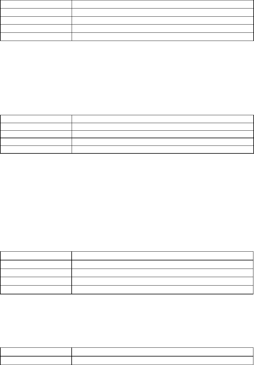
97/144
the Decay HF Ratio value decreases below 1.0, the high-frequency decay time decreases so it’s
shorter than the decay time of the mid frequencies. You hear a more natural reverberation.
Specify using this ID AL_EAXREVERB_DECAY_LFRATIO
Value type FLOAT
Value range 0.1 to 20.0
Default value 1.0
Value units A linear multiplier value
The Decay LF Ratio property adjusts the spectral quality of the Decay Time parameter. It is the
ratio of low-frequency decay time relative to the time set by Decay Time. The Decay LF Ratio
value 1.0 is neutral: the decay time is equal for all frequencies. As Decay LF Ratio increases
above 1.0, the low-frequency decay time increases so it’s longer than the decay time at mid
frequencies. You hear a more booming reverberation with a longer decay at low frequencies. As
the Decay LF Ratio value decreases below 1.0, the low-frequency decay time decreases so it’s
shorter than the decay time of the mid frequencies. You hear a more tinny reverberation.
Reflections Gain and Reflections Delay
Specify using this ID AL_EAXREVERB_REFLECTIONS_GAIN
Value type FLOAT
Value range 0.0 to 3.16
Default value 0.05
Value units Linear gain
The Reflections Gain property controls the overall amount of initial reflections relative to the Gain
property. (The Gain property sets the overall amount of reflected sound: both initial reflections
and later reverberation.) The value of Reflections Gain ranges from a maximum of 3.16 (+10 dB)
to a minimum of 0.0 (-100 dB) (no initial reflections at all), and is corrected by the value of the
Gain property. The Reflections Gain property does not affect the subsequent reverberation
decay.
You can increase the amount of initial reflections to simulate a more narrow space or closer walls,
especially effective if you associate the initial reflections increase with a reduction in reflections
delays by lowering the value of the Reflection Delay property. To simulate open or semi-open
environments, you can maintain the amount of early reflections while reducing the value of the
Late Reverb Gain property, which controls later reflections.
Specify using this ID AL_EAXREVERB_REFLECTIONS_DELAY
Value type FLOAT
Value range 0.0 to 0.3
Default value 0.007
Value units Seconds
The Reflections Delay property is the amount of delay between the arrival time of the direct path
from the source to the first reflection from the source. It ranges from 0 to 300 milliseconds. You
can reduce or increase Reflections Delay to simulate closer or more distant reflective surfaces—
and therefore control the perceived size of the room.
Reflections Pan
Specify using this ID AL_EAXREVERB_REFLECTIONS_PAN
Value type VECTOR
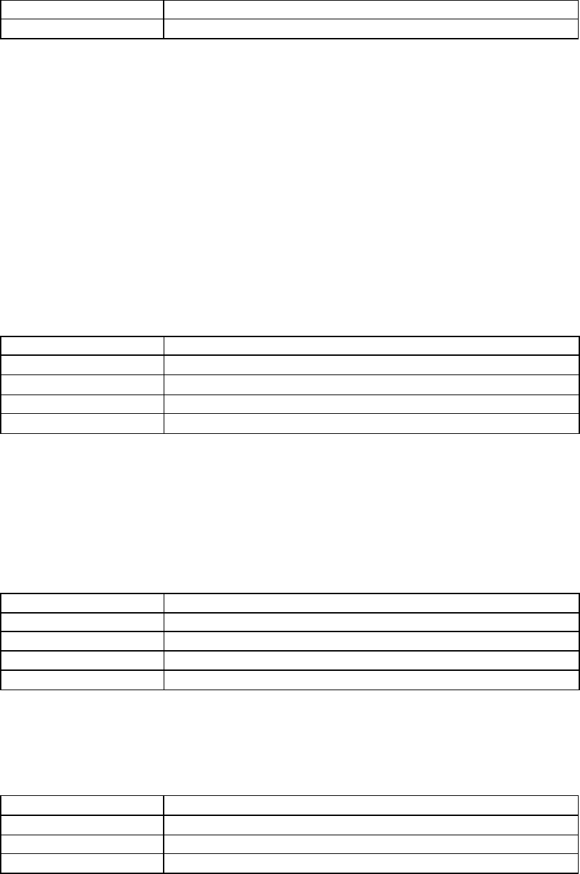
98/144
Value range Magnitude between 0 and 1
Default value [0.0, 0.0, 0.0]
The Reflections Pan property is a 3D vector that controls the spatial distribution of the cluster of
early reflections. The direction of this vector controls the global direction of the reflections, while
its magnitude controls how focused the reflections are towards this direction.
It is important to note that the direction of the vector is interpreted in the coordinate system of the
user, without taking into account the orientation of the virtual listener. For instance, assuming a
four-point loudspeaker playback system, setting Reflections Pan to (0., 0., 0.7) means that the
reflections are panned to the front speaker pair, whereas as setting of (0., 0., −0.7) pans the
reflections towards the rear speakers. These vectors follow the a left-handed co-ordinate system,
unlike OpenAL uses a right-handed co-ordinate system.
If the magnitude of Reflections Pan is zero (the default setting), the early reflections come evenly
from all directions. As the magnitude increases, the reflections become more focused in the
direction pointed to by the vector. A magnitude of 1.0 would represent the extreme case, where
all reflections come from a single direction.
Late Reverb Gain and Late Reverb Delay
Specify using this ID AL_EAXREVERB_LATE_REVERB_GAIN
Value type FLOAT
Value range 0.0 to 10.0
Default value 1.26
Value units Linear gain
The Late Reverb Gain property controls the overall amount of later reverberation relative to the
Gain property. (The Gain property sets the overall amount of both initial reflections and later
reverberation.) The value of Late Reverb Gain ranges from a maximum of 10.0 (+20 dB) to a
minimum of 0.0 (-100 dB) (no late reverberation at all).
Note that Late Reverb Gain and Decay Time are independent properties: If you adjust Decay
Time without changing Late Reverb Gain, the total intensity (the averaged square of the
amplitude) of the late reverberation remains constant.
Specify using this ID AL_EAXREVERB_LATE_REVERB_DELAY
Value type FLOAT
Value range 0.0 to 0.1
Default value 0.011
Value units Seconds
The Late Reverb Delay property defines the begin time of the late reverberation relative to the
time of the initial reflection (the first of the early reflections). It ranges from 0 to 100 milliseconds.
Reducing or increasing Late Reverb Delay is useful for simulating a smaller or larger room.
Late Reverb Pan
Specify using this ID AL_EAXREVERB_LATE_REVERB_PAN
Value type VECTOR
Value range Magnitude between 0 and 1
Default value [0.0, 0.0, 0.0]

99/144
The Late Reverb Pan property is a 3D vector that controls the spatial distribution of the late
reverb. The direction of this vector controls the global direction of the reverb, while its magnitude
controls how focused the reverb are towards this direction. The details under Reflections Pan,
above, also apply to Late Reverb Pan.
Echo Time, Echo Depth
Specify using this ID AL_EAXREVERB_ECHO_TIME
Value type FLOAT
Value range 0.075 to 0.25
Default value 0.25
Value units Seconds
Specify using this ID AL_EAXREVERB_ECHO_DEPTH
Value type FLOAT
Value range 0.0 to 1.0
Default value 0.0
Value units A linear multiplier value
Echo Depth introduces a cyclic echo in the reverberation decay, which will be noticeable with
transient or percussive sounds. A larger value of Echo Depth will make this effect more
prominent. Echo Time controls the rate at which the cyclic echo repeats itself along the
reverberation decay. For example, the default setting for Echo Time is 250 ms. causing the echo
to occur 4 times per second. Therefore, if you were to clap your hands in this type of
environment, you will hear four repetitions of clap per second.
Together with Reverb Diffusion, Echo Depth will control how long the echo effect will persist along
the reverberation decay. In a more diffuse environment, echoes will wash out more quickly after
the direct sound. In an environment that is less diffuse, you will be able to hear a larger number
of repetitions of the echo, which will wash out later in the reverberation decay. If Diffusion is set
to 0.0 and Echo Depth is set to 1.0, the echo will persist distinctly until the end of the
reverberation decay.
Modulation Time, Modulation Depth
Specify using this ID AL_EAXREVERB_MODULATION_TIME
Value type FLOAT
Value range 0.004 to 4.0
Default value 0.25
Value units Seconds
Specify using this ID AL_EAXREVERB_MODULATION_DEPTH
Value type FLOAT
Value range 0.0 to 1.0
Default value 0.0
Value units A linear multiplier value
Using these two properties, you can create a pitch modulation in the reverberant sound. This will
be most noticeable applied to sources that have tonal color or pitch. You can use this to make
some trippy effects! Modulation Time controls the speed of the vibrato (rate of periodic changes
in pitch).

100/144
Modulation Depth controls the amount of pitch change. Low values of Diffusion will contribute to
reinforcing the perceived effect by reducing the mixing of overlapping reflections in the
reverberation decay.
HF Reference, LF Reference
Specify using this ID AL_EAXREVERB_HFREFERENCE
Value type FLOAT
Value range 1000.0 to 20000.0
Default value 5000.0
Value units Hz
Specify using this ID AL_EAXREVERB_LFREFERENCE
Value type FLOAT
Value range 20.0 to 1000.0
Default value 250.0
Value units Hz
The properties HF Reference and LF Reference determine respectively the frequencies at which
the high-frequency effects and the low-frequency effects created by EAX Reverb properties are
measured, for example Decay HF Ratio and Decay LF Ratio.
Note that it is necessary to maintain a factor of at least 10 between these two reference
frequencies so that low frequency and high frequency properties can be accurately controlled and
will produce independent effects. In other words, the LF Reference value should be less than
1/10 of the HF Reference value.
Room Rolloff Factor
Specify using this ID AL_EAXREVERB_ROOM_ROLLOFF_FACTOR
Value type FLOAT
Value range 0.0 to 10.0
Default value 0.0
Value units A linear multiplier value
The Room Rolloff Factor property is one of two methods available to attenuate the reflected
sound (containing both reflections and reverberation) according to source-listener distance. It’s
defined the same way as OpenAL’s Rolloff Factor, but operates on reverb sound instead of
direct-path sound. Setting the Room Rolloff Factor value to 1.0 specifies that the reflected sound
will decay by 6 dB every time the distance doubles. Any value other than 1.0 is equivalent to a
scaling factor applied to the quantity specified by ((Source listener distance) - (Reference
Distance)). Reference Distance is an OpenAL source parameter that specifies the inner border
for distance rolloff effects: if the source comes closer to the listener than the reference distance,
the direct-path sound isn’t increased as the source comes closer to the listener, and neither is the
reflected sound.
The default value of Room Rolloff Factor is 0.0 because, by default, the Effects Extension reverb
effect naturally manages the reflected sound level automatically for each sound source to
simulate the natural rolloff of reflected sound vs. distance in typical rooms. (Note that this isn’t
the case if the source property flag AL_AUXILIARY_SEND_FILTER_GAIN_AUTO is set to
AL_FALSE) You can use Room Rolloff Factor as an option to automatic control so you can
exaggerate or replace the default automatically-controlled rolloff.

101/144
Air Absorption Gain HF
Specify using this ID AL_EAXREVERB_AIR_ABSORPTION_GAINHF
Value type FLOAT
Value range 0.892 to 1.0
Default value 0.994
Value units Linear gain per meter
The Air Absorption Gain HF property controls the distance-dependent attenuation at high
frequencies caused by the propagation medium. It applies to reflected sound only. You can use
Air Absorption Gain HF to simulate sound transmission through foggy air, dry air, smoky
atmosphere, and so on. The default value is 0.994 (-0.05 dB) per meter, which roughly
corresponds to typical condition of atmospheric humidity, temperature, and so on. Lowering the
value simulates a more absorbent medium (more humidity in the air, for example); raising the
value simulates a less absorbent medium (dry desert air, for example).
Decay HF Limit
Specify using this ID AL_EAXREVERB_DECAYHF_LIMIT
Value type INTEGER
Value range AL_FALSE, AL_TRUE
Default value AL_TRUE
When this flag is set, the high-frequency decay time automatically stays below a limit value that’s
derived from the setting of the property Air Absorption Gain HF. This limit applies regardless of
the setting of the property Decay HF Ratio, and the limit doesn’t affect the value of Decay HF
Ratio. This limit, when on, maintains a natural sounding reverberation decay by allowing you to
increase the value of Decay Time without the risk of getting an unnaturally long decay time at
high frequencies. If this flag is set to AL_FALSE, high-frequency decay time isn’t automatically
limited.
Standard Reverb
AL_EFFECT_REVERB is the standard Effects Extension’s environmental reverberation effect.
Reverb Density
Specify using this ID AL_REVERB_DENSITY
Value type FLOAT
Value range 0.0 to 1.0
Default value 1.0
Reverb Modal Density controls the coloration of the late reverb. Lowering the value adds more
coloration to the late reverb.
Reverb Diffusion
Specify using this ID AL_REVERB_DIFFUSION
Value type FLOAT
Value range 0.0 to 1.0
Default value 1.0
Value units A linear multiplier value
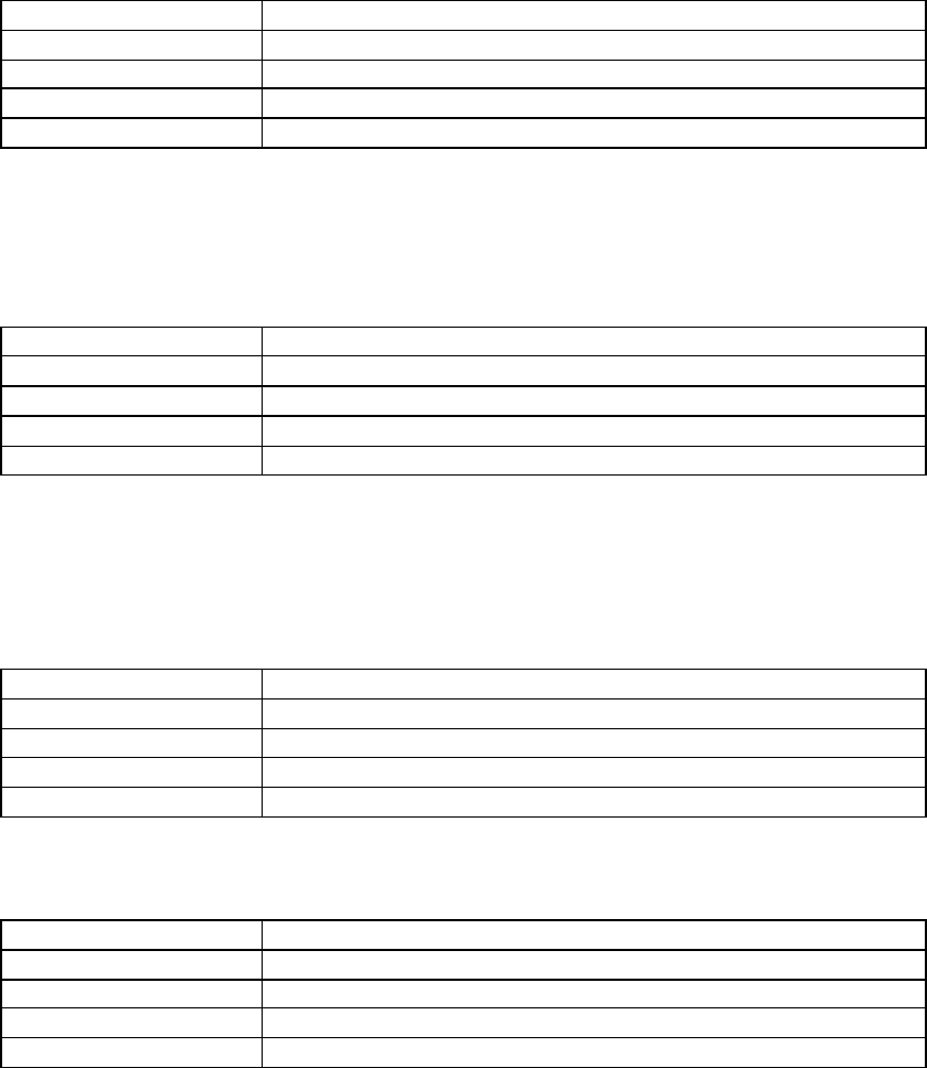
102/144
The Reverb Diffusion property controls the echo density in the reverberation decay. It’s set by
default to 1.0, which provides the highest density. Reducing diffusion gives the reverberation a
more “grainy” character that is especially noticeable with percussive sound sources. If you set a
diffusion value of 0.0, the later reverberation sounds like a succession of distinct echoes.
Reverb Gain and Reverb Gain HF
Specify using this ID AL_REVERB_GAIN
Value type FLOAT
Value range 0.0 to 1.0
Default value 0.32
Value units Linear gain
The Reverb Gain property is the master volume control for the reflected sound (both early
reflections and reverberation) that the reverb effect adds to all sound sources. It sets the
maximum amount of reflections and reverberation added to the final sound mix. The value of the
Reverb Gain property ranges from 1.0 (0db) (the maximum amount) to 0.0 (-100db) (no reflected
sound at all).
Specify using this ID AL_REVERB_GAINHF
Value type FLOAT
Value range 0.0 to 1.0
Default value 0.89
Value units Linear gain
The Reverb Gain HF property further tweaks reflected sound by attenuating it at high frequencies.
It controls a low-pass filter that applies globally to the reflected sound of all sound sources
feeding the particular instance of the reverb effect. The value of the Reverb Gain HF property
ranges from 1.0 (0db) (no filter) to 0.0 (-100db) (virtually no reflected sound).
Decay Time and Decay HF Ratio
Specify using this ID AL_REVERB_DECAY_TIME
Value type FLOAT
Value range 0.1 to 20.0
Default value 1.49
Value units Seconds
The Decay Time property sets the reverberation decay time. It ranges from 0.1 (typically a small
room with very dead surfaces) to 20.0 (typically a large room with very live surfaces).
Specify using this ID AL_REVERB_DECAY_HFRATIO
Value type FLOAT
Value range 0.1 to 2.0
Default value 0.83
Value units A linear multiplier value
The Decay HF Ratio property sets the spectral quality of the Decay Time parameter. It is the
ratio of high-frequency decay time relative to the time set by Decay Time. The Decay HF Ratio
value 1.0 is neutral: the decay time is equal for all frequencies. As Decay HF Ratio increases
above 1.0, the high-frequency decay time increases so it’s longer than the decay time at low
frequencies. You hear a more brilliant reverberation with a longer decay at high frequencies. As
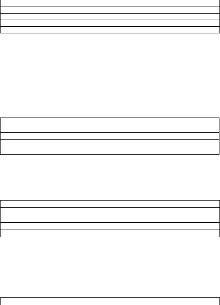
103/144
the Decay HF Ratio value decreases below 1.0, the high-frequency decay time decreases so it’s
shorter than the decay time of the low frequencies. You hear a more natural reverberation.
Reflections Gain and Reflections Delay
Specify using this ID AL_REVERB_REFLECTIONS_GAIN
Value type FLOAT
Value range 0.0 to 3.16
Default value 0.05
Value units Linear gain
The Reflections Gain property controls the overall amount of initial reflections relative to the Gain
property. (The Gain property sets the overall amount of reflected sound: both initial reflections
and later reverberation.) The value of Reflections Gain ranges from a maximum of 3.16 (+10 dB)
to a minimum of 0.0 (-100 dB) (no initial reflections at all), and is corrected by the value of the
Gain property. The Reflections Gain property does not affect the subsequent reverberation
decay.
You can increase the amount of initial reflections to simulate a more narrow space or closer walls,
especially effective if you associate the initial reflections increase with a reduction in reflections
delays by lowering the value of the Reflection Delay property. To simulate open or semi-open
environments, you can maintain the amount of early reflections while reducing the value of the
Late Reverb Gain property, which controls later reflections.
Specify using this ID AL_REVERB_REFLECTIONS_DELAY
Value type FLOAT
Value range 0.0 to 0.3
Default value 0.007
Value units Seconds
The Reflections Delay property is the amount of delay between the arrival time of the direct path
from the source to the first reflection from the source. It ranges from 0 to 300 milliseconds. You
can reduce or increase Reflections Delay to simulate closer or more distant reflective surfaces—
and therefore control the perceived size of the room.
Late Reverb Gain and Late Reverb Delay
Specify using this ID AL_REVERB_LATE_REVERB_GAIN
Value type FLOAT
Value range 0.0 to 10.0
Default value 1.26
Value units Linear gain
The Late Reverb Gain property controls the overall amount of later reverberation relative to the
Gain property. (The Gain property sets the overall amount of both initial reflections and later
reverberation.) The value of Late Reverb Gain ranges from a maximum of 10.0 (+20 dB) to a
minimum of 0.0 (-100 dB) (no late reverberation at all).
Note that Late Reverb Gain and Decay Time are independent properties: If you adjust Decay
Time without changing Late Reverb Gain, the total intensity (the averaged square of the
amplitude) of the late reverberation remains constant.
Specify using this ID AL_REVERB_LATE_REVERB_DELAY

104/144
Value type FLOAT
Value range 0.0 to 0.1
Default value 0.011
Value units Seconds
The Late Reverb Delay property defines the begin time of the late reverberation relative to the
time of the initial reflection (the first of the early reflections). It ranges from 0 to 100 milliseconds.
Reducing or increasing Late Reverb Delay is useful for simulating a smaller or larger room.
Room Rolloff Factor
Specify using this ID AL_REVERB_ROOM_ROLLOFF_FACTOR
Value type FLOAT
Value range 0.0 to 10.0
Default value 0.0
Value units A linear multiplier value
The Room Rolloff Factor property is one of two methods available to attenuate the reflected
sound (containing both reflections and reverberation) according to source-listener distance. It’s
defined the same way as OpenAL’s Rolloff Factor, but operates on reverb sound instead of
direct-path sound. Setting the Room Rolloff Factor value to 1.0 specifies that the reflected sound
will decay by 6 dB every time the distance doubles. Any value other than 1.0 is equivalent to a
scaling factor applied to the quantity specified by ((Source listener distance) - (Reference
Distance)). Reference Distance is an OpenAL source parameter that specifies the inner border
for distance rolloff effects: if the source comes closer to the listener than the reference distance,
the direct-path sound isn’t increased as the source comes closer to the listener, and neither is the
reflected sound.
The default value of Room Rolloff Factor is 0.0 because, by default, the Effects Extension reverb
effect naturally manages the reflected sound level automatically for each sound source to
simulate the natural rolloff of reflected sound vs. distance in typical rooms. (Note that this isn’t
the case if the source property flag AL_AUXILIARY_SEND_FILTER_GAIN_AUTO is set to
AL_FALSE) You can use Room Rolloff Factor as an option to automatic control so you can
exaggerate or replace the default automatically-controlled rolloff.
Air Absorption Gain HF
Specify using this ID AL_REVERB_AIR_ABSORPTION_GAINHF
Value type FLOAT
Value range 0.892 to 1.0
Default value 0.994
Value units Linear gain per meter
The Air Absorption Gain HF property controls the distance-dependent attenuation at high
frequencies caused by the propagation medium. It applies to reflected sound only. You can use
Air Absorption Gain HF to simulate sound transmission through foggy air, dry air, smoky
atmosphere, and so on. The default value is 0.994 (-0.05 dB) per meter, which roughly
corresponds to typical condition of atmospheric humidity, temperature, and so on. Lowering the
value simulates a more absorbent medium (more humidity in the air, for example); raising the
value simulates a less absorbent medium (dry desert air, for example).

105/144
Decay HF Limit
Specify using this ID AL_REVERB_DECAY_HFLIMIT
Value type INTEGER
Value range AL_FALSE, AL_TRUE
Default value AL_TRUE
When this flag is set, the high-frequency decay time automatically stays below a limit value that’s
derived from the setting of the property Air Absorption HF. This limit applies regardless of the
setting of the property Decay HF Ratio, and the limit doesn’t affect the value of Decay HF Ratio.
This limit, when on, maintains a natural sounding reverberation decay by allowing you to increase
the value of Decay Time without the risk of getting an unnaturally long decay time at high
frequencies. If this flag is set to AL_FALSE, high-frequency decay time isn’t automatically limited.
Chorus
The chorus effect essentially replays the input audio accompanied by another slightly delayed
version of the signal, creating a ‘doubling’ effect. This was originally intended to emulate the
effect of several musicians playing the same notes simultaneously, to create a thicker, more
satisfying sound.
To add some variation to the effect, the delay time of the delayed versions of the input signal is
modulated by an adjustable oscillating waveform. This causes subtle shifts in the pitch of the
delayed signals, emphasizing the thickening effect.
Chorus Waveform
Specify using this ID AL_CHORUS_WAVEFORM
Value type INTEGER
Value range 0 (sin), 1 (triangle)
Default value 1
This property sets the waveform shape of the LFO that controls the delay time of the delayed
signals.
Chorus Phase
Specify using this ID AL_CHORUS_PHASE
Value type INTEGER
Value range -180 to 180
Default value 90
This property controls the phase difference between the left and right LFO’s. At zero degrees the
two LFOs are synchronized. Use this parameter to create the illusion of an expanded stereo field
of the output signal.
Chorus Rate
Specify using this ID AL_CHORUS_RATE
Value type FLOAT
Value range 0.0 to 10.0

106/144
Default value 1.1
This property sets the modulation rate of the LFO that controls the delay time of the delayed
signals.
Chorus Depth
Specify using this ID AL_CHORUS_DEPTH
Value type FLOAT
Value range 0.0 to 1.0
Default value 0.1
This property controls the amount by which the delay time is modulated by the LFO.
Chorus Feedback
Specify using this ID AL_CHORUS_FEEDBACK
Value type FLOAT
Value range -1.0 to 1.0
Default value 0.25
This property controls the amount of processed signal that is fed back to the input of the chorus
effect. Negative values will reverse the phase of the feedback signal. At full magnitude the
identical sample will repeat endlessly. At lower magnitudes the sample will repeat and fade out
over time. Use this parameter to create a “cascading” chorus effect.
Chorus Delay
Specify using this ID AL_CHORUS_DELAY
Value type FLOAT
Value range 0.0 to 0.016
Default value 0.016
This property controls the average amount of time the sample is delayed before it is played back,
and with feedback, the amount of time between iterations of the sample. Larger values lower the
pitch. Smaller values make the chorus sound like a flanger, but with different frequency
characteristics.
Distortion
The distortion effect simulates turning up (overdriving) the gain stage on a guitar amplifier or
adding a distortion pedal to an instrument’s output. It is achieved by clipping the signal (adding
more square wave-like components) and adding rich harmonics.
The distortion effect could be very useful for adding extra dynamics to engine sounds in a driving
simulator, or modifying samples such as vocal communications.
The OpenAL Effects Extension distortion effect also includes EQ on the output signal, to help
‘rein in’ excessive frequency content in distorted audio. A low-pass filter is applied to input signal
before the distortion effect, to limit excessive distorted signals at high frequencies.

107/144
Distortion Edge
Specify using this ID AL_DISTORTION_EDGE
Value type FLOAT
Value range 0.0 to 1.0
Default value 0.2
This property controls the shape of the distortion. The higher the value for Edge, the ‘dirtier’ and
‘fuzzier’ the effect.
Distortion Gain
Specify using this ID AL_DISTORTION_GAIN
Value type FLOAT
Value range 0.01 to 1.0
Default value 0.05
This property allows you to attenuate the distorted sound.
Distortion Low Pass Cutoff
Specify using this ID AL_DISTORTION_LOWPASS_CUTOFF
Value type FLOAT
Value range 80.0 to 24000.0
Default value 8000.0
Input signal can have a low pass filter applied, to limit the amount of high frequency signal
feeding into the distortion effect.
Distortion EQ Center
Specify using this ID AL_DISTORTION_EQCENTER
Value type FLOAT
Value range 80.0 to 24000.0
Default value 3600.0
This property controls the frequency at which the post-distortion attenuation (Distortion Gain) is
active.
Distortion EQ Bandwidth
Specify using this ID AL_DISTORTION_EQBANDWIDTH
Value type FLOAT
Value range 80.0 to 24000.0
Default value 3600.0
This property controls the bandwidth of the post-distortion attenuation.

108/144
Echo
The echo effect generates discrete, delayed instances of the input signal. The amount of delay
and feedback is controllable. The delay is ‘two tap’ – you can control the interaction between two
separate instances of echoes.
Echo Delay
Specify using this ID AL_ECHO_DELAY
Value type FLOAT
Value range 0.0 to 0.207
Default value 0.1
This property controls the delay between the original sound and the first ‘tap’, or echo instance.
Subsequently, the value for Echo Delay is used to determine the time delay between each
‘second tap’ and the next ‘first tap’.
Echo LR Delay
Specify using this ID AL_ECHO_LRDELAY
Value type FLOAT
Value range 0.0 to 0.404
Default value 0.1
This property controls the delay between the first ‘tap’ and the second ‘tap’. Subsequently, the
value for Echo LR Delay is used to determine the time delay between each ‘first tap’ and the next
‘second tap’.
Echo Damping
Specify using this ID AL_ECHO_DAMPING
Value type FLOAT
Value range 0.0 to 0.99
Default value 0.5
This property controls the amount of high frequency damping applied to each echo. As the sound
is subsequently fed back for further echoes, damping results in an echo which progressively gets
softer in tone as well as intensity.
Echo Feedback
Specify using this ID AL_ECHO_FEEDBACK
Value type FLOAT
Value range 0.0 to 1.0
Default value 0.5
This property controls the amount of feedback the output signal fed back into the input. Use this
parameter to create “cascading” echoes. At full magnitude, the identical sample will repeat
endlessly. Below full magnitude, the sample will repeat and fade.
Echo Spread
Specify using this ID AL_ECHO_SPREAD
Value type FLOAT
109/144
Value range -1.0 to 1.0
Default value -1.0
This property controls how hard panned the individual echoes are. With a value of 1.0, the first
‘tap’ will be panned hard left, and the second tap hard right. A value of –1.0 gives the opposite
result. Settings nearer to 0.0 result in less emphasized panning.
Flanger
The flanger effect creates a “tearing” or “whooshing” sound (like a jet flying overhead). It works
by sampling a portion of the input signal, delaying it by a period modulated between 0 and 4ms by
a low-frequency oscillator, and then mixing it with the source signal.
Flanger Waveform
Specify using this ID AL_FLANGER_WAVEFORM
Value type INTEGER
Value range 0 (sin), 1 (triangle)
Default value 1
Selects the shape of the LFO waveform that controls the amount of the delay of the sampled
signal. Zero is a sinusoid and one is a triangle.
Flanger Phase
Specify using this ID AL_FLANGER_PHASE
Value type INTEGER
Value range -180 to 180
Default value 0
This changes the phase difference between the left and right LFO’s. At zero degrees the two
LFOs are synchronized.
Flanger Rate
Specify using this ID AL_FLANGER_RATE
Value type FLOAT
Value range 0.0 to 10.0
Default value 0.27
The number of times per second the LFO controlling the amount of delay repeats. Higher values
increase the pitch modulation.
Flanger Depth
Specify using this ID AL_FLANGER_DEPTH
Value type FLOAT
Value range 0.0 to 1.0
Default value 1.0
The ratio by which the delay time is modulated by the LFO. Use this parameter to increase the
pitch modulation.

110/144
Flanger Feedback
Specify using this ID AL_FLANGER_FEEDBACK
Value type FLOAT
Value range -1.0 to 1.0
Default value -0.5
This is the amount of the output signal level fed back into the effect’s input. A negative value will
reverse the phase of the feedback signal. Use this parameter to create an “intense metallic”
effect. At full magnitude, the identical sample will repeat endlessly. At less than full magnitude,
the sample will repeat and fade out over time.
Flanger Delay
Specify using this ID AL_FLANGER_DELAY
Value type FLOAT
Value range 0.0 to 0.004
Default value 0.002
The average amount of time the sample is delayed before it is played back; with feedback, the
amount of time between iterations of the sample.
Frequency Shifter
The frequency shifter is a single-sideband modulator, which translates all the component
frequencies of the input signal by an equal amount. Unlike the pitch shifter, which attempts to
maintain harmonic relationships in the signal, the frequency shifter disrupts harmonic
relationships and radically alters the sonic qualities of the signal. Applications of the frequency
shifter include the creation of bizarre distortion, phaser, stereo widening and rotating speaker
effects.
Frequency Shifter Frequency
Specify using this ID AL_FREQUENCY_SHIFTER_FREQUENCY
Value type FLOAT
Value range 0.0 to 24000.0
Default value 0.0
This is the carrier frequency. For carrier frequencies below the audible range, the single-
sideband modulator may produce phaser effects, spatial effects or a slight pitch-shift. As the
carrier frequency increases, the timbre of the sound is affected; a piano or guitar note becomes
like a bell's chime, and a human voice sounds extraterrestrial!
Frequency Shifter Left Direction
Specify using this ID AL_FREQUENCY_SHIFTER_LEFT_DIRECTION
Value type INTEGER
Value range 0 (down), 1 (up), 2 (off)
Default value 0
These select which internal signals are added together to produce the output. Different
combinations of values will produce slightly different tonal and spatial effects.

111/144
Frequency Shifter Right Direction
Specify using this ID AL_FREQUENCY_SHIFTER_RIGHT_DIRECTION
Value type INTEGER
Value range 0 (down), 1 (up), 2 (off)
Default value 0
These select which internal signals are added together to produce the output. Different
combinations of values will produce slightly different tonal and spatial effects.
Vocal Morpher
The vocal morpher consists of a pair of 4-band formant filters, used to impose vocal tract effects
upon the input signal. If the input signal is a broadband sound such as pink noise or a car engine,
the vocal morpher can provide a wide variety of filtering effects. A low-frequency oscillator can be
used to morph the filtering effect between two different phonemes. The vocal morpher is not
necessarily intended for use on voice signals; it is primarily intended for pitched noise effects,
vocal-like wind effects, etc.
These are the available phoneme (formant filter settings) types:-
ID Value Enumerated
0 “A” AL_VOCAL_MORPHER_PHONEME_A
1 “E” AL_VOCAL_MORPHER_PHONEME_E
2 “I” AL_VOCAL_MORPHER_PHONEME_I
3 “O” AL_VOCAL_MORPHER_PHONEME_O
4 “U” AL_VOCAL_MORPHER_PHONEME_U
5 “AA” AL_VOCAL_MORPHER_PHONEME_AA
6 “AE” AL_VOCAL_MORPHER_PHONEME_AE
7 “AH” AL_VOCAL_MORPHER_PHONEME_AH
8 “AO” AL_VOCAL_MORPHER_PHONEME_AO
9 “EH” AL_VOCAL_MORPHER_PHONEME_EH
10 “ER” AL_VOCAL_MORPHER_PHONEME_ER
11 “IH” AL_VOCAL_MORPHER_PHONEME_IH
12 “IY” AL_VOCAL_MORPHER_PHONEME_IY
13 “UH” AL_VOCAL_MORPHER_PHONEME_UH
14 “UW” AL_VOCAL_MORPHER_PHONEME_UW
15 “B” AL_VOCAL_MORPHER_PHONEME_B
16 “D” AL_VOCAL_MORPHER_PHONEME_D
17 “F” AL_VOCAL_MORPHER_PHONEME_F
18 “G” AL_VOCAL_MORPHER_PHONEME_G
19 “J” AL_VOCAL_MORPHER_PHONEME_J
20 “K” AL_VOCAL_MORPHER_PHONEME_K
21 “L” AL_VOCAL_MORPHER_PHONEME_L
22 “M” AL_VOCAL_MORPHER_PHONEME_M
23 “N” AL_VOCAL_MORPHER_PHONEME_N
24 “P” AL_VOCAL_MORPHER_PHONEME_P
25 “R” AL_VOCAL_MORPHER_PHONEME_R
26 “S” AL_VOCAL_MORPHER_PHONEME_S
27 “T” AL_VOCAL_MORPHER_PHONEME_T
28 “V” AL_VOCAL_MORPHER_PHONEME_V
29 “Z” AL_VOCAL_MORPHER_PHONEME_Z

112/144
Vocal Morpher Phoneme A and Vocal Morpher Phoneme B
Specify using this ID AL_VOCAL_MORPHER_PHONEMEA
Value type INTEGER
Value range 0 to 29
Default value 0 (“A”)
Specify using this ID AL_VOCAL_MORPHER_PHONEMEB
Value type INTEGER
Value range 0 to 29
Default value 10 (“ER”)
If both parameters are set to the same phoneme, that determines the filtering effect that will be
heard. If these two parameters are set to different phonemes, the filtering effect will morph
between the two settings at a rate specified by AL_VOCAL_MORPHER_RATE.
Vocal Morpher Phoneme A and Vocal Morpher Phoneme B coarse
tuning
Specify using this ID AL_VOCAL_MORPHER_PHONEMEA_COARSE_TUNING
Value type INTEGER
Value range -24 to 24
Default value 0
Specify using this ID AL_VOCAL_MORPHER_PHONEMEB_COARSE_TUNING
Value type INTEGER
Value range -24 to 24
Default value 0
These are used to adjust the pitch of phoneme filters A and B in 1-semitone increments.
Vocal Morpher Waveform
Specify using this ID AL_VOCAL_MORPHER_WAVEFORM
Value type INTEGER
Value range 0 (sin), 1 (triangle), 2 (saw)
Default value 0
This controls the shape of the low-frequency oscillator used to morph between the two phoneme
filters. By selecting a saw tooth wave and a slow AL_VOCAL_MORPHER_RATE, one can create
a filtering effect that slowly increases or decreases in pitch (depending on which of the two
phoneme filters A or B is perceived as being higher-pitched).
Vocal Morpher Rate
Specify using this ID AL_VOCAL_MORPHER_RATE
Value type FLOAT
Value range 0.0 to 10.0
Default value 1.41
This controls the frequency of the low-frequency oscillator used to morph between the two
phoneme filters
113/144
Pitch Shifter
The pitch shifter applies time-invariant pitch shifting to the input signal, over a one octave range
and controllable at a semi-tone and cent resolution.
Pitch Shifter Coarse Tune
Specify using this ID AL_PITCH_SHIFTER_COARSE_TUNE
Value type INTEGER
Value range -12 to 12
Default value 12
This sets the number of semitones by which the pitch is shifted. There are 12 semitones per
octave. Negative values create a downwards shift in pitch, positive values pitch the sound
upwards.
Pitch Shifter Fine Tune
Specify using this ID AL_PITCH_SHIFTER_FINE_TUNE
Value type INTEGER
Value range -50 to 50
Default value 0
This sets the number of cents between Semitones a pitch is shifted. A Cent is 1/100th of a
Semitone. Negative values create a downwards shift in pitch, positive values pitch the sound
upwards.
Ring Modulator
The ring modulator multiplies an input signal by a carrier signal in the time domain, resulting in
tremolo or inharmonic effects.
Ring Modulator Frequency
Specify using this ID AL_RING_MODULATOR_FREQUENCY
Value type FLOAT
Value range 0.0 to 8000.0
Default value 440.0
This is the frequency of the carrier signal. If the carrier signal is slowly varying (less than 20 Hz),
the result is a tremolo (slow amplitude variation) effect. If the carrier signal is in the audio range,
audible upper and lower sidebands begin to appear, causing an inharmonic effect. The carrier
signal itself is not heard in the output.
Ring Modulator High-pass Cutoff
Specify using this ID AL_RING_MODULATOR_HIGHPASS_CUTOFF
Value type FLOAT
Value range 0.0 to 24000.0
Default value 800.0
This controls the cutoff frequency at which the input signal is high-pass filtered before being ring
modulated. If the cutoff frequency is 0, the entire signal will be ring modulated. If the cutoff

114/144
frequency is high, very little of the signal (only those parts above the cutoff) will be ring
modulated.
Ring Modulator Waveform
Specify using this ID AL_RING_MODULATOR_WAVEFORM
Value type INTEGER
Value range 0 (sin), 1 (saw), 2 (square)
Default value 0
This controls which waveform is used as the carrier signal. Traditional ring modulator and
tremolo effects generally use a sinusoidal carrier. Sawtooth and square waveforms are may
cause unpleasant aliasing.
Auto-Wah
The Auto-wah effect emulates the sound of a wah-wah pedal used with an electric guitar, or a
mute on a brass instrument. Such effects allow a musician to control the tone of their instrument
by varying the point at which high frequencies are cut off. This OpenAL Effects Extension effect
is called Auto-wah because there is no user input for modulating the cut-off point. Instead the
effect is achieved by analysing the input signal, and applying a band-pass filter according the
intensity of the incoming audio.
Auto-Wah Attack Time
Specify using this ID AL_AUTOWAH_ATTACK_TIME
Value type FLOAT
Value range 0.0001 to 1.0
Default value 0.06
This property controls the time the filtering effect takes to sweep from minimum to maximum
center frequency when it is triggered by input signal.
Auto-Wah Release Time
Specify using this ID AL_AUTOWAH_RELEASE_TIME
Value type FLOAT
Value range 0.0001 to 1.0
Default value 0.06
This property controls the time the filtering effect takes to sweep from maximum back to base
center frequency, when the input signal ends.
Auto-Wah Resonance
Specify using this ID AL_AUTOWAH_RESONANCE
Value type FLOAT
Value range 2.0 to 1000.0
Default value 1000.0
This property controls the resonant peak, sometimes known as emphasis or Q, of the auto-wah
band-pass filter. Resonance occurs when the effect boosts the frequency content of the sound

115/144
around the point at which the filter is working. A high value promotes a highly resonant, sharp
sounding effect.
Auto-Wah Peak Gain
Specify using this ID AL_AUTOWAH_PEAK_GAIN
Value type FLOAT
Value range 0.00003 to 31621.0
Default value 11.22
This property controls the input signal level at which the band-pass filter will be fully opened.
Compressor
The Automatic Gain Control effect performs the same task as a studio compressor – evening out
the audio dynamic range of an input sound. This results in audio exhibiting smaller variation in
intensity between the loudest and quietest portions. The AGC Compressor will boost quieter
portions of the audio, while louder portions will stay the same or may even be reduced.
The Compressor effect cannot be tweaked in depth – it can just be switched on and off.
Compressor
Specify using this ID AL_COMPRESSOR_ONOFF
Value type INTEGER
Value range 0 (off), 1(on)
Default value 1
The OpenAL Effect Extension Compressor can only be switched on and off – it cannot be
adjusted.
Equalizer
The OpenAL Effects Extension EQ is very flexible, providing tonal control over four different
adjustable frequency ranges. The lowest frequency range is called “low.” The middle ranges are
called “mid1” and “mid2.” The high range is called “high.”
Equalizer Low Gain
Specify using this ID AL_EQUALIZER_LOW_GAIN
Value type FLOAT
Value range 0.126 to 7.943
Default value 1.0
This property controls amount of cut or boost on the low frequency range.
Equalizer Low Cutoff
Specify using this ID AL_EQUALIZER_LOW_CUTOFF
Value type FLOAT
Value range 50.0 to 800.0
Default value 200.0

116/144
This property controls the low frequency below which signal will be cut off.
Equalizer Mid 1 Gain
Specify using this ID AL_EQUALIZER_MID1_GAIN
Value type FLOAT
Value range 0.126 to 7.943
Default value 1.0
This property allows you to cut / boost signal on the “mid1” range.
Equalizer Mid 1 Center
Specify using this ID AL_EQUALIZER_MID1_CENTER
Value type FLOAT
Value range 200.0 to 3000.0
Default value 500.0
This property sets the center frequency for the “mid1” range.
Equalizer Mid 1 Width
Specify using this ID AL_EQUALIZER_MID1_WIDTH
Value type FLOAT
Value range 0.01 to 1.0
Default value 1.0
This property controls the width of the “mid1” range.
Equalizer Mid 2 Gain
Specify using this ID AL_EQUALIZER_MID2_GAIN
Value type FLOAT
Value range 0.126 to 7.943
Default value 1.0
This property allows you to cut / boost signal on the “mid2” range.
Equalizer Mid 2 Center
Specify using this ID AL_EQUALIZER_MID2_CENTER
Value type FLOAT
Value range 1000.0 to 8000.0
Default value 3000.0
This property sets the center frequency for the “mid2” range.
Equalizer Mid 2 Width
Specify using this ID AL_EQUALIZER_MID2_WIDTH
Value type FLOAT
Value range 0.01 to 1.0
Default value 1.0

117/144
This property controls the width of the “mid2” range.
Equalizer High Gain
Specify using this ID AL_EQUALIZER_HIGH_GAIN
Value type FLOAT
Value range 0.126 to 7.943
Default value 1.0
This property allows you to cut / boost the signal at high frequencies.
Equalizer High Cutoff
Specify using this ID AL_EQUALIZER_HIGH_CUTOFF
Value type FLOAT
Value range 4000.0 to 16000.0
Default value 6000.0
This property controls the high frequency above which signal will be cut off.

118/144
Appendix 2 - Designing Environmental effects for
interactive applications
Introduction
This section of the documentation suggests how designers of interactive 3D audio applications can use
DSP effects in their projects.
As described in the Environmental Audio Introduction section, reverberation is the principle audio effect
employed to enhance an interactive audio application such as a game. Here, you will find a description
of the acoustic model that lies behind the effects extension’s environmental reverb effects.
The Environmental Audio Introduction section also described scenarios where audio sources are
obstructed, occluded or excluded. In the Designing Environmental Filtering effects section you will find
an explanation of how using the effects extension, you actually use low-pass filters applied to sound
sources and to their reverb sends in order to simulate these scenarios.
The details here are intended to give the sound designer or programmer the background to select,
customise and deploy environmental effects like reverb, so you can give your interactive project the
exact same dynamic and lifelike soundtrack you’ve imagined in your head!
Designing and using Environmental Reverb effects
On today’s advanced 3D graphics renderers, the lifelike visual appearance of a user’s surroundings
can set very high user expectations in respect to the sophistication of the audio scene. Suitably
designed reverb effects will help an application’s interactive soundtrack to match the standards of
realism set by the images.
OpenAL’s Effect Extension SDK includes a fully controllable environmental reverb effect, giving an
audio designer the sonic palette to create a lifelike simulation of almost any acoustic environment. This
flexibility allows the designer to introduce flair and imagination to effects, and thereby inject some
distinctive personality into the soundtrack.
Definition: Environmental Reverb presets
The Effects Extension reverberation model is derived from Creative Labs’ EAX standards.
There are two reverb effect types in this SDK. The reverb effect enumerated as
“AL_EFFECT_REVERB” is supported on all known OpenAL Effect Extension implementations,
including Creative’s PC software renderer.
The reverb “AL_EFFECT_EAXREVERB” has a more advanced parameter set. Not all OpenAL
implementations support this effect type. It is however guaranteed to be available on native
implementations for Creative’s Audigy and X-Fi series PCI sound cards (providing the user has the
latest driver update installed.) The parameter set for the EAX Reverb is a superset of that of the
standard OpenAL reverb.
The table below shows the reverb controls available in the EAX Reverb, plus where they exist the
corresponding properties exposed in the general OpenAL Reverb.:
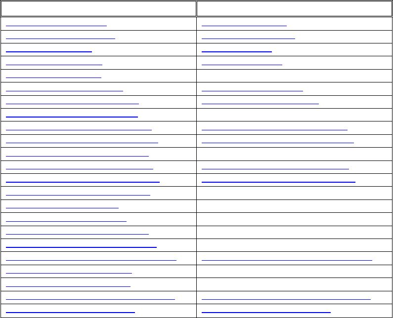
119/144
Reverb Effect Parameters
OpenAL EAXReverb Parameter Name OpenAL standard reverb equivalent
AL_EAXREVERB_DENSITY AL_REVERB_DENSITY
AL_EAXREVERB_DIFFUSION AL_REVERB_DIFFUSION
AL_EAXREVERB_GAIN AL_REVERB_GAIN
AL_EAXREVERB_GAINHF AL_REVERB_GAINHF
AL_EAXREVERB_GAINLF N/A
AL_EAXREVERB_DECAY_TIME AL_REVERB_DECAY_TIME
AL_EAXREVERB_DECAY_HFRATIO AL_REVERB_DECAY_HFRATIO
AL_EAXREVERB_DECAY_LFRATIO N/A
AL_EAXREVERB_REFLECTIONS_GAIN AL_EAXREVERB_REFLECTIONS_GAIN
AL_EAXREVERB_REFLECTIONS_DELAY AL_EAXREVERB_REFLECTIONS_DELAY
AL_EAXREVERB_REFLECTIONS_PAN N/A
AL_EAXREVERB_LATE_REVERB_GAIN AL_EAXREVERB_LATE_REVERB_GAIN
AL_EAXREVERB_LATE_REVERB_DELAY AL_EAXREVERB_LATE_REVERB_DELAY
AL_EAXREVERB_LATE_REVERB_PAN N/A
AL_EAXREVERB_ECHO_TIME N/A
AL_EAXREVERB_ECHO_DEPTH N/A
AL_EAXREVERB_MODULATION_TIME N/A
AL_EAXREVERB_MODULATION_DEPTH N/A
AL_EAXREVERB_AIR_ABSORPTION_GAINHF AL_EAXREVERB_AIR_ABSORPTION_GAINHF
AL_EAXREVERB_HFREFERENCE N/A
AL_EAXREVERB_LFREFERENCE N/A
AL_EAXREVERB_ROOM_ROLLOFF_FACTOR AL_EAXREVERB_ROOM_ROLLOFF_FACTOR
AL_EAXREVERB_DECAY_HFLIMIT AL_EAXREVERB_DECAY_HFLIMIT
The reverb response is defined by the following parameters:
The energy in the Reflections and Reverb sections at mid frequencies
The Reflections Delay and the Reverb Delay
The Reflections Pan and Reverb Pan vectors, for spatial/directional distribution (available
in EAX Reverb only)
The “Room filter,” which affects the Reflections and the Reverb identically and allows
correcting their energy at high frequencies (both reverb types) and low frequencies (EAX
Reverb only)
The Decay Time at mid and high frequencies (both reverb types) and low frequencies
(EAX Reverb only)
The reference low and high frequencies (EAX Reverb only)
The Diffusion of the reverberation
The Echo and Modulation parameters, which affect the late reverberation. (EAX Reverb
only)
An Environment is characterized by the values of all reverberation response parameters, when the
distance between source and listener is equal to the source’s 3D property Minimum Distance. This
defines an “Environment preset.”
120/144
A note on distance balancing
Environmental Reverberation is not the only effect available in OpenAL’s Effects Extension system.
However the reverb effect is unique in one particular respect, which is this; the reverb algorithm can
actually influence the effect send amount for each source. This is important because, as you will see
later, the perceived level of reverb on a 3D sound source can vary depending on the distance between
source and listener. The default settings provide a realistic effect, but you can adjust the balance if
necessary, or even turn off the automatic setting and control reverb level for yourself.
Approaches to designing Reverb Effects
There are a couple of different approaches that you can take to crafting reverb effects for an
application’s audio implementation.
Select an environmental preset from the SDK
The OpenAL SDK includes a set of reverb presets, designed by Creative’s audio specialists. These
ready-made acoustic models are presented as #define macros in the efx-util.h file. That file can be
included in a project, or the individual macros can be cut-and-pasted directly into a programmer’s own
code.
The presets are broadly categorised by scenario. For example, there are sets of acoustic simulations
for different rooms in a castle, or in a cave. There is one group of effects, which are relevant to driving
simulations, another one containing effects which might occur in a virtual city. There is also a group
that contains settings for the twenty-six presets included in the original EAX 1.0 release.
So, choosing an effect for each location in your application could be as simple as selecting from the list
a preset that best fits your criteria.
Build an effect from scratch
Any enthusiastic audio designer will be excited by the prospect of being able to control the powerful
Effects Extension reverberation model for a specific application. In the same way that a development
team will use specially designed models, textures and lighting effects to give the three dimensional
world a unique look, custom-designed statistical models of room acoustics can give an application a
truly distinctive sonic identity.
Static Modelling
The way that reverberation sounds in an environment is broadly determined by the size of the room
and the absorptive quality of the boundaries. The contents of the room also have some effect on the
reverb.
Dynamic factors such as listener and source position have a direct bearing on the way that sound
propagates in an environment. The OpenAL Effects Extension renderer takes into account the
distance between the listener and a source when it automatically sets the reverb level for each source.
The statistical approach to environmental modelling means that you don’t have to account for these
dynamic factors when designing static reverbs. You can create lifelike reverb settings by using ‘best fit’
reverb models with static values for its properties.
However, it is always possible to add some extra dynamics, so that the environmental reverb changes
as the listener moves within a room. The next section (see 7Dynamic Modelling) details the
circumstances in which some reverb characteristics change as the listener moves around, and shows
how to adjust these parameters in real time to achieve an even more lifelike simulation.

121/144
In general, it can be understood that a room’s size will contribute particularly to the temporal aspects of
a room’s acoustic model. In normal atmospheric conditions, sound travels at 344 metres (1129 feet)
per second, which is approximately equivalent to one foot per millisecond, or one metre every three
milliseconds. When calculating factors such as Reflections Delay and Reverb Delay, you should bear
this in mind.
Imagine a square room, with walls twenty feet apart. The listener is located in the centre of the room,
and makes a noise. Discounting the floor and ceiling, the first early reflections from the walls will return
to the listener’s ears after a journey of (2 x 10 feet) 20 feet. Therefore the delay between the initial
(direct) sound and the appearance of the first reflected sounds will be around 20 milliseconds. This
case represents the longest possible reflection delay for this room.
Reflections Delay
Value range 0.0 to 0.3
Default value 0.007
Value units Seconds
Reflections Delay controls the amount of time it takes for the first reflected wave front to
reach the listener, relative to the arrival of the direct-path sound. The smaller the value
the less time it takes the early reflections to reach the listener. Overall, a higher value will
simulate a larger environment where both the listener and the source are distant from the
walls.
Reverb Delay
Value range 0.0 to 0.1
Default value 0.011
Value units Seconds
Reverb Delay sets the amount of time it takes for the reverberated sound to reach the
listener. Higher values imply a larger room; lower values a smaller room. This value
defines the time between the start of the Reflections and the start of the Reverb. During
this phase, reflections will be heard.
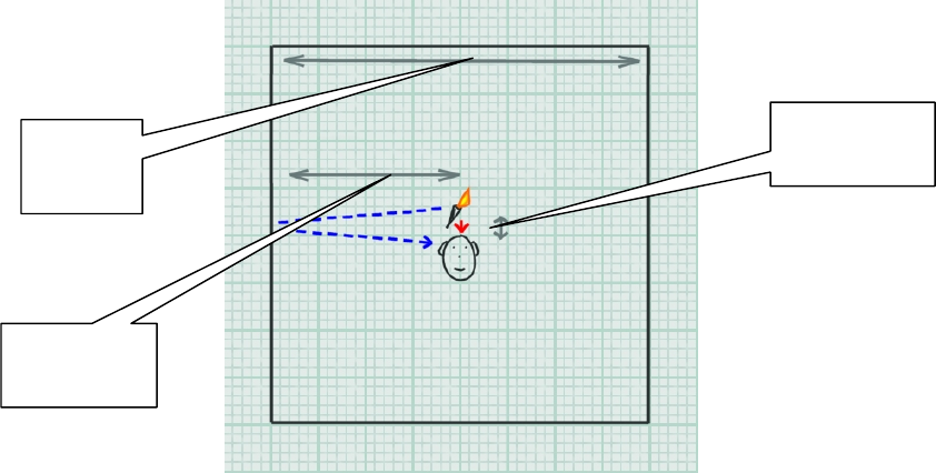
122/144
Figure 12 – Worst case: reflections delay approximately 20 milliseconds
Of course, this is only true when sound source and listener are positioned in the centre of the room –
move them both closer to a common wall and the delay would be much shorter. Again, reckon on one
millisecond for each foot in the path travelled by sound moving from the source to the wall and then the
listener. If the source is located at a distance from the listener, then in reality things get more complex -
the reflections delay will be offset by the time taken for the direct path to reach the listener’s ears.
When designing a reverb model, an estimation for the time delay between the direct sound and the first
reflections reaching the listener’s ears must be made based on the most likely set of circumstances. As
the reverb model does not support localisation of reflections on a ‘per-source’ basis, we must make a
generalised assumption regarding the location of sound sources. A reasonable supposition could be
that in an application, which focuses around the user’s on-screen self, many prominent sounds in an
application originate at, or near to, the listener’s position.
Also, it is likely that the position of a moving listener will, over time, be distributed fairly evenly between
the centre of a room and its perimeter. If you are implementing a dynamic system, you can account for
changing listener position by varying the Reflection Delay. But if you are designing a static
environment for a given room, you’ll need to assume an average proximity between the listener and the
nearest wall. A larger room gives the listener the potential to be further from a reflecting wall, implying
longer reflection delay times.
Figure 13 shows a typical scenario for the twenty foot square room, giving a Reflection Delay of around
twelve milliseconds when the listener is at a typical distance of around 6 feet from the wall.
Source -> Listener
0 ft
Source -> Wall
10 ft
Room Width
20 ft

123/144
Figure 13 - A typical scenario for calculating Reflection Delay - in this case around 6 milliseconds
The size of the room also has a direct bearing on the time gap between the first reflections and the
onset of reverberation. In a small room, reflections will occur more frequently, so any reverberation will
build up quicker than in a larger room.
Conclusion
When designing an environmental reverb, making a good estimate of the room’s size will help you to
approximate a good starting value for Reflections Delay. This in turn will provide a good starting point
towards developing values for many of the other environmental reverb properties, including Reverb
Delay. These calculations are really “rules of thumb” – they can be used to generate suitable values for
a general set of situations.
To summarise, the length of delay before a listener hears early reflections (Reflections Delay) is directly
affected by the distance between the listener and the reflecting surface. In a larger room, a sound is
statistically likely to travel further before being reflected back to the listener. Therefore when designing
an environment, assume that Reflections Delay will be proportional to room size. If you are working on
dynamically adjusting parameters in real time, Reflections Delay can be altered according to the
distance between the listener and the nearest surface. Reverb becomes prominent quicker in smaller
rooms, but the delay between the first early reflections and the onset of reverb (Reverb Delay) can be
kept considered independent from the listener’s position.
Surface Reflectivity
In order to investigate further properties of environmental reverb, we must take into account another
room characteristic – how well the room’s walls absorb sound. Some energy is always absorbed when
sound strikes a surface. Materials such as metal and concrete are relatively reflective; they absorb less
sound energy than materials such as fabric and wood panelling. A room that consists of reflective walls
will generally support louder reflections and longer reverberation than a room consisting of absorptive
surfaces. Let’s look in more detail at how surface material can influence reflections and reverberation.
Room Width
20 ft
Source -> Listener
0 ft = 0 ms
Source -> Wall -> Listener
6 ft x 2 = 12 ms

124/144
Setting the Gain value for an environment, or for all environments, is a good way to adjust the overall
amount of environmental sound in an application. For instance, a slider could be presented in the
application’s audio options menu, allowing the user to control the global level of reflected sound. The
slider’s value could then be applied as a modifier to the Gain property each time a reverb is applied.
However, for independently tweaking and balancing the levels of reflected and reverberant sound
within an environment, Reflections Gain and Reverb Gain should be used.
We have seen how room size affects the time it takes for early reflections to reach the listener.
Just like direct path sound, reflected sound is attenuated over distance due to the expansion of
the spherical waves and to air absorption (at high frequencies). So the longer the path from
source to reflecting wall, and wall to listener, the lower the intensity of perceived early reflected
sounds. This implies that reflections tend to be louder in small rooms. But path length alone does
not determine the intensity of early reflections reaching the listener. Highly absorptive walls will
reduce the reflected sound’s intensity at each bounce; this means that early reflections level is a
function of path length and surface reflectivity. Reflection intensity is determined by the listener’s
proximity to a surface, as well as the room’s surface absorptivity, so Reflections Gain is an ideal
candidate for dynamic adjustment.
Reverb, like reflections, tends to be quieter in larger rooms, but for slightly different reasons. The key to
overall reverb intensity is the total room volume – in a larger room, the energy emitted by a source must
spread over a larger volume. Because reverberation is the combined effect of many instances of
reflected sound washing around a room in different directions, its level is more or less the same no
matter where the listener is positioned within the room.
Gain
Value range 0.0 to 1.0
Default value 0.32
Value units Linear gain
Gain controls the amount of reflected sound in an environment. Changes made to Gain
adjust the level of both the early reflections and the reverberation at the same time.
Setting this parameter to 0.0 mutes all reflections and reverberant sound in an
environment.
Reflections Gain
Value range 0.0 to 3.16
Default value 0.05
Value units Linear gain
Reflections Gain sets the level of the early reflections in an environment. We use earl
y
reflections as a cue for determining the size of the environment we are in. The loude
r
(and less delayed) the reflections are the nearer a wall will sound.

125/144
Reverb level does vary slightly for each source according to its distance from the listener and to the
room's Decay Time. The OpenAL Reverb specifies that the renderer will continuously calculate these
changes for itself automatically, so the property Reverb Gain does not require further dynamic
modification. For more details on how attenuation is calculated and deployed for reflected sound, see
the section on Additional source specific enhancements.
Now let’s look at the time it takes for reverb to die away – Decay Time. As we have established, sound
waves are absorbed when they collide with solid objects, such as a room’s walls, and also at high
frequencies by the air. So the more often sound energy collides with absorptive surfaces, the quicker
the reverb will decay.
In a bigger room with a larger volume, there will be a longer mean time between each energy-sapping
collision of sound with surface. As room dimensions increase, the room’s volume increases to a power
of three, while the surface area available for absorption just increases to a power of two. The resulting
effect is that, if wall absorptivity is kept constant, Decay Time is linearly proportional to the room's size.
Conclusion
A room’s absorption coefficient is an indication of how much sound is absorbed by a room’s surfaces.
Environments with highly reflective walls tend to support louder reflections and longer reverbs.
Environments with absorptive walls tend to generate less reflected sound. A large room size implies a
greater volume, making the reverb quieter although the decay time is longer.
As the listener moves within an environment, the intensity of early reflections (Reflections Gain)
varies with the listener’s proximity to surfaces. Reverberation intensity (Reverb Gain) and
reverberation decay (Decay Time) remain more or less constant within an environment.
Reverb Gain
Value range 0.0 to 10.0
Default value 1.26
Value units Linear gain
Reverb Gain controls the level of the reverberant sound in an environment. A high level
of reverb is characteristic of rooms with highly reflective walls and/or small dimensions.
Decay Time
Value range 0.1 to 20.0
Default value 1.49
Value units Seconds
Decay Time controls the amount of time the reverberated sound takes to decay 60 dB.
Decay time is dependant on both the size of the room and the reflectivity of the walls.
Generally speaking, rooms with low absorbance and large size will support a longe
r
reverb decay time.

126/144
Surface Reflectivity at different frequencies
Up until now, we have made the assumption that a surface will absorb and reflect sound at a constant
level, regardless of the sound’s frequency. In actual fact, materials react differently when struck by
sounds of different frequency. Generally, harder and smoother materials such as glass, wood and
concrete tend to absorb low frequencies and reflect high frequencies. Softer materials like woven
fabrics are reflective of low frequencies, but absorb more high frequency sound.
Gain HF
Value range 0.0 to 1.0
Default value 0.89
Value units Linear gain
Gain HF is used to attenuate the high frequency content of all the reflected sound in an
environment. You can use this property to give a room specific spectral characteristic. I
f
you want to model a room that absorbs many high frequencies, reduce Gain HF until you
get the timbre you are looking for. HF Reference sets the frequency at which the value o
f
this property is measured.
Gain LF
EAX Reverb Only
Value range 0.0 to 1.0
Default value 1.0
Value units Linear gain
Gain LF is the low frequency counterpart to Gain HF. Use this to reduce or boost the lo
w
frequency content in an environment. LF Reference sets the frequency at which the value
of this
p
ro
p
ert
y
is measured.
Decay HF Ratio
Value range 0.1 to 2.0
Default value 0.83
Value units A linear multiplier value
Decay HF Ratio scales the decay time of high frequencies relative to the value of the
Decay Time property. By changing this value, you are changing the amount of time i
t
takes for the high frequencies to decay compared to the mid frequencies of the reverb.
A
value of 1.0 means that the high frequency content of the reverb will decay at the same
rate as the mid frequencies. Setting this value to 0.5 will cause the high frequencies to
decay twice as fast. Setting it to 2.0 means the high frequency content will last twice as
long as the mid frequencies. HF Reference sets the frequency at which the value of this
property is measured.
In most cases, the high frequency content should decay faster than the rest of the reverb
(high frequencies are absorbed more easily by most materials and by the air). Increasing
Decay Time will proportionally increase the high frequency decay time of a reverb. The
flag Decay HF Limit can be set to cap the high-frequency decay time at a realistic value,
determined by the property Air Absorption HF.

127/144
The properties described above allow you to manage the overall tone of reflected sound, and
additionally the tone of the late reverb decay, at the high and low frequencies. What’s more, by
changing the HF and LF reference frequencies, you can adjust where in the frequency spectrum these
controls are effective, similar to a two band parametric equaliser or two swept EQ channels on a mixing
console.
If you have some idea of how the surfaces of a room react to different frequencies, then you can
use this knowledge as a starting point for using the environmental reverb tonal controls. It would
be quite involved to work out scientifically accurate values for these settings. So in this case, as
with many other aspects of reverb design, it is best to make aesthetic choices, guided by
scientific principles: -
Decide the ‘feel’ you want for the room, guided by the wall materials and the context of the
room. Should the room be ‘bright’ or ‘dark’? Should the room be ‘boomy’ or ‘tinny’?
Set the parameters to achieve the feel you want. For ‘bright’ rooms, boost high
frequencies with high values for Gain HF, and maybe also bias the reverb decay towards
Decay LF Ratio
EAX Reverb Only
Value range 0.1 to 2.0
Default value 1.0
Value units A linear multiplier value
Decay LF Ratio scales the decay time of low frequencies in the reverberation in the same
manner that Decay HF Ratio handles high frequencies. LF Reference sets the frequenc
y
at which the value of this property is measured.
HF Reference
EAX Reverb Only
Value range 1000.0 to 20000.0
Default value 5000.0
Value units Hertz
LF Reference
EAX Reverb Only
Value range 20.0 to 1000.0
Default value 250.0
Value units Hertz
The properties HF Reference and LF Reference determine respectively the frequencies at
which the high-frequency effects and the low-frequency effects created by Reverb
properties are measured.
Note that, for listener properties, it is necessary to maintain a factor of at least 10 between
these two reference frequencies so that low frequency and high frequency properties can
be accurately controlled and will produce independent effects. In other words, the L
F
Reference value should be less than 1/10 of the HF Reference value.

128/144
higher frequencies by setting Decay HF Ratio near 1.0 (or even over 1.0). To get rid of
‘booming’ at low frequencies, turn down Gain LF and/or Decay LF Ratio.
Or if you want a darker, more damped room, get rid of high frequencies with lower settings
for Gain HF and/or putting Decay HF Ratio below 1.0.
Audition some of your application’s sounds with your environment applied, and revise the
effect as necessary. Of course, it’s important to assess how the effects work in relation to
the source sounds it will process, and to pay heed to the spectral content of the sound
samples when designing effects.
Figure 14 – Three dimensional reverberation response model from Creative’s EAGLE reverb design tool. Frequency is represented in the
depth dimension – high (near) to low (far). Note how the reverb decay is longer at lower frequencies in this reverb model.
Conclusion
Tonal coloration in reflected sound tells us a lot about the materials that make up our surroundings.
Different materials might be particularly absorptive or reflective of certain frequencies. A key task in
designing an environmental reverb is to determine a tonal character for the location you want to model.
The EAX Reverb allows for tonal control over the entire reflected sound (Gain HF, Gain LF). You can
also set how quickly the late reverb decays at high and low frequencies (Decay HF, Decay LF) in
comparison to the decay time at mid frequency (Decay). You can vary the frequencies at which these
controls are effective (HF Reference, LF Reference). The standard reverb effect is not so adjustable.
You only have controls for damping (i.e. attenuating at high frequency), and you cannot change the
reference frequency at which the damping is applied. Spectral effects are unlikely to be suitable for
dynamic adjustment.
Wall configuration
The arrangement of the surfaces in an environment can greatly affect the granularity of the
reverberation. In an environment with many rough surfaces, sound will be reflected in countless
directions, greatly increasing the chance that a reflection will reach the listener’s ears. This will result in
a smooth reverberation.
However, in environments with few diffuse surfaces - bare rooms with smooth walls - you are more
likely to hear distinct echoes, resulting in a more grainy reverberation sound. Two parallel, smooth
surfaces in a room can cause sound energy to bounce backwards and forwards, making a ‘fluttering’
echo effect. The Diffusion and Echo parameters allow the sound designer to introduce discrete echoes
HF Reference
set to 8 kHz
HF Decay < 1.0
A short decay
time at high
frequency
Decay LF > 1.0
A long decay
time at low
frequency
LF Reference
set to 30 Hz

129/144
into the reverberated signal, simulating this phenomenon. This effect can be more easily heard with a
percussive source sound such as a pistol shot or a drum hit.
Once again, the environment size will be an influence on the reverb. In this case, the length of the path
between the walls will determine the time it takes for the wave front to traverse the room. With our
Environment Diffusion
Value range 0.0 to 1.0
Default value 1.0
Value units A linear multiplier value
Environment Diffusion controls how the individual reflections in the reverb are distributed.
If the value for this property is high, then there is a richer pattern of reflected waves in the
room and therefore a greater number of reflections will reach the listener. This results in a
smooth sounding reverberation. This type of environment is said to be “diffuse.” Rooms
that have small dimensions or very uneven, coarse surfaces or contain many reflective
obstacles often exhibit this type of effect.
Rooms or enclosures that have large dimensions and smooth surfaces, or open
environments with sparse reflectors, produce fewer reflections patterns than diffuse
environments. Such an environment will therefore require a lower value for Environmen
t
Diffusion. (Smoother surfaces do not “break the reverb up,” and therefore, there are
fewer echoes.)
Echo Depth
EAX Reverb Only
Value range 0.0 to 1.0
Default value 0.0
Value units A linear multiplier value
Echo Time
EAX Reverb Only
Value range 0.075 to 0.25
Default value 0.25
Value units Seconds
Echo Depth introduces a cyclic echo in the reverberation decay, which will be noticeable
with transient or percussive sounds. A larger value of Echo Depth will make this effect
more prominent. Echo Time controls the rate at which the cyclic echo repeats itself along
the reverberation decay. For example, the default setting for Echo Time is 250 ms.
causing the echo to occur 4 times per second. Therefore, if you were to clap your hands
in this type of environment, you will hear four repetitions of clap per second.
Together with Environment Diffusion, Echo Depth will control how long the echo effect will
persist along the reverberation decay. In a more diffuse environment, echoes will wash
out more quickly after the direct sound. In an environment that is less diffuse, you will be
able to hear a larger number of repetitions of the echo, which will wash out later in the
reverberation decay. If Environment Diffusion is set to 0.0 and Echo Depth is set to 1.0,
the echo will persist distinctly until the end of the reverberation decay.
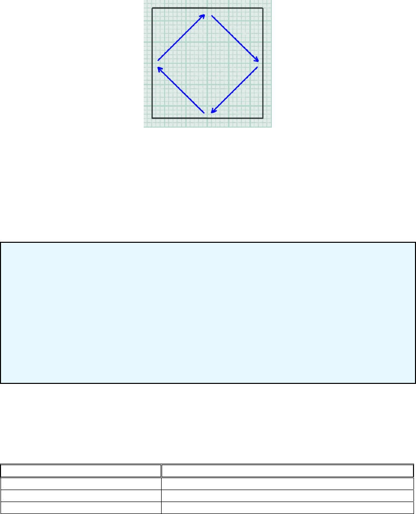
130/144
rough figure of one millisecond per foot, we can calculate that under the appropriate conditions, a
listener in a room containing two smooth, parallel surfaces 20 feet apart, might hear a discrete echo
every 20 milliseconds. And furthermore, the echo intensity will be dependant on the wall absorptivity.
Small Rooms
As described above, fluttering echoes are heard in an environment where reflections have a low
temporal density. But there are also situations where environmental sound is also unevenly distributed
in the frequency domain. At the root of this phenomenon is the concept of cyclic echoes.
Figure 15 - Cyclic echoes in a room
The wall geometry of a room can cause some reflections to take repetitive or cyclic paths. This occurs
particularly in small, reverberant rooms.
In this situation, a resonance or ‘standing wave’ will be set up in the room, at a frequency
corresponding to the length of the cyclic echo’s path. The frequencies of the different standing waves
in a room are known as the room’s modal frequencies.
Static Dependencies
Table 3, below, shows how room characteristics influence environmental reverb properties. The right
hand column simply shows which room features you should consider when tweaking the different
reverb parameters to design a static acoustic simulation for a room.
Reverb Parameter Room Characteristic
Reflection Delay Room Size (Implying path length)
Reverb Delay Room Size (Implying path length)
Reflections Gain Room Size (Implying path length), Room Absorptivity
Reverb Density
Value range 0.0 to 1.0
Default value 1.0
Value units A linear multiplier value
In larger environments where the distribution of modal frequencies tends to be denser, no
particular resonance stands out. But smaller, relatively reverberant rooms such as
bathrooms tend to have sparser modal frequencies, giving rise to a more hollow tone.
Reverb Density controls the coloration of the late reverb. Lowering the value adds more
coloration to the late reverb.

131/144
Reverb Gain Room Size (Implying surface area), Room Absorptivity
Decay Time Room Size, Room Absorptivity
HF Reference
LF Reference Absorptivity of surfaces at different frequencies
Gain HF
Gain LF Absorptivity of surfaces at different frequencies
Decay HF Ratio
Decay LF Ratio Absorptivity of surfaces at different frequencies
Environment Diffusion Presence of smooth surfaces, sparseness of reflectors
Echo Depth Presence of reflective parallel surfaces
Echo Time Room Size (Implying path length)
Table 3 - Showing room characteristic to reverb property dependencies for designing
environmental reverbs.
Dynamic Modelling
The physical modelling paradigm has the potential to offer a high quality dynamic acoustic model,
particularly in respect of early reflections. However physical modelling implementations have difficulty
tracing reflections far enough to realistically re-create the subtleties of late reverb.
To physically model sophisticated phenomena like tonal variation (see Surface Reflectivity at different
frequencies), echo density (see Wall configuration) and modal density (see Small Rooms) would
require prohibitive amounts of processing power. Possibly the optimum solution, then, is to employ a
hybrid system. The idea is to create statistical models simulating life-like late reverberation for each
discrete room or zone in an application, and to also manipulate the early reflections properties
according to the precise relationship between the listener and the walls for added realism.
Localising Reflections and Reverb
Making a multi-environment audio engine involves dynamically panning the Reflections and the
Reverb.
Knowing a little bit about the architecture of a room as well as the position and orientation of the
listener, it is possible for a program to calculate and set the direction from which the early reflections in
the listener’s environment tend to come. (For instance, by considering the positions of the nearest
walls relative to the listener).
As mentioned in the Panning Environments section, it is vital that the reflected sound from
environments other than the listener’s is correctly localised when implementing multiple environments.
If the programmer does not carry out these calculations, then the realism of the multiple environments
will severely compromised. Reflections Pan and Reverb Pan should be set to imply the distance and
direction between the listener and another environment. Reflections Gain and Reverb Gain can be
used to further attenuate reflected sound from distant environments.
Reverb Pan
EAX Reverb Only
Value range Vector of length 0 to 1
Default value (0, 0, 0)
Value units N/A
Reverb Pan does for the Reverb what Reflections Pan does for the Reflections.
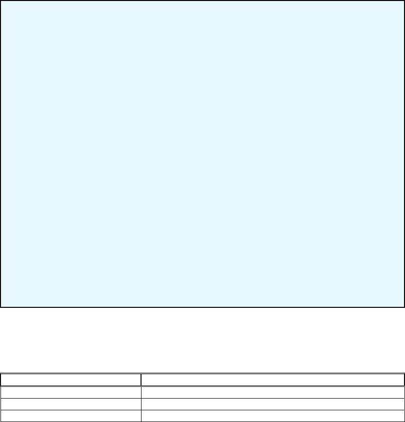
132/144
Dynamic Dependencies
Table 4shows the reverb parameters that are most suitable for real-time adjustment according to
listener position, and shows the variables their value would depend on.
Reverb Parameter Listener / Wall relationship
Reflections Delay Listener to reflecting surface path length
Reflections Gain Listener to reflecting surface path length
Reflection Pan Listener to reflecting surface direction, surface size/shape
Table 4 - Showing room characteristic to reverb property dependencies for dynamically updating
parameters
Additional Properties
Pitch modulation effects
As well as providing amplitude modulation effects (in the form of a tune-able repeating echo), The EAX
Reverb allows the designer to introduce pitch modulation in the reverberation decay. While this effect
is probably not encountered in many natural environments, it is useful when designing a reverberation
effect that signifies emotional state rather than location in an application.
Designers are encouraged to use these parameters, maybe in combination with extreme settings for
other reverberation properties, in creating effects that reinforce the experiences of an avatar in a game
or other application. Examples include dizziness, intoxication, or high stress.
Reflections Pan
EAX Reverb Only
Value range Vector of length 0 to 1
Default value (0, 0, 0)
Value units N/A
The Reflections Pan property is a 3D vector that controls the spatial distribution of the
cluster of early reflections. The direction of this vector controls the global direction of the
reflections, while its magnitude controls how focused the reflections are towards this
direction.
In using panning, it is important to note that the direction of the vector is interpreted in the
coordinate system of the user, without taking into account the orientation of the virtual
listener. For instance, assuming a four-point loudspeaker playback system, setting
Reflections Pan to (0.0, 0.0, 0.7) means that the reflections are panned to the fron
t
speaker pair, whereas as setting of (0.0, 0.0, −0.7) pans the reflections towards the rea
r
speakers. For legacy reasons these vectors follow a left-handed co-ordinate system
–
you will need to make allowances for the fact that OpenAL API uses a right-handed co
-
ordinate system.
If the magnitude of Reflections Pan is zero (the default setting), the early reflections come
evenly from all directions. As the magnitude increases, the reflections become more
focused in the direction pointed to by the vector. A magnitude of 1.0 would represent the
extreme case, where all reflections come from a single direction, and is therefore unusual.

133/144
Distance Controls
The remaining Reverb properties do not adjust the reverberation characteristics. They are concerned
with controlling how the reverb level on sources varies according to distance.
The phenomenon of rolloff on audio is simple – the further you get from a sound source, the quieter it
gets. It is also worth considering that the same applies to that sound source’s reflected path, although
to a lesser degree than its direct path. According to statistical room acoutics theory, the precise rate at
which reverb rolls off tends to be roughly proportional to the room’s decay time; in rooms with shorter
reverb decays, the reflected sound rolls off quicker. Since the decay time is usually shorter at high
frequencies, the reverb is subject to a natural-sounding (usually subtle) distance-dependent low-pass
filtering effect, in addition to the effect of air absorption (which applies to both the direct and reflected
paths).
Under normal circumstances you don’t need to worry about this effect, as the reverb effects
automatically calculate rolloff on reflected sound for each sound source, bearing in mind the distance
between the source and the listener, and characteristics of the environment. However, if the situation
arises where you think that distant sounds in an environment are accompanied by too much reverb,
you can make adjustments for yourself with Room Rolloff Factor.
The default value of 0.0 means that no additional attenuation is added to each source’s reflected
sound. A value of 1.0 will add additional attenuation at the same rate as the direct sound attenuates
with respect to distance.
Modulation Depth
EAX Reverb Only
Value range 0.0 to 1.0
Default value 0.0
Value units A linear multiplier value
Modulation Time
EAX Reverb Only
Value range 0.04 to 4.0
Default value 0.25
Value units Seconds
Using these two properties, you can create a pitch modulation in the reverberant sound.
This will be most noticeable applied to sources that have tonal color or pitch. You can use
this to make some trippy effects! Modulation Time controls the speed of the vibrato (rate
of periodic changes in pitch).
Modulation Depth controls the amount of pitch change. Low values of Diffusion will
contribute to reinforcing the perceived effect by reducing the mixing of overlapping
reflections in the reverberation decay.

134/144
To calculate the statistical reverb rolloff and the air absorption effect, the reverb engine makes the
assumption that the distance unit in use is the meter. If this is not the case, it is important to set
accordingly the OpenAL listener extension AL_METERS_PER_UNIT. This will ensure that your unit is
correctly converted into metres by the OpenAL reverb engine.
The Effect Extension filters enable the simulation of a more subtle rolloff effect, that of air absorption. In
normal conditions, our atmosphere absorbs sound slightly more at high frequencies. This is why
distant sounds often sound duller. The source object extension property
AL_AIR_ABSORPTION_FACTOR controls how much air absorption is applied to each source’s dry
path. But it is also possible to add extra high frequency attenuation to the reflected sound using the
reverb’s Air Absorption HF property.
Designing and Using Environmental Filtering effects
As mentioned earlier, Environmental filtering is a fundamental part of the positional audio experience.
What’s more, compared to creating your own environmental reverb presets, designing filtering effects is
Room Rolloff Factor
Value range 0.0 to 10.0
Default value 0.0
Value units A linear multiplier value
The intensity of a sound source’s reflections becomes attenuated with distance in a simila
r
way to its direct path, although not as fast. By default the reverb engine calculates the roll-
off on the Room path (reflected sound, including reflections and reverb), taking into
account such properties as Decay Time.
A
dditional attenuation on each source’s reflections can be added by increasing this factor.
A factor of 1.0 will add attenuation at the same rate as attenuation is added to the source’s
direct sound as the distance between the source and the listener increases.
A
ir Absorption Gain HF
Value range 0.892 to 1.0
Default value 0.994
Value units Linear gain per meter
The reverb property Air Absorption Gain HF is used to simulate environments containing
propagation mediums that have different levels of sound absorption, particularly at high
frequencies. In typical conditions of atmospheric humidity and temperature, air attenuates
high frequency sound at approximately 0.05 dB per meter at 5 kHz. Moist or ashy air ma
y
slightly muffle sounds traveling through it – use a lower value. Set a higher level for a less
absorptive medium such as dry, desert air. This property only applies high frequenc
y
attenuation to reflected sound. To adjust air absorption filtering on individual 3D sources’
dry paths, use the source property AL_AIR_ABSORPTION_FACTOR.

135/144
a breeze. So with the knowledge and tips you’ll pick up in this section, there’s no excuse for designing
a positional sound implementation without realistic environmental filtering any more!
Environmental filtering effects can be applied on a per-source basis to simulate muffling on sound
sources that are hidden from the listener behind walls, partitions, or obstacles.
Previous environmental audio systems such as Creative’s EAX API defined three different filtering
scenarios: Obstruction, Occlusion and Exclusion. These were in actual fact simply ‘high-level’
abstractions, which managed lower level properties controlling attenuation and filtering on sources’
direct and processed paths.
The specific combinations of attenuation and filtering on direct and reflected sound is shown in the
following table:
Direct Path Reflected sound in listener’s environment
Obstruction Filtered and attenuated -
Occlusion Filtered and attenuated Filtered and attenuated
Exclusion - Filtered and attenuated
Table 5 - Filtering and attenuation of direct and reflected sound paths for different sound
muffling scenarios
The old ‘high-level’ controls are not present in the OpenAL Effects Extension. But the filter objects
which can be attached to sources give the developer close control over the amount of filtering and
attenuation that takes place on every 3D sound. So it is entirely possible to simulate all kinds of
muffling scenarios by directly manipulating the following:-
Sound element to control Control technique
Attenuation on Direct path Attach direct filter, adjust AL_LOWPASS_GAIN
Attenuation on Reverb path Attach aux send filter, adjust AL_LOWPASS_GAIN
Filtering on Direct path Attach direct filter, adjust AL_LOWPASS_GAINHF
Filtering on Reverb path Attach aux send filter, adjust AL_LOWPASS_GAINHF
Whenever transmission through an obstacle is involved, the amount of filtering and attenuation should
be determined by the material through which the sound is passing.
Obstruction
Consider the Obstruction scenario mentioned in the Environmental Filtering section earlier:

136/144
Figure 16 - Obstruction
In this scenario the direct path between the sound source and the listener (shown in red) is broken. The
effect of diffraction and absorption mean that any dry sound reaching the listener will be muffled.
However, reflected and reverberant sound, shown in blue, reaches the listeners ears largely without
interruption.
So when the obstruction scenario is detected for a sound source, the source’s direct path (the signal
path where the sound source directly feeds the 3D mix) should have attenuation and filtering applied.
However, the room path (the signal path where the sound source feeds the 3D reverb) should be
unaffected.
Occlusion
Now consider the Occlusion scenario mentioned earlier in the Environmental Filtering section:
Figure 17 - Occlusion
In this instance, both the direct path and the room path will be interrupted. Hence attenuation and
filtering should be applied to both components. As with obstruction, occlusion on a sound source can
be simulated using the source’s properties and Filter Objects.
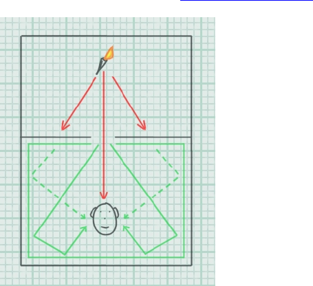
137/144
Exclusion
Finally, consider the Exclusion scenario mentioned earlier in the Environmental Filtering section:
Figure 18 - Exclusion
Since the direct sound source to listener path is uninterrupted, but an aperture such as a window or
doorway restricts the amount of room path heard by the listener, the resultant effect is the opposite to
that heard in the obstruction scenario; muffled room path but un-attenuated direct path.
Applying muffling effects in real time
There are many considerations when determining the amount of attenuation and filtering to apply to a
sound that is heard through an architectural object such as a wall of a pillar. First, it is sensible to first
consider the material the sound is travelling through, and its thickness. The amount of filtering and
attenuation in these situations depends a great deal on the sound transmission qualities of the material
separating the two rooms. Some materials are thick and absorbent and transmit very little sound;
others are stiff and thin and transmit clearly; others have transmission qualities in between. Frequency
response varies too; some materials attenuate high frequencies more than others do.
In a dynamic audio engine, it might possible to assign different surface types with a sound
transmissiveness rating. The engine could use this value when calculating filtering and attenuation
figures.
Here’s another useful tip for realistic occlusion effects. Compared to the direct sound path, the
reflected sound should undergo 50% more frequency-independent attenuation. This creates a natural
sensation of occlusion because, in the physical world, it is the occluding wall that acts as the actual
sound source in the listener’s room. Since the wall radiates sound in only half the space that a sound
source in the middle of the room can, it generates significantly less reflected sound than the original
source would, if it were located in the room.
If you want to simulate diffraction around an obstacle in the obstruction scenario, the audio engine
could determine the shortest propagation path from source to listener and set the values according to
the angle of deviation undergone by this shortest path. For an accurate simulation, the application
should also set the positional parameters of the source to the corresponding apparent position relative
to the listener.

138/144
Note that you can use Obstruction and Occlusion simultaneously – if, for example, the source is in
another room from the listener and there is a large obstacle between the listener and the wall. In this
case, the direct path is filtered twice: once by Occlusion and once by Obstruction.
To correctly simulate obstruction, occlusion, and exclusion, the audio engine is likely to check several
times every second, to see if any of the situations apply to any of the sources currently playing.
Parameters for simulating obstruction, occlusion or exclusion on a sound source may well vary as the
positions of the source and listener move in relation to their surroundings. In the case of obstruction,
the amount of attenuation is likely to reduce as the sound source clears the obstruction. In the case of
exclusion, the amount of reverberation heard is likely to increase as the source approaches the
aperture. Although the task of calculating these adjustments should be carried out in the application, it
is likely that the sound designer will have a hand in defining the policies used.
Additional source specific enhancements
OpenAL provides the application developer with all the basic facilities for positioning sounds in 3D. As
well as adding environmental effects like reverberation and filtering, the Effects Extension also extends
the positional basics such as roll-off and directivity with some subtle but useful extra enhancements.
This section details how you can use the extensions to make the 3D soundtrack more convincing, even
before you reach for the reverb and filtering effects. It also deals with properties that allow you to
balance the overall amount of direct and reflected sound on each sound source.
3D Source Controls
The following properties provide automatic methods for making per-source direct and reflected volume
adjustments according to the positional parameters of the sound source or the listener. They extend
the rolloff effect, Doppler effects and directivity effects provided by OpenAL.
A
ir Absorption Factor
Value range 0.0 to 10.0
Default value 0.0
Value units A linear multiplier value
The Air Absorption Factor property is a multiplier value for the constant air absorption
value set by OpenAL, which is 0.994 (-0.05dB per meter). The resultant air absorption
value applies only to this sound source.
The Air Absorption Factor default value is 0.0. This means that the overall Air absorption
effect for any source is off by default. A value of 1.0 will correspond to air absorption equal
to the constant value 0.994.
You can use the Air Absorption Factor to simulate a source located in differen
t
atmospheric conditions than the rest of the room. You can increase air absorption, fo
r
example, for a sound source that comes from the middle of a cloud of smoke.
Alternatively, you can decrease air absorption for a sound source coming from a suddenl
y
visible object in moving clouds.

139/144
Room Rolloff Factor
Value range 0.0 to 10.0
Default value 0.0
Value units A linear multiplier value
This is the per-source equivalent of the Reverb property of the same name. This propert
y
only affects one specific sound source. The Reverb property Room Rolloff Factor will be
added to this property to determine the additional attenuation applied to the sound
source’s reflected path.
This parameter brings you the ability to change how quickly an individual source’s
reflected sound will roll off as listener to source distance increases.
Doppler Factor
Value range 0.0 to 10.0
Default Value 1.0
Value Units A linear multiplier value
This is a low-level per-source property that is defined in the same way as the global
Doppler Factor property provided in OpenAL and DirectSound. It is important to keep in
mind the source Doppler factor is a multiplier of the global Doppler factor propert
y
provided in OpenAL and DirectSound.
A
zero value will therefore disable Doppler shift effects for the corresponding source.
A
value of 1.0 provides natural Doppler effects according to the movement of the source
relative to the listener. A value larger then 1.0 will exaggerate these effects.
Cone Outer Gain HF
Value range 0.0 to 1.0
Default value 0
Value units Gain
The Cone Outer Gain HF property enhances the directivity effect provided by OpenAL fo
r
individual sound sources. Using standard directivity properties, a source can be made to
sound at full volume when the listener is directly in front of the source and will be
attenuated as the listener circles the source away from the front.
When OpenAL attenuates a source’s direct-path sound to simulate directivity, i
t
attenuates high and low frequency sound equally. Real world sources tend to be more
directional at high frequencies than at low frequencies.
The Cone Outer Gain HF property allows the developer to enhance the directivity effec
t
by attenuating the high frequencies more than the low frequencies. At the default setting
of 1.0, there is no additional high-frequency attenuation, so OpenAL’s directivity effect is
unaltered. At the minimum setting of 0.0, directivity attenuation for high frequencies is
100 dB more than it is for low frequencies.
This property sets directivity high-frequency attenuation for both the direct-path and the
reflected sounds of the sound source. You can turn off its effect on direct-path sound
using the AL_DIRECT_FILTER_GAINHF_AUTO property, or you can turn off its effect on
reflected sound using the AL_AUXILIARY_SEND_FILTER_GAINHF_AUTO property.

140/144
Creative End-User Software License Agreement
for Software Development Kit
Creative Labs, Inc. Phone (408) 428 6600
1901 McCarthy Blvd. Fax (408) 428 6611
Milpitas, CA 95035 www.creative.com
PLEASE READ THIS DOCUMENT CAREFULLY. YOU MUST AGREE TO THE TERMS OF THIS
AGREEMENT BEFORE USING OR DOWNLOADING THE SOFTWARE AND/OR MANUAL FROM
THE INTERNET. BY USING OR DOWNLOADING THE SOFTWARE AND/OR MANUAL, YOU
AGREE TO BE BOUND BY THE TERMS OF THIS AGREEMENT. THIS AGREEMENT SHOULD BE
PRINTED AND RETAINED FOR REFERENCE.
This is a legal agreement between you ("Licensee") and Creative Technology Ltd. and its subsidiaries
("Creative"). This Agreement states the terms and conditions upon which Creative offers to license the
software and/or manual provided or downloaded from this website together with all related
documentation and accompanying items including, but not limited to, the executable programs, drivers,
libraries and data files associated with such programs (collectively, the "Software").
LICENSE
1. Grant of License
This License Agreement is your proof of license to exercise the rights granted herein and must be
retained by you. As between you and Creative (and, to the extent applicable, its licensors), Creative
retains all title to and ownership of the Software and reserves all rights not expressly granted to you.
The license under this Section 1 is conditioned upon your compliance with all of your obligations under
this Agreement. Creative grants to Licensee a non-exclusive, non-transferable, limited, royalty-free
license to use the Software solely in accordance with the terms contained in this Agreement provided
that:
a. Licensee shall use the Software solely for the purpose of developing Licensee applications
compatible with Creative’s products, unless otherwise agreed to by further written agreement from
Creative.
b. the Software is not distributed without execution of a separate distribution agreement between
Creative and Licensee;
c. the Software may NOT be modified except for the source code examples found under the
“Samples” directory; and
d. Creative's BBS and FTP websites are the only on-line sites where Licensee may download
electronic files containing the Software.
No other license is granted hereunder and any use not expressly provided for in this Agreement is
prohibited.
2. Copyright and Intellectual Property Protection
The Software and all derivative works are owned by Creative and/or its licensors, and are protected by
United States intellectual property laws and international treaty provisions. You may not remove the
copyright notice from any copy of the Software or any copy of the written materials, if any,
accompanying the Software and you must reproduce all copyright and other proprietary rights notices
included in the originals of the Software on all products incorporating the Software or portions thereof.
141/144
3. One Archival Copy
You may make one (1) archival copy of the machine-readable portion of the Software for backup
purposes only, provided that you reproduce on the copy all copyright and other proprietary rights
notices included in the originals of the Software.
4. Limitations on Using and Copying the Software
Except to the extent expressly permitted by this Agreement or by any other developer agreement
agreed to in writing by Creative, you may not use or copy the Software for any purpose and shall keep
the Software confidential and not disclose the Software to any other person, firm or corporation.
Neither may you sub-license any of your rights under this Agreement. You may use the Software for
your personal use only, and absent a written agreement with Creative to the contrary, not for public
display of any kind.
5. Decompiling, Disassembling, or Reverse Engineering
You acknowledge that the Software contains trade secrets and other proprietary information of Creative
and its licensors. Except to the extent expressly permitted by this Agreement or by the laws of the
jurisdiction where you are located, you may not decompile, disassemble create derivative works or
otherwise reverse engineer the Software, or engage in any other activities to obtain underlying
information that is not visible to the user in connection with normal use of the Software.
In particular, you agree not to transmit the Software or display the Software's object code for any
purpose on any computer screen or to make any hardcopy memory dumps for any purpose of the
Software's object code. If you believe you require information related to the interoperability of the
Software with other programs, you shall not decompile or disassemble the Software to obtain such
information, and you agree to request such information from Creative. Upon receiving such a request,
Creative shall determine whether you require such information for a legitimate purpose and, if so,
Creative will provide such information to you within a reasonable time and on reasonable conditions.
In any event, you will notify Creative of any information derived from reverse engineering or such other
activities, and the results thereof will constitute the confidential information of Creative that may be used
only in connection with the Software.
TERMINATION
The license granted to you is effective until terminated. You may terminate it at any time by destroying
the Software (including any portions or copies thereof) currently in your possession or control. The
license will also terminate automatically without any notice from Creative if you fail to comply with any
term or condition of this Agreement. You agree upon any such termination to destroy the Software
(including any portions or copies thereof). Upon termination, Creative may also enforce any and all
rights provided by law. The provisions of this Agreement that protect the proprietary rights of Creative
will continue in force after termination.
NO WARRANTY
ANY USE BY YOU OF THE SOFTWARE IS AT YOUR OWN RISK. THE SOFTWARE IS PROVIDED
FOR USE ONLY WITH CREATIVE'S HARDWARE AND RELATED SOFTWARE. THE SOFTWARE
IS PROVIDED FOR USE "AS IS" WITHOUT WARRANTY OF ANY KIND. TO THE MAXIMUM
EXTENT PERMITTED BY LAW, CREATIVE DISCLAIMS ALL WARRANTIES OF ANY KIND,
EITHER EXPRESS OR IMPLIED, INCLUDING, WITHOUT LIMITATION, IMPLIED WARRANTIES
OR CONDITIONS OF MERCHANTABILITY, FITNESS FOR A PARTICULAR PURPOSE, TITLE OR
NONINFRINGEMENT. CREATIVE IS NOT OBLIGATED TO PROVIDE ANY UPDATES OR
UPGRADES TO THE SOFTWARE.
No distributor, dealer or any other entity or person is authorized to expand or alter this warranty or any
other provisions of this Agreement. Creative does not warrant that the functions contained in the
Software will meet your requirements or that the operation of the Software will be uninterrupted, error-
free, or free from malicious code. For purposes of this paragraph, “malicious code” means any
program code designed to contaminate other computer programs or computer data, consume
computer resources, modify, destroy, record, or transmit data, or in some other fashion usurp the
normal operation of the computer, computer system, or computer network, including viruses, Trojan
horses, droppers, worms, spyware, logic bombs, and the like.
142/144
Further, Creative shall not be liable for the accuracy of any information provided by Creative or third-
party technical support personnel, or any damages caused, either directly or indirectly, by acts taken or
omissions made by you as a result of such technical support.
Any representation, other than the warranties set forth in this Agreement, will not bind Creative. You
assume full responsibility for the selection of the Software to achieve your intended results, and for the
downloading, use and results obtained from the Software. You also assume the entire risk as it applies
to the quality and performance of the Software. Should the Software prove defective, you (and not
Creative, or its distributors or dealers) assume the entire liability of any and all necessary servicing,
repair or correction.
This warranty gives you specific legal rights, and you may also have other rights, which vary from
country/state to country/state. Some countries/states do not allow the exclusion of implied warranties,
so the above exclusion may not apply to you. Creative disclaims all warranties of any kind if the
Software was customized, repackaged, or altered in any way by any third party other than Creative.
IN NO EVENT WILL CREATIVE'S LIABILITY TO YOU OR ANY OTHER PERSON EVER EXCEED
THE AMOUNT PAID BY YOU TO USE THE SOFTWARE, REGARDLESS OF THE FORM OF THE
CLAIM.
NO LIABILITY FOR DAMAGES, INCLUDING WITHOUT LIMITATION
CONSEQUENTIAL DAMAGES
In no event shall Creative or its Licensor's be liable for any damages whatsoever (including, without
limitation, incidental, direct, indirect, special or consequential damages, damages for loss of business
profits, business interruption, loss of business information, or other pecuniary loss) arising out of the
use or inability to use this Software, even if Creative or its Licensor's have been advised of the
possibility of such damages. Because some states/ countries do not allow the exclusion or limitation of
liability for consequential or incidental damages, the above limitation may not apply to you.
LICENSEE’S LIABILITY FOR DAMAGES
In the event that Licensee breaches this Agreement, Creative shall be entitled to damages in
connection therewith. Licensee agrees to liquidated damages in the amount of no less than
US$30,000 for each occurrence of any violation under this Agreement. Any violation by any third party
under this Agreement shall be fully attributed to Licensee irrespective of supervision for purposes of this
Paragraph.
INDEMNIFICATION BY YOU
Creative shall have no liability for, and Licensee shall defend, indemnify and hold Creative harmless
from and against any claim, loss, demand, liability, obligation or expenses (including reasonable
attorneys’ fees) based upon or arising out of any loss, costs, damage, or any claim, including but not
limited to, any personal or property damages, arising out of, pertaining to, or resulting in any way from,
the use or possession of the Software by Licensee and/or any of Licensee’s directors, officers,
employees, representatives, agents, developers or contractors.
U.S. GOVERNMENT RESTRICTED RIGHTS
All Software and related documentation are provided with restricted rights. Use, duplication or
disclosure by the U.S. Government is subject to restrictions as set forth in subdivision (b)(3)(ii) of the
Rights in Technical Data and Computer Software Clause at 252.227-7013. If you are sub-licensing or
using the Software outside of the United States, you will comply with the applicable local laws of your
country, U.S. export control law, and the English version of this Agreement.
CONTRACTOR/MANUFACTURER
The Contractor/Manufacturer for the Software is:
Creative Technology Ltd.
31 International Business Park
Creative Resource
Singapore 609921
143/144
Safety & Regulatory Information
The following sections contain notices for various countries:
CAUTION: This device is intended to be connected by the user to a CSA/TUV/UL certified/listed IBM
AT or compatible personal computers in the manufacturer's defined operator access area. Check the
equipment operating/installation manual and/or with the equipment manufacturer to verify/confirm if
your equipment is suitable for devices to be connected to it.
ATTENTION: Ce périphérique est destiné à être connecté par l'utilisateur à un ordinateur IBM AT
certifié ou listé CSA/TUV/UL ou compatible, à l'intérieur de la zone d'accès définie par le fabricant.
Consulter le mode d'emploi/guide d'installation et/ou le fabricant de l'appareil pour vérifier ou confirmer
qu'il est possible de connecter d'autres périphériques à votre système.
GENERAL
This Agreement is binding on you as well as your employees, employers, contractors and agents, and
on any successors and assignees. Neither the Software nor any information derived therefrom may be
exported except in accordance with the laws of the U.S. or other applicable provisions. This
Agreement is governed by the laws of the State of California (except to the extent federal law governs
patents, copyrights and federally registered trademarks). This Agreement is the entire agreement
between us relating to the subject matter hereof, and you agree that Creative will not have any liability
for any untrue statement or representation made by it, its agents or anyone else (whether innocently or
negligently) upon which you relied upon entering this Agreement, unless such untrue statement or
representation was made fraudulently. This Agreement supersedes any other understandings or
agreements, including, but not limited to, advertising, with respect to the Software.
If any provision of this Agreement is deemed invalid or unenforceable by any country or government
agency having jurisdiction, that particular provision will be deemed modified to the extent necessary to
make the provision valid and enforceable, and the remaining provisions will remain in full force and
effect.
For questions concerning this Agreement, please contact Creative at the address stated above. For
questions on product or technical matters, contact the Creative technical support center nearest you.
SPECIAL PROVISIONS APPLICABLE TO THE EUROPEAN UNION
If you downloaded the Software in the European Union (EU), the following provisions also apply to you.
If there is any inconsistency between the terms of the Software License Agreement set out above and
the following provisions, the following provisions shall take precedence.
Decompilation
You agree not for any purpose to transmit the Software or display the Software's object code on any
computer screen or to make any hard copy memory dumps of the Software's object code. If you
believe you require information related to the interoperability of the Software with other programs, you
shall not decompile or disassemble the Software to obtain such information, and you agree to request
such information from Creative at the address listed above. Upon receiving such a request, Creative
shall determine whether you require such information for a legitimate purpose and, if so, Creative will
provide such information to you within a reasonable time and on reasonable conditions.
Limited Warranty
EXCEPT AS STATED ABOVE IN THIS AGREEMENT, AND AS PROVIDED BELOW UNDER THE
HEADING "STATUTORY RIGHTS," THE SOFTWARE IS PROVIDED AS-IS WITHOUT WARRANTY
OF ANY KIND, EITHER EXPRESS OR IMPLIED, INCLUDING, BUT NOT LIMITED TO, ANY
IMPLIED WARRANTIES OR CONDITIONS OF MERCHANTABILITY, QUALITY AND FITNESS FOR
A PARTICULAR PURPOSE.
Limitation of Remedy and Damages
THE LIMITATIONS OF REMEDIES AND DAMAGES IN THE SOFTWARE LICENSE AGREEMENT
SHALL NOT APPLY TO PERSONAL INJURY (INCLUDING DEATH) TO ANY PERSON CAUSED BY
CREATIVE'S NEGLIGENCE AND ARE SUBJECT TO THE PROVISION SET OUT BELOW UNDER
THE HEADING "STATUTORY RIGHTS."
144/144
Irish Statutory rights
Irish law provides that certain conditions and warranties may be implied in contracts for the sale of
goods and in contracts for the supply of services. Such conditions and warranties are hereby excluded,
to the extent such exclusion, in the context of this transaction, is lawful under Irish law. Conversely,
such conditions and warranties, insofar as they may not be lawfully excluded, shall apply. Accordingly,
nothing in this Agreement shall prejudice any rights that you may enjoy by virtue of Sections 12, 13, 14
or 15 of the Irish Sale of Goods Act 1893 (as amended).
General
This Agreement is governed by the laws of the Republic of Ireland. The local language version of this
agreement shall apply to Software downloaded in the EU. This Agreement is the entire agreement
between us and you agree that Creative will not have any liability for any untrue statement or
representation made by it, its agents or anyone else (whether innocently or negligently) upon which you
relied upon entering this Agreement, unless such untrue statement or representation was made
fraudulently.
