EMPOWR Knee System Surgical Technique
2016-09-29
: Pdf Empowr Knee System Surgical Technique EMPOWR_Knee_System_Surgical_Technique 9 2016 pdf
Open the PDF directly: View PDF ![]() .
.
Page Count: 47
EMPOWR D Knee®
EMPOWR PS Knee™
SURGICAL TECHNIQUE
NATURAL MOTION TECHNOLOGY
SURGICAL TECHNIQUE
2
Contents
System Features .......................................................................
Indications and Contraindications .......................................................
Surgical Snap Shot ....................................................................
Preoperative Planning ..................................................................
Surgical Technique ....................................................................
Femoral Preparation .....................................................................
Tibial Preparation ......................................................................
Recut Guides ..........................................................................
Gap Assessment .......................................................................
Patella Preparation .....................................................................
Trial Reduction ........................................................................
Component Implantation ................................................................
Reference Guide .....................................................................
Implant Dimensions ....................................................................
Sizing Chart ...........................................................................
Instrument Guide ......................................................................
Implant Part Numbers ..................................................................
Notes ..............................................................................
DJO Surgical is a manufacturer of orthopedic implants and does not practice medicine. Only an orthopedic
surgeon can determine what treatment is appropriate. Individual results of total joint replacement may vary.
The life of any implant will depend on the patient’s weight, age, activity level, and other factors.
SURGICAL TECHNIQUE
3
System Features
FEMORAL AND TIBIAL COMPONENTS
The EMPOWR Knee System has -up, -down sizing
interchangeability, allowing for intraoperative flexibly.
In all sizing combinations, the Tibial Insert size always
matches the Tibial Baseplate size.
The EMPOWR D Femoral Components may be
matched with the same size Tibial Baseplate as the
Femoral Component, the minus sized Tibial Baseplate,
or one size up Tibial Baseplate. For example, a size
Femoral Component will match a size , size minus, or
size Tibial Baseplate. Minus sized Tibial Baseplates are
intended to be used when a larger Femoral Component
will be matched with a smaller profile Tibial Baseplate.
Minus sized tibial bases have the A/P and M/L profile of
one size smaller tibial base.
The EMPOWR PS does not use the minus baseplate
option. EMPOWR PS Femoral Components may be
matched with the same size Tibial Baseplate as the
Femoral Component, one size smaller Tibial Baseplate,
or one size larger Tibial Baseplate.
TIBIAL INSERT
The Tibial Insert thicknesses are stated by the total tibial
construct height (Baseplate + Insert), measured at the
thinnest point.
EMPOWR D Knee Tibial Inserts are available in sizes
through , with five thicknesses (, , , and mm)
available for each. The Tibial Insert size will always
correspond with the Tibial Baseplate size. For example, a
size and a 6 minus Tibial Baseplate both accept a size
Tibial Insert.
The EMPOWR PS is available in sizes through , with
seven thicknesses (, , , , , and mm). The
insert size will always match the baseplate size.
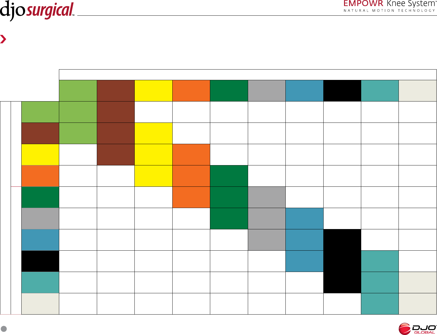
EMPOWR D KNEE SIZING CHART
TIBIAL SIZE
FEMORAL SIZE
2
MINUS 23
MINUS 34
MINUS 45
MINUS 56
MINUS 67
MINUS 78
MINUS 89
MINUS 910
MINUS 10 11
MINUS 11 11
PLUS
222 3
3 3 3 4
4 4 4 5
5 5 5 6
6 6 6 7
7 7 7 8
8 8 8 9
9 9 9 10
10 10 10 11
11 11 11 11
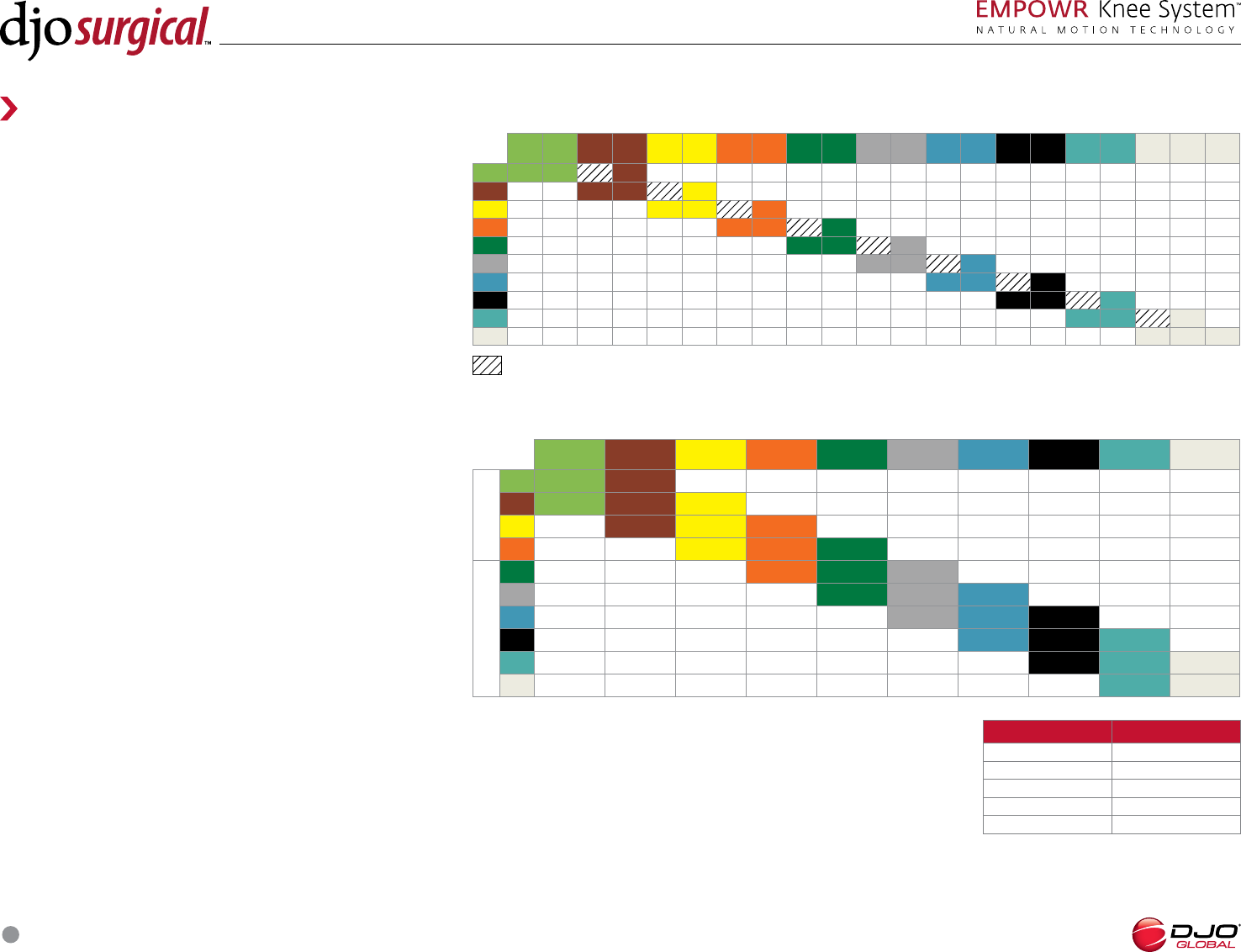
EMPOWR PS KNEE SIZING CHART
TIBIAL SIZE
234 5 6 7 8 910 11
FEMORAL SIZE
18.5MM Box
2 2 3
3234
434 5
5 4 5 6
BRIDGE DOWN
22.5MM Box
65
BRIDGE UP 6 7
7 6 7 8
8 7 8 9
98910
10 910 11
11 10 11
This box denotes a size combination that is available, but not recommended as minus size tibial bases have the A/P and M/L profile of one size smaller tibial base.
SAW BLADES
A .mm sagittal saw blade is recommended for use with this system.
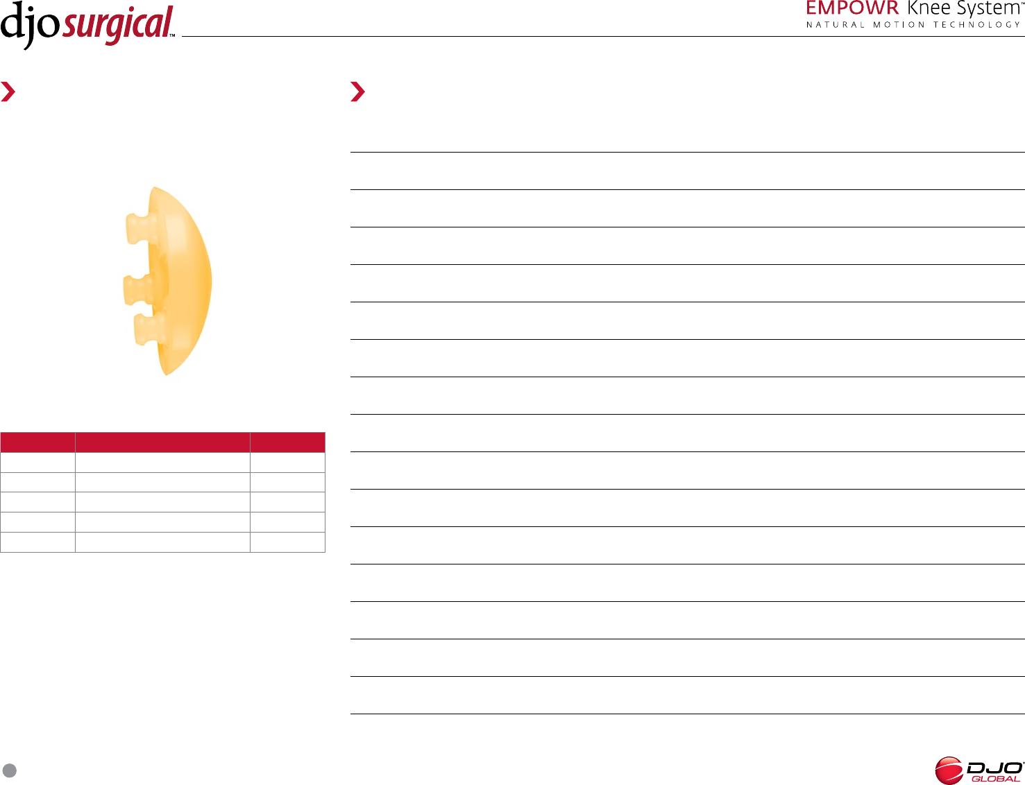
PATELLAR COMPONENT
A symmetrical, Domed Patella is used with the EMPOWR Knee
System and is available in the following sizes and thicknesses:
SIZE/DIAMETER THICKNESS
26 8MM
29 8MM
32 8MM
35 9MM
38 9MM
STERILE PINS
Sterile fluted .mm pins are available for order from DJO for use with
the EMPOWR Knee System.

SURGICAL TECHNIQUE
4
Indications and Contraindications
INDICATIONS
Joint replacement is indicated for patients suering from disability due to:
• degenerative, post-traumatic or rheumatoid arthritis;
• avascular necrosis of the femoral condyle;
• post-traumatic loss of joint configuration, particularly when there is patellofemoral erosion, dysfunction or prior patellectomy;
• moderate valgus, varus or flexion deformities;
• treatment of fractures that are unmanageable using other techniques.
This device may also be indicated in the salvage of previously failed surgical attempts. This system is to be used for cemented applications only.
CONTRAINDICATIONS
Joint replacement is contraindicated where there is:
• infection (or a history of infection), acute or chronic, local or systemic;
• insucient bone quality which may aect the stability of the implant;
• muscular, neurological or vascular deficiencies, which compromise the aected extremity;
• obesity;
• alcoholism or other addictions;
• materials sensitivity;
• loss of ligamentous structures;
• high levels of physical activity (e.g. competitive sports, heavy physical labor).
• The EMPOWR D Knee is also contraindicated for patients without sucient soft tissue integrity to provide adequate stability.
The indications and contraindications for TKA vary among patients and are always the decision of the surgeon performing the procedure.
SURGICAL TECHNIQUE
5
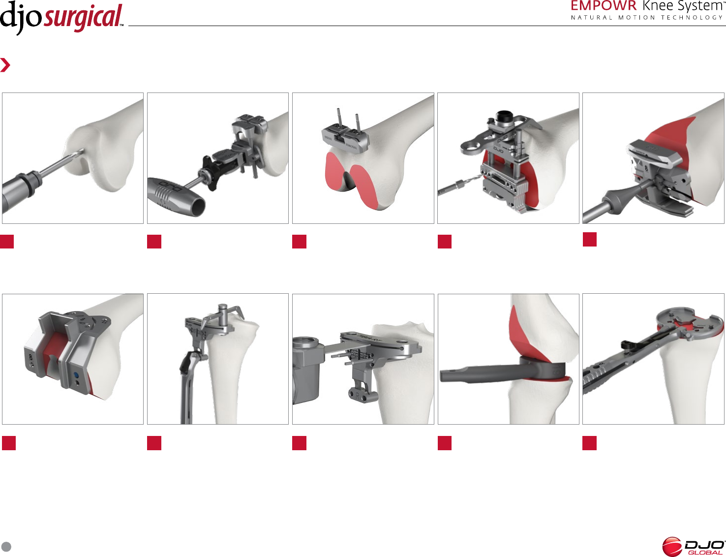
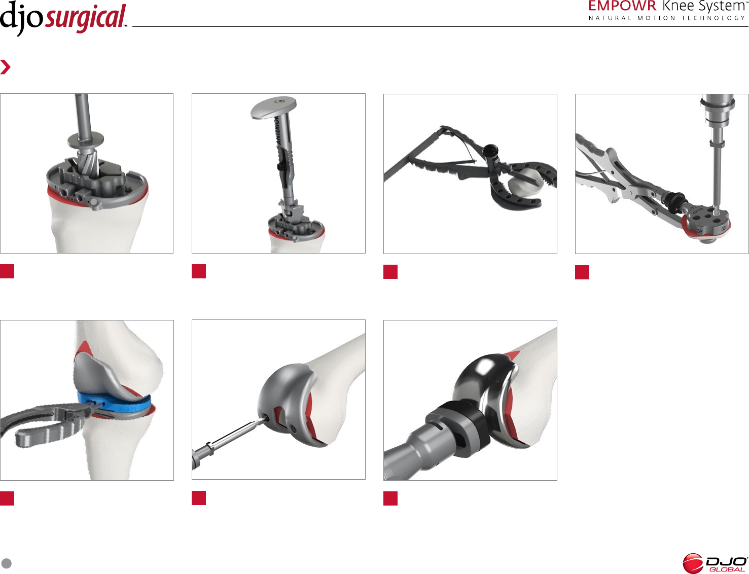
Surgical Snap Shot
Drill IM canal. Make -in- femoral cuts.
Establish femoral
alignment and determine
distal cut depth.
Make distal cut. Size femur and set
femoral rotation.
Establish tibial alignment
and determine
resection depth.
Make tibial resection. Assess resections and
balance knee.
Select tibial size.
Align PS Box Cut and make
PS box resections (PS only).
SURGICAL TECHNIQUE
6
Drill holes for the patella pegs.
Insert trials.
Broach the tibial canal until the
punch is fully seated.
Drill holes for femoral pegs
(D only).
Set the patella resection depth and
resect the patella.
Implant final components.
Surgical Snap Shot
Ream for the tibial
keel through the Tibial
Punch Bushing.
SURGICAL TECHNIQUE
7
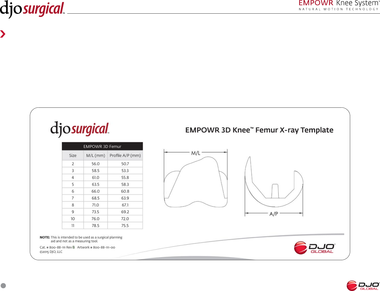
Preoperative Planning
Templates for the EMPOWR Knee System are available to aid in preoperative implant sizing.
With any bony deformity, use long standing radiographs to evaluate the angle between the mechanical axis of the leg and the anatomic axis of the femur. The
normal mechanical axis is formed by a straight line which begins at the center of the femoral head, passes through the center of the knee joint and ends at the
center of the ankle. The angle measured between the mechanical axis and the anatomic axis of the femur will determine which of the angle to set the Distal Femoral
Alignment Guide to that will obtain a distal femoral cut which will be perpendicular to the mechanical axis of the joint. The goal of this preoperative planning exercise
is to demonstrate the correct mechanical axis of the leg, promote minimal bone stock removal, and optimize collateral ligament balance in reconstruction.
SURGICAL TECHNIQUE
8
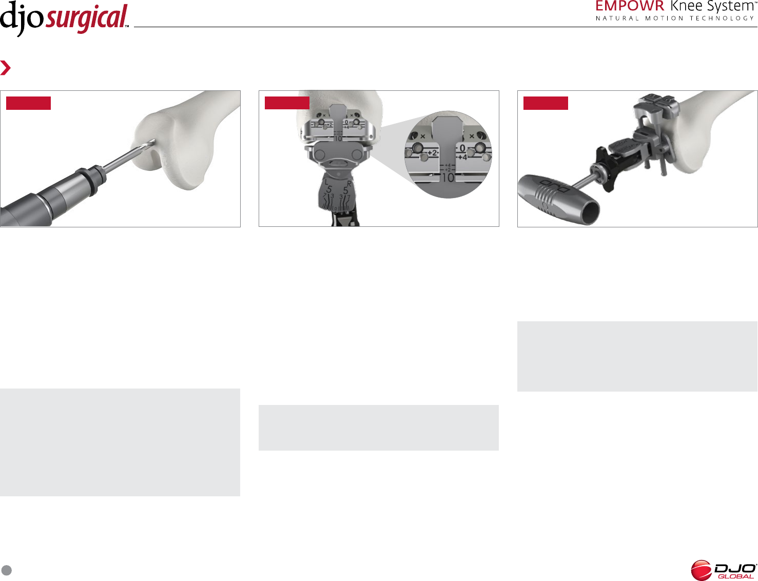
Femoral Preparation
FEMORAL ALIGNMENT
Set the valgus angle on the Distal Femoral Alignment
Guide by pulling back on the spring-loaded trigger and
adjust to the appropriate left or right valgus angle from
° to °. Typical valgus angles range from ° to °.
Attach the Distal Femoral Cut Block to the Distal
Femoral Alignment Guide and set the Distal Femoral
Cut Block at the 10mm resection line on the indicator
bar. The Distal Femoral Cut Block is set at 10mm when
the 10mm line can be read through the cut slot of the
Distal Femoral Cut Block. (FIGURE 2)
FIGURE
INTRAMEDULLARY EXPOSURE
Using the 8mm IM Drill, locate and drill a pilot hole into
the intramedullary femoral canal. The inferior edge of
this hole should be positioned approximately to mm
anterior to the intercondylar notch. Make the hole
larger by toggling the bit inside the canal. This reduces
the risk of fat emboli and allows the T-Handle IM Rod
to seek the proper position in the canal. Irrigate and
suction the canal to further decrease the risk of fat
embolism. (FIGURE 1)
NOTE: Placement of the hole too superior will
result in a femoral component position that is in
relative extension with respect to the long axis of the
femur. In contrast, placement of the hole too posterior
or close to the apex of the intercondylar notch will
result in a femoral component position which is in
relative flexion compared to the long axis of the femur.
NOTE: Additional distal resection may be
considered for knees with flexion contractures.
FIGURE
NOTE: The posterior condyles and epicondyles
may be used as reference landmarks for rotation and
to ensure a proper neutral placement of the Distal
Femoral Resection Guide.
FEMORAL ALIGNMENT
Insert the T-Handle IM Rod through the Distal Femoral
Alignment Guide then down the femoral IM canal
until the distal resection paddles rest against the most
prominent distal condyle. (FIGURE 3)
FIGURE
SURGICAL TECHNIQUE
9
NOTE: A general guideline for the distal femoral
resection is to remove an amount of bone that results
in the saw blade passing near or at the depth of the
intercondylar notch.
Femoral Preparation
DISTAL RESECTION
Fix the position of the Distal Femoral Cut Block to the
anterior cortex with two pins through the “” holes.
Additional mm adjustments may be made by using
the sets of holes marked + and +. These sets of holes
allow for re-adjustment of the Cut Block to remove
more bone, in millimeters, as determined necessary.
Remove the assembled Distal Femoral Resection
Guide and T-Handle IM Rod leaving only the Cut Block
attached to the femur. Once the Cut Block depth is
satisfactory, an additional fixation pin may be added
through the divergent hole for increased fixation.
Using a saw blade, resect the distal femur. (FIGURE 4)
Remove all pins and Cut Block.
FIGURE FIGURE
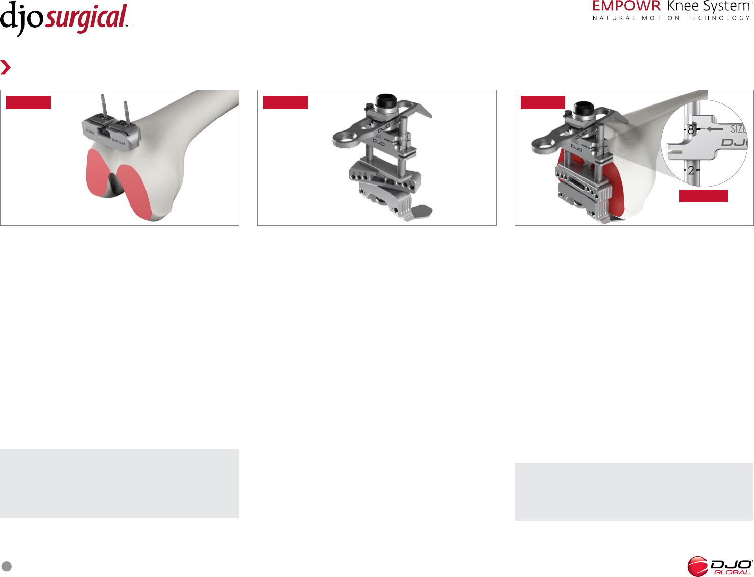
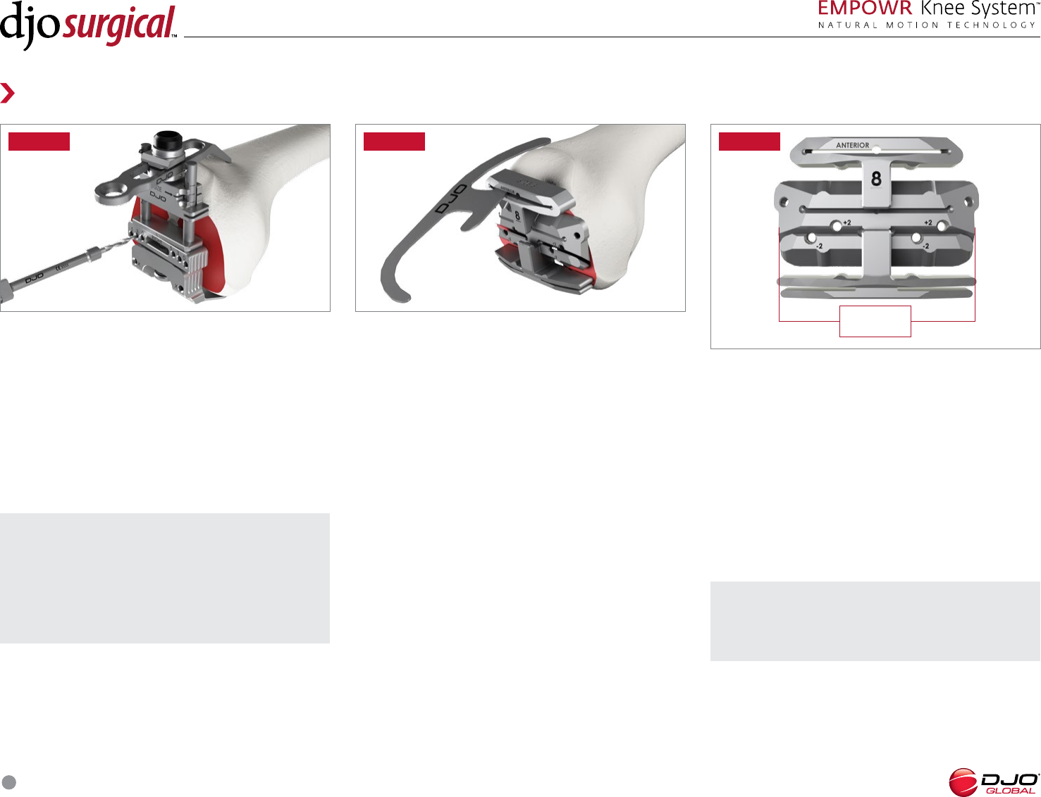
FEMORAL SIZING AND ROTATION
Mount the Femoral Sizer Stylus on the Femoral Sizer.
Rotate the external rotation bar indicator on the
Femoral Sizer so that the appropriate “Left” or “Right”
orientation markings are visible when the Femoral
Sizer is placed on the distal aspect of the bone.
(FIGURE 5)
FIGURE
NOTE: If the knee is in between sizes, choose
the larger size to avoid the potential for anterior
femoral notching.
FEMORAL SIZING
Seat the Femoral Sizer flush against the distal femur
using the Sizer feet to reference the posterior condyles.
Place the Femoral Sizer Stylus tip on the lateral aspect
of the anterior cortex. (FIGURE 6)
Femoral component size is read through the windows
on the anterior face of the Femoral Sizer. (FIGURE 6A)
Slide the Stylus anteriorly or posteriorly so the number
matches what was read on the anterior face of the
Femoral Sizer. This will determine the run out of the
saw blade. The femoral component size is chosen when
the size marked on the stylus and anterior face of the
Femoral Sizer match.
Alternativly, the Angel Wing may be used in the slots
of the Femoral Sizer to determine the exit point of the
saw blade.
FIGURE A
SURGICAL TECHNIQUE
10
Femoral Preparation
FIGURE FIGURE
NOTE: In the instance that a hypoplastic condyle
is present, place the middle of the zero degree holes
along the midline of the distal femur and align the
long axis of the holes to match the anatomy, such as
perpendicular to the AP axis (i.e. Whiteside’s line) or
parallel to the rotational axis of the knee.
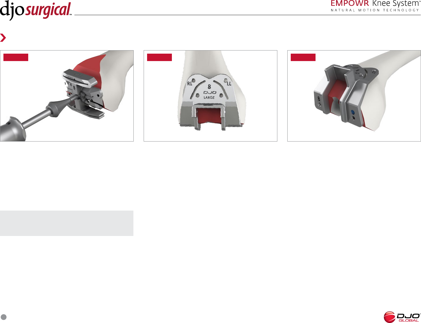
FEMORAL ROTATION
External rotation can be set at °, ° or ° from the
posterior condylar axis using the °, ° or ° holes in
the external rotation bar on the Femoral Sizer. Hold
the Femoral Sizer in place and drill through the holes
with the .mm Femoral Drill to set the rotation for the
-in-1 Cut Block. (FIGURE 7)
FEMORAL IN RESECTIONS
Insert the pegs of the appropriate size -in- Femoral
Cut Block into the pre-drilled holes on the distal femur.
Impact the face of the -in- Block using a mallet until
the -in- Block is flush with the femur. The Angel
Wing should be used to verify the anterior cut to avoid
notching of the anterior cortex. (FIGURE 8)
FIGURE
M/L width
of implant
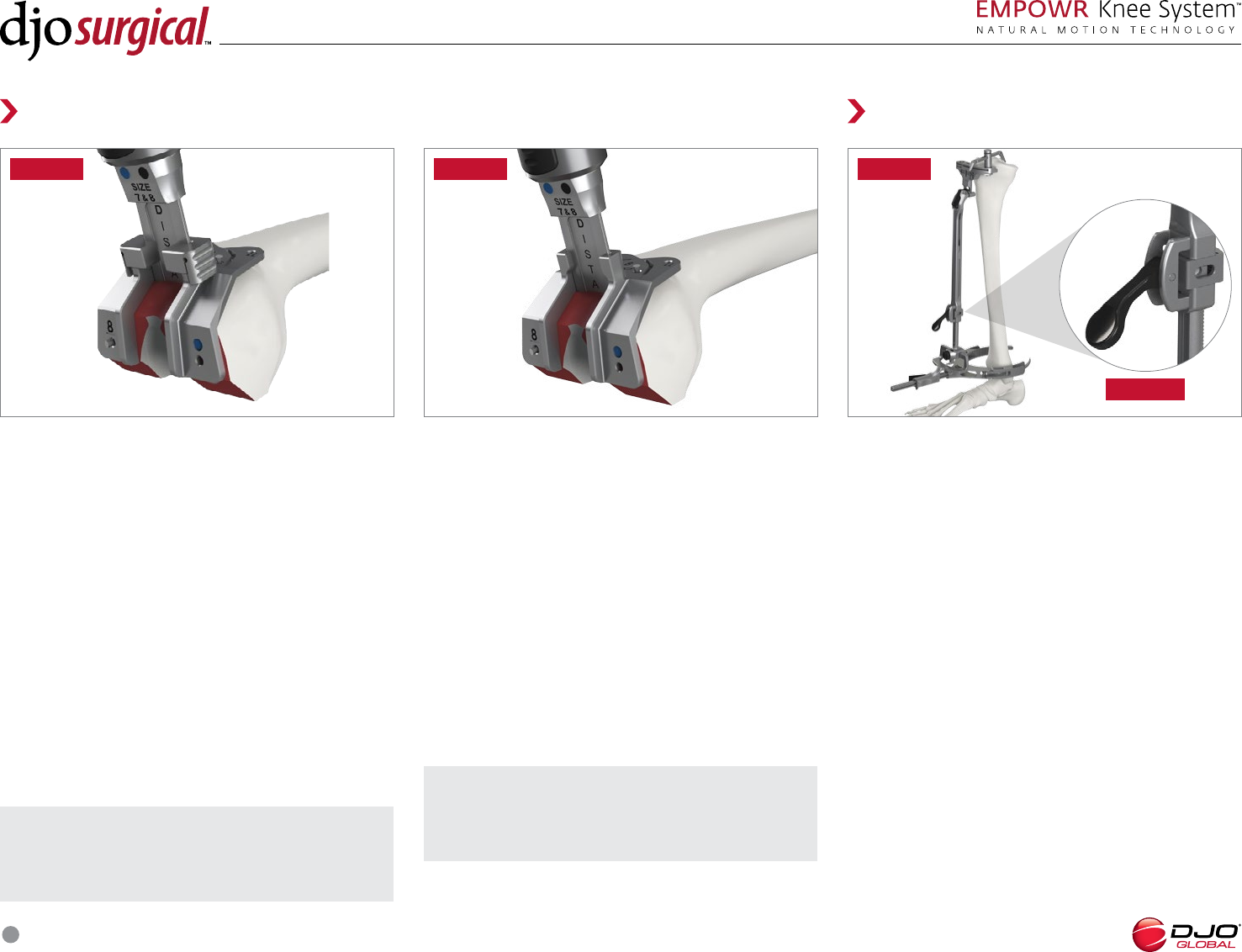
NOTE: When using the 4-in-1 Cut Block for a size 2
or 3, the Femoral Shift Block is used to make the plus
2 or minus 2mm adjustments.
IN CUT BLOCK
Additional 2mm adjustments may be made by using
the sets of holes marked + and . These sets of
holes allow for anterior or posterior re-adjustment
of the cutting block to remove more or less bone, in
millimeters, as necessary. To adjust the -in- Cut Block,
drill through the appropriate holes in the -in- Cut
Block, remove the -in- Cut Block from the femur,
and re-insert the pegs of the -in- Cut Block in the
new holes. (FIGURE 9)
SURGICAL TECHNIQUE
11
Femoral Preparation
FIGURE FIGURE
NOTE: Posterior osteophytes should be removed to
ensure full postoperative extension.
FEMORAL IN RESECTIONS
After final placement of the -in- Cut Block, pin the
-in- Cut Block in place using ” Headed Bone Pins.
Make the anterior and posterior resections followed by
the anterior and posterior chamfer resections using a
saw blade.
After resections have been made, remove the pins
and the -in- Cut Block with the Slap Hammer.
(FIGURE 10)
POSTERIOR STABILIZED BOX CUT
PS Box Cut Guides are used to prepare for a PS femoral
component. Box Cut Guides are designed to replicate
the anterior profile of the femoral component and are
labeled “RL” for the Right Lateral flange and “LL” for the
Left Lateral flange. (FIGURE 11)
Two types of PS Box Cut Guides are available: Standard
and Captured. The selection of the guide will depend
on surgeon preference. Dierent types of box guides
accomplish the same goal.
STANDARD PS BOX CUT SAW
Select the Standard PS Box Cut Guide that
corresponds to the selected size femoral component.
Place the Box Cut Guide in the desired ML position,
resting against the anterior and distal surfaces of
the bone.
Pin the selected PS Box Cut Guide in place with Tibial
Bone Pins. (FIGURE 12) Using a reciprocating saw
with a saber blade, resect the sides and back of the
box.
FIGURE
SURGICAL TECHNIQUE
12
FIGURE
FIGURE A
EXTRAMEDULLARY ALIGNMENT
Assemble the EM Ankle Clamp, EM Proximal Body, EM
Distal Body, and selected Tibial Cut Block (left or right
in neutral or °).
Position the Ankle Clamp around the patient’s ankle.
Adjust the overall length of the EM Tibial Resection
Guide to the appropriate tibial length using the lever
on the EM Proximal Body. (FIGURE 15)
Place the Tibial Stylus into the medial hole of the
resection guide. Generally the Stylus is set to resect
mm from the less aected compartment, or mm
from the most aected compartment. The Angel Wing
should be used to check the amount of bone to be
resected and visualize planned tibial slope.
Adjust the resection by adjusting the height of the
Proximal Body until the desired resection depth is
found. The height of the Proximal Body is locked when
the lever is in the middle position. (FIGURE 15A)
CAPTURED PS BOX CUT
SAW AND CHISEL
Select the Captured PS Box Cut Guide that corresponds
to the selected size femoral component. Place the Box
Cut Guide in the desired ML position, resting against
the anterior and distal surfaces of the bone.
Pin the selected PS Box Cut Guide in place with the
Tibial Bone Pins. Insert the corresponding size Chisel
into the Captured PS Box Cut Guide and resect the
back of the PS box half way, leaving the Chisel as a
back stop for the oscillating saw. (FIGURE 14) Use the
oscillating saw to cut the sides of the PS box.
Ensure the cuts for the sides are completed by aligning
the saw blade perpendicular to the chisel. Slowly
impact the Chisel until it is fully seated. The Chisel will
stop at the appropriate depth for the indicated size.
Femoral Preparation
FIGURE
Tibial Preparation
FIGURE
STANDARD PS BOX CUT
SAW AND CHISEL
The Modular Capture may be used in conjunction with
the Standard PS Box Cut Guides and is intended to allow
the user to prepare the back of the box with a Chisel.
To use, place the Modular Capture over the anterior
portion of the Standard PS Box Cut Guide and seat it
until fully engaged. Pin the selected PS Box Cut Guide in
place with Tibial Bone Pins.
Insert the corresponding size Chisel in the Modular
Capture and resect the back of the PS box half way,
leaving the Chisel as a back stop for the oscillating saw.
(FIGURE 13) Use the oscillating saw to cut the sides of
the PS box.
Ensure the cuts for the sides are completed by aligning
the saw blade perpendicular to the chisel. Slowly impact
the Chisel until it is fully seated. The Chisel will stop at
the appropriate depth for the indicated size. NOTE: Failure to complete the entire side wall cuts
of the PS box prior to final Chisel impaction may
increase the risk of condylar fracture.
NOTE: Failure to complete the entire side wall cuts
of the PS box prior to final Chisel impaction may
increase the risk of condylar fracture.
SURGICAL TECHNIQUE
13
FIGURE
NOTE: For an anatomically sloped resection, place
the Angel Wing in the cutting slot of the Tibial Cut
Block and adjust the long axis of the EM Ankle Clamp
by engaging the lever and pulling away from the ankle.
EXTRAMEDULLARY ALIGNMENT
Position the center of the Tibial Cut Block just medial to
the tibial tubercle. With the foot in the neutral position,
align the Proximal Body with the second metatarsal.
This is accomplished by the M/L EM Ankle Adjustment
Body at the ankle. Additionally, the Tibial Cut Block may
be pinned through the center slot to provide stability
while the M/L position and slope of the EM Ankle
Adjustment Body is adjusted.
When the proper resection depth is achieved, secure
the Tibial Cut Block onto the tibia using self-drilling
smooth pins through the holes marked “”. These are
highlighted with a laser mark. (FIGURE 17)
Remove the remainder of the Tibial EM Assembly by
depressing the black button to disengage the Proximal
Rod Body and Ankle Clamp from the Cut Block.
EXTRADMEDULLARY ALIGNMENT
If a shorter extramedullary guide is needed, the
Transition Module may be used in conjunction with
the Extramedullary Guide. Clip the Transition Module
around the EM Proximal Body and attach the selected
Tibial Cut Block to the Transitional Module. (FIGURE
16) Lock the Tibial Cut Block to the EM Proximal Body
by turning the knob on the Transition Module until it
is tight.
INTRAMEDULLARY ALIGNMENT
Using the 8mm IM Drill, locate and drill a pilot hole
into the intramedullary tibial canal. The posterior
edge of this hole should be positioned to mm
anterior to the pinnacle of the proximal tibial spine
and in line with the tibial tubercle. Insert the T-Handle
IM Rod into the pilot hole created by the IM drill and
introduce the IM Rod beyond the depth of the pilot
hole to open the intramedullary canal. Remove the
T-Handle IM Rod. Slide the IM Guide Base over the
T-Handle IM Rod and insert the T-Handle IM Rod into
the intramedullary canal. (FIGURE 18)
FIGURE FIGURE
Tibial Preparation
SURGICAL TECHNIQUE
14
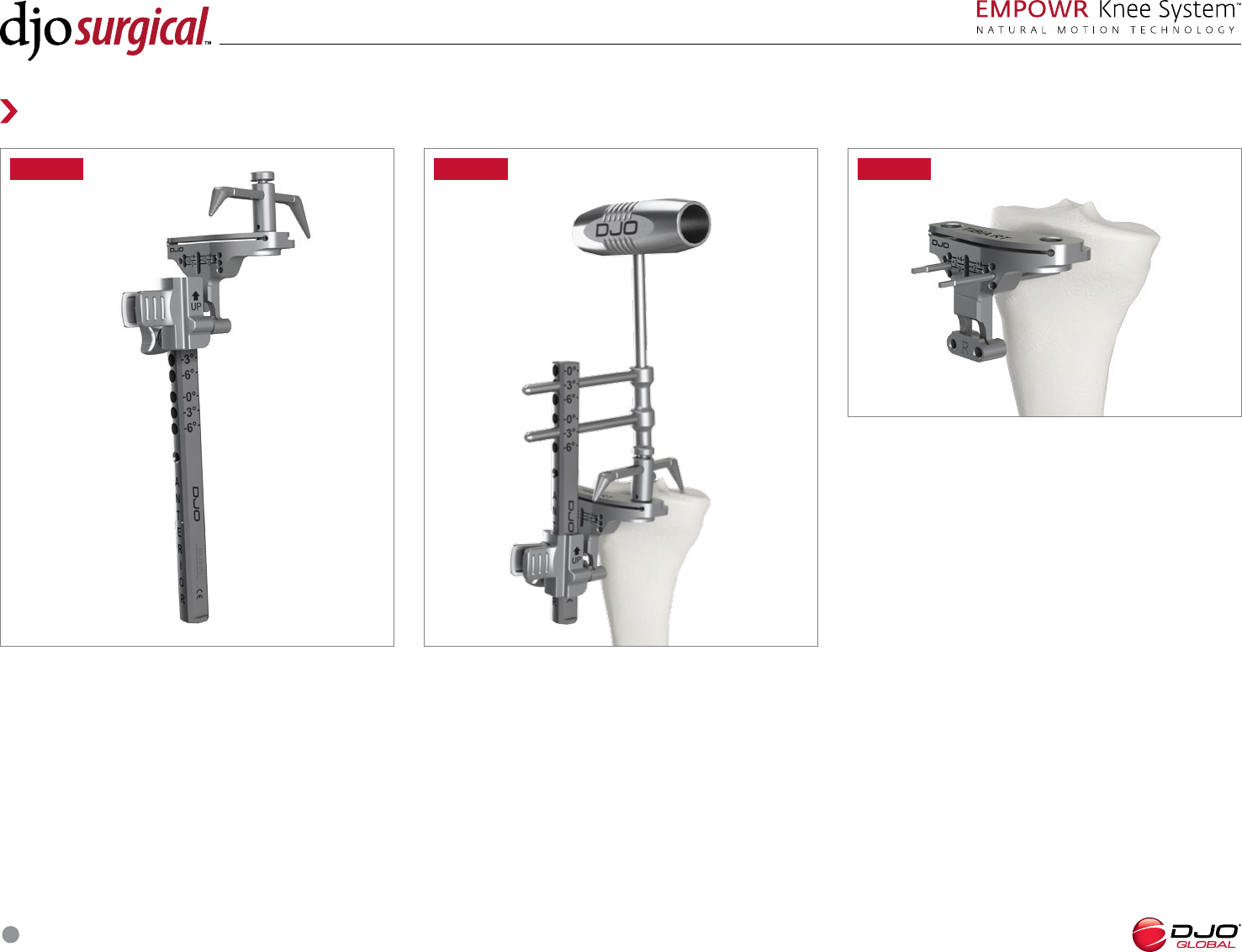
INTRAMEDULLARY ALIGNMENT
Select the desired amount of tibial slope (°,°, or °)
and slide the °/°/° IM Guide over the corresponding
prongs of the IM Guide Base.
Position the center of the Tibial Cut Block just medial
to the tibial tubercle. When the desired resection is
found, lock the Tibial Cut Block in place by turning
the knob on the Transition Module until it is tight.
(FIGURE 20)
INTRAMEDULLARY ALIGNMENT
Assemble the Transition Module and Tibial Stylus to
the selected ° Tibial Cut Block. Insert the °/°/°
IM Guide through the Transition Module from the
bottom. (FIGURE 19)
FIGURE FIGURE
Tibial Preparation
FIGURE
INTRAMEDULLARY ALIGNMENT
Pin the Tibial Cut Block onto the tibia using self-drilling
smooth pins through the holes marked “” which are
highlighted with a laser mark.
Unlock the Transition Module and disengage it from
the Tibial Cut Block by squeezing the levers on the
anterior side and pulling it straight towards the user.
Remove the Stylus, °/°/° IM Guide, IM Guide Base
and T-Handle IM Rod. (FIGURE 21)
SURGICAL TECHNIQUE
15
Tibial Preparation
FIGURE
TIBIAL ALIGNMENT
To assess proper alignment of the Tibial Cut Block,
insert the Alignment Rod Guide in the resection slot
of the Tibial Cut Block and insert the Alignment Rod
through the Alignment Rod Guide.
If the Alignment Rod is too long to accurately assess
alignment, slide the Modular Stop on the Alignment
Rod before inserting it into the Alignment Rod Guide.
(FIGURE 22) After pinning, the Tibial Cut Block may be
adjusted distally using the holes marked + and + to
add an additional mm or mm to the resection depth.
The cross pin hole may be used for additional fixation.
FIGURE
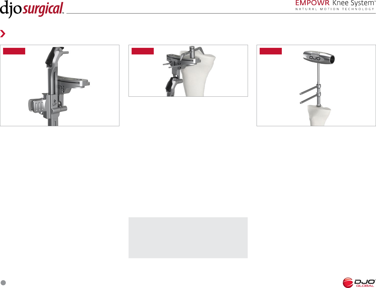
TIBIAL RESECTION
Resect the proximal tibia using a saw blade.
(FIGURE 23)
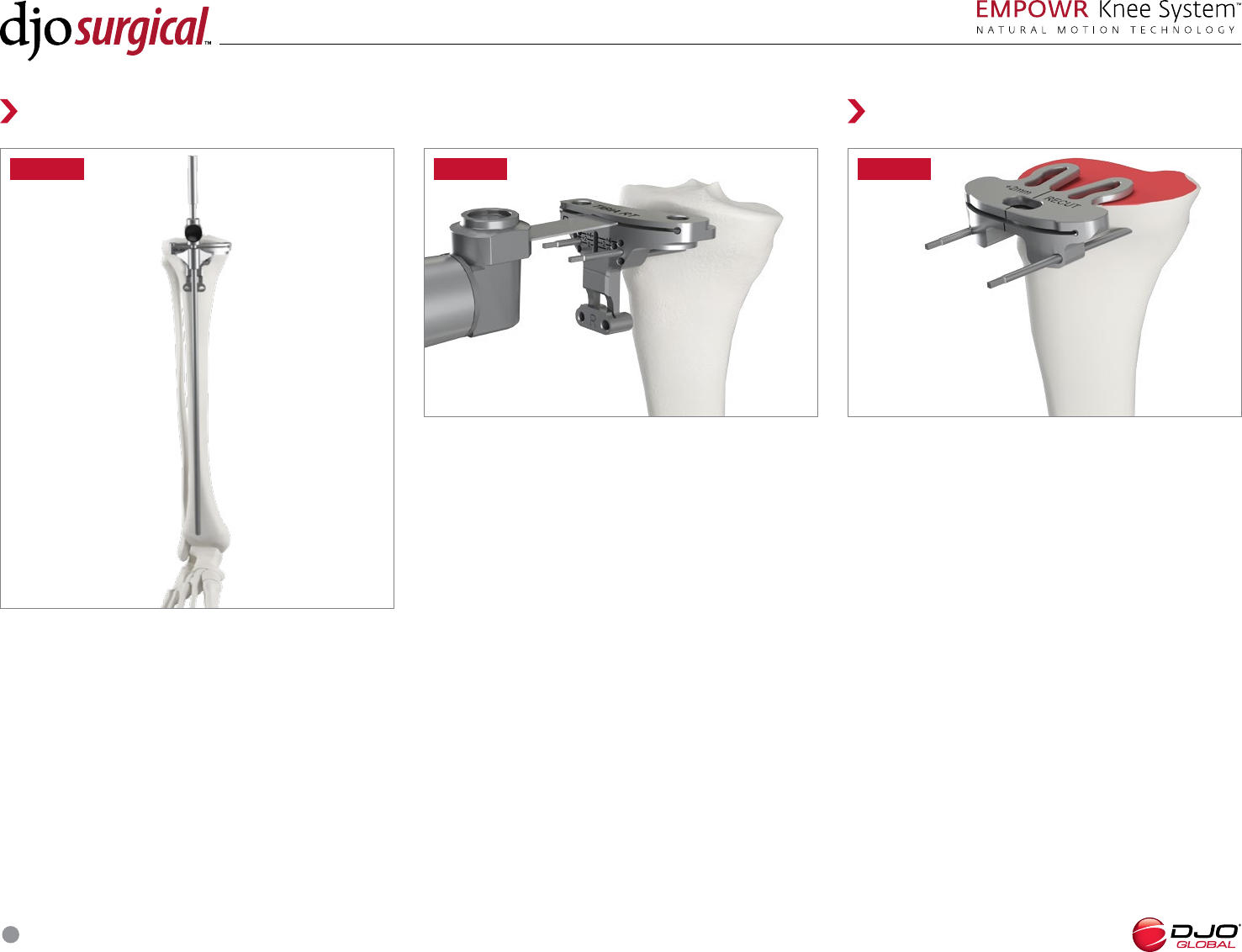
Recut Guides
+mm, ° RECUT GUIDES
Recut guides are available in three configurations
and may be used after the proximal tibial resection.
The holes on the guides are convergent and do not
correlate to the holes on the Tibial Cut Block.
The mm Recut Guide and ° Slope Recut Guide are
used by placing the feet on the proximal tibial resection
and pinning the guide to the tibia. (FIGURE 24)
FIGURE
SURGICAL TECHNIQUE
16
Recut Guides
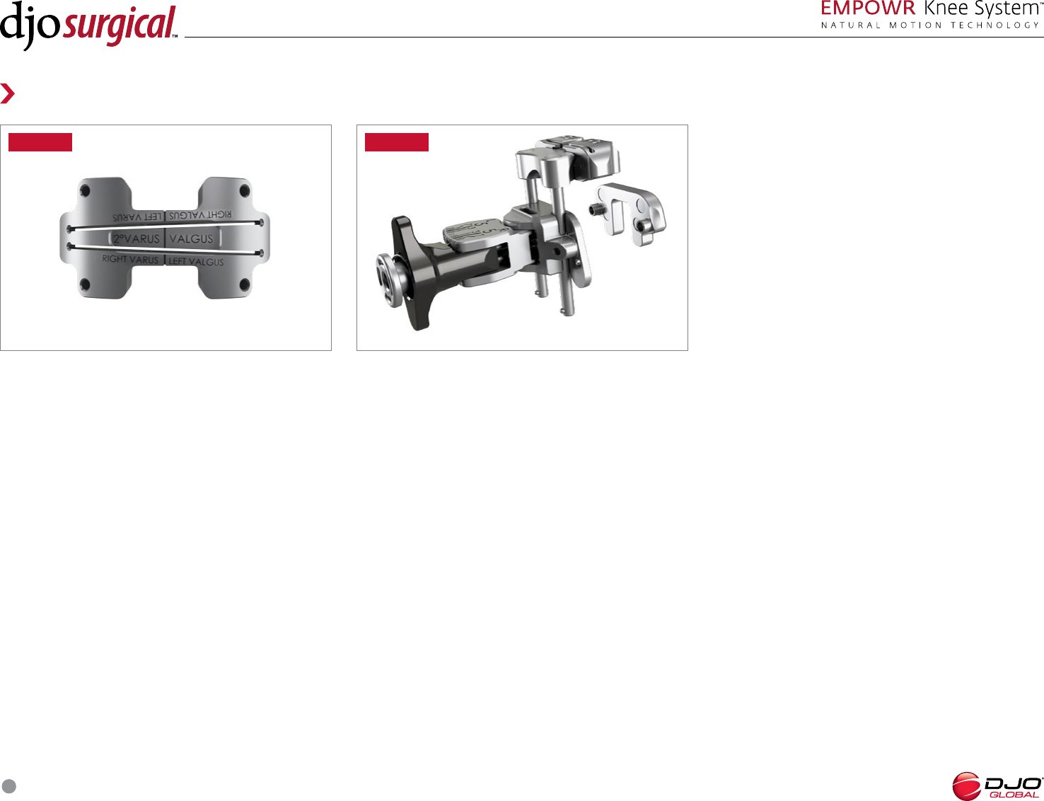
VARUS/ VALGUS RECUT GUIDE
The ° Varus/ Valgus Recut Guide will change the
varus/ valgus orientation of the proximal tibial resection
depending on which way the guide is oriented.
(FIGURE 25)
DISTAL FEMORAL RECUT GUIDE
If a distal femoral recut is deemed necessary after the
-in- resections have been made, the mm Distal
Recut Spacer may be used. The mm Distal Recut
Spacer is attached to the internal face of the Distal
Femoral Alignment Guide and allows the user to make
a mm distal femoral resection. (FIGURE 26)
Attach the mm Distal Recut Spacer and the Distal
Femoral Cut Block to the Distal Femoral Alignment
Guide. Insert the T-Handle IM Rod through the Distal
Femoral Alignment Guide then down the femoral IM
canal until the distal resection paddles rest against
the most prominent distal condyle. Pin the Distal
Femoral Cut Block and recut the distal femur. Chamfer
resections will need to be recut in order to achieve
proper femoral component fit.
FIGURE FIGURE
SURGICAL TECHNIQUE
17
FIGURE
Tibial Preparation
NOTE: Care should be taken to avoid excessive
amounts of tibial external rotation. Floating the
Baseplate Trial and Insert Trial may help facilitate
proper tibial rotation.
EXTENSION
TIGHT BALANCED LOOSE
FLEXION
TIGHT
downsize insert thickness,
cut more proximal tibia
select smaller size -in-
guide (to downsize femoral
component) and shift anteriorly
to cut more posterior condyle
select smaller size -in- guide (to
downsize femoral component)
and shift anteriorly to cut more
posterior condyle and use a
thicker insert as necessary
BALANCED
recut distal femur no adjustment necessary cut more posterior slope
and use thicker insert
LOOSE
recut distal femur and use
thicker insert if necessary
change may not be necessary.
If desired, recut distal femur
and use thicker poly
use thicker insert
TIBAL BASEPLATE PREPARATION
Select the appropriate size Tibial Baseplate Trial.
Minus size tibial bases have the A/P and M/L profile
of one size smaller tibial base and are only used in
conjunction with the D femoral component. Connect
the Baseplate Trial that most accurately matches the
periphery of the tibial plateau to the Baseplate Trial
Handle. The Alignment Rod may be inserted through
the Baseplate Trial Handle to assess Baseplate Trial
alignment. Once appropriately aligned, secure the trial
in place with two short Tibial Bone Pins. Using the
Multi-Pin Tool, grasp the Tibial Bone Pins and insert
them into the most posterior holes in the Baseplate
Trial. (FIGURE 28)
WARNING: Only the short Fixation Pin may be used in
the anterior hole of the Baseplate Trial.
NOTE: If gaps are not adequate, soft tissue releases
or bone cuts can balance the gaps. Refer to the chart
below.
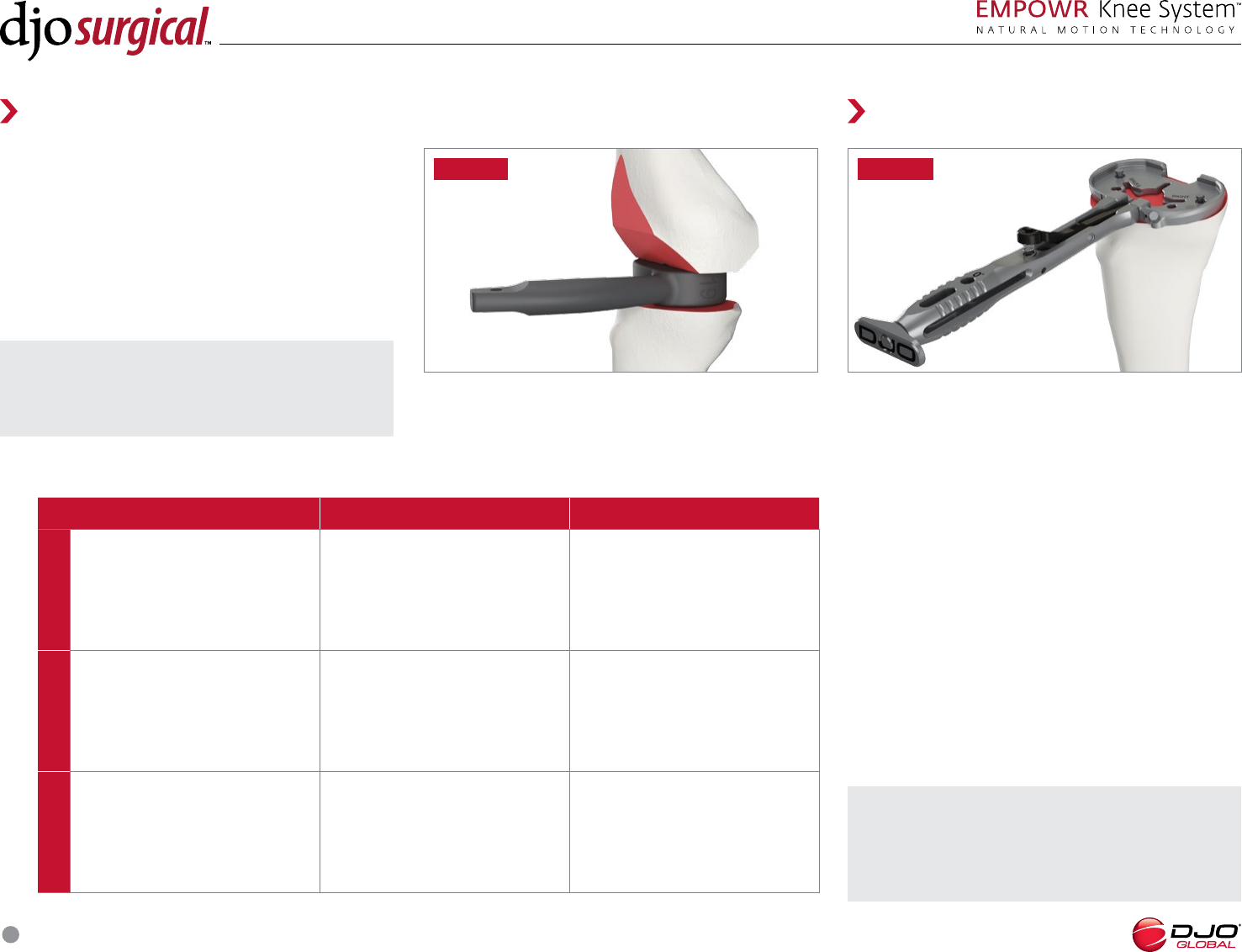
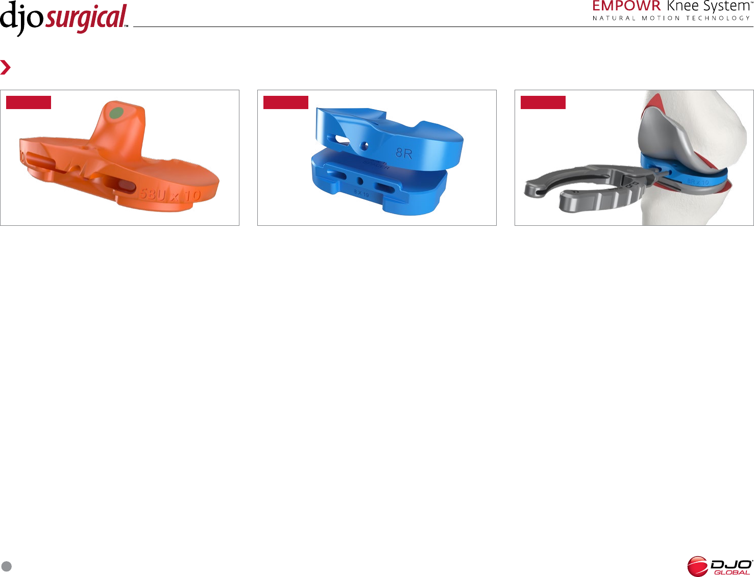
Spacer Blocks are available to evaluate proper bone
removal and balancing of the joint space. Spacer Blocks
are used with no trials in place, with the Spacer Block
representing the total combined thickness of the
baseplate, insert, and femoral component. For example,
using the “mm” Block will represent the overall
implant thickness when using a mm insert in both
extension and flexion. (FIGURE 27)
FIGURE
Gap Assessment
SURGICAL TECHNIQUE
18
FIGURE
FIGURE
Tibial Preparation Patella Preparation
FIGURE FIGURE
FIGURE A FIGURE A
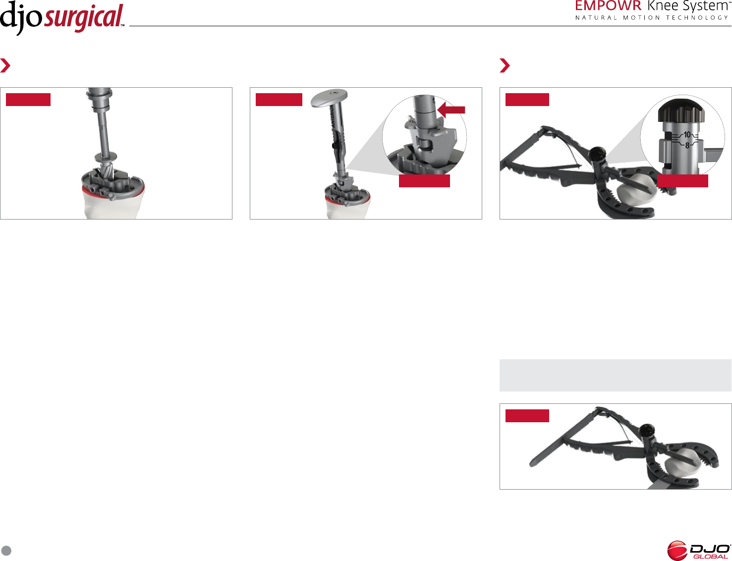
TIBAL BASEPLATE PREPARATION
Place the Tibial Punch Bushing in the center recess of
the Baseplate Trial and use the Tibial Reamer to ream
the area for the tibial keel. (FIGURE 29)
PATELLA RESECTION
Using a saw blade, resect the patella (FIGURE 32).
PATELLA RESECTION DEPTH
Measure the overall patellar thickness using the Caliper.
Select the Patella Osteotomy Guide and set the stylus
to indicate an amount of bone equal to the thickness of
the patellar component to be used. (FIGURE 31) To set
the stylus depth, turn the dial clockwise to increase the
depth of the resection. Each half turn represents 1mm
thickness. The resection depth can be read o the top
of the stylus. (FIGURE 31A)
TIBIAL KEEL PREPARATION
Select the appropriate size Tibial Punch: Small (),
Medium () or Large () and connect it to Tibial
Punch Handle. For minus bases, use the same size Tibial
Punch as non-minus bases. For example, use a size
Punch for a size minus base. Center the appropriate
size Tibial Punch in the Tibial Punch Bushing and broach
the tibial canal until the punch is fully seated. (FIGURE
30) The punch is fully seated when the engraved line
on the Tibial Punch Handle is flush with the top of the
Tibial Punch Bushing. (FIGURE 30A) If desired, the
Tibial Punch may be disengaged from the Tibial Punch
Handle and left in place during trialing. To remove the
Tibial Punch, pull back on the handle and insert the
Tibial Punch Handle into the Modular Punch.
NOTE: Use care not to overresect the patella.
SURGICAL TECHNIQUE
19
FIGURE
Patella Preparation Trial Reduction
FIGURE FIGURE
FIGURE A
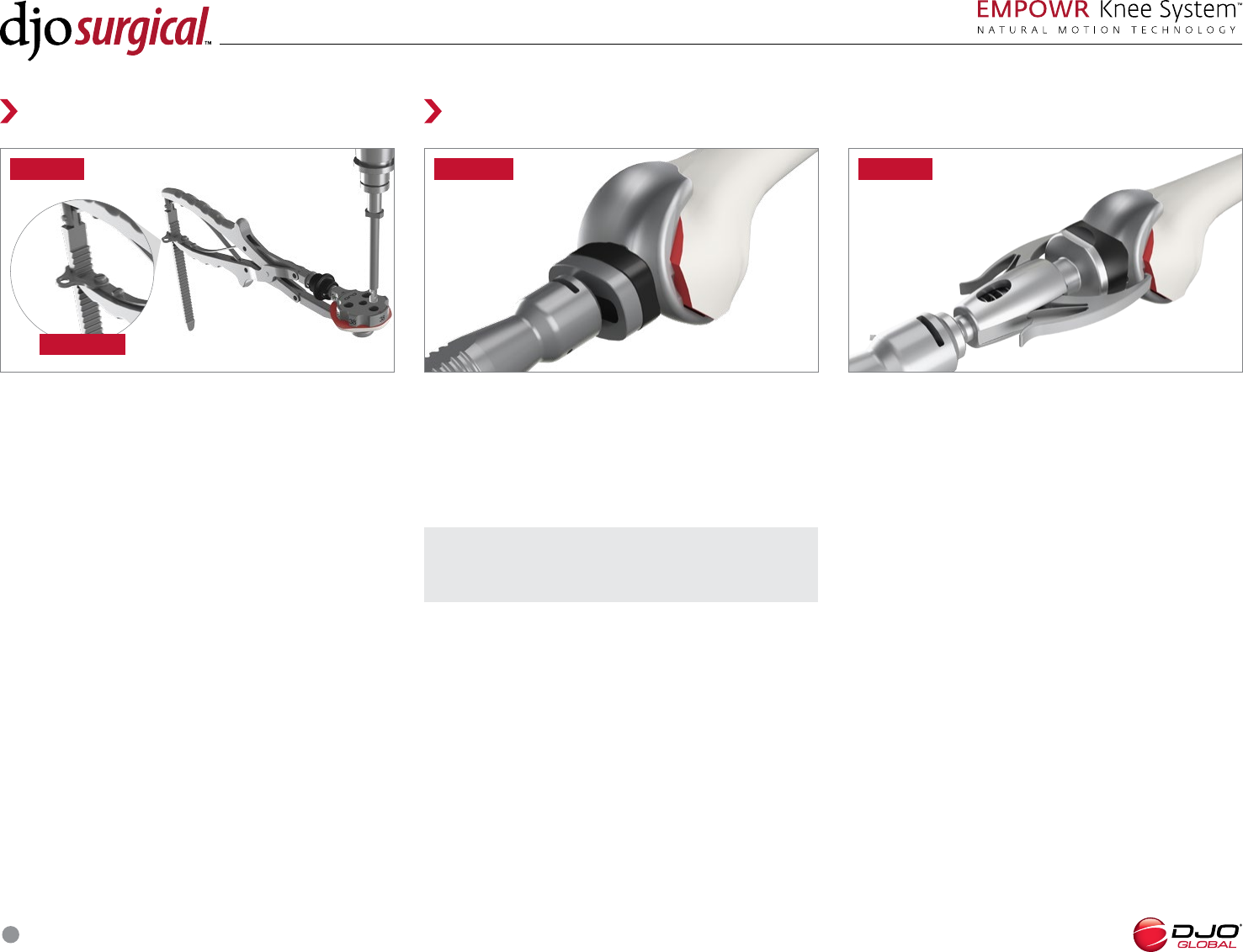
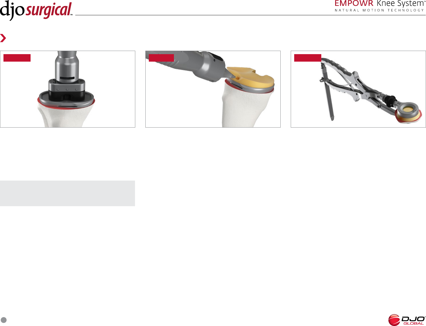
FEMORAL TRIAL IMPACTION
Alternatively, the Locking Femoral Impactor may be
used to position and impact the Femoral Trial. Connect
the Locking Femoral Impactor to the Impactor Handle.
Depress the finger holds and clip the Locking Femoral
Impactor to the Femoral Trial. Turn the Impactor
Handle clockwise to secure the Femoral Trial to the
Locking Femoral Impactor. (FIGURE 35) Impact the
Femoral Trial onto the prepared bone.
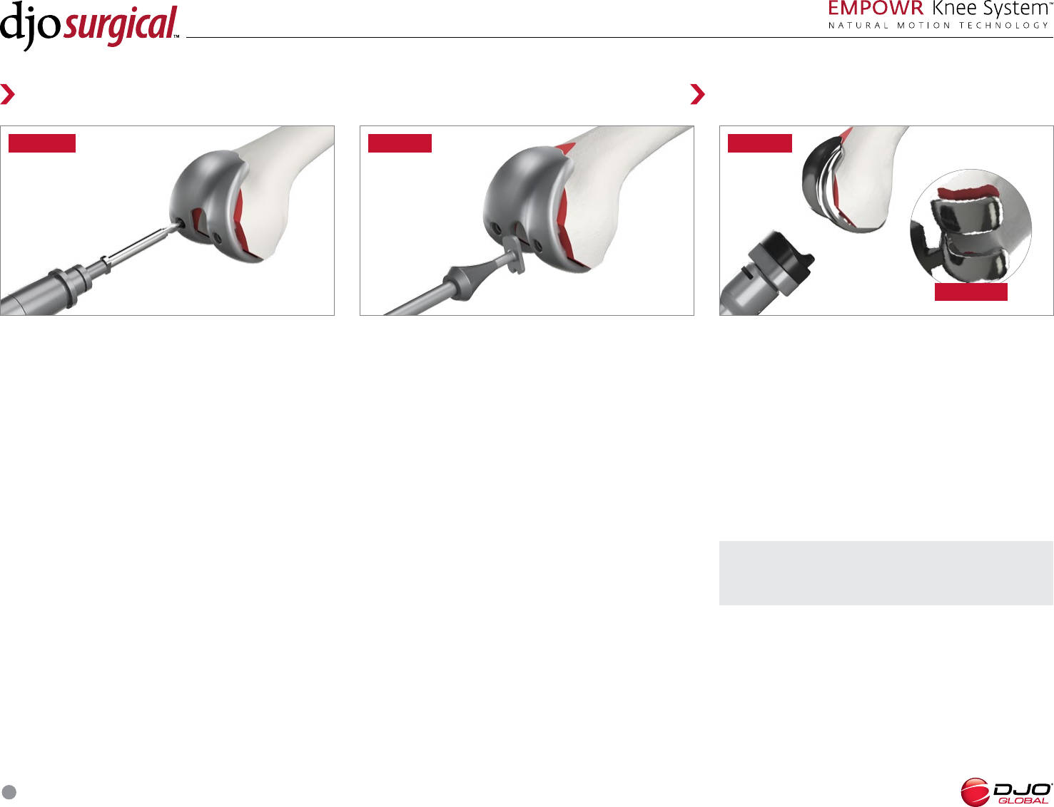
PATELLA PEG PREPARATION
Use the Patella Drill Guides to size the resected
patella. Five diameter sizes of patellas are available:
, , , and mm. Insert the selected Patella
Drill Guide into the Patella Clamp. Clamp the spikes
on the Patella Drill Guide to the resected patella and
secure the Patella Clamp using the locking hook.
(FIGURE 33A) Drill for the patella pegs using the
Patella Drill. (FIGURE 33) Do not drill through the
center hole in the Patella Drill Guide. Remove the
Patella Clamp and insert the selected Patella Trial.
FEMORAL TRIAL IMPACTION
Leave the Baseplate Trial pinned in place. Connect the
Femoral Impactor Head to the Impactor Handle and
impact the Femoral Trial onto the prepared femur.
(FIGURE 34 )
NOTE: The protrusion of the femoral impactor can
be used to adjust flexion of the femoral implant.
SURGICAL TECHNIQUE
20
ARTICULATING SPACER TRIALS
For Insert Trials with thicknesses of 16 or 19mm, use the
appropriate size Articulating Spacer Trial in conjunction
with the proper thickness Insert Spacer Trial.
(FIGURE 37) The Insert Trial Handle is used to hold
the Articulating Spacer Trial and the Insert Spacer Trial
together.
Trial Reduction
FIGURE FIGURE FIGURE
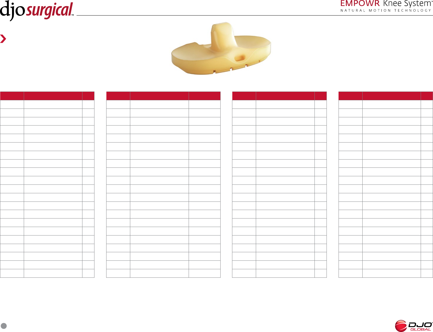
TRIAL INSERTION
Using the Insert Trial Handle, grasp the preferred
thickness Trial Insert and insert it into the Baseplate
Trial. (FIGURE 38)
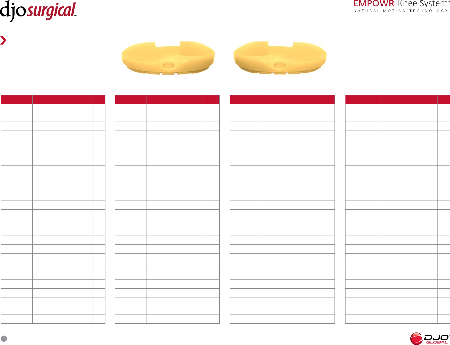
INSERT TRIAL SELECTION
In all configurations, the insert size will always match
the tibial baseplate size.
D inserts are side specific and come in left and
right configurations. D inserts are available in five
thicknesses: , , , , and mm.
PS inserts are symmetric and available in seven
thicknesses: , , , , , , and mm. The EMPOWR
PS has two additional insert configurations: Bridge
Up and 6 Bridge Down. These inserts are used to bridge
the gap between the large and small PS Box width. The
Bridge Up is used to bridge a size tibial baseplate
up to a size PS femur. The Bridge Down is used
to bridge a size 6 tibial baseplate down to a size PS
femur. These inserts are designated with a color dot on
the post of the insert that corresponds to the dot on
the appropriately sized femoral trial. (FIGURE 36)
SURGICAL TECHNIQUE
21
Component Implantation
FIGURE A
FIGURE
NOTE: The protrusion of the femoral impactor can
be used to adjust flexion of the femoral implant.
FEMORAL COMPONENT
IMPLANTATION
The order for implantation is left up to the discretion of
the surgeon.
Select the appropriate femoral component. Place
cement on the underside of the femoral component
and impact the femoral component on the bone
using the Femoral Impactor Head or Locking Femoral
Impactor and Impactor Handle. Remove excess cement.
(FIGURE 41 and 41A)
TRIAL IMPLANT REMOVAL
After the trial reduction is complete, remove the
Femoral Trial. The 3D Femoral Trial is removed by
inserting the Slap Hammer into the intercondylar
notch vertically, then turning it horizontally to engage
the 3D Femoral Trial. The PS Femoral Trial is removed
by inserting the Slap Hammer vertically in the
intercondylar notch. During removal, keep one hand on
the Femoral Trial to control its extraction. (FIGURE 40)
Remove the Trial Insert using the Insert Trial Handle.
Remove the Tibial Bone Pins with the Multi Pin Tool.
Remove the Baseplate Trial and Tibial Punch if it was
left in during trialing.
FIGURE
Trial Reduction
FEMORAL PEG PREPARATION
If the D femur will be implanted, the Femoral Peg
Drill is used to prepare for the pegs on the back of the
femoral implant. (FIGURE 39)
FIGURE
SURGICAL TECHNIQUE
22
PATELLA IMPLANTATION
Select the appropriate patella component. Place
cement on the underside of the patella component.
Insert the patella component and use the Patella
Clamp with attached Patella Seater to seat the patella.
Secure the Patella Clamp using the locking hook.
Remove excess cement. The Patella Clamp and Patella
Seater may be left in place while the cement cures.
(FIGURE 44)
FIGURE
Component Implantation
FIGURE
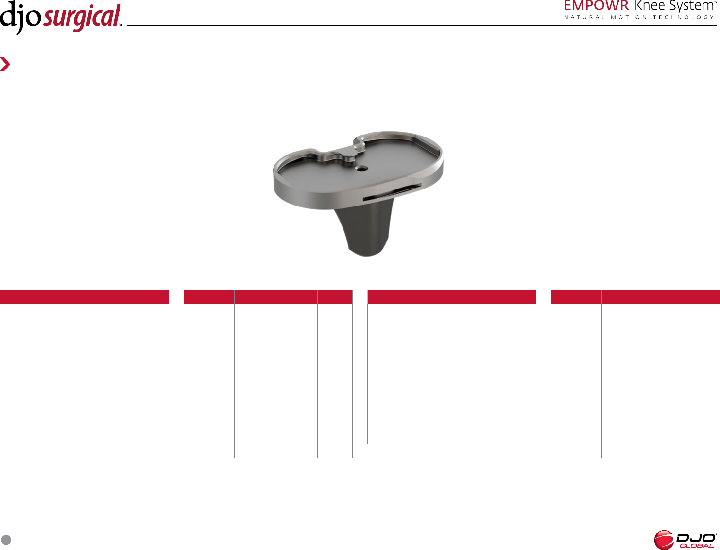
INSERT IMPACTION
After ensuring that the tray is completely free of debris,
place the appropriate insert into the baseplate. Engage
the insert into the posterior captures of the baseplate
and impact it with the Insert Impactor Head and
Impactor Handle. When correctly impacted the anterior
insert tabs will engage behind the anterior lip of the
baseplate. (FIGURE 43)
FIGURE
NOTE: Keeping the knee in full extension may
facilitate cementing.
BASEPLATE IMPLANTATION
Select the appropriately sized tibial baseplate. Place
cement on the underside of the baseplate and impact
it into place using the Baseplate Impactor Head and
Impactor Handle. Remove excess cement. (FIGURE 42)
SURGICAL TECHNIQUE
23
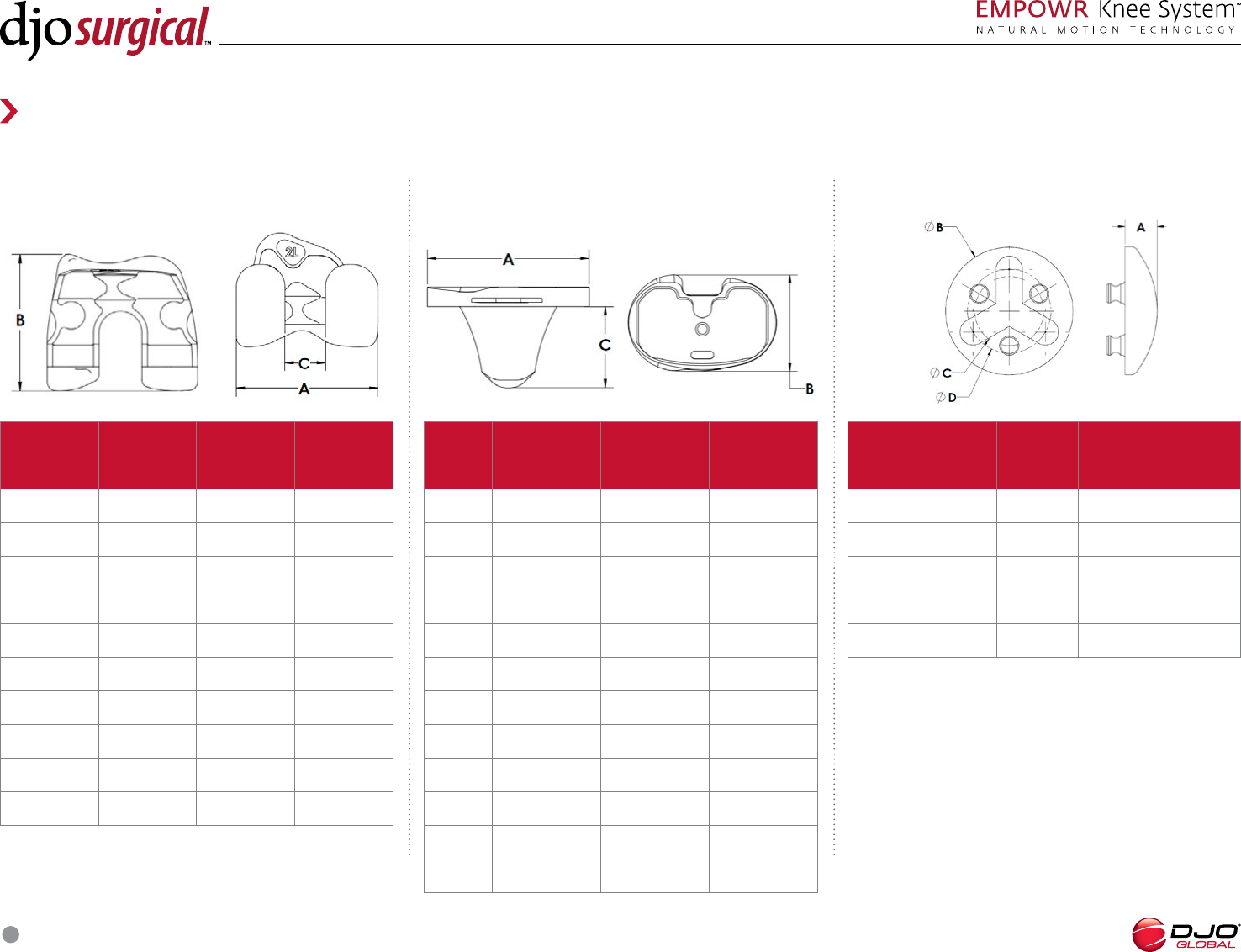
Size M/L(mm)
Dim ‘A’
A/P(mm)
Dim ‘B’ Dim ‘C’ (mm)
. . .
. . .
. . .
. . .
. . .
. . .
. . .
. . .
. . .
. . .
. . .
+ . . .
Size M/L(mm)
Dim ‘A’
A/P(mm)
Dim ‘B’
Dim ‘C’
(mm)
Dim ‘D’
(mm)
. .
. .
. .
. .
. .
Size M/L(mm)
Dim ‘A’
A/P(mm)
Dim ‘B’ Dim ‘C’ (mm)
. .
. .
. .
. .
. .
. . .
. . .
. . .
. . .
. . .
Reference Guide
IMPLANT DIMENSIONS
EMPOWR D Knee System Femur EMPOWR Knee System Baseplate All- Poly Domed Tri- Peg Patella
SURGICAL TECHNIQUE
24
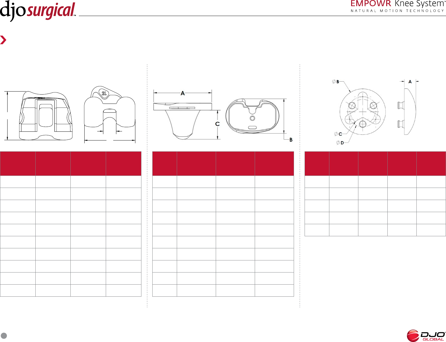
Size M/L(mm)
Dim ‘A’
A/P(mm)
Dim ‘B’ Dim ‘C’ (mm)
. . .
. . .
. . .
. . .
. . .
. . .
. . .
. . .
. . .
. . .
Size M/L(mm)
Dim ‘A’
A/P(mm)
Dim ‘B’
Dim ‘C’
(mm)
Dim ‘D’
(mm)
. .
. .
. .
. .
. .
Size M/L(mm)
Dim ‘A’
A/P(mm)
Dim ‘B’ Dim ‘C’ (mm)
. . .
. . .
. . .
. . .
. . .
. . .
. . .
. . .
. . .
. . .
Reference Guide
IMPLANT DIMENSIONS
EMPOWR PS Knee System Femur EMPOWR Knee System Baseplate All- Poly Domed Tri- Peg Patella
'A'
'C'
'B'
SURGICAL TECHNIQUE
25
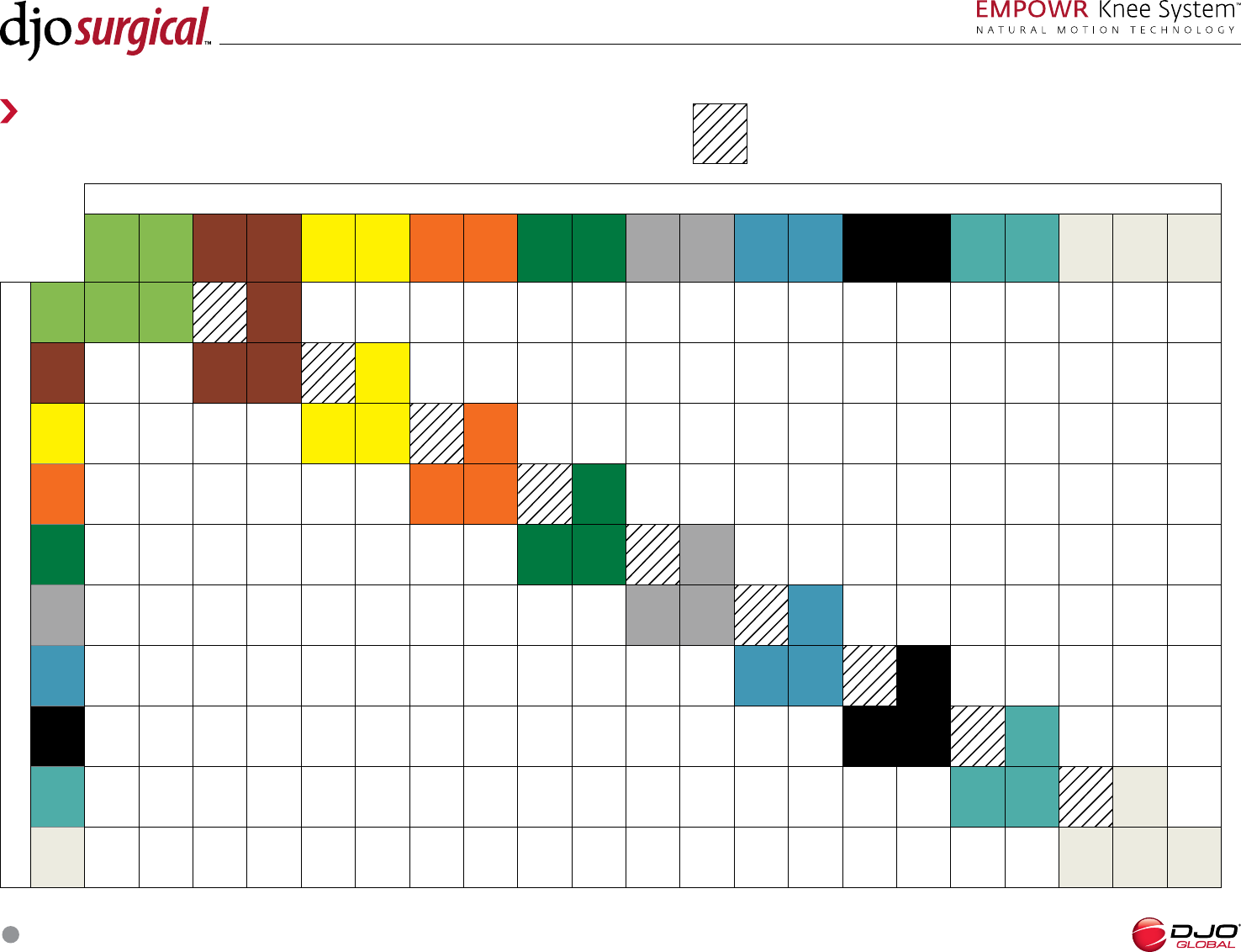
EMPOWR D SIZING CHART
TIBIAL SIZE
MINUS
MINUS
MINUS
MINUS
MINUS
MINUS
MINUS
MINUS
MINUS
MINUS
PLUS
FEMORAL SIZE
This box denotes a size combination that is available, but not recommended as
minus size tibial bases have the A/P and M/L profile of one size smaller tibial base.
Reference Guide
SURGICAL TECHNIQUE
26
Reference Guide
EMPOWR PS SIZING CHART
TIBIAL SIZE
234 5 6 7 8 910 11
FEMORAL SIZE
18.5MM Box
2 2 3
3234
434 5
5 4 5
6
BRIDGE
DOWN
22.5MM Box
65
BRIDGE UP 6 7
7 6 7 8
8 7 8 9
98910
10 910 11
11 10 11
SURGICAL TECHNIQUE
27
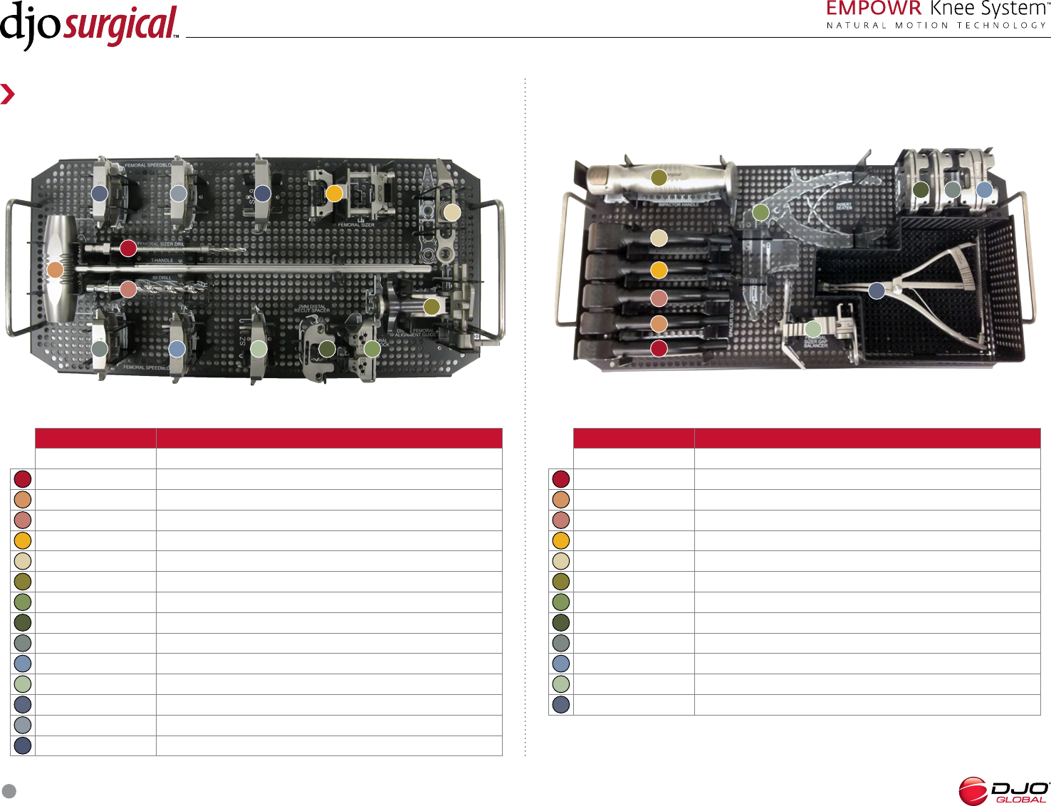
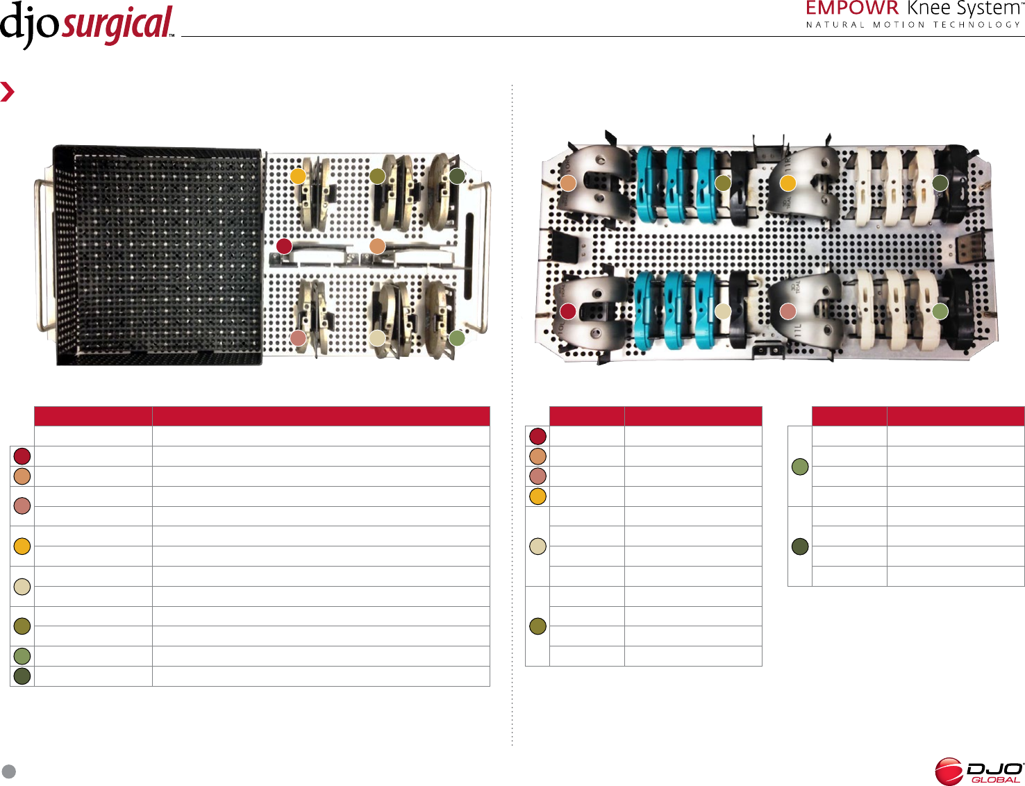
EMPOWR Knee Femoral Prep
Part Number Description
Case, EMPOWR DRF Femoral Prep
.mm Femoral Sizer Drill
T- Handle IM Rod
IM Drill
Femoral Sizer
Femoral Sizer Stylus
Distal Femoral Alignment Guide
Distal Femoral Cut Block
mm Distal Recut Spacer
- in- Cut Block, SZ
- in- Cut Block, SZ
- in- Cut Block, SZ
- in- Cut Block, SZ
- in- Cut Block, SZ
- in- Cut Block, SZ
EMPOWR Knee Bonus Tray
Part Number Description
Case, EMPOWR Bonus Tray
mm Insert Spacer Block
mm Insert Spacer Block
mm Insert Spacer Block
mm Insert Spacer Block
mm Insert Spacer Block
Impactor Handle
EMPTY (Insert Seater)
° Slope Recut Guide
mm Recut Guide
° Varus/Valgus Recut Guide
EMPTY (Gap Balancer)
EMPTY (Gap Balancer Lamina Spreader)
Reference Guide
INSTRUMENT GUIDE
1
9
5
13
3
11
7
2
6
4
12
8
10
14
1
1
9
9
5
5
13
3
3
11
11
7
7
2
2
6
6
4
4
12
12
8
8
10
10
14
1
9
5
3
11
7
2
6
4
12
8
10
SURGICAL TECHNIQUE
28
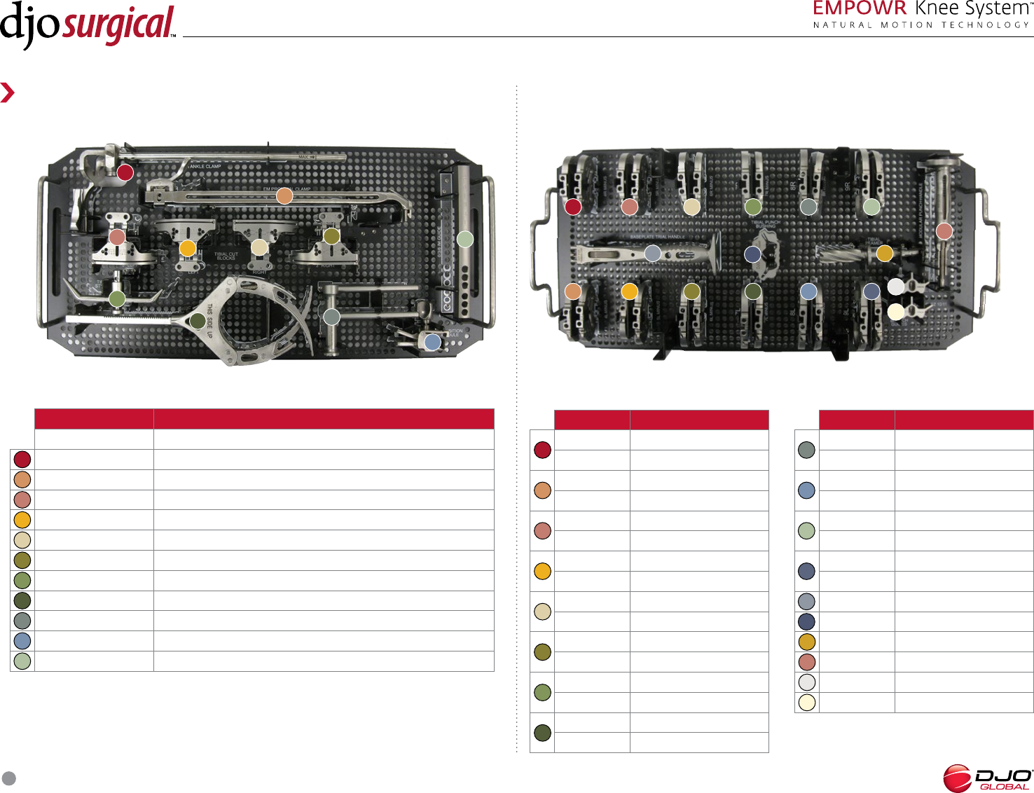
Part Number Description
Baseplate Trial, R
Baseplate Trial, R Minus
Baseplate Trial, L
Baseplate Trial, L Minus
Baseplate Trial, R
Baseplate Trial, R Minus
Baseplate Trial, L
Baseplate Trial, L Minus
Baseplate Trial Handle
Tibial Punch Bushing
Tibial Reamer
Tibial Punch Handle
Tibial Punch, Core
Tibial Punch, Large
EMPOWR Knee Tibial Prep: Upper Tray
Part Number Description
Case, EMPOWR Tibial Prep
EM Distal Body
EM Proximal Body
Tibial Cut Block, °, Left
Tibial Cut Block, °, Left
Tibial Cut Block, °, Right
Tibial Cut Block, °, Right
Tibial Stylus
EM Ankle Clamp
IM Guide Base
Transition Module
°/°/° IM Guide
Part Number Description
Baseplate Trial, R
Baseplate Trial, R Minus
Baseplate Trial, L
Baseplate Trial, L Minus
Baseplate Trial, R
Baseplate Trial, R Minus
Baseplate Trial, L
Baseplate Trial, L Minus
Baseplate Trial, R
Baseplate Trial, R Minus
Baseplate Trial, L
Baseplate Trial, L Minus
Baseplate Trial, R
Baseplate Trial, R Minus
Baseplate Trial, L
Baseplate Trial, L Minus
1
9
9
5
13
17
3
11
11
7
2
6
4
12
8
10
10
14
18
16
15
1
5
3
7
2
6
4
8
EMPOWR Knee Tibial Prep: Lower Tray
17
18
16
15
1
1
9
9
5
5 13
3
3
11
11
7
7
2
2
6
6
4
4
12 8
8
10
10
14
Reference Guide
INSTRUMENT GUIDE
SURGICAL TECHNIQUE
29
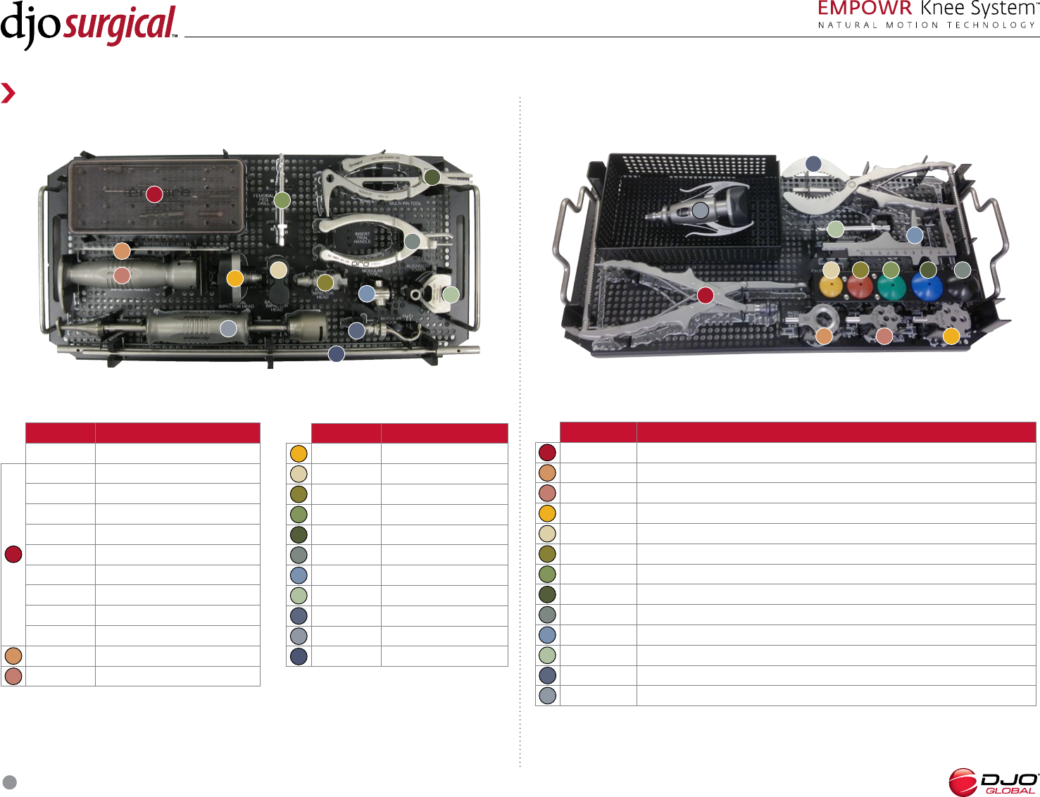
Part Number Description
Case, EMPOWR Tool Kit
Pin Case
.” Quick Headed Bone Pins (QTY )
” Quick Headed Bone Pins (QTY )
.” Qui ck Release Bone Pins (QTY )
Quick Release Bone Pins (QTY )
Quick Release Adapter (QTY )
SS, Tibial Bone Pins (QTY )
Fixation Pin, Tibia Sizer (QTY )
/” Quick Connect Drill Bit (QTY )
Angel Wing
Impactor Handle
EMPOWR Knee Patella and Tool Kit: Lower Tray
Part Number Description
Patella Clamp
Patella Seater
Patella Drill Guide, //mm
Patella Drill Guide, /mm
Domed Patella Trial, mm
Domed Patella Trial, mm
Domed Patella Trial, mm
Domed Patella Trial, mm
Domed Patella Trial, mm
Caliper
Patella Drill
Patella Osteotomy Guide
Locking Femoral Impactor
1
9
5
3
11
7
2
6
4
8
10
12
Part Number Description
Femoral Impactor Head
Baseplate Impactor Head
Insert Impactor Head
Femoral Peg Drill
Multi Pin Tool
Insert Trial Handle
Modular Stop
Alignment Rod Guide
EMPTY (Modular Hook)
Slap Hammer
Alignment Rod
5
7
6
4
8
9
13
13
13
11
12
10
14
1
3
2
EMPOWR Knee Patella and Tool Kit: Upper Tray
Reference Guide
INSTRUMENT GUIDE
1
1
9
9
5 5
13
3
3
11
11
7
7
2
2
6
6
4
4
12
12
8
8
10
10
14
SURGICAL TECHNIQUE
30
Part Number Description
Case, EMPOWR D Large Outlier
-in- Cut Block, SZ
-in- Cut Block, SZ
Baseplate Trial, L
Baseplate Trial, L Minus
Baseplate Trial, R
Baseplate Trial, R Minus
Baseplate Trial, L
Baseplate Trial, L Minus
Baseplate Trial, R
Baseplate Trial, R Minus
Baseplate Trial, L Plus
Baseplate Trial, R Plus
1
5
3
7
2
6
4
8
Part Number Description
D Femoral Trial, L
D Femoral Trial, L
D Femoral Trial, R
D Femoral Trial, R
D Insert Trial, L, mm
D Insert Trial, L, mm
D Insert Trial, L, mm
D Articulating Spacer, SZ L
D Insert Trial, L, mm
D Insert Trial, L, mm
D Insert Trial, L, mm
D Articulating Spacer, SZ L
1
5
3
2
6
4
EMPOWR D Knee Large Outlier:: Lower Tray
EMPOWR D Knee Large Outlier: Upper Tray
1
5
3 7
2
6 4
1 5 3 7
2 6 4 8
8
Reference Guide
INSTRUMENT GUIDE
Part Number Description
D Insert Trial, R, mm
D Insert Trial, R, mm
D Insert Trial, R, mm
D Articulating Spacer, SZ R
D Insert Trial, R, mm
D Insert Trial, R, mm
D Insert Trial, R, mm
D Articulating Spacer, SZ R
7
8
SURGICAL TECHNIQUE
31
Part Number Description
Case, EMPOWR D Femoral
Trials, Core, Left
D Femoral Trial, L
D Femoral Trial, L
D Femoral Trial, 6L
D Femoral Trial, L
D Femoral Trial, 8L
D Femoral Trial, L
D Insert Trial, L, mm
D Insert Trial, L, mm
D Insert Trial, L, mm
D Articulating Spacer, L
D Insert Trial, L, mm
D Insert Trial, L, mm
D Insert Trial, L, mm
D Articulating Spacer, L
Part Number Description
Case, EMPOWR D Femoral
Trials, Core, Right
D Femoral Trial, R
D Femoral Trial, R
D Femoral Trial, R
D Femoral Trial, R
D Femoral Trial, R
D Femoral Trial, R
D Insert Trial, R, mm
D Insert Trial, R, mm
D Insert Trial, R, 1mm
D Articulating Spacer, R
D Insert Trial, R, mm
D Insert Trial, R, mm
D Insert Trial, R, mm
D Articulating Spacer, R
9
13
17
11
12
10
14
18
16
15
EMPOWR D Knee Femoral Trials, Core, Right
17
18
16
15
1
9
5
13
3
11 7
2 6 4
12 8 10 14
17
18
16
15
1
9
5
13
3
11 7
2 6 4
12 8 10 14
Reference Guide
INSTRUMENT GUIDE
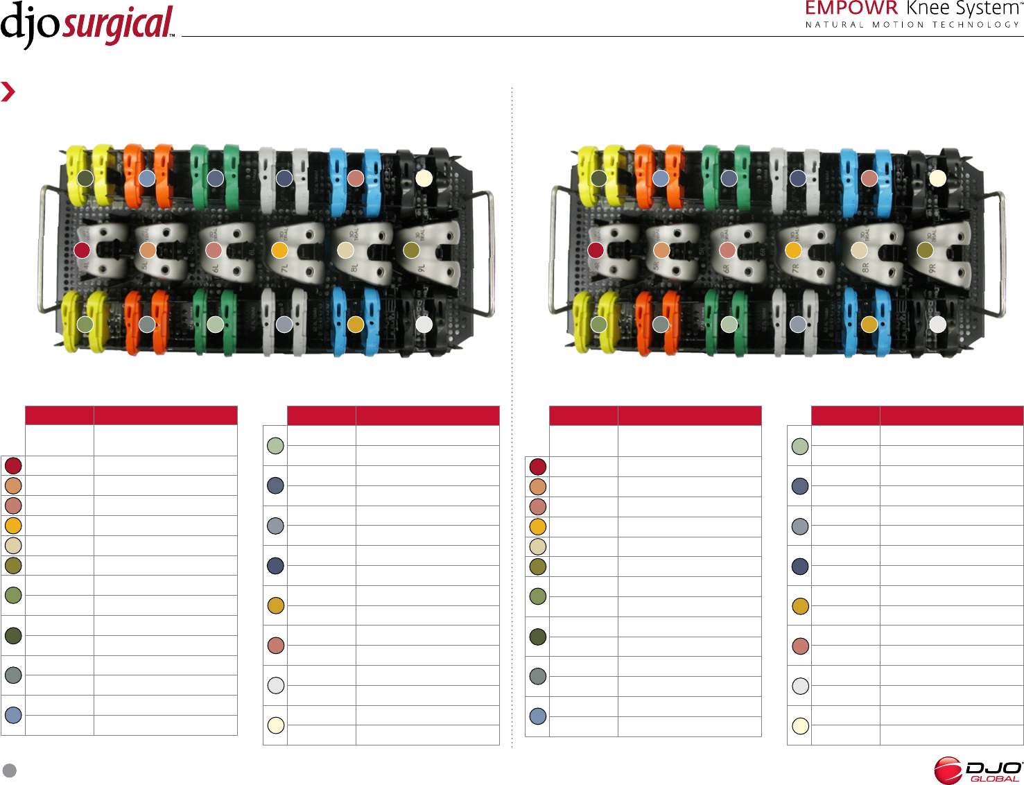
EMPOWR D Knee Femoral Trials, Core, Left
Part Number Description
D Insert Trial, L, mm
D Insert Trial, L, mm
D Insert Trial, L, mm
D Articulating Spacer, 6L
D Insert Trial, L ,mm
D Insert Trial, L ,mm
D Insert Trial, L ,mm
D Articulating Spacer ,L
D Insert Trial, L, mm
D Insert Trial, L, mm
D Insert Trial, L, mm
D Articulating Spacer, 8L
D Insert Trial, L, mm
D Insert Trial, L, mm
D Insert Trial, L, mm
D Articulating Spacer, L
1
9
5
3
7
2
6
4
8
10
13
17
11
12
14
18
16
15
Part Number Description
D Insert Trial, R, mm
D Insert Trial, R, mm
D Insert Trial, R, mm
D Articulating Spacer, R
D Insert Trial, R, mm
D Insert Trial, R, mm
D Insert Trial, R, mm
D Articulating Spacer, R
D Insert Trial, R, mm
D Insert Trial, R, mm
D Insert Trial, R, mm
D Articulating Spacer, R
D Insert Trial, R, mm
D Insert Trial, R, mm
D Insert Trial, R, mm
D Articulating Spacer, R
1
9
5
3
7
2
6
4
8
10
13
17
11
12
14
18
16
15
SURGICAL TECHNIQUE
32
Part Number Description
Case, EMPOWR D Small Outlier
Tibial Punch, Small
EMPTY
mm Femoral Shift Block
-in- Cut Block, SZ
-in- Cut Block, SZ
Baseplate Trial, L
Baseplate Trial, L Minus
Baseplate Trial, R
Baseplate Trial, R Minus
Baseplate Trial, L
Baseplate Trial, L Minus
Baseplate Trial, R
Baseplate Trial, R Minus
1
5
3
7
2
6
4
8
EMPOWR D Knee Small Outlier: Upper Tray EMPOWR D Knee Small Outlier: Lower Tray
1
5
3
7
2
6
4
1 5 3 7
2 6 4 8
8
Reference Guide
INSTRUMENT GUIDE
Part Number Description
EMPTY
EMPTY
D Femoral Trial, L
D Femoral Trial, L
D Femoral Trial, R
D Femoral Trial, R
D Insert Trial, L, mm
D Insert Trial, L, mm
D Insert Trial, L, mm
D Articulating Spacer, SZ L
D Insert Trial, L, mm
D Insert Trial, L, mm
D Insert Trial, L, mm
D Articulating Spacer, SZ L
1
5
3
2
4
7
8
6
9
Part Number Description
D Insert Trial, R, mm
D Insert Trial, R, mm
D Insert Trial, R, mm
D Articulating Spacer, SZ R
D Insert Trial, R, mm
D Insert Trial, R, mm
D Insert Trial, R, mm
D Articulating Spacer, SZ R
9
10
9
9
10
SURGICAL TECHNIQUE
33
Part Number Description
Case, EMPOWR Spacer Trials
Insert Spacer Trial, SZ , mm
Insert Spacer Trial, SZ , mm
Insert Spacer Trial, SZ , mm
Insert Spacer Trial, SZ , mm
Insert Spacer Trial, SZ , mm
Insert Spacer Trial, SZ , mm
Insert Spacer Trial, SZ , mm
Insert Spacer Trial, SZ , mm
Part Number Description
Insert Spacer Trial, SZ , mm
Insert Spacer Trial, SZ , mm
Insert Spacer Trial, SZ , mm
Insert Spacer Trial, SZ , mm
Insert Spacer Trial, SZ , mm
Insert Spacer Trial, SZ , mm
Insert Spacer Trial, SZ , mm
Insert Spacer Trial, SZ , mm
Part Number Description
Insert Spacer Trial, SZ , mm
Insert Spacer Trial, SZ , mm
Insert Spacer Trial, SZ , mm
Insert Spacer Trial, SZ , mm
Spacer Trials
Reference Guide
INSTRUMENT GUIDE
1
9
5
3
7
2
6
4
8
10
1
9
5 3
7
2 6
4
8 10
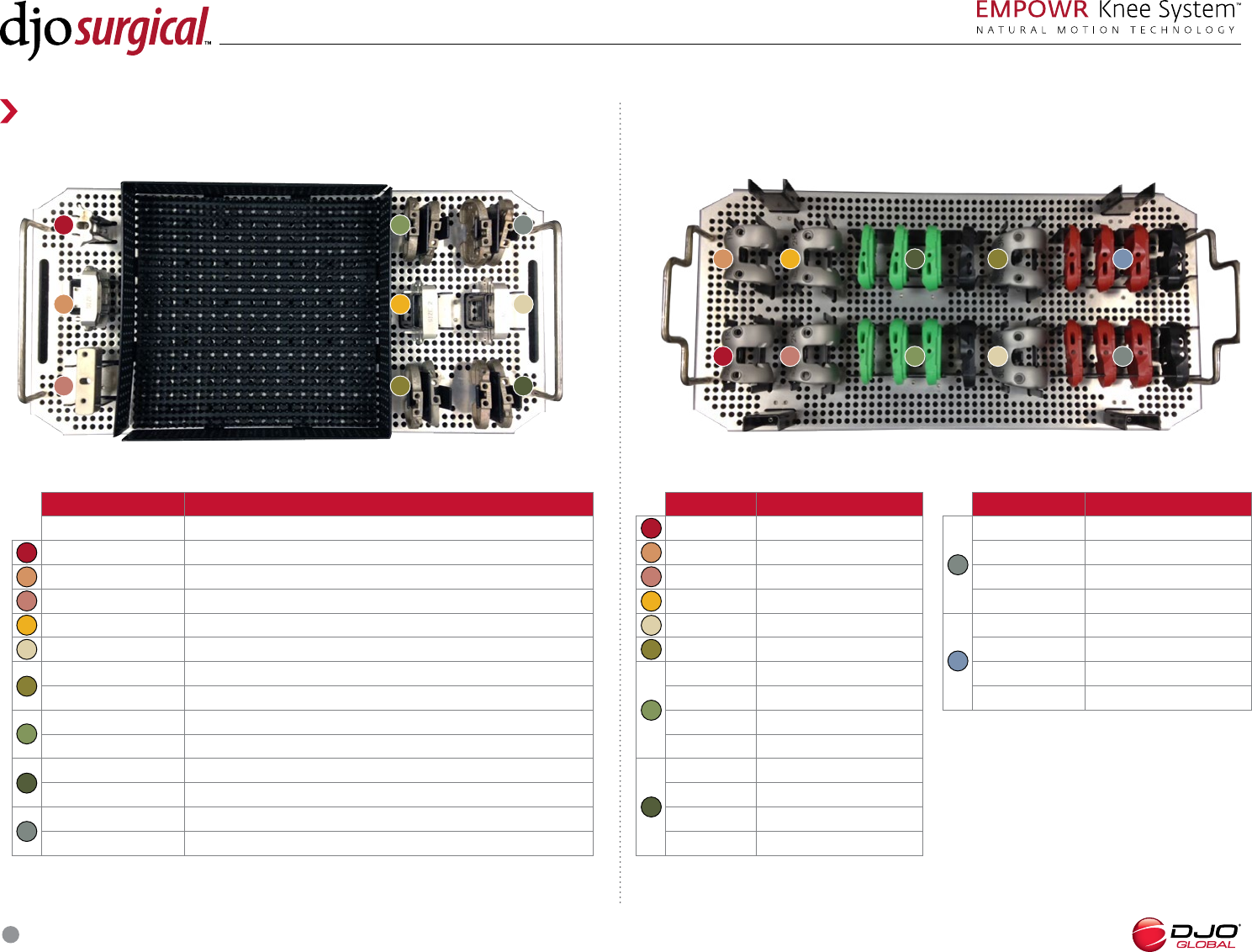
SURGICAL TECHNIQUE
34
Part Number Description
Case, EMPOWR PS Femoral
Trials, Core
1 PS Femoral Trial, L
2 PS Femoral Trial, R
3 PS Femoral Trial, L
4 PS Femoral Trial, R
5 PS Femoral Trial, L
6 PS Femoral Trial, R
7 PS Femoral Trial, L
8 PS Femoral Trial, R
9 PS Femoral Trial, 8L
Part Number Description
9 PS Femoral Trial, L
10 PS Femoral Trial, R
11 PS Femoral Trial, L
12 PS Femoral Trial, R
13 PS Box Cut Guide, Size
14 PS Box Cut Guide, Size
15 PS Box Cut Guide, Size
16 PS Box Cut Guide, Size
17 PS Box Cut Guide, Size
18 PS Box Cut Guide, Size
EMPOWR PS Knee Femoral Trials, Core
1
9
9
5
3
7
2
6
4
8
10
13
17
11
12
14
18
16
15
17 18
1615
1 9 5
13
3 11
7
2 6 4 12 8 10
14
Reference Guide
INSTRUMENT GUIDE
EMPOWR PS trays are available in two configurations: those with
Standard PS Box Cut Guides and those with Captured Box Cut
Guides. For reference purposed, the Captured Box Cut Guide part
numbers are listed below.
...............PS Box Cut Guide with capture, Size
...............PS Box Cut Guide with capture, Size
...............PS Box Cut Guide with capture, Size
...............PS Box Cut Guide with capture, Size
...............PS Box Cut Guide with capture, Size
...............PS Box Cut Guide with capture, Size
...............PS Box Cut Guide with capture, Size
...............PS Box Cut Guide with capture, Size
...............PS Box Cut Guide with capture, Size
. . . . . . . . . . . . . . . .PS Box Cut Guide with capture, Size
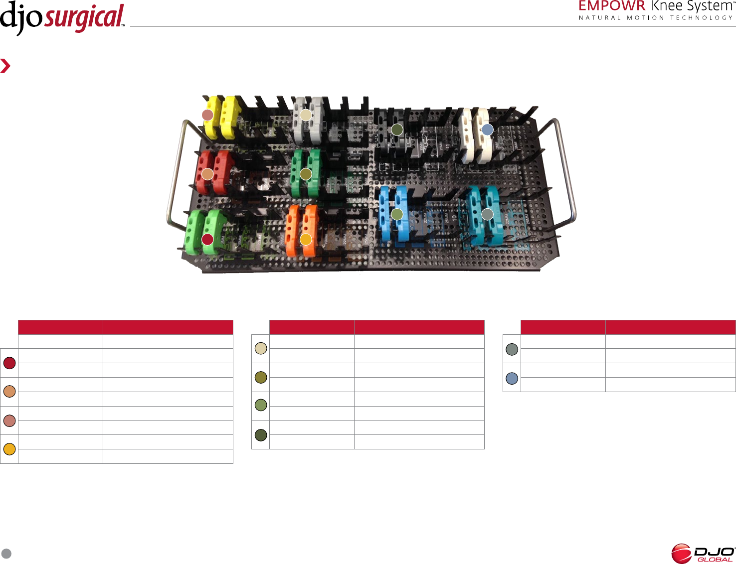
SURGICAL TECHNIQUE
35
EMPOWR PS Knee Insert Trials, Core: Lower Tray
Part Number Description
PS Insert Trial, SZ , mm
Ps Insert Trial, SZ , mm
Ps Insert Trial, SZ , mm
Ps Insert Trial, SZ , mm
Ps Insert Trial, SZ , mm
PS Articulating Spacer, SZ
Ps Insert Trial, SZ , mm
Ps Insert Trial, SZ , mm
Ps Insert Trial, SZ , mm
Ps Insert Trial, SZ , mm
Ps Insert Trial, SZ , mm
PS Articulating Spacer, SZ
1
2
Part Number Description
Ps Insert Trial, SZ Bridge Up, mm
Ps Insert Trial, SZ Bridge Up, mm
Ps Insert Trial, SZ Bridge Up, mm
Ps Insert Trial, SZ Bridge Up, mm
Ps Insert Trial, SZ Bridge Up, mm
PS Articulating Spacer, SZ Bridge Up
Ps Insert Trial, SZ Bridge Down, mm
Ps Insert Trial, SZ Bridge Down, mm
Ps Insert Trial, SZ Bridge Down, mm
Ps Insert Trial, SZ Bridge Down, mm
Ps Insert Trial, SZ Bridge Down, mm
PS Articulating Spacer, SZ 6 Bridge Down
3
4
1 3
2 4
Reference Guide
INSTRUMENT GUIDE
Part Number Description
800-99-118 Case, EMPOWR PS Insert
Trials, Core
Ps Insert Trial, SZ , mm
Ps Insert Trial, SZ , mm
Ps Insert Trial, SZ , mm
Ps Insert Trial, SZ , mm
Ps Insert Trial, SZ , mm
PS Articulating Spacer, SZ
Ps Insert Trial, SZ , mm
Ps Insert Trial, SZ , mm
Ps Insert Trial, SZ , mm
Ps Insert Trial, SZ , mm
Ps Insert Trial, SZ , mm
PS Articulating Spacer, SZ
Part Number Description
Ps Insert Trial, SZ , mm
Ps Insert Trial, SZ , mm
Ps Insert Trial, SZ , mm
Ps Insert Trial, SZ , mm
Ps Insert Trial, SZ , mm
PS Articulating Spacer, SZ
Ps Insert Trial, SZ , mm
Ps Insert Trial, SZ , mm
Ps Insert Trial, SZ , mm
Ps Insert Trial, SZ , mm
Ps Insert Trial, SZ , mm
PS Articulating Spacer, SZ
Modular Capture
Box Cut Guide Chisel, SZ and
Box Cut Guide Chisel, SZ and
Box Cut Guide Chisel, SZ and
EMPOWR PS Knee Insert Trials, Core: Upper Tray
1
5
3
7
2
6
4
8
1 3
2 4
5 7 6 8
SURGICAL TECHNIQUE
36
1 9
5 13
3 11 7
2
6
4 12 8 10
EMPOWR PS Knee Large Outlier
Part Number Description
Case, EMPOWR PS Large Outlier
PS Femoral Trial, L
PS Femoral Trial, R
PS Femoral Trial, L
PS Femoral Trial, R
EMPOWR PS Box Cut Guide, Size
EMPOWR PS Box Cut Guide, Size
-in- Cut Block, SZ
-in- Cut Block, SZ
Ps Insert Trial, SZ , mm
Ps Insert Trial, SZ , mm
Ps Insert Trial, SZ , mm
Ps Insert Trial, SZ , mm
Ps Insert Trial, SZ , mm
PS Articulating Spacer, SZ
9
1
5
3
7
2
6
4
8
Part Number Description
Ps Insert Trial, SZ , mm
Ps Insert Trial, SZ , mm
Ps Insert Trial, SZ , mm
Ps Insert Trial, SZ , mm
Ps Insert Trial, SZ , mm
PS Articulating Spacer, SZ
Baseplate Trial, L
Baseplate Trial, R
Baseplate Trial, L
Baseplate Trial, R
Box Cut Guide Chisel, SZ and
10
13
11
12
EMPOWR PS Knee Small Outlier
Part Number Description
Case, EMPOWR PS Small Outlier
EMPOWR PS, Femoral Trial, L
EMPOWR PS, Femoral Trial, R
EMPOWR PS, Femoral Trial, L
EMPOWR PS, Femoral Trial, R
EMPOWR PS Box Cut Guide, Size
EMPOWR PS Box Cut Guide, Size
-in- Cut Block, SZ
-in- Cut Block, SZ
mm Femoral Shift Block, .mm
PS Insert Trial, SZ , mm
PS Insert Trial, SZ , mm
PS Insert Trial, SZ , mm
PS Insert Trial, SZ , mm
PS Insert Trial, SZ , mm
PS Articulating Spacer, SZ
1
9
5
3
7
2
6
4
8
10
Part Number Description
PS Insert Trial, SZ , mm
PS Insert Trial, SZ , mm
PS Insert Trial, SZ , mm
PS Insert Trial, SZ , mm
PS Insert Trial, SZ , mm
PS Articulating Spacer, SZ
Baseplate Trial, L
Baseplate Trial, R
Baseplate Trial, L
Baseplate Trial, R
Tibial Punch, Small
Box Cut Guide Chisel, SZ and
13
11
12
14
15
15
1
9 5
13
3
11
7
2
6
4
12
8
10
14
Reference Guide
INSTRUMENT GUIDE
SURGICAL TECHNIQUE
37
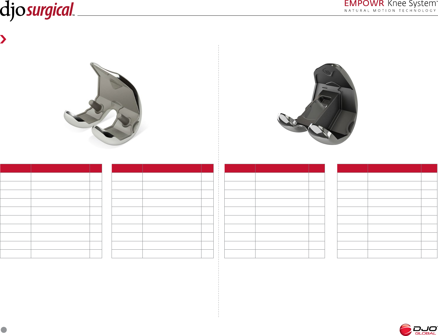
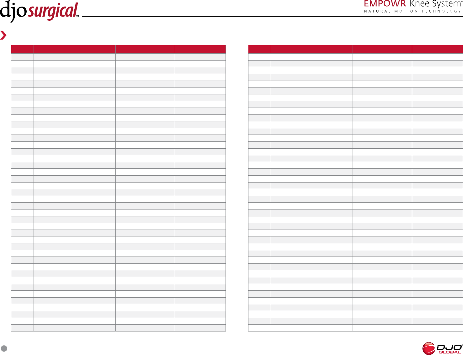
EMPOWR D Knee Femur, RightEMPOWR D Knee Femur, Left
PART NUMBER NONPOROUS FEMURS SIZE
EMPOWR D Femur, Right
EMPOWR D Femur, Right
EMPOWR D Femur, Right
EMPOWR D Femur, Right
EMPOWR D Femur, Right
EMPOWR D Femur, Right
EMPOWR D Femur, Right
EMPOWR D Femur, Right
EMPOWR D Femur, Right
EMPOWR D Femur, Right
PART NUMBER NONPOROUS FEMURS SIZE
EMPOWR D Femur, Left
EMPOWR D Femur, Left
EMPOWR D Femur, Left
EMPOWR D Femur, Left
EMPOWR D Femur, Left
EMPOWR D Femur, Left
EMPOWR D Femur, Left
EMPOWR D Femur, Left
EMPOWR D Femur, Left
EMPOWR D Femur, Left
Reference Guide
IMPLANT PART NUMBERS
EMPOWR PS Knee Femur, Right EMPOWR PS Knee Femur, Left
PART NUMBER NONPOROUS FEMURS SIZE
EMPOWR PS Femur, Right
EMPOWR PS Femur, Right
EMPOWR PS Femur, Right
EMPOWR PS Femur, Right
EMPOWR PS Femur, Right
EMPOWR PS Femur, Right
EMPOWR PS Femur, Right
EMPOWR PS Femur, Right
EMPOWR PS Femur, Right
EMPOWR PS Femur, Right
PART NUMBER NONPOROUS FEMURS SIZE
EMPOWR PS Femur, Left
EMPOWR PS Femur, Left
EMPOWR PS Femur, Left
EMPOWR PS Femur, Left
EMPOWR PS Femur, Left
EMPOWR PS Femur, Left
EMPOWR PS Femur, Left
EMPOWR PS Femur, Left
EMPOWR PS Femur, Left
EMPOWR PS Femur, Left
SURGICAL TECHNIQUE
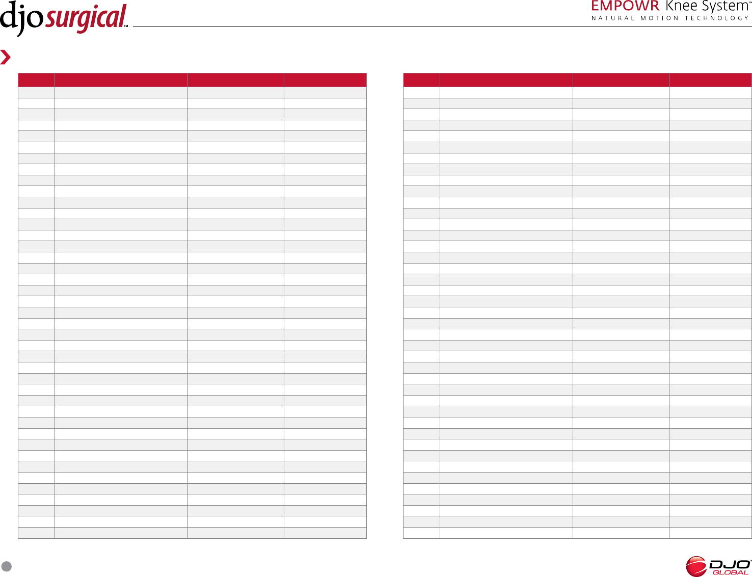
38
PART NUMBER e+™ INSERTS SIZE
e+™ Insert, mm, Left
e+™ Insert, mm, Left
e+™ Insert, mm, Left
e+™ Insert, mm, Left
e+™ Insert, mm, Left
e+™ Insert, mm, Left
e+™ Insert, mm, Left
e+™ Insert, mm, Left
e+™ Insert, mm, Left
e+™ Insert, mm, Left
e+™ Insert, mm, Left
e+™ Insert, mm, Left
e+™ Insert, mm, Left
e+™ Insert, mm, Left
e+™ Insert, mm, Left
e+™ Insert, mm, Left
e+™ Insert, mm, Left
e+™ Insert, mm, Left
e+™ Insert, mm, Left
e+™ Insert, mm, Left
e+™ Insert, mm, Left
e+™ Insert, mm, Left
e+™ Insert, mm, Left
e+™ Insert, mm, Left
e+™ Insert, mm, Left
EMPOWR 3D Knee e+ Insert, Left EMPOWR 3D Knee e+ Insert, Left EMPOWR 3D Knee e+ Insert, Right EMPOWR 3D Knee e+ Insert, Right
PART NUMBER e+™ INSERTS SIZE
e+™ Insert, mm, Right
e+™ Insert, mm, Right
e+™ Insert, mm, Right
e+™ Insert, mm, Right
e+™ Insert, mm, Right
e+™ Insert, mm, Right
e+™ Insert, mm, Right
e+™ Insert, mm, Right
e+™ Insert, mm, Right
e+™ Insert, mm, Right
e+™ Insert, mm, Right
e+™ Insert, mm, Right
e+™ Insert, mm, Right
e+™ Insert, mm, Right
e+™ Insert, mm, Right
e+™ Insert, mm, Right
e+™ Insert, mm, Right
e+™ Insert, mm, Right
e+™ Insert, mm, Right
e+™ Insert, mm, Right
e+™ Insert, mm, Right
e+™ Insert, mm, Right
e+™ Insert, mm, Right
e+™ Insert, mm, Right
e+™ Insert, mm, Right
PART NUMBER e+™ INSERTS SIZE
e+™ Insert, mm, Left
e+™ Insert, mm, Left
e+™ Insert, mm, Left
e+™ Insert, mm, Left
e+™ Insert, mm, Left
e+™ Insert, mm, Left
e+™ Insert, mm, Left
e+™ Insert, mm, Left
e+™ Insert, mm, Left
e+™ Insert, mm, Left
e+™ Insert, mm, Left
e+™ Insert, mm, Left
e+™ Insert, mm, Left
e+™ Insert, mm, Left
e+™ Insert, mm, Left
e+™ Insert, mm, Left
e+™ Insert, mm, Left
e+™ Insert, mm, Left
e+™ Insert, mm, Left
e+™ Insert, mm, Left
e+™ Insert, mm, Left
e+™ Insert, mm, Left
e+™ Insert, mm, Left
e+™ Insert, mm, Left
e+™ Insert, mm, Left
Reference Guide
IMPLANT PART NUMBERS
SURGICAL TECHNIQUE
39
PART NO. e+™ INSERTS SIZE
PS e+™ Insert, mm, Symmetric
PS e+™ Insert, mm, Symmetric
PS e+™ Insert, 1mm, Symmetric
PS e+™ Insert, mm, Symmetric
PS e+™ Insert, mm, Symmetric
PS e+™ Insert, mm, Symmetric
PS e+™ Insert, mm, Symmetric
PS e+™ Insert, mm, Symmetric
PS e+™ Insert, mm, Symmetric
PS e+™ Insert, mm, Symmetric
PS e+™ Insert, mm, Symmetric
PS e+™ Insert, mm, Symmetric
PS e+™ Insert, mm, Symmetric
PS e+™ Insert, mm, Symmetric
PS e+™ Insert, mm, Symmetric
PS e+™ Insert, mm, Symmetric
PS e+™ Insert, mm, Symmetric
PS e+™ Insert, mm, Symmetric
PS e+™ Insert, mm, Symmetric
PS e+™ Insert, mm, Symmetric
PS e+™ Insert, mm, Symmetric
PART NO. e+™ INSERTS SIZE
PS e+™ Insert, mm, Symmetric
PS e+™ Insert, mm, Symmetric
PS e+™ Insert, mm, Symmetric
PS e+™ Insert, mm, Symmetric
PS e+™ Insert, mm, Symmetric
PS e+™ Insert, mm, Symmetric
PS e+™ Insert, mm, Symmetric
PS e+™ Insert, mm, Symmetric
PS e+™ Insert, mm, Symmetric
PS e+™ Insert, mm, Symmetric
PS e+™ Insert, mm, Symmetric
PS e+™ Insert, mm, Symmetric
PS e+™ Insert, mm, Symmetric
PS e+™ Insert, mm, Symmetric
PS e+™ Insert, mm, Symmetric
PS e+™ Insert, mm, Symmetric
PS e+™ Insert, mm, Symmetric
PS e+™ Insert, mm, Symmetric
PS e+™ Insert, mm, Symmetric
PS e+™ Insert, mm, Symmetric
PS e+™ Insert, mm, Symmetric
EMPOWR PS Knee e+ Insert, Symmetric
PART NO. e+™ INSERTS SIZE
PS e+™ Insert, mm, Symmetric
PS e+™ Insert, mm, Symmetric
PS e+™ Insert, mm, Symmetric
PS e+™ Insert, mm, Symmetric
PS e+™ Insert, mm, Symmetric
PS e+™ Insert, mm, Symmetric
PS e+™ Insert, mm, Symmetric
PS e+™ Insert, mm, Symmetric Bridge Up
PS e+™ Insert, mm, Symmetric Bridge Up
PS e+™ Insert, mm, Symmetric Bridge Up
PS e+™ Insert, mm, Symmetric Bridge Up
PS e+™ Insert, mm, Symmetric Bridge Up
PS e+™ Insert, mm, Symmetric Bridge Up
PS e+™ Insert, mm, Symmetric Bridge Up
PS e+™ Insert, mm, Symmetric Bridge Down
PS e+™ Insert, mm, Symmetric Bridge Down
PS e+™ Insert, mm, Symmetric Bridge Down
PS e+™ Insert, mm, Symmetric Bridge Down
PS e+™ Insert, mm, Symmetric Bridge Down
PS e+™ Insert, mm, Symmetric Bridge Down
PS e+™ Insert, mm, Symmetric Bridge Down
Reference Guide
IMPLANT PART NUMBERS
SURGICAL TECHNIQUE
40
EMPOWR Knee Tibia, Right
PART NUMBER NONPOROUS TIBIA SIZE
EMPOWR Tibia, Right
EMPOWR Tibia, Right
EMPOWR Tibia, Right
EMPOWR Tibia, Right
EMPOWR Tibia, Right
EMPOWR Tibia, Right
EMPOWR Tibia, Right
EMPOWR Tibia, Right
EMPOWR Tibia, Right
EMPOWR Tibia, Right
PART NUMBER NONPOROUS TIBIA SIZE
EMPOWR D Tibia, Right MINUS
EMPOWR D Tibia, Right MINUS
EMPOWR D Tibia, Right MINUS
EMPOWR D Tibia, Right MINUS
EMPOWR D Tibia, Right MINUS
EMPOWR D Tibia, Right MINUS
EMPOWR D Tibia, Right MINUS
EMPOWR D Tibia, Right MINUS
EMPOWR D Tibia, Right MINUS
EMPOWR D Tibia, Right MINUS
EMPOWR D Tibia, Right PLUS
PART NUMBER NONPOROUS TIBIA SIZE
EMPOWR D Tibia, Left MINUS
EMPOWR D Tibia, Left MINUS
EMPOWR D Tibia, Left MINUS
EMPOWR D Tibia, Left MINUS
EMPOWR D Tibia, Left MINUS
EMPOWR D Tibia, Left MINUS
EMPOWR D Tibia, Left MINUS
EMPOWR D Tibia, Left MINUS
EMPOWR D Tibia, Left MINUS
EMPOWR D Tibia, Left MINUS
EMPOWR D Tibia, Left PLUS
EMPOWR Knee Tibia, Left
PART NUMBER NONPOROUS TIBIA SIZE
EMPOWR Tibia, Left
EMPOWR Tibia, Left
EMPOWR Tibia, Left
EMPOWR Tibia, Left
EMPOWR Tibia, Left
EMPOWR Tibia, Left
EMPOWR Tibia, Left
EMPOWR Tibia, Left
EMPOWR Tibia, Left
EMPOWR Tibia, Left
Reference Guide
IMPLANT PART NUMBERS
SURGICAL TECHNIQUE
41
Reference Guide
IMPLANT PART NUMBERS
PART NUMBER ALLPOLY DOMED TRIPEG PATELLAS SIZE
All-Poly Domed Patella, e+™ x mm
All-Poly Domed Patella, e+™ x mm
All-Poly Domed Patella, e+™ x mm
All-Poly Domed Patella, e+™ x mm
All-Poly Domed Patella, e+™ x mm
Notes
All-Poly Domed Tri-Peg Patellas
SURGICAL TECHNIQUE
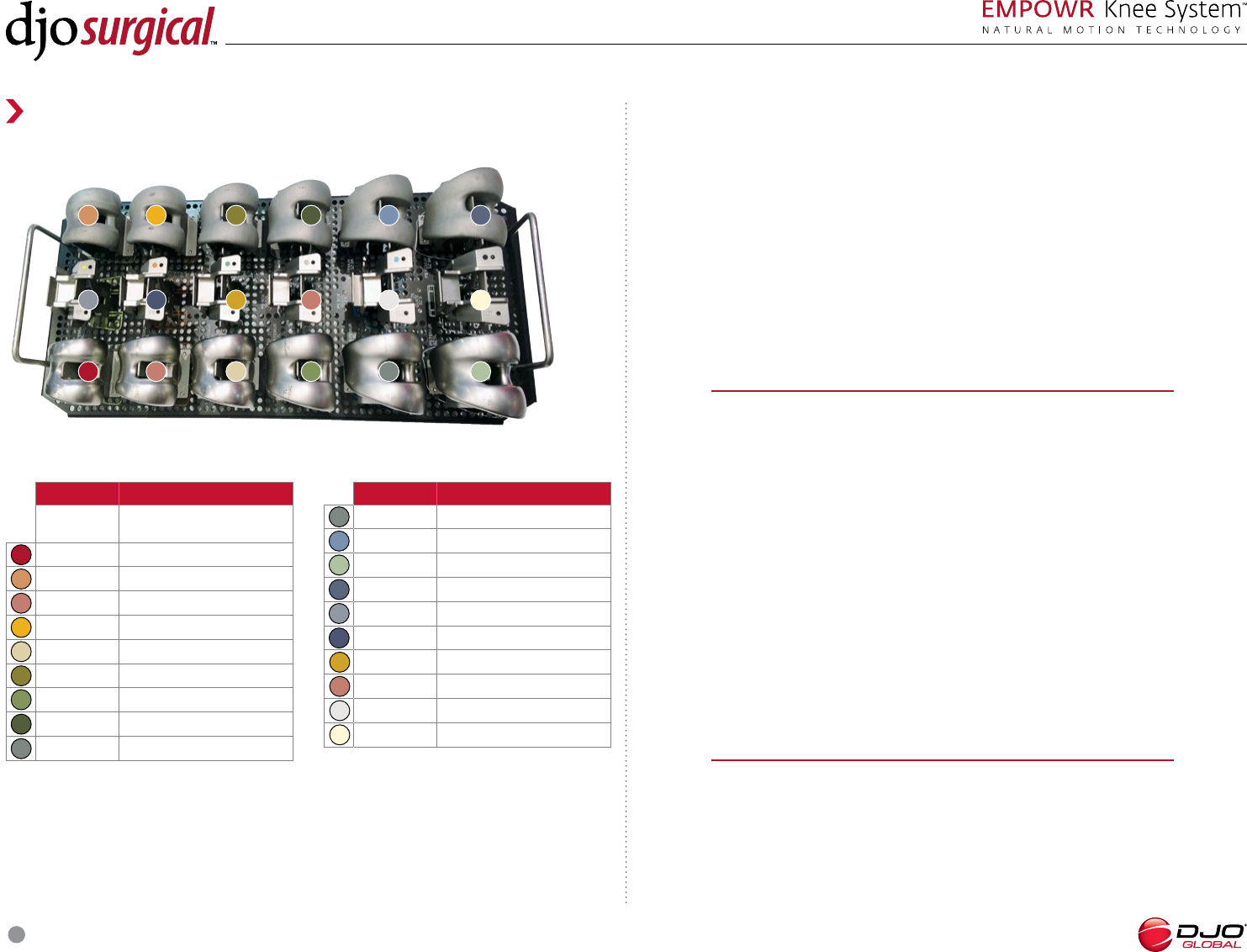
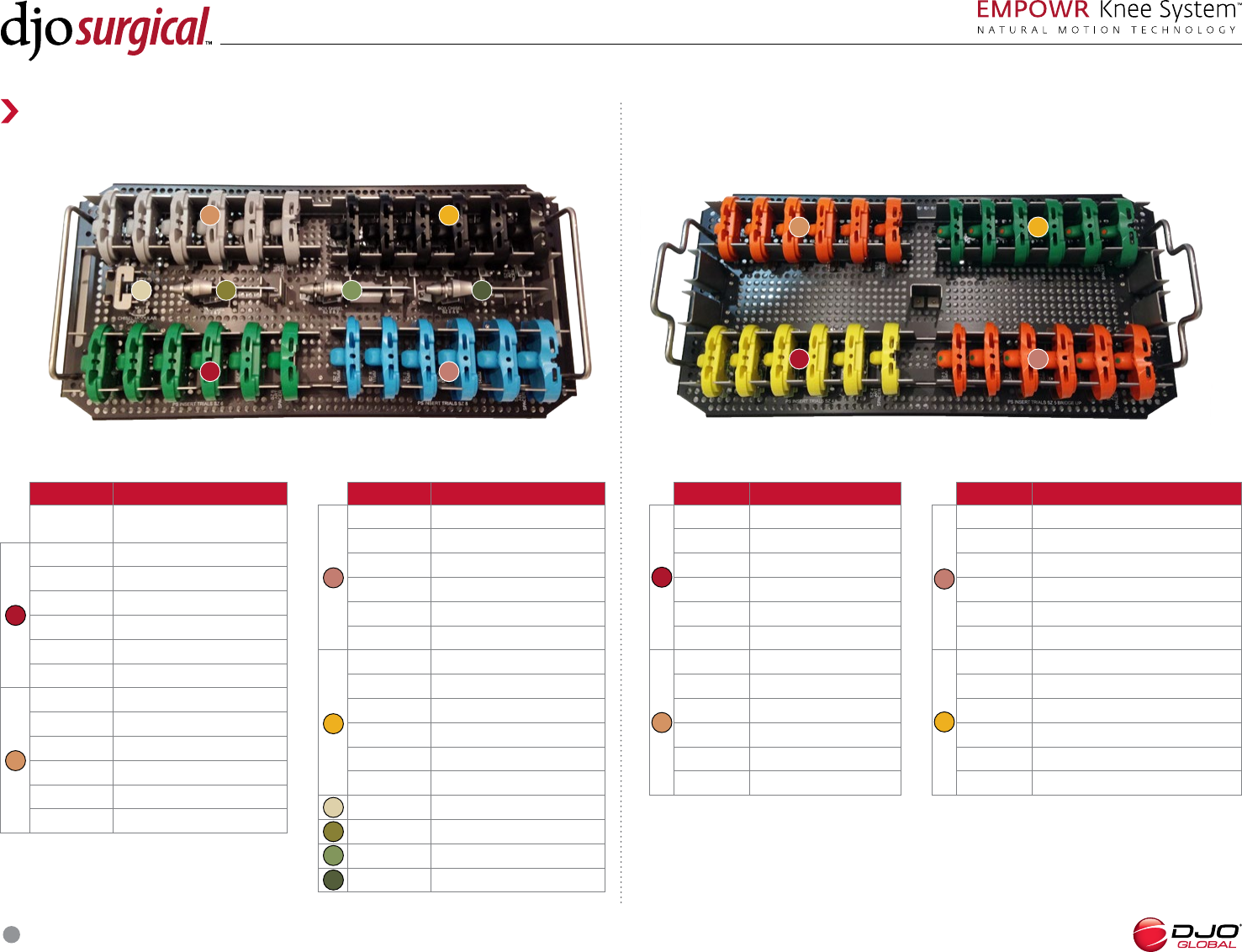
42
PART NO. DESCRIPTION MATERIALS COLORANT
EMPOWR PS KNEE, INSERT TRIAL, SZ , MM POLYPHENYLSULFONE YELLOW C
EMPOWR PS KNEE, INSERT TRIAL, SZ , MM POLYPHENYLSULFONE YELLOW C
EMPOWR PS KNEE, INSERT TRIAL, SZ , MM POLYPHENYLSULFONE YELLOW C
EMPOWR PS KNEE, INSERT TRIAL, SZ , MM POLYPHENYLSULFONE YELLOW C
EMPOWR PS KNEE, INSERT TRIAL, SZ , MM POLYPHENYLSULFONE YELLOW C
EMPOWR PS KNEE, ART SURFACE SPACER, SZ POLYPHENYLSULFONE YELLOW C
EMPOWR PS KNEE, INSERT TRIAL, SZ , MM POLYPHENYLSULFONE NEON ORANGE C
EMPOWR PS KNEE, INSERT TRIAL, SZ , MM POLYPHENYLSULFONE NEON ORANGE C
EMPOWR PS KNEE, INSERT TRIAL, SZ , MM POLYPHENYLSULFONE NEON ORANGE C
EMPOWR PS KNEE, INSERT TRIAL, SZ , MM POLYPHENYLSULFONE NEON ORANGE C
EMPOWR PS KNEE, INSERT TRIAL, SZ , MM POLYPHENYLSULFONE NEON ORANGE C
EMPOWR PS KNEE, ART SURFACE SPACER, SZ POLYPHENYLSULFONE NEON ORANGE C
EMPOWR PS KNEE, INSERT TRIAL, SZ BRIDGE UP, MM POLYPHENYLSULFONE NEON ORANGE C, VERDE C
EMPOWR PS KNEE, INSERT TRIAL, SZ BRIDGE UP, MM POLYPHENYLSULFONE NEON ORANGE C, VERDE C
EMPOWR PS KNEE, INSERT TRIAL, SZ BRIDGE UP, MM POLYPHENYLSULFONE NEON ORANGE C, VERDE C
EMPOWR PS KNEE, INSERT TRIAL, SZ BRIDGE UP, MM POLYPHENYLSULFONE NEON ORANGE C, VERDE C
EMPOWR PS KNEE, INSERT TRIAL, SZ BRIDGE UP, MM POLYPHENYLSULFONE NEON ORANGE C, VERDE C
EMPOWR PS KNEE, ART SURFACE SPACER, SZ BRIDGE UP POLYPHENYLSULFONE NEON ORANGE C, VERDE C
EMPOWR PS KNEE, INSERT TRIAL, SZ BRIDGE DOWN, MM POLYPHENYLSULFONE NEON ORANGE C, VERDE C
EMPOWR PS KNEE, INSERT TRIAL, SZ BRIDGE DOWN, MM POLYPHENYLSULFONE NEON ORANGE C, VERDE C
EMPOWR PS KNEE, INSERT TRIAL, SZ BRIDGE DOWN, MM POLYPHENYLSULFONE NEON ORANGE C, VERDE C
EMPOWR PS KNEE, INSERT TRIAL, SZ BRIDGE DOWN, MM POLYPHENYLSULFONE NEON ORANGE C, VERDE C
EMPOWR PS KNEE, INSERT TRIAL, SZ BRIDGEDOWN, MM POLYPHENYLSULFONE NEON ORANGE C, VERDE C
EMPOWR PS KNEE, ART SURFACE SPACER, SZ BRIDGE DOWN POLYPHENYLSULFONE NEON ORANGE C, VERDE C
EMPOWR PS KNEE, INSERT TRIAL, SZ , MM POLYPHENYLSULFONE VERDE C
EMPOWR PS KNEE, INSERT TRIAL, SZ , MM POLYPHENYLSULFONE VERDE C
EMPOWR PS KNEE, INSERT TRIAL, SZ , MM POLYPHENYLSULFONE VERDE C
EMPOWR PS KNEE, INSERT TRIAL, SZ , MM POLYPHENYLSULFONE VERDE C
EMPOWR PS KNEE, INSERT TRIAL, SZ , MM POLYPHENYLSULFONE VERDE C
EMPOWR PS KNEE, ART SURFACE SPACER, SZ POLYPHENYLSULFONE VERDE C
EMPOWR PS KNEE, INSERT TRIAL, SZ , MM POLYPHENYLSULFONE GREY C
EMPOWR PS KNEE, INSERT TRIAL, SZ , MM POLYPHENYLSULFONE GREY C
EMPOWR PS KNEE, INSERT TRIAL, SZ , MM POLYPHENYLSULFONE GREY C
EMPOWR PS KNEE, INSERT TRIAL, SZ , MM POLYPHENYLSULFONE GREY C
EMPOWR PS KNEE, INSERT TRIAL, SZ , MM POLYPHENYLSULFONE GREY C
EMPOWR PS KNEE, ART SURFACE SPACER, SZ POLYPHENYLSULFONE GREY C
EMPOWR PS KNEE, INSERT TRIAL, SZ , MM POLYPHENYLSULFONE WINDY BLUE C
EMPOWR PS KNEE, INSERT TRIAL, SZ , MM POLYPHENYLSULFONE WINDY BLUE C
EMPOWR PS KNEE, INSERT TRIAL, SZ , MM POLYPHENYLSULFONE WINDY BLUE C
EMPOWR PS KNEE, INSERT TRIAL, SZ , MM POLYPHENYLSULFONE WINDY BLUE C
EMPOWR PS KNEE, INSERT TRIAL, SZ , MM POLYPHENYLSULFONE WINDY BLUE C
Instrument Material list
PART NO. DESCRIPTION MATERIALS COLORANT
EMPOWR PS KNEE, ART SURFACE SPACER, SZ POLYPHENYLSULFONE WINDY BLUE C
EMPOWR PS KNEE, INSERT TRIAL, SZ , MM POLYPHENYLSULFONE BLACK C
EMPOWR PS KNEE, INSERT TRIAL, SZ , MM POLYPHENYLSULFONE BLACK C
EMPOWR PS KNEE, INSERT TRIAL, SZ , MM POLYPHENYLSULFONE BLACK C
EMPOWR PS KNEE, INSERT TRIAL, SZ , MM POLYPHENYLSULFONE BLACK C
EMPOWR PS KNEE, INSERT TRIAL, SZ , MM POLYPHENYLSULFONE BLACK C
EMPOWR PS KNEE, ART SURFACE SPACER, SZ POLYPHENYLSULFONE BLACK C
EMPOWR BOX CUT GUIDE CHISEL, SZ AND STAINLESS STEEL/POLYPHENYLSULFONE YELLOW C, NEON ORANGE C
EMPOWR BOX CUT GUIDE CHISEL, SZ AND STAINLESS STEEL/POLYPHENYLSULFONE VERDE C, GREY C
EMPOWR BOX CUT GUIDE CHISEL, SZ AND STAINLESS STEEL/POLYPHENYLSULFONE WINDY BLUE C, BLACK C
EMPOWR MODULAR CHISEL GUIDE STAINLESS STEEL NONE
EMPOWR PS KNEE, FEMORAL TRIAL, L COBALT CHROME NONE
EMPOWR PS KNEE, FEMORAL TRIAL, R COBALT CHROME NONE
EMPOWR PS KNEE, FEMORAL TRIAL, L COBALT CHROME/POLYPHENYLSULFONE NEON ORANGE C
EMPOWR PS KNEE, FEMORAL TRIAL, R COBALT CHROME/POLYPHENYLSULFONE NEON ORANGE C
EMPOWR PS KNEE, FEMORAL TRIAL, L COBALT CHROME/POLYPHENYLSULFONE VERDE C
EMPOWR PS KNEE, FEMORAL TRIAL, R COBALT CHROME/POLYPHENYLSULFONE VERDE C
EMPOWR PS KNEE, FEMORAL TRIAL, L COBALT CHROME NONE
EMPOWR PS KNEE, FEMORAL TRIAL, R COBALT CHROME NONE
EMPOWR PS KNEE, FEMORAL TRIAL, L COBALT CHROME NONE
EMPOWR PS KNEE, FEMORAL TRIAL, R COBALT CHROME NONE
EMPOWR PS KNEE, FEMORAL TRIAL, L COBALT CHROME NONE
EMPOWR PS KNEE, FEMORAL TRIAL, R COBALT CHROME NONE
EMPOWR PS KNEE BOX CUT GUIDE, SIZE STAINLESS STEEL/POLYPHENYLSULFONE YELLOW C
EMPOWR PS KNEE BOX CUT GUIDE, SIZE STAINLESS STEEL/POLYPHENYLSULFONE NEON ORANGE C
EMPOWR PS KNEE BOX CUT GUIDE, SIZE STAINLESS STEEL/POLYPHENYLSULFONE VERDE C
EMPOWR PS KNEE BOX CUT GUIDE, SIZE STAINLESS STEEL/POLYPHENYLSULFONE GREY C
EMPOWR PS KNEE BOX CUT GUIDE, SIZE STAINLESS STEEL/POLYPHENYLSULFONE WINDY BLUE C
EMPOWR PS KNEE BOX CUT GUIDE, SIZE STAINLESS STEEL/POLYPHENYLSULFONE BLACK C
EMPOWR PS KNEE BOX CUT GUIDE WITH CAPTURE, SIZE STAINLESS STEEL/POLYPHENYLSULFONE YELLOW C
EMPOWR PS KNEE BOX CUT GUIDE WITH CAPTURE, SIZE STAINLESS STEEL/POLYPHENYLSULFONE NEON ORANGE C
EMPOWR PS KNEE BOX CUT GUIDE WITH CAPTURE, SIZE STAINLESS STEEL/POLYPHENYLSULFONE VERDE C
EMPOWR PS KNEE BOX CUT GUIDE WITH CAPTURE, SIZE STAINLESS STEEL/POLYPHENYLSULFONE GREY C
EMPOWR PS KNEE BOX CUT GUIDE WITH CAPTURE, SIZE STAINLESS STEEL/POLYPHENYLSULFONE WINDY BLUE C
EMPOWR PS KNEE BOX CUT GUIDE WITH CAPTURE, SIZE STAINLESS STEEL/POLYPHENYLSULFONE BLACK C
EMPOWR PS KNEE, FEMORAL TRIAL, L COBALT CHROME NONE
EMPOWR PS KNEE, FEMORAL TRIAL, R COBALT CHROME NONE
EMPOWR PS KNEE, FEMORAL TRIAL, L COBALT CHROME NONE
EMPOWR PS KNEE, FEMORAL TRIAL, R COBALT CHROME NONE
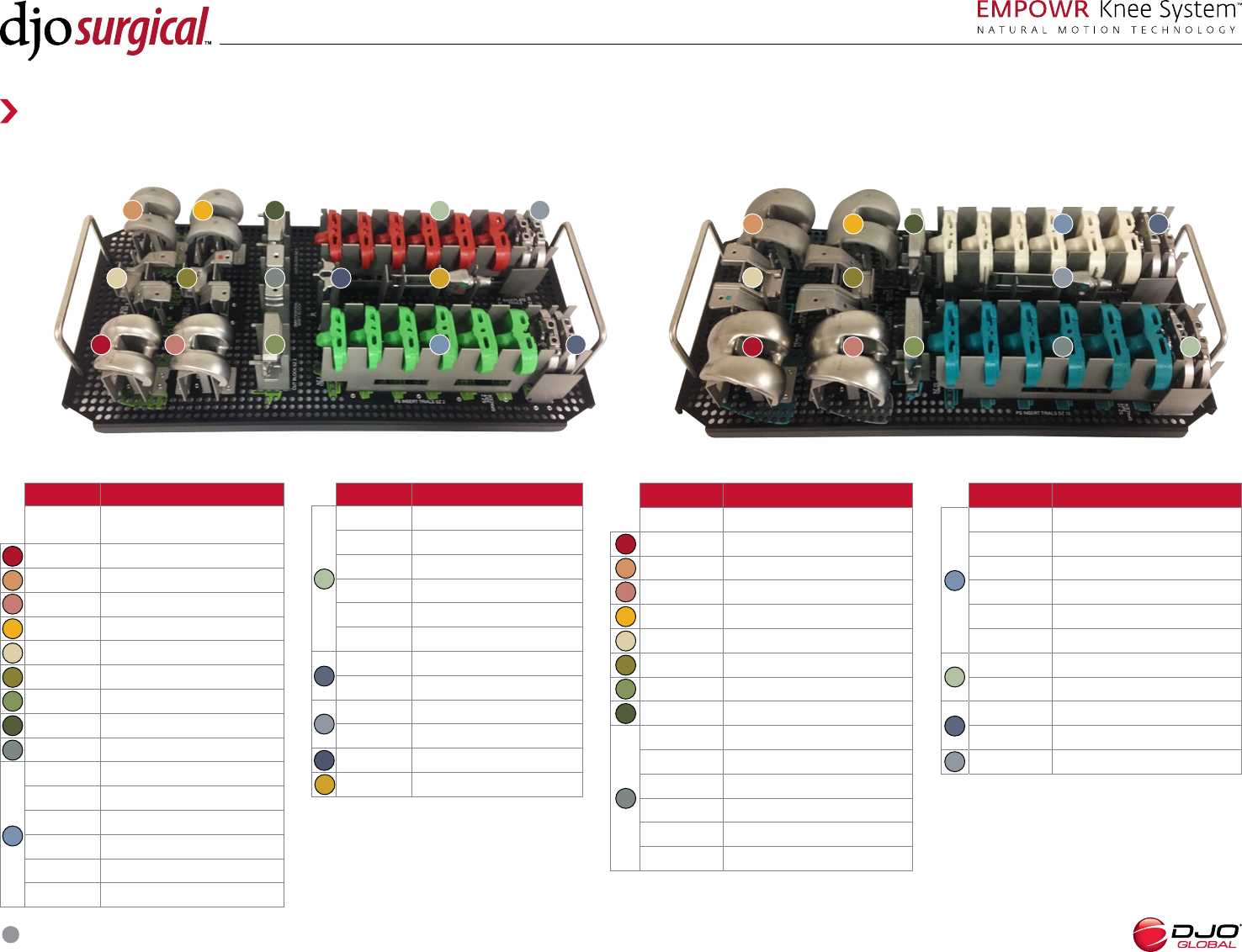
EMPOWR PS KNEE, INSERT TRIAL, SZ , MM POLYPHENYLSULFONE AQUA C
EMPOWR PS KNEE, INSERT TRIAL, SZ , MM POLYPHENYLSULFONE AQUA C

SURGICAL TECHNIQUE
43
Instrument Material list
PART NO. DESCRIPTION MATERIALS COLORANT
EMPOWR PS KNEE, INSERT TRIAL, SZ , MM POLYPHENYLSULFONE AQUA C
EMPOWR PS KNEE, INSERT TRIAL, SZ , MM POLYPHENYLSULFONE AQUA C
EMPOWR PS KNEE, INSERT TRIAL, SZ , MM POLYPHENYLSULFONE AQUA C
EMPOWR PS KNEE, ART SURFACE SPACER, SZ POLYPHENYLSULFONE AQUA C
EMPOWR PS KNEE, INSERT TRIAL, SZ , MM POLYPHENYLSULFONE BEIGE C
EMPOWR PS KNEE, INSERT TRIAL, SZ , MM POLYPHENYLSULFONE BEIGE C
EMPOWR PS KNEE, INSERT TRIAL, SZ , MM POLYPHENYLSULFONE BEIGE C
EMPOWR PS KNEE, INSERT TRIAL, SZ , MM POLYPHENYLSULFONE BEIGE C
EMPOWR PS KNEE, INSERT TRIAL, SZ , MM POLYPHENYLSULFONE BEIGE C
EMPOWR PS KNEE, ART SURFACE SPACER, SZ POLYPHENYLSULFONE BEIGE C
EMPOWR PS KNEE BOX CUT GUIDE, SIZE STAINLESS STEEL/POLYPHENYLSULFONE AQUA C
EMPOWR PS KNEE BOX CUT GUIDE, SIZE STAINLESS STEEL/POLYPHENYLSULFONE BEIGE C
EMPOWR PS KNEE BOX CUT GUIDE WITH CAPTURE, SIZE STAINLESS STEEL/POLYPHENYLSULFONE AQUA C
EMPOWR PS KNEE BOX CUT GUIDE WITH CAPTURE, SIZE STAINLESS STEEL/POLYPHENYLSULFONE BEIGE C
EMPOWR BOX CUT GUIDE CHISEL, SZ AND STAINLESS STEEL/POLYPHENYLSULFONE AQUA C, BEIGE C
EMPOWR PS KNEE, FEMORAL TRIAL, L COBALT CHROME NONE
EMPOWR PS KNEE, FEMORAL TRIAL, R COBALT CHROME NONE
EMPOWR PS KNEE, FEMORAL TRIAL, L COBALT CHROME NONE
EMPOWR PS KNEE, FEMORAL TRIAL, R COBALT CHROME NONE
EMPOWR PS KNEE, INSERT TRIAL, SZ , MM POLYPHENYLSULFONE LIME GREEN C
EMPOWR PS KNEE, INSERT TRIAL, SZ , MM POLYPHENYLSULFONE LIME GREEN C
EMPOWR PS KNEE, INSERT TRIAL, SZ , MM POLYPHENYLSULFONE LIME GREEN C
EMPOWR PS KNEE, INSERT TRIAL, SZ , MM POLYPHENYLSULFONE LIME GREEN C
EMPOWR PS KNEE, INSERT TRIAL, SZ , MM POLYPHENYLSULFONE LIME GREEN C
EMPOWR PS KNEE, ART SURFACE SPACER, SZ POLYPHENYLSULFONE LIME GREEN C
EMPOWR PS KNEE, INSERT TRIAL, SZ , MM POLYPHENYLSULFONE RUST C
EMPOWR PS KNEE, INSERT TRIAL, SZ , MM POLYPHENYLSULFONE RUST C
EMPOWR PS KNEE, INSERT TRIAL, SZ , MM POLYPHENYLSULFONE RUST C
EMPOWR PS KNEE, INSERT TRIAL, SZ , MM POLYPHENYLSULFONE RUST C
EMPOWR PS KNEE, INSERT TRIAL, SZ , MM POLYPHENYLSULFONE RUST C
EMPOWR PS KNEE, ART SURFACE SPACER, SZ POLYPHENYLSULFONE RUST C
EMPOWR PS KNEE BOX CUT GUIDE, SIZE STAINLESS STEEL/POLYPHENYLSULFONE LIME GREEN C
EMPOWR PS KNEE BOX CUT GUIDE, SIZE STAINLESS STEEL/POLYPHENYLSULFONE RUST C
EMPOWR PS KNEE BOX CUT GUIDE WITH CAPTURE, SIZE STAINLESS STEEL/POLYPHENYLSULFONE LIME GREEN C
EMPOWR PS KNEE BOX CUT GUIDE WITH CAPTURE, SIZE STAINLESS STEEL/POLYPHENYLSULFONE RUST C
EMPOWR BOX CUT GUIDE CHISEL, SZ AND STAINLESS STEEL/POLYPHENYLSULFONE LIME GREEN C, RUST C
EMPOWR, FEMORAL SIZER STYLUS STAINLESS STEEL NONE
EMPOWR, FEMORAL SIZER STAINLESS STEEL NONE
EMPOWR, DRF FEMORAL SPEEDBLOCK, SZ STAINLESS STEEL NONE
EMPOWR, DRF FEMORAL SPEEDBLOCK, SZ STAINLESS STEEL NONE
EMPOWR, DRF FEMORAL SPEEDBLOCK, SZ STAINLESS STEEL NONE
PART NO. DESCRIPTION MATERIALS COLORANT
EMPOWR, DRF FEMORAL SPEEDBLOCK, SZ STAINLESS STEEL NONE
EMPOWR, DRF FEMORAL SPEEDBLOCK, SZ STAINLESS STEEL NONE
EMPOWR, DRF FEMORAL SPEEDBLOCK, SZ STAINLESS STEEL NONE
EMPOWR, DRF FEMORAL SPEEDBLOCK, SZ STAINLESS STEEL NONE
EMPOWR, DRF FEMORAL SPEEDBLOCK, SZ STAINLESS STEEL NONE
EMPOWR, DRF FEMORAL SPEEDBLOCK, SZ STAINLESS STEEL NONE
EMPOWR, DRF FEMORAL SPEEDBLOCK, SZ STAINLESS STEEL NONE
EMPOWR, DRF FEMORAL SPEEDBLOCK, SZ STAINLESS STEEL NONE
EMPOWR, FEMORAL HOLDER IMPACTOR/EXTRACTOR STAINLESS STEEL NONE
EMPOWR, FEMORAL PEG SPIKE STAINLESS STEEL NONE
EMPOWR, GAP BALANCER, FEMORAL SIZER INSTRUMENT STAINLESS STEEL NONE
EMPOWR D, FEMORAL TRIAL, L COBALT CHROME NONE
EMPOWR D, FEMORAL TRIAL, L COBALT CHROME NONE
EMPOWR D, FEMORAL TRIAL, L COBALT CHROME NONE
EMPOWR D, FEMORAL TRIAL, L COBALT CHROME NONE
EMPOWR D, FEMORAL TRIAL, L COBALT CHROME NONE
EMPOWR D, FEMORAL TRIAL, L COBALT CHROME NONE
EMPOWR D, FEMORAL TRIAL, L COBALT CHROME NONE
EMPOWR D, FEMORAL TRIAL, L COBALT CHROME NONE
EMPOWR D, FEMORAL TRIAL, L COBALT CHROME NONE
EMPOWR D, FEMORAL TRIAL, L COBALT CHROME NONE
EMPOWR D, FEMORAL TRIAL, R COBALT CHROME NONE
EMPOWR D, FEMORAL TRIAL, R COBALT CHROME NONE
EMPOWR D, FEMORAL TRIAL, R COBALT CHROME NONE
EMPOWR D, FEMORAL TRIAL, R COBALT CHROME NONE
EMPOWR D, FEMORAL TRIAL, R COBALT CHROME NONE
EMPOWR D, FEMORAL TRIAL, R COBALT CHROME NONE
EMPOWR D, FEMORAL TRIAL, R COBALT CHROME NONE
EMPOWR D, FEMORAL TRIAL, R COBALT CHROME NONE
EMPOWR D, FEMORAL TRIAL, R COBALT CHROME NONE
EMPOWR D, FEMORAL TRIAL, R COBALT CHROME NONE
EMPOWR D, FEMORAL TRIAL, R COBALT CHROME NONE
EMPOWR, TIBIAL STEM REAMER FIN STAINLESS STEEL NONE
EMPOWR, MODULAR FIN BROACH, SMALL STAINLESS STEEL NONE
EMPOWR, MODULAR FIN BROACH, CORE STAINLESS STEEL NONE
EMPOWR, MODULAR FIN BROACH, LARGE STAINLESS STEEL NONE
EMPOWR, INSERT SEATER STAINLESS STEEL NONE
EMPOWR, TIBIAL INSERT TRIAL INSERTION HANDLE STAINLESS STEEL NONE
EMPOWR, TIBIAL BASEPLATE IMPACTOR HEAD STAINLESS STEEL/POLYPHENYLSULFONE BLACK C
EMPOWR, TIBIAL INSERT IMPACTOR HEAD STAINLESS STEEL/POLYPHENYLSULFONE BLACK C
EMPOWR, EXT GAP BLOCK, MM POLYPHENYLSULFONE BLACK C
SURGICAL TECHNIQUE
44
Instrument Material list
PART NO. DESCRIPTION MATERIALS COLORANT
EMPOWR, EXT GAP BLOCK, MM POLYPHENYLSULFONE BLACK C
EMPOWR, EXT GAP BLOCK, MM POLYPHENYLSULFONE BLACK C
EMPOWR, EXT GAP BLOCK, MM POLYPHENYLSULFONE BLACK C
EMPOWR, EXT GAP BLOCK, MM POLYPHENYLSULFONE BLACK C
EMPOWR, FIN BASEPLATE TRIAL, L MINUS STAINLESS STEEL/POLYPHENYLSULFONE LIME GREEN C
EMPOWR, FIN BASEPLATE TRIAL, L STAINLESS STEEL/POLYPHENYLSULFONE LIME GREEN C
EMPOWR, FIN BASEPLATE TRIAL, L MINUS STAINLESS STEEL/POLYPHENYLSULFONE RUST C
EMPOWR, FIN BASEPLATE TRIAL, L STAINLESS STEEL/POLYPHENYLSULFONE RUST C
EMPOWR, FIN BASEPLATE TRIAL, L MINUS STAINLESS STEEL/POLYPHENYLSULFONE YELLOW C
EMPOWR, FIN BASEPLATE TRIAL, L STAINLESS STEEL/POLYPHENYLSULFONE YELLOW C
EMPOWR, FIN BASEPLATE TRIAL, L MINUS STAINLESS STEEL/POLYPHENYLSULFONE NEON ORANGE C
EMPOWR, FIN BASEPLATE TRIAL, L STAINLESS STEEL/POLYPHENYLSULFONE NEON ORANGE C
EMPOWR, FIN BASEPLATE TRIAL, L MINUS STAINLESS STEEL/POLYPHENYLSULFONE VERDE C
EMPOWR, FIN BASEPLATE TRIAL, L STAINLESS STEEL/POLYPHENYLSULFONE VERDE C
EMPOWR, FIN BASEPLATE TRIAL, L MINUS STAINLESS STEEL/POLYPHENYLSULFONE GREY C
EMPOWR, FIN BASEPLATE TRIAL, L STAINLESS STEEL/POLYPHENYLSULFONE GREY C
EMPOWR, FIN BASEPLATE TRIAL, L MINUS STAINLESS STEEL/POLYPHENYLSULFONE WINDY BLUE C
EMPOWR, FIN BASEPLATE TRIAL, L STAINLESS STEEL/POLYPHENYLSULFONE WINDY BLUE C
EMPOWR, FIN BASEPLATE TRIAL, L MINUS STAINLESS STEEL/POLYPHENYLSULFONE BLACK C
EMPOWR, FIN BASEPLATE TRIAL, L STAINLESS STEEL/POLYPHENYLSULFONE BLACK C
EMPOWR, FIN BASEPLATE TRIAL, L MINUS STAINLESS STEEL/POLYPHENYLSULFONE AQUA C
EMPOWR, FIN BASEPLATE TRIAL, L STAINLESS STEEL/POLYPHENYLSULFONE AQUA C
EMPOWR, FIN BASEPLATE TRIAL, L MINUS STAINLESS STEEL/POLYPHENYLSULFONE BONE C
EMPOWR, FIN BASEPLATE TRIAL, L STAINLESS STEEL/POLYPHENYLSULFONE BONE C
EMPOWR, FIN BASEPLATE TRIAL, R MINUS STAINLESS STEEL/POLYPHENYLSULFONE LIME GREEN C
EMPOWR, FIN BASEPLATE TRIAL, R STAINLESS STEEL/POLYPHENYLSULFONE LIME GREEN C
EMPOWR, FIN BASEPLATE TRIAL, R MINUS STAINLESS STEEL/POLYPHENYLSULFONE RUST C
EMPOWR, FIN BASEPLATE TRIAL, R STAINLESS STEEL/POLYPHENYLSULFONE RUST C
EMPOWR, FIN BASEPLATE TRIAL, R MINUS STAINLESS STEEL/POLYPHENYLSULFONE YELLOW C
EMPOWR, FIN BASEPLATE TRIAL, R STAINLESS STEEL/POLYPHENYLSULFONE YELLOW C
EMPOWR, FIN BASEPLATE TRIAL, R MINUS STAINLESS STEEL/POLYPHENYLSULFONE NEON ORANGE C
EMPOWR, FIN BASEPLATE TRIAL, R STAINLESS STEEL/POLYPHENYLSULFONE NEON ORANGE C
EMPOWR, FIN BASEPLATE TRIAL, R MINUS STAINLESS STEEL/POLYPHENYLSULFONE VERDE C
EMPOWR, FIN BASEPLATE TRIAL, R STAINLESS STEEL/POLYPHENYLSULFONE VERDE C
EMPOWR, FIN BASEPLATE TRIAL, R MINUS STAINLESS STEEL/POLYPHENYLSULFONE GREY C
EMPOWR, FIN BASEPLATE TRIAL, R STAINLESS STEEL/POLYPHENYLSULFONE GREY C
EMPOWR, FIN BASEPLATE TRIAL, R MINUS STAINLESS STEEL/POLYPHENYLSULFONE WINDY BLUE C
EMPOWR, FIN BASEPLATE TRIAL, R STAINLESS STEEL/POLYPHENYLSULFONE WINDY BLUE C
EMPOWR, FIN BASEPLATE TRIAL, R MINUS STAINLESS STEEL/POLYPHENYLSULFONE BLACK C
EMPOWR, FIN BASEPLATE TRIAL, R STAINLESS STEEL/POLYPHENYLSULFONE BLACK C
EMPOWR, FIN BASEPLATE TRIAL, R MINUS STAINLESS STEEL/POLYPHENYLSULFONE AQUA C
PART NO. DESCRIPTION MATERIALS COLORANT
EMPOWR, FIN BASEPLATE TRIAL, R STAINLESS STEEL/POLYPHENYLSULFONE AQUA C
EMPOWR, FIN BASEPLATE TRIAL, R MINUS STAINLESS STEEL/POLYPHENYLSULFONE BONE C
EMPOWR, FIN BASEPLATE TRIAL, R STAINLESS STEEL/POLYPHENYLSULFONE BONE C
EMPOWR, FIN BASEPLATE TRIAL, L PLUS STAINLESS STEEL/POLYPHENYLSULFONE BONE C
EMPOWR, FIN BASEPLATE TRIAL, R PLUS STAINLESS STEEL/POLYPHENYLSULFONE BONE C
EMPOWR D, INSERT TRIAL, L, MM POLYPHENYLSULFONE LIME GREEN C
EMPOWR D, INSERT TRIAL, L, MM POLYPHENYLSULFONE LIME GREEN C
EMPOWR D, INSERT TRIAL, L, MM POLYPHENYLSULFONE LIME GREEN C
EMPOWR D, INSERT TRIAL, L, MM POLYPHENYLSULFONE RUST C
EMPOWR D, INSERT TRIAL, L, MM POLYPHENYLSULFONE RUST C
EMPOWR D, INSERT TRIAL, L, MM POLYPHENYLSULFONE RUST C
EMPOWR D, INSERT TRIAL, L, MM POLYPHENYLSULFONE YELLOW C
EMPOWR D, INSERT TRIAL, L, MM POLYPHENYLSULFONE YELLOW C
EMPOWR D, INSERT TRIAL, L, MM POLYPHENYLSULFONE YELLOW C
EMPOWR D, INSERT TRIAL, L, MM POLYPHENYLSULFONE NEON ORANGE C
EMPOWR D, INSERT TRIAL, L, MM POLYPHENYLSULFONE NEON ORANGE C
EMPOWR D, INSERT TRIAL, L, MM POLYPHENYLSULFONE NEON ORANGE C
EMPOWR D, INSERT TRIAL, L, MM POLYPHENYLSULFONE VERDE C
EMPOWR D, INSERT TRIAL, L, MM POLYPHENYLSULFONE VERDE C
EMPOWR D, INSERT TRIAL, L, MM POLYPHENYLSULFONE VERDE C
EMPOWR D, INSERT TRIAL, L, MM POLYPHENYLSULFONE GREY C
EMPOWR D, INSERT TRIAL, L, MM POLYPHENYLSULFONE GREY C
EMPOWR D, INSERT TRIAL, L, MM POLYPHENYLSULFONE GREY C
EMPOWR D, INSERT TRIAL, L, MM POLYPHENYLSULFONE WINDY BLUE C
EMPOWR D, INSERT TRIAL, L, MM POLYPHENYLSULFONE WINDY BLUE C
EMPOWR D, INSERT TRIAL, L, MM POLYPHENYLSULFONE WINDY BLUE C
EMPOWR D, INSERT TRIAL, L, MM POLYPHENYLSULFONE BLACK C
EMPOWR D, INSERT TRIAL, L, MM POLYPHENYLSULFONE BLACK C
EMPOWR D, INSERT TRIAL, L, MM POLYPHENYLSULFONE BLACK C
EMPOWR D, INSERT TRIAL, L, MM POLYPHENYLSULFONE AQUA C
EMPOWR D, INSERT TRIAL, L, MM POLYPHENYLSULFONE AQUA C
EMPOWR D, INSERT TRIAL, L, MM POLYPHENYLSULFONE AQUA C
EMPOWR D, INSERT TRIAL, L, MM POLYPHENYLSULFONE BONE C
EMPOWR D, INSERT TRIAL, L, MM POLYPHENYLSULFONE BONE C
EMPOWR D, INSERT TRIAL, L, MM POLYPHENYLSULFONE BONE C
EMPOWR D, INSERT TRIAL, R, MM POLYPHENYLSULFONE LIME GREEN C
EMPOWR D, INSERT TRIAL, R, MM POLYPHENYLSULFONE LIME GREEN C
EMPOWR D, INSERT TRIAL, R, MM POLYPHENYLSULFONE LIME GREEN C
EMPOWR D, INSERT TRIAL, R, MM POLYPHENYLSULFONE RUST C
EMPOWR D, INSERT TRIAL, R, MM POLYPHENYLSULFONE RUST C
EMPOWR D, INSERT TRIAL, R, MM POLYPHENYLSULFONE RUST C
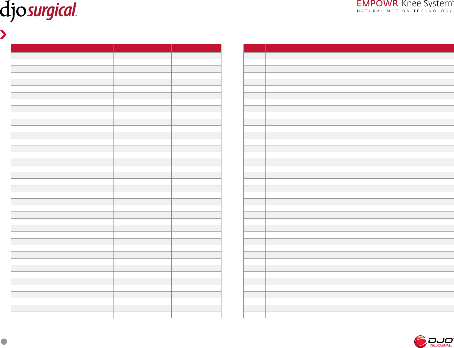
SURGICAL TECHNIQUE
45
Instrument Material list
PART NO. DESCRIPTION MATERIALS COLORANT
EMPOWR D, INSERT TRIAL, R, MM POLYPHENYLSULFONE YELLOW C
EMPOWR D, INSERT TRIAL, R, MM POLYPHENYLSULFONE YELLOW C
EMPOWR D, INSERT TRIAL, R, MM POLYPHENYLSULFONE YELLOW C
EMPOWR D, INSERT TRIAL, R, MM POLYPHENYLSULFONE NEON ORANGE C
EMPOWR D, INSERT TRIAL, R, MM POLYPHENYLSULFONE NEON ORANGE C
EMPOWR D, INSERT TRIAL, R, MM POLYPHENYLSULFONE NEON ORANGE C
EMPOWR D, INSERT TRIAL, R, MM POLYPHENYLSULFONE VERDE C
EMPOWR D, INSERT TRIAL, R, MM POLYPHENYLSULFONE VERDE C
EMPOWR D, INSERT TRIAL, R, MM POLYPHENYLSULFONE VERDE C
EMPOWR D, INSERT TRIAL, R, MM POLYPHENYLSULFONE GREY C
EMPOWR D, INSERT TRIAL, R, MM POLYPHENYLSULFONE GREY C
EMPOWR D, INSERT TRIAL, R, MM POLYPHENYLSULFONE GREY C
EMPOWR D, INSERT TRIAL, R, MM POLYPHENYLSULFONE WINDY BLUE C
EMPOWR D, INSERT TRIAL, R, MM POLYPHENYLSULFONE WINDY BLUE C
EMPOWR D, INSERT TRIAL, R, MM POLYPHENYLSULFONE WINDY BLUE C
EMPOWR D, INSERT TRIAL, R, MM POLYPHENYLSULFONE BLACK C
EMPOWR D, INSERT TRIAL, R, MM POLYPHENYLSULFONE BLACK C
EMPOWR D, INSERT TRIAL, R, MM POLYPHENYLSULFONE BLACK C
EMPOWR D, INSERT TRIAL, R, MM POLYPHENYLSULFONE AQUA C
EMPOWR D, INSERT TRIAL, R, MM POLYPHENYLSULFONE AQUA C
EMPOWR D, INSERT TRIAL, R, MM POLYPHENYLSULFONE AQUA C
EMPOWR D, INSERT TRIAL, R, MM POLYPHENYLSULFONE BONE C
EMPOWR D, INSERT TRIAL, R, MM POLYPHENYLSULFONE BONE C
EMPOWR D, INSERT TRIAL, R, MM POLYPHENYLSULFONE BONE C
EMPOWR, INSERT SPACER TRIAL, SZ , MM POLYPHENYLSULFONE LIME GREEN C
EMPOWR, INSERT SPACER TRIAL, SZ , MM POLYPHENYLSULFONE LIME GREEN C
EMPOWR, INSERT SPACER TRIAL, SZ , MM POLYPHENYLSULFONE RUST C
EMPOWR, INSERT SPACER TRIAL, SZ , MM POLYPHENYLSULFONE RUST C
EMPOWR, INSERT SPACER TRIAL, SZ , MM POLYPHENYLSULFONE YELLOW C
EMPOWR, INSERT SPACER TRIAL, SZ , MM POLYPHENYLSULFONE YELLOW C
EMPOWR, INSERT SPACER TRIAL, SZ , MM POLYPHENYLSULFONE NEON ORANGE C
EMPOWR, INSERT SPACER TRIAL, SZ , MM POLYPHENYLSULFONE NEON ORANGE C
EMPOWR, INSERT SPACER TRIAL, SZ , MM POLYPHENYLSULFONE VERDE C
EMPOWR, INSERT SPACER TRIAL, SZ , MM POLYPHENYLSULFONE VERDE C
EMPOWR, INSERT SPACER TRIAL, SZ , MM POLYPHENYLSULFONE GREY C
EMPOWR, INSERT SPACER TRIAL, SZ , MM POLYPHENYLSULFONE GREY C
EMPOWR, INSERT SPACER TRIAL, SZ , MM POLYPHENYLSULFONE WINDY BLUE C
EMPOWR, INSERT SPACER TRIAL, SZ , MM POLYPHENYLSULFONE WINDY BLUE C
EMPOWR, INSERT SPACER TRIAL, SZ , MM POLYPHENYLSULFONE BLACK C
EMPOWR, INSERT SPACER TRIAL, SZ , MM POLYPHENYLSULFONE BLACK C
PART NO. DESCRIPTION MATERIALS COLORANT
EMPOWR, INSERT SPACER TRIAL, SZ , MM POLYPHENYLSULFONE AQUA C
EMPOWR, INSERT SPACER TRIAL, SZ , MM POLYPHENYLSULFONE AQUA C
EMPOWR, INSERT SPACER TRIAL, SZ , MM POLYPHENYLSULFONE BONE C
EMPOWR, INSERT SPACER TRIAL, SZ , MM POLYPHENYLSULFONE BONE C
EMPOWR D, ART SURFACE SPACER, SZ L POLYPHENYLSULFONE LIME GREEN C
EMPOWR D, ART SURFACE SPACER, SZ L POLYPHENYLSULFONE RUST C
EMPOWR D, ART SURFACE SPACER, SZ L POLYPHENYLSULFONE YELLOW C
EMPOWR D, ART SURFACE SPACER, SZ L POLYPHENYLSULFONE NEON ORANGE C
EMPOWR D, ART SURFACE SPACER, SZ L POLYPHENYLSULFONE VERDE C
EMPOWR D, ART SURFACE SPACER, SZ L POLYPHENYLSULFONE GREY C
EMPOWR D, ART SURFACE SPACER, SZ L POLYPHENYLSULFONE WINDY BLUE C
EMPOWR D, ART SURFACE SPACER, SZ L POLYPHENYLSULFONE BLACK C
EMPOWR D, ART SURFACE SPACER, SZ L POLYPHENYLSULFONE AQUA C
EMPOWR D, ART SURFACE SPACER, SZ L POLYPHENYLSULFONE BONE C
EMPOWR D, ART SURFACE SPACER, SZ R POLYPHENYLSULFONE LIME GREEN C
EMPOWR D, ART SURFACE SPACER, SZ R POLYPHENYLSULFONE RUST C
EMPOWR D, ART SURFACE SPACER, SZ R POLYPHENYLSULFONE YELLOW C
EMPOWR D, ART SURFACE SPACER, SZ R POLYPHENYLSULFONE NEON ORANGE C
EMPOWR D, ART SURFACE SPACER, SZ R POLYPHENYLSULFONE VERDE C
EMPOWR D, ART SURFACE SPACER, SZ R POLYPHENYLSULFONE GREY C
EMPOWR D, ART SURFACE SPACER, SZ R POLYPHENYLSULFONE WINDY BLUE C
EMPOWR D, ART SURFACE SPACER, SZ R POLYPHENYLSULFONE BLACK C
EMPOWR D, ART SURFACE SPACER, SZ R POLYPHENYLSULFONE AQUA C
EMPOWR D, ART SURFACE SPACER, SZ R POLYPHENYLSULFONE BONE C
EMPOWR, PATELLA DRILL GUIDE, //MM STAINLESS STEEL NONE
EMPOWR, PATELLA DRILL GUIDE, /MM STAINLESS STEEL NONE
EMPOWR, PATELLA SEATER STAINLESS STEEL NONE
TRIAL, DOMED PATELLA XMM ACETAL COPOLYMER YELLOW C
TRIAL, DOMED PATELLA XMM ACETAL COPOLYMER RUST C
TRIAL, DOMED PATELLA XMM ACETAL COPOLYMER GREEN C
TRIAL, DOMED PATELLA XMM ACETAL COPOLYMER BLUE C
TRIAL, DOMED PATELLA XMM ACETAL COPOLYMER BLACK C X
LOCKING FEMORAL IMPACTOR STAINLESS STEEL / POLYPROPLYENE BKV
LOCKING FEMORAL IMPACTOR REPLACEMENT HEAD POLYPROPLYENE BKV
EMPOWR, GAP BALANCER, LAMINA SPREADER STAINLESS STEEL NONE
EMPOWR, TIBIAL TRANSITION MODULE STAINLESS STEEL NONE
DJO EMPOWR KNEE, EM PROXIMAL BODY STAINLESS STEEL NONE
EMPOWR, TIBIAL IM GUIDE BASE STAINLESS STEEL NONE
EMPOWR, TIBIA IM // DEG GUIDE STAINLESS STEEL NONE
DJO EMPOWRTM, GAP BALANCER, LAMINA SPREADER STAINLESS STEEL NONE
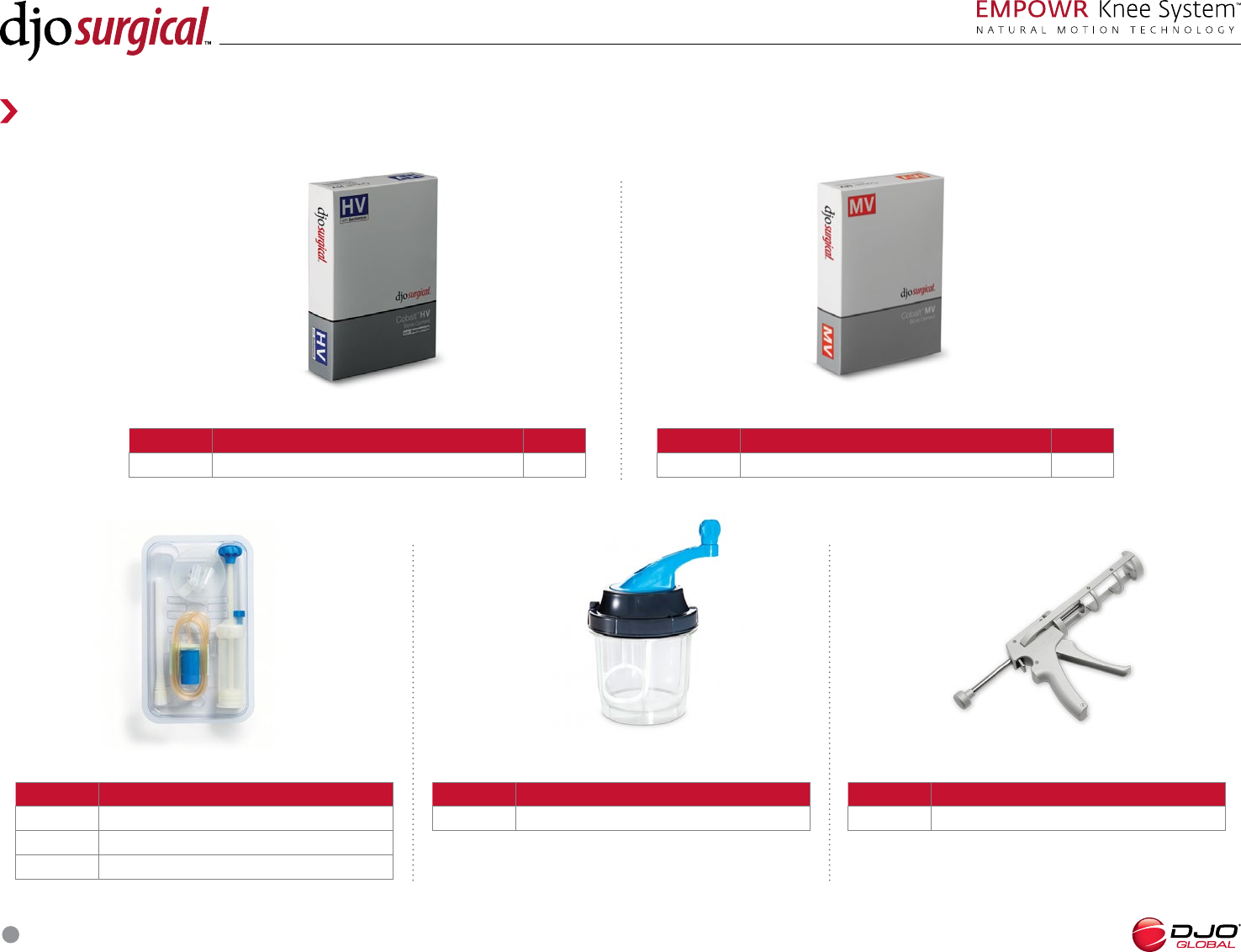
SURGICAL TECHNIQUE
46
Optitwist® Vacuum Mixing Bowl
PART NO. DESCRIPTION
Max Capacity g ( units) High Viscosity (Pk of )
Optivac® Vacuum Mixing System
PART NO. DESCRIPTION
Total Hip kit, g Single Mix
Total Hip kit, g Double Mix
Total Hip kit, g Triple Mix
Optigun® Cement Gun
PART NO. DESCRIPTION
Optigun® Cement Gun
Cobalt® HV Bone Cement
PART NO. DESCRIPTION SIZE
Cobalt MV Bone Cement g
Reference Guide
CEMENT AND CEMENT ACCESSORIES
Cobalt® HV Bone Cement
PART NO. DESCRIPTION SIZE
Cobalt HV Bone Cement g
0010314-131 Rev F 09/16
COPYRIGHT © 2016 BY DJO, LLC
ALL RIGHTS RESERVED. NO PART OF THIS PUBLICATION MAY BE REPRODUCED, DISTRIBUTED, OR TRANSMITTED IN ANY FORM OR BY ANY MEANS, INCLUDING PHOTOCOPYING, RECORDING, OR OTHER ELECTRONIC OR MECHANICAL METHODS, WITHOUT THE PRIOR
WRITTEN PERMISSION OF THE PUBLISHER, EXCEPT IN THE CASE OF BRIEF QUOTATIONS EMBODIED IN CRITICAL REVIEWS AND CERTAIN OTHER NONCOMMERCIAL USES PERMITTED BY COPYRIGHT LAW. FOR PERMISSION REQUESTS, WRITE TO THE PUBLISHER, ADDRESSED
“ATTENTION: IP COUNSEL,” AT THE ADDRESS 1430 DECISION ST, VISTA, CA 92081.
DJO Surgical I A DJO Global Company
T 800.456.8696 D 512.832.9500 F 512.834.6300
9800 Metric Blvd. I Austin, TX 78758 I U.S.A.
djoglobal.com/djosurgical
