Experiment Builder User Manual
User Manual: Pdf
Open the PDF directly: View PDF ![]() .
.
Page Count: 408 [warning: Documents this large are best viewed by clicking the View PDF Link!]

SR Research Experiment Builder
User Manual
Version 2.1.140
Please report all functionality comments and bugs to:
support@sr-research.com
An HTML version of this document, which contains extra sections
on example projects and frequently asked questions, can be
accessed by pressing F1 or clicking “Help → Content” from the
Experiment Builder application, or can be downloaded from
https://www.sr-support.com/forums/showthread.php?t=99.
Copyright ©2004-2017 SR Research Ltd.
EyeLink is a registered trademark of SR Research Ltd., Mississauga, Canada
SR Research Experiment Builder User Manual ©2004-2017 SR Research Ltd.
i
Table of Contents
1!Introduction ................................................................................................................... 1!
1.1!Features .................................................................................................................. 1!
1.2!How to Use This Manual ....................................................................................... 2!
1.3!Citing Experiment Builder ..................................................................................... 3!
2!Experiment Builder Experiment Life Cycle ................................................................. 4!
2.1!Experiment Design ................................................................................................. 4!
2.2!Building and Test-running Experiment ................................................................. 5!
2.3!Experiment Deployment ........................................................................................ 5!
2.4!Participant Data Set Randomization ...................................................................... 6!
2.5!Data Collection ...................................................................................................... 6!
2.6!Data Analysis ......................................................................................................... 6!
3!Installation ..................................................................................................................... 8!
3.1!Windows PC System Requirements ...................................................................... 8!
3.1.1!Computer Configuration ................................................................................. 8!
3.1.2!Maximizing the Real-time Performance of the Display PC ........................... 9!
3.1.3!Host Computer and Display Computer Software Requirements .................. 11!
3.2!Software Installation and Licensing on Windows ............................................... 11!
3.2.1!For Standard Installation (Applicable to Most Users) .................................. 12!
3.2.2!For Installation Using Network Licensing .................................................... 12!
3.3!Software Installation and Licensing on Mac OS X ............................................. 14!
3.3.1!Experiment Builder Installation .................................................................... 14!
3.3.2!Other Software Installation ........................................................................... 15!
3.3.3!HASP Driver Installation and Licensing ...................................................... 16!
4!Working with Files ..................................................................................................... 18!
4.1!Creating a New Project ........................................................................................ 18!
4.2!Saving a Project ................................................................................................... 20!
4.3!Saving an Existing Project to a Different Directory ............................................ 21!
4.4!Opening an Existing Project ................................................................................ 21!
4.5!Reopening a Recent Experiment Project ............................................................. 23!
4.6!Lock/Unlock a Project ......................................................................................... 24!
4.7!Packaging an Experiment .................................................................................... 24!
4.8!Unpacking an Experiment .................................................................................... 25!
4.9!Building an Experiment ....................................................................................... 25!
4.10!Cleaning an Experiment ..................................................................................... 26!
4.11!Test-running an Experiment from EB Application ............................................ 26!
4.12!Deploying an Experiment .................................................................................. 26!
4.13!Running an Experiment for Data Collection ..................................................... 27!
4.14!Converting Projects Between Windows and Mac OS X ................................... 29!
5!Experiment Builder Graphical User Interface ............................................................ 30!
5.1!Project Explorer Window .................................................................................... 30!
5.2!Graph Editor Window .......................................................................................... 34!
5.3!Application Menu Bar and Toolbar ..................................................................... 35!
5.3.1!File Menu and Tool Buttons ......................................................................... 35!
5.3.2!Edit Menu and Tool Buttons ......................................................................... 36!
5.3.3!View Menu .................................................................................................... 37!
SR Research Experiment Builder User Manual ©2004-2017 SR Research Ltd.
ii
5.3.4!Experiment Menu and Tool Buttons ............................................................. 37!
5.3.5!Help Menu .................................................................................................... 37!
6!Designing an Experiment in Experiment Builder ....................................................... 39!
6.1!Hierarchical Organization of Experiments .......................................................... 39!
6.2!Experiment Graph: Flow Diagram ....................................................................... 40!
6.2.1!Adding Components to an Experiment ......................................................... 41!
6.2.2!Linking Experiment Components ................................................................. 42!
6.2.3!Linking Rules ................................................................................................ 42!
6.3!Actions ................................................................................................................. 43!
6.4!Triggers ................................................................................................................ 44!
6.5!Other Node Types ................................................................................................ 45!
6.6!Sequence .............................................................................................................. 45!
6.7!References and Equations .................................................................................... 46!
7!Experiment Graph and Components ........................................................................... 49!
7.1!Graph Editing Operations .................................................................................... 49!
7.2!Node Connection ................................................................................................. 50!
7.2.1!Connection: Create, Cancel, and Delete ....................................................... 50!
7.2.2!Connection Order .......................................................................................... 50!
7.2.3!Node Exporting and Importing ..................................................................... 51!
7.2.3.1!Exporting ................................................................................................ 51!
7.2.3.2!Importing ................................................................................................ 52!
7.3!Layout of Nodes in Work Space .......................................................................... 53!
7.4!Editing Properties of a Node ................................................................................ 54!
7.5!Experiment Node ................................................................................................. 55!
7.6!Sequence .............................................................................................................. 57!
7.6.1!Typical Use of Sequences in an Experiment ................................................ 60!
7.6.2!EyeLink Recording Status Message ............................................................. 63!
7.7!Start Node ............................................................................................................ 64!
7.8!Actions ................................................................................................................. 64!
7.8.1!Display Screen .............................................................................................. 65!
7.8.1.1!Reading Display Time ........................................................................... 68!
7.8.1.2!Using Display Screen Actions ............................................................... 69!
7.8.2!Performing Drift Correction ......................................................................... 70!
7.8.3!Performing Camera Setup and Calibration ................................................... 75!
7.8.4!Sending EyeLink Message ............................................................................ 81!
7.8.5!Sending EyeLink Command ......................................................................... 83!
7.8.6!Sending TTL Signals .................................................................................... 86!
7.8.7!Adding to Experiment Log ........................................................................... 89!
7.8.8!Updating Attribute ........................................................................................ 91!
7.8.9!Adding to Accumulator ................................................................................. 93!
7.8.10!Adding to Results File ................................................................................ 93!
7.8.11!Prepare Sequence ........................................................................................ 94!
7.8.12!Reset Node .................................................................................................. 98!
7.8.13!Playing Sound ............................................................................................. 98!
7.8.14!Play Sound Control ................................................................................... 105!
7.8.15!Record Sound ............................................................................................ 107!
SR Research Experiment Builder User Manual ©2004-2017 SR Research Ltd.
iii
7.8.16!Record Sound Control ............................................................................... 109!
7.8.17!Terminating an Experiment ...................................................................... 111!
7.8.18!Recycle Data Line ..................................................................................... 112!
7.8.19!Execute Action .......................................................................................... 114!
7.8.20!Null Action ................................................................................................ 115!
7.8.21!ResponsePixx LED Control ...................................................................... 117!
7.9!Triggers .............................................................................................................. 119!
7.9.1!Timer Trigger .............................................................................................. 119!
7.9.2!Invisible Boundary Trigger ......................................................................... 122!
7.9.2.1!The Location Type of the Invisible Boundary Trigger ........................ 126!
7.9.2.2!How to Show the Triggering Region on the Host PC? ........................ 128!
7.9.3!Conditional Trigger ..................................................................................... 129!
7.9.4!EyeLink Button Trigger .............................................................................. 133!
7.9.4.1!Calculating Response Time of a Button Press ..................................... 135!
7.9.4.2!Collecting Inputs from the EyeLink Button Box Without Ending the
Trial 136!
7.9.4.3!Knowing the ID of a Specific Button on the EyeLink Button Box ..... 137!
7.9.5!Cedrus Button Trigger ................................................................................ 138!
7.9.5.1!Calculating Response Time of a Button Press ..................................... 141!
7.9.5.2!Collecting Inputs from the Cedrus Button Box Without Ending the Trial
142!
7.9.6!Keyboard Trigger ........................................................................................ 143!
7.9.6.1!Calculating Response Time from a Keyboard Input ............................ 146!
7.9.6.2!Collecting Inputs from the Keyboard Without Ending the Trial ......... 148!
7.9.6.3!Enabling Multiple Keyboards .............................................................. 149!
7.9.6.4!Disabling / Re-enabling the Windows Logo Keys .............................. 150!
7.9.7!Mouse Trigger ............................................................................................. 150!
7.9.7.1!Mouse Press, Release, Scroll, and Mouse Over ................................... 154!
7.9.7.2!Center Location Type vs. Top-left Location Type. ............................. 156!
7.9.7.3!Calculating Response Time of a Mouse Click ..................................... 158!
7.9.7.4!Collecting Inputs from the Mouse Without Ending the Trial .............. 159!
7.9.7.5!Resetting the Initial Position of the Mouse Device ............................. 160!
7.9.7.6!Enabling Multiple Mice ....................................................................... 160!
7.9.7.7!Recording Mouse Traces in a Data File ............................................... 161!
7.9.8!TTL Input Trigger ....................................................................................... 162!
7.9.8.1!Setting the Pin Values .......................................................................... 165!
7.9.8.2!TTL Trigger and the Type of Cable Used ........................................... 166!
7.9.9!Fixation Trigger .......................................................................................... 167!
7.9.9.1!Optimal Triggering Duration ............................................................... 171!
7.9.9.2!Top-left vs. Center Triggering Location Type ..................................... 172!
7.9.9.3!How to Show the Triggering Region on the Host PC .......................... 173!
7.9.10!Saccade Trigger ........................................................................................ 174!
7.9.10.1!Top-left vs. Center Triggering Location Type ................................... 177!
7.9.10.2!Online RT Calculation ....................................................................... 179!
7.9.10.3!How to Show the Triggering Region on the Host PC ........................ 179!
7.9.11!Sample Velocity Trigger ........................................................................... 180!
SR Research Experiment Builder User Manual ©2004-2017 SR Research Ltd.
iv
7.9.11.1!Top-left vs. Center Triggering Location Type ................................... 185!
7.9.11.2!How to Show the Triggering Region on the Host PC ........................ 186!
7.9.12!Voice Key Trigger .................................................................................... 187!
7.9.12.1!How to Calculate the Voice Key RT Online ..................................... 189!
7.9.12.2!How to Align the Recordings in the Audio File and Eye Tracker Event
Time 190!
7.10!Other Building Components ............................................................................ 192!
7.10.1!Variable ..................................................................................................... 192!
7.10.2!Results File ............................................................................................... 195!
7.10.3!Accumulator .............................................................................................. 198!
7.10.4!Custom Class Instance .............................................................................. 201!
8!Screen Builder ........................................................................................................... 203!
8.1!Resources ........................................................................................................... 204!
8.1.1!Image Resource ........................................................................................... 204!
8.1.1.1!Image Displaying Modes ..................................................................... 210!
8.1.1.2!Gaze-Contingent Window Manipulations ........................................... 210!
8.1.1.3!Transparency Manipulation ................................................................. 211!
8.1.2!Video Resource ........................................................................................... 212!
8.1.2.1!Reading Frame Time ............................................................................ 217!
8.1.2.2!Video Frame Timing ............................................................................ 217!
8.1.2.3!Video Frame Rate and Display Retrace Rate ...................................... 218!
8.1.2.4!Pausing, Unpausing, and the Status of Video Playing ......................... 219!
8.1.2.5!Dropping Frames ................................................................................. 220!
8.1.2.6!Frame Caching ..................................................................................... 221!
8.1.2.7!Video Codec ......................................................................................... 221!
8.1.2.8!Playing Video Clips with Audio .......................................................... 223!
8.1.3!Text Resource ............................................................................................. 223!
8.1.3.1!Non-ASCII Characters ......................................................................... 226!
8.1.3.2!Anti-aliasing and Transparency ........................................................... 226!
8.1.4!Multiline Text Resource ............................................................................. 228!
8.1.5!Line Resource ............................................................................................. 232!
8.1.6!Rectangle Resource ..................................................................................... 234!
8.1.7!Ellipse Resource .......................................................................................... 236!
8.1.8!Triangle Resource ....................................................................................... 239!
8.1.9!Freeform Resource ...................................................................................... 241!
8.2!Movement Patterns ............................................................................................ 244!
8.2.1!Sinusoidal Movement Pattern ..................................................................... 244!
8.2.2!Custom Movement Pattern ......................................................................... 246!
8.2.2.1!Option 1: Adding Resource Postions ................................................... 247!
8.2.2.2!Option 2: Movement Pattern File ........................................................ 249!
8.3!Interest Areas ..................................................................................................... 251!
8.3.1!Manually Creating an Interest Area ............................................................ 252!
8.3.1.1!Rectangular/Elliptic Interest Area ........................................................ 252!
8.3.1.2!Freeform Interest Area ......................................................................... 253!
8.3.2!Automatic Segmentation ............................................................................. 253!
8.3.3!Using Interest Area Set Files ...................................................................... 255!
SR Research Experiment Builder User Manual ©2004-2017 SR Research Ltd.
v
8.4!Resource Operations .......................................................................................... 257!
8.4.1!Resource Editing ......................................................................................... 257!
8.4.2!Resource Alignment .................................................................................... 257!
8.4.3!Resource Locking ....................................................................................... 259!
8.4.4!Resource Grouping ..................................................................................... 260!
8.4.5!Composite Resource ................................................................................... 261!
8.4.6!Resource Order ........................................................................................... 263!
8.4.7!Others .......................................................................................................... 264!
9!Data Source ............................................................................................................... 266!
9.1!Creating Data Source ......................................................................................... 267!
9.2!Editing Data Source ........................................................................................... 267!
9.3!Importing Existing Files as Data Source ........................................................... 271!
9.4!Using Data Source File ...................................................................................... 272!
9.5!Data Source Splitby ........................................................................................... 273!
9.6!Data Source Randomization .............................................................................. 273!
9.6.1!Internal Randomization ............................................................................... 274!
9.6.1.1!Randomization Seed ............................................................................ 274!
9.6.1.2!Blocking ............................................................................................... 275!
9.6.1.3!Trial randomization and Run Length Control ...................................... 276!
9.6.1.4!Randomize on Roll-Over ..................................................................... 276!
9.6.1.5!Splitting Column .................................................................................. 276!
9.6.1.6!Running Experiment with Internal Randomizer .................................. 277!
9.6.2!External Randomization .............................................................................. 277!
10!References ............................................................................................................... 280!
10.1!Using References ............................................................................................. 280!
10.2!Entering in Values ............................................................................................ 281!
10.3!Entering in References ..................................................................................... 281!
10.4!Entering in Equations ....................................................................................... 282!
10.4.1!Creating a Complex String: Formatting and Concatenating ..................... 283!
10.4.2!Examples ................................................................................................... 284!
10.5!Reference Manager .......................................................................................... 285!
11!EyeLink Data Viewer Integration ........................................................................... 287!
11.1!Trial Condition Variables ................................................................................ 287!
11.2!Images and Interest Areas ................................................................................ 288!
12!Custom Class .......................................................................................................... 290!
12.1!Enabling the Custom Class Option .................................................................. 290!
12.2!Creating a New Custom Class ......................................................................... 290!
12.3!Syntax of Custom Class ................................................................................... 291!
12.3.1!Example .................................................................................................... 292!
12.3.2!Class Definition ........................................................................................ 294!
12.3.3!Class Initialization .................................................................................... 294!
12.3.4!Class Attributes ......................................................................................... 294!
12.3.5!Class Methods ........................................................................................... 295!
12.3.6!'setX' and 'getX' Methods .......................................................................... 296!
12.4!Instantiating Custom Class .............................................................................. 297!
12.5!Using Custom Class ......................................................................................... 299!
SR Research Experiment Builder User Manual ©2004-2017 SR Research Ltd.
vi
12.6!Using the Custom Class Editor ........................................................................ 300!
13!Creating Experiments: Overview ............................................................................ 303!
14!Creating EyeLink Experiments: The First Example ............................................... 304!
14.1!Creating the Experiment .................................................................................. 304!
14.1.1!Creating a New Experiment Project ......................................................... 304!
14.1.2!Configuring Experiment Preference Settings ........................................... 305!
14.1.3!Creating the Experiment Block Sequence ................................................ 308!
14.1.4!Editing the Block Sequence ...................................................................... 309!
14.1.5!Creating the Instructions Screen ............................................................... 311!
14.1.6!Editing the Trial Sequence: Data Source .................................................. 313!
14.1.7!Editing the Trial Sequence: Preparing Sequence and Drift Correction .... 315!
14.1.8!Editing the Recording Sequence ............................................................... 316!
14.1.9!Modifying the Properties of a Display Screen .......................................... 317!
14.1.10!Creating the Display Screen .................................................................... 318!
14.1.11!Writing Trial Condition Variables to EDF file ....................................... 320!
14.1.12!Showing Experiment Progress Message on Tracker Screen ................... 321!
14.2!Building the Experiment .................................................................................. 321!
14.3!Deploying the Experiment ............................................................................... 322!
14.4!Running the Experiment .................................................................................. 322!
14.4.1!Error in Initializing Graphics .................................................................... 322!
14.4.2!Error in Tracker Version ........................................................................... 323!
15!Creating Non-EyeLink Experiments: Stroop Effect .............................................. 324!
15.1!Creating a New Experiment Project ................................................................ 324!
15.2!Configuring Experiment Preference Settings .................................................. 325!
15.3!Creating the Experiment Block Sequence ....................................................... 327!
15.4!Editing the Block Sequence ............................................................................. 328!
15.5!Creating the Instruction Screen ........................................................................ 330!
15.6!Editing the Trial Sequence: Data Source ......................................................... 332!
15.7!Editing the Trial Sequence: Setting Initial Values and Preparing Sequence ... 335!
15.8!Editing the Trial Event Sequence – Part 1 ....................................................... 339!
15.8.1!Creating the Fixation Screen ..................................................................... 341!
15.8.2!Creating the Stroop Display Screen. ......................................................... 342!
15.9!Editing the Trial Event Sequence – Part 2 ....................................................... 344!
15.10!Outputting Data to the Results File ................................................................ 350!
15.11!Running the Experiment ................................................................................ 351!
16!Experiment Builder Project Check List (version 2.1) ............................................. 352!
17!Preference Settings .................................................................................................. 356!
17.1!Experiment ....................................................................................................... 356!
17.1.1!EyeLink ..................................................................................................... 358!
17.1.2!Display ...................................................................................................... 365!
17.1.3!Audio......................................................................................................... 367!
17.1.4!Mouse ........................................................................................................ 368!
17.1.5!Keyboard ................................................................................................... 370!
17.1.6!Cedrus ....................................................................................................... 372!
17.1.7!EyeLink Button Box Device ..................................................................... 373!
17.1.8!Parallel Port ............................................................................................... 374!
SR Research Experiment Builder User Manual ©2004-2017 SR Research Ltd.
vii
17.1.9!USB-1208HS Box ..................................................................................... 375!
17.1.10!Timer ....................................................................................................... 376!
17.1.11!Invisible Boundary .................................................................................. 376!
17.1.12!Conditional .............................................................................................. 377!
17.1.13!EyeLink Button ....................................................................................... 377!
17.1.14!Cedrus Input ............................................................................................ 377!
17.1.15!Keyboard ................................................................................................. 377!
17.1.16!Mouse ...................................................................................................... 377!
17.1.17!TTL Trigger ............................................................................................ 377!
17.1.18!Fixation ................................................................................................... 377!
17.1.19!Saccade ................................................................................................... 377!
17.1.20!Sample Velocity ...................................................................................... 377!
17.1.21!Voice Key ............................................................................................... 377!
17.1.22!Display Screen ........................................................................................ 377!
17.1.23!Drift Correct ............................................................................................ 377!
17.1.24!Camera Setup .......................................................................................... 377!
17.1.25!Send EyeLink Message ........................................................................... 377!
17.1.26!Send Command ....................................................................................... 377!
17.1.27!Set TTL ................................................................................................... 378!
17.1.28!Add to Experiment Log .......................................................................... 378!
17.1.29!Update Attribute ...................................................................................... 378!
17.1.30!Add to Accumulator ................................................................................ 378!
17.1.31!Add to Results File ................................................................................. 378!
17.1.32!Prepare Sequence .................................................................................... 378!
17.1.33!Sequence ................................................................................................. 378!
17.1.34!Reset Node .............................................................................................. 378!
17.1.35!Play Sound .............................................................................................. 378!
17.1.36!Play Sound Control ................................................................................. 378!
17.1.37!Record Sound .......................................................................................... 378!
17.1.38!Record Sound Control ............................................................................. 378!
17.1.39!Terminate Experiment ............................................................................ 378!
17.1.40!Recycle Data Line ................................................................................... 378!
17.1.41!Execute .................................................................................................... 378!
17.1.42!Null Action .............................................................................................. 379!
17.1.43!ResponsePixx LED Control .................................................................... 379!
17.1.44!Accumulator ............................................................................................ 379!
17.1.45!Results File ............................................................................................. 379!
17.2!Screen ............................................................................................................... 379!
17.2.1!Screen ........................................................................................................ 379!
17.2.2!Image Resource ......................................................................................... 380!
17.2.3!Video Resource ......................................................................................... 380!
17.2.4!Text Resource ........................................................................................... 380!
17.2.5!Multiline Text Resource ........................................................................... 380!
17.2.6!Line Resource ........................................................................................... 380!
17.2.7!Rectangle Resource ................................................................................... 380!
17.2.8!Ellipse Resource ........................................................................................ 380!
SR Research Experiment Builder User Manual ©2004-2017 SR Research Ltd.
viii
17.2.9!Triangle Resource ..................................................................................... 380!
17.2.10!Freeform Resource .................................................................................. 380!
17.2.11!Sine Pattern ............................................................................................. 380!
17.2.12!Grid Segmentation .................................................................................. 381!
17.2.13!Auto Segmentation .................................................................................. 381!
17.2.14!Word Segmentation ................................................................................ 382!
17.3!Build/Deploy .................................................................................................... 385!
17.4!GUI .................................................................................................................. 386!
17.4.1!Graph_Layout ........................................................................................... 387!
17.4.2!CustomClass_Editor ................................................................................. 388!
18!Revision History ..................................................................................................... 389!
SR Research Experiment Builder User Manual ©2004-2017 SR Research Ltd.
ix
List of Figures
Figure 3-1. Driver Installation for USB-1208 HS DAQ. .................................................. 12!
Figure 3-2. Choosing “Custom” Setup Type. .................................................................. 13!
Figure 3-3. Enabling HaspHL Driver Option for Network License. ............................... 13!
Figure 3-4. Installing Experiment Builder on Mac OS X. ............................................... 15!
Figure 3-5. Updating Experiment Builder License on Mac OS X. .................................. 17!
Figure 4-1. File Menu. ..................................................................................................... 18!
Figure 4-2. Dialog for Creating a New Project. ............................................................... 19!
Figure 4-3. Warning Messages after Experiment Creation. ............................................ 20!
Figure 4-4. Open an Experiment Builder Project. ........................................................... 22!
Figure 4-5. Save Confirmation When Opening a New Project. ...................................... 22!
Figure 4-6. Change in Video Environment When Opening a New Project. .................... 23!
Figure 4-7. Reopening Recent Experiment Projects. ....................................................... 23!
Figure 4-8. Unlock a Locked Project. .............................................................................. 24!
Figure 4-9. Unpacking an Experiment Project. ............................................................... 25!
Figure 4-10. Experiment Menu. ....................................................................................... 26!
Figure 5-1. Sample Experiment Builder Interface. .......................................................... 30!
Figure 5-2. The View Menu. ............................................................................................ 31!
Figure 5-3. Components of the Project Explorer Window. ............................................. 32!
Figure 5-4. Different Tabs of the Structure Panel. ........................................................... 33!
Figure 5-5. Components of the Graph Editor Window. ................................................... 35!
Figure 6-1. Hierarchical Organization of Events in an Experiment. ............................... 40!
Figure 6-2. Sample Experiment Sequence. ...................................................................... 41!
Figure 6-3. Connecting Between Source and Target Components. .................................. 42!
Figure 6-4. Nested Sequences in an Experiment. ............................................................ 46!
Figure 6-5. Using a Reference to Update Text to Be Displayed. .................................... 48!
Figure 7-1. Connection Order. ......................................................................................... 50!
Figure 7-2. Exporting Node. ............................................................................................ 52!
Figure 7-3. Reference Maintenance. ................................................................................ 52!
Figure 7-4. Export Library Files. ..................................................................................... 52!
Figure 7-5. Importing Node. ............................................................................................ 53!
Figure 7-6. Choosing Layout of Components in Work Space. ........................................ 54!
Figure 7-7. Property Field Editable with Attribute Reference Editor. ............................. 55!
Figure 7-8. Properties of the Experiment Node. .............................................................. 57!
Figure 7-9. Using Sequences in an Experiment. .............................................................. 62!
Figure 7-10. Creating Recording Status Message. ........................................................... 63!
Figure 7-11. Sending the Recording Status Message to the Tracker. .............................. 64!
Figure 7-12. Action Tab of the Component Toolbox. ..................................................... 65!
Figure 7-13. Using Display Screen. ................................................................................. 70!
Figure 7-14. Using Drift Correction Action. ................................................................... 75!
Figure 7-15. Using Camera Setup Action. ....................................................................... 81!
Figure 7-16. Using Sending Message Action. ................................................................. 83!
Figure 7-17. Using Sending EyeLink Command Action. ................................................ 86!
Figure 7-18. Configuring the Direction of Data Flow on USB-1208HS ......................... 89!
Figure 7-19. Using Add to Experiment Log Action. ....................................................... 90!
Figure 7-20. Using Update Attribute Action. .................................................................. 92!
SR Research Experiment Builder User Manual ©2004-2017 SR Research Ltd.
x
Figure 7-21. Using Prepare Sequence Action. ................................................................. 97!
Figure 7-22. Adding Audio Files to the Library Manager. .............................................. 99!
Figure 7-23. Choose Audio Driver. ............................................................................... 100!
Figure 7-24. Setting ASIO Buffer Latency. ................................................................... 102!
Figure 7-25. Using Play Sound Action. ......................................................................... 105!
Figure 7-26. Using Play Sound Control Action. ............................................................ 107!
Figure 7-27. Using Record Sound Action. ..................................................................... 109!
Figure 7-28. Using Terminate Experiment Action. ....................................................... 112!
Figure 7-29. Using Recycle Dataline Action. ................................................................ 114!
Figure 7-30. Using a NULL_ACTION node. ................................................................ 117!
Figure 7-31. Using a ResponsePixx LED Control Action. ............................................ 119!
Figure 7-32. Triggers Implemented in Experiment Builder. ......................................... 119!
Figure 7-33. Using Timer Trigger. ................................................................................ 122!
Figure 7-34. Using an Invisible Boundary Trigger. ....................................................... 126!
Figure 7-35. Using Invisible_Boundary Trigger with Top-left and Center Location
Types. ...................................................................................................................... 127!
Figure 7-36. Drawing the Trigger Region on Host PC. ................................................. 129!
Figure 7-37. Using Conditional Trigger. ....................................................................... 131!
Figure 7-38. Displaying different instruction screens at the beginning of each block. . 132!
Figure 7-39. Using EyeLink Button Trigger. ................................................................. 135!
Figure 7-40. Collecting EyeLink Button Response Data. .............................................. 136!
Figure 7-41. Checking EyeLink Button Response Accuracy. ....................................... 136!
Figure 7-42. Using EyeLink Button Trigger Without Ending a Trial. .......................... 137!
Figure 7-43. Using Cedrus Button Trigger. ................................................................... 141!
Figure 7-44. Collecting Cedrus Button Response Data. ................................................ 142!
Figure 7-45. Checking Cedrus Button Response Accuracy. .......................................... 142!
Figure 7-46. Using Cedrus Button Trigger Without Ending a Trial. ............................. 143!
Figure 7-47. Using Keyboard Trigger. .......................................................................... 146!
Figure 7-48. Collecting Keyboard Response Data. ....................................................... 147!
Figure 7-49. Checking Keyboard Response Accuracy. ................................................. 148!
Figure 7-50. Using Keyboard Without Ending a Trial. ................................................. 149!
Figure 7-51. Using the Mouse Trigger. ......................................................................... 155!
Figure 7-52. Setting the Mouse Triggering Region. ...................................................... 156!
Figure 7-53. Using Mouse Trigger with Top-left and Center Location Types. ............. 158!
Figure 7-54. Collecting Mouse Response Data. ............................................................ 159!
Figure 7-55. Checking Mouse Response Accuracy. ...................................................... 159!
Figure 7-56. Using Mouse Trigger Without Ending a Trial. ......................................... 160!
Figure 7-57. Viewing Mouse Traces in the Data Viewer Temporal Graph View. ........ 162!
Figure 7-58. Using TTL Trigger. ................................................................................... 166!
Figure 7-59. Using Fixation Trigger. ............................................................................. 171!
Figure 7-60. Using Fixation Trigger with Top-left and Center Location Types. .......... 173!
Figure 7-61. Using the Saccade Trigger. ....................................................................... 177!
Figure 7-62. Using Saccade Trigger with Top-left and Center Location Types. .......... 179!
Figure 7-63. Using Sample Velocity Trigger. ............................................................... 184!
Figure 7-64. Using Sample Velocity Trigger with Top-left and Center Location Types.
................................................................................................................................. 186!
SR Research Experiment Builder User Manual ©2004-2017 SR Research Ltd.
xi
Figure 7-65. Collecting the Voicekey Response Data. .................................................. 190!
Figure 7-66. Aligning Audio Recording Times. ............................................................ 191!
Figure 7-67. Other Components Implemented in Experiment Builder. ......................... 192!
Figure 7-68. Using a Variable. ....................................................................................... 193!
Figure 7-69. Property Settings for Variables. ................................................................ 194!
Figure 7-70. Dynamic Data Type Casting. .................................................................... 195!
Figure 7-71. Using Results File. .................................................................................... 196!
Figure 7-72. Setting Properties of the Results File Node. ............................................. 197!
Figure 7-73. Using Accumulator. .................................................................................. 199!
Figure 7-74. Setting the Properties of Accumulator. ..................................................... 200!
Figure 7-75. Adding Data to and Retrieving Data from the Accumulator. ................... 201!
Figure 8-1. Sample View of the Screen Builder Interface. ............................................ 204!
Figure 8-2. Resources Implemented in Screen Builder. ................................................ 204!
Figure 8-3. Loading Images into Image Library. ........................................................... 205!
Figure 8-4. Setting Different Location Types for Images Used in a Gaze-Contingent
Window Application. .............................................................................................. 211!
Figure 8-5. Loading Video Clips into Video Library. ................................................... 213!
Figure 8-6. Video Frame Rate and Display Retrace Rate. ............................................. 219!
Figure 8-7. Pausing and Unpausing Video Play ............................................................. 220!
Figure 8-8. Xvid Configuration. .................................................................................... 222!
Figure 8-9. Setting UTF-8 Encoding. ............................................................................ 226!
Figure 8-10. Aliased and Anti-aliased Texts. ................................................................ 227!
Figure 8-11. Antialiasing Drawing Preference Setting. ................................................. 227!
Figure 8-12. Setting the Transparency Color for the Experiment. ................................ 228!
Figure 8-13. Multiline Text Resource Editor. ................................................................ 229!
Figure 8-14. Creating a Movement Pattern. ................................................................... 244!
Figure 8-15. Adding Resource Positions to a Custom Movement Pattern. ................... 247!
Figure 8-16. Creating a Custom Movement Pattern. ..................................................... 248!
Figure 8-17. Creating a File-based Custom Movement Pattern. ................................... 250!
Figure 8-18. Toggling Interest Area Visibility. ............................................................. 252!
Figure 8-19. Creating an Interest Area. ......................................................................... 252!
Figure 8-20. Creating Interest Area with Auto Segmentation. ...................................... 254!
Figure 8-21. Creating Interest Area with Grid Segmentation. ....................................... 255!
Figure 8-22. Resource Alignment (Left) and Toggling Grid Visibility. ........................ 258!
Figure 8-23. Snap to Grid. ............................................................................................. 259!
Figure 8-24. Error When Trying to Modify a Locked Resource. .................................. 259!
Figure 8-25. Resource Grouping. ................................................................................... 260!
Figure 8-26. Creating a Composite Resource. ............................................................... 261!
Figure 8-27. Two Resources with Different Resource Order. ....................................... 263!
Figure 8-28. Changing the Order of Resources. ............................................................ 264!
Figure 8-29. Choosing "Fit to Screen" Option. .............................................................. 264!
Figure 8-30. Save Screen as Image. ............................................................................... 265!
Figure 9-1. Using Data Source in Experiment Builder. ................................................. 266!
Figure 9-2. Change the Type of Variables. .................................................................... 267!
Figure 9-3. Adding New Rows to the Data Source. ...................................................... 268!
Figure 9-4. Data Types Used in Experiment Builder. ................................................... 269!
SR Research Experiment Builder User Manual ©2004-2017 SR Research Ltd.
xii
Figure 9-5. Editing Operations for Data Source Columns and Rows. ........................... 269!
Figure 9-6. Editing Data Source Cells. .......................................................................... 270!
Figure 9-7. Importing an Existing File as Data Source. ................................................ 270!
Figure 9-8. Importing an Existing File as Data Source. ................................................ 271!
Figure 9-9. Append or Overwrite Confirmation. ........................................................... 271!
Figure 9-10. Choosing a Data Set File during Run-Time. ............................................. 272!
Figure 9-11. Using "Split by" Option to Customize the Number of Iterations to Run in a
Sequence. ................................................................................................................ 273!
Figure 9-12. Using Internal Randomization. ................................................................. 274!
Figure 9-13. Setting Randomization Seed. .................................................................... 274!
Figure 9-14. Configuring Randomization Blocking. ..................................................... 275!
Figure 9-15. Enabling Trial Randomization and Configuring Run-Length Control. .... 276!
Figure 9-16. Configuring Splitting Column. ................................................................. 276!
Figure 9-17. Selecting Condition Value to Run. ............................................................ 277!
Figure 9-18. Using External Randomization. ................................................................ 278!
Figure 10-1. Using Attribute References. ...................................................................... 281!
Figure 10-2. Creating Equations in the Attribute Editor. ............................................... 283!
Figure 10-3. Using the Reference Manager. .................................................................. 286!
Figure 11-1. Editing Trial ID Message. ......................................................................... 288!
Figure 12-1. Creating a New Custom Class. .................................................................. 291!
Figure 12-2. Attributes and Properties of a Custom Class Instance. ............................. 298!
Figure 12-3. Assigning Attribute Values through Custom Class Instance. ................... 299!
Figure 12-4. Data Exchange through Execute Action. .................................................. 300!
Figure 12-5. Custom Class Code Editor. ....................................................................... 301!
Figure 12-6. Custom Class Find/Replace Dialog Box. .................................................. 302!
Figure 14-1. Creating a New Experiment Builder Project. ............................................ 305!
Figure 14-2. Configuring Preference Settings. .............................................................. 306!
Figure 14-3. Setting the Screen Preferences. ................................................................. 307!
Figure 14-4. Setting the Tracker Version for the Experiment. ...................................... 307!
Figure 14-5. Setting the File Encoding for the Project. ................................................. 308!
Figure 14-6. Creating Experiment Block Sequence. ..................................................... 309!
Figure 14-7. Editing Block Sequence. ........................................................................... 310!
Figure 14-8. Adding Instruction to Block Sequence. .................................................... 311!
Figure 14-9. Adding Multiline Text Resource onto a Display Screen. ......................... 312!
Figure 14-10. Create Instruction Screen. ....................................................................... 313!
Figure 14-11. Creating Data Source. ............................................................................. 314!
Figure 14-12. Editing Trial Sequence. ........................................................................... 315!
Figure 14-13. Editing Recording Sequence. .................................................................. 316!
Figure 14-14. Modifying the Properties of DISPLAY_SCREEN Action. .................... 318!
Figure 14-15. Adding Text to Display Screen. .............................................................. 318!
Figure 14-16. Showing Text by Referring to Data Source. ........................................... 319!
Figure 14-17. Configuring the EyeLink DV Variables. ................................................ 320!
Figure 14-18. Creating Trial Recording Status Message. .............................................. 321!
Figure 14-19. Error in Initializing Graphics. ................................................................. 323!
Figure 14-20. Error in Tracker Version. ........................................................................ 323!
Figure 15-1. Creating a New Experiment Builder Session. ........................................... 324!
SR Research Experiment Builder User Manual ©2004-2017 SR Research Ltd.
xiii
Figure 15-2. Editing Project Display Preferences. ......................................................... 325!
Figure 15-3. Setting the Screen Preferences. ................................................................. 326!
Figure 15-4. Editing Project Build/Deploy Preferences. ............................................... 327!
Figure 15-5. Creating Experiment Block Sequence. ..................................................... 327!
Figure 15-6. Editing Block Sequence. ........................................................................... 328!
Figure 15-7. Adding Instruction to Block Sequence. .................................................... 330!
Figure 15-8. Adding Multiline Text Resource onto a Display Screen. ......................... 331!
Figure 15-9. Create Instruction Screen. ......................................................................... 332!
Figure 15-10. Creating Data Source. ............................................................................. 333!
Figure 15-11. Adding a New Data Source Column. ...................................................... 334!
Figure 15-12. Data Source Randomization. ................................................................... 335!
Figure 15-13. Editing Trial Sequence. ........................................................................... 336!
Figure 15-14. Updating Trial Index. .............................................................................. 337!
Figure 15-15. Update Trial Iteration. ............................................................................. 338!
Figure 15-16. Updating the Attribute of RT. ................................................................. 338!
Figure 15-17. Editing Recording Sequence. .................................................................. 339!
Figure 15-18. Setting Response Keys. ........................................................................... 340!
Figure 15-19. Loading Resources to Image Library. ..................................................... 341!
Figure 15-20. Loading Resources to Image Library. ..................................................... 342!
Figure 15-21. Adding Text to Display Screen. .............................................................. 343!
Figure 15-22. Showing Text by Referring to Data Source. ........................................... 344!
Figure 15-23. Editing the Trial Event Sequence. ........................................................... 345!
Figure 15-24. Add Attribute-Value Pairs to the UPDATE_ATTRIBUTE Node. .......... 346!
Figure 15-25. Accessing the TriggeredData Attribute. .................................................. 346!
Figure 15-26. Evaluating the Accuracy of the Response Using a Conditional Trigger 347!
Figure 15-27. Loading Feedback Audio Clips. .............................................................. 348!
Figure 15-28. Send Results to a Results File. ................................................................ 349!
Figure 15-29. Adding Variables to Results File. ........................................................... 350!
Figure 17-1. Accessing the Experiment Builder Preference Settings. ........................... 356!
SR Research Experiment Builder User Manual ©2004-2017 SR Research Ltd.
1
1 Introduction
The SR Research Experiment Builder (SREB) is a visual experiment creation tool for use
by Psychologists and Neuroscientists on Windows and Mac OS X. Experiment Builder is
designed to be easy to use while maintaining a high degree of flexibility. This unique
design combination allows for a wide range of experimental paradigms to be created by
someone with little or no programming or scripting expertise. When used in combination
with an SR Research EyeLink® eye tracking system, Experiment Builder provides
seamless integration into the EyeLink hardware and software platform.
1.1 Features
Experiment Builder provides a comprehensive graphical experiment creation
environment and contains functionality that addresses a wide variety of research needs
encountered by eye tracking researchers. This functionality allows users to create
everything from simple experiments in which each trial shows a static screen of text or
picture and then waits for a response from the participant, to highly sophisticated
experiments in which complex gaze-contingent event sequences can be scheduled with
excellent timing precision.
Experiments are created in the Experiment Builder by dragging and dropping experiment
components into a workspace and configuring the properties of the added components.
There are two main classes of experiment components in the Experiment Builder: actions
and triggers. Actions tell the computer to do something, like displaying a set of graphics
on the screen or playing a sound. Triggers define the conditions that must be met before
an action can be performed. Examples of triggers are keyboard events and eye (Fixation,
Saccade, and Invisible Boundary) events.
The flow of the experiment is achieved by connecting sequentially related components in
the workspace in a flow diagram-like fashion. For example, a Display Screen action may
be connected to a Keyboard trigger, which is in turn connected to another Display Screen
action. This simple Action → Trigger → Action sequence would result in a given set of
graphics being displayed until users press a button, at which time a second set of graphics
would be displayed. Detailed discussion on the experiment component connection or
linking process, including a set of "rules" for linking experiment components together,
can be found in Section 6.2 “Experiment Graph: Flow Diagram”.
As a convenient tool for creating eye-tracking experiments, Experiment Builder is fully
integrated with EyeLink eye trackers. Performing camera setup, calibration, validation,
and drift correction can be achieved by simply inserting the appropriate action in the
experiment. A single check box can be enabled to record eye movements for a period of
time. Online eye position data (e.g., fixation, saccade, or instantaneous eye sample) can
be used to drive display changes in gaze-contingent or gaze-control applications. In
addition, users can set eye-tracker preferences and send commands and messages to the
EyeLink tracker.
SR Research Experiment Builder User Manual ©2004-2017 SR Research Ltd.
2
With these capabilities, Experiment Builder allows users to focus on stimulus
presentation and data analysis. Recording data collected from experiments created by
Experiment Builder is fully integrated with EyeLink Data Viewer. For example,
Experiment Builder automatically sends messages to the EDF file when a screen is
displayed so that images and/or simple drawings can be used as overlay background in
Data Viewer for visualizing gaze data relative to onscreen stimuli. Experiment Builder
also allows users to specify condition variables for a trial and to add interest areas to
display screens, which may be used in Data Viewer’s analysis tools. Finally, the users
can send custom messages to the EDF file so that time critical or important events can be
marked in the data file and used to guide future analyses.
Experiment Builder also contains a built-in Screen Builder utility that makes the creation
of 2D visual displays easier. The Screen Builder is a what-you-see-is-what-you-get
("WYSIWYG") tool, allowing users to create and view 2D visual stimuli right within the
Experiment Builder application. The Screen Builder allows various types of graphic
resources (movies, images, text, or simple line drawings) to be added to a Display Screen
action. The exact properties of the resources can be further modified from a property
panel. In addition, Screen Builder supports creation of both static and dynamic displays.
In a dynamic display, users can have some resources on the screen move along a pre-
specified movement pattern, or make the position of the resources contingent on the
current eye or mouse position.
Experiment Builder is highly configurable. Nearly all of the properties of experiment
components can be modified. This can be done either by directly entering the parameter
values or, more flexibly, by attribute reference and equations (i.e., setting the value of
one parameter to the value of another parameter, variable, or data source column). With
this dynamic reference capability, a typical experiment requires the users to create a
prototype of experiment conditions while leaving all parameter settings (e.g., experiment
trial condition labeling, images to be used, text to be shown, positions of the resources) to
be handled by a data source. This makes the randomization of trials across participants
easier. In addition, attribute reference allows users to access some run-time data so that
useful experiment manipulations such as conditional branching, displaying appropriate
feedback, and creating new variables can be made.
1.2 How to Use This Manual
This manual is intended for users who are using version 2.0 or later of SR Research
Experiment Builder. If you are still using an earlier version of the software, please
download the latest version from https://www.sr-
support.com/forums/showthread.php?t=9. The latest version of this document can be
obtained from https://www.sr-support.com/forums/showthread.php?t=99. (Note: you
must be a registered user of https://www.sr-support.com to access these updates and the
Experiment Builder usage discussion forum.) If you have feature requests or bug reports,
please send an e-mail to support@sr-research.com. If you have questions on using the
software, please check out the "Frequently Asked Questions" and "Experiment Builder

SR Research Experiment Builder User Manual ©2004-2017 SR Research Ltd.
3
Project Checklist" sections of the user manual (html version), the Experiment Builder
usage discussion forum, or send us an e-mail.
To use Experiment Builder effectively, it might help if you follow Chapter 14 "Creating
EyeLink Experiments: The First Example" to re-create the "SIMPLE" example by
yourself and get a sense of the life cycle of experiment creation and data collection with
Experiment Builder. The present section can be used as a "Getting Started" guide. You
should also read the following sections of the document very carefully as they discuss the
basic concepts of Experiment Builder software: Chapter 2 "Experiment Builder Life
Cycle", Chapter 6 "Designing an Experiment in Experiment Builder", Chapter 9 "Data
Source", and Chapter 10 "References". Following this, you can then take a look at other
examples we provided (see the .html version of this document for detailed explanations
of the examples) and start reading other sections. Chapter 16 “Experiment Builder Project
Checklist” may be used to make sure common problems can be avoided when creating
your experiments. Users who are new to the Experiment Builder software are
recommended to check out the series of brief instructional videos at our support forums -
https://www.sr-support.com/showthread.php?4682 - as they are an excellent introduction
to the basics of how the software works.
1.3 Citing Experiment Builder
Please use the following to cite the Experiment Builder software in your manuscript:
SR Research Experiment Builder 2.1.140 [Computer software]. (2017). Mississauga,
Ontario, Canada: SR Research Ltd.
SR Research Experiment Builder User Manual ©2004-2017 SR Research Ltd.
4
2 Experiment Builder Experiment Life Cycle
The following sequence of steps is required in order to create an experiment with
Experiment Builder:
• Experiment Design
• Building and Test-running Experiment
• Deploying Experiment
• Participant Data Set Randomization (optional)
• Data Collection
• Data Analysis
2.1 Experiment Design
Whilst Experiment Builder simplifies many of the tasks required for creating an
experiment, a good understanding of experiment design (e.g., blocking, counterbalancing,
factorial design, etc.) and experience with the EyeLink system makes the initial use of
Experiment Builder easier. In the stage of experiment design, users need to do the
following:
1) Conceptualizing the Experiment. Users should have a clear concept of the
experiment before creating it. Which variables will be manipulated in the
experiment? Within each trial, how is the display presented: a static display or a
dynamic display? Can the same display presentation routine be used across all
conditions or should a different routine be created for each of the experiment
conditions? This allows users to contemplate all of the possible trial types in the
experiment, design conditional branching if necessary, and create a data source
for providing parameters which change from trial to trial (e.g. image filenames /
trial durations etc). Once this is done, study one or more of the sample
experiments supplied with Experiment Builder before creating your own project.
2) Creating a New Experiment Session. Start the Experiment Builder application
and create a new experiment session. Please read Chapter 4 “Working with Files”
for details on experiment creation and file/folder management.
3) Adding Experiment Building Blocks to the Graph. To schedule an array of
events in an experiment, users need to add individual building blocks (triggers,
actions, sequences, and other components) to the workspace in the Graph Editor
Window. Connecting components by arrowed lines, which represent sequence
and dependency relationships, forms the experiment flow. Please read Chapter 6
on experimental flow and Chapter 7 on the components of Experiment Builder.
4) Modifying Properties of Experiment Components. Users will need to change the
default settings for the actions, triggers, and sequences so that the experiment can
be run as intended. For example, if a timer trigger is used, users may change the
Duration property of the trigger. If an invisible-boundary trigger is used, the
desired triggering location needs to be specified. Similarly, users need to supply
data for all actions. For example, if a display screen action is used, users need to
add different resources into the screen builder and adjust the layout of the
resources in the screen. To change the default settings for triggers, actions, and
SR Research Experiment Builder User Manual ©2004-2017 SR Research Ltd.
5
subsequences, and make the new values available for future uses, users may make
the modification through the preference settings of the Experiment Builder
application (see Chapter 17).
5) Creating a Data Source. Experiment Builder allows users to create prototypical
trials for the experiment and to supply actual parameters for individual trials from
a data source. A data source can be created within Experiment Builder or by
loading a text file. The use of a data source makes the creation of experiments
more efficient and less error-prone. It also makes the randomization of trial order
across participants easier (see Chapter 9 “Data Source” for details).
6) Saving the Experiment Session. After the experiment is generated, don’t forget
to save the experiment session so that it can be re-opened later on. If you are
creating an experiment by modifying one of the example scripts, don't forget to
uncheck the Read Only property of the script before saving.
2.2 Building and Test-running Experiment
After the experiment is created, the next step is to see whether there are any errors in the
experiment graph (for example, failing to make a connection between items, incomplete
data source, wrong data type used, etc). Users can compile the experiment by clicking on
"Experiment → Build" menu to build the experiment. Build time errors (in red) or
warnings (in orange) will be displayed in the "Output" tab of the Graph Editor Window.
In most cases, clicking on the error or warning message will select the experiment
component at issue and thus enable users to quickly identify and fix the problem.
Please note that the above build process just checks whether there are obvious mistakes in
the experiment graph but does not check for the content and validity of the experiment
itself. Therefore, users should test-run the experiment on a couple of participants to see
whether the experiment behaves exactly as intended. By clicking on "Experiment → Test
Run", the experiment will be executed from within the Experiment Builder application.
For an EyeLink experiment, a connection to the tracker PC will be made and users may
record some data using mouse simulation, or with an actual participant. The EDF data file
should be carefully examined to see whether all of the trial condition variables are
properly recorded, whether interest areas and images are shown correctly, whether time-
critical and other important messages are recorded for analysis, and so on. For a non-
EyeLink experiment, users may rely on a message-log file or results file to debug the
experiment.
Important Note: Every time "Experiment → Test Run" is performed, the experiment is
rebuilt and all of previous data files in the experiment directory are deleted. Do not use
"Experiment → Test Run" for collecting real experiment data; "Experiment → Test Run"
is intended for testing purposes only.
2.3 Experiment Deployment
After fixing errors in the experiment graph and checking that the experiment is working
as intended, users can then deploy the experiment to a new directory. This will generate a
set of folders and files in the intended directory. Please note that the "Experiment → Test
Run" step mentioned in the previous section must be used only for the purpose of testing
SR Research Experiment Builder User Manual ©2004-2017 SR Research Ltd.
6
and debugging the experiment graph. To collect experiment data, users must use a
deployed version of the experiment as this does not rely on the Experiment Builder
application (and also does not require the license key to run). In addition, running the
deployed version of an experiment generally has a better timing performance than
running it directly from the Experiment Builder application because the computer is not
running the Experiment Builder interface at the same time as the experiment. To run an
experiment on a different computer, users should copy the entire directory of the
deployed version of the experiment to the new experiment computer, assuming the latter
is running on the same operating system as the original computer and has the required
hardware (e.g., monitor, sound card, response device) for the proper execution of the
experiment. If a different operating system is used, the user will need to deploy the
original Experiment Builder project again on the new computer. The experiment should
be run at least once and results validated on the new computer before starting full data
collection from multiple participants.
2.4 Participant Data Set Randomization
As mentioned earlier, users typically first create prototypical trials for the experiment in
the software and then supply the actual parameters of individual trials from a data source.
In many experiments, users will want to randomize trial order so that the experiment
materials are not presented in the same sequence across participants. Randomization of
data source can be done with either an internal randomizer or an external randomizer.
These two randomization methods are almost identical and therefore users may use the
internal randomizer to perform randomization unless complicated counterbalancing or
Latin-square designs are needed.
Please note that configuration of the internal randomization settings should be done
before deploying the experiment project whereas the external randomization can be done
after deploying the experiment project (see Chapter 9 “Data Source”).
2.5 Data Collection
Data can now be collected from the deployed version of the experiment. Double click the
executable file in the deployed experiment directory or type in the .exe file name from the
command-line prompt. If the experiment uses a data source, and the “Prompt for Dataset
File” property of the relevant sequence has been checked, a dialog will be displayed,
allowing users to choose the appropriate data source file. In an EyeLink Experiment,
users will also be asked to enter an EDF file name. At the End of experiment, an EDF
file will be generated for EyeLink recording session and saved in the experiment
directory. Optional results file(s) will be created if users have specified them in EyeLink
and non-EyeLink experiments.
2.6 Data Analysis
EyeLink Data Files can be conveniently analyzed with EyeLink Data Viewer as
experiments created with Experiment Builder are fully integrated with this analysis tool.
Experiment Builder sends messages to the data file so that images or simple drawing can
be added as overlay background by Data Viewer. Users can also specify trial variables,
SR Research Experiment Builder User Manual ©2004-2017 SR Research Ltd.
7
create interest areas, and send messages for the ease of data analysis. Experiment Builder
can also create results files, which contain columnar outputs for selected variables in the
experiment. This file can be easily loaded by common statistics packages. This can be
useful for non-EyeLink experiments.
SR Research Experiment Builder User Manual ©2004-2017 SR Research Ltd.
8
3 Installation
Version 2.0 of Experiment Builder runs on both Windows (32-bit and 64-bit of Windows
XP, Vista, Windows 7, Windows 8, and Windows 10) and Mac OS X (Intel CPU, OS
v10.6 or later). The current section covers system requirements for computers used to
create and run experiments with Experiment Builder as well as installation and licensing
issues.
3.1 Windows PC System Requirements
The computer recommendations for SR Research Experiment Builder are in a large part
dependent on the experimental paradigm being run. For example, an experiment that
simply displays a single screen of text and waits for a manual response can run on a
computer with much lower specifications than an experiment where video presentation is
occurring during the trial. We recommend that you buy the best computer you can for
running your experiments, even if you do not immediately plan on using all the features
of the computer. The following computer specifications are guidelines only. SR Research
can be contacted for input on what computer specifications would best match your actual
experiment designs.
IMPORTANT: Regardless of the computer used and the experimental design, it is
critical to evaluate the timing of the experiment to ensure it operates as expected.
3.1.1 Computer Configuration
This recommended PC configuration should handle any experiment that can be created
by SR Research Experiment Builder, including video presentation, saccade-contingent
display changes, accurately timed audio presentation, audio recording, and ASIO-based
voice key support.
• Recent Intel CPUs with duo-core/multi-core processor
• Windows 7 (32-bit or 64-bit), or Windows 10 (32-bit or 64-bit)
• At least 4 GB of memory
• 250 GB or larger hard disk with 7,200 or higher rpm, or solid-state hard drive
• A recent video card with at least 1.0 GB of memory and OpenGL 2.0 support
• Monitor that supports high refresh rate
• ASIO-Compatible Sound Device ***
• Keyboard and Mouse
• Free USB ports (for Experiment Builder key)
• A dedicated Ethernet port to connect the Display PC to the EyeLink Host PC.
*** Any DirectX compatible sound card can be used for hearing calibration and drift
correction feedback tones and playing audio files where exact audio timing is not
important to the experiment. In cases where accurate audio timing is important, or if the
audio recording and/or computer-base voice key features of the software will be used,
then a supported ASIO-compliant audio card or USB device must be available in the PC.
The following cards have been tested and the results of the ASIO driver tests are listed

SR Research Experiment Builder User Manual ©2004-2017 SR Research Ltd.
9
below. SR Research strongly recommends that you use a card from the table that supports
the features required for your experiment.
ASIO-compatible Sound
Card
Windows
XP
32-bit
Windows
7
64-bit
Windows
7
32-bit
Windows
10
64-bit
Windows
10
Format
Creative Labs Sound
Blaster Audigy 5/ RX
(SB1550)
No
Supported
Supported
Supported
Supported
PCI-
Express
Asus Xonar DS
No
Supported
Supported
Supported
Supported
PCI
Asus Xonar DGX
No
Supported
Supported
Supported
Supported
PCI-
Express
Asus Xonar DX
(Please note this card
requires one available 4-
pin power cable from PC's
power supply unit.)
No
Supported
Supported
Supported
Supported
PCI-
Express
M-Audio M-Track 2x2M
No
Supported
Supported
Supported
Supported
USB *
M-Audio M-Track Plus II
*
No
Supported
Supported
Supported
Supported
USB *
Steinberg UR22MKII
No
Supported
Supported
Supported
Supported
USB *
* It's our understanding that performance of a USB-based sound card can be influenced by the presence of
other USB and wireless devices etc, in addition to the buffer latency settings on the card. So if your
display computer can use PCI or PCI-Express sound cards, please use those sound cards instead of the
USB one.
For details on the currently supported and legacy sound card selection and installation,
please see section “Installation → System Requirements → ASIO Card Installation” in
the html version of this document. This can be accessed by pressing F1 or clicking “Help
→ Content” when running Experiment Builder software, or downloaded from
(https://www.sr-support.com/forums/showthread.php?t=99).
3.1.2 Maximizing the Real-time Performance of the Display PC
If you have options to tweak/reconfigure computer hardware, the following
enhancements in particular will improve performance:
• Install more and/or faster RAM
• Upgrade to a better video card
• Use a SSD (Solid State Drive) instead of HDD (Hard Disk Drive)
To maximize the real-time performance of the Display PC, users should do the following:
• Shut down all other applications (browser windows, chat clients, email programs,
etc.) prior to running an EyeLink experiment. These applications are listed in the
taskbar at the bottom of the screen.
• Shut down any programs (volume controller, Windows Messenger, Google
Desktop, etc.) running in the notification area of the taskbar where you usually
see the current time displayed (lower-right corner of the screen). In Windows 10,
SR Research Experiment Builder User Manual ©2004-2017 SR Research Ltd.
10
click “Settings → System → Notifications & Actions”. Set “Notifications – Get
notifications from apps and other senders” to “Off”.
• Remove live tiles from the Start menu of Windows 10. Open the Start menu,
right-click a tile and select “Unpin from Start”. Now do that for every single tile
on the right side of the Start menu.
• Make sure no scheduled tasks (e.g., data backup, virus checking, Windows
Update) are active.
• Remove unnecessary devices (e.g., flash drive, external hard drive) connected to
the computer.
• Scan the computer for virus, spyware, and malware. However, turn off the
antivirus program when you run experiments.
• Shut down screen-saver management. On Windows 7, click the right mouse
button at a blank space on the Display PC desktop and choose “Personalize” from
the popup menu. Click the "Screen Saver" icon at the bottom-right corner of the
window, and set the screen saver to “None” in the following dialog box. On
Windows 10, click “Settings → Personalization → Lock Screen”. Click the
“Screen Saver Settings” at the bottom of the “Lock Screen” page.
• Choose a high performance power setting. On Windows 7, click “Control Panel
→ Power options”. Choose the “High Performance” option in the “Select a
power plan” page. On Windows 10, click “Settings → System → Power and
Sleep”. Choose “Never” for both the Screen and Sleep dropdown lists. Click the
“Additional Power Settings” button. Choose the “High Performance” option in
the “Choose or Customize a power plan” page.
• For a computer with multiple Ethernet cards installed, use the Windows Control
Panel to temporarily disable all network connections except for the one dedicated
for EyeLink connection. Disable wi-fi and Bluetooth when they are not in use.
• Uninstall any unneeded programs on the PC (e.g., the bloatware and trial software
supplied by the manufacturer of the computer). If you are using an NVIDIA video
card, make sure the “NVIDIA GeForce Experience” program is not installed.
• Stop some of the unnecessary services running at the background. For example
you can stop the Index “Windows Search” process. Press Ctrl + Alt + Del three
keys together to start the Task Manager. Click the “Services” tab. Find the
“WSearch” by name, select the service and click the right mouse button, and
choose “Stop”. Now click the “Processes” tab and review the applications and
processes listed. On Windows 10, you can pretty much kill all processes listed in
the “Background processes” section except for Cortana and a few Windows
processes. If you are using an NVidia video card, make sure the “NVIDIA
Backend” or “NvBackend.exe” process is disabled in the Processed list.
WARNING: Disabling the wrong service could hurt performance, or even
cripple Windows. If you do not truly know what you are doing, then it's highly
recommended not to do this.
• If you are using a recent NVidia graphics card, please make sure NVIDIA
Streamer Service, NVIDIA Streamer Network Service and NVIDIA Streamer
User Agent are disabled. Type services.msc in the Windows search box to start
the Services Window. If you find these services listed in the Services Window,

SR Research Experiment Builder User Manual ©2004-2017 SR Research Ltd.
11
select the process, click the Stop button to disable it for the session, and set the
“Start type” to “Disabled”.
• Stop all virtual machines if you have them running (e.g., virtual box, hyper-v
services, vmware, etc). Make sure that the idling CPU usage of the computer is
very low.
• To run the experiment project, go to the deployed folder, and double click the file
.exe file in the folder. Click “Yes” in the following “User Account Control”
dialog box. Please don’t collect data by using the “Test Run” option from the
Experiment Builder software. Please make sure the Experiment Builder
application window(s) is closed before you collect data with your experiment.
3.1.3 Host Computer and Display Computer Software Requirements
SR Research Experiment Builder works with EyeLink I, II, 1000, 1000 Plus, and Portable
Duo eye trackers.
• EyeLink I users should make sure that version 2.11 of the eyelink.exe file
(https://www.sr-support.com/forums/showthread.php?t=45) is installed on the
Host PC.
• EyeLink II users should use a recent version (2.0 or later) of eyelink2.exe
(https://www.sr-support.com/forums/showthread.php?t=11).
• Any version of EyeLink 1000 host software will be fine, although version 4.56 or
later is recommended (https://www.sr-
support.com/forums/showthread.php?t=179).
• Any version of EyeLink 1000 Plus host software will be fine, although the latest
version is recommended (https://www.sr-support.com/showthread.php?4256).
• If using EyeLink Data Viewer for data analysis, users should make sure to install
the most recent version of the software (https://www.sr-
support.com/showthread.php?4434).
3.2 Software Installation and Licensing on Windows
The latest version of Experiment Builder installer can be downloaded from
https://www.sr-support.com/forums/showthread.php?t=9. If you have a previous version
of Experiment Builder installed on the computer, please choose the “Clean Install” option
to remove the existing version of the software and install the new version. By default,
Experiment Builder will be installed at "{Windows Drive}:\Program Files (x86)\SR
Research\Experiment Builder" for 64-bit Windows or "{Windows Drive}:\Program
Files\SR Research\Experiment Builder" for 32-bit Windows. Click
ExperimentBuilderW.exe (or “Start → All Programs → SR Research → Experiment
Builder”) to run the software.
Users can run the Experiment Builder software in demo mode immediately. All of the
functionality of the licensed copy of Experiment Builder is available in the demo mode
except that experiments created with a demo version of the software will not re-open
using a fully-licensed version of the software. An "UNLICENSED DEMO VERSION"
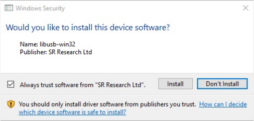
SR Research Experiment Builder User Manual ©2004-2017 SR Research Ltd.
12
watermark will be drawn on every display screen in an experiment that is created with the
demo version of the software.
To run Experiment Builder in a fully licensed mode, users need to purchase a license key
for the software and have a USB license key connected to the computer on which the
Experiment Builder software is installed. If this is the first time that the USB license key
has been used on the Display PC, you will need to install the HASP key driver.
3.2.1 For Standard Installation (Applicable to Most Users)
The following installation instructions are applicable to users who use a standalone USB
license key that supports a single-PC license.
1. Install the Experiment Builder software. Double click the sreb_2.*.exe installer
and proceed, keeping all the default settings. You may see the following dialog
box (Figure 3-1) if this is the first time Experiment Builder is installed on the PC.
This is a confirmation whether you want to install device driver for USB-1208HS
DAQ box. You may choose either “Install” or “Don’t Install” to proceed.
Figure 3-1. Driver Installation for USB-1208 HS DAQ.
2. If this is the first time that the USB license key has been used on the computer,
install the standalone HASP key driver. First plug the license key into the Display
PC. Then install the driver by clicking "Start → All Programs → SR Research →
Install HASP Driver", or by double clicking on "hdd32.exe" in the "C:\Program
Files (x86)\SR Research\Common" folder.
3. Open the License Manager utility (Start → All Programs → SR Research →
License Manager) to check the licensing status for the Experiment Builder
software.
3.2.2 For Installation Using Network Licensing
The following instructions are applicable to users who have purchased a network license
(i.e., a shared license for several computers on a network that are running Experiment
Builder at the same time) for Experiment Builder.
1. Install the Experiment Builder software. Double click the sreb_2.*.exe installer
and proceed, keeping the default settings on InstallShield Wizard screens except
for the following two:
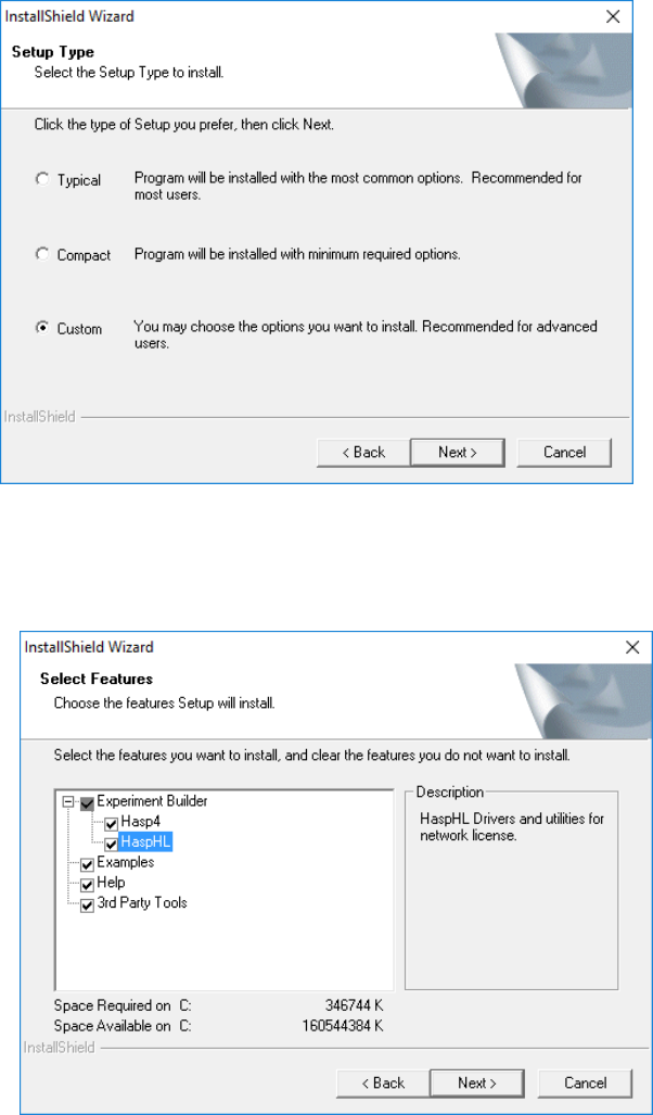
SR Research Experiment Builder User Manual ©2004-2017 SR Research Ltd.
13
• On the "Setup Type" dialog box, select "Custom" (See Figure 3-2).
Figure 3-2. Choosing “Custom” Setup Type.
• On the "Select Feature" screen, make sure that both "HASP4" and "HASPHL"
driver options are selected (see Figure 3-3).
Figure 3-3. Enabling HaspHL Driver Option for Network License.
2. Install the network HASP key driver by clicking "Start → All Programs → SR
Research → HASP HL Driver", or by double clicking on "hdd32.exe" in
"C:\Program Files (x86)\SR Research\Common" folder.
3. Install the network HASP License Manager by clicking "Start → All Programs →
SR Research → Networked HASP License Manager, or by double clicking on
SR Research Experiment Builder User Manual ©2004-2017 SR Research Ltd.
14
"lmsetup.exe" in "C:\Program Files (x86)\SR Research\Common" folder. Failing
to install this will report a "NO HASP Key Found" error in the SR License
Manager dialog box.
• When installing the License Manager, set the "Installation Type" to Service
(nhsrvice.exe).
• On the "HASP License Manager" dialog box, check either Yes or No to
continue.
4. If this is the server computer, you may install the optional Aladdin Monitor
software by clicking "Start → All Programs → SR Research → Aladdin Monitor"
from your computer desktop or double clicking on "aksmon32.exe" in
"C:\Program Files (x86)\SR Research\Common" folder.
5. Test the license status.
• Please make sure the server and client computers are running and visible to
each other in the same network group (check this out from "My Network Places
→ View Network computers"). Contact your system administrator if the
computers cannot see each other in the same network group.
• Please make sure the network license key is plugged into the server computer
and that the drivers are already installed. Remove any other HASP keys from the
server computer.
• Then click "Start → All Programs → SR Research → License Manager" to
check the licensing status for each of the client computers in the network.
Note: If you are using Experiment Builder for developing EyeLink experiments,
test running experiments must be done using a secondary network card unless the
EyeLink Host PC also stays on the same network as the other computers.
3.3 Software Installation and Licensing on Mac OS X
SR Research Experiment Builder runs on most recent Intel-based Macs (software version
Mac OS X 10.6 and higher). The computer recommendations are in a large part
dependent on the experimental paradigm being run; it is always suggested to get the best
computer you can for running your experiments, even if you do not immediately plan on
using all the features of the computer.
3.3.1 Experiment Builder Installation
The latest version of Experiment Builder installer can be downloaded from
https://www.sr-support.com/forums/showthread.php?t=9. If you have a previous version
of Experiment Builder installed on the computer, please uninstall it first by removing the
"/Applications/ExperimentBuilder" folder to Trash. Now click the dmg installer of the
software. Select the "ExperimentBuilder" folder in the package, and drag and drop it into
the "Applications" folder (see Figure 3-4). The software is now installed at
"/Applications/ExperimentBuilder". Click "ExperimentBuilder.app" to run the software.
The examples can be found in the "~/Documents/ExperimentBuilder Examples" folder.
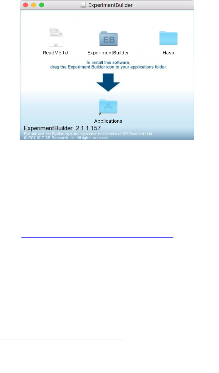
SR Research Experiment Builder User Manual ©2004-2017 SR Research Ltd.
15
Figure 3-4. Installing Experiment Builder on Mac OS X.
If you see the error message “ExperimentBuilder is damaged and can’t be opened” when
you try installing the software, please click the Apple logo in the top-left corner and
select “System Preferences”, then go to “Security & Privacy” and under the General tab
make sure “Allow apps downloaded from:" is set to “Anywhere” (you may need to click
the padlock to make changes).
If you are using the recent Mac OS X, you may be prompted to download legacy Java 6
from this link: https://support.apple.com/kb/DL1572?locale=en_GB and install it.
3.3.2 Other Software Installation
SR Research Experiment Builder works with EyeLink I, II, 1000, 1000 Plus, and Portable
Duo eye trackers.
• EyeLink I users should make sure that version 2.11 of the eyelink.exe file
(https://www.sr-support.com/forums/showthread.php?t=45) runs on the Host PC.
• EyeLink II users should use a recent version (2.0 or later) of eyelink2.exe
(https://www.sr-support.com/forums/showthread.php?t=11).
• Any version of EyeLink 1000 host software will be fine, although version 4.56 or
later is recommended (https://www.sr-
support.com/forums/showthread.php?t=179).
• Any version of EyeLink 1000 Plus host software will be fine, although the latest
version is recommended (https://www.sr-support.com/showthread.php?4256).
• If using EyeLink Data Viewer for data analysis, you should get the most recent
version of the software (https://www.sr-support.com/showthread.php?4434).
SR Research Experiment Builder User Manual ©2004-2017 SR Research Ltd.
16
3.3.3 HASP Driver Installation and Licensing
Users can run Experiment Builder in demo mode immediately for 30 days from the first
installation of the software on the computer. All of the functionality of the licensed copy
of Experiment Builder is available in the demo mode except that Experiments created
with a demo version of the software will not re-open using a fully-licensed version of the
software. An "UNLICENSED DEMO VERSION" watermark will be drawn on every
display screen in an experiment that is created with the demo version of the software.
To run Experiment Builder in a fully licensed mode, users need to purchase a license
code for the software and have a USB license key connected to the computer on which
the Experiment Builder software is installed. If this is the first time that the USB license
key has been used on your Mac, you will need to install the driver for the HASP key. The
driver installer can be found in the "Hasp" folder after unpacking the Experiment Builder
installer .dmg (see Figure 3-4). Double click the "Sentinel_HASP_RTE_Installer.dmg"
file and then run the "Install HASP SRM Runtime Environment" application with the
default settings. If the driver installation is successful and the USB license key is attached
to the computer, the licene key should glow.
If your key is not licensed for the Experiment Builder software, you will need to contact
sales@sr-research.com to purchase a license for the software. If your key is already
licensed for the Windows version of the software, you may update the license for the Mac
version remotely by following the steps below; please contact support@sr-research.com
if you have trouble updating the key.
• Make sure you have an internet connection on your Mac.
• Start the LicenseManager application, which is located at
"/Applications/ExperimentBuilder".
• From the "File" menu at the top-left corner of the desktop, click "Get
ExperimentBuilder Mac License". In the following dialog box, click “Update”
(see Figure 3-5).
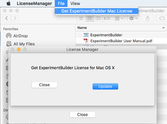
SR Research Experiment Builder User Manual ©2004-2017 SR Research Ltd.
17
Figure 3-5. Updating Experiment Builder License on Mac OS X.
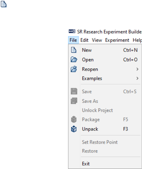
SR Research Experiment Builder User Manual ©2004-2017 SR Research Ltd.
18
4 Working with Files
Experiment Builder can be used to create, build/test run, and deploy experiments on
either Windows (XP, Vista, Windows 7, 8, or 10) or Mac OS X (10.6.8 or later). Each
experiment creation session generates a binary file (graph.ebd), which contains the
graphic layout of the experiment, and a set of supporting files and directories for
preference settings, image loading, etc. With these files, the experiment creation session
can be reopened later for review or modification. After the experiment is built, users can
deploy the experiment to a new directory. This will generate a set of files so that the
experiment can be run on a different computer without relying on the Experiment Builder
application.
4.1 Creating a New Project
To create a new experiment project, from the application menu bar, choose (see Figure 4-
1):
File → New
Tip: A new experiment project can also be created by clicking on the "New Experiment"
button ( ) on the application toolbar, or by pressing the shortcut keys Ctrl+N on
Windows or Command ⌘+N on Mac OS X.
Figure 4-1. File Menu.
This will bring up a “New Project” dialog (see Figure 4-2), prompting for the experiment
project name and a directory in which the experiment project should be saved. Enter the
name for the experiment in the “Project Name” edit box. Click the “…” button to the
right of the "Project Location" field to browse to the directory where the experiment files
should be saved; if you are manually entering the "Project Location" field, please make
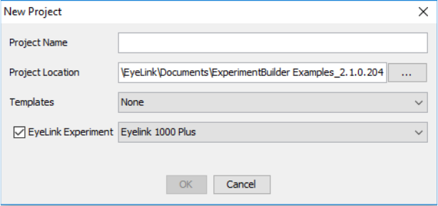
SR Research Experiment Builder User Manual ©2004-2017 SR Research Ltd.
19
sure that the intended directory already exists. In both cases, please make sure you have
writing permission for the selected directory. If your intended project is an EyeLink
experiment, make sure to check the "EyeLink Experiment" box and choose the
appropriate tracker version from the dropdown list.
Note: Please avoid using non-ASCII characters in the project name or directory path as
this may cause runtime problems. The experiment project name must start with a letter
between ‘a’ and ‘z’ or ‘A’ and ‘Z’ and may contain letters, digits, and the underscore
character. If there is any space in the filename, this will be replaced by an underscore.
An “Invalid Value” or “invalid label format” error dialog box will be displayed if the
format of session label is invalid.
Figure 4-2. Dialog for Creating a New Project.
After the experiment is generated, the following files and folders are created.
Experiment
|--- [datasets]
|--- [library]
|--- [audio]
|--- [customClass]
|--- [images]
|--- [datasource]
|--- [interestAreaSet]
|--- [movementPattern]
|--- [video]
|--- [myfiles]
|--- [runtime]
|--- [dataviewer]
|--- [images]
|--- graph.ebd
|--- Preferences.properties
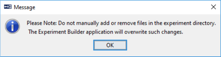
SR Research Experiment Builder User Manual ©2004-2017 SR Research Ltd.
20
• graph.ebd: This file contains the experiment graph. Double-click this file to open
the experiment project.
• Preferences.properties: This file contains the preference settings for the current
experiment project.
• datasets: This is the directory where the data source file is located.
• library: This is the folder where the image, audio, interest area set, and video files
are stored.
• runtime: This folder contains all of the runtime image and Data Viewer
integration files (image drawing list and interest area set files).
• myfiles: This directory (and all files and subdirectories within it) will not be
deleted or cleaned by the build process, so this is where users may store any
additional files related to the project (randomized data sets, test EDF files, etc).
Files in this directory will be included in the packed project and copied to the
deployed folder.
Note: If you are running Experiment Builder from a non-Administrative account of
Windows XP, you should create the new projects to the user account directory (i.e., the
project location should be "{Windows Drive}:\Documents and Settings\{User
Account}\My Documents"). In Windows Vista, 7, 8, or 10, a new project should be
created at a directory with user read/write permission (e.g., at "C:\Users\{User Name}").
Similarly, you should deploy your experiments to the user account directory.
Note: The above files and folders are created and maintained by Experiment Builder.
Users should not attempt to modify these files and folders or store important files in
the experiment project folder except within the "myfiles" directory. Experiment
Builder will overwrite any manual changes made to the experiment project directory
(except "myfiles").
Figure 4-3. Warning Messages after Experiment Creation.
4.2 Saving a Project
An experiment project can be saved by choosing from the application menu bar:
File → Save

SR Research Experiment Builder User Manual ©2004-2017 SR Research Ltd.
21
Tip: The experiment creation session can also be saved by clicking on the Save button
on the application tool bar, or by pressing the shortcut keys Ctrl+S on Windows or
Command ⌘+S on Mac OS X.
If there is any change to the experiment project, the previous experiment graph is saved
as “graph.ebd.bak” in the experiment directory.
4.3 Saving an Existing Project to a Different Directory
To save an experiment project with a different project name and/or in a different
directory,
1) From the application menu bar, choose:
File → Save As
2) In the Save As dialog box, click the “…” button to the right of “Project Location”
to browse to the directory where the project should be saved.
3) Enter the new project name in the Project Name edit box.
4) Click the OK button.
Tip: The project can also be saved by clicking the “Save As” button on the
application tool bar.
4.4 Opening an Existing Project
To open an existing experiment project from the Experiment Builder application,
1) From the application menu bar, choose:
File → Open
2) In the “Open” dialog box, browse to the directory of experiment and select the
“graph.ebd” file (see Figure 4-4).
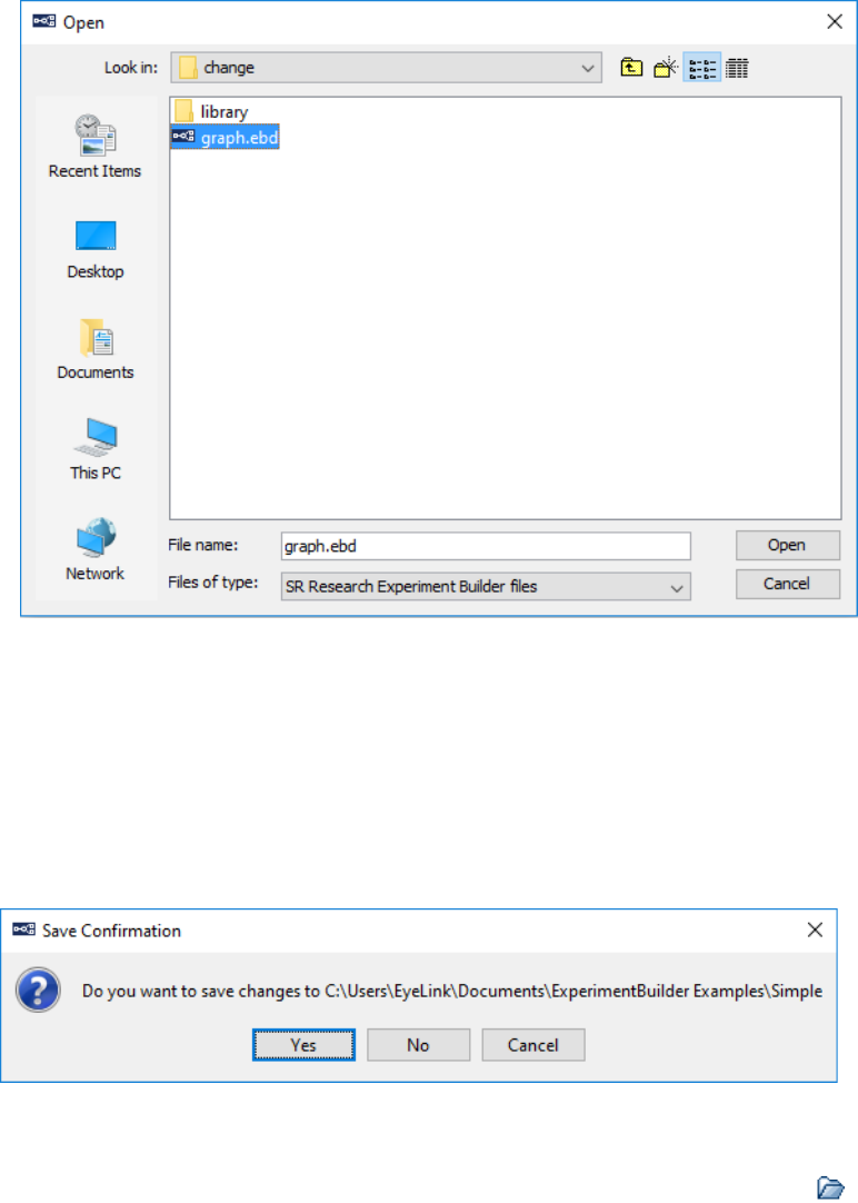
SR Research Experiment Builder User Manual ©2004-2017 SR Research Ltd.
22
Figure 4-4. Open an Experiment Builder Project.
3) Click the “Open” button.
Note: If an experiment is already open in the current project, the “Open” operation will
first bring up a “Save Confirmation” dialog box so that users can either save the current
session (“YES”), abandon the current session (“NO”), or stay in the current session
(“CANCEL”; see Figure 4-5).
Figure 4-5. Save Confirmation When Opening a New Project.
Tip: A saved experiment project can also be opened by clicking the Open button on
the application toolbar, or pressing the shortcut keys Ctrl+O on Windows or Command
⌘+O on Mac OS X.
Note: Users can also open an existing experiment project with Windows Explorer, or
Finder in Mac, by going to the directory where the experiment project is contained and
double clicking on the graph.ebd file.
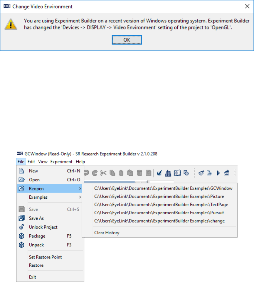
SR Research Experiment Builder User Manual ©2004-2017 SR Research Ltd.
23
Note: If you are opening a project created with version 1.x of Experiment Builder on a
Windows 8 or 10 computer, you will see the following warning message (see Figure 4-6).
This is the expected behavior as the OpenGL graphics provide better display timing on
the recent operating systems whereas on Windows 7 or earlier operating systems either
OpenGL or DirectDraw graphics will be fine.
Figure 4-6. Change in Video Environment When Opening a New Project.
4.5 Reopening a Recent Experiment Project
Experiment Builder keeps a history of five recently opened experiment projects. To
reopen a recent experiment project:
1) From the application menu bar, choose:
File → Reopen
2) Choose the project to open from the list of recent experiment projects. (see Figure
4-7).
Figure 4-7. Reopening Recent Experiment Projects.
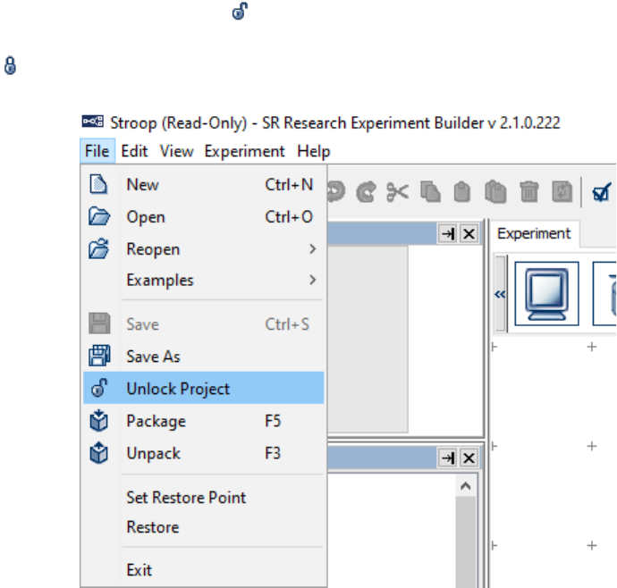
SR Research Experiment Builder User Manual ©2004-2017 SR Research Ltd.
24
A “File Not Found” error will be displayed if the intended experiment project has been
moved, renamed, or deleted. To clear the list of recent projects, click the “Clear History”
menu.
4.6 Lock/Unlock a Project
If you open a locked Experiment Builder project, you will notice that there is a “(Read-
Only)” string in the titlebar of the experiment project. With a locked project, the “Save”
button in the application toolbar is grayed out when you try to save modifications to the
experiment graph. The Add, Delete, and Rename buttons in the Library Manager are also
disabled. To unlock a locked project, click the “File → Unlock Project” option on the
application menu, or click the ( ) button on the application toolbar (see Figure 4-8). To
lock a project, click the “File → Lock Project” option on the application menu, or click
the ( ) button on the application toolbar.
Figure 4-8. Unlock a Locked Project.
4.7 Packaging an Experiment
Experiment packaging is very useful if you want to send another Experiment Builder user
an experiment you have created so they can modify the experiment in Experiment
Builder. Users can pack up the current experiment project by clicking
File → Package
from the application File menu.
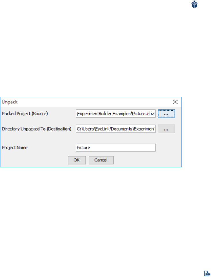
SR Research Experiment Builder User Manual ©2004-2017 SR Research Ltd.
25
This will zip up the experiment directory and save the zip file at a selected location. The
created .ebz file contains only the files necessary to rebuild and run the experiment
(graph.ebd, Preferences.properties, the library directory, and the myfiles directory if it
has any contents). The packed project can be unpacked by Experiment Builder.
Tip: The experiment can also be packaged up by clicking the “Package” button on
the application tool bar or pressing F5 on Windows or Ctrl+Shift+P on Mac OS X.
4.8 Unpacking an Experiment
The packed experiment project can be unpacked by clicking "File → Unpack" from the
application File menu. In the following dialog, users should select the packed project
(source) and specify a directory to which the project should be unpacked (Destination;
see Figure 4-9). By default, the destination directory will be the folder where the .ebz file
is located.
Figure 4-9. Unpacking an Experiment Project.
Tip: A packed project can also be unpacked by pressing F3 on Windows or Ctrl+Shift+U
on Mac OS X.
Note: Users can also unpack a project by simply double-clicking on the .ebz file.
4.9 Building an Experiment
After creating the experiment, users need to compile the experiment to make sure there
are no errors in the experiment graph. To do that, from the application menu bar, choose
(see Figure 4-10):
Experiment → Build
Tip: Building an experiment can also be performed by clicking on the “Build” button
on the application tool bar or pressing F9 on Windows or Ctrl+Shift+B on Mac OS X.
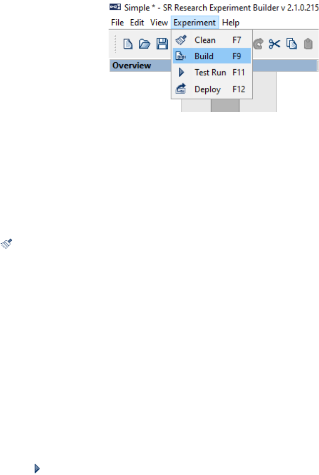
SR Research Experiment Builder User Manual ©2004-2017 SR Research Ltd.
26
Figure 4-10. Experiment Menu.
4.10 Cleaning an Experiment
Sometimes users may want to clean up the experiment projects. This is especially
important when users have changed the images or other screen resources used for the
experiment. To clean the project, from the application menu bar, choose:
Experiment → Clean
Tip: Cleaning an experiment can also be performed by clicking on the “Clean” button (
) on the application tool bar or by pressing shortcut key F7 on Windows or
Ctrl+Shift+C on Mac OS X.
4.11 Test-running an Experiment from EB Application
To check whether the experiment works, users may test run the experiment from the
Experiment Builder application. To perform a Test Run, from the application menu bar,
choose:
Experiment → Test Run
This will create a “Results” directory containing the data collected from the test run
session. Note that the test run is not intended for real data collection and should only be
used when you are testing your experiment. Each time you test run, the results folder is
created again, and existing results will be lost.
Tip: Test running an experiment can also be performed by clicking on the “Test Run”
button on the application tool bar or pressing the shortcut key F11 on Windows or
Ctrl+Shift+R on Mac OS X.
Note: If the experiment is tested under dummy mode, a warning dialog box "You are
running in dummy mode! Some eye tracking functionality will not be available" will be
displayed at the beginning of the experiment, and a warning dialog "No EDF file is
created for dummy mode session" will be displayed at the end.
4.12 Deploying an Experiment
To deploy a built experiment so that it can be run for data collection without relying on
the Experiment Builder application, choose from the application menu bar:

SR Research Experiment Builder User Manual ©2004-2017 SR Research Ltd.
27
Experiment → Deploy
In the Deploy dialog box, click the “…” button to the right of “Project Location” to
browse to the directory where the deployed project should be saved. The project will be
saved into a new subdirectory named for the entered File Name. This experiment
subdirectory contains all of the required files generated. Please note that non-ASCII
characters are not allowed in a deployment path (e.g., deploying a project to a folder that
contains Chinese characters will fail). Users can cancel the deploy process by pressing
the “Cancel” button.
Tip: Deploying an experiment can also be performed by clicking on the “Deploy” button
on the application tool bar or pressing shortcut key F12 on Windows or Ctrl+Shift+D
on Mac OS X.
Tip: For the ease of reconstructing the original experiment project, a "source" folder will
also be created in the deployed project. Depending on the Build/Deploy preference
settings, this folder contains either the packed experiment project or only the graph.ebd
and Preferences.properties files.
Note: Users may deploy the experiment on one computer and then copy and execute the
project on a different computer. Please make sure the deploy computer and the test
computer have the same operating system installed and the test computer has the required
hardware (e.g., monitor, sound card, response device) for the proper execution of the
experiment. For example, an experiment deployed on a Windows XP computer will not
run on a display computer with Windows 7 installed, as the dependency files are different
between two operating systems. Similarly, experiment deployed on Mac OS X will not
run on the Windows computers and vice versa. Other runtime errors can occur if the two
computers have different settings in the Cedrus driver, I/O driver, video card driver,
audio device, etc.
4.13 Running an Experiment for Data Collection
To run the experiment for data collection from the deployed folder, simply double click
the executable file in the deployed directory, or from your computer desktop, click "Start
→ All Programs → Accessories → Command Prompt". Go to the deployed experiment
directory by typing "cd {experiment path}" on the command prompt and type the
{experiment}.exe file name to start the experiment. Running the experiment from the
command line prompt also allows users to pass additional parameters to the program.
Some of the useful command line options are:
• -session= <your edf or session name >
If the "-session" option is used, the software will not prompt for a session name
via a dialog box at the beginning of the experiment. The session name pass along
the "-session=" option must be within eight characters (consisting only of letters,
numbers, and the underscore character).
SR Research Experiment Builder User Manual ©2004-2017 SR Research Ltd.
28
• -ui=[GUI|CONSOLE|NONE]
The "-ui" option allows to disable the file transferring dialog box at the end of the
session. If -ui=GUI the graphical progress bar is popped up (default); if -
ui=CONSOLE, progress updates of the file transfer are printed to the console; if -
ui=NONE no progress messages are brought to the users. For example, for an
experiment named "simple_deployed", you can pass the "-ui=NONE" to disable
the files transfer progress bar.
simple_deployed -session=myTest -ui=NONE
• The actual parameters passed along the command line can be retrieved through
the "Command Line Arguments" property of the Experiment node.
Running the deployed version of the experiment doesn't require a license key plugged to
the computer. If the experiment needs to be run on a different machine with similar or
better computer specifications, users should first copy the entire directory of the deployed
version of the experiment to that computer. To make the experiment transfer easier (given
the large number of files involved), users may first zip up the {Experiment Name} folder
(keeping the directory structure) and then unzip the file on the target computer.
Users should also pay attention to the following details:
• For accurate display drawing, the dots-per-inch (DPI) resolution of the display PC
that is used to run the experiment must match that of the development PC which
is used to create the experiments. To check the DPI settings, click the right mouse
button at a blank space on the Display PC desktop to open a dialog box for
display properties settings. Click the "Advanced display settings" link at the
bottom of the page, and then the “Advanced sizing of text and other items” link
on the following page. On Windows 10, users should use the default 100%
display scaling. Click “Start menu -> Settings -> System -> Display”. Set the
“Scale and Layout” to 100% (if you don’t see this option on your version of
Windows, search for other similar options like “Change the size of text, apps and
other items" in Display Settings).
• If the deployed experiment shows video clips, please make sure that codec used
to test run the video experiment is also installed on the deployment computer as
well; otherwise, the deployed experiment will not run.
Important: Please check out section 3.1.2 on steps that should be taken to maximize the
real-time performance of the deployment computer.
Finally, when an experiment is in progress, please avoid hitting the Windows logo key on
the keyboard so that the experiment will not be aborted for failing to lock the experiment
graphics window. You may check out Section 7.10.6.4 for instructions to disable the
Windows Logo Keys.
SR Research Experiment Builder User Manual ©2004-2017 SR Research Ltd.
29
4.14 Converting Projects Between Windows and Mac OS X
Experiment projects saved on the Windows operating systems can be opened with the
same version or a newer version of the software on Mac OS X, and vice versa. There are
some exceptions on the transferability between the two families of operating systems.
• Audio playback and recording is done through the OS X driver on Mac OS X.
When converting a project created on Windows with audio playing (either
through DirectX or ASIO driver) or recording (through the ASIO driver), the
audio device will be reset to OS X. Conversely, the audio device will be reset to
the ASIO driver when converting a Mac version of the experiment project with
audio recording or playing.
• The Mac OS X version of the software uses the OpenGL graphics library for
visual stimulus presentation. The Windows version uses either DirectDraw or
OpenGL, although the latter is preferred on Windows 8 and 10.
• The two versions of the software may exhibit different levels of compatibility
when playing video clips with .avi file extension. Specially, Experiment Builder
uses the ffmpeg video loader by default to play.avi files on Mac OS X, and uses
the vfw (video-for-windows) loader by default on Windows (though users can
choose to use the ffmpeg video loader).
• Sending TTL signals or receiving TTL signals on Mac OS X is only supported
through the USB-1208HS box. So the TTL device of an Experiment Builder
project created in Windows using the parallel port will be reset to USB-1208 HS
when opened in Mac OS X.
• Some of the fonts may be missing when converting from the other operating
system. Single-line texts or multi-line texts of the same font size will look smaller
(by a factor of about 1.33) on Mac OS X than on Windows due to different
default DPI values used across the two operating systems.
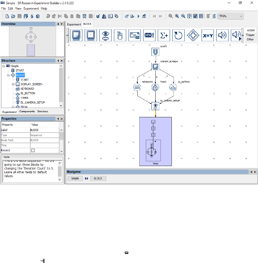
SR Research Experiment Builder User Manual ©2004-2017 SR Research Ltd.
30
5 Experiment Builder Graphical User Interface
Experiment Builder uses a desktop framework that contains all the windows of the
application. The following figure shows a typical graphical user interface (GUI) users
will see in an experiment creation session. Below the menu and toolbar, the Experiment
Builder desktop is divided into two areas: the Project Explorer Window on the left and
the Graph Editor Window on the right. The Project Explorer Window lists all of the
experiment nodes in a hierarchical fashion and allows users to select the nodes for review
or modification. The Graph Editor Window allows users to create the experiment graph
by dragging individual building blocks and making connections between components to
form experiment flow.
Figure 5-1. Sample Experiment Builder Interface.
5.1 Project Explorer Window
The Project Explorer Window allows users to select experiment nodes to be viewed, to
modify the selected node’s properties, and to configure default devices (e.g., eye tracker,
display, audio driver, parallel port, and Cedrus Input settings). This window has four
individual panels: Overview, Structure, Property, and Connections panels. Each of the
individual sections can either be a docked ( ) panel of the Project Explorer Window or a
free-floating ( ) window. In addition, each of the panels can be hidden or made visible
from the "View" menu (see Figure 5-2).
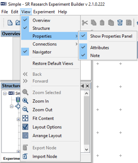
SR Research Experiment Builder User Manual ©2004-2017 SR Research Ltd.
31
Figure 5-2. The View Menu.
The Overview panel (on the top) shows the graph layout of all components in the current
level of experiment and highlights the currently selected node. The part of the graph
within the shaded box is currently visible in the workspace of the Graph Editor Window.
Users can choose to work on a different part of the graph by clicking on the shaded box
and dragging it over to the intended region.
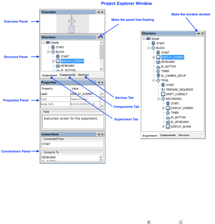
SR Research Experiment Builder User Manual ©2004-2017 SR Research Ltd.
32
Figure 5-3. Components of the Project Explorer Window.
The Structure panel (in the middle) lists the nodes used in the experiment. This panel has
three tabs: Experiment, Components, and Devices. The Experiment Tab (left panel,
Figure 5-4) contains a hierarchical representation of the Experiment -- all component
nodes are listed under the sequence in which they are contained. The Components Tab
(middle panel, Figure 5-4) lists the nodes by type (triggers, actions, or other components).
Similar to the interface used by Windows Explorer, if certain types of components are
used, the folder containing those components can be opened ( ) or closed ( ). The
Devices Tab (right panel, Figure 5-4) allows users to configure default settings for the
EyeLink tracker, experiment display and other devices (see section 17 on Preferences
settings).
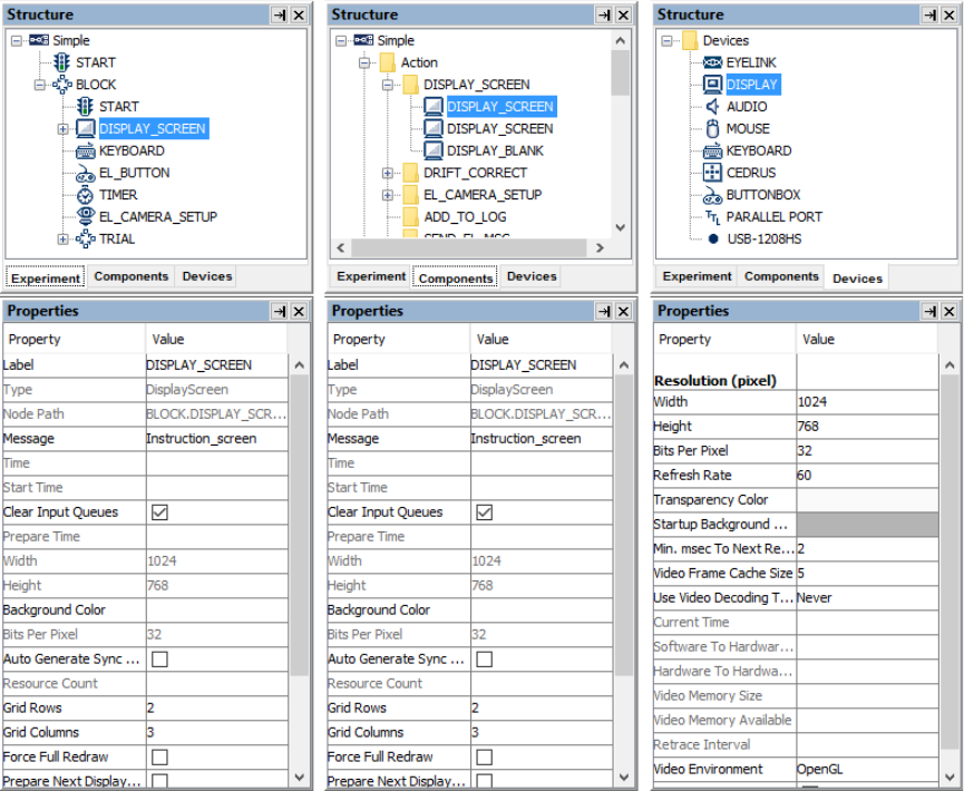
SR Research Experiment Builder User Manual ©2004-2017 SR Research Ltd.
33
Figure 5-4. Different Tabs of the Structure Panel.
The Properties panel (at the bottom) displays properties of the selected item in the
Structure panel. Users can review the current property values and make modifications if
necessary. If a property field is grayed out (e.g., the "Time" property of the
DISPLAY_SCREEN action), the value of the property cannot be directly modified, but
may be referred to. All the other properties may be modified directly (see section 7.5
"Editing Properties of a Node").
The Note section of a properties panel allows users to add comments to the node.
The Connections panel lists all of the nodes that are connected to the current node. The
"Connected From" section lists all of the nodes that target the current node, and the
"Connects To" section lists all of the nodes that receive a connection from the current
node.
SR Research Experiment Builder User Manual ©2004-2017 SR Research Ltd.
34
5.2 Graph Editor Window
The Graph Editor Window provides an interface through which the experiment can be
created graphically. This window is divided into four sections: the Component Toolbox,
Work Space, Editor Selection Tabs, and Navigator (see Figure 5-5).
The Component Toolbox contains the basic building blocks of the experiment graph and
allows users to select a desired component to be added into the experiment. The
experiment components are grouped under three categories: Trigger (including timer,
invisible boundary, conditional, EyeLink button, Cedrus Input, TTL, keyboard, mouse,
voice key, fixation, saccade, and sample velocity triggers), Action (display screen,
perform camera setup, perform drift correction, send EyeLink message, log experiment
data, send EyeLink command, update variable attribute, prepare sequence, add to results
file, add to accumulator, send TTL signal, play/record sound, control sound
playing/recording, terminate experiment, recycle data line, reset node, as well as a NULL
action), and Other (variable, results file, accumulator, and custom class).
The Work Space provides the graphical environment in which the experiment is
generated. In an empty sequence, the Work Space area contains a START node to which
actions and triggers can be connected. Users can drag selected experiment elements from
the Component Toolbox and drop them into the work space, then make connections to
and from other components. Users can select individual items in the Work Space to edit
their properties.
The Editor Selection Tabs and Navigator provide convenient shortcuts for selecting a
display screen or an experiment sequence to work on. When an experiment involves
several different layers of sequences (for example Blocks → Trials → Trial Recording),
the Navigator at the bottom of the graph editor window indicates the current layer the
user is working on. Users can switch to work on a higher-level layer by clicking one of
buttons in the Navigator corresponding to the higher-level sequences. All sequences and
display screens opened in the experiment, as well as the project output screen, are listed
as individual Editor Selection Tabs above the Component Toolbox for direct access. To
dismiss Editor Selection Tabs, right-click a tab, then select either “Close” to close just
that tab, or “Close Others” to close all except the clicked tab and the top-level
“Experiment” tab.
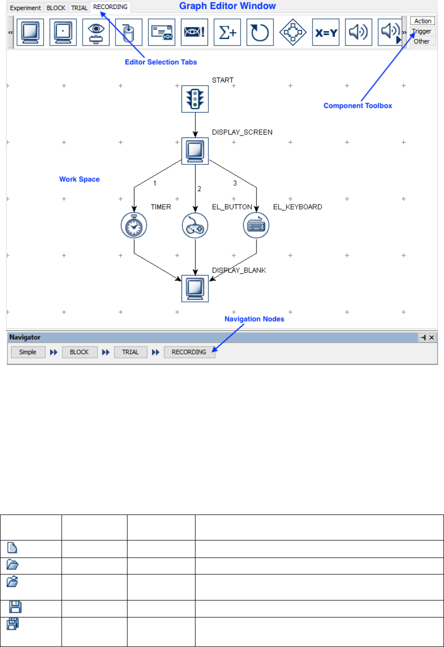
SR Research Experiment Builder User Manual ©2004-2017 SR Research Ltd.
35
Figure 5-5. Components of the Graph Editor Window.
5.3 Application Menu Bar and Toolbar
The Experiment Builder application menu bar and toolbar contain a list of common
operations. Most of the operations can also be performed by keyboard shortcuts or by
using buttons on the application toolbar.
5.3.1 File Menu and Tool Buttons
Commands that affect creating, opening, saving, packaging, or closing the Experiment
Builder sessions are located here (see Chapter 4 for details). 1
Operation
Shortcut
(Windows)
Shortcut
(Mac OS X)
Function
New
Ctrl + N
⌘ + N
Creates a new experiment project.
Open
Ctrl + O
⌘ + O
Opens an existing experiment project.
Reopen
Reopens a recent Experiment Builder project.
Save
Ctrl + S
⌘ + S
Saves the current experiment project.
Save
As
Saves the experiment project to a different directory.
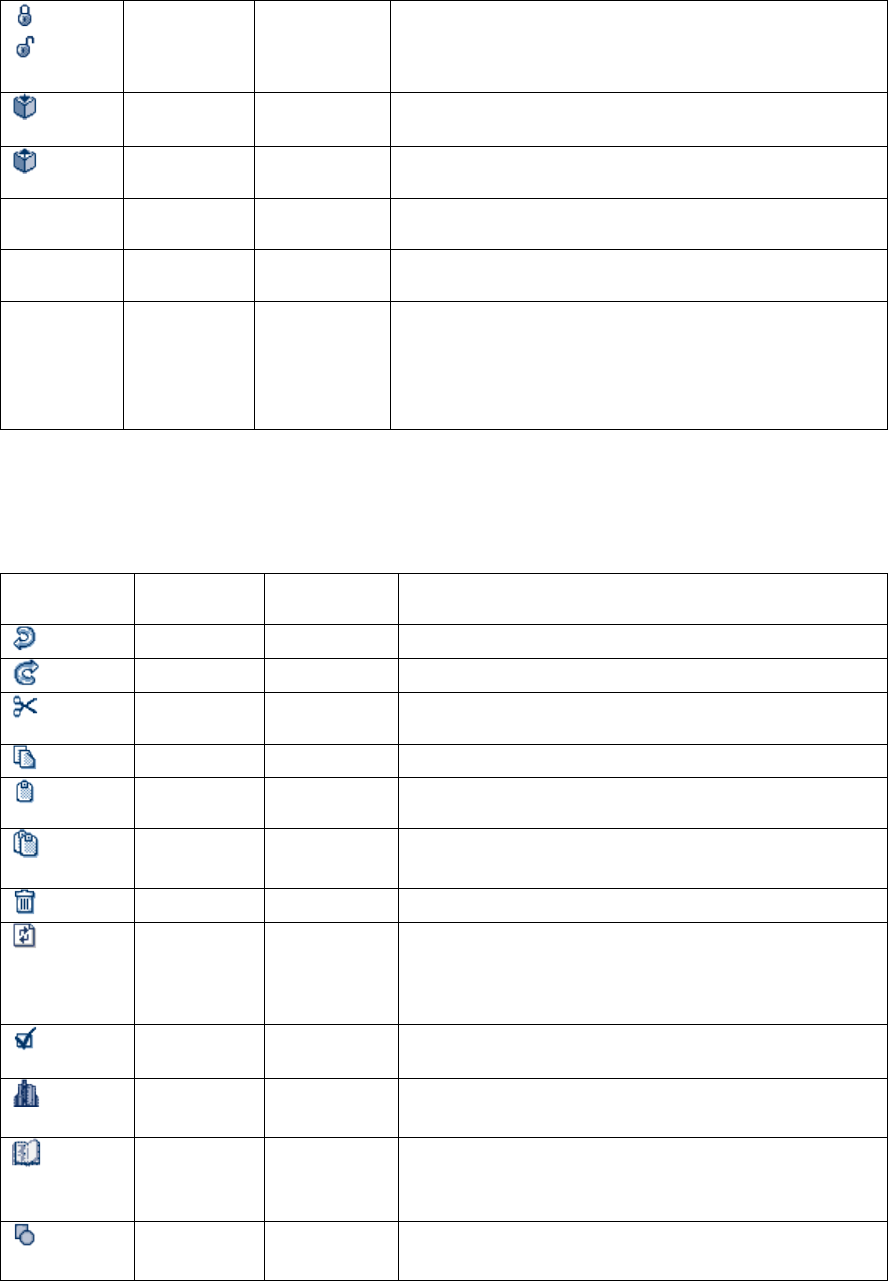
SR Research Experiment Builder User Manual ©2004-2017 SR Research Ltd.
36
Lock
Unlock
Project
Click the closed icon to lock a currently unlocked
project, or the open icon to unlock a currently locked
project.
Package
F5
Ctrl + Shift
+ P
Used to compress the experiment project into an .ebz
file for file sharing, etc.
Unpack
F3
Ctrl + Shift
+ U
Used to extract the experiment project from a
compressed .ebz file.
Set Restore
Point
Sets a restore point for the project so that users can
revert the project’s state to that point in time.
Restore
Reverts the project's state to that of a previous point
in time.
Exit
⌘ Q
(under
"Experiment
Builder"
menu)
Closes the Experiment Builder application.
5.3.2 Edit Menu and Tool Buttons
The Edit menu contains commands such as copy, paste, cut, delete, and undo. It also
contains tools for resource library management, node group organization, and preference
settings (see Chapter 17).
Operation
Shortcut
(Windows)
Shortcut
(Mac OS X)
Function
Undo
Ctrl + Z
⌘ + Z
Undoes the last action performed.
Redo
Ctrl + Y
⌘ + Y
Redoes or repeats an action.
Cut
Ctrl + X
⌘ + X
Removes a selection from the project and places it
into the clipboard.
Copy
Ctrl + C
⌘ + C
Puts a copy of a selection to the clipboard.
Paste
Ctrl + V
⌘ + V
Inserts the previously copied item from the
clipboard to the current position.
Paste
Multiple
Ctrl + M
⌘ + M
Inserts several copies of the previously copied item
from the clipboard to the current position.
Delete
Delete
⌘ + Delete
Removes the selection from the current location.
Refresh
Custom
Class
Ctrl + H
Refreshes the Custom Class files (i. e., reparses the
contents of the files). This tool is useful to users
who use an external editor to edit the content of
custom classes.
Preferences
F4
⌘ + ,
Shows a list of preference settings for Experiment
Builder.
Library
Manager
Ctrl + L
⌘ + L
Used to load in image, audio, interest area set, video,
custom class, or movement pattern files.
Reference
Manager
Ctrl + R
⌘ + R
Tabulates the source, property, and value of each
reference used in the experiment graph (see section
10.5).
Node
Groups
Ctrl + G
⌘ + G
Allows users to rearrange the layout of the
components in the component toolbox.

SR Research Experiment Builder User Manual ©2004-2017 SR Research Ltd.
37
Select All
Ctrl+ A
⌘ + A
Selects the entire contents of the active window.
5.3.3 View Menu
The View menu contains commands that display or hide panels in the Project Explorer
Window, or change the layout of the experiment graph.
Operation
Function
Overview
Display the Overview panel.
Structure
Display the Structure panel.
Properties
Display the ‘Attributes’ and/or ‘Note’ sections of the Properties
Panel.
Connections
Display the ‘Connects To’ and/or ‘Connected From’ sections of the
Connections Panel.
Navigator
Display the “Navigator" panel in the Graph Editor Window.
Restore Default Views
Restore the default layout of the windows and panels.
Back
Go back to the previously selected/viewed node.
Forward
Move forward to a previously selected/viewed node.
Zoom Selected
When one or more components in the graph are selected, zoom in
on the selected items.
Zoom In
Zoom in towards the center of the work space.
Zoom Out
Zoom out so that more items can be displayed in the work space.
Fit Content
Zoom in or out so all the components in the work space are
displayed.
Layout Options
Configure the layout of components when “Arrange Layout” is
applied.
Arrange Layout
Rearrange the graph components in an orderly manner.
Export Node
Export the selected node(s) to an .ebo file so they can be shared.
Import Node
Import nodes from an .ebo file into the current experiment project.
5.3.4 Experiment Menu and Tool Buttons
The Experiment Menu contains commands that are used to compile and run the
experiment, clean up the experiment project, and to create a deployed version of the
experiment (see Chapter 4 for details).
Operation
Shortcut
(Windows)
Shortcut
(Mac OS X)
Function
Clean
F7
Ctrl + Shift +
C
Used to clean up the experiment project.
Build
F9
Ctrl + Shift +
B
Used to compile the experiment.
Test
Run
F11
Ctrl + Shift +
R
Used to test run the experiment from the Experiment
Builder application.
Deploy
F12
Ctrl + Shift +
D
Used to generate deploy code so that the experiment
can be executed as a standalone program.
5.3.5 Help Menu
The Help menu contains the Experiment Builder Help document as well as licensing and
product release information (see Chapter 3 for details).
Operation
Shortcut
(Windows)
Shortcut
(Mac OS X)
Function
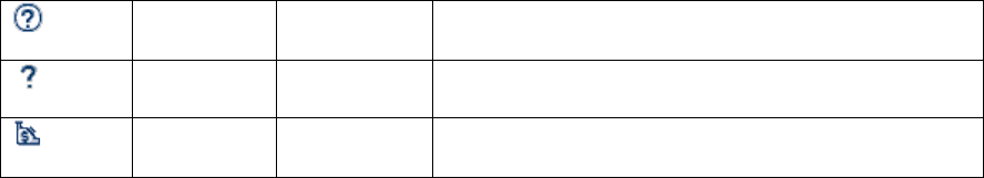
SR Research Experiment Builder User Manual ©2004-2017 SR Research Ltd.
38
Contents
F1
Displays the online help (htlm version of this
document) of the Experiment Builder application.
About
Displays the release information for this copy of the
software.
License
Displays license information for this copy of
Experiment Builder
SR Research Experiment Builder User Manual ©2004-2017 SR Research Ltd.
39
6 Designing an Experiment in Experiment Builder
This chapter introduces the general concepts of experiment design in Experiment Builder:
hierarchical organization of events in an experiment, flow diagram, and attribute
referencing. It also provides an overview of Experiment Builder components (triggers,
actions, sequences, and other nodes) and linking rules for the experiment graph.
6.1 Hierarchical Organization of Experiments
One of the important concepts in SR Research Experiment Builder is the hierarchical
organization of events in an experiment. A typical experiment can be dissected into
several levels along a hierarchy of Experiment → Blocks → Trials → Trial Runtime /
Recording. All of the events within each level of this hierarchy can be conveniently
wrapped in a loop (called a Sequence in Experiment Builder). This allows the whole
sequence to be connected to other objects as a unit and be repeated several times in a row.
The following figure illustrates a common high-level EyeLink experiment architecture.
To create an experiment, users need to create several nested sequences, add a list of
actions and triggers to each sequence, and make necessary connections between
components to form the experiment flow. In this example, the top-most level of the
experiment (Experiment Sequence) contains a greeting message or instruction screen
followed by a sequence representing blocks of trials (Block Sequence), and then a
goodbye or debriefing message at the end of the experiment. Within each repetition of the
Block Sequence, users first perform camera adjustments, calibration and validation, and
then run several trials (Trial Sequence). Every iteration of the Trial Sequence starts with
pre-recording preparations (e.g., preloading image, audio, video resources, clearing
trigger data, sending some simple drawing graphics to the tracker screen, flushing log
file) and drift correction followed by the trial recording (Recording Sequence), and
finally displaying feedback information if necessary. The Recording Sequence is
responsible for collecting the eye data and is where visual and auditory stimuli are
presented. Response collection from the participant is also performed in the Recording
Sequence.
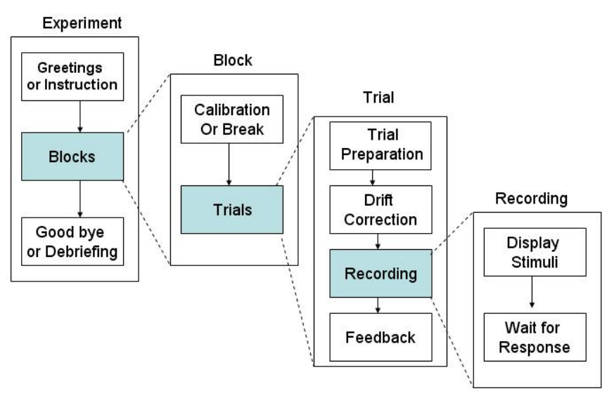
SR Research Experiment Builder User Manual ©2004-2017 SR Research Ltd.
40
Figure 6-1. Hierarchical Organization of Events in an Experiment.
6.2 Experiment Graph: Flow Diagram
Experiment Builder uses an intuitive flow diagram interface for experiment creation - the
whole experiment generated can be called a graph. Users can drag and drop experiment
components into the work space of the Graph Editor Window. These experiment
components include triggers and actions that represent individual events and
preconditions in the experiment. An Action tells the computer to do something (e.g.,
display a screen or play an audio clip), whereas a Trigger represents some preconditions
that must be met for the experiment to continue past that point. Experiment components
are connected to each other using arrowed lines that represent sequence and dependency
relationships (i.e., X must be done before Y can be done). The connection of experiment
components forms the flow of the experiment. The following figure illustrates a very
simple experiment sequence with gaze-contingent manipulation.
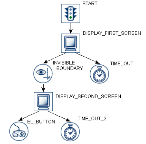
SR Research Experiment Builder User Manual ©2004-2017 SR Research Ltd.
41
Figure 6-2. Sample Experiment Sequence.
In this example, the experiment sequence starts with a DISPLAY_FIRST_SCREEN
action, which draws graphics to the computer display. Now the sequence constantly
monitors two Triggers until one of the Triggers is satisfied: an
INVISIBLE_BOUNDARY trigger and a TIME_OUT. The INVISIBLE_BOUNDARY is
triggered if the participant’s gaze falls within a pre-specified region of the screen whereas
the TIME_OUT is triggered if a specified amount of time (e.g., 30000 milliseconds) has
passed since DISPLAY_FIRST_SCREEN was drawn.
If TIME_OUT is triggered, the sequence ends since the TIME_OUT Trigger does not
connect to any subsequent experiment components. However if
INVISIBLE_BOUNDARY is triggered, DISPLAY_SECOND_SCREEN action is
performed and new graphics are drawn to the computer screen.
Now the sequence monitors two new Triggers: a TIME_OUT_2 trigger and an
EL_BUTTON trigger. The EL_BUTTON trigger fires if the participant presses a button
on the EyeLink button box. TIME_OUT_2 is triggered if a pre-specified duration has
elapsed since the second display was drawn. The sequence ends when either of the
triggers (EL_BUTTON and TIME_OUT_2) becomes true.
Important: Note that in the above example, once the DISPLAY_SECOND_SCREEN
Action has been performed the TIME_OUT and INVISIBLE_BOUNDARY Triggers are
no longer monitored; only the Triggers connected to the last processed Action are
monitored.
6.2.1 Adding Components to an Experiment
To add individual components to the workspace of the Graph Editor, first choose the
corresponding node group of the Components Toolbox by clicking on the Trigger, Action,
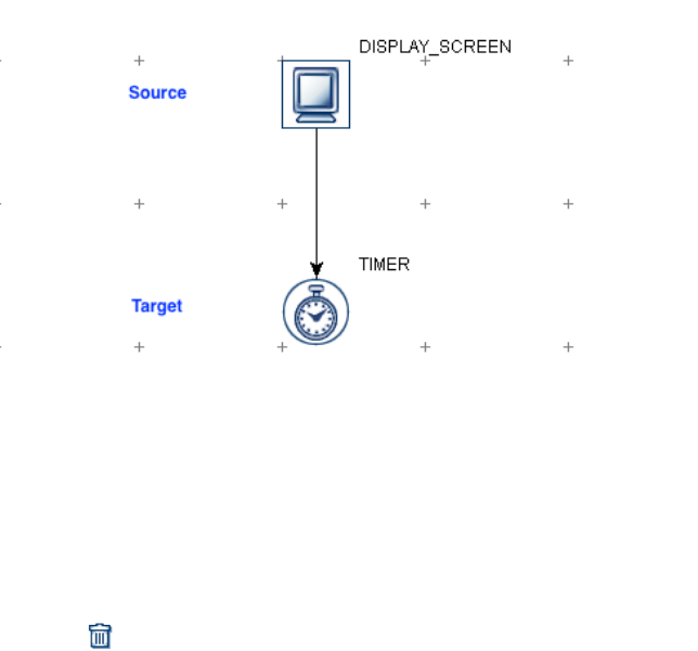
SR Research Experiment Builder User Manual ©2004-2017 SR Research Ltd.
42
or Other tab. Left-click on the icon of the desired component and drag the selected item
to the desired location in the work space, then release the mouse button. For a description
of any component, simply hover the mouse cursor over the icon
6.2.2 Linking Experiment Components
The flow of an experiment sequence moves from the default "START" node to one or
several triggers or actions and then to other triggers or actions, and so on. This requires
users to connect two nodes with arrowed line to establish a directional or dependency
relationship between a "Source" node and a "Target" node.
Figure 6-3. Connecting Between Source and Target Components.
To make a connection from a Source node to a Target node, left-click on the Source node
and drag the mouse to the Target node, then release the mouse button. To cancel a
connecting operation in progress, press the "ESC" key. To remove a connection between
two experiment nodes, click the connecting line until it is highlighted in yellow, and then
press the "Delete" key on a Windows keyboard (Command ⌘ + Delete together on Mac
OS X) or select the button on the application tool bar.
6.2.3 Linking Rules
The connection between a Source node and a Target node is governed by a set of rules:
1) A node cannot be connected to itself.
2) You cannot connect from the source node to the target node more than once.
3) The START node cannot be a Target (i.e., it cannot receive a connection from
other nodes in a graph). The START node can target to an action, trigger, or
sequence.
4) A Source node cannot have more than one Target Action; unless it is a
Conditional Trigger in which case each conditional branch cannot Target more
than one Action node.
5) A Source node can target many Trigger nodes.
6) A Source node cannot target a Trigger node and an Action node at the same time.
7) A Sequence node cannot target a Trigger node.

SR Research Experiment Builder User Manual ©2004-2017 SR Research Ltd.
43
8) A Target trigger node cannot receive connections from multiple source trigger
nodes.
9) A Source node cannot target multiple Sequence nodes. That is, the current version
of Experiment Builder does not support parallel processing.
10) A Drift Correct Action or Camera Setup Action cannot target any Trigger.
11) Storage space elements (Accumulator, Variable, and Results File) cannot be
Source or Target Nodes (i.e., never directly connected to other nodes).
12) Certain node types, such as Fixation, Saccade, Invisible Boundary, and Sample
Velocity Triggers, can only be added to a sequence that has the "Record"
checkbox ticked.
13) Drift Correct and Camera Setup Actions cannot be added to a sequence that has
the "Record" checkbox enabled.
14) A Trigger cannot be the target of an action and a trigger at the same time.
6.3 Actions
Action nodes instruct the computer to do something, for example, to display a screen or
play a sound. One or multiple actions can be added to a sequence, depending on the
complexity of the experiment. For example, a recording sequence showing a static page
of text may just require a single display screen action whereas an experiment studying
change detection necessitates several display screen actions to present alternating screens
at a fixed interval. SR Research Experiment Builder supports a set of actions listed in the
following table.
Display Screen
Used to show a set of 2D graphics on the computer screen. Please
follow Chapter 8 “Screen Builder” to modify the content of the
screen.
Camera Setup
Displays the EyeLink camera setup screen for the experimenter to
perform camera setup, calibration, and validation.
Drift Correction
Performs an EyeLink drift correction by using a fixation point at a
known position to correct for small drifts in the calculation of
gaze position that can build up over time. This is particularly
useful when using the pupil-only mode of EyeLink. On the recent
versions of eye trackers (e.g., EyeLink 1000, 1000 Plus, Portable
Duo), a drift check will be performed instead, in which no
correction is applied to the gaze data.
EyeLink Command
Sends a text command to the EyeLink tracker through the
Ethernet link for on-line tracker configuration and control.
EyeLink Message
Writes a text message to the EyeLink eye tracker. The text is
millisecond time stamped and is inserted into the EyeLink EDF
file.
Add to Log File
Allows users to add text to a log file for experiment debugging.
Prepare Sequence
Performs preparatory operations for a sequence (e.g., preloading
image or audio files, drawing feedback graphics on the Host PC,
and re-initializing trigger settings) to ensure real-time
performance and better recording feedback.
Add to Accumulator
Adds a number to an Accumulator object.
Add to Results File
Used to output data to a tab-delimited Results File.
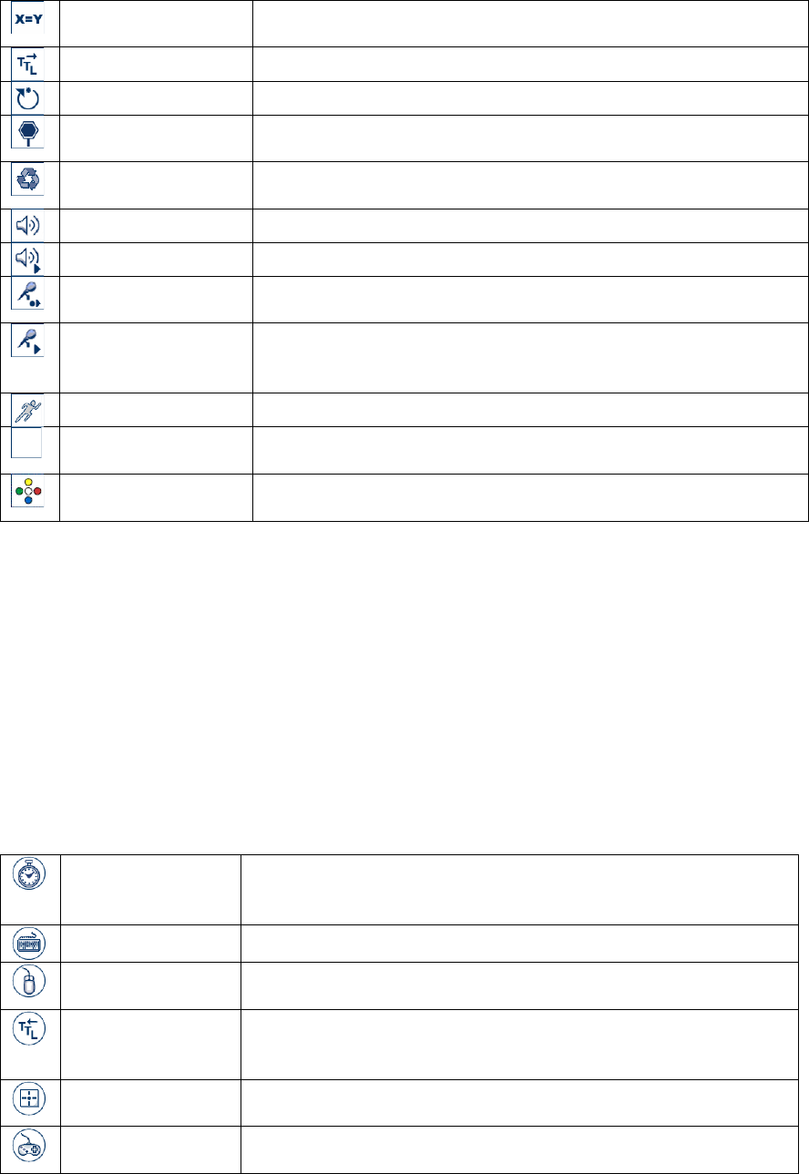
SR Research Experiment Builder User Manual ©2004-2017 SR Research Ltd.
44
Update Attribute
Updates the value of a Variable or an attribute of an experiment
component.
Send TTL Signal
Sends a TTL signal via the parallel port or other data ports.
Reset Node
Allows users to pick a node in the experiment and reset its data.
Terminate
Experiment
Used to terminate the experiment project programmatically.
Recycle Data Line
Instructs the experiment sequencer to run the current data source
line again at a later time.
Play Sound
Plays a .WAV audio file.
Play Sound Control
Stops, pauses, or unpauses a specified Play Sound action
Record Sound
Records audio to a .WAV file. Only supported with an ASIO-
compatible sound card in Windows or in Mac OS X.
Record Sound
Control
Stop, pause, unpause, or abort the current sound being recorded.
Only supported with an ASIO-compatible sound card in Windows
or in Mac OS X.
Execute
Executes a method defined in a Custom Class Resource.
Null Action
A dummy action used primarily for the purpose of controlling
experiment flow and cleaning cached trigger data.
ResponsePixx LED
Control
An action used to turn on/off the LEDs on the ResponsePixx
Button box.
6.4 Triggers
A Trigger is some condition that must be met for the experiment flow to continue past
that point. Triggers are used by Experiment Builder to control the transition from one
Action to another, or to end a sequence itself. For example, in a simple reaction-time
experiment, following the onset of the stimulus display a speeded response from the
keyboard or a button box can be used as a trigger to end the trial. In a change-detection
experiment, the time delay serves as a trigger to make the transition from one display
screen to another (and therefore controls the exposure duration of a display screen). In a
gaze-control experiment, a trigger for display change can be elicited when the eye enters
or leaves a pre-specified invisible boundary. Experiment Builder supports the following
set of triggers:
Timer
Fires when a specified amount of time elapses. Timers can be used
to add a delay between actions and/or triggers, and to control the
maximum amount of time a node can last.
Keyboard
Fires when a specified key is pressed.
Mouse
Fires when a mouse button is pressed and / or when the mouse
cursor falls within a specified region of the screen.
TTL
Checks TTL input to the input ports (e.g., parallel port or USB
1208HS box) of the display computer and fires when a specified
TTL signal is received.
Cedrus Button
Fires when a specified button on the Cedrus response pad is
pressed.
EyeLink Button
Fires when a specified button on the EyeLink button box is
pressed.
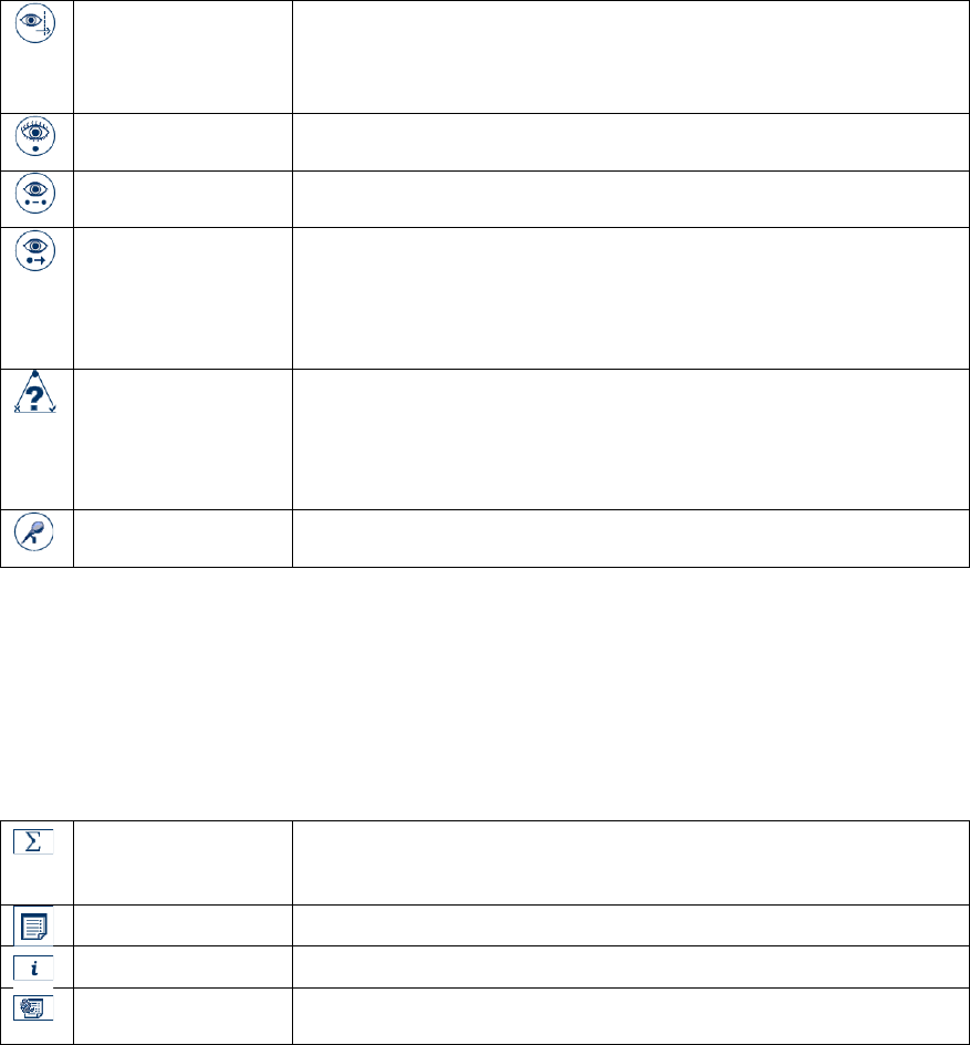
SR Research Experiment Builder User Manual ©2004-2017 SR Research Ltd.
45
Boundary
Fires when gaze position falls inside or outside of a pre-specified
invisible boundary, either after a single sample or a minimum
duration. Boundary triggers can be used to implement display
changes based on eye positions.
Fixation
Fires when a fixation falls inside or outside of a specified region of
the display for a certain amount of time.
Saccade
Fires when a saccade to a specified region of the display is
detected.
Sample Velocity
Implements a fast saccade detection algorithm by checking the
velocity and acceleration information on a sample-by-sample
basis. The Sample Velocity Trigger fires when the sample velocity
and acceleration values exceed or fall below their respective
thresholds.
Conditional
Fires when one or two conditional evaluations are met. The
Conditional trigger may connect to two different target nodes,
depending on whether the condition evaluates to True or False.
This is useful to implement conditional branching in a graph when
several conditions are possible.
Voice Key Trigger
Triggers when ASIO input exceeds a pre-specified threshold. Only
supported with an ASIO-compatible sound card or in Mac OS X.
6.5 Other Node Types
Experiment Builder also supports other components: Variable, Results File, and
Accumulator. These components mainly function as a storage of experiment data. Note
that these objects are never connected to other components in an experiment in the Graph
Editor Window. Instead, they are used and updated within the experiment by attribute
referencing (see section 6.7).
Accumulator
Used to keep numeric values and do statistical analysis on the
accumulated data. The Accumulator is a circular list, so items
added to the list last are kept in case of an overflow.
Results File
Provides a columnar output of selected variables.
Variable
Used to store data during run time.
Custom Class
Instance
Used to create a new instance of a custom class
6.6 Sequence
As the experiment loop controller, a Sequence is used to chain together different actions
and triggers and execute them as a group. Therefore, Sequence itself can be considered as
a complex action. To implement the hierarchical organization of events in an experiment,
Experiment Builder allows one graph containing the triggers and actions to be nested
within another graph. In a typical experiment, users need to add a few nested sequences
so that the implementation of blocking, trial, and recording can be done efficiently (see
Figure 6-4 for an example).
Given the repetitive nature of the sequence component, a data source can be attached to a
sequence node to supply different parameters for each sequence iteration. The data source
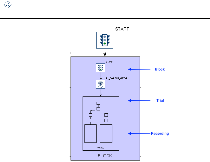
SR Research Experiment Builder User Manual ©2004-2017 SR Research Ltd.
46
is similar to a spreadsheet . Each column of a data source contains a variable label and
each row contains values for the variables. For a typical experiment created in
Experiment Builder, users will create prototypical trials and to supply the actual
parameters for individual trials in a data source attached to the trial sequence. During
experiment runtime, individual lines can be read from the data source, providing the
actual parameters for each trial, by setting relevant node attributes as references to data
source columns (see section 10 “References”).
Sequence
A controller for experiment flow. Used to chain together different
Actions and Triggers and execute them in a group or to simply
modularize a set of experiment components.
Figure 6-4. Nested Sequences in an Experiment.
6.7 References and Equations
Experiment Builder uses "references" to link or bind an attribute of one experiment
component to the attribute of another component. References (see Chapter 10) are a
critical part of Experiment Builder, providing much of the flexibility to the application.
For example, assume a sequence has two nodes, X and Y, and node X has attribute AX
and node Y has attribute AY. If attribute AX is set to reference AY, then the value of AX
will always be equal to the value of AY. In this example it is said that AX is the
"referencing" attribute and AY is the "referenced" attribute. Even if AY changes value
during the experiment, AX will always reflect the current value of AY.
SR Research Experiment Builder User Manual ©2004-2017 SR Research Ltd.
47
A reference is represented by a string that starts and ends with an @ symbol in the
attribute editor for an experiment node. For example @X.AX@ is a reference to the AX
attribute of node X. @Y.AY@ is a reference to the AY attribute of node Y. If the
reference is to a node attribute that is not in the same sequence as the referencing node,
the reference will also contain the graph path to the referenced node.
Users can refer a variable or an attribute of one node to an attribute of another node
(trigger, action, or sequence), a variable, or a data source column. Users can also create
more complex equations, which may include a combination of values and/or references.
In most cases the data type of the referring attribute must match that of the referenced
attribute.
As a more concrete example of using references, imagine that a user needs to show some
text on the screen. In the Properties table of the text resource, the user can enter the text
to be displayed directly into the "Text" property field (see left panel of Figure 6-5). This
will result in the same text being presented in each iteration of the sequence. This static
approach is fine for things like presenting a fixation cross, but will be problematic when
the user needs to display different text across trials. An alternative, more flexible
approach, is to have the "Text" attribute refer to a column of a data source. Then on each
iteration of the sequence, the resource will use different text values as defined in the data
source.
In addition to setting values dynamically, references can be used to access the value of
attributes of an action or a trigger. In the above example, the width and height of the text
shown on the screen will change dynamically across trials. To know the exact text
dimension in one trial, the user can refer to the "Width" and "Height" properties of the
text resource.
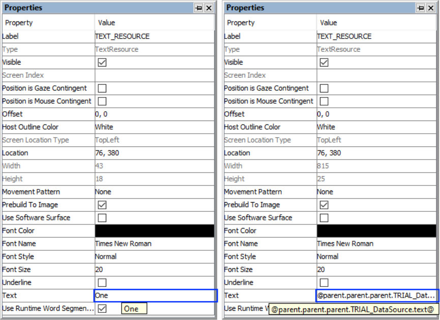
SR Research Experiment Builder User Manual ©2004-2017 SR Research Ltd.
48
Figure 6-5. Using a Reference to Update Text to Be Displayed.
SR Research Experiment Builder User Manual ©2004-2017 SR Research Ltd.
49
7 Experiment Graph and Components
The Component Toolbox in the Graph Editor Window contains the basic building blocks
for building experiments. To create an experiment, users need to add necessary
components into different sequences of the experiment and make connections between
those components. Following this, the properties of the individual components should be
reviewed and modified as necessary. The current chapter reviews the use and properties
of the individual components in the toolbox.
7.1 Graph Editing Operations
Experiment Builder is an interactive tool, allowing users to create a new experiment
graph from scratch and to modify an existing graph. With the Graph Editor Window,
users are able to add/remove Experiment Builder component nodes, add/remove the
connection between nodes, modify the attributes of nodes, and so on.
The following lists common operations used in editing a graph in Experiment Builder.
Most of the operations can be performed by keyboard shortcuts, by using buttons on the
application toolbar, or by options in the "Edit" menu.
• Insert a new node: Find the component to add in the Action, Trigger, or Other tab of
the Component Toolbox. Left-click on the icon of the desired component, then drag it
to the desired location in the work space, and release the mouse button.
• Cut: To remove a selection from the project and place it into the clipboard, first
select the nodes to be cut, then press the Ctrl + X keys together (Command ⌘ + X in
Mac OS X). Alternatively, select the nodes, then right-click and select "Cut" from the
popup menu.
• Copy: To copy a selection to the clipboard, select the nodes to be copied, then press
the Ctrl + C keys together (Command ⌘ + C in Mac OS X). "Copy" from the popup
menu.
• Paste: To paste the previously copied or cut items from the clipboard to the current
location, press the Ctrl + V keys together (Command ⌘ + V in Mac OS X).
Alternatively, right-click in the graph area, and select "Paste" from the popup menu.
• Paste a selection Multiple times: To paste the contents of the clipboard multiple
times, press Ctrl + M (Command ⌘ + M in Mac OS X). Alternatively, right-click in
the graph area, and select "Paste" from the popup menu. Enter the number of copies
to paste and click “OK”
• Delete: Select the nodes to be removed and press the "Delete" key (Command ⌘ +
Delete in Mac OS X). Alternatively, select the nodes, then right-click and select
"Delete" from the popup menu.
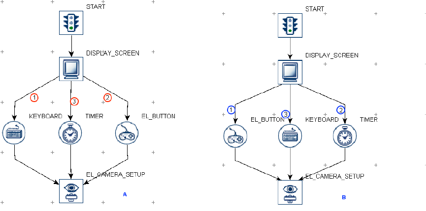
SR Research Experiment Builder User Manual ©2004-2017 SR Research Ltd.
50
• Undo: To undo the last action performed, press Ctrl + Z (Command ⌘ + Z in Mac
OS X).
7.2 Node Connection
The flow of an experiment sequence moves from the default "START" node to one or
several triggers or actions and then to other triggers or actions, and so on. This requires
users to connect two experiment nodes with an arrowed line to establish a directional or
dependency relationship between a "Source" node and a "Destination" node.
7.2.1 Connection: Create, Cancel, and Delete
To connect a Source node to a Destination node, left-click on the Source node, then drag
the arrow to the Destination node and release the mouse button. (Note that if the Source
node is selected, clicking and dragging from the Source node will move the node rather
than drawing a connection. To de-select a node, simply click an empty space in the graph
area.) To cancel a connecting operation in progress, press the "ESC" key. To remove a
connection between two nodes, click the connecting line so it is highlighted in yellow,
and press the "Delete" key (Command ⌘ + Delete in Mac OS X), or click the “Delete”
button in the application toolbar.
7.2.2 Connection Order
Figure 7-1. Connection Order.
When several triggers are connected to a common source node, a small number is drawn
by each edge in the graph (see Figure 7-1). This number represents the order that triggers
will be evaluated. In the above example (Left Panel), the keyboard trigger will be
evaluated first, then followed by the EyeLink button trigger, and then by the timer trigger.
To change the connection order, delete the connection arrows between the source and
target nodes, and then reconnect the nodes in the desired order. For example, if a user
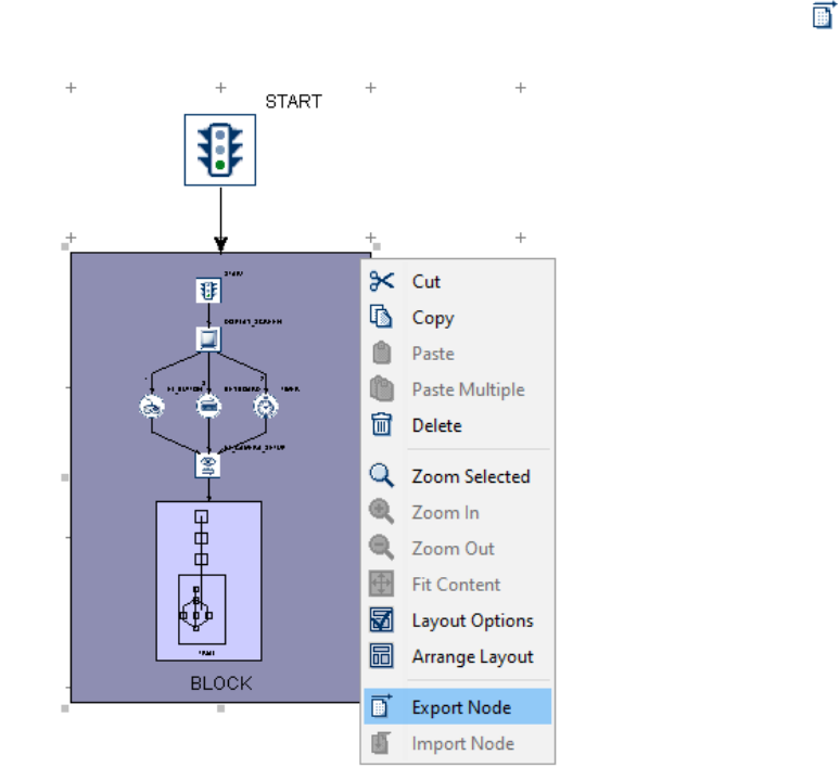
SR Research Experiment Builder User Manual ©2004-2017 SR Research Ltd.
51
deletes the connection between DISPLAY_SCREEN and KEYBOARD, the remaining
connections increase in priority, so the EyeLink button trigger is evaluated first, and then
the Timer trigger. If the user re-connects the keyboard trigger to the display screen, the
keyboard trigger is now the third to be evaluated (see Right Panel).
7.2.3 Node Exporting and Importing
Experiment Builder allows users to share data between several experiment creation
sessions by importing and exporting nodes. Users can select nodes in the graph and
export to a .ebo file. The user can later import the .ebo file into another session. The
following explains in detail how to share data between Experiment Builder sessions by
exporting and importing.
7.2.3.1 Exporting
1) Select the node or sequence to be exported. Please make sure that only one node or
sequence is selected. (To export multiple nodes, place all the nodes into a single
sequence, then export this sequence.)
2) Click the right mouse button to bring up a popup menu, and select "Export Node"
(see Figure 7-2). If the "Export Node" option is grayed out, please make sure that
only one node or sequence is selected. Alternatively, click the Export button ( ) on
the application toolbar.
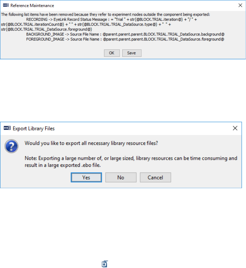
SR Research Experiment Builder User Manual ©2004-2017 SR Research Ltd.
52
Figure 7-2. Exporting Node.
3) In the following "Export" dialog box, select the directory where the node should be
exported, enter the export file name, and then click the "OK" button.
• If the node to be exported contains references to other nodes or data source
columns that are not part of the selection, a "Reference Maintenance" dialog (see
the figure below) will be displayed to enumerate all of the references that will be
removed. Click the "Save" button to save the information to a text file if desired,
then click the "OK" button to continue.
Figure 7-3. Reference Maintenance.
• A dialog box will ask whether to export all necessary library files—any image,
sound, video files, etc., used in the selected node or sequence. Click "Yes" to
include all necessary library files in the exported file. Click "No" to export only the
node or sequence itself, excluding any library files. Click "Cancel" to abort the
export process.
Figure 7-4. Export Library Files.
7.2.3.2 Importing
1) Go to the intended sequence level and click anywhere in the blank area of the
workspace to make sure that no node or sequence is selected.
2) Click the right mouse button and select "Import Node" (see Figure 7-5). If the
"Import Node" option is grayed out, please make sure no node is currently selected.
Alternatively, click the Import button ( ) on the application toolbar.
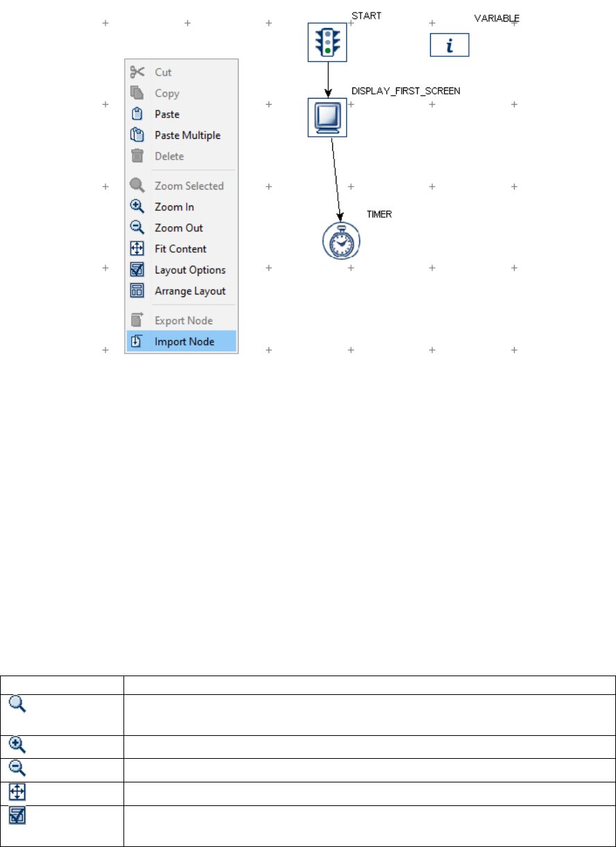
SR Research Experiment Builder User Manual ©2004-2017 SR Research Ltd.
53
3) In the following "Open" dialog box, go to the directory where the exported node file
is located, select the ".ebo" file, and click "Open".
Figure 7-5. Importing Node.
7.3 Layout of Nodes in Work Space
The Work Space in the Graph Editor Window functions like a flow diagram editor which
components are dragged onto and connected. If a large number of items are added, the
work space may get cluttered. The Experiment Builder graphic user interface allows for
automatic node arrangement and zoom-in or zoom-out operations to create high-quality
drawings of a graph for ease of reading.
To rearrange the layout of items in an orderly manner, place the mouse cursor in a blank
area of the Work Space, click the right mouse button to bring up a popup menu, and
choose “Arrange Layout” (see Figure 7-6). From the menu, users can also zoom in or out
the current graph, or to make the current graph fit the screen. The following table lists of
the options available from the popup menu.
Operation
Function
Zoom
Selected
When one or more components in the graph are selected, zoom in on the
selected items.
Zoom In
Zoom in towards the center of the work space.
Zoom Out
Zoom out so that more items can be displayed in the work space.
Fit Content
Zoom in or out so all the components in the work space are displayed.
Layout
Option
Configure the layout of components when “Arrange Layout” is applied.
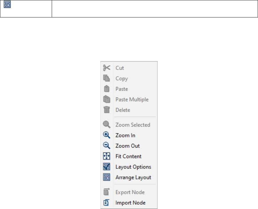
SR Research Experiment Builder User Manual ©2004-2017 SR Research Ltd.
54
Arrange
Layout
Rearrange the graph components in an orderly manner.
Note: To perform “Zoom Selected”, first select the nodes to zoom to, then right-click in
the work space to bring up the menu.To perform the other operations listed in the table,
first click a blank area in the work space to ensure no nodes are selected, then click right-
click in the work space to bring up the menu and select the operation to perform.
Figure 7-6. Choosing Layout of Components in Work Space.
7.4 Editing Properties of a Node
After a component is added into the workspace, some of its default property values can
be modified according to the requirements of the experiment. For example, the
maximum “duration” of a TIMER trigger is set to 4000 milliseconds by default. This
may not be a desired value in an actual experiment and therefore users may need to set a
different value for that field. To edit the properties of a node, first click the node so it is
highlighted by a green border.
When one experiment node is selected, its properties and corresponding values are
displayed in the property panel for review and modification. Depending on the property,
it can be edited in one of the following ways:
• If a properties field (e.g., “Time” and “Start Time” of various actions) is grayed
out then the value of the property is “read-only” and cannot be directly modified.
• If the value field of a property contains a check box (e.g., “Record” property of a
sequence), that property can be either enabled or disabled by clicking the check
box.
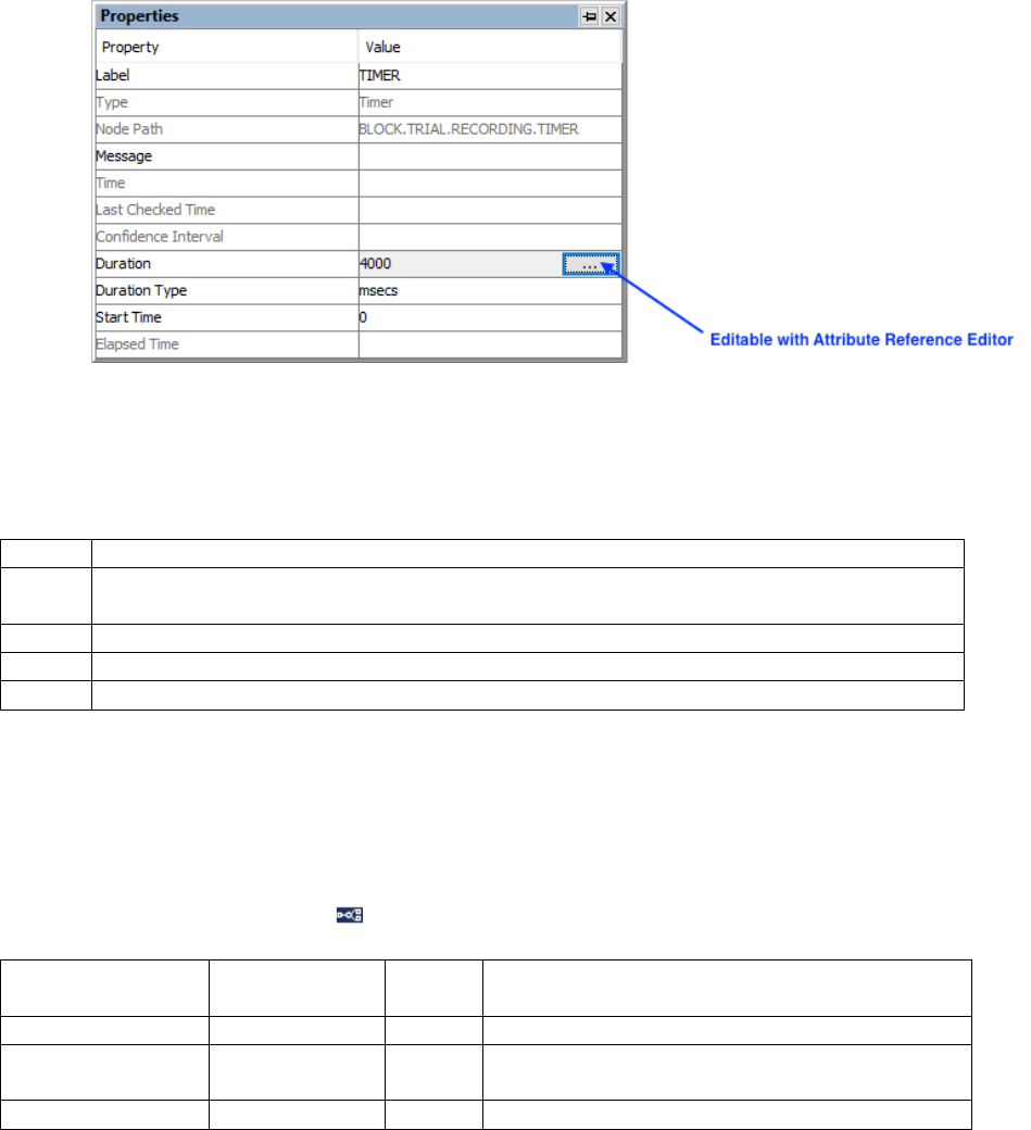
SR Research Experiment Builder User Manual ©2004-2017 SR Research Ltd.
55
• If a dropdown list appears after doubling clicking the property value field (e.g.,
“Duration Type” property of the Timer trigger), make the selection from the list.
• For some properties (e.g., “Label” of an action), the value can be modified by
double clicking on the value field, entering the desired value, and then pressing
the ENTER key to register the change.
• If a button box appears at the right side of the attribute cell after selecting the field
(see Figure 7-7), the property field may also be edited with Attribute Reference
Editor (see Chapter 10).
Figure 7-7. Property Field Editable with Attribute Reference Editor.
In the following sections of this chapter, a set of symbols are used to indicate the
properties of each attribute of an experiment component:
#
Attribute is read-only and is not directly modifiable
*
Attribute can not reference another attribute (Attribute Reference Editor is not available
for the property)
NR
The attribute cannot be referenced by other component attributes.
¶
Attribute value can be selected from a dropdown list
†
Attribute is a Boolean value. True if the box is checked; false if unchecked.
All other attributes can be modified either by entering the value directly in the edit field
or by setting a reference in an attribute editor dialog box. Those fields can also be
accessed for attribute references.
7.5 Experiment Node
Clicking on the topmost node ( ) of the structure list in the Project Explorer Window
displays the properties of the experiment project in the property panel.
Field
Attribute
Reference
Type
Content
Label *
.label
String
Label of the Experiment
Type #
NR
The type of Experiment Builder object
(“Experiment”) the current node belongs to.
EyeLink DV
.dataViewerVar
List of
Clicking on the value field of this property will

SR Research Experiment Builder User Manual ©2004-2017 SR Research Ltd.
56
Variables
iables
Strings
bring up a dialog box allowing users to select
variables and data source columns to be
recorded in the EDF file as trial condition data
in Data Viewer. This attribute is only available
in an EyeLink experiment (i.e., the “EyeLink
Experiment” setting of the Experiment
Preference is enabled).
Time Out
.timeout
Integer
The maximum time (in milliseconds) the
experiment should run. If 0, the experiment will
not time out.
Created Date #
.createdDate
String
Time and Date when the experiment was first
created.
Last Modified
Date #
.lastModifiedD
ate
String
Time and Date when the experiment was last
modified.
Session Name #
.sessionName
String
Name of the experiment session. This is the
string input in the "Session Name" dialog box
when running the experiment.
Test Run
Command Line
Arguments
.cmdargs
List of
String
Extra parameters that can be passed to the
experiment program. When running the
deployed experiment from the command line
prompt, users may enter an extra string
following the {experiment}.exe command.
Extra parameters can be added to Test Runs
under Preferences → Build/Deploy.
License ID #
NR
ID of the license key. “Demo” if the
Experiment Builder software is unlicensed.
Save Messages †
.saveMessages
Boolea
n
Whether the messages associated with any
triggers or action should be logged in a text file.
This attribute is available in Non-EyeLink
Experiments only. If enabled, the “Message”
property will be available in most of the triggers
and actions.
Read-Only †
NR
Boolea
n
Check this box to prevent any changes to the
experiment project from being saved.
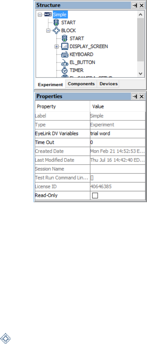
SR Research Experiment Builder User Manual ©2004-2017 SR Research Ltd.
57
Figure 7-8. Properties of the Experiment Node.
The "EyeLink DV Variables" property is used to send trial condition messages to the
EDF file so that users know exactly under which conditions each trial recording was
performed. The list of possible variables includes columns in the experiment data source
(see Chapter 9 "Data Source") as well as new variables created by the user (see Section
7.11.1 "Variable"). Version 2.0 of Experiment Builder now automatically adds the
variables and data source columns to the EyeLink DV Variables field. To remove some
variables from the list, or to change the order of the variables, click on the value field of
the property. A dialog box will allow the user to choose the variables to be recorded and
to reorder them in the list.
To have the experiment to time out after a certain duration, enter the time out value in
milliseconds into the "Time Out" field.
7.6 Sequence
A sequence ( ) object encapsulates different actions and triggers, allowing users to
perform editing operations (cut, copy, delete, paste) on all of the items contained within
the sequence together. It also allows users to execute them in a loop and repeat the
execution several times if required. In a typical experiment, users need to add a couple of
nested sequences so that a blocking-trial-recording hierarchy can be implemented

SR Research Experiment Builder User Manual ©2004-2017 SR Research Ltd.
58
efficiently. In an EyeLink experiment, the "Record" attribute should be ticked for one of
the sequences (usually the “innermost” sequence) so eye-tracker data can be collected.
Field
Attribute
Reference
Type
Content
Label *
.label
String
Label of the Sequence node. The default label
is “SEQUENCE”.
Type #
NR
The type of Experiment Builder object
("Sequence") the current node belongs to.
Node Path #
.absPath
String
The absolute path of the node in the experiment
graph.
Time #
.time
Float
Display computer time (in milliseconds from
the start of the experiment) when the sequence
is executed.
Record †
.record
Boolea
n
Whether EyeLink recording should be done
within the sequence. Recording is done for each
iteration of the sequence, starting at the
beginning of the sequence and ending after
executing the nodes along one of the flow paths.
The default setting is “False” (box unchecked).
This attribute is only available in an EyeLink
experiment.
Recording Pause
Time
.recordingPauseT
ime
Integer
Time (in milliseconds) to wait to execute the
sequence after the recording starts (typically set
as 20). This attribute is only available in an
EyeLink experiment with the “Record” attribute
of the current sequence enabled.
EyeLink Record
Status Message
.eyeLinkRecordS
tatusMessage
String
This supplies the title at the bottom of the Host
PC recording screen. This attribute is only
available in an EyeLink experiment with the
“Record” setting of the current sequence
enabled.
Custom Trial
ID Message
.customTrialID
Message
String
This property will only be available when
the "Enable Custom Trial ID Message"
option in "Edit -> Preferences ->
Experiment" is enabled. Instead of the
default value of "TRIALID", users can send
out a customized Trial ID message that can
be used by their analysis software. For
compatibility with EyeLink Data Viewer,
we recommend users starting this message
with a "TRIALID " token, followed by
whatever trial-specific condition data they
wish to send.
Trial Result
.trialResult
Integer
A value used to encode the result of the current
recording trial (e.g., "MSG 1067284
TRIAL_RESULT 12" in the EDF file). It is 0 by

SR Research Experiment Builder User Manual ©2004-2017 SR Research Ltd.
59
default but can be referenced to some responses
made in the trial. This attribute is only available
in an EyeLink experiment with the "Record"
setting of the current sequence enabled.
Is Real Time †
.isRealTime
Boolea
n
When set to True, sets the application priority to
real-time mode. Real-time mode is only
maintained for the duration of the sequence. The
default setting is “False” (box unchecked).
It may take up to 100 milliseconds, depending
on the operation system, for the real-time mode
to stabilize. Also note that on some (older)
computers, real-time mode locks keyboard and
mouse inputs from occurring. For recent
computers with dual- or multicore processors,
the keyboard and mouse will function properly
in the real-time mode.
Iteration #
.iteration
Integer
The current iteration of the sequence execution.
Iteration Count
.iterationCount
Integer
Total number of times (1 by default) the
sequence should be executed.
Split by
.splitBy
List of
Integer
s
Specifies the number of iterations to be
executed each time the sequence is encountered.
If the list is not empty, each number in the list
should be no less than 1.
Data Source
NR
Double clicking on this field will bring up a data
Source editor (see Chapter 9 “Data Source” for
details). The "Columns: X/Rows: X” reports the
amount of data in the data source.
Freeze Display
Until First
Display Screen †
.freezeDisplayUn
tilFirstDisplayScr
een
Boolea
n
If checked, the display will not be updated until
the call of the first Display Screen action within
the sequence (to avoid some undesired display
changes). The field should be checked in most
experiments.
Prompt for
Dataset File †
.promptForDatas
etFile
Boolea
n
If checked, a dialog box will show up at the
beginning of the experiment to allow the user to
choose the intended dataset file. If unchecked, it
will load in the default dataset file.
Callback
NR
For an experiment project with custom class
enabled, a method defined in the custom class
can be run for every poll of the sequence.
Similar to the EXECUTE action, a list of
parameters will be displayed if a method is
selected from a custom class instance. Please
note that running this callback function may add
an extra delay to sequence polling and it should
be used with caution (please avoid running any
callback function that takes a significant amount
of time to finish).
Result #
NR
Result of the execution method.
Result Data
NR
Type of the data returned by the execute

SR Research Experiment Builder User Manual ©2004-2017 SR Research Ltd.
60
Type #
method.
A recording sequence must be included in an EyeLink experiment. To specify a sequence
as a recording sequence, select the sequence and tick the "Record" checkbox in the
properties panel. This checkbox is only available in an EyeLink experiment, and only in
sequences not already contained within a recording sequence.
If the "Record" box is checked, users will see additional properties: "EyeLink Record
Status Message" allows users to send a text message to be displayed at the bottom of the
tracker screen, for instance, to inform the experimenter of the progress of experiment
testing; and "Recording Pause Time" controls the delay in executing the sequence
following the start of the tracker recording. To maximize real-time performance in data
collection, users should have the "Is Real Time" box checked for the Recording sequence
and include a prepare sequence action before executing the sequence.
The Recording sequence enables on-line access to gaze data, so all the eye-based triggers
can be only used in a recording sequence—i.e., the invisible boundary, fixation, saccade,
and sample velocity triggers. Conversely, the drift correction and camera setup actions
cannot be used in a recording sequence.
7.6.1 Typical Use of Sequences in an Experiment
The following figure illustrates the use of sequences in a typical experiment. In this
example, a RECORDING sequence that performs the actual eye-tracker recording is
nested within a TRIAL sequence, which itself is nested within a BLOCK sequence. The
"Record" field is checked in the RECORDING sequence but not in the BLOCK or
TRIAL sequences. The RECORDING sequence also allows users to send a message
(EyeLink Record Status Message) to the tracker screen so that the experimenter can be
informed of the progress of the experiment.
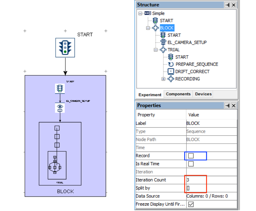
SR Research Experiment Builder User Manual ©2004-2017 SR Research Ltd.
61
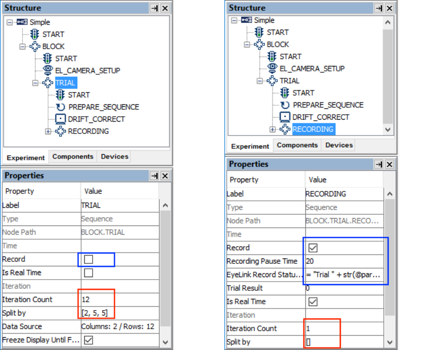
SR Research Experiment Builder User Manual ©2004-2017 SR Research Ltd.
62
Figure 7-9. Using Sequences in an Experiment.
The iteration count of a sequence specifies the maximum number of times the sequence
should be executed, while the "Split by" field allows users to flexibly configure the
number of actual iterations to be executed. By default, the "Split by" field contains an
empty list "[]", which means that all of the iterations should be executed each time the
sequence is called. Users can add values to the split-by list to specify the actual number
of iterations to be executed for each call of the sequence. This allows users to easily
design experiments in which unequal numbers of trials are tested in different blocks. In
the above example, the iteration count of the BLOCK sequence is 3 and the split-by list is
empty. This means that the BLOCK sequence will be executed three times in total (i.e., 3
blocks). The total iteration count of the TRIAL sequence is 12 and its split-by field
contains a list of [2, 5, 5]. This means that the TRIAL sequence will be executed two,
five, and five times during the first, second, and last call of the BLOCK sequence. The
iteration count of the RECORDING sequence is 1 and the split-by list is empty. This
means that the recording sequence will be executed once for each call (in other words,
once per trial). Therefore, the above graph indicates that this experiment has three blocks,
which contains two, five, and five trials, respectively. Each trial will perform one eye-
tracker recording.
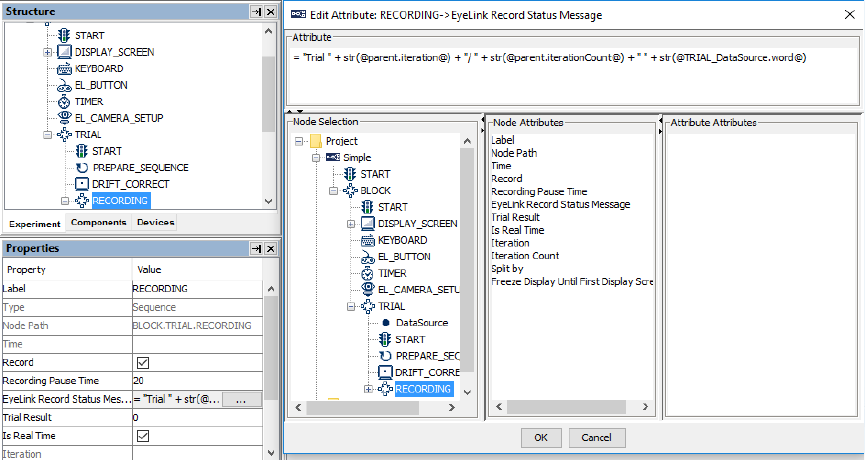
SR Research Experiment Builder User Manual ©2004-2017 SR Research Ltd.
63
7.6.2 EyeLink Recording Status Message
During data collection, the EyeLink Record Status Message can be used to display a text
message at the bottom of the tracker screen, e.g., to inform the experimenter of the
progress of the experiment, or to report trial condition information (so that the
experimenter knows immediately which condition is being tested and therefore may be
able to evaluate the performance of the participant). To configure the status message,
select the recording sequence. Make sure that the “Record” property of the sequence is
checked, otherwise the “EyeLink Record Status Message” property will not be displayed.
Click the Value field of the EyeLink Record Status Message property, then click the [ …
] button to bring up the attribute editor. Then enter the message string, making sure the
string is shorter than 80 characters for an EyeLink II, 1000, 1000 Plus, or Portable Duo,
and shorter than 40 characters for an EyeLink I (see Figure 7-10). Make sure to include
only ASCII characters in the message screen, as non-ASCII characters will not be
displayed properly.
For example, if a user has a data source with the variables “Trial” and “Word”, the record
status message can be:
="Trial " + str(@parent.iteration@) + "/" +
str(@parent.iteratonCount@)+ “ “ +str(@TRIAL_SEQ_DataSource.Word@)
Figure 7-10. Creating Recording Status Message.
If the values for “.iteration” and “word” are “1” and “One” for the first trial and
“.iterationCount” is 12, this will display “Trial 1/12 One” on the tracker screen.
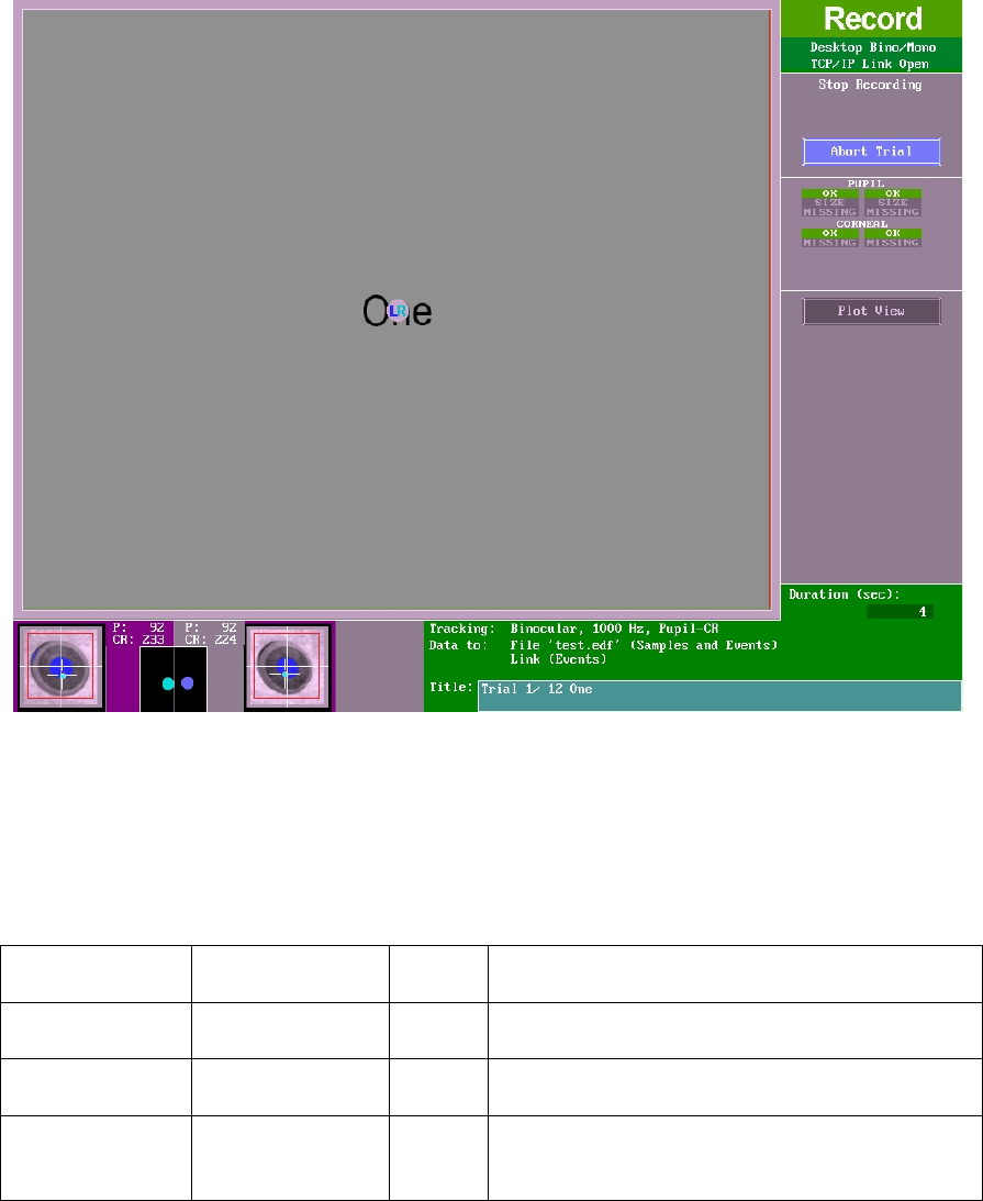
SR Research Experiment Builder User Manual ©2004-2017 SR Research Ltd.
64
Figure 7-11. Sending the Recording Status Message to the Tracker.
7.7 Start Node
For each sequence in an experiment graph, the flow always begins with the default
"START" node. Each sequence requires a connection made from the "START" node to a
trigger or an action. The START node cannot receive a connection from other nodes.
Field
Attribute
Reference
Type
Content
Type #
NR
The type of Experiment Builder object ("Start")
the current node belongs to.
Node Path #
.absPath
String
The absolute path of the node in the experiment
graph.
Time #
.time
Float
Display computer time (in milliseconds from
the start of the experiment) when the experiment
flow starts.
7.8 Actions
SR Research Experiment Builder supports a list of actions, such as displaying a screen,
performing drift correction, performing camera setup and calibration/validation, sending
a message to an EDF file or to a log file, preparing a sequence, sending a command,
sending a TTL signal, updating variable values, adding to a results file, adding data to an
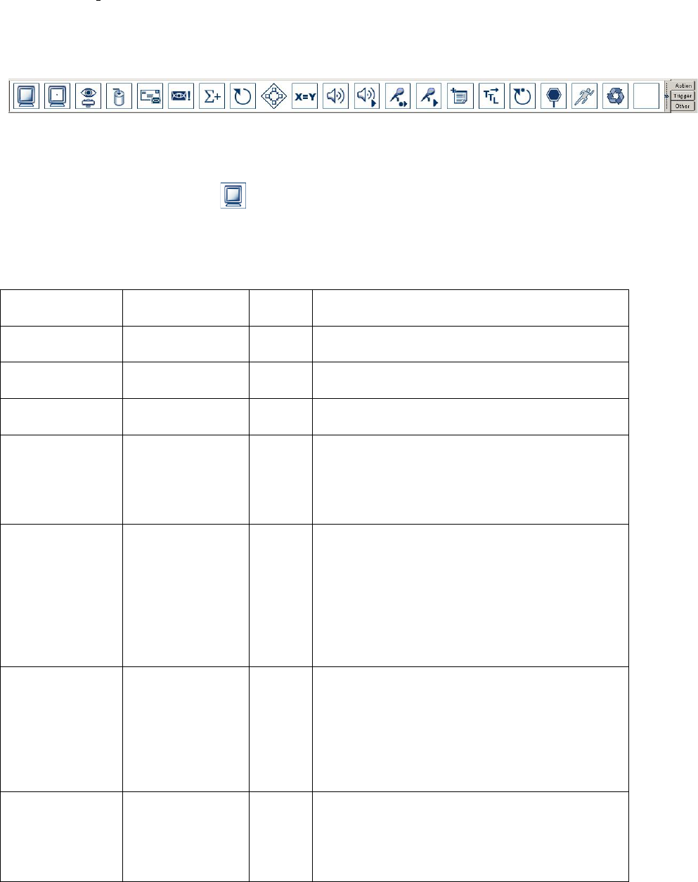
SR Research Experiment Builder User Manual ©2004-2017 SR Research Ltd.
65
accumulator, playing sound, recording sound, recycling a data source line, or terminating
the experiment. Actions can be accessed by clicking on the "Action Tab" of the
Component Toolbox (see Figure 7-12). The following sections describe the usage and
properties of each action type in detail.
Figure 7-12. Action Tab of the Component Toolbox.
7.8.1 Display Screen
The DISPLAY_SCREEN action ( ) is used to show visual stimuli on a computer monitor.
Double clicking on the newly added DISPLAY_SCREEN action will show a blank Screen
Builder workspace for creating visual displays. Please follow Chapter 8 “Screen Builder”
to modify the content of the screen.
Field
Attribute
Reference
Type
Content
Label *
.label
String
Label of the Display Screen action. The default
value is “DISPLAY_SCREEN”.
Type #
NR
The type of Experiment Builder object
("DisplayScreen") the current node belongs to.
Node Path #
.absPath
String
The absolute path of the node in the experiment
graph.
Message
.message
String
Message to be sent to the EDF file (in an
EyeLink experiment) or messages.txt (in a non-
EyeLink experiment with "Save Messages"
attribute of the Experiment node checked) when
display screen action is processed.
Time #
.time
Float
Display computer time (in milliseconds from
the start of the experiment) for the start of the
retrace when the screen was actually
drawn/redrawn.
Important: This is the field you should use to
check for the time when the display is actually
shown.
Start Time #
.startTime
Float
Display computer time (in milliseconds from
the start of the experiment) when the display
screen action is entered (so that the graphics can
be prepared and shown). Note: the display
screen is not shown yet by this time. Use
the .time field instead to report the time when
the display is actually shown.
Clear Input
Queues †
.clearInputQueue
s
Boolea
n
If true, all events from input queues are flushed
when the action starts. This includes all
Experiment Builder triggers, such as keyboard,
mouse, TTL, and EyeLink inputs (button,
saccade, fixation). This feature is designed to

SR Research Experiment Builder User Manual ©2004-2017 SR Research Ltd.
66
ensure the software only evaluates the
upcoming triggers that occur after the start of
the action. If false, the input queues are not
cleared when the action is performed. This
means that events already in the queues may be
evaluated by the triggers following the action.
Prepare Time #
.prepareTime
Float
Actual time (in msec) used to prepare for the
display screen action.
Width #
.width
Integer
The width of the display screen in pixels (1024
by default)
Height #
.height
Integer
The height of the display screen in pixels (768
by default)
Background
Color
.backgroundColo
r
Color
The background color of the screen. The
default color is white (255, 255, 255).
Bits Per Pixel #
.bitsPerPixel
Integer
The number of bits (32 by default) used to
represent the luminance and chroma information
contained in each pixel.
Auto Generate
Sync Messages
†
.autoGenerateSyn
cMessages
Boolea
n
Whether or not to a send a default message
(“SYNCTIME”) when the display changes.
This message will not be generated if the
“Message” field is filled. The default setting is
“false” (box unchecked).
Resource Count
.resourceCount
Integer
Number of resources included in the display
screen action, not including screen background.
Grid Rows *
NR
Integer
If the “toggle grid visibility” button in the
Screen Builder toolbar is on, several horizontal
lines will be drawn to divide the screen into the
specified number (2 by default) of rows.
Grid Columns *
NR
Integer
If the “toggle grid visibility” button in the
Screen Builder toolbar is on, several vertical
lines will be drawn to divide the screen into the
specified number (3 by default) of columns.
Force Full
Redraw †
.forceFullRedraw
Boolea
n
If checked, this will force a full redraw of all
resources on the display screen. If unchecked,
this will just redraw the resources that require
updating (e.g. mouse-contingent resources,
gaze-contingent resources, moving resources,
and resources whose position or visibility has
been modified) as well as other resources drawn
beneath them. Having this option unchecked
will typically decrease the time required to
update the screen. However, if the screen
contains a large number of resources,
performing a full redraw may actually be more
efficient sometimes. The possible values are
“True” and “False” (default value).
Prepare Next
Display Screen
Action
.prepareNextDisp
layScreenAction
Boolea
n
If the current display screen action is followed
by one specific display screen action across all
possible flow routes (i.e., resolving to only one
possible display and not looping back to itself),

SR Research Experiment Builder User Manual ©2004-2017 SR Research Ltd.
67
checking this box will have the next display
screen prepared in advance for a faster display
presentation. If the current screen may lead to
multiple display screens or update attribute
actions, checking this box will not have any
effect (as Experiment Builder does not know
which screen to prepare). Please note that the
current display screen should not contain any
gaze- or mouse-contingent resources, video
resources, or any resources with a movement
pattern.
Estimated
Prepare Time
.estimatedPrepare
Time
Float
Time (in milliseconds) required to prepare for
the display screen. This is typically set to the
value of Default Estimated Prepare Time. The
preparation time is influenced by screen
resolution, computer video hardware, and
whether the screen resources have been
preloaded or not. Note that the Estimated
Prepare time is useful only when a timer trigger
is used before the display screen action. This
allows the timer to pre-release for the
preparation of the following display screen
action.
Default
Estimated
Prepare Time #
.defaultEstimated
PrepareTime
Float
Default time (in milliseconds) set for display
screen preparation. Typically this is set to 1.5
times of a display refresh cycle. Note that the
Estimated Prepare time is useful only when a
timer trigger is used before a display screen.
This allows the timer to pre-release for the
preparation of the following display screen
action.
Auto Update
Screen
.autoUpdateScree
n
Boolea
n
If true (default), the display screen will be
updated automatically without re-entering the
display screen action again. This applies to
anything that modifies the currently visible
screen (e.g., if there are mouse- or gaze-
contingent resources on the screen, resources
have movement patterns, or resources
visibility/position is modified by
update_attribute action or custom class code,
etc). If false, the screen is only ever updated
when the display screen action is re-entered (so
no automatic screen updating of any kind is
done). Note: If a static display is used (i.e., none
of the above mentioned manipulations is
applicable), turning off this option might be
advantageous and will improve timing
performance (e.g., faster trigger firing) as the
program does not have to constantly check
whether the display should be updated.

SR Research Experiment Builder User Manual ©2004-2017 SR Research Ltd.
68
Send EyeLink
DV Messages†
.sendEyeLinkDV
Messages
Boolea
n
If checked, writes messages (“!V
DRAW_LIST” and “!V IAREA”) to the EDF
file for the ease of analysis with EyeLink Data
Viewer. This message will draw images/simple
graphics in Data Viewer as the background for
gaze data and record interest area data for the
screen. This field is only available when the
display screen action is contained in a recording
sequence.
Use for Host
Display †
.useForHostDispl
ay
Boolea
n
If checked, the current screen will be transferred
to the Host PC as a bitmap or primitive
drawings for online gaze feedback. This field
needs to work together with the “Draw to
EyeLink Host” field of the
PREPARE_SEQUENCE action. This attribute
is only available in an EyeLink experiment.
Interest Area Set
Name
.interestAreaSetN
ame
String
If users have interest area set files, they can first
add the interest area set files into the library
manager, then set this field to the desired
interest area set file. Please make sure the
interest area file name does not contain a space
or any non-ASCII characters. Returns
“MISSING_DATA” if no value is set in this
field. This attribute is only available in an
EyeLink experiment.
Synchronize
Audio †
.syncAudio
Boolea
n
Allows a sound file to be played relative to the
presentation of the screen. When checked, this
will bring up a list of additional properties to
specify the parameters of the sound playback.
This option is available in Mac OS X, and in
Windows when the ASIO driver is used to play
sound clips (see the "Audio Driver" setting in
the Audio Device settings of the Structure
panel).
Sound Offset
.soundOffset
Integer
Intended start time of the audio playing (in
milliseconds) relative to the onset of the display
screen. A 0 offset value means the audio and
visual stimuli are presented at the same time; a
positive offset means that the audio starts after
the visual stimulus; and negative offset means
the audio starts before the visual stimulus.
Sound Time
.soundTime
Float
Display PC Time (in milliseconds from the start
of the experiment) when the sound begins to
play.
7.8.1.1 Reading Display Time
If the "message" property of the display screen action is filled, a message will be written
to the EDF file (for an EyeLink experiment) or messages.txt file (for a non-EyeLink
SR Research Experiment Builder User Manual ©2004-2017 SR Research Ltd.
69
experiment) in the "results/{Experiment Session Name}" folder. The following is a
sample output from one experiment session.
5038.401 -2 DISPLAY_SCREEN_EVENTS
22220.512 PREPARE_SEQUENCE
22264.206 -15 DISPLAY_BLANK_INITIAL
23265.601 -14 DISPLAY_RED
23298.943 -14 DISPLAY_BLANK_RED
23398.964 -14 DISPLAY_GREEN
23432.382 -14 DISPLAY_BLANK_GREEN
The messages are written in the following format:
Time [Offset] Message_text
Where,
• "Time" reflects the time (in milliseconds) since the experiment was started for a
non-EyeLink experiment or the Host PC time (EDF file time) since the EyeLink
host program was started.
• "Offset" is an optional integer, which is subtracted from the above "Time" field to
generate the real message time. For example, a message line of "2435806.072 -14
display_screen" means that the event the message was referring to
(display_screen) actually happened at time 2435820.072 (= 2435806.072 - (-14)).
• "Message_text" is the text sent when the action is executed or trigger fires.
This means that in the above sample output file: The DISPLAY_BLANK_INITIAL was
shown at time 22279.206, and DISPLAY_RED was shown at time 23279.601 (1000
following DISPLAY_BLANK_INITIAL). DISPLAY_BLANK_RED was shown at
23312.943 (33 msec following the onset of DISPLAY_RED). DISPLAY_GREEN was
shown at 23412.964 (100 msec following the onset of DISPLAY_BLANK_RED).
Finally, DISPLAY_BLANK_GREEN was shown at 23446.382 (34 msec following the
onset of DISPLAY_GREEN).
7.8.1.2 Using Display Screen Actions
The following figure illustrates a simple experiment trial by displaying a screen and then
waiting either for a button response from the participant, or for the sequence to end after
a pre-specified amount of time set in the TIMER trigger. For the ease of data analysis
(reaction time calculation, for example), users should record an EyeLink message to the
EDF file when the display is presented. This can be done by entering a text message in
the "Message" field.
In a trial with multiple display screens, each of the display-screen actions should send a
unique Data Viewer integration message. In a recording sequence, users may enable the
"Use for Host Display" button only for the primary display of the trial for gaze accuracy
monitoring. Please add a PREPARE_SEQUENCE action before the recording sequence,
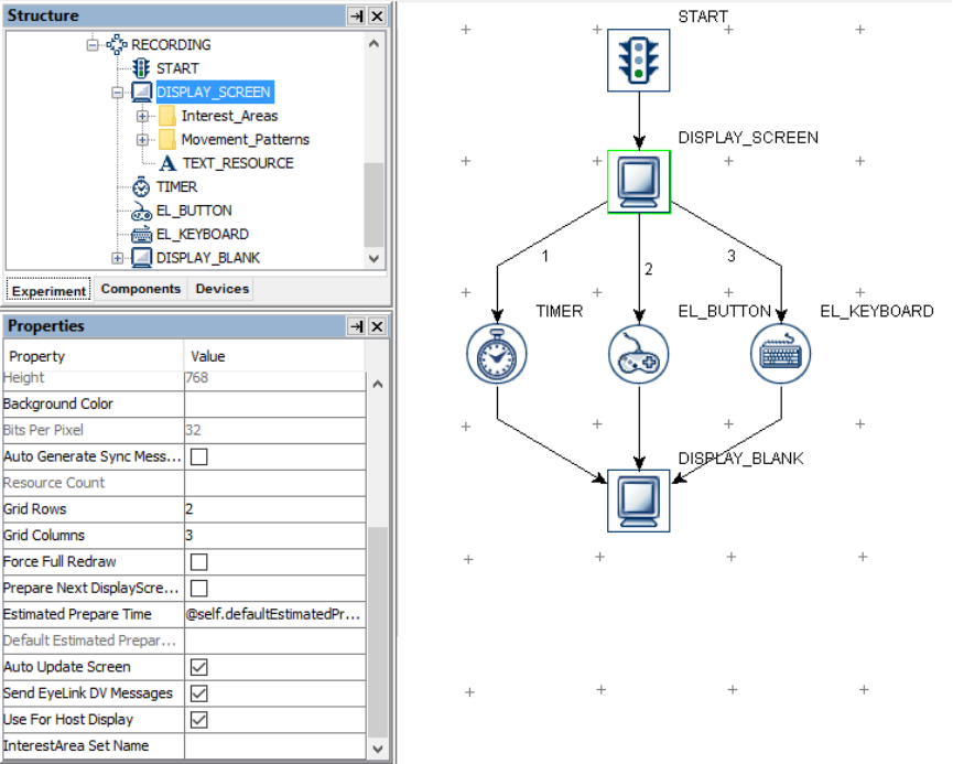
SR Research Experiment Builder User Manual ©2004-2017 SR Research Ltd.
70
with its "Draw to EyeLink Host" field enabled.
Figure 7-13. Using Display Screen.
7.8.2 Performing Drift Correction
For many experiments it can be beneficial to display a fixation point at the start of each
trial or a set of trials so the participant's gaze can be checked against a known position.
EyeLink I and II eye trackers use this fixation point to correct for small drifts in the
calculation of gaze position that can build up over time. Even when using the EyeLink II
tracker's corneal reflection mode, a fixation target should be presented, and a drift
correction allows the experimenter the opportunity to recalibrate if needed.
For the EyeLink 1000, 1000 Plus, and Portable Duo, a drift check, rather than a drift
correction, will be performed by default. A drift check measures and reports the fixation
error without actually correcting for it, and allows the experimenter to recalibrate if
needed. To enable drift correction on these later trackers, users may add the line
“driftcorrect_cr_disable = OFF” to the Final.ini file in the host directory or by sending an
EyeLink Command at the beginning of the experiment.

SR Research Experiment Builder User Manual ©2004-2017 SR Research Ltd.
71
Experiment Builder implements the drift correction/drift check feature using the Drift
Correction action ( ). The display coordinate of the fixation target should be supplied.
Usually this is at the center of the display, but can be anywhere that gaze should be
located at the start of trial recording, for instance, in a line of text, the target could be
positioned just before the first word.
Field
Attribute
Reference
Type
Content
Label *
.label
String
Label of the Drift correction action. The default
value is “DRIFT_CORRECT”.
Type #
NR
The type of Experiment Builder object
("DriftCorrection") the current node belongs to.
Node Path #
.absPath
String
The absolute path of the current node in the
experiment graph.
Message
.message
String
Message to be sent to the EDF file when the
drift correction action is done.
Time #
.time
Float
Display PC time (in milliseconds from the start
of the experiment) when the drift correction
action is done.
Start Time #
.startTime
Float
Display PC time (in milliseconds from the start
of the experiment) when the drift correction
state is entered (the drift correction is not done
yet by this time).
Clear Input
Queues †
.clearInputQueue
s
Boolea
n
If true, all events from input queues are flushed
when the action starts. This includes all
Experiment Builder triggers, such as keyboard,
mouse, TTL, and EyeLink inputs (button,
saccade, fixation). This feature is designed to
ensure the software only evaluates the
upcoming triggers that occur after the start of
the action. If false, the input queues are not
cleared when the action is performed. This
means that events already in the queues may be
evaluated by the triggers following the action.
X Location
.xLocation
Integer
X coordinate of the drift correction target in
screen pixels. Typically this is center of the
screen, but can be set to any other screen
location.
Y Location
.yLocation
Integer
Y coordinate of the drift correction target in
screen pixels. Typically this is center of the
screen, but can be set to any other screen
location.
Allow Setup †
.allowSetup
Boolea
n
If this is checked, the Camera Setup screen on
the host software can be called up by pressing
the ESC key during drift correction so that
calibration problems can be corrected. The
default setting is “True”.
Draw Drift
Correction
.drawDefaultTarg
et
Boolea
n
By default (the box is checked), the drift
correction procedure clears the screen, draws

SR Research Experiment Builder User Manual ©2004-2017 SR Research Ltd.
72
Target †
the fixation target, and clears the screen when
done. However, sometimes it is better for the
user to draw the target themselves, for example
if the drift correction is part of the initial
fixation in a task and the user wants the target to
stay on the screen after drift correction. If this
field is unchecked, the user should draw the
drift correction target in a DISPLAY_SCREEN
action before the drift correct.
Clear Target At
Exit †
.clearTargetAtExi
t
Boolea
n
If checked, the screen will be cleared to the
background color after the drift correction
finishes; otherwise, the drift correction target
remains on the screen. This option is valid only
if the "Draw Drift Correction Target" option is
enabled; it has no effect if the drift correction
drawing is supplied by the users.
Foreground
Color
.foregroundColor
Color
Color in which the drift correction target is
drawn.
Background
Color
.backgroundColo
r
Color
The color to which the entire display is cleared
before calibration. The background color should
match the average brightness of your
experimental displays as closely as possible, as
this will prevent rapid changes in the subject's
pupil size at the start of the trial. This will
provide the best eye-tracking accuracy as well.
Using white or gray backgrounds rather than
black helps reduce pupil size and increase eye-
tracking range, and may reduce retinal
afterimages.
Use Animation
Target †
.useAnimationTa
rget
Boolea
n
If checked, a video clip can be used as the drift
correction target. Users should preload the
intended video clip into the library manager.
Animation
Target ¶
.animationTarget
String
The name of the video clip used as the drift
correction target. The video to be used as the
animation calibration target should be a type 1
.avi file, containing both video frames and audio
stream. This field is only available if the “Use
Animation Target” option is checked.
Animation Play
Count
.animationPlayCo
unt
Integer
Total number of times the video clip will be
played before the calibration target is accepted.
If -1, the clip will be played continuously
(looping). This field is only available if the “Use
Animation Target” option is checked.
Apply
Transparency
.applyTransparen
cy
Boolea
n
If checked, transparency manipulation will be
applied to the video resource similar to that
which is done on the image resources (i.e.,
pixels with the same color value as the
transparency color will not be displayed). We
recommend keeping the default setting
(unchecked).

SR Research Experiment Builder User Manual ©2004-2017 SR Research Ltd.
73
Use Custom
Target †
.useCustomTarge
t
Boolea
n
If checked, drift correction will use the custom
target supplied by the users (a small image file,
with the "feature"/interesting part appearing in
the center of the image).
Custom Target *
.customTarget
String
The name of the image file that is used for
drawing the drift correction target. The image
files should be preloaded into the library
manager. This property is only available if "Use
Custom Target" is checked.
Target Outer
Size
.outerSize
Integer
Diameter of the outer disk of the default drift
correction target in pixels. This property is only
available if “Use Custom Target” is not
checked.
Target Inner
Size
.innerSize
Integer
Diameter of the inner disk of the default drift
correction target in pixels. This property is only
available if “Use Custom Target” is not
checked.
Use Custom
Background †
.useCustomBack
ground
Boolea
n
If checked, drift correction will use the custom
background image supplied.
Custom
Background *
.customBackgrou
nd
String
The name of the image file that is used for
drawing the drift correction background. The
image file should ideally be a full-screen image
and must be preloaded into the library manager.
This property is only available if "Use Custom
Background" is checked.
Target Beep ¶
.targetBeep
String
Sets sound to play when the drift correction
target is presented. If set to DEFAULT, the
default sound is played; if set to OFF, no sound
will be played for that event; otherwise a sound
file from the audio library can be played.
Error Beep ¶
.errBeep
String
Sets sound (DEFAULT, OFF, or sound file) to
play on failure or interruption.
Good Beep ¶
.goodBeep
String
Sound (DEFAULT, OFF, or sound file) to play
on successful operation.
Enable External
Control
.enableExternalC
ontrol
Boolea
n
Toggling through different camera views,
adjusting pupil and CR thresholds, and
accepting calibration, validation and drift
correction targets are usually done through key
presses on the Display or Host PC keyboard.
However, the keyboard may not be easily
accessible in some experiments. Enabling this
option allows the use of an external control
device to assist the pupil/CR thresholding and
calibration process.
External Control
Device Config
.externalControl
DeviceConfig
String
This specifies a file used to define button
functions to control the pupil/CR thresholding
and to accept calibration, validation, and drift
correction target. If this field is left blank, the
default configuration is used. This property is

SR Research Experiment Builder User Manual ©2004-2017 SR Research Ltd.
74
only available if the "Enable External Control"
option is checked.
External Control
Device
.externalControl
Device
String
The type of external device that is used to
control the camera setup, calibration and
validation processes. This can be "CEDRUS"
(Lumina fMRI Response Pad or RB Series
response pad from Cedrus), "KEYBOARD"
(computer keyboard or keypad), or "CUSTOM"
(a user control device interfaced through a
callback function defined in the custom class
code). This property is only available if the
"Enable External Control" option is checked.
Button State
Callback
Function
NR
For an experiment project with custom class
enabled, a method defined in the custom class
can be run to check the button status of an
external control device (the HTML version of
this document provides a usage example) and
thus to control the camera image thresholding
and calibration through the "External Control
Device Config" setting. This property is only
available if the "External Control Device"
option is set to "CUSTOM".
Result #
.result
Integer
0 if successful; 27 if the ESC key is pressed to
enter Setup menu or abort; “None” if this
attribute is accessed before this action is done.
Please note that the Drift Correction action is only available in an EyeLink experiment
and must be placed outside of a recording sequence (see Section 6.2.3 “Linking Rules”).
In addition, this action cannot be connected to another drift correct action or any trigger.
If a prepare sequence action is used, it should be placed before the drift correction action.
The "Allow Setup" field is checked by default, so that when the "ESC" key is pressed, the
host software switches to the camera setup screen. This allows the experimenter to make
adjustments to the camera setup and thresholding, and redo calibration and validation,
then return to the drift correction screen to continue with the experiment.
The "Draw Drift Correction Target" box should be checked if the built-in or custom drift
correction target should be displayed when entering the drift correction mode. In some
(e.g., pursuit or saccade) experiments, users may want to have the drift correction target
be the same as the pursuit target or other display items. If this is the case, users may
uncheck this box and insert a display screen action to pre-draw the drift correction target.
However, a drawback with this approach is that if users have to interrupt the drift
correction process by switching to the camera setup screen and then come back to the
drift correction again, the target will no longer be drawn. Alternatively, users may have
both the "Draw Drift Correction Target" and "Use Custom Target" fields checked and
supply an image for the "Custom Target" field.
The following figure illustrates the use of the drift correction action in a typical trial.
SR Research Experiment Builder User Manual ©2004-2017 SR Research Ltd.
75
Figure 7-14. Using Drift Correction Action.
7.8.3 Performing Camera Setup and Calibration
The Camera Setup action ( ) will bring up a camera setup screen on the EyeLink Host
PC for the experimenter to perform camera setup, calibration, and validation. Scheduling
this at the start of each block gives the experimenter a chance to fix any setup problems.
Simply pressing the ESC key immediately can skip calibration. This also allows the
participant an opportunity for a break - the entire setup can be repeated when the
participant is reseated. Users can set the calibration type and other calibration
configurations through this action.
Typical operations for the camera setup and calibration can be performed by using either
the Host PC keyboard or the Display PC keyboard. Using the display computer monitor
and peripherals, Camera Setup and Calibration can also be performed through an external
control device for environments in which the Host PC is located far away from the
display (e.g., MEG/MRI environments).
Field
Attribute
Reference
Type
Content

SR Research Experiment Builder User Manual ©2004-2017 SR Research Ltd.
76
Label *
.label
String
Label of the Camera setup action. The default
value is “EL_CAMERA_SETUP”.
Type #
NR
The type of Experiment Builder object
("EyeLinkCameraSetup") the current node
belongs to.
Node Path #
.absPath
String
The absolute path of the node in the experiment
graph.
Message
.message
String
Message to be sent to the EDF file (in an
EyeLink experiment) or messages.txt (in a non-
EyeLink experiment with the "Save Messages"
attribute of the Experiment node checked) when
camera setup action is done.
Time #
.time
Float
Display PC time (in milliseconds from the start
of the experiment) when the camera setup action
is done.
Start Time #
.startTime
Float
Display PC time (in milliseconds from the start
of the experiment) when camera setup action
starts (the calibration is not done yet by this
time).
Clear Input
Queues †
.clearInputQueue
s
Boolea
n
If true, all events from input queues are flushed
when the action starts. This includes all
Experiment Builder triggers, such as keyboard,
mouse, TTL, and EyeLink inputs (button,
saccade, fixation). This feature is designed to
ensure the software only evaluates the
upcoming triggers that occur after the start of
the action. If false, the input queues are not
cleared when the action is performed. This
means that events already in the queues may be
evaluated by the triggers following the action.
Calibration Type
¶
.calibrationType
String
This sets the calibration type. One of these
calibration types can be selected from the
dropdown list:
H3: horizontal 3-point calibration
HV3: 3-point calibration, bilinear
HV5: 5-point calibration, biquadratic
HV9: 9-point grid calibration, biquadratic with
corner correction
HV13: 13-point calibration (EyeLink II version
2.0 or later; Any versions of EyeLink 1000,
EyeLink 1000 Plus, EyeLink Portable Duo).
The default calibration type is HV9. When
using the head-free remote mode, the HV13 is
recommended.
Horizontal
Target Y
Position
.horizontalTarget
Location
Integer
This sets the Y position of the automatically-
generated targets for the H3 calibration type.
This option is only available when the
calibration type is set to H3.
Pacing Interval
.pacingInterval
Integer
Sets the time delay in milliseconds for
calibration and validation if calibration

SR Research Experiment Builder User Manual ©2004-2017 SR Research Ltd.
77
triggering is done automatically
Randomize
Order †
.randomizeOrder
Boolea
n
If checked, randomizes the presentation
sequence of the calibration and validation
targets.
Repeat First
Point †
.repeatFirstPoint
Boolea
n
If checked, redisplays the first calibration or
validation fixation dot.
Force Manual
Accept †
.forceManualAcc
ept
Boolea
n
If checked, users have to manually accept each
calibration and validation fixation point.
Lock Eye After
Calibration †
.lockEyeAfterCal
ibration
Boolea
n
If checked, locks the recording eye on the
display computer keyboard if performing a
monocular recording.
Select Eye After
Validation †
.selectEyeAfterV
alidation
Boolea
n
Controls whether the best eye is automatically
selected as the default after validation. If
unchecked, binocular tracking is kept by
default.
Enable
Customized
Calibration
Positions †
.enableManualCa
librationPositions
Boolea
n
If checked, user-defined calibration positions
can be used, instead of the default positions.
Customized
Calibration
Positions
.calibrationPositi
ons
List of
Points
A list of X/Y pairs to specify the calibration
target positions in the intended display screen
resolution. The number of points included in the
list must match the calibration type. This option
is only available if the "Enable Customized
Calibration Positions" setting is enabled. The
following lists example (default)
calibration/validation point lists under a 1024 *
768 recording resolution. Please be aware that
the points in the list MUST be ordered on
screen.
* Point order for 5, 9, or 13 point calibrations:
6 2 7
10 11
4 1 5
12 13
8 3 9
HV5: [(512,384), (512,65), (512,702),
(61,384), (962,384)]
HV9: [(512,384), (512,65), (512,702),
(61,384), (962,384), (61,65), (962,65), (61,702),
(962,702)]
HV13: [(512,384), (512,65), (512,702),
(61,384), (962,384), (61,65), (962,65), (61,702),
(962,702), (286,224), (737,224), (286,543),
(737,543)]

SR Research Experiment Builder User Manual ©2004-2017 SR Research Ltd.
78
* Point order for H3 calibration type:
2 1 3
H3: [(512,384), (61,384), (962,384)]
* Point order for HV3 calibration type:
1
3 2
HV3: [(512,65), (962,702), (61,702)]
Enable
Customized
Validation
Positions †
.enableManualVa
lidationPositions
Boolea
n
If checked, user-defined validation positions can
be used, instead of the default positions.
Customized
Validation
Positions
.validationPositio
ns
List of
Points
A list of X/Y pairs to specify the validation
target positions in the intended display screen
resolution. These points MUST be ordered on
screen and match the calibration type selected.
See “Customized Calibration Positions” for
examples. This option is only available if the
"Enable Customized Validation Positions"
setting is enabled.
Foreground
Color
.foregroundColor
Color
Color used to draw calibration targets, and for
the text on the camera image display. It should
be chosen to supply adequate contrast to the
background color.
Background
Color
.backgroundColo
r
Color
The color to which the entire display is cleared
before calibration. This is also the background
for the camera images. The background color
should match the average brightness of your
experimental displays as closely as possible,
as this will prevent large changes in the
participant's pupil size at the start of the trial.
This will provide the best eye-tracking accuracy
as well.
Use Animation
Target †
.useAnimationTa
rget
Boolea
n
If checked, a video clip can be used as the
calibration target. Users should preload the
intended video clip into the library manager.
Animation
Target ¶
.animationTarget
String
The name of the video clip used as the
calibration target. The video to be used as the
animation calibration target should be a type 1
.avi file, containing both video frames and audio
stream. This field is only available if the “Use
Animation Target” option is checked.
Animation Play
Count
.animationPlayCo
unt
Integer
Total number of times the video clip will be
played before the calibration target is accepted.
If -1, the clip will be played continuously
(looping). This field is only available if the “Use
Animation Target” option is checked.

SR Research Experiment Builder User Manual ©2004-2017 SR Research Ltd.
79
Apply
Transparency
.applyTransparen
cy
Boolea
n
If checked, transparency manipulation will be
applied to the video resource similar to that
which is done on the image resources (i.e.,
pixels with the same color value as the
transparency color will not be displayed). We
recommend keeping the default setting
(unchecked).
Use Custom
Target †
.useCustomTarge
t
Boolea
n
If checked, calibration will use the custom
target supplied (a small image file, with the
"feature"/interesting part appearing in the center
of the image).
Custom Target
.customTarget
String
The name of the image file that is used for
drawing the calibration target. The image file
should be preloaded into the library manager.
This property is only available if "Use Custom
Target" is checked.
Use Custom
Background †
.useCustomBack
ground
Boolea
n
If checked, calibration will use the custom
background image supplied.
Custom
Background
.customBackgrou
nd
String
The name of the image file that is used for
drawing the calibration background. The image
file should ideally be a full-screen image and
must be preloaded into the library manager.
This property is only available if "Use Custom
Background" is checked.
Target Outer
Size
.outerSize
Integer
The standard calibration and drift correction
target is a filled circle (for peripheral
detectability) with a central "hole" target (for
accurate fixation). The disk is drawn in the
calibration foreground color, and the hole is
drawn in the calibration background color. The
"Target Outer Size" property specifies the
diameter of the outer disk of the default
calibration target in pixels. This property is only
available if "Use Custom Target" is not
checked.
Target Inner
Size
.innerSize
Integer
Diameter of the inner disk of the default
calibration target in pixels). If hole size is 0, no
central feature will be drawn. This property is
only available if "Use Custom Target" is not
checked.
Target Beep ¶
.targetBeep
String
Experiment Builder plays alerting sounds during
calibration. These sounds have been found to
improve the speed and stability of calibrations
by cueing the participant, and make the
experimenter's task easier. The "Target Beep"
property specifies the sound to play when the
target moves. If set to DEFAULT, the default
sound will be played; if set to OFF, no sound
will be played; otherwise a sound file from the
audio library can be chosen.

SR Research Experiment Builder User Manual ©2004-2017 SR Research Ltd.
80
Error Beep ¶
.errBeep
String
Sound (DEFAULT, OFF, or sound file) to play
on failure or interruption.
Good Beep ¶
.goodBeep
String
Sets sound (DEFAULT, OFF, or sound file) to
play on successful operation.
Enable External
Control
.enableExternalC
ontrol
Boolea
n
Toggling through different camera views,
adjusting pupil and CR thresholds, and
accepting calibration, validation and drift
correction targets are usually done through key
presses on the Display or Host PC keyboard.
However, the keyboard may not be easily
accessible in some environments. Enabling this
option allows the use of an external control
device to assist the pupil/CR thresholding and
calibration process.
External Control
Device Config
.externalControl
DeviceConfig
String
This specifies a file used to define the button
functions to control the pupil/ CR thresholding
and accept calibration, validation, and drift
correction targets. If this field is left blank, the
default configuration is used. This property is
only available if the "Enable External Control"
option is checked.
External Control
Device
.externalControl
Device
String
The type of external device that is used to
control the camera setup and accept calibration
and validation targets. This can be "CEDRUS"
(Lumina fMRI Response Pad or RB Series
response pad from Cedrus), "KEYBOARD"
(computer keyboard or keypad), or "CUSTOM"
(a user control device interfaced through a
callback function defined in the custom class
code). This property is only available if the
"Enable External Control" option is checked.
Button State
Callback
Function
NR
For an experiment project with custom class
enabled, a method defined in the custom class
can be run to check the button status of an
external control device and thus to control the
camera image thresholding and calibration/drift
correction through the "External Control Device
Config" setting. This property is only available
if the "External Control Device" option is set to
"CUSTOM".
Result #
.result
Integer
Always returns “None”.
Please note that the Camera Setup action is only available in an EyeLink experiment and
must be placed outside of a recording sequence. As a linking rule, the camera setup
action cannot be connected to another camera setup action or any triggers. Figure 7-15
illustrates the use of camera setup in a typical experiment.
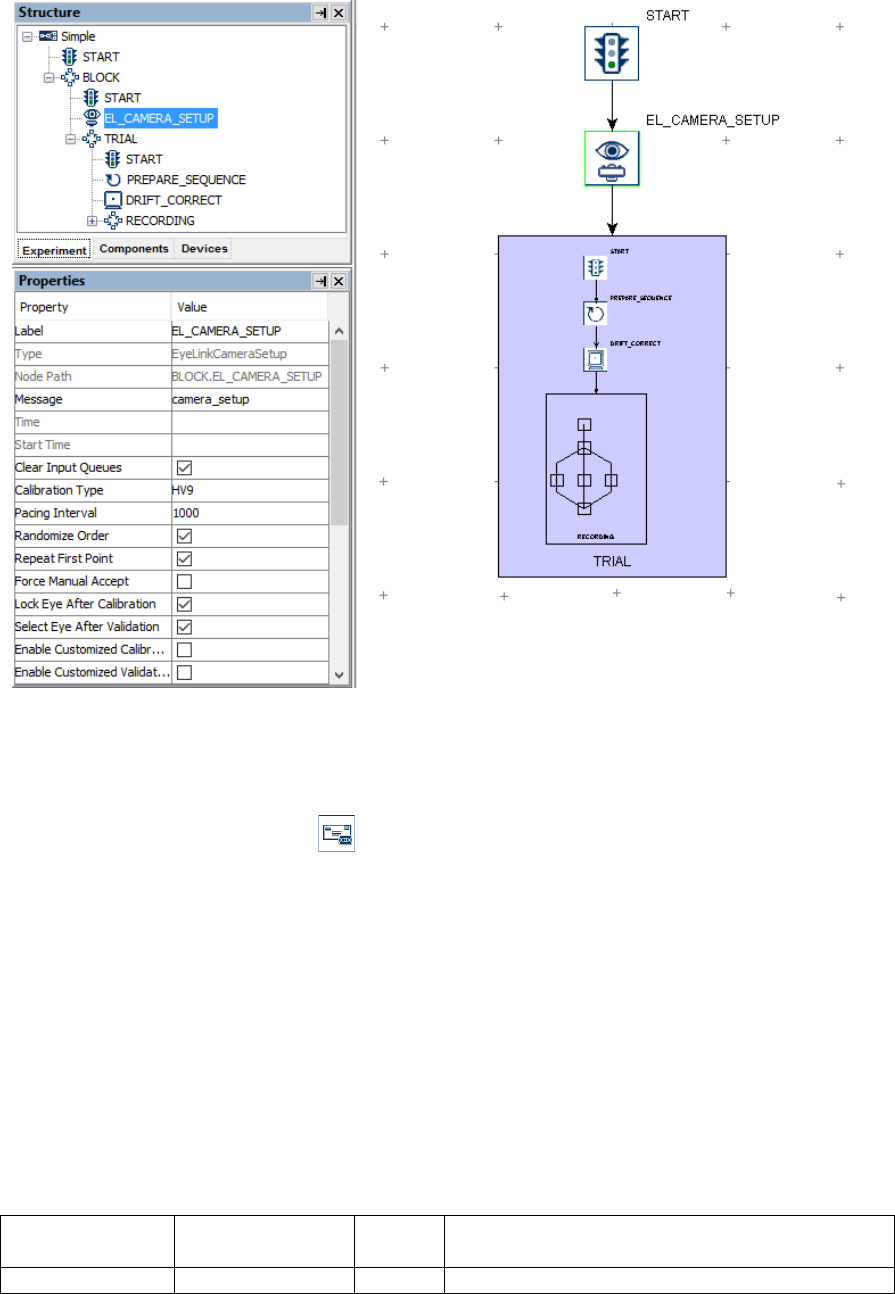
SR Research Experiment Builder User Manual ©2004-2017 SR Research Ltd.
81
Figure 7-15. Using Camera Setup Action.
7.8.4 Sending EyeLink Message
While messages can be sent by filling out the “Message” property of a relevant node, the
SEND_EL_MESSAGE action ( ) can be used to send an additional text message to the
EyeLink eye tracker, which timestamps the message and writes it to the EDF data file.
Messages are useful for logging trial conditions, recording responses from participants, or
marking time-critical events for debugging and analysis. The EDF message text can be
created with the attribute editor to include references to node attributes, equations and
other expressions. This action is not available in non-EyeLink experiments.
When using the SEND_EL_MESSAGE action, users should avoid end-of-line characters
(“\n”) in the message text and avoid making reference to strings with quotes (“”).
Message text should be no more than 128 characters in length – the tracker will truncate
text messages longer than that limit. Also be careful not to send messages too quickly: the
eye tracker can handle about 2 messages a millisecond. Above this rate, some messages
may be lost and not written to the EDF file.
Field
Attribute
Reference
Type
Content
Label *
.label
String
Label of the SEND_EL_MSG action. The

SR Research Experiment Builder User Manual ©2004-2017 SR Research Ltd.
82
default value is "SEND_EL_MSG”.
Type #
NR
The type of Experiment Builder object
("SendEyeLinkMessage") the current node
belongs to.
Node Path #
.absPath
String
The absolute path of the node in the experiment
graph.
Time #
.time
Float
Display PC time (in milliseconds from the start
of the experiment) when the message is sent.
Start Time #
.startTime
Float
Display PC time (in milliseconds from the start
of the experiment) when the processing of the
node starts (the action is not done yet by this
time).
Clear Input
Queues †
.clearInputQueue
s
Boolea
n
If true, all events from input queues are flushed
when the action starts. This includes all
Experiment Builder triggers, such as keyboard,
mouse, TTL, and EyeLink inputs (button,
saccade, fixation). This feature is designed to
ensure the software only evaluates the
upcoming triggers that occur after the start of
the action. If false, the input queues are not
cleared when the action is performed. This
means that events already in the queues may be
evaluated by the triggers following the action.
Message
.message
String
Text to be sent to the eye tracker.
The following figure illustrates the use of the SEND_EL_MESSAGE action. In the
EyeLink Message field, users can enter a string directly (see the left panel at the bottom).
In case runtime data accessing is required, users may use references and equations and
create the message text in the attribute editor (see the right panel at the bottom; see
Chapter 10 “References” for details).
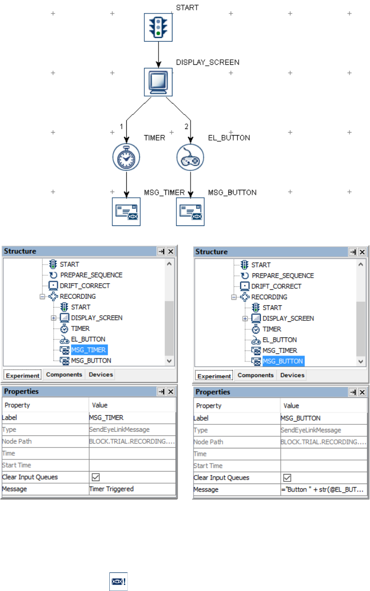
SR Research Experiment Builder User Manual ©2004-2017 SR Research Ltd.
83
Figure 7-16. Using Sending Message Action.
7.8.5 Sending EyeLink Command
The EyeLink tracker accepts text commands sent through the link. The
SEND_COMMAND action ( ) is used for on-line tracker configuration and control.
Please refer to the .ini files in the EyeLink directory of the Host PC (typically “elcl\exe”
for EyeLink 1000 Plus and Portable Duo, “c:\elcl\exe” for EyeLink 1000,
“c:\eyelink2\exe” for EyeLink II and “c:\EyeLink\exe” for EyeLink I) for a list of

SR Research Experiment Builder User Manual ©2004-2017 SR Research Ltd.
84
possible commands that can be sent with this action. The send_command action is not
available in non-EyeLink experiments.
Field
Attribute
Reference
Type
Content
Label *
.label
String
Label of the SEND_COMMAND action. The
default value is “EL_COMMAND”.
Type #
NR
The type of Experiment Builder object
("EyeLinkCommand") the current node belongs
to.
Node Path #
.absPath
String
The absolute path of the node in the experiment
graph.
Time #
.time
Float
Display PC time (in milliseconds from the start
of the experiment) when the
SEND_COMMAND action is done.
Start Time #
.startTime
Float
Display PC time (in milliseconds from the start
of the experiment) when the processing of the
node starts (the action is not done yet by this
time).
Clear Input
Queues †
.clearInputQueue
s
Boolea
n
If true, all events from input queues are flushed
when the action starts. This includes all
Experiment Builder triggers, such as keyboard,
mouse, TTL, and EyeLink inputs (button,
saccade, fixation). This feature is designed to
ensure the software only evaluates the
upcoming triggers that occur after the start of
the action. If false, the input queues are not
cleared when the action is performed. This
means that events already in the queues may be
evaluated by the triggers following the action.
Command
.command
String
The command used to configure or control the
EyeLink tracker. For a complete list of
commands and current tracker configuration,
examine the *.INI files in the EyeLink directory
of the eye-tracker computer.
Text
.text
String
The parameters to be passed along with the
command.
Priority †
.priority
Boolea
n
If enabled, causes the command to be executed
with the highest priority. This priority is even
higher than the output of analog or link sample
data, so please use it carefully. The use of this
prefix should be limited to the “write_ioport”
command. Typical command execution is 1-20
ms after the action is pressed. With priority
enabled, this is reduced to less than 1 ms 99% of
the time—in the worst case, it may be about 10
ms but is rarely higher than 2 ms. The default
setting is “False”. This setting has no effect on
EyeLink I.
Log Time †
.logTime
Boolea
If enabled, logs the command and its delay in

SR Research Experiment Builder User Manual ©2004-2017 SR Research Ltd.
85
n
execution to the EDF file (and link if message
events are enabled). The default setting is
“False”. The message time is when the
command completed execution. The message
syntax is :
!CMD <execution delay> <text of command>
This setting has no effect on EyeLink I.
Wait for Result
†
.waitForResult
Boolea
n
Whether the program should wait for a response
from the tracker.
Result Timeout
.resultTimeout
Integer
Sets the maximum amount of time to wait for a
response from the tracker. If no result is
returned, then the error code NO_REPLY is
returned.
Exit On Fail †
.exitOnFail
Boolea
n
Whether the experiment should be terminated if
there is an error in the command. Important:
please leave this field unchecked unless it is
absolutely necessary that you should terminate
the experiment if the EyeLink send command
action fails.
Result #
.result
Integer
Result code for the command:
0: Command successfully sent;
1: Unknown command;
-1: Unexpected end of line;
-2: Syntax error;
1000: No reply from the tracker.
Result Message
#
.resultMessage
String
Returns text associated with last command
response: may have error message (see above).
Figure 7-17 illustrates how to draw a white filled box on the top-left quadrant of the
tracker screen using the EyeLink Command action. In the “Command” field, type in
“draw_filled_box” (without quotes) and in the “Text” field, enter “0 0 512 384 15”
(without quotes). Please refer to the .ini files on the Host PC for the syntax of EyeLink
commands.
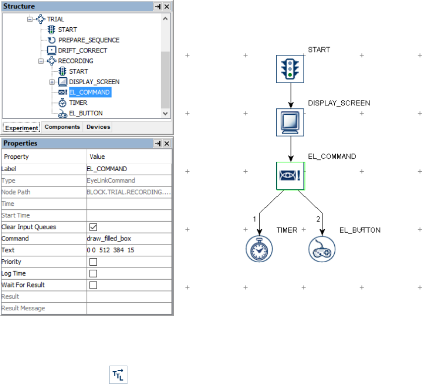
SR Research Experiment Builder User Manual ©2004-2017 SR Research Ltd.
86
Figure 7-17. Using Sending EyeLink Command Action.
7.8.6 Sending TTL Signals
The SET_TTL action ( ) sends a TTL signal through the parallel port of a Windows
PC, or through the USB-1208 HS box in either Windows or Mac OS X. Version 1.6.121
or later of this software automatically installs the I/O port driver necessary for interfacing
with the parallel port in Windows (both 32-bit and 64-bit versions).
If using a parallel port, SET_TTL action requires proper identification of the base address
of the port. In version 1.10.1630 or later of the software, users may set the “Parallel Port
Base Address” of the “Parallel Port” Device to 0x0 so that the software will automatically
detect and configure the base address. To set the base address manually, first determine
the parallel port base address through the Device Manager in Windows. In the Device
Manager list, find the entry for the parallel port device under "Ports (COM & LPT)" - if
you use PCI, PCI Express, or PCMCIA version of the parallel port adapter card, you'll
need to install a driver for the port before it is correctly recognized by Windows. Click
the port and select the "Resources" in the properties table. This should list the I/O address
of the card. For the built-in LPT1 on a desktop computer, this is typically "0378-037F"
(hex value). Once you have found out the parallel port address, open the Experiment
Builder project, go to the "Parallel Port" device setting, and enter the hex value for the
port reported by the device manager (e.g., 0x378 for "0378" you see in the device
manager).

SR Research Experiment Builder User Manual ©2004-2017 SR Research Ltd.
87
The other supported device is the USB-1208HS box from Measurement Computing,
which can be used on both Windows and Mac OS X. No extra driver installation is
required as long as you have installed the libusb-win32 component when you first run
through the installation procedure in Windows (see Figure 3-1). If for any reason you
have to install the device driver, please first connect the box to the Windows PC. When
asked "Can Windows connect to Windows Update to search for software?", choose "No,
not this time". When asked "What do you want the Wizard to do?", choose "Install from a
list or specific location (Advanced)". On the "Please choose your search and installation
options" screen, select the "Search for the best driver in these locations", check the
"Include this location in the search" option only and browse to "C:\Program Files\SR
Research\3rdparty\usb1208hs" in 32-bit Windows or "C:\Program Files(x86)\SR
Research\3rdparty\usb1208hs" in 64-bit Windows).
Field
Attribute
Reference
Type
Content
Label *
.label
String
Label of the SET_TTL action.
Type #
NR
The type of Experiment Builder object
("SetTTL") the current node belongs to.
Node Path #
.absPath
String
The absolute path of the node in the experiment
graph.
Message
.message
String
Message to be written to the EDF file (in an
EyeLink experiment) or messages.txt (in a non-
EyeLink experiment with the “Save Messages”
attribute of the Experiment node checked) when
sending the TTL signal.
Time #
.time
Float
Display PC time (in milliseconds from the start
of the experiment) when the TTL signal is sent.
Start Time #
.startTime
Float
Display PC time (in milliseconds from the start
of the experiment) when the processing of the
node starts (the action is not done yet by this
time).
Clear Input
Queues †
.clearInputQueue
s
Boolea
n
If true, all events from input queues are flushed
when the action starts. This includes all
Experiment Builder triggers, such as keyboard,
mouse, TTL, and EyeLink inputs (button,
saccade, fixation). This feature is designed to
ensure the software only evaluates the
upcoming triggers that occur after the start of
the action. If false, the input queues are not
cleared when the action is performed. This
means that events already in the queues may be
evaluated by the triggers following the action.
Device
.device
String
Which device (parallel port or USB-1208 HS) is
used to send or receive TTL signals. Note that
this is always set to "USB-1208HS" on Mac OS
X.
Register ¶
.register
String
Usually set as "DATA" register. Note that this
option is only available when the “Device” is

SR Research Experiment Builder User Manual ©2004-2017 SR Research Ltd.
88
set to a parallel port.
Mode *
.mode
String
Either "Word" mode (the decimal or
hexadecimal value of the TTL output signal) or
"Pin" mode (status of each individual pin).
Data
.data
Integer
The byte value of the current TTL output signal.
It could be a decimal or hexadecimal value. This
field is only available if the "Mode" property is
set to "Word". If a decimal value is entered, it
will be automatically translated into a
hexadecimal value.
Pin0
Pin1
Pin2
Pin3
Pin4
Pin5
Pin6
Pin7
.pin0
.pin1
.pin2
.pin3
.pin4
.pin5
.pin6
.pin7
String
The desired status for the corresponding pins.
The pin value can be either "ON" (high) or
"OFF" (low). These fields are only available if
the "Mode" property is set to "Pin". If using a
USB-1208HS box, the available output pins can
be configured through the device preferences.
The TTL communication works by the detection of a change in the pin status in the
receiving end. Typically a clearing signal should be sent (e.g., 0x0) after sending the
intended TTL signal. The clearing signal may be sent using a second SET_TTL action
either at the end of the trial, or some time after the initial TTL signal (at least a 20 msec
gap is recommended). If the same TTL value is sent repeatedly, no change will be
detected on the receiving end.
For most applications involving a parallel port, users will need to use the "DATA"
register in the "Register" property of the SET_TTL action to send out a signal. Users
need to make sure the parallel port of the Display PC is not in a bi-directional mode, in
which the data register is used to read incoming signals, and thus users are not able to
send a signal from this register. Bidirectional mode is set by pin 5 of the control register.
To turn off the bidirectional mode, users may add a SET_TTL action at the beginning of
the experiment, and set the "Register" to "CONTROL", "Mode" to "Word", and "Data"
value to 0x0.
The pins on a USB-1208 HS box can be configured either for sending signals or for
receiving signals. To set which pins are used for sending and receiving, go to the “USB-
1208HS” device settings and click the "Value" field of the “Pins” property. This will
bring up a USB-1208HS configuration window. The arrows indicate the directions of
data flow that each pin is configured for: if the arrow points towards the box, the pin is
used to receive signals; if the arrow points away from the box, the pin is used to send
signals. To change whether a pin is used for sending or receiving signals, simply click on
the arrow next to the pin to change its direction. The following figure illustrates a
configuration in which pins 0 to 7 are used to send signals and pins 8 to 15 are used to
receive signals.
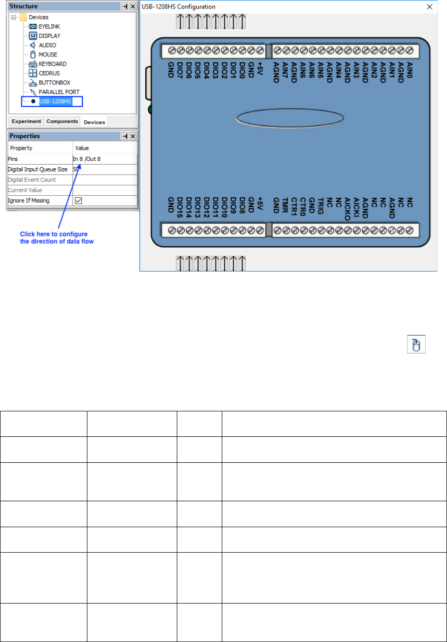
SR Research Experiment Builder User Manual ©2004-2017 SR Research Ltd.
89
Figure 7-18. Configuring the Direction of Data Flow on USB-1208HS
7.8.7 Adding to Experiment Log
For the ease of experiment debugging, messages can be written to a log file so that errors
in the experiment programming can be detected early. The ADD_TO_LOG action ( )
allows users to send one log message per call. While the SEND_EL_MSG action is
available in an EyeLink experiment only, the ADD_TO_LOG action can be used in both
EyeLink and non-EyeLink experiments.
Field
Attribute
Reference
Type
Content
Label *
.label
String
Label of the ADD_TO_LOG action. The
default value is “ADD_TO_LOG”.
Type #
NR
The type of Experiment Builder object
("AddToExperimentLog") the current node
belongs to.
Node Path #
.absPath
String
The absolute path of the node in the experiment
graph.
Time #
.time
Float
Display PC time (in milliseconds from the start
of the experiment) when the action is processed.
Start Time #
.startTime
Float
Display PC time (in milliseconds from the start
of the experiment) when the processing of the
node starts (the action is not done yet by this
time).
Clear Input
Queues †
.clearInputQueue
s
Boolea
n
If true, all events from input queues are flushed
when the action starts. This includes all
Experiment Builder triggers, such as keyboard,
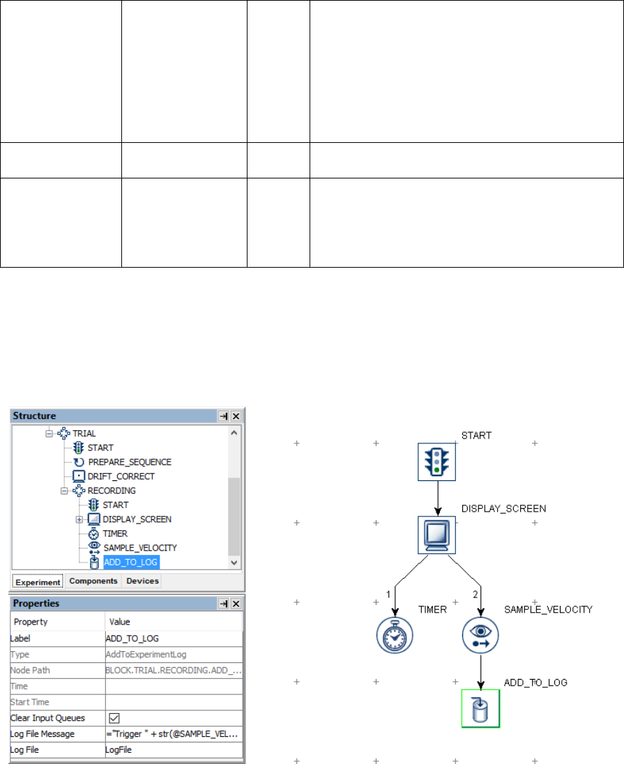
SR Research Experiment Builder User Manual ©2004-2017 SR Research Ltd.
90
mouse, TTL, and EyeLink inputs (button,
saccade, fixation). This feature is designed to
ensure the software only evaluates the
upcoming triggers that occur after the start of
the action. If false, the input queues are not
cleared when the action is performed. This
means that events already in the queues may be
evaluated by the triggers following the action.
Log File
Message
.logMessage
String
Message to be written to the log file.
Log File *
.logFile
String
File to which the log message is written. The
default file name is "Logfile". If this field is left
empty, the message will be printed to command
line (or the output tab of Experiment Builder if
test running the project).
In the following example (Figure 7-19), the user added a sample velocity trigger in the
experiment and wants to check out whether the correct values (e.g., left eye gaze position,
eye velocity and acceleration, and trigger time) are reported when the trigger fires. The
user may add an ADD_TO_LOG action following the sample velocity trigger, and set the
“Log File Message” field of the action as:
Figure 7-19. Using Add to Experiment Log Action.
= "Trigger " + str(@SAMPLE_VELOCITY.triggeredData.EDFTime@)
+ " LOC "+ str(@SAMPLE_VELOCITY.triggeredData.leftGazeX@)
+ " " + str(@SAMPLE_VELOCITY.triggeredData.leftGazeY@)
+ " VEL " + str(@SAMPLE_VELOCITY.triggeredData.leftVelocity@)

SR Research Experiment Builder User Manual ©2004-2017 SR Research Ltd.
91
+ " AC1000 " +
str(@SAMPLE_VELOCITY.triggeredData.leftAcceleration@)
The following is one sample output from the LogFile.txt file when the sample-velocity
trigger fires:
Trigger 852012 LOC 500.299987793 403.399993896 VEL 196.741027908
AC1000 98370.5273723
7.8.8 Updating Attribute
The UPDATE_ATTRIBUTE action ( ) modifies the value of a variable or an attribute
of an experiment component. For example, in a change-detection experiment (see section
7.11.1 “Variable”), users may want to display two slightly different images for a certain
number of cycles and then stop the presentation after that. To do that, users may create a
new variable to keep track of the current iteration status (behaving as a counter) and use
the UPDATE_ATTRIBUTE action to update the counter’s value following each cycle.
Field
Attribute
Reference
Type
Content
Label *
.label
String
Label of the UPDATE_ATTRIBUTE action.
The default value is “UPDATE_ATTRIBUTE”.
Type #
NR
The type of Experiment Builder object
("UpdateAttribute") the current node belongs to.
Node Path #
.absPath
String
The absolute path of the node in the experiment
graph.
Message
.message
String
Message to be sent to the EDF file (in an
EyeLink experiment) or messages.txt (in a non-
EyeLink experiment with the "Save Messages"
attribute of the Experiment node checked) when
the action is executed.
Time #
.time
Float
Display PC time (in milliseconds from the start
of the experiment) when the
UPDATE_ATTRIBUTE action is done.
Start Time #
.startTime
Float
Display PC time (in milliseconds from the start
of the experiment) when the processing of the
node starts (the action is not done yet by this
time).
Clear Input
Queues †
.clearInputQueue
s
Boolea
n
If true, all events from input queues are flushed
when the action starts. This includes all
Experiment Builder triggers, such as keyboard,
mouse, TTL, and EyeLink inputs (button,
saccade, fixation). This feature is designed to
ensure the software only evaluates the
upcoming triggers that occur after the start of
the action. If false, the input queues are not
cleared when the action is performed. This
means that events already in the queues may be
evaluated by the triggers following the action.
Attribute-Value
List
NR
Used to set up an attribute-value list; the
number of currently established attribute-value
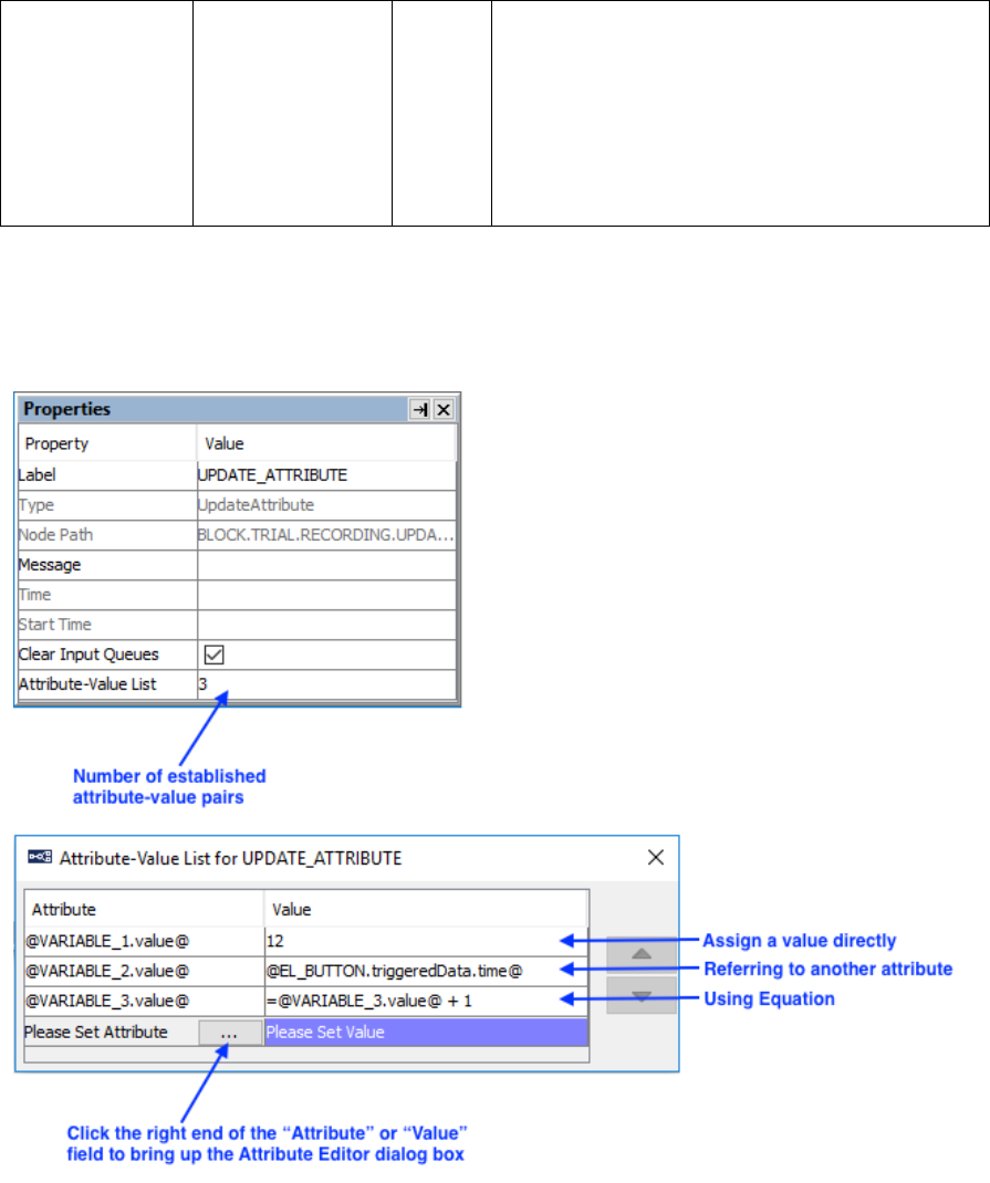
SR Research Experiment Builder User Manual ©2004-2017 SR Research Ltd.
92
pairs is displayed in the value field of the
property. To add or edit attribute-value pairs,
click the value field or double click the
UPDATE_ATTRIBUTE node. The "Attribute"
column of the dialog box specifies the variable
or attribute to which the current action is
referring and the "Value" column specifies the
new value assigned to the attribute.
Users can update the value of an attribute by assigning a value directly (e.g., setting the
value of VARIABLE1 to 0), referring to another attribute (e.g., retrieving the time when
the EyeLink button box was pressed and assign this time to VARIABLE2), or using an
equation (e.g., increasing the value of VARIABLE3 by 1).
Figure 7-20. Using Update Attribute Action.

SR Research Experiment Builder User Manual ©2004-2017 SR Research Ltd.
93
7.8.9 Adding to Accumulator
The ADD_ACCUMULATOR action ( ) is used to add data to an accumulator object
(see Section 7.11.3 “Accumulator” for example) so that statistical analysis can be
performed on the stored data.
Field
Attribute
Reference
Type
Content
Label *
.label
String
Label of the ADD_ACCUMULATOR action.
The default value is
“ADD_ACCUMULATOR”.
Type #
NR
The type of Experiment Builder object
("AddAccumulator") the current node belongs
to.
Node Path #
.absPath
String
The absolute path of the node in the experiment
graph.
Message
.message
String
Message to be sent to the EDF file (in an
EyeLink experiment) or messages.txt (in a non-
EyeLink experiment with the "Save Messages"
attribute of the Experiment node checked) when
the action is executed.
Time #
.time
Float
Display PC time (in milliseconds from the start
of the experiment) when the action is done.
Start Time #
.startTime
Float
Display PC time (in milliseconds from the start
of the experiment) when the processing of the
node starts (the action is not done yet by this
time).
Clear Input
Queues †
.clearInputQueue
s
Boolea
n
If true, all events from input queues are flushed
when the action starts. This includes all
Experiment Builder triggers, such as keyboard,
mouse, TTL, and EyeLink inputs (button,
saccade, fixation). This feature is designed to
ensure the software only evaluates the
upcoming triggers that occur after the start of
the action. If false, the input queues are not
cleared when the action is performed. This
means that events already in the queues may be
evaluated by the triggers following the action.
Accumulator ¶*
NR
The accumulator the current action is referring
to.
Add Value
.addValue
Float
This specifies the value (0.0 by default) to be
added to the accumulator.
7.8.10 Adding to Results File
The ADD_TO_RESULTS_FILE action ( ) is used to send data to a results file so that
users will get a columnar data output. Users should first add a RESULTS_FILE object
(see Section 7.11.2 “Results File” for example) into the experiment graph and then

SR Research Experiment Builder User Manual ©2004-2017 SR Research Ltd.
94
configure the columns of the data source file and/or the variables to the results file. Note -
version 2.0 of Experiment Builder now automatically adds the variables and data source
columns to the “Columns” field of the results file node. If necessary, users can double
click on the field and use the dialog box to remove some variables/columns from the list
or to change the order of the variables/columns.
Field
Attribute
Reference
Type
Content
Label *
.label
String
Label of the ADD_TO_RESULTS_FILE action.
The default value is
“ADD_TO_RESULTS_FILE”.
Type #
NR
The type of Experiment Builder object
("AddToResultsFile") the current node belongs
to.
Node Path #
.absPath
String
The absolute path of the node in the experiment
graph.
Time #
.time
Float
Display PC time (in milliseconds from the start
of the experiment) when the action is done.
Start Time #
.startTime
Float
Display PC time (in milliseconds from the start
of the experiment) when the processing of the
node starts (the action is not done yet by this
time).
Clear Input
Queues †
.clearInputQueue
s
Boolea
n
If true, all events from input queues are flushed
when the action starts. This includes all
Experiment Builder triggers, such as keyboard,
mouse, TTL, and EyeLink inputs (button,
saccade, fixation). This feature is designed to
ensure the software only evaluates the
upcoming triggers that occur after the start of
the action. If false, the input queues are not
cleared when the action is performed. This
means that events already in the queues may be
evaluated by the triggers following the action.
Results File ¶*
NR
The Results file the current action is referring
to.
7.8.11 Prepare Sequence
Before starting the portion of the experiment that contains the important experiment
manipulations and time-critical actions (often this is the sequence in which eye tracker
data is recorded as well), the experiment should be given the opportunity to prepare the
upcoming actions. The Prepare Sequence Action ( ) includes the following operations:
a) Preload the image or audio files to memory for real-time image drawing or sound
playing;
b) Draw feedback graphics on the Host PC so that the participants’ gaze accuracy
can be monitored;
c) Re-initialize trigger and action settings;

SR Research Experiment Builder User Manual ©2004-2017 SR Research Ltd.
95
d) Synchronize the clocks between the display computer and Cedrus button box;
e) Flush data to the log files.
In a typical experiment, users should call the Prepare Sequence action before entering the
recording sequence of a trial, preferably before performing a drift correction. In most of
the experiments, the “Reinitialize Triggers” box should be checked so that the data for
each trigger are reset for the nodes to function properly.
IMPORTANT: For the proper event timing, it is critical that the Prepare Sequence
Action should be called before the trial run-time for EACH iteration of the sequence.
IMPORTANT: The Prepare Sequence Action loads the image and audio files based on
the state of display screen and Play Sound actions at the time the Prepare Sequence is
called. This means that if an image name or audio file name is changed after the Prepare
Sequence action is called, the new image or audio resource will not be preloaded and
timing may be affected. If an image or audio file has not been preloaded when it is used
in the Display Screen or Play Sound action that references it, a warning message will be
written to the warnings.log file for the experiment session.
Field
Attribute
Reference
Type
Content
Label *
.label
String
Label of the PREPARE_SEQUENCE action.
The default value is “PREPARE_SEQUENCE”.
Type #
NR
The type of Experiment Builder object
("PrepareSequence") the current node belongs
to.
Node Path #
.absPath
String
The absolute path of the node in the experiment
graph.
Message
.message
String
Message to be sent to the EDF file (in an
EyeLink experiment) or messages.txt (in a non-
EyeLink experiment with the "Save Messages"
attribute of the Experiment node checked) when
the PREPARE_SEQUENCE action is done.
Time #
.time
Float
Display PC time (in milliseconds from the start
of the experiment) when the
PREPARE_SEQUENCE action is processed.
Start Time #
.startTime
Float
Display PC time (in milliseconds from the start
of the experiment) when the processing of the
node starts (the action is not done yet by this
time).
Clear Input
Queues †
.clearInputQueue
s
Boolea
n
If true, all events from input queues are flushed
when the action starts. This includes all
Experiment Builder triggers, such as keyboard,
mouse, TTL, and EyeLink inputs (button,
saccade, fixation). This feature is designed to
ensure the software only evaluates the
upcoming triggers that occur after the start of
the action. If false, the input queues are not
cleared when the action is performed. This

SR Research Experiment Builder User Manual ©2004-2017 SR Research Ltd.
96
means that events already in the queues may be
evaluated by the triggers following the action.
Load Screen
Resources *†
.loadImages
Boolea
n
If enabled (default), all of the possible images
used in the current sequence (and sequences
nested within it) will be preloaded for real-time
performance.
Load Audio *†
.loadAudio
Boolea
n
If enabled (default), all of the possible sound
clips used in the current sequence (and
sequences nested within it) will be preloaded for
real-time performance.
Draw to
EyeLink Host *¶
.drawToEyeLink
Host
Integer
If set to “NO” (0), no feedback graphics are
drawn on the Host PC screen. If set to
“IMAGE” (1), transfers one of the display
screens to the tracker PC as the backdrop for
gaze cursors. If set to “PRIMITIVE” (2), draws
primitive line drawings on the Host PC to
indicate the location of resources used in a
display screen. This attribute is only available in
an EyeLink experiment.
Reinitialize
Triggers *†
.reinitTriggers
Boolea
n
If checked, performing this action will also clear
trigger data for re-initialization.
Reinitialize
Actions *†
.reinitActions
Boolea
n
If checked, performing this action will also clear
action data for re-initialization.
Reinitialize
Video Resources
*†
.reinitVideoReso
urces
Boolea
n
If checked, any video resources used in the
previous trial will be rewound to the beginning
of the clip.
Flush Log *†
.flushLogs
Boolea
n
If checked, this will write the messages to the
log file and clear the buffer.
The following (Figure 7-21) illustrates the use of the PREPARE_SEQUENCE action. In
this example, “Draw to EyeLink Host” field of the PREPARE_SEQUENCE action is set
to IMAGE. The “Use for Host Display” field of the DISPLAY_SCREEN is also checked
so that drawing on that screen will be shown on the Host PC.
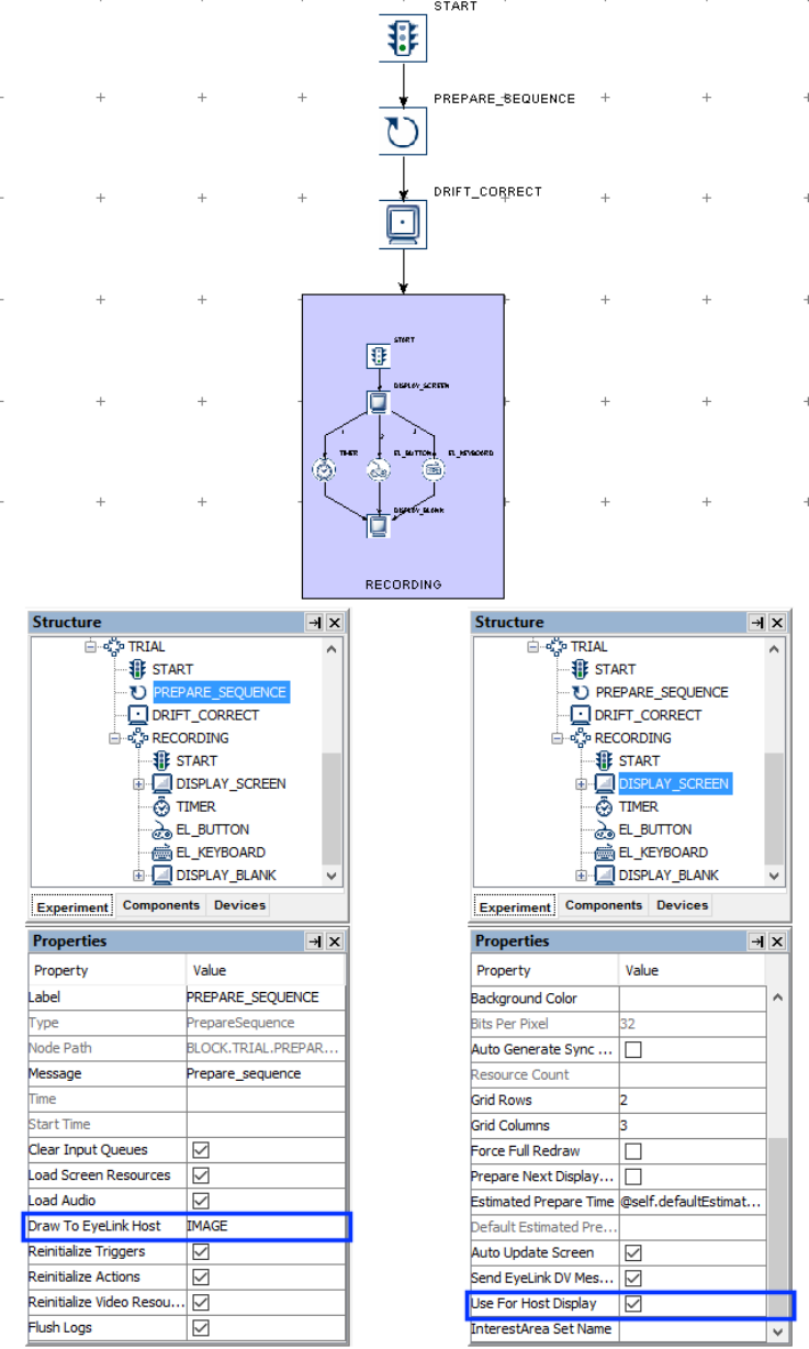
SR Research Experiment Builder User Manual ©2004-2017 SR Research Ltd.
97
Figure 7-21. Using Prepare Sequence Action.

SR Research Experiment Builder User Manual ©2004-2017 SR Research Ltd.
98
7.8.12 Reset Node
Similar to the PREPARE_SEQUENCE action, the RESET_NODE action ( ) can be
used to re-initialize trigger and action data. The RESET_NODE can also be used to clear
the data stored in an accumulator.
Field
Attribute
Reference
Type
Content
Label *
.label
String
Label of the RESET_NODE action.
Type #
NR
The type of Experiment Builder object
("ResetNode") the current node belongs to.
Node Path #
.absPath
String
The absolute path of the node in the experiment
graph.
Message
.message
String
Message to be sent to the EDF file (in an
EyeLink experiment) or messages.txt (in a non-
EyeLink experiment with the "Save Messages"
attribute of the Experiment node checked) when
the RESET_NODE action is done.
Time #
.time
Float
Display PC time (in milliseconds from the start
of the experiment) when this action is done.
Start Time #
.startTime
Float
Display PC time (in milliseconds from the start
of the experiment) when the processing of the
node starts (the action is not done yet by this
time).
Clear Input
Queues †
.clearInputQueue
s
Boolea
n
If true, all events from input queues are flushed
when the action starts. This includes all
Experiment Builder triggers, such as keyboard,
mouse, TTL, and EyeLink inputs (button,
saccade, fixation). This feature is designed to
ensure the software only evaluates the
upcoming triggers that occur after the start of
the action. If false, the input queues are not
cleared when the action is performed. This
means that events already in the queues may be
evaluated by the triggers following the action.
Reset Node *¶
NR
The node to be reset.
7.8.13 Playing Sound
Experiment Builder supports playing .WAV audio files using the PLAY_SOUND action
( ). Please make sure the target sound files are loaded into the library manager of the
experiment by clicking “Edit → Library Manager” from the application menu bar (see
Figure 7-22). The Library Manager dialog allows users to load in images, videos, sound
resources, and interest area set files. Select the “Sound” tab and click the “Add” button to
load in audio files, or select the audio files in Windows Explorer (Finder in Mac OS X)
and drag them into the Library Manager window. The name of the audio files to be
imported should not contain spaces or non-ASCII characters.
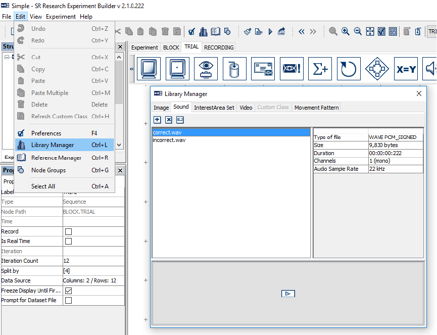
SR Research Experiment Builder User Manual ©2004-2017 SR Research Ltd.
99
Please note that the playing of an audio clip in Experiment Builder is asynchronous (i.e.,
the action returns before the sound finishes playing). As a result, if a sound clip is played
at the end of a sequence (e.g., used as a feedback to the participant), users must attach a
timer following the play sound action to ensure that the whole sound clip will be played.
Figure 7-22. Adding Audio Files to the Library Manager.
In Windows, users may choose either the DirectX or ASIO audio driver to play the sound
files (chosen from the “Devices → Audio” settings; see Figure 7-23). The ASIO driver
supports predictable and low latency audio playback and recording, and is therefore ideal
for experiments that require high audio timing precision (e.g., with audio-visual
synchronization or an audio stimulus onset asynchrony manipulation). If using the ASIO
driver, make sure a sound card that supports the ASIO 2.0 specification is installed on the
computer(s) used for developing and running the experiment. In the device setting for the
ASIO driver (Figure 7-23, left panel), “ASIO Audio driver” indicates the name of the
ASIO driver. The “Output Interval” property returns the interval (in milliseconds)
between the ASIO buffer swaps, which determines how often new sounds can be output.
The “Minimum Output Latency” property indicates the minimum output latency of the
ASIO driver (delay from the buffer switch to first sample output).
In Mac OS X, the audio driver is set to "OSX". Similar to the ASIO driver, it schedules
audio events ahead of time to achieve a precise playing time. All audio clips scheduled
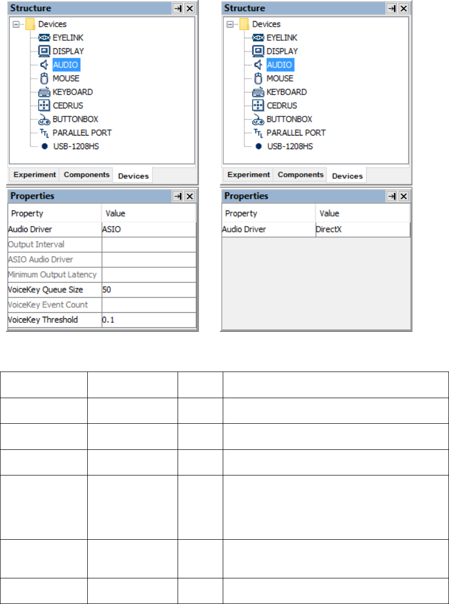
SR Research Experiment Builder User Manual ©2004-2017 SR Research Ltd.
100
with a TIMER trigger with a duration longer than the “Minimum Scheduling Latency”
(which is about 40 ms) or played through the “Synchronize Audio” option of a
DISPLAY_SCREEN action will be played at the intended/scheduled time.
Figure 7-23. Choose Audio Driver.
The following table lists the properties of a PLAY_SOUND action.
Field
Attribute
Reference
Type
Content
Label *
.label
String
Label of the PLAY_SOUND Action. The
default value is “PLAY_SOUND”.
Type #
NR
The type of Experiment Builder object
("PlaySound") the current node belongs to.
Node Path #
.absPath
String
The absolute path of the node in the experiment
graph.
Message
.message
String
Message to be sent to the EDF file (in an
EyeLink experiment) or messages.txt (in a non-
EyeLink experiment with the "Save Messages"
attribute of the Experiment node checked) when
the PLAY_SOUND action is executed.
Time #
.time
Float
Display PC time (in milliseconds from the start
of the experiment) when the PLAY_SOUND
action is done.
Start Time #
.startTime
Float
Display PC time (in milliseconds from the start
of the experiment) when the processing of the

SR Research Experiment Builder User Manual ©2004-2017 SR Research Ltd.
101
node starts (the sound playing has not started
yet by this time).
Clear Input
Queues †
.clearInputQueue
s
Boolea
n
If true, all events from input queues are flushed
when the action starts. This includes all
Experiment Builder triggers, such as keyboard,
mouse, TTL, and EyeLink inputs (button,
saccade, fixation). This feature is designed to
ensure the software only evaluates the
upcoming triggers that occur after the start of
the action. If false, the input queues are not
cleared when the action is performed. This
means that events already in the queues may be
evaluated by the triggers following the action.
Audio Device #
NR
Indicates the current audio driver setting (either
DirectX or ASIO in Windows, or OS X in Mac
OS X). This field is neither editable nor
referable.
Sound File
.firstSoundFile
String
The name of the sound file. This is
automatically set to one of the sound files in the
library (“None” if no sound file is loaded in the
library).
Volume
.firstVolume
Float
Adjusts the volume of audio playing. Volume
ranges from 0.0 (muted) to 1.0 (full volume).
The default value is 1.0.
Playing #
.playing
Boolea
n
Whether the sound playing has begun and is in
progress. The possible values are “True” and
“False”. Returns “False” if sound playing hasn’t
started, if sound playing is paused (with DirectX
driver), or if sound playing is done.
Note: The following fields are specific to the ASIO driver only.
Balance
.firstPan
Float
Adjusts the balance of the sound buffer. Balance
ranges from -1.0 (left channel only) through 0.0
(left and right channels have equal volume) to
1.0 (right channel only). Balance works by
attenuating one of the channels: for example, at
a pan of 0.5 the right channel is at full volume
while the left channel is at a volume of 0.5. This
option is not available on Mac OS X.
Estimated
Prepare Time
.estimatedPrepare
Time
Float
If the sound is scheduled enough in advance it
will play on time. The estimated time to prepare
for clip playing for guaranteed performance will
be the ASIO minimum output latency * 2.
Play Start
Sample
.playStartSample
Integer
The position within the buffer for the start of
play (samples from the beginning of the file
loaded into buffer; 0, beginning of the buffer).
In Windows, this option is only available when
using the ASIO driver.
Play End
Sample
.playEndSample
Integer
The position within the buffer for the end of
play (samples from the beginning of the file
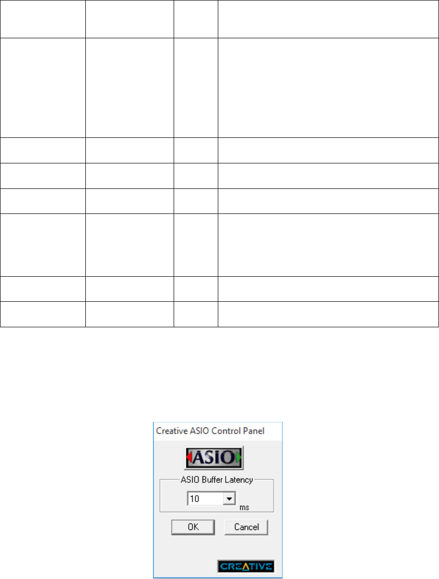
SR Research Experiment Builder User Manual ©2004-2017 SR Research Ltd.
102
loaded into buffer; 0, end of the buffer). In
Windows, this option is only available when
using the ASIO driver.
Play Start Time
#
.playStartTime
Float
Reports the Display PC time (in milliseconds
from the start of the experiment) at which the
first sample of a clip was played. This is set to 0
when the clip playing is scheduled. End of audio
play can be determined by a combination
of .playing (when it returns "False")
and .playStartTime attributes (when it returns a
value greater than 0).
Buffer Max
Samples #
.bufferMaxSampl
es
Integer
Reports the maximum number of samples the
audio buffer allocated can hold.
Sample Count #
.sampleCount
Integer
Reports the actual sample count stored in the
buffer.
Is Mono #
.ismono
Boolea
n
Reports whether the buffer contains mono or
stereo data.
Sample Rate #
sampleRate
Integer
Reports the sample rate (in samples per second)
of the buffer. All of the audio buffers have a
sample rate of either 48,000 or 24,000 samples
per second, chosen to be compatible with most
ASIO drivers.
Current Play
Position #
playPosition
Float
Reports the current play position (time in
milliseconds from the start of the clip playing).
Current Sample
#
.currentSample
Integer
Reports the current sample being played.
When you run a project using the ASIO driver in Windows, a "Creative ASIO Control
Panel" dialog box will show up. This latency sets the minimum output latency of the
ASIO driver (delay from buffer switch to first sample output) and the interval (in
milliseconds) between ASIO buffer swaps (i.e., how often new sounds can be output).
For better ASIO playing/recording performance, set the ASIO buffer latency to 10 ms
(the default is 50 ms).
Figure 7-24. Setting ASIO Buffer Latency.
SR Research Experiment Builder User Manual ©2004-2017 SR Research Ltd.
103
The synchronization of audio and visual presentations is critical in some experiments.
When the DirectX driver is used for playing an audio clip, the play sound action is done
as quickly as possible; however, no timing certainty should be expected when using this
audio driver. If using Windows to create and run an experiment requiring accurate audio
timing, the ASIO driver should be used. The ASIO driver creates two audio buffers for
each input or output channel. When producing sounds, one buffer is being played by the
sound card while the other buffer is being filled with sound data by Experiment Builder.
When the ASIO driver finishes playing its buffer, the application and driver buffers are
switched. This means that sounds are actually produced at a short (but highly predictable)
delay after the data is stored in the buffer. Since the Creative Labs sound cards we
recommended have a typical latency setting of 10 milliseconds, this would have a buffer
switch interval of 10 milliseconds and an output delay of 10 milliseconds. The time that
the clip was actually played will be accurately reported in the EDF file. When using an
ASIO driver:
• If the start of a sound has been commanded far enough in advance of the time the
sound is to be played (e.g., the PLAY_SOUND action is preceded by a TIMER
trigger with a duration of greater than 20 ms), Experiment Builder will be able to
write the sound data in advance to the ASIO buffer and therefore the first sample
of the clip will be emitted from the sound card within 3 milliseconds (plus or
minus) of the scheduled time.
• If the sound is commanded to happen as quickly as possible (e.g., for example in
response to a participant’s response, external signal, or eye movement event), or if
the sound play command was not given far enough in advance (e.g., the
PLAY_SOUND action is preceded by a TIMER with a duration shorter than 20
ms or is not preceded by a timer), Experiment Builder is unable to compensate for
system delays and the audio will begin after a short delay. However, the exact
moment that the sound will play is predictable and can be reported precisely for
analysis later.
• Experiment Builder allows users to schedule the audio playback at a predictable
time relative to the visual stimulus presentation when the display screen and play
sound actions are separated by only a TIMER trigger. Experiment Builder also
allows users to play audio files directly from the DISPLAY_SCREEN action by
enabling the "Synchronize Audio" check box. Users then specify the clip to be
played and the time offset relative to the display onset (a negative offset value
means the audio clip will be played before the visual stimulus, and a positive
offset means the visual information will be presented earlier). A PLAY_SOUND
action is not necessary if the audio playing is scheduled through the “Synchroniz
e Audio” option of the DISPLAY_SCREEN action. You may check out one
example in the .CHM version of this document (section “Installation → Windows
PC System Requirements → ASIO Card Installation → Related → Using ASIO
Driver”). In Windows this option is only available if ASIO is selected as the
Audio Device.
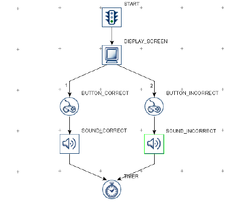
SR Research Experiment Builder User Manual ©2004-2017 SR Research Ltd.
104
Audio played with the ASIO driver will have messages automatically logged in the EDF
(EyeLink experiment) or message file (non-EyeLink experiment with the "Save
Messages" option enabled in the project node). The start time of audio playing is logged
with a "!V APLAYSTART" message and the end time is marked by a "!V APLAYSTOP
" message. Both messages have a negative time offset typically preceding this message.
• Playing Starts: MSG <EDF time> <offset> < !V APLAYSTART> <start frame>
<clip id> <audio file>
• Playing Ends: MSG <EDF time> <offset> <!V APLAYSTOP > <stop frame> <clip
id> <audio file>
In the following example, the FIXATION_SCREEN is displayed at time 10400921
[10400919 - (-2)], and the PLAY_BEEP sound is emitted at time 10401021 [10401007 -
(-14) ]. So the delay between FIXATION_SCREEN and PLAY_BEEP is 100 ms.
MSG 10400919 -2 FIXATION_SCREEN
MSG 10401007 -14 !V APLAYSTART 0 1 library\audio\innertrialbeep.wav
MSG 10401021 PLAY_BEEP
MSG 10401903 -14 !V APLAYSTOP 19755 1 library\audio\innertrialbeep.wav
The following figure illustrates the use of the PLAY_SOUND action to provide feedback
on participant's performance: if the participant presses the correct button, one sound is
played; if the participant presses the wrong button, another sound is played. For each
PLAY_SOUND action, the user specifies the desired sound file to be played from the
library.
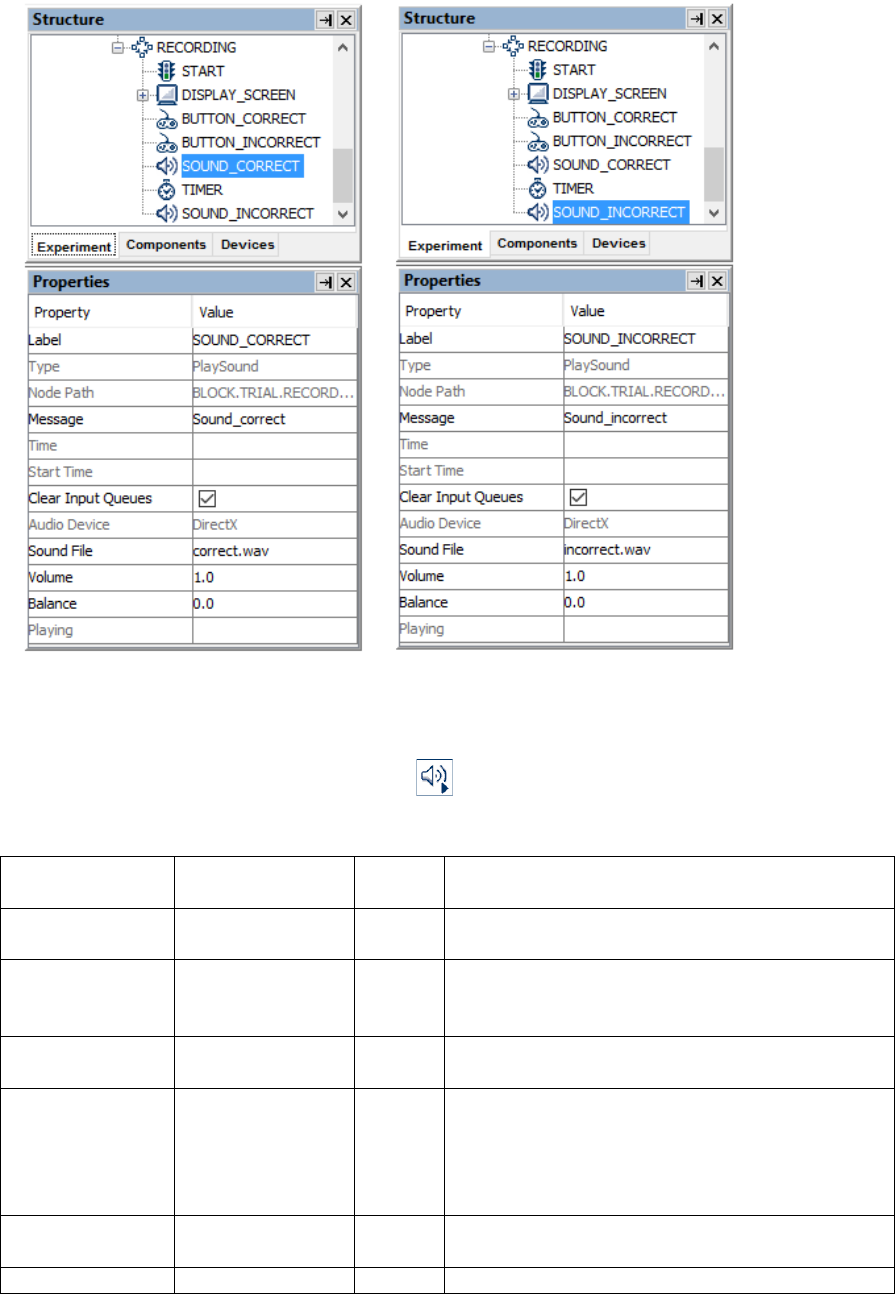
SR Research Experiment Builder User Manual ©2004-2017 SR Research Ltd.
105
Figure 7-25. Using Play Sound Action.
7.8.14 Play Sound Control
The PLAY_SOUND_CONTROL action ( ) stops, pauses, or plays a specified play
sound action.
Field
Attribute
Reference
Type
Content
Label *
.label
String
Label of the Play Sound Control action. The
default label is "PLAY_SOUND_CONTROL".
Type #
NR
The type of Experiment Builder object
("PlaySoundControl") the current node belongs
to.
Node Path #
.absPath
String
The absolute path of the node in the experiment
graph.
Message
.message
String
Message to be sent to the EDF file (in an
EyeLink experiment) or messages.txt (in a non-
EyeLink experiment with the "Save Messages"
attribute of the Experiment node checked) when
the action is done.
Time #
.time
Float
Display PC time (in milliseconds from the start
of the experiment) when the action is done.
Start Time #
.startTime
Float
Display PC time (in milliseconds from the start

SR Research Experiment Builder User Manual ©2004-2017 SR Research Ltd.
106
of the experiment) when the processing of the
node starts (the action is not done yet by this
time).
Clear Input
Queues †
.clearInputQueue
s
Boolea
n
If true, all events from input queues are flushed
when the action starts. This includes all
Experiment Builder triggers, such as keyboard,
mouse, TTL, and EyeLink inputs (button,
saccade, fixation). This feature is designed to
ensure the software only evaluates the
upcoming triggers that occur after the start of
the action. If false, the input queues are not
cleared when the action is performed. This
means that events already in the queues may be
evaluated by the triggers following the action.
Target Play
Sound Action *¶
NR
The intended play sound action to be controlled
(stop, pause, or play). Experiment Builder 2.0
also allows users to stop the sound file played
through the “Synchronize Audio” option of the
DISPLAY_SCREEN node.
Operation *¶
.operation
String
Action used to control the current audio playing:
STOP, PAUSE, or PLAY (continue playing a
paused audio). The PAUSE and PLAY options
are only applicable when playing the sound
using the DirectX driver; they will not work
when the ASIO and Mac OS X driver are used.
The following graph illustrates playing a sound file (PLAY_SOUND_DIRECTX) for 1
second (TIMER_PLAYING), pausing the playback (PAUSE_AUDIO) for 1 second
(TIMER_PAUSING), and then resuming playback (UNPAUSE AUDIO) with the
DirectX driver.
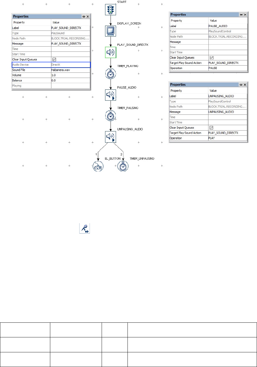
SR Research Experiment Builder User Manual ©2004-2017 SR Research Ltd.
107
Figure 7-26. Using Play Sound Control Action.
7.8.15 Record Sound
The Record_Sound action ( ) supports recording audio to a .WAV file, and can be
used with the Voicekey Trigger to record and measure latency of verbal responses. The
recommended experimental procedure would be to record a .WAV file for each trial,
specifying a unique filename for each trial, and to use the Voicekey Trigger to detect the
response. Recorded data is always written to an audio buffer first, and can later be copied
to a .WAV file. A message placed in the EDF file will mark the exact time and position
in the .WAV file of the first recorded sample for analysis. The resulting .wav files are
saved in "results/{session name}" directory.
This action is only supported in Mac OS X or in Windows using the ASIO Audio Device.
The following table lists the properties of a RECORD_SOUND action.
Field
Attribute
Reference
Type
Content
Label *
.label
String
Label of the Record Sound action. The default
label is "RECORD_SOUND".
Type #
NR
The type of Experiment Builder object
("RecordSound") the current node belongs to.

SR Research Experiment Builder User Manual ©2004-2017 SR Research Ltd.
108
Node Path #
.absPath
String
The absolute path of the node in the experiment
graph.
Message
.message
String
Message to be sent to the EDF file (in an
EyeLink experiment) or messages.txt (in a non-
EyeLink experiment with the "Save Messages"
attribute of the Experiment node checked) when
the action returns.
Time #
.time
Float
Display PC time (in milliseconds from the start
of the experiment) when the action is processed.
Start Time #
.startTime
Float
Display PC time (in milliseconds from the start
of the experiment) when the processing of the
node starts (the action is not done yet by this
time).
Clear Input
Queues †
.clearInputQueue
s
Boolea
n
If true, all events from input queues are flushed
when the action starts. This includes all
Experiment Builder triggers, such as keyboard,
mouse, TTL, and EyeLink inputs (button,
saccade, fixation). This feature is designed to
ensure the software only evaluates the
upcoming triggers that occur after the start of
the action. If false, the input queues are not
cleared when the action is performed. This
means that events already in the queues may be
evaluated by the triggers following the action.
File Name
.fileName
String
Filename (.wav) for the audio clip. Ideally this
should use a unique file name for each of the
recording trials (e.g., a reference to the trial
iteration or a data source column with a unique
trial identifier). If the same file name is used
across trials, only the recording of the last trial
will be saved.
Duration
.duration
Integer
Maximum duration for the sound recording.
Note: An "Audio not recording; End of buffer
reached" message will be written to the
warning.log file if the maximum recording
duration has been reached.
Status #
.status
Integer
Current status of the record_sound action. 1
(recording yet to be started), 0 (recording in
progress), -1000 (recording finished).
Position #
.position
Integer
Position into recording (in milliseconds since
the recording started). Returns 0 before or after
recording.
Record Start
Time #
.recordStartTime
Float
Display PC time (in milliseconds from the start
of the experiment) when the audio recording
starts. Returns 0 before or after recording.
A possible trial recording sequence involving audio recording would be:
1) Add a RECORD_SOUND action to open the recording file for the trial.
2) Present visual events with DISPLAY_SCREEN action.
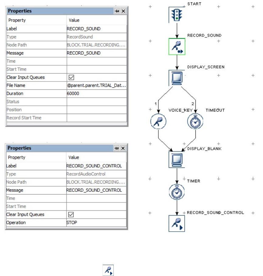
SR Research Experiment Builder User Manual ©2004-2017 SR Research Ltd.
109
3) Add a Voice Key trigger to the DISPLAY_SCREEN in addition to other trigger types
(if required).
4) Wait until timeout or a VOICE_KEY trigger event.
5) Blank the display immediately (or after a very short delay) to let the participant know
their utterance has been detected.
6) Add a timer trigger so that recording can be continued for a short period (e.g., 1000
ms) to ensure the entire word has been recorded. If a long response is expected, you
may want to continue checking the Voice Key and end only after 1000 ms or so of
silence.
7) Close the recording .WAV file with the RECORD_SOUND_CONTROL action.
The following graph illustrates the above event sequence.
Figure 7-27. Using Record Sound Action.
7.8.16 Record Sound Control
The Record Sound Control action ( ) is used to stop, pause, resume, or abort the
current sound being recorded. This action is only supported if Mac OS X is used or if an

SR Research Experiment Builder User Manual ©2004-2017 SR Research Ltd.
110
ASIO-compatible sound card is installed in the Windows computer and the Audio Device
is set to "ASIO".
Field
Attribute
Reference
Type
Content
Label *
.label
String
Label of the Record Sound Control action. The
default label is
"RECORD_SOUND_CONTROL".
Type #
NR
The type of Experiment Builder object
("RecordAudioControl") the current node
belongs to.
Node Path #
.absPath
String
The absolute path of the node in the experiment
graph.
Message
.message
String
Message to be sent to the EDF file (in an
EyeLink experiment) or messages.txt (in a non-
EyeLink experiment with the "Save Messages"
attribute of the Experiment node checked) when
the action is done.
Time #
.time
Float
Display PC time (in milliseconds from the start
of the experiment) when the action is done.
Start Time #
.startTime
Float
Display PC time (in milliseconds from the start
of the experiment) when the processing of the
node starts (the action is not done yet by this
time).
Clear Input
Queues †
.clearInputQueue
s
Boolea
n
If true, all events from input queues are flushed
when the action starts. This includes all
Experiment Builder triggers, such as keyboard,
mouse, TTL, and EyeLink inputs (button,
saccade, fixation). This feature is designed to
ensure the software only evaluates the
upcoming triggers that occur after the start of
the action. If false, the input queues are not
cleared when the action is performed. This
means that events already in the queues may be
evaluated by the triggers following the action.
Operation *¶
.operation
String
Action (STOP, PAUSE, RECORD, or ABORT)
used to control the current audio recording.
STOP: Stops the current audio recording, writes
out the data stored in the record buffer to
the .wav file; and frees the buffer.
ABORT: Stops the current audio recording
without saving the .wav file.
PAUSE: Pauses the current audio recording.
Recording may be continued by using the
"RECORD" action.
RECORD: Resumes a paused recording.
The RECORD_SOUND_CONTROL action can only be applied after a
RECORD_SOUND action. For the usage of this action, please take a look at the Record
Sound example.

SR Research Experiment Builder User Manual ©2004-2017 SR Research Ltd.
111
7.8.17 Terminating an Experiment
The experiment ends when all iterations of sequences have been executed. Users can
choose to terminate an experiment earlier by using the TERMINATE_EXPERIMENT
action ( ). All of the nodes following the TERMINATE_EXPERIMENT node and
remaining sequence iterations will be ignored.
Field
Attribute
Reference
Type
Content
Label *
.label
String
Label of the TERMINATE_EXPERIMENT
action. The default value is
“TERMINATE_EXPERIMENT”.
Type #
NR
The type of Experiment Builder object
("TerminateExperiment") the current node
belongs to.
Node Path #
.absPath
String
The absolute path of the node in the experiment
graph.
Message
.message
String
Message to be sent to the EDF file (in an
EyeLink experiment) or messages.txt (in a non-
EyeLink experiment with the "Save Messages"
attribute of the Experiment node checked) when
the TERMINATE_EXPERIMENT action is
done.
Time #
.time
Float
Display PC time (in milliseconds from the start
of the experiment) when the
TERMINATE_EXPERIMENT action is done.
Start Time #
.startTime
Float
Display PC time (in milliseconds from the start
of the experiment) when the processing of the
node starts (the action is not done yet by this
time).
Clear Input
Queues †
.clearInputQueue
s
Boolea
n
If true, all events from input queues are flushed
when the action starts. This includes all
Experiment Builder triggers, such as keyboard,
mouse, TTL, and EyeLink inputs (button,
saccade, fixation). This feature is designed to
ensure the software only evaluates the
upcoming triggers that occur after the start of
the action. If false, the input queues are not
cleared when the action is performed. This
means that events already in the queues may be
evaluated by the triggers following the action.
In the following example (Figure 7-28), an ERROR_COUNT variable is used to store the
number of errors made in the experiment. When a target button is pressed, the
ERROR_COUNT is updated. If the error count exceeds a pre-set number, the
experiment can be terminated earlier by the TERMINATE_EXPERIMENT action.
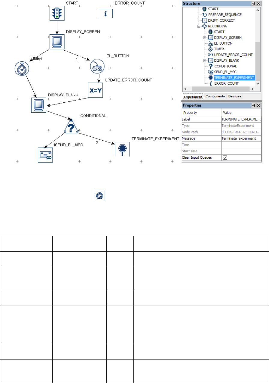
SR Research Experiment Builder User Manual ©2004-2017 SR Research Ltd.
112
Figure 7-28. Using Terminate Experiment Action.
7.8.18 Recycle Data Line
The Recycle Data Line action ( ) directs the experiment program to perform the
current data-source line at a later time. Note: A Recycle Data Line action must be used
inside a sequence. If a Recycle Data Line action is used when neither the current
sequence nor the parent sequences have a data source, a build-time error will be raised.
Field
Attribute
Reference
Type
Content
Label *
.label
String
Label of the Recycle DataLine action. The
default value is "RECYCLE_DATALINE".
Type #
NR
The type of Experiment Builder object
("RecycleDataLine") the current node belongs
to.
Node Path #
.absPath
String
The absolute path of the node in the experiment
graph.
Message
.message
String
Message to be sent to the EDF file (in an
EyeLink experiment) or messages.txt (in a non-
EyeLink experiment with the "Save Messages"
attribute of the Experiment node checked) when
the action is done.
Time #
.time
Float
Display PC time (in milliseconds from the start
of the experiment) when the action is done.
Start Time #
.startTime
Float
Display PC time (in milliseconds from the start
of the experiment) when the processing of the
node starts (the action is not done yet by this

SR Research Experiment Builder User Manual ©2004-2017 SR Research Ltd.
113
time).
Clear Input
Queues †
.clearInputQueue
s
Boolea
n
If true, all events from input queues are flushed
when the action starts. This includes all
Experiment Builder triggers, such as keyboard,
mouse, TTL, and EyeLink inputs (button,
saccade, fixation). This feature is designed to
ensure the software only evaluates the
upcoming triggers that occur after the start of
the action. If false, the input queues are not
cleared when the action is performed. This
means that events already in the queues may be
evaluated by the triggers following the action.
Data Source #
NR
The data source from which the current trial
data line will be repeated.
Recycling Mode
*¶
.recyclingMode
String
Method of data-source line recycling. If set to
"IMMEDIATE", the same data-source line will
be repeated in the next trial; if set to
"RANDOM", the data-source line will be
repeated at a random point later; if set to
"END", the data-source line will be repeated at
the end of the experiment.
If the experiment uses internal randomization
with a blocking level manipulation, the recycled
trial will be repeated within the current blocking
level.
The Recycle Data Line action can be used to recycle a trial and rerun it at a later time.
The following graph illustrates the case of recycling the trial if the participant presses
button 5. (Note: A dummy action such as NULL_ACTION or ADD_TO_LOG node
should be added to the false/left branch of the CONDITIONAL trigger.)
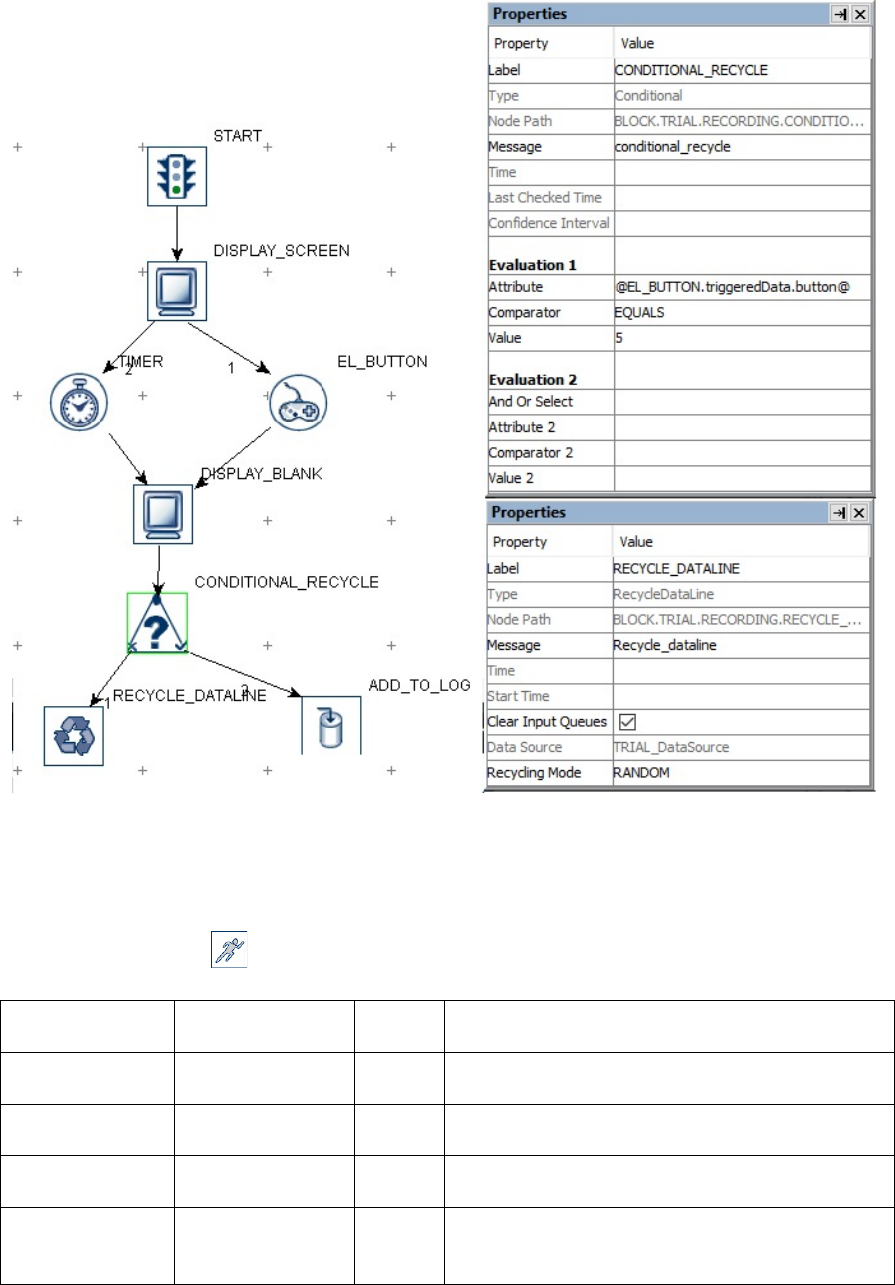
SR Research Experiment Builder User Manual ©2004-2017 SR Research Ltd.
114
Figure 7-29. Using Recycle Dataline Action.
7.8.19 Execute Action
The Execute action ( ) is used to execute a method defined in the custom class python
code (see section 12.5 “Using Custom Class” for details).
Field
Attribute
Reference
Type
Content
Label *
.label
String
Label of the Execute action. The default label is
"EXECUTE".
Type #
NR
The type of Experiment Builder object
("Execute") the current node belongs to.
Node Path #
.absPath
String
Path of the node in the experiment graph.
Message
.message
String
Message to be sent to the EDF file (in an
EyeLink experiment) or messages.txt (in a non-
EyeLink experiment with the "Save Messages"

SR Research Experiment Builder User Manual ©2004-2017 SR Research Ltd.
115
attribute of the Experiment node checked) when
the action is done.
Time #
.time
Float
Display PC time (in milliseconds from the start
of the experiment) when the action is done.
Start Time #
.startTime
Float
Display PC time (in milliseconds from the start
of the experiment) when the processing of the
node starts (the action is not done yet by this
time).
Clear Input
Queues †
.clearInputQueue
s
Boolea
n
If true, all events from input queues are flushed
when the action starts. This includes all
Experiment Builder triggers, such as keyboard,
mouse, TTL, and EyeLink inputs (button,
saccade, fixation). This feature is designed to
ensure the software only evaluates the
upcoming triggers that occur after the start of
the action. If false, the input queues are not
cleared when the action is performed. This
means that events already in the queues may be
evaluated by the triggers following the action.
Execute Method
NR
Method of a custom class to be executed. Click
the right side of the value field to start the
attribute editor to locate a method defined in a
custom class instance.
If a method defined in a custom class is already
linked to this field, double clicking the
EXECUTE node should bring up the custom
class editor, with the current editing position set
to the start of the method that the execute action
is using.
Parameter(s)
NR
A list of parameters the execute method may
take.
Result #
.result
Result of the execution method.
Result Data
Type #
NR
Type of the data returned by the execute
method.
7.8.20 Null Action
The Null Action node ( ), as suggested by its name, does not perform any actual
action. It is primarily used for two reasons:
a) Controlling the experiment flow. For example, the current linking rules do not
allow for a direct connection between a sequence and triggers. A null action can
be used as a dummy action in between, instead of using a SEND_EL_MESSAGE
action or an ADD_TO_LOG action. The null action can also be attached to the
unused branch of a conditional trigger so that the experiment flow can continue. It
can also be used between two successive triggers to make the reading of the
experiment graph less ambiguous.
b) Clearing cached trigger data.

SR Research Experiment Builder User Manual ©2004-2017 SR Research Ltd.
116
Field
Attribute
Reference
Type
Content
Label *
.label
String
Label of the NULL_ACTION action. The
default value is "NULL_ACTION".
Type #
NR
The type of Experiment Builder object
("NullAction") the current node belongs to.
Node Path #
.absPath
String
The absolute path of the node in the experiment
graph.
Message
.message
String
Message to be sent to the EDF file (in an
EyeLink experiment) or messages.txt (in a non-
EyeLink experiment with the "Save Messages"
attribute of the Experiment node checked) when
the action is executed.
Time #
.time
Float
Display PC time (in milliseconds from the start
of the experiment) when the action is done.
Start Time #
.startTime
Float
Display PC time (in milliseconds from the start
of the experiment) when the processing of the
node starts (the action is not done yet by this
time).
Clear Input
Queues †
.clearInputQueue
s
Boolea
n
If true, all events from input queues are flushed
when the action starts. This includes all
Experiment Builder triggers, such as keyboard,
mouse, TTL, and EyeLink inputs (button,
saccade, fixation). This feature is designed to
ensure the software only evaluates the
upcoming triggers that occur after the start of
the action. If false, the input queues are not
cleared when the action is performed. This
means that events already in the queues may be
evaluated by the triggers following the action.
The following illustrates one common use of the NULL_ACTION node. Suppose that in
an experiment, the participant's response should be recorded without ending the trial
(e.g., pressing a key or button whenever the participant detects a specific event in the
video clip). This can be done by adding a NULL_ACTION node after the
DISPLAY_SCREEN and having the input trigger branch looping back to the
NULL_ACTION - use an UPDATE_ATTRIBUTE action following the input trigger to
collect response data. All other triggers initially attached to the DISPLAY_SCREEN
action should be connected from the NULL_ACTION as well. Please note that if a
TIMER trigger is used to end the trial, the "start time" should be set to the .time of the
DISPLAY_SCREEN so that the start time of the TIMER trigger will not be reset
whenever a key is pressed.
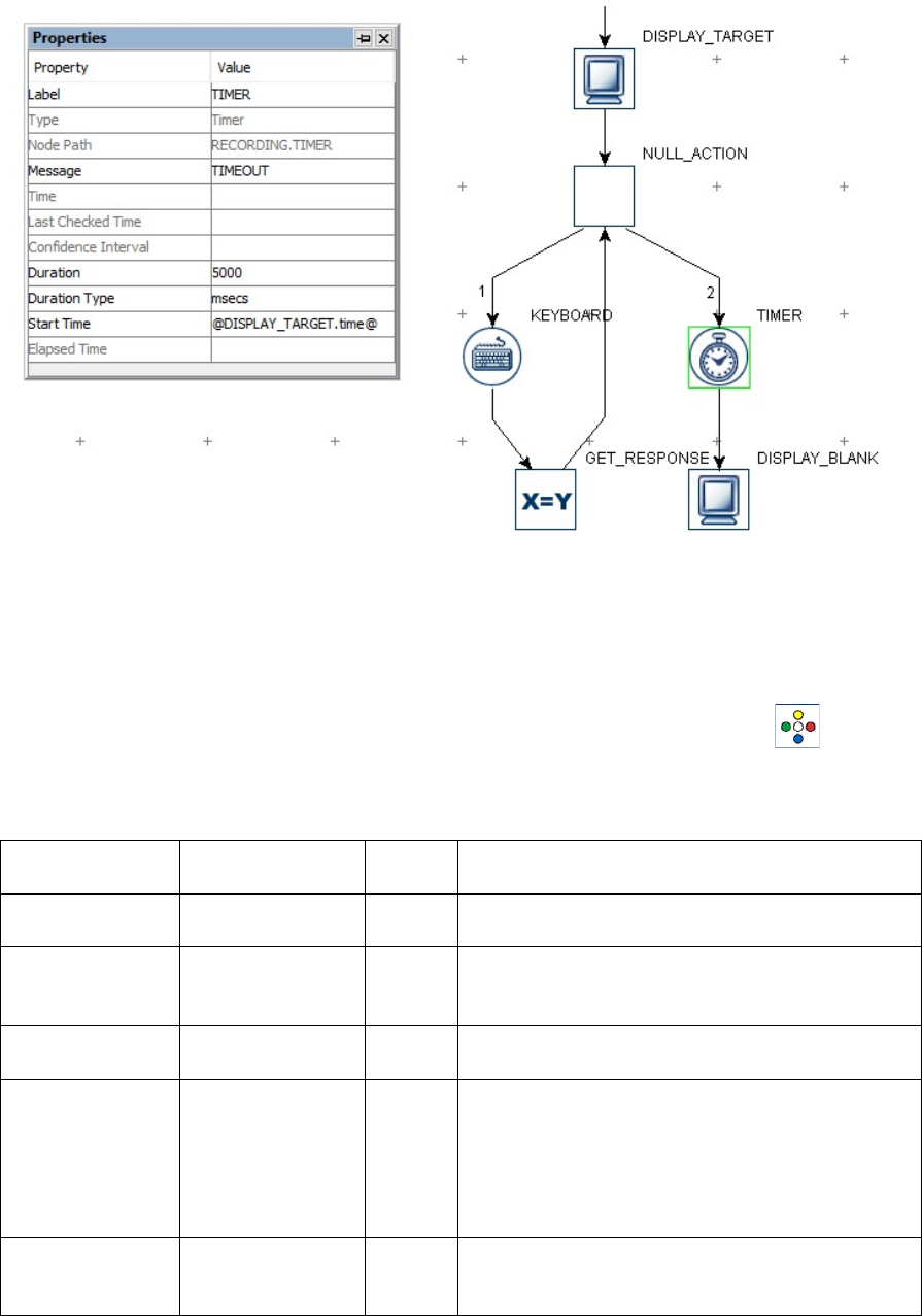
SR Research Experiment Builder User Manual ©2004-2017 SR Research Ltd.
117
Figure 7-30. Using a NULL_ACTION node.
7.8.21 ResponsePixx LED Control
If a ResponsePixx button box is used as the EyeLink button box, this action ( ) allows
to turn on/off the LEDs on the button box. This option is only available in EyeLink
experiments.
Field
Attribute
Reference
Type
Content
Label *
.label
String
Label of the
RESPONSEPIXX_LED_CONTROL action.
Type #
NR
The type of Experiment Builder object
("RESPONSEPixxLEDControl") the current
node belongs to.
Node Path #
.absPath
String
The absolute path of the node in the experiment
graph.
Message
.message
String
Message to be sent to the EDF file (in an
EyeLink experiment) or messages.txt (in a non-
EyeLink experiment with the "Save Messages"
attribute of the Experiment node checked) when
the RESPONSEPixx_LED_Control action is
done.
Time #
.time
Float
Display PC time (in milliseconds from the start
of the experiment) when the
RESPONSEPIXX_LED_CONTROL action is

SR Research Experiment Builder User Manual ©2004-2017 SR Research Ltd.
118
done.
Start Time #
.startTime
Float
Display PC time (in milliseconds from the start
of the experiment) when the processing of the
node starts (the action is not done yet by this
time).
Clear Input
Queues †
.clearInputQueue
s
Boolea
n
If true, all events from input queues are flushed
when the action starts. This includes all
Experiment Builder triggers, such as keyboard,
mouse, TTL, and EyeLink inputs (button,
saccade, fixation). This feature is designed to
ensure the software only evaluates the
upcoming triggers that occur after the start of
the action. If false, the input queues are not
cleared when the action is performed. This
means that events already in the queues may be
evaluated by the triggers following the action.
Button One †
.button1
Boolea
n
Whether the LED for button one should be
turned on or not.
Button Two †
.button2
Boolea
n
Whether the LED for button two should be
turned on or not.
Button Three †
.button3
Boolea
n
Whether the LED for button three should be
turned on or not.
Button Four †
.button4
Boolea
n
Whether the LED for button four should be
turned on or not.
Button Five †
.button5
Boolea
n
Whether the LED for button five should be
turned on or not.
The following figure illustrates the use of the ResponsePixx_LED_Control action. All of
the LEDs are turned off at the beginning of the trial. The participant presses either button
2 or 4. Once the button is pressed, the LED for that button is turned on. The experiment
project can be downloaded from the HTML version of this document.
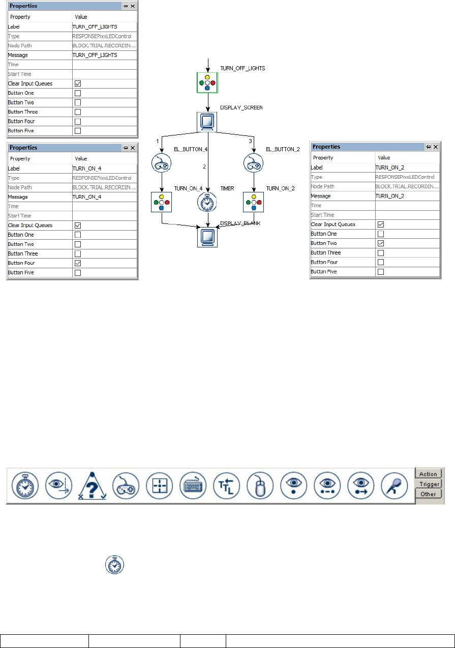
SR Research Experiment Builder User Manual ©2004-2017 SR Research Ltd.
119
Figure 7-31. Using a ResponsePixx LED Control Action.
7.9 Triggers
Triggers are used to control the experiment flow, such as the transition from one action to
the other, or ending the sequence. Experiment Builder supports several kinds of triggers,
including a duration-based trigger, responses from an input device (keyboard, mouse,
TTL, Cedrus, voice key, and EyeLink button box), those involving online eye data
(invisible boundary, fixation, saccade, and sample velocity), and conditional evaluations.
The following sections list the use of each trigger type. Triggers can be selected from the
trigger tab of the component toolbox (Figure 7-32).
Figure 7-32. Triggers Implemented in Experiment Builder.
7.9.1 Timer Trigger
The Timer Trigger ( ) fires when a specified amount of time has elapsed since the
trigger started. Timer triggers can be used to introduce a delay between actions and/or
triggers, and to control the maximum amount of time a sequence can last. The following
table lists the properties of a timer trigger.
Field
Attribute
Type
Content

SR Research Experiment Builder User Manual ©2004-2017 SR Research Ltd.
120
Reference
Label *
.label
String
Label of the Timer trigger. The default value is
“TIMER”.
Type #
NR
The type of Experiment Builder object
("Timer") the current node belongs to.
Node Path #
.absPath
String
The absolute path of the node in the experiment
graph.
Message
.message
String
Message to be sent to the EDF file (in an
EyeLink experiment) or messages.txt (in a non-
EyeLink experiment with the "Save Messages"
attribute of the Experiment node checked) when
the timer trigger fires.
Time #
.time
Float
Display PC time (in milliseconds from the start
of the experiment) when the processing of the
trigger is done (so the experiment flow is ready
to move to the next node).
Last Checked
Time #
.lastCheckedTim
e
Float
Experiment Builder checks for the status of the
timer trigger about every 1 msec. This property
can be used to retrieve the Display PC time (in
milliseconds from the start of the experiment)
when the trigger was last checked.
Confidence
Interval #
.confidenceInterv
al
Float
Time difference between the trigger time and
last check time of the trigger. This indicates a
window of uncertainty.
Duration
.duration
Integer
The duration after which the trigger will fire
(4000 msec by default).
Duration Type ¶
.durationType
String
Unit of timer duration (either “msecs” or
“retraces”).
Start Time
.startTime
Float
Display PC time (in milliseconds from the start
of the experiment) when the trigger starts. The
default value is 0—the timer starts from the last
action to which the timer is linked and resets if
that action is re-entered in a loop. If a different
start time should be used for the trigger, users
can set the Start Time as an attribute reference,
e.g., to the .time property of an earlier node.
Elapsed Time #
.elapsedTime
Float
Amount of elapsed time (in milliseconds) since
the timer started.
By default, the start time of the timer trigger is set to "0", which means that the timer
starts from the end time of the previous action. Therefore, if a timer trigger immediately
follows a display screen, the trigger doesn't start until the display screen's retrace starts.
Similarly, if it is attached to an EyeLink Message action, the timer will start only after the
message is sent. Please note if the timer is connected from a trigger, the start time of the
timer trigger will still be the end of the last action—not the time when the previous
trigger fires. In general, users should avoid having two triggers connected directly in
sequence for ease of interpreting the experiment graph. Rather, use a NULL action in
between two triggers for better control of experiment timing.
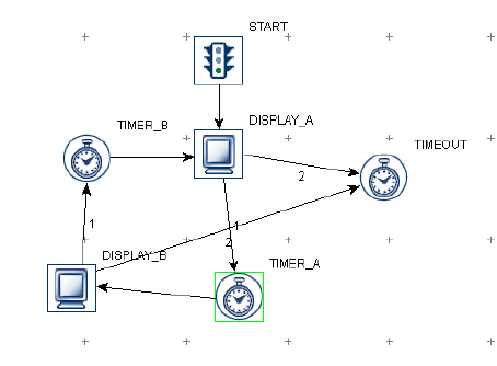
SR Research Experiment Builder User Manual ©2004-2017 SR Research Ltd.
121
Users need to explicitly set the 'Start Time' value of the TIMER trigger when the desired
start time is the triggered time of the previous trigger, or when the action from which the
timer trigger is connected may be repeated (see FAQ: "Using an EyeLink button trigger
without ending the trial sequence" in the html version of this document).
The TIMER trigger uses a pre-release mechanism when it is connected to a DISPLAY
SCREEN action or a PLAY SOUND action (when using either the ASIO or OS X audio
driver) to ensure the upcoming audio/visual event will be presented at the intended time.
To make this preleasing mechanism work, please do not insert any intervening
trigger/actions between the TIMER trigger and the intended DISPLAY SCREEN or
PLAY SOUND action. Therefore, a sequence like "DISPLAY A → TIMER →
DISPLAY B → UPDATE_ATTRIBUTE" is recommended for accurate timing while
"DISPLAY A → TIMER → UPDATE_ATTRIBUTE → DISPLAY B" is not.
The following illustrates the use of TIMER triggers to control the duration of display
presentation and how long a sequence should be run. Imagine that the user wants to show
display A for 500 milliseconds, then show display B for 500 milliseconds, and then
display A again for 500 milliseconds, and so on, while the whole sequence should end in
4000 milliseconds. Users may design the graph as the following:
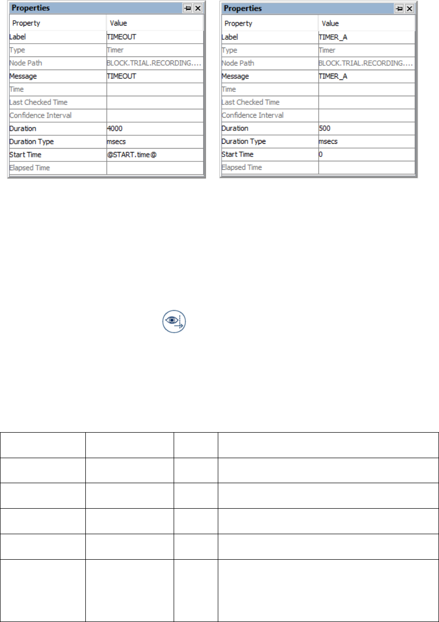
SR Research Experiment Builder User Manual ©2004-2017 SR Research Ltd.
122
Figure 7-33. Using Timer Trigger.
Note that the "Start Time" of TIMER_A and TIMER_B is set to 0, which means that the
timers reset themselves when Display_A and Display_B actions are repeated. The Timer
TIMEOUT controls the duration to stay within the sequence and therefore its start time
shouldn't be reset when either of the two display screen actions is repeated. The start time
of this trigger is set to the start of the sequence (@START.time@) instead.
7.9.2 Invisible Boundary Trigger
The Invisible Boundary trigger ( ) fires when the gaze position is detected inside or
outside of a specified region, either after a single sample or after a specified duration.
This trigger can be used to implement a display change based on the gaze position. For
example, a line of text may be changed when the reader proceeds past a critical word in a
sentence. This trigger is only available in an EyeLink experiment. Please note that the
“Link Filter Level” setting in the EyeLink device influences how quickly the trigger will
fire.
Field
Attribute
Reference
Type
Content
Label *
.label
String
Label of the Invisible Boundary trigger. The
default value is “INVISIBLE_BOUNDARY”.
Type #
NR
The type of Experiment Builder object
("Boundary") the current node belongs to.
Node Path #
.absPath
String
The absolute path of the node in the experiment
graph.
Message
.message
String
Message to be sent to the EDF file when the
invisible boundary trigger fires.
Time #
.time
Float
Display PC time (in milliseconds from the start
of the experiment) when the processing of the
invisible boundary trigger is done (so the
experiment flow is ready to move to the next
node). Note: To check the time when the
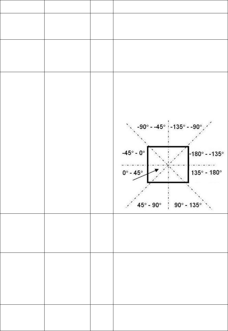
SR Research Experiment Builder User Manual ©2004-2017 SR Research Ltd.
123
triggering sample occurs, you should use
@*.triggeredData.time@ instead.
Last Check
Time #
.lastCheckTime
Float
This property can be used to retrieve the
Display PC time (in milliseconds from the start
of the experiment) when the trigger was
checked for the last time.
Confidence
Interval #
.confidenceInterv
al
Float
Time difference between the trigger time and
last check time of the trigger. This indicates a
window of uncertainty, as the triggering event
may actually occur between the last checked
time and the actual firing time.
Region
Direction
.regionDirection
List of
Strings
A range of eye angles from a multiple-selection
list ['0 - 45', '45 - 90', '90 - 135', '135 - 180', '-
180 - -135', '-135 - -90', '-90 - -45', '-45 - 0']
used to restrict the direction in which the
invisible boundary trigger fires. For each angle
range, the first value is inclusive and the second
value is not.
Region Type ¶
.regionType
String
The type of triggering Region used:
RECTANGLE, ELLIPSE, or INTEREST
AREA. The "INTEREST AREA" option is only
available when interest areas are defined in one
of the display screens in the same recording
sequence.
Region Location
(Top Left)
.regionLocation
Point
Pixel coordinate of the top-left corner of the
boundary region in (x, y) tuple. The default
value is (0, 0). The x and y coordinates of the
region location can be further referred
as .regionLocation.x and .regionLocation.y,
respectively. This property is only available
when the "Region Type" property is set to either
RECTANGLE or ELLIPSE.
Region Width
.regionWidth
Integer
Width (0 by default) of the boundary region in
screen pixels. This property is only available
when the "Region Type" property is set to either
RECTANGLE or ELLIPSE.

SR Research Experiment Builder User Manual ©2004-2017 SR Research Ltd.
124
Region Height
.regionHeight
Integer
Height (0 by default) of the boundary region in
screen pixels. This property is only available
when the "Region Type" property is set to either
RECTANGLE or ELLIPSE.
Interest Area
Screen *¶
NR
The display screen on which the target interest
area regions are located. This property is only
available when the "Region Type" property is
set to INTEREST AREA.
Interest Area
Regions¶
NR
Target interest areas used to define the
triggering region. This property is only available
when the "Region Type" property is set to
INTEREST AREA.
Within †
.within
Boolea
n
If set to “True” (default), the trigger will fire
when gaze samples are within the boundary
region; otherwise, the trigger fires when
samples are outside the region.
Tracking Eye ¶
.trackingEye
Integer
Determines which eye’s data is used for online
triggering. The default value is “EITHER” (2).
It can also be set to LEFT (0) or RIGHT (1).
Minimum
Duration
.minimumDuratio
n
Integer
Duration (in milliseconds) in or out of the
region before the trigger fires. If the default
value 0 is used, the trigger fires immediately
after detecting a sample inside (or outside) of
the boundary.
Triggered Data #
.triggeredData
If the invisible boundary trigger fires, the
triggered data can be further accessed (see the
following table).
If the Invisible Boundary Trigger fires, users can further check the triggered data (e.g.,
time when the trigger fires, eye position/velocity when the trigger fires). The sub-
attributes of the TriggeredData attribute are listed in the following table. They can be
used for attribute references.
Attribute
Reference
Type
Content
Time
.time
Float
Display PC time (in milliseconds from the start
of the experiment) when the triggering sample
occurs.
EDF Time
.EDFTime
Integer
EDF time of the triggering sample.
Eyes Available
.eyesAvailable
Integer
Eyes available in recording (0 for left eye; 1 for
right eye; 2 for both eyes).
Start Time
.startTime
Float
Display PC time (in milliseconds from the start
of the experiment) when the first sample
appears in the region.
EDF Start Time
.EDFStartTime
Integer
EDF time (time since the EyeLink program
started on the Host PC) when the first sample
occurs in the region.
Triggered Eye
.triggeredEye
Integer
Eye (0 for left eye; 1 for right eye) whose data
makes the current invisible boundary trigger
fire.
PPD X, PPD Y
.PPDX, .PPDY
Float
Gaze resolution at the current position (in screen

SR Research Experiment Builder User Manual ©2004-2017 SR Research Ltd.
125
pixels per degree of visual angle) along the x-,
or y-axis.
Left Gaze X,
Right Gaze X,
Average Gaze X
.leftGazeX, .right
GazeX, .average
GazeX ¹
Float
Gaze position of the triggering sample along the
x-axis for the left eye, right eye and an average
between the two.
Left Gaze Y,
Right Gaze Y,
Average Gaze Y
.leftGazeY, .right
GazeY, .average
GazeY ¹
Float
Gaze position of the triggering sample along the
y-axis for the left eye, right eye and an average
between the two.
Left Pupil Size,
Right Pupil Size,
Average Pupil
Size
.leftPupilSize, .ri
ghtPupilSize,
.averagePupilSize
¹
Float
Left eye, right eye, or average pupil size (in
arbitrary units, area or diameter as selected in
the EyeLink device settings).
Left Velocity,
Right Velocity,
Average Velocity
.leftVelocity,
.rightVelocity,
.averageVelocity
¹
Float
Left eye, right eye, or average sample velocity
(in degrees /second). ²
Left
Acceleration,
Right
Acceleration,
Average
Acceleration
.leftAcceleration,
.rightAcceleratio
n,
.averageAccelerat
ion ¹
Float
Left eye, right eye, or average sample
acceleration (in degrees /second²). ²
Angle
.angle
Float
The angle of the eye movements when the
trigger fires.
Target Distance
.targetDistance
Integer
Distance between the target and camera (10
times the measurement in millimeters). This
option is for the EyeLink Remote mode only.
Returns "MISSING_DATA" (-32768) if target
is missing or if a remote tracking mode is not
being used.
Target X, Target
Y
.targetX, .targetY
Integer
X, Y position of the target in camera
coordinates. This option is for the EyeLink
Remote mode only. Returns
"MISSING_DATA" (-32768) if target is
missing or if a remote tracking mode is not
being used
Target Flags
.targetFlags
Integer
Flags used to indicate target tracking status (0 if
target tracking is ok; otherwise error code). This
option is for the the EyeLink Remote mode
only. Returns "MISSING_DATA" (-32768) a
remote tracking mode is not being used
Note:
¹ Returns "MISSING_DATA" (-32768) for the untracked eye.
² For EyeLink I and II, the velocity and acceleration of the 2nd sample before the
triggering sample are reported. For EyeLink 1000, 1000 Plus, and Portable Duo, the
reported velocity and acceleration values belong to the nth sample (n = 2, 4 or 8,
respectively, if a 5-, 9-, or 17- sample velocity/acceleration model is used) before the
trigging sample.
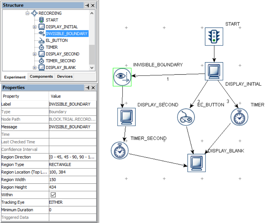
SR Research Experiment Builder User Manual ©2004-2017 SR Research Ltd.
126
The Invisible Boundary Trigger can be used to check whether the participant's gaze
position crosses into a specified region and therefore is useful for experiments involving
the boundary paradigm. For example, if a user wants to change the display immediately
after the participant's left-eye gaze position is in a rectangular region (100, 384, 250, 818),
the recording sequence can be programmed as follows:
Figure 7-34. Using an Invisible Boundary Trigger.
Since the invisible boundary trigger keeps monitoring the online recording data, this
trigger type must be placed within a recording sequence (i.e., the "Record" property of
the sequence is checked).
7.9.2.1 The Location Type of the Invisible Boundary Trigger
Please note that the Location Type of all location-based triggers (invisible boundary
trigger, mouse trigger, fixation trigger, saccade trigger, and sample velocity trigger) is
based on the top-left corner of the region, whereas the screen resources can be based on
either the top-left corner or the center of the resource. (The screen resource/interest area
location type can be set in the project Preferences under Screen). This means that
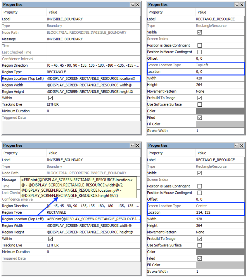
SR Research Experiment Builder User Manual ©2004-2017 SR Research Ltd.
127
references should be created differently depending on whether the region location of a
trigger refers to a center-based resource or a top-left-based resource.
Figure 7-35. Using Invisible_Boundary Trigger with Top-left and Center Location
Types.
Imagine that an invisible boundary trigger should fire when the gaze is within a rectangle
resource (RECTANGLE_RESOURCE). The top-panel of the figure below illustrates
creating the Region Location reference to the rectangle resource when the screen location
type is TopLeft (@DISPLAY_SCREEN.RECTANGLE_RESOURCE.location@). The
bottom panel of the figure illustrates creating a location equation when the location type
SR Research Experiment Builder User Manual ©2004-2017 SR Research Ltd.
128
is Center, by subtracting half the resource width from the x coordinate, and half the
resource height from the y coordinate:
(=EBPoint(@DISPLAY_SCREEN.RECTANGLE_RESOURCE.location.x@ -
@DISPLAY_SCREEN.RECTANGLE_RESOURCE.width@/2,
@DISPLAY_SCREEN.RECTANGLE_RESOURCE.location.y@ -
@DISPLAY_SCREEN.RECTANGLE_RESOURCE.height@/2)).
7.9.2.2 How to Show the Triggering Region on the Host PC?
Sometimes it is useful to draw feedback graphics on the Host PC so the experimenter can
monitor whether the participant's eye position is within the triggering region, or so the
programmer can test the experiment code by running the eye tracker in mouse simulation
mode. The user can draw graphics to the Host PC with an EyeLink_Command action
before the recording sequence or as the first node in the recording sequence. The
command should be added after the Prepare Sequence so the drawing is overlaid on top
of the existing host graphics. The drawing command can be either "draw_box" or
"draw_filled_box". The Text of the command must include the top, left, right, and bottom
pixel positions of the triggering region, followed by the drawing color. This can be done
either with string concatenation or string formatting. The top-left corner of the triggering
region is (@INVISIBLE_BOUNDARY.regionLocation.x@,
@INVISIBLE_BOUNDARY.regionLocation.y@) and the bottom-right corner of the
triggering region is (@INVISIBLE_BOUNDARY.regionLocation.x@ +
@INVISIBLE_BOUNDARY.regionWidth@,
@INVISIBLE_BOUNDARY.regionLocation.y@ +
@INVISIBLE_BOUNDARY.regionHeight@)
String Concatenation:
=str(@INVISIBLE_BOUNDARY.regionLocation.x@) + " "
+ str(@INVISIBLE_BOUNDARY.regionLocation.y@) + " "
+ str(@INVISIBLE_BOUNDARY.regionLocation.x@ + @INVISIBLE_BOUNDARY.regionWidth@) + " "
+ str(@INVISIBLE_BOUNDARY.regionLocation.y@ + @INVISIBLE_BOUNDARY.regionHeight@) + "
3"
String Formatting:
="%d %d %d %d 3" % (@INVISIBLE_BOUNDARY.regionLocation.x@,
@INVISIBLE_BOUNDARY.regionLocation.y@,
@INVISIBLE_BOUNDARY.regionLocation.x@ + @INVISIBLE_BOUNDARY.regionWidth@,
@INVISIBLE_BOUNDARY.regionLocation.y@ + @INVISIBLE_BOUNDARY.regionHeight@)
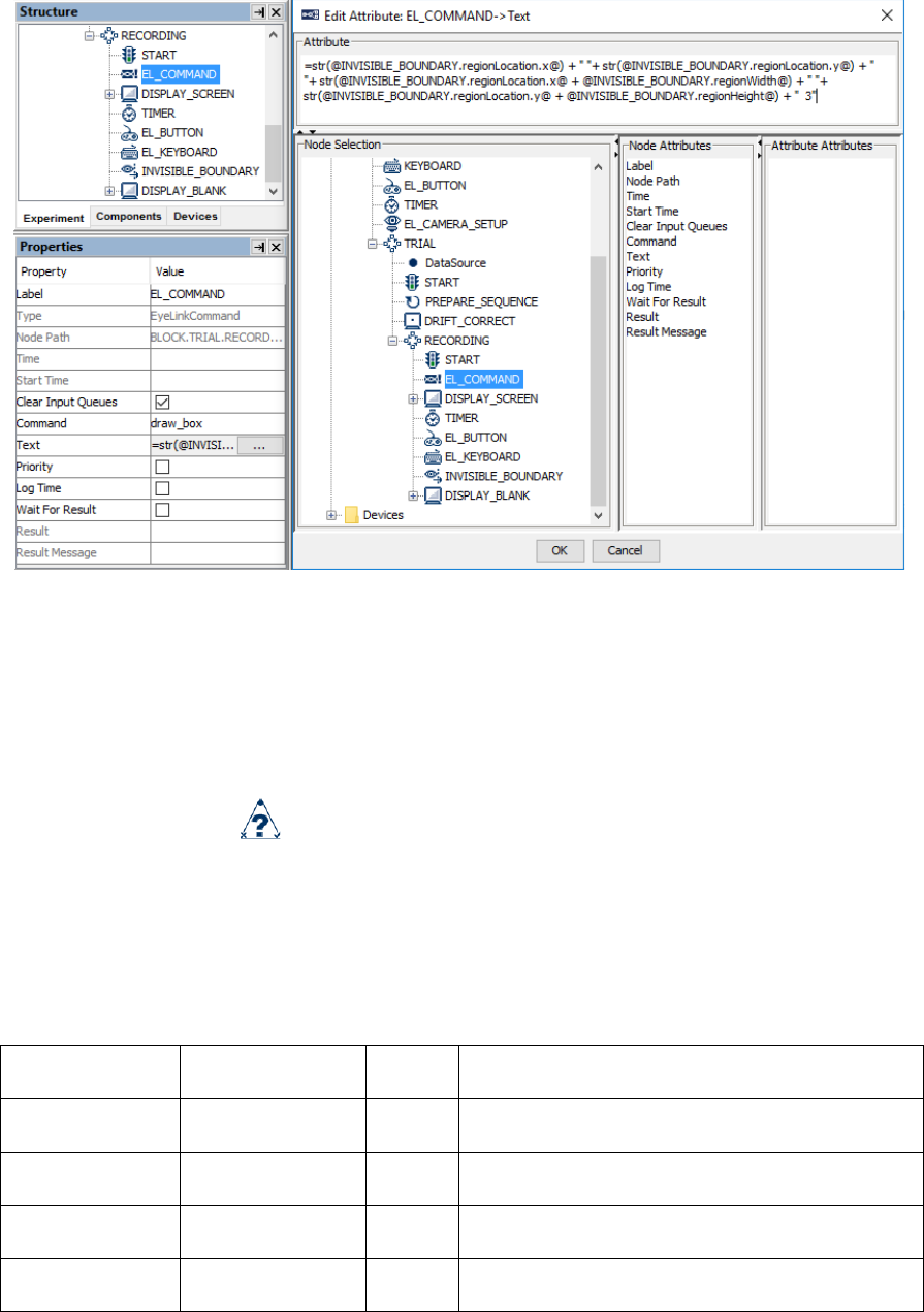
SR Research Experiment Builder User Manual ©2004-2017 SR Research Ltd.
129
Figure 7-36. Drawing the Trigger Region on Host PC.
All of the drawing commands are documented in the "COMMANDS.INI" file under
C:\EYELINK2\EXE or \ELCL\EXE directory of the host partition.
7.9.3 Conditional Trigger
A Conditional trigger ( ) fires when one or two conditional evaluations are met. This
is a useful way to implement branching in a sequence where several conditions are
possible (see the Saccade example). In each conditional evaluation, users specify an
attribute (the variable to be evaluated), a comparator (equals, less than, greater than, etc.),
and the target value to which the attribute is being compared. Two conditional
evaluations, connected with an “and”, “or”, “and not”, or “or not” logical operator, can be
made within the same trigger.
Field
Attribute
Reference
Type
Content
Label *
.label
String
Label of the conditional trigger. The default
value is “CONDITIONAL”.
Type #
NR
The type of Experiment Builder object
("Conditional") the current node belongs to.
Node Path #
.absPath
String
The absolute path of the node in the experiment
graph.
Message
.message
String
Message to be sent to the EDF file (in an
EyeLink experiment) or messages.txt (in a non-

SR Research Experiment Builder User Manual ©2004-2017 SR Research Ltd.
130
EyeLink experiment with the "Save Messages"
attribute of the Experiment node checked) when
the conditional trigger fires.
Time #
.time
Float
Display PC time (in milliseconds from the start
of the experiment) when the trigger fires.
Last Check
Time #
.lastCheckTime
Float
This property can be used to retrieve the
Display PC time (in milliseconds from the start
of the experiment) when the trigger was
checked for the last time.
Confidence
Interval #
.confidenceInterv
al
Float
Time difference between the trigger time and
last check time of the trigger. This indicates a
window of uncertainty.
Attribute,
Attribute 2
.attribute,
.attribute2
The attribute whose value needs to be evaluated.
Comparator, ¶*
Comparator 2
¶*
.comparitor,
.comparitor2
String
Dropdown list used to select possible
comparison between the attribute and value.
Possible values: “EQUALS” (default value),
“GREATER THAN”, “LESS THAN OR
EQUALS”, “CONTAINS”, “NOT EQUALS”,
“LESS THAN”, or “GREATER THAN OR
EQUAL”.
Value,
Value 2
.value,
.value2
The value used to evaluate one attribute. The
data type of this field depends on the attribute
used.
And Or Select
¶*
.andOrSelect
String
Connection between multiple conditional
evaluations. Possible values are: “AND”, “OR”,
“AND NOT”, or “OR NOT”.
In the previous example (section 7.9.2), users may want to further check whether the
velocity and acceleration of the triggering sample in the invisible boundary trigger exceed
a set of target values. The following figure illustrates the use of a conditional trigger to
check the current values against the parser criteria. The “Attribute” field of the trigger is
set to “@INVISIBLE_BOUNDARY.triggeredData.leftVelocity@” and the “Attribute 2”
field of the trigger is set to
“@INVISIBLE_BOUNDARY.triggeredData.leftAcceleration@”.
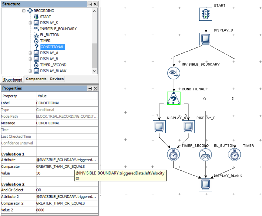
SR Research Experiment Builder User Manual ©2004-2017 SR Research Ltd.
131
Figure 7-37. Using Conditional Trigger.
When performing a conditional evaluation, make sure the data type of the “Value” field
matches that of the “Attribute” field (ditto for “Value 2” and “Attribute 2”). Conditional
triggers support using String, Integer, Double, Boolean, List, and Color variables.
• When comparing strings, please note that the strings are case-sensitive (without
quotes, see the “Saccade” template for the implementation of conditional evaluations
with strings).
• If evaluating a Boolean value (e.g., checking whether the “Force Full Redraw” field
of a DISPLAY_SCREEN action is checked or not), set the “Attribute” field of the
conditional trigger by referring to the target attribute (e.g.,
@DISPLAY_A.forceFullRedraw@), choosing either “EQUALS” or “NOT EQUALS”
as the Comparator, and typing in “true” or “false” in the Value field of the conditional
trigger.
• Sometimes, users may want to evaluate attributes against missing values, for instance,
to check whether a trigger has fired or whether a valid datum has been retrieved from
an attribute. If the target attribute is a string type, set the “Value” field of the
conditional trigger to “MISSING_DATA”. If the target attribute is an integer or float
data, set the comparison Value to “-32768”.
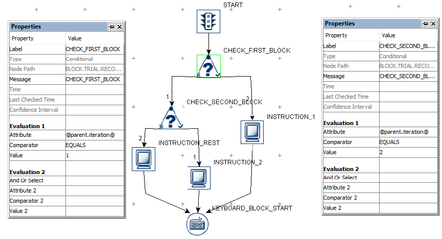
SR Research Experiment Builder User Manual ©2004-2017 SR Research Ltd.
132
• To clear a non-string value (eg. 3) set in the "Value" or "Value 2" attributes of a
conditional trigger, users may first set the value to a string (e.g., "hello") and then
delete the string.
Conditional triggers can connect to a maximum of two actions or triggers (forming two
branches), and must connect to another node from at least one of its branches. If the firing
of the conditional trigger exits the current sequence, users may attach some other node
(e.g., a NULL_ACTION node, blank display screen action or a timer trigger, etc.)
following this trigger. As an exception to the general linking rules (#6, Section 6.2.3
“Linking Rules”), a conditional trigger may connect to both an action on one branch and
a trigger on the other.
It is possible to use multiple chained conditional triggers to do a series of evaluations.
The following picture illustrates how to give out different instructions at the beginning of
each block in a multi-block experiment.
Figure 7-38. Displaying different instruction screens at the beginning of each block.
Important: If a conditional trigger does not have a connection from either its True or
False branch, then the branch that does not have a connection is NOT evaluated. For
example, if a Conditional trigger has a connection from its True branch, but no
connection from its False branch, then the trigger will only fire if the conditional
evaluates to True, and nothing will be done if it conditional evaluates to False. So if a
Conditional trigger only has a connection on the True branch, the user may need to use
other types of trigger in parallel to prevent the experiment from getting stuck if the
trigger will not evaluate to True.

SR Research Experiment Builder User Manual ©2004-2017 SR Research Ltd.
133
7.9.4 EyeLink Button Trigger
The EyeLink Button Trigger ( ), available only in an EyeLink experiment, fires when
one of the buttons on a supported EyeLink button box device is pressed or released.
Note that the EyeLink button box should be attached to the Host PC, not to the Display
PC. The button box will not work when running the project with dummy mode enabled.
Field
Attribute
Reference
Type
Content
Label *
.label
String
Label of the EyeLink button trigger. The
default value is “EL_BUTTON”.
Type #
NR
The type of Experiment Builder object
("EyeLinkButton") the current node belongs to.
Node Path #
.absPath
String
The absolute path of the node in the experiment
graph.
Message
.message
String
Message to be sent to the EDF file (in an
EyeLink experiment) when the EyeLink button
trigger fires.
Time #
.time
Float
Display PC time (in milliseconds from the start
of the experiment) when the processing of the
EyeLink button trigger is done (so the
experiment flow is ready to move to the next
node). Note: To check the time when the button
was pressed/released, users should use
@*.triggeredData.time@ instead of the current
field.
Last Checked
Time #
.lastCheckedTim
e
Float
This property can be used to retrieve the
Display PC time (in milliseconds from the start
of the experiment) when the trigger was
checked for the last time.
Confidence
Interval #
.confidenceInterv
al
Float
Time difference between the trigger time and
last check time of the trigger. This indicates a
window of uncertainty as the true trigger time
could be between the last check time
(.lastCheckedTime) and the reported trigger
time (.time).
Clear Input
Queue ¶
.clearInputQueue
Integer
Experiment Builder maintains an event queue so
that multiple button events can be accessed over
time. The “Clear Input Queue” option checks
whether the button event(s) cached in the event
queue should be cleared when the current
trigger fires. (NO: no event clearing; EVENT:
removes the current triggering event from the
button event queue; LIST: all button events
from event queue will be removed.)
Type #
.type
String
This identifies the type of EyeLink button box
plugged to the host computer (specified through
the EyeLink Button Box device).
Buttons
.buttons
List of
List of buttons that may be pressed/released to

SR Research Experiment Builder User Manual ©2004-2017 SR Research Ltd.
134
Integer
s
make the trigger fire. Default value is [1, 2, 3, 4,
5, 6,7]. Multiple button selections can be made
by holding down the Ctrl key in Windows or the
command ⌘ key in Mac OS X. Note: To check
which button is actually pressed or released, use
@*.triggeredData.button@ (i.e., the .button sub-
attribute of the .triggeredData attribute).
Press Events †
.pressEvents
Boolea
n
Whether the trigger should fire when a button
press event occurs. This is set to "True" (box
checked) by default.
Release Events †
.releaseEvents
Boolea
n
Whether the trigger should fire when a button
release event occurs. This is set to "False" (box
unchecked) by default.
Triggered Data #
.triggeredData
If the EyeLink button trigger fires, the triggered
data can be further accessed (see the following
table).
To specify a list of button(s) used for response, click the value field of the "Buttons"
property and select the desired buttons. Multiple buttons can be selected or unselected by
holding down the "Ctrl" key in Windows or the Command ⌘ key in Mac OS X. The
buttons can also be set via attribute reference by double clicking on the right end of the
"Buttons" value field.
When the button trigger fires, the triggered data can be further accessed. The sub-
attributes of the Triggered Data field are listed in the following table.
Attribute
Reference
Type
Content
Button
.button
Integer
The ID of the button pressed/released that fired
the trigger.
State
.state
Boolea
n
Whether the button is pressed (True) or released
(False) when the trigger fires.
EDF Time
.EDFTime
Integer
EDF time when the button is pressed/released.
Time
.time
Integer
Display PC time (in milliseconds from the start
of the experiment) when the button is
pressed/released.
The following figure illustrates the button settings for the EyeLink Button trigger if a user
wants to end the trial by pressing button 1 or 4.
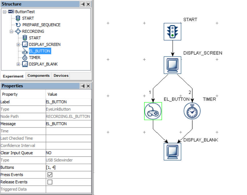
SR Research Experiment Builder User Manual ©2004-2017 SR Research Ltd.
135
Figure 7-39. Using EyeLink Button Trigger.
The following section discusses some of the common applications of the EyeLink button
trigger:
7.9.4.1 Calculating Response Time of a Button Press
EyeLink button responses can be retrieved by using the Update Attribute action.
Typically, users can create variables to record the button pressed, the time or RT of the
button press, and the accuracy of the button press. The ID of the button pressed may be
retrieved as "@EL_BUTTON.triggeredData.button@". To determine the reaction time,
the user must first determine the time of the button press by recording the
"@EL_BUTTON.triggeredData.time@" attribute (see Figure 7-40). With the time of the
button press, users can calculate the response time as
=(@BUTTON_PRESS_TIME.value@ - @DISPLAY_ON_TIME.value@). In case the
trial can end without the participant pressing a button, an UPDATE_ATTRIBUTE action
should be used to reset the default values for the variables at the beginning of the trial so
that the response data from the previous trial will not be carried over to the current trial.
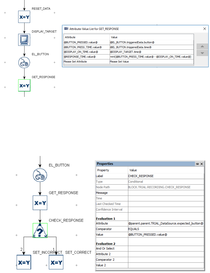
SR Research Experiment Builder User Manual ©2004-2017 SR Research Ltd.
136
Figure 7-40. Collecting EyeLink Button Response Data.
To evaluate the accuracy of a button press, users will need to determine the expected
button press for the trial. This can be encoded in the data source with a number column.
Use a CONDITIONAL trigger to check whether the pressed button matches the expected
button and then use an UPDATE_ATTRIBUTE action at each branch of the trigger to
update the accuracy variable accordingly (check out the HTML version of this document
for the complete example project).
Figure 7-41. Checking EyeLink Button Response Accuracy.
7.9.4.2 Collecting Inputs from the EyeLink Button Box Without
Ending the Trial
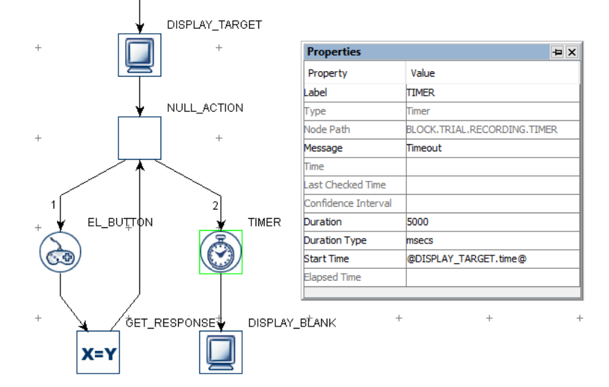
SR Research Experiment Builder User Manual ©2004-2017 SR Research Ltd.
137
Sometimes the participant's button response should be recorded without ending the trial
(e.g., the participant may be instructed to press a button whenever they detect a specific
event in a video clip). This can be done by adding a Null Action node after the Display
Screen and having the EyeLink Button trigger loop back to the Null Action—use an
Update Attribute action following the button trigger to collect response data. All other
triggers initially attached to the Display Screen action should be connected from the Null
Action as well. If a Timer trigger is used to end the trial, the "Start Time" should be set to
the .time property of the Display Screen so that the start time of the Timer trigger will not
be reset when a button is pressed.
Figure 7-42. Using EyeLink Button Trigger Without Ending a Trial.
7.9.4.3 Knowing the ID of a Specific Button on the EyeLink Button
Box
The supported EyeLink button box should be used on the host computer. The button box
can be attached to a USB port (Microsoft SideWinder Plug and Play Gamepad for
EyeLink II or EyeLink 1000, or Microsoft Xbox 360 and Logitech F310 button box for
EyeLink 1000 Plus and EyeLink Portable Duo) or attached to the parallel port on the
motherboard, or to the designated PCI-express parallel port adapter card on the host
computer (SR Research Gamepad or ResponsePixx button box). The use of the parallel
port-based button box on the designated PCI Express adapter card (LF811) requires
running version 2.30 or later of the EyeLink II host software or 4.50 or later of the
EyeLink 1000 host software. Users will also need to go to the Button Box Device
Preferences to specify the particular button box used for the study so Experiment Builder
can automatically configure the button mappings.

SR Research Experiment Builder User Manual ©2004-2017 SR Research Ltd.
138
• Microsoft SideWinder Plug and Play gamepad: 'Y' → 1; 'X' → 2; 'B' → 3; 'A' → 4;
Big D-pad on the left → 5; left back trigger → 6; right back trigger → 7.
• SR Research Gamepad: blue → 1; green → 2; yellow → 3; red → 4; big (purple)
→ 5. The other two side trigger buttons are non-functional.
• ResponsePixx Button Box (5-button handheld and 5-button desktop models):
Yellow → 1; red → 2; blue → 3; green → 4; white → 5.
• Microsoft Xbox 360: 'Y' → 1; 'X' → 2; 'B' → 3; 'A' → 4; Big D-pad on the lower
left → 5; left back trigger (top) → 6; right back trigger (top) → 7. The other
buttons are not functional.
• Logitech F310: 'Y' → 1; 'X' → 2; 'B' → 3; 'A' → 4; Big D-pad on the left → 5;
left back trigger (top) → 6; right back trigger (top) → 7. The other buttons are not
functional.
7.9.5 Cedrus Button Trigger
The Cedrus Input trigger ( ) fires when one of the specified buttons on a Cedrus RB
Series response pad (https://www.cedrus.com/rb_series/) or a Lumina fMRI Response
Pad (https://www.cedrus.com/lumina/) is pressed or released. To use the Cedrus RB
Series response pad, please follow the installation instructions provided by Cedrus
(http://www.cedrus.com/support/rb_series; Experiment Builder only supports the
response pads shipped after 2011). Users should also check the setting of the DIP
switches located on the back of the response pad, to the left of where the USB cable plugs
into the pad. Experiment Builder requires all the switches to be in the down (On)
position. The Lumina Response Pad for fMRI doesn't require a driver installation.
The Cedrus Input trigger can also be used to detect Cedrus SV-1 Voice Key responses.
The onset of a Voice Key trigger is represented as a button 1 down event; the offset of the
voice key event is represented as a button 1 up event. Please follow https://www.sr-
support.com/forums/showthread.php?t=56 for setup and example. Please note that only
one Cedrus device can be connected to the experiment computer at a time.
A "warning:2003 The IO node CEDRUS_INPUT is used in realtime Sequence
RECORDING *** -> CEDRUS_INPUT" message may be seen if the Cedrus Input
trigger is used in a sequence with the "Is Real Time" option checked. This warning means
that the Cedrus Input trigger may not work when your sequence is running under the
realtime mode; this is the case if you are using an old display computer. For most recent
computers with dual core/multicore processor, the Cedrus Input (along with mouse and
keyboard) will function properly in the real-time mode, so this message can be ignored.
Note: Make sure you use the Prepare Sequence action before each iteration of the
sequence in which the Cedrus Input trigger is used—the Prepare Sequence action is used
to re-establish the clock synchronization between the display computer and the built-in
timer on the Cedrus response box. Failing to do so might result in a significant drift in the
trigger time returned by the Cedrus response pad.

SR Research Experiment Builder User Manual ©2004-2017 SR Research Ltd.
139
Field
Attribute
Reference
Type
Content
Label *
.label
String
Label of the Cedrus button trigger. The default
value is "CEDRUS_INPUT".
Type #
NR
The type of Experiment Builder object
("CedrusInput") the current node belongs to.
Node Path #
.absPath
String
The absolute path of the node in the experiment
graph.
Message
.message
String
Message to be sent to the EDF file (in an
EyeLink experiment) or messages.txt (in a non-
EyeLink experiment with the "Save Messages"
attribute of the Experiment node checked) when
the Cedrus Input trigger fires.
Time #
.time
Float
Display PC time (in milliseconds from the start
of the experiment) when the processing of the
Cedrus Input trigger is done (so the experiment
flow is ready to move to the next node). Note:
To check the time when the Cedrus Input was
received, you should use
@*.triggeredData.time@ instead.
Last Checked
Time #
.lastCheckedTim
e
Float
This property can be used to retrieve the
Display PC time (in milliseconds from the start
of the experiment) when the trigger was
checked for the last time.
Confidence
Interval #
.confidenceInterv
al
Float
Time difference between the trigger time and
last check time of the trigger. This indicates a
window of uncertainty as the true trigger time
could be between the last check time
(.lastCheckedTime) and the reported trigger
time (.time).
Clear Input
Queue ¶
.clearInputQueue
Integer
Experiment Builder maintains an event queue so
that multiple Cedrus Input events can be
accessed over time. The “Clear Input Queue”
option checks whether the Cedrus event(s)
cached in the event queue should be cleared
when the trigger fires. (NO: no event clearing;
EVENT: removes the current triggering event
from the Cedrus event queue; LIST: all Cedrus
events from event queue will be removed.)
Triggered Data #
.triggeredData
If the Cedrus trigger fires, the triggered data can
be further accessed (see the following table).
Press Events †
.pressEvents
Boolea
n
Whether the trigger should fire when a button
press event occurs. This is set to “True” (box
checked) by default.
Release Events †
.releaseEvents
Boolea
n
Whether the trigger should fire when a button
release event occurs. This is set to “True” by
default.
Buttons
.buttons
List of
Integer
s
List of buttons that may be pressed/released to
fire the trigger. Default value is [1, 2, 3, 4, 5, 6,
7, 8]. Multiple button selections can be made by

SR Research Experiment Builder User Manual ©2004-2017 SR Research Ltd.
140
holding down the Ctrl key in Windows or the
Command ⌘ key in Mac OS X. Note: To check
which button is actually pressed or released, use
@*.triggeredData.button@ (i.e., the .button sub-
attribute of the .triggeredData attribute) instead.
To set the button(s) used for response, click the value field of the “Buttons” property and
select the desired buttons. Multiple buttons can be selected or unselected by holding
down the "Ctrl" key in Windows or the Command ⌘ key in Mac OS X. The buttons can
also be set via attribute reference by double clicking the right end of the “Buttons” value
field.
When the Cedrus Input trigger fires, the triggered data can be further accessed. The
attributes of the TriggeredData attribute are listed in the following table.
Attribute
Reference
Type
Content
Button
.button
Integer
The ID of the pressed/released button that fires
the trigger.
EDF Time
.EDFTime
Integer
EDF time when the button is pressed/released.
Time
.time
Float
Display PC time (in milliseconds from the start
of the experiment) when the button is
pressed/released.
Pressed
.pressed
Integer
Whether the triggering button is pressed (1) or
released (0).
For example, if a user wants to end the trial by pressing Cedrus button 1 or 4, the
properties of the button trigger can be set as shown in the figure below.
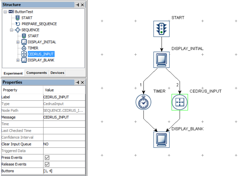
SR Research Experiment Builder User Manual ©2004-2017 SR Research Ltd.
141
Figure 7-43. Using Cedrus Button Trigger.
The following section discusses some of the common applications of the Cedrus Input
trigger:
7.9.5.1 Calculating Response Time of a Button Press
Cedrus button responses can be retrieved by using an Update Attribute action. Typically,
users can use variables to record the button pressed, the time or RT of the button press,
and the accuracy of the button press. The ID of the button pressed may be retrieved as
"@CEDRUS_INPUT.triggeredData.button@". To determine the reaction time, the user
must first determine the time of the button press by recording the
"@CEDRUS_INPUT.triggeredData.time@" attribute (see Figure 7-44). With the time of
the button press, the response time can be calculated as
=(@BUTTON_PRESS_TIME.value@ - @DISPLAY_ON_TIME.value@). In case the
trial can be ended without the participant pressing a button, the Update Attribute should
be used to reset the default values for the variables at the beginning of the trial so that the
response data from the previous trial will not be carried over to the following trial.
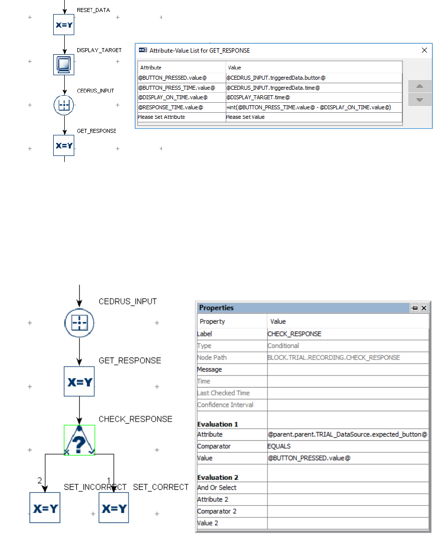
SR Research Experiment Builder User Manual ©2004-2017 SR Research Ltd.
142
Figure 7-44. Collecting Cedrus Button Response Data.
To evaluate the accuracy of the button press, users will need to determine the expected
button press for the trial. This can be encoded in the data source with a number column.
Use a Conditional trigger to check whether the button pressed matches the expected
button and then use an Update Attribute action at each branch of the trigger to update the
accuracy variable accordingly. (Check the HTML version of this document for the
complete example project.)
Figure 7-45. Checking Cedrus Button Response Accuracy.
7.9.5.2 Collecting Inputs from the Cedrus Button Box Without
Ending the Trial
Sometimes the participant's button response should be recorded without ending the trial
(e.g., the participant may be instructed to press a button whenever they detect a specific
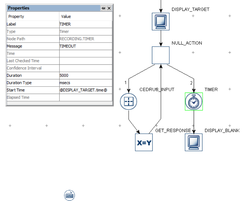
SR Research Experiment Builder User Manual ©2004-2017 SR Research Ltd.
143
event in a video clip). This can be done by adding a Null Action node after the Display
Screen and having the Cedrus Input trigger branch loop back to the Null Action—use an
Update Attribute action following the button trigger to collect response data. All other
triggers initially attached to the Display Screen action should be connected from the Null
Action as well. If a Timer trigger is used to end the trial, the "Start Time" should be set to
the .time attribute of the Display Screen so the start time of the Timer trigger will not be
reset whenever a button is pressed.
Figure 7-46. Using Cedrus Button Trigger Without Ending a Trial.
7.9.6 Keyboard Trigger
The Keyboard trigger ( ) responds to an input from the keyboard device attached to
the display computer. (The host computer keyboard may be used as well, but some keys
may not be used as they are designated in the host software.) Users can specify a list of
possible key presses on the keyboard so that the trigger will fire. To set the key(s) used
for response, click the value field of the "Keys" property and select the desired keys.
Multiple keys can be selected or unselected by holding down the "Ctrl" key in Windows
or the Command ⌘ key in Mac OS X.
Please note users should not use the keyboard trigger to collect timing-critical responses
due to large variability in response timing from the keyboard devices in general. A
"warning:2003 The IO node KEYBOARD is used in realtime Sequence RECORDING
***->KEYBOARD" message may be seen if the keyboard trigger is used in a sequence
with the "Is Real Time" option checked. This warning means that the keyboard may not
work when your sequence is running under the realtime mode; this is especially the case
if you are using an old Display PC. For most recent computers with dual core/multicore

SR Research Experiment Builder User Manual ©2004-2017 SR Research Ltd.
144
processor, the keyboard trigger input (along with mouse and Cedrus Input) will function
properly in the real-time mode, so this message can be ignored.
Field
Attribute
Reference
Type
Content
Label *
.label
String
Label of the keyboard trigger. The default label
is “KEYBOARD”.
Type #
NR
The type of Experiment Builder object
("Keyboard") the current node belongs to.
Node Path #
.absPath
String
The absolute path of the node in the experiment
graph.
Message
.message
String
Message to be sent to the EDF file (in an
EyeLink experiment) or messages.txt (in a non-
EyeLink experiment with the "Save Messages"
attribute of the Experiment node checked) when
the keyboard trigger fires.
Time #
.time
Float
Display PC time (in milliseconds from the start
of the experiment) when the processing of the
keyboard trigger is done (so the experiment
flow is ready to move to the next node). Note:
To check the time when the key was pressed,
you should use @*.triggeredData.time@
instead.
Last Checked
Time #
.lastCheckedTim
e
Float
This property can be used to retrieve the
Display PC time (in milliseconds from the start
of the experiment) when the trigger was
checked for the last time.
Confidence
Interval #
.confidenceInterv
al
Float
Time difference between the trigger time and
last check time of the trigger. This indicates a
window of uncertainty as the true trigger time
could be between the last check time
(.lastCheckedTime) and the reported trigger
time (.time).
Clear Input
Queue ¶
.clearInputQueue
Integer
Experiment Builder maintains an event queue so
that multiple key press/release events can be
accessed over time. The “Clear Input Queue”
option checks whether the keyboard event(s)
cached in the event queue should be cleared
when the current trigger fires. (NO: no event
clearing; Event: removes the current triggering
event from the keyboard event queue; LIST: all
key press events from event queue will be
removed.)
Keys # ‡
.keys
List of
Integer
s
Keys allowed for the trigger to fire. Use the
dropdown list to select target keys. In the
attribute editor, keys should be specified as a list
of keycodes (the internal numeric identifier for a
key on a keyboard).
Use Keyboard *
¶
.useKeyboard
String
Specifies the keyboard (Display PC, Tracker
PC, or Either) used for response. If "Enable

SR Research Experiment Builder User Manual ©2004-2017 SR Research Ltd.
145
Multiple Input" option is enabled, the keyboard
option would be Any, Tracker PC,
KEYBOARD_1, KEYBOARD_2, ...
Press Events †
.pressEvents
Boolea
n
Whether the trigger should fire when a key
press event occurs. This is set to "True" (box
checked) by default.
Release Events †
.releaseEvents
Boolea
n
Whether the trigger should fire when a key
release event occurs. This is set to "False" by
default.
Triggered Data #
.triggeredData
If the keyboard trigger fires, the triggered data
can be further accessed (see the following
table).
‡ The supported named keys in attribute editor are:
Any, Backspace, Tab, Clear, Enter, Pause, Escape, Space, Exclaim, Quotedbl,
Hash, Dollar, Ampersand, Quote, Leftparen, Rightparen, Asterisk, Plus, Comma,
Minus, Period, Slash, 0, 1, 2, 3, 4, 5, 6, 7, 8, 9, Colon, Semicolon, Less, Equals,
Greater, Question, At, Leftbracket, Backslash, Rightbracket, Caret, Underscore,
Backquote, a, b, c, d, e, f, g, h, i, j, k, l, m, n, o, p, q, r, s, t, u, v, w, x, y, z, Delete,
NumPad-0, NumPad-1, NumPad-2, NumPad-3, NumPad-4, NumPad-5, NumPad-
6, NumPad-7, NumPad-8, NumPad-9, NumPad-Period, NumPad-Divide,
NumPad-Multiply, NumPad-Minus, NumPad-Plus, NumPad-Enter, NumPad-
Equals, Up, Down, Right, Left, Insert, Home, End, Pageup, Pagedown, F1, F2, F3,
F4, F5, F6, F7, F8, F9, F10, F11, F12, F13, F14, F15, Numlock, Capslock,
Scrollock, Rshift, Lshift, Rctrl, Lctrl, Ralt, Lalt, Rmeta, Lmeta, Lsuper, Rsuper,
Mode, Compose, Help, Print, Sysreq, Break, Menu, Power, Euro, Undo.
When a keyboard trigger fires, users can further access the triggered data. The sub-
attributes of the TriggeredData for a keyboard trigger are listed in the following table.
Attribute
Reference
Type
Content
Keyboard
.keyboard
String
Keyboard on which the triggering key is
pressed. If "Enable Multiple Input" option is
enabled, this returns Tracker PC,
KEYBOARD_1, KEYBOARD_2, ...;
otherwise, this returns Display PC, or Tracker
PC.
Key
.key
String
The key pressed that fired the trigger.
Key Code
.keyCode
Integer
The numeric code for the key pressed.
Unicode Key
.unicodeKey
String
Returns the Unicode key for the key(s) pressed.
A MISSING_DATA will be returned if the
system cannot translate the key sequence to a
character.
Modifier
.modifier
Integer
A bit field enumeration for one or multiple
modifier keys (Shift, Ctrl, and Alt) pressed.
Is Shift Pressed
.isShiftPressed
Boolea
n
Whether one of the SHIFT keys is pressed.
Is CTRL Pressed
.isCtrlPressed
Boolea
n
Whether one of the Ctrl keys is pressed.
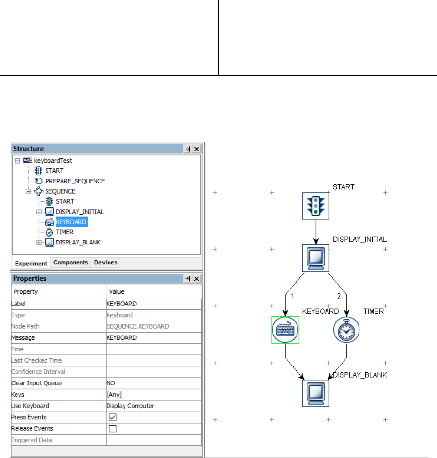
SR Research Experiment Builder User Manual ©2004-2017 SR Research Ltd.
146
Is ALT Pressed
.isAltPressed
Boolea
n
Whether one of the Alt keys is pressed.
EDF Time
.EDFTime
Integer
EDF time of the triggering key press.
Time
.time
Float
Display PC time (in milliseconds from the start
of the experiment) when the triggering key is
pressed.
Using a keyboard trigger is very straightforward. For example, if a user wants to press the
"ENTER" or "SPACEBAR" of the display computer to end a trial, the properties of the
keyboard trigger can be set as shown in the following figure.
Figure 7-47. Using Keyboard Trigger.
To set the key(s) used for response, click the value field of the "Keys" property and select
the desired keys. By holding down the "Ctrl" key in Windows or the Command ⌘ key in
Mac OS X, users can select or de-select multiple target keys from the dropdown list.
The following section discusses some of the common applications of the keyboard trigger:
7.9.6.1 Calculating Response Time from a Keyboard Input
Keyboard responses can be retrieved with an UPDATE_ATTRIBUTE action. Users can
create variables to store the key pressed, the time or RT of the key press, and the
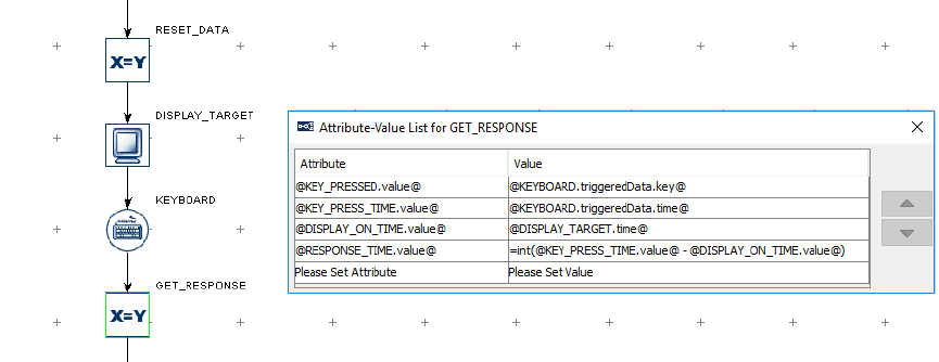
SR Research Experiment Builder User Manual ©2004-2017 SR Research Ltd.
147
accuracy of the key press. The key pressed may be retrieved as
"@KEYBOARD.triggeredData.key@". To determine the reaction time, the user must
first determine the time of the button press by recording the
“@KEYBOARD.triggeredData.time@” attribute (see Figure 7-48). With the time of the
button press, users can calculate the response time as (@KEY_PRESS_TIME.value@ -
@DISPLAY_ON_TIME.value@). In case the trial can end without the participant
pressing a key, the UPDATE_ATTRIBUTE can be used to reset the default values for the
variables at the beginning of the trial so that the response data from the previous trial will
not be carried over to the current trial.
Figure 7-48. Collecting Keyboard Response Data.
To evaluate the accuracy of the key press, users will need to determine the expected key
press for the trial. This can be encoded in the data source with a string column. Use a
Conditional trigger to check whether the pressed key matches the expected key and then
use an Update Attribute action at each branch of the trigger to update the accuracy
variable accordingly (please check out the HTML version of this document for the
complete example project).
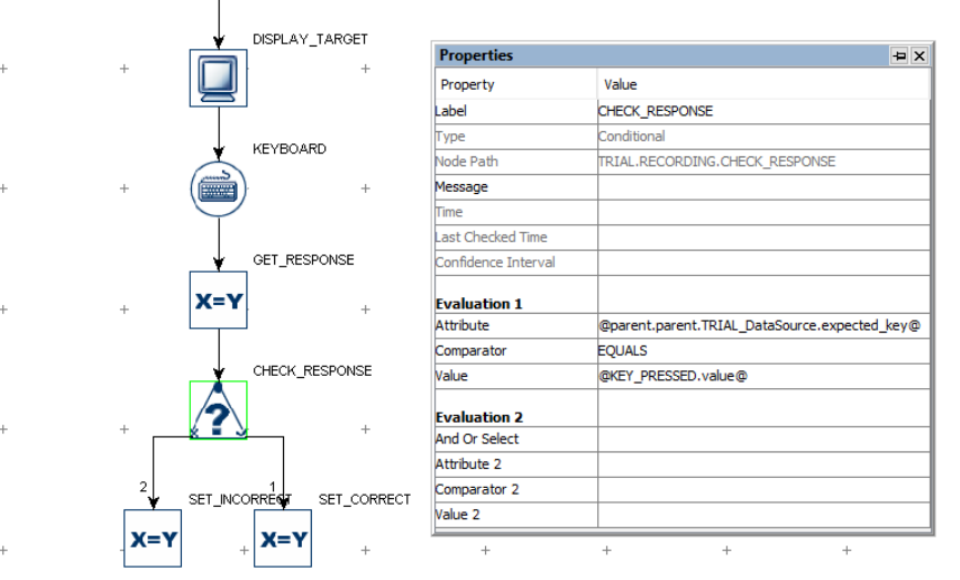
SR Research Experiment Builder User Manual ©2004-2017 SR Research Ltd.
148
Figure 7-49. Checking Keyboard Response Accuracy.
To evaluate a keypress that may use non-ASCII characters (e.g., the spacebar), you may
use the numeric "Key Code". In the "Attribute" field of the conditional trigger, use a
reference to the triggeredData.keyCode of the KEYBOARD trigger, and in the "Value"
field, enter the expected keycode for the character (e.g., 32 for the spacebar).
7.9.6.2 Collecting Inputs from the Keyboard Without Ending the
Trial
Sometimes the participant's key response should be recorded without ending the trial (e.g.,
the participant may be instructed to press a button whenever they detect a specific event
in a video clip). This can be done by adding a Null Action node after the Display Screen
and having the keyboard trigger branch looping back to the Null Action—use an Update
Attribute action following the keyboard trigger to collect response data. All other triggers
initially attached to the Display Screen action should be connected from the Null Action
as well. If a Timer trigger is used to end the trial, the "Start Time" should be reset to
the .time attribute of the Display Screen so the start time of the Timer trigger will not be
reset whenever a key is pressed.
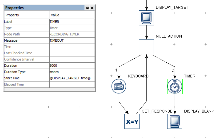
SR Research Experiment Builder User Manual ©2004-2017 SR Research Ltd.
149
Figure 7-50. Using Keyboard Without Ending a Trial.
7.9.6.3 Enabling Multiple Keyboards
If multiple keyboards or mice are attached to the display computer, responses from all of
the keyboards and mice are treated in the same way (e.g. as if the response is made on a
single keyboard or mouse). In some applications, users may want to differentiate the
responses from different keyboards or mice. This can be done by enabling multiple
keyboard support.
1. First plug in all of the intended keyboards and mice to the display computer.
2. Install the keyboard and mouse driver that supports multiple keyboard/mouse
inputs. Start the Windows Explorer. For Windows 10, go to the folder
“C:\Program Files (x86)\SR Research\Experiment Builder\drivers\win10”. For
Windows XP and 7, go to the folder “C:\Program Files (x86)\SR
Research\Experiment Builder\drivers\win7andXp”. Run the installer program
“EBDriversStarter.exe” in the folder. Follow the instructions provided to
complete the installation. For Mac OS X, no special driver installation is required.
3. Open the experiment project, click "Edit → Preferences → Experiment" to open
the Experiment preference settings and tick the "Enable Multiple Input" option.
4. If multiple keyboards are used, go to the "KEYBOARD” device preferences, set
the intended number of keyboards for the experiment project and assign distinct
labels for the keyboards if you need to. If multiple mice are used, go to the
"MOUSE” device preferences, set the intended number of mice for the
experiment project and assign distinct labels for the mice if you need to.
5. Now for all of the keyboard triggers, the possible keyboards to be used are listed
in the "Use Keyboard" property of the trigger.

SR Research Experiment Builder User Manual ©2004-2017 SR Research Ltd.
150
6. When you run your experiment with multiple keyboards, you will now be asked
to press the ENTER key on the intended keyboards in sequence so that
Experiment Builder can map the keyboards labeled in the "KEYBOARD” device
settings to the physical keyboard devices. The experiment will start after the
keyboards and mice are identified.
7.9.6.4 Disabling / Re-enabling the Windows Logo Keys
Experiment Builder may fail to lock the drawing surface if the participants accidentally
press the Windows logo key when using the keyboard. To prevent this from happening,
users may disable the Windows logo keys (https://support.microsoft.com/en-
us/kb/216893). Download the windowskey.zip file and unzip the files from the HTML
version of this document.
• To disable the Windows logo keys, select the disable_both_windows_keys.reg
file, click the right mouse button, and select the "Merge" option. Reboot the
computer.
• To re-enable the Windows logo keys, select the enable_back_windows_key.reg
file, click the right mouse button, and select the "Merge" option. Reboot the
computer.
7.9.7 Mouse Trigger
A Mouse trigger ( ) fires by pressing or releasing a pre-specified mouse button. As
with the invisible boundary trigger, users may specify a region for the mouse trigger to
fire. The mouse trigger can also be used with a touchscreen monitor to detect the location
of touches. Using a mouse as a response device is not recommended for timing-critical
experiments because the temporal resolution of the mouse response is unknown (the
delays introduced by Windows are highly variable) and the timing performance may vary
across different types of mouse (USB vs. serial).
If the mouse trigger is used in a sequence with the "Is Real Time" option checked, a
"WARNING: 2003 The IO node MOUSE is used in realtime Sequence ***->MOUSE"
message will be reported. This warning means the mouse trigger may not work when
your sequence is running under the realtime mode; this is especially the case if you are
using an old Display PC. For most recent computers with a dual- or multicore processor,
the Mouse trigger input (along with keyboard and Cedrus Input) will function properly in
the real-time mode, so this message can be ignored.
Field
Attribute
Reference
Type
Content
Label *
.label
String
Label of the mouse trigger. The default value is
“MOUSE”.
Type #
NR
The type of Experiment Builder object
("Mouse") the current node belongs to.
Node Path #
.absPath
String
The absolute path of the node in the experiment

SR Research Experiment Builder User Manual ©2004-2017 SR Research Ltd.
151
graph.
Message
.message
String
Message to be sent to the EDF file (in an
EyeLink experiment) or messages.txt (in a non-
EyeLink experiment with the "Save Messages"
attribute of the Experiment node checked) when
the mouse trigger fires.
Time #
.time
Float
Display PC time (in milliseconds from the start
of the experiment) when the processing of the
mouse trigger is done (so the experiment flow is
ready to move to the next node). Note: To
check the time when the mouse button is
pressed/released or the mouse position falls
within the triggering region, you should use
@*.triggeredData.time@ (i.e., the .time sub-
attribute of the .triggeredData attribute) instead.
Last Checked
Time #
.lastCheckedTim
e
Float
This property can be used to retrieve the
Display PC time (in milliseconds from the start
of the experiment) when the trigger was
checked for the last time.
Confidence
Interval #
.confidenceInterv
al
Float
Time difference between the trigger time and
last check time of the trigger. This indicates a
window of uncertainty as the true trigger time
could be between the last check time
(.lastCheckedTime) and the reported trigger
time (.time).
Clear Input
Queue ¶
.clearInputQueue
Integer
Experiment Builder maintains an event queue so
multiple mouse press/release events can be
accessed over time. The “Clear Input Queue”
option checks whether the mouse event(s)
cached in the event queue should be cleared
when the current trigger fires. (NO: no event
clearing; EVENT: removes the current
triggering event from the mouse press/release
event queue; LIST: all mouse events from event
queue will be removed.)
Buttons
.buttons
List of
Integer
s
List of Integers ([1, 2, 3, 4, 5] by default in
version 2.0 or later of the software) to represent
the buttons that may be pressed/released for
trigger firing. When using the scroll wheel,
scrolling up is coded as a press event of button 4
and scrolling down is coded as a release event
of button 5. Use [4, 5] in this field to set the
intended scrolling buttons.
Use Mouse *¶
.useMouse
String
Specifies the Mouse (Any, MOUSE_1,
MOUSE_2, ...) used for response. This option
will only be available if the "Enable Multiple
Input" option in the Experiment Preferences
(“Edit → Preferences”) is enabled.
Press Events †
.pressEvents
Boolea
n
Whether the trigger should fire when a button
press event occurs. This is set to “True” (box
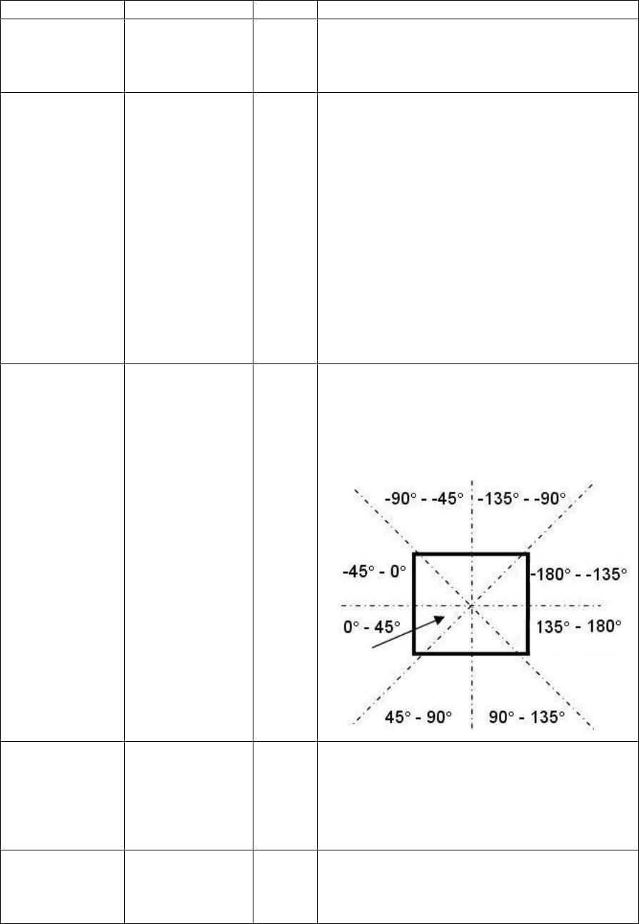
SR Research Experiment Builder User Manual ©2004-2017 SR Research Ltd.
152
checked) by default.
Release Events †
.releaseEvents
Boolea
n
Whether the trigger should fire when a button
release event occurs. This is set to “False” (box
unchecked) in version 2.0 or later of Experiment
Builder.
Position
Triggered †
.positionTriggere
d
Boolea
n
Whether the mouse must be in a specific region
to register as a response. This field is
independent of the Press and Release Events
options. If Press Events and/or Release Events
are checked, with Position Triggered enabled,
then the mouse trigger will only fire with a click
or release event in the specified region; if
Position Triggered is not enabled, the trigger
will fire with a click or release on any part of
the screen. If Position Triggered is checked
while neither the Press Events nor Release
Events field is checked, the mouse trigger will
fire when the mouse enters the specified region
without a press or release event (i.e., a
mouseover event).
Region
Direction
.regionDirection
List of
Strings
A range of angles from a multiple-selection list
['0 - 45', '45 - 90', '90 - 135', '135 - 180', '-180 - -
135', '-135 - -90', '-90 - -45', '-45 - 0'] used to
restrict the direction in which the mouse trigger
fires. For each angle range, the first value is
inclusive and the second value is not inclusive.
Region Type ¶
.regionType
String
The type of triggering Region used:
RECTANGLE (0), ELLIPSE (1), or INTEREST
AREA (2). The "INTEREST AREA" option is
only available when interest areas are defined in
one of the display screens in the same recording
sequence.
Region Location
(Top Left)
.regionLocation
Point
Pixel coordinate of the top-left corner of the
trigger region in (x, y) tuple. The default value
is (0, 0). Note that the x, y coordinates of the
region location can be further referred to

SR Research Experiment Builder User Manual ©2004-2017 SR Research Ltd.
153
individually as .regionLocation.x
and .regionLocation.y, respectively. This
property is only available when the "Region
Type" property is set to either RECTANGLE or
ELLIPSE.
Region Width
.regionWidth
Integer
Width (0 by default) of the triggering region in
screen pixels. This property is only available
when the "Region Type" property is set to either
RECTANGLE or ELLIPSE.
Region Height
.regionHeight
Integer
Height (0 by default) of the triggering region in
screen pixels. This property is only available
when the "Region Type" property is set to either
RECTANGLE or ELLIPSE.
Interest Area
Screen *¶
NR .
The display screen on which target interest area
regions are located. This property is only
available when the "Region Type" property is
set to INTEREST AREA.
Interest Area
Regions ¶
NR
Target interest areas used to define the
triggering region. This property is only available
when the "Region Type" property is set to
INTEREST AREA.
Within †
.within
Boolea
n
If set to "True" (default), the trigger should fire
when the mouse is within the above-mentioned
trigger region; if “False,” the trigger fires when
the mouse is outside of the region.
Triggered Data #
.triggeredData
If the mouse trigger fires, the triggered data can
be further accessed (see the following table).
When a mouse trigger fires, users may further access the triggered Data. The sub-
attributes of the TriggeredData attribute are listed in the following table:
Attribute
Reference
Type
Content
Time
.time
Float
Display PC time (in milliseconds from the start
of the experiment) when the mouse button was
pressed/released.
EDF Time
.EDFTime
Integer
EDF time of the mouse button press/release.
Pressed
.pressed
Integer
Whether the mouse button is pressed (1) or
released (0). When using the scrolling wheel on
the mouse, scrolling up is associated with press
event of button 4 and scrolling down is
associated with the release event of button 5.
Button
.button
Integer
Specific button pressed/released for trigger
firing. When using the scrolling wheel on the
mouse, scrolling up is associated with press
event of button 4 and scrolling down is
associated with the release event of button 5.
X
.x
Float
Pixel coordinate of the mouse cursor along the
x-axis when the trigger fired.
Y
.y
Float
Pixel coordinate of the mouse cursor along the
y-axis when the trigger fired.

SR Research Experiment Builder User Manual ©2004-2017 SR Research Ltd.
154
Offset
.offset
Point
The triggered mouse position relative to the top-
left corner of the triggering region.
Angle
.angle
Float
The angle of the mouse movements when the
trigger fired.
Mouse
.mouse
String
For a project with multiple input support, this
reports the mouse device from which the
response is collected. Otherwise, it reports
“Display PC”
The following section discusses some of the common applications of the Mouse trigger:
7.9.7.1 Mouse Press, Release, Scroll, and Mouse Over
The Mouse trigger can be used to collect various behaviors with the mouse, such as clicks
and releases of the mouse buttons, scroll wheel movements, and movements inside or
outside of specified regions. The “Press Events” and “Release Events” attributes can be
configured independently of the “Position Triggered” property to specify the types of
mouse behavior that will cause the trigger to fire.
For example, to configure a sequence to end when the participant clicks any mouse
button, regardless of position, set the properties of the mouse trigger as in the figure
below. The "Position Triggered" attribute should be unchecked so the press event will be
accepted anywhere on the screen.
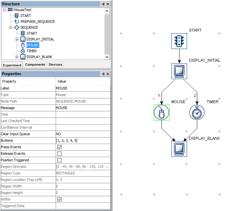
SR Research Experiment Builder User Manual ©2004-2017 SR Research Ltd.
155
Figure 7-51. Using the Mouse Trigger.
To configure the Mouse trigger to fire only when the mouse is within (or outside of) a
specified region (e.g., to click an onscreen button), check the box for the “Position
Triggered” attribute. Then set the triggering region. The Region Type attribute can be
specified as either a Rectangle, Ellipse, or Interest Area. If the Region Type is set to
Interest Area, set the Interest Area Screen to the Display Screen action that includes the
Interest Area(s) to be used, then choose the desired interest area(s) by clicking the value
cell of the Interest Area Regions attribute. If the Region Type is set to either Rectangle or
Ellipse, set the Region Location, Width and Height as desired (see the left panel of the
following figure.)
If “Position Triggered” is enabled, it is often necessary to add a cursor onscreen so the
participant knows where the mouse is. To add a cursor to a Display Screen, simply add a
small image or shape resource to the screen and enable the “Position is Mouse
Contingent” for the resource (see the right panel of the following figure). If using an
image resource with a cursor, make sure the background pixels of the cursor image are
set to the same color as the project Transparency Color.
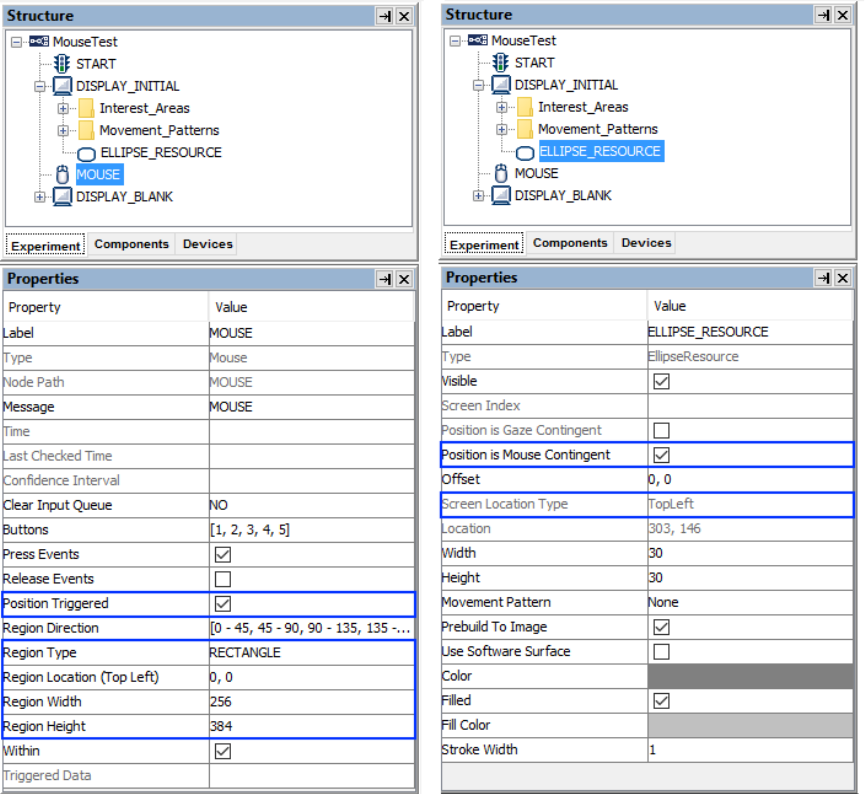
SR Research Experiment Builder User Manual ©2004-2017 SR Research Ltd.
156
Figure 7-52. Setting the Mouse Triggering Region.
If “Position Triggered” is enabled, but both “Press Events” and “Release Events” are
disabled, then the Mouse trigger will fire as soon as the mouse enters the triggering
region. See "FAQ: Will mouse trigger fire when I use the 'Position Triggered' Option and
do not check the Press/Release Event boxes?" in the HTML version of this document for
more information.
The mouse trigger can also be used to detect scrolling events on the mouse wheel.
Experiment Builder reports a press event on button 4 if the mouse wheel is rolled up, and
a release event on button 5 when the mouse wheel is rolled down. To detect scrolling
events, set the “Buttons” field to [4, 5] and check both the “Pressed Events” and “Release
Events” attributes.
7.9.7.2 Center Location Type vs. Top-left Location Type.
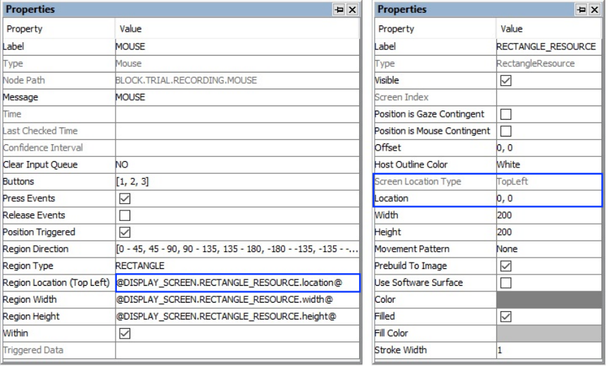
SR Research Experiment Builder User Manual ©2004-2017 SR Research Ltd.
157
The Location Type of all location-based triggers (invisible boundary trigger, mouse
trigger, fixation trigger, saccade trigger, and sample velocity trigger) is based on the top-
left corner of the region, whereas the screen resources can be based on either the top-left
corner or the center of the resource. (The screen resource/interest area location type can
be set in the project Preferences under Screen). This means that references should be
created differently depending on whether the region location of a trigger refers to a
center-based resource or a top-left-based resource.
Imagine that a mouse trigger should fire when the cursor is within a rectangle resource
(RECTANGLE_RESOURCE). The top panel of the figure below illustrates creating the
Region Location reference to the rectangle resource when the screen location type is
TopLeft (@DISPLAY_SCREEN.RECTANGLE_RESOURCE.location@). The bottom
panel of the figure illustrates creating a location equation when the location type is Center,
by subtracting half the resource width from the x coordinate, and half the resource height
from the y coordinate:
(=EBPoint(@DISPLAY_SCREEN.RECTANGLE_RESOURCE.location.x@ -
@DISPLAY_SCREEN.RECTANGLE_RESOURCE.width@/2,
@DISPLAY_SCREEN.RECTANGLE_RESOURCE.location.y@ -
@DISPLAY_SCREEN.RECTANGLE_RESOURCE.height@/2)).
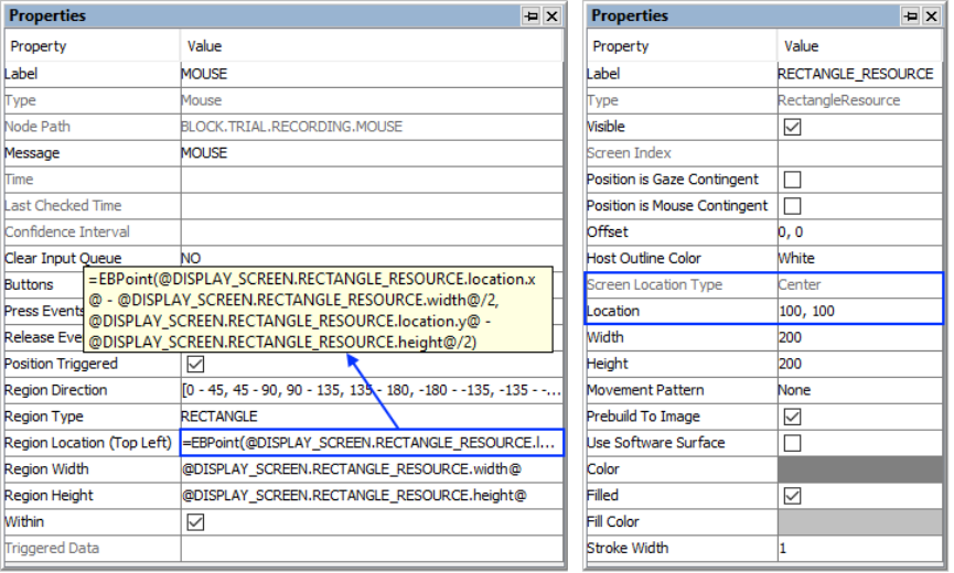
SR Research Experiment Builder User Manual ©2004-2017 SR Research Ltd.
158
Figure 7-53. Using Mouse Trigger with Top-left and Center Location Types.
7.9.7.3 Calculating Response Time of a Mouse Click
To record information about the mouse response, users can create variables, e.g., to
record which button was pressed, the time or RT of the button press, and the accuracy of
the response. After the response, an Update Attribute action can be used to set the values
of these variables. To record the button pressed, refer to the
"@MOUSE.triggeredData.button@" attribute, and to record the time of the button press,
refer to the "@MOUSE.triggeredData.time@" attribute (see the figure below). With the
time of the mouse click, the response time can be calculated as
(@BUTTON_PRESS_TIME.value@ - @DISPLAY_ON_TIME.value@). If the trial can
be ended without the participant making a response (e.g., the trial times out after some
period), use an Update Attribute action at the beginning of the trial to reset the default
values for the variables to ensure the response data from the previous trial will not be
carried over to the current trial.
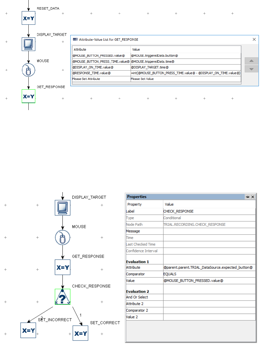
SR Research Experiment Builder User Manual ©2004-2017 SR Research Ltd.
159
Figure 7-54. Collecting Mouse Response Data.
To evaluate the accuracy of the button press, users will need to determine the expected
button press for the trial. This can be specified in the data source with a number column.
Use a Conditional trigger to check whether the pressed button matches the expected
button, then connect an Update Attribute action to each branch of the trigger to update the
accuracy variable accordingly (check the HTML version of this document for the
complete example project).
Figure 7-55. Checking Mouse Response Accuracy.
7.9.7.4 Collecting Inputs from the Mouse Without Ending the Trial
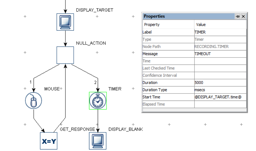
SR Research Experiment Builder User Manual ©2004-2017 SR Research Ltd.
160
Sometimes the participant's mouse response should be recorded without ending the trial
(e.g., the participant may be instructed to click the mouse whenever they detect a specific
event in a video clip). This can be done by adding a Null Action node after the Display
Screen and having the mouse trigger branch loop back to the Null Action—use an Update
Attribute action following the mouse trigger to collect response data. All other triggers
initially attached to the Display Screen action should be connected from the Null Action
as well. If a Timer trigger is used to end the trial, the "Start Time" should be reset to
the .time attribute of the Display Screen so the start time of the Timer trigger will not be
reset whenever a button is pressed.
Figure 7-56. Using Mouse Trigger Without Ending a Trial.
7.9.7.5 Resetting the Initial Position of the Mouse Device
The initial position of a mouse-contingent resource can be reset by updating the "X
Position" and "Y Position" of the mouse device to the intended values. See "FAQ: What
should I do to reset the mouse position to a default position at the beginning of each
trial?" in the HTML version of this document.
7.9.7.6 Enabling Multiple Mice
If multiple keyboards or mice are connected to the display computer, responses from all
of the keyboards and mice are treated in the same way (e.g. as if the response is made to a
single keyboard or mouse). For some applications, users may want to differentiate the
responses from different keyboards or mice. This can be done by enabling multiple
mouse support.
1. First plug in all of the intended keyboards and mice to the display computer.
SR Research Experiment Builder User Manual ©2004-2017 SR Research Ltd.
161
2. Install the keyboard and mouse driver that supports multiple keyboard/mouse
inputs. Start the Windows Explorer. For Windows 10, go to the folder
“C:\Program Files (x86)\SR Research\Experiment Builder\drivers\win10”. For
Windows XP and 7, go to the folder “C:\Program Files (x86)\SR
Research\Experiment Builder\drivers\win7andXp”. Run the installer program
“EBDriversStarter.exe”. Follow the instructions provided to complete the
installation. For Mac OS X, no special driver installation is required.
3. Open the experiment project, and click "Edit → Preferences → Experiment" to
open the Experiment preference settings and tick the "Enable Multiple Input"
option.
4. Go to the "MOUSE” device preferences, set the intended number of mice for the
experiment project, and assign distinct labels for each of the mice if desired.
5. All Mouse triggers in the project will now have the “Use Mouse” property to
specify which mouse (or “Any” mouse) to use.
6. When running an experiment with multiple mouse devices, Experiment Builder
will prompt you to click the left button of the intended mice so that Experiment
Builder can map the mice labeled in the "MOUSE” device to the physical mice.
The experiment shall start after the keyboards and mice are identified.
7.9.7.7 Recording Mouse Traces in a Data File
To save the mouse coordinates into an EDF file or to a results file, include the
coordinates of the mouse in the Message field of the Display Screen action. (For a non-
EyeLink experiment, make sure the "Save Messages" option of the topmost experiment
node in the Structure panel is checked.) The message will be sent each time the screen is
redrawn—i.e., each time the onscreen cursor resource moves. For example, enter a
message like the following in the Display Screen resource:
="TRIAL\t" + str(@parent.parent.iteration@) + "\tMOUSE\tX\t" +
str(@CUSTOM_CLASS_INSTANCE.mouseX@) + "\tY\t" +
str(@CUSTOM_CLASS_INSTANCE.mouseY@)
The EDF file (or Messages.txt) will contain messages like:
13645.141 -16 TRIAL 2 MOUSE X 512 Y 378
13661.688 -16 TRIAL 2 MOUSE X 512 Y 370
13678.538 -16 TRIAL 2 MOUSE X 512 Y 360
13695.127 -16 TRIAL 2 MOUSE X 512 Y 348
13711.654 -16 TRIAL 2 MOUSE X 512 Y 336
13728.289 -16 TRIAL 2 MOUSE X 512 Y 327
13745.155 -16 TRIAL 2 MOUSE X 512 Y 315
13761.735 -16 TRIAL 2 MOUSE X 512 Y 305
13778.291 -16 TRIAL 2 MOUSE X 512 Y 289
13795.179 -16 TRIAL 2 MOUSE X 512 Y 284
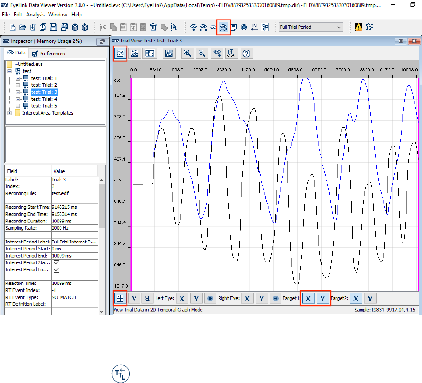
SR Research Experiment Builder User Manual ©2004-2017 SR Research Ltd.
162
The time at which the actual mouse/resource position was shown on screen will be the
difference between the first two columns (i.e., 13661.141 for "13645.141 -16"). Note that
the messages are only sent out when the mouse position changes, causing the screen to
update based on the resource position change. For a continuous output, users will need to
interpolate messages themselves for periods of time in which the mouse is not moving.
If recording the mouse position in an EDF file for use in Data Viewer, the mouse position
traces can be displayed in the Temporal Graph View and included in the Sample Report
by using a "TARGET_POS " message. Data Viewer reads these messages and
interpolates the mouse position for an estimate of sample-level mouse position. Please
see the HTML version of this document for an example project that demonstrates sending
TARGET_POS messages.
Figure 7-57. Viewing Mouse Traces in the Data Viewer Temporal Graph View.
7.9.8 TTL Input Trigger
The TTL Input trigger ( ) is used to check for TTL signals sent to the parallel port (in
Windows only) or a USB-1208 HS interface box in either Windows or Mac OS X.
When interfacing the parallel port on the PC, Experiment Builder automatically installs
the driver for both 32-bit and 64-bit versions of Windows.

SR Research Experiment Builder User Manual ©2004-2017 SR Research Ltd.
163
If using a parallel port, the TTL trigger requires proper identification of the base address
of the port. In version 1.10.1630 or later of the software, users may set the “Parallel Port
Base Address” of the “Parallel Port” Device to 0x0 so that the software will automatically
detect and configure the base address. To set the base address manually, first determine
the parallel port base address through the Device Manager in Windows. In the Device
Manager list, find the entry for the parallel port device under "Ports (COM & LPT)" - if
you use PCI, PCI Express, or PCMCIA version of the parallel port adapter card, you'll
need to install a driver for the port before it is correctly recognized by Windows. Click
the port and select the "Resources" in the properties table. This should list the I/O address
of the card. For the built-in LPT1 on a desktop computer, this is typically "0378-037F"
(hex value). Once you have found out the parallel port address, open the Experiment
Builder project, go to the "Parallel Port" device setting, and enter the hex value for the
port reported by the device manager (e.g., 0x378 for "0378" you see in the device
manager).
The other supported device is the USB-1208HS box from Measurement Computing,
which can be used on both Windows and Mac OS X. No extra driver installation is
required as long as you have installed the libusb-win32 component when you first run
through the installation procedure in Windows (see Figure 3-1). If for any reason you
have to install the device driver, please first connect the box to the Windows PC. When
asked "Can Windows connect to Windows Update to search for software?", choose "No,
not this time." When asked "What do you want the Wizard to do?", choose "Install from a
list or specific location (Advanced)." On the "Please choose your search and installation
options" screen, select the "Search for the best driver in these locations," check the
"Include this location in the search" option only and browse to "C:\Program Files\SR
Research\3rdparty\usb1208hs" in 32-bit Windows or "C:\Program Files(x86)\SR
Research\3rdparty\usb1208hs" in 64-bit Windows).
Field
Attribute
Reference
Type
Content
Label *
.label
String
Label of the TTL trigger. The default value is
“TTL_INPUT”.
Type #
NR
The type of Experiment Builder object ("TTL")
the current node belongs to.
Node Path #
.absPath
String
The absolute path of the node in the experiment
graph.
Message
.message
String
Message to be sent to the EDF file (in an
EyeLink experiment) or messages.txt (in a non-
EyeLink experiment with the "Save Messages"
attribute of the Experiment node checked) when
the TTL trigger fires.
Time #
.time
Float
Display PC time (in milliseconds from the start
of the experiment) when the processing of the
TTL trigger is done (so the experiment flow is
ready to move to the next node). Note: To check
the time when the triggering TTL pulse was
received, use @*.triggeredData.time@ (i.e.,
the .time sub-attribute of the .triggeredData

SR Research Experiment Builder User Manual ©2004-2017 SR Research Ltd.
164
attribute) instead.
Last Checked
Time #
.lastCheckedTim
e
Float
Display PC time (in milliseconds from the start
of the experiment) of the previous check on the
trigger.
Confidence
Interval #
.confidenceInterv
al
Float
Time difference between the trigger time and
last check time of the trigger. This indicates a
window of uncertainty as the true trigger time
could be between the last check time
(.lastCheckTime) and the reported trigger time
(.time).
Clear Input
Queue ¶
.clearInputQueue
Integer
Experiment Builder maintains an event queue so
that multiple TTL events can be accessed over
time. The “Clear Input Queue” option checks
whether the TTL event(s) cached in the event
queues should be cleared when the trigger fires
(NO: no event clearing; EVENT: removes the
current triggering event from the TTL event
queue; LIST: all TTL events from event queue
will be removed).
Device ¶
.device
String
Which device (parallel port or USB-1208 HS) is
used to receive TTL signals. Always set to
"USB-1208HS" in Mac OS X.
Register ¶
.register
String
This is usually set to "STATUS" register (but
please see Section 7.10.8.2 "TTL trigger and the
type of cable used"). This option is only
available in Windows when the device is set to a
parallel port.
Mode *¶
.mode
String
Either "Word" mode (the decimal or
hexadecimal value of the TTL input value) or
"Pin" mode (status of each individual pin).
Data
.data
Integer
The byte value of the current input TTL signal.
This could be a decimal or hexadecimal
number. This field is only available if the
"Mode" property is set to "Word".
Pin0
Pin1
Pin2
Pin3
Pin4
Pin5
Pin6
Pin7
.pin0
.pin1
.pin2
.pin3
.pin4
.pin5
.pin6
.pin7
String
The desired state for each of the pins. The pin
value can be either "ON" (high), "OFF" (low),
or "EITHER" (the status of that pin and changes
in the status of that pin are ignored). This field
is only available if the "Mode" property is set to
"Pin". If using a USB-1208HS box, the
available output pins can be configured through
the device preferences.
Triggered Data #
.triggeredData
If the TTL trigger fires, the triggered data can
be further accessed (see the following table).
When the TTL trigger fires, the triggered data can be further accessed. The sub-attributes
of the Triggered Data field are listed in the following table.
Attribute
Reference
Type
Content
Time
.time
Float
Display PC time (in milliseconds from the start
SR Research Experiment Builder User Manual ©2004-2017 SR Research Ltd.
165
of the experiment) when the TTL trigger fires.
EDF Time
.EDFTime
Integer
EDF time when the TTL trigger fires.
Pin Data
.pinData
Integer
The byte value (a decimal number) of the
current input TTL signal.
The following section discusses some of the common applications of the TTL trigger:
7.9.8.1 Setting the Pin Values
The TTL trigger fires when a TTL signal is received. To detect any change in the input
signal, or if no specific trigger values are known, you may use the "PIN” mode and set all
of the pin values to "EITHER". The trigger will then fire if the incoming TTL signal
changes the status of any pin on the specified register of the TTL device being used. To
configure the trigger to fire based only on a single pin, set the intended state of that pin
(“ON” or “OFF”) and leave the value of all other pins to "EITHER". If the exact trigger
value is known, then specify it either in the PIN or WORD mode. For instance, if the trial
should end when the parallel port receives the signal data 0x58, the properties of the TTL
trigger can be set as the following:
• If the Mode is set to “PIN”, set pin #3, 4, and 6 to "ON", with the rest of the pins
set to "OFF" (see panel A).
• If the Mode is set to “WORD”, enter either '0x58' (hexadecimal) or '88' (decimal)
in the Data field. If a decimal number is entered, it will be automatically
converted to a hexadecimal number (see panel B).
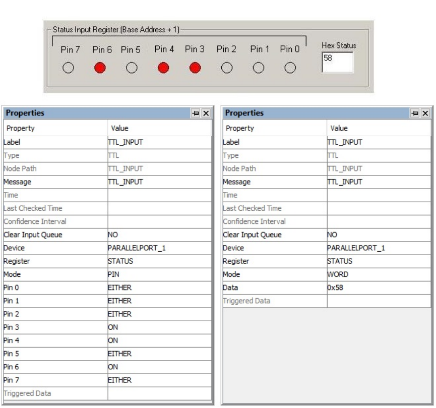
SR Research Experiment Builder User Manual ©2004-2017 SR Research Ltd.
166
Figure 7-58. Using TTL Trigger.
7.9.8.2 TTL Trigger and the Type of Cable Used
When sending and receiving signals through the parallel port, make sure to determine the
type of cable being used. Parallel port cables may either be straight-through (i.e., with a
1-to-1 pin mapping), or crossed (i.e., in which pins from the Data register on one end are
wired to the Status register of the opposite end, and vice versa).
• If using a straight-through parallel port cable, data will be sent to the data register
of the Display PC. To enable reading from the data register of the parallel port,
first enable the bidirectional mode for the port.
o Reboot your Display PC to go into the BIOS settings. Select the settings for
"Parallel Port Mode" and make sure the the mode is set to either "PS/2",
"EPP" or "Bidirectional Mode." (The BIOS settings are usually not available
for add-on parallel port cards. It may be necessary to use a crossed cable with
add-on cards.)

SR Research Experiment Builder User Manual ©2004-2017 SR Research Ltd.
167
o Next, enable the bidirectional mode for the parallel port in Experiment Builder.
Add a Set TTL action at the very beginning of the experiment. Set the
"Register" to "CONTROL", and set the “Data” to "0x20". (This toggles on pin
5 of the control register, which enables bidirectional mode).
o Set the "Register" of the TTL Input trigger to "DATA". To simply check
whether any new signal is received, choose the "Pin" mode and set all of the
pin values to EITHER. Remember to fill out the "Message" property of TTL
trigger to mark the event time in the EDF.
• If using a crossed parallel cable, data will be sent to the status register of the
parallel port.
o The parallel port can be set to any mode, so there is no need to configure the
BIOS settings of the Display PC.
o Make sure the bidirectional mode is disabled by toggling off pin 5 of the
control register. Add a Set TTL action at the very beginning of the experiment.
Set the "Register" to "CONTROL", and set the “Data” to "0x0".
o Set the “Register” of the TTL Input trigger to “STATUS”.
7.9.9 Fixation Trigger
The fixation trigger ( ) fires when a fixation occurs within a specified region of the
display for a certain amount of time. The Event Type attribute of the determines whether
the trigger will fire when the fixation starts (STARTFIXATION), ends
(ENDFIXATION), or after the fixation exceeds a specified minimum duration
(UPDATEFIXATION). This trigger is only available in an EyeLink experiment. Please
note that when reading real-time data through the link, the start of the fixation event data
will be delayed by about 35 milliseconds from the corresponding sample. This is caused
by the velocity detection and event validation processing in the EyeLink tracker. The
timestamps obtained from the event data, however, reflect the true sampletime for the
start or end of the event.
Field
Attribute
Reference
Type
Content
Label *
.label
String
Label of the fixation trigger. The default value
is “FIXATION”.
Type #
NR
The type of Experiment Builder object
("Fixation") the current node belongs to.
Node Path #
.absPath
String
The absolute path of the node in the experiment
graph.
Message
.message
String
Message to be sent to the EDF file when the
fixation trigger fires.
Time #
.time
Float
Display PC time (in milliseconds from the start
of the experiment) when the processing of the
fixation trigger is done (so the experiment flow
is ready to move to the next node). Note: To
check the start and end time of the triggering
fixation, use @*.triggeredData.startTime@ and

SR Research Experiment Builder User Manual ©2004-2017 SR Research Ltd.
168
@*.triggeredData.endTime@ (i.e.,
the .startTime and .endTime sub-attributes of
the .triggeredData attribute).
Last Checked
Time #
.lastCheckedTim
e
Float
This property can be used to retrieve the
Display PC time (in milliseconds from the start
of the experiment) when the trigger was
checked for the last time.
Confidence
Interval #
.confidenceInterv
al
Float
Time difference between the trigger time and
last check time of the trigger. This indicates a
window of uncertainty as the true trigger time
could be between the last check time
(.lastCheckedTime) and the reported trigger
time (.time).
Clear Input
Queue ¶
.clearInputQueue
Integer
Experiment Builder maintains an event queue so
multiple fixation events (start of a fixation,
fixation updates, and end of a fixation) can be
accessed over time. The “Clear Input Queue”
option checks whether the fixation event(s)
cached in the event queue should be cleared
when the trigger fires (NO: no event clearing;
EVENT: removes the current triggering event
from the fixation event queue; LIST: all fixation
events from event queue will be removed).
Region Type ¶
.regionType
String
The type of triggering Region used:
RECTANGLE (0), ELLIPSE (1), or INTEREST
AREA (2). The "INTEREST AREA" option is
only available when interest areas are defined in
one of the display screens in the same recording
sequence.
Region Location
(Top Left)
.regionLocation
Point
Pixel coordinates of the top-left corner of the
trigger region in (x, y) tuple. The default value
is (0, 0). Note that the x, y coordinates of the
region location can be further referred to
individually as .regionLocation.x
and .regionLocation.y, respectively. This
property is only available when the "Region
Type" property is set to either RECTANGLE or
ELLIPSE.
Region Width
.regionWidth
Integer
Width (0 by default) of the trigger region in
screen pixels. This property is only available
when the "Region Type" property is set to either
RECTANGLE or ELLIPSE.
Region Height
.regionHeight
Integer
Height (0 by default) of the trigger region in
screen pixels. This property is only available
when the "Region Type" property is set to either
RECTANGLE or ELLIPSE.
InterestArea
Screen *
NR
The display screen on which target interest area
regions are located. This property is only
available when the "Region Type" property is
set to INTEREST AREA.

SR Research Experiment Builder User Manual ©2004-2017 SR Research Ltd.
169
InterestArea
Regions
NR
Target interest areas used to define the trigger
region. This property is only available when the
"Region Type" property is set to INTEREST
AREA.
Within †
.within
Boolea
n
If set to “True,” the trigger should fire when the
fixation is within the target region. If “False,”
the trigger will fire when the fixation is outside
of the target region.
Tracking Eye ¶
.trackingEye
String
Decides which eye’s data is used for online
parsing. The default value is “EITHER,” can
also be “LEFT” or “RIGHT”.
Minimum
Duration
.minimumDuratio
n
Integer
Minimum duration (0 by default) of a fixation in
the specified region to cause the trigger to fire.
This property is available only if the Event Type
is set as “UPDATEFIXATION” or
“ENDFIXATION.”
Event Type ¶
.eventType
String
The type of fixation event used for triggering.
If set to “STARTFIXATION,” This trigger fires
when the start of a fixation is detected, and if set
to “ENDFIXATION,” when the end of a
fixation is detected. If set to
“UPDATEFIXATION”, Experiment Builder
checks for the fixation update event (i.e.,
summary data of the fixation), which is sent
from the tracker at a constant interval (50 ms by
default); the trigger will fire after a pre-specified
amount of time into a fixation is accumulated. If
the “Minimum Duration” of the
“UPDATEFIXATION” event is set to 0 (or any
value within one fixation update interval), the
trigger will fire after receiving one fixation
update event.
Triggered Data #
.triggeredData
If the fixation trigger fires, the triggered data
can be further accessed (see the following
table).
When a fixation trigger fires, users can access the triggered data by using the
“TriggeredData” field. The sub-attributes of the TriggeredData attribute are listed in the
following table.
Attribute
Reference
Type
Content
Start Time
.startTime
Float
Display PC time (in milliseconds from the start
of the experiment) when the triggering fixation
or fixation update event starts.
End Time
.endTime *
Float
Display PC time (in milliseconds from the start
of the experiment) when the triggering fixation
or fixation update event ends (-32768 if eye
event is set to “STARTFIXATION”).
EDF Start Time
.EDFStartTime
Integer
EDF time (time since the EyeLink program
started on the Host PC) when the triggering
fixation starts.

SR Research Experiment Builder User Manual ©2004-2017 SR Research Ltd.
170
EDF End Time
.EDFEndTime *
Integer
EDF time when the triggering fixation or
fixation update event ends (-32768 if eye event
is set to “STARTFIXATION”).
Eyes Available
.eyesAvailable
Integer
This attribute is depreciated; it will always
return the same value as the "Triggered Eye"
property. To retrieve the eye(s) used in the
recording, check the "Eye Used" property
(.eyeUsed) of the EyeLink Device.
Triggered Eye
triggeredEye
Integer
Returns the eye (0 for the left eye; 1 for the right
eye) whose data makes the current fixation
trigger fire.
Duration
.duration *
Integer
Duration of the triggering fixation or fixation
update event.
Average Gaze X,
Average Gaze Y
.averageGazeX*
.averageGazeY *
Float
Average X/Y gaze position of the triggering
fixation or fixation update event.
Average Pupil
Size
.averagePupilSize
*
Float
Average pupil size of the triggering fixation or
fixation update event.
Start Gaze X,
Start Gaze Y
.startGazeX
.startGazeY
Float
X/Y gaze position when the triggering fixation
or fixation update event started.
Start Pupil Size
.startPupilSize
Float
Pupil size when the triggering fixation or
fixation update event started.
End Gaze X, End
Gaze Y
.endGazeX *
.endGazeY *
Float
X/Y gaze position when the triggering fixation
or fixation update event ended.
End Pupil Size
.endPupilSize *
Float
Pupil size when the triggering fixation or
fixation update event ended.
Start PPD X,
Start PPD Y
.startPPDX
.startPPDY
Float
Angular X/Y resolution when triggering fixation
or fixation update event starts (in screen pixels
per degree of visual angle, PPD).
End PPD X, End
PPD Y
.endPPDX *
.endPPDY *
Float
Angular X/Y resolution when the triggering
fixation or fixation update event ends (in screen
pixels per degree of visual angle, PPD).
Note: * -32768 if the Event Type is set to “STARTFIXATION”.
The fixation trigger may be configured to fire based on various fixation behaviors. For
example, to end the display after the participant looks at a target region for a minimum
duration of 300 milliseconds, the "Event Type" may be configured as
"UPDATEFIXATION" as in the figure below:
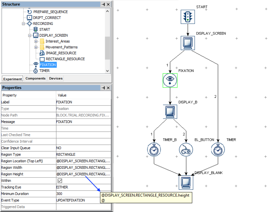
SR Research Experiment Builder User Manual ©2004-2017 SR Research Ltd.
171
Figure 7-59. Using Fixation Trigger.
If the fixation trigger should fire regardless of where the participant is fixating, the trigger
region may be set as the whole screen (i.e., for a 1024 × 768 screen resolution, set Region
Location as (0,0), Region Width as 1024, and Region Height as 768). Alternatively, keep
the default region settings and uncheck the "Within" button.
Since the fixation trigger monitors the online eye data, it must be placed within a
recording sequence (i.e., the "Record" property of the sequence is checked). If you see a
"This node type cannot be added to this sequence" error message, please check whether
the sequence in which the trigger is being added has the “Record” property enabled.
7.9.9.1 Optimal Triggering Duration
If the UPDATEFIXATION event is used, the fixation trigger doesn't work well if the
duration is set to 0 or a very short value, as mis-triggering can occur during the start and
end of a fixation. A duration around 250-350 ms will generally work much better with
non-patient participants. If the required duration is longer than 1000 ms, try using the
INVISIBLE_BOUDARY trigger instead with the identical triggering region and duration
settings, as it is difficult for participants to maintain a single fixation for more than a few
hundred ms.
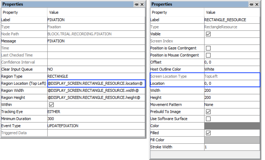
SR Research Experiment Builder User Manual ©2004-2017 SR Research Ltd.
172
7.9.9.2 Top-left vs. Center Triggering Location Type
The Location Type of all location-based triggers (invisible boundary trigger, mouse
trigger, fixation trigger, saccade trigger, and sample velocity trigger) is based on the top-
left corner of the region, whereas the screen resources can be based on either the top-left
corner or the center of the resource. (The screen resource/interest area location type can
be set in the project Preferences under Screen). This means that references should be
created differently depending on whether the region location of a trigger refers to a
center-based resource or a top-left-based resource.
Imagine that a fixation trigger should fire when the gaze position is within a rectangle
resource (RECTANGLE_RESOURCE). The top panel of the figure below illustrates
creating the Region Location reference to the rectangle resource when the screen location
type is TopLeft (@DISPLAY_SCREEN.RECTANGLE_RESOURCE.location@). The
bottom panel of the figure illustrates creating a location equation when the location type
is Center, by subtracting half the resource width from the x coordinate, and half the
resource height from the y coordinate:
(=EBPoint(@DISPLAY_SCREEN.RECTANGLE_RESOURCE.location.x@ -
@DISPLAY_SCREEN.RECTANGLE_RESOURCE.width@/2,
@DISPLAY_SCREEN.RECTANGLE_RESOURCE.location.y@ -
@DISPLAY_SCREEN.RECTANGLE_RESOURCE.height@/2)).
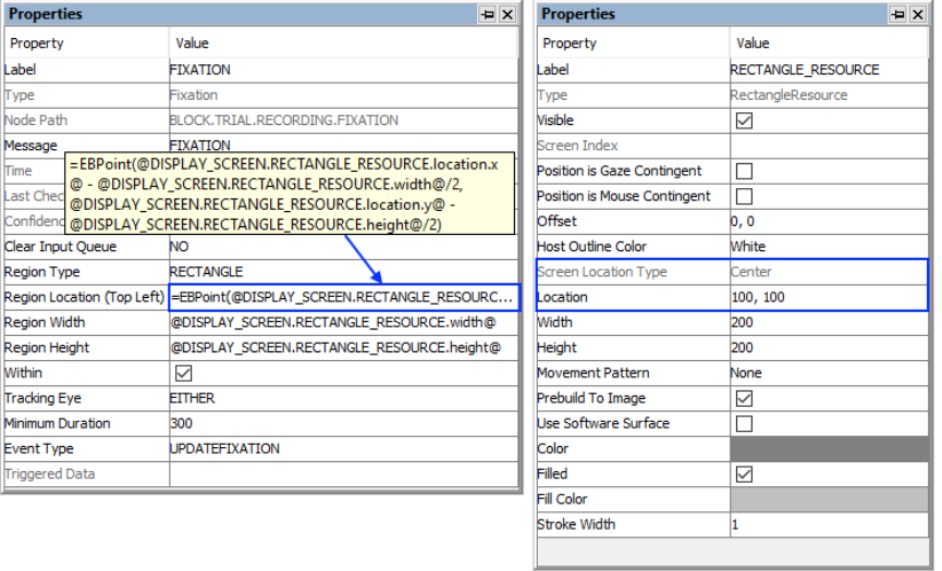
SR Research Experiment Builder User Manual ©2004-2017 SR Research Ltd.
173
Figure 7-60. Using Fixation Trigger with Top-left and Center Location Types.
7.9.9.3 How to Show the Triggering Region on the Host PC
Sometimes it is useful to draw feedback graphics on the Host PC so the experimenter can
monitor whether the participant's eye position is within the triggering region, or so the
programmer can debug the experiment code by running the eye tracker in the mouse
simulation mode. Drawing on the Host PC screen can be done by using an EyeLink
Command action either before the recording sequence (immediately after the Prepare
Sequence node) or as the first node in the recording sequence, so the drawing is overlaid
on top of the existing host PC graphics. The drawing command can be either "draw_box"
or "draw_filled_box". The Text of the command must include tracker of the top, left,
right, and bottom pixel position of the triggering region, followed by the drawing color.
This can be done either with string concatenation or string formatting. The top left corner
of the triggering region is (@FIXATION.regionLocation.x@,
@FIXATION.regionLocation.y@) and the bottom right corner of the triggering region is
(@FIXATION.regionLocation.x@ + @FIXATION.regionWidth@,
@FIXATION.regionLocation.y@ + @FIXATION.regionHeight@)
String Concatenation:
=str(@FIXATION.regionLocation.x@) + " "
+ str(@FIXATION.regionLocation.y@) + " "
+ str(@FIXATION.regionLocation.x@ + @FIXATION.regionWidth@) + " "
+ str(@FIXATION.regionLocation.y@ + @FIXATION.regionHeight@) + " 3"
String Formatting:
="%d %d %d %d 3" % (@FIXATION.regionLocation.x@, @FIXATION.regionLocation.y@,
@FIXATION.regionLocation.x@ + @FIXATION.regionWidth@,

SR Research Experiment Builder User Manual ©2004-2017 SR Research Ltd.
174
@FIXATION.regionLocation.y@ + @FIXATION.regionHeight@)
All of the drawing commands are documented in the "COMMANDS.INI" file under
C:\EYELINK2\EXE or \ELCL\EXE directory of the host PC.
7.9.10 Saccade Trigger
The saccade trigger ( ), available only in EyeLink experiments, fires following the
detection of a saccade into a specified region on the display. This trigger waits for an
"ENDSACC" online parser signal from the tracker. If the timing of saccade onset is
critical, users may use the sample velocity trigger instead. Since the saccade trigger
monitors the online eye data, this trigger type must be placed within a recording sequence
(i.e., the "Record" property of the sequence is checked). If you see a "This node type
cannot be added to this sequence" error message, please check whether the sequence in
which the trigger is being added has the “Record” property enabled.
Field
Attribute
Reference
Type
Content
Label *
.label
String
Label of the saccade trigger. The default value
is “SACCADE”.
Type #
NR
The type of Experiment Builder object
("Saccade") the current node belongs to.
Node Path #
.absPath
String
The absolute path of the node in the experiment
graph.
Message
.message
String
Message to be written to EDF file when the
saccade trigger fires.
Time #
.time
Float
Display PC time (in milliseconds from the start
of the experiment) when the processing of the
saccade trigger is done (so the experiment flow
is ready to move to the next node). Note: To
check the start and end time of the triggering
saccade, use @*.triggeredData.startTime@ and
@*.triggeredData.endTime@ (i.e.,
the .startTime and .endTime sub-attributes of
the .triggeredData attribute).
Last Checked
Time #
.lastCheckedTim
e
Float
This property can be used to retrieve the
Display PC time (in milliseconds from the start
of the experiment) when the trigger was
checked for the last time.
Confidence
Interval #
.confidenceInterv
al
Float
Time difference between the trigger time and
last check time of the trigger. This indicates a
window of uncertainty as the true trigger time
could be between the last check time
(.lastCheckedTime) and the reported trigger
time (.time).
Clear Input
Queue ¶
.clearInputQueue
Integer
Experiment Builder maintains an event queue so
multiple saccade events can be accessed over
time. The “Clear Input Queue” option checks
whether the saccade event(s) cached in the event

SR Research Experiment Builder User Manual ©2004-2017 SR Research Ltd.
175
queue should be cleared when the trigger fires
(NO: no event clearing; EVENT: removes the
current triggering event from the saccade event
queue; LIST: all saccade events from event
queue will be removed).
Region
Direction
.regionDirection
List
A range of eye angles from a multiple-selection
list ['0 - 45', '45 - 90', '90 - 135', '135 - 180', '-
180 - -135', '-135 - -90', '-90 - -45', '-45 - 0']
used to restrict the direction in which the
saccade trigger fires. For each angle range, the
first value is inclusive and the second value is
not inclusive.
Region Type ¶
.regionType
String
The type of triggering Region used:
RECTANGLE (0), ELLIPSE (1), or INTEREST
AREA (2). Note that the "INTEREST AREA"
option is only available when interest areas are
defined in one of the display screens in the same
recording sequence.
Region Location
(Top Left)
.regionLocation
Point
Pixel coordinate of the top-left corner of the
trigger region in (x, y) tuple. The default value
is (0, 0). Note that the x, y coordinates of the
region location can be further referred to
individually as .regionLocation.x
and .regionLocation.y, respectively. This
property is only available when the "Region
Type" property is set to either RECTANGLE or
ELLIPSE.
Region Width
.regionWidth
Integer
Width (0 by default) of the trigger region in
screen pixels. This property is only available
when the "Region Type" property is set to either
RECTANGLE or ELLIPSE.
Region Height
.regionHeight
Integer
Height (0 by default) of the trigger region in
screen pixels. This property is only available
when the "Region Type" property is set to either
RECTANGLE or ELLIPSE.
Interest Area
Screen *¶
NR
The display screen on which target interest area
regions are located. This property is only
available when the "Region Type" property is
set to INTEREST AREA.
Interest Area
Regions ¶
NR
Target interest areas used to define the
triggering region. This property is only available
when the "Region Type" property is set to
INTEREST AREA.
Within †
.within
Boolea
n
If “True” (default), the trigger fires when the
saccade lands within the target region. If
“False,” the trigger fires when the saccade ends
outside the region.
Tracking Eye ¶
.trackingEye
String
Determines which eye’s data is used for online
parsing. The default value is “EITHER,” can
also be LEFT or RIGHT.

SR Research Experiment Builder User Manual ©2004-2017 SR Research Ltd.
176
Minimum
Amplitude
.minimumAmplit
ude
Float
Minimum amplitude (0 by default) of the
triggering saccade.
Triggered Data #
.triggeredData
Data about the saccade trigger if fired (see the
following table).
Users can further get access to the triggered data if a saccade trigger fires. The sub-
attributes of the Triggered Data field are listed in the following table.
Reference
Attribute
Type
Content
Start Time
.startTime
Float
Display PC time (in milliseconds from the start
of the experiment) when the triggering saccade
starts.
End Time
.endTime
Float
Display PC time (in milliseconds from the start
of the experiment) when the triggering saccade
ends.
EDF Start Time
.EDFStartTime
Integer
EDF time (time since the EyeLink program
started on the Host PC) when the triggering
saccade starts.
EDF End Time
.EDFEndTime
Integer
EDF time when the triggering saccade ends.
Eyes Available
.eyesAvailable
Integer
This attribute is depreciated; it will always
return the same value as the "Triggered Eye"
property. To retrieve the eye(s) used in the
recording, please check the "Eye Used" property
(.eyeUsed) of the EyeLink Device.
Triggered Eye
.triggeredEye
Integer
Returns the eye (0 for the left eye; 1 for the right
eye) whose data makes the current fixation
trigger fire.
Duration
.duration
Integer
Duration of the triggering saccade.
Start Gaze X
.startGazeX
Float
X gaze position when the triggering saccade
started.
Start Gaze Y
.startGazeY
Float
Y gaze position when the triggering saccade
started.
End Gaze X
.endGazeX
Float
X gaze position when the triggering saccade
ended.
End Gaze Y
.endGazeY
Float
Y gaze position when the triggering saccade
ended.
Start PPD X
.startPPDX
Float
Angular X resolution at the start of saccade (in
screen pixels per visual degree, PPD).
Start PPD Y
.startPPDY
Float
Angular Y resolution at the start of saccade (in
screen pixels per visual degree, PPD).
End PPD X
.endPPDX
Float
Angular X resolution at the end of saccade (in
screen pixels per visual degree, PPD).
End PPD Y
.endPPDY
Float
Angular Y resolution at the end of saccade (in
screen pixels per visual degree, PPD).
Average Velocity
.averageVelocity
Float
Average gaze velocity (in degrees/second) of
the current saccade.
Peak Velocity
.peakVelocity
Float
Peak value of gaze velocity (in degrees/second)
of the current saccade.
Amplitude
.amplitude
Float
Amplitude of the current saccade in degrees of
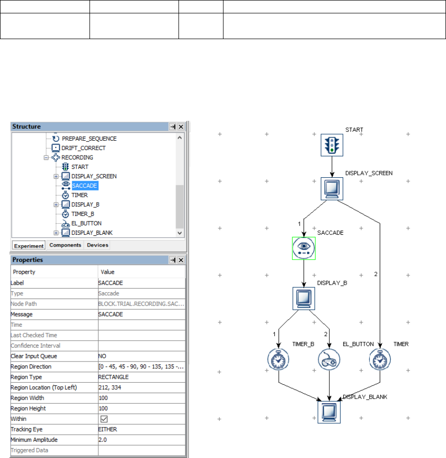
SR Research Experiment Builder User Manual ©2004-2017 SR Research Ltd.
177
visual angle.
Angle
.angle
Float
The angle of the saccade movement when the
trigger fires.
An example of using the Saccade trigger is illustrated below. To end a sequence after the
participant makes a saccade towards the target region from (212, 334) to (312, 434), set
the "Region Location" as (212, 334), "Region Width" as 100, and "Region Height" as 100.
Users may further configure the minimum amplitude, triggering eye, etc., as desired.
Figure 7-61. Using the Saccade Trigger.
If the saccade trigger should fire regardless of the saccade end position, the trigger region
may be set as the whole screen (i.e., for a 1024 × 768 screen resolution, set Region
Location as (0,0), Region Width as 1024, and Region Height as 768). Alternatively, keep
the default region settings and uncheck the "Within" button.
7.9.10.1 Top-left vs. Center Triggering Location Type
The Location Type of all location-based triggers (invisible boundary trigger, mouse
trigger, fixation trigger, saccade trigger, and sample velocity trigger) is based on the top-
left corner of the region, whereas the screen resources can be based on either the top-left
corner or the center of the resource. (The screen resource/interest area location type can
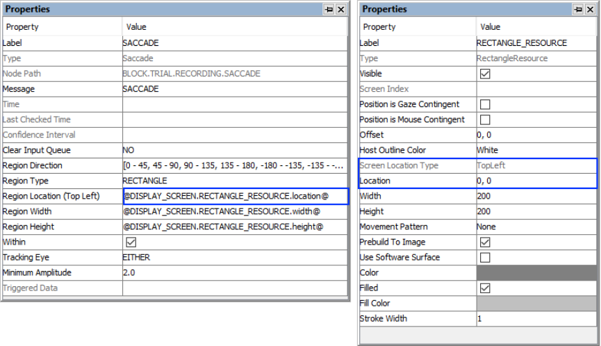
SR Research Experiment Builder User Manual ©2004-2017 SR Research Ltd.
178
be set in the project Preferences under Screen). This means that references should be
created differently depending on whether the region location of a trigger refers to a
center-based resource or a top-left-based resource.
Imagine that a saccade trigger should fire when the gaze position is within a rectangle
resource (RECTANGLE_RESOURCE). The top panel of the figure below illustrates
creating the Region Location reference to the rectangle resource when the screen location
type is TopLeft (@DISPLAY_SCREEN.RECTANGLE_RESOURCE.location@). The
bottom panel of the figure illustrates creating a location equation when the location type
is Center, by subtracting half the resource width from the x coordinate, and half the
resource height from the y coordinate:
(=EBPoint(@DISPLAY_SCREEN.RECTANGLE_RESOURCE.location.x@ -
@DISPLAY_SCREEN.RECTANGLE_RESOURCE.width@/2,
@DISPLAY_SCREEN.RECTANGLE_RESOURCE.location.y@ -
@DISPLAY_SCREEN.RECTANGLE_RESOURCE.height@/2)).
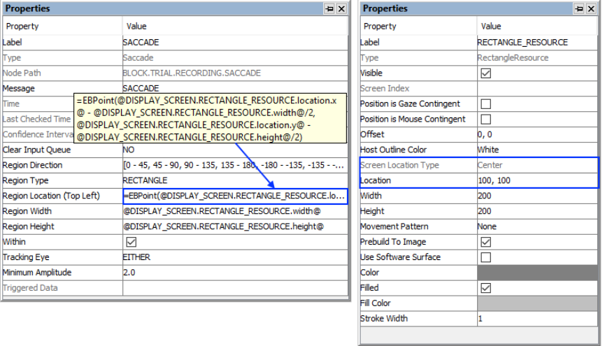
SR Research Experiment Builder User Manual ©2004-2017 SR Research Ltd.
179
Figure 7-62. Using Saccade Trigger with Top-left and Center Location Types.
7.9.10.2 Online RT Calculation
See “Frequently Asked Questions: How can I calculate Saccade RT?” of the HTML
version of this document.
7.9.10.3 How to Show the Triggering Region on the Host PC
Sometimes it is useful to draw feedback graphics on the Host PC so the experimenter can
monitor whether the participant's eye position is within the triggering region, or so the
programmer can debug the experiment code by running the eye tracker in the mouse
simulation mode. Drawing on the Host PC screen can be done by using an EyeLink
Command action either before the recording sequence (immediately after the Prepare
Sequence node) or as the first node in the recording sequence, so the drawing is overlaid
on top of the existing host PC graphics. The drawing command can be either "draw_box"
or "draw_filled_box". The Text of the command must include tracker of the top, left,
right, and bottom pixel position of the triggering region, followed by the drawing color.
This can be done either with string concatenation or string formatting. The top-left corner
of the triggering region is (@SACCADE.regionLocation.x@,
@SACCADE.regionLocation.y@) and the bottom right corner of the triggering region is
(@SACCADE.regionLocation.x@ + @SACCADE.regionWidth@,
@SACCADE.regionLocation.y@ + @SACCADE.regionHeight@)
String Concatenation:
=str(@SACCADE.regionLocation.x@) + " "
+ str(@SACCADE.regionLocation.y@) + " "

SR Research Experiment Builder User Manual ©2004-2017 SR Research Ltd.
180
+ str(@SACCADE.regionLocation.x@ + @SACCADE.regionWidth@) + " "
+ str(@SACCADE.regionLocation.y@ + @SACCADE.regionHeight@) + " 3"
String Formatting:
="%d %d %d %d 3" % (@SACCADE.regionLocation.x@, @SACCADE.regionLocation.y@,
@SACCADE.regionLocation.x@ + @SACCADE.regionWidth@,
@SACCADE.regionLocation.y@ + @SACCADE.regionHeight@)
All of the drawing commands are documented in the "COMMANDS.INI" file under
C:\EYELINK2\EXE or C:\ELCL\EXE directory of the host partition. See the “change”
template for an example.
7.9.11 Sample Velocity Trigger
The Sample Velocity trigger ( ), available only in EyeLink experiments, implements a
saccade or fixation detection algorithm by checking the velocity (and acceleration if
desired) on a sample-by-sample basis.
This trigger will fire much more quickly than the Saccade trigger and therefore may be
used when a saccade needs to be detected as quickly as possible, e.g., so a display change
can be implemented. Please note that how quickly the trigger will fire is influenced by the
tracker heuristic filter setting and the velocity/acceleration model used for the
calculations (applicable to EyeLink 1000, 1000 Plus, and Portable Duo only).
Occasionally, there may be "misses" and "false alarms" in saccade detection compared to
the "slower" saccade trigger, because the Sample Velocity trigger skips the velocity and
event validation processing by the EyeLink tracker for the fixation or saccade triggers.
As with all other eye-based trigger types, a sample velocity trigger must be used in a
Recording sequence.
Field
Attribute
Reference
Type
Content
Label *
.label
String
Label of the sample velocity trigger. The default
label is “SAMPLE_VELOCITY”.
Type #
NR
The type of Experiment Builder object
("SampleVelocity") the current node belongs to.
Node Path #
.absPath
String
The absolute path of the node in the experiment
graph.
Message
.message
String
Message to be sent to the EDF file when the
sample velocity trigger fires.
Time #
.time
Float
Display PC time (in milliseconds from the start
of the experiment) when the processing of the
sample velocity trigger is done (so the
experiment flow is ready to move to the next
node). Note: To check the time when the
triggering sample occurs, you should use
@*.triggeredData.time@ instead.
Last Checked
.lastCheckedTim
Float
This property can be used to retrieve the
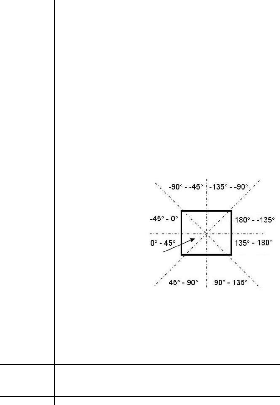
SR Research Experiment Builder User Manual ©2004-2017 SR Research Ltd.
181
Time #
e
Display PC time (in milliseconds from the start
of the experiment) when the trigger was
checked for the last time.
Confidence
Interval #
.confidenceInterv
al
Float
Time difference between the trigger time and
last check time of the trigger. This indicates a
window of uncertainty as the true trigger time
could be between the last check time
(.lastCheckedTime) and the reported trigger
time (.time).
Region Type ¶
.regionType
String
The type of triggering Region used:
RECTANGLE (0), ELLIPSE (1), or INTEREST
AREA (2). The "INTEREST AREA" option is
only available when interest areas are defined in
one of the display screens in the same recording
sequence.
Region
Direction
.regionDirection
List of
Strings
A range of eye angles from a multiple-selection
list ['0 - 45', '45 - 90', '90 - 135', '135 - 180', '-
180 - -135', '-135 - -90', '-90 - -45', '-45 - 0']
used to restrict the direction in which the sample
velocity trigger fires. For each angle range, the
first value is inclusive and the second value is
not inclusive.
Region Location
(Top Left)
.regionLocation
Point
Pixel coordinate of the top-left corner of the
trigger region in (x, y) tuple. The default value
is (0, 0). Note that the x, y coordinate of the
region location can be further referred to
individually as .regionLocation.x
and .regionLocation.y, respectively. This
property is only available when the "Region
Type" property is set to either RECTANGLE or
ELLIPSE.
Region Width
.regionWidth
Integer
Width (0 by default) of the trigger region in
screen pixels. This property is only available
when the "Region Type" property is set to either
RECTANGLE or ELLIPSE.
Region Height
.regionHeight
Integer
Height (0 by default) of the trigger region in

SR Research Experiment Builder User Manual ©2004-2017 SR Research Ltd.
182
screen pixels. This property is only available
when the "Region Type" property is set to either
RECTANGLE or ELLIPSE.
Interest Area
Screen *¶
NR
The display screen on which target interest area
regions are located. This property is only
available when the "Region Type" property is
set to INTEREST AREA.
Interest Area
Regions ¶
NR
Target interest areas used to define the
triggering region. This property is only available
when the "Region Type" property is set to
INTEREST AREA.
Within †
.within
Boolea
n
If checked, the trigger fired when the samples
are in the target region.
Tracking Eye ¶
.trackingEye
String
Decides which eye’s data is used for online
triggering. The default value is “EITHER,” can
also be LEFT or RIGHT.
Trigger Above
Threshold †
.triggerAboveThr
eshold
Boolea
n
If “True” (default), trigger will fire when the
current velocity and acceleration values exceed
the threshold values. If “False,” the trigger will
fire when velocity and acceleration are below
the threshold values.
Velocity
Threshold
.velocityThreshol
d
Integer
Sets the velocity threshold of the online saccade
detector: usually 30 (°/sec) for cognitive
research, 22 (°/sec) for pursuit and neurological
work. The default is 30. This setting is different
from the “Saccade Sensitivity” setting in the
EyeLink device, which is used for the parsing of
the events to be saved to the EDF file.
Use
Acceleration †
.useAcceleration
Boolea
n
Whether the acceleration value should be used
for the online saccade detection. If unchecked,
only the velocity data is used. Version 2.0 or
later of the Experiment Builder software has this
option turned off by default.
Acceleration
Threshold
.accelerationThre
shold
Integer
Sets the acceleration threshold of the online
saccade detector: usually 8000 (°/sec/sec) for
cognitive research, 3800 (°/sec/sec) for pursuit
and neurological work. The default value is
8000. This setting is different from the “Saccade
Sensitivity” setting in the EyeLink device,
which is used for the parsing of the events to be
saved to the EDF file.
Triggered Data #
.triggeredData
Data of the sample velocity trigger if fired (see
the following table).
If the Sample Velocity trigger fires, users can further access the triggered data. The
attributes of the Triggered Data field are listed in the following table.
Reference
Attribute
Type
Content
Time
.time
Float
Display PC time (in milliseconds from the start
of the experiment) when the trigger fires.

SR Research Experiment Builder User Manual ©2004-2017 SR Research Ltd.
183
EDF Time
.EDFTime
Integer
EDF time of the triggering sample.
Eyes Available
.eyesAvailable
Integer
This attribute is depreciated; it will always
return the same value as the "Triggered Eye"
property. To retrieve the eye(s) used in the
recording, check the "Eye Used" property
(.eyeUsed) of the EyeLink Device.
Triggered Eye
.triggered Eye
Integer
Returns the eye (0 for the left eye; 1 for the right
eye) whose data makes the current fixation
trigger fire.
PPD X, PPD Y
.PPDX, .PPDY
Float
Angular resolution at the current gaze position
in screen pixels per degree of visual angle along
the x-, or y-axis.
Left Gaze X,
Right Gaze X,
Average Gaze X
.leftGazeX, .right
GazeX, .average
GazeX ¹
Float
Gaze position of the triggering sample along the
x-axis for the left eye, right eye and the average
between the two eyes.
Left Gaze X,
Right Gaze X,
Average Gaze Y
.leftGazeY, .right
GazeY, .average
GazeY ¹
Float
Gaze position of the triggering sample along the
y-axis for the left eye, right eye and the average
between the two eyes.
Left Pupil Size,
Right Pupil Size,
Average Pupil
Size
.leftPupilSize, .ri
ghtPupilSize,
.averagePupilSize
¹
Float
Left eye, right eye, or average pupil size (in
arbitrary units, area or diameter).
Left Velocity,
Right Velocity,
Average Velocity
.leftVelocity,
.rightVelocity,
.averageVelocity
¹
Float
Left eye, right eye, or average velocity (in
degrees /second).
Left
Acceleration,
Right
Acceleration,
Average
Acceleration
.leftAcceleration,
.rightAcceleratio
n,
.averageAccelerat
ion ¹
Float
Left eye, right eye, or average acceleration (in
degrees /second²).
Angle
.angle
Float
The angle of the eye movements when the
trigger fires.
Target Distance
.targetDistance
Integer
Distance between the target sticker and camera
(10 times the measurement in millimeters). This
option is available only when the eye tracker is
operating in the Remote mode. Returns
"MISSING_DATA" (-32768) if target is
missing or if a remote tracking mode is not
being used.
Target X, Target
Y
.targetX, .targetY
Integer
X, Y position of the target sticker in camera
coordinates. This option is available only when
the eye tracker is operating in the Remote mode.
Returns "MISSING_DATA" (-32768) if target
is missing or if a remote tracking mode is not
being used.
Target Flags
.targetFlags
Integer
Flags used to indicate target tracking status (0 if
target tracking is ok; otherwise error code). This
option is available only when the eye tracker is
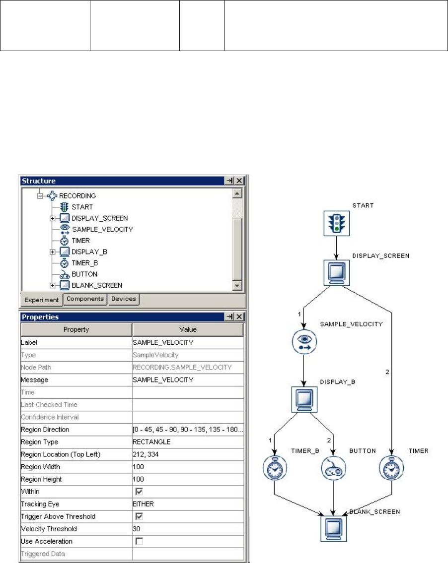
SR Research Experiment Builder User Manual ©2004-2017 SR Research Ltd.
184
operating in the Remote mode. Returns
"MISSING_DATA" (-32768) if target is
missing or if a remote tracking mode is not
being used.
Note:
¹ Returns "MISSING_DATA" (-32768) for the untracked eye.
An example of using the Sample Velocity trigger is illustrated below. To end a sequence
when the participant makes a saccade within the target region from (212, 334) to (312,
434), set the "Region Location" as (212, 334), "Region Width" as 100, and "Region
Height" as 100. Users may further configure the velocity threshold, triggering eye, etc.,
as desired.
Figure 7-63. Using Sample Velocity Trigger.
The sample velocity trigger can be used when a saccade needs to be detected as quickly
as possible so that a display change can be implemented. Please note that how quickly the
SR Research Experiment Builder User Manual ©2004-2017 SR Research Ltd.
185
trigger will fire is influenced by the tracker heuristic filter setting and the
velocity/acceleration model used for calculation (applicable to EyeLink 1000, EyeLink
1000 Plus and EyeLink Portable Duo only). To detect a saccade, instantaneous velocity
and acceleration values are calculated for each sample and compared to the threshold
values. For cognitive experiments, the velocity threshold is typically set to 30 degrees/sec
(and the acceleration threshold to 8000 degrees/sec2, if using) to detect saccades of 0.5
degrees of visual angle or greater. For psychophysical studies, the threshold values are
typically lower to make the parser more sensitive.
The sample velocity trigger is location-based and fires only when the eyes are within or
outside of a specified region. To make the trigger fire regardless of current eye position,
the trigger region may be set as the whole screen (i.e., for a 1024 x 768 screen resolution,
set Region Location as (0,0), Region Width as 1024, and Region Height as 768).
Alternatively, keep the default region settings and uncheck the "Within" button.
7.9.11.1 Top-left vs. Center Triggering Location Type
The Location Type of all location-based triggers (invisible boundary trigger, mouse
trigger, fixation trigger, saccade trigger, and sample velocity trigger) is based on the top-
left corner of the region, whereas the screen resources can be based on either the top-left
corner or the center of the resource. (The screen resource/interest area location type can
be set in the project Preferences under Screen). This means that references should be
created differently depending on whether the region location of a trigger refers to a
center-based resource or a top-left-based resource.
Imagine that a sample velocity trigger should fire only when the gaze position is within a
rectangle resource (RECTANGLE_RESOURCE). The top panel of the figure below
illustrates creating the Region Location reference to the rectangle resource when the
screen location type is TopLeft
(@DISPLAY_SCREEN.RECTANGLE_RESOURCE.location@). The bottom panel of
the figure illustrates creating a location equation when the location type is Center, by
subtracting half the resource width from the x coordinate, and half the resource height
from the y coordinate:
(=EBPoint(@DISPLAY_SCREEN.RECTANGLE_RESOURCE.location.x@ -
@DISPLAY_SCREEN.RECTANGLE_RESOURCE.width@/2,
@DISPLAY_SCREEN.RECTANGLE_RESOURCE.location.y@ -
@DISPLAY_SCREEN.RECTANGLE_RESOURCE.height@/2)).
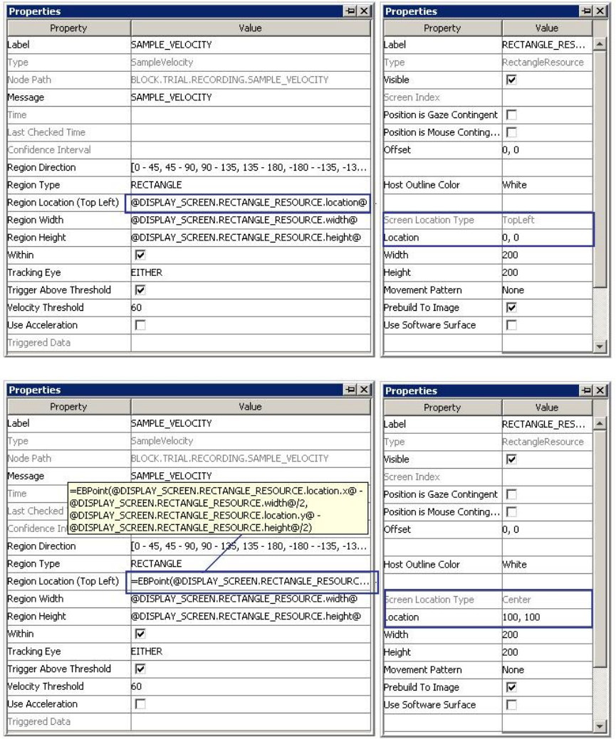
SR Research Experiment Builder User Manual ©2004-2017 SR Research Ltd.
186
Figure 7-64. Using Sample Velocity Trigger with Top-left and Center Location Types.
7.9.11.2 How to Show the Triggering Region on the Host PC
Sometimes it is useful to draw feedback graphics on the Host PC so the experimenter can
monitor whether the participant's eye position is within the triggering region, or so the
programmer can debug the experiment code by running the eye tracker in the mouse
simulation mode. Drawing on the Host PC screen can be done by using an EyeLink

SR Research Experiment Builder User Manual ©2004-2017 SR Research Ltd.
187
Command action either before the recording sequence (immediately after the Prepare
Sequence node) or as the first node in the recording sequence, so the drawing is overlaid
on top of the existing host PC graphics. The drawing command can be either "draw_box"
or "draw_filled_box". The Text of the command must include tracker of the top, left,
right, and bottom pixel position of the triggering region, followed by the drawing color.
This can be done either with string concatenation or string formatting. The top-left corner
of the triggering region is (@SAMPLE_VELOCITY.regionLocation.x@,
@SAMPLE_VELOCITY.regionLocation.y@) and the bottom right corner of the
triggering region is (@SAMPLE_VELOCITY.regionLocation.x@ +
@SAMPLE_VELOCITY.regionWidth@, @SAMPLE_VELOCITY.regionLocation.y@
+ @SAMPLE_VELOCITY.regionHeight@)
String Concatenation:
=str(@SAMPLE_VELOCITY.regionLocation.x@) + " "
+ str(@SAMPLE_VELOCITY.regionLocation.y@) + " "
+ str(@SAMPLE_VELOCITY.regionLocation.x@ + @SAMPLE_VELOCITY.regionWidth@) + " "
+ str(@SAMPLE_VELOCITY.regionLocation.y@ + @SAMPLE_VELOCITY.regionHeight@) + " 3"
String Formatting:
="%d %d %d %d 3" % (@SAMPLE_VELOCITY.regionLocation.x@,
@SAMPLE_VELOCITY.regionLocation.y@,
@SAMPLE_VELOCITY.regionLocation.x@ + @SAMPLE_VELOCITY.regionWidth@,
@SAMPLE_VELOCITY.regionLocation.y@ + @SAMPLE_VELOCITY.regionHeight@)
All of the drawing commands are documented in the "COMMANDS.INI" file under
C:\EYELINK2\EXE or \ELCL\EXE directory of the host partition.
7.9.12 Voice Key Trigger
Note this section is only applicable to the Windows version with a recommended ASIO
sound card and the AUDIO device set to the "ASIO" driver, or Mac OS X when running
Version 2.0 or later of the Experiment Builder software.
The Voice Key trigger ( ) fires when the audio input exceeds a specified threshold
level. A voice key will typically respond to the "voiced" parts of vowels and some
consonants, and therefore it may not represent the actual onset time of speech. To
determine the actual speech onset time, users may record the entire audio recording of the
trial and use a third-party audio editing tool to analyze the recorded audio. For instance,
the voice key is useful in detecting whether a participant has made a response, to trigger
the end of a trial.
Field
Attribute
Reference
Type
Content
Label *
.label
String
Label of the voice key trigger. The default value
is "VOICE_KEY".
Type #
NR
The type of Experiment Builder object
("VoiceKey") the current node belongs to.
Node Path #
.absPath
String
The absolute path of the node in the experiment
graph.
Message
.message
String
Message to be sent to the EDF file (in an

SR Research Experiment Builder User Manual ©2004-2017 SR Research Ltd.
188
EyeLink experiment) or messages.txt (in a non-
EyeLink experiment with the "Save Messages"
attribute of the Experiment node checked) when
the trigger fires.
Time #
.time
Float
Display PC time (in milliseconds from the start
of the experiment) when the processing of the
voicekey trigger is done (so the experiment flow
is ready to move to the next node). Note: To
check the time when the input voice level
exceeds the threshold, use
@*.triggeredData.time@ (i.e., the .time sub-
attribute of the .triggeredData attribute) instead.
Last Checked
Time #
.lastCheckedTim
e
Float
Experiment Builder checks for the status of the
trigger about every 1 msec. This property can be
used to retrieve the Display PC time (in
milliseconds from the start of the experiment)
when the trigger was checked for the last time.
Confidence
Interval #
.confidenceInterv
al
Float
Time difference between the trigger time and
last check time of the trigger. This indicates a
window of uncertainty as the true trigger time
could be between the last check time
(.lastCheckedTime) and the reported trigger
time (.time).
Clear Input
Queue ¶
.clearInputQueue
Integer
Experiment Builder maintains an event queue so
that multiple voicekey events can be accessed
over time. The “Clear Input Queue” option
checks whether the voice key event(s) cached in
event queue should be cleared when the trigger
fires (NO: no event clearing; EVENT: removes
the current triggering event from the voicekey
event queue; LIST: all voicekey events from
event queue will be removed).
Threshold #
.threshold
Float
Value from 0.0 to 1.0 to set the voicekey trigger
level, with 1.0 being the maximum audio level.
The threshold should be set high enough to
reject noise and prevent false triggering, but low
enough to trigger quickly on speech. A
threshold of 0.05 to 0.10 is typical.
Below
Threshold
.belowThreshold
Boolea
n
Whether the voice key should trigger if the
audio level is below the specified threshold
level.
Triggered Data #
.triggeredData
If the voice key trigger fires, the triggered data
can be further accessed (see the following
table).
When the voice key trigger fires, the triggered data can be further accessed. The sub-
attributes of the TriggeredData field are listed in the following table.
Reference
Attribute
Type
Content
Time
.time
Float
Display PC time (in milliseconds from the start

SR Research Experiment Builder User Manual ©2004-2017 SR Research Ltd.
189
of the experiment) when the voicekey trigger
fires.
EDF Time
.EDFTime
Integer
EDF time when the voice key trigger fires.
Level
.level
Float
Returns the voice key audio level (in the same
units as the voice key threshold) when the voice
key trigger fires, with 0.0 being silence and 1.0
being the maximum audio level.
The following discusses some of the common applications of the voice key trigger. You
may check out the HTML version of this document for the complete example project.
7.9.12.1 How to Calculate the Voice Key RT Online
To record information about the voice key response, users can create variables,to store
the time of the display event and the time of the voice key trigger. After the response, an
Update Attribute action can be used to set the values of these variables, referring to the
"@VOICE_KEY.triggeredData.time@" attribute to record the time of the voice key
response (see the figure below). With the time of the voice key response, the response
time can be calculated as (@voicekey_time.value@ - @display_onset_time.value@). If
the trial can be ended without the participant making a response (e.g., the trial times out
after some period, or the voice key fails to trigger), use an Update Attribute action at the
beginning of the trial to reset the default values for the variables to ensure the response
data from the previous trial will not be carried over to the current trial.
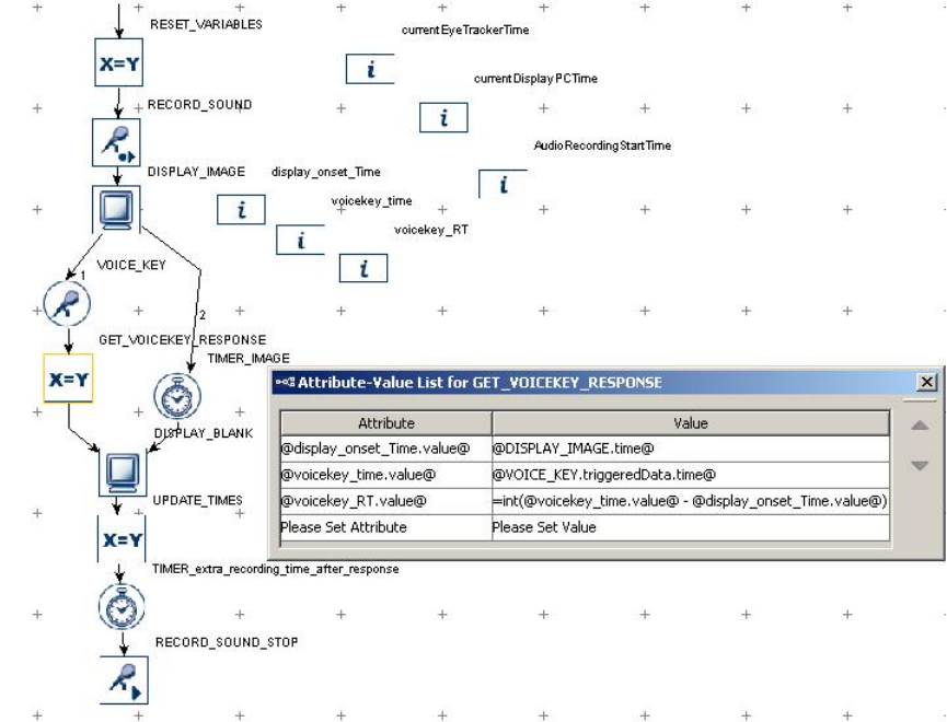
SR Research Experiment Builder User Manual ©2004-2017 SR Research Ltd.
190
Figure 7-65. Collecting the Voicekey Response Data.
7.9.12.2 How to Align the Recordings in the Audio File and Eye
Tracker Event Time
To verify the accuracy of the vocal response, it is best to record the audio on every trial
using a Record Sound node. Adding a brief Timer trigger at the end of the trial, before
the Record Sound Control action, ensures that the entire vocal response can be captured.
In an experiment in which both eye movements and speech/voice key are recorded
simultaneously, it is important that users are able to examine the temporal relationship
between the two data streams (ideally, to compare the two streams of data in the same
time scale). In Experiment Builder and Data Viewer, the time stamps for the eye
movement data and messages (i.e., EDF file time) are based on a different clock than the
time fields for the actions and triggers (i.e., EB run time). The EDF file time runs on the
host PC clock, with the 0-ms being the time when the EyeLink host program started. The
EB run time is based on the display computer clock, with 0-ms being the time when the
experiment project starts. To align the eye movement data and the recorded speech data,
add the following variables to the experiment project:
• currentEyeTrackerTime - used to retrieve the current time on the eye tracker
clock.
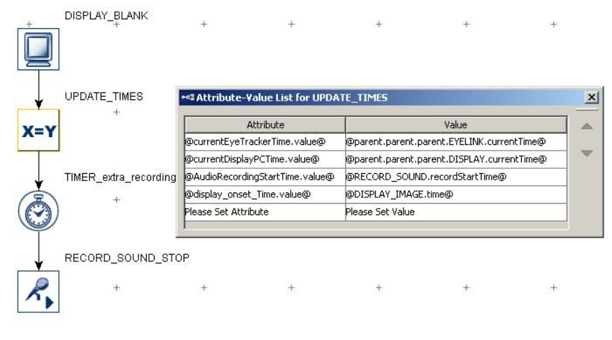
SR Research Experiment Builder User Manual ©2004-2017 SR Research Ltd.
191
• currentDisplayPCTime - used to retrieve the current time on the display computer
clock when the currentEyeTrackerTime value is updated.
• AudioRecordingStartTime - used to retrieve the time when the audio recording
starts.
Use an UPDATE_ATTRIBUTE action to update these three variables while the audio
recording is still ongoing.
• @currentEyeTrackerTime.value@ - the "Current Time" field of the EyeLink
device
• @currentDisplayPCTime.value@ - the "Current Time" field of the Display
Device
• @AudioRecordingStartTime.value@ - the "Record Start Time" attribute of the
Record Sound action.
Figure 7-66. Aligning Audio Recording Times.
The onset of the audio recording in the EDF file (eye tracker) time in each trial can then
be calculated as (currentEyeTrackerTime + AudioRecordingStartTime -
currentDisplayPCTime).
In Data Viewer, please note that the timing of all eye movement measures is reported
relative to the start of the trial if no reaction time period definition is applied to the
session, or to the start of the reaction time period if one is applied. The 0-point for the eye
recording in a trial will be the TRIAL_START_TIME output variable in Data Viewer.
The EDF file time for the start of a fixation can then be calculated from the Fixation
Report as (CURRENT_FIX_START + TRIAL_START_TIME).
SR Research Experiment Builder User Manual ©2004-2017 SR Research Ltd.
192
7.10 Other Building Components
This section lists other types of components for experiment building: the Variable,
Results File, and Accumulator nodes (see Figure 7-67).
Figure 7-67. Other Components Implemented in Experiment Builder.
7.10.1 Variable
Users can create a variable ( )to keep track of important information during run time
(e.g., the iteration status in a loop, or a participant’s response). To create a new variable,
open the “Other” tab of the Component Toolbox, then click and drag the Variable into the
work area. The label of a variable must be a string starting with a letter between 'a' and 'z'
or 'A' and 'Z' and consisting of alphanumerical characters ('A' - 'Z', 'a' - 'z', '0' - '9', or '_');
any space entered is converted to an underscore. The new variable label shouldn't
duplicate the name of any existing data source columns, variable labels, or any of these
reserved words: "EYELINK", "DISPLAY", "AUDIO", "TTL", and "CEDRUS". Note
that the variable object does not connect to other items in a graph like action and trigger
nodes. Users can update the value of the variable by assigning a value directly, referring
to the attribute of another item, or by equation. When setting the variable to a reference or
equation, it is best to use an Update Attribute to update the value of the variable. The
variable can then be output as a trial variable in the EDF and/or in the Results File. (Note
that in Experiment Builder 2.0, all newly-added variable nodes are automatically
included in Results Files and in the EyeLink DV Variables attribute of the topmost
experiment node in the Structure panel.)
Field
Attribute
Reference
Type
Content
Label *
.label
String
Label of the variable. The default value is
“VARIABLE”.
Type #
NR
The type of Experiment Builder object
("Variable") the current node belongs to.
Node Path #
.absPath
String
The absolute path of the node in the experiment
graph.
Type #
NR
The data type of the variable (could be “String”,
“Integer”, “Float”, “Point”, “Color”, and
“List”).
Value
.value
The value of the variable.
Imagine an experiment in which the visual stimulus presentation alternates between two
screens and the trial ends after a certain number of alternations. In this experiment it
could help to create a counter to keep track of the number of loops. To create a counting
variable, first add a Variable node to the graph (see Figure 7-68) and set its initial value
to 0 (see Panel A of Figure 7-69). Then add an Update Attribute action in the loop to
increase the value of the variable by 1 for each loop. Open the Attribute-Value List and
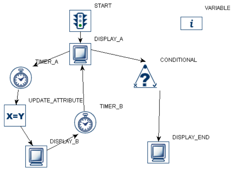
SR Research Experiment Builder User Manual ©2004-2017 SR Research Ltd.
193
set the “Attribute” cell as “@VARIABLE.value@”, and the “Value” field as
“=@VARIABLE.value@ + 1” (see Panel B of Figure 7-69). Finally, add a Conditional
trigger to check whether the VARIABLE value equals 5. Then connect the next action to
the “True” branch of the Conditional trigger to exit the loop after 5 repetitions (see Panel
C of Figure 7-69).
Figure 7-68. Using a Variable.
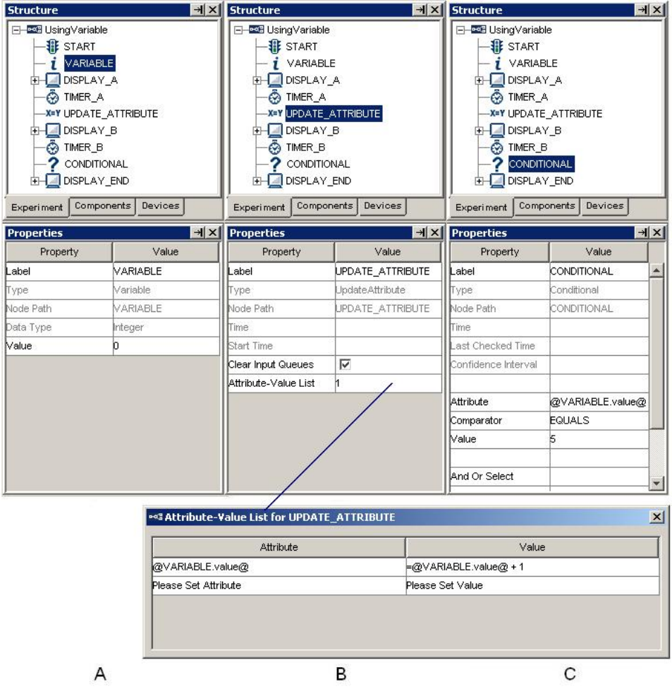
SR Research Experiment Builder User Manual ©2004-2017 SR Research Ltd.
194
Figure 7-69. Property Settings for Variables.
Variables can be conveniently used as temporary data storage, e.g., to record participants’
responses by saving triggered data such as response time and key or button pressed.
Simply add a variable from the Component Toolbox into the project workspace, then use
an Update Attribute node after the trigger to set the new variable value(s). The default
data type for a newly-added variable is “String.” To set the type of a variable, simply
enter a value in the “Value” field that corresponds to the intended data type. For example
(see Figure 7-70), entering “0” in the Value field will set the Type to “Integer,” and
entering “0.0” will set the Type to “Double.” When referring the variable value to an
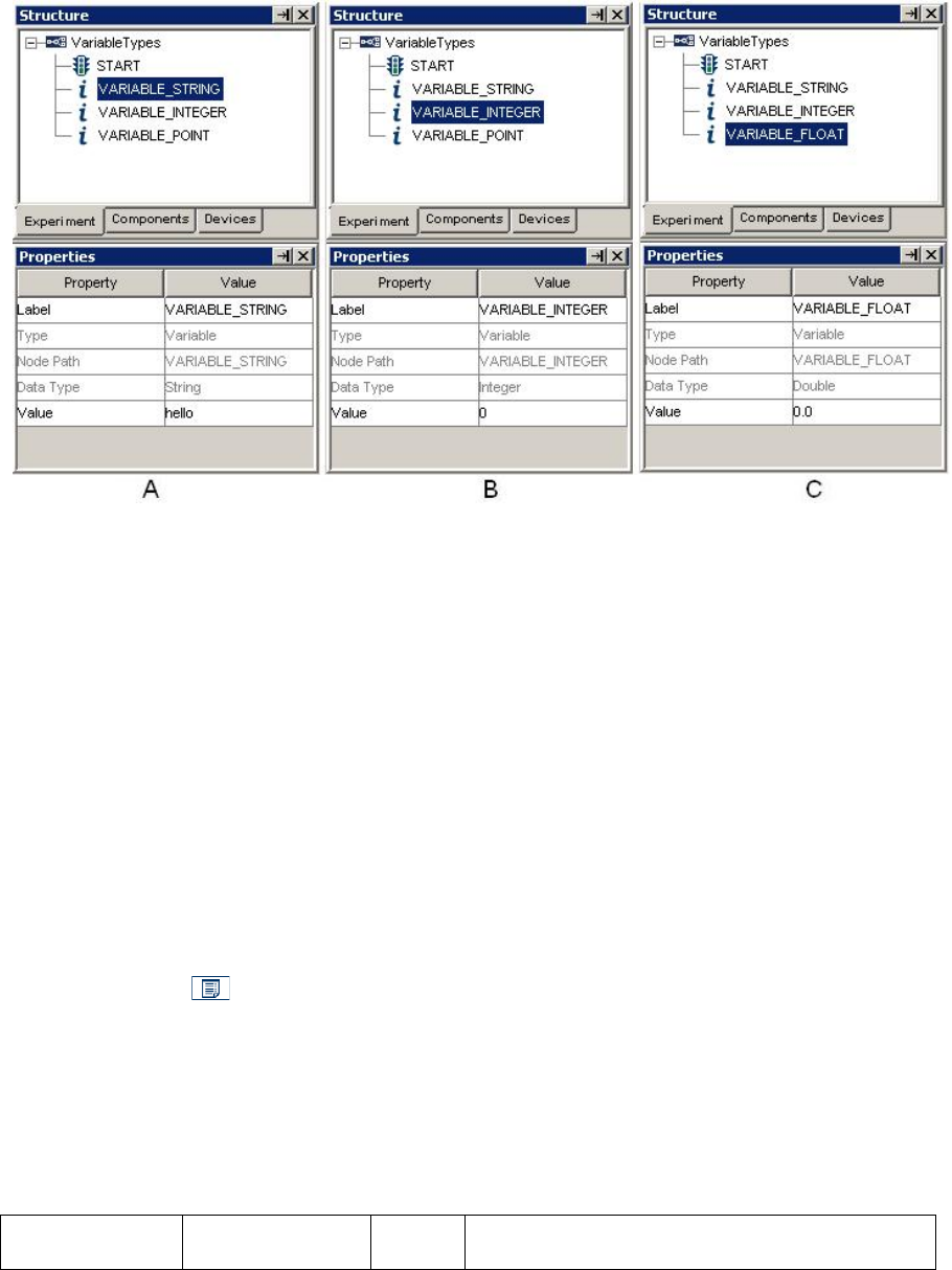
SR Research Experiment Builder User Manual ©2004-2017 SR Research Ltd.
195
attribute of a node in the graph, make sure the data type of the variable matches the data
type of the intended attribute.
Figure 7-70. Dynamic Data Type Casting.
Make sure to set the initial value of a variable to a plausible value to avoid a build-time
error. For example:
• To use a variable to store the temporary value of an image file name, the initial
value of the variable should be set to the name of an image resource in the image
library, instead of an arbitrary string like “abc”.
• If the variable is used in any equations, the default value needs to be a valid value
for equation use. For example, if a variable is used as the divisor in a division
operation, make sure that the initial value of the divisor is non-zero.
To clear a non-string value (e.g., a number or point) set in the "Value" attribute of a
variable, first set the value to some string (e.g., "hello") and then clear it.
7.10.2 Results File
The Results File ( ) allows users to create a tab-delimited .txt file output separate from
the EDF. This is especially useful for non-EyeLink experiments, where no EDF is
recorded, but may also be used as a quick summary of trial data. Variables selected to be
included in the Results File will be listed as columns. Each time the Add To Results File
action is called (typically at the end of the trial), a row is added to the Results File that
includes the current value for each variable in the file. Similar to the Variable object, a
Results File object does not connect to other objects in the graph.
Field
Attribute
Reference
Type
Content
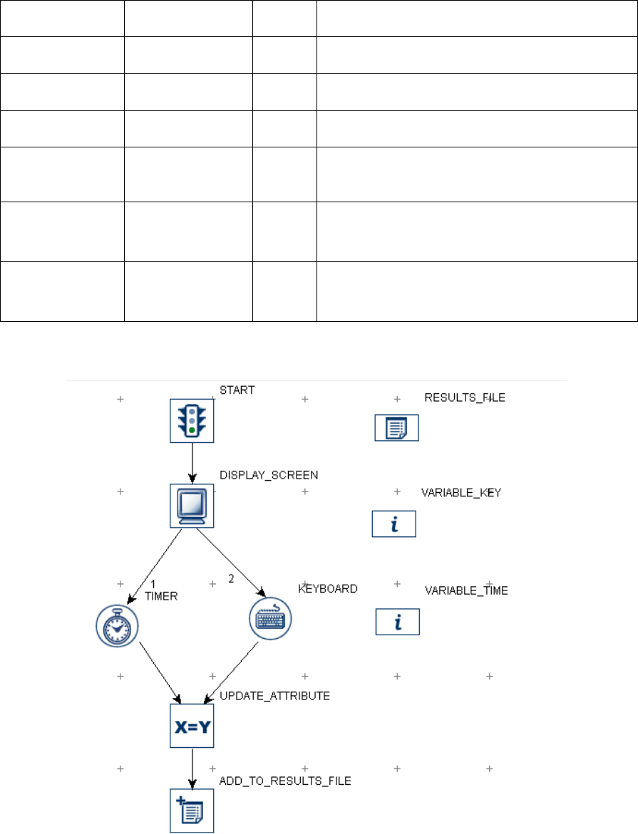
SR Research Experiment Builder User Manual ©2004-2017 SR Research Ltd.
196
Label *
.label
String
Label of the RESULTS FILE object. The
default value is “RESULTS_FILE”.
Type #
NR
The type of Experiment Builder object
("ResultsFile") the current node belongs to.
Node Path #
.absPath
String
The absolute path of the node in the experiment
graph.
Columns
NR
The list of variables to be recorded in the results
file.
Use Period for
Missing Values
† *
.usePeriodForMis
singValues
Boolea
n
If true, a “.” will be written out to the results file
instead of missing values (i.e., -32768 for
numbers and “MISSING_VALUE” for strings).
Field Width *
.fieldWidth
Integer
Specifies the minimum number of
characters that are output for the numerical
values.
Precision *
.precision
Integer
Specifies the number of digits after the
decimal-point character for floating-point
values.
Results file is useful for recording data in non-EyeLink experiments. The following graph
(Figure 7-71) illustrates part of a simple reaction-time experiment:
Figure 7-71. Using Results File.
To record the keyboard response and response time to the results file, the user in this
example created two new variables: “VARIABLE_KEY,” referring to the keyboard
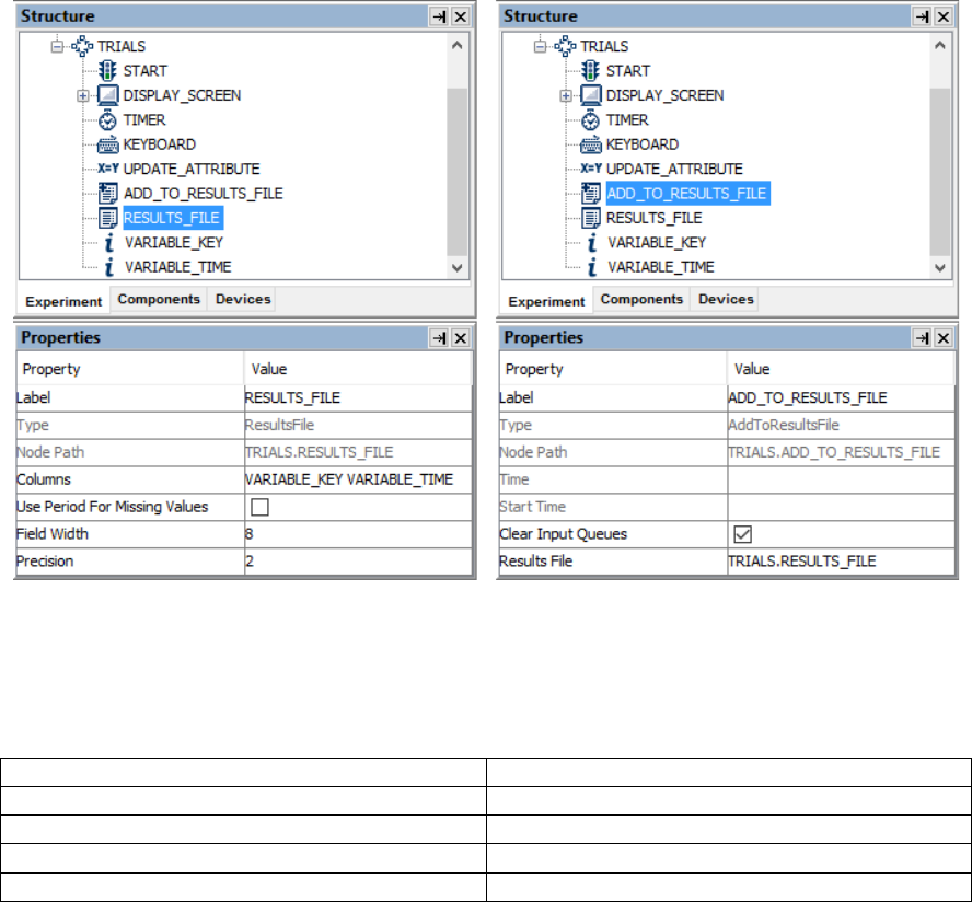
SR Research Experiment Builder User Manual ©2004-2017 SR Research Ltd.
197
response (@KEYBOARD.triggeredData.key@), and “VARIABLE_TIME,” referring to
the response time from the onset of the screen to the key press event
=(@KEYBOARD.triggeredData.time@ - @DISPLAY_SCREEN.time@). The user also
added a Results File object to the experiment. and configured the “Columns” property to
add ensure all the desired variables are included in the output (note that starting in
Experiment Builder 2.0, all variables and data source columns are included in the
“Columns” property by default; see Panel A of Figure 7-72). An Add To Results File
action is added after the Keyboard trigger to record responses and reaction time for the
sequence. The “Results File” property of the Add To Results File action is set to
“RESULTS_FILE,” the only results file currently in the project. If desired, multiple
Results Files may be created and configured with different variables, or made to include
different sets of trials.
Figure 7-72. Setting Properties of the Results File Node.
When the experiment is executed, a results file is generated in the session folder in the
results directory, with one column for each of the output variables. The results file is tab-
delimited and can be easily imported into most statistical software.
VARIABLE_TIME
VARIABLE_BUTTON
686.0
b
603.0
n
530.0
n
532.0
b

SR Research Experiment Builder User Manual ©2004-2017 SR Research Ltd.
198
7.10.3 Accumulator
The accumulator ( ) is used to keep numeric values and provide descriptive
statistics of the accumulated data.
Field
Attribute
Reference
Type
Content
Label *
.label
String
Label of the accumulator.
Type #
NR
The type of Experiment Builder object
("Accumulator") the current node belongs to.
Node Path #
.absPath
String
The absolute path of the node in the
experiment graph.
Maximum Size
.maximumSize
Integer
Maximum number of data points that can be
added to the accumulator. If the number
added exceeds the limit, the initial data points
will be overwritten.
Elements #
.elements
List
A list of data points added in the accumulator.
Size #
.size
Integer
Actual number of elements in the
accumulator.
Sum #
.sum
Number
Sum of all values.
Maximum #
.maximum
Number
Maximum of all added values.
Minimum #
.minimum
Number
Minimum of all added values.
Mean #
.mean
Number
Mean across all added values.
Median #
.median
Number
Median across all added values.
Standard
Deviation #
.stddev
Number
Standard Deviation of all values added to the
accumulator.
Standard Error #
.stderr
Number
Standard error value of all values added to the
accumulator.
The accumulator can be used as a handy tool for presenting a summary of the
participant’s performance (e.g., an average RT calculation) at the end of the experiment.
For an example, the following figure illustrates an eye-tracking experiment using a
saccade trigger with an Accumulator. Whenever the saccade trigger fires, the triggered
data is collected and the duration of each saccade can be added to the accumulator. At the
end of the trial or at the end of the experiment, we can easily calculate statistics such as
the maximum, minimum, mean, etc., of the durations across all saccades. Like the
Results File, the Accumulator itself must first be added to the project, and does not
connect to other nodes. An Add To Accumulator action is used to send the desired value
to the Accumulator.
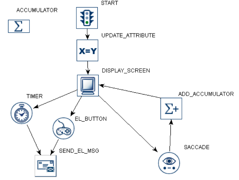
SR Research Experiment Builder User Manual ©2004-2017 SR Research Ltd.
199
Figure 7-73. Using Accumulator.
When adding a new Accumulator, make sure to first set the Maximum Size attribute (see
Panel A of Figure 7-74). Note that if the maximum size is exceeded, the earliest value
added to the Accumulator will be flushed to make room for the newly added value. (E.g.,
if the values 1, 2, 3, 4, and 5 are added in that order to an Accumulator with a Maximum
Size of 3, the contents of the Accumulator will be 3, 4, and 5.)
In some applications it may be necessary to clear the data in the accumulator. For
instance, in this example, we want to display data from only the saccades in the trial, so
it’s important to clear the accumulator at the beginning of the trial. The accumulator can
be cleared either by adding an “UPDATE_ATTRIBUTE” action and resetting the
maximum data size for the accumulator (see Panel B of Figure 7-74), or by using a Reset
Node action.
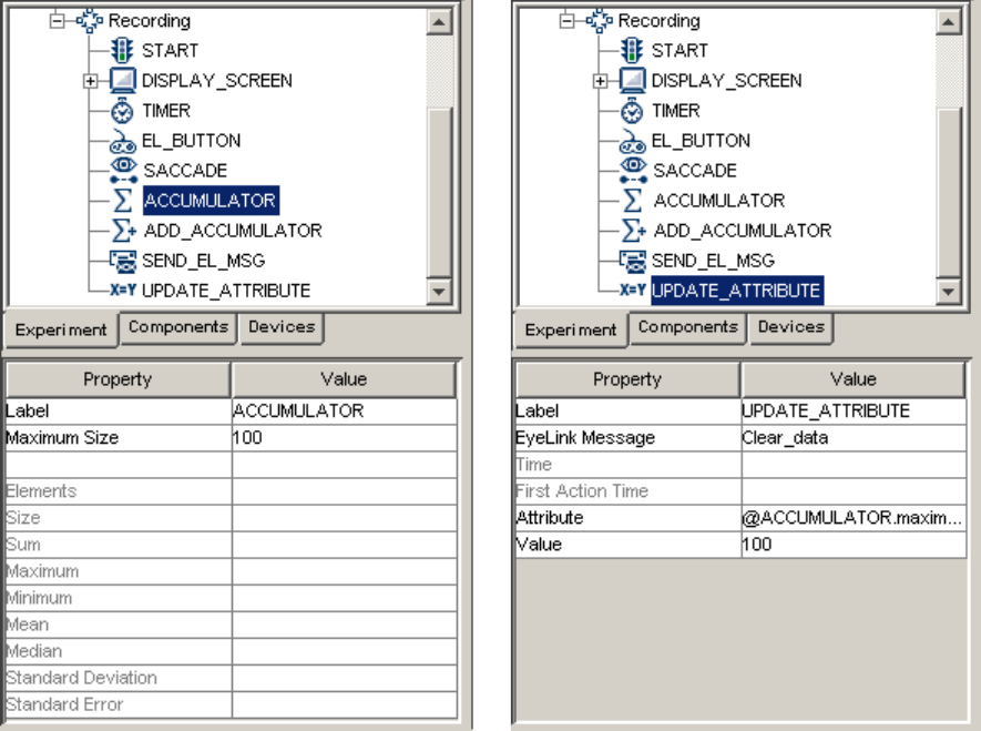
SR Research Experiment Builder User Manual ©2004-2017 SR Research Ltd.
200
A
B
Figure 7-74. Setting the Properties of Accumulator.
The Add to Accumulator action is added to the sequence to send the saccade duration
data to the Accumulator. After adding the Add to Accumulator action, specify the
accumulator in which the data is stored (“Accumulator”) and the value to add (“Add
Value”; see Panel A of Figure 7-75). When desired, the data can be retrieved by referring
to the properties of the Accumiulator. For example, a Send EyeLink Message action can
be used to report the number of saccades in the sequence and some basic statistics of
saccade duration:
= "saccade data "+ str(@ACCUMULATOR.size@) + "max " + str(@ACCUMULATOR.maximum@)
+ " min " + str(@ACCUMULATOR.minimum@) + " mean " + str(@ACCUMULATOR.mean@)
This will record a message similar to “MSG 3153136 saccade data 8 max 60.0 min 48.0
mean 55.0” in the EDF file.
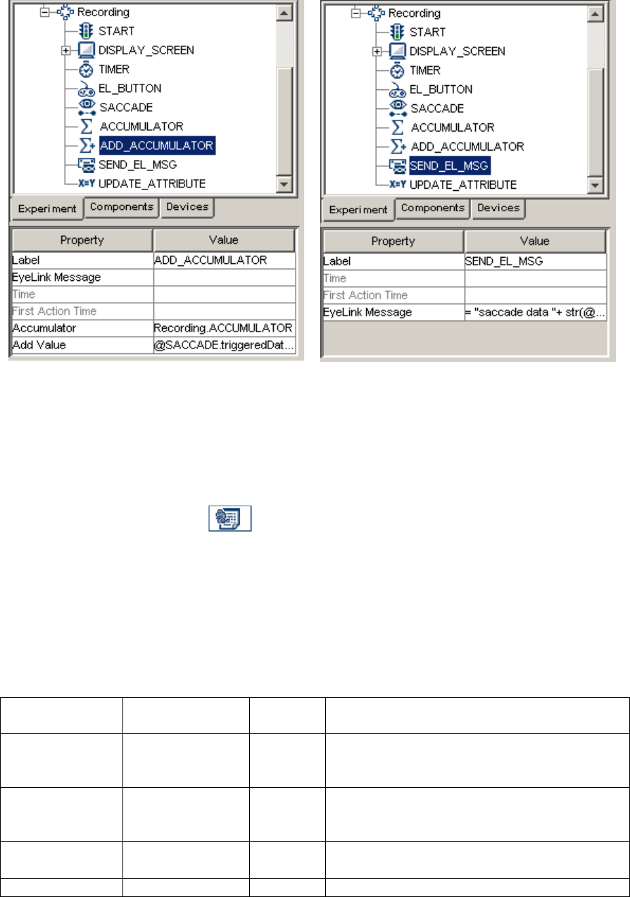
SR Research Experiment Builder User Manual ©2004-2017 SR Research Ltd.
201
A
B
Figure 7-75. Adding Data to and Retrieving Data from the Accumulator.
7.10.4 Custom Class Instance
The Custom Class Instance ( ) creates a new instance of a custom class. Users can
select a custom class file from the project library to which the current instance belongs.
Simply click the Value field of the “Custom Class” property and select the .py file from
the dropdown menu.
Once the class is determined, double-click on the Custom Class Instance in the
experiment graph to open a custom class editor for viewing and editing the source code
of the custom class. See Chapter 12 “Custom Class” for details.
Field
Attribute
Reference
Type
Content
Label *
.label
String
Label of the custom class instance. By default,
the label is
"CUSTOM_CLASS_INSTANCE".
Type #
NR
The type of Experiment Builder object
("CustomClassInstance") the current node
belongs to.
Node Path #
.absPath
String
The absolute path of the node in the
experiment graph.
Custom Class *
NR
Select a class (defined in the Experiment

SR Research Experiment Builder User Manual ©2004-2017 SR Research Ltd.
202
Builder library manager) to which the current
instance belongs.
Note: The property table of the custom class instance will also list all of the methods and
attributes defined in the custom class in an alphabetical order.
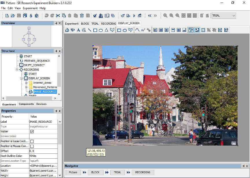
SR Research Experiment Builder User Manual ©2004-2017 SR Research Ltd.
203
8 Screen Builder
Experiment Builder provides a built-in Screen Builder interface as a convenient tool for
creating visual displays. After adding a Display Screen action in the workspace, users can
open the Screen Builder by double clicking the node.
Screen Builder is a what-you-see-is-what-you-get (“WYSIWYG”) type of interface,
which allows users to see what the display will actually look like during the runtime of
the experiment. The Screen Builder behaves like a drawing board onto which various
types of the graphic resources (images, videos, text, or simple line drawings) can be
added (see Figure 8-1). Once added, the exact properties of the resources can be further
edited from the property panel. For example, for text resources, users can specify the
position, font (name, size, and style), color, and alignment style of the text. For a
dynamic display with moving objects on the screen, users can specify the movement
pattern of the graphic resources. Addition tools such as the drawing grid and interest
areas are provided for the ease of screen editing and data analysis.
When users move the mouse cursor around in the Screen Builder, Experiment Builder
(version 2.0 or later) prints the current mouse position as well as the color of the pixel
(the background of the Screen Builder or resources on the screen) at the current mouse
position – see Figure 8-1.
SR Research Experiment Builder User Manual ©2004-2017 SR Research Ltd.
204
Figure 8-1. Sample View of the Screen Builder Interface.
8.1 Resources
Resources are the individual graphic drawings (e.g., image, video, text, line, etc) to be
displayed on the screen. The following types of resources can be added to a display
screen: images, videos, text (single line or multiple lines), and simple shapes like
rectangles, ellipses, lines, triangles, and polygons (see Figure 8-2).
Figure 8-2. Resources Implemented in Screen Builder.
As for all of the nodes discussed in the previous chapter, the layout and properties of a
selected resource can be easily modified in the Property panel. In addition to configuring
the physical appearance of the resource (position, size, style, etc.), users may manipulate
the following attributes of a graphic resource:
• Visibility: After a resource is added to a screen, it can be either visible or invisible
when the display is shown. This property is useful for experiments in which
similar displays are used except that one or more items may appear and disappear.
• Position is Gaze or Mouse Contingent: These properties allow a resource to
change position according to the current gaze or mouse position (see the
GCWINDOW and TRACK examples) during recording. For an image resource,
the clipping area can also be made gaze contingent (see the GCWINDOW
example).
• Movement Pattern: Users can specify a movement pattern (either sinusoidal or
custom) for a resource (see the PURSUIT example). A resource cannot be gaze-
or mouse-contingent if it has been assigned a movement pattern.
• Interest Area: For static resources, creating interest areas may simplify data
analysis at a later stage. Interest areas can be generated either manually or by
using the auto segmentation features of the Screen Builder.
• Location Type: Two location types can be used in the Screen Builder: top-left or
center. For the top-left location type, the “Location” attribute of the resource
specifies the position of the top-left corner of the resource, while for the center
location type, the “Location” attribute specifies the position of the center of the
resource. The screen location type can be set from “Preferences → Screen →
Location Type”.
The following sections describe the usage and properties of each resource type in detail.
8.1.1 Image Resource
To add an image resource onto a display screen, first make sure images are loaded into
the Library Manager by clicking "Edit → Library Manager" from the application menu
bar. In the "Library Manager" dialog box, select the "Image" tab and click the "Add"
button to load in image files, or select the image files in Windows Explorer (Finder in
Mac OS X) and drag them into the Library Manager window. The names of the image
files to be imported should not contain spaces or non-ASCII characters.
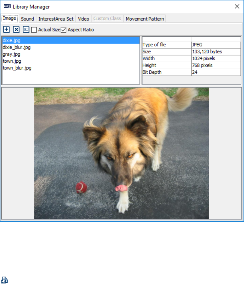
SR Research Experiment Builder User Manual ©2004-2017 SR Research Ltd.
205
Figure 8-3. Loading Images into Image Library.
The following image file formats are supported in Experiment Builder: PNG, TIF, GIF,
JPG, and BMP. Transparency manipulations through the alpha channel are supported
only in version 2 of Experiment Builder when using the OpenGL graphics.
To add an image resource onto a display screen, click the “Insert Image Resource” button
( ) on the Screen Builder toolbar, and then click anywhere in the workspace. Choose the
desired image file in the “Select Image” dialog. The image will now be displayed in the
Screen Builder.
To adjust the position of the image resource on the screen, click on the image resource
and drag it to the intended location, then release the mouse button. The resource position
can also be set from the value field of the “Location” property in the Property Panel.
Tip: The x, y coordinates of the current mouse cursor position will be displayed below
the cursor if the mouse is left idle for a few seconds in the Screen Builder workspace.

SR Research Experiment Builder User Manual ©2004-2017 SR Research Ltd.
206
Field
Attribute
Reference
Type
Content
Label *
.label
String
Label of the resource. The default label is
“IMAGE_RESOURCE”.
Type #
NR
The type of screen resource ("ImageResource")
the current item belongs to.
Visible †
.visible
Boolea
n
Whether the resource should be visible. The
default setting is True (box checked).
Screen Index #
.screenIndex
Integer
Index of the resource in the screen resource list
(0 - n).
Position is Gaze
Contingent †
.positionAtGazeC
ontingent
Boolea
n
Whether the position of the resource is
contingent on the gaze position. The default
setting is False. This setting is only available
when the parent display screen is contained
inside a recording sequence.
Gaze Contingent
Eye
.gazeContingentE
ye
String
Sets the eye used to provide data for the gaze-
contingent drawing. Options are Left, Right,
Either, Average, or Cyclopean (default setting).
For a left-eye-only recording, data from the left
eye is used when the gaze-contingency eye is
set to “Left”, “Either”, or “Cyclopean”, and
missing data when set to “Right” or “Average”.
For a right-eye-only recording, data from the
right eye is used when the gaze-contingency eye
is set to “Right”, “Either”, or “Cyclopean”, and
missing data when set to “Left” or “Average”.
For a binocular recording, left eye data is used
when the gaze-contingency eye is set to “Left”
or “Either”, right eye data is used when set to
“Right”, average data from both eyes if this is
set to “Average” (with missing data if either
either is missing), and average data from both
eyes when set to “Cyclopean” (with missing
data if both eyes are missing, and data from the
remaining tracked eye if a single eye is
missing).
Position is
Mouse
Contingent †
.positionAtMouse
Contingent
Boolea
n
Whether the position of the resource is
contingent on the mouse position. The default
setting is False.
Contingency
Deadband
.contingentDeadb
and
Tuple
of
Integer
s
Sets the minimum amount of eye movement
required to update the gaze-contingent moving
window. This is designed to make the display
drawing less susceptible to jitters in the eye
position. Typically the deadband shouldn’t be
larger than 3.0 pixels—larger deadband values
will likely result in a lag in updating the display.
Offset
.offset
Point
Adjustment of the resource position relative to
the intended resource location, whether
specified by the Location attribute, the current

SR Research Experiment Builder User Manual ©2004-2017 SR Research Ltd.
207
gaze or mouse position, or a movement pattern.
The default value is (0, 0) for a perfect
alignment of the resource position with the
specified position. Values specified in the Offset
will be subtracted from the specified location.
For example, if the location field is set to (512,
384), and the offset is (100, 100), the actual
resource position will be (412, 284).
Host Outline
Color ¶
.
hostOutlineColor
Color
The color of the box drawn on the host screen to
show the position and dimensions of the current
resource. This property is available only if the
“Use for Host Display” option of the parent
display screen action is enabled and the “Draw
to EyeLink Host” property of the prepare
sequence action is set to “Primitive”.
Screen Location
Type #
NR
Whether the location specified below refers to
the top-left corner or center of the resource. This
setting can be changed in “Screen Preferences”.
Location
.location
Point
The coordinates of the top-left corner or center
of the resource. If the Offset is non-zero, the
actual screen position where the resource is
displayed will be the coordinates set in
the .location field minus the offset adjustment.
Width
.width
Integer
Intended width of the resource in screen pixels.
Height
.height
Integer
Intended height of the resource in screen pixels.
Movement
Pattern ¶ *
NR
Movement pattern (sinusoidal or custom) of the
resource.
Prebuild to
Image †
.prebuildToImage
Boolea
n
Whether the resource should be built into an
image when the experiment is built (instead of
having it created during runtime). Uncheck this
option only if you will need to supply the image
file name during runtime (e.g., by using a
variable or an equation, instead of referring to a
data source column or using a static image file
name).
Use Software
Surface †
.useSoftwareSurf
ace
Boolea
n
If unchecked, memory on the video card is used
to hold the resource (blitting from the video
card memory to the display surface is fast). If
checked, the system memory is used to hold the
resource (blitting is slow as it is done by
copying from RAM to display surface).
Clipping
Location
.clippingLocation
Point
The coordinates of the top-left corner of the
clipping region. If this is not set to (0,0), only
the part of the image within the clipping region
will be shown.
Clipping Width
.clippingWidth
Integer
Intended width (in pixels) of the clipping region
of the resource. Only the part of the image
within the clipping region will be shown.
Clipping Height
.clippingHeight
Integer
Intended height (in pixels) of the clipping region
of the resource. Only the part of the image

SR Research Experiment Builder User Manual ©2004-2017 SR Research Ltd.
208
within the clipping region will be shown.
Clipping Area is
Position
Contingent †
.clippingAreaAtG
azeContingent
Boolea
n
Whether the clipping region should be
contingent on the mouse or gaze position. The
default setting is False.
Source File
Name ¶
.sourceFileName
String
The name of the image file. Make sure that the
file name does not contain spaces or non-ASCII
characters. The image(s) must be first loaded
into the resource library.
Use Original
Size †
.useOriginalSize
Boolea
n
If set to true, this will display the image in its
original size; otherwise, the image may be
stretched to the dimension set by “Width” and
“Height” fields.
Lock Aspect
Ratio
.lockAspectRatio
Boolea
n
This option is used to lock the aspect ratio of the
actual image used (instead of the aspect ratio of
the template image). If this is unchecked, users
have the option of freely modifying the width
and height of the image resources. If this is
checked, users can freely adjust the “Width”
value of the image resource, and the height of
the resource will be calculated from the Width
value and the aspect ratio of the image.
Use Fixed Pixel
Area
Boolea
n
If this option is checked, the image size will be
controlled by the "Total Image Pixel Area"
attribute, and the “Width” and “Height” fields
will be grayed out. If “Use Fixed Pixel Area” is
unchecked, the size of the image will be
controlled by the “Width” property based on the
aspect ratio of the original image. This option is
only available if the "Lock Aspect Ratio" option
is enabled.
Total Image
Pixel Area
.totalImagePixel
Area
Integer
This option is only available if the "Total Image
Pixel Area" option is checked. If set to 0
(default value), the image will be displayed in
the original size. If set to another integer value,
the image will be rescaled to constrain the total
pixel area while maintaining the original aspect
ratio.
Background
Color
.backgroundColo
r
Color
Chromatic multiplier for the pixel values. Each
of the RGBA channels of the source image
multiplies the intensity of each channel of the
background color. For example, color
information will be fully preserved when a
white background is used, pixels will only be
rendered in a gray-scale version when a black
background is used, and colors will appear
muted when a gray background is used. Default
is white so that all of the colors will be
rendered. This option is available only in the
OpenGL video environment.
Source Factor
.sourceFactor
Integer
In the OpenGL graphics, pixels can be drawn

SR Research Experiment Builder User Manual ©2004-2017 SR Research Ltd.
209
using a function that blends the incoming
(source) red, green, blue, and alpha (RGBA)
values with the RGBA values that are already in
the frame buffer (the destination values). The
“Source Factor” specifies how the red, green,
blue, and alpha source blending factors are
computed. The initial value is
GL_SRC_ALPHA. This option is available only
in the OpenGL video environment.
Destination
Factor
.destinationFactor
Integer
This specifies how the red, green, blue, and
alpha destination blending factors are computed.
The default value is
GL_ONE_MINUS_SRC_ALPHA. This option
is available only in the OpenGL video
environment.
Use Color Key
Boolea
n
Whether image transparency should be rendered
through the color-keying method. That is, a
specific color in the image is designated as the
transparent color. Any pixel in the image with
the RGB color that matches the transparency
color will not be rendered, so the background
pixels show through instead. This option,
available only in the OpenGL video
environment, is equivalent to using the
“Transparency Color” in the DISPLAY device
in the DirectDraw graphics. This field should be
used if the image doesn’t contain the built-in
alpha channel; otherwise uncheck this option to
perform transparency using the image's alpha
channel.
Color Key
.colorKey
Color
This sets an intended color key so the
transparency of the image resource can be
manipulated. This option is only available when
the OpenGL video environment is used and the
“Use Color Key” option of the image resource
is enabled.
Ignore Alpha
.ignoreAlpha
Boolea
n
If the “Ignore Alpha” option is unchecked
(default setting), the alpha channel of the image
resource will be used to render image
transparency. When an image is overlaid onto
another image, the alpha value of the source
(foreground) color is used to determine the
resulting color. If the alpha value is transparent,
the source color is invisible, allowing the
background color to show through. If the
“Ignore Alpha” option is checked, the alpha
channel data in the image will be ignored. This
is option is available only in the OpenGL video
environment.

SR Research Experiment Builder User Manual ©2004-2017 SR Research Ltd.
210
8.1.1.1 Image Displaying Modes
Image Resources in Experiment Builder allow users to display images in their original
size, or scaled or stretched to specified dimensions.
1) To display the images in their original size, check the “Use Original Size”
property of the image resource. Enabling that field will make the following
attributes read-only: “Width”, “Height”, “Clipping Location”, “Clipping Width”,
“Clipping Height”, and “Clipping Area is Gaze Contingent”.
2) To stretch all images to a fixed width and height, first make sure that the “Use
Original Size” field of the image resource is unchecked, then set the “Width” and
“Height” properties to the desired values. If only a portion of the image is to be
shown, set the “Clipping Location”, “Clipping Width” and “Clipping Height”
attributes. By default, the Clipping Location is (0,0), and the Clipping Width and
Height are the same as the image Width and Height. The Clipping Location is
relative to the top-left corner of the image.
3) To stretch the images to different dimensions, add two columns in the experiment
data source to specify the desired width and height of the image. Refer the
“Width”, “Height”, “Clipping Width”, and “Clipping Height” properties of the
image resource to the two columns created in the data source. See the “PICTURE”
template for an example.
The “Screen Location Type” attribute of the image resource indicates the current location
coordinates type. The location type can be set in the Preferences menu in the “Location
Type” property of the “Screen” node.
1) “Center” positioning makes it easy to display images in the center of the screen.
To center an image resource, select the resource, then click the horizontal center
alignment and vertical center alignment ( ) buttons on the Screen Editor toolbar.
If the image should be center-aligned to a different position, enter the desired
coordinate values in the Location field of the image resource.
2) “TopLeft” positioning can be used if the top-left corner of all images is aligned to
a specific (x, y) location. Simply enter the desired (x, y) position in the Location
field of the image resource.
Please note that users should determine the “Location Type” for the project before
working on any resources, as changing the location type in the middle of the experiment
creation process may cause some undesired behaviors.
8.1.1.2 Gaze-Contingent Window Manipulations
To create a gaze-contingent window manipulation, add two full-screen images to the
display screen, one as the “background”—the part of the image to be displayed outside of
the gaze-contingent window—and the other one as the “foreground—the part of the
image to be displayed in the window. Add the background image resource first, followed
by the foreground image resource, so the foreground image is drawn in front of the
background. Alternatively, to ensure the foreground image is drawn over the background,
right-click the foreground image and select “Order > Bring Forward” (see Section 8.4.5
on setting the order of resources).
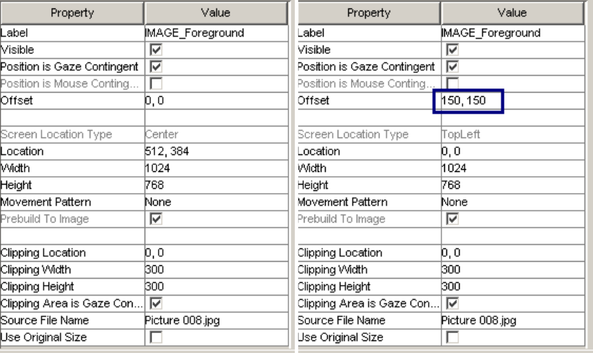
SR Research Experiment Builder User Manual ©2004-2017 SR Research Ltd.
211
Make sure the two image resources are set to the same Location to ensure they overlap
properly, either by specifying the same Location for both resources, or by using the
horizontal and vertical alignment buttons. For the foreground image, then make sure the
“Position is Gaze Contingent” and “Clipping Area is Gaze Contingent” boxes are
checked. Note that these two attributes will only be available when the display screen is
contained in a Recording sequence; otherwise, they will be grayed out. Set the “Clipping
Width” and “Clipping Height” properties (in pixels) of the foreground image to specify
the size of the central window. See the “GCWindow” template for an example.
With the Screen Location set to Center, the gaze-contingent clipping area will be centered
on the gaze position (see the left panel of Figure 8-4). If the Screen Location is set to
TopLeft, the “Offset” attribute of the foreground image should be set to half the clipping
area width and height, respectively, to ensure the clipping area is centered on the gaze
position (see the right panel of Figure 8-4).
A
B
Figure 8-4. Setting Different Location Types for Images Used in a Gaze-Contingent
Window Application.
8.1.1.3 Transparency Manipulation
The Windows version of Experiment Builder uses either the OpenGL or DirectDraw
graphics engine whereas the Mac OS X version uses the OpenGL graphics only. When
using the DirectDraw graphics, the transparency manipulation is done through color
keying. That is, Experiment Builder specifies a particular color to be transparency color
(defined in “Transparency Color” of the “Display Device”). When the graphics engine
does the drawing on the screen, it checks for what to draw and what not to draw based on
the transparency color—when drawing an image on top of a background, the portion of
the image matching the transparency color will not be drawn, and as a result, the

SR Research Experiment Builder User Manual ©2004-2017 SR Research Ltd.
212
background will be seen through. With the color keying approach, you usually only have
fully transparent or fully opaque colors.
For the OpenGL graphics in Windows or Mac OS X, the color keying approach will still
work (ticking the “Use Color Key” option of the image and then specify the appropriate
transparent color in the “Color Key” property). Another option is to use the alpha
channel, if properly encoded in the images. This works by encoding the transparency
information in a separate color channel (i.e., RGBA instead of RGB). When an image is
overlaid onto another image, the alpha value of the source (foreground) color is used to
determine the resulting color. If the value of the alpha channel is transparent, the source
color is invisible, allowing the background color to show through. Alpha values can
range from 0-255, allowing 255 different levels of transparency. To render transparency
through the alpha channel, make sure both the “Use Color Key” and “Ignore Alpha”
options of the image resource are unchecked. Also make sure the image files are properly
prepared—the images are usually in .png format, and the “Bit Depth” of the image
reported in the image Library Manager should be 32 instead of 24.
8.1.2 Video Resource
The Video Resources ( ) is used to present a video clip in a display screen. Experiment
Builder uses a custom-developed video display engine for video clip playback,
specifically designed to allow access to the msec time that each frame of the video is
displayed (the start of the first retrace that contained the frame data on the display) and to
function in Windows real-time mode. This allows researchers to display video stimuli
while avoiding the timing limitations of display packages that use Windows DirectShow
for video presentation.
For optimal video playing performance, a display computer with a fast CPU processor, at
least 4 GB of RAM, a video card with at least 1.0 GB of memory and OpenGL 2.0
support, and a SSD hard drive.
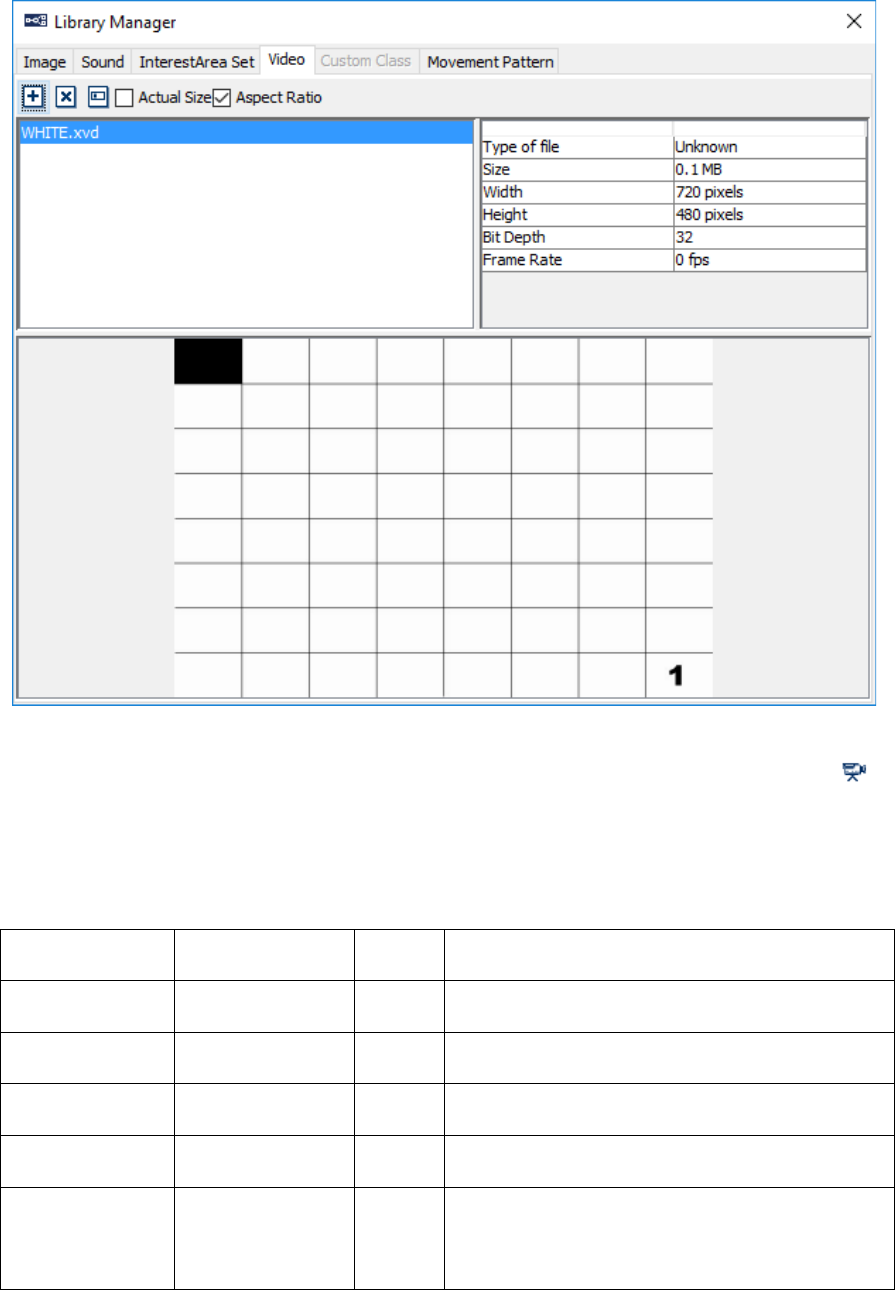
SR Research Experiment Builder User Manual ©2004-2017 SR Research Ltd.
213
Figure 8-5. Loading Video Clips into Video Library.
To add a video resource to a display screen, click the "Insert Video Resource" button ( )
on the Screen Builder toolbar, then click anywhere in the Screen Builder workspace.
Choose the desired video file in the “Select Video” dialog, and then the first frame of the
video will be displayed on the screen.
Field
Attribute
Reference
Type
Content
Label *
.label
String
Label of the video resource. The default label is
“VIDEO_RESOURCE”.
Type #
NR
The type of screen resource ("VideoResource")
the current item belongs to.
Visible †
.visible
Boolea
n
Whether the resource should be visible. The
default setting is True (box checked).
Screen Index #
.screenIndex
Integer
Index of the resource in the screen resource list
(0 - n).
Position is Gaze
Contingent †
.positionAtGazeC
ontingent
Boolea
n
Whether the position of the resource is
contingent on the gaze position. The default
setting is False. This setting is only available
when the parent display screen is contained

SR Research Experiment Builder User Manual ©2004-2017 SR Research Ltd.
214
inside a recording sequence.
Gaze Contingent
Eye
.gazeContingentE
ye
String
Sets the eye used to provide data for the gaze-
contingent drawing. Options are Left, Right,
Either, Average, or Cyclopean (default setting).
For a left-eye-only recording, data from the left
eye is used when the gaze-contingency eye is
set to “Left”, “Either”, or “Cyclopean”, and
missing data when set to “Right” or “Average”.
For a right-eye-only recording, data from the
right eye is used when the gaze-contingency eye
is set to “Right”, “Either”, or “Cyclopean”, and
missing data when set to “Left” or “Average”.
For a binocular recording, left eye data is used
when the gaze-contingency eye is set to “Left”
or “Either”, right eye data is used when set to
“Right”, average data from both eyes if this is
set to “Average” (with missing data if either is
missing), and average data from both eyes when
set to “Cyclopean” (with missing data if both
eyes are missing, and data from the remaining
tracked eye if a single eye is missing).
Position is
Mouse
Contingent †
.positionAtMouse
Contingent
Boolea
n
Whether the position of the resource is
contingent on the mouse position. The default
setting is False.
Contingency
Deadband
.contingentDeadb
and
Tuple
of
integer
s
Sets the minimum amount of eye movement
required to update the gaze-contingent moving
window. This is designed to make the display
drawing less susceptible to jitters in the eye
position. Typically the deadband shouldn’t be
larger than 3.0 pixels—larger deadband values
will likely result in a lag in updating the display.
Offset
.offset
Point
Adjustment of the resource position relative to
the intended resource location, whether
specified by the Location attribute, the current
gaze or mouse position, or a movement pattern.
The default value is (0, 0) for a perfect
alignment of the resource position with the
specified position. Values specified in the Offset
will be subtracted from the specified location.
For example, if the location field is set to (512,
384), and the offset is (100, 100), the actual
resource position will be (412, 284).
Host Outline
Color ¶
.
hostOutlineColor
Color
The color of the box drawn on the host screen to
show the position and dimensions of the current
resource. This property is available only if the
“Use for Host Display” option of the parent
display screen action is enabled and the “Draw
to EyeLink Host” option of the prepare
sequence action is set to “Primitive”.
Screen Location
NR
Whether the location specified below refers to

SR Research Experiment Builder User Manual ©2004-2017 SR Research Ltd.
215
Type #
the top-left corner or center of the resource. This
setting can be changed at “Screen Preferences”.
Location
.location
Point
The coordinates of the top-left corner or center
of the resource. If the Offset is non-zero, the
actual screen position where the resource is
displayed will be the coordinates set in
the .location field minus the .offset adjustment.
Width #
.width
Integer
Width of the video stream (in pixels).
Height #
.height
Integer
Height of the video stream (in pixels).
Movement
Pattern ¶ *
NR
Movement pattern (sinusoidal or custom) of the
resource.
Use Software
Surface #
.useSoftwareSurf
ace
Boolea
n
Always true for Video Resources.
Clipping
Location
.clippingLocation
Point
The coordinates of the top-left corner of the
clipping region. If this is not set to (0,0), only
the part of the image within the clipping region
will be shown.
Clipping Width
.clippingWidth
Integer
Intended width (in pixels) of the clipping region
of the resource. Only the part of the image
within the clipping region will be shown.
Clipping Height
.clippingHeight
Integer
Intended height (in pixels) of the clipping region
of the resource. Only the part of the image
within the clipping region will be shown.
Clipping Area is
Position
Contingent †
.clippingAreaAtG
azeContingent
Boolea
n
Whether the clipping region should be
contingent on the mouse or gaze position. The
default setting is False.
Play Count
.playCount
Integer
Total number of times the video clip will be
played when the display screen is shown. If 0,
the clip will be played continuously in a loop.
Frame List
.frameList
List
XVID video clips: The intended frames of the
video clip to be played. If set to [1--1] (i.e.,
from the first frame 1 to the last frame -1), the
whole clip will be played. Since XVID does not
support frame seeking, the first value must be 1,
whereas the end frame can be configured.
VFW video clips: Specifies the frame list
(frame number and/or ranges of frames) that
should be played for the video. Ranges of
frames and frame indexes can be in any order.
For example, [1-50,52-100,99-50,50,50] would
start to play frames 1 -50, skip frame 51, play
frames 52-100, then play frames 99-50 (i.e.
backwards), then hold frame 50 for 2 more
frames. Note that the performance of presenting
non-sequential frames or presenting frames in
reverse order will be strongly influenced by the
video codec used and the specifications of the
display computer. Performance will generally
be worse than when playing the video in the

SR Research Experiment Builder User Manual ©2004-2017 SR Research Ltd.
216
standard, first-to-last frame order.
Video Loader
.videoLoader
String
The codec used to the play the video clips. In
general, users are recommended to use the
“Default” option, as the software will
automatically choose the video loader for you
based on the file extension. In Mac OS X, the
supported video loader options are Default,
ffmpegLoader (ideal for most .avi, .mp4, .mov
clips), and xvidloader (ideal for most .xvid
clips). In Windows, the supported video loader
options are Default, ffmpegLoader (ideal for
most .mp4, .mov files), vfwloader (ideal for
most .avi clips), and xvidloader (ideal for
most .xvid clips).
Source File
Name ¶
.sourceFileName
String
The name of the video resource file. The video
resource must first be loaded into the resource
library.
Frame Rate
.frameRate
Float
Intended number of frames (default is 30.0) to
be displayed each second (typically 30 frames
per second for NTSC or 25 frames per second
for PAL formatted video). Video playback can
be paused by setting the frame rate to 0 and
unpaused by setting the frame rate to a value
greater than 0. Note that a frame rate higher
than the screen refresh rate is not possible.
Apply
Transparency
.applyTransparen
cy
Boolea
n
When checked, applies a transparency
manipulation to the video—pixels with the same
color value as the transparency color will not be
drawn. In most cases it is best to leave this in its
default setting (unchecked).
Is Playing #
.isPlaying
Boolea
n
Whether the video clip is playing. Returns
“True” if the clip playing is still in progress, and
“False” if the playing has stopped or hasn’t
started yet.
Current Frame
Number #
.currentFrameNu
mber
Integer
The currently processed frame number. This
may not be the currently visible frame on the
screen. Increases by one for every frame
presented.
Current Frame
Index #
.currentFrameInd
ex
Integer
The currently processed frame index. This
should be identical to “Current Frame Number”
for a non-looping video. For video played in a
loop, this reports the relative frame position in a
clip (i.e., a number between 1 and last frame of
the video clip).
Next Frame
Number #
.nextFrameNumb
er
Integer
The index number of next frame to be flipped
(shown on the screen).
Last Frame
Number #
.lastFrameNumbe
r
Integer
The last frame that has been flipped.
Last Frame
Time #
.lastFrameTime
Float
The time of the last frame that has been flipped.

SR Research Experiment Builder User Manual ©2004-2017 SR Research Ltd.
217
Next Frame
Desired Time #
.nextFrameDesire
dTime
Float
Predicted time when the next frame is flipped.
Displayed Frame
Count #
.displayedFrame
Count
Integer
Reports the number of frames displayed (not
including dropped frames).
Dropped Frame
Count #
.droppedFrameC
ount
Integer
Reports the number of dropped frames.
Frames Per
Second #
.FPS
Float
Frames per second calculated as (displayed
frames/(duration played in msec/1000))
Duration #
.duration
Float
Duration (in milliseconds) into clip playback.
When the playback ends, the duration may be
calculated as (@self.displayedFrameCount-
1@)/@self.frameRate@. If the video has been
paused during playback, the reported duration is
calculated from the start to the end of the video,
including the pause duration.
Is Completed
.isCompleted
Boolea
n
Whether the video playback has completed.
Reports False before or during video playback,
and True after playback.
Is Paused
.isPaused
Boolea
n
Whether the video playback is paused. Reports
True if playback is paused, and reports False if
playback is ongoing, as well as before and after
playback.
8.1.2.1 Reading Frame Time
Experiment Builder can record the time of each frame in the EDF file. For example, if a
user adds the following message to the Message field of the Display Screen:
= "Display " + str(@self.VIDEO_RESOURCE.lastFrameNumber@) + "*CRT*" +
str(@self.VIDEO_RESOURCE.currentFrameNumber@)
Output like the following will be written to the EDF:
MSG 8046616 -8 Display 30*CRT*31.
This shows that at the message time (8046616), the visible frame should be 30 (Last
Frame Number). Frame 31 (Current Frame Number) appears at 8046616 + 8 = 8046624.
This flip event also updates frame count and index number, and the associated frame time.
After this flip, Experiment Builder processes frame number 32, the next frame to be
flipped, with the last flipped frame now set to 31.
8.1.2.2 Video Frame Timing
Experiment Builder decodes each frame of the video in advance and attempts to present
the frame at the desired time. The desired display time for a frame is calculated as:
desired_frame_time = video_start_time + (frameNumber * 1000.0 / frameRate)
SR Research Experiment Builder User Manual ©2004-2017 SR Research Ltd.
218
where video_start_time is the millisecond time that the first frame of the video was
presented, frameNumber is the number of the frame to be presented, and frameRate is the
number of frames to display per second. For example, assume the first frame of a video
was presented at time T and the frame rate of the video is 30 frames per second. The
desired display time for frame 100 would therefore be T + 3333.33 msec.
However, the video frame will likely not be able to be presented at the exact time that is
desired, and will instead have an actual display time that is slightly different than the
desired frame time. Two main factors can influence the offset between the desired and
actual display time for a video frame:
1) Interaction between the display monitor's retrace rate and the video's frame rate.
Video frames can only be presented at intervals that are a multiple of the
monitor’s retrace rate. If the monitor retrace rate and video frame rate are not
evenly divisible, then the desired and actual frame display times can be offset by
up to one display retrace (e.g., 16.67 msec at 60 Hz).
2) Duration of decoding and displaying the video frame. If the computer hardware
used to run the video presentation is not able to decode and display frames fast
enough, there may be delays in the frame presentation. If the delay is greater than
a frame’s duration (e.g., 33.33 msec for a 30 fps video), then a video frame can
actually be dropped, increasing the dropped frame count for the video resource.
8.1.2.3 Video Frame Rate and Display Retrace Rate
It is important to know how the nominal frame rate of the video file interacts with the
monitor video refresh rate to determine the actual time point at which a frame is
displayed. As described above, a video frame's desired display time is equal to:
desired_frame_time = video_start_time + (frameNumber*1000.0/frameRate)
The video frame's actual display time, assuming the display computer hardware is
capable of presenting the video without dropping frames, can be conceptualized as:
actual_frame_time = nearestRetraceTo(desired_frame_time)
where nearestRetraceTo calculates the display retrace start time that is closest to the
desired_frame_time provided to the function.
Take the following Figure 8-6 for an example. If a video clip has a nominal frame rate of
30 fps (one frame every 33.33 ms, blue bars) but the hardware video refresh rate is 85 Hz
(one refresh every 11.765 ms, green bars) then the two different update intervals are not
multiples of each other. Assuming a video start time of 0, the second frame would have a
desired display time of 33.33 ms, but the nearest retrace to the desired time is at time
35.29 msec (retrace rate * 3), which would be the actual time that the frame is displayed.
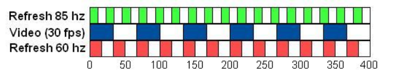
SR Research Experiment Builder User Manual ©2004-2017 SR Research Ltd.
219
Figure 8-6. Video Frame Rate and Display Retrace Rate.
This suggests that it will be ideal to run a video experiment with the vertical refresh rate
being an integer multiple of the frame rate. For practical purposes, that would mean a
refresh rate of either 60 Hz (see the red bars), 90 Hz, 120 Hz, or 150 Hz for a video clip
playing at 30 frames per second. Refresh rates between integer multiples of the frame rate
(75 Hz, for example, with a 30 fps clip) will cause increased variability in the offset
between actual and desired video frame display times.
In reality, the refresh rate of a 60 Hz or 120 Hz monitor may be slightly off. For instance,
the actual refresh rate of a monitor running at 60 Hz could be 60.01 Hz. This means that
even when using a retrace rate that is a multiple of the frame rate, some small drift
between actual and desired frame display times can occur during the course of video
presentation. If this drift between the actual and desired frame display times approaches
one display retrace, the video playing engine corrects for the drift by displaying the
current video frame for a duration slightly less than the full frame duration.
8.1.2.4 Pausing, Unpausing, and the Status of Video Playing
Video playback can be paused by setting the frame rate of the video resource to 0 using
an UPDATE_ATTRIBUTE action (see Figure 8-7); video clip can be unpaused by
setting the frame rate back to the original frame rate. The current status of the video play
can be checked by using the “.isPaused” property of the resource; use the “.isCompleted”
property to check whether the video play ends. The duration of the video play is reported
relative to the onset of the first frame of the video clip.
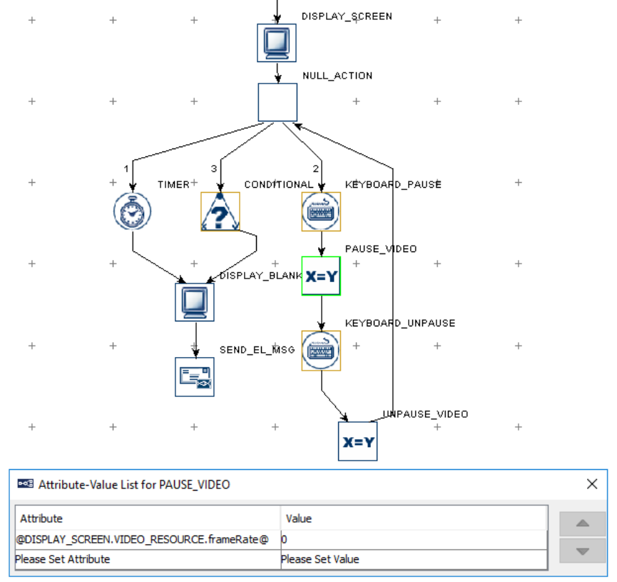
SR Research Experiment Builder User Manual ©2004-2017 SR Research Ltd.
220
Figure 8-7. Pausing and Unpausing Video Play
8.1.2.5 Dropping Frames
The term "dropping frames" refers to the situation where a frame or set of frames was not
displayed on the screen. Dropped frames indicate that the display computer hardware is
not able to keep up with the requested frame rate for the video resource. If the display
computer used meets the recommended specifications for video presentation, dropped
frames should be minimal for normal video playback scenarios.
Experiment Builder will drop a frame if the actual display time for that frame is estimated
to be equal to or greater than the desired display time of the upcoming frame. If the video
playback performance is very poor, this may result in several frames being dropped in a
row.
If a frame is dropped, the "Dropped Frame Count" will be increased in the video resource
object. Furthermore, a warning message is printed to the console and to the warnings.log
SR Research Experiment Builder User Manual ©2004-2017 SR Research Ltd.
221
file indicating the occurrence of the frame drop and the index of the dropped frame. You
can also detect dropped frames by looking at the display screen messages. If a frame is
dropped, no frame display message will be written to the data file, and therefore a
discontinuity will be present in the message stream.
8.1.2.6 Frame Caching
To help ensure smooth video presentation, Experiment Builder caches a certain number
of video frames in memory. By decoding frames in advance, the software does not have
to wait for the decoding of the next frame before it can be displayed on screen and thus
reduces the chances of frame dropping.
The maximum number of frames that are cached for each video resource can be changed;
go the Display Device to set the desired value of the "Video Frame Cache Size". This
should be a value between 5 and 60. A large frame cache size results in a larger amount
of system memory use. This can cause a longer initial preparation time for the video
resources, increasing the execution delay of the Prepare Sequence action. A larger frame
cache size and increased system memory usage can also cause the overall system
performance to degrade if there is not enough physical RAM to hold the frame caches.
Unless there is a specific reason to change the default frame cache size, we suggest that
you do not change the frame cache value.
8.1.2.7 Video Codec
In Windows, Experiment Builder supports video files with .xvd, .mov, and .mp4
encoding, and .avi files compatible with the VFW (video for windows) specifications; In
Mac OS X, Experiment Builder supports files with .xvd, .mov, and .mp4 encoding,
and .avi files encoded with the ffmpeg codec.
The video quality and playback performance will vary depending on the codec used to
compress the video files. Our internal tests have shown that XVID encoded files perform
much better than VFW files as the XVID loader runs faster than the VFW loaders.
Users can re-encode .avi video files as XVID with the Split AVI tool packaged with
Experiment Builder, allowing them to use the better-performing XVID video loader. In
the Split AVI application, set the “Video Codec” in the preferences to “Xvid MPEG-4
Codec” in Windows, or “Xvid Encoder” in Mac OS X (see "Video Experiments" in the
html version of this document.) The "Xvid MPEG-4 codec" is not installed by default in
Windows. To install the XVID codec, run the "Xvid-Install.exe" driver contained in the
"Program Files (x86)\SR Research\3rdparty" folder (for 64-bit Windows; for 32-bit
Windows it will be under "Program Files\SR Research\3rdparty").
If not properly configured, the Split Avi tool may occasionally drop the last frame during
conversion when using the Xvid MPEG-4 codec. Before converting the videos, make
sure the “B-VOPs” option, used to control the between-frames compression, is
unchecked (see the figure below).
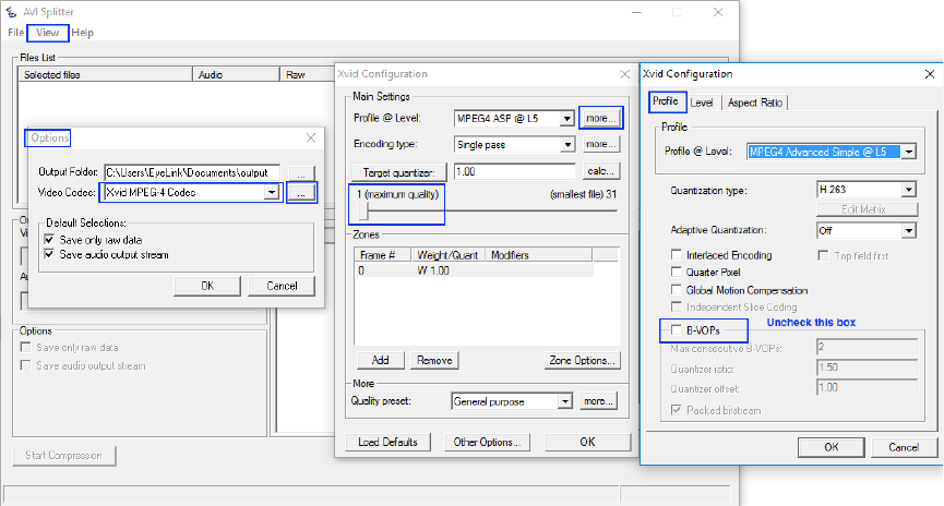
SR Research Experiment Builder User Manual ©2004-2017 SR Research Ltd.
222
Figure 8-8. Xvid Configuration.
If Split AVI displays an error message "Failed to connect source pin to video. No
combination of intermediate filters could be found to make the connection”, this typically
indicates the computer does not have the right combination of filters installed to properly
decode and re-encode your videos. The issue can often be fixed by installing FFDshow, a
DirectShow filter and VFW codec that supports many audio and video formats. The
FFDshow installer can be found in the “C:\Program Files (x86)\SR
Research\3rdParty\ffdshow” directory (in 64-bit Windows; “C:\Program Files\SR
Research\3rdParty\ffdshow” in 32-bit Windows).
Split AVI may also be used to encode video files into the VFW format by choosing one
of the other video codecs from the compressor list, but not all VFW video files can be
recognized and loaded into the Library Manager. In addition, the performance of video
files converted by different video codecs varies. Users may try installing DivX
(http://www.divx.com/divx/play/download/) for VFW codecs with good performance.
Presently Data Viewer only supports the XVID, .mp4, and .mov codecs in the Animation
Playback. Support for the playback of.avi clips in Data Viewer is heavily dependent on
the availability of the video codec. In general, users are advised not to use .avi files in the
Experiment Builder project if they need to play back the video clips during data analysis.
If users deploy the experiment project and run it on a different deployment computer,
please make sure that codec used to test run the video experiment is also installed on the
deployment computer as well; otherwise, the deployed experiment will not run.

SR Research Experiment Builder User Manual ©2004-2017 SR Research Ltd.
223
8.1.2.8 Playing Video Clips with Audio
For those video clips with sound, the "Split Avi" program splits the video stream from the
audio stream in the original video file and saves them into two separate files: a video file,
and a .wav file containing the audio. To play the video and audio together, use a Display
Screen action to show the video stream, and either a Play Sound action, or the
“Synchronize Audio” option of the Display Screen action to play back the audio stream.
To synchronize the playback of the video and audio streams, we recommend using the
ASIO driver (click the "Devices" tab of the structure panel and select the "AUDIO”
device) to play the audio file. To make sure the ASIO driver is installed correctly, please
follow the instructions in the HTML version of this manual under “Installation →
Windows PC System Requirements → ASIO Card Installation”. Once the ASIO driver
has been selected, double click the Display Screen action used to show the video, and
enable the "Synchronize Audio" option. Then select a .wav file from the project library to
play with the video. Set the "Sound Offset" to 0 for synchronized audio and video
playback.
If precise audio/video synchronization is not critical to your experiment, or you do not
have an ASIO sound card on your display computer, you can alternatively use a separate
PLAY_SOUND action right before the DISPLAY_SCREEN action that displays the
video, and have the PLAY_SOUND action play the associated .wav file for the video clip.
This method will work with any audio card when the AUDIO device is in DirectX driver
mode, but will not result in exact synchronization between the audio and video.
8.1.3 Text Resource
To add a text resource onto a display screen, click the “Insert Text Resource” button ( )
on the Screen Builder toolbar and click at the desired position in the workspace where the
text resource will be placed.
To edit the text, double click the resource. A text-editing cursor will appear and users can
type text directly in the Screen Builder. The text can also be edited from the value field of
the “Text” property in the property panel. Users can either enter the text directly in the
text editor or click the right end of the value field to bring up the […] button, then click
this button to bring up an attribute editor dialog box. Various aspects of text appearance
can be modified, including color, font name, style, and size.
Field
Attribute
Reference
Type
Content
Label *
.label
String
Label of the resource (“TEXT_RESOURCE” by
default).
Type #
NR
The type of screen resource ("TextResource")
the current item belongs to.
Visible †
.visible
Boolea
n
Whether the resource should be visible (True by
default).
Screen Index #
.screenIndex
Integer
Index of the resource in the screen resource list
(0 - n).

SR Research Experiment Builder User Manual ©2004-2017 SR Research Ltd.
224
Position is Gaze
Contingent †
.positionAtGazeC
ontingent
Boolea
n
Whether the position of the resource is
contingent on the gaze position. The default
setting is False. This setting is only available
when the parent display screen is contained
inside a recording sequence.
Gaze Contingent
Eye
.gazeContingentE
ye
String
Sets the eye used to provide data for the gaze-
contingent drawing. Options are Left, Right,
Either, Average, or Cyclopean (default setting).
For a left-eye-only recording, data from the left
eye is used when the gaze-contingency eye is
set to “Left”, “Either”, or “Cyclopean”, and
missing data when set to “Right” or “Average”.
For a right-eye-only recording, data from the
right eye is used when the gaze-contingency eye
is set to “Right”, “Either”, or “Cyclopean”, and
missing data when set to “Left” or “Average”.
For a binocular recording, left eye data is used
when the gaze-contingency eye is set to “Left”
or “Either”, right eye data is used when set to
“Right”, average data from both eyes if this is
set to “Average” (with missing data if either is
missing), and average data from both eyes when
set to “Cyclopean” (with missing data if both
eyes are missing, and data from the remaining
tracked eye if a single eye is missing).
Position is
Mouse
Contingent †
.positionAtMouse
Contingent
Boolea
n
Whether the position of the resource is
contingent on the mouse position. The default
setting is False.
Contingency
Deadband
.contingentDeadb
and
Tuple
of
Integer
s
Sets the minimum amount of eye movement
required to update the gaze-contingent moving
window. This is designed to make the display
drawing less susceptible to jitters in the eye
position. Typically the deadband shouldn’t be
larger than 3.0 pixels—larger deadband values
will likely result in a lag in updating the display.
Offset
.offset
Point
Adjustment of the resource position relative to
the intended resource location, whether
specified by the Location attribute, the current
gaze or mouse position, or a movement pattern.
The default value is (0, 0) for a perfect
alignment of the resource position with the
specified position. Values specified in the Offset
will be subtracted from the specified location.
For example, if the location field is set to (512,
384), and the offset is (100, 100), the actual
resource position will be (412, 284).
Host Outline
Color ¶
.
hostOutlineColor
Color
The color of the box drawn on the host screen to
show the position and dimensions of the current
resource. This property is available only if the
“Use for Host Display” option of the parent

SR Research Experiment Builder User Manual ©2004-2017 SR Research Ltd.
225
display screen action is enabled and the “Draw
to EyeLink Host” of the prepare sequence action
is set to “Primitive”.
Screen Location
Type #
NR
Whether the location specified below refers to
the top-left corner or center of the resource. This
setting can be changed in “Screen Preferences”.
Location
.location
Point
The coordinate of the top-left corner or center of
the resource.
Width #
.width
Integer
Intended width of the resource (in pixels).
Height #
.height
Integer
Intended height of the resource (in pixels).
Movement
Pattern ¶ *
NR
Movement pattern (sinusoidal or custom) of the
resource
Prebuild to
Image †
.prebuildToImage
Boolea
n
Whether the resource should be built into an
image when the experiment is built (instead of
having it created during the actual execution of
the trial). This field is always true when the
screen is contained in a recording sequence.
IMPORTANT: If the “Prebuild to Image”
option is turned off, the run-time text rendering
may not look exactly as it does in the screen
editor. In addition, images will not be saved to
support Data Viewer overlay.
Use Software
Surface †
.useSoftwareSurf
ace
Boolea
n
If unchecked, memory on the video card is used
to hold the resource (blitting from the video
card memory to the display surface is fast). If
checked, the system memory is used to hold the
resource (blitting is slow as it is done by
copying from RAM to display surface).
Font Color
.fontColor
Color
Color in which the text is drawn. The default
color is Black (0, 0, 0).
Font Name ¶
.fontName
String
String that specifies the typeface name of the
font. Font Name can be selected from a
dropdown list. The default font is "Times New
Roman". When transferring project from one
computer to another, please ensure the target
computer has this font installed.
Font Style ¶
.fontStyle
String
Sets whether the text is to be rendered using a
normal, italic, or bold face.
Font Size
.fontSize
Integer
Sets the desired font size (20 by default). Please
note that text of the same font size will look
smaller (by a factor of about 1.33) on Mac OS X
than on Windows due to different default DPI
values used across the two operating systems.
Underline †
.underline
Boolea
n
Underlines the text if set to True.
Text
.text
String
Text to appear on screen.
Use Runtime
Word Segment
Interest Area * †
.useRuntimeIAS
Boolea
n
If enabled, an Interest Area set file will be
created during runtime to provide segmentation
for individual words.
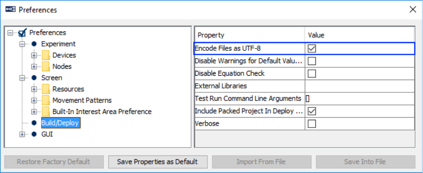
SR Research Experiment Builder User Manual ©2004-2017 SR Research Ltd.
226
8.1.3.1 Non-ASCII Characters
If intending to use any characters that do not fit in the ASCII encoding range (1-127),
please make sure UTF-8 encoding is enabled. Go to Edit → Preferences and make sure
the “Encode Files as UTF-8” box of the Build/Deploy node is checked (see Figure 8-9;
this node is checked by default in later versions of Experiment Builder). This includes
non-English characters (eg. à, è, ù, ç), special curved quotes, and any non-European
language characters (e.g., Chinese characters). In addition, please make sure that the right
font for the text is chosen before entering any text.
Figure 8-9. Setting UTF-8 Encoding.
8.1.3.2 Anti-aliasing and Transparency
Anti-aliasing is one of the most important techniques in making graphics and text easy to
read and pleasing to the eye on-screen. Take the text in Figure 8-10 for example. Panel A
shows an aliased character, in which all of the curves and line drawing appear coarse,
while Panel C shows the same character anti-aliased, which looks smooth. Anti-aliasing
is done by substituting shades of grey (Panel D) around the lines which would otherwise
be broken across a pixel (Panel B).
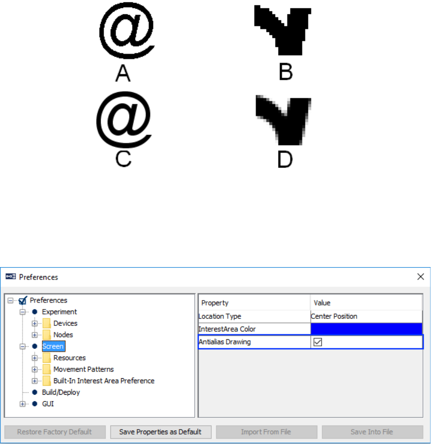
SR Research Experiment Builder User Manual ©2004-2017 SR Research Ltd.
227
Figure 8-10. Aliased and Anti-aliased Texts.
To apply anti-aliasing, first check the Experiment Builder preference settings under Edit
→ Preferences (ExperimentBuilder → Preferences in Mac OS X). Click the “Screen”
node and make sure that the “Antialias Drawing” box is checked (see Figure 8-11).
Figure 8-11. Antialiasing Drawing Preference Setting.
When using the DirectDraw Video Environment, anti-aliasing works well with a uniform
background. If using DirectDraw, set the Transparency color of the Experiment close to,
but not identical to, the background color in the display. For example (see Figure 8-12),
to show black (0, 0, 0) text over white (255, 255, 255) background, users may set the
transparency color to something close to white, for example, (251, 250, 251). Never set
the transparency color the same as the display background color—this will cause the
display to be drawn improperly. If using Mac OS X, make sure the resolution
(Preferences -> Experiment -> Devices -> Display -> "Width" and "Height") is set to the
native resolution of the built-in screen or external monitor to achieve the best anti-
aliasing results.
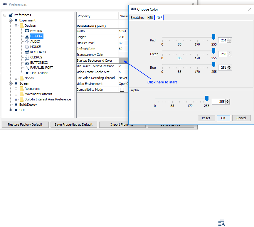
SR Research Experiment Builder User Manual ©2004-2017 SR Research Ltd.
228
Figure 8-12. Setting the Transparency Color for the Experiment.
Generally speaking, anti-aliasing should be applied when using text, multi-line text
resources, line, ellipse, and freeform screen resources. The following sample
experiments use anti-aliasing in resource drawing: Simple, Stroop, TextPage, TextLine,
Saccade, and Pursuit.
8.1.4 Multiline Text Resource
While the above-mentioned text resource allows users to present a single line of text on
the screen, the Multi-Line Text Resources allows up to a full page of text. To add a
Multi-Line Resource, click on the “Insert Multi Line Text Resource” button ( ) on the
Screen Builder toolbar and then click anywhere in the workspace.
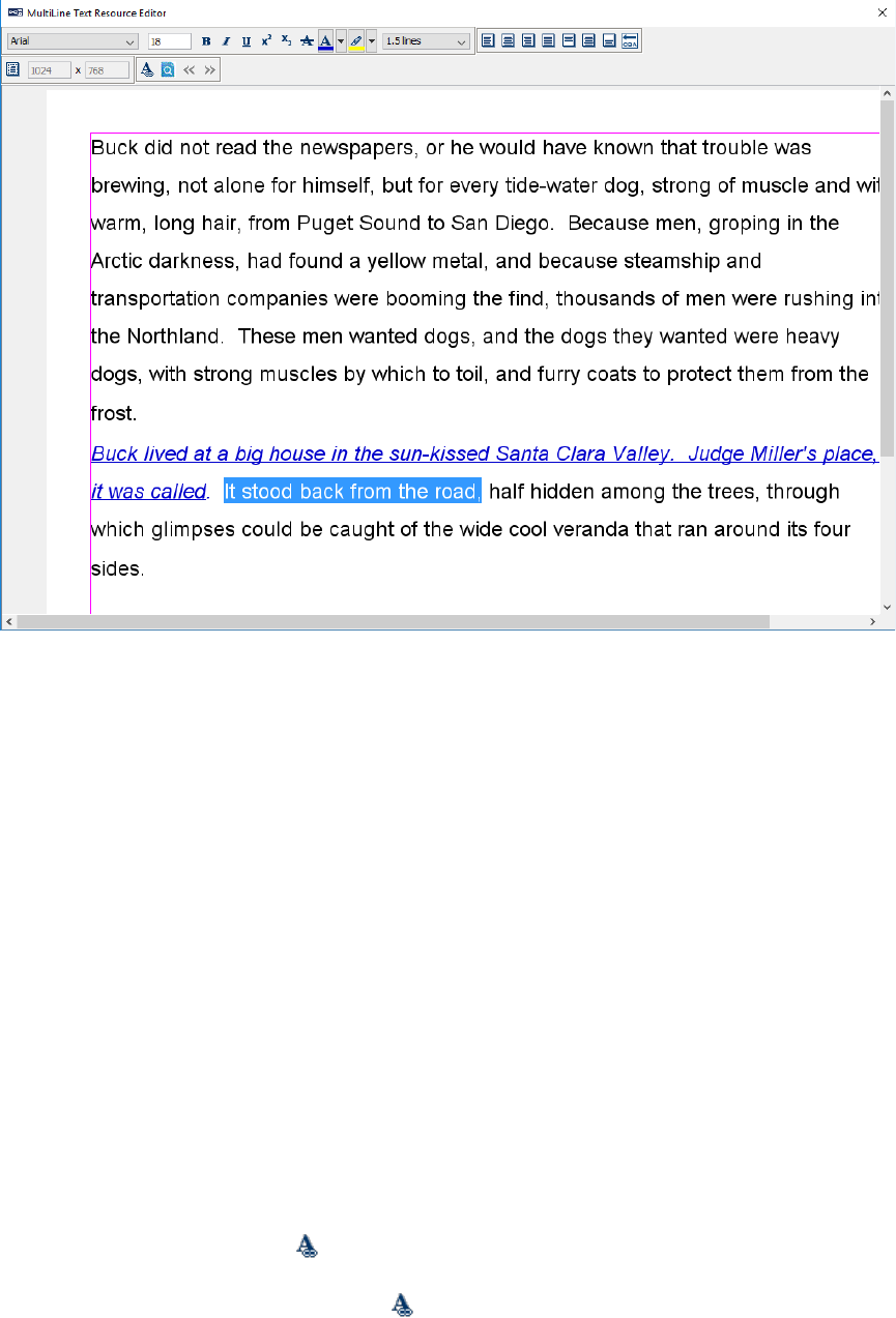
SR Research Experiment Builder User Manual ©2004-2017 SR Research Ltd.
229
Figure 8-13. Multiline Text Resource Editor.
After a multi-line text resource is added to the screen, double-clicking any blank area in
the work space where there is no other resource, will bring up the multi-line text resource
editor. Users can type text in the editor, or paste copied text from other sources using
shortcut keys Ctrl + V on Windows or Command ⌘ + V on Mac OS X. Buttons on the
toolbar of the text editor allow users to modify the appearance of text entered. This
includes text font, font size, text style (bold, italic, underline, subscript, superscript,
strikethrough), text color, background color, line space, horizontal alignment style (left-
aligned, right-aligned, justified, or centered), vertical alignment style (top-aligned,
centered, or bottom-aligned), among options. Text options can be specified either before
the text is entered, or afterwards by selecting the text to be changed and then making the
necessary changes. To select all the text in the multi-line text resource editor, press the
Ctrl + A keys in Windows or Command ⌘ + A in Mac OS X. When changing the font
size of the selected text, press the Enter key to register the change. Text of the same font
size will look smaller (by a factor of about 1.33) on Mac OS X than on Windows due to
different default DPI values used across the two operating systems.
Similar to other screen resources, users can present different materials across trials by
referring the multiline text resource to a data source. To add a reference in the multiline
text resource editor, click the button in the toolbar. In the “Node Attribute” column of
the Attribute Editor, choose the data source column that contains the intended text to be
used for each trial. The referenced text will be placed at the current cursor position.

SR Research Experiment Builder User Manual ©2004-2017 SR Research Ltd.
230
Version 2.0 added a preview option for multiline text resources when they are drawn
through a reference to the data source. Click the “preview” button ( ) on the right-end of
the toolbar to display the text of the first trial in the resource editor. Users can use the
and buttons to navigate to different trials in the data source.
Version 2.0 of Experiment Builder also supports multiline text resource formatted with
basic html code—presently the Cascading Styles Sheets (CSS) or Java Scripts are not
supported. To use the html code, wrap the text within a pair of <html> and </html> tags,
and use the basic html formatting styles as normal. See
http://www.w3schools.com/html/html_formatting.asp and
http://www.w3schools.com/html/html_styles.asp for a supported list of formatting styles.
This page http://www.jonstorm.com/html/font.htm gives a fairly comprehensive example
of text formatting. See the CHM version of this document (section “Screen Builder ->
Resources -> Multiline Text Resource - > Related”) for a project that replicates the text
presentation in Experiment Builder. Note: when using the multiline text resource
formatted with the html tags, please avoid mixing in the formatting styles (e.g., “\n” for a
new line, “\t” for a tab) that are normally used in the plain text.
For example, users may enter the following text in the datasource column and have the
multiline text resource refer to the datasource column:
<html><p style = "font-size:16px;font-family: tahoma">Buck did not <b>read
</b> the <i>newspapers</i>, or <font color="red"> he would</font> have known
that trouble was brewing.</p></html>
Experiment Builder will render the above text as the following during runtime. Please
note - to make the font size consistent with other text resources or non-html multiline text
resources, user may use “font-size:16px” instead of “font-size:16pt” in the html code.
Buck did not read the
newspapers
, or he would have known
that trouble was brewing.
Earlier versions of the software always treated the multiline text resource as a full-screen
resource. Version 2.0 allows users to customize the dimension of the multiline text
resource. In the property table of the multiline text resource, uncheck the “Full Screen”
option. In the multiline text resource editor, you will now see the two editor boxes on the
right-end of the toolbar to set the intended width and height of the text resource. The Top,
Bottom, Left, Right margins of the text can be configured by clicking on the “margins”
button.
The following table lists the properties of a multiline text resource.
Field
Attribute
Reference
Type
Content
Label *
.label
String
Label of the resource
(“MULTILINE_TEXT_RESOURCE” by
default).
Type #
NR
The type of screen resource
("MultiLineTextResource") the current item

SR Research Experiment Builder User Manual ©2004-2017 SR Research Ltd.
231
belongs to.
Visible †
.visible
Boolea
n
Whether the resource should be visible (True by
default).
Screen Index #
.screenIndex
Integer
Index of the resource in the screen resource list
(0 - n).
Position is Gaze
Contingent †
.positionAtGazeC
ontingent
Boolea
n
Whether the position of the resource is
contingent on the gaze position. The default
setting is False. This setting is only available
when the parent display screen is contained
inside a recording sequence.
Position is
Mouse
Contingent †
.positionAtMouse
Contingent
Boolea
n
Whether the position of the resource is
contingent on the mouse position. The default
setting is False.
Offset #
.offset
Point
Adjustment of the resource position relative to
the intended resource location, whether
specified by the Location attribute, the current
gaze or mouse position, or a movement pattern.
The default value is (0, 0) for a perfect
alignment of the resource position with the
specified position. Values specified in the Offset
will be subtracted from the specified location.
For example, if the location field is set to (512,
384), and the offset is (100, 100), the actual
resource position will be (412, 284).
Host Outline
Color ¶
.
hostOutlineColor
Color
The color of the box drawn on the host screen to
show the position and dimensions of the current
resource. This property is available only if the
“Use for Host Display” option of the parent
display screen action is enabled and the “Draw
to EyeLink Host” of the prepare sequence action
is set to “Primitive”.
Screen Location
Type #
NR
Whether the location specified below refers to
the top-left corner or center of the resource. This
setting can be changed in “Screen Preferences”.
Location
.location
Point
The coordinate of the top-left corner or center of
the resource, depending on the Screen
Preferences. For a full-screen multiline text
resource, the default location is (0, 0) for top-
left screen coordinate and center of screen in the
center-position coordinate type.
Width #
.width
Integer
Width of the resource (screen width).
Height #
.height
Integer
Height of the resource (screen height).
Prebuild to
Image # †
.prebuildToImage
Boolea
n
Always True.
Use Software
Surface †
.useSoftwareSurf
ace
Boolea
n
If unchecked, memory on the video card is used
to hold the resource (blitting from the video
card memory to the display surface is fast). If
checked, the system memory is used to hold the
resource (blitting is slow as it is done by
copying from RAM to display surface).

SR Research Experiment Builder User Manual ©2004-2017 SR Research Ltd.
232
Use Runtime
Word Segment
InterestArea * †
.useRuntimeIAS
Boolea
n
If enabled, an Interest Area set file will be
created during runtime to provide segmentation
data for individual words in the text.
Full Screen
NR
Whether the multiline text resource should be a
full-screen resource or not. If unchecked, users
can configure the intended resource dimension
in the multiline text resource editor.
Text Orientation
NR
This option is applicable to the treatment of the
punctuation position in bidirectional languages
(e.g., Arabic, Hebrew). If the “Left-to-Right”
option is selected, the punctuation mark is
placed at the right side of the text; if the “Right-
to-Left” option is selected the punctuation mark
is placed at the left side of the text.
If intending to use any characters that do not fit in the ASCII encoding range (1-127),
please make sure UTF-8 encoding is enabled. Go to Edit → Preferences and make sure
the “Encode Files as UTF-8” box of the Build/Deploy node is checked (see Figure 8-9;
this node is checked by default in later versions of Experiment Builder). This includes
non-English characters (eg. à, è, ù, ç), special curved quotes, and any non-European
language characters (e.g., Chinese characters).
8.1.5 Line Resource
A line resource creates a line drawing on the screen. Click the “Draw Line Resource”
button ( ) on the toolbar to select the line resource type. Place the mouse cursor at the
desired line start location in the work space, click down the left mouse button, keep
dragging the mouse cursor until it reaches the desired end location, and then release the
mouse button. The precise location of the line resource can be edited in the properties
panel. Select the “Start Point” and “End Point” attributes and enter the desired positions
in the (x, y) format. The color and width of the line resource can also be modified.
Field
Attribute
Reference
Type
Content
Label *
.label
String
Label of the resource (“LINE_RESOURCE” by
default).
Type #
NR
The type of screen resource ("LineResource")
the current item belongs to.
Visible †
.visible
Boolean
Whether the resource should be visible. The
default setting is True.
Screen Index #
.screenIndex
Integer
Index of the resource in the screen resource list
(0 - n).
Position is Gaze
Contingent †
.positionAtGaz
eContingent
Boolean
Whether the position of the resource is
contingent on the gaze position. The default
setting is False. This setting is only available
when the parent display screen is contained
inside a recording sequence.
Gaze Contingent
Eye
.gazeContingen
tEye
String
Sets the eye used to provide data for the gaze-
contingent drawing. Options are Left, Right,

SR Research Experiment Builder User Manual ©2004-2017 SR Research Ltd.
233
Either, Average, or Cyclopean (default setting).
For a left-eye-only recording, data from the left
eye is used when the gaze-contingency eye is
set to “Left”, “Either”, or “Cyclopean”, and
missing data when set to “Right” or “Average”.
For a right-eye-only recording, data from the
right eye is used when the gaze-contingency eye
is set to “Right”, “Either”, or “Cyclopean”, and
missing data when set to “Left” or “Average”.
For a binocular recording, left eye data is used
when the gaze-contingency eye is set to “Left”
or “Either”, right eye data is used when set to
“Right”, average data from both eyes if this is
set to “Average” (with missing data if either is
missing), and average data from both eyes when
set to “Cyclopean” (with missing data if both
eyes are missing, and data from the remaining
tracked eye if a single eye is missing).
Position is
Mouse
Contingent †
.positionAtMou
seContingent
Boolean
Whether the position of the resource is
contingent on the mouse position. The default
setting is False.
Contingency
Deadband
.contingentDea
dband
Tuple of
integers
Sets the minimum amount of eye movement
required to update the gaze-contingent moving
window. This is designed to make the display
drawing less susceptible to jitters in the eye
position. Typically the deadband shouldn’t be
larger than 3.0 pixels—larger deadband values
will likely result in a lag in updating the display.
Offset
.offset
Point
Adjustment of the resource position relative to
the intended resource location, whether
specified by the Location attribute, the current
gaze or mouse position, or a movement pattern.
The default value is (0, 0) for a perfect
alignment of the resource position with the
specified position. Values specified in the Offset
will be subtracted from the specified location.
For example, if the location field is set to (512,
384), and the offset is (100, 100), the actual
resource position will be (412, 284).
Host Outline
Color ¶
.
hostOutlineCol
or
Color
The color of the box drawn on the host screen to
show the position and dimensions of the current
resource. This property is available only if the
“Use for Host Display” option of the parent
display screen action is enabled and the “Draw
to EyeLink Host” of the prepare sequence action
is set to “Primitive”.
Screen Location
Type
NR
Whether the location specified below refers to
the top-left corner or center of the resource. This
setting can be changed in “Screen Preferences”.
Location
.location
Point
The coordinates of the top-left corner or center
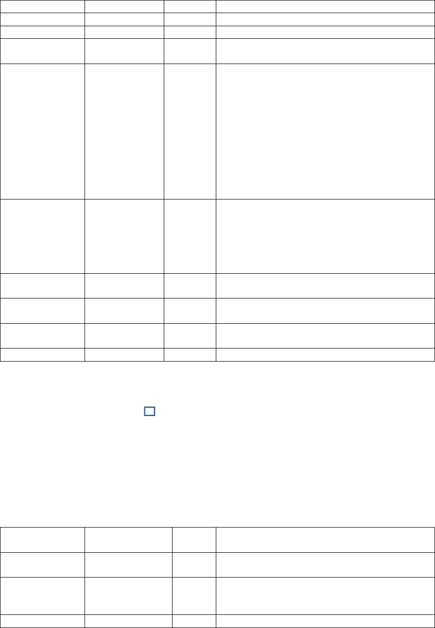
SR Research Experiment Builder User Manual ©2004-2017 SR Research Ltd.
234
of the resource.
Width #
.width
Integer
Intended width (in pixels) of the resource.
Height #
.height
Integer
Intended height (in pixels) of the resource.
Movement
Pattern ¶ *
NR
Movement pattern (sinusoidal or custom) of the
resource.
Prebuild to
Image †
.prebuildToIma
ge
Boolean
Whether the resource should be built into an
image when the experiment is built (instead of
having it created during runtime). This field is
always true when the display screen is contained
in a recording sequence.
IMPORTANT: If this attribute is False, the
run-time drawing may not look exactly as it
does in the Screen Builder. In addition, images
will not be saved to support Data Viewer
overlay.
Use Software
Surface †
.useSoftwareSu
rface
Boolean
If unchecked, memory on the video card is used
to hold the resource (blitting from the video
card memory to the display surface is fast). If
checked, the system memory is used to hold the
resource (blitting is slow as it is done by
copying data from RAM to display surface).
Color
.color
Color
Color in which the line is drawn. The default
color is medium gray (128, 128, 128).
Stroke Width
.strokeWidth
Integer
Specifies the width (1 pixel by default) of the
pen.
Start Point
.startPoint
Point
(x, y) coordinates of the starting point of the
line.
End Point
.endPoint
Point
(x, y) coordinates of the ending point of the line.
8.1.6 Rectangle Resource
The rectangle resource creates a filled or framed rectangle on the screen. Click the “Draw
Rectangle Resource” button ( ) on the toolbar to select the resource type. Then simply
click and drag the mouse within the Screen Builder to draw the rectangle. The precise
size and location of the resource can be set in the properties panel with the “Location”,
“Width”, and “Height” attributes. The appearance of the rectangle’s border can be set
with the “Color” and “Stroke Width” attributes. If the “Filled” property is set to true, the
interior of the rectangle will be filled with the color specified as the “Fill Color”;
otherwise, only the border of the rectangle will be drawn, and the fill color will be
ignored.
Field
Attribute
Reference
Type
Content
Label *
.label
String
Label of the resource. The default value is
“RECTANGLE_RESOURCE”.
Type #
NR
The type of screen resource
("RectangleResource") the current item belongs
to.
Visible †
.visible
Boolea
Whether the resource should be visible. The

SR Research Experiment Builder User Manual ©2004-2017 SR Research Ltd.
235
n
default setting is True (box checked).
Screen Index #
.screenIndex
Integer
Index of the resource in the screen resource list
(0 - n).
Position is Gaze
Contingent †
.positionAtGazeC
ontingent
Boolea
n
Whether the position of the resource is
contingent on the gaze position. The default
setting is False. This setting is only available
when the parent display screen is contained
inside a recording sequence.
Gaze Contingent
Eye
.gazeContingentE
ye
String
Sets the eye used to provide data for the gaze-
contingent drawing. Options are Left, Right,
Either, Average, or Cyclopean (default setting).
For a left-eye-only recording, data from the left
eye is used when the gaze-contingency eye is
set to “Left”, “Either”, or “Cyclopean”, and
missing data when set to “Right” or “Average”.
For a right-eye-only recording, data from the
right eye is used when the gaze-contingency eye
is set to “Right”, “Either”, or “Cyclopean”, and
missing data when set to “Left” or “Average”.
For a binocular recording, left eye data is used
when the gaze-contingency eye is set to “Left”
or “Either”, right eye data is used when set to
“Right”, average data from both eyes if this is
set to “Average” (with missing data if either is
missing), and average data from both eyes when
set to “Cyclopean” (with missing data if both
eyes are missing, and data from the remaining
tracked eye if a single eye is missing).
Position is
Mouse
Contingent †
.positionAtMouse
Contingent
Boolea
n
Whether the position of the resource is
contingent on the mouse position. The default
setting is False.
Contingency
Deadband
.contingentDeadb
and
Tuple
of
integer
s
Sets the minimum amount of eye movement
required to update the gaze-contingent moving
window. This is designed to make the display
drawing less susceptible to jitters in the eye
position. Typically the deadband shouldn’t be
larger than 3.0 pixels—larger deadband values
will likely result in a lag in updating the display.
Offset
.offset
Point
Adjustment of the resource position relative to
the intended resource location, whether
specified by the Location attribute, the current
gaze or mouse position, or a movement pattern.
The default value is (0, 0) for a perfect
alignment of the resource position with the
specified position. Values specified in the Offset
will be subtracted from the specified location.
For example, if the location field is set to (512,
384), and the offset is (100, 100), the actual
resource position will be (412, 284).
Host Outline
.
Color
The color of the box drawn on the host screen to

SR Research Experiment Builder User Manual ©2004-2017 SR Research Ltd.
236
Color ¶
hostOutlineColor
show the position and dimensions of the current
resource. This property is available only if the
“Use for Host Display” option of the parent
display screen action is enabled and the “Draw
to EyeLink Host” property of the prepare
sequence action is set to “Primitive”.
Screen Location
Type #
NR
Whether the location specified below refers to
the top-left corner or center of the resource. This
setting can be changed in Screen Preferences.
Location
.location
Point
The coordinates of the top-left corner or center
of the resource.
Width
.width
Integer
Width of the resource (in pixels).
Height
.height
Integer
Height of the resource (in pixels).
Movement
Pattern ¶ *
NR
Movement pattern (sinusoidal or custom) of the
resource.
Prebuild to
Image †
.prebuildToImage
Boolea
n
Whether the resource should be built into an
image when the experiment is built (instead of
having it created during run time). This field is
always true when the display screen is contained
in a recording sequence.
IMPORTANT: If this attribute is False, the
run-time drawing may not look exactly as it
does in the screen editor. In addition, images
will not be saved to support Data Viewer
overlay.
Use Software
Surface †
.useSoftwareSurf
ace
Boolea
n
If unchecked, memory on the video card is used
to hold the resource (blitting from the video
card memory to the display surface is fast). If
checked, the system memory is used to hold the
resource (blitting is slow as it is done by
copying from RAM to display surface).
Color
.color
Color
Color of the resource outline. The default color
is medium gray (128, 128, 128).
Filled †
.filled
Boolea
n
Whether the interior of the resource should be
filled. If False, this just draws a framed
rectangle. True by default.
Fill Color
.fillColor
Color
Color filling the resource interior. The default
color is medium gray (192, 192, 192).
Stroke Width
.strokeWidth
Integer
Specifies the width (1 by default) of the pen in
pixels.
8.1.7 Ellipse Resource
Similar to the rectangle resource, clicking on the ‘Draw Ellipse Resource’ tool button ( )
creates a filled or framed ellipse bounded by a box defined by the “Location”, “Width”,
and “Height” properties of the resource. Follow the same steps as in the previous section
to create an ellipse resource and to modify its appearance.
Field
Attribute
Type
Content

SR Research Experiment Builder User Manual ©2004-2017 SR Research Ltd.
237
Reference
Label *
.label
String
Label of the resource. The default value is
“ELLIPSE_RESOURCE”.
Type #
NR
The type of screen resource ("EllipseResource")
the current item belongs to.
Visible †
.visible
Boolea
n
Whether the resource should be visible. The
default setting is True (box checked).
Screen Index #
.ScreenIndex
Integer
Index of the resource in the screen resource list
(0 - n).
Position is Gaze
Contingent †
.positionAtGazeC
ontingent
Boolea
n
Whether the position of the resource is
contingent on the gaze position. The default
setting is False. This setting is only available
when the parent display screen is contained
inside a recording sequence.
Gaze Contingent
Eye
.gazeContingentE
ye
String
Sets the eye used to provide data for the gaze-
contingent drawing. Options are Left, Right,
Either, Average, or Cyclopean (default setting).
For a left-eye-only recording, data from the left
eye is used when the gaze-contingency eye is
set to “Left”, “Either”, or “Cyclopean”, and
missing data when set to “Right” or “Average”.
For a right-eye-only recording, data from the
right eye is used when the gaze-contingency eye
is set to “Right”, “Either”, or “Cyclopean”, and
missing data when set to “Left” or “Average”.
For a binocular recording, left eye data is used
when the gaze-contingency eye is set to “Left”
or “Either”, right eye data is used when set to
“Right”, average data from both eyes if this is
set to “Average” (with missing data if either is
missing), and average data from both eyes when
set to “Cyclopean” (with missing data if both
eyes are missing, and data from the remaining
tracked eye if a single eye is missing).
Position is
Mouse
Contingent †
.positionAtMouse
Contingent
Boolea
n
Whether the position of the resource is
contingent on the mouse position. The default
setting is False.
Contingency
Deadband
.contingentDeadb
and
Tuple
of
integer
s
Sets the minimum amount of eye movement
required to update the gaze-contingent moving
window. This is designed to make the display
drawing less susceptible to jitters in the eye
position. Typically the deadband shouldn’t be
larger than 3.0 pixels—larger deadband values
will likely result in a lag in updating the display.
Offset
.offset
Point
Adjustment of the resource position relative to
the intended resource location, whether
specified by the Location attribute, the current
gaze or mouse position, or a movement pattern.
The default value is (0, 0) for a perfect
alignment of the resource position with the

SR Research Experiment Builder User Manual ©2004-2017 SR Research Ltd.
238
specified position. Values specified in the Offset
will be subtracted from the specified location.
For example, if the location field is set to (512,
384), and the offset is (100, 100), the actual
resource position will be (412, 284).
Host Outline
Color ¶
.
hostOutlineColor
Color
The color of the box drawn on the host screen to
show the position and dimensions of the current
resource. This property is available only if the
“Use for Host Display” option of the parent
display screen action is enabled and the “Draw
to EyeLink Host” of the prepare sequence action
is set to “Primitive”.
Screen Location
Type #
NR
Whether the location specified below refers to
the top-left corner or center of the resource. This
setting can be changed in “Screen Preferences”.
Location
.location
Point
The coordinates of the top-left corner or center
of the resource.
Width
.width
Integer
Width of the resource in screen pixels.
Height
.height
Integer
Height of the resource in screen pixels.
Movement
Pattern ¶ *
NR
Movement pattern (sinusoidal or custom) of the
resource.
Prebuild to
Image †
.prebuildToImage
Boolea
n
Whether the resource should be built into an
image when the experiment is built (instead of
having it created during the actual execution of
the trial). This field is always true when the
screen is contained in a recording sequence.
IMPORTANT: If this attribute is False, the
run-time drawing may not look exactly as it
does in the screen editor. In addition, images
will not be saved to support Data Viewer
overlay.
Use Software
Surface †
.useSoftwareSurf
ace
Boolea
n
If unchecked, memory on the video card is used
to hold the resource (blitting from the video
card memory to the display surface is fast). If
checked, the system memory is used to hold the
resource (blitting is slow as it is done by
copying from RAM to display surface).
Color
.color
Color
Color of the resource outline. The default color
is medium gray (128, 128, 128).
Filled †
.filled
Boolea
n
Whether the interior of the resource should be
filled. If False, just draws a framed ellipse. True
by default.
Fill Color
.fillColor
Color
Color filling the resource interior. The default
color is medium gray (192, 192, 192).
Stroke Width
.strokeWidth
Integer
Specifies the width (1 by default) of the pen in
pixels.

SR Research Experiment Builder User Manual ©2004-2017 SR Research Ltd.
239
8.1.8 Triangle Resource
The triangle resource can be used to create an isosceles triangle. (To create other types of
triangle, use the freeform resource instead.) To create a triangle resource on the screen,
click the “Draw Triangle Resource” button ( ) on the toolbar. Then simply click and
drag the mouse within the Screen Builder to draw the rectangle.
To adjust the location of the triangle resource, select the resource, then click and drag it
to the intended location. The precise location of the resource can also be set in the value
field of the “Location” property. To adjust the height and width of the triangle, select the
resource and hover the cursor over one of the three vertices—the cursor will change to a
resizing cursor (e.g., ). Then simply click and drag the vertex to its intended location.
The appearance of the triangle resource can be configured in the “Color”, “Fill Color”,
and “Stroke Width” properties. If the “Filled” property is set to true, the interior of the
rectangle will be filled with the color specified as the “Fill Color”; otherwise, only the
border of the rectangle will be drawn, and the fill color will be ignored.
Field
Attribute
Reference
Type
Content
Label *
.label
String
Label of the resource. The default label is
“TRIANGLE_RESOURCE”.
Type #
NR
The type of screen resource
("TriangleResource") the current item belongs
to.
Visible †
.visible
Boolea
n
Whether the resource should be visible. This is
True by default (box checked).
Screen Index #
.screenIndex
Integer
Index of the resource in the screen resource list
(0 - n).
Position is Gaze
Contingent †
.positionAtGazeC
ontingent
Boolea
n
Whether the position of the resource is
contingent on the gaze position. The default
setting is False. This setting is only available
when the parent display screen is contained
inside a recording sequence.
Gaze Contingent
Eye
.gazeContingentE
ye
String
Sets the eye used to provide data for the gaze-
contingent drawing. Options are Left, Right,
Either, Average, or Cyclopean (default setting).
For a left-eye-only recording, data from the left
eye is used when the gaze-contingency eye is
set to “Left”, “Either”, or “Cyclopean”, and
missing data when set to “Right” or “Average”.
For a right-eye-only recording, data from the
right eye is used when the gaze-contingency eye
is set to “Right”, “Either”, or “Cyclopean”, and
missing data when set to “Left” or “Average”.
For a binocular recording, left eye data is used
when the gaze-contingency eye is set to “Left”
or “Either”, right eye data is used when set to
“Right”, average data from both eyes if this is

SR Research Experiment Builder User Manual ©2004-2017 SR Research Ltd.
240
set to “Average” (with missing data if either is
missing), and average data from both eyes when
set to “Cyclopean” (with missing data if both
eyes are missing, and data from the remaining
tracked eye if a single eye is missing).
Position is
Mouse
Contingent †
.positionAtMouse
Contingent
Boolea
n
Whether the position of the resource is
contingent on the mouse position. The default
setting is False.
Contingency
Deadband
.contingentDeadb
and
Tuple
of
integer
s
Sets the minimum amount of eye movement
required to update the gaze-contingent moving
window. This is designed to make the display
drawing less susceptible to jitters in the eye
position. Typically the deadband shouldn’t be
larger than 3.0 pixels—larger deadband values
will likely result in a lag in updating the display.
Offset
.offset
Point
Adjustment of the resource position relative to
the intended resource location, whether
specified by the Location attribute, the current
gaze or mouse position, or a movement pattern.
The default value is (0, 0) for a perfect
alignment of the resource position with the
specified position. Values specified in the Offset
will be subtracted from the specified location.
For example, if the location field is set to (512,
384), and the offset is (100, 100), the actual
resource position will be (412, 284).
Host Outline
Color ¶
.
hostOutlineColor
Color
The color of the box drawn on the host screen to
show the position and dimensions of the current
resource. This property is available only if the
“Use for Host Display” option of the parent
display screen action is enabled and the “Draw
to EyeLink Host” of the prepare sequence action
is set to “Primitive”.
Screen Location
Type #
NR
Whether the location specified below refers to
the top-left corner or center of the resource. This
setting can be changed in “Screen Preferences”.
Location
.location
Point
The coordinates of the top-left corner or center
of the resource.
Width #
.width
Integer
Width of the resource in pixels.
Height #
.height
Integer
Height of the resource in pixels.
Movement
Pattern ¶ *
NR
Movement pattern (sinusoidal or custom) of the
resource.
Prebuild to
Image †
.prebuildToImage
Boolea
n
Whether the resource should be built into an
image when the experiment is built (instead of
having it created during the actual execution of
the trial). This field is always true when the
display screen is contained in a recording
sequence.
IMPORTANT: If this attribute is False, the

SR Research Experiment Builder User Manual ©2004-2017 SR Research Ltd.
241
run-time drawing may not look exactly as it
does in the screen editor. In addition, images
will not be saved to support Data Viewer
overlay.
Use Software
Surface †
.useSoftwareSurf
ace
Boolea
n
If unchecked, memory on the video card is used
to hold the resource (blitting from the video
card memory to the display surface is fast). If
checked, the system memory is used to hold the
resource (blitting is slow as it is done by
copying from RAM to display surface).
Color
.color
Color
Color of the resource outline. The default color
is medium gray (128, 128, 128).
Filled †
.filled
Boolea
n
Whether the interior of the resource should be
filled. The default setting is True.
Fill Color
.fillColor
Color
Color filling the resource interior. The default
color is medium gray (192, 192, 192).
Stroke Width
.strokeWidth
Integer
Specifies the width (1 by default) of the pen in
pixels.
Point One #
.pointOne
Point
(x, y) coordinates of the first point of the
triangle.
Point Two #
.pointTwo
Point
(x, y) coordinates of the second point of the
triangle.
Point Three #
.pointThree
Point
(x, y) coordinates of the third point of the
triangle.
8.1.9 Freeform Resource
The freeform resource can be used to draw a polygon consisting of two or more vertices
connected by straight lines. To create a freeform resource on the screen, it may be helpful
to first determine the list of x, y coordinates for all of the intended vertices in order. Click
the “Draw Freeform Resource” button ( ) on the toolbar, then click the mouse in the
Screen Builder workspace at the intended position for the first vertex. Next, click the
position for the second vertex, and continue for the remaining points. To end drawing,
simply press the “Enter” key, and the last vertex will be connected back to the first. To
create a curved object, simply click and drag the mouse cursor along the intended shape
until the shape is closed.
To move a freeform resource on the screen, simply select the object and drag it to a
desired location. To adjust the position of individual vertices, select the resource and
hover the cursor over one of the vertices—the cursor will change to a resizing cursor (e.g.,
). Then simply click and drag the vertex to its intended location.
The appearance of the triangle resource can be configured in the “Color”, “Fill Color”,
and “Stroke Width” properties. If the “Filled” property is set to true, the interior of the
rectangle will be filled with the color specified as the “Fill Color”; otherwise, only the
border of the rectangle will be drawn, and the fill color will be ignored.
Field
Attribute
Type
Content

SR Research Experiment Builder User Manual ©2004-2017 SR Research Ltd.
242
Reference
Label *
.label
String
Label of the resource. The default label is
“FREEFORM_RESOURCE”.
Type #
NR
The type of screen resource
("FreehandResource") the current item belongs
to.
Visible †
.visible
Boolea
n
Whether the resource should be visible. True by
default.
Screen Index #
.screenIndex
Integer
Index of the resource in the screen resource list
(0 - n).
Position is Gaze
Contingent †
.positionAtGazeC
ontingent
Boolea
n
Whether the position of the resource is
contingent on the gaze position. The default
setting is False. This setting is only available
when the parent display screen is contained
inside a recording sequence.
Gaze Contingent
Eye
.gazeContingentE
ye
String
Sets the eye used to provide data for the gaze-
contingent drawing. Options are Left, Right,
Either, Average, or Cyclopean (default setting).
For a left-eye-only recording, data from the left
eye is used when the gaze-contingency eye is
set to “Left”, “Either”, or “Cyclopean”, and
missing data when set to “Right” or “Average”.
For a right-eye-only recording, data from the
right eye is used when the gaze-contingency eye
is set to “Right”, “Either”, or “Cyclopean”, and
missing data when set to “Left” or “Average”.
For a binocular recording, left eye data is used
when the gaze-contingency eye is set to “Left”
or “Either”, right eye data is used when set to
“Right”, average data from both eyes if this is
set to “Average” (with missing data if either is
missing), and average data from both eyes when
set to “Cyclopean” (with missing data if both
eyes are missing, and data from the remaining
tracked eye if a single eye is missing).
Position is
Mouse
Contingent †
.positionAtMouse
Contingent
Boolea
n
Whether the position of the resource is
contingent on the mouse position. The default
setting is False.

SR Research Experiment Builder User Manual ©2004-2017 SR Research Ltd.
243
Contingency
Deadband
.contingentDeadb
and
Tuple
of
integer
s
Sets the minimum amount of eye movement
required to update the gaze-contingent moving
window. This is designed to make the display
drawing less susceptible to jitters in the eye
position. Typically the deadband shouldn’t be
larger than 3.0 pixels—larger deadband values
will likely result in a lag in updating the display.
Offset
.offset
Point
Adjustment of the resource position relative to
the intended resource location, whether
specified by the Location attribute, the current
gaze or mouse position, or a movement pattern.
The default value is (0, 0) for a perfect
alignment of the resource position with the
specified position. Values specified in the Offset
will be subtracted from the specified location.
For example, if the location field is set to (512,
384), and the offset is (100, 100), the actual
resource position will be (412, 284).
Host Outline
Color ¶
.
hostOutlineColor
Color
The color of the box drawn on the host screen to
show the position and dimensions of the current
resource. This property is available only if the
“Use for Host Display” option of the parent
display screen action is enabled and the “Draw
to EyeLink Host” of the prepare sequence action
is set to “Primitive”.
Screen Location
Type #
NR
Whether the location specified below refers to
the top-left corner or center of the resource. This
setting can be changed in “Screen Preferences”.
Location
.location
Point
The coordinates of the top-left corner or center
of the resource.
Width #
.width
Integer
Width of the resource in pixels.
Height #
.height
Integer
Height of the resource in pixels.
Movement
Pattern ¶ *
NR
Movement pattern (sinusoidal or custom) of the
resource.
Prebuild to
Image †
.prebuildToImage
Boolea
n
Whether the resource should be saved in an
image file when the experiment is built (instead
of having it created during run time). This field
is always true when the screen is contained in a
recording sequence.
IMPORTANT: If this attribute is False, the
run-time drawing may not look exactly as it

SR Research Experiment Builder User Manual ©2004-2017 SR Research Ltd.
244
does in the screen editor. In addition, images
will not be saved to support Data Viewer
overlay.
Use Software
Surface †
.useSoftwareSurf
ace
Boolea
n
If unchecked, memory on the video card is used
to hold the resource (blitting from the video
card memory to the display surface is fast). If
checked, the system memory is used to hold the
resource (blitting is slow as it is done by
copying from RAM to display surface).
Color
.color
Color
Color of the resource outline. The default color
is medium gray (128, 128, 128).
Filled †
.filled
Boolea
n
Whether the interior of the freeform should be
filled. The default setting is True.
Fill Color
.fillColor
Color
Color filling the resource interior. The default
color is medium gray (192, 192, 192).
Stroke Width #
.strokeWidth
Integer
Specifies the width (1 by default) of the pen in
pixels.
Points #
.points
List of
Points
(x, y) coordinates of the points of the freeform.
8.2 Movement Patterns
Experiment Builder allows users to define Movement Patterns, so that screen resources
such as images, shapes, text and videos may move onscreen. Various movement patterns
can be created, allowing resources to move at a constant speed, oscillate sinusoidally, or
jump discontinuously. This is convenient for experiments showing moving targets on the
screen, such as smooth pursuit paradigms.
Two types of movement patterns can be created: Sinusoidal and Custom. To create a
movement pattern, click the “Insert Sine MovementPattern” button ( ) or “Insert
Custom MovementPattern” button ( ) on the Screen Builder toolbar (see Figure 8-14).
After creating the movement pattern, users can assign the pattern to a resource by setting
the “Movement Pattern” attribute of the resource.
Figure 8-14. Creating a Movement Pattern.
In order for Data Viewer to integrate the target position information, write out a "!V
TARGET_POS" message from the Display Screen action used to present the moving
screen resource. (See the EyeLink Data Viewer User Manual, section "Protocol for
EyeLink Data to Viewer Integration → Target Position Commands”, or the “Pursuit”
example, for illustrations of using this message). Target position can be derived from the
TARGET_X and TARGET_Y variables of a Sample Report.
8.2.1 Sinusoidal Movement Pattern
Smooth sinusoidal movement patterns are widely used in diagnostic testing due to their
wide range of velocities and lack of abrupt changes in speed and direction. To review the

SR Research Experiment Builder User Manual ©2004-2017 SR Research Ltd.
245
properties of a movement pattern, click the movement pattern node in the Structure Panel
of the Project Explorer Window. The defining parameters of a sinusoidal movement are
the frequency (cycles per second), amplitude of the movement, start phase, and the center
X and Y coordinates (see the following table for details). In one full cycle, the target will
move from (Xcenter - Xamplitude, Ycenter - Yamplitude) to (Xcenter + Xamplitude, Ycenter + Yamplitude),
and the movement will be centered at (Xcenter, Ycenter).
Field
Attribute
Reference
Type
Content
Label *
.label
String
Label of the sinusoidal movement pattern
(“SINE_PATTERN” by default).
Type #
NR
The type of Experiment Builder object
("SinePattern") the current item belongs to.
Screen
Location Type
#
NR
Whether the locations specified refer to the top-left
corner or center of the resource. This setting can be
changed at “Screen Preferences”.
Start Time
.startTime
Float
Start Time of the movement. Typically set to 0 so
that the start time of the movement pattern is
aligned to the display screen action.
Amplitude X
.amplitudeX
Float
The amplitude of horizontal movement in pixels
(341.0 by default).
Amplitude Y
.amplitudeY
Float
The amplitude of vertical movement in pixels (256.0
by default).
Center X
.plotX
Float
The horizontal center of the movement in pixels.
Typically the center of the screen.
Center Y
.plotY
Float
The vertical center of the movement in pixels.
Frequency X
.frequencyX
Float
The speed of horizontal movement (in number of
cycles per second; Hz).
Frequency Y
.frequencyY
Float
The speed of vertical movement.
Start Phase X
.startPhaseX
Float
The start phase position of horizontal movement.
This number should be between 0 and 360.
Start Phase Y
.startPhaseY
Float
The start phase position of vertical movement. This
number should be between 0 and 360.
Note: Amplitude X should be set to 0 for a vertical sine movement and Amplitude Y
should be 0 for a horizontal movement. X and Y amplitudes must be the same for a
circular movement; unequal values will result in an elliptic movement.
The start point of the movement is specified by the Start Phase X and Start Phase Y. The
following table lists the most important landmark positions in a sinusoidal movement.
Dimension
Phase
Position
Direction
Horizontal (x)
0°
Center
Moving right
Horizontal (x)
90°
Right
Stationary
Horizontal (x)
180°
Center
Moving left

SR Research Experiment Builder User Manual ©2004-2017 SR Research Ltd.
246
Horizontal (x)
270°
Left
Stationary
Vertical (y)
0°
Center
Moving down
Vertical (y)
90°
Bottom
Stationary
Vertical (y)
180°
Center
Moving up
Vertical (y)
270°
Top
Stationary
For a horizontal-only movement, Start Phase Y should be set to 0°. A Start Phase X of 0°
defines a movement that starts at the center of the movement range and moves right; a
Start Phase X of 90° defines a movement that starts at the right end of the range and
moves left; a Start Phase X of 180° defines a movement that starts at the center of the
range and moves left; and a Start Phase X of 270° defines a movement that starts at the
left end of the movement and moves right.
For a vertical-only movement, Start Phase X should be set to 0°. A Start Phase Y of 0°
creates a movement that starts at the center of the movement range and moves down; a
Start Phase Y of 90° creates a movement that starts at the low end of the range and moves
up; a Start Phase Y of 180° creates a movement tat starts at the center of the range and
moves up; and a Start Phase Y of 270° creates a movement that starts at the top end of the
range and moves down.
The sinusoidal movement can be two-dimensional if both Start Phase X and Start Phase
Y are non-zero. To create a clockwise circular or elliptic movement pattern, make sure
Start Phase X - Start Phase Y = 90°, and for a counterclockwise movement, make sure
Start Phase Y - Start Phase X = 90°. The circular or elliptic movement will be reduced to
a movement along an oblique axis if Start Phase Y = Start Phase X. All other phase value
combinations will result in a complex Lissajou figure.
8.2.2 Custom Movement Pattern
Experiment Builder also allows users to create Custom Movement Patterns consisting of
a linear movement at a constant velocity or a set of such linear smooth movements. The
custom movement pattern uses a list of resource positions specifying the destination
movement position and the time in milliseconds (since the start of the current screen)
when the resource reaches the position. A message can be sent when each target position
is reached.
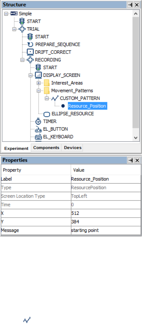
SR Research Experiment Builder User Manual ©2004-2017 SR Research Ltd.
247
Figure 8-15. Adding Resource Positions to a Custom Movement Pattern.
To create a custom movement pattern, users can either add resource positions and define
their x, y coordinates and time values in the Screen Builder, or specify a movement
pattern file that contains the coordinates and time for each position:
8.2.2.1 Option 1: Adding Resource Postions
To specify the movement pattern in the Screen Builder, first click the “Insert Custom
MovementPattern” button ( ) on the Screen Builder toolbar. Then select the movement
pattern in the Structure panel and make sure that the "Use Points From File" box is
unchecked.
When a custom movement pattern is created with this option, a default
Resource_Position node is automatically created in the Structure panel within the
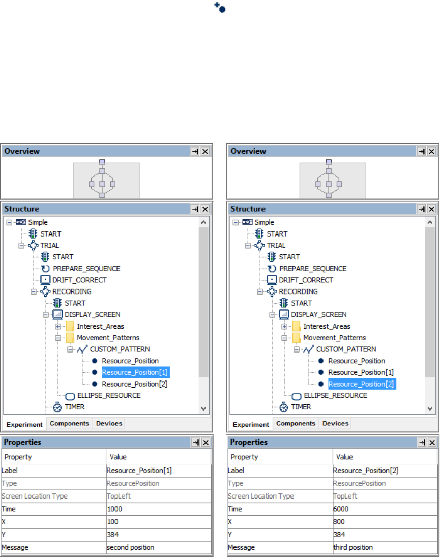
SR Research Experiment Builder User Manual ©2004-2017 SR Research Ltd.
248
movement pattern to serve as the start point of the movement pattern—its Time property
is set to 0 and cannot be changed. The x and y coordinates are initially set to the center of
the screen. This node cannot be deleted unless the entire movement pattern is removed.
To add additional positions to the movement pattern, click the "Insert Resource Position
in the selected Custom MovementPattern" ( ). Each additional resource position node
can be updated with the intended coordinate and time values.
Consider the following custom movement pattern: the first (default) resource position has
a time field of 0 and a screen position of (512, 384); the second point has a time of 1000
and a position of (100, 384); and the third point has a time of 6000 and a position of (800,
384). This translates into two segments of movement. The first segment moves from (512,
384) to (100, 384) when the sequence starts; the movement ends in 1000 milliseconds.
The second movement starts from time 1000 (since the sequence starts) and ends on time
6000, moving smoothly from position (100, 384) to (800, 384).
Figure 8-16. Creating a Custom Movement Pattern.

SR Research Experiment Builder User Manual ©2004-2017 SR Research Ltd.
249
8.2.2.2 Option 2: Movement Pattern File
Alternatively, users can create a tab-delimited text file to specify the landmark positions
in a movement pattern; this is particularly useful when a large number of movement
segments must be specified. The movement pattern file should contain time (integer), x
(integer), and y (integer) fields, followed by an optional message field (string).
Neighboring fields should be separated by a tab:
0 512 384 "Start of Movement"
1000 100 384 "Left End"
6000 800 384 "Right End"
Save this .txt file and add it to the "Movement Pattern" tab of the Library Manager.
In the Screen Builder, click the “Insert Custom MovementPattern” button ( ) on the
Screen Builder toolbar. Then select the movement pattern in the Structure panel and
check the "Use Points From File" box. Select the movement pattern file from the
dropdown list or specify the file in the attribute editor.
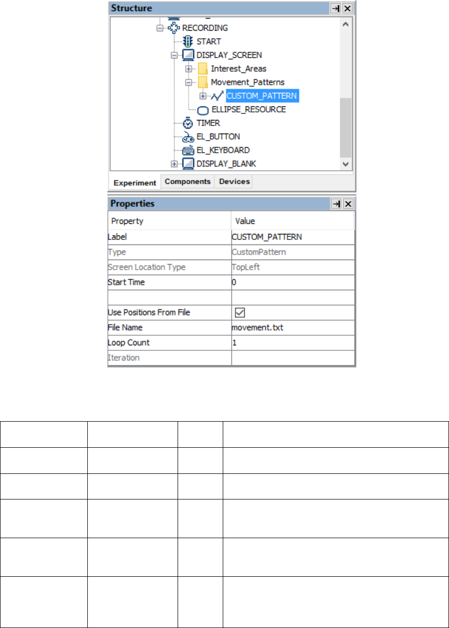
SR Research Experiment Builder User Manual ©2004-2017 SR Research Ltd.
250
Figure 8-17. Creating a File-based Custom Movement Pattern.
The following is a list of properties for a custom movement pattern.
Field
Attribute
Reference
Type
Content
Label *
.label
String
Label of the custom movement pattern. The
default label is “CUSTOM_PATTERN”.
Type #
NR
The type of Experiment Builder object
("CustomPattern") the current item belongs to.
Screen Location
Type #
NR
Whether the location specified refers to the top-
left corner or center of the resource. This setting
can be changed in “Screen Preferences”.
Start Time
.startTime
Float
Start Time of the movement. Typically set to 0
so that the movement pattern is aligned to the
display screen action.
Use Positions
From File †
.usePositionsFro
mFile
Boolea
n
Whether the movement pattern point list is
specified in a text file. If enabled, a text file
must be added into the "Movement Pattern" tab
of the library manager and selected either from

SR Research Experiment Builder User Manual ©2004-2017 SR Research Ltd.
251
the dropdown list or from the attribute editor. If
this box is unchecked, users must add a list of
resource positions to the movement pattern (see
the following table).
File Name
.fileName
String
Name of a text file that is used to specify the
custom movement pattern.
Loop Count
.loop
Integer
This sets the number of times the custom
movement pattern should repeat.
Iteration
.iteration
Integer
This reports the current iteration number
(starting from 0) of the repeated movement
pattern.
Each of the individual resource positions in the custom movement pattern has the
following properties.
Field
Attribute
Reference
Type
Content
Label *
.label
String
Label of the resource position in the custom
movement pattern. The default label is
“Resource_Position”.
Type #
NR
The type of Experiment Builder object
("ResourcePosition") the current item belongs
to.
Screen Location
Type #
NR
Whether the locations specified refer to the top-
left corner or center of the resource. This setting
can be changed in “Screen Preferences".
Time #
.time
Integer
Time (since the start of the movement sequence)
when the resource reaches the destination
position.
X
.x
Integer
X coordinate of the resource when this segment
of movement finishes.
Y
.y
Integer
Y coordinate of the resource when this segment
of movement finishes.
Message
.message
String
Message text to be sent when the resource
reaches the specified position.
8.3 Interest Areas
Interest areas can be drawn on the Screen Builder workspace and their details recorded in
the EDF file to simplify subsequent analysis with EyeLink Data Viewer. The interest
areas created in the Screen Builder will not be visible to the participants during data
collection. To show interest areas on the workspace, the “Toggle Interest Area Visibility”
button should be clicked on the Screen Builder toolbar (see Figure 8-18). In the Structure
panel, interest areas are listed under the “Interest_Areas” folder of the Display Screen
node.
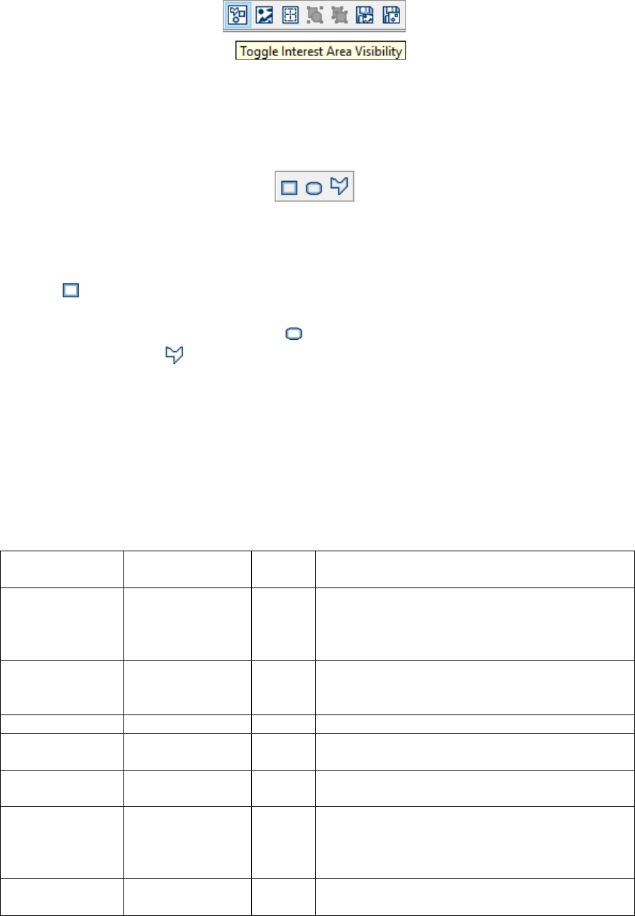
SR Research Experiment Builder User Manual ©2004-2017 SR Research Ltd.
252
Figure 8-18. Toggling Interest Area Visibility.
8.3.1 Manually Creating an Interest Area
SR Research Experiment Builder supports three types of interest areas (rectangular,
elliptic, or freeform). The following sections illustrate the use of each type of interest area.
Figure 8-19. Creating an Interest Area.
To create a rectangular interest area, click the “Insert Rectangle Interest Area Region”
button ( ). Then simply click and drag the mouse within the Screen Builder to draw the
rectangle. The precise location of the rectangular interest area can be edited in the
property panel. An elliptic interest area ( ) can be created in a similar fashion. A
freeform interest area ( ) can be created in the same way as a freeform resource (see
Section 8.1.9).
8.3.1.1 Rectangular/Elliptic Interest Area
The following table lists the properties of a rectangular or elliptic interest area. Please
note that the precise location of an interest area can be edited with the “Location”,
“Width”, and “Height” attributes in property table.
Field
Attribute
Reference
Type
Content
Label *
.label
String
Label of the Rectangle or Ellipse interest area.
The default label is
“RECTANGLE_INTERESTAREA” or
“ELLIPSE_INTERESTAREA”.
Type #
NR
The type of Experiment Builder object
("RectangleInterestArea") the current item
belongs to.
ID *
.ID
String
Ordinal ID of the interest area.
Data Viewer
Name
.DVName
String
Text associated with the interest area in Data
Viewer.
Color *
NR
Color
Color used to draw the interest area in the
Screen Builder.
Screen Location
Type
NR
Whether the locations specified refer to the top-
left corner or center of the interest area. This
global setting can be changed in “Screen
Preferences”.
Location
.location
Point
The top-left or center of the interest area,
depending on the preference setting of screen

SR Research Experiment Builder User Manual ©2004-2017 SR Research Ltd.
253
location type.
Width
.width
Integer
The width of the interest area in pixels.
Height
.height
Integer
The height of the interest area in pixels.
8.3.1.2 Freeform Interest Area
The shape of a freeform interest area can be adjusted by moving the vertices individually.
To adjust the position of individual vertices, select the interest and hover the cursor over
one of the vertices—the cursor will change to a resizing cursor (e.g., ). Then simply
click and drag the vertex to its intended location. The properties of a freeform interest
area are listed in the following table.
Field
Attribute
Reference
Type
Content
Label *
.label
String
Label of the Freeform interest area. The default
label is “FREEFORM_INTERESTAREA”.
Type #
NR
The type of Experiment Builder object
("FreehandInterestArea") the current item
belongs to.
ID *
.ID
String
Ordinal ID of the interest area.
Data Viewer
Name
.DVName
String
Text associated with the interest area when
viewing in Data Viewer.
Color *
NR
Color
Color used to draw the interest area in the
screen editor.
Screen Location
Type #
NR
Whether the locations specified refer to the top-
left corner or center of the interest area. This
global setting can be changed in “Screen
Preferences”.
Location
.location
Point
The top-left or center of the interest area,
depending on the preference setting of screen
location type.
Points #
.points
List of
Points
List of points (2-tuple of x, y coordinates) for
the vertices of the interest area.
8.3.2 Automatic Segmentation
Interest areas can be automatically created for some screen resources. To automatically
create rectangular or elliptic interest areas to contain resources on the screen, select the
desired resource(s), then right-click and select "Create Interest Area Set → Auto
Segment" (see Figure 8-20). The margins and shape of the interest areas can be set in the
"AUTO_SEGMENT" preference settings (from the Edit → Preferences menu or
ExperimentBuilder → Preferences in Mac OS X, select Preferences → Screen → Built-in
Interest Area Preference → AUTO_SEGMENT). An interest area created with the "Auto
Segment" option will be associated with the screen resource and its location. Its width
and height cannot be modified directly, but will vary along with the shape and size of the
resource.
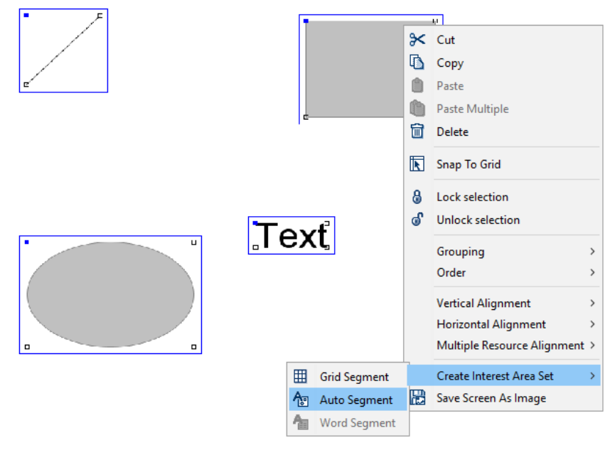
SR Research Experiment Builder User Manual ©2004-2017 SR Research Ltd.
254
Figure 8-20. Creating Interest Area with Auto Segmentation.
There are two ways to automatically segment text resources into interest areas for each
individual word. For static text (i.e., text that remains constant each trial), this can be
done by selecting the text resource, right-clicking, and selecting "Create Interest Area Set
→ Word Segment" from the popup menu. These interest area sets will remain from trial
to trial, even if the text in the resource has changed.
For text that changes from trial to trial, select the text resource or multi-line text resource
and check the "Use Runtime Word Segment InterestArea" option in the resource’s
Properties table. Note: Interest areas created with runtime word segmentation will not be
listed under the "Interest_Areas" folder of the Display Screen action and will not be
displayed in the Screen Editor.
By default, the automatic word segmentation is based on the space character between
words, though users may choose other delimiter options. For example, to see whether the
participant detects semantic anomaly in the sentence "The authorities were trying to
decide where to bury the survivors", a user may group "bury the survivors" into one
interest area instead of creating three separate interest areas. To determine their own
interest area boundaries, the user can decide to use a custom delimiter. Users can set a
custom delimiter in the WORD_SEGMENT preference settings (from the Edit →
Preferences menu or ExperimentBuilder → Preferences in Mac OS X, select Preferences
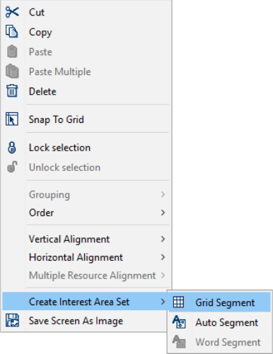
SR Research Experiment Builder User Manual ©2004-2017 SR Research Ltd.
255
→ Screen → Built-in Interest Area Preference → WORD_SEGMENT). Check the
"Enable Interest Area Delimiter" option, and set the "Delimiter Character" to the desired
character—in this case, the user is defining the asterisk as the delimiter, so they would set
Delimiter Character to “[*]”. Check the "Enable Interest Area Delimiter Replacement"
option and set the "Delimiter Replacement Character" as a single space. Note: the default
value for Delimiter Character is “[ ]”, which may appear empty but actually contains a
space character. Make sure when defining custom delimiter characters to remove the
space and include only your intended character.
After setting the custom delimiter character, the user may replace each space in the
original sentence with an ‘*’:
"*The*authorities*were*trying*to*decide*where*to*bury the survivors.*"
Users may also generate a set of rectangular interest areas partitioning the entire work
space into grids. Click the right mouse button in the workspace to bring up a popup menu.
Select "Create Interest Area Set → Grid Segment". The number of columns and rows
created is set in the "Rows" and "Columns" options of the "GRID_SEGMENT"
preference settings (from the Edit → Preferences menu or ExperimentBuilder →
Preferences in Mac OS X, select Preferences → Screen → Built-in Interest Area
Preference → GRID_SEGMENT).
Figure 8-21. Creating Interest Area with Grid Segmentation.
8.3.3 Using Interest Area Set Files
For some experiments, it may be difficult to define interest areas within Experiment
Builder. For example, if the experiment presents different images across trials, it may be
difficult to manually create built-in interest areas or to create runtime interest areas

SR Research Experiment Builder User Manual ©2004-2017 SR Research Ltd.
256
automatically. It is generally simplest to create the interest areas manually in Data Viewer,
then save the created interest areas as Interest Area Set files. With this approach, the user
can run through their project once (either with a pilot participant or using Mouse
Simulation mode), then open the .edf in Data Viewer. They can then easily scroll through
trials, creating and saving one interest area set file for each of the images to be displayed.
The Interest Area Sets can then be added to the “InterestArea Set” tab of the Library
Manager. Select the Display Screen to which the interest areas are associated and set
"InterestArea Set Name" field to a desired interest area set file, or link to a column in the
data source that lists the interest area set name to use for that trial. Please make sure the
name of the interest area file does not contain space or non-ASCII characters.
In an interest area set file, each line represents one interest area. The interest areas are
coded in the following formats:
* Rectangular Interest Area:
RECTANGLE id left top right bottom [label]
The "id", "left", "top", "right", and "bottom" fields must be integer numbers. For
example,
RECTANGLE 1 118 63 332 208
RECTANGLE_INTERESTAREA
* Elliptic Interest Area:
ELLIPSE id left top right bottom [label]
The "id", "left", "top", "right", and "bottom" fields must be integer numbers. For
example,
ELLIPSE 2 191 168 438 350 ELLIPSE_INTERESTAREA
* Freehand Interest Area:
FREEHAND id x1,y1 x2,y2 ... xn,yn [label]
The "id" field and each item in the pairs of "xi,yi" must be integer numbers. The x
and y coordinates in each pair are delimited by a comma (,). For example,
FREEHAND 3 481,54 484,57 678,190 602,358 483,330 483,327 493,187
468,127 FREEFORM_INTERESTAREA
Versions 2.1 and higher of EyeLink Data Viewer support dynamic interest areas. The
format of the dynamic interest areas is the same as discussed above except for two
additional parameters at the beginning of the line.
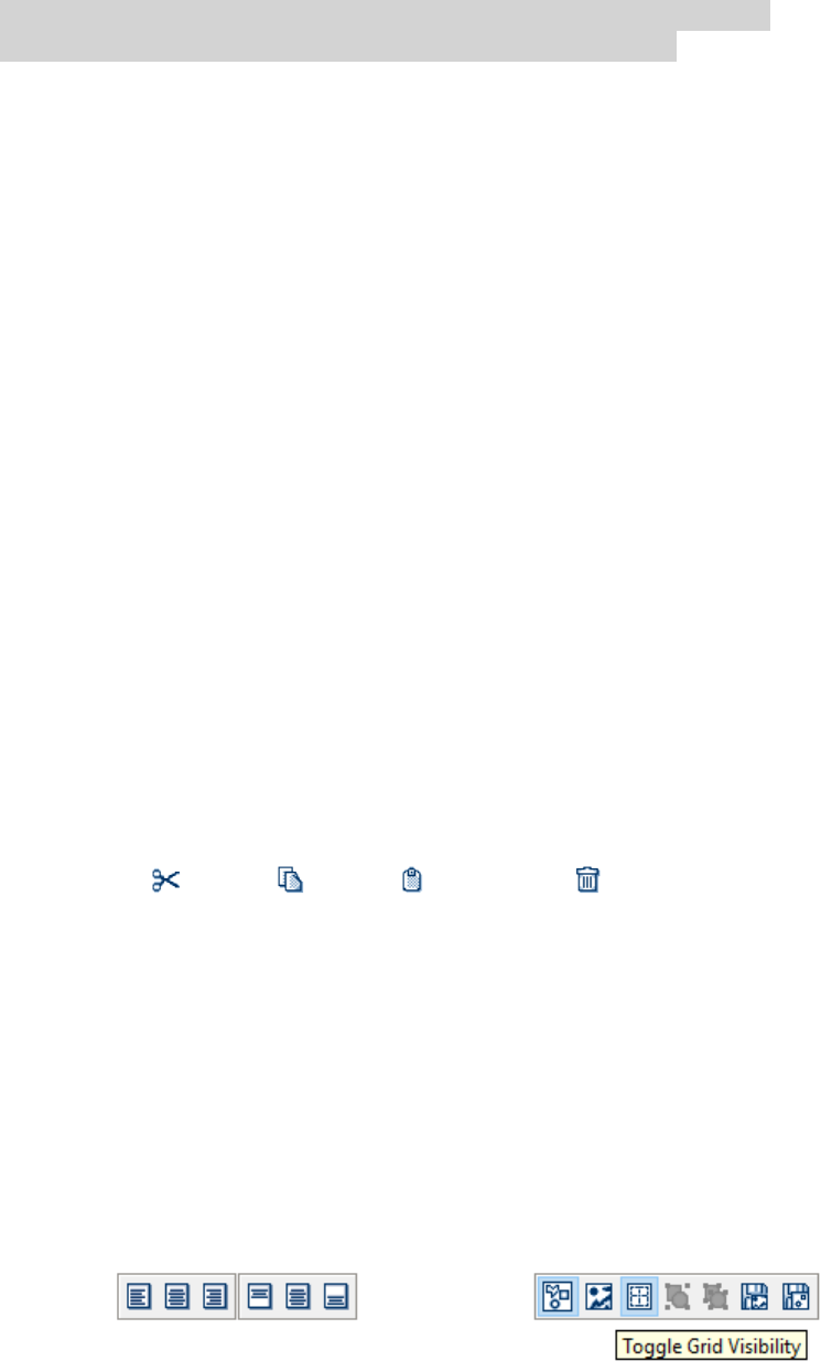
SR Research Experiment Builder User Manual ©2004-2017 SR Research Ltd.
257
start_offset end_offset RECTANGLE id left top right bottom [label]
e.g., -500 -1500 RECTANGLE 1 0 0 512 384 images\hearts.jpg
The "start_offset" and "end_offset" values are usually negative, indicating a future time
relative to the start of the currently selected interest period in Data Viewer (the default
Full Trial Period will be used if no interest periods have been created for the viewing
session). If the interest areas are read from a file specified by a message in the EDF file
(e.g., the “!V IAREA FILE” message in the EDF file), the “start_offset” and “end_offset”
are relative to the time stamp of that message in the EDF file. For example, if the interest
area file message was written at 800 ms following the trial start, the particular interest
area of the above example would start at 1300 ms and end at 2300 ms following the trial
start.
For all three types of interest areas, please make sure the individual fields are tab-
delimited.
Note: Interest areas contained in an interest area file will not be listed under the
"Interest_Areas" folder of the Display Screen action nor will be displayed in the Screen
Builder editor.
8.4 Resource Operations
The current section lists miscellaneous operations for adjusting the appearance of display
screens and the layout of resource components.
8.4.1 Resource Editing
The following operations can be applied to screen resources, interest areas and movement
patterns: Cut ( ), Copy ( ), Paste ( ) and Delete ( ) using the application menubar,
the toolbar, or the popup menu.
8.4.2 Resource Alignment
The position of screen resources and interest areas can be adjusted with alignment
buttons on the Screen Builder toolbar (see Figure 8-22). To adjust an item’s alignment,
select the item and then click one of the alignment tool buttons. The horizontal alignment
buttons determine the position of a resource on the horizontal dimension: left aligned,
right aligned, or centered. The vertical alignment buttons determine the position on the
vertical dimension: top-aligned, bottom-aligned, or centered. Alternatively, select the
resource, then right-click and choose one of the alignment buttons from the popup menu.

SR Research Experiment Builder User Manual ©2004-2017 SR Research Ltd.
258
Figure 8-22. Resource Alignment (Left) and Toggling Grid Visibility.
Version 2.0 of Experiment Builder added options to support the relative alignment of
multiple resources on the screen. In the Screen Builder, select two or more resources,
click the right mouse button, and choose the “Multiple Resource Alignment Options”
menu option. When an alignment operation is selected, the positions of the selected
resources will be set to the position of the last resource in the selection (i.e., the last
resource selected will not move). When a resizing operation is selected, the horizontal
and/or vertical dimensions of the selected resources will be rescaled to be the width or
height of the last resource in the selection (i.e., the last resource selected will not be
resized). The following table describes the supported alignment/resizing options.
Align Lefts
This aligns the left edges of the resources, without changing the
vertical positions of the resources.
Align Centers
This aligns the center of the resources, without changing the vertical
positions of the resources.
Align Rights
This aligns the right edges of the resources, without changing the
vertical positions of the resources.
Align Tops
This aligns the top edges of the resources, without changing the
horizontal positions of the resources.
Align Middles
This aligns the centers of the resources, without changing the
horizontal positions of the resources.
Align Bottoms
This aligns the bottom edges of the resources, without changing the
horizontal positions of the resources.
Make Same Width
This makes the width of the selected resources to be the same as the
last resource in the selection, without changing the height of the
resources.
Make Same Height
This makes the height of the selected resources to be the same as the
last resource in the selection, without changing the width of the
resources.
Make Same Size
This makes the size (bounding box) of the selected resources to be the
same as the last resource in the selection.
Make Horizontal
Spacing Equal
This makes the horizontal spacing equal among the selected resources
without adjusting the vertical spacing.
Make Vertical
Spacing Equal
This makes the vertical spacing equal among the selected resources
without adjusting the horizontal spacing.
When arranging many resources onscreen it may be helpful to use the “Snap to Grid”
option. First, click the “Toggle Grid Visibility” button (see Figure 8-22). This will create
a grid, partitioning the whole workspace into small areas. The number of gridlines can be
configured in the “Grid Columns” and “Grid Rows” attributes of the Display Screen.
Once the grid is properly configured, select the resource to be aligned, then right-click
and select “Snap to Grid” in the popup menu. This will align the center of the resource to
the center of the grid if the location type is set as “Center Position”, and align the top-left
corner of the resource with the top-left edge of the grid if the location type is set as
“TopLeft Position” (see the preference settings for Screen).
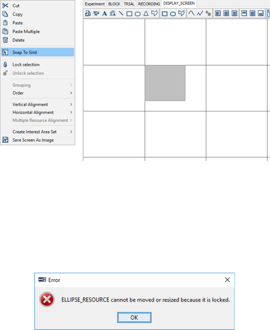
SR Research Experiment Builder User Manual ©2004-2017 SR Research Ltd.
259
Figure 8-23. Snap to Grid.
Position alignments should be re-applied if the properties of the resource have been
changed. For example, in a top-left screen coordinate system, changing the font size of
the text resource after applying the center alignment will result in the text not being
displayed in the center of the screen.
8.4.3 Resource Locking
When building the screen, users may want to lock a resource to prevent it from being
moved or resized by accident. To lock a resource, right-click on the resource and choose
“Lock Selection” option from the popup menu. To unlock the resource, select the
“Unlock Selection” option from the popup menu.
Figure 8-24. Error When Trying to Modify a Locked Resource.
When a resource is locked, any attempts to change the location of the resource from the
workspace will prompt an error (see Figure 8-24, though users can still make
modifications from the properties panel of the resource. Alternatively, first unlock the
resource, make the adjustments, and then re-lock the resource.
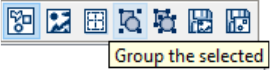
SR Research Experiment Builder User Manual ©2004-2017 SR Research Ltd.
260
8.4.4 Resource Grouping
Resource grouping offers a handy tool so several individual component resources can be
treated as a single resource for the purposes of moving and aligning. For example, after a
schematic face is created on the screen with several components resources, a user may
want to adjust the position of the whole drawing. It will be much easier if all of the
components resources are grouped and moved together than the individual resource
components are moved individually. To group several resources together, select the
resources, right-click and select “Grouping → Group” in the popup menu. To ungroup
resources, select “Grouping → Ungroup”. Alternatively, click the “Group” or “Ungroup”
tool buttons on the Screen Builder toolbar (see Figure 8-25).
Figure 8-25. Resource Grouping.
Please note that after several resources are grouped together, a
“COMPOSITE_RESOURCE” object is created, and the individual component resources
are removed from the Structure Panel (see Figure 8-26). The content of the Property
Panel is also updated to reflect this change.
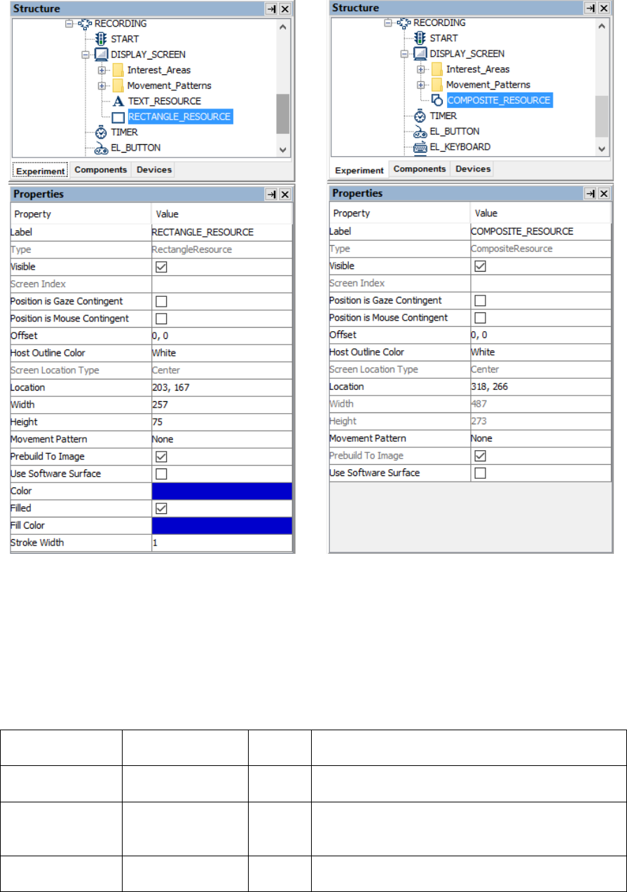
SR Research Experiment Builder User Manual ©2004-2017 SR Research Ltd.
261
Figure 8-26. Creating a Composite Resource.
8.4.5 Composite Resource
A "COMPOSITE_RESOURCE" object can be created by grouping several individual
resources together. The individual component resources are removed from the structure
panel when a composite resource is created.
Field
Attribute
Reference
Type
Content
Label *
.label
String
Label of the resource
("COMPOSITE_RESOURCE" by default).
Type #
NR
The type of screen resource
("CompositeResource") the current item
belongs to.
Visible †
.visible
Boolea
n
Whether the resource should be visible. The
default setting is True (checked).

SR Research Experiment Builder User Manual ©2004-2017 SR Research Ltd.
262
Screen Index #
.screenIndex
Integer
Index of the resource in the screen resource list
(0 - n).
Position is Gaze
Contingent †
.positionAtGazeC
ontingent
Boolea
n
Whether the position of the resource is
contingent on the gaze position. The default
setting is False. This setting is only available
when the parent display screen is contained
inside a recording sequence.
Gaze Contingent
Eye
.gazeContingentE
ye
String
Sets the eye used to provide data for the gaze-
contingent drawing. Options are Left, Right,
Either, Average, or Cyclopean (default setting).
For a left-eye-only recording, data from the left
eye is used when the gaze-contingency eye is
set to “Left”, “Either”, or “Cyclopean”, and
missing data when set to “Right” or “Average”.
For a right-eye-only recording, data from the
right eye is used when the gaze-contingency eye
is set to “Right”, “Either”, or “Cyclopean”, and
missing data when set to “Left” or “Average”.
For a binocular recording, left eye data is used
when the gaze-contingency eye is set to “Left”
or “Either”, right eye data is used when set to
“Right”, average data from both eyes if this is
set to “Average” (with missing data if either is
missing), and average data from both eyes when
set to “Cyclopean” (with missing data if both
eyes are missing, and data from the remaining
tracked eye if a single eye is missing).
Position is
Mouse
Contingent †
.positionAtMouse
Contingent
Boolea
n
Whether the position of the resource is
contingent on the mouse position. The default
setting is False.
Contingency
Deadband
.contingentDeadb
and
Tuple
of
integer
Sets the minimum amount of eye movement
required to update the gaze-contingent moving
window. This is designed to make the display
drawing less susceptible to jitters in the eye
position. Typically the deadband shouldn’t be
larger than 3.0 pixels—larger deadband values
will likely result in a lag in updating the display.
Offset
.offset
Point
Adjustment of the resource position relative to
the intended resource location, whether
specified by the Location attribute, the current
gaze or mouse position, or a movement pattern.
The default value is (0, 0) for a perfect
alignment of the resource position with the
specified position. Values specified in the Offset
will be subtracted from the specified location.
For example, if the location field is set to (512,
384), and the offset is (100, 100), the actual
resource position will be (412, 284).
Host Outline
Color ¶
.
hostOutlineColor
Color
The color of the box drawn on the host screen to
show the position and dimensions of the current
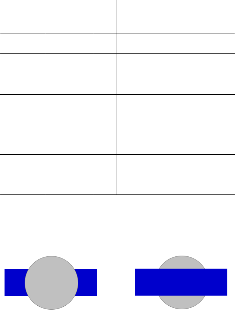
SR Research Experiment Builder User Manual ©2004-2017 SR Research Ltd.
263
resource. This property is available only if the
“Use for Host Display” option of the parent
display screen action is enabled and the “Draw
to EyeLink Host” of the prepare sequence action
is set to “Primitive”.
Screen Location
Type #
NR
Whether the location specified below refers to
the top-left corner or center of the resource. This
setting can be changed in “Screen Preferences”.
Location
.location
Point
The coordinates of the top-left corner or center
of the resource.
Width #
.width
Integer
Width of the resource in pixels.
Height #
.height
Integer
Height of the resource in pixels.
Movement
Pattern ¶ *
NR
Movement pattern (sinusoidal or custom) of the
resource.
Prebuild to
Image † #
.prebuildToImage
Boolea
n
Whether the resource should be built into an
image when the experiment is built (instead of
having it created during runtime). This field is
always true when the screen is contained in a
recording sequence. Important: If this attribute
is False, the run-time drawing may not look
exactly as it does in the screen editor. In
addition, images will not be saved to support
Data Viewer overlay.
Use Software
Surface †
.useSoftwareSurf
ace
Boolea
n
If unchecked, memory on the video card is used
to hold the resource (blitting from the video
card memory to the display surface is fast). If
checked, the system memory is used to hold the
resource (blitting is slow as it is done by
copying from RAM to display surface).
8.4.6 Resource Order
As resources are added to the screen, new resources are added in front of existing
resources, which can result in some resources being occluded (see Figure 8-27).
Therefore, the surface layout of individual resources may be rearranged.
Figure 8-27. Two Resources with Different Resource Order.
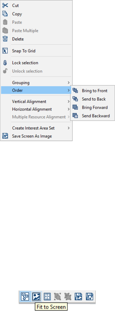
SR Research Experiment Builder User Manual ©2004-2017 SR Research Ltd.
264
Figure 8-28. Changing the Order of Resources.
To change the order of a resource, select the resource, right-click, and choose one of the
options under the “Order” menu from the popup menu (see Figure 8-28). “Bring to Front”
makes the selected resource to appear on the topmost layer, so no other resources can
occlude it; “Send to Back” moves the selected resource to the bottommost layer; “Bring
Forward” moves the resource one layer closer to the surface; and “Send Backward”
moves the resource one layer away from the surface. Changing the resource order on the
workspace also modifies the order of the resource listed in the structure panel.
8.4.7 Others
The Screen Builder allows users to adjust the canvas size of the workspace. If the “Fit to
Screen” option is enabled (see Figure 8-29), the workspace area is scaled to the size of
the screen to be displayed; otherwise, the workspace area is set to its actual size (i.e., one
pixel of workspace area corresponds to one pixel of computer desktop).
Figure 8-29. Choosing "Fit to Screen" Option.
Finally, users can save the current graphics in the work space to a file with the “Save
Screen as Image” option (see Figure 8-30).
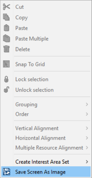
SR Research Experiment Builder User Manual ©2004-2017 SR Research Ltd.
265
Figure 8-30. Save Screen as Image.
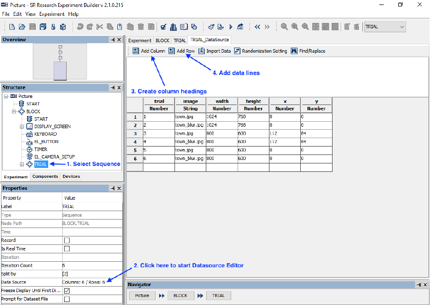
SR Research Experiment Builder User Manual ©2004-2017 SR Research Ltd.
266
9 Data Source
An important issue for most experiments is to specify the actual parameters of the
individual trials. For example, which experiment condition should each trial be in?
Which image should be presented? One approach would be to hard code the content of
each trial in the experiment. Obviously, this will be extremely time-consuming and error-
prone if there are several hundreds of trials involved, as is often the case for a perception
or cognition experiment.
Experiment Builder handles this issue by allowing users to create prototypical trials for
the experiment and to supply the actual parameters for individual trials from a Data
Source (see Figure 9-1). A data source can be created within Experiment Builder or by
loading a text file. During the execution of an experiment, lines in the data source are
read one at a time, supplying the actual parameters for each trial. Resources in the trial
can load parameters from the data source by setting attribute references, which are
discussed further in chapter 10.
Figure 9-1. Using Data Source in Experiment Builder.
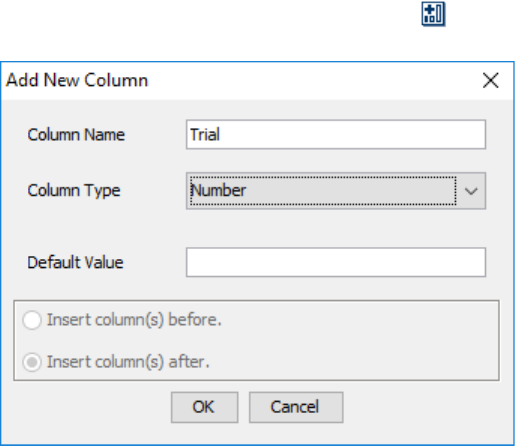
SR Research Experiment Builder User Manual ©2004-2017 SR Research Ltd.
267
9.1 Creating Data Source
A data source is attached to a sequence, with each iteration of a sequence corresponding
to a row of the data source. To create a data source, select the intended sequence node
and click the value field of the “Data Source” property (by default, it shows “Columns: 0
/ Rows: 0”). This will bring up the Data Source Editor. Any existing data sources will be
listed in the dropdown menu on the rightmost end of the application toolbar (“None” if
no data source has been created). Select a data source from this menu will bring up its
data source editor.
9.2 Editing Data Source
To create a new data source, click the “Add Column” button ( ) at the top of the Data
Source Editor window.
Figure 9-2. Change the Type of Variables.
In the Add New Column dialog (see Figure 9-2), fill in the "Column Name" field. The
column name must be a string starting with a letter between 'a' and 'z' or 'A' and 'Z', and
must consist only of alphanumerical characters ('A' - 'Z', 'a' - 'z', '0' - '9', or '_'); any space
entered is converted to an underscore. The new data source column name shouldn't
duplicate the name of any existing data source columns, variable labels, or any of these
reserved words: "EYELINK”, "DISPLAY”, "AUDIO”, "TTL”, and "CEDRUS". In the
"Column Type" dropdown list, choose the appropriate data type. If desired, set the
Default Value for the new. Select the location where the column should be created (at the
end of the data source editor, to the left of the currently selected column, or to the right of
the currently selected column) and then click "OK" to create the new. Subsequent data
source columns can also be added by selecting an existing data source column, clicking
the right mouse button, and choosing the “Insert Column” option.
After adding the first column, an empty anchor row will be created. Click the empty cell,
type a value into the cell, and press the ENTER key to register the change. This will now
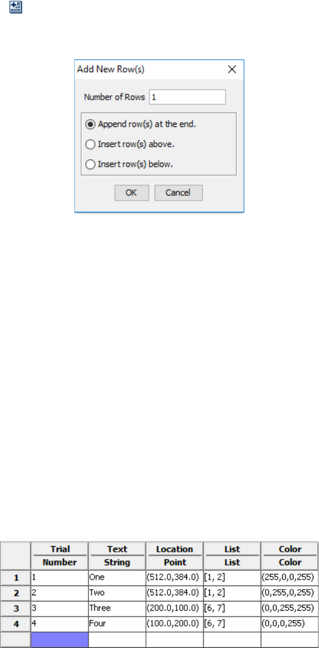
SR Research Experiment Builder User Manual ©2004-2017 SR Research Ltd.
268
be the fist data source row, and a new blank anchor row will be created. Click the “Add
Row” button ( ) to create more rows of empty cells for data input. By default, the new
data source rows will be created at the end of the table, or users can choose to insert the
new row(s) above or below the currently selected data source row(s).
Figure 9-3. Adding New Rows to the Data Source.
Currently, Experiment Builder supports six data types: Number, String, Point, Color, List,
and Boolean.
• The Number data type consists of one integer (1, 2, 3, ...) or float number (0.1, 2.0,
3.14159, ...) in each cell.
• The String data type can consist of any text. Note that the entered string does not
need to be in quotes—if the text contains or is flanked by a pair of quotes, the
quotes will be shown.
• The Point data type consists of two numbers separated by a comma representing
the x and y coordinates—a pair of brackets will be added automatically.
• The Color data type consists of three integer numbers between 0 and 255,
separated by commas, representing the red, green, and blue values. The program
will automatically fill in a fourth alpha value of 255 when the entered color data is
accepted.
• The List data type consists of a list of numbers, strings, colors, points, or lists,
with each in the list separated by a comma. A pair of square brackets will be
added automatically.
• The Boolean data type consists of either "true" or "false" in the data cell.
Figure 9-4 illustrates the use of these data types.
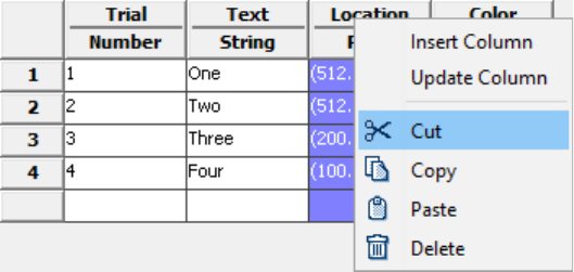
SR Research Experiment Builder User Manual ©2004-2017 SR Research Ltd.
269
Figure 9-4. Data Types Used in Experiment Builder.
To delete a data column, click the column heading of the intended column, then right-
click and select "Cut" or "Delete" from the popup menu. To copy a column of data, click
the column heading, then right-click and select "Copy". Then press "Paste" to append the
new column to the end of the data source. To select a row, click on the row label. The
same Copy, Paste, Cut and Delete operations may be performed on rows.
Figure 9-5. Editing Operations for Data Source Columns and Rows.
The Copy, Paste, Cut and Delete operations may also be used on a single selected cell or
a range of selected cells. Users may copy cells from the Data Source Editor and paste
them into a spreadsheet program like Microsoft Excel, or copy data from a spreadsheet
program into the Data Source Editor. Selections can also be copied and pasted between
two ongoing Experiment Builder sessions. Note: when copying and pasting between
projects, or from an external spreadsheet program, make sure the data types of the copied
cells match the types specified in the columns (e.g., do not paste a column of string data
to a column specified as the color type).
Please make sure that there are no empty cells in the data source editor before performing
a Test Run or Deploying the project.
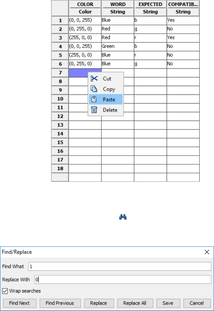
SR Research Experiment Builder User Manual ©2004-2017 SR Research Ltd.
270
Figure 9-6. Editing Data Source Cells.
Version 2.0 of Experiment Builder allows users to find or replace text strings in the data
source editor using the Find/Replace tool ( ). With the “Wrap searches” option
(enabled by default), if the searched value is not found between the current position and
the end of the Data Source, the tool will begin searching again from the beginning.
Figure 9-7. Importing an Existing File as Data Source.
The new version of Experiment Builder also supplies a workspace above the data source
where the content of the currently selected data cell will be displayed. This expanded
workspace can be useful for data source editing, especially if the cell contains lots of data
(e.g., paragraphs of text). The changes to the data cell through this expanded workspace
will be saved when you click anywhere in the data source editor.
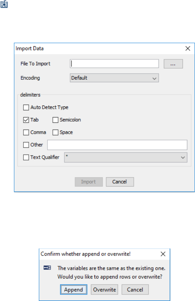
SR Research Experiment Builder User Manual ©2004-2017 SR Research Ltd.
271
9.3 Importing Existing Files as Data Source
For greater flexibility, users can also generate a data source with an external text editor
software like Wordpad, Notepad, etc., and then load the plain-text file into Experiment
Builder. In that file, use the first row for column variable labels. Experiment Builder 2.0
supports using various column delimiter characters, although earlier versions of
Experiment Builder require Tab as the delimiter, so using Tab as the delimiter will
improve compatibility. To import a data source from a text file, click the “Import Data”
Button ( ) on the data source editor screen. In the “Import Data” dialog, choose the
target file and the delimiter used. If the external data source file is encoded in the ASCII
format, leave the “Encoding” field as “default”. If the file is encoded in the UTF-8 format,
choose UTF-8 from the dropdown menu. Then click the “Import” button.
Figure 9-8. Importing an Existing File as Data Source.
If the current data source editor has existing data before the external data file is imported,
choose whether to append the new data after the existing data lines, or to overwrite the
old data lines (see Figure 9-9).
Figure 9-9. Append or Overwrite Confirmation.
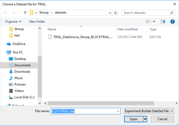
SR Research Experiment Builder User Manual ©2004-2017 SR Research Ltd.
272
Experiment Builder will automatically detect the type of data source columns upon
importing the external file. To change data type for a column, click the column heading,
then right-click and select “Update Column” from the popup menu. Then choose the
desired data type.
9.4 Using Data Source File
Experiment Builder allows users to specify an external Data Source file to be loaded each
time they run the experiment. To enable this option, select the sequence that the data
source is attached to, and check the box for "Prompt for Dataset file" (unchecked by
default). If checked, when running the experiment, the user will be prompted for a data
source file for the session. Then either select the intended external data source file, or
click the "datasets" folder and choose the default .dat file prepared by the program. If the
"Prompt for Dataset file" option is unchecked, the file chooser will not be displayed
during experiment runtime and the default data source file will be chosen.
Figure 9-10. Choosing a Data Set File during Run-Time.
It's possible to prepare your own version of the data source file. When preparing data
source files, please:
• Make sure all of the variable labels on the first row of the file are in lower case,
regardless of the case used in the data source editor.
• Add a $ before the label of a string column (e.g., $word)—a $ sign should not be
used for the labels of any other data types.
• Use a tab to separate between neighboring fields.
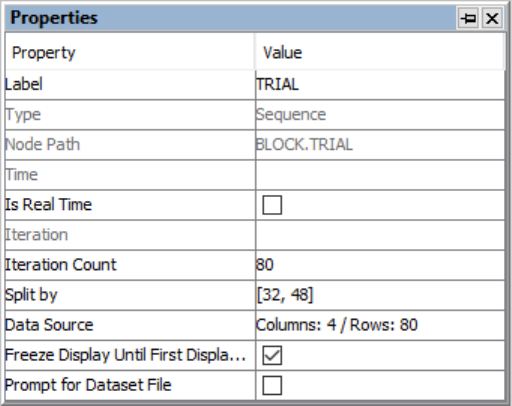
SR Research Experiment Builder User Manual ©2004-2017 SR Research Ltd.
273
• Wrap the position and color values within (), string values with a pair of "", and list
values with [].
• Make sure all of the values in each column of the data file appear in the original
column of the data source editor.
9.5 Data Source Splitby
The "Split by" property specifies the actual number of iterations of a sequence to be
executed each time the sequence is encountered. This can be used to divide the trials
specified in the data source into different blocks. To divide the trials between the blocks,
select the block the data source is attached to, and set the "Split by" attribute. For instance,
if a user has 80 trials in their data source, but wants to split these trials evenly across two
different blocks, they can set the Split by value to [40].
This feature can also be used to for experiments in which unequal number of trials are
tested in different blocks. For example, the user may now want to run 32 trials in the first
block, followed by 48 trials in the second block. In this case, they can enter [32, 48] in
the "Split by" attribute.
Figure 9-11. Using "Split by" Option to Customize the Number of Iterations to Run in a
Sequence.
9.6 Data Source Randomization
In most experiments, the trial order is randomized so the experiment materials are not
presented in the same sequence across participants. Users can perform data source
randomization either internally (during runtime of the experiment) or externally (before
running the experiment). These two randomization methods are almost identical except
that the external randomizer allows for further counterbalancing manipulations across
participants. You may experiment with both methods to see which one fits your needs
better.
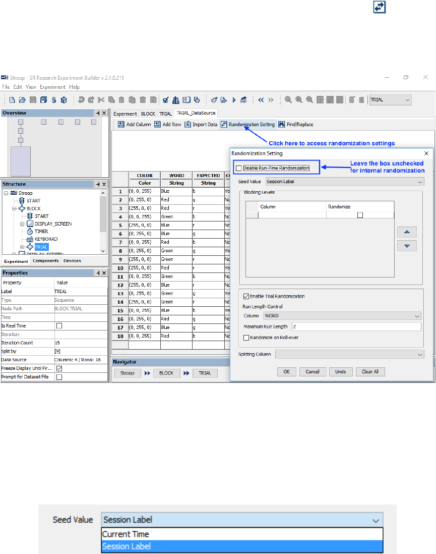
SR Research Experiment Builder User Manual ©2004-2017 SR Research Ltd.
274
9.6.1 Internal Randomization
To configure the internal randomization, click the “Randomization Setting” ( ) button
in the data source editor and make sure “Disable Run-Time Randomization” is unchecked
(this option can be checked to disable the randomization for debugging purposes if
necessary).
Figure 9-12. Using Internal Randomization.
9.6.1.1 Randomization Seed
If the Seed Value is set to "Current Time", the current Display PC system time is used as
the randomization seed. If set to "Session Label", the string you input in the "Session
Name" dialog box when running the experiment is used as the randomization seed. Any
two runs of randomization with the same seed will generate identical randomization
outputs.
Figure 9-13. Setting Randomization Seed.
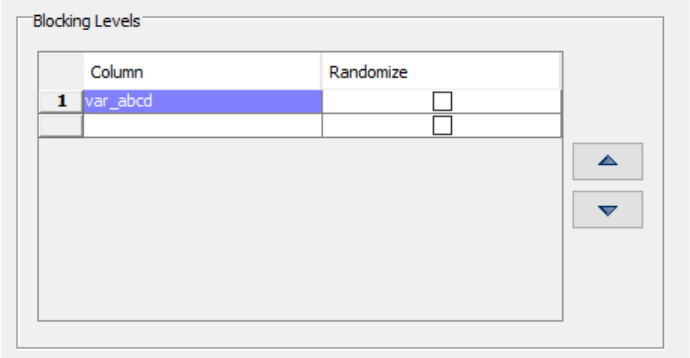
SR Research Experiment Builder User Manual ©2004-2017 SR Research Ltd.
275
9.6.1.2 Blocking
In some cases, when randomizing trials, it may be necessary to keep certain trials
grouped together. The internal randomizer allows users to define blocking variables to
group trials—all trials with the same value of the blocking variable will appear in a group.
To add a blocking level in the Randomization Setting window, click the first cell under
the “Column” heading, and then choose the blocking variable from the dropdown list. If a
second blocking level is needed, simply click the second “Column” cell, and so on. To
change the order of the blocking variables, click the numeric heading to the left of the
variable column so the row is highlighted, then click the up or down button on the right
side of the window. To remove an existing blocking level, simple click the “Column” cell
and then choose the first value (blank) in the dropdown list. If a blocking manipulation is
not required in your experiment design, simply leave the “Blocking Levels” field empty.
If blocking is applied, the order of the trial groups (i.e., different values of the blocking
variable) to appear in the randomization output can be controlled by whether the
“Randomize” box is checked or not.
• If the “Randomize” box is not checked: The order of the blocking groups will be the
same as the order they appear in the original data file. For example, the four levels
of the $var_abcd variable appear in the order of ABCD in the original file. The
$var_abcd variable in the randomization output also appear in the order of ABCD.
• If the “Randomize” box is checked: Levels of the blocking variable will appear in a
random order. For example, blocking by variable "$var_abcd" with randomization
type set to "Random" will create one of the 24 possible orders (ABCD, ABDC,
ACBD, ACDB, ADCB, ADBC, BACD, BADC, BCAD, BCDA, BDAC, BDCA,
CABD, CADB, CBAD, CBDA, CDAB, CDBA, DABC, DACB, DBAC, DBCA,
DCAB, or DCBA).
Figure 9-14. Configuring Randomization Blocking.
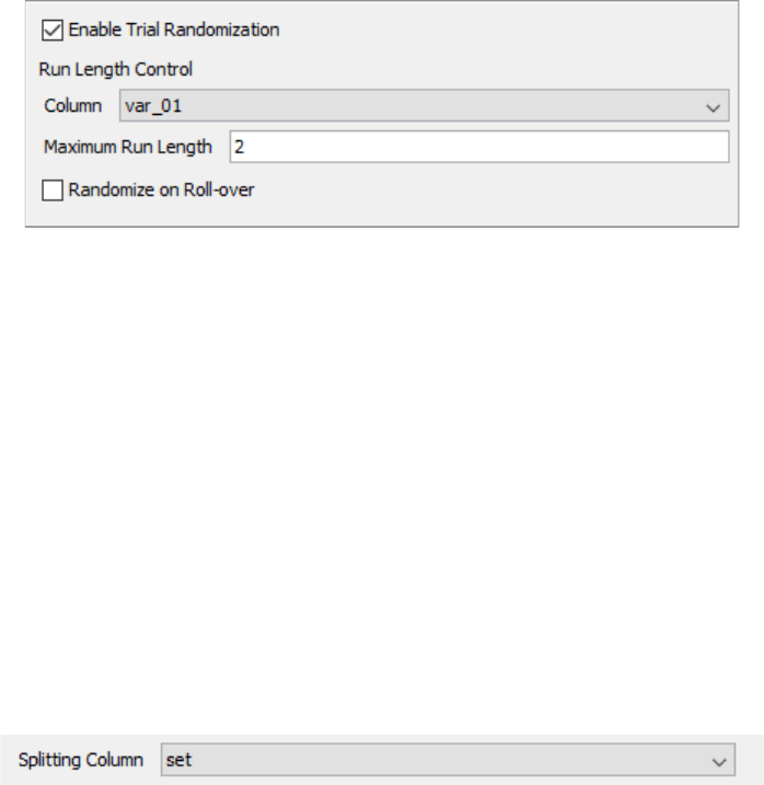
SR Research Experiment Builder User Manual ©2004-2017 SR Research Ltd.
276
9.6.1.3 Trial randomization and Run Length Control
If the "Enable Trial Randomization" box is checked, the trial order will be randomized.
To limit how many trials with the same condition can be run consecutively, choose a
variable to serve as the 'Run Length Control' from the dropdown list (currently, only one
run length control variable is supported). Enter the “Maximum Run Length”, the
maximum number of consecutive trials to run with the same condition, and press Enter to
register the change. Version 2.0 of the software allows the maximum run length to be set
to 1 or higher. Note: controlling run length may not be possible for some data sets. While
the software applies run-length control across trials within each blocking group, this
control is not enforced for consecutive trials spanning two blocking groups.
Figure 9-15. Enabling Trial Randomization and Configuring Run-Length Control.
9.6.1.4 Randomize on Roll-Over
If checked, a different randomization sequence will be created for the data source when it
is re-used. Otherwise, the same randomization output will be reused.
9.6.1.5 Splitting Column
For some users, it may be convenient to create a large data source containing multiple
sets of trials, and run only a set of trials per session. For instance, this makes it easy to
implement between-participant manipulations without having to create multiple separate
Experiment Builder scripts, or to choose from different fixed pseudorandom trial orders.
Users can define a Splitting Column in the Randomization Setting window (see Figure 9-
16).
Figure 9-16. Configuring Splitting Column.
When running the experiment, the software will prompt the experimenter at the
beginning of the session to select a value from the Splitting Column (see Figure 9-17).
Experment Builder will then create a runtime data source using only the data source rows
with the value of the “splitting column” matching the value specified.
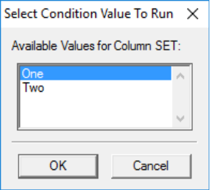
SR Research Experiment Builder User Manual ©2004-2017 SR Research Ltd.
277
Figure 9-17. Selecting Condition Value to Run.
9.6.1.6 Running Experiment with Internal Randomizer
Once the experiment has been fully tested, deploy the project (Experiment → Deploy).
Click the {experiment name}.exe file in the deployed directory to run the experiment. If
you have specified a variable for splitting the data source, a dialog box will be displayed
at the beginning of the experiment, prompting to choose the level of the splitting variable.
Experiment Builder will then randomize the data source using the specified parameters.
At the end of the experiment, a file containing the randomized data source actually used
in the session will be saved in the results directory.
9.6.2 External Randomization
In the experiment project, please make sure the "Prompt for Dataset File" box is checked
on the sequence the data source is attached to. In the Randomization Setting window of
the data source, make sure the “Disable Run-Time Randomization” box is checked so the
internal randomization is ignored. (See Figure 9-18.)
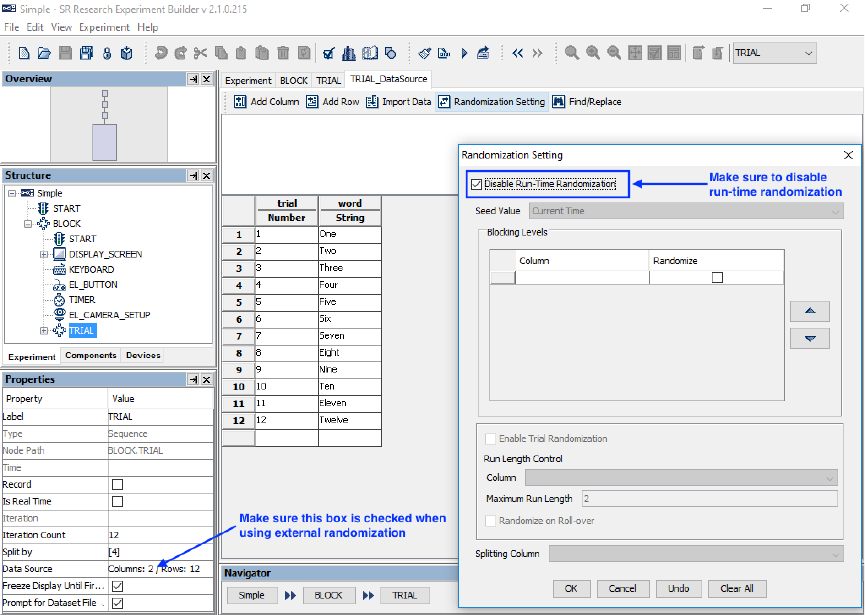
SR Research Experiment Builder User Manual ©2004-2017 SR Research Ltd.
278
Figure 9-18. Using External Randomization.
(Important: Before deploying the project, make sure the data source within the project
contains every possible trial instance that may occur in the randomized files to be loaded
at runtime. If an external file is used that contains a value not present in the internal data
source, the experiment may crash during runtime.)
Once the experiment has been fully tested, deploy the project (Experiment → Deploy). In
the intended deploy directory, the project data source will be saved as a .dat file in the
"datasets" directory. Perform the randomization using the project data source file and put
the randomized copies in the “datasets” directory. (Important: When a project is rebuilt
by clicking Experiment → Build or Experiment → Test Run ..., all of the files in the
"datasets" directory will be deleted. If working on data sets before deploying the project,
please back up those files in a different folder, e.g., the "myfiles" directory, before
rebuilding the project.)
On Windows, the external Randomizer tool can be found in the Start Menu under SR
Research → Experiment Builder → Randomizer, or at {Windows Drive:}/Program
Files/SR Research/Experiment Builder/Randomizer/RandomizerW.exe. On Mac OS X,
the Randomizer.app can be found in the "/Applications/ExperimentBuilder" folder. See
the Help document in the Randomizer tool for more information.
SR Research Experiment Builder User Manual ©2004-2017 SR Research Ltd.
279
Users may also create the trial randomization files manually by using a program like
Microsoft Excel to create the data source files, then saving them into tab-delimited .txt
files.
Once the randomization is done, click the {experiment name}.exe file in the deployed
directory to run your experiment. When prompted to load a data source file, choose one
of the randomized copies from the "datasets" directory.
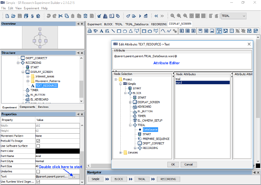
SR Research Experiment Builder User Manual ©2004-2017 SR Research Ltd.
280
10 References
Experiment Builder uses “references” to link an attribute of one experiment component to
the value of another component attribute. References are a critical part of Experiment
Builder, providing much of the application’s flexibility.
For example, say a sequence has two components, X and Y. Component X has attribute
X.a and component Y has attribute Y.b. If attribute X.a is set to reference Y.b, then the
value of X.a will always be equal to the value of Y.b. X.a is thus the ‘referencing’ or
‘referring’ attribute, and Y.b is the ‘referenced’ attribute. Even if the referenced attribute
Y.b changes value during the experiment, the referencing attribute X.a will always reflect
the current value of Y.b.
10.1 Using References
References have the following syntax: “@object_name.attribute_name@”, always
starting and ending with a ‘@’ sign. References can easily be added from the Attribute
Editor. To open the Attribute Editor, click once in the value field of the property to be
edited (see Figure 10-1). If the field supports attribute referencing, a button with three
dots [ … ] will be displayed on the right side of the cell. Click on the [ … ] button to
open the Attribute Editor. Users can enter a value, reference, or equation into the
Attribute field at the top of the editor. Components and their attributes can be referenced
from the Node Selection panes at the bottom of the editor.

SR Research Experiment Builder User Manual ©2004-2017 SR Research Ltd.
281
Figure 10-1. Using Attribute References.
10.2 Entering in Values
To enter static values into the attribute editor, simply type the value. Any preceding or
trailing white spaces are removed. The following table illustrates how some commonly
used data types can be entered in the attribute editor.
Entered value
Translated
type
Translated value
Usage
Hello
String
Hello
Label, Message, Text
properties
“Hello”
String
“Hello” (Quotes are
preserved).
_Hello_
String
Hello (The under scores are
representing white spaces,
which are trimmed)
1
Number
1.0
Width, Height, Time
1.0
Number
1.0
Width, Height, Time
True
Boolean
True
Check Boxes (Possible
values are “True” or
“False”)
False
Boolean
False
Check Boxes (Possible
values are “True” or
“False”)
(100,100)
Screen Point
(100.0,100.0)
Location
[5, 2, 6]
List
[5.0, 2.0, 6.0]
Buttons, keys, Split-by
List
(15, 223, 58)
Color
(15, 223, 58)
Color
Please note that all non-string data entries are automatically translated into the
appropriate data types, unless the type of the field is already specified as a string.
10.3 Entering in References
The easiest way to enter a reference in the Attribute Editor is navigate to the node in the
object tree, select the node, then double click on the desired node attribute or sub-
attribute (see Figure 10-1). The reference will then appear in the Attribute window at the
top of the editor. If desired, users may also enter in the reference manually without using
the object tree.
References have the following constraints:
1. The referred value should match the assigning field’s value type. Suppose object
X has attribute p and object Y has attribute q. If the type of attribute X.p is number,
and the value of Y.q is the string “5”, X.p cannot directly refer to Y.q or vice versa.
An “Invalid Value” error dialog box will be displayed if wrong type of data is
entered in the attribute editor.
SR Research Experiment Builder User Manual ©2004-2017 SR Research Ltd.
282
2. One attribute cannot refer to itself. In the above example, Y.q cannot have
reference to Y.q. A “Recursive/Invalid reference” error message will be reported
during build time.
3. Type conversion is only partially supported. An integer can be assigned to a
number (float or non-float) and vice versa. Most conversions, however, will
require use of an equation.
10.4 Entering in Equations
Equations are a combination of values and/or references. Equations can be used to
calculate data at runtime based on static or dynamic values, or both. All equations start
with an ‘=’ sign followed by references and/or values concatenated with operators (+, -,
*, /, %). All of these operators support numerical operations, and the ‘+’ sign can also be
used for string concatenation. Functions like “str”, “int”, and “float” can be used for data
type conversion.
Note: Any valid Python equation is a valid equation in Experiment Builder. For details
on Python, the run-time programming environment used by Experiment Builder, visit
http://www.python.org/.
Although equations will be evaluated during build time to check for obvious problems,
users should always check for the completeness and validity of the equations themselves.
In particular, make sure that the data type of the equation created matches the data type
required in the attribute field. In the following Example 1 (see Figure 10-2), the “EyeLink
Record Status Message” field of a recording sequence expects a string value. Therefore,
the equation created in Example 1 must be a string, so it uses the “str” function to convert
numerical values to strings). In Example 2, the Location property expects the point data
type, so the equation is written as two numerical values separated by a comma inside
parentheses.
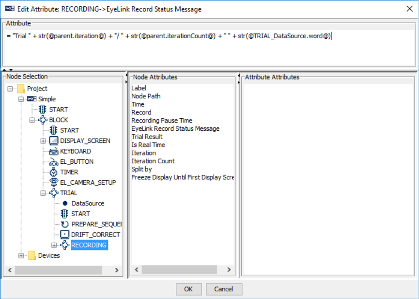
SR Research Experiment Builder User Manual ©2004-2017 SR Research Ltd.
283
Figure 10-2. Creating Equations in the Attribute Editor.
10.4.1 Creating a Complex String: Formatting and Concatenating
String formatting in Python uses the same syntax (see http://docs.python.org/lib/typesseq-
strings.htmll) as the sprintf function in C.
="my string %s, %s followed by an integer %d" % (string1, string2, number)
The whole expression evaluates to a string. The first %s is replaced by the value of
'string1'; the second %s is replaced by the value of 'string2'. The %d is replaced by the
value of number. All other characters in the string (in this case, the equal sign) stay as
they are.
Users can also conveniently creating a string by concatenating string literals. The
following illustrates creating the same string by concatenation.
="my string " + string1 + ", " + string2 + " followed by an integer " + str(number)
Please note that:
• equation starts with a =;
• + is the string concatenation operator.
SR Research Experiment Builder User Manual ©2004-2017 SR Research Ltd.
284
• Trying to concatenate a string with a non-string raises an exception. Unlike string
formatting, string concatenation works only when everything is already a string.
Therefore, for all non-string data ('number' in this example), users may use str() to
do type casting.
10.4.2 Examples
The following is a few examples of equations in Experiment Builder.
• Example 1: During recording, a text message can be displayed at the bottom of
the tracker screen (e.g., like “Trial 1/12 One”) so the experimenter knows the
progress of experiment. To set this message, select the “Recording” sequence
node in the structure list. Click the value field of the “EyeLink Record Status
Message” property of the sequence once, then click the [ … ] button to bring up
the attribute editor. Enter a reference equation such as:
="Trial " + str(@TRIAL_DataSource.Trial@) + "/12 "
+@TRIAL_DataSource.Word@
• Example 2: To draw a text resource to the center of the display screen (“parent”),
the location of the text resource can be referred as:
=(@parent.width@/2,@parent.height@/2)
• Example 3: To write the position of the text resource (“TEXT_RESOURCE”) to
the data file using an EyeLink Message action in the same sequence as the display
screen (DISPLAY_SCREEN) that contains the text resource, the Message
property of the EyeLink Message action can be referred as:
= "Text Location " + "x = " +
str(@parent.DISPLAY_SCREEN.TEXT_RESOURCE.location.x@) + " y= " +
str(@parent.DISPLAY_SCREEN.TEXT_RESOURCE.location.y@)
This will record a message like, “MSG 11545029 Text Location x = 512 y= 384”
in the EDF file.
• Example 4: This illustrates how to write the reaction time calculation for a button
press (EL_BUTTON) following the onset of the display screen
(DISPLAY_SCREEN) to the data file, assuming that all actions and triggers are
contained in the same sequence. The following equation could be set as the
Message field of an EyeLink Message action:
="Button pressed time " +
str(@EL_BUTTON.triggeredData.time@-@DISPLAY_SCREEN.time@)
This will record a message like, “MSG 12818953 Button pressed time 1228.0” in
the EDF file.

SR Research Experiment Builder User Manual ©2004-2017 SR Research Ltd.
285
10.5 Reference Manager
All of the references used in the experiment graph can be reviewed and modified in the
Reference Manager, which tabulates the source, parent of source, property and value for
each reference. The Reference Manager can be accessed by clicking "Edit → Reference
Manager" from the application menu bar. To edit a reference through the Reference
Manager, click the Value field of the reference once, then click the [ … ] button to bring
up the attribute editor.
The Reference Manager has a Find and Replace function to search for any reference
entries that contain a given string, and if desired to replace the searched string with
different text. To search for a string, enter the text in the "Find What" edit box and press
the ENTER key (note that the search is case-sensitive). References containing the
searched string will be displayed in the list. To replace a string, enter the text to be
replaced in the "Find What" edit box and the new text in the "Replace With" edit box.
Make sure the “Replace With” box is selected (the blinking text cursor should be in the
box) and press ENTER key to perform the replacement. Click the "Undo Replacement"
button ( ) to revert to the original text.
To limit the scope of displayed references, select a sequence from the dropdown list at
the upper-left corner. Only references inside that sequence will now be displayed,
including any subsequences within the specified sequence, as “Include Subsequence” is
checked by default. To display only references within the specified, and not within
subsequences, simply uncheck this box. To show only the invalid references, check the
“Only Display Invalid References” box.
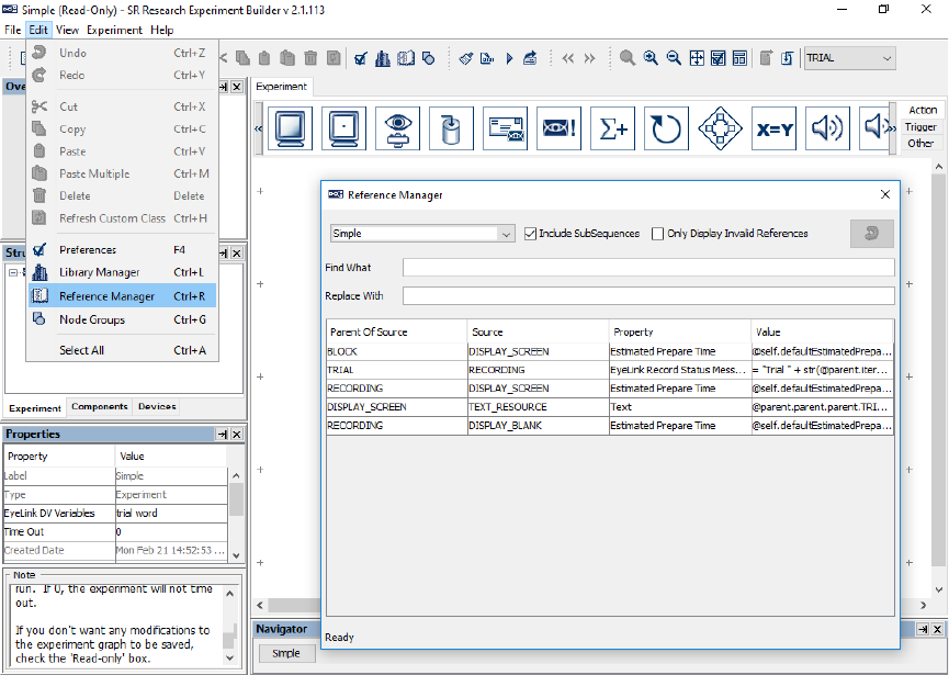
SR Research Experiment Builder User Manual ©2004-2017 SR Research Ltd.
286
Figure 10-3. Using the Reference Manager.
SR Research Experiment Builder User Manual ©2004-2017 SR Research Ltd.
287
11 EyeLink Data Viewer Integration
EyeLink recording data, saved as .EDF files, can be conveniently analyzed with the Data
Viewer application. A set of messages can be written to the data file so that the Viewer
can automate configurations for individual trials. Examples of such messages include
specifying trial variables, defining images and simple drawings to be used as background
for overlay display, creating interest areas, etc. Experiment Builder automates many of
these integration messages, but users may wish to configure what is included in these
messages.
It’s always a good idea to plan for data analysis while the experiment is still being
designed. Spending a short amount of time configuring messages and interest areas at the
design stage may save hours in data analysis later. We strongly recommend testing at
least one participant after creating the experiment and collecting the recorded data to
examine timing accuracy and to check whether any critical information is missing.
11.1 Trial Condition Variables
The "EyeLink DV Variables" property of the experiment is used to send trial condition
messages to the EDF file on each trial so users know exactly under which conditions each
trial was performed. At the end of each trial recording, a “!V TRIAL_VAR” message will
be written to the EDF data file for each of the selected variables and their corresponding
values, which Data Viewer will then read automatically as trial variable messages.
The list of possible variables includes columns in the experiment data source as well as
Variable nodes created by the user. To open the EyeLink DV Variables selection window,
click the experiment node at the very top of the Structure tree, then click the value cell
next to the EyeLink DV Variables property.
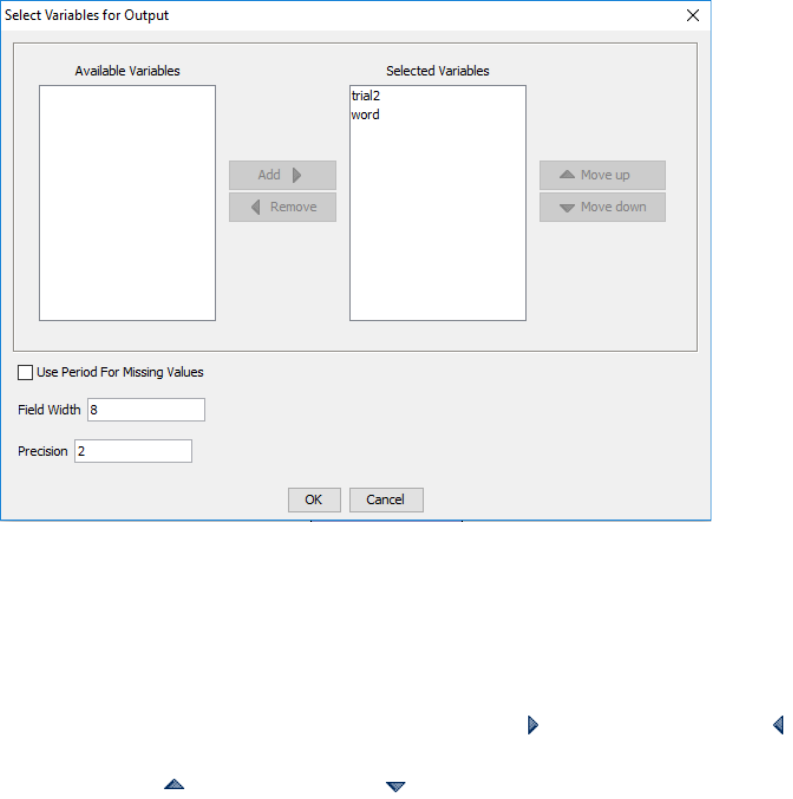
SR Research Experiment Builder User Manual ©2004-2017 SR Research Ltd.
288
Figure 11-1. Editing Trial ID Message.
The “Selected Variables” panel on the right lists all the data source columns and variables
currently selected to be written to the EDF as trial variables, and “Available Variables”
will show any variables not selected to be written as trial variables. Version 2.0 of
Experiment Builder now automatically adds new variables and data source columns to
the Selected Variables list. To add or remove items from the Selected Variables, select
the item(s) to be moved, then click the “Add” button ( ) or “Remove” button ( ). To
configure the order of the variables in the output, select the item(s) to be moved and click
the “Move Up” ( ) or “Move Down” ( ) buttons. Users may also configure the “Field
Width”, specifying the minimum number of characters output for numerical values, and
“Precision”, specifying the number of digits after the decimal-point character for floating-
point values, as well as whether to write out a period (.) for missing values.
11.2 Images and Interest Areas
The Spatial Overlay View in Data Viewer allows users to visualize eye movements over
the visual stimuli used in the experiment by reading “DRAW_LIST” messages in the
EDF that specify the images and drawings in each trial. By default, Experiment Builder
will send a “DRAW_LIST” message to the EDF corresponding to the visual stimuli on
all the Display Screen actions within the Recording sequence.
MSG 12808461 -9 !V DRAW_LIST runtime/dataviewer/graphics/1116546752.vcl
The "Send EyeLink DV Messages" property of a Display Screen action, checked by
default, controls whether that Display Screen will be included in the “DRAW_LIST”
message. If unchecked, the stimuli from this screen will not be visible in Data Viewer. It
SR Research Experiment Builder User Manual ©2004-2017 SR Research Ltd.
289
can be useful to uncheck this property, for instance, if a blank screen at the end of the
trial is used to clear the display screen, so the blank screen is not displayed in the Spatial
Overlay View in Data Viewer.
Important: Screen resources will only be visible in Data Viewer if the “Prebuild to
Image” property of the resource is checked. “Prebuild to Image” builds the screen
resource into an image file saved in the "\runtime\images" directory when the experiment
is built—unbuilt images will not be visible in Data Viewer. In addition to making
resources available for Data Viewer, having “Prebuild to Image” checked ensures a better
runtime performance.
For some experiments, users may create interest areas to easily determine measures like
Dwell Time, First Fixation Time, and Fixation Count within a given region. If a Display
Screen contains interest areas, Experiment Builder will write an interest area message to
the EDF data file to inform Data Viewer to include those interest areas for analysis.
MSG 63036 -13 !V IAREA FILE runtime/dataviewer/test/aoi/ias_1021582019659.ias
Important: In order for Data Viewer to properly load trial images and interest areas, the
file structure of the deployed project directory should be maintained. For instance, if the
“results” directory is moved to a new location on the computer, Data Viewer will not be
able to find the images in the “\runtime\images” relative to the new location. If
performing data analysis on another computer, make sure to copy the entire deployed
project directory (the whole {Experiment Name} folder) to the analysis computer. To
make the data transfer easier, you may first zip up the {Experiment Name} folder
(keeping the directory structure) and then unzip the file on the data analysis computer.

SR Research Experiment Builder User Manual ©2004-2017 SR Research Ltd.
290
12 Custom Class
In addition to programming through the Graphical User Interface, Experiment Builder
allows users to do custom scripting using the Python programming language. This section
explains how to create a new custom class, how to define class attributes and methods,
how to instantiate a custom class object, and how to use the custom class object in the
Experiment Builder GUI.
12.1 Enabling the Custom Class Option
To create a custom class in an Experiment Builder project, please first check the project
preference settings to make sure custom class is enabled. Click "Edit → Preferences”,
select "Experiment Preferences”, and check the "Enable Custom Class" box. This will
activate several node types for use in the experiment project: "Custom Class Instance”,
"Execute Action”, and the "Custom Class” tab of the Library Manager (see below).
12.2 Creating a New Custom Class
To create a new custom class, click "Edit → Library Manager". Select the "Custom
Class" tab and click the "New" button ( ). In the following "File Name" dialog box,
enter the intended custom class file name. To load a python file (.py) as a new custom
class, click the "Add" button.
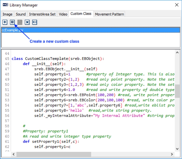
SR Research Experiment Builder User Manual ©2004-2017 SR Research Ltd.
291
Figure 12-1. Creating a New Custom Class.
There are some restrictions in the file naming:
1) The file name cannot use any of the following reserved words (names of packages
that already exist in the python library path): ctypes, numarray, py2exe, pyasio,
pygame, pylink, pypsy, pythonwin, serial, sreb, win32, and wxPython.
2) The file name cannot have spaces or non-ANSI characters.
3) The file name cannot contain a period (.) other than for the “.py” extension.
12.3 Syntax of Custom Class
Custom Classes are written using the Python programming language. As such, an
understanding of the Python programming language is necessary before creating a
Custom Class in Experiment Builder. Please refer to the Python documentation
https://docs.python.org/2/ if you are not familiar with the language.
While a custom class is written in Python, a set of rules is used by the Experiment
Builder GUI to parse the custom class and display the properties of the class in the
Experiment Builder GUI. It is critical that these rules, described later in this section, are
understood as you define your custom class so access to class attributes and methods is
possible from within the rest of the experiment. The following explains the basics of
creating a custom class in Experiment Builder with an example.

SR Research Experiment Builder User Manual ©2004-2017 SR Research Ltd.
292
12.3.1 Example
Line 001:
Line 002:
Line 003:
Line 004:
Line 005:
Line 006:
Line 007:
Line 008:
Line 009:
Line 010:
Line 011:
Line 012:
Line 013:
Line 014:
Line 015:
Line 016:
Line 017:
Line 018:
Line 019:
Line 020:
Line 021:
Line 022:
Line 023:
Line 024:
Line 025:
Line 026:
Line 027:
Line 028:
Line 029:
Line 030:
Line 031:
Line 032:
Line 033:
Line 034:
Line 035:
Line 036:
Line 037:
Line 038:
Line 039:
Line 040:
import sreb
class CustomClassTemplate(sreb.EBObject):
def __init__(self):
sreb.EBObject.__init__(self)
self.property1=1
#property of Integer type. This is also a read,write property. see the getter and setter
self.property2=(1,2)
#read only point property. Note the setter missing for this property.
self.property3=(1,2,3)
#read only color property. Note the setter missing for this property.
self.property4=1.0
#read and write property of double type, also will not accept references or equation.
self.property5=sreb.EBPoint(100,200)
#read, write point property.
#Note this property is similar to proprty2 except the writeableness.
self.property6=sreb.EBColor(200,100,100)
#read, write color property.
#Note this property is similar to proprty3 except the writeableness.
self.property7=[1,'abc',self.property6]
#read,write eblist property.
self.property8='hello'
#read,write string property.
self._myInternalAttribute="My Internal Attribute"
#string property, however this is hidden from the interface.
#
#Property: property1
#A read and write integer type property
def setProperty1(self,c):
self.property1=c
def getProperty1(self):
return self.property1
#
#Property: property2
#A read only property. The type will be treated as a point(EBPoint)
def getProperty2(self):
return self.property2
def getProperty3(self):
return self.property3
#
#Callable method using Execute action.
#Note the default arguments and the doc string
#to let eb know what is the expected return type.
def myMethod(self,parm1,parm2=[100,1,1,1], param3=(100,100,50),
param4=(50,75),param5="hi"):
"""RETURN:[1000,2000,3000]""" #The first line of the doc of method
is used to get the return type of the method. return [1000,2000,3000]

SR Research Experiment Builder User Manual ©2004-2017 SR Research Ltd.
293
Line 041:
Line 042:
Line 043:
Line 044:
Line 045:
Line 046:
Line 047:
Line 048:
Line 049:
Line 050:
Line 051:
Line 052:
Line 053:
Line 054:
Line 055:
Line 056:
Line 057:
Line 058:
Line 059:
Line 060:
Line 061:
Line 062:
Line 063:
Line 064:
Line 065:
Line 066:
Line 067:
Line 068:
Line 069:
Line 070:
Line 071:
Line 072:
Line 073:
Line 074:
Line 075:
Line 076:
Line 077:
Line 078:
Line 079:
Line 080:
Line 081:
Line 082:
Line 083:
Line 084:
Line 085:
Line 086:
Line 087:
Line 088:
Line 089:
Line 090:
#internal method
def _myInternalMethod(self):
pass
#
#Property: property4
#A read and write float type property
def setProperty4(self,c=5.7):
self.property4=c
def getProperty4(self):
return self.property4
#
#Property: property5
#A read and write EBPoint type property
def setProperty5(self,c):
self.property5=c
def getProperty5(self):
return self.property5
#
#Property: property6
#A read and write EBColor type property
def setProperty6(self,c):
self.property6=c
def getProperty6(self):
return self.property6
#
#Property: property7
#A read and write list type property
def setProperty7(self,c):
self.property7=c
def getProperty7(self):
return self.property7
#
#Property: property8
#A read and write string type property
def setProperty8(self,c):
self.property8=c
def getProperty8(self):
return self.property8

SR Research Experiment Builder User Manual ©2004-2017 SR Research Ltd.
294
12.3.2 Class Definition
A Python class starts with the reserved word "class", followed by the class name. Each
word in a class name is usually capitalized, but this is only a convention, not a
requirement. Python functions have no explicit begin or end, and no curly braces to mark
where the function code starts and stops. The only delimiter is a colon (:) and the
indentation of the code itself. Everything in a class is indented.
class ClassName(BaseClasses):
statement(s)
The class name of the above example is CustomClassTemplate (Line 003). In Python, the
ancestor of a class is simply listed in parentheses immediately after the class name. All
custom classes in Experiment Builder must inherit the sreb.EBObject class (Line 003)
and import the sreb module (Line 001). If a class starts with _ then it is considered
internal and will not be treated as a custom class.
12.3.3 Class Initialization
The body of the class is where you normally specify the attributes and methods of the
class. An Experiment Builder custom class always starts with an __init__(self) method
(Line 004). This method is used to initialize the CustomClassTemplate class. The first
argument of every class method, including __init__, is always a reference to the current
instance of the class. By convention, this argument is always named self. The custom
class __init__ method will only use the default constructor (i.e., a constructor with only
the self parameter or any other parameter with the default arguments. If any default
arguments are passed in, only the default arguments will be used.).
def __init__(self):
sreb.EBObject.__init__(self)
#list of attributes
self.identifier = value
12.3.4 Class Attributes
Within the __init__ method, the constructor must call sreb.EBObject's constructor (Line
005). Following this, all the possible attributes and methods used in the class should be
listed. Attributes of the class are specified by binding a value (1 for Line 006) to an
identifier (self.property1 for Line 006). All of the attributes used in the class must start
with "self.". The attribute identifier must be an alphanumeric string and start with a
lowercase letter; if the property starts with an _(underscore) or an upper-case letter, then
the property is treated as internal. For example, "self.thisIsAnExmaple" and
"self.example2" are valid custom class attributes whereas "self.2Example", and
"self.badString$" are not valid.

SR Research Experiment Builder User Manual ©2004-2017 SR Research Ltd.
295
The data type of the class attribute is determined by the initial value assigned to the
attribute. Supported data types are int, float, string, EBPoint, EBColor, tuple, and list. For
example (Line 006), self.property1 attribute has an initial value of 1. As a result, this
class attribute is an integer. The following table lists typical data types used in a custom
class.
Attribute Value
Data Type
Usage
'Hello'
String
Example: Line 013
"Hello"
String
self.myString = "This is another string"
1
Number (Integer)
Example: Line 006
1.0
Number (Float)
Example: Line 009
True
Boolean
self.property=True
False
Boolean
self.property= False
(100,100)
Point
Example: Line 007
If an attribute's default value is of tuple type
and only has two items, the property will be
treated as an EBPoint. The parameter of the
setX method and the return type of the getX
method is expected to be the same as the
attribute type.
sreb.EBPoint(100,200)
Point
Example: Line 010
(1,2,3)
Color
Example: Line 008
If an attribute's default value is a tuple of 3
items, the property will be treated as an
EBColor. The parameter of the setX
method and the output type of the getX
method is expected to be the same as the
type of the attribute.
sreb.EBColor(200,100,100)
Color
Example: Line 011
[1,'abc',self.property6]
List
Example: Line 012
list()
List
self.myList = list()
This creates an empty list.
None
Unknown Type
self.unknownType = None
12.3.5 Class Methods
Methods in a class are defined by a def statement. The def statement is a single clause
statement with the following syntax:
def function-name(self, [parameter list]):
statement(s)
All of the code within the function is indented. Unlike other python functions, a method
defined in a class body always has a mandatory first parameter “self”. In addition to the
first mandatory parameter “self”, users can pass a variable comma-separated list of
parameters to the functions. Zero or more mandatory parameters may be followed by zero
or more optional parameters, where each optional parameter has the following syntax:

SR Research Experiment Builder User Manual ©2004-2017 SR Research Ltd.
296
identifier = expression
The code segment below illustrates a function named doMyCalculations, which takes
three parameters, x, y, and items. The last parameter item is optional as it has a default
value.
def doMyCalculations(self, x, y, items = 2):
"""RETURN: 1 """
if items == 2:
return x
else:
return y
By default, the return type of a method is string, unless a doc string with the following
constraints is available:
• The doc string is a multi-line string flanked by a triple quotes. Everything
between the start and end quotes is part of a single string, which documents what
the function does. A doc string, if it exists, must be the first thing defined in a
function (that is, the first thing after the colon). While a doc string is not
technically required in a function, it is good practice and should always be
included if the return data type is not a string.
• The doc string should start with a "RETURN:" text (case sensitive).
• Following the "RETURN:" text, provide a default value of the type or the
__repr__ value of the class (e.g., str for string).
12.3.6 'setX' and 'getX' Methods
Method names starting with 'set' and 'get' are assumed to operate on the class attributes
and are handled differently from regular custom class methods.
def __init__(self):
sreb.EBObject.__init__(self)
self.myProperty=1
#Property: myProperty
#A read and write integer type property
def setMyProperty(self,c):
self.MyProperty=c
def getMyProperty(self):
return self.myProperty

SR Research Experiment Builder User Manual ©2004-2017 SR Research Ltd.
297
To allow the getX and setX methods to operate directly on a class attribute x, the
following syntax rules must be followed:
• The class attribute identifier must be an alphanumeric string and start with a
lowercase letter (e.g, use self.myProperty instead of self.MyProperty).
• The getX and setX method names should be composed of 'set' and 'get' string and
the attribute identifier, with the first letter of the identifier capitalized (e.g.,
getMyProperty instead of getmyProperty). Any getX and setX methods that do
not follow this rule will be treated as regular class methods.
• The getX method shouldn't take extra parameters except for the mandatory
parameter self.
• The setX method expects one extra parameter. To support attribute referencing of
that property in Experiment Builder, do not give a default value for the parameter.
For example,
def setEBAttrib(self,value):
That is, the attribute EBAttrib should be able to be set to a reference. If a default
value is assigned to the setX method, this would tell Experiment Builder that the
attribute NonEBAttrib should not be able to be set to a reference. For example,
def setNonEBAttrib(self,value=0):
A class attribute that has a corresponding getX method is a readable attribute. A class
attribute that has a corresponding setX method is a writeable attribute. An attribute is a
readable and writeable property if it has corresponding getX and setX methods.
12.4 Instantiating Custom Class
Once a custom class is defined, users can instantiate the class by creating a concrete
instance of that class in the experiment graph. To instantiate the class, click the Other tab
of the component tool box, and drag a Custom Class Instance node into the experiment
graph.
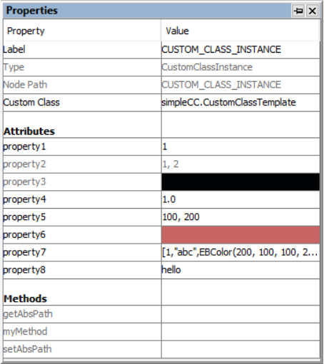
SR Research Experiment Builder User Manual ©2004-2017 SR Research Ltd.
298
Figure 12-2. Attributes and Properties of a Custom Class Instance.
Select the newly added Custom Class Instance node. Click the value field of the "Custom
Class" property, and select the custom class from a dropdown list. Once the class is
loaded, attributes and methods will be listed in alphabetical order in the property table.
The "Attribute" section lists all of the class attributes that have a corresponding getX
method.
• Attributes that have a getX method only, but without a corresponding setX
method, will be read-only and are not directly modifiable (see attributes property2
and property3 in the example from section 12.3.1).
• Attributes that have both a getX method and a setX method, without a default
value for the parameter, are both readable and writeable. These attributes may be
set to a reference (see attributes property1, property5, property6, property7, and
property8 in the 12.3.1 example).
• Attributes that have both a getX method and a setX method with a default value
are readable and writeable. However, these attributes cannot be set to a reference
(see attribute property4 in the 12.3.1 example).
• Attributes that have a setX method but not a getX method will not be displayed in
the attribute section. The setX method will be displayed as a regular method.
The "Methods" section lists all methods available for the class (see myMethod of the
12.3.1 example) except for the __init__, getX, and setX methods mentioned above.
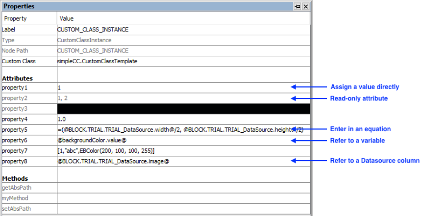
SR Research Experiment Builder User Manual ©2004-2017 SR Research Ltd.
299
12.5 Using Custom Class
The custom class and the Experiment Builder graph may interact through attribute
reference, as well as through the Execute, Sequence, and Update Attribute actions.
Through these options, users can set values for the class attributes and pass parameters to
the class methods, and conversely may retrieve the current value of class attributes and
access the return values of class methods.
This bi-directional exchange of data between the custom class attributes and Experiment
Builder GUI is enabled by the getX and setX methods. For class attributes with a
corresponding setX method (without a default value as the function parameter), users can
set a value, an equation, or a reference for the class attribute directly in the custom class
instance. Users can may also set a value/reference for a class attribute through an Update
Attribute action. Similarly, if a class attribute has a corresponding getX method, its
current value can be referenced and used directly much like any other EB component
attribute.
Figure 12-3. Assigning Attribute Values through Custom Class Instance.
Users can call a class method through the Execute action or the "Callback" property of a
Sequence. Values can be passed to the argument list of a custom class method from the
properties of the Execute action or the Callback sequence (see Figure 12-4).
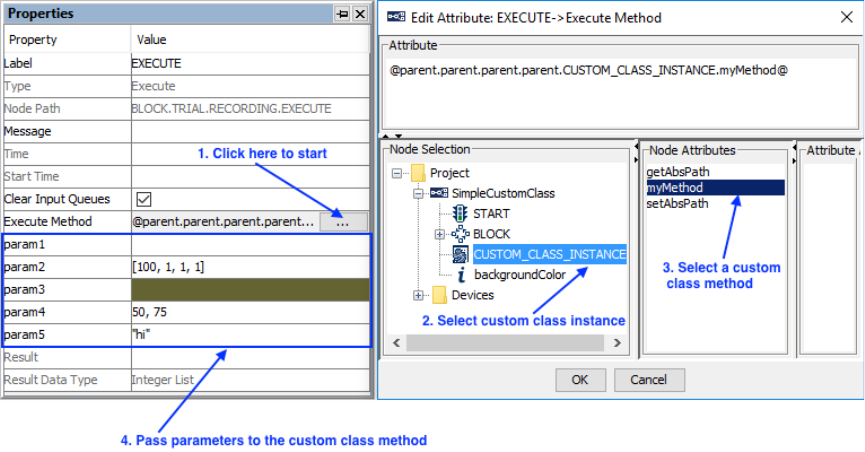
SR Research Experiment Builder User Manual ©2004-2017 SR Research Ltd.
300
Figure 12-4. Data Exchange through Execute Action.
In addition, a value can be returned from the custom class to the Experiment Builder GUI
as the return value of a class method. Please note that the return type of a method is string
by default unless a doc string is used to specify the data type of the return value.
12.6 Using the Custom Class Editor
To edit the content of a custom class, double-click the Custom Class Instance node in the
experiment graph. This will open the Custom Class Editor as a new tab in the Graph
Editor Window. (There is also a simple text editor in the Library Manager for previewing
and making basic changes to the custom class.) The following table summarizes the tools
available for code editing using the custom class editor.
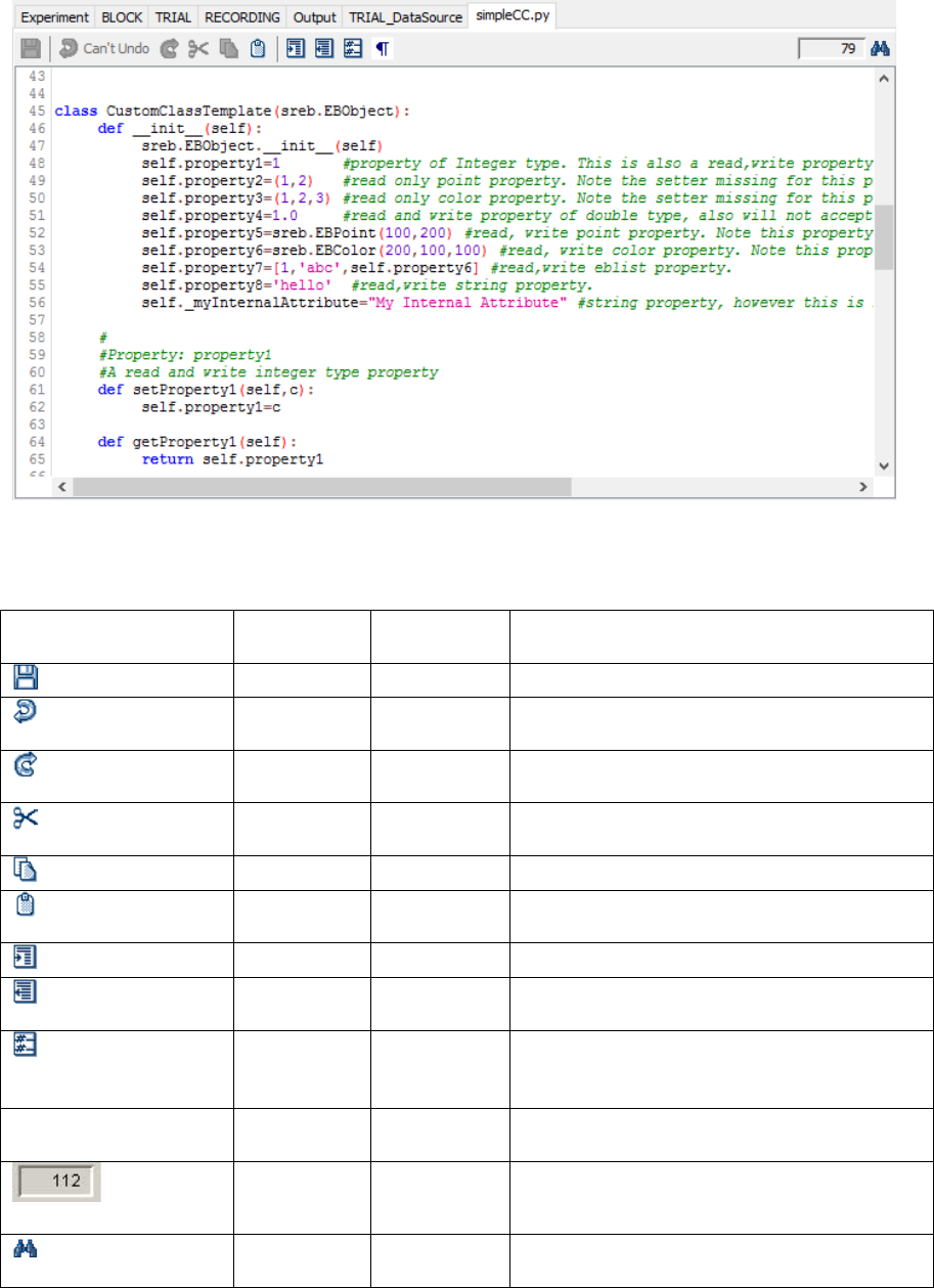
SR Research Experiment Builder User Manual ©2004-2017 SR Research Ltd.
301
Figure 12-5. Custom Class Code Editor.
Custom Class Editor Toolbar
Operation
Shortcut
(Windows)
Shortcut
(Mac OS X)
Function
Save Code
Ctrl + S
⌘ + S
Save the custom class code.
Undo
Ctrl + Z
⌘ + Z
Undo the last change made to the custom
class editor.
Redo
Ctrl + Y
⌘ + Y
Redo the last change made to the custom
class editor.
Cut
Ctrl + X
⌘ + X
Removes a selection from the project and
place it into the clipboard.
Copy
Ctrl + C
⌘ + C
Puts a copy of a selection into the clipboard.
Paste
Ctrl + V
⌘ + V
Inserts the previously copied item from the
clipboard to the current position.
Increase Indent
Tab
Tab
Inserts a tab space before the current code.
Reduce Indent
Shift + Tab
Shift + Tab
Removes a tab space before the current
code.
Comment
Ctrl + /
⌘ + /
Creates comment. This will add a comment
symbol "#" in front of the current line of
code.
¶ Visible Space
Click to toggle on/off the visibility of space
and tab characters in the custom class code.
Go to Line
Number
Go to a specified line.
Find/Replace
Ctrl + F
⌘ + F
Search or replace a specified text string in
the custom class code.
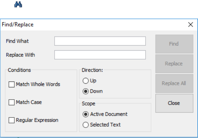
SR Research Experiment Builder User Manual ©2004-2017 SR Research Ltd.
302
Clicking on the button opens the Find/Replace dialog box for the custom class editor.
Figure 12-6. Custom Class Find/Replace Dialog Box.

SR Research Experiment Builder User Manual ©2004-2017 SR Research Ltd.
303
13 Creating Experiments: Overview
The easiest way to start developing EyeLink experiments is to study the supplied
templates included with the Experiment Builder software, installed at:
• Windows Vista or Windows 7, 8 and 10: "C:/Users/{User
Name}/Documents/ExperimentBuilder Examples"
• Windows XP with user read/write permission: "C:/Documents and Settings/{User
Name}/My Documents/ExperimentBuilder Examples"
• Mac OS X: "Documents\ExperimentBuilder Examples"
Each of these experiment templates illustrates a typical experimental paradigm. The
following table provides a brief description of the experiments. A detailed analysis of
each template's operations is documented in the following sections. More examples can
be found in the Experiment Builder Examples discussion forum (https://www.sr-
support.com/forums/forumdisplay.php?f=7).
Experiment
Purpose
Simple
The basic experiment template, displaying a single word in the center of the
screen in each trial. This example is used to introduce how to create an
experiment with SR Research Experiment Builder step-by-step.
Stroop
The basic template for creating non-EyeLink experiments. This template
illustrates the use of a results file, RT calculation, and audio feedback.
Picture
Illustrates various parameter settings for showing an image on the screen (in
original size versus stretched, centered versus not centered).
TextLine
Experiment to show a single line of text, illustrating the use of runtime
interest area segmentation.
TextPage
Experiment to show a full screen of text using a multi-line text resource.
GCWindow
Demonstrates how to use real-time gaze position to display a gaze-contingent
window.
Track
Displays the user’s current gaze position during recording and illustrates how
to set the resource position contingent on the current gaze position.
Change
Displays several almost identical screens rapidly, and illustrates use the of the
fixation trigger.
Saccade
Illustrates the creation of a simple experiment for saccade/anti-saccade
research.
Video
Illustrates creating an experiment display video clips using xvid codec.
Pursuit
Illustrates several kinds of sinusoidal movement in a pursuit task.
The discussion of the “simple” template should be read before working with any of other
templates, as it illustrates most of the shared operations for all experiments. You may go
over the “Stroop” example for creating non-eye tracking experiments. In general, we
recommend reading through all of the templates before programming your own
experiment. When creating your experiment, you may also refer to the Experiment
Builder Project Checklist in Chapter 16.
Before making any changes to the existing examples, we suggest you first make a copy of
the examples and then uncheck the "Read-only" box of the topmost experiment node.
SR Research Experiment Builder User Manual ©2004-2017 SR Research Ltd.
304
14 Creating EyeLink Experiments: The First Example
To illustrate the use of Experiment Builder, we are going to create a very simple eye-
tracking experiment that runs three blocks of four trials each. In each trial, a single word
is displayed in the center of the screen (much like the “SIMPLE” template of the EyeLink
C Programming API).
Creating an Experiment with SR Research Experiment Builder, consists of the following
three overall steps:
• Create an Experiment
• Build and test run the Experiment
• Deploy the Experiment
Deploying the experiment generates a set of files used to run the experiment for data
collection without relying on the Experiment Builder application.
14.1 Creating the Experiment
This section provides a step-by-step tutorial to walk you through the basics of creating an
experiment with SR Research Experiment Builder.
14.1.1 Creating a New Experiment Project
To open Experiment Builder, in Windows click Start → All Applications → SR Research
and choose “Experiment Builder”. On Mac OS X, go to the “Applications/Experiment
Builder/” folder, and open the “ExperimentBuilder” application.
When the application starts:
1) Click “File → New” on the application menu bar.
2) In the following “New Project” dialog box, enter “Simple” in the “Project Name”
edit box.
3) Click the button on the right end of the “Project Location” to browse to the
directory where the experiment project should be saved. If manually entering the
“Project Location” field, please make sure that the intended directory already
exists.
4) Make sure the “EyeLink Experiment” box is checked for an EyeLink experiment.
5) Select the eye tracker version from the dropdown menu (EyeLink I, EyeLink II,
EyeLink 1000, EyeLink 1000 Plus, or EyeLink Portable Duo). Or select
“Current” to allow any EyeLink eye tracker (See Figure 14-1).
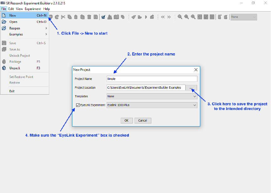
SR Research Experiment Builder User Manual ©2004-2017 SR Research Ltd.
305
Figure 14-1. Creating a New Experiment Builder Project.
Important: Users should not manually add or remove files in the experiment directory.
To maintain file integrity for the experiment projects created, any changes made to the
experiment directory will be overwritten by Experiment Builder. Any image files, audio
files, video files, etc., should be added or removed from the project through the Library
Manager.
14.1.2 Configuring Experiment Preference Settings
After creating a new experiment session, check whether the default display and screen
preference settings are appropriate for the experiment to be created.
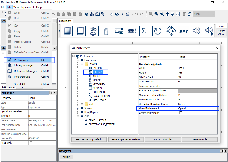
SR Research Experiment Builder User Manual ©2004-2017 SR Research Ltd.
306
Figure 14-2. Configuring Preference Settings.
1) Select “Edit → Preferences” from the application menu bar or press the shortcut
key “F4” on Windows. On Mac OS X, click “ExperimentBuilder → Preferences”
from the application menu bar or press Command ⌘+“ ,”.
2) Click “Preferences → Experiment → Devices → Display” to check display
settings. Make sure the settings (Width, Height, Bits per Pixel, and Refresh Rate)
used in the current example are supported by your video card and monitor. For
this example, set the “Video Environment” to “OpenGL”. If using the DirectDraw
graphics, additionally set the “Transparency Color” of the project close to (but not
identical to) the background color of the display screens to make the text look
better. For example, this experiment has a white background (255, 255, 255), so
you may set the RGB value of the transparency color to (251, 250, 251). It is not
necessary to set the Transparency Color when using the “OpenGL” video
environment.
3) Click “Preferences → Screen” to check Screen Builder settings. Set the Location
Type as "Center Position" and check the "Antialis Drawing" box.
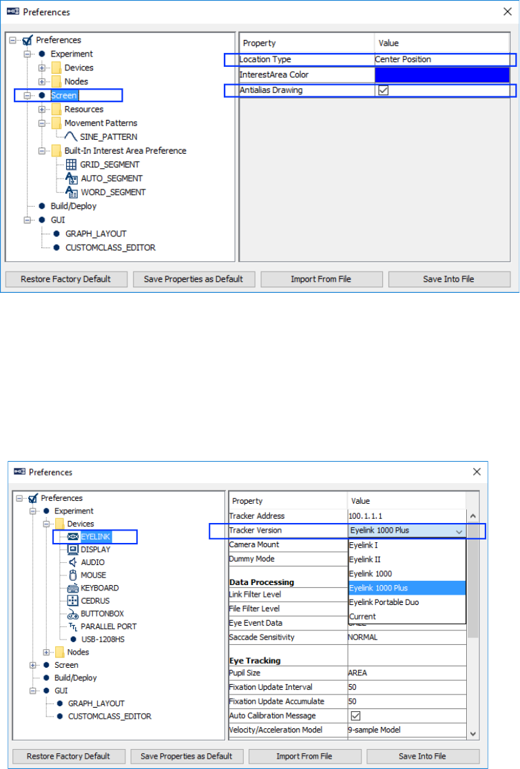
SR Research Experiment Builder User Manual ©2004-2017 SR Research Ltd.
307
Figure 14-3. Setting the Screen Preferences.
4) EyeLink I, II, 1000, and Portable Duo users: The default tracker version is set
to EyeLink 1000 Plus. EyeLink I, II, 1000, and Portable Duo users should also
make sure the "Tracker Version" setting in the "Preferences -> Experiment ->
Devices -> EyeLink" preferences is set to EyeLink I, EyeLink II, EyeLink 1000,
or EyeLink Portable Duo. If you use EyeLink 1000, 1000 Plus, or Portable Duo,
please make sure you configure the correct “Camera Mount” and “Mouse Usage
setting.
Figure 14-4. Setting the Tracker Version for the Experiment.
5) After changing any preference settings, if you would like to keep the new settings
as defaults for all of your future experiments, click the "Save Properties as
Default” button.
6) Once finished, press the close button on the dialog box.
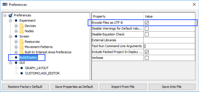
SR Research Experiment Builder User Manual ©2004-2017 SR Research Ltd.
308
If intending to use any characters that do not fit in the ASCII encoding range, including
non-English characters (eg. à, è, ù, ç), special curved quotes, and any non-European
language characters (e.g., Chinese characters), please also make sure the “Encode Files as
UTF-8” box of the Build/Deploy node is checked (enabled by default in later versions of
Experiment Builder; see Figure 14-5).
Failing to enable UTF-8 encoding when non-ASCII characters are used will result in the
following build/run time warning:
WARNING: warning:2001 You are using characters that ascii encoding cannot
handle! Please change your encoding!
Likewise, if Chinese, Japanese, or Korean characters are used and UTF-8 encoding is not
enabled, this will result in the following error:
ERROR: error:2070 Internal Error. Could not create script. Please contact SR
Research! Sorry: MemoryError: ().
Figure 14-5. Setting the File Encoding for the Project.
14.1.3 Creating the Experiment Block Sequence
In this example, we are going to run three blocks of four trials each. The first step is to
add a sequence to repeat the blocks (see Figure 14-6).
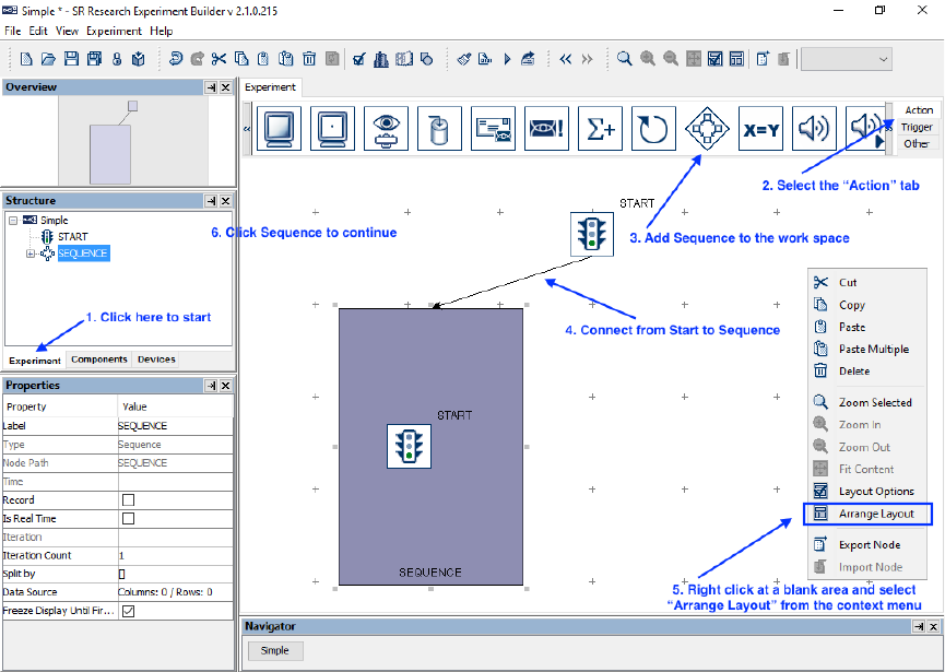
SR Research Experiment Builder User Manual ©2004-2017 SR Research Ltd.
309
Figure 14-6. Creating Experiment Block Sequence.
1) Click the Experiment Tab in the Project Explorer Window to start.
2) Click the “Action” Tab of the component toolbox.
3) Click and drag the “Sequence” node from the component toolbox into the work
space.
4) Connect the “START” and “SEQUENCE” nodes by clicking and dragging the
mouse from the “START” node to the “SEQUENCE” node. (Note: If the
“START” node is selected, clicking and dragging will move the node instead of
drawing an arrow. To de-select the node, simply click in an empty area of the
work space.)
5) To rearrange the nodes into an orderly layout onscreen, right-click any blank area
in the work window and select "Arrange Layout" in the popup menu.
6) Select the SEQUENCE node in the structure list to continue.
14.1.4 Editing the Block Sequence
Next, we can edit the properties of the Block Sequence. We will first set the “Label” of
the sequence to give it a meaningful name, then set the “Iteration Count” to the number
of blocks to be tested (see Figure 14-7). (We do not edit the “Split by” field for the block-
level sequence; we will instead set the “Split by” of the trial-level sequence.)
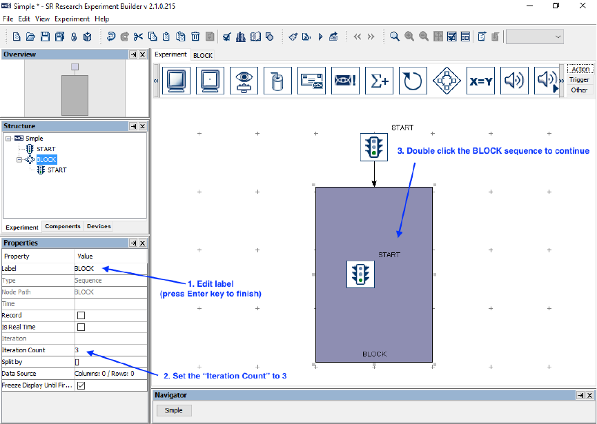
SR Research Experiment Builder User Manual ©2004-2017 SR Research Ltd.
310
Figure 14-7. Editing Block Sequence.
1) Click the value field of the “Label” property of the Sequence created. Type a new
label, e.g., “BLOCK”, into the text editor and press the Enter key to finish.
2) Click the “Iteration Count” value field and enter “3” as the total number of
sequence loops.
3) Double-click the BLOCK Sequence object in the work space to enter the
sequence.
In each block, we will first display some instructions onscreen, perform a camera setup
and calibration, and then run four trials (see Figure 14-8).
We can start by adding the necessary nodes to the workspace within the BLOCK
sequence:
1) Open the “Action” Tab of the component toolbox, then click and drag a “Display
Screen” action into the work area.
2) Open the “Trigger” Tab of the component toolbox, then drag a “Keyboard”
trigger into the work area.
3) Add an “EyeLink Button” trigger to the work space.
4) Add a “Timer” trigger to the work space.
5) Click the Timer trigger and set the duration to 20000 msec.
6) Open the “Action” Tab of the component toolbox and add a “Camera Setup”
action to the work space.
7) Add a “Sequence” node to the work space. This will be our trial-level sequence.
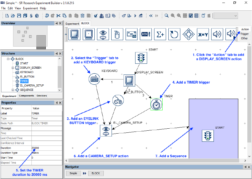
SR Research Experiment Builder User Manual ©2004-2017 SR Research Ltd.
311
Then we can continue by drawing the connections between the nodes in the BLOCK
sequence:
8) Click and drag from the START node to the DISPLAY_SCREEN node.
9) Draw three connections from the DISPLAY_SCREEN action to the KEYBOARD,
EL_BUTTON, and TIMER triggers. When a single action connects to several
triggers, a number is added to each connection indicating the evaluation order
among the three trigger types. In this experiment, it doesn’t matter which order
the nodes are connected in.
10) Draw a connection from each of the three triggers to the EL_CAMERA_SETUP
node, then from EL_CAMERA_SETUP to the SEQUENCE node.
Figure 14-8. Adding Instruction to Block Sequence.
11) Right-click any blank area in the work window and select "Arrange Layout" in
the popup menu.
14.1.5 Creating the Instructions Screen
Next we can configure the DISPLAY_SCREEN node to display a set of instructions at
the beginning of the experiment. In this example, we will create the instructions by
adding a Multi-Line Text Resource to the Display Screen; users may also create the
instructions as an image file and use the Display Screen to display the image.
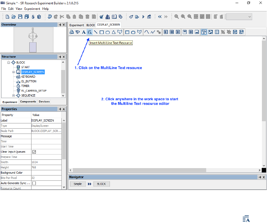
SR Research Experiment Builder User Manual ©2004-2017 SR Research Ltd.
312
To start editing the screen, open the Screen Builder by double-clicking the
DISPLAY_SCREEN node in the workspace.
Figure 14-9. Adding Multiline Text Resource onto a Display Screen.
1) Once you’ve opened the Screen Builder, click the multiline text resource ( )
button on the screen builder toolbar to select the resource to add.
2) Click anywhere on the screen to add the resource.
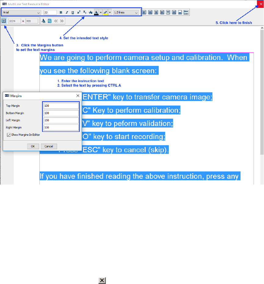
SR Research Experiment Builder User Manual ©2004-2017 SR Research Ltd.
313
Figure 14-10. Create Instruction Screen.
In the following Multi-Line Text Resource Editor,
1) Click the “Margins” button in the toolbar to set the text margins. Enter 100 in all
fields. Click the "OK" button on the dialog box.
2) Enter the desired instruction text.
3) Press Ctrl + A on Windows (Command ⌘ + A on Mac OS X) to select all text
entered.
4) Then click the buttons on the toolbar to set the desired text appearance (font name,
font size, font style, alignment style, line spacing, and text color).
5) Click the “Close” button ( ) at the top right corner of the Multi-Line Text
Resource Editor to finish.
14.1.6 Editing the Trial Sequence: Data Source
Next, we will design the Trial sequence, which will contain all the necessary triggers and
actions in each trial. We will first create a data source to set the parameters in individual
trials (see Figure 14-11). In this experiment, we will add two columns to the data source:
“Trial”, to serve as a trial identifier variable, and “Word”, to determine the text displayed
on each trial.
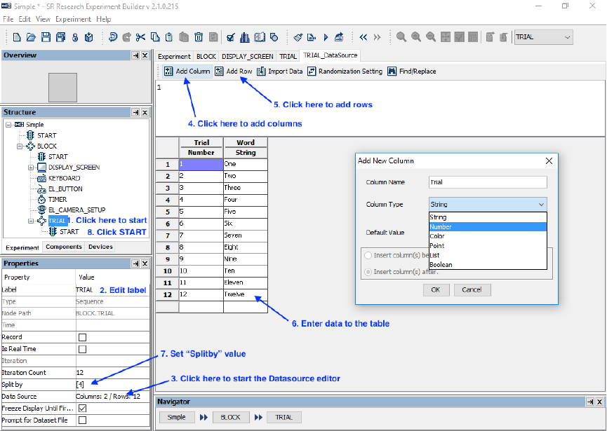
SR Research Experiment Builder User Manual ©2004-2017 SR Research Ltd.
314
Figure 14-11. Creating Data Source.
1) First, select the last “SEQUENCE” node in the structure list (the one we added
within the BLOCK sequence).
2) In the Properties table, enter a new value for the Label, e.g., “TRIAL”.
3) Click the value cell of the “Data Source” property (where it says “Columns: 0 /
Rows: 0”) to bring up the Data Source Editor.
Next we can create the Data Source columns and enter our values.
4) Click the "Add Column" button. Type "Trial" (without quotes) in the Column
Name box, and set the Column Type to "Number". Click the "OK" button to
finish. Click the "Add Column" button again. Enter the Column Name as "Word"
and set Column Type to "String". Click "OK" to finish.
5) Click the “Add Row” button. Set the “Number of Rows” to 12 to add 12 rows of
empty cells, then click “OK”.
6) To add a value to the Data Source, simply click in one of the empty cells, type the
value into the editor, then press the Enter key. Set the values of the “trial” column
as 1, 2, 3, … 12, and in the “word” column, enter the words “One”, “Two”,
“Three”, etc., all the way to “Twelve”.
7) Click the “Split by” value field. To make sure only 4 of the 12 trials are run in
each block, enter a value of [4].
8) To enter the TRIAL sequence, double-click the TRIAL sequence node in the
project workspace.
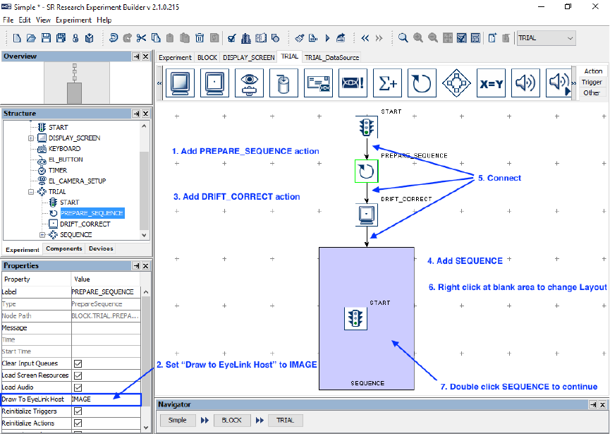
SR Research Experiment Builder User Manual ©2004-2017 SR Research Ltd.
315
14.1.7 Editing the Trial Sequence: Preparing Sequence and Drift
Correction
Next we can start filling the contents of our TRIAL sequence.
Each trial should begin with a Prepare Sequence action, followed by a Drift Correct
action, and then by the actual trial recording sequence (see Figure 14-12). The Prepare
Sequence action preloads any image files or audio clips in the trial for real-time image
drawing or sound playing, draws feedback graphics on the Host PC to evaluate
participants’ performance, and reinitializes trigger settings. Users should typically call the
Prepare Sequence action before performing a drift correction.
Figure 14-12. Editing Trial Sequence.
1) Open the “Action” Tab of the component toolbox, then drag a “Prepare Sequence”
action into the workspace.
2) Select the added PREPARE SEQUENCE action and review the settings in the
properties table. To draw an image from the trial or simple feedback graphics on
the host screen to evaluate the participants’ gaze position during recording, make
sure the "Draw To EyeLink Host" field is set to "IMAGE" or "PRIMITIVE".
3) Drag a "Drift Correction" action into the workspace.
4) Then drag a “Sequence” node into the workspace.
5) Click and drag to draw a connection from the “START” node to
“PREPARE_SEQUENCE”, then from “PREPARE_SEQUENCE” to
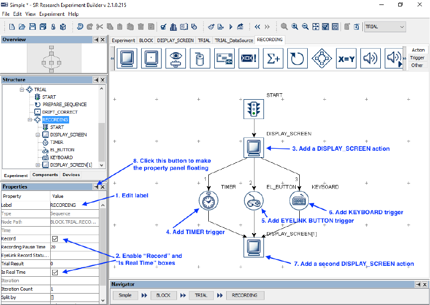
SR Research Experiment Builder User Manual ©2004-2017 SR Research Ltd.
316
“DRIFT_CORRECTION”, then from “DRIFT_CORRECT” to the “SEQUENCE”
node.
6) Right-click any blank area in the work window and select "Arrange Layout" in
the popup menu.
14.1.8 Editing the Recording Sequence
We will start by setting the properties of the recording sequence, as well as the actual
contents of the trial recording (see Figure 14-13). In this simple recording sequence, we
will display a screen and then wait for a button press response from the participant. The
trial times out automatically if no response is made within 10 seconds. After the response
or time out, the display screen is cleared. It is critical within the Recording sequence to
fill in the “Message” field of action and trigger nodes corresponding to stimulus
presentation and participant response so the timing of these events will be marked in the
EDF.
Figure 14-13. Editing Recording Sequence.
1) Select the newly added “Sequence” node and enter a new value for the Label, e.g.,
“RECORDING”.
2) Make sure that the “Record” and “Is Real Time” checkboxes are checked.
Double-click the “RECORDING” node in the structure list until seeing a
“START” node under it. As we double click the “START” node, the content of
the work area window is also updated.
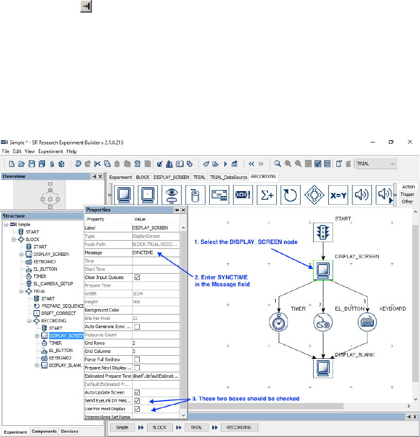
SR Research Experiment Builder User Manual ©2004-2017 SR Research Ltd.
317
3) Open the “Action” Tab of the component toolbox and drag a “Display Screen”
action into the work area.
4) Then open the “Triggers” tab and drag a “Timer” trigger into the work space.
Select the Timer object. In the “Duration” field enter 10000, and in the “Message”
field, enter “Time out” (without quotes).
5) Drag an “EyeLink Button” trigger into the workspace.
6) Open the “Action” tab and drag a second “Display Screen” action into the
workspace. Select the second Display Screen action, then set its Label, e.g., as
“DISPLAY_BLANK”, and uncheck the “Send EyeLink DV Messages” box.
7) Draw connections from the “START” node to “DISPLAY_SCREEN”, from
“DISPLAY_SCREEN” to both “TIMER” and “EL_BUTTON”, and from both
“TIMER” and “EL)BUTTON” to “DISPLAY_BLANK”.
8) Right-click any blank area in the work space and select “Arrange Layout” in the
popup menu to re-arrange the nodes.
9) Click the button in the properties window to make it a free-floating window.
14.1.9 Modifying the Properties of a Display Screen
We can next configure the property settings of the display screen actions in the Recording
sequence (see Figure 14-14). For Data Viewer integration and for reaction time
calculation, we can set a message to be written to the EDF file to indicate the time when
the stimulus was visible to the participant. We can also configure which screen’s graphics
are drawn the host screen so that the participants’ gaze position can be evaluated during
recording.
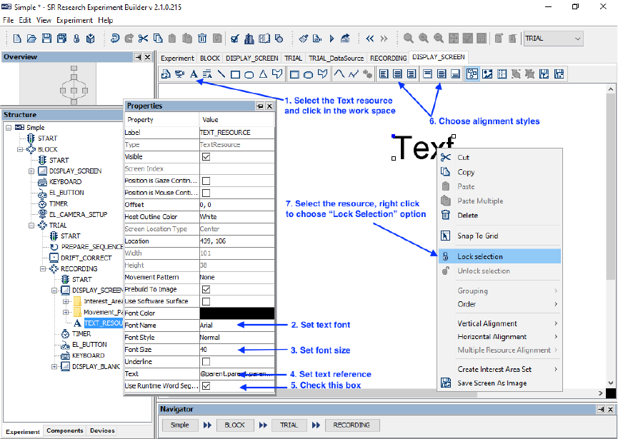
SR Research Experiment Builder User Manual ©2004-2017 SR Research Ltd.
318
Figure 14-14. Modifying the Properties of DISPLAY_SCREEN Action.
1) Select the first DISPLAY_SCREEN node. In the properties window, double-click
the value field of the “Message” property. Type in a message, e.g., “SYNCTIME”,
to mark the screen presentation, then press the Enter key.
2) Make sure the “Send EyeLink DV Messages” and “Use for Host Display”
properties are checked.
3) Next, select the “DISPLAY_BLANK” action. Double click the value field of the
“Message” property Type in a message, e.g., “blank_screen”, and then press the
Enter key.
4) Make sure both the “Send EyeLink DV Messages” and the “Use for Host Display”
checkboxes for the “DISPLAY_BLANK” action are unchecked.
14.1.10 Creating the Display Screen
We will next add a text resource to the display screen and modify the properties of the
text resource, such as the text to be displayed, font name, size, and alignment style. We
will also create an interest area for the text (see Figure 14-15). To open the Screen
Builder window, double-click the “DISPLAY_SCREEN” object in the work space (not
in the structure list!).
Figure 14-15. Adding Text to Display Screen.
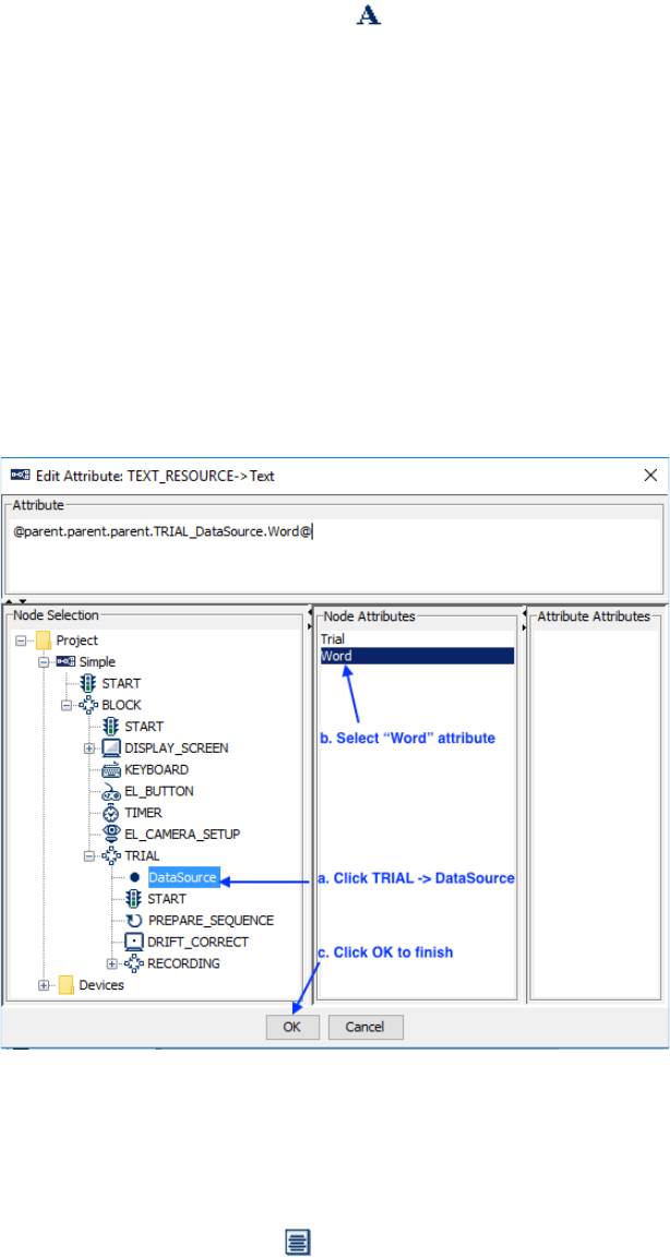
SR Research Experiment Builder User Manual ©2004-2017 SR Research Ltd.
319
1) Click the “Insert Text Resource” button ( ) on the Screen Builder tool bar, then
click any position in the screen area to add the resource.
2) Double click the Value of the Font Name property (e.g., “Times New Roman”).
Select the desired font from the dropdown list—we’ll be using “Arial”.
3) Double click the value of Font Size (20). Enter the desired text size (40) in the
text editor.
4) To set the text resource to load the text from the data source, click the value field
of the “Text” property once, then click the [ … ] button to open the Attribute
Editor dialog (see Figure 14-16).
a. Click the DataSource node under the “TRIAL” sequence in the Node
Selection list.
b. Double click the “word” attribute in the Node Attributes panel. This will
update the contents of the “Attribute” panel as
“@parent.parent.parent.TRIAL_DataSource.Word@”.
c. Click the “OK” button to finish.
Figure 14-16. Showing Text by Referring to Data Source.
5) Check the “Use Runtime Word Segment” box. This will create interest areas
automatically for the text used.
6) Select the newly added text resource, click both the “Horizontal Center Alignment”
and “Vertical Center Alignment” ( ) buttons to place the text in the center of the
screen.
7) Select the text resource in the work area, then right-click the resource and select
the “Lock Selection” option so that the resource will not be moved accidentally.
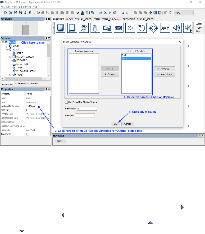
SR Research Experiment Builder User Manual ©2004-2017 SR Research Ltd.
320
14.1.11 Writing Trial Condition Variables to EDF file
Users may configure which variables, including variable nodes and data source columns,
should be written to the EDF file so the experimental conditions of each trial can be
identified during analysis (see Figure 14-17). In Experiment Builder 2.0, all newly-added
variable nodes and data source columns will automatically be added to the list of trial
variables.
Figure 14-17. Configuring the EyeLink DV Variables.
1) Click the Experiment node in the structure list (the topmost node in the tree).
2) In the properties table, click the value field of the “EyeLink DV Variables”
property.
3) In the following dialog box, the “Selected Variables” panel on the right lists all
the data source columns and variables currently selected to be written to the EDF
as trial variables, and “Available Variables” will show any variables not selected
to be written as trial variables. To add or remove items from the Selected
Variables, select the item(s) to be moved, then click the “Add” button ( ) or
“Remove” button ( ). To configure the order of the variables in the output,
select the item(s) to be moved and click the “Move Up” ( ) or “Move Down”
( ) buttons. In this example, make sure both the “Trial” and “Word” columns are
included in the Selected Variables list.
4) Click “OK” to finish.
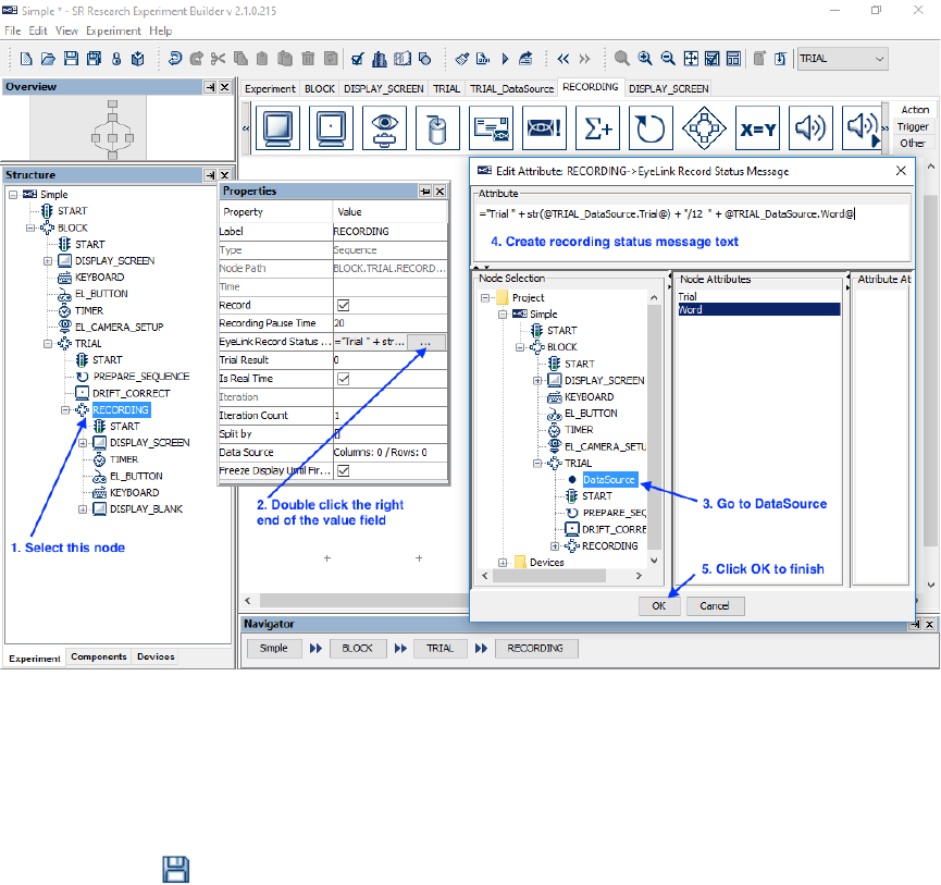
SR Research Experiment Builder User Manual ©2004-2017 SR Research Ltd.
321
14.1.12 Showing Experiment Progress Message on Tracker
Screen
During trial recording, a text message can be displayed at the bottom of the tracker screen
so the experimenter can be informed of the experiment progress (see Figure 14-18). In
this example, we will display a text message like “Trial 1/12 One” on the tracker screen,
indicating the current trial and the word displayed.
1) Select the “RECORDING” sequence node in the structure list.
2) In the properties panel, click the value field of the “EyeLink Record Status
Message” property once, then click the [ … ] button to open the Attribute Editor
dialog.
3) In the attribute editor, enter the following equation:
="Trial " + str(@TRIAL_DataSource.Trial@) + "/12 " +
@TRIAL_DataSource.Word@
4) Click the “OK” button to finish.
Figure 14-18. Creating Trial Recording Status Message.
14.2 Building the Experiment
Now your first experiment is created. If you haven’t saved your experiment project yet,
click the Save ( ) button on the application tool bar. Click “Experiment → Build” to
SR Research Experiment Builder User Manual ©2004-2017 SR Research Ltd.
322
build the experiment. An “Output” tab will be opened in the Graph Editor Window and
build information will be displayed. Watch for error messages (displayed in red) and
warning messages (in brown) during building. If any error or warning messages appear,
double-click on an error or warning message in the output tab to highlight the node or
screen resource that produced the error/warning.
Once the project builds successfully, users may test run the experiment by clicking on
“Experiment → Test Run” from the application menubar. This will try connecting the
Display PC to the Host PC to run the experiment code, so the Display PC must have an
Ethernet connection to the Host PC (or Dummy Mode may be enabled). Please note that
the “Test Run” should only be used for testing and debugging experiment code, and not
for actual data collection. To collect experiment data, users should run the deployed
version of the experiment (see the next section).
14.3 Deploying the Experiment
After the experiment is built, users must “deploy” the experiment into a new folder by
clicking Experiment → Deploy (see Section 4.11). This will create an executable version
of the experiment so it can run without relying on the Experiment Builder application. If
a data source is used, this will create a “datasets” subdirectory with a copy of the data set
file in it. If desired, users may create several data set files with the external randomizer
application (see Section 9.5.2).
14.4 Running the Experiment
To run the experiment, first make sure the EyeLink host software is running, and the
network connection between the host and display computers has been established. Then
go to the directory where the experiment was deployed and click “simple.exe” to start the
experiment. A dialog box will prompt for an EDF file name (the name should be no
more than 8 characters, featuring only letters, numbers and the underscore “_” character).
Click the “OK” button to continue. Following the initial welcome message, the
participant will be shown the camera setup and calibration screen; the recording can be
started following a calibration, validation, and pre-trial drift correction. After running
three blocks of four trials (blocks are separated by the instructions screen and camera
setup procedure), an EDF file will be transferred to the display computer. It may take
some time to complete the file transfer, so please be patient.
The following sections list some common errors while attempting to run an experiment.
14.4.1 Error in Initializing Graphics
If you start the experiment and see an “Error Initializing Graphics” error, please check
whether the display settings (screen resolution, color bits, and refresh rate) specified for
the experiment are supported by your video card and monitor (see Figure 14-19). If not,
please set the correct display settings in “Preferences → Experiment → Devices →
DISPLAY”.
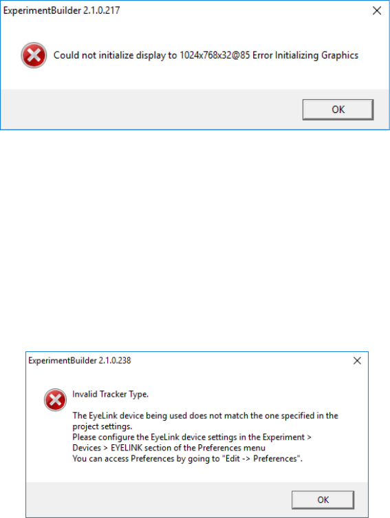
SR Research Experiment Builder User Manual ©2004-2017 SR Research Ltd.
323
Figure 14-19. Error in Initializing Graphics.
14.4.2 Error in Tracker Version
SR Research Experiment Builder is compatible with EyeLink I, EyeLink II, EyeLink
1000, EyeLink 1000 Plus, and EyeLink Portable Duo eye trackers. The default tracker
version is set to EyeLink 1000 Plus (see “Preferences → Experiment → Devices →
EYELINK”). If the eye tracker specified in the preferences doesn’t match the eye tracker
being used, Experiment Builder will display an error message like the one pictured in
Figure 14-20—if you see this message, please set the correct tracker version in the device
settings (see Figure 14-4).
Figure 14-20. Error in Tracker Version.
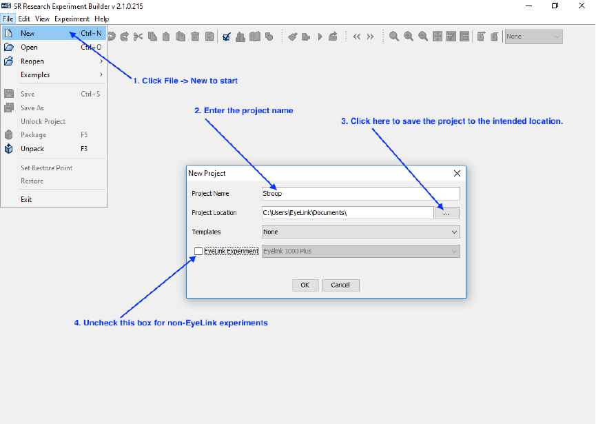
SR Research Experiment Builder User Manual ©2004-2017 SR Research Ltd.
324
15 Creating Non-EyeLink Experiments: Stroop Effect
This chapter illustrates using SR Research Experiment Builder to create a non-eye-
tracking experiment. This Stroop sample experiment demonstrates testing the Stroop
Effect with keyboard response: the participant is asked to respond to the colors of the
words as quickly and as accurately as possible. For example, for the word “BLUE”, the
participant should respond "RED" instead of “BLUE”.
15.1 Creating a New Experiment Project
To open Experiment Builder in Windows click Start → All Applications → SR Research
and choose “Experiment Builder”. On Mac OS X, go to
“Applications/ExperimentBuilder”, then open the “ExperimentBuilder” application.
When the application starts:
Figure 15-1. Creating a New Experiment Builder Session.
1) Click “File → New” on the application menu bar.
2) In the following “New Project” dialog box, enter “Stroop” in the “Project Name”
edit box.
3) Click the button on the right end of the “Project Location” to browse to the
directory where the experiment project should be saved. If manually entering the
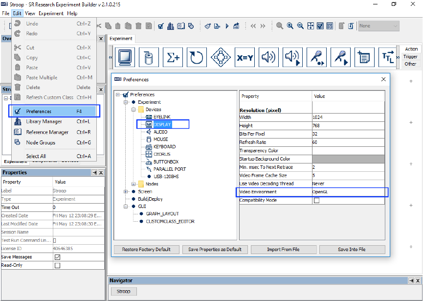
SR Research Experiment Builder User Manual ©2004-2017 SR Research Ltd.
325
“Project Location” field, please make sure that the intended directory already
exists.
4) Make sure the “EyeLink Experiment” box is unchecked for a non-EyeLink
experiment.
15.2 Configuring Experiment Preference Settings
After creating a new experiment session, check whether the default display and screen
preference settings are appropriate for the experiment to be created.
Figure 15-2. Editing Project Display Preferences.
1) Select “Edit → Preferences” from the application menu bar or press the shortcut
key “F4” on Windows. On Mac OS X, click “ExperimentBuilder → Preferences”
from the application menu bar or press Command ⌘+“ ,”.
1) Click “Preferences → Experiment → Devices → Display” to check display
settings. Make sure the settings (Width, Height, Bits per Pixel, and Refresh Rate)
used in the current example are supported by your video card and monitor. For
this example, set the “Video Environment” to “OpenGL”. If using the DirectDraw
graphics, additionally set the “Transparency Color” of the project close to (but not
identical to) the background color of the display screens to make the text look
better. For example, this experiment has a white background (255, 255, 255), so
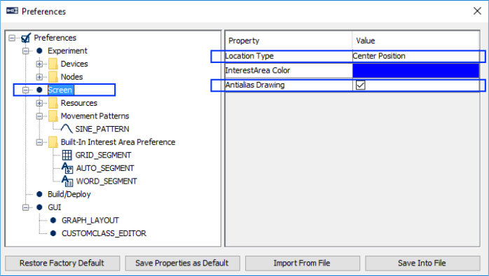
SR Research Experiment Builder User Manual ©2004-2017 SR Research Ltd.
326
you may set the RGB value of the transparency color to (251, 250, 251). It is not
necessary to set the Transparency Color when using the “OpenGL” video
environment.
2) Click “Preferences → Screen” to check Screen Builder settings. Set the Location
Type as "Center Position" and check the "Antialis Drawing" box.
Figure 15-3. Setting the Screen Preferences.
3) After changing any preference settings, if you would like to keep the new settings
as defaults for all of your future experiments, click the "Save Properties as
Default” button.
4) Once finished, press the close button on the dialog box.
If intending to use any characters that do not fit in the ASCII encoding range, including
non-English characters (eg. à, è, ù, ç), special curved quotes, and any non-European
language characters (e.g., Chinese characters), please also make sure the “Encode Files as
UTF-8” box of the Build/Deploy node is checked (enabled by default in later versions of
Experiment Builder; see Figure 15-4).
Failing to enable UTF-8 encoding when non-ASCII characters are used will result in the
following build/run time warning:
WARNING: warning:2001 You are using characters that ascii encoding cannot
handle! Please change your encoding!
Likewise, if Chinese, Japanese, or Korean characters are used and UTF-8 encoding is not
enabled, this will result in the following error:
ERROR: error:2070 Internal Error. Could not create script. Please contact SR
Research! Sorry: MemoryError: ().
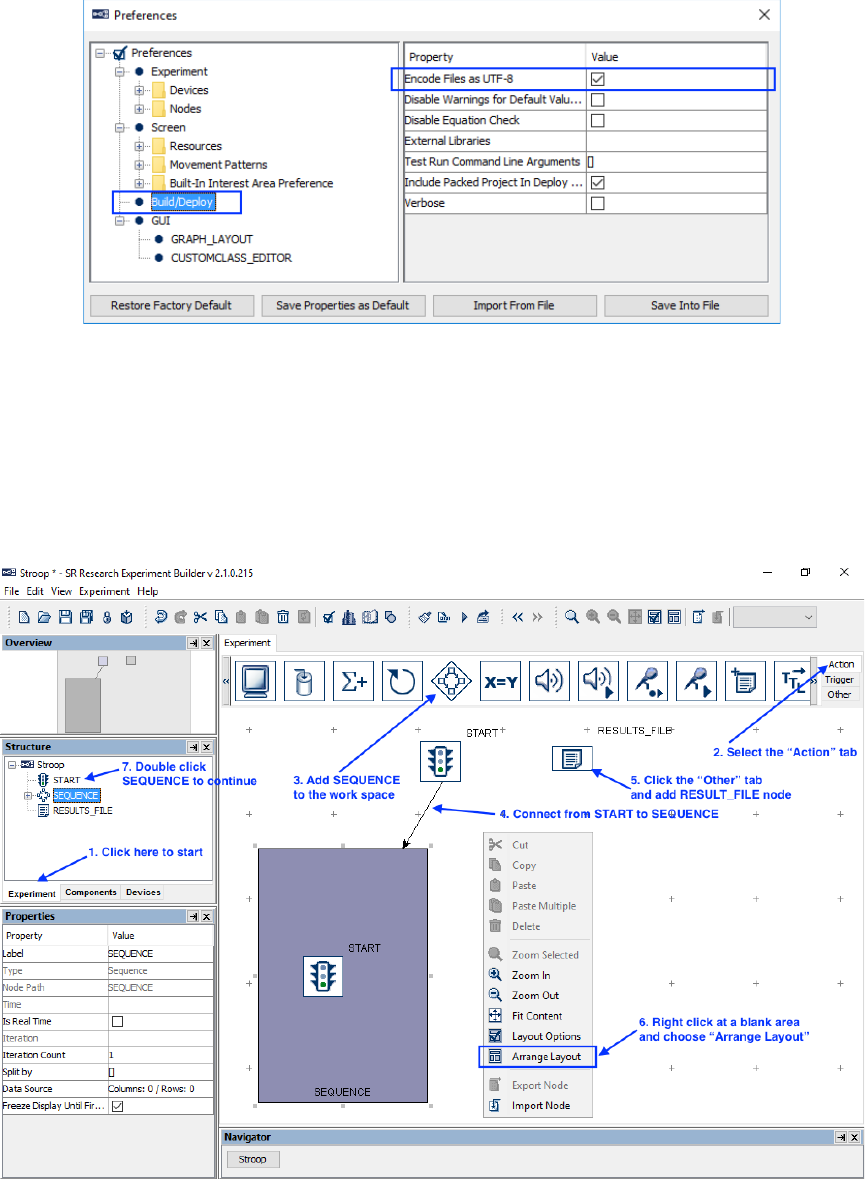
SR Research Experiment Builder User Manual ©2004-2017 SR Research Ltd.
327
Figure 15-4. Editing Project Build/Deploy Preferences.
15.3 Creating the Experiment Block Sequence
In this example, we are going to run two blocks of nine trials each. The first step is to add
a block sequence for repeating blocks (see Figure 15-5). Then we will add a results file to
save data output.
Figure 15-5. Creating Experiment Block Sequence.
1) Click the Experiment Tab in the Project Explorer Window to start.
2) Open the “Action” Tab of the component toolbox.
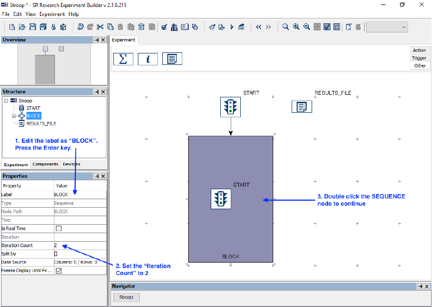
SR Research Experiment Builder User Manual ©2004-2017 SR Research Ltd.
328
3) Click and drag the “Sequence” node from the component toolbox into the work
space.
4) Connect the “START” and “SEQUENCE” nodes by clicking and dragging the
mouse from the “START” node to the “SEQUENCE” node. (Note: If the
“START” node is selected, clicking and dragging will move the node instead of
drawing an arrow. To de-select the node, simply click in an empty area of the
work space.)
5) Open the “Other” Tab of the component toolbox and add a “RESULTS_FILE”
node to the graph.
6) To rearrange the nodes into an orderly layout onscreen, right-click any blank area
in the work window and select "Arrange Layout" in the popup menu.
7) Select the SEQUENCE node in the structure list to continue.
15.4 Editing the Block Sequence
Next, we can edit the properties of the Block Sequence. We will first set the “Label” of
the sequence to give it a meaningful name, then set the “Iteration Count” to the number
of blocks to be tested (see Figure 15-6). (We do not edit the “Split by” field for the block-
level sequence; we will instead set the “Split by” of the trial-level sequence.)
Figure 15-6. Editing Block Sequence.
1) Click the value field of the “Label” property of the Sequence created. Type a new
label, e.g., “BLOCK”, into the text editor and press the Enter key to finish.
SR Research Experiment Builder User Manual ©2004-2017 SR Research Ltd.
329
2) Click the “Iteration Count” value field and enter “2” as the total number of loops
to execute.
3) Double-click the BLOCK Sequence object in the work space to enter the
sequence.
In each block, we will first display some instructions onscreen and then run nine trials
(see Figure 15-7). We can start by adding the necessary nodes to the workspace within
the BLOCK sequence:
1) Open the “Action” Tab of the component toolbox, then click and drag a “Display
Screen” action into the work area.
2) Open the “Trigger” Tab of the component toolbox, then drag a “Timer” trigger
into the work space.
3) Select the Timer trigger and set the duration to 120000 msec.
4) Add a “Keyboard” trigger to the work space.
5) Open the “Action” Tab of the toolbox and add a “Sequence” node to the
workspace. This will be our trial-level sequence.
Then we can continue by drawing the connections between the nodes in the BLOCK
sequence:
6) Click and drag from the START node to the DISPLAY_SCREEN node.
7) Draw two connections from the DISPLAY_SCREEN action to the KEYBOARD
and TIMER triggers. When a single action connects to multiple triggers, a number
is added to each connection indicating the evaluation order among the two trigger
types. In this experiment, it doesn’t matter which order the nodes are connected in.
8) Draw a connection from each of the two triggers to the trial-level SEQUENCE
node.
9) Right-click any blank area in the work window and select "Arrange Layout" in
the popup menu.
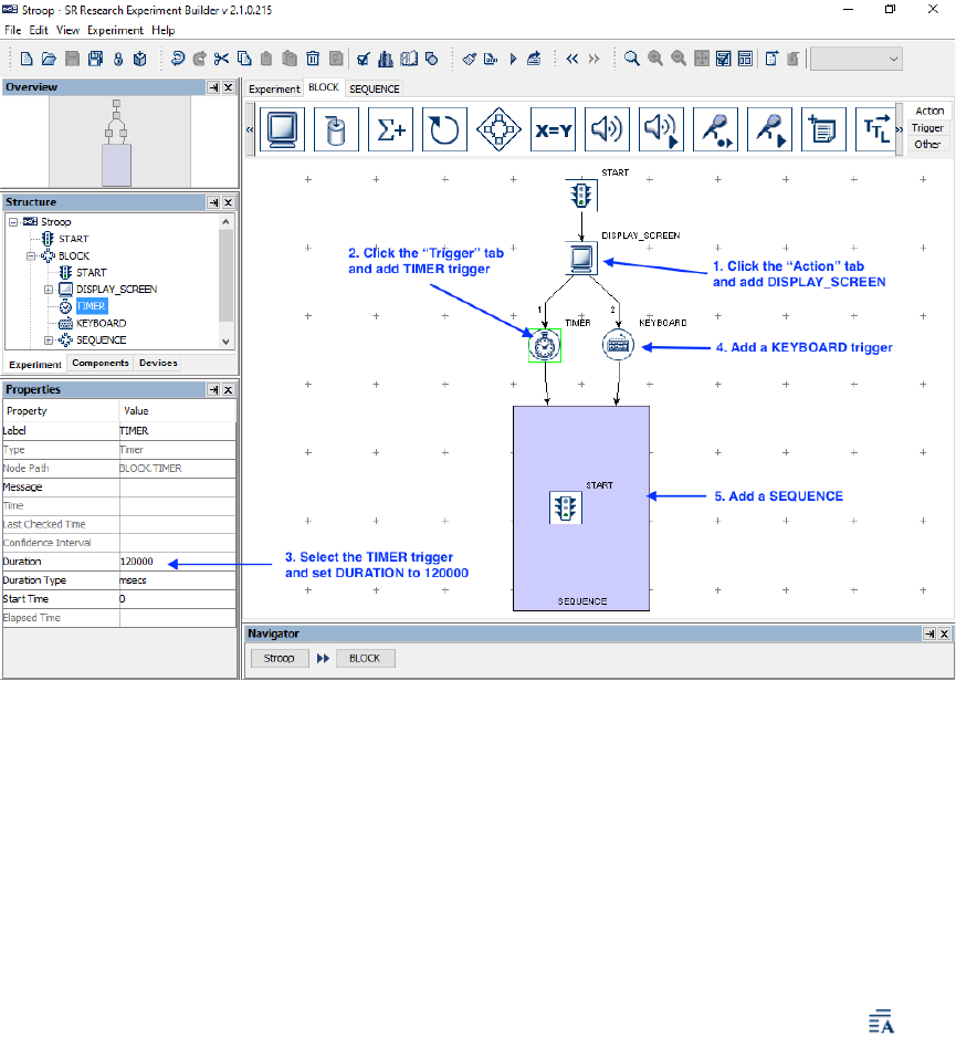
SR Research Experiment Builder User Manual ©2004-2017 SR Research Ltd.
330
Figure 15-7. Adding Instruction to Block Sequence.
15.5 Creating the Instruction Screen
Next we can configure the DISPLAY_SCREEN node to display a set of instructions at
the beginning of the experiment. In this example, we will create the instructions by
adding a Multi-Line Text Resource to the Display Screen; users may also create the
instructions as an image file and use the Display Screen to display the image.
To start editing the screen, open the Screen Builder by double-clicking the
DISPLAY_SCREEN node in the workspace.
1) Once you’ve opened the Screen Builder, click the multiline text resource ( )
button on the screen builder toolbar to select the resource to add.
2) Click anywhere on the screen to add the resource.
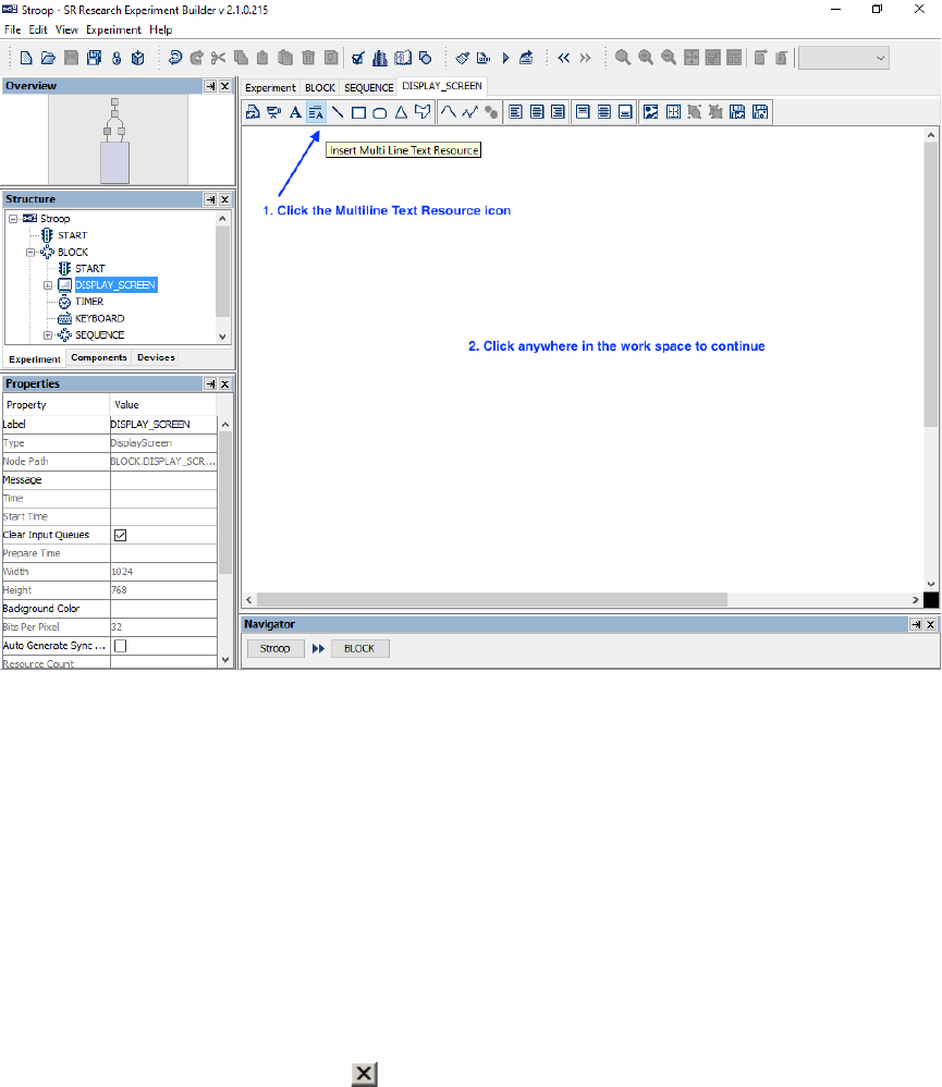
SR Research Experiment Builder User Manual ©2004-2017 SR Research Ltd.
331
Figure 15-8. Adding Multiline Text Resource onto a Display Screen.
In the following Multiline Text Resource Editor,
1) Click the “Margins” button in the toolbar to set the text margins. Enter 100 in all
fields. Click the "OK" button on the dialog box.
2) Enter the desired instruction text (see Figure 15-9).
3) Press Ctrl + A on Windows (Command ⌘ + A on Mac OS X) to select all text
entered.
4) Then click the buttons on the toolbar to set the desired text appearance (font name,
font size, font style, alignment style, line spacing, and text color).
5) Select the example word “Green” in the text and set its color to blue and text size
to 50.
6) Click the “Close” button ( ) at the top right corner to close the Screen Builder.
Please note that, instead of using a multi-line text resource, users can also present the
instruction text by using an image resource (see Section 8.1.1).
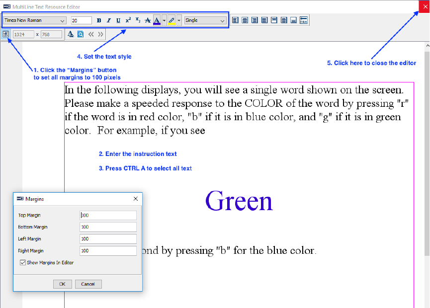
SR Research Experiment Builder User Manual ©2004-2017 SR Research Ltd.
332
Figure 15-9. Create Instruction Screen.
15.6 Editing the Trial Sequence: Data Source
Next, we will design the Trial sequence, which will contain all the necessary triggers and
actions in each trial. We will first create a data source to set the parameters in individual
trials (see Figure 15-10). In this experiment, we will add four columns to the data source:
“Color”, to speciy the color of the text; “Word”, to specify the text displayed on each trial;
“Expected”, to specify the expected keyboard response; and “Compatible”, to specify
whether the text color matches the word.
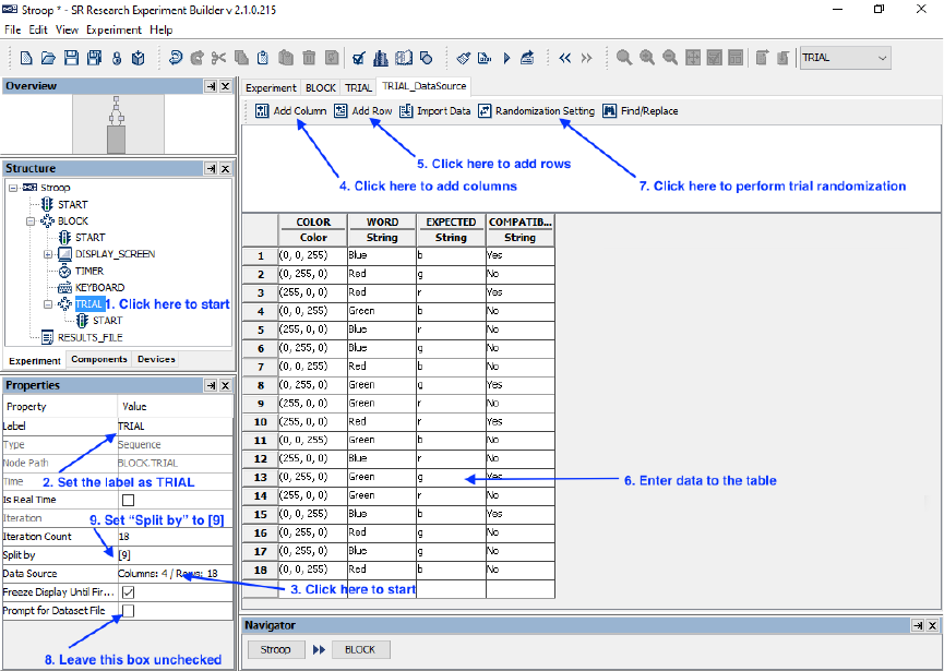
SR Research Experiment Builder User Manual ©2004-2017 SR Research Ltd.
333
Figure 15-10. Creating Data Source.
1) First, select the last “SEQUENCE” node in the structure list (the one we added
within the BLOCK sequence).
2) In the Properties table, enter a new value for the Label, e.g., “TRIAL”.
3) Click the value cell of the “Data Source” property (where it says “Columns: 0 /
Rows: 0”) to bring up the Data Source Editor.
Next we can create the Data Source columns and enter our values.
4) Click the "Add Column" button. Type "COLOR" (without quotes) in the Column
Name box, and set the Column Type to "Color". Click the "OK" button to finish.
Click the "Add Column" button again, to create three more columns. Set the
Column Names as “WORD”, “EXPECTED”, and “COMPATIBLE”, and set
these Column Types as “String”. (Important: Your experiment may not run if
inappropriate column types are used for the data source.)
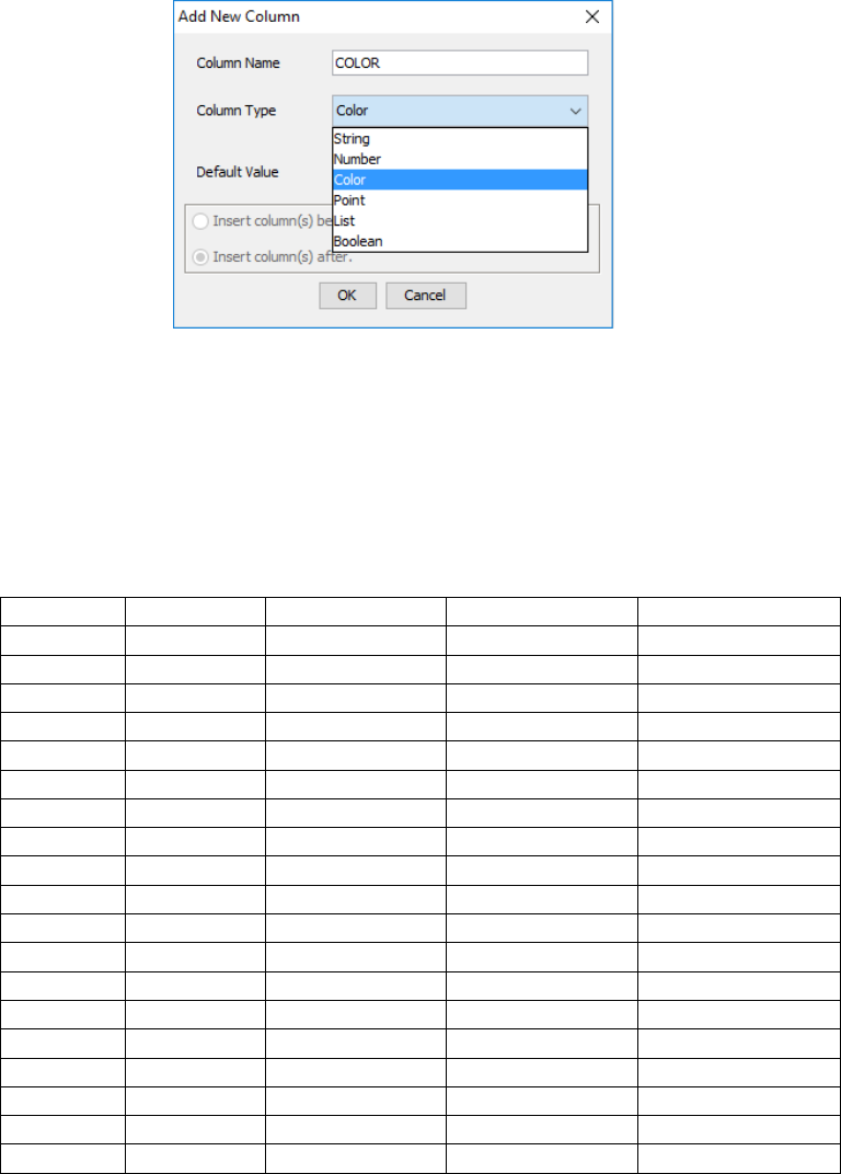
SR Research Experiment Builder User Manual ©2004-2017 SR Research Ltd.
334
Figure 15-11. Adding a New Data Source Column.
5) Click the “Add Row” button. Set the “Number of Rows” to 18 to add 18 rows of
empty cells, then click “OK”.
6) Add the following data to the table just created. For cells expecting Color data,
enter the RGB values as three integers (between 0-255) separated by commas;
Experiment Builder will automatically append a fourth alpha value of 255.
Color
WORD
EXPECTED
COMPATIBLE
data type
Color
String
String
String
1
(0, 0, 255)
Blue
b
Yes
2
(0, 255, 0)
Red
g
No
3
(255, 0, 0)
Red
r
Yes
4
(0, 0, 255)
Green
b
No
5
(255, 0, 0)
Blue
r
No
6
(0, 255, 0)
Blue
g
No
7
(0, 0, 255)
Red
b
No
8
(0, 255, 0)
Green
g
Yes
9
(255, 0, 0)
Green
r
No
10
(255, 0, 0)
Red
r
Yes
11
(0, 0, 255)
Green
b
No
12
(255, 0, 0)
Blue
r
No
13
(0, 255, 0)
Green
g
Yes
14
(255, 0, 0)
Green
r
No
15
(0, 0, 255)
Blue
b
Yes
16
(0, 255, 0)
Red
g
No
17
(0, 255, 0)
Blue
g
No
18
(0, 0, 255)
Red
b
No
7) Click the "Randomization Setting" button to configure randomization settings. In
the Randomization Setting window, set the randomization Seed Value to "Session
Label" so the same trial sequence will be presented when the same recording
session label is used. Check the "Enable Trial Randomization" box, and set the
Run Length Control column to "WORD" and Maximum Run Length to 2. This
ensures that the trial presentation order is randomized, with a restriction that the
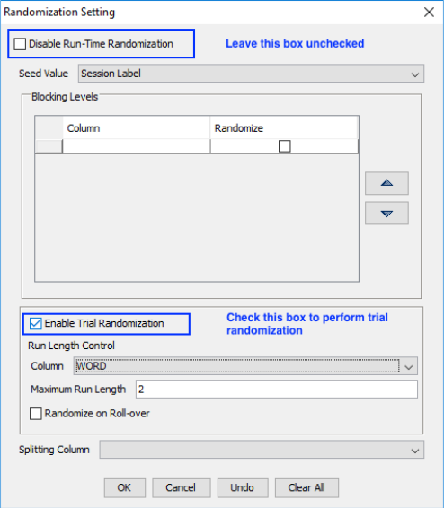
SR Research Experiment Builder User Manual ©2004-2017 SR Research Ltd.
335
same "WORD" value will not be shown on three consecutive trials. Press the OK
button to finish.
Figure 15-12. Data Source Randomization.
8) In the properties table of the TRIAL sequence, leave the "Prompt for Dataset File"
box unchecked so you will not be prompted to select a data source file at the
beginning of the experiment.
9) Click the "Split by" value field. Enter a value of [9] so 9 trials will be run in each
block.
10) Double click the "TRIAL" sequence node in the workspace to enter the sequence.
15.7 Editing the Trial Sequence: Setting Initial Values and
Preparing Sequence
Each trial should begin with a Prepare Sequence action, followed by the actual trial
recording (see Figure 15-13). In a non-EyeLink experiment, the Prepare Sequence action
preloads any image files or audio clips in the trial for real-time image drawing or sound
playing and reinitializes trigger settings. We will also add several variables to store
dependent data (e.g., RT, key press, and trial response accuracy) for each trial.
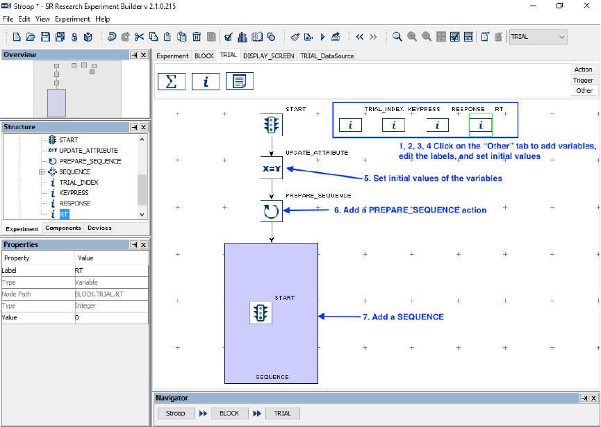
SR Research Experiment Builder User Manual ©2004-2017 SR Research Ltd.
336
Figure 15-13. Editing Trial Sequence.
1) Open the “Other” Tab of the component toolbox and drag a “Variable” node into
the work space. Select the newly added VARIABLE node, change its label to
“TRIAL_INDEX” and set the initial value as “0”. This variable will be used to
keep track of the current trial index. The data type will automatically changed to
“Integer” upon setting the initial value of “0”.
2) Add another variable to the workspace, then set its label to “KEYPRESS” and its
initial value to “.”. This variable will be used to record the participant’s key press
for the trial.
3) Add a third variable, then set its label to “RESPONSE” and its initial value to “.”.
This variable will be used to check whether the response recorded is correct or not.
4) Add in a fourth variable, then set its label to "RT" and its initial value to “0.0”.
This variable will be used to store reaction time for the trial.
5) Open the "Action" Tab of the component toolbox, then drag an Update Attribute
action into the work space. Select the Update Attribute node (step A1 of the figure
below) and set the initial values of the following four variables, TRIAL_INDEX,
RT, RESPONSE, and KEYPRESS:
a. Click the value field of the "Attribute-Value List" property (step A2) to
open the “Attribute-Value List" window.
b. Click once in the first cell under the "Attribute" column (step A3), then
click the [ … ] button to open the Attribute Editor window. In the "Node
Selection" panel on the left, select the TRIAL_INDEX variable node
under the "TRIAL" sequence (step A4). In the middle "Node Attributes"
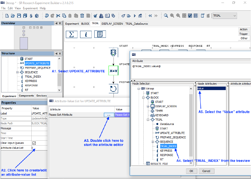
SR Research Experiment Builder User Manual ©2004-2017 SR Research Ltd.
337
panel, double-click the "Value" attribute (step A5). This will set the
contents of the "Attribute" panel on top as "@TRIAL_INDEX.value@".
Click the "OK" button to finish. This will fill in the first cell of the
Attribute-Value list dialog.
Figure 15-14. Updating Trial Index.
c. Next, click the first cell under the "Value" column once, then press the
[ … ] button (See B1 of the figure below). In the "Node Selection" panel
of the attribute editor, click the "TRIAL" sequence (see B2). In the middle
"Node Attributes" panel, double click the "Iteration" attribute (B3). This
will update the contents of the top "Attribute" editor dialog as
"@parent.iteration@". Click the "OK" button to finish (B4).
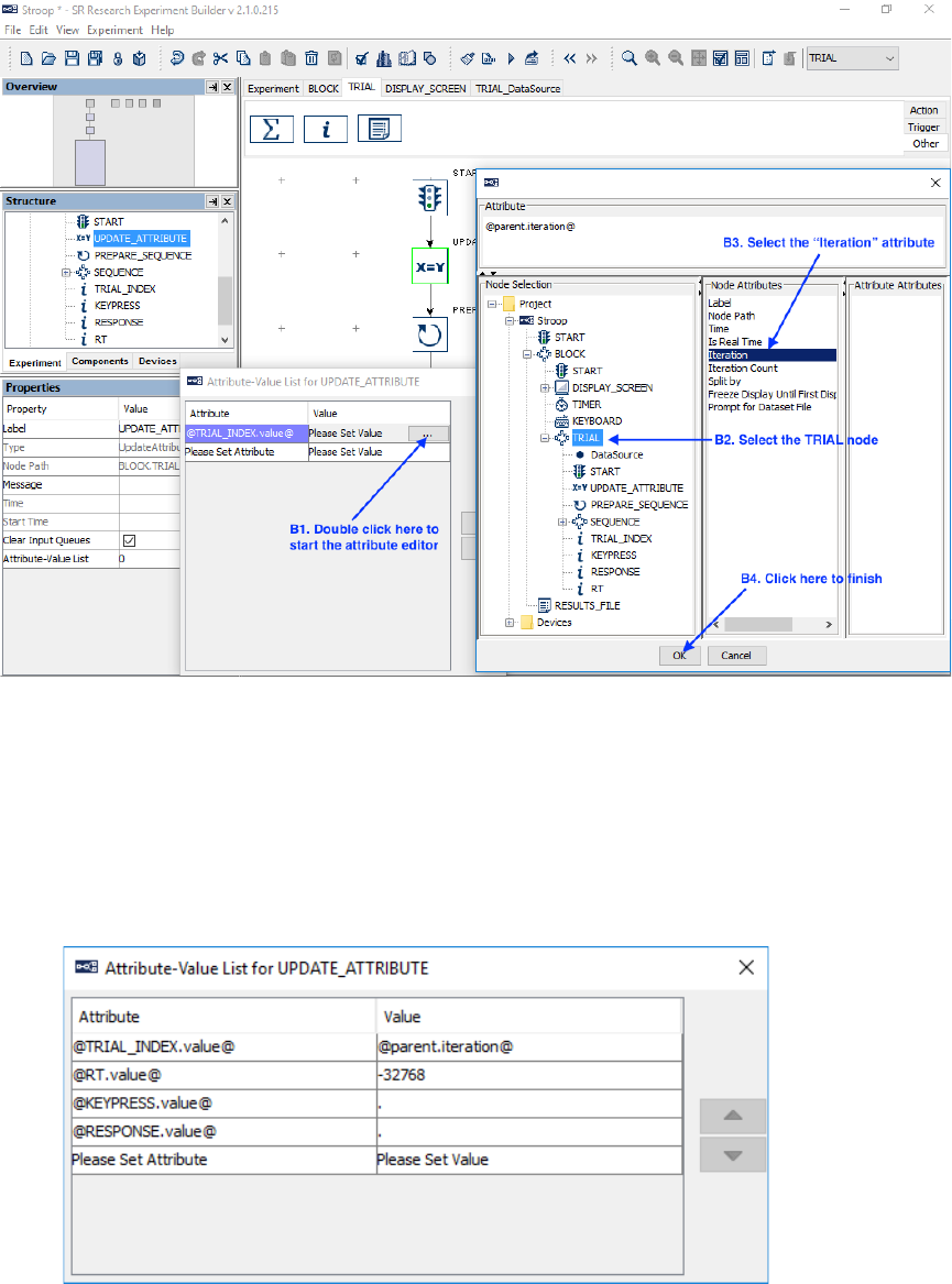
SR Research Experiment Builder User Manual ©2004-2017 SR Research Ltd.
338
Figure 15-15. Update Trial Iteration.
d. Similarly, set the second cell of the "Attribute" column to @RT.value@.
Double-click in the left side of the corresponding "Value" cell, then type
in “-32768” (without quotes; this is equivalent to a “missing value” for
Integer data) and press Enter to register the change (see Figure 15-16).
e. Set the Attribute 3 to "@KEYPRESS.value@" and value 3 to ".".
f. Set the Attribute 4 to "@RESPONSE.value@" and value 4 to ".".
Figure 15-16. Updating the Attribute of RT.
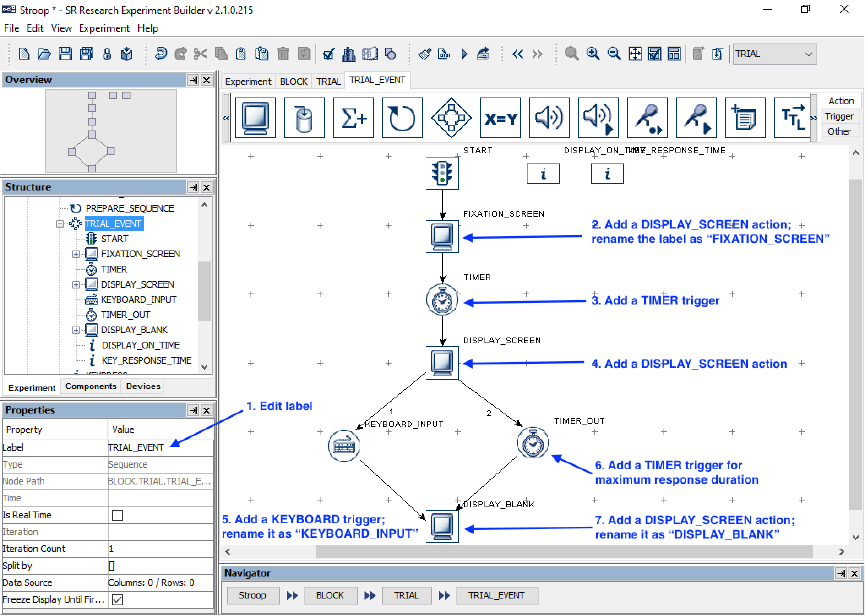
SR Research Experiment Builder User Manual ©2004-2017 SR Research Ltd.
339
6) Next, drag a “Prepare Sequence” action into the work space. Click the added
action and review the settings in the property table—make sure the “Flush Log”
box is checked so data output for the previous trial is completed before starting a
new trial.
7) Then drag a “Sequence” node into the work space.
8) Click and drag to draw a connection from the “START” node to
“UPDATE_ATTRIBUTE”, from “UPDATE_ATTRIBUTE” to
“PREPARE_SEQUENCE”, and from “PREPARE_SEQUENCE” to the
“SEQUENCE” node. The four variable nodes (RT, KEYPRESS, RESPONSE,
and TRIAL_INDEX) should not be connected to other nodes.
9) Right-click any blank area in the workspace and select “Arrange Layout” in the
popup menu.
15.8 Editing the Trial Event Sequence – Part 1
The next step is to design the actual display presentation in a trial. In this example, we
first show a fixation cross in the center of the screen for one second, followed by the
presentation of the Stroop word. We then wait for a keyboard response by the participant
or for the trial to time out in eight seconds, and finally the display is cleared.
Figure 15-17. Editing Recording Sequence.
1) Select the newly added “Sequence” node and enter a new value for the Label, e.g.,
“TRIAL_EVENT”. If using an older computer with a single-core processor, make
sure the “Is Real Time” box is not checked, as this may prevent the keyboard
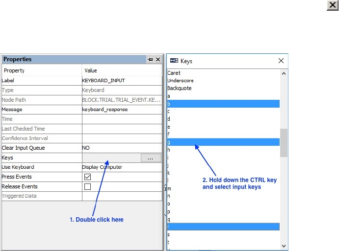
SR Research Experiment Builder User Manual ©2004-2017 SR Research Ltd.
340
from functioning. Then double-click the TRIAL_EVENT sequence in the
workspace to enter the sequence.
2) Open the “Action” Tab of the component toolbox and drag a “Display Screen”
action into the work area. Select the newly added Display Screen node and enter a
new label, e.g., “FIXATION_SCREEN”. We will later add a fixation cross in this
screen (see Section 15.8.1).
3) Then open the “Triggers” tab and drag a “Timer” trigger into the work space.
Select the Timer node, and enter “1000” in the “Duration” field.
4) Open the “Action” tab and drag a second “Display Screen” action into the
workspace. This will be the screen showing the Stroop word (see Section 15.8.2).
Set the “Message” property to “target_display” (without quotes) and press the
Enter key.
5) Add a Keyboard Trigger. Select the trigger and set the Label, e.g., as
“KEYBOARD_INPUT”. Then set the “Message” property, e.g., as
“keyboard_response”. Double-click the left part of the value field for the “Keys”
attribute to bring up a menu to choose the possible response keys. To select
multiple response keys, hold the Ctrl key ( Command ⌘ on Mac OS X) and click
on the desired keys. In this experiment, choose the following keys: b (for blue
color), r (for red color), and g (for green color). Then click the “Close” button ( )
at the upper right corner of the dialog box to finish. The “Keys” property of the
trigger will now be [b, g, r].
Figure 15-18. Setting Response Keys.
6) Add another Timer trigger to the work space. Set its Label as “TIME_OUT” and
set the Duration as 8000 msec. Update the “Message” property of the trigger as
“TIME_OUT”.
7) Add another “DISPLAY_SCREEN” action and set its label as
“DISPLAY_BLANK”. This will be the blank screen to clear the Stroop word. Set
the “Message” property as “DISPLAY_BLANK”.
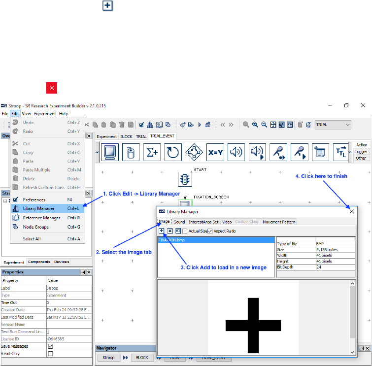
SR Research Experiment Builder User Manual ©2004-2017 SR Research Ltd.
341
8) Draw a connection from the “START” node to “FIXATION_SCREEN”, from
“FIXATION_SCREEN” to “TIMER”, from “TIMER” to “DISPLAY_SCREEN”,
from “DISPLAY_SCREEN” to both “KEYBOARD_INPUT” and “TIME_OUT”,
and from the last two triggers to “DISPLAY_BLANK”.
9) Right-click any blank area in the work space and select “Arrange Layout” in the
popup menu to re-arrange the nodes.
15.8.1 Creating the Fixation Screen
We can now create the fixation screen. In this example, we will use an image to serve as
the fixation target. (Alternatively, a text resource with a “+” may be used.) Images must
be loaded into the Library Manager before they can be used. Follow the steps below to
add the included image FIXATION.bmp to the resource library (see Figure 15-19):
1) From the application menu bar, select “Edit → Library Manager”.
2) In the Library Manager, select the “Image” tab.
3) Click the Add button to load in an image—the example image
“FIXATION.bmp” can be found at “Documents\ExperimentBuilder
Examples\Resources\Images\”. (Alternatively, click and drag the image file from
Explorer in Windows or Finder in Mac into the Library Manager.) The image file
properties and a preview of the image will then be displayed in the Library
Manager.
4) Click the button on the Library Manager to finish.
Figure 15-19. Loading Resources to Image Library.
5) Double click the FIXATION_SCREEN action in the graph workspace to open the
Screen Builder.
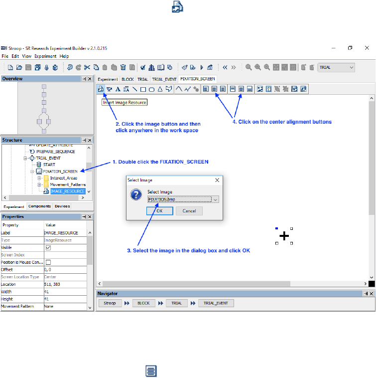
SR Research Experiment Builder User Manual ©2004-2017 SR Research Ltd.
342
6) Click the “Insert Image Resource” ( ) button on the Screen Builder toolbar, then
click anywhere on the screen to add the image resource. In the following “Select
Image” dialog, select “FIXATION.bmp”, then click the “OK” button.
Figure 15-20. Loading Resources to Image Library.
7) Select the image resource. Click both the “Horizontal Center Alignment” and
“Vertical Center Alignment” ( ) buttons to place it in the center of the screen.
Right-click on the resource and choose “Lock Selection” in the popup menu to
prevent the image from being accidentally moved in the Screen Builder.
15.8.2 Creating the Stroop Display Screen.
Next we will create a screen containing the Stroop color word. We will add a text
resource to the display screen and modify the properties of the text resource, such as the
text to be displayed, text color, font name, size, and alignment style. We will also create
an interest area for the text (see Figure 15-21). To open the Screen Builder window,
double-click the “DISPLAY_SCREEN” object in the work space.
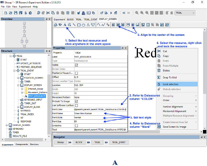
SR Research Experiment Builder User Manual ©2004-2017 SR Research Ltd.
343
Figure 15-21. Adding Text to Display Screen.
1) Click the “Insert Text Resource” button ( ) on the Screen Builder toolbar, and
click any space in the work area to add the resource.
2) To set the Font Color to refer to the “COLOR” column of the Data Source, click
the value field of the “Font Color” property once, then click the [ … ] button to
open the Attribute Editor dialog (see Figure 15-22).
a. Click the DataSource node under the “TRIAL” sequence on the Node
Selection list.
b. Double click the “COLOR” node in the Node Attributes panel. This will
update the contents of “Attribute” panel as
@parent.parent.parent.TRIAL_DataSource.COLOR@”.
c. Click the “OK” button to finish.
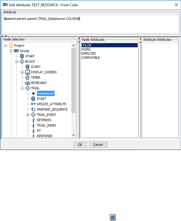
SR Research Experiment Builder User Manual ©2004-2017 SR Research Ltd.
344
Figure 15-22. Showing Text by Referring to Data Source.
3) Set the appearance of the Text by choosing the desired font name, style and size.
In this example, we will set the “Font Name” to “Times New Roman”, the “Font
Style” to “Normal”, and the “Font Size” to “50”.
4) Then set the “Text” property to refer to the “WORD” column of the Data Source.
The Attribute panel should list the reference as
“@parent.parent.parent.TRIAL_DataSource.WORD@”.
5) Select the newly added text resource, and click both the “Horizontal Center
Alignment” and “Vertical Center Alignment” ( ) buttons to place the text in the
center of the screen.
6) Right-click the resource and choose “Lock Selection” so the resource will not be
moved accidentally.
15.9 Editing the Trial Event Sequence – Part 2
Following the presentation of the Stroop word, we will check for the participant’s
response and calculate the reaction time for the trial. We will then add a Conditional
trigger to check the response, and nodes to record and give feedback on the participant’s
performance (see Figure 15-23).
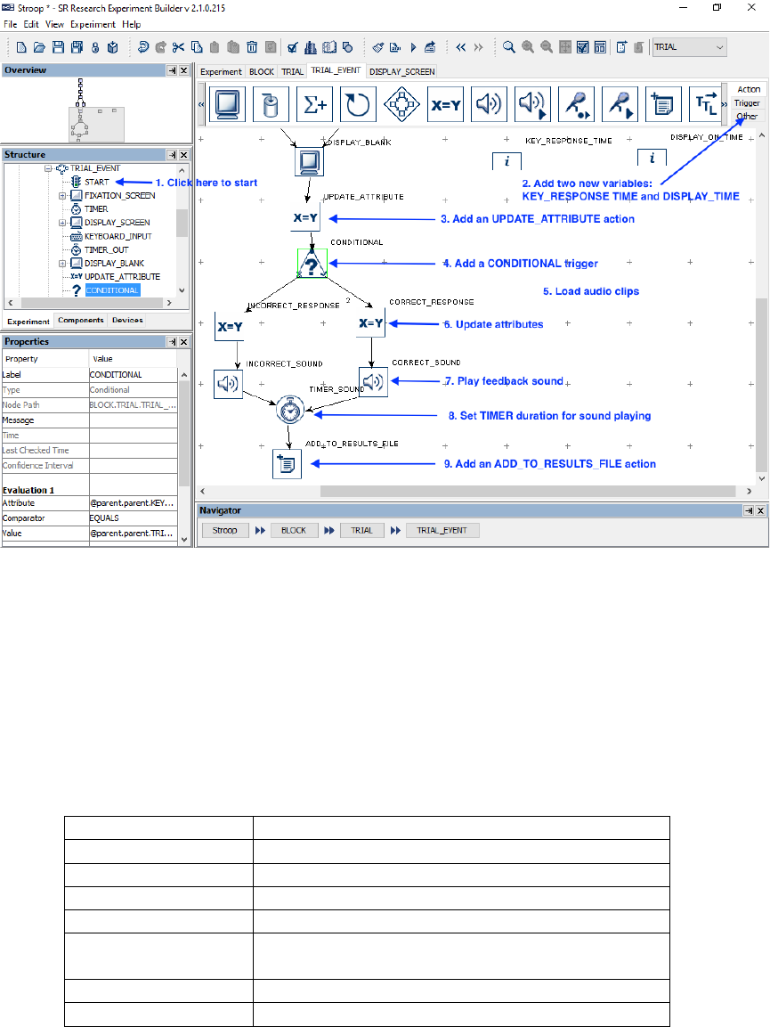
SR Research Experiment Builder User Manual ©2004-2017 SR Research Ltd.
345
Figure 15-23. Editing the Trial Event Sequence.
1) Make sure Graph Editor view is within the “TRIAL_EVENT” sequence.
2) Add two new variables into the workspace and rename them as
“DISPLAY_ON_TIME” and “KEY_RESPONSE_TIME”. Set the initial values
of both variables to 0.0.
3) Add an Update Attribute action to record the time for the target display onset, the
time of the response, and the key pressed. Double-click the Update Attribute node
and add the following attribute-value pairs to the table (see Figure 15-24):
Attribute
@KEY_RESPONSE_TIME.value@
Value
@KEYBOARD_INPUT.triggeredData.time@
Attribute 2
@DISPLAY_ON_TIME.value@
Value 2
@DISPLAY_SCREEN.time@
Attribute 3
@parent.parent.RT.value@
Value 3
= int(@KEY_RESPONSE_TIME.value@-
@DISPLAY_ON_TIME.value@)
Attribute 4
@parent.parent.KEYPRESS.value@
Value 4
@KEYBOARD_INPUT.triggeredData.key@
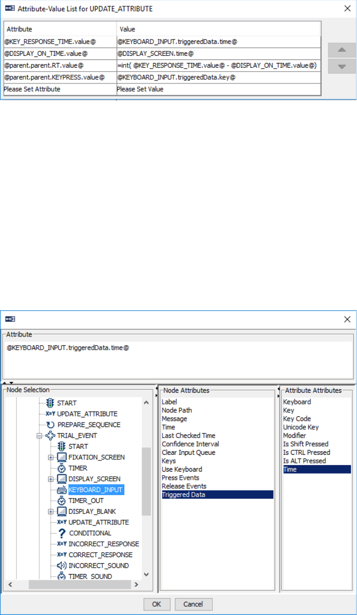
SR Research Experiment Builder User Manual ©2004-2017 SR Research Ltd.
346
Figure 15-24. Add Attribute-Value Pairs to the UPDATE_ATTRIBUTE Node.
Note that the actual time when the Stroop display is presented is
@DISPLAY_SCREEN.time@, not @DISPLAY_SCREEN.startTime@—the
latter is the time when the DISPLAY_SCREEN action starts preparing the screen
to be flipped. The time of the keyboard response should be the
@KEYBOARD_INPUT.triggeredData.time@ from the “Attribute Attributes”
panel instead of @KEYBOARD_INPUT.time@ from the “Node Attributes”
panel—the triggeredData.time is the time when the response key is pressed,
where the latter is the time when the KEYBOARD_INPUT trigger fires (see
Figure 15-25). Note also that an "=" sign is added before
"int(@KEY_RESPONSE_TIME.value@-@DISPLAY_ON_TIME.value@)" so
an equation can be created in the cell.
Figure 15-25. Accessing the TriggeredData Attribute.
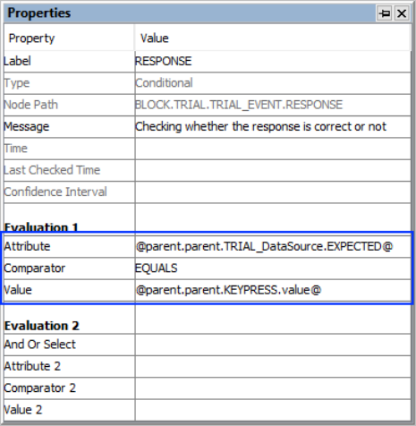
SR Research Experiment Builder User Manual ©2004-2017 SR Research Ltd.
347
4) Drag a Conditional trigger into the workspace to determine whether a correct
response has been made. To check whether the key pressed is the desired
keyboard response, select the conditional trigger, then set the following properties:
a. Attribute to “@parent.parent.TRIAL_DataSource.EXPECTED@”.
b. Comparator to “EQUALS”
c. Value to “@parent.parent.KEYPRESS.value@”.
Figure 15-26. Evaluating the Accuracy of the Response Using a Conditional Trigger
The Conditional trigger yields a True result when the key pressed is the same as
the expected key response set in the Data Source, and otherwise yields a False
result. For each branch of the conditional trigger, we will set a value for the
RESPONSE variable and provide audio.
5) Before working on each branch of the CONDITIONAL trigger, load audio clips
for the feedback into the Library Manager. Click Edit → Library Manager from
the Experiment Builder menu bar, then do the following (see Figure 15-27):
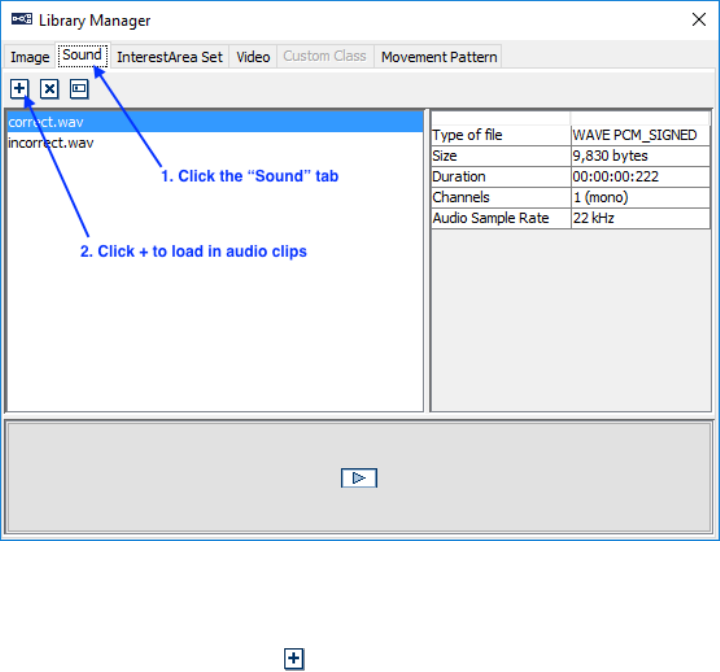
SR Research Experiment Builder User Manual ©2004-2017 SR Research Ltd.
348
Figure 15-27. Loading Feedback Audio Clips.
a. Select the “Sound” Tab
b. Click the “Add” button and load in the desired audio files. The example
audio files “correct.wav” and “incorrect.wav” can be found at
“Documents\ExperimentBuilder Examples\Resources\Audio\”.
(Alternatively, click and drag the audio files from Explorer in Windows or
Finder in Mac into the Library Manager.)
c. Click the “close” button at the upper right corner of the Library Manager.
6) Add an Update Attribute action and a Play Sound action:
a. Select the Update Attribute action and set the Label to
“CORRECT_RESPONSE”. Click the Value cell of the “Attribute-Value
List” property, then in the Attribute-Value List editor, set the Attribute
field to “@parent.parent.RESPONSE.value@” and the Value field to
“Correct”.
b. Select the Play Sound node and rename it to “CORRECT_SOUND”.
Select “Correct.wav” from the dropdown list of the “Sound File” property.
7) Add another pair of Update Attribute and Play Sound actions:
a. Select the Update Attribute action and rename it to
“INCORRECT_RESPONSE”. Set the Attribute field to
“@parent.parent.RESPONSE.value@” and the Value field to “Incorrect”.
b. Select the Play Sound action and rename it to “INCORRECT_SOUND”.
Select “Incorrect.wav” from the dropdown list of the “Sound File”
property.
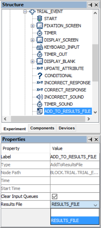
SR Research Experiment Builder User Manual ©2004-2017 SR Research Ltd.
349
8) Add a Timer trigger and edit its Label to "TIMER_SOUND". Set the Duration of
the Timer to 500 msec so the feedback sound can be played completely before the
trial ends.
9) From the "Action" tab of the component toolbox, add an Add to Results File
action into the workspace. Select the node and set the "Results File" to the
RESULTS_FILE we added earlier.
Figure 15-28. Send Results to a Results File.
10) Draw the following connections in the experiment graph:
a. from DISPLAY_BLANK to the UPDATE_ATTRIBUTE action;
b. from UPDATE_ATTRIBUTE to the CONDITIONAL trigger;
c. from the left (X) branch of the CONDITIONAL trigger to
INCORRECT_RESPONSE;
d. from INCORRECT_RESPONSE to INCORRECT_SOUND;
e. from INCORRECT_SOUND to TIMER_SOUND;
f. from the right (V) branch of the CONDITIONAL trigger to
CORRECT_RESPONSE;
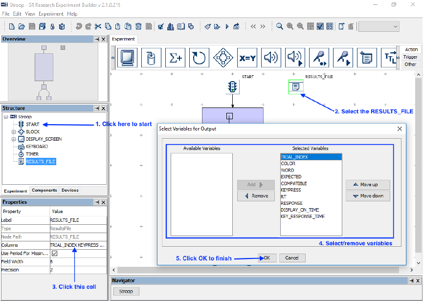
SR Research Experiment Builder User Manual ©2004-2017 SR Research Ltd.
350
g. from CORRECT_RESPONSE to CORRECT_SOUND;
h. from CORRECT_SOUND to TIMER_SOUND; and
i. from TIMER_SOUND to ADD_TO_RESULTS_FILE.
11) Right-click any blank area in the work space and select “Arrange Layout” in the
popup menu to re-arrange the nodes.
15.10 Outputting Data to the Results File
Finally, variables should be added to the results file (see Figure 15-29). Users may
configure which variables, including variable nodes and data source columns, should be
written to the results file so the experimental conditions of each trial can be identified
during analysis (see Figure 15-29). In Experiment Builder 2.0, all variable nodes and data
source columns will automatically be added to the Results File.
Figure 15-29. Adding Variables to Results File.
1) In the Structure Window, click the first "START" node (just underneath the
topmost "Stroop" node) to navigate to the topmost level of the experiment.
2) Select the RESULTS_FILE node.
3) Then click the value field of the “Columns” attribute.
4) In the following dialog box, the “Selected Variables” panel on the right lists all
the data source columns and variables currently selected to be written to the

SR Research Experiment Builder User Manual ©2004-2017 SR Research Ltd.
351
results file as trial variables, and “Available Variables” will show any variables
not selected to be written as trial variables. To add or remove items from the
Selected Variables, select the item(s) to be moved, then click the “Add” button
( ) or “Remove” button ( ). To configure the order of the variables in the
output, select the item(s) to be moved and click the “Move Up” ( ) or “Move
Down” ( ) buttons. In this example, make sure all the variables and data source
columns are included in the Selected Variables list. Click OK to finish.
5) In the Properties window of the RESULTS_FILE node, set “Field Width” to 8
and “Precision” to 2. To record the missing values as “.” in the results file, make
sure the “Use Period for Missing Values” box is checked.
15.11 Running the Experiment
Click “Experiment → Build” from the application menu to build the experiment An
“Output” tab will be opened in the Graph Editor Window and build information will be
displayed. Watch for error messages (displayed in red) and warning messages (in brown)
during building. If any error or warning messages appear, double-click on an error or
warning message in the output tab to highlight the node or screen resource that produced
the error/warning.
Once the project builds successfully, users may test run the experiment by clicking on
“Experiment → Test Run” from the application menubar. Please note that the “Test Run”
should only be used for testing and debugging experiment code, and not for actual data
collection. To collect experiment data, users should first deploy the experiment
(“Experiment → Deploy”). The deployed project can be run without relying on the
Experiment Builder GUI for better timing performance. Simply double click the
executable file Stroop.exe in the deployed directory and then follow the instructions on
the screen. The experiment results file will be saved in the “results/{session name}”
folder of the experiment.
SR Research Experiment Builder User Manual ©2004-2017 SR Research Ltd.
352
16 Experiment Builder Project Check List (version 2.1)
Users may refer to the following checklist to prevent some common problems in creating
and running an Experiment Builder project. See the .html version of this document for a
list of frequently asked questions.
If this is an EyeLink experiment,
1) Is there a recording sequence in the project?
[FAQ: How to convert a non-EyeLink experiment to an EyeLink experiment?]
2) Does the project use the "hierarchical organization" concept of experiment
design? Is the data source attached to the trial-level sequence, instead of the
recording sequence? (If the data source is attached to the recording sequence, you
will not be able to do image drawing to the Host PC, perform a pre-recording drift
correction, or reset triggers, actions, and resources.)
3) Have the experiment trial variables been added to the "EyeLink DV Variables" of
the Experiment node? (Note: Starting in Experiment Builder 2.0, all newly added
variables are now automatically added in the “EyeLink DV Variables.”)
[FAQ: The automatic TRIALID creator doesn't work.]
4) Has the 'Message' field of the critical nodes (e.g., triggers and actions used in the
recording sequence) been filled? Messages will be sent to the EDF file to mark
important events. For example, you may write a "SYNCTIME" message for the
DISPLAY_SCREEN action that shows the target screen.
5) Has the most important screen in the recording sequence been transferred to the
Host PC as feedback graphics?
[FAQ: How can we see the text on the Host PC?]
[FAQ: Warning:2015 No display screen is selected for PrepareSequence
TRIAL→PREPARE_SEQUENCE. ]
[FAQ: Tracker screen flashes many times very quickly prior to each trial on the
Host PC.]
6) Has a Recording Status Message been written to the tracker screen to report
progress of experiment testing?
7) Has a PREPARE_SEQUENCE action been added before the recording sequence?
Is this action called for EVERY iteration of the trial recording sequence?
8) Have you prepared interest areas as necessary for each of the trials?
[FAQ: How can I create individual interest areas for every single image in the
EB?]
9) Has an optimal screen refresh rate been used? Has a proper video card/monitor
driver been installed?
SR Research Experiment Builder User Manual ©2004-2017 SR Research Ltd.
353
[FAQ: The stimuli screen was really flickering during the experiment.]
[FAQ: Could not initialize display.]
10) Is the trial recording sequence running with “Is Real Time” enabled?
[Discussion Forum Post: Real time mode, EL_Button box]
[FAQ: Warning:2003 The IO node KEYBOARD is used in realtime Sequence.]
11) Does the "Background Color" property of the camera setup and drift correction
nodes match that of the display screens used in the experiment? Try matching the
background color of the screen during calibration and validation to that of the
experiment displays, as changes in pupil size caused by large brightness
differences can degrade system accuracy.
12) If using DirectDraw graphics, is the transparency color of the display device set
correctly? The transparency color of the project should be set close to (but not
identical to) the background color of the display screen. For example, if you use a
white background color for your experiment, try setting the transparency color to
something like (254, 254, 254). Similarly, if you use a black display background,
try setting the transparency color to something like (0, 1, 0). Some of the resource
drawing, especially text resources, may look fuzzy if the transparency color is
very different from the background color. Then make sure to click "Experiment
→ Clean" before you re-run your experiment. (Note: this is only applicable when
you use the DirectDraw graphics (Devices → DISPLAY → Video Environment).
You can ignore it when using the OpenGL graphics.)
[FAQ: Images shown in Display Screen are surrounded by white dots.]
[Text Resource: Anti-aliasing and Transparency]
13) Are you running the deployed version of the experiment?
[FAQ: 'Results file' had disappeared when we cleaned the experiment project.]
[FAQ: File disappears from the folder where it was stored when we got ready to
run it.]
14) Have you set up the proper randomization for your experiment? Check the
Randomization Settings in the data source, and if you plan to randomize the data
source file for each participant, make sure you have created the randomized data
source files.
[FAQ: How to modify the data source file to create different trial ordering?]
[FAQ: What do I do with the randomized data source files?]
[Data Source: Common Experiment Designs and Data Source Manipulations]
15) Have you taken measures to maximize real-time performance of the Display PC
when running the experiment?
16) After data collection, are you viewing your EDF files at the original file locations
(i.e., "Results/{Session Name}" directories)? If you need to analyze data on a
different computer, you may copy the entire deployed {Experiment Name} folder
SR Research Experiment Builder User Manual ©2004-2017 SR Research Ltd.
354
to your data analysis computer. You may first zip up the {Experiment Name}
folder (keeping the directory structure) and then unzip the file on your analysis
computer.
[FAQ: No image is overlaid under the fixations in Data Viewer.]
If this is a non-EyeLink Experiment,
1) Please consider the above issues # 2, 5, 8, 10, 11, 12, 13, 14, 15, 16 and the
following two extra issues.
2) Have you added a Results File to the project? And are you calling the Add To
Results File action on each trial or as necessary to record data to the results file? If
so, have variables and data source columns been added to the "Columns" field of
the results file node?
3) Are you planning to write out timing or debugging messages for the experiment?
If so, check the “Save Messages” attribute of the Experiment node and fill the
“Message” field of the triggers and actions.
If this is a reading experiment,
1) If using a text or image resource, has the "Prebuild to Image" box of the resource
been enabled?
[FAQ: How to show the images in Data Viewer?]
2) If using a text or multi-line text resource, have you enabled antialias drawing?
3) Is the drift correction target displayed at the intended location, usually at the
beginning of the text?
[FAQ: How can I draw my own fixation cross and keep it stable at one point
during drift correction and stimulus presentation?]
4) Have you chosen the appropriate font, style, and size for the text or multi-line text
resource? You may need to use special fonts to display non-ASCII characters.
(Note: This is especially important when switching platforms between Windows
and Mac, as the two operating systems have different fonts available and use
different DPI settings, meaning text will be sized differently between Windows
and Mac.)
5) Have you enabled the "Use Runtime Word Segment Interest Area" setting of the
text or multi-line text resource? Advanced Word Segmentation options are
available from “Edit → Preferences → Screen → Built-In Interest Area
Preference → WORD_SEGMENT,” allowing you to set custom delimiters to
segment the text as desired. If the above word-based interest areas are not
satisfactory, or if you plan to use an image resource to show the text, you may
SR Research Experiment Builder User Manual ©2004-2017 SR Research Ltd.
355
instead assign a text file to the "InterestArea Set Name" field of the
DISPLAY_SCREEN action that contains the screen resource.
[FAQ: How can I create individual interest areas for every single image in the
EB?]
[FAQ: “Runtime word segmentation” returns incorrect interest area segmentation.]
If this is an experiment using eye-based triggers,
1) Have you checked the location type used in the Screen Builder? Please note that
screen resources can be based on either the top-left or center coordinate, whereas
the location of all trigger types (e.g., invisible boundary trigger, mouse trigger,
fixation trigger, saccade trigger, and sample velocity trigger) is based on the top-
left coordinate.
2) If running a saccade experiment, which saccade trigger type (saccade trigger vs.
sample velocity trigger) should be used?
3) If using an invisible boundary trigger or sample velocity trigger, is the heuristic
filter set to the desired setting?
If this is an experiment involving audio playback or recording,
1) If using Windows, are you using the ASIO or DirectX audio driver? If precise
audio timing is required, make sure to use the ASIO driver and a supported ASIO
device. (If using Mac, the default Mac OS X audio drivers support high-precision
audio timing.)
[FAQ: Example for synchronized audio-video presentation.]
2) If using the ASIO driver, have you followed the instructions for Experiment
Builder ASIO Installation?
[FAQ: Empty .WAV files created with the RECORD_AUDIO action.]
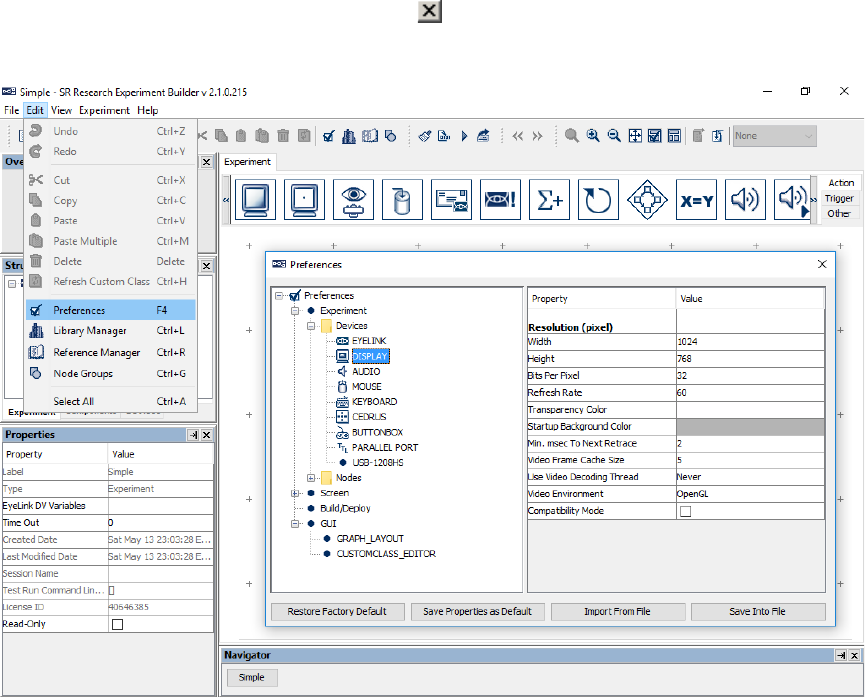
SR Research Experiment Builder User Manual ©2004-2017 SR Research Ltd.
356
17 Preference Settings
Many aspects of the SR Research Experiment Builder can be configured in the
application preference settings, which can be accessed by selecting “Edit → Preferences”
(“ExperimentBuilder → Preferences” in Mac OS X) from the application menu bar (see
Figure 17-1). These include the EyeLink tracker settings, display setup, screen coordinate
type, default values for the experiment components (triggers, actions, and screen
resources), graph layout, etc. Once the desired changes have been made, pressing the
“Save Properties as Default” button will save the current preferences to be used by
default in future experiment projects. If the changes are valid only for the current
experiment project, simply press the close ( ) button on the dialog box after making any
changes.
Figure 17-1. Accessing the Experiment Builder Preference Settings.
17.1 Experiment
This section lists preference settings related to the Experiment Builder devices and nodes
(actions, triggers, etc.).
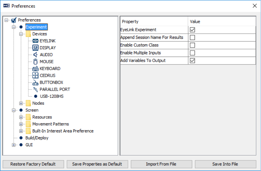
SR Research Experiment Builder User Manual ©2004-2017 SR Research Ltd.
357
EyeLink Experiment: If checked, the experiment will be designed for use with an
EyeLink eye tracker. All eye-tracking related triggers (saccade, fixation, sample velocity,
invisible boundary, and EyeLink button triggers) and actions (sending EyeLink message,
sending EyeLink command, camera setup, and drift-correction actions) will be available
for experiment creation. If this field is unchecked, all of the abovementioned actions and
triggers will be removed from the components toolbox and experiment graph.
Append Session Name For Results: If checked, Experiment Builder will concatenate
the current session name with the output files (warning.log, messages.txt, etc.) in the
"results\{session name}" directory.
Enable Custom Class: If checked, additional features (Custom class instance, Execute
method, Custom class library, Callback attribute for Sequences, etc.) will be available for
programming an experiment using custom class. Please note that custom class-related
features use advanced Experiment Builder functionality that requires knowledge of the
Python programming language.
Enable Multiple Inputs: If checked, multiple display keyboards and mice can be used in
the same experiment; responses on the different input devices can be handled differently.
The number of distinct keyboards and mice can be set in the keyboard and mouse device
settings. If unchecked, responses from all keyboards and mice connected to the computer
are treated the same (as if the response is made to a single keyboard or mouse).
Add Variables To Output: If checked, new variables and data source column labels will
be added automatically to the “EyeLink DV Variable” list of the topmost experiment
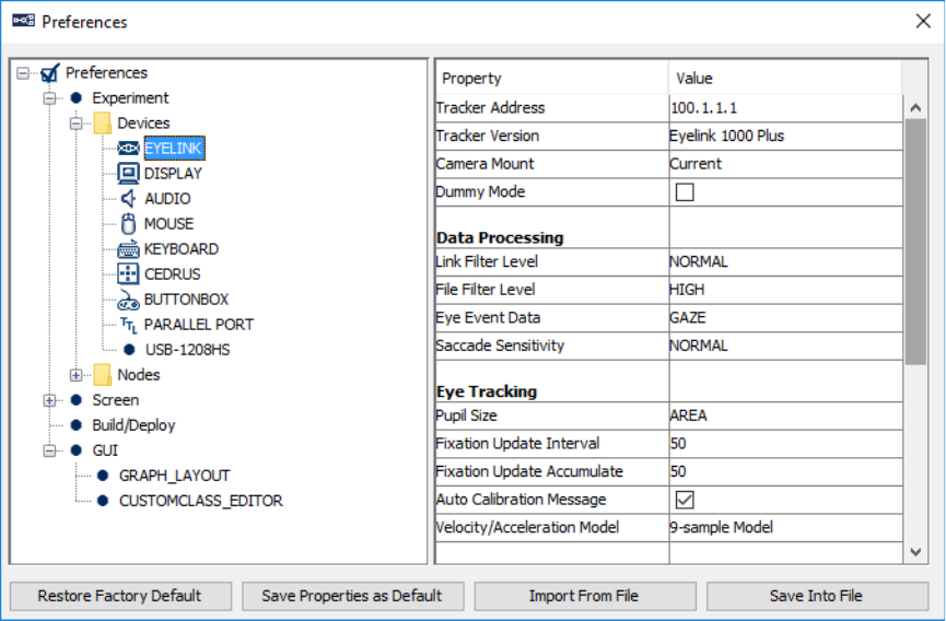
SR Research Experiment Builder User Manual ©2004-2017 SR Research Ltd.
358
node (see section 7.6 “Experiment Node”) and to the “Columns” field of the
RESULTS_FILE node (see section “7.11.2 Result File”). Users need to manage the
output variables to Data Viewer or results file manually if this option is not enabled.
17.1.1 EyeLink
Tracker Address (.trackerAddress): The IP address of the Host PC. This must be the
same as the "host_address" setting in the eyenet.ini file on the Host PC (typically under
\eyelink2\exe directory for an EyeLink II tracker, \EyeLink\exe directory for an EyeLink
I tracker, and \elcl\exe directory for an EyeLink 1000, EyeLink 1000 Plus, or EyeLink
Portable Duo eye tracker).
Tracker Version (.trackerVersion): The version of the EyeLink eye tracker being used:
EyeLink I , EyeLink II, EyeLink 1000 (previously EyeLink CL), EyeLink 1000 Plus,
EyeLink Portable Duo, or Current. When “Current” is selected, Experiment Builder will
connect to any EyeLink tracker and not modify the tracker settings on the host side.
Camera Mount (.mount): The mount type (e.g., Tower, Desktop, Arm, Long Range) if
the Tracker version is EyeLink 1000, 1000 Plus, or Portable Duo. If the option “Current”
is selected, Experiment Builder will not attempt to change the camera mount setting on
the host side.
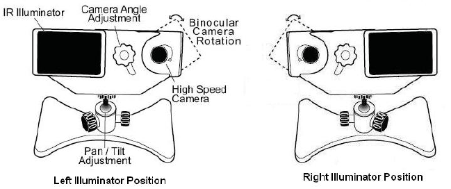
SR Research Experiment Builder User Manual ©2004-2017 SR Research Ltd.
359
Desktop Version (.desktopVersion): The version of EyeLink 1000 Desktop Mount
(Illuminator on Left vs. Illuminator on Right). This option is only available if the
“Tracker Version” is EyeLink 1000 and the "Camera Mount" type is set to Desktop. This
option requires version 4.20 or later of the EyeLink 1000 host software.
Mount Usage (.mountUsage): This option is only available when the "Camera Mount" is
set to "Desktop" or "Arm." If the Desktop Mount is used, possible options are
"Monocular - Stabilized Head," "Binoc / Monoc - Stabilized Head," "Monocular –
Remote," or “Binoc / Monoc – Remote.” If the Arm Mount is used, users can choose the
"Monocular - Stabilized Head" or "Monocular - Remote" options.
Dummy Mode (.dummyMode): If checked, the experiment can be run without
attempting to connect to the EyeLink tracker. This can be used to simulate EyeLink link
connection for early development work, or when an EyeLink tracker is not available.
Data Processing
Link Filter Level (.linkFilterLevel): Each increase in the filter level reduces noise by a
factor of 2 to 3 but introduces a 1-sample delay to the link sample feed. This setting is
only available for EyeLink II, 1000, 1000 Plus, and Portable Duo eye trackers.
File Filter Level (.fileFilterLevel): Selects the file sample filter for data in the EDF file.
Each increase in filter level reduces noise by a factor of 2 to 3. Note: By changing the file
sample filter from high to another value this will affect EyeLink Data Viewer and other
analysis tool calculations. SR Research Ltd recommends leaving this value set to High.
This setting is only available for EyeLink II, 1000, 1000 Plus, and Portable Duo eye
trackers.
Heuristic Filter (.heuristicFilter): Sets level of filtering on the link output, analog output,
and file data. This setting is only available for EyeLink I tracker.
Eye Event Data (.eyeEventData): Sets how velocity information for saccade detection is
to be computed. This setting is almost always left to GAZE.
SR Research Experiment Builder User Manual ©2004-2017 SR Research Ltd.
360
Saccade Sensitivity (.saccadeSensitivity): Defines the sensitivity of the EyeLink II,
EyeLink 1000, EyeLink 1000 Plus, or EyeLink Portable Duo parser for saccade event
generation. Normal is intended for cognitive tasks like reading; while High is intended
for psychophysical tasks where small saccades must be detected (Not available for
EyeLink I).
Eye Tracking
Eye-tracking Mode (.eyeTrackingMode): Select the tracking mode for recording.
EyeLink II runs either under the pupil-CR (corneal reflection) mode or pupil-only mode.
EyeLink I only runs under the pupil-only mode. EyeLink 1000, 1000 Plus, and Portable
Duo almost always run under the pupil-CR mode.
Eye-tracking High Speed (.eyeTrackingHighSpeed): Sets sampling rate in combination
with the Eye-tracking mode setting for EyeLink II trackers. If set to true, it will be 500
Hz in a pupil-only recording and 250 Hz in a pupil-CR mode. This setting is only
available for EyeLink II tracker.
Pupil Detection (.pupilDetection): Algorithm used to detect the pupil center position
(centroid algorithm vs. ellipse fitting algorithm). This option is only applicable to
EyeLink 1000, EyeLink 1000 Plus, and EyeLink Portable trackers when operating in a
head-supported mode.
Eye-tracking Sampling Rate (.eyeTrackingSamplingRate): Sets sampling rate for
EyeLink 1000, 1000 Plus, and Portable Duo. The available options are: 2000, 1000, 500,
and 250. The default sampling rate depends on the tracker version and operating mode.
Availability of some sampling rates depends on having the appropriate hardware and
camera programming.
Eyes To Track (.eyesToTrack): Select the eye(s) to track during recording. For EyeLink
I and II, the default is "BOTH." For EyeLink 1000, EyeLink 1000 Plus, and EyeLink
Portable Duo, the default is "EITHER."
Pupil Size (.pupilSize): Record the participants' eye area or diameter in arbitrary units.
Fixation Update Interval (.fixationUpdateInterval): During fixation, send updates every
(m) msec, integrated over (n) msec (max=m, min = 4 msec), where the Fixation Update
Interval is (m). These can be used for gaze-controlled software or for pursuit tracking.
Intervals of 50 or 100 msec are suggested. Interval of 0 disables.
Fixation Update Accumulate (.fixationUpdateAccumulate): During fixation, send
updates every (m) msec, integrated over (n) msec (max=m, min = 4 msec), where the
Fixation Update Accumulate is (n). Set to 50 or 100 msec to produce updates for gaze-
controlled interface applications. Set to 4 to collect single sample rather than average
position. Set to 0 to disable.
SR Research Experiment Builder User Manual ©2004-2017 SR Research Ltd.
361
Auto Calibration Message (.autoCalibrationMessage): If True, the calibration messages
will be included in the EDF file.
Velocity/Acceleration Model (.velocityAccelerationModel): EyeLink 1000, EyeLink
1000 Plus, and EyeLink Portable Duo only. Allows the user to choose the model (5-
sample, 9-sample, 17-sample, or EL1000 Tracker) used to calculate velocity and
acceleration data. For 5-, 9-, and 17-samples, the calculation of instantaneous velocity
and acceleration is based on 5, 9, or 17 samples. If EyeLink 1000 eye tracker models are
used, 5, 9, 19, and 39 samples will be used for the calculation under 250, 500, 1000, and
2000 hz respectively. In general, the more samples used in the calcuation, the less noisy
velocity/acceleration estimates will be (and the longer delay in the sample velocity trigger
firing as well).
Current Time # (.currentTime): Returns the current tracker time in milliseconds. The
tracker clock starts at 0 when the EyeLink host program was started.
Sample Rate # (.sampleRate): Returns the actual sample rate running in the experiment.
This may differ from the value set in the "Eye-tracking Sampling Rate" property, e.g., if
the setting is changed in the Camera Setup screen.
CR Mode # (.CRMode): Returns the actual mode ("PUPIL_CR" or "PUPIL_ONLY"
string) running on the Host PC. This may differ from the value set at the above "Eye-
tracking Mode" property.
File Filter # (.fileFilter): Returns the actual file filter level ("OFF", "NORMAL", or
"HIGH") used in the experiment. This may differ from the value set at the above "File
Filter Level" property.
Link Filter # (.linkFilter): Returns the actual link filter level ("OFF", "NORMAL", or
"HIGH") used in the experiment. This may differ from the value set at the above "Link
Filter Level" property.
Eye Used # (.eyeUsed): Returns the actual eye(s) used ("LEFT", "RIGHT", or "BOTH")
in the experiment. This may differ from the value set at the above "Eyes To Track"
property.
Pupil Detection Model # (.pupilDetectionModel): Returns the actual algorithm used to
detect the pupil center position (centroid algorithm vs. ellipse fitting algorithm). This
option is only applicable to EyeLink 1000, 1000 Plus, and Portable Duo trackers.
Last Sample #: Possible data that can be retrieved from the last eye sample (see the table
below for details).
Data File Contents
SR Research Experiment Builder User Manual ©2004-2017 SR Research Ltd.
362
Important: SR Research Ltd. does not recommend changing the following default settings
as this may have negative impacts on the data file integrity and your data analysis.
Samples: If checked, samples will be recorded in the EDF file.
Fixations: If checked, fixations will be recorded in the EDF file.
Saccades: If checked, saccades will be recorded in the EDF file.
Blinks: If checked, blinks will be recorded in the EDF file.
Buttons: If checked, presses and releases of the EyeLink button box will be recorded in
the EDF file.
Inputs: If checked, input data will be recorded in the EDF file.
Remote Warnings
Note: The following options are only available for EyeLink Remote eye trackers. The
remote warning may not work on some older, single-core processor computers running
under real-time mode. If so, please check the BIOS setting of the Display PC so that
hyperthreading or multithreading is enabled.
Enable Remote Warning (.enableRemoteWarning): Whether a warning beep should be
given when the eye or target is missing when the eye tracker is operating in the remote
mode.
Minimum Eye Missing Duration (.eyeMissingThreshold): Minimum amount of time (in
milliseconds) the eye data is missing before a warning beep will be given.
Eye Missing Beep (.eyeMissingBeep): The audio clip to be played when the eye is
missing. A different audio clip may be used if it has already been loaded into the Library
Manager ("Edit → Library Manager", select the "Sound" tab). Messages
("REMOTE_WARNING_AUDIO_ON" and "REMOTE_WARNING_AUDIO_OFF")
are recorded to the EDF file to mark the time of the onset and offset of the audio.
Minimum Target Missing Duration (.targetMissingThreshold): Minimum amount of
time (in milliseconds) the target is missing before a warning beep will be given.
Target Missing Beep (.targetMissingBeep): The audio clip to be played when the target
is missing. A different audio clip may be used if that clip has already been loaded into the
library manager ("Edit → Library Manager", select the "Sound" tab).
Event/ Sample Queue Sizes:

SR Research Experiment Builder User Manual ©2004-2017 SR Research Ltd.
363
Experiment Builder maintains separate event queues for the eye-based triggers. The
following sets the size of the event queue and reports the current event count in each
queue.
Fixation Queue Size (.fixationQueueSize): Sets the maximum number of fixation events
(FIXUPDATE, STARTFIX, or ENDFIX) that can be cached in the fixation event queue.
Saccade Queue Size (.saccadeQueueSize): Sets the maximum number of saccade events
that can be cached in the saccade event queue.
Button Queue Size (.buttonQueueSize): Sets the maximum number of button events that
can be cached in the button event queue.
Sample Queue Size (.sampleQueueSize): Sets the maximum number of samples that can
be cached in the link sample queue.
Fixation Event Count # (.fixationEventCount): The number of fixation events
(FIXUPDATE, STARTFIX, or ENDFIX) cached in the fixation event queue.
Saccade Event Count # (.saccadeEventCount): The number of saccade events cached in
the saccade event queue.
Button Event Count # (.buttonEventCount): The number of button press/released events
cached in the button event queue.
Use Keyboard (.useKeyboard): In a project with multiple-input support, this specifies
the display keyboard(s) that can be used to control the camera setup, calibration, and drift
correction process.
Use Mouse (.useMouse): In a project with multiple-input support, this specifies the
display mouse/mice that can be used in the camera setup process.
The following table lists possible data that can be retrieved from the last eye sample:
Reference
Attribute
Type
Content
Time
.time
Integer
Display computer time (in milliseconds from
the start of the experiment) when the last sample
occurs.
EDF Time
.EDFTime
Integer
EDF time of the last sample.
Eyes Available
.eyesAvailable
Integer
Eyes available in recording (0 for left eye; 1 for
right eye; 2 for both eyes).
PPD X, PPD Y
.PPDX, .PPDY
Float
Angular resolution at the current gaze position
(in screen pixels per visual degree) along the x-,
or y-axis.
Left Gaze X,
Right Gaze X,
Average Gaze X
.leftGazeX, .right
GazeX, .average
GazeX ¹
Float
Gaze position of the last sample along the x-axis
for the left eye, right eye and an average
between the two.

SR Research Experiment Builder User Manual ©2004-2017 SR Research Ltd.
364
Left Gaze Y,
Right Gaze Y,
Average Gaze Y
.leftGazeY, .right
GazeY, .average
GazeY ¹
Float
Gaze position of the last sample along the y-axis
for the left eye, right eye and an average
between the two.
Left Pupil Size,
Right Pupil Size,
Average Pupil
Size
.leftPupilSize, .ri
ghtPupilSize,
.averagePupilSize
¹
Float
Left eye, right eye, or average pupil size (in
arbitrary units, either area or diameter as
selected in the EyeLink device settings).
Target Distance
.targetDistance
Integer
Distance between the target and camera (10
times the measurement in millimeters). This
option is available only when the eye tracker is
operating in the remote mode. Returns
"MISSING_DATA" (-32768) if target is
missing or if the tracker is operating in a head-
supported mode.
Target X, Target
Y
.targetX, .targetY
Integer
X, Y position of the target in camera
coordinates. This option is available only when
the eye tracker is operating in the remote mode.
Returns "MISSING_DATA" (-32768) if target
is missing or if the tracker is operating in a
head-supported mode.
Target Flags
.targetFlags
Integer
Flags used to indicate target tracking status (0 if
target tracking is ok; otherwise error code). This
option is available only when the eye tracker is
operating in the remote mode. Returns
"MISSING_DATA" (-32768) if target is
missing or if the tracker is operating in a head-
supported mode.
Note:
¹ Returns "MISSING_DATA" (-32768) for the untracked eye.
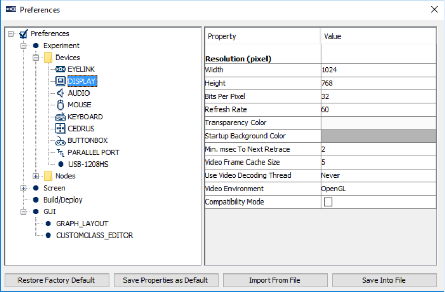
SR Research Experiment Builder User Manual ©2004-2017 SR Research Ltd.
365
17.1.2 Display
Width (.width): The width of the display screen in pixels. If using Mac OS X and having
“Antialias Drawing” enabled (Preferences -> Screen), make sure the resolution is set to
the native resolution of the built-in screen or external monitor to achieve the best anti-
aliasing results.
Height (.height): The height of the display screen in pixels.
Bits Per Pixel (.bitsPerPixel): The number of bits used to represent the luminance and
chroma information contained in each pixel.
Refresh Rate (.refreshRate): Sets the refresh rate (Hz) of the monitor.
Transparency Color (.transparencyColor): When the DirectDraw Video Environment id
being used (see below in this section), defines the color value to be used as transparency.
Any pixels in image resources that match the specified transparency color will be treated
as transparent and will not be drawn.
Startup Background Color (.startupBackgroundColor): The background color used
when experiment starts up.
Minimum msec To Next Retrace (.flipRemainThreshold): The minimum amount of
time (in milliseconds) remaining in a retrace before the next flip can be scheduled.
During experiment runtime, if the remaining time in a retrace to perform a flip is less
SR Research Experiment Builder User Manual ©2004-2017 SR Research Ltd.
366
than the specified amount of time, the flip will be scheduled to the retrace after to ensure
that the flip is done properly.
Video Frame Cache Size (.cacheFrameThreshold): Sets the number of video frames that
are decoded and cached in advance when playing back a video resource. Min should be 5,
max should be 60.
Use Video Decoding Thread (.useVideoDecodingThread): Whether to use a video
decoding thread for video playback. If used, a buffer is created so that a decoding thread
continually fills this buffer while video playing thread consumes it.
Current Time # (.currentTime): Reads the millisecond clock running on the display
computer; the clock starts at 0 when the EyeLink library is initialized.
Software To Hardware Blit Time # (.softwareToHardwareBlitTime): Time required to
perform a software-based copying of resource from system memory to the display surface.
Hardware To Hardware Blit Time # (.hardwareToHardwareBlitTime): Time required
to blit resource from the video card memory to the display surface.
Video Memory Size # (.hardwareMemorySize): The total amount of memory found in a
video card.
Video Memory Available # (.hardwareMemoryAvailable): The amount of memory in a
video card available for graphics operation (e.g., stores images before they are sent to the
display monitor).
Retrace Interval # (.retraceInterval): The duration of one refresh cycle of the monitor,
calculated as 1000/refresh rate.
Video Environment: Whether OpenGL or DirectDraw graphics should be used to
support visual stimulus presentation in the current experiment project. Version 1.x of
Experiment Builder used DirectDraw graphics on Windows and OpenGL graphics on
Mac OS X. OpenGL is recommended for experiment projects running on Windows 8 and
10.
Compatibility Mode: This option is only applicable when the OpenGL graphics is used
(i.e., Mac OS X or Windows when the “Video Environment” is set to OpenGL). This
mode is necessary when the display graphics are done through Custom Class drawing and
require some Pygame function calls to support the drawing operations. This option
should be turned off for typical experiments that don’t use Custom Class graphics.
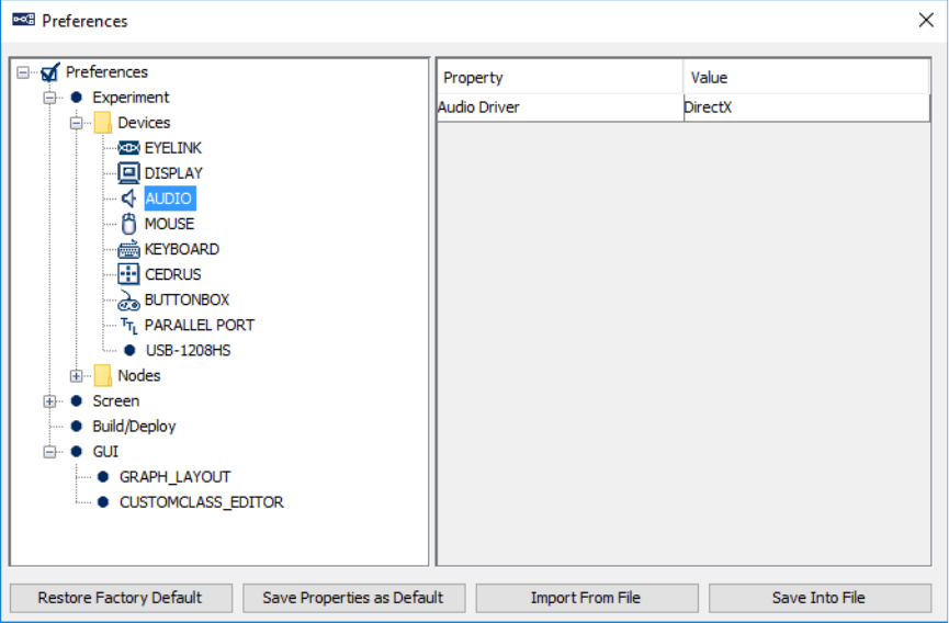
SR Research Experiment Builder User Manual ©2004-2017 SR Research Ltd.
367
17.1.3 Audio
Audio Driver (.driver): The driver used to play audio clips. Two audio drivers are
available on Windows: DirectX or ASIO. If using the ASIO driver, an ASIO-compatible
sound card should be installed on the computer with the proper sound card driver
installed. On Mac OS X, this is always set to "OS X".
Properties applicable to ASIO Driver:
• Output Interval # (.outputInterval): The interval (in milliseconds) between ASIO
buffer swaps, which determines how often new sounds can be output.
• ASIO Audio Driver # (.driverName): The name of the ASIO driver.
• Minimum Output Latency # (.minimumOutputLatency): The minimum output
latency of the ASIO driver (delay from buffer switch to first sample output).
Properties applicable to OS X Audio Driver (Mac OSX)
• Minimum Scheduling Latency # (.minimumSchedulingLatency): The minimum
amount of delay (in milliseconds) required for the audio to be played at the
intended/scheduled time.
Properties applicable to ASIO driver or OS X Audio Driver
• VoiceKey Queue Size (.voiceKeyQueueSize): Sets the maximum number of
voice key events that can be cached in the voicekey event queue.
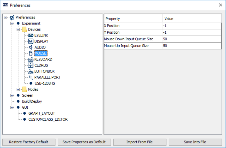
SR Research Experiment Builder User Manual ©2004-2017 SR Research Ltd.
368
• VoiceKey Event Count # (.voiceKeyEventCount): Returns total number of voice
key events cached in the event queue.
VoiceKey Threshold (.voiceKeyThreshold): Value from 0.0 to 1.0 to set voice
key trigger level, with 1.0 being the maximum audio level. The threshold should
be set high enough to reject noise and prevent false triggering, but low enough to
trigger quickly on speech. A threshold of 0.05 to 0.10 is typical.
17.1.4 Mouse
Number of Mice (.numberOfMouses): Sets how many distinct mice are used in the
experiment. This option is only available if "Enable Multiple Input" option is enabled.
Mouse One Label (.mouseOneLabel): Supplies a label for the first mouse detected by
the experiment. This option is only available if "Enable Multiple Input" option is enabled.
X Position (.xPosition): Default X position of the mouse (or the first mouse if multiple
inputs are supported).
Y Position (.yPosition): Default Y position of the mouse (or the first mouse if multiple
inputs are supported).
Mouse Down Input Queue Size (.mouseDownInputQueueSize): Sets the maximum
number of press events that can be cached in the press event queue for the mouse (or the
first mouse if multiple inputs are supported).
SR Research Experiment Builder User Manual ©2004-2017 SR Research Ltd.
369
Mouse Up Input Queue Size (.mouseUpInputQueueSize): Sets the maximum number of
release events that can be cached in the release event queue for the mouse (or the first
mouse if multiple inputs are supported).
Mouse Down Event Count # (.mouseDownEventCount): Total number of press events
cached in the press event queue for the mouse (or the first mouse if multiple inputs are
supported).
Mouse Up Event Count # (.mouseUpEventCount): Total number of release events
cached in the release event queue for the mouse (or the first mouse if multiple inputs are
supported).
Mouse Two Label, Mouse Three Label, ... (.mouseTwoLabel, .mouseThreeLabel, ...):
Supplies a label for the second, third, ..., mouse detected by the experiment. This option
is only available if "Enable Multiple Input" option is enabled.
Mouse Two X Position, Mouse Three X Position, ...
(.mouseTwoXPosition, .mouseThreeXPosition, ...): Default X position of the second,
third, ... mouse.
Mouse Two Y Position, Mouse Three Y Position, ...
(.mouseTwoYPosition, .mouseThreeYPosition, ...): Default Y position of the second,
third, ... mouse.
Mouse Two Button Down Input Queue size, Mouse Three Button Down Input
Queue size, ...
(.mouseTwoDownInputQueueSize, .mouseThreeDownInputQueueSize, ...): Sets the
maximum number of press events that can be cached in the press event queue for the
second, third, ... mouse.
Mouse Two Button Up Input Queue Size, Mouse Three Button Up Input Queue
Size, ... (.mouseTwoUpInputQueueSize, .mouseThreeUpInputQueueSize, ...): Sets the
maximum number of release events that can be cached in the release event queue for the
second, third, ... mouse.
Mouse Two Button Down Event Count #, Mouse Three Button Down Event Count
#, ... (.mouseTwoDownEventCount, .mouseThreeDownEventCount, ...): Total number of
press events cached in the press event queue for the second, third, ... mouse.
Mouse Two Button Up Event Count #, Mouse Three Button Up Event Count #, ...
(.mouseTwoUpEventCount, .mouseThreeUpEventCount, ...): Total number of release
events cached in the release event queue for the second, third, ... mouse.
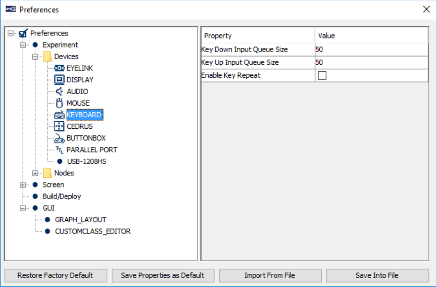
SR Research Experiment Builder User Manual ©2004-2017 SR Research Ltd.
370
17.1.5 Keyboard
Number of Keyboards (.numberOfKeyboards): Sets how many distinct keyboards are
used in the experiment. This option is only available if "Enable Multiple Input" option is
enabled.
Keyboard One Label (.keyboardOneLabel): Supplies a label for the first keyboard
detected by the experiment. This option is only available if "Enable Multiple Input"
option is enabled.
Key Down Input Queue Size (.keyDownInputQueueSize): Sets the maximum number of
press events that can be cached in the press event queue for the keyboard (or the first
keyboard if multiple inputs are supported).
Key Up Input Queue Size (.keyUpInputQueueSize): Sets the maximum number of
release events that can be cached in the release event queue for the keyboard (or the first
keyboard if multiple inputs are supported).
Key Down Event Count # (.keyDownEventCount): Total number of press events cached
in the press event queue for the keyboard (or the first keyboard if multiple inputs are
supported).
Key Up Event Count # (.keyUpEventCount): Total number of release events cached in
the release event queue for the keyboard (or the first keyboard if multiple inputs are
supported).
SR Research Experiment Builder User Manual ©2004-2017 SR Research Ltd.
371
Enable Key Repeat (NR): If enabled, supports repeated key inputs when you hold down
a key. This option is only available if "Enable Multiple Input" option is NOT enabled.
Repeat Delay (.repeatDelay): Adjusts the amount of time that elapses before characters
repeat when you hold down a key. This option is only available if "Enable Multiple
Input" option is NOT enabled.
Repeat Interval (.repeatInterval): Adjusts how quickly characters repeat when you hold
down a key. This option is only available if "Enable Multiple Input" option is NOT
enabled.
Keyboard Two Label, Keyboard Three Label, ... (.keyboardTwoLabel,
.keyboardThreeLabel, ...): Supplies a label for the second, third, ... keyboard detected by
the experiment. This option is only available if "Enable Multiple Input" option is enabled.
Keyboard Two Key Down Input Queue Size, Keyboard Three Key Down Input
Queue Size, ... (.keyboardTwoKeyDownInputQueueSize,
.keyboardThreeKeyDownInputQueueSize, ...): Sets the maximum number of press events
that can be cached in the press event queue for the second, third, ... keyboard.
Keyboard Two Key Up Input Queue Size, Keyboard Three Key Up Input Queue
Size, ... (.keyboardTwoKeyUpInputQueueSize, .keyboardThreeKeyUpInputQueueSize,
...): Sets the maximum number of release events that can be cached in the release event
queue for the second, third, ... keyboard.
Keyboard Two Key Down Event Count #, Keyboard Three Key Down Event Count
#, ... (.keyboardTwoKeyDownEventCount, .keyboardThreeKeyDownEventCount, ...):
Total number of press events cached in the press event queue for the second, third, ...
keyboard.
Keyboard Two Key Up Event Count #, Keyboard Three Key Up Event Count #, ...
(.keyboardTwoKeyUpEventCount, .keyboardThreeKeyUpEventCount, ...): Total number
of release events cached in the release event queue for the second, third, ... keyboard.
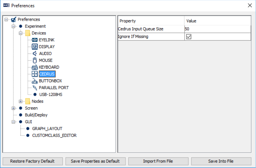
SR Research Experiment Builder User Manual ©2004-2017 SR Research Ltd.
372
17.1.6 Cedrus
Cedrus Input Queue Size (.cedrusInputQueueSize): Sets the maximum number of
Cedrus device input events that can be cached in the Cedrus device event queue.
Cedrus Event Count # (.cedrusEventCount): Total number of Cedrus device input
events cached in the event queue.
Ignore if Missing (.ignoreIfMissing). If unchecked, experiment will not run if no Cedrus
button box is detected. If checked, the experiment will still run even if the device is not
detected (however the Cedrus Input trigger itself will not be functional).
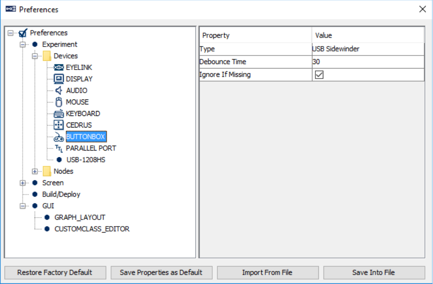
SR Research Experiment Builder User Manual ©2004-2017 SR Research Ltd.
373
17.1.7 EyeLink Button Box Device
Type (.type): Identifies the type of button box plugged into the host computer. This can
be the "Microsoft SideWinder Plug and Play gamepad" (plugged to a USB port), "SR
Research Gamepad" (plugged to a parallel port), or "ResponsePixx Button Box" (plugged
to a parallel port). Button presses on the response box will be processed by the EyeLink
button trigger.
Debounce Time (.debounceTime): Sets the button debounce time in milliseconds.
Typically, button responds immediately to first change; any change following this is
ignored for the amount of time set in the debounce time.
Model (.model): Different model options (5-button handheld, 4-button dual-handheld,
and 5-button desktop) if a "ResponsePixx Button Box" is used.
Parallel Port (.parallelPort): The parallel port to which the gamepad is plugged if the
"SR Research Gamepad" or "ResponsePixx Button Box" is chosen. This can be the
parallel port on the motherboard, or the PCI-express adapter card (LF811) installed on the
host computer. The "Card" option is only supported with version 4.50 or later of the
EyeLink 1000 host software or 2.30 or later of the EyeLink II host software. If using an
EyeLink 1000 Plus, should be set to “Card” as this system only uses an add-on card. A
"Parallel port expansion card not supported in this version of host software" error will be
reported if an earlier version of software is running on the host computer. If this property
is set to "Card" while the physical card (LF811) is not installed on the host computer, a
"No parallel port card detected by the tracker" error message will be displayed.
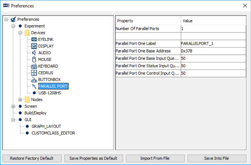
SR Research Experiment Builder User Manual ©2004-2017 SR Research Ltd.
374
Digital In/Output Address (.digitalAddress). The base address of the parallel port
device to which the button box is connected. The default is 0x8 if using an add-on
parallel port on the Host PC, or 0x378 if using the parallel port on the motherboard..
Ignore if Missing (.ignoreIfMissing). If unchecked, the experiment will not run if no
EyeLink button box is detected. If checked, the experiment will still run even if the
button box is not detected, though any node that uses the device will not be functional.
17.1.8 Parallel Port
Number of Parallel Ports (.numberOfParallelPorts): Sets how many distinct parallel
ports are used in the experiment.
Parallel Port One Label, Parallel Port Two Label, ... (.portOneLabel, .portTwoLabel,
...): Supplies a label for the first, second, ... parallel port device used in the experiment.
Parallel Port One Base Address, Parallel Port Two Base Address, ...
(.portOnebaseAddress, .portTwobaseAddress, ...): The address of data port or data
register for outputting data on the first, second, ... parallel port's data lines. LPT1 on a
motherboard is normally assigned a base address of 0x378, while parallel port cards may
have addresses within a wide range. This field expects a hexadecimal number, so users
should enter values like “0x378” (without quotes) instead of “378”. If this is set to 0, the
software will detect he parallel port address automatically.
SR Research Experiment Builder User Manual ©2004-2017 SR Research Ltd.
375
Parallel Port One Base Input Queue Size, Parallel Port Two Base Input Queue Size,
... (.portOneBaseInputQueueSize, .portTwoBaseInputQueueSize, ... ): Sets the maximum
number of input events at the base register of the first, second, ... parallel port that can be
cached in the event queue.
Parallel Port One Status Input Queue Size, Parallel Port Two Status Input Queue
Size, ... (.portOneStatusInputQueueSize, .portTwoStatusInputQueueSize, ...): Sets the
maximum number of input events at the status register of the first, second, ... parallel port
that can be cached in the event queue.
Parallel Port One Control Input Queue Size, Parallel Port Two Control Input
Queue Size, ... (.portOneControlInputQueueSize, .portTwoControlInputQueueSize, ...):
Sets the maximum number of input events at the control register of the first, second, ...
parallel port that can be cached in the event queue.
Parallel Port One Base Event Count, Parallel Port Two Base Event Count, ... #
(.portOneBaseEventCount, .portTwoBaseEventCount, ...): Total number of input events
at the base register of the first, second, ... parallel port cached in the event queue.
Parallel Port One Status Event Count, Parallel Port Two Status Event Count, ... #
(.portOneStatusEventCount, .portTwoStatusEventCount, ...): Total number of input
events at the status register of the first, second, ... parallel port cached in the event queue.
Parallel Port One Control Event Count, Parallel Port Two Control Event Count, ...
# (.portOneControlEventCount, .portTwoControlEventCount, ...): Total number of input
events at the control register of the first, second, ... parallel port cached in the event
queue.
Parallel Port One Current Value, Parallel Port Two Current Value, ... #
(.portOneCurrentValue, .portTwoCurrentValue, ...): Current value of the first, second, ...
parallel port in the format of (data register value, status register value, control register
value).
17.1.9 USB-1208HS Box
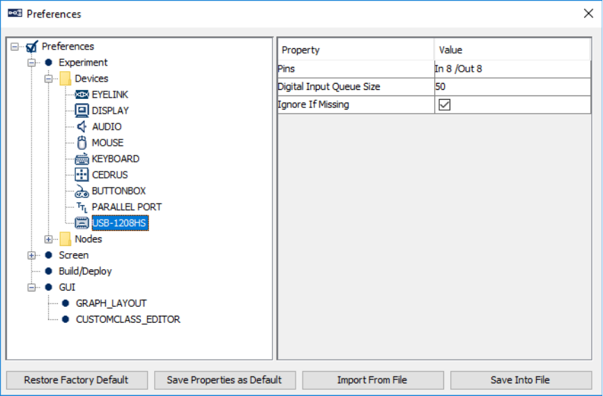
SR Research Experiment Builder User Manual ©2004-2017 SR Research Ltd.
376
Pins (.pins): Sets the digital pins used for sending or receiving signals through the USB-
1208HS box. Clicking on the "Value" field will bring up a USB-1208HS configuration
dialog box. The arrows indicate the directions of the data flow that each pin is configured
for: if the arrow points towards the box, the pin is used to receive signals; if the arrow
points away from the box, the pin is used to send signals.
Digital Input Queue Size (.digitalInputQueueSize): Sets the maximum number of TTL
input events from the USB-1208 HS box that can be cached in the event queue.
Digital Event Count # (.digitalEventCount): Total number of TTL input events from the
USB-1208 HS box that are cached in the event queue.
Current Value # (.currentValue): The current TTL value across all 16 pins.
Ignore if Missing (.ignoreIfMissing). If unchecked, the experiment will not run if the
USB-1208HS is not detected. If checked, the experiment will still run even if the device
is not detected, though any node that uses the device will not be functional.
17.1.10 Timer
See section 7.10.1 “Timer Trigger”.
17.1.11 Invisible Boundary
See section 7.10.2 “Invisible Boundary Trigger”.
SR Research Experiment Builder User Manual ©2004-2017 SR Research Ltd.
377
17.1.12 Conditional
See section 7.10.3 “Conditional Trigger”.
17.1.13 EyeLink Button
See section 7.10.4 “EyeLink Button Trigger”.
17.1.14 Cedrus Input
See section 7.10.5 “Cedrus Button Trigger”.
17.1.15 Keyboard
See section 7.10.6 “Keyboard Trigger”.
17.1.16 Mouse
See section 7.10.7 “Mouse Trigger”.
17.1.17 TTL Trigger
See section 7.10.8 “TTL Trigger”.
17.1.18 Fixation
See section 7.10.9 “Fixation Trigger”.
17.1.19 Saccade
See section 7.10.10 “Saccade Trigger”.
17.1.20 Sample Velocity
See section 7.10.11 “Sample Velocity Trigger”.
17.1.21 Voice Key
See section 7.10.12 “ASIO Voice Key Trigger”.
17.1.22 Display Screen
See section 7.9.1 “Display Screen”.
17.1.23 Drift Correct
See section 7.9.2 “Performing Drift Correction”.
17.1.24 Camera Setup
See section 7.9.3 “Performing Camera Setup and Calibration”.
17.1.25 Send EyeLink Message
See section 7.9.4 “Sending EyeLink Message”.
17.1.26 Send Command
See section 7.9.5 “Sending EyeLink Command”.
SR Research Experiment Builder User Manual ©2004-2017 SR Research Ltd.
378
17.1.27 Set TTL
See section 7.9.6 “Sending TTL Signal”.
17.1.28 Add to Experiment Log
See section 7.9.7 “Adding to Experiment Log”.
17.1.29 Update Attribute
See section 7.9.8 “Update Attribute”.
17.1.30 Add to Accumulator
See section 7.9.9 “Adding to Accumulator”.
17.1.31 Add to Results File
See section 7.9.10 “Add to Results File”.
17.1.32 Prepare Sequence
See section 7.9.11 “Preparing Sequence”.
17.1.33 Sequence
See section 7.7 “Sequence”.
17.1.34 Reset Node
See section 7.9.12 “Reset Node”.
17.1.35 Play Sound
See section 7.9.13 “Playing Sound”.
17.1.36 Play Sound Control
See section 7.9.14 “Play Sound Control”.
17.1.37 Record Sound
See section 7.9.15 “Record Sound”.
17.1.38 Record Sound Control
See section 7.9.16 “Record Sound Control”.
17.1.39 Terminate Experiment
See section 7.9.17 “Terminating an Experiment”.
17.1.40 Recycle Data Line
See section 7.9.18 “Recycle Data Line”.
17.1.41 Execute
See section 7.9.19 “Execute Action”.
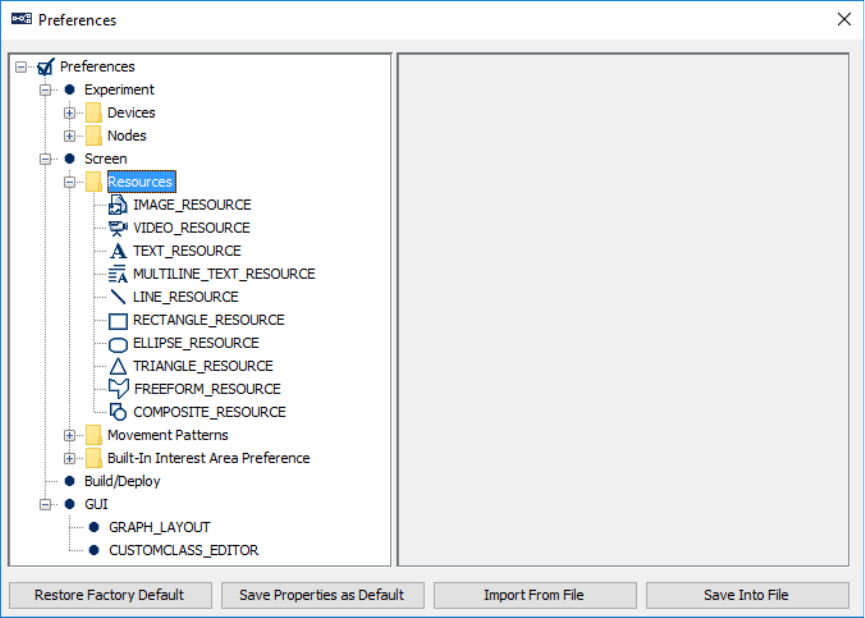
SR Research Experiment Builder User Manual ©2004-2017 SR Research Ltd.
379
17.1.42 Null Action
See section 7.9.20 “Null Action”.
17.1.43 ResponsePixx LED Control
See section 7.9.21 “ResponsePixx LED Control”.
17.1.44 Accumulator
See section 7.11.3 “Accumulator”.
17.1.45 Results File
See section 7.11.2 “Results File”.
17.2 Screen
17.2.1 Screen
Location Type: For all resources on the Screen Builder, whether the “Location” refers to
the top-left corner or the center of the resource.
InterestArea Color: Color used to draw the border of interest areas.
Antialias Drawing: Anti-aliasing is the process of blurring sharp edges in text or line
drawings to get rid of the jagged edges on lines. If this preference is set to true, anti-
SR Research Experiment Builder User Manual ©2004-2017 SR Research Ltd.
380
aliasing is applied to resources to make screen drawings appear smoother. If using Mac
OS X, make sure the resolution (Preferences -> Experiment -> Devices -> Display ->
"Width" and "Height") is set to the native resolution of the built-in screen or external
monitor to achieve the best anti-aliasing results. When using the DirectDraw Video
Environment, make sure the transparency color (Preferences -> Experiment -> Devices ->
Display -> "Transparency Color") is set close to, but not identical to, the background
color of the display (Preferences -> Experiment -> Nodes -> Action -> Display Screen ->
"Background Color").
17.2.2 Image Resource
See section 8.1.1 “Image Resource”.
17.2.3 Video Resource
See section 8.1.2 “Video Resource”.
17.2.4 Text Resource
See section 8.1.3 “Text Resource”.
17.2.5 Multiline Text Resource
See section 8.1.4 “Multiline Text Resource”.
17.2.6 Line Resource
See section 8.1.5 “Line Resource”.
17.2.7 Rectangle Resource
See section 8.1.6 “Rectangle Resource”.
17.2.8 Ellipse Resource
See section 8.1.7 “Ellipse Resource”.
17.2.9 Triangle Resource
See section 8.1.8 “Triangle Resource”.
17.2.10 Freeform Resource
See section 8.1.9 “Freeform Resource”.
17.2.11 Sine Pattern
See section 8.2.1 “Sinusoidal Movement Pattern”.
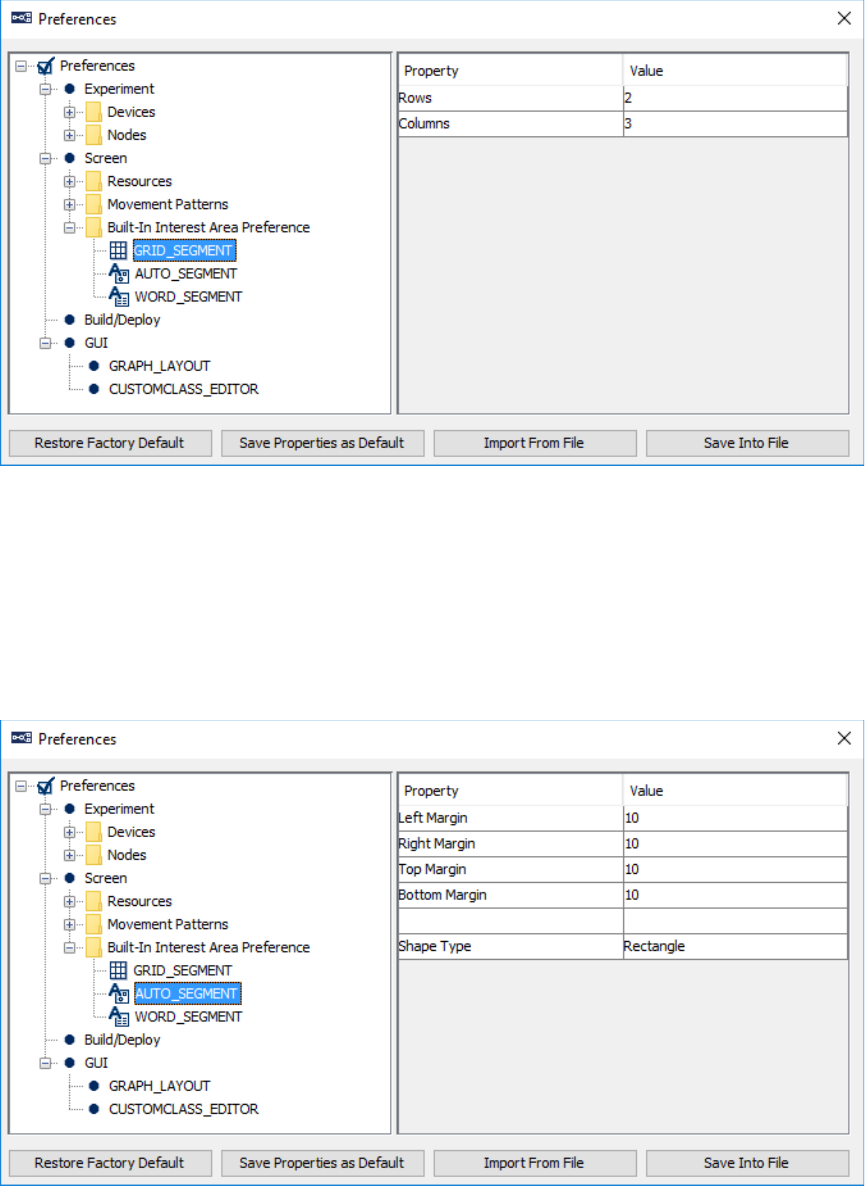
SR Research Experiment Builder User Manual ©2004-2017 SR Research Ltd.
381
17.2.12 Grid Segmentation
Grid segmentation will divide the entire screen into evenly spaced [Rows] × [Columns]
interest areas.
Rows: Number of rows used to create grid segment.
Columns: Number of columns used to create grid segment.
17.2.13 Auto Segmentation
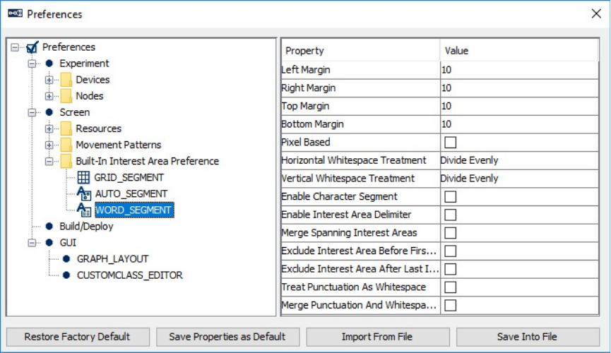
SR Research Experiment Builder User Manual ©2004-2017 SR Research Ltd.
382
Auto segmentation will create a rectangular or elliptic interest area for the selected
resources on the display screen based on the minimum bounding rectangle.
Left Margin, Right Margin, Top Margin, and Bottom Margin: Number of pixels
added to the left, top, right, and bottom of the interest area that bounds the resource.
Shape Type: The type of interest area to be created (either rectangular or elliptic).
17.2.14 Word Segmentation
Word segmentation will create a rectangular interest area to contain each of the words in
a text or multiline text resource.
Left Margin, Right Margin, Top Margin, and Bottom Margin: Number of pixels
added to the left, top, right, and bottom of the interest area.
Pixel Based: This option is intended for interest area segmentation for the right-to-left
texts (e.g., Arabic, Hebrew). If this option is enabled, interest areas are created based on
the image analysis of the text created. Essentially, it will look for a cluster of dark/bright
pixels in one or multiple lines and use "Segmentation Spacing Threshold" to decide
where the boundary of an interest area should be. Note, for this feature to work properly,
please make sure the "Text Orientation" property of the multiline text resource is set to
"Right to Left".
Segmentation Spacing Threshold: Number of consecutive pixels below threshold
before segment end is identified.
SR Research Experiment Builder User Manual ©2004-2017 SR Research Ltd.
383
Fill Gap Between: If checked, gaps between consecutive interest areas will be filled by
expanding the size of each interest area.
Horizontal Whitespace Treatment: This specifies how the whitespace between words
is treated in the interest area segmentation. The following options are supported:
• Divide Evenly – Divides the space evenly so half of the whitespace goes to the
interest area containing the previous word, and the other half goes to the next
interest area. This is the existing and default segmentation behavior. For example:
Whitespace | Treatment.
• Include with Previous Word – Includes the space with the lower-numbered
interest area, which will usually contain the word earlier in the direction of
reading. For example, Whitespace |Treatment.
• Include with Next Word – Includes the space with the higher-numbered interest
area, which will usually be later in the direction of reading. For example,
Whitespace| Treatment.
• Exclude – Excludes the space from being included in any interest areas.
Whitespace| |Treatment. Note that for this example only two interest areas are
created and they don’t contain any part of the interword space.
• Extend Left and Right Margins of Words – Extends the left and right margins of
the interest areas by the amount specified by the "Left Margin" and "Right
Margin" options specified above. For example, Whitespace | | Treatment. Note,
extra pixels specified by the “Right Margin” are added to the previous word
"Whitespace". Similarly, extra pixels specified by the “Left Margin” are added to
the next word "Treatment".
• Create IA for Whitespace – Creates a separate interest area for the whitespace,
and for punctuations as well if the "Treat Punctuation as Whitespace" preference
is checked (see below). For example, Whitespace| |Treatment. Note, unlike all of
the above options, this will create three interest areas instead of two.
Vertical Whitespace Treatment: Specifies how the space between lines of texts is
treated in the interest area segmentation. The following options are supported:
• Divide Evenly – Divides the space evenly between the lines of text, and has part
of the line space included in the interest areas above and below the space. This is
the existing and default segmentation behavior.
• Include with Previous Line – Groups the line space with the previous line of text.
• Include with Next Line – Groups the line space with the following line of text.
• Exclude – Excludes the line space from being included in any interest areas.
• Extend Top and Bottom Margins of Words - Extends interest areas for the text
above the line space by extra pixels specified by the Bottom Margin option.
Similarly, interest areas for the text below the space are extended by extra pixels
specified by the Top Margin option.
• Create IA for Whitespace – Creates a separate interest area for the line space.
Enable Character Segment: If checked, an interest area will be created for each
letter/character of the text. This is useful for interest area segmentation, e.g., with some
SR Research Experiment Builder User Manual ©2004-2017 SR Research Ltd.
384
languages such as Chinese, or for letter-by-letter segmentation in English text. This
option applies to the multiline text resource only, and is ignored for the text resource.
Enable Interest Area Delimiter: Whether a special delimiter character should be used to
mark the boundary between segments. If False, the space character will be used as the
delimiter.
Delete Delimiter: If enabled, the delimiter character will be removed from the text
without replacement. This option also toggles off the “Enable Interest Area Delimiter
Replacement” option.
Delimiter Character: Specifies the delimiter character(s) used to separate segments.
Version 2.0 of Experiment Builder allows one or more delimiter characters to be used.
Simply type all of the delimiters characters into the editor box. (Note: any space or
comma entered will be interpreted as one of the delimiter characters—enter only the
desired delimiter character(s), and Experiment Builder will parse this into a list of
characters separated by commas.)
Enable Interest Area Delimiter Replacement: Whether the delimiter character should
be replaced by another character. The delimiter characters are used to separate string
tokens and will not be displayed in the text or multiline text resource. Therefore, if using
space as the delimiter character, the delimiter replacement option should be enabled, and
space should be set as the replacement character. Please note that enabling this option
will toggle off the “Delete Delimiter” option if it is enabled.
Delimiter Replacement Character: A list of characters that are used to replace the
delimiter characters. Version 2.0 of Experiment Builder allows one or more delimiter
characters to be used. This property should be set to either one character, to apply the
same replacement character to all delimiter characters, or to the same number of
characters as in the “Delimiter Character” list, for a 1-to-1 mapping between the
Delimiter Characters and the Delimiter Replacement Characters.
Merge Spanning Interest Areas: Sometimes interest areas can span across multiple
lines (e.g., when you are trying to create a phrase-, sentence-, or paragraph- based interest
area segmentation). Enabling this option will merge interest areas across lines and create
a single (freehand) interest area.
Exclude Interest Area Before First Instance of Delimiter Character, Exclude
Interest Area After Last Instance of Delimiter Character: If the option is checked, no
interest area will be created before the first, or after the last instance of the delimiter
characters.
Treat Punctuation As Whitespace: If checked, punctuation marks such as , . ! - will be
treated as if they were a space; segmentation options “Horizontal Whitespace Treatment”
and “Vertical Whitespace Treatment” will be similarly applied to the punctuation
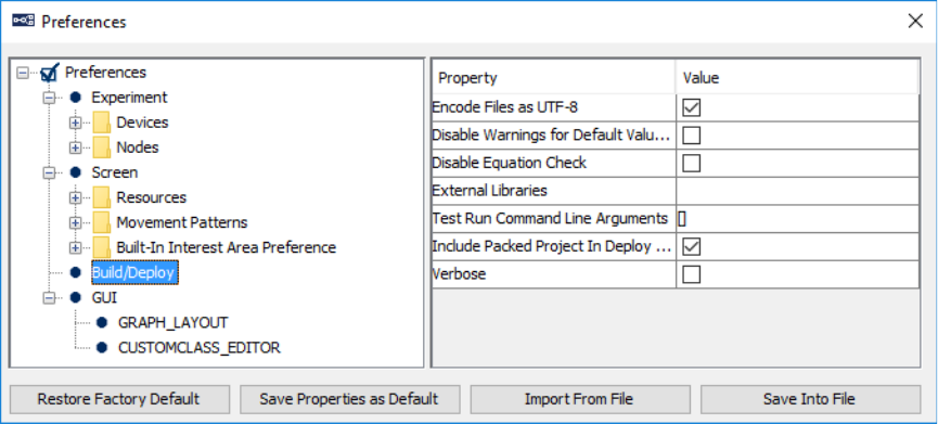
SR Research Experiment Builder User Manual ©2004-2017 SR Research Ltd.
385
characters. The list of applicable punctuation marks can be specified through the
“Punctuation” option below.
Punctuation: Specifies a list of applicable punctuation marks to be treated as whitespace
if the “Treat Punctuation as Whitespace” option is enabled.
Segmentation Direction: Direction ("Left to Right, Top to Bottom", "Left to Right,
Bottom to Top", "Right to Left, Top to Bottom", and "Right to Left, Bottom to Top") in
which the text is segmented. Interest areas are numbered consecutively based on the order
they are created.
Merge Punctuation And Whitespace Interest Areas: If the “Horizontal Whitespace
Treatment” option is set to “Create IA for Whitespace” and the "Treat Punctuation as
Whitespace" option is enabled, this preference allows to create separate interest areas for
the punctuation and neighboring whitespace, or to merge them.
17.3 Build/Deploy
This section lists preference settings related to the build and deploy processes.
Encode Files as UTF-8: If enabled, the generated experiment code and dataset files are
written using UTF-8 encoded files (http://en.wikipedia.org/wiki/UTF-8). This must be
enabled if the user is using any characters not included in the ASCII encoding range (1-
127), i.e., any characters with diacritics (e.g., à, è, ù, ç), or from non-European languages,
curved quotes, etc.
Disable Warnings for Default Value Use: If unchecked, this will raise a warning in the
Output tab of the Graph Editor Window for some particular properties if the default value
is used for the property (for instance, if the default value of 4000 msec is used for the
Duration of a Timer trigger). If checked, these warnings are not displayed in the Output
tab.
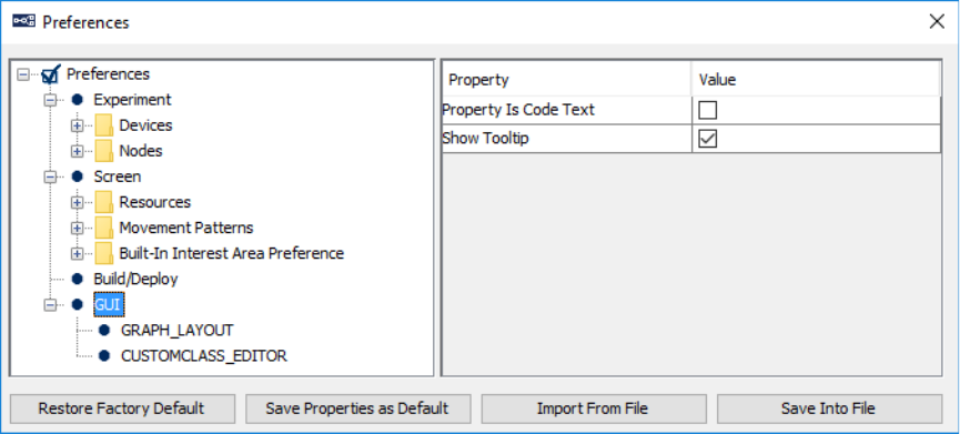
SR Research Experiment Builder User Manual ©2004-2017 SR Research Ltd.
386
Disable Equation Check: A warning message will be given if the value and attribute of
an equation are of different data types. Check this option to hide the type mismatch
warning.
External Libraries: Put directory paths here if you will need to use other Python
packages in custom class code.
Test Run Command Line Arguments: If the deployed experiment runs from the
command prompt, additional parameters can be passed to the program. The parameter
can be retrieved as ".cmdargs" of the topmost experiment node. Users can add parameters
to this field for test run purposes.
Include Packed Project in Deploy Directory: If checked, a copy of the packed
experiment project will be included in the "source" folder of the deployed directory;
otherwise, only the graph.ebd and preferences.properties files will be included for
reconstructing the original project if necessary. (Note: Version 2.0 or later of the
Experiment Builder software includes the packed project in the deploy directory by
default.)
Verbose: If checked, a detailed printout will be shown in the EB output tab when
deploying a project for debugging purposes.
17.4 GUI
Property is Code Text: Sets the format of labels in the property table. If unchecked (the
default setting), the label of the properties will be formatted and/or translated (for
internationalization) to be understood easily. If enabled, an internal label will be
displayed (for ease of references) and no internationalization or formatting will be done.
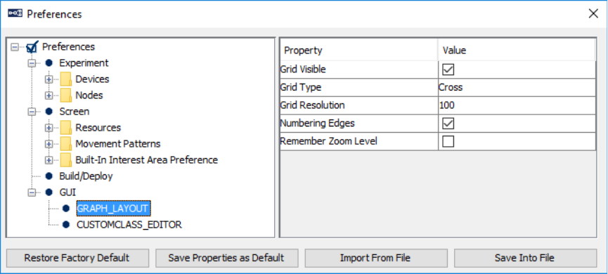
SR Research Experiment Builder User Manual ©2004-2017 SR Research Ltd.
387
Show Tooltip: If enabled, a description text will appear beside the item on which the
mouse cursor is placed.
17.4.1 Graph_Layout
Grid Visible: Whether the grids should be visible in the workspace outside of the Screen
Builder.
Grid Type: Determines whether the grid should be drawn as lines, crosses, or points.
Grid Resolution: Determines the distance between grid lines in pixels.
Numbering Edges: If checked, adds a number to each of the connections between a node
and multiple triggers that connect from the node to indicate evaluation priority among the
triggers.
Remember Zoom Level: If checked, the current zoom level will be saved and
remembered when the project is re-opened later.
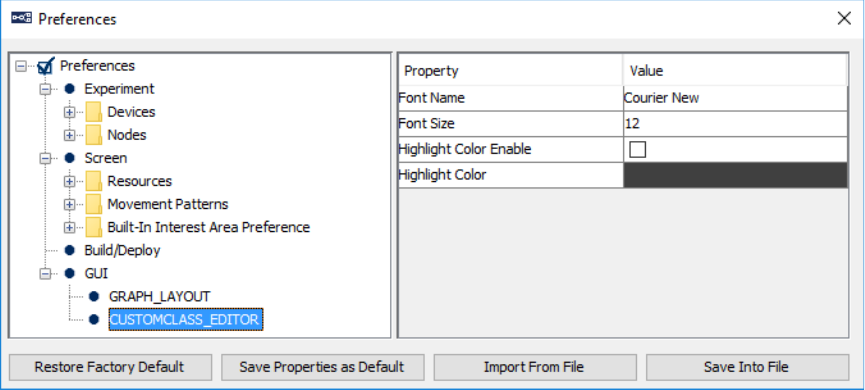
SR Research Experiment Builder User Manual ©2004-2017 SR Research Ltd.
388
17.4.2 CustomClass_Editor
Font Name: Name of the font that the custom class editor uses to show custom class
code.
Font Size: Size of the font that the custom class editor uses to show code.
Highlight Color Enable: If enabled, the current editing line will be highlighted.
Highlight Color: Color used to highlight the current editing line.
SR Research Experiment Builder User Manual ©2004-2017 SR Research Ltd.
389
18 Revision History
Version 2.1.140
• Provided various bug fixes and documentation updates for the 2.1 build
• Supported automatic interest area segmentation for right-to-left texts
• Added “Apply Transparency” option to CAMERA_SETUP and
DRIFT_CORRECT when animation targets are used
Version 2.1.1
• This is a full release of Experiment Builder that runs on 32-bit and 64-bit
Windows (XP, Vista, 7, 8, and 10) and Mac OS X (version 10.6 or later).
• Added Multiple Input Support for keyboard and mouse on Windows 10.
• Added support for playing .mov, and mp4 files directly.
• Added “Video Loader” option for video resources.
• Added support for EyeLink Portable Duo in the EyeLink Device
• Added 2000 Hz head-fixed tracking and 1000 Hz remote tracking for EyeLink
1000 Plus in the EyeLink Device
• Improvements to the Custom Class Editor
• Added Split Avi tool in the Mac build
• Added Set Restore Point and Restore option for project version control
• Added “Enable Custom Trial ID Message” option in the “Experiment”
Preferences
• Added “Custom Trial ID Messages” to the EyeLink recording sequence.
Version 2.0.0.0
• This is a beta release of Experiment Builder that runs on 32-bit and 64-bit
Windows (XP, Vista, 7, 8, and 10).
• Added OpenGL graphics for Windows 10 (configured through "Devices →
DISPLAY → Video Environment")
• Added "Contingency deadband" and "Gaze-contingent Eye" options to all screen
resources
• Added "Lock Aspect Ratio", "Use Fixed Pixel Area", and "Total Image Pixel" to
the Image Resources. Added "Background colour", "Source Factor", "Destination
Factor", "Use Color Key", "Color Key", and "Ignore Alpha" to the image
resources when in the OpenGL mode.
• Added "Is Completed" and "Is Paused" options to the video resources
• Added "Supports html" and "Full Screen", and "Text Orientation" options to the
Multiline Text Resource properties. Multiline text resources are no longer a full-
screen resource.
• Added "Superscript", "Subscript", "Strikethrough", "Background colour",
"Justify", "Vertical Alignment options", "Width", "Height", "Text Orientation",
"Preview", "Show margins in the Editor" options to the Multiline Text Resource
Editor
• Added "Multiple Resource Alignment" options when multiple screen resources
are selected
SR Research Experiment Builder User Manual ©2004-2017 SR Research Ltd.
390
• Added "Add Column", "Add Row", "Import Data", "Randomizer settings", "Find
/ Replacement" buttons to the Data Source editor. Added "Delimiter option" in the
Import Data editor
• Added workspace to view/edit context of data cell in the screen editor.
• Added more blocking levels to the randomizer. Relaxed the maximum run-length
restriction to 1.
• Added "Export node", "Import node" buttons and Data Source selector to the
application toolbar.
• Supported more word segmentation options (Preferences → Screen → IA →
Word Segment): Horizontal whitespace treatment, Vertical whitespace treatment,
Enable character Segment, Merge Spanning Interest Areas, Exclude IA before
first instance, Exclude IA after last instance, Treat punctuations as whitespace,
Merge punctuations and white space, Support multiple delimiter character.
• Added "Loop" and "Iteration" properties to Custom Movement pattern
• Added automatic experiment message logging
• Added multiple instances of EB sessions on Mac
• Nodes are now sorted by experiment flow, instead of order of adding
• Supported pause/unpause video plyaback
• Allowed to pause current ASIO playback
• Allowed to stop ASIO sound if played through DISPLAY_SCREEN action
• Provided a standalone EB Asio configuration tool
• Supported automatically adding data source columns and variables to the EyeLink
DV Variables property
• Provided project template for new project creation
• Enhancement to project unpacking
• Voicekey support on Mac OSX
Version 1.10.1939
• Adds a "Current" option in the EyeLink Device to support newer EyeLink eye
trackers.
• Fixes the deploy error when running Experiment Builder on Windows 10.
Version 1.10.1630
• Adds support for playing animation target during calibration and drift correction
on Mac OS X.
• New variables and data source columns will now be automatically added to the
"EyeLink DV Variable" list.
Version 1.10.1385
• Adds support for Mac OS X Yosemite (version 10.10).
Version 1.10.1241
SR Research Experiment Builder User Manual ©2004-2017 SR Research Ltd.
391
• Adds support for the Binocular Tower Mount, Binocular Remote, and “Current”
option for EyeLink 1000 Plus eye tracker in the EyeLink devices.
• Supports loading dynamic interest area files in the library manager.
Version 1.10.968
• Adds support for EyeLink 1000 Plus eye tracker in the EyeLink devices.
• Supports the parallel port auto detection by setting the port address to 0.
• Bug fix in the video handler.
• Bug fix for exception in running projects using sinusoidal movement pattern.
• Bug fix for word segmentation involving Chinese text.
• Updates in camera image display and file transfer.
Version 1.10.165
• Bug fix for automatic interest area creation for multiline text resources.
• Bug fix for performing internal randomization with data sources attached to
multiple sequences;
• Bug fix for ResponsePixx LED Control action;
• Bug fix for TTL_INPUT trigger not firing properly;
• Bug fix for improper reporting of composite resources in Data Viewer;
• Bug fix for file transfer issues (aborted file transfers, corrupted EDF files, or false
alarms).
Version 1.10.1
• This is a full release of Experiment Builder that runs on 32-bit and 64-bit
Windows (2000, XP, Vista, and 7). This is also a beta release of Experiment
Builder that also supports running on Mac OS X (Intel CPU, OS v10.6 or later).
Experiment projects saved on the Windows operating systems can be opened with
the same version or a newer version of the software on Mac OS X and vice versa,
with some exceptions on the transferability. Known limitations when
designing/running the experiment on Mac OS X with this release:
o Voicekey is not supported.
o Only Xvid video clips are supported through the video resources;
animation video clips are not supported in Camera Setup and Drift
Correction actions.
o Sending or receiving TTL signals is only supported through USB-1208HS
box.
o Calibration control through external device is not supported.
• Adds support for ASIO driver for sound playing, sound recording, and voice key
on 64-bit Windows 7.
• Adds support for USB-1208HS box through SET_TTL action and TTL_INPUT
trigger.
SR Research Experiment Builder User Manual ©2004-2017 SR Research Ltd.
392
• Adds "Ignore if Missing" option to the EyeLink Button Box device so that the
project can still be run if button box is missing from EyeLink II and 1000. Also
fixes EyeLink I button box issue.
• Adds a "Lock Project/Unlock Project" icon to the application toolbar and file
menu.
• Adds support for using multiple parallel port devices and for reading the current
data/status/control register values of the parallel port device.
• fix for automatic interest area creation for the multi-line text resource when
delimiter characters are used.
• Bug fix for "Error: 2031: Equation parse error..." when running projects with
non-ASCII characters in the multi-line text resource.
• Bug fix for collecting response from button 8 of Cedrus RB-830 and RB-834
response pads.
Version 1.6.121
• This release supports using multiple display keyboards and mice in the same
experiment; responses on the different input devices can be handled differently.
• Supports the keyboard trigger to detect a release event.
• Adds options for different types of EyeLink button boxes (Microsoft SideWinder
Plug & Play Gamepad as well as button boxes plugged to the parallel port).
• Adds RESPONSEPixx_LED_CONTROL action to allow set the LED lighting on
a ResponsePixx button box.
• Allows to cancel the "Clean", "Build", "Test", and "Deploy" processes before
they start.
• This release provides an I/O port driver for both 32-bit and 64-bit Windows. You
will need to manually install the I/O driver if you are running Windows 2000.
• Cedrus Input trigger now works on 32-bit Windows XP, Vista, Windows 7, and
64-bit versions of Windows Vista and Windows 7.
• SplitAvi and Xvid codec runs fine with both 32-bit and 64-bit versions of
Windows.
• Bug fix for the custom movement pattern when the first resource point doesn't
start from time 0.
• Bug fix for the mouse movement range in screen resolutions higher than 1024 ×
768.
• Bug fix for uncleared EyeLink Button trigger used in the non-recording sequence.
• Bug fix for gaze-contingent moving window manipulations with a variable size
across trials.
• Bug fix for size error when the location of a triangle resource is modified by a
reference.
Version 1.6.1
• This release runs fully on 32-bit versions of Windows 2000, XP, Vista, and
Windows 7. Known limitations on 64-bit of Windows 7:

SR Research Experiment Builder User Manual ©2004-2017 SR Research Ltd.
393
o TTL driver is not supported
o Cedrus Input Trigger is not supported
o ASIO audio driver is not supported.
o Cannot install xvid driver; Split Avi tool will not be able to convert the files
to .xvd file format.
• Updated the "ASIO Sound Card Installation" section of this document. Existing
users of the following sound cards should re-check the installation steps to select
the "Audio Creation Mode" and enable "Bit-Matched Playback" option, even if
you have already had the sound card working with the software.
o Creative Labs Soundblaster X-Fi XtremeGamer
o Creative Labs Soundblaster X-Fi XtremeMusic
o Creative Labs Soundblaster X-Fi Titanium PCI Express
• Bug fix for resource drawing when the offset value is not (0,0).
• Added more options for line spacing in multiline text resource.
• Bug fix for displaying non-ASCII (Chinese, Hebrew, Thai, etc.) characters in
English versions of Windows.
• Splitavi converter now supports multiple input files.
• Added "Clear Target At Exit" option for drift correction action.
• Touch screens are now supported (as a variant of the mouse trigger) in 32-bit
Windows 2000, XP, Vista, and Windows 7.
Version 1.5.201
• For MEG/MRI applications, adds supports for camera setup,
calibration/validation, drift correction through an external control device (e.g., a
Cedrus Lumina fMRI Response Pad). These can be done through the Camera
Setup action and Drift Correction action.
• Several improvements have been introduced to the calibration procedure thorough
the Camera Setup action.
o For horizontal only (H3) calibration type, now users can specify the
intended vertical position using the "Horizontal Target Y Position" option.
o Now support using a customized calibration background image.
o Users can now specify customized calibration/validation point list.
o Some calibration related EyeLink device settings are now moved to the
Camera Setup screen.
o Bug fix for using non-English keyboards while in the calibration mode.
• Bug fix for the duration calculation of the fixation trigger and saccade trigger.
• The packed project now includes files contained in the "myfiles" folder of the
project.
Version 1.5.58
• Bug fix for the default directory of the "ExperimentBuilder Examples".
SR Research Experiment Builder User Manual ©2004-2017 SR Research Ltd.
394
Version 1.5.1
• This release runs on 32-bit versions of Windows 2000, XP, and Vista. Known
issues with Windows Vista:
o Touch screens are not supported;
o Driver for the Cedrus button box needs to be installed twice before the device
is fully functional;
• Bug fix for the "Prepare Next Display Screen Action" of the Display Screen
action.
Version 1.4.624
• Bug fix for automatic interest area creation for multiline text resources.
• Bug fix for resetting the position of mouse cursor.
Version 1.4.562
• Touch screens are now supported (as a variant of the mouse trigger).
• More options ("Camera Mount", "Desktop Version" and "Mount Usage") are
added to the EyeLink Device.
Version 1.4.402
• EyeLink Remote: EyeLink Device can now be set to use EyeLink Remote system
• Invisible Boundary Trigger Updated: Trigger now supports specification of a
minimum duration that the eye needs to be in the boundary before the trigger will
fire. Also added "EDF Start Time" and "Start Time" to the TriggeredData.
• Animation Target: Now supports calibration and drift correction with an
animation target.
