FS I6S USER MANUAL
User Manual: Pdf
Open the PDF directly: View PDF ![]() .
.
Page Count: 32

FS-l6S
Copyright ©2015-2016 Flysky RC model technology co., ltd
USER MANUAL
Digital Proportional Radio
Control System
FCC ID:N4ZFLYSKYI6S

Thank you for purchasing our product, an ideal radio system for beginners or
experienced users alike.
Read this manual carefully before operation in order to ensure your safety, and
the safety of others or the safe operation of your system.
If you encounter any problem during use, refer to this manual first. If the problem
persists, contact your local dealer or visit our service and support website for help:
www.flysky-cn.com

Contents
1. Safety..................................................................................................................................1
1.1 Safety Symbols ........................................................................................................................................................................1
1.2 Safety Guide..............................................................................................................................................................................1
2. Introduction.......................................................................................................................2
2.1 System Features.......................................................................................................................................................................2
2.2 Transmitter Overview .......................................................................................................................................................................3
2.2.1 Transmitter Antenna ...................................................................................................................................................................4
2.2.2 Stick/Knob/Switch/Key...............................................................................................................................................................4
2.2.3 Status Indicator..............................................................................................................................................................................4
2.2.4 USB Simulator Mode...................................................................................................................................................................5
2.2.5 PS/2 Port .........................................................................................................................................................................................5
2.3 Receiver Overview ...................................................................................................................................................................5
2.3.1 Receiver Antenna..........................................................................................................................................................................5
2.3.2 Status Indicator..............................................................................................................................................................................5
2.3.3 Connectors ....................................................................................................................................................................................5
3. Getting Started ...............................................................................................................6
3.1 Transmitter Battery Installation.....................................................................................................................................................6
3.2 Connecting the Receiver and Servos .........................................................................................................................................6
4. Operation Instructions.....................................................................................................7
4.1 Power On....................................................................................................................................................................................7
4.2 Binding........................................................................................................................................................................................7
4.3 Pre-use Check...........................................................................................................................................................................7
4.4 Power Off....................................................................................................................................................................................8
5. System Interface...............................................................................................................9
5.1 Home Screen.............................................................................................................................................................................9
5.2 Timers.....................................................................................................................................................................................................9
5.3 Fly Mode..................................................................................................................................................................................10
5.4 TX/RX Battery ........................................................................................................................................................................11
5.5 Display Servos........................................................................................................................................................................11
5.6 Display Sensors......................................................................................................................................................................11
6. Function Settings............................................................................................................12
6.1 Reverse ....................................................................................................................................................................................12
6.2 End Points ...............................................................................................................................................................................12
6.3 Subtrim ....................................................................................................................................................................................12
6.4 Trims .........................................................................................................................................................................................13
6.5 Rate/Exp. .................................................................................................................................................................................13
6.6 Throt Curve ............................................................................................................................................................................13
6.7 Aux. Channels ........................................................................................................................................................................14
6.8 Mix ............................................................................................................................................................................................14
6.9 Failsafe......................................................................................................................................................................................14
7. System Settings...............................................................................................................15
7.1 RX Bind ....................................................................................................................................................................................15
7.2 Models .....................................................................................................................................................................................15
7.3 Output Mode .........................................................................................................................................................................15

7.4 Sticks Mode ............................................................................................................................................................................15
7.5 Throt Mode ............................................................................................................................................................................16
7.6 Sticks Adjust ...........................................................................................................................................................................16
7.7 Bri./Sound ...............................................................................................................................................................................16
7.8 Factory Reset .........................................................................................................................................................................16
7.9 Firmware Update ..................................................................................................................................................................17
7.10 About FS-i6S .......................................................................................................................................................................17
8. DIY Customization..........................................................................................................18
8.1 Throt Bracket Installation...................................................................................................................................................18
8.2 Throt Spring Installation.....................................................................................................................................................19
8.3 Swapping Gimbals................................................................................................................................................................20
8.4 Knob Bracket Installation...................................................................................................................................................21
8.5 Knob Spring Installation.....................................................................................................................................................22
8.6 Device Holder.........................................................................................................................................................................23
9. Product Specifications...................................................................................................25
9.1 Transmitter Specifications (FS-i6S) ...............................................................................................................................25
9.2 Receiver Specifications (FS-iA6B) ..................................................................................................................................25
10. Package Contents.........................................................................................................26
Appendix 1 FCC Statement .....................................................................................27
1
• Misuse of this product may lead to serious injury or death. To ensure the safety of
you and your equipment, read this manual and follow the instructions.
• Make sure the product is properly installed in your model. Failure to do so may
result in serious injury.
• Make sure to disconnect the receiver battery before turning off the transmitter.
Failure to do so may lead to unintended operation and cause an accident.
• Ensure that all motors operate in the correct direction. If not, adjust the direction
first.
• Make sure the model flies within a certain distance. Otherwise, it would cause loss of
control.
• Do not use the product at night or in bad weather like rain or thunderstorm. It can
cause erratic operation or loss of control.
• Do not use the product when visibility is limited.
• Do not use the product on rain or snow days. Any exposure to moisture (water or
snow) may cause erratic operation or loss of control.
• Interference may cause loss of control. To ensure the safety of you and others, do
not operate in the following places:
• Near any site where other radio control activity may occur
• Near power lines or communication broadcasting antennas
• Near people or roads
• On any body of water when passenger boats are present
• Do not use this product when you are tired, uncomfortable, or under the influence
of alcohol or drugs. Doing so may cause serious injury to yourself or others.
• The 2.4GHz radio band is limited to line of sight. Always keep your model in sight as
a large object can block the RF signal and lead to loss of control.
• Never grip the transmitter antenna during operation. It significantly degrades signal
quality and strength and may cause loss of control.
• Do not touch any part of the model that may generate heat during operation, or
immediately after use. The engine, motor or speed control, may be very hot and can
cause serious burns.
Prohibited Mandatory
1. Safety
1.1 Safety Symbols
Pay close attention to the following symbols and their meanings. Failure to follow these warnings could cause
damage, injury or death.
1.2 Safety Guide
Warning • Not following these instructions may lead to major injuries.
Danger • Not following these instructions may lead to serious injuries or death.
Attention • Not following these instructions may lead to minor injuries.
Digital Proportional Radio Control System
2
FS-l6S
2. Introduction
The FS-i6S transmitter and iA6B receiver constitute a 6 channel 2.4GHz AFHDS 2A digital proportional
computerized R/C system. This system supports quadcopter.
2.1 System Features
The AFHDS 2A (Automatic Frequency Hopping Digital System Second Generation) developed and patented
by FLYSKY is specially developed for all radio control models. Offering superior protection against interference
while maintaining lower power consumption and high reliable receiver sensitivity, FLYSKY's AFHDS technology
is considered to be one of the leaders in the RC market today.
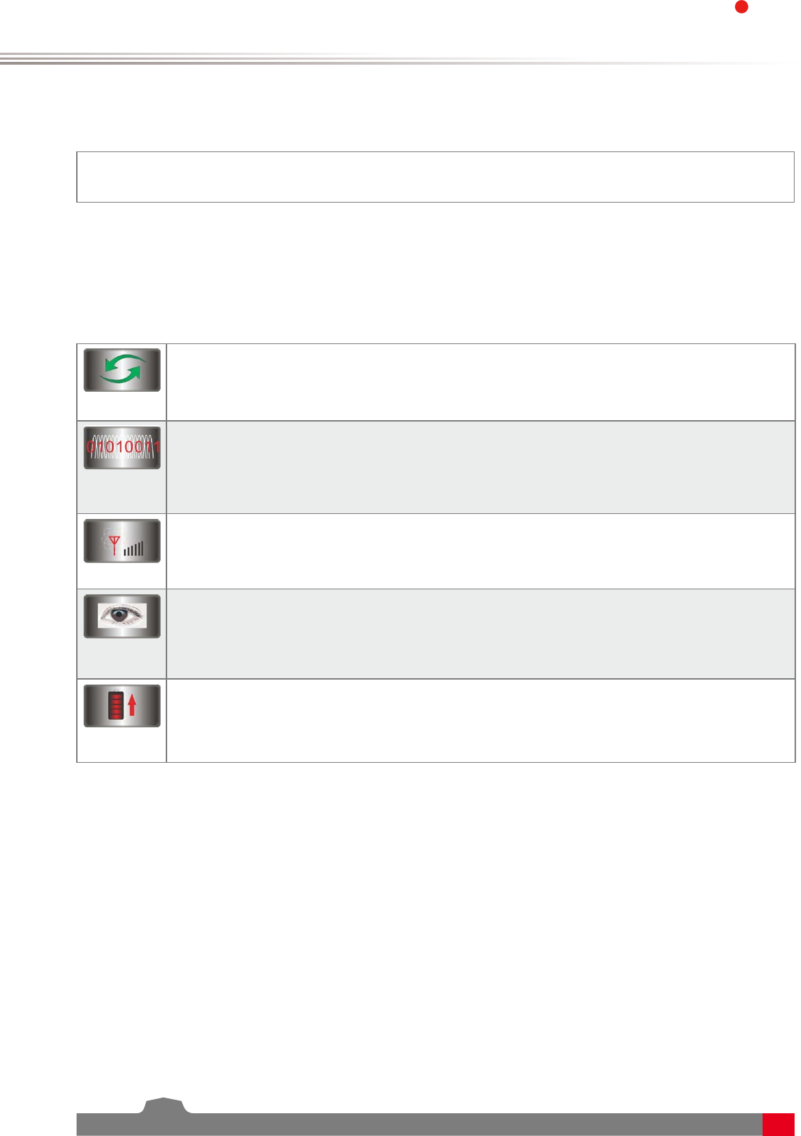
Bidirectional Communication
Capable of sending and receiving data, each transmitter is capable of receiving data from
temperature, altitude and many other types of sensors, servo calibration and i-BUS Support.
Multi-channel Hopping Frequency
This systems bandwidth ranges from 2.4055GHz to 2.475GHz. This band is divided in 140
channels. Each transmitter hops between 16 channels (32 for Japanese and Korean versions) in
order to reduce interference from other transmitters.
Omni-directional Gain Antenna
The high efficiency Omni-directional high gain antenna cuts down on interference, while using
less power and maintaining a strong reliable connection.
Unique ID Recognition System
Each transmitter and receiver has it's own unique ID. Once the transmitter and receiver have
been paired, they will only communicate with each other, preventing other systems accidentally
connecting to or interfering with the systems operation.
Low Power Consumption
The system is built using highly sensitive low power consumption components, maintaining
high receiver sensitivity, while consuming as little as one tenth the power of a standard FM
system, dramatically extending battery life.
33
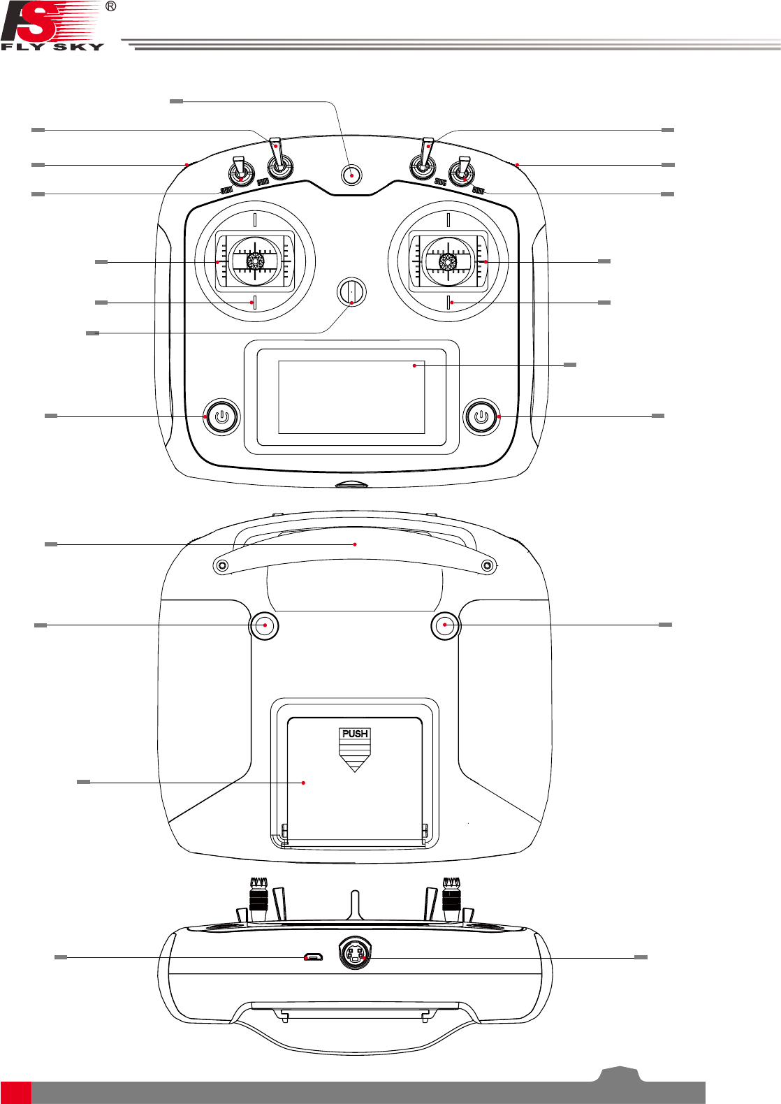
2.2 Transmitter Overview
VrA
Rudder/Aileron
Throttle/Elevotor
Power
Neck strap eye
SwA
SwB SwC
VrB
SwD
Device holder mounting point
Handle
Key 2
Battery cover
USB port
Rudder/Aileron
Throttle/Elevotor
Capacitive touch screen
Power
Key 1
PS/2 port
Digital Proportional Radio Control System
4
FS-l6S
2.2.1 Transmitter Antenna
Note • Never grip the transmitter antenna during operation. It significantly degrades the RF
signal quality and strength and may cause loss of control.
2.2.3 Status Indicator
The status indicator is used to indicate the power and working status of the transmitter.
• Off: The transmitter is powered off.
• Blue light: The transmitter is on and working.
2.2.5 PS/2 Port
This port enables PPM output.
2.2.2 Stick/Knob/Switch/Key
The FS-i6S has 2 sticks, 2 knobs, 4 switches and 2 keys.
• Stick: Used to control aileron, elevator, throttle and rudder, or controls aux. channels.
• Switch: Controls aux. channels or timer.
• Knob: Used to control aux. channels.
• Key: Used to control aux. channels or timers.
The FS-i6S transmitter has a built-in dual omnidirectional antenna.
2.2.4 USB Simulatior Function
The system can be connected via a USB cable to a computer for use as a HID device. This function is
automatically activated when connected to a computer and will be recognised as a standard HID controller.
Caution • If the computer does not recognise the transmitter unplug and reconnect the USB
cable.
Antenna
5
2.3 Receiver Overview
Caution • For best signal quality, ensure that the receiver is mounted away from motors or
metal parts.
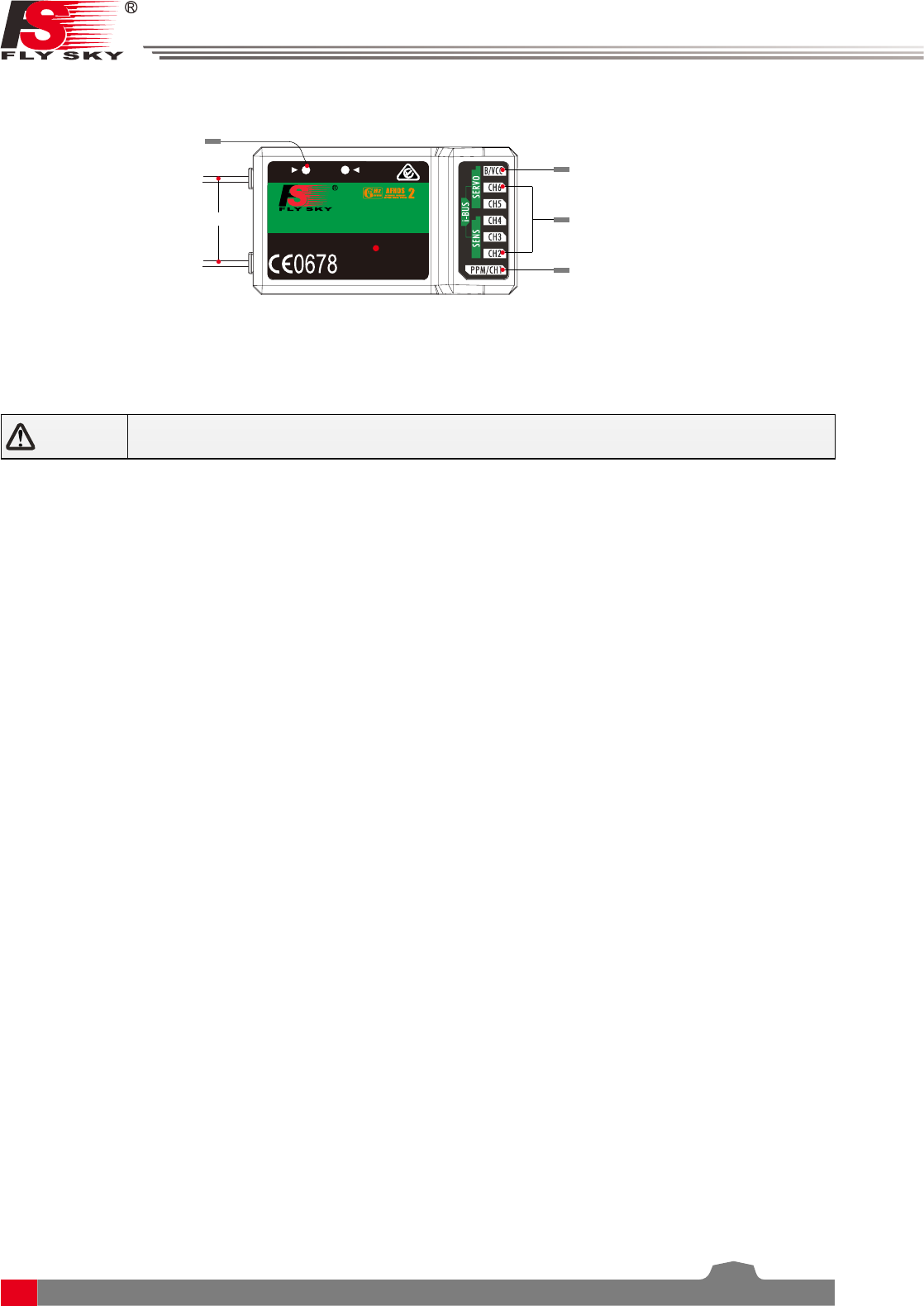
2.3.3 Connectors
The connectors are used to connect the parts of model and the receiver.
• PPM/CH1: Connection of CH1 or PWM output signal.
• CH2 to CH6: Used to connect the servos, power or other parts.
• B/VCC: Used to connect the bind cable for binding, and the power cable during normal operation,in the
range of 4.0-8.4V.
• SERVO: For connecting an i-BUS receiver.
• SENS: For connecting sensors.
2.3.2 Status Indicator
The status indicator is used to indicate the power and working status of the receiver.
• Off: The power is not connected.
• Lit in red: The receiver is on and working.
• Flashing quickly: The receiver is binding.
• Flashing slowly: The bound transmitter is off or signal is lost.
2.3.1 Receiver Antenna
The FS-iA6B has a dual 26mm omnidirectional antenna.
Antenna
Bind/VCC
Ch2- 6
PPM/CH1
A
LED UPDATE
FS-IA6B
6 VER
2.4
GHz
4.0-8.4V/DC
FC C ID:N4ZFLYSKYIA10
CHANNEL
Status indicator
RECEI
Digital Proportional Radio Control System
6
FS-l6S
3. Getting Started
Before operation, install the battery and connect the system as instructed below.
3.1 Transmitter Battery Installation
Danger • Only use specified battery (X4 AA batteries).
Danger • Do not open, disassemble, or attempt to repair the battery.
Danger • Do not crush/puncture the battery, or short the external contacts.
Danger • Do not expose to excessive heat or liquids.
Danger • Do not drop the battery or expose to strong shocks or vibrations.
Danger • Always store the battery in a cool, dry place.
Danger • Do not use the battery if damaged.
Follow the steps to install the transmitter battery:
1. Open the battery compartment.
2. Insert 4 fully-charged AA batteries into the compartment. Make sure that the battery makes good contact
with the battery compartment's contacts.
3. Replace the battery compartment cover.
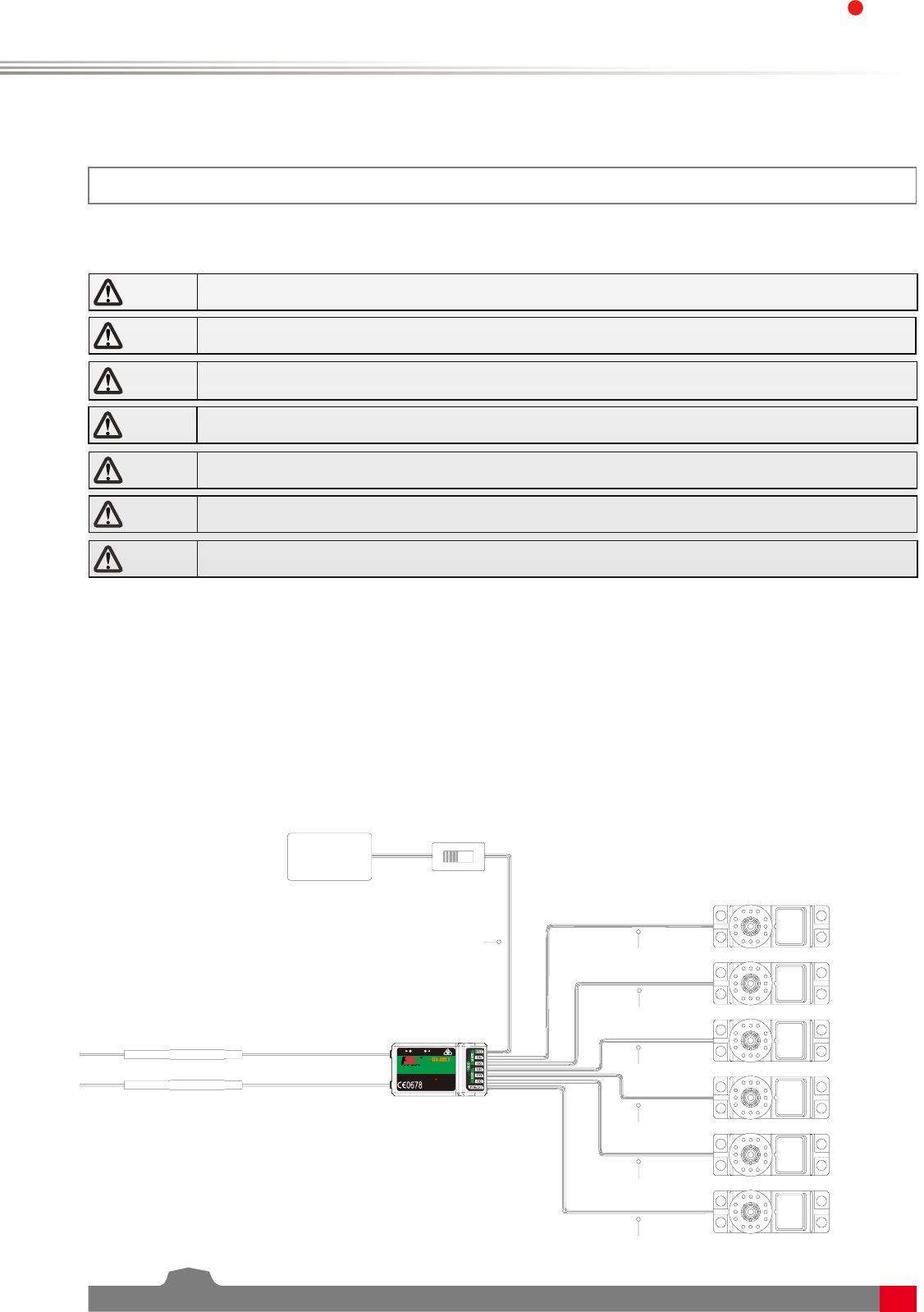
3.2 Connecting the Receiver and Servos
Connect the receiver and the servos as indicated below:
A
LED UPDA TE
FS-IA6B
6 VER
2.4
GHz
4.0-8.4V/DC
FCC ID:N4ZFLYSKYIA10
Rudder servo
Throttle servo
Elevator servo
Aileron servo
CHANNEL
CH1
CH2
CH3
CH4
CH5
CH6
B/Vcc
Switch (Optional)
Battery
RECEI

7
4. Operation Instructions
After setting up, follow the instructions below to operate the system.
4.1 Power On
Follow the steps below to turn on the system:
1. Check the system and make sure that:
• The batteries are charged and installed properly.
• The receiver is off and correctly installed.
2. Hold the power buttons until screen lights up.
3. Connect the receiver power supply to the B/VCC port on the receiver.
Note • Operate with caution in order to avoid damage or injury.
Note • Make sure that the throttle is at its lowest position and the switches are set to their
up position.
4.2 Binding
The transmitter and receiver have been pre-bound before delivery.
1. Turn the transmitter on, press to select
[System], and scroll down and then select
[RX bind].
2. Connect the bind cable to the B/VCC port
of the receiver.
If you are using another transmitter or receiver, follow the steps below to bind the transmitter and receiver:
4.3 Pre-use Check
Before operation, perform the following steps to check the system:
1. Check to make sure that all servos and motors are working as expected.
2. Check operating distance: one person holds the transmitter, and another one moves the model away from
the transmitter. Check the model and mark the distance from where the model starts to lose control.
Danger • Stop operation if any abnormal activity is observed.
Danger • Make sure the model does not go out of range.
Attention • Sources of interference may affect signal quality.
RF standard Receiver type
AFHDS 2 iA10B,iA6B,iA6,iA4B,A6,A3
2.4G AFHDS 2A X6B,A8S
3. Connect the power to any other port. The indicator
will start to flash, indicating that the receiver is in bind
mode.
• After successfully binding the transmitter will
automatically exit this menu, then the receivers LED
will stop flashing indicating that binding has been
successful.
4. Remove the bind and power cable from the receiver.
Then connect the power cable to the B/VCC port.
5. Check the servos' operation. If anything does not work
as expected, restart this procedure from the beginning.

Digital Proportional Radio Control System
8
FS-l6S
4.4 Power Off
Danger • Make sure to disconnect the receiver power before turning off the transmitter.
Failure to do so may lead to damage or serious injury.
Follow the steps below to turn off the system:
1. Disconnect the receiver power.
2. Hold the transmitter's power buttons to turn off the transmitter.
9
5. System Interface
The system interface displays useful information about your model, including timers, fly mode and TX/RX
status.
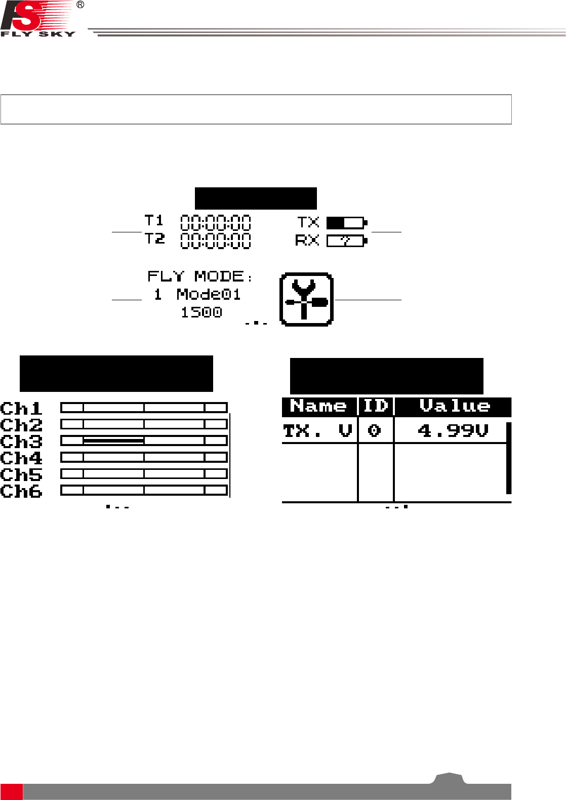
5.1 Home Screen
The main interface displays model.
Fly Mode Status
+ Fly Mode Setup
Menu
Timers + Timer
Menu
TX/RX Battery
Status + Battery
Main Menu
Start page
Swipe to the right to display the
servo interface
Swipe to the left to display
the sensors
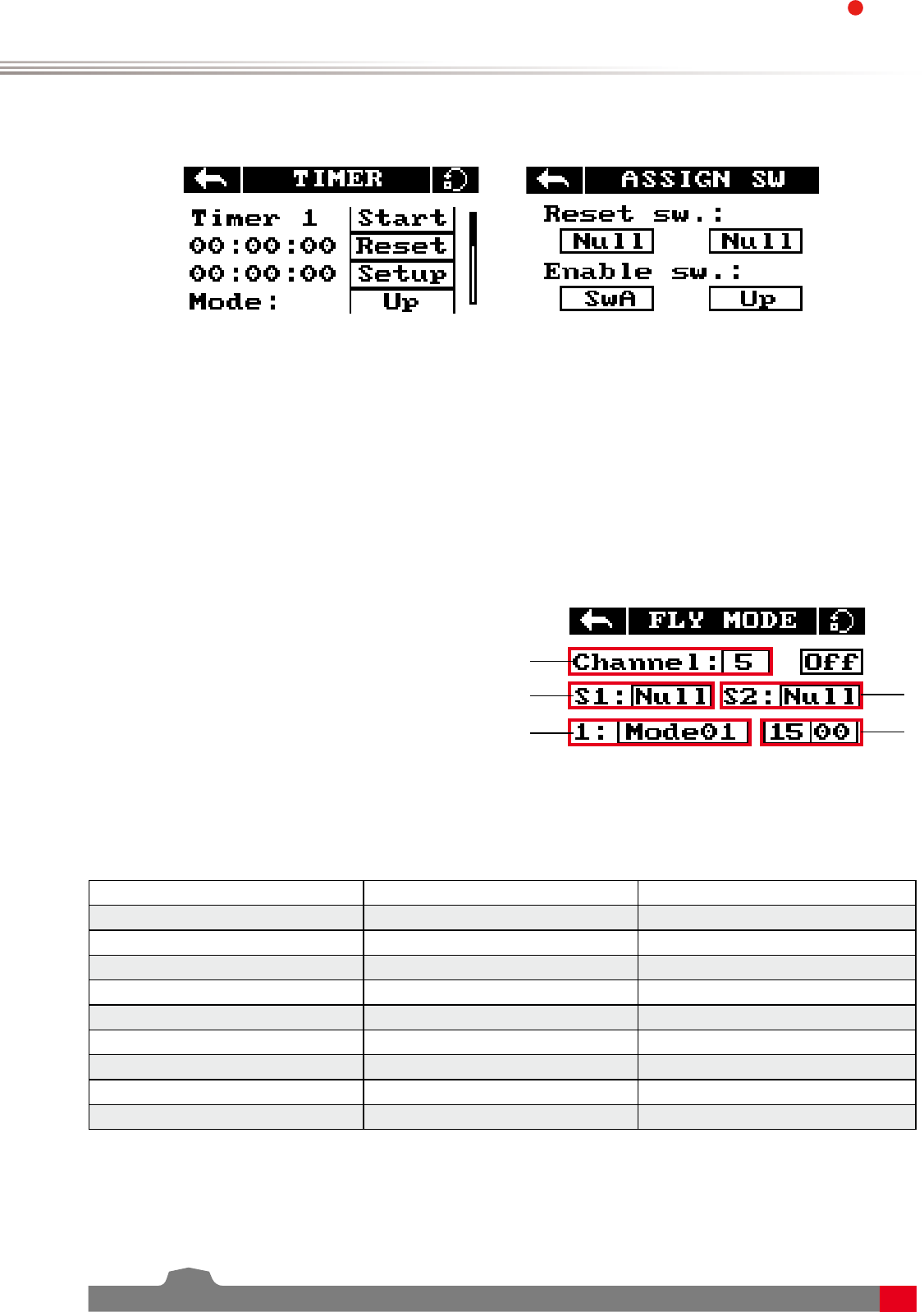
5.2 Timers
This function can set up to 2 timers at the same time.
Usually used to keep track of total flight time.
Setup:
To enter the timer function touch T1/T2 on the main screen. The system has 2 timers available, both can be
assigned to a switch and have 3 different settings.
Setup:
1. Select a mode.
• Up: The up timer starts from zero and counts up.
• Down: The down timer starts from a pre selected time and counts down.
• D/U(Down then up): The D/U timer starts from down to 0 from a preset time, then starts counting up
again.
2. If necessary set a pre defined time by selecting the [Setup] option. Select the correct decimal and use the
onscreen arrow keys to change the value.
Digital Proportional Radio Control System
10
FS-l6S
3. Touch [Switch] to enter the switch selection sub menu. If no switch is selected you can press [Start] to start
the time and [Stop] to stop it.
5.3 Fly Mode
Setup:
This mode can store settings that can be recalled by
toggling a switch.
There are several options available:
A: Stores the channel used by the flight controller.
1. Touch the box to the right of the desired
channel.
2. Select the correct decimal and use the up and
down arrow keys.
B: Stores the first selected activation switch.
C: Stores the second selected activation switch.
D: This number represents the currently selected
mode. The name beside the mode number can
be changed.
Touch the box, use the onscreen keyboard to enter
a new name.
The fly mode function can store up to 9 different fly modes which can activated using a switch.
Different fly modes are assigned using combinations of switches. A 2-way switch will enable you to switch
between modes 1 and 2,two 2-way switches will enable you to 4 fly modes, two 3-way switches will allow you
to switch between all 9 fly modes. Use the table below to see which positions are assigned to each mode.
SwB Position SwC Position Mode
Up Up 1
Up Middle 2
Up Down 3
Middle Down 4
Middle Middle 5
Middle Up 6
Down Up 7
Down Middle 8
Down Down 9
B
D
C
E
A
E: Changes the output for each mode.
1. Touch the box to the right of the desired
channel.
2. Select the correct decimal and use the up and
down arrow keys.

11
5.5 Display Servos
This function displays channel position in real time.
All changes to channel's functions will be displayed here also.
Setup:
1. Turn on the transmitter and swipe right on the screen.
2. To scroll swipe up and down on the screen.
• Hold your finger on the screen to activate the channel sweep function. The system will ask if you are sure,
make sure that all motors are disconnected in order to prevent damage to the model or harming others.
3. To disable the channel sweep function touch or swipe the screen to the left or right.
5.6 Display Sensors
This function displays all connected sensor names, type, number in real-time.
[Name] Sensor name/type.
[ID] The system gives each sensor connected to the receiver an ID starting from 0 (Transmitter Voltage), so the
first sensor attached to the receiver will have an ID of 1.
[Value] Displays the sensor output.
All data in this list is displayed in real time, when a sensor is connected or disconnected the system will update
the list.
5.4 TX/RX Battery
This function sets up the receiver and transmitter low battery alarm.
Setup:
1. Click on the TX/RX voltage icon to enter its sub-menu.
2. To edit each setting touch its box and use the on-screen arrows to
change the value.
• The alarm voltage is limited by the set low and high voltage
settings. For example if the high voltage is set to 6V and the low
4V then the alarm must be set between 4.1V and 5.9V.
• When the voltage drops below the alarm voltage the system will
alert the user via an audio alarm and an on-screen warning.

Digital Proportional Radio Control System
12
FS-l6S
6. function Settings
This section details functions and their use.
6.1 Reverse
The reverse function changes a channels direction of movement in relation to its input. For example, if the
blades are spinning in the wrong direction, pushing the model into the ground instead of taking off, this
function can be used to correct this.
6.2 End Points
The end points function changes the range of movement available to a channel. This can be used to limit the
tilt of the model, so that it is easier to control.
The left box is the low end points, the right box is the high end points, marked below as low being blue and
red being high.
Setup:
To change between normal and reverse touch the box to the right
side of the desired channel.
Nor = Normal, Rev = Reverse.
Select the icon to save and return to the previous menu.
Press the To reset the function to its default settings.
Setup:
1. Touch the low or high end points box.
2. Touch the desired decimal to change then use the onscreen up
and down arrows to change the value.
6.3 Subtrim
Subtrim changes the center point of the channel. For example, if a model is always drifting to one side, the sub
trim can be used to fix this.
Setup:
1. Touch the box to the right of the desired channel.
2. Select the correct decimal and use the up and down arrow keys.
13
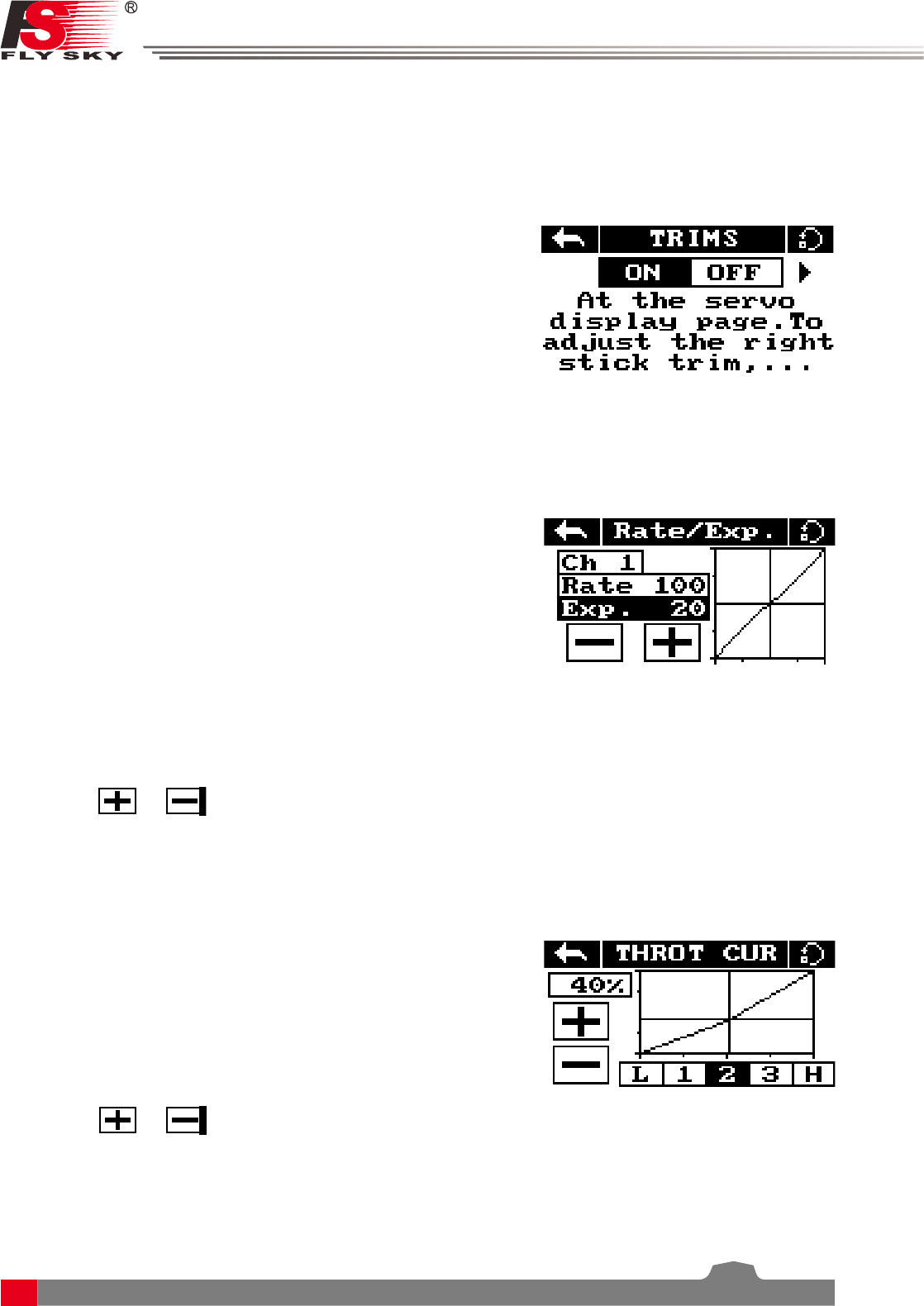
Setup:
The X on the graph shows the sticks current position and output.
The X axis represents the current stick position and the Y axis displays
[L] Is represents the throttle at its 0 position.
The currently selected variable will be highlighted in black.
1. Touch [Throt Curve] in the function menu.
2. Select a point by touching it.
2. Click the or icons to change the value.
Setup:
This function is only available on channels 1, 2 and 4, the selected
channel is displayed under the back button.
[Rate] Changes the channel's range (100% being full range).
[Exp.] Changes the amount of curve in the sticks response.
The currently selected variable will be highlighted in black.
The X on the graph shows the sticks (switches and knobs) current
position.
The Y axis represents the channels output.
Curve's create a non linear relationship between input and output.
1. Touch [Rate/Exp.] in the function menu.
2. Select [Rate] or [Exp. ].
3. Click the or icons to change the value.
6.5 Rate/Exp.
This function creates a curve for the stick inputs and outputs.
When applied to a channel this function will change the response curve.
Usually the entire range of the servo movement will be mapped in this function.
6.6 Throt Curve
The throttle curve function adds a curve to the throttle stick's input. This curve has 5 points that can be set to
create a custom curve.
6.4 Trims
The trims function changes the center point for the 4 stick axis. If a control surface does not match up exactly
to its expected position the trim function can be used to bring it back into alignment.
• If the throttle is not self-centering, channel 3 can not be adjusted.
This function is for slight adjustments only, if parts of the model are still out of alignment consider adapting
the model.
Setup:
1. In the function menu select [Trims],Select "On" to activate.
2. Go to the servo display screen:
To adjust the right stick: Hold key 1 then hold a sick on an axis to
adjust in that direction, hold until the desired change has been made.
To adjust the left stick: Hold key 2 then hold a sick on an axis to
adjust in that direction, hold until the desired change has been made.
Digital Proportional Radio Control System
14
FS-l6S
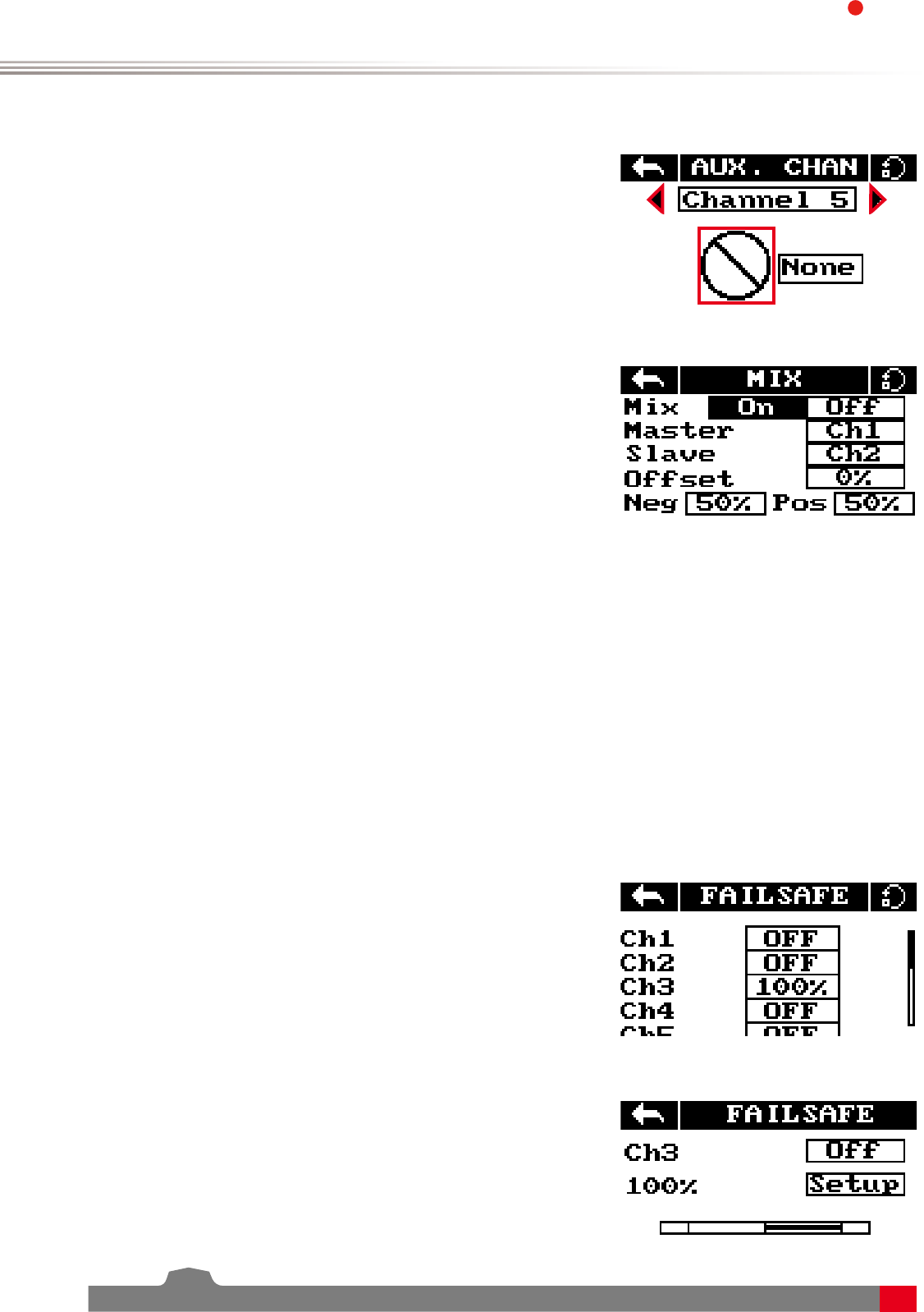
6.7 Aux. Channels
The auxiliary channels can be used to control additional part of a model such as landing gear or lights.
Setup:
1. Select channels using the left or right arrow keys on the screen
on either side of the channel name.
2. The left box below the channel name allows the user to pick the
type of control for that channel, Nul, VRx, STx, KEY and SWx.
• If the channel is in use for a fly mode, the system will inform the
user and prevent any changes to that channel.
6.8 Mix
The mix function creates a mix between 2 different channels. For
example, it is possible to make a mix between rudder and ailerons,
so whenever the model rolls, the rudder will move automatically to
perform a turn.
Setup:
[Master]: This channel will control the slave.
[Slave]: This channel is controlled by the master.
[offset]: Offset works like trim or sub trim allowing for the center position of the slave channel to be changed.
[Pos.]: Changes how much the slave will move in relation to the master in a positive movement. At 50% when
the master moves to 100% of its positive motion, the slave will move to positive 50%.
[Neg.]: Changes how much the slave will move in relation to the master in a negative movement. At 50% when
the master moves to 100% of its negative motion, the slave will move to negative 50%.
1. If the mix is not already disabled turn it off by touching the box labeled "on".
2. Select a master by touching the box to the right of the master channel and choose a channel from the list.
3. Select a slave by touching the box to the right of the slave channel, then choose a channel from the list.
4. If needed, set an offset on the slave channel. Select the box to the right of the offset function, select the
correct decimal and use the up and down arrow keys to change the value.
5. Set the positive/negative ratio using the box to the right of "pos", select the correct decimal and use the
up and down arrow keys to change the value.
The failsafe function enables you to pre-set channel positions for the receiver in case of signal loss.
6.9 Failsafe
Setup:
[Ch1:Off]:means that in case of a loss of signal, the corresponding
servo will keep its last received position.
[Ch3:100%]:If it displays a percentage, the servo will instead move
to the selected position.
1. To setup a failsafe position on a channel, select the channel from
the list, to select the channel touch the box to the right of the
channel name.
2. The box next to the channel name should display "On", to activate
the failsafe touch the box. The box should now display "Off".
3. Move and hold the channel at the desired position, then while
keeping the channel at the desired value touch the setup box.
You can set the failsafe position for all channels with the [All channels]
button at once. To do so:
1. Turn all the channels on as stated above, hold all the channels in
the desired position and select "Set all" at the bottom of the list.
2. The system will prompt for a conformation, select "Y" for yes.
15
7. System Settings
This chapter covers system functions.
This function is for binding a transmitter and receiver.
For more information please refer to【4.2 Binding】.
7.1 RX Bind
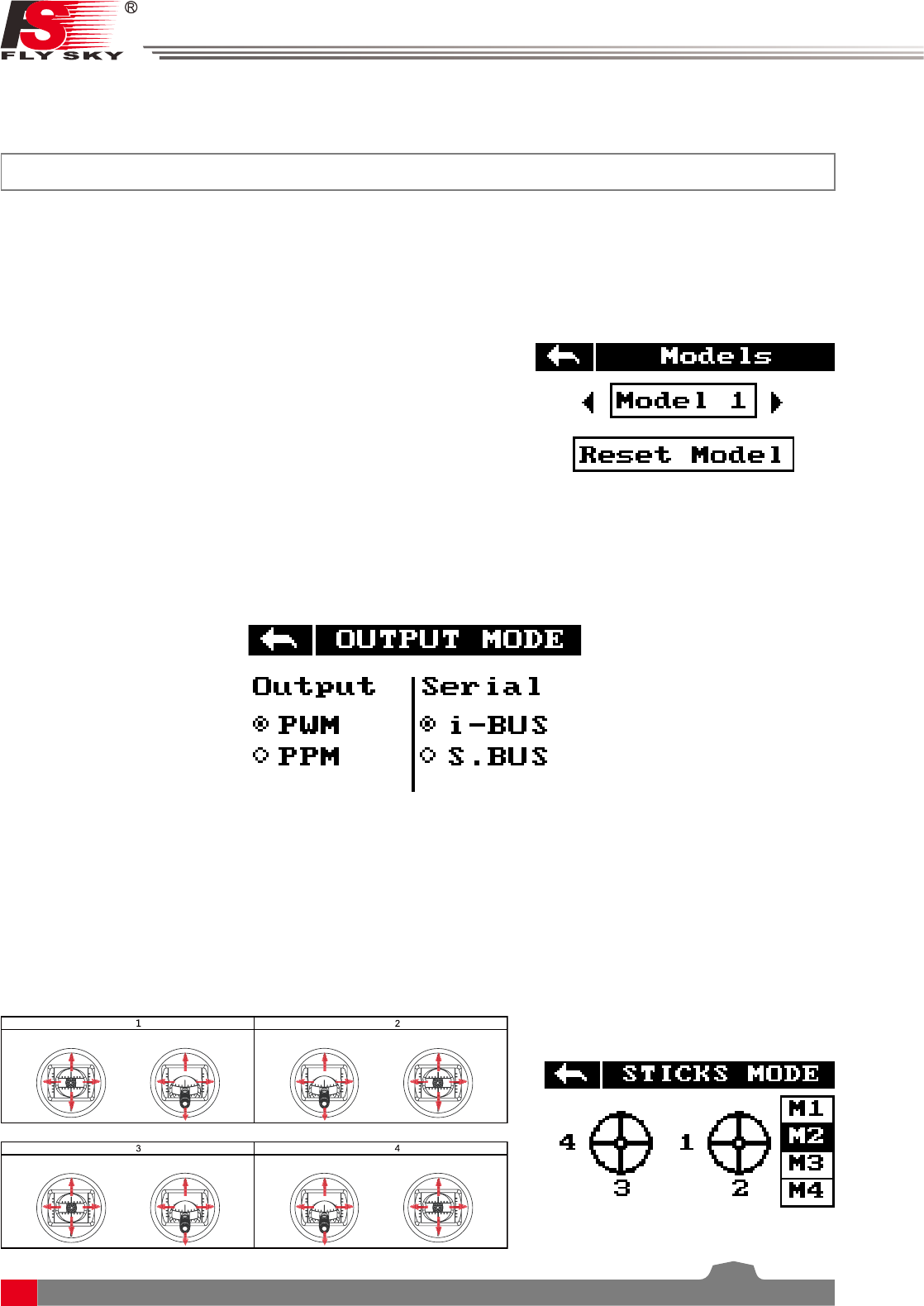
This function is for selecting and resetting models.
Setup:
1. Select [Models] From the system menu and use the left and right
arrow icons to change between models.
2. To reset a model to factory default press [Reset Model].
• Model reset can not be undone.
The system has two output modes, PWM and PPM. To change between the modes touch the desired mode,
the currently selected mode will have a black dot.
7.3 Output Mode
7.2 Models
The system has 4 stick modes , to change the mode touch M1, 2, 3 or 4 on the right hand side of the screen.
The currently selected mode is highlighted in black. Changing between modes 2/4 and 1/3 will necessitate
changing the throttle gimbals position. The user will have to open up the product, see [8.3 Swapping Gimbals]
for details.
7.4 Sticks Modes
[PWM]: PWM output 1-6 channels outputting on the receivers 1-6 pins.
[PPM]: Up to 8 channels outputting via PPM on the receivers channel 1 pins. Pins 2-6 have no output.
Elevator
Mode
Throttle
Rudder
Aileron
Mode
Elevator Throttle
Rudder
Aileron
Mode
Mode
Throttle Elevator
Rudder
Aileron
Throttle Elevator
Rudder
Aileron
Digital Proportional Radio Control System
16
FS-l6S
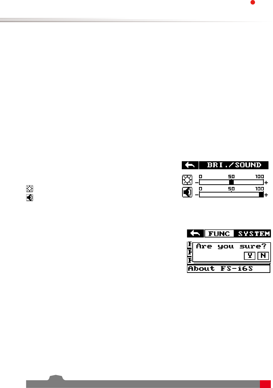
This function controls screen brightness and volume for the system.
7.7 Bri./Sound
Setup:
Represents brightness ranging from 0-100%.
Represents volume from 0-100%.
Touch [Bri./Sound] in the system menu. Touch the sliders to change
screen brightness and volume.
This function resets all settings back to default.
To reset the system touch [Factory Reset] in the main menu then
when prompted touch "Y" for yes.
• Once reset all user settings will be lost.
7.8 Factory Reset
This function changes the throttle mode (Software only), for information on hardware refer to [8.1 Throttle
Bracket Installation] and [8.2 Throttle Spring Installation].
7.5 Throt Mode
Setup:
[Self centering] :If both sticks are set to self-centreing select this throttle mode.
[Non self centering]: When one of the transmitters sticks is set to non self-centering select this throttle mode.
Touch [Throt Mode] in the system menu then select your systems mode. (Must match hardware setup)
This function calibrates the sticks and knobs.
7.6 Sticks Adjust
Setup:
1. Enter stick adjust in the menu.
2. Move the sticks and knobs though their entire range of motion on each axis. To save touch the back icon.
If you can not go back it means that one or all of the sticks and knobs have not moved their full range of
motion.
3. Go to the servo display screen to check the calibration.

17
This function is for updating the system firmware.
7.9 Firmware Update
Setup:
1. Download the latest firmware from www.flysky-cn.com/download.html.
2. Open the firmware update on a computer and connect the system via USB cable.
3. Select [Firmware Update] from the systems function menu. The system will show a prompt, "This will enter
firmware update mode and halt other functions" with an option to continue, select "Y". When in update
mode the screen will turn off.
4. Once the system has been recognized by the computer select the update button at the bottom of the
firmware update software.
• Once the system has been updated it will restart.
• Once the system has restarted it is safe to remove the USB cable.
This menu shows the product name, hardware version, firmware release date and firmware version.
7.10 About FS-i6S

Digital Proportional Radio Control System
18
FS-l6S
8. DIY Customization
The system can be reconfigured to change joystick placement, knob response etc.
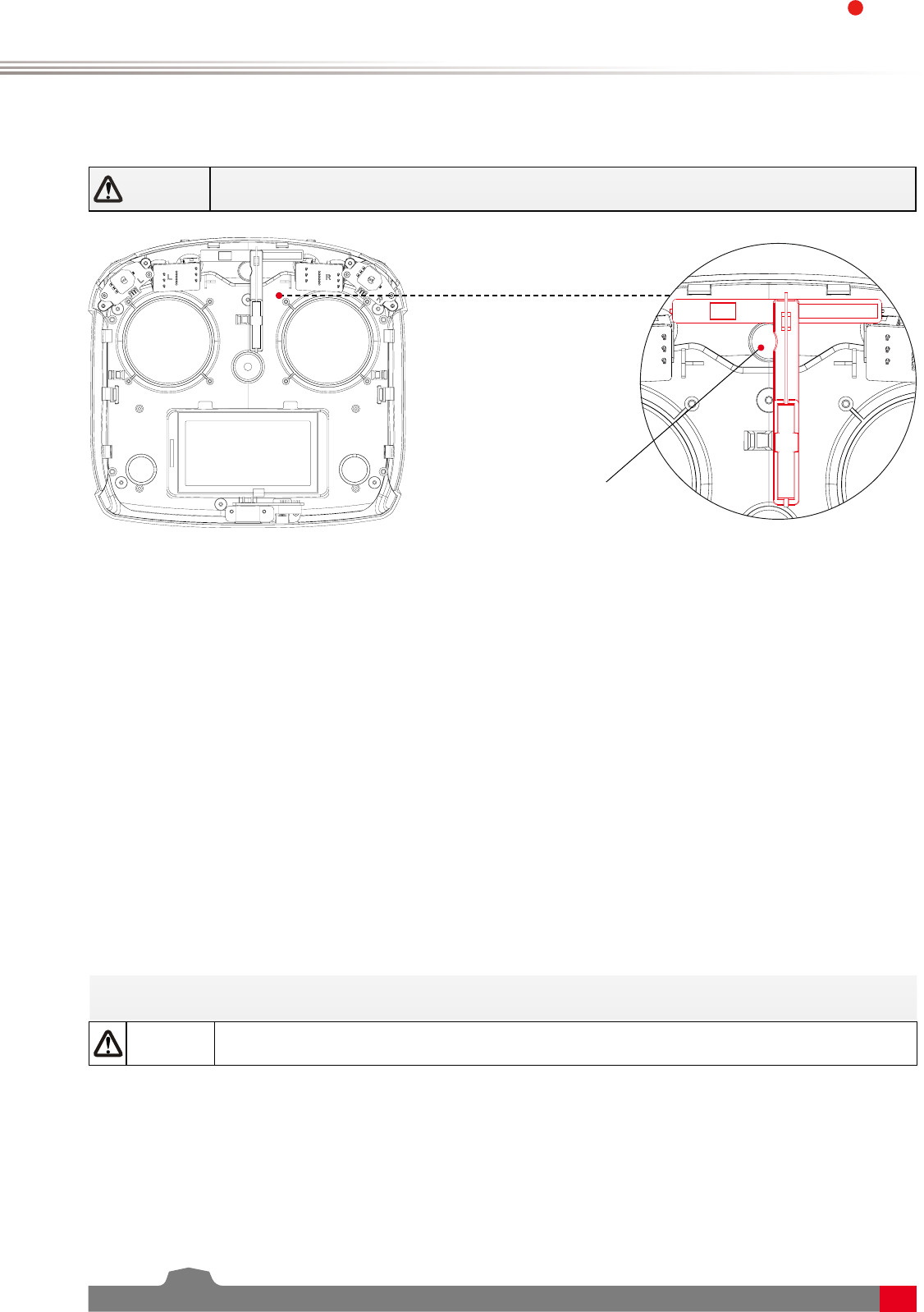
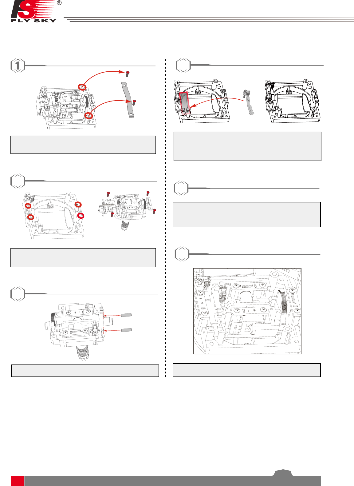
8.1 Throttle Bracket Installation
The gimbals can have their self centering function deactivated or activated, to do so follow the steps below:
1. Use tweezers to remove the left and right hand
grips. Then use a screwdriver to remove the 4
screws marked in red.
2
2. Carefully pull the front and back covers apart.
There are 2 cables connecting the back and
front.
3. Loosen the assembly screws shown in fig.4
and remove the plate. Be careful to ensure no
damage to cables.
4. Remove the bottom of the seat assembly of
the spring hook assembly.
3
• The throttle spring installation, swapping
gimbals, knob bracket installation and knob
spring installation requires that the transmitter
be disassembled and reassembled. The
disassembly instructions will only be provided
here, not for each change.
4
5
5. Secure the assembly back in its original
position with the 4 screws.
6
6. Secure the bracket using the screws provided.
• If the screws are too tight or too loose the
mechanism may not work as expected.
7. The assembly process is now complete.
7
Attention • These instructions are for mode 2, steps 3-6 are for making changes to the right
stick shown in picture. Do not dismantle the left stick.
19
4
8.2 Throttle Spring Installation
The following instructions explain how to install the vertical self-centering spring.
3. Take the transmitter apart,then remove the
screws marked in blue and remove the
2. Loosen the screws shown in fig.4 and remove
the plates.
6. Throttle spring installation complete.
2
5
3. Insert the 2 dowels as shown above.
3
4. Place the spring hook assembly into position
and hook the spring onto the hook located
inside the transmitter.
5. Secure the assembly back in its original position
with the 4 screws.
5
6
Digital Proportional Radio Control System
20
FS-l6S
8.3 Swapping Gimbals
When changing between modes 2/4 and 1/3 you will need to switch the gimbals around so that the throttle
gimbal is on the correct side.
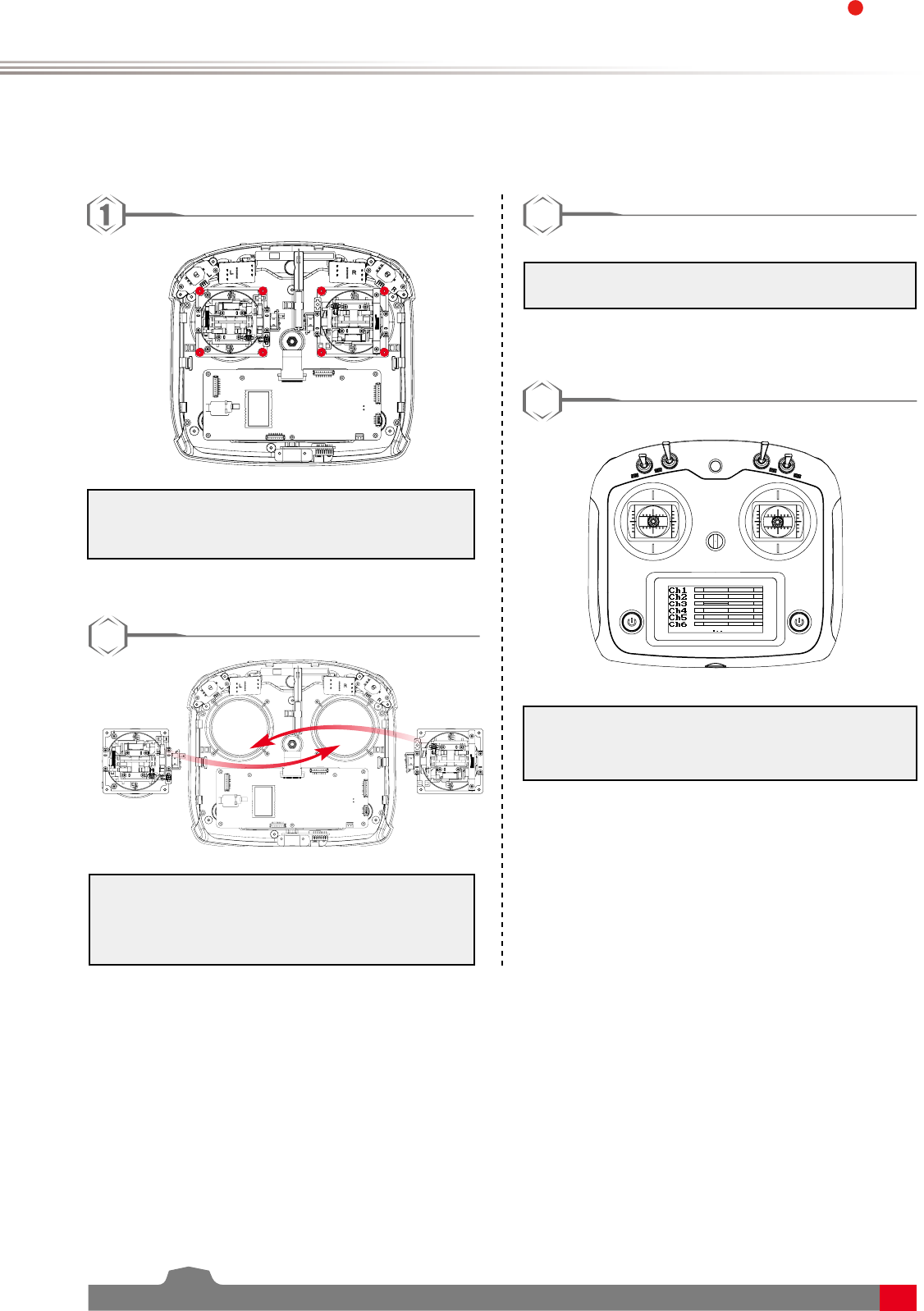
2. Swap the gimbals and rotate them 180
degrees, then line them up with the screw
holes and replace the screws. (There is no
need to disconnect the cables.)
3. Replace the hand grips and insert batteries.
4. Turn on the transmitter and enter the servo
display screen to make sure everything is
working as expected.
1. Take the transmitter apart, using a Philips
screwdriver, remove the 8 screws marked in
red.
2
3
4
21
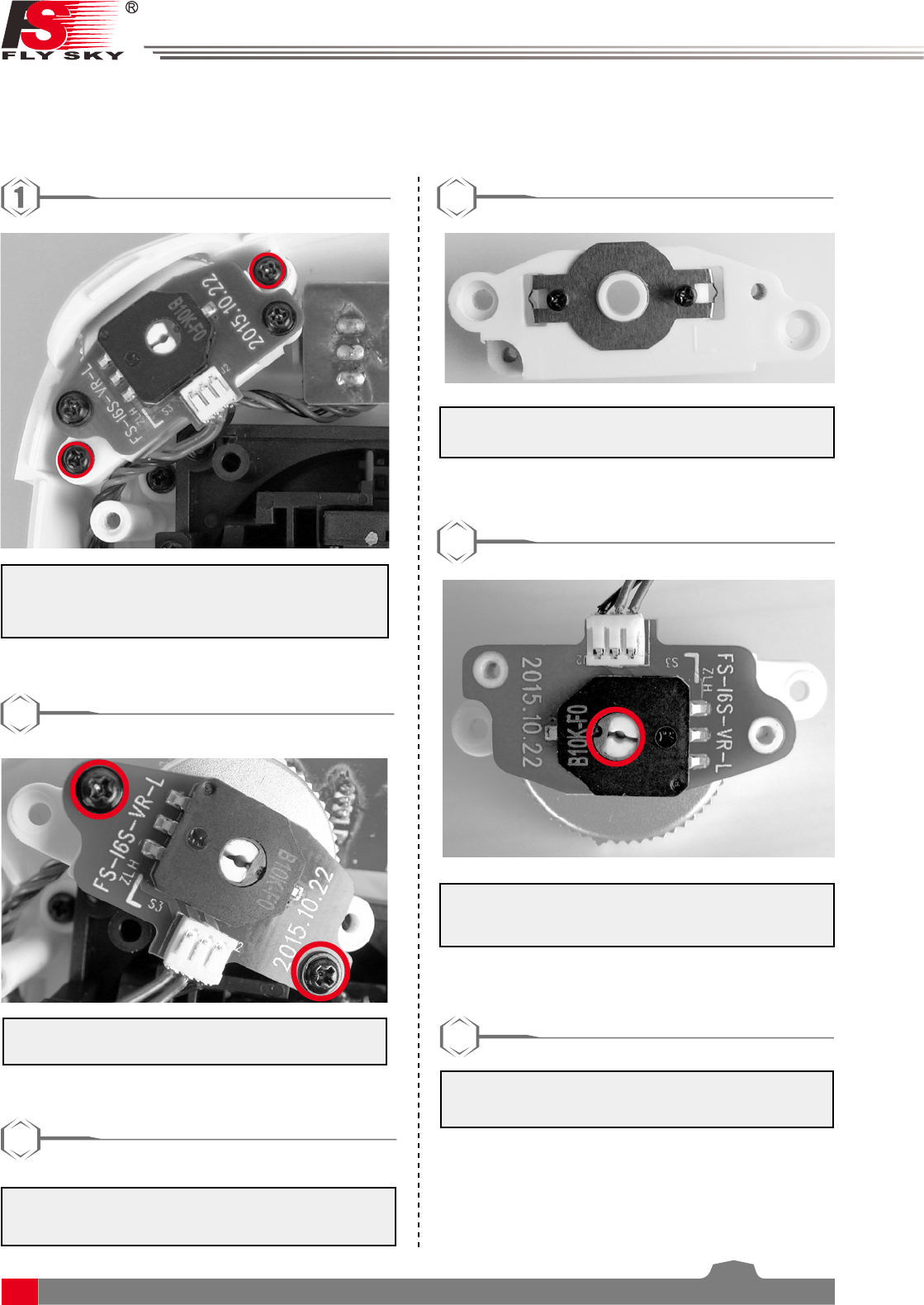
8.4 Knob Bracket Installation
The FS-i6S has 2 knobs that can be changed from self-centering to non-self-centering.
1. Take the transmitter apart, then use a
screwdriver to remove the screws marked in
red.
2
2. Remove the PCB screws marked in red.
3
3. Remove the knob from the potentiometer and
put them in a safe place.
4
4. Install the bracket shown above and secure
with the screws provided.
5
5. Reassemble the parts keeping everything in
alignment. Then replace all the screws.
6. Place the fully assembled part back into its
original position and secure with the screws.
6

Digital Proportional Radio Control System
22
FS-l6S
8.5 Knob Spring Installation
The following instructions explain how to install the vertical self-centering bracket.
1. Take the transmitter apart, then use a
screwdriver to remove the screws marked in
red.
2
2. Remove the PCB screws marked in red.
3
3. Remove the knob from the potentiometer and
put them in a safe place.
4
4. Please the spring as marked in red with the
2 ends pinched between the plastic at the
bottom.
5
5. Reassemble the parts keeping everything in
alignment. Then replace all the screws.
6. Place the fully assembled part back into its
original position and secure with the screws.
6

23
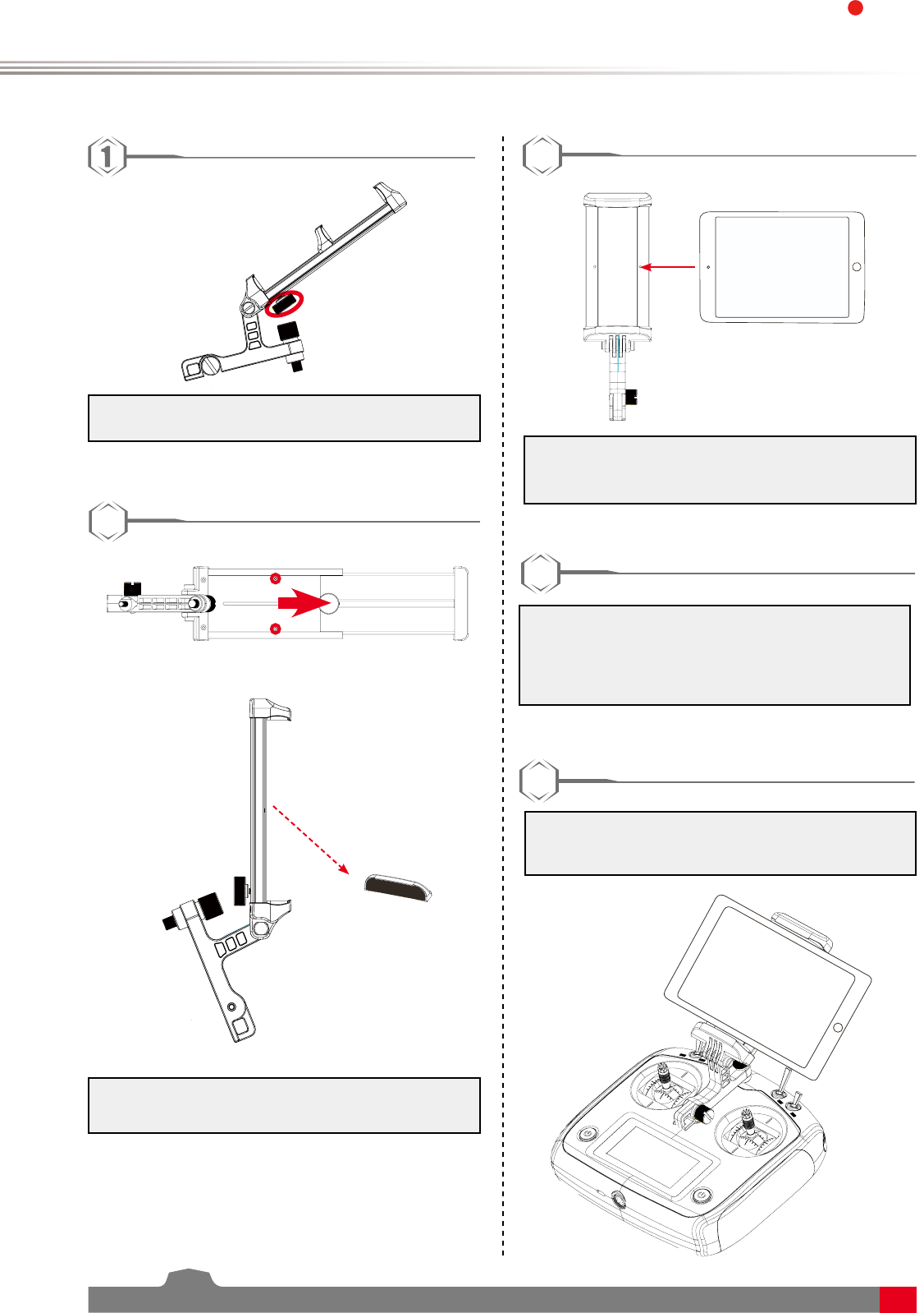
8.6 Device Holder
Mobile devices can be used in real time to receive information from an aircraft. For convince your device may
be fitted into the mobile device bracket.
1. To adjust the bracket, loosen locking screw by
turning it anti-clockwise.
2
2. Slide the top part of the phone holder up.
3
3. Place the phone/device in the middle of the
bracket, be careful not to let the device fall.
4
4. Slide the bracket back down and tighten the
locking screw. Make sure that the bracket has
a firm grip.
5
5. Tighten the lock screw on the back of the
bracket.
Digital Proportional Radio Control System
24
FS-l6S
If you are using a mobile device with a large screen follow the steps below:
1. Loosen the locking screw by turning it anti-
clockwise.
2
2. Move the slide to the highest position and
remove the screws marked in red.
3
3. Move the your device into the centre of the
bracket. Be careful not to let the device fall.
4
5. Adjust the slider so that it grips the device
firmly, and tighten the locking screw on the
back of the bracket.
5
4. Attached the bracket to the transmitter. Make
sure that the notch at the front of the bracket
fits over the eye located on the centre of the
transmitter and that the locking screws are
secure.
25
9. Product Specifications
This section contains the FS-i6S transmitter and FS-iA6B receiver specifications.
9.1 Transmitter specification(FS-i6S)
Channels 6
Model type Quadcopter
RF range 2.4055 - 2.475 GHz
Bandwidth 500 KHz
RF channel 140
RF power Less than 20 dBm
2.4GHz system AFHDS 2A
Modulation type GFSK
Stick resolution 4096
Low voltage alarm Yes (lower than 4.2V)
PS2/USB Port Yes
Power input 4.2V - 6.0V
Weight 410g
Size (Length x Width x Height) 179mm x 81mmx 161mm
Color White
Certificate CE0678, FCC ID:N4ZFLYSKYI6S
11.2 Receiver Specification(FS-iA6B)
Channels 6
Model type Quadcopter/Helicopter/Fixed-wing
RF range 2.4055-2.475 GHz
RF channel 140
RX sensitivity -105dBm
2.4GHz system AFHDS 2A
Modulation type GFSK
Power input 4.5 - 8.4 V DC
Weight 14.9 g
Antenna length 26 mm*2
Size (Length x Width x Height) 47mm x 26.2mm x 15 mm
Color Black
Certificate CE0678, FCC ID:N4ZFLYSKYIA10
i-BUS port Yes
Data acquisition port Yes

Digital Proportional Radio Control System
26
FS-l6S
10. Package Contents
Product Quantity
FS-i6S transmitter 1
FS-iA6B receiver 1
A
LED UPDATE
FS-IA6B
6 CHANNEL RECEI VER
2.4
GHz
4.0-8.4V/DC
FC C ID:N4ZFLYSKYIA10
Micro USB cable 1
Mobile phone holder Optional
DIY parts:
Throttle bracket(1)
PB 2.6*6(2)
Knob bracket(2)
PA 1.2*4(4)
9
Quick start guide 1

27
Appendix 1 FCC Statement
This equipment has been tested and found to comply with the limits for a Class B digital device pursuant
to part 15 of the FCC rules. These limits are designed to provide reasonable protection against harmful
interference in a residential installation. This equipment generates, uses and can radiate radio frequency energy
and, if not installed and used in accordance with the instructions, may cause harmful interference to radio
communications. However, there is no guarantee that interference will not occur in a particular installation. If
this equipment does cause harmful interference to radio or televison reception, which can be determined by
turning the equipment off and on, the user is encouraged to try to correct the interference by one or more of
the following measures:
• Reorient or relocate the receiving antenna.
• Increase the separation between the equipment and receiver.
• Connect the equipment into an outlet on a circuit different from that to which the receiver is
connected.
• Consult the dealer or an experienced radio/TV technician for help.
To assure continued compliance, any changes or modifications not expressly approved by the party responsible
for compliance could void the user’s authority to operate this equipment. (Example use only shielded
interface cables when connecting to computer or peripheral devices).
This equipment complies with Part 15 of the FCC Rules. Operation is subject to the following two conditions:
(1) This device may not cause harmful interference, and
(2) This device must accept any interference received, including interference that may cause undesired
operation.
Caution!
The manufacturer is not responsible for any radio or TV interference caused by unauthorized modifications to
this equipment. Such modifications could void the user authority to operate the equipment.
1. Move all your channels to the desired position.
2. Select [All channels] and then [Yes] in the confirmation box.

Digital Proportional Radio Control System
28
FS-l6S
Copyright ©2015-2016 Flysky RC model technology co., ltd
www.flysky-cn.com
Released date:2016-11-17
FCC ID:N4ZFLYSKYI6S
