PSS Niko Ltd Changes Fall Arrest System Manual May2014
fall-arrest-system-manual-may2014
User Manual: Pdf
Open the PDF directly: View PDF ![]() .
.
Page Count: 20

Fall Protection
4
4
4
• Modular
• Ergonomic
• Smooth Running
• Versatile
Eliminate Bounce Effect
and Secondary Falls
www.nikotrack.com

Contents
General Instructions
Safety Instructions
Manufacturer
Distribution
1.1. Purpose
1.
2.
3.
4.
5.
6.
4.5. Switches
6
7
2.1. Terms of use
3.1. Components
3.2. Standards
3.3. Assembly
4.1. Use of components
4.2. Track suspension
4.3. Trolleys
4.4. Support brackets & stopper
4. . Example of line
4. . Assembly regulations
6.1. Checklist
Product Description
System Elements
Safety Instructions
Servicing
A - ENG - 2011

1.
1.1.
2.
Manufacturer
Helm Hellas S.A
PO Box 209
20100 Korinthos
Greece
Tel: 0030-27410-85803
Fax: 0030-27410-25368
e-mail: info@niko.eu.com
Purpose
Safety Instructions
.foytefasehtrofylevisulcxedesuebotsi52SSPOKINmetsystserrallafehT
The system does not replace personal safety harnesses (PPE – personal protective equipment).
Generally the fall arrest system is suited for maxim 3 persons per meter length of line. The maximum number of
persons must be adjusted according to the requirements as follows:
a.) Determination of the maximum number of persons
b.)
c.)
d.)
1 person permitted on one trolley.
Each safety trolley must only be used in combination with a personal safety harness.
Dampers/shock absorbers are to be used.
.553NEsessenrahytefaS)a
b)
c)Distance to collision:
llafehTnosrepderucesatahterusneotderiuqerecapsehtsnaemsihT
height must always be reduced to a minimum. The calculation of the fall height depends on the system used:
connectors/fasteners, dampers/shock absorbers, distortion of safety belt.
Minimum distance from the impact point (incl. body height) + 1m to floor or obstacle.
persons suspended after a fall
um
The supporting structure must be designed to withstand the worst case scenario,i.e. if all persons operating the
system were to fall at once.
Calculate 10kn dynamic load affecting the system (or according to chart at 26.B06P) for one person:for each
additional person add 1kn.
it is important to conduct an analysis of the rescue options for the maximum number of persons.
must be worn during use in accordance with
Be aware of the required fall and arrest distances.
.elcatsboynaotnollaftonseodmumini m
2.1. Terms of Use
!!! Pay attention to spurs, mouldings or other construction obstacles !!!
General Instructions
Distribution Austria
NIKO VertriebsgmbH
A-2564 Weissenbach
Tel: 0043-2674-81005
Fax: 0043-2674-81006
e-mail: office.at@niko.eu.com
Hainsfeldstraße 3
Distribution U.K.
NIKO Limited
Unit 12, Southfield Road
Kineton Road Ind.Estate
CV47 0FB Southam
Warwickshire
Tel: 0044-19268-13111
Fax: 0044-19268-15599
e-mail: sales@niko-ltd.co.uk
A - ENG - 2011
Distribution Germany
NIKO TECHNIK GmbH
Friedrichstrasse 269A
42551 Velbert
Tel: 0049-2051-604736
Fax: 0049-2051-604738
e-mail: office.de@niko.eu.com
Distribution U.S.A.
NIKO TRACK
300 Highpoint Avenue
Portsmouth
RI 02871
Tel: 001-401-6837525
Fax: 001-401-6836450
e-mail: sales@nikotrack.com
3.
3.2.
3.3.
Product Description
3.1.Components
Horizontal running track system with support brackets for wall or ceiling mounting as well as mounting to a steel beam
above.
The internally running trolleys are 4 ball bearing rollers and a safety bolt preven the trolley falling
due to axle or bearing .
yBn a straight line or follow a specified course using several types of bends.idelbmessaebnacmetsyskcartehT
dividing the line in several directions, switches are installed which can lead into one or more lines. The trolleys are
available in two different types.
Trolley T40P with vertical swivel bolt 360° and ring nut DIN 582.
Trolley T10P with hole (for the use of this trolley as person carrier you have to use a PPE rotating swivel). Track
stoppers of type 25.X01 are screwed at the open end of the track. Swivel switches are delivered either with manually
or automatically changing switch tongues. The operation can be carried out manually by switch lever or by lever with
pulling chain.
The components comply with EN 795 class D.
The track system is constructed for vertical assembly. The lines can be in straight c .
Mounting: The tracks are attached to steel beams or masonry with support brackets or adjustable brackets. The
mounting distances are at 4.1.
During assembly the . Assembly
onto steel construction's you must use screws of DIN 933 M16 (8.8).
The free standing track ends are allowed to jut out over the last support bracket according to chart page 15 / 4.6. If
this distance is exceeded then additional support brackets must be installed.
Track stop be used on open track be secured with a steel bolt and nyloc DIN 933
.08x8M
totitlumhtiwdettif
breakage of the s
or urved
given
support structure must be checked and the strength of the mounting points tested
dluohsdnadedne-tsumsdne
to prevent horizontal shift
Standards
Assembly
Warning: Each mounting point must be capable of holding a load of 10KN.
Free standing track ends and track joints are to be separated by at least a full section. See 4.7 assembly regulations.
Except bracket 26.B06P (look at the chart on page 5)
A - ENG - 2011
For the assembly of bends, a support bracket should be fitted in the center of each bend.The exact positioning of the
support brackets is depicted at 4.6 (Example of line) and must be followed. Since the trolleys have no brake
mechanism, ascending or descending track requires a different type of support or other restraint method. Please
consult the manufacturer for recommendations and ensure proper testing by a qualified person.
(All non-horizontal lines require an extra examination)
The switches are connected into the system via the track joints and must be positioned immediately before the joint.
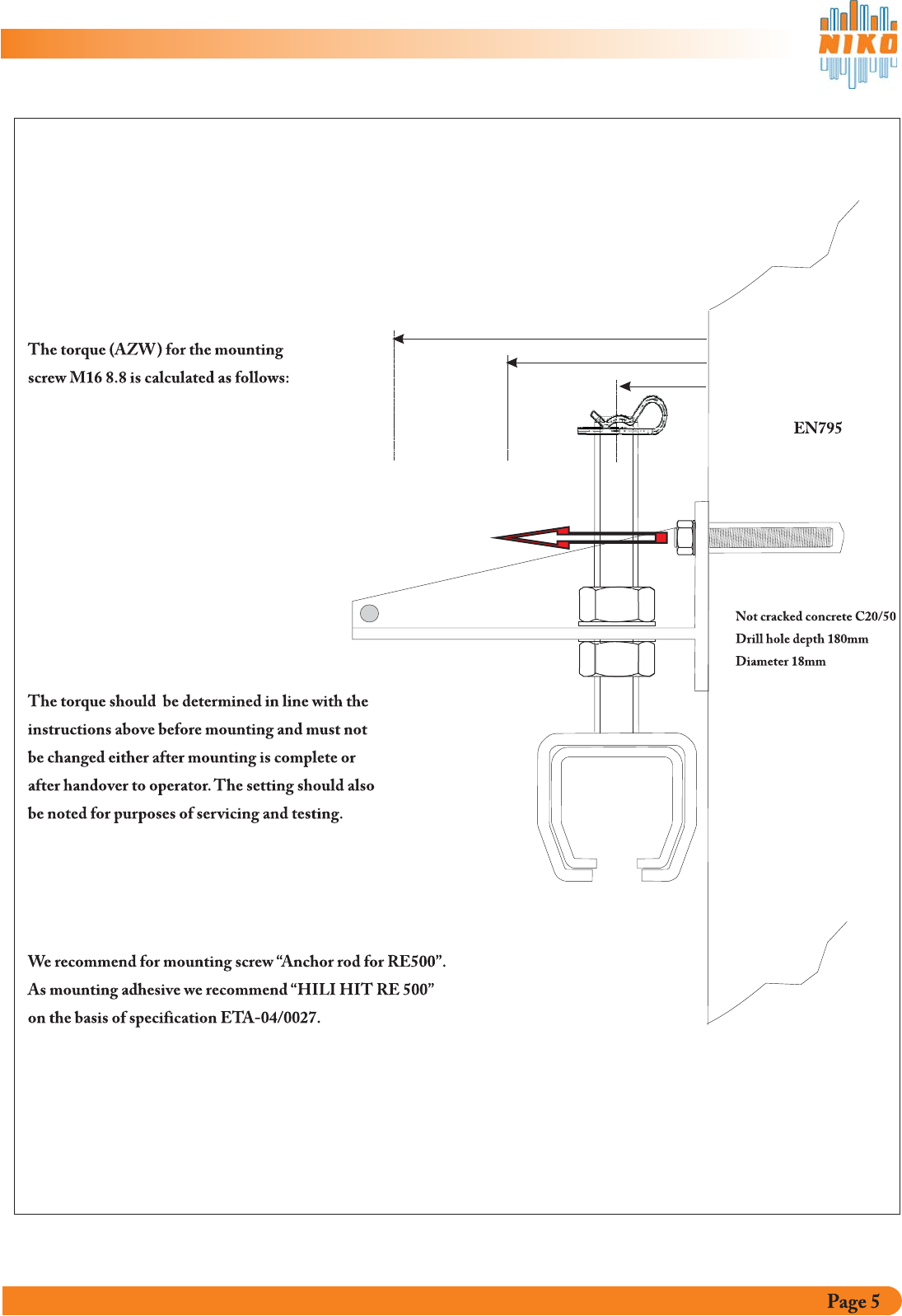
EN 795
Torque for double adjustable wall bracket Type 26.B06P
A
B
C
A Projection
B Projection
C Projection
up to 45mm
up to 110 mm
165 mmup to
10 KN
17 KN
35 KN
Once fixed, mark the position of the bracket, which should
remain the same at all times. Positioning should be noted on the
checklist and periodically checked during maintenance (page 18).
AZW
A - ENG - 2011
4.
4.1.
System Elements
Use of Components
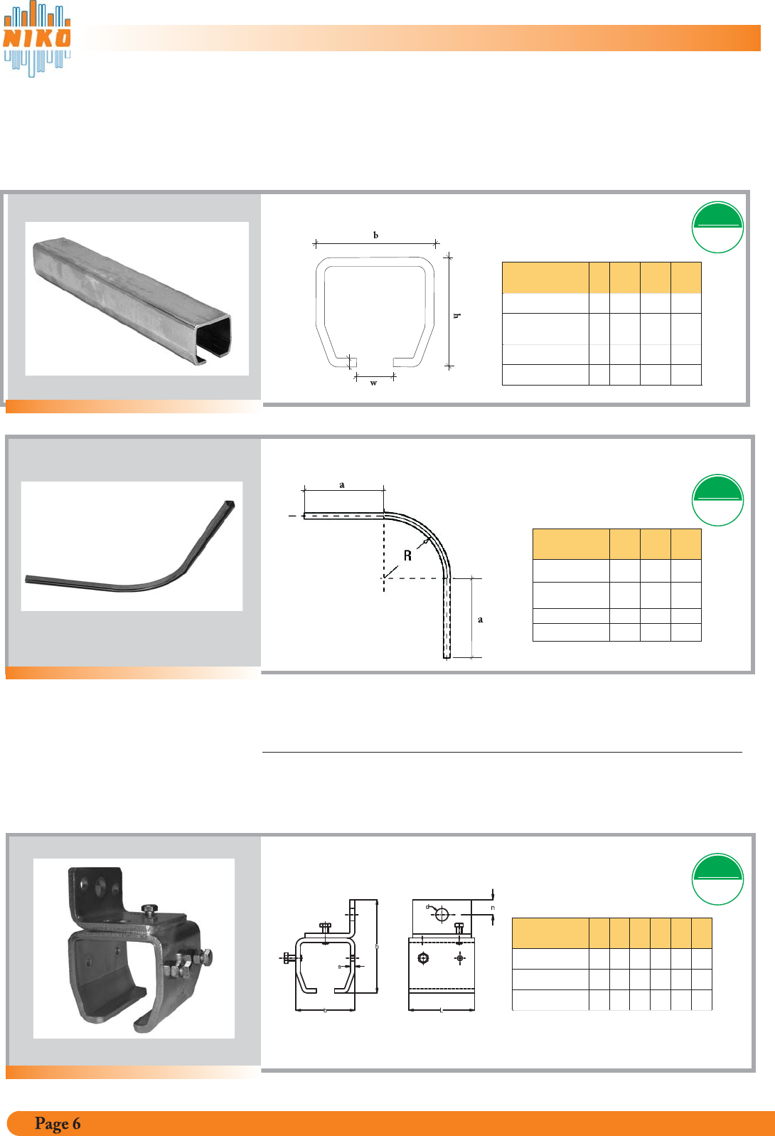
Track profiles and track bends
Track “NIKO”, standard 6000 mm lengths
Material for accessories and components
Steel quality St37_2 according to DIN 17100
Ball bearing material AISI 1015, Surface hardness 58-62 HRC
Surface galvanised & yellow chromated.
Track Art.Nr. bhsw
25.000 galv. 65
60
3,6 18
25.060
sendzimier galv. 65 60 3,6 18
2 .0006 galv 80 75 4,5 22
110 90 6,5 25
s
Track bends
Standard bends
Art. Nr. R +/- a
580 10 500
580 10 500
770 20
1035 20
4.
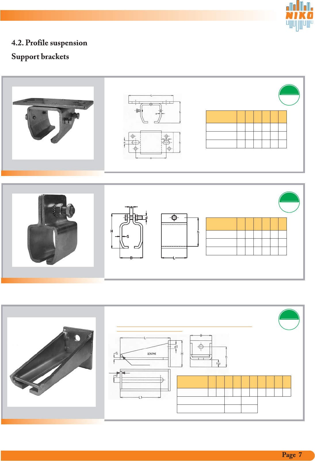
4.2.
System Elements
Profile suspension
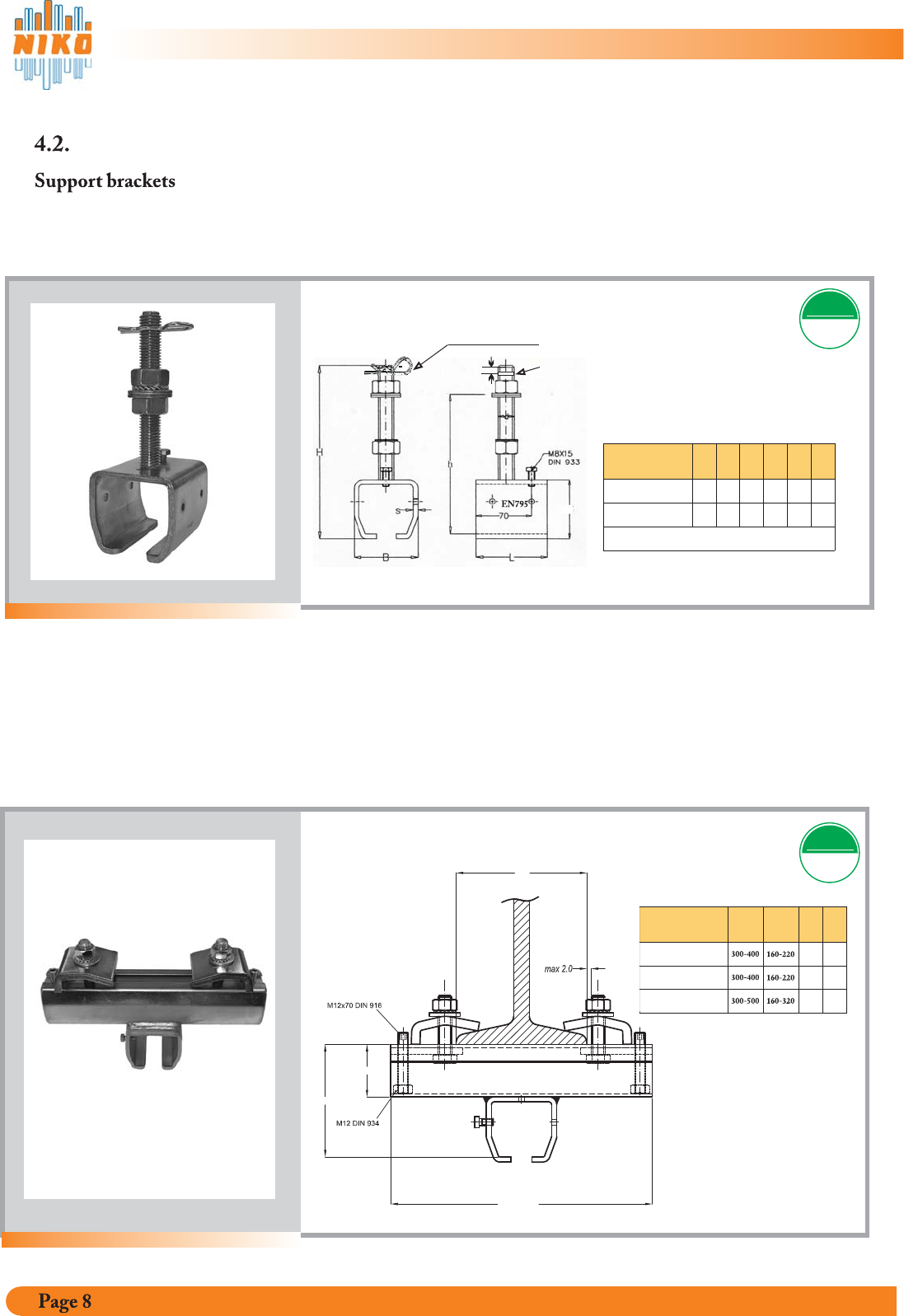
Support brackets
! the support brackets and dowels be !In the event of a fall, should examined
EN 795EN 795
TESTED
Wall support bracket
EN 795EN 795
TESTED
EN 795EN 795
TESTED
Wall support
bracket Art. Nr. bhsL
25.B01P 80 125 6 90
100 160 8 110
118 210 10 120
EN795 26.B01P
27.B01P
n
18
25
32
d
17
22
27
A - ENG - 2011
500
500
2 .0007 galv
2. 05 C 6 galv.
2. 05C 6W
sendzimier galv.
2. 17 C 0 galv.
2. 06 C 8 galv.
d2
d2
4. System Elements
Ceiling support bracket
EN 795EN 795
TESTED
Ceiling support
bracket Art. Nr. bhsL
25.B02P 80 83 6 170
100 103 8 210
118 146 10 260
26.B02P
27.B02P
m
10
12
23
d
17
22
22
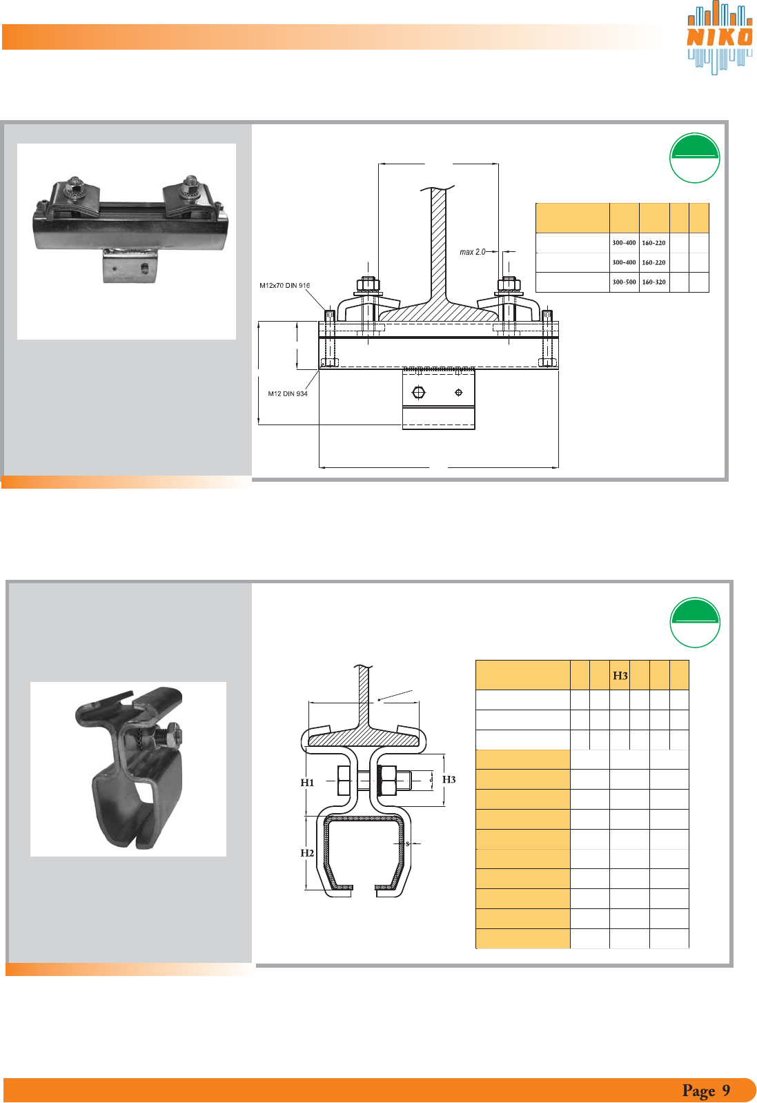
Split support bracket for flat steel
EN 795EN 795
TESTED
Split support
bracket Art. Nr. BhsL
25.B03P 77 132 6 90
96 150 8 110
110 180 10 120
26.B03P
27.B03P
e
6
8
10
d
M16
M16
M16
Double adjustable wall bracket EN 795EN 795
TESTED
Double adjustable
wall bracket Art. Nr. HhsB
26.B06P 110 85 8 90
Suitable for adjustable brackets
ho
31
b
21
Adjustable support brackets for height and lateral adjustment
25.B04P 26.B04P
LL1
d1 d2
208 168 1888
!
!
In the event of a fall, the double adjustable wall brackets and bolts must be
examined and changed if necessary
A - ENG - 2011
4. System Elements
Profile suspension
Adjustable support brackets for height and lateral adjustment
Adjustable joint clamp, parallel
EN 795EN 795
TESTED
Adj. joint clamp,
parallel Art. Nr. LB hH
25.B35P
26.B35P
129
Spring cotter 4 mm
Drill-hole 5 mm
15 mm
Adjustable bracket
EN 795EN 795
TESTED
Adjustable
bracket
Art. Nr. HhsB
25.B04P 215 140 6 82
Suitable for adjustable wall bracket
L
90
C
75
26.B06P
26.B04P
C292 183 8 100 110 93
Components for I-Beam mounting
L
H
h
B
60
146 60
A - ENG - 2011
27.B35P 214 110
Adjustable joint clamp, horizontal
EN 795EN 795
TESTED
Adj. joint clamp,
horizontal Art. Nr. LB hH
25.B36P
26.B36P
129
h
60
146 60
L
H
B
Split suspension bracket for I-beam
EN 795EN 795
TESTED
Split suspension
bracket for track profile H1 s
25.000 56 60 42 6
63 75 44 8
90 110 66 10
26.000
27.000
d
M16
M16
M16
IPN / IPE
H2
For I-beam
IPN / IPE 25.000 26.000 27.000
100 ( 80 )
120 ( 100 )
140 ( 120 )
160 ( 140 )
180 ( 160 )
200 ( 180 )
220 ( 200 )
240 ( 220 )
260 ( 240 )
25.B10P
25.B12P
25.B14P
25.B16P
25.B18P
25.B20P
25.B22P
25.B24P
25.B26P
26.B16P
26.B18P
26.B20P
26.B22P
26.B24P
26.B26P
27.B20P
27.B22P
27.B24P
27.B26P
Components for I-Beam mounting
A - ENG - 2011
27.B36P 214 110
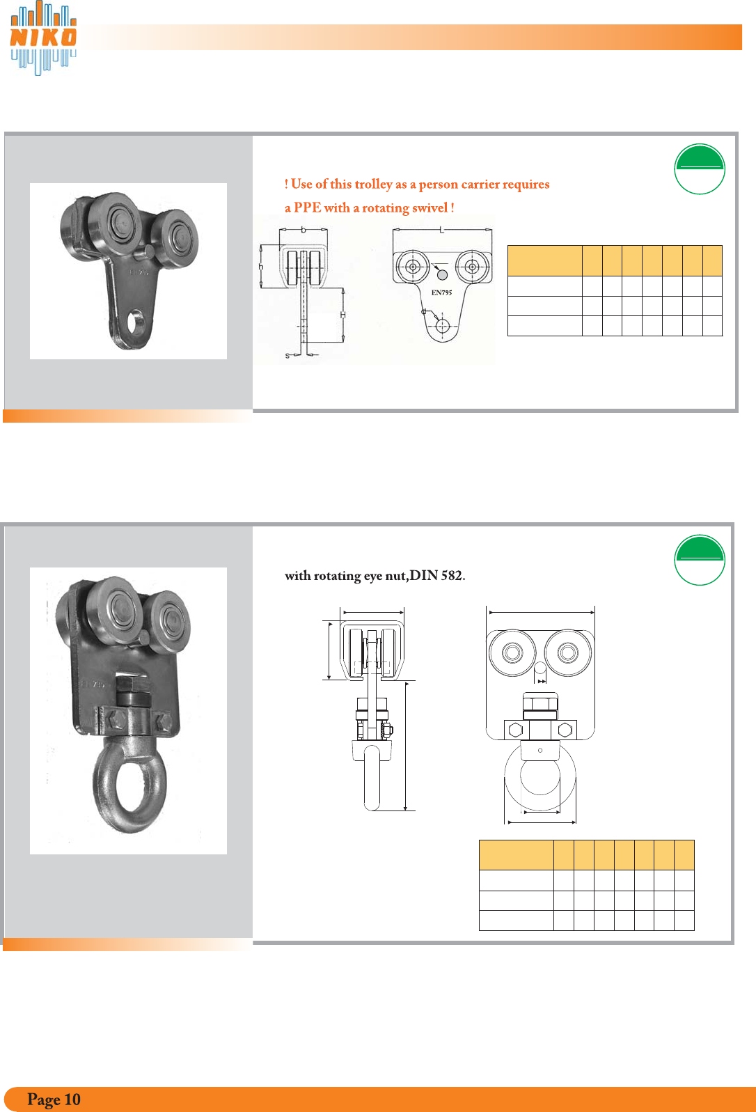
4.3. Trolleys
4-wheel Trolley for persons EN 795EN 795
TESTED
Trolley
Art. Nr. Hhb
25.T40P
Ld
26.T40P
27.T40P
d1
4-wheel Trolley EN 795EN 795
TESTED
Trolley
Art. Nr. Hhsb
25.T10P 62 60 10 65
L
120
d
18
26.T10P
27.T10P
d1 d1
12
70
108
75
110
12
15
80
90
145
210
22
26
12
12
L
b
h
H
d1
d
D
D
122
145
163
60
75
110
65
80
90
110
150
200
12
12
12
12
12
12
72
90
108
A - ENG - 2011
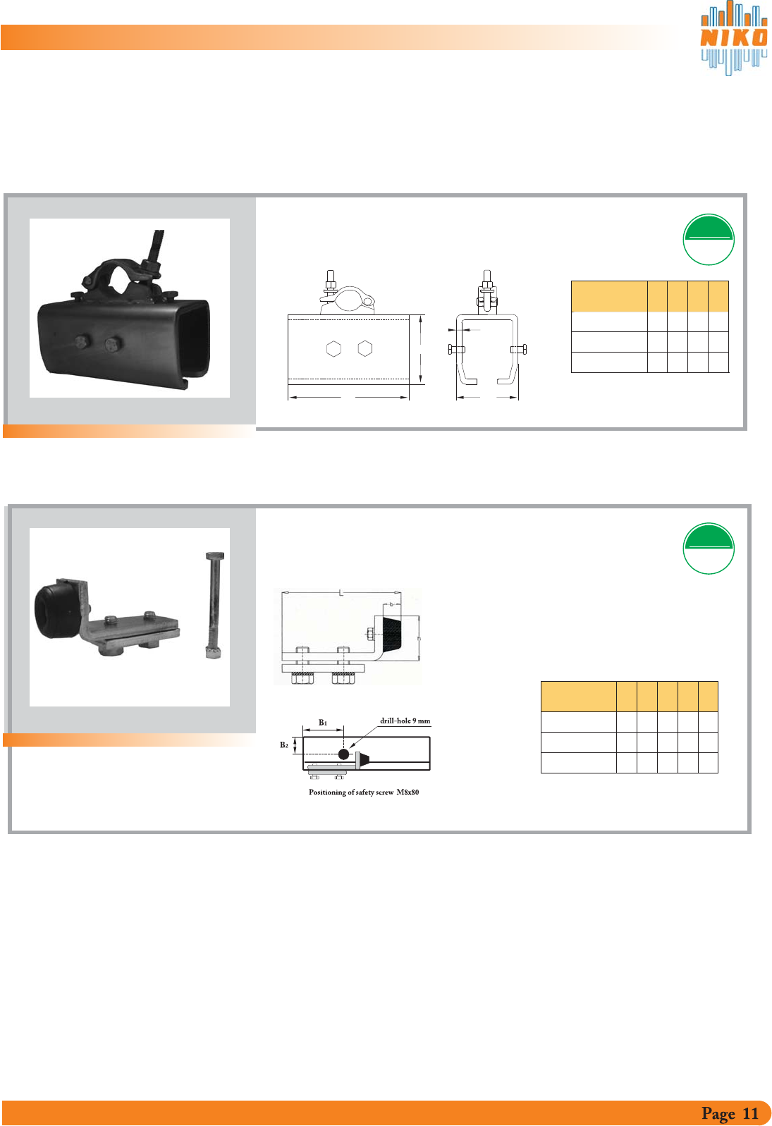
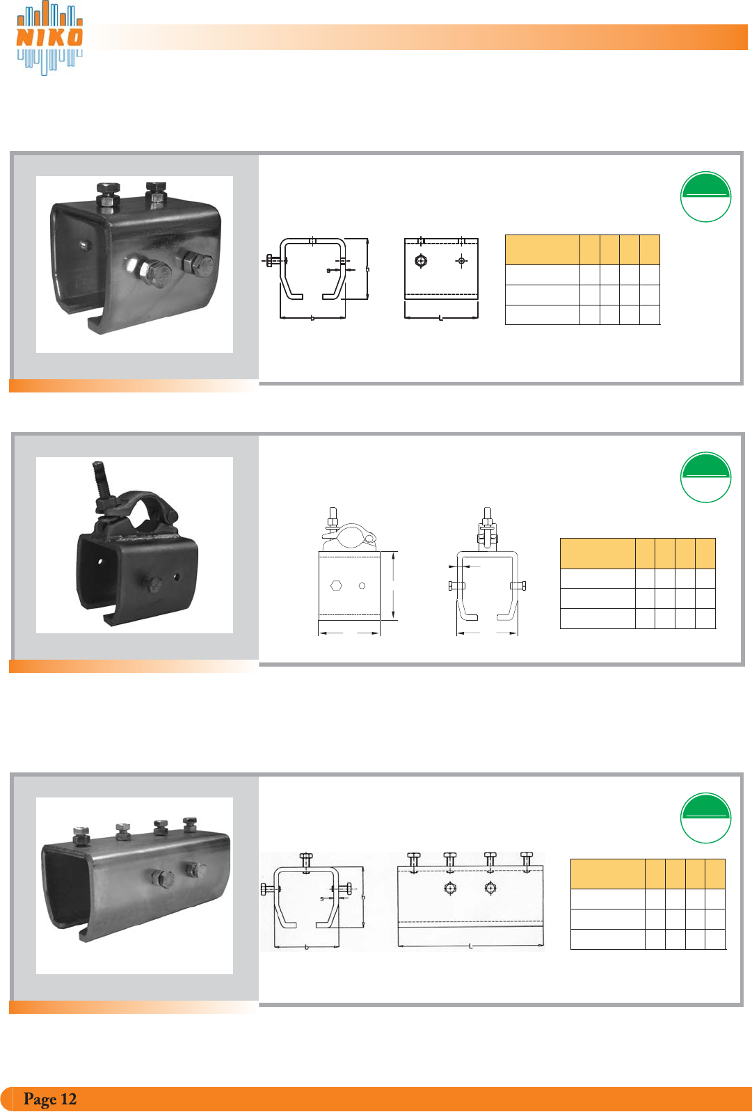
4.4. Splice joints, brackets + track end stop
Scaffolding splice joint for
mounting on scaffold tube 1 “, 48,30 mm TESTED
1
2
/
EN 795EN 795
Scaffolding splice
joint Art. Nr. bhsL
25.B80P 80 75 6180
s
100 93 8 200
26.B80P
h
114 134 10 250
27.B80P
Lb
Track end stop
In addition to the track end stop a safety screw
is required (see sketch).
TESTED
EN 795EN 795
Track endstop
Art. Nr. Lbh
25.X01P 80 75 6
100 93 8
26.X01P
114 134 10
27.X01P
Splice joint for tracks
Track End Stops
B1B2
110
135
135
30
30
50
A - ENG - 2011
Splice joints for Track
4.4 Support brackets & stopper
Scaffolding support bracket
for mounting of
Scaffold tube 1 “, 48,30 mm
Bracket for welding on existing
building frame.
L
Splice joint for tracks
h
s
1
/
b
2
Support bracket
Art. Nr.
25.B00P
26.B00P
27.B00P
Scaffolding support
bracket Art. Nr.
25.B90P
26.B90P
27.B90P
Splice joint
Art. Nr.
b
80
100
114
25.B49P
26.B49P
27.B49P
h
75
93
134
s
6
8
10
100
114
L
90
110
120
b
80
100
114
134
b
80
h
75
93
134
h
75
93
EN 795EN 795
TESTED
EN 795EN 795
TESTED
s
6
8
10
EN 795EN 795
TESTED
110
120
s
6
8
10
L
90
180
200
250
L
4.4 Support brackets & stopper
Support bracket without mounting flange
A - ENG - 2011
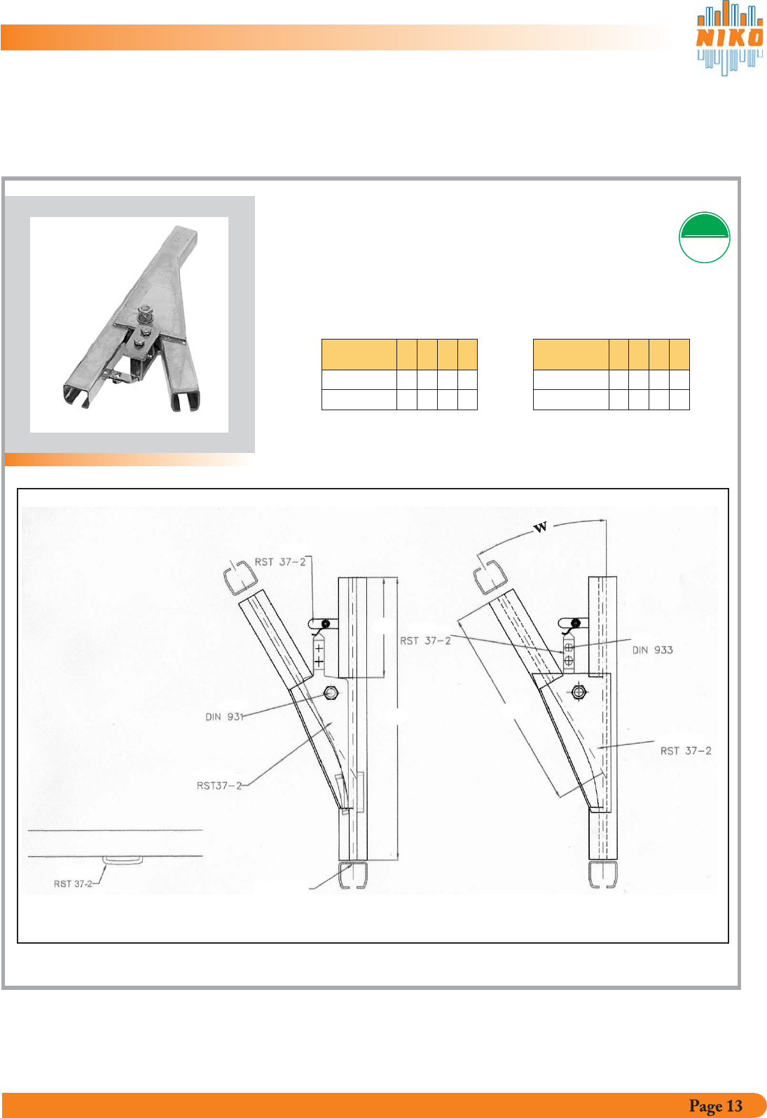
4.5. Switches
Tongue switches without bends
Manual operation
left or right running angle 30°
TESTED
EN 795EN 795
Tongue switch w/o
bend Art. Nr. L
25.A05
26.A05
W
Design left switch
Switch left Switch right
L1
L2
L
25.000
26.000
27.000
L1L2
650
750 30°
30°
500
550
220
280
Tongue switch w/o
bend Art. Nr. L
25.A04
26.A04
WL1L2
650
750 30°
30°
500
550
220
280
A - ENG - 2011
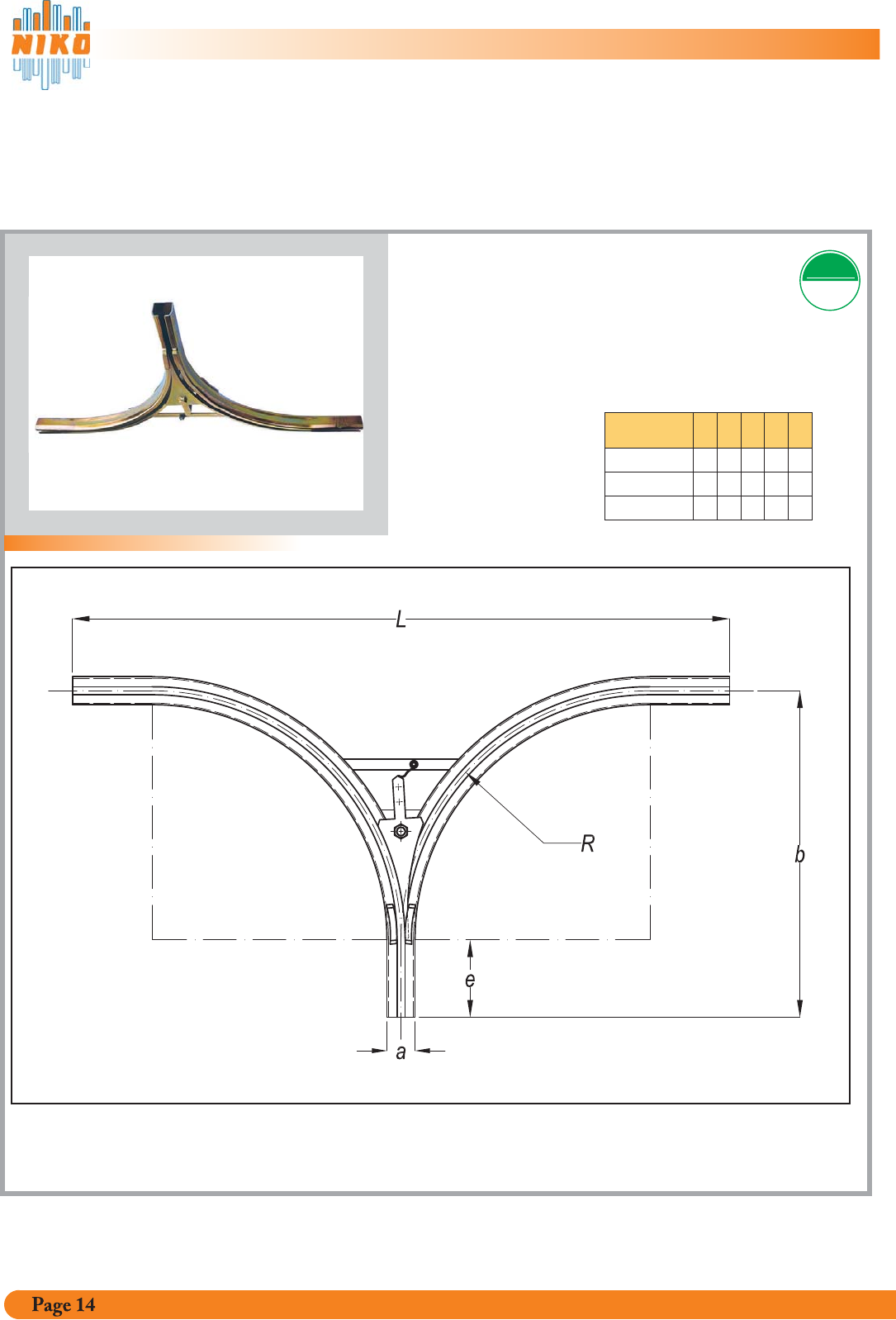
4.5. Switches
Tongue switch complete with Bends
Manual operation
left and right running in angle 90 bends
complete with two 90 bends
°
°
TESTED
EN 795EN 795
Tongue switch
Art. Nr. abL
25.A47
26.A47
eR
27.A47
A - ENG - 2011
65
80
90
760
980
1335
1600
2000
3000
180
210
300
580
770
1035
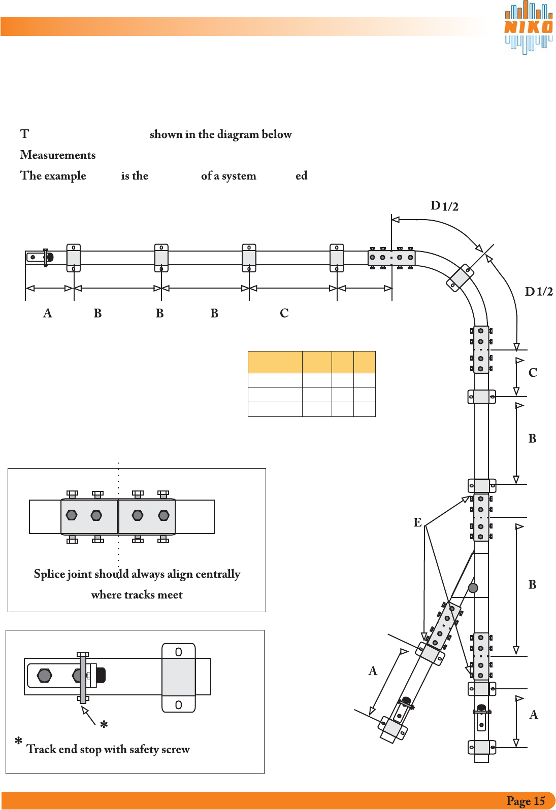
4.6. Example of line
he mounting points are .
given are maximum distances.
below top view mount with ceiling brackets.
A = max Cantilever end shown in chart
B =support centres in max mm
C = max distance between support & splice joint
D = Middle of bend max 1000 mm
E = Switch support points are positioned immediately after the splice joints
Mounting
max distancesimum BA
25.000
26.000
C
27.000
1100 300 500
1600 400 500
2800 500 500
A - ENG - 2011
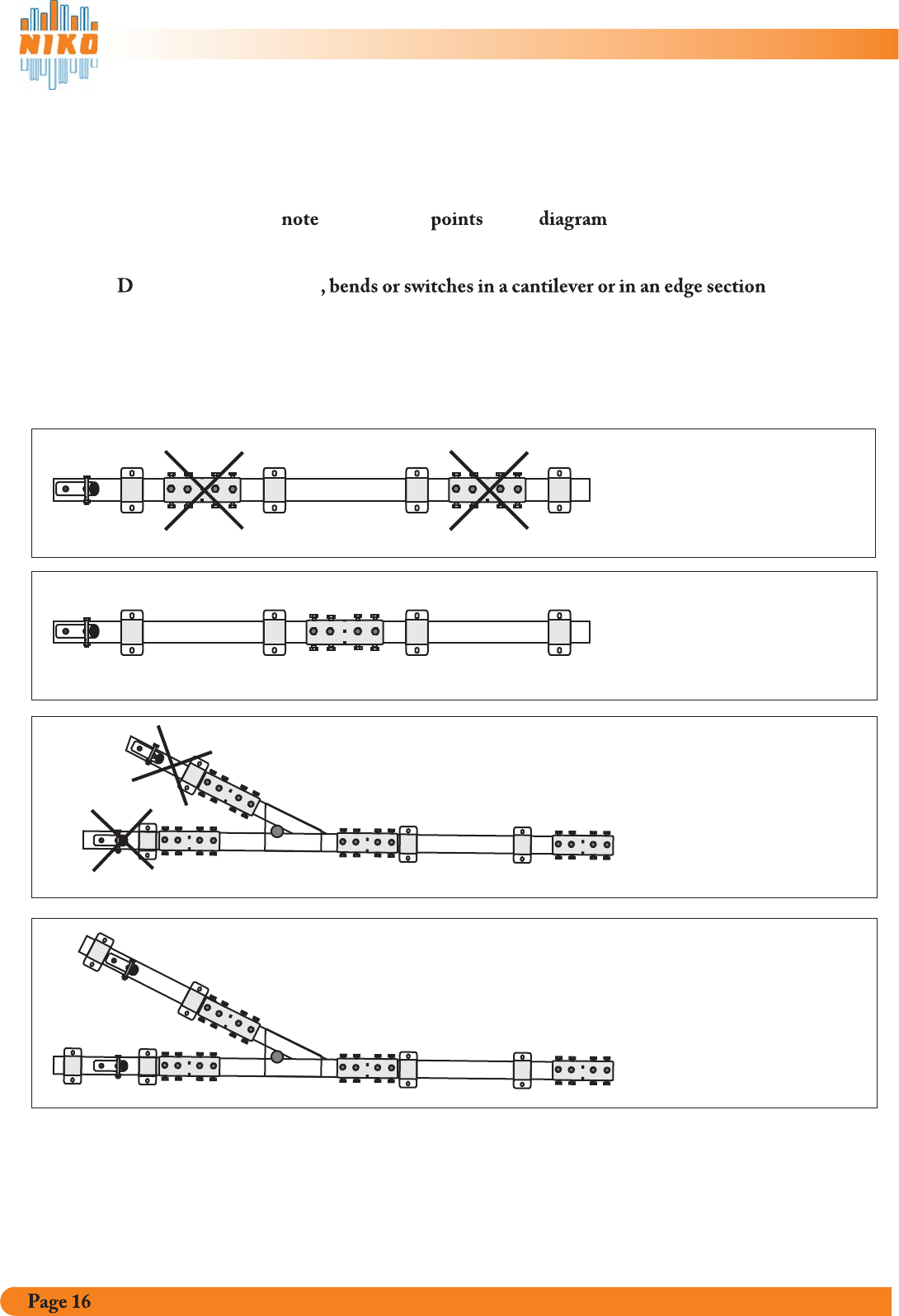
4.7. Assembly regulations
Please the specified in the below.
o not place track joints .
The same goes for track bends and switches.
Incorrect
Correct
Incorrect
Correct
Special constructions are only permitted after proper investingations
andwritten approval from an authorised afency.
A - ENG - 2011

5.
6.
Safety Instruction
Servicing
A - ENG - 2011
All mounting points must be set up as in example 4. . The manufacturer takes no
responsibility for i assembly. at track crossings.
orrect alignment of the parts After assembly of the
support brackets, the track is pushed into the support brackets and fixed using the overhead
security screws. oor fixing of the tracks may
out. (Risk of falling)
T40P. T10P
shown 6
ncorrect Ensure all parts are correctly
C will produce the best running quality.
P lead to uneven pressure, causing the track to slide
out .
The standard trolley for fall arrest application is The use of trolleys(designed for
carrying materials) requires a PPE rotating swivel in order to carry personnel.
aligned
All Fall Arrest systems NIKO PSS 25-26-27 are subject to repeated inspection. The inspection
intervals depend on the use and demands placed on equipment.
Basically the following minimum intervals are to be maintained:
or safety devices use one
or safety devices use on e week xamination in accordance with checklist
daily high rope courses event facilities xamination
in accordance with checklist
Special installations must be by an authorized inspection office
.
F that are d no m than once a month: annual examination in
accordance with checklist.
F d c a : quarterly e
e
approved and should be dealt
with seperately
F d , such as & ; weeklyor safety devices use

6.1. Examination Checklist PSS 25-26-27
All examinations of the fall arrest system NIKO PSS 25-26-27 must be documented in this list.
Screw connections to substructure
Fixing screw
Observe yielding
After fall (change brackets and dowels)
Projection up to the wall bracket 26.B06P
Corrosion
Material wear out
Track crossings
Fixing
Positioning
Fixing
Corrosion
Material wear out
Track crossings
Fixing
Corrosion
Axle screw wear out and play
Switch tongue function and wear out
Switch lock function and screw connection
Wear out & position of switch tongue support holder
Crossings and position of the track joints
Screw connection of track joints
Screw connection and position
Security screw positioning
Rubber buffer
Running quality
Bearing play
Position of carrying screws
Position of clip screws
Wear out on eye nut
Wear out on trolley body
Corrosion
Track profile
Track joints
Track bends
Switches
Track stopper
Trolleys
Other
Part Tested: Complies: Comments
Support brackets
A - ENG - 2011

Fall Arrest System PSS 25-26-27
Permitted for Persons
Mechanism tested according to EN 795 Class D
Test. cert. No. TÜV-A- MHF/FÖT-1/04/FT04-026
Use of the system is permitted only by instructed persons.
Maximum loading weight respectively 100kg respectively 1 trolley.
Loads and persons run along separate tracks.
Pay attention to the operation instructions.
NikoTrack LLC
300 Highpoint Ave, Portsmouth, RI 02871
T:401-683-7525
NikoTrack LLC
300 Highpoint Ave, Portsmouth, RI 02871
T:401-683-7525
Fall Arrest System PSS 25-26-27
Test. cert. No. TÜV-A- MHF/FÖT-1/04/FT04-026
:eudnoitanimaxetxeN:eciffOnoitcepsnI
A - ENG - 2011

A - ENG - 2011
NikoTrack LLC
300 Highpoint Ave, Portsmouth, RI 02871
T: 401-683-7525
