FANUC Robot Series R 30iA/R 30iA Mate/R 30iB CONTROLLER EtherNet/IP OPERATOR'S MANUAL R30ia Ethernet IP Operator
User Manual: Pdf
Open the PDF directly: View PDF ![]() .
.
Page Count: 122 [warning: Documents this large are best viewed by clicking the View PDF Link!]
- B-82854EN_02
- SAFETY PRECAUTIONS
- TABLE OF CONTENTS
- 1 INTRODUCTION
- 2 SYSTEM OVERVIEW
- 3 ADAPTER CONFIGURATION
- 4 SCANNER CONFIGURATION
- 5 ETHERNET/IP TO DEVICENET ROUTING
- 6 I/O CONFIGURATION
- 7 EXPLICIT MESSAGING
- 7.1 OVERVIEW
- 7.2 ROBOT EXPLICIT MESSAGING CLIENT
- 7.3 REMOTE EXPLICIT MESSAGING CLIENT CONFIGURATION
- 7.4 VENDOR SPECIFIC REGISTER OBJECTS
- 7.5 VENDOR SPECIFIC ACTIVE ALARM OBJECT (0xA0)
- 7.6 VENDOC SPECIFIC ALARM HISTORY OBJECT (0xA1)
- 7.7 VENDOR SPECIFIC MOTION ALARM OBJECT (0xA2)
- 7.8 VENDOR SPECIFIC SYSTEM ALARM OBJECT (0xA3)
- 7.9 VENDOR SPECIFIC APPLICATION ALARM OBJECT (0xA4)
- 7.10 VENDOR SPECIFIC RECOVERY ALARM OBJECT (0xA5)
- 7.11 VENDOR SPECIFIC COMMUNICATIONS ALARM OBJECT (0xA6)
- 7.12 ACCESSING I/O USING EXPLICIT MESSAGING
- 7.13 USING EXPLICIT MESSAGING IN RSLogix 5000
- 8 NETWORK DESIGN AND PERFORMANCE
- 9 DIAGNOSTICS AND TROUBLESHOOTING
- APPENDIX
- INDEX
- REVISION RECORD
R-30+A/R-30+A Mate/R-30+B CONTROLLER
OPERATOR'S MANUAL
B-82854EN/02
EtherNet/IP
< > !

• Original Instructions
Before using the Robot, be sure to read the "FANUC Robot Safety Manual (B-80687EN)" and
understand the content.
• No part of this manual may be reproduced in any form.
• All specifications and designs are subject to change without notice.
The products in this manual are controlled based on Japan’s “Foreign Exchange and
Foreign Trade Law”. The export from Japan may be subject to an export license by the
government of Japan.
Further, re-export to another country may be subject to the license of the government of
the country from where the product is re-exported. Furthermore, the product may also be
controlled by re-export regulations of the United States government.
Should you wish to export or re-export these products, please contact FANUC for advice.
In this manual we have tried as much as possible to describe all the various matters.
However, we cannot describe all the matters which must not be done, or which cannot be
done, because there are so many possibilities.
Therefore, matters which are not especially described as possible in this manual should be
regarded as ”impossible”.

B-82854EN/02 SAFETY PRECAUTIONS
s-1
SAFETY PRECAUTIONS
Thank you for purchasing FANUC Robot.
This chapter describes the precautions which must be observed to ensure the safe use of the robot.
Before attempting to use the robot, be sure to read this chapter thoroughly.
Before using the functions related to robot operation, read the relevant operator's manual to become
familiar with those functions.
If any description in this chapter differs from that in the other part of this manual, the description given in
this chapter shall take precedence.
For the safety of the operator and the system, follow all safety precautions when operating a robot and its
peripheral devices installed in a work cell.
In addition, refer to the “FANUC Robot SAFETY HANDBOOK (B-80687EN)”.
1 WORKING PERSON
The personnel can be classified as follows.
Operator:
• Turns robot controller power ON/OFF
• Starts robot program from operator’s panel
Programmer or teaching operator:
• Operates the robot
• Teaches robot inside the safety fence
Maintenance engineer:
• Operates the robot
• Teaches robot inside the safety fence
• Maintenance (adjustment, replacement)
- An operator cannot work inside the safety fence.
- A programmer, teaching operator, and maintenance engineer can work inside the safety fence. The
working activities inside the safety fence include lifting, setting, teaching, adjusting, maintenance,
etc.
- To work inside the fence, the person must be trained on proper robot operation.
During the operation, programming, and maintenance of your robotic system, the programmer, teaching
operator, and maintenance engineer should take additional care of their safety by using the following
safety precautions.
- Use adequate clothing or uniforms during system operation
- Wear safety shoes
- Use helmet
SAFETY PRECAUTIONS B-82854EN/02
s-2
2 DEFINITION OF WARNING, CAUTION AND
NOTE
To ensure the safety of user and prevent damage to the machine, this manual indicates each precaution on
safety with "Warning" or "Caution" according to its severity. Supplementary information is indicated by
"Note". Read the contents of each "Warning", "Caution" and "Note" before attempting to use the
oscillator.
WARNING
Applied when there is a danger of the user being injured or when there is a
danger of both the user being injured and the equipment being damaged if the
approved procedure is not observed.
CAUTION
Applied when there is a danger of the equipment being damaged, if the
approved procedure is not observed.
NOTE
Notes are used to indicate supplementary information other than Warnings and
Cautions.
• Read this manual carefully, and store it in a sales place.
3 WORKING PERSON SAFETY
Working person safety is the primary safety consideration. Because it is very dangerous to enter the
operating space of the robot during automatic operation, adequate safety precautions must be observed.
The following lists the general safety precautions. Careful consideration must be made to ensure
working person safety.
(1) Have the robot system working persons attend the training courses held by FANUC.
FANUC provides various training courses. Contact our sales office for details.
(2) Even when the robot is stationary, it is possible that the robot is still in a ready to move state, and is
waiting for a signal. In this state, the robot is regarded as still in motion. To ensure working
person safety, provide the system with an alarm to indicate visually or aurally that the robot is in
motion.
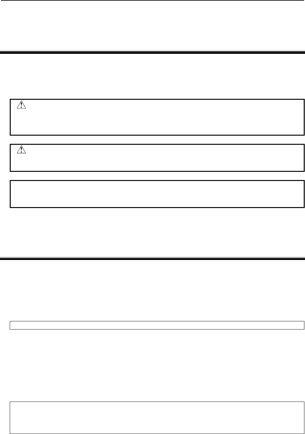
(3) Install a safety fence with a gate so that no working person can enter the work area without passing
through the gate. Install an interlocking device, a safety plug, and so forth in the safety gate so that
the robot is stopped as the safety gate is opened.
The controller is designed to receive this interlocking signal of the door switch. When the gate
is opened and this signal received, the controller stops the robot (Please refer to "STOP
TYPE OF ROBOT" in SAFETY PRECAUTIONS for detail of stop type). For connection, see
Fig.3 (a) and Fig.3 (b).

B-82854EN/02 SAFETY PRECAUTIONS
s-3
(4) Provide the peripheral devices with appropriate grounding (Class A, Class B, Class C, and Class D).
(5) Try to install the peripheral devices outside the work area.
(6) Draw an outline on the floor, clearly indicating the range of the robot motion, including the tools
such as a hand.
(7) Install a mat switch or photoelectric switch on the floor with an interlock to a visual or aural alarm
that stops the robot when a working person enters the work area.
(8) If necessary, install a safety lock so that no one except the working person in charge can turn on the
power of the robot.
The circuit breaker installed in the controller is designed to disable anyone from turning it on
when it is locked with a padlock.
(9) When adjusting each peripheral device independently, be sure to turn off the power of the robot
(10) Operators should be ungloved while manipulating the operator’s panel or teach pendant. Operation
with gloved fingers could cause an operation error.
(11) Programs, system variables, and other information can be saved on memory card or USB memories.
Be sure to save the data periodically in case the data is lost in an accident.
(12) The robot should be transported and installed by accurately following the procedures recommended
by FANUC. Wrong transportation or installation may cause the robot to fall, resulting in severe
injury to workers.
(13) In the first operation of the robot after installation, the operation should be restricted to low speeds.
Then, the speed should be gradually increased to check the operation of the robot.
(14) Before the robot is started, it should be checked that no one is in the area of the safety fence. At the
same time, a check must be made to ensure that there is no risk of hazardous situations. If detected,
such a situation should be eliminated before the operation.
(15) When the robot is used, the following precautions should be taken. Otherwise, the robot and
peripheral equipment can be adversely affected, or workers can be severely injured.
- Avoid using the robot in a flammable environment.
- Avoid using the robot in an explosive environment.
- Avoid using the robot in an environment full of radiation.
- Avoid using the robot under water or at high humidity.
- Avoid using the robot to carry a person or animal.
- Avoid using the robot as a stepladder. (Never climb up on or hang from the robot.)
(16) When connecting the peripheral devices related to stop(safety fence etc.) and each signal (external
emergency , fence etc.) of robot. be sure to confirm the stop movement and do not take the wrong
connection.
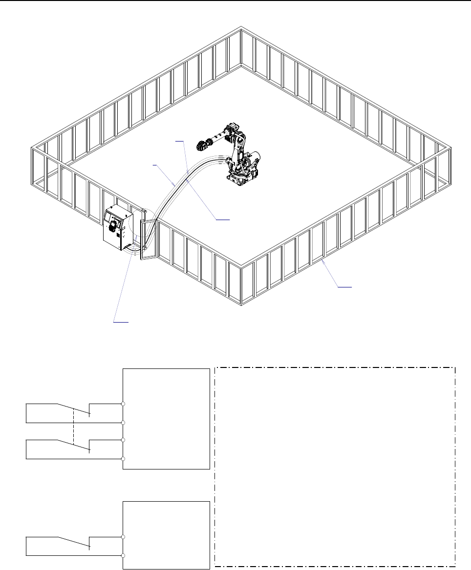
(17) When preparing trestle, please consider security for installation and maintenance work in high place
according to Fig.3 (c). Please consider footstep and safety bolt mounting position.
SAFETY PRECAUTIONS B-82854EN/02
s-4
RM1
Motor power/brake
RP1
Pulsecoder
RI/RO,XHBK,XROT
EARTH
Safety fence
Interlocking device and safety plug that are activated if the
gate is opened.
Fig. 3 (a) Safety fence and safety gate
Dual chain
Single chain Panel board
FENCE1
FENCE2
Panel board
EAS1
EAS11
EAS2
EAS21
(Note)
In case of R-30iA
Terminals EAS1,EAS11,EAS2,EAS21 or FENCE1,FENCE2
are provided on the operation box or on the terminal block
of the printed circuit board.
In case of R-30iA Mate
Terminals EAS1,EAS11,EAS2,EAS21 are provided
on the emergency stop board or connector panel.
(in case of Open air type)
Termianls FENCE1,FENCE2 are provided
on the emergency stop board.
Refer to controller maintenance manual for details.
Emergency stop board
or Panel board
(Note)
In case of R-30iB
Terminals EAS1,EAS11,EAS2,EAS21 are provided on the
emergency stop board.
In case R-30iA
Terminals EAS1,EAS11,EAS2,EAS21 are provided on the
emergency stop board or connector panel
In case R-30iA Mate
Terminals EAS1,EAS11,EAS2,EAS21 or FENCE1,FENCE2
are provided on the emergency stop board or in the connector
panel of CRM65 (Open air type).
Refer to the ELECTRICAL CONNCETIONS Chapter
of CONNECTION of controller maintenance manual for details.
Fig. 3 (b) Limit switch circuit diagram of the safety fence
B-82854EN/02 SAFETY PRECAUTIONS
s-5
Steps
Hook for safety belt
Fence
Trestle
Footstep
for maintenance
Fig.3 (c) Footstep for maintenance
3.1 OPERATOR SAFETY
The operator is a person who operates the robot system. In this sense, a worker who operates the teach
pendant is also an operator. However, this section does not apply to teach pendant operators.
(1) If you do not have to operate the robot, turn off the power of the robot controller or press the
EMERGENCY STOP button, and then proceed with necessary work.
(2) Operate the robot system at a location outside of the safety fence
(3) Install a safety fence with a safety gate to prevent any worker other than the operator from entering
the work area unexpectedly and to prevent the worker from entering a dangerous area.
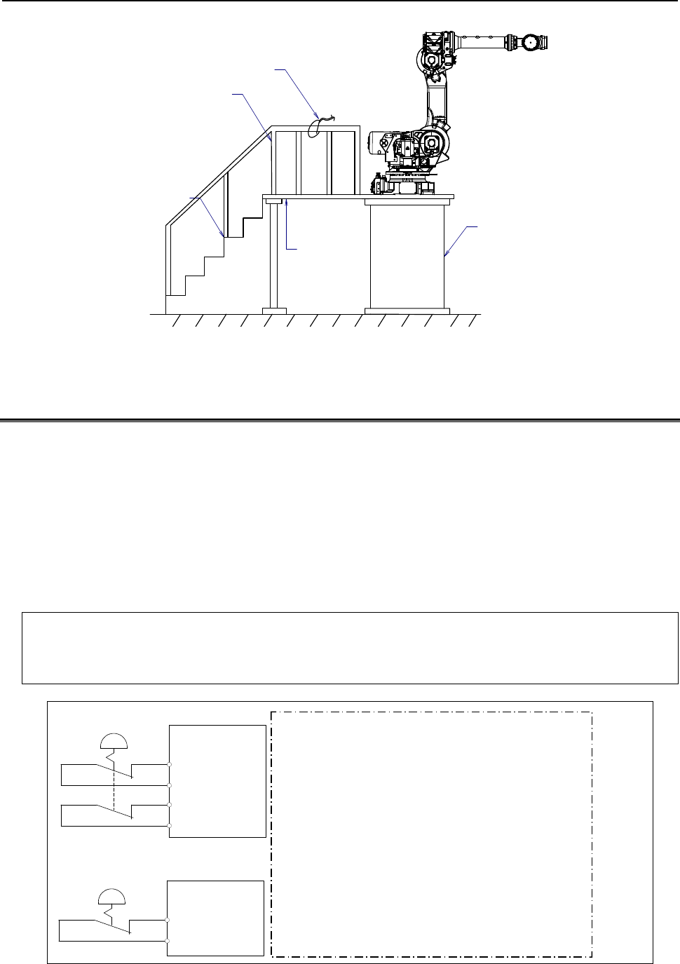
(4) Install an EMERGENCY STOP button within the operator’s reach.
The robot controller is designed to be connected to an external EMERGENCY STOP button.
With this connection, the controller stops the robot operation (Please refer to "STOP TYPE
OF ROBOT" in SAFETY PRECAUTIONS for detail of stop type), when the external
EMERGENCY STOP button is pressed. See the diagram below for connection.
Dual chain
Single chain
(Note)
Connect EES1and EES11,EES2 and EES21or EMGIN1and EMGIN2.
In case of R-30iA
EES1,EES11,EES2,EES21 or EMGIN1,EMGIN2 are on the panel board.
In case of R-30iA Mate
EES1,EES11,EES2,EES21 are on the emergency stop board
or connector panel (in case of Open air type).
EMGIN1,EMGIN2 are on the emergency stop board.
Refer to the maintenance manual of the controller for details.
External stop button
Panel board
EMGIN1
EMGIN2
Panel board
EES1
EES11
EES2
EES21
External stop button
(Note)
Connect EES1 and EES11, EES2 and EES21 or EMGIN1
and EMGIN2
In case R-30iB
EES1,EES11,EES2,EES21 are on the emergency stop board
In case R-30iA
EES1,EES11,EES2,EES21 or EMGIN1, EMGIN2 are on the
panel board.
In case R-30iA Mate
Terminals EAS1,EAS11,EAS2,EAS21 or FENCE1,FENCE2
are provided on the emergency stop board or in the connector
panel of CRM65 (Open air type).
Refer to the ELECTRICAL CONNCETIONS Chapter
of CONNECTION of controller maintenance manual for details.
Emergency stop board
or Panel board
Fig.3.1 Connection diagram for external emergency stop button

SAFETY PRECAUTIONS B-82854EN/02
s-6
3.2 SAFETY OF THE PROGRAMMER
While teaching the robot, the operator must enter the work area of the robot. The operator must ensure
the safety of the teach pendant operator especially.
(1) Unless it is specifically necessary to enter the robot work area, carry out all tasks outside the area.
(2) Before teaching the robot, check that the robot and its peripheral devices are all in the normal
operating condition.
(3) If it is inevitable to enter the robot work area to teach the robot, check the locations, settings, and
other conditions of the safety devices (such as the EMERGENCY STOP button, the DEADMAN
switch on the teach pendant) before entering the area.
(4) The programmer must be extremely careful not to let anyone else enter the robot work area.
(5) Programming should be done outside the area of the safety fence as far as possible. If programming
needs to be done in the area of the safety fence, the programmer should take the following
precautions:
- Before entering the area of the safety fence, ensure that there is no risk of dangerous situations
in the area.
- Be prepared to press the emergency stop button whenever necessary.
- Robot motions should be made at low speeds.
- Before starting programming, check the entire system status to ensure that no remote instruction
to the peripheral equipment or motion would be dangerous to the user.
Our operator panel is provided with an emergency stop button and a key switch (mode switch) for selecting the
automatic operation mode (AUTO) and the teach modes (T1 and T2). Before entering the inside of the safety
fence for the purpose of teaching, set the switch to a teach mode, remove the key from the mode switch to prevent
other people from changing the operation mode carelessly, then open the safety gate. If the safety gate is opened
with the automatic operation mode set, the robot stops (Please refer to "STOP TYPE OF ROBOT" in SAFETY
PRECAUTIONS for detail of stop type). After the switch is set to a teach mode, the safety gate is disabled. The
programmer should understand that the safety gate is disabled and is responsible for keeping other people from
entering the inside of the safety fence. (In case of R-30iA Mate Controller standard specification, there is no mode
switch. The automatic operation mode and the teach mode is selected by teach pendant enable switch.)
Our teach pendant is provided with a DEADMAN switch as well as an emergency stop button. These button and
switch function as follows:
(1) Emergency stop button: Causes an emergency stop (Please refer to "STOP TYPE OF ROBOT" in SAFETY
PRECAUTIONS for detail of stop type) when pressed.
(2) DEADMAN switch: Functions differently depending on the teach pendant enable/disable switch setting
status.
(a) Disable: The DEADMAN switch is disabled.
(b) Enable: Servo power is turned off when the operator releases the DEADMAN switch or when the
operator presses the switch strongly.
Note) The DEADMAN switch is provided to stop the robot when the operator releases the teach pendant or
presses the pendant strongly in case of emergency. The R-30iB/R-30iA/ R-30iA Mate employs a
3-position DEADMAN switch, which allows the robot to operate when the 3-position DEADMAN switch is
pressed to its intermediate point. When the operator releases the DEADMAN switch or presses the
switch strongly, the robot stops immediately.
The operator’s intention of starting teaching is determined by the controller through the dual operation of setting the
teach pendant enable/disable switch to the enable position and pressing the DEADMAN switch. The operator
should make sure that the robot could operate in such conditions and be responsible in carrying out tasks safely.
Based on the risk assessment by FANUC, number of operation of DEADMAN SW should not exceed about 10000
times per year.

B-82854EN/02 SAFETY PRECAUTIONS
s-7
The teach pendant, operator panel, and peripheral device interface send each robot start signal. However the
validity of each signal changes as follows depending on the mode switch and the DEADMAN switch of the operator
panel, the teach pendant enable switch and the remote condition on the software.
In case of R-30iB/R-30iA controller or CE or RIA specification of R-30iA Mate controller
Mode Teach pendant
enable switch
Software
remote
condition Teach pendant Operator panel Peripheral device
Local Not allowed Not allowed Not allowed
On Remote Not allowed Not allowed Not allowed
Local Not allowed Allowed to start Not allowed
AUTO
mode Off Remote Not allowed Not allowed Allowed to start
Local Allowed to start Not allowed Not allowed
On Remote Allowed to start Not allowed Not allowed
Local Not allowed Not allowed Not allowed
T1, T2
mode Off Remote Not allowed Not allowed Not allowed
T1,T2 mode: DEADMAN switch is effective.
In case of standard specification of R-30iA Mate controller
Teach pendant enable switch Software remote condition Teach pendant Peripheral device
On Ignored Allowed to start Not allowed
Local Not allowed Not allowed Off
Remote Not allowed Allowed to start
(6) (Only when R-30iB/R-30iA Controller or CE or RIA specification of R-30iA Mate controller is
selected.) To start the system using the operator’s panel, make certain that nobody is the robot work
area and that there are no abnormal conditions in the robot work area.
(7) When a program is completed, be sure to carry out a test operation according to the procedure
below.
(a) Run the program for at least one operation cycle in the single step mode at low speed.
(b) Run the program for at least one operation cycle in the continuous operation mode at low
speed.
(c) Run the program for one operation cycle in the continuous operation mode at the intermediate
speed and check that no abnormalities occur due to a delay in timing.
(d) Run the program for one operation cycle in the continuous operation mode at the normal
operating speed and check that the system operates automatically without trouble.
(e) After checking the completeness of the program through the test operation above, execute it in
the automatic operation mode.
(8) While operating the system in the automatic operation mode, the teach pendant operator should
leave the robot work area.
3.3 SAFETY OF THE MAINTENANCE ENGINEER
For the safety of maintenance engineer personnel, pay utmost attention to the following.
(1) During operation, never enter the robot work area.
(2) A hazardous situation may arise when the robot or the system, are kept with their power-on during
maintenance operations. Therefore, for any maintenance operation, the robot and the system should
be put into the power-off state. If necessary, a lock should be in place in order to prevent any other
person from turning on the robot and/or the system. In case maintenance needs to be executed in the
power-on state, the emergency stop button must be pressed.
(3) If it becomes necessary to enter the robot operation range while the power is on, press the
emergency stop button on the operator panel, or the teach pendant before entering the range. The

SAFETY PRECAUTIONS B-82854EN/02
s-8
maintenance personnel must indicate that maintenance work is in progress and be careful not to
allow other people to operate the robot carelessly.
(4) When entering the area enclosed by the safety fence, the maintenance worker must check the entire
system in order to make sure no dangerous situations exist. In case the worker needs to enter the
safety area whilst a dangerous situation exists, extreme care must be taken, and entire system status
must be carefully monitored.
(5) Before the maintenance of the pneumatic system is started, the supply pressure should be shut off
and the pressure in the piping should be reduced to zero.
(6) Before the start of teaching, check that the robot and its peripheral devices are all in the normal
operating condition.
(7) Do not operate the robot in the automatic mode while anybody is in the robot work area.
(8) When you maintain the robot alongside a wall or instrument, or when multiple workers are working
nearby, make certain that their escape path is not obstructed.
(9) When a tool is mounted on the robot, or when any moving device other than the robot is installed,
such as belt conveyor, pay careful attention to its motion.
(10) If necessary, have a worker who is familiar with the robot system stand beside the operator panel
and observe the work being performed. If any danger arises, the worker should be ready to press
the EMERGENCY STOP button at any time.
(11) When replacing a part, please contact FANUC service center. If a wrong procedure is followed, an
accident may occur, causing damage to the robot and injury to the worker.
(12) When replacing or reinstalling components, take care to prevent foreign material from entering the
system.
(13) When handling each unit or printed circuit board in the controller during inspection, turn off the
circuit breaker to protect against electric shock.
If there are two cabinets, turn off the both circuit breaker.
(14) A part should be replaced with a part recommended by FANUC. If other parts are used, malfunction
or damage would occur. Especially, a fuse that is not recommended by FANUC should not be used.
Such a fuse may cause a fire.
(15) When restarting the robot system after completing maintenance work, make sure in advance that
there is no person in the work area and that the robot and the peripheral devices are not abnormal.
(16) When a motor or brake is removed, the robot arm should be supported with a crane or other
equipment beforehand so that the arm would not fall during the removal.
(17) Whenever grease is spilled on the floor, it should be removed as quickly as possible to prevent
dangerous falls.
(18) The following parts are heated. If a maintenance worker needs to touch such a part in the heated
state, the worker should wear heat-resistant gloves or use other protective tools.
- Servo motor
- Inside the controller
- Reducer
- Gearbox
- Wrist unit
(19) Maintenance should be done under suitable light. Care must be taken that the light would not cause
any danger.
(20) When a motor, reducer, or other heavy load is handled, a crane or other equipment should be used to
protect maintenance workers from excessive load. Otherwise, the maintenance workers would be
severely injured.
(21) The robot should not be stepped on or climbed up during maintenance. If it is attempted, the robot
would be adversely affected. In addition, a misstep can cause injury to the worker.
(22) When performing maintenance work in high place, secure a footstep and wear safety belt.
(23) After the maintenance is completed, spilled oil or water and metal chips should be removed from the
floor around the robot and within the safety fence.
(24) When a part is replaced, all bolts and other related components should put back into their original
places. A careful check must be given to ensure that no components are missing or left not mounted.
(25) In case robot motion is required during maintenance, the following precautions should be taken :

B-82854EN/02 SAFETY PRECAUTIONS
s-9
- Foresee an escape route. And during the maintenance motion itself, monitor continuously the
whole system so that your escape route will not become blocked by the robot, or by peripheral
equipment.
- Always pay attention to potentially dangerous situations, and be prepared to press the emergency
stop button whenever necessary.
(26) The robot should be periodically inspected. (Refer to the robot mechanical manual and controller
maintenance manual.) A failure to do the periodical inspection can adversely affect the performance
or service life of the robot and may cause an accident
(27) After a part is replaced, a test operation should be given for the robot according to a predetermined
method. (See TESTING section of “Controller operator’s manual”.) During the test operation, the
maintenance staff should work outside the safety fence.
4 SAFETY OF THE TOOLS AND
PERIPHERAL DEVICES
4.1 PRECAUTIONS IN PROGRAMMING
(1) Use a limit switch or other sensor to detect a dangerous condition and, if necessary, design the
program to stop the robot when the sensor signal is received.
(2) Design the program to stop the robot when an abnormal condition occurs in any other robots or
peripheral devices, even though the robot itself is normal.
(3) For a system in which the robot and its peripheral devices are in synchronous motion, particular care
must be taken in programming so that they do not interfere with each other.
(4) Provide a suitable interface between the robot and its peripheral devices so that the robot can detect
the states of all devices in the system and can be stopped according to the states.
4.2 PRECAUTIONS FOR MECHANISM
(1) Keep the component cells of the robot system clean, and operate the robot in an environment free of
grease, water, and dust.
(2) Don’t use unconfirmed liquid for cutting fluid and cleaning fluid.
(3) Employ a limit switch or mechanical stopper to limit the robot motion so that the robot or cable does
not strike against its peripheral devices or tools.
(4) Observe the following precautions about the mechanical unit cables. When theses attentions are not
kept, unexpected troubles might occur.
• Use mechanical unit cable that have required user interface.
• Don’t add user cable or hose to inside of mechanical unit.
• Please do not obstruct the movement of the mechanical unit cable when cables are added to
outside of mechanical unit.
• In the case of the model that a cable is exposed, Please do not perform remodeling (Adding a
protective cover and fix an outside cable more) obstructing the behavior of the outcrop of the
cable.
• Please do not interfere with the other parts of mechanical unit when install equipments in the
robot.
(5) The frequent power-off stop for the robot during operation causes the trouble of the robot. Please
avoid the system construction that power-off stop would be operated routinely. (Refer to bad case
example.) Please execute power-off stop after reducing the speed of the robot and stopping it by
hold stop or cycle stop when it is not urgent. (Please refer to "STOP TYPE OF ROBOT" in
SAFETY PRECAUTIONS for detail of stop type.)
(Bad case example)

SAFETY PRECAUTIONS B-82854EN/02
s-10
• Whenever poor product is generated, a line stops by emergency stop.
• When alteration was necessary, safety switch is operated by opening safety fence and
power-off stop is executed for the robot during operation.
• An operator pushes the emergency stop button frequently, and a line stops.
• An area sensor or a mat switch connected to safety signal operate routinely and power-off stop
is executed for the robot.
(6) Robot stops urgently when collision detection alarm (SRVO-050) etc. occurs. The frequent urgent
stop by alarm causes the trouble of the robot, too. So remove the causes of the alarm.
5 SAFETY OF THE ROBOT MECHANISM
5.1 PRECAUTIONS IN OPERATION
(1) When operating the robot in the jog mode, set it at an appropriate speed so that the operator can
manage the robot in any eventuality.
(2) Before pressing the jog key, be sure you know in advance what motion the robot will perform in the
jog mode.
5.2 PRECAUTIONS IN PROGRAMMING
(1) When the work areas of robots overlap, make certain that the motions of the robots do not interfere
with each other.
(2) Be sure to specify the predetermined work origin in a motion program for the robot and program the
motion so that it starts from the origin and terminates at the origin.
Make it possible for the operator to easily distinguish at a glance that the robot motion has
terminated.
5.3 PRECAUTIONS FOR MECHANISMS
(1) Keep the work areas of the robot clean, and operate the robot in an environment free of grease, water,
and dust.
5.4 PROCEDURE TO MOVE ARM WITHOUT DRIVE POWER
IN EMERGENCY OR ABNORMAL SITUATIONS
For emergency or abnormal situations (e.g. persons trapped in or by the robot), brake release unit can be
used to move the robot axes without drive power.
Please refer to controller maintenance manual and mechanical unit operator’s manual for using method of
brake release unit and method of supporting robot.

B-82854EN/02 SAFETY PRECAUTIONS
s-11
6 SAFETY OF THE END EFFECTOR
6.1 PRECAUTIONS IN PROGRAMMING
(1) To control the pneumatic, hydraulic and electric actuators, carefully consider the necessary time
delay after issuing each control command up to actual motion and ensure safe control.
(2) Provide the end effector with a limit switch, and control the robot system by monitoring the state of
the end effector.
7 STOP TYPE OF ROBOT
The following three robot stop types exist:
Power-Off Stop (Category 0 following IEC 60204-1)
Servo power is turned off and the robot stops immediately. Servo power is turned off when the robot is
moving, and the motion path of the deceleration is uncontrolled.
The following processing is performed at Power-Off stop.
- An alarm is generated and servo power is turned off.
- The robot operation is stopped immediately. Execution of the program is paused.
Controlled stop (Category 1 following IEC 60204-1)
The robot is decelerated until it stops, and servo power is turned off.
The following processing is performed at Controlled stop.
- The alarm "SRVO-199 Controlled stop" occurs along with a decelerated stop. Execution of the
program is paused.
- An alarm is generated and servo power is turned off.
Hold (Category 2 following IEC 60204-1)
The robot is decelerated until it stops, and servo power remains on.
The following processing is performed at Hold.
- The robot operation is decelerated until it stops. Execution of the program is paused.
WARNING
The stopping distance and stopping time of Controlled stop are longer than the
stopping distance and stopping time of Power-Off stop. A risk assessment for
the whole robot system, which takes into consideration the increased stopping
distance and stopping time, is necessary when Controlled stop is used.
When the emergency stop button is pressed or the FENCE is open, the stop type of robot is Power-Off
stop or Controlled stop. The configuration of stop type for each situation is called stop pattern. The stop
pattern is different according to the controller type or option configuration.

SAFETY PRECAUTIONS B-82854EN/02
s-12
There are the following 3 Stop patterns.
Stop
pattern Mode Emergency
stop
button
External
Emergency
stop FENCE open SVOFF input Servo
disconnect
AUTO P-Stop P-Stop C-Stop C-Stop P-Stop
A T1 P-Stop P-Stop - C-Stop P-Stop
T2 P-Stop P-Stop - C-Stop P-Stop
AUTO P-Stop P-Stop P-Stop P-Stop P-Stop
B T1 P-Stop P-Stop - P-Stop P-Stop
T2 P-Stop P-Stop - P-Stop P-Stop
AUTO C-Stop C-Stop C-Stop C-Stop C-Stop
C T1 P-Stop P-Stop - C-Stop P-Stop
T2 P-Stop P-Stop - C-Stop P-Stop
P-Stop: Power-Off stop
C-Stop: Controlled stop
-: Disable
The following table indicates the Stop pattern according to the controller type or option configuration.
Option R-30iB
Standard A (*)
Controlled stop by E-Stop (A05B-2600-J570) C (*)
(*) R-30iB does not have servo disconnect.
R-30iA R-30iA Mate
Option Standard
(Single) Standard
(Dual) RIA
type CE
type Standard RIA
type CE
type
Standard B (*) A A A A (**) A A
Stop type set (Stop pattern C)
(A05B-2500-J570) N/A N/A C C N/A C C
(*) R-30iA standard (single) does not have servo disconnect.
(**) R-30iA Mate Standard does not have servo disconnect, and the stop type of SVOFF input is
Power-Off stop.
The stop pattern of the controller is displayed in "Stop pattern" line in software version screen. Please
refer to "Software version" in operator's manual of controller for the detail of software version screen.
"Controlled stop by E-Stop" option
When "Controlled stop by E-Stop" (A05B-2600-J570) option (In case of R-30iA/R-30iA Mate, it is Stop
type set (Stop pattern C) (A05B-2500-J570)) is specified, the stop type of the following alarms becomes
Controlled stop but only in AUTO mode. In T1 or T2 mode, the stop type is Power-Off stop which is
the normal operation of the system.
Alarm Condition
SRVO-001 Operator panel E-stop Operator panel emergency stop is pressed.
SRVO-002 Teach pendant E-stop Teach pendant emergency stop is pressed.
SRVO-007 External emergency stops External emergency stop input (EES1-EES11, EES2-EES21) is
open. (R-30iA/R-30iB controller)
SRVO-194 Servo disconnect Servo disconnect input (SD4-SD41, SD5-SD51) is open.
(R-30iA controller)
SRVO-218 Ext.E-stop/Servo Disconnect External emergency stop input (EES1-EES11, EES2-EES21) is
open. (R-30iA Mate/R-30iB controller)
SRVO-408 DCS SSO Ext Emergency Stop In DCS Safe I/O connect function, SSO[3] is OFF.
SRVO-409 DCS SSO Servo Disconnect In DCS Safe I/O connect function, SSO[4] is OFF.

B-82854EN/02 SAFETY PRECAUTIONS
s-13
Controlled stop is different from Power-Off stop as follows:
- In Controlled stop, the robot is stopped on the program path. This function is effective for a system
where the robot can interfere with other devices if it deviates from the program path.
- In Controlled stop, physical impact is less than Power-Off stop. This function is effective for
systems where the physical impact to the mechanical unit or EOAT (End Of Arm Tool) should be
minimized.
- The stopping distance and stopping time of Controlled stop is longer than the stopping distance and
stopping time of Power-Off stop, depending on the robot model and axis. Please refer to the
operator's manual of a particular robot model for the data of stopping distance and stopping time.
In case of R-30iA or R-30iA Mate, this function is available only in CE or RIA type hardware.
When this option is loaded, this function cannot be disabled.
The stop type of DCS Position and Speed Check functions is not affected by the loading of this option.
WARNING
The stopping distance and stopping time of Controlled stop are longer than the
stopping distance and stopping time of Power-Off stop. A risk assessment for
the whole robot system, which takes into consideration the increased stopping
distance and stopping time, is necessary when this option is loaded.

B-82854EN/02 TABLE OF CONTENTS
c-1
TABLE OF CONTENTS
SAFETY PRECAUTIONS............................................................................s-1
1 INTRODUCTION .....................................................................................1
2 SYSTEM OVERVIEW..............................................................................3
2.1 OVERVIEW ...................................................................................................3
2.2 SPECIFICATION OVERVIEW.......................................................................3
2.3 ETHERNET CONNECTION AND IP ADDRESS ASSIGNMENT...................4
2.4 ADAPTER MODE CONFIGURATION OUTLINE...........................................5
2.5 SCANNER MODE CONFIGURATION OUTLINE..........................................5
3 ADAPTER CONFIGURATION ................................................................7
3.1 OVERVIEW ...................................................................................................7
3.2 SETTING UP YOUR ROBOT ........................................................................7
3.2.1 Configuring the Robot I/O Size................................................................................7
3.2.2 Configuring the Remote Scanner .............................................................................9
3.2.3 Common Errors......................................................................................................13
4 SCANNER CONFIGURATION..............................................................14
4.1 OVERVIEW ................................................................................................. 14
4.2 SETTING UP YOUR ROBOT ......................................................................14
4.2.1 Overview ................................................................................................................14
4.2.2 Configure the Adapter Device................................................................................15
4.2.3 Configure the Robot Scan List...............................................................................15
4.2.4 Advanced EtherNet/IP Scanner Configuration ......................................................19
4.2.4.1 Quick connect feature........................................................................................21
4.2.5 Analog I/O..............................................................................................................24
4.2.5.1 Overview ........................................................................................................... 24
4.2.5.2 Examples ........................................................................................................... 25
4.2.6 Common Errors......................................................................................................25
5 ETHERNET/IP TO DEVICENET ROUTING..........................................26
5.1 OVERVIEW ................................................................................................. 26
5.2 GUIDELINES...............................................................................................26
5.3 SETTING UP ETHERNET/IP TO DEVICENET ROUTING.......................... 26
5.4 USING ETHERNET/IP TO DEVICENET ROUTING....................................27
6 I/O CONFIGURATION...........................................................................32
6.1 OVERVIEW ................................................................................................. 32
6.1.1 I/O Size of Each Connection and I/O Configuration..............................................32

TABLE OF CONTENTS B-82854EN/02
c-2
6.2 MAPPING I/O ON THE ROBOT ..................................................................32
6.3 BACKING UP AND RESTORING ETHERNET/IP AND I/O CONFIGURATION
.....................................................................................................................33
7 EXPLICIT MESSAGING........................................................................35
7.1 OVERVIEW ................................................................................................. 35
7.2 ROBOT EXPLICIT MESSAGING CLIENT...................................................36
7.2.1 Overview ................................................................................................................36
7.2.2 Creating a Configuration File for the Batch File Method ......................................38
7.3 REMOTE EXPLICIT MESSAGING CLIENT CONFIGURATION ................. 39
7.4 VENDOR SPECIFIC REGISTER OBJECTS ...............................................39
7.4.1 Numeric Register Objects (0x6B and 0x6C)..........................................................40
7.4.1.1 Instance attributes..............................................................................................41
7.4.1.2 Common services............................................................................................... 41
7.4.1.3 Errors................................................................................................................. 42
7.4.1.4 Read single register............................................................................................42
7.4.1.5 Read all registers................................................................................................43
7.4.1.6 Read a block of registers....................................................................................44
7.4.1.7 Write single register........................................................................................... 45
7.4.1.8 Write all registers............................................................................................... 46
7.4.1.9 Write a block of registers................................................................................... 47
7.4.2 String Register Object (0x6D)................................................................................48
7.4.2.1 Instance attributes..............................................................................................48
7.4.2.2 Common services............................................................................................... 49
7.4.2.3 Errors................................................................................................................. 50
7.4.2.4 Read single register............................................................................................50
7.4.2.5 Read all register................................................................................................. 50
7.4.2.6 Read a block of register..................................................................................... 51
7.4.2.7 Write single register........................................................................................... 52
7.4.2.8 Write all registers............................................................................................... 52
7.4.2.9 Write a block of registers................................................................................... 53
7.4.3 Position Register Object (0x7B, 0x7C, 0x7D, 0x7E).............................................54
7.4.3.1 Instance attributes..............................................................................................54
7.4.3.2 Common services............................................................................................... 56
7.4.3.3 Errors................................................................................................................. 57
7.4.3.4 Read single register............................................................................................57
7.4.3.5 Read all registers................................................................................................58
7.4.3.6 Read a block of registers....................................................................................59
7.4.3.7 Read current position (CURPOS or CURJPOS) ...............................................60
7.4.3.8 Write single register........................................................................................... 61
7.4.3.9 Write all registers............................................................................................... 62
7.4.3.10 Write a block of registers...................................................................................62

B-82854EN/02 TABLE OF CONTENTS
c-3
7.5 VENDOR SPECIFIC ACTIVE ALARM OBJECT (0xA0)..............................63
7.5.1 Instance Attributes..................................................................................................63
7.5.2 Common Services...................................................................................................64
7.5.2.1 Get_Attribute_All Response.............................................................................. 64
7.5.3 Errors......................................................................................................................65
7.5.4 Examples ................................................................................................................65
7.5.4.1 Read most recent active alarm cause code.........................................................65
7.5.4.2 Read all alarm information from the second most recent active alarm.............. 65
7.6 VENDOC SPECIFIC ALARM HISTORY OBJECT (0xA1) ...........................66
7.6.1 Instance Attributes..................................................................................................66
7.6.2 Common Services...................................................................................................66
7.6.3 Errors......................................................................................................................66
7.6.4 Examples ................................................................................................................66
7.6.4.1 Read most recent alarm cause code................................................................... 66
7.6.4.2 Real all alarm information from the second most recent alarm.........................66
7.7 VENDOR SPECIFIC MOTION ALARM OBJECT (0xA2).............................67
7.7.1 Instance Attributes..................................................................................................67
7.7.2 Common Services...................................................................................................67
7.7.3 Errors......................................................................................................................67
7.7.4 Examples ................................................................................................................67
7.7.4.1 Read most recent motion alarm cause code.......................................................67
7.7.4.2 Read all alarm information from the second most recent motion alarm............67
7.8 VENDOR SPECIFIC SYSTEM ALARM OBJECT (0xA3) ............................68
7.8.1 Instance Attributes..................................................................................................68
7.8.2 Common Services...................................................................................................68
7.8.3 Errors......................................................................................................................68
7.8.4 Examples ................................................................................................................68
7.8.4.1 Read most recent system alarm cause code .......................................................68
7.8.4.2 Read all alarm information from the second most recent system alarm ............ 69
7.9 VENDOR SPECIFIC APPLICATION ALARM OBJECT (0xA4) ................... 69
7.9.1 Instance Attributes..................................................................................................69
7.9.2 Common Services...................................................................................................69
7.9.3 Errors......................................................................................................................69
7.9.4 Examples ................................................................................................................69
7.9.4.1 Read most recent application alarm cause code.................................................69
7.9.4.2 Read all alarm information from the second most recent application alarm......70
7.10 VENDOR SPECIFIC RECOVERY ALARM OBJECT (0xA5)....................... 70
7.10.1 Instance Attributes..................................................................................................70
7.10.2 Common Services...................................................................................................70

TABLE OF CONTENTS B-82854EN/02
c-4
7.10.3 Errors......................................................................................................................70
7.10.4 Examples ................................................................................................................71
7.10.4.1 Read most recent recovery alarm cause code .................................................... 71
7.10.4.2 Read all alarm information from the second most recent recovery alarm .........71
7.11 VENDOR SPECIFIC COMMUNICATIONS ALARM OBJECT (0xA6)..........71
7.11.1 Instance Attributes..................................................................................................71
7.11.2 Common Services...................................................................................................71
7.11.3 Errors......................................................................................................................72
7.11.4 Examples ................................................................................................................72
7.11.4.1 Read most recent communication alarm cause code..........................................72
7.11.4.2 Read all alarm information from the second most recent communications alarm
...........................................................................................................................72
7.12 ACCESSING I/O USING EXPLICIT MESSAGING...................................... 72
7.12.1 Accessing I/O Specific to an Implicit EtherNet/IP Connection .............................72
7.12.2 Accessing General I/O............................................................................................75
7.13 USING EXPLICIT MESSAGING IN RSLogix 5000...................................... 76
8 NETWORK DESIGN AND PERFORMANCE........................................80
8.1 NETWORK DESIGN CONSIDERATIONS................................................... 80
8.2 I/O RESPONSE TIME ................................................................................. 81
9 DIAGNOSTICS AND TROUBLESHOOTING........................................84
9.1 VERIFYING NETWORK CONNECTIONS...................................................84
9.1.1 Ethernet Status LEDs .............................................................................................84
9.1.2 PING Utility ...........................................................................................................84
9.2 ERROR CODES.......................................................................................... 86
APPENDIX
A THIRD-PARTY CONFIGURATION TOOLS..........................................91
A.1 TOOLS OVERVIEW ....................................................................................91
B KAREL PROGRAMS FOR ETHERNET/IP Scanner Quick Connect..94
B.1 OVERVIEW .................................................................................................94
B.2 KAREL PROGRAM DESCRIPTIONS AND PARAMETERS........................ 94
B.3 USING KAREL PROGRAMS IN TEACH PENDANT PROGRAMS ............. 95
B.4 EXAMPLES USING ETHERNET/IP MACROS............................................96
B.4.1 Overview ................................................................................................................96
B.4.2 Individual Examples...............................................................................................96
B.4.3 Advanced Examples...............................................................................................97

B-82854EN/02 1.INTRODUCTION
- 1 -
1 INTRODUCTION
The EtherNet/IP interface supports an I/O exchange with other EtherNet/IP enabled devices over an
Ethernet network. The EtherNet/IP specification is managed by the Open DeviceNet Vendors Association
(www.odva.org).
From the EtherNet/IP Specification (Release 1.0) Overview :
EtherNet/IP (Ethernet/Industrial Protocol) is a communication system suitable for use in industrial
environments. EtherNet/IP allows industrial devices to exchange time-critical application information.
These devices include simple I/O devices such as sensors/actuators, as well as complex control devices
such as robots, programmable logic controllers, welders, and process controllers.
EtherNet/IP uses CIP (Control and Information Protocol), the common network, transport and application
layers also shared by ControlNet and DeviceNet. EtherNet/IP then makes use of standard Ethernet and
TCP/IP technology to transport CIP communications packets. The result is a common, open application
layer on top of open and highly popular Ethernet and TCP/IP protocols.
EtherNet/IP provides a producer/consumer model for the exchange of time-critical control data. The
producer/consumer model allows the exchange of application information between a sending device (e.g.,
the producer) and many receiving devices (e.g., the consumers) without the need to send the data multiple
times to multiple destinations. For EtherNet/IP, this is accomplished by making use of the CIP network
and transport layers along with IP Multicast technology. Many EtherNet/IP devices can receive the same
produced piece of application information from a single producing device.
EtherNet/IP makes use of standard IEEE 802.3 technology; there are no non-standard additions that
attempt to improve determinism. Rather, EtherNet/IP recommends the use of commercial switch
technology, with 100 Mbps bandwidth and full-duplex operation, to provide for more deterministic
performance.
The terms adapter and scanner are used throughout this manual. Although EtherNet/IP is a
producer/consumer network, these terms are still appropriate to describe a device which creates the I/O
connection (the scanner), and a device which responds to connection requests (the adapter). The scanner
can also be called the connection originator. The adapter can also be called the connection target.
The following steps are necessary to configure EtherNet/IP with the robot as the adapter:
1. Design and install the network. It is critical to follow good network design and installation
practices for a reliable network. Refer to Section 8.1 .
2. Set the IP addresses. All devices on the network require a valid IP address. Refer to Section 2.3 for
additional information for the robot.
3. Configure the adapter devices. Adapter devices might require configuration such as setting I/O
sizes. Refer to Section 3.2.1 to configure the robot as an adapter.
4. Configure the scanner devices. Scanners must be configured with a list of devices (adapters) to
connect to along with parameters for each connection. Refer to Section 3.2.2 to configure an Allen
Bradley ControlLogix PLC to connect to the robot.
5. Map EtherNet/IP I/O to digital, group, or UOP I/O points within the robot. Refer to Section 6.2
for more information. Scanner connections can also be mapped to analog. Refer to Section 4.2.5 .
6. Backup the configuration. Refer to Section 6.3 for details on doing this for the robot.
NOTE
If you need to perform diagnostics or troubleshooting, refer to Chapter 9 .

1.INTRODUCTION B-82854EN/02
- 2 -
NOTE
For EtherNet/IP Safety function that exchanges safety signals on EtherNet/IP,
please read “R-30iA/R-30iA Mate controller Dual Check Safety Function (ISO
13849-1:2006 compliant) operator’s manual (B-83104EN)” or “R-30iB controller
Dual Check Safety Function operator’s manual (B-83184EN) in addition to this
manual.

B-82854EN/02 2.SYSTEM OVERVIEW
- 3 -
2 SYSTEM OVERVIEW
2.1 OVERVIEW
The robot supports 32 connections. Each connection can be configured as either a Scanner connection, or
as an Adapter connection. Adapter connections are normally to a cell controller or PLC to exchange cell
interface I/O data. The EtherNet/IP Adapter option must be loaded to support this functionality.
Each Scanner connection can be configured to exchange I/O with a remote device capable of acting as an
adapter on an EtherNet/IP network. The EtherNet/IP Scanner option must be loaded to support this
functionality (the EtherNet/IP Scanner option includes the adapter functionality as well).
The EtherNet/IP interface corresponds to Rack 89 in the robot for I/O mapping. The slot number reflects
the connection number from the EtherNet/IP interface user interface screen. Any amount of I/O can be
mapped within EtherNet/IP, up to the maximum supported on the robot. Analog I/O is supported on
scanner connections.
Good network design is critical to having reliable communications. Excessive traffic and collisions must
be avoided or managed. Refer to Section 8.1 for details.
2.2 SPECIFICATION OVERVIEW
Table 2.2(a) and table 2.2(b) provides an overview of specifications for EtherNet/IP.
Table 2.2(a) R-30iA/R-30iA Mate specification overview
Item Specification
Number Adapter
Connections
0–32
Number Scanner
Connections
32 minus the number of adapter connections
Minimum RPI 8 msec
Maximum Number of
Input bytes per
connection (combination
of Digital and Analog)
64 Words (1Word = 16 bits) or 128 Bytes (1Bytes = 8bits)
Maximum Number of
Output bytes per
connection (combination
of Digital and Analog)
64 Words (1Word = 16 bits) or 128 Bytes (1Bytes = 8bits)
Supported Signal Types Digital, Group, UOP, Analog (for scanner connections only)
Table 2.2(b) R-30iB specification overview
Item Specification
Number Adapter
Connections
0–32
Number Scanner
Connections
32 minus the number of adapter connections
Minimum RPI 8 msec

2.SYSTEM OVERVIEW B-82854EN/02
- 4 -
Item Specification
Maximum Number of
Input bytes per
connection (combination
of Digital and Analog)
248 Words (1Word = 16 bits) or 496 Bytes (1Bytes = 8bits)
Maximum Number of
Output bytes per
connection (combination
of Digital and Analog)
248 Words (1Word = 16 bits) or 496 Bytes (1Bytes = 8bits)
Supported Signal Types Digital, Group, UOP, Analog (for scanner connections only)
NOTE
The maximum number of Input/Output bytes per connection in table 2.2(a) and
table 2.2(b) is the range of value that can be set as the data size of EtherNet/IP
connection. On the other hand, the maximum number fo I/O that can be used in
a robot controller differs according to the application software and other option
software configuration.
NOTE
In order for the scanner to work, the EtherNet/IP Scanner option must be loaded.
NOTE
For EtherNet/IP Safety function that exchanges safety signals on EtherNet/IP,
please read “R-30iA/R-30iA Mate controller Dual Check Safety Function (ISO
13849-1:2006 compliant) operator’s manual (B-83104EN)” or “R-30iB controller
Dual Check Safety Function operator’s manual (B-83184EN) in addition to this
manual.
2.3 ETHERNET CONNECTION AND IP ADDRESS
ASSIGNMENT
The robot must have a valid IP (Internet protocol) address and subnet mask to operate as an EtherNet/IP
node.
The Ethernet interface supports 10Mbps and 100Mbps baud rates, along with half and full duplex
communication. By default both interfaces will auto-negotiate and should be connected to a switch which
supports 100Mbps full duplex connections. The LEDs located near the RJ45 connectors on the main CPU
board are useful in confirming link establishment.
The IP address(es) can be configured in the following ways :
Manually configured on the robot teach pendant
DHCP (Dynamic Host Configuration Protocol)
NOTE
DHCP is an optional software component. It is important to utilize static or infinite
lease IP addresses when using EtherNet/IP.
Either one or both Ethernet ports can be configured for use with EtherNet/IP. Note that in order to use
both ports at the same time they must be properly configured on separate subnets. Also note that port 2
(CD38B) is optimized for Ethernet I/O protocols such as EtherNet/IP. The preferred setup is to connect

B-82854EN/02 2.SYSTEM OVERVIEW
- 5 -
port 1 (CD38A) to your building network to access the robot through HTTP, FTP, and so forth , and to
connect port 2 (CD38B) to an isolated network for use by EtherNet/IP.
NOTE
Be sure that all EtherNet/IP node IP addresses are configured properly before
you perform the functions in this manual. The PING utility can be used to verify
basic communications. Refer to Chapter 9 for more information.
2.4 ADAPTER MODE CONFIGURATION OUTLINE
Perform the following steps to configure the adapter connection on the robot:
Configure the I/O size on the robot. Refer to Section 3.2.1 .
Map the physical EtherNet/IP I/O to logical I/O points (digital, group, or UOP) on the robot. Refer
to Section 6.2 .
Configure the remote scanner (for example, ControlLogix PLC). Refer to Section 3.2.2 .
Table 2.4 provides a summary of the adapter configuration. This information is used in the scanner device
(for example, PLC) configured to communicate with the robot EtherNet/IP Adapter interface.
Table 2.4 Adapter configuration summary
ITEM DESCRIPTION
Vendor ID 356
Product Code 2
Device Type 12
Communication Format Data – INT
Input Assembly Instance 101–132
Input Size User Configurable, Set in 16-bit Words
Output Assembly Instance 151–182
Output Size User Configurable, Set in 16-bit Words
Configuration Instance 100
Configuration Size 0
The default I/O size for the adapter connection is four words for both inputs and outputs. This
corresponds to 64 I/O points based on a 16-bit word. This size must be configured on the robot teach
pendant, as well as on the remote scanner (for example, PLC).
Refer to Chapter 3 for details.
2.5 SCANNER MODE CONFIGURATION OUTLINE
The robot must be configured to initiate EtherNet/IP connections. Up to 32 scanner connections are
supported. Perform the following steps to configure the scanner connection on the robot :
Configure the robot scan list on the teach pendant. Refer to Section 4.2.3 .
Map the physical EtherNet/IP I/O to logical I/O points (for example, digital, group, analog, or UOP)
on the robot. Refer to Section 6.2 .
For each connection the following data must be provided on the robot teach pendant. (Refer to the manual
that applies to the adapter device being configured for more information.)

2.SYSTEM OVERVIEW B-82854EN/02
- 6 -
Name/IP address
Vendor ID
DeviceType
Product Code
Input Size (16-bit words or 8-bit byes)
Output Size (16-bit words or 8-bit byes)
RPI (ms)
Input assembly instance
Output assembly instance
Configuration instance
NOTE
The robot currently cannot be configured for devices with a non-zero
configuration size from the teach pendant. Refer to Appendix A for information
on third party configuration tools.

B-82854EN/02 3.ADAPTER CONFIGURATION
- 7 -
3 ADAPTER CONFIGURATION
3.1 OVERVIEW
The robot supports up to 32 adapter connections. These connections are normally to a cell controller or
PLC to exchange cell interface I/O data. The EtherNet/IP Adapter Option must be loaded to support this
functionality.
The following steps are required to configure the adapter connection on the robot :
Configure I/O size on the robot. Refer to Section 3.2.1 .
Map the physical EtherNet/IP I/O to logical I/O points (digital, group, or UOP) on the robot. Refer
to Section 6.2 .
Configure the remote scanner (for example, ControlLogix PLC). Refer to Section 3.2.2 .
3.2 SETTING UP YOUR ROBOT
3.2.1 Configuring the Robot I/O Size
The Input size and Output size are set in 16-bit word sizes. This means if 32 bits of input and 32 bits of
output are needed then the Input size and Output Size would be set to 2 words each. The default size of
the adapter connection is 4 words (64 bits) of input and 4 words (64 bits) of output. Changes in I/O size
require you to turn off and turn on the robot to take effect.
Refer to Procedure 3-1 to configure I/O size on the robot.
Table 3.2.1(a) describes the items displayed on the EtherNet/IP Status screen.
Table 3.2.1(b) describes the items on the EtherNet/IP Configuration screen.
Table 3.2.1(a) EtherNet/IP status screen descriptions
ITEM DESCRIPTION
Description
Default: ConnectionX where
X is the slot number of the
Adapter.
This item is the description of the adapter or scanner. This can be set as desired to
coordinate with your equipment.
TYP
Default: ADP
This item indicates whether the connection is configured as an Adapter, or as a
Scanner.
Enable
Default: TRUE (for Adapter 1,
FALSE for Adapters 2–32)
This item indicates whether the adapter or scanner is enabled (TRUE) or disabled
(FALSE).
Status The Status field can have the following values :
OFFLINE– the connection is disabled.
ONLINE – the connection is enabled but is not active (for example,
waiting for a connection).
RUNNING - the connection is enabled and active (I/O is being
exchanged).
<RUNNING> - the connection is enabled and active (I/O is being
exchanged), and auto-reconnect is enabled. See Table 4.2.4 for more
information on the auto-reconnect setting.
PENDING – changes have taken place in configuration. You must
turn off the robot, then turn it on again.

3.ADAPTER CONFIGURATION B-82854EN/02
- 8 -
ITEM DESCRIPTION
Slot This item is the value used when mapping EtherNet/IP I/O to digital, group, or UOP
I/O signals.
Table 3.2.1(b) EtherNet/IP configuration screen descriptions
ITEM DESCRIPTION
Description This item is the comment that shows up on the Status screen. It is set on the Status
screen as well.
Input size (words)
Default:
This item is the number of 16 bit words configured for input.
Output size (words)
Default:
This item is the number of 16 bit words configured for output.
Alarm Severity
Default: WARN
This item indicates the severity of alarm that will be posted by the adapter
connection. The valid choices are STOP, WARN, and PAUSE.
Scanner IP The IP address of the connected scanner.
API 0 => T Actual Packet Interval at which the scanner/originator is producing.
API T => 0 Actual Packet Interval at which the adapter/target is producing.
Procedure 3-1 Configuring I/O Size on the Robot
Steps
1. Press MENUS.
2. Select I/O.
3. Press F1, [TYPE], and select EtherNet/IP. You will see a screen similar to the following.
I/O EtherNet/IP JOINT 10 %
EtherNet/IP List(Rack 89) 1/8
Description TYP Enable Status Slot
Connection1 ADP TRUE ONLINE 1
Connection2 ADP FALSE OFFLINE 2
Connection3 ADP FALSE OFFLINE 3
Connection4 ADP FALSE OFFLINE 4
Connection5 ADP FALSE OFFLINE 5
Connection6 ADP FALSE OFFLINE 6
Connection7 ADP FALSE OFFLINE 7
Connection8 ADP FALSE OFFLINE 8
Refer to Table 3.2.1(a) for descriptions of these screen items.
4. Move the cursor to select a connection. If the connection is configured as a scanner, move the cursor
to the TYP column and press F5. This configures the connection as an adapter.
5. Move the cursor to select the desired adapter. If you plan to make changes to the adapter
configuration, you must first disable the connections. Otherwise, the configuration screen is
read-only.
NOTE
If the adapter connection is Enabled, the first line of the adapter configuration
screen will display “Adapter config (Read-only)” and the items on the screen
cannot be modified. To make changes to the adapter configuration screen, you
must disable the adapter connection on the EtherNet/IP Status screen.
6. To change adapter status:

B-82854EN/02 3.ADAPTER CONFIGURATION
- 9 -
a. Move the cursor to highlight the field in the Enable column for the adapter.
b. To disable the adapter and change the status to OFFLINE, press F5, FALSE.
To enable the adapter and change the status to ONLINE, press F4, TRUE.
7. Move the cursor to the Description column. Press F4, CONFIG. You will see a screen similar to the
following.
Adapter configuration :
Description : Connection1
Input size (words) : 4
Output size(words) : 4
Alarm Severity : WARN
Scanner IP : ****************
API O=>T : 0
API T=>O : 0
Refer to Table 3.2.1(b) for descriptions of these screen items.
8. To change the I/O size:
a. Move the cursor to select "Input size (words)."
b. Type the value you want and press Enter.
c. Move the cursor to select "Output size (words)."
d. Type the value you want and press Enter.
e. Move the cursor to select the alarm severity.
f. Pres F4, [CHOICE], and select the desired severity.
g. To return to the previous screen, press F3, [PREV].
9. After modifying the adapter configuration, you must enable the connection on the EtherNet/IP status
screen. If any changes were made, the status will show as “PENDING”. This indicates that you must
cycle power in order for the changes to take effect.
NOTE
To map EtherNet/IP I/O to digital, group, or UP I/O, refer to Section 6.2 .
3.2.2 Configuring the Remote Scanner
The EtherNet/IP Interface status screen should show that the adapter connection is ONLINE. This means
it is available and waiting for a request from a scanner (for example, PLC) to exchange I/O. If the adapter
status is not ONLINE, refer to Procedure 3-1 , Step 6 .
Table 3.2.2(a) provides a summary of the adapter configuration. This information is used to configure the
remote scanner (for example, PLC).
Table 3.2.2(a) Adapter configuration summary
ITEM DESCRIPTION
Vendor ID 356
Product Code 2
Device Type 12
Communication Format Data – INT
Input Assembly Instance 101–132
Input Size User Configurable, Set in 16-bit Words
Output Assembly Instance 151–182
Output Size User Configurable, Set in 16-bit Words
Configuration Instance 100
Configuration Size 0

3.ADAPTER CONFIGURATION B-82854EN/02
- 10 -
Table 3.2.2(b) Connection points
Slot Number Input Assembly Instance Output Assembly Instance
1 101 151
2 102 152
3 103 153
4 104 154
5 105 155
6 106 156
7 107 157
8 108 158
9 109 159
10 110 160
11 111 161
12 112 162
13 113 163
14 114 164
15 115 165
16 116 166
17 117 167
18 118 168
19 119 169
20 120 170
21 121 171
22 122 172
23 123 173
24 124 174
25 125 175
26 126 176
27 127 177
28 128 178
29 129 179
30 130 180
31 131 181
32 132 182
Use Procedure 3-2 to configure the Allen Bradley ControlLogix PLC. for other scanners, refer to their
configuration software in conjunction with Table 3.2.2(a) .
B-82854EN/02 3.ADAPTER CONFIGURATION
- 11 -
Procedure 3-2 Configuring the Scanner Using RS-Logix5000 Software
Steps
NOTE
The following screens show how to configure the scanner using RS-Logix5000
software, which is used with the Allen Bradley ControlLogix PLC. This example
assumes that an EtherNet/IP Bridge module has been added to the configuration
in the ControlLogix PLC.
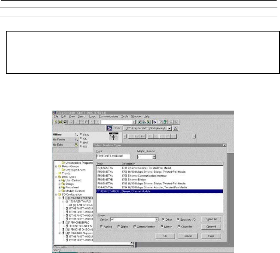
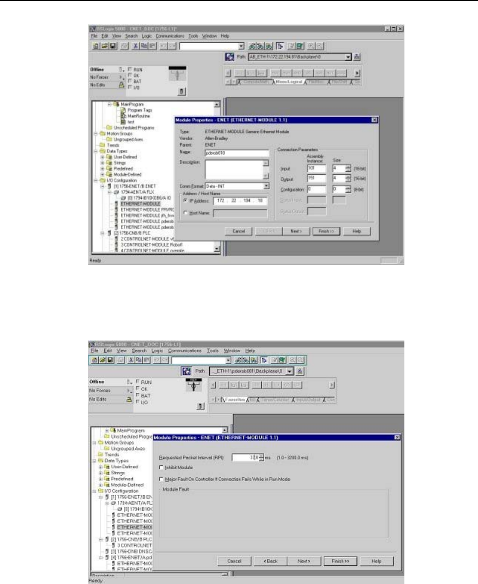
1. To add the robot adapter connection to the configuration, right-click the EtherNet/IP Bridge module
in the PLC, and select“ New Module”.
2. Select “Generic Ethernet Module,” and click OK. You will see a screen similar to the following.
3. In the next screen, RSLogix will ask for information regarding the communication to the robot. Type
a name for the robot adapter connection.
In the example below we call the module “Example_Robot”. This name will create a tag in RSLogix,
which can be used to access the memory location in the PLCs memory where the data for the
Example_Robot will be stored. A description can also be added if desired (optional).
4. Select the “Comm_Format,” which tells RSLogix the format of the data.
In this example we select Data-INT, which will represent the data in the robot as a field of 16-bit
words.
5. Set connection parameters as follows:
Each of the 32 Connections have different Connection parameters, which are based on the slot
number. Refer to Table 3.2.2(b) to determine the correct parameters. The size of the input
connection and the output connection must correspond to the size that we have configured for the
robot. In this example we configured the robot for 4 (16 bit) words of input data and output data.
The configuration instance should be set to 100 and size of the configuration instance is set to 0.
In the following example, we will be setting up connection parameters corresponding to the adapter
in slot 1.
6. Type the IP address that we have configured for the module.
This could be the Host Name if the DNS (Domain Name Service) is configured and available for the
PLC to resolve names to IP addresses (if names are used be sure the DNS server is very reliable and
always available to the PLC during operation). You will see a screen similar to the following.
3.ADAPTER CONFIGURATION B-82854EN/02
- 12 -
7. The RPI (requested packet interval) is set on the next screen. This sets the rate for I/O updates. In the
following example the RPI is set to 32ms. This means the PLC will send its outputs to the robot
every 32ms, and the robot will send its inputs to the PLC every 32ms. You will see a screen similar
to the following.
8. Press Finish to complete this step.
9. To download the new configuration to the ControlLogix PLC, select Download from the
Communications menu. You will see a screen similar to the following.
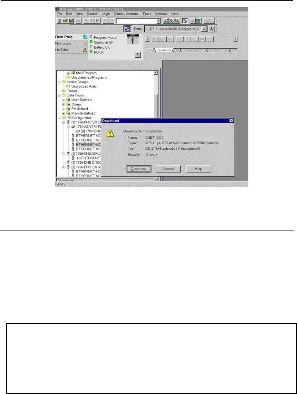
B-82854EN/02 3.ADAPTER CONFIGURATION
- 13 -
10. If there are any errors, a warning triangle will be present on the Example_Robot in the I/O
configuration listing. Double click the module to view any error that is reported.
3.2.3 Common Errors
The robot will post an alarm indicating that the adapter connection is idle if it is enabled but no scanner
has connected to it. This is an informational alarm (warning level) by default. This message is reposted
whenever the robot RESET button is pressed and the adapter connection is idle. If desired, the error
severity level of EtherNet/IP adapter alarms can be increased. See Step 8 of Procedure 3-1 for more
details.
If the adapter connection is lost the values of any mapped inputs will be zeroed out (by default). The last
state behavior can be changed by setting the following system variable : $EIP_CFG.$KEEP_IO_ADP.
The values are :
FALSE : The last state values of the adapter inputs will be zero (default)
TRUE : The last state values of the adapter inputs will be their last value
NOTE
If some of the EtherNet/IP adapter I/O signals are configured as UOP
HOLD/IMSTP signals and communication is interrupted, then the default behavior
will cause the robot to stop. This is due to the UOP inputs going to zero (last state
behavior) and causing UOP HOLD and IMSTP alarms to be posted. It is typical for
the adapter connection to be configured so that alarms are of “WARNING” severity
and the “Last State” is set to FALSE (default behavior), which allows UOP in/out
signals to stop the robot operation.

4.SCANNER CONFIGURATION B-82854EN/02
- 14 -
4 SCANNER CONFIGURATION
4.1 OVERVIEW
The robot supports up to 32 scanner connections. Each connection can be configured to exchange I/O
with a remote device capable of acting as an adapter on an EtherNet/IP network. The EtherNet/IP Scanner
option must be loaded to support this functionality. The EtherNet/IP Scanner option includes the adapter
functionality as well. An example of an EtherNet/IP adapter device that the robot would connect to might
be an I/O block.
The robot must be configured to initiate EtherNet/IP connections. Up to 32 scanner connections are
supported. Perform the following steps to configure the scanner connection on the robot :
Configure the adapter device if required. Refer to Section 4.2.2 .
Configure the robot scan list on the teach pendant. Refer to Section 4.2.3 or configure the robot scan
list from RSNetWorx for EtherNet/IP (Refer to Appendix A ).
Map the physical EtherNet/IP I/O to logical I/O points (digital, group, analog, or UOP) on the robot.
Refer to Section 6.2 .
NOTE
All scanlist configurations must either be done entirely from the teach pendant, or
be done entirely from a third-party configuration tool such as RSNetWorx for
EtherNet/IP.
4.2 SETTING UP YOUR ROBOT
4.2.1 Overview
For each connection, the following data must be provided on the robot teach pendant (see documentation
for the adapter device being configured for more information) :
Name/IP address
Vendor ID
Device Type
Product Code
Input Size (16-bit words or 8-bit byes)
Output Size (16-bit words or 8-bit byes)
RPI (ms)
Input assembly instance
Output assembly instance
Configuration instance
NOTE
The robot currently cannot be configured for devices with a non-zero configuration
size from the teach pendant. Refer to Appendix A for information on third party
configuration tools.

B-82854EN/02 4.SCANNER CONFIGURATION
- 15 -
4.2.2 Configure the Adapter Device
See the documentation for the adapter device being configured. Configuring the adapter is typically a
matter of connecting the device to the network and setting the IP address. The device should successfully
respond to a PING request before proceeding. Refer to Chapter 9 for details on using PING.
NOTE
The number of scanner connections equals 32 minus the number of adapter
connections.
4.2.3 Configure the Robot Scan List
Use Procedure 4-1 to configure the robot scan list from the teach pendant.
Table 4.2.3(a) describes the items displayed on the EtherNet/IP Status screen. Table 4.2.3(b) describes the
items displayed on the EtherNet/IP scanner configuration screen. Table 4.2.3(c) lists RPI minimum
values.
NOTE
When the scanner connection type is other than Exclusive-Owner, set O=>T
formant and T=>O format by selecting the connection type in Advanced
EtherNet/IP Scanner Configuration screen. Refer to 4.2.4 for more detail.
Table 4.2.3(a) EtherNet/IP status screen item descriptions
ITEM DESCRIPTION
Description
Default: ConnectionX
where X is the slot number
of the Adapter.
This item is the description of the adapter or scanner. This can be set as desired to
coordinate with your equipment.
TYP
Default: ADP
This item indicates whether the connection is configured as an Adapter, or as a
Scanner.
Enable
Default: TRUE (for Adapter
1, FALSE for Adapters
2–32)
This item indicates whether the adapter or scanner is enabled (TRUE) or disabled
(FALSE).
Status The Status field can have the following values :
OFFLINE– the connection is disabled.
ONLINE – the connection is enabled but is not active (for example,
waiting for a connection).
RUNNING - the connection is enabled and active (I/O is being
exchanged).
<RUNNING> - the connection is enabled and active (I/O is being
exchanged), and auto-reconnect is enabled. See Table 4.2.4 for more
information on the auto-reconnect setting.
PENDING – changes have taken place in configuration. You must turn
off the robot, then turn it on again.
Slot This item is the value used when mapping EtherNet/IP I/O to digital, group, or UOP
I/O signals.

4.SCANNER CONFIGURATION B-82854EN/02
- 16 -
Table 4.2.3(b) Scanner configuration screen item descriptions
ITEM DESCRIPTION
Description This item is the comment that shows up on the Status screen.
Name/IP address This item is the hostname or IP address of the device to which you are connecting. If a
hostname is used, it must be in the local host table or available through DNS.
Vendor ID This item is the vendor ID of the device to which you are connecting. Refer to the
adapter (target) device's documentation of EDS files for assigned value.
The vendor ID, Device Type, and Product Code can be entered if electronic keying is
needed (this information must match the device in order to make a successful
connection). If the fields are left at 0 then the keying is ignored.
Device Type This item is the Device Type of the device to which you are connecting. Refer to the
adapter (target) device's documentation or EDS file for assigned value.
The vendor ID, Device Type, and Product Code can be entered if electronic keying is
needed (this information must match the device in order to make a successful
connection). If the fields are left at 0 then the keying is ignored.
Product code This item is the product code of the device to which you are connecting. Refer to the
adapter (target) device's documentation or EDS file for assigned value.
The vendor ID, Device Type, and Product Code can be entered if electronic keying is
needed (this information must match the device in order to make a successful
connection). If the fields are left at 0 then the keying is ignored.
Input size
Range: 0 – 64
(R-30iA/R-30iA Mate),
0-248 (R-30iB)
Default: 0
This item is the number of words or bytes configured for input. The default data type is
16-bit words, but can be configured as 8-bit bytes. To change the data type, modify
the I/O Data Type field in the EtherNet/IP Advanced Scanner Configuration Screen
(See Table 4.2.4).
The Input size and Output size need to match the adapter device to which the robot
will connect.
Output size
Range: 0 – 64
(R-30iA/R-30iA Mate),
0-248 (R-30iB)
Default: 0
This item is the number of words or bytes configured for output.The default data type
is 16-bit words, but can be configured as 8-bit bytes. To change the data type, modify
the I/O Data Type field in the EtherNet/IP Advanced Scanner Configuration Screen
(See Table 4.2.4).
The Input size and Output size need to match the adapter device to which the robot
will connect.
RPI (ms)
Min: 8 ms
Max:5000
Default: 32
This item is the requested packet interval. This defines how often I/O updates are
done. The minimum value allowed is 8 ms, however this value should be set based on
application requirements. Be aware that fast I/O updates cause excessive network
traffic. Refer to Table 4.2.3(c) for a guide to minimum RPI values within the robot. As a
rule of thumb, the robot controller can support a maximum of 1250 packet per second.
Both Originator-to-Target and Target-to-Originator packets must be factored into this
calculation.
Assembly instance
(input) The Input, Output, and Configuration instance values need to be set based on the
adapter device to which the robot will connect.
Assembly instance
(output) The Input, Output, and Configuration instance values need to be set based on the
adapter device to which the robot will connect.
Configuration instance The Input, Output, and Configuration instance values need to be set based on the
adapter device to which the robot will connect.

B-82854EN/02 4.SCANNER CONFIGURATION
- 17 -
Table 4.2.3(c) Requested packet interval (RPI) minimum values
Number of Connections Minimum RPI for any connection (ms)
1 8
2 8
3 8
4 8
5 8
6 12
7 12
8 16
9 16
10 16
11 20
12 20
13 24
14 24
15 24
16 28
17 28
18 32
19 32
20 32
21 36
22 36
23 36
24 40
25 40
26 44
27 44
28 44
29 48
30 48
31 48
32 52
Procedure 4-1 Configuring the Robot Scan List
Steps
1. Press MENUS.

4.SCANNER CONFIGURATION B-82854EN/02
- 18 -
2. Select I/O.
3. Press F1, [TYPE], and select EtherNet/IP. You will see a screen similar to the following.
I/O EtherNet/IP JOINT 10 %
EtherNet/IP List(Rack 89) 1/8
Description TYP Enable Status Slot
Connection1 ADP TRUE ONLINE 1
Connection2 ADP FALSE OFFLINE 2
Connection3 ADP FALSE OFFLINE 3
Connection4 SCN FALSE OFFLINE 4
Connection5 SCN FALSE OFFLINE 5
Connection6 SCN FALSE OFFLINE 6
Connection7 SCN FALSE OFFLINE 7
Connection8 SCN FALSE OFFLINE 8
4. Move the cursor to the connection you want to set. If the connection is configured as an adaptor,
move the cursor to the TYP column, and press F4. This configures the connection as a scanner.
NOTE
If the scanner connection is enabled, the first line of the scanner configuration
screen will display “Scanner config (Read-only)” and the items on the screen
cannot be modified. To make changes to the read-only scanner configuration
screen, you must disable the scanner connection on the EtherNet/IP status
screen.
5. To change scanner status:
a. Move the cursor to highlight the field in the Enable column for the scanner you want to
modify.
b. To disable the scanner and change the status to OFFLINE, press F5, [FALSE].
To enable the scanner and change the status to RUNNING, press F4, [TRUE].
NOTE
The status will not change until the connection has been established and I/O is
being exchanged.
6. Press F4, CONFIG. You will see a screen similar to the following.
I/O EtherNet/IP JOINT 10 %
Scanner configuration : 1/10
Description : Connection1
Name/IP address : 192.168.0.12
Vendor Id : 0
Device Type : 0
Product code : 0
Input size (words): 1
Output size (words): 1
RPI (ms) : 32
Assembly instance(input) : 1
Assembly instance(output) : 2
Configuration instance : 4
7. Move the cursor to select each item and set the appropriate value.
NOTE
If you make changes to I/O size, you must turn off then turn on the controller in
order for the changes to take effect. Other changes in the configuration do not
require you to turn off then turn on the controller to take effect.

B-82854EN/02 4.SCANNER CONFIGURATION
- 19 -
8. Press the PREV key to return to the EtherNet/IP Status screen. You can enable the connection. If the
status is PENDING then you must turn off then turn on the controller in order for the changes to take
effect.
NOTE
Any enabled scanner connections which are not RUNNING or PENDING will be
retried each time the robot is RESET.
NOTE
To map EtherNet/IP to digital, group, analog, or UOP I/O, refer to Section 6.2 .
4.2.4 Advanced EtherNet/IP Scanner Configuration
An advanced EtherNet/IP configuration screen is provided to allow you to access advanced scanner
configuration options. Table 4.2.4 describes the items displayed on the Advanced Scanner Configuration
Screen. The advance screen can be accessed and configured by using Procedure 4-2 .
NOTE
Part of items, such as Quick connect, can be used only in system software V8.10
or above.
Table 4.2.4 EtherNet/IP advanced scanner configuration screen item descriptions
ITEM DESCRIPTION
I/O Data Type
Default: 16-bit words
This item allows changing the data type to 16-bit words or 8-bit bytes.
Timeout Multiplier
Default: DEFAULT
This item allows changing the timeout multiplier. When set to DEFAULT, the controller
will intelligently choose an appropriate multiplier based on the RPI value.
Reconnect
Default: FALSE
If this item is set to TRUE, the scanner will attempt to re-establish the connection when
the connection is enabled and in an OFFLINE state.
NOTE
The reconnect parameter was designed for tool changing
applications. Enabling reconnect has the following side
effect. While enabled, all EtherNet/IP alarms relating to
connection establishment and connection time-outs for
the corresponding connection will be masked (will not be
posted). See Appendix B in the manual for more details.
As such, it is recommended that non-tool changing
applications do not enable this parameter in a production
environment.
Major Revision
Default: 0
This item indicates the major revision number of the device being scanned. Is
sometimes required by third-party configuration devices.
Minor Revision
Default: 0
The minor revision number of the device being scanned. Is sometimes required by
third-party configuration devices.
Alarm Severity This item indicates the severity of alarm that will be posted by the scanner connection.
The valid choices are STOP, WARN, and PAUSE.

4.SCANNER CONFIGURATION B-82854EN/02
- 20 -
ITEM DESCRIPTION
Quick Connect
Default: FALSE
If this item is set to TRUE, the scanner will attempt to establish the connection in quick
connect mode if connection is started using KAREL macro. See Appendix B for details.
NOTE
The quick connect parameter was designed for tool
changing applications. Enabling connection using KAREL
macro forces scanner to wait for gratuitous ARP from
adapter device before initiating the connection. As such,
it is recommended that non-tool changing applications do
not enable this parameter in a production environment.
Originator To Target
RPI(ms)
Default: 32
This item indicates the Requested Packet Interval for the scanner to produce at in
milliseconds. This field allows for the scanner to have different RPIs for producing and
consuming data.
Transport Type
Default: UNICAST
This item allows the scanner to request that the adapter send data using a
point-to-point/unicast connection, or to multicast data. If multicasting is not required, we
strongly recommend setting this value to UNICAST. However, a small number of
adapter devices only support the MULTICAST setting.
Target To Originator
RPI(ms)
Default: 32
This item indicates the Requested Packet Interval for the scanner to consume at in
milliseconds. This field allows for the scanner to have different RPIs for producing and
consuming data.
Connection Type
Default: (blank)
This item allows the user to set up a scanner connection of type Exclusive-Owner,
Input-Only, or Listen-Only. When a connection type is selected, the O=>T Format and
T=>O Format fields will automatically be modified to correspond with the selected
Connection Type. This field will be blank after each power-cycle, as this field is only an
aid in selecting the proper O=>T and T=>O formats. Exclusive-Owner is the must
common connection type.
O=>T Format
Default: Run/Idle Header
The format of the producer's data packet. By default this is set to Run/Idle Header,
consistent with an Exclusive-Owner Connection Type.
T=>O Format
Default: Modeless
The format of the consumer's data packet. By default this is set to Modeless,
consistent with an Exclusive-Owner Connection Type.
Configuration String
Status Size(bytes)
Some EtherNet/IP adapters accept or require a non-zero length configuration string.
This configuration data can only be configured on the robot using a third party
configuration tool such as RSNetWorx for EtherNet/IP (Refer to Appendix A in the
manual). This status item displays how much configuration data is currently configured
for the connection. If no third party configuration tool is used, this item will always be 0.
Procedure 4-2 Configuring Advanced Scanner Options
1. Press MENUS.
2. Select I/O.
3. Press F1, [TYPE], and select EtherNet/IP.
4. Move the cursor to a Scanner connection.
5. Press F4, [CONFIG].
6. Press F2, [ADV]. You will see a screen similar to the following:
B-82854EN/02 4.SCANNER CONFIGURATION
- 21 -
I/O EtherNet/IP JOINT 100 %
Advanced configuration : 1/12
General
I/O Data Type : 16-BIT WORDS
Timeout Multiplier :DEFAULT
Reconnect : FALSE
Major Revision : 0
Minor Revision : 0
Alarm Severity : STOP
Quick Connect : FALSE
Originator To Target
RPI : 32
Target To Originator
Transport Type : UNICAST
RPI : 32
Connection Type
Type : Exclusive-Owner
O=>T Format : Run/Idle Header
T=>O Format : Modeless
Configuration String Status
Size(bytes) : 0
7. Move the cursor to select each item and set the appropriate value.
8. Press the PREV key to return to the EtherNet/IP Scanner configuration screen.
9. Press the PREV key to return to the EtherNet/IP Status screen. You can enable the connection. If the
status is PENDING then you must turn off then turn on the controller in order for the changes to take
effect.
4.2.4.1 Quick connect feature
CAUTION
Please note that this feature is available only to software version V810 or above.
To make using EtherNet/IP feasible for changes in robot end-of-arm tooling, especially when frequent
changes are involved, a methodology for EtherNet/IP “Quick Connect” must be established. This means
that the robot scanner should establish an EtherNet/IP implicit connection and begin exchanging I/O with
a new end-of-arm adapter device “within 150 ms after receiving gratuitous ARP from the adapter device”.
As per spec EIP Vol 2 V1.11 adapter device shall power-up within 300 ms. Altogether power-up and first
IO data exchange shall not exceed 500ms.
NOTE
Please note that Quick Connect feature is disabled by factory default setting.
Enable Quick Connect Feature in FANUC's Scanner
Quick Connect feature can be turned on by setting 'Quick Connect' parameter to TRUE. Quick Connect
feature is only effective when it is started using KAREL macros(EN_ONLN). See Appendix B for more
details.
NOTE
Please note that FANUC's adapter does not support quick connect feature.
Enable Quick Connect Feature in Adapter (not FANUC robot’s)
Follow : Menu >> I/O >> EthernetI/P >> NEXT >>F2 (EXP_MSG) >> Input Mode >> F4 (Q-Conn).
You will see a screen similar to Figure 4.2.4.1(a) .
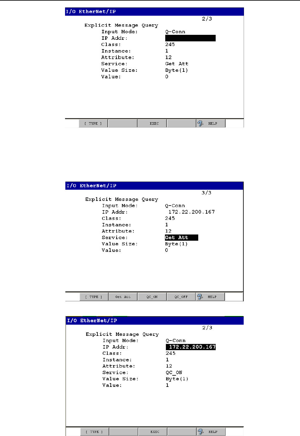
4.SCANNER CONFIGURATION B-82854EN/02
- 22 -
Fig. 4.2.4.1(a) Enabling quick connect using explicit messaging
Fill-in IP address of target device and cursor down to Service. You will see a screen similar to Figure
4.2.4.1(b) . Now you can choose the service you want to perform. To check current status of quick
connect feature on target device leave default i.e. 'Get Att' or press F2 to select. Now cursor up or down to
see 'EXEC' on F3 and press F3 to execute selected service.
Fig. 4.2.4.1(b) Fill-in IP address and select service
Fig. 4.2.4.1(c) Select quick connect service
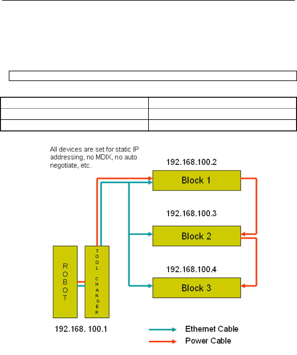
B-82854EN/02 4.SCANNER CONFIGURATION
- 23 -
To turn on quick connect feature press F3 (QC_ON) or press F4 (QC_OFF) to turn off quick connect
feature on target device. Now cursor up or down (Figure 4.2.4.1(c) ) to see 'EXEC' on F3 and press F3 to
execute selected service.
Quick Connection Time
The scanner connection is estimated as follows after device powers up and sends gratuitous ARP
indicating that it is ready to communicate. This time may vary due to network load along with switch and
adapter device behavior. Figure 4.2.4.1(d) shows general quick connect setup.
Connection Time = 60 + 10 x (no of devices — 3) miliseconds
Table 4.2.4.1 Connection time
No of Devices Connection Time
3 60 + 10 x (3–3) = 60 ms
7 60 + 10 x (7–3) = 100 ms
Fig. 4.2.4.1(d) Quick connection setup

4.SCANNER CONFIGURATION B-82854EN/02
- 24 -
4.2.5 Analog I/O
4.2.5.1 Overview
I/O for EtherNet/IP Scanner connections can be mapped to analog. Analog and digital I/O can be
intermixed—for example a device may produce sixteen points of Digital Inputs and two words of Analog
Inputs on the same connection to the robot controller.
Table 4.2.5.1 describes the items displayed on the Scanner Analog Configuration Screen. The analog
screen can be accessed and configured by using Procedure 4-3 .
Table 4.2.5.1 Scanner analog configuration screen setup items
ITEM DESCRIPTION
RANGE
Default: 1 – maximum allocated I/O
The Range of I/O points to be mapped to an analog
channel, or a digital start point.
TYPE
Default: Digital
The type of I/O being mapped: Analog or Digital.
START PT/CHNL
Default: 1
The analog channel or the digital start point.
Procedure 4-3 Configuring Scanner Analog I/O
1. Press MENUS.
2. Select I/O.
3. Press F1, [TYPE], and select EtherNet/IP.
4. Move the cursor to a Scanner connection.
5. Press F4, [CONFIG].
6. Type the correct input and output sizes.
7. Press F4, [ANALOG]. You will see a screen similar to the following.
I/O EtherNet/IP JOINT 100 %
Map Inputs: 1/1
# RANGE TYPE START PT/CHNL
1 [ 1- 128] Digital 1
8. Move the cursor to the RANGE column and select the range of the first collection of Inputs. If you
do not want to intermix Analog and Digital Inputs, do not modify this column.
9. Select the type of Inputs, Analog or Digital, in the TYPE column.
10. Select the channel for Analog Input, or the point for Digital Input in the START PT/CHNL column.
11. Repeat as necessary as additional rows are automatically created.
12. Press F2 [IN/OUT]. You will see a screen similar to the following.
I/O EtherNet/IP JOINT 100 %
Map Outputs: 1/1
# RANGE TYPE START PT/CHNL
1 [ 1- 128] Digital 1
13. Repeat Step 8 through Step 11 as necessary for Outputs.
14. Press the PREV key to return to the EtherNet/IP Scanner configuration screen.
15. Press the PREV key to return to the EtherNet/IP Status screen. You can enable the connection. If the
status is PENDING then you must turn off then turn on the controller in order for the changes to take
effect.
B-82854EN/02 4.SCANNER CONFIGURATION
- 25 -
NOTE
The 16-bits of each analog I/O channel can be byte-swapped (toggled from
big-endian to little-endian) on a per connection basis by toggling the system
variable $EIP_SC[].$ANALOGFMT. When the system variable is set to 0, the data
will be produced and consumed in big-endian format. When set to 1, little-endian
format will be used.
4.2.5.2 Examples
Suppose a device produces sixteen consecutive points of digital input followed by two words of analog
input. A properly configured EtherNet/IP Analog In screen would look like the following:
I/O EtherNet/IP JOINT 100 %
Map Inputs: 1/2
# RANGE TYPE START PT/CHNL
1 [ 1- 16] Digital 1
2 [ 17- 48] Analog 1
Suppose a device produces sixteen consecutive points of digital input followed by two words of analog
input followed by eight more consecutive points of digital input. A properly configured EtherNet/IP
Analog In screen would look like the following. Note that the 49th connection input point will be mapped
as the 17th digital input point.
I/O EtherNet/IP JOINT 100 %
Map Inputs: 1/3
# RANGE TYPE START PT/CHNL
1 [ 1- 16] Digital 1
2 [ 17- 48] Analog 1
3 [ 49- 56] Digital 17
4.2.6 Common Errors
If the connection is lost, the values of any mapped inputs will be zeroed out. The last state behavior can
be changed by setting the following system variable : $EIP_CFG.$KEEP_IO_SCN. The values are :
FALSE : The last state values of the adapter inputs will be zero (default)
TRUE : The last state values of the adapter inputs will be their last value
This setting applies to all the scanner connections.
Any enabled scanner connections which are not RUNNING or PENDING will be retried each time the
robot is RESET.

5.ETHERNET/IP TO DEVICENET ROUTING B-82854EN/02
- 26 -
5 ETHERNET/IP TO DEVICENET ROUTING
5.1 OVERVIEW
EtherNet/IP and DeviceNet are both based on the Common and Industrial Protocol (CIP) which was
initially defined by Rockwell with specifications managed by ODVA (www.odva.org). The robot can
have connections to both Ethernet and DeviceNet networks and this feature provides the capability to
route messages between two networks for configuration and diagnostics purposes.
This feature allows you to configure and manage the local robot DeviceNet network from personal
computers (PCs) connected to their plant's Ethernet network. This eliminates someone having to connect
a laptop PC to the physical robot in the DeviceNet network for certain third party device configuration
and diagnostics functions. The PC software used is typically a tool such as RS-Networx for DeviceNet,
which supports the following features:
CIP routing
Functions such as remotely configuring a device attached to the local DeviceNet network
Network “who” of the local robot in the DeviceNet network from the PC connected to Ethernet.
Explicit Messaging Connections to the devices in DeviceNet via “Class Instance Editor”
For more detailed technical information on EtherNet/IP to DeviceNet routing, refer to Chapter 10,
Bridging and Routing, in The CIP Common specification (EtherNet/IP specification volume 1).
NOTE
The following option hardware is required:
• DeviceNet Interface board with SST DN3 or DN4 daugther board.
The following option software is required:
• EtherNet/IP Router (R-30iA/R-30iA Mate) (R539)
• EtherNet/IP DN Router (R-30iB) (R804)
• DeviceNet Interface (Master, Slave) (J753)
5.2 GUIDELINES
Review the following guidelines before you use routing:
Any errors returned from devices in DeviceNet are posted in the third party application software.
(e.g. RSNetworx for DeviceNet)
The G3_ONLY feature is supported on SST DN3 or DN4 cards only
Routing is limited to explicit messages directed to the connection manager object using the
unconnected send service. Routing of I/O is not supported.
Do not change the status of the devices while Routing is performed. This disrupts the connection
between the master (robot in the DeviceNet network) and slave (device in DeviceNet network).
5.3 SETTING UP ETHERNET/IP TO DEVICENET ROUTING
EtherNet/IP to DeviceNet Routing is installed with the EthernetIP (DN) Router option. The default
method for using Routing is to have it configured to start when the controller is turned on. Even though
the EtherNet/IP to DeviceNet Routing interface screen is available, some features can only be configured
by setting system variables.

B-82854EN/02 5.ETHERNET/IP TO DEVICENET ROUTING
- 27 -
NOTE
$EIP_RTR.$G3_ONLY is added to protect I/O performance. Group 2 devices need
to set up Predefined Master/Slave connections to exchange Explicit Messaging
packets and I/O packets. The priorities of Group 2 messages are predefined by
ODVA. For example, Explicit Message request and response have higher priority
than the Master’s I/O poll request. Thus, there is a chance that an Explicit
Message request and response will win over a Master’s I/O poll request. This
could affect I/O performance. When $EIP_RTR.$G3_ONLY is enabled, routing to
Group 2 devices are not allowed.
$EIP_RTR.$DIN_NUM is added to enable/disable routing dynamically based on a digital input. For
example, this feature can be useful for I/O sensitive processes such as dispensing around a windshield.
When the corresponding DIN is ON, the routing is disabled. Refer to Table 5.3 for information on the
system variables used in routing.
Table 5.3 EtherNet/IP to devicenet routing system variables
System Variable Default Value Description
$EIP_RTR.$ENABLE TRUE Enable EIP Router*
$EIP_RTR.$BOARD_1 FALSE When this is enabled, DeviceNet Board 1 routes
packets from EtherNet to DeviceNet.
$EIP_RTR.$BOARD_2 TRUE When this is enabled, DeviceNet Board 2 routes
packets from EtherNet to DeviceNet.
$EIP_RTR.$BOARD_3 FALSE When this is enabled, DeviceNet Board 3 routes
packets from EtherNet to DeviceNet.
$EIP_RTR.$BOARD_4 FALSE When this is enabled, DeviceNet Board 4 routes
packets from EtherNet to DeviceNet.
$EIP_RTR.$G3_ONLY FALSE When this is enabled, CIP packets are only routed to
Group 3 only (UCMM capable) devices.
$EIP_RTR.$DIN_NUM 0 When DIN input port is specified and input port is ON,
no packets are routed to DeviceNet network.*
* $ENABLE and $DIN_NUM can be set via user interface screen.
5.4 USING ETHERNET/IP TO DEVICENET ROUTING
After system variables are configured, enabling and disabling Router and Setting DIN[] can be done using
the EtherNet/IP Configuration screen. Refer to Procedure 5-1 to set up EtherNet/IP to DeviceNet Routing.
Refer to Procedure 5-2 for information on Routing using RSNetworx for DeviceNet.
Procedure 5-1 Setting Up EtherNet/IP to DeviceNet Routing
Conditions
The controller is turned on.
Steps
1. Press MENUS.
2. Select I/O.
3. Press F1, [TYPE].
4. Select EtherNet/IP. You will see a screen similar to the following.

5.ETHERNET/IP TO DEVICENET ROUTING B-82854EN/02
- 28 -
I/O EtherNet/IP JOINT 10 %
EtherNet/IP List(Rack 89) 1/8
Description TYP Enable Status Slot
1 Conn1 ADP TRUE ONLINE 1
2 Conn2 ADP FALSE OFFLINE 2
3 Conn3 ADP FALSE OFFLINE 3
4 Conn4 ADP FALSE OFFLINE 4
5 Conn5 ADP FALSE OFFLINE 5
6 Conn6 ADP FALSE OFFLINE 6
7 Conn7 ADP FALSE OFFLINE 7
8 Conn8 ADP FALSE OFFLINE 8
5. Press NEXT and then press F3 [RTR]. You will see a screen similar to the following.
I/O EtherNet/IP JOINT 10 %
Router configuration : 1/2
Enable : TRUE
Disable when DIN[ 0] is ON
6. Make sure Enable is set TRUE. If it is not, move the cursor to Enable, and press F4, TRUE.
7. If you want to disable routing when a particular DIN is ON, move the cursor to DIN[ ], and type the
port number. Note that DIN[] port 0 does not exist in the robot I/O. Thus, DIN[0] would not disable
Routing unless the port number is changed.
NOTE
This feature is optional and can be useful for I/O sensitive processes such as
dispensing around a windshield.
Procedure 5-2 Routing using RSNetworx for DeviceNet
Conditions
$EIP_RTR.$BOARD_2 is set TRUE.
Board 2 in DeviceNet is ONLINE.
You are using a personal computer (PC), and have installed RSNetworx for DeviceNet.
Steps
1. Launch RSNetworx for DeviceNet. For example on your PC, select Start, Programs, Rockwell
software, RSNetworx, and then RSNetworx for DeviceNet. You will see a screen similar to the
following.
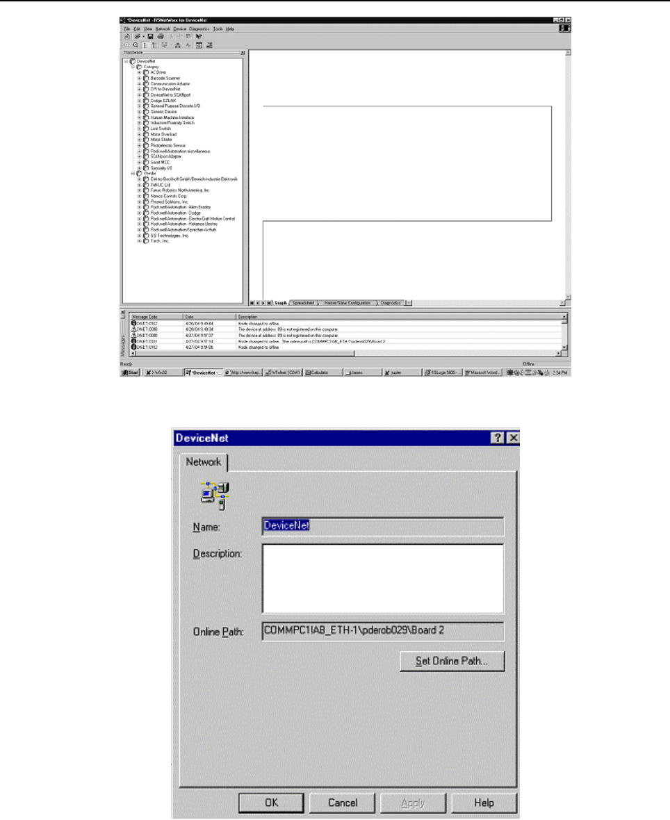
B-82854EN/02 5.ETHERNET/IP TO DEVICENET ROUTING
- 29 -
Fig. 5.4(a) RSNetworx for DeviceNet first screen
2. Select Properties under Network tab. You will see a screen similar to the following.
Fig. 5.4(b) DeviceNet network screen
3. Click Set Online Path. You will see a screen similar to the following.
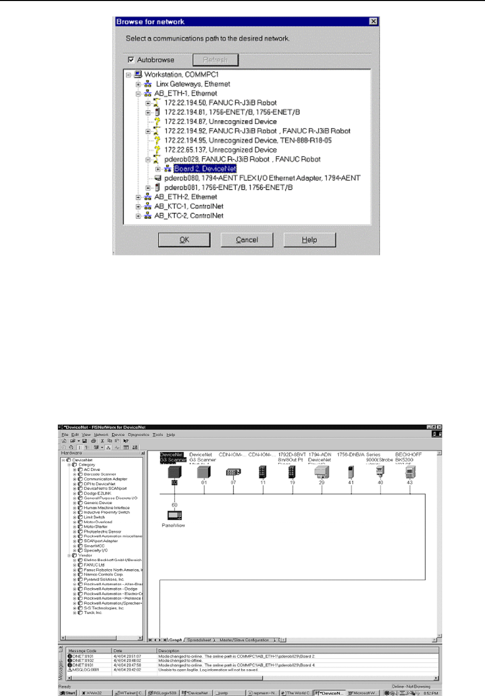
5.ETHERNET/IP TO DEVICENET ROUTING B-82854EN/02
- 30 -
Fig. 5.4(c) Set online path.. screen
4. Find the robot under Ethernet channel. In this example, the robot named pderob029 is under
AB-ETH1, EtherNet.
5. Select Board 2, DeviceNet under the robot (pderob029), and click OK. You should see new path in
Online Path text box. This is shown as COMMPC1¥AB_ETH-1¥pderob029¥Board 2 in this
example.
6. Click Apply, and then click OK. After the path is set, you are ready to browse the devices in
DeviceNet.
7. Select Online under the Network tab.
8. Click OK to begin browsing the network. After this is done, you will see the screen similar to the
following.
Fig. 5.4(d) Local DeviceNet

B-82854EN/02 5.ETHERNET/IP TO DEVICENET ROUTING
- 31 -
9. At this point you can use the Class Instance Editor to get or set device parameters. For more
information on how to use RSNetworx for DeviceNet, refer to the RSNetworx for DeviceNet
Manual .

6.I/O CONFIGURATION B-82854EN/02
- 32 -
6 I/O CONFIGURATION
6.1 OVERVIEW
This chapter describes how to make EtherNet/IP I/O available within the robot by mapping it to digital,
group, and UOP I/O points. Scanner connection I/O can also map to analog. Refer to Section 4.2.5 .
This chapter also describes procedures for backing up and restoring the EtherNet/IP and I/O
configurations.
6.1.1 I/O Size of Each Connection and I/O Configuration
Each connection (adapter or scanner) has input/output size setting, which determines the amount of I/O
of each connection that can be assigned to I/O of the robot.
In some application software, the I/O is automatically configured when you turn on the controller.
The system variable $IO_AUTO_CFG (for digital I/O) and $IO_AUTO_UOP (for UOPI/O) controls this
behavior.
If I/O is automatically configured, I/O configuration of each connection is made according to
the input/output size of each connection.
If a connection was once configured and it is no longer used, please set its input/output size to 0
in addition to setting its ENABLE to FALSE, and removing its I/O assignment.
If input/output size is not 0, I/O assignment is made again by next power on.
6.2 MAPPING I/O ON THE ROBOT
The EtherNet/IP I/O can be mapped to digital, group, or UOP I/O points within the robot scanner
connection. I/O can also map to analog (for scanner connections only). This is similar to mapping other
I/O points on the robot where the rack, slot, and starting point number are used to map physical I/O to
logical I/O within the I/O map.
All EtherNet/IP I/O uses rack 89. The slot number for each connection is shown in the EtherNet/IP Status
screen. Use Procedure 6-1 to map I/O on the robot.
Procedure 6-1 Mapping I/O on the Robot
Steps
1. Press MENUS.
2. Select I/O.
3. Press F1, [TYPE], and select Digital, Group, UOP, or analog (analog is supported on scanner
connections).
4. Press F2, CONFIG.
5. Set the Range to the appropriate value. For analog, set the channel to the appropriate value.
6. Set the Rack to 89 and set the appropriate slot number and starting point as required.
NOTE
Refer to the Input/Output (I/O) Setup chapter in the application-specific Setup and
Operations Manual for additional information on I/O configuration.
NOTE
See Procedure 4-3 for additional information on configuring Analog I/O on the
controller.

B-82854EN/02 6.I/O CONFIGURATION
- 33 -
In some application software the I/O is automatically configured when you turn on the controller. The
system variable $IO_AUTO_CFG (for digital I/O) and $IO_AUTO_UOP (for UOP I/O) controls this
behavior. If the system has already automatically configured the I/O, and sizes are changed, the I/O
assignments can be cleared to force the system to remap all the I/O. This is done by clearing assignments
(CLR_ASG). Use Procedure 6-2 to clear I/O assignments.
Procedure 6-2 Clearing I/O Assignments
Steps
1. Press MENUS.
2. Select I/O.
3. Press F1, [TYPE].
4. Select Link Device.
5. Press F5, CLR_ASG.
6. To remap all I/O, turn the controller off and back on.
NOTE
This clears all I/O assignments. The I/O will be remapped when you turn off then
turn on the controller based on the settings of $IO_AUTO_CFG (for digital I/O) and
$IO_AUTO_UOP (for UOP I/O).
6.3 BACKING UP AND RESTORING ETHERNET/IP AND I/O
CONFIGURATION
There are two files which contain information on the configuration of EtherNet/IP and I/O mappings :
DIOCFGSV.IO contains general I/O configuration and all I/O mappings (for example, mappings
between EtherNet/IP and digital, group, and UOP I/O).
SYSEIP.SV contains EtherNet/IP specific configuration including all adapter and scanner settings.
Use Procedure 6-3 to back up files manually.
Use Procedure 6-4 to do a full application backup, which includes DIOCFGSV.IO and SYSEIP.SV.
Procedure 6-3 Backing Up Files Manually
Steps
1. Select the default file device where files will be saved:
a. Press MENUS.
b. Select File.
c. Press F5, [UTIL], and choose SET DEVICE.
d. Select the device to which you want to save the files.
2. Save DIOCFGSV.IO:
a. Press MENUS.
b. Select I/O.
c. Press F1, [TYPE], and choose DIGITAL.
d. Press FCTN.
e. Select Save to save DIOCFGSV.IO to the default device.
3. Save SYSEIP.SV:
a. Press MENUS.
b. Select I/O.
c. Press F1, [TYPE], and choose EtherNet/IP.
d. Press FCTN.
e. Select Save to save SYSEIP.SV to the default device.

6.I/O CONFIGURATION B-82854EN/02
- 34 -
Procedure 6-4 Performing a Full Application Backup
Steps
1. Select the default file device (where files will be saved):
a. Press MENUS.
b. Select File.
c. Press F5, [UTIL], and choose SET DEVICE.
d. Select the device to which you want to save the files.
2. Press F4, [BACKUP], and choose “All of above”.

B-82854EN/02 7.EXPLICIT MESSAGING
- 35 -
7 EXPLICIT MESSAGING
7.1 OVERVIEW
The robot controller is an explicit message server and supports connected and unconnected explicit
messaging. Up to six explicit message connections are supported. The EtherNet/IP Adapter option must
be loaded to support this functionality. The following objects are supported by the controller:
Identity Object (0x01)
Message Router Object (0x02)
Assembly Object (0x04)
Connection Manager Object (0x06)
Vendor Specific Register Object--Integers (0x6B)
Vendor Specific Register Object--Reals (0x6C)
Vendor Specific Register Object--Strings (0x6D)
Vendor Specific Register Object--Position Registers: Cartesian (0x7B)
Vendor Specific Register Object--Position Registers: Joint (0x7C)
Vendor Specific Active Alarm Object (0xA0)
Vendor Specific Alarm History Object (0xA1)
Vendor Specific Motion Alarm Object (0xA2)
Vendor Specific System Alarm Object (0xA3)
Vendor Specific Application Alarm Object (0xA4)
Vendor Specific Recovery Alarm Object (0xA5)
Vendor Specific Communications Alarm Object (0xA6)
Connection Configuration Object (0xF3)
Port Object (0xF4)
TCPIP Object (0xF5)
Ethernet Link Object (0xF6)
This chapter does not go into the details of the standard CIP objects defined by ODVA. This chapter will
instead document FANUC’s Vendor Specific Alarm and Register objects, and the Assembly Object
instances numbers for accessing I/O on the robot controller.
In general, no configuration is required on the robot controller to use explicit messaging. I/O must be
configured on the robot if it is to be accessed through the Assembly Object.
NOTE
Writing to a register is only supported by V7.20P11 or later.
NOTE
Vendor Specific Register Object--Reals (0x6C) is only supported by V7.40 or later.
Only Vendor Specific Register Object--Integers (0x6B) can be used before
V7.40P.
NOTE
Vendor Specific Register Object--Strings (0x6D) is only supported by V7.70P27 or
later.
NOTE
Vendor Specific Register Object--Position Registers can be used in V8.10P or
later.

7.EXPLICIT MESSAGING B-82854EN/02
- 36 -
7.2 ROBOT EXPLICIT MESSAGING CLIENT
7.2.1 Overview
NOTE
Robot Explicit Message Client is only supported by V7.40P or later.
The Robot Explicit Messaging Client allows you to send simple EtherNet/IP explicit messages to other
EtherNet/IP enabled devices on the network. You can access this option from the main EtherNet/IP screen
and execute queries from the teach pendant.
The explicit messaging feature implements the Get Attribute Single, and Set Attribute Single services.
Explicit messaging clients require up to five values for configuration. These values are usually described
in hexadecimal notation, with the exception of the IP address. These values are shown in Table 7.2.1 .
Table 7.2.1 Explicit messaging configuration values
ITEM DESCRIPTION
IP Address The address of the remote device to be queried.
Class The class of Object to which the explicit message is being sent.
Instance The instance number defines which instance of the class will receive the message.
Attribute Defines which attribute of the instance is being accessed.
Service The action to be performed. The robot explicit messaging client only supports the Get
Attribute Single, and Set Attribute Single services.
An explicit message configuration file can also be created that performs a batch of commands. (Refer to
Procedure 7-3 ). Normally this is used with the Set Attributes Single service to configure a remote device.
Procedure 7-1 describes how to use the Get Attribute Single service. Procedure 7-2 describes how to use
the Set Attribute Single service.
Procedure 7-1 Get Attribute Single Service
1. Press MENUS.
2. Select I/O.
3. Press F1, [TYPE].
4. Select EtherNet I/P.
5. Press NEXT and then press F2 [EXP-MSG]. (If you scrolled to an active connection, that
connection's IP address will be used as the default IP address). You will see a screen similar to the
following.
I/O EtherNet/IP JOINT 10 %
Explicit Message Query 1/8
Input Mode: Manual
IP Addr:
Class: 1
Instance: 1
Attribute: 1
Service: Get Att
Value Size: Byte(1)
Value: 0
6. Select Input Mode, and choose Manual (the default).
7. Set the IP Addr field to the address of the remote device.

B-82854EN/02 7.EXPLICIT MESSAGING
- 37 -
8. Set the Class, Instance, and Attribute fields. This information should either describe standard CIP
objects, or be provided by the vendor of the remote device.
9. Select Service field and choose Get Att (the default).
10. Press F3 [EXEC] (you will have to cursor to a field other then Services and Value Size to see the F3
[EXEC] function). The robot will attempt to send the Explicit Message query to the device. A valid
response or any errors will be displayed at the bottom of the screen.
Procedure 7-2 Set Attribute Single Service
1. Press MENUS.
2. Select I/O.
3. Press F1, [TYPE].
4. Select EtherNet I/P.
5. Press NEXT and then press F2 [EXP-MSG]. (If you scrolled to an active connection, that
connection's IP address will be used as the default IP address). You will see a screen similar to the
following.
I/O EtherNet/IP JOINT 10 %
Explicit Message Query 1/8
Input Mode: Manual
IP Addr:
Class: 1
Instance: 1
Attribute: 1
Service: Get Att
Value Size: Byte(1)
Value: 0
6. Select Input Mode, and choose Manual (the default).
7. Set the IP Addr field to the address of the remote device.
8. Set the Class, Instance, and Attribute fields. This information should either describe standard CIP
objects, or be provided by the vendor of the remote device.
9. Select Service field and choose Set Att.
10. Set the Value Size, and Value fields. The supported Value Size fields are Byte, Word, and Long.
11. Press F3, [EXEC] (you will have to cursor to a field other then Services and Value Size to see the F3
[EXEC] function). The robot will attempt to send the Explicit Message query to the device. The
result of the query or any errors will be displayed at the bottom of the screen.
Procedure 7-3 Explicit Messaging Batch File Method
1. Press MENUS.
2. Select I/O.
3. Press F1, [TYPE].
4. Select EtherNet I/P.
5. Press NEXT and then press F2 [EXP-MSG]. You will see a screen similar to the following.
I/O EtherNet/IP JOINT 10 %
Explicit Message Query 1/8
Input Mode: Manual
IP Addr:
Class: 1
Instance: 1
Attribute: 1
Service: Get Att
Value Size: Byte(1)
Value: 0
6. Move the cursor to Input Mode, and choose File. You will see a screen similar to the following.

7.EXPLICIT MESSAGING B-82854EN/02
- 38 -
I/O EtherNet/IP JOINT 10 %
Explicit Message Query 1/2
Device: MC:¥
Input Mode: File
Config File Name: None
7. Move the cursor to the Config File Name field. Press F2, [DEVICE] to select the device where the
explicit message config file is located.
8. Press F4, [CHOICE] to select the config file. (Only files with a .EM extension can be selected.)
9. Press F3, [EXEC] to execute the config file. The robot will attempt to send the Explicit Message
query to the device. The result of the query or any errors will be displayed at the bottom of the
screen.
7.2.2 Creating a Configuration File for the Batch File Method
The configuration file format is documented in this section. All files must be name with the .EM file
extension (for example, MYCONFIG.EM). Lines beginning with ‘*’ are comments. Comments and blank
lines are ignored. See Example 7.1 .
The following seven (7) lines MUST exist for each query followed by a space and corresponding value:
QUERY:
IPADDR:
CLASS:
INSTANCE:
ATTRIBUTE:
SIZE:
VALUE:
There can be multiple queries within a file. The Set Attribute Single service is assumed in all cases. Each
Query begins with a query number, which is unique and generally sequential.
The Size field refers to the Data Size of the parameter (Value), the following three are supported.
1 (BYTE or 1 byte)
2(WORD or 2 bytes)
4 (LONG or 4 bytes)
Example 7.2.2 Batch file example
* File Name: EMCFG.EM
* Author: Joe User
* Date: 03/15/2004
* File must be saved with an .EM extension
* Lines beginning with ‘*’ are comments.
* Comments and blank lines are ignored.
* Following 7 lines MUST exist for each query.
* There can be multiple queries within a file.
* The “SET ATT” service is assumed in all cases.
* Each Query begins with a query number, which is
* unique and generally sequential.
* Size field refers to the Data Size of the
* parameter, the following three are supported
* 1 (BYTE or 1 byte), 2(WORD or 2 bytes), 4 (LONG or 4 bytes)
QUERY: 1
IPADDR: 172.22.200.147
CLASS: 15
INSTANCE: 2
ATTRIBUTE: 1
SIZE: 1
VALUE: 4
QUERY: 2
IPADDR: 172.22.200.147
CLASS: 15
INSTANCE: 3
ATTRIBUTE: 1
SIZE: 2
VALUE: 300
B-82854EN/02 7.EXPLICIT MESSAGING
- 39 -
7.3 REMOTE EXPLICIT MESSAGING CLIENT
CONFIGURATION
Explicit messaging clients require up to four values for configuration. These values are usually described
in hexadecimal notation. These values are shown in Table 7.3 .
Table 7.3 Configuration values
ITEM DESCRIPTION
Class The class of Object to which the explicit message is being sent.
Instance The instance number defines which instance of the class will receive the message.
Attribute Defines which attribute of the instance is being accessed.
Service The action to be performed.
These values are documented in this manual for all FANUC’s Vendor Specific Objects.
Here is an example of configuring an Explicit Message in RSLogix5000. Note the Service Code, Class,
Instance and Attribute fields.
Fig. 7.3 Message configuration
7.4 VENDOR SPECIFIC REGISTER OBJECTS
NOTE
Writing to a register is only supported by V7.20P11 or later.
Table 7.4 shows the brief description of FANUC register object model.
Table 7.4 FANUC register object model
Register Type Service Class Instance Attribute
NUMREG (Int) Get_Attr_Single 0x6B 1 (8 bits) reg #
NUMREG (Int) Get_Attr_All 0x6B 1 (8 bits) N/A

7.EXPLICIT MESSAGING B-82854EN/02
- 40 -
Register Type Service Class Instance Attribute
NUMREG (Int) Get_Attr_Block 0x6B blk_size, 1 (16 bits) start reg #
NUMREG (Int) Set_Attr_Single 0x6B 1 (8 bits) reg #
NUMREG (Int) Set_Attr_All 0x6B 1 (8 bits) N/A
NUMREG (Int) Set_Attr_Block 0x6B blk_size, 1 (16 bits) start reg #
NUMREG (Real) Get_Attr_Single 0x6C 1 (8 bits) reg #
NUMREG (Real) Get_Attr_All 0x6C 1 (8 bits) N/A
NUMREG (Real) Get_Attr_Block 0x6C blk_size, 1 (16 bits) start reg #
NUMREG (Real) Set_Attr_Single 0x6C 1 (8 bits) reg #
NUMREG (Real) Set_Attr_All 0x6C 1 (8 bits) N/A
NUMREG (Real) Set_Attr_Block 0x6C blk_size, 1 (16 bits) start reg #
STRREG Get_Attr_Single 0x6D 1 (8 bits) reg #
STRREG Get_Attr_All 0x6D 1 (8 bits) N/A
STRREG Get_Attr_Block 0x6D blk_size, 1 (16 bits) start reg #
STRREG Set_Attr_Single 0x6D 1 (8 bits) reg #
STRREG Set_Attr_All 0x6D 1 (8 bits) N/A
STRREG Set_Attr_Block 0x6D blk_size, 1 (16 bits) start reg #
POSREG (CRT) Get_Attr_Single 0x7B group # (8 bits) reg #
POSREG (CRT) Get_Attr_All 0x7B group # (8 bits) N/A
POSREG (CRT) Get_Attr_Block 0x7B blk_size, group # (16 bits) start reg #
POSREG (CRT) Set_Attr_Single 0x7B group # (8 bits) reg #
POSREG (CRT) Set_Attr_All 0x7B group # (8 bits) N/A
POSREG (CRT) Set_Attr_Block 0x7B blk_size, group # (16 bits) start reg #
POSREG (JNT) Get_Attr_Single 0x7C group # (8 bits) reg #
POSREG (JNT) Get_Attr_All 0x7C group # (8 bits) N/A
POSREG (JNT) Get_Attr_Block 0x7C blk_size, group # (16 bits) start reg #
POSREG (JNT) Set_Attr_Single 0x7C group # (8 bits) reg #
POSREG (JNT) Set_Attr_All 0x7C group # (8 bits) N/A
POSREG (JNT) Set_Attr_Block 0x7C blk_size, group # (16 bits) start reg #
CURPOS (CRT) Get_Attr_Single 0x7D group # (8 bits) 1
CURJPOS (JNT) Get_Attr_Single 0x7E group # (8 bits) 1
7.4.1 Numeric Register Objects (0x6B and 0x6C)
NOTE
Vendor Specific Register Object--Reals (0x6C) is only supported by V7.40 or later.
Only Vendor Specific Register Object--Integers (0x6B) can be used before
V7.40P.

B-82854EN/02 7.EXPLICIT MESSAGING
- 41 -
Numeric registers can be read and written through FANUC’s Registers Object. These registers on the
robot controller can be one of two types: Integer type, or Real type. Normally, the type is transparent to
the user. For example, if R[1] is set to a value of 49 (R[1] = 49), the numeric register will automatically
be configured as an Integer type. However, if R[2] is set to a value of 1.61803 (R[2] = 1.61803), the
numeric register will be automatically configured as a Real type.
Because of the format of the data transfer through explicit messaging, this automatic configuration cannot
be done. Therefore, two Register Objects have been created: Register Object--Integers (0x6B), and
Register Object--Reals (0x6C). To read or write a numeric register as an Integer value, the Register
Object--Integers (0x6B) should be accessed. To read or write a numeric register as a Real value, the
Register Object--Real (0x6C) should be accessed.
Note that when writing to the Register Object--Integers, the numeric register will be changed to the
Integer type. Likewise, when writing to the Register Object--Reals, the numeric register will be changed
to the Real type.
However, when reading a numeric register using the Register Object--Integers, if the numeric register is
configured as a Real type, an “Undefined Attribute” (0x14) error will be returned. Likewise, when
reading a numeric register using the Register Object--Real, if the numeric register is configured as an
Integer type, an “Undefined Attribute” (0x14) error will be returned.
NOTE
FANUC's Register objects also allow reading and writing of the registers in blocks.
The Get_Attribute_All service allows reading of up to the first 124 registers starting
from first register. The Set_Attribute_All service allows writing of up to the first 115
registers starting from first register. The Get_Attribute_Block allows up to 124
registers for Reading and Set_Attribute_Block allows writing up to 115 registers at
a time starting from any register number.
7.4.1.1 Instance attributes
FANUC’s Register Objects support a single instance: instance 1. Each attribute in the instance
corresponds to a register. For example, attribute 1 corresponds to R[1] and attribute 5 corresponds to R[5].
Refer to Table 7.4.1.1 . Table 7.4.1.1 Instance attributes
Attribute ID Name Data Type Description of Attribute
1 R[1] 32-bit integer Register 1
2 R[2] 32-bit integer Register 2
...
n-1 R[n-1] 32-bit integer Register n-1
n* R[n] 32-bit integer Register n
*Where n is the total number of registers on the controller.
7.4.1.2 Common services
FANUC's Register Objects provide the Common Services at the Instance level shown in Table 7.4.1.2(a).
No Class level services are provided.

7.EXPLICIT MESSAGING B-82854EN/02
- 42 -
Table 7.4.1.2(a) Common services
Service Code Service Name Description of Service
0E hex Get_Attribute_Single Returns the content of the specified attribute.
01 hex Get_Attribute_All Returns a listing of the object’s attributes (See the
Get_Attribute_All definition below).
32 hex Get_Attribute_Block Returns specified block o registers values
10 hex Set_Attribute_Single Sets the specified attribute to the specified value.
02 hex Set_Attribute_All Sets all attributes starting from Attribute 1 to 115 or MAX
registers on controller whichever is smaller.
33 hex Set_Attribute_Block Sets values to the specified block of registers up to 115 or MAX
registesr on conttroler whichever is smaller.
At the Instance level, the attributes are returned in the order shown in Table 7.4.1.2(b) using little-endian
byte-swapping. Table 7.4.1.2(b) Get_Attribute_All response
32–bit integer Byte 0 Byte 1 Byte 2 Byte 3
1 Register 1 (R[1])
2 Register 2 (R[2])
...
n-1 Register n-1 (R[n-1])
n* Register n (R[n])
*Where n is the total number of registers on the controller or 124, whichever is smaller.
7.4.1.3 Errors
FANUC’s Vendor Specific Register Objects will return the errors shown in Table 7.4.1.3 .
Table 7.4.1.3 FANUC’s vendor specific register object errors
Error Status Error Description
Undefined Attribute (0x14) Returned when the Register requested does not exist.
Unsupported Service (0x08) Returned when the requested service is unsupported.
Undefined Class Instance (0x05) Returned when the requested instance number is unsupported.
7.4.1.4 Read single register
The examples below assume the numeric register(s) have type integer, and use object 0x6B. The same
examples can be used for numeric registers of type Real by using Class 0x6C, instead of Class 0x6B. To
read R[5] from the controller, assuming R[5]’s type is an integer, the explicit message client would be
configured with the values shown in Table 7.4.1.4 .
B-82854EN/02 7.EXPLICIT MESSAGING
- 43 -
Table 7.4.1.4 Read register R[5]
Class 0x6B
Instance 0x01
Attribute 0x05
Service 0x0E
Figure 7.4.1.4 shows message block configuration in RSLogix5000 where my_reg is a 32–bits integer
variable. The explicit message server on the robot controller would return R[5] to the client as a 32-bit
integer.
Fig. 7.4.1.4 Read register R[5]
7.4.1.5 Read all registers
To read up to the first 124 Registers from the controller, and assuming all these registers are configured as
type integer, the explicit message client would be configured with the values shown in Table 7.4.1.5 .
Table 7.4.1.5 Read all registers
Class 0x6B
Instance 0x01
Attribute 0x0
Service 0x01
Figure 7.4.1.5 is snapshot of RSLogix5000 message block configuration to read all registers where
my_regall is an array of 124 integers. The explicit message server on the robot controller would return up
to the first 124 Registers as an array of integers as described in Section 7.4.1.2 .
7.EXPLICIT MESSAGING B-82854EN/02
- 44 -
Fig. 7.4.1.5 Read all registers
7.4.1.6 Read a block of registers
Register objects also provide the functionality to read or write a block of registers. Common services used
for read a block is Get_Attribute_Block (0x32). In order to use this functionality Instance and attributes
are used as follows.
Instance is 2 byte. It is divided into two pieces. First (lower) 8 bits carry instance number which could be
maximum 255 (for now it is just place holder because FANUC's register supports only single class
instance). Second (higher) 8 bits carry the number of registers to be read so maximum 255 but FANUC's
register object allows 124 for reading at time. Please refer to Table 7.4.1.6(a) for instance number
calculation. For example, to read 10 registers starting from register number 6 in integer format see Table
7.4.1.6(b) and Figure 7.4.1.6 for configuration details. Messaging server would return values of registers
6 to 15. Table 7.4.1.6(a) Instance numbers for block access
Block Size Decimal (HEX) Instance (HEX) Instance (Decimal)
1 (0x01) 0x0101 257
2 (0x2) 0x0201 513
3 (0x3) 0x0301 769
4 (0x4) 0x0401 1025
5 (0x5) 0x0501 1281
Table 7.4.1.6(b) Read 10 registers from R[6]-R[15]
Class 0x6B
Instance 0x0A01
Attribute 0x06
Service 0x01
B-82854EN/02 7.EXPLICIT MESSAGING
- 45 -
Fig. 7.4.1.6 Read 10 registers from R[6]-R[15]
7.4.1.7 Write single register
To write the integer value 49 to R[5], the explicit message client would be configured with the values
shown in Table 7.4.1.7 . Table 7.4.1.7 Write value to R[5]
Class 0x6B
Instance 0x01
Attribute 0x05
Service 0x10
Value 49
Figure 7.4.1.7 is an snapshot of RSLogix5000 message block configuration. my_reg is 32–bits integer
which has value 49. The explicit message server on the robot controller would write the value 49 to R[5]
as a 32-bit integer.
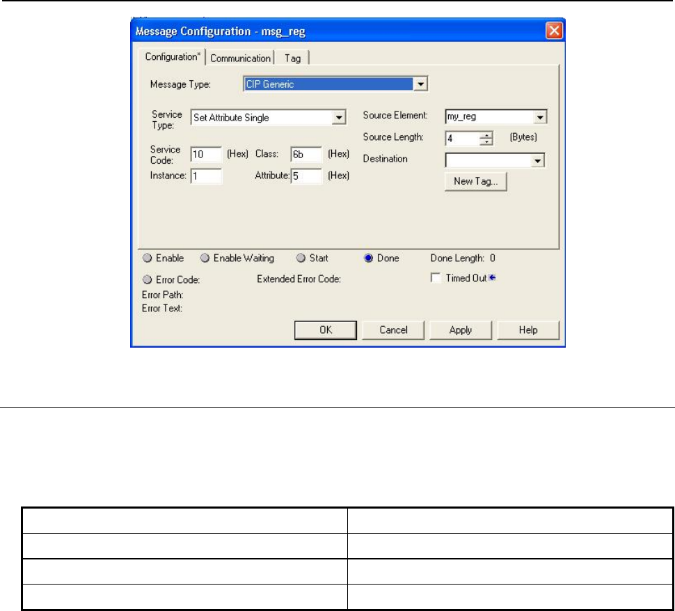
7.EXPLICIT MESSAGING B-82854EN/02
- 46 -
Fig. 7.4.1.7 Write value to R[5]
7.4.1.8 Write all registers
Similarly, all register can be written at once. Only 115 or total number of registers on controller
(whichever is less) can be written, configuration parameters shown in Table 7.4.1.8 . Explicit message
client (e.g. PLC) would carry an array of 115 integers or real (460 bytes total) along with this
configuration. Table 7.4.1.8 Write all registers
Class 0x6B
Instance 0x01
Attribute 0x0
Service 0x02
Figure 7.4.1.8 is taken from RSLogix5000 to write all registers to controllers. Source element is
my_regall[115] which is an array of 115 DINT. Source length is data size to be written. Service code is
0x02, class 0x6B for Integer, Instance is 1 and attribute has to be zero.

B-82854EN/02 7.EXPLICIT MESSAGING
- 47 -
Fig. 7.4.1.8 Write all registers
7.4.1.9 Write a block of registers
Similarly, a block of registers can be written to robot using this functionality. Service used for function is
Set_Attribute_Block (0x33). Maximum 115 or maximum available registers in controller whichever is
less can be written at a time. For example, to write 5 registers (integer) starting from 11 (0xB) following
configuration is needed, see Table 7.4.1.9 .
Table 7.4.1.9 Write 5 registers from R[11]-R[15]
Class 0x6C
Instance 0x501
Attributes 0xB
Service 0x02
Please refer to Figure 7.4.1.9 for message block configuration to write registers in RSLogix5000.
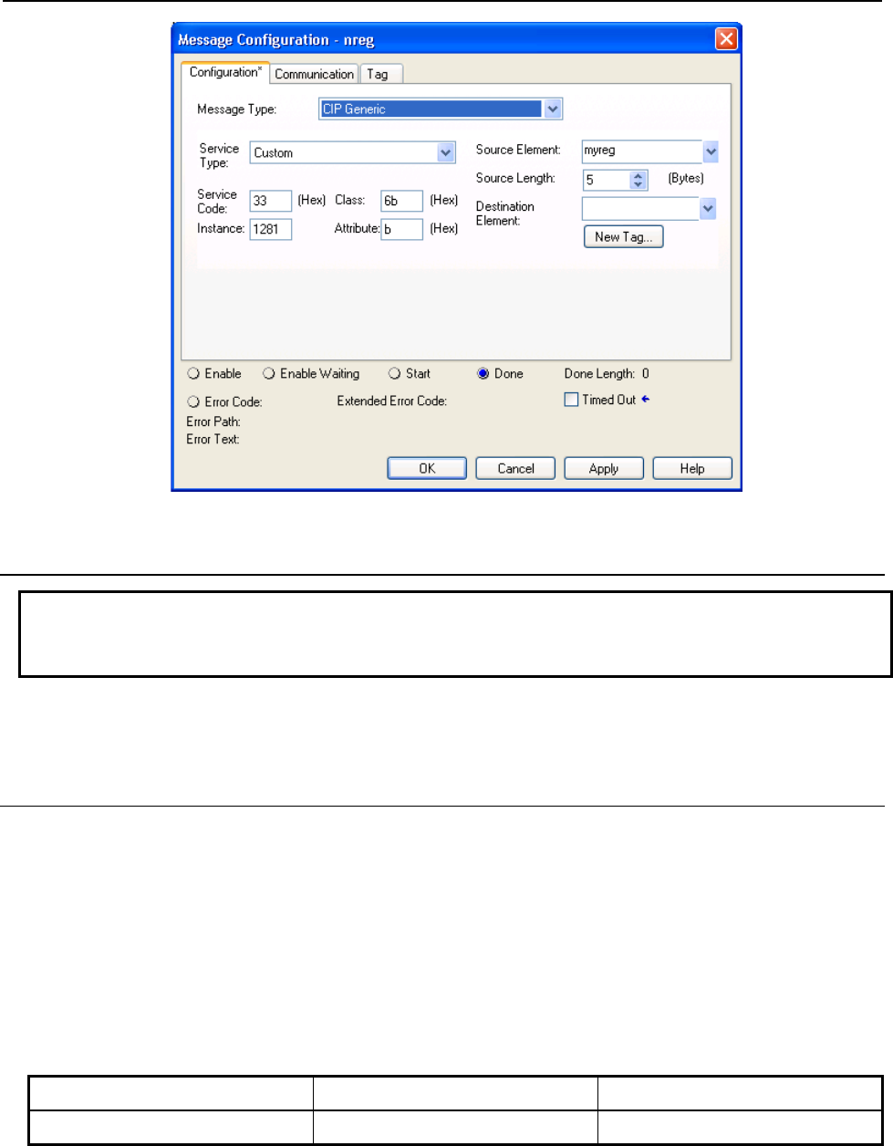
7.EXPLICIT MESSAGING B-82854EN/02
- 48 -
Fig. 7.4.1.9 Write registers from R[11]-R[15]
7.4.2 String Register Object (0x6D)
NOTE
Vendor Specific Register Object--Strings (0x6D) is only supported by V7.70P27 or
later.
String register object will provide similar functionality as numeric register objects. It provides the ability
to read string data as well as write string data via Ethernet/IP explicit messaging.
7.4.2.1 Instance attributes
FANUC's string register object provides single class instance i.e. 1. Instance attributes supported are
maximum string registers supported on controller. String register is of STRING or STRING2 or
STRINGN type. The declaration of a variable of type STRING, STRING2, or STRINGN is equivalent to
declaring a structured data type for the variable which allocates a UINT variable (first 4 bytes) containing
the current size of the string in characters and an array of declared character size elements. String register
object is composed of first 4 bytes string length, 82 bytes long string and 2 bytes padding which totals to
88 bytes in single string register, refer to Table 7.4.2.1(a) and Figure 7.4.2.1 . So on reading single
register, it returns 88 bytes of data which contains maximum 82 byte long string. This is done to be
compatible with RockWell PLC string structure (RSLogix5000) as shown in Figure 7.4.2.1 .
Table 7.4.2.1(a) String format
0–3 Byte 4-85 Bytes 86-87 bytes
String Length String Register n (SR[n]) Padding

B-82854EN/02 7.EXPLICIT MESSAGING
- 49 -
Fig. 7.4.2.1 String structure RSLogix5000
Please note that size of string shown in Figure 7.4.2.1 also includes 2 byte padding.
Table 7.4.2.1(b) Instance attributes
Attribute ID Name Data Type Description of
Attribute
1 SR[1] Structure containing unsigned integer and char
array of 82 bytes and last 2 bytes is padding Array
String Register 1
2 SR[2] Structure containing unsigned integer and char
array of 82 bytes and last 2 bytes is padding Array
String Register 2
...
n-1 SR[n-1] Structure containing unsigned integer and char
array of 82 bytes and last 2 bytes is padding Array
String Register n-1
n* SR[n] Structure containing unsigned integer and char
array of 82 bytes and last 2 bytes is padding Array
String Register n
*Where n is the total number of registers on the controller.
7.4.2.2 Common services
FANUC's Register Objects provide the Common Services at the Instance level shown in Table 7.4.2.2 .
No Class level services are provided.
Table 7.4.2.2 Common services
Service Code Service Name Description
0E hex Get_Attribute_Single Returns the content of the specified attribute i.e. 88 byte
char array.
01 hex Get_Attribute_All Returns an array of 88 bytes char arrays. Maximum
register returned are 5 or string registers supported on
controller whichever is smaller.
32 hex Get_Attribute_Block Returns block of string registers starting from any
register up to next 5 registers or maximum string
registers supported on controller whichever is smaller.
10 hex Set_Attribute_Single Sets the specified attribute to the specified value.
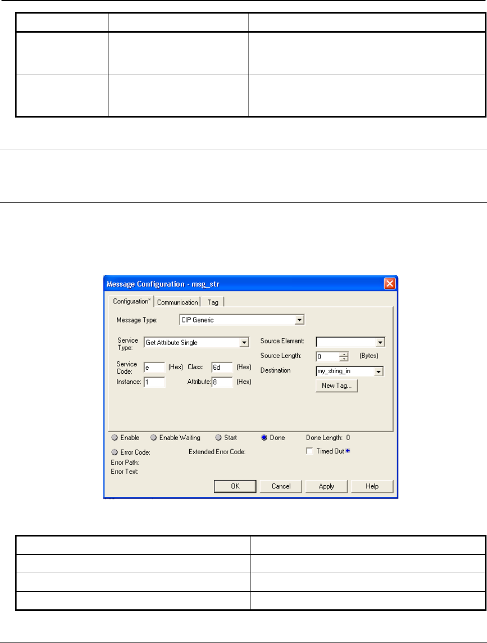
7.EXPLICIT MESSAGING B-82854EN/02
- 50 -
Service Code Service Name Description
02 hex Set_Attribute_All Sets all attributes starting from Attribute 1 to 5 or
maximum string registers supported on controller
whichever is smaller.
33 hex Set_Attribute_Block Sets values to block of string registers starting from any
register up to next 5 registers or maximum string
registers supported on controller whichever is smaller.
7.4.2.3 Errors
Refer to Section 7.4.1.3
7.4.2.4 Read single register
Figure 7.4.2.4 shows message block configuration to read single string registers. Example screen shots
are taken from RSLogix5000. To read string register 8, a string type variable“my_string_in” needs to be
created to read the string. Please note that Instance value in Figure 7.4.2.4 is decimal number and all
others are hexadecimal numbers.Table 7.4.2.4 lists the all configuration parameters to read SR[8].
Fig. 7.4.2.4 Read string register SR[8]
Table 7.4.2.4 Read register SR[8]
Class 0x6D
Instance 0x01
Attribute 0x08
Service 0x0E
7.4.2.5 Read all register
Reading all registers is also supported for string registers. Reading all register allows to read first 5 string
registers. This limitation is posed due to maintain compatibility with RSLogix5000. Figure 7.4.2.5 shows
the message block configuration to read all string registers where 'mystr' is an array of 5 STRING
variables.
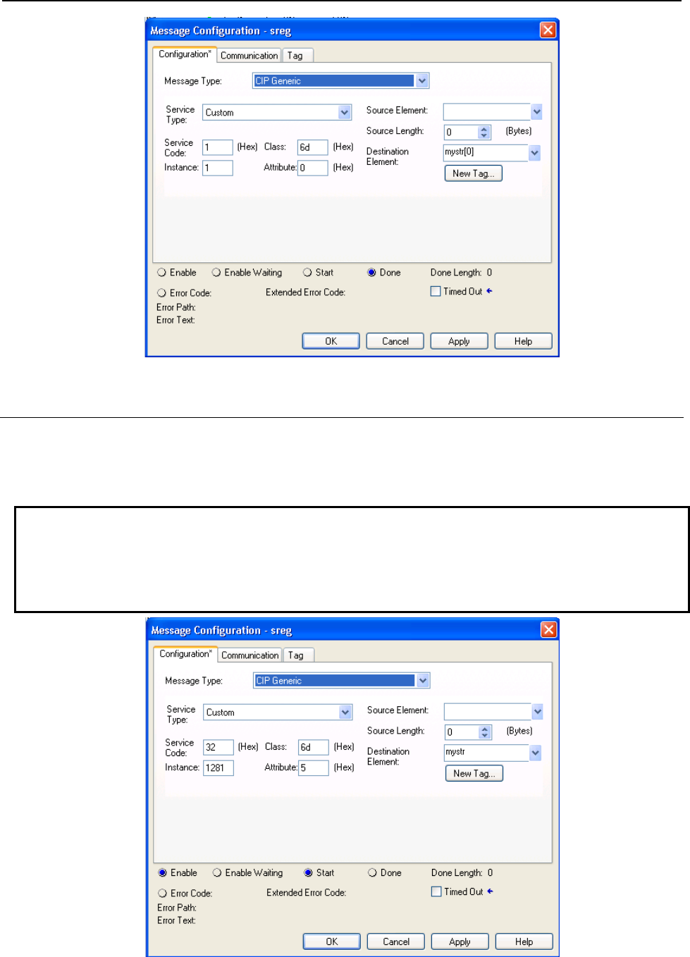
B-82854EN/02 7.EXPLICIT MESSAGING
- 51 -
Fig. 7.4.2.5 Read all register
7.4.2.6 Read a block of register
String registers also can be read in blocks. The block size limitation is 5 registers at a time. The advantage
over read all register is that it allows to read from any register index to next 5 registers. Please refer to
Figure 7.4.2.6 for configuration details to read 5 registers starting from register number 5.
NOTE
Please note that the data returned/consumed as a result of block read/write
operation is always multiple of 88 which is 88 times block size. In case of
read/write all data size is 440 bytes, if total string registers available on controller
are 5 or more.
Fig. 7.4.2.6 Read a block of register
7.EXPLICIT MESSAGING B-82854EN/02
- 52 -
7.4.2.7 Write single register
For writing string to any specified string register, a variable of STRING (RSLogix5000) type or a
structure as described in Section 7.4.2.1 needs to be created which carries string data. Please refer to
Figure 7.4.2.7 .
Fig. 7.4.2.7 Write string to SR[5]
Table 7.4.2.7 Write string to SR[5]
Class 0x6D
Instance 0x01
Attribute 0x05
Service 0x10
7.4.2.8 Write all registers
This service allows to write strings to first 5 string registers. Each string data could be 82 bytes long.
Figure 7.4.2.8 shows the message block configuration where 'mystr' is an array of 5 STRING data type.
Please refer to Figure 7.4.2.1 for STRING data type definition.
B-82854EN/02 7.EXPLICIT MESSAGING
- 53 -
Fig. 7.4.2.8 Write all registers
7.4.2.9 Write a block of registers
This service is similar to write all except it allows to write string data starting from any registers to next 5
registers. Please refer to Figure 7.4.2.9 for message configuration details.
Fig. 7.4.2.9 Write a block of registers

7.EXPLICIT MESSAGING B-82854EN/02
- 54 -
7.4.3 Position Register Object (0x7B, 0x7C, 0x7D, 0x7E)
CAUTION
Please note that Position Register object is only applicable to software version
v810 or above.
Position register object provides similar functionality as numeric register objects. It provides the ability to
read position data as well as writing the position data. This also has flexibility to read/write data in two
representations Cartesian and Joint.
7.4.3.1 Instance attributes
FANUC's position register object provides single class instance i.e. 1. Instance attributes supported are
maximum position registers supported in controller. Position register is an structure shown in Figure
7.4.3.1(a) and Figure 7.4.3.1(b) for joint and cartesian representations respectively. Joint representation
can be accommodated in an structure consisting an unsigned 32–bits integer and 9 real which supports up
to 9 axes . If robot axes are less than 9 then remaining axes returned are zeros. The explicit messaging
server returns 40 bytes data for joint position representation on reading and consumes 40 bytes position
data on writing. On the other hand, cartesian position representation is 44 byte. The explicit messaging
server returns 44 bytes of data on reading and consumes 44 bytes of data on writing.
Table 7.4.3.1(a) Structure definition for joint position representation
Structure Name: PRJNT9 (User defined)
Member Names Data Size Data Type Description
UT 1 Byte Decimal User Tool Number
UF 1 Byte Decimal User Frame Number
Dummy 2 Bytes Decimal Reserved
JNT_ANGLE[9] 36 Bytes Float Robot Axes: An array of 9 Real
Table 7.4.3.1(b) Instance number calculation
Block Size Decimal
(HEX) Instance (HEX)
Group #1 Instance (Decimal)
Group #1 Instance (HEX)
Group #2 Instance (Decimal)
Group #2
1 (0x01) 0x0101 257 0x0102 258
2 (0x02) 0x0201 513 0x0202 514
3 (0x03) 0x0301 769 0x0302 770
4 (0x04) 0x0401 1025 0x0402 1026
5 (0x05) 0x0501 1281 0x0502 1282
Table 7.4.3.1(c) Structure definition for cartesian position representation
Structure Name: PRCRT (user defined)
Member Names Data Size Data Type Description
UT 1 Byte Decimal User Tool Number
UF 1 Byte Decimal User Frame Number
Dummy 2 Bytes Decimal Reserved
X 4 Bytes Float X mm
B-82854EN/02 7.EXPLICIT MESSAGING
- 55 -
Structure Name: PRCRT (user defined)
Member Names Data Size Data Type Description
Y 4 Bytes Float Y mm
Z 4 Bytes Float Z mm
W 4 Bytes Float W Degree
P 4 Bytes Float P Degree
R 4 Bytes Float R Degree
Turn4 1 Byte Decimal Turn4
Turn5 1 Byte Decimal Turn5
Turn6 1 Byte Decimal Turn6
Reserved1–4 4–Bits Bool Reserved
Front 1 Bit Bool Front
Up 1 Bit Bool Up
Left 1 Bit Bool Left
Flip 1 Bit Bool flip
EXT[3] 12 Bytes Float Extended Axes
Fig. 7.4.3.1(a) Position register joint mode
7.EXPLICIT MESSAGING B-82854EN/02
- 56 -
Fig. 7.4.3.1(b) Position register cartesian mode
7.4.3.2 Common services
FANUC's Register Objects provide the Common Services at the Instance level shown in Table 7.4.3.2 .
No Class level services are provided.
Table 7.4.3.2 Common services
Service Code Service Name Description
0E hex Get_Attribute_Single Returns the content of the specified attribute i.e. 40 or 44
bytes for Joint or Cartesian representation respectively.
01 hex Get_Attribute_All Returns an array of position registers. Maximum register
returned are 10 or position registers supported on
controller whichever is smaller.
32 hex Get_Attribute_Block Returns block of position registers starting from any
register up to next 10 registers or maximum position
registers supported on controller whichever is smaller.
10 hex Set_Attribute_Single Sets the specified attribute to the specified value.
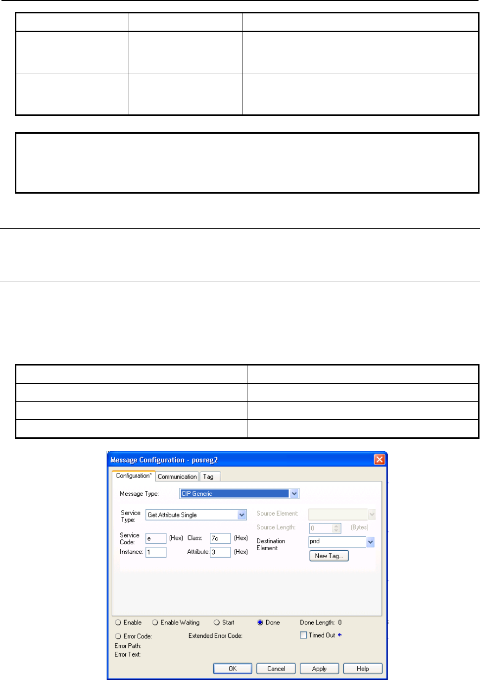
B-82854EN/02 7.EXPLICIT MESSAGING
- 57 -
Service Code Service Name Description
02 hex Set_Attribute_All Sets all attributes starting from Attribute 1 to 10 or
maximum position registers supported on controller
whichever is smaller.
33 hex Set_Attribute_Block Sets values to block of position registers starting from
any register up to next 10 registers or maximum position
registers supported on controller whichever is smaller.
NOTE
Please note that reading or writing of position registers in any representation i.e.
joint or cartesian, would NOT affect controller's current position register
representation.
7.4.3.3 Errors
Refer to Section 7.4.1.3.
7.4.3.4 Read single register
Reading position register is similar to numeric or string registers except instance number represents the
group number of the robot having multiple groups so instance number is always nonzero positive integer.
This object allows to read registers from multiple groups of the robot. Table 7.4.3.4(a) and Figure
7.4.3.4(a) show the configuration details to read position register 3 in joint representation.
Table 7.4.3.4(a) Read position register 3 in joint mode
Class 0x7C
Instance 0x01
Attribute 0x03
Service 0x0E
Fig. 7.4.3.4(a) Read single register in joint mode
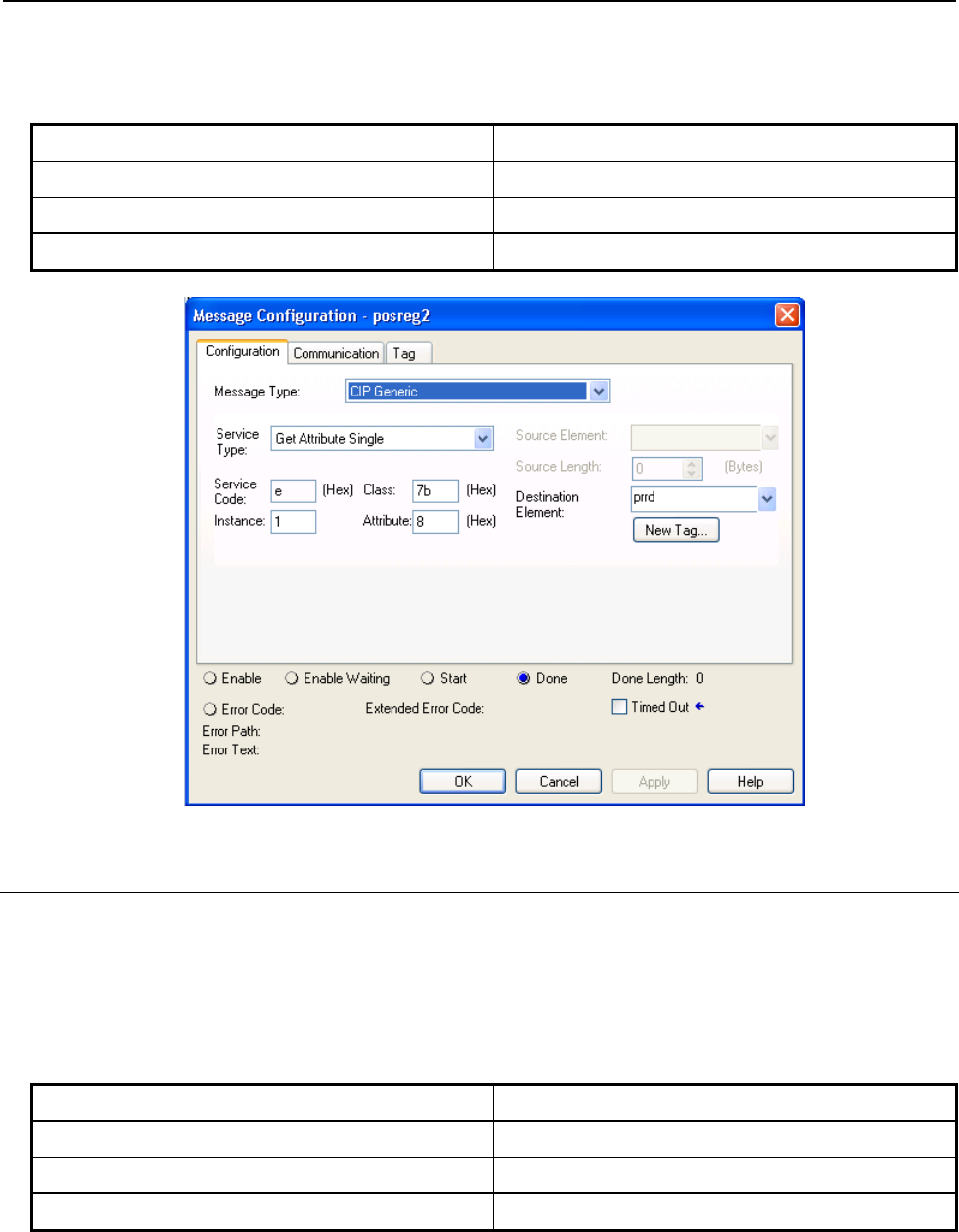
7.EXPLICIT MESSAGING B-82854EN/02
- 58 -
Similarly Table 7.4.3.4(b) and Figure 7.4.3.4(b) show the configuration for read position register 8 in
cartesian mode. Please remember that Joint representation is a 40 bytes and Cartesian representation is 44
byte data. Table 7.4.3.4(b) Read position register 8 in cartesian mode
Class 0x7B
Instance 0x01
Attribute 0x08
Service 0x0E
Fig. 7.4.3.4(b) Read single register in cartesian mode
7.4.3.5 Read all registers
Reading all registers is also supported for position registers. Reading procedure is similar to Numeric or
String Registers except class and data type. Reading all position registers is limited to maximum of 10 or
number of registers on controller whichever is SMALLER starting from register 1. Please refer to Table
7.4.3.5 and Figure 7.4.3.5 for configuration details. prrd is an array of structures PRCRT a user define
data type shown in Figure 7.4.3.1(b) for cartesian representation.
Table 7.4.3.5 Read all registers
Class 0x7B
Instance 0x01
Attribute 0x00
Service 0x01
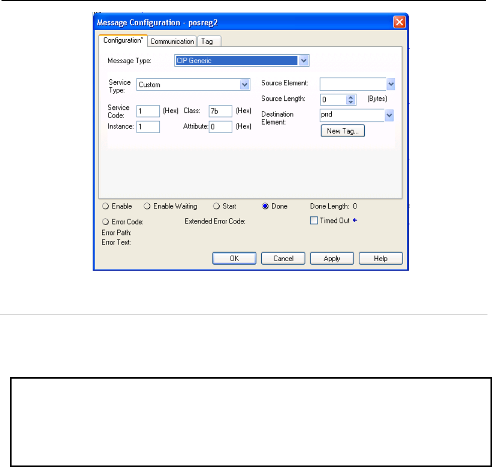
B-82854EN/02 7.EXPLICIT MESSAGING
- 59 -
Fig. 7.4.3.5 Read all registers
7.4.3.6 Read a block of registers
Position registers also can read or written in blocks. The block size limitation is 10 registers at a time.
This functionality provides the flexibility to set start register index of the block of registers i.e. read 23 to
32 or 50 to 59, etc.
NOTE
Please note that the data returned/consumed as a result of block read/write
operation is always multiple of 40 (joint) or 44 (cartesian) which is 40 or 44 times
block size for joint and cartesian respectively. In case of read/write all data size is
400 (joint) or 440 (cartesian) bytes, if total position registers available on controller
are 10 or more.
For example, message block configuration is shown in Figure 7.4.3.6 for reading 8 position registers of
group 1 starting from register number 10 in cartesian mode. Instance 2049 is decimal equivalent of
0x0801 and 'prrd' is an array of structure defined in Figure 7.4.3.1(b) to hold position data in cartesian
mode.

7.EXPLICIT MESSAGING B-82854EN/02
- 60 -
Fig. 7.4.3.6 Read a block of registers
7.4.3.7 Read current position (CURPOS or CURJPOS)
This functionality also allows to read current position of robot in two modes: joint and cartesian.
Configuration is same as reading a single position register with index 1 except class 0x7D is used for
cartesian and 0x7E is used for joint. Please refer to Figure 7.4.3.7(a) for cartesian mode and Figure
7.4.3.7(b) for joint mode in RSLogix5000 message block configuration.Table 7.4.3.7(a) and Table
7.4.3.7(b) show the configuration parameters for cartesian and joint mode respectively.
Table 7.4.3.7(a) Read current position in cartesian mode
Class 0x7D
Instance 0x01
Attribute 0x01
Service 0x0E
Fig. 7.4.3.7(a) Read CURPOS
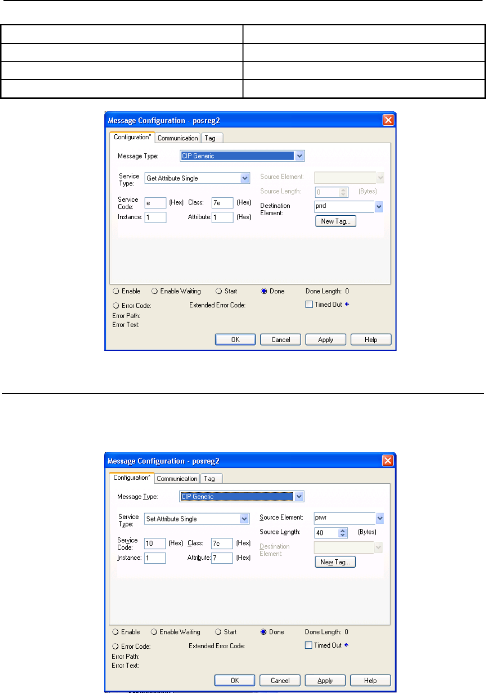
B-82854EN/02 7.EXPLICIT MESSAGING
- 61 -
Table 7.4.3.7(b) Read current position in joint mode
Class 0x7E
Instance 0x01
Attribute 0x01
Service 0x0E
Fig. 7.4.3.7(b) Read CURJPOS
7.4.3.8 Write single register
This service provides the flexibility to write position data to position registers in two modes cartesian and
joint. Figure 7.4.3.8 shows the configuration parameters. Here prwr is a user defined data structure as
shown in Figure 7.4.3.1(a) to hold the position data for joint representation.
Fig. 7.4.3.8 Write single register in joint mode
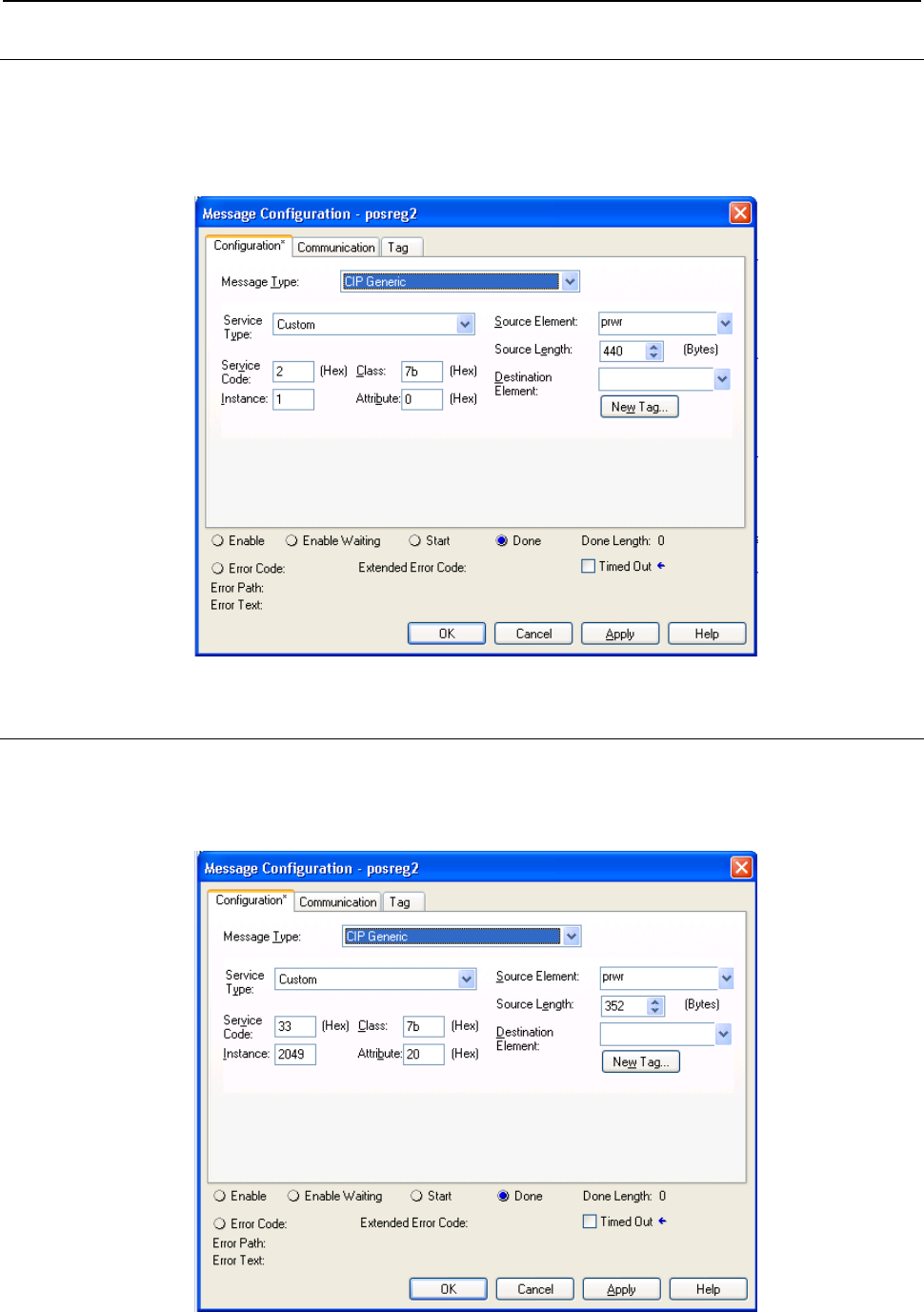
7.EXPLICIT MESSAGING B-82854EN/02
- 62 -
7.4.3.9 Write all registers
This service allows to write position data to first 10 position registers. Position data for each register is 44
or 40 bytes long for cartesian and joint representation respectively. Figure 7.4.3.9 shows the message
block configuration where 'prwr' is an array of 10 data structures to hold cartesian position data. Please
refer to Figure 7.4.3.1(b) for cartesian position data structure.
Fig. 7.4.3.9 Write all registers
7.4.3.10 Write a block of registers
Figure 7.4.3.10(a) is message block configuration for writing 8 position registers of group 1 starting from
register index 32 (0x20) in cartesian mode where “prwr” is an array of structure defined in Figure
7.4.3.1(b) to carry position data.
Fig. 7.4.3.10(a) Write a block of registers
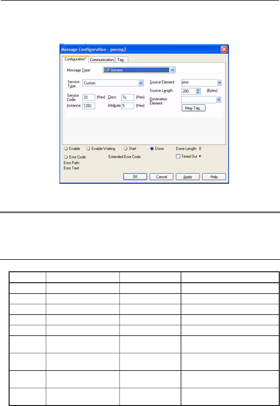
B-82854EN/02 7.EXPLICIT MESSAGING
- 63 -
Similarly a block of registers can be written to group #2 of robot. Figure 7.4.3.10(b) shows the message
block configuration for writing 5 position registers of group #2 starting from register index 5 in joint
mode. Instance 1282 is decimal equivalent of 0x0502, see Table 7.4.3.1(b) . Variable “prwr” is an array
of structure defined in Figure 7.4.3.1(a) .
Fig. 7.4.3.10(b) Write a block of registers to group #2
7.5 VENDOR SPECIFIC ACTIVE ALARM OBJECT (0xA0)
Information about Active Alarms can be read through FANUC’s Active Alarm Object. Each instance of
the object corresponds to an active alarm. For example, instance 1 corresponds to the most recent Active
Alarm, and instance 5 corresponds to the 5th most recent Active Alarm.
7.5.1 Instance Attributes
Table 7.5.1 Instance attributes
Attribute ID Name Data Type Description of Attribute
1 Alarm ID 16-bit integer The Alarm ID, or Alarm Code.
2 Alarm Number 16-bit integer The Alarm Number
3 Alarm ID Cause Code 16-bit integer The Cause Code of the Alarm ID.
4 Alarm Num Cause Code 16-bit integer The Cause Code of the Alarm Number.
5 Alarm Severity 16-bit integer The Alarm Severity.
6 Time Stamp 32-bit integer The Alarm Time Stamp in 32-bit
MS-DOS format.
7 Date/Time String 24 character string The Alarm Time Stamp in a human
readable string.
8 Alarm Message 80 character string The Alarm Message in a human
readable string.
9 Cause Code Message 80 character string The Alarm Cause Code Message in a
human readable string.

7.EXPLICIT MESSAGING B-82854EN/02
- 64 -
Attribute ID Name Data Type Description of Attribute
10 Alarm Severity String 24 character string The Alarm Severity in a human
readable string.
7.5.2 Common Services
FANUC’s Active Alarm Object provides the following Common Services at the Instance level. No Class
level services are provided. Refer to Table 7.5.2 .
Table 7.5.2 Common services
Service Code Service Name Description of Service
0E hex Get_Attribute_Single Returns the content of the specified attribute.
01 hex Get_Attribute_All Returns a listing of the object’s attributes
(See the Get_Attribute_All definition below).
7.5.2.1 Get_Attribute_All Response
At the Instance level, the attributes are returned in the order shown in Table 7.5.2.1 using little-endian
byte-swapping for 16-bit and 32-bit integers.
Table 7.5.2.1 Get_Attribute_All responses
32-bit integer Byte 0 Byte 1 Byte 2 Byte 3
1 Alarm ID Alarm Number
2 Alarm ID Cause Code Alarm Num Cause Code
3 Alarm Severity PAD (All Zeros)
4 Time Stamp
5 Date/Time String (24 bytes)
... ...
11 Alarm Message (80 bytes)
... ...
31 Cause Code Message (80 bytes)
... ...
51 Alarm Severity String (24 bytes)
... ...

B-82854EN/02 7.EXPLICIT MESSAGING
- 65 -
7.5.3 Errors
FANUC’s Vendor Specific Active Alarm Object will return the errors shown in Table 7.5.3 .
Table 7.5.3 Errors
Error Status Error Description
Undefined Attribute (0x14) Returned when the Alarm Attribute requested does not exist.
Unsupported Service (0x08) Returned when the requested service is unsupported.
Undefined Class Instance (0x05) Returned when the requested instance number does not exists. For
example, if there is only 1 single active alarm, requesting the Active Alarm
Object instance 2 will cause this error to be returned.
7.5.4 Examples
7.5.4.1 Read most recent active alarm cause code
To read the most recent active alarm’s cause code from the controller, the explicit message client would
be configured with the values shown in Table 7.5.4.1 .
Table 7.5.4.1 Read most recent active alarm cause code
Class 0xA0
Instance 0x01
Attribute 0x03
Service 0x0E
The explicit message server on the robot controller would return the cause code to the client as a 16-bit
integer.
7.5.4.2 Read all alarm information from the second most recent
active alarm
To read all alarm information about the second most recent active alarm from the controller, the explicit
message client would be configured with the values shown in Table 7.5.4.2 .
Table 7.5.4.2 Read all alarm information from the second most recent active alarm
Class 0xA0
Instance 0x02
Attribute Not Required
Service 0x01
The explicit message server on the robot controller would return all Registers as described in Section
7.5.2.1 .

7.EXPLICIT MESSAGING B-82854EN/02
- 66 -
7.6 VENDOC SPECIFIC ALARM HISTORY OBJECT (0xA1)
Information about the Alarm History can be read through FANUC’s Alarm History Object. Each instance
of the object corresponds to an alarm in the history. For example, instance 1 corresponds to the most
recent Alarm in the alarm history, and instance 5 corresponds to the 5th most recent Alarm.
7.6.1 Instance Attributes
The instance attributes are identical to those of FANUC’s Active Alarm Object (0xA0) and are
documented in Section 7.5.1 .
7.6.2 Common Services
The common services are identical to those of FANUC’s Active Alarm Object (0xA0) and are
documented in Section 7.5.2 .
7.6.3 Errors
The errors are identical to those of FANUC’s Active Alarm Object (0xA0) and are documented in Section
7.5.3 .
7.6.4 Examples
7.6.4.1 Read most recent alarm cause code
To read the most recent alarm’s cause code from the controller, the explicit message client would be
configured with the values shown in Table 7.6.4.1 .
Table 7.6.4.1 Read most recent alarm cause code
Class 0xA1
Instance 0x01
Attribute 0x03
Service 0x0E
The explicit message server on the robot controller would return the cause code to the client as a 16-bit
integer.
7.6.4.2 Real all alarm information from the second most recent alarm
To read all alarm information about the second most recent alarm from the controller, the explicit
message client would be configured with the values shown in Table 7.6.4.2 .
Table 7.6.4.2 Real all alarm information from the second most recent alarm
Class 0xA1
Instance 0x02
Attribute Not Required
Service 0x01

B-82854EN/02 7.EXPLICIT MESSAGING
- 67 -
The explicit message server on the robot controller would return all Registers as described in Section
7.5.2.1 .
7.7 VENDOR SPECIFIC MOTION ALARM OBJECT (0xA2)
Information about Motion Alarms can be read through FANUC’s Motion Alarm Object. Each instance of
the object corresponds to a motion alarm. For example, instance 1 corresponds to the most recent motion
alarm, and instance 5 corresponds to the 5th most recent motion alarm.
7.7.1 Instance Attributes
The instance attributes are identical to those of FANUC’s Active Alarm Object (0xA0) and are
documented in Section 7.5.1 .
7.7.2 Common Services
The common services are identical to those of FANUC’s Active Alarm Object (0xA0) and are
documented in section Section 7.5.2 .
7.7.3 Errors
The errors are identical to those of FANUC’s Active Alarm Object (0xA0) and are documented in Section
7.5.3 .
7.7.4 Examples
7.7.4.1 Read most recent motion alarm cause code
To read the most recent motion alarm’s cause code from the controller, the explicit message client would
be configured with the values shown in Table 7.7.4.1 .
Table 7.7.4.1 Read most recent motion alarm cause code
Class 0xA2
Instance 0x01
Attribute 0x03
Service 0x0E
The explicit message server on the robot controller would return the cause code to the client as a 16-bit
integer.
7.7.4.2 Read all alarm information from the second most recent
motion alarm
To read all alarm information about the second most recent motion alarm from the controller, the explicit
message client would be configured with the values shown in Table 7.7.4.2 .

7.EXPLICIT MESSAGING B-82854EN/02
- 68 -
Table 7.7.4.2 Read all alarm information from the second most recent motion alarm
Class 0xA2
Instance 0x02
Attribute Not Required
Service 0x01
The explicit message server on the robot controller would return all Registers as described in Section
7.5.2.1 .
7.8 VENDOR SPECIFIC SYSTEM ALARM OBJECT (0xA3)
Information about System Alarms can be read through FANUC’s System Alarm Object. Each instance of
the object corresponds to a system alarm. For example, instance 1 corresponds to the most recent system
alarm, and instance 5 corresponds to the 5th most recent system alarm.
7.8.1 Instance Attributes
The instance attributes are identical to those of FANUC’s Active Alarm Object (0xA0) and are
documented in Section 7.5.1 .
7.8.2 Common Services
The common services are identical to those of FANUC’s Active Alarm Object (0xA0) and are
documented in Section 7.5.2 .
7.8.3 Errors
The errors are identical to those of FANUC’s Active Alarm Object (0xA0) and are documented in Section
7.5.3 .
7.8.4 Examples
7.8.4.1 Read most recent system alarm cause code
To read the most recent system alarm’s cause code from the controller, the explicit message client would
be configured with the following values:
Table 7.8.4.1 Read most recent system alarm cause code
Class 0xA3
Instance 0x01
Attribute 0x03
Service 0x0E
The explicit message server on the robot controller would return the cause code to the client as a 16-bit
integer.

B-82854EN/02 7.EXPLICIT MESSAGING
- 69 -
7.8.4.2 Read all alarm information from the second most recent
system alarm
To read all alarm information about the second most recent system alarm from the controller, the explicit
message client would be configured with the following values:
Table 7.8.4.2 Read all alarm information from the second most recent system alarm
Class 0xA3
Instance 0x02
Attribute Not Required
Service 0x01
The explicit message server on the robot controller would return all Registers as described in Section
7.5.2.1 .
7.9 VENDOR SPECIFIC APPLICATION ALARM OBJECT
(0xA4)
Information about Application Alarms can be read through FANUC’s Application Alarm Object. Each
instance of the object corresponds to an application alarm. For example, instance 1 corresponds to the
most recent application alarm, and instance 5 corresponds to the 5th most recent application alarm.
7.9.1 Instance Attributes
The instance attributes are identical to those of FANUC’s Active Alarm Object (0xA0) and are
documented in Section 7.5.1 .
7.9.2 Common Services
The common services are identical to those of FANUC’s Active Alarm Object (0xA0) and are
documented in Section 7.5.2 .
7.9.3 Errors
The errors are identical to those of FANUC’s Active Alarm Object (0xA0) and are documented in Section
7.5.3 .
7.9.4 Examples
7.9.4.1 Read most recent application alarm cause code
To read the most recent alarm’s cause code from the controller, the explicit message client would be
configured with the values shown in Table 7.9.4.1 .

7.EXPLICIT MESSAGING B-82854EN/02
- 70 -
Table 7.9.4.1 Read most recent application alarm cause code
Class 0xA4
Instance 0x01
Attribute 0x03
Service 0x0E
The explicit message server on the robot controller would return the cause code to the client as a 16-bit
integer.
7.9.4.2 Read all alarm information from the second most recent
application alarm
To read all alarm information about the second most recent application alarm from the controller, the
explicit message client would be configured with the values shown in Table 7.9.4.2 .
Table 7.9.4.2 Read all alarm information from the second most recent application alarm
Class 0xA4
Instance 0x02
Attribute Not Required
Service 0x01
The explicit message server on the robot controller would return all Registers as described in Section
7.5.2.1 .
7.10 VENDOR SPECIFIC RECOVERY ALARM OBJECT (0xA5)
Information about Recovery Alarms can be read through FANUC’s Recovery Alarm Object. Each
instance of the object corresponds to a recovery alarm. For example, instance 1 corresponds to the most
recent recovery alarm, and instance 5 corresponds to the 5th most recent recovery alarm.
7.10.1 Instance Attributes
The instance attributes are identical to those of FANUC’s Active Alarm Object (0xA0) and are
documented in Section 7.5.1 .
7.10.2 Common Services
The common services are identical to those of FANUC’s Active Alarm Object (0xA0) and are
documented in Section 7.5.2 .
7.10.3 Errors
The errors are identical to those of FANUC’s Active Alarm Object (0xA0) and are documented in Section
7.5.3 .

B-82854EN/02 7.EXPLICIT MESSAGING
- 71 -
7.10.4 Examples
7.10.4.1 Read most recent recovery alarm cause code
To read the most recent recovery alarm’s cause code from the controller, the explicit message client
would be configured with the values shown in Table 7.10.4.1 .
Table 7.10.4.1 Read most recent recovery alarm cause code
Class 0xA5
Instance 0x01
Attribute 0x03
Service 0x0E
The explicit message server on the robot controller would return the cause code to the client as a 16-bit
integer.
7.10.4.2 Read all alarm information from the second most recent
recovery alarm
To read all alarm information about the second most recent recovery alarm from the controller, the
explicit message client would be configured with the values shown in Table 7.10.4.2 .
Table 7.10.4.2 Read all alarm information from the second most recent recovery alarm
Class 0xA5
Instance 0x02
Attribute Not Required
Service 0x01
The explicit message server on the robot controller would return all Registers as described in Section
7.5.2.1 .
7.11 VENDOR SPECIFIC COMMUNICATIONS ALARM OBJECT
(0xA6)
Information about Communications Alarms can be read through FANUC’s Communications Alarm
Object. Each instance of the object corresponds to a communications alarm. For example, instance 1
corresponds to the most recent communications alarm and instance 5 corresponds to the 5th most recent
communications alarm.
7.11.1 Instance Attributes
The instance attributes are identical to those of FANUC’s Active Alarm Object (0xA0) and are
documented in Section 7.5.1 .
7.11.2 Common Services
The common services are identical to those of FANUC’s Active Alarm Object (0xA0) and are
documented in Section 7.5.2 .

7.EXPLICIT MESSAGING B-82854EN/02
- 72 -
7.11.3 Errors
The errors are identical to those of FANUC’s Active Alarm Object (0xA0) and are documented in Section
7.5.3 .
7.11.4 Examples
7.11.4.1 Read most recent communication alarm cause code
To read the most recent alarm’s cause code from the controller, the explicit message client would be
configured with the values shown in Table 7.11.4.1 .
Table 7.11.4.1 Read most recent communication alarm cause code
Class 0xA6
Instance 0x01
Attribute 0x03
Service 0x0E
The explicit message server on the robot controller would return the cause code to the client as a 16-bit
integer.
7.11.4.2 Read all alarm information from the second most recent
communications alarm
To read the second most recent alarm’s cause code from the controller, the explicit message client would
be configured with the values shown in Table 7.11.4.2 .
Table 7.11.4.2 Read all alarm information from the second most recent communications alarm
Class 0xA6
Instance 0x02
Attribute Not Required
Service 0x0E
The explicit message server on the robot controller would return all Registers as described in Section
7.5.2.1 .
7.12 ACCESSING I/O USING EXPLICIT MESSAGING
7.12.1 Accessing I/O Specific to an Implicit EtherNet/IP Connection
I/O can be accessed through ODVA’s standard Assembly Object. Table 7.12.1(a) describes the Assembly
Instance numbers that can be used to read or write I/O specific to an Implicit EtherNet/IP connection
configured on a FANUC robot controller.

B-82854EN/02 7.EXPLICIT MESSAGING
- 73 -
NOTE
I/O can not be written to the writable assembly instances using explicit messaging
while an active implicit connection to the instance is running.
Detailed instructions for mapping I/O on the robot controller can be found in Section 6.2 of this manual.
Table 7.12.1(a) Accessing I/O
Instance Number Read/Write Input/Output Slot
101 r output 1
102 r output 2
103 r output 3
104 r output 4
105 r output 5
106 r output 6
107 r output 7
108 r output 8
109 r output 9
110 r output 10
111 r output 11
112 r output 12
113 r output 13
114 r output 14
115 r output 15
116 r output 16
117 r output 17
118 r output 18
119 r output 19
120 r output 20
121 r output 21
122 r output 22
123 r output 23
124 r output 24
125 r output 25
126 r output 26
127 r output 27
128 r output 28
129 r output 29
130 r output 30
131 r output 31

7.EXPLICIT MESSAGING B-82854EN/02
- 74 -
Instance Number Read/Write Input/Output Slot
132 r output 32
151 r/w* input 1
152 r/w* input 2
153 r/w* input 3
154 r/w* input 4
155 r/w* input 5
156 r/w* input 6
157 r/w* input 7
158 r/w* input 8
159 r/w* input 9
160 r/w* input 10
161 r/w* input 11
162 r/w* input 12
163 r/w* input 13
164 r/w* input 14
165 r/w* input 15
166 r/w* input 16
167 r/w* input 17
168 r/w* input 18
169 r/w* input 19
170 r/w* input 20
171 r/w* input 21
172 r/w* input 22
173 r/w* input 23
174 r/w* input 24
175 r/w* input 25
176 r/w* input 26
177 r/w* input 27
178 r/w* input 28
179 r/w* input 29
180 r/w* input 30
181 r/w* input 31
182 r/w* input 32
* Only instances corresponding to Adapter connections are writable using Explicit Messaging; however,
these instances will not be writable while an active implicit connection to the instance is running. If the
corresponding connection is a Scanner connection, then the instance will be read-only.
For example, suppose the controller is configured with one Adapter connection on slot 1 with a 16-bit
word of input and a 16-bit word of output, which are mapped to DI[1-16] and to DO[1-16] respectively.

B-82854EN/02 7.EXPLICIT MESSAGING
- 75 -
Once an implicit connection is establish to the adapter, the output values in DO[1-16] can be accessed
through explicit messaging with the values shown in Table 7.12.1(b) .
Table 7.12.1(b) Output values
Class 0x04
Instance 0x65
Attribute 0x03
Service 0x0E
And the input values in DI[1-16] can be accessed through explicit messaging with the values Table
7.12.1(c) . Table 7.12.1(c) Input values
Class 0x04
Instance 0x97
Attribute 0x03
Service 0x0E
7.12.2 Accessing General I/O
In addition to I/O mapped from EtherNet/IP connections, other types of I/O can be read with explicit
messaging using the following Assembly Object Instance numbers.
Table 7.12.2(a) Accessing general I/O
I/O Type Instance Number (hexadecimal)
Digital input 0x320
Digital output 0x321
Analog input 0x322
Analog output 0x323
Tool output 0x324
PLC input 0x325
PLC output 0x326
Robot digital input 0x327
Robot digital output 0x328
Brake output 0x329
Operator panel input 0x32a
Operator panel output 0x32b
Teach pendant digital input 0x32d
Teach pendant digital output 0x32e
Weld input 0x32f
Weld output 0x330
Group input 0x331
Group output 0x332

7.EXPLICIT MESSAGING B-82854EN/02
- 76 -
I/O Type Instance Number (hexadecimal)
User operator panel input 0x333
User operator panel output 0x334
Laser DIN 0x335
Laser DOUT 0x336
Laser AIN 0x337
Laser AOUT 0x338
Weld stick input 0x339
Weld stick output 0x33a
Memory image boolean 0x33b
Memory image DIN 0x33c
Dummy boolean port type 0x33d
Dummy numeric port type 0x33e
Process axes (ISDT) 0x33f
Internal operator panel input 0x340
Internal operator panel output 0x341
Flag (F[ ]) 0x342
Marker (M[ ]) 0x343
For example, the values shown in Table 7.12.2(b) would access all Digital Outputs (DOs) with explicit
messaging. Table 7.12.2(b) Accessing digital outputs
Class 0x04
Instance 0x321
Attribute 0x03
Service 0x0E
7.13 USING EXPLICIT MESSAGING IN RSLogix 5000
This section steps through an example of how to configure an I/O read and write operation on a robot
controller using RSLogix5000. In this example, an I/O read and write is done on Rack 89 Slot 1 of the
robot controller every 1000ms.
Three rungs are created in our main program. The first rung is a timer rung. This timer, mtime, will
trigger read and write messages to be sent to the robot controller every 1000ms. The next two rungs have
MSG blocks, where the individual Explicit Messages will be defined. Figure 7.13(a) shows the three
rungs.

B-82854EN/02 7.EXPLICIT MESSAGING
- 77 -
Fig. 7.13(a) RsLogix 5000 example rungs
NOTE
We have created the element tcoil to turn the sending of the two Explicit Messages
on and off.
To add a message block, you will need to add a MSG ladder element. Figure 7.13(b) shows an example of
adding a MSG ladder element.
Fig. 7.13(b) RSLogix 5000 add MSG block
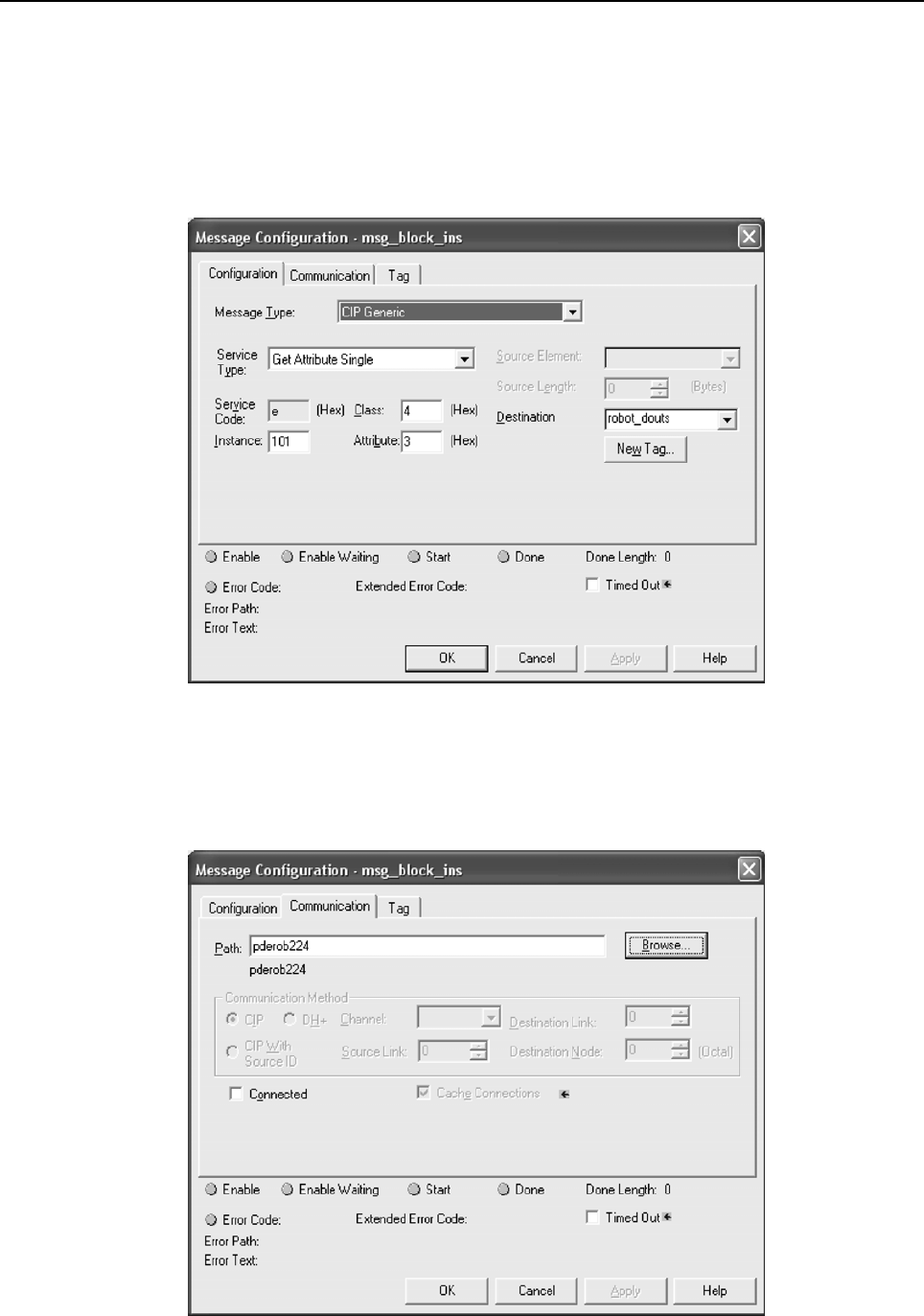
7.EXPLICIT MESSAGING B-82854EN/02
- 78 -
Configuration of the message block requires the Class, Instance, Attribute, and Service values as
discussed in Section 7.3 of this manual. For example, to read the robot controller outputs at Rack 89 Slot
1, we would access the Assembly Class (0x04), Attribute 3 (0x03), Instance 101 (0x65), and Service
Get_Attribute_Single (0x0e). See Section 7.12 for more details.
Thus, once configured, the MSG block should look similar to Figure 7.13(c) . You will need to create a
destination for the robot controller outputs to be read into. In this example, we created an array named
robot_douts.
Fig. 7.13(c) MSG block: read robot DOUTs
Next, click on the Communications tab. From this tab you should be able to browse to the device to
which you want to connect. In Figure 7.13(d) , we browsed to and are connecting to a device named
pderob224. Note that the robot controller must already be configured in RSLogix5000’s I/O
Configuration for the Browse button to successfully find the robot.
Fig. 7.13(d) MSG block communication tab
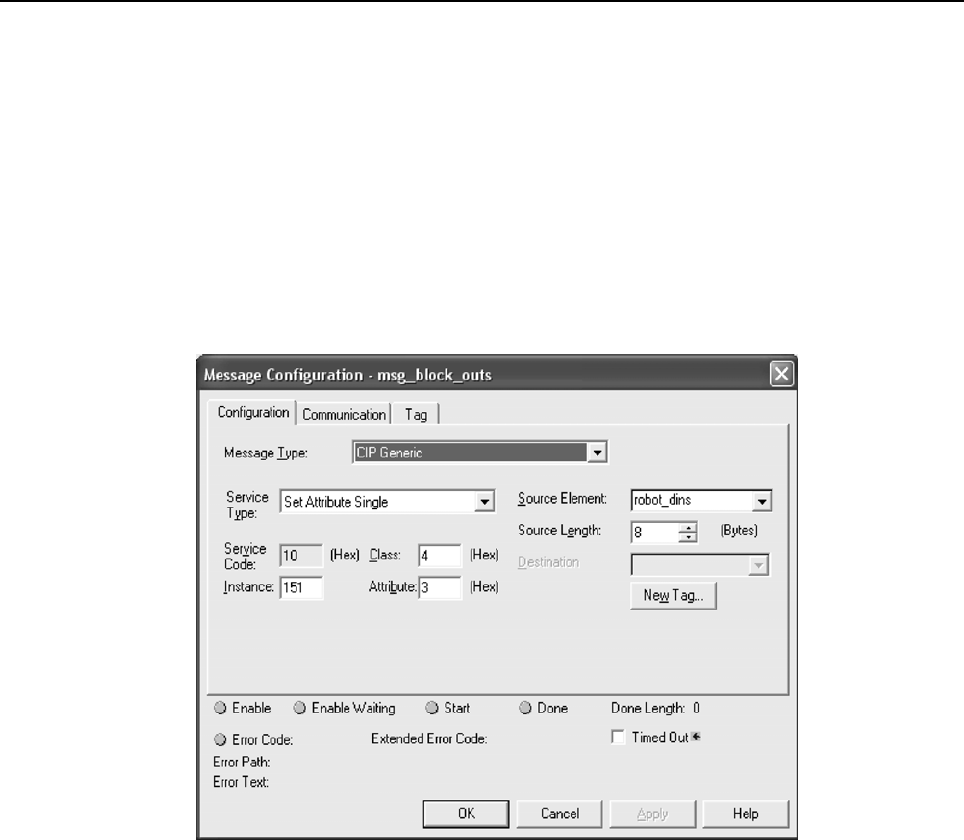
B-82854EN/02 7.EXPLICIT MESSAGING
- 79 -
Documentation for RSLogix5000 also provides two additional ways of expressing the Path. First, the path
can be an expression of comma-separated values that indicate the route for the MSG starting at the
Ethernet module on the PLC and ending at the target device. For example “ENET,2,192.168.1.224”
would be a path from the ENET module, port 2 on the ENET module (this value should always be 2), to
the IP address of the robot controller.
Secondly, the same path could be expressed as “1,2,2,192.168.1.224”. Where the 1 represents the slot
number of the processor in the rack, and the 2 in the second position represents the slot number of the
ENET module. The 2 in the third position would represent port two on the ENET module, and the fourth
position contains the IP address of the robot.
Figure 7.13(e) shows the MSG block used to write to the robot controller’s inputs. In this case we use
Class 0x04, Instance 151 (0x97), Attribute 0x03, and Service Set_Attribute_Single (0x10). We also
created the array robot_dins to write to the robot controller.
Fig. 7.13(e) MSG block: write robot DINs

8.NETWORK DESIGN AND PERFORMANCE B-82854EN/02
- 80 -
8 NETWORK DESIGN AND PERFORMANCE
8.1 NETWORK DESIGN CONSIDERATIONS
Good network design is critical for reliable operation. It is important to pay special attention to wiring
guidelines and environmental conditions affecting the cable system and equipment. It is also necessary to
control network traffic to avoid wasted network bandwidth and device resources.
Keep in mind the following wiring guidelines and environmental considerations:
Use category 5 twisted pair (or better) rated for 100-BaseTX Ethernet applications and the
application environment. Consider shielded versus unshielded twisted pair cabling.
Pay careful attention to wiring guidelines such as maximum length from the switch to the device
(100 meters).
Do not exceed recommended bending radius of specific cabling being used.
Use connectors appropriate to the environment. There are various industrial Ethernet connectors in
addition to the standard open RJ45 that should be used where applicable. For example, connectors
are available with IP65 or IP67 ratings. M12 4-pin D-coded Connectors are included in the
Ethernet/IP specification.
Route the wire runs away from electrical or magnetic interference or cross at ninety degrees to
minimize induced noise on the Ethernet network.
Keep the following in mind as you manage network traffic:
Control or eliminate collisions by limiting the collision domain.
Control broadcast traffic by limiting the broadcast domain.
Control multicast traffic with multicast aware switches (support for IGMP snooping).
Use QOS (Quality of Service) techniques in very demanding applications.
Collisions are a traditional concern on an Ethernet network but can be completely avoided by using
switches—rather than hubs—and full duplex connections. It is critical to use switches and full duplex
connections for any Ethernet I/O network, because it reduces the collision domain to only one device so
that no collisions will occur. The robot interface will autonegotiate by default and use the fastest
connection possible. Normally this is 100Mbps and full duplex. The robot can be set for a specific
connection speed and duplex. However be very careful that both ends of the connection use the same
speed and duplex mode. Be careful not to set one end of a connection for autonegotiate and set the other
end to a specific speed duplex – both ends must autonegotiate, or both ends must be fixed to the same
settings.
The LEDs near the RJ45 connector on the robot will confirm a connection link. Link State can be
confirmed using the TCP/IP status Host Comm screen by following Procedure 8-1 .
Procedure 8-1 Verifying Link State
1. Press MENUS.
2. Select Setup.
3. Press [F1] TYPE and select Host Comm.
4. Select TCP/IP.
5. Toggle to the correct port (port #1 or port #2) by pressing [F3] PORT.
6. Press NEXT, then [F2] STATUS.
Broadcast traffic is traffic that all nodes on the subnet must listen for and in some cases respond to.
Excessive broadcast traffic wastes network bandwidth and wastes resources in all effected nodes. The
broadcast domain is the range of devices (typically the entire subnet) that must listen to all broadcasts. It
is recommended to limit the broadcast domain to only the control devices (for example, EtherNet/IP
nodes) by using a separate subnet for the control equipment or by using VLANs (virtual LANs) supported

B-82854EN/02 8.NETWORK DESIGN AND PERFORMANCE
- 81 -
by some higher end switches. If the EtherNet/IP network is completely isolated as a separate control
network this is not a concern. However, when connecting into larger networks this becomes important.
Some network environments have a significant amount of multicast traffic. A basic layer 2 switch will
treat multicast traffic like broadcast traffic and forward to all ports in the switch wasting network
bandwidth and node resources on traffic which is ultimately dropped for the nodes that are not interested
in the multicast traffic. Switches that support “IGMP snooping” will selectively send multicast traffic
only to the nodes which have joined a particular group. EtherNet/IP UDP packet has a TTL (time to link)
value of one. You will not be able to route I/O traffic across more than one switch.
Quality of Service (QOS) techniques provide mechanisms to prioritize network traffic. Generally on an
Ethernet network all packets are equal. Packets can be dropped or delayed within network infrastructure
equipment (for example, switches) in the presence of excessive traffic. Which packets are dropped or
delayed is random.
QOS is a term covering several different approaches to prioritizing packets including:
MAC layer (layer 2) prioritization (IEEE 802.1p).
IP layer (layer 3) prioritization using source/destination IP addresses.
Transport layer (layer 4) prioritization using source/destination ports.
These QOS mechanisms are generally implemented within the network infrastructure equipment and are
beyond the scope of this manual. Some form of QOS should be considered on complex networks
requiring the highest possible level of determinism in I/O exchanges within the control network.
It is important to select the proper switch in order for the network to function correctly. The switch should
support :
100 Mbps baud rate
Full duplex connections
Port auto-negotiation
Environmental specifications appropriate for the application (for example, temperature)
Power supply requirements and redundancy (for example, support for 24vdc or 120vac and support
for a second redundant power supply if warranted)
NOTE
If there is a significant amount of multicast traffic, the switch should support IGMP
snooping (multicast aware). Please consider this when Ethernet/IP and/or RIPE
(robot ring) traffic exists.
NOTE
If the control network will be part of a larger network, the control network should be
on a separate VLAN or subnet. This can be done within the control switch or
possibly based on how the larger network connects to the control switch.
Some examples of switch products are:
Cisco 2955 (industrialized version of 2950) – www.cisco.com
Hischmann MICE (modular industrial switch) – www.hirschmann.de
Phoenix Contact (managed/unmanaged industrial switch) – www.ethernetrail.com
N-Tron 508TX-A, 8 port industrial switch with advanced firmware – www.n-tron.com
8.2 I/O RESPONSE TIME
The system response time is the amount of time it takes an I/O signal to propagate through the system to
its destination and back again. For a Controller -to- PLC system this time would be from the time an
output is sent to the time a modified input is read. The system response time depends on many factors
including:

8.NETWORK DESIGN AND PERFORMANCE B-82854EN/02
- 82 -
The Actual Packet Interval (API is based on RPI)
PLC Ladder Scan Time
No lost or delayed packets due to excessive traffic or noise
To calculate the response time, keep in mind that the response time is asynchronous but has a
deterministic upper limit. After a signal is set in the I/O Image, it will take a maximum of one API before
it gets transmitted to any node on the network.
Figure 8.2 shows a case where a DO is transferred to a PLC and back as a DI. In this case, after the DO is
set in the I/O Image, it will take a maximum of one API, t(api), to get the DO to the Ethernet transceiver.
After the DO is in the Ethernet transceiver, it is sent to the destination (PLC) at wire speed, t(wire)
(assumes full duplex link so no collisions).
Fig. 8.2 EtherNet/IP response time diagram
In the PLC, the inputs are scanned into the Ladder I/O Image, which fixes them for the entire Ladder Scan,
t(e-li). The inputs are processed during the ladder scan t(l) and then set back to the PLC’s Ethernet
transceiver at it’s API rate.
The PLC outputs are transferred at Ethernet wire speed back to the controller. They are then transferred to
the I/O Image t(e-i) where they can be read by the KAREL or teach pendant program.
T(Controller -to- PLC -to- Controller) = t(api) + t(wire) + t(e-li) + t(l) +
t(api) + t(wire) + t(e-i)
t(api) = KAREL or teach pendant outputs get immediately set in the I/O Image. The time necessary
to get to them to Ethernet transceiver can be a maximum of one API. In this example it is assumed
robot->plc API and plc->robot API values are the same.
t(wire) = The time it takes for the packet to traverse the network including any switch delays due to
queueing.
t(e-l i) = After the signal is in the PLC Ethernet transceiver, it must get processed through the PLC
network stack and placed in an appropriate ladder image data file to be accessed by the PLC Ladder.
t(l) = The input value needs to be fixed for the entire scan in the ladder. The PLC Scan can usually
be obtained by examining an appropriate status register in the PLC. After the signal has been
processed, the reverse process must take place.
T(e-i ) = After the signal is in the robot Ethernet transceiver, it must get processed through the robot
network stack and placed in I/O image area to be accessed by the TP or Karel program.
For example, using V7.10 or higher and a ControlLogix PLC over a simple network with a 20ms API, the
following times were calculated. This example assumes wire time is negligible (100Mbps network, no
switch delays), input packets are processed through the network stack and into image area within 1ms,
and ladder scan time is 5ms.
T(Controller - to - PLC - to - Controller
) = t(api) + t(wire) + t(e-li) + t(l) + t(api) + t(wire) + t(e-i)

B-82854EN/02 8.NETWORK DESIGN AND PERFORMANCE
- 83 -
T(Controller - to - PLC - to - Controller) = 20ms + 0ms + 1ms + 5ms +
20ms + 0ms + 1ms
T(Controller - to - PLC - to - Controller) = 47ms ***
*** This value assumes no delayed/lost packets due to excessive traffic or noise.
Your actual PLC ladder scan times might vary from the example. Most PLCs offer the capability to get
the actual scan time from a programmer or monitor.
This example assumes the packet is not delayed or dropped in a network switch or at the
source/destination node. Packets can be dropped due to the following reasons:
Excessive traffic can cause queue delays or dropped packets in the switch or source/destination
nodes depending on extent of traffic and queue sizes.
Packet corruption due to noise can cause a bad CRC check on the packet (a packet with a bad CRC
is dropped).
The maximum upper limit is based on EtherNet/IP timeout values. Timeouts will occur when a consumer
does not receive data from a producer within a multiple of the API. Typically this timeout value is 3-4
times the API value. If a timeout occurs, an error is posted. The error severity and last state I/O behavior
can be configured. Refer to Section 3.2.3 for adapter.

9.DIAGNOSTICS AND TROUBLESHOOTING B-82854EN/02
- 84 -
9 DIAGNOSTICS AND TROUBLESHOOTING
9.1 VERIFYING NETWORK CONNECTIONS
There are two basic tools for verifying network connections:
Ethernet status LEDs
PING
The LEDs and PING utility are basic tools but they give a good indication of whether or not devices are
able to communicate on the network. If the LINK LED is off, or if PING times out, then no other network
functionality will work for that device.
Refer to Section 9.1.1 for more information about Ethernet status LEDs.
Refer to Section 9.1.2 for more information about the PING utility.
9.1.1 Ethernet Status LEDs
The Ethernet status LEDs at the Ethernet RJ45 connector on the robot will indicate if the robot is
connected. Most Ethernet switches and other equipment will have similar LEDs indicating a physical
connection. If the LINK LED is off then there is no Ethernet connectivity at all. This generally implies a
disconnected or bad cable or bad connections. The speed and duplex must match between the robot and
the switch. The robot will auto-negotiate by default and should not be changed in most cases.
9.1.2 PING Utility
PING is a network utility that sends a request to a specific IP address and expects a response. The request
is essentially "Can you hear me?" The destination node will send a response that it received the request.
The requesting node will either receive the response or timeout. PING is a basic network utility that is
included with most operating systems, such as Windows and Unix, and is also supported on the robot.
Even devices that do not support generating PING requests (for example, an EtherNet/IP block with no
user interface) will respond to the PING request.
The robot supports PING directly from the EtherNet/IP status screen. Use Procedure 9-1 .
The PING utility is also available on the robot to PING any name or IP address. Use Procedure 9-2 .
The PING utility is also available from any windows PC. Use Procedure 9-3 .
Procedure 9-1 Using PING from the EtherNet/IP Status Screen
Steps
1. Press MENUS.
2. Select I/O.
3. Press F1, [TYPE].
4. Select EtherNet/IP.
5. Move the cursor to the connection with the device you want to PING.
6. Press F2, PING.
The prompt line on the teach pendant will indicate if the PING was successful or if the PING request
timed out.
NOTE
This function only works on the adapter connection (connection #1) if there is a
scanner connected.
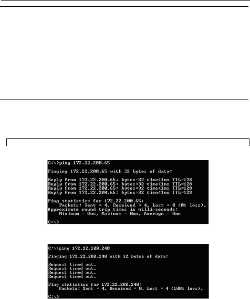
B-82854EN/02 9.DIAGNOSTICS AND TROUBLESHOOTING
- 85 -
Procedure 9-2 Using PING on the Robot
Steps
1. Press MENUS.
2. Select Setup.
3. Press F1, [TYPE].
4. Select Host Comm.
5. Move the cursor to select PING in the Protocol List and press ENTER.
6. Enter the name or IP address of the node to PING.
7. Press F2, PING.
The prompt line on the teach pendant will indicate if the PING was successful or if the PING request
timed out.
Procedure 9-3 Using PING on a Windows PC
Steps
1. Open a DOS command prompt.
2. Type the following command, replacing the IP address with the IP address you want to PING, and
press ENTER.
PING 192.168.0.10
The following image shows a successful PING.
The following image shows an unsuccessful PING.
If the LINK LED is on but a PING request fails it usually indicates a problem with IP address
configuration. Either no IP address is configured, or the combination of IP address and subnet mask is
inconsistent for the network.

9.DIAGNOSTICS AND TROUBLESHOOTING B-82854EN/02
- 86 -
9.2 ERROR CODES
The following error codes are defined by the EtherNet/IP January 2005 Specification. When a controller
scanner connection fails when establishing a connection to a target device, the controller posts an error in
the following format (PRIO-350 is the error code, and PRIO-358 is the cause code).
PRIO-350 EtherNet/IP Scanner Error (#)
PRIO-358 EtherNet/IP Fwd Open Fail (0x#)
The PRIO-350 code (#) specifies on which connection the error has occurred. The PRIO-358 code (0x#)
specifies the extended status of the error returned by the target device (in hexadecimal format).
Table 9.2 lists the descriptions of the extended status error codes:
NOTE
EtherNet/IP alarms are documented in the R-30iA/R-30iA Mate controller ALARM
CODE LIST operator’s manual (B-83124EN-6) or R-30iB controller ALARM CODE
LIST operator’s manual (B-83284EN-1).
Table 9.2 Forward open failure error codes
GENERAL STATUS EXTENDED STATUS DESCRIPTION
0x01 0x0100 Connection in Use or Duplicate Forward Open
0x01 0x0103 Transport Class and Trigger combination not
supported
0x01 0x0106 Ownership Conflict
0x01 0x0107 Connection not found at target application.
0x01 0x0108 Invalid Connection Type. Indicates a problem with
either the Connection Type or Priority of the
Connection
0x01 0x0109 Invalid Connection Size
0x01 0x0110 Device not configured
0x01 0x0111 RPI not supported. Might also indicate problem with
connection timeout multiplier or production inhibit
time.
0x01 0x0113 Connection Manager cannot support any more
connections
0x01 0x0114 Either the Vendor Id or the Product Code in the key
segment did not match the device
0x01 0x0115 Product Type in the key segment did not match the
device
0x01 0x0116 Major or Minor Revision information in the key
segment did not match the device
0x01 0x0117 Invalid Connection Point
0x01 0x0118 Invalid Configuration Format
0x01 0x0119 Connection request fails since there is no controlling
connection currently open.
0x01 0x011A Target Application cannot support any more
connections

B-82854EN/02 9.DIAGNOSTICS AND TROUBLESHOOTING
- 87 -
GENERAL STATUS EXTENDED STATUS DESCRIPTION
0x01 0x011B RPI is smaller than the Production Inhibit Time.
0x01 0x0203 Connection cannot be closed since the connection
has timed out
0x01 0x0204 Unconnected Send timed out waiting for a response.
0x01 0x0205 Parameter Error in Unconnected Send Service
0x01 0x0206 Message too large for Unconnected message service
0x01 0x0207 Unconnected acknowledge without reply
0x01 0x0301 No buffer memory available
0x01 0x0302 Network Bandwidth not available for data
0x01 0x0303 No screeners available
0x01 0x0304 Not Configured to send real-time data
0x01 0x0311 Port specified in Port Segment Not Available
0x01 0x0312 Link Address specified in Port Segment Not Available
0x01 0x0315 Invalid Segment Type or Segment Value in Path
0x01 0x0316 Error in close path
0x01 0x0317 Scheduling not specified
0x01 0x0318 Link Address to Self Invalid
0x01 0x0319 Resources on Secondary Unavailable
0x01 0x031A Connection already established
0x01 0x031B Direct connection already established
0x01 0x031C Miscellaneous
0x01 0x031D Redundant connection mismatch
0x01 0x031E No more consumer resources available in the
producing module
0x01 0x031F No connection resources exist for target path
0x01 0x320 — 0x7FF Vendor specific
APPENDIX
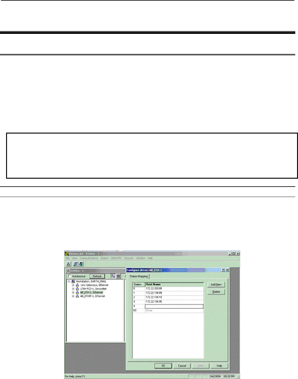
B-82854EN/02 A.THIRD-PARTY CONFIGURATION TOOLS
- 91 -
A THIRD-PARTY CONFIGURATION TOOLS
A.1 TOOLS OVERVIEW
Robot Scanner connections can be configured from the EtherNet/IP Interface screens, or from third party
tools such as RSNetWorx for EtherNet/IP using the Connection Configuration Object (CCO). Certain
devices require detailed configuration data, and can only be added to the robot scanlist by using offline
tools such as an Allen Bradley Flex I/O block with attached modules. Other devices can be configured
through both interfaces, such as another FANUC Robot, or an RJ-Lynx I/O block. To use the offline tools,
an EDS file for each device is required.
It is recommended that either all scanlist configurations be done entirely from the teach pendant, or be
done entirely from RSNetWorx for EtherNet/IP. In certain situations RSNetWorx for EtherNet/IP version
4.11 might delete scanlist entries configured through the teach pendant.
NOTE
TIP: Some third party tools cannot import scanlist configurations from the robot
controller unless both the configured revision numbers (major and minor) exactly
match the revision numbers in the EDS file that the third party tool had loaded for
the corresponding device. To set the revision numbers, see Section 4.2.4 .
Procedure A-1 Configure the Robot Scanners Using RSNetworX for EtherNet/IP
Steps
1. From the EtherNet/IP Interface Status screen, create and configure the desired number of scanner
connections. See Section 4.2.3 .
2. Perform a Controlled start.
3. Configure an AB_ETH driver in RSLinx. The configuration screen should be similar to the screen
shown in Figure A.1(a) .
Fig. A.1(a) Configuring the driver
4. In RSNetWorx, under Tools, select the EDS Wizard and register the FANUC Robot EDS file.
5. Create an EtherNet/IP project in RSNetWorx that includes the devices configured in RSLinx.
6. Right click on the robot icon, and select Scanlist Configuration. You will see a screen similar to the
one shown in Figure A.1(b)
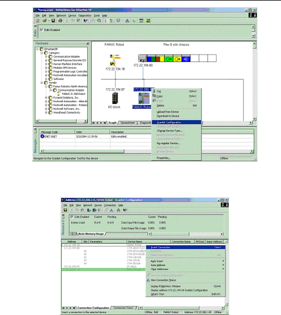
A.THIRD-PARTY CONFIGURATION TOOLS B-82854EN/02
- 92 -
Fig. A.1(b) Scanlist configuration screen
7. A new window appears entitle “FANUC Robot – Scanlist Configuration”. In this configuration
window, right click over the device you want to add to the robot’s scanlist, and select Insert
Connection. See Figure A.1(c)
Fig. A.1(c) Insert connection screen
8. Configure the connection properties and click on OK. Pay specific attention to the selecting the
appropriate Connection Name, Input Size, and Output Size. Other configurable values might include
RPI, and Target to Scanner Transmission Mode. Note that the robot does not use values inserted for
Input Address or Output Address. The screens below show a FANUC Robot being added to the
scanlist of another FANUC Robot.
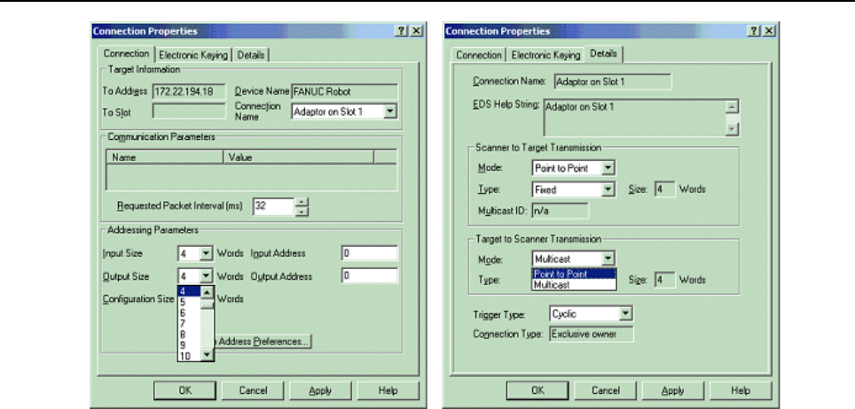
B-82854EN/02 A.THIRD-PARTY CONFIGURATION TOOLS
- 93 -
Fig. A.1(d) Adding a robot
9. In the Scanlist Configuration window, select Device/Download to Device.
10. When finished, Cold start the controller.

B.KAREL PROGRAMS FOR ETHERNET/IP Scanner Quick Connect B-82854EN/02
- 94 -
B KAREL PROGRAMS FOR ETHERNET/IP
Scanner Quick Connect
B.1 OVERVIEW
The EtherNet/IP Scanner option installs the following KAREL programs:
EN_OFFLN Allows a teach pendant program to turn an EtherNet/IP scanner connection off
EN_ONLN Allows a teach pendant program to turn an EtherNet/IP scanner connection on
EN_AROFF - Allows a teach pendant program to turn off auto-reconnect for an EtherNet/IP scanner
connection.
EN_ARON - Allows a teach pendant program to turn on auto-reconnect for an EtherNet/IP scanner
connection.
EN_STCHK - Allows a teach pendant program to check the status of an EtherNet/IP scanner
connection.
B.2 KAREL PROGRAM DESCRIPTIONS AND PARAMETERS
The following are the KAREL program descriptions and parameters.
EN_OFFLN (INTEGER slot_number)
This program allows a teach pendant program to turn an EtherNet/IP scanner connection offline. This
program takes the slot number as an argument. The valid values for a slot number are 1 through 32. For
example, 1 corresponds to the EtherNet/IP Connection on slot 1, rack 89, or the first connection displayed
on the EtherNet/IP Status Screen. There is no difference between this call and disabling the connection
from the teach pendant.
EN_ONLN (INTEGER slot_number, INTEGER <wait_time>)
This program allows a teach pendant program to turn an EtherNet/IP scanner connection online. This
program takes the slot number as an argument. The valid values for a slot number are 1 through 32. For
example, 1 corresponds to the EtherNet/IP Connection on slot 1, rack 89, or the first connection displayed
on the EtherNet/IP Status Screen. The optional argument, wait_time, is used as follows:
If wait_time is not used. If wait_time is not explicitly specified (it is an optional argument), its
value will be defaulted to 15 and EN_ONLN follows the: if wait_time is not 0 rule.
If wait_time is not 0. The EtherNet/IP scanner connection will be enabled. Auto-reconnect will also
be enabled, causing the scanner to attempt to make a connection to the adapter device every 2
seconds until successful. Note that EN_ONLN will block and will not return until a successful
connection is made, or until the user aborts the teach pendant program. An alarm will be posted if
wait_time seconds pass before a connection is established. After the alarm is posted and the robot
faults, a reset/resume from either the PLC or teach pendant will restart/resume the program inside of
the EN_ONLN call and the wait_time timer will be reset. Before EN_ONLN returns, auto-reconnect
will set to its original state (its state before EN_ONLN was called).
If wait_time is used and set to 0. Auto-reconnect will not be enabled--the user must explicitly
enable Auto-reconnect if needed. The EtherNet/IP connection will be enabled and the call will return
immediately (will not block). The application or user programs can then use EN_STCHK to check
the status if it needs to confirm the status of the connection.
There is difference between this call and enabling the connection from the teach pendant. Call to this
macro forces scanner device (if Quick Connect mode enabled) to wait for GRATUITOUS ARP packet
from target device before starting the connection process.

B-82854EN/02 B.KAREL PROGRAMS FOR ETHERNET/IP Scanner Quick Connect
- 95 -
EN_AROFF (INTEGER slot_number)
This program allows a teach pendant program to turn off auto-reconnect for an EtherNet/IP scanner
connection. This program takes the slot number as an argument. The valid values for a slot number are 1
through 32. For example, 1 corresponds to the EtherNet/IP Connection on slot 1, rack 89, or the first
connection displayed on the EtherNet/IP Status Screen.
There is no difference between this call and disabling auto-reconnect from the teach pendant.
EN_ARON (INTEGER slot_ number)
This program allows a teach pendant program to turn on auto-reconnect for an EtherNet/IP scanner
connection. This program takes the slot number as an argument. The valid values for a slot number are 1
through 32. For example, 1 corresponds to the EtherNet/IP Connection on slot 1, rack 89, or the first
connection displayed on the EtherNet/IP Status Screen.
Enabling auto-reconnect has the following side effects. While enabled, all EtherNet/IP alarms relating to
connection establishment and connection time-outs for this slot number will be masked (will not be
posted). The EtherNet/IP scanner corresponding to the slot number will attempt to make a connection to
the adapter device every 2 seconds until successful. Before each retry, the ARP cache in the TCP/IP stack
will be flushed of the target IP address. Also, the status on the teach pendant will become encapsulated in
< and > as in <STATUS>, for example.
There is no difference between this call and enabling auto-reconnect from the teach pendant.
EN_STCHK (INTEGER slot_number, INTEGER register_number)
This program allows a teach pendant program to check the status of an EtherNet/IP connection. This
program takes the slot number, and register_number as arguments. The valid values for a slot number are
1 through 32. For example, 1 corresponds to the EtherNet/IP Connection on slot 1, rack 89, or the first
connection displayed on the EtherNet/IP Status Screen. The possible status values returned in the
register_number are:
0 Offline
1 Error
2 Pending
3 Enabled but not connected or trying to connection
4 Enabled but not connected. Is trying to connect.
5 Online and connected but I/O is not being received from adapter
6 Online and I/O is being exchanged
NOTE
When a connection is taken offline, if a background application were to access I/O
belonging to that connection, an unassigned port alarm would be posted. This
should be taken into consideration by the teach pendant programmer when using
the EN_OFFLN program.
B.3 USING KAREL PROGRAMS IN TEACH PENDANT
PROGRAMS
Procedure B-1 shows how to use the EN_STCHK KAREL program. The other programs listed in this
section can be used in the same way.
Procedure B-1 Placing the Call to the KAREL Program in the Teach Pendant
Program
1. Press SELECT.
2. Display the appropriate list of programs. If F1, [TYPE], is not displayed on the screen, press >,
NEXT, until it is displayed.
a. Press F1, [TYPE].
b. Select the list you want:

B.KAREL PROGRAMS FOR ETHERNET/IP Scanner Quick Connect B-82854EN/02
- 96 -
3. Move the cursor to the name of the program you want to modify and press ENTER.
4. Turn the teach pendant ON/OFF switch to ON.
5. Select F4, [INST].
6. Select Call from the list of options that appear at the top of the screen.
7. Select Call Program and press ENTER.
8. Press F3, [KAREL] to display the available KAREL programs at the top of the screen.
9. Select EN_STCHK and press ENTER.
10. Place the cursor to the right of the word EN_STCHK.
11. Press F4, [CHOICE].
12. Select Constant from the list at the top of the screen and press ENTER.
13. Type the Slot Number and press ENTER.
14. Press F4, [CHOICE].
15. Select Constant from the list at the top of the screen and press ENTER.
16. Type the Register Number for the result of the device status check and press ENTER.
The finished line in the teach pendant program should look like the following:
CALL EN_STCHK (2,50)
NOTE
50 is the register number for result (R[50]).
B.4 EXAMPLES USING ETHERNET/IP MACROS
B.4.1 Overview
Generally, EtherNet/IP macros are used to support tool change applications. The following examples
demonstrate using Auto-Reconnect and connection Offline/Online macros in tool changing applications.
The connection offline/online macros are similar to manually taking the connection offline or online in
the teach pendant screens but are called programmatically through a teach pendant program.
A single EtherNet/IP scanner connection can be used to connect to different types of I/O blocks (different
electronic keying) that may be used on the various tools if the I/O sizes for these blocks are the same. In
these cases, the electronic keying parameters must be set to 0 in the corresponding scanner configuration
screen.
Turning on Auto-Reconnect means that the robot will automatically try to reconnect to the target device if
the connection is lost. Without Auto-Reconnect enabled, the robot will fault if an EtherNet/IP scanner
connection is lost, and reset must be pressed to retry the connection. With auto-reconnect enabled, the
robot will not fault and will continuously try to reconnect to the device. Auto- reconnect should be turned
off if a tool change is not underway (when you do not expect the connection to be lost) so that unexpected
connection problems are not masked.
B.4.2 Individual Examples
The example below turns on Auto-Reconnect for the second connection (the connection corresponding to
EtherNet/IP slot 2). This call can be executed just before the tool is to be physically disconnected to
prevent the robot from faulting once the disconnection occurs. Alternatively, call EN_OFFLN to disable
the EtherNet/IP scanner connection before the tool is to be physically disconnected, and execute this call
when the tool is physically reconnected, but before EN_ONLN is called.
1: CALL EN_ARON(2) ;
The next example enables, or brings online, the second connection (the connection corresponding to
EtherNet/IP slot 2). This call should be executed when the tool is physically reconnected.

B-82854EN/02 B.KAREL PROGRAMS FOR ETHERNET/IP Scanner Quick Connect
- 97 -
1: CALL EN_ONLN(2) ;
The example below checks the status of the second connection (the connection corresponding to
EtherNet/IP slot 2). The status is placed in register 5, R[5]. The connection is not established and
exchanging I/O until the status is equal to the value 6.
1: CALL EN_STCHK(2,5) ;
The next example turns off Auto-Reconnect for the second connection (the connection corresponding to
EtherNet/IP slot 2). This call should be executed after an EtherNet/IP scanner connection has been
established. Any problem with this EtherNet/IP connection at this point would be a valid error and will
now fault the robot.
1: CALL EN_AROFF(2) ;
The example below disables, or takes offline, the second connection (the connection corresponding to
EtherNet/IP slot 2). This call may be executed just before the tool is to be physically disconnected.
1: CALL EN_OFFLN(2) ;
B.4.3 Advanced Examples
It can take up to 300ms for an EtherNet/IP adapter device to power-up and become ready to exchange I/O.
The following example can be done after moving away from the tool changer nest to help cycle time by
allowing the device power-up and connection time to be done in parallel with the robot motion. The
following logic will check for the device to go online for up to 15 seconds. If the device status becomes
online in less than 15 seconds, the robot will resume immediately after the online status is obtained. If the
device is still not online after 15 seconds a User Alarm is posted and the robot will fault. Note that in line
#3, the option argument wait_time is set to 0 for EN_ONLN. Care must be used when setting a device
online just after it is reconnected. If it is not fully powered up and available for reconnection by the
scanner, an alarm might be generated. To avoid this problem, auto-reconnect is generally enabled while
setting the device online, and then disabled once the device comes online. The following logic assumes
auto-reconnect has already been enabled.
1: TIMER[1]=RESET ;
2: TIMER[1]=START ;
3: CALL EN_ONLN(2,0)
4: LBL[1] ;
5: WAIT .10(sec) ;
6: CALL EN_STCHK(2,50) ;
7: IF R[50]=6,JMP LBL[3] ;
8: IF (TIMER[1]<15),JMP LBL[1] ;
9: UALM[1] ;
10: JMP LBL[1] ;
11: LBL[3] ;
12: TIMER[1]=STOP ;
13: CALL EN_AROFF(2) ;
The same functionality of the above logic can also be achieved by setting the optional parameter
wait_time of the EN_ONLN program to a non-zero value as seen in the logic below. When the wait_time
parameter is not set, it will default to 15. In this case, EN_ONLN does not return until an EtherNet/IP
scanner connection has been established.
1: CALL EN_ONLN(2,15)
2: CALL EN_AROFF(2) ;
OR
1: CALL EN_ONLN(2)
2: CALL EN_AROFF(2) ;

B.KAREL PROGRAMS FOR ETHERNET/IP Scanner Quick Connect B-82854EN/02
- 98 -
Below is an outline of how a tool change may occur and a recommended sequence of calls to
programmatically handle the tool change.
* Tool is connected and exchanging I/O with EtherNet/IP scanner connection 2.
* A tool change is scheduled to occur.
CALL EN_OFFLN(2) ;
* Physically disconnect the tool.
* Physically connect a new tool.
CALL EN_ARON(2) ;
CALL EN_ONLN(2) ;
* When EN_ONLN returns, tool is connected and exchanging I/O with EtherNet/IP scanner connection 2.
CALL EN_AROFF(2) ;

B-82854EN/02 INDEX
i-1
INDEX
<A>
Accessing General I/O ..........................................................75
Accessing I/O Specific to an Implicit EtherNet/IP
Connection ........................................................................72
ACCESSING I/O USING EXPLICIT MESSAGING...........72
ADAPTER CONFIGURATION.............................................7
ADAPTER MODE CONFIGURATION OUTLINE..............5
Advanced EtherNet/IP Scanner Configuration......................19
Advanced Examples..............................................................97
Analog I/O.............................................................................24
<B>
BACKING UP AND RESTORING ETHERNET/IP
AND I/O CONFIGURATION...........................................33
<C>
Common Errors................................................................13,25
Common services..................... 41,49,56,64,66,67,68,69,70,71
Configure the Adapter Device...............................................15
Configure the Robot Scan List..............................................15
Configuring the Remote Scanner............................................9
Configuring the Robot I/O Size...............................................7
Creating a Configuration File for the Batch File Method
...........................................................................................38
<D>
DIAGNOSTICS AND TROUBLESHOOTING ...................84
<E>
ERROR CODES ...................................................................86
Errors........................................ 42,50,57,65,66,67,68,69,70,72
ETHERNET CONNECTION AND IP ADDRESS
ASSIGNMENT ...................................................................4
Ethernet Status LEDs............................................................84
ETHERNET/IP TO DEVICENET ROUTING.....................26
Examples............................................25,65,66,67,68,69,71,72
EXAMPLES USING ETHERNET/IP MACROS.................96
EXPLICIT MESSAGING.....................................................35
<G>
Get_Attribute_All Response .................................................64
GUIDELINES.......................................................................26
<I>
I/O CONFIGURATION........................................................32
I/O RESPONSE TIME..........................................................81
I/O Size of Each Connection and I/O Configuration.............32
Individual Examples .............................................................96
Instance attributes .................... 41,48,54,63,66,67,68,69,70,71
INTRODUCTION ..................................................................1
<K>
KAREL PROGRAM DESCRIPTIONS AND
PARAMETERS ................................................................94
KAREL PROGRAMS FOR ETHERNET/IP Scanner
Quick Connect...................................................................94
<M>
MAPPING I/O ON THE ROBOT.........................................32
<N>
NETWORK DESIGN AND PERFORMANCE ...................80
NETWORK DESIGN CONSIDERATIONS........................80
Numeric Register Objects (0x6B and 0x6C).........................40
<O>
OVERVIEW ................................ 3,7,14,24,26,32,35,36,94,96
<P>
PING Utility..........................................................................84
Position Register Object (0x7B, 0x7C, 0x7D, 0x7E)............54
<Q>
Quick connect feature ...........................................................21
<R>
Read a block of register ........................................................51
Read a block of registers..................................................44,59
Read all alarm information from the second most recent
active alarm.......................................................................65
Read all alarm information from the second most recent
application alarm...............................................................70
Read all alarm information from the second most recent
communications alarm ......................................................72
Read all alarm information from the second most recent
motion alarm .....................................................................67
Read all alarm information from the second most recent
recovery alarm...................................................................71
Read all alarm information from the second most recent
system alarm......................................................................69
Read all register ....................................................................50

INDEX B-82854EN/02
i-2
Read all registers..............................................................43,58
Read current position (CURPOS or CURJPOS) ...................60
Read most recent active alarm cause code ............................65
Read most recent alarm cause code.......................................66
Read most recent application alarm cause code....................69
Read most recent communication alarm cause code.............72
Read most recent motion alarm cause code ..........................67
Read most recent recovery alarm cause code........................71
Read most recent system alarm cause code...........................68
Read single register.....................................................42,50,57
Real all alarm information from the second most recent
alarm..................................................................................66
REMOTE EXPLICIT MESSAGING CLIENT
CONFIGURATION ..........................................................39
ROBOT EXPLICIT MESSAGING CLIENT .......................36
<S>
SAFETY PRECAUTIONS ..................................................s-1
SCANNER CONFIGURATION...........................................14
SCANNER MODE CONFIGURATION OUTLINE..............5
SETTING UP ETHERNET/IP TO DEVICENET
ROUTING.........................................................................26
SETTING UP YOUR ROBOT ..........................................7,14
SPECIFICATION OVERVIEW.............................................3
String Register Object (0x6D)...............................................48
SYSTEM OVERVIEW...........................................................3
<T>
THIRD-PARTY CONFIGURATION TOOLS.....................91
TOOLS OVERVIEW............................................................91
<U>
USING ETHERNET/IP TO DEVICENET ROUTING........27
USING EXPLICIT MESSAGING IN RSLogix 5000...........76
USING KAREL PROGRAMS IN TEACH PENDANT
PROGRAMS.....................................................................95
<V>
VENDOC SPECIFIC ALARM HISTORY OBJECT
(0xA1) ...............................................................................66
VENDOR SPECIFIC ACTIVE ALARM OBJECT
(0xA0) ...............................................................................63
VENDOR SPECIFIC APPLICATION ALARM
OBJECT (0xA4)................................................................69
VENDOR SPECIFIC COMMUNICATIONS ALARM
OBJECT (0xA6)................................................................71
VENDOR SPECIFIC MOTION ALARM OBJECT
(0xA2) ...............................................................................67
VENDOR SPECIFIC RECOVERY ALARM OBJECT
(0xA5) ...............................................................................70
VENDOR SPECIFIC REGISTER OBJECTS ......................39
VENDOR SPECIFIC SYSTEM ALARM OBJECT
(0xA3) ...............................................................................68
VERIFYING NETWORK CONNECTIONS........................84
<W>
Write a block of registers............................................47,53,62
Write all registers........................................................46,52,62
Write single register....................................................45,52,61

B-82854EN/02 REVISION RECORD
r-1
REVISION RECORD
Edition Date Contents
02 Sep., 2012
• Revised as the manual for R-30iA/R-30iA Mate/R-30iB controller.
01 Feb., 2008

B-82854EN/02
* B- 82854EN/ 02*
