FCC Part 15.247W 15
2016-04-12
: Pdf Fcc Part 15 FCC_Part_15 CertsReports 525756 ProductFiles
Open the PDF directly: View PDF ![]() .
.
Page Count: 95
Intracom Asia Co., Ltd. Model: 525756
REPORT NO.: STR15048243I-1 PAGE 1 OF 95 FCC PART 15.247
FCC Part 15C
Measurement and Test Report
For
Intracom Asia Co., Ltd.
4F., No. 77, Sec. 1, Xintai 5th Rd., Xinzhi Dist., New Taipei City 221,
Taiwan
FCC ID: 2ADQY525756
FCC Rule(s): FCC Part 15C
Product Description: Wireless 300N Range Extender
Tested Model: 525756
Report No.: STR15048243I-1
Tested Date: 2015-04-29 to 2015-05-12
Issued Date: 2015-05-14
Tested By: Susan Su / Engineer
Reviewed By: Lahm Peng / EMC Manager
Approved & Authorized By: Jandy so / PSQ Manager
Prepared By:
Shenzhen SEM.Test Technology Co., Ltd.
1/F, Building A, Hongwei Industrial Park, Liuxian 2nd Road,
Bao'an District, Shenzhen, P.R.C.(518101)
Tel.: +86-755-33663308 Fax.: +86-755-33663309 Website: www.semtest.com.cn
Note: This test report is limited to the above client company and the product model only. It
may not be duplicated without prior permitted by Shenzhen SEM.Test Technology Co., Ltd.

Intracom Asia Co., Ltd. Model: 525756
REPORT NO.: STR15048243I-1 PAGE 2 OF 95 FCC PART 15.247
TABLE OF CONTENTS
1. GENERAL INFORMATION ................................................................................................................................... 3
1.1 PRODUCT DESCRIPTION FOR EQUIPMENT UNDER TEST (EUT) ............................................................................... 3
1.2 TEST STANDARDS ................................................................................................................................................... 4
1.3 TEST METHODOLOGY ............................................................................................................................................. 4
1.4 TEST FACILITY ....................................................................................................................................................... 4
1.5 EUT SETUP AND TEST MODE ................................................................................................................................. 5
2. SUMMARY OF TEST RESULTS ........................................................................................................................... 6
3. RF EXPOSURE ......................................................................................................................................................... 7
3.1 STANDARD APPLICABLE ......................................................................................................................................... 7
3.2 TEST RESULT.......................................................................................................................................................... 7
4. ANTENNA REQUIREMENT .................................................................................................................................. 8
4.1 STANDARD APPLICABLE ......................................................................................................................................... 8
4.2 EVALUATION INFORMATION .................................................................................................................................. 8
5. POWER SPECTRAL DENSITY ............................................................................................................................. 9
5.1 STANDARD APPLICABLE ......................................................................................................................................... 9
5.2 TEST EQUIPMENT LIST AND DETAILS ..................................................................................................................... 9
5.3 TEST PROCEDURE ................................................................................................................................................... 9
5.4 ENVIRONMENTAL CONDITIONS .............................................................................................................................. 9
5.5 SUMMARY OF TEST RESULTS/PLOTS .................................................................................................................... 10
6. 6DB BANDWIDTH ................................................................................................................................................. 23
6.1 STANDARD APPLICABLE ....................................................................................................................................... 23
6.2 TEST EQUIPMENT LIST AND DETAILS ................................................................................................................... 23
6.3 TEST PROCEDURE ................................................................................................................................................. 23
6.4 ENVIRONMENTAL CONDITIONS ............................................................................................................................ 23
6.5 SUMMARY OF TEST RESULTS/PLOTS .................................................................................................................... 24
7. RF OUTPUT POWER ............................................................................................................................................ 37
7.1 STANDARD APPLICABLE ....................................................................................................................................... 37
7.2 TEST EQUIPMENT LIST AND DETAILS ................................................................................................................... 37
7.3 TEST PROCEDURE ................................................................................................................................................. 37
7.4 ENVIRONMENTAL CONDITIONS ............................................................................................................................ 37
7.5 SUMMARY OF TEST RESULTS/PLOTS .................................................................................................................... 38
8. FIELD STRENGTH OF SPURIOUS EMISSIONS ............................................................................................. 51
8.1 MEASUREMENT UNCERTAINTY ............................................................................................................................ 51
8.2 STANDARD APPLICABLE ....................................................................................................................................... 51
8.3 TEST EQUIPMENT LIST AND DETAILS ................................................................................................................... 51
8.4 TEST PROCEDURE ................................................................................................................................................. 52
8.5 CORRECTED AMPLITUDE & MARGIN CALCULATION ............................................................................................ 53
8.6 ENVIRONMENTAL CONDITIONS ............................................................................................................................ 53
8.7 SUMMARY OF TEST RESULTS/PLOTS .................................................................................................................... 53
9. OUT OF BAND EMISSIONS ................................................................................................................................. 82
9.1 STANDARD APPLICABLE ....................................................................................................................................... 82
9.2 TEST EQUIPMENT LIST AND DETAILS ................................................................................................................... 82
9.3 TEST PROCEDURE ................................................................................................................................................. 82
9.4 ENVIRONMENTAL CONDITIONS ............................................................................................................................ 83
9.5 SUMMARY OF TEST RESULTS/PLOTS .................................................................................................................... 83
10. CONDUCTED EMISSIONS ................................................................................................................................ 92
10.1 MEASUREMENT UNCERTAINTY .......................................................................................................................... 92
10.2 TEST EQUIPMENT LIST AND DETAILS ................................................................................................................. 92
10.3 TEST PROCEDURE ............................................................................................................................................... 92
10.4 BASIC TEST SETUP BLOCK DIAGRAM ................................................................................................................. 92
10.5 ENVIRONMENTAL CONDITIONS .......................................................................................................................... 93
10.6 TEST RECEIVER SETUP ....................................................................................................................................... 93
10.7 SUMMARY OF TEST RESULTS/PLOTS .................................................................................................................. 93
10.8 CONDUCTED EMISSIONS TEST DATA .................................................................................................................. 93
Intracom Asia Co., Ltd. Model: 525756
REPORT NO.: STR15048243I-1 PAGE 3 OF 95 FCC PART 15.247
1. GENERAL INFORMATION
1.1 Product Description for Equipment Under Test (EUT)
Client Information
Applicant: Intracom Asia Co., Ltd.
Address of applicant: 4F., No. 77, Sec. 1, Xintai 5th Rd., Xinzhi Dist., New
Taipei City 221, Taiwan
Manufacturer: Intracom Asia Co., Ltd.
Address of manufacturer: 4F., No. 77, Sec. 1, Xintai 5th Rd., Xinzhi Dist., New
Taipei City 221, Taiwan
General Description of EUT
Product Name: Wireless 300N Range Extender
Trade Name: Manhattan
Model No.: 525756
Adding Model(s): /
Rated Voltage: AC 100-240V
Note: The test data is gathered from a production sample provided by the manufacturer.
Technical Characteristics of EUT
Support Standards: 802.11b, 802.11g, 802.11n
Frequency Range: 2412-2462MHz for 802.11b/g/n(HT20)
2422-2452MHz for 802.11n(HT40)
RF Output Power: 17.31dBm (Conducted)
Type of Modulation: CCK, OFDM, QPSK, BPSK, 16QAM, 64QAM
Data Rate: 1-11Mbps, 6-54Mbps, up to 150Mbps
Quantity of Channels: 11 for 802.11b/g/n(HT20); 7 for 802.11n(HT40)
Channel Separation: 5MHz
Type of Antenna: Integral
Antenna Gain: 2dBi
Lowest Internal Frequency 40MHz

Intracom Asia Co., Ltd. Model: 525756
REPORT NO.: STR15048243I-1 PAGE 4 OF 95 FCC PART 15.247
1.2 Test Standards
The following report is prepared on behalf of the Intracom Asia Co., Ltd. in accordance with FCC Part 15,
Subpart C, and section 15.203, 15.205, 15.207, 15.209 and 15.247 of the Federal Communication Commissions
rules.
The objective is to determine compliance with FCC Part 15, Subpart C, and section 15.203, 15.205, 15.207,
15.209 and 15.247 of the Federal Communication Commissions rules.
Maintenance of compliance is the responsibility of the manufacturer. Any modification of the product, which
result in lowering the emission, should be checked to ensure compliance has been maintained.
1.3 Test Methodology
All measurements contained in this report were conducted with ANSI C63.4-2014, American National Standard
for Methods of Measurement of Radio-Noise Emissions from Low-Voltage Electrical and Electronic Equipment in
the range of 9 kHz to 40 GHz. The measurement guide KDB 558074 D01 V03r02 for digital transmission systems
shall be performed also.
1.4 Test Facility
FCC – Registration No.: 934118
Shenzhen SEM.Test Technology Co., Ltd. EMC Laboratory has been registered and fully described in a report
filed with the (FCC) Federal Communications Commission. The acceptance letter from the FCC is maintained in
our files and the Registration is 934118.
Industry Canada (IC) Registration No.: 11464A
The 3m Semi-anechoic chamber of Shenzhen SEM.Test Technology Co., Ltd. has been registered by Certification
and Engineering Bureau of Industry Canada for radio equipment testing with Registration No.: 11464A.
CNAS Registration No.: L4062
Shenzhen SEM.Test Technology Co., Ltd. is a testing organization accredited by China National Accreditation
Service for Conformity Assessment (CNAS) according to ISO/IEC 17025. The accreditation certificate number is
L4062. All measurement facilities used to collect the measurement data are located at 1/F, Building A, Hongwei
Industrial Park, Liuxian 2nd Road, Bao’an District, Shenzhen, P.R.C (518101).
Intracom Asia Co., Ltd. Model: 525756
REPORT NO.: STR15048243I-1 PAGE 5 OF 95 FCC PART 15.247
1.5 EUT Setup and Test Mode
The EUT was operated in the engineering mode to fix the Tx frequency that was for the purpose of the
measurements. All testing shall be performed under maximum output power condition, and to measure its highest
possible emissions level, more detailed description as follows:
Test Mode List
Test Mode Description Remark
TM1 802.11b 2412MHz, 2437MHz, 2462MHz
TM2 802.11g 2412MHz, 2437MHz, 2462MHz
TM3 802.11n-HT20 2412MHz, 2437MHz, 2462MHz
TM4 802.11n-HT40 2422MHz, 2437MHz, 2452MHz
EUT Cable List and Details
Cable Description Length (m) Shielded/ Unshielded With / Without Ferrite
RJ45 1.0 Unshielded Without Ferrite
Special Cable List and Details
Cable Description Length (m) Shielded/Unshielded With / Without Ferrite
Auxiliary Equipment List and Details
Description Manufacturer Model Serial Number

Intracom Asia Co., Ltd. Model: 525756
REPORT NO.: STR15048243I-1 PAGE 6 OF 95 FCC PART 15.247
2. SUMMARY OF TEST RESULTS
FCC Rules Description of Test Item Result
§ 2.1093 RF Exposure Compliant
§15.203;§15.247(b)(4)(i) Antenna Requirement Compliant
§15.207(a) Conducted Emission Compliant
§15.247(e) Power Spectral Density Compliant
§15.247(a)(2) 6 dB Bandwidth Compliant
§15.247(b)(3) RF Output Power Compliant
§15.209(a) Radiated Emission Compliant
§15.247(d) Band Edge (Out of Band Emissions) Compliant
N/A: not applicable

Intracom Asia Co., Ltd. Model: 525756
REPORT NO.: STR15048243I-1 PAGE 7 OF 95 FCC PART 15.247
3. RF Exposure
3.1 Standard Applicable
According to§1.1307 and §2.1093, the portable transmitter must comply the RF exposure requirements.
3.2 Test Result
This product complied with the requirement of the RF exposure, please see the RF Exposure Report.

Intracom Asia Co., Ltd. Model: 525756
REPORT NO.: STR15048243I-1 PAGE 8 OF 95 FCC PART 15.247
4. Antenna Requirement
4.1 Standard Applicable
According to FCC Part 15.203, an intentional radiator shall be designed to ensure that no antenna other than that
furnished by the responsible party shall be used with the device. The use of a permanently attached antenna or of
an antenna that uses a unique coupling to the intentional radiator shall be considered sufficient to comply with the
provisions of this section.
4.2 Evaluation Information
This product has an integral antenna, fulfill the requirement of this section.
Intracom Asia Co., Ltd. Model: 525756
REPORT NO.: STR15048243I-1 PAGE 9 OF 95 FCC PART 15.247
5. Power Spectral Density
5.1 Standard Applicable
According to 15.247(a)(1)(iii), For digitally modulated systems, the power spectral density conducted from the
intentional radiator to the antenna shall not be greater than 8 dBm in any 3 kHz band during any time interval of
continuous transmission.
5.2 Test Equipment List and Details
Description Manufacturer Model Serial Number Cal. Date Due. Date
Spectrum Analyzer Agilent E4402B US41192821 2014-05-28 2015-05-27
Attenuator ATTEN ATS100-4-20 / 2014-05-28 2015-05-27
5.3 Test Procedure
According to the KDB 558074 D01 V03r02, such specifications require that the same method as used to
determine the conducted output power shall also be used to determine the power spectral density. The test method
of power spectral density as below:
a) Set instrument center frequency to DTS channel center frequency.
b) Set span to at least 1.5 times the OBW.
c) Set RBW to: 3 kHz ≤ RBW ≤ 100 kHz. .
d) Set VBW ≥3 x RBW.
e) Detector = power averaging (RMS) or sample detector (when RMS not available).
f) Ensure that the number of measurement points in the sweep ≥ 2 x span/RBW.
g) Sweep time = auto couple.
h) Employ trace averaging (RMS) mode over a minimum of 100 traces.
i) Use the peak marker function to determine the maximum amplitude level.
j) If measured value exceeds limit, reduce RBW (no less than 3 kHz) and repeat (note that this may require
zooming in on the emission of interest and reducing the span in order to meet the minimum measurement point
requirement as the RBW is reduced).
5.4 Environmental Conditions
Temperature: 26° C
Relative Humidity: 54%
ATM Pressure: 1011 mbar
Intracom Asia Co., Ltd. Model: 525756
REPORT NO.: STR15048243I-1 PAGE 10 OF 95 FCC PART 15.247
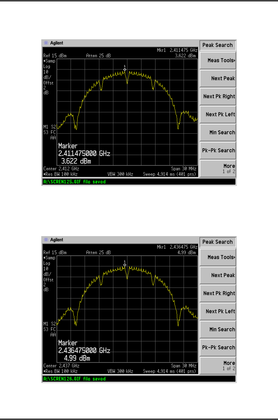
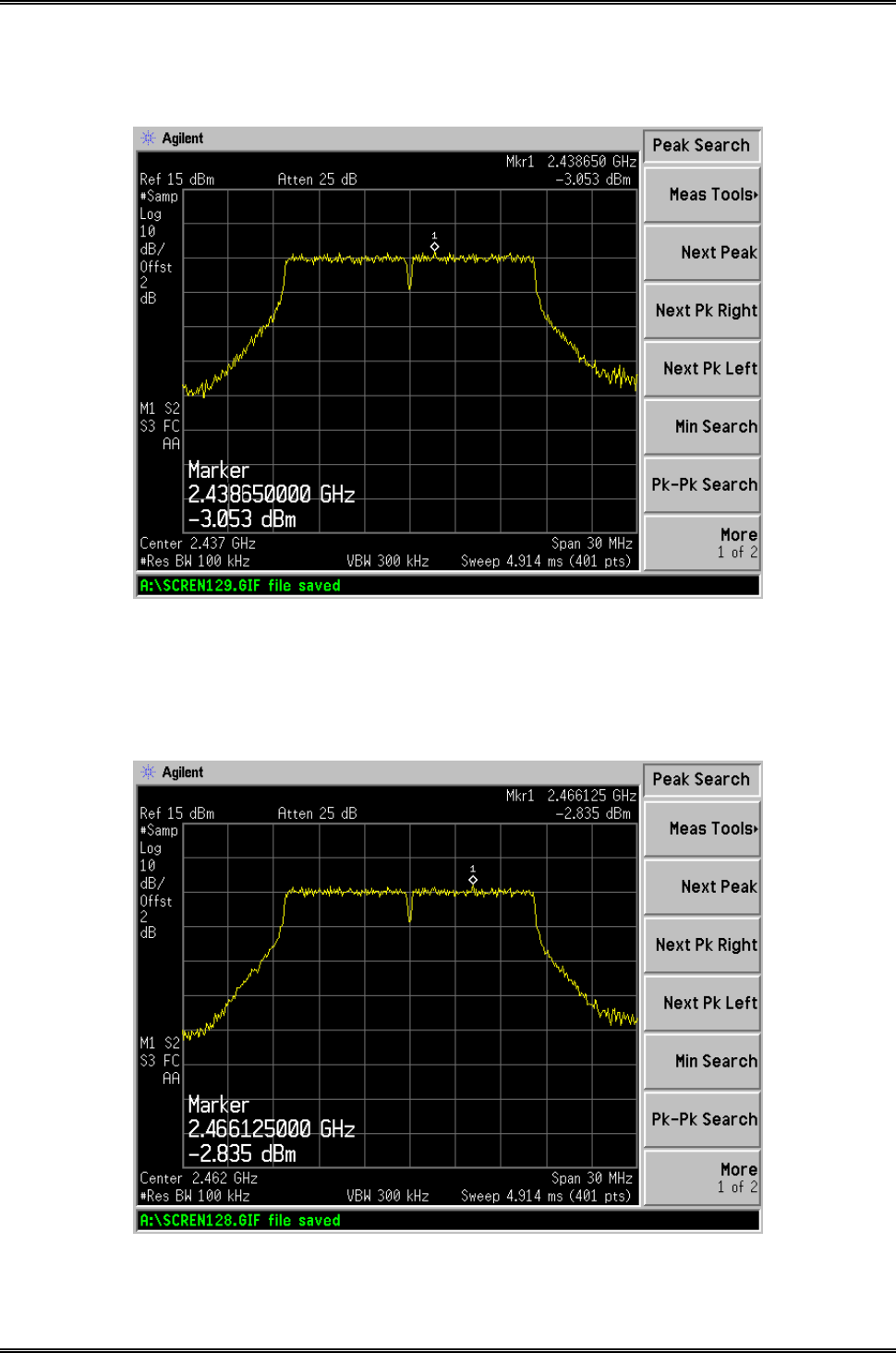
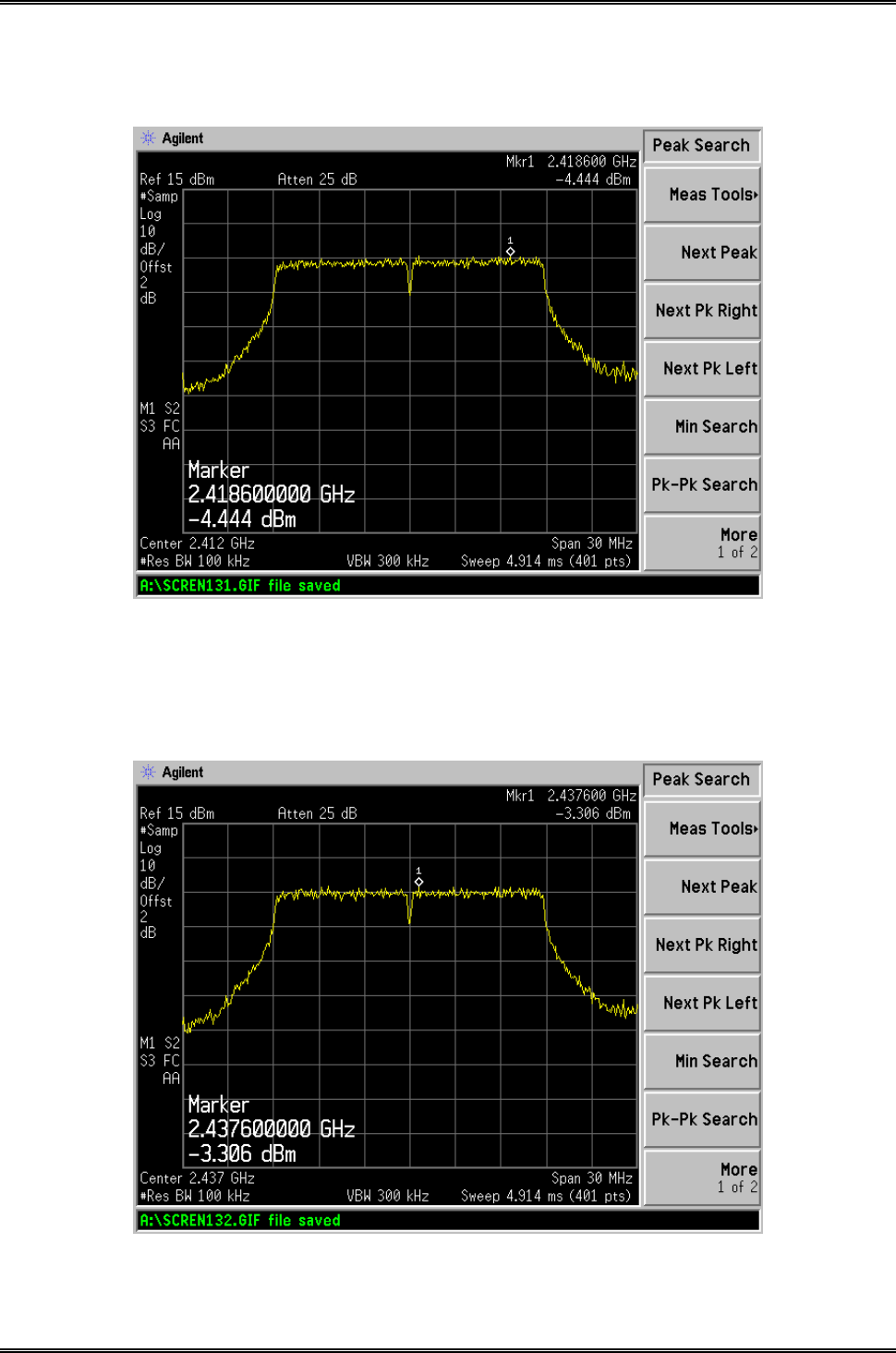
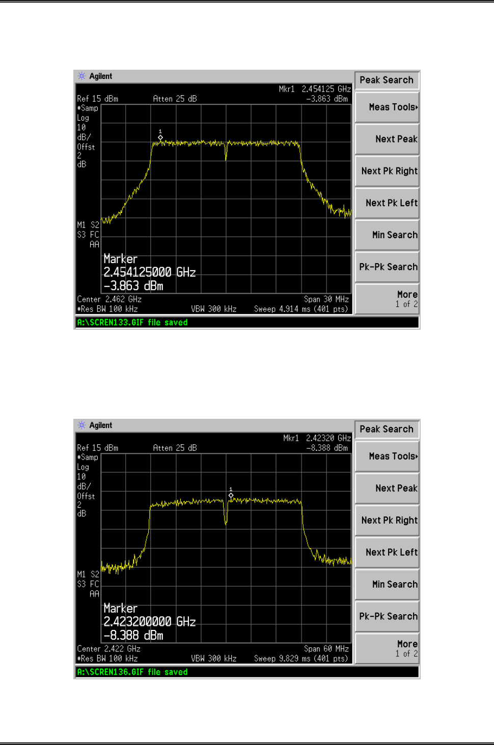
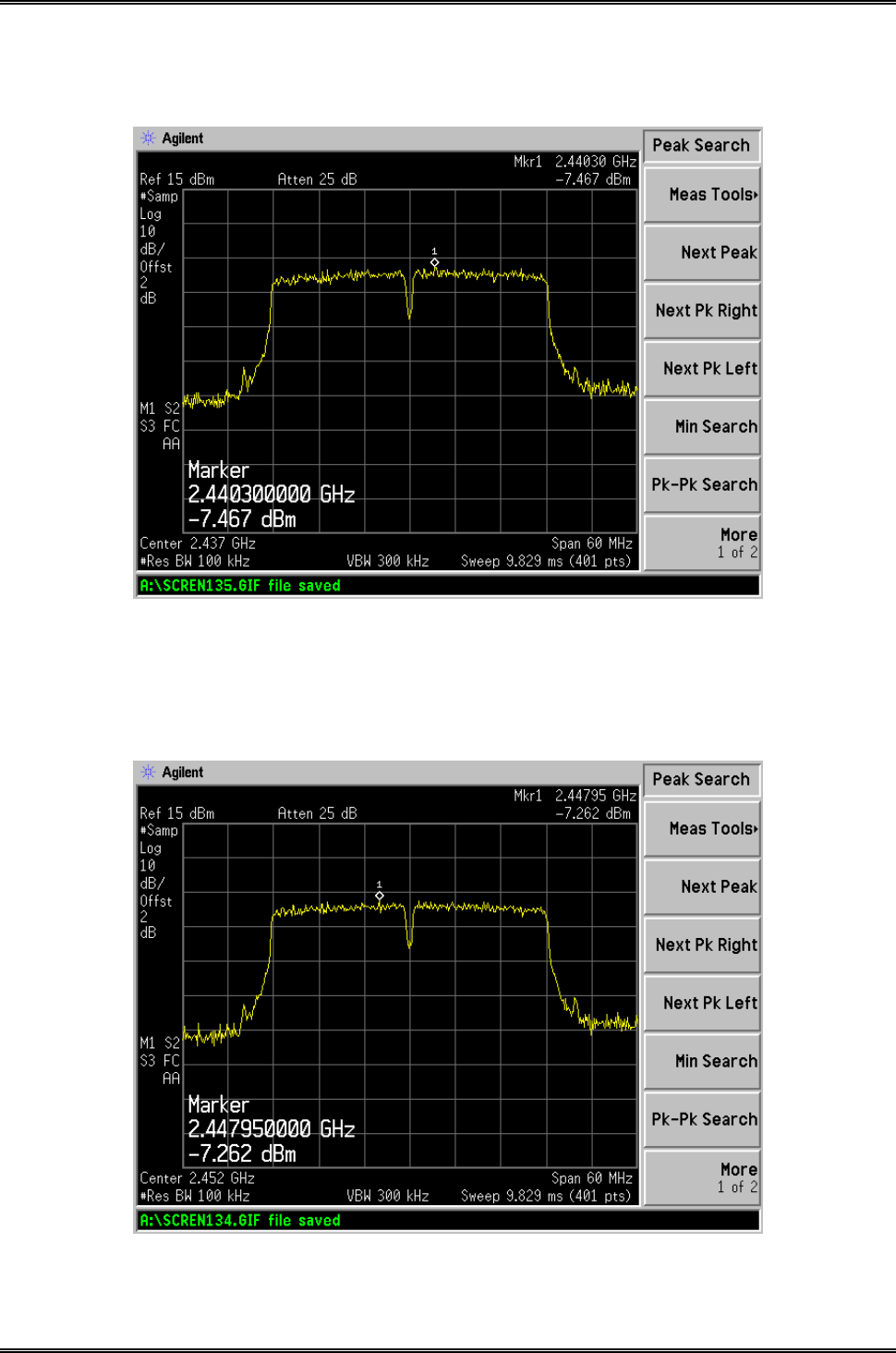
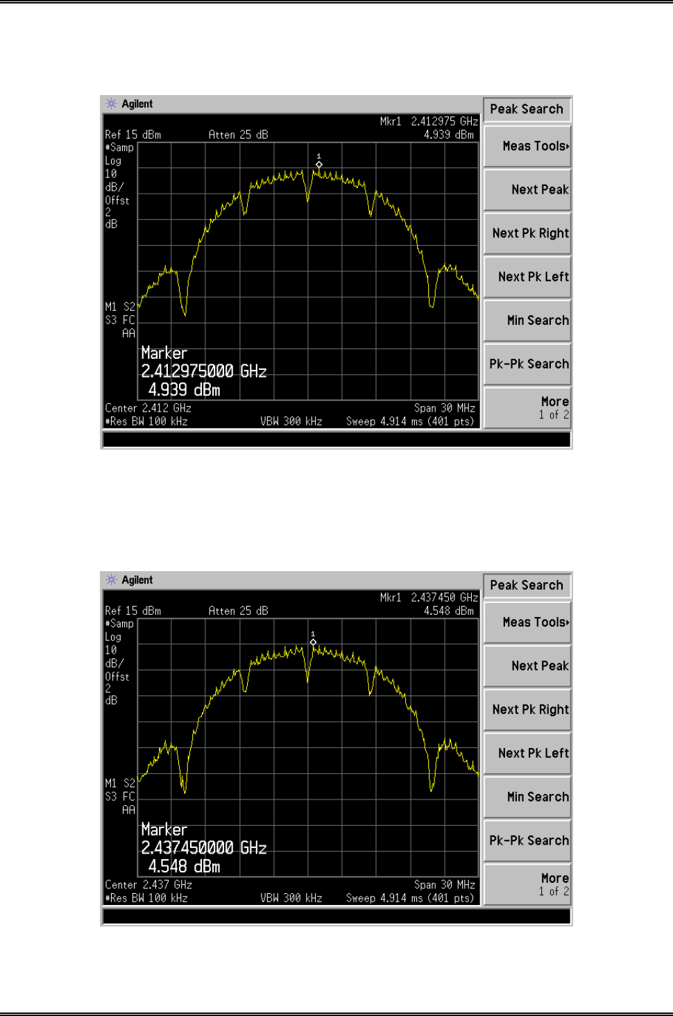
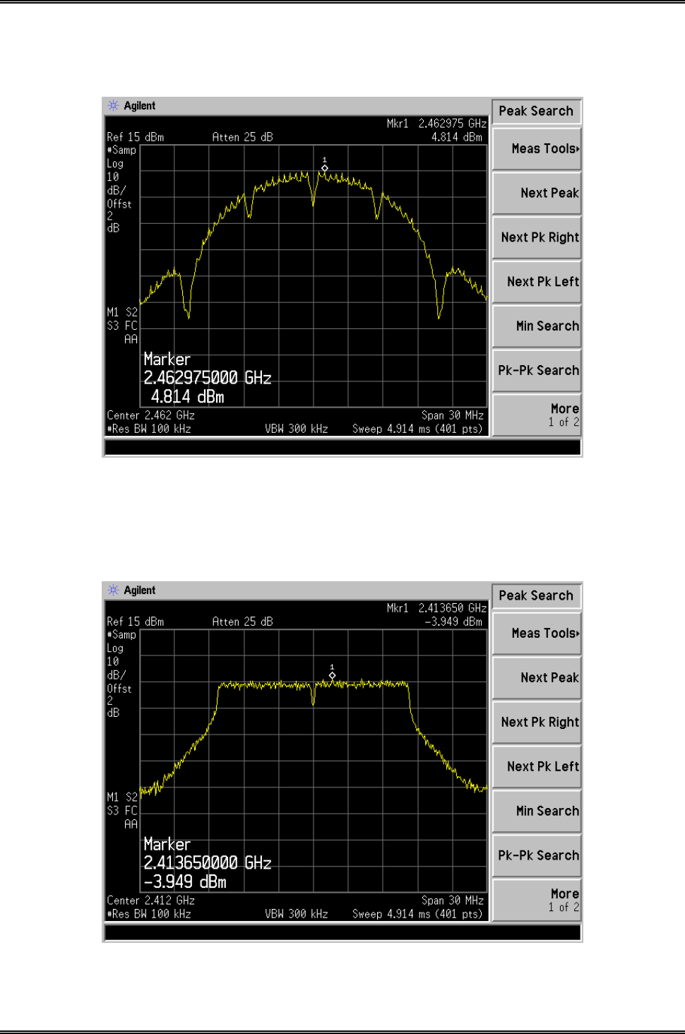
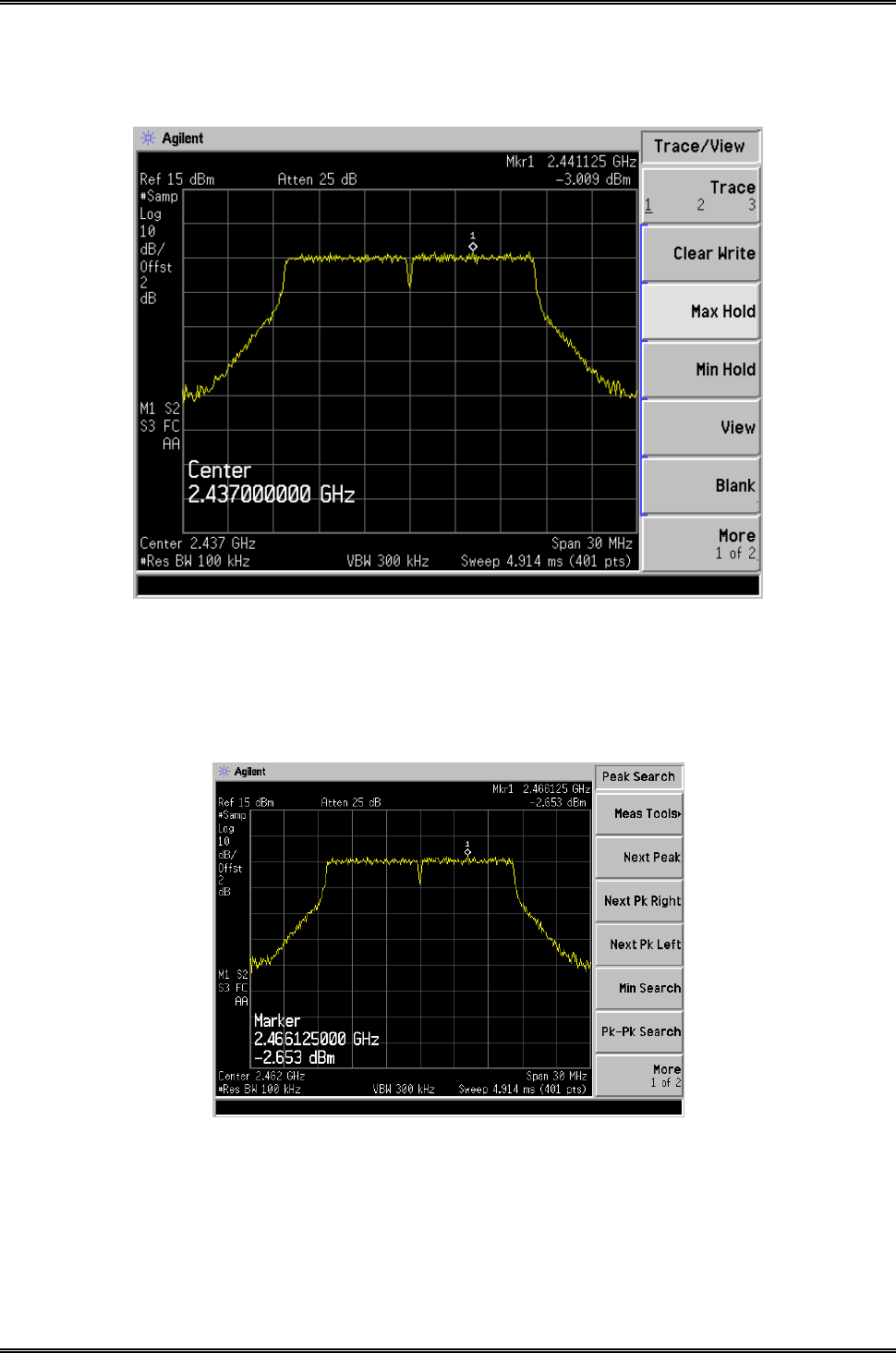
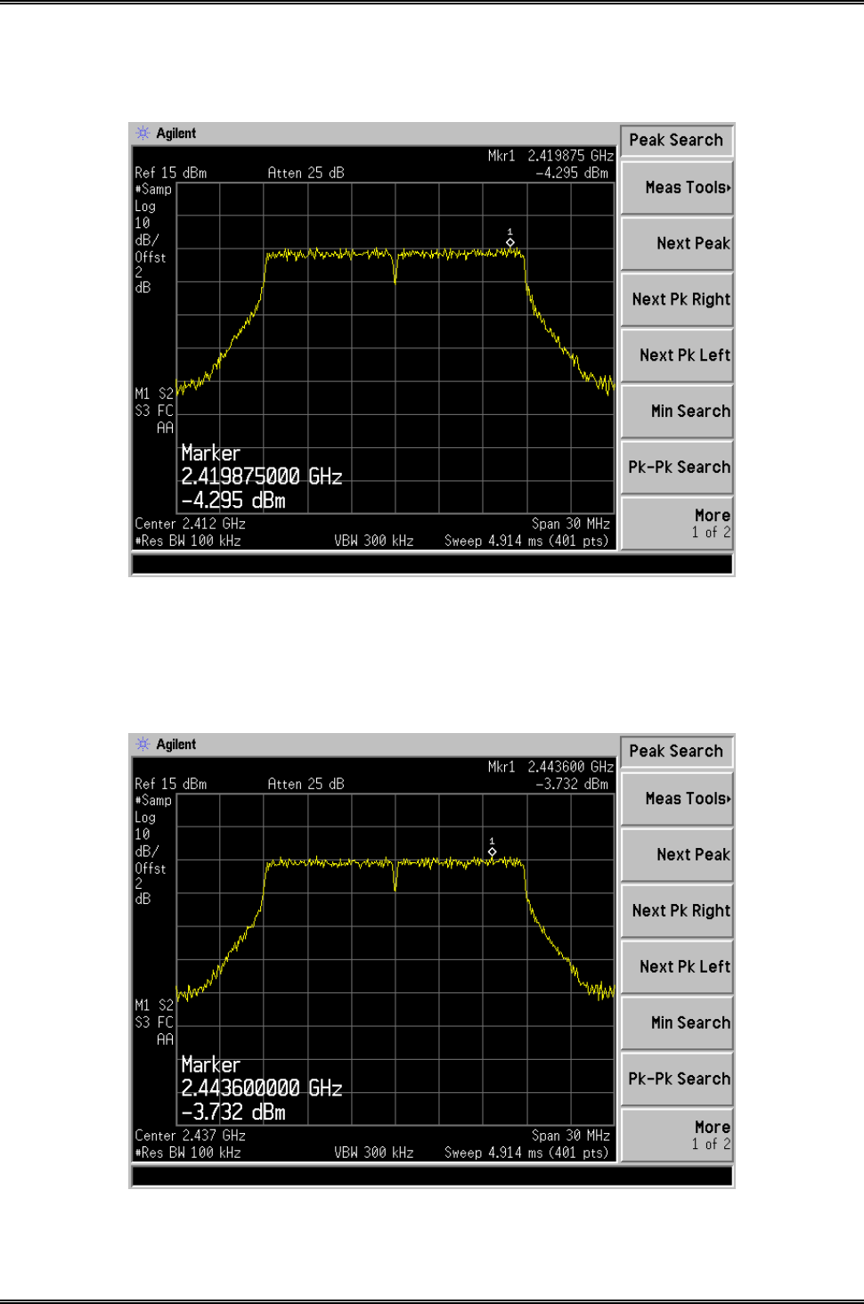
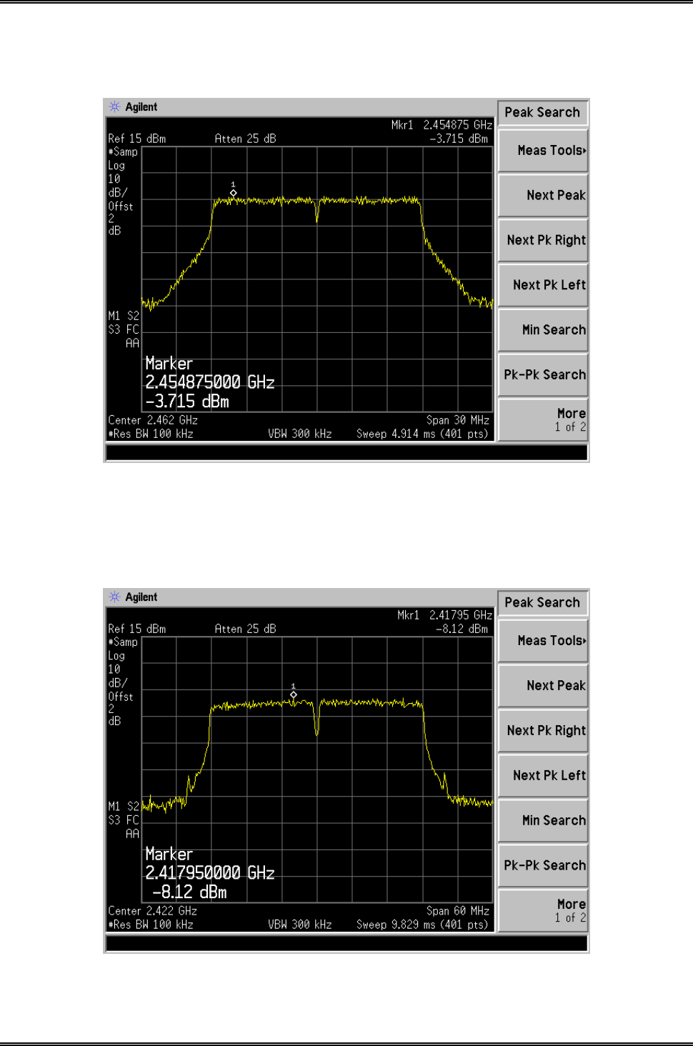
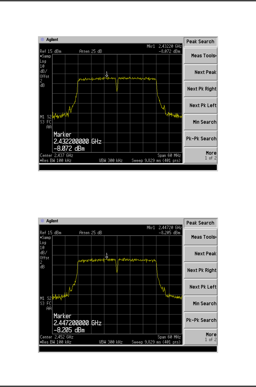
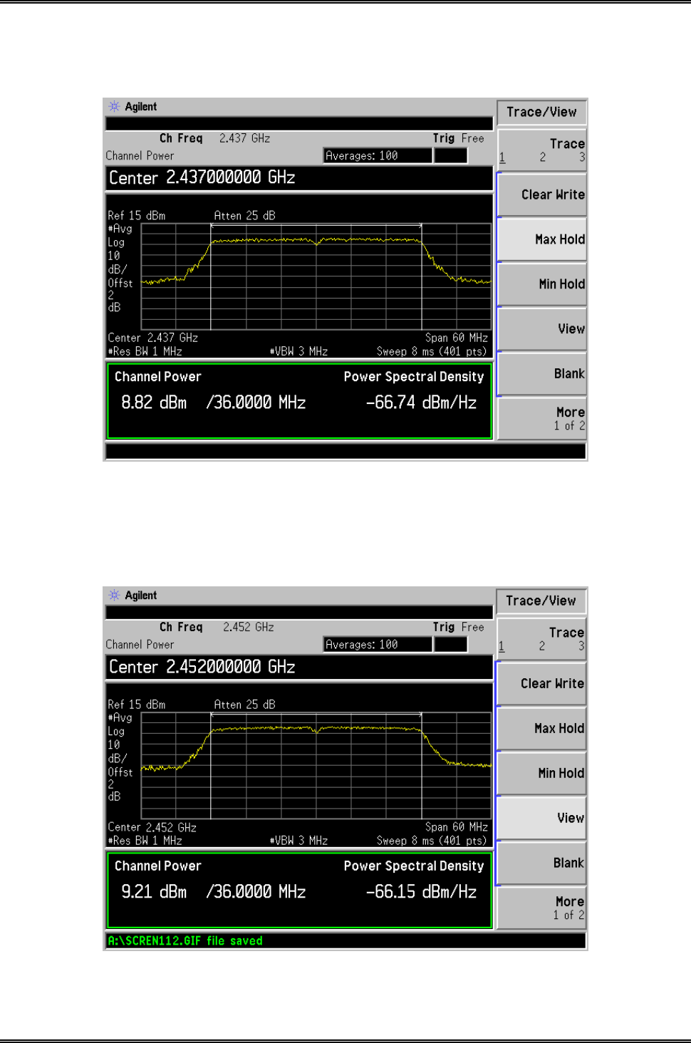
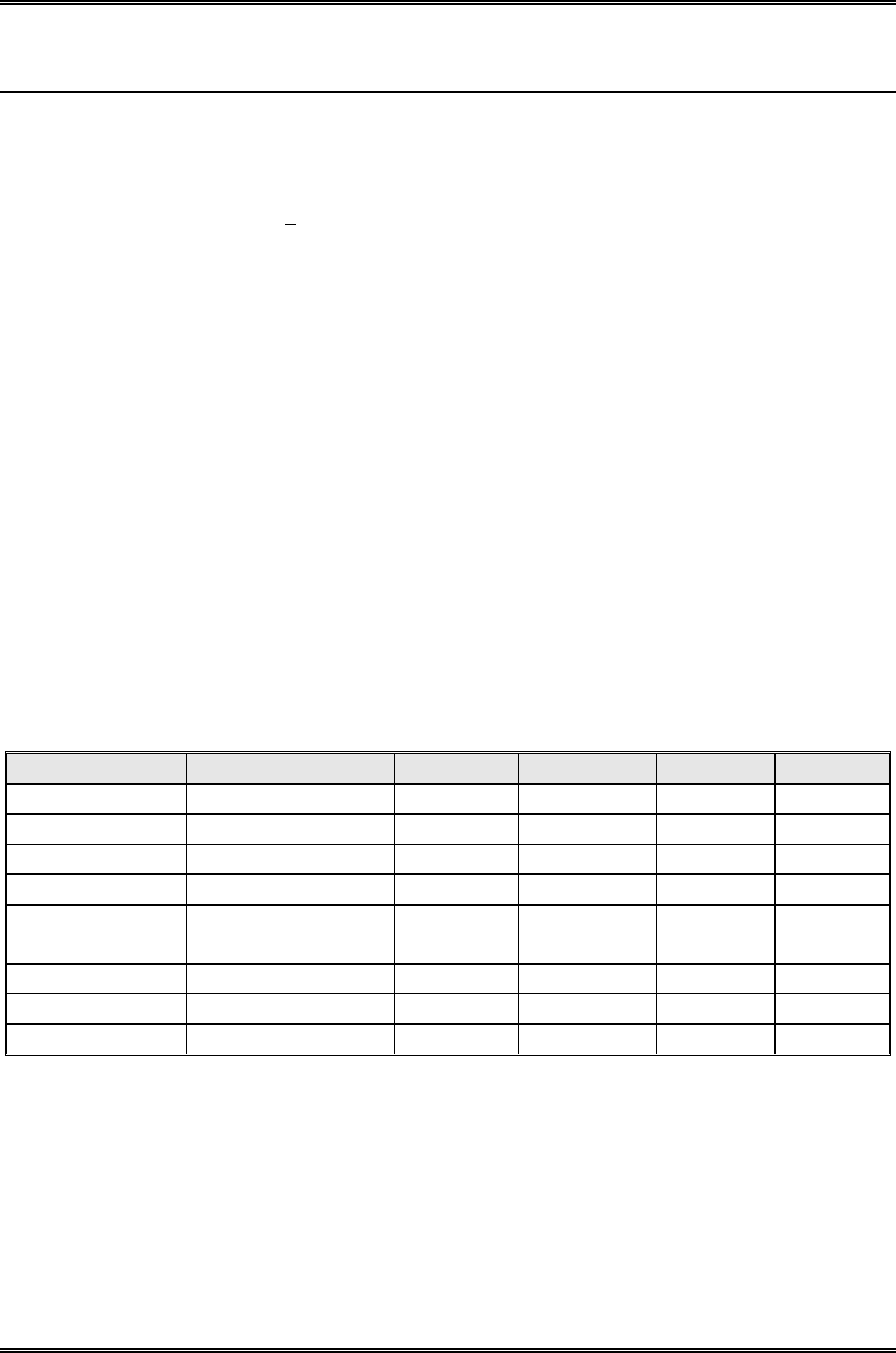
5.5 Summary of Test Results/Plots
Test Mode Test Channel
MHz
PSD Ant.A
dBm/100kHz
PSD Ant.B
dBm/100kHz
Total PSD
dBm/100kHz
Limit
dBm/3kHz
802.11b
2412 3.622 4.939 7.341 8
2437 4.99 4.548 7.785 8
2462 5.478 4.814 7.971 8
802.11g
2412 -4.145 -3.949 -1.036 8
2437 -3.053 -3.009 -0.021 8
2462 -2.835 -2.653 0.267 8
802.11n
HT20
2412 -4.444 -4.295 -1.359 8
2437 -3.306 -3.732 -0.503 8
2462 -3.863 -3.715 -0.778 8
802.11n
HT40
2422 -8.388 -8.12 -5.242 8
2437 -7.467 -8.072 -4.749 8
2452 -7.262 -8.205 -4.698 8
Please refer to the following test plots:
Intracom Asia Co., Ltd. Model: 525756
REPORT NO.: STR15048243I-1 PAGE 11 OF 95 FCC PART 15.247
For Ant.A
802.11b-Low Channel
802.11b-Middle Channel

Intracom Asia Co., Ltd. Model: 525756
REPORT NO.: STR15048243I-1 PAGE 12 OF 95 FCC PART 15.247
802.11b-High Channel
802.11g-Low Channel
Intracom Asia Co., Ltd. Model: 525756
REPORT NO.: STR15048243I-1 PAGE 13 OF 95 FCC PART 15.247
802.11g-Middle Channel
802.11g-High Channel
Intracom Asia Co., Ltd. Model: 525756
REPORT NO.: STR15048243I-1 PAGE 14 OF 95 FCC PART 15.247
802.11n-HT20-Low Channel
802.11n-HT20-Middle Channel
Intracom Asia Co., Ltd. Model: 525756
REPORT NO.: STR15048243I-1 PAGE 15 OF 95 FCC PART 15.247
802.11n-HT20-High Channel
802.11n-HT40-Low Channel
Intracom Asia Co., Ltd. Model: 525756
REPORT NO.: STR15048243I-1 PAGE 16 OF 95 FCC PART 15.247
802.11n-HT40-Middle Channel
802.11n-HT40-High Channel
Intracom Asia Co., Ltd. Model: 525756
REPORT NO.: STR15048243I-1 PAGE 17 OF 95 FCC PART 15.247
For Ant.B
802.11b-Low Channel
802.11b-Middle Channel
Intracom Asia Co., Ltd. Model: 525756
REPORT NO.: STR15048243I-1 PAGE 18 OF 95 FCC PART 15.247
802.11b-High Channel
802.11g-Low Channel
Intracom Asia Co., Ltd. Model: 525756
REPORT NO.: STR15048243I-1 PAGE 19 OF 95 FCC PART 15.247
802.11g-Middle Channel
802.11g-High Channel
Intracom Asia Co., Ltd. Model: 525756
REPORT NO.: STR15048243I-1 PAGE 20 OF 95 FCC PART 15.247
802.11n-HT20-Low Channel
802.11n-HT20-Middle Channel
Intracom Asia Co., Ltd. Model: 525756
REPORT NO.: STR15048243I-1 PAGE 21 OF 95 FCC PART 15.247
802.11n-HT20-High Channel
802.11n-HT40-Low Channel
Intracom Asia Co., Ltd. Model: 525756
REPORT NO.: STR15048243I-1 PAGE 22 OF 95 FCC PART 15.247
802.11n-HT40-Middle Channel
802.11n-HT40-High Channel
Intracom Asia Co., Ltd. Model: 525756
REPORT NO.: STR15048243I-1 PAGE 23 OF 95 FCC PART 15.247
6. 6dB Bandwidth
6.1 Standard Applicable
According to 15.247(a)(2). Systems using digital modulation techniques may operate in the 902–928 MHz,
2400–2483.5 MHz, and 5725–5850 MHz bands. The minimum 6 dB bandwidth shall be at least 500 kHz.
6.2 Test Equipment List and Details
Description Manufacturer Model Serial Number Cal. Date Due. Date
Spectrum Analyzer Agilent E4402B US41192821 2014-05-28 2015-05-27
Attenuator ATTEN ATS100-4-20 / 2014-05-28 2015-05-27
6.3 Test Procedure
a) Set RBW = 100 kHz.
b) Set the video bandwidth (VBW) ≥ 3 × RBW.
c) Detector = Peak.
d) Trace mode = max hold.
e) Sweep = auto couple.
f) Allow the trace to stabilize.
g) Measure the maximum width of the emission that is constrained by the frequencies associated with the two
outermost amplitude points (upper and lower frequencies) that are attenuated by 6 dB relative to the maximum
level measured in the fundamental emission.
6.4 Environmental Conditions
Temperature: 25° C
Relative Humidity: 53%
ATM Pressure: 1018 mbar
Intracom Asia Co., Ltd. Model: 525756
REPORT NO.: STR15048243I-1 PAGE 24 OF 95 FCC PART 15.247
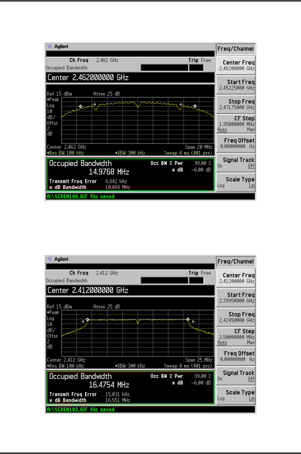
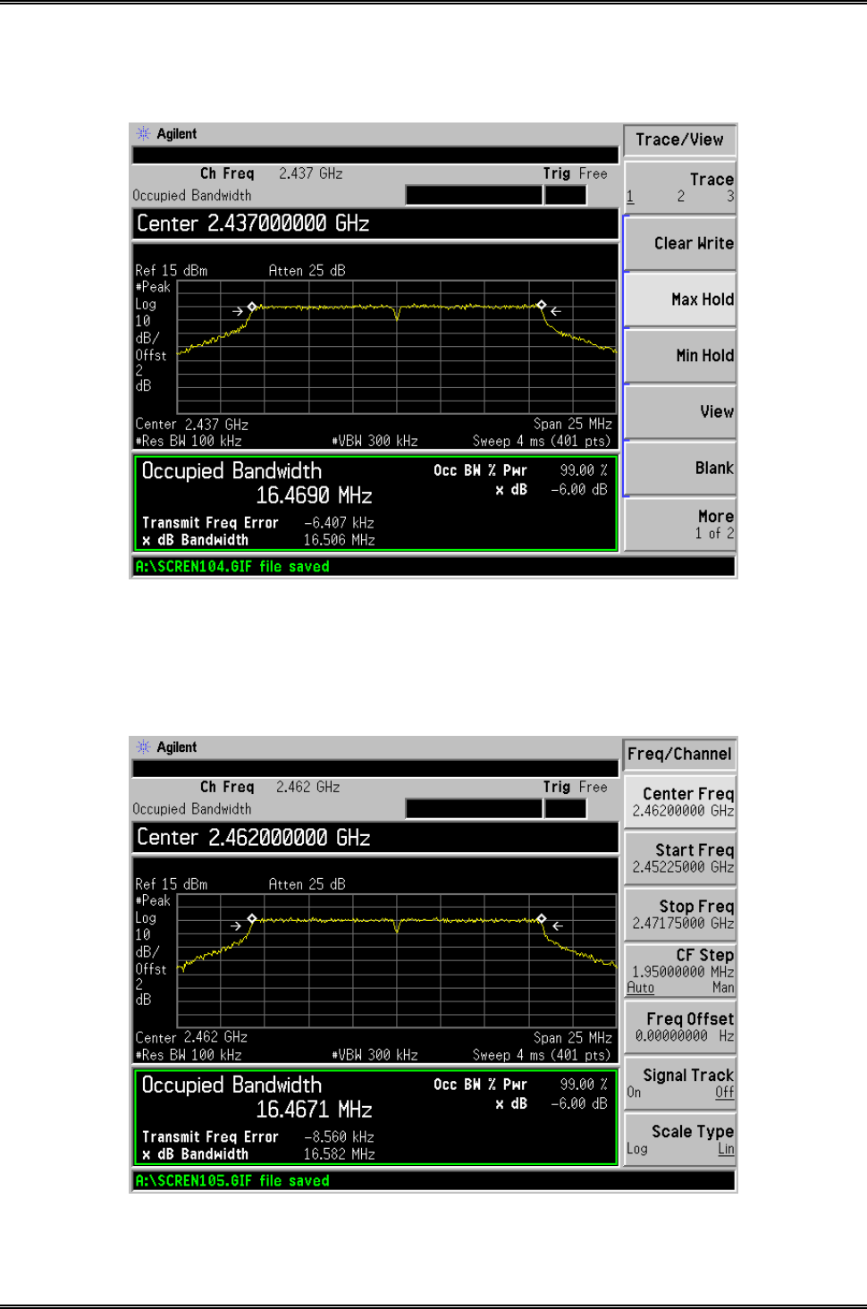
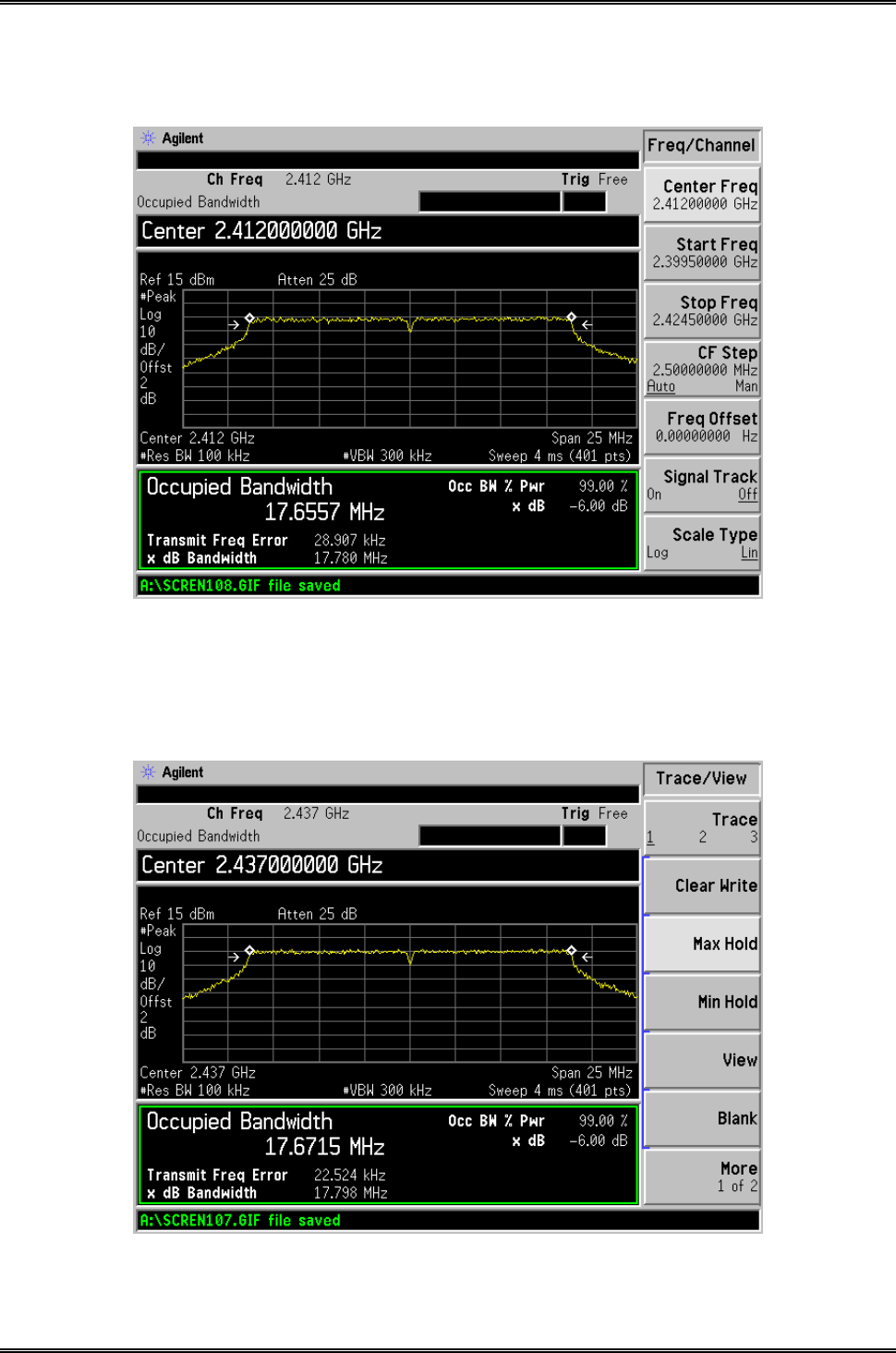
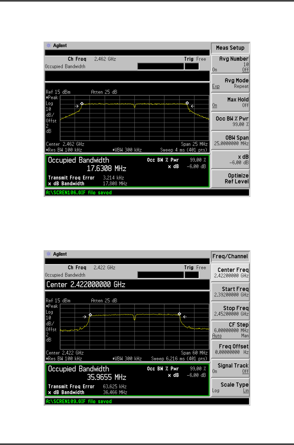
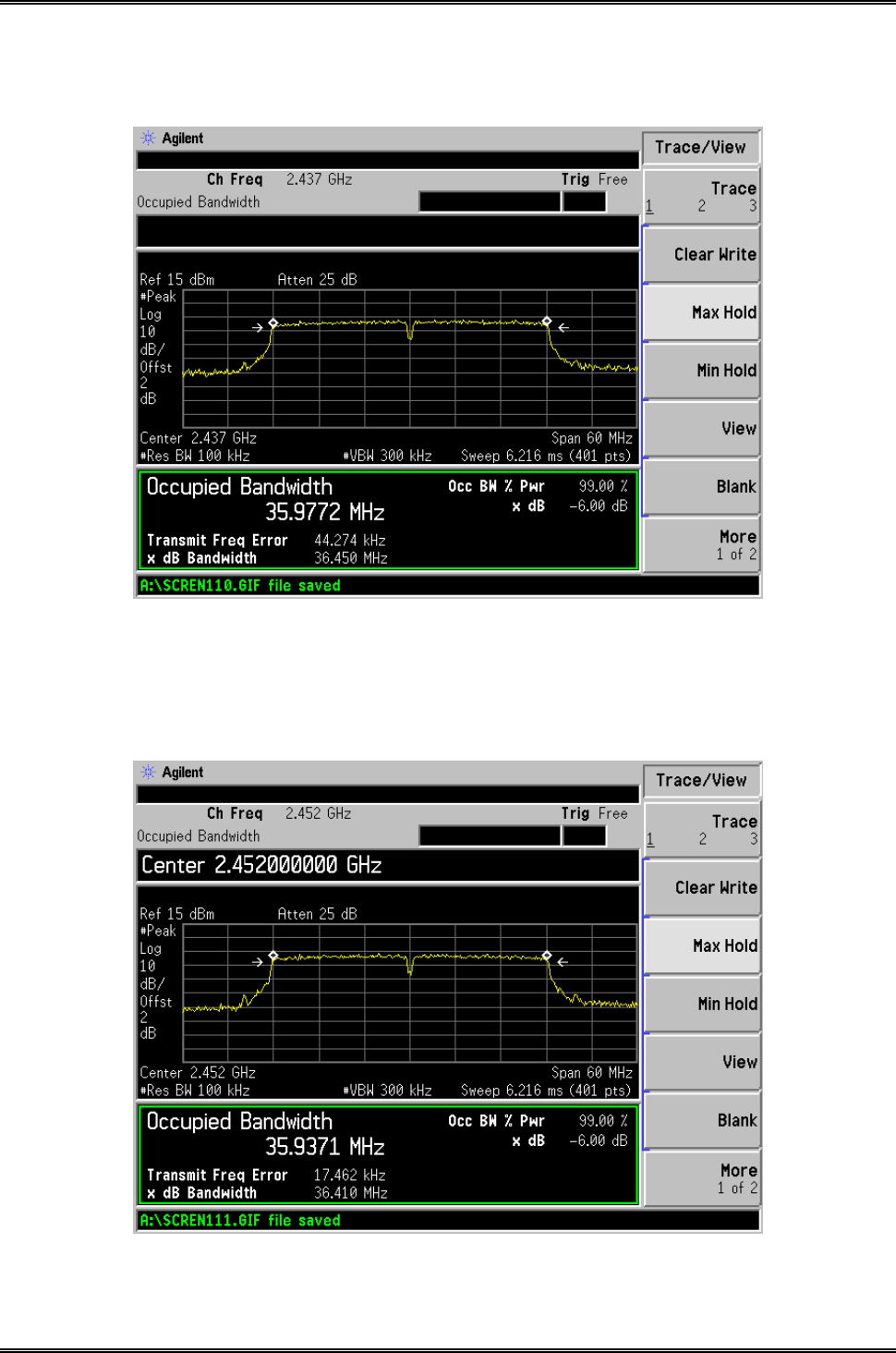
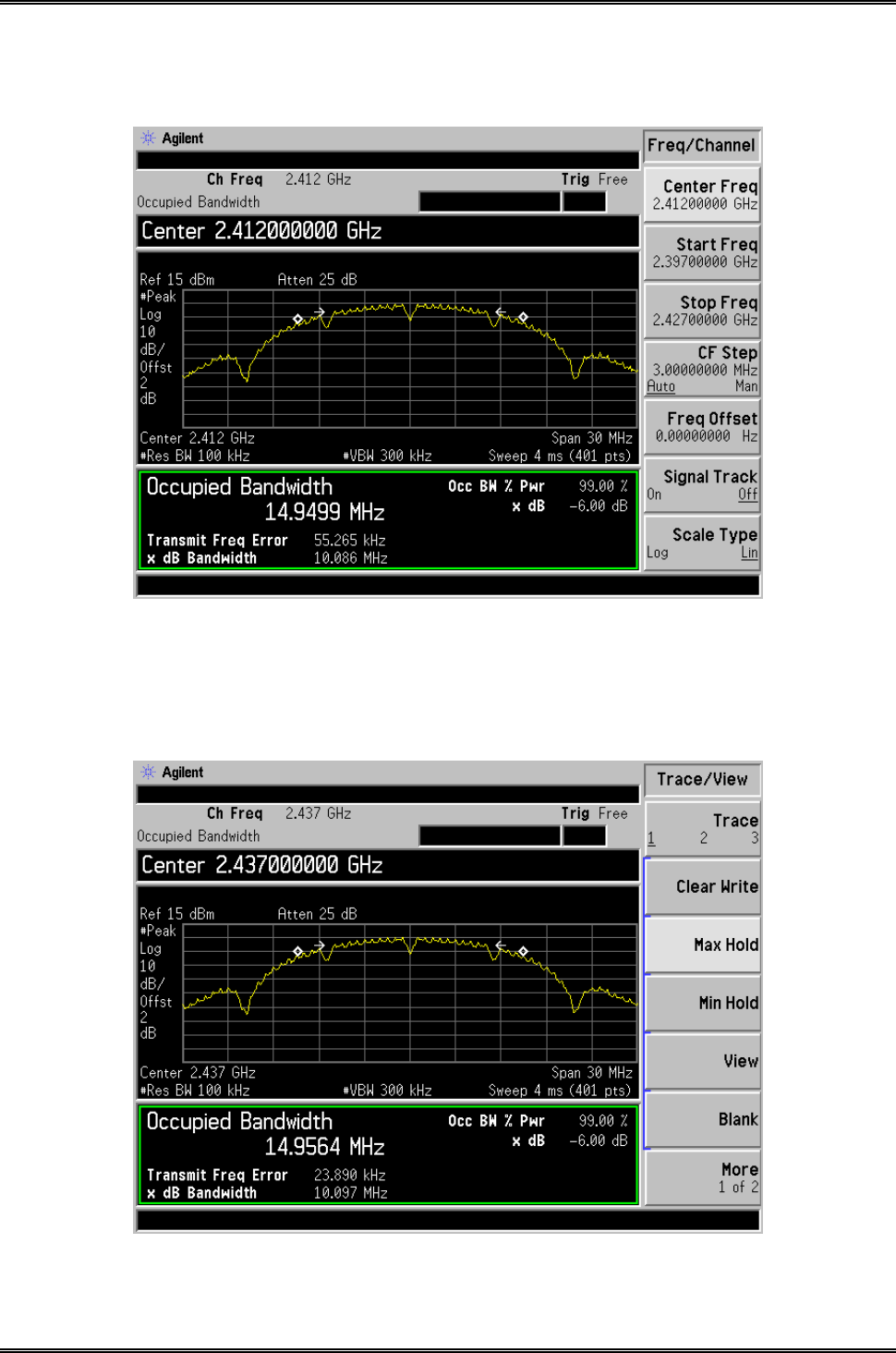
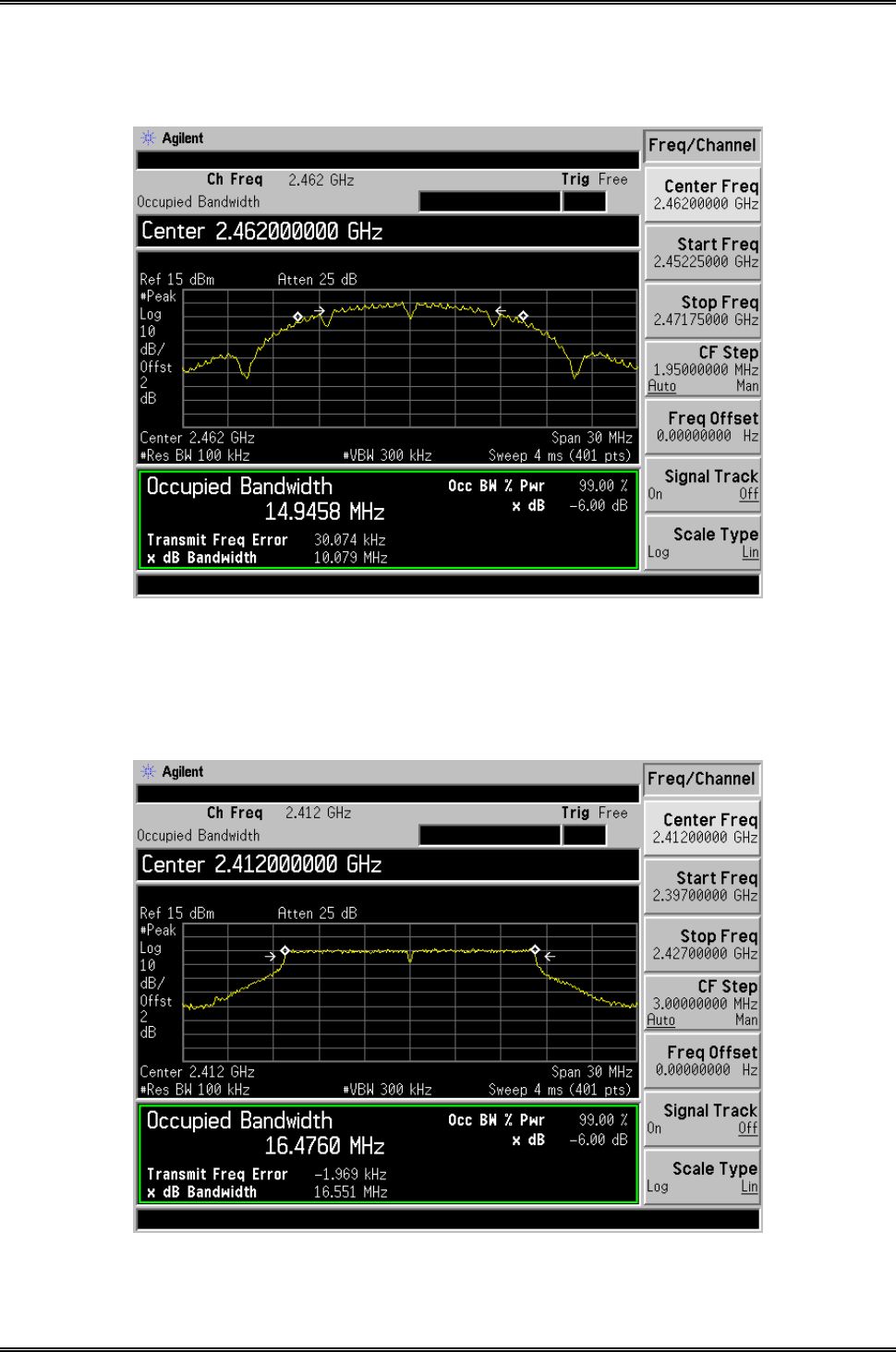
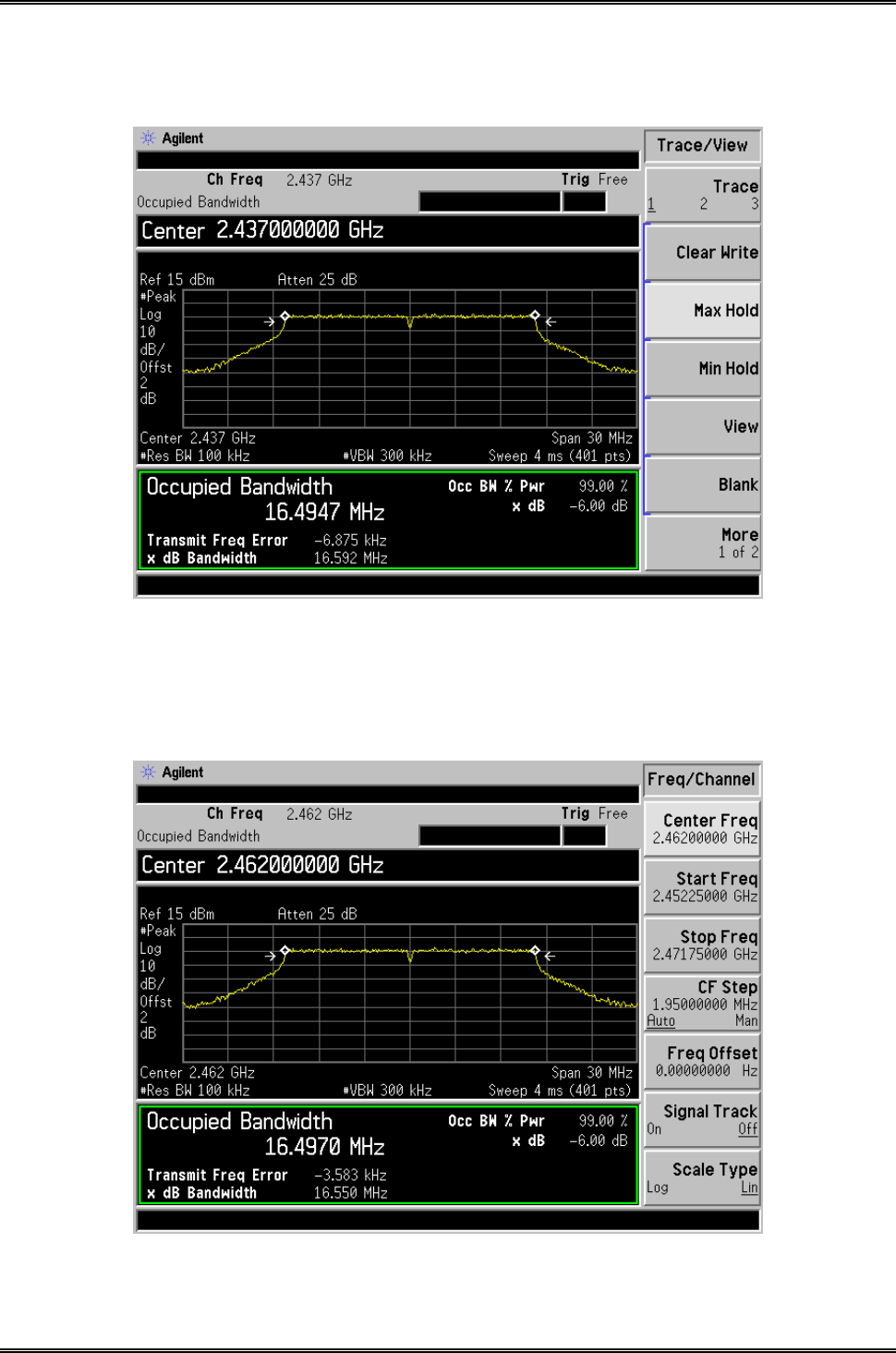
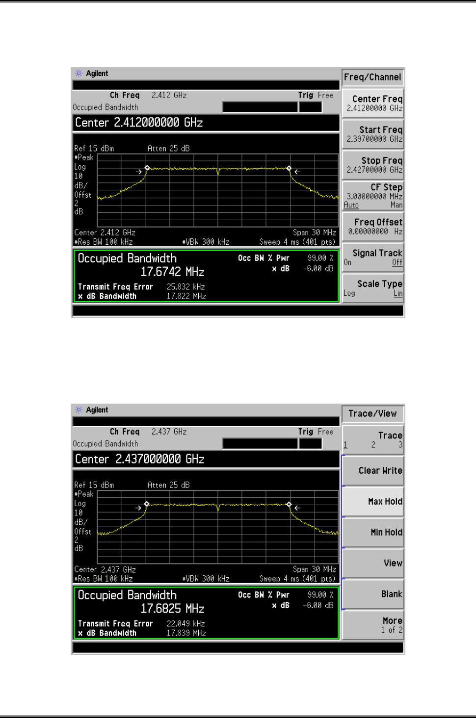
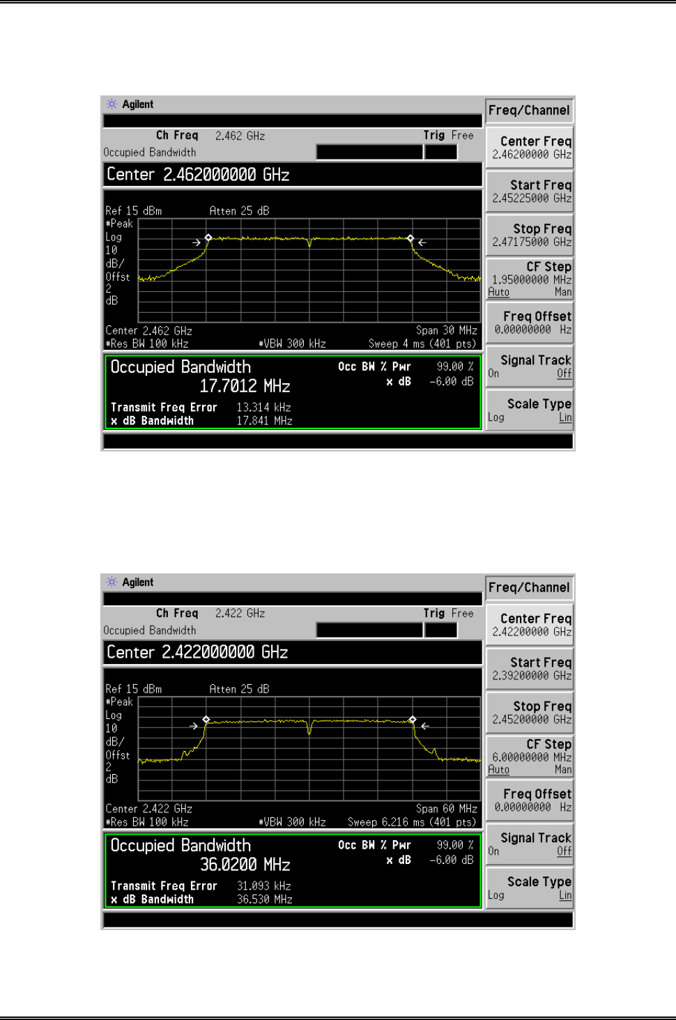
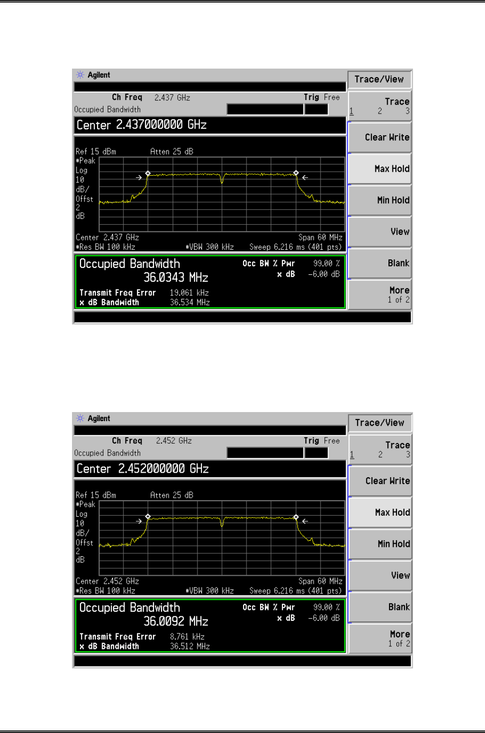
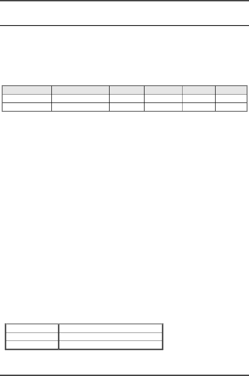
6.5 Summary of Test Results/Plots
Test Mode Test Channel
MHz
6 dB BW
Ant.A kHz
99% BW
Ant.A kHz
6 dB BW
Ant.B kHz
99% BW
Ant.B kHz
Limit
kHz
802.11b
2412 10038 14894.8 10086 14949.9 >500
2437 10013 14936.8 10097 14956.4 >500
2462 10088 14976.8 10079 14945.8 >500
802.11g
2412 16551 16475.4 16551 16476.0 >500
2437 16506 16469.0 16592 16494.7 >500
2462 16582 16467.1 16550 16497.0 >500
802.11n-HT20
2412 17780 17655.7 17822 17674.2 >500
2437 17798 17671.5 17839 17682.5 >500
2462 17808 17630.8 17841 17701.2 >500
802.11n-HT40
2422 36466 35966.5 36530 36020.0 >500
2437 36450 35977.2 36534 36034.3 >500
2452 36410 35937.1 36512 36009.2 >500
Please refer to the following test plots:

Intracom Asia Co., Ltd. Model: 525756
REPORT NO.: STR15048243I-1 PAGE 25 OF 95 FCC PART 15.247
For Ant.A
802.11b-Low Channel
802.11b-Middle Channel
Intracom Asia Co., Ltd. Model: 525756
REPORT NO.: STR15048243I-1 PAGE 26 OF 95 FCC PART 15.247
802.11b-High Channel
802.11g-Low Channel
Intracom Asia Co., Ltd. Model: 525756
REPORT NO.: STR15048243I-1 PAGE 27 OF 95 FCC PART 15.247
802.11g-Middle Channel
802.11g-High Channel
Intracom Asia Co., Ltd. Model: 525756
REPORT NO.: STR15048243I-1 PAGE 28 OF 95 FCC PART 15.247
802.11n-HT20-Low Channel
802.11n-HT20-Middle Channel
Intracom Asia Co., Ltd. Model: 525756
REPORT NO.: STR15048243I-1 PAGE 29 OF 95 FCC PART 15.247
802.11n-HT20-High Channel
802.11n-HT40-Low Channel
Intracom Asia Co., Ltd. Model: 525756
REPORT NO.: STR15048243I-1 PAGE 30 OF 95 FCC PART 15.247
802.11n-HT40-Middle Channel
802.11n-HT40-High Channel
Intracom Asia Co., Ltd. Model: 525756
REPORT NO.: STR15048243I-1 PAGE 31 OF 95 FCC PART 15.247
For Ant.B
802.11b-Low Channel
802.11b-Middle Channel
Intracom Asia Co., Ltd. Model: 525756
REPORT NO.: STR15048243I-1 PAGE 32 OF 95 FCC PART 15.247
802.11b-High Channel
802.11g-Low Channel
Intracom Asia Co., Ltd. Model: 525756
REPORT NO.: STR15048243I-1 PAGE 33 OF 95 FCC PART 15.247
802.11g-Middle Channel
802.11g-High Channel
Intracom Asia Co., Ltd. Model: 525756
REPORT NO.: STR15048243I-1 PAGE 34 OF 95 FCC PART 15.247
802.11n-HT20-Low Channel
802.11n-HT20-Middle Channel
Intracom Asia Co., Ltd. Model: 525756
REPORT NO.: STR15048243I-1 PAGE 35 OF 95 FCC PART 15.247
802.11n-HT20-High Channel
802.11n-HT40-Low Channel
Intracom Asia Co., Ltd. Model: 525756
REPORT NO.: STR15048243I-1 PAGE 36 OF 95 FCC PART 15.247
802.11n-HT40-Middle Channel
802.11n-HT40-High Channel
Intracom Asia Co., Ltd. Model: 525756
REPORT NO.: STR15048243I-1 PAGE 37 OF 95 FCC PART 15.247
7. RF Output Power
7.1 Standard Applicable
According to 15.247(b)(3). For systems using digital modulation in the 902–928 MHz, 2400–2483.5 MHz, and
5725–5850 MHz bands: 1 Watt.
7.2 Test Equipment List and Details
Description Manufacturer Model Serial Number Cal. Date Due. Date
Spectrum Analyzer Agilent E4402B US41192821 2014-05-28 2015-05-27
Attenuator ATTEN ATS100-4-20 / 2014-05-28 2015-05-27
7.3 Test Procedure
According to section 15.247(b)-power output of the KDB-558074 D01 V03r02, 9.2.2.2 (channel integration
method) When this option is exercised, the measured power is to be referenced to the OBW rather than the DTS
bandwidth
a) Set span to at least 1.5 times the OBW.
b) Set RBW = 1-5% of the OBW, not to exceed 1 MHz.
c) Set VBW ≥ 3 x RBW.
d) Number of points in sweep ≥ 2 × span / RBW. (This gives bin-to-bin spacing ≤ RBW/2, so that
narrowband signals are not lost between frequency bins.)
e) Sweep time = auto.
f) Detector = RMS (i.e., power averaging), if available. Otherwise, use sample detector mode.
g) If transmit duty cycle < 98 %, use a sweep trigger with the level set to enable triggering only on full power
pulses. The transmitter shall operate at maximum power control level for the entire duration of every
sweep. If the EUT transmits continuously (i.e., with no off intervals) or at duty cycle ≥ 98 %, and if
each transmission is entirely at the maximum power control level, then the trigger shall be set to “free
run”.
h) Trace average at least 100 traces in power averaging (i.e., RMS) mode.
i) Compute power by integrating the spectrum across the OBW of the signal using the instrument’s band
power measurement function, with band limits set equal to the OBW band edges. If the instrument does
not have a band power function, sum the spectrum levels (in power units) at intervals equal to the RBW
extending across the entire OBW of the spectrum.
7.4 Environmental Conditions
Temperature: 26° C
Relative Humidity: 57%
ATM Pressure: 1011 mbar
Intracom Asia Co., Ltd. Model: 525756
REPORT NO.: STR15048243I-1 PAGE 38 OF 95 FCC PART 15.247
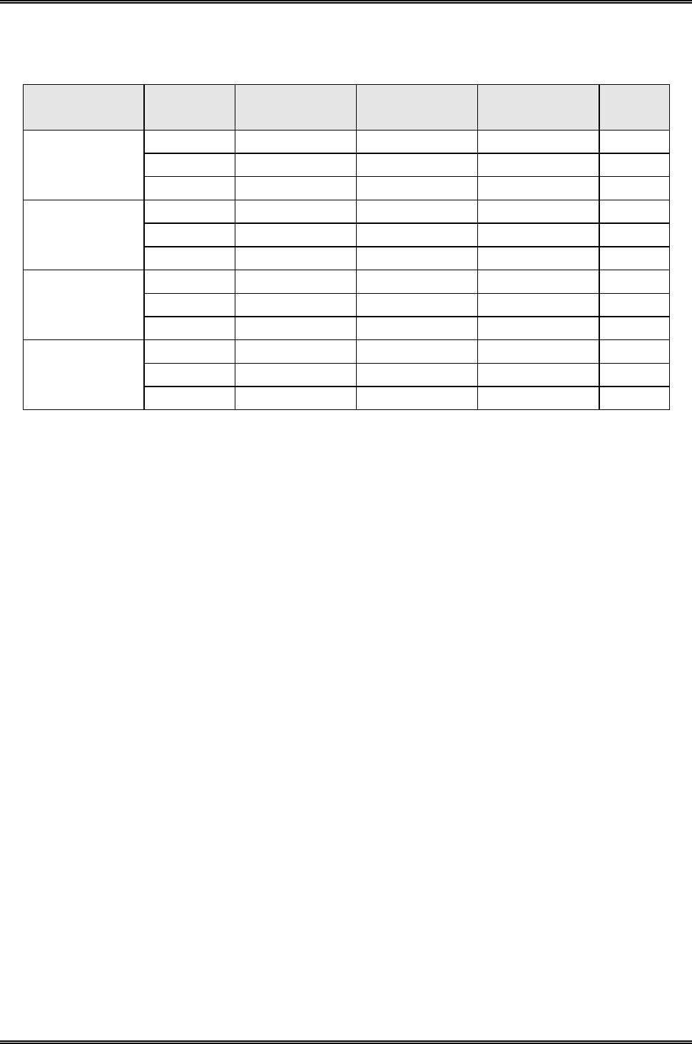
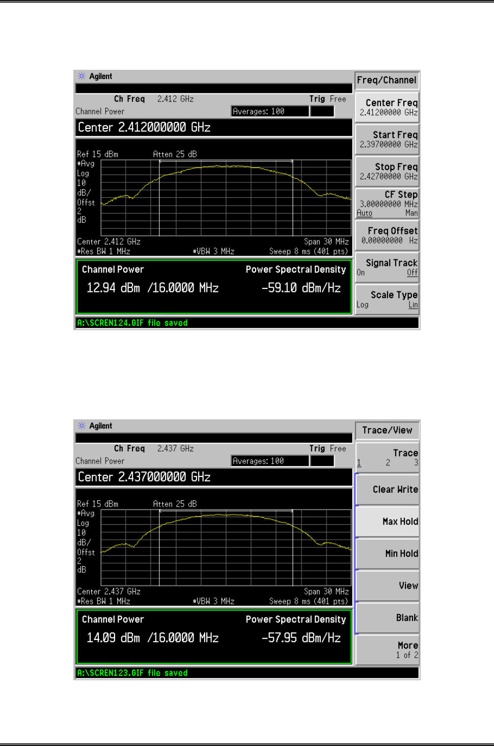
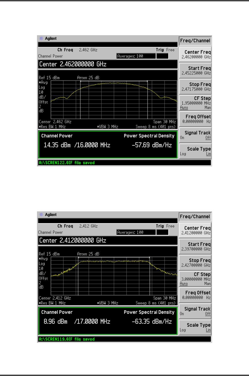
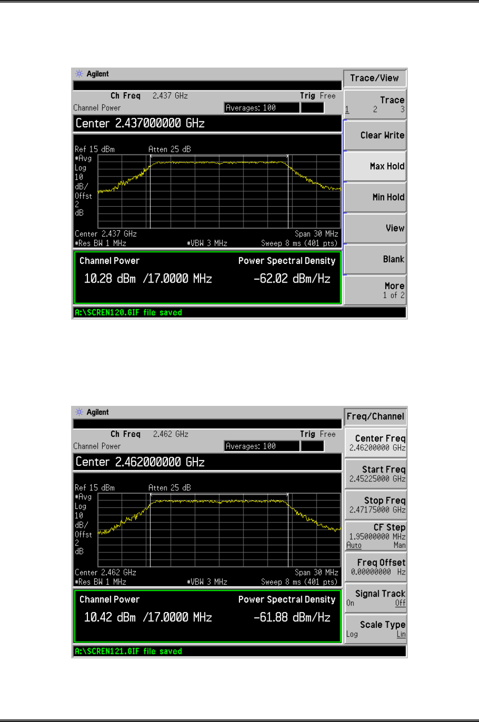
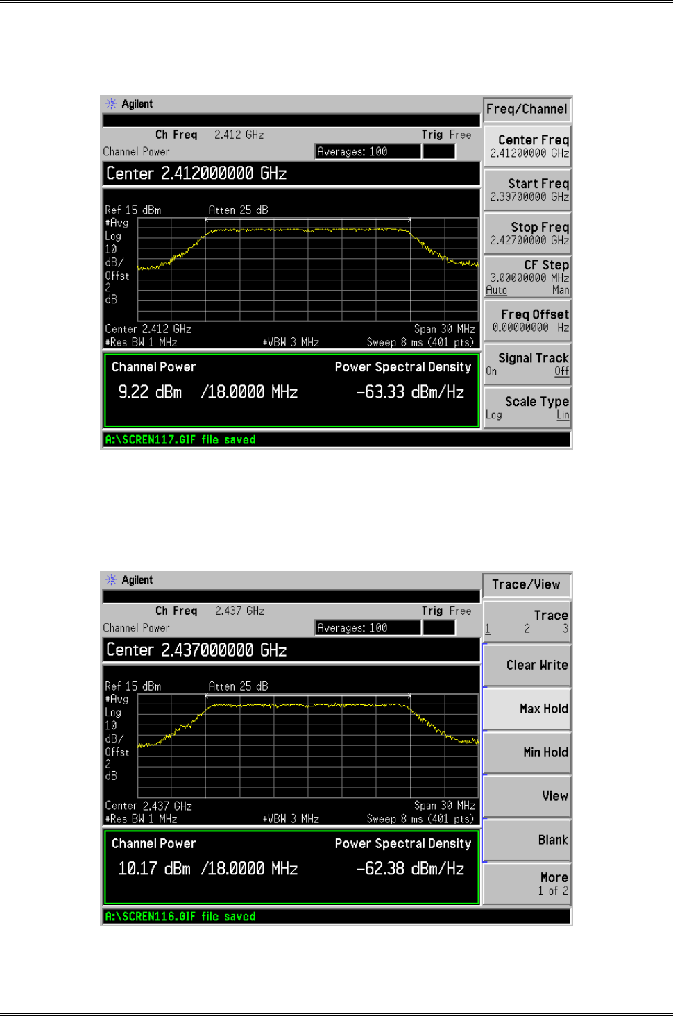
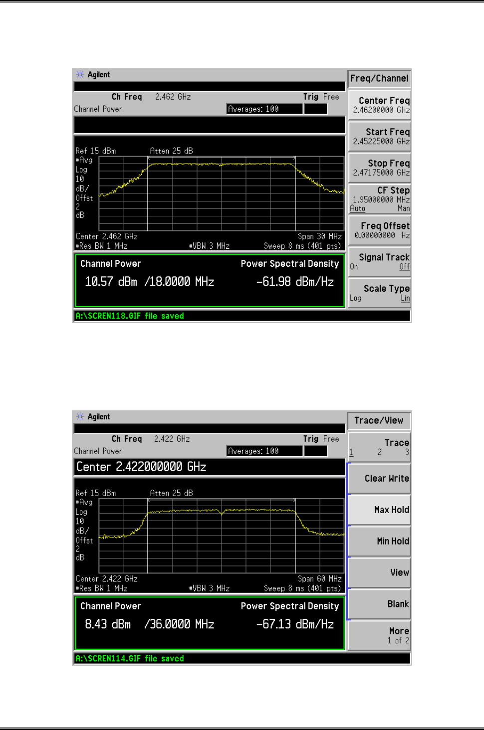
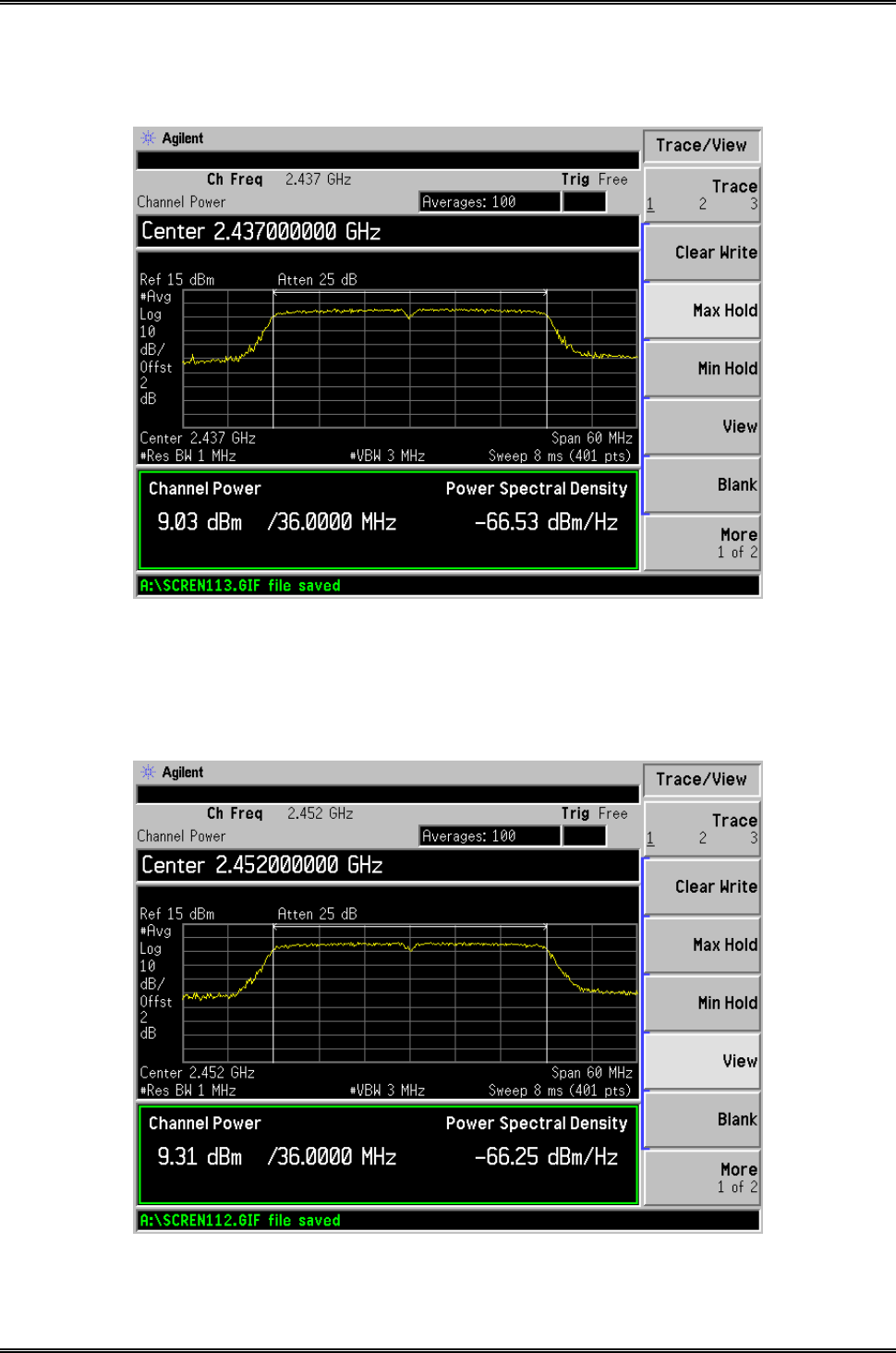
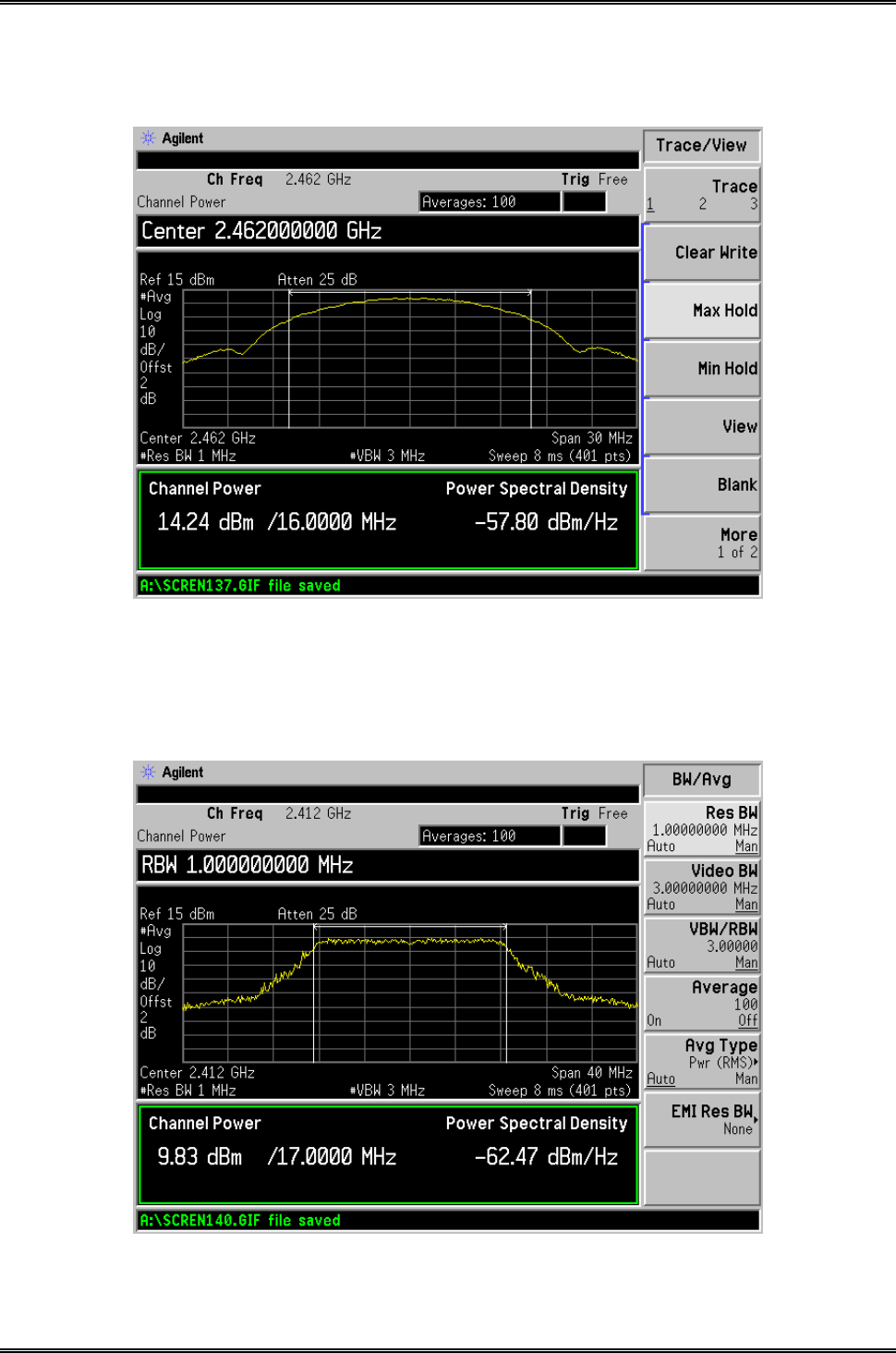
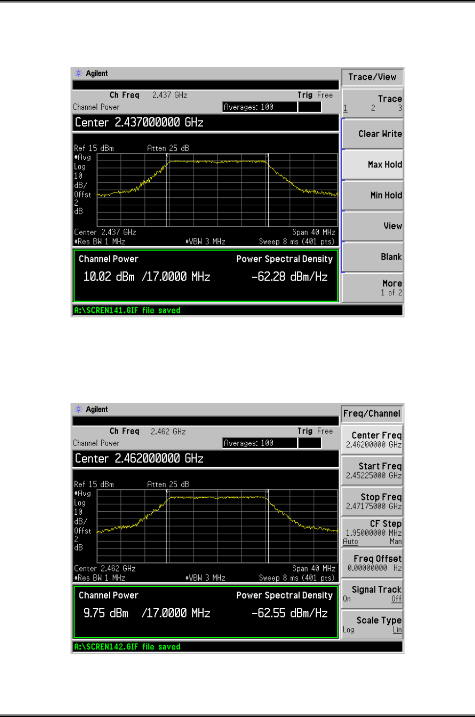
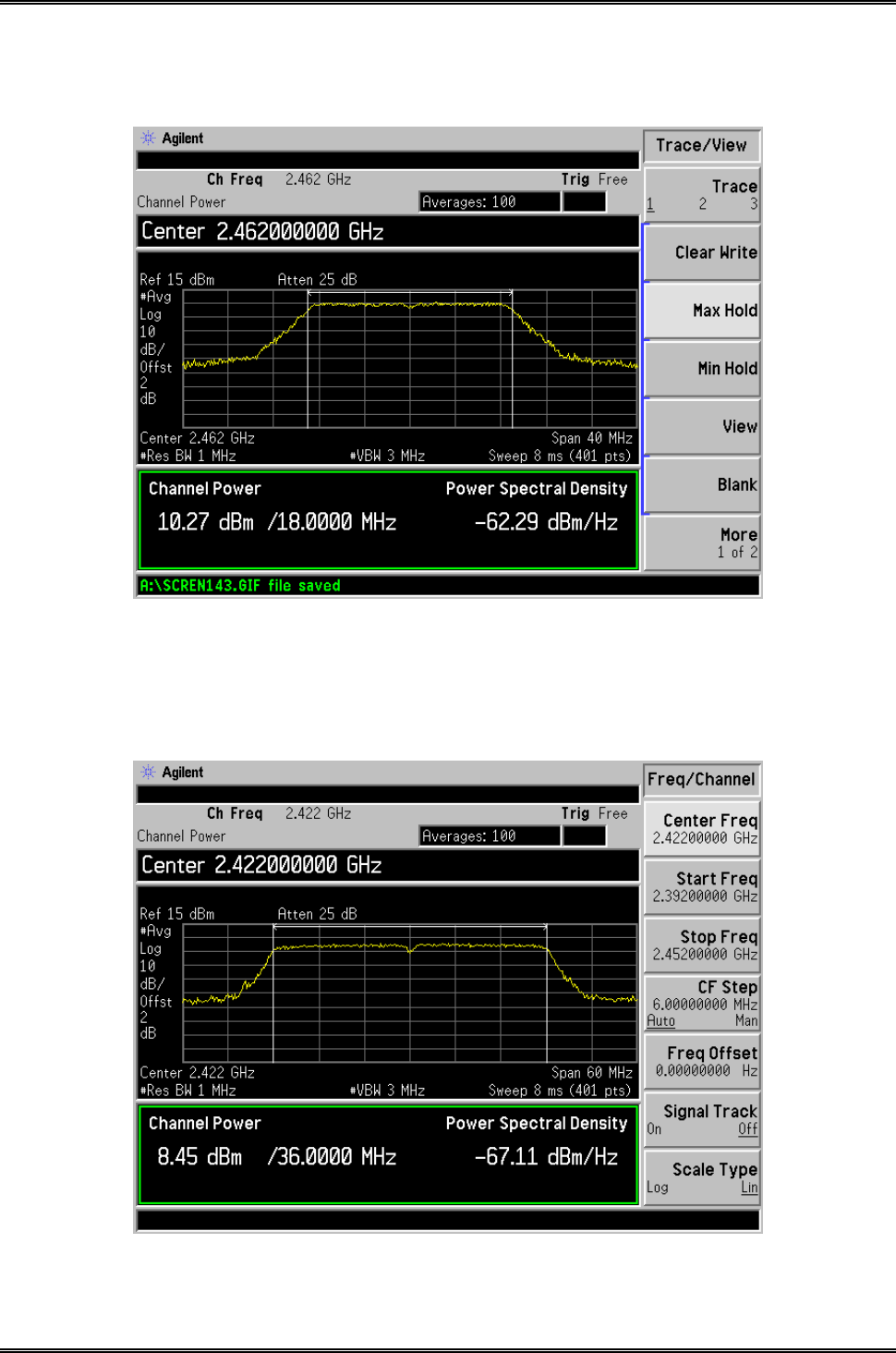
7.5 Summary of Test Results/Plots
Test Mode Frequency
MHz
Reading Ant.A
dBm
Reading Ant.B
dBm
Output Power
mW
Limit
mW
802.11b_1Mbps
2412 12.94 13.31 16.14 1000
2437 14.09 13.72 16.92 1000
2462 14.35 14.24 17.31 1000
802.11g_6Mbps
2412 8.96 9.83 12.43 1000
2437 10.28 10.02 13.16 1000
2462 10.42 9.75 13.11 1000
802.11n
HT20_MCS0
2412 9.22 9.25 12.25 1000
2437 10.17 9.92 13.06 1000
2462 10.57 10.27 13.43 1000
802.11n
HT40_MCS0
2422 8.43 8.45 11.45 1000
2437 9.03 8.82 11.94 1000
2452 9.31 9.21 12.27 1000
Please refer to the following test plots:
Intracom Asia Co., Ltd. Model: 525756
REPORT NO.: STR15048243I-1 PAGE 39 OF 95 FCC PART 15.247
For Ant.A
802.11b-1Mbps-Low Channel
802.11b -1Mbps-Middle Channel
Intracom Asia Co., Ltd. Model: 525756
REPORT NO.: STR15048243I-1 PAGE 40 OF 95 FCC PART 15.247
802.11b -1Mpbs-High Channel
802.11g-6Mbps-Low Channel
Intracom Asia Co., Ltd. Model: 525756
REPORT NO.: STR15048243I-1 PAGE 41 OF 95 FCC PART 15.247
802.11g-6Mbps-Middle Channel
802.11g-6Mpbs-High Channel
Intracom Asia Co., Ltd. Model: 525756
REPORT NO.: STR15048243I-1 PAGE 42 OF 95 FCC PART 15.247
802.11n-HT20-MCS0-Low Channel
802.11n-HT20-MCS0-Middle Channel
Intracom Asia Co., Ltd. Model: 525756
REPORT NO.: STR15048243I-1 PAGE 43 OF 95 FCC PART 15.247
802.11n-HT20-MCS0-High Channel
802.11n-HT40-MCS0-Low Channel
Intracom Asia Co., Ltd. Model: 525756
REPORT NO.: STR15048243I-1 PAGE 44 OF 95 FCC PART 15.247
802.11n-HT40-MCS0-Middle Channel
802.11n-HT40-MCS0-High Channel

Intracom Asia Co., Ltd. Model: 525756
REPORT NO.: STR15048243I-1 PAGE 45 OF 95 FCC PART 15.247
For Ant.B
802.11b-1Mbps-Low Channel
802.11b -1Mbps-Middle Channel
Intracom Asia Co., Ltd. Model: 525756
REPORT NO.: STR15048243I-1 PAGE 46 OF 95 FCC PART 15.247
802.11b -1Mpbs-High Channel
802.11g-6Mbps-Low Channel
Intracom Asia Co., Ltd. Model: 525756
REPORT NO.: STR15048243I-1 PAGE 47 OF 95 FCC PART 15.247
802.11g-6Mbps-Middle Channel
802.11g-6Mpbs-High Channel

Intracom Asia Co., Ltd. Model: 525756
REPORT NO.: STR15048243I-1 PAGE 48 OF 95 FCC PART 15.247
802.11n-HT20-MCS0-Low Channel
802.11n-HT20-MCS0-Middle Channel
Intracom Asia Co., Ltd. Model: 525756
REPORT NO.: STR15048243I-1 PAGE 49 OF 95 FCC PART 15.247
802.11n-HT20-MCS0-High Channel
802.11n-HT40-MCS0-Low Channel
Intracom Asia Co., Ltd. Model: 525756
REPORT NO.: STR15048243I-1 PAGE 50 OF 95 FCC PART 15.247
802.11n-HT40-MCS0-Middle Channel
802.11n-HT40-MCS0-High Channel
Intracom Asia Co., Ltd. Model: 525756
REPORT NO.: STR15048243I-1 PAGE 51 OF 95 FCC PART 15.247
8. Field Strength of Spurious Emissions
8.1 Measurement Uncertainty
Based on NIS 81, The Treatment of Uncertainty in EMC Measurements, the best estimate of the uncertainty of a
radiation emissions measurement is +5.10 dB.
8.2 Standard Applicable
According to §15.247(d), in any 100 kHz bandwidth outside the frequency band in which the spread spectrum or
digitally modulated intentional radiator is operating, the radio frequency power that is produced by the intentional
radiator shall be at least 20 dB below that in the 100 kHz bandwidth within the band that contains the highest level
of the desired power, based on either an RF conducted or a radiated measurement, provided the transmitter
demonstrates compliance with the peak conducted power limits. If the transmitter complies with the conducted
power limits based on the use of RMS averaging over a time interval, as permitted under paragraph (b)(3) of this
section, the attenuation required under this paragraph shall be 30 dB instead of 20 dB. Attenuation below the
general limits specified in §15.209(a) is not required. In addition, radiated emissions which fall in the restricted
bands, as defined in §15.205(a), must also comply with the radiated emission limits specified in §15.209(a).
The emission limit in this paragraph is based on measurement instrumentation employing an average detector. The
provisions in §15.35 for limiting peak emissions apply. Spurious Radiated Emissions measurements starting
below or at the lowest crystal frequency.
8.3 Test Equipment List and Details
Description Manufacturer Model Serial Number Cal. Date Due. Date
Spectrum Analyzer R&S FSP 836079/035 2014-05-28 2015-05-27
EMI Test Receiver R&S ESVB 825471/005 2014-05-28 2015-05-27
Pre-amplifier Agilent 8447F 3113A06717 2014-05-28 2015-05-27
Pre-amplifier Compliance Direction PAP-0118 24002 2014-05-28 2015-05-27
Trilog Broadband
Antenna SCHWARZBECK VULB9163 9163-333 2014-05-24 2015-05-23
Horn Antenna ETS 3117 00086197 2014-05-24 2015-05-23
Horn Antenna ETS 3116B 00088203 2014-05-24 2015-05-23
Loop Antenna SCHWARZECK HFRA 5165 9365 2014-05-24 2015-05-23

Intracom Asia Co., Ltd. Model: 525756
REPORT NO.: STR15048243I-1 PAGE 52 OF 95 FCC PART 15.247
8.4 Test Procedure
The setup of EUT is according with per ANSI C63.4-2014 measurement procedure. The specification used was
with the FCC Part 15.205 15.247(a) and FCC Part 15.209 Limit.
The external I/O cables were draped along the test table and formed a bundle 30 to 40 cm long in the middle.
The spacing between the peripherals was 10 cm.
Ground Plane
Turntable
Table
EUT SYS
1m-4m
3m
0.8m
Antenna
Tower
To EMI Receiver
Intracom Asia Co., Ltd. Model: 525756
REPORT NO.: STR15048243I-1 PAGE 53 OF 95 FCC PART 15.247
Frequency :9kHz-30MHz Frequency :30MHz-1GHz Frequency :Above 1GHz
RBW=10KHz, RBW=120KHz, RBW=1MHz,
VBW =30KHz VBW=300KHz VBW=3MHz(Peak), 10Hz(AV)
Sweep time= Auto Sweep time= Auto Sweep time= Auto
Trace = max hold Trace = max hold Trace = max hold
Detector function = peak Detector function = peak, QP Detector function = peak, AV
8.5 Corrected Amplitude & Margin Calculation
The Corrected Amplitude is calculated by adding the Antenna Factor and the Cable Factor, and subtracting the
Amplifier Gain from the Amplitude reading. The basic equation is as follows:
Corr. Ampl. = Indicated Reading + Ant. Factor + Cable Loss – Ampl. Gain
The “Margin” column of the following data tables indicates the degree of compliance with the applicable limit.
For example, a margin of -6dBμV means the emission is 6dBμV below the maximum limit for Class B. The
equation for margin calculation is as follows:
Margin = Corr. Ampl. – FCC Part 15 Limit
8.6 Environmental Conditions
Temperature: 25 °C
Relative Humidity: 52%
ATM Pressure: 1012 mbar
8.7 Summary of Test Results/Plots
According to the data below, the FCC Part 15.205, 15.209 and 15.247 standards, and had the worst cases:
Note: this EUT was tested in 3 orthogonal positions and the worst case position data was reported.
Intracom Asia Co., Ltd. Model: 525756
REPORT NO.: STR15048243I-1 PAGE 54 OF 95 FCC PART 15.247
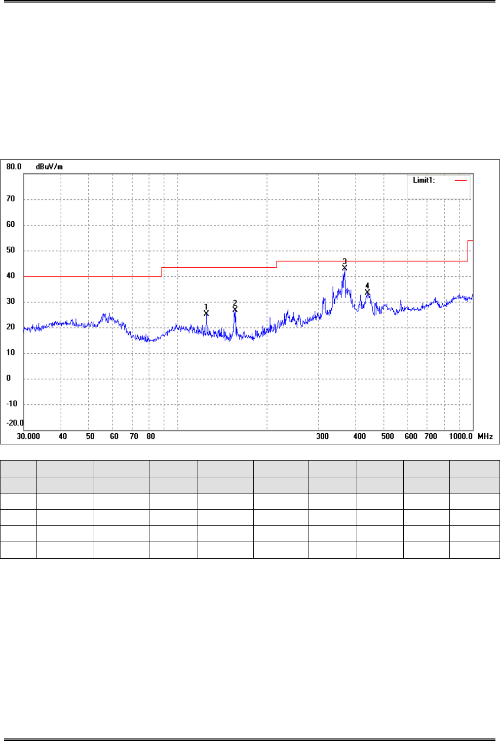
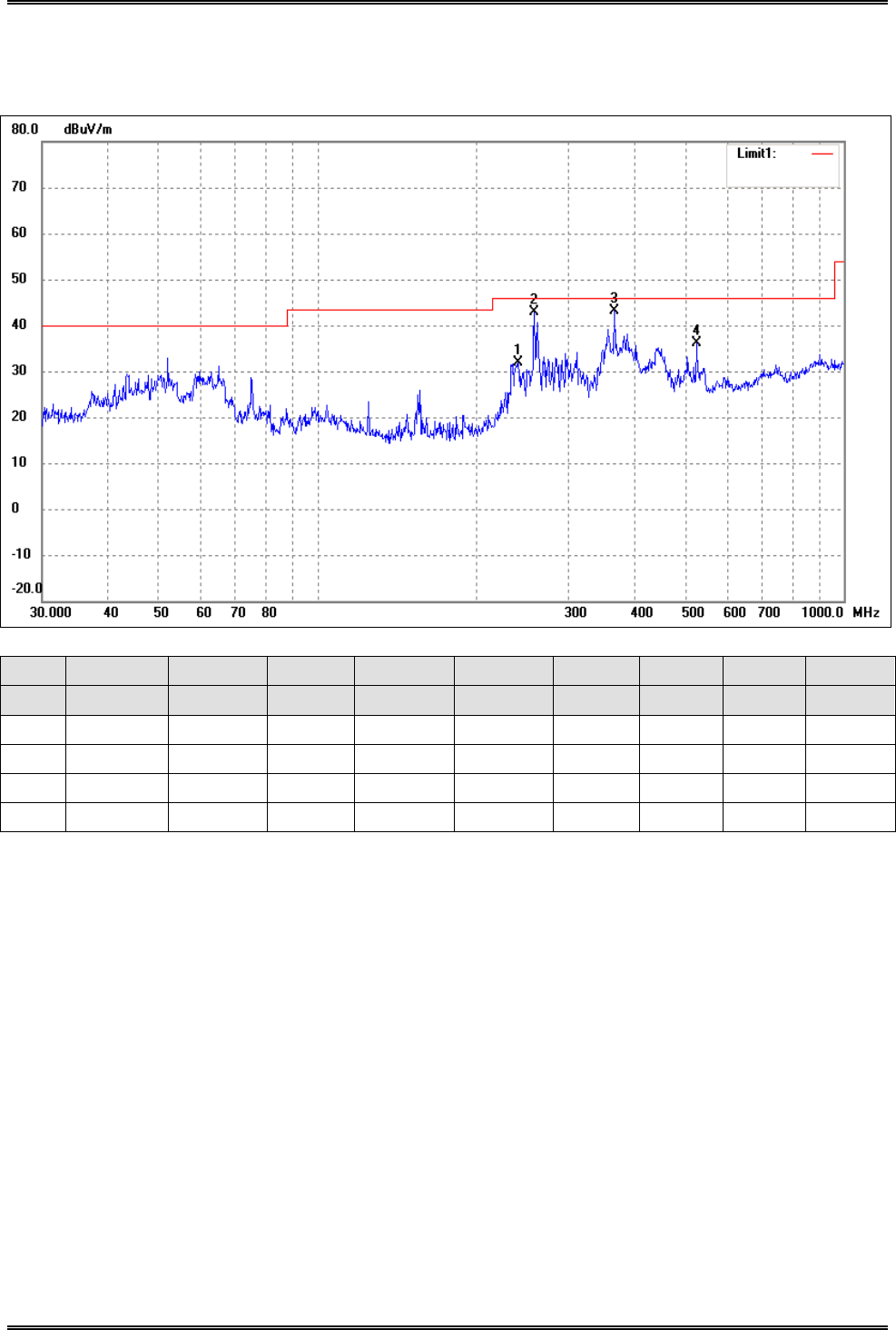
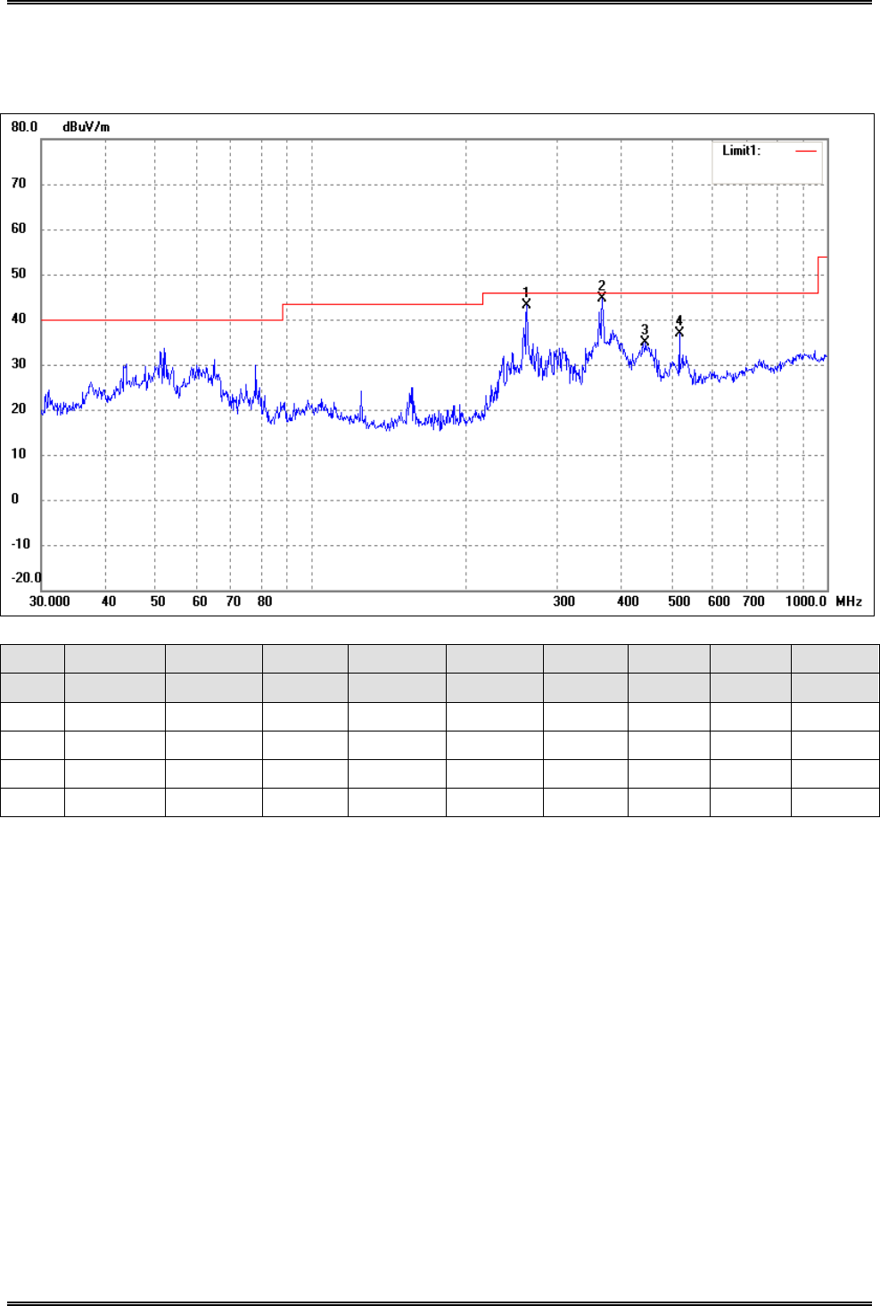
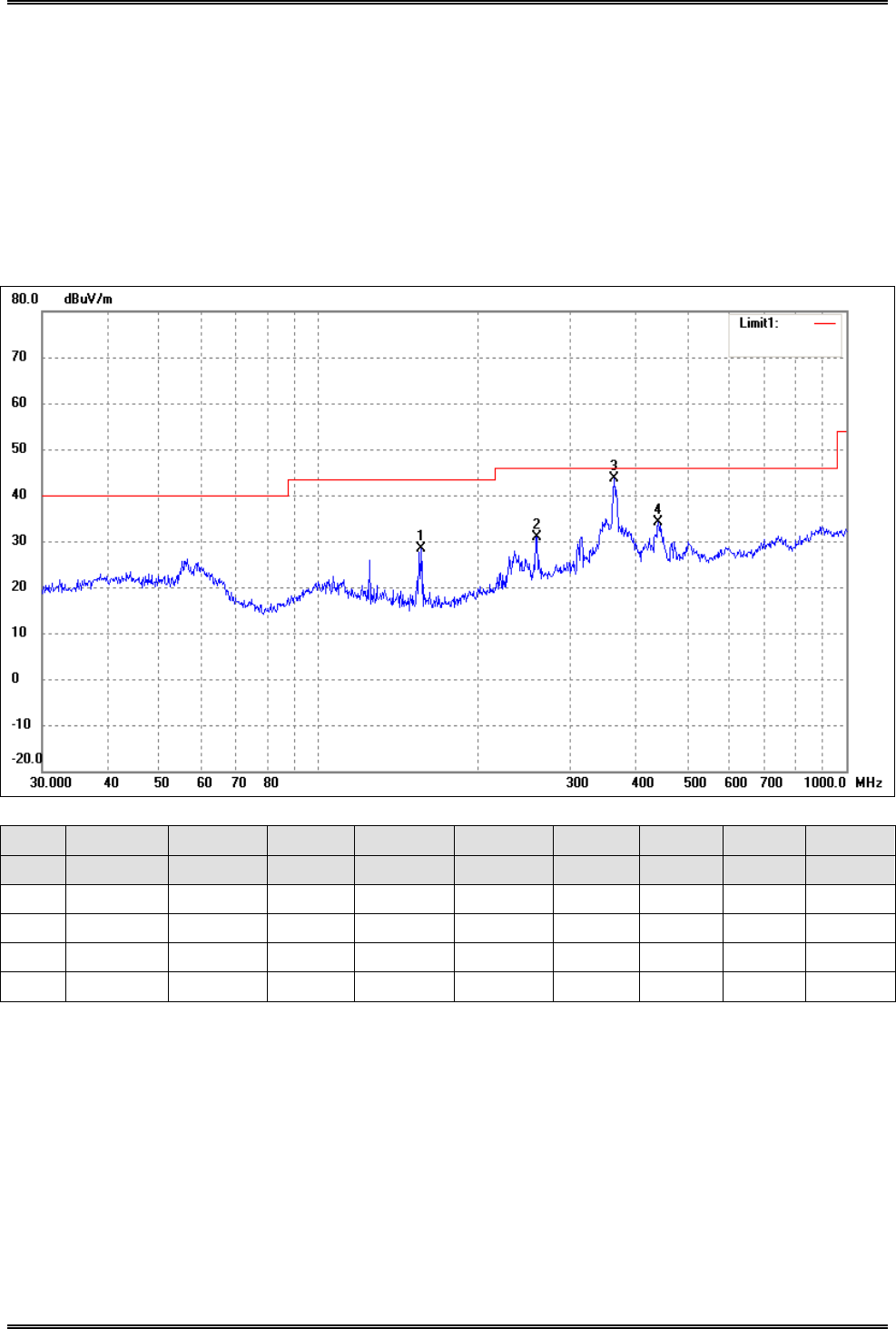
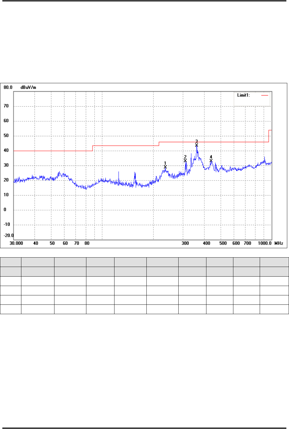
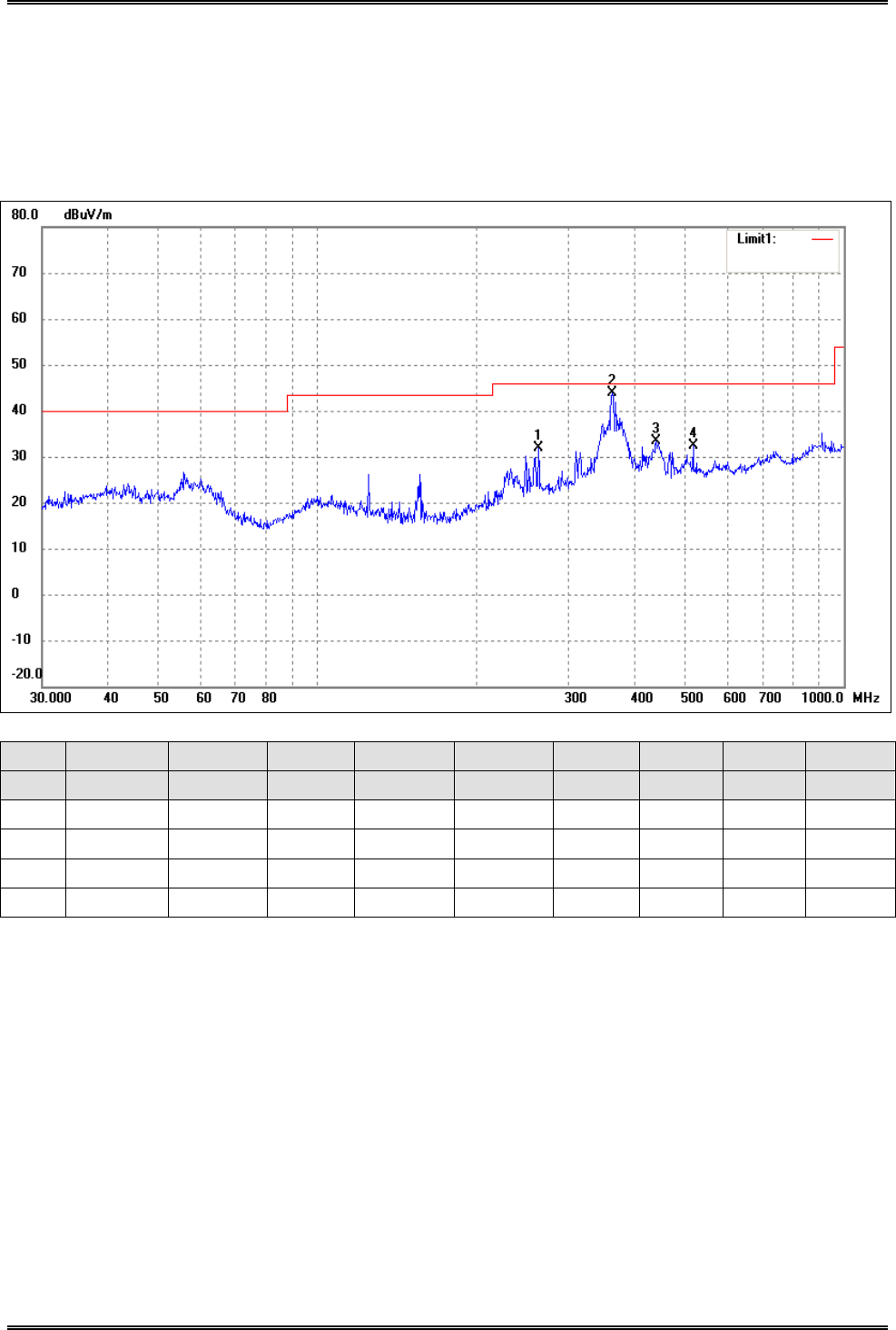
Plot of Radiated Emissions Test Data (30MHz to 1GHz)
EUT: Wireless 300N Range Extender
Tested Model: 525756
Operating Condition: 802.11b Transmitting Low Channel-2412MHz
Comment: AC 120V/60Hz
Test Specification: Horizontal
No. Frequency Reading Correct Result Limit Margin Degree Height Remark
(MHz) (dBuV/m) dB/m (dBuV/m) (dBuV/m) (dB) (·) (cm)
1 125.0066 21.54 3.61 25.15 43.50 -18.35 114 100 peak
2 156.4578 24.11 2.58 26.69 43.50 -16.81 270 100 peak
3 368.1116 33.66 9.23 42.89 46.00 -3.11 360 100 peak
4 440.1963 23.35 10.03 33.38 46.00 -12.62 116 100 peak
Intracom Asia Co., Ltd. Model: 525756
REPORT NO.: STR15048243I-1 PAGE 55 OF 95 FCC PART 15.247
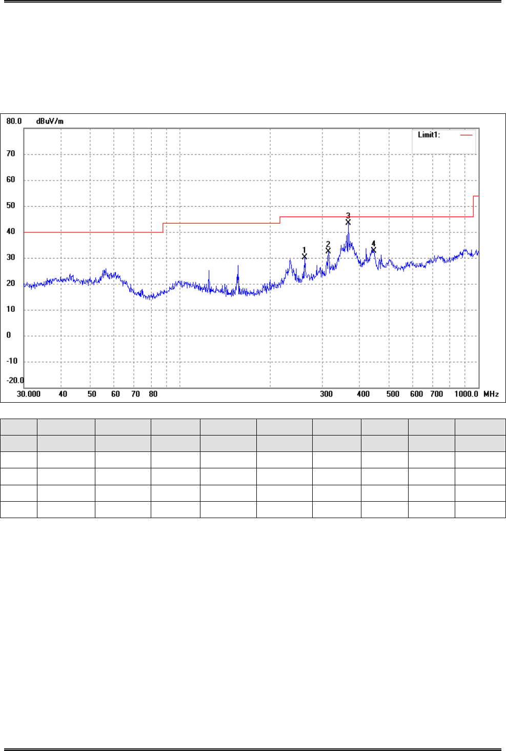
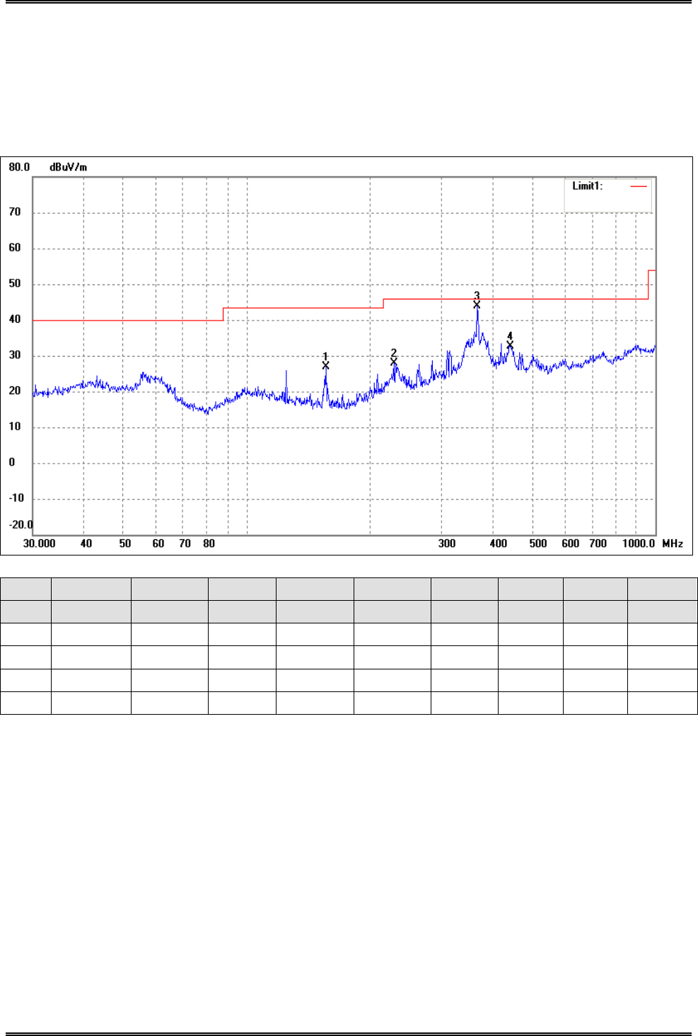
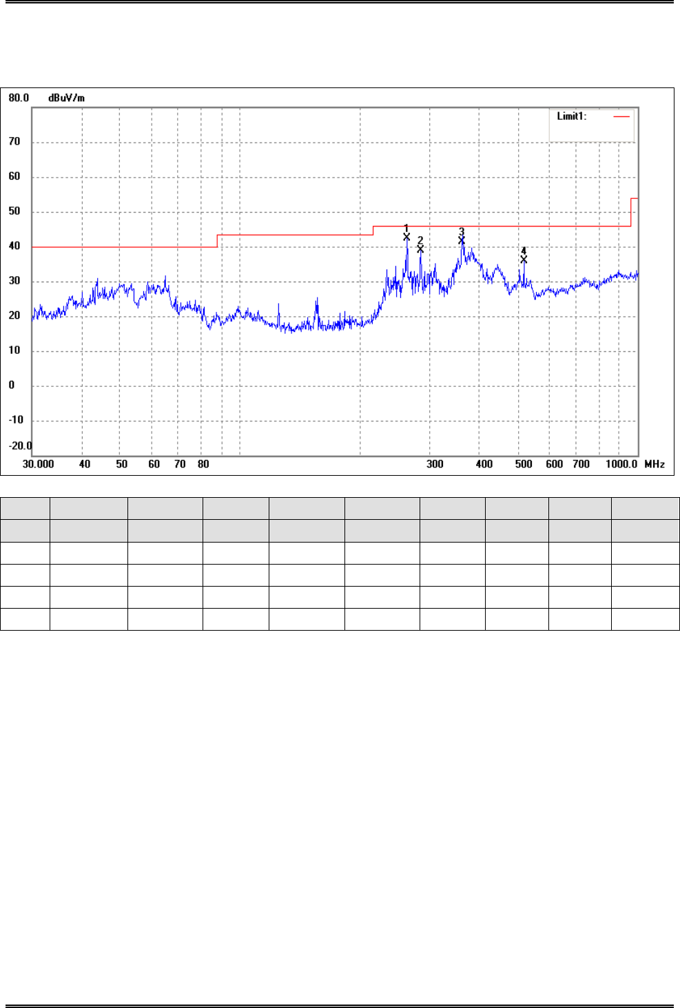
Test Specification: Vertical
No. Frequency Reading Correct Result Limit Margin Degree Height Remark
(MHz) (dBuV/m) dB/m (dBuV/m) (dBuV/m) (dB) (·) (cm)
1 240.8304 25.45 6.36 31.81 46.00 -14.19 178 100 peak
2 258.3264 35.80 6.98 42.78 46.00 -3.22 224 100 peak
3 366.8231 33.92 9.22 43.14 46.00 -2.86 160 100 peak
4 524.5541 24.80 11.36 36.16 46.00 -9.84 290 100 peak
Intracom Asia Co., Ltd. Model: 525756
REPORT NO.: STR15048243I-1 PAGE 56 OF 95 FCC PART 15.247
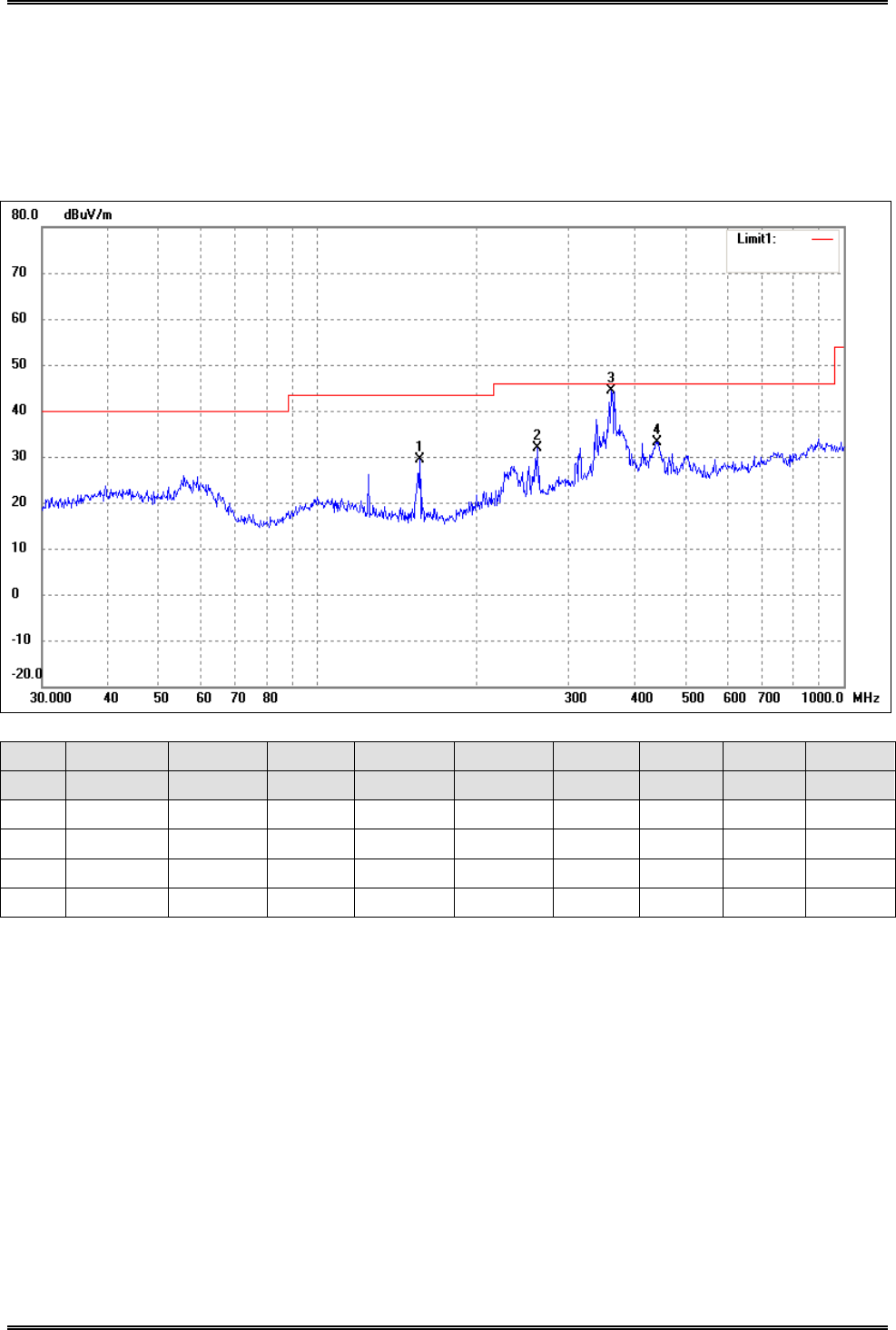
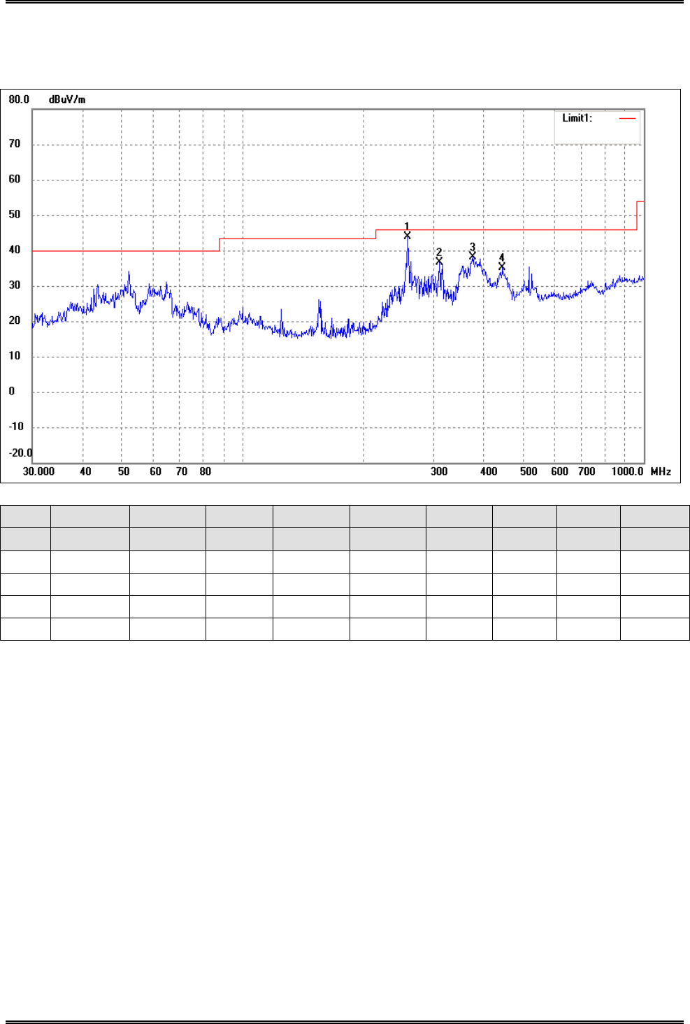
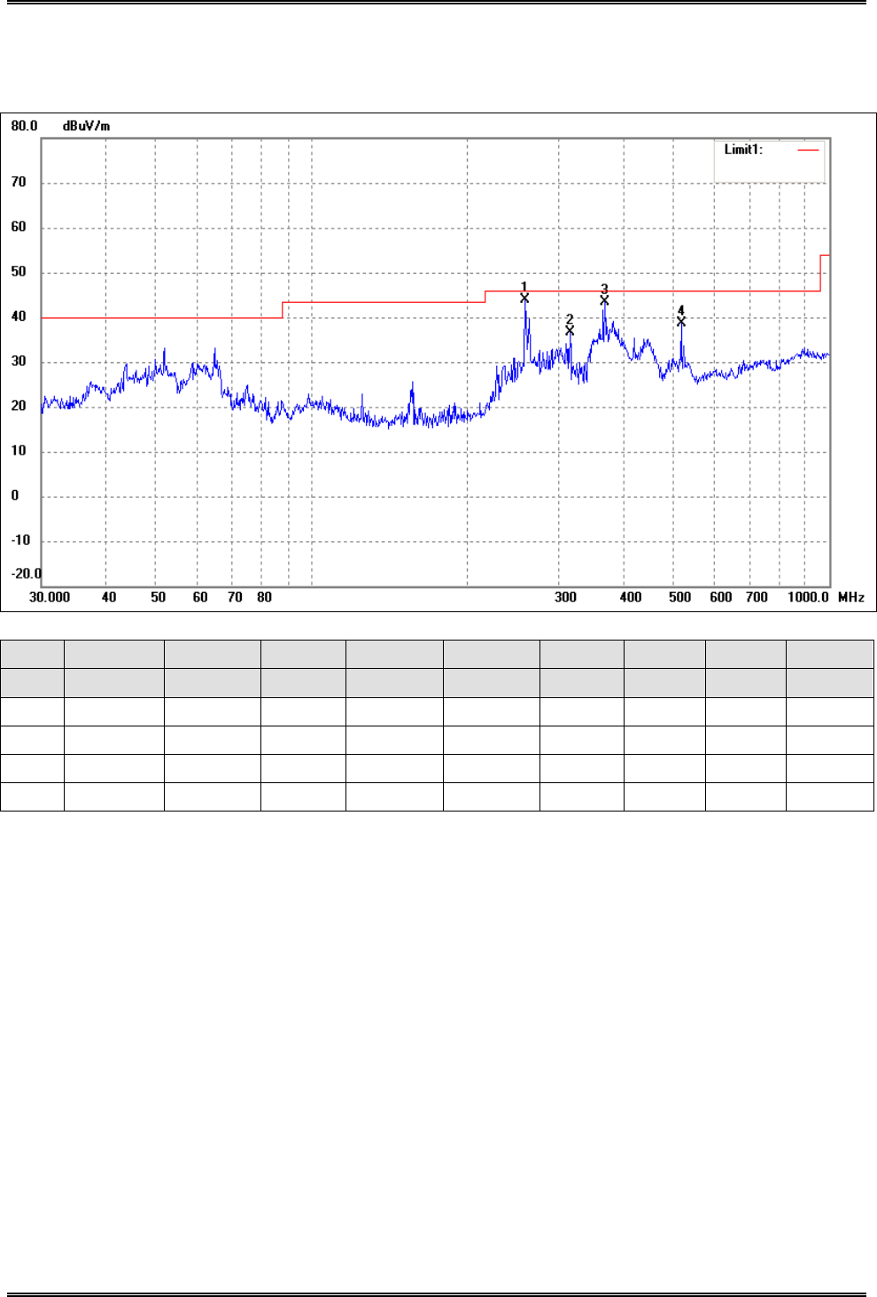
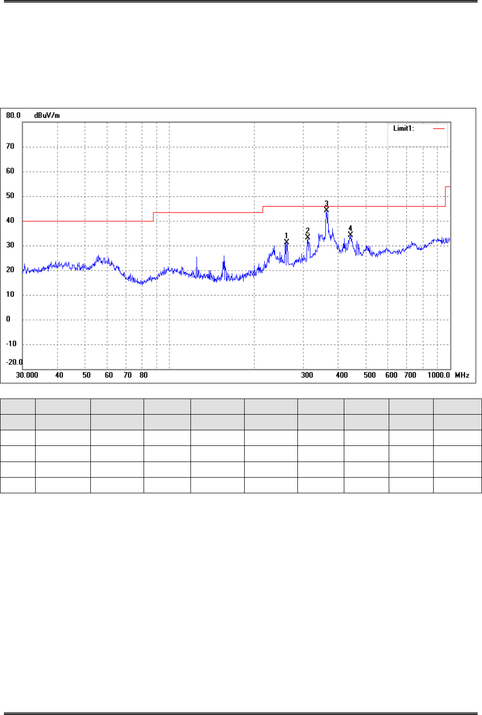
Operating Condition: 802.11b Transmitting Middle Channel-2437MHz
Comment: AC 120V/60Hz
Test Specification: Horizontal
No. Frequency Reading Correct Result Limit Margin Degree Height Remark
(MHz) (dBuV/m) dB/m (dBuV/m) (dBuV/m) (dB) (·) (cm)
1 156.4578 26.73 2.58 29.31 43.50 -14.19 256 100 peak
2 261.9753 24.69 7.17 31.86 46.00 -14.14 360 100 peak
3 361.7139 35.21 9.24 44.45 46.00 -1.55 360 100 peak
4 441.7426 23.15 10.06 33.21 46.00 -12.79 360 100 peak

Intracom Asia Co., Ltd. Model: 525756
REPORT NO.: STR15048243I-1 PAGE 57 OF 95 FCC PART 15.247
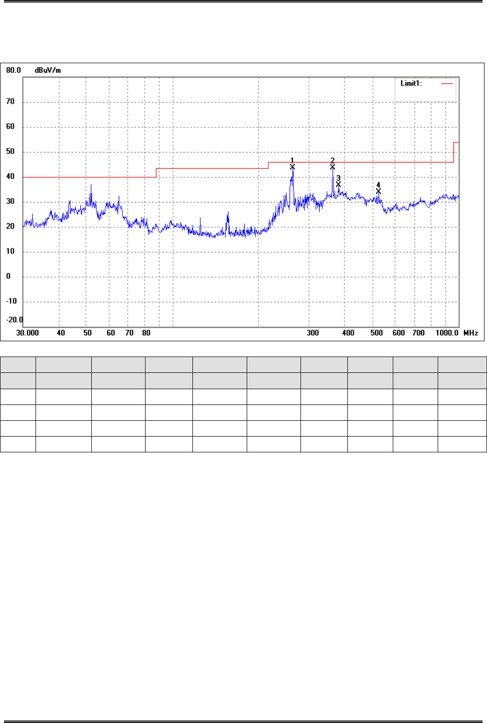
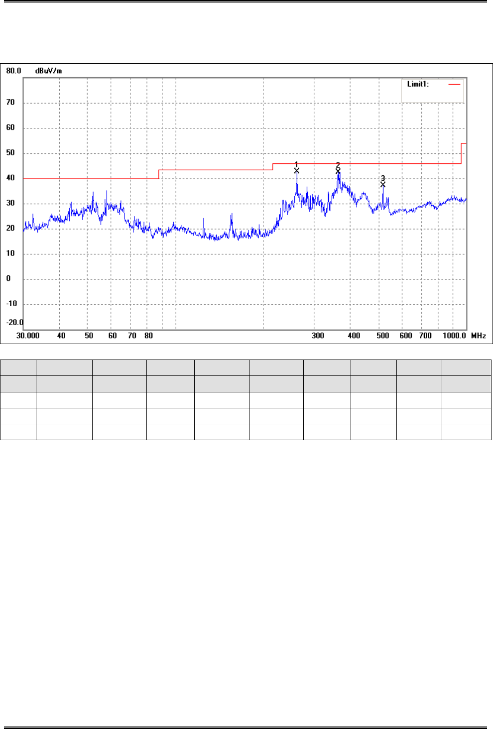
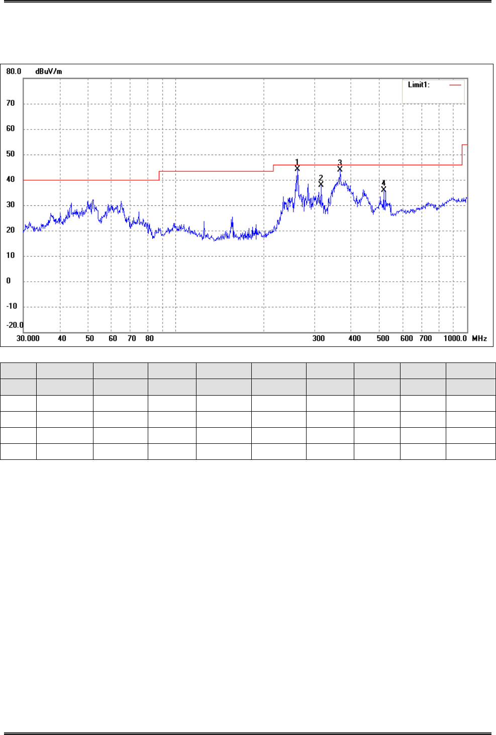
Test Specification: Vertical
No. Frequency Reading Correct Result Limit Margin Degree Height Remark
(MHz) (dBuV/m) dB/m (dBuV/m) (dBuV/m) (dB) (·) (cm)
1 261.9753 36.22 7.17 43.39 46.00 -2.61 176 100 peak
2 362.9845 34.68 9.24 43.92 46.00 -2.08 255 100 peak
3 517.2480 26.55 11.30 37.85 46.00 -8.15 360 100 peak
Intracom Asia Co., Ltd. Model: 525756
REPORT NO.: STR15048243I-1 PAGE 58 OF 95 FCC PART 15.247
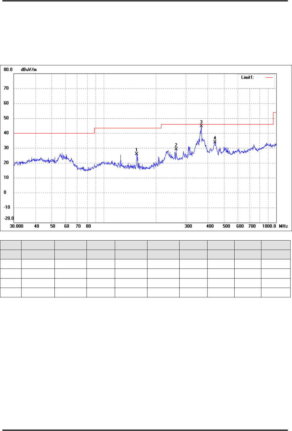
Operating Condition: 802.11b Transmitting High Channel-2462MHz
Comment: AC 120V/60Hz
Test Specification: Horizontal
No. Frequency Reading Correct Result Limit Margin Degree Height Remark
(MHz) (dBuV/m) dB/m (dBuV/m) (dBuV/m) (dB) (·) (cm)
1 154.8205 23.34 2.55 25.89 43.50 -17.61 360 100 peak
2 262.8955 21.91 7.23 29.14 46.00 -16.86 225 100 peak
3 368.1116 35.34 9.23 44.57 46.00 -1.43 160 100 peak
4 441.7426 23.74 10.06 33.80 46.00 -12.20 310 100 peak

Intracom Asia Co., Ltd. Model: 525756
REPORT NO.: STR15048243I-1 PAGE 59 OF 95 FCC PART 15.247
Test Specification: Vertical
No. Frequency Reading Correct Result Limit Margin Degree Height Remark
(MHz) (dBuV/m) dB/m (dBuV/m) (dBuV/m) (dB) (·) (cm)
1 235.8164 27.84 6.07 33.91 46.00 -12.09 174 100 peak
2 259.2338 35.75 7.01 42.76 46.00 -3.24 160 100 peak
3 361.7139 32.06 9.24 41.30 46.00 -4.70 320 100 peak
4 517.2480 25.80 11.30 37.10 46.00 -8.90 360 100 peak
Intracom Asia Co., Ltd. Model: 525756
REPORT NO.: STR15048243I-1 PAGE 60 OF 95 FCC PART 15.247
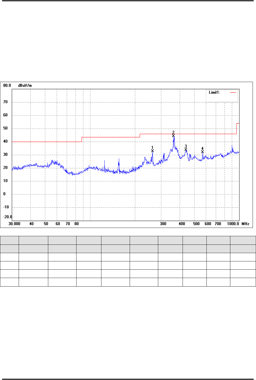
Plot of Radiated Emissions Test Data (30MHz to 1GHz)
EUT: Wireless 300N Range Extender
Tested Model: 525756
Operating Condition: 802.11g Transmitting Low Channel-2412MHz
Comment: AC 120V/60Hz
Test Specification: Horizontal
No. Frequency Reading Correct Result Limit Margin Degree Height Remark
(MHz) (dBuV/m) dB/m (dBuV/m) (dBuV/m) (dB) (·) (cm)
1 262.8955 25.52 7.23 32.75 46.00 -13.25 177 100 peak
2 362.9845 35.00 9.24 44.24 46.00 -1.76 90 100 peak
3 440.1963 23.72 10.03 33.75 46.00 -12.25 336 100 peak
4 568.6127 19.93 11.98 31.91 46.00 -14.09 360 100 peak
Intracom Asia Co., Ltd. Model: 525756
REPORT NO.: STR15048243I-1 PAGE 61 OF 95 FCC PART 15.247
Test Specification: Vertical
No. Frequency Reading Correct Result Limit Margin Degree Height Remark
(MHz) (dBuV/m) dB/m (dBuV/m) (dBuV/m) (dB) (·) (cm)
1 261.9753 35.95 7.17 43.12 46.00 -2.88 270 100 peak
2 366.8231 35.48 9.22 44.70 46.00 -1.30 164 100 peak
3 444.8514 24.63 10.15 34.78 46.00 -11.22 228 200 peak
4 517.2480 25.58 11.30 36.88 46.00 -9.12 130 200 peak
Intracom Asia Co., Ltd. Model: 525756
REPORT NO.: STR15048243I-1 PAGE 62 OF 95 FCC PART 15.247
Operating Condition: 802.11g Transmitting Middle Channel-2437MHz
Comment: AC 120V/60Hz
Test Specification: Horizontal
No. Frequency Reading Correct Result Limit Margin Degree Height Remark
(MHz) (dBuV/m) dB/m (dBuV/m) (dBuV/m) (dB) (·) (cm)
1 261.9753 23.07 7.17 30.24 46.00 -15.76 360 100 peak
2 314.3765 23.11 9.26 32.37 46.00 -13.63 255 100 peak
3 366.8231 34.10 9.22 43.32 46.00 -2.68 270 100 peak
4 446.4141 22.36 10.19 32.55 46.00 -13.45 180 100 peak
Intracom Asia Co., Ltd. Model: 525756
REPORT NO.: STR15048243I-1 PAGE 63 OF 95 FCC PART 15.247
Test Specification: Vertical
No. Frequency Reading Correct Result Limit Margin Degree Height Remark
(MHz) (dBuV/m) dB/m (dBuV/m) (dBuV/m) (dB) (·) (cm)
1 258.3264 36.95 6.98 43.93 46.00 -2.07 270 100 peak
2 309.9977 27.35 9.23 36.58 46.00 -9.42 51 200 peak
3 375.9385 29.00 9.20 38.20 46.00 -7.80 360 200 peak
4 444.8514 24.87 10.15 35.02 46.00 -10.98 360 100 peak

Intracom Asia Co., Ltd. Model: 525756
REPORT NO.: STR15048243I-1 PAGE 64 OF 95 FCC PART 15.247
Operating Condition: 802.11g Transmitting High Channel-2462MHz
Comment: AC 120V/60Hz
Test Specification: Horizontal
No. Frequency Reading Correct Result Limit Margin Degree Height Remark
(MHz) (dBuV/m) dB/m (dBuV/m) (dBuV/m) (dB) (·) (cm)
1 240.8304 22.58 6.36 28.94 46.00 -17.06 360 100 peak
2 284.9767 21.31 8.58 29.89 46.00 -16.11 180 100 peak
3 362.9845 34.32 9.24 43.56 46.00 -2.44 225 100 peak
4 440.1963 24.11 10.03 34.14 46.00 -11.86 67 100 peak
Intracom Asia Co., Ltd. Model: 525756
REPORT NO.: STR15048243I-1 PAGE 65 OF 95 FCC PART 15.247
Test Specification: Vertical
No. Frequency Reading Correct Result Limit Margin Degree Height Remark
(MHz) (dBuV/m) dB/m (dBuV/m) (dBuV/m) (dB) (·) (cm)
1 262.8955 36.41 7.23 43.64 46.00 -2.36 260 100 peak
2 362.9845 34.29 9.24 43.53 46.00 -2.47 131 200 peak
3 379.9141 27.39 9.19 36.58 46.00 -9.42 285 200 peak
4 526.3967 22.53 11.35 33.88 46.00 -12.12 224 100 peak
Intracom Asia Co., Ltd. Model: 525756
REPORT NO.: STR15048243I-1 PAGE 66 OF 95 FCC PART 15.247
Plot of Radiated Emissions Test Data (30MHz to 1GHz)
EUT: Wireless 300N Range Extender
Tested Model: 525756
Operating Condition: 802.11n-HT20 Transmitting Low Channel-2412MHz
Comment: AC 120V/60Hz
Test Specification: Horizontal
No. Frequency Reading Correct Result Limit Margin Degree Height Remark
(MHz) (dBuV/m) dB/m (dBuV/m) (dBuV/m) (dB) (·) (cm)
1 156.4578 25.83 2.58 28.41 43.50 -15.09 155 100 peak
2 259.2338 23.90 7.01 30.91 46.00 -15.09 197 100 peak
3 362.9845 34.50 9.24 43.74 46.00 -2.26 310 100 peak
4 440.1963 24.00 10.03 34.03 46.00 -11.97 229 100 peak

Intracom Asia Co., Ltd. Model: 525756
REPORT NO.: STR15048243I-1 PAGE 67 OF 95 FCC PART 15.247
Test Specification: Vertical
No. Frequency Reading Correct Result Limit Margin Degree Height Remark
(MHz) (dBuV/m) dB/m (dBuV/m) (dBuV/m) (dB) (·) (cm)
1 250.3012 25.83 6.71 32.54 46.00 -13.46 274 100 peak
2 261.9753 36.24 7.17 43.41 46.00 -2.59 116 100 peak
3 366.8231 34.41 9.22 43.63 46.00 -2.37 82 100 peak
4 524.5541 23.46 11.36 34.82 46.00 -11.18 134 100 peak
Intracom Asia Co., Ltd. Model: 525756
REPORT NO.: STR15048243I-1 PAGE 68 OF 95 FCC PART 15.247
Operating Condition: 802.11n-HT20 Transmitting Middle Channel-2437MHz
Comment: AC 120V/60Hz
Test Specification: Horizontal
No. Frequency Reading Correct Result Limit Margin Degree Height Remark
(MHz) (dBuV/m) dB/m (dBuV/m) (dBuV/m) (dB) (·) (cm)
1 156.4578 24.32 2.58 26.90 43.50 -16.60 264 100 peak
2 229.2931 22.25 5.68 27.93 46.00 -18.07 110 100 peak
3 366.8231 34.64 9.22 43.86 46.00 -2.14 136 100 peak
4 441.7426 22.66 10.06 32.72 46.00 -13.28 90 100 peak
Intracom Asia Co., Ltd. Model: 525756
REPORT NO.: STR15048243I-1 PAGE 69 OF 95 FCC PART 15.247
Test Specification: Vertical
No. Frequency Reading Correct Result Limit Margin Degree Height Remark
(MHz) (dBuV/m) dB/m (dBuV/m) (dBuV/m) (dB) (·) (cm)
1 258.3264 36.98 6.98 43.96 46.00 -2.04 360 100 peak
2 315.4808 27.33 9.27 36.60 46.00 -9.40 112 100 peak
3 368.1116 34.23 9.23 43.46 46.00 -2.54 180 200 peak
4 517.2480 27.39 11.30 38.69 46.00 -7.31 270 200 peak

Intracom Asia Co., Ltd. Model: 525756
REPORT NO.: STR15048243I-1 PAGE 70 OF 95 FCC PART 15.247
Operating Condition: 802.11n-HT20 Transmitting High Channel-2462MHz
Comment: AC 120V/60Hz
Test Specification: Horizontal
No. Frequency Reading Correct Result Limit Margin Degree Height Remark
(MHz) (dBuV/m) dB/m (dBuV/m) (dBuV/m) (dB) (·) (cm)
1 155.3644 22.04 2.57 24.61 43.50 -18.89 267 100 peak
2 259.2338 25.42 7.01 32.43 46.00 -13.57 116 100 peak
3 361.7139 34.58 9.24 43.82 46.00 -2.18 360 100 peak
4 440.1963 22.99 10.03 33.02 46.00 -12.98 228 100 peak
Intracom Asia Co., Ltd. Model: 525756
REPORT NO.: STR15048243I-1 PAGE 71 OF 95 FCC PART 15.247
Test Specification: Vertical
No. Frequency Reading Correct Result Limit Margin Degree Height Remark
(MHz) (dBuV/m) dB/m (dBuV/m) (dBuV/m) (dB) (·) (cm)
1 261.9753 35.36 7.17 42.53 46.00 -3.47 267 100 peak
2 362.9845 33.18 9.24 42.42 46.00 -3.58 114 200 peak
3 517.2480 25.73 11.30 37.03 46.00 -8.97 35 200 peak
Intracom Asia Co., Ltd. Model: 525756
REPORT NO.: STR15048243I-1 PAGE 72 OF 95 FCC PART 15.247
EUT: Wireless 300N Range Extender
Tested Model: 525756
Operating Condition: 802.11n-HT40 Transmitting Low Channel-2422MHz
Comment: AC 120V/60Hz
Test Specification: Horizontal
No. Frequency Reading Correct Result Limit Margin Degree Height Remark
(MHz) (dBuV/m) dB/m (dBuV/m) (dBuV/m) (dB) (·) (cm)
1 235.8164 22.59 6.07 28.66 46.00 -17.34 360 100 peak
2 309.9977 23.74 9.23 32.97 46.00 -13.03 258 100 peak
3 361.7139 34.15 9.24 43.39 46.00 -2.61 347 100 peak
4 440.1963 22.93 10.03 32.96 46.00 -13.04 270 100 peak
Intracom Asia Co., Ltd. Model: 525756
REPORT NO.: STR15048243I-1 PAGE 73 OF 95 FCC PART 15.247
Test Specification: Vertical
No. Frequency Reading Correct Result Limit Margin Degree Height Remark
(MHz) (dBuV/m) dB/m (dBuV/m) (dBuV/m) (dB) (·) (cm)
1 262.8955 35.06 7.23 42.29 46.00 -3.71 251 100 peak
2 284.9767 30.35 8.58 38.93 46.00 -7.07 167 100 peak
3 361.7139 32.18 9.24 41.42 46.00 -4.58 44 100 peak
4 517.2480 24.49 11.30 35.79 46.00 -10.21 130 100 peak
Intracom Asia Co., Ltd. Model: 525756
REPORT NO.: STR15048243I-1 PAGE 74 OF 95 FCC PART 15.247
Operating Condition: 802.11n-HT40 Transmitting Middle Channel-2437MHz
Comment: AC 120V/60Hz
Test Specification: Horizontal
No. Frequency Reading Correct Result Limit Margin Degree Height Remark
(MHz) (dBuV/m) dB/m (dBuV/m) (dBuV/m) (dB) (·) (cm)
1 261.9753 24.04 7.17 31.21 46.00 -14.79 47 100 peak
2 311.0867 23.86 9.24 33.10 46.00 -12.90 264 100 peak
3 362.9845 34.96 9.24 44.20 46.00 -1.80 225 100 peak
4 441.7426 24.08 10.06 34.14 46.00 -11.86 180 100 peak
Intracom Asia Co., Ltd. Model: 525756
REPORT NO.: STR15048243I-1 PAGE 75 OF 95 FCC PART 15.247
Test Specification: Vertical
No. Frequency Reading Correct Result Limit Margin Degree Height Remark
(MHz) (dBuV/m) dB/m (dBuV/m) (dBuV/m) (dB) (·) (cm)
1 261.9753 36.99 7.17 44.16 46.00 -1.84 360 100 peak
2 315.4808 28.52 9.27 37.79 46.00 -8.21 287 100 peak
3 366.8231 34.69 9.22 43.91 46.00 -2.09 168 100 peak
4 517.2480 24.49 11.30 35.79 46.00 -10.21 122 100 peak
Intracom Asia Co., Ltd. Model: 525756
REPORT NO.: STR15048243I-1 PAGE 76 OF 95 FCC PART 15.247
Operating Condition: 802.11n-HT40 Transmitting High Channel-2452MHz
Comment: AC 120V/60Hz
Test Specification: Horizontal
No. Frequency Reading Correct Result Limit Margin Degree Height Remark
(MHz) (dBuV/m) dB/m (dBuV/m) (dBuV/m) (dB) (·) (cm)
1 262.8955 24.77 7.23 32.00 46.00 -14.00 78 100 peak
2 362.9845 34.53 9.24 43.77 46.00 -2.23 136 100 peak
3 440.1963 23.27 10.03 33.30 46.00 -12.70 284 100 peak
4 517.2480 21.15 11.30 32.45 46.00 -13.55 60 100 peak

Intracom Asia Co., Ltd. Model: 525756
REPORT NO.: STR15048243I-1 PAGE 77 OF 95 FCC PART 15.247
Test Specification: Vertical
No. Frequency Reading Correct Result Limit Margin Degree Height Remark
(MHz) (dBuV/m) dB/m (dBuV/m) (dBuV/m) (dB) (·) (cm)
1 259.2338 36.36 7.01 43.37 46.00 -2.63 124 100 peak
2 362.9845 34.51 9.24 43.75 46.00 -2.25 36 100 peak
3 444.8514 24.41 10.15 34.56 46.00 -11.44 127 100 peak
4 517.2480 24.13 11.30 35.43 46.00 -10.57 159 100 peak
Intracom Asia Co., Ltd. Model: 525756
REPORT NO.: STR15048243I-1 PAGE 78 OF 95 FCC PART 15.247
Spurious Emissions Above 1GHz
Test Mode: 802.11b
Frequency Reading Correct Result Limit Margin Polar Detector
(MHz) (dBuV/m) dB/m (dBuV/m) (dBuV/m) (dB) H/V
Low Channel-2412MHz
4824.000 54.09 -3.87 50.22 74.00 -23.78 H PK
4824.000 38.84 -3.87 34.97 54.00 -19.03 H AV
7236.000 46.30 1.14 47.44 74.00 -26.56 H PK
7236.000 34.98 1.19 36.17 54.00 -17.83 H AV
4824.000 57.31 -3.86 53.45 74.00 -20.55 V PK
4824.000 40.50 -3.86 36.64 54.00 -17.36 V AV
7236.000 49.11 1.10 50.21 74.00 -23.79 V PK
7236.000 37.44 1.10 38.54 54.00 -15.46 V AV
Middle Channel-2437MHz
4874.000 54.74 -3.74 51.00 74.00 -23.00 H PK
4874.000 39.99 -3.74 36.25 54.00 -17.75 H AV
7311.000 47.77 1.47 49.24 74.00 -24.76 H PK
7311.000 33.10 1.47 34.57 54.00 -19.43 H AV
4874.000 53.97 -3.74 50.23 74.00 -23.77 V PK
4874.000 40.89 -3.74 37.15 54.00 -16.85 V AV
7311.000 47.98 1.47 49.45 74.00 -24.55 V PK
7311.000 34.08 1.47 35.55 54.00 -18.45 V AV
High Channel-2462MHz
4924.000 55.82 -3.59 52.23 74.00 -21.77 H PK
4924.000 41.76 -3.59 38.17 54.00 -15.83 H AV
7386.000 46.38 1.79 48.17 74.00 -25.83 H PK
7386.000 34.83 1.79 36.62 54.00 -17.38 H AV
4924.000 54.94 -3.59 51.35 74.00 -22.65 V PK
4924.000 42.04 -3.59 38.45 54.00 -15.55 V AV
7386.000 47.99 1.79 49.78 74.00 -24.22 V PK
7386.000 35.18 1.79 36.97 54.00 -17.03 V AV
Intracom Asia Co., Ltd. Model: 525756
REPORT NO.: STR15048243I-1 PAGE 79 OF 95 FCC PART 15.247
Test Mode: 802.11g
Frequency Reading Correct Result Limit Margin Polar Detector
(MHz) (dBuV/m) dB/m (dBuV/m) (dBuV/m) (dB) H/V
Low Channel-2412MHz
4824.000 55.50 -3.86 51.64 74.00 -22.36 H PK
4824.000 42.23 -3.86 38.37 54.00 -15.63 H AV
7236.000 48.42 1.10 49.52 74.00 -24.48 H PK
7236.000 34.40 1.10 35.50 54.00 -18.50 H AV
4824.000 55.99 -3.86 52.13 74.00 -21.87 V PK
4824.000 42.65 -3.86 38.79 54.00 -15.21 V AV
7236.000 49.22 1.10 50.32 74.00 -23.68 V PK
7236.000 35.54 1.10 36.64 54.00 -17.36 V AV
Middle Channel-2437MHz
4874.000 55.10 -3.74 51.36 74.00 -22.64 H PK
4874.000 43.28 -3.74 39.54 54.00 -14.46 H AV
7311.000 47.38 1.47 48.85 74.00 -25.15 H PK
7311.000 35.27 1.47 36.74 54.00 -17.26 H AV
4874.000 57.07 -3.74 53.33 74.00 -20.67 V PK
4874.000 43.86 -3.74 40.12 54.00 -13.88 V AV
7311.000 48.40 1.47 49.87 74.00 -24.13 V PK
7311.000 35.33 1.47 36.80 54.00 -17.20 V AV
High Channel-2462MHz
4924.000 54.00 -3.59 50.41 74.00 -23.59 H PK
4924.000 40.75 -3.59 37.16 54.00 -16.84 H AV
7386.000 47.18 1.79 48.97 74.00 -25.03 H PK
7386.000 34.73 1.79 36.52 54.00 -17.48 H AV
4924.000 56.11 -3.59 52.52 74.00 -21.48 V PK
4924.000 42.69 -3.59 39.10 54.00 -14.90 V AV
7386.000 48.58 1.79 50.37 74.00 -23.63 V PK
7386.000 35.95 1.79 37.74 54.00 -16.26 V AV
Intracom Asia Co., Ltd. Model: 525756
REPORT NO.: STR15048243I-1 PAGE 80 OF 95 FCC PART 15.247
Test Mode: 802.11n-HT20
Frequency Reading Correct Result Limit Margin Polar Detector
(MHz) (dBuV/m) dB/m (dBuV/m) (dBuV/m) (dB) H/V
Low Channel-2412MHz
4824.000 65.60 -3.86 61.74 74.00 -12.26 H PK
4824.000 44.54 -3.86 40.68 54.00 -13.32 H AV
7236.000 57.26 1.10 58.36 74.00 -15.64 H PK
7236.000 37.44 1.10 38.54 54.00 -15.46 H AV
4824.000 66.71 -3.86 62.85 74.00 -11.15 V PK
4824.000 43.18 -3.86 39.32 54.00 -14.68 V AV
7236.000 59.21 1.10 60.31 74.00 -13.69 V PK
7236.000 35.77 1.10 36.87 54.00 -17.13 V AV
Middle Channel-2437MHz
4874.000 65.16 -3.74 61.42 74.00 -12.58 H PK
4874.000 43.48 -3.74 39.74 54.00 -14.26 H AV
7311.000 60.74 1.47 62.21 74.00 -11.79 H PK
7311.000 33.10 1.47 34.57 54.00 -19.43 H AV
4874.000 64.92 -3.74 61.18 74.00 -12.82 V PK
4874.000 42.62 -3.74 38.88 54.00 -15.12 V AV
7311.000 58.49 1.47 59.96 74.00 -14.04 V PK
7311.000 35.20 1.47 36.67 54.00 -17.33 V AV
High Channel-2462MHz
4924.000 66.90 -3.59 63.31 74.00 -10.69 H PK
4924.000 46.23 -3.59 43.64 54.00 -10.36 H AV
7386.000 58.31 1.79 60.10 74.00 -13.90 H PK
7386.000 36.10 1.79 37.89 54.00 -16.11 H AV
4924.000 64.70 -3.59 61.11 74.00 -12.89 V PK
4924.000 41.48 -3.59 37.89 54.00 -16.11 V AV
7386.000 57.55 1.79 59.34 74.00 -14.66 V PK
7386.000 35.36 1.79 37.15 54.00 -16.85 V AV

Intracom Asia Co., Ltd. Model: 525756
REPORT NO.: STR15048243I-1 PAGE 81 OF 95 FCC PART 15.247
Test Mode: 802.11n-HT40
Frequency Reading Correct Result Limit Margin Polar Detector
(MHz) (dBuV/m) dB/m (dBuV/m) (dBuV/m) (dB) H/V
Low Channel-2422MHz
4844.000 63.25 -3.90 59.35 74.00 -14.65 H PK
4824.000 38.25 -3.90 34.35 54.00 -19.65 H AV
7266.000 56.48 1.06 57.54 74.00 -16.46 H PK
7266.000 32.56 1.06 33.62 54.00 -20.38 H AV
4844.000 64.22 -3.90 60.32 74.00 -13.68 V PK
4824.000 39.42 -3.90 35.52 54.00 -18.48 V AV
7266.000 58.81 1.06 59.87 74.00 -14.13 V PK
7266.000 34.78 1.06 35.84 54.00 -18.16 V AV
Middle Channel-2437MHz
4874.000 62.53 -3.74 58.79 74.00 -15.21 H PK
4874.000 37.88 -3.74 34.14 54.00 -19.86 H AV
7311.000 54.88 1.47 56.35 74.00 -17.65 H PK
7311.000 32.03 1.47 33.50 54.00 -20.50 H AV
4874.000 63.74 -3.74 60.00 74.00 -14.00 V PK
4874.000 39.95 -3.74 36.21 54.00 -17.79 V AV
7311.000 55.78 1.47 57.25 74.00 -16.75 V PK
7311.000 34.00 1.47 35.47 54.00 -18.53 V AV
High Channel-2452MHz
4904.000 64.65 -3.63 61.02 74.00 -12.98 H PK
4904.000 39.37 -3.63 35.74 54.00 -18.26 H AV
7356.000 47.63 1.62 49.25 74.00 -24.75 H PK
7356.000 30.73 1.62 32.35 54.00 -21.65 H AV
4904.000 64.84 -3.63 61.21 74.00 -12.79 V PK
4904.000 40.83 -3.63 37.20 54.00 -16.80 V AV
7356.000 58.18 1.62 59.80 74.00 -14.20 V PK
7356.000 35.12 1.62 36.74 54.00 -17.26 V AV
Note: Testing is carried out with frequency rang 30MHz to the tenth harmonics, which above 3th Harmonics are
attenuated more than 20dB below the permissible limits or the field strength is too small to be measured.
Intracom Asia Co., Ltd. Model: 525756
REPORT NO.: STR15048243I-1 PAGE 82 OF 95 FCC PART 15.247
9. Out of Band Emissions
9.1 Standard Applicable
According to §15.247 (d) In any 100 kHz bandwidth outside the frequency band in which the spread spectrum or
digitally modulated intentional radiator is operating, the radio frequency power that is produced by the intentional
radiator shall be at least 20 dB below that in the 100 kHz bandwidth within the band that contains the highest level
of the desired power, based on either an RF conducted or a radiated measurement, provided the transmitter
demonstrates compliance with the peak conducted power limits. If the transmitter complies with the conducted
power limits based on the use of RMS averaging over a time interval, as permitted under paragraph (b)(3) of this
section, the attenuation required under this paragraph shall be 30 dB instead of 20 dB. Attenuation below the
general limits specified in §15.209(a) is not required. In addition, radiated emissions which fall in the restricted
bands, as defined in §15.205(a), must also comply with the radiated emission limits specified in §15.209(a).
9.2 Test Equipment List and Details
Description Manufacturer Model Serial Number Cal. Date Due. Date
Spectrum Analyzer R&S FSP 836079/035 2014-05-28 2015-05-27
EMI Test Receiver R&S ESVB 825471/005 2014-05-28 2015-05-27
Pre-amplifier Agilent 8447F 3113A06717 2014-05-28 2015-05-27
Pre-amplifier Compliance Direction PAP-0118 24002 2014-05-28 2015-05-27
Trilog Broadband
Antenna SCHWARZBECK VULB9163 9163-333 2014-05-24 2015-05-23
Horn Antenna ETS 3117 00086197 2014-05-24 2015-05-23
9.3 Test Procedure
According to the KDB 558074D01 v03r02, the band-edge radiated test method as follows:
Set span = wide enough to capture the peak level of the emission operating on the channel closest to the bandedge,
as well as any modulation products which fall outside of the authorized band of operation (2310MHz to 2420MHz
for low bandedge, 2460MHz to 2500MHz for the high bandedge)
RBW = 1MHz, VBW = 1MHz for peak value measured
RBW = 1MHz, VBW = 10Hz for average value measured
Sweep = auto; Detector function = peak/average; Trace = max hold
All the trace to stabilize, set the marker on the emission at the bandedge, or on the highest modulation product
outside of the band, if this level is greater than that at the bandedge. Enable the marker-delta function, then use the
marker-to-peak function to move the marker to the peak of the in-band emission. Those emission must comply
with the 15.209 limit for fall in the restricted bands listed in section 15.205. Note that the method of measurement
KDB publication number: 913591 may be used for the radiated bandedge measurements.
Intracom Asia Co., Ltd. Model: 525756
REPORT NO.: STR15048243I-1 PAGE 83 OF 95 FCC PART 15.247
According to the KDB 558074 D01 V03r02, the conducted spurious emissions test method as follows:
1. Set start frequency to DTS channel edge frequency.
2. Set stop frequency so as to encompass the spectrum to be examined.
3. Set RBW = 100 kHz.
4. Set VBW ≥ 300 kHz.
5. Detector = peak.
6. Trace Mode = max hold.
7. Sweep = auto couple.
8. Allow the trace to stabilize (this may take some time, depending on the extent of the span).
9. Use peak marker function to determine maximum amplitude of all unwanted emissions within any 100 kHz
bandwidth.
Ensure that the amplitude of all unwanted emissions outside of the authorized frequency band (excluding
restricted frequency bands) are attenuated by at least the minimum requirements specified in section 8.1. Report
the three highest emissions relative to the limit.
9.4 Environmental Conditions
Temperature: 23°C
Relative Humidity: 54%
ATM Pressure: 1011 mbar
9.5 Summary of Test Results/Plots
Please refer to the test plots as below.
Intracom Asia Co., Ltd. Model: 525756
REPORT NO.: STR15048243I-1 PAGE 84 OF 95 FCC PART 15.247
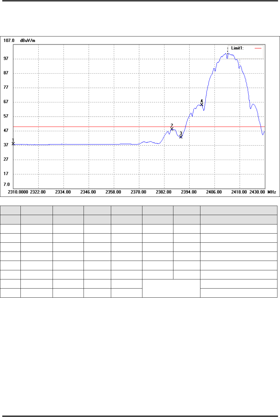
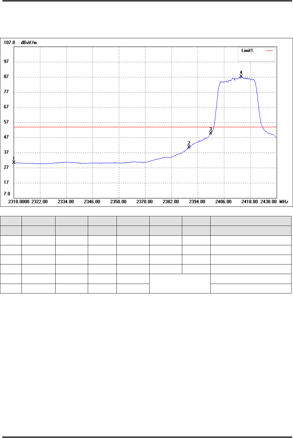
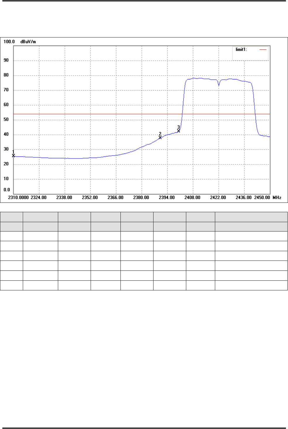
802.11b-Lowest Bandedge
Horizontal (Worst case)
No. Frequency Reading Correct Result Limit Margin Remark
(MHz) (dBuV/m) dB/m (dBuV/m) (dBuV/m) (dB)
1 2310.000 41.37 -3.76 37.61 50.00 -12.39 Average Detector
2310.000 47.50 -3.76 43.74 74.00 -30.26 Peak Detector
2 2385.720 51.46 -3.56 47.90 50.00 -2.10 Average Detector
2385.720 62.40 -3.56 58.84 74.00 -15.16 Peak Detector
3 2390.000 45.87 -3.55 42.32 50.00 -7.68 Average Detector
2390.000 57.26 -3.55 53.71 74.00 -20.29 Peak Detector
4 2400.000 68.29 -3.52 64.77 Delta=36.12dBc Average Detector
5 2412.840 104.37 -3.48 100.89 Average Detector
Intracom Asia Co., Ltd. Model: 525756
REPORT NO.: STR15048243I-1 PAGE 85 OF 95 FCC PART 15.247
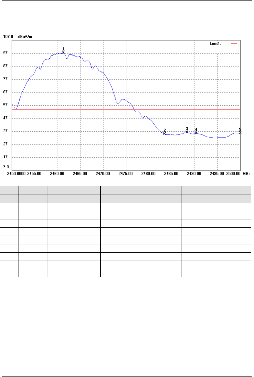
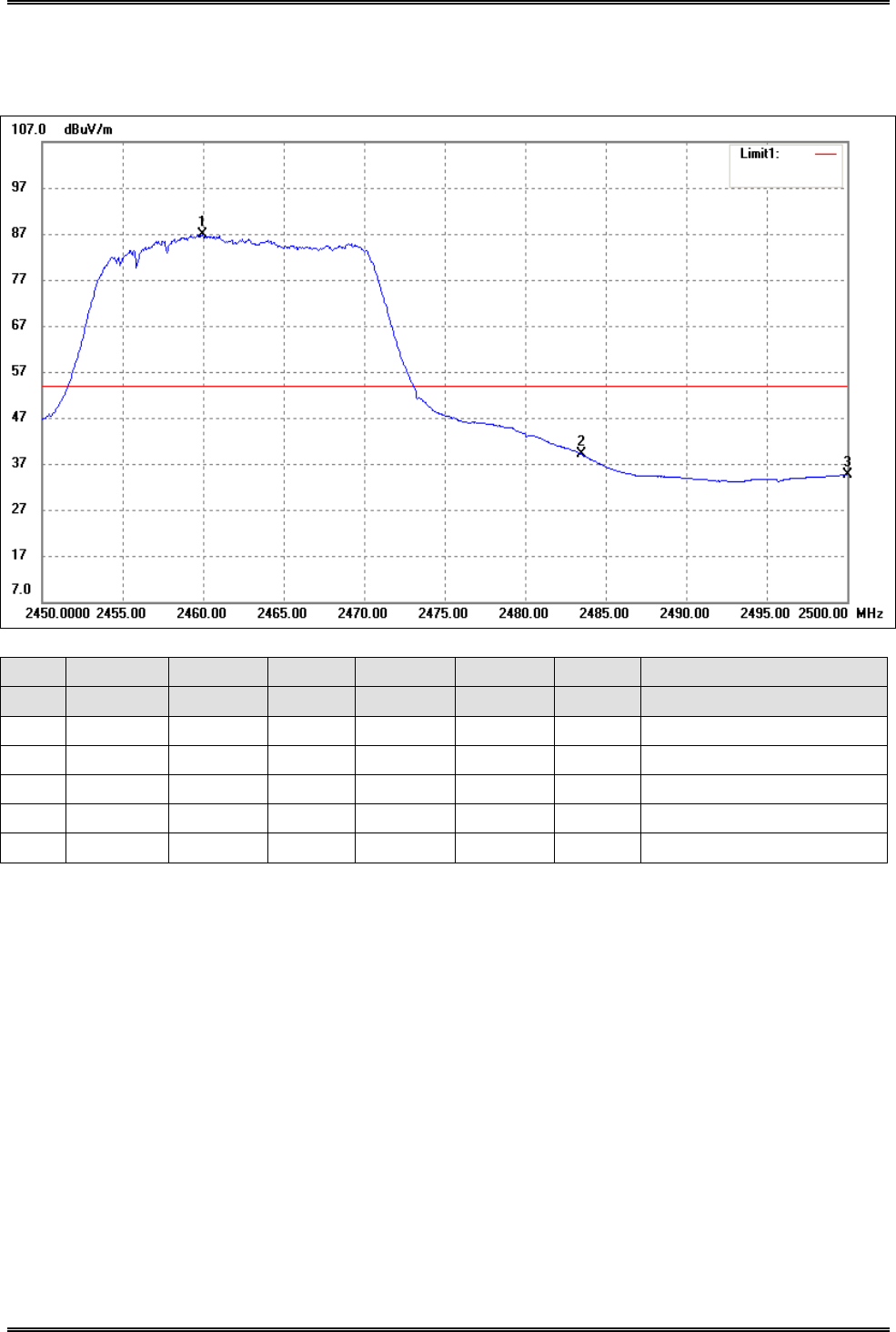
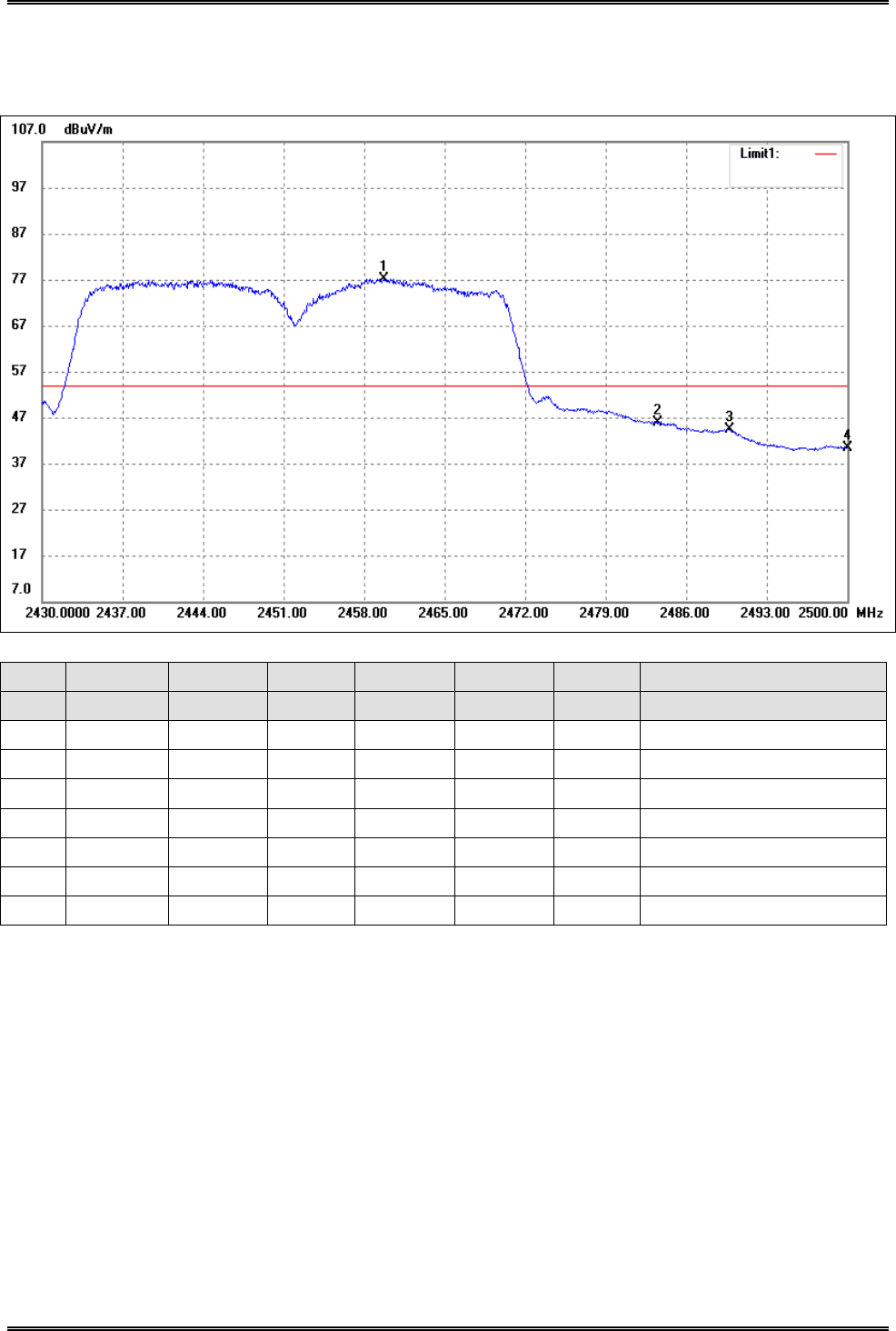
802.11b-Highest Bandedge
Horizontal (Worst case)
No. Frequency Reading Correct Result Limit Margin Remark
(MHz) (dBuV/m) dB/m (dBuV/m) (dBuV/m) (dB)
1 2461.300 100.75 -3.35 97.40 / / Average Detector
2 2483.500 38.23 -3.30 34.93 54.00 -19.07 Average Detector
2483.500 51.26 -3.30 47.96 74.00 -26.04 Peak Detector
3 2488.350 39.34 -3.29 36.05 54.00 -17.95 Average Detector
2488.350 51.78 -3.29 48.49 74.00 -25.51 Peak Detector
4 2490.350 38.75 -3.28 35.47 54.00 -18.53 Average Detector
2490.350 51.64 -3.28 48.36 74.00 -25.64 Peak Detector
5 2500.000 38.97 -3.25 35.72 54.00 -18.28 Average Detector
2500.000 51.08 -3.25 47.83 74.00 -26.17 Peak Detector
Intracom Asia Co., Ltd. Model: 525756
REPORT NO.: STR15048243I-1 PAGE 86 OF 95 FCC PART 15.247
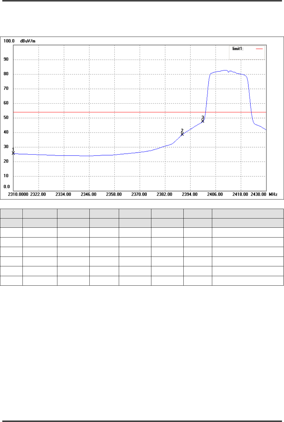
802.11g-Lowest Bandedge
Horizontal (Worst case)
No. Frequency Reading Correct Result Limit Margin Remark
(MHz) (dBuV/m) dB/m (dBuV/m) (dBuV/m) (dB)
1 2310.000 33.99 -3.76 30.23 54.00 -23.77 Average Detector
2310.000 45.91 -3.76 42.15 74.00 -31.85 Peak Detector
2 2390.000 43.88 -3.55 40.33 54.00 -13.67 Average Detector
2390.000 59.58 -3.55 56.03 74.00 -17.97 Peak Detector
3 2400.000 53.10 -3.52 49.58 Delta=37.55dBc Average Detector
4 2413.920 90.61 -3.48 87.13 Average Detector
Intracom Asia Co., Ltd. Model: 525756
REPORT NO.: STR15048243I-1 PAGE 87 OF 95 FCC PART 15.247
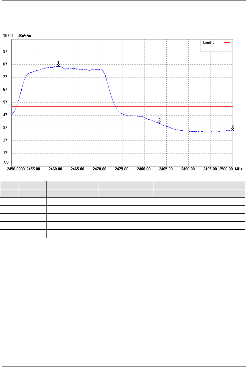
802.11g-Highest Bandedge
Horizontal (Worst case)
No. Frequency Reading Correct Result Limit Margin Remark
(MHz) (dBuV/m) dB/m (dBuV/m) (dBuV/m) (dB)
1 2459.950 90.19 -3.35 86.84 / / Average Detector
2 2483.500 42.40 -3.30 39.10 54.00 -14.90 Average Detector
2483.500 61.29 -3.30 57.99 74.00 -16.01 Peak Detector
3 2500.000 37.89 -3.25 34.64 54.00 -19.36 Average Detector
2500.000 50.66 -3.25 47.41 74.00 -26.59 Peak Detector
Intracom Asia Co., Ltd. Model: 525756
REPORT NO.: STR15048243I-1 PAGE 88 OF 95 FCC PART 15.247
802.11n-HT20-Lowest Bandedge
Horizontal (Worst case)
No. Frequency Reading Correct Result Limit Margin Remark
(MHz) (dBuV/m) dB/m (dBuV/m) (dBuV/m) (dB)
1 2310.000 29.11 -3.71 25.40 54.00 -28.60 Average Detector
2310.000 38.48 -3.71 34.77 74.00 -39.23 Peak Detector
2 2390.000 41.94 -3.54 38.40 54.00 -15.60 Average Detector
2390.000 54.59 -3.54 51.05 74.00 -22.95 Peak Detector
3 2400.000 50.87 -3.51 47.36 54.00 -6.64 Average Detector
2400.000 61.86 -3.51 58.35 74.00 -15.65 Peak Detector
Intracom Asia Co., Ltd. Model: 525756
REPORT NO.: STR15048243I-1 PAGE 89 OF 95 FCC PART 15.247
802.11n-HT20-Highest Bandedge
Horizontal (Worst case)
No. Frequency Reading Correct Result Limit Margin Remark
(MHz) (dBuV/m) dB/m (dBuV/m) (dBuV/m) (dB)
1 2460.600 89.03 -3.35 85.68 / / Average Detector
2 2483.500 43.65 -3.30 40.35 54.00 -13.65 Average Detector
2483.500 61.74 -3.30 58.44 74.00 -15.56 Peak Detector
3 2500.000 38.41 -3.25 35.16 54.00 -18.84 Average Detector
2500.000 52.80 -3.25 49.55 74.00 -24.45 Peak Detector
Intracom Asia Co., Ltd. Model: 525756
REPORT NO.: STR15048243I-1 PAGE 90 OF 95 FCC PART 15.247
802.11n-HT40-Lowest Bandedge
Horizontal (Worst case)
No. Frequency Reading Correct Result Limit Margin Remark
(MHz) (dBuV/m) dB/m (dBuV/m) (dBuV/m) (dB)
1 2310.000 29.03 -3.71 25.32 54.00 -28.68 Average Detector
2310.000 42.42 -3.71 38.71 74.00 -35.29 Peak Detector
2 2390.000 41.17 -3.54 37.63 54.00 -16.37 Average Detector
2390.000 58.01 -3.54 54.47 74.00 -19.53 Peak Detector
3 2400.000 45.53 -3.51 42.02 54.00 -11.98 Average Detector
2400.000 61.59 -3.51 58.08 74.00 -15.92 Peak Detector
Intracom Asia Co., Ltd. Model: 525756
REPORT NO.: STR15048243I-1 PAGE 91 OF 95 FCC PART 15.247
802.11n-HT40-Highest Bandedge
Horizontal (Worst case)
No. Frequency Reading Correct Result Limit Margin Remark
(MHz) (dBuV/m) dB/m (dBuV/m) (dBuV/m) (dB)
1 2459.750 80.56 -3.35 77.21 / / Average Detector
2 2483.500 49.23 -3.30 45.93 54.00 -8.07 Average Detector
2483.500 67.05 -3.30 63.75 74.00 -10.25 Peak Detector
3 2489.780 47.73 -3.28 44.45 54.00 -9.55 Average Detector
2489.780 65.71 -3.28 62.43 74.00 -11.57 Peak Detector
4 2500.000 43.74 -3.25 40.49 54.00 -13.51 Average Detector
2500.000 63.91 -3.25 60.66 74.00 -13.34 Peak Detector
Intracom Asia Co., Ltd. Model: 525756
REPORT NO.: STR15048243I-1 PAGE 92 OF 95 FCC PART 15.247
10. Conducted Emissions
10.1 Measurement Uncertainty
Base on NIS 81, The Treatment of Uncertainty in EMC Measurements, the best estimate of the uncertainty of any
conducted emissions measurement is + 2.88 dB.
10.2 Test Equipment List and Details
Description Manufacturer Model Serial Number Cal. Date Due. Date
EMI Test Receiver Rohde & Schwarz ESPI 101611
2014-05-28 2015-05-27
L.I.S.N Schwarz beck NSLK8126 8126-224 2014-05-28 2015-05-27
Pulse Limiter Rohde & Schwarz ESH3-Z2 100911 2014-05-28 2015-05-27
10.3 Test Procedure
The setup of EUT is according with per ANSI C63.4-2014 measurement procedure. The specification used was
with the FCC Part 15.207 Limit.
The external I/O cables were draped along the test table and formed a bundle 30 to 40 cm long in the middle.
The spacing between the peripherals was 10 cm.
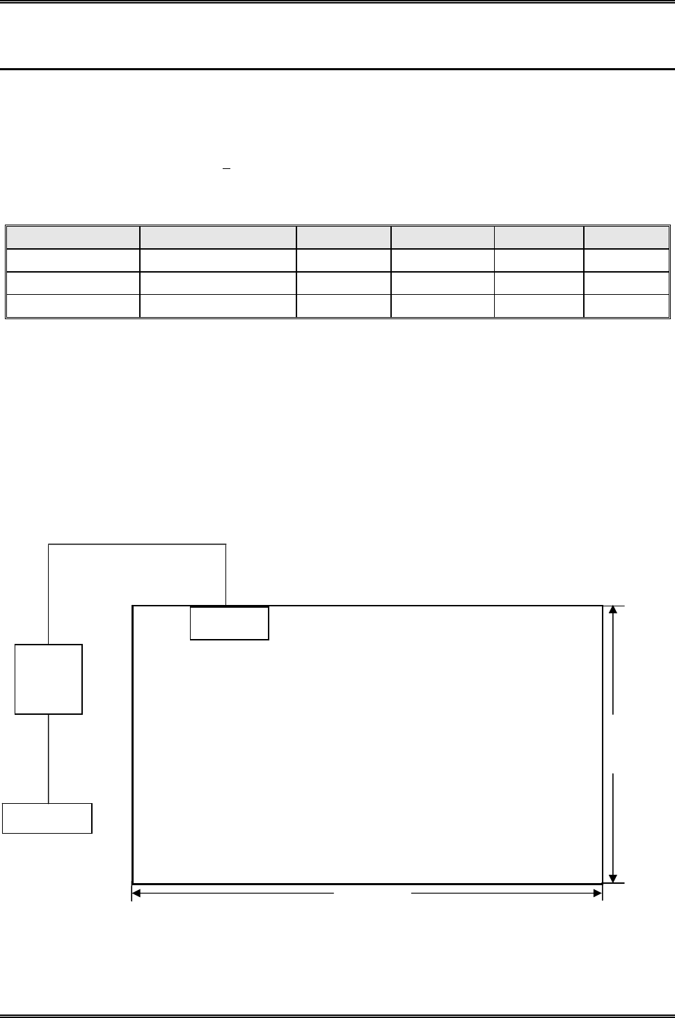
10.4 Basic Test Setup Block Diagram
To Receiver
1. 5 m
1.0 m
1.5
Non-conduction table
80 cm above Ground
Plane
EUT
LISN

Intracom Asia Co., Ltd. Model: 525756
REPORT NO.: STR15048243I-1 PAGE 93 OF 95 FCC PART 15.247
10.5 Environmental Conditions
Temperature: 25 °C
Relative Humidity: 52%
ATM Pressure: 1012 mbar
10.6 Test Receiver Setup
During the conducted emission test, the test receiver was set with the following configurations:
Start Frequency .......................................................................... 150 kHz
Stop Frequency........................................................................... 30 MHz
Sweep Speed .............................................................................. Auto
IF Bandwidth .............................................................................. 10 kHz
Quasi-Peak Adapter Bandwidth ................................................. 9 kHz
Quasi-Peak Adapter Mode ......................................................... Normal
10.7 Summary of Test Results/Plots
According to the data in section 9.8, the EUT complied with the FCC Part 15.207 Conducted margin for a Class B
device, with the worst margin reading of:
-10.58 dB at 0.4220 MHz in the Neutral mode, Peak detector, 0.15-30MHz
10.8 Conducted Emissions Test Data
Intracom Asia Co., Ltd. Model: 525756
REPORT NO.: STR15048243I-1 PAGE 94 OF 95 FCC PART 15.247
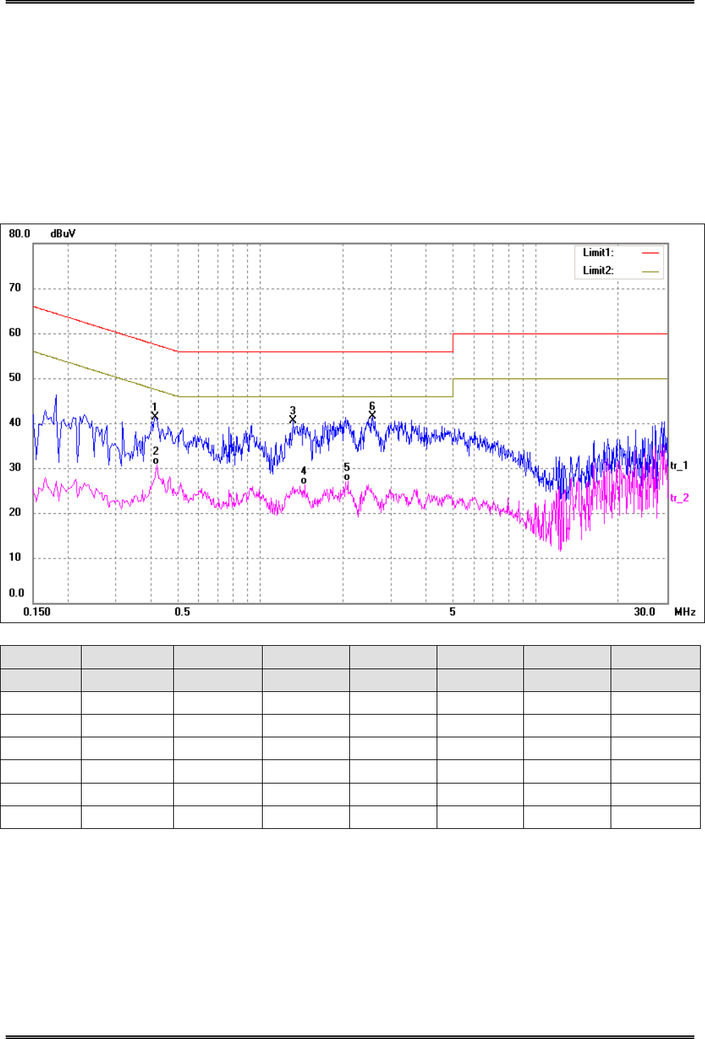
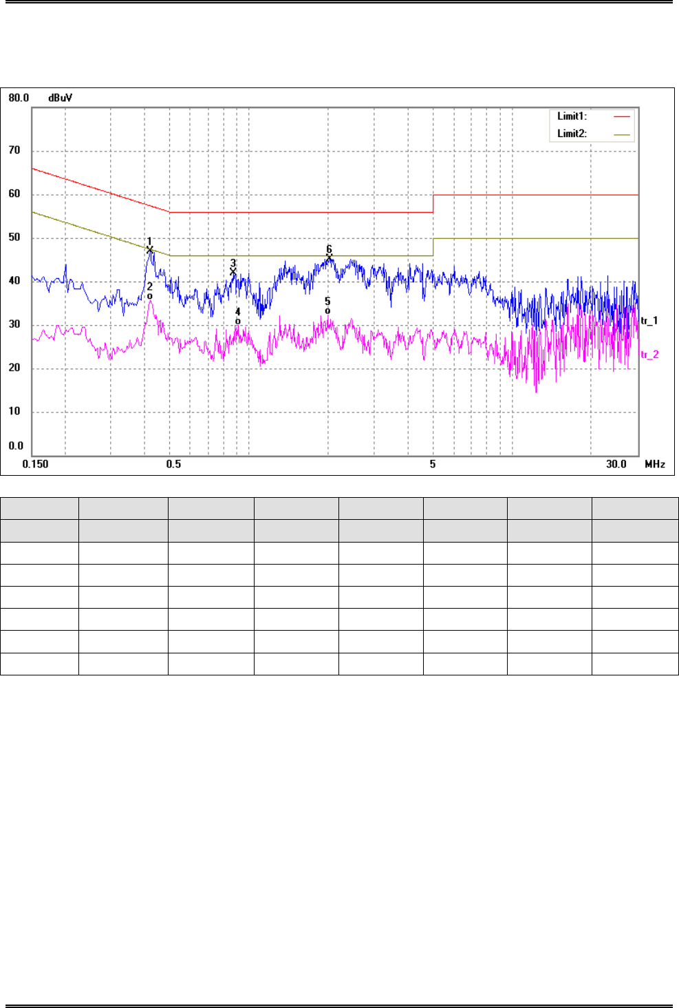
Plot of Conducted Emissions Test Data
EUT: Wireless 300N Range Extender
Tested Model: 525756
Operating Condition: Transmitting(Wi-Fi)
Comment: AC 120V/60Hz
Test Specification: Neutral
No. Frequency Reading Correct Result Limit Margin Detector
(MHz) (dBuV) (dB/m) (dBuV) (dBuV) (dB)
1 0.4180 31.83 9.50 41.33 57.49 -16.16 peak
2 0.4220 21.11 9.50 30.61 47.41 -16.80 AVG
3 1.3180 30.44 10.00 40.44 56.00 -15.56 peak
4 1.4500 16.21 10.00 26.21 46.00 -19.79 AVG
5 2.0860 17.02 10.00 27.02 46.00 -18.98 AVG
6* 2.5620 31.43 10.00 41.43 56.00 -14.57 peak
Intracom Asia Co., Ltd. Model: 525756
REPORT NO.: STR15048243I-1 PAGE 95 OF 95 FCC PART 15.247
Test Specification: Line
No. Frequency Reading Correct Result Limit Margin Detector
(MHz) (dBuV) (dB/m) (dBuV) (dBuV) (dB)
1* 0.4220 37.33 9.50 46.83 57.41 -10.58 peak
2 0.4220 26.23 9.50 35.73 47.41 -11.68 AVG
3 0.8740 32.13 9.87 42.00 56.00 -14.00 peak
4 0.9100 20.07 9.91 29.98 46.00 -16.02 AVG
5 1.9940 22.21 10.00 32.21 46.00 -13.79 AVG
6 2.0300 35.10 10.00 45.10 56.00 -10.90 peak
***** END OF REPORT *****
