Dishwasher Bulletin DW030 Fisher & Paykel Dish Drawer DD602
2012-10-25
: Pdf Fisher & Paykel Dishdrawer Dd602 Fisher & Paykel_DishDrawer_DD602 Fisher & Paykel
Open the PDF directly: View PDF ![]() .
.
Page Count: 5
Fisher & Paykel Appliances Ltd
78 Springs Road, East Tamaki, PO Box 58-732, Greenmount,
Auckland, New Zealand, Ph: 09 273 0600, Fax: 09 273 0656
Fisher & Paykel Customer Services Pty Ltd
A.C.N. 003 3335 171, 19 Enterprise Street, Cleveland, QLD 4163
PO Box 798, Cleveland, QLD 4163, Ph: 07 3826 9100, Fax: 07 3826 9164
Fisher & Paykel Appliances Inc
27 Hubble, Irvine, California, CA92618, USA,
Ph: 949 790 8900, Fax: 949 790 8911
Fisher & Paykel Appliances Ltd UK
Broxell Close, Wedgnock Industrial Estate, Warwick CV34 5QF,
Ph: 01926 626700, Fax: 01926 626701
DW030
April 2002
COPYRIGHT © FISHER & PAYKEL LTD 2002
DISHDRAWERS
DD602 Micro-switch Failure – NZ, AUS, SGP, UK, USA
We are seeing a large number of microswitch failures in the field. The main reason switches are failing is
because they were damaged during the product’s assembly. The slide pin has got under the microswitch
lever spring, probably as the slide was being fitted to the product. When the slide was then extended to fit
the tub, the lever spring is bent back and damaged. Everything still works the same as the slide pin still
activates the microswitch when the drawer is closed. However the life of the spring is reduced from
approximately 50,000 operations to approximately 1000 (depending on the extent of the damage.)
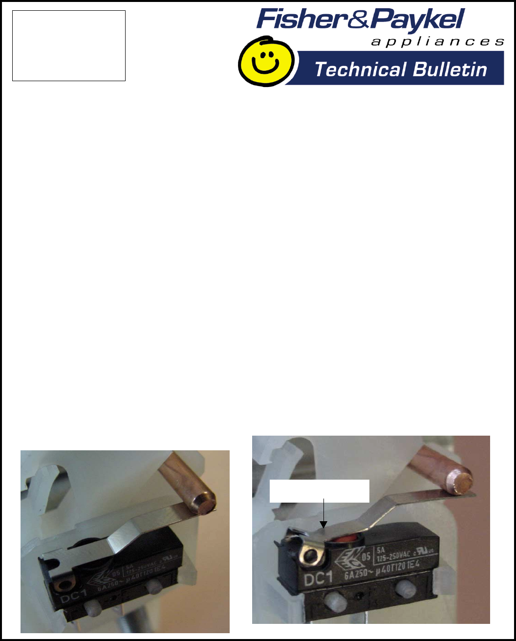
When replacing a broken microswitch, it is important to check that the slide pin cannot get under the
microswitch lever spring and damage the new part.
Also, for a double DishDrawer, it is essential to check the microswitch in the other drawer to ensure that it
hasn’t also been damaged. The picture on the left shows a good microswitch, the one on the right shows
a damaged microswitch.
To help us determine the failure mode in the field, please return all microswitches that are replaced in
New Zealand before the 30th June ‘02, including the lever spring pieces. Please include product details,
and if it is a repeat failure, advise whether it is the top or bottom tub.
Please send the failed components along with the requested details direct to: Peter Swale, Fisher &
Paykel Appliances Ltd, Dukes Road, Mosgiel, New Zealand. The warranty claim forms can be sent
through to the Warranty Claims Department in Auckland and processed in the normal way.
Distorted lever
IMPORTANT:
Please read this
bulletin and pass
on to others in your
organisation.
DW030
April 2002
COPYRIGHT © FISHER & PAYKEL LTD 2002
DD603 Tub Removal Tip
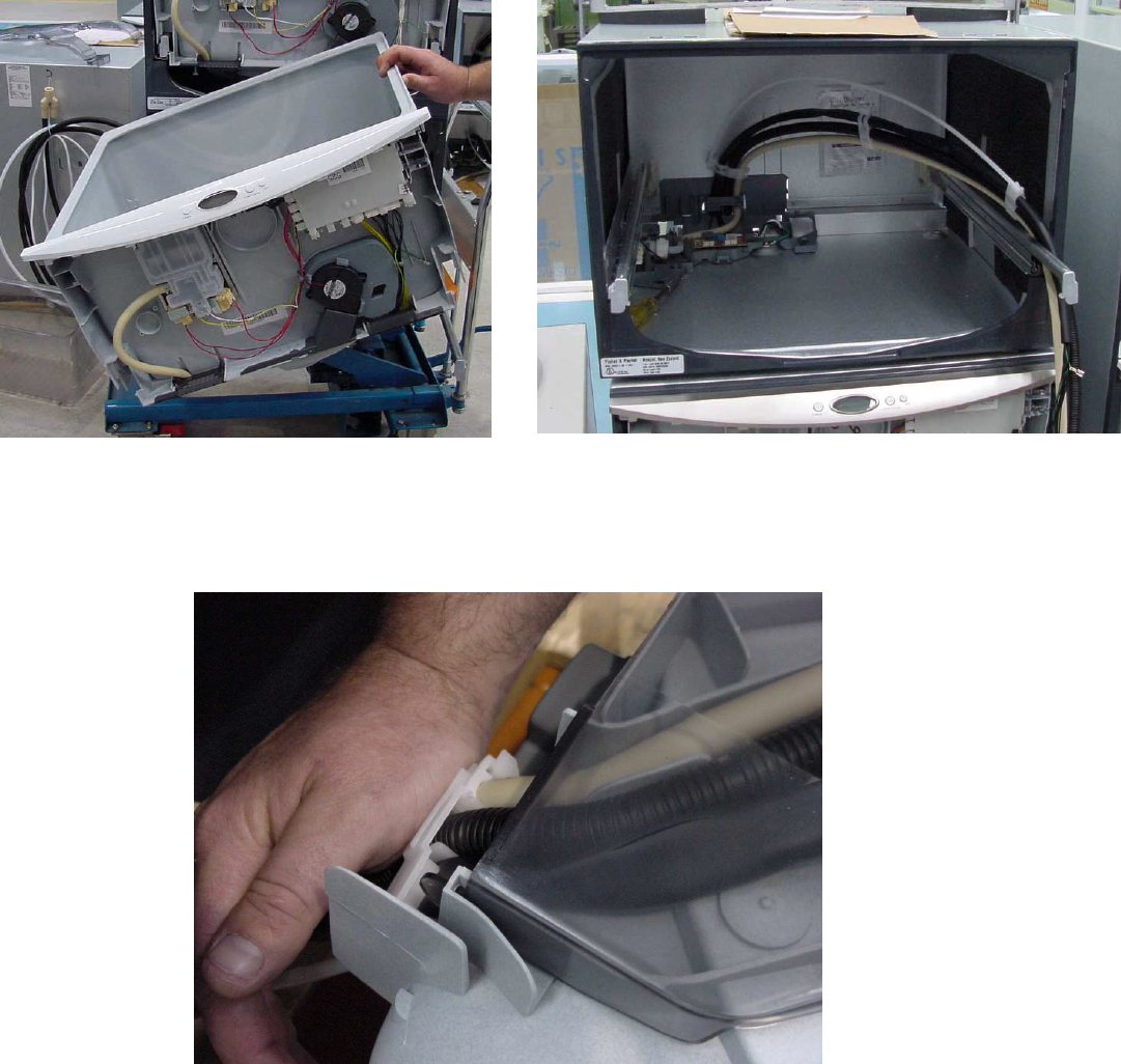
When a tub is lifted off the slides and turned upside down for servicing, e.g to replace a heater plate, it is
best to rotate it in an anti-clockwise direction. This is the opposite way to which it was assembled and will
help prevent the hoses from getting twisted inside the link support. Once upside down, the hoses and
wiring can be removed and placed over the right hand slide. These can then be reassembled to the tub
without the need to twist them awkwardly.
It is also a good idea to push the hoses and the link support down while re-fitting the wiring cover. This
ensures that the link support does not interfere with the tub when the drawer is closing. If the hoses have
become twisted in the link support, or if the link support is too close to the tub, this can cause drawer
closing problems. Either the drawer will not close fully or will close slowly over the last 35 mm. (1 ½
inches)
DW030
April 2002
COPYRIGHT © FISHER & PAYKEL LTD 2002
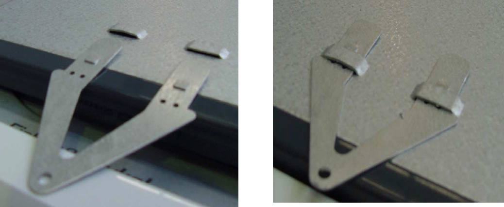
DD603 Chassis – Top Installation Tabs
The top installation tabs on double DishDrawers were changed to the new type (illustrated) on 20/02/02.
The tabs push into the slots in the chassis from the front. The clips on the tab lock it into place once
inserted.
DW030
April 2002
COPYRIGHT © FISHER & PAYKEL LTD 2002
DISHWASHERS
Moulded Tub Roller Assembly – Improved Design - NZ, AUS, SGP
When servicing a Dishwasher with a F1 fault code, first determine the cause of the leak. If you suspect
the leak has come from the tub roller assembly we advise that you remove the cabinet wrapper and
inspect the outside of the tub for any visible water stains or marks.
If it is clear the leak has come from the tub roller assembly check the tightness of the roller screws.
Please order and fit the new spare part kit, part number 521428, if there is any sign of stripping or
damage to the tub roller assembly or if there has been a repeat call for leaking tub rollers on the product
being serviced.
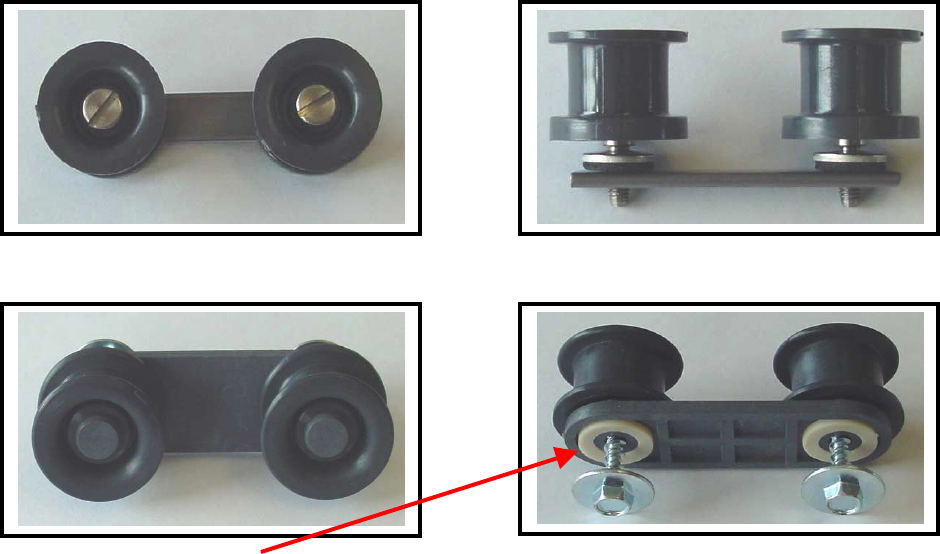
The old design of tub roller is shown below with the tapping plate and screws.
The new design of tub roller is shown below and is available in a spare part kit part number 521428.
Note: Please check the white seal is correctly fitted before installing the rollers in the product.
The new kit, part number 521428, includes:
4 Tub roller assemblies
8 Screws
Note: The older tapping plates and screws are no longer available for the old tub roller assembly, the old
part numbers have been superseded to the part number of the new kit. When ordering parts it is
important to only use the part number of the new kit. For example if you ordered a screw and tapping
plate from the old assembly you would be supplied with two of the new kits.
DW030
April 2002
COPYRIGHT © FISHER & PAYKEL LTD 2002
To fit the new design of tub roller, first remove the cabinet wrapper. This must be done because the
screws on the new assembly tap directly into the tub rollers from the outside of the tub. Tighten the
screws until they are firm. The large head on the new screws gives adequate support to clamp the rollers
to the tub. After fitting the new design of tub roller you will notice that the tapping plate is no longer
required.
Note: To compensate for the removal of the cabinet wrapper in order to fit the new tub rollers, the
standard time to replace or refit the tub rollers has been updated to 5 labour units.
