599089 DD603 Diagnostics Fisher & Paykel Dish Drawer And DS603
2012-10-25
: Pdf Fisher & Paykel Dishdrawer Dd603 And Ds603 Fisher & Paykel_DishDrawer_DD603 and DS603 Fisher & Paykel
Open the PDF directly: View PDF ![]() .
.
Page Count: 31
- DISHDRAWER®
- DD603 DS603
- DIMENSIONS & SPECIFICATIONS
- Product Size (mm)
- Specifications
- Water Inlet Valves24Volt DC
- 1202 Ohms @ 60oC (140oF)
- Motor80 Volt DC 3 Phase
- Drain4200 RPM
- Wash2300 – 2850 RPM
- Stator8 ± .5 Ohms per winding
- Inlet Hose1.7m (66 inches)
- 1000Kpa (145 PSI)
- Detergent Dispenser 24 Volt DC
- Rinse Aid Dispenser 24 Volt DC
- Heater Track60 ± 3 Ohms
- Power Supply Resistor 125 + 5 Ohms
- Heater Track26 ± 2.5 Ohms
- Power Supply Resistor 30 + 5 Ohms
- Heater Track20 ± 1.5 Ohms
- Power Supply Resistor 20 + 2 Ohms
- Diverter Valve Softener Assy24 Volt DC
- Brine Pump24 Volt DC
- OPTION ADJUSTMENT
- DIAGNOSTICS
- DIAGNOSTICS QUICK REFERENCE CHARTS
- WIRING DIAGRAM
- WIRING DIAGRAM
DISHDRAWER®
MODELS
DD603 DS603
599089
Fisher & Paykel Appliances © 2003 October 2003

2
DIMENSIONS & SPECIFICATIONS
Product Size (mm)
Height (double) 819 - 870mm
Height (single) 409mm
Width 595mm
Depth 570mm
Drawer Open (incl cabinet) 1080mm
Specifications
Electrical
NZ/AUS/UK/UE 230-240Volt AC 50Hz 10 amp max.
USA 110-120Volt AC 60Hz 12.5 amp max.
JAP 90-110Volt AC 50/60Hz 11.6 amp max.
Water Inlet Valves 24Volt DC
70 ± 5 Ohms
5 Lt/min (1.3 US gal/min)
Chassis P.C.B.
NZ/AUS/UK/UE 240 Volt AC
USA/JAP 120 Volt AC
Temperature Sensor 962 Ohms @ 20oC (68oF)
(On Heater Plate) 1000 Ohms @ 30oC (86oF)
1202 Ohms @ 60oC (140oF)
Drying Fan 3.4 K Ohms
Motor 80 Volt DC 3 Phase
Drain 4200 RPM
Wash 2300 – 2850 RPM
Stator 8 ± .5 Ohms per winding

3
Inlet Hose 1.7m (66 inches)
1000Kpa (145 PSI)
Drain Hose 2.0m (78 inches) from rear of cabinet
2.5m (98 inches) bottom tub
2.9m (114 inches) top tub
Detergent Dispenser 24 Volt DC
70 ± 5 Ohms
Rinse Aid Dispenser 24 Volt DC
70 ± 5 Ohms
Heater Plate (NZ/AUS/UK/UE) 240 Volt AC
Heater Track 60 ± 3 Ohms
Power Supply Resistor 125 + 5 Ohms
Heater Plate (USA) 120 Volt AC
Heater Track 26 ± 2.5 Ohms
Power Supply Resistor 30 + 5 Ohms
Heater Plate (JAP) 110 Volt AC
Heater Track 20 ± 1.5 Ohms
Power Supply Resistor 20 + 2 Ohms
Diverter Valve Softener Assy 24 Volt DC
70 + 5 Ohms
Brine Pump 24 Volt DC
70 + 5 Ohms

4
OPTION ADJUSTMENT
Changing Setup Options
To enter the option adjustment mode, press POWER to turn the LCD on, then
hold the ECO button and KEYLOCK button simultaneously for 5 seconds,
ensuring that ECO is pushed first. Once the option adjustment mode is
entered, a beep is emitted and the LCD displays the letters rA. Pushing the
START/PAUSE button scrolls through the options and allows changes as
follows:-
Rinse Aid Setup (rA).
Water Supply Hardness Setup (hd).
Auto Power Option (AP).
End of Cycle Beeps (EC).
Closed Drawer Option (Ld).
Clean/Dirty Dish Symbol (dS).
Dry Enhancement Option (LH).
Integrated:- On an integrated DishDrawer where there is no display, the
option chosen is indicated by the lights showing on the integrated badge as
follows:-
Rinse Aid Setup (red light above START/PAUSE button).
Water Supply Hardness (green light above START/PAUSE button).
Auto Power Option (orange light above START/PAUSE button).
End of Cycle Beeps (green light above START/PAUSE and red light above
Keylock) button).
Closed Drawer Option (red light above START/PAUSE and KEYLOCK
buttons).
Clean/Dirty Dish Symbol (not available on Integrated models).
Dry Enhancement Option (orange light above START/PAUSE button, ECO
light is red).
Push POWER at any time to exit this setup mode.
Integrated:- On an integrated DishDrawer when one of the options is
changed, it is indicated by the red wash cycle LEDs on the secondary control
panel. If an option is turned on, then all the LEDs turn on, and if an option is
turned off, all the LEDs turn off.
5
Rinse Aid Setup (rA)
The current rinse aid setting is shown using the red LED’s on the touch switch
panel.
The amount of rinse aid dispensed into a rinse cycle can be varied to suit the
level of hardness of the local water supply. It is adjusted for 1 - 5 dispenser
levels
(1 = approx 0.5mls (1/10) teaspoon of rinse aid, 5 = approx. 2.5mls (1½)
teaspoon of rinse aid).
Push KEYLOCK to advance the rinse aid setting. Once the desired setting is
achieved, push POWER to exit. The rinse aid index is stored in EE memory,
so even with the power removed, the rinse aid level is retained.
Water Supply Hardness Setup (hd) (Where Fitted)
The current supply hardness setting is shown using the red LED’s on the
touch switch panel. One of 5 settings should be selected according to the
known hardness of the supply water. Each setting is appropriate for the
following water supply hardness:
No LED Water Softener turned off, continuous bypass of softener
1 LED 150-250 ppm water supply hardness
2 LEDs 250-350 ppm water supply hardness
3 LEDs 350-450 ppm water supply hardness
4 LEDs 450-550 ppm water supply hardness
5 LEDs 550-625 ppm water supply hardness
Push KEYLOCK to advance the Water Softener setting. Once the desired
setting has been achieved push POWER to exit.
Selection of a setting affects how the Electronic Controller diverts supply
water, how much water is treated, and how much salt is used in regeneration,
in a manner that optimises the performance of the Water Softener.
Auto Power Option (AP)
The automatic power up sequence that occurs when the tub is opened can be
turned on or off using the KEYLOCK button. If the scrubbing brush is
showing on the LCD, then the auto power up sequence will occur when the
tub is opened. If the scrubbing brush is not showing, then the DishDrawer will
not automatically power up when the tub is opened (the customer will need to
push the power button each time they wish to use the DishDrawer). Push
POWER to exit when the desired setting has been selected.
6
End of Cycle Beeps (EC)
The six beeps that occur at the end of the cycle can be turned on or off using
the KEYLOCK button. If the scrubbing brush is showing on the LCD, then the
end of cycle beeps are activated. If the scrubbing brush is not showing, then
the end of cycle beeps are deactivated. Push POWER to exit when the
desired setting has been selected.
Closed Drawer Option (Ld)
The closed drawer option can be turned on or off using the KEYLOCK button.
If the scrubbing brush is showing on the LCD, then the closed drawer option
is selected and it will keep the DishDrawer locked at all times by bringing the
lid down. When this mode is selected the customer needs to push the
POWER button to lift the lid whenever they want to open the drawer. When
they close the drawer again, the lid comes down automatically after 30
seconds and locks the tub. If the scrubbing brush is not showing, then the
closed drawer option is deactivated. Push POWER to exit when the desired
setting has been selected.
Clean/Dirty Dish Symbol (dS)
(Not available on integrated models)
The clean/dirty dish symbol can be turned on or off using the KEYLOCK
button. If the scrubbing brush is showing on the LCD, then the clean/dirty dish
option is selected. This means that the end of cycle clean dishes symbol will
remain in the LCD display until the power button is pressed to clear it. If the
scrubbing brush is not showing, then the clean/dirty dish symbol will
disappear when the drawer is first opened at the end of a cycle (factory
setting). Push POWER to exit when the desired setting has been selected.
Dry Enhancement Option (LH)
(Available in prefinished products from Serial Number MEM741743,
manufactured after 21/5/03, software version 3.2.06. Estimated to be
available in integrated models from October 2003, software version
3.2.07.)
Dry enhancement option can be turned on or off using the KEYLOCK button.
If the scrubbing brush is showing on the LCD, then the dry enhancement
option is selected. This means the lid will stay down and the drying fan will
continue running for 4 hours after the wash program completes.
7
If the customer wishes to open or stop the DishDrawer during this 4 hour
period, they can do so by pushing the POWER or START/PAUSE button.
This will reset the feature until the end of the next wash program. Push
POWER to exit when the desired setting has been selected.

8
DIAGNOSTICS
DishDrawer Diagnostics
Dishwasher Diagnostics can only be entered in Power Off mode, ie. when
there is no display on the LCD or the badge LED’s are off. Diagnostics is
entered by holding the KEYLOCK and START/PAUSE buttons
simultaneously for 5 seconds. Ensure that KEYLOCK is pushed first.
There are currently four levels of diagnostics. To move to the next level push
POWER. To enter a level push START/PAUSE. Once a level has been
entered, pushing POWER will exit diagnostics completely. If no level is
entered, then the display will cycle through the four levels and exit after the
last. On entering diagnostic mode, the first level is the Display/Download
Mode.
Display/Download Mode
In this mode, all LED’s and LCD segments (except keylock) are illuminated.
Optical LED Download/Fault Display
An optical data download is available here to download all EE data to a PC or Palm PC
via the lower tub-home sensor light pipe. Hold the reader pen over the lower tub-home
sensor light pipe and press START/PAUSE to initiate the download. A short beep
indicates the start and finish of download.
The last two faults are displayed on the LCD (secondary control panel LEDs for
integrated models) during the optical download. The Current Fault code is displayed first
followed by the Previous Fault Code. To read the Fault Code on the secondary display,
refer to page 7 on Fault Codes.
Clearing Fault Logs
To clear the Current Fault, press the KEYLOCK button until a beep is
sounded. This action moves the Current Fault into the Previous Fault while
clearing the Current Fault. To Clear the Previous Fault press KEYLOCK
once more until the beep is sounded.
Warning: Once a fault has been cleared, it is permanently removed from
memory and cannot be recovered.
Press POWER to advance to the next level.
9
Hardware Output Diagnostic Test Mode
This level tests all the hardware outputs and inputs. The LCD display shows
“HO”.
Press POWER to skip hardware diagnostics and advance to the next level.
Press START/PAUSE to enter hardware diagnostics.
Once hardware diagnostics has been entered, the current hardware output
being tested is indicated by letters in the LCD display, and for integrated
models the LEDs on the touch switch panel using binary encoding, as shown
in the table on the next page.
Different combinations of outputs can be switched on or off together, but the
controller will prevent higher current drawing components such as the wash
pump and the lid motors being turned on together.
Press START/PAUSE to advance to the next hardware output.
Press KEYLOCK to turn the currently displayed output on or off. If the
scrubbing brush symbol (green LED above start/pause button on integrated
models) is displayed, then that output has been switched on, and if it is not
displayed then that output is off.
Press POWER to Exit at any time (all outputs will be switched off on exit).
10
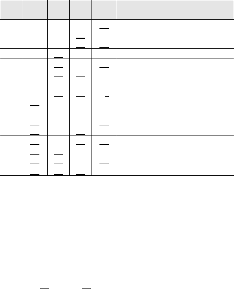
As mentioned on the previous page, the LCD display and touch switch panel
LEDs are illuminated to correspond to a particular hardware device. The
following table details the display order of the test.
LCD
Norm
LED
Fast
LED
Deli
LED
Rinse
LED
Hardware Output
bL Off Off Off On Backlight
Er Off Off On Off Element Relay
Ld Off Off On On Lid Motors (will run for 10 seconds)
dd Off On Off Off Detergent Diverter Valve
FU Off On Off On Fill Water Valve
P1 Off On On Off Motor Wash direction (2300-2850
rpm)
P2 Off On On On Motor Drain direction (4200 rpm)
rd On Off Off Off Rinse Aid Dispenser (dispenses
current setting)
dF On Off Off On Drying fan
LE On Off On Off Rinse Aid LED
C1 On Off On On Water Softener Diverter Valve
C2 On On Off Off Water Softener Brine Pump
°COn On Off On Displays current water temperature.
°EOn On On Off Displays controller rail voltage
(C3 is used in the Factory to empty the Water Softener before the Product is
packed.)
WARNING: In diagnostic mode there is no component protection. Therefore
take care when running individual components not to overload them. It is
advisable to avoid turning the element on without filling the tub with water first.
NB : No fault codes will come up while in diagnostics mode.
Tub Home Sensor Test: At any time during HO test mode, the Keylock
symbol on the LCD display (Keylock LED on integrated badge) indicates the
tub position. On = Closed, Off = Open.
11
Fast Test Cycle
This level runs a 5 minute fast test cycle.
Press POWER to skip Fast Test Cycle and advance to the next level.
Press START/PAUSE to enter Fast Test cycle.
Once Fast Test Cycle is selected the DishDrawer goes into standby mode
and 5 minutes will be showing on the display. The test cycle is started by
pushing START/PAUSE and the following components are run during the 5
minute cycle that follows:- Lid motors, fill valve, wash motor, element, drain
motor.
Press POWER to Exit at any time.
Continuous Cycle Test Mode
In this level the DishDrawer can be run continuously in any wash cycle. Once
the cycle has finished, the DishDrawer automatically restarts the same wash
cycle.
Press POWER to skip Continuous Cycle. As this is the last level, doing this
will exit diagnostics.
Press START/PAUSE to enter Continuous Cycle.
Once selected, the LCD backlight flashes on and off to indicate the
DishDrawer is in continuous cycle and the cycle starts straight away (for
integrated models the LED above the start/pause button will be orange
instead of green to indicate the DishDrawer is running in continuous cycle). It
will run the last cycle that had been selected prior to going into diagnostics
mode.
If it is desired to run a different cycle, exit diagnostics, turn the DishDrawer on
as normal and select the cycle required. Then turn the DishDrawer off again,
re-enter diagnostics and restart the Continuous Cycle as above.
Press POWER to Exit at any time.
12
Cycle Count Retrieval
(not available on integrated models)
To display the cycle count on the LCD screen, pause the DishDrawer while
running a Continuous Cycle. The two bytes of the cycle count will be
displayed alternately, in syncronisation with the changing backlight.
The Low byte is displayed when the backlight is off.
The High byte is displayed when the backlight is on.
To calculate the Total DishDrawer cycle count use the formula below.
Cycle_Count = (200 x High_byte) + Low_byte.
Eg. Low_byte = 156
High_byte = 2
Cycle_count = (200 x 2) + 156 = 556.
Temperature & Voltage Display Mode
(Not available on integrated models)
During a wash cycle, the current water temperature or the power supply rail
voltage of the controller can be displayed on the LCD instead of the time
remaining. To enter temperature/voltage display mode, start a wash cycle as
normal. Initiate a keylock by pushing and holding the KEYLOCK button for 4
seconds
Once in keylock mode, push and hold START/PAUSE for 8 seconds to enter
temperature display mode. The display now alternates between a °C symbol
and the water temperature. Pressing the START/PAUSE again changes the
display to alternate between an °E symbol and the power supply rail voltage
of the controller.
To cancel temperature/voltage display mode, press the POWER button.
Show Off/Showroom Wash Mode
This mode initiates a shop show off display and wash operation
demonstration.
With the DishDrawer powered up and turned on, the show off mode is entered
by holding the ECO and POWER buttons simultaneously for 5 seconds.
Ensure that ECO is pushed first.

13
The DishDrawer is now in the Show Off mode and cycles through all of the
LED & LCD segments while pulsing the LCD backlight on and off.
Pressing the POWER button now puts the DishDrawer into the Showroom
Wash mode. Before running this mode the tub should be filled with water until
it is just touching the underside of the spray arm. The Showroom Wash is
started by pushing the START/PAUSE button whereby the following cycle is
run:-
The lid is pulled down.
The wash motor starts and runs for 4 minutes.
The wash motor stops.
The lid is lifted.
The display counts down to zero throughout this cycle.
The DishDrawer turns off at the end of this cycle.
The DishDrawer is still in the Showroom wash mode however, and it can be
re-run by pushing POWER and then START/PAUSE. Once Show
Off/Showroom Wash mode has been initiated, the mains power must be
removed to exit out.

14
DIAGNOSTICS QUICK REFERENCE CHARTS
Fault Display/Download Mode
Press and hold KEYLOCK, then START/PAUSE for 5 seconds.
All LEDs & LCD segments except Keylock are illuminated.
Press START/PAUSE.
This initiates Pen upload via lower tub-home light pipe. At the same time
the current and then the previous fault code will be displayed in the LCD
screen and on the secondary control panel LEDs. To read the fault code
on the secondary display, refer to page 7 on Fault Codes.
Press KEYLOCK.
This will clear current fault code. Note: if Keylock is pressed again, the
previous fault code will be cleared.
Press POWER to exit.
15
Hardware Output Test Mode
Press and hold KEYLOCK, then START/PAUSE for 5 seconds.
All LEDs & LCD segments except Keylock are illuminated.
Press POWER once.
“HO” will show in the display (integrated: Heavy, Normal, Fast, Delicate,
Rinse LEDs showing)
Press START/PAUSE.
Scroll through the following outputs using Start/Pause. Turn the outputs on
& off using Keylock button.
Press POWER to exit.
Note: Scrubbing Brush = output on, No Scrubbing Brush = output off (on
integrated models a green LED above the start/pause button is used in
place of the scrubbing brush).
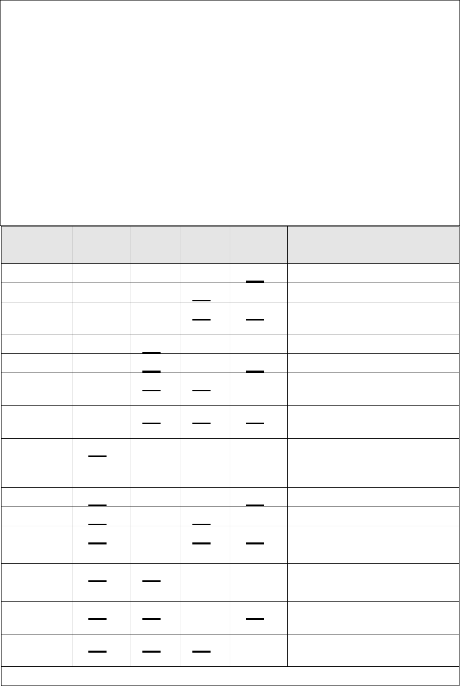
LCD Norm Fast Deli Rinse Hardware Output
Display LED LED LED LED
bL Off Off Off On Backlight
Er Off Off On Off Element Relay
Ld Off Off On On Lid Motors (will run for 10
seconds)
dd Off On Off Off Detergent Diverter Valve
FU Off On Off On Fill Water Valve
P1 Off On On Off Motor Wash direction
(2300-2850 rpm)
P2 Off On On On Motor Drain direction
(4200 rpm)
rd On Off Off Off Rinse Aid Dispenser
(dispenses current
setting)
dF On Off Off On Drying fan
LE On Off On Off Rinse Aid LED
C1 On Off On On Water Softener Diverter
Valve
C2 On On Off Off Water Softener Brine
Pump
°COn On Off On Displays current water
temperature.
°EOn On On Off Displays controller rail
voltage
Tub Home Sensor test:- Keylock symbol on = tub closed, off = tub open

16
Fast Test Cycle
Press and hold KEYLOCK, then START/PAUSE for 5 seconds.
All LEDs & LCD segments except Keylock are illuminated.
Press POWER twice.
“FC” will show in the display (integrated: Heavy, Normal, Delicate, Rinse
LEDs showing).
Press START/PAUSE twice.
The 5 minute fast test cycle will start.
Press POWER to exit.
Continuous Cycle
Press and hold KEYLOCK, then START/PAUSE for 5 seconds.
All LEDs & LCD segments except Keylock are illuminated.
Press POWER three times.
“CC” will show in the display (integrated: Heavy, Normal, Rinse LEDs
showing).
Press START/PAUSE.
The last cycle that had been selected prior to going into diagnostics mode
will be run continuously.
Press POWER to exit.
Temperature & Voltage Display Mode
(Not available on integrated models)
Start a wash cycle running.
Press & hold KEYLOCK for 4 seconds.
Keylock will be activated.
Press & hold START/PAUSE for 8 seconds.
LCD will now alternate between °C symbol & the water temperature.
Press START/PAUSE.
LCD will now alternate between °E symbol & the controllers rail voltage.
Press & hold KEYLOCK for 4 seconds.
Keylock is deactivated.
Press POWER to exit.
17
Fault Codes
The faults are displayed in the LCD as one of 5 F (fatal) faults or 1 U (user)
fault along with the symbol of a spanner. A fatal fault will usually require the
assistance of a qualified service person, while a U1 user fault indicates the
machine had failed to prime within a certain length of time usually because
the tap has not been turned on. For this reason at the same time a U1 comes
up in the display we also show the symbol of a tap. In the Integrated models,
an LCD is not available, and the presence of a fault is indicated by a Red
centre LED, with the fault number indicated on the touch switch panel with
Red LEDs.
Once a fault is repaired it can be cleared by pressing the POWER button. If
the fault is still present then it will not clear.
A fatal or user fault is accompanied by a continuous pulsating beep, which
can be turned off by pressing either the POWER, START/PAUSE, or KEY
LOCK button.
The last two faults are logged into EE memory.
The other U (user) faults have been removed. The old U2 fault, which was
the tub forced open during a cycle, has been removed completely. Instead, if
the tub is forced open, the product simply pauses as if someone had pressed
the start/pause button. The old U3 fault, which indicated a failure to drain, i.e.
water left in the tub, will not show up a fault and the DishDrawer will continue
through the cycle.

18
Fault Code Description Chart
The following chart is a quick reference guide on fault codes. To read a fault
code off an integrated model, refer to the LED Display column on the chart
below. The LED that has activated on the secondary display indicates which
fault code has occurred.
Fault
Code
LED
Display
Fault Possible Causes
F1 Rinse LED The flood
switch has
been activated
for more than
six seconds
· Inlet hose to inlet valve
connection loose
· Inlet valve body leak
· Damage to the fill or drain
hoses
· Heater plate damage
(chipped enamel)
· Seals/O Rings (pinched,
contaminated or poor join)
· Dispenser (seal, diverter
valve or weld leak)
· Lid area (lid motors not
functioning correctly, lid off
yoke, yoke jammed or broken,
or foreign object interfering
with lid seal)
F2 Delicate
LED
The motor has
not been
sensed
rotating
· Foreign object has jammed
the rotor
· The rotor has failed
· The hall sensor has failed
· The electronic controller has
failed
F3 Delicate
and Rinse
LED
The water
temperature
has been
sensed at
greater than
85°C (185°F)
· The incoming water is greater
than 85°C (185°F)
· The element has failed closed
circuit
· The temperature sensor has
failed
· The electronic controller has
failed

19
Fault
Code
LED
Display
Fault Possible Causes
F4 Fast LED No
temperature
increase has
been sensed
for 2 hours
while the
element is on
· The element is not connected
· The element has failed open
circuit
· The temperature sensor has
failed
· The electronic controller has
failed
F9 Normal and
Rinse LED
Electronics
Failure
· The electronic controller has
failed
U1 Heavy and
Rinse LED
Machine has
failed to prime
with water
within approx.
3 minutes
· The water supply is not turned
on
· The machine is syphoning
· The spray arm is not in place
· Excessive foaming
· The inlet valve has failed
· The electronic controller has
failed
· Rotor not fitted correctly

20
Fault Code Problem Solving Charts
The following charts can be used as a guide to help locate faults in a
DishDrawer. Answer each question with a yes or no and follow the
instructions inside the relevant box.
F1 The flood switch has been activated for more than 6 seconds
Question Yes No
1 Is there a F1 on both
displays?
Go to Question 2 If power fails to the
bottom tub it will cause
the top tub to go F1.
Test heater plate.
2 Has a flood occurred?
(N.B. The flood may
have dried up)
Go to Question 3 Go to Question 13
3 Is the lid sealing on the
tub correctly?
Go to Question 5 Go to Question 4
4 Are the lid actuators
functioning correctly?
Go to Question 5 Check the lid actuators
are assembled correctly
on the slides and yokes.
Check the plugs on the
RFI board and the
terminals on the lid
motors. If the lid
actuators look slow
replace them.
5 Is the water level in the
tub high?
Go to Question 6 Go to Question 8
6 Is the water inlet valve
leaking?
Replace inlet
valve
Go to Question 7
7 Is the DishDrawer
priming correctly?
Go to Question
12
Go to Question 8
8 Is the spray arm split? Replace spray
arm
Go to Question 9

21
9 Is the spray arm
running freely?
Go to Question
10
Check the rotor is
running freely, clear of
foreign objects and fitted
correctly. Make sure
the wash impeller is not
slipping off the rotor
shaft
10 Is water leaking from a
split inlet or drain
hose?
Replace split inlet
or drain hose
Go to Question 11
11 Is water leaking around
the heater plate ‘O’
rings?
Replace or refit
‘O’ rings
Go to Question 12
12 Is the drain hose
blocked?
Clear drain hose
of blockage
Go to Question 13
13 Is there condensation
or foreign matter
around the flood switch
PCB?
Clear flood
sensor of
condensation or
foreign matter
Go to Question 14
14 After clearing water
does the F1 fault code
still activate?
Replace Chassis
RFI board
Go to Question 15
15 Refer to Bulletin
DW028
F2 The motor is not sensed to be rotating
Question Yes No
1 Is the rotor jammed? Free jammed
rotor, check for
foreign object
damage to rotor
and rotor
housing.
Go to Question 2
2 Does the stator wiring
from the controller test
okay?
Go to Question 3 Replace wiring harness or
repair faulty connections.
3 Do the stator windings
show the correct
resistance?
Go to Question 4 Repair or replace stator
as required

22
4 Is the rotor position
sensor clipped into the
stator housing
correctly? Is the
sensor plugged into the
controller with a good
connection?
Go to Question 5 Clip rotor position sensor
into stator housing or
repair wiring connection
at electronic controller.
5 Rotor position sensor
fault?
Replace rotor
position sensor
Go to Question 1
F3 Water temperature sensed at greater than 85°C ( 185°F)
Question Yes No
1 Is the incoming water
temperature greater than
85°C (185°F)
Adjust the incoming
water temperature.
Go to Question 2
2 Is the element on all the
time?
Replace the electronic
controller
Go to Question 3
3 Are the wiring and
connections from the
controller to the element
all okay?
Go to Question 4 Repair or replace
wiring harness or
wiring
connections
4 Are there any signs of
moisture around the
temperature sensor?
Locate and repair
source of leak
Go to Question 5
5 Is the resistance of the
temperature sensor
correct?
Go to Question 6 Replace heater
plate assembly
6 Does the machine fault
again if run through a test
cycle?
Go to Question 1 No fault found

23
F4 No temperature increase has been sensed while the element is
turned on
Question Yes No
1 Does the element heat in
diagnostics?
Go to Question 7 Go to Question 2
2 Test the resistance of the
heater element using the
connection on the
controller, is it correct?
Go to Question 3 Go to Question 5
3 Is the connection on the
controller okay?
Go to Question 4 Replace or repair
connection
4 Electronic controller
failure?
Replace electronic
controller
Go to Question 1
5 Are the wiring and
connections from the
controller to the element
all okay?
Go to Question 6 Repair or replace
wiring harness or
wiring
connections
6 Is the resistance of the
heater element correct?
Go to Question 7 Replace heater
plate
7 Is the resistance of the
temperature sensor
correct?
Replace electronic
controller
Go to Question 8
8 Are the wiring and
connections down to the
temperature sensor okay?
Go to Question 9 Replace or repair
wiring harness or
wiring
connections
9 Heater element failure? Replace heater plate Go to Question 1
F9 Electronics failure (EEPROM access error)
Question Yes No
1 If the DishDrawer is
isolated from the power
supply for 10 seconds,
does the fault clear?
No fault found Go to Question 2
2 Electronic controller
failure?
Replace electronic
controller
Go to Question 1

24
U1 DishDrawer failed to prime with water within approx. 3 minutes
Question Yes No
1 Is the tap turned on? Go to Question 2 Turn the tap on
2 Is the spray arm in place?
(spray arm may have
been refitted since U1
fault occurred)
Go to Question 3 Refit spray arm
3 Activate the water inlet
valve in diagnostics. Does
any water enter the
machine?
Go to Question 4 Go to Question 7
4 Is the impeller on the rotor
slipping?
Replace the rotor Go to Question 5
5 Is the supply water
pressure above 30Kpa
(4.3p.s.i)?
Go to Question 6 The DishDrawer
requires a
minimum water
pressure
installation of
30Kpa (4.3p.s.i)
6 Are the inlet water hoses
and valves free of any
blockages or
obstructions?
Go to Question 10 Clear the water
valves or hoses
of blockage or
obstruction
7 Is the resistance of the
water inlet valve
measured at the plug on
the controller correct?
Go to Question 8 Go to Question 9
8 Is there 24V DC coming
from the controller during
the water inlet valve test?
Go to Question 6 Replace the
electronic
controller
9 Are the wiring and edge
connections down to the
water inlet valve okay?
Go to Question 10 Replace or repair
wiring harness or
wiring
connections
10 Water inlet valve failure? Replace water inlet
valve
Go to Question
11
11 Is the Rotor fitted
correctly?
Go to Question 1 Refit Rotor

25
Poor Dry Performance
Poor Dry Performance
Question Yes No
1 Is the customer
complaining of plastic
items not drying?
Advise customer
that due to plastics
having a low
thermal mass these
items give inherently
bad drying
performance
Go to Question 2
2 Is the customer using
rinse aid?
Go to Question 3 Advise customer that
the use of rinse aid will
improve dry
performance
3 Is the customer using
Fast or Eco cycles
Advise customer
that due to lower
final rinse
temperatures dry
performance is
comprised when
using Fast and Eco
cycles (there is less
residual heat for
drying at the end of
cycle)
Go to Question 4
4 Is the rinse aid setting
high enough for the
water hardness in the
area?
Go to Question 5 Turn the rinse aid up to
a higher setting
5 Using diagnostics test
the dispenser. Is it
dispensing the correct
amount of rinse aid?
Go to Question 1 Replace dispenser

26
Poor Wash Performance
Customers Complaint Food Particles left on Dishes
Cause of
problem (1)
Spray arm has stopped rotating.
How to resolve
the problem
a) One of the dishes / cutlery / utensils has fallen
through the basket and jammed the spray arm,
remove the obstruction.
b) Filter plate, drain filter, or drain filter access panel is
not installed correctly and is causing the spray arm
to jam.
Cause of
problem (2)
The product is being over loaded or incorrectly loaded
with dishes.
How to resolve
the problem
Advise customer of correct loading.
Cause of
problem (3)
Customer is selecting the wrong wash cycle for the soil
level on the dishes.
How to resolve
the problem
Advise customer about reduced water temperatures
(up to 20ºC / 70°F lower) and wash times when using
Fast and Eco cycles.
Customers Complaint Coffee/Tea Stains left in Cups
Cause of
problem (1)
Not enough detergent being used. To remove these
stains requires a stronger concentration of detergent in
the water.
More detergent is also required in hard water areas as
minerals in the hard water reduce the effectiveness of
the detergent.
How to resolve
the problem
Fill the main-wash detergent cup to the top & for best
results also fill the pre-wash detergent cup. Run on
normal or heavy cycles not Eco.
Cause of
problem (2)
The product is being over loaded which is preventing
water reaching the cups on the upper cup racks.
How to resolve
the problem
Advise customer of correct loading.

27
Customers Complaint Dishes have blotchy marks on them that look
like water stain marks not food
Cause of
problem
Not enough rinse aid being used. The water is not soft
enough during the final rinse and therefore hard water
droplets containing impurities are drying on the dishes
instead of running off during the dry cycle.
How to resolve
the problem
Confirm that the customer is using rinse aid.
The rinse aid may need to be turned up to a higher
setting (4 or 5 lights) and for optimum dry performance
run the DishDrawer on normal or heavy cycles not Eco.
Check that the rinse aid dispenser is dispensing
correctly in diagnostics.
Customers Complaint Glasses & Cutlery have a Cloudy White film on
them and/or Plates have a White Chalky film on them
Cause of
problem
Hard water & not enough detergent being used.
Minerals from the water are building up on the dishes
or the Water Softener is not set to the correct Water
Hardness Level or is faulty.
How to resolve
the problem
Once this film forms on the dishes it cannot be
removed by normal running in the dishwasher. The
dishes will need to be cleaned by soaking them in an
acidic solution such as white vinegar and water.
Where a Water Softener is not fitted;
To prevent the build up re-occurring the customer will
need to fill both the main-wash & pre-wash detergent
cups to the top with a power detergent and we would
recommend running on normal cycles.
In problem areas with very hard water the customer
may need to use a detergent additive designed for use
in hard water areas or fit a water softener to the
incoming water supply.

28
Where a Water Softener is fitted;
Set the Water Softener for the correct local Water
Supply hardness. Check that the Water Softener is
functioning correctly in Diagnostics;
C1 Water Softener Diverter Valve
In hardware output Diagnostics Test Mode
FU – turn the Fill Water Valve on
P2 – turn the Motor Drain on
C1 – Water Softener Diverter Valve
On – water bypasses the resin tank
Off – water flows through the resin tank
C2 Water Softener Brine Pump
Turn the Brine Pump on in Diagnostics mode.
Observe a small quantity of water (approx. 30 ml per
min.) flowing out the bottom of the dispenser. (Drop
the Dispenser Door down to observe this.) Observe a
change in the water level (approximately 120ml per 4
min.) in the Salt Reservoir. The Reservoir should
pump dry of water in this time.
Note:- Fill the Salt Reservoir with Salt (and then water
if not already) before performing this test.
Pipe Interrupter (Air Break) Function
A critical component in the performance of the Water
Softener is the pipe Interrupter (PI). There is a certain
amount of spray leakage from the PI which is used to
provide water to the Salt Reservoir.
If the spray is inadequate, there will be insufficient
water in the Salt Reservoir to make Brine.
If there is too much spray then the excess bypasses
the Water Softener and defeats the softening process
by pouring untreated water into the Tub.
To check that the amount spray leakage is
appropriate:-

29
Fill the Salt Reservoir with water.
In diagnostics mode, Turn on the Fill Water Valve, and
the Motor Drain. Water will flow out of the Dispenser
into the Tub, as well as out of the Water Softener
Overflow into the Tub.
Observe the flow from the Water Softener Overflow
(beside the Dispenser). There should be a trickle (25-
100 ml per minute). With experience you can guess
what is appropriate. If the trickle is outside these rates,
replace the softener as the PI is faulty.
To check that there is water in the Salt Reservoir,
remove the Drawer front and observe the level of water
in the tank. (A quick way to check that there is water in
the Salt Reservoir is to remove the Salt Bung and test
the water level by placing your finger down through the
opening.)
Detergent or Rinse Aid in the Water Softener
If detergent or rinse aid is poured in to the Salt
Reservoir it will destroy the Water Softener. This could
also happen if the Salt Bung is left off or falls out.
Evidence of this could be white streaks through the
Resin.
30
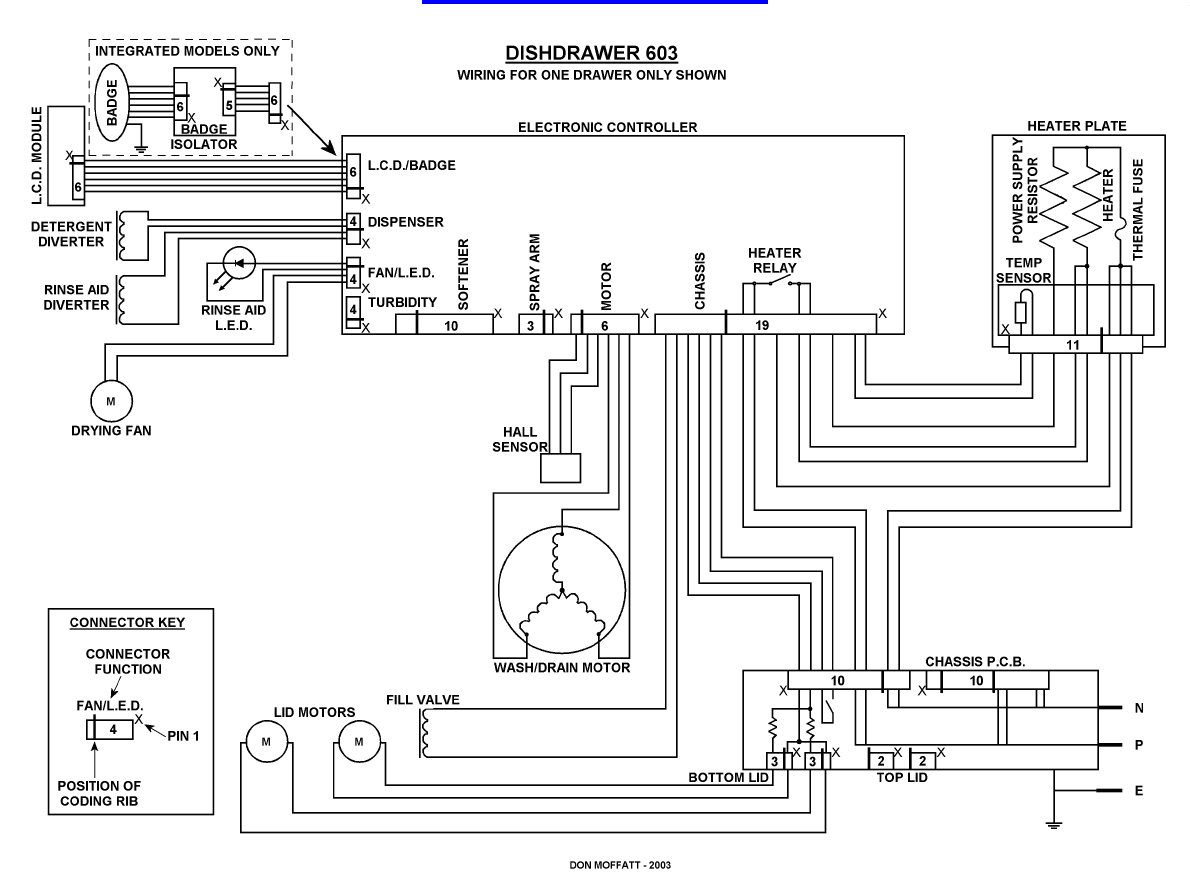
WIRING DIAGRAM
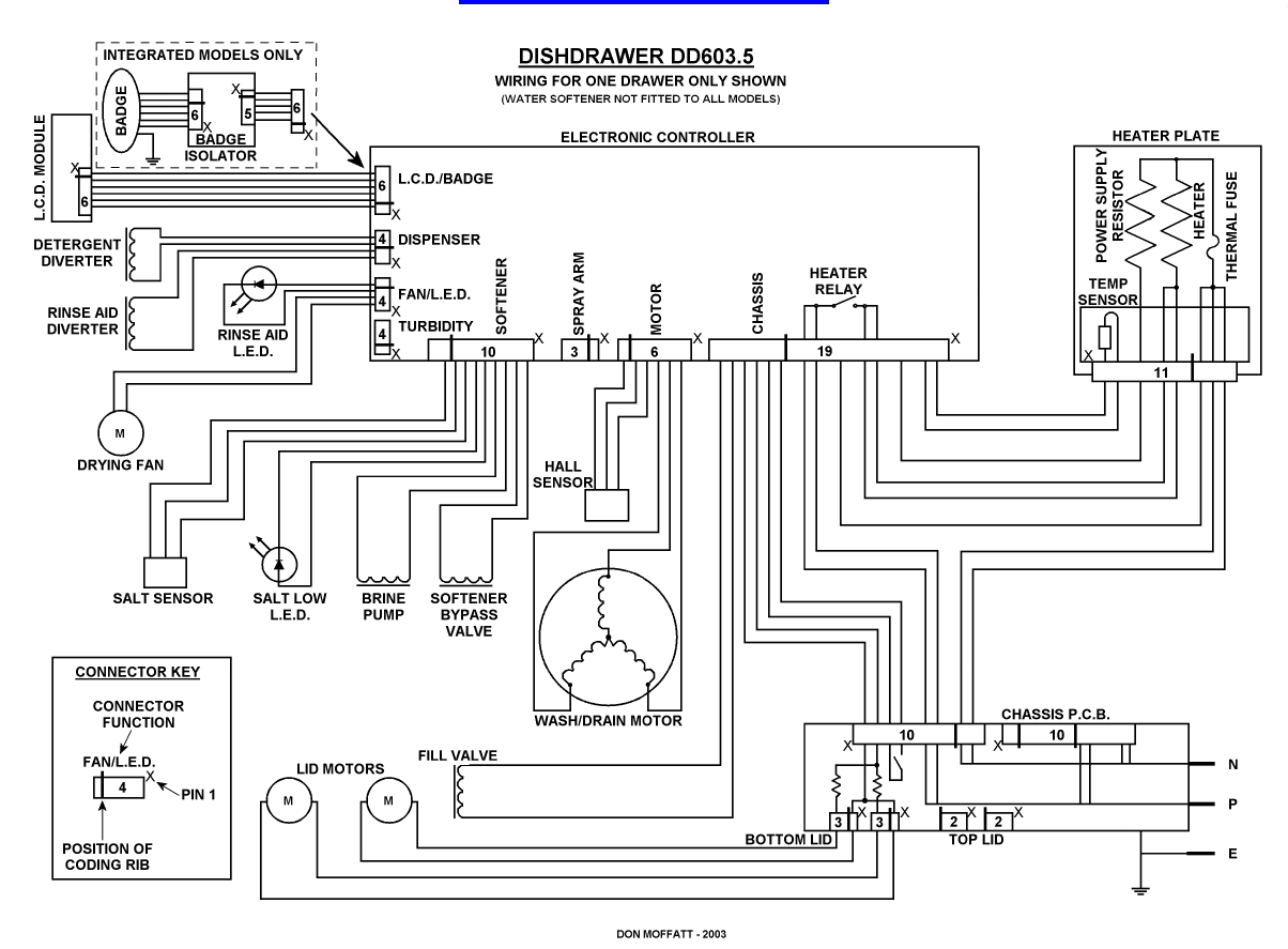
31
WIRING DIAGRAM
