FortiGate II Student Guide Forti Gate Online V2
User Manual: Pdf
Open the PDF directly: View PDF ![]() .
.
Page Count: 595 [warning: Documents this large are best viewed by clicking the View PDF Link!]
- Virtual Lab Basics
- LAB 1–Routing
- LAB 2–Virtual Domains
- LAB 3–Transparent Mode
- LAB 4 –High Availability
- LAB 5–Advanced IPsec VPN
- LAB 6–Intrusion Prevention System (IPS)
- LAB 7–Fortinet Single Sign-On (FSSO)
- LAB 8–Certificate Operations
- LAB 9–Data Leak Prevention
- LAB 10–Diagnostics
- LAB 11–IPv6
- Appendix A: Additional Resources
- Appendix B: Presentation Slides

FortiGate II
Student Guide
for FortiGate 5.4.1
DO NOT REPRINT
© FORTINET
FortiGate II Student Guide
for FortiGate 5.4.1
Last Updated: 3 August 2016
Fortinet®, FortiGate®, and FortiGuard® are registered trademarks of Fortinet, Inc., and other Fortinet
names herein may also be trademarks, registered or otherwise, of Fortinet. All other product or
company names may be trademarks of their respective owners. Copyright © 2002 - 2016 Fortinet, Inc.
All rights reserved. Contents and terms are subject to change by Fortinet without prior notice. No part
of this publication may be reproduced in any form or by any means or used to make any derivative
such as translation, transformation, or adaptation without permission from Fortinet, Inc., as stipulated
by the United States Copyright Act of 1976.
DO NOT REPRINT
© FORTINET
Table of Contents
VIRTUAL LAB BASICS ...................................................................................5
LAB 1–ROUTING .........................................................................................15
1 Route Failover and Link Health Monitor .............................................................................17
2 Equal Cost Multipath and Policy Routing ...........................................................................24
3 WAN Link Load Balancing ..................................................................................................29
LAB 2–VIRTUAL DOMAINS ...........................................................................33
1 VDOMs and VDOM Objects ...............................................................................................35
2 Inter-VDOM Link .................................................................................................................40
LAB 3–TRANSPARENT MODE .......................................................................45
1 Transparent Mode VDOM ...................................................................................................47
2 Inter-VDOM Link .................................................................................................................49
LAB 4 –HIGH AVAILABILITY .........................................................................54
1 Configuring High Availability (HA) ......................................................................................57
2 High Availability Failover ....................................................................................................62
3 Configuring HA Management Interface .............................................................................65
LAB 5–ADVANCED IPSEC VPN ....................................................................70
1 Configure an IPsec VPN Between Two FortiGates ............................................................72
2 Configuring a Backup IPsec VPN .......................................................................................79
DO NOT REPRINT
© FORTINET
3 IPsec VPN with FortiClient ..................................................................................................82
LAB 6–INTRUSION PREVENTION SYSTEM (IPS).............................................88
1 Blocking Known Exploits .....................................................................................................90
2 Mitigating a DoS Attack .......................................................................................................94
3 Creating Custom Signatures ...............................................................................................96
LAB 7–FORTINET SINGLE SIGN-ON (FSSO) .................................................99
1 FSSO Agents ......................................................................................................................101
2 Single Sign-On (SSO) on FortiGate....................................................................................108
LAB 8–CERTIFICATE OPERATIONS ...............................................................114
1 Certificate Authentication ....................................................................................................116
2 SSL Full Inspection .............................................................................................................123
LAB 9–DATA LEAK PREVENTION .................................................................129
1 Blocking Files by File Type ................................................................................................131
2 Quarantining an IP Addresses ...........................................................................................135
3 DLP Fingerprinting .............................................................................................................137
LAB 10–DIAGNOSTICS.................................................................................142
1 Knowing What is Happening Now ......................................................................................144
2 Troubleshooting a Connectivity Problem ............................................................................146
LAB 11–IPV6 ..............................................................................................150
1 IPv6 Interface and SLAAC Setup .......................................................................................152
2 NAT64 .................................................................................................................................155
DO NOT REPRINT
© FORTINET
3 Using IPsec to Tunnel IPv6 Over an IPv4 Network............................................................157
APPENDIX A: ADDITIONAL RESOURCES........................................................160
APPENDIX B: PRESENTATION SLIDES............................................................161
1 Routing................................................................................................................................162
2 Virtual Domains...................................................................................................................206
3 Transparent Mode and Layer 2 Switching..........................................................................237
4 High Availability...................................................................................................................263
5 Advanced IPsec VPN..........................................................................................................297
6 Intrusion Prevention and Denial of Service ........................................................................329
7 Fortinet Single Sign-On (FSSO) .........................................................................................369
8 Certificate Operations .........................................................................................................403
9 Data Leak Prevention (DLP)...............................................................................................451
10 Diagnostics........................................................................................................................470
11 Hardware Acceleration......................................................................................................503
12 IPv6 ...................................................................................................................................545
DO NOT REPRINT
© FORTINET

Virtual Lab Basics
FortiGate II Student Guide 5
Virtual Lab Basics
In this class, you will use a virtual lab for hands-on exercises. This section explains how to connect to
the lab and its virtual machines. It also shows the topology of the virtual machines in the lab.
Note: If your trainer asks you to use a different lab, such as devices physically located in
your classroom, please ignore this section. This applies only to the virtual lab accessed
through the Internet. If you do not know which lab to use, please ask your trainer.
DO NOT REPRINT
© FORTINET
Virtual Lab Basics
FortiGate II Student Guide 6
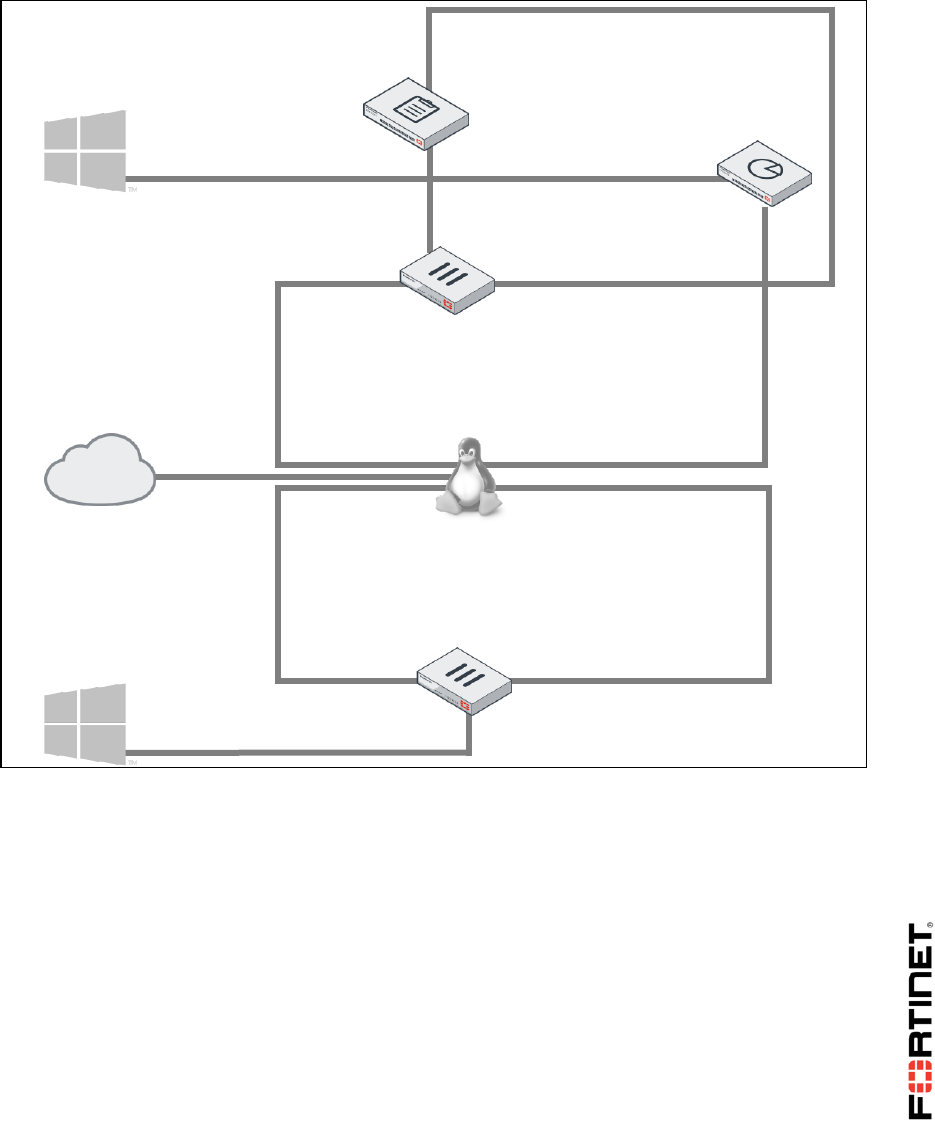
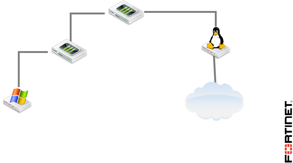
Network Topology
Logging In
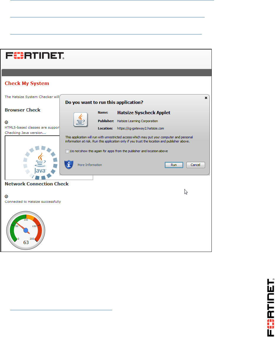
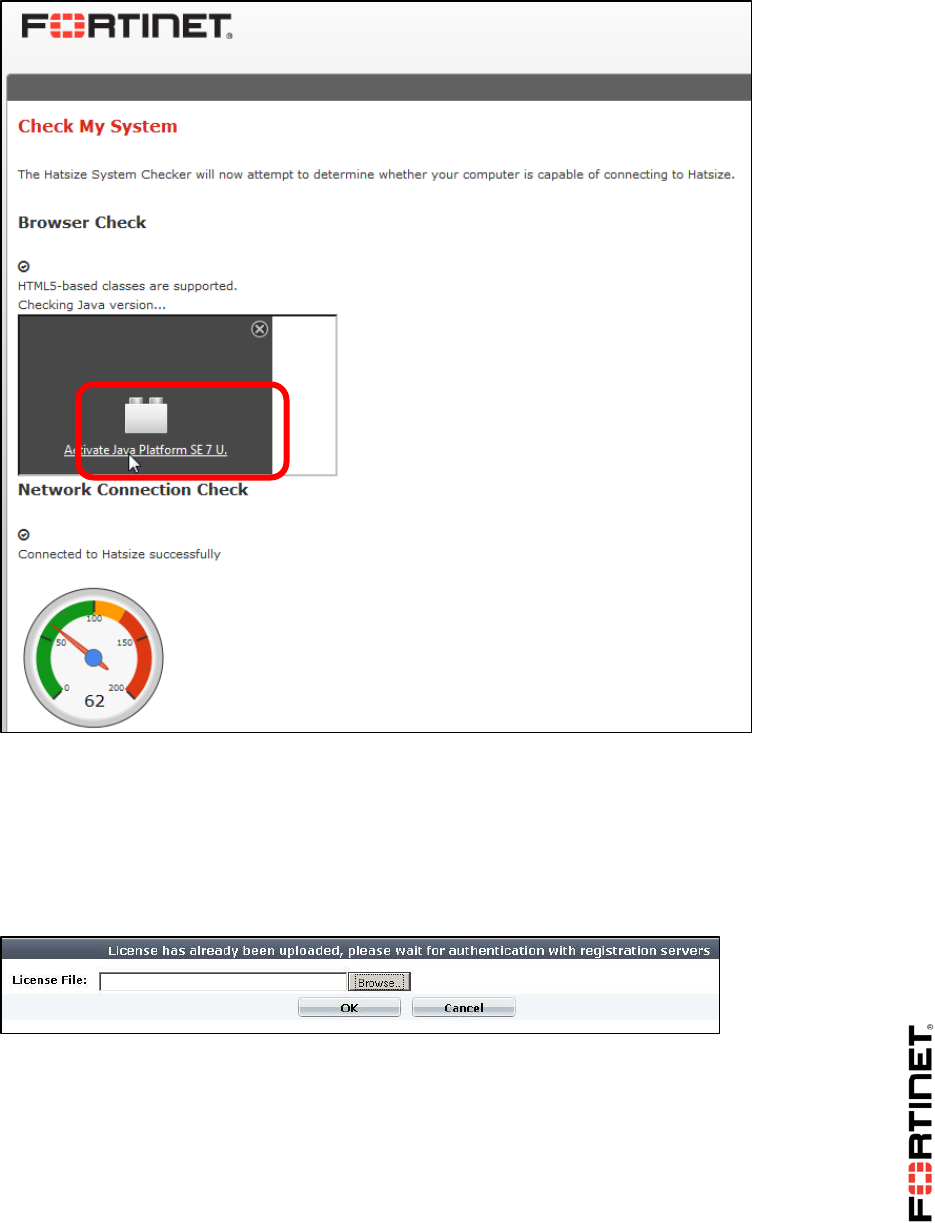
1. Run the System Checker. This will fully verify both:
compatibility with the virtual lab environment's software, and
that your computer can connect.
It can also diagnose problems with your Java Virtual Machine, firewall, or web proxy.
eth0
LOCAL-WINDOWS
10.0.1.10
10.0.1.254/24
port3
port310.0.1.254/2
4
port3
LOCAL-FORTIGATE
port1
10.200.1.1/24
REMOTE-WINDOWS
10.0.2.10
10.200.4.1/24
port5
port6
10.0.2.254/24
10.200.2.254
eth2
LINUX
10.200.1.254
eth1
eth4
10.200.4.254
eth3
10.200.3.254
FortiManager
port1
10.0.1.241
port3
10.200.1.210
port2
10.200.1.241
FortiAnalyzer
port1
10.0.1.210
port2
10.200.2.1/24
REMOTE-FORTIGATE
10.200.3.1/24
port4
DO NOT REPRINT
© FORTINET
Virtual Lab Basics
FortiGate II Student Guide 7
Use the URL for your location.
North America/South America:
https://remotelabs.training.fortinet.com/training/syscheck/?location=NAM-West
Europe/Middle East/Africa:
https://remotelabs.training.fortinet.com/training/syscheck/?location=Europe
Asia/Pacific:
https://remotelabs.training.fortinet.com/training/syscheck/?location=APAC
If a security confirmation dialog appears, click Run.
If your computer successfully connects to the virtual lab, the result messages for the browser and
network checks will each display a check mark icon. Continue to the next step.
If a browser test fails, this will affect your ability to access the virtual lab environment. If a
network test fails, this will affect the usability of the virtual lab environment. For solutions, either
click the Support Knowledge Base link or ask your trainer.
2. With the user name and password from your trainer, log into the URL for the virtual lab. Either:
https://remotelabs.training.fortinet.com/
DO NOT REPRINT
© FORTINET

Virtual Lab Basics
FortiGate II Student Guide 8
https://virtual.mclabs.com/
3. If prompted, select the time zone for your location, and then click Update.
This ensures that your class schedule is accurate.
4. Click Enter Lab.
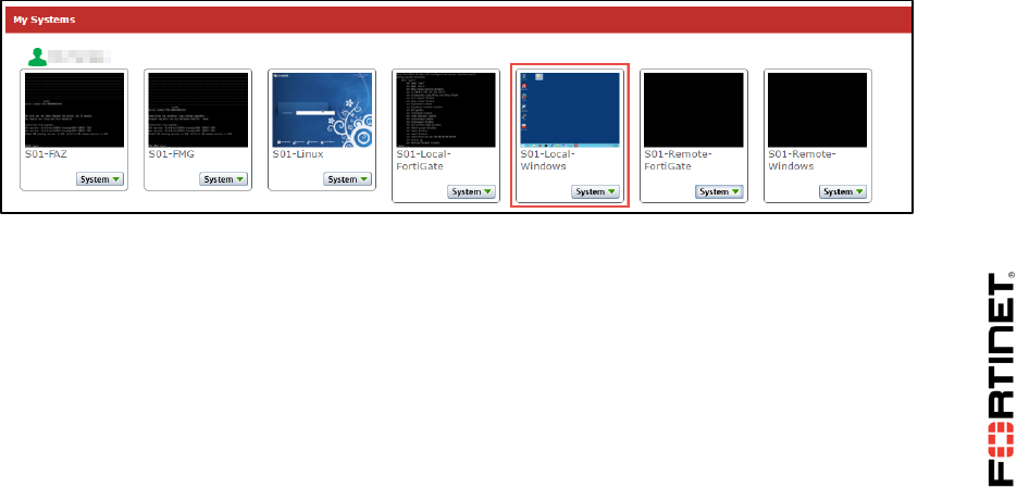
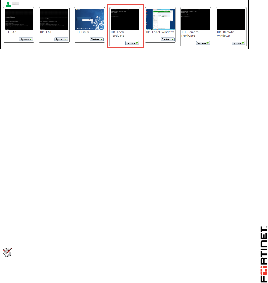
A list of virtual machines that exist in your virtual lab should appear.
DO NOT REPRINT
© FORTINET
Virtual Lab Basics
FortiGate II Student Guide 9
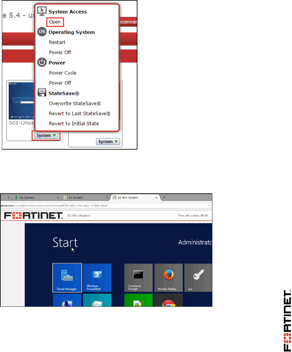
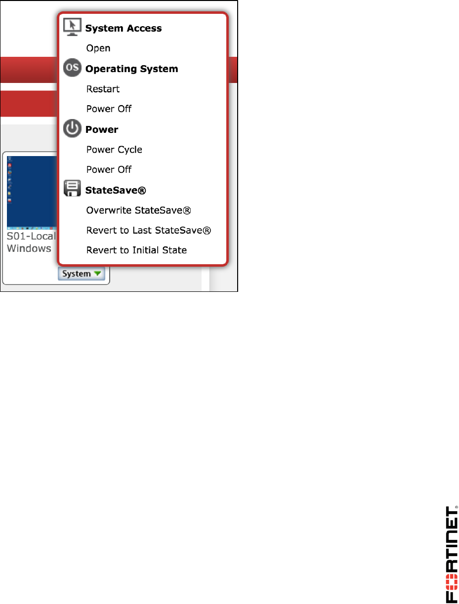
From this page, you can access the console or desktop of any of your virtual devices by either:
clicking on the device’s square, or
selecting System > Open.
5. Click Local-Windows to open a desktop connection to that virtual machine.
A new window should open within a few seconds. (Depending on your account’s preferences, the
window may be a Java applet. If that is the case, you may need change browser settings to allow
Java to run on this web site.)
Connections to Windows and Linux machines will use a remote desktop-like GUI. You should
automatically log in. After that, the desktop is displayed.
Connections to Fortinet's VM use the VM console port, which you can use to enter command
line interface (CLI) commands.
DO NOT REPRINT
© FORTINET
Virtual Lab Basics
FortiGate II Student Guide 10
Disconnections/Timeouts
If your computer’s connection with the virtual machine times out or if you are accidentally
disconnected, to regain access, return to the initial window/tab that contains your session’s list of VMs
and open the VM again.
If that does not succeed, see Troubleshooting Tips.
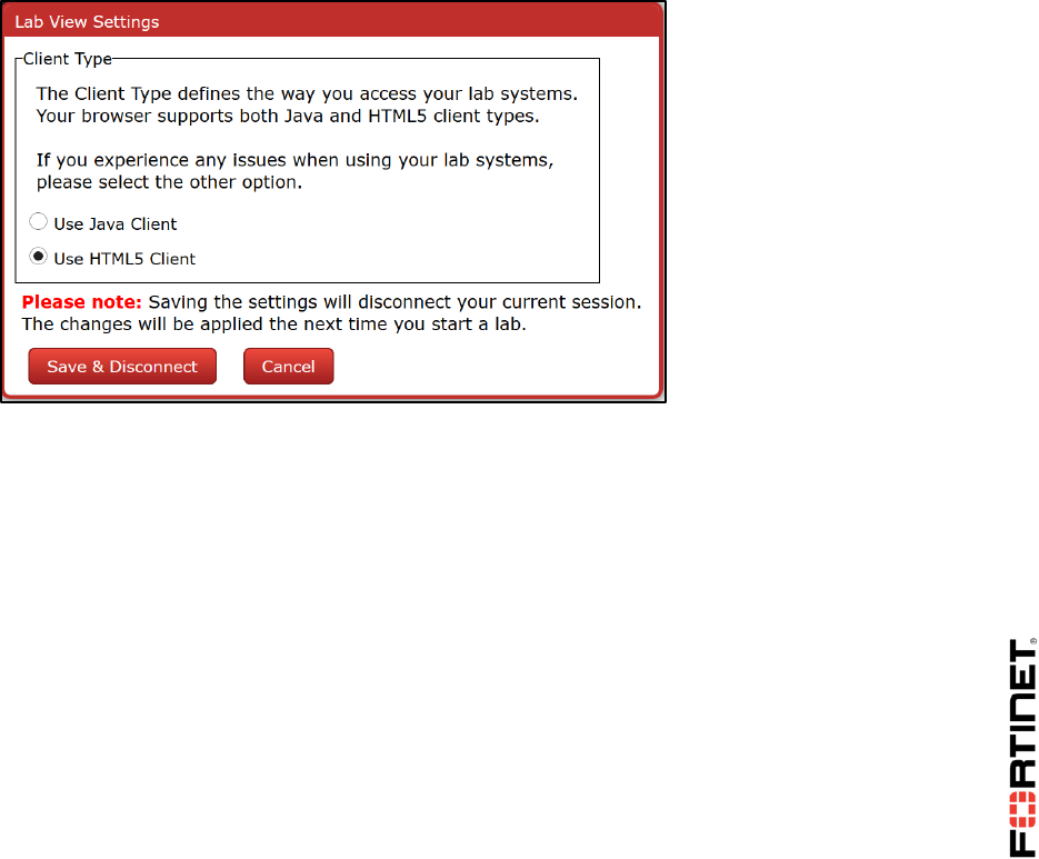
Using Java Instead of HTML5
When you open a VM, by default, your browser will use HTML5 to connect to your lab's VM.
Alternatively, you may be able to use Java instead. Your browser will download and use a Java
application to connect to the virtual lab’s VM. Not all browsers support the Java plug-in, so if you want
to use Java, Mozilla Firefox is recommended. This means that Java must be installed, updated, and
enabled in your browser. Once you have done that, in your virtual lab, click the Settings button, and
then select Use Java Client. Click Save & Disconnect, then log in again. (To use this preference,
your browser must allow cookies.)
When connecting to a VM, your browser should then open a display in a new applet window.
DO NOT REPRINT
© FORTINET
Virtual Lab Basics
FortiGate II Student Guide 11
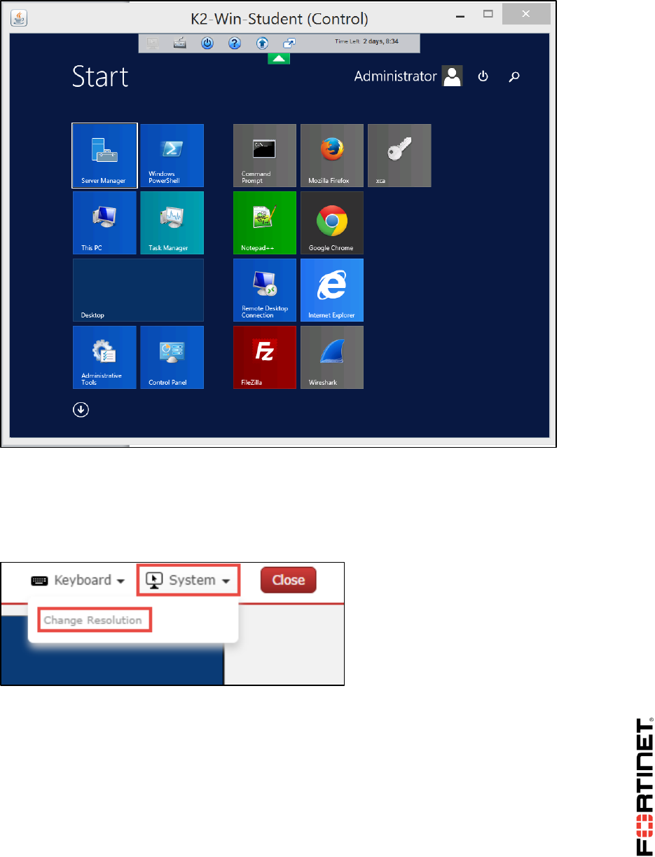
Screen Resolution
Some Fortinet devices' user interfaces require a minimum screen size.
In the HTML 5 client, to configure screen resolution, open the System menu.
DO NOT REPRINT
© FORTINET
Virtual Lab Basics
FortiGate II Student Guide 12
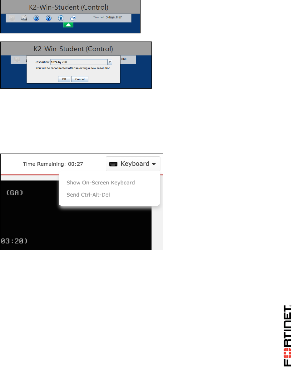
In the Java client, to configure the screen resolution, click the arrow at the top of the window.
International Keyboards
If characters in your language don’t display correctly, keyboard mappings may not be correct.
To solve this in the HTML 5 client, open the Keyboard menu at the top of the window. Choose to
display the on-screen keyboard.
Troubleshooting Tips
Do not connect to the virtual lab environment through Wi-Fi, 3G, VPN tunnels or other low-
bandwidth or high-latency connections. For best performance, use a stable broadband connection
such as a LAN.
If disconnected unexpectedly from any of the virtual machines (or from the virtual lab portal),
please attempt to reconnect. If unable to reconnect, please notify the instructor.
If you can't connect to a VM, on the VM's icon, click System > Power Cycle. This fixes most
problems by forcing VM startup and connection initiation. If that does not solve the problem, try
System > Revert to Initial State.
Note: Reverting to the VM's initial snapshot will undo all of your work. Try other solutions first.
DO NOT REPRINT
© FORTINET
Virtual Lab Basics
FortiGate II Student Guide 13
If the HTML 5 client does not work, try the Java client instead. Remembering this preference
requires that your browser allows cookies.
Do not disable or block Java applets if you want to use the Java client. Network firewalls can block
Java executables. Not all browsers/systems allow Java. In late 2015, Google Chrome removed
Java compatibility, so it cannot be used with the Java client. On Mac OS X since early 2014, to
improve security, Java has been disabled by default. In your browser, you must allow Java for this
web site. On Windows, if the Java applet is allowed and successfully downloads, but does not
appear to launch, you can open the Java console while troubleshooting. To do this, open the
Control Panel, click Java, and change the Java console setting to be Show console.
Note: JavaScript is not the same as Java.
DO NOT REPRINT
© FORTINET
Virtual Lab Basics
FortiGate II Student Guide 14
Prepare your computer's settings:
o Disable screen savers
o Change the power saving scheme so that your computer is always on, and does not go to
sleep or hibernate
If during the labs, particularly when reloading configuration files, you see a message similar to the
one shown below, the VM is waiting for a response from the FortiGuard server.
To retry immediately, go to the console and enter the CLI command:
execute update-now
DO NOT REPRINT
© FORTINET
LAB 1–Routing
FortiGate II Student Guide 15
LAB 1–Routing
In this lab, you will configure the router settings and try scenarios to learn how FortiGate makes
routing decisions.
Objectives
Route traffic based on the destination IP address, as well as other criteria.
Balance traffic among multiple paths.
Implement route failover.
Diagnose a routing problem.
Time to Complete
Estimated: 45 minutes
Prerequisites
Before beginning this lab, you must restore a configuration file to the Local-FortiGate.
To restore the FortiGate configuration file
1. In the virtual lab portal, click the Local-Windows icon to open the Local-Windows VM.
(Alternatively, in the dropdown menu below the icon, go to System > Open.)
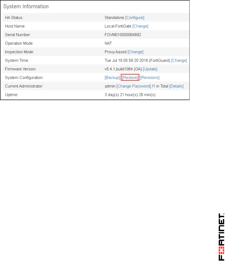
1. On Local-Windows, open a browser and log in as admin to the Local-FortiGate GUI at
10.0.1.254.
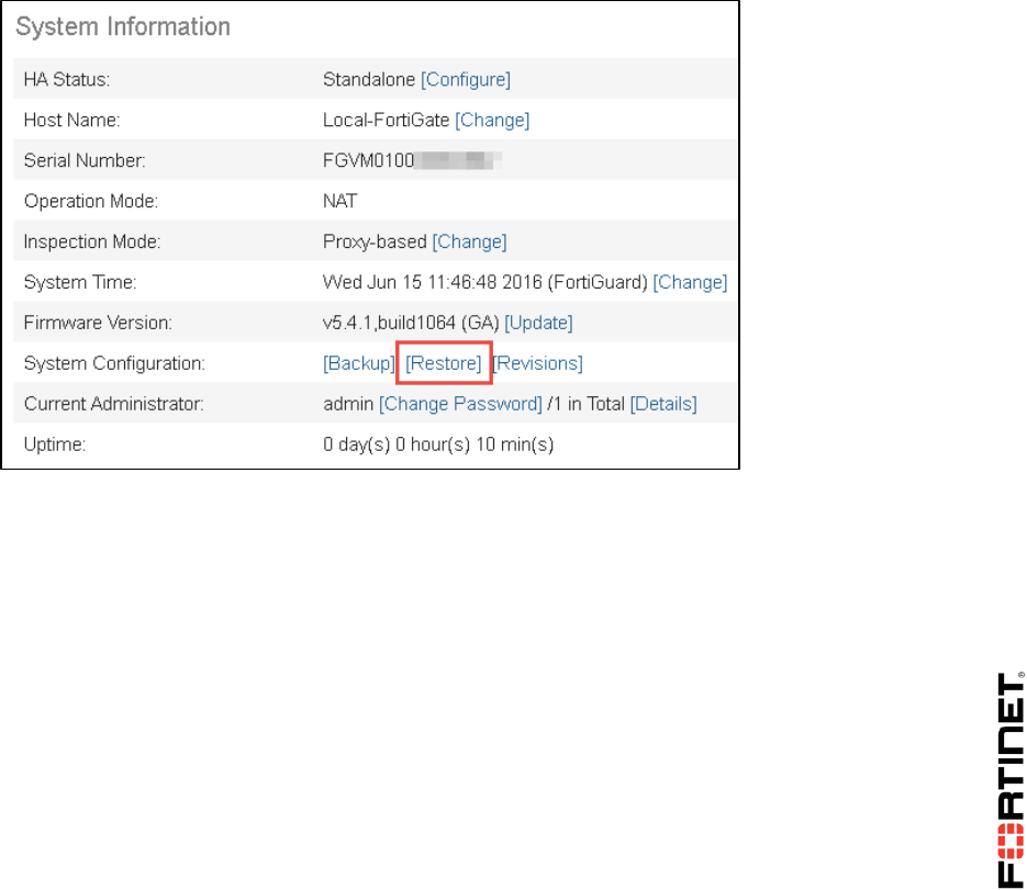
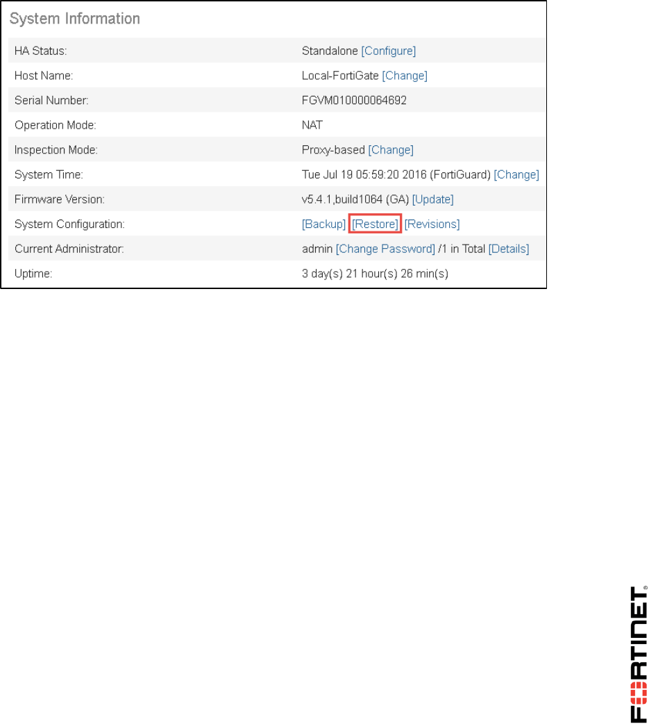
2. Go to Dashboard, from the System Information widget click Restore.
DO NOT REPRINT
© FORTINET

LAB 1–Routing
FortiGate II Student Guide 16
3. Select to restore from Local PC and click Upload.
4. Go to Desktop > Resources > FortiGate-II > Routing and select local-routing.conf.
5. Click OK.
6. Click OK to reboot.
DO NOT REPRINT
© FORTINET
LAB 1–Routing
FortiGate II Student Guide 17
1 Route Failover and Link Health Monitor
If there are multiple paths to the same destination – for example, if you have redundant ISP
connections – you can use link health monitors to provide failover. To monitor the viability of each path
to an upstream device, FortiGate can send probe signals and listen for the replies.
Often, you'll configure FortiGate to use ICMP type 8 (ping) probes, but it also supports UDP echo,
TCP echo, HTTP, and TWAMP. If the device fails to respond after a number of retries, then FortiGate
removes the static routes associated with the respective gateway from its routing table.
As indicated in the diagram for the lab network topology, the Local-FortiGate has two interfaces
connected to the Internet: port1 and port2. During this exercise, you will configure the port1 connection
as the primary Internet link, and the port2 connection as the backup Internet link. The port2 connection
should be used only if the port1 connection is down. To achieve this objective, you will configure two
default routes with different administrative distances and create two link health monitors.
Checking the Routing Configuration
First you'll check the current routing configuration.
To check the routing configuration
1. From the Local-Windows VM, open a browser and log in as admin to the Local-FortiGate GUI at
10.0.1.254.
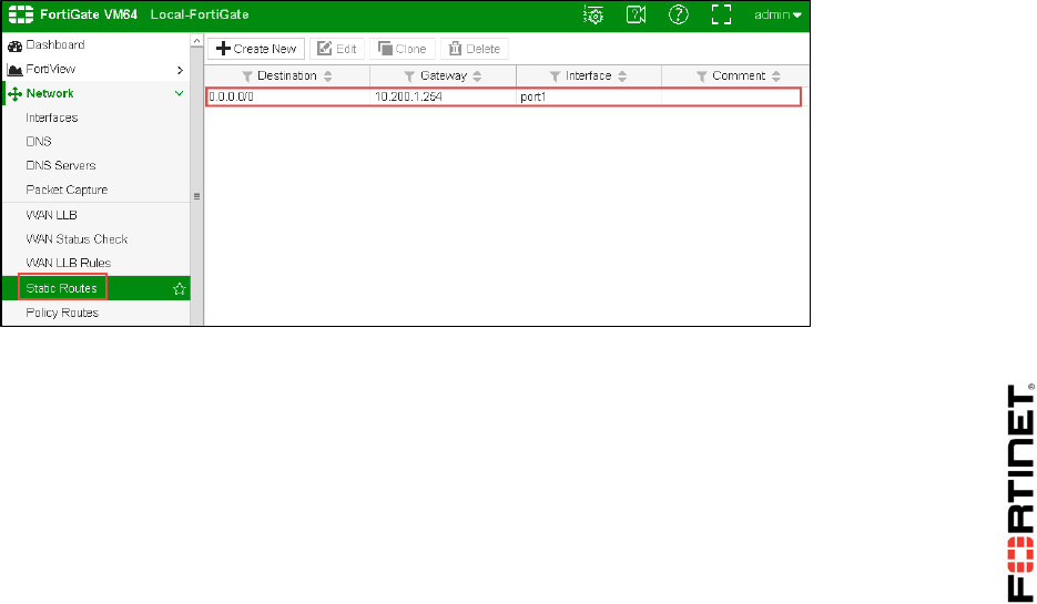
2. Go to Network > Static Routes.
Observe that there is already one default route using the interface port1:
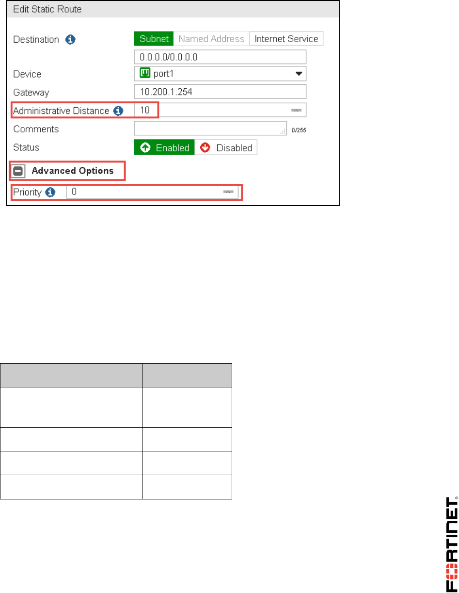
3. Select this route and click Edit to open it.
Observe the Administrative Distance value (10).
4. Click Advanced Options to observe the Priority value (0):
DO NOT REPRINT
© FORTINET
LAB 1–Routing
FortiGate II Student Guide 18
5. Click OK.
Adding a Second Default Route
You will create a second default route with a higher distance for the backup Internet link.
To add a second default route
1. In the Local-FortiGate GUI, go to Network > Static Routes.
2. Click Create New.
3. Configure the following settings:
Field
Value
Destination
Subnet
0.0.0.0/0.0.0.0
Device
port2
Gateway
10.200.2.254
Administrative Distance
20
4. Click Advanced Options and enter a Priority value of 5.
5. Click OK.
Checking the Routing Table
The Local-FortiGate configuration now has two default routes with different distances. Let's check
the routing table to see which one is active.
DO NOT REPRINT
© FORTINET
LAB 1–Routing
FortiGate II Student Guide 19
To check the routing table
1. In the Local-FortiGate GUI, go to Monitor > Routing Monitor.
You will see that the default route you created is not there.
2. In the Local-Windows, open PuTTY and connect to the LOCAL-FORTIGATE saved session
(connect over SSH).
3. Log in as admin and execute the following command to reconfirm the list of active routes in the
routing table:
get router info routing-table all
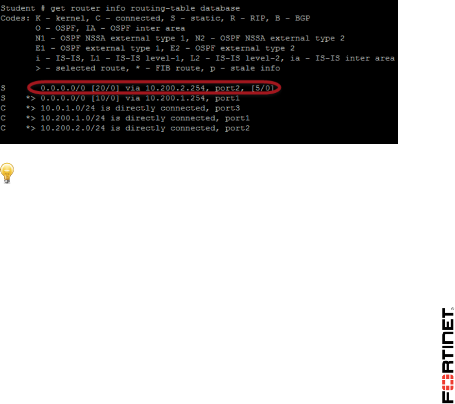
4. Enter this CLI command to list the active routes as well as the inactive routes:
get router info routing-table database
Observe that the default static route is listed now, as inactive:
Stop and Think
Why is the new default route not active?
Discussion
The new route is inactive because it has a higher administrative distance than the other
default route. When two or more routes to the same destination have different distances,
the one with the shortest distance is active. The other ones remain inactive.
Configuring Link Health Monitors
To configure the Local-FortiGate to monitor the status of the port1 connection (and use the port2
connection as backup), you will configure a link health monitor. You will also add a second link
health monitor to check the status of the port2 connection to the Internet.
DO NOT REPRINT
© FORTINET

LAB 1–Routing
FortiGate II Student Guide 20
To configure link health monitors
1. Still connected to the Local-FortiGate CLI though PuTTY, enter the following commands to create
a link health monitor for port1:
config system link-monitor
edit port1-monitor
set srcintf port1
set server 4.2.2.1
set gateway-ip 10.200.1.254
set protocol ping
set update-static-route enable
next
end
2. Add the link health monitor for port2:
config system link-monitor
edit port2-monitor
set srcintf port2
set server 4.2.2.2
set gateway-ip 10.200.2.254
set protocol ping
set update-static-route enable
next
end
Testing the Redundant Routing Configuration
Now that you've completed the configuration, you can test it by running a sniffer while connecting
to some HTTP websites. The first objective is to confirm that the port1 route is the primary one. The
second objective is to confirm the route failover. In other words, confirm that the port2 route is used
if the port1 connection goes down.
To force the failover, you will configure the port1 link health monitor to ping an invalid IP address. In
this way, you are simulating a network problem in the port1 connection.
DO NOT REPRINT
© FORTINET
LAB 1–Routing
FortiGate II Student Guide 21
To confirm port1 is the primary route
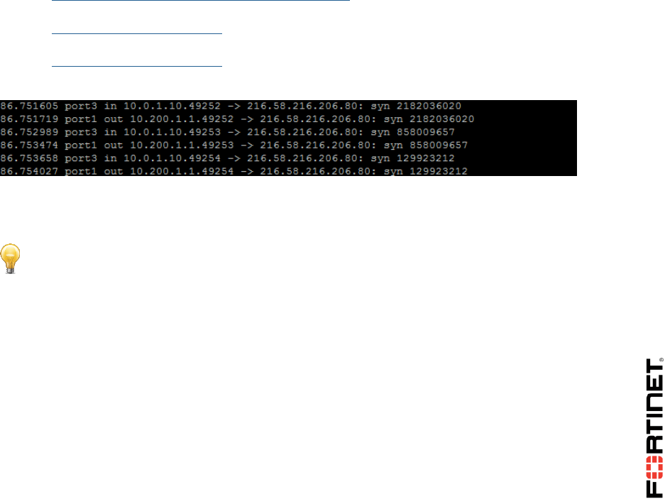
1. Still connected to the Local-FortiGate CLI though PuTTY, enable the sniffer:
diagnose sniffer packet any 'tcp[13]&2==2 and port 80' 4
Tip: The filter 'tcp[13]&2==2' matches packets with the SYN flag on, so the output will
show all SYN packets to port 80 (HTTP).
2. From the Local-Windows VM, open a few tabs in your browser and access multiple HTTP
websites, such as:
http://www.pearsonvue.com/fortinet/
http://cve.mitre.org
http://www.eicar.org
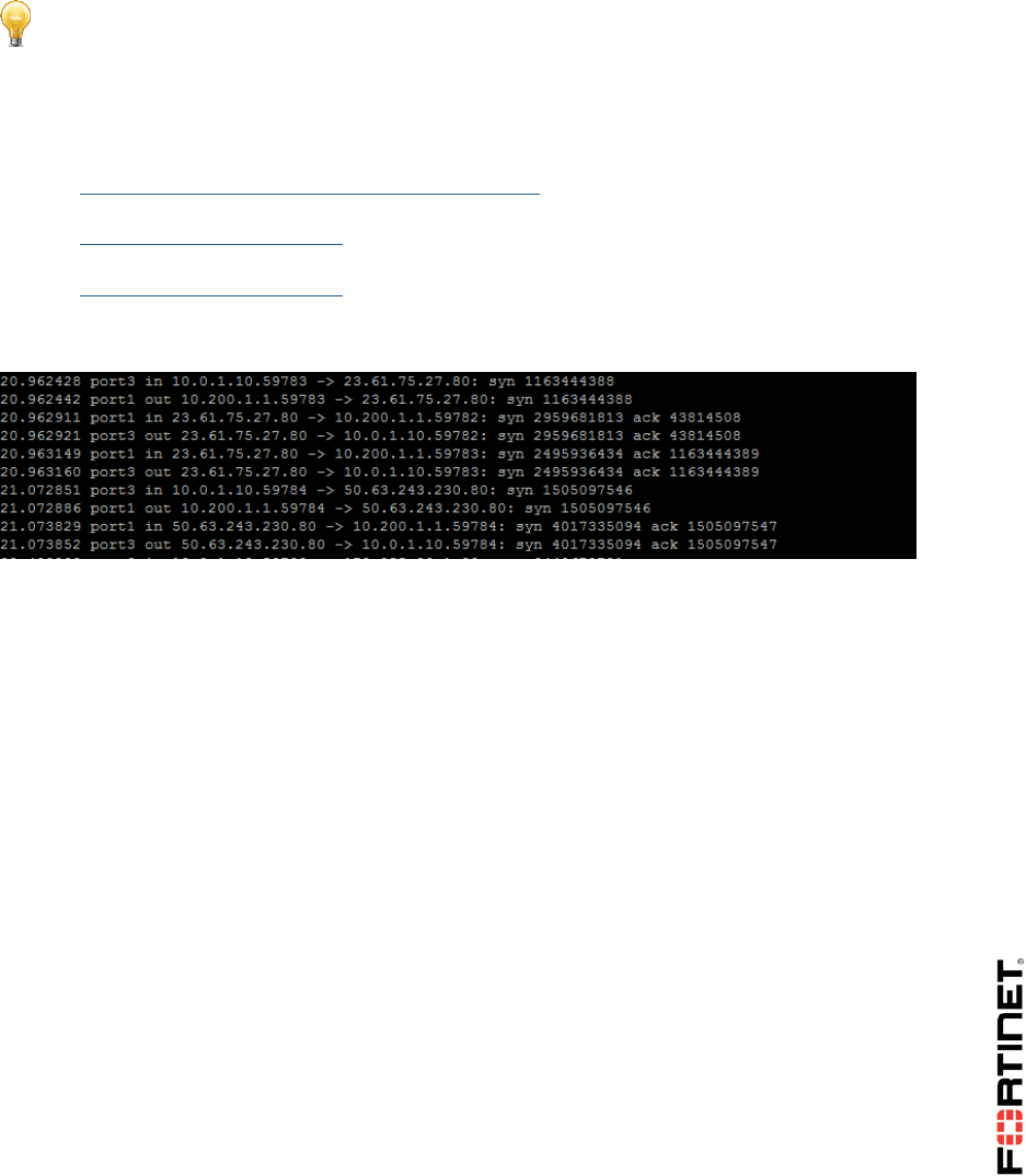
3. Go back to the Local-FortiGate CLI in PuTTY and press Ctrl-C to stop the sniffer. Analyze the
output:
You will notice that all outgoing packets are being routed through port1. The FortiGate is not using
the port2 route. The primary Internet link is the port1 connection. This is one of objectives of this
exercise.
To test the failover
1. Still connected to the Local-FortiGate CLI though PuTTY, enter the following commands:
config system link-monitor
edit port1-monitor
set server 10.200.1.13
next
end
2. Wait a few seconds.
As 10.200.1.13 is an invalid IP, the link health monitor will not receive replies from that
address and it would assume that the port1's Internet connection is down.
3. Go back to the Local-FortiGate GUI and go to Monitor > Routing Monitor to check the routing
table:
DO NOT REPRINT
© FORTINET
LAB 1–Routing
FortiGate II Student Guide 22
FortiGate has removed the port1 route from the routing table and the port2 route is now the
active one.
To test the routing one more time.
1. Return to the Local-FortiGate CLI connection though PuTTY, and execute the following command
to start the sniffer:
diagnose sniffer packet any 'tcp[13]&2==2 and port 80' 4
2. Generate more HTTP traffic by opening a few tabs in your browser and accessing multiple HTTP
websites, such as:
http://www.pearsonvue.com/fortinet/
http://cve.mitre.org
http://www.eicar.org
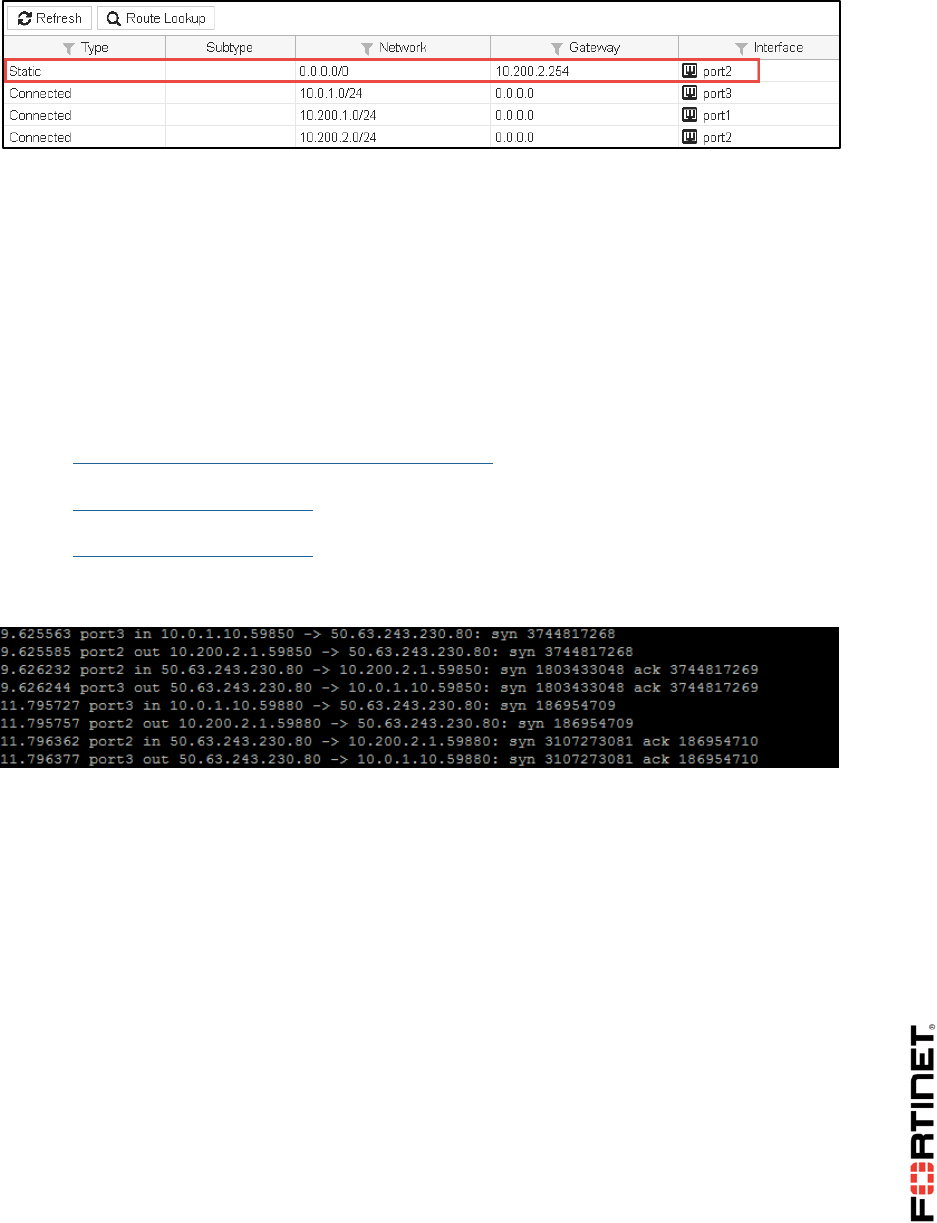
3. Go back to the Local-FortiGate CLI in PuTTY and press Ctrl-C to stop the sniffer. Check the
output:
The Internet traffic is taking the port2 route now. You have achieved the second objective of this
exercise.
Bringing the port1 Health Monitor Back Up
Before starting the next exercise, restore the port1 link health monitor configuration with a valid IP
address. This will bring the port1 route back to the routing table and will remove the port2 route.
To bring the port1 health monitor back up
1. Still connected to the Local-FortiGate CLI though PuTTY, execute the following configuration
change:
config system link-monitor
edit port1-monitor
set server 4.2.2.1
DO NOT REPRINT
© FORTINET
LAB 1–Routing
FortiGate II Student Guide 23
next
end
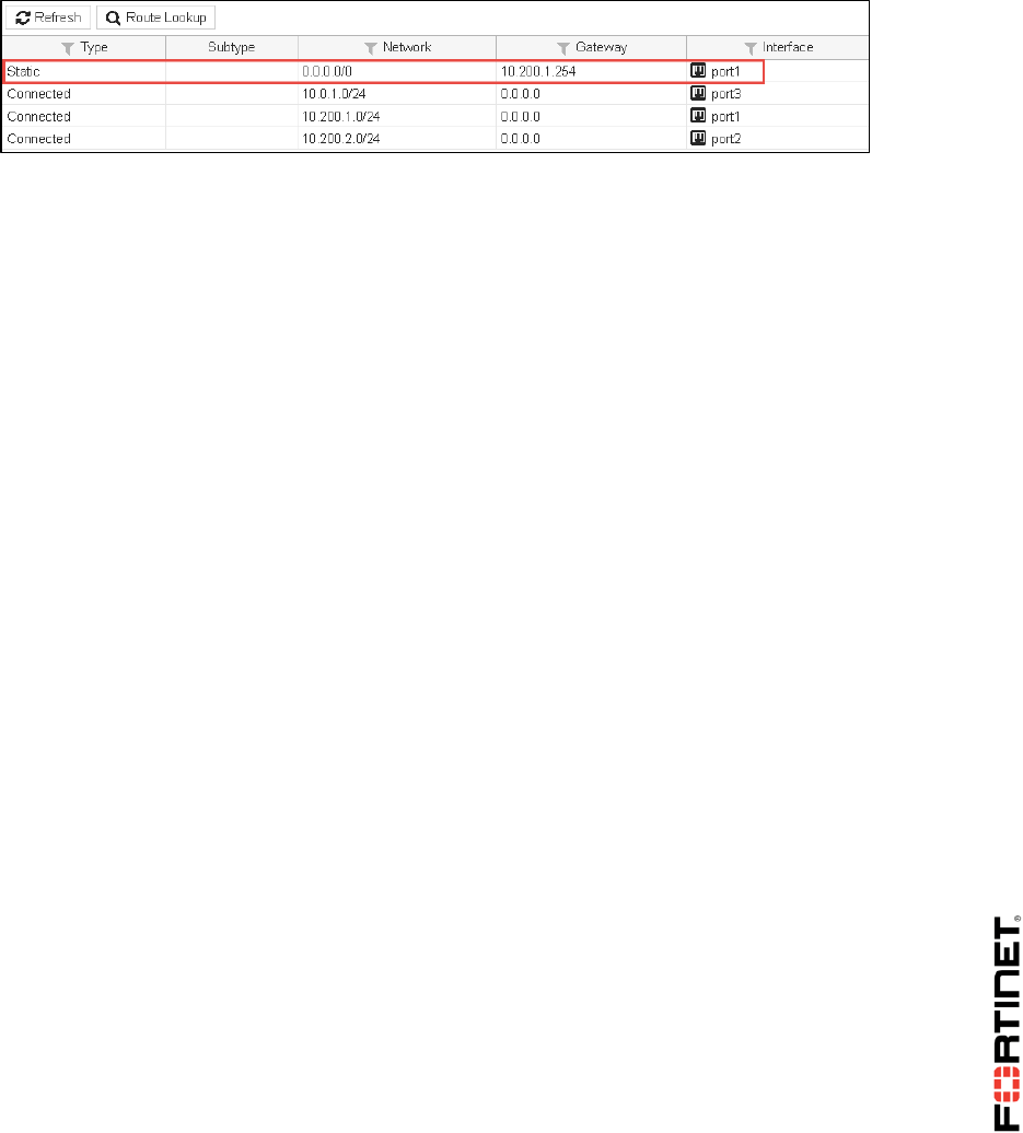
2. In the Local-FortiGate GUI go to Monitor > Routing Monitor.
3. Click Refresh.
4. Check that the port1 route is back to the routing table:
DO NOT REPRINT
© FORTINET
LAB 1–Routing
FortiGate II Student Guide 24
2 Equal Cost Multipath and Policy
Routing
In this exercise, you'll configure the Local-FortiGate to balance the Internet traffic between port1 and
port2. This is called equal cost multipath (ECMP).
After that, you'll configure a policy route to route HTTPS traffic through port1 only.
Configuring the Same Distance
One requirement for achieving ECMP with static routes is to use the same administrative distance. So,
let's start configuring both default routes with the same distance.
To configure the same distance
1. From the Local-Windows VM, open a browser and log in as admin to the Local-FortiGate GUI at
10.0.1.254.
2. Go to Network > Static Routes and edit the static route for the interface port2.
3. Change the Administrative Distance to 10.
4. Click OK.
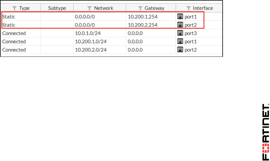
5. Go to Monitor > Routing Monitor and check that it displays the two default routes as active now.
Static routes with the same distance are displayed as active in the routing table.
Changing the Load Balancing Method
By default, the ECMP load balancing method is Source IP. This works well when you have multiple
clients generating traffic. In this case, because we have only one client (Local-Windows), the
source IP method will not balance the traffic. The entire Internet traffic load will be coming from the
same source IP address, so the same route will always be used. For that reason, you will change
the load balancing method to Destination IP. This way, as long as the traffic goes to multiple
destination IP addresses (regardless of the source IP address), FortiGate will balance it between
both Internet connections.
To change the load balancing method
1. From Local-Windows, open PuTTY and connect to the LOCAL-FORTIGATE saved session
(connect over SSH).
2. Log in as admin and enter the following configuration change:
DO NOT REPRINT
© FORTINET
LAB 1–Routing
FortiGate II Student Guide 25
config sys settings
set v4-ecmp-mode source-dest-ip-based
end
Testing How the FortiGate Is Routing Internet Traffic
Let's test to see if FortiGate is balancing the traffic between both default routes now. You will run a
sniffer while generating some HTTP traffic. The output of the sniffer shows which interface (or
interfaces) FortiGate is using.
To test how FortiGate is routing Internet traffic
1. Still connected to the Local-FortiGate CLI though PuTTY, run the sniffer:
diagnose sniffer packet any 'tcp[13]&2==2 and port 80' 4
2. From the Local-Windows VM, open a few tabs in your browser and connect to some HTTP
websites, such as:
http://www.pearsonvue.com/fortinet/
http://cve.mitre.org
http://www.eicar.org
3. Press Ctrl-C to stop the sniffer and check its output:
You will notice that all the outgoing packets are still being routed through port1. The FortiGate is
not using the port2 route yet.
Stop and Think
Why is the new default route, although active now, not being used yet?
Discussion
The new route is not being used because it has a higher priority value than the original
route. When two routes to the same destination have the same administrative distance,
both remain active. However if the priorities are different, only the one with the smallest
priority value is used for routing traffic. So, to achieve ECMP with static routes, the
distance values must be the same and the priority values must be the same as well.
Configuring the Same Priority
You will change the priority value for the port2 route to match the value in the port1 route.
DO NOT REPRINT
© FORTINET
LAB 1–Routing
FortiGate II Student Guide 26
To configure the same priority
1. Go back to the FortiGate GUI and go to Network > Static Routes.
2. Edit the static route for the interface port2.
3. Click Advanced Options and change the Priority to 0.
4. Click OK.
To retest how FortiGate is routing Internet traffic
1. Still connected to the Local-FortiGate CLI though PuTTY, run the sniffer:
diagnose sniffer packet any 'tcp[13]&2==2 and port 80' 4
2. Generate HTTP traffic one more time by opening a few tabs in your browser and connecting to
multiple HTTP websites, such as:
http://www.pearsonvue.com/fortinet/
http://cve.mitre.org
http://www.eicar.org
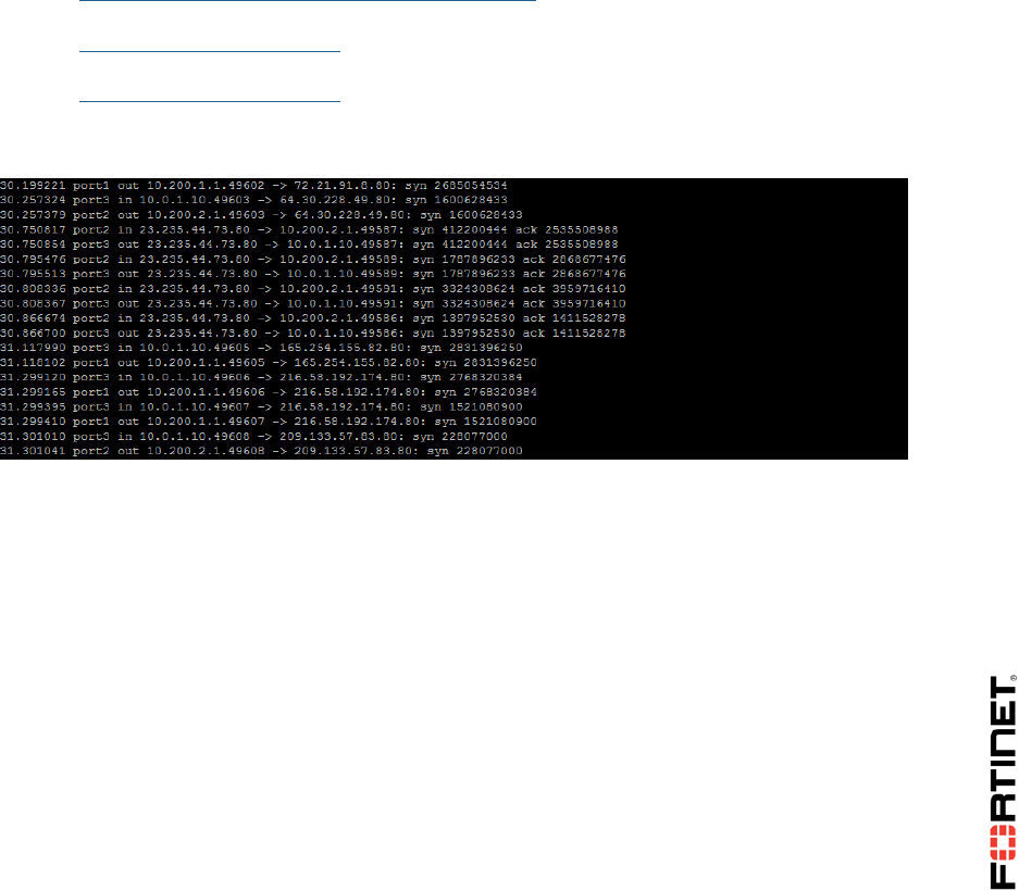
3. Press Ctrl-C to stop the sniffer and check its output. You will now see some packets being routed
through port1, and some through port2:
You've successfully configured FortiGate for ECMP.
Configuring Policy Route for HTTPS traffic
Now, let's say that you want to keep balancing your Internet traffic through both links, but route all
HTTPS traffic through port1 only. How can you do it?
Policy routes are used to make routing decisions using criteria that is different than the destination
IP address. In this case, you will use the destination TCP port.
To force HTTPS traffic to go through port1 and keep all other traffic balanced between port1 and
port2, you will add a policy route that matches traffic to port TCP 443.
To configure policy route for HTTPS traffic
1. From the FortiGate GUI go to Network > Policy Routes.
2. Click Create New.
3. Configure the following settings under If incoming traffic matches:
DO NOT REPRINT
© FORTINET

LAB 1–Routing
FortiGate II Student Guide 27
Field
Value
Protocol
TCP
Incoming interface
port3
Source address / mask
10.0.1.0/24
Destination address / mask
0.0.0.0/0
Source Ports
From 1 to 65535
Destination Ports
From 443 to 443
4. Configure the following settings under Then:
Field
Value
Action
Forward Traffic
Outgoing interface
port1
Gateway Address
10.200.1.254
5. Click OK.
Testing the Policy Routing Configuration
You will run two sniffers and generate traffic. One sniffer will show how FortiGate is routing HTTP
traffic. The other sniffer will show the routing of HTTPS traffic.
To test how FortiGate is routing HTTP traffic
1. Still connected to the Local-FortiGate CLI though PuTTY, run the sniffer:
diagnose sniffer packet any 'tcp[13]&2==2 and port 80' 4
2. Generate HTTP traffic from the Local-Windows VM by opening a few tabs in your browser and
connecting to some HTTP websites, such as:
http://www.pearsonvue.com/fortinet/
http://cve.mitre.org
http://www.eicar.org
3. Press Crtrl-C to stop the sniffer and check its output. The FortiGate is indeed still balancing the
HTTP traffic between the two outgoing interfaces (port1 and port2).
To test how FortiGate is routing the HTTPS traffic
1. Close all your browsers connections to the Local-FortiGate GUI, but keep the SSH connection
to the Local-FortiGate CLI in PuTTY open.
DO NOT REPRINT
© FORTINET
LAB 1–Routing
FortiGate II Student Guide 28
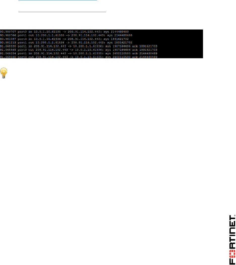
2. From the Local-FortiGate CLI though PuTTY, run this sniffer one more time:
diagnose sniffer packet any 'tcp[13]&2==2 and port 443' 4
3. Generate some HTTPS traffic to the Internet by opening a few tabs in your browser and
connecting to some HTTPS websites, such as:
https://www.fortiguard.com
https://support.fortinet.com/
4. Press Ctrl-C to stop the sniffer and check its output. The HTTPS traffic is being routed through
port1 only:
Stop and Think
The FortiGate configuration still has the two link health monitors for port1 and port2. Do
they also enable routing failover for ECMP scenarios?
Discussion
Yes. If there is a problem in one of the two health link monitors, all the Internet traffic is
routed through the other link.
DO NOT REPRINT
© FORTINET
LAB 1–Routing
FortiGate II Student Guide 29
3 WAN Link Load Balancing
In the previous exercise, you configured load balancing using two static routes with the same distance
and priority. In this exercise, you will use WAN link load balancing instead.
Restoring the Required Configuration for This Exercise
Before beginning this exercise, you must restore a configuration file to the Local-FortiGate.
To restore the FortiGate configuration file
1. From the Local-Windows VM, open a browser and log in as admin to the Local-FortiGate GUI at
10.0.1.254.
2. Go to Dashboard, and from the System Information widget click Restore.
3. Click Upload and browse to Desktop > Resources > FortiGate-II > Routing. Select local-
routing-2.conf.
4. Click OK.
5. Click OK.
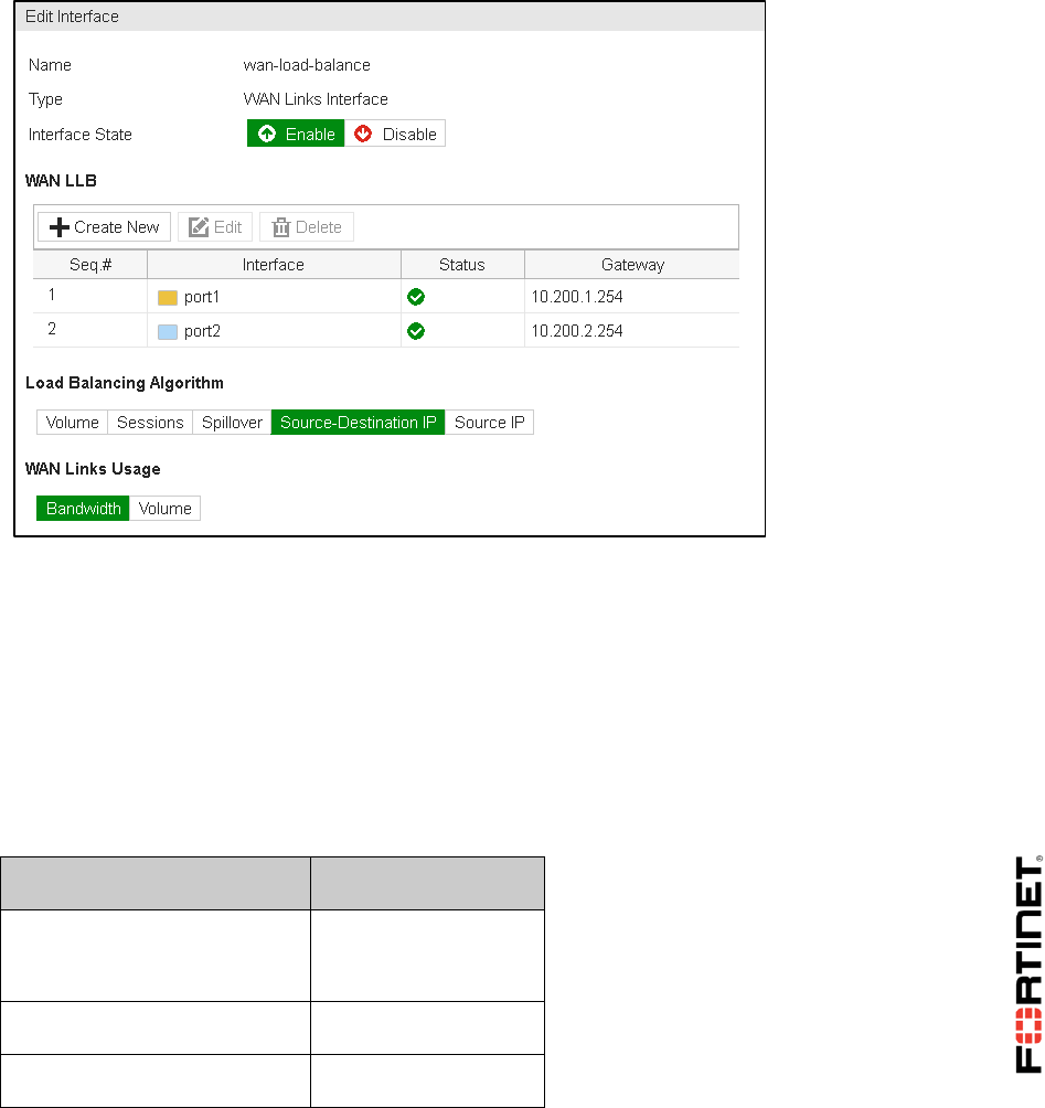
Enabling WAN Link Load Balancing
You will enable WAN Link load balancing to balance the Internet traffic between port1 and port2.
To enable WAN link load balancing
1. From the Local-Windows VM, open a browser and log in as admin to the Local-FortiGate GUI
at 10.0.1.254.
2. Go to Network > WAN LLB and enable Interface State.
DO NOT REPRINT
© FORTINET
LAB 1–Routing
FortiGate II Student Guide 30
3. Under WAN LLB, click Create New.
4. Add port1 with the Gateway 10.200.1.254.
5. Click Create New one more time.
6. Add port2 with the Gateway 10.200.2.254.
7. Select Source-Destination IP as the Load Balancing Algorithm.
8. Click Apply.
Your configuration should look like this:
Creating a Static Route for WAN Link Load Balancing
WAN link load balancing requires at least one static route to the virtual interface wan-load-balance.
To create a static route for WAN Link Load Balancing
1. In the Local-FortiGate GUI, go to Network > Static Routes.
2. Click Create New.
3. Add this default route:
Field
Value
Destination
Subnet
0.0.0.0/0.0.0.0
Device
wan-load-balance
Administrative Distance
10
DO NOT REPRINT
© FORTINET
LAB 1–Routing
FortiGate II Student Guide 31
4. Click OK.
Creating a Firewall Policy for WAN Link Load Balancing
You will create the firewall policy to allow the Internet traffic from port3 to the WAN link load balancing
interface.
To create a firewall policy for WAN link load balancing
1. In the Local-FortiGate GUI, go to Policy & Objects > IPv4 Policy.
2. Click Create New.
3. Configure the following settings:
Field
Value
Name
Internet
Incoming Interface
port3
Outgoing Interface
wan-load-balance
Source
LOCAL_SUBNET
Destination Address
all
Schedule
always
Services
ALL
4. Under Firewall / Network options, enable NAT.
5. Click OK.
Testing the WAN Link Load Balancing Configuration
Sniffer the HTTP traffic while generating some traffic. You should see that FortiGate is balancing the
Internet traffic between port1 and port2.
To test the WAN Link Load Balancing Configuration
1. From Local-Windows, open PuTTY and connect to the LOCAL-FORTIGATE saved session
(connect over SSH).
2. Log in as admin and enable the sniffer of SYN packets to port 80 using the following
command:
diagnose sniffer packet any 'tcp[13]&2==2 and port 80' 4
3. Generate some HTTP traffic from the Local-Windows VM by opening a few tabs in your
browser and connecting to some HTTP websites, such as:
http://www.pearsonvue.com/fortinet/
DO NOT REPRINT
© FORTINET

LAB 2–Virtual Domains
FortiGate II Student Guide 33
LAB 2–Virtual Domains
In this lab, you will create one VDOM and configure an inter-VDOM link.
Objectives
Use VDOMs to split a FortiGate into multiple virtual units.
Create an administrative account with the access limited to one VDOM.
Route traffic between VDOMs by using inter-VDOM links.
Time to Complete
Estimated: 25 minutes
Topology
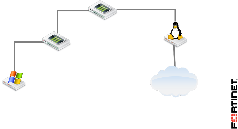
The goal of the lab is to create the topology below. You will use VDOMs to logically split the Local-
FortiGate into two virtual firewalls: the root VDOM and the customer VDOM. Both are in NAT mode.
So, all Internet traffic coming from Local-Windows must transverse the customer VDOM first, then the
root VDOM.
Prerequisites
Before beginning this lab, you must restore a configuration file to FortiGate.
Internet
Local-Windows
10.0.1.10
Local-FortiGate
customer VDOM
Local-FortiGate
root VDOM
LINUX
10.200.1.254
eth1
vlink1
10.10.100.2/30
port1
10.200.1.1/24
vlink0
10.10.100.1/30
port3
10.0.1.254/24
DO NOT REPRINT
© FORTINET
LAB 2–Virtual Domains
FortiGate II Student Guide 34
To restore the FortiGate configuration file
1. From the Local-Windows VM, open a browser and log in as admin to the Local-FortiGate GUI at
10.0.1.254.
2. Go to Dashboard, and from the System Information widget click Restore.
3. Select to restore from Local PC and click Upload.
4. Go to Desktop > Resources > FortiGate-II > VDOM and select local-vdom.conf.
5. Click OK.
6. Click OK to reboot.
DO NOT REPRINT
© FORTINET
LAB 2–Virtual Domains
FortiGate II Student Guide 35
1 VDOMs and VDOM Objects
During this exercise you will first add a new VDOM. Then you will create an inter-VDOM link between
the VDOM you added and the root VDOM. You will also create an administrator account that will have
access to only one VDOM.
Note: The configuration file for this exercise already has VDOMs enabled.
Creating a VDOM
A FortiGate with VDOMs enabled always includes a root VDOM. Administrators can create additional
VDOMs to split the physical FortiGate into multiple virtual firewalls. In the next steps, you will add a
second VDOM.
To create a VDOM
1. From the Local-Windows VM, open a browser and log in as admin to the Local-FortiGate GUI at
10.0.1.254.
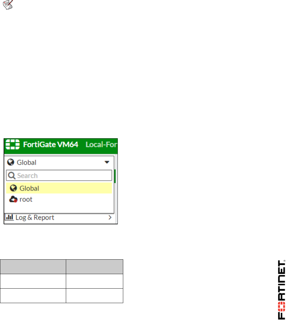
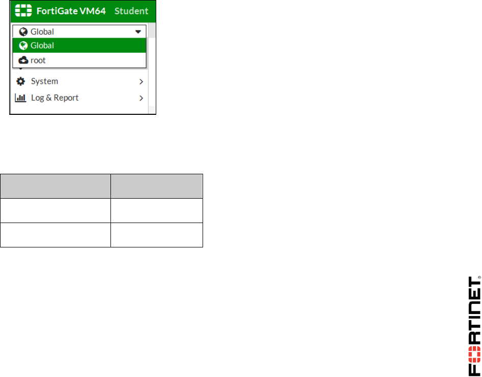
You will notice that the FortiGate menu has changed. This is because VDOMs are enabled. There
is now a drop-down list at the top of the menu. From there you can access either the global
settings or the VDOM-specific settings for the root VDOM:
2. Select Global and go to System > VDOM.
3. Click Create New.
4. Configure the following VDOM:
Field
Value
Virtual Domain
customer
Inspection Mode
Proxy (Default)
5. Click OK.
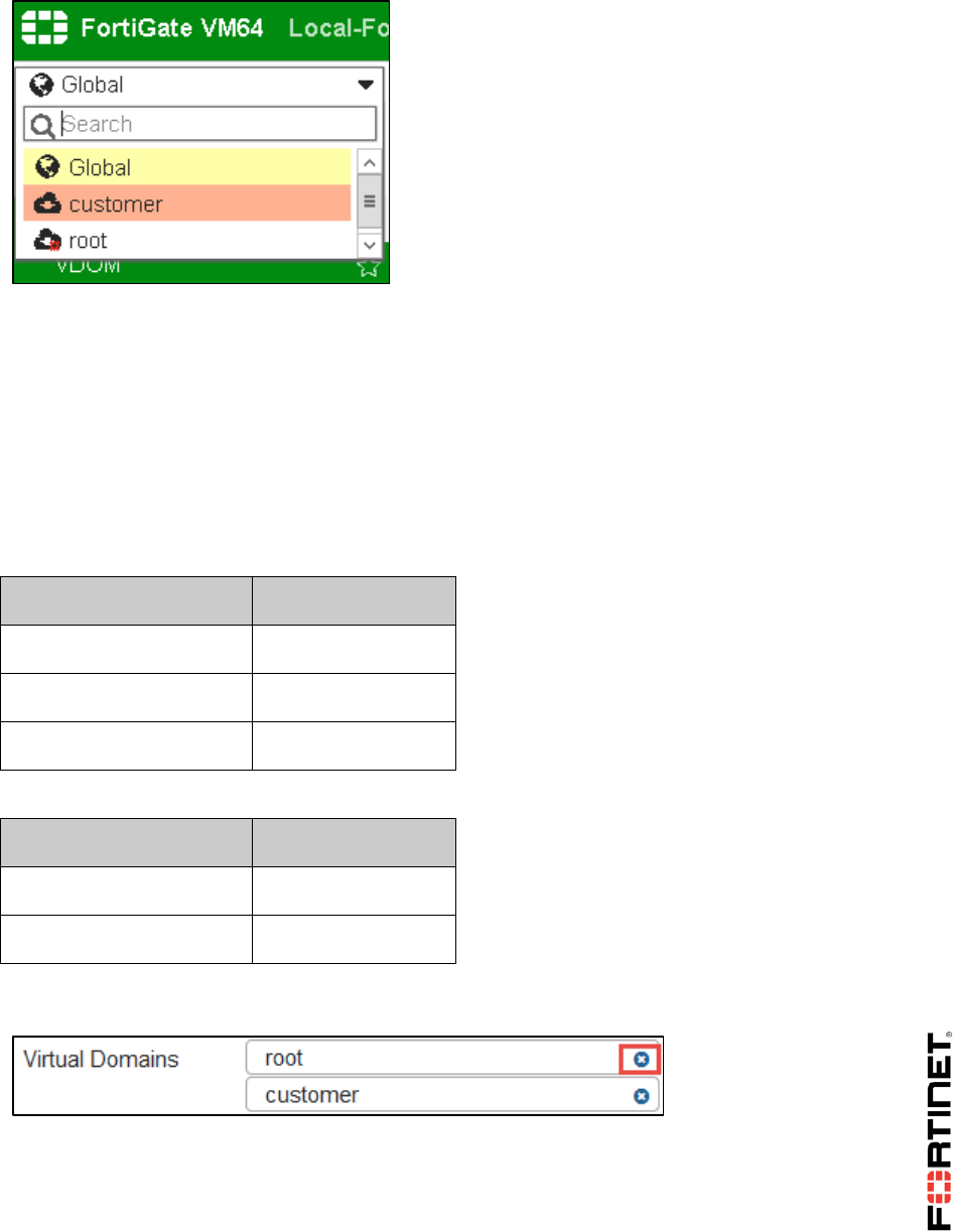
Notice that the drop-down list on the top of the menu shows a third option - the VDOM-specific
settings for customer:
DO NOT REPRINT
© FORTINET
LAB 2–Virtual Domains
FortiGate II Student Guide 36
Creating a Per-VDOM Administrator
You will create an administrator account with access to the customer VDOM only.
To create a per-VDOM administrator
1. In the Local-FortiGate GUI, go to Global > System > Administrators.
2. Click Create New.
3. Configure the following settings:
Field
Value
User Name
customer-admin
Password
fortinet
Confirm Password
fortinet
4. Under Type, select Local User and configure the following settings:
Field
Value
Administrator Profile
prof_admin
Virtual Domains
customer
5. Remove root from the Virtual Domains list, so that the new administrator can only access
customer.
6. Click OK.
Moving an Interface to a Different VDOM
The account customer-admin will only be able to log in through an interface in the customer
DO NOT REPRINT
© FORTINET
LAB 2–Virtual Domains
FortiGate II Student Guide 37
VDOM. So, move the port3 interface, which connects to the internal network, to the customer VDOM.
To move an interface to a different VDOM
1. In the Local-FortiGate GUI, go to Global > Network > Interfaces.
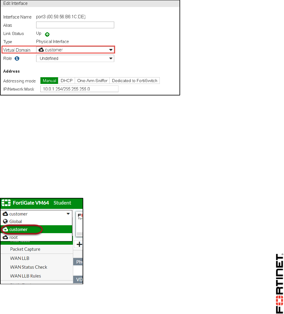
2. Edit port3.
3. Change the Virtual Domain to customer:
4. Click OK.
Leave the port1 and port2 interfaces in the root VDOM.
Adding DNS service on an Interface
For Local-Windows DNS server is port3. First you will enable DNS database from feature select and
then you will add DNS service on port3.
To enable DNS database
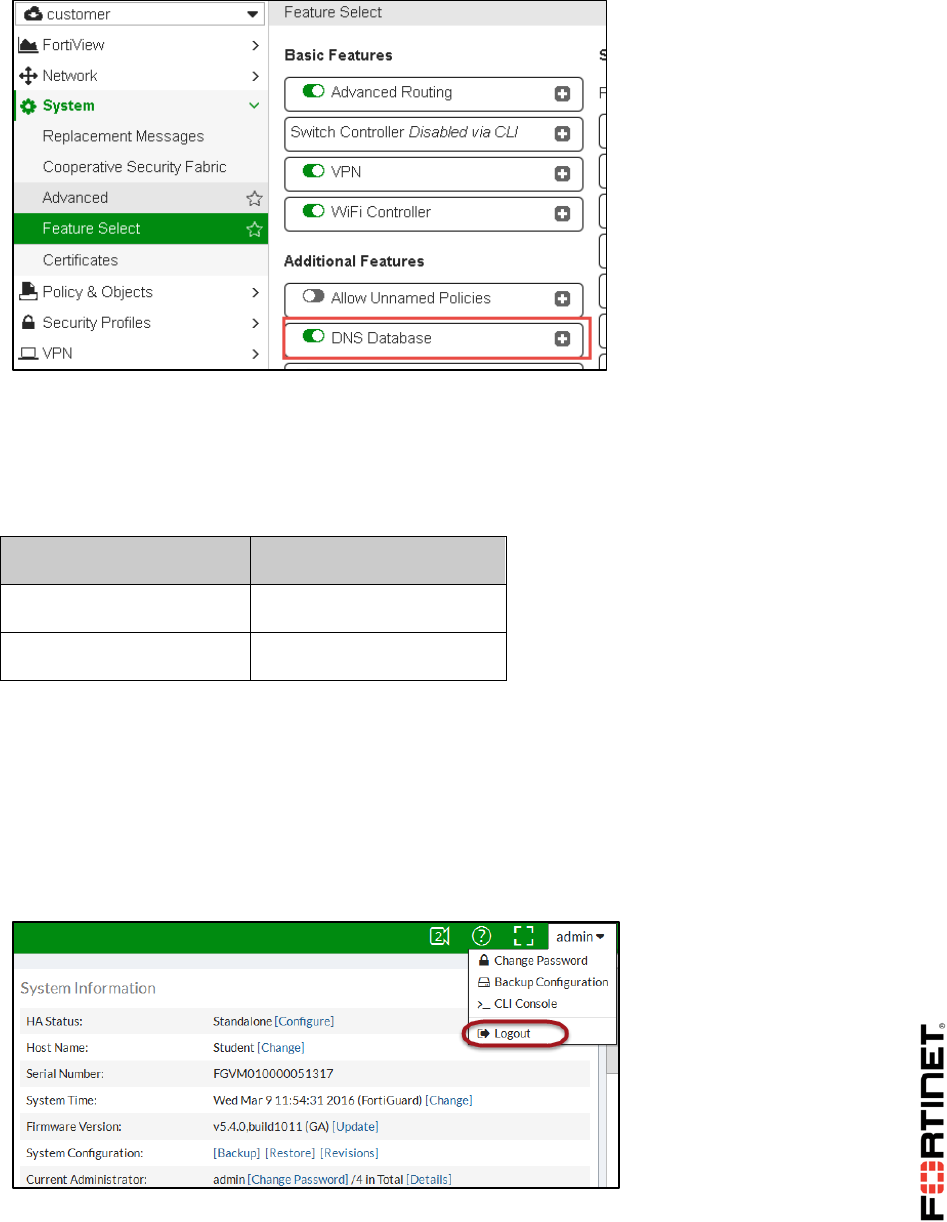
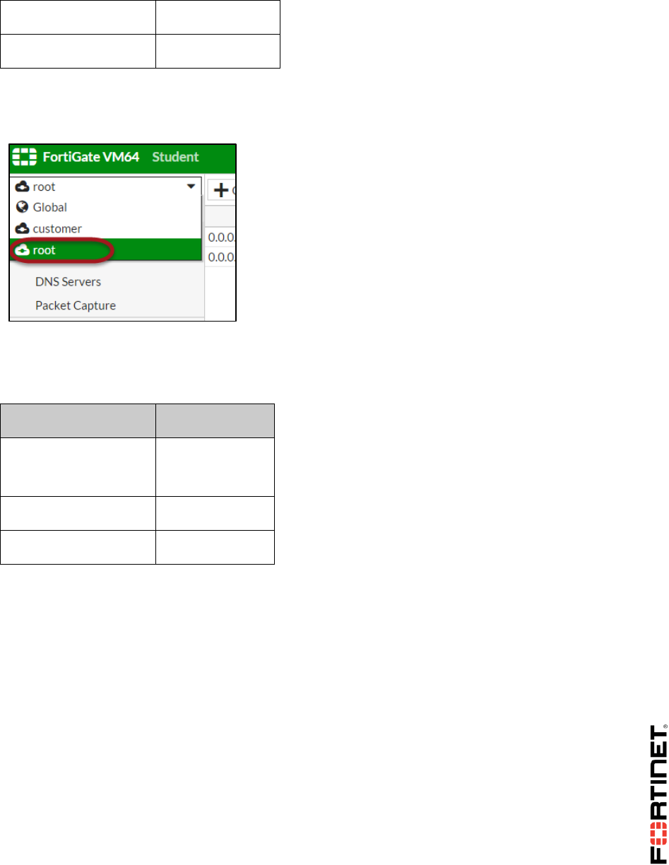
1. In the Local-FortiGate GUI, select the customer VDOM from the drop-down list on the top of the
menu to go to the VDOM-specific settings for the customer VDOM.
2. Go to System > Feature Select.
3. Under Additional Features enable DNS Database.
DO NOT REPRINT
© FORTINET
LAB 2–Virtual Domains
FortiGate II Student Guide 38
To add DNS service on an Interface
1. Still in the customer VDOM-specific settings, go to Network > DNS Server.
2. Click Create New and configure the following.
Field
Value
Interface
port3
Mode
Forward to System DNS
3. Click OK.
Testing the Per-VDOM Administrator Account
In order to see what access is available to the customer-admin account, try logging into the
FortiGate-Local GUI as customer-admin.
To test the per-VDOM administrator account
1. Log out from the Local-FortiGate GUI:
2. Log in again to the Local-FortiGate GUI, but this time use the administrator name customer-
admin with password fortinet.
DO NOT REPRINT
© FORTINET

LAB 2–Virtual Domains
FortiGate II Student Guide 39
3. Navigate through the GUI and examine what the VDOM administrator is allowed to control.
Since the customer-admin administrator can access the customer VDOM only, the GUI does not
display the Global configuration settings or the VDOM-specific settings for the root VDOM.
4. Log out from the Local-FortiGate GUI one more time and log in back as the admin user (blank
password), which has access to the global settings and all VDOMs.
Executing per-VDOM CLI Commands
When VDOMs are enabled, the structure of the GUI menu changes as well as the tree structure of the
CLI. In this exercise, you will examine the differences in the CLI for VDOMs.
To execute per-VDOM CLI commands
1. From Local-Windows, open PuTTY and connect to the LOCAL-FORTIGATE saved session
(connect over SSH).
2. Log in as admin and try to execute the following command to list the routing table:
get router info routing-table all
ATTENTION: Did the CLI reject the command? To execute this command when VDOMs are
enabled, you must specify the VDOM first, in order for FortiGate to know which VDOM’s routing
table to display.
3. To enter the customer VDOM context, type:
config vdom
edit customer
Note: Be careful when typing VDOM names with the edit command.
VDOM names are case-sensitive, and the edit command can both modify and create.
For example, if you enter edit Root, you will not enter the pre-existing root VDOM.
Instead, you will create and enter a new VDOM named Root.
4. Now that you've specified the VDOM, try looking at the routing table again:
get router info routing-table all
It works now. The information displayed in the routing table is specific to the customer VDOM.
Remember that each VDOM has its own routing table.
5. Go to the root VDOM context now:
next
edit root
6. Now use the command for listing the routing table:
get router info routing-table all
This time, the information displayed in the routing table belongs to the root VDOM. You will
observe that this table is different than the one for the customer VDOM.
DO NOT REPRINT
© FORTINET

LAB 2–Virtual Domains
FortiGate II Student Guide 40
2 Inter-VDOM Link
In this exercise you will route traffic between both VDOMs using an inter-VDOM link.
Creating an Inter-VDOM Link
You will create an inter-VDOM link to route traffic between both VDOMs.
To create an inter-VDOM link
1. From the Local-Windows VM, open a browser and log in as admin to the Local-FortiGate GUI at
10.0.1.254.
2. Go to Global > Network > Interfaces.
3. Click Create New and select VDOM Link.
4. In the Name field, enter vlink.
5. Under Interface #0, configure the following settings:
Field
Value
Virtual Domain
root
IP/Network Mask
10.10.100.1/30
Administrative Access
HTTPS, PING, SSH
6. Under Interface #1, configure the following settings:
Field
Value
Virtual Domain
customer
IP/Network Mask
10.10.100.2/30
Administrative Access
HTTPS, PING, SSH
7. Click OK.
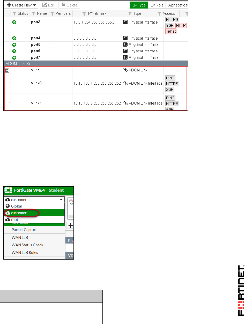
After creating the inter-VDOM link, notice the two inter-VDOM sub-interfaces added within the
root and customer VDOMs. These interfaces are named vlink0 and vlink1. They can be
used to route traffic between both VDOMs.
DO NOT REPRINT
© FORTINET
LAB 2–Virtual Domains
FortiGate II Student Guide 41
Configuring Routing Between VDOMs
You will add the static routes in both VDOMs to route traffic between them. The objective is to have
Internet traffic from Local-Windows crossing the customer VDOM first and then the root VDOM,
before going to the Linux server and the Internet.
To configure routing between VDOMs
8. In the Local-FortiGate GUI, select the customer VDOM from the drop-down list on the top of the
menu to go to the VDOM-specific settings for the customer VDOM.
9. Go to Network > Static Routes to specify a default route for the customer.
10. Click Create New.
11. Add this route:
Field
Value
Destination
Subnet
0.0.0.0/0
DO NOT REPRINT
© FORTINET
LAB 2–Virtual Domains
FortiGate II Student Guide 42
Device
vlink1
Gateway
10.10.100.1
12. Click OK.
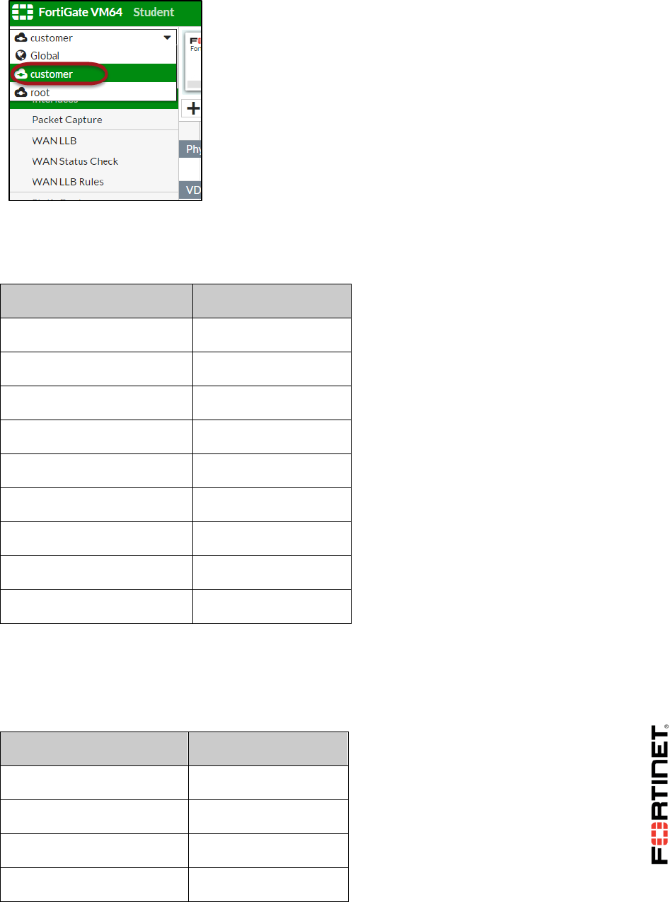
13. Specify a route for the root VDOM to the internal network. Go to the VDOM-specific settings for
the root VDOM and select root from the drop-down list.
14. Go to Network > Static Routes.
15. Click Create New.
16. Configure this route:
Field
Value
Destination
Subnet
10.0.1.0/24
Device
vlink0
Gateway
10.10.100.2
17. Click OK.
Configuring the Firewall Policies for Inter-VDOM Traffic
You will create the firewall policies to allow the Internet traffic through the customer and root VDOMs.
To configure the firewall policies for inter-VDOM traffic
1. In the Local-FortiGate GUI, select the customer VDOM from the drop-down list on the top of
the menu to go to the VDOM-specific settings for the customer VDOM.
DO NOT REPRINT
© FORTINET
LAB 2–Virtual Domains
FortiGate II Student Guide 43
2. Go to Policy & Objects > IPv4 Policy.
3. Click Create New.
4. Configure the following firewall policy to allow traffic from port3 to vlink1:
Field
Value
Name
Internet
Incoming Interface
port3
Outgoing Interface
vlink1
Source
all
Destination Address
all
Schedule
always
Service
ALL
Action
ACCEPT
NAT
Disable
5. Click OK.
6. Go to the VDOM-specific settings for the root VDOM and go to Policy & Objects > IPv4 Policy.
7. Click Create New.
8. Configure the following policy:
Field
Value
Name
Internet
Incoming Interface
vlink0
Outgoing Interface
port1
Source
all
DO NOT REPRINT
© FORTINET

LAB 2–Virtual Domains
FortiGate II Student Guide 44
Destination Address
all
Schedule
always
Service
ALL
Action
ACCEPT
NAT
Enable
9. Click OK.
Testing the Inter-VDOM Link
You will now test your configuration to confirm that Internet traffic is being routed through the two
VDOMs and the inter-VDOM link.
To test the inter-VDOM link
1. From Local-Windows, open a few browser tabs and go to external HTTP websites, such as:
http://www.pearsonvue.com/fortinet/
http://cve.mitre.org
http://www.eicar.org
Traffic should be flowing through both VDOMs now.
2. Open a command prompt window in Local-Windows and execute a traceroute command to an
Internet public IP address:
tracert –d 4.2.2.2
3. Check the output.
The first hop IP address is 10.0.1.254, which is port3 in the customer VDOM. The second hop
IP address is 10.10.100.1, which is the inter-VDOM link in the root VDOM. The third hop IP
address is 10.200.1.254, which is the Linux server.
DO NOT REPRINT
© FORTINET
LAB 3–Transparent Mode
FortiGate II Student Guide 45
LAB 3–Transparent Mode
In this lab, you will create a transparent mode VDOM. You will also configure an inter-VDOM link, this
time between a transparent mode VDOM and a NAT mode VDOM.
Objectives
Configure a transparent mode VDOM.
Configure an inter-VDOM link.
Time to Complete
Estimated: 20 minutes
Lab Topology
The goal of the lab is to create the topology below. You will use VDOMs to logically split the Local-
FortiGate into two virtual firewalls: the root VDOM and the inspect VDOM. The root VDOM is in NAT
mode. The inspect VDOM is in transparent mode and will be inspecting the traffic for virus protection.
So, all Internet traffic coming from Local-Windows must transverse first the root VDOM, then the
inspect VDOM.
Prerequisites
Internet
Local-Windows
10.0.1.10/24
Local-FortiGate
root VDOM
Local-FortiGate
inspect VDOM
Management IP
10.200.1.200/24
LINUX
vlink0
10.200.1.1/24
10.200.1.254/24
vlink1
port3
10.0.1.254/24
port1
DO NOT REPRINT
© FORTINET
LAB 3–Transparent Mode
FortiGate II Student Guide 46
Before beginning this lab, you must restore a configuration file to the Local-FortiGate.
To restore the FortiGate configuration file
1. From the Local-Windows VM, open a browser and log in as admin to the Local-FortiGate GUI at
10.0.1.254.
2. Go to Dashboard, and from the System Information widget click Restore.
3. Select to restore from Local PC and click Upload.
4. Browse to Desktop > Resources > FortiGate-II > Transparent-Mode and select local-
transparent-mode.conf.
5. Click OK.
6. Click OK to reboot.
DO NOT REPRINT
© FORTINET
LAB 3–Transparent Mode
FortiGate II Student Guide 47
1 Transparent Mode VDOM
The configuration file for this exercise already has the setting VDOMs enabled. As such, in this
exercise, you just need to create a transparent mode VDOM called inspect and then move the
interface to the inspect VDOM.
Creating a Transparent Mode VDOM
You will create a new mode and then change its operation mode to transparent.
To create a transparent mode VDOM
1. From the Local-Windows VM, open a browser and log in as admin to the Local-FortiGate GUI at
10.0.1.254.
The configuration that you restored at the beginning of this lab has VDOMs enabled. For this
reason, you will see a drop-down list at the top of the menu. It provides access to the global
settings and to each VDOM-specific settings.
2. Select Global from the drop-down list.
3. Go to System > VDOM and click Create New.
4. Configure the following settings:
Field
Value
Virtual Domain
inspect
Inspection Mode
Proxy (Default)
5. Click OK.
6. In Local-Windows, open PuTTY and connect to the LOCAL-FORTIGATE saved session
(connect over SSH).
7. Log in as admin and execute the following command to change the inspect VDOM operation
mode from the default NAT mode to transparent mode:
config vdom
edit inspect
config system settings
DO NOT REPRINT
© FORTINET

LAB 3–Transparent Mode
FortiGate II Student Guide 48
set opmode transparent
set manageip 10.200.1.200/24
end
end
Stop and Think
What is that 10.200.1.200 IP address for?
Discussion
It is the management IP address for the transparent mode VDOM. Interfaces that belong
to a transparent mode VDOM do not have IP addresses, but the VDOM itself has one. You
can use this IP address for administrative access to the device and this VDOM.
Moving an Interface to a Different VDOM
You will move the interface port1 to the inspect VDOM.
To move an interface to a different VDOM
1. In the Local-FortiGate GUI, go to Global > Network > Interfaces.
2. Edit port1.
3. From the Virtual Domain drop-down list, select inspect.
4. Click OK.
DO NOT REPRINT
© FORTINET

LAB 3–Transparent Mode
FortiGate II Student Guide 49
2 Inter-VDOM Link
In this exercise, you will create an inter-VDOM link. After that, you will create the firewall policies that
allow Internet access across both VDOMs. Finally, you will configure and test antivirus inspection in
the inspect VDOM.
Creating an Inter-VDOM Link
Create the inter-VDOM link for routing traffic from the root VDOM to the Internet through the inspect
VDOM.
To create an inter-VDOM link
1. From the Local-Windows VM, open a browser and log in as admin to the Local-FortiGate GUI at
10.0.1.254.
2. Go to Global > Network > Interfaces.
3. Click Create New and select VDOM Link.
4. In the Name field, enter vlink.
5. Under Interface #0, configure the following settings:
Field
Value
Virtual Domain
root
IP/Network Mask
10.200.1.1/24
Administrative Access
HTTP, HTTPS, PING, SSH
6. Under Interface #1, configure the following settings:
Field
Value
Virtual Domain
inspect
Administrative Access
HTTP, HTTPS, PING, SSH
7. Click OK.
You are returned to the Interfaces page.
8. Review the inter-VDOM link interfaces you just created:
DO NOT REPRINT
© FORTINET

LAB 3–Transparent Mode
FortiGate II Student Guide 50
Note that vlink0 and vlink1 are logical interfaces that can be used to route traffic between the
root and inspect VDOMs. An IP address is only configurable on the NAT mode VDOM interface.
Creating the Firewall Policies
You will create the firewall policies to allow Internet traffic through both VDOMs. You will also enable
antivirus inspection in the inspect VDOM.
To create the firewall policies
1. In the Local-FortiGate GUI, select the VDOM-specific settings for the inspect VDOM.
2. Go to Policy & Objects > IPv4 Policy and click Create New.
3. Configure the following settings:
Field
Value
Name
Inspected_Internet
Incoming Interface
vlink1
Outgoing Interface
port1
Source
all
Destination Address
all
Schedule
always
Service
ALL
Action
ACCEPT
4. Under Firewall/Network Options, disable NAT.
5. Under Security Profiles, enable AntiVirus and select default as the antivirus profile.
DO NOT REPRINT
© FORTINET

LAB 3–Transparent Mode
FortiGate II Student Guide 51
6. Click OK.
7. Now select the VDOM-specific settings for the root VDOM.
8. Go to Policy & Objects > IPv4 Policy and click Create New.
9. Configure the following settings:
Field
Value
Name
Internet
Incoming Interface
port3
Outgoing Interface
vlink0
Source
all
Destination Address
all
Schedule
always
Service
ALL
Action
ACCEPT
10. From Firewall/Network Options, enable NAT.
11. From Logging Options, enable Log Allowed Traffic and select All Sessions.
12. Click OK.
Routing Inter-VDOM traffic
To route traffic from Local-Windows to the inspect VDOM, you need to create a default route in the
root VDOM.
To route inter-VDOM traffic
1. In the Local-FortiGate GUI, select the VDOM-specific settings for the root VDOM.
2. Go to Network > Static Routes and click Create New.
3. Configure the following settings:
Field
Value
Destination
Subnet
0.0.0.0/0
Device
vlink0
Gateway
10.200.1.254
4. Click OK.
DO NOT REPRINT
© FORTINET
LAB 3–Transparent Mode
FortiGate II Student Guide 52
Testing the Transparent Mode VDOM
You will use the traceroute command to confirm that Internet traffic is crossing the inter-VDOM link.
Then you will try to download a virus to confirm that antivirus inspection in the inspect VDOM is
working.
To test the transparent mode VDOM
1. Open a command prompt window on the Local-Windows VM.
2. Execute the following traceroute to verify that your first two hops are 10.0.1.254 and
10.200.1.254:
tracert –d 10.200.3.1
Stop and Think
You will observe that the first hop IP address is 10.0.1.254, which is port3 in the root
VDOM. The second hop IP address is 10.200.1.254, which is the Linux server. Why
isn't the traceroute showing any IP address belonging to the inspect VDOM?
Discussion
A transparent VDOM does not route packets like a NAT VDOM. Instead, it forwards
frames based on the destination MAC addresses as a LAN layer-2 switch. A traceroute
shows the IP addresses of all the routers along a path to a destination. The inspect
VDOM is not acting as a router, but as a layer-2 switch.
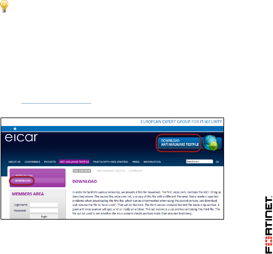
3. In Local-Windows VM, open a browser tab and go to:
http://www.eicar.org
4. Click Download Anti Malware Testfile and then click Download:
5. Select the option to download the eicar.com file via HTTP:
DO NOT REPRINT
© FORTINET
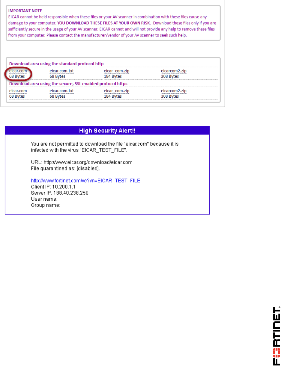
LAB 3–Transparent Mode
FortiGate II Student Guide 53
6. Confirm that the AV profile in the inspect VDOM blocks this action:
DO NOT REPRINT
© FORTINET

LAB 4 –High Availability
FortiGate II Student Guide 54
LAB 4 –High Availability
In this lab, you will set up a high availability (HA) cluster of FortiGate devices. You will explore Active-
Active HA mode and observe FortiGate HA behavior. You will also perform HA failover and use
diagnostic commands to observe election of new primary in the cluster.
You will also configure management port(s) on each FortiGate to reach each FortiGate individually for
management purposes.
Objectives
Set up an HA cluster using FortiGate devices
Observe HA synchronization and interpret diagnostic output
Performing HA failover
Manage individual cluster members by configuring reserved management interface
Time to Complete
Estimated: 45 minutes
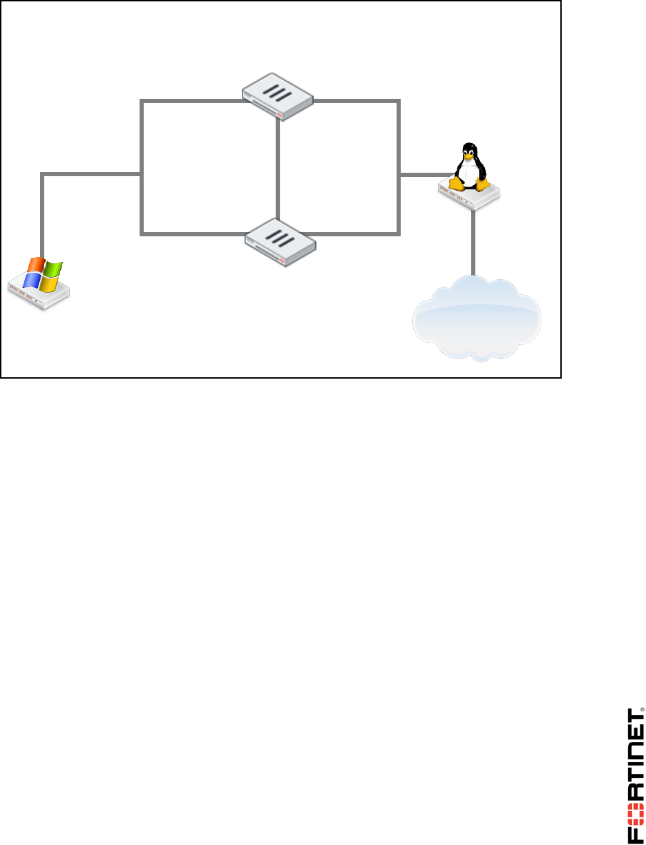
Lab HA Topology
After you upload the required configurations to each FortiGate, the logical topology will change to this.
DO NOT REPRINT
© FORTINET
LAB 4 –High Availability
FortiGate II Student Guide 55
Prerequisites
Before beginning this lab, you must restore a configuration file to each FortiGate.
Note: Make sure to restore the correct configuration in each FortiGate as per the steps below. Failure
to restore proper configuration in each FortiGate will prevent you from doing the lab exercise.
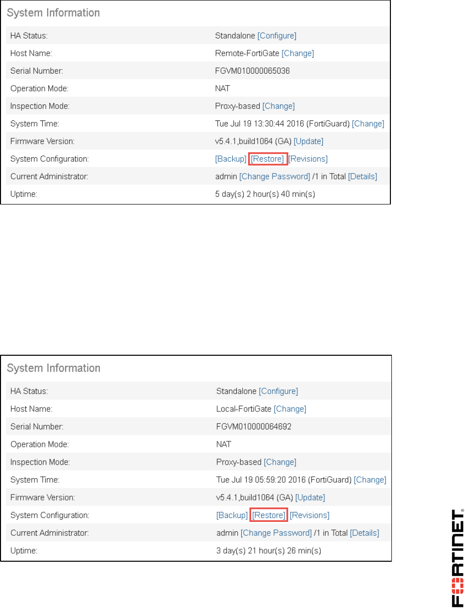
To restore the Remote-FortiGate configuration file
1. From the Local-Windows, open a web browser and log in as admin to the Remote-FortiGate GUI
at 10.200.3.1.
2. Go to Dashboard, and from the System Information widget click Restore.
LOCAL-
WINDOWS
10.0.1.10
port1
10.200.1.1/24
LOCAL-
FORTIGATE
REMOTE-
FORTIGATE
LINUX
10.200.1.254
eth1
port3
10.0.1.254/24
port1
port3
port2
port2
Internet
DO NOT REPRINT
© FORTINET
LAB 4 –High Availability
FortiGate II Student Guide 56
3. Select to restore from Local PC and click Upload.
4. Browse to Desktop > Resources > FortiGate-II > HA and select remote-ha.conf.
5. Click OK.
6. Click OK to reboot.
To restore the Local-FortiGate configuration file
1. From the Local-Windows, open a new web browser and log in as admin to the Local-FortiGate
GUI at 10.0.1.254.
2. Go to Dashboard, and from the System Information widget click Restore.
3. Select to restore from Local PC and click Upload.
4. Browse to Desktop > Resources > FortiGate-II > HA and select local-ha.conf.
5. Click OK.
6. Click OK to reboot.
DO NOT REPRINT
© FORTINET

LAB 4 –High Availability
FortiGate II Student Guide 57
1 Configuring High Availability (HA)
FortiGate HA uses FortiGate Clustering Protocol (FGCP) which uses heartbeat link for HA related
communications to discover other FortiGates in same HA group, elect primary, synchronize
configuration, and detect failed device in HA cluster.
In this exercise, you will configure HA settings on both the FortiGate devices. You will observe the HA
synchronize status and verify the configuration is in sync on both FortiGate devices using the diagnose
commands.
Configure HA Settings on Local-FortiGate
Now you will configure HA related setting on the Local-FortiGate GUI.
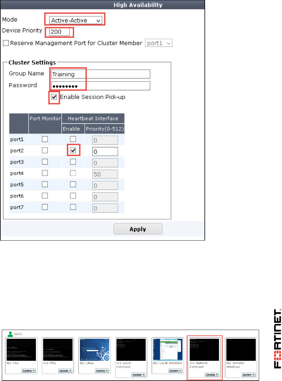
To configure HA settings on Local-FortiGate
1. From the Local-Windows, open a browser and log in as admin to the Local-FortiGate GUI at
10.0.1.254.
2. Go to System > HA and configure the following high availability (HA) settings.
Field
Value
Mode
Active-Active
Device Priority
200
Group Name
Training
Password
Fortinet
Enable Session Pick-up
Check the box to enable it
Heartbeat Interface
Enable
Check the box for port2
Uncheck the box for port4
You configuration should like as below:
DO NOT REPRINT
© FORTINET
LAB 4 –High Availability
FortiGate II Student Guide 58
3. Click Apply.
Configure HA Settings on the Remote-FortiGate
Now you will configure HA related setting on the Remote-FortiGate from the console.
To configure HA settings on the Remote-FortiGate
1. Click on Remote-FortiGate to launch the Remote-FortiGate console window.
DO NOT REPRINT
© FORTINET
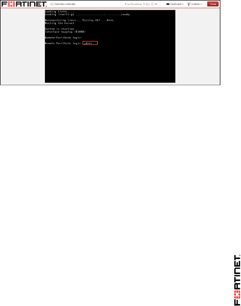
LAB 4 –High Availability
FortiGate II Student Guide 59
2. Login as admin.
3. Configure the high availability (HA) settings.
config system ha
set group-name Training
set mode a-a
set password Fortinet
set hbdev "port2" 0
set session-pickup enable
set override disable
set priority 100
end
Observing and Verifying the HA Synchronization Status
Now you have configured the HA on both FortiGate devices, you will verify the HA has been
established and configurations are in fully synchronized.
All cluster members checksum must match in order for the FortiGate devices to be in synchronized
state.
To observe and verify the HA synchronization status
1. Still in the Remote-FortiGate console, you should see the error messages that FortiGate sends
to the console. This sometimes shows useful status change information, such as:
slave succeeded to sync external files with master
slave starts to sync with master
logout all admin users
DO NOT REPRINT
© FORTINET
LAB 4 –High Availability
FortiGate II Student Guide 60
Wait 4 to 5 minutes for the FortiGate devices to synchronize. Once the FortiGate devices are
synchronized, it will log out all admin users.
2. In the Remote-FortiGate console, again log in as admin.
3. To check the HA synchronize status, run the following command on the Remote-FortiGate
console.
diagnose sys ha checksum show
4. Click on Local-FortiGate to launch the Local-FortiGate console window.
5. Log in as admin.
6. To check the HA synchronize status, run the following command on the Local-FortiGate console.
diagnose sys ha checksum show
7. Compare the output from both FortiGate devices. If both FortiGate devices are synchronized, then
the checksum will match.
8. Alternatively, you can run the following command to view the checksums of all cluster members
from any FortiGate in the cluster.
diagnose sys ha checksum cluster
Verifying FortiGate Roles in a HA Cluster
Once the checksum match on both FortiGates, you will be verifying the cluster member roles to
confirm primary and secondary device.
To verify FortiGate Roles in a HA Cluster
1. Run the following command on both the Local-FortiGate console and the Remote-FortiGate
console to verify that the HA cluster has been established.
get system status
2. View the Current HA mode line.
3. Notice that the Local-FortiGate is a-a master, and the Remote-FortiGate device is a-a
backup.
Note: FortiGate named Local-FortiGate is master in the HA cluster because in this
configuration override is disabled and monitored ports are not configured and next
cluster checks for priority for which Local-FortiGate has more priority set to 200 and
Remote-FortiGate has priority of 100.
4. From the Local-Windows, open a browser and log in as admin to the Local-FortiGate GUI at
10.0.1.254.
DO NOT REPRINT
© FORTINET
LAB 4 –High Availability
FortiGate II Student Guide 61
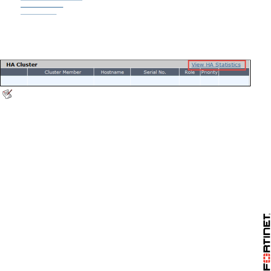
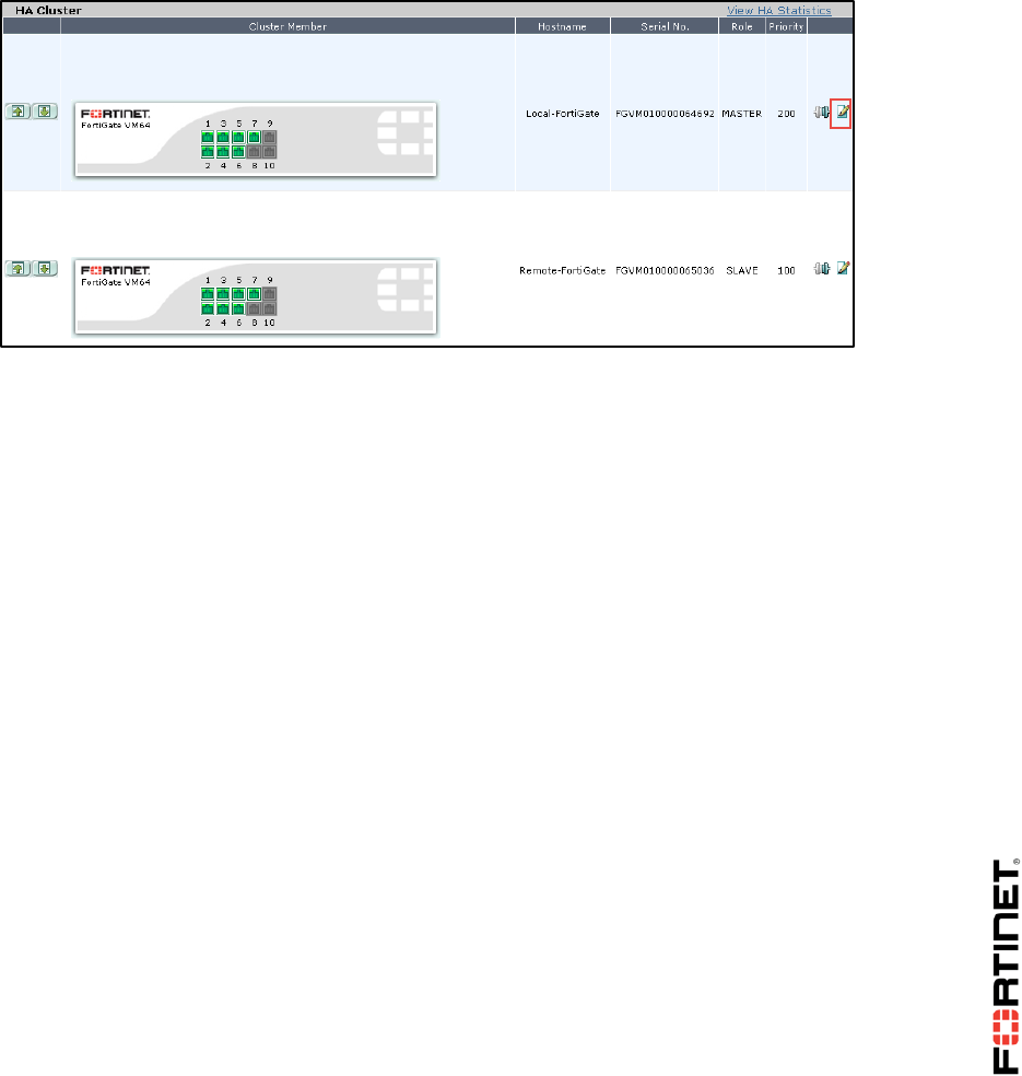
5. Go to the Dashboard >System Information widget, it will show the cluster members and their
roles.
Viewing HA Statistics
Now you will be viewing HA statistics from the GUI of primary FortiGate.
To view HA Statistics
1. In Local-Windows, open few web browser tabs and connect to a few websites. For example:
https://www.fortinet.com
www.yahoo.com
www.bbc.com
2. Go back to the GUI of the cluster’s primary FortiGate at 10.0.1.254.
3. Go to System > HA.
4. Click View HA Statistics.
This will show you the status, uptime and session information of the cluster members.
Note: The primary FortiGate will have more active sessions than the secondary
FortiGate. This is because all management traffic is with the primary; all non-TCP
traffic is handled by the primary also. By default, only TCP sessions which are not
handled by UTM proxy for inspection are load balanced between the primary and
secondary FortiGate.
DO NOT REPRINT
© FORTINET

LAB 4 –High Availability
FortiGate II Student Guide 62
2 High Availability Failover
You have setup HA cluster. Now, you will be triggering HA failover and observe the renegotiation to
elect new primary and redistribution of sessions.
Triggering Failover by Rebooting the Primary FortiGate
You will be rebooting the primary FortiGate in the cluster to trigger failover.
To trigger failover by rebooting the Primary FortiGate
1. From the Local-Windows, open a web browser and go to the following URL:
http://www.dailymotion.com
If Java is not enabled, please enable it.
2. Play a long video.
3. During this, open a command prompt on the Local-Windows and run continuous ping to a public
IP address.
ping 4.2.2.2 -t
4. Go to the Local-FortiGate console.
5. To trigger a failover, reboot the Local-FortiGate by entering the following command:
execute reboot
6. Press y to continue to reboot the FortiGate.
Verifying the HA Failover and FortiGate Roles
Now you will be verifying the HA failover and check the roles of FortiGate in HA cluster.
To verify the HA failover and FortiGate roles
1. Go back to Local-Windows and check the command prompt and video that you started earlier.
Because of the failover, the Remote-FortiGate device is now the primary to process of traffic. Your
ping and video should be still running.
2. Go to the Remote-FortiGate console.
3. Type the following command to verify that Remote-FortiGate is now acting as primary device in
HA cluster.
get system status
When the Local-FortiGate finishes rebooting and rejoins the cluster, does it rejoin as the
secondary, or resume its initial role of primary?
4. To see the status of all cluster members, run the following command on any FortiGate in the
cluster:
diagnose sys ha status
DO NOT REPRINT
© FORTINET

LAB 4 –High Availability
FortiGate II Student Guide 63
You should observe the Local-FortiGate rejoins the cluster as a secondary. It has lost its role of
primary.
Note: FortiGate named Local-FortiGate becomes secondary in the HA cluster
because in this configuration override is disabled and monitored ports are not
configured and next, cluster checks for uptime. As Local-FortiGate is rebooted, it has
less uptime than the Remote-FortiGate.
Triggering HA Failover by Resetting Uptime
Now you will trigger failover by resetting the uptime on the current primary FortiGate, which should be
Remote-FortiGate, and you will verify the FortiGate's role in a HA cluster.
To trigger HA failover by resetting uptime on the FortiGate
1. Go to the Remote-FortiGate console.
2. Run the following command:
diagnose sys ha reset-uptime
Note: By resetting the HA uptime, you are forcing the cluster to use the next value to
determine which FortiGate has priority for becoming the primary. You will observe that
the Local-FortiGate now has the primary role in the cluster.
3. To see the status of all cluster members, run the following command on any FortiGate console in
the cluster:
diagnose sys ha status
4. Go back to the Remote-FortiGate console.
5. Check the Uptime (system uptime) on Remote-FortiGate to see that this remains unchanged:
get system performance status
Notice that Remote-FortiGate uptime is not reset; only the HA uptime.
Observing HA Failover Using Diagnostic Commands
The HA synchronization process is responsible for FGCP packets that communicate cluster status and
build the cluster. You will be using real time diagnostic commands to observe this process.
To observe HA failover using diagnostic commands
1. Go to the Local-FortiGate console and log in as admin.
2. Run the following commands.
diagnose debug enable
diagnose debug application hasync 0
diagnose debug application hasync 255
DO NOT REPRINT
© FORTINET
LAB 4 –High Availability
FortiGate II Student Guide 64
3. Go to the Remote-FortiGate console.
4. Reboot the Remote-FortiGate.
execute reboot
5. Press y to continue to reboot the FortiGate.
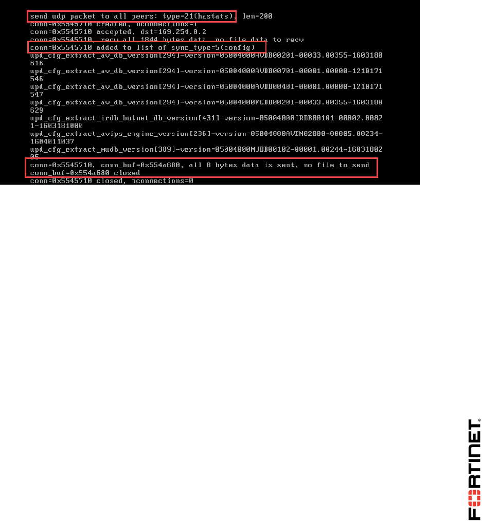
6. On the Local-FortiGate console, observe the output while the secondary reboots and starts
communicating with the cluster.
It will show that the current primary FortiGate is sending heartbeat packets and trying to synchronize
its configuration with the secondary FortiGate’s.
7. To stop the debug output on the Local-FortiGate, press the Up-Arrow key twice, selecting the
command before last (in this case diagnose debug application hasync 0), then press the
Enter key.
DO NOT REPRINT
© FORTINET
LAB 4 –High Availability
FortiGate II Student Guide 65
3 Configuring HA Management Interface
In this exercise, you will configure a spare interface of the cluster to be a non-synchronizing
management interface. This will allow both FortiGates to be reachable for SNMP and management
purposes only.
If management interface is not configured, you will have access to the GUI for only the primary
FortiGate in the cluster. However, you can connect to the secondary FortiGate through the primary
FortiGate's CLI.
Accessing the Secondary FortiGate through the Primary
FortiGate CLI
You will be connecting to the secondary FortiGate through the primary FortiGate's CLI.
To access the secondary FortiGate through the primary FortiGate CLI
1. From the Local-Windows VM, open PuTTY and connect to the LOCAL-FORTIGATE saved
session (connect over SSH).
2. Log in as admin.
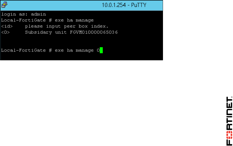
3. Type the following command to access the secondary FortiGate CLI through the primary’s HA link:
execute ha manage <id> (use ? to list the id values)
4. Log in as admin.
5. Run the following command to get the status of the secondary FortiGate.
get system status
View the Current HA mode line. You will notice that the Remote-FortiGate device is a-a
backup.
6. To return to the CLI of Local-FortiGate, run the command below:
exit (to return to the primary)
Setting up a Management Interface
You will be using an unused interface on the FortiGates in a HA cluster to configure a management
DO NOT REPRINT
© FORTINET
LAB 4 –High Availability
FortiGate II Student Guide 66
interface. This allows you to configure a different IP address for this interface for each FortiGate in the
HA cluster.
To setup a management interface
1. From the Local-Windows VM, open a browser and log in as admin to the Local-FortiGate GUI
(normally the primary) at 10.0.1.254.
2. Go to System > HA.
3. Edit the Local-FortiGate.
4. Select Reserve Management Port for Cluster Member and choose port7.
5. Click Apply.
Note: Port7 connects to the same LAN segment as port3.
Configuring and Accessing Using the Management
Interface for the Primary FortiGate
You will be configuring and verifying access to primary FortiGate using management interface.
To configure and verify access using the management interface for the primary FortiGate
1. Go to the Local-FortiGate console.
2. Log in as admin.
3. Configure the port7 as following:
config system interface
edit port7
set ip 10.0.1.253/24
set allowaccess http snmp ping ssh
end
DO NOT REPRINT
© FORTINET

LAB 4 –High Availability
FortiGate II Student Guide 67
Note: Even though this address overlaps with port3, and would not be normally
allowed (FortiGate does not allow overlapping subnets), it is allowed here because the
interface now has a special purpose, and is excluded from the routing table.
4. From the Local-Windows, open a web browser and log in as admin to the Local-FortiGate GUI at
10.0.1.253.
This will verify connectivity to port7.
Configuring and Accessing Using the Management
Interface for the Secondary FortiGate
You will be configuring and verifying access to secondary FortiGate using the management interface.
To configure and verify access using the management interface for the secondary FortiGate
1. Go to the Remote-FortiGate console.
2. Log in as admin.
3. Verify that the non-synchronizing interface settings have been synced to the secondary.
show system ha
Look for ha-mgmt-status and ha-mgmt-interface. These should be set.
4. In the Remote-FortiGate console, verify that port7 has no configuration by running the following
command:
show system interface
5. Configure port7 through the CLI:
config system interface
edit port7
set ip 10.0.1.252/24
set allowaccess http ping ssh snmp
end
6. From the Local-Windows, open a web browser and log in as admin to the Remote-FortiGate GUI
at 10.0.1.252.
This will verify connectivity to port7.
Each device in the cluster now has its own management IP address for monitoring purposes.
Disconnecting FortiGate from the Cluster
You will be disconnecting the Remote-FortiGate from the cluster. FortiGate will prompt you to
configure an IP address on any port on FortiGate so that you can access it after disconnecting.
DO NOT REPRINT
© FORTINET
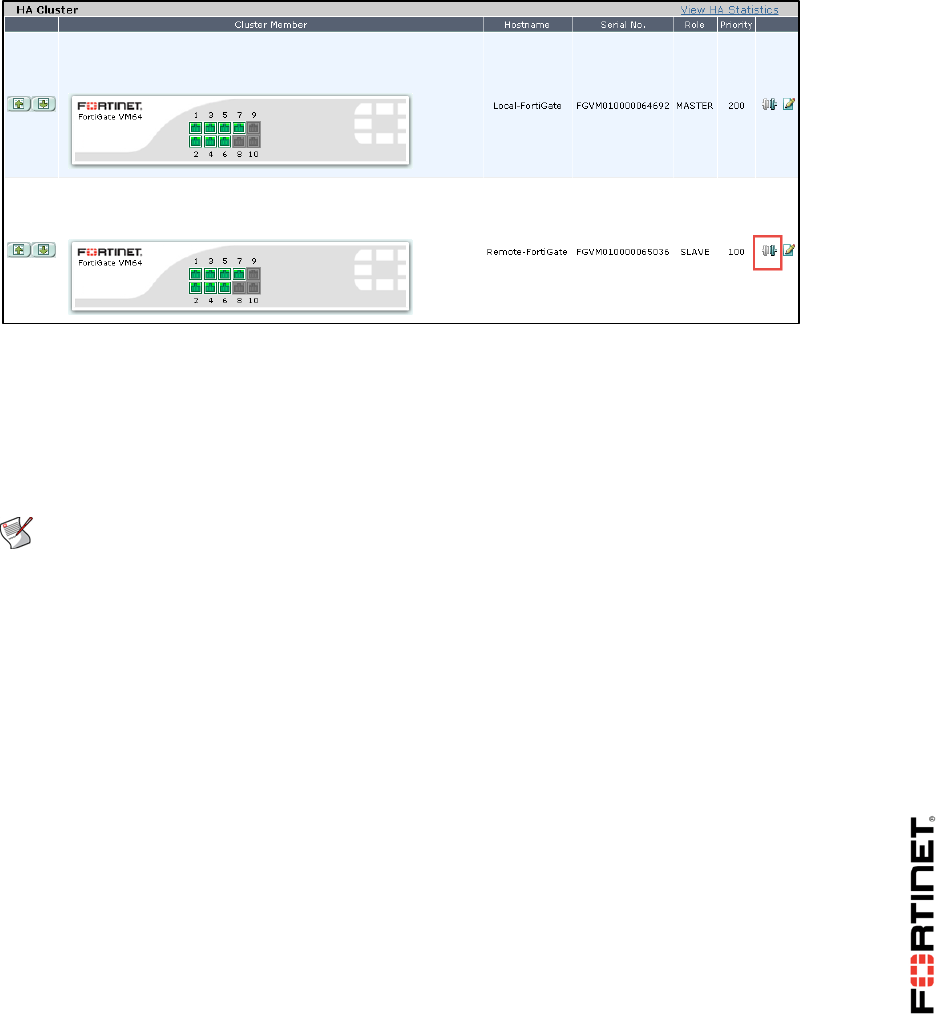
LAB 4 –High Availability
FortiGate II Student Guide 68
To disconnect FortiGate from the cluster
1. From the Local-Windows, open a browser and log in as admin to the Local-FortiGate GUI at
10.0.1.254.
2. Go to System > HA.
3. For the Remote-FortiGate, click the Disconnect from cluster icon.
This will remove the FortiGate from the HA cluster.
4. When prompted, configure port3 with the IP address of 10.0.1.251/24.
Restoring the Remote-FortiGate Configuration
Now you will restore the Remote-FortiGate configuration so that you can use the Remote-FortiGate in
the next labs.
Note: Failure to do these steps will prevent you from doing the next exercise.
To restore the Remote-FortiGate configuration
1. In the Local-Windows, open a browser and log in as admin to the Remote-FortiGate GUI at
10.0.1.251.
2. Go to Dashboard, and from the System Information widget click Restore.
DO NOT REPRINT
© FORTINET
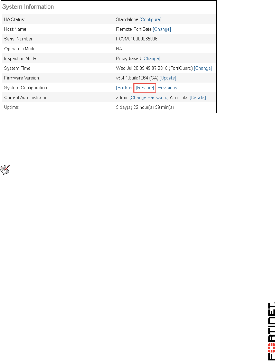
LAB 4 –High Availability
FortiGate II Student Guide 69
3. From your local PC (Local-Windows), click Upload and browse to Desktop > Resources >
FortiGate-I > Introduction and select remote-initial.conf.
4. Click OK.
5. Click OK.
Note: Failure to do these steps will prevent you from doing the next exercises.
DO NOT REPRINT
© FORTINET
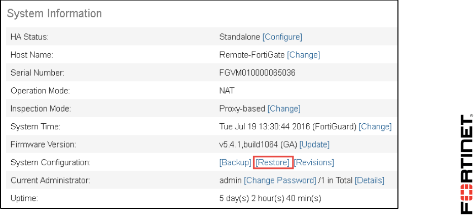
LAB 5–Advanced IPsec VPN
FortiGate II Student Guide 70
LAB 5–Advanced IPsec VPN
In this lab, you will configure redundant VPN tunnels with failover capability between two FortiGates.
You will also create a dial-up VPN between a FortiGate and FortiClient.
Objectives
Deploy a dialup VPN between two FortiGates.
Deploy a dialup VPN for FortiClient.
Configure redundant VPNs between two FortiGates.
Time to Complete
Estimated: 60 minutes
Prerequisites
Before beginning this lab, you must restore configuration files to the Local-FortiGate and Remote-
FortiGate.
To restore the Remote-FortiGate configuration file
1. From the Local-Windows VM, open a browser and log in as admin to the Remote-FortiGate GUI
at 10.200.3.1.
2. Go to Dashboard, and from the System Information widget click Restore.
3. Select to restore from Local PC and click Upload.
DO NOT REPRINT
© FORTINET
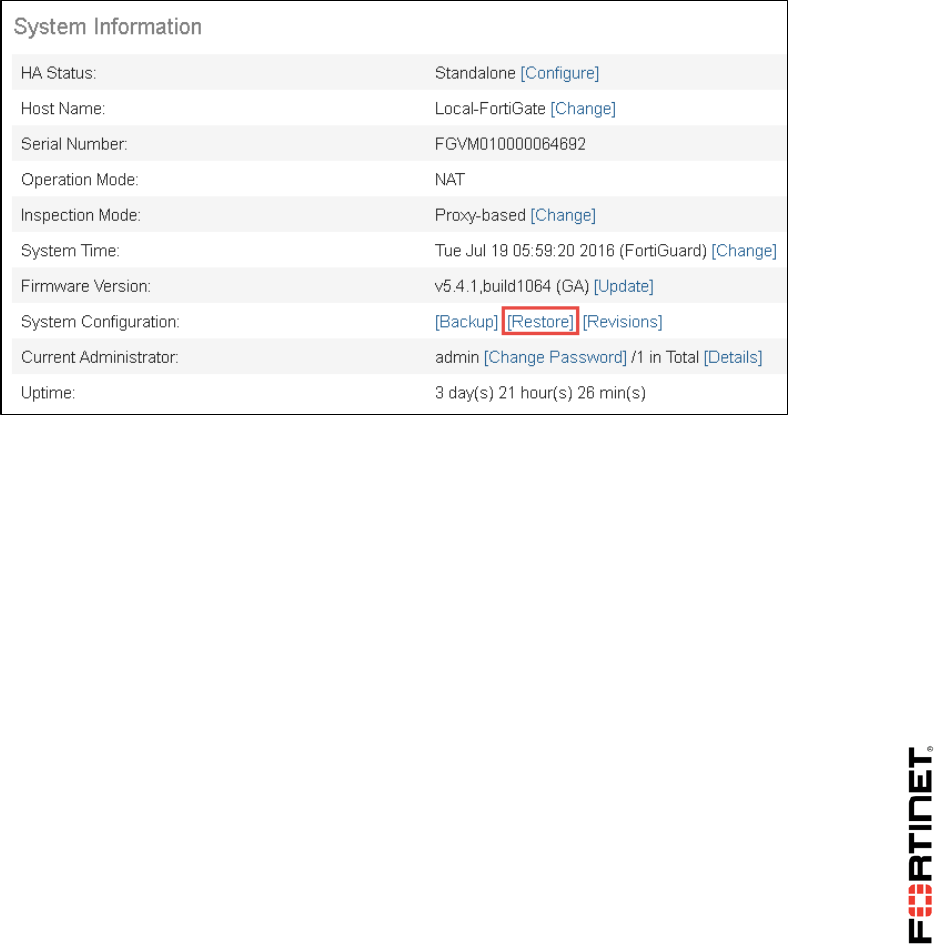
LAB 5–Advanced IPsec VPN
FortiGate II Student Guide 71
4. Browse to Desktop > Resources > FortiGate-II > Advanced-IPsec and select remote-
advanced-ipsec.conf.
5. Click OK.
6. Click OK to reboot.
To restore the Local-FortiGate configuration file
1. From the Local-Windows VM, open a browser and log in as admin to the Local-FortiGate GUI at
10.0.1.254.
2. Go to Dashboard, and from the System Information widget click Restore.
3. Select to restore from Local PC and click Upload.
4. Browse to Desktop > Resources > FortiGate-II > Advanced-IPsec and select local-
advanced-ipsec.conf.
5. Click OK.
6. Click OK to reboot.
DO NOT REPRINT
© FORTINET

LAB 5–Advanced IPsec VPN
FortiGate II Student Guide 72
1 Configure an IPsec VPN Between Two
FortiGates
In this exercise, you will configure one VPN between the Local-FortiGate and the Remote-FortiGate
for redundancy.
Local-FortiGate: Creating the Phases 1 and 2
You will configure the IPsec VPN by creating the phases 1 and 2.
To create the phases 1 and 2
1. From the Local-Windows VM, open a browser and log in as admin to the Local-FortiGate GUI at
10.0.1.254.
2. Go to VPN > IPsec Tunnels and click Create New.
3. In the Name field, enter Remote_1.
4. Under Template Type, select Custom.
5. Click Next.
6. Under Network, configure the following settings:
Field
Value
Remote Gateway
Static IP Address
IP Address
10.200.3.1
Interface
port1
Dead Peer Detection
On Idle
7. Under Authentication, configure the following settings:
Field
Value
Method
Pre-shared Key
Pre-shared Key
fortinet
8. Leave all other settings at their default values.
9. Click OK.
DO NOT REPRINT
© FORTINET
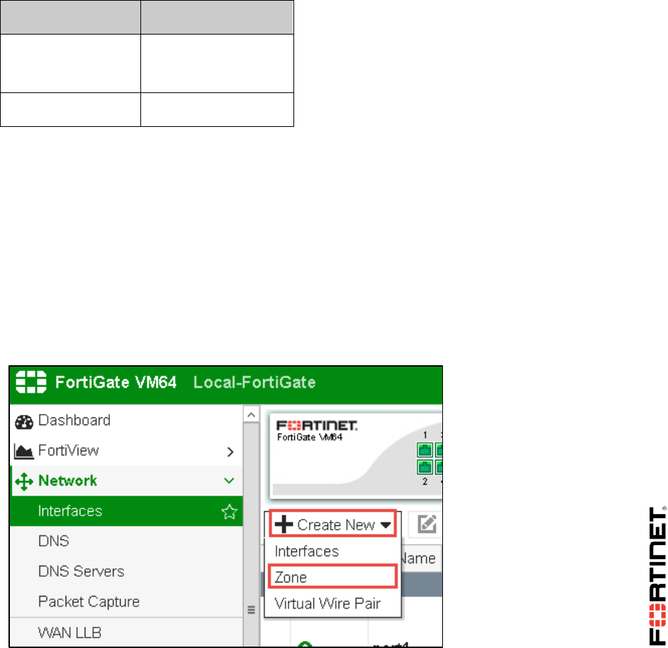
LAB 5–Advanced IPsec VPN
FortiGate II Student Guide 73
Local-FortiGate: Creating a Static Route for Route-
based VPN
The VPN was created as route-based. This means that it requires at least one route (static or
dynamic) to forward the traffic through the tunnel. You will create a static route for that purpose.
To create a static route for route-based VPN
1. In the Local-FortiGate GUI, go to Network > Static Routes.
2. Click Create New.
3. Configure the following settings:
Field
Value
Destination
Subnet
10.0.2.0/24
Device
Remote_1
4. Click OK.
Local-FortiGate: Creating an Interface Zone
You will create an interface zone that will include the two IPsec virtual interfaces (the virtual IPsec
interface for the primary VPN and the one for the secondary VPN). It is not mandatory to have an
interface zone for redundant VPNs, but it simplifies the number of firewall policies to create later.
To create an interface zone
1. In the Local-FortiGate GUI, go to Network > Interfaces.
2. Click Create New and select Zone.
3. Configure the following settings:
DO NOT REPRINT
© FORTINET

LAB 5–Advanced IPsec VPN
FortiGate II Student Guide 74
Field
Value
Zone Name
VPN
Interface Members
Remote_1
4. Click OK.
Local-FortiGate: Creating Firewall Policies for VPN
Traffic
Create two firewall policies between port3 and Remote_1, one for each traffic direction.
To create the firewall policies for VPN traffic
1. In the Local-FortiGate GUI, go to Policy & Objects > IPv4 Policy.
2. Click Create New.
3. Configure the following settings:
Field
Value
Name
Remote_out
Incoming Interface
port3
Outgoing Interface
VPN
Source
LOCAL_SUBNET
Destination Address
REMOTE_SUBNET
Schedule
always
Service
ALL
Action
ACCEPT
4. Under Firewall/Network Options, disable NAT.
5. Click OK.
6. Click Create New one more time.
7. Configure the following settings:
Field
Value
Name
Remote_in
Incoming Interface
VPN
DO NOT REPRINT
© FORTINET

LAB 5–Advanced IPsec VPN
FortiGate II Student Guide 75
Outgoing Interface
port3
Source
REMOTE_SUBNET
Destination Address
LOCAL_SUBNET
Schedule
always
Service
ALL
Action
ACCEPT
8. Under Firewall/Network Options, disable NAT.
9. Click OK.
Remote-FortiGate: Creating Phases 1 and 2
You will now go to the Remote-FortiGate and start adding phases 1 and 2.
To create phases 1 and 2
1. From the Local-Windows VM, open a browser and log in as admin to the Remote-FortiGate GUI
at 10.200.3.1.
2. Go to VPN > IPsec Tunnels.
3. Click Create New.
4. In the Name field, enter Local_1.
5. From Template Type, select Custom.
6. Click Next.
7. Under Network, configure the following settings:
Field
Value
Remote Gateway
Static IP Address
IP Address
10.200.1.1
Interface
port4
Dead Peer Detection
On Idle
8. Under Authentication, configure the following settings:
Field
Value
Method
Pre-shared Key
Pre-shared Key
fortinet
DO NOT REPRINT
© FORTINET
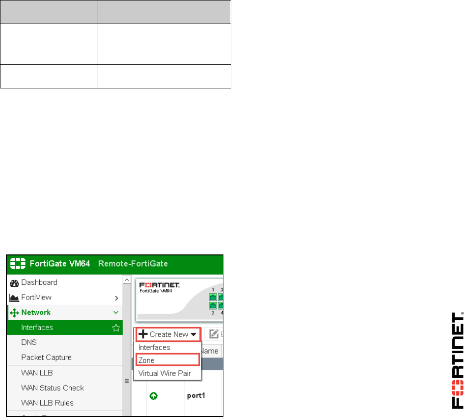
LAB 5–Advanced IPsec VPN
FortiGate II Student Guide 76
9. Leave the other settings with their default values.
10. Click OK.
Remote-FortiGate: Creating a Static Route for Route-
based VPN
As this VPN was also created as route-based, you will need one static route.
To create a static route for route-based VPN
1. In the Remote-FortiGate GUI, go to Network > Static Routes.
2. Click Create New.
3. Configure the following settings:
Field
Value
Destination
Subnet
10.0.1.0/24
Device
Local_1
4. Click OK.
Remote-FortiGate: Creating an Interface Zone
You will also create an interface zone on Remote-FortiGate that will include the two IPsec virtual
interfaces. Again, this is not mandatory for having redundant VPNs, but it simplifies the number of
firewall policies to create later.
To create an interface zone
1. In the Remote-FortiGate GUI, go to Network > Interfaces.
2. Click Create New and select Zone:
3. Configure the following settings:
DO NOT REPRINT
© FORTINET

LAB 5–Advanced IPsec VPN
FortiGate II Student Guide 77
Field
Value
Zone Name
VPN
Interface Members
Local_1
4. Click OK.
Remote-FortiGate: Creating the Firewall Policies for
Internet Traffic
Create two firewall policies between port6 and Local_1, one for each traffic direction.
To create the firewall policies for Internet traffic
1. In the Remote-FortiGate GUI, go to Policy & Objects > IPv4 Policy.
2. Click Create New.
3. Configure the following settings:
Field
Value
Name
Local_out
Incoming Interface
port6
Outgoing Interface
VPN
Source
REMOTE_SUBNET
Destination Address
LOCAL_SUBNET
Schedule
always
Service
ALL
Action
ACCEPT
4. Under Firewall/Network Options, disable NAT.
5. Click OK.
6. Click Create New again.
7. Configure the following settings:
Field
Value
Name
Local_in
Incoming Interface
VPN
DO NOT REPRINT
© FORTINET

LAB 5–Advanced IPsec VPN
FortiGate II Student Guide 78
Outgoing Interface
port6
Source
LOCAL_SUBNET
Destination Address
REMOTE_SUBNET
Schedule
Always
Service
ALL
Action
ACCEPT
8. Under Firewall/Network Options, disable NAT.
9. Click OK.
Testing the IPsec VPN
You will test the VPN by generating some traffic and confirming that the VPN goes up.
To test the IPsec VPN
1. Open a command prompt window on the Local-Windows VM.
2. Generate a ping to the Remote-Windows VM (10.0.2.10):
ping 10.0.2.10
Note: FortiGate may not have previously established the VPN. If so, the first few
pings will fail while FortiGate negotiates and establishes the VPN.
3. Go back to the Local-FortiGate GUI and go to Monitor > IPsec Monitor.
4. Confirm that the Remote_1 VPN is up.
A green arrow should be displayed in the Status column.
DO NOT REPRINT
© FORTINET

LAB 5–Advanced IPsec VPN
FortiGate II Student Guide 79
2 Configuring a Backup IPsec VPN
In this exercise, you will create the second route-based VPN for redundancy. This time, configure the
VPN from the Local-FortiGate port2 to the Remote-FortiGate port5.
Configuring the Backup VPN on the Local-FortiGate
You will start by configuring the Local-FortiGate side.
To configure the backup VPN on the Local-FortiGate
1. From the Local-Windows VM, open a browser and log in as admin to the Local-FortiGate GUI at
10.0.1.254.
2. Repeat the configuration steps in Local-FortiGate: Creating Phases 1 and 2 to create phases 1
and 2. Use Remote_2 for the VPN name.
3. Go to Network > Static Routes.
4. Click Create New.
5. Add this static route:
Field
Value
Destination
Subnet
10.0.2.0/24
Device
Remote_2
Administrative Distance
20
6. Click OK.
7. Go to Network > Interfaces.
8. Edit the zone VPN.
9. Add the interface Remote_2 to it.
10. Click OK.
Configuring the Backup VPN in the Remote-FortiGate
You will configure the Remote-FortiGate side.
To configure the backup VPN in the remote-FortiGate
1. From the Local-Windows VM, open a browser and log in as admin to the Remote-FortiGate
GUI at 10.200.3.1.
DO NOT REPRINT
© FORTINET

LAB 5–Advanced IPsec VPN
FortiGate II Student Guide 80
2. Repeat the configuration steps in Remote-FortiGate: Creating Phases 1 and 2 to create phases 1
and 2.Use Local_2 for the VPN name.
3. Go to Network > Static Routes.
4. Click Create New.
5. Add this static route:
Field
Value
Destination
10.0.1.0/24
Device
Local_2
Administrative Distance
20
6. Click OK.
7. Go to Network > Interfaces.
8. Edit the zone VPN.
9. Add the interface Local_2 to it.
10. Click OK.
Testing the VPN Redundancy
You will now test the VPN failover. You will use the sniffer tool to monitor which VPN the traffic is
using.
To test the VPN redundancy
1. In Local-Windows, open PuTTY and connect to the LOCAL-FORTIGATE saved session (connect
over SSH).
2. Log in as admin and execute the following command to sniffer all ICMP traffic to 10.0.2.10 with
verbosity 4:
diagnose sniffer packet any 'icmp and host 10.0.2.10' 4
3. Open a command prompt window in Local-Windows and run a continuous ping to Remote-
Windows:
ping –t 10.0.2.10
4. Check the sniffer output. It will show that the Local-FortiGate is routing the packets through the
VPN Remote_1:
28.040086 port3 in 10.0.1.10 -> 10.0.2.10: icmp: echo request
28.040107 Remote_1 out 10.0.1.10 -> 10.0.2.10: icmp: echo request
28.041188 Remote_1 in 10.0.2.10 -> 10.0.1.10: icmp: echo reply
28.041196 port3 out 10.0.2.10 -> 10.0.1.10: icmp: echo reply
DO NOT REPRINT
© FORTINET

LAB 5–Advanced IPsec VPN
FortiGate II Student Guide 81
Now, let's simulate a failure in the VPN Remote_1 and observe how the FortiGate starts using the
secondary VPN Remote_2.
5. From the Local-FortiGate GUI, go to Network > Interfaces.
6. Edit port1.
7. Set the Interface State to Disabled to bring down the tunnel Remote_1.
8. Click OK.
9. Wait a few minutes until FortiGate detects the failure in the VPN Remote_1 and reroutes the
traffic through Remote_2.
10. Check the sniffer output again. You will observe that the VPN Remote_2 is being used now:
546.352063 port3 in 10.0.1.10 -> 10.0.2.10: icmp: echo request
546.352090 Remote_2 out 10.0.1.10 -> 10.0.2.10: icmp: echo request
546.353546 Remote_2 in 10.0.2.10 -> 10.0.1.10: icmp: echo reply
546.353560 port3 out 10.0.2.10 -> 10.0.1.10: icmp: echo reply
11. To finish this exercise, on the Local-FortiGate GUI, go to Network > Interfaces.
12. Edit port1.
13. Configure the Interface State back to Enabled.
14. Click OK.
Note: Omitting these last steps will prevent you from doing the next exercise.
DO NOT REPRINT
© FORTINET
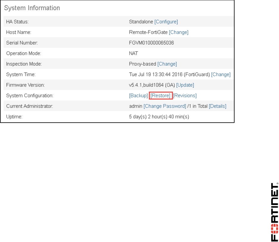
LAB 5–Advanced IPsec VPN
FortiGate II Student Guide 82
3 IPsec VPN with FortiClient
You will now create a dial-up VPN between a FortiGate and FortiClient.
Prerequisites
Before beginning, you must restore the initial configuration files to the Local-FortiGate and Remote-
FortiGate.
To restore the Remote-FortiGate configuration file
1. From the Local-Windows VM, open a browser and log in as admin to the Remote-FortiGate GUI
at 10.200.3.1.
2. Go to Dashboard, and from the System Information widget click Restore.
3. Select to restore from Local PC and click Upload.
4. Browse to Desktop > Resources > FortiGate-II > Advanced-IPsec and select remote-
advanced-ipsec.conf.
5. Click OK.
6. Click OK to reboot.
To restore the Local-FortiGate configuration file
1. From the Local-Windows VM, open a browser and log in as admin to the Local-FortiGate GUI
at 10.0.1.254.
2. Go to Dashboard, and from the System Information widget click Restore.
DO NOT REPRINT
© FORTINET
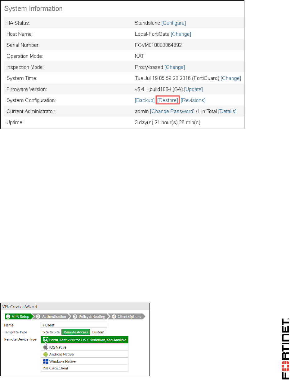
LAB 5–Advanced IPsec VPN
FortiGate II Student Guide 83
3. Select to restore from Local PC and click Upload.
4. Browse to Desktop > Resources > FortiGate-II > Advanced-IPsec and select local-
advanced-ipsec.conf.
5. Click OK.
6. Click OK to reboot.
Creating a Dialup VPN
You will create the dialup VPN in the Local-FortiGate.
To create the dialup VPN
1. From the Local-Windows VM, open a browser and log in as admin to the Local-FortiGate GUI at
10.0.1.254.
2. Go to VPN > IPsec Tunnels and click Create New.
3. In the Name field, enter FClient.
4. From Template Type, select the template Remote Access.
5. From Remote Device Type, select FortiClient VPN for OS X, WIndows, and Android.
6. Click Next.
7. Configure these settings:
DO NOT REPRINT
© FORTINET

LAB 5–Advanced IPsec VPN
FortiGate II Student Guide 84
Field
Value
Incoming Interface
port1
Authenticated Method
Pre-shared Key
Pre-Shared Key
fortinet
User Group
training
8. Click Next.
9. Configure these other settings in the next wizard step:
Field
Value
Local Interface
port3
Local Address
LOCAL_SUBNET
Client Address Range
172.20.1.1-172.20.1.5
Subnet
255.255.255.0
DNS Server
Use System DNS
Enable IPv4 Split Tunnel
Enabled
Allow Endpoint Registration
Disabled
10. Click Next.
11. Verify that Save Password is enabled.
12. Click Create. The VPN wizard creates not only IPsec phases 1 and 2, but also two firewall
addresses and one firewall policy that allows incoming traffic from the VPN to the internal subnet.
Note: Although you have created a route-based IPsec tunnel, you do not need to add
a static route because it is a dial-up VPN. FortiGate will dynamically add or remove
appropriate routes to each dial-up peer, each time their VPNs are established or
disconnected.
Configuring FortiClient for Dialup VPN
You will configure the FortiClient IPsec client to connect to the Local-FortiGate. You will use the
FortiClient installed in the Remote-Windows VM.
To configure FortiClient for dialup VPN
1. Go to the Remote-Windows VM and double-click the FortiClient icon to start that application.
DO NOT REPRINT
© FORTINET
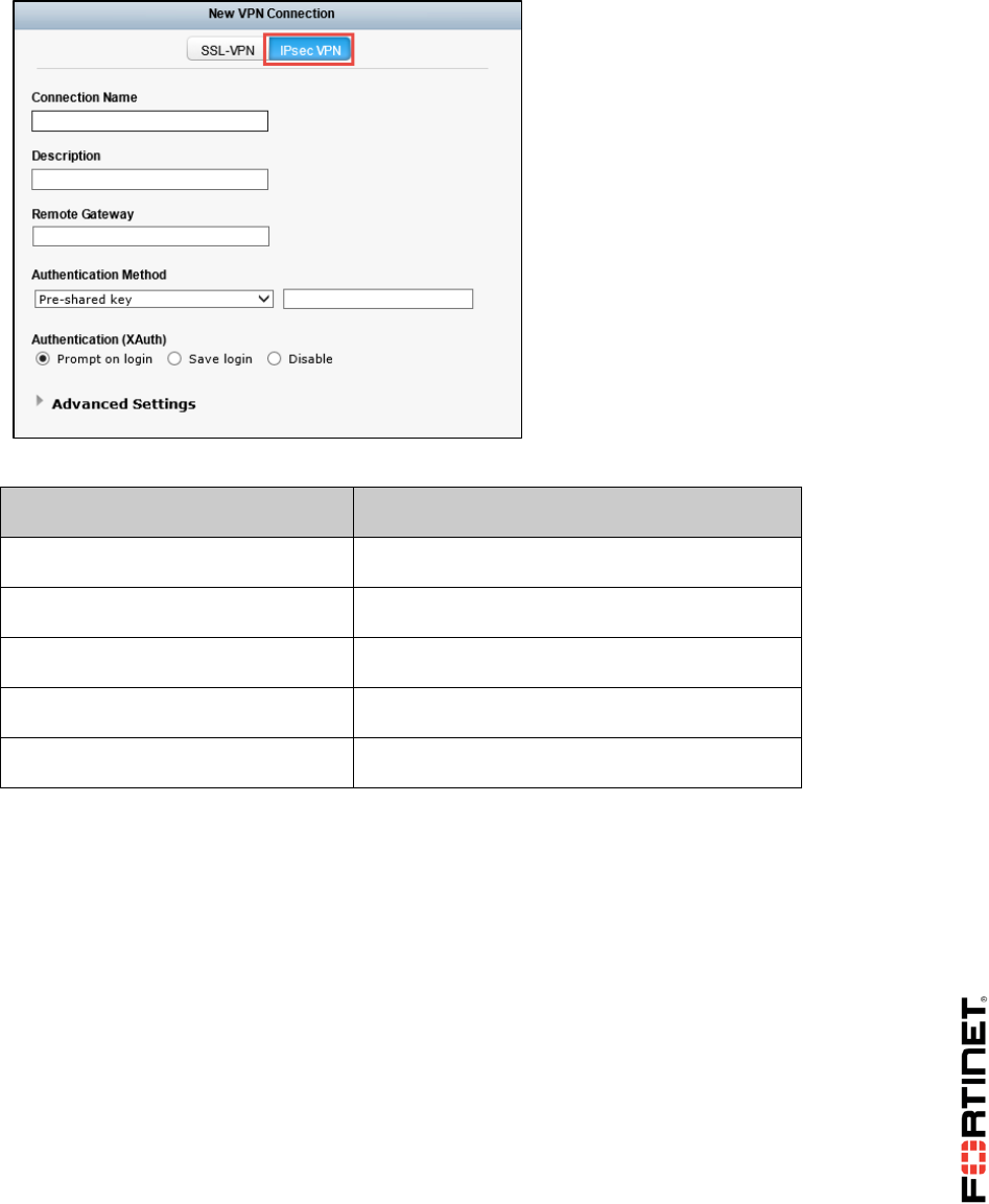
LAB 5–Advanced IPsec VPN
FortiGate II Student Guide 85
2. Click the Configure VPN link.
3. Select IPsec VPN:
4. Configure these settings:
Field
Value
Connection Name
FC_VPN
Remote Gateway
10.200.1.1
Authentication Method
Preshared Key with the password fortinet
Authentication (XAuth)
Save Login
Username
student
5. Click Apply.
6. Click Close.
Connecting to the Dialup VPN
You will use FortiClient to connect to the dialup VPN created in the Local-FortiGate.
To connect to the dialup VPN
1. On the FortiClient application running on Remote-Windows, enter the password fortinet.
2. Click Connect.
3. Wait a few seconds.
4. Open the FortiClient application again. A green checkmark confirms that the tunnel is up:
DO NOT REPRINT
© FORTINET
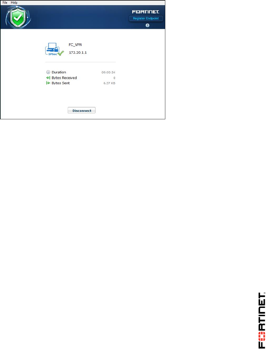
LAB 5–Advanced IPsec VPN
FortiGate II Student Guide 86
Checking the IP Address and Route Added to the
Remote-Windows VM
While the dialup VPN is up, the Remote-Windows VM receives an IP address within the 172.20.1.1 -
172.20.1.5 range. The FortiGate also installs a route to the subnet 10.0.1.0/24.
To check the IP address and route added to the Remote-Windows VM
1. Open a command prompt window in Remote-Windows and enter this command:
ipconfig /all
2. Analyze the output. You should observe an interface with an IP address in the 172.20.1.1 -
172.20.1.5 range.
3. Enter this other command to display the routing table information:
route print
4. Locate the 10.0.1.0/24 network entry in the output.
Testing the Dialup VPN
You will test the dialup VPN by sending traffic from the Remote-Windows VM to the Local-Windows
VM.
To test the dialup VPN
1. Still from the command prompt on the Remote-Windows VM, try to ping the Local-Windows VM
(10.0.1.10). The ping will succeed, confirming that the tunnel is working.
2. From a browser on the Local-Windows VM, go back to the Local-FortiGate GUI and go to
Monitor > Routing Monitor.
3. Find the static route that was dynamically added to the FortiGate:
DO NOT REPRINT
© FORTINET

LAB 5–Advanced IPsec VPN
FortiGate II Student Guide 87
4. Go to Monitor > IPsec Monitor.
5. View the details of the FClient_0 VPN connection. Notice the Remote Gateway IP address.
Disconnecting the Dialup VPN
To finish this lab, disconnect the Remote-Windows VM from the dialup VPN.
To disconnect the dialup VPN
1. Go to the Remote-Windows VM and open FortiClient.
2. Click Disconnect.
DO NOT REPRINT
© FORTINET
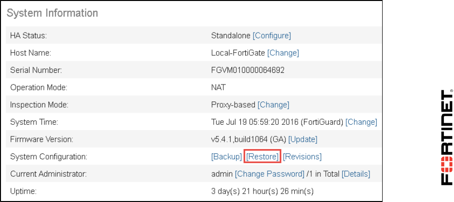
LAB 6–Intrusion Prevention System (IPS)
FortiGate II Student Guide 88
LAB 6–Intrusion Prevention
System (IPS)
In this lab, you will set up IPS profiles and denial of service (DoS) policies. You will also use a
vulnerability scanner and packet crafting software to attempt to flood the FortiGates.
Objectives
Protect your network against known attacks using IPS signatures.
Mitigate and block network anomalies and DoS attacks.
Write custom IPS signatures.
Time to Complete
Estimated: 40 minutes
Prerequisites
Before beginning this lab, you must restore a configuration file to the Local-FortiGate.
To restore the FortiGate configuration file
1. From the Local-Windows VM, open a browser and log in as admin to the Local-FortiGate GUI at
10.0.1.254.
2. Go to Dashboard, and from the System Information widget click Restore.
DO NOT REPRINT
© FORTINET

LAB 6–Intrusion Prevention System (IPS)
FortiGate II Student Guide 89
3. Select to restore from Local PC and click Upload.
4. Browse to Desktop > FortiGate-I > Introduction and select local-initial.conf.
5. Click OK.
6. Click OK to reboot.
DO NOT REPRINT
© FORTINET
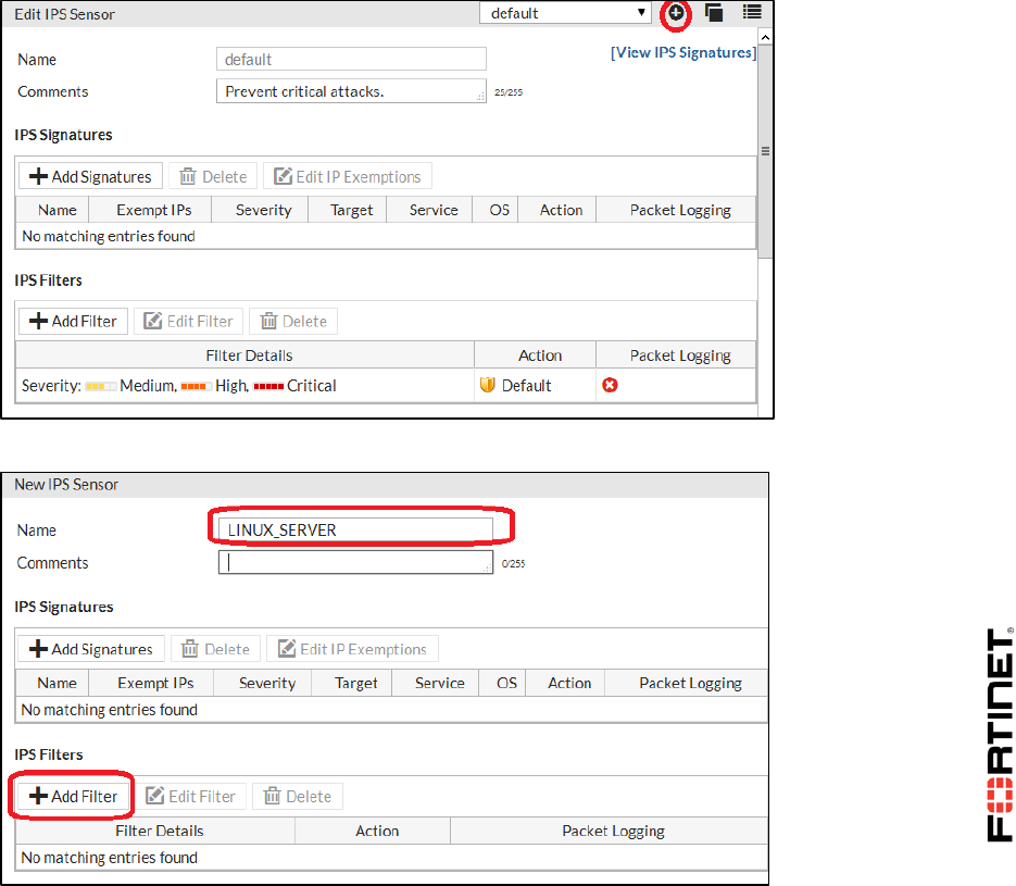
LAB 6–Intrusion Prevention System (IPS)
FortiGate II Student Guide 90
1 Blocking Known Exploits
During this exercise you will configure IPS inspection to block known attacks. You will test your
configuration by generating an attack on the Linux server from the Local-Windows VM.
Configure IPS Inspection
First you will create an IPS sensor that will include the signatures for known attacks on Linux servers.
To configure IPS
1. From the Local-Windows VM, open a browser and log in as admin to the Local-FortiGate GUI at
10.0.1.254.
2. Go to Security Profiles > Intrusion Protection.
3. To create a new sensor, click the plus sign (+) in the upper-right corner:
4. Use the name LINUX_SERVER for the new sensor and click Add Filter:
DO NOT REPRINT
© FORTINET
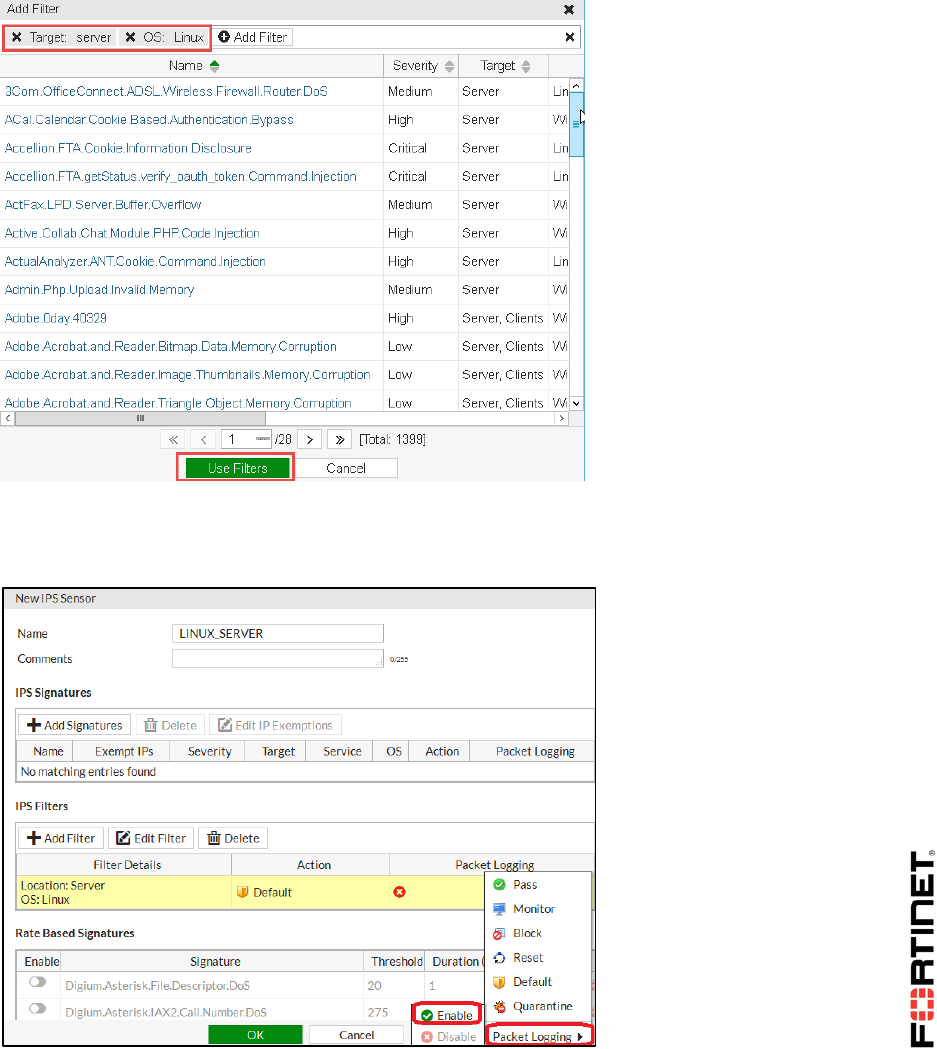
LAB 6–Intrusion Prevention System (IPS)
FortiGate II Student Guide 91
5. Click Add Filter.
6. Select Target: server.
7. Click Add Filter one more time.
8. Select OS: Linux.
9. Click Use Filters:
All the signatures matching the filter are added to the IPS sensor.
10. Right-click the entry in the IPS Filters table that was just added and select Packet Logging >
Enable:
11. Click OK.
DO NOT REPRINT
© FORTINET

LAB 6–Intrusion Prevention System (IPS)
FortiGate II Student Guide 92
Applying an IPS Sensor to a Firewall Policy
You will apply the new IPS sensor to the firewall policy that allows Internet access.
To apply an IPS sensor to a firewall policy
1. In the Local-FortiGate GUI, go to Policy & Objects > IPv4 Policy.
2. Edit the firewall policy that allows the traffic from port3 to port1.
3. In the Security Profiles section, set IPS to ON, then from the drop-down list, select
LINUX_SERVER.
4. Click OK.
Generating Attacks on the Linux Server
You will run a Perl script to generate attacks on the Linux server located in front of the FortiGate.
To generate attacks on the Linux server
1. Open a command prompt window on the Local-Windows VM and run the script to start the
attacks:
nikto.pl -host 10.200.1.254
2. All the attacks take around 10 minutes to run. However, you do not need to wait that time. Wait
around 5 minutes and press Ctrl-C to stop the script.
Monitoring the IPS
You will check the IPS logs to monitor for known attacks being detected by the FortiGate.
To monitor the IPS
1. Go back to the Local-FortiGate GUI and go to Log & Report > Intrusion Protection.
2. Locate the multiple entries for the attacks generated.
Note: The IPS logs section will not display if there are no IPS logs. FortiGate will show
it after creating logs. After the attacks, if this menu item does not display, log out from
the FortiGate GUI and log in again to refresh it.
3. Note that for some of the attacks discovered by the IPS, the Action column shows the value
Detected. This indicates that a signature was matched, but that FortiGate was configured to
allow traffic to pass.
In the spaces below, write the signature names for two of those detected attacks that were not
blocked. The signature name appears in the Attack Name column of the log.
Signature 1:
____________________________________
Signature 2:
____________________________________
DO NOT REPRINT
© FORTINET

LAB 6–Intrusion Prevention System (IPS)
FortiGate II Student Guide 93
Changing a Signature Action
You took note of two attacks that were detected, but not blocked, because the default action for their
signatures is Monitor. You will change the action for those two signatures to Block and test again.
To change a signature action
1. In the Local-FortiGate GUI go to Security Profiles > Intrusion Protection.
2. Select the sensor named LINUX_SERVER from the top drop-down list to edit it.
3. Click Add Signatures.
4. Search the signature name that you wrote in Signature 1 from the previous procedure.
5. Select the signature and click Use Selected Signatures to add it.
6. Right click the signature and set its Action to Block.
7. Right click the signature again and enable Packet Logging.
8. Click Apply.
9. Repeat this procedure for the signature that you noted in Signature 2.
Testing the New Signatures Action
You will generate the attack again from the Local-Windows VM. This time, the FortiGate should block
the two attacks.
To test the new signature actions
1. Open a command prompt window on the Local-Windows VM and run the script one more time to
start the attacks:
nikto.pl -host 10.200.1.254
2. This time wait around 10 minutes for the script to run all the attacks. If, after 10 minutes, the script
has not finished running yet, press Ctrl-C to stop it.
3. Return to the Local-FortiGate GUI and go to Log & Report > Intrusion Protection.
Examine the log entries again. Locate the log messages for the two signatures whose actions
were changed. The Status field should contain dropped. This indicates either: a dropped packet,
dropped session, or cleared session.
DO NOT REPRINT
© FORTINET
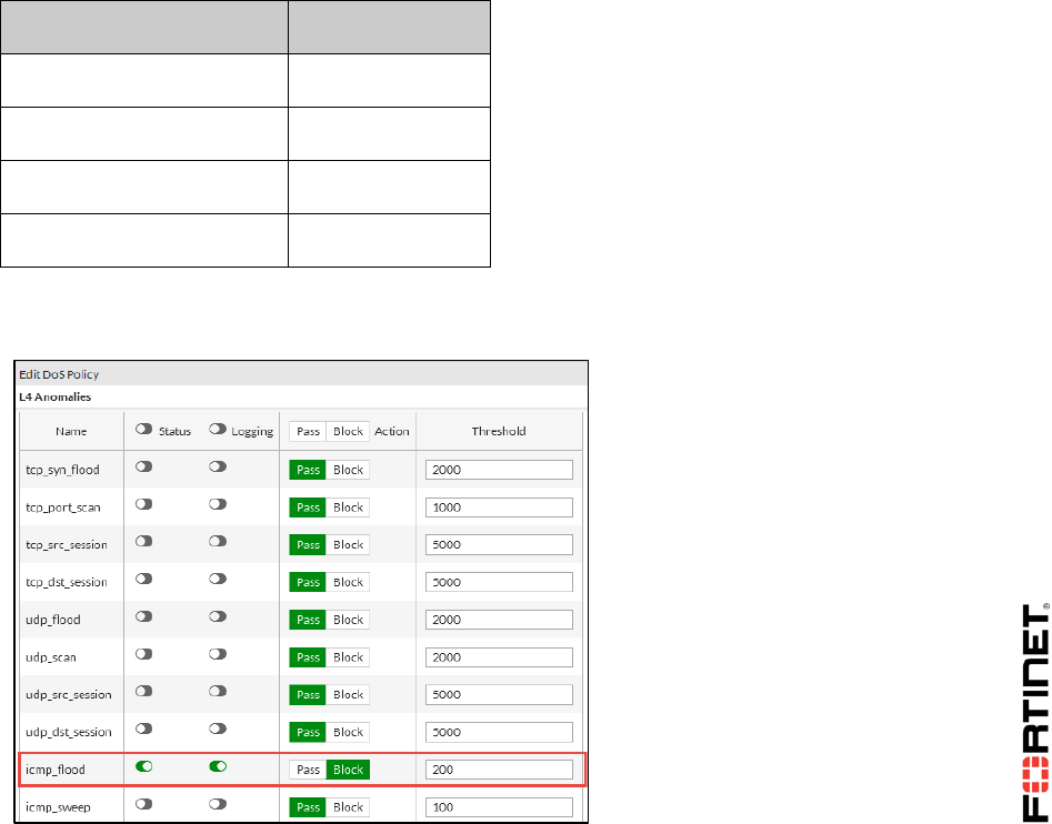
LAB 6–Intrusion Prevention System (IPS)
FortiGate II Student Guide 94
2 Mitigating a DoS Attack
In this exercise you will configure the Local-FortiGate for DoS protection. After that, you will simulate a
DoS attack by generating traffic from the Linux server.
Creating a DoS Policy
You will create a DoS policy.
To create a DoS policy
1. From the Local-Windows VM, open a browser and log in as admin to the Local-FortiGate GUI at
10.0.1.254.
2. Go to Policy & Objects> IPv4 DoS Policy.
3. Click Create New.
4. Configure these settings:
Field
Value
Incoming Interface
port1
Source Address
all
Destination Address
all
Service
ALL
5. Enable Status and Logging for icmp_flood.
6. Set the Action to Block and the Threshold to 200:
7. Click OK.
DO NOT REPRINT
© FORTINET
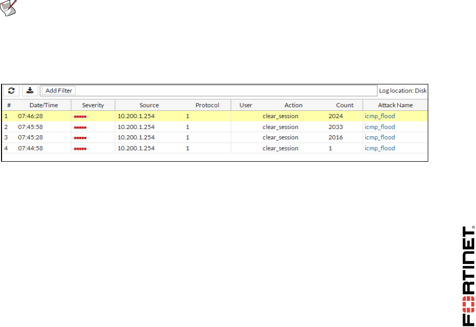
LAB 6–Intrusion Prevention System (IPS)
FortiGate II Student Guide 95
Testing the DoS Policy
You will generate a high number of ICMP packets per second from the Linux server to the Local-
FortiGate. This will trigger the DoS policy.
To test the DoS policy
1. In the Local-Windows VM, open PuTTY and connect to the LINUX saved session (connect over
SSH).
2. Enter the username root with a password of password.
3. Execute this command to use the ping flood option against the Local-FortiGate:
ping -f 10.200.1.1
The command option -f causes the ping utility to run continuously and not wait for replies between
ICMP echo requests.
FortiGate will block pings when the amount of packets per second exceeds the configured
threshold.
Leave the Linux SSH connection open with the ping running.
4. Go back to the Local-FortiGate GUI and press Ctrl-F5 to refresh the browser (or log out and log
in).
5. Go to Log & Report > Anomaly.
Note: The Anomaly logs section will not display if there are no anomaly logs.
FortiGate will show it after creating logs. After the attacks, if this menu item does not
display, log out from the FortiGate GUI and log in again to refresh it.
6. Examine the logs. Note that the ICMP flood has been blocked. This is indicated by the Action field
entry clear_session:
7. Go back to the SSH connection to the Linux server and press Crtl-C to stop the ping.
DO NOT REPRINT
© FORTINET

LAB 6–Intrusion Prevention System (IPS)
FortiGate II Student Guide 96
3 Creating Custom Signatures
During this exercise you will create a custom signature to block RETR (GET) commands on FTP
traffic.
Creating a Custom Signature
You will first create the custom signature.
To create the custom signature
1. From the Local-Windows, open PuTTY and connect to the LOCAL-FORTIGATE saved session
(connect over SSH).
2. Log in as admin and enter the following commands to create the custom signature:
config ips custom
edit "FTP_GET"
set severity medium
set protocol FTP
set log-packet enable
set action pass
set signature "F-SBID(--name 'FTP Download'; --flow from_client; --
pattern RETR;)"
end
3. From the Local-Windows VM, open a browser and log in as admin to the Local-FortiGate GUI at
10.0.1.254.
4. Go to Security Profiles > Intrusion Protection.
5. Edit the LINUX_SERVER sensor created earlier.
6. Click Add Signature.
7. Search for the signature FTP_GET. Select it and click Use Selected Signatures.
8. Right-click the custom signature and change the action to Reset.
9. Click Apply.
Testing the Custom Signature
You will use an FTP client named FileZilla to try to download a file located at the Linux server. To
get the file, the FTP client will send a RETR command that will be detected and blocked by the
custom signature.
DO NOT REPRINT
© FORTINET
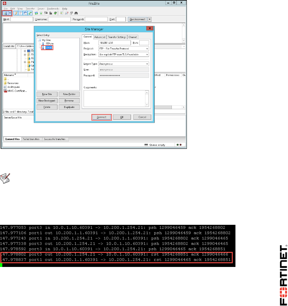
LAB 6–Intrusion Prevention System (IPS)
FortiGate II Student Guide 97
To test the custom signature
1. Go back to the Local-FortiGate CLI and execute the following command to sniffer all FTP traffic:
diagnose sniffer packet any 'port 21' 4
2. From the Local-Windows server, open the FileZilla Client from the desktop.
3. Go to File and choose Site manager.
4. Select Linux and click Connect:
5. Try to download the file called test.text.
The connection to the remote host should be closed.
Note: When FortiGate resets the TCP connection, FileZilla may show a notification pop-
up a few times.
6. Go back to the Local-FortiGate CLI and examine the sniffer output to verify that the reset action
was applied to the session. You should see a TCP reset sent out to the client on port3 and to
the server on port1:
7. Alternately, go back to the Local-FortiGate GUI and go to Log & Report > Intrusion
Protection. Locate the attack log entry to verify that the FortiGate reset the connection:
DO NOT REPRINT
© FORTINET
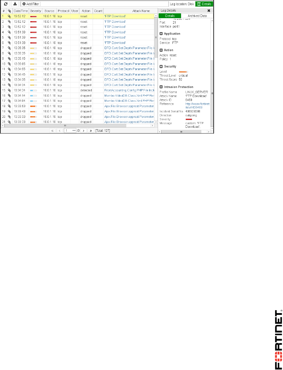
LAB 6–Intrusion Prevention System (IPS)
FortiGate II Student Guide 98
DO NOT REPRINT
© FORTINET

LAB 7–Fortinet Single Sign-On (FSSO)
FortiGate II Student Guide 99
LAB 7–Fortinet Single Sign-On
(FSSO)
In this lab, you will configure FSSO. FSSO enables FortiGate to identify users by collecting user login
activity on a Windows server set with active directory.
This includes installing and configuring the domain controller agent and FSSO collector agent in order
to monitor and consolidate the user logon events and send them to FortiGate.
You will also configure the SSO option on FortiGate to enable communication with the collector agent,
specifically to poll event log information.
Objectives
Install and configure the Fortinet domain controller agent.
Install and configure the FSSO collector agent.
Configure SSO on FortiGate.
Test the automatic user identification by generating user logon events.
Monitor the SSO status and operation.
Time to Complete
Estimated: 25 minutes
Prerequisites
Before beginning this lab, you must restore a configuration file to FortiGate.
To restore the FortiGate configuration file
1. From the Local-Windows VM, open a browser and log in as admin to the Local-FortiGate GUI at
10.0.1.254.
2. Go to Dashboard, and from the System Information widget click Restore.
DO NOT REPRINT
© FORTINET

LAB 7–Fortinet Single Sign-On (FSSO)
FortiGate II Student Guide 100
3. Select to restore from Local PC and click Upload.
4. Browse to Desktop > Resources > FortiGate-II > FSSO and select local-fsso.conf.
5. Click OK.
6. Click OK to reboot.
DO NOT REPRINT
© FORTINET
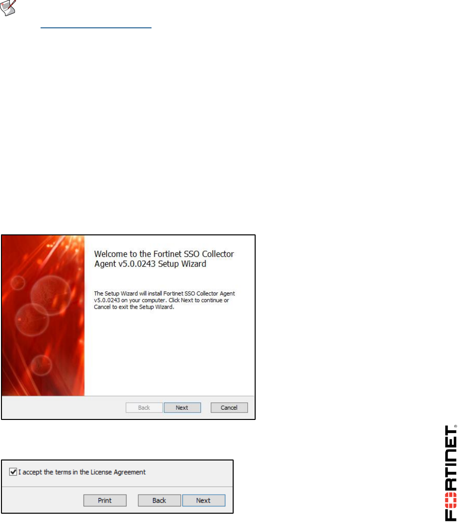
LAB 7–Fortinet Single Sign-On (FSSO)
FortiGate II Student Guide 101
1 FSSO Agents
In order to configure FortiGate to identify users by polling their login events from the FSSO agents,
you must to install and configure both agents: the collector and the domain controller.
Note: The FSSO agents are available from the Fortinet Support website
(http://support.fortinet.com). The available agents are:
DC agent
Collector agent for Microsoft servers: FSSO_Setup
Collector agent for Novell directories: FSSO_Setup_edirectory
Controller agent for Citrix servers: TSAgent_Setup
Installing the FSSO Collector Agent
In this exercise, you will install the FSSO collector agent on a Windows server.
To install the FSSO collector agent on a Windows server
1. From the Local-Windows VM, go to Desktop > Resources > FortiGate-II > FSSO.
2. Right-click FSSO_Setup_5.0.0243_x64 and select Run as administrator from the menu.
The FSSO collector agent installation wizard appears.
3. Click Next.
4. Accept the license agreement and click Next.
5. Accept the default destination folder and click Next.
6. Supply the following credentials and click Next:
DO NOT REPRINT
© FORTINET
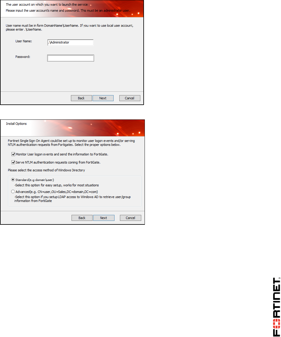
LAB 7–Fortinet Single Sign-On (FSSO)
FortiGate II Student Guide 102
User Name: .\Administrator
Password: password
The password is the administrative user password of the Local-Windows VM.
7. Accept the default settings and click Next.
8. Click Install to complete the installation.
You successfully installed the FSSO collector agent.
Before completing the FSSO collector agent installation, you will configure the FSSO DC agent to
automatically launch.
9. Continue to Configuring the FSSO Domain Controller Agent below.
Configuring the FSSO Domain Controller (DC) Agent
Following the install of the FSSO collector agent, the wizard prompts you to launch the FSSO DC
agent. In this procedure, you will configure the FSSO DC agent to automatically launch.
To install and configure the FSSO DC agent on a Windows server
1. Continuing from the previous procedure, select Launch DC Agent Install Wizard and click
Finish.
DO NOT REPRINT
© FORTINET
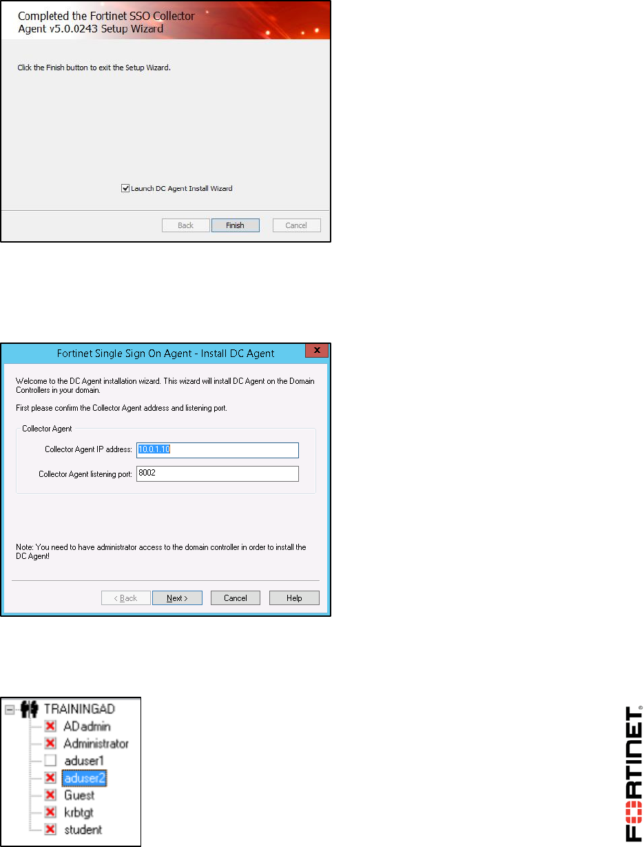
LAB 7–Fortinet Single Sign-On (FSSO)
FortiGate II Student Guide 103
The Install DC Agent wizard appears.
2. Enter the following values and click Next:
Collector Agent IP address: 10.0.1.10
Collector Agent listening port: 8002
3. Select the TRAININGAD:trainingAD.training.lab domain to monitor and click Next.
4. Expand TRAININGAD, disable all users except for aduser1, and click Next.
For this lab, only the aduser1 account will be monitored.
DO NOT REPRINT
© FORTINET
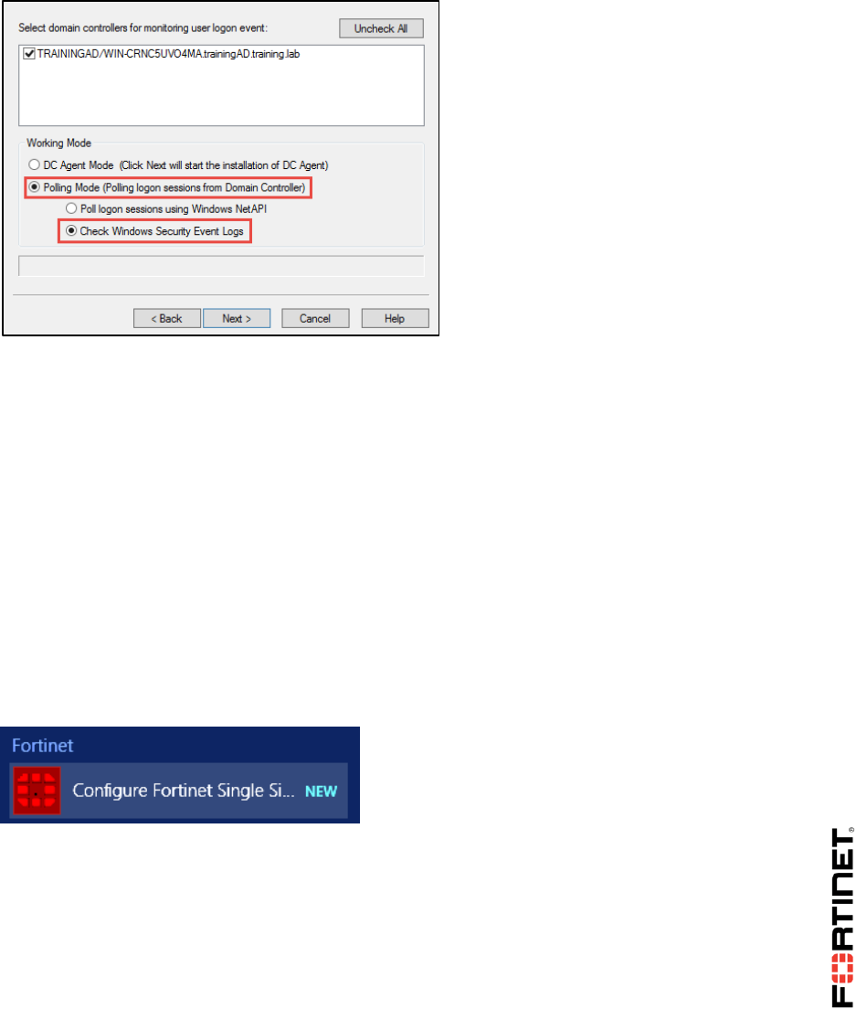
LAB 7–Fortinet Single Sign-On (FSSO)
FortiGate II Student Guide 104
5. Under the Working Mode section, ensure the following settings are selected in order to poll the
login sessions from the domain controller and then click Next:
Polling Mode
Check Windows Security Event Logs
The installation wizard for the DC agent completes its configuration.
6. Click Finish.
The collector agent is now monitoring your domain controller.
Configuring the FSSO Collector Agent
In this procedure, you will configure the FSSO collector agent to allow FortiGate to poll information
from it. For this, you must to select the groups that your DC agent will monitor and forward to the
collector agent.
To configure the FSSO collector agent
1. In the Local-Windows VM, click the Windows icon to open the Start menu.
2. Click the down arrow at the bottom of the screen and scroll right to locate and select Configure
Fortinet Single Sign On Agent under the Fortinet menu.
The Fortinet Single Sign On Agent Configuration wizard appears.
3. Under Authentication, complete the following:
Enable Require authenticated connection from FortiGate.
Enter Fortinet in the Password field.
DO NOT REPRINT
© FORTINET
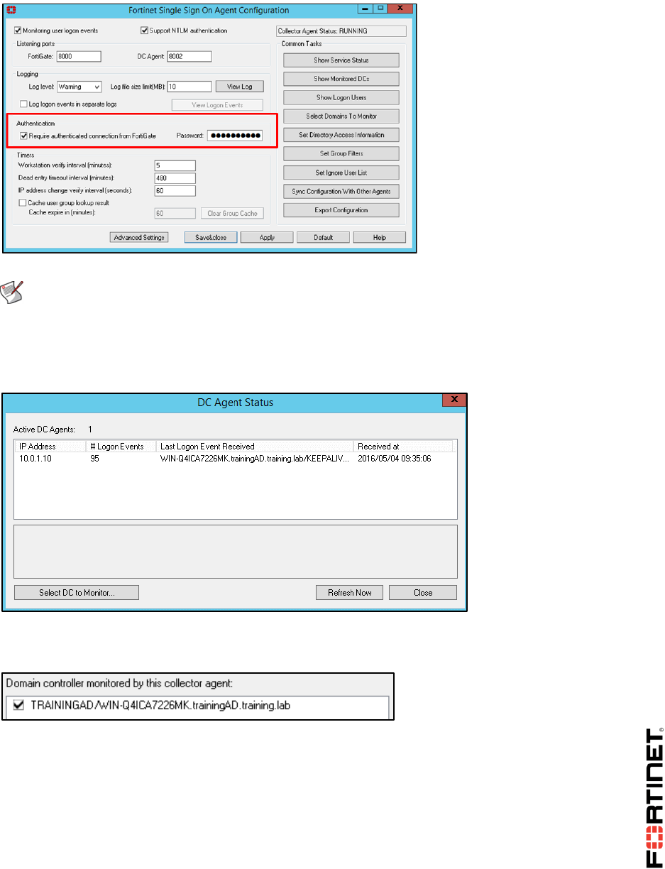
LAB 7–Fortinet Single Sign-On (FSSO)
FortiGate II Student Guide 105
Note: You will use this password later when configuring FortiGate. This password allows
the FortiGate to communicate and poll the logon events from the FSSO collector agent.
4. Click Show Monitored DCs in the right menu to specify the monitored domain controller.
You will see a logon event for the IP address: 10.0.1.10.
5. Click Select DC to Monitor.
6. Ensure the TRAININGAD:trainingAD.training.lab domain is selected and click OK.
7. Click Close.
8. Click Set Group Filters in the right menu to specify the monitored groups.
9. Click Add.
10. Enable the Default filter and click Advanced.
DO NOT REPRINT
© FORTINET
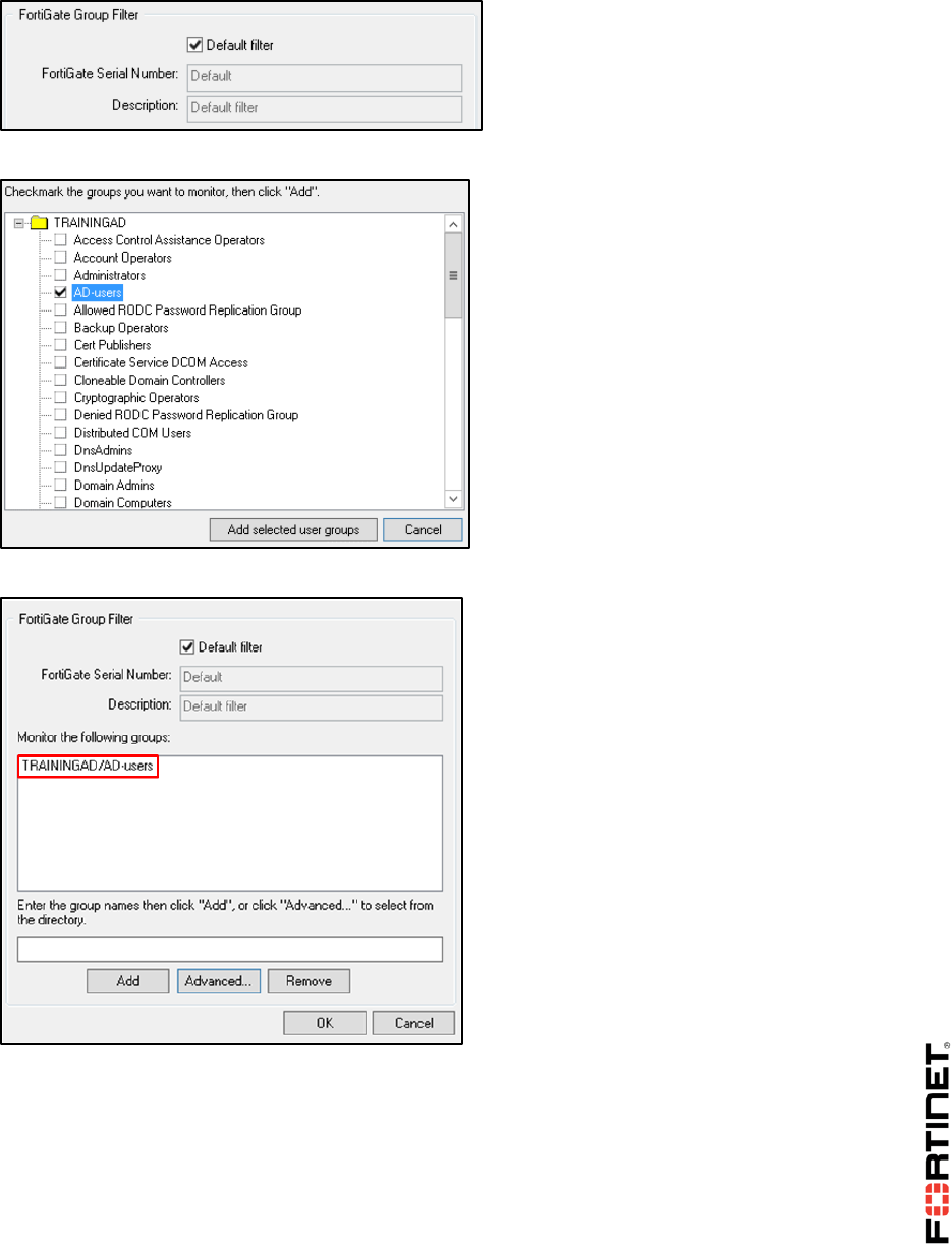
LAB 7–Fortinet Single Sign-On (FSSO)
FortiGate II Student Guide 106
11. Expand TRAININGAD and select AD-users.
12. Click Add selected user groups.
Your Monitored group is named: TRAININGAD/AD-users. FortiGate will now poll it.
13. Click OK.
14. Click OK.
DO NOT REPRINT
© FORTINET
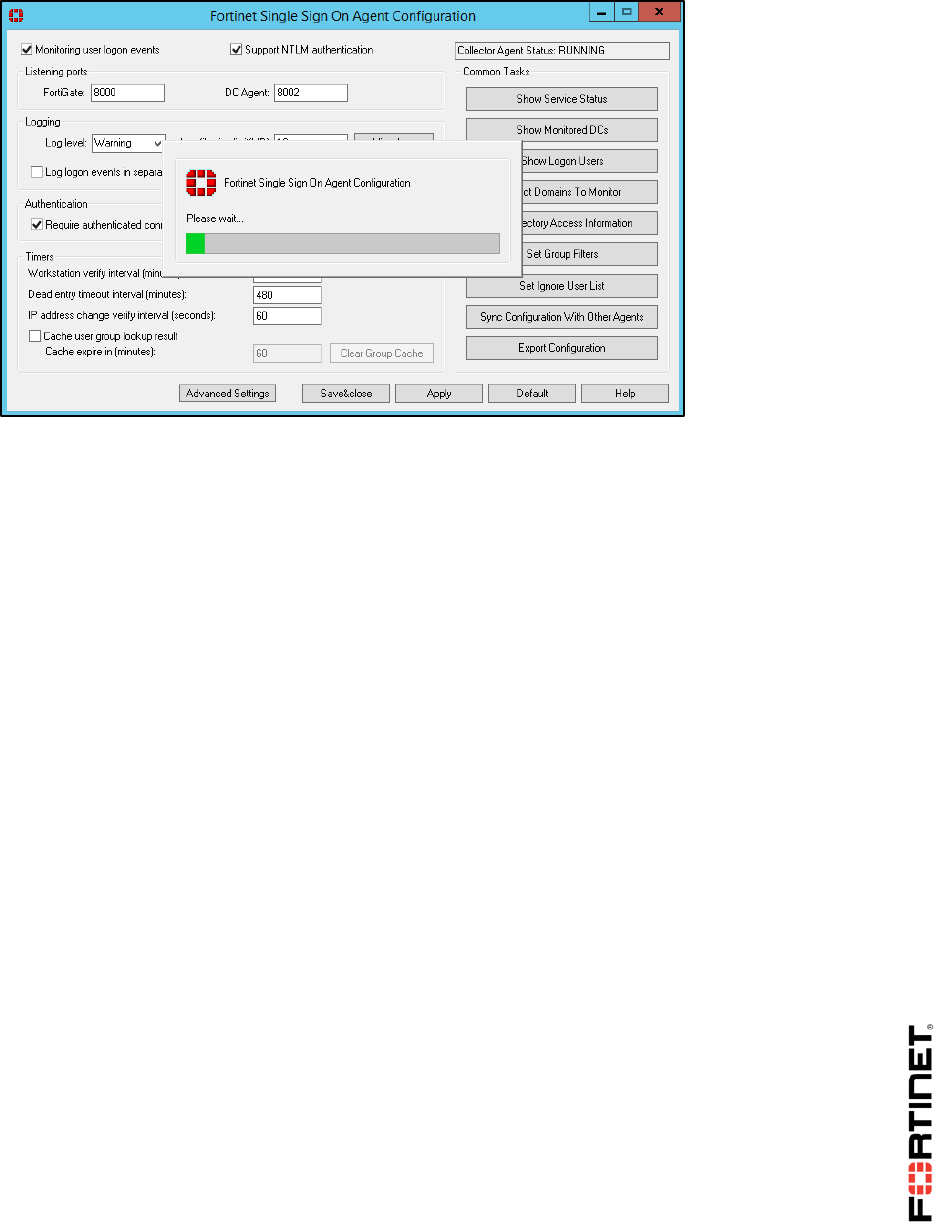
LAB 7–Fortinet Single Sign-On (FSSO)
FortiGate II Student Guide 107
The FSSO collector agent loads your settings.
15. Click Save&close to finish the configuration.
DO NOT REPRINT
© FORTINET
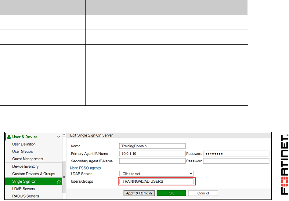
LAB 7–Fortinet Single Sign-On (FSSO)
FortiGate II Student Guide 108
2 Single Sign-On (SSO) on FortiGate
Now that the agents are set up, you must configure your FortiGate to communicate and poll
information from the FSSO collector agent.
You must then assign the polled user to a firewall user group and add the user group as a source on a
firewall policy.
Finally, you can verify the user logon event collected by FortiGate. This event is generated once a
user logs onto the Windows active directory domain. Therefore, no firewall authentication is required.
Configuring SSO on FortiGate
In this procedure, you will set up the SSO feature on FortiGate. This process allows FortiGate to
automatically identify the user that will connect on SSO.
To configure the SSO option on FortiGate
1. From the Local-Windows VM, open a browser and log in as admin to the Local-FortiGate GUI at
10.0.1.254.
2. Go to User & Device > Single Sign-On.
3. Click Create New and enter the following settings:
Field
Value
Type
Fortinet Single-Sign-On Agent
Name
TrainingDomain
Primary Agent IP/Name
10.0.1.10
Password
Fortinet
Note: This is the password you specified while
configuring the Fortinet Single Sign On Agent. This
password allows the FortiGate to communicate and poll
the logon events from the FSSO collector agent.
4. Click Apply & Refresh twice.
The FortiGate communicates to the FSSO collector agent and polls the User/Group.
DO NOT REPRINT
© FORTINET
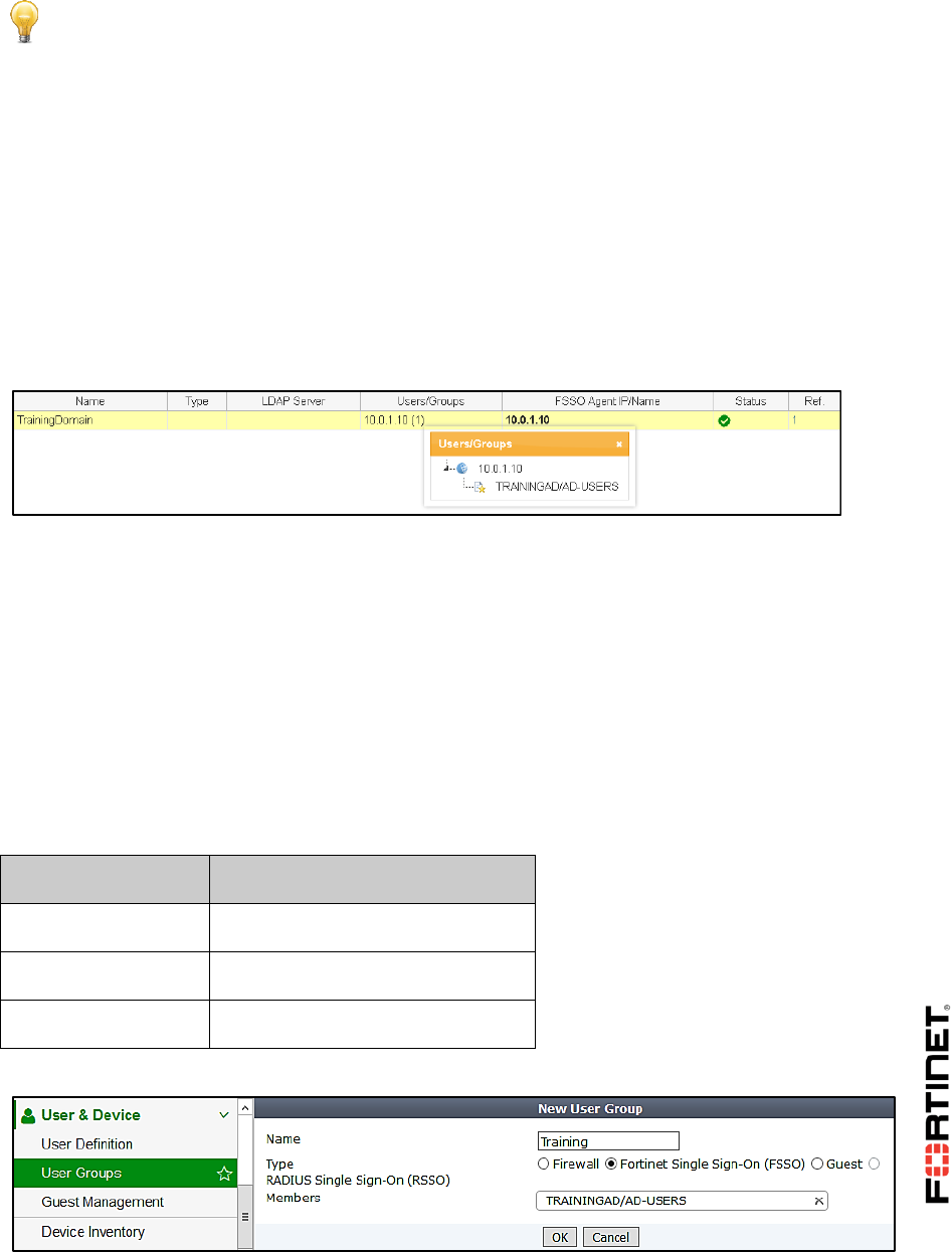
LAB 7–Fortinet Single Sign-On (FSSO)
FortiGate II Student Guide 109
Stop and Think
Under which conditions is the User/Group field is not automatically displayed after clicking
Apply and Refresh?
Discussion
Apply and Refresh allows FortiGate to communicate and poll information from the FSSO
collector agent. If FortiGate does not properly refresh with the polled information, it could
be a password mismatch. The agent IP password must be the same as the password you
set up in the Authentication section during the FSSO collector agent configuration.
5. Click OK.
A green checkmark in the Status column confirms that the communication with the FSSO
collector agent is up.
Assigning an FSSO User to a Firewall Policy
In this task, you must assign your polled FSSO user as a source on your firewall policy.
For this, you must first to add the FSSO user to a firewall user group. Then, you can configure firewall
policies to act on the firewall user group. This allows you to control the FSSO user access to network
resources.
To assign the polled FSSO user to a firewall user group
1. In the FortiGate-Local GUI, go to User & Device > User Groups.
2. Click Create New and enter the following settings:
Field
Value
Name
Training
Type
Fortinet Single Sign On (FSSO)
Members
TRAININGAD/AD-USERS
DO NOT REPRINT
© FORTINET
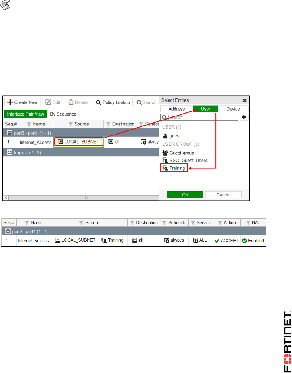
LAB 7–Fortinet Single Sign-On (FSSO)
FortiGate II Student Guide 110
Note: The polled FSSO user is automatically listed in the drop-down list due to the
selected group type: FSSO.
3. Click OK.
To add the FSSO user group to your firewall policy
1. In the Local-FortiGate GUI, go to Policy & Objects > IPv4 Policy.
2. Edit the firewall policy sequence named Internet_Access.
3. Under Source, click LOCAL_SUBNET, select Users from the right-hand menu and add the
Training group.
4. Click OK.
Testing FSSO
Once a user logs into the Windows AD domain, the user is automatically IP-based identified and
logged on. Hence, the FortiGate allows the user to access to network resources, as policy decisions
are made.
For the purposes of this lab, you will generate a user logon event and monitor FortiGate to observe
how it identifies the user.
To monitor the communication between the FSSO collector agent and FortiGate
1. From the Local-Windows, open PuTTY and connect to the LOCAL-FORTIGATE saved
session (connect over SSH).
2. Log in as admin and type the following command to monitor the communication between the
FSSO collector agent and the FortiGate:
diagnose debug enable
DO NOT REPRINT
© FORTINET
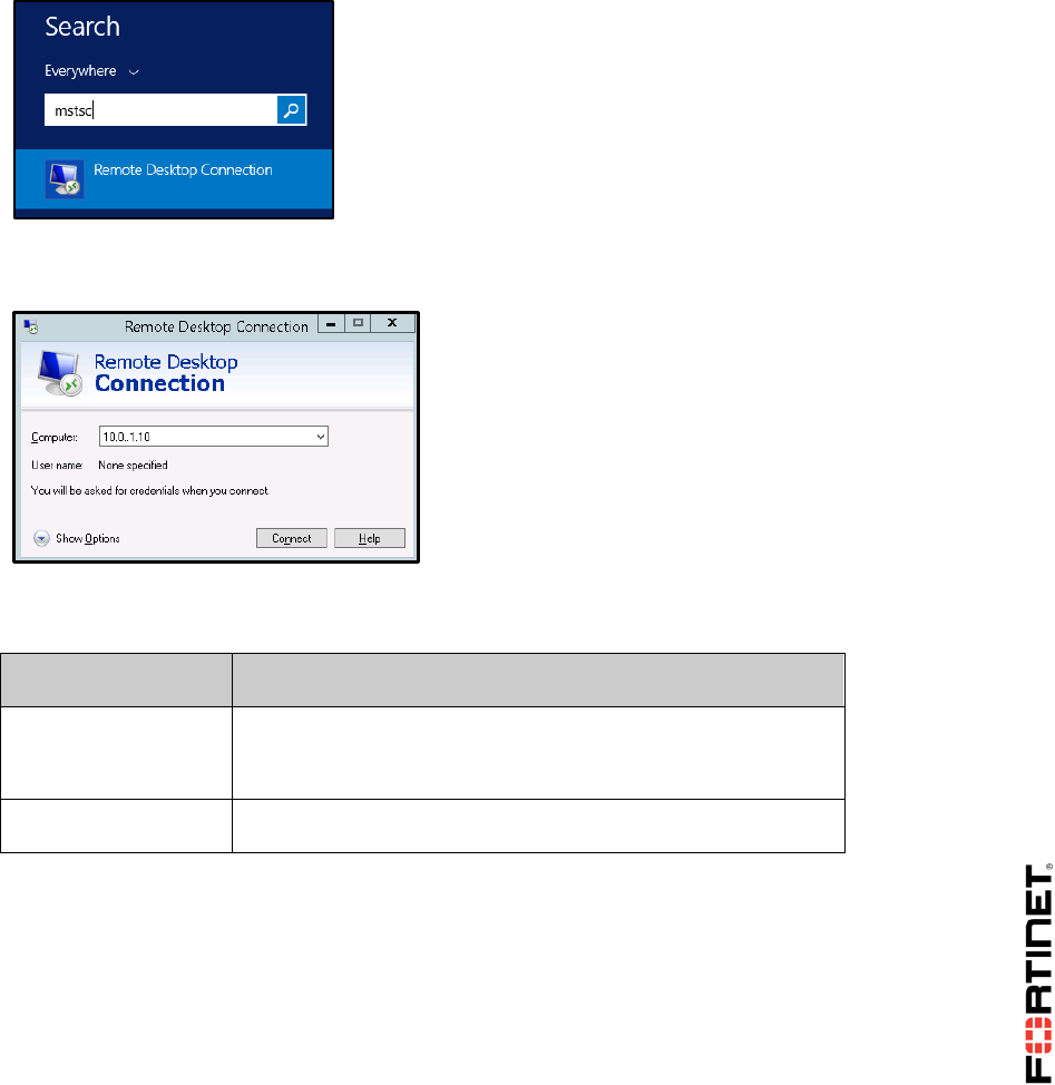
LAB 7–Fortinet Single Sign-On (FSSO)
FortiGate II Student Guide 111
diagnose debug application authd 8256
You will return to this output after generating a logon event.
3. Continue to the next procedure.
To generate a logon event
1. From the Local-Windows VM, click the Windows button.
2. In the search field, enter mstsc to launch the Windows Remote Desktop Connection
application.
3. Enter the remote computer IP address: 10.0.1.10.
This is the IP of the Local-Windows VM. For more information, see the network topology diagram.
4. Click Connect.
5. Select Use another account, and log in with the following credentials:
Field
Value
Username
aduser1
This user has been pre-created for you in Active Directory.
Password
Training!
6. Click Yes.
7. Click OK.
Ignore the error message indicating that the user is not authorized for remote login.
8. Return to the PuTTY CLI connection and observe the output of the diagnose command:
DO NOT REPRINT
© FORTINET

LAB 7–Fortinet Single Sign-On (FSSO)
FortiGate II Student Guide 112
Note: You have generated a logon event using the Windows Remote Desktop
Connection application and it has been captured by your DC agent, forwarded to your
collector agent, and polled by FortiGate.
9. Type the following command to stop the diagnose command.
diagnose debug disable
To display the FSSO logins
1. In the PuTTY CLI session, type the following command:
diagnose debug authd fsso list
2. Review the output, it shows the FSSO logins.
Note: You may see two IP addresses because the Local-Windows VM has two NICs in
your lab environment.
To review the user event logs
1. From the Local-FortiGate GUI, go to Log & Report > User Events.
Note: The Event Log menu will not display the User Events option until FortiGate
registers the user event logs.
FortiGate will show this option after creating logs. So, if this menu item does not
display after the user event log, log out from the FortiGate GUI and log in again to
refresh it.
2. You will observe FSSO log events.
3. Click Details to view more information about each FSSO log.
----FSSO logons----
IP:10.0.1.10 User: ADUSER1 Groups: TRAINING/AD-USERS
Workstation: LOCAL-WINDOWS MemberOf: Training
Total number of logons listed: 1, filtered: 0
----end of FSSO logons----
_process_logon[TrainingDomain]: ADUSER1(10.0.1.10) logged on with session
id(0), port_range_sz=0
_process_logon-903: cannot find such a user, try to add it
DO NOT REPRINT
© FORTINET

LAB 7–Fortinet Single Sign-On (FSSO)
FortiGate II Student Guide 113
DO NOT REPRINT
© FORTINET

LAB 8–Certificate Operations
FortiGate II Student Guide 114
LAB 8–Certificate Operations
In this lab, you will configure certificate authentication on FortiGate. This includes importing a CA
certificate into FortiGate, configuring a PKI peer user, and importing the PKI peer user certificate into
the personal certificate store on the user's computer (Local-Windows). You will then authenticate as
the PKI peer user over SSL VPN.
You will also configure SSL deep inspection using a self-signed SSL certificate on FortiGate, so you
can inspect encrypted traffic.
Objectives
Configure certificate authentication on FortiGate so that a PKI user can authenticate to the
network with their certificate over SSL VPN.
Configure and enable SSL deep inspection on FortiGate so you can inspect encrypted traffic.
Time to Complete
Estimated: 25 minutes
Prerequisites
Before beginning this lab, you must restore a configuration file to FortiGate.
To restore the FortiGate configuration file
1. From the Local-Windows VM, open a browser and log in as admin to the Local-FortiGate GUI at
10.0.1.254.
2. Go to Dashboard, and from the System Information widget click Restore.
DO NOT REPRINT
© FORTINET
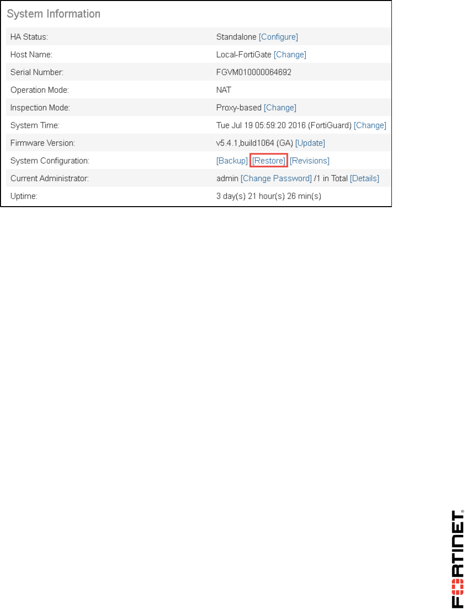
LAB 8–Certificate Operations
FortiGate II Student Guide 115
3. Select to restore from Local PC and click Upload.
4. Browse to Desktop > Resources > FortiGate-II > Certificates and select local-
certificates.conf.
5. Click OK.
6. Click OK to reboot.
DO NOT REPRINT
© FORTINET
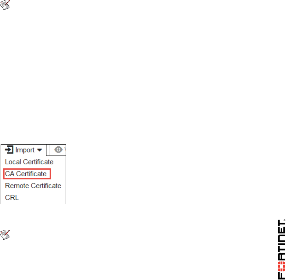
LAB 8–Certificate Operations
FortiGate II Student Guide 116
1 Certificate Authentication
In order to configure FortiGate for certificate authentication, you must import the root CA certificate on
FortiGate. The root CA generates and signs user certificates and is necessary to verify the validity of
any user certificate being used to authenticate.
You must then create a PKI peer user on FortiGate and add the PKI peer user to a firewall user group.
Finally, you must install the PKI peer user's digital certificate in the personal certificate store of their
computer (Local-Windows).
Once configured, you can test certificate authentication by logging into SSL VPN.
Note: All certificates have been pre-generated for you by FortiAuthenticator—a user
authentication and identity management appliance. Keep in mind that you can generate
certificates using many different applications or purchase certificates from various
certificate providers. As such, this lab focuses on importing certificates rather than
certificate generation.
Importing the Root CA on FortiGate
In this exercise, you will import the pre-generated root CA into FortiGate.
To import a CA certificate
1. From the Local-Windows VM, open a browser and log in as admin to the Local-FortiGate GUI at
10.0.1.254.
2. Go to System > Certificates.
3. Click Import and select CA Certificate from the drop-down menu.
4. From the Import CA Certificate dialog box, select Local PC and browse to Desktop >
Resources > FortiGate-II > Certificates and select FortiAuthCA.crt.
Note: This CA certificate is generated by FortiAuthenticator.
5. Click OK.
The CA certificate CA_Cert_1 (CN = FortiAuthCA) is added to the Certificates page under
External CA Certificates.
DO NOT REPRINT
© FORTINET
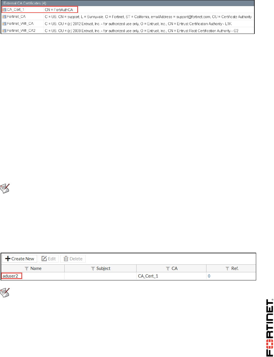
LAB 8–Certificate Operations
FortiGate II Student Guide 117
Creating a PKI Peer User
In order for FortiGate to recognize PKI users, the user must be added to FortiGate as a PKI peer user.
In this exercise, you will create a PKI user called aduser2. The first PKI user you add to FortiGate
must be added through the CLI (subsequent users can be added directly through the FortiGate GUI).
To create a PKI peer user account
1. In Local-Windows, open PuTTY and connect to the LOCAL-FORTIGATE saved session (connect
over SSH).
2. Log in as admin and type the following command to add a PKI peer user:
config user peer
edit aduser2
set ca CA_Cert_1
set two-factor enable
set passwd Training!
end
Note: CA_Cert_1 is the name of the CA certificate you imported in the previous
procedure. The common name of the certificate (cn) is FortiAuthCA.
3. Close PuTTY.
4. To confirm the PKI peer user you just created was added successfully in the FortiGate GUI,
refresh your browser and go to User & Device > PKI.
Remember, the PKI page appears only once you add your first PKI peer user through the CLI.
Note: You now have the option to create subsequent PKI peer users directly through the
FortiGate GUI, as the PKI page is now visible. No additional users are required for this lab,
however.
Assigning a PKI Peer User to a User Group
In this procedure, you will assign your PKI peer user to a firewall user group called PKI-users. This
way, you can configure firewall policies to act on the firewall user group.
DO NOT REPRINT
© FORTINET
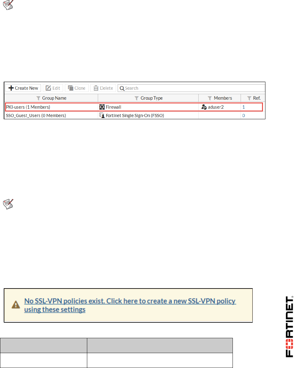
LAB 8–Certificate Operations
FortiGate II Student Guide 118
Generally, groups are used to more effectively manage individuals that have some kind of shared
relationship.
Note: The PKI-users group was pre-configured for you. However, it needs to be modified
to add the PKI peer user you created (aduser2).
To assign a PKI peer user to a firewall group
1. In the FortiGate-Local GUI, go to User & Device > User Groups and edit the PKI-users group.
2. From the Members drop-down list, select the peer user aduser2.
3. Click OK.
Adding the PKI Peer User Group to your Firewall Policy
Now that the PKI peer user is added to the PKI-users firewall user group, you can add the group to a
firewall policy. This allows you to control access to network resources, as policy decisions are applied
to the group as a whole.
Since your PKI peer user will be authenticating over SSL-VPN, you will add the group to a SSL-VPN
firewall policy.
Note: Configuring SSL-VPN is out of scope for this lab. As such, the SSL-VPN settings
have been pre-configured for you. However, you still need to configure the SSL-VPN
firewall policy and add the PKI-users group to it.
To add the remote user group to your firewall policy
1. In the Local-FortiGate GUI, go to VPN > SSL-VPN Settings and click the warning message at the
top of the page.
Clicking this warning message will create a new SSL-VPN policy for you using these pre-
configured settings.
2. Complete the following:
Field
Value
Outgoing Interface
port1
DO NOT REPRINT
© FORTINET
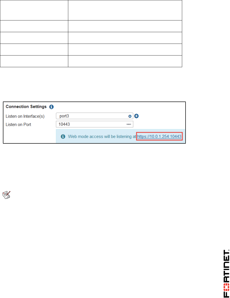
LAB 8–Certificate Operations
FortiGate II Student Guide 119
Source
LOCAL_SUBNET
PKI-users (click the User tab to locate this group)
Destination Address
all
Schedule
always
Service
ALL
Action
ACCEPT
3. Click OK.
4. Click OK.
The SSL-VPN Settings page appears and provides the URL for the SSL Web mode access. You
will use this URL later in testing.
Installing the User Certificate in the Browser
Finally, because this lab environment uses Firefox as the browser, you must install the aduser2 user
certificate in the Firefox browser. Unlike Internet Explorer and Chrome, which use the Windows
repository to store certificates, Firefox uses its own browser certificate repository.
Note: If using a browser other than Firefox, the user certificate would be stored in the
personal certificate store of the user's computer.
Once the user certificate is stored in the Firefox browser, Firefox automatically accesses this location
in order to locate the certificate, when prompted.
To install the user certificate in Firefox browser
1. In the Local-Windows VM, open a new tab in the Firefox browser.
2. Click the menu icon from the top-right corner and select Options.
DO NOT REPRINT
© FORTINET
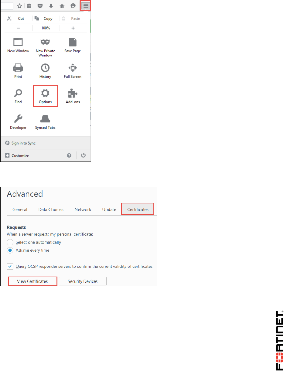
LAB 8–Certificate Operations
FortiGate II Student Guide 120
3. Click Advanced from the left menu, and then click the Certificates tab in the main window.
4. Click View Certificates.
The Certificate Manager appears.
DO NOT REPRINT
© FORTINET
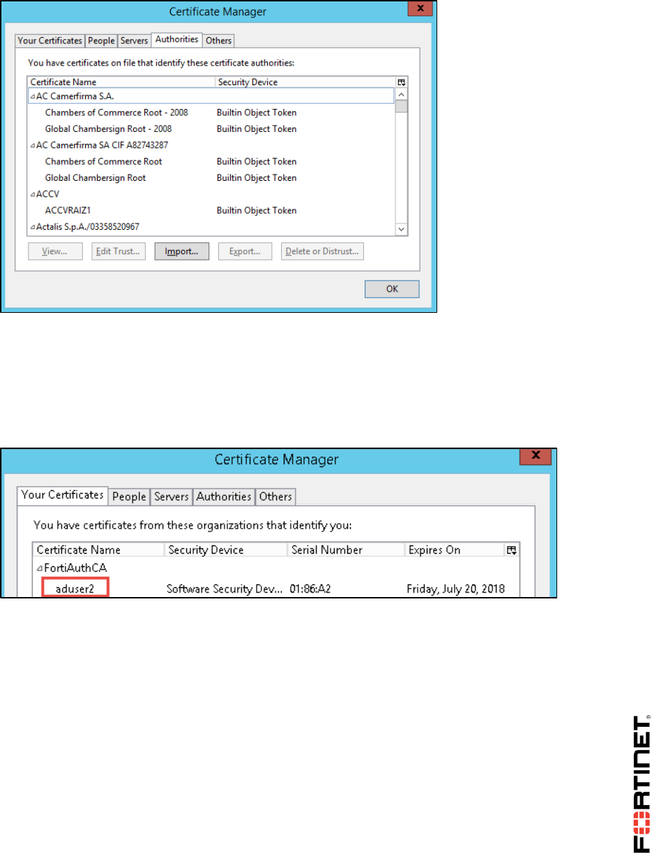
LAB 8–Certificate Operations
FortiGate II Student Guide 121
5. Click the Your Certificates tab and click Import.
6. Browse to Desktop > Resources > FortiGate-II > Certificates and select aduser2.
7. When prompted for a password, enter fortinet and click OK.
8. Click OK.
The aduser2 certificate issued by FortiAuthCA is added to the browser.
9. Click OK to close the Certificate Manager.
10. Close the Options browser tab.
Testing Certificate Authentication
For the purposes of this lab, you will authenticate with a certificate over SSL VPN (Web mode).
Based on the SSL VPN firewall policy you configured, aduser2 will be prompted to authenticate
using a certificate.
As you are logging into the web mode SSL VPN over Firefox, it will automatically check the Firefox
browser certificate repository for a user certificate.
DO NOT REPRINT
© FORTINET
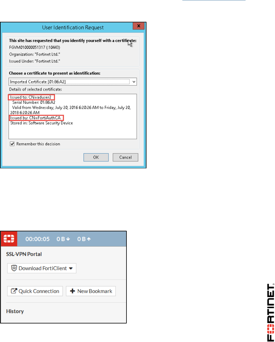
LAB 8–Certificate Operations
FortiGate II Student Guide 122
To test certificate authentication
1. Open a new browser tab and go to the VPN Web mode access at https://10.0.1.254:10443.
The site requests you identify yourself with a certificate. It automatically points to the aduser2
certificate stored in the personal certificate store on the Local-Windows VM.
2. Click OK.
3. If you receive an error that indicates your connection is not secure, click Advanced and then
select Add Exception.
The login screen appears with the username already prefilled.
4. Enter Training! as the password and click Login.
You successfully logged in with a certificate.
5. From the top-right corner, log out of the SSL VPN portal.
6. Close the SSL VPN browser tab.
DO NOT REPRINT
© FORTINET
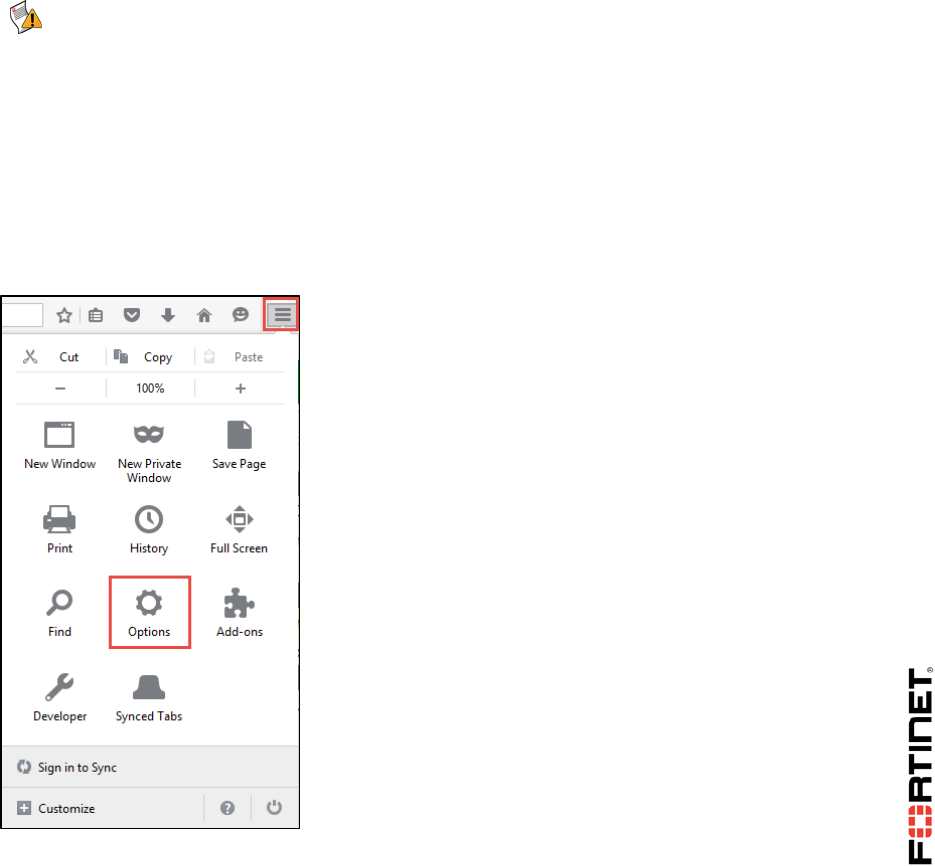
LAB 8–Certificate Operations
FortiGate II Student Guide 123
2 SSL Full Inspection
In this exercise, you will configure and enable SSL inspection on FortiGate and then test it.
With SSL deep inspection, the firewall receives traffic on behalf of the client and opens up the
encrypted traffic. Once it is finished, it re-encrypts the traffic and sends it on to its intended recipient. It
is very similar to a man-in-the-middle (MITM) attack. By enabling this feature, FortiGate will filter on
traffic that is using the SSL encrypted protocol.
Prerequisites
Before beginning this lab, you must remove the Fortinet_CA_SSL certificate from the Firefox browser.
Note: The FortiGate II lab environment begins with the Fortinet_CA_SSL certificate
installed in the Firefox browser by default. However, because this lab includes
configuring FortiGate for SSL inspection and then testing SSL inspection--both with
and without the SSL certificate installed--the SSL certificate must first be removed.
.
To remove the Fortinet_CA_SSL certificate from the Firefox browser
1. In the Local-Windows VM, open the Firefox browser.
2. Click the menu icon from the top-right corner and select Options.
3. Click Advanced from the left menu and then click the Certificates tab in the main window.
4. Click View Certificates.
DO NOT REPRINT
© FORTINET
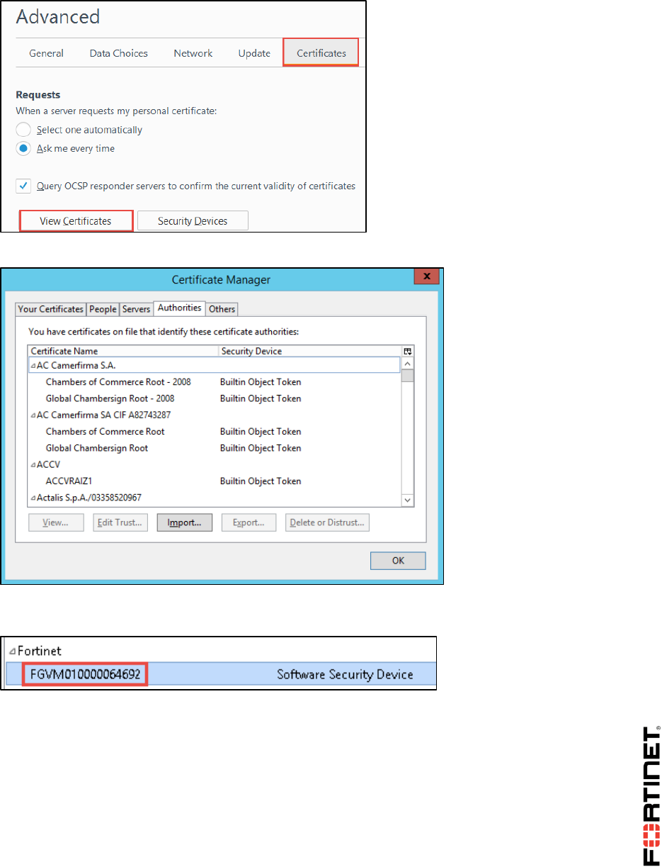
LAB 8–Certificate Operations
FortiGate II Student Guide 124
The Certificate Manager appears.
5. Click the Authorities tab and from the certificate authorities in the list, scroll to the Fortinet
section.
6. Select the certificate in the Fortinet section and click Delete or Distrust.
7. Click OK to verify.
The FortiGate SSL certificate is removed from the Firefox browser.
8. Click OK to close the Certificate Manager dialog box.
9. Close the Options tab in the Firefox browser.
Configuring SSL inspection
By default, FortiGate includes two security profiles for SSL/SSH inspection: certificate-inspection
DO NOT REPRINT
© FORTINET
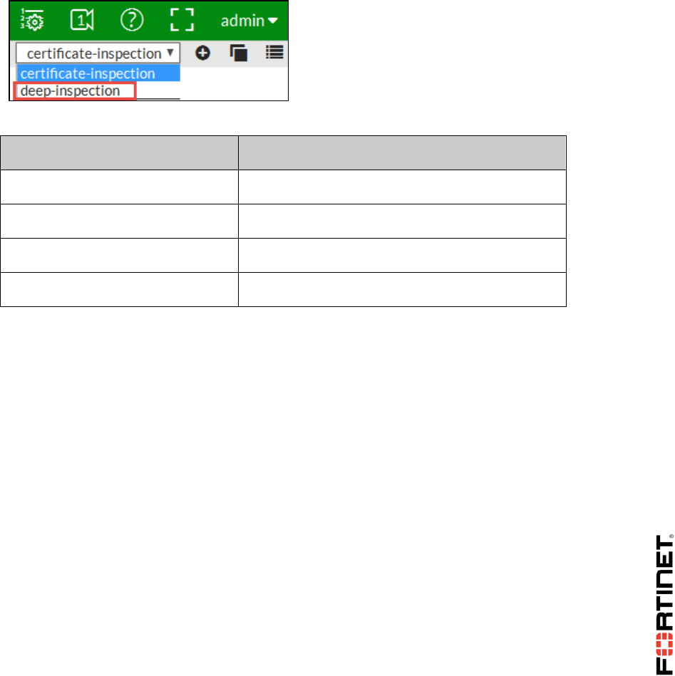
LAB 8–Certificate Operations
FortiGate II Student Guide 125
and deep-inspection.
Since this exercise involves configuring FortiGate for SSL full inspection, you will configure the default
deep-inspection security profile.
To configure SSL inspection
1. From the Local-Windows VM, open a browser and log in as admin to the Local-FortiGate GUI at
10.0.1.254.
2. Go to Security Profiles > SSL/SSH Inspection.
3. From the upper-right drop-down list, select deep-inspection.
4. From the SSL Inspection Options section, complete the following:
Field
Value
Enable SSL Inspection of
Multiple Clients Connecting to Multiple Servers
Inspection Method
Full SSL Inspection
CA Certificate
Fortinet_CA_SSL
Untrusted SSL Certificates
Allow
5. From the Exempt from SSL Inspection section, disable Reputable Websites.
6. From the Common Options section, enable the following:
Allow Invalid SSL: Certificates
Log Invalid Certificates
7. Click Apply.
Enabling SSL Inspection on a Firewall Policy
Now that you have configured the deep-inspection security profile, you must enable SSL inspection on
a firewall policy in order to start inspecting traffic.
The firewall policy must have one or more other security profiles enabled, as enabling SSL
inspection only tells FortiGate how to handle encrypted traffic--you still need to tell FortiGate which
traffic to inspect. For the purposes of this lab, you will enable the default CASI security profile.
To enable SSL inspection on a firewall policy
1. In the Local-FortiGate GUI, go to Policy & Objects > IPv4 Policy and edit the Full_Access
firewall policy (sequence #1).
2. Under Security Profiles, complete the following:
enable CASI and select default from the drop-down list.
DO NOT REPRINT
© FORTINET

LAB 8–Certificate Operations
FortiGate II Student Guide 126
enable SSL/SSH Inspection and select deep-inspection.
3. Under Logging Options, enable Log Allowed Traffic and select All Sessions.
4. Click OK.
Installing the Fortinet_CA_SSL certificate
FortiGate includes an SSL certificate that you can use for full SSL inspection called Fortinet_CA_SSL.
It is signed by a CA called FortiGate CA, which is not public. Because the CA is not public, your
browser will display a certificate warning each time a user connects to an HTTPS site. This is because
the browser is receiving certificates signed by FortiGate, which is a CA it does not know and trust. You
can avoid this warning by downloading the Fortinet_CA_SSL certificate and installing it in all the
workstations as a public authority.
In this procedure, you will first test access to an HTTPS site without the Fortinet_CA_SSL certificate
installed. Then you will install the Fortinet_CA_SSL certificate and test again.
To test SSL deep inspection without a trusted CA
1. In Local-Windows, open a new browser tab and go to a HTTPS site, such as:
https://salesforce.com
2. Click Advanced.
Notice the certificate warning. This is because the browser is receiving certificates signed by
FortiGate, which is a CA it does not know and trust.
3. Leave the browser tab open and continue to the next procedure. Do not add the exception.
To install the Fortinet_CA_SSL certificate into the browser
1. Return to the browser tab where you are logged into the Local-FortiGate GUI as admin and go to
System > Certificates.
2. Select Fortinet_CA_SSL, click Download, and save the file.
The certificate downloads to your Downloads folder.
3. In the Firefox browser, click the menu icon ( ) in the top-right corner and select Options.
4. Click Advanced from the left menu and then click the Certificates tab in the main window.
5. Click View Certificates.
DO NOT REPRINT
© FORTINET
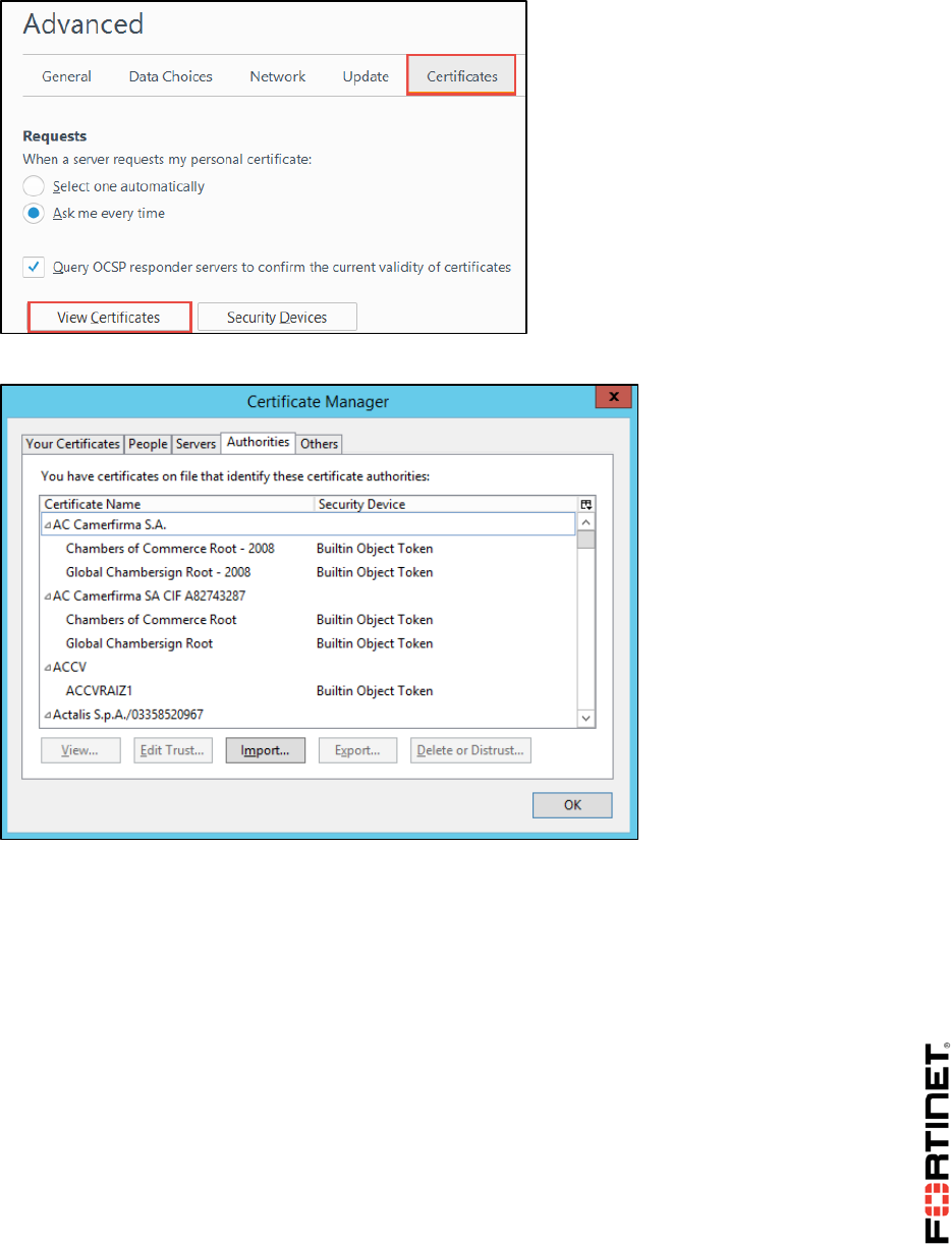
LAB 8–Certificate Operations
FortiGate II Student Guide 127
The Certificate Manager appears.
6. Click the Authorities tab and click Import.
7. Browse to the Downloads folder and select Fortinet_CA_SSL. You may need to select All
Files as the file type.
This is the FortiGate SSL certificate you downloaded earlier.
8. Click Open.
9. From the dialog box that appears, select Trust this CA to identify websites and click OK.
DO NOT REPRINT
© FORTINET
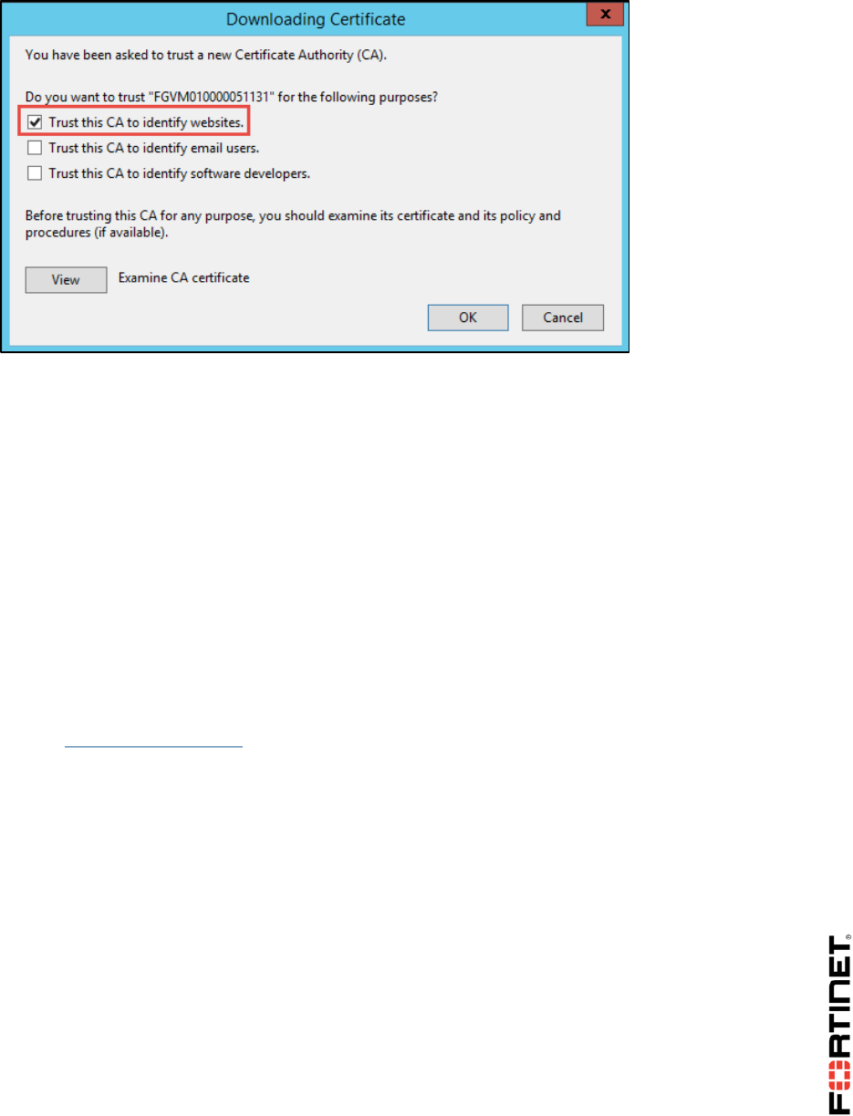
LAB 8–Certificate Operations
FortiGate II Student Guide 128
The Fortinet_CA_SSL certificate is added to the list under the Authorities tab.
10. Click OK to exit the Certificate Manager.
11. Close the Options tab in your browser.
Testing SSL Full Inspection
Now that you have added the Fortinet_CA_SSL certificate to your browser, you will not receive any
certificate warnings when accessing a secure site.
The CA that signed this certificate is not public, but the browser is aware of it because you added it as
a trusted authority in the previous exercise.
To test SSL full inspection
1. In the Local-Windows VM, open a new browser tab and go to a secure site, such as:
https://salesforce.com
This time you are passed through to the site without any certificate warnings.
2. Close the browser.
DO NOT REPRINT
© FORTINET
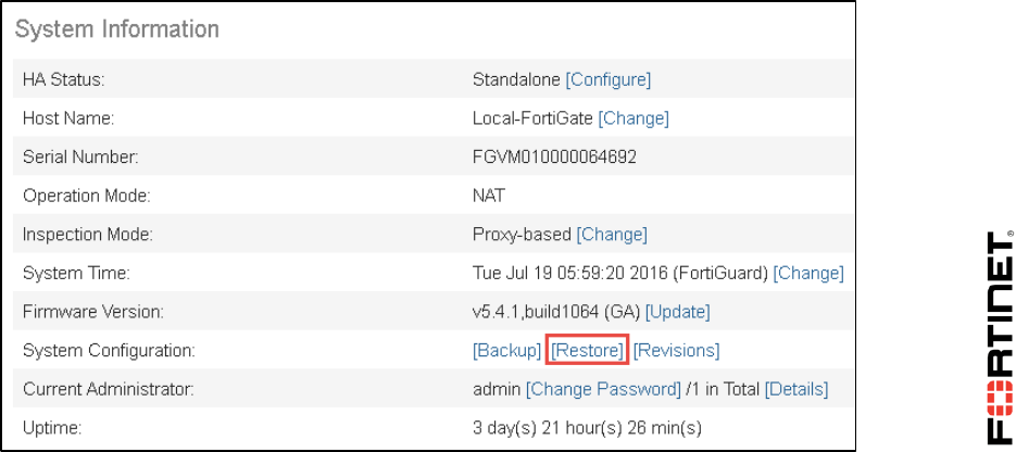
LAB 9–Data Leak Prevention
FortiGate II Student Guide 129
LAB 9–Data Leak Prevention
In this lab, you will use data leak prevention (DLP) rules and sensors to block sensitive data from
leaving the private network.
Objectives
Configure DLP to block ZIP files.
Read and interpret DLP log entries.
Set up DLP banning and quarantining.
Configure DLP fingerprinting.
Time to Complete
Estimated: 30 minutes
Prerequisites
Before beginning this lab, you must restore a configuration file to the FortiGate.
To restore the FortiGate configuration file
1. On the Local-Windows, open a web browser and log in as admin to the Local-FortiGate GUI at
10.0.1.254.
2. Go to Dashboard, and from the System Information widget click Restore.
3. Select to restore from Local PC and click Upload.
DO NOT REPRINT
© FORTINET

LAB 9–Data Leak Prevention
FortiGate II Student Guide 130
4. Browse to Desktop > Resources > FortiGate-II > DLP and select local-dlp.conf.
5. Click OK.
6. Click OK to reboot.
DO NOT REPRINT
© FORTINET
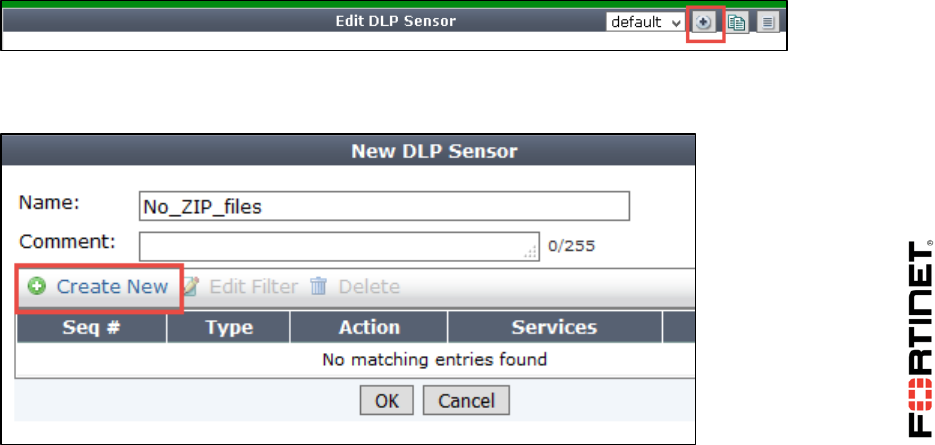
LAB 9–Data Leak Prevention
FortiGate II Student Guide 131
1 Blocking Files by File Type
There are multiple ways that you can configure in DLP to block sensitive information leaving out of
your network.
In this exercise, you will configure the DLP to block files by file types and apply to firewall policy. Then,
you will test the configuration and view the logs.
Enabling DLP
DLP is not enabled in the GUI by default. You will enable DLP to be visible in the GUI.
To enable DLP
1. On the Local-Windows, open a browser and log in as admin to the Local-FortiGate GUI at
10.0.1.254.
2. Go to System > Feature Select.
3. Under Security Features, enable DLP.
4. Click Apply.
Configuring the DLP Sensor and DLP Filter
You will be configuring a new DLP sensor and will create a DLP filter to block ZIP files.
To configuring the DLP sensor and DLP filter
1. In the Local-FortiGate GUI, go to Security Profiles > Data Leak Prevention.
2. Click Create New.
3. Configure the Name as No_ZIP_files.
4. In the New DLP Sensor window, click Create New to create a new filter.
DO NOT REPRINT
© FORTINET
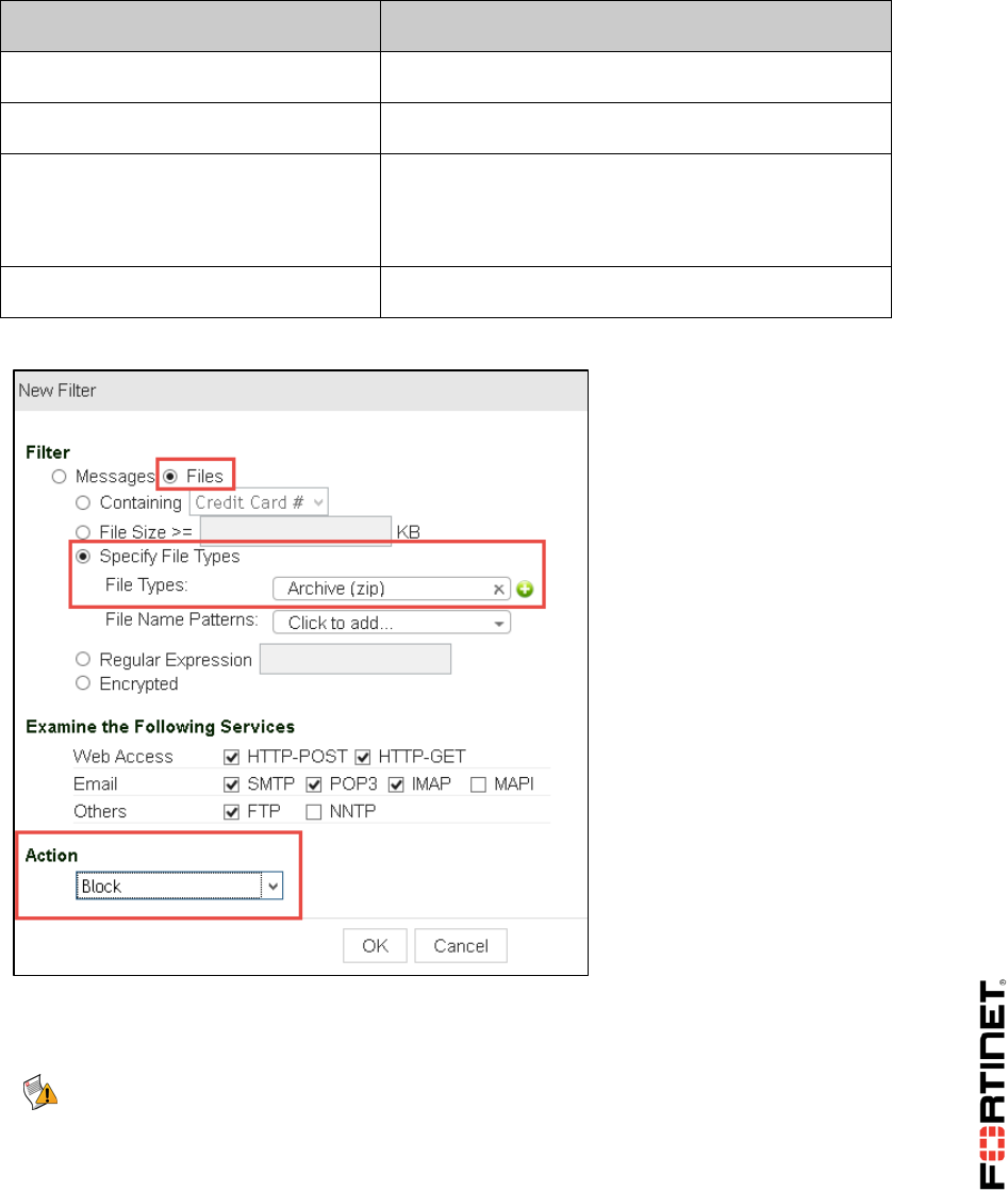
LAB 9–Data Leak Prevention
FortiGate II Student Guide 132
5. Configure the following settings:
Field
Value
Filter
Click on Files radio button to select
Specify File Types
Click on radio button to select
File Types
Archive (zip)
(Tip: Type the name in the search box at the
bottom and click on file types to add.)
Action
Block
Your configuration will look similar to this:
6. Click OK.
7. Click on Apply on the DLP sensor window.
Note: You can also block based upon a file name of *.zip, but it is not recommended.
A person could circumvent that type of DLP by changing the filename to, for
example, *.zp1, or *.txt.
In comparison, file type identification works by analyzing the binary layout of the file.
DO NOT REPRINT
© FORTINET

LAB 9–Data Leak Prevention
FortiGate II Student Guide 133
Applying a DLP Sensor to a Firewall Policy
Now that you have created a DLP sensor, you will be editing existing firewall policy to apply the DLP
sensor to it.
To apply DLP sensor to firewall policy
1. In the Local-FortiGate GUI, go to Policy & Objects > IPv4 Policy.
2. Right-click on the Seq.# column for DLP firewall policy.
3. Click Edit.
4. Under Security Profiles, enable DLP Sensor.
5. Select No_ZIP_files DLP sensor from the drop-down list.
Note: When selecting a DLP sensor, Proxy Options is automatically enabled. You cannot
disable Proxy Options, but can select any pre-configured proxy options profile from the
associated drop-down list.
6. Click OK.
7. Optionally, if you would like to see the default proxy options profile selected in the firewall policy,
go to Security Profiles > Proxy Options.
This profile determines how FortiGate’s proxies pick up protocols. For example, the HTTP
listening port is set to port 80.
Testing the DLP Sensor
Now you will test the DLP sensor by trying to transmit a ZIP file by uploading to a web URL.
To test the DLP sensor
1. In the Local-Windows VM, open a web browser and go to the following URL:
http://10.200.1.254/fileupload.html
2. On the web page, click Browse.
3. Locate and select the Resources folder on the desktop.
4. Double click the FortiGate II folder.
5. Double click the DLP folder.
6. Click DLP_Lab.Zip.
7. Click Open.
8. Click Submit the file.
The DLP block message will appear.
Checking the DLP Logs
Now you will check the logs related to DLP for the above test you just performed.
DO NOT REPRINT
© FORTINET
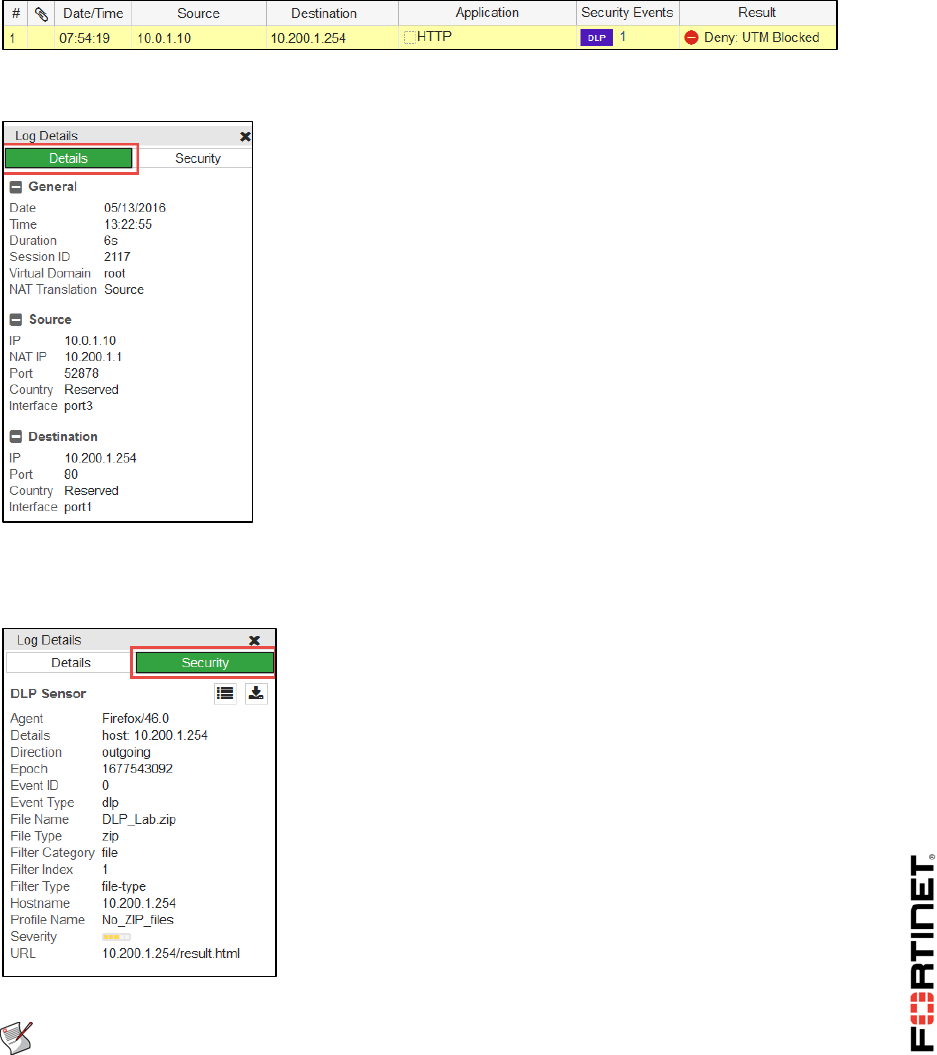
LAB 9–Data Leak Prevention
FortiGate II Student Guide 134
To check the DLP logs
1. In the Local-FortiGate GUI, go to the Log & Report > Forward Traffic.
2. Find the log entry that has DLP in the Security Events column and a Result column with a Deny
action for this attempted data leak.
3. Double click on that log entry to select it.
4. On the right-hand side, the Details column shows the forward traffic log information such as NAT
translation, NAT IP, policy ID, and security action.
5. Click the Security tab to view security log information.
This tab provides information that is more specific to security profile, such as event type, file
name, file type, filter type, filter category, and security profile name.
You can also view DLP logs under Log & Report > Data Leak Prevention.
Note: The DLP logs section will not display if there are no DLP logs. FortiGate will
show it after creating logs. If this menu item does not display, log out from the
FortiGate GUI and log in again to refresh it.
DO NOT REPRINT
© FORTINET
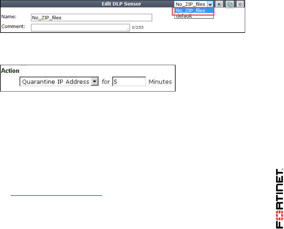
LAB 9–Data Leak Prevention
FortiGate II Student Guide 135
2 Quarantining an IP Addresses
You can also configure the action to quarantine IP addresses that are trying to leak the sensitive
information. The quarantined IP address will be blocked from accessing the network so that you have
time to investigate the issue proactively.
Quarantining an IP Address
Now you will be modifying action of the previously configured DLP filter to quarantine the IP address.
To quarantine an IP address
1. On the Local-Windows, open a browser and log in as admin to the Local-FortiGate GUI at
10.0.1.254.
2. Go to Security Profiles > Data Leak Prevention.
3. Edit the No_ZIP_files DLP sensor by selecting it from right-hand dropdown menu.
4. Select the Seq# 1 and click Edit Filter.
5. Change the action for the filter entry that detects ZIP files to Quarantine IP Address and enter an
interval of 5 minutes.
6. Click OK.
7. Click Apply.
Testing the Quarantined IP Address
Now you will test the quarantine action by trying to upload again ZIP file.
To test the quarantined IP address
1. In the Local-Windows VM, open a web browser and go to the following URL:
http://10.200.1.254/fileupload.html
2. On the web page, click Browse.
3. Locate and select the Resources folder on the desktop.
4. Double click the FortiGate II folder.
5. Double click the DLP folder.
DO NOT REPRINT
© FORTINET

LAB 9–Data Leak Prevention
FortiGate II Student Guide 136
6. Click DLP_Lab.Zip.
7. Click Open.
8. Click Submit the file.
The DLP block message will appear.
9. In the Local-Windows VM, open a web browser and go to the few websites such as:
http://www.bbc.com
http://dailymotion.com
A replacement message should appear instead of the website. This occurs because the IP
address that is sending the request has been quarantined and is not allowed through the firewall
policy on the FortiGate.
Un-quarantining a Quarantined IP Address
Now you will be un-quarantining your IP address so that you can access the network.
To un-quarantine a quarantined IP address
1. From the GUI on the Local-FortiGate, go to Monitor > User Quarantine Monitor.
2. Select your IP address (10.0.1.10).
3. Click Delete to remove it from the banned entry.
4. Click OK.
5. In the Local-Windows VM, open a web browser and again go to the few websites such as:
http://www.bbc.com
http://dailymotion.com
You should now be able to access the Internet, even if five minutes has not yet elapsed.
DO NOT REPRINT
© FORTINET

LAB 9–Data Leak Prevention
FortiGate II Student Guide 137
3 DLP Fingerprinting
DLP fingerprinting is technique that uses content-based filtering and identifies specific files using one
or more CRC checksums for the files in the configured network share.
Configuring a DLP Filter for the Network Share
A network share is preconfigured on the Local-Windows VM with user account of Administrator
and share name of DLPshare.
In the configuration that you uploaded at the start, FortiGate is preconfigured to access the network
share.
In this procedure, you will first view the DLP configuration for network share and then you will
configure new filter for the DLP fingerprinting.
To configure a DLP filter for the network share
1. From the Local-Windows, open PuTTY and connect to the LOCAL-FORTIGATE saved session
(connect over SSH).
2. Log in as admin and execute the following command to check the DLP fingerprinting
configuration:
show dlp fp-doc-source
You will notice that the Local-FortiGate is configured to access the network share configured on
Local-Windows with an IP address of 10.0.1.10.
3. Enter the following commands to configure a new filter for the DLP fingerprinting in the DLP
sensor named No_ZIP_files:
config dlp sensor
edit No_ZIP_files
config filter
edit 2
set proto http-post
set filter-by fingerprint
set fp-sensitivity Critical
set action block
end
end
DO NOT REPRINT
© FORTINET
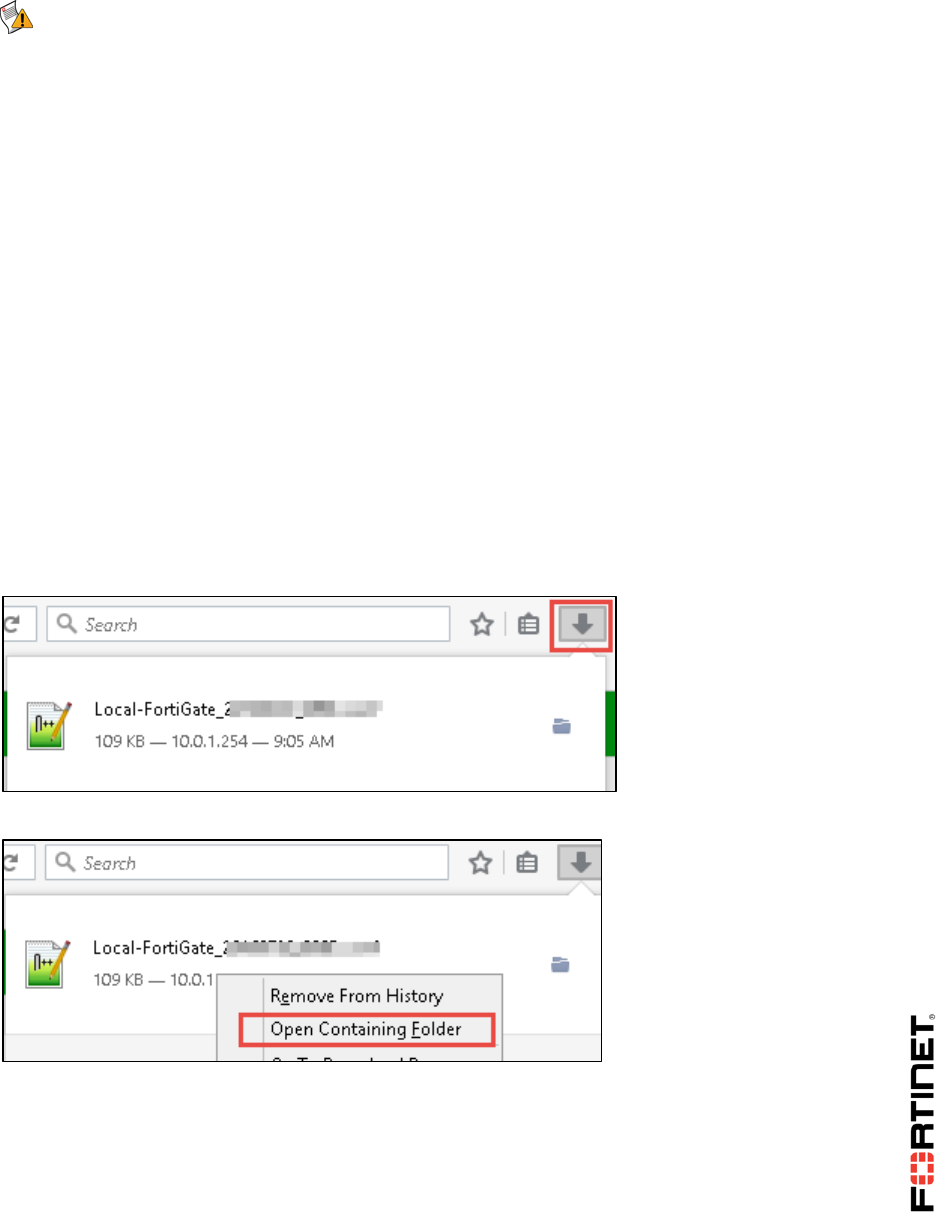
LAB 9–Data Leak Prevention
FortiGate II Student Guide 138
Note: DLP fingerprinting filter can only be configured from the CLI. Once it is configured,
it is visible in GUI.
Adding a File to the Network Share
Now you will be adding a file to the network share.
To add file to the network share
1. On the Local-Windows VM, open a browser and log in as admin to the Local-FortiGate GUI at
10.0.1.254.
2. Go to Dashboard > System Information.
3. Click Backup.
4. Click OK.
5. Click Save File.
6. Click OK.
Check your browser's downloads folder.
7. Click the download icon on the browser.
8. Right-click your backed up configuration and click Open Containing Folder.
9. Right-click on the configuration file and click Copy.
10. In the Local-Windows open the File Explorer.
11. Go to C:\DLPshare.
12. Right-click and click Paste to paste the configuration file in that folder.
DO NOT REPRINT
© FORTINET
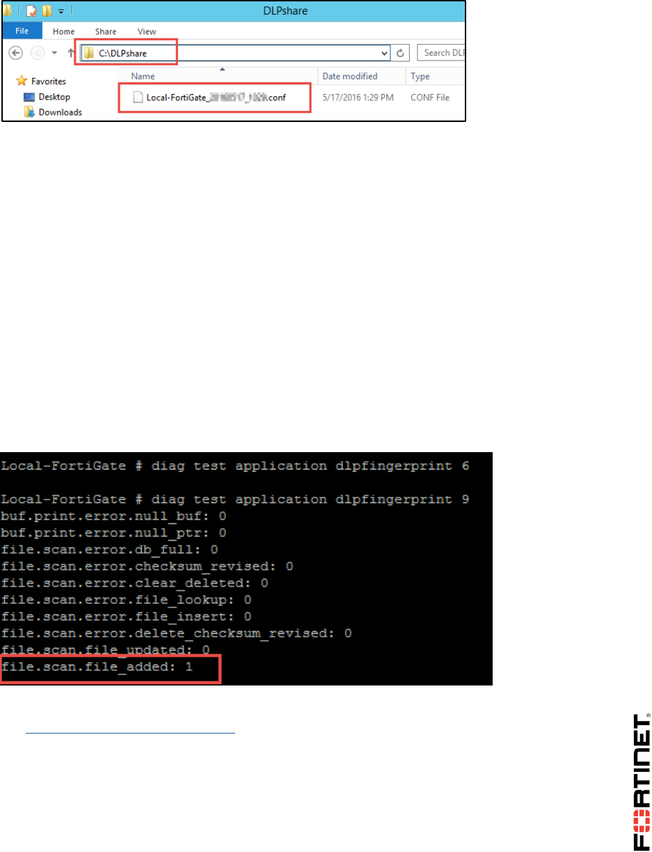
LAB 9–Data Leak Prevention
FortiGate II Student Guide 139
Testing DLP Fingerprinting
Now you will be testing DLP fingerprinting for the file added to network share. DLP fingerprinting is
configured based on a schedule. For the purpose of this lab, we will be triggering fingerprint
checksums manually, using CLI commands. This is because training is conducted at different times
globally, and a configured schedule may not work properly.
To test DLP fingerprinting
1. In the LOCAL-FORTIGATE PuTTY session, run the following command to refresh DLP fingerprint
checksums:
diagnose test application dlpfingerprint 6
2. Run the following command to check the updated checksum:
diagnose test application dlpfingerprint 9
You will see that a new file has been added.
3. In the Local-Windows VN, open a browser and go to the following URL:
http://10.200.1.254/fileupload.html
4. On the web page, click Browse and go to C:\DLPshare.
5. Click on the configuration file.
6. Click Open.
7. Click Submit the file.
The file upload should be blocked.
DO NOT REPRINT
© FORTINET
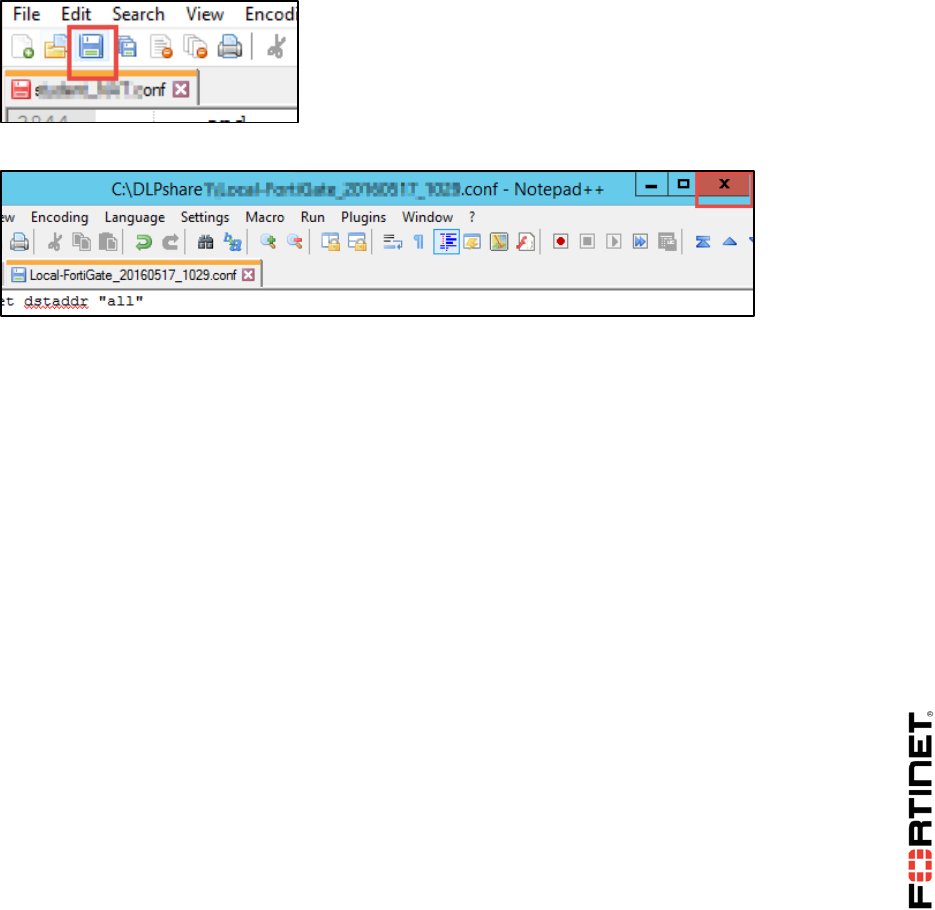
LAB 9–Data Leak Prevention
FortiGate II Student Guide 140
Modifying a File in the Network Share
Now you will modify a file in the network share.
To modify a file in the Network Share
1. In the Local-Windows VM, open File Explorer and go to C:\DLPshare.
2. Right-click on the FortiGate configuration file.
3. Click Edit with Notepad++.
4. Make a few small changes to different areas of the configuration.
5. Click Save.
6. Close Notepad++.
Testing DLP Fingerprinting With the Modified File
Now you will be testing DLP fingerprinting using the modified file in the network share. DLP
fingerprinting is configured based on schedule. For the purpose of this lab we will be triggering
fingerprint checksums manually using CLI commands. This is because training is conducted at
different times globally and using a configured schedule may not work properly.
To test DLP fingerprinting with the modified file
1. In the LOCAL-FORTIGATE PuTTY session, run the following command to refresh DLP fingerprint
checksums:
diagnose test application dlpfingerprint 6
2. Run the following command to check the updated checksum:
diagnose test application dlpfingerprint 9
You will see that the file has been updated.
DO NOT REPRINT
© FORTINET
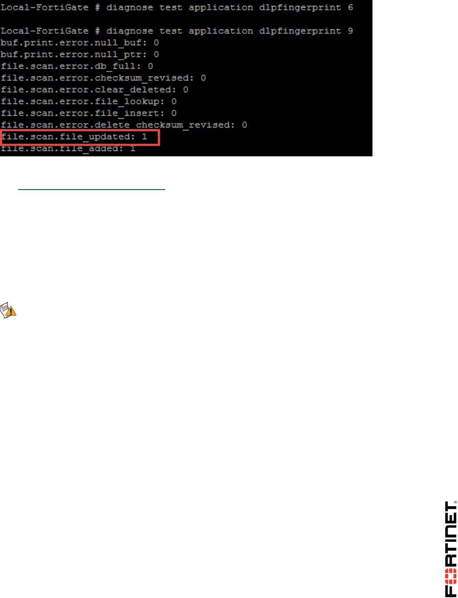
LAB 9–Data Leak Prevention
FortiGate II Student Guide 141
3. In the Local-Windows VM, open a browser and go to the following URL:
http://10.200.1.254/fileupload.html
4. On the web page, click Browse and go to C:\DLPshare.
5. Click on the configuration file.
6. Click Open.
7. Click Submit the file.
The file upload should be blocked. (Assuming that changes made to file were not too large, and
not in too many areas).
Note: Fingerprinting breaks the file into chunks and performs checksums on each part. By
default, DLP will detect a match if any part's checksum from the fingerprint matches.
DO NOT REPRINT
© FORTINET
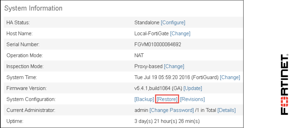
LAB 10–Diagnostics
FortiGate II Student Guide 142
LAB 10–Diagnostics
In this lab, you will run some diagnostic commands to learn about the current status of the FortiGate.
You will also use the sniffer and debug flow tools to troubleshoot and fix a connectivity problem.
Objectives
Identify your network’s normal behavior.
Monitor for abnormal behavior such as traffic spikes.
Diagnose problems at the physical and network layers.
Diagnose connectivity problems using the debug flow.
Diagnose resource problems, such as high CPU or memory usage.
Time to Complete
Estimated: 30 minutes
Prerequisites
Before beginning this lab, you must restore a configuration file to the Local-FortiGate.
To restore the FortiGate configuration file
1. From the Local-Windows VM, open a browser and log in as admin to the Local-FortiGate GUI at
10.0.1.254.
2. Go to Dashboard, and from the System Information widget click Restore.
DO NOT REPRINT
© FORTINET

LAB 10–Diagnostics
FortiGate II Student Guide 143
3. Select to restore from Local PC and click Upload.
4. Browse to Desktop > Resources > FortiGate-II > Diagnostics and select local-
diagnostics.conf.
5. Click OK.
6. Click OK to reboot.
DO NOT REPRINT
© FORTINET

LAB 10–Diagnostics
FortiGate II Student Guide 144
1 Knowing What is Happening Now
During this exercise you will use CLI commands to get information about the FortiGate, such as traffic
volume crossing the device, CPU usage, memory usage, and an ARP table.
Executing Diagnostic Commands
You will execute some diagnostic commands and take notes of some of the information displayed.
To execute diagnostic commands
1. From Local-Windows VM, open PuTTY and connect to the LOCAL-FORTIGATE saved session
(connect over SSH).
2. Log in as admin and find the following information (write down your answers in the spaces
provided). Below, see the list of commands you should use to get the answers.
Firmware branch point:
______________________
Current HA mode:
______________________
Hostname:
______________________
CPU utilization:
______________________
Memory utilization:
______________________
Average network usage:
______________________
Average session setup rate:
______________________
Negotiated speed and duplex mode for interface port1:
______________________
MTU for port1:
______________________
MAC address for the IP address 10.200.1.254:
______________________
Name of the process consuming most CPU (if any):
______________________
Name of the process consuming most memory:
______________________
Tip: Use the following CLI commands to find the information requested above:
get system status
get system performance status
DO NOT REPRINT
© FORTINET

LAB 10–Diagnostics
FortiGate II Student Guide 145
get hardware nic port1
diagnose ip arp list
diagnose sys top 1
(Press Shift-P to order the processes by CPU usage, or press Shift-M to order them by
memory usage.)
DO NOT REPRINT
© FORTINET

LAB 10–Diagnostics
FortiGate II Student Guide 146
2 Troubleshooting a Connectivity Problem
During this exercise you will use the sniffer and debug flow to troubleshoot a network connectivity
problem.
Identifying the Problem
As you will see in this procedure, there is a network connectivity problem between the Local-Windows
VM and the Linux server.
To identify the problem
1. From the Local-Windows VM, open a command prompt window.
2. Start a continuous ping to the Linux server (IP address 10.200.1.254):
ping -t 10.200.1.254
The ping is failing. You will use the sniffer and debug flow tools in the Local-FortiGate to find out
why.
Do not close this window. Keep the ping running.
Using the Sniffer
You will start troubleshooting by sniffing the ICMP traffic going to the Linux server.
To use the sniffer
1. In the Local-Windows VM, open PuTTY and connect to the LOCAL-FORTIGATE saved session
(connect over SSH).
2. Log in as admin and execute the following command to sniffer the ICMP traffic to
10.200.1.254:
diagnose sniffer packet any "icmp and host 10.200.1.254" 4
Observe the output:
interfaces=[any]
filters=[icmp and host 10.200.1.254]
5.439019 port3 in 10.0.1.10 -> 10.200.1.254: icmp: echo request
10.442347 port3 in 10.0.1.10 -> 10.200.1.254: icmp: echo request
15.444343 port3 in 10.0.1.10 -> 10.200.1.254: icmp: echo request
20.545397 port3 in 10.0.1.10 -> 10.200.1.254: icmp: echo request
The packets are arriving to the FortiGate, but the FortiGate is not routing them out.
DO NOT REPRINT
© FORTINET

LAB 10–Diagnostics
FortiGate II Student Guide 147
Using the Debug Flow Tool
To get information about why the packets are being dropped, you will run the debug flow tool.
To use the debug flow tool
1. In the Local-Windows VM, open PuTTY again and connect to the LOCAL-FORTIGATE saved
session (connect over SSH).
2. Log in as admin and enter the commands below. You will configure the debug flow filter to
capture all ICMP traffic to and from the IP address 10.200.1.254:
diagnose debug flow filter clear
diagnose debug flow filter proto 1
diagnose debug flow filter addr 10.200.1.254
diagnose debug flow show console enable
diagnose debug enable
diagnose debug flow trace start 3
Output should be similar to what is shown below. The FortiGate receives the ICMP packet from
10.0.1.10 to 10.200.1.254 from port3:
id=20085 trace_id=3 func=print_pkt_detail line=4717 msg="vd-root
received a packet(proto=1, 10.0.1.10:1->10.200.1.254:8) from port3.
code=8, type=0, id=1, seq=30."
It creates a new session:
id=20085 trace_id=3 func=init_ip_session_common line=4868
msg="allocate a new session-000072c1"
It finds a route for the destination 10.200.1.254, via port1:
id=20085 trace_id=3 func=vf_ip_route_input_common line=2584 msg="find
a route: flag=04000000 gw-10.200.1.254 via port1"
It drops the packet. The debug flow shows the error message:
id=20085 trace_id=3 func=fw_forward_handler line=565 msg="Denied by
forward policy check (policy 0)"
The message Denied by forward policy check indicates that the traffic is denied by a
firewall policy. It could be either a denied policy explicitly configured by the administrator, or the
implicit denied policy for traffic that does not match any configured policy.
The policy 0 indicates that the traffic was denied by the default implicit policy. Because the
traffic is blocked by an explicitly configured policy, its policy ID number is indicated in this
output instead of the number zero.
Fixing the Problem
Now that we have found the cause of the problem, let's fix it.
DO NOT REPRINT
© FORTINET

LAB 10–Diagnostics
FortiGate II Student Guide 148
To fix the problem
1. On the Local-Windows, open a browser and log in as admin to the Local-FortiGate GUI at
10.0.1.254.
2. Go to Policy & Objects > IPv4 Policy.
Look at the firewall policies. There is only one and it does not allow ICMP traffic (only HTTP). That
explains why the FortiGate is dropping the ping packets.
3. Edit the policy.
4. Change the service from HTTP to ALL.
5. Click OK.
Testing the Fix
You will test that the configuration change fixed the problem.
To test the fix
1. Check the continuous ping running from the Local-Windows VM. It is working now.
2. Stop it by pressing Ctrl-C.
3. Go back to the Local-FortiGate PuTTY session where you are running debug commands and
clear all the ICMP sessions from the session table:
diagnose sys session filter clear
diagnose sys session filter proto 1
diagnose sys session clear
4. Start the debug flow one more time:
diagnose debug flow filter clear
diagnose debug flow filter proto 1
diagnose debug flow filter addr 10.200.1.254
diagnose debug flow show console enable
diagnose debug enable
diagnose debug flow trace start 3
There should not be any output yet, as the ping is not running.
5. From the Local-Windows command prompt window, start the ping one more time:
ping -t 10.200.1.254
6. Check the debug flow output. It is a bit different now. The error message is not displayed and
you will see the a few new logs.
Traffic is allowed by the firewall policy with the ID 1:
DO NOT REPRINT
© FORTINET

LAB 10–Diagnostics
FortiGate II Student Guide 149
id=20085 trace_id=7 func=fw_forward_handler line=698 msg="Allowed by
Policy-1: SNAT"
FortiGate applies source NAT (SNAT):
id=20085 trace_id=7 func=__ip_session_run_tuple line=2755 msg="SNAT
10.0.1.10->10.200.1.1:62464"
Additionally, you will see the debug flow logs from the return (ping reply) packets:
id=20085 trace_id=8 func=print_pkt_detail line=4717 msg="vd-root
received a packet(proto=1, 10.200.1.254:62464->10.200.1.1:0) from
port1. code=0, type=0, id=62464, seq=3605."
id=20085 trace_id=8 func=resolve_ip_tuple_fast line=4781 msg="Find an
existing session, id-00008b03, reply direction"
id=20085 trace_id=8 func=__ip_session_run_tuple line=2769 msg="DNAT
10.200.1.1:0->10.0.1.10:1"
id=20085 trace_id=8 func=vf_ip_route_input_common line=2584 msg="find
a route: flag=04000000 gw-10.0.1.10 via port3"
Tip: The procedure in this exercise describes what you should usually do when
troubleshooting connectivity problems with a FortiGate. Sniffer the traffic first to check that
the packets are arriving to the FortiGate, and that the FortiGate is properly routing them
out. If the sniffer shows that the traffic is being dropped by the FortiGate, use the debug
flow tool to find out why.
DO NOT REPRINT
© FORTINET

LAB 11–IPv6
FortiGate II Student Guide 150
LAB 11–IPv6
In this lab, you will perform initial IPv6 interface configuration, and add an IPv6 network prefix to your
Local-FortiGate to advertise and automatically configure Local-Windows.
Then, you will configure two IPv6 transition technologies: NAT64 and IPv6 over IPv4 IPsec. The IPsec
tunnel will connect the two internal networks of your FortiGate devices. Remote-FortiGate is already
configured, so you will only need to configure Local-FortiGate.
Objectives
Show IPv6 options in the FortiOS GUI.
Configure an IPv6 address and administrative protocols on an interface.
Test IPv6 connectivity.
Configure a FortiGate to automatically configure Windows and other hosts on the local network
with an IPv6 address and prefix.
Configure transition technologies including NAT64, and IPv6 over IPv4 IPsec.
Time to Complete
Estimated: 30 minutes
Prerequisites
Before beginning this lab, you must restore a configuration file to both the Local-FortiGate and
Remote-FortiGate.
To restore the Remote-FortiGate configuration file
1. From the Local-Windows VM, open a browser and log in as admin to the Remote-FortiGate GUI
at 10.200.3.1.
2. Go to Dashboard, and from the System Information widget click Restore.
DO NOT REPRINT
© FORTINET

LAB 11–IPv6
FortiGate II Student Guide 151
3. Select to restore from Local PC and click Upload.
4. Browse to Desktop > Resources > FortiGate-II > IPv6 and select remote-ipv6.conf.
5. Click OK.
6. Click OK to reboot.
To restore the Local-FortiGate configuration file
1. From the Local-Windows VM, open a browser and log in as admin to the Local-FortiGate GUI at
10.0.1.254.
2. Go to Dashboard, and from the System Information widget click Restore.
3. Select to restore from Local PC and click Upload.
4. Browse to Desktop > Resources > FortiGate-II > IPv6 and select local-ipv6.conf.
5. Click OK.
6. Click OK to reboot.
DO NOT REPRINT
© FORTINET

LAB 11–IPv6
FortiGate II Student Guide 152
1 IPv6 Interface and SLAAC Setup
During this lab you will configure the Local-FortiGate to dynamically assign an IPv6 prefix to the Local-
Windows VM using stateless auto-address configuration (SLAAC).
Configuring an IPv6 Address
This procedure configures an IPv6 address in a FortiGate's interface.
To configure an IPv6 address
1. From the Local-Windows VM, open a browser and log in as admin to the Local-FortiGate GUI at
10.0.1.254.
2. Go to System > Feature Select.
3. Enable IPv6 to show it in the GUI.
4. Click Apply.
5. Go to Network > Interfaces.
6. Edit port3 with a manual IPv6 Address/Prefix of:
2001:db8:1::254/64
Notice, however, that this does not enable FortiGate to offer DHCPv6 or SLAAC on port3 yet.
7. Click OK.
Configuring SLAAC
SLAAC configuration must be done via CLI.
To configure SLAAC
1. In the Local-Windows VM, open PuTTY and connect to the LOCAL-FORTIGATE saved session
(connect over SSH).
2. Enter the following commands to configure port3 with an IPv6 prefix and enable SLAAC:
config system interface
edit port3
config ipv6
set ip6-address 2001:db8:1::254/64
set ip6-allowaccess ping http https ssh
set ip6-send-adv enable
config ip6-prefix-list
DO NOT REPRINT
© FORTINET

LAB 11–IPv6
FortiGate II Student Guide 153
edit 2001:db8:1::/64
set autonomous-flag enable
set onlink-flag enable
end
end
end
Stop and Think
SLAAC is auto-configuration, but you've not enabled the autoconf setting. Why?
Discussion
Remember that FortiGate can be either a SLAAC client or SLAAC server (router). In this
case, we are configuring FortiGate to be a router sending router advertisements (RA) to
clients, so instead of:
set autoconf enable
we configure:
set ip6-send-adv enable
and then the prefix that FortiGate will advertise to hosts such as Windows laptops.
Testing the SLAAC Configuration
This procedure tests your configuration by dynamically assigning an IPv6 prefix to Local-Windows.
To test the SLAAC configuration
1. In the Local-Windows VM, open a command prompt window and execute the following batch file.
It will configure the Local-Windows's LAN interface to use IPv4 DHCP and IPv6 SLAAC:
SetDHCP
2. Refresh the IPv6 address information, and then verify that it has auto-configured IPv6 settings
from FortiGate.
To do this, in the command prompt window, run the commands:
ipconfig /renew
ipconfig
If SLAAC was successful, you should see an IP address in the 2001:db8:1::/64 range, such as:
IPv6 Address: 2001:db8:1::2222(Preferred)
3. Test IPv6 connectivity between the Local-Windows VM and port3 on the Local-FortiGate by
entering:
DO NOT REPRINT
© FORTINET


LAB 11–IPv6
FortiGate II Student Guide 155
2 NAT64
In this exercise you will configure the Local-FortiGate to translate IPv6 addresses to IPv4.
Configuring and Testing NAT64
You will use the CLI to enable NAT64, create the IPv6 address objects, and create the firewall policy
for NAT64.
To configure NAT64 through the CLI
1. From the Local-Windows VM, open PuTTY and connect to the LOCAL-FORTIGATE saved
session (connect over SSH).
2. Log in as admin.
3. Type the following commands to enable both the NAT64 service using the default prefix and
DNS64 AAAA record synthesis:
config system nat64
set status enable
set always-synthesize-aaaa-record enable
end
4. Create IPv6 firewall address objects for the IPv6 internal subnets on Local-FortiGate:
config firewall address6
edit "LOCAL_INTERNAL6"
set ip6 2001:db8:1::/64
next
edit "REMOTE_INTERNAL6"
set ip6 2001:db8:2::/64
end
5. Create a firewall policy that applies NAT64 between port3 and port1 for HTTP and ICMP
traffic.
Remember that the source address is an IPv6 address; the destination address is an IPv4
address:
config firewall policy64
edit 0
set srcintf "port3"
DO NOT REPRINT
© FORTINET

LAB 11–IPv6
FortiGate II Student Guide 156
set dstintf "port1"
set srcaddr "LOCAL_INTERNAL6"
set dstaddr "all"
set action accept
set schedule "always"
set service "HTTP" "ALL_ICMP6"
end
To test NAT64
1. In the Local-Windows VM, open a command prompt window and test IPv6 connectivity to port4 on
the Remote-FortiGate by entering this command:
ping 64:ff9b::ac8:301
Stop and Think
Is this an IPv6 address for transition technologies?
Discussion
Remember that the IPv4 address space fits inside the IPv6 address space. The prefix
beginning with 64 indicates that it is an address reserved for NAT64. If you use a
hexadecimal converter with the final six numbers, you can see that this is a NAT64
address: it translates to the IPv4 address 10.200.3.1.
DO NOT REPRINT
© FORTINET

LAB 11–IPv6
FortiGate II Student Guide 157
3 Using IPsec to Tunnel IPv6 Over an
IPv4 Network
During this exercise you will create an IPv4 IPsec tunnel between the Local-FortiGate and Remote-
FortiGate to encapsulate IPv6 traffic between the local subnet (2001:db8:1::/64) and the remote
subnet (2001:db8:2::/64).
The Remote-FortiGate is already configured. Your task in this exercise is to configure the Local-
FortiGate side.
Creating an IPv6 Over IPv4 IPsec Tunnel
You will use the CLI to create IPsec phases 1 and 2. After that, you will create the static route and
firewall policies required for the VPN.
To create the IPsec phases 1 and 2
1. In the Local-Windows VM, open PuTTY and connect to the LOCAL-FORTIGATE saved session
(connect over SSH).
2. Log in as admin and type the following commands to create an IPsec phase1 object with the IPv4
address of Remote-FortiGate as the remote gateway:
config vpn ipsec phase1-interface
edit "ipv4_to_ipv6"
set interface "port1"
set remote-gw 10.200.3.1
set psksecret fortinet
next
end
3. Create an IPsec phase 2 object with the IPv6 source address of the Local-FortiGate and the
destination IPv6 address of the Remote-FortiGate:
config vpn ipsec phase2-interface
edit "ipv4_to_ipv6-P2"
set phase1name "ipv4_to_ipv6"
set src-addr-type subnet6
set dst-addr-type subnet6
set src-subnet6 2001:db8:1::/64
DO NOT REPRINT
© FORTINET

LAB 11–IPv6
FortiGate II Student Guide 158
set dst-subnet6 2001:db8:2::/64
next
end
To create the static route
1. In the Local-FortiGate's CLI, create a static route for the 2001:db8:2::/64 prefix, with the local
IPsec interface as the egress device.
config router static6
edit 0
set dst 2001:db8:2::/64
set device "ipv4_to_ipv6"
next
end
To create the firewall policies
1. In the Local-FortiGate's CLI, create two IPv6 firewall policies, one for each traffic direction,
between the internal interface and the IPsec interface:
config firewall policy6
edit 0
set srcintf "port3"
set dstintf "ipv4_to_ipv6"
set srcaddr "LOCAL_INTERNAL6"
set dstaddr "REMOTE_INTERNAL6"
set action accept
set schedule "always"
set service "ALL"
next
edit 0
set srcintf "ipv4_to_ipv6"
set dstintf "port3"
set srcaddr "REMOTE_INTERNAL6"
DO NOT REPRINT
© FORTINET

LAB 11–IPv6
FortiGate II Student Guide 159
set dstaddr "LOCAL_INTERNAL6"
set action accept
set schedule "always"
set service "ALL"
next
end
Testing the IPv6 Over IPv4 IPsec Tunnel
You will generate some IPv6 ICMP traffic from the Local-Windows VM to the remote subnet through
the IPv4 tunnel.
To test the IPv6 over IPv4 IPsec tunnel
1. In the Local-Windows VM, open a command prompt window and test the tunnel by running a ping
to the internal interface (port6) of the Remote-FortiGate:
ping 2001:db8:2::254
This IPv6 traffic is encapsulated and sent encrypted through an IPv4 network.
2. From the Local-FortiGate's CLI, execute the following commands to check the IPv6 routes,
interface addresses, and the tunnel state, noting the selectors (proxy IDs) for the IPv6 subnets:
get router info6 routing-table
get router info6 interface
diagnose vpn tunnel list
3. Before finishing the lab, open a command prompt window in the Local-Windows VM and execute
the following command to restore the static IPv4 address configuration:
SetIP
DO NOT REPRINT
© FORTINET

Appendix A: Additional Resources
FortiGate II Student Guide 160
Appendix A: Additional
Resources
Training Services
http://www.fortinet.com/training
Technical Documentation
http://docs.fortinet.com
Knowledge Base
http://kb.fortinet.com
Forums
https://forum.fortinet.com/
Customer Service & Support
https://support.fortinet.com
FortiGuard Threat Research & Response
http://www.fortiguard.com
DO NOT REPRINT
© FORTINET

Appendix B: Presentation Slides
FortiGate II Student Guide 161
Appendix B: Presentation Slides
DO NOT REPRINT
© FORTINET

In this lesson, we will talk about how to route traffic with FortiGate devices.
Routing
FortiGate II Student Guide
162
DO NOT REPRINT
© FORTINET
After completing this lesson, you will have the practical skills needed to implement routing using static
and policy-based routes. You will also learn about traffic load balancing using ECMP and WAN link
load balancing. This lesson will also briefly introduce the concept of dynamic routing.
Lab exercises can help you to test and reinforce your skills.
Routing
FortiGate II Student Guide
163
DO NOT REPRINT
© FORTINET

To start the lesson, we will talk about static and policy routing.
Routing
FortiGate II Student Guide
164
DO NOT REPRINT
© FORTINET
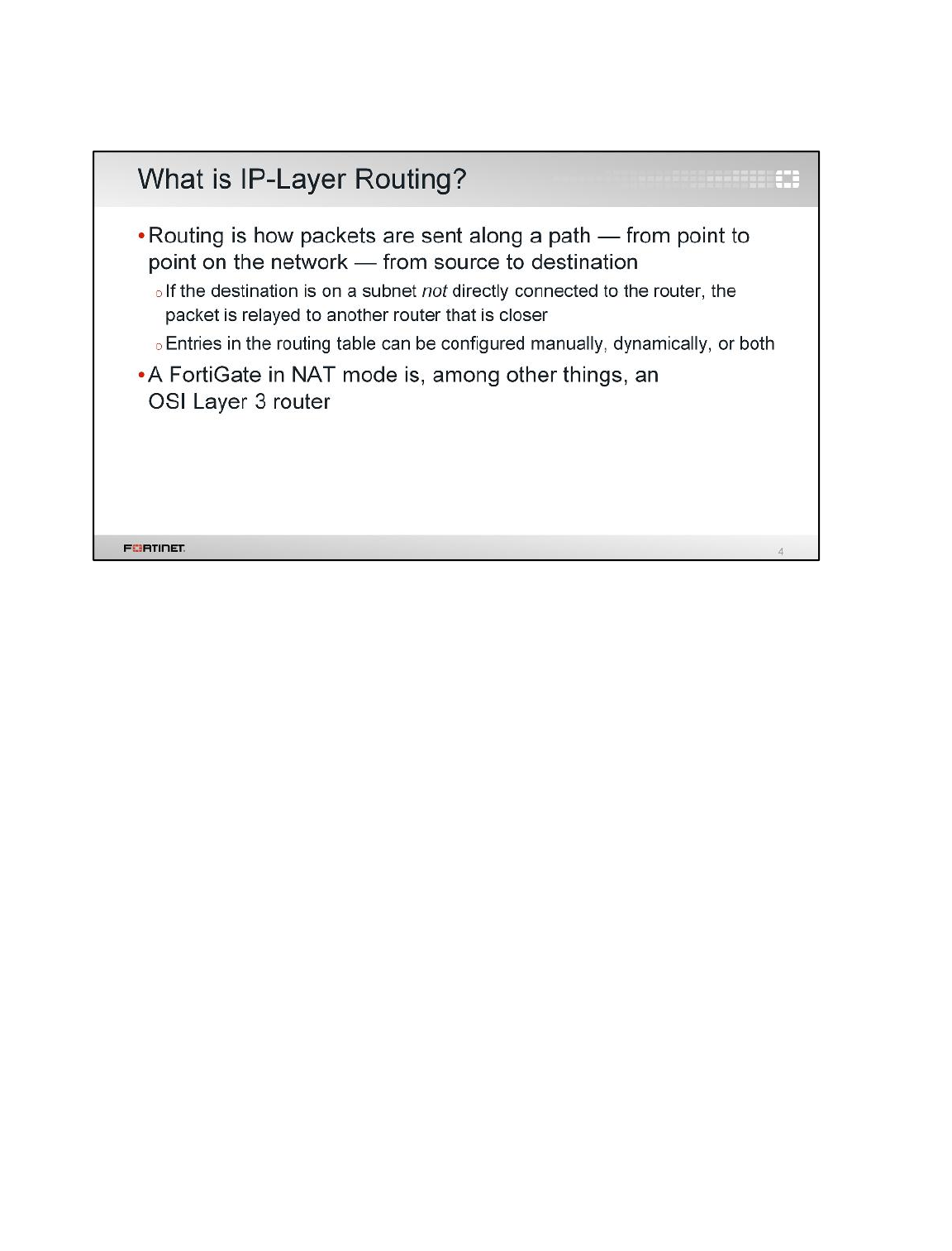
What is routing?
Routing decides where FortiGate in NAT mode will send the packets that it receives, and that it
generates.
All network devices doing routing have a routing table. As we will see later, a routing table contains a
series of rules. One or more rules for each destination subnet. Each rule specifies how a packet must
be routed to reach its destination. For example, FortiGate checks the destination field of the packet’s
IP header. If routing rules match that destination, FortiGate can transmit the packet from port1 to
port2, towards Router 1 based on the information.
If an allowed packet is not destined for the FortiGate itself — not administrative access, for example
— FortiGate must relay the packet. FortiGate searches for matching active routes in the routing table
that it can use to deliver the packet. FortiGate either delivers the packet directly to its final destination,
or relays it to the next router along the path towards the final destination.
Usually, IP routing is done based on the destination IP address; however, as we’ll discuss later, you
can also route packets using more than a destination IP address.
Proper routing configuration is important. If the routing directions are misconfigured, packets will not
reach their destination and will be lost.
Routing
FortiGate II Student Guide
165
DO NOT REPRINT
© FORTINET
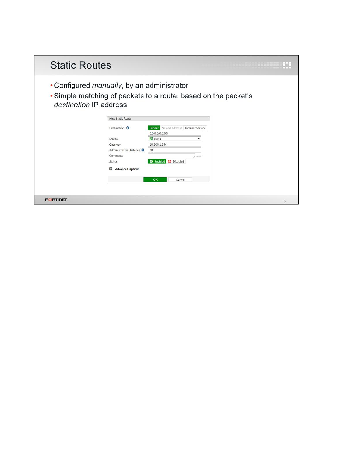
One type of manually configured route is called a static route. In the routing table, its Type column is
set to Static.
When you configure a static route, you are telling the FortiGate device, “When you see a packet
whose destination is within this range of destination addresses, send it through this network interface,
towards this router.” We also configure the distance and priority so that FortiGate knows which is the
best route to any destination. We will talk about distance and priority later.
For example, in simple home networks, DHCP automatically retrieves and configures one static route.
Your modem then sends all outgoing traffic through your ISP’s Internet router, which can relay packets
to their destination.
When do you not require a static route?
When a destination is cabled directly to one of FortiGate’s network interfaces, with no router in
between, FortiGate will be aware of the destination. In the route table, its Type is Connected.
Routing
FortiGate II Student Guide
166
DO NOT REPRINT
© FORTINET
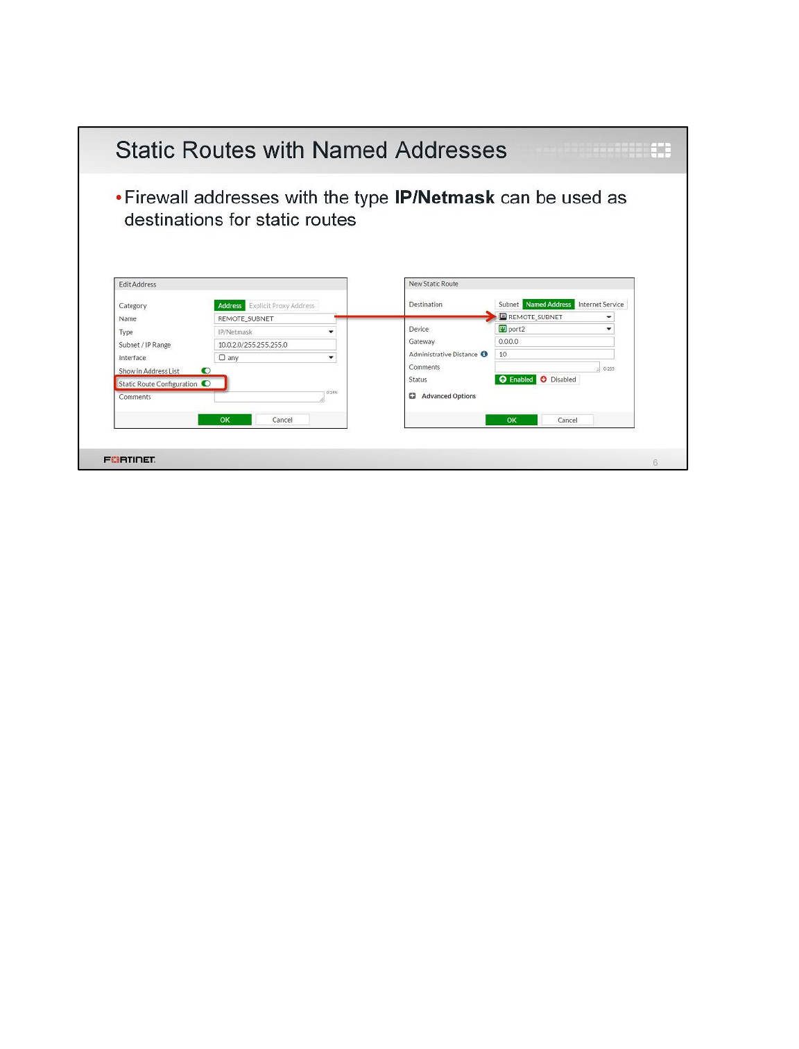
If you create a firewall address object with the type IP/Netmask, you can use that firewall address as
the destination of one or more static routes. First, enable the setting Static Route Configuration
inside the firewall address configuration. Once it is enabled, the firewall address object is displayed
and can be selected from the destination drop-down list of any static route.
Routing
FortiGate II Student Guide
167
DO NOT REPRINT
© FORTINET
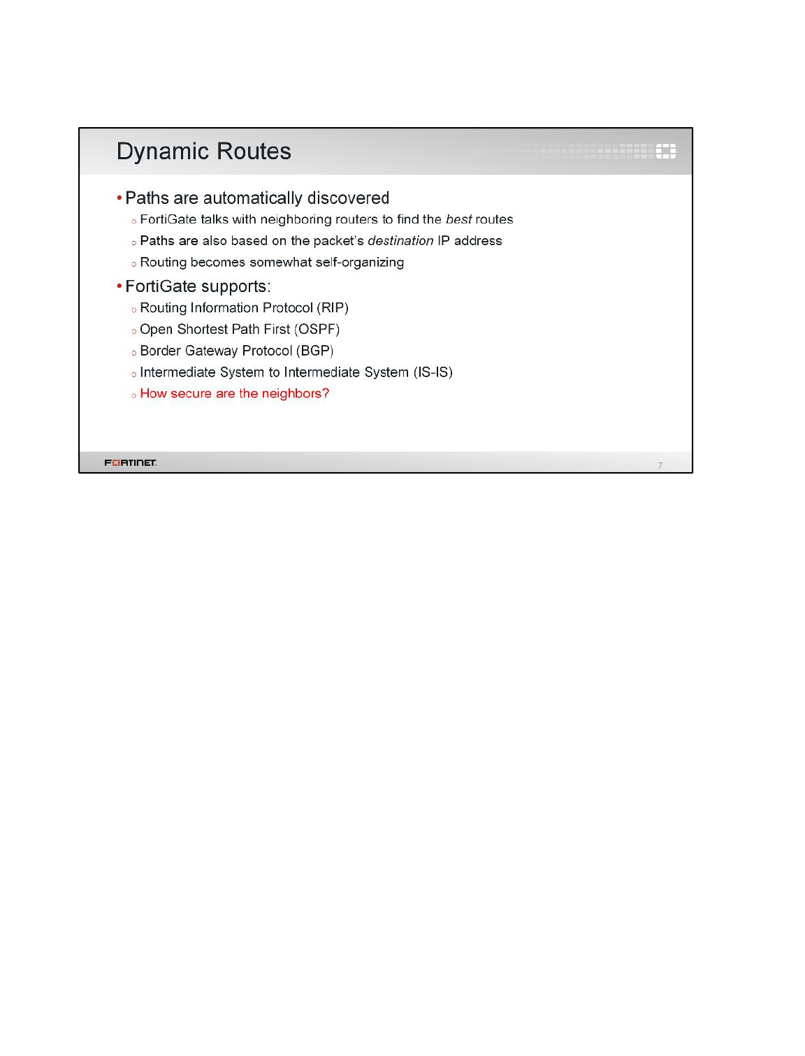
For large networks, manually configuring hundreds of static routes may not be practical.
Your FortiGate can help, by configuring routes automatically. FortiGate supports several dynamic
routing protocols: RIP, OSPF, BGP, and IS-IS.
In dynamic routing, FortiGate communicates with nearby routers to discover their paths, and to
advertise its own directly connected subnets. Discovered paths are automatically added to FortiGate’s
routing table. (So verify that your neighbor routers are trusted and secured!)
Larger networks also may need to balance routing load among multiple valid paths, and detect and
avoid routers that are down. We’ll discuss that later also.
Routing
FortiGate II Student Guide
168
DO NOT REPRINT
© FORTINET
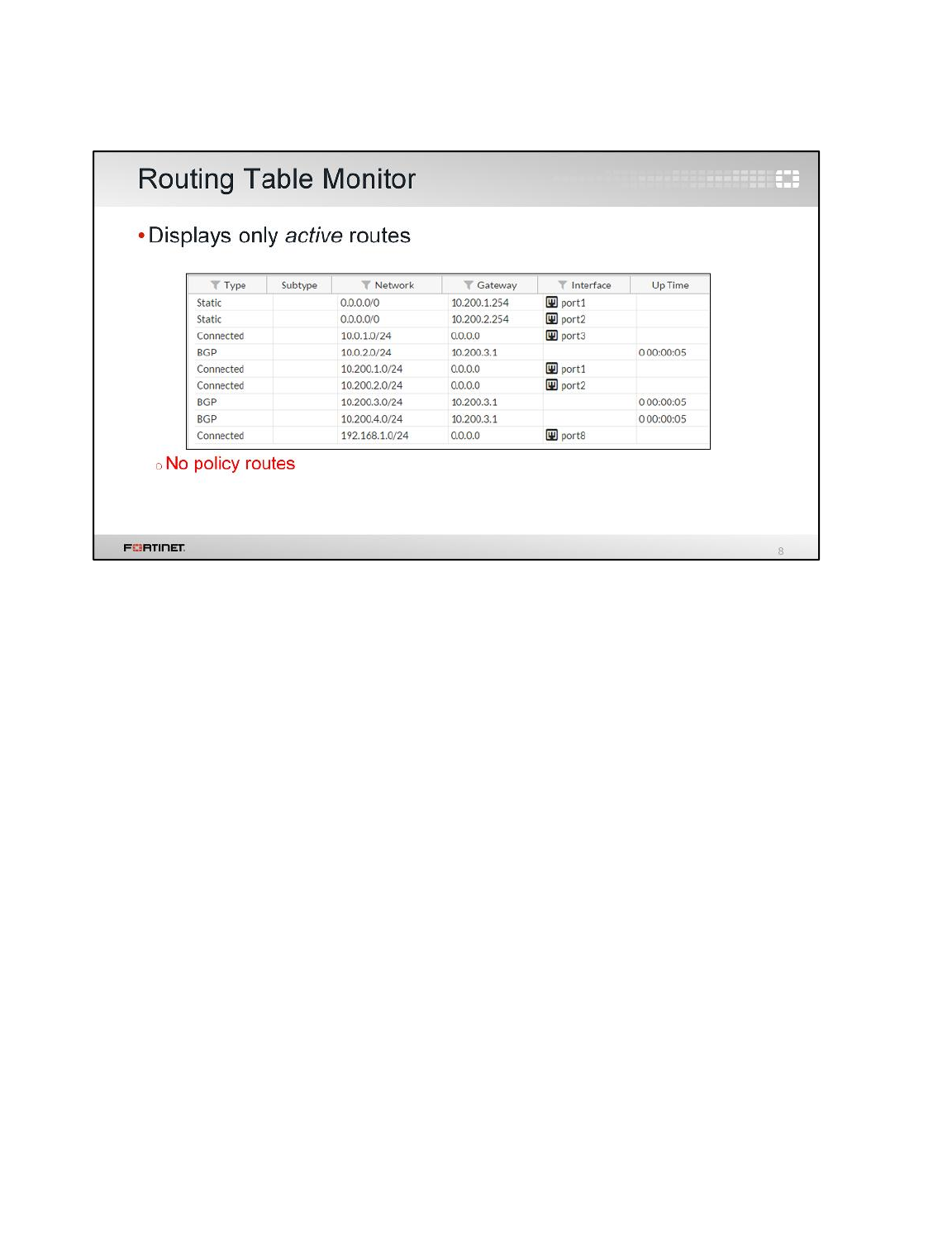
The routing table monitor in the FortiGate GUI shows the active routes.
Which routes besides the static ones are displayed here?
•Directly connected subnets – When a subnet is assigned to a FortiGate’s interface, a route to the
subnet is automatically added to the routing table. The FortiGate knows how to route those
packets.
•Dynamic routes – On larger networks, your FortiGate may receive routes from other routers, via
protocols such as BGP. This is faster and more scalable than manually configuring many routers.
Which configured routes aren’t displayed in the routing table monitor?
•Inactive routes – Only active routes (which are usually the best paths) are displayed. We will see
later how the best path is elected when there are multiple routes to the same destination.
•Policy routes – These are omitted, too. Why? By design, policy routes override the routing table.
So, they have to be in a separate table.
Routing
FortiGate II Student Guide
169
DO NOT REPRINT
© FORTINET
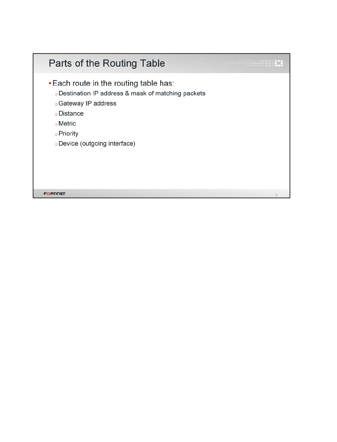
Each of the routes listed in the routing table includes several settings with associated values. Those
values are used to relay or deliver each matching packet.
Destination IP address and gateway IP address are self-explanatory. The device is the name of the
outgoing interface to where the packet will be routed. But what about the distance, metric, and
priority? How do they effect which routing path packets will use?
Let’s explain each briefly.
Routing
FortiGate II Student Guide
170
DO NOT REPRINT
© FORTINET
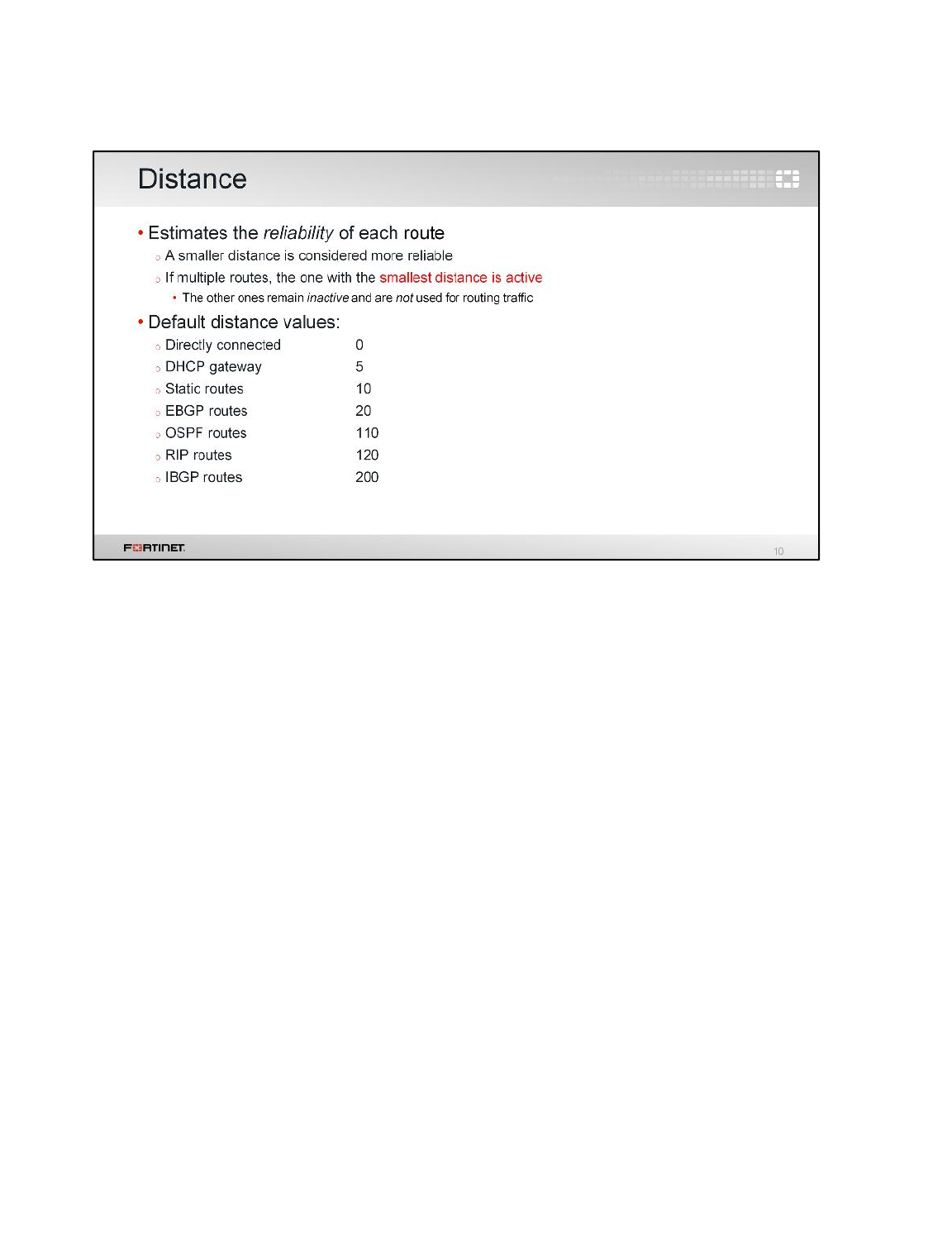
Distance, or administrative distance, is a number that estimates the reliability or quality of each routing
protocol and static route. If there are two routes to the same destination, the one with the lower
distance value is active and used for routing because it is considered to be more reliable. The routes
with higher distances are inactive and not used for routing.
By default, routes learned through the RIP protocol have a higher distance value than routes learned
through OSPF protocol. OSPF is considered to be more accurate than RIP.
Routing
FortiGate II Student Guide
171
DO NOT REPRINT
© FORTINET
In the case of routes learned through a dynamic routing protocol, the metric is another value that is
used to determine the best route to a destination. If two routes have the same distance, the metric is
used to break the tie. The route with the lowest metric is active and used for routing.
How the metric is measured depends on the routing protocol. RIP uses hop counts, which is the
number of routers to reach the destination. OSPF uses cost, which is determined by how much
bandwidth a link has.
Routing
FortiGate II Student Guide
172
DO NOT REPRINT
© FORTINET
When multiple static routes have the same distance value, the priority value is used to determine the
best route. That is, FortiGate uses the route with the lowest priority setting.
Note that, unlike routes that have the same distance and metric settings, all routes with the same
distance setting are active. However, only the route with the lowest priority setting is used to route the
traffic. This, as we will see later, is an important concept to know when dealing with reverse
forwarding path (RPF) check issues.
Routing
FortiGate II Student Guide
173
DO NOT REPRINT
© FORTINET
We saw how the distance, metric, and priority settings are used to determine the best route to a
destination. So, what happens when two or more routes to the same destination share the same
values for all of those settings?
If the routes are static, OSPF, or BGP; FortiGate balances the traffic among all the routes. This is
called equal cost multi-path (ECMP).
Routing
FortiGate II Student Guide
174
DO NOT REPRINT
© FORTINET
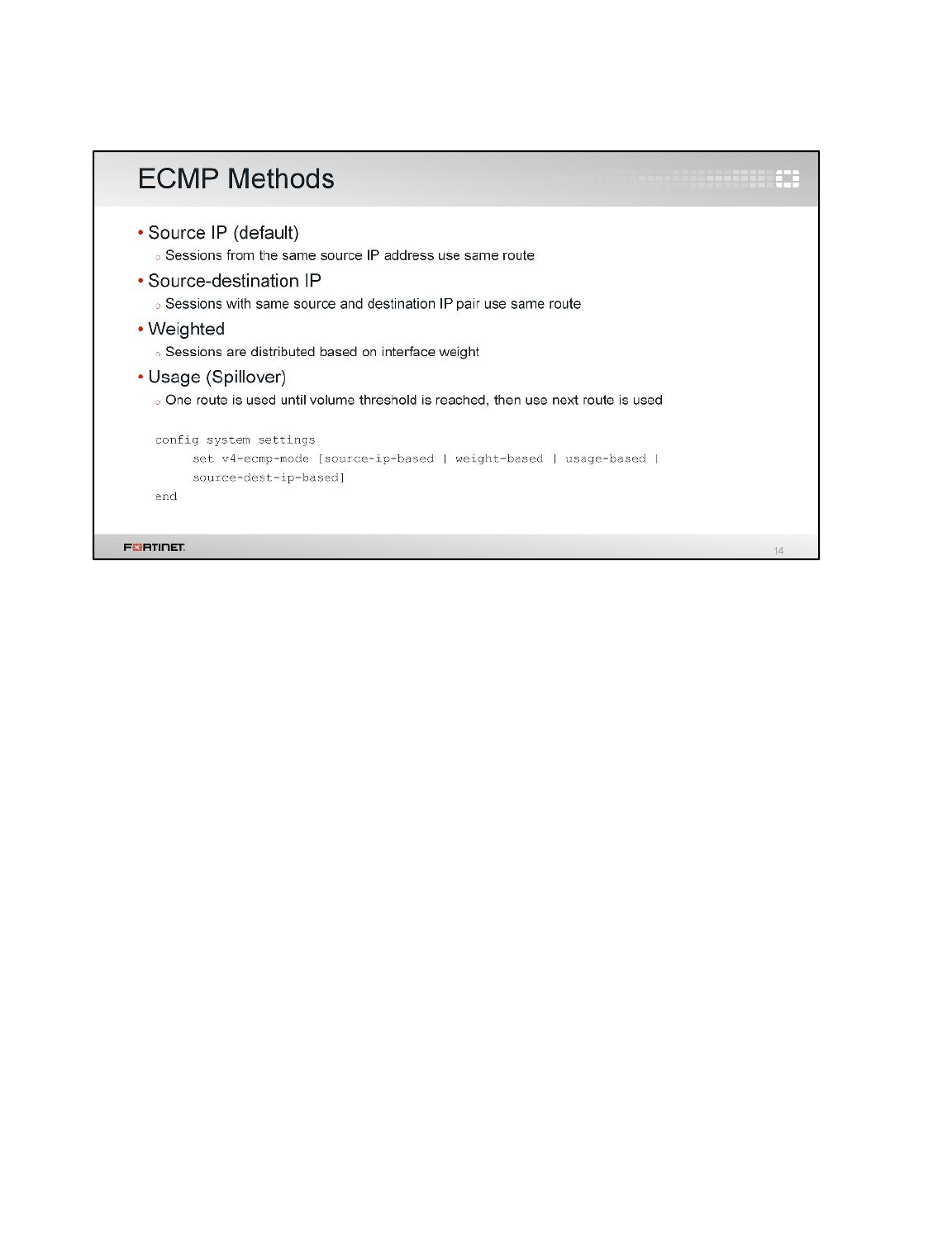
When FortiGate is applying ECMP, one of these four methods is used.
Sessions can be balanced among equal routes depending on the source IP address, source and
destination IP addresses, or interface weight. There is an additional method called usage-based (or
spillover). In usage-based routing, FortiGate uses a primary route until a traffic volume threshold is
reached; after that, it uses the next available route.
Routing
FortiGate II Student Guide
175
DO NOT REPRINT
© FORTINET
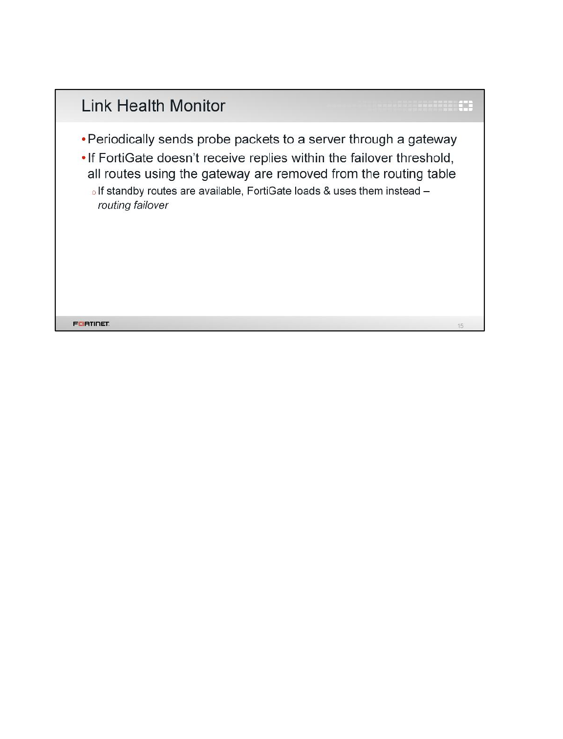
Link health monitor is a mechanism for detecting when a router along the path is down. It is often used
where there are redundant routers onsite, such as for dual ISP links.
When configured, FortiGate periodically sends signals through one of the gateways to a server that
acts as a beacon. The server can be any host that should normally be reachable through that path.
Usually, it’s best to choose a stable server with robust infrastructure, and to choose the protocol to
which the server would normally respond.
If the FortiGate stops receiving a replay from the server, all the routes using that gateway will be
removed from the routing table. Alternatively, you can configure the device to administratively bring
down an interface, so all routes using that interface will be removed. While a server is unresponsive,
FortiGate will continue to send link health monitor signals. As soon as FortiGate receives a reply, it will
reinstate the routes.
It may be useful to choose a server that is indirectly attached, located 1 or 2 hops beyond the
FortiGate’s gateway. This does not exactly test availability of this one gateway, but rather the
combination of gateways. That way, FortiGate will accurately indicate availability of services and
subsequent hops.
Routing
FortiGate II Student Guide
176
DO NOT REPRINT
© FORTINET
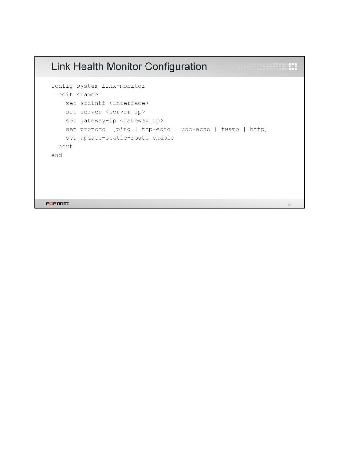
Here is how you configure the link health monitor from the CLI.
You must set the egress interface, the IP address of the gateway router, and the IP address and
protocol (HTTP, ICMP, UDP or TCP) of a beacon that is beyond that gateway.
You can configure multiple link health monitors, for example one for each ISP.
Routing
FortiGate II Student Guide
177
DO NOT REPRINT
© FORTINET
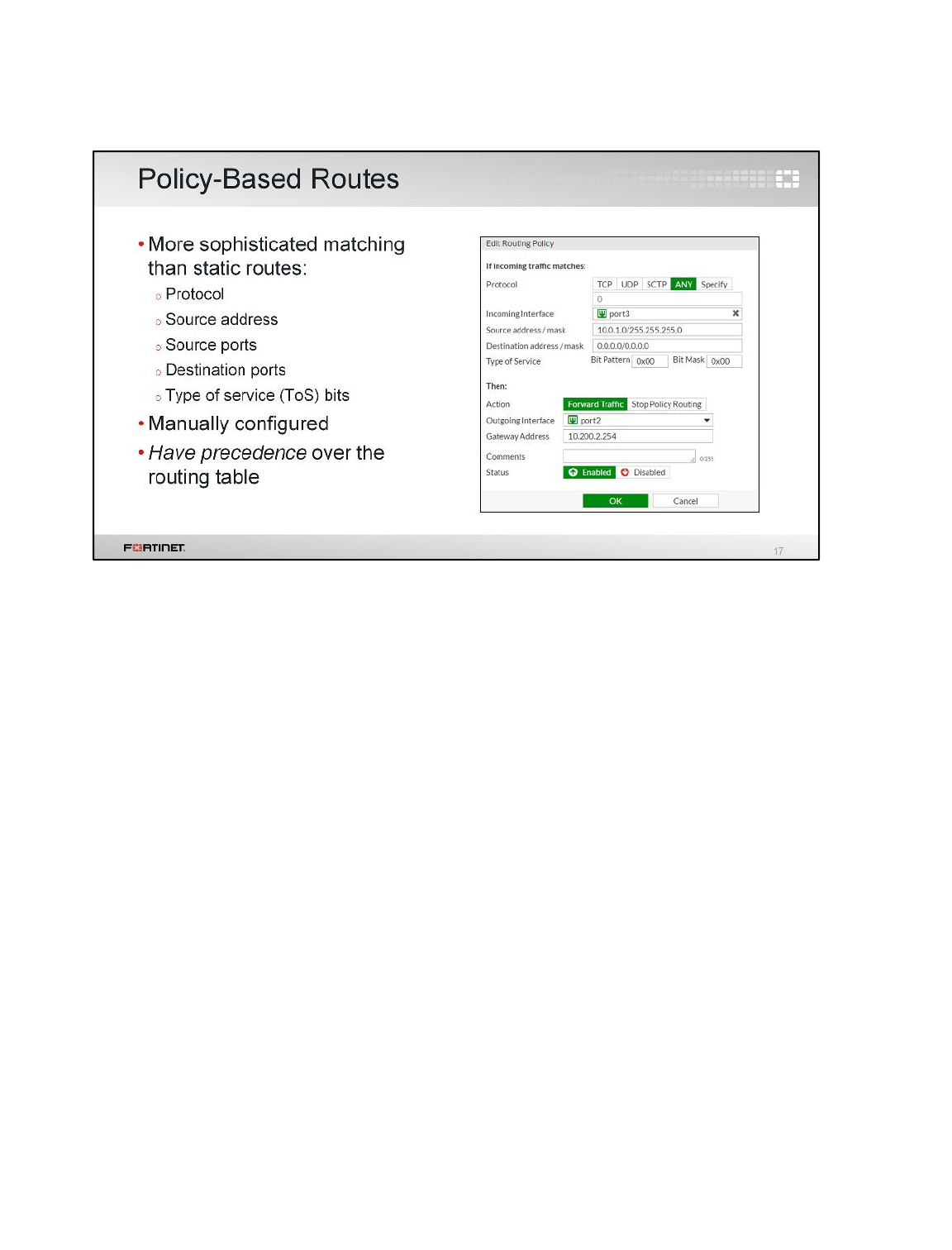
Static routes are simple and are often used in small networks. Policy-based routes, however, are more
flexible. They can match more than just the destination IP address. An example? If you have two links
– a slow one and a fast one – you can route packets from low-priority source IPs to the slow link.
Policy routes with the action Forward Traffic have precedence over static and dynamic routes. So, if
a packet matches the policy route, FortiGate bypasses the routing table lookup.
Like static routes, policy routes must be valid: a destination and gateway are required, and
disconnected (or down) interfaces can’t be used. For policy routes, packets must also match all
specified subnets, ToS bits, and port number. So, if you don’t want a setting to be included in the
matching criteria, leave it blank.
Routing
FortiGate II Student Guide
178
DO NOT REPRINT
© FORTINET
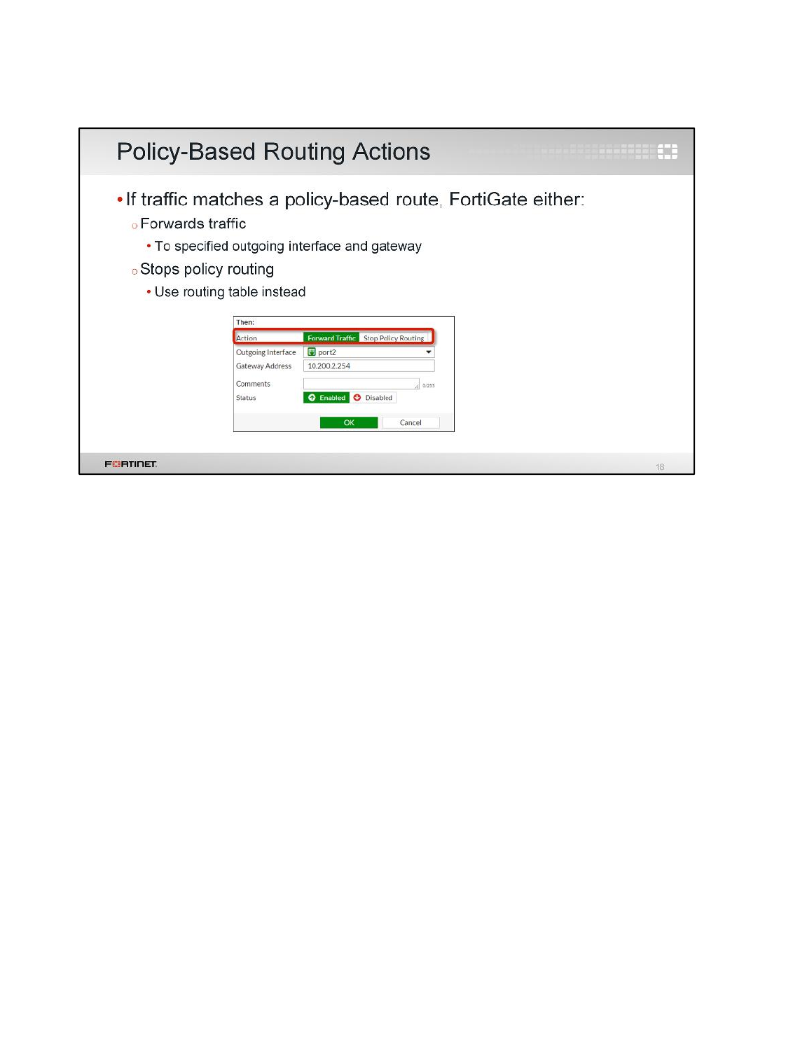
When a packet matches a policy route, FortiGate takes one of two actions. Either it routes the packet
to the configured interface and gateway, bypassing the routing table, or it stops checking the policy
routes, so the packet will be routed based on the routing table.
Routing
FortiGate II Student Guide
179
DO NOT REPRINT
© FORTINET
In this section, we will examine a concept related with routing: reverse path forwarding check.
Routing
FortiGate II Student Guide
180
DO NOT REPRINT
© FORTINET
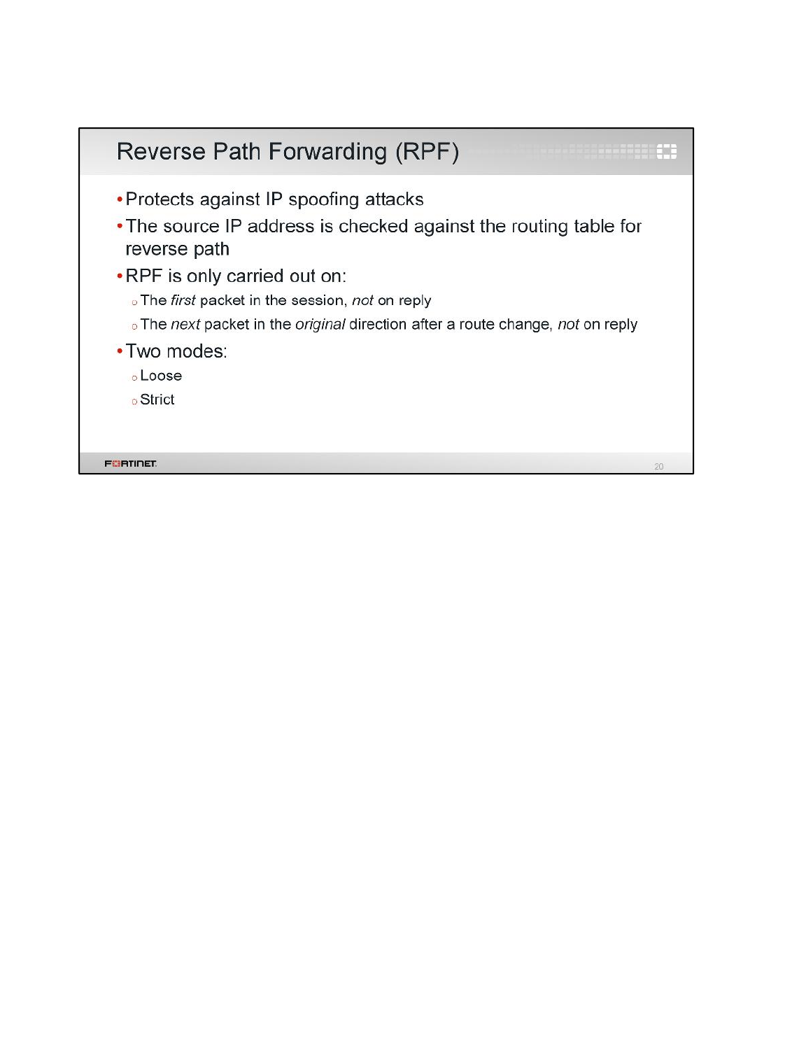
Packets are sometimes dropped for routing and security reasons.
RFP is a mechanism that protects FortiGate and the network from IP spoofing attacks. It checks if
there is a route back to the packet’s source.
This check is executed over the first packet of any new session. It is also executed after a route
change, over the next packet in the original direction.
There are two RPF modes: loose and strict.
Routing
FortiGate II Student Guide
181
DO NOT REPRINT
© FORTINET
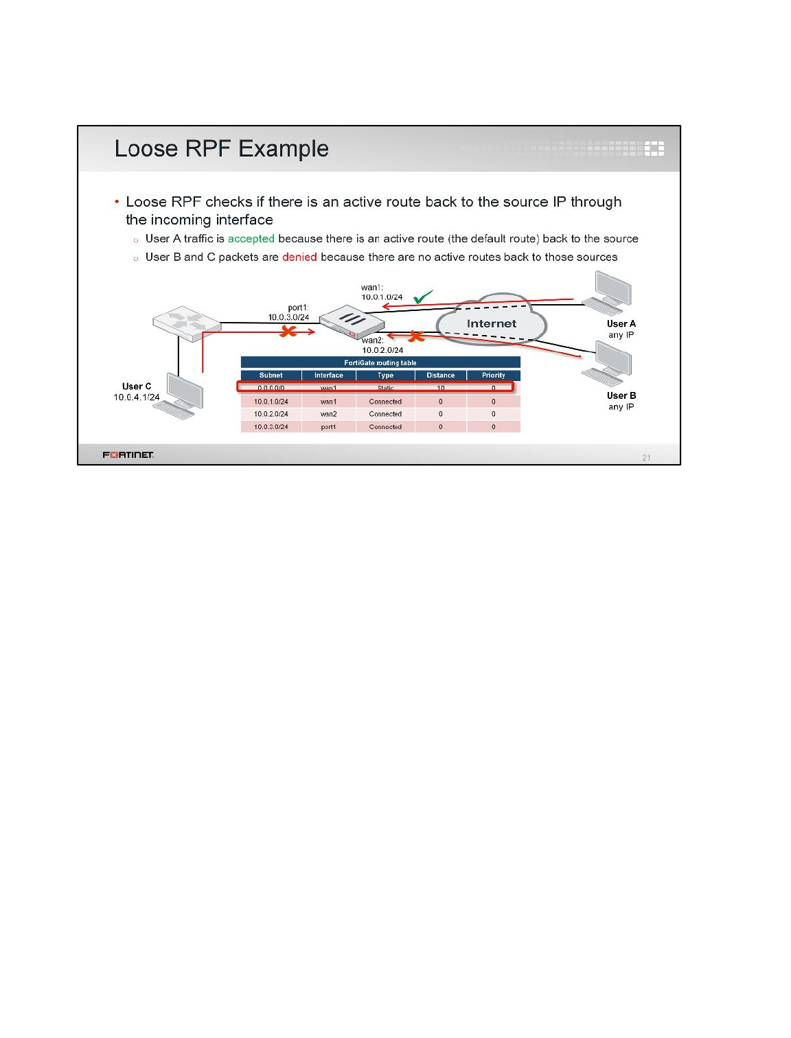
(slide contains animation)
Here’s a sample network setup and routing table.
(click)
Incoming Internet traffic arriving at wan1 will be accepted, because the default route is a valid route
back to the source.
(click)
However, there are two interfaces that will not route some incoming traffic: port1 and wan2.
port1 will not route traffic because the subnet for user C is 10.0.4.0/24. There is no active route for
that subnet through port1. So, traffic coming from 10.0.4.0/24 to port1 will be dropped because that
subnet cannot be routed back.
The other interface that will not route traffic is wan2. While wan2 is physically connected to the
Internet, the only IP addresses that are valid as sources or destinations are those in the 10.0.2.0/24
subnet. So, incoming Internet traffic will not pass the RPF check and will be dropped.
Routing
FortiGate II Student Guide
182
DO NOT REPRINT
© FORTINET
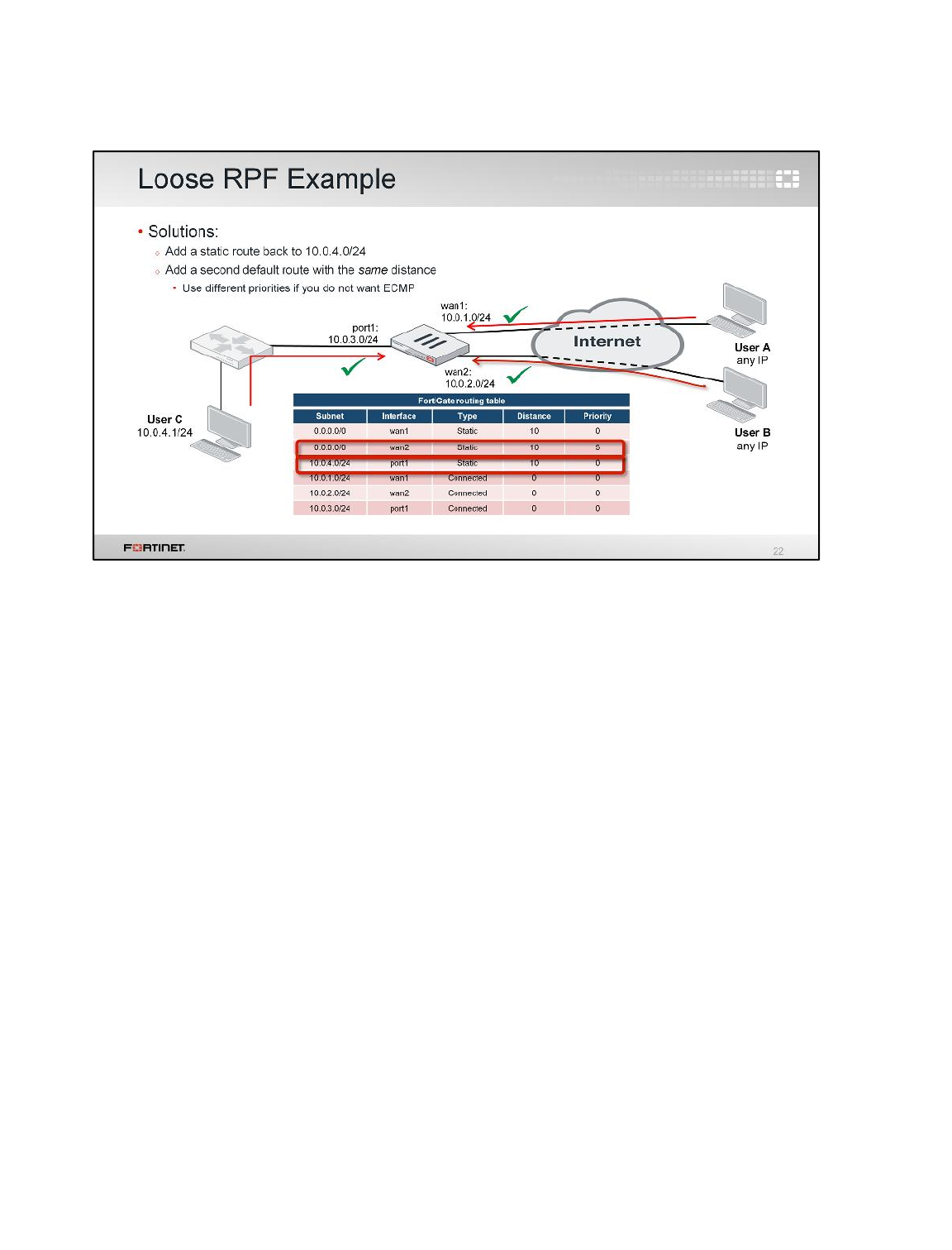
(slide contains animation)
Let's see how to fix those two problems.
(click)
The first problem is fixed by adding a static route to 10.0.4.0/24. Now, when FortiGate does the RPF
check for user C packets, it finds an active route to that subnet through port1 and the packet is
accepted.
(click)
The second problem is also fixed by adding a static route. In this case, the route acts as a default
gateway for wan2. To become active, it needs to have the same distance as the default route for
wan1. They both can have different priorities, but they must have the same distance to be active.
This is an example of when two routes with the same distance, but different priorities, are required.
So, one route will be the best (the one with the lowest priority), but both will be active. The best route
will be used for outbound traffic, but both can receive incoming connections without failing the RPF
check.
If the priorities are also the same, this creates a situation similar to the one we talked about in the
ECMP example. So, if the destination is the Internet, there are two possible paths: through wan1 or
through wan2. Some sessions will exit from wan1, and others will exit from wan2.
Routing
FortiGate II Student Guide
183
DO NOT REPRINT
© FORTINET
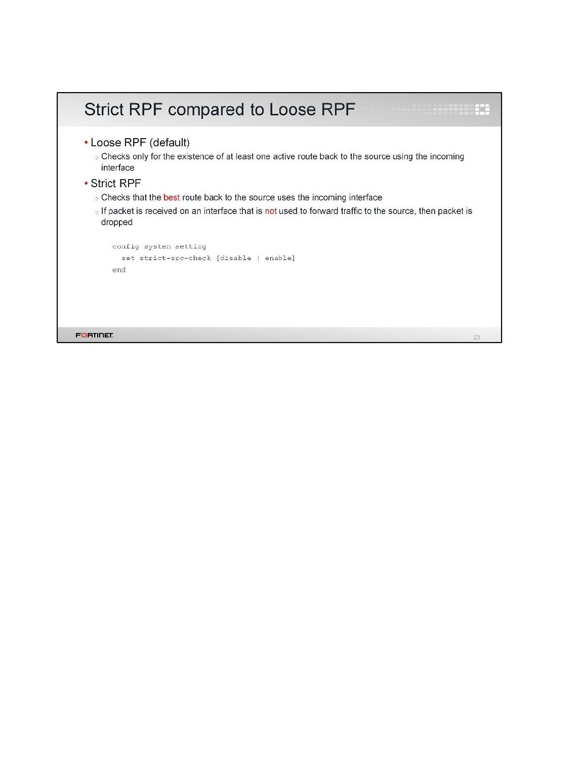
Reverse path forwarding can be either strictly or loosely enforced.
In loose mode, the packet is accepted as long as there is one active route to the source IP through the
incoming interface. It does not have to be the best route, just an active one.
In strict mode, FortiGate checks that the best route to the source IP address is through the incoming
interface. The route not only has to be active (as in the case of loose mode), but it also has to be the
best.
In the following slide, we will look at two sample network configurations to compare loose mode to
strict mode.
Routing
FortiGate II Student Guide
184
DO NOT REPRINT
© FORTINET
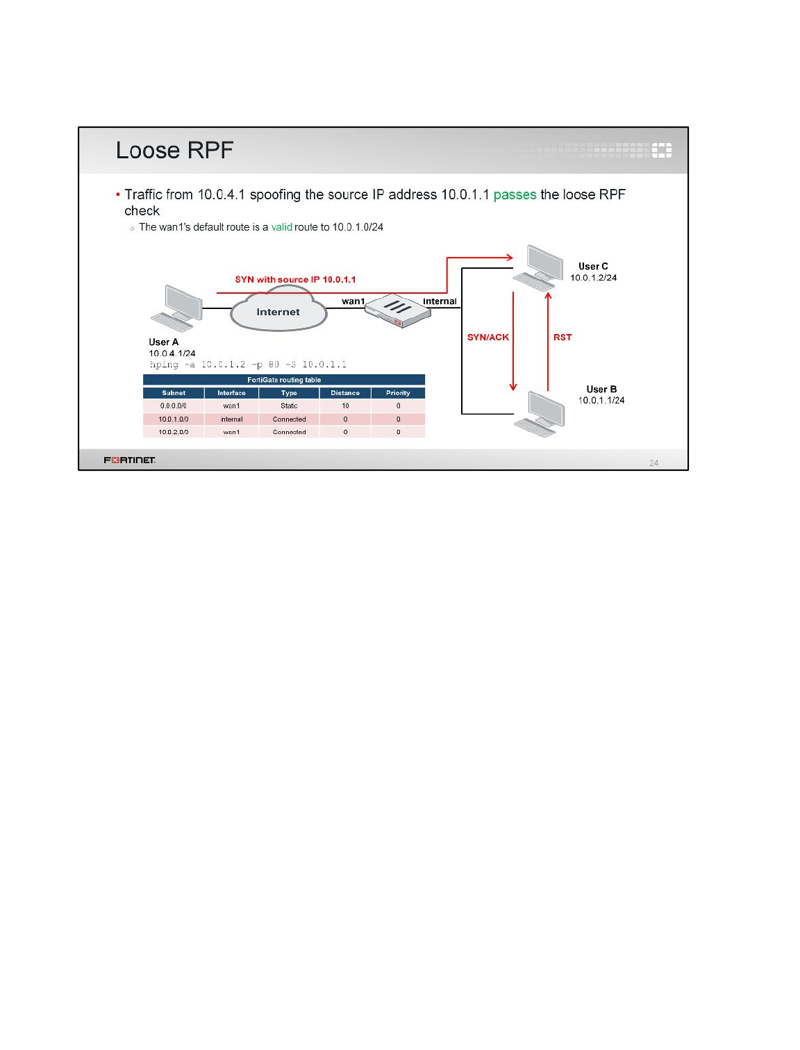
(slide contains animation)
Let’s start with the loose mode example. In this example, 10.0.4.1 pings 10.0.1.2, but spoofs a source
IP of 10.0.1.1. This makes the packet appear to be initiated from the internal network. Loose RPF
allows this traffic because the route on wan1 is a default route (0.0.0.0/0) that is active.
(click)
What happens next is that 10.0.1.2 would send the SYN/ACK packet to the real device with the IP
address 10.0.1.1.
(click)
But since 10.0.1.1 is not expecting SYN/ACK packets (as it has not previously sent any SYN packet to
10.0.1.2), it will reply with a TCP reset (RST) packet.
Routing
FortiGate II Student Guide
185
DO NOT REPRINT
© FORTINET
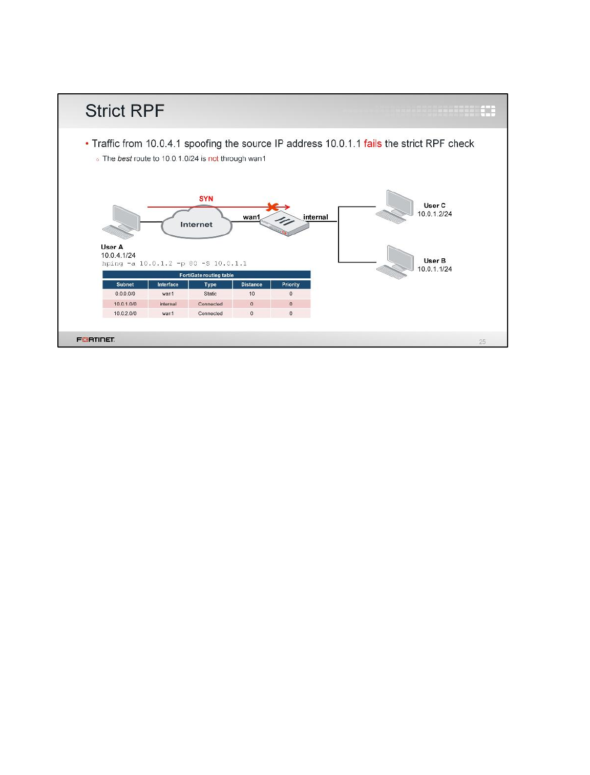
(slide contains animation)
Let’s see what happens in the same sample network when strict RPF is used.
(click)
Strict RPF drops the packet. The default route in wan1 is an active route to the subnet 10.0.4.0/24,
but it’s not the best route. The best route is through the internal interface.
Although strict RPF is more secure, it can backfire if you use dynamic routing. Dynamic routes can
change quickly, and they could cause FortiGate to drop legitimate packets each time the preferred
route changes. In general, it is recommended to use loose RPF in combination with firewall policies
that block spoofed traffic, instead of using strict RPF for that purpose.
Routing
FortiGate II Student Guide
186
DO NOT REPRINT
© FORTINET
In this section, we’ll examine two additional routing features in FortiGate: internet services and WAN
link load balancing.
Routing
FortiGate II Student Guide
187
DO NOT REPRINT
© FORTINET
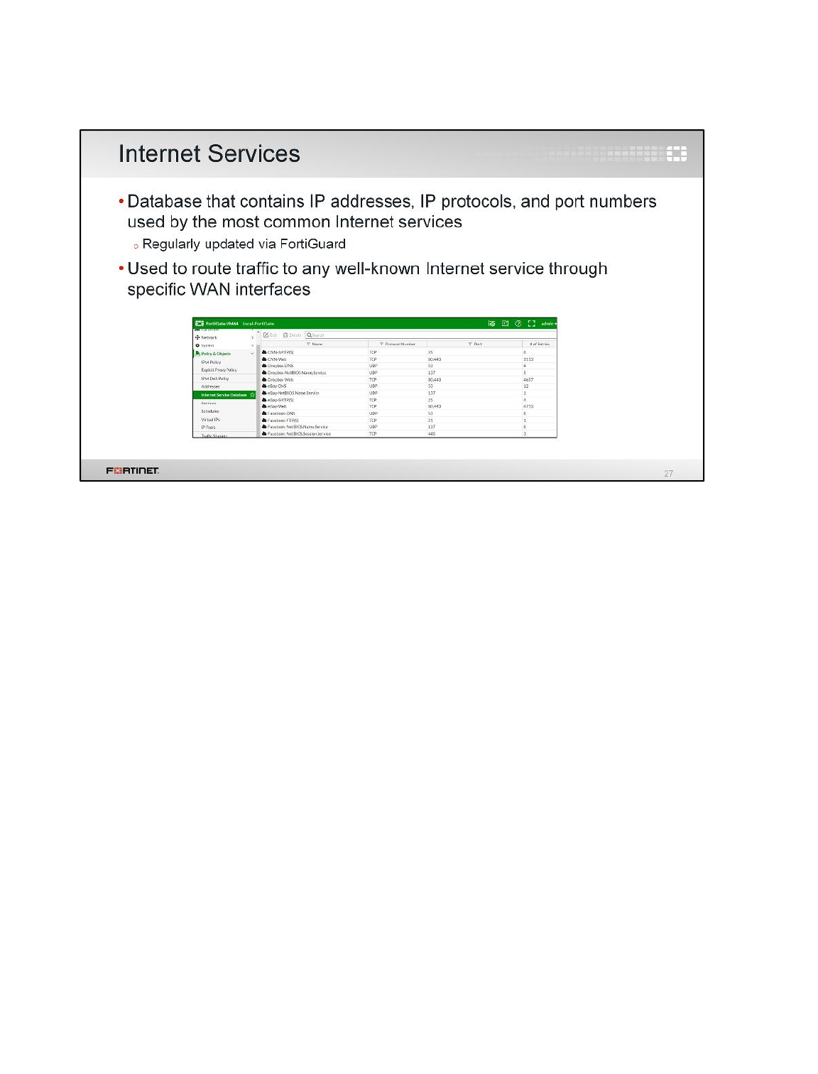
Internet services is a database that contains a list of IP addresses, IP protocols, and port numbers
used by the most common Internet services. FortiGate periodically downloads the newest version of
this database from FortiGuard. The information can be used to selectively route traffic to any of the
listed Internet services though specific WAN interfaces.
What happens if you need to route traffic to a public Internet service (such as Dropbox or Facebook)
through one specific route? Let's say that you have two ISPs and you want to route Netflix traffic
through one ISP and all your other Internet traffic though the other ISP. To achieve this goal, you need
to know the Netflix IP addresses and configure multiple static routes. After that, you would need to
frequently check to make sure that none of the IP addresses have changed. Internet services helps
make this type of routing easier and simpler.
Routing
FortiGate II Student Guide
188
DO NOT REPRINT
© FORTINET
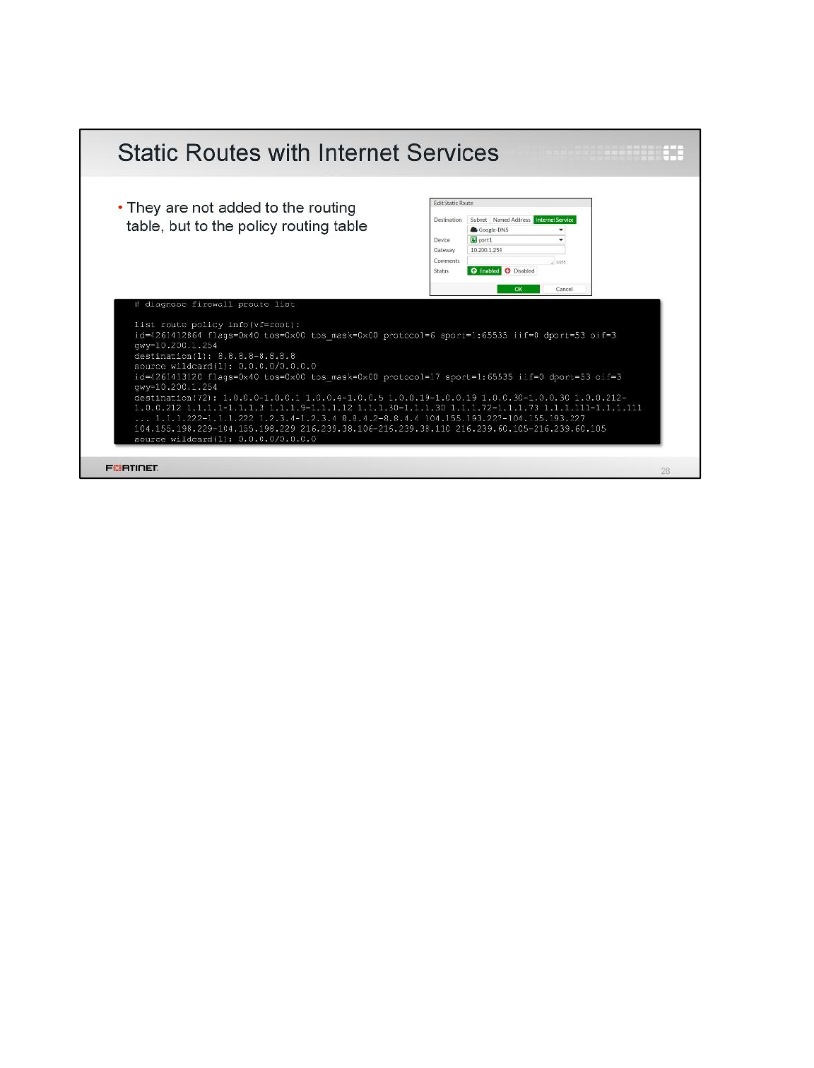
You can use Internet services addresses as the destination for static routes. In this example, we are
configuring FortiGate to route all Google DNS traffic through interface port1.
Static routes created using Internet services addresses (for example, static routes with either subnet
or named addresses as the destination) are not added to the routing table; they are added to the
policy routing table. These routes can be displayed using the CLI command diagnose firewall
proute list . This command lists all the active routes in the policy routing table.
Routing
FortiGate II Student Guide
189
DO NOT REPRINT
© FORTINET
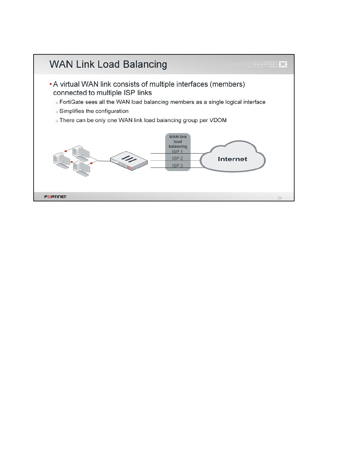
WAN link load balancing consists of a group of interfaces usually connected to multiple ISPs.
FortiGate sees all those Internet interfaces as one single logical interface: the WAN load balancing
interface. This simplifies the configuration because the administrator can configure a single set of
routes and firewall policies that will be applied to all the ISPs.
There can be only one WAN load balancing interface per VDOM.
Routing
FortiGate II Student Guide
190
DO NOT REPRINT
© FORTINET
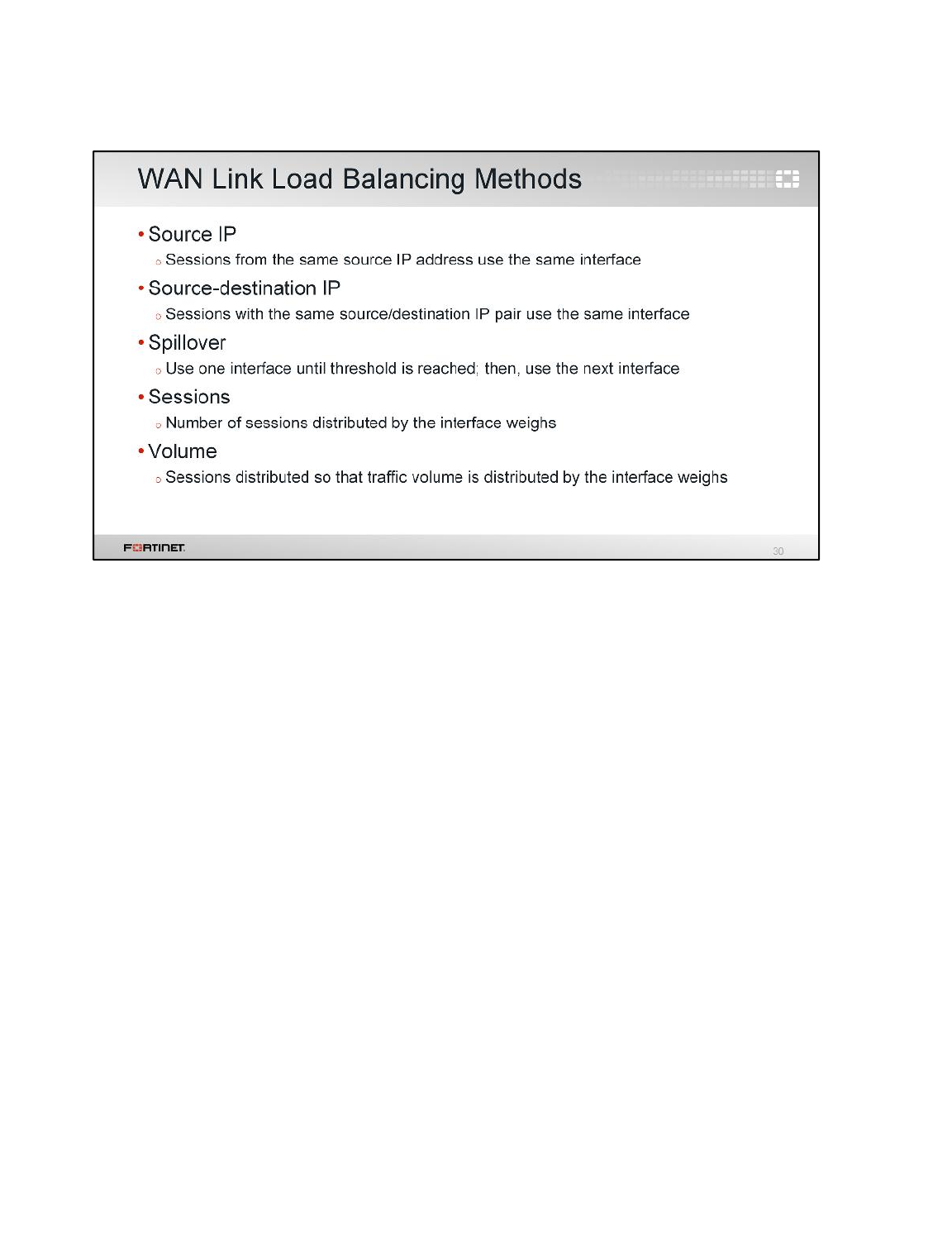
WAN link load balancing uses traffic distribution methods that are similar to ECMP; however, WAN
link load balancing includes one more balancing method: volume.
WAN link load balancing uses these methods:
• Source IP: Traffic from the same IP address uses the same link.
• Source-destination IP: Traffic from the same pair of source and destination IP addresses uses the
same link.
• Spillover: Similar to the spillover method for ECMP. A link routes all the traffic until the volume
reaches a threshold, after that another link is used.
• Sessions: The interface weights define the proportion of sessions that each link should have.
Sessions are distributed among the links based on the interface weights.
• Volume: The interface weights define the proportion of traffic volume that each link should have.
Sessions are balanced so that traffic volume is distributed based on the interface weights.
Routing
FortiGate II Student Guide
191
DO NOT REPRINT
© FORTINET
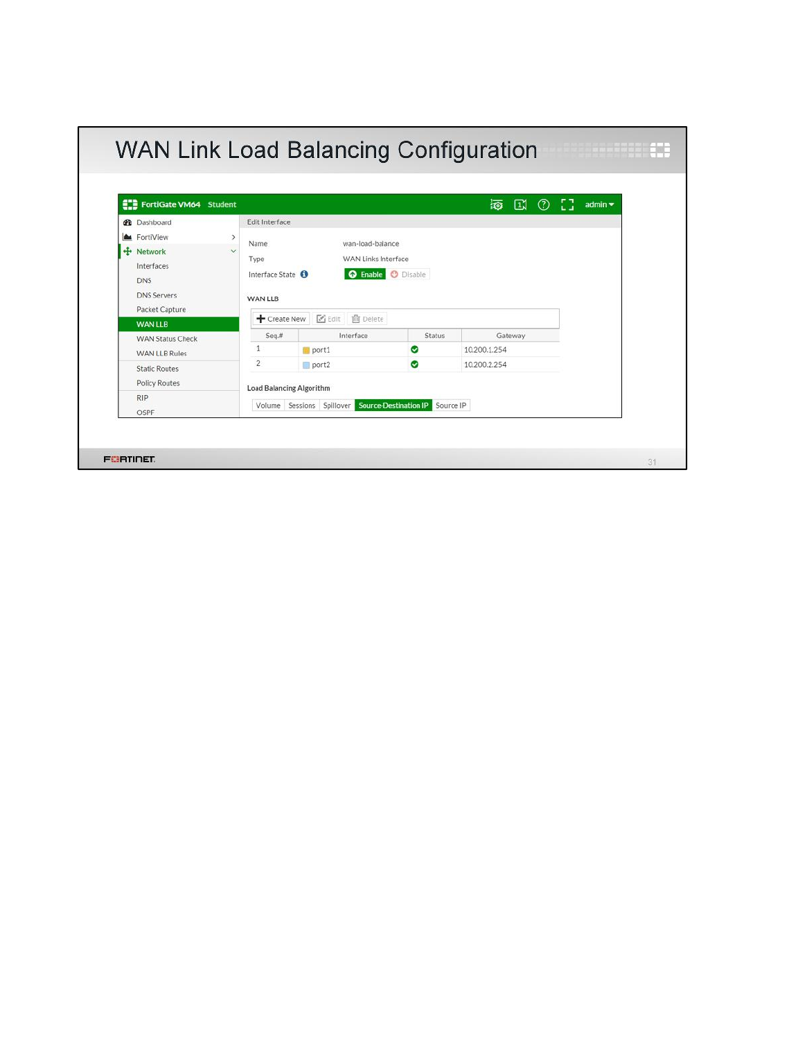
When configuring WAN link load balancing, you specify which interfaces are going to be members. In
other words, which interfaces are connected to the Internet.
Routing
FortiGate II Student Guide
192
DO NOT REPRINT
© FORTINET
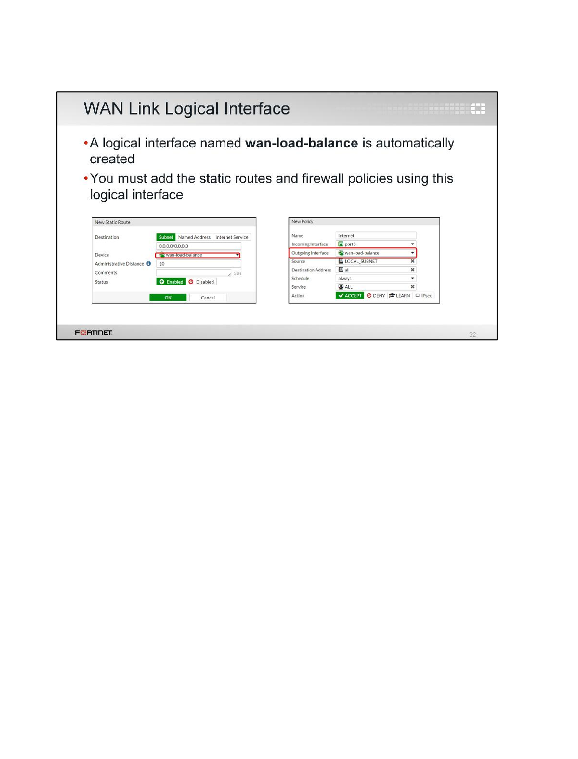
After you have configured WAN link load balancing, a logical interface with the name wan-load-
balance is automatically added to the configuration. Next, you create the routes and firewall policies
using this logical interface.
Routing
FortiGate II Student Guide
193
DO NOT REPRINT
© FORTINET
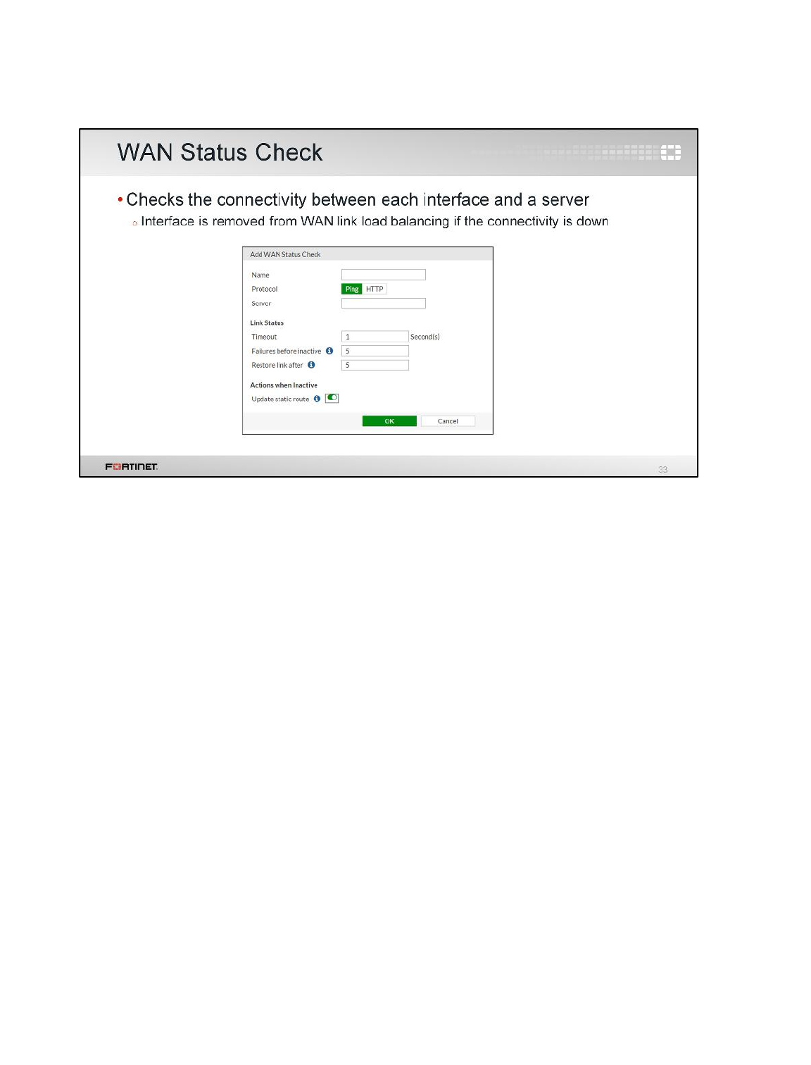
FortiGate can check the status (health) of each interface member of a WAN link load balancing group.
After configuring a protocol, a server IP address, and a failure threshold, FortiGate periodically sends
IP packets to the server through each of the links. If the number of consecutives packets with no reply
in one link goes above the threshold, that member is removed from WAN link load balancing.
Routing
FortiGate II Student Guide
194
DO NOT REPRINT
© FORTINET
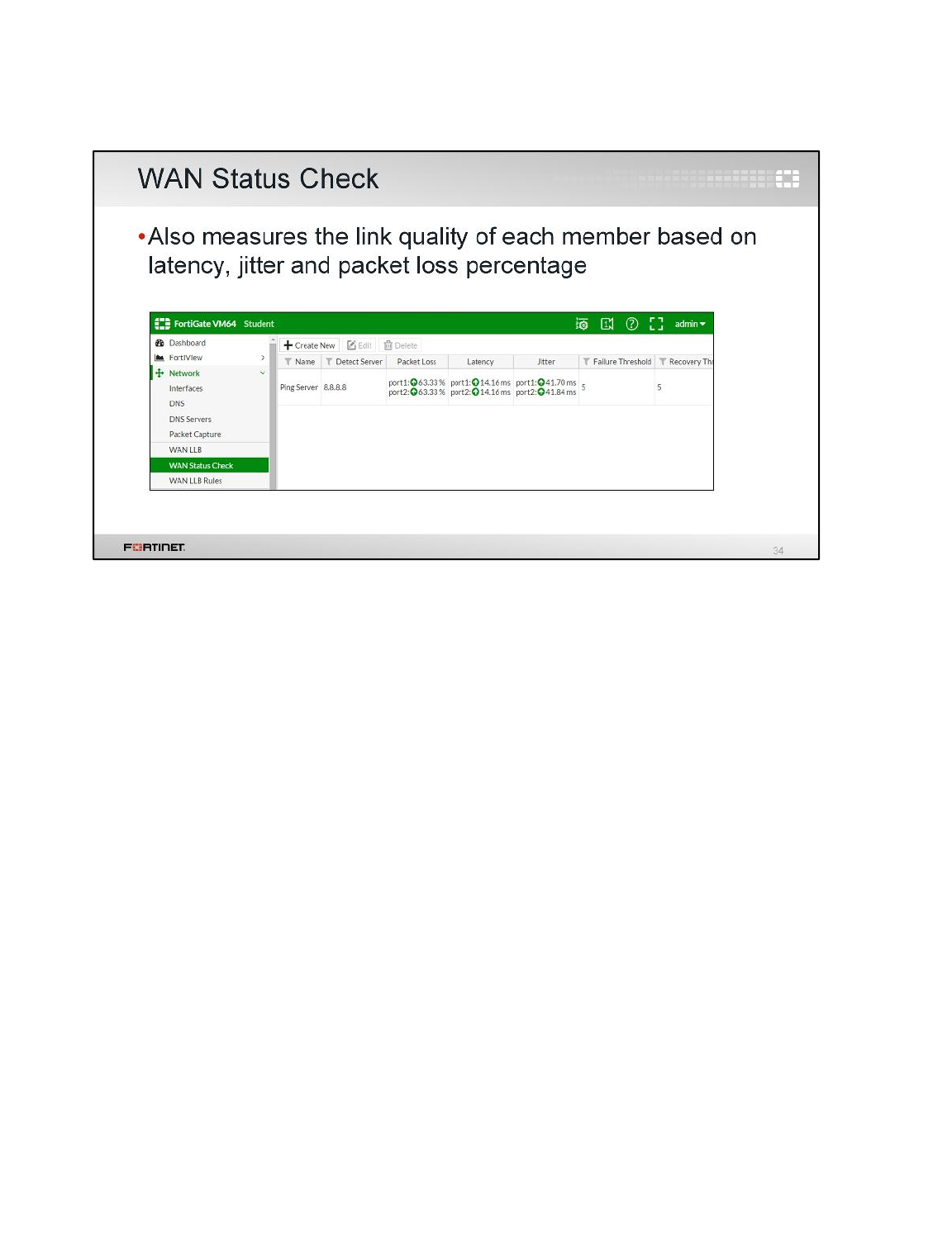
The WAN status checks also measure the quality of the links connected to each WAN interface. Three
different criteria are used for this measurement: latency, jitter, and packet loss percentage. As we will
see in the next slides, priority rules can be used to route traffic based on the link quality of each
member.
Routing
FortiGate II Student Guide
195
DO NOT REPRINT
© FORTINET

Priority rules allow you to specify what traffic you want to route through which interface. You can use
priority rules to route traffic through specific interfaces, or through the interface with the highest link
quality. Routing rules can be based on any of the three criteria: latency, jitter, or packet loss
percentage.
The priority rules are evaluated in the same way as the firewall policies: from top to bottom, using the
first match. The following parameters can be used to match the traffic:
• Source IP address
• Destination IP address
• Destination port number
• Internet service
• Users and/or user groups
• Type of service (ToS)
This offers great flexibility when configuring how FortiGate routes traffic. For example, you can route
Facebook traffic from specific authenticated users through one ISP, while keeping your other Internet
traffic through another ISP.
Routing
FortiGate II Student Guide
196
DO NOT REPRINT
© FORTINET
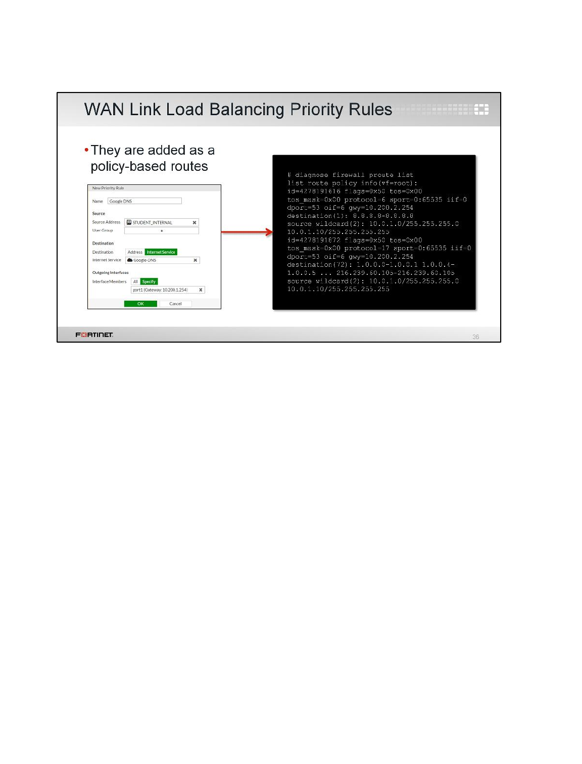
Similar to static routes with Internet services, priority rules are added as policy routes. Priority rules
can be displayed using the CLI command diagnose firewall proute list.
In this example, we have created a rule to route Google DNS traffic through port1. The slide shows
the partial output of the policy route added.
Routing
FortiGate II Student Guide
197
DO NOT REPRINT
© FORTINET

To finish this lesson, we will provide some commands and tools for troubleshooting routing problems.
Routing
FortiGate II Student Guide
198
DO NOT REPRINT
© FORTINET
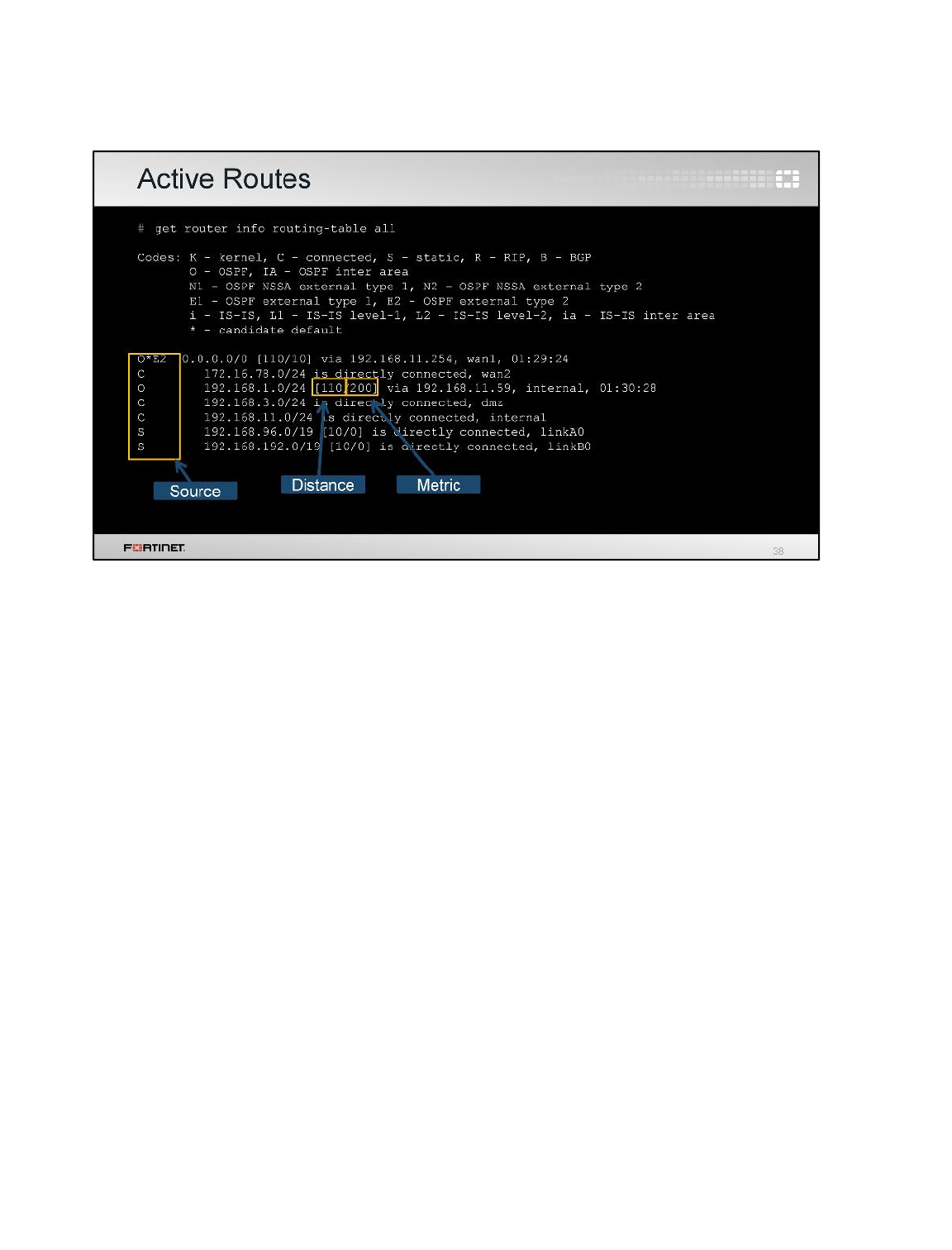
(slide contains animation)
The CLI command get router info routing-table all displays all the active routes in the
routing table. The left column indicates the source for the route.
(click)
The first number inside the brackets is the distance.
(click)
The second number is the metric. This command doesn't show inactive routes. For example, when
two static routes to the same destination subnet have different distances, the one with the lowest
distance is active. The one with the highest distance is inactive. So, this command displays only the
one with the lowest distance (the active one).
Routing
FortiGate II Student Guide
199
DO NOT REPRINT
© FORTINET
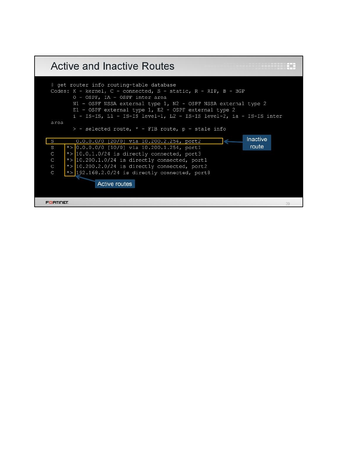
If you want to display both the active and the inactive routes, use this CLI command: get router
info routing-table database.
In this example, you can see that the command shows one inactive route. The route is inactive
because it has a higher distance than the one below.
Routing
FortiGate II Student Guide
200
DO NOT REPRINT
© FORTINET
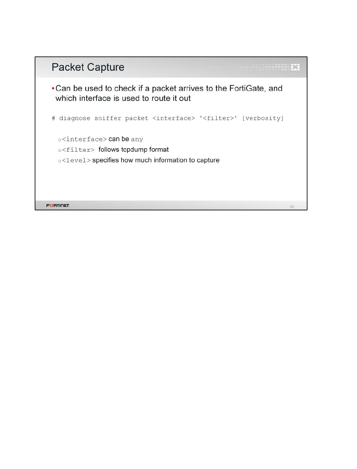
Packet captures, or sniffers, are one of the most useful sources of information for debugging network
problems. FortiOS includes a built-in traffic sniffer tool. It can be used to check when packets arrive to
the device, and which outgoing interfaces are used to route them out.
The built-in sniffer can be executed from either the GUI or the CLI. The syntax of the CLI command is
diagnose sniffer packet <interface> <filter> <level>.The interface is the name
of the physical or logical interface; if your account has the access profile super_admin, you can
specify any to sniffer all the interfaces. The filters are similar to tcpdump on Linux.
Routing
FortiGate II Student Guide
201
DO NOT REPRINT
© FORTINET
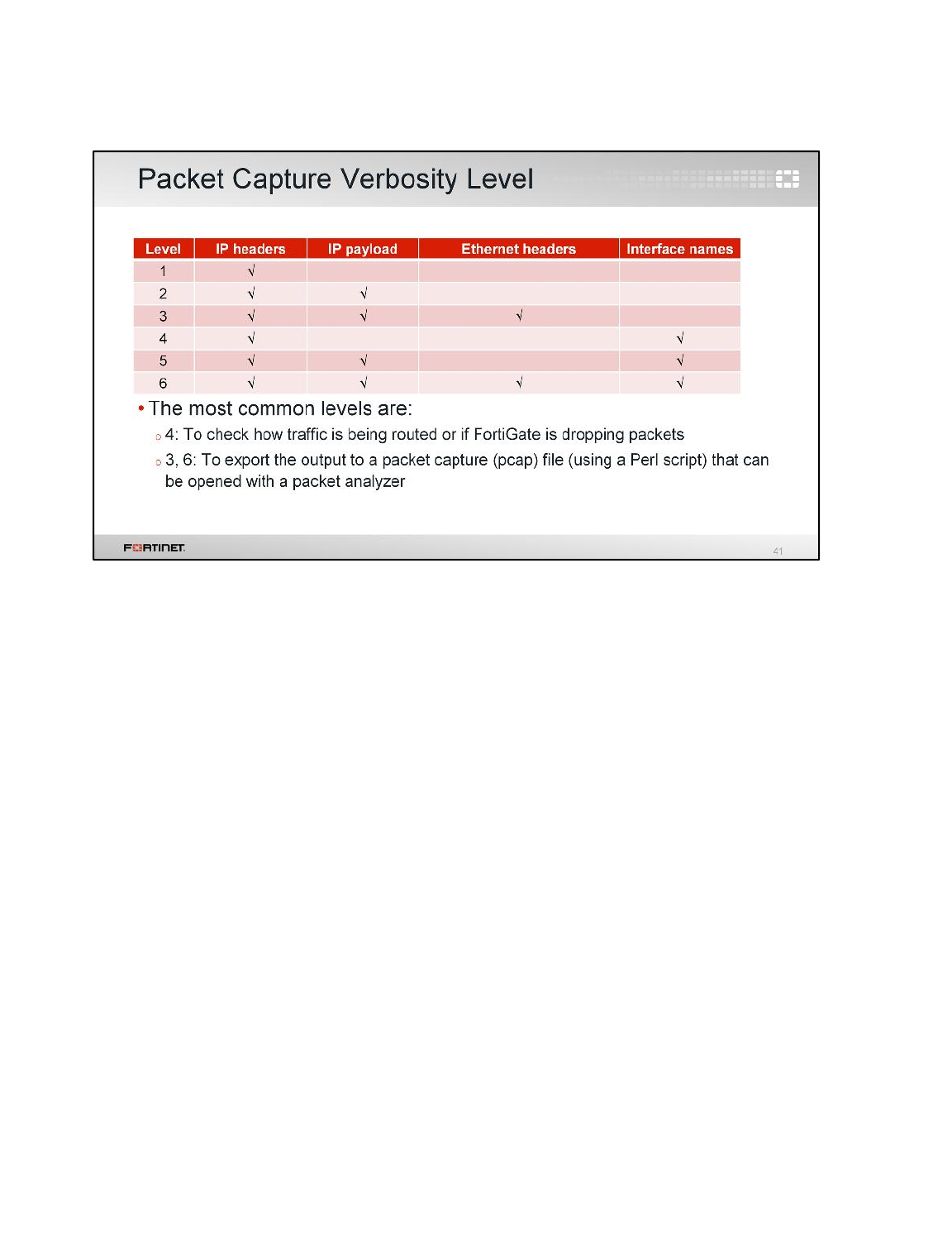
The level specifies how much information you want to display. There are six different levels and this
table shows which ones display the IP headers, IP payloads, Ethernet headers, and interface names.
We usually run verbosity 4 to take a quick look of how the traffic is flowing through FortiGate (if
packets arrive and how FortiGate is routing them out.) The verbosity 4 can also be used to easily
check if FortiGate is dropping packets.
Verbosities 3 and 6 provide the longest outputs. Both show the IP payloads and Ethernet headers.
You can save their output and export it to a packet capture (pcap) file using a Perl script. The pcap file
can then be opened with a packet analyzer, such as Wireshark, for further investigation. The Perl
script that converts the sniffer output to pcap can be found on the Fortinet Knowledge Base website
(kb.fortinet.com).
Routing
FortiGate II Student Guide
202
DO NOT REPRINT
© FORTINET
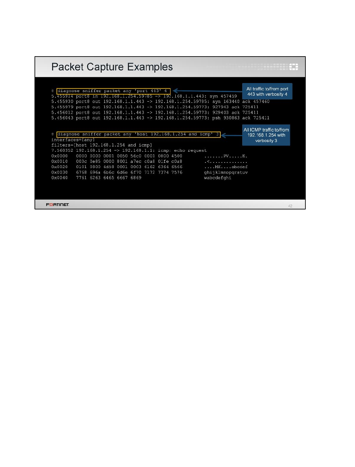
This slide shows two examples of packet sniffer outputs. The first sniffer captures all traffic to and from
port 443. It uses verbosity 4, so the information is easy to read. It displays one line per packet,
containing the incoming and outgoing interface, IP addresses, port numbers, and type of packet (SYN,
SYN/ACK, and so on).
The second sniffer captures all ICMP traffic coming from or going to the host 192.168.1.254. In this
case, the output is verbosity 3, which is longer and more difficult to read as it includes the IP payload
of the packets. However, this is one of the two verbosity levels to use (6 being the other one) if you
need to export the output to Wireshark.
Routing
FortiGate II Student Guide
203
DO NOT REPRINT
© FORTINET
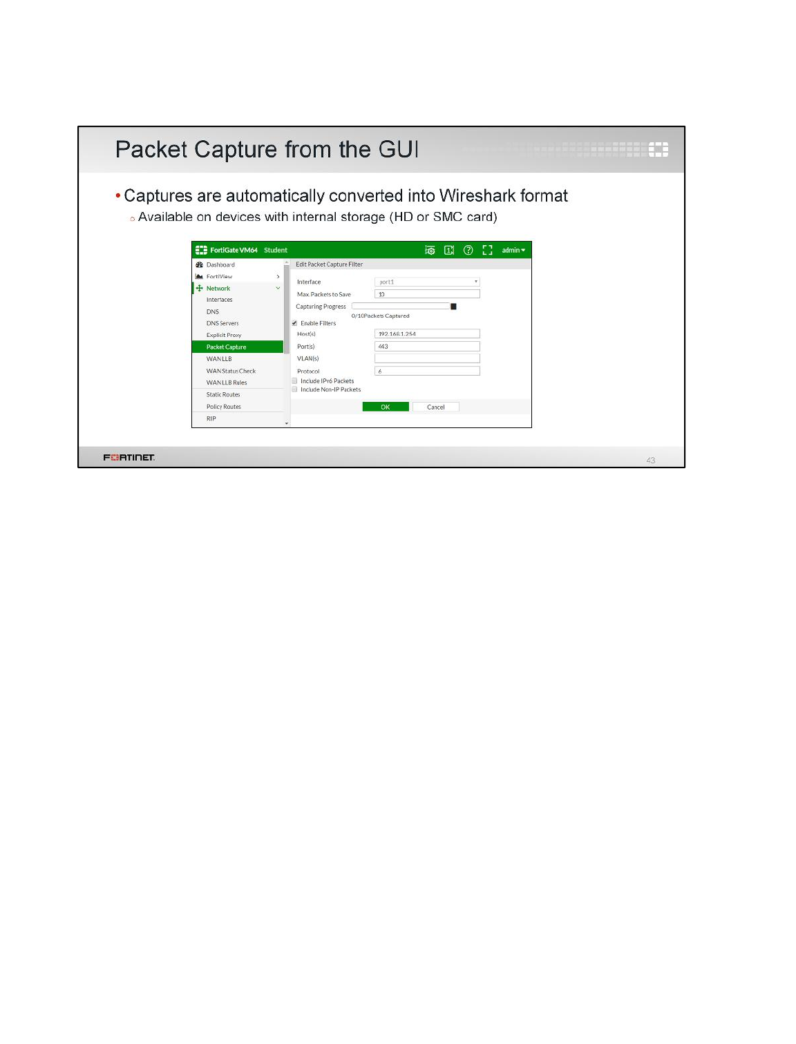
If your model of FortiGate has internal storage, you can capture packets from the GUI. The options
are similar as those for the CLI. To run a trace, specify a source interface and a filter.
What is the main advantage over the CLI? You download the output in a file format (pcap) that is
ready to be open with Wireshark, without having to use a conversion script.
Regardless of which method you use (CLI or GUI), packet capture filters should be very specific. So,
you will capture only the relevant packets and avoid writing large amounts of data to disk.
Routing
FortiGate II Student Guide
204
DO NOT REPRINT
© FORTINET
To review, in this lesson we talked about static and policy-based routing concepts and configuration,
including the following topics:
• Routing table elements
• How FortiGate matches each packet with a route
• Static and policy-based routes
• Equal cost multi-path (ECMP)
• Link health monitor
• Loose and strict reverse path forwarding (RPF)
• Routing Internet services
• WAN link load balancing
• Routing diagnostics
• Packet capture
Routing
FortiGate II Student Guide
205
DO NOT REPRINT
© FORTINET

In this lesson, we will show you how to configure virtual domains (VDOMs) and common usage
examples. This lesson also covers VLANs configuration.
Virtual Domains
FortiGate II Student Guide
206
DO NOT REPRINT
© FORTINET
After completing this lesson, you should have the practical skills that you need to create VDOMs and
VLANs. You will also learn to limit the resources allocated to each VDOM and create per-VDOM
administrative accounts. The lesson also covers inter-VDOM connectivity.
Lab exercises can help you to test and reinforce your skills.
Virtual Domains
FortiGate II Student Guide
207
DO NOT REPRINT
© FORTINET

In this section, we will explore virtual local area networks (VLANs).
Virtual Domains
FortiGate II Student Guide
208
DO NOT REPRINT
© FORTINET
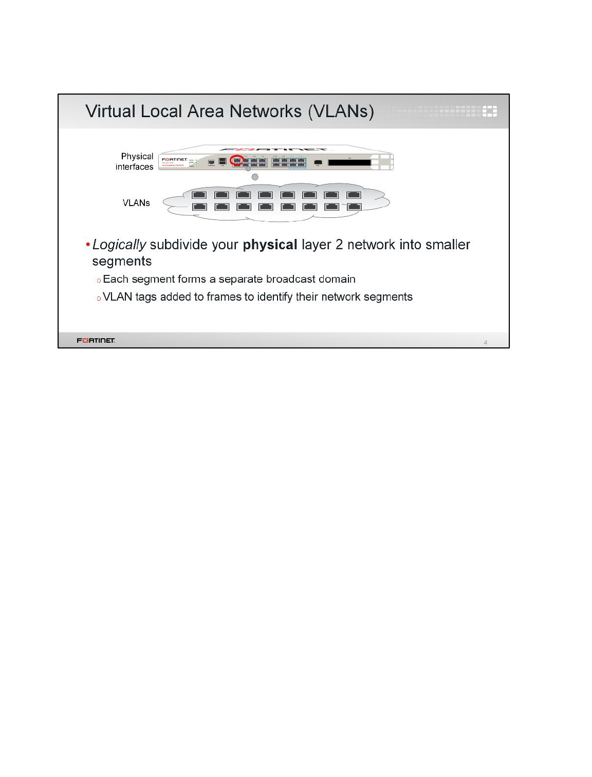
VDOMs are a virtualization within FortiOS, providing virtual firewalls. Interfaces have VDOM
membership. The interface that a packet arrives on determines which VDOM processes the traffic.
Interfaces can be physical or logical; IEEE 802.1Q VLANs are logical interfaces commonly used in
FortiGate devices.
VLANs split your physical LAN into multiple logical LANs. In NAT/Route mode, each VLAN forms a
separate broadcast domain. Multiple VLANs can coexist in the same physical interface. In this way, a
physical interface is split into two or more logical interfaces. A tag is added to each Ethernet frame to
identify the VLAN to which it belongs.
Virtual Domains
FortiGate II Student Guide
209
DO NOT REPRINT
© FORTINET
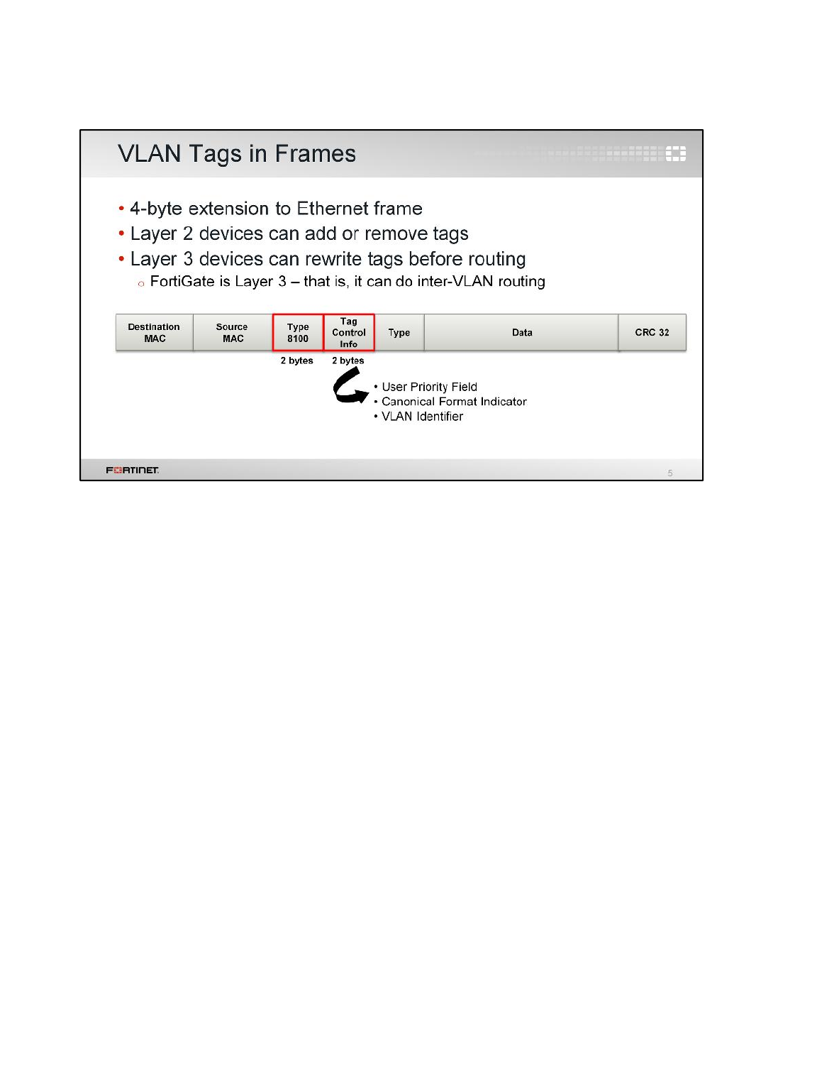
This slide shows an Ethernet frame. The frame contains the destination and source MAC addresses,
the type, the data payload, and a CRC code, to confirm that is not corrupted.
In the case of Ethernet frames with VLAN tagging, according to the 802.11q standard, four more
bytes are inserted after the MAC addresses. They contain an ID number that identifies the VLAN.
An OSI Layer 2 device, such as a switch, can add or remove these tags from Ethernet frames, but it
cannot change them.
A Layer 3 device, such as a router or a FortiGate, can change the VLAN tag before proceeding to
route the packet. In this way, they can route traffic between VLANs.
Virtual Domains
FortiGate II Student Guide
210
DO NOT REPRINT
© FORTINET
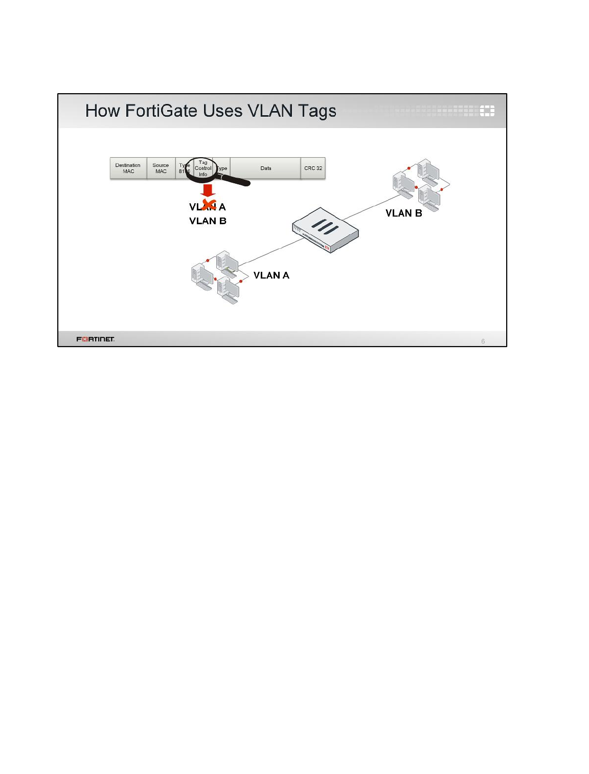
When operating in NAT/route mode, FortiGate operates as an OSI Layer 3 router in its most basic
configuration. In this mode, a VLAN is an interface on the device. VLAN tags may be added on
egress, removed on ingress, or rewritten based on a routing decision.
Virtual Domains
FortiGate II Student Guide
211
DO NOT REPRINT
© FORTINET
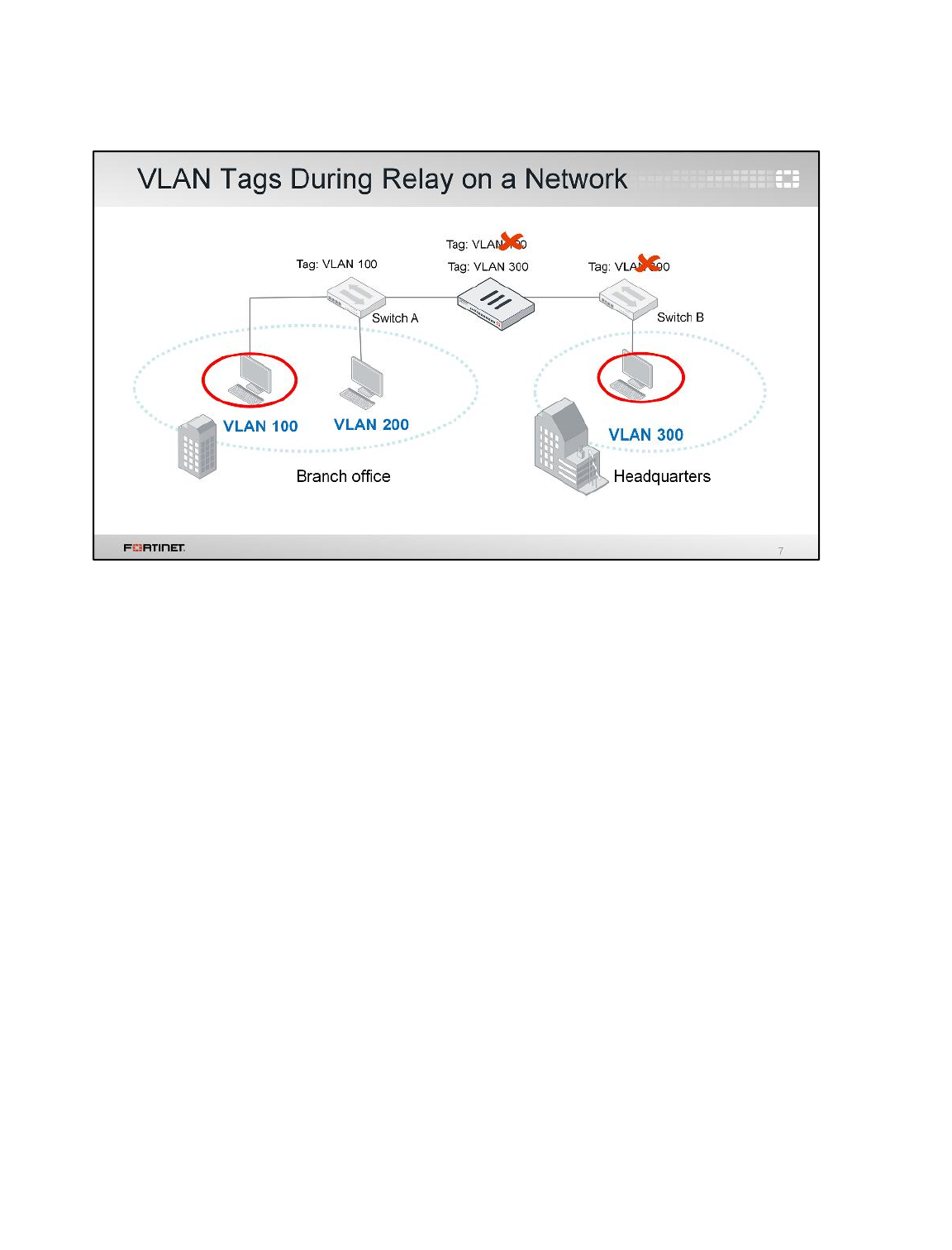
(slide contains animation)
In this example of NAT/route mode, a host on VLAN 100 sends a frame to a host on VLAN 300.
Switch A receives the frame on the untagged VLAN 100 interface. After that, it adds the VLAN 100 tag
on the tagged trunk link between switch A and the FortiGate.
(click)
FortiGate receives the frame on the VLAN 100 interface. Then, it routes the traffic from VLAN 100 to
VLAN 300, rewriting the VLAN ID to VLAN 300 in the process.
(click)
Switch B receives the frame on the VLAN trunk interface and removes the VLAN tag before
forwarding the frame to its destination on the untagged VLAN 300 interface.
Virtual Domains
FortiGate II Student Guide
212
DO NOT REPRINT
© FORTINET
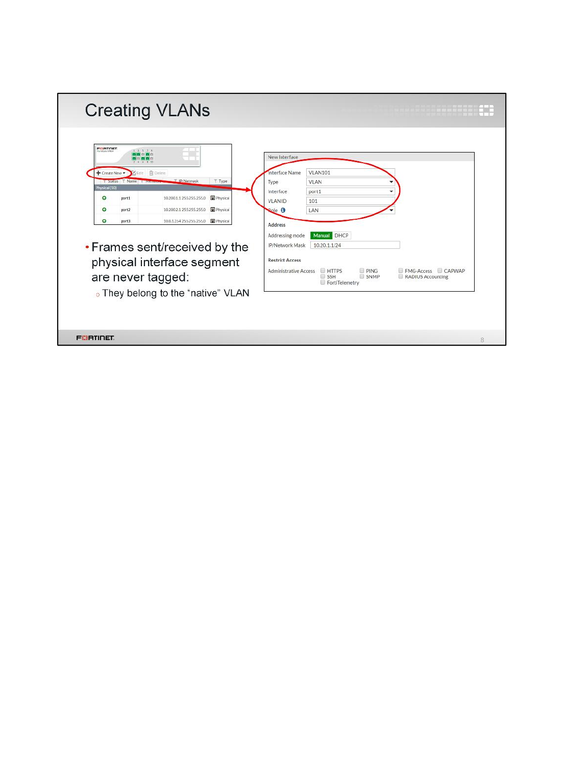
To create a VLAN from the GUI, click Create New and select VLAN as the Type. You must specify
the VLAN ID and the physical interface to which the VLAN will be bound. Frames that belong to
interfaces of that type are always tagged. On the other hand, frames sent or received by the physical
interface segment are never tagged. They belong to what is called the native VLAN.
Virtual Domains
FortiGate II Student Guide
213
DO NOT REPRINT
© FORTINET

In this section, we will explore Virtual Domains (VDOMs).
Virtual Domains
FortiGate II Student Guide
214
DO NOT REPRINT
© FORTINET
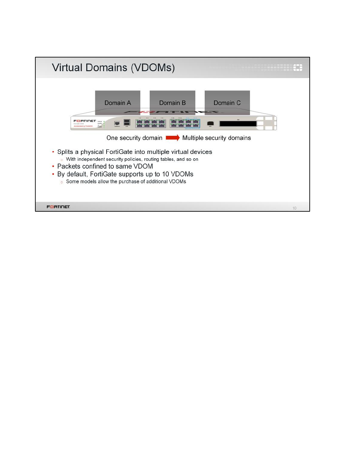
What if more than segmenting your network, you want to subdivide policies and administrators into
multiple security domains?
In that case, you can enable FortiGate VDOMs, which split your physical FortiGate into multiple logical
devices. Each VDOM has independent security policies and routing tables. Also, and by default, traffic
from one VDOM cannot go to a different VDOM. This means, for example, that two interfaces in
different VDOMs can share the same IP address, without any overlapping subnet problems.
Virtual Domains
FortiGate II Student Guide
215
DO NOT REPRINT
© FORTINET
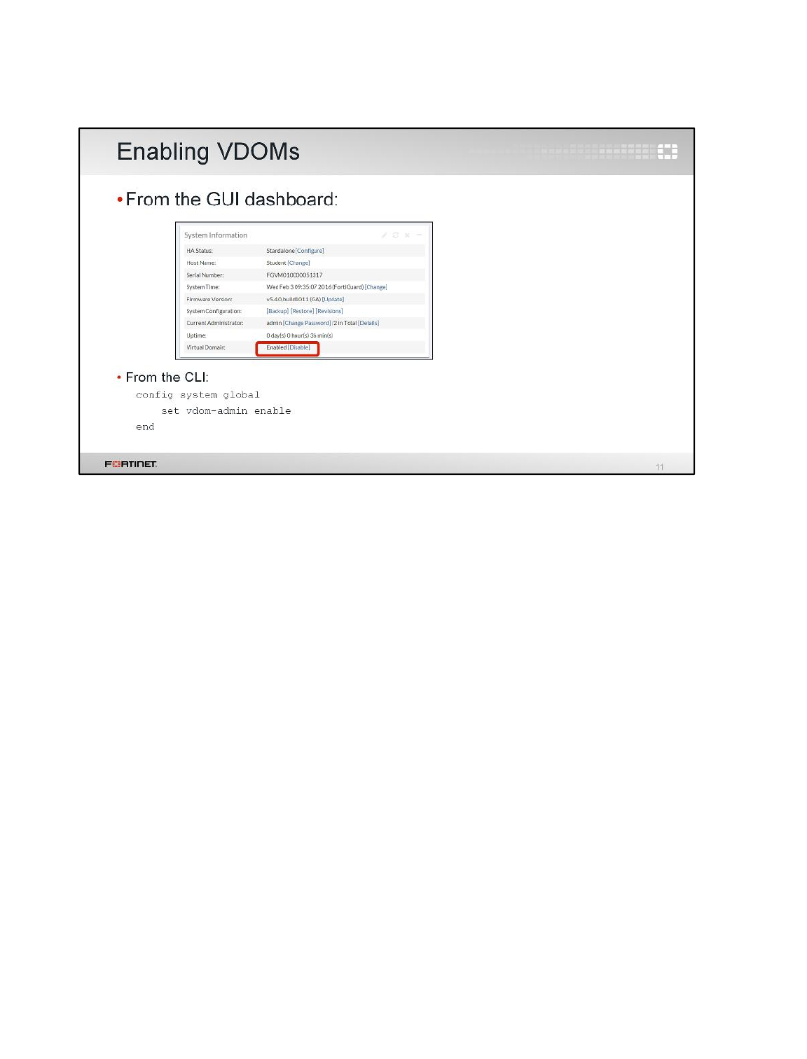
To enable VDOMs from the GUI, in the System Information widget on the dashboard, click Enable in
the Virtual Domain field.
Alternatively, to enable VDOMs when you are logged into the CLI, enter the command:
set vdom-admin enable
This won’t reboot your FortiGate, but it will log you out; enabling VDOMs restructures both the GUI
and CLI, which you will see when you log in again.
Virtual Domains
FortiGate II Student Guide
216
DO NOT REPRINT
© FORTINET
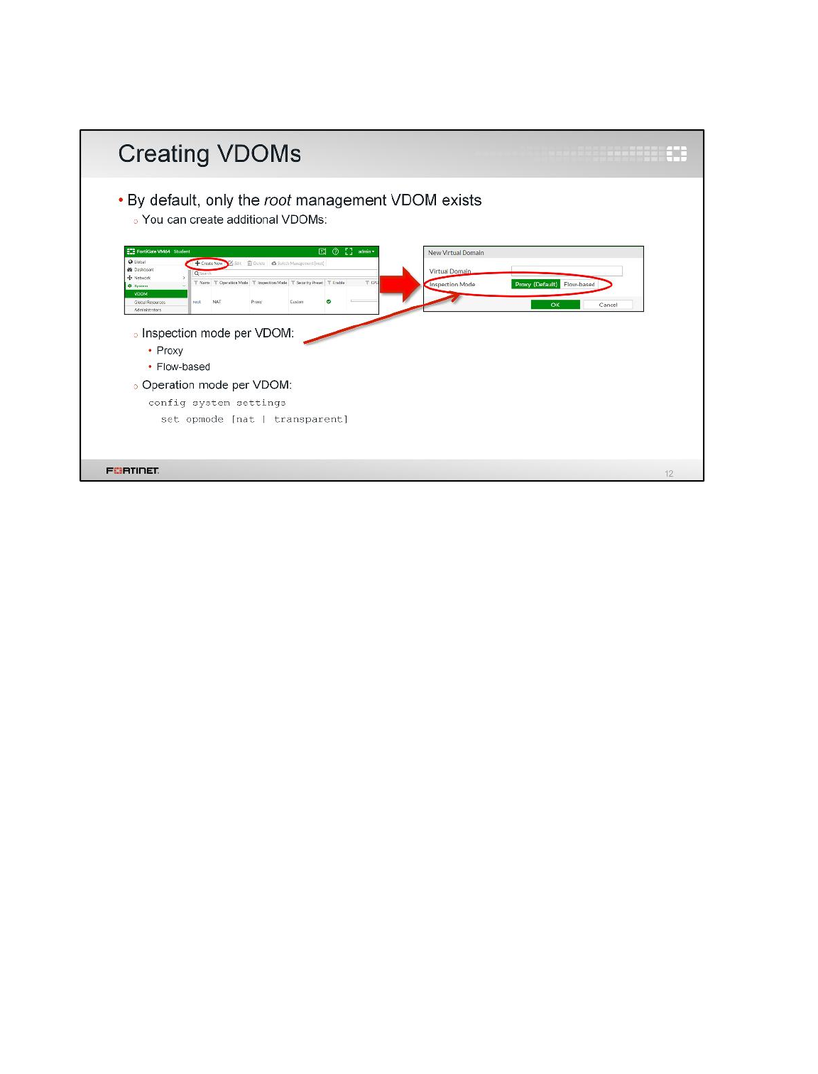
After enabling VDOMs, by default, only one VDOM exists: the root VDOM. It’s the default
management VDOM, which we will discuss later in the lesson.
You need to add a VDOM for each of your security domains. If you’re an MSSP, for example, you
might add one VDOM for each client company. If you are an enterprise business, you might add one
VDOM for each division of your company.
The inspection mode (proxy or flow-based) is a per-VDOM setting that defines how traffic is inspected.
In a VDOM in proxy mode, FortiGate inspects the traffic acting as an implicit TCP proxy. The original
client-to-server TCP session is actually split into two TCP sessions: one from the client to the
FortiGate, and another one from the FortiGate to the server.
In a VDOM in flow-based mode, the traffic is scanned on a TCP flow basis as it passes through
FortiGate. There is no implicit TCP proxy involved.
The operation mode is also a per-VDOM setting. You can combine transparent mode VDOMs with
NAT/route mode VDOMs in the same physical FortiGate.
Virtual Domains
FortiGate II Student Guide
217
DO NOT REPRINT
© FORTINET
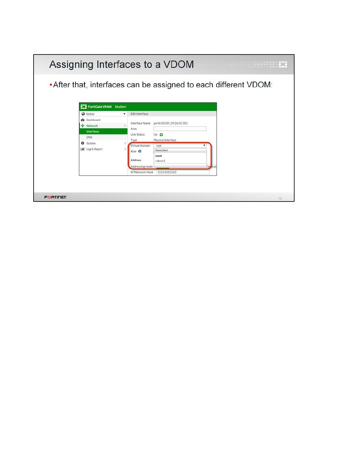
After adding the additional VDOMs, you can proceed to specify which interfaces belong to each
VDOM. Each interface (physical or VLAN) can belong to only one VDOM.
Virtual Domains
FortiGate II Student Guide
218
DO NOT REPRINT
© FORTINET

Remember, VDOMs are a logical separation only – each VDOM shares physical resources with the
others.
Unlike with FortiGate-VM, VDOMs are not allocated and balanced with weighted vCPU cores, vRAM,
and other virtualized hardware.
To fine-tune performance, you can configure resource limits for each feature – IPsec tunnels, address
objects, and so on – at both the global level and at each VDOM level. This controls the ratio of each
VDOM’s system resource usage to the total available resources.
Virtual Domains
FortiGate II Student Guide
219
DO NOT REPRINT
© FORTINET
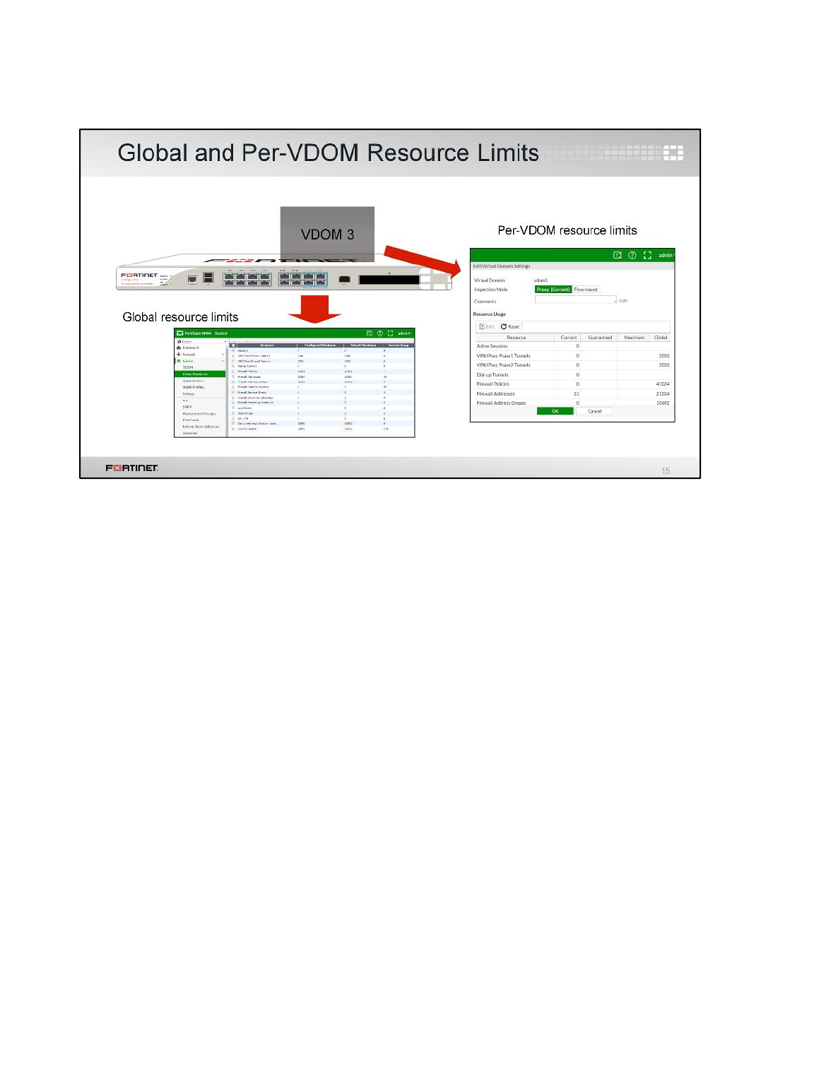
For example, on this FortiGate, the hardware is powerful enough to handle up to 2000 IPsec VPN
tunnels. The FortiGate is configured with three VDOMs.
vdom1 and vdom2 don’t use IPsec VPN tunnels often. So, they are allowed to have up to 50 tunnels
each. vdom3, however, uses VPN extensively. Therefore, this FortiGate will be configured to allow
vdom3 to have up to 1900 tunnels. Additionally, 1000 of those tunnels will be guaranteed.
Configure your FortiGate with global limits for critical features such as sessions, policies, and others.
Then configure each VDOM with its own quotas and minimums, within the global limits.
Virtual Domains
FortiGate II Student Guide
220
DO NOT REPRINT
© FORTINET
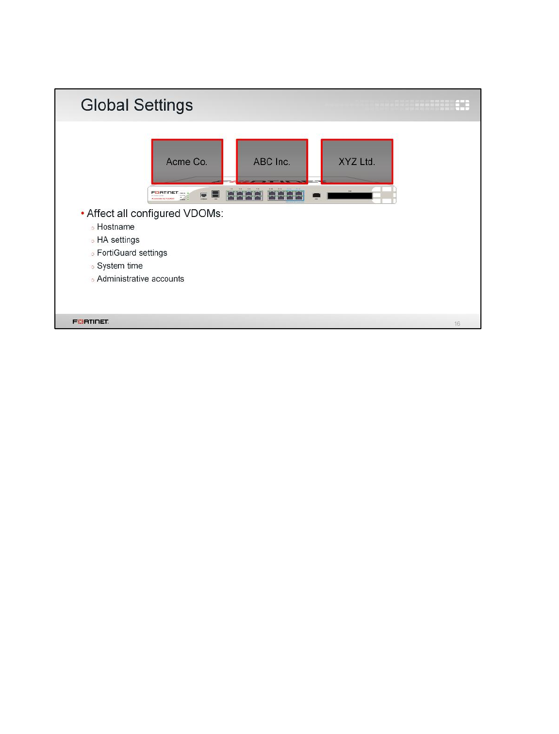
Global resource limits are an example of global settings. The firmware on your FortiGate and some
settings, such as system time, apply to the entire appliance – they are not specific to each VDOM.
Virtual Domains
FortiGate II Student Guide
221
DO NOT REPRINT
© FORTINET
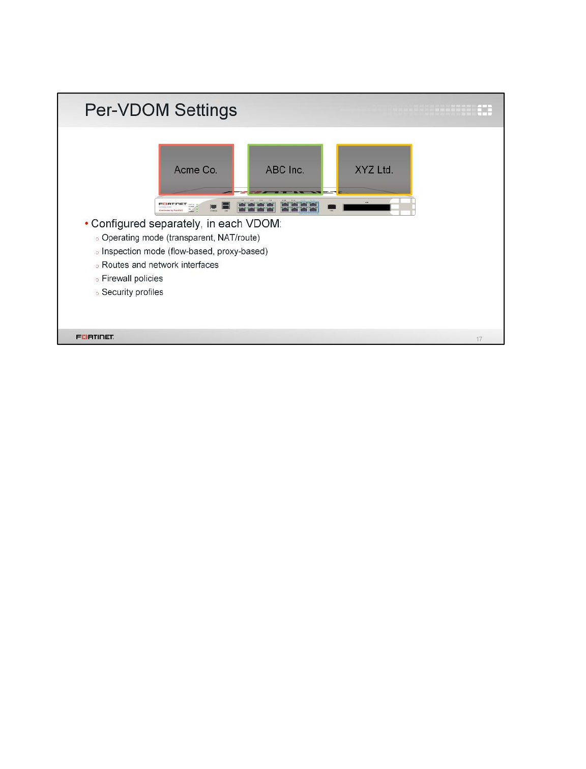
Most settings, however, can be configured to be different for each VDOM. Some examples are:
firewall policies, firewall objects, static routes, protection profiles, and so on.
Virtual Domains
FortiGate II Student Guide
222
DO NOT REPRINT
© FORTINET
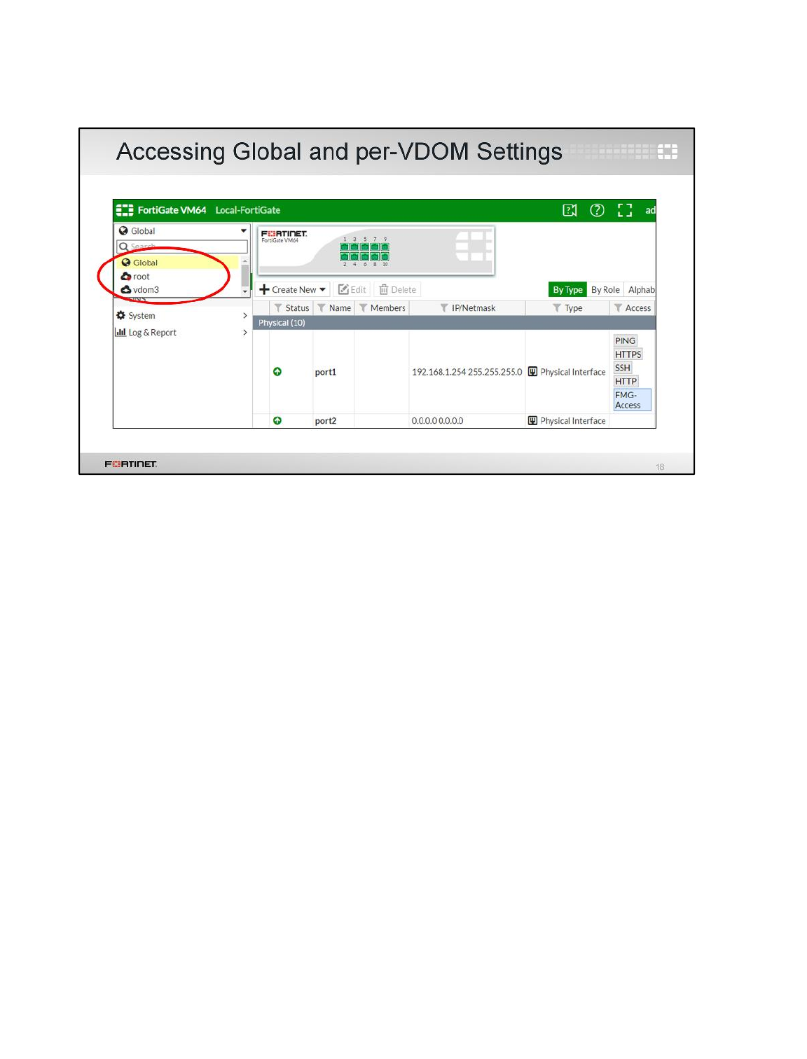
If you log in as most administrator accounts, you will enter your VDOM automatically.
But if you are logged in as the account named admin, you aren’t assigned to any VDOM.
To enter a VDOM on the GUI, select the VDOM from the drop-down list on the top.
Inside each VDOM, the submenu should be familiar: it is essentially the same navigation menu that
you had before you enabled VDOMs. However, the global settings are moved to the Global part of the
menu.
Virtual Domains
FortiGate II Student Guide
223
DO NOT REPRINT
© FORTINET
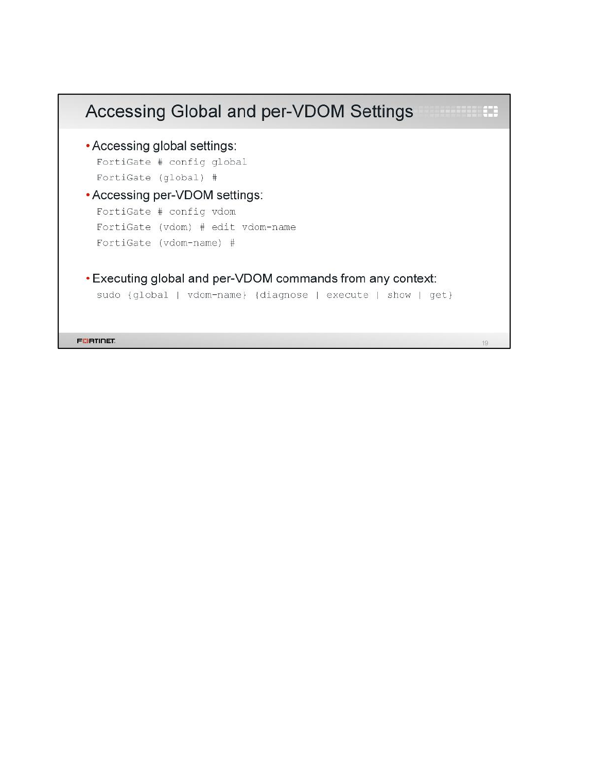
To access the global configuration settings from the CLI, you must first type config global to enter
into the global context. After that, you can execute global commands and change global configuration
settings.
To access per-VDOM configuration settings from the CLI, you must first type config vdom, then
type edit followed by the VDOM name. From the VDOM context you can execute VDOM-specific
commands and change per-VDOM configuration settings.
Regardless of the context where you are (global or VDOM), you can use the sudo keyword to
execute diagnostics commands in a context different than your current one. This allows you, for
example, to execute global and per-VDOM commands without switching back and forth between the
global and per-VDOM context.
Virtual Domains
FortiGate II Student Guide
224
DO NOT REPRINT
© FORTINET
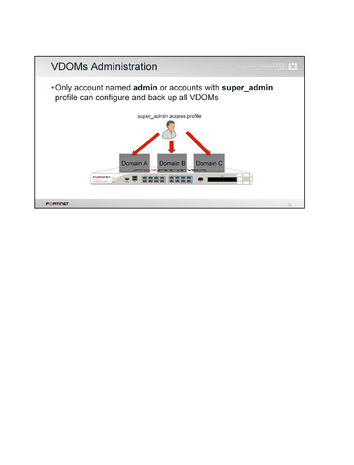
If you want to grant access to all VDOMs and global settings, select super_admin as the access
profile when configuring the administrator account. Similar to the account named admin, this account
will be able to configure all VDOMs.
Best practice dictates that you should usually avoid unnecessary security holes, however. Do not
provide super_admin access if possible. Instead, restrict each administrator to their relevant domain.
That way, they cannot accidentally or maliciously impact other VDOMs, and any damage or mistakes
will be limited in scope.
Virtual Domains
FortiGate II Student Guide
225
DO NOT REPRINT
© FORTINET
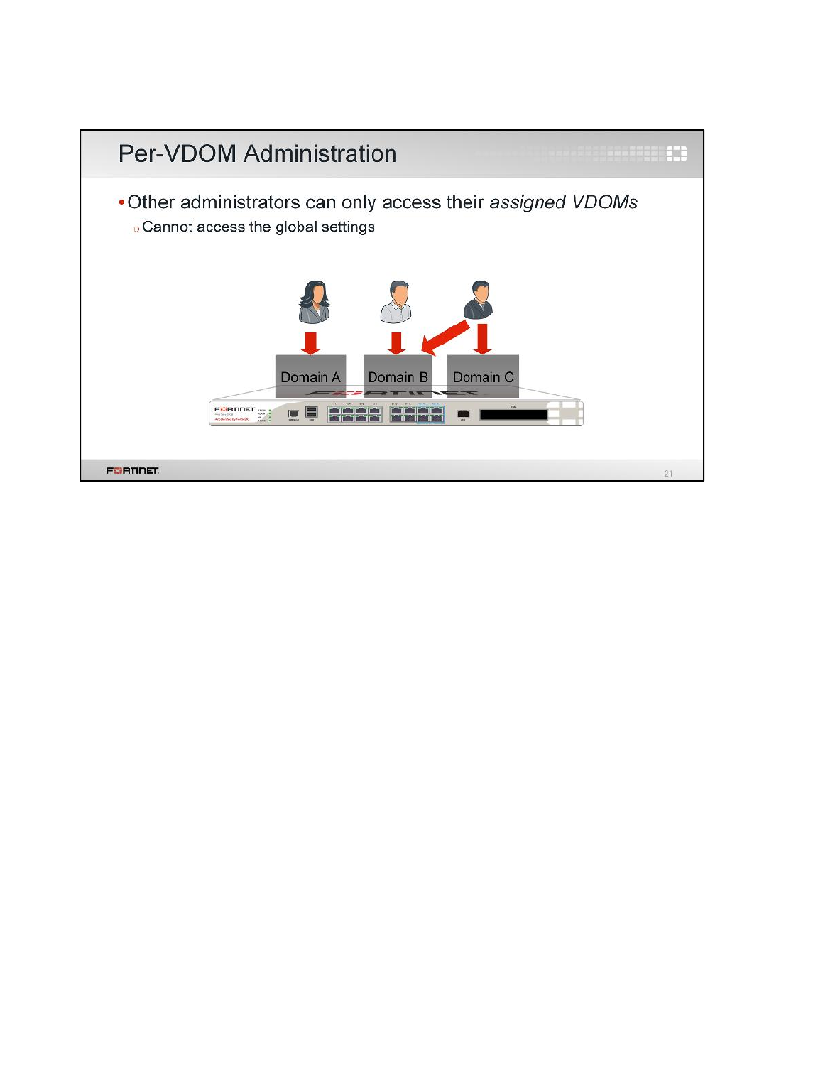
In most cases, you’ll start by creating one administrator account per VDOM. That administrator will be
chiefly responsible for that domain, including that VDOM’s configuration backups. In larger
organizations, you may need to make more VDOM administrators. Multiple administrators can be
assigned to each VDOM. You can subdivide permissions using access profiles in order to follow best
practices for segregation of duties.
The converse is also possible. If required, you can assign an administrator to multiple VDOMs.
Virtual Domains
FortiGate II Student Guide
226
DO NOT REPRINT
© FORTINET
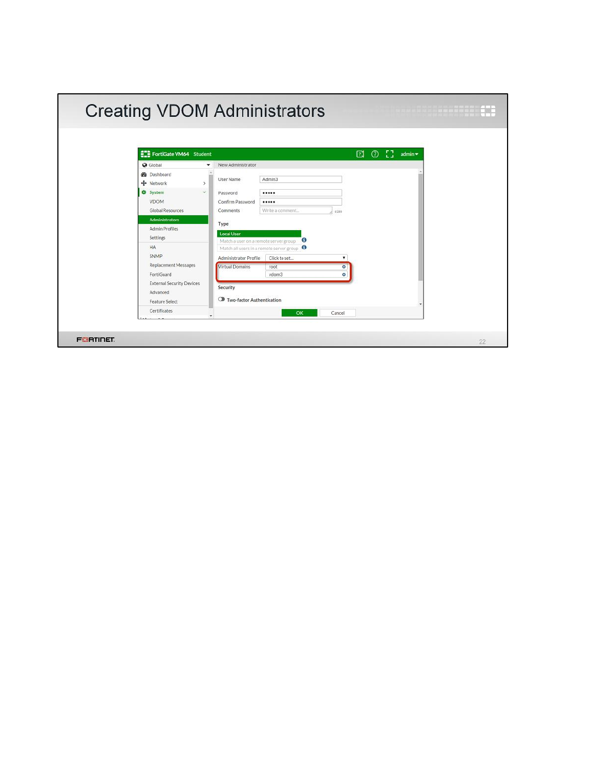
To create new administrator accounts and assign them to a VDOM, go to the Global part of the menu.
Virtual Domains
FortiGate II Student Guide
227
DO NOT REPRINT
© FORTINET
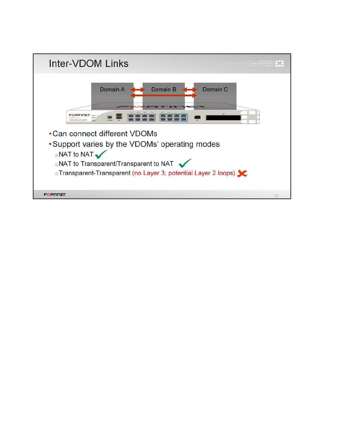
To review, each VDOM behaves as it is on a separate FortiGate appliance. With separate FortiGates,
you would normally connect a network cable and configure routing and policies between them. But
VDOMs are on the same FortiGate. So how should you route traffic between them?
The solution is inter-VDOM links. With inter-VDOM links, you won’t send traffic out through a physical
cable or VLAN, and then back into the same FortiGate to reach another VDOM. Inter-VDOM links are
a type of virtual interface.
Note that like with inter-VLAN routing, Layer 3 must be involved – you cannot create an inter-VDOM
link between layer-2 transparent mode VDOMs. At least 1 of the VDOMs must be operating in NAT
mode. This, among other benefits, prevents potential Layer 2 loops.
Virtual Domains
FortiGate II Student Guide
228
DO NOT REPRINT
© FORTINET
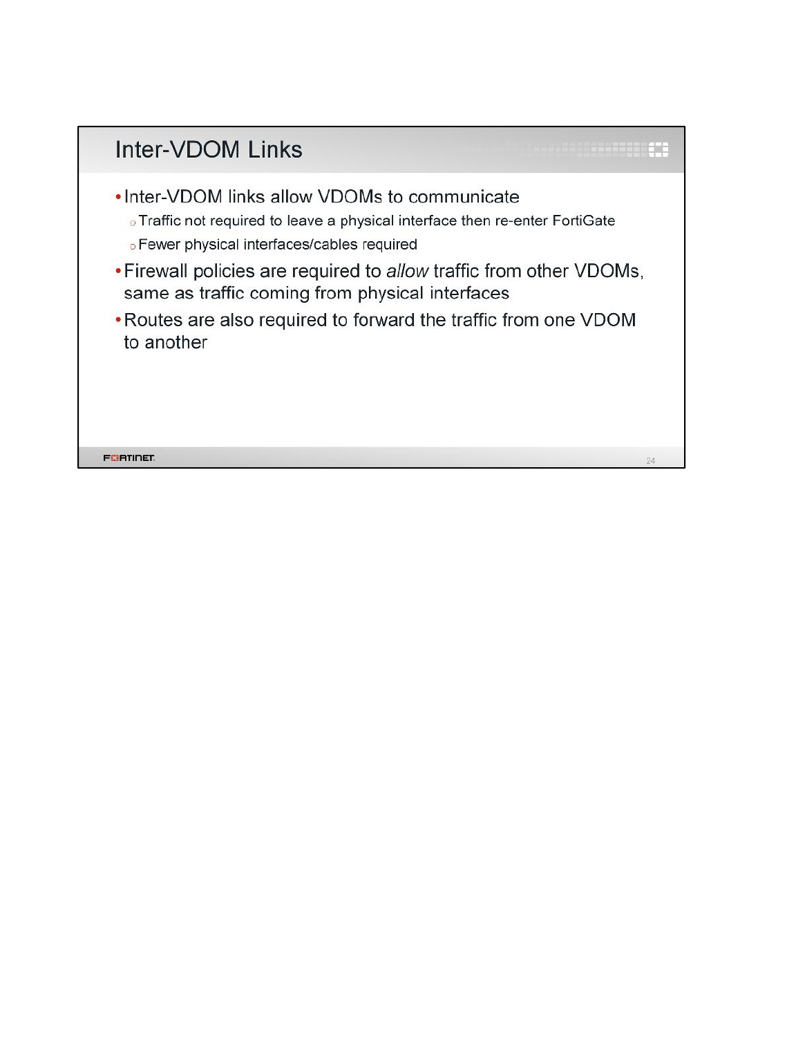
When creating inter-VDOM links, you’ll need to create the virtual interfaces. You must also create a
matching firewall policy, just as you would if the traffic were arriving on a network cable. Otherwise,
FortiGate will block it.
Additionally, routes are required to properly route packets between two VDOMs.
Virtual Domains
FortiGate II Student Guide
229
DO NOT REPRINT
© FORTINET
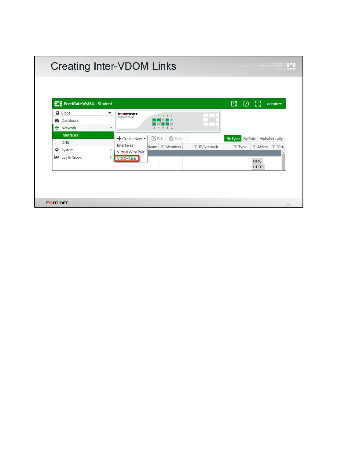
In the menu, creating a network interface is located in the Global settings. To create the virtual
interface, click Create New, then choose VDOM Link.
Virtual Domains
FortiGate II Student Guide
230
DO NOT REPRINT
© FORTINET
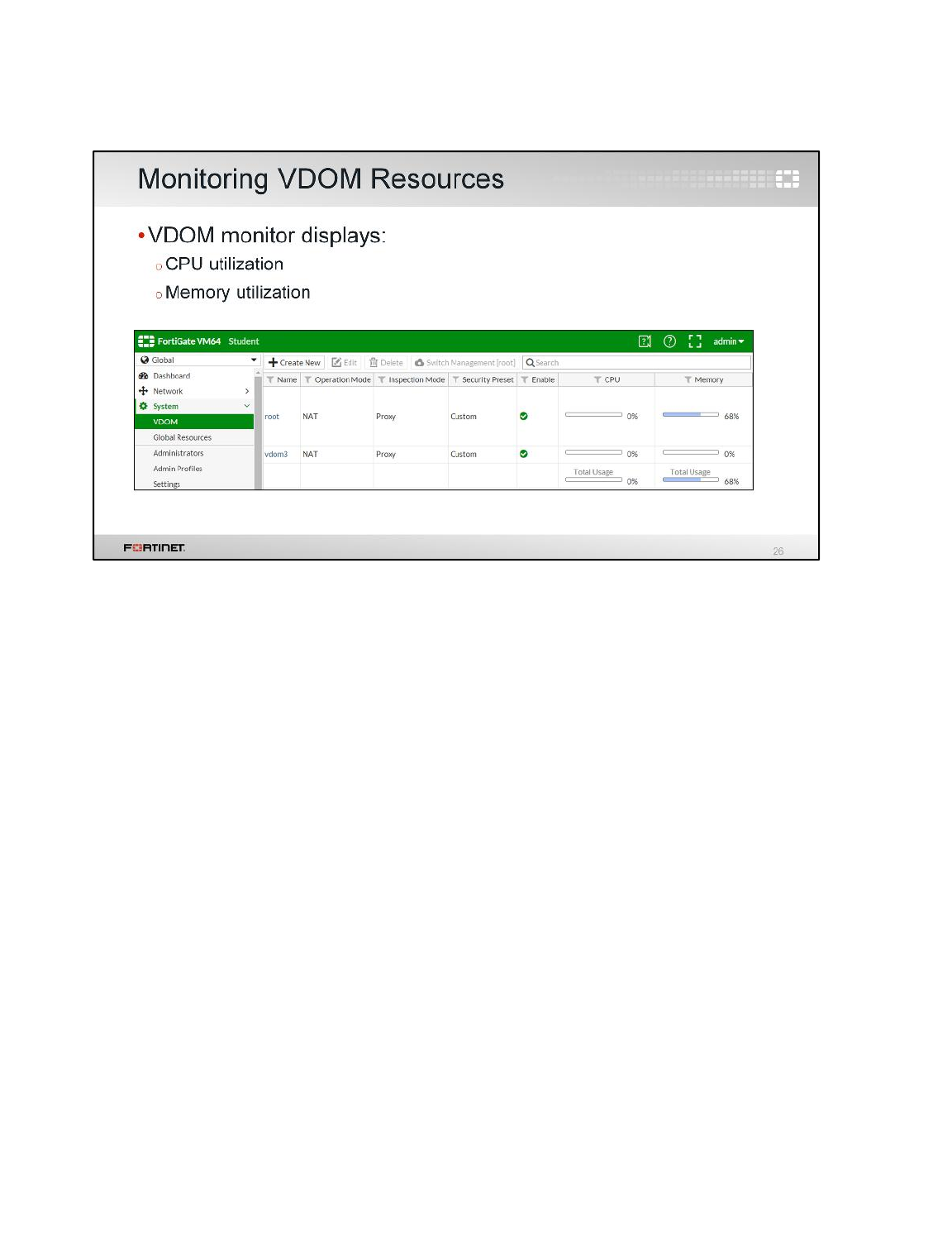
In the global section of the GUI, there is a VDOM monitor. It displays the CPU and memory usage for
each VDOM.
Virtual Domains
FortiGate II Student Guide
231
DO NOT REPRINT
© FORTINET
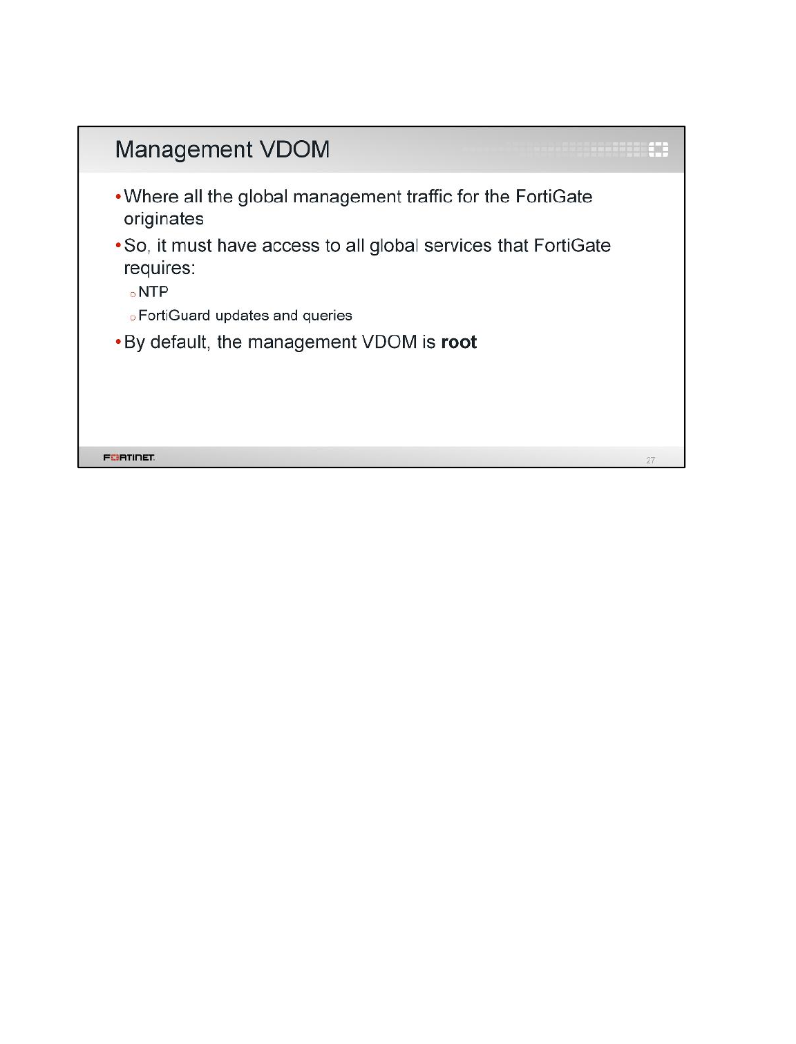
Up until now, we’ve discussed traffic passing through FortiGate, from one VLAN or VDOM to another.
What about traffic originating from your FortiGate itself?
Some system daemons, such as NTP and FortiGuard updates, generate this kind of traffic. One, and
only one, of the VDOMs in a FortiGate device is assigned the role of being the management VDOM.
Traffic from FortiGate to those global services is originated from the management VDOM. By default,
the VDOM root acts as the management VDOM, but you can manually re-assign this task to a
different VDOM.
Similar to a FortiGate without VDOMs, the administrative VDOM usually should have outgoing Internet
access. Otherwise, features such as scheduled FortiGuard updates will fail.
Virtual Domains
FortiGate II Student Guide
232
DO NOT REPRINT
© FORTINET
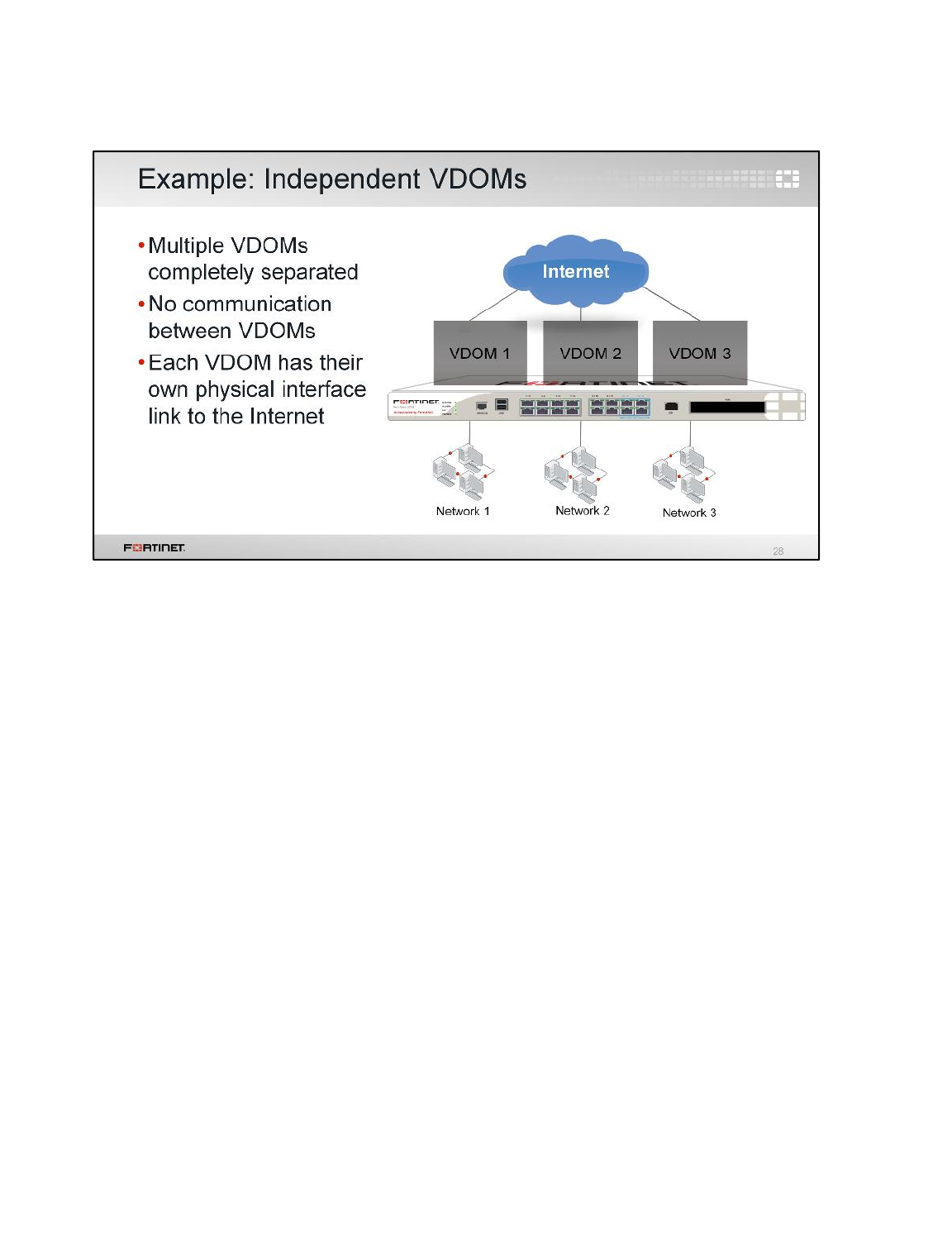
There are a few ways you can arrange your VDOMs. In this topology, each network accesses the
Internet through its own VDOM.
Notice that there are no inter-VDOM links. So, inter-VDOM traffic is not possible unless it physically
leaves the FortiGate, towards the Internet, and is rerouted back. This is most suitable for multiple
customers sharing a single FortiGate, each in their own VDOM, with physically separated ISPs, for
example.
Virtual Domains
FortiGate II Student Guide
233
DO NOT REPRINT
© FORTINET
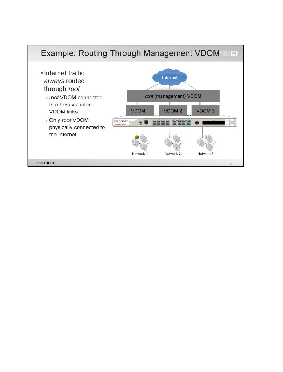
This is another example.
Like the previous topology, each network sends traffic through its VDOM. But after that, traffic is
routed through the management VDOM – by default, named root. So, Internet-bound traffic flows
through a single pipe in the root VDOM.
This could be suitable for multiple customers sharing a single FortiGate, each in their own VDOM. But
in this case, the management VDOM could log and monitor traffic and/or provide standard services
like antivirus scanning.
Note that this topology has inter-VDOM links, but peer VDOMs are only linked with the management
VDOM, not with each other.
Inspection could be done by either the root or originating VDOM, depending on your requirements.
Alternatively, you could split inspection so that some scans occur in the root VDOM – ensuring a
common security baseline – while other more intensive scans occur in the originating VDOM.
Virtual Domains
FortiGate II Student Guide
234
DO NOT REPRINT
© FORTINET
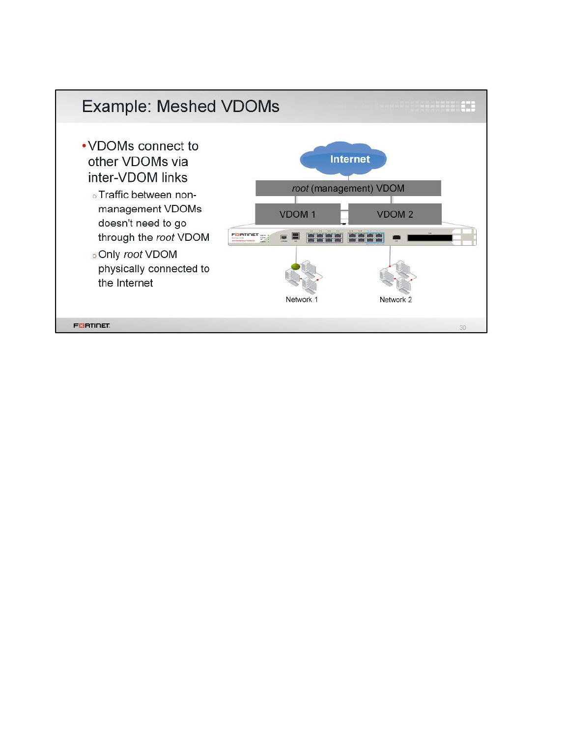
Here, traffic again flows through a single pipe in the root VDOM towards the Internet. Traffic between
VDOMs doesn’t need to leave the FortiGate either.
However, now inter-VDOM traffic doesn’t need to flow through the management VDOM. Inter-VDOM
links between VDOMs allow more direct communication.
Like the previous example, inspection could be done by either the root or originating VDOM,
depending on your requirements.
Due to the number of inter-VDOM links, this example is the most complex, requiring the most routes
and firewall policies. Troubleshooting meshed VDOMs can also be more time-consuming.
However, meshed VDOMs also provide the most flexibility. For large businesses, inter-VDOM
communication may be required. Also, inter-VDOM traffic performance may be better due to a shorter
processing path which bypasses the management VDOM.
Virtual Domains
FortiGate II Student Guide
235
DO NOT REPRINT
© FORTINET
This is a review of what we covered: VLANs, VDOMs, Inter-VDOM links, and VDOM topologies.
Virtual Domains
FortiGate II Student Guide
236
DO NOT REPRINT
© FORTINET
In this lesson, you will learn how to do transparent mode and Layer 2 switching in a FortiGate.
Transparent Mode and Layer 2 Switching
FortiGate II Student Guide
237
DO NOT REPRINT
© FORTINET
After completing this lesson, you should have these practical skills that you can use to configure
FortiGate for Layer 2 switching:
• Configure FortiGate interfaces to operate as a Layer 2 switch
• Configure a VDOM to operate in transparent mode
• Monitor the MAC address table
• Segment the Layer 2 network into multiple broadcast domains
• Install FortiGate in networks running spanning tree protocol (STP)
Lab exercises can help you to test and reinforce your skills.
Transparent Mode and Layer 2 Switching
FortiGate II Student Guide
238
DO NOT REPRINT
© FORTINET

In this section, we will explore transparent mode.
Transparent Mode and Layer 2 Switching
FortiGate II Student Guide
239
DO NOT REPRINT
© FORTINET
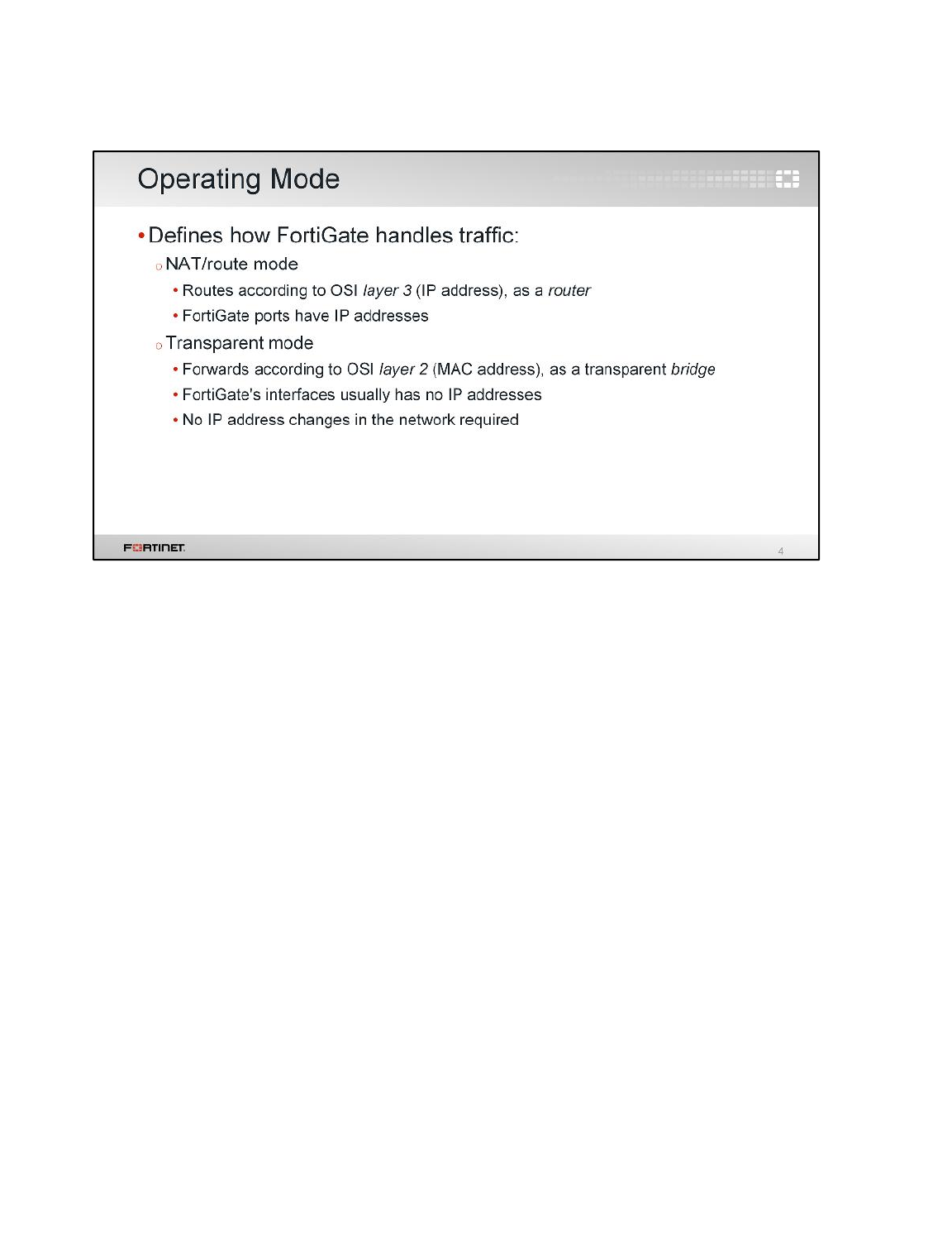
Traditional IPv4 firewalls and NAT mode FortiGates handle traffic as routers do. So, each interface
has to be in different subnets and each forms different broadcast domains. FortiGate routes IP
packets based on the IP header information, overwriting the source MAC address. So, if a client sends
a packet to a server connected to a different FortiGate interface, the packet will arrive to the server
with a FortiGate MAC address, instead of the client’s MAC address.
In the case of transparent mode, FortiGate forwards frames without changing the MAC addresses.
When the client receives a packet from a server connected to a different FortiGate interface, the frame
contains the server’s real MAC address – FortiGate doesn’t rewrite the MAC header. The FortiGate is
a Layer 2 bridge or switch. So, the interfaces do not have IP addresses and all belong (by default) to
the same broadcast domain.
This means that a transparent mode FortiGate can be installed in a customer network without
changing the customer’s IP address plan. Some customers, especially large organizations, don’t want
to reconfigure thousands of devices to define a new internal vs. external network.
Transparent Mode and Layer 2 Switching
FortiGate II Student Guide
240
DO NOT REPRINT
© FORTINET
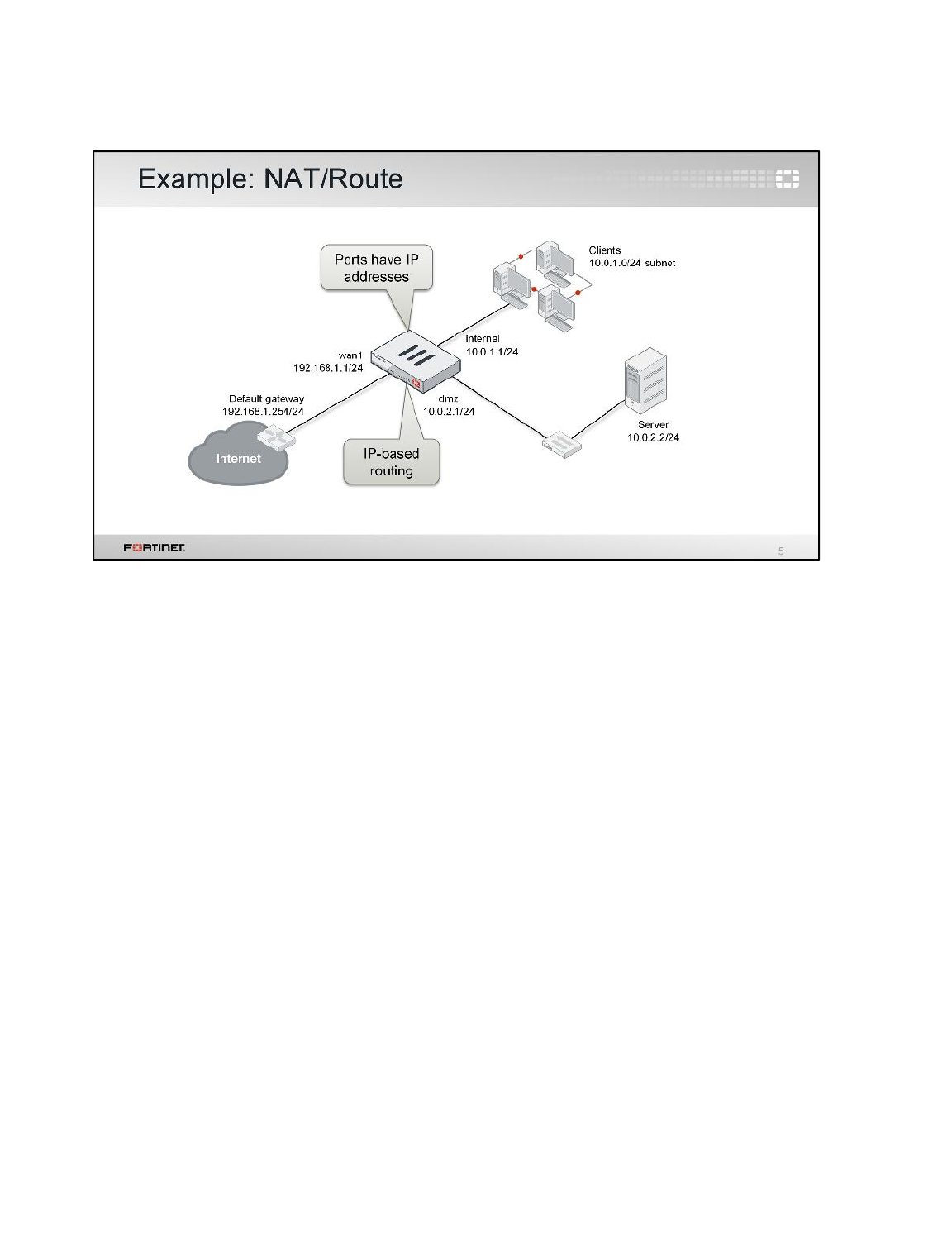
Here is an example showing NAT mode.
FortiGate has three connected ports, each with separate IP subnets. All interfaces on the FortiGate
have IP addresses, and, in this case, NAT translates between networks. Firewall policies allow traffic
to flow between networks.
FortiGate handles packets according to their routes, which are in most of the cases based on the
destination IP address (at Layer 3 of the OSI model).
Clients on each subnet send frames that are destined for a FortiGate MAC address – not the real
MAC address of the server.
Transparent Mode and Layer 2 Switching
FortiGate II Student Guide
241
DO NOT REPRINT
© FORTINET
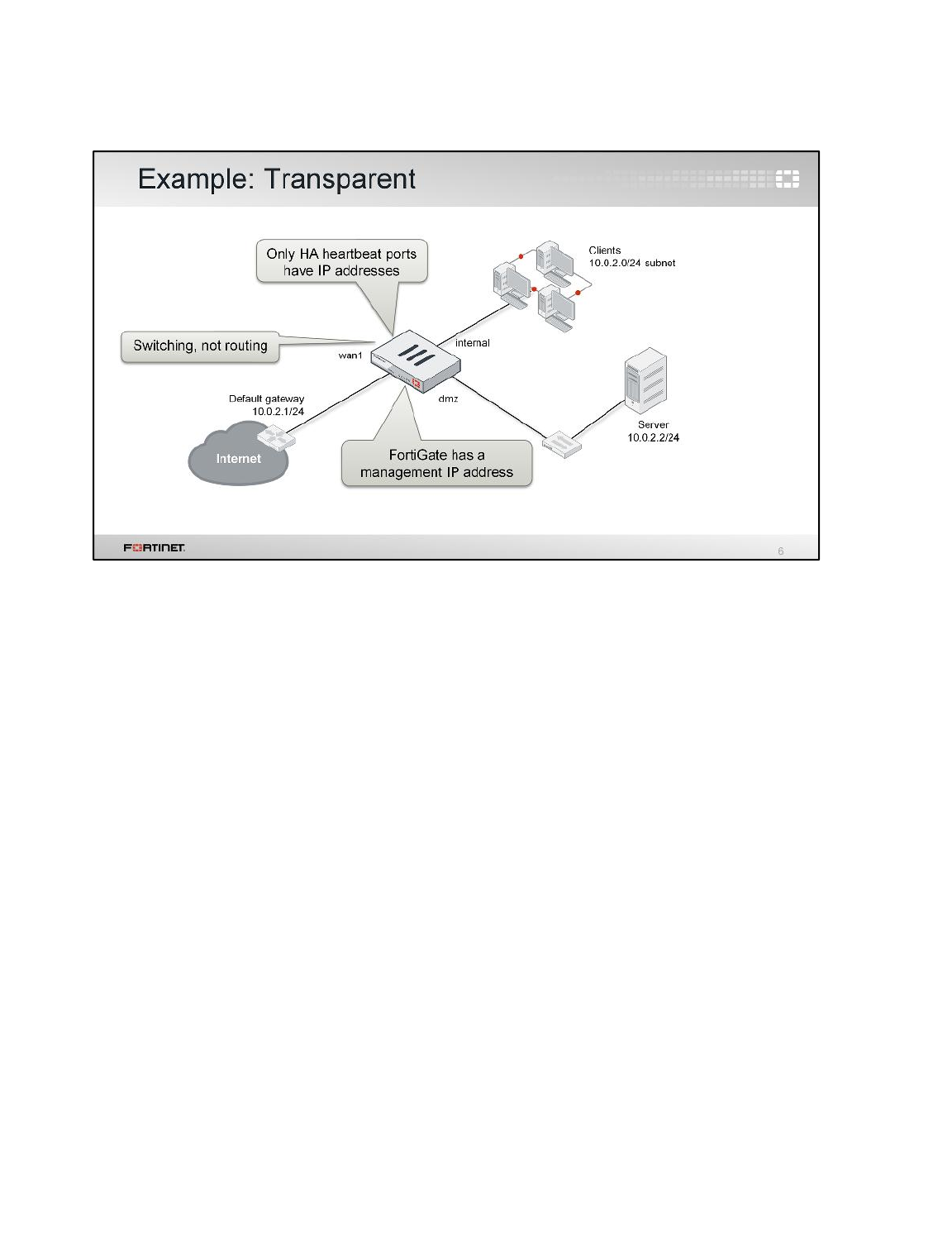
Here is an example showing transparent mode. Firewall policies still scan, then allow or block traffic.
But there are differences.
Notice that the physical interfaces on FortiGate have no IPs. So FortiGate won’t respond to ARP
requests. There are some exceptions although. For example, when changing to transparent mode,
you must specify a management IP address to receive connections from your network administrators;
and send log messages, SNMP traps, alert email, and so forth. This IP address is not assigned to any
particular interface, but to the VDOM settings.
By default, a transparent FortiGate won’t do NAT. Also, clients will send frames destined directly to the
real router or server MAC address.
Transparent Mode and Layer 2 Switching
FortiGate II Student Guide
242
DO NOT REPRINT
© FORTINET
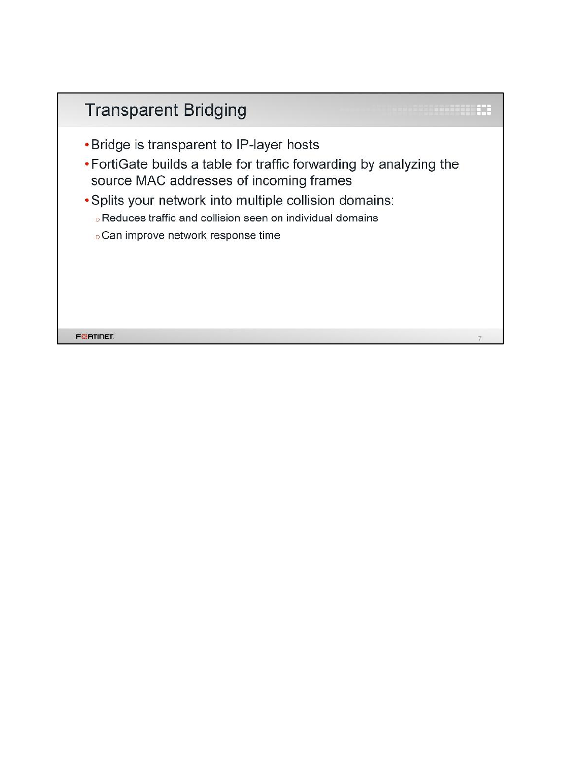
We have mentioned that a transparent mode FortiGate acts as a transparent bridge. What does that
mean?
It means that FortiGate has a MAC address table that contains, among other things, the interface that
must be used to reach each MAC address. FortiGate populates this table with information taken from
the source MAC address of each frame.
FortiGate, as a transparent switch, splits the network into multiple collision domains, reducing the
traffic in the network and improving the response time.
Transparent Mode and Layer 2 Switching
FortiGate II Student Guide
243
DO NOT REPRINT
© FORTINET

In transparent mode, by default, each VDOM forms a separate forward domain. Interfaces, though,
don’t. How does this affect the network?
Until you change the initial VDOM configuration, all interfaces, regardless of their VLAN ID, are part of
the same broadcast domain. FortiGate will broadcast from every interface in the VDOM in order to find
any unknown destination MAC address. On large networks, this could generate massive broadcast
traffic and overwhelming replies – a broadcast storm.
Transparent Mode and Layer 2 Switching
FortiGate II Student Guide
244
DO NOT REPRINT
© FORTINET
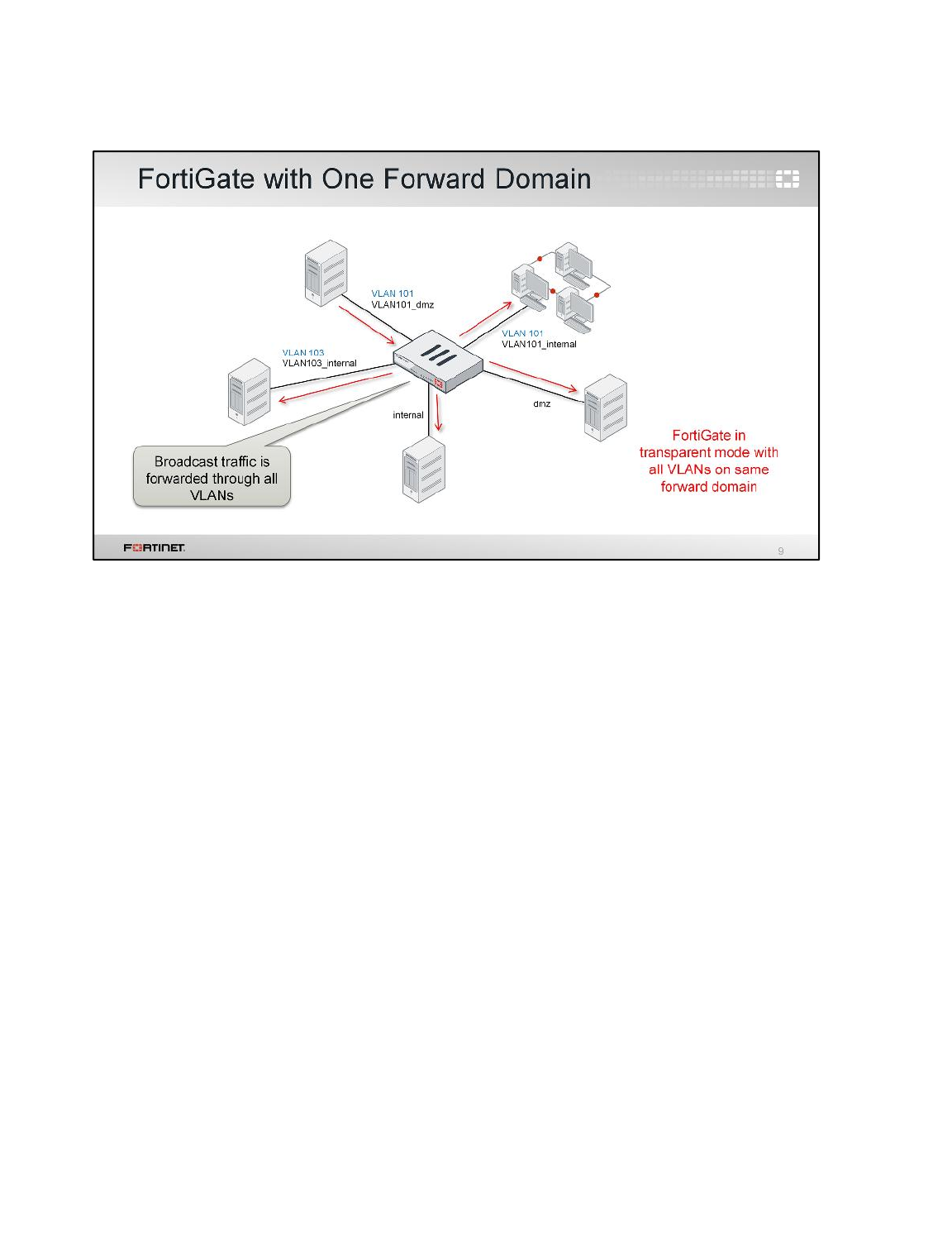
(slide contains animation)
Here’s an illustration of the problem – a broadcast with all the interfaces on the forward domain 0
(default). One device sends an ARP request. It reaches FortiGate through one of the interfaces in the
VDOM.
(click)
Because all interfaces belong to the same forward domain, FortiGate then re-broadcasts to all the
other interfaces, even to interfaces that belong to different VLANs. This generates unnecessary traffic.
After that, the ARP reply will still arrive on only one interface, and FortiGate will learn that the MAC is
on that interface.
Transparent Mode and Layer 2 Switching
FortiGate II Student Guide
245
DO NOT REPRINT
© FORTINET
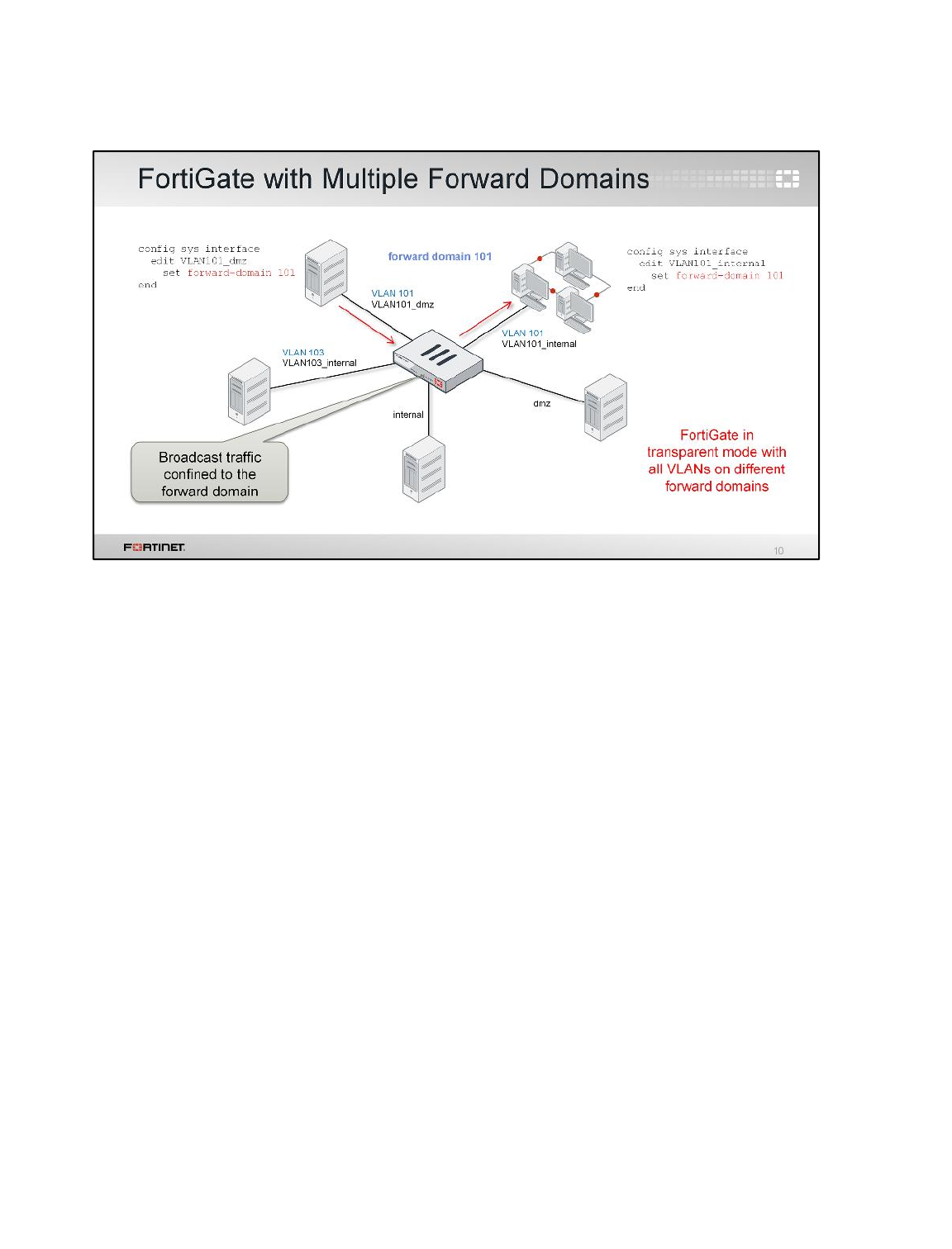
(slide contains animation)
As we explained, forward domains are like broadcast domains.
This example is the same network that we showed before, but here, different forward domain IDs are
assigned to each VLAN.
(click)
Traffic arriving on one interface is only broadcast to interfaces that are in the same forward domain ID.
Transparent Mode and Layer 2 Switching
FortiGate II Student Guide
246
DO NOT REPRINT
© FORTINET

This debug command lists the MAC address table in a VDOM operating in transparent mode. The
table, as we explained before, contains the outbound interfaces to reach each learned MAC address.
Transparent Mode and Layer 2 Switching
FortiGate II Student Guide
247
DO NOT REPRINT
© FORTINET

This section is about virtual wire pairing. As you will see, virtual wire pairing offers another way to
create broadcast domains. With virtual wire pairing, you can also have interface pairs operating like
transparent mode in a NAT/route VDOM.
Transparent Mode and Layer 2 Switching
FortiGate II Student Guide
248
DO NOT REPRINT
© FORTINET
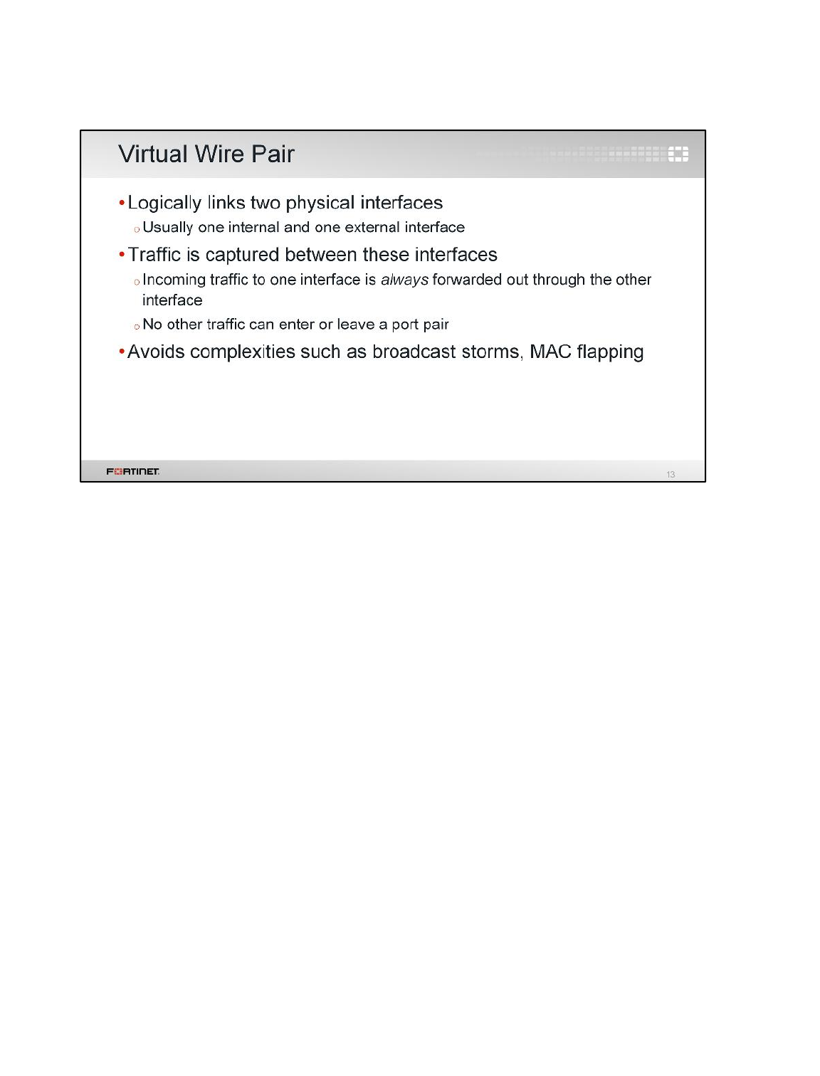
You can use virtual wire pairing when only two physical interfaces need to be connected to the same
broadcast domain. This is usually the case, for example, of a FortiGate connected between the
internal network and the ISP’s router.
When you configure virtual wire pairing, two ports are logically bound or linked, acting like a filtered
cable or pipe. All the traffic that arrived to one port is forwarded to the other port. This avoids issues
related with broadcast storms or MAC address flapping.
You can create more than one port pair in a FortiGate.
Transparent Mode and Layer 2 Switching
FortiGate II Student Guide
249
DO NOT REPRINT
© FORTINET
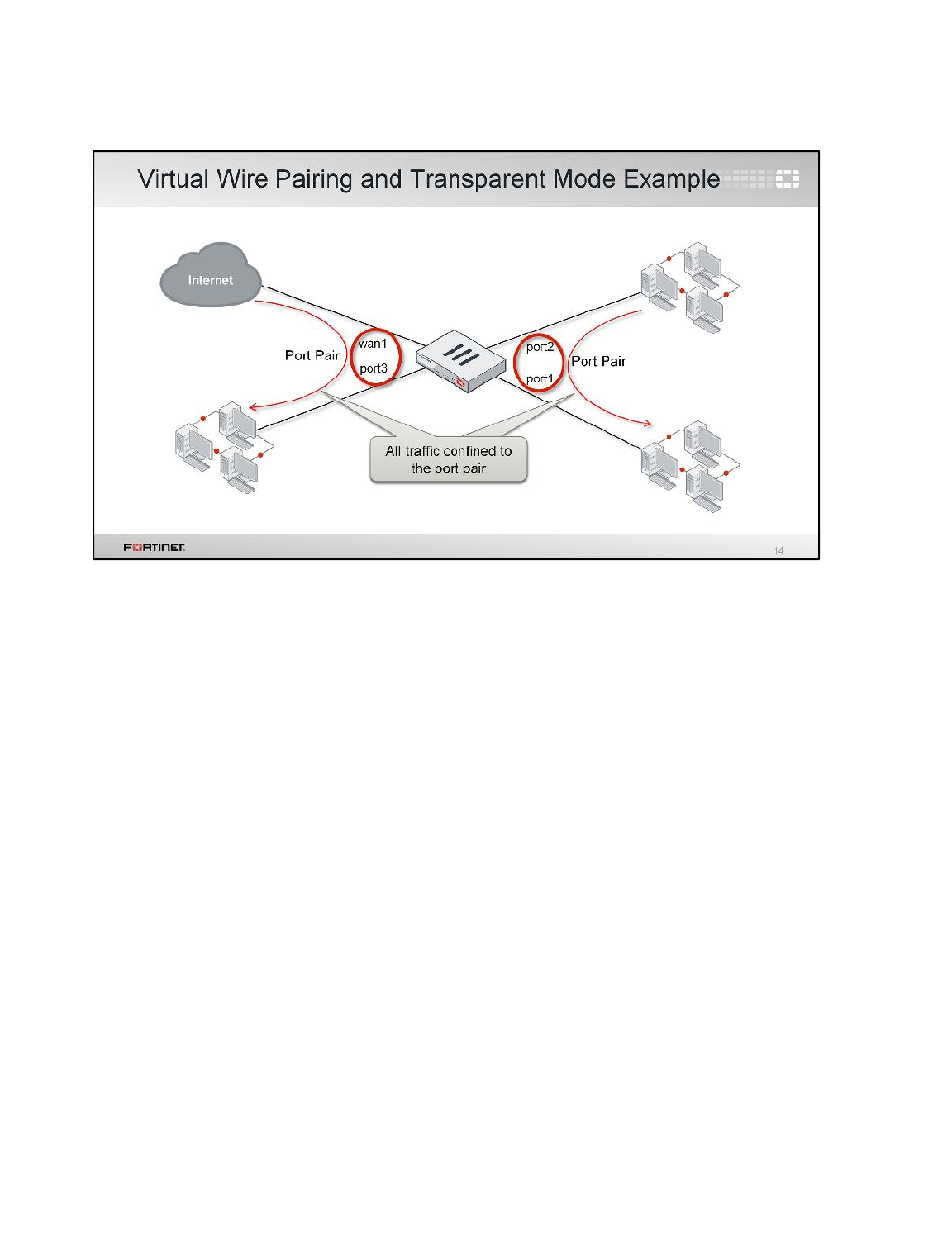
Here’s an example where two virtual wire pairs are used in a FortiGate in transparent mode.
This FortiGate has four ports, each connected to different physical locations. But traffic is not allowed
to flow between all four locations. Virtual wire pairing only allows traffic between ports in the same
pair: between port1 and port2, and between port3 and wan1.
So, in this example, the network on port3 can reach the Internet through wan1. However, the
networks on port2 and port1 can’t reach the Internet. They can only reach each other.
Transparent Mode and Layer 2 Switching
FortiGate II Student Guide
250
DO NOT REPRINT
© FORTINET
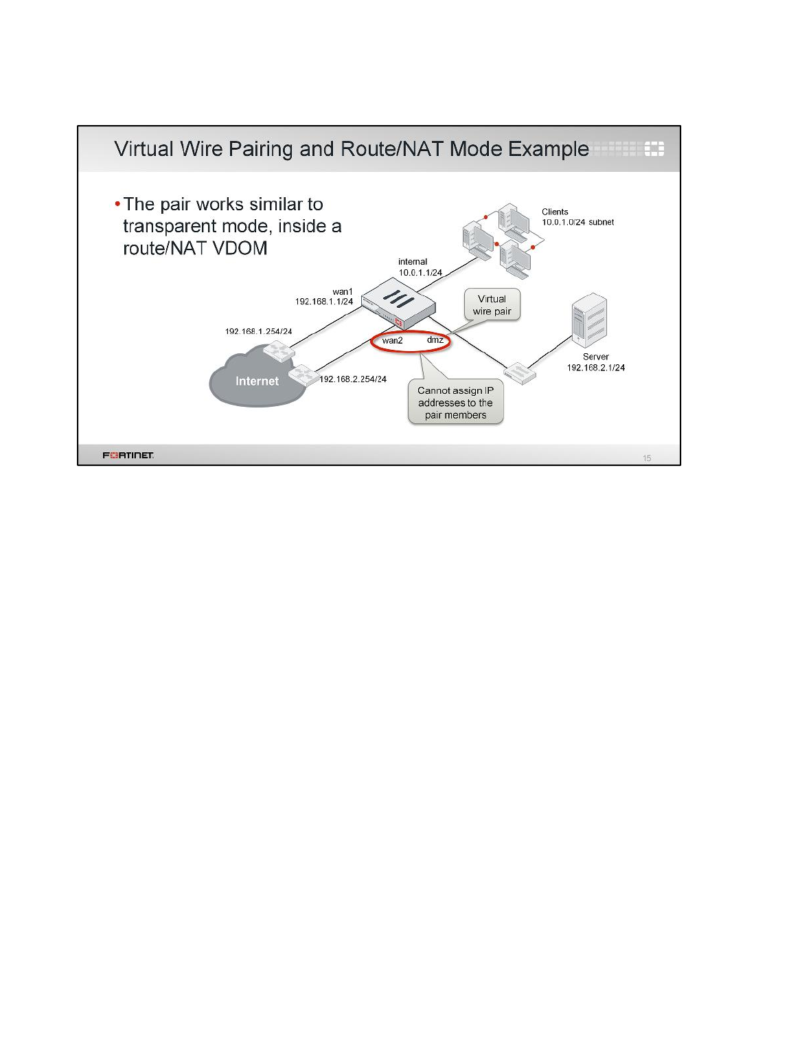
This, on the other hand, is an example of a virtual wire pair in a FortiGate operating in NAT mode. In
this example, IP packets ingressing interfaces wan1 and internal are routed using the IP header
information. Those two interfaces have different IP addresses, and each one forms a separated
broadcast domain.
Now, the case of interfaces wan2 and dmz is different. As they are configured as a virtual port pair,
they don't have IP addresses assigned, and they form one single broadcast domain. Observe the IP
addresses for the server and the router connected to wan2. They must both belong to the same
subnet.
So, virtual wire pairing offers a way to mix NAT/route mode functionalities with some transparent
mode functionalities into the same VDOM.
Transparent Mode and Layer 2 Switching
FortiGate II Student Guide
251
DO NOT REPRINT
© FORTINET
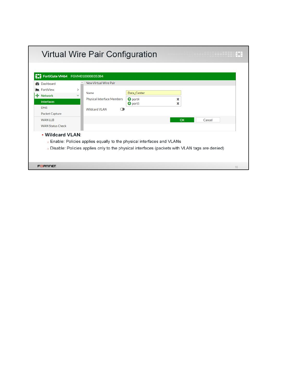
Creating a virtual wire pair requires selecting two physical interfaces, no more, no less.
After that, you create the virtual wire pair policies to inspect the traffic crossing the virtual wire pair.
The Wildcard VLAN setting specifies how to apply those policies to the different VLANs whose traffic
flows between the pair:
• If Wildcard VLAN is enabled, the virtual wire pair policies are applied equally to the physical
interfaces and VLANs' traffic.
• If Wildcard VLAN is disabled, the virtual wire pair policies are applied only to the physical
interfaces. Traffic with any VLAN tag is denied.
Transparent Mode and Layer 2 Switching
FortiGate II Student Guide
252
DO NOT REPRINT
© FORTINET
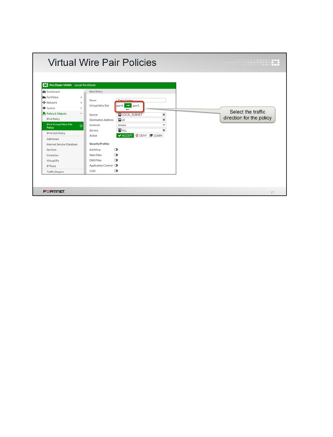
The firewall policies for virtual wire pairing are created under a different menu section. This section is
displayed as long as there is at least one virtual wire pair created.
Transparent Mode and Layer 2 Switching
FortiGate II Student Guide
253
DO NOT REPRINT
© FORTINET
In this section, we will explore software switches. A software switch adds a virtual Layer 2 switch to
the FortiGate configuration.
Transparent Mode and Layer 2 Switching
FortiGate II Student Guide
254
DO NOT REPRINT
© FORTINET
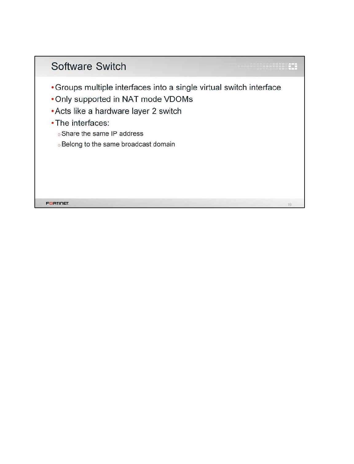
A software switch groups multiple interfaces to form a virtual switch, which acts as a hardware Layer 2
switch. This means that all switch interfaces are part of the same broadcast domain.
Transparent Mode and Layer 2 Switching
FortiGate II Student Guide
255
DO NOT REPRINT
© FORTINET
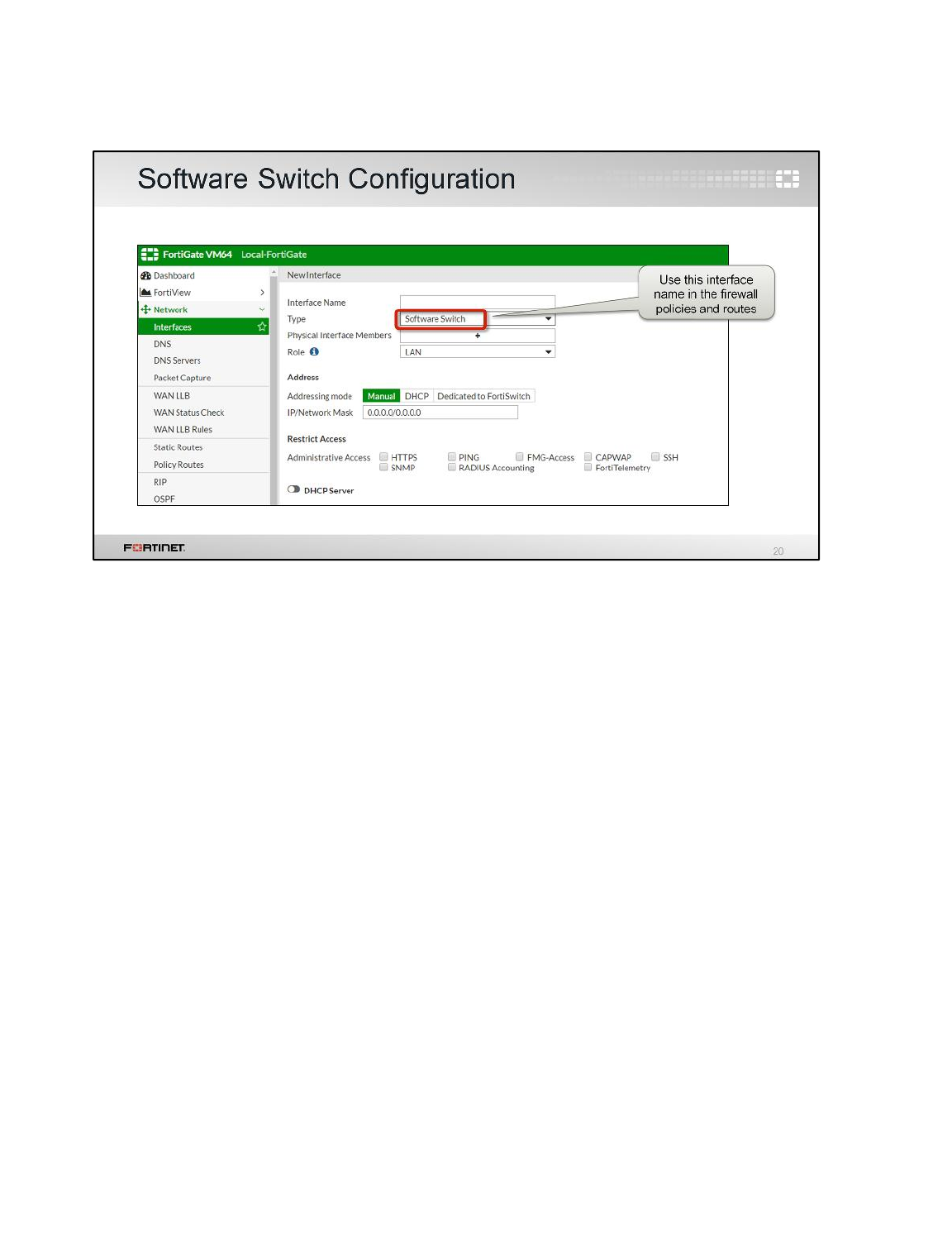
Each software switch has a virtual interface associated with it. Its IP address is shared by all the
physical switch interfaces. You use this virtual interface in the firewall policies and routing
configuration.
Transparent Mode and Layer 2 Switching
FortiGate II Student Guide
256
DO NOT REPRINT
© FORTINET
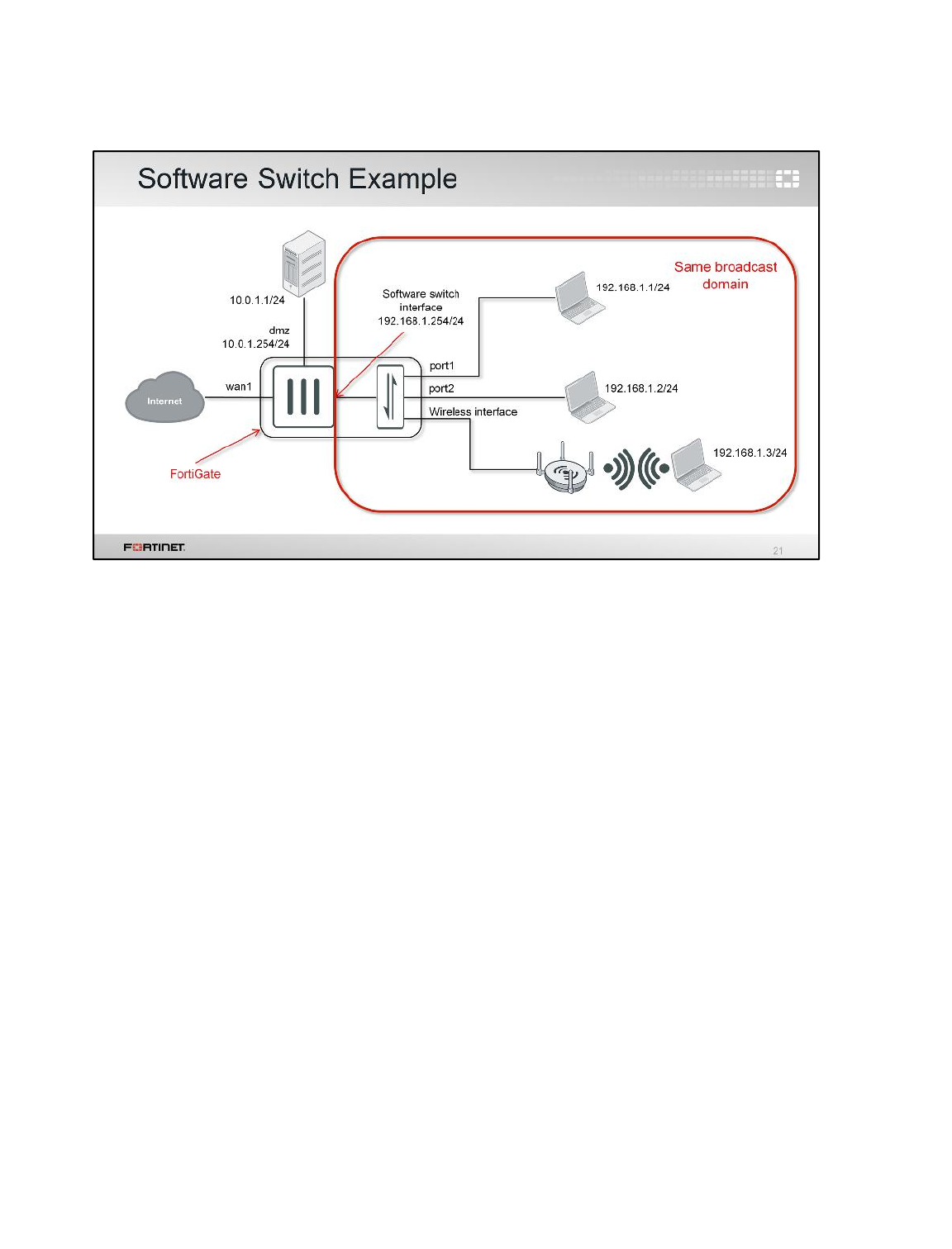
In this example, the administrator grouped a wireless interface with port1 and port2 to form a
software switch. These three interfaces are part of the same broadcast domain. All the devices
connected to the switch interfaces belong to the same IP subnet 192.168.1.0/24. This allows
FortiGate, for example, to forward broadcast traffic from the wireless clients to port1 and port2.
The software switch interface itself has an IP address, which is also in the same subnet
192.168.1.0/24. This is the default gateway IP address for all the devices connected to the software
switch.
The server 10.0.1.1 is connected to an interface (dmz) that is not part of the software switch. So, it
belongs to a different broadcast domain and IP subnet.
Transparent Mode and Layer 2 Switching
FortiGate II Student Guide
257
DO NOT REPRINT
© FORTINET

This section is about FortiGate devices in Layer 2 networks running spanning tree protocol.
Transparent Mode and Layer 2 Switching
FortiGate II Student Guide
258
DO NOT REPRINT
© FORTINET
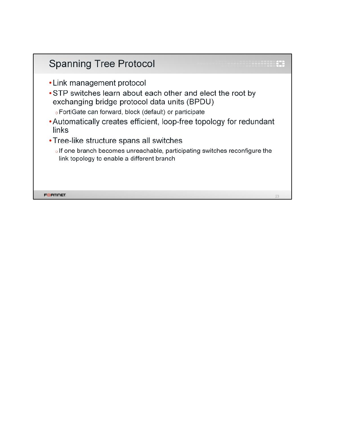
Spanning tree protocol automatically ensures that there are no Layer 2 loops. By default, FortiGate
does not participate in STP learning, nor forward BPDUs. But you can enable it. (You must still restrict
broadcast domains so that they are not overwhelmingly large, though)
Transparent Mode and Layer 2 Switching
FortiGate II Student Guide
259
DO NOT REPRINT
© FORTINET
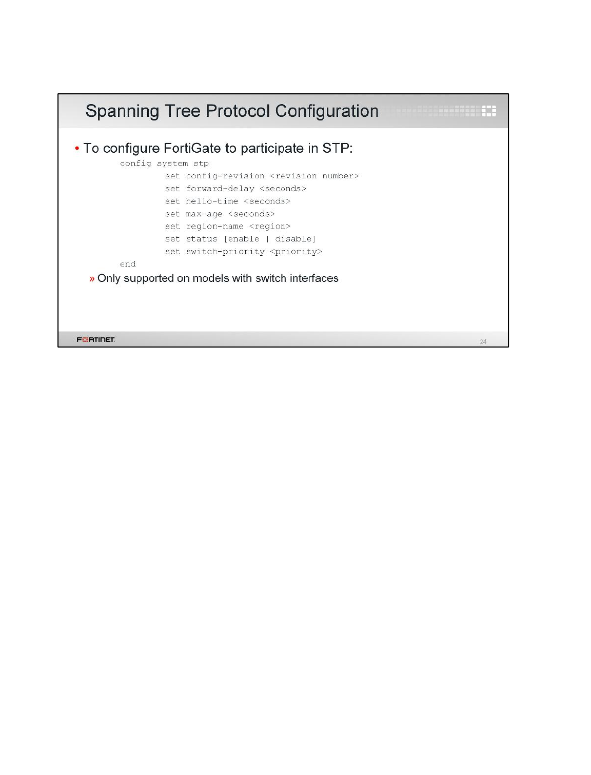
To enable FortiGate to participate in the STP tree, use the config system stp command in the
CLI.
Note that this is only supported on models with physical switch interfaces, such as FortiGate 30D,
60C, 60D, 80C, and 90D.
Transparent Mode and Layer 2 Switching
FortiGate II Student Guide
260
DO NOT REPRINT
© FORTINET
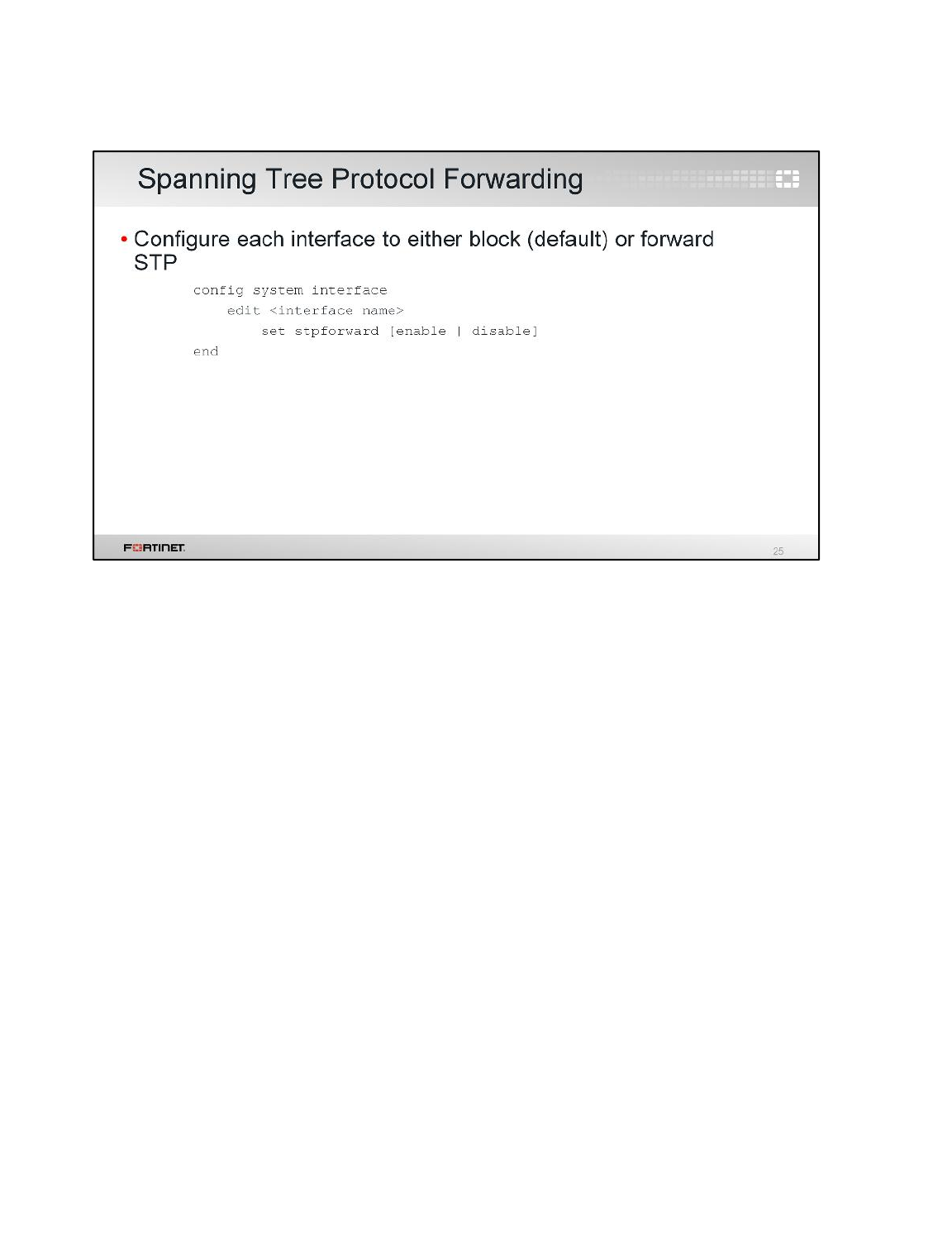
For interfaces that are not physical switch interfaces, you can either forward or block STP BPDUs.
Transparent Mode and Layer 2 Switching
FortiGate II Student Guide
261
DO NOT REPRINT
© FORTINET
This is a review of the topics we covered:
• Transparent mode and NAT mode
• Forward domains
• MAC address table monitoring
• Virtual wire pairing
• Software switch
• STP configuration
Transparent Mode and Layer 2 Switching
FortiGate II Student Guide
262
DO NOT REPRINT
© FORTINET

In this lesson, you’ll learn the fundamentals of FortiGate high availability (HA) and how to configure it.
FortiGate HA provides a solution for enhanced reliability and increased performance.
High Availability
FortiGate II Student Guide
263
DO NOT REPRINT
© FORTINET
After completing this lesson, you should have the practical skills required to configure, operate, and
monitor a FortiGate HA cluster.
Lab exercises can help you to test and reinforce your skills.
High Availability
FortiGate II Student Guide
264
DO NOT REPRINT
© FORTINET
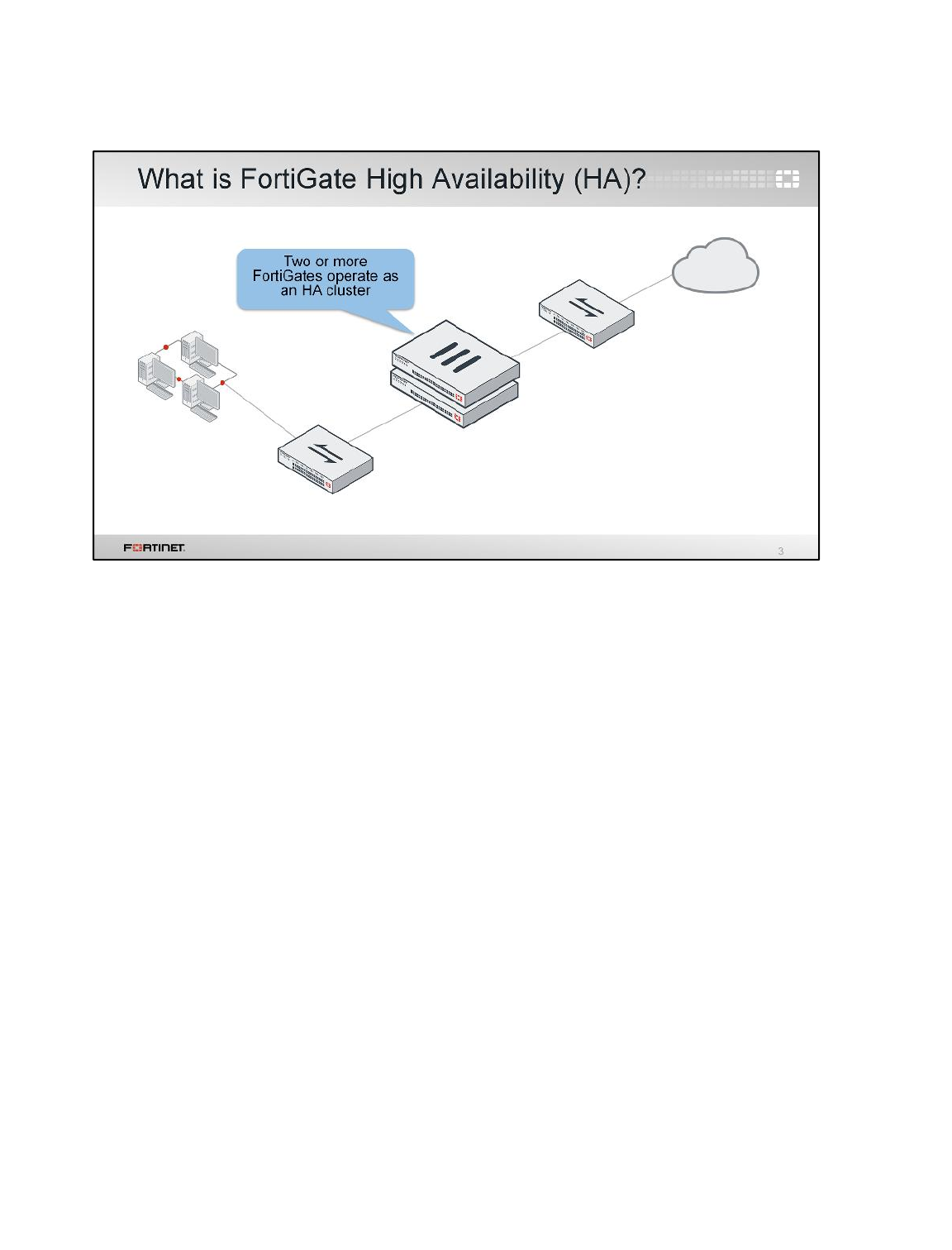
The idea of HA is simple. HA links and synchronizes two or more devices.
In FortiGate HA, one FortiGate device acts as the primary appliance (also called the active FortiGate).
It synchronizes its configuration to the other devices. The other FortiGates are called secondary or
standby devices.
A heartbeat link between all the appliances is used to detect unresponsive devices.
What is synchronized between the devices? Are all FortiGate devices processing traffic? Does HA
improve availability, or does it improve throughput?
The answers vary depending on the HA mode. There are currently two HA modes available: active-
active and active-passive. Let’s examine the differences.
High Availability
FortiGate II Student Guide
265
DO NOT REPRINT
© FORTINET
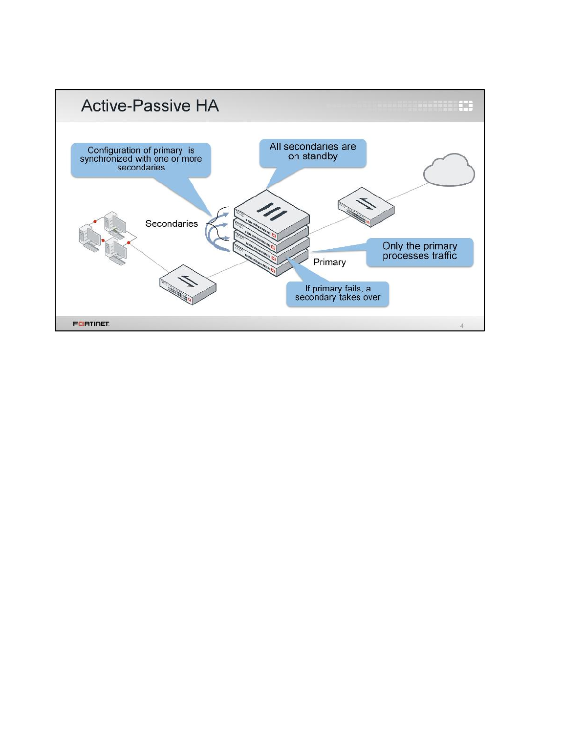
(slide contains animation)
First, let's take a look at active-passive mode. In either of the two HA operation modes, the
configuration of the secondary FortiGates is synchronized with the configuration of the primary device.
(click)
In active-passive mode, the primary FortiGate is the only FortiGate device that actively processes
traffic. Secondary FortiGates remain in passive mode, monitoring the status of the primary device.
(click)
If a problem is detected in the primary FortiGate, one of the secondary devices will take over the
primary role. This event is what we call HA failover.
High Availability
FortiGate II Student Guide
266
DO NOT REPRINT
© FORTINET
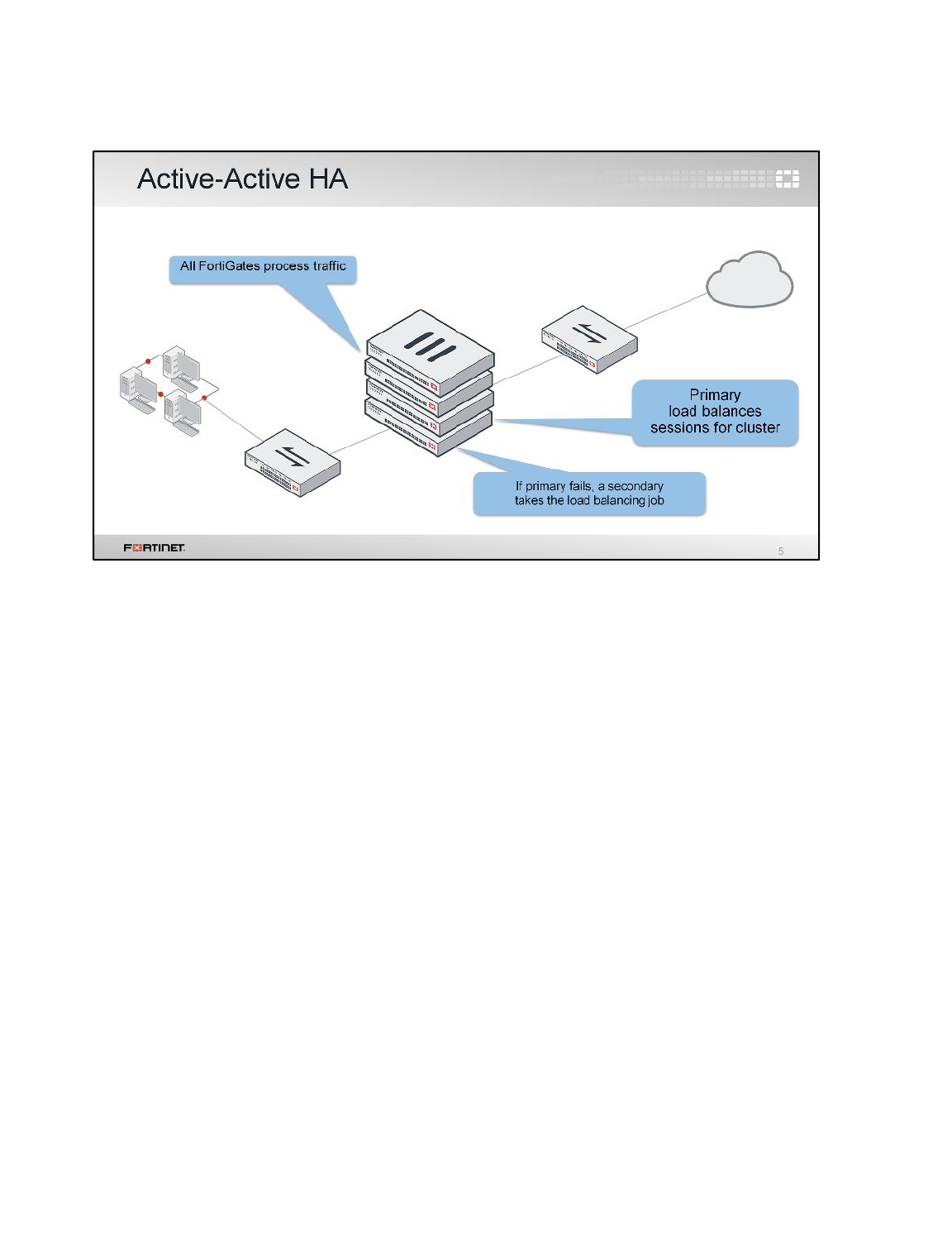
The other HA mode is called active-active.
Like active-passive HA, in active-active HA, all FortiGates’ configurations are synchronized. Also, if a
problem is detected in the primary device, one of the secondaries will take over the role of the primary,
to process the traffic.
However, one of the main differences in the active-passive mode is that in the active-active mode, all
of the FortiGates are processing traffic. One of the tasks of a primary FortiGate in active-active mode
is to balance some of the traffic among all the secondary devices.
High Availability
FortiGate II Student Guide
267
DO NOT REPRINT
© FORTINET
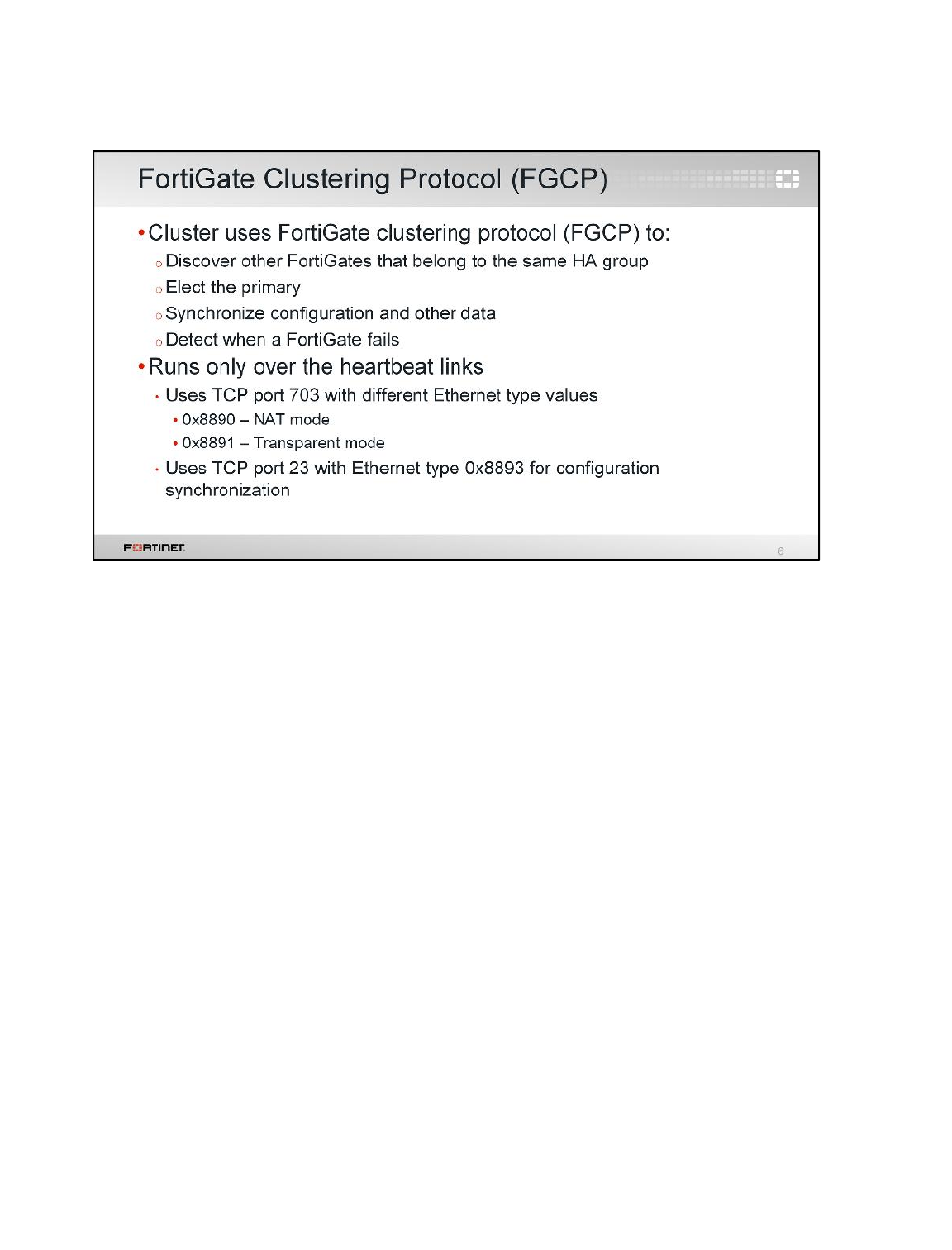
So how do the FortiGate devices in an HA cluster communicate?
FortiGate HA uses FGCP, the FortiGate clustering protocol, for HA-related communications. FGCP
travels between the clustered FortiGate devices over the links that you have designated as the
heartbeats.
A heartbeat link between the two FortiGate devices should be achieved using a regular RJ45 or
crossover cable. If you have another device in between, such as a switch, ensure that it is dedicated
and isolated from the rest of your network. In this way, critical FGCP traffic does not need to compete
with the other traffic for bandwidth.
NAT mode cluster and transparent mode cluster use different Ethernet type values to discover and
verify the status of other FortiGates in an operating cluster.
FortiGates in a cluster also use telnet sessions over TCP port 23 with Ethernet type 0x8893 over
heartbeat links to synchronize the cluster configuration and to connect to the CLI of another FortiGate
in a cluster.
High Availability
FortiGate II Student Guide
268
DO NOT REPRINT
© FORTINET
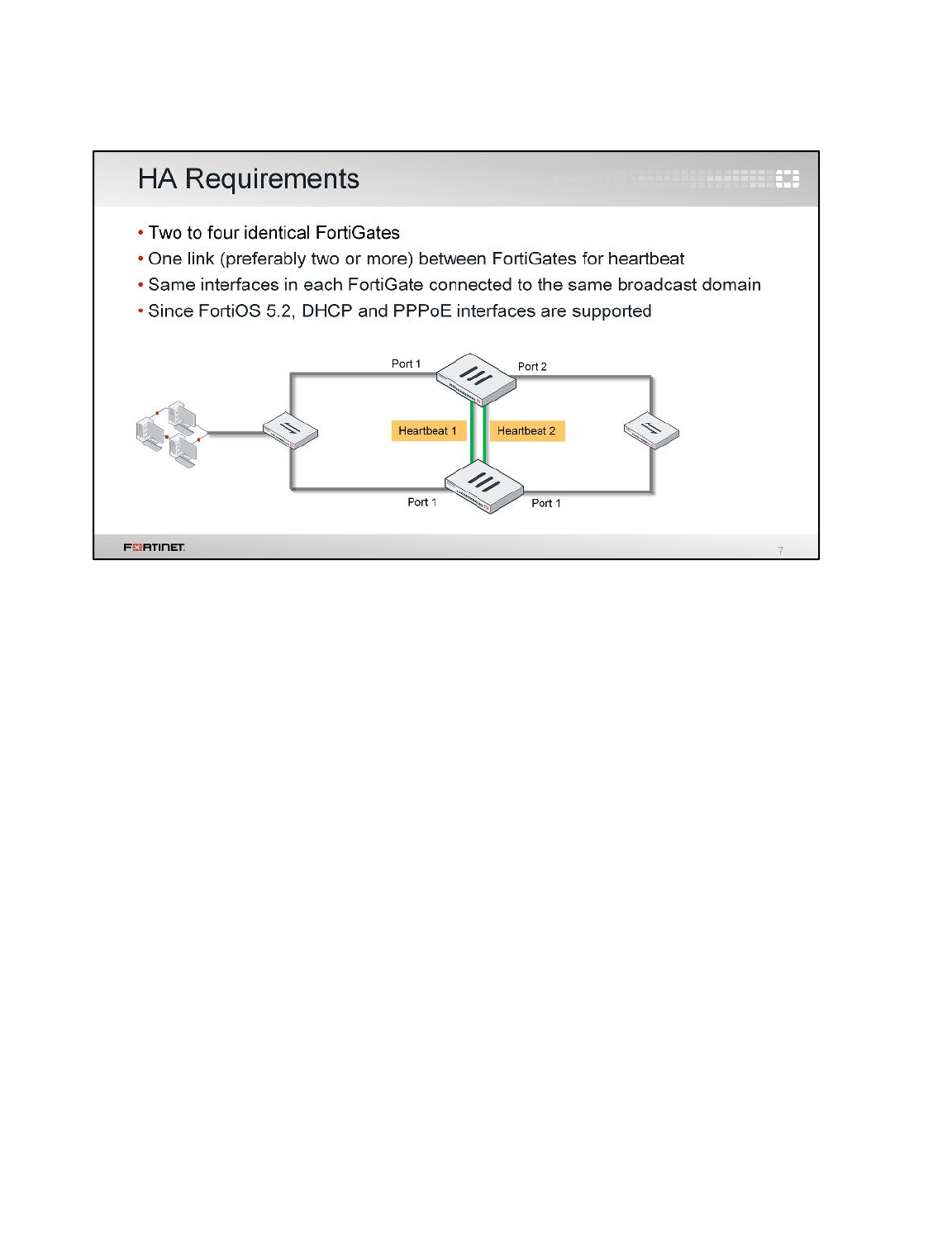
FortiGate HA configuration requires the following devices and set up.
First, at least two, but up to four, FortiGate devices with the same:
• Firmware
• Hardware model and VM license
• Hard drive capacity and partitions
• Operating mode (transparent or NAT)
Second, at least one link between the FortiGate devices for the HA communication, which is called
heartbeat traffic. For redundancy, up to eight heartbeat interfaces can be used. If one link fails, HA will
use the next one, as indicated by priority and position in the heartbeat interface list.
Third, the same interfaces on each FortiGate device have to be connected to the same switch or LAN
segment. Notice that in the example shown in the slide, the FortiGate devices are redundant to
mitigate failure. But, the switches and their links still are a single point of failure. As we will see later,
you can also have redundancy in the network switches and links.
One important change in HA, is that now the cluster can include interfaces whose IP addresses are
assigned dynamically, through either DHCP or PPPoE. Prior to FortiOS 5.2, an HA cluster could only
contain interfaces with static IP addresses. As a best practice (and Fortinet recommendation),
configure the FortiGate interfaces with static IP addresses when forming an HA cluster. Once an HA is
formed, you can configure the DHCP or PPPoE addressing for an interface. If an interface is
configured for DHCP or PPPoE, enabling HA may result in the interface receiving an incorrect
address, or not being able to connect to the DHCP or PPPoE server correctly.
High Availability
FortiGate II Student Guide
269
DO NOT REPRINT
© FORTINET
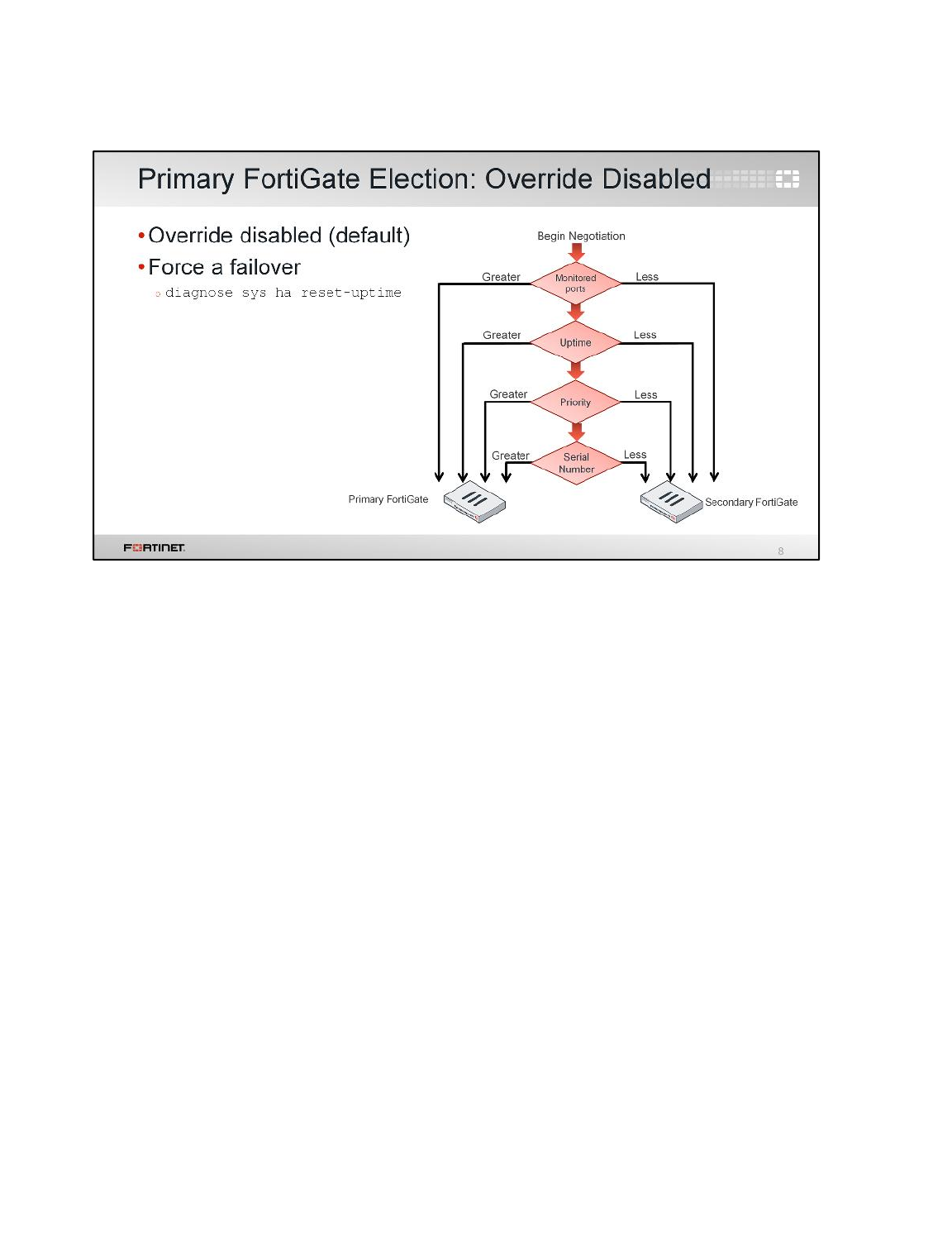
The process for electing the primary FortiGate depends on an HA setting called HA override. This
slide shows the process and selection criteria that a cluster uses to elect the primary FortiGate when
the HA override setting is disabled, which is the default behavior.
Note:The selection process stops at the first matching criteria that successfully selects a primary
FortiGate in a cluster.
1. The cluster first compares the number of monitored interfaces whose statuses are up. The
FortiGate device with the most available monitored interfaces becomes the primary.
2. The cluster compares the system uptimes. If the system uptime of a device is five minutes more
than the system uptimes of the other FortiGates, it becomes the primary.
3. The FortiGate with the configured highest priority becomes the primary.
4. The cluster chooses the primary by comparing the serial numbers.
When HA override is disabled, the uptime has precedence over the priority setting. If for any reason
you need to change which device is the current primary, you can manually force a failover event.
When the override setting is disabled, the easiest way of doing this is by executing the CLI command
diagnose sys ha reset-uptime in the primary FortiGate.
Note:The reset-uptime command resets the HA age internally and does not affect the up time
displayed on the dashboard of a FortiGate. Also, if a monitored interface fails, or a FortiGate in a
cluster reboots, the HA uptime for that FortiGate is reset to 0.
High Availability
FortiGate II Student Guide
270
DO NOT REPRINT
© FORTINET
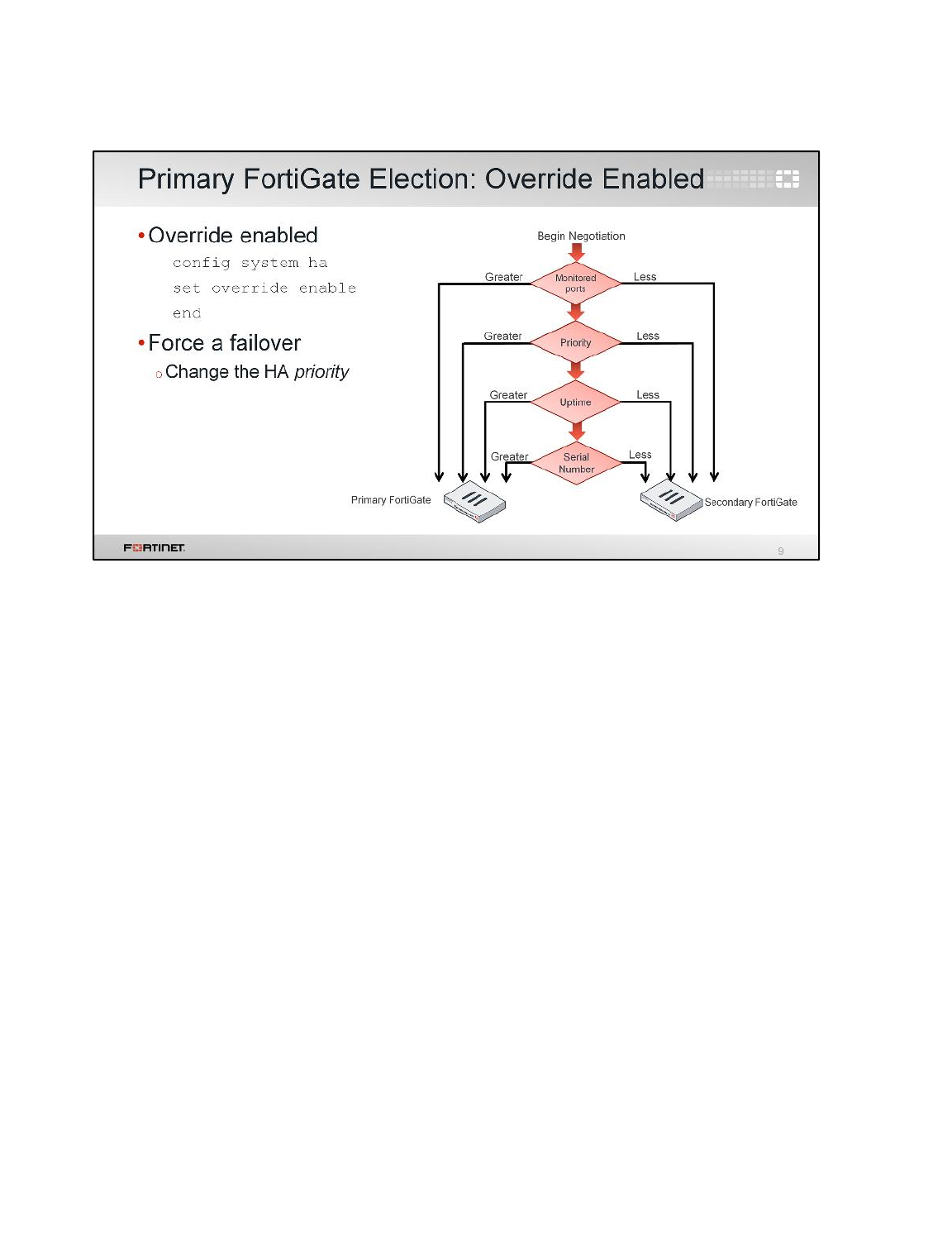
You can alter the order of the selection criteria that clusters consider when electing the primary
FortiGate.
If the HA override setting is enabled, priority is considered before the system uptime.
The advantage of this method is that you can specify which device is the preferred primary every time
(as long as it is up and running) by configuring it with the highest HA priority value. The disadvantage
is that a failover event is triggered not only when the primary fails, but also when the primary is
available again. When a primary becomes available again, it takes back its primary role from the
secondary FortiGate that temporarily replaced it.
Note:The selection process stops at the first matching criteria that successfully selects a primary
FortiGate in a cluster.
When override is enabled, the easiest way of triggering a failover is to change the HA priorities. For
example, you can either increase the priority in one of the secondaries, or decrease the priority in the
primary.
The override setting and device priority values are not synchronized to all cluster members. You must
enable override and adjust device priority manually and separately for each cluster member.
High Availability
FortiGate II Student Guide
271
DO NOT REPRINT
© FORTINET
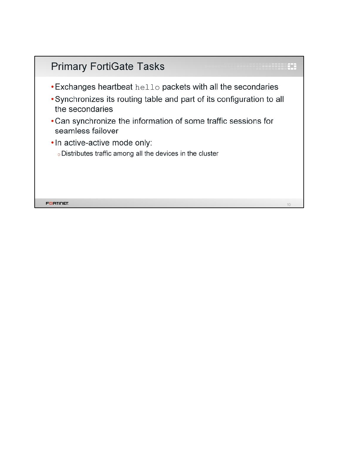
So, what are the tasks of a primary FortiGate?
It monitors the cluster by sending hello signals and listening for replies, to determine if each other
FortiGate is alive and available. It also synchronizes its routing table and part of its configuration to the
other devices.
You can optionally configure the primary FortiGate to synchronize some traffic session information to
all the secondary devices. This allows a faster and seamless failover for some sessions. Some
customers will not need to reestablish their sessions after a failure of a primary FortiGate. We will
discuss which session information can be synchronized later in the lesson.
In active-active mode only, a primary FortiGate also distributes traffic among all the available devices
in the cluster.
High Availability
FortiGate II Student Guide
272
DO NOT REPRINT
© FORTINET
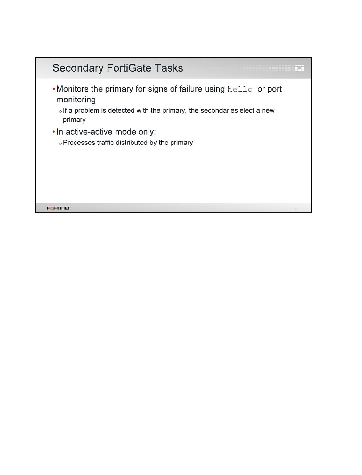
Now, let's take a look at the tasks of secondary FortiGates.
If the mode is active-passive, the secondaries will simply wait, receiving synchronization data but not
actually processing any traffic. If the primary FortiGate fails, the secondaries will elect a new primary.
In active-active mode, the secondaries don’t wait passively. They process all traffic assigned to them
by the primary device.
High Availability
FortiGate II Student Guide
273
DO NOT REPRINT
© FORTINET
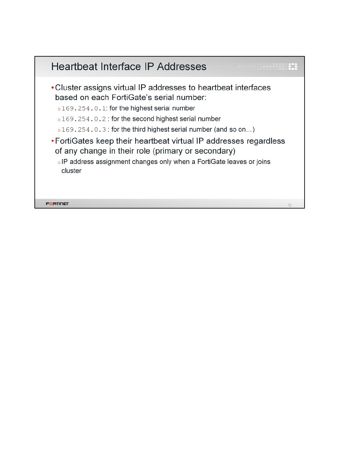
What about the heartbeat interfaces?
You don’t need to configure them. FGCP will automatically negotiate the heartbeat IP addresses
based on each device’s serial number. The IP address 169.254.0.1 is assigned to the device with the
highest serial number. The IP address 169.254.0.2 is assigned to the device with the second highest
serial number, and so on. The IP address assignment does not change when a failover happens.
Regardless of the device role at any time (primary or secondary), its heartbeat virtual IP address
remains the same.
A change in the heartbeat IP addresses might happen, when a FortiGate device joins or leaves the
cluster. In those cases, the cluster renegotiates the heartbeat IP address assignment, this time taking
into account the serial number of any new device, or removing the serial number of any device that left
the cluster.
High Availability
FortiGate II Student Guide
274
DO NOT REPRINT
© FORTINET
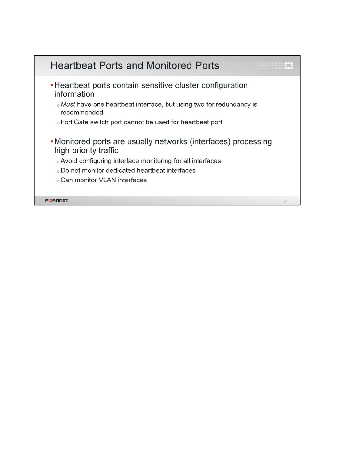
There are a few items that need to be considered when connecting heartbeat interfaces and
configuring interface monitoring:
• Heartbeat ports contain sensitive information about cluster configuration and require a fair amount
of bandwidth to make sure cluster configurations are in a synchronized state at all times. You must
have atleast one port for the heartbeat traffic, preferably two.
Note:Heartbeat communication can be enabled for physical interfaces, but not for VLAN
subinterfaces, IPsec VPN interfaces, redundant interfaces, 802.3ad aggregate interfaces, or FortiGate
switch ports.
• You should configure interface monitoring only for those ports whose failure should trigger a device
failover (for example, high-priority traffic ports). You should not configure port monitoring for
dedicated heartbeat ports.
High Availability
FortiGate II Student Guide
275
DO NOT REPRINT
© FORTINET
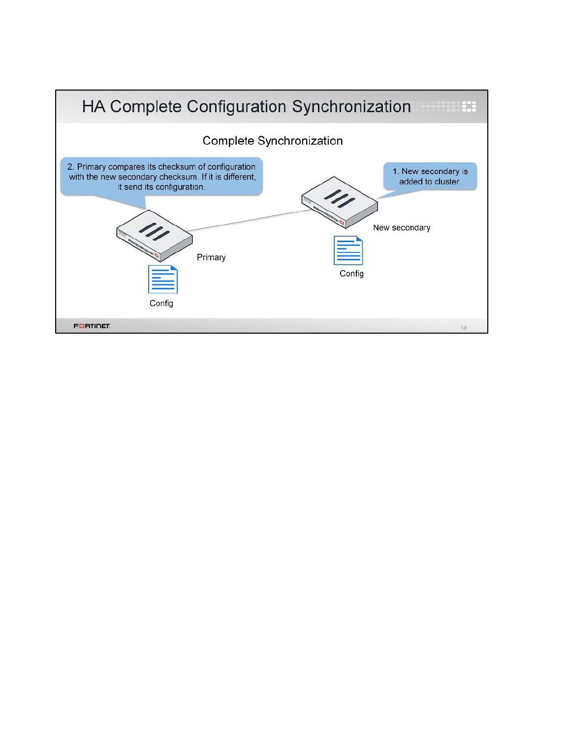
To prepare for a failover, an HA cluster keeps its configurations in sync. Let’s take a look at that now.
FortiGate HA uses a combination of both incremental and complete synchronizations.
When a new FortiGate is added to the cluster, the primary FortiGate compares its configuration
checksum with the new secondary FortiGate configuration checksum. If the checksums don't match,
the primary FortiGate uploads its complete configuration to the secondary FortiGate.
High Availability
FortiGate II Student Guide
276
DO NOT REPRINT
© FORTINET
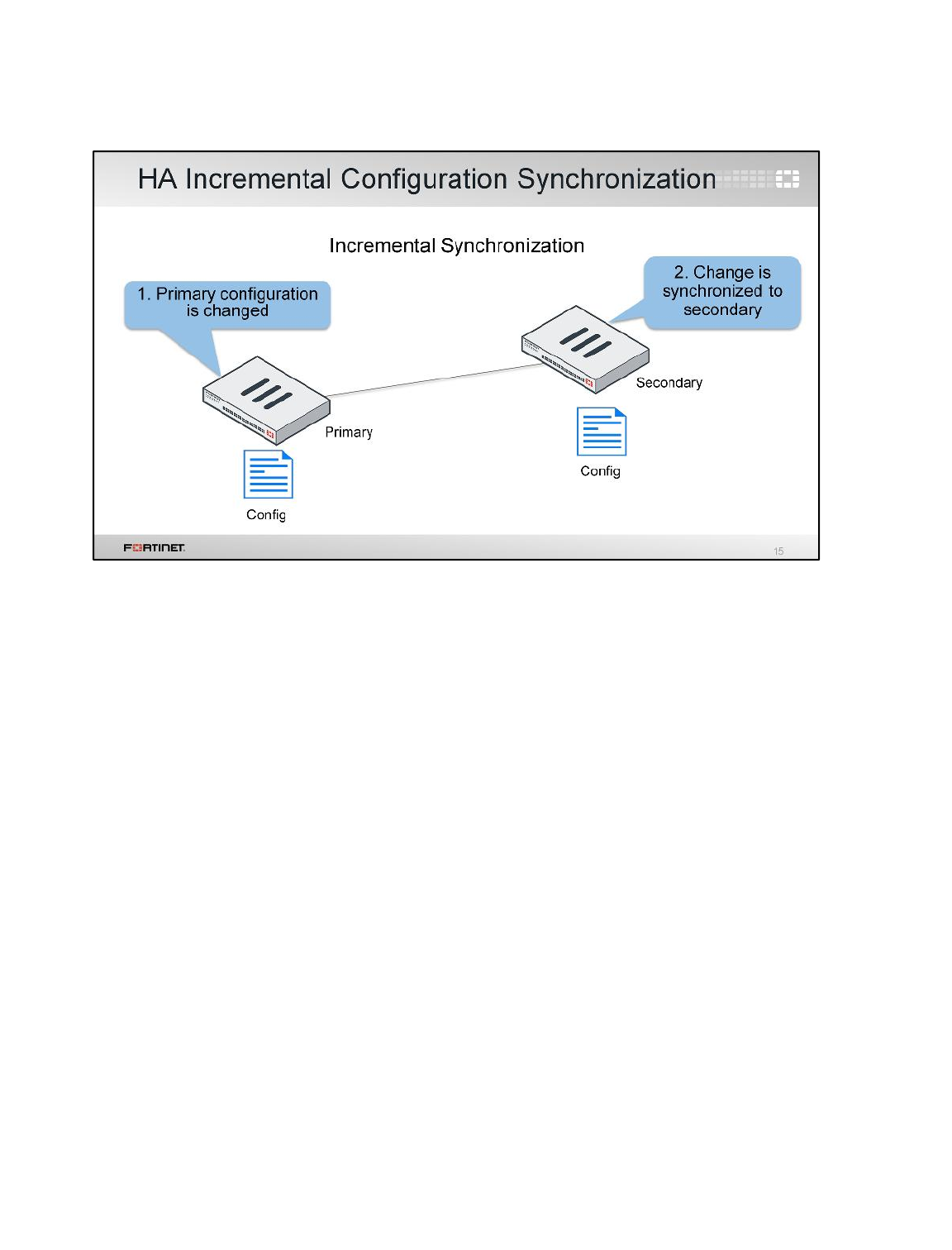
After the initial synchronization is complete, the primary will send any further configuration changes
done by an administrator to all the secondaries. For example, if you create a firewall address object,
the primary doesn’t resend its complete configuration, it sends just the new object.
High Availability
FortiGate II Student Guide
277
DO NOT REPRINT
© FORTINET
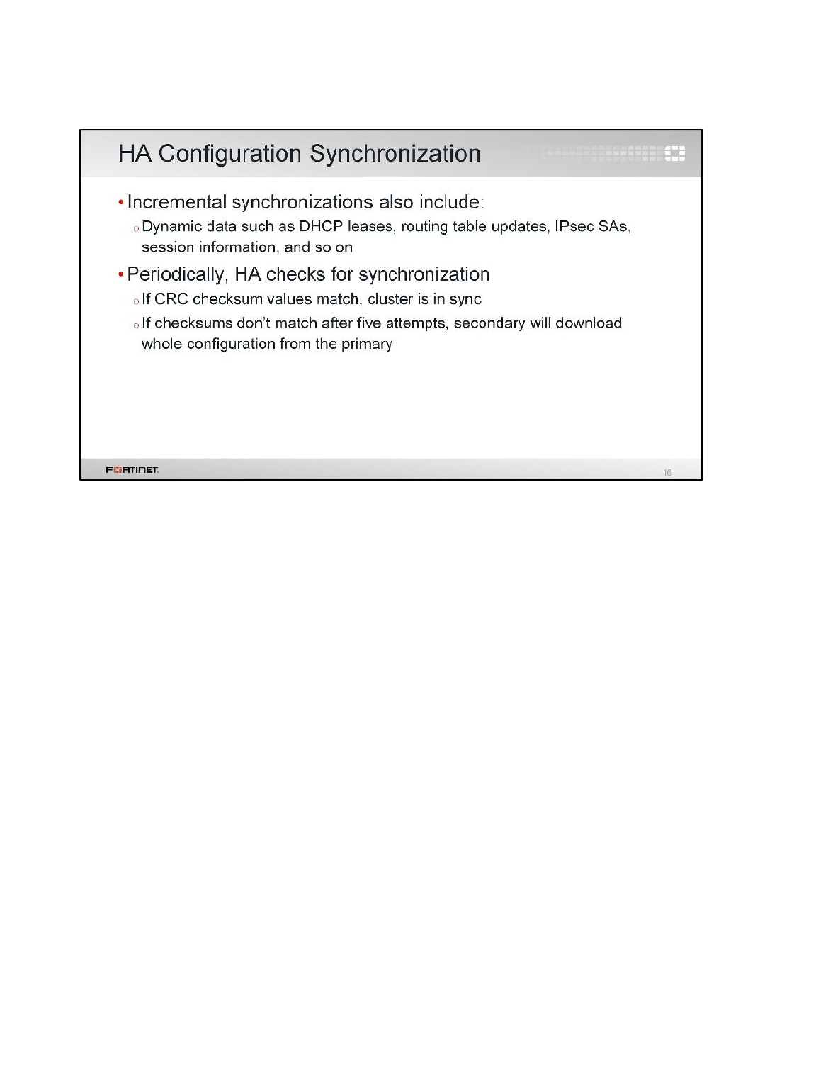
HA propagates more than just configuration details. Some runtime data, such as DHCP leases and
routing tables, are also synchronized.
By default, the cluster checks every 60 seconds to ensure that all devices are synchronized. If any
secondary is out of sync, the checksum of secondary devices is then checked every 15 seconds. If
checksums don’t match for five consecutives checks, a complete re-synchronization is done.
High Availability
FortiGate II Student Guide
278
DO NOT REPRINT
© FORTINET
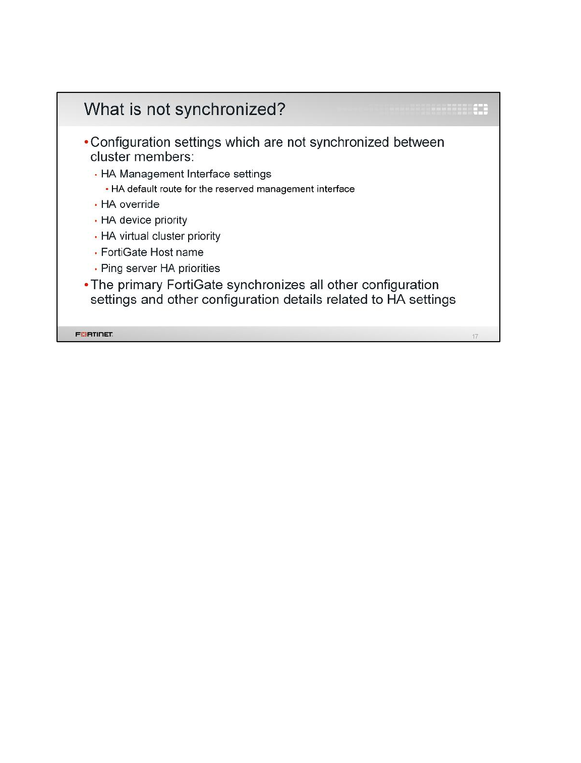
Not all the configuration settings are synchronized. There are a few that are not, such as:
• The system interface settings of the HA reserved management interface and the HA default route
for the reserved management interface
• HA override
• HA device priority
• The virtual cluster priority
• The FortiGate host name
• The HA priority setting for a ping server (or dead gateway detection) configuration
The primary FortiGate synchronizes all other configuration settings, including other configurations
related to HA settings.
High Availability
FortiGate II Student Guide
279
DO NOT REPRINT
© FORTINET
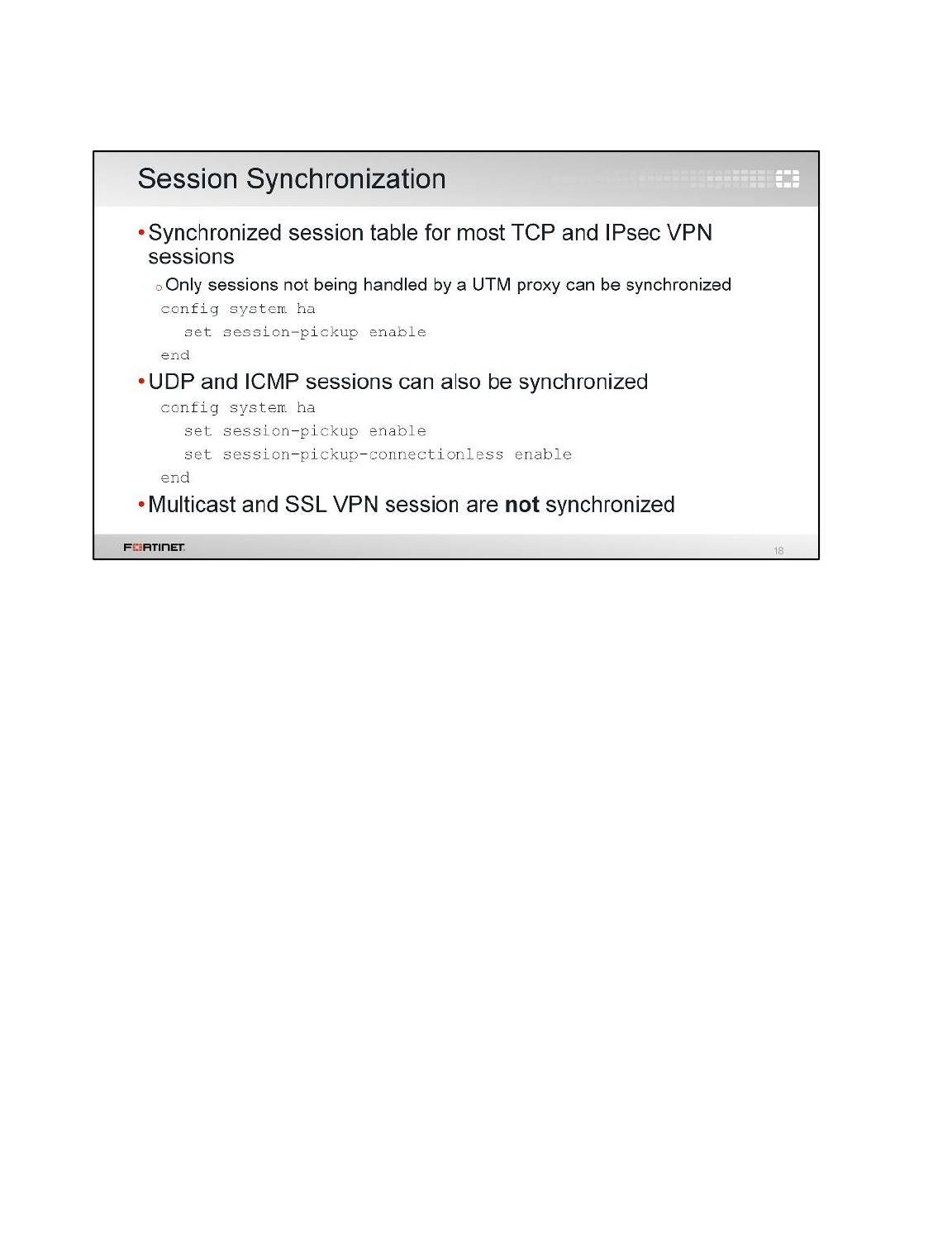
Session synchronization enables seamless failover for some traffic. The information of some sessions
is synchronized, so when the primary fails, the new primary can take over those sessions where they
were left and keep them open. Traffic might be interrupted for a few seconds, but the network
applications don’t need to reconnect the sessions again.
By default, once session synchronization is enabled, the device synchronizes TCP and IPsec VPN
sessions that comply with one requirement: they are not handled by a UTM proxy, such as antivirus or
web filtering.
You can optionally enable the synchronization of UDP and ICMP sessions. Although both protocols
are session-less, entries are created in the FortiGate session table for each UDP and ICMP traffic
flow. Usually, this synchronization is not required, because most of the network applications based on
UDP or ICMP are able to keep the communication even when their session information is lost.
Synchronization of multicast and SSL VPN sessions is not supported.
High Availability
FortiGate II Student Guide
280
DO NOT REPRINT
© FORTINET
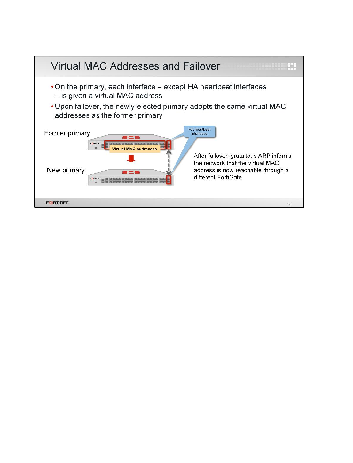
To forward traffic correctly, a FortiGate HA solution uses virtual MAC addresses.
When a primary joins an HA cluster, each interface is given a virtual MAC address.
Through the heartbeats, the primary informs all secondaries about the assigned virtual MAC address.
Upon failover, a secondary adopts the same virtual MAC addresses for the equivalent interfaces.
The new primary broadcasts gratuitous ARP packets, notifying the network that each virtual MAC
address is now reachable through a different switch port.
High Availability
FortiGate II Student Guide
281
DO NOT REPRINT
© FORTINET
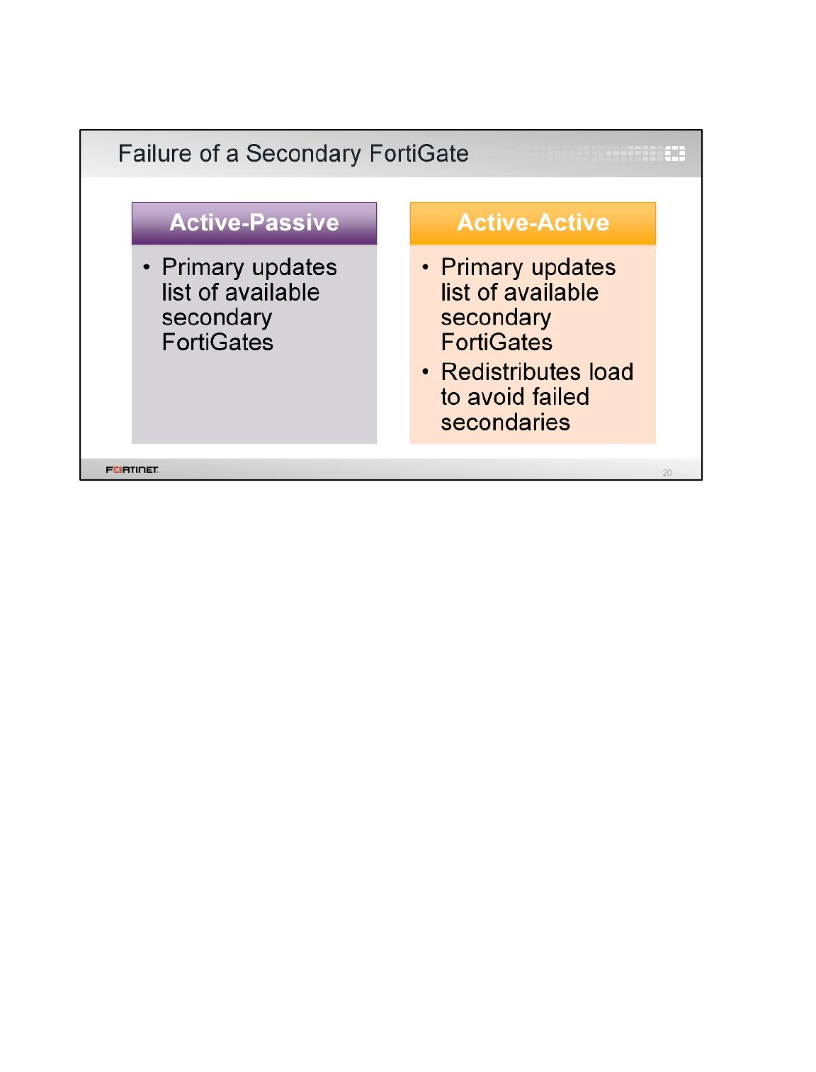
As already explained, if a primary fails, a new primary is elected. But what happens if a secondary
FortiGate device fails? It depends on the HA mode.
In an active-passive cluster, the primary only updates its list of available secondary FortiGates. It also
starts monitoring for the failed secondary, waiting for it to come online again.
In an active-active cluster though, all secondaries are handling traffic. So the primary (which tracks
and assigns sessions to each secondary) must not only update its list of available secondary
FortiGates, but it must also reassign sessions from the failed FortiGate device to a different secondary
FortiGate.
High Availability
FortiGate II Student Guide
282
DO NOT REPRINT
© FORTINET
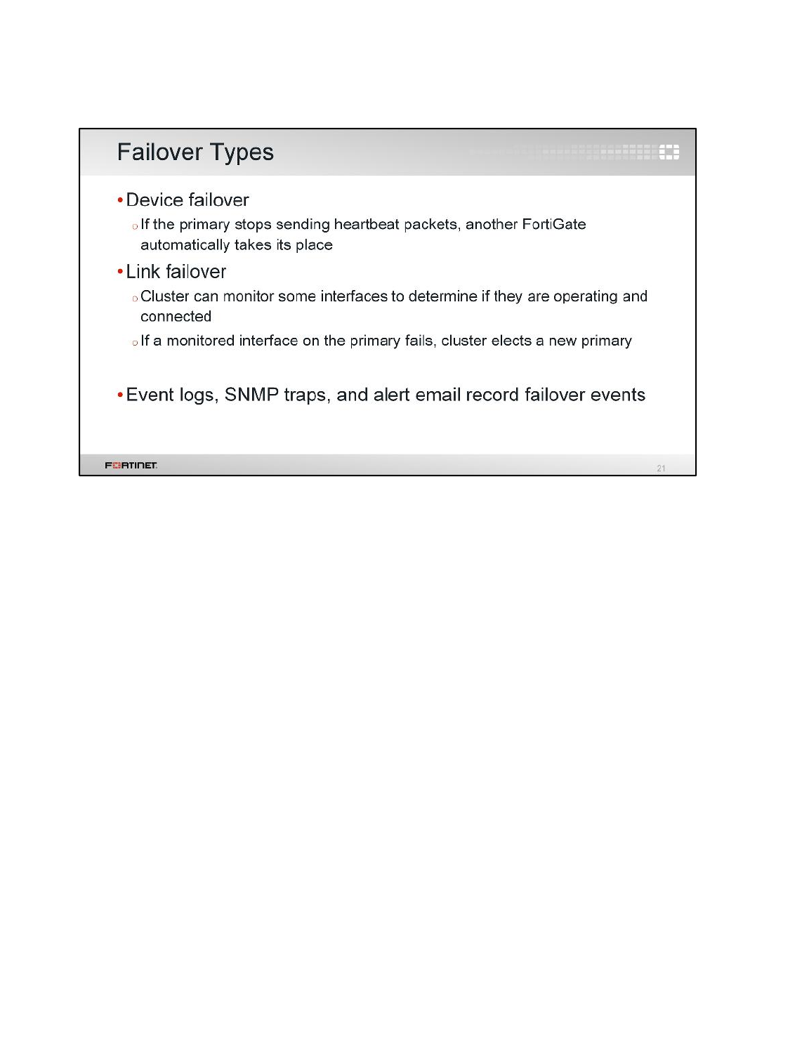
The most common types of failovers are device failovers and link failovers.
A device failover is basically triggered when the primary FortiGate stops sending heartbeat traffic.
When this happens, the secondaries renegotiate a new primary.
A link failover occurs when the link status of a monitored interface on the primary FortiGate goes
down. You can configure an HA cluster to monitor the link status of some interfaces. If a monitored
interface on the primary FortiGate is unplugged, or its link status goes down, a new primary FortiGate
is elected.
There are multiple events that might trigger an HA failover, such as hardware or software failure in the
primary FortiGate or an issue in one of the primary’s interfaces. When a failover occurs, an event log
is generated. Optionally, the device can also generate a SNMP trap and an alert email.
High Availability
FortiGate II Student Guide
283
DO NOT REPRINT
© FORTINET
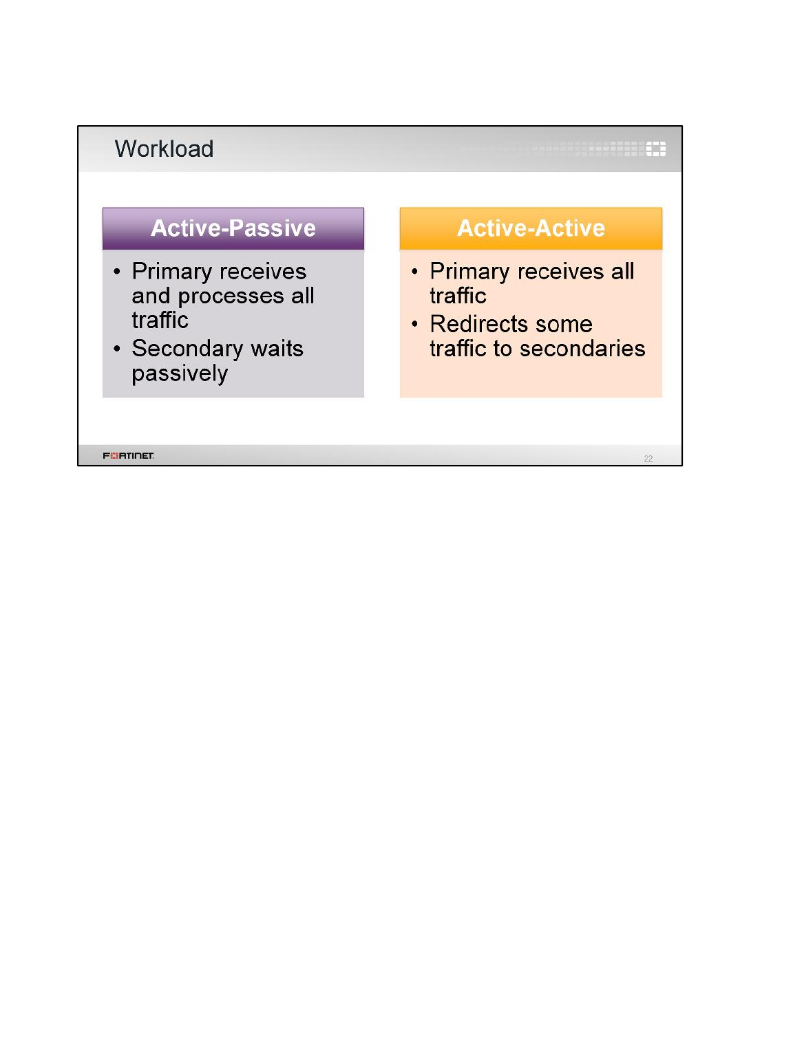
This is how the workload is distributed between roles, depending on the HA mode.
Notice that traffic workload is not distributed in active-passive mode, but it is in active-active mode.
High Availability
FortiGate II Student Guide
284
DO NOT REPRINT
© FORTINET
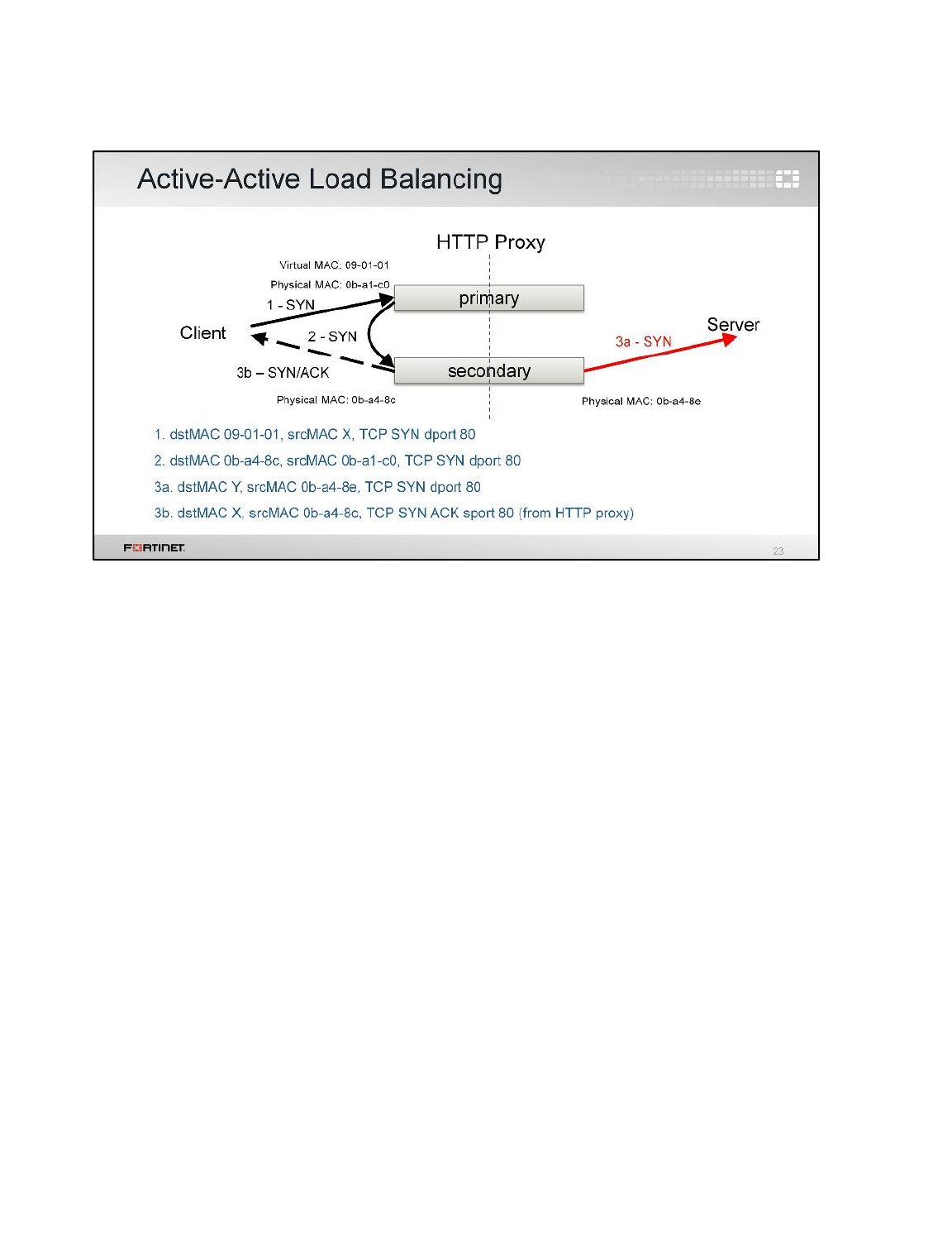
(slide contains animation)
Let’s look at how an HA cluster in active-active mode distributes traffic.
(click)
First, the client side sends a SYN packet. It’s always forwarded to the primary FortiGate using the
internal interface’s virtual MAC address as the destination.
(click)
If the primary decides that the session is going to be inspected by a secondary, the primary forwards
the SYN packet to the secondary that will do the inspections. In this example, the destination MAC
address is the physical MAC address of the secondary FortiGate.
(click)
The secondary responds with SYN/ACK to the client, and starts the connection with the server by
directly sending a SYN packet.
High Availability
FortiGate II Student Guide
285
DO NOT REPRINT
© FORTINET
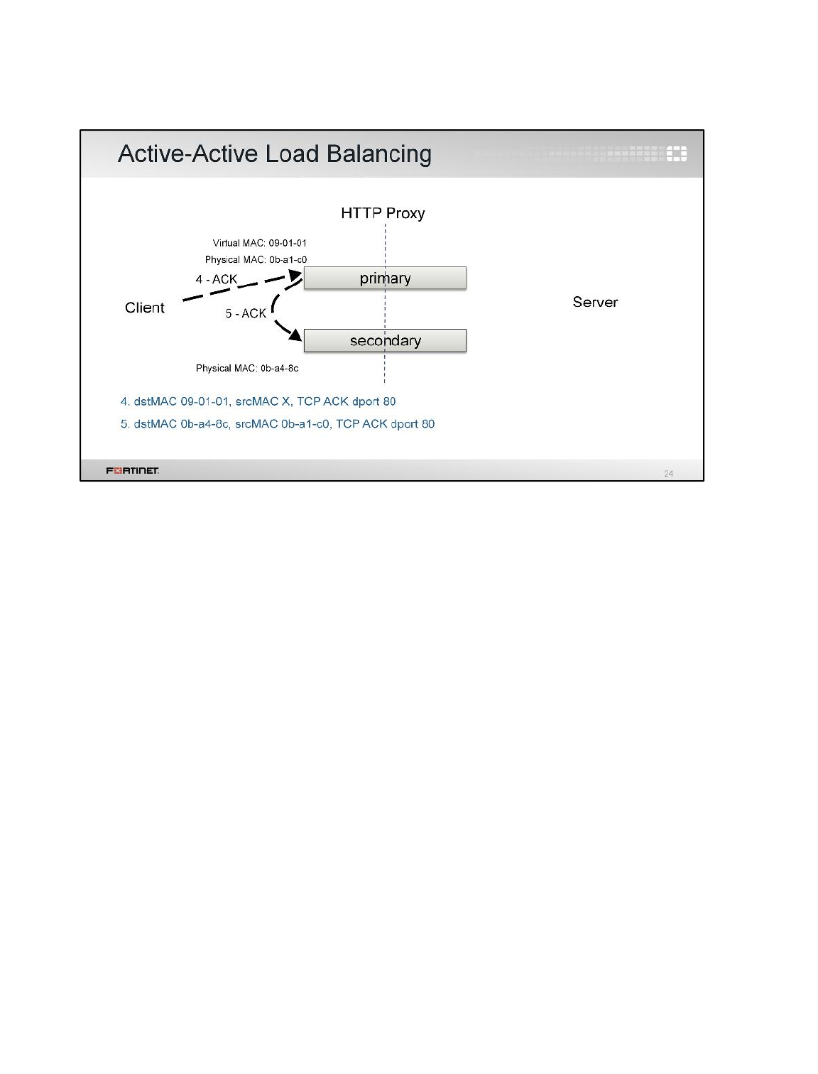
(slide contains animation)
Next, the client acknowledges the ACK. It’s forwarded again to the primary using the virtual MAC
address as the destination.
(click)
The primary device forwards the packet to the secondary inspecting that session, using the
secondary’s physical MAC address.
High Availability
FortiGate II Student Guide
286
DO NOT REPRINT
© FORTINET
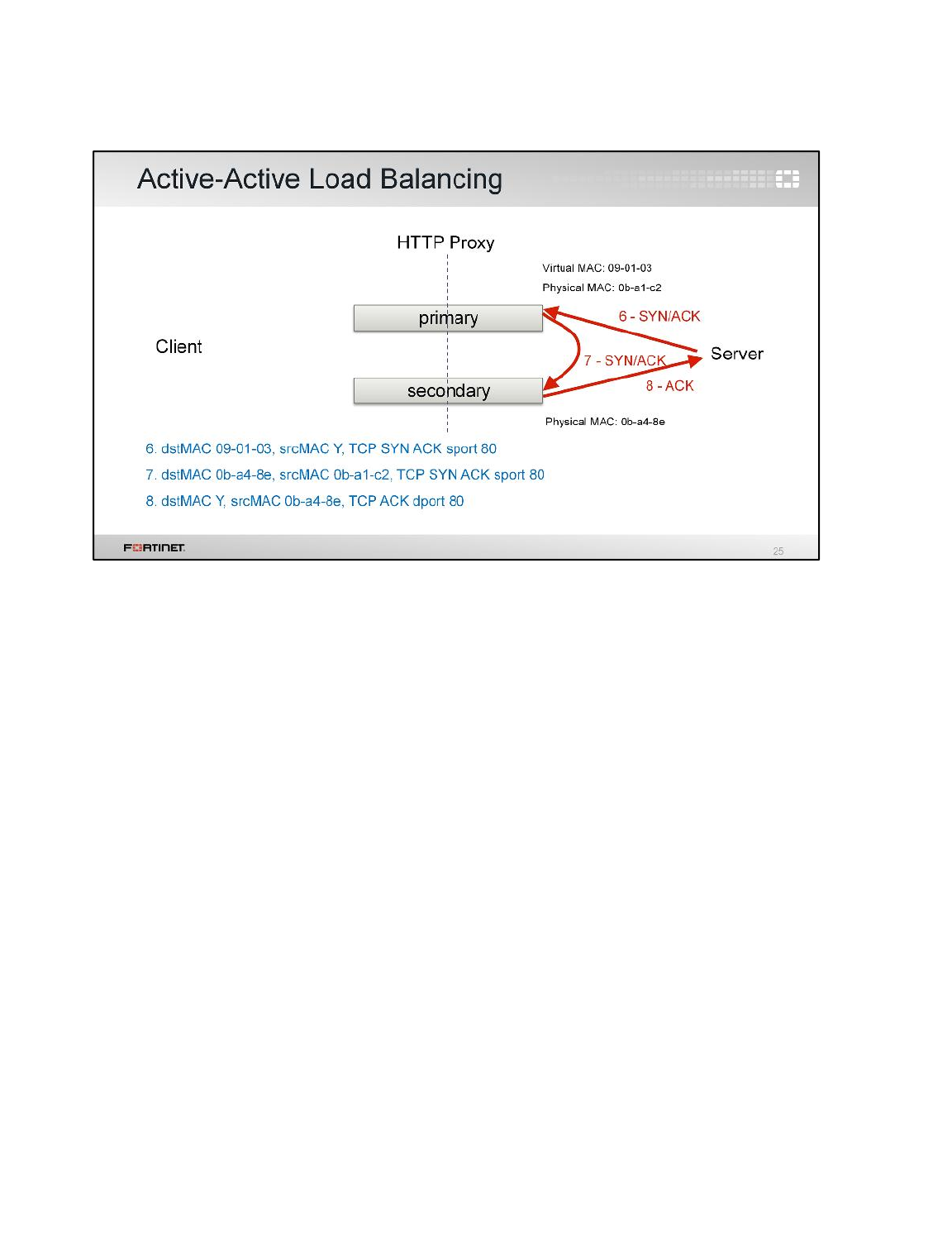
(slide contains animation)
When the server responds to the TCP SYN, again, the packet is sent to the primary using the external
interface’s virtual MAC address.
(click)
So, the primary signals the secondary.
(click)
The secondary replies to the server.
The idea is not to load balance bandwidth. The traffic is always sent to the primary first. The main
objective is to share CPU and memory among multiple FortiGates for traffic inspection.
High Availability
FortiGate II Student Guide
287
DO NOT REPRINT
© FORTINET
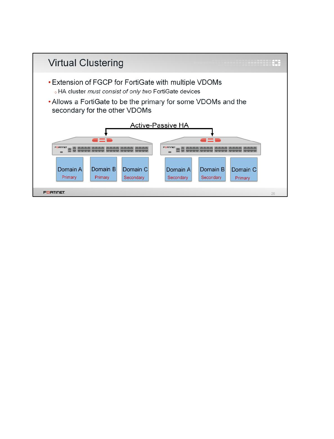
So far, we’ve discussed HA clustering where each FortiGate device acts as a whole security domain.
But, if you have an HA cluster with multiple VDOMs, you can configure virtual clusters.
Virtual clusters allow you to have one device acting as the primary for one VDOM and as the
secondary for a different VDOM. Each VDOM has a primary and a secondary FortiGate, and any
device can act as the primary for some VDOMs, and as the secondary for the other VDOMs at the
same time. Virtual clustering can be configured only in a cluster operating in the active-passive mode.
Because traffic from different VDOMs can go to different primary FortiGates, you can use virtual
clustering to manually distribute your traffic between the two cluster devices, and allow the failover
mechanism for each VDOM between two FortiGates.
Note:You can configure virtual clustering between only two FortiGate devices with multiple VDOMs.
High Availability
FortiGate II Student Guide
288
DO NOT REPRINT
© FORTINET
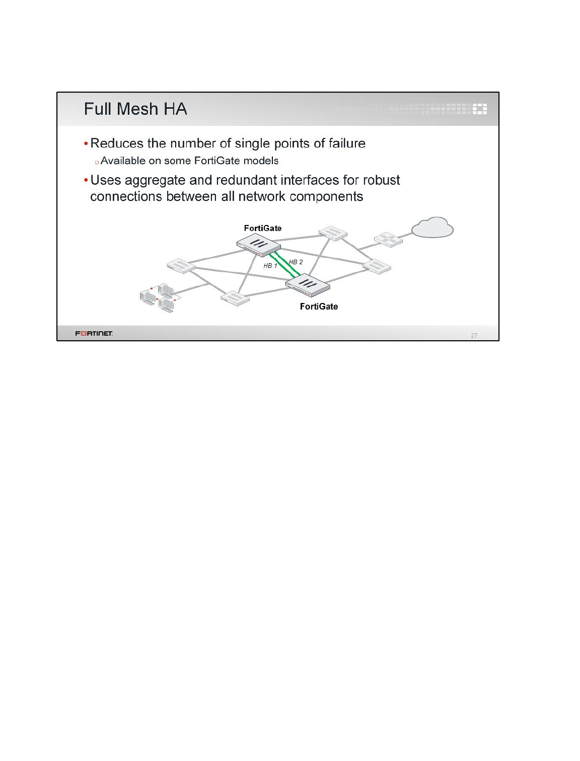
At the beginning of this lesson, we showed a simple HA topology. Now, let’s look at a more robust
topology. It is called full mesh HA.
The idea is to prevent any single point of failure, not only in the FortiGate devices, but also in the
network switches and interfaces.
As you can see in the slide, you have two FortiGates for redundancy and each FortiGate is connected
to two redundant switches, using two different interfaces.
A full mesh HA is more complicated to assemble and administer, but it can provide the availability
required by critical installations. This solution is only available with higher-end FortiGate models
because not all FortiGate models are capable of creating aggregated or redundant interfaces, which
are required for building this type of topology.
High Availability
FortiGate II Student Guide
289
DO NOT REPRINT
© FORTINET
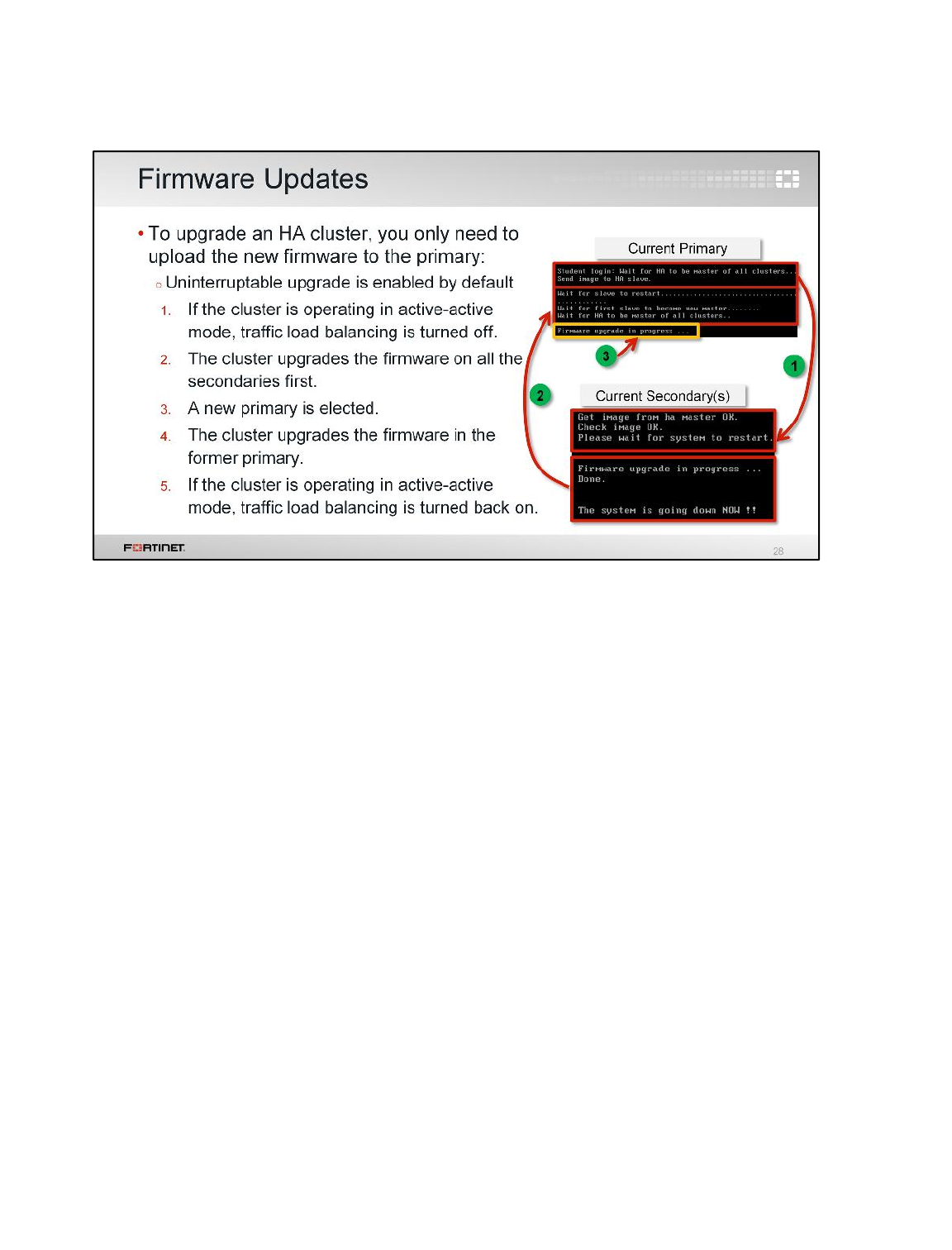
As with a standalone device, when upgrading an HA cluster, each updating FortiGate device must
reboot. As the uninterruptable upgrade is enabled by default, the cluster upgrades the secondary
FortiGates first. Once all the secondary FortiGates are running the new firmware, a new primary is
elected and the firmware in the original primary device is upgraded.
If the cluster is operating in active-active mode, traffic load balancing is temporally disabled while all
devices are upgrading their firmware.
You can change the firmware upgrade process by disabling uninterruptable upgrade from the CLI
under config system ha. This will result in all FortiGates in a cluster being upgraded at the same
time. This takes less time, but interrupts the traffic flow.
High Availability
FortiGate II Student Guide
290
DO NOT REPRINT
© FORTINET
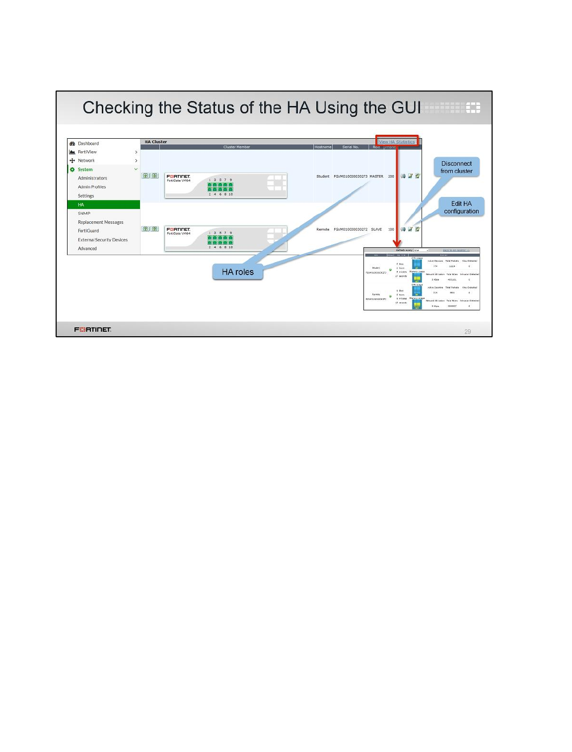
If the HA cluster has formed successfully, the GUI displays all the FortiGates in the cluster, together
with their hostnames, serial numbers, roles, and priorities.
You can also view the HA statistics, which shows the uptime, active sessions, and network utilization.
You can also disconnect a cluster member from the cluster and edit the HA configurations.
High Availability
FortiGate II Student Guide
291
DO NOT REPRINT
© FORTINET
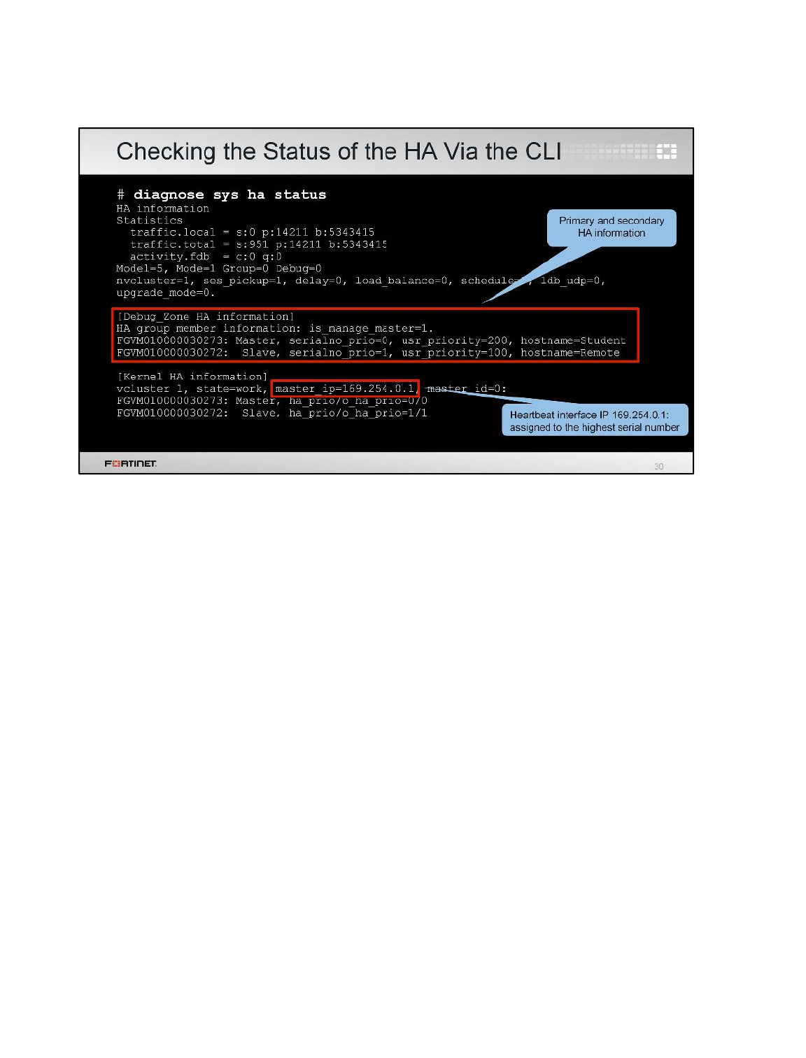
You can get more information about the status of the HA from the CLI. For example, the command
diagnose sys ha status displays heartbeat traffic statistics, as well as the serial number and HA
priority of each FortiGate. This command also shows the heartbeat interface IP address automatically
assigned to the FortiGate with the highest serial number.
Remember, the heartbeat IP address assignment changes only when a FortiGate leaves or joins the
cluster.
High Availability
FortiGate II Student Guide
292
DO NOT REPRINT
© FORTINET
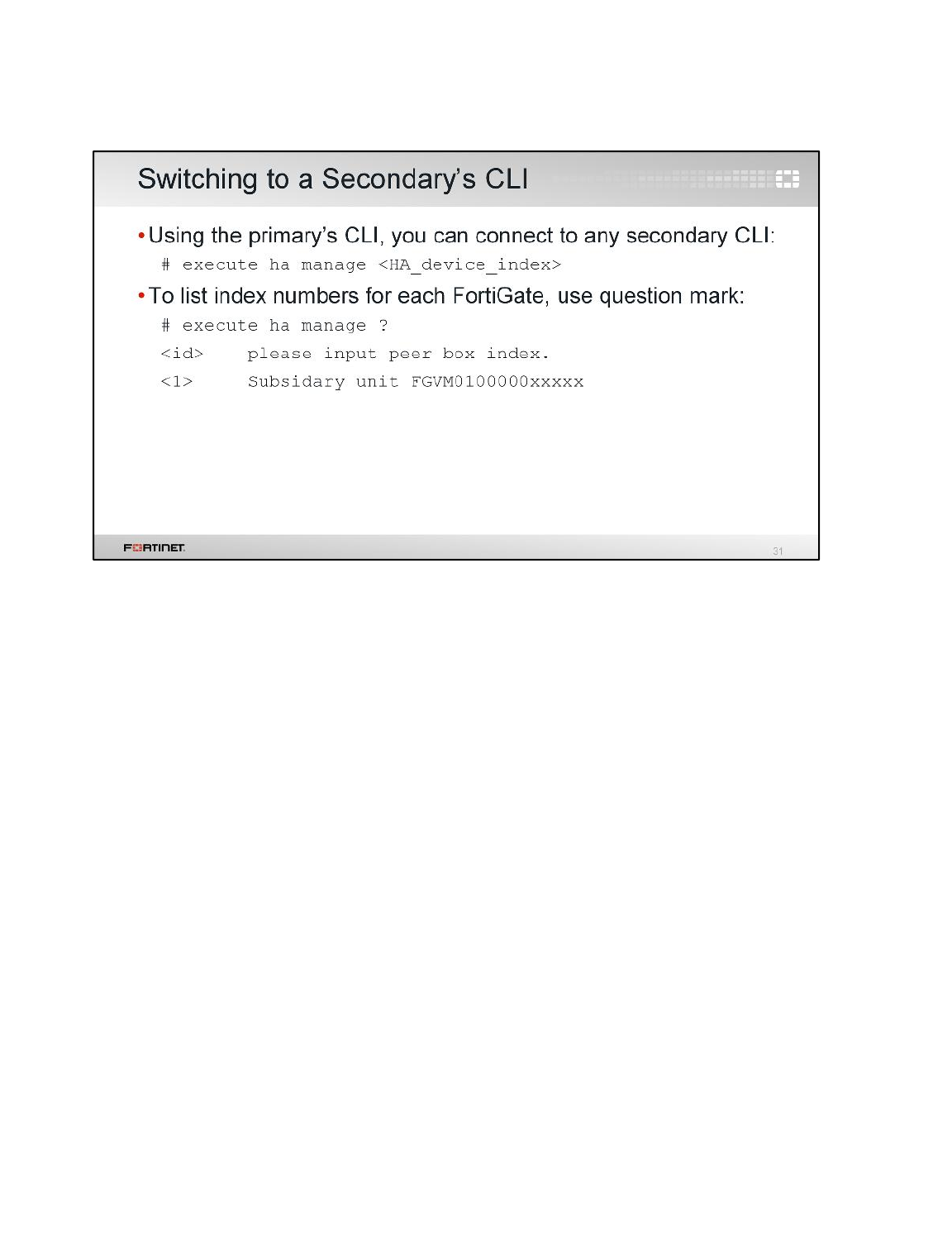
When troubleshooting a problem in an HA cluster, it is useful to know that you can connect to the CLI
of any secondary FortiGate from the CLI of the primary FortiGate. You have to use the command
execute ha manage with the secondary HA index for that purpose.
To get the list of secondary FortiGates with their HA indexes, you can use the question mark at the
end of that same command.
High Availability
FortiGate II Student Guide
293
DO NOT REPRINT
© FORTINET
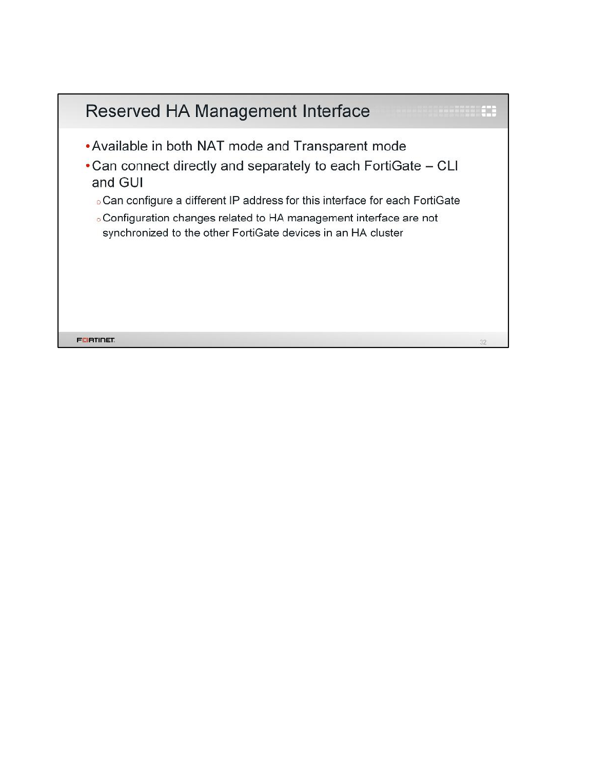
If you want to be able to connect to each device directly, you can reserve an interface for HA
management, so its configuration will not be synchronized, and each device can have different
management IP addresses. The HA reserved management interface can also be used by each device
to send SNMP traffic and logs independently.
High Availability
FortiGate II Student Guide
294
DO NOT REPRINT
© FORTINET
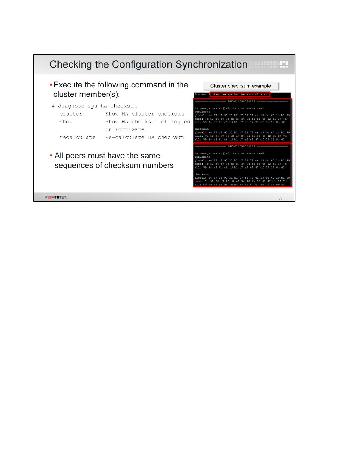
Another indication of the health of an HA cluster is the status of the configuration synchronization. The
diagnose sys ha checksum command tree provides many options to check or recalculate the HA
checksum.
To check that all the secondary configurations are synchronized with the primary configuration:
• Execute the diagnose sys ha checksum cluster command to view the checksums of all
cluster members from any FortiGate in a cluster.
• The diagnose sys ha checksum show command shows the checksum of the individual
FortiGate from which this command is executed.
• You can also run the diagnose sys ha checksum recalculate command from any cluster
member to recalculate the HA checksums.
If a secondary FortiGate displays exactly the same sequence of numbers as the primary, its
configuration is well synchronized with the primary FortiGate in the cluster. In this example, the
diagnose sys ha checksum cluster command is executed to view the checksums of all
cluster members.
•global represents the checksum of the global configuration, such as administrators, admin
profiles, global logging settings, and FortiGuard settings, to name a few.
•root is the checksum for the root VDOM. If you have configured multiple VDOMs, you will see
checksums of all configured VDOMs.
•all is the checksum of the global configuration, plus all the VDOMs checksums.
High Availability
FortiGate II Student Guide
295
DO NOT REPRINT
© FORTINET
In this lesson, we discussed:
• Active-passive and active-active HA modes
• How the primary FortiGate is elected
• Configuration and session synchronization
• Which events can trigger an HA failover
• How the primary FortiGate in an active-active cluster distributes the traffic to the secondary devices
• Virtual clustering
• Upgrading an HA cluster’s firmware
• How to check the health of an HA cluster
High Availability
FortiGate II Student Guide
296
DO NOT REPRINT
© FORTINET

In this lesson, we will show how to set up IPsec VPN topologies, such as partial mesh and full mesh –
in other words, complex point-to-multipoint VPNs.
Although we’ll quickly review it, you should already be familiar with site-to-site VPNs. Site-to-site
VPNs are taught in the FortiGate I: Basic IPsec VPN lesson. This lesson also assumes you are
familiar with:
• IPsec terminology, such as what an SA and a peer are
• Diffie-Hellman exchanges
• Quick mode selectors
• Policy-based and route-based VPNs
• How to use the VPN monitor
Advanced IPsec VPN
FortiGate II Student Guide
297
DO NOT REPRINT
© FORTINET
After completing this lesson, you should have the practical skills that you need to deploy the right VPN
topology for your needs, increase availability, and troubleshoot tunnels.
Unlike a simple static VPN – such as between two offices – VPNs between multiple dynamic peers
require additional considerations.
Lab exercises can help you to test and reinforce your skills.
Advanced IPsec VPN
FortiGate II Student Guide
298
DO NOT REPRINT
© FORTINET
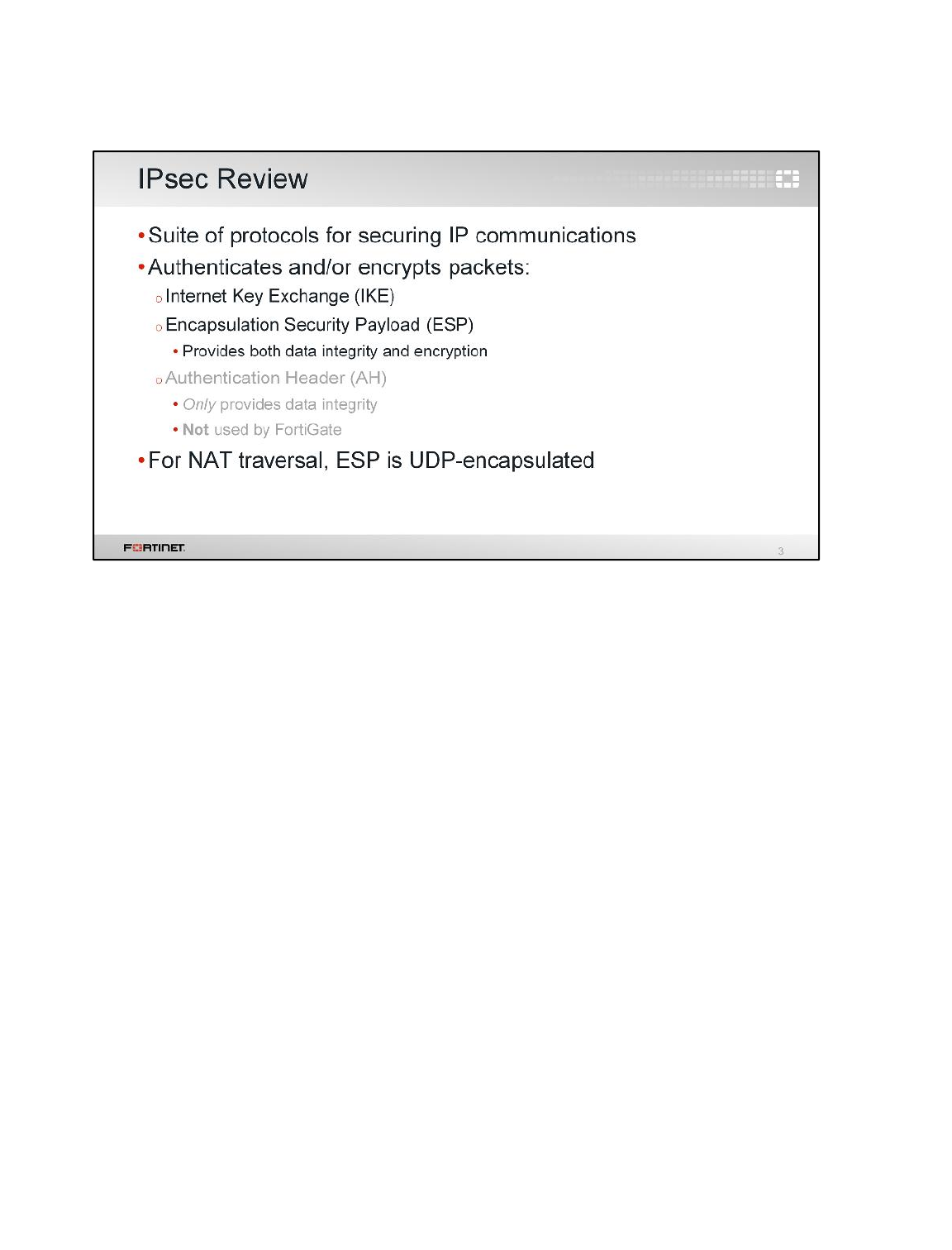
As we saw in the lesson for basic IPsec VPNs, IPsec is a suite of protocols for authenticating and
encrypting the traffic between two peers. The three most used protocols in the suite are:
• Internet Key Exchange (IKE), which does the handshake, tunnel maintenance, and disconnection
• Encapsulation Security Payload (ESP), which ensures data integrity and encryption
• Authentication Header (AH), which offers only data integrity – not encryption
FortiGate uses only ESP to transport the packet payload. AH is not used by FortiGate.
Advanced IPsec VPN
FortiGate II Student Guide
299
DO NOT REPRINT
© FORTINET
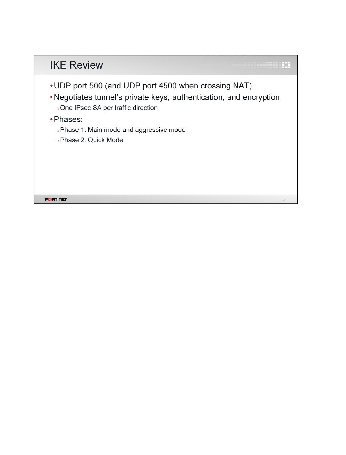
Since we’ll expand first on IKE, let’s review a little about the key exchange, which uses port UDP 500
(and, if NAT-T is enabled in a NAT scenario, UDP port 4500).
IKE establishes an IPsec VPN tunnel. FortiGate uses it to negotiate with the peer and determine the
security association (SA). The SA defines the authentication, keys, and settings that will be used to
encrypt and decrypt that peer’s packets. It is based on the Internet Security Association and Key
Management Protocol (ISAKMP).
As explained in the basic IPsec VPN lesson, IKE defines two phases. Each IPsec SA negotiated
during the phase 2 is direction-specific. So in two-way traffic, there are two SAs per phase 2.
For phase 1, there are two possible negotiation modes: main mode and aggressive mode. Phase 2
only has quick mode. Main mode and aggressive mode have different considerations with dialup
VPNs. So, let’s examine the differences between main mode and aggressive mode.
Advanced IPsec VPN
FortiGate II Student Guide
300
DO NOT REPRINT
© FORTINET
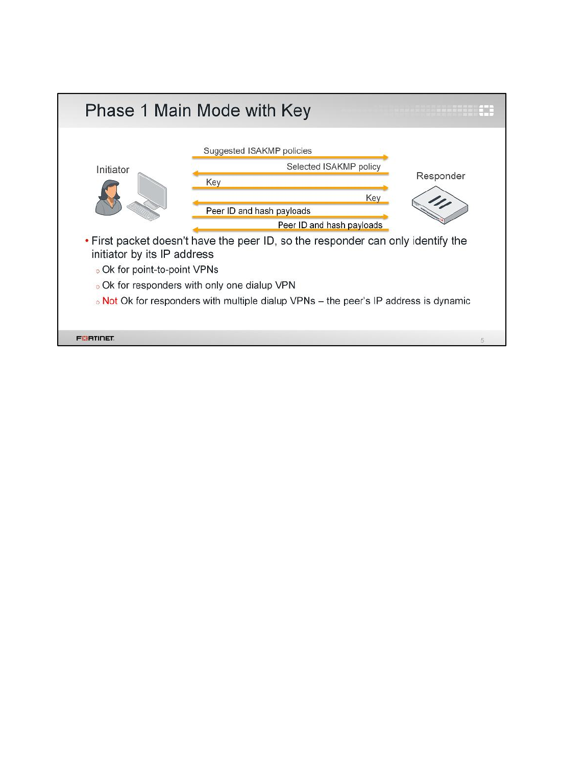
(slide contains animation)
This shows main mode. Six packets are exchanged.
First, the client initiates by proposing that the tunnel will use one or more security policies. The
responder selects which security policy it agrees to use, and replies. Then, the initiator sends its key.
The responder replies with its own key. Finally, the initiator sends its peer ID and hash payload, and
the responder replies in the same way.
(click)
In this case, the responder can identify the initiator only by the source IP address of the first packet.
Nothing else. This is because the first packet does not contain the peer ID. That works well for point-
to-point VPNs because the responder knows the IP address of each peer. So, the responder is aware
of which security policies to propose for each case. It’s also OK for a responder with only one dialup
VPN. In that case, the responder does not need to identify the peer. There is only one set of security
policies to use for all of them.
However, it is a problem for a responder with multiple dialup VPNs. If that case, the responder needs
to identify the initiator with something different than the source IP address, as the peer IP addresses
are unknown and can change. Without that information the responder does not know which dialup
VPN each initiator belongs to, nor which security policies apply.
Advanced IPsec VPN
FortiGate II Student Guide
301
DO NOT REPRINT
© FORTINET
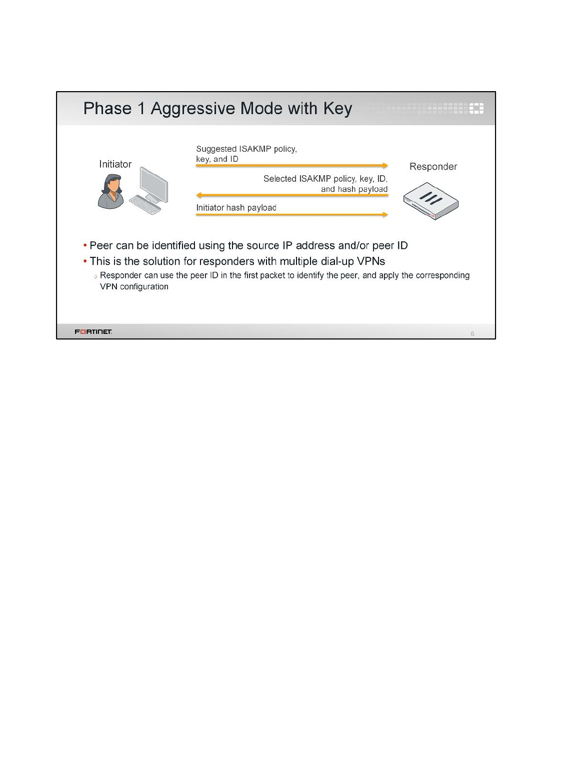
(slide contains animation)
In comparison, let’s show aggressive mode negotiation. Only 3 packets are exchanged:
First, the client initiates by suggesting a security policy, and providing its key and peer ID. The
responder replies with the same information, plus a hash. Finally, the initiator sends its hash payload.
(click)
Unlike main mode, the first packet contains the initiator’s peer ID. Therefore, the responder can use
this ID (and not only the source IP address) to identify who the peer is, and which security policy to
use. This is the solution for responders with multiple dialup VPNs. But, because the peer ID is
exposed in the initial, unsecured exchange, attackers could see it and use it to try a fraudulent
connection. So, it’s safer to pair this mode with extended authentication (xAuth).
Advanced IPsec VPN
FortiGate II Student Guide
302
DO NOT REPRINT
© FORTINET
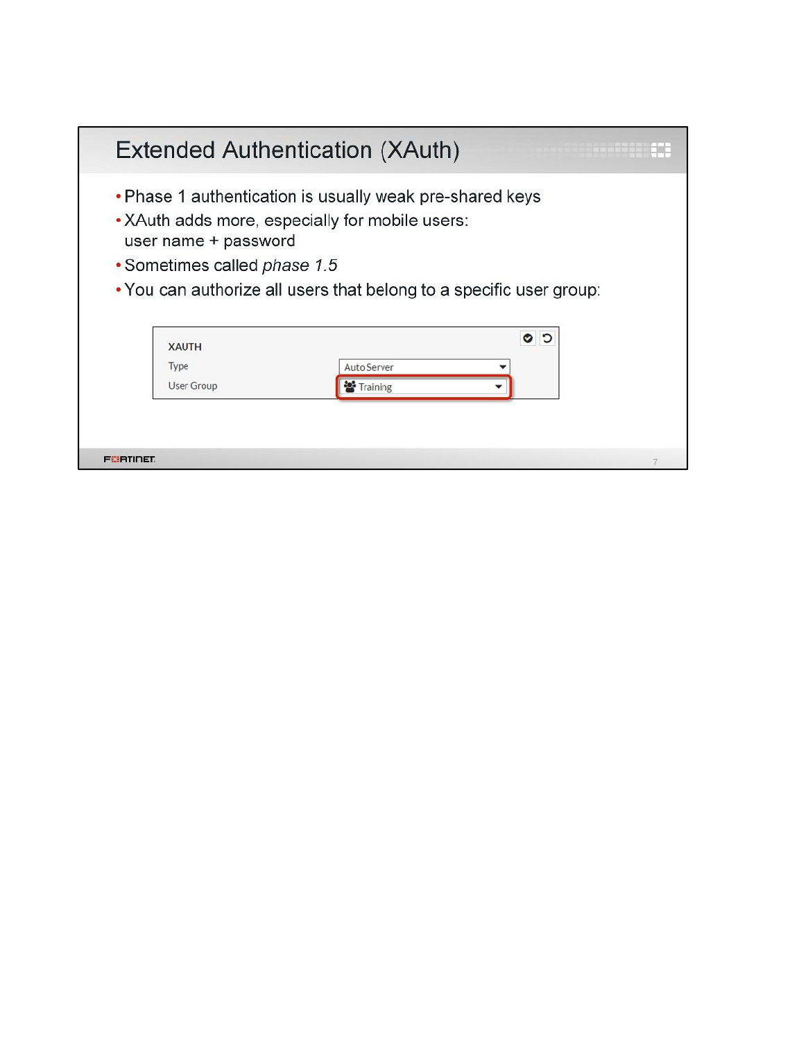
Another advanced phase 1 option is XAuth.
Phase 1 supports two types of authentication: pre-shared keys and digital certificates. The XAuth
extension to IPsec forces remote users to additionally authenticate with their credentials (user name
and password). So, additional authentication packets are exchanged if you enable it.
What is the benefit? Stronger authentication.
There are two ways of configuring the list of users authorized to connect to the VPN. One is by
selecting a specific user group that contains those users. With this method, you need to configure
more than one dialup VPN if you want to apply different access policies, depending on the user group.
As we saw before, that also means using aggressive mode and peer IDs.
Advanced IPsec VPN
FortiGate II Student Guide
303
DO NOT REPRINT
© FORTINET
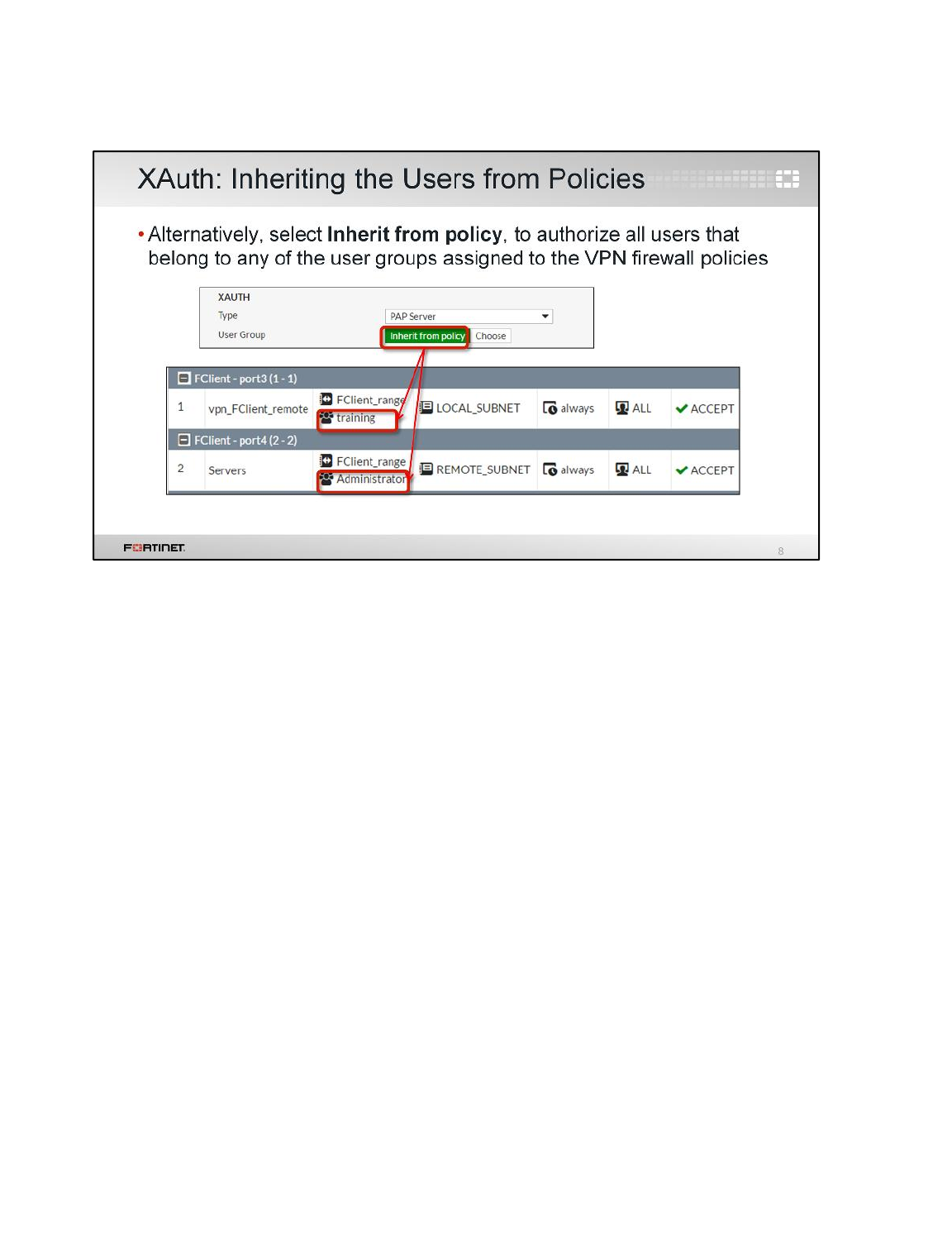
The other way of configuring the list of authorized VPN users is by selecting the option Inherit from
policy. With this setting, FortiGate authorizes all users that belong to any user group assigned to any
of the firewall policies that allow the VPN traffic. In this example, there are two firewall policies for the
VPN traffic. One allows the traffic from the user group Administrator. The other policy allows the
traffic from the user group training. In this case, all users that belong to either Administrator or
training can connect to the VPN.
The advantage of this method is that you can have different access policies for different user groups
and keep only one dialup VPN in the configuration.
Advanced IPsec VPN
FortiGate II Student Guide
304
DO NOT REPRINT
© FORTINET
Let's talk about types of IPsec remote peers and VPN topologies.
Advanced IPsec VPN
FortiGate II Student Guide
305
DO NOT REPRINT
© FORTINET
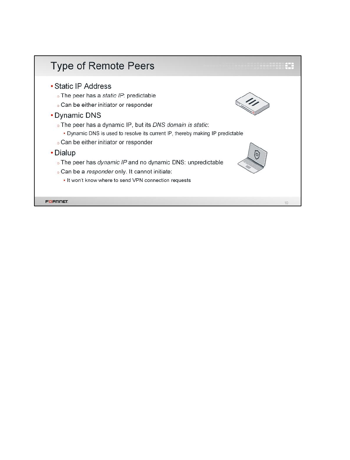
When configuring a phase 1, we must specify the type of remote peer. There are three types:
•Static IP Address is used when the peer's IP address is known and will not change
•Dynamic DNS is used when the peer’s IP address is dynamic, but FortiGate can resolve it through
a DNS query. This makes it – in effect – a static peer. For example, branch offices often use DHCP
from an ISP. The IP address changes, but not often. So you could use Dynamic DNS to get a static
DNS name that resolves to the dynamic IP. Then you would configure your FortiGate with the
peer’s DNS domain name, which your FortiGate will query to resolve whenever it needs to connect.
•Dialup is used when the peer’s IP address is dynamic, and there is no dynamic DNS. This is often
true for branch offices and mobile VPN clients. As a peer with a dialup VPN does not know the
other peers' IP addresses, it cannot initiate a VPN connection request.
Advanced IPsec VPN
FortiGate II Student Guide
306
DO NOT REPRINT
© FORTINET
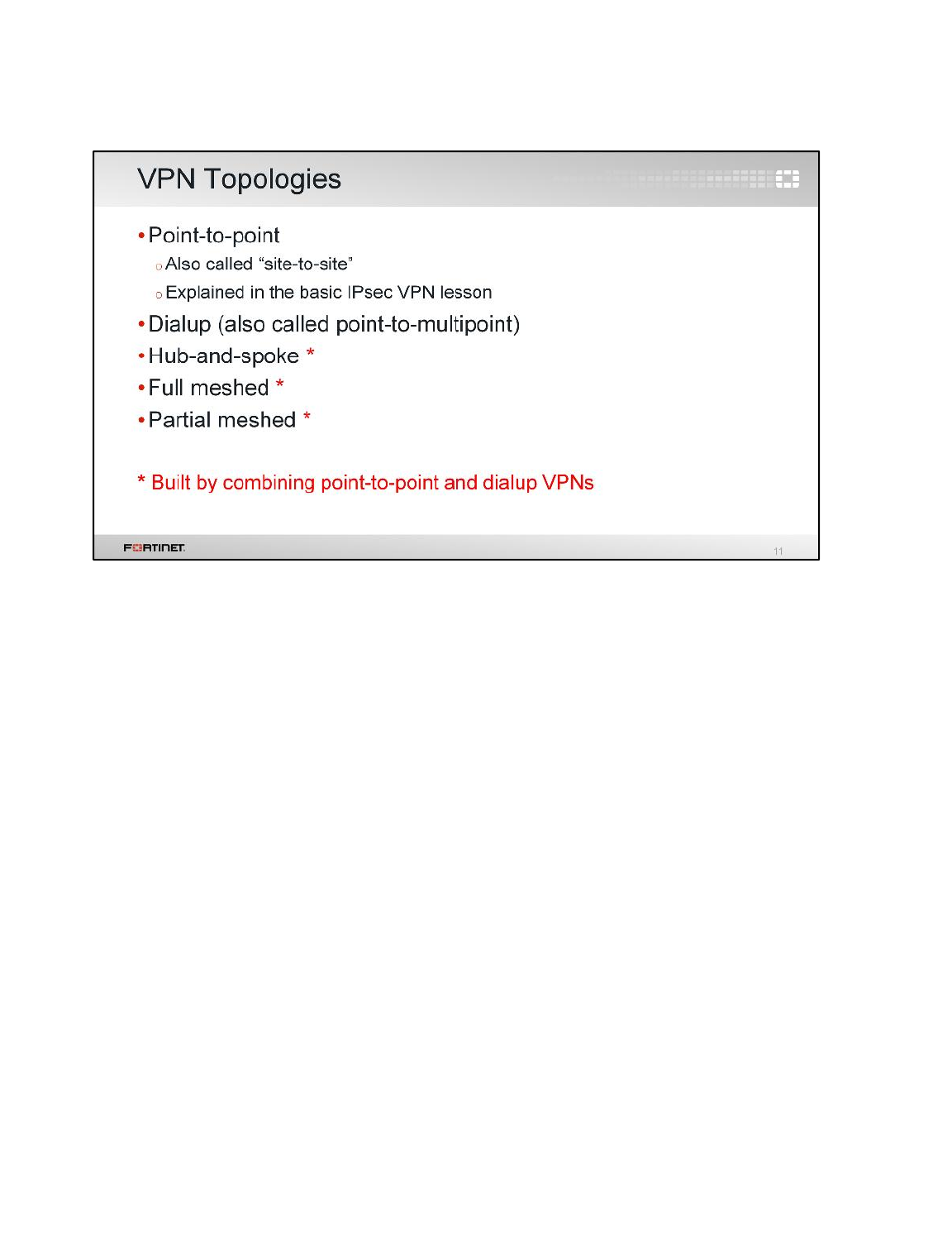
Let's study the different topologies for VPN networks. There are five types:
• Point-to-point
• Dialup
• Hub-and-spoke
• Full mesh
• Partial mesh
Point-to-point VPNs are the simplest. Two peers communicate directly. This topology, and how to
configure it, was covered in the FortiGate I: Basic IPsec VPN lesson. Now, let’s look at the other four
topologies.
Advanced IPsec VPN
FortiGate II Student Guide
307
DO NOT REPRINT
© FORTINET
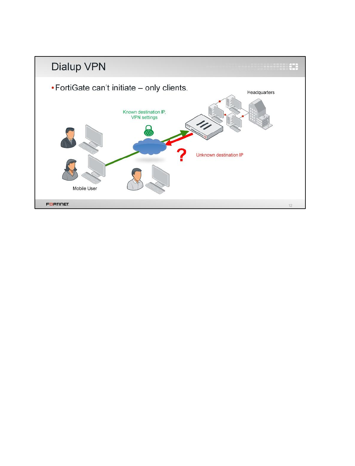
(slide contains animations)
First, let's look at a dialup VPN. It is used when you don’t know where the remote peer will be
connecting from, such as with travelling employees with FortiClient on their laptops.
Unlike site-to-site VPNs, one dialup VPN configuration on your FortiGate can be used for multiple
IPsec tunnels from many remote offices or users; hence its other name, point-to-multipoint.
(click)
Remember that, in dialup, the client’s IP is dynamic, so FortiGate can’t predict where it will be. That
means that FortiGate cannot initiate the VPN, only the remote peer can.
Advanced IPsec VPN
FortiGate II Student Guide
308
DO NOT REPRINT
© FORTINET
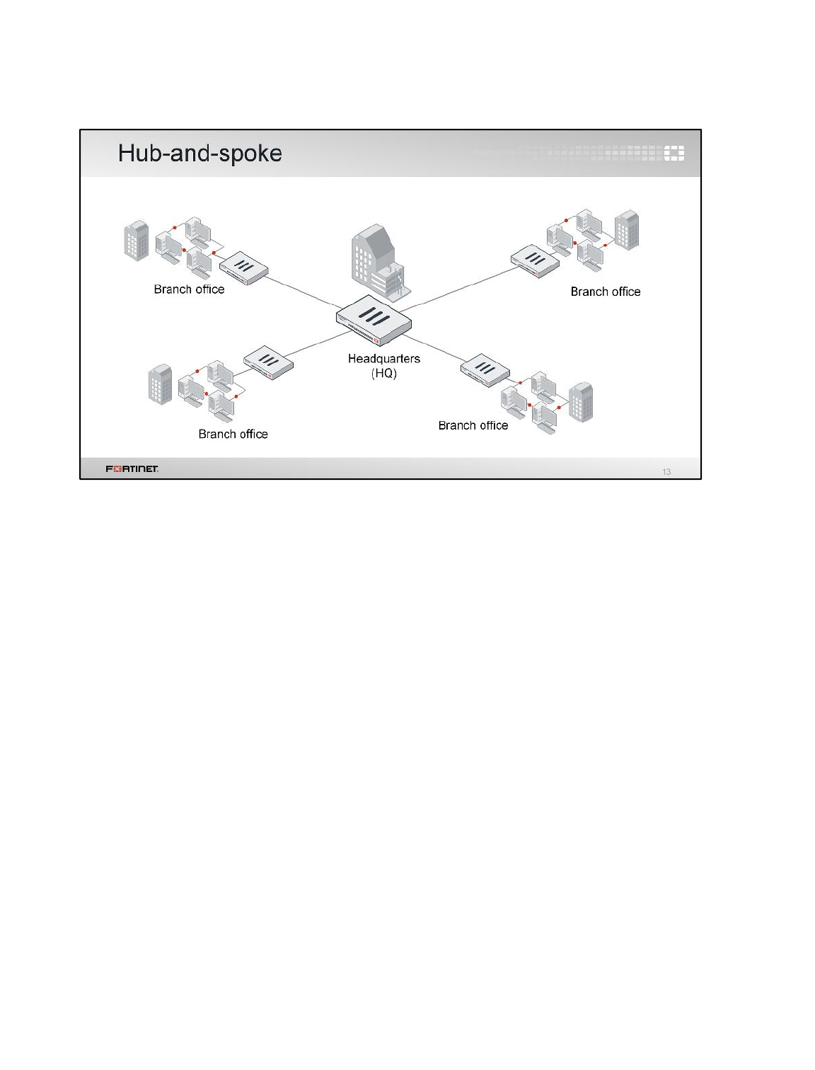
One point-to-multipoint topology variation is called hub-and-spoke. Its name describes how all clients
connect through a central hub, similar to how spokes connect to hubs on wheels.
In this example, the clients – spokes – are each branch office FortiGates. For any branch office to
reach another, its traffic must pass through the hub.
An advantage of this topology is that the VPN configuration and firewall policies are easily managed.
System requirements are also minimal for the branch office FortiGates, since each only needs to
maintain one tunnel– two SAs. In this example, four tunnels – eight SAs – are required in the hub.
A disadvantage is that – especially if headquarters (HQ) is physically distant like it can be for global
companies – communications between branch offices through HQ will be slower than with a direct
connection. If your HQ is in Brazil and you have offices in Japan and Germany, latency can be very
significant. For example, if the FortiGate at HQ fails, VPN failure will be company-wide. Also, the
FortiGate at HQ must be much more powerful. It handles four tunnels simultaneously – eight SAs.
So what would a topology look like if some, or all, branch offices could bypass HQ, and connect
directly to each other?
Advanced IPsec VPN
FortiGate II Student Guide
309
DO NOT REPRINT
© FORTINET
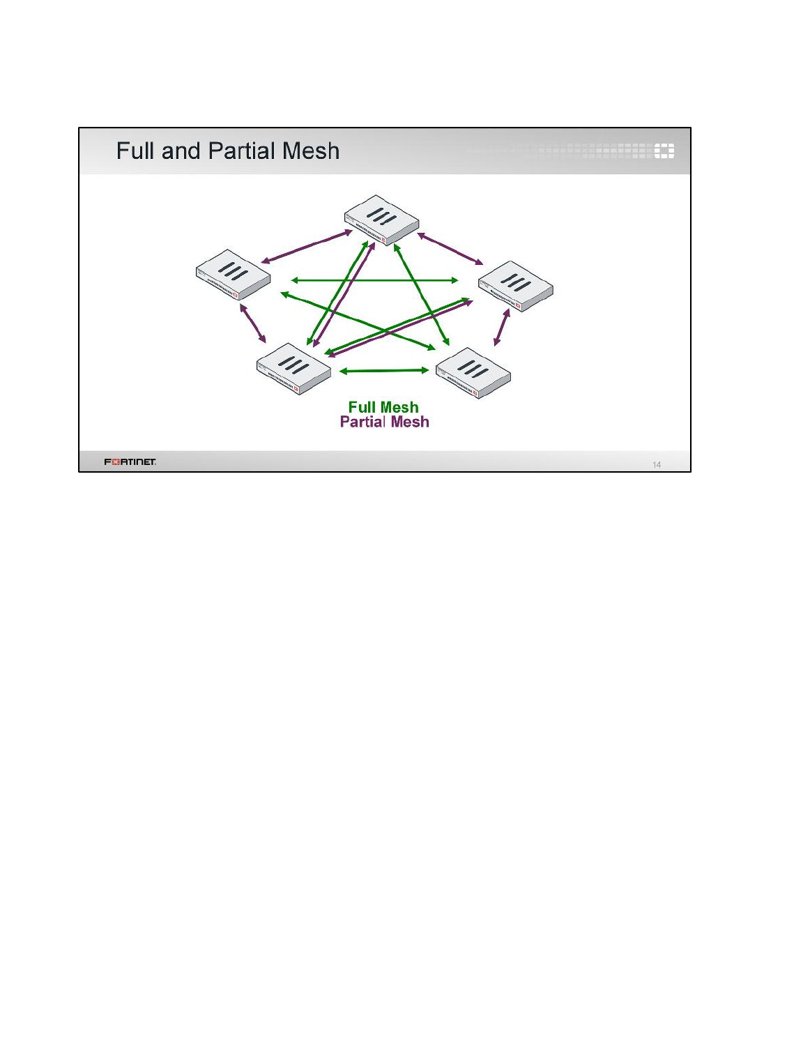
(slide contains animation)
These are VPNs with a mesh topology. Two variations exist.
Full mesh connects every location to every other. Like the previous hub-and-spoke example, there are
only five locations here. But to fully interconnect, every FortiGate requires four VPN tunnels – eight
SAs – to the others. This is three more tunnels per spoke FortiGate. In total, 20 tunnels are required. If
you expand to six locations, it would require 30 VPNs, seven locations would need 42, and so on.
This topology causes less latency and requires much less HQ bandwidth than hub-and-spoke. Its
disadvantage? Every spoke FortiGate must be more powerful.
(click)
Partial mesh attempts to compromise, minimizing required resources but also latency. Partial mesh
can be appropriate if communication is not required between every location. However, each
FortiGate’s configuration is still more complex than hub-and-spoke. Routing especially may require
extensive planning.
So generally, the more locations you have, hub-and-spoke will be cheaper (but slower) than a meshed
topology. Mesh will place less strain on the central location, and be more fault-tolerant (but more
expensive).
Advanced IPsec VPN
FortiGate II Student Guide
310
DO NOT REPRINT
© FORTINET
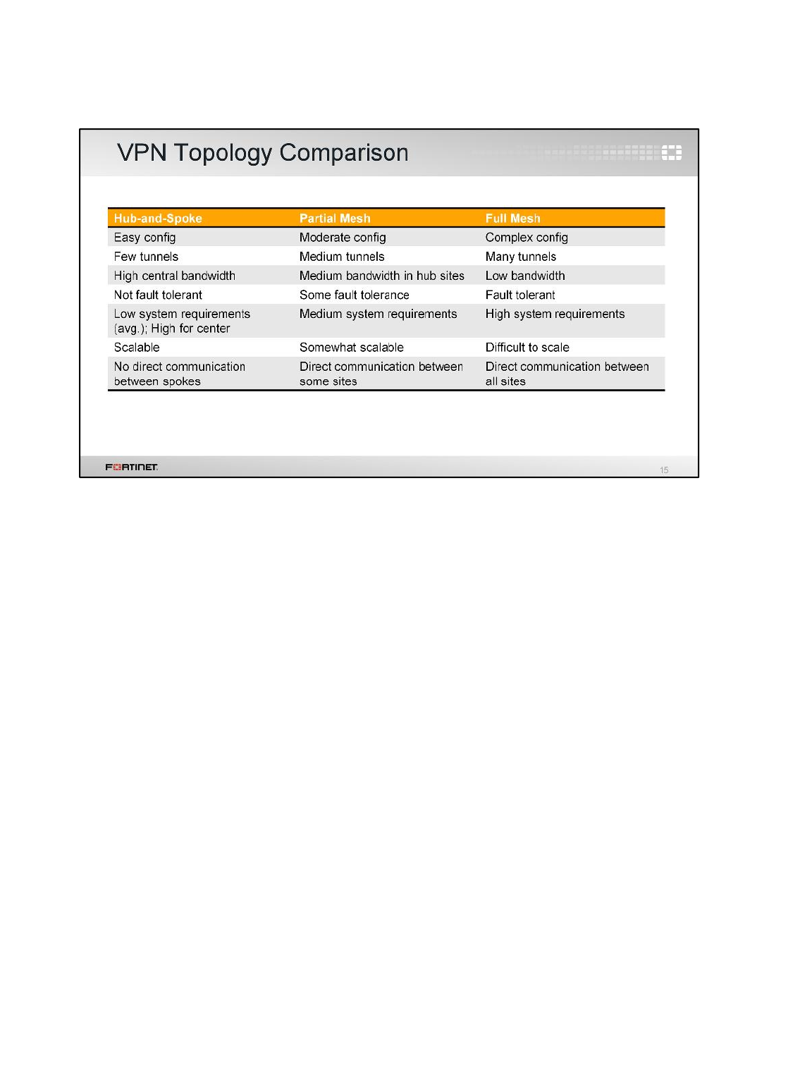
To review, here is a quick comparison. You should choose the topology that is most appropriate to
your situation.
Advanced IPsec VPN
FortiGate II Student Guide
311
DO NOT REPRINT
© FORTINET
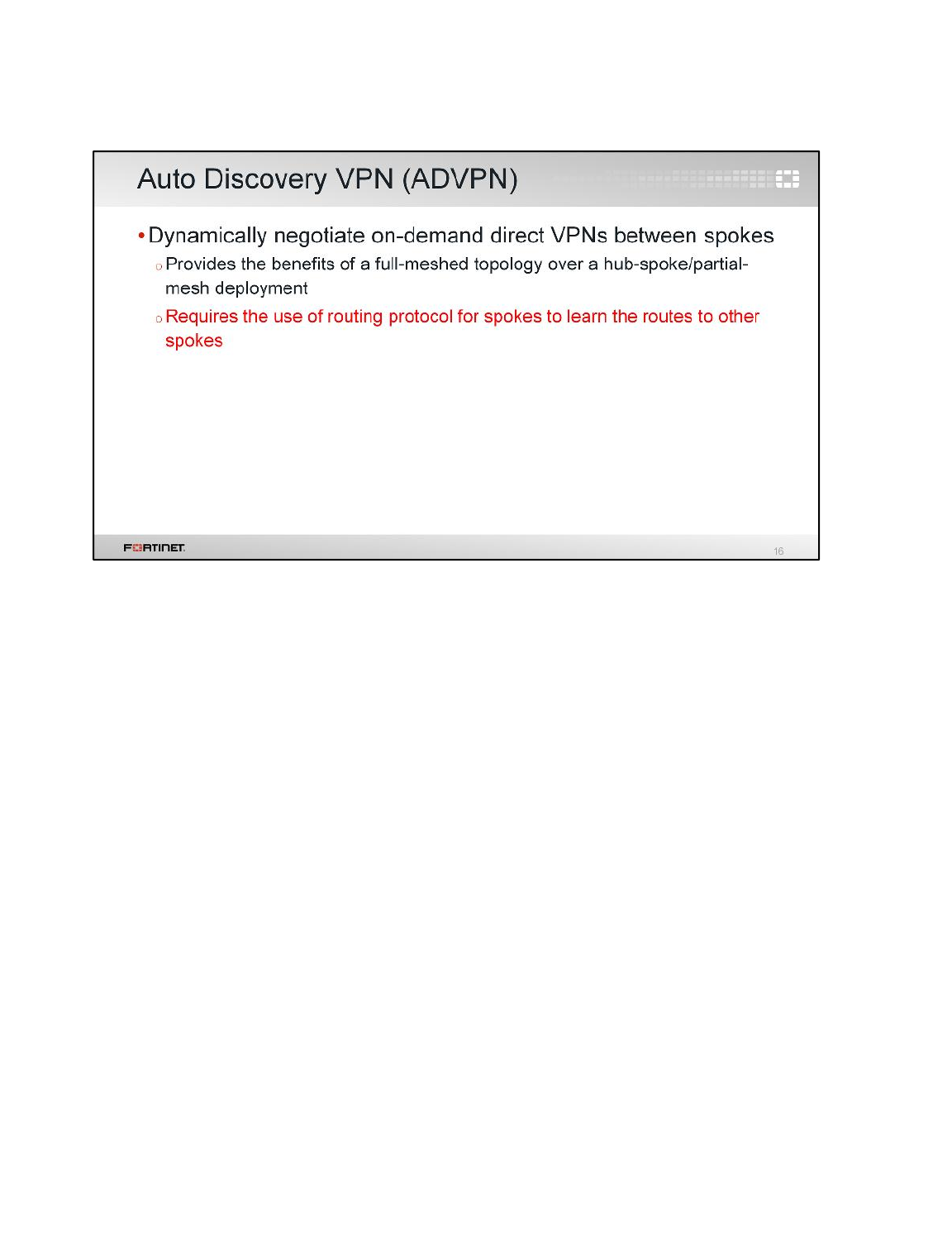
As we saw, each VPN topology has its advantages and disadvantages.
Auto discovery VPN (ADVPN) is a FortiGate feature that achieves the benefits of a full-meshed
topology with the easier-to-configure and scalability benefits of the hub-and-spoke and partial-mesh
topologies.
First, you add to the FortiGates the VPN configurations for building either a hub-and-spoke or a
partial-mesh topology. After that, you enable ADVPN on the VPNs. ADVPN will dynamically negotiate
tunnels between spokes (without having them pre-configured) to get the benefits of a full-mesh
topology.
ADVPN requires the use of a dynamic routing protocol running over the IPsec tunnels, so that spokes
can learn the routes to other spokes after the dynamic VPNs negotiate.
Advanced IPsec VPN
FortiGate II Student Guide
312
DO NOT REPRINT
© FORTINET
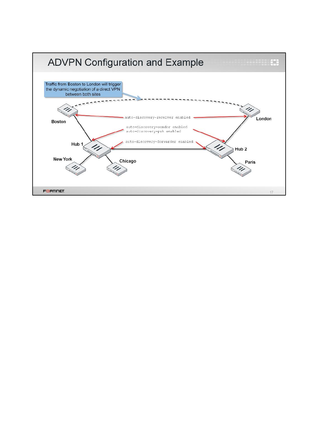
This is an example of how ADVPN works. An administrator configures IPsec VPNs in multiple
FortiGate devices to form a VPN partial-mesh topology. There are two hubs. Hub 1 has three spokes.
Hub 2 has two spokes.
The administrator also enables ADVPN in all the VPNs. To do that, you must enable the following
IPsec phase 1 settings:
•auto-discovery-receiver in the spokes' VPNs
•auto-discovery-sender and auto-discovery-psk in the hubs' VPNs that go to each spoke
•auto-discovery-forwarded in the hubs' VPNs that go to each other hub
The dynamic tunnels between spokes are created on demand. Let's say that a user in Boston sends
traffic to London. Initially, the direct tunnel between Boston and London has not been negotiated yet.
So, the first packets from Boston to London are routed through the hubs 1 and 2. When Hub 1
receives those packets, it notices that ADVPN is enabled in all the VPNs all the way to London. So,
Hub 1 sends an IKE message to Boston informing that it can try to negotiate a direct connection to
London. On receipt of this IKE message, Boston creates a FortiOS-specific IKE information message
which contains its public IP address, its local subnet, the desired destination subnet (London's
subnet), and an auto-generated PSK to use for securing the direct tunnel (alternatively digital
certificate authentication can be used instead). This IKE message is sent to London through hubs 1
and 2. When London receives the IKE message from Boston, it stores the PSK and replies back with
another IKE information message that contains London's public IP address. After the reply arrives to
Boston, the dynamic tunnel is negotiated between both peers. The negotiation will succeed because
London is expecting a connection attempt from Boston's public IP address.
Advanced IPsec VPN
FortiGate II Student Guide
313
DO NOT REPRINT
© FORTINET

We covered how to configure point-to-point VPNs in the Basic IPsec VPN lesson. This lesson covers
dialup VPN configuration.
Advanced IPsec VPN
FortiGate II Student Guide
314
DO NOT REPRINT
© FORTINET
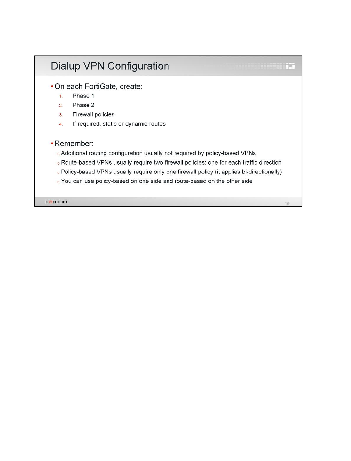
Before, we said that hub-and-spoke, full mesh, and partial mesh can be built using a combination of
point-to-point (site-to-site) and point-to-multipoint VPNs. So let’s configure point-to-multipoint, called
Dialup VPN on the GUI.
Notice that the steps are the same. What is different? The settings. We must configure:
1. A phase 1
2. At least one phase 2
3. Firewall policies
4. If required, static routes or a dynamic routing protocol
Remember, there are two different ways of configuring VPNs on FortiGate: policy-based and route-
based.
• For policy-based VPNs, additional routing entries are usually not required. Also firewall policies for
policy-based VPNs are applied directionally. So, one policy is enough to allow the traffic initiated at
either end.
• For route-based VPNs, routing entries are required, and at least two firewall policies are needed to
allow the traffic initiated at either side.
Advanced IPsec VPN
FortiGate II Student Guide
315
DO NOT REPRINT
© FORTINET
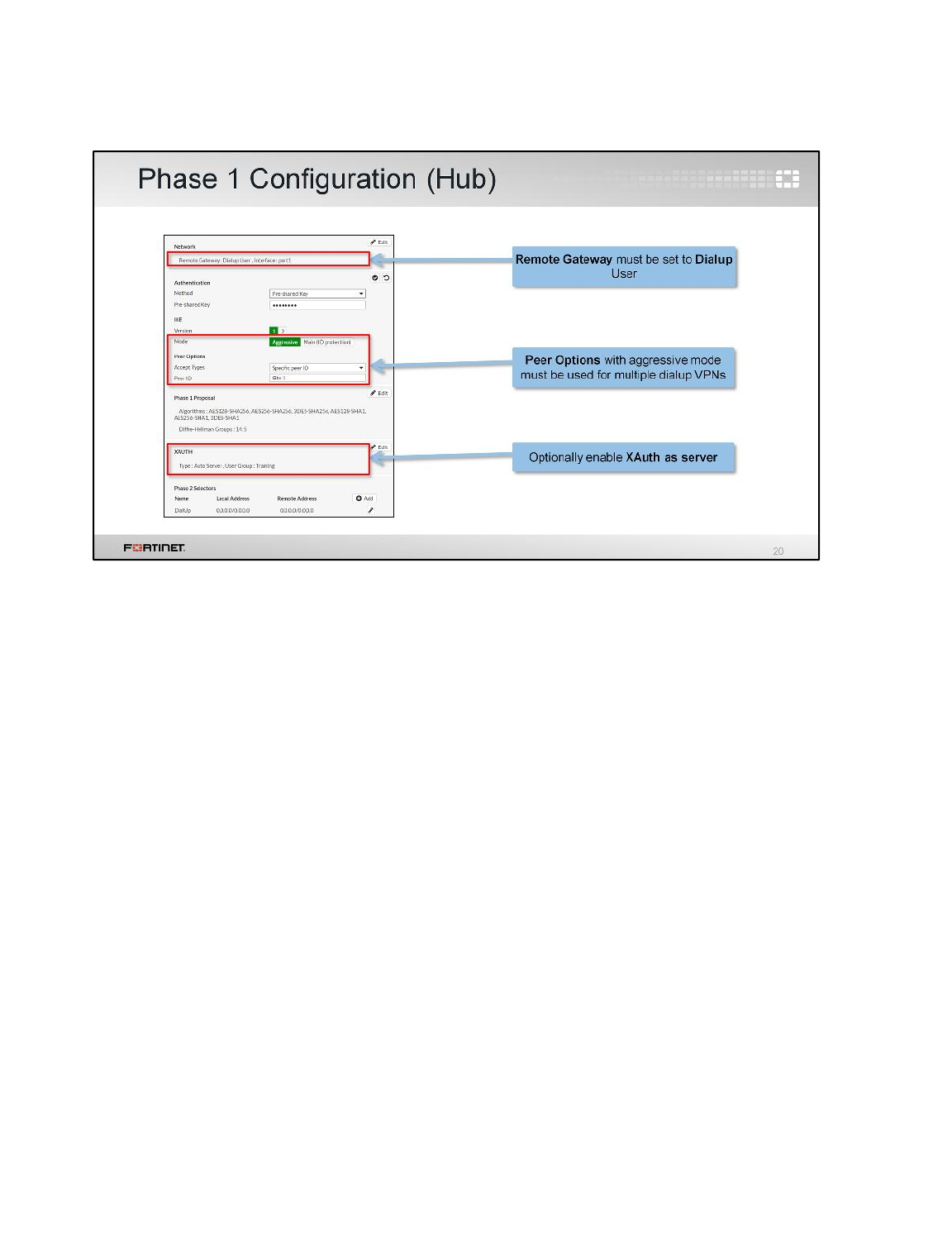
(slide contains animation)
Let’s start by configuring the phase 1 for the hub in a hub-and-spoke topology.
The Remote Gateway setting must be set to Dialup User.
(click)
If the hub contains multiple dialup VPNs, Aggressive Mode and the use of peer IDs is required.
(click)
To strengthen authentication, you can enable XAuth. The hub FortiGate will use the Enable as Server
setting. (Each FortiClient or spoke FortiGate will use Enable as Client.)
Additionally, NAT Traversal should be enabled if your spokes are mobile dialup users, because they
are usually behind NAT at airport terminals, home routers, and hotel firewalls.
Advanced IPsec VPN
FortiGate II Student Guide
316
DO NOT REPRINT
© FORTINET
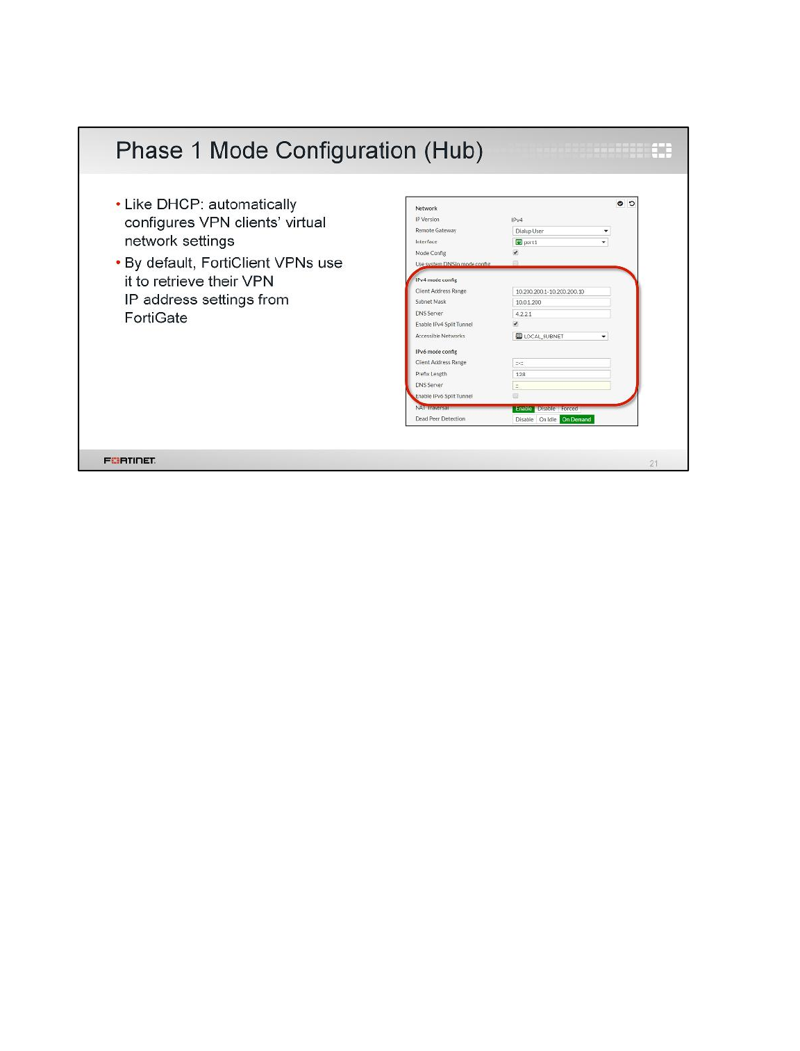
If your spokes are mobile users, such as FortiClient users, you will probably enable and configure
Mode Config on the hub’s phase 1. This is for an IPsec extension called IKE mode configuration.
Why? It’s usually not practical to allocate static IPs to each laptop and mobile phone. IKE mode
configuration is an alternative.
Like DHCP for VPNs, Mode Config automatically configures the client’s network settings. Like with
DHCP, you define a range for the pool of VPN virtual IPs and the DNS settings.
Advanced IPsec VPN
FortiGate II Student Guide
317
DO NOT REPRINT
© FORTINET
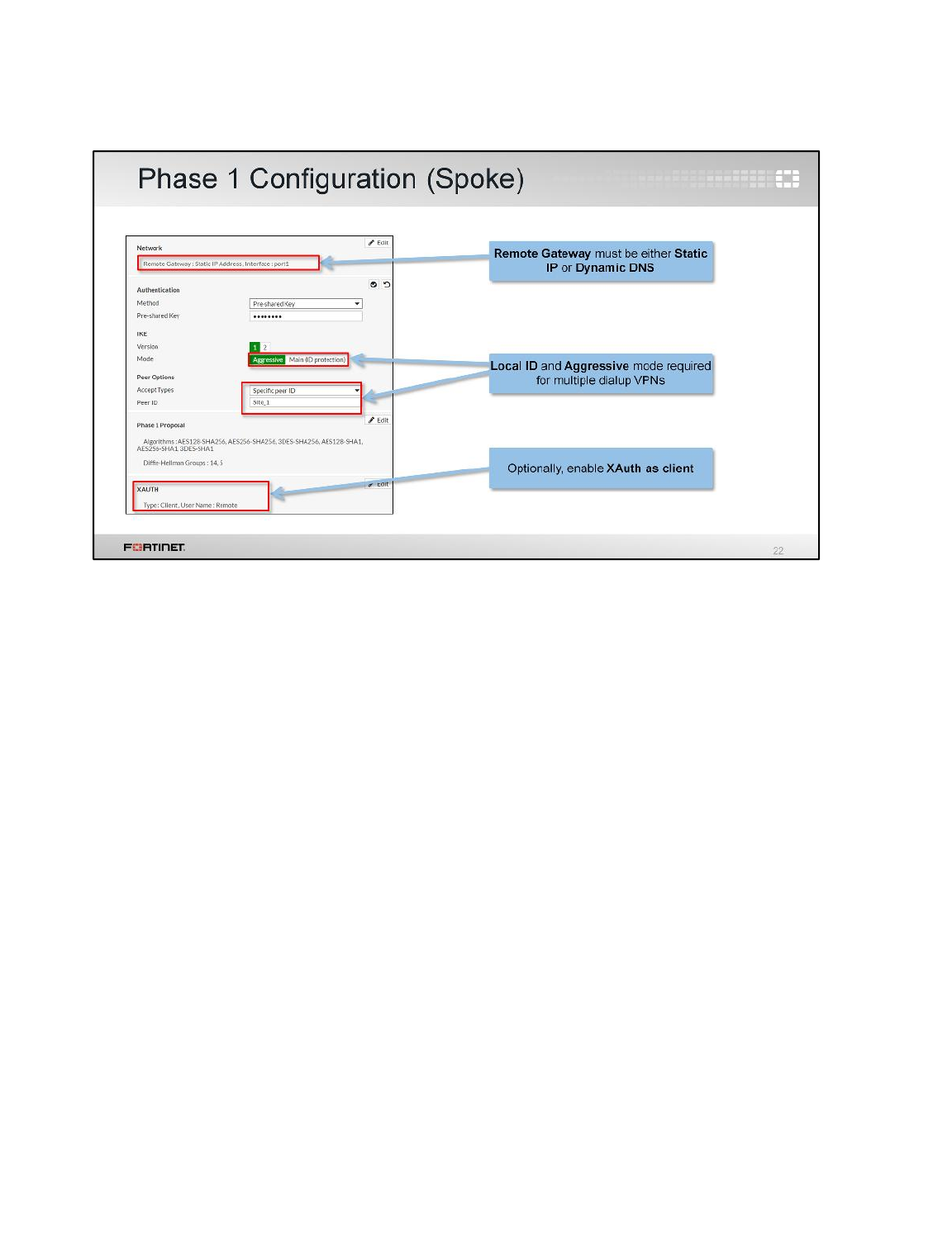
(slide contains animation)
Next, let’s look at the spoke's phase 1.
First, specify whether the hub for this spoke is using a Static IP or Dynamic DNS.
(click)
If the hub has multiple dialup VPNs, you must set the Mode to Aggressive. Then, in the Local ID,
you must enter the name that this spoke will use to identify itself to the hub. This ID must match the
one configured on the hub.
(click)
If you enable XAuth on the hub, you must enable XAuth on the spoke, too, and configure the user
name and password.
Advanced IPsec VPN
FortiGate II Student Guide
318
DO NOT REPRINT
© FORTINET
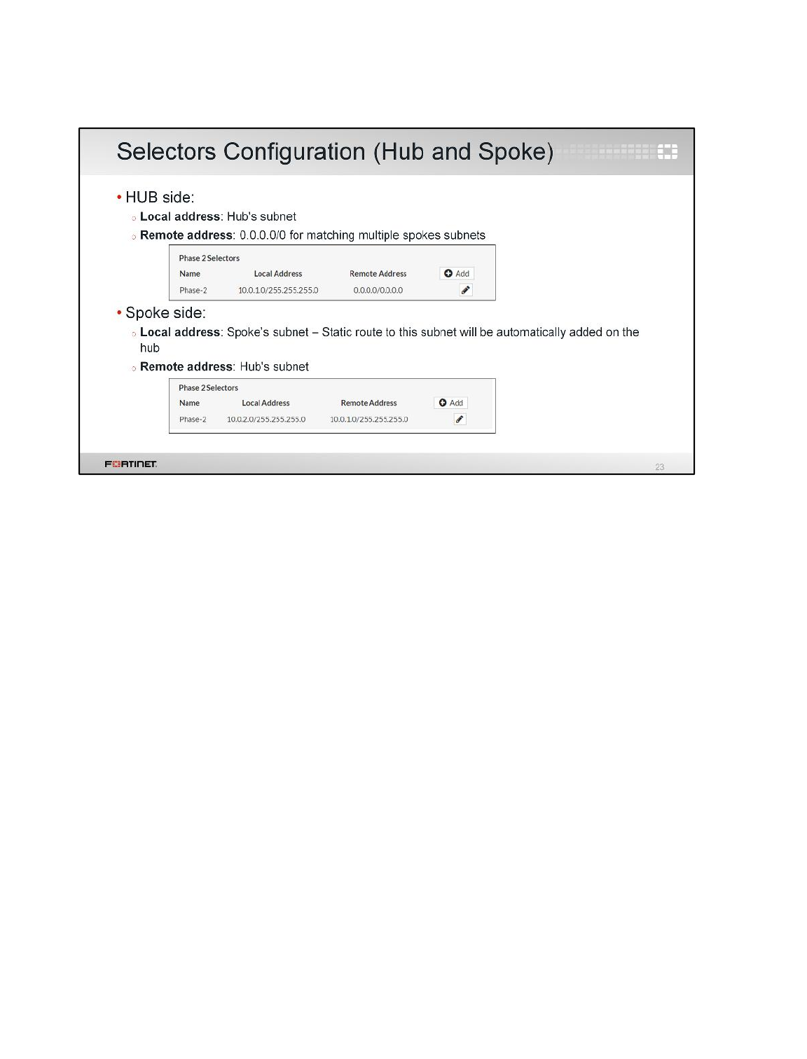
What about the quick mode selectors configuration in the phase 2?
Usually the local (source) quick mode selector in the hub is set either to 0.0.0.0/0 or to the hub's
subnet. The remote (destination) quick mode selector in the hub is usually set to 0.0.0.0/0 to match all
spoke subnets.
In the case of the quick mode selectors in the spoke, the local address must be the spoke’s subnet.
For route-based VPNs, the hub will dynamically add a static route to this subnet, immediately after
the VPN is established. (That way, you don’t need to manually configure the hub FortiGate with all
static routes for each spoke.)
The remote quick mode selector in the spoke is usually the hub’s subnet. In this case, a static route to
the hub's subnet is not dynamically added in the spoke when the tunnel comes up. This route must be
added to the configuration.
Note that unlike with point-to-point VPNs, quick mode selectors for point-to-multipoint do not need to
mirror each other.
Advanced IPsec VPN
FortiGate II Student Guide
319
DO NOT REPRINT
© FORTINET
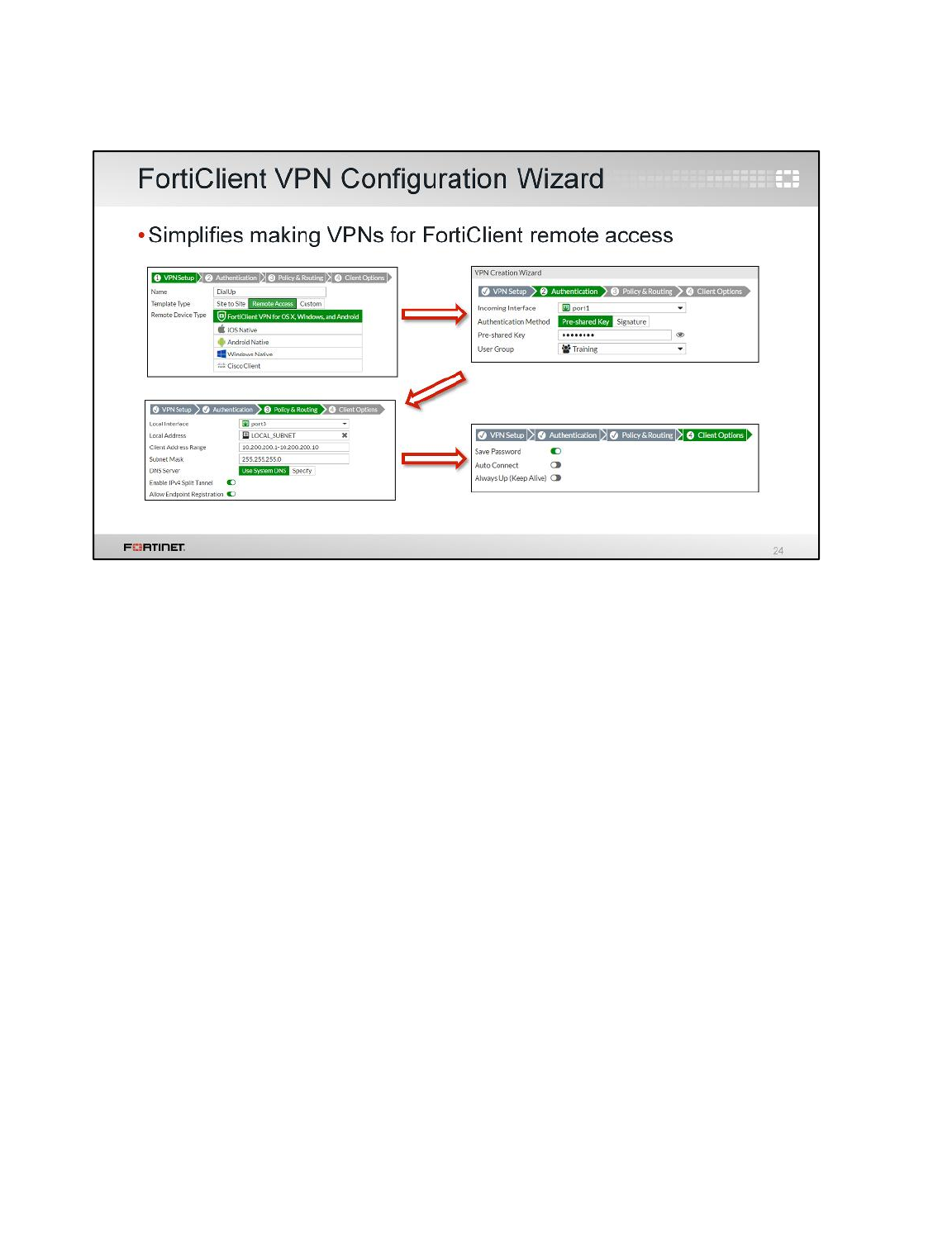
If your clients are FortiClient, there’s a simpler alternative to configure the hub. Use the VPN wizard. It
will use route-based and enable IKE Mode Config,XAuth, and other appropriate settings.
Advanced IPsec VPN
FortiGate II Student Guide
320
DO NOT REPRINT
© FORTINET

You can create more than one VPN between two sites, for traffic sharing and/or redundancy purposes.
Let's examine how to do it.
Advanced IPsec VPN
FortiGate II Student Guide
321
DO NOT REPRINT
© FORTINET
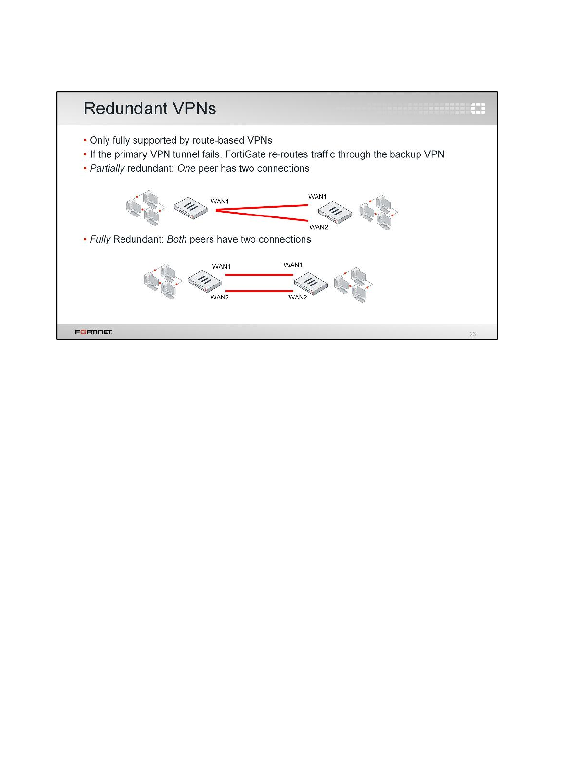
We mentioned briefly that hub-and-spoke is inherently not fault-tolerant: if something fails, then all
VPN tunnels might go down. How can you make your hub-and-spoke or point-to-point VPN more
resilient?
Provide a second ISP connection to your hub, and configure two route-based VPNs. If the primary
VPN fails, another tunnel can be used instead.
Two types of redundant VPNs exist:
• Partially redundant – On one peer (usually the hub, where a backup ISP is available if the main ISP
is down), each VPN terminates on different physical ports. That way FortiGate can use an
alternative VPN. But on the other peer, both VPNs terminate on the same physical port – so the
spoke is not fault-tolerant.
• Fully-redundant – Both peers terminate their VPNs on different physical ports. So they are both
fault-tolerant.
Advanced IPsec VPN
FortiGate II Student Guide
322
DO NOT REPRINT
© FORTINET
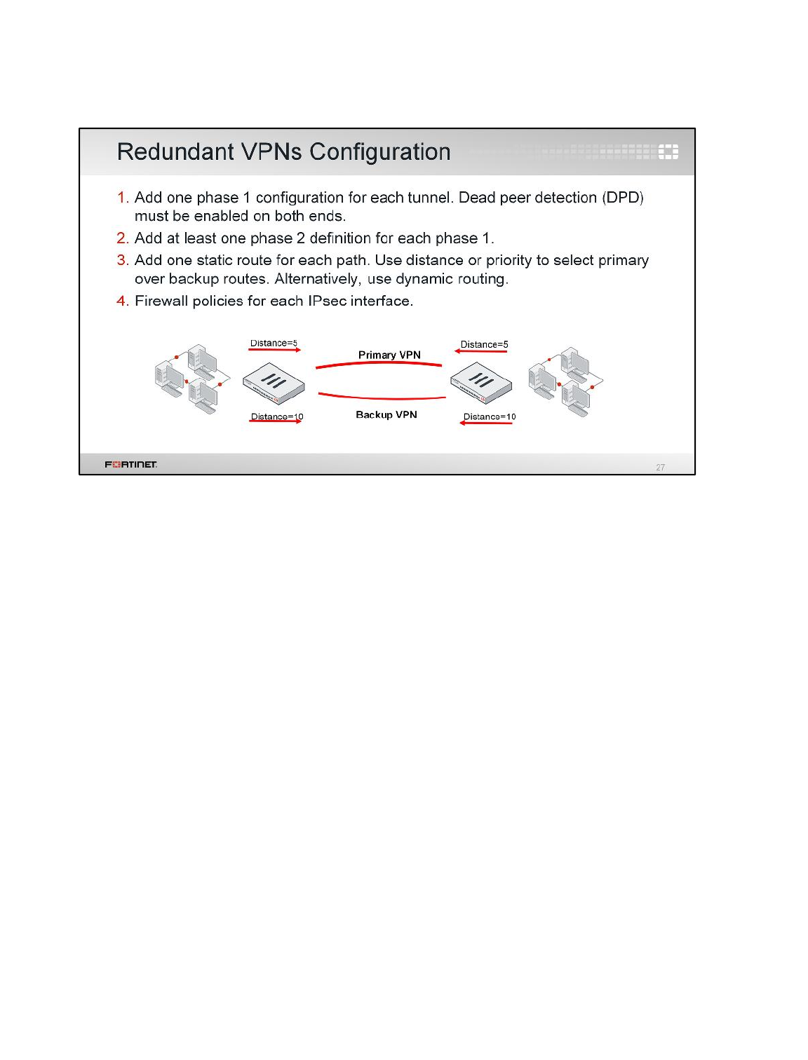
(slide contains animation)
So how can we configure a partially or fully redundant VPN?
First, create one route-based phase 1 for each path – one phase 1 for the primary VPN, and one for
the backup. Enable dead peer detection (DPD).DPD is a method for IPsec gateways to detect when
the VPN tunnel to its peer is down.
(click)
Second, create the phase 2s.
(click)
Then, because these are route-based VPNs, you must add at least one static route for each VPN.
Routes for the primary VPN must have a smaller distance (or smaller priority) than the backup. This
causes FortiGate to use the primary VPN while it’s available. If the primary VPN fails, then FortiGate
automatically uses the backup route. Alternatively, we could use a dynamic routing protocol, such as
OSPF or BGP.
(click)
Finally, configure firewall policies to allow traffic through both the primary and the backup VPNs.
Advanced IPsec VPN
FortiGate II Student Guide
323
DO NOT REPRINT
© FORTINET

What do you do if, after creating a tunnel, it does not come up? Let's take a look at that in this section.
Advanced IPsec VPN
FortiGate II Student Guide
324
DO NOT REPRINT
© FORTINET
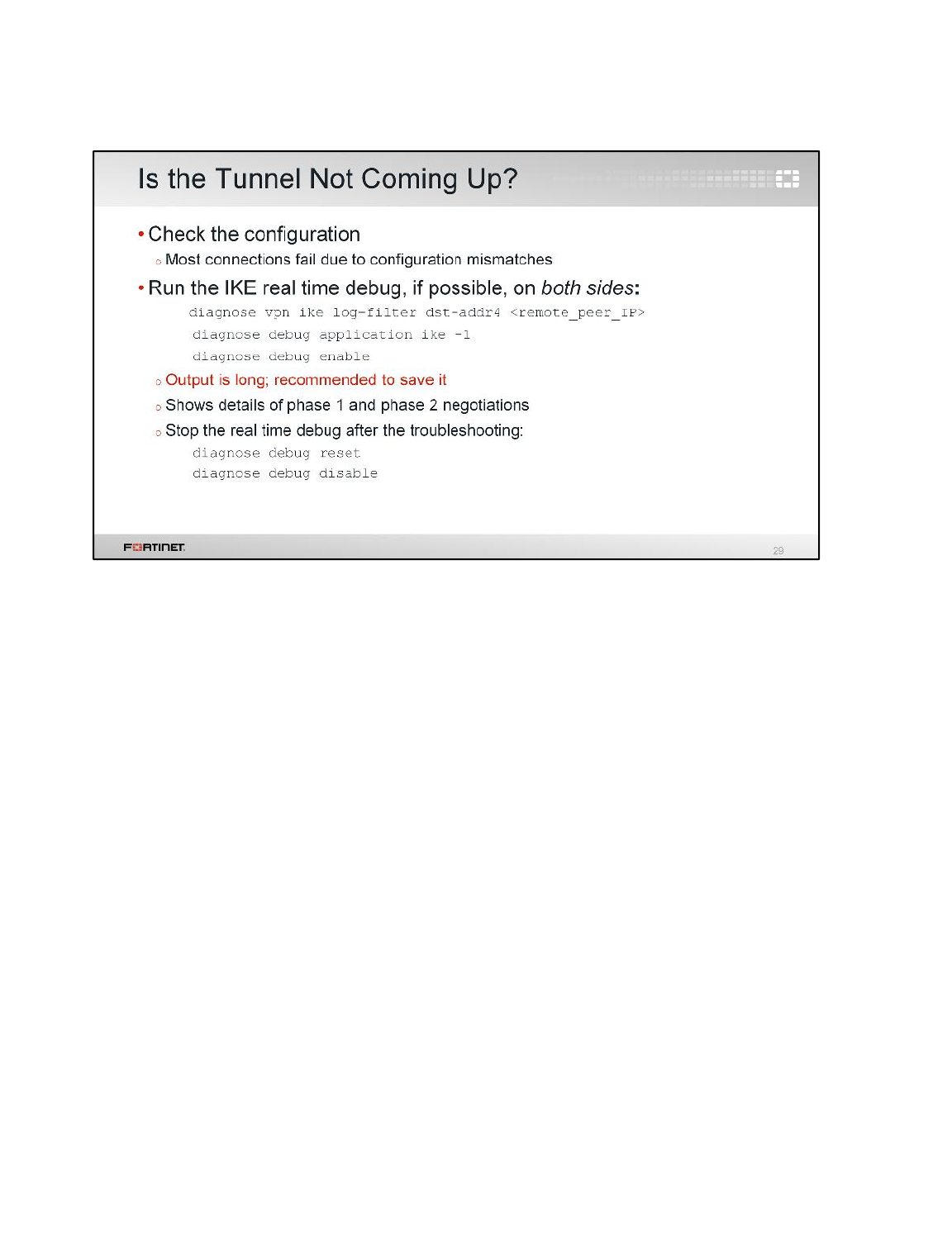
As you can see, IPsec VPN configuration can be complex. What is the best way to solve problems?
When troubleshooting a tunnel that does not negotiate, look for setting mismatches first. Most
connection failures are due to misconfiguration.
If you do not see any configuration mismatch, run the IKE real-time debug. Its output is extensive as it
shows the phase 1 and 2 negotiations step-by-step. If the negotiation fails, the IKE real-time debug
shows messages that can guide you toward the problem resolution.
To enable the IKE real-time debug, first create a filter with the command diagnose vpn ike log-
filter dst-addr4 and the IPsec peer's public IP address.
Then enable the debug with the commands diagnose debug application ike -1 and
diagnose debug enable.
Try to bring the tunnel while the debug is running and capture all the output.
After that, remember to stop the debug with the commands diagnose debug reset and
diagnose debug disable. It is not recommended to keep a real-time debug running on the
background of a FortiGate for a long time.
Advanced IPsec VPN
FortiGate II Student Guide
325
DO NOT REPRINT
© FORTINET
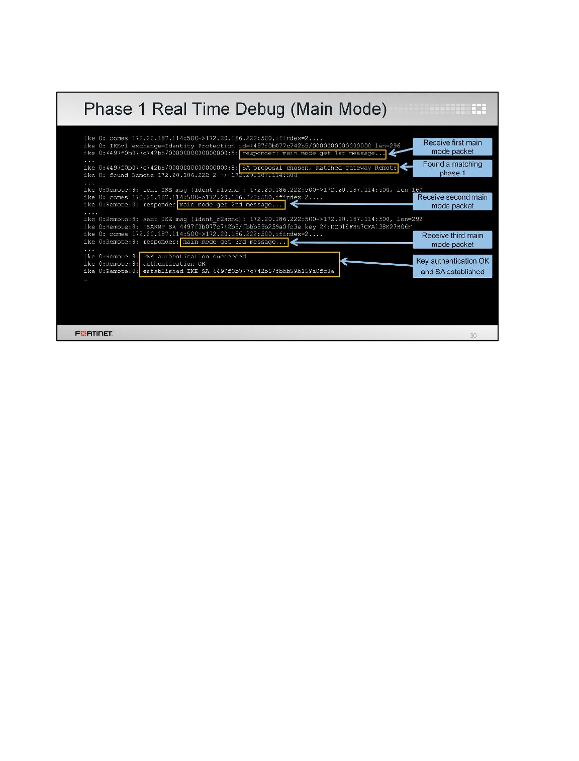
This shows some output for a successful phase 1 negotiation using main mode.
The first line shows the arrival of an IPsec packet from the IP address 172.20.187.114. The third line
indicates that the peer is using main mode.
A bit later, the debug shows that FortiGate accepted the SA proposal from the remote peer. It displays
the name of the phase 1 that matches the proposal. In this case, it’s the name Remote.
FortiGate replies to the first main mode packet. Then, the second main mode packet arrives.
FortiGate replies again, and the third main mode packet is received.
After finishing the negotiation, the output displays messages that indicate that the key exchange was
successful, and the IKE SA was established.
Advanced IPsec VPN
FortiGate II Student Guide
326
DO NOT REPRINT
© FORTINET
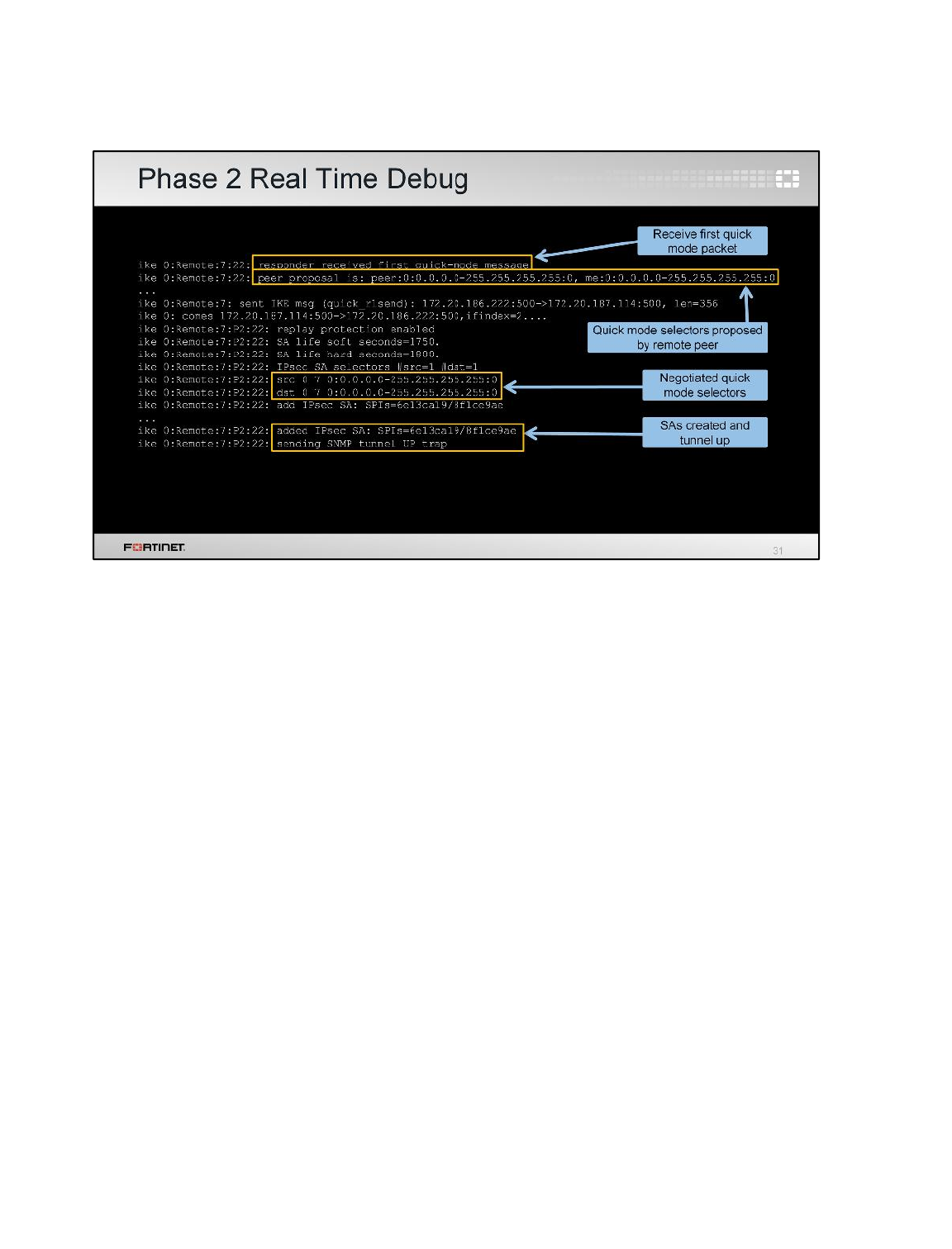
Let’s see what is displayed during the phase 2 negotiation. Again, the output is much longer than this.
The slide only shows a sample of some parts of that output.
The first line announces the arrival of the first quick mode packet.
The second line shows the quick mode selector proposed by the remote peer. In this case, it's
0.0.0.0/0 for both the source and destination.
Some lines below, the debug displays the quick mode selector that was successfully negotiated
between both peers.
The last two lines finally show that the tunnel is up and the IPsec SAs are established.
If there were any problem in the negotiation of either the phase 1 or 2, the output would show an error
message.
Advanced IPsec VPN
FortiGate II Student Guide
327
DO NOT REPRINT
© FORTINET
To review, this is what we talked about in this lesson.
We explained the differences between main mode and aggressive mode. We also covered extended
authentication, VPN topologies, ADVPN, dialup VPNs, and redundant VPNs. Finally, we provided
some troubleshooting tips.
Advanced IPsec VPN
FortiGate II Student Guide
328
DO NOT REPRINT
© FORTINET

In this lesson, you will learn how to use FortiGate to protect your network against intrusion and denial
of service attacks.
Intrusion Prevention and Denial of Service
FortiGate II Student Guide
329
DO NOT REPRINT
© FORTINET
After completing this lesson, you should have the practical skills required to detect and block known
attacks and network anomalies using IPS, denial of service (DoS) policies, and web application
firewall profiles.
The lesson also covers one-arm sniffer deployment.
Lab exercises can help you to test and reinforce your skills.
Intrusion Prevention and Denial of Service
FortiGate II Student Guide
330
DO NOT REPRINT
© FORTINET
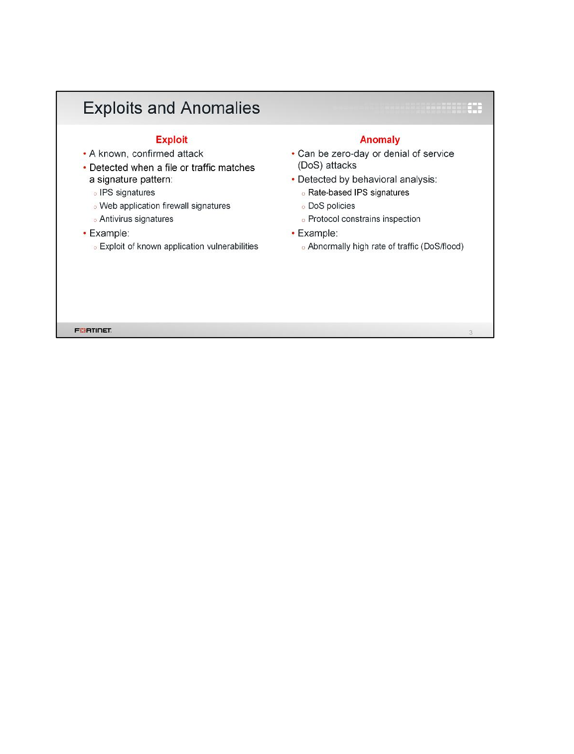
Before we begin, it’s important to understand the difference between an anomaly and an exploit. It’s
also important to know which FortiGate features offer protection against each of these two types of
threats.
Exploits are known attacks, with known patterns that can be matched by IPS, web application firewall,
or antivirus signatures.
Anomalies are unusual behaviors in the network, such as higher-than-usual CPU usage or network
traffic. Anomalies must be detected and monitored (and, in some cases, blocked or mitigated)
because they can be the symptoms of a new, never-seen-before attack. Anomalies are usually better
detected by behavioral analysis, such as rate-based IPS signatures, DoS policies, and protocol
constrains inspection.
Intrusion Prevention and Denial of Service
FortiGate II Student Guide
331
DO NOT REPRINT
© FORTINET
Exploits of unknown vulnerabilities – called zero-day attacks – are sold for large amounts of money on
the black market. Since these exploits aren’t known to their vendors, or to security experts, there’s no
available patch or signature for detection. That’s what makes them so dangerous.
Some companies and organizations, like Facebook and Google, have offered bounties for the
responsible disclosure of these exploits, but there’s a very profitable market for black hat hackers to
sell these discoveries to everyone from covert government surveillance to organized crime syndicates.
Zero-day attacks are the keys to your network’s kingdom.
Intrusion Prevention and Denial of Service
FortiGate II Student Guide
332
DO NOT REPRINT
© FORTINET
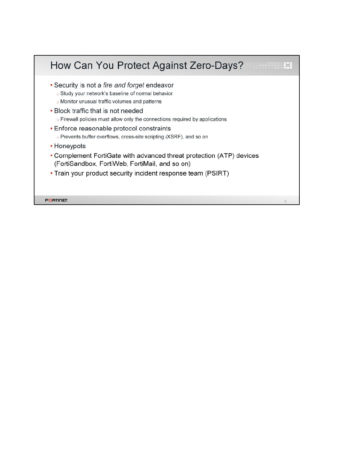
If you detect a zero-day attack, your initial instinct may be to take the server offline immediately, then
format it to remove all traces of malware. But by doing this, you’ll alert the attacker, and destroy
forensic evidence. This will only educate motivated attackers – their next attack will be harder to
detect, and more sophisticated. Make sure your PSIRT team understands the most appropriate way
to respond to each different type of intrusion.
Intrusion Prevention and Denial of Service
FortiGate II Student Guide
333
DO NOT REPRINT
© FORTINET

Now we’ll talk about the FortiGate features that protect your network against anomalies and exploits.
Let's start with intrusion prevention system (IPS).
Intrusion Prevention and Denial of Service
FortiGate II Student Guide
334
DO NOT REPRINT
© FORTINET
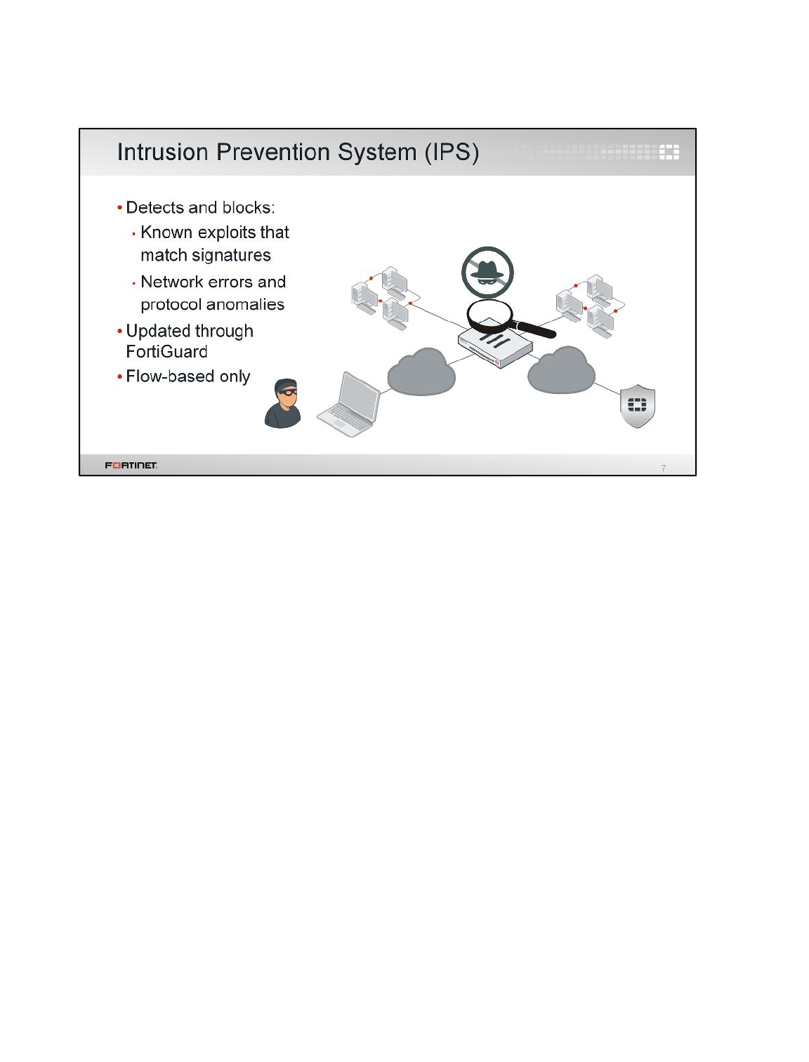
IPS uses signature databases to detect known attacks. IPS signatures can also be used to detect
network errors and anomalies.
Like the AV signature databases, the IPS signature databases are also updated through FortiGuard.
Intrusion Prevention and Denial of Service
FortiGate II Student Guide
335
DO NOT REPRINT
© FORTINET
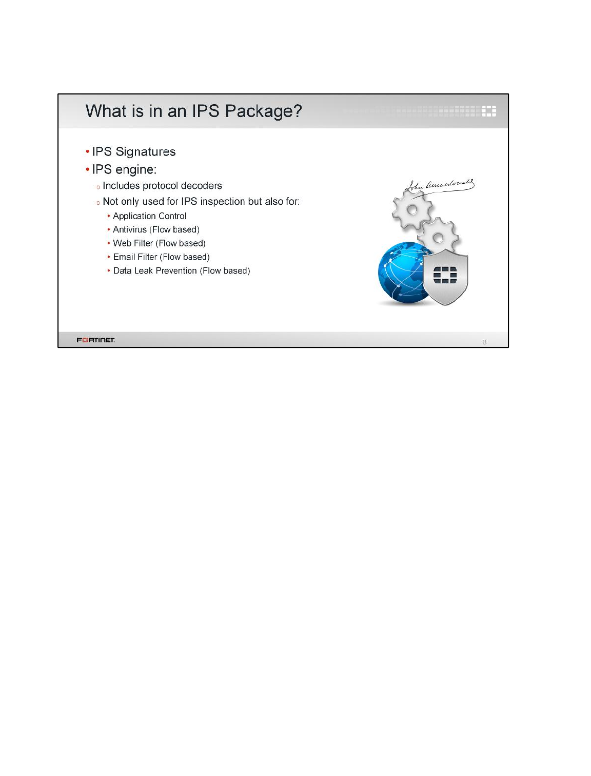
What does the IPS engine do?
The IPS engine is responsible for most of the features shown in this lesson: intrusion protection,
protocol decoders, and more. It’s also responsible for application control, flow-based antivirus
protection, web filtering, email filtering, and DLP.
Intrusion Prevention and Denial of Service
FortiGate II Student Guide
336
DO NOT REPRINT
© FORTINET
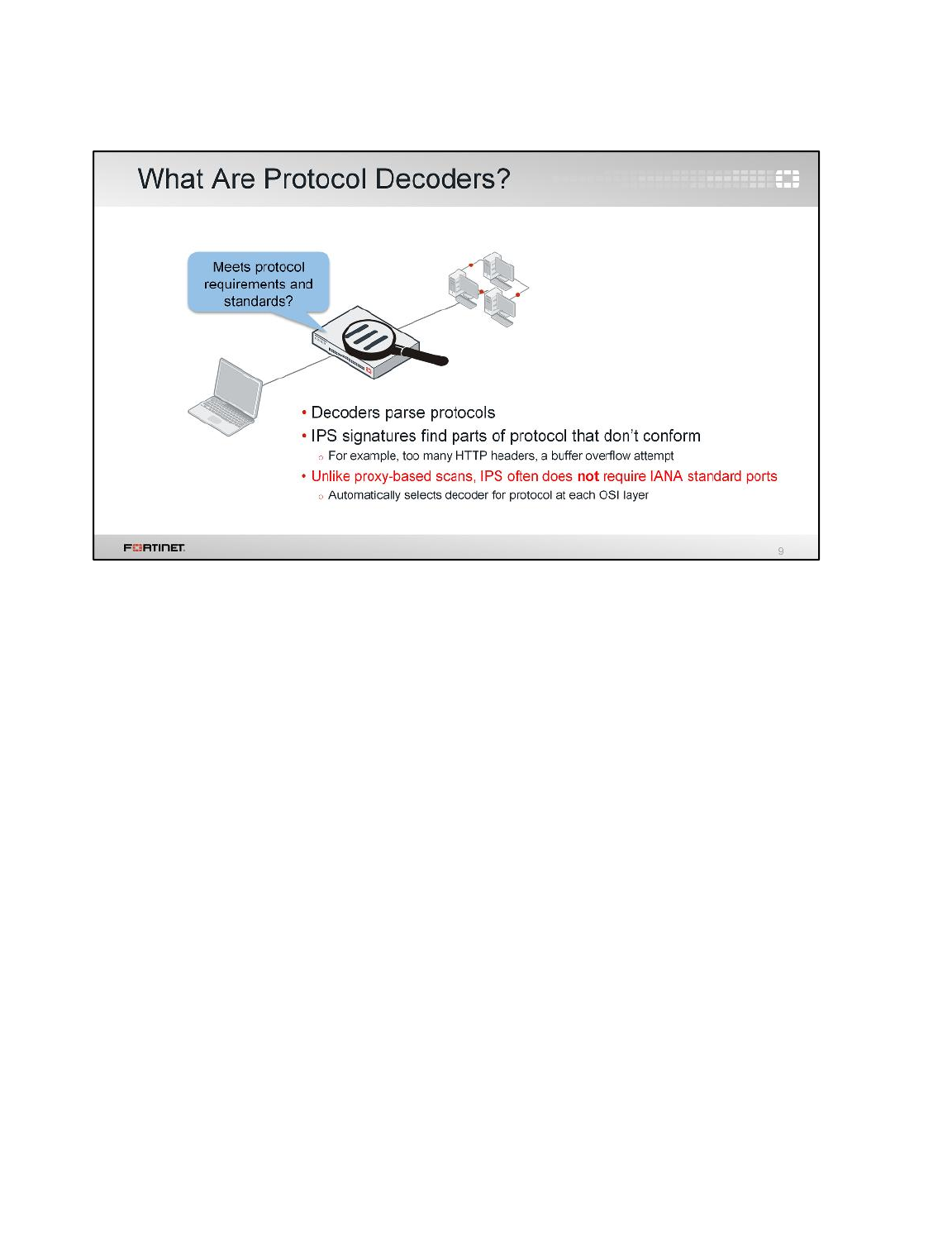
How does the IPS engine determine if a packet contains an attack or anomaly?
Protocol decoders parse each packet according to the protocol specifications. Some protocol
decoders require a port number specification (configured in the CLI), but usually, the protocol is
automatically detected. If the traffic doesn’t conform to the specification – if, for example, it sends
malformed or invalid commands to your servers – then the protocol decoder detects the error.
A default, initial set of IPS signatures is included in each FortiGate firmware release. FortiGuard IPS
service updates the IPS signatures, sometimes daily, with new signatures. That way, IPS remains
effective against new exploits. Unless a protocol specification or RFC changes (which is not very
often), protocol decoders are rarely updated. The IPS engine itself changes more frequently, but still
not often.
What part of IPS is updated most often? The IPS signatures. New signatures are identified and built
by FortiGuard research teams, just like antivirus signatures. So, if your FortiGuard Services contract
expires, you can still use IPS. However, just like with anti-virus scans, IPS scans will become
increasingly ineffective the longer your signatures go without being updated – old signatures won’t
defend against new attacks.
Intrusion Prevention and Denial of Service
FortiGate II Student Guide
337
DO NOT REPRINT
© FORTINET
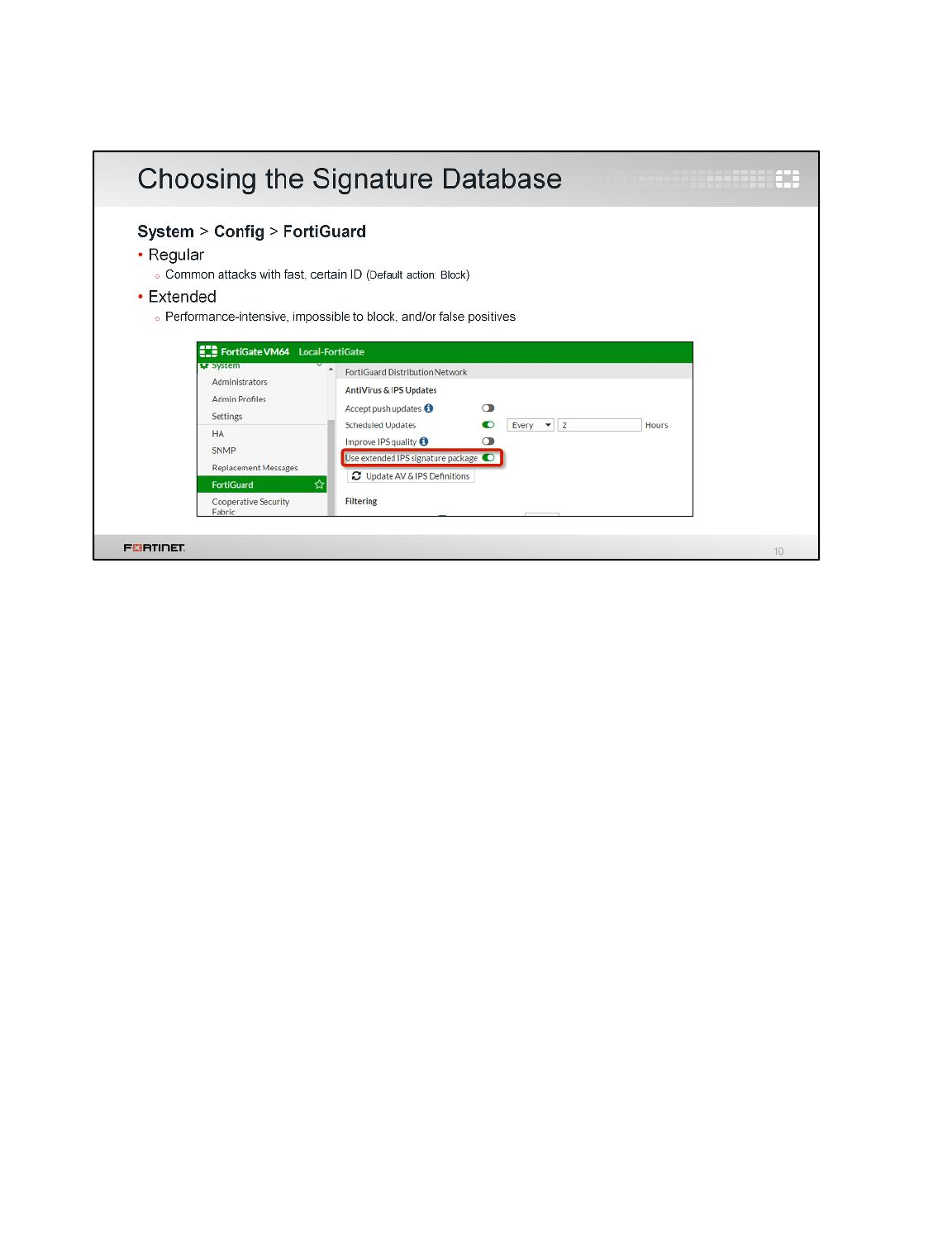
The regular signature database contains signatures for common attacks whose signatures cause rare
or no false positives. It's a smaller database, and its default action is to block the detected attack.
The extended signature database contains additional signatures for attacks that:
• cause a significant performance impact, or
• don’t support blocking due to their nature.
In fact, due to its size, the extended database is not available for FortiGate models with a smaller disk
or RAM. But, for high security networks, you may be required to enable the extended signatures
database.
Intrusion Prevention and Denial of Service
FortiGate II Student Guide
338
DO NOT REPRINT
© FORTINET
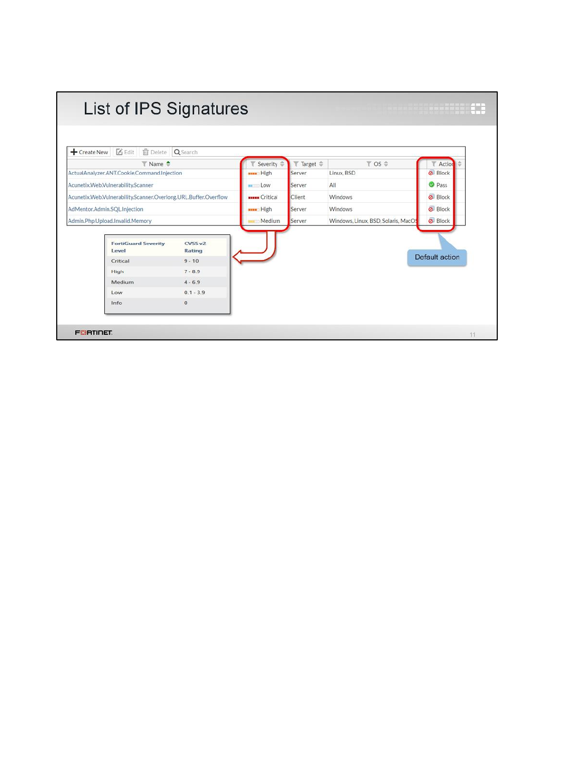
When your FortiGate downloads a FortiGuard IPS package, new signatures might appear in the
signature list. When configuring your FortiGate, you can change the Action setting for each sensor
that uses a signature.
The default action setting is often correct, except in these cases:
• Your software vendor releases a security patch. Continuing to scan for exploits will waste FortiGate
resources.
• Your network has a custom application with traffic that inadvertently triggers an IPS signature. You
can disable the setting until you notify Fortinet so that FortiGuard can modify the signature to avoid
false positives.
The severity level of each signature is also listed in the list of IPS signatures. What do the severity
indicators mean?
The FortiGuard severity level is based on the CVSS 2 rating system. There are many contributing
factors. For details, go to the first.org website.
Do all severity levels match CVSS exactly? No.
Fortinet always marks remote code execution as high or critical severity, regardless of the CVSS
rating. Details are explained on the FortiGuard website.
Intrusion Prevention and Denial of Service
FortiGate II Student Guide
339
DO NOT REPRINT
© FORTINET
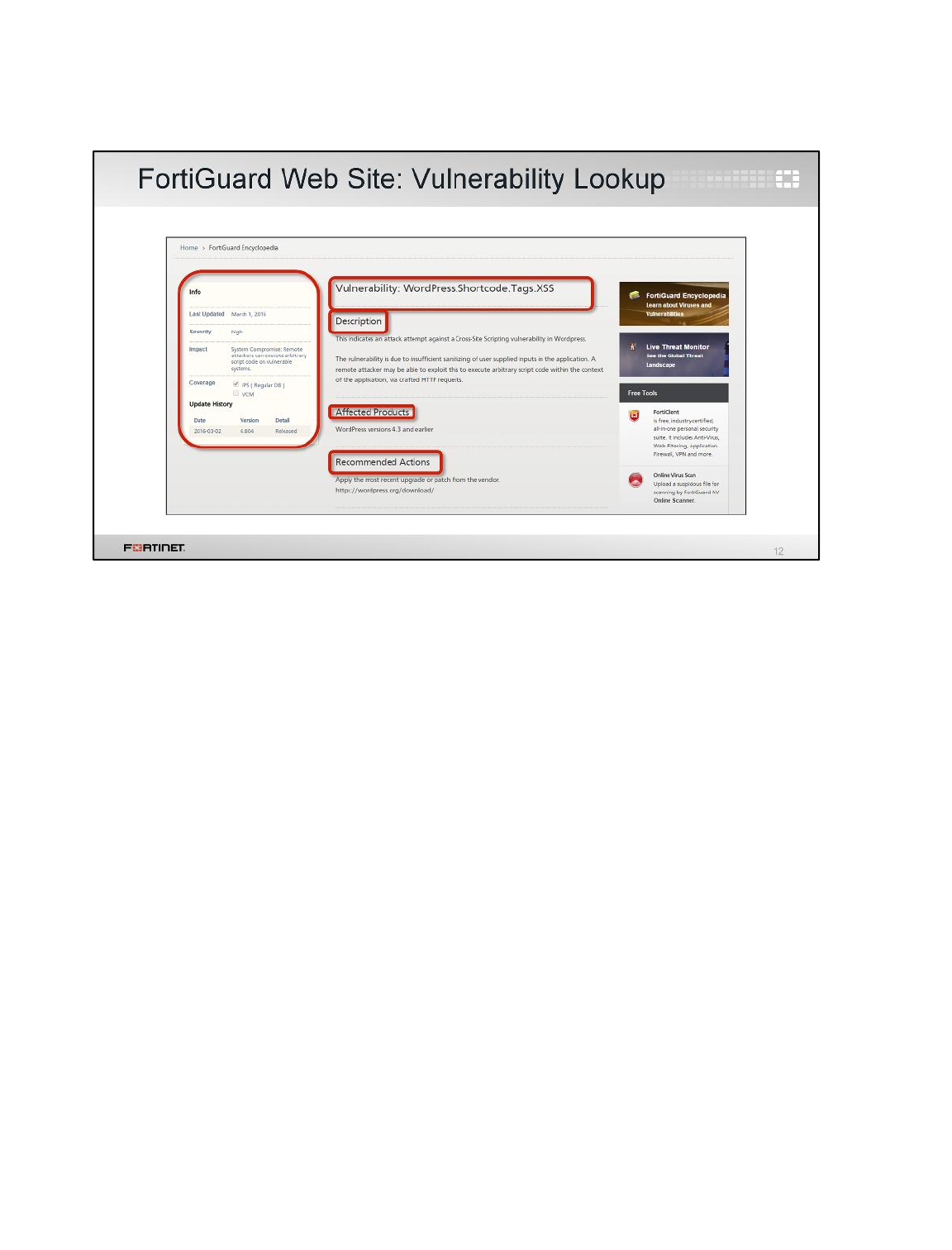
If you’re not sure if you should enable an IPS signature on your FortiGate, you can search the
encyclopedia on the FortiGuard website.
The encyclopedia contains useful information, such as affected systems and recommended corrective
actions. So if you don’t use that protocol or don’t have a vulnerable system, you can safely disable the
corresponding signature. But if you are vulnerable, the encyclopedia can provide information about
how to protect yourself.
The FortiGuard encyclopedia only contains publicly disclosed vulnerabilities. It does not contain
vulnerabilities that can’t yet be responsibly disclosed, regardless of the reason.
Intrusion Prevention and Denial of Service
FortiGate II Student Guide
340
DO NOT REPRINT
© FORTINET
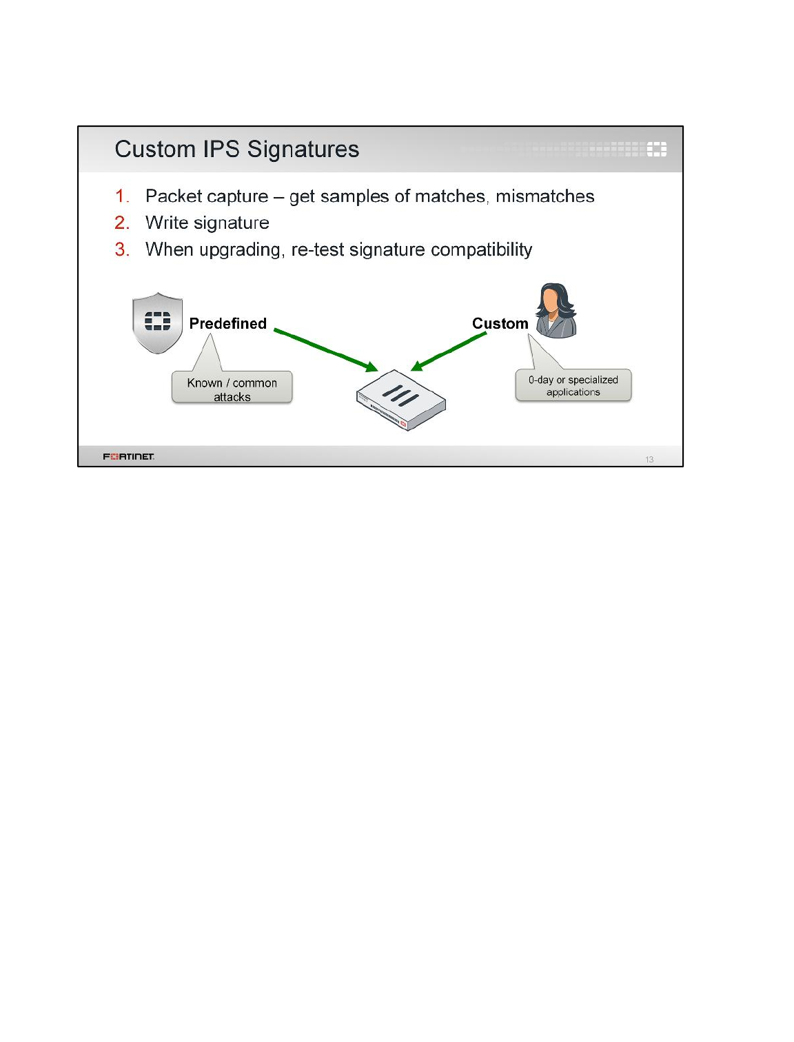
In addition to using the FortiGuard predefined signatures, you can also create your own custom
signatures. Before writing a custom signature, you should use packet capture to record packet
samples. You can use packet samples to help you understand and avoid mismatches with normal
packets on your network.
Remember, Fortinet does not provide support for problems created by misconfigured custom
signatures. So, if possible, you should test your custom signatures in a lab.
Intrusion Prevention and Denial of Service
FortiGate II Student Guide
341
DO NOT REPRINT
© FORTINET
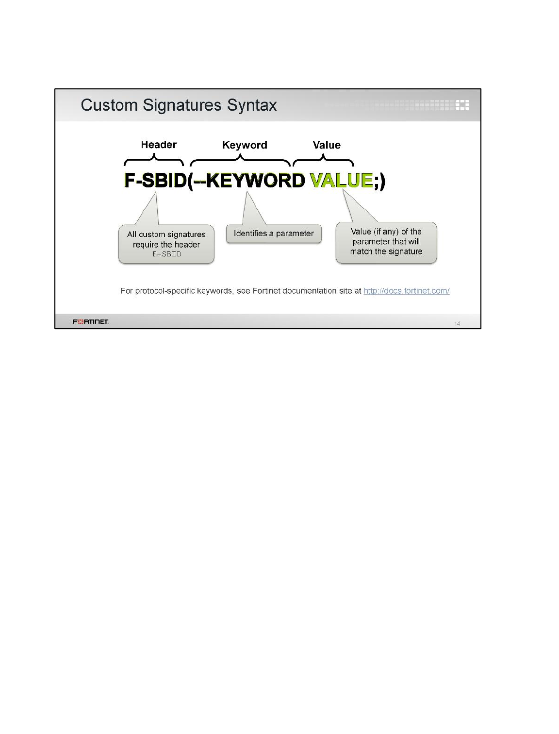
(slide contains animation)
What does a custom signature look like?
(click)
All custom signatures start with F-SBID(
(click)
After that, protocol-specific keywords define what part of the packet to search for a match, and what
values comprise a match. Usually, a keyword is followed by a corresponding value that represents its
setting, except for a few standalone keywords, such as --no_case. Each keyword-value pair ends
with a semi-colon and a space. You can include multiple key-value pairs in a signature. The signature
ends with a closing parenthesis.
A reference to syntax for custom IPS signatures can be found on the Fortinet documentation site.
Supported keywords vary by the protocol decoders. For example, the SMTP protocol supports the
VRFY command, and so there is a protocol decoder flag for it.
Intrusion Prevention and Denial of Service
FortiGate II Student Guide
342
DO NOT REPRINT
© FORTINET
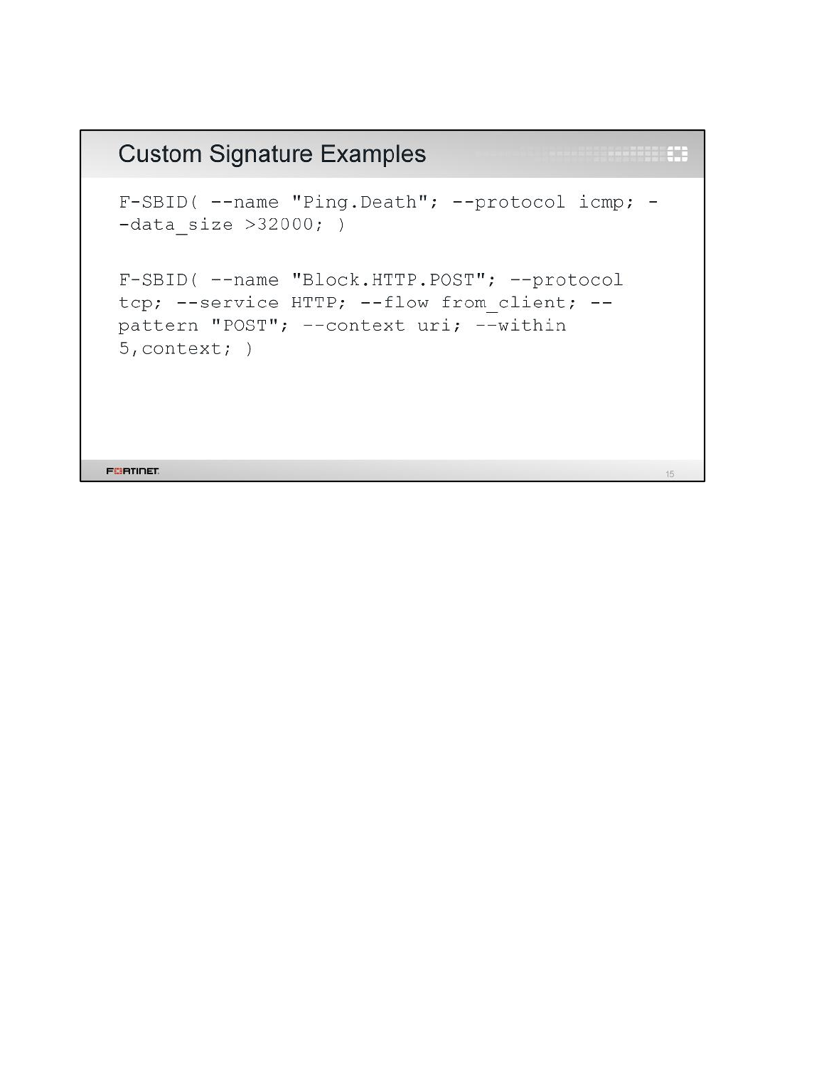
(slide contains animation)
In this example, the first sample custom signature is called Ping.Death. It searches for ICMP traffic
that exceeds about 32 KB.
(click)
The next sample custom signature is called Block.HTTP.POST. It searches for the pattern POST in a
specific location inside the packet. In normal HTTP POST requests, the method should be in this
specific location. Using a specific location in the signature prevents IPS from scanning the entire
HTTP payload, which could contain a web page that accidentally matches the pattern (for example,
the words POSTAL CODE). Your signature should be specific, but not too specific – extra comparisons
reduce performance.
Intrusion Prevention and Denial of Service
FortiGate II Student Guide
343
DO NOT REPRINT
© FORTINET
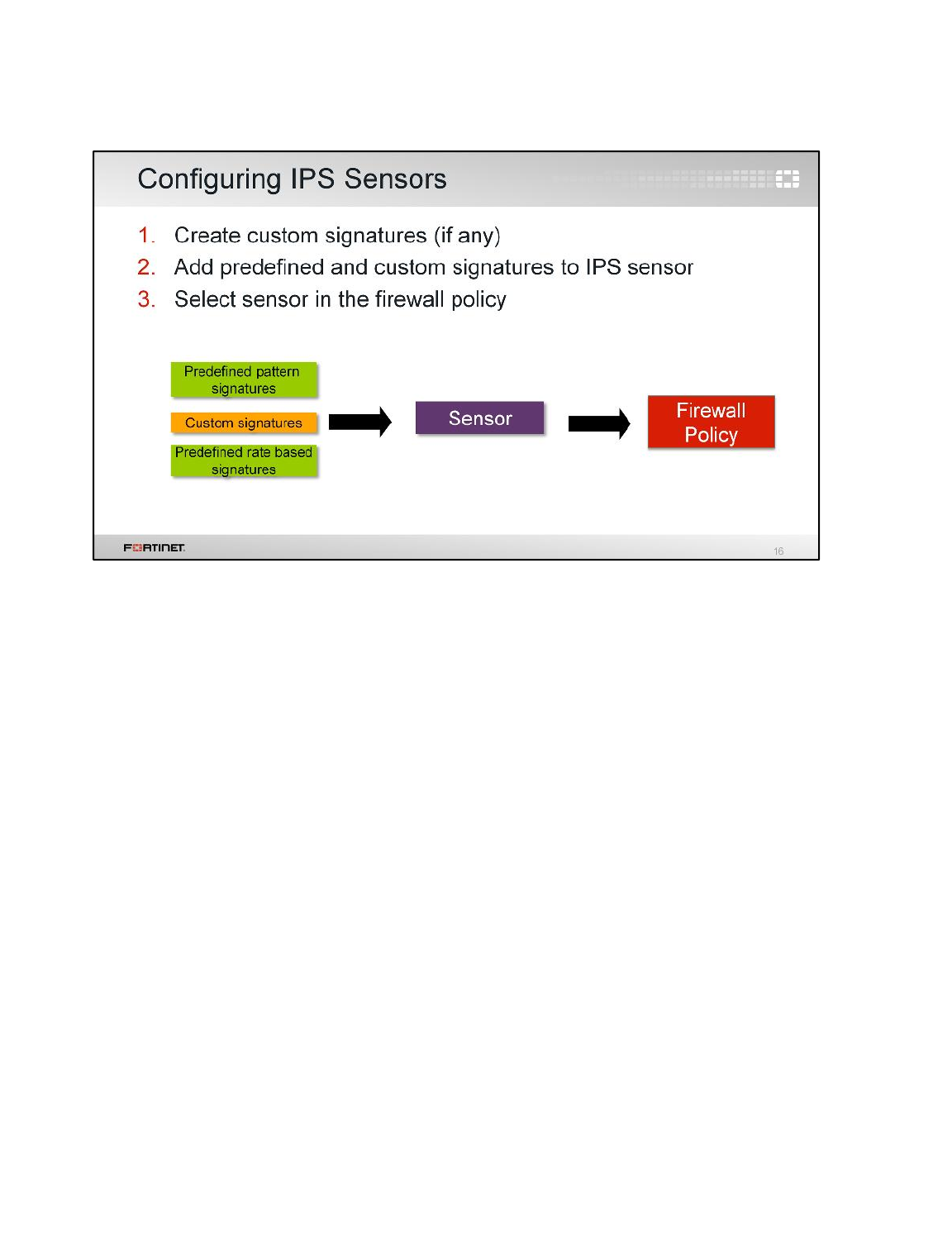
Once you have created your custom signature, pair it with an action within an IPS sensor, then
reference that IPS sensor in a firewall policy.
The steps for configuring IPS sensors are the same, regardless of whether you want to use custom
signatures or predefined signatures. A single IPS sensor can combine multiple predefined and custom
signatures.
Intrusion Prevention and Denial of Service
FortiGate II Student Guide
344
DO NOT REPRINT
© FORTINET
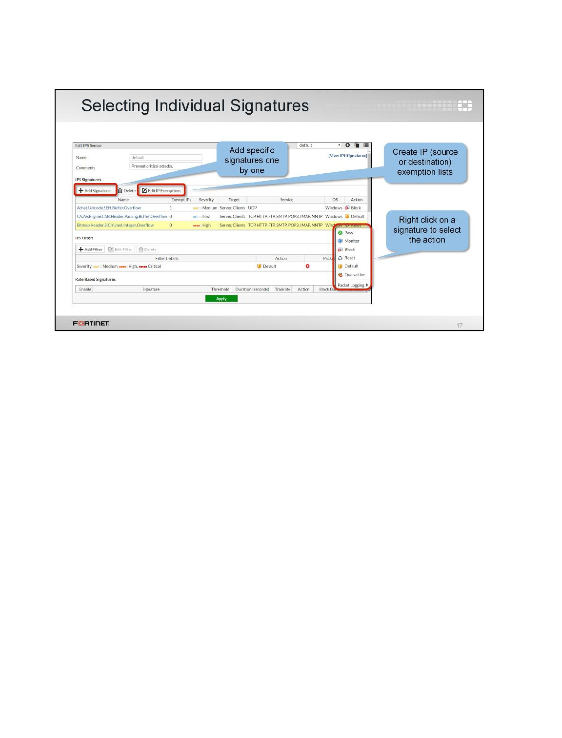
There are two ways of adding predefined signatures to an IPS sensor. One way is to select the
signatures individually. When you use this method you can create an exemption list based on the
source or destination IP address. Once a signature has been selected from the list, it is added to the
sensor with its default action. After that, you can right-click the signature and change the action.
Intrusion Prevention and Denial of Service
FortiGate II Student Guide
345
DO NOT REPRINT
© FORTINET
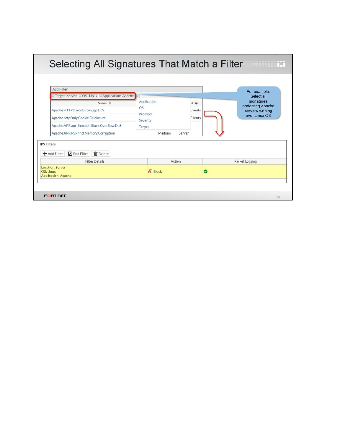
The second way to add a signature to a sensor is by using filters. FortiGate will add all the signatures
that match the filters.
In this example we’ve created a filter to include all the signatures that protect Apache severs running
over a Linux OS. The action is set to block all traffic that matches those signatures.
Each individual signature can include multiple tags, such as HTTP, Microsoft, IIS, and TCP. The more
specific you can make your filter, the less resources will be used to scan your traffic. This is because
the signature’s parts will seldom match the traffic, so the IPS engine can quickly continue with the next
comparison or scan.
If the signature that matches the traffic is both in the IPS Signature list and the IPS Filter list, the
FortiGate applies the action specified in the former one.
Intrusion Prevention and Denial of Service
FortiGate II Student Guide
346
DO NOT REPRINT
© FORTINET
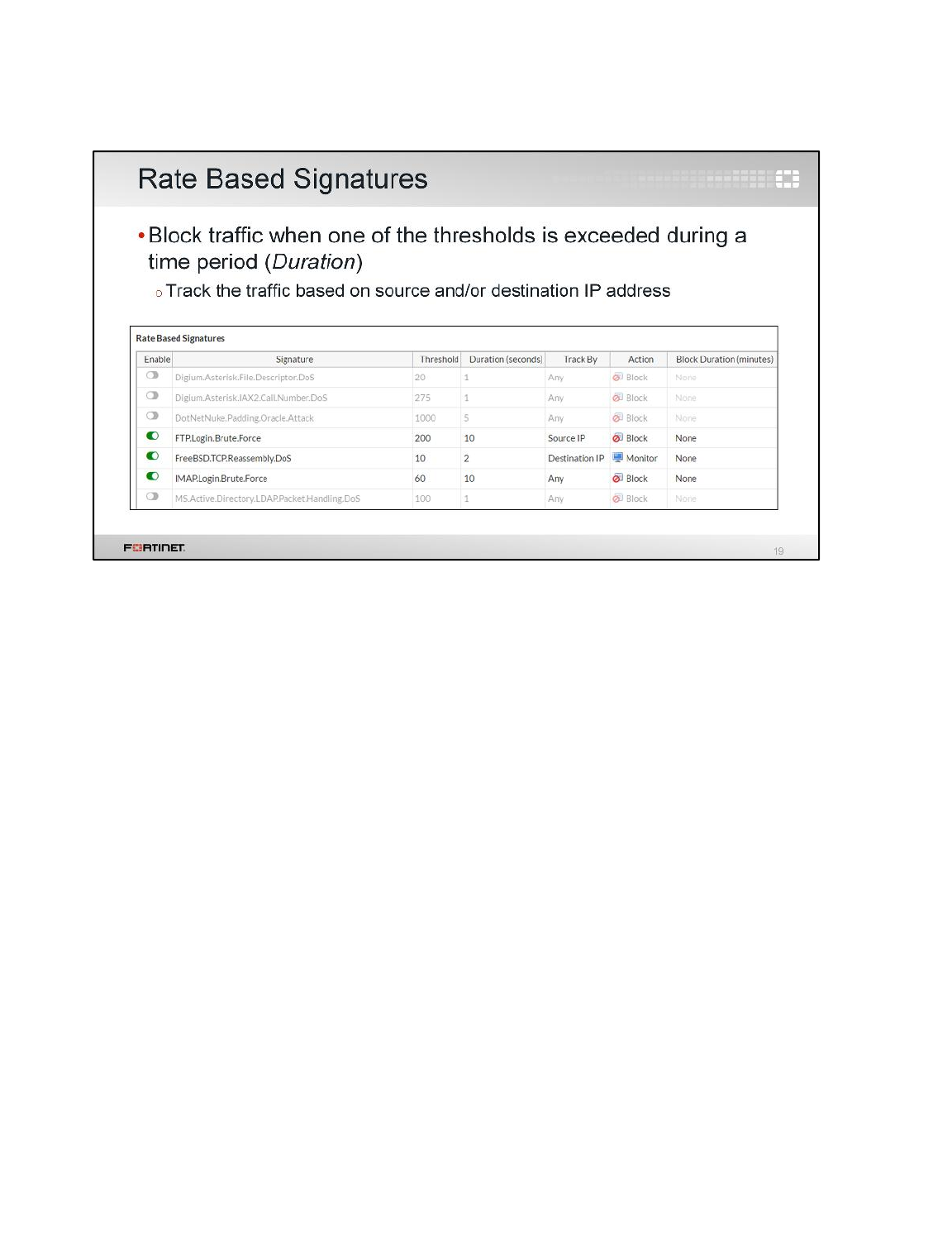
Rate based signatures (previously called anomalies) block specific traffic when one of the thresholds
is exceeded during the configured time period. Rate based signatures should be applied only to
protocols you actually use. Then block malicious clients for extended periods. This saves system
resources and can discourage a repeat attack: FortiGate will not track statistics for that client while it is
temporarily blacklisted.
Intrusion Prevention and Denial of Service
FortiGate II Student Guide
347
DO NOT REPRINT
© FORTINET
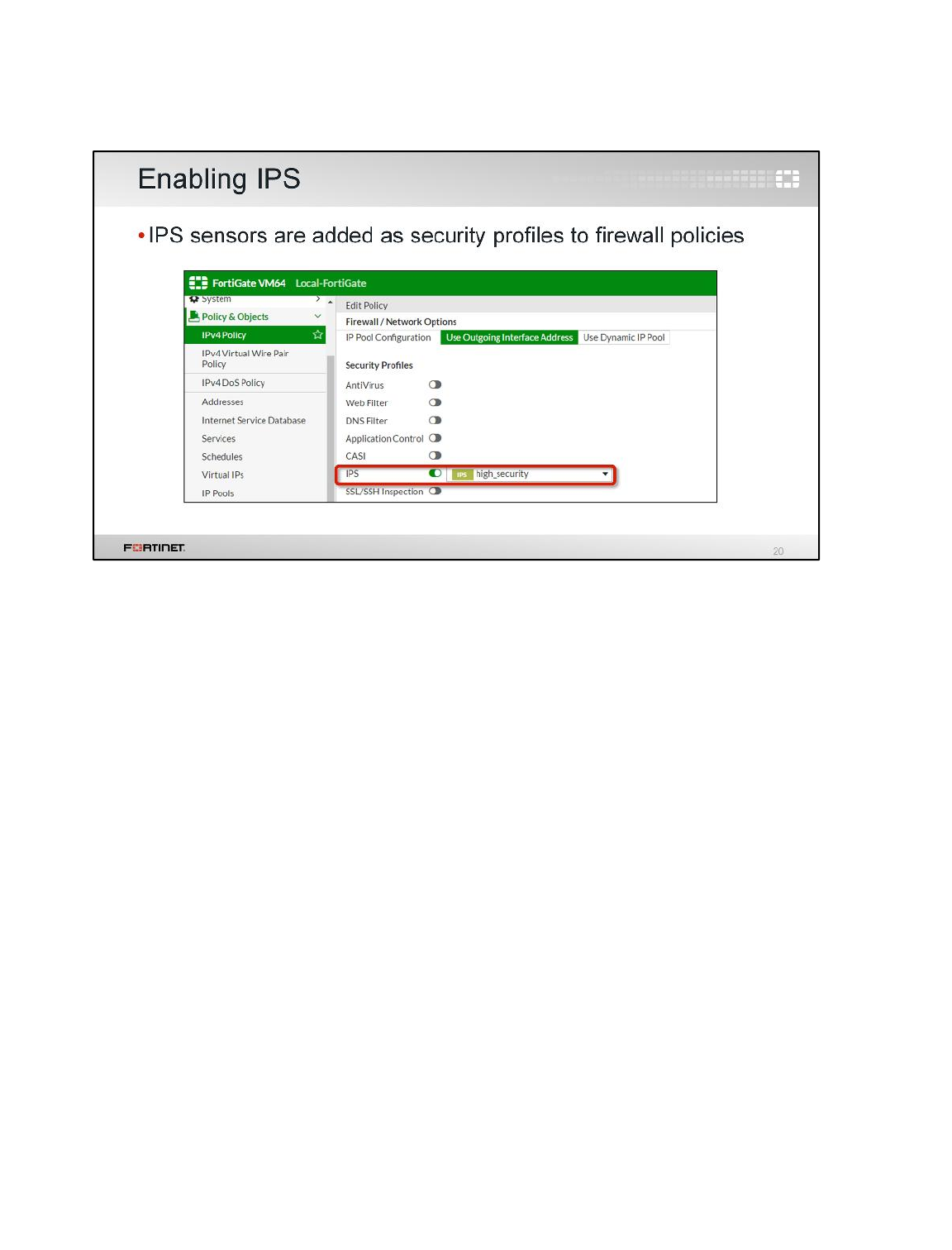
To apply an IPS sensor, you must enable IPS and then select the sensor in a firewall policy.
Intrusion Prevention and Denial of Service
FortiGate II Student Guide
348
DO NOT REPRINT
© FORTINET
Let's talk about denial of service (DoS) attacks and DoS policies.
Intrusion Prevention and Denial of Service
FortiGate II Student Guide
349
DO NOT REPRINT
© FORTINET
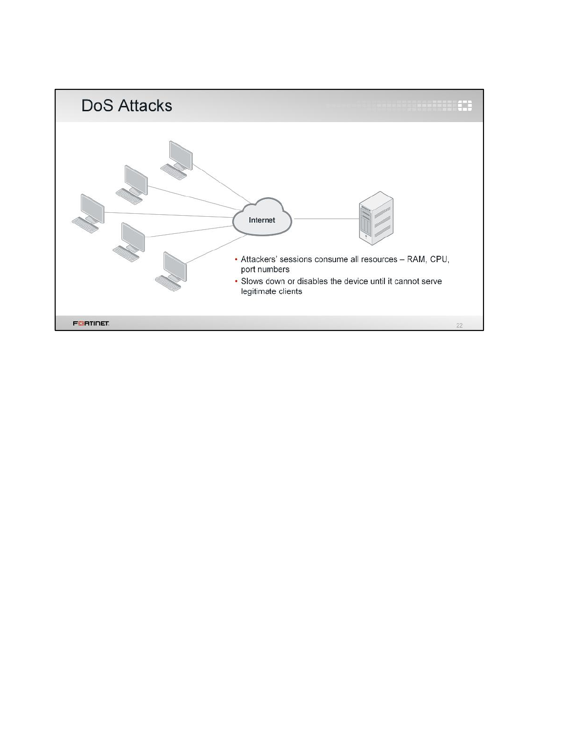
So far we’ve shown signatures that match illegal commands and invalid protocol implementations.
Those are easy to confirm as an attack.
What about attacks that function by exploiting asymmetric processing, or bandwidth between clients
and servers? There are many ways to make a DoS attack. For example, some DoS attacks exhaust
limited server-side bandwidth or sockets. Unless you know what bandwidth is abnormal for your
network, you may not be able to confirm an attack.
The goal of a DoS attack is to overwhelm the target – to consume resources until the target can’t
respond to legitimate traffic. This can be done in various ways. High bandwidth usage is only one type
of DoS attack. Many sophisticated DoS attacks, such as Slowloris, don’t require high bandwidth.
Intrusion Prevention and Denial of Service
FortiGate II Student Guide
350
DO NOT REPRINT
© FORTINET
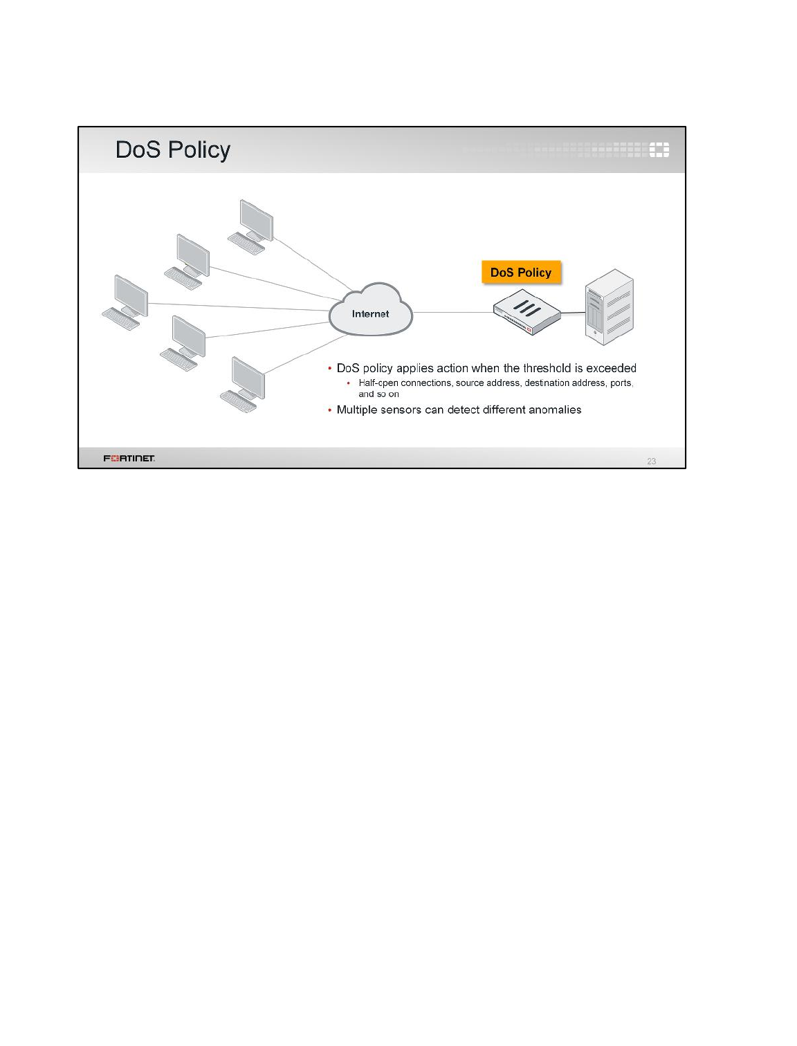
To block DoS attacks, apply a DoS policy on a FortiGate that sits between attackers and all the
resources that you want to protect.
Intrusion Prevention and Denial of Service
FortiGate II Student Guide
351
DO NOT REPRINT
© FORTINET
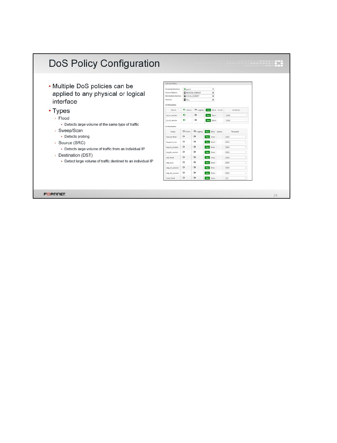
DoS protection can be applied to four protocols: TCP, UDP, ICMP and SCTP. Four different types of
anomaly detection can be applied to each protocol:
• A flood sensor detects a high volume of that particular protocol, or signal in the protocol.
• A sweep/scan detects attempts to map which of a host’s ports respond and therefore may be
vulnerable.
• Source signatures look for large volumes of traffic originating from a single IP.
• Destination signatures look for large volumes of traffic destined for a single IP.
If you do not have an accurate baseline for your network, when you implement DoS for the first time,
be careful not to completely block network services. To prevent this, initially configure the DoS policy
to log, but not block. Using the logs, you can analyze and determine normal and peak levels for each
protocol. Then, adjust the thresholds to comfortably, but not loosely, allow the usual peaks.
Thresholds that are too high can allow your resources to be exhausted before the DoS policies trigger.
Thresholds that are too low will cause FortiGate to drop normal traffic.
Intrusion Prevention and Denial of Service
FortiGate II Student Guide
352
DO NOT REPRINT
© FORTINET
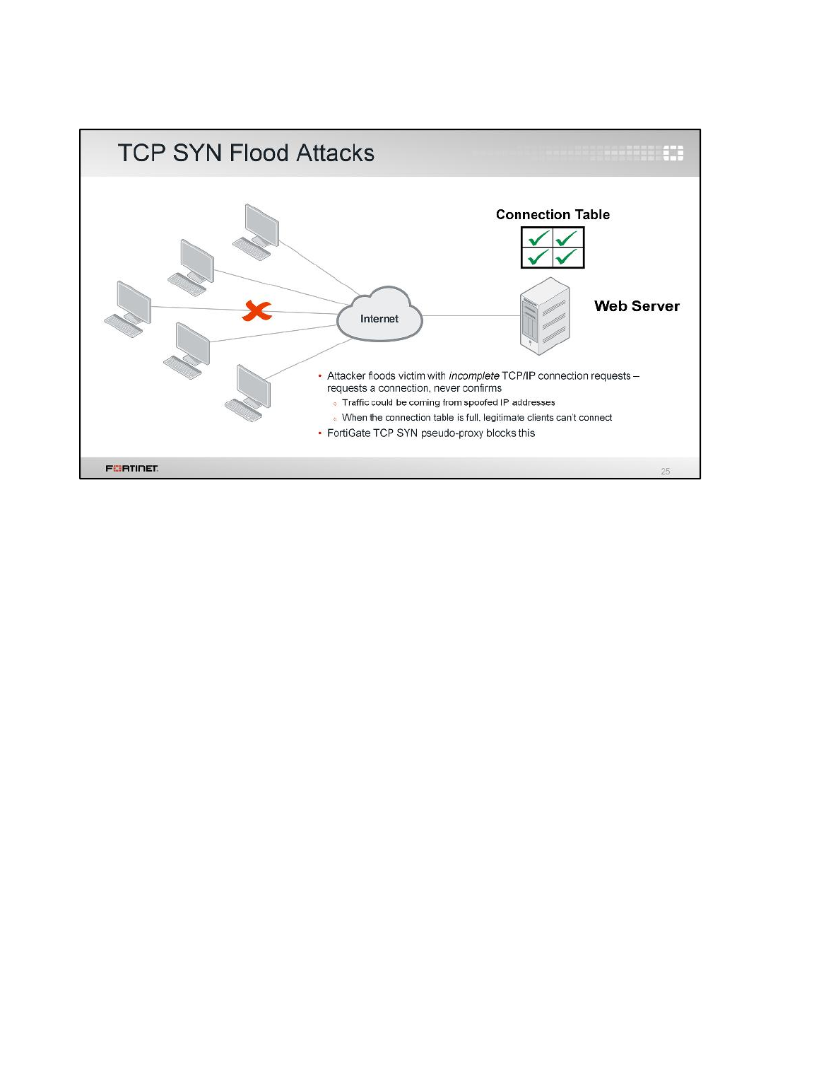
Now we’ll take a look at some common types of DoS attacks. The first is called a SYN flood attack.
In TCP, the client sends a SYN signal to initiate a connection. The server must respond, then
remember the start of the connection in RAM while it waits for the client to acknowledge (or ACK).
Normal clients will ACK quickly and begin to transmit data. But malicious clients continue to send
more SYN packets, half-opening more connections, until the server’s table is full. Once the server’s
table is full, it can’t accept more connections and begins to ignore all new clients.
To defend against this type of attack, FortiGate acts as a pseudo-proxy. It waits until the client has
finished connection build-up to form the back-end connection. If the connection build-up doesn’t
complete quickly, FortiGate begins to drop the attacker’s connection requests from the table.
Intrusion Prevention and Denial of Service
FortiGate II Student Guide
353
DO NOT REPRINT
© FORTINET
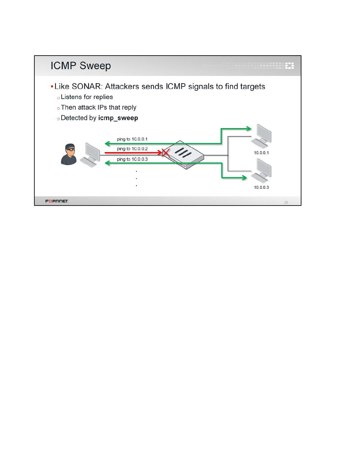
Another type of anomaly, or attack, is an ICMP sweep. ICMP is used during troubleshooting: devices
respond with success or error messages. But attackers can use ICMP to probe the network for valid
routes and responsive hosts.
By doing an ICMP sweep, the attacker can gain information about your network before crafting more
serious exploits.
Intrusion Prevention and Denial of Service
FortiGate II Student Guide
354
DO NOT REPRINT
© FORTINET
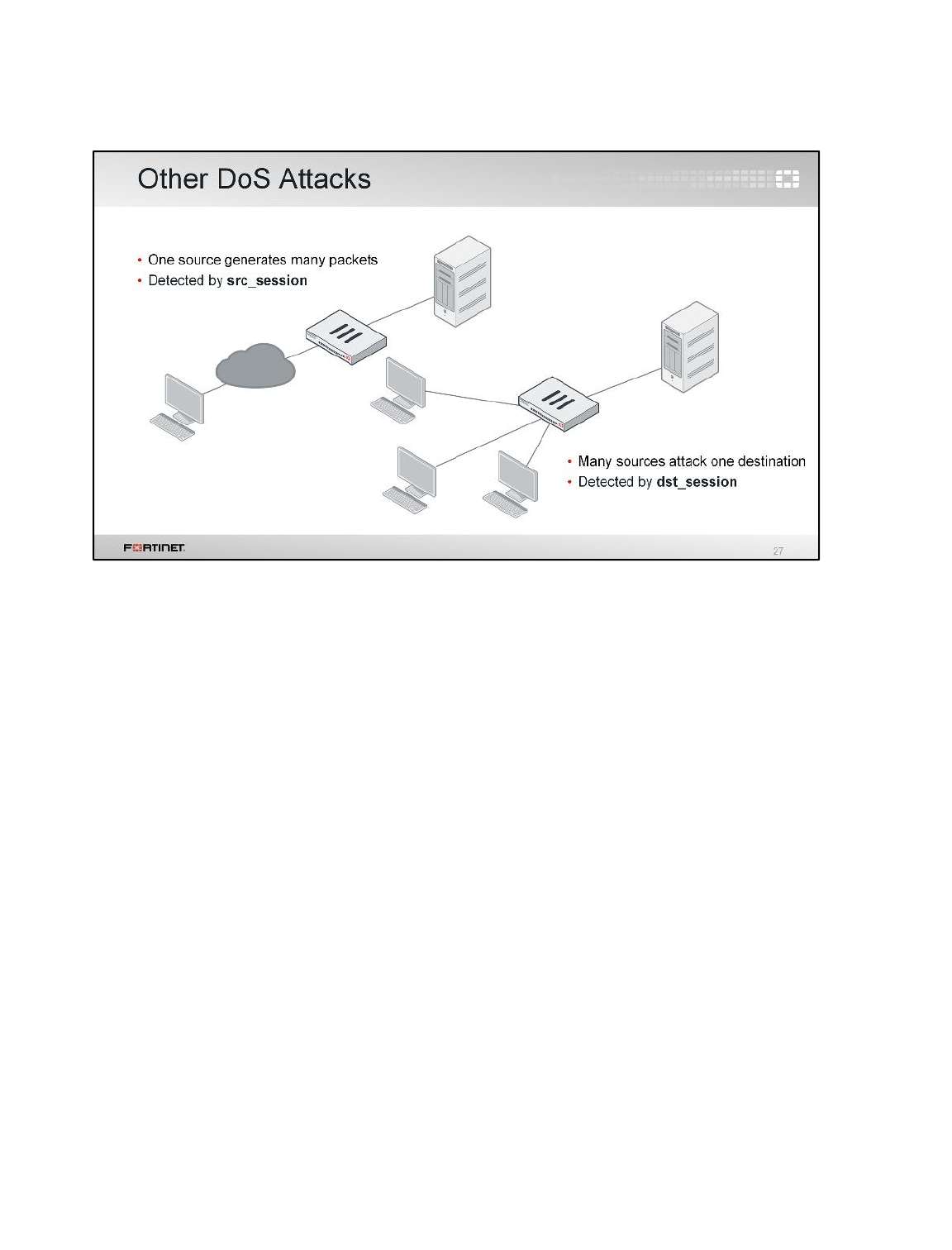
An individual DoS attack is a flood of traffic coming from a single address. It can originate from the
Internet, or even from your internal network. Typically, a single device makes many connections or
sessions, and possibly uses much bandwidth to a connect to a single location.
All four protocols in the DoS profile (ICMP, TCP, UDP, SCTP) have an anomaly sensor for the source.
These are built to examine the traffic that each IP is generating and compare that traffic to the
threshold value.
A variation of this is the distributed denial of service attack or DDoS. It has many of the same
characteristics as a single DoS attack, but the main difference is that multiple devices are all attacking
one destination at the same time.
Intrusion Prevention and Denial of Service
FortiGate II Student Guide
355
DO NOT REPRINT
© FORTINET

This section is about web application firewall, known as WAF.
Intrusion Prevention and Denial of Service
FortiGate II Student Guide
356
DO NOT REPRINT
© FORTINET
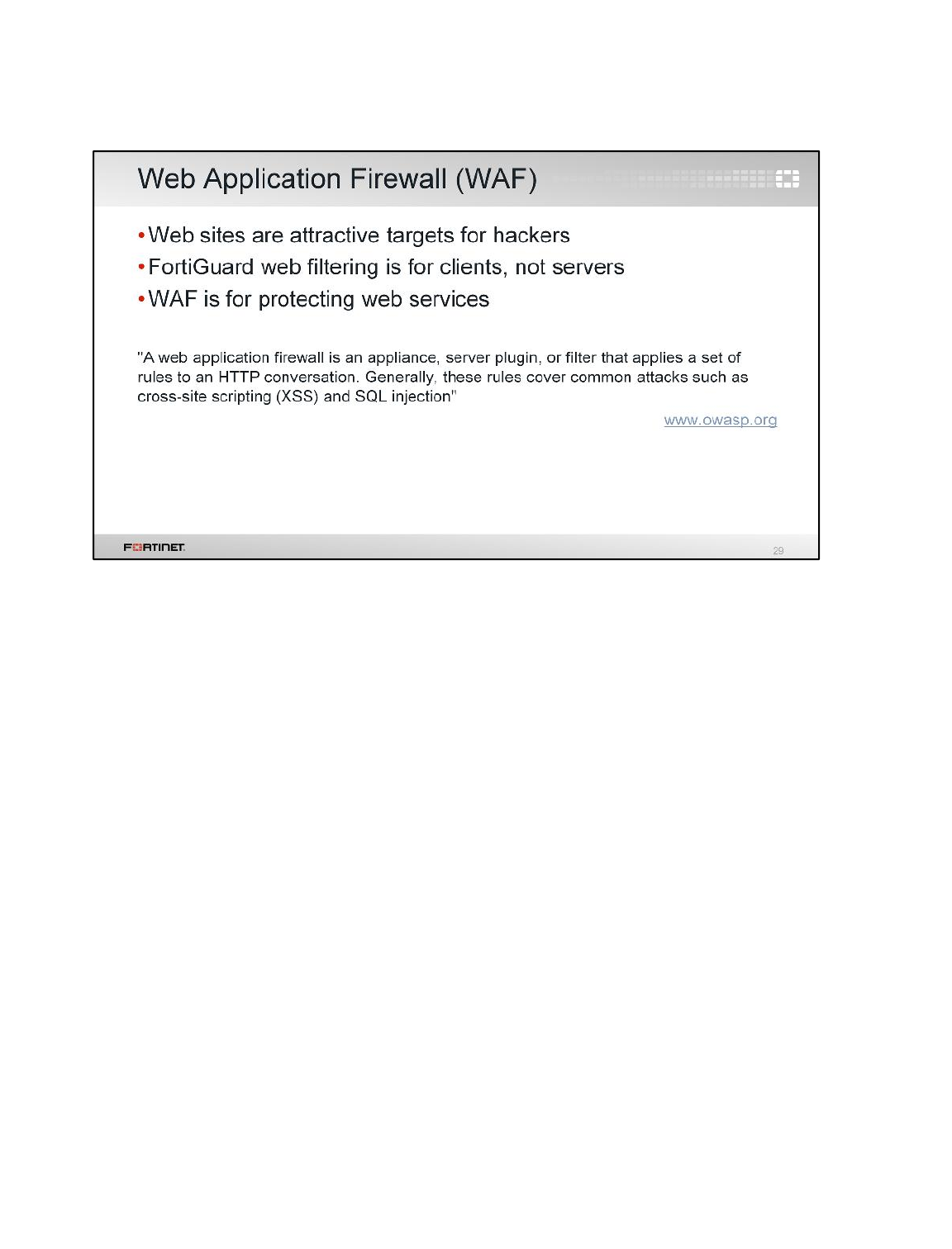
What is a WAF and why do you need it?
Some FortiGate features are meant to protect clients, not servers. For example, FortiGuard web
filtering blocks requests based on the category of the server’s web pages. Antivirus prevents clients
from accidentally downloading spyware and worms. Neither protect an innocent server (which doesn’t
send requests – it receives them) from script kiddies or SQL injections.
Protecting web servers requires a different approach because they are subject to other kinds of
attacks.
Intrusion Prevention and Denial of Service
FortiGate II Student Guide
357
DO NOT REPRINT
© FORTINET
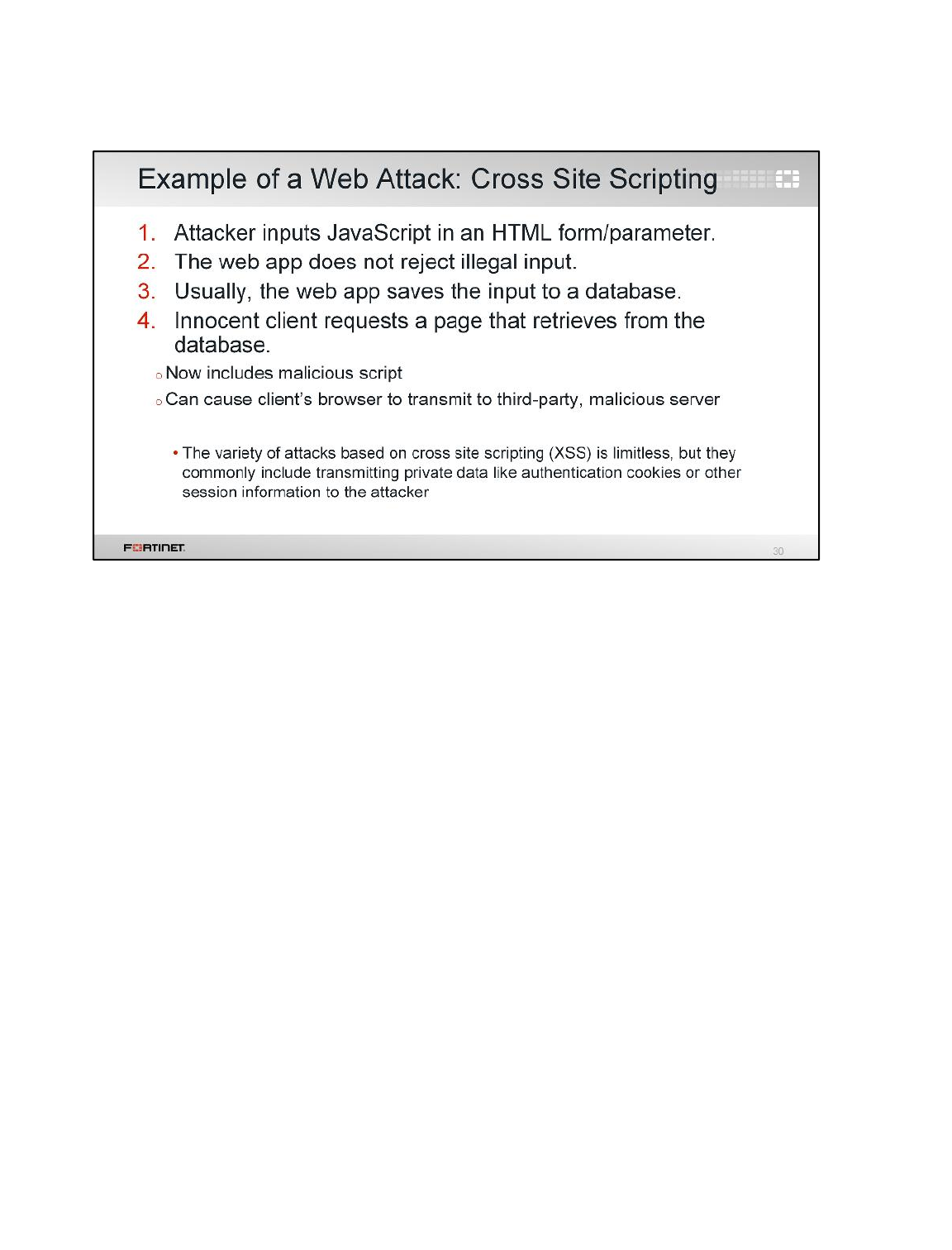
Let's look at some examples of attacks that specifically target web applications.
One type of attack is called cross-site scripting (XSS). If a web application doesn’t sanitize its inputs
and reject JavaScript, it ends up storing the XSS attack in its database. Then, when other clients
request the page that re-uses that data, the JavaScript is now embedded in the page.
JavaScript can do many things with a page, including rewriting the whole page and making its own
requests. This is the basic mechanism of AJAX apps. In this case, XSS causes innocent clients to
transmit to a different server that is controlled by the attacker. This could, for example, transmit credit
card information or passwords from an HTTP form to the attacker.
Intrusion Prevention and Denial of Service
FortiGate II Student Guide
358
DO NOT REPRINT
© FORTINET
Another very common web attack is a SQL injection. Just like an XSS attack, the root cause of a SQL
injection is that the web application does not sanitize input. If the attacker enters a SQL query into an
input such as an HTML form, the web app simply accepts it, and passes it along to the database
engine, which accidentally runs the query.
The SQL language can do anything to the data. It can, for example, download the table of users so
that the attacker can run a password cracker. A query could add new entries for new administrator
logins, or modify logins, blocking administrators from logging.
Intrusion Prevention and Denial of Service
FortiGate II Student Guide
359
DO NOT REPRINT
© FORTINET
One component of a web application firewall profile is the WAF signatures. WAF signatures work in
the same way as IPS signatures. FortiGate can take an action over the traffic that matches any of
them.
Some WAF signatures are categorized as extended. They are more likely to cause false positives, but
are sometimes required in high-security environments.
Intrusion Prevention and Denial of Service
FortiGate II Student Guide
360
DO NOT REPRINT
© FORTINET
HTTP constraints can monitor and control the number, type, and length of many HTTP headers, which
are also inputs. This prevents unexpected inputs that a malicious client could craft to compromise your
server.
The limits can vary by your server’s software, but also by its hardware. If a server has limited RAM, for
example, then it is potentially easier to overload or crash with an excessive number of headers, since
parsing the headers and storing them in buffers requires RAM.
Intrusion Prevention and Denial of Service
FortiGate II Student Guide
361
DO NOT REPRINT
© FORTINET
FortiWeb is a specialized web application firewall device.
Why do you need it? Doesn’t FortiGate include web application firewall protection?
It’s true. It does. But, for environments where the protection of the web services is critical, you can
complement a FortiGate solution with a FortiWeb device.
FortiWeb offers a more complete HTTP protocol understanding and state attack protection. It can
perform vulnerability scans and penetration tests. It can also rewrite the HTTP packets, and route
traffic based on the HTTP content.
Intrusion Prevention and Denial of Service
FortiGate II Student Guide
362
DO NOT REPRINT
© FORTINET
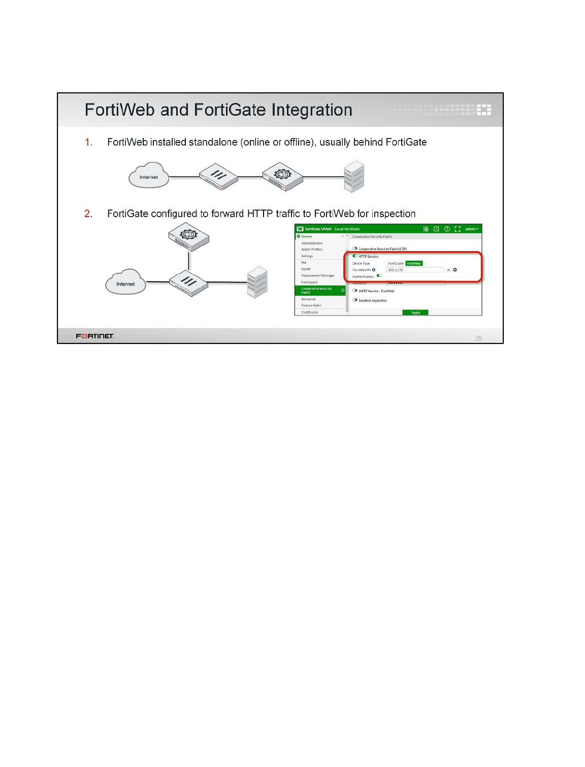
In most cases, FortiWeb is installed as a standalone device, usually located between FortiGate and
the protected web servers. FortiWeb can be installed online (web traffic crossing the device), or offline
(device is connected as a one-arm sniffer).
Alternatively, you can configure FortiGate to forward the web traffic to an external FortiWeb, where the
WAF inspection happens. This is useful, for example, when you need to protect servers located in
multiple sites with one single FortiWeb. In order to do this, you need first to configure each FortiGate
with the FortiWeb IP address (authentication is optional). After that, you select External in the WAF
profile, to instruct FortiGate to use FortiWeb.
Intrusion Prevention and Denial of Service
FortiGate II Student Guide
363
DO NOT REPRINT
© FORTINET
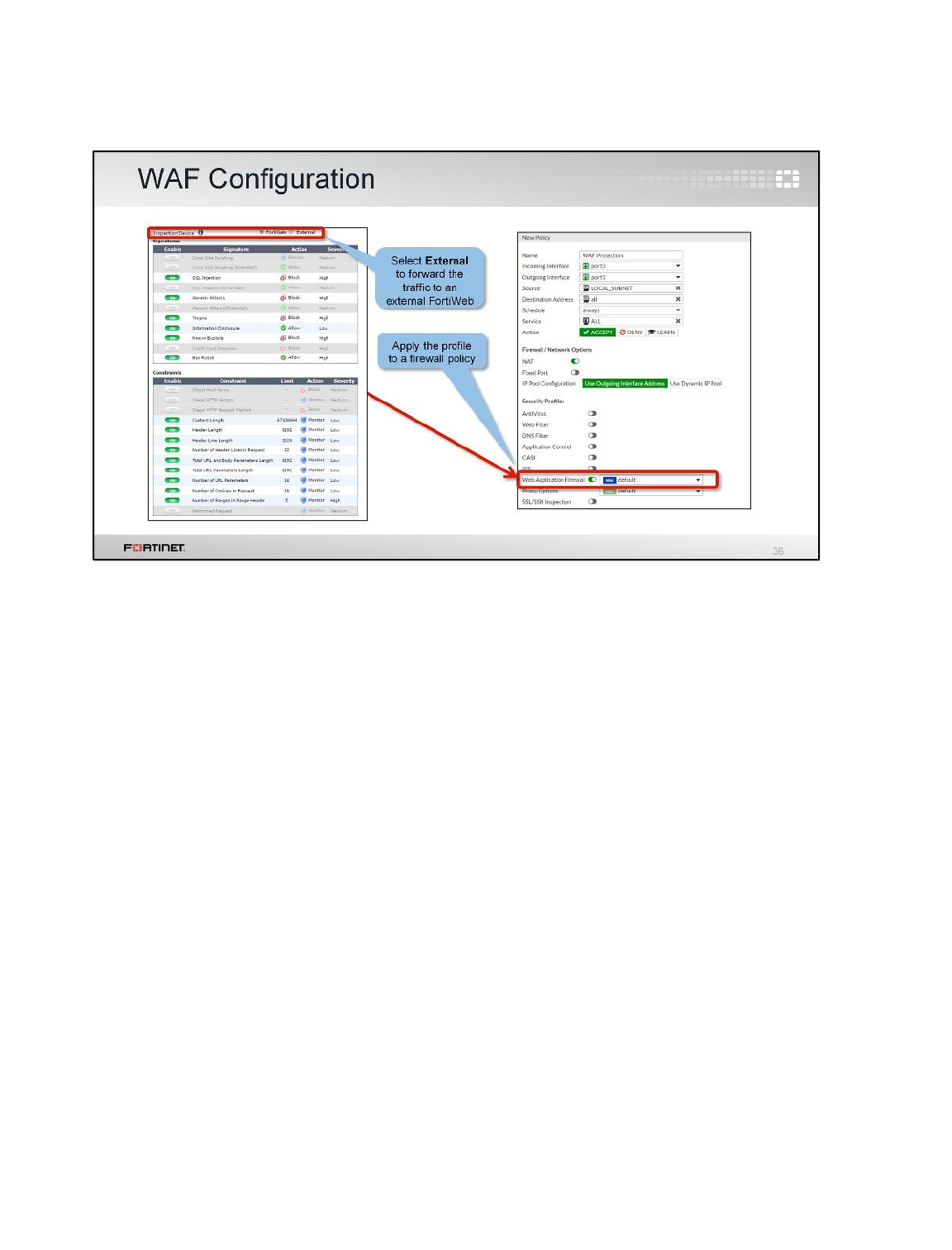
If you’ve configured a FortiGate with an external FortiWeb IP address, when creating the WAF profile,
you have the option to select where the WAF inspection will happen: either in FortiGate itself, or in the
external FortiWeb. If you select FortiGate (or if there is no external FortiWeb), you must configure the
different signatures and constraints to use. After that, the WAF profile is assigned to one or more
firewall policies.
Intrusion Prevention and Denial of Service
FortiGate II Student Guide
364
DO NOT REPRINT
© FORTINET

The last section of this lesson covers one-arm sniffer deployment.
Intrusion Prevention and Denial of Service
FortiGate II Student Guide
365
DO NOT REPRINT
© FORTINET
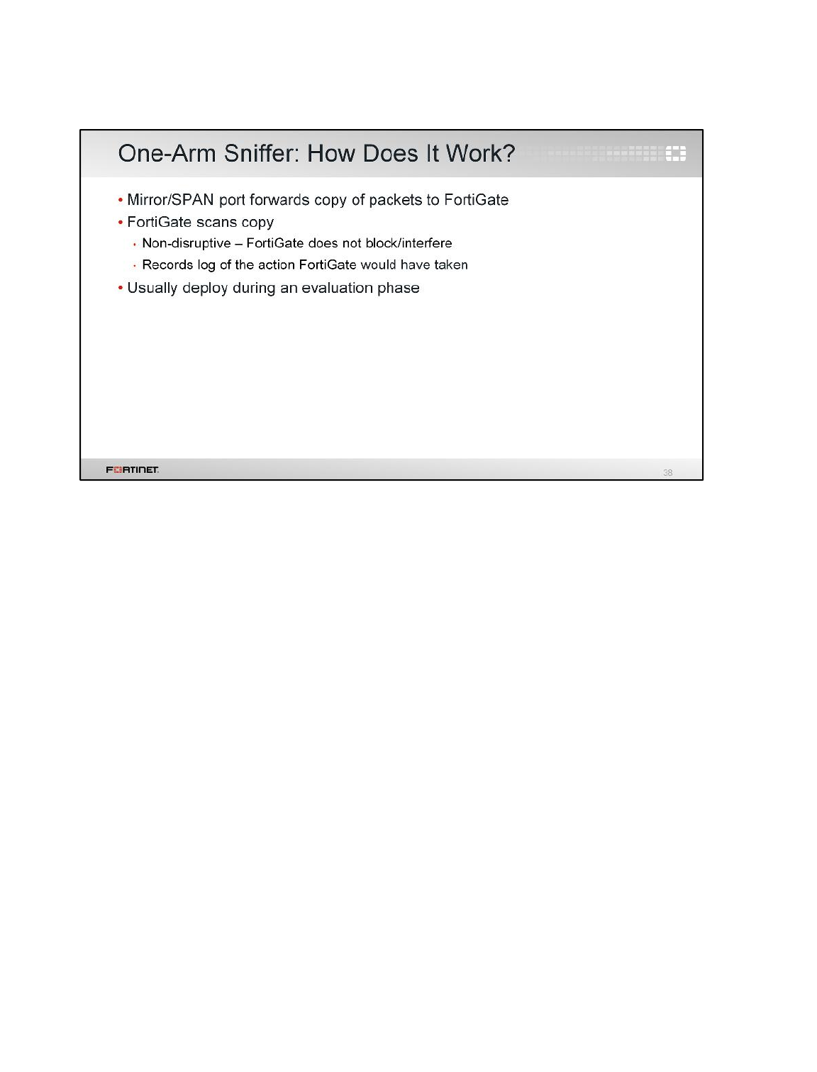
Everything we’ve shown so far is inline scanning: traffic passes through FortiGate from one interface
to another. But, you can also deploy FortiGate outside of the direct path of packets, in a one-arm
topology with a monitor-only mechanism. This is also called sniffer mode because it detects but does
not block.
To do this, connect FortiGate to a switch’s SPAN or mirroring port. The switch will send a duplicate of
egressing packets to FortiGate for inspection. Notice that because FortiGate is inspecting a copy – not
the original packet – it can’t modify or block the connection.
When should you use one-arm sniffer?
Historically, when IPS scanning was first invented, it was slow. Old IPS could introduce high latency.
So, one-arm deployment was common, but IPS on an inline firewall wasn’t.
Now, hardware performance is much better, and one-arm sniffer has a significant limitation: cannot
block traffic. Because it’s on a mirrored port on the switch, not directly in between the attacker and
your protected network, FortiGate isn’t placed to intervene. So today, most people use one-arm sniffer
only during testing or evaluation.
Intrusion Prevention and Denial of Service
FortiGate II Student Guide
366
DO NOT REPRINT
© FORTINET
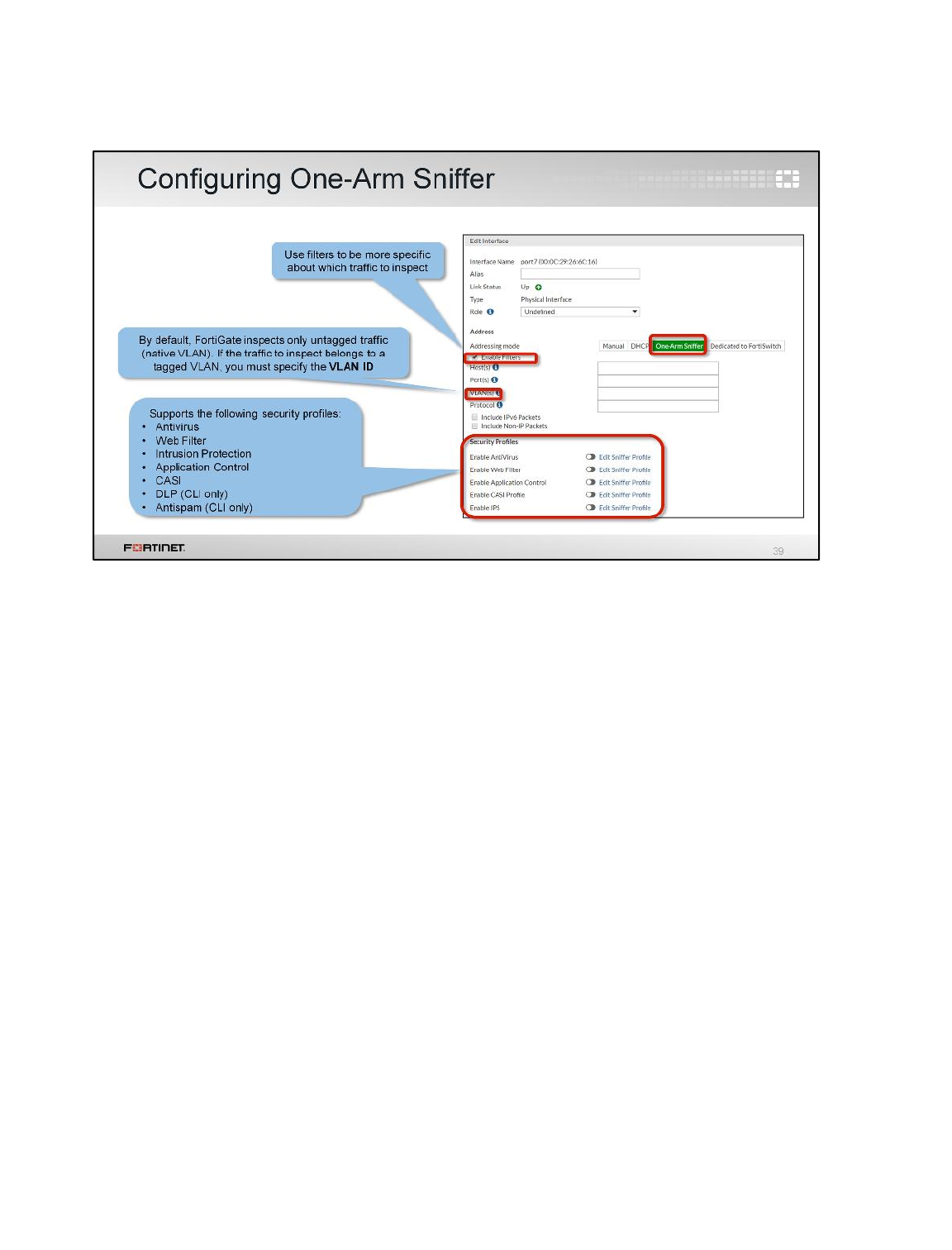
One-arm sniffer is enabled on a FortiGate’s physical interface, not on a logical interface, such as a
VLAN.
After you select One-Arm Sniffer on an interface, you can choose the security profiles.
Intrusion Prevention and Denial of Service
FortiGate II Student Guide
367
DO NOT REPRINT
© FORTINET
Here is a review of what we discussed. We looked at:
• The difference between exploits and anomalies
• Zero-day attacks
• How to configure IPS sensors and custom signatures
• Denial of service attacks
• Web application firewall profiles
• One-arm sniffer deployment
Intrusion Prevention and Denial of Service
FortiGate II Student Guide
368
DO NOT REPRINT
© FORTINET

In this lesson, you will learn about Fortinet Single Sign-On (FSSO). With this feature, your users don’t
need to log on each time they access a different network resource.
Fortinet Single Sign-On (FSSO)
FortiGate II Student Guide
369
DO NOT REPRINT
© FORTINET
After completing this lesson, you should have these practical skills to configure the Fortinet SSO
feature. This includes:
• Define SSO
• Explore the FSSO methods
• Detect user login events in Windows Active Directory using FSSO
• Configure the Web-Initiated FSSO for NTLM authentication
• Configure FortiGate and Collector Agent for FSSO
• Basic FSSO troubleshooting
Lab exercises can help you to test and reinforce your skills.
Fortinet Single Sign-On (FSSO)
FortiGate II Student Guide
370
DO NOT REPRINT
© FORTINET
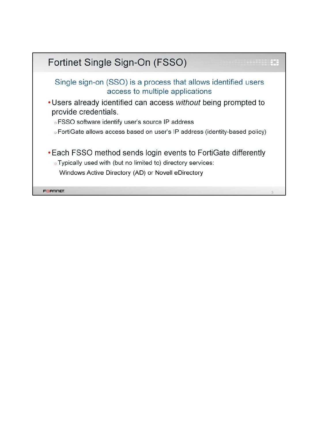
Single Sign-On (SSO) allows users to be automatically logged in to every application after being
identified, regardless of the platform, technology, and domain.
Fortinet Single Sign-On (FSSO) software-agent enables FortiGate to identify network users for
security policy or VPN access, without asking again for their username and password. When a user
logs in to a directory service, the FSSO agent sends FortiGate the user’s IP address and the names of
the user groups to which the user belongs. FortiGate uses this information to maintain a copy of the
domain controller user group database. Because the domain controller authenticates users, the
FortiGate device does not perform authentication. It recognizes group members by their IP address.
FSSO is typically used with directory service networks such as Windows Active Directory (AD) or
Novell eDirectory.
Fortinet Single Sign-On (FSSO)
FortiGate II Student Guide
371
DO NOT REPRINT
© FORTINET
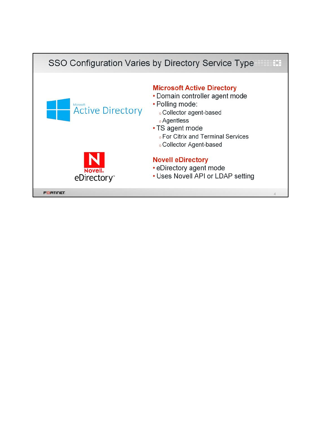
How you deploy and configure FSSO depends on the server that provides your directory services.
FSSO for Windows AD uses a collector agent. Domain controller (DC) agents may also be required,
depending on the collector agent working mode. There are two working modes that monitor user sign-
on activities in Windows: DC agent mode and polling mode.
There is another kind of DC agent exclusively for Citrix and Terminal Services environments – TS
agents. TS agents require the AD’s collector agent to collect and send the log events to FortiGate.
The eDirectory agent is installed on a Novell network to monitor user sign-ons and send the required
information to FortiGate. It functions much like the collector agent on a Windows AD domain
controller. The agent can obtain information from the Novell eDirectory using either the Novell API or
LDAP.
Fortinet Single Sign-On (FSSO)
FortiGate II Student Guide
372
DO NOT REPRINT
© FORTINET
In this section, we’ll examine the available modes for Windows Active Directory: DC agent mode and
polling. When looking at polling mode, we’ll cover both collector-agent based polling mode and
agentless polling mode.
Fortinet Single Sign-On (FSSO)
FortiGate II Student Guide
373
DO NOT REPRINT
© FORTINET
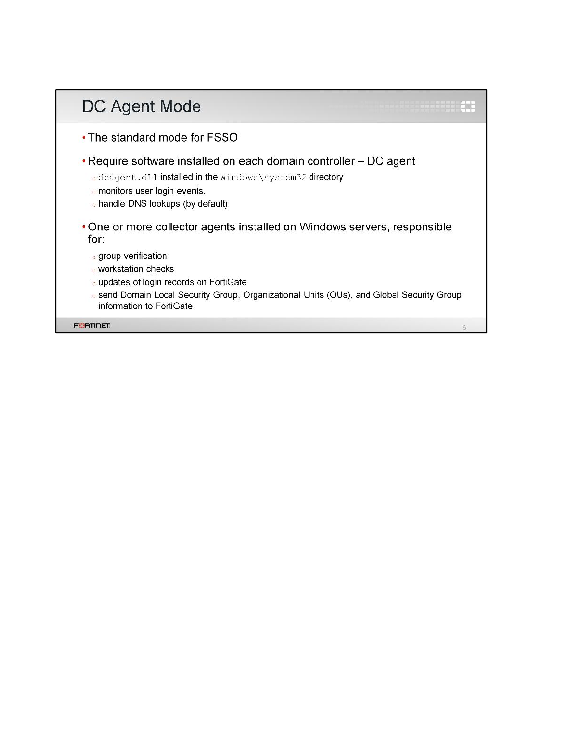
Let’s start with the DC agent mode, which is considered the standard mode for FSSO.
DC agent mode requires:
• One DC agent installed on each Windows domain controller. If you have multiple DCs, this means
multiple DC agents. The DC agents monitor and forward user login events to the collector agents.
• The collector agent. The collector agent is another FSSO component that’s installed on a Windows
server. It consolidates events received from the DC agents, then forwards them to FortiGate. The
collector agent is responsible for group verification, workstation checks, and FortiGate updates of
login records. The FSSO collector agent sends Domain Local Security Group, Organizational Units
(OUs), and Global Security Group information to FortiGate devices. It can also be customized for
DNS lookups.
Fortinet Single Sign-On (FSSO)
FortiGate II Student Guide
374
DO NOT REPRINT
© FORTINET
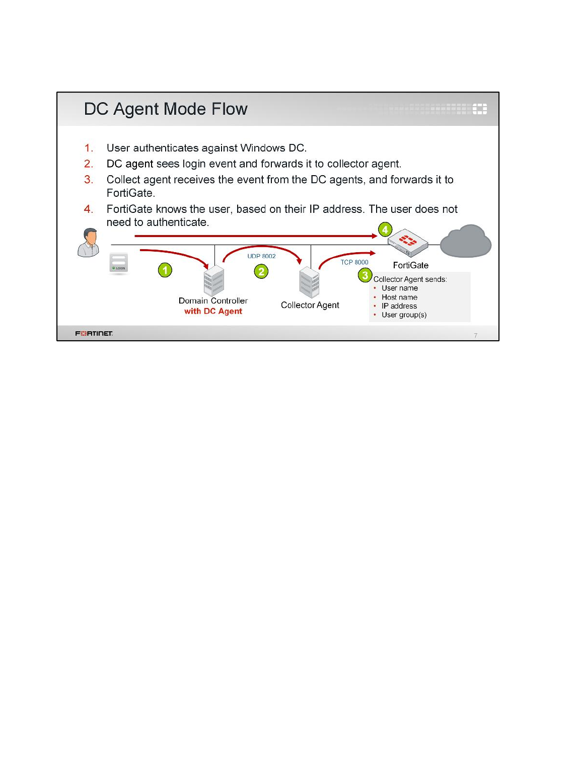
(slide contains animation)
Here we show the flow of information between DC agents, the collector agent, and a FortiGate
configured for FSSO authentication.
(click)
1. When users authenticate with the DC, they provide their credentials.
(click)
2. The DC agent sees the login event, and forwards it to the collector agent.
(click)
3. The collector agent aggregates all login events, then forwards that information to the FortiGate.
The information sent by the collector agent contains the user name, host name, IP address, and
user group(s). The collector agent communicates with the FortiGate over TCP port 8000 (default)
and it listens on UDP port 8002 (default) for updates from the DC agents. The ports are
customizable.
(click)
4. Now that the collector agent has forwarded the user login information, the FortiGate knows who
the user is, their IP address, and which Active Directory group permissions also apply. When a
user tries to access the Internet, FortiGate compares the source IP address to its list of active
FSSO users. Because the user in this case has already logged in and the FortiGate already has
their information, FortiGate will not request the user to authenticate again.
Fortinet Single Sign-On (FSSO)
FortiGate II Student Guide
375
DO NOT REPRINT
© FORTINET
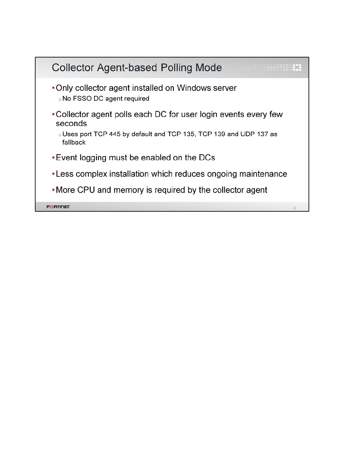
Now let’s look at polling mode. Polling mode can be collector agent-based or agentless.
First, let’s look at the collector agent-based polling mode. Like DC agent mode, collector agent-based
mode requires a collector agent to be installed on a Windows server, but it doesn’t require DC agents
to be installed in each DC. In collector agent-based polling mode, the collector agent must be more
powerful than the collector agent in DC agent mode, and it will also generate unnecessary traffic when
there have been no login events.
In this mode, the collector agent contacts periodically the windows DC to get its information directly.
Fortinet Single Sign-On (FSSO)
FortiGate II Student Guide
376
DO NOT REPRINT
© FORTINET
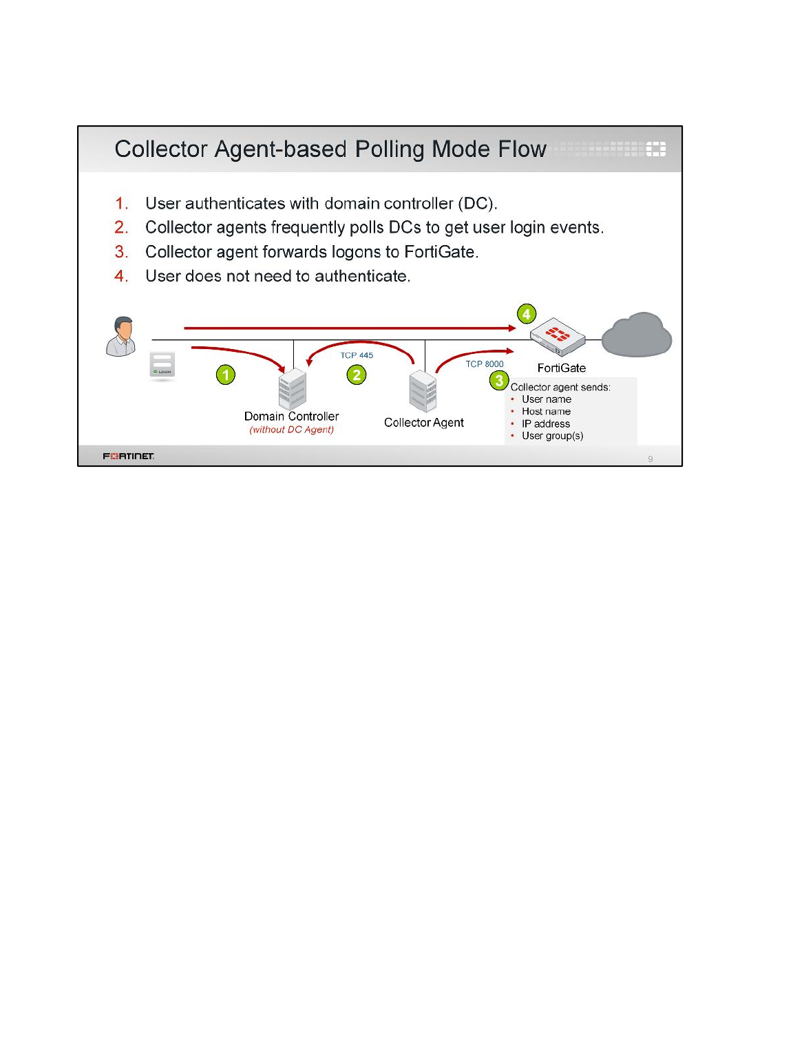
(slide contains animation)
Let’s see an example of FSSO using the collector agent-based polling mode. Again we have a DC, a
collector agent, and FortiGate. But the DC doesn’t have an agent installed.
(click)
1. Users authenticate with the DC providing their credentials.
(click)
2. The collector agent periodically (every few seconds) polls TCP port 445 of each DC directly, to
ask if anyone has logged in.
(click)
3. The collector agent sends the login information to FortiGate over TCP port 8000. This is the same
information that is sent in the DC agent mode.
(click)
4. When user traffic arrives at FortiGate, it already knows who is at what IP address, and no
repeated authentication is required.
Fortinet Single Sign-On (FSSO)
FortiGate II Student Guide
377
DO NOT REPRINT
© FORTINET
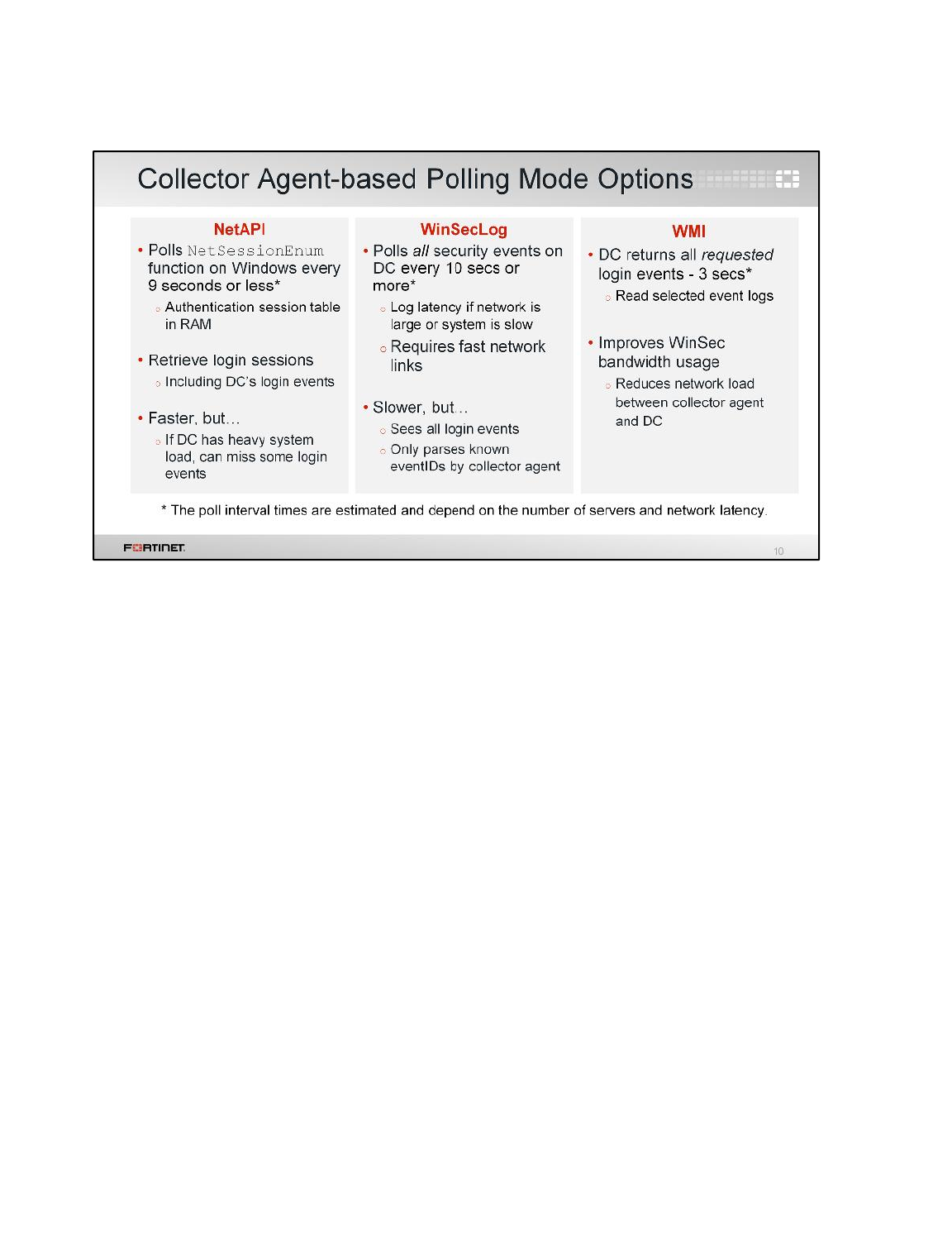
Collector agent-based polling mode has three methods (or options) for collecting login information:
•NetAPI: Polls temporary sessions created on the DC when a user logs in or logs off and calls the
NetSessionEnum function on Windows. It’s faster than the WinSec and WMI methods; however,
it can miss some login events if a DC is under heavy system load. This is because sessions can be
quickly created and purged from RAM, before the agent has a chance to poll and notify FortiGate.
•WinSecLog: Polls all the security event logs from the DC. It doesn’t miss any login events, because
events are not normally deleted from the logs. There can be some delay in FortiGate receiving
events if the network is large and, therefore, writing to the logs is slow.
•WMI: A Windows API that gets system information from a Windows server. The DC returns all
requested login events. The collector agent is a WMI client and sends WMI queries for user login
events to the DC, which, in this case, is a WMI server. The collector agent doesn’t need to search
security event logs on the DC for user login events; instead, the DC returns all requested login
events. This reduces network load between the collector agent and DC.
Fortinet Single Sign-On (FSSO)
FortiGate II Student Guide
378
DO NOT REPRINT
© FORTINET
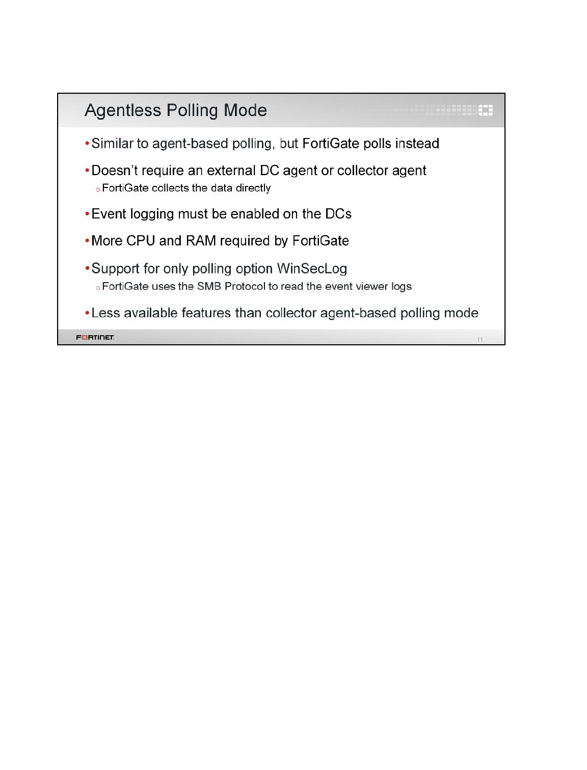
You can deploy FSSO without installing an agent. FortiGate polls the DCs directly, instead of receiving
login information indirectly from a collector agent.
Because FortiGate collects all of the data itself, agentless polling mode requires greater system
resources, and it doesn’t scale as easily.
Agentless polling mode uses WinSecLog. Because there’s no collector agent, the FortiGate uses SMB
protocol to read the event viewer logs from DCs.
Also because the FortiGate does all of the polling, you will not have all the extra features, such as
workstation checks, that are available with the external collector agent.
Fortinet Single Sign-On (FSSO)
FortiGate II Student Guide
379
DO NOT REPRINT
© FORTINET

(slide contains animation)
Now let’s see how the communication flows without agents (There is no collector agent or DC agent).
(click)
1. FortiGate polls the DC’s TCP port 455 to get user login events.
(click)
2. After the user authenticates with DC, FortiGate will register the login event during its next poll,
obtaining the following information: the user name, the host name, the IP address, and the user
group(s).
(click)
3. When the user sends traffic, FortiGate already knows whose traffic it is. Thus, the user does not
need to authenticate
Fortinet Single Sign-On (FSSO)
FortiGate II Student Guide
380
DO NOT REPRINT
© FORTINET
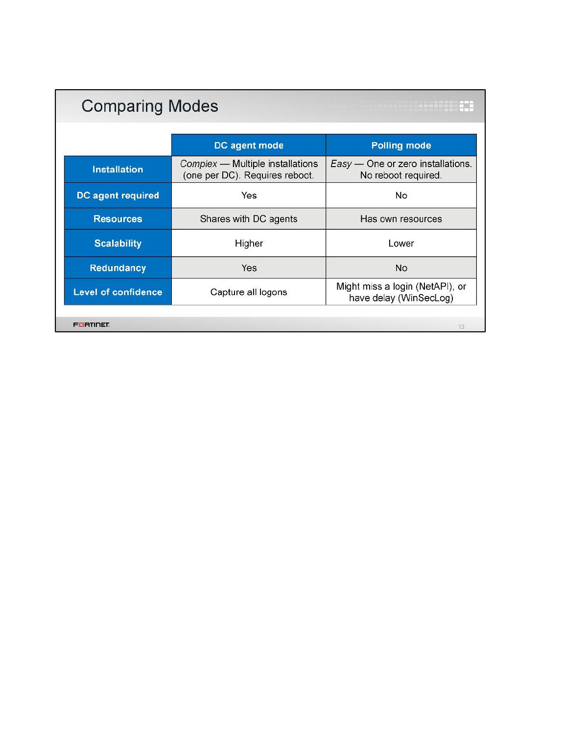
This table summarizes the main differences between DC agent mode and polling mode.
DC agent mode is more complex. It requires not only a collector agent, but also a DC agent for each
DC. However, it is also more scalable because the work of capturing logins is done by the DC agents
who pass their information directly to the collector.
In polling mode, the collector needs to query every domain controller, every few seconds. So, with
each DC that is added, the number of queries grows. If you want to add a second collector agent for
redundancy in polling mode, both collector agents need to query every DC individually.
In DC agent mode, the DC agent just has to get the log once and send a copy of the necessary
information to all the collector agents. In comparison, if you use polling mode, some login events might
be missed or delayed, depending on the polling option used.
Fortinet Single Sign-On (FSSO)
FortiGate II Student Guide
381
DO NOT REPRINT
© FORTINET
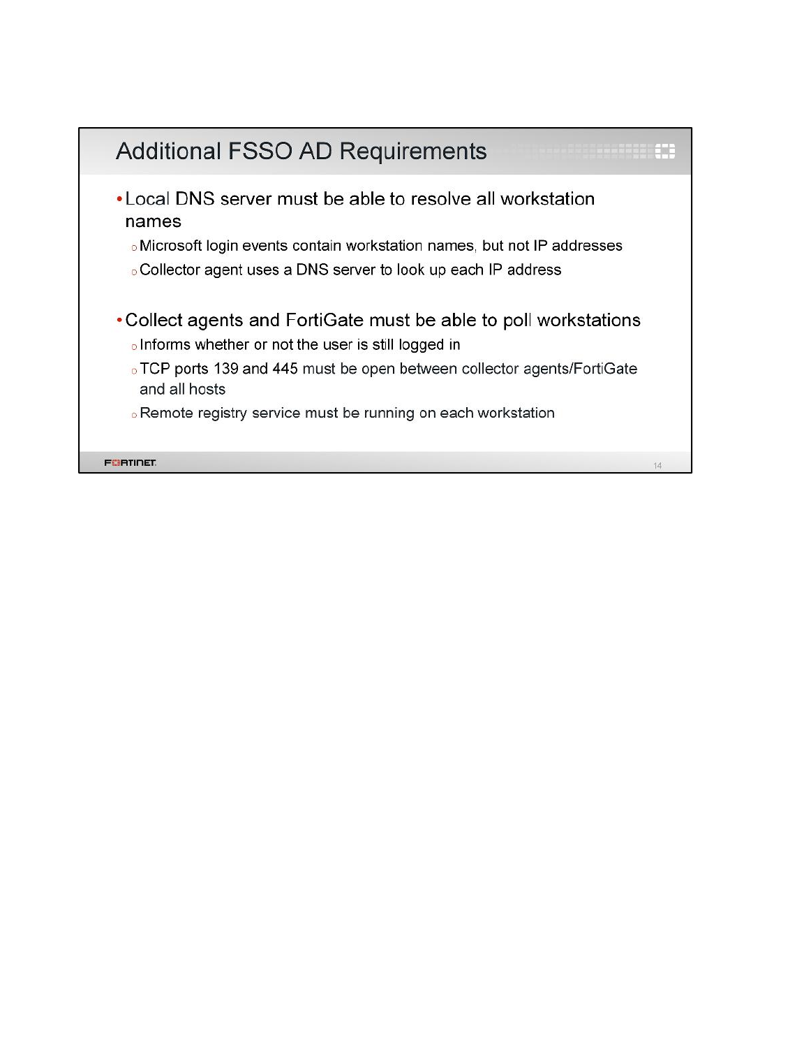
Regardless of the login collector method you choose, some FSSO requirements for your active
directory network are the same:
• Microsoft Windows login events have the workstation name and username, but not the workstation
IP address. When the collector agent gets a login event, it will query a DNS server to resolve the IP
address of the workstation. So, FSSO requires that you have your own DNS server. If a
workstation IP address changes, DNS records must be updated immediately.
• Collectors must have connectivity with all workstations. Because an event log is not generated on
logoff, the collector agent (depending on the FSSO mode) must use a different method to verify
whether users are still logged in. So, each user workstation is polled to see if users are still there.
Fortinet Single Sign-On (FSSO)
FortiGate II Student Guide
382
DO NOT REPRINT
© FORTINET
In an active directory (AD) environment, FSSO can also work with NT LAN Manager (NTLM), which is
a suite of Microsoft security protocols that provides authentication, integrity, and confidentiality to
users. Let’s take a look at how NTLM works and interacts with FSSO.
Fortinet Single Sign-On (FSSO)
FortiGate II Student Guide
383
DO NOT REPRINT
© FORTINET
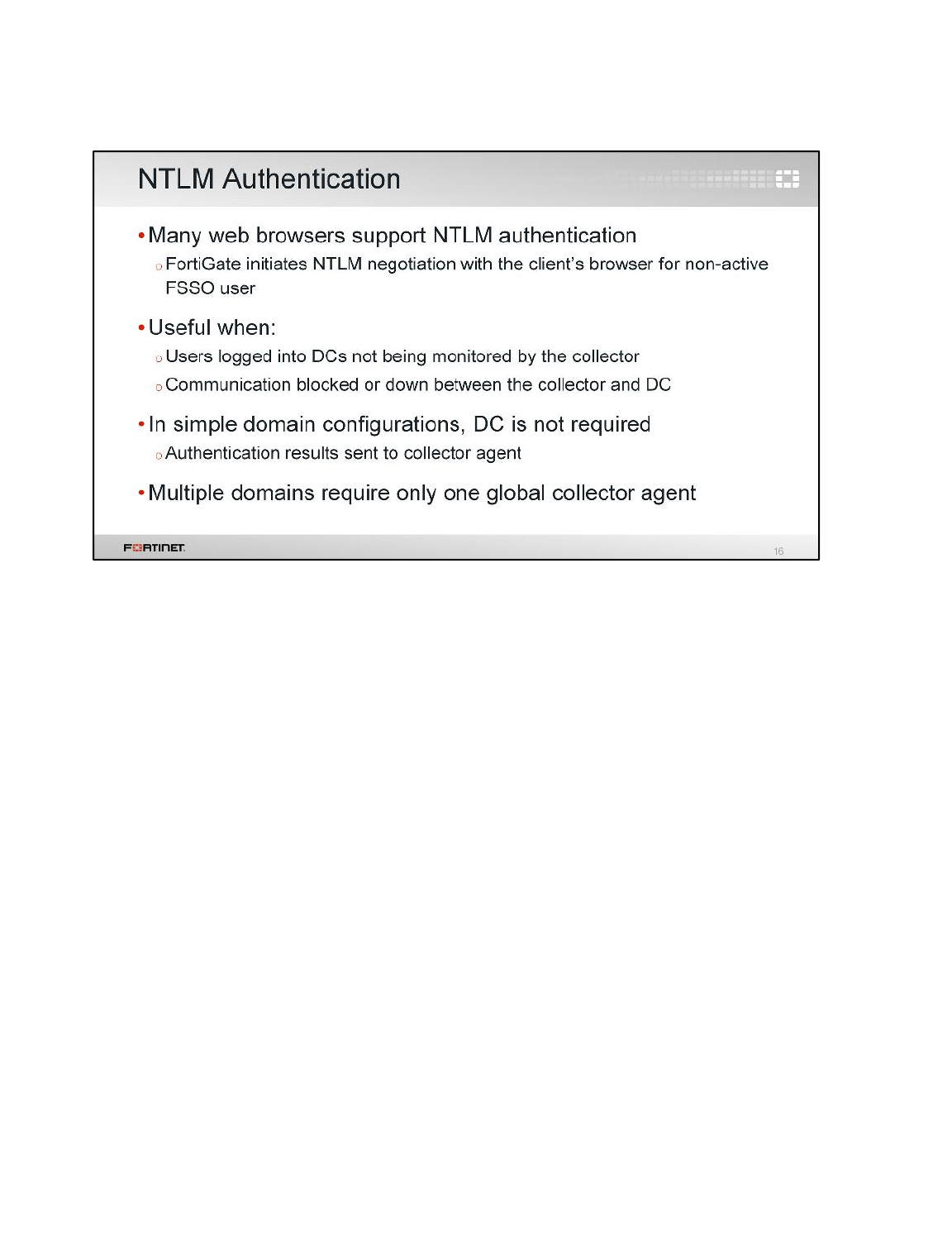
NTLM authentication does not require DC agents, but it is not fully invisible to users: they must enter
their credentials during NTLM negotiation. NTLM authentication is a Microsoft-proprietary solution, so
it can only be implemented in a Windows network.
NTLM is most useful when users log in to DCs that, for some reason, can’t be monitored by the
collector agent, or when there is a communication problem between the collector agent and one of the
DCs’ agents. In other words, NTLM authentication is best used as a backup to FSSO.
Fortinet Single Sign-On (FSSO)
FortiGate II Student Guide
384
DO NOT REPRINT
© FORTINET
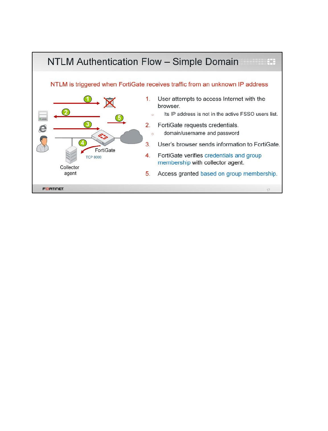
(slide contains animations)
This example shows how messages flow during NTLM authentication in a simple domain
configuration.
(click)
1. When both FSSO and NTLM are enabled, NTLM will back up FSSO. When FortiGate receives
traffic from an IP address that doesn’t exist in the list of active FSSO users, NTLM is triggered.
(click)
2. FortiGate replies with an NTLM challenge, requesting credentials.
(click)
3. The user’s browser sends the requested credentials.
(click)
4. FortiGate receives the user credentials, then authenticates them with the collector agent over TCP
port 8000. The FortiGate also receives the names of the groups that the user belongs to.
(click)
5. If the credentials are correct, FortiGate authorizes access for the user. New NTLM requests are
initiated when the browser is closed or the session is timed out.
Fortinet Single Sign-On (FSSO)
FortiGate II Student Guide
385
DO NOT REPRINT
© FORTINET
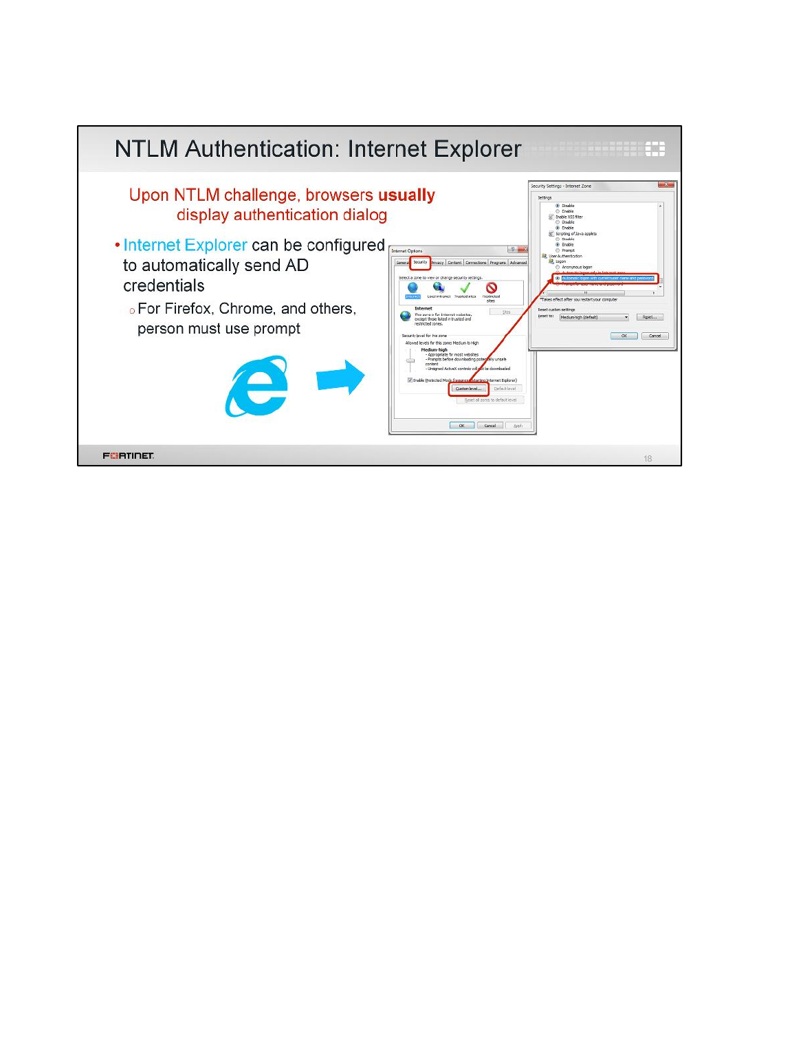
Unlike full FSSO, NTLM authentication is not transparent to users. In most browsers, and by default in
Internet Explorer, users must enter their credentials whenever the browser receives a NTLM
authentication challenge.
However, Internet Explorer can be configured to automatically send the user’s credentials each time it
receives an NTLM challenge. To do this, in the Internet Options dialog, click Custom level. Then, in
the Settings dialog, scroll to User Authentication login and select Automatic login with current
user name and password.
Fortinet Single Sign-On (FSSO)
FortiGate II Student Guide
386
DO NOT REPRINT
© FORTINET
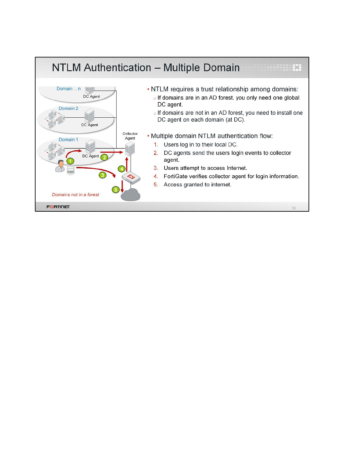
(slide contains animations)
In a multiple domain environment for NTLM, it’s important to have a trust relationship between the
domains. When multiple domains exist in an AD forest, a trust relationship is automatically created, so
only one DC agent is required on one of the domain controllers. But, when multiple domains are not
in an AD forest, you have two options:
• create a trust relationship between the domains through AD settings, or
• install one DC agent on each domain, then use security policies to configure server access.
If you decide to install one DC agent on each domain, the DC agents send login information to the
collector agent. Let’s see how this process flow works.
(click)
1. The user logs in to their local DC.
(click)
2. The DC agent sends the user login event information to the collector agent.
(click)
3. The user attempts to access the Internet.
(click)
4. FortiGate verifies that the user is authenticated by contacting the collector agent for the login
information.
(click)
5. If the user is properly authenticated, FortiGate allows access to the Internet.
Fortinet Single Sign-On (FSSO)
FortiGate II Student Guide
387
DO NOT REPRINT
© FORTINET

Now, let’s take a look at how to configure FSSO on FortiGate, and how to install the Fortinet collector
agent.
Fortinet Single Sign-On (FSSO)
FortiGate II Student Guide
388
DO NOT REPRINT
© FORTINET
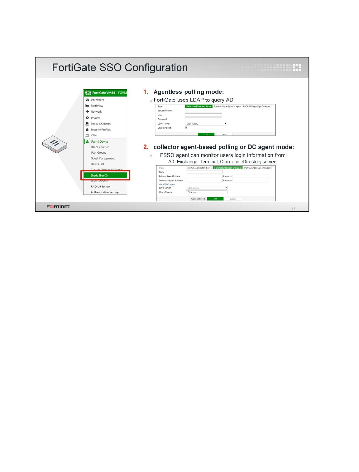
FortiGate FSSO configuration is straightforward.
If FortiGate is acting as a collector for agentless polling mode, you must select Poll Active Directory
Server and configure the IP addresses and AD administrator credentials for each DC.
If you have external collector agents, either using the DC agent mode or the collector agent-based
polling mode, you must select Fortinet Single-Sign-On Agent and configure the IP address and
password for each collector agent.
Fortinet Single Sign-On (FSSO)
FortiGate II Student Guide
389
DO NOT REPRINT
© FORTINET
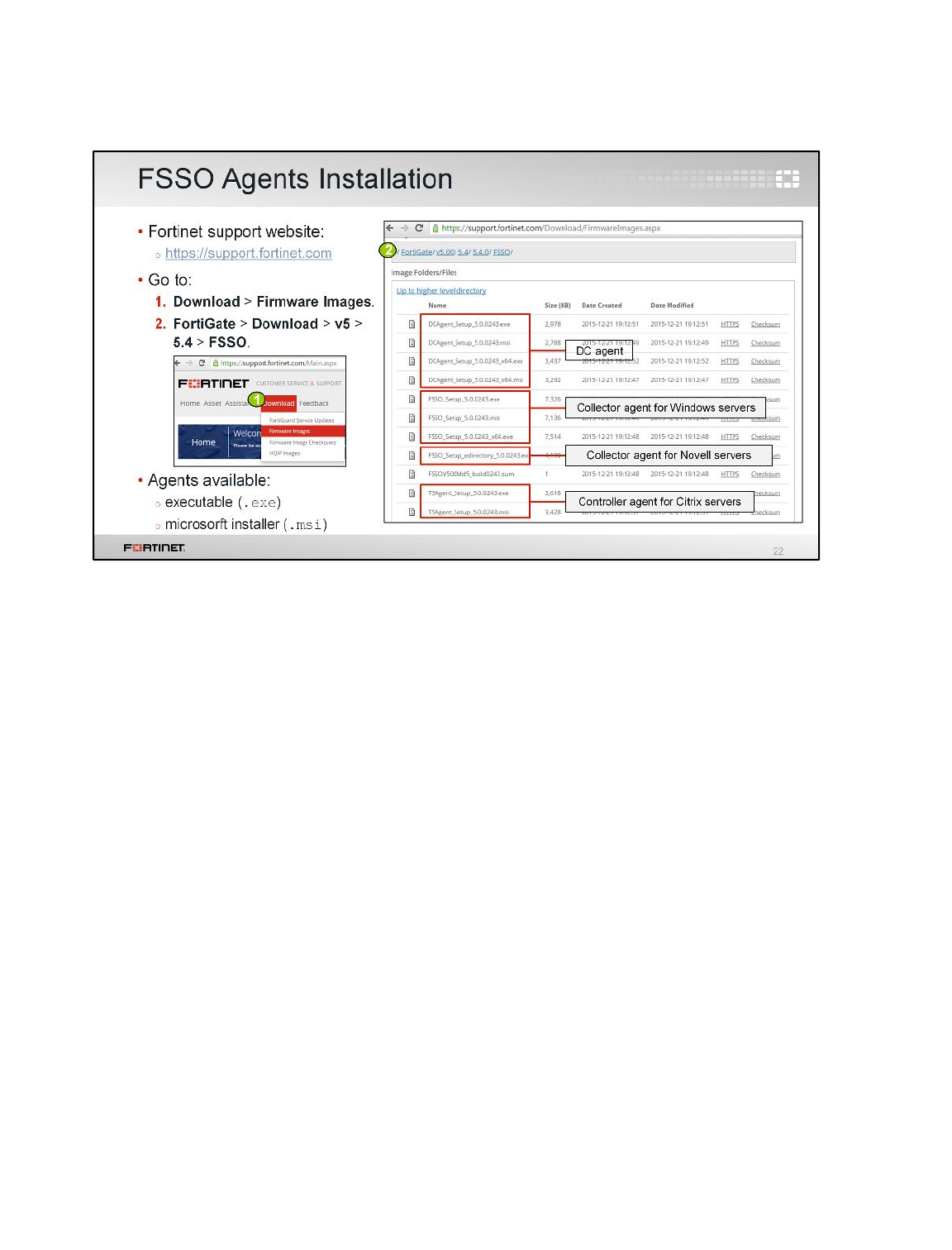
The FSSO agents are available on the Fortinet Support website. There you will find the:
• the DC agent,
• the collector agent for Microsoft servers: FSSO_Setup,
• the collector agent for Novell directories: FSSO_Setup_edirectory, and
• the controller agent for Citrix servers: TSAgent_Setup.
Also, for each agent, there are two versions available for download: the executable (.exe), or
Microsoft Installer (.msi).
Fortinet Single Sign-On (FSSO)
FortiGate II Student Guide
390
DO NOT REPRINT
© FORTINET
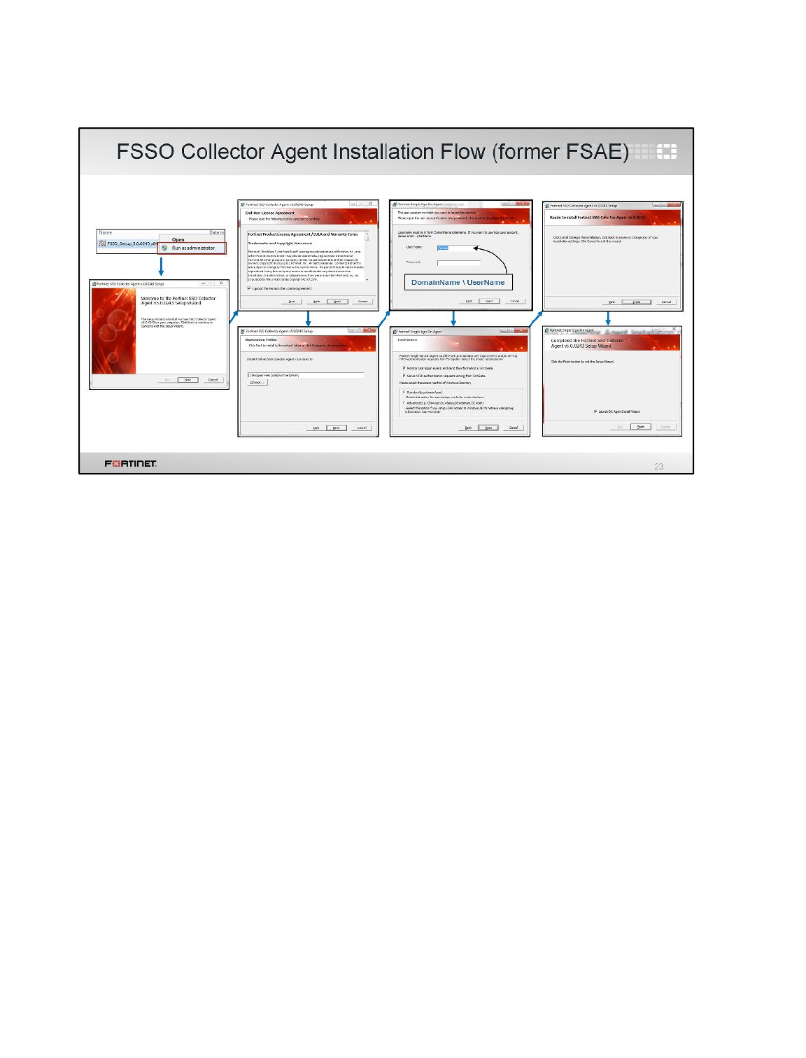
Once you’ve downloaded the collector agent, run the installation process as administrator, then follow
these steps in the installation wizard:
1. Read and accept the license agreement.
2. Optionally, change the installation location. The default folder is named FSAE.
3. Enter the user name. By default, the agent uses the name of the currently running account.
However, you can change it using the format: DomainName\UserName
4. Alternatively, customize your collector agent for monitoring, NTLM authentication, and directory
access. These options are also customizable after installation.
5. If you want to use DC agent mode, ensure that Launch DC Agent Install Wizard is selected.
This will automatically start the DC agent installation.
Fortinet Single Sign-On (FSSO)
FortiGate II Student Guide
391
DO NOT REPRINT
© FORTINET
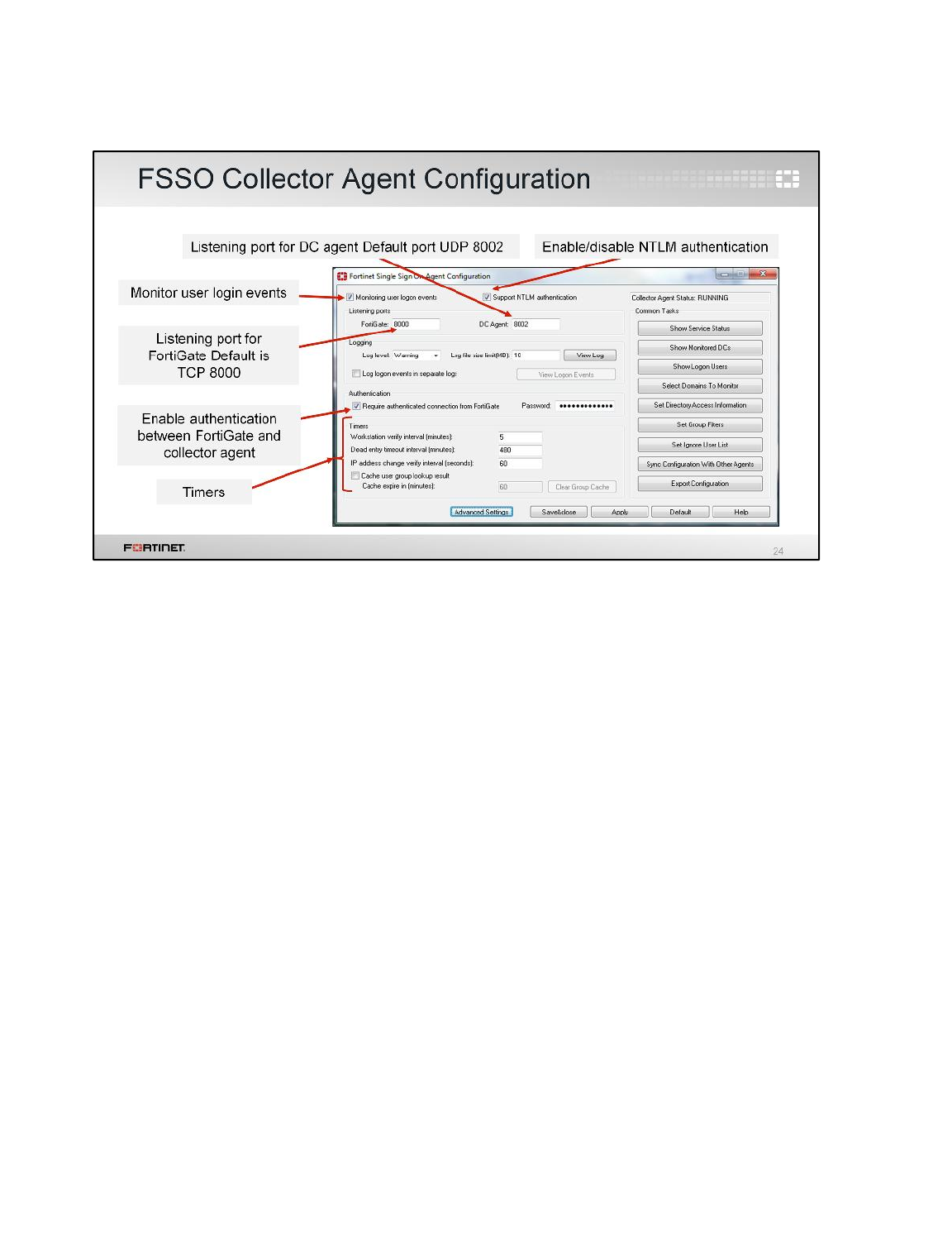
This is the collector agent installed. From the FSSO Agent Configuration application, you can
configure settings such as:
• the listening port for the communication with the DC agents,
• the listening port for the communication with the FortiGate,
• NTLM authentication support, and
• password authentication between the collector agent and the FortiGate.
Fortinet Single Sign-On (FSSO)
FortiGate II Student Guide
392
DO NOT REPRINT
© FORTINET
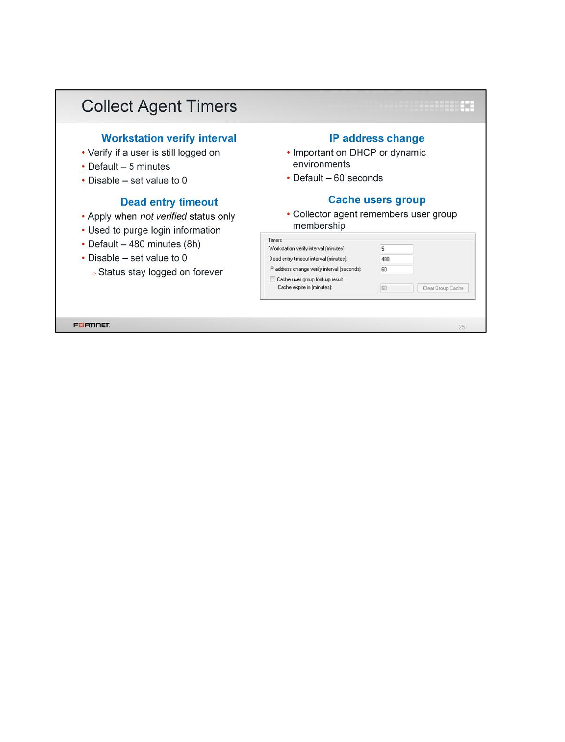
The FSSO collector agent timers are also very important to ensure proper operation. Let’s take a look
at each one and how they work.
•Workstation verify interval. This setting controls when the collector agent connects to individual
workstations to verify if a user is still logged in to the same station. It changes the status of the user
under Show login User, to not verified when it cannot connect to the workstation. If it does
connect, it verifies the user and the status remains OK.
•Dead entry timeout interval. This setting applies only to entries with an unverified status. When
an entry is not verified, the collector starts this timer. It’s used to age out the entry. When the timer
expires, the login is removed from the collector. From FortiGate’s perspective, there is no
difference between entries that are OK and entries that are not verified. Both are considered valid.
•IP address change verify interval. This setting checks the IP addresses of logged-in users and
updates the FortiGate when user’s IP addresses change. This timer is especially important in
DHCP or dynamic environments to prevent users from being locked out if they change IP
addresses.
•Cache user group lookup result. This setting caches the user group membership for a defined
period of time. It is not updated, even if the user changes group membership in AD.
Fortinet Single Sign-On (FSSO)
FortiGate II Student Guide
393
DO NOT REPRINT
© FORTINET
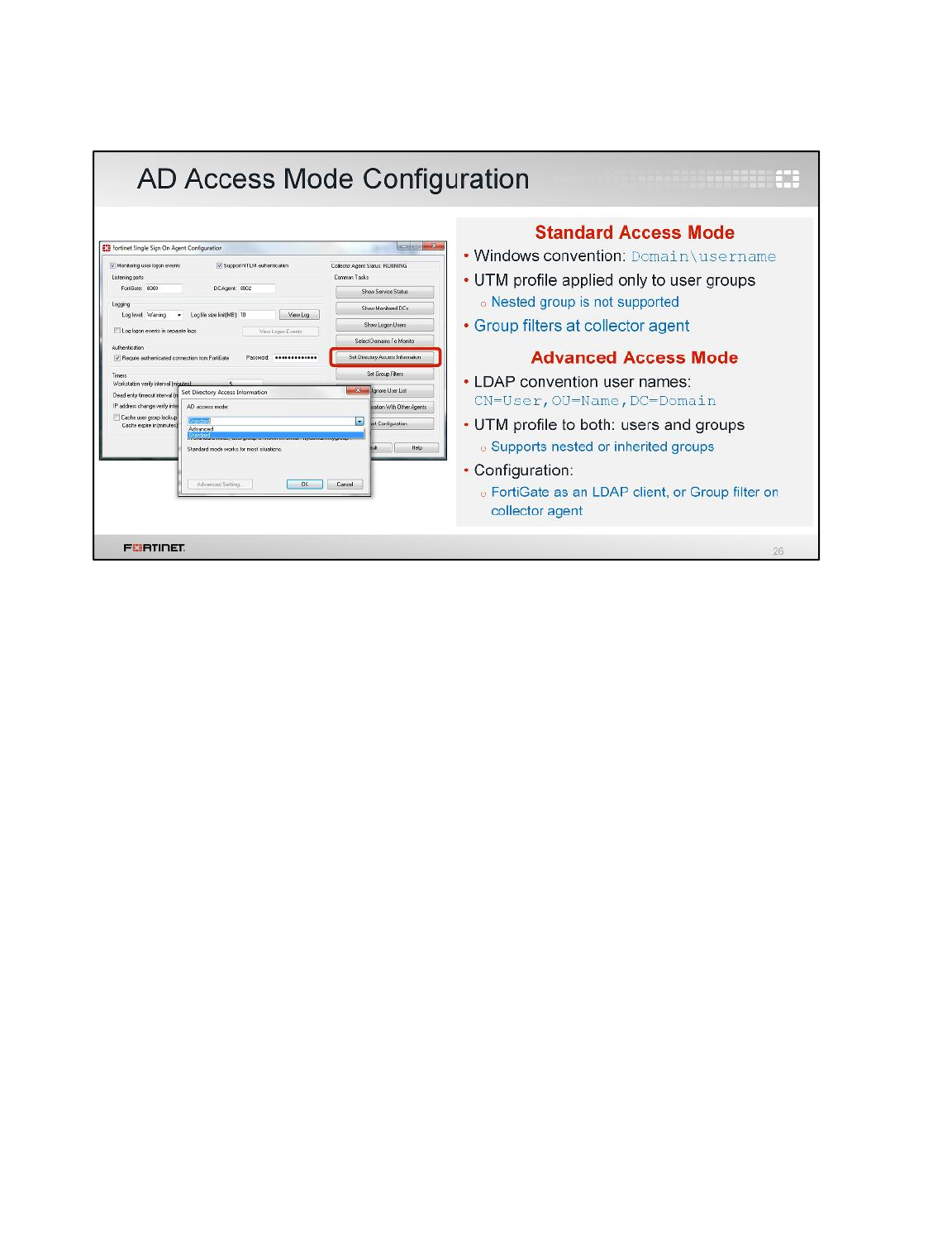
Another important FSSO setting is the AD access mode. You can set the AD access mode by clicking
Set Directory Access Information. It specifies how the collector agent accesses and collects the
user and user group information. There are two modes that can be used to access AD user
information: standard and advanced.
The main difference in both modes include the naming convention used:
• standard mode uses the Windows convention - NetBios: Domain\Username, while
• advanced mode uses the LDAP convention: CN=User, OU=Name, DC=Domain.
Also, advanced mode supports nested or inherited groups; that is, users can be members of
subgroups that belong to monitored parent groups. Additionally, in advanced mode FortiGate can
apply protection profiles to individual users, user groups, and organizational units (OUs).
In comparison, in standard mode, protection profiles can only be applied to user groups, not individual
users.
In advanced mode, you can configure FortiGate as an LDAP client and configure the group filters on
the FortiGate. You can also configure group filters on the collector agent.
If the LDAP on the collector agent fails, it doesn't matter what the LDAP on the FortiGate says, FSSO
won't work. If the FortiGate LDAP fails, but the LDAP on the collector agent is still running, the
FortiGate may not be able to collect logs, but the collector agent will still collect logs.
Fortinet strongly encourages users to create filters from the collector agent.
Fortinet Single Sign-On (FSSO)
FortiGate II Student Guide
394
DO NOT REPRINT
© FORTINET
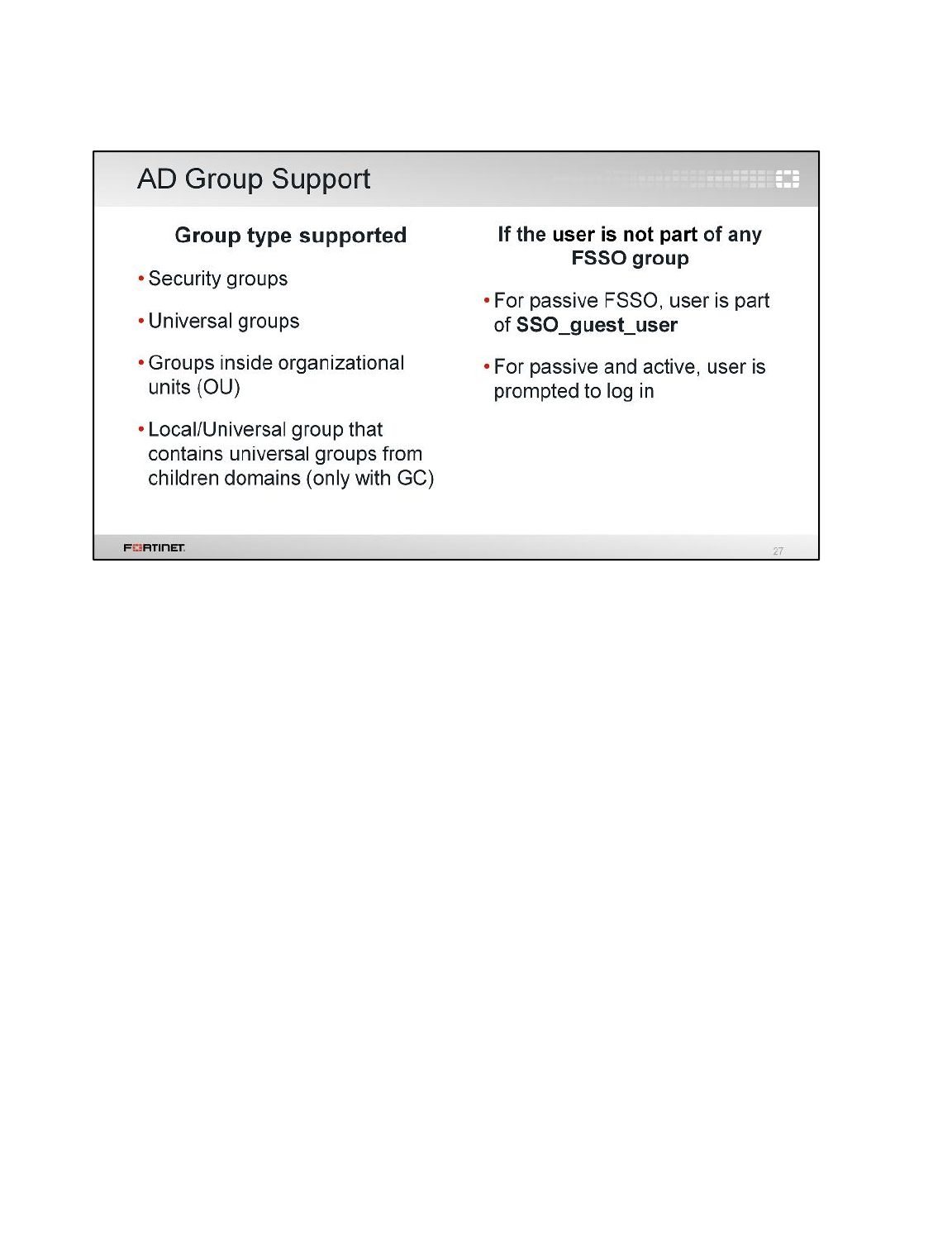
In AD settings, not all group types are supported. It only supports filtering groups from:
• security groups
• universal groups
• groups inside organizational units (OU), and
• Local or universal groups that contain universal groups from child domains (only with Global
Catalog).
All FortiGate configurations include a user group called SSO_guest_user. When only passive
authentication is used, all the users that do not belong to any FSSO group are automatically included
in this guest group.
This allows an administrator to configure limited network access to guest users that do not belong to
the Windows AD domain.
However, if both passive and active authentication are enabled, the behavior is different. Users that do
not belong to any FSSO group will be prompted to enter their credentials.
Fortinet Single Sign-On (FSSO)
FortiGate II Student Guide
395
DO NOT REPRINT
© FORTINET
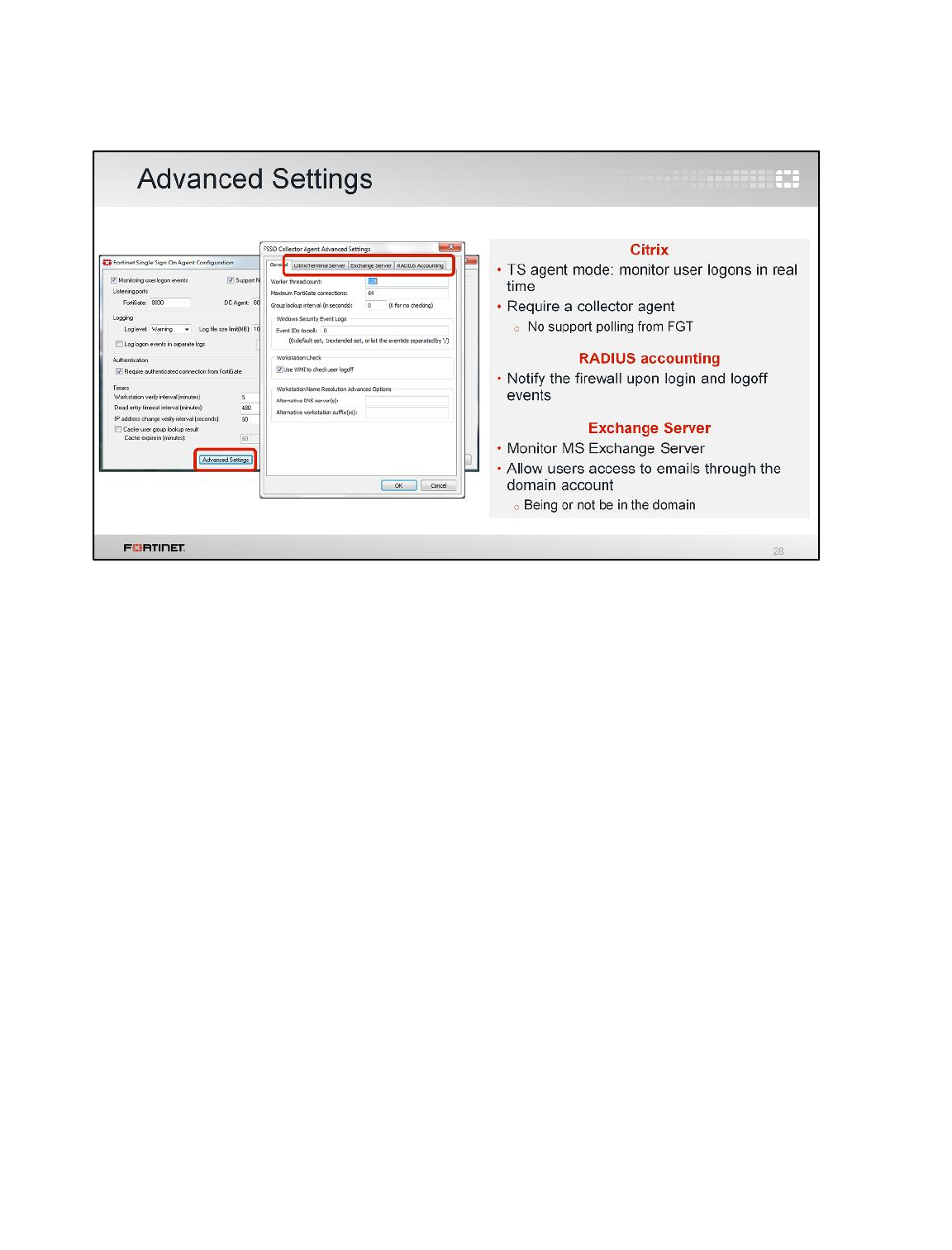
Depending on your network, you may need to configure advanced settings in your FSSO collector
agent.
Citrix servers support FSSO. TS agent mode allows the server to monitor user logins in real time. The
TS agent is like a DC agent, but it needs the collector agent to collect and send the login events to
FortiGate. It then uses the same ports to report the logins back to the collector agent.
Citrix servers must be configured with VIP to allow the collector agent to collect user login events. The
TS agent cannot forward logs directly to FortiGate, they first have to be gathered by a collector. This
does not work with polling from FortiGate.
A RADIUS server configured as a RADIUS-based accounting system can interact in your network by
sending accounting messages to the collector agent.
FSSO collector agent also supports monitoring a Microsoft Exchange Server, which is useful when
users access their email using their domain account.
Fortinet Single Sign-On (FSSO)
FortiGate II Student Guide
396
DO NOT REPRINT
© FORTINET

Finally, let’s take a look at some of the FortiGate diagnostic commands that you can use to
troubleshoot FSSO issues.
Fortinet Single Sign-On (FSSO)
FortiGate II Student Guide
397
DO NOT REPRINT
© FORTINET
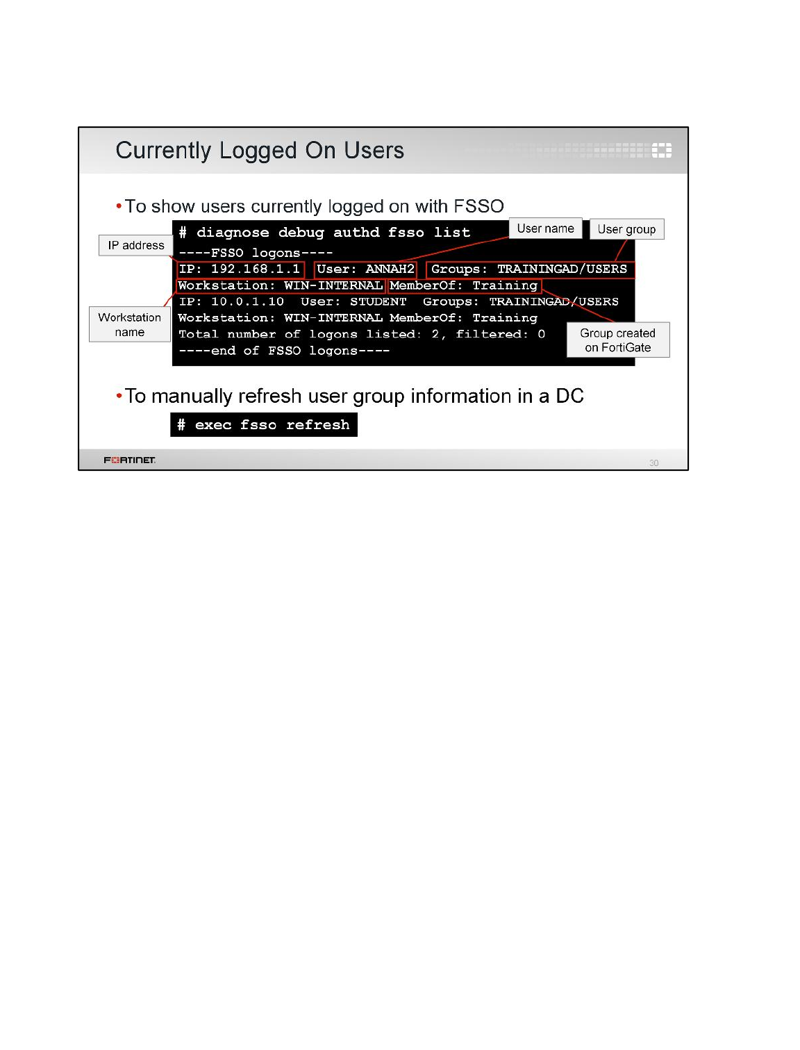
To display the list of FSSO users that are currently logged in, use the CLI command diagnose
debug authd fsso list.
For each user, the user name, user group, IP address, and the name of the workstation from which
they logged in are shown.
The Memberof section shows the group that was created on the firewall that you mapped the AD
group to. The same group should be shown in the User group screen on the GUI.
Use exec fsso refresh to manually refresh user group information from any directory service
servers connected to FortiGate using the collector agent.
Fortinet Single Sign-On (FSSO)
FortiGate II Student Guide
398
DO NOT REPRINT
© FORTINET
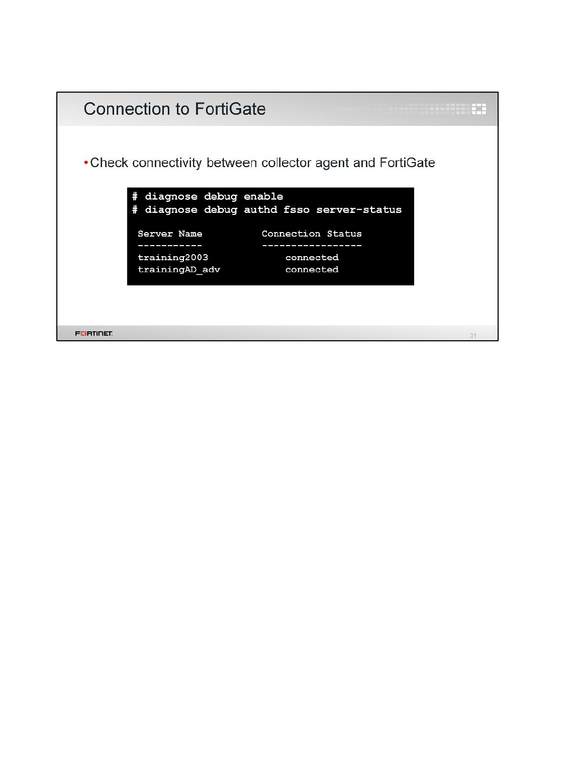
To show the status of communication between the FortiGate and each collector agent, you can use
the CLI command diagnose debug authd fsso server-status.
However, before you use that command, you must first run the command diagnose debug
enable.
Fortinet Single Sign-On (FSSO)
FortiGate II Student Guide
399
DO NOT REPRINT
© FORTINET
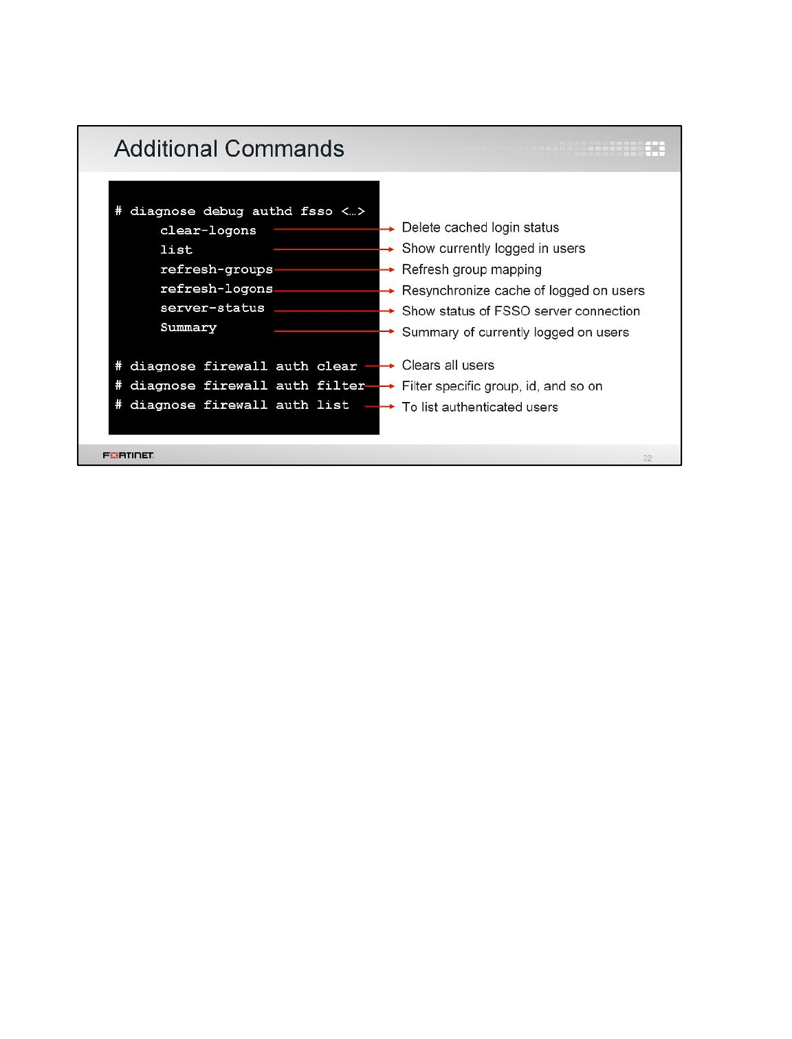
Also available under diagnose debug authd fsso are commands for clearing FortiGate’s cache
of all currently logged in users, filtering the display of the list of logged in users, and refreshing the
login and user group information.
Fortinet Single Sign-On (FSSO)
FortiGate II Student Guide
400
DO NOT REPRINT
© FORTINET
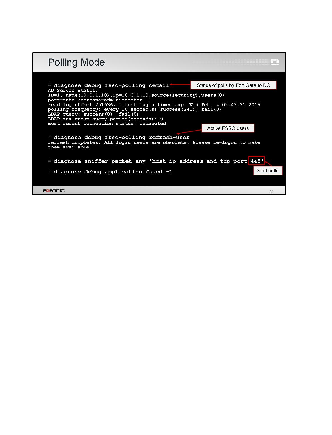
The command diagnose debug fsso-polling detail displays status information and some
statistics related with the polls done by FortiGate on each DC.
The command diagnose debug fsso-polling refresh-user flushes the information about all
active FSSO users.
In agentless polling mode, FortiGate frequently polls the event viewer to get the login events. You can
sniffer this traffic on port 445.
Also, there is a specific FortiGate daemon that handles the polling mode. It is the fssod daemon. To
enable agentless polling mode real-time debug, use the diagnose debug application fssod
-1 command.
Fortinet Single Sign-On (FSSO)
FortiGate II Student Guide
401
DO NOT REPRINT
© FORTINET
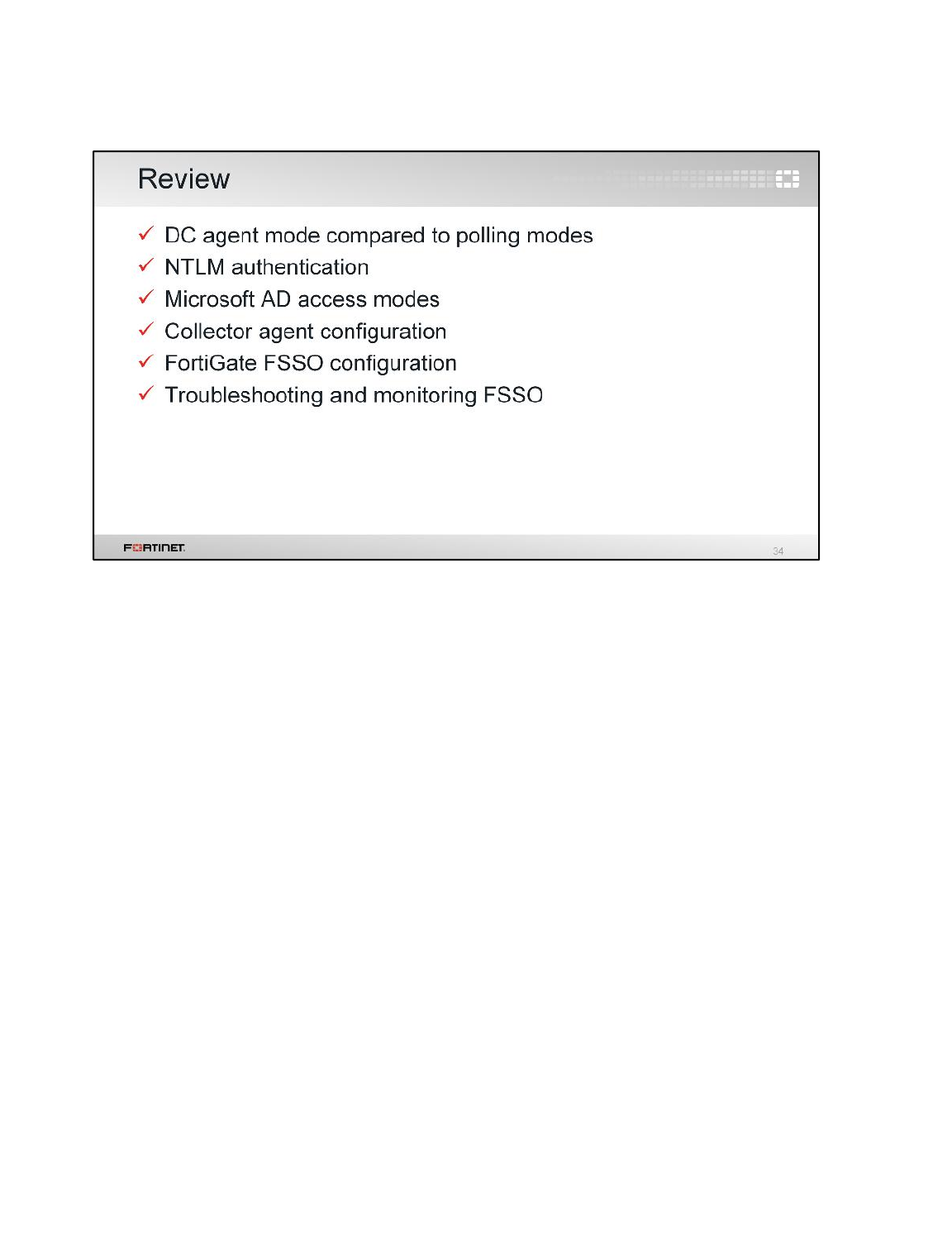
In this lesson, you learned about the methods for collecting user login information using FSSO; NTLM
authentication and AD access modes; how to configure FortiGate and the collector agent for FSSO;
and, finally, how to troubleshoot and monitor FSSO.
Fortinet Single Sign-On (FSSO)
FortiGate II Student Guide
402
DO NOT REPRINT
© FORTINET

In this lesson, you will learn about public key infrastructure (PKI); how to manage certificates on
FortiGate; how FortiGate can use certificate-based authentication for administrators, SSL VPN clients,
and IPsec peers; how to use SSL certificates; and how to inspect the contents of encrypted traffic.
Certificate Operations
FortiGate II Student Guide
403
DO NOT REPRINT
© FORTINET
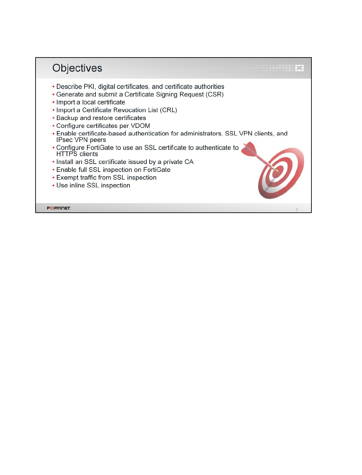
After completing this lesson, you should have these practical skills in certificate management. You
should be able to describe PKI and cryptography; understand digital certificates and certificate
authorities; manage digital certificates; configure certificate-based authentication; use SSL certificates;
enable full SSL inspection; and use inline SSL inspection.
Certificate Operations
FortiGate II Student Guide
404
DO NOT REPRINT
© FORTINET
This section provides a brief overview of public key infrastructure and cryptography.
Certificate Operations
FortiGate II Student Guide
405
DO NOT REPRINT
© FORTINET
Public key infrastructure, or PKI, provides the framework for the fundamentals of security, such as
authentication, confidentiality, integrity, non-repudiation, and access control. It is a comprehensive
system of hardware, software, policies, and procedures that allows both users and computers to
securely exchange data over networks, and verify the identity of the other party.
PKI has two core elements: public key cryptography and certification authorities (CA).
Certificate Operations
FortiGate II Student Guide
406
DO NOT REPRINT
© FORTINET
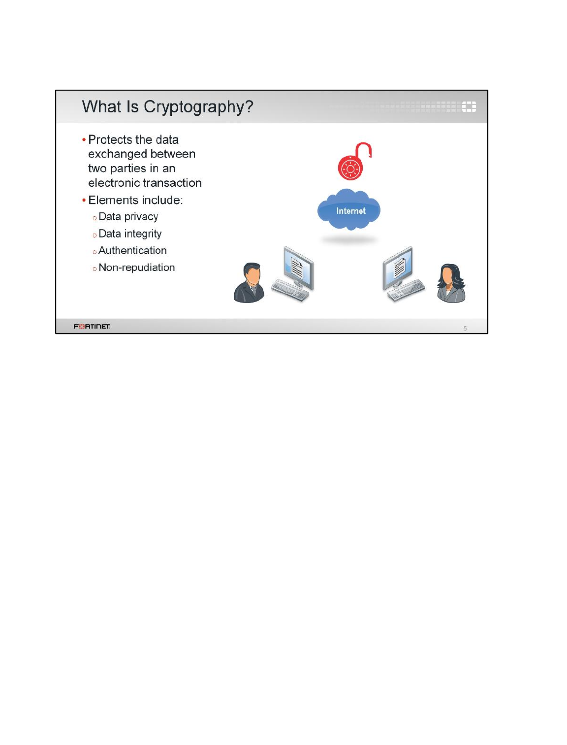
Before we get into the more specific public key cryptography—or asymmetric cryptography—used in
PKI, let’s examine the subject of cryptography in general. Cryptography is essentially about securing
communications between two entities through the process of encryption and decryption: scrambling
plaintext into cipher text (encryption) and then back into plaintext (decryption).
Cryptography includes elements that achieve four objectives:
• Data privacy (or confidentiality)
• Data integrity
• Authentication
• Non-repudiation
In this section, we will explore each objective in more detail.
Certificate Operations
FortiGate II Student Guide
407
DO NOT REPRINT
© FORTINET
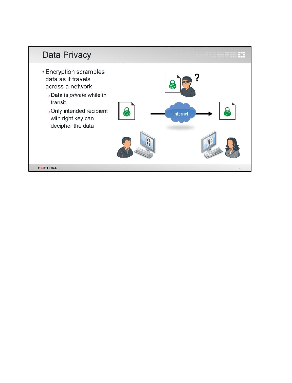
Some protocols, such as HTTP or SMTP, send data in plain or clear text. That means that anyone in
the middle running a packet sniffer can see and understand exactly what is being transmitted. This is
how private information, including passwords, can be captured by third parties.
In cryptography, data privacy is achieved with encryption. Encryption applies an algorithm and key to
the data, making it unintelligible to a third party, before it travels across the network. Only the recipient
with the right key can decrypt the data and access the information.
Certificate Operations
FortiGate II Student Guide
408
DO NOT REPRINT
© FORTINET
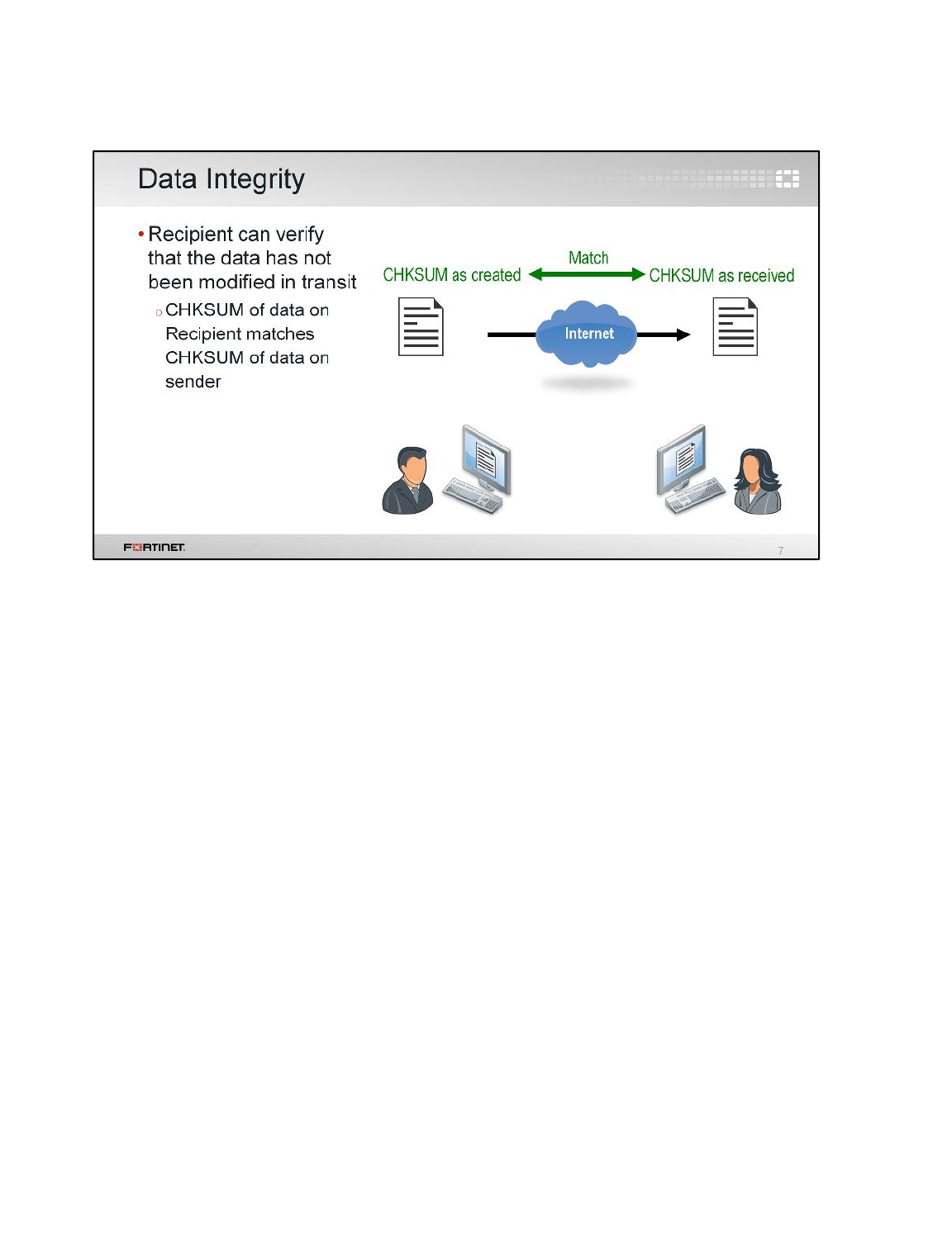
Data integrity ensures information is not altered in storage or transit. The recipient can verify that the
information has not been modified. If a third-party device changes the data, the decryption fails and an
error is generated.
There are several methods to verify data integrity. Many are checksums (CHKSUM), or one-way
hashes, which generate a unique value from applying the hashing algorithm to the original clear text.
First, the sender sends the cipher text and the hash. Next, the recipient recovers the plaintext and
recalculates the hash. If the calculated hash is the same as the received value, then the message has
not been modified in storage or transit.
Certificate Operations
FortiGate II Student Guide
409
DO NOT REPRINT
© FORTINET
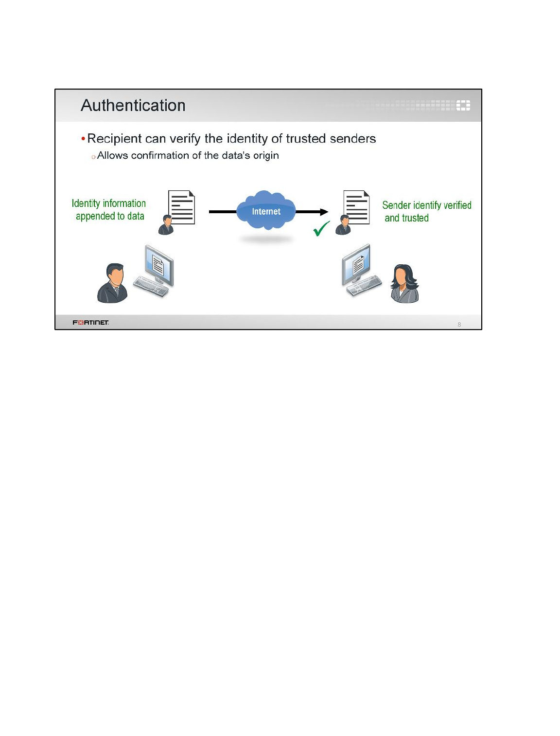
Authentication allows the sender and receiver to confirm each other’s identity. Since only the sender
has the correct key to encrypt the data and only the recipient has the correct key to decrypt the data,
they can verify each other’s identity. The sender can be assured that only the correct recipient will be
able to decrypt the data and the recipient can confirm the origin of the data as the trusted sender.
Certificate Operations
FortiGate II Student Guide
410
DO NOT REPRINT
© FORTINET
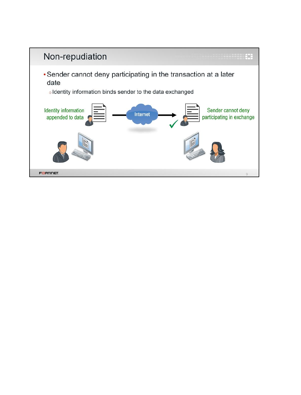
Non-repudiation ensures that an individual cannot deny the authenticity of their digital signature on a
document or message. With cryptography, the identity of the sender is bound to the data being
exchanged by a digital signature. As a result, the sender cannot deny participating in the transaction at
a later date.
Certificate Operations
FortiGate II Student Guide
411
DO NOT REPRINT
© FORTINET
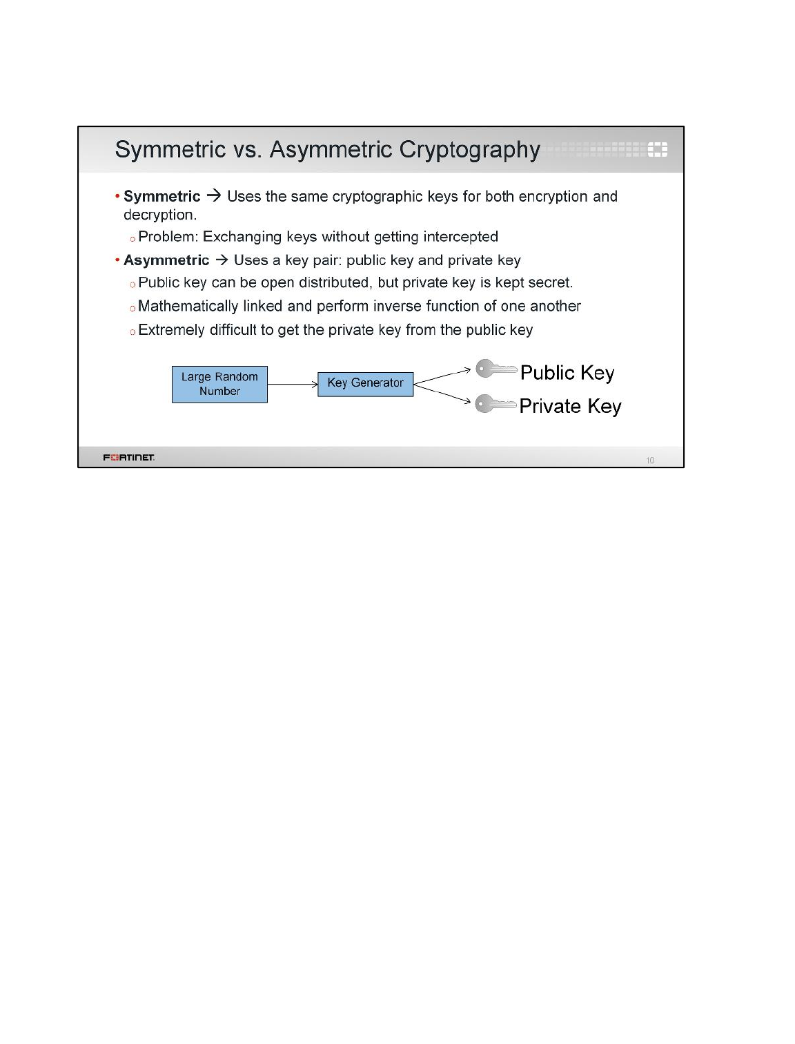
There are two different forms of cryptography: symmetric cryptography and asymmetric cryptography.
Both use a key to mathematically scramble and unscramble data in a way that only the recipient can
predict. However, there is a significant difference between the two forms.
Symmetric cryptography uses the same cryptographic key for both encryption and decryption. A
secret key is used to change the content of a message, and as long as both the sender and recipient
know the secret key, they can encrypt and decrypt all messages that use it. With symmetric
cryptography, the problem is exchanging the secret keys over the Internet without getting intercepted.
A solution to this problem is asymmetric cryptography, also referred to as public key cryptography
because it is used in PKI. With asymmetric cryptography, a key pair is used. There is a public key,
which can be openly distributed, and a private key, which is kept secret by the owner. There is no
concern about exchanging keys over the Internet, as the only one that is exchanged is the public key,
which is supposed to be public. The key pairs are mathematically linked, and perform the inverse
function of each other. For example, a message encrypted by the public key can be decrypted only by
using the matching private key. Likewise, a message encrypted using the private key can only be
decrypted using the matching public key. It is extremely difficult (or practically impossible) to get the
private key from the public key.
Asymmetric cryptography achieves all four objectives previously discussed: data privacy, data
integrity, authentication, and non-repudiation.
Certificate Operations
FortiGate II Student Guide
412
DO NOT REPRINT
© FORTINET

As just explained, asymmetric cryptography requires the use of key pairs. If the sender encrypts a
message with their private key, only the matching public key can decrypt it. So how do recipients get
the public key? Through digital certificates. This section will examine digital certificates and certificate
authorities.
Certificate Operations
FortiGate II Student Guide
413
DO NOT REPRINT
© FORTINET
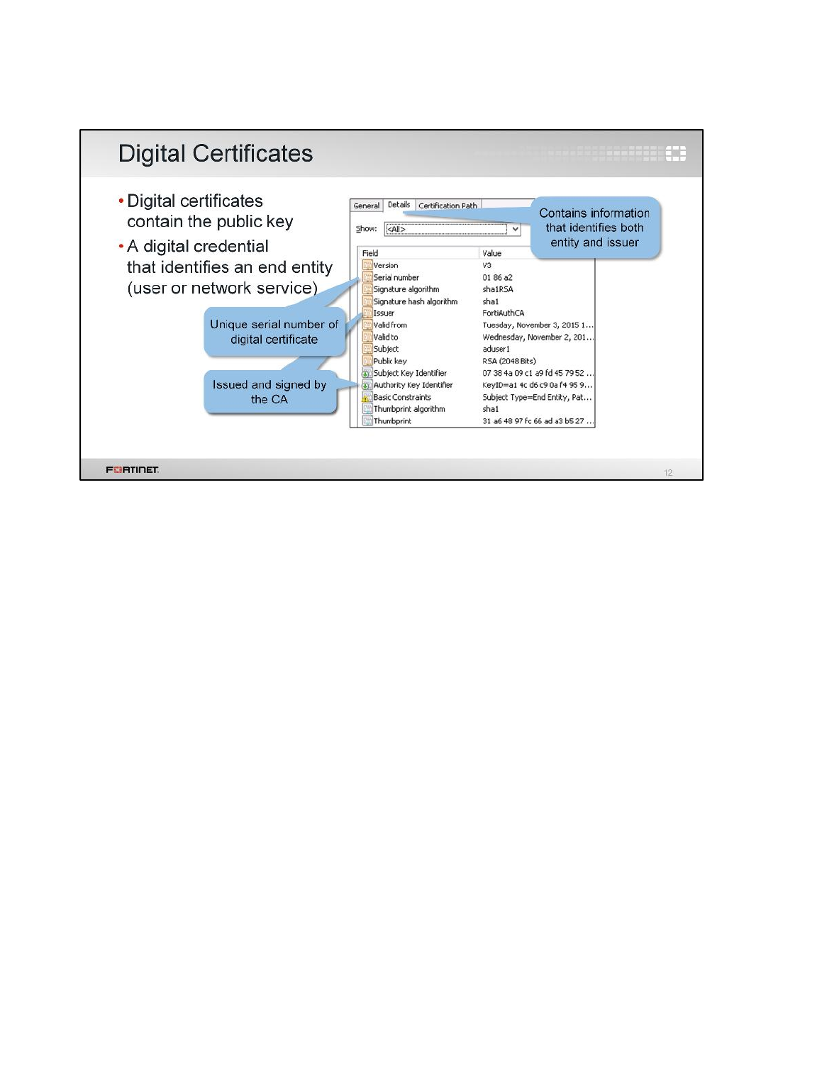
Digital certificates, also known as X.509 certificates, are used to exchange the public key between two
entities. But they are also much more than that. They contain specific information that identifies both
the entity and the certificate issuer.
The certificate issuer is a certificate authority (CA). A CA signs each certificate it issues in order to
certify that the digital certificate and its contents are trusted and valid.
Certificate Operations
FortiGate II Student Guide
414
DO NOT REPRINT
© FORTINET
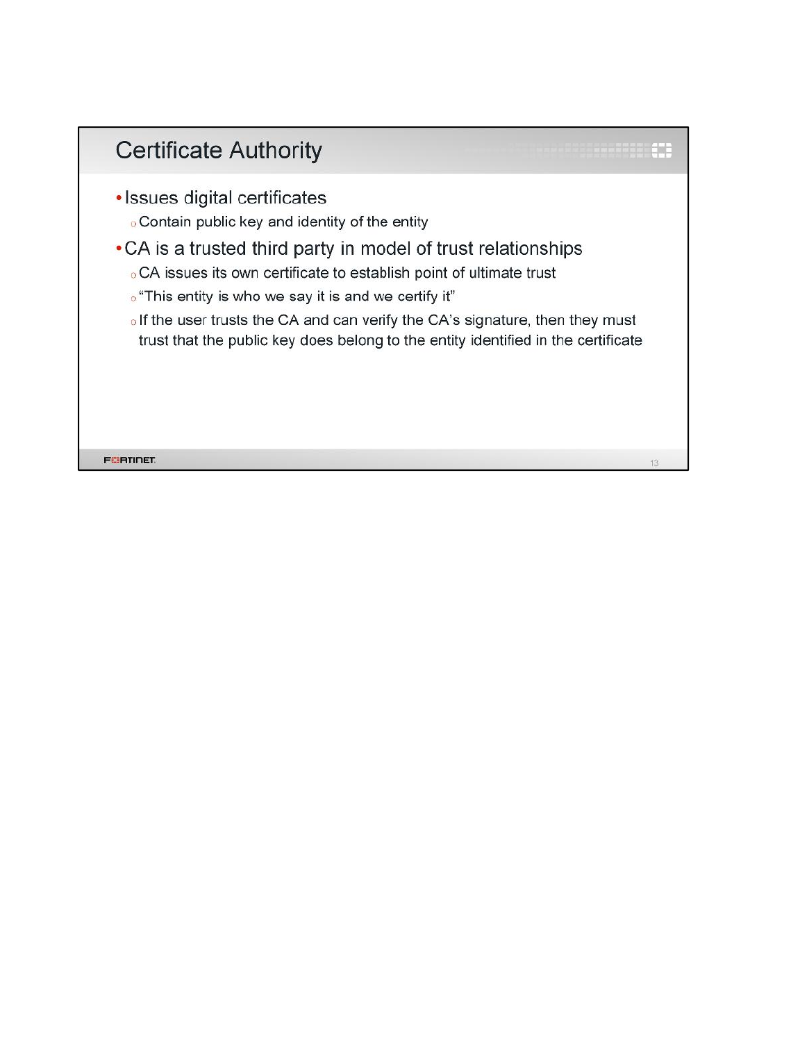
PKI uses the relationship trust model, and the CA is at the root of the hierarchy as the trusted third
party: everything begins with the CA. A CA issues its own digital certificate—known as the root
certificate—in order to establish this point of ultimate trust. Once the root certificate is established, the
CA can generate digital certificates that are issued and signed by the root certificate. It can also issue
a certificate to a subordinate CA, which issues certificates on its behalf.
When a CA issues and signs a digital certificate, they are essentially proclaiming “this is the entity who
we say it is and we certify it”. Accordingly, if users trust the CA and can verify the CA’s signature as
authentic, then they must trust that the public key does belong to the entity identified in the digital
certificate.
Certificate Operations
FortiGate II Student Guide
415
DO NOT REPRINT
© FORTINET
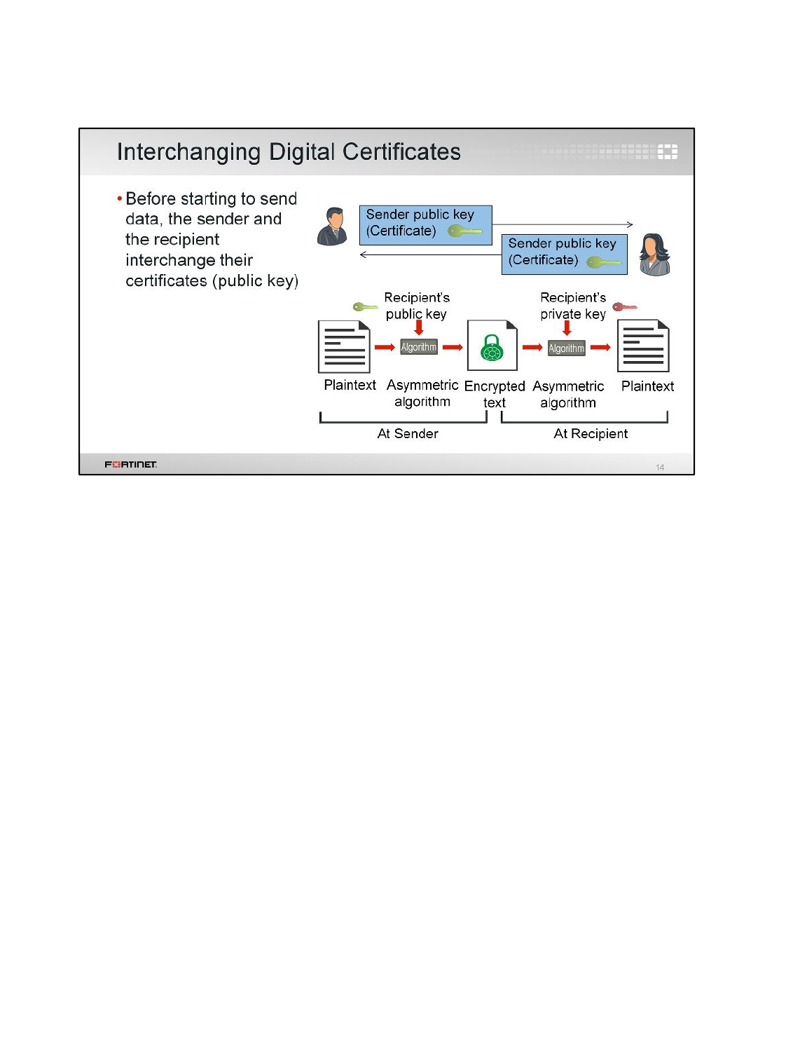
This slide shows how asymmetric cryptography using digital certificates works.
1. Before starting the data transmission, the sender must send their certificate to the recipient. The
sender’s certificate includes the sender’s public key.
2. Similarly, the recipient sends their certificate to the sender. This contains the recipient’s public key.
3. The sender encrypts the message using the recipient’s public key and sends it.
4. The recipient uses their matching private key to decrypt the message. Only the equivalent private
key (which is held only by the recipient) can decrypt the data.
The same process applies to traffic travelling in the other way. That is, the side sending the data uses
the other side’s public key to encrypt the data.
Certificate Operations
FortiGate II Student Guide
416
DO NOT REPRINT
© FORTINET
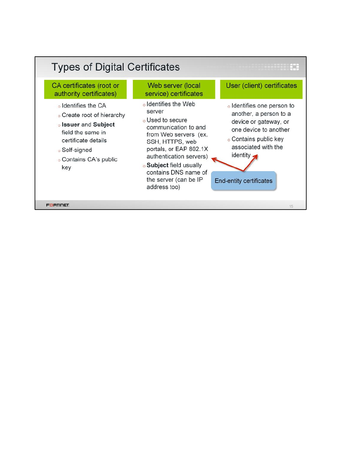
There are many different types of certificates, each with different functions (and some certificates of
the same function even have different names). A few common certificate types include:
• CA certificates (also called root or authority certificates). These certificates identify the certification
authority and create the root of a CA hierarchy. As such, the certificate details have the same input
for both the Issuer and Subject fields. These certificates are self-signed and contain the CA’s
public key needed to decrypt signatures in the signed certificates.
• Web server certificates (also called local service certificates). These certificates identify Web
servers and are used to secure communication to and from Web servers, such as an SSH server,
HTTPS website, Web portals, or EAP 802.1X authentication servers. The certificate details usually
have the DNS name of the server in the Subject field, though this can be the Web server IP
address too. The public key of the Web server is included.
• User certificates (also called client certificates). These certificates identify one person to another, a
person to a device or gateway, or one device to another device. The certificate includes the public
key associated with the identity.
Both user and Web server certificates fall under the category of end-entity certificates.
Certificate Operations
FortiGate II Student Guide
417
DO NOT REPRINT
© FORTINET
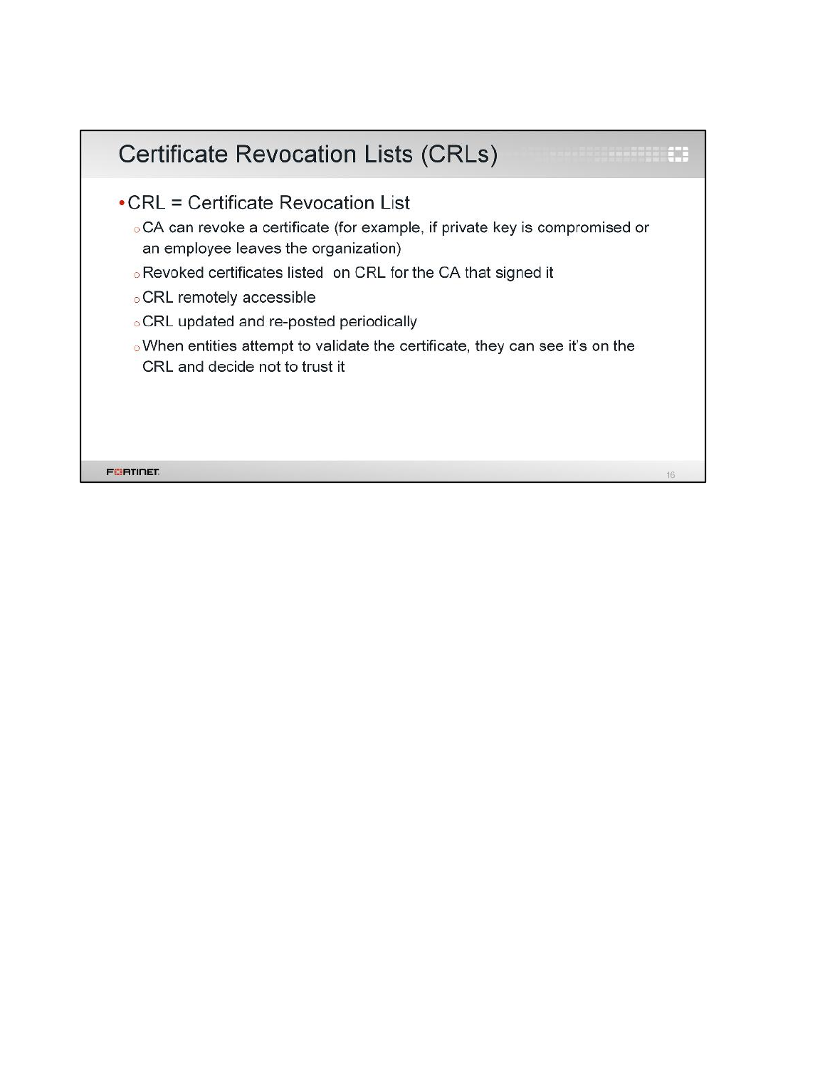
It is possible for a private key to become compromised. For example, if an employee leaves your
organization or it is revealed the CA no longer considers the certificate holder trustworthy. When this
occurs, the CA can revoke the certificate. One way to revoke a certificate is to list the serial number of
the certificate on a remotely accessible certificate revocation list (CRL), which is updated and re-
posted by the CA periodically. As such, any entities attempting to validate the certificate can see that
is revoked, based on its presence on the CRL, and choose not to trust it.
Certificate Operations
FortiGate II Student Guide
418
DO NOT REPRINT
© FORTINET
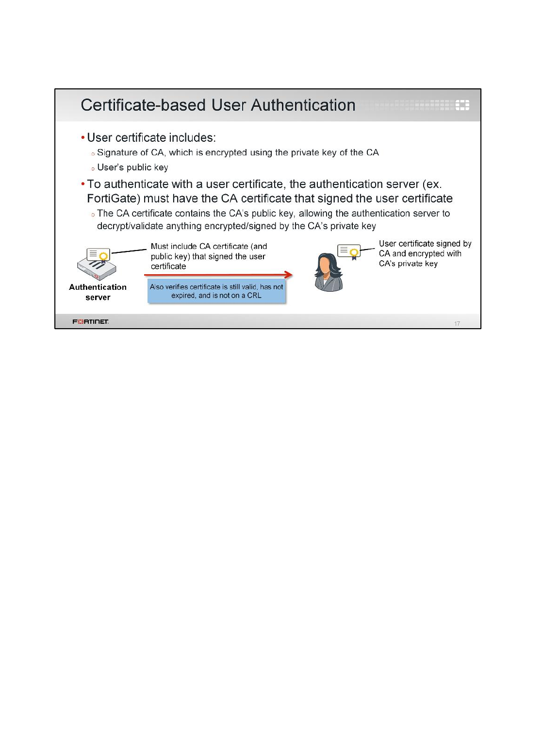
Certificate-based user authentication uses a user certificate to identify the user. The user certificate
contains their public key and also the signature of the CA that issued their certificate. The CA’s
signature is encrypted using the private key of the CA.
Accordingly, in order for an authentication server (for example, FortiGate) to authenticate a user
through their user certificate, the authentication server must have the certificate of the CA that signed
the user certificate. Why? Because the CA certificate contains the CA’s public key, allowing the
authentication server to decrypt and validate the user certificate, which is encrypted/signed by the
CA’s private key.
The authentication server also verifies that the certificate is still valid, has not expired, and is not on a
CRL. If any of these verifications fail, the certificate-based user authentication would fail.
Certificate Operations
FortiGate II Student Guide
419
DO NOT REPRINT
© FORTINET
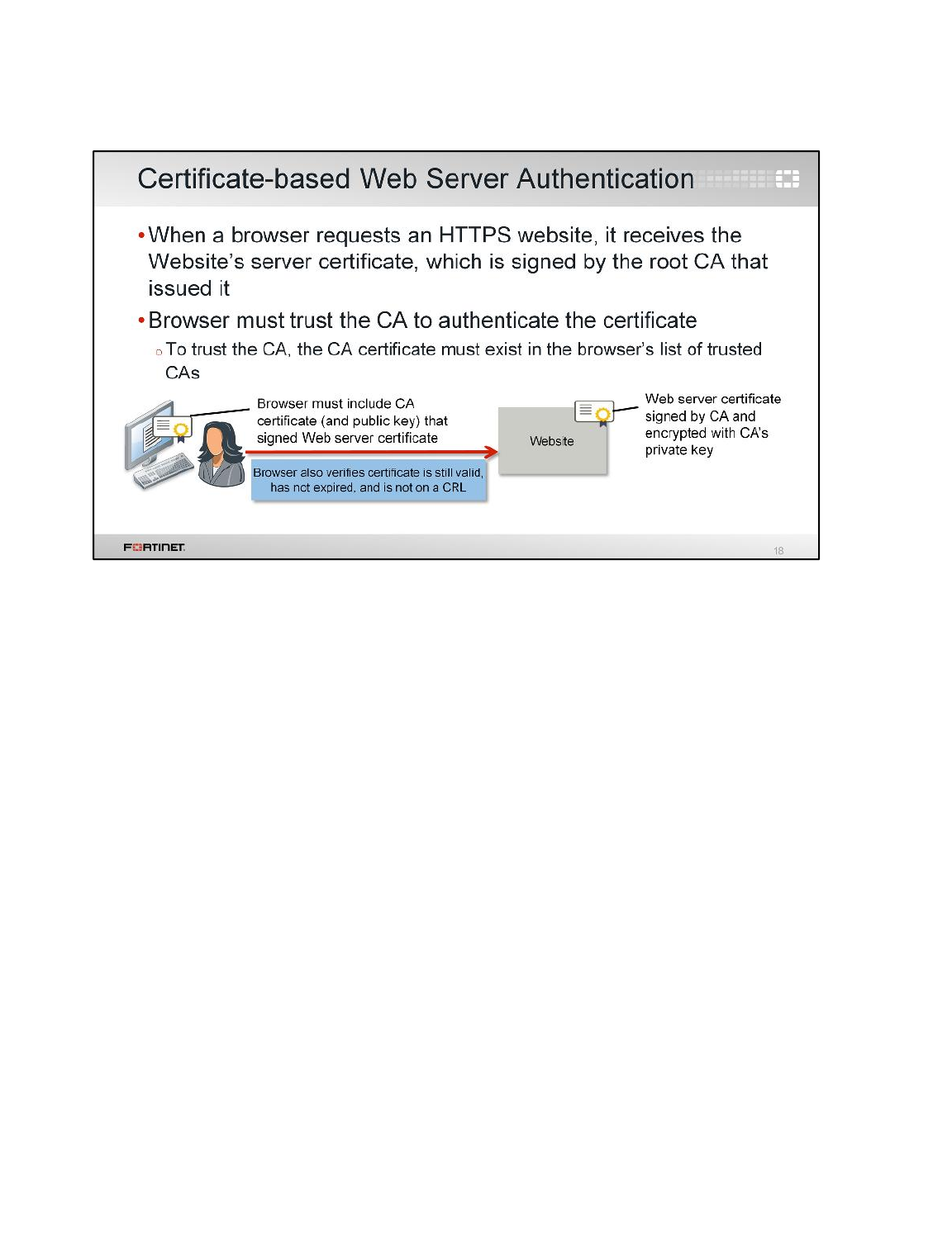
An HTTPS server (a website) identifies itself using a Web server certificate (also known as a local
service certificate). When a user connects to the HTTPS website, the browser receives that Web
server certificate. The Web server certificate is signed by the root CA that issued it.
In order for the browser to trust the website through its Web server certificate, the browser must have
the CA certificate that issued the Web server certificate installed. Why? Because the CA certificate
contains the CA’s public key, and the public key is used to decrypt and validate the signature in the
Web server certificate.
The most common browsers include the CA certificates of well-known public CAs (for example,
Comodo, Entrust, GoDaddy, RSA, and Verisign). As such, installing the CA certificate is not required if
signed by a well-known CA already pre-installed in the browser by default. However, if the Web server
certificate is signed by a private CA, for example, you must install the CA certificate in the browser so
that it can trust the Web server certificate the website is using to identify itself.
The browser also verifies that the certificate is still valid, has not expired, and is not on a CRL. If any of
these verifications fail, the browser presents a certificate warning to the user, indicating something is
not right with the website being visited.
Certificate Operations
FortiGate II Student Guide
420
DO NOT REPRINT
© FORTINET

This section examines how you can manage digital certificates on FortiGate. This includes how to get
digital certificates (including SSL certificates); how to import certificate revocation lists (CRLs); and
how to back up and restore certificates.
Certificate Operations
FortiGate II Student Guide
421
DO NOT REPRINT
© FORTINET
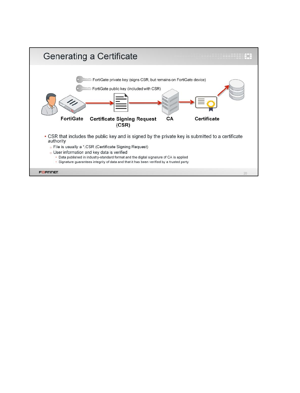
The process of getting a digital certificate for your FortiGate begins with creating a certificate signing
request (CSR). The process is as follows:
1. Generate a certificate signing request for FortiGate. A private and public key pair is created for
your FortiGate. The CSR is signed by the FortiGate’s private key.
2. Submit the CSR to a CA. The CSR includes the FortiGate public key and specific information
about the FortiGate itself (IP address, distinguished name, email address, and so on). Note that
the private key remains confidential on FortiGate.
3. The CA verifies that the information in the CSR is valid and then creates a digital certificate for
FortiGate. The certificate is digitally signed using the CA’s private key. The CA also stores the
certificate in a central repository and publishes the public key bound to FortiGate.
4. Install the certificate on your FortiGate.
Certificate Operations
FortiGate II Student Guide
422
DO NOT REPRINT
© FORTINET
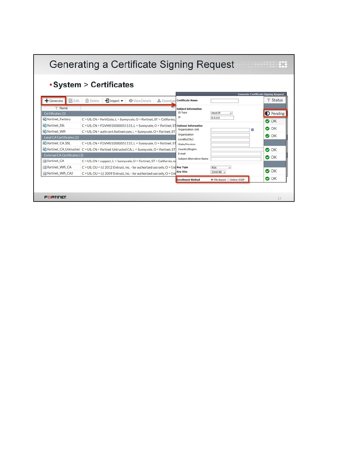
You can create a CSR through the Certificates page of the GUI by clicking Generate. Fill out all the
required information, such as the IP address (or FQDN) and company name. Ensure the key type and
size fit your requirements. You can submit the CSR through two different methods:
• Select File Based to generate the CSR as a .cer file, which is then sent to the CA.
• Select Online SCEP to submit the CSR to the CA online using the SCEP protocol. For example, if
using FortiAuthenticator as your CA, you can enable and configure SCEP on FortiAuthenticator
and use this method.
Certificate Operations
FortiGate II Student Guide
423
DO NOT REPRINT
© FORTINET
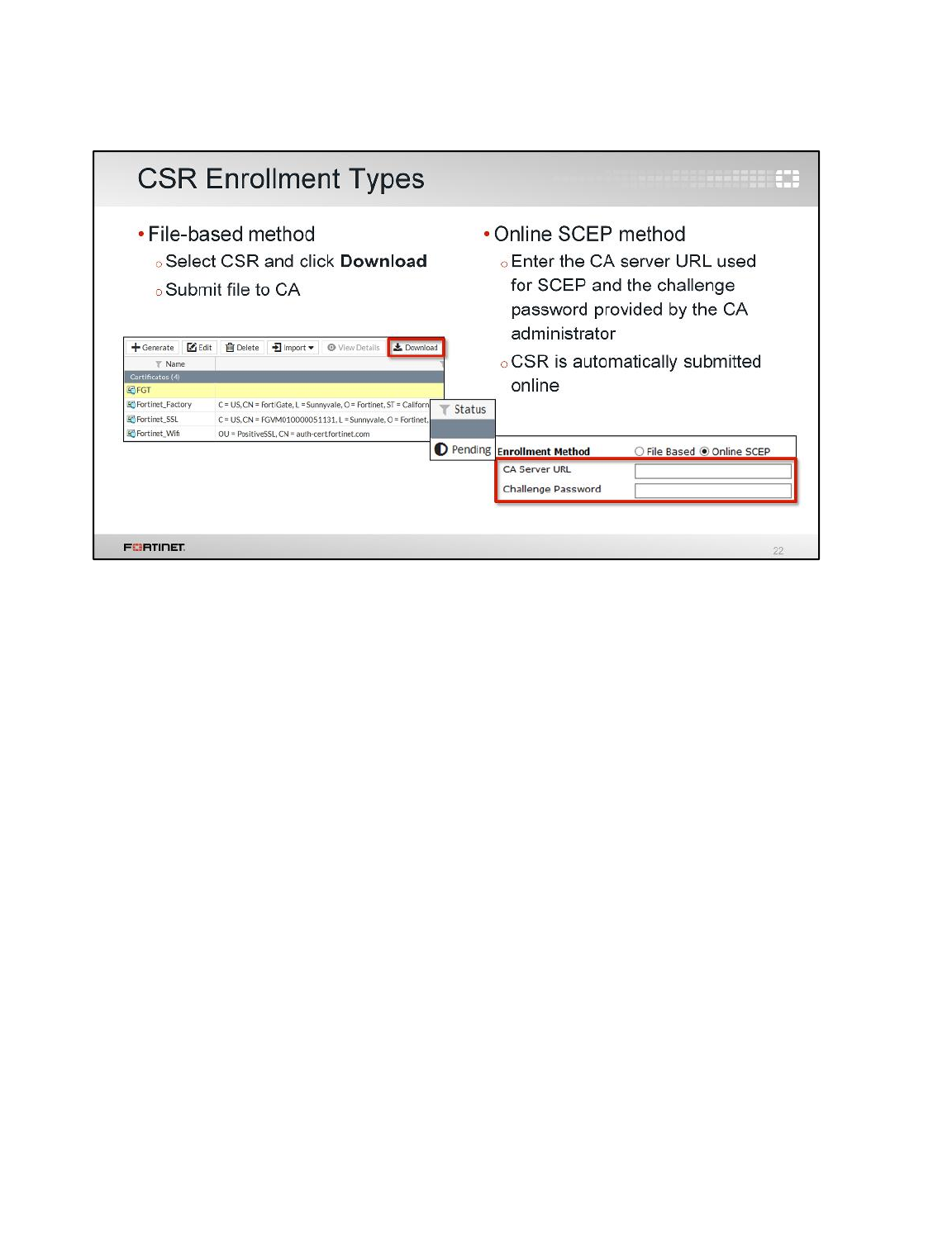
If using the file-based method, the CSR is added to your list of certificates on the Certificates page.
Select the CSR and click Download. The administrator can now download the file (.cer), which is a
PKCS#10 request (an unsigned copy of your certificate) and submit it to the CA. The CA uses this file
to generate a signed certificate.
If using the online SCEP method, enter the CA server URL used for SCEP and the challenge
password provided by the CA administrator. The CSR is automatically submitted online.
Once submitted through either method, FortiGate shows the certificate status as pending until the
certificate has been validated and signed by the CA. At this point, the status changes to OK and the
digital certificate can be used.
Certificate Operations
FortiGate II Student Guide
424
DO NOT REPRINT
© FORTINET
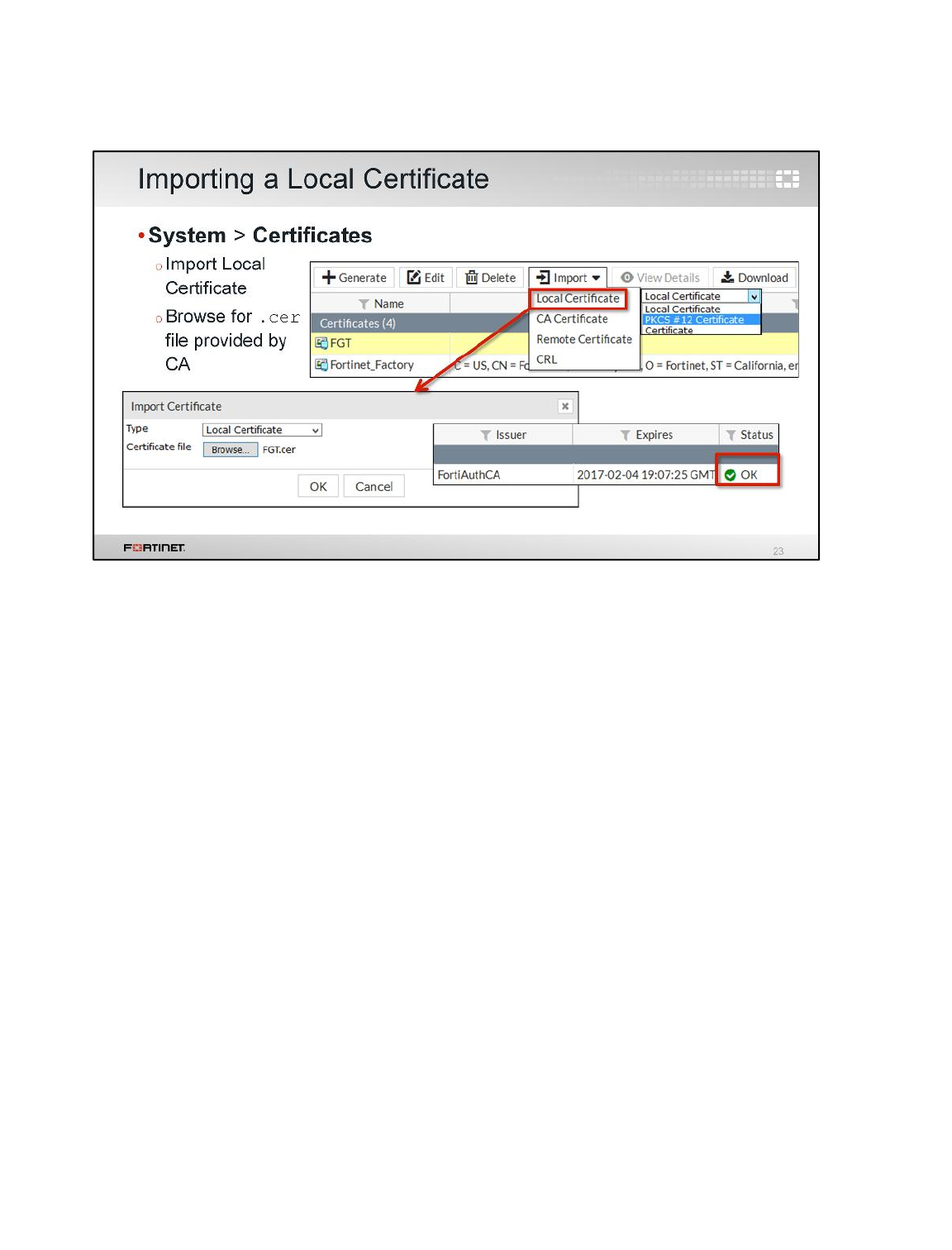
When you receive a signed digital certificate back from the CA, you must import it into FortiGate. This
only applies if you used the file-based method to submit the CSR. With SCEP, the process occurs
automatically online—no file import is required.
You can import the certificate from the Certificates page. Click Import and select Local Certificate.
From the import certificate dialog box that appears, ensure Local Certificate is selected as the type
and browse for the .cer file provided by the CA.
Once you import the certificate, the status changes from pending to OK.
Note that it is possible to add a certificate that FortiGate will use in SSL communications without
generating and signing a CSR. The CA can create a certificate for your FortiGate without a CSR
(though the CA is responsible for providing all the certificate details for your FortiGate). In this way,
you can add a certificate using the following methods:
• Upload a PKCS#12 file, which is a single file that includes the signed certificate file and the key file.
• Upload both a certificate file and the key file.
Certificate Operations
FortiGate II Student Guide
425
DO NOT REPRINT
© FORTINET
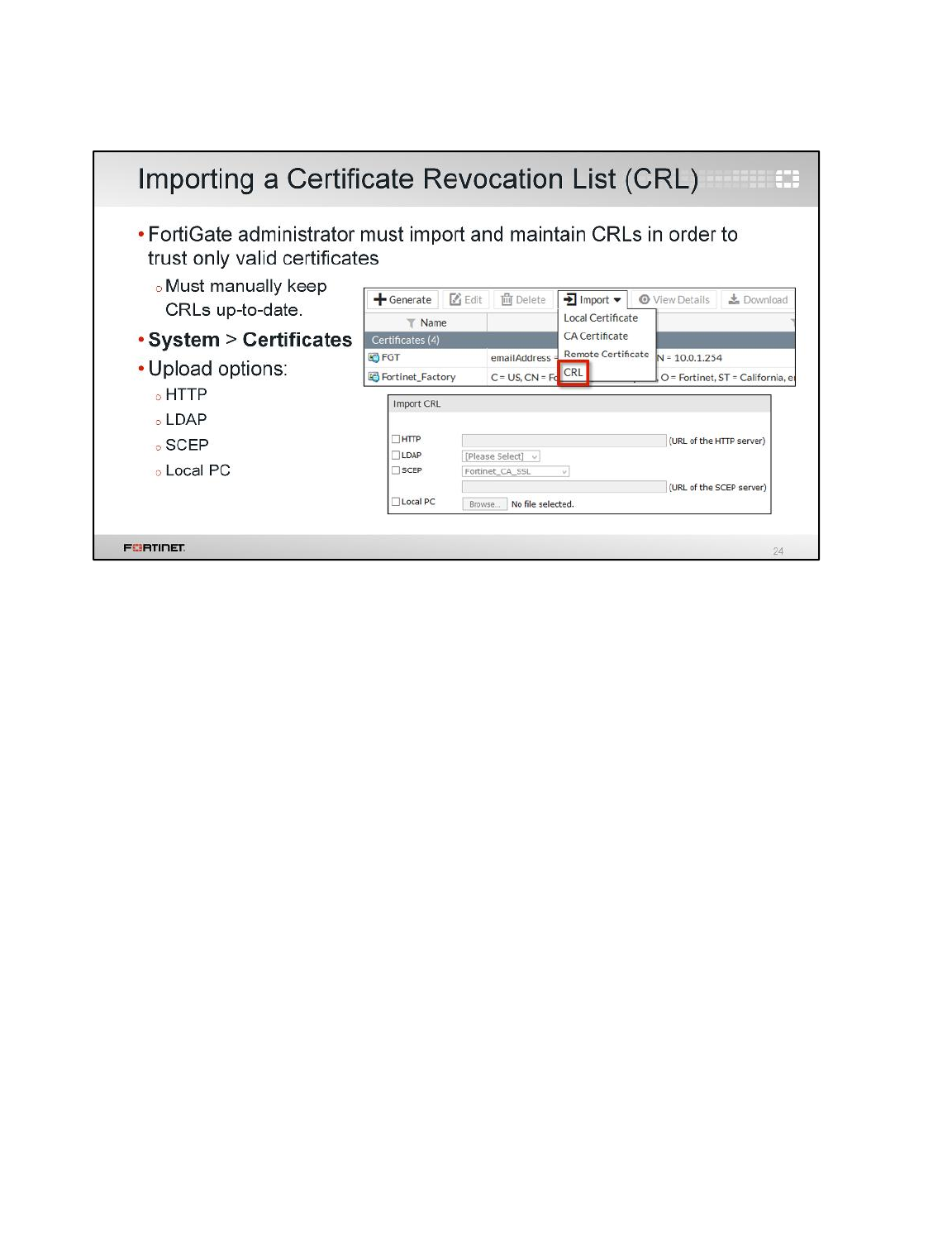
In order for FortiGate to trust only valid certificates, it is important to import and maintain CRLs. A
certificate revocation list is a list that contains revoked certificates (or more specifically, the serial
number of the certificates). When FortiGate is validating a certificate, it will check that the certificate’s
serial number is not listed in a CRL imported to the FortiGate. Administrators must manually keep all
CRLs up-to-date.
You can import a CRL from the Certificates page by clicking Import >CRL. There are four different
import options you can use: HTTP, LDAP, SCEP, and Local PC. The first three options point to
external repositories and require you to connect to the repositories to upload the CRL to FortiGate.
The last option, Local PC, requires you to have the CRL file locally stored before you can upload the
CRL to FortiGate.
Certificate Operations
FortiGate II Student Guide
426
DO NOT REPRINT
© FORTINET
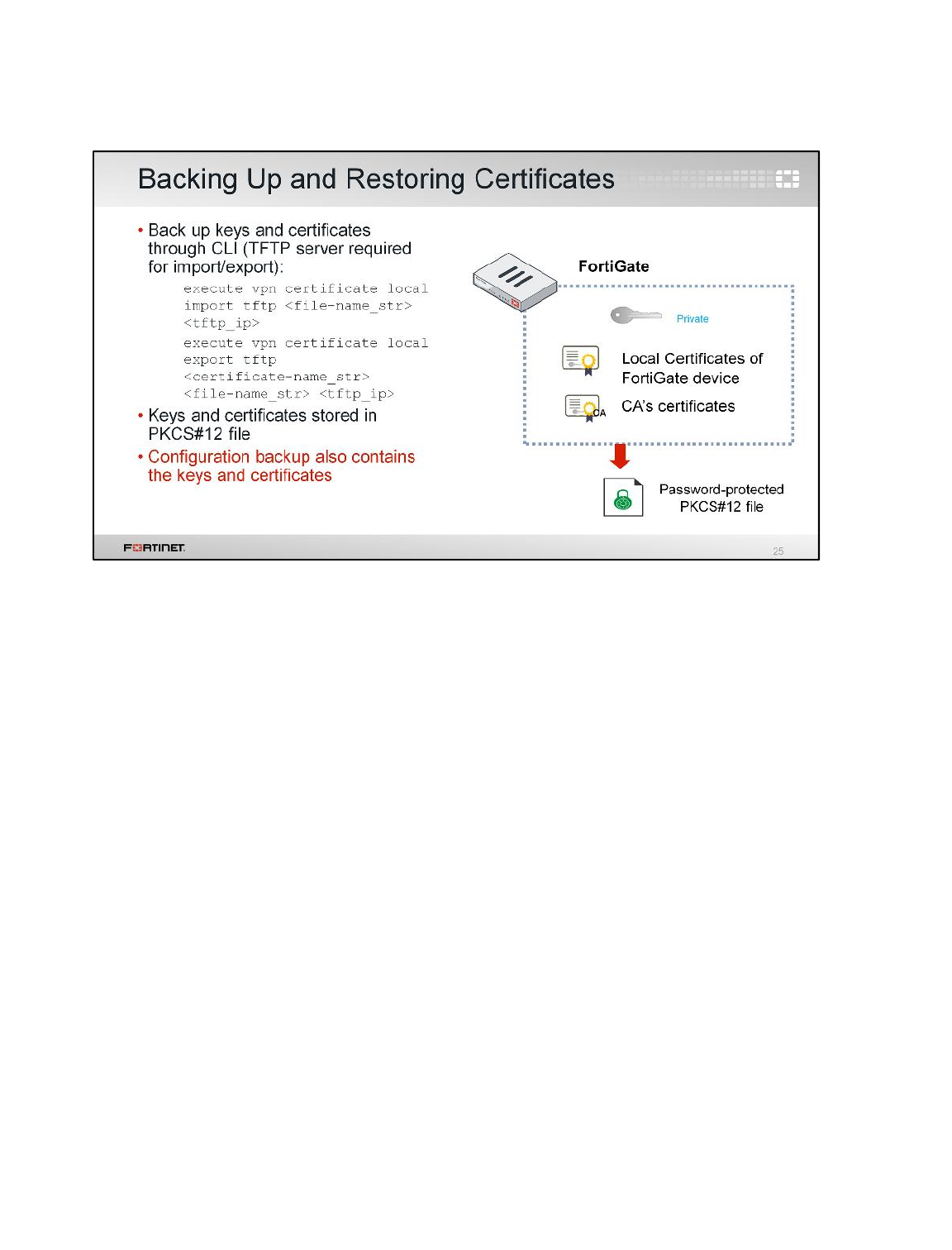
When you back up the FortiGate configuration, the keys and certificates are backed up as well.
FortiGate also provides the option to store digital certificates as a PKCS#12 file, which includes the
private and public keys as well as the certificate. You can restore the PKCS#12 file to a FortiGate
device of any model or firmware version, or to a non-FortiGate device.
You can perform the backup and restore from the CLI only and it requires the use of a TFTP server.
Certificate Operations
FortiGate II Student Guide
427
DO NOT REPRINT
© FORTINET
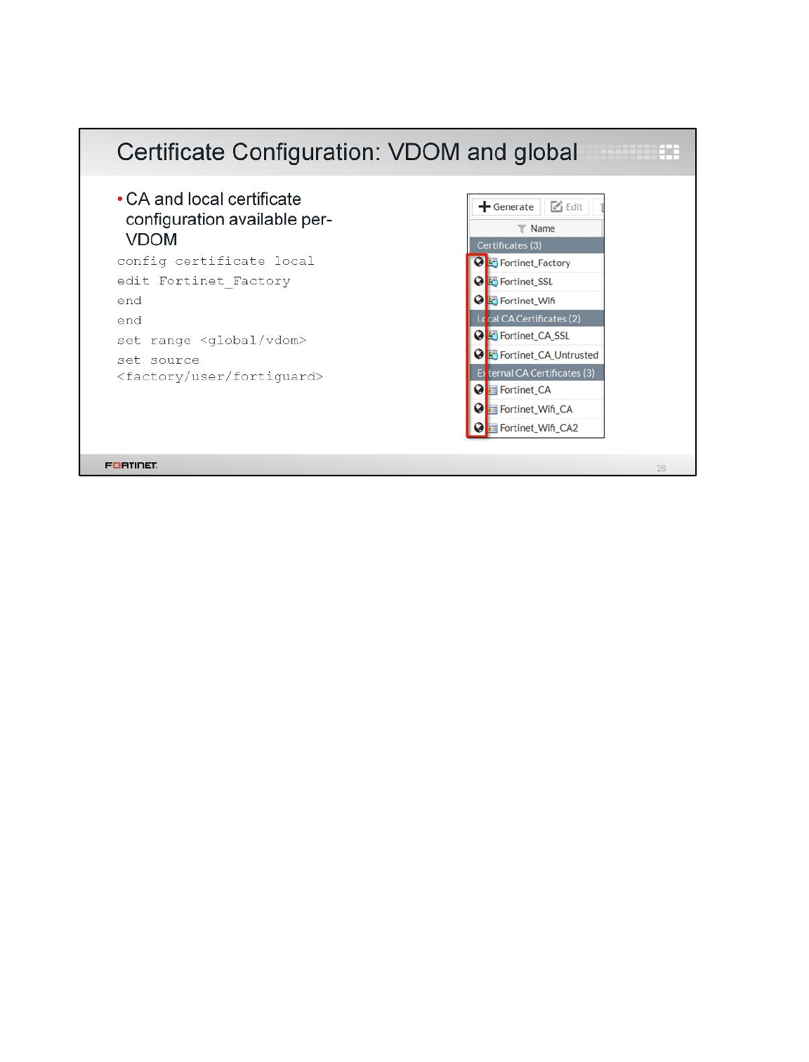
You can configure a CA and local certificate for a VDOM or globally. If you upload a certificate to a
VDOM, it is only accessible inside that VDOM. If you upload a certificate globally, it is accessible to all
VDOMs and global.
Global and VDOM-based certificate configuration includes view details, download, delete, and import
certificate.
In the GUI, a global icon indicates that the certificate is global when VDOMs are enabled.
Certificate Operations
FortiGate II Student Guide
428
DO NOT REPRINT
© FORTINET
This section outlines how to configure FortiGate to use certificate-based authentication for
administrators, SSL VPN clients, and IPsec VPN peers.
Certificate Operations
FortiGate II Student Guide
429
DO NOT REPRINT
© FORTINET
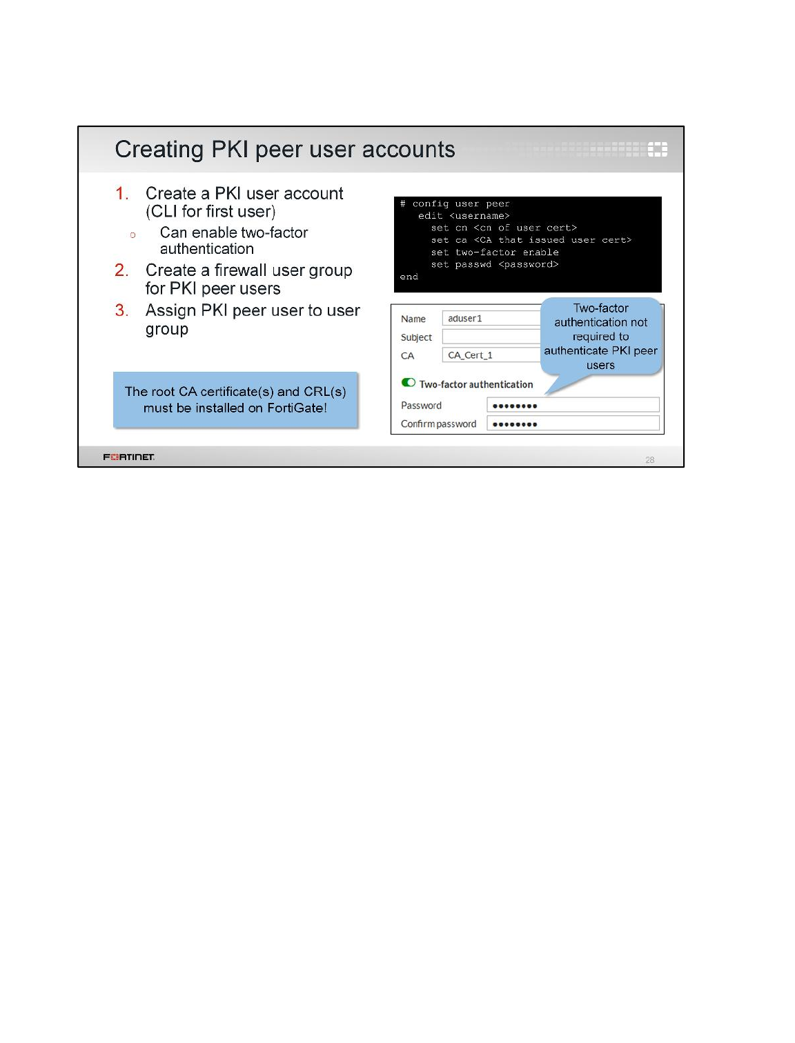
FortiGate supports certificate-based authentication of users. In FortiGate, users who authenticate with
a certificate are referred to as PKI peer users. Before creating a PKI peer user on FortiGate, you must
import the root CA certificate that issued and signed the user certificates on FortiGate. Once you have
completed that, the process is as follows:
1. Create a PKI peer user account. You must create the first PKI user through the CLI config
user peer command. After that, a new PKI page appears in the GUI under User & Device.
You can create new PKI users from there. When creating the account, you must specify the CA
that issued each user’s certificate.
2. Create a firewall user group for PKI peer users.
3. Assign the PKI peer user to the user group.
You can add the user group with PKI peer users to your firewall policies. Note that in order for PKI
peer users to authenticate with their certificates the user must install their certificate in the personal
certificate store of their computer. If using the Mozilla Firefox browser, however, users must install the
certificate in the Firefox browser certificate store, as Firefox uses its own certificate repository (unlike
Internet Explorer and Google Chrome, which use the certificate repository of the OS).
Certificate Operations
FortiGate II Student Guide
430
DO NOT REPRINT
© FORTINET
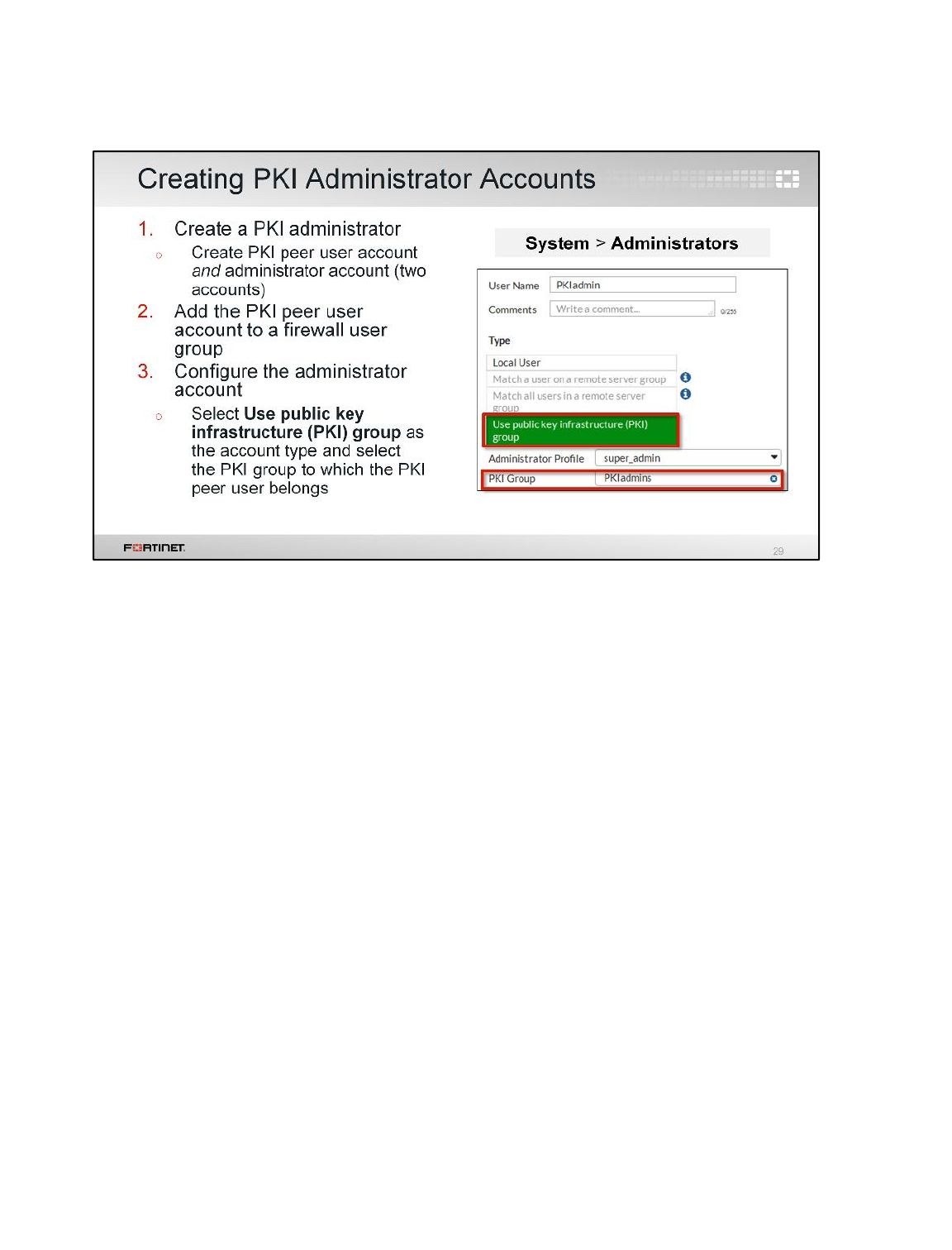
FortiGate supports certificate-based authentication of administrators as well. When logging into the
FortiGate GUI as a PKI administrator, FortiGate will use the certificate installed on the management
computer to authenticate.
Similar to the process of creating a PKI peer user (as discussed on the previous slide), you must first
install the root CA certificate on FortiGate and the administrator must have their digital certificate
installed in the personal certificate store of their computer (or Firefox browser certificate repository if
logging in through Firefox).
The process of enabling certificate authentication for administrators is then as follows:
1. Create the PKI administrator. You need to create two user accounts on FortiGate: a PKI peer user
account and an administrator account. These two accounts work together to form a single PKI
administrator account. You do not need to give these accounts the same name, but because they
refer to a single PKI administrative user, it might be helpful for maintenance purposes.
2. Add the PKI peer user account to a firewall user group dedicated to PKI administrators.
3. Configure the administrator account. Select Use public key infrastructure (PKI) group as the
account type and select the PKI group to which the PKI peer user belongs.
Certificate Operations
FortiGate II Student Guide
431
DO NOT REPRINT
© FORTINET
FortiGate can also use certificates to authenticate SSL VPN clients and IPsec VPN peers. Both
require that you install the root CA certificate on FortiGate. Configuration is more complex then
creating PKI peer user accounts an PKI administrator accounts. Refer to the FortiOS Administration
Guide for more details.
Any time you use certificate-based authentication, whether for users or administrators, you should
always make sure you import the CRL into FortiGate and keep it updated.
.
Certificate Operations
FortiGate II Student Guide
432
DO NOT REPRINT
© FORTINET
SSL/TLS is primarily used to encrypt communications between a server and client, such as a Web
server and Web browser. In order to establish secure communications, the server requires an SSL
certificate and optionally one for the client for authentication purposes. This section outlines how
FortiGate uses an SSL certificate to authenticate itself to HTTPS clients.
Certificate Operations
FortiGate II Student Guide
433
DO NOT REPRINT
© FORTINET
Secure Sockets Layer (SSL) is the cryptographic protocol used to secure transmissions over TCP.
One common application of SSL is secure HTTP, or HTTPS. When a user attempts to connect to an
HTTPS site, SSL/TLS is the protocol used between the Web server and the browser to authenticate
and encrypt the data.
SSL uses both asymmetric and symmetric encryption as you will see on the following slide.
Certificate Operations
FortiGate II Student Guide
434
DO NOT REPRINT
© FORTINET
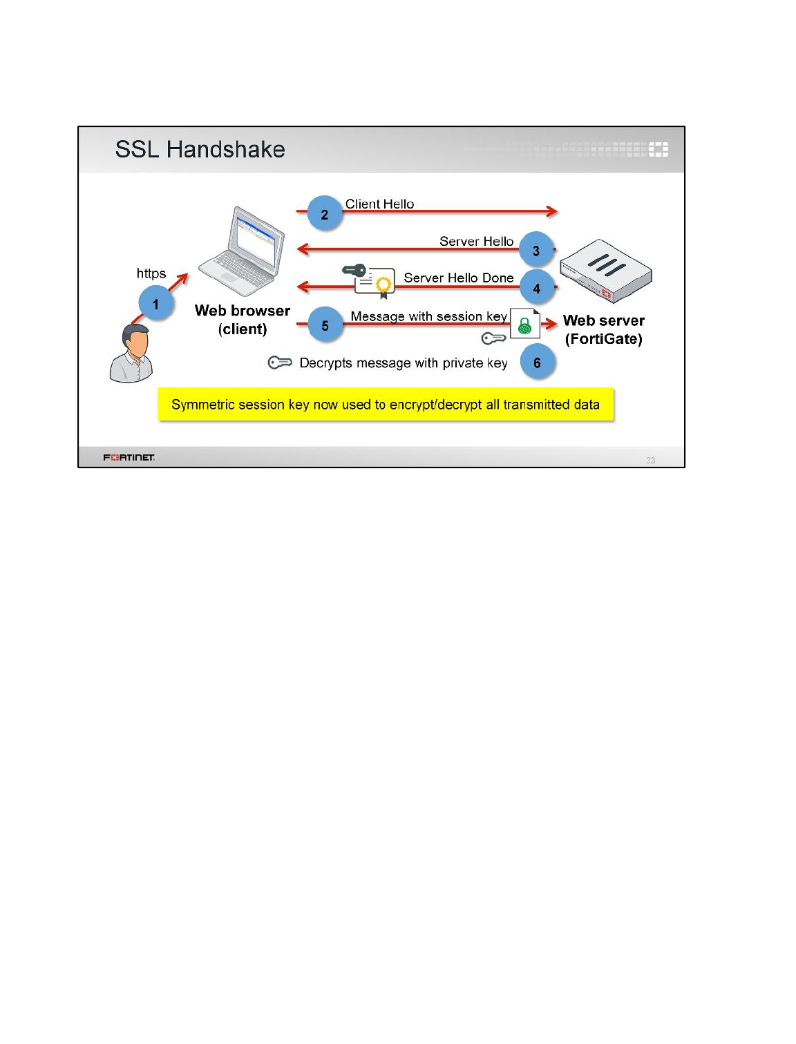
An SSL session starts with the SSL handshake. The handshake process is as follows:
1. The user enters an HTTPS URL into a browser.
2. The browser sends a Client Hello message to the Web server that includes information
about which encryption and compression algorithms the browser supports, as well as a pseudo-
random number.
3. The server replies with a Server Hello message that includes supported algorithms and a
pseudo-random number.
4. The server sends its digital certificate to the browser, which contains its public key and the name
of the server.
5. The browser verifies the contents of the digital certificate to ensure the name of the server
matches the name the browser requested, and if valid, creates a symmetric session key using the
two random values The symmetric session key is sent to the server as a message encrypted
using the public key from the server's certificate.
6. The server decrypts the message with its private key. If the decryption is successful, it proves to
the browser the authenticity of the server.
This handshake happens over two round-trips—though verifying the validity of certificates is optional
in the second round. An abbreviated handshake can be used if a client has a previous session
cached, which means only a single round trip is needed. The server and browser can now encrypt and
decrypt all transmitted data with the symmetric session key. It is secure, because only the browser
and server know the symmetric session key. The symmetric key is valid only for the length of the
session. If the user closes the current session, that symmetric key is no longer valid and cannot be
used again. When a new SSL session is created, a new symmetric key is created.
Certificate Operations
FortiGate II Student Guide
435
DO NOT REPRINT
© FORTINET
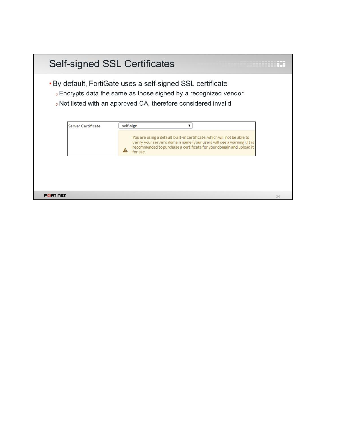
By default, FortiGate uses a self-signed security certificate to authenticate itself to HTTPS clients.
These self-signed certificates encrypt data just as well as those purchased from any of the big
vendors of SSL certificates, but self-signed certificates are not listed with an approved certificate
authority (CA) and are therefore considered untrusted.
Certificate Operations
FortiGate II Student Guide
436
DO NOT REPRINT
© FORTINET

We just discussed the benefits of using HTTPS. However, there are risks associated with its use,
since encrypted traffic can be used to get around your normal defenses. For example, if the session is
encrypted when you download a file containing a virus, it might get past your network’s security
measures.
This section examines how you can use full SSL inspection, also known as deep inspection, to protect
encrypted sessions.
Certificate Operations
FortiGate II Student Guide
437
DO NOT REPRINT
© FORTINET
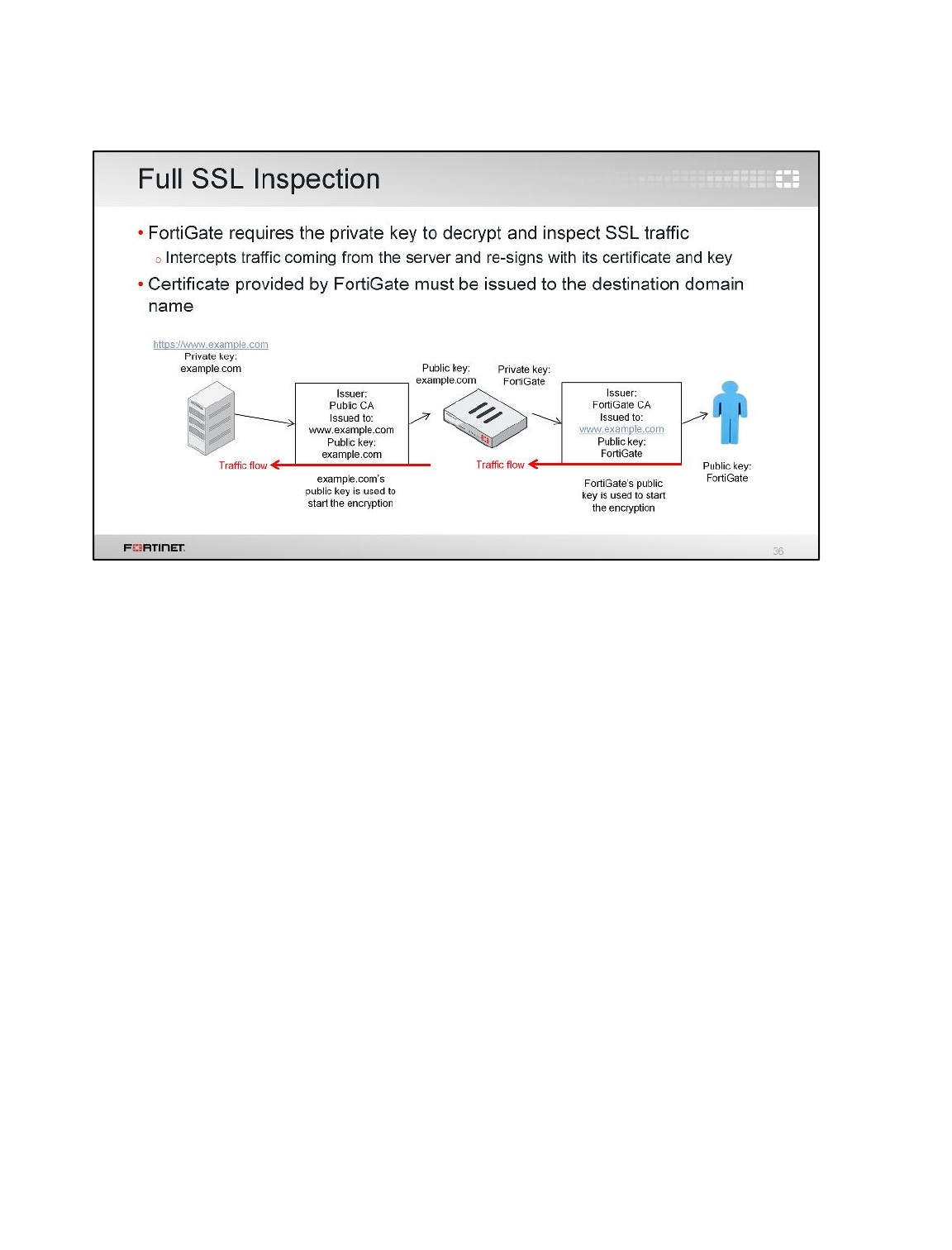
Some FortiGate devices offer a mechanism to inspect and apply protection profiles over SSL
encrypted traffic. It is called full SSL inspection. Without SSL inspection, encrypted traffic cannot be
inspected, as the firewall does not have the key that is required to decrypt the data.
To configure, you must position your FortiGate in the middle of the communication between the user’s
browser and the website. When the browser connects to the site, the Web server sends its certificate,
which contains its public key. Its certificate has been issued to the website by a CA.
The FortiGate intercepts the Web server certificate and generates a new one. The new certificate is
also issued to the website, but this time it is issued by the CA installed on the FortiGate (which is a
private CA). The FortiGate also generates a new pair of public and private keys. The new certificate
contains the public key generated by FortiGate.
Now FortiGate uses the FortiGate public key—and not the Web server’s public key—to start the
encryption to the user’s browser. On the other side, it uses the Web server’s public key to start the
encryption and establish the conversation with the server.
Certificate Operations
FortiGate II Student Guide
438
DO NOT REPRINT
© FORTINET
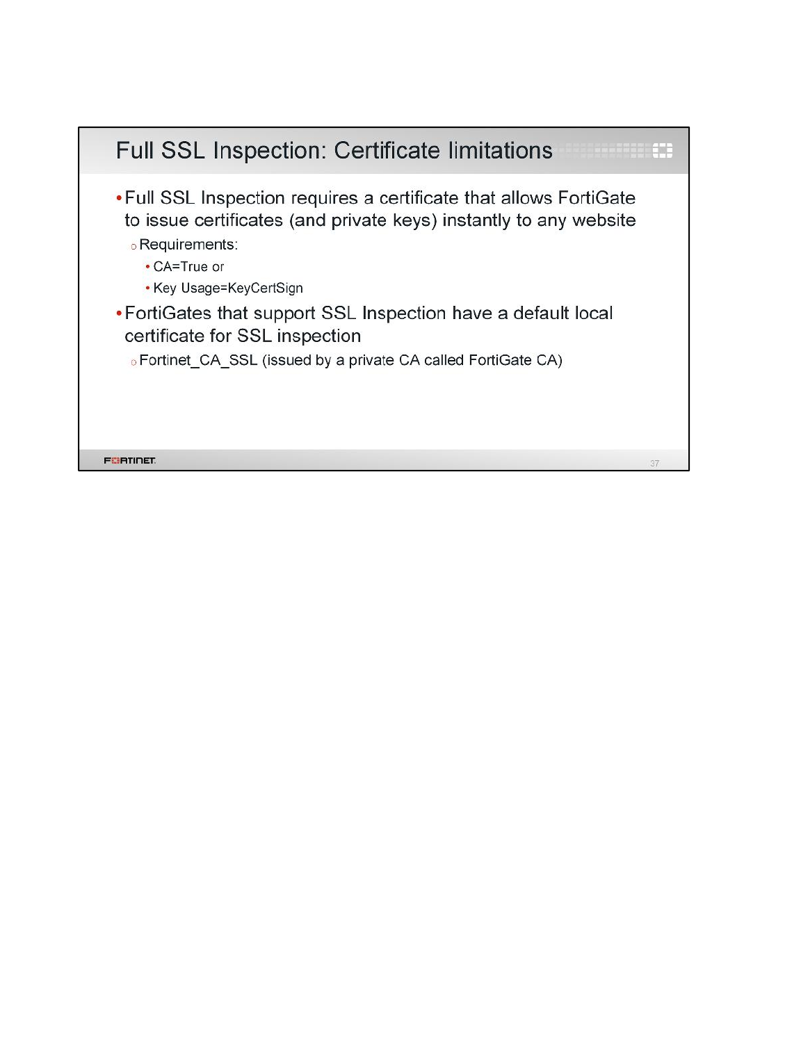
SSL inspection requires an SSL certificate that allows FortiGate to generate a new pair of keys and a
new certificate. FortiGate must do this each time a user connects to a different site.
The certificate required for SSL inspection must have either the CA field equal to True, or the Key
Usage to include KeyCertSign. The FortiGate models that support SSL inspection include an SSL
certificate that you can use for full SSL inspection. It is called Fortinet_CA_SSL and is signed by a CA
called FortiGate CA, which is not public.
Certificate Operations
FortiGate II Student Guide
439
DO NOT REPRINT
© FORTINET

Because self-signed SSL certificates are not trusted, the browser presents a certificate warning when
you attempt to access an HTTPS site that uses an untrusted certificate. This warning does not
necessarily indicate you are vulnerable to eavesdroppers—it just means the browser cannot verify the
identity of the website. FortiGate has its own configuration setting on the SSL/SSH Inspection page
that allows, blocks, or ignores untrusted SSL certificates.
When set to Allow, FortiGate continues its inspection of the secured site by using the FortiGate
Untrusted CA certificate to re-sign/replace the server certificate when the server certificate is
untrusted. The browser presents a warning, but the user can proceed to the site by adding an
exception to the browser. The security rationale behind this setting is that it will generate certificate
warnings to clients that are connecting to untrusted sites when doing deep SSL inspection. If the
server certificate is trusted, a trusted FortiGate certificate is used to re-sign the server certificate.
When set to Block, FortiGate blocks the connection outright and the user cannot proceed. There is no
option to add an exception.
When set to Ignore, FortiGate continues its inspection of the secured site by using the self-signed
SSL certificate (Fortinet_CA_SSL) to re-sign/replace the server certificate, even when the server
certificate is untrusted. This certificate can be trusted after installing the FortiGate root certificate,
which can be downloaded from FortiGate. In this case, the browser presents a warning, but the user
can proceed to the site by adding an exception to the browser. The Ignore setting is only configured
through the CLI with the command displayed in the slide.
Certificate Operations
FortiGate II Student Guide
440
DO NOT REPRINT
© FORTINET
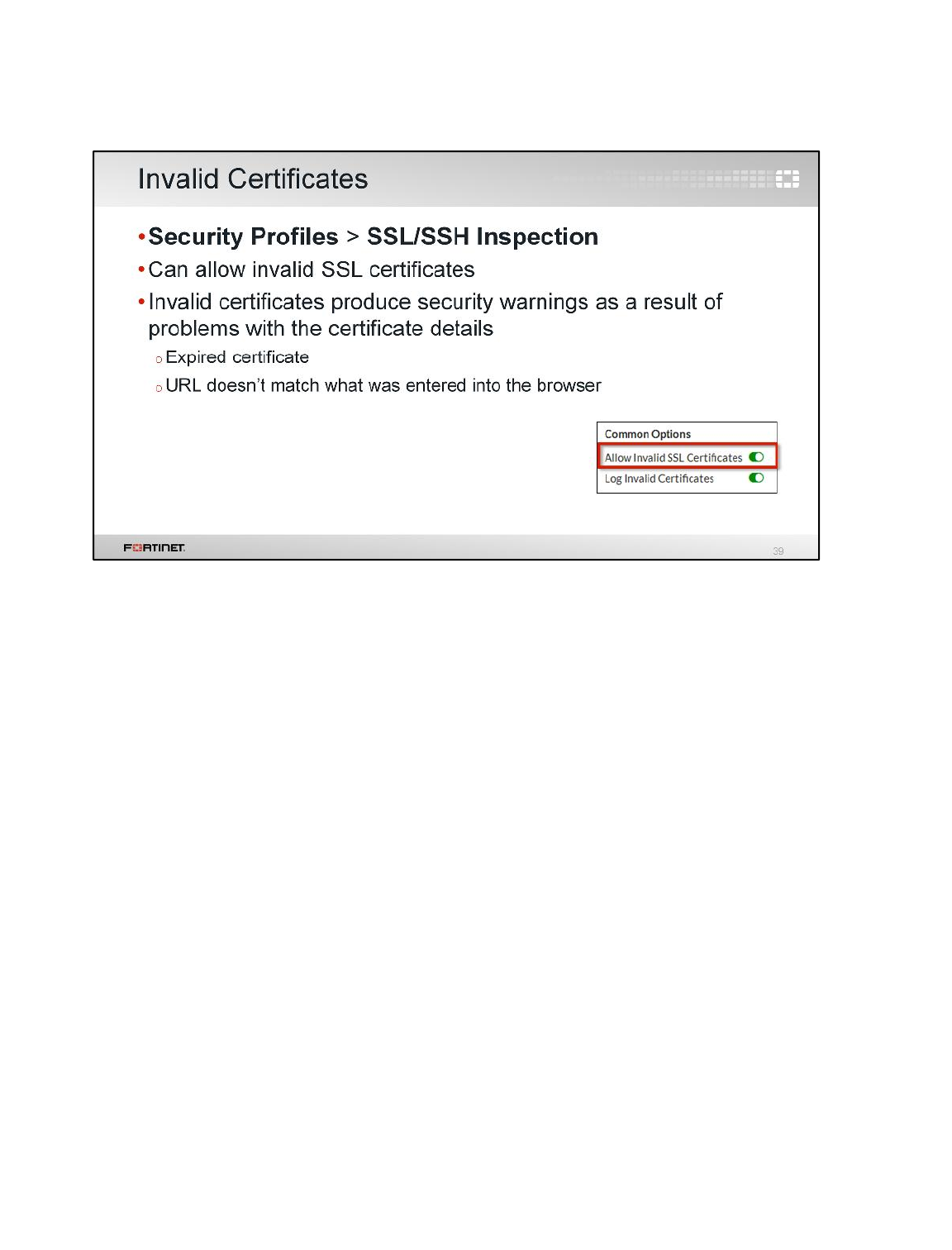
FortiGate provides a configuration setting that allows invalid SSL certificates. Invalid certificates
produce certificate warnings as well, though as a result of problems with the certificate details itself
(for example, the certificate is expired or the URL doesn’t precisely match what you entered into the
browser). You can allow invalid certificates by enabling the Allow Invalid SSL Certificates option.
You can also log invalid certificates as well by enabling Log Invalid Certificates.
Certificate Operations
FortiGate II Student Guide
441
DO NOT REPRINT
© FORTINET
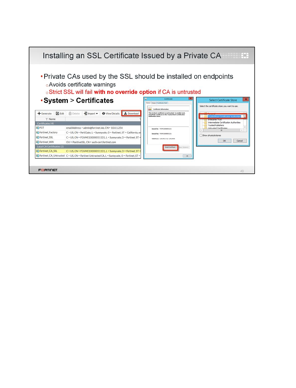
If you don’t want to use FortiGate’s self-signed certificate, you can install an X.509 certificate issued
by a public or private CA, and configure FortiGate to identify itself using a server certificate instead.
If using an SSL certificate issued by a private CA, you must install your certificate in the list of trusted
CAs. Failure to do this results in warning messages in Web browsers any time there is access to any
HTTPS website. It may also result in encrypted communications failing, simply because the CA that
issued and signed the certificate is untrusted.
Once you download the SSL certificate from FortiGate, you can install it into any Web browser or
operating system. Not all browsers use the same certificate repository (for example, Firefox uses its
own repository, while Internet Explorer stores certificates in a system wide repository). In order to
avoid certificate warnings, you need to install the SSL certificate as a trusted root CA.
When installing the certificate, make sure that it is properly set up as a root authority. The process
varies from one software to another.
Certificate Operations
FortiGate II Student Guide
442
DO NOT REPRINT
© FORTINET
When doing full SSL inspection using the FortiGate self-signed CA, your browser displays a certificate
warning each time a user connects to a HTTPS site. This is because the browser is receiving
certificates signed by FortiGate, which is a CA it does not know and trust. There are a few ways to
avoid this warning:
• Download the Fortinet_CA_SSL certificate and install it in all the workstations as a public authority.
The Allow option ensures that the client won’t trust all connections with this certificate—including
connections to sites that should normally prompt the warning.
• Use a SSL certificate issued by a private CA. In this case, the certificate needs to be installed on
FortiGate and the device configured to use that certificate for SSL inspection. The private CA may
still need to be installed in all the workstations.
This is not a limitation in FortiGate, but a consequence of how digital certificates are designed to work.
The only way for any vendor device to inspect encrypted traffic is to intercept the certificate coming
from the server and generate a new one. In other words, FortiGate must do an authorized man-in-the-
middle attack or have the private keys already installed.
Certificate Operations
FortiGate II Student Guide
443
DO NOT REPRINT
© FORTINET
It should be noted that there are some Web security policy mechanisms that prevent full SSL
inspection, for example HTTP Public Key Pinning (HPKP).
HPKP is a security feature designed to prevent MITM attacks. In this case, the SSL certificate is
deployed on a website and the client (browser) is instructed to pin the server’s cryptographic identity
(public key of one of the certificates in the chain) for a set period of time. An HTTP header provides
the information about which public key belongs to the server. When an HPKP-enabled browser (such
as Chrome and Firefox) connects to the site, it compares the public key hash presented by the server
with the previously pinned information. If the server provides an unknown certificate, the Web client
presents a trust dialog warning. Pinning the public key to a server prevents any attacks where
fraudulent certificates are used, as the client can detect when the cryptographic identity has changed.
HPKP does have its limitations, however, such as trust-on-first-use (before the browser receives the
HTTP header value).
The options to work around the SSL certificate requirements of different servers and software are
limited, especially the hardcoded Microsoft/Apple update. With HPKP, you can replace the SSL
certificate with one that will satisfy the security settings. Another option is to disable the settings
causing this. HPKP can be disabled in some browsers, but this is not an option in all environments.
The last option is to bypass SSL inspection of that traffic or to manually install the intercepting CA as a
trusted root CA.
Other servers or software can have their own requirements on the certificates that are used for SSL.
Certificate Operations
FortiGate II Student Guide
444
DO NOT REPRINT
© FORTINET
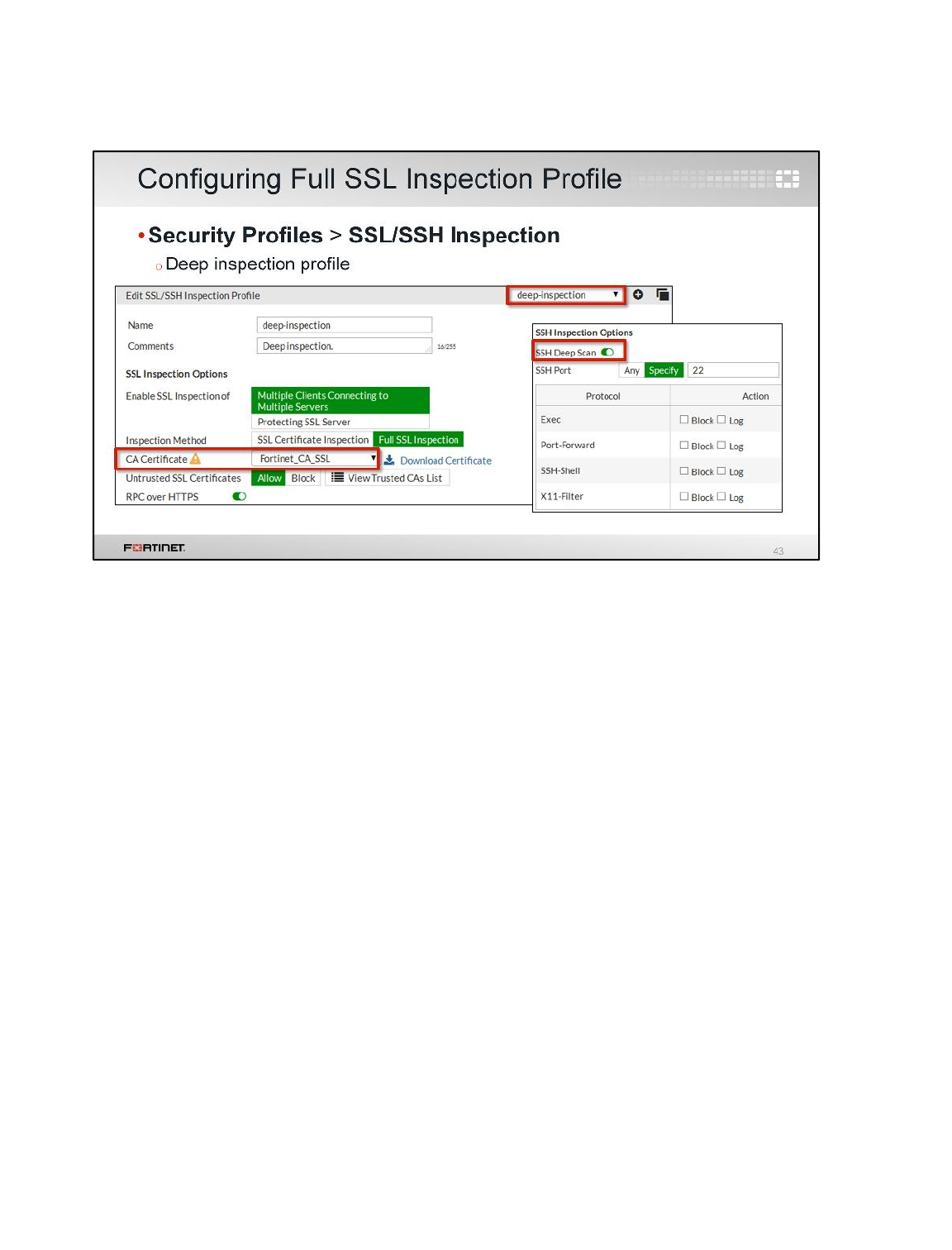
You can configure the full SSL inspection profile from the SSL/SSH Inspection page by selecting the
deep-inspection profile.
The deep inspection profile allows you to enable SSL inspection of the following:
•Multiple Clients Connecting to Multiple Servers. Use this option for generic policies where the
destination is unknown.
•Protecting SSL Server. Use this option when setting up a profile customized for a specific SSL
server with a specific certificate.
By default, the inspection method is set to Full SSL Inspection (all the traffic is inspected) and the CA
certificate is the self-signed Fortinet_CA_SSL.
SSH Deep Scan is also enabled by default on this profile. SSH deep scan enables FortiGate to do
man-in-the-middle for SSH traffic (which is based on SSL). A similar process occurs: FortiGate re-
signs the certificate provided by the SSH server and starts inspecting the encrypted traffic. The SSH
client will present a certificate warning if you do not install the root certificate. Note that SSH Deep
Scan allows you to restrict the search for SSH protocol packets to TCP/IP port 22. This is not as
comprehensive as searching all ports, but it is easier on the performance of the firewall. You can set
the protocol actions for deep inspection.
Certificate Operations
FortiGate II Student Guide
445
DO NOT REPRINT
© FORTINET
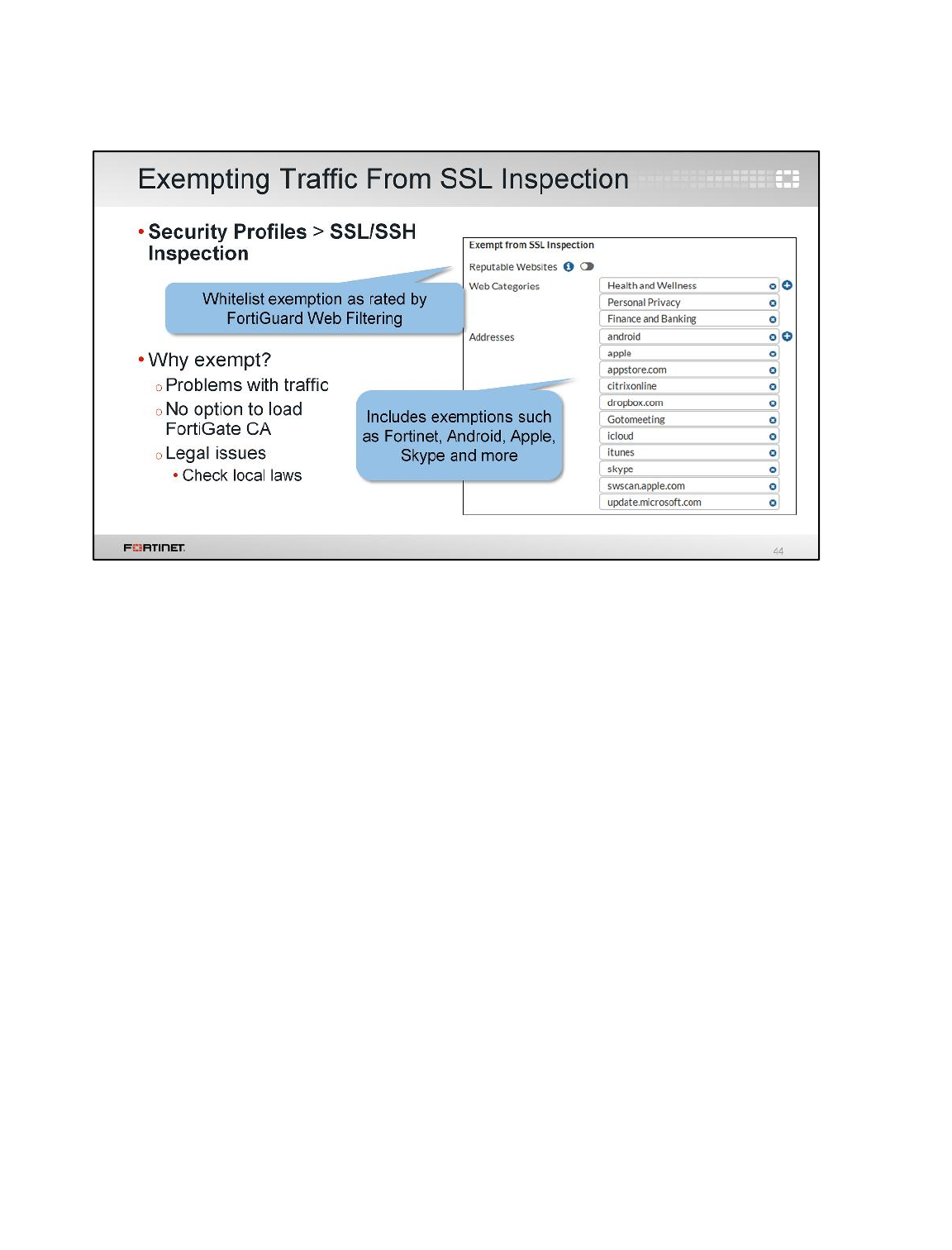
Within the deep inspection profile, you can also specify which traffic, if any, you want to exempt from
SSL inspection. You may need to exempt traffic from SSL inspection if it is causing problems with
traffic or for legal reasons.
Performing SSL inspection on an HPKP-enabled site, for example, can cause problems with traffic.
Remember the only way for any vendor device to inspect encrypted traffic is to intercept the certificate
coming from the server and generate a new one. Once FortiGate presents its default SSL certificate—
or any other SSL certificate—the browser refuses to proceed (no click-through option) if the issuing
FortiGate CA is not loaded as a trusted root CA. The SSL inspection profile, therefore, allows you to
exempt specific traffic.
Another reason it may be necessary to bypass SSL inspection is the law. In some countries it is illegal
to do SSL inspection of banking related traffic, for example. Configuring an exemption for specific
categories (like Finance and Banking) is simpler than setting up firewall policies for each individual
bank. Become familiar with whatever local laws may apply to encrypted Internet traffic in your
jurisdiction.
Certificate Operations
FortiGate II Student Guide
446
DO NOT REPRINT
© FORTINET
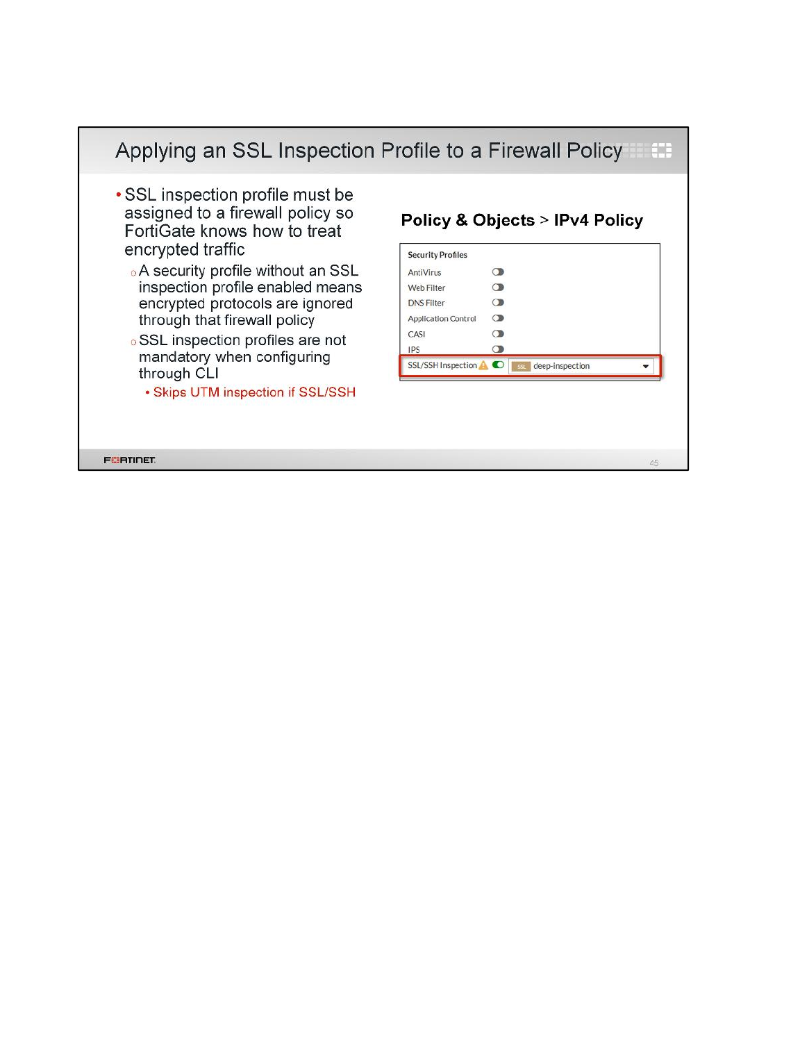
After you create and configure an SSL inspection profile, you must assign it to a firewall policy so
FortiGate knows how to inspect encrypted traffic.
A security profile without an SSL inspection profile enabled results in encrypted protocols being
ignored through that firewall policy. When an SSL inspection profile is enabled, it does not mean that
traffic is subject to SSL inspection and man-in-the-middle decryption by FortiGate. Rather it defines
how encrypted traffic is handled.
From the CLI, however, an SSL inspection profile is not required because this is a more advanced
method of configuration.
Certificate Operations
FortiGate II Student Guide
447
DO NOT REPRINT
© FORTINET
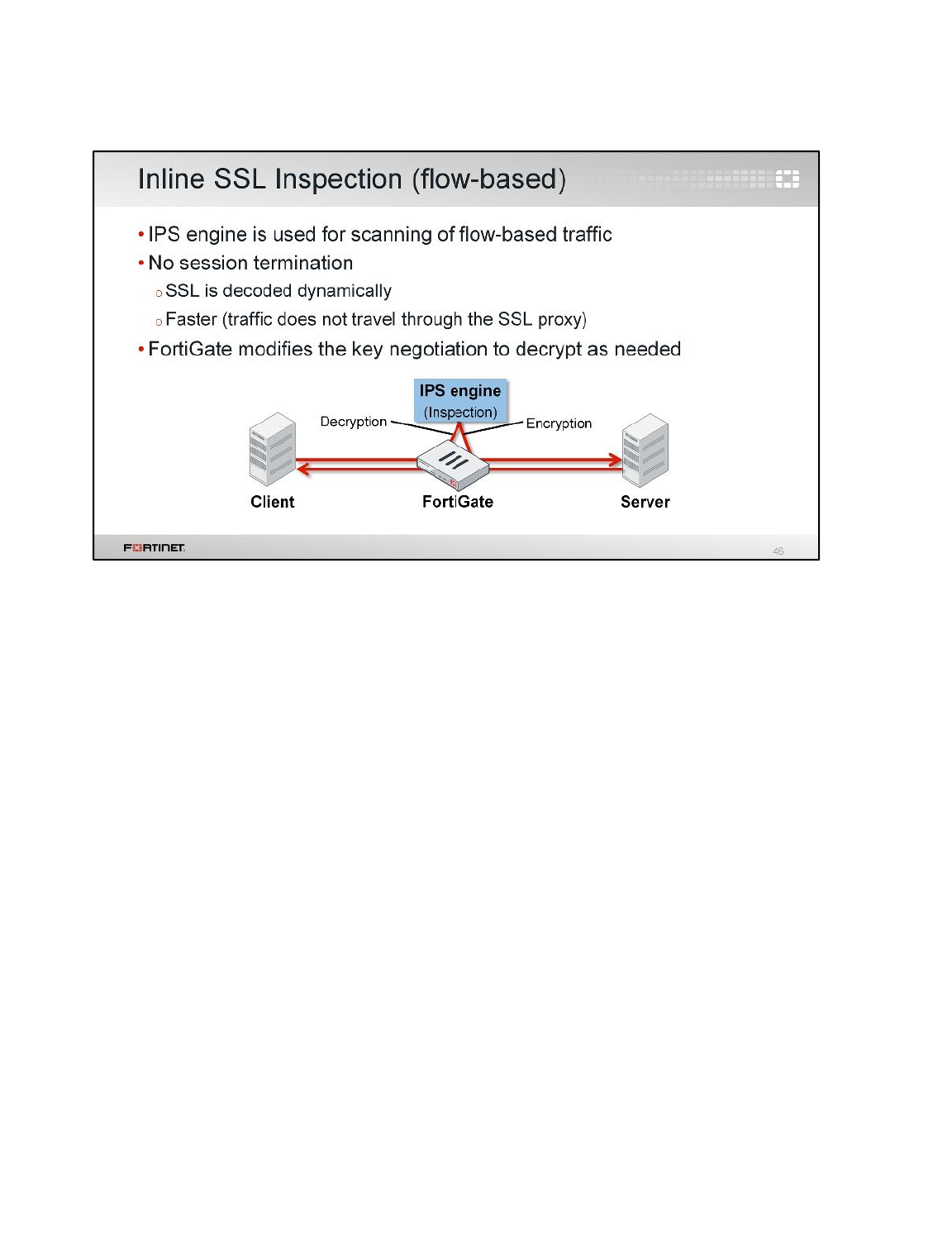
With flow-based traffic, FortiGate can do inline SSL inspection. SSL decryption and encryption is
done by the IPS engine, rather than the SSL proxy. The IPS engine is not a proxy, so it does not break
communication on Layer 3 the way a proxy does. The key negotiation is modified so that the traffic is
decrypted as needed.
Certificate Operations
FortiGate II Student Guide
448
DO NOT REPRINT
© FORTINET
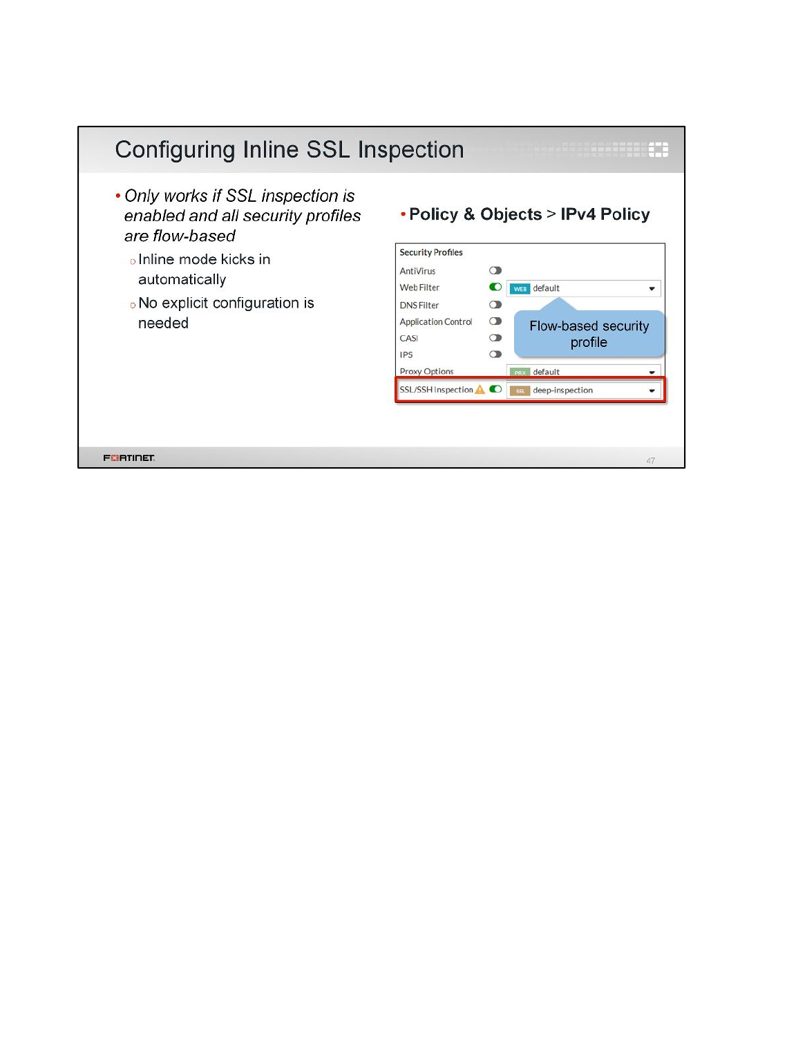
To use inline inspection on FortiGate, you must enable SSL inspection and all security profiles must
be flow-based (Antivirus, Web Filter, Application Control, Intrusion Protection, FortiClient Profiles, SSL
Inspection). No explicit configuration is needed.
Certificate Operations
FortiGate II Student Guide
449
DO NOT REPRINT
© FORTINET
Here is a review of the topics we covered in this lesson:
• PKI, digital certificates, and certificate authorities
• Certificate Signing Requests (CSRs)
• Local certificates
• Certificate Revocation Lists (CRLs)
• Backing up and restoring certificates
• Certificates and VDOMs
• Certificate-based authentication for administrators, SSL VPN clients, and IPsec VPN peers
• SSL certificates
• Full SSL inspection
• Inline SSL inspection
Certificate Operations
FortiGate II Student Guide
450
DO NOT REPRINT
© FORTINET

In this lesson, we will learn how to prevent crucial private data, such as bank account routing numbers
and credit card numbers, from leaving your network, and from being inappropriately transmitted.
Data leak prevention is required by some compliance regimes, such as PCI DSS and HIPAA, but
other networks may also find it useful to help prevent, for example, student cheating.
Data Leak Protection (DLP)
FortiGate II Student Guide
451
DO NOT REPRINT
© FORTINET
After this lesson, you should have the practical skills required to enforce data leak prevention (DLP).
These skills include knowing when to use DLP, knowing how to monitor specific data types, and how
to configure DLP filters and sensors.
Lab exercises can help you to test and reinforce your skills.
Data Leak Protection (DLP)
FortiGate II Student Guide
452
DO NOT REPRINT
© FORTINET
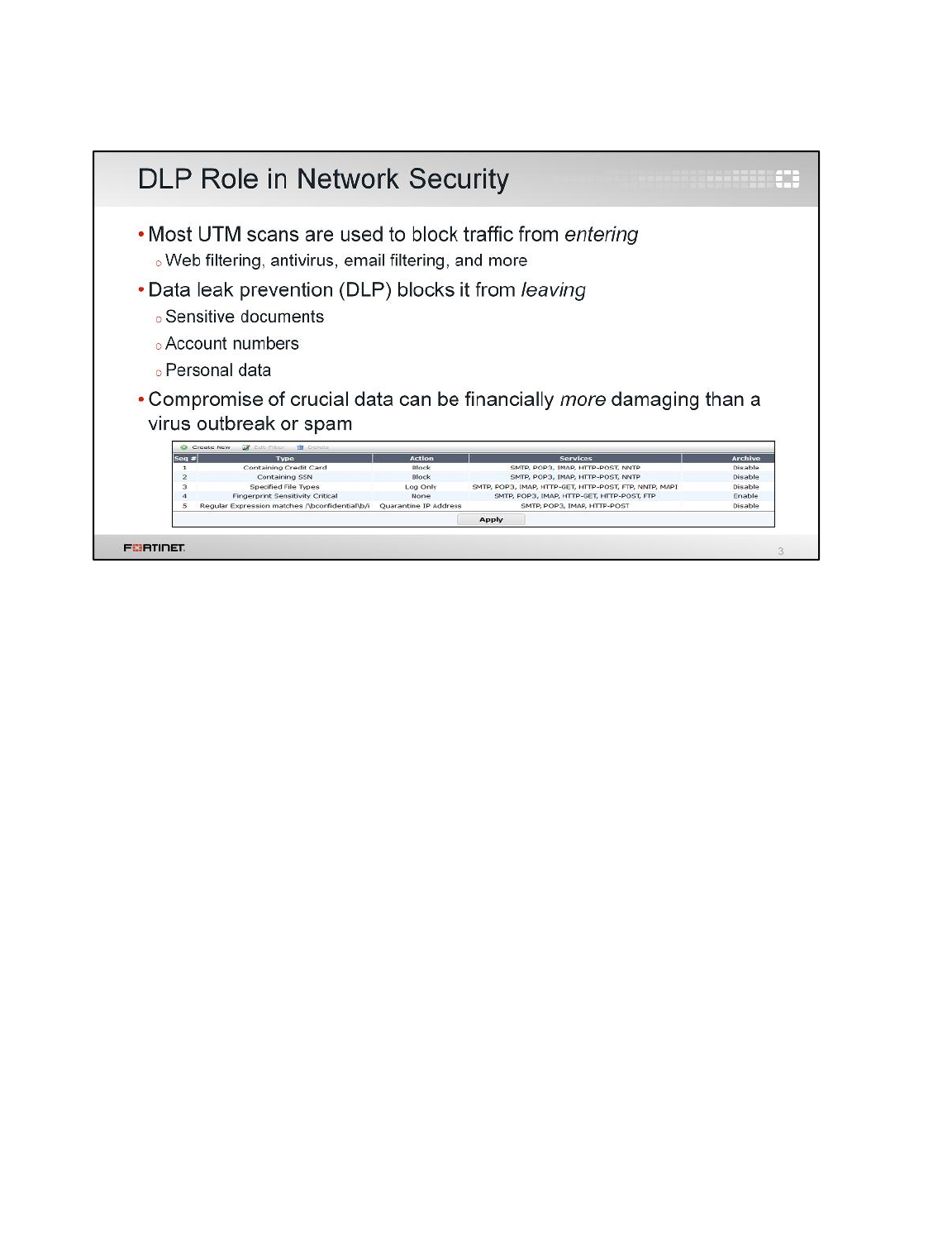
FortiGate has other features, such as IPS and antivirus, that can detect and block files. What makes
DLP different? Why should you use it?
Traditional firewalls and first-generation UTMs were designed to prevent attacks and nuisances from
getting into your network. Web filtering is applied to only traffic coming in. Likewise, despite best
practice to apply it in both directions, many people apply antivirus and email filtering to traffic coming
in only.
DLP prevents specific data from getting out.
How can traffic that is leaving your network affect security?
Co-workers to often share sensitive documents inside your network. Sensitive information is also
shared between servers that work together to host a single application. But, if sensitive data, such as
financial information, becomes public, it can have serious effects. Stock prices, bank transactions,
privacy, and password security can all be compromised.
DLP helps to ensure that your network follows the rules required by your real-world organization, and
doesn’t give out important information.
Data Leak Protection (DLP)
FortiGate II Student Guide
453
DO NOT REPRINT
© FORTINET
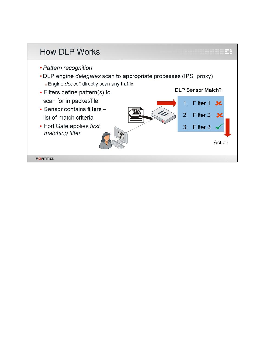
So how does DLP work?
FortiGate scans traffic matching to your firewall policy for the DLP patterns that you specify.
When you configure a pattern, whether pre-defined or custom, DLP doesn’t directly inspect traffic.
Instead, it communicates the pattern to the proxy’s or IPS engine’s processes, which do the scanning.
So, when you are troubleshooting, you may need to investigate traffic flow through modules that you
didn’t manually enable.
If the scan finds a match, it executes the filter’s corresponding action. In the example shown here, the
first two filters didn’t match the file, but the third one did, so FortiGate performed its action.
Data Leak Protection (DLP)
FortiGate II Student Guide
454
DO NOT REPRINT
© FORTINET
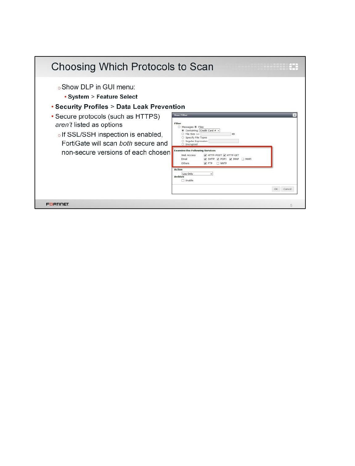
Now that we’ve talked about DLP in general, let’s look at some specifics, such as how to add filters in
a DLP sensor. Initially, we’ll use some default file filters and message patterns. Later, we’ll show how
to customize and expand them. Most DLP behavior is dependent on the filter type, and we will look at
later, in depth. Right now, let’s look at service inspection and action.
First, you need to change the GUI menu settings to show DLP (it’s hidden by default). You can do this
from the Feature Select page. Then, go to the DLP submenu available under Security Profiles to
create a DLP sensor. Inside it, add a filter.
In each filter, we’ll specify:
• match criteria
• which protocols to scan, and
• actions that FortiGate will apply when traffic matches.
Note that DLP is only available in a proxy-mode virtual domain (VDOM).
In the Examine the Following Services area, choose which network protocols should be scanned.
Like other security features, secure protocols aren’t in the list of scannable network services.
However, if you enabled SSL/SSH Inspection (specifically deep inspection), FortiGate will scan each
protocol that you choose and its secure equivalent. For example, if you mark the check box for HTTP,
FortiGate will scan HTTP as well as HTTPs. More information on deep inspection is available in the
FGT II Certificate Operations lesson.
Note: FortiOS Carrier models also examine MMS services (MM1, MM3, MM4, MM7).
Data Leak Protection (DLP)
FortiGate II Student Guide
455
DO NOT REPRINT
© FORTINET
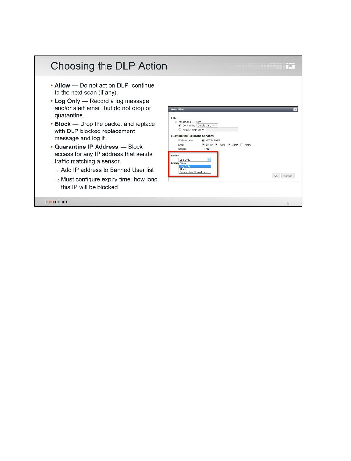
For each filter in the DLP sensor, you must select an action—what FortiGate should do if traffic
matches.
The default setting is Log Only. If you’re not sure which action to choose, the default setting can be
useful, initially. While you study your network, use this action to see what sensitive information is
being transmitted. Later you can fine-tune your sensor and select the most appropriate action to block
sensitive files from the WAN.
Data Leak Protection (DLP)
FortiGate II Student Guide
456
DO NOT REPRINT
© FORTINET
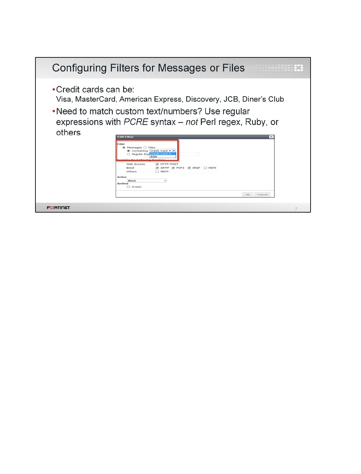
Now let’s return to the top of the filter, which is the more complex part of the configuration. Select the
type: either Messages or Files. Most other available options depend on this initial choice.
Messages scans for words, credit card numbers, or other text-based patterns directly embedded in the
protocol, not as a file. There are two preconfigured message filters available: Credit Card and SSN.
If the pre-defined DLP patterns don’t match exactly what you’re looking for, you can use the Regular
Expression option to configure your own custom pattern. Use PCRE syntax. Supported expressions
and performance with complex Turing complete expressions always vary by the regular expression
engine. So, if you’re looking for references, look specifically for PCRE, not others, such as the
similarly-named Perl language.
File changes the available options to be appropriate for files, such as file size, fingerprinting, and
watermarking.
Data Leak Protection (DLP)
FortiGate II Student Guide
457
DO NOT REPRINT
© FORTINET
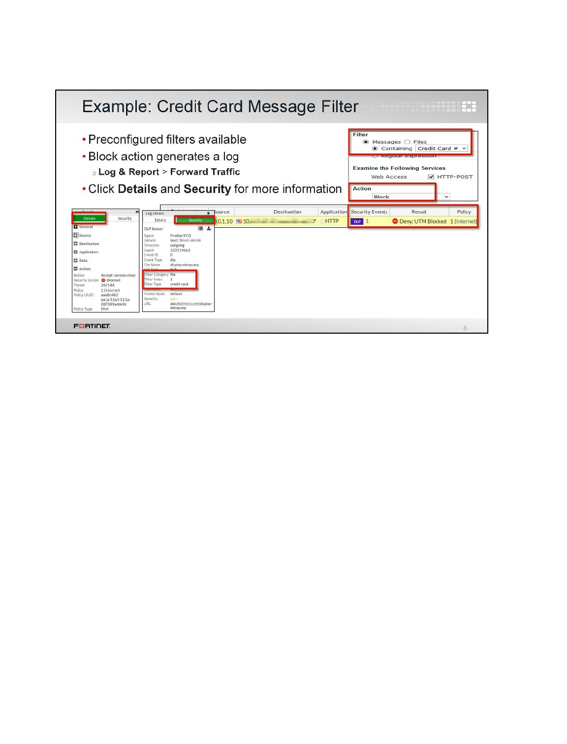
In this example, we are blocking credit card numbers from leaving the network using a preconfigured
message filter. The Block action stops the violation traffic, but it also generates a log, which you can
view in the forward traffic logs. The logs provide information such as security event, result, and firewall
policy. Select the log for more details.
The Details tab provides more information about the source, destination, and action, to name a few.
The Security tab provides additional information, such as the filter type, filter category, and DLP filter
index.
Data Leak Protection (DLP)
FortiGate II Student Guide
458
DO NOT REPRINT
© FORTINET
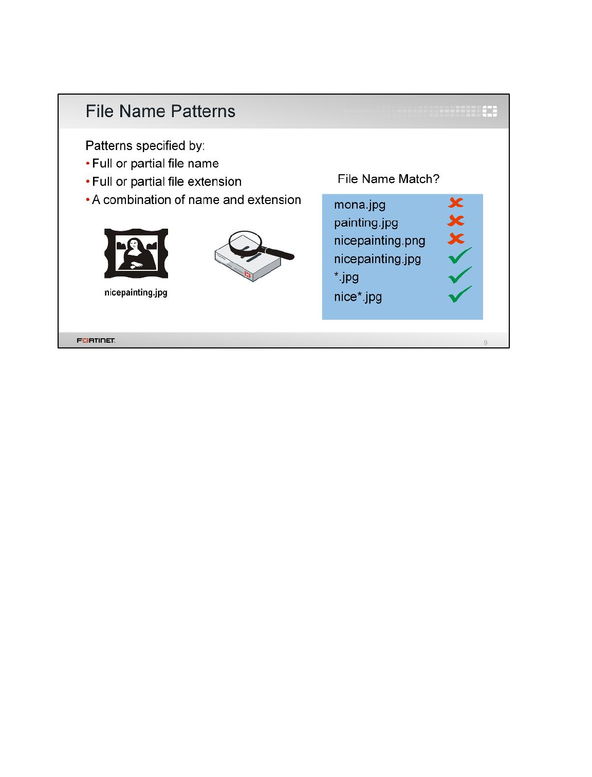
Let’s take a look at the file-specific sub-filters.
File name patterns are intuitive. If a file name either matches literally, or matches the pattern, then
FortiGate will perform the action.
If an important file name varies (users often try to evade DLP by renaming files to a harmless-
sounding name) then you should use patterns, not the literal file name. Configure FortiGate to match
all intended file names, but no unintended file names. For example, browsers often rename
downloads of duplicate file names to prevent accidentally overwriting an existing different, yet
identically named, file. For example, they would add (2) before the file extension. Likewise, Windows
renames copies of files so that they start with Copy of. So you should use a name pattern such as
nice*.jpg, not the literal file name, nicepainting.jpg.
The example here shows which filters would match the file name, and which filters wouldn’t.
But what if the file name doesn’t match any pattern? What if the file name is radically different, and
therefore a broad pattern would cause false positives? What if we want to block all executables
regardless of name or platform, for example?
Data Leak Protection (DLP)
FortiGate II Student Guide
459
DO NOT REPRINT
© FORTINET
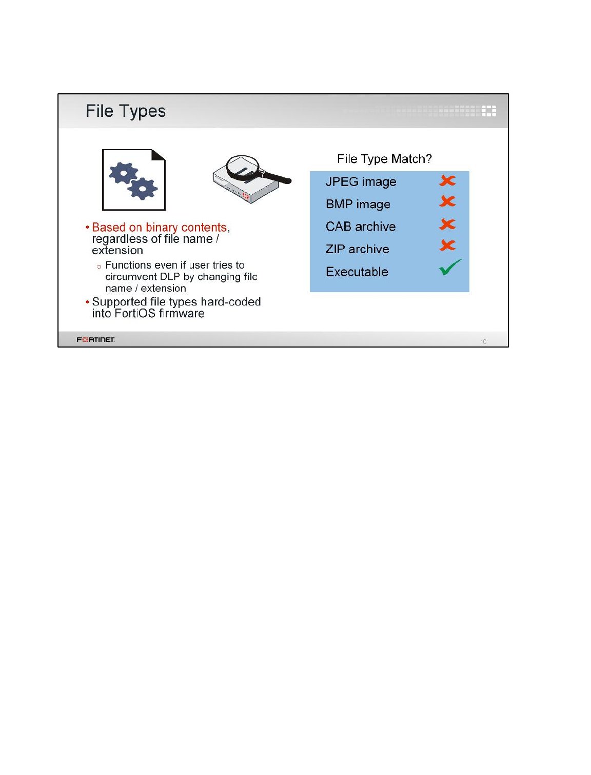
File name matching alone is often not enough for very sensitive data. You may want a more
sophisticated filter. One alternative is to use file type matching.
File type matching behaves as you’d expect. FortiGate does not identify file types by their extension
(for example, .doc). This is because users could circumvent DLP by simply renaming the extension.
Instead, FortiGate identifies file types by scanning for matching binary patterns; that is, how that file
type stores data in specific areas, in specific patterns of 1’s and 0’s. However, in order to use this
accurate technology, FortiGate must have a corresponding decoder that understands the binary data
source. Without a decoder, FortiGate cannot decipher the string of zeros and ones and, therefore
cannot identify the file type.
Data Leak Protection (DLP)
FortiGate II Student Guide
460
DO NOT REPRINT
© FORTINET
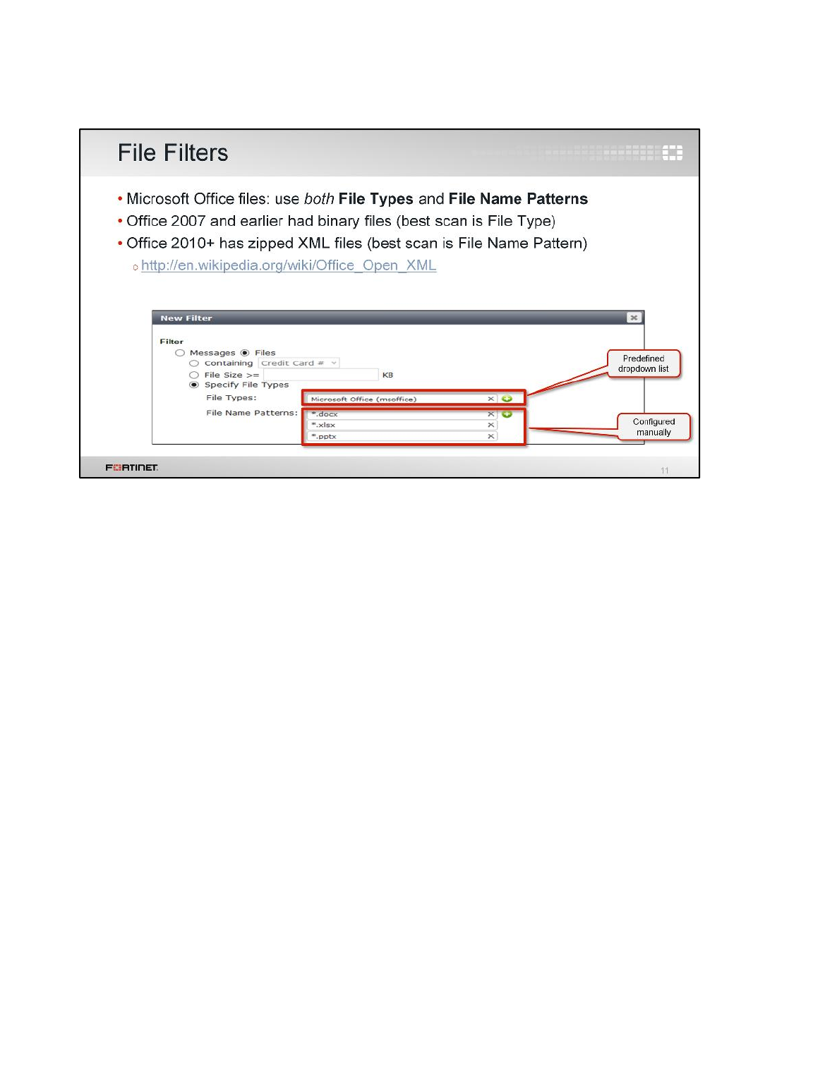
If you choose a Files type for the filter, and select the Specify File Type option, File Types and File
Name Patterns settings become available.
File Types scans file contents, regardless of the file name or extension. Even if the file is renamed
with a different extension, DLP will still detect it. It has a corresponding drop-down menu where you
can select for which file types to scan.
File Name Patterns scans the names of files. It is configured manually.
Here is an example file filter table that matches all Microsoft Office files. Notice that in order to do this,
the table must contain sub-filters of both types. This is because:
• Older versions of Office use a binary file format, identifiable by a binary file type scan.
• Office 2010 and newer files are not binary, but ZIP archives. They are actually XML files inside a
ZIP archive. This is documented on the Microsoft website (see link in slide).
It’s crucial to note that because Office 2010 and newer use a nested file type, if you use file type filters
with them, the filters will match any ZIP file, not just Office files.This is a common DLP
misconfiguration. So, to avoid false positives with Office 2010 and newer, the default profile matches
by file extension instead. Note, however, that the tradeoff is possible false negatives.
Data Leak Protection (DLP)
FortiGate II Student Guide
461
DO NOT REPRINT
© FORTINET
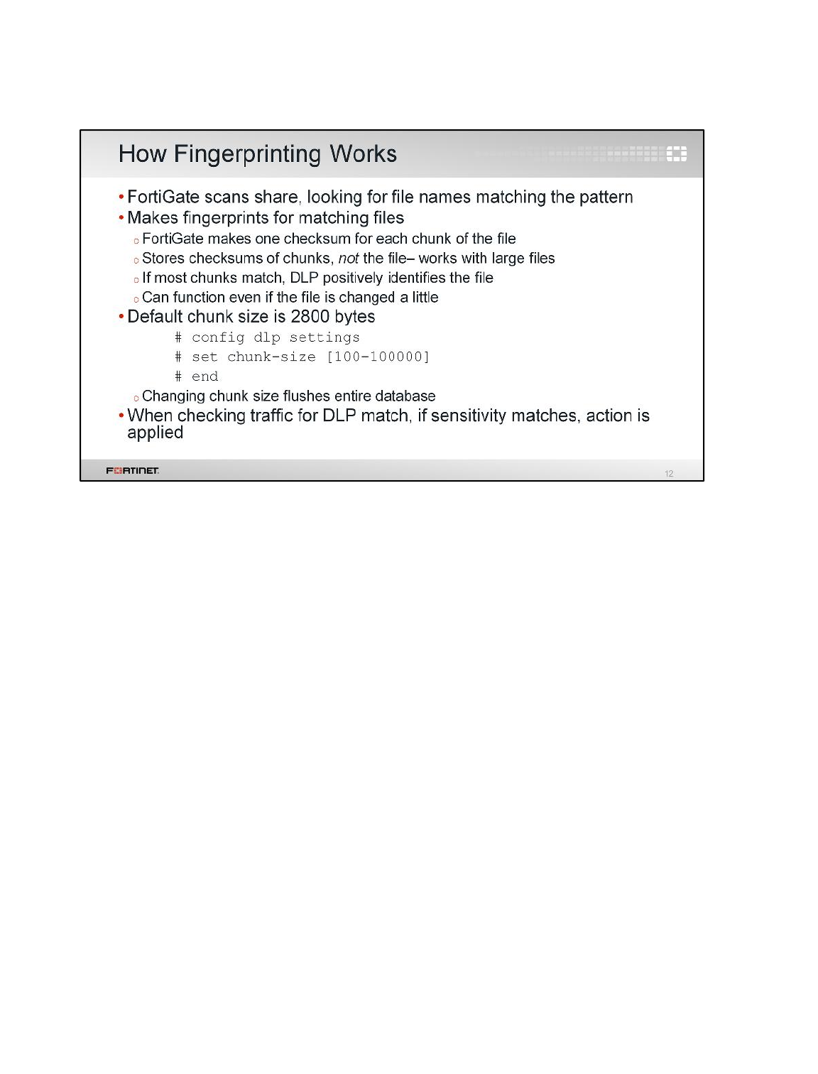
Let’s return to our DLP sensor’s filter. When scanning files, types and names aren’t our only option.
On most networks, it’s typically not an option to block all Microsoft Office files, and blocking by file
name is not effective if users try to circumvent. So, what alternatives do we have?
FortiGate can use a content-based filter called document fingerprinting. Document fingerprinting
identifies specific files using one or more CRC checksums. You can apply this content-based filter on
many files at once, including large files.
How accurate is document fingerprinting? How many checksums will DLP calculate and store?
The file itself is not stored in FortiGate, only the checksums of chunks. Smaller chunks mean that
more checksums will be calculated for each file and DLP will fingerprint more accurately. That is, even
if someone changes a file in a few places, fingerprinting will still be able to identify it because the
checksums of the other chunks will still match. The tradeoff is that more checksums require more
storage space on FortiGate. So you must decide the best balance between performance and
accuracy.
Note: The document fingerprint feature requires a FortiGate with internal storage.
Data Leak Protection (DLP)
FortiGate II Student Guide
462
DO NOT REPRINT
© FORTINET
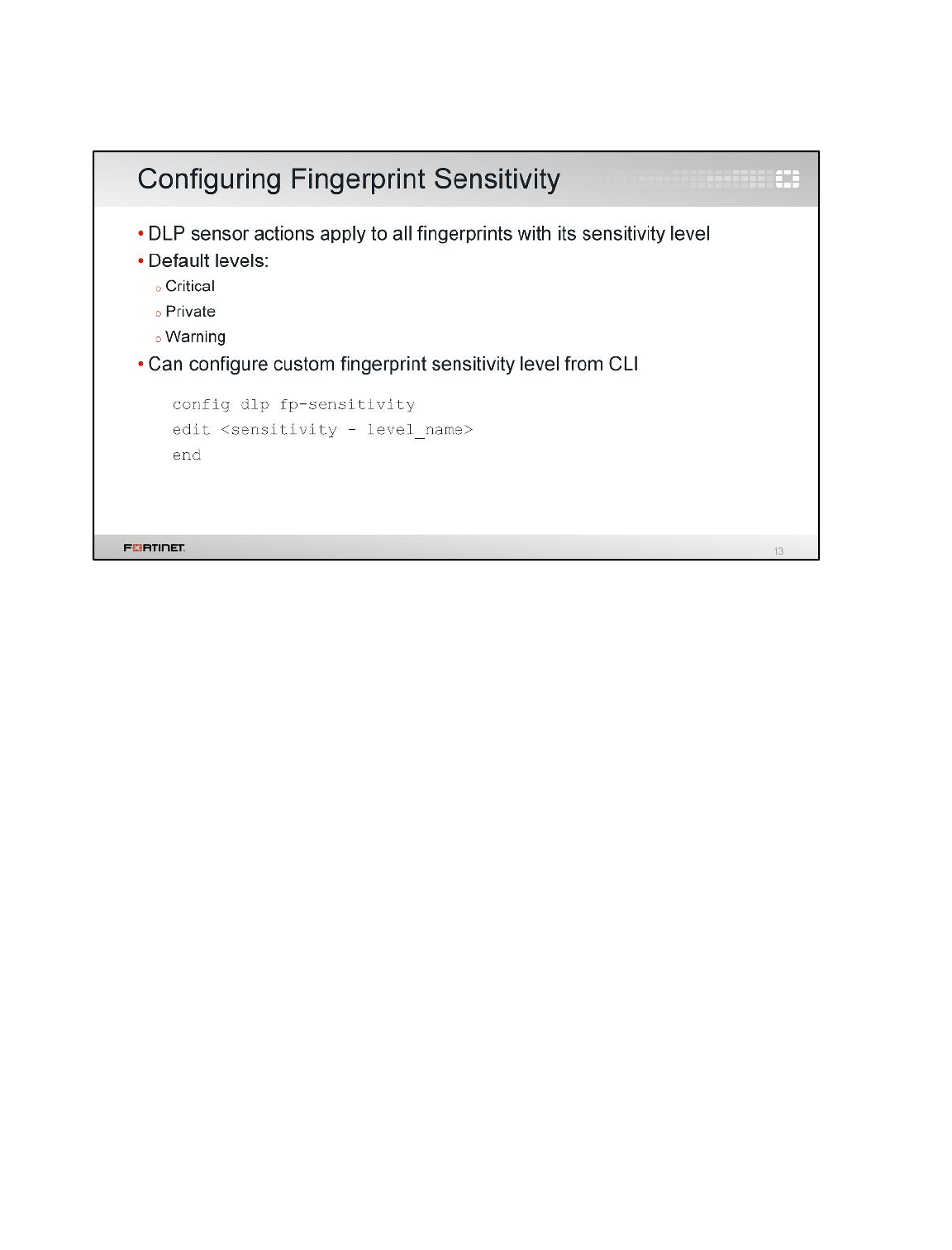
Before you configure any fingerprint filters in a DLP sensor, consider whether you’d like to make
custom sensitivity level tags. For example, you could make a custom sensitivity level named Finance.
When configuring fingerprint filters, you can use the Finance sensitivity level to tag all money-related
fingerprints.
The sensitivity level has two effects:
• It will appear in log files
• When you configure each filter in a DLP sensor, you will select which fingerprints the file filter will
use by specifying a sensitivity level. All fingerprints that have that sensitivity level will be included in
that filter.
Data Leak Protection (DLP)
FortiGate II Student Guide
463
DO NOT REPRINT
© FORTINET
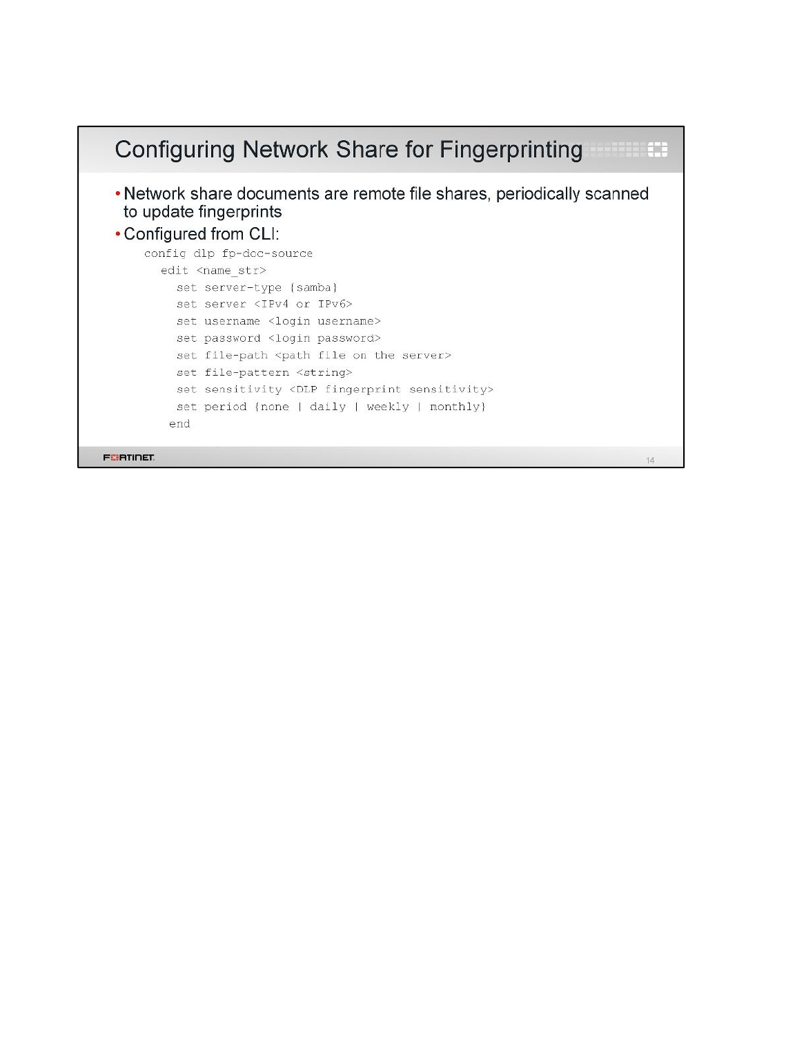
Once you’ve defined any custom sensitivity levels, you’re ready to define your fingerprints for network
share documents.
Using the CLI, you can configure FortiGate to connect to a file share, either on a daily, weekly, or
monthly basis. Each time it connects, FortiGate can automatically recreate checksums for all files in
the share, or retain old fingerprints (in case an old version of the file is still circulating).
Fingerprinting through a file share allows you to add many files and update the fingerprint for each
addition or change. While configuring, choose which sensitivity level FortiGate will use to tag those
fingerprints.
Data Leak Protection (DLP)
FortiGate II Student Guide
464
DO NOT REPRINT
© FORTINET
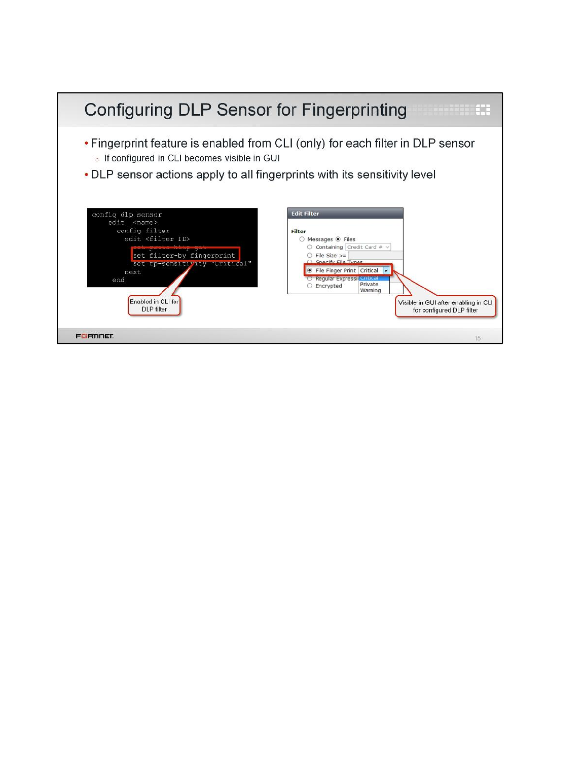
After fingerprint sensitivity and the network share are configured, the next step is to configure the DLP
sensor’s filter.
The fingerprinting feature is enabled (configured) from the CLI as a filter in the DLP sensor, which
allows you to choose the sensitivity level. Once you have configured a filter in your DLP sensor from
the CLI by setting set filter-by fingerprint, the File Finger Print option appears in the GUI.
From the File Finger Print drop-down menu, you can choose whether the filter will use Critical,
Private,Warning, or your own custom group of fingerprints, according to their sensitivity level tag.
DLP will scan and inspect these rules (filters) for fingerprint matching, from top to bottom. As DLP
stores the file checksum in chunks, it detects that the fingerprint file changed from the original file, and
takes action as defined in the DLP sensor.
The diagnose test application dlpfingerprint CLI command provides many options to
view stats, dump all chunks, or refresh all doc sources in all VDOMs.
Data Leak Protection (DLP)
FortiGate II Student Guide
465
DO NOT REPRINT
© FORTINET
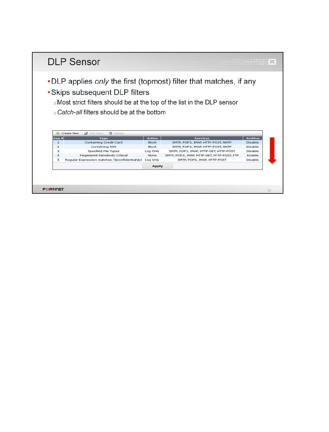
So now we’ve configured a few filters in the DLP sensor. Continue with more filters until the sensor
matches all traffic that it should, but doesn’t match unintentionally. Finally, apply the DLP sensor by
selecting it in a firewall policy.
Here is an example DLP sensor with a few filters. Each filter searches traffic for different types of
sensitive information, such as a credit card number or fingerprint. If traffic matches a filter, FortiGate
will apply that filter’s action.
Remember, DLP filters are evaluated for a match sequentially, from top to bottom, and FortiGate uses
the first matching filter. For example, let’s say an email contains a credit card number (which filter
sequence 1 says to block), but also has sensitive text (which filter sequence 5 says to log, but allow).
FortiGate will only use the sequence 1 filter: the email will be blocked, not allowed.
Data Leak Protection (DLP)
FortiGate II Student Guide
466
DO NOT REPRINT
© FORTINET
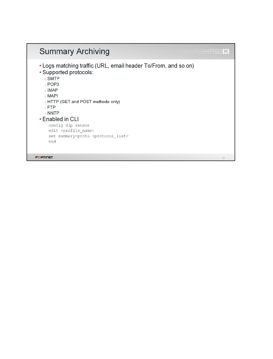
Up until now, we’ve shown DLP blocking or monitoring sensitive data. What else can DLP do?
It can record traffic summaries – that is, logs – and, if enabled, the full files and messages that were
contained in the traffic.
If you are familiar with content archiving on older versions of FortiOS, you will recognize summary
archives and full archives here.
Summary archiving records a log message that summarizes the traffic, and therefore will vary by
protocol. For example, with an email message, the summary archive would contain the sender’s email
address, the recipient’s email address, and the size. When users access the Web, FortiGate logs
would record every URL they visited.
Data Leak Protection (DLP)
FortiGate II Student Guide
467
DO NOT REPRINT
© FORTINET
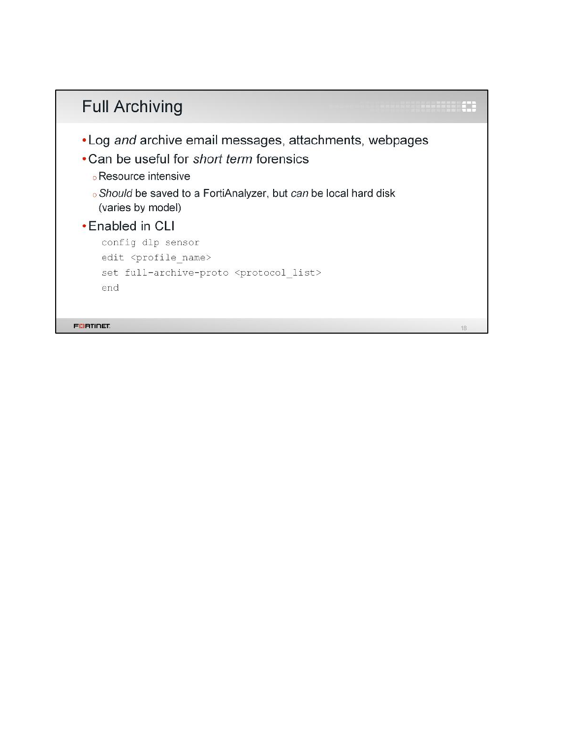
Full archiving records the summary log, but a complete email message, including any attachments, is
also archived. When a user accesses the Web, every page the user visits is archived.
This can be useful in forensic investigations; however, it’s not meant for prolonged use. Depending on
what you’re archiving, full archiving can require large amounts of FortiGate’s disk, CPU, and RAM
resources, which decreases performance.
For example, if you fully DLP archive a 100 MB file, FortiGate will store more than just 100 MB. It
stores the data plus Ethernet, IP, and other headers that were used during network transmission, plus
the log message. So, it will require slightly more than 100 MB of storage. It will also require RAM and
CPU until the FortiGate finishes writing the file to its hard disk. Full DLP archiving also consumes disk
space that FortiGate may need for other UTM features.
So for performance reasons, it’s better to use a FortiAnalyzer or external storage device.
If you need to inspect and archive email – especially for prolonged times – then FortiMail may be a
better alternative. It has local archiving, plus antispam, secure messaging, and other in-depth features
that FortiGate’s SMTP proxy cannot support.
Data Leak Protection (DLP)
FortiGate II Student Guide
468
DO NOT REPRINT
© FORTINET
To review, here are the topics we covered in this lesson. We discussed:
• When to use DLP
• Differences between detecting sensitive data using messages filter and file filters
• Configuring DLP sensor and filter
• How DLP fingerprinting works
• Logs and traffic content that DLP can record
Data Leak Protection (DLP)
FortiGate II Student Guide
469
DO NOT REPRINT
© FORTINET

In this lesson, you will learn how to use some diagnose commands and tools.
Diagnostics
FortiGate II Student Guide
470
DO NOT REPRINT
© FORTINET
After completing this lesson, you should have these practical skills required to determine your network
baseline, read diagnostic output, troubleshoot the physical and network layers, trace packet flow
through FortiGate processing, and find the root causes of abnormally high CPU or memory usage.
Lab exercises can help you to test and reinforce your skills.
Diagnostics
FortiGate II Student Guide
471
DO NOT REPRINT
© FORTINET
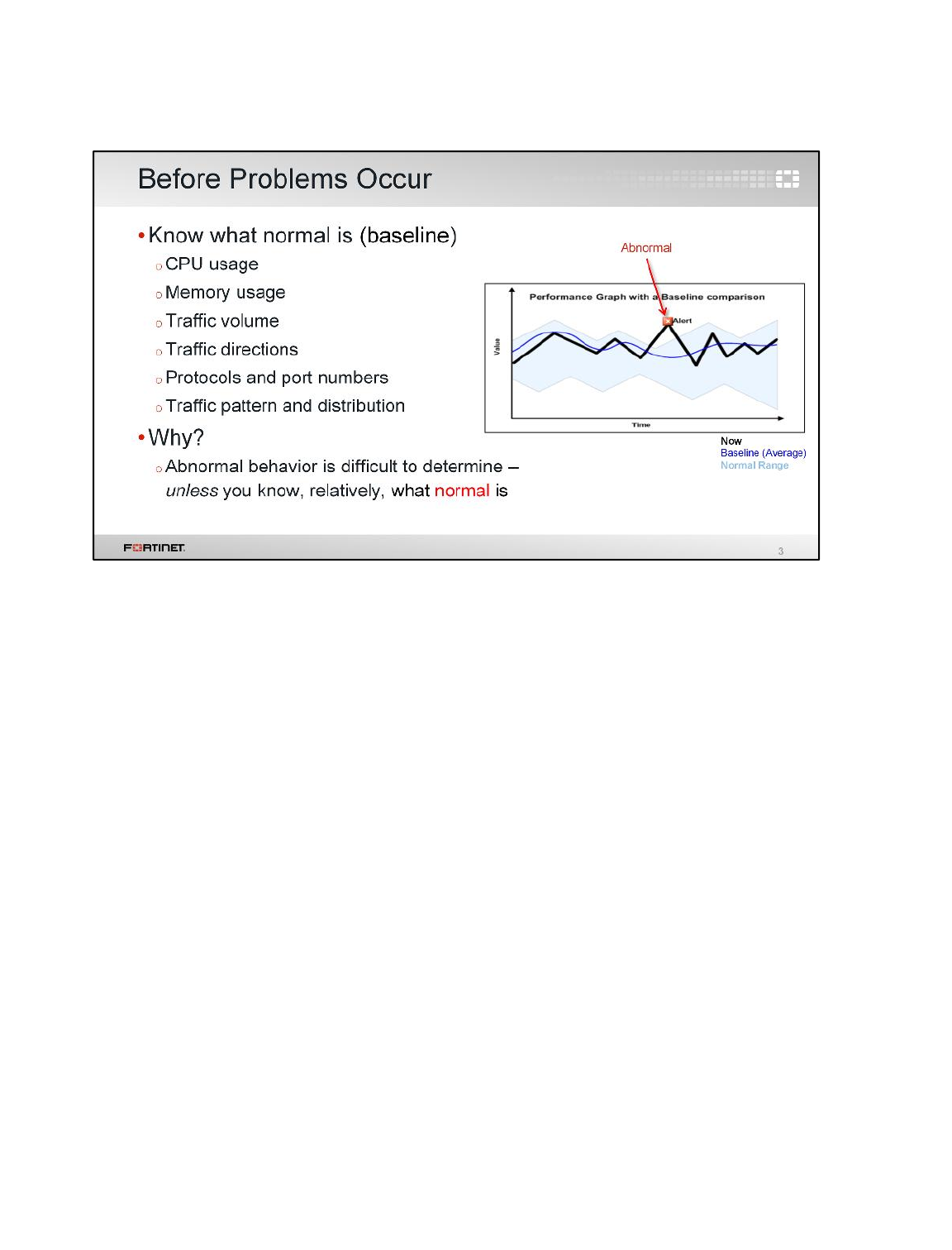
In order to define any problem, first you must know what your network’s normal behavior is.
In the graph shown here, the range that indicates “normal” is in blue. What is exactly this blue line? It
indicates the averages – our baseline. What is the thick black line? It’s the behavior right now. When
the current behavior (black line) leaves the normal range, an abnormal event is happening.
Normal is measured and defined in many ways. It can be performance: the expected CPU and
memory utilization, bandwidth, and traffic volumes. But it can also be your network topology: which
devices are normally connected at each node. It’s behavior too: traffic flow directions, which protocols
are blocked or proxied, and the distribution of protocols and applications used during specific times of
the day, week, or year.
Diagnostics
FortiGate II Student Guide
472
DO NOT REPRINT
© FORTINET

In this section, we’ll look at some measurements – how you can determine if the network has a
problem.
If you’re starting a new network, many things may not work yet. Many problems are obvious, and
normal behavior is, too.
But, in large or established networks, the difference between normal and broken may be subtle. How
can you find what needs to be fixed or improved?
Diagnostics
FortiGate II Student Guide
473
DO NOT REPRINT
© FORTINET
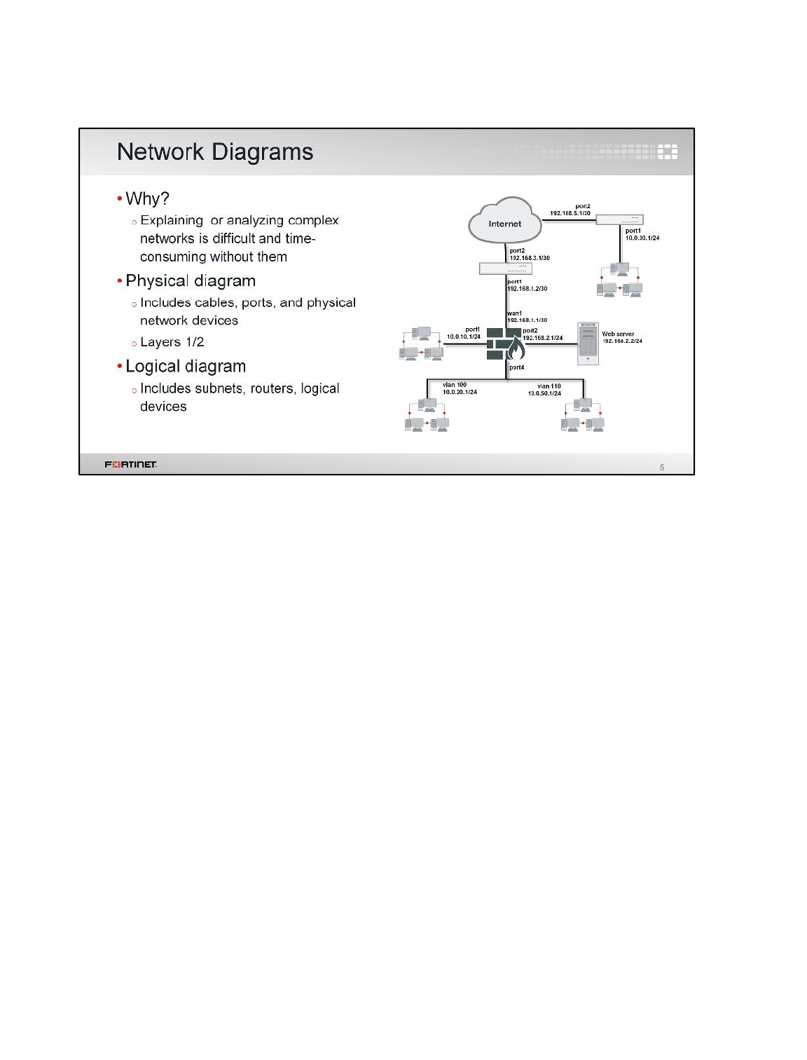
What is the first way to define what normal is for your network?
Topology. Flows and other specifications of normal behaviour are derived from this. So during
troubleshooting, a network diagram is essential. If you create a ticket with Fortinet Technical Support,
it should be the first thing you attach.
Network diagrams sometimes combine the two types:
• Physical
• Logical
A physical diagram shows how cables, ports, and devices are connected between buildings and
cabinets. A logical diagram shows relationships (usually at OSI Layer 3) between virtual LANs, IP
subnets, and routers. It can also show application protocols such as HTTP or DHCP.
Diagnostics
FortiGate II Student Guide
474
DO NOT REPRINT
© FORTINET
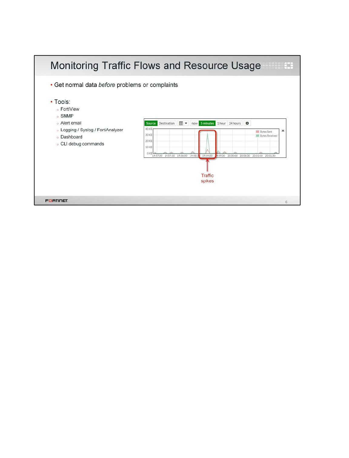
Another way to define normal is to know the average performance range. On an ongoing basis, collect
data that shows normal usage.
For example, if traffic processing is suddenly slow, and your FortiGate’s CPU usage is 75%, what
does that indicate? If CPU utilization is usually 60-69%, then 75% is probably still normal. But if
normal is 12-15%, there may be a problem.
Get data on both typical maximum and minimum for the time and date: that is, on a workday or
holiday, how many bits per second should ingress or egress each interface in your network diagrams?
Diagnostics
FortiGate II Student Guide
475
DO NOT REPRINT
© FORTINET

If you find that something is not normal, what should you do?
It depends on the type of the problem.
Diagnostics
FortiGate II Student Guide
476
DO NOT REPRINT
© FORTINET
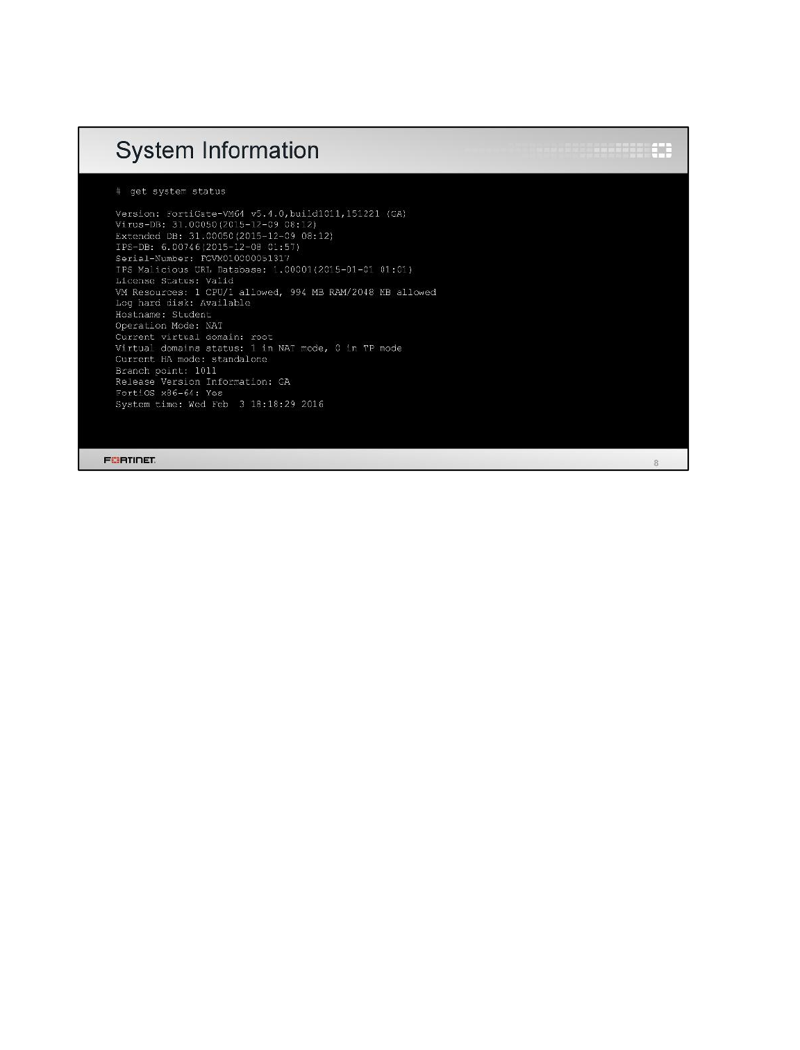
How else can we get current statuses? First, let’s look at CLI commands: you can use them through a
local console, even if network issues make GUI access slow or impossible.
A few commands provide system statuses. The get system status command provides most
general purpose information. Output shows:
• Model
• Serial number
• Firmware version
• Host name
• FortiGuard license status
• System time
• Version of the FortiGuard antivirus, IPS, and IP reputation databases, and others.
Diagnostics
FortiGate II Student Guide
477
DO NOT REPRINT
© FORTINET
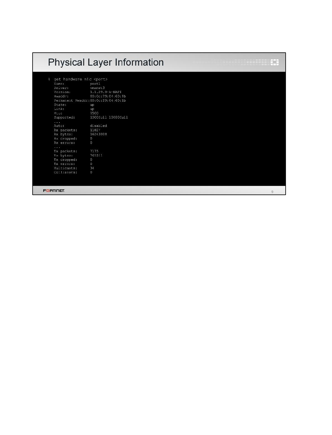
At the physical layer, troubleshooting analyzes which ports are plugged in, media capacity, and
negotiated speed and duplex mode.
At the data link layer, diagnostics often analyze how many frames are being dropped due to CRC
errors or collisions.
The output might vary depending on the model and NIC driver version. It all the cases, the output
shows the physical MAC address, administrative status, and link status.
Diagnostics
FortiGate II Student Guide
478
DO NOT REPRINT
© FORTINET

This command is available on FortiGate models with SFP/SFP+ interfaces. It provides the optical
received signal strengths, which can be used to diagnose layer-1 optical issues.
Diagnostics
FortiGate II Student Guide
479
DO NOT REPRINT
© FORTINET
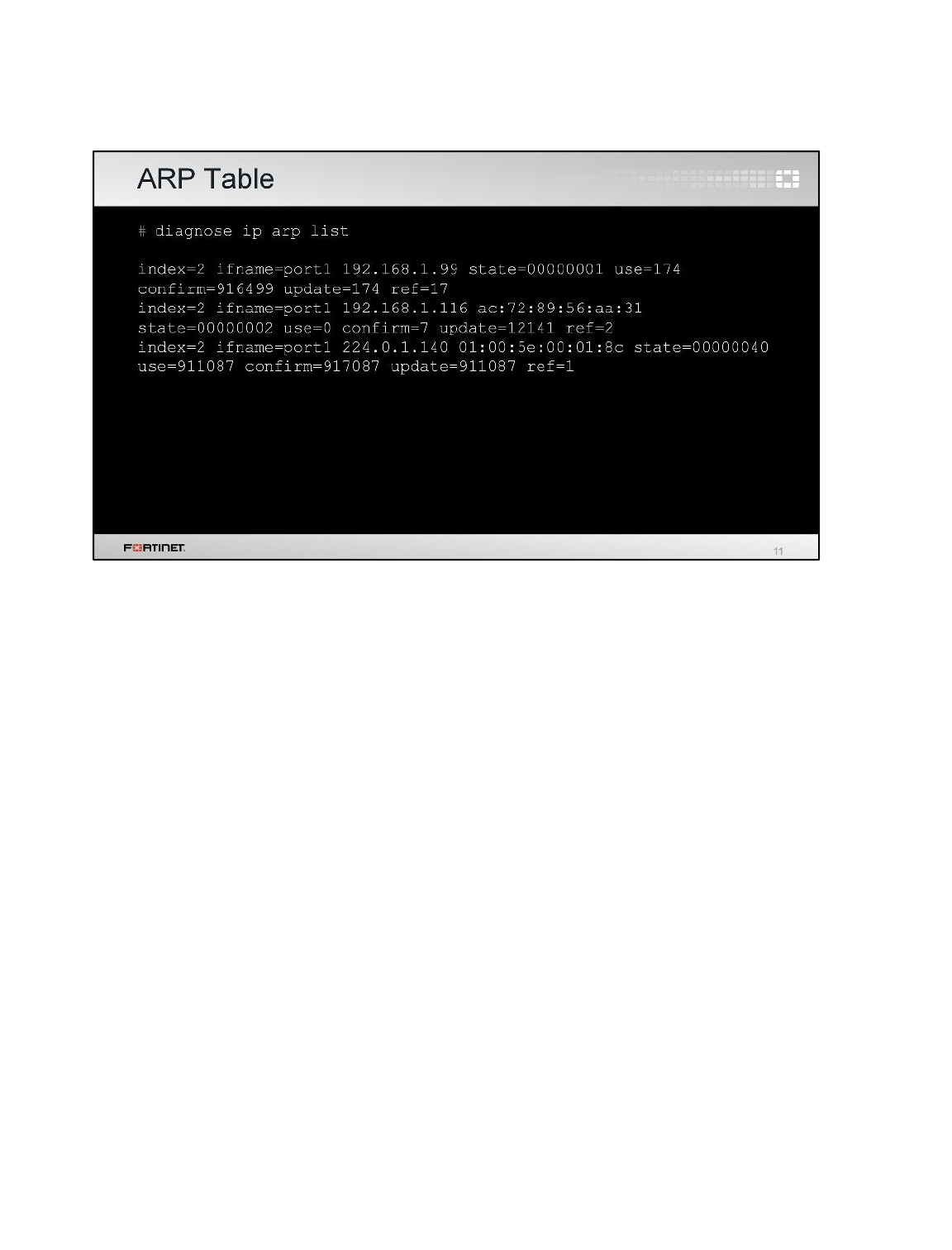
If you suspect that there is an IP address conflict, or that an IP has been assigned to the wrong
device, you may need to look at the ARP table. This command is used for that purpose. It shows the
FortiGate interface, IP address, and associated MAC address. This command lists the information for
all the external devices connected to the same LAN segments where FortiGate is connected.
FortiGate’s own IP and MAC addresses are not included.
Diagnostics
FortiGate II Student Guide
480
DO NOT REPRINT
© FORTINET
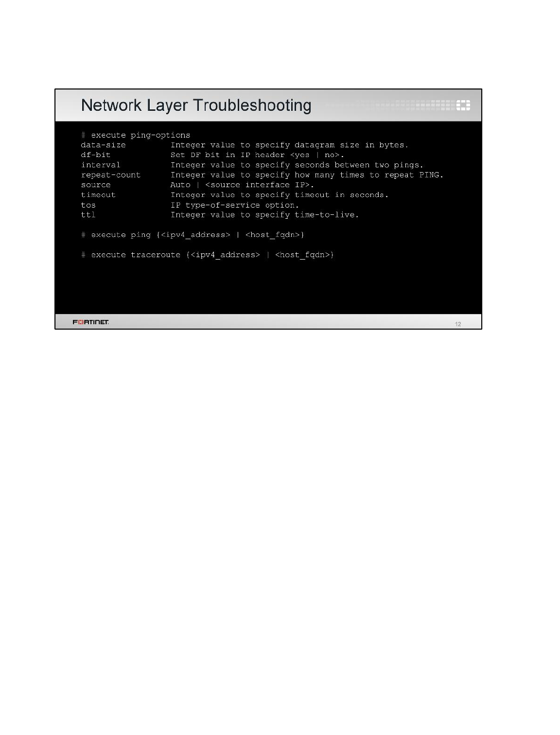
Let’s say that FortiGate can contact some hosts through port1, but not others. Is the problem in the
physical or link layer? None of them. Connectivity has been proven with at least part of the network.
Instead, you should check the network layer. To test this, like usual, we start with ping and traceroute.
The same commands exist for IPv6 too: execute ping becomes execute ping6, for example.
Remember: location matters. Tests will be accurate only if you use the same path as the traffic that
you are troubleshooting. To test from FortiGate (to a FortiAnalyzer or FortiGuard, for example), use
FortiGate’s own execute ping and execute traceroute CLI commands. But to test the path
through FortiGate, additionally use ping and tracert or traceroute from the endpoint – from the
Windows, Linux, or Mac OS X computer; not only from the FortiGate CLI.
Due to NAT and routing, you may need to specify a different ping source IP address – the default is
the IP of the outgoing interface. If there is no response, verify that the target is configured to reply to
ICMP echo requests.
Diagnostics
FortiGate II Student Guide
481
DO NOT REPRINT
© FORTINET
One of the most powerful troubleshooting tools in FortiGate is the debug flow. We will teach it in this
section.
Diagnostics
FortiGate II Student Guide
482
DO NOT REPRINT
© FORTINET
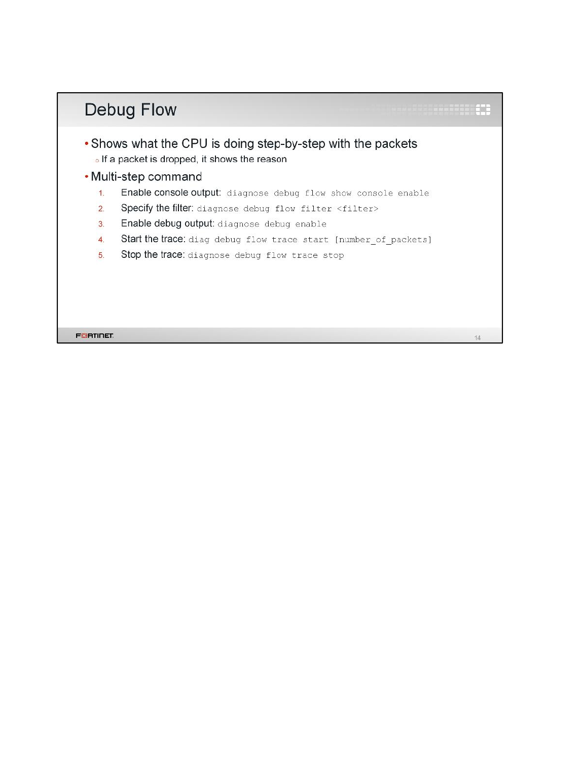
If FortiGate is dropping packets, can a packet capture (sniffer) be used to know the reason? To find
the cause, you should use the debug (packet) flow.
The debug flow shows step-by-step how the CPU is handling each packet.
To enable the debug flow, follow these steps:
1. Enable the console output.
2. Define a filter.
3. Enable debug output.
4. Start the trace.
5. Stop when you’ve finished.
Diagnostics
FortiGate II Student Guide
483
DO NOT REPRINT
© FORTINET
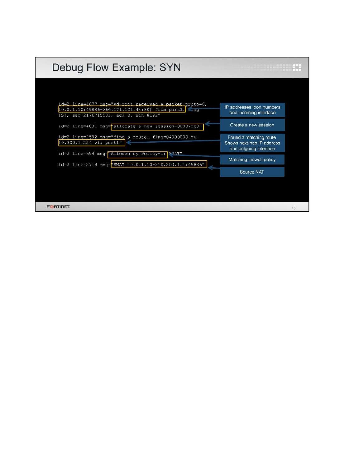
This is a sample of a debug flow output. Here we have captured the first packet of a TCP 3-way
handshake, the SYN packet. It shows:
the packet arriving to the FortiGate, indicating the source and destination IP addresses, port numbers,
and incoming interface
the FortiGate creating a session, indicating the session ID
finding the route to the destination, indicating the next-hop IP address and outgoing interface
ID of the policy that matches and allows this traffic, and
how the source NAT is applied.
Diagnostics
FortiGate II Student Guide
484
DO NOT REPRINT
© FORTINET
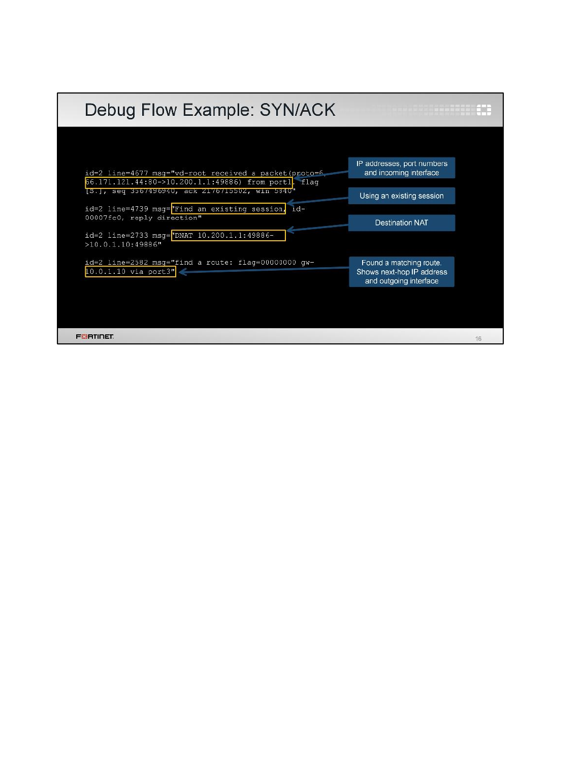
This is the output for the SYN/ACK packet. It shows:
the packet arrival, indicating again the source and destination IP addresses, port numbers, and
incoming interface
the ID of the existing session for this traffic. This number should match the ID of the session created
during the SYN packet
how the destination NAT is applied, and
finding the route to the destination, indicating again the next-hop IP address and outgoing interface.
What is also important, if the packet is dropped by FortiGate, this output shows the reason for that
action.
This tool is useful for many other troubleshooting cases, for example when you need to understand
why a packet is taking a specific route, or why a specific NAT IP address is being applied.
Diagnostics
FortiGate II Student Guide
485
DO NOT REPRINT
© FORTINET

We will now talk about some commands for CPU and memory diagnostics.
Diagnostics
FortiGate II Student Guide
486
DO NOT REPRINT
© FORTINET
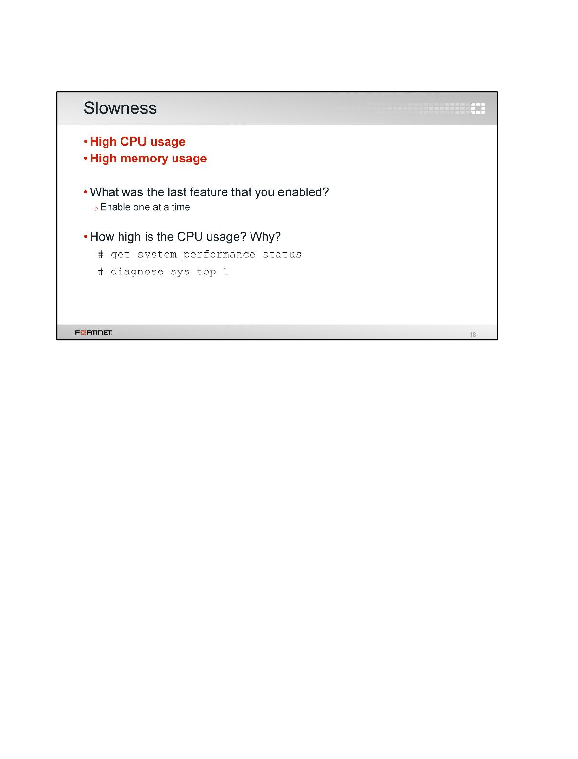
Not all problems are network connectivity failures. Sometimes, there might be resource problems in
the devices.
What else could causes latency? Once you have discarded problems with the physical media and
bandwidth usage, you should check the FortiGate resources usage: CPU and memory.
If usage is high, tools can find which feature is consuming the most. Additionally, you can troubleshoot
faster if you know precisely which change (if any) corresponds with when the problem began. So it’s a
good idea to gradually enable features. Don’t enable everything at once. If the CPU or RAM usage is
too high, and you’ve just enabled many features, it will be more complex to determine how to lower
the usage.
Diagnostics
FortiGate II Student Guide
487
DO NOT REPRINT
© FORTINET
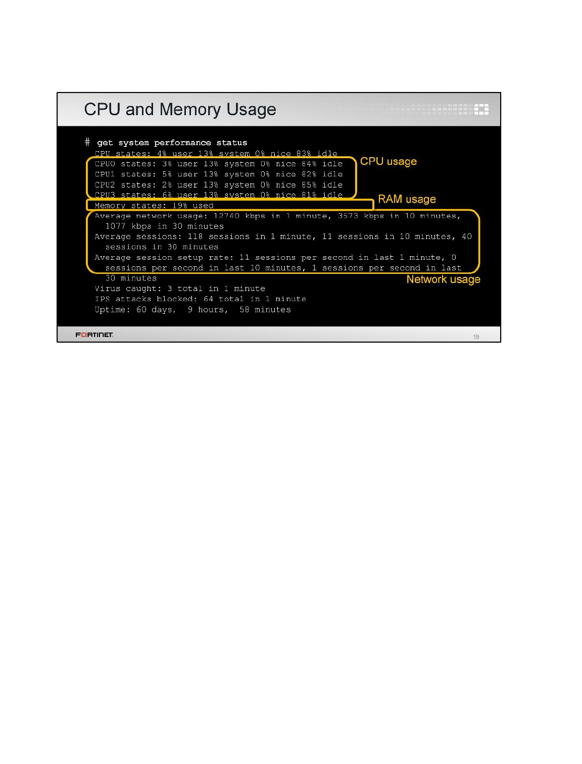
Let’s begin by showing get system performance status.
At the top, output shows that this FortiGate model has a multicore CPU: usage is shown for each core,
CPU0 to CPU3. This is followed by the RAM usage.
At the bottom, output shows your network traffic.
Diagnostics
FortiGate II Student Guide
488
DO NOT REPRINT
© FORTINET
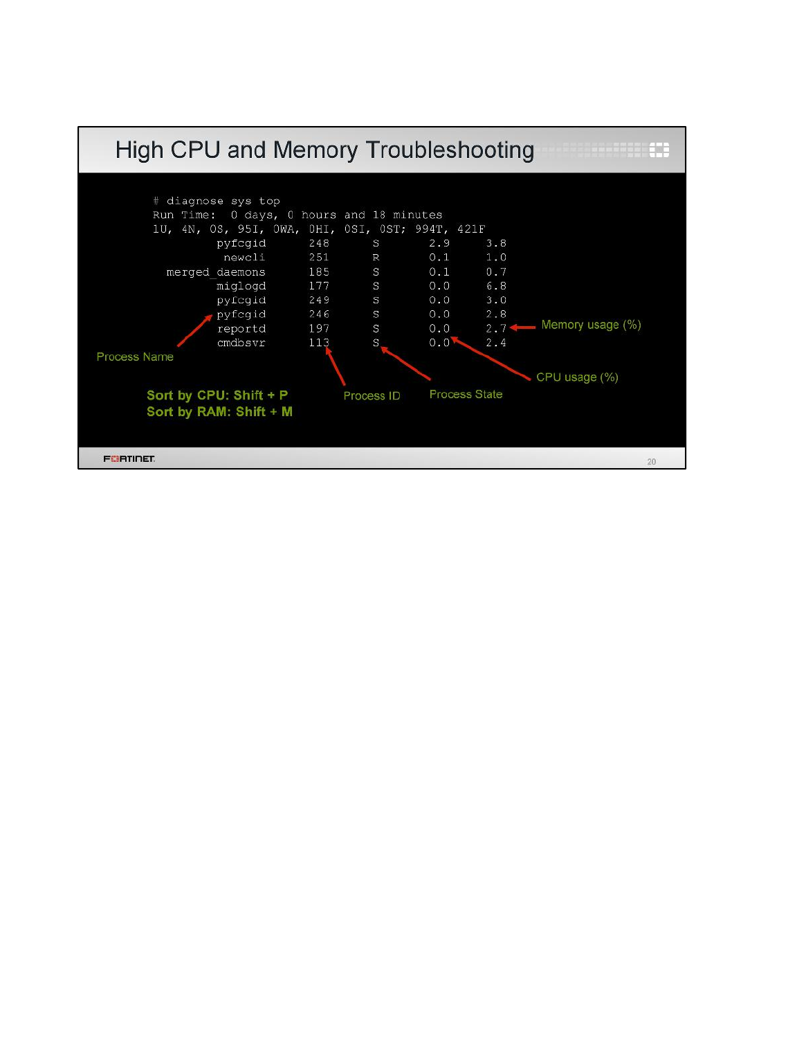
Next, let’s examine the output for diagnose sys top. It lists processes that use the most CPU or
memory. Some common processes include:
• ipsengine, scanunitd, and other inspection processes
• reportd
• fgfmd for FortiGuard and FortiManager connections
• forticron for scheduling
• management processes (newcli, miglogd, cmdb, sshd, and httpsd)
To sort the list by highest CPU, press Shift-P. To sort by highest RAM usage, press Shift-M.
Diagnostics
FortiGate II Student Guide
489
DO NOT REPRINT
© FORTINET
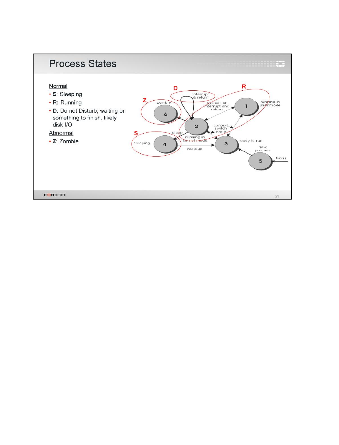
Previously, we showed that diagnose sys top has a column for the process state. This explains
the relationship between the states.
Most of the time, the process state will be either Ror S. This means the process is doing something
(running), or waiting to be told to do something (sleeping).
Occasionally, and for short periods, you may also see processes in the Dstate while writing to a disk.
If a process is staying in the Dstate for a long time, this could mean there is a reading or writing
problem.
You should never see a process in a Zstate. It’s a zombie process and it means the OS has
encountered an error it can’t continue from.
Diagnostics
FortiGate II Student Guide
490
DO NOT REPRINT
© FORTINET
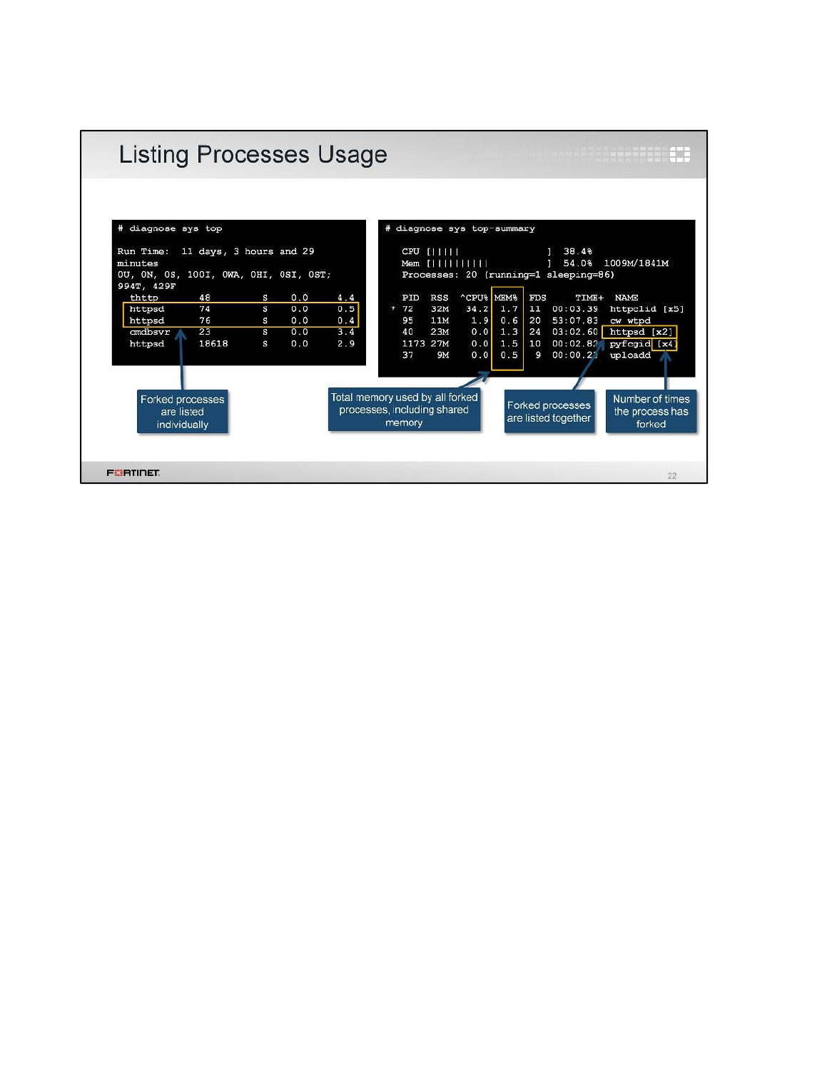
The diagnose sys top-summary command is slightly different than the diagnose sys top
command. The former is better for examining memory usage. Why?
It collects all memory being used by a process and its child processes, including any memory that is
shared between the processes.
Let’s compare the outputs of diagnose sys top and diagnose sys top-summary. They are
different. In the diagnose sys top output, child processes are listed individually. But in the
diagnose sys top-summary output, all child processes are listed together. The name is marked
by an X, indicating how many times a process has forked.
Because RAM for all forks (children) is added together into a total, diagnose sys top-summary is
better when you need to determine which feature to adjust in order to correct performance.
What is forking?
Diagnostics
FortiGate II Student Guide
491
DO NOT REPRINT
© FORTINET
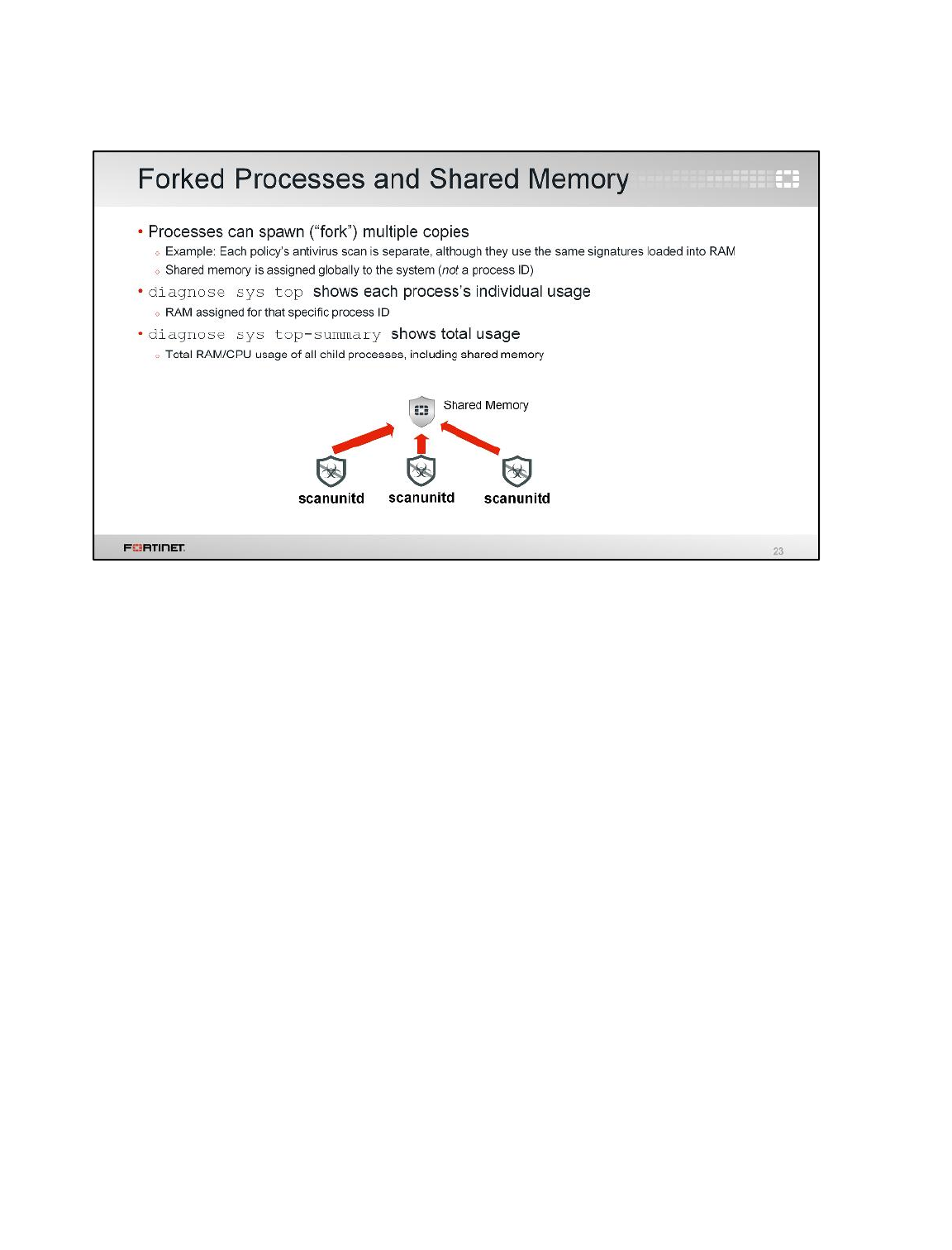
Forking is when the operating system makes multiple copies of a process in order to either subdivide
processing load, or handle multiple similar tasks.
If diagnose sys top shows scanunitd running three times, diagnose sys top-summary would
show one entry with an “x3”, meaning it was forked 3 times. But diagnose sys top-summary
shows that all scanunitd processes are using 12 MB of RAM, while diagnose sys top indicates
that each scanunitd is using just under 2 MB. Why do they indicate different RAM usage?
The 10 MB anti-virus database isn’t duplicated in RAM for each child process; it is loaded into shared
memory, which isn’t counted by diagnose sys top.
FortiOS doesn’t allow different processes to communicate directly. So if memory wasn’t shared, then
FortiOS would be required to load a copy of the antivirus database for each scan process. Each
individual process would be using around 11 MB; only three concurrent scans would require 33 MB.
Performance would decrease.
Diagnostics
FortiGate II Student Guide
492
DO NOT REPRINT
© FORTINET

To finish this lesson, we’ll talk about firmware installations through the console port and hardware
tests.
Diagnostics
FortiGate II Student Guide
493
DO NOT REPRINT
© FORTINET
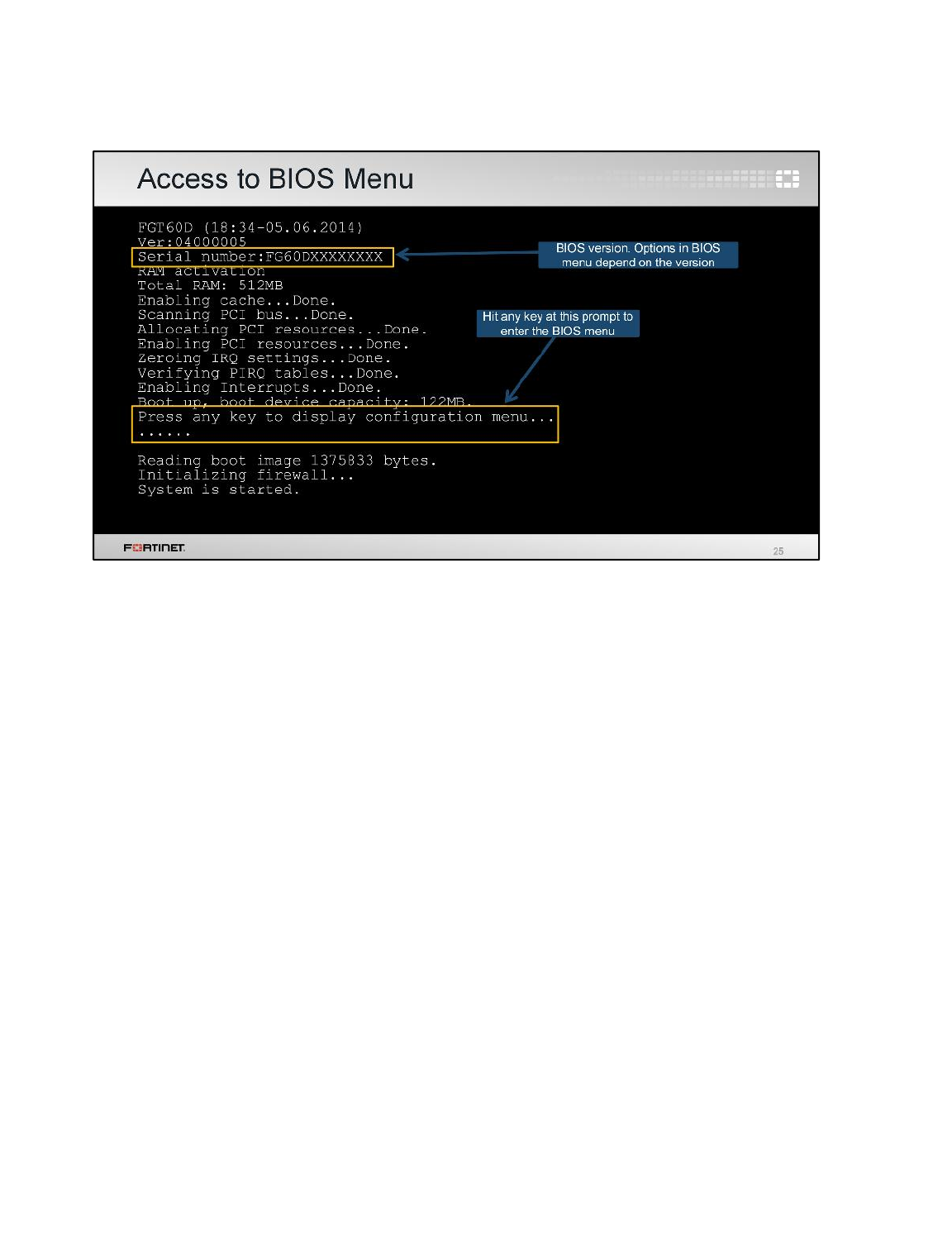
From the FortiGate BIOS, administrators can execute some operations over the flash memory and the
firmware images. To access the BIOS menu you must reboot the device while connected to the
console port. The booting process, at one point, shows the message:
Press any key to display configuration menu
Press any key while this prompt is displayed to interrupt the booting process and display the BIOS
menu.
Diagnostics
FortiGate II Student Guide
494
DO NOT REPRINT
© FORTINET
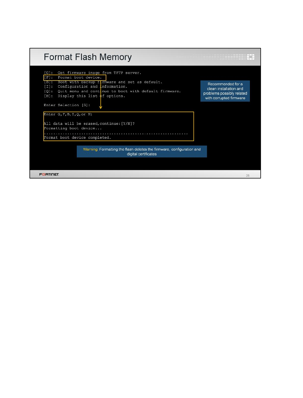
By pressing Ffrom the BIOS menu you can format the flash memory.
This might be required if the firmware got corrupted, or if the administrator wants to do a clean
installation of a new firmware. Keep in mind, though, that formatting the flash deletes any information
stored on it, such as firmware images, configuration, and digital certificates.
Diagnostics
FortiGate II Student Guide
495
DO NOT REPRINT
© FORTINET
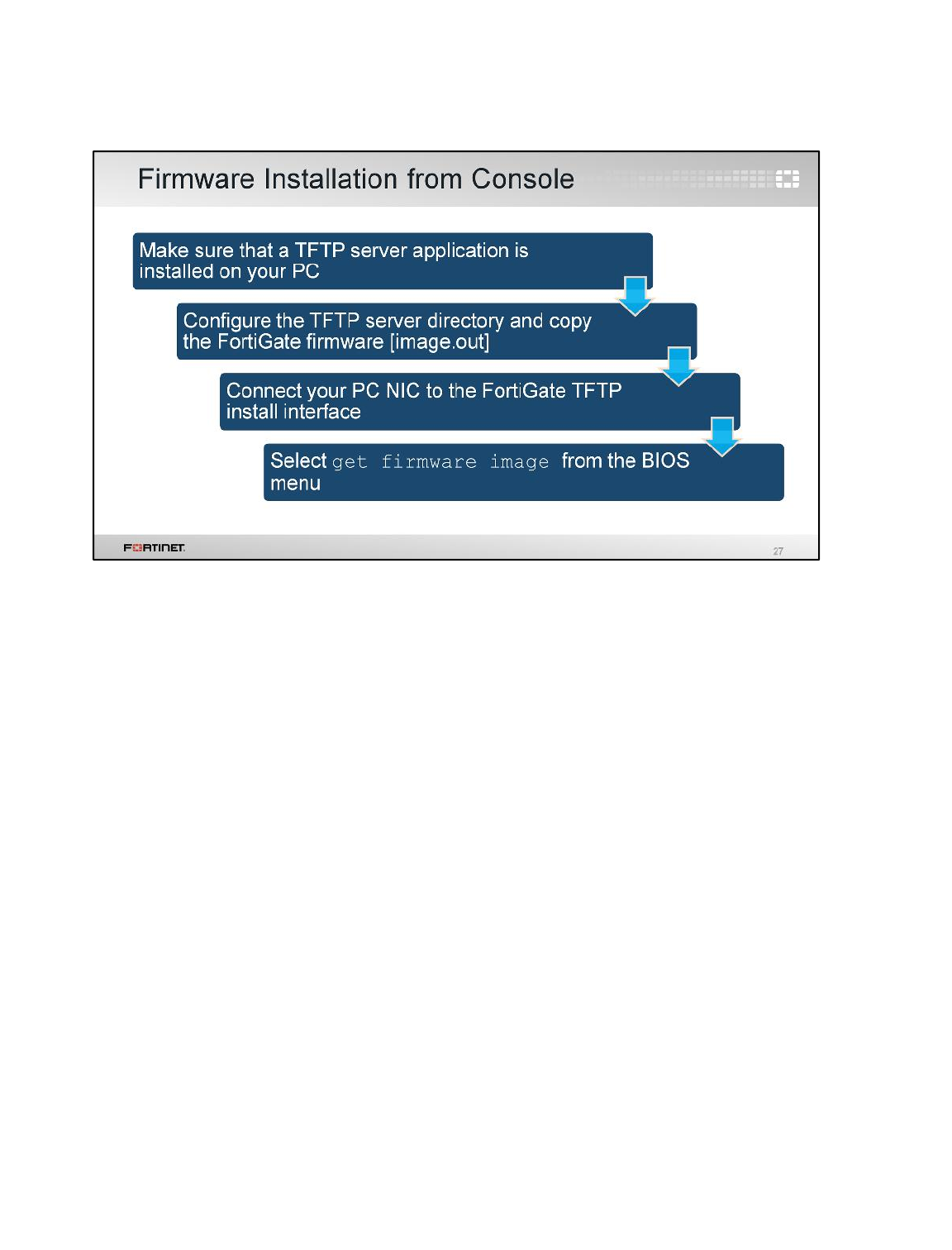
After reformatting the flash, you will need to install the firmware image from the BIOS. Follow these
steps:
1. Run a TFTP server
2. Configure the TFTP server with the folder where the firmware image file is stored
3. Connect the PC Ethernet port to the FortiGate TFTP install interface
4. Select get firmware image from the BIOS menu
The interface assigned as the TFTP install interface depends on the model. However, and in most
cases, it is either the port1 or internal interface.
Diagnostics
FortiGate II Student Guide
496
DO NOT REPRINT
© FORTINET
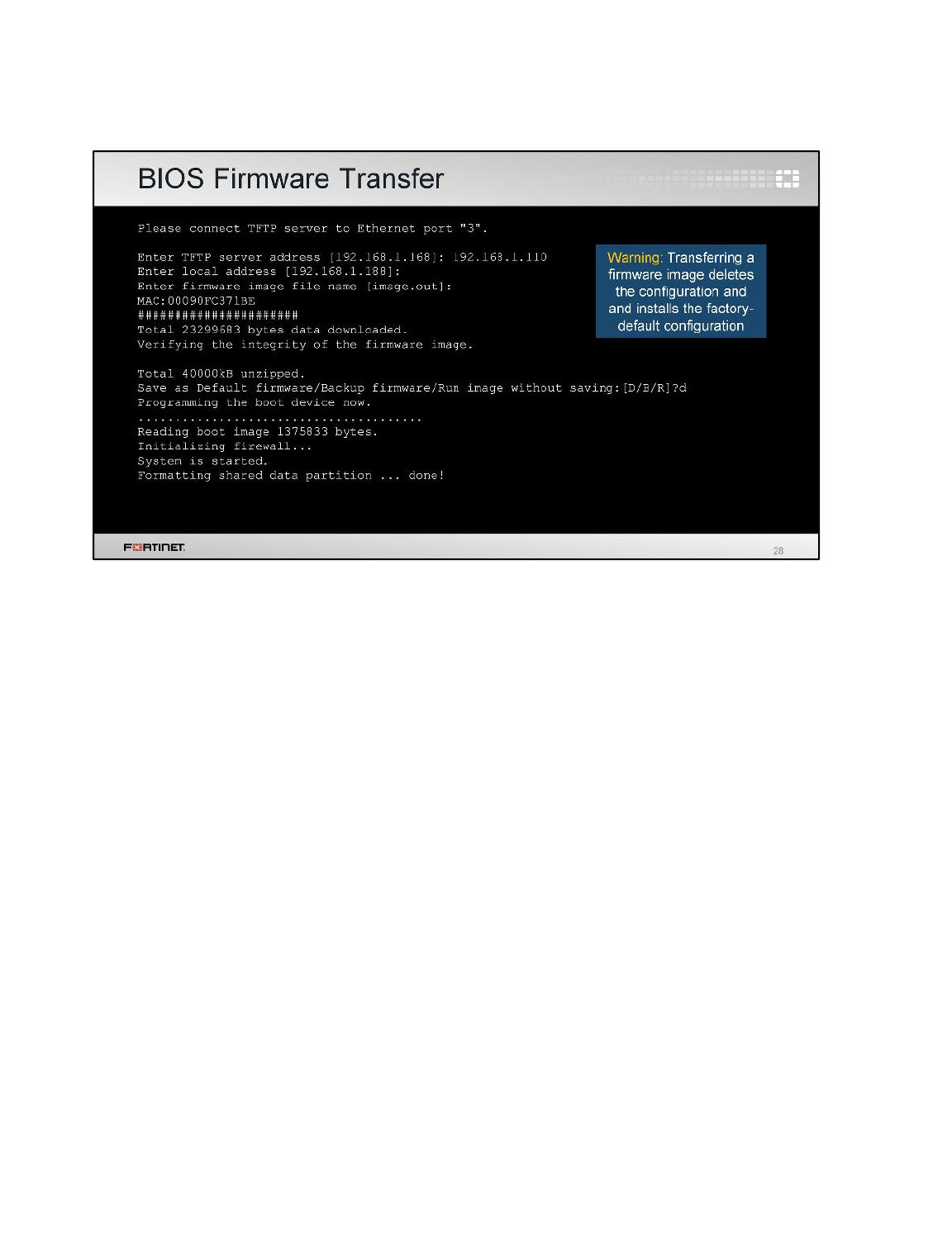
From the BIOS menu, select the option Gto install a new firmware.
The BIOS will ask for:
• the IP address of the TFTP server
• the FortiGate IP address (it must be in the same class-C subnet as the TFTP server)
• the name of the firmware image
If everything is ok, you should see a series of pound signs, indicating that the device is downloading
the image. The BIOS will then verify the integrity of the file and give you these three options:
•Save it as the default firmware
•Save it as the backup firmware
•Run the image without saving it
If the firmware is going to be used in production, select the first option: Save it as the default
firmware.
The last option (Run the image without saving it) allows you to run and test firmware
without overwriting any existing firmware in the flash. Once you have finished the tests and are ready
to roll back the change, you need to reboot the device, and the previously existing firmware will be
used.
Diagnostics
FortiGate II Student Guide
497
DO NOT REPRINT
© FORTINET
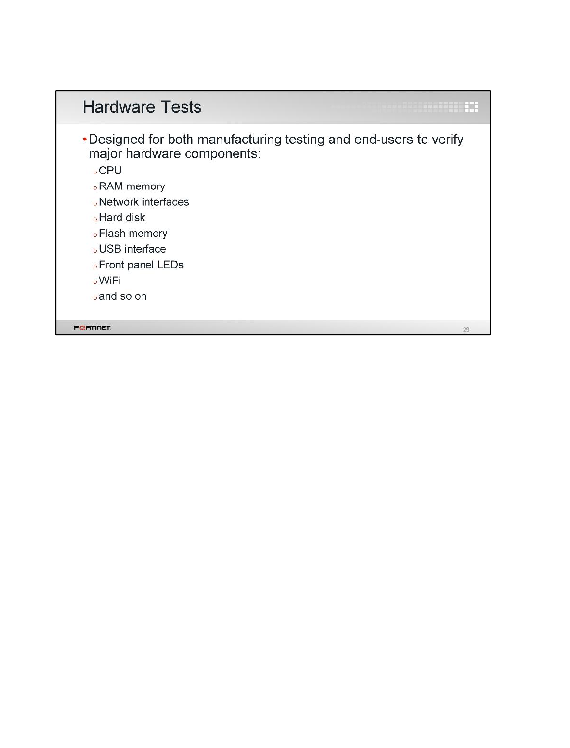
Like with any other electronic device, damage to RAM can cause intermittent crashes.
If you suspect hardware failure, you can run the hardware tests.
How do you run the hardware tests? It depends on the FortiGate model.
Diagnostics
FortiGate II Student Guide
498
DO NOT REPRINT
© FORTINET
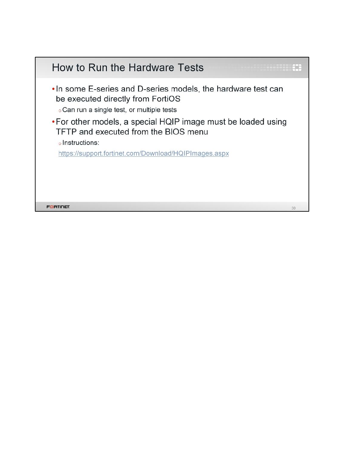
For some FortiGate E-series and D-Series models, you can run the hardware tests directly from the
FortiOS CLI.
For other models, you must download special HQIP hardware testing images from the Fortinet
Technical Support website.
The steps for uploading the hardware test image are the same as the ones used for uploading a
firmware image. You can run the hardware test image without saving it in the flash, so any existing
firmware image won’t be overwritten.
Diagnostics
FortiGate II Student Guide
499
DO NOT REPRINT
© FORTINET
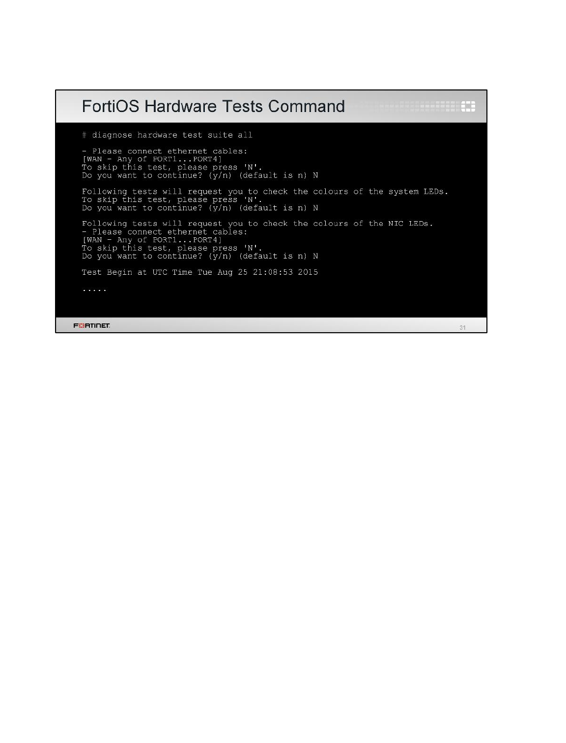
For some E-series and D-series models, the command diagnose hardware test suite all
runs the hardware tests from FortiOS. The hardware tests require user interaction while running.
Users can skip some of the steps and some tests require connecting external devices (such as USB
sticks) or network cables to the FortiGate.
Diagnostics
FortiGate II Student Guide
500
DO NOT REPRINT
© FORTINET
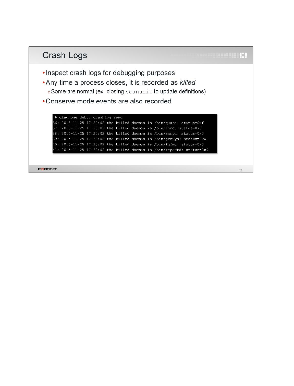
Another area you may want to monitor, purely for diagnostics, are the crash logs. Crash logs are
available through the CLI. Any time a process is closed for any reason, the crash log records this as a
crash. Most of the logs in the crash log are normal. For example, any time the antivirus definitions
package is updated, the scanunit process needs to close down in order to apply the new package.
This is a normal shutdown.
Some logs in the crash log might indicate problems. For that reason, crash logs are frequently
requested by Fortinet Technical Support for troubleshooting purposes. This slide shows the command
you have to use to get a crash log.
Diagnostics
FortiGate II Student Guide
501
DO NOT REPRINT
© FORTINET
During this lesson, we discussed how to measure the network, CPU, and memory usage. We covered
physical and network layer troubleshooting. The lesson also included the debug flow, loading a
firmware from the BIOS, hardware tests, and crash logs.
Diagnostics
FortiGate II Student Guide
502
DO NOT REPRINT
© FORTINET

In this lesson, you will learn how FortiASIC chips and Fortinet’s mezzanine cards accelerate
FortiGate’s performance.
The accelerated processing by specialized hardware is different from traditional processing by
general-purpose CPUs.
Hardware Acceleration
FortiGate II Student Guide
503
DO NOT REPRINT
© FORTINET
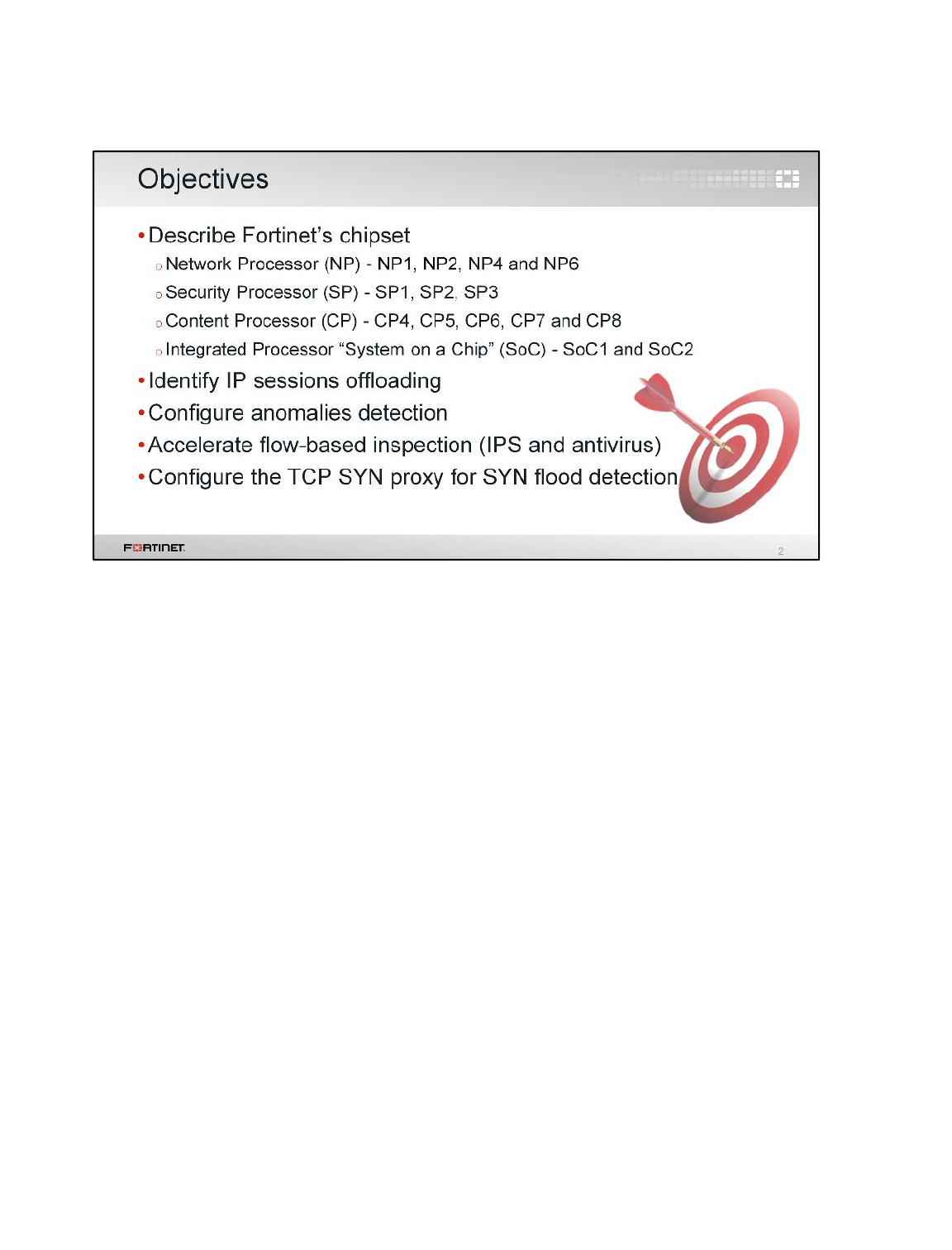
After completing this lesson, you should have these practical skills that you can use to fine tune your
configuration to enhance your network and security performance.
You will be able to describe Fortinet’s chipset, identify IP sessions offloading, configure anomalies
detection, accelerate flow-based inspection, and configure the TCP SYN proxy for SYN flood
detection.
Hardware Acceleration
FortiGate II Student Guide
504
DO NOT REPRINT
© FORTINET

Let’s start by looking at what’s inside a FortiGate, and comparing the specialized hardware
accelerator-FortiASIC types.
Hardware Acceleration
FortiGate II Student Guide
505
DO NOT REPRINT
© FORTINET
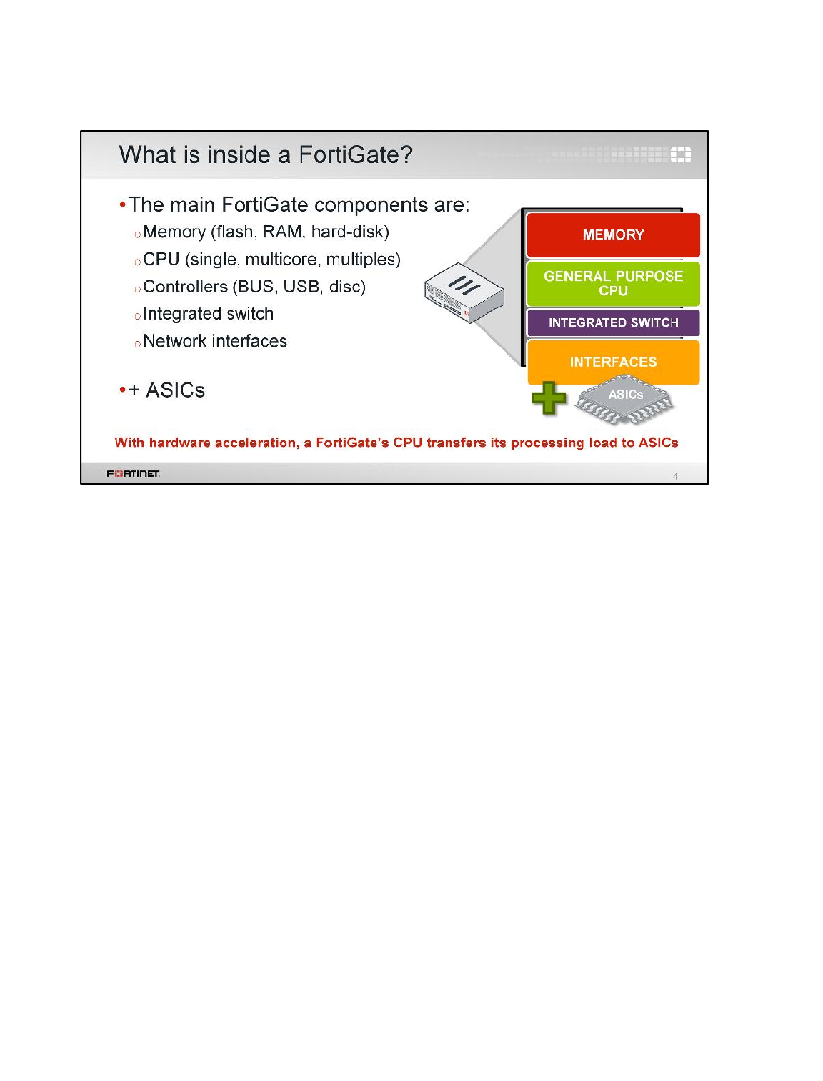
Like most security devices, FortiGate is built from a general purpose computer foundation. However,
general purpose computer appliances are limited in network security performance. That’s why
Fortinet has included special add-on hardware acceleration components.
What does “hardware acceleration” mean? Hardware acceleration allows FortiGate to offload, or
transfer, its processing load from its general purpose CPU to specialized processors.
Note that offloading frees up CPU cycles and offloaded tasks execute faster on specialized hardware
than they do on general purpose CPUs. This process is similar to how your computer uses the GPU
on its graphics card; that is, the GPU often has dedicated RAM of its own, and GPU circuits are
designed to be more efficient at processing images.
Hardware Acceleration
FortiGate II Student Guide
506
DO NOT REPRINT
© FORTINET
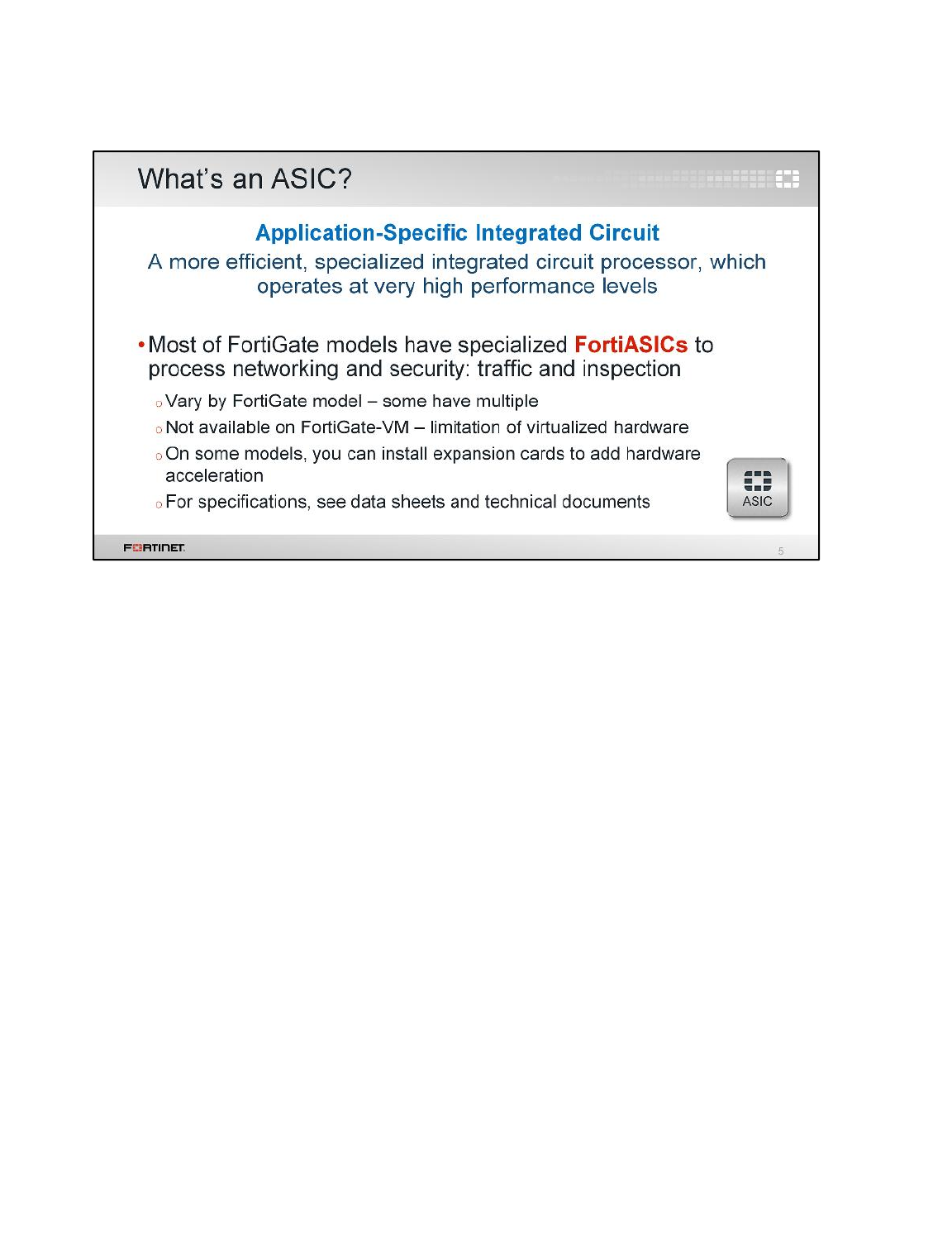
ASICs are chips that are designed to perform a single set of functions with optimal efficiency,
performance, and scalability.
FortiASICs are specialized to offload traffic and inspection processes.
Hardware Acceleration
FortiGate II Student Guide
507
DO NOT REPRINT
© FORTINET
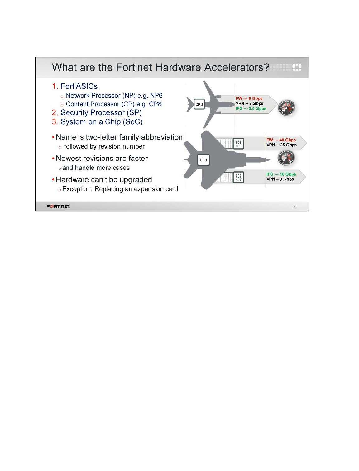
The strength of an ASIC chip is in its specialization; therefore, Fortinet develops several key ASICs
identified by their type (network processor or content processor) and version. Fortinet also develops
security processors, which are not considered FortiASICs.
Note the convention name is the family abbreviation plus the revision number. Generally, newer
versions have more features and better performance. This graphic illustrates the difference in
performance between an older FortiGate that uses CPU-only gear compared to a newer, faster
FortiGate with hardware acceleration.
ASICs are wired into the circuit board; therefore, they are not upgradable.
Hardware Acceleration
FortiGate II Student Guide
508
DO NOT REPRINT
© FORTINET
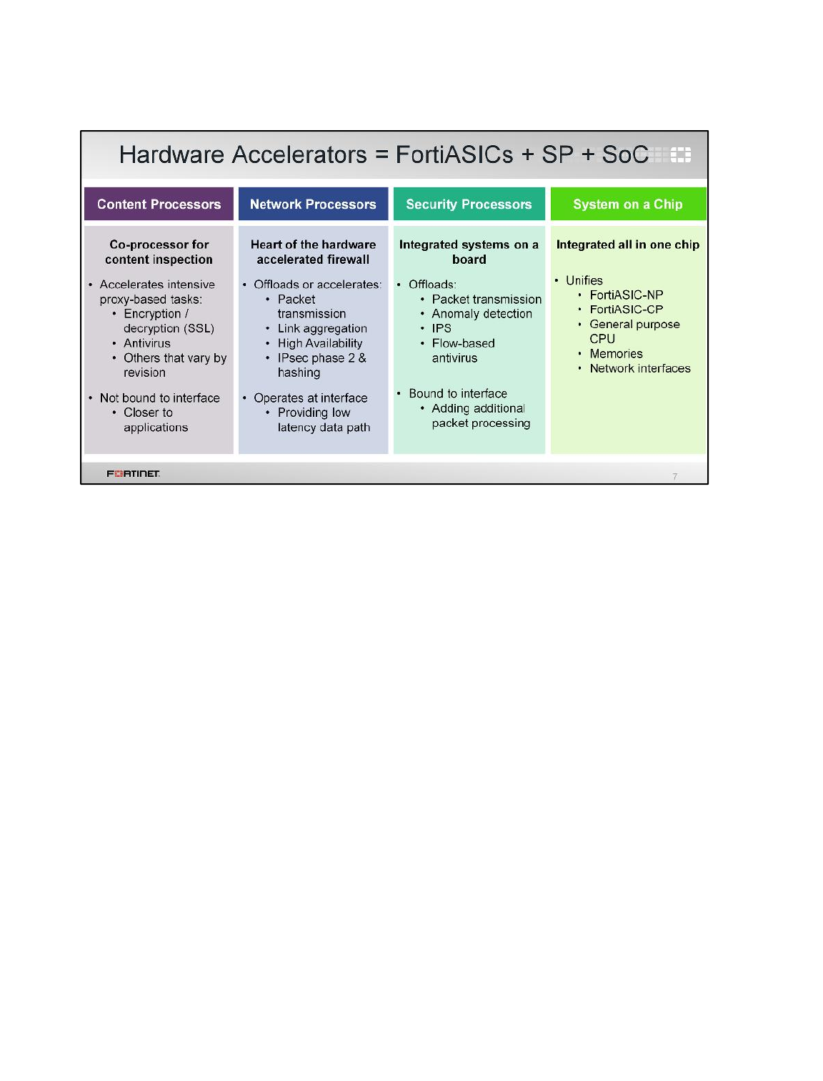
What types of processing does each hardware accelerator do?
• Content Processors (CPs)
A CP is a FortiASIC. CPs offload some types of content inspection capabilities from the CPU. They
inspect the content against threats that are loaded into memory for comparison. They also handle
SSL cryptography.
• Network Processors (NPs)
An NP is a FortiASIC. NPs operate at the interface level to deliver an extremely low latency data
path. NPs can handle packet forwarding; IPsec cryptography and hashing; link aggregation; high
availability (HA); and a few other types of packet processing.
CPs can also handle cryptography, so what’s the difference? CPs act like a co-processor, in terms
of its physical wiring and, unlike most NPs, CPs are not bound to a specific network interface.
• Security Processors (SPs)
An SP is not a FortiASIC. An SP is a mezzanine card with a content processor logic. SPs operate
with their own multi-core/multi-threaded CPU. They can process multicast, IPv6, DoS, and SYN
proxy.
• System-on-a-Chip processors (SoCs)
SoCs are integrated chips that combine a traditional system CPU with both a CP and an NP.
Now that we’ve briefly compared the types of FortiASIC chips, let’s look at the evolution of each chip,
and how to configure your FortiGate to use each ASIC for performance boosts. We’ll also show how
offloading changes expected output for diagnostics.
Hardware Acceleration
FortiGate II Student Guide
509
DO NOT REPRINT
© FORTINET

In this section, we will examine the features of CP chips, and which configurations can use them to
achieve higher performance.
Hardware Acceleration
FortiGate II Student Guide
510
DO NOT REPRINT
© FORTINET
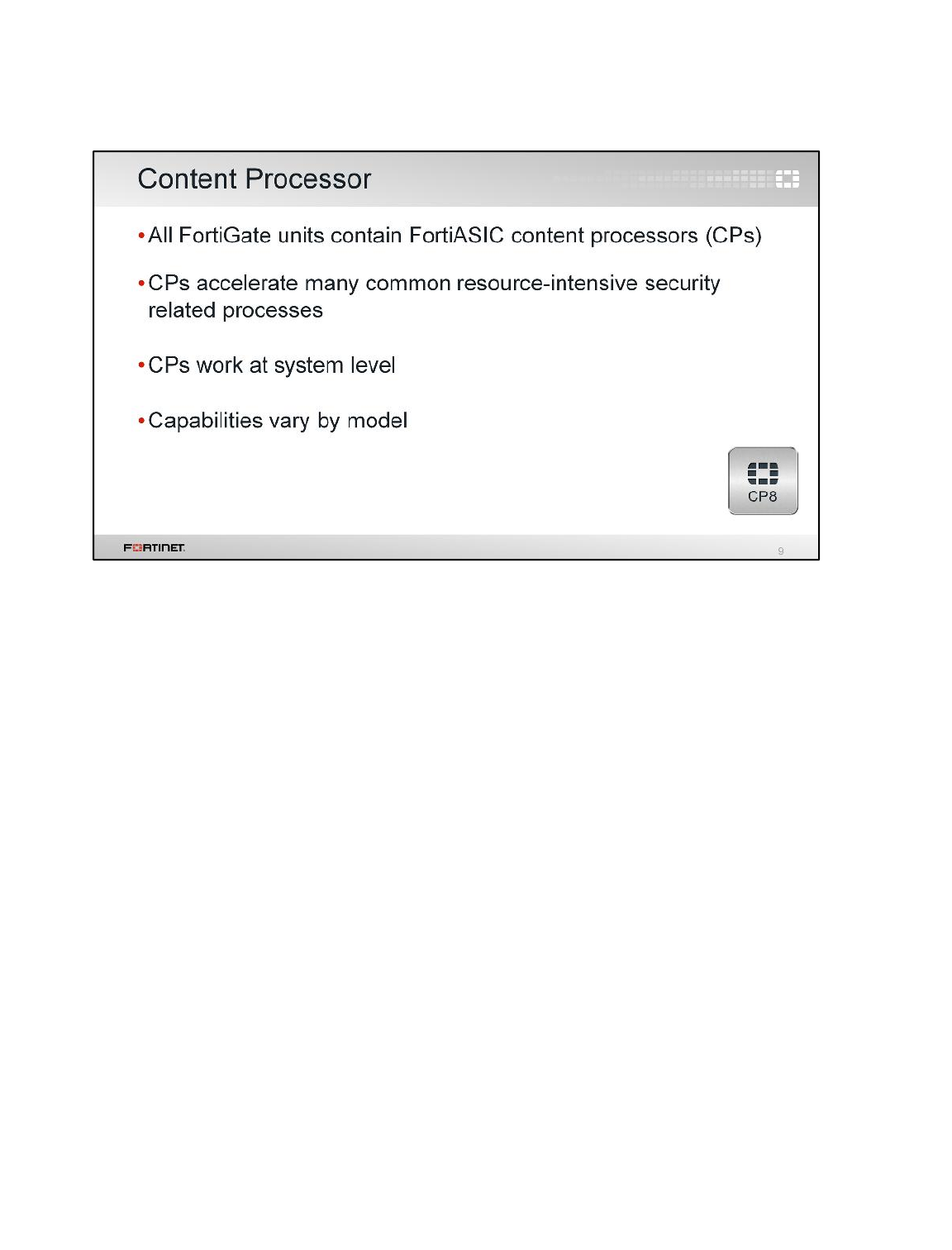
The CP is a co-processor for the CPU. It accelerates many common resource-intensive security-
related processes.
Since the very first FortiGate model, Fortinet has included a CP in the design. The CP works at the
system level. Those early FortiGate models are now out-of-date, so we will start by looking at the
earliest, relevant CP: CP4.
Hardware Acceleration
FortiGate II Student Guide
511
DO NOT REPRINT
© FORTINET
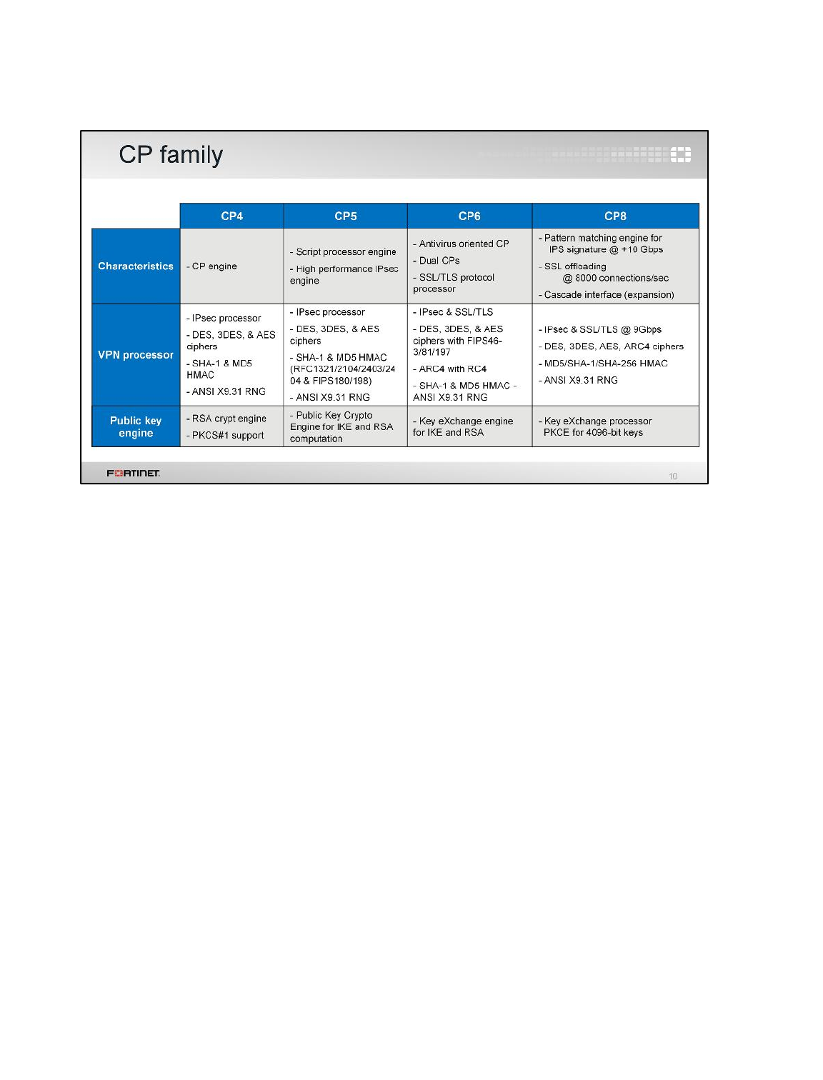
Each generation of CPs builds on the capabilities of the previous one.
CP4 processes IPsec. More specifically, it encrypts and decrypts DES, 3DES, and AES for IPsec
Phase 2. It also generates pseudorandom numbers for cryptography, calculates SHA-1 and MD5
checksums for message authentication, and validates RSA public keys in PKCS#1 certificates.
CP5 added FIPS and RFC compliance, and improved IPsec offloading with support for IKE and RSA.
Additionally, its random number generator is compliant with SSL, which would become especially
relevant to the next generation, CP6.
CP6 included hardware support for SSL, which was required for performance given the growing
popularity of SSL VPN and SSL inspection.
CP8 added support for an IPS engine for signature pattern-matching; extended cryptographic support
to include ARC4 and SHA-256; and large public keys. Additionally, CP8 chips can be stacked for
scalability.
Hardware Acceleration
FortiGate II Student Guide
512
DO NOT REPRINT
© FORTINET
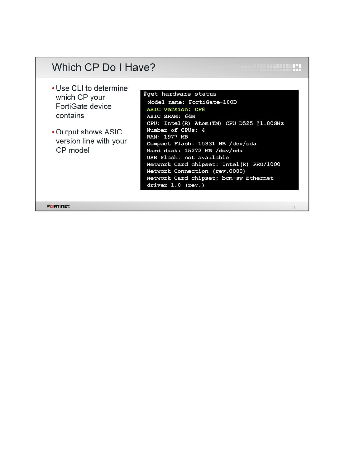
Which CP does your FortiGate have?
To determine this, use the CLI command get hardware status.
Hardware Acceleration
FortiGate II Student Guide
513
DO NOT REPRINT
© FORTINET
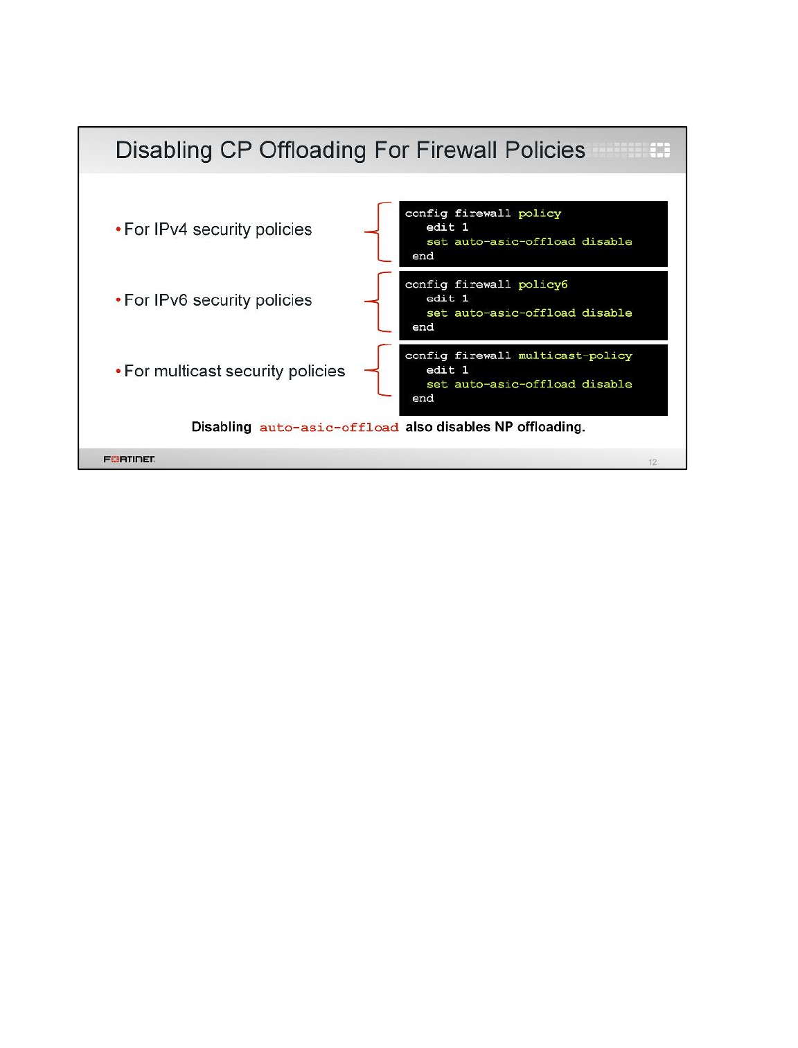
What if you want to disable the CP offloading processes?
You can disable CP offloading processes based on configured firewall security policies:
• IPv4
• IPv6
• Multicast
When you disable auto-asic-offload, it also disables NP offloading.
Hardware Acceleration
FortiGate II Student Guide
514
DO NOT REPRINT
© FORTINET

Now, let’s continue by looking at the NP chip.
Hardware Acceleration
FortiGate II Student Guide
515
DO NOT REPRINT
© FORTINET
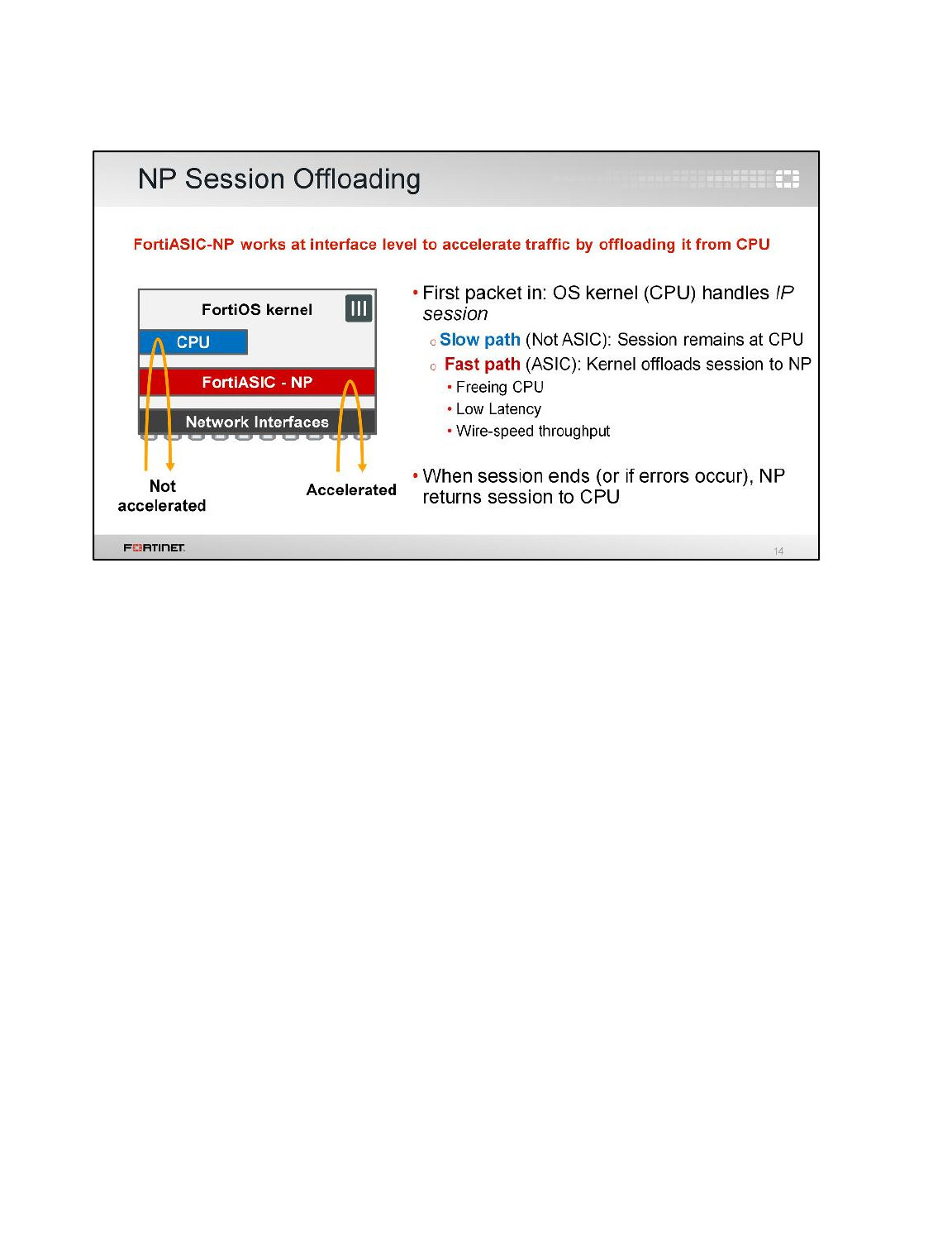
NP works at an interface level to accelerate traffic by offloading it from the CPU.
For each new session, the first packet always goes to the kernel on the CPU. However, if the NP
doesn't support all of the features that you have configured FortiGate to apply to the session, the
kernel must continue to process all of that session’s packets on the slow path.
If the NP does support all features you’ve configured FortiGate to apply to that session, the kernel
sends an instruction to the NP programing it to handle that session, and enable a fast path. The NP
accelerates transmission.
Once FortiGate has processed the last packet – a TCP FIN (finish) or RST (reset) signal, for example,
or if there are errors – then the NP returns the session to the CPU so it can tear down the session.
Hardware Acceleration
FortiGate II Student Guide
516
DO NOT REPRINT
© FORTINET
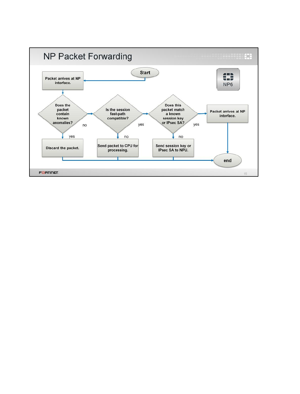
This diagram illustrates how FortiGate decides whether or not to accelerate packet forwarding and IP
session handling.
This process may change according to NP version. Similar to CPs, there are also several NP
revisions.
Hardware Acceleration
FortiGate II Student Guide
517
DO NOT REPRINT
© FORTINET
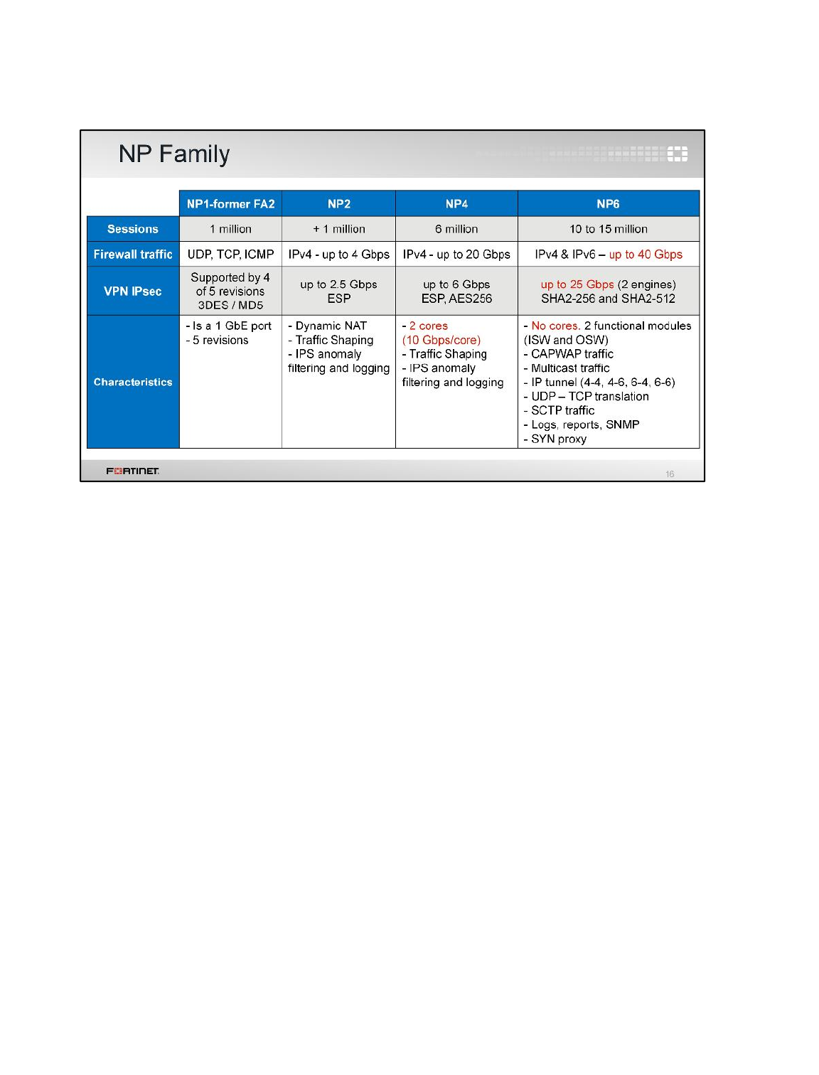
NP1 and NP2 were released many years ago, and can offload most types of IPv4 traffic.
The next generation, NP4, presented a significant performance increase over earlier versions.
NP6 doubles NP4 performance, and adds support for IPv6, CAPWAP traffic (for wireless control and
provisioning), and multicast.
Hardware Acceleration
FortiGate II Student Guide
518
DO NOT REPRINT
© FORTINET
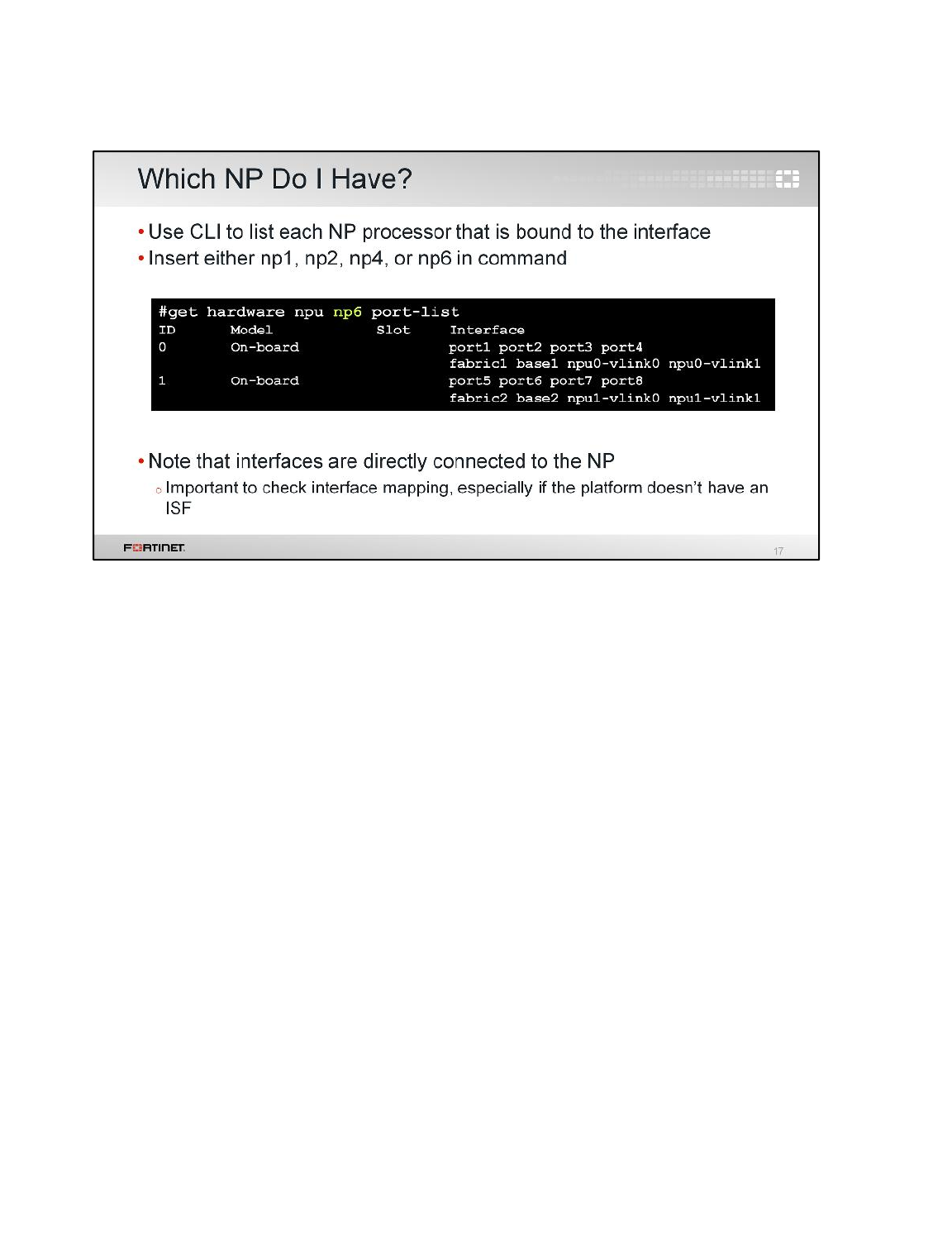
To find information about each of your FortiGate’s network processors, use the CLI command get
hardware npu.
The interfaces of platforms without integrated switch fabric (ISF) are connected directly to NPs.
Therefore, it is particularly important to be aware of those direct mappings, especially when the
platform has multiple NPs.
Hardware Acceleration
FortiGate II Student Guide
519
DO NOT REPRINT
© FORTINET
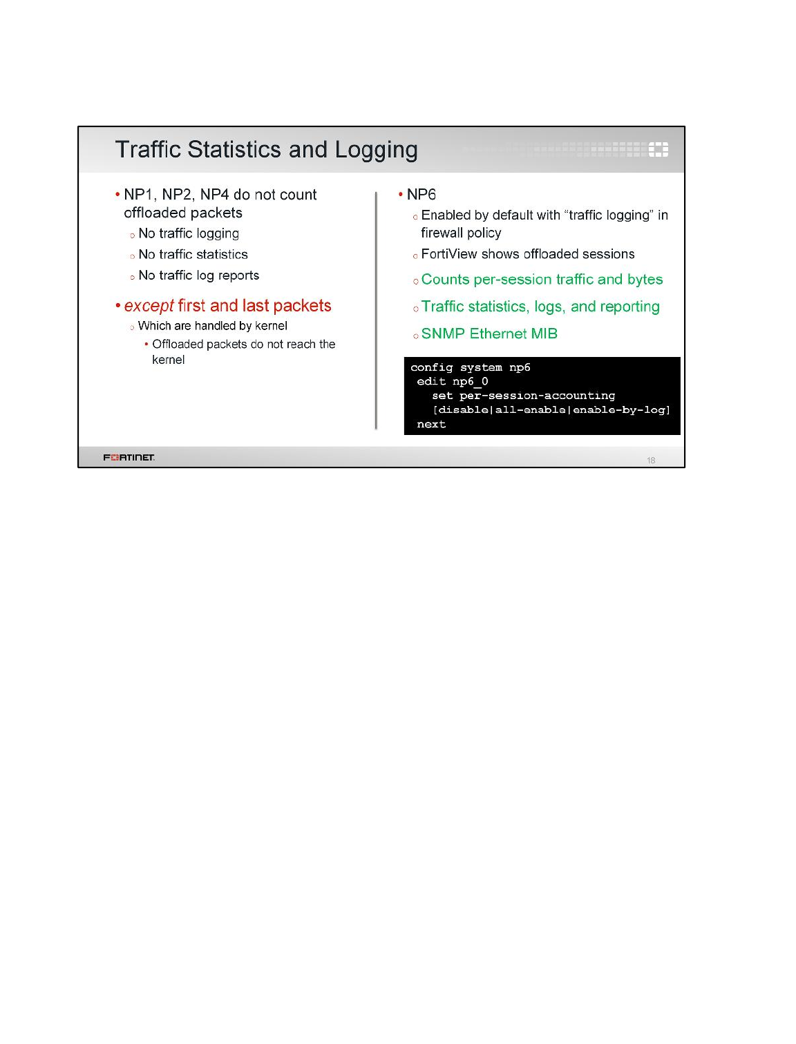
NP versions 1, 2, and 4 do not support traffic statistics (including logs). The only exception to this rule
are the first and last packets in the IP session.
This exception occurs because the first and last packets are handled by the kernel, before the session
information is passed to an ASIC. The ASIC chip processes all of the packets in between, so the
kernel is not aware of any statistics that occur during that time. As well, NP1 through NP4 do not have
the memory to keep their own statistics.
NP6 does support statistics. It also supports the SNMP Ethernet MIB, so it can answer queries about
these statistics too.
Hardware Acceleration
FortiGate II Student Guide
520
DO NOT REPRINT
© FORTINET
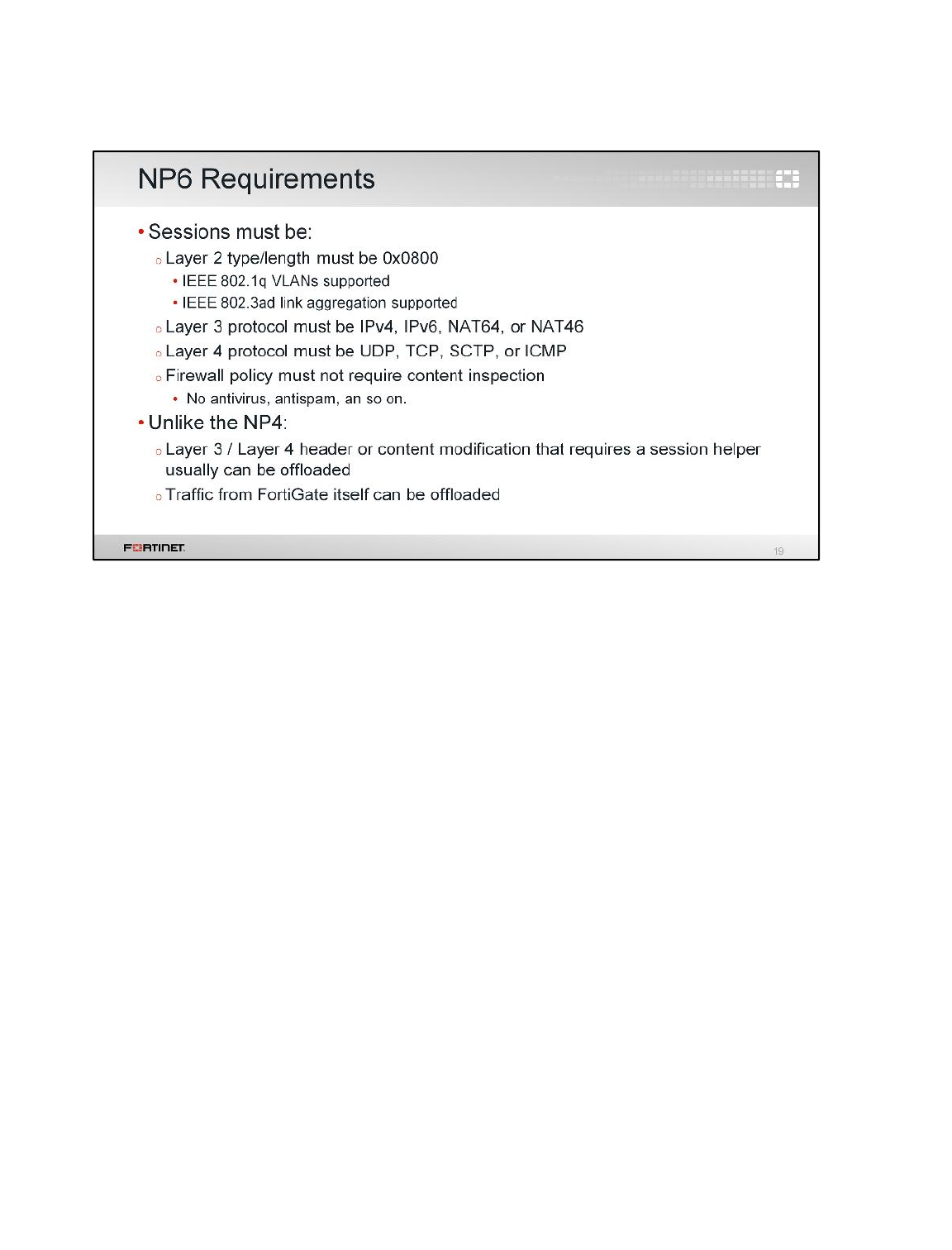
To be eligible for offload, the traffic must match the ASIC chip’s design criteria. For NP4, the criteria
are:
• Layer 2 type/length must be set to 0X0800. IEEE 802.1q and 802.3ad traffic can also be offloaded.
• Layer 3 must be unicast IPv4. (Multicast and IPv6 are not supported by NP4.)
• Layer 4 must be UDP, TCP, SCTP, or ICMP.
• Header or content must not require modification by a session helper.
• Traffic must not be inspected by any kind of security profile, such as antivirus or web filtering.
• Traffic must not have originated from the firewall.
• Ingress and egress ports must be on the same NP4, unless there is an EEI bridge between two
communicating NP4s.
The NP6 and NP4 criteria for offloading are the same, except that NP6 also supports IPv6, NAT64,
NAT46, and others.
Hardware Acceleration
FortiGate II Student Guide
521
DO NOT REPRINT
© FORTINET
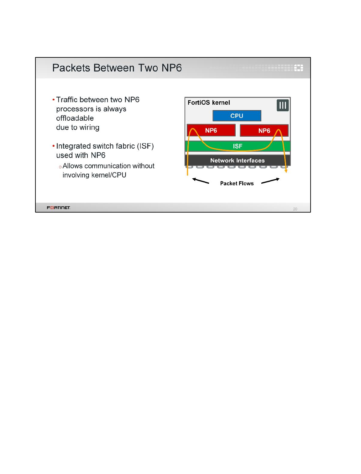
FortiGate models with NP6 are physically wired together with an ISF. The ISF wiring allows
communication between all interfaces and the NP6 processors, without requiring the traffic to pass
through the CPU. This means that offloading is possible, even if the ingress and egress ports are not
on the same processor.
Hardware Acceleration
FortiGate II Student Guide
522
DO NOT REPRINT
© FORTINET
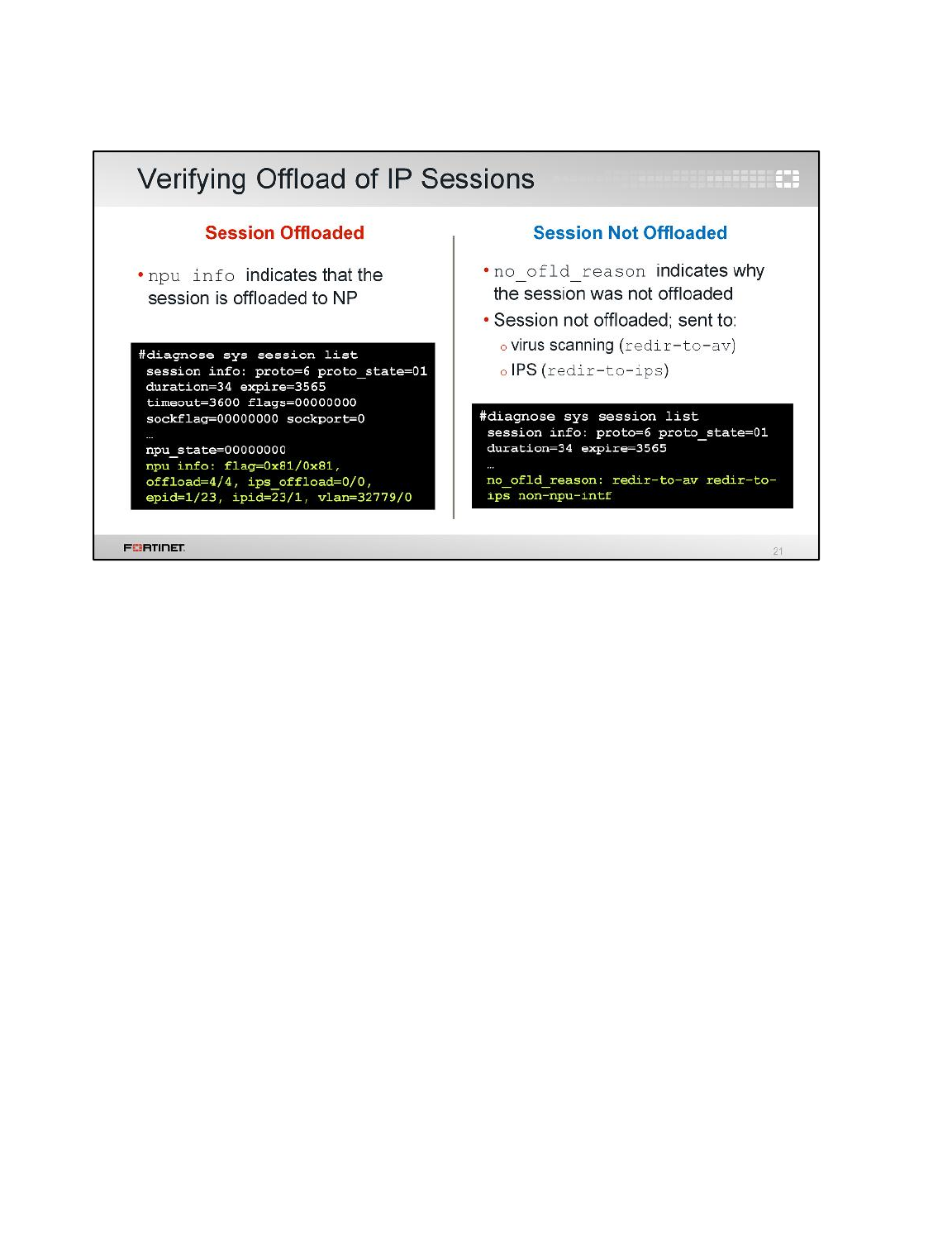
To verify if a session was offloaded, use the CLI command diagnose sys session list.
npu info indicates the sessions can be offloaded. The offload=x/y flag states this. In this
example, all the sessions have been offloaded (offload=4/4). An output offload=0/0 indicates
non accelerated sessions.
no_ofld_reason indicates the session was not offloaded, such as if the sessions were redirected
to antivirus or IPS analysis.
Hardware Acceleration
FortiGate II Student Guide
523
DO NOT REPRINT
© FORTINET
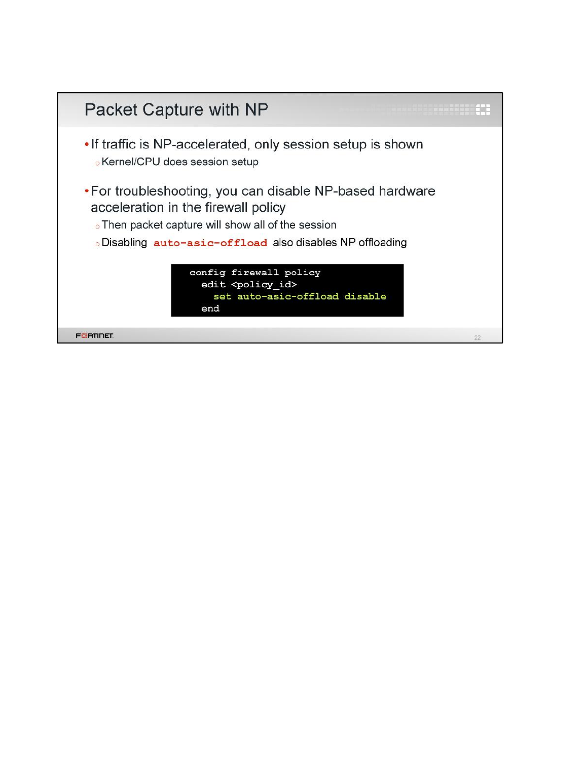
The kernel is not aware of what is happening with a session while that session is being handled by an
NP. This impacts logging. What else does it impact?
Packet capture involves FortiGate’s kernel, which uses the CPU. NP chips do not send all of their data
back to the CPU, since this would counteract acceleration. As a result, once a session is offloaded to
an NP, the sniffer does not see the offloaded packets.
During troubleshooting, you often need to see the entire session. In order to do this, you may need to
temporarily disable offloading. You can do this on a per-policy basis, in the CLI. Remember, this
action also disables CP offloading.
Hardware Acceleration
FortiGate II Student Guide
524
DO NOT REPRINT
© FORTINET
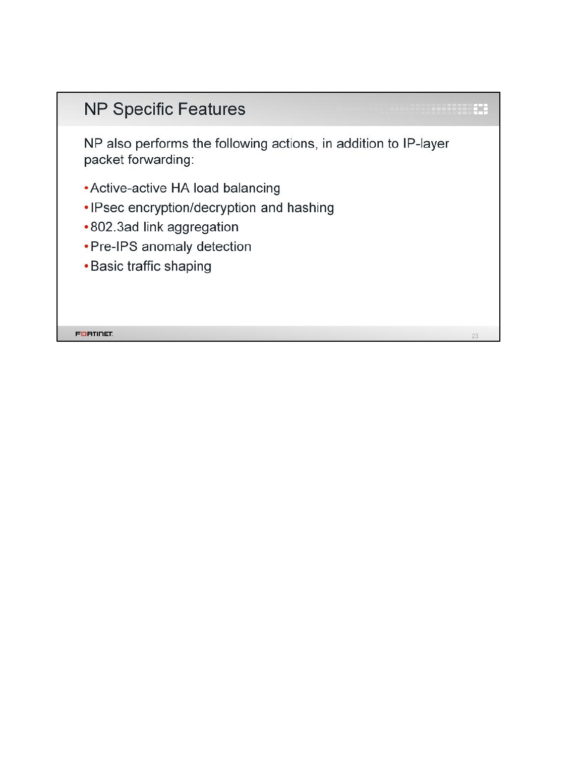
NP does more than just IP layer packet forwarding. It also does the following:
• Active-Active HA load balancing
• IPsec cryptography
• Link aggregation
• Basic anomaly detection (before the software IPS engine)
• Basic traffic shaping
Hardware Acceleration
FortiGate II Student Guide
525
DO NOT REPRINT
© FORTINET
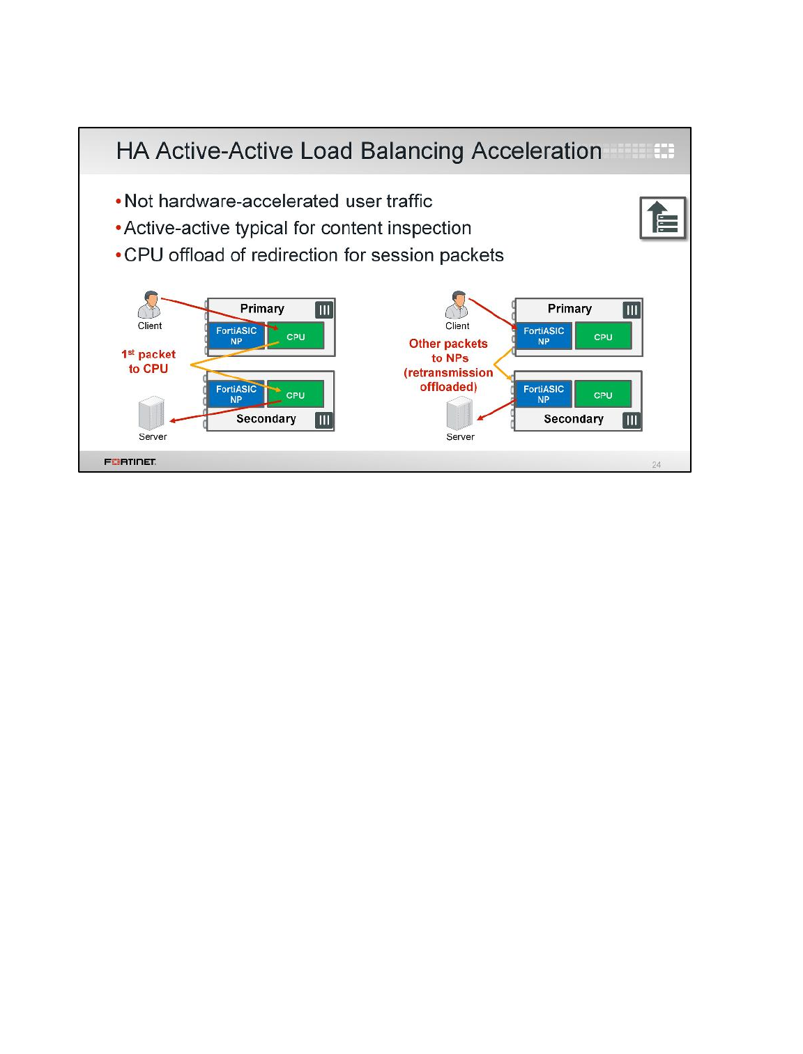
In HA active-active, the offload criteria is the same as for a standalone FortiGate.
Hardware acceleration of user traffic is decided by each individual FortiGate in the cluster. Generally,
traffic is load balanced for content inspection purposes, so hardware acceleration does not apply. It is,
however, the redirection of packets in the same session that is offloaded. This means that the network
processor re-writes the MAC addresses, offloading the CPU from these interrupts.
Hardware Acceleration
FortiGate II Student Guide
526
DO NOT REPRINT
© FORTINET
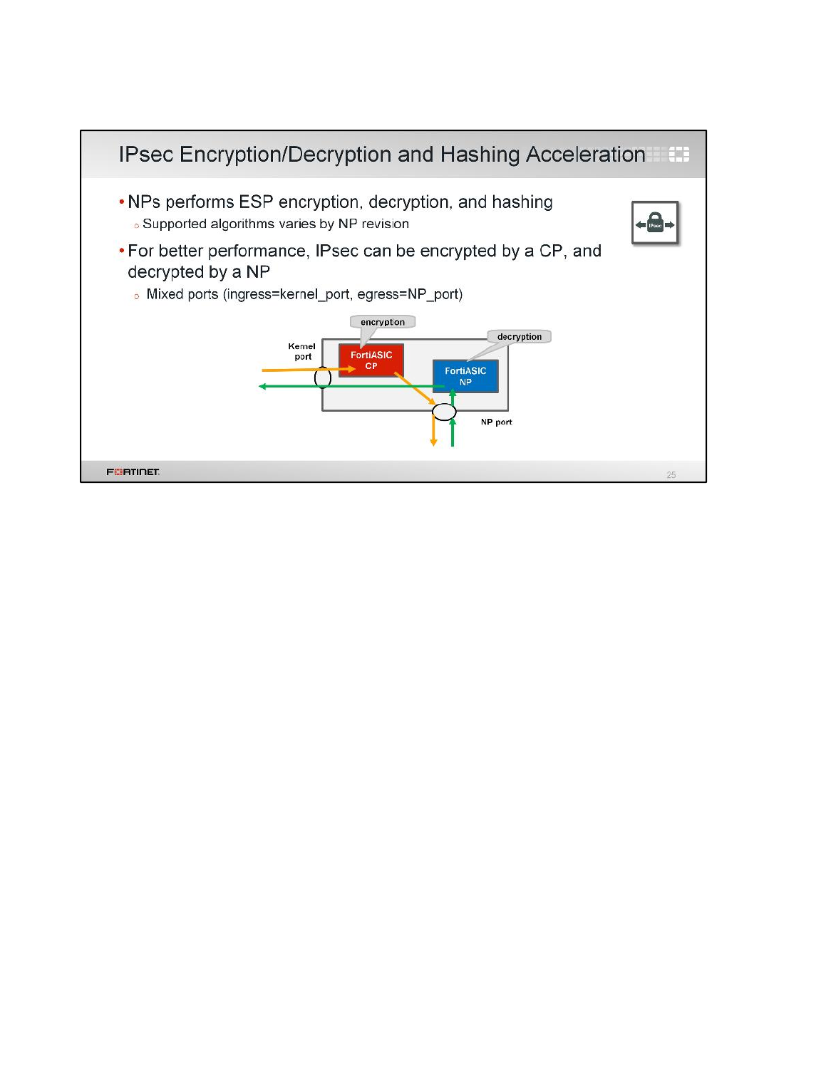
If an IPsec tunnel uses encryption and hashing algorithms supported by the network processor, than
the IPsec user data processing can be offloaded.
Hardware Acceleration
FortiGate II Student Guide
527
DO NOT REPRINT
© FORTINET
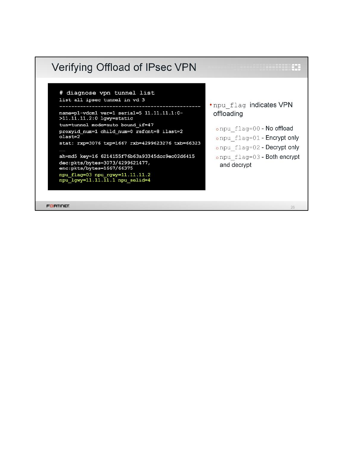
To verify if IPsec traffic is offloaded, use the CLI command diagnose vpn tunnel list.
This shows the status and statistics for each VPN tunnel. If it contains a line with npu_flag, the
tunnel is being offloaded.
Remember that it is necessary to get initial packets from both directions first, before checking the
npu_flag field. Otherwise, it is expected to be 0/0 – initially.
Hardware Acceleration
FortiGate II Student Guide
528
DO NOT REPRINT
© FORTINET
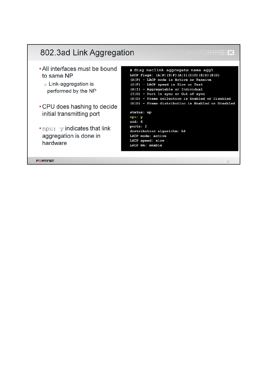
Network processors can also accelerate traffic for 802.3ad link aggregation – if all aggregated
interfaces are associated with the same NP. (Depending on which vendors you’re familiar with, link
aggregation is also called NIC teaming,channeling, or link bonding.) To determine if the channel is
offloaded, use the CLI command diagnose netlink aggregate.
Will all link aggregation-related processing be offloaded? No, offloading doesn’t occur until the CPU
establishes the session and sends it to the NP. So in the initial phase of hashing – which is how the
kernel decides which interface in the aggregate will send the first frame – the CPU is still involved.
Offloading occurs after link aggregate hashing.
Hardware Acceleration
FortiGate II Student Guide
529
DO NOT REPRINT
© FORTINET
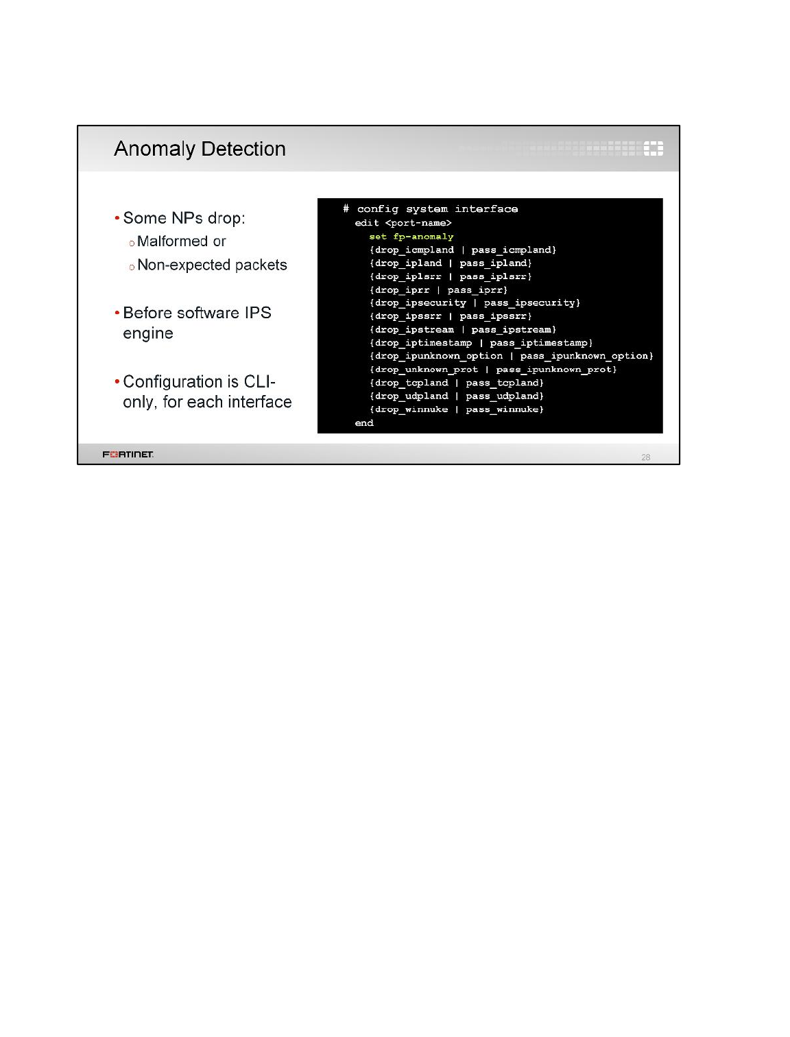
Some network processors can also detect some anomalies and drop those packets. This occurs in
hardware. It is independent from the IPS engine, and occurs before the IPS engine is involved. To do
this, configure the interface with set fp-anomaly. For example, you can configure your NP
processor to drop packets with an unknown protocol number.
Hardware Acceleration
FortiGate II Student Guide
530
DO NOT REPRINT
© FORTINET
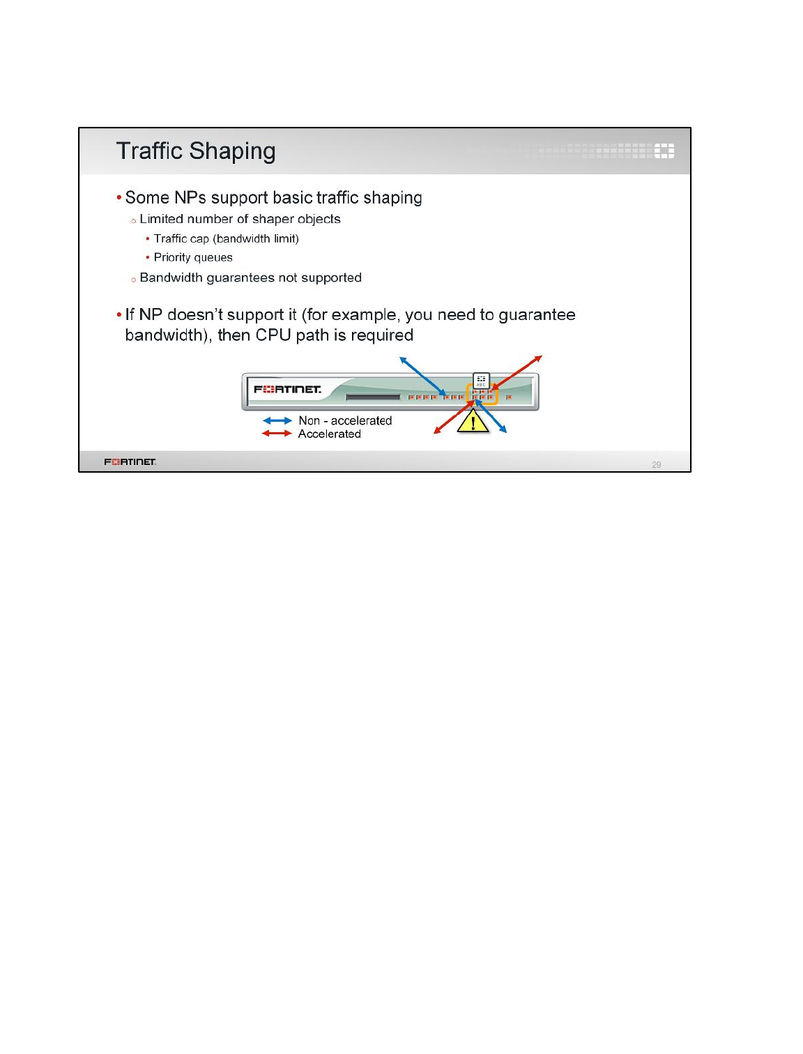
Some types of traffic shaping can also be offloaded to an NP.
Note that only limitations and prioritizations are supported, however guaranteed bandwidth cannot be
offloaded and it is handled by the CPU.
NPs have limited shaper objects (NP6 has more shaping objects and packet flow improvements),
therefore traffic shaping by the CPU is still common.
Hardware Acceleration
FortiGate II Student Guide
531
DO NOT REPRINT
© FORTINET

Now we will look at SPs, which are mezzanine cards that accelerate FortiGate’s performance.
Hardware Acceleration
FortiGate II Student Guide
532
DO NOT REPRINT
© FORTINET
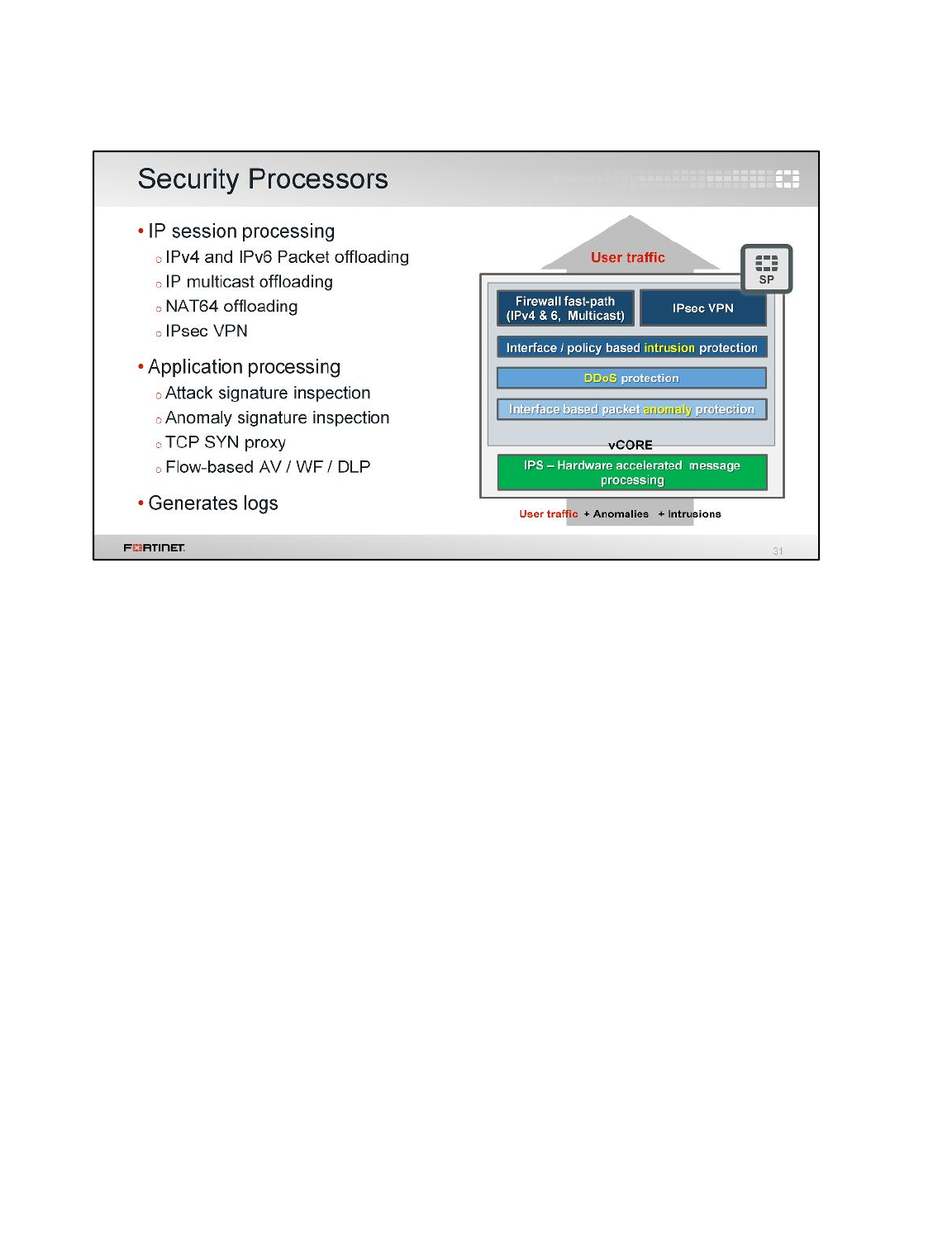
SPs provide an integrated, high-performance, fast-path multilayer solution for both intrusion protection
and firewall functions.
The intrusion protection starts at an IPS hardware accelerated engine, which ensures that each packet
is OK. Then, a set of interface-based packet anomaly protection, DDoS protection, policy-based
intrusion protection, and firewall fast path are employed to prevent attacks.
SPs can also offload packet transmissions, such as multicast, IPv4, IPv6, and NAT64 traffic. It
accelerates IPsec encryption and decryption. It can perform flow-based content inspection and
provide SYN proxy functionalities.
Hardware Acceleration
FortiGate II Student Guide
533
DO NOT REPRINT
© FORTINET
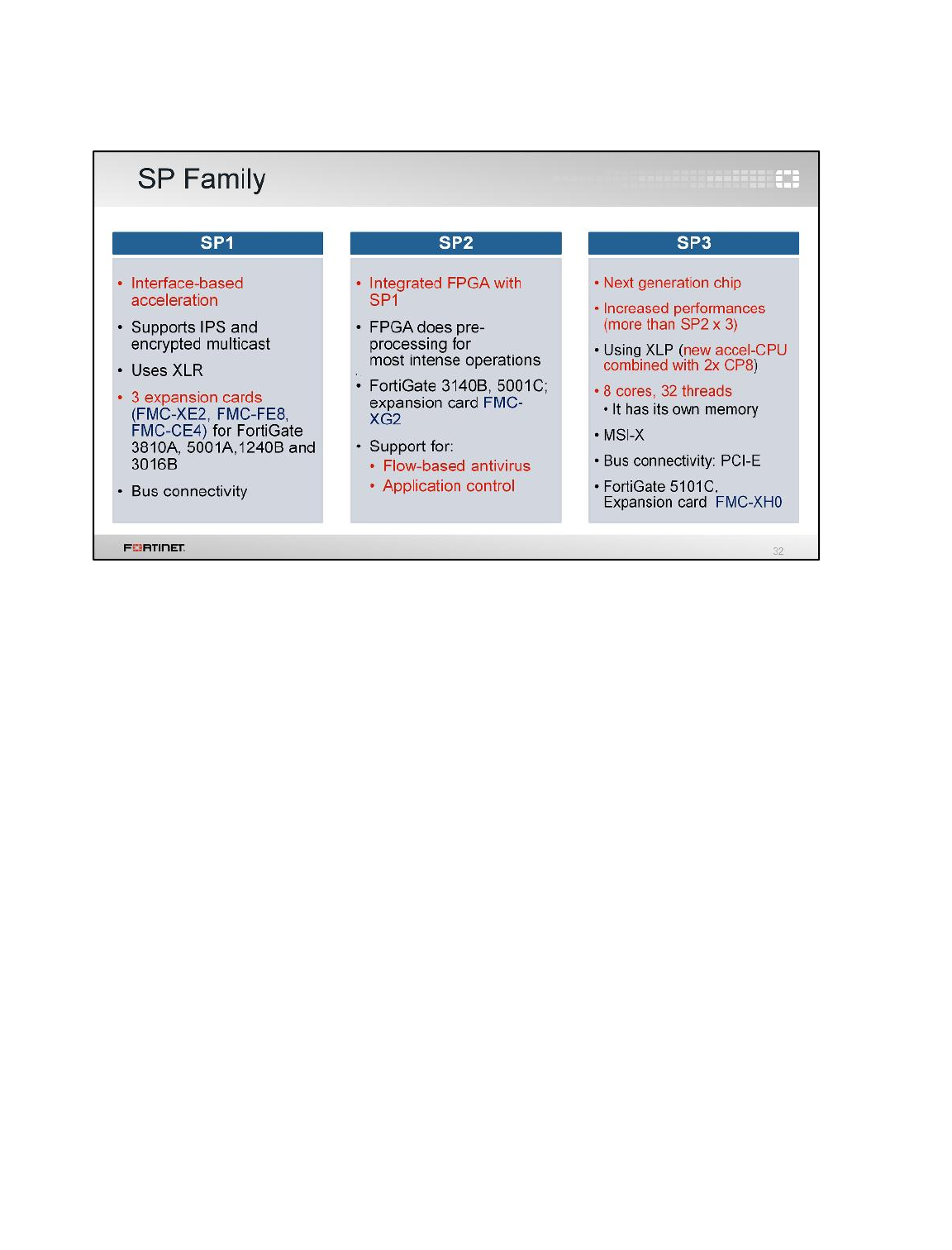
Like CPs and NPs, SP features increase with each revision.
The first revision can handle IPS and encrypted multicasting offload. This version is built in three
expansion cards: FMC-XE2, FMC-FE8, FMC-CE4, which are all compatible with FortiGate’s 3810A,
5001A,1240B, and 3016B.
The second revision added support for flow-based inspection. The mezzanine expansion card of this
SP is FMC-XG2, which is compatible to FortiGates 3140B and 5001C.
And, the third revision has performance benefits built-in the FMC-XH0 card.
Hardware Acceleration
FortiGate II Student Guide
534
DO NOT REPRINT
© FORTINET
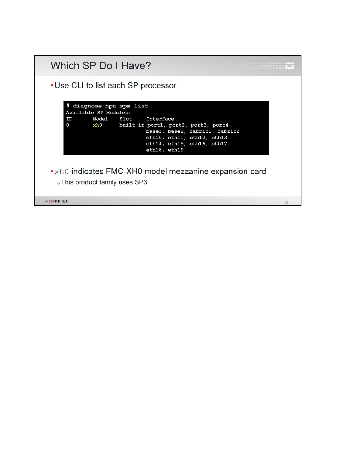
To determine the SP installed in your FortiGate model (if any), use the CLI command diagnose npu
spm list.
In the example shown here, xh0 indicates that the FMC-XH0 model mezzanine expansion card is
installed. This product family uses SP3.
Remember, SPs mostly accelerate security related features, an NP does not support these sessions.
Hardware Acceleration
FortiGate II Student Guide
535
DO NOT REPRINT
© FORTINET
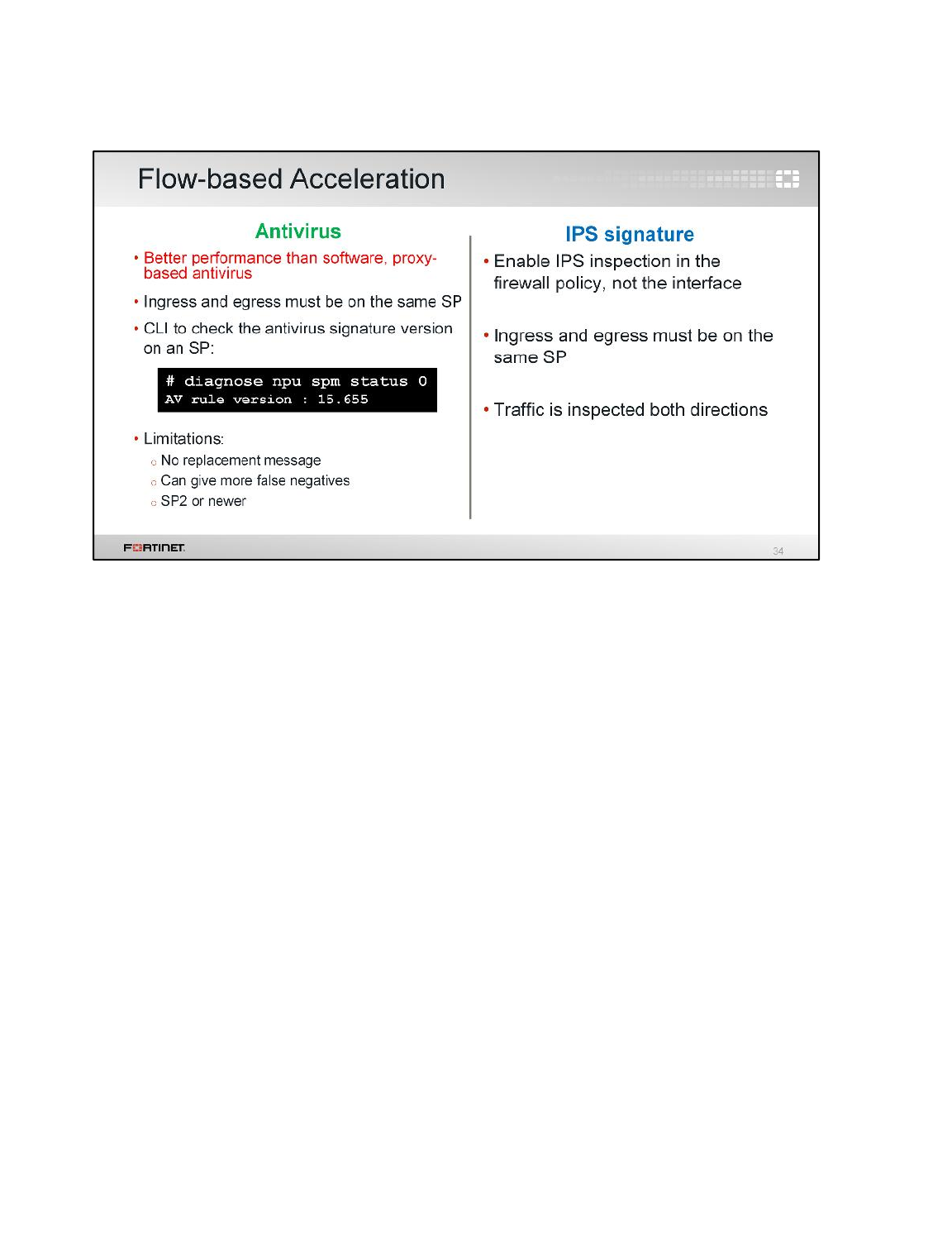
SPs handle flow-based inspection, such as AV, IPS, and application control, providing significant
throughput benefits.
To offload flow-based inspections, it is necessary that ingress and egress interfaces in firewall policies
be bound to the same SP.
Hardware Acceleration
FortiGate II Student Guide
536
DO NOT REPRINT
© FORTINET
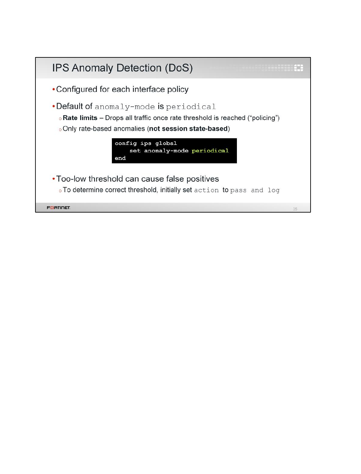
DoS policies, depending on the type, can also be offloaded to the security processor.
Hardware Acceleration
FortiGate II Student Guide
537
DO NOT REPRINT
© FORTINET
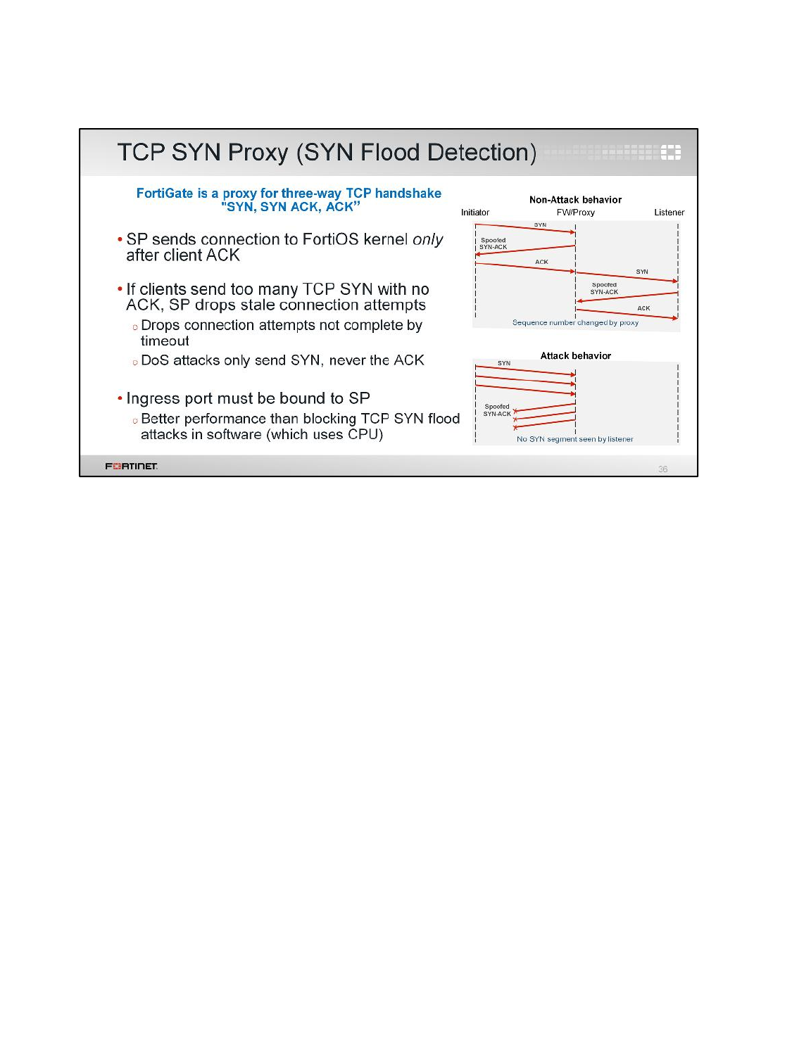
An interface on an SP can also act as a TCP SYN proxy, dropping all connections not completed by
the client within the timeout period. This provides greater protection and performance for your back-
end servers against SYN floods.
The TCP connection is not passed to the server until the client finishes the 3-way handshake. In this
way, SYN flood attacks do not exhaust CPU resources.
SP supports VLANs and traffic with spoofed source IP.
Hardware Acceleration
FortiGate II Student Guide
538
DO NOT REPRINT
© FORTINET
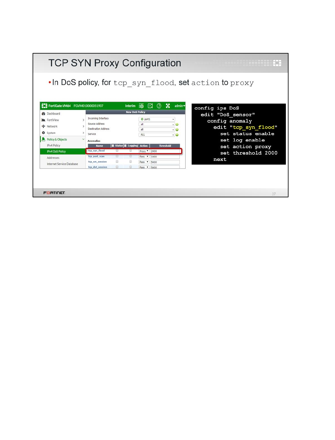
The SYN proxy is configured in the DoS profile tcp_syn_flood setting, and applied to an interface
with a security processor.
Hardware Acceleration
FortiGate II Student Guide
539
DO NOT REPRINT
© FORTINET

Finally, let’s look at a type of ASIC that integrates two of the others: System on a Chip (SoC).
Hardware Acceleration
FortiGate II Student Guide
540
DO NOT REPRINT
© FORTINET
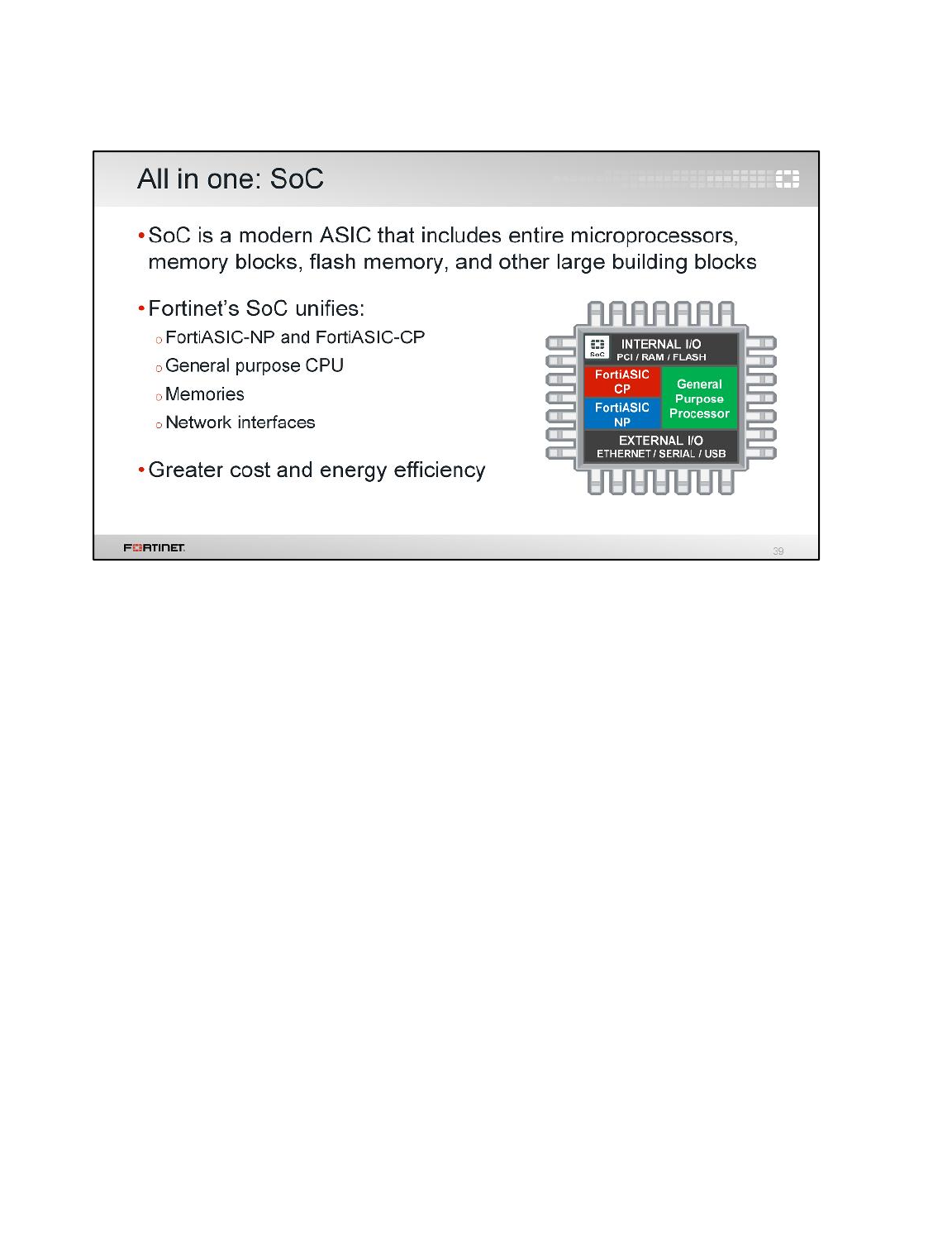
SoC combines a general purpose CPU with Fortinet’s custom ASIC network, NPs, and CPs, into a
single chip.
Usually, SoC modules are found in desktop or small office models, because it allows smaller form
factors, but cannot handle a carrier grade computing load. The biggest benefit of SoC is greater cost
and energy efficiency.
Hardware Acceleration
FortiGate II Student Guide
541
DO NOT REPRINT
© FORTINET
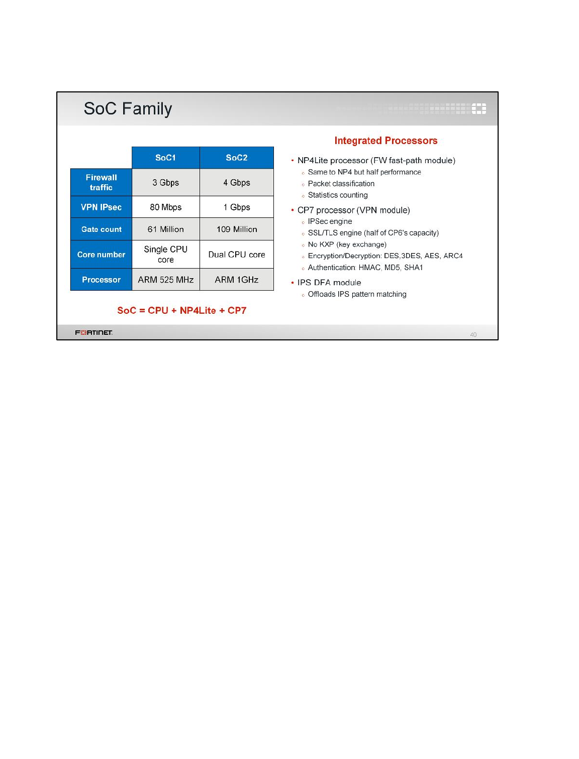
SoC modules present a modest performance level.
Did you note in previous sections we didn’t mention anything about CP7 and NP3?
CP7 and NP3 (or NP4Lite as it’s really known), were developed to be integrated in Fortinet’s SoC
processor. This integrated processor has three modules:
• VPN module (CP7 processor) includes the SSL, TLS, and IPsec engines, which handle the
encryption and decryption of traffic and message authentication algorithms.
• Firewall fast-path module (NP4Lite processor) is a light version (with fewer features) of an NP4
processor. It accelerates session handling.
• The IPS deterministic finite automata (DFA) module is used to offload some IPS signature
matching.
Hardware Acceleration
FortiGate II Student Guide
542
DO NOT REPRINT
© FORTINET
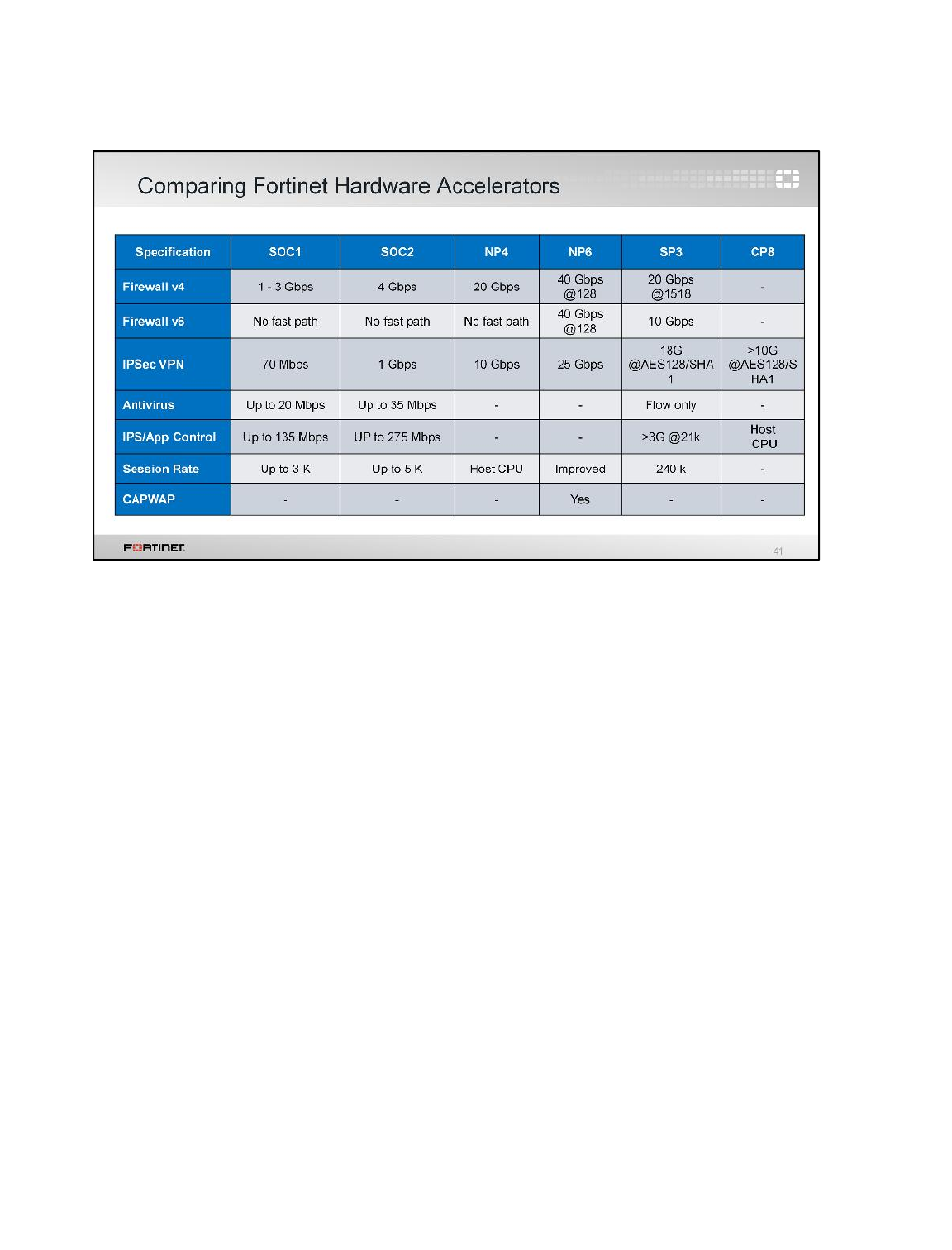
This table compares the performance for each specification in the most used FortiASICs, SoCs, and
SPs.
Hardware Acceleration
FortiGate II Student Guide
543
DO NOT REPRINT
© FORTINET
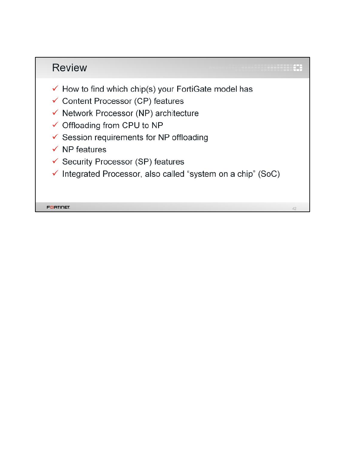
Here is a review of what we discussed. We examined:
• The architecture of each of the FortiASIC chip families
• Which features can be offloaded to each chip
• Differences between the chips
• How to find which chips your model has
Hardware Acceleration
FortiGate II Student Guide
544
DO NOT REPRINT
© FORTINET

In this lesson, we’ll cover the fundamentals of IPv6, and how to configure it on your FortiGate. This
lesson also includes examples of how to enable security features in an IPv6 environment.
IPv6
FortiGate II Student Guide
545
DO NOT REPRINT
© FORTINET
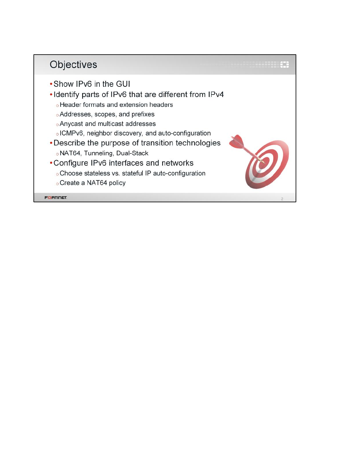
After completing this lesson, you should have the practical skills necessary to configure IPv6 networks
on FortiOS. You should also have a solid understanding of IPv6 routing and firewalling; transition
technologies such as dual-stack, NAT64, and tunneling; and IPv6-compatible security profiles.
Lab exercises can help you to test and reinforce your skills.
IPv6
FortiGate II Student Guide
546
DO NOT REPRINT
© FORTINET
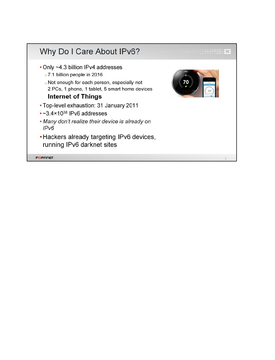
(This slide contains animations.)
The first thing people usually ask is why they need IPv6 when IPv4 is still working. They feel that IPv6
is for the future, not now. But that question is old. The future is now. Most network devices are already
IPv6-capable, although many administrators don’t realize it. According to Google
(http://www.google.ca/intl/en/ipv6/statistics.html), on January 5, 2016, 43% of requests from Belgium
involved devices that supported IPv6 and adoption of IPv6 in the USA was 25%. Governments, such
as those in USA and China, have guidelines and requirements for IPv6 compatibility. Aside from
government organizations, some ISPs, such as Comcast and Verizon, have already begun putting
clients on IPv6. That’s because IPv4 address space exhaustion has already occurred at the top level
and regional exhaustion is occurring now.
(click)
IPv6 provides many more addresses.
(click)
But with hosts already on the IPv6 network, it’s both a new favorite target and hiding place for
attackers.
(click)
So, even if your users don’t need IPv6 connectivity internally, you need to be aware of IPv6 on the
Internet, and its security effects.
IPv6
FortiGate II Student Guide
547
DO NOT REPRINT
© FORTINET
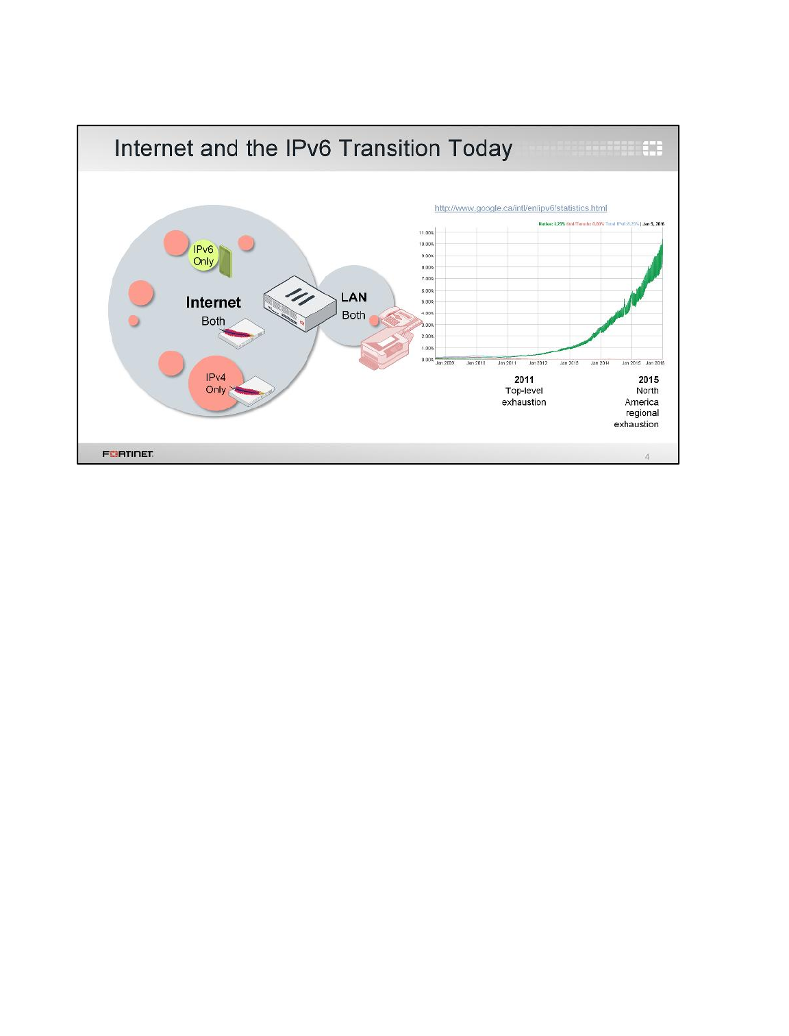
Even if you don’t implement IPv6 on your internal network, on the Internet, IPv6 usage is accelerating.
Due to IPv4 address exhaustion, many of the hosts that are being added to the Internet, especially
smartphones in rapidly growing countries, now have a public IPv6 address only. IPv6 adoption is
doubling almost every year.
The presence of servers that offer native IPv6 is increasing rapidly to support IPv6-only clients. So,
within the next few years, it is quite likely that your network security will need to support IPv6.
IPv6
FortiGate II Student Guide
548
DO NOT REPRINT
© FORTINET
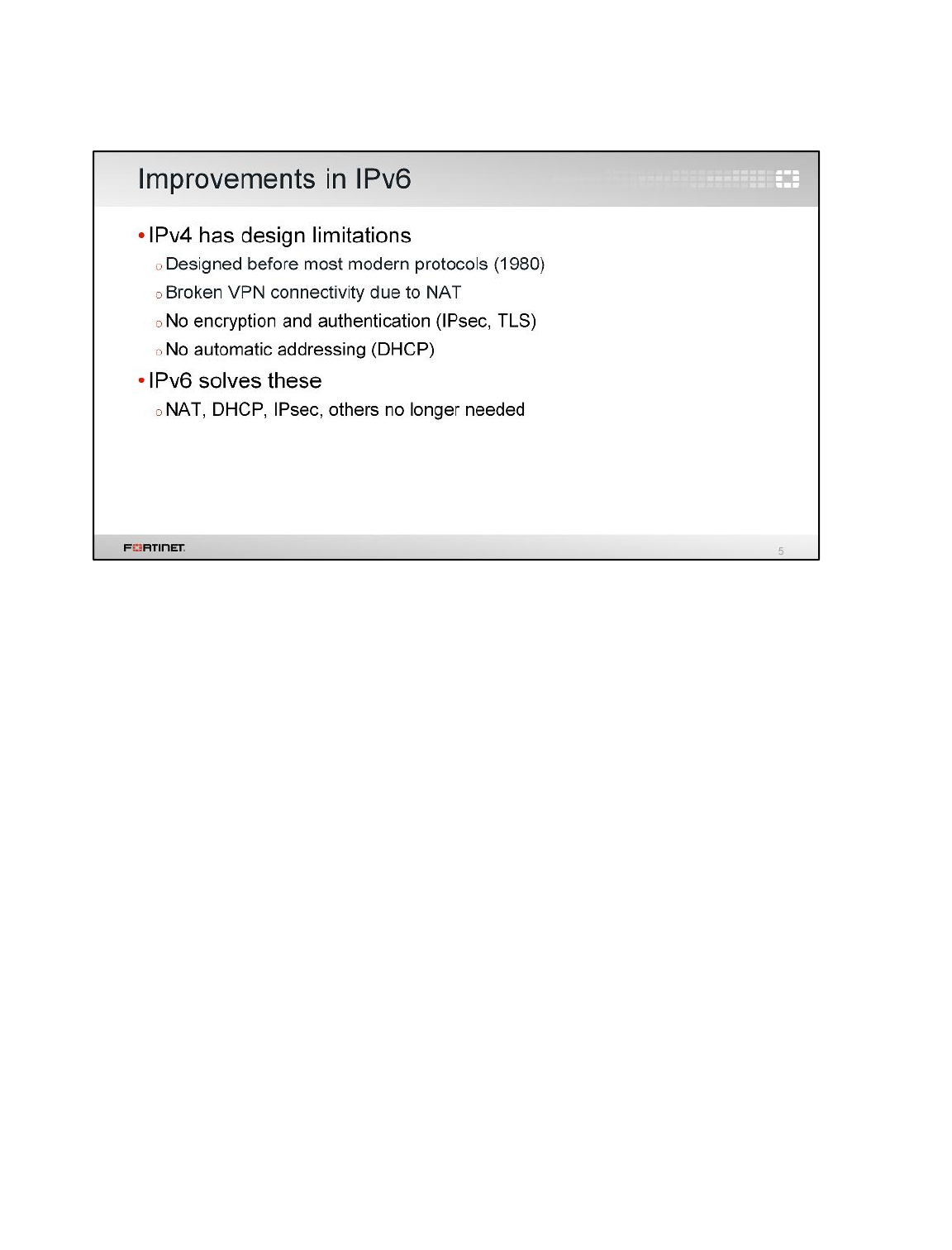
What many people aren’t aware of is that IPv6 solves more than just the problem of IP address
exhaustion.Many of the services and realities that we use today were actually added to work around
IPv4 limitations. These include:
• NAT,
• Secure communications, like VPN and SSL,and
• DHCP.
When you implement IPv6, you may not need some of your old IPv4 services.
IPv4 was designed in 1980 and first deployed on ARPANET – a precursor to the Internet – in 1983.
This was before smart phones and tablets, before security breaches became a daily occurrence,
before VPNs for remote workers became commonplace, and before hardware existed for fast, strong
encryption and decryption.
IPv6 was designed in 1998. So it’s far from new, but new enough to factor in many of the changes in
how we use networks. To ensure a graceful transition period, IPv6 design includes ways for legacy
IPv4 to connect with IPv6 networks.
IPv6
FortiGate II Student Guide
549
DO NOT REPRINT
© FORTINET

First, let’s look at how you show the IPv6 settings on the FortiGate GUI. By default, they’re hidden in
the GUI, and only available in the CLI.
IPv6
FortiGate II Student Guide
550
DO NOT REPRINT
© FORTINET
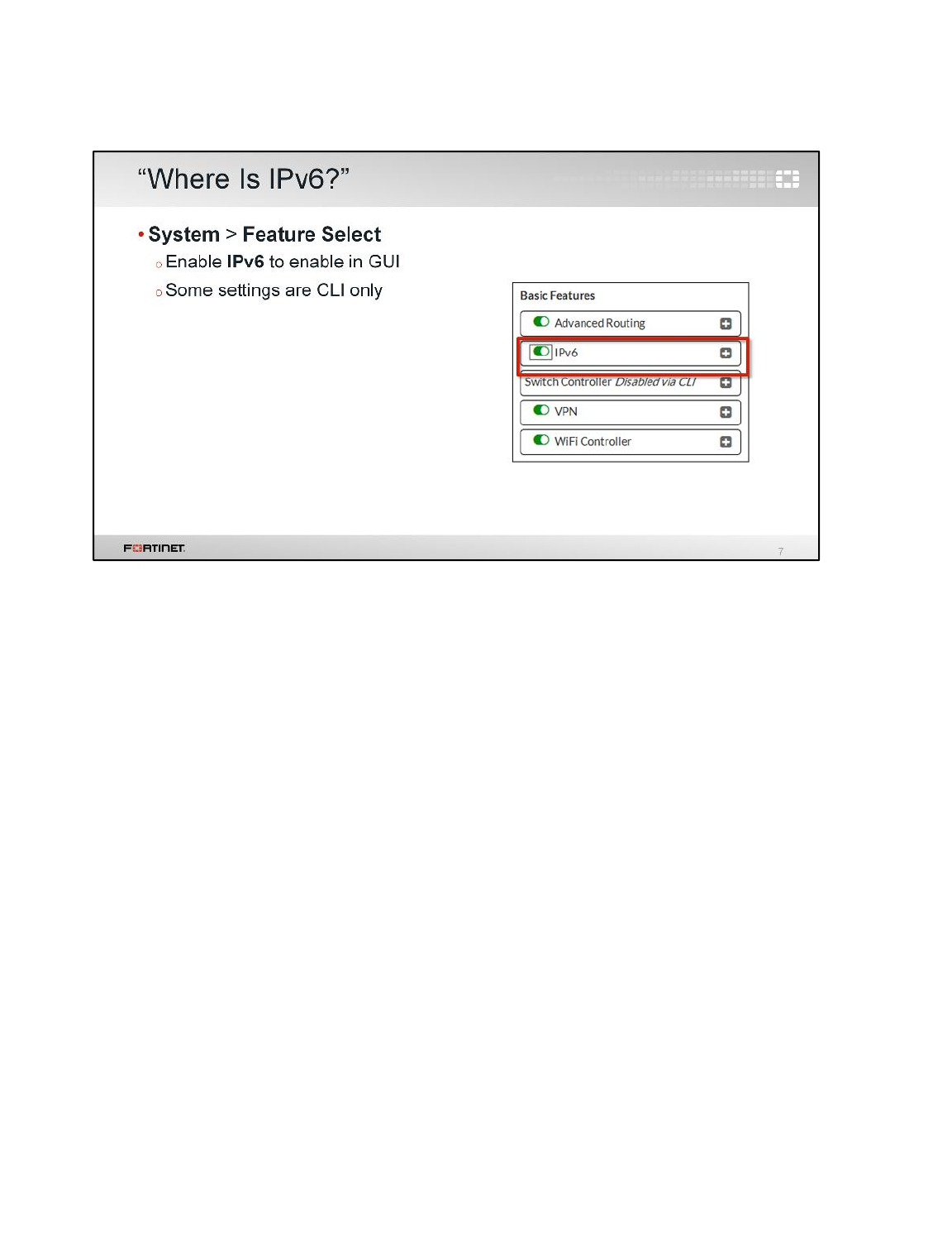
Whether you’re running IPv6 on your network, or you simply want to secure yourself against attackers
using IPv6, the good news is that Fortinet devices, like FortiGate, already support IPv6.
To keep the FortiGate GUI simple and the performance level high, not all features are initially shown
in the GUI. You can show IPv6 features from the Feature Select page.
Like other advanced features, a few IPv6 settings are available in the CLI only.
IPv6
FortiGate II Student Guide
551
DO NOT REPRINT
© FORTINET
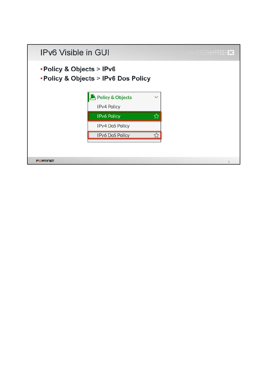
Once you’ve turned IPv6 settings on in the GUI, two new policy types appear: IPv6 firewall policies,
and IPv6 denial of service (DoS) policies.
You’ll also notice IPv6 network interface addresses and routes.
IPv6
FortiGate II Student Guide
552
DO NOT REPRINT
© FORTINET
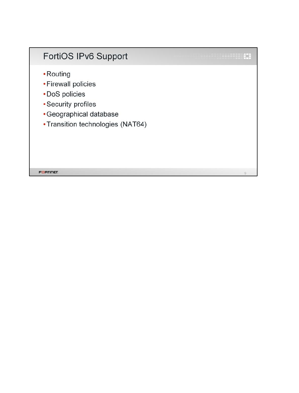
Now that IPv6 settings are visible, what features are supported?
Obviously, IPv6 firewall policies are supported, as we just mentioned. Malware and application-layer
threats are largely independent of the IP version, so security profiles are supported in the new IPv6
firewall policies.
Just like IPv4 public addresses, IPv6 addresses on the public Internet can be mapped to regions
where the ISP routers are located, so there is a geographical database for that.
There are also some less obvious, but necessary, transition features. FortiOS is typically deployed
with dual stack routing, where administrators assign both IPv4 and IPv6 addresses to interfaces.
IPv6
FortiGate II Student Guide
553
DO NOT REPRINT
© FORTINET

Once you’ve enabled IPv6 settings, you need to know the answers to these questions:
• What works the same way in IPv6 as it did in IPv4?
• What is different about IPv6 from IPv4?
• What upgrades are required?
• How do packets move between IPv4 and IPv6 networks?
IPv6
FortiGate II Student Guide
554
DO NOT REPRINT
© FORTINET
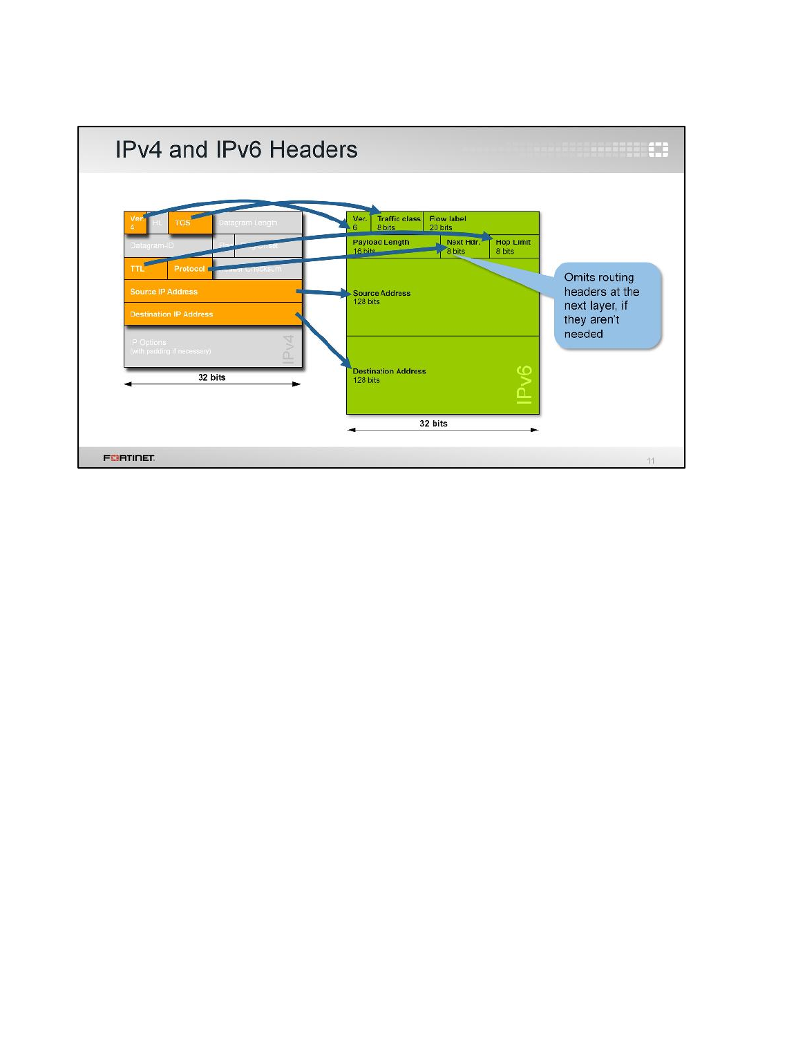
You may not need to upgrade anything on your network. Many devices, including home Wi-Fi routers
and Windows computers, have supported IPv6 for a long time. They’ll work automatically. But, you
should verify that they support, especially if you have older devices, VoIP, printers, or ISP modems.
IPv6 is not backwards compatible with IPv4-only devices: the headers are too different. If you use a
device that doesn’t support IPv6, you can configure your FortiGate to use transition technologies.
Transition technologies help by rewriting the IP header on packets that have to move between IPv4
and IPv6 along their path. Transition technologies include:
• NAT64,
• tunneling, and
• dual stack.
So, what are the differences between IPv4 and IPv6 headers?
The first, obvious difference is the version number. Next? The address length. IPv6 addresses are
much longer – 128 bits instead of 32 bits – and therefore have a new notation, which we’ll explain
soon.
Other parts of the header are the same, even though they may have a different name: the TOS/DSCP
bits are now named traffic class, and the TTL is now named hop limit.Protocol, which indicates the
next protocol layer in the packet, is called next header in IPv6. Why was the name changed? IPv6
may have chains of extension headers between the IP header and the next protocol with a payload.
Let’s look at how extension headers work.
IPv6
FortiGate II Student Guide
555
DO NOT REPRINT
© FORTINET
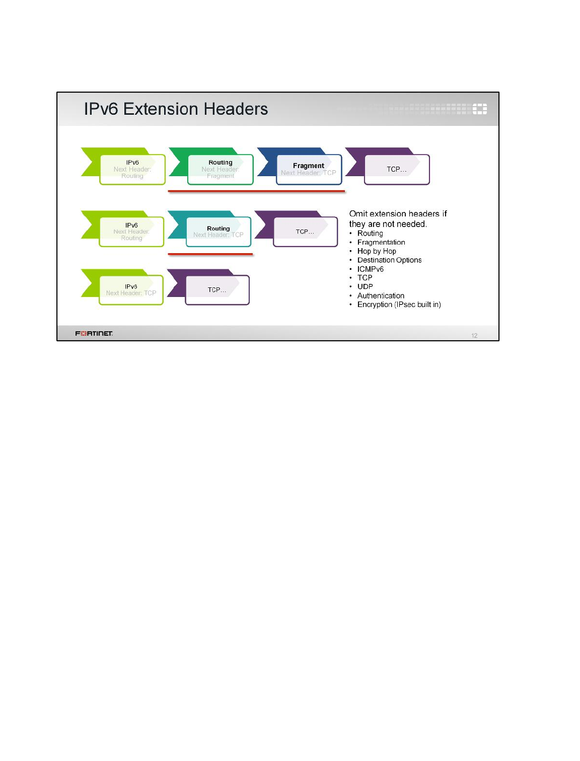
It’s easy to see that you need more bits for larger IP addresses. Other than that, why are IPv6 headers
different?
One reason is to increase efficiency. Remember the next header field? IPv6 can abbreviate packets.
Packets only use the headers they need. For example, a packet that does not need routing is not
required to have the routing header. These optional headers between the IPv6 header and the
payload are named extension headers. There are as many extension headers as there are protocols
on IPv4, plus new headers. Example extension headers include:
• Hop by Hop (data to be processed by all the routers in the path of the packet)
• ICMPv6
• TCP
• UDP
• Fragmentation
• Routing
• Destination Options (parameters/data that must be processed by the destination host only)
• Authentication (AH, IPsec)
• Encrypted (ESP, IPsec)
IPv6
FortiGate II Student Guide
556
DO NOT REPRINT
© FORTINET
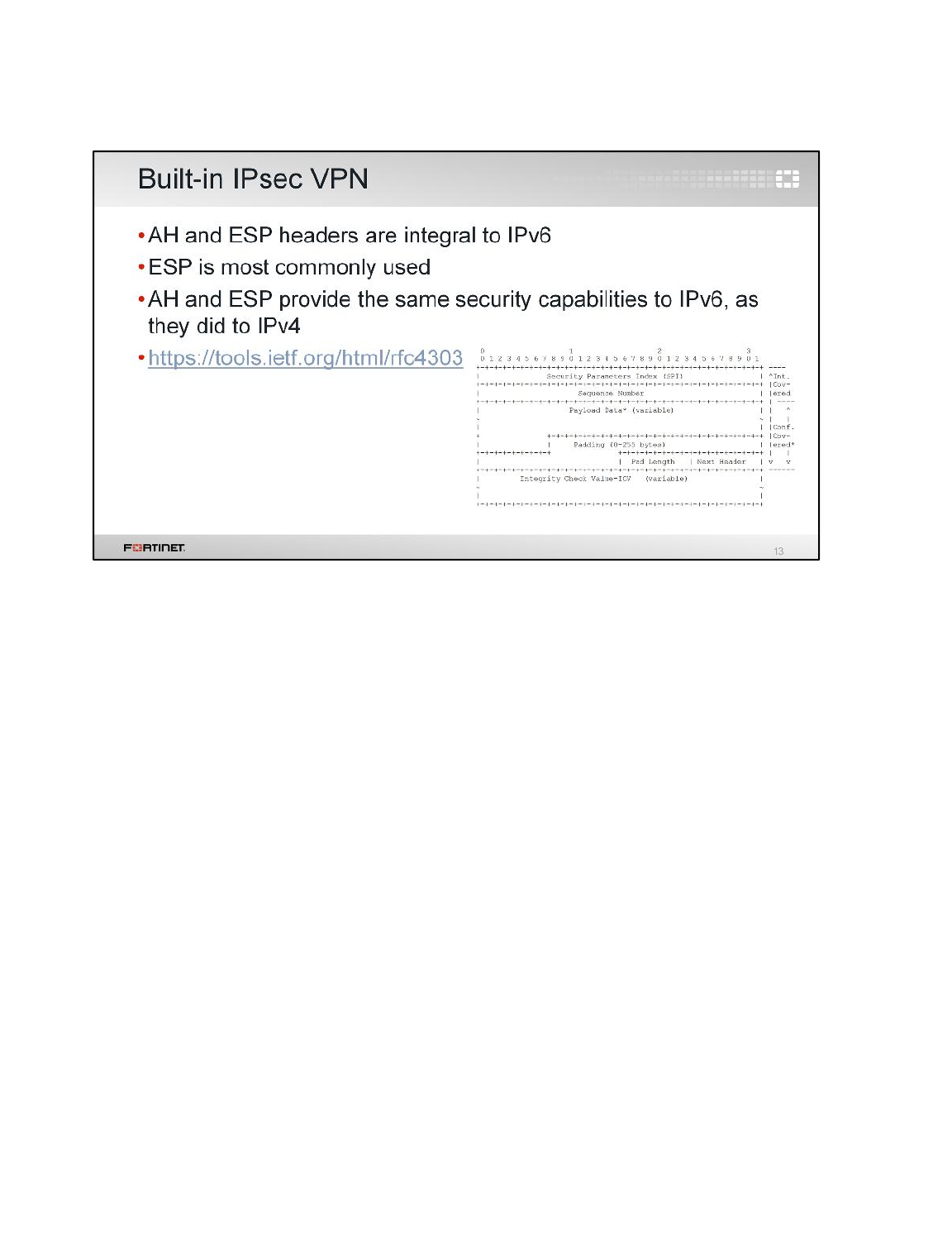
In IPv4, IPsec VPN was added on. In IPv6, it’s an integral part of the IPv6 stack – it’s part of the
defined extension headers – and, therefore, available with any implementation. The specification
defines protocols for the Authentication Header (AH) and the Encapsulating Security Payload (ESP)
header.
The ESP header provides a mix of security services in IPv4 and IPv6. ESP may be applied alone. The
ESP header is either inserted after the IP header and before the next layer protocol header (in
transport mode), or before an encapsulated IP header (in tunnel mode).
ESP can be used to provide confidentiality, data origin authentication, connectionless integrity, an anti-
replay service (a form of partial sequence integrity), and (limited) traffic flow confidentiality. The set of
services provided depends on options selected at the time of Security Association (SA) establishment
and on the location of the implementation in a network topology.
The header diagram shown here applies to both IPv4 and IPv6.
IPv6
FortiGate II Student Guide
557
DO NOT REPRINT
© FORTINET
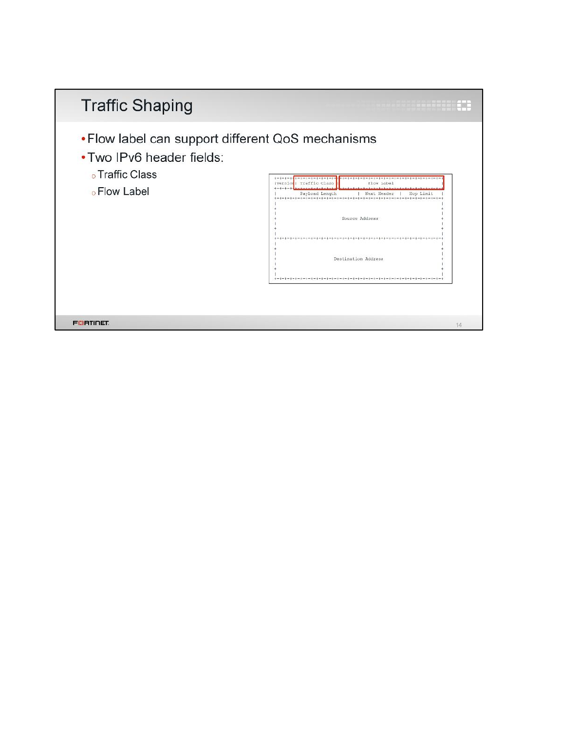
There are two fields in the IPv6 header that can be used for Quality of Service (QoS): Traffic
Class and Flow Label.
The 8-bit Traffic Class field in the IPv6 header is available for use by routers and/or traffic
sources to identify and distinguish between different classes or priorities of IPv6 packets. The
Traffic Class field is specified in RFC 2474, and introduces the term DS field for the
Traffic Class field. The goal of this specification is that DiffServ routers have a known set of DS
routines, which are determined by the value in the DS field. The forwarding path behaviors include the
differential treatment an individual packet receives, as implemented by queue service disciplines
and/or queue management disciplines. These per-hop behaviors are useful and required in network
nodes to deliver differentiated treatment of packets.
The 20-bit Flow Label field in the IPv6 header may be used by a traffic source to label sequences of
packets that it wants IPv6 routers to handle in a special way, such as non-default quality of service or
real-time service. The Flow Label field is specified in RFC 6437. Packet classifiers can use the
triplet of Flow Label, Source Address,and Destination Address fields to identify the flow
to which a particular packet belongs.
IPv6
FortiGate II Student Guide
558
DO NOT REPRINT
© FORTINET
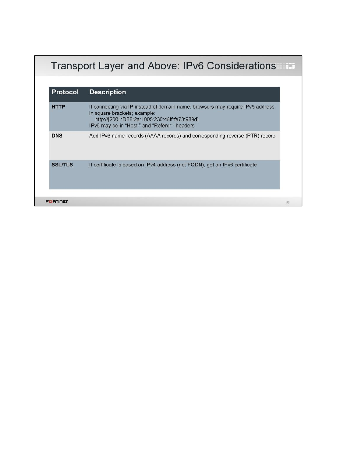
Most transport- and application-layer protocols are independent of IP addressing, so you don’t need to
upgrade or configure them for IPv6 support. Simply configure the server’s IPv6 address.
For HTTP, colon characters (which are part of a normal IPv6 address) are also used to denote port
numbers. So if you want to go to an IPv6 URI, to solve the ambiguity, enclose the IP address in
square brackets ( [ ] ) so that the browser will correctly interpret the colon characters. For example, to
go to this URI:
2001:DB8:2a:1005:230:48ff:fe73:989d
In your browser, you would enter:
[2001:DB8:2a:1005:230:48ff:fe73:989d]
Relatedly, on your website’s DNS server, you would need to add an AAAA record.
Most website certificates are based on their domain name, but if yours identifies the host by the
server’s public IPv4 address, add a certificate for the IPv6 address.
IPv6
FortiGate II Student Guide
559
DO NOT REPRINT
© FORTINET
Now that we’ve seen the IPv6 packet structure, let’s examine the new 128-bit source address and
destination address fields.
IPv6
FortiGate II Student Guide
560
DO NOT REPRINT
© FORTINET
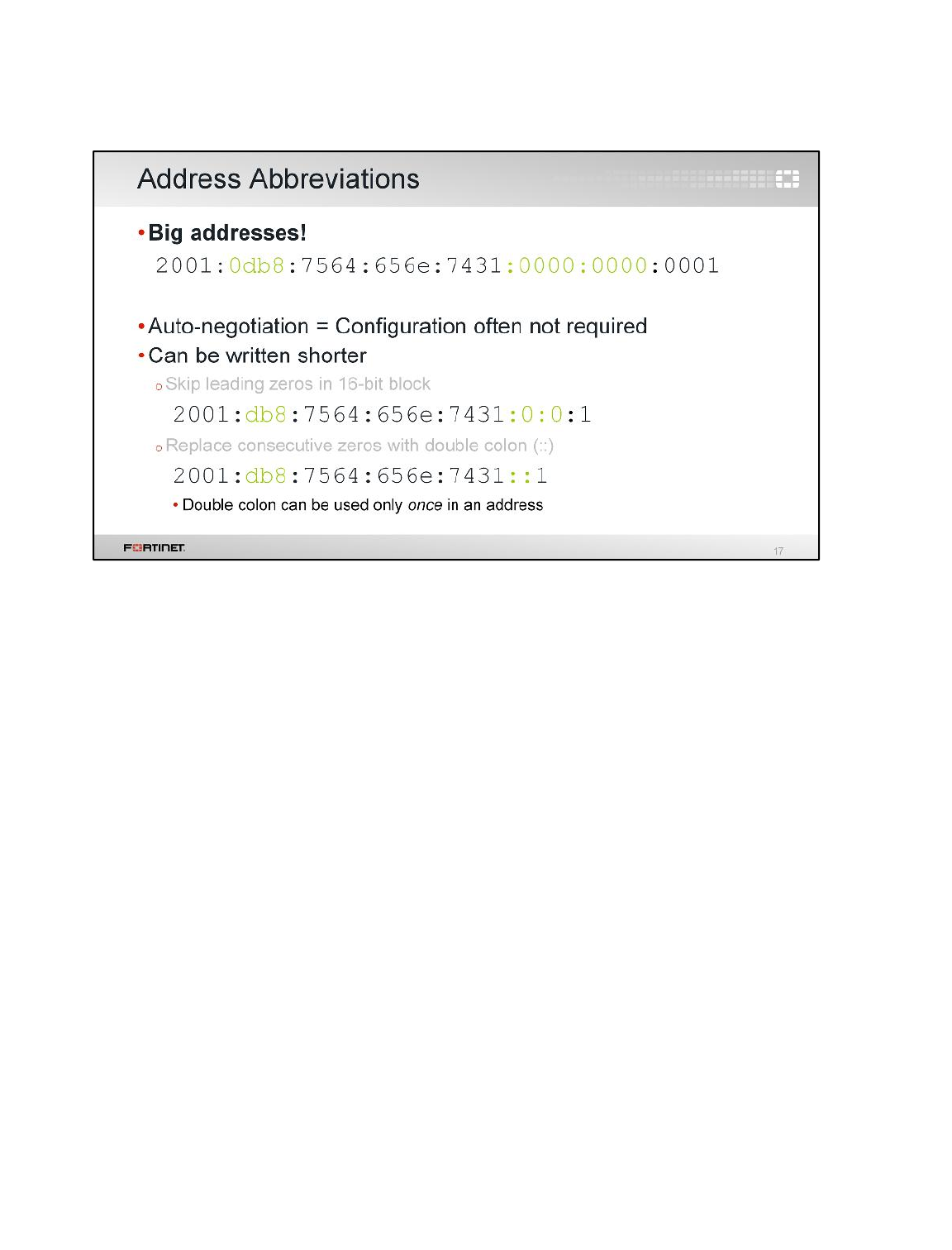
The first thing that you might notice about IPv6 addresses is that they are big and include letters. Any
IPv6 host (or node, in IPv6 terminology) can have many IPv6 addresses on the same network
interface card (NIC). In IPv4, interfaces often need manual configuration, so the thought of typing in
those large IPv6 addresses for each NIC might seem intimidating. But it’s not as hard as it seems. In
IPv4, DHCP evolved to ease administrative burden. IPv6 has a more advanced mechanism already
built in. You won’t be required to configure many IPv6 addresses at all. In fact, privacy extensions on
Windows, Mac OS X, and others may make addresses ephemeral.
Even if you do need to type or write an address, you may be able to abbreviate it. Look at the first
address shown in this example. Compare it with the second address. You can skip leading zeroes, in
the same way that we usually write 1instead of 0001. Now, compare that with the last, most
abbreviated address: if the address has consecutive zeros in multiple 16-bit blocks, you can simply
omit all of the zeros between two colon marks (::). Of course, when you input the address, devices
must interpret it as the full length address. If multiple double colon abbreviations were allowed, a
device would have to guess how to expand an address such as 2001::1::1.
Would it be expanded as:
• 2001:0000:1:0000:0000:0000:0000:0001 or
• 2001:0000:0000:0000:0000:1:0000:0001
Addressing would be uncertain. That’s why each IPv6 address can only have one double colon
abbreviation.
IPv6
FortiGate II Student Guide
561
DO NOT REPRINT
© FORTINET
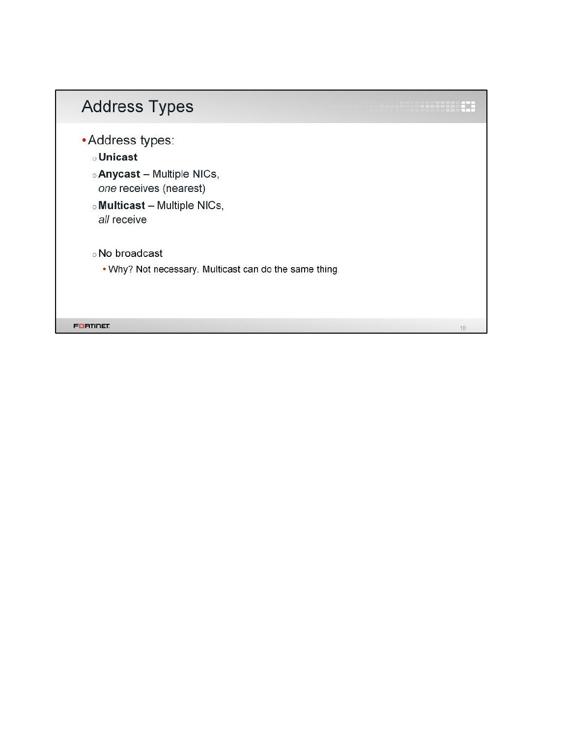
In IPv4, there are multiple types of address: broadcast, multicast, and so on. But, what about in IPv6?
In IPv6, there are three types of addresses: unicast, anycast, and multicast.
•Unicast identifies one interface or interface group. (For link load balancing, multiple interfaces
may use the same address as long as they appear as one interface to the host’s IPv6
implementation.)
•Anycast identifies multiple interfaces, typically belonging to different nodes. A packet sent to an
anycast address is delivered to one of the interfaces (the nearest one, according to the routing
protocol’s measure of distance).
•Multicast also identifies multiple interfaces, but a packet sent to a multicast address is delivered to
all interfaces identified by that address.
Why is there no broadcast address?
Technically, it’s not needed. Broadcast is simply multicast that includes all addresses, not a subset.
But, from an engineering perspective, IPv4 broadcast also proved problematic. Broadcast storms and
performance problems related to large broadcast domains – which could be huge due to more
addresses in IPv6 – may be better in the future by omitting broadcast from IPv6.
IPv6
FortiGate II Student Guide
562
DO NOT REPRINT
© FORTINET
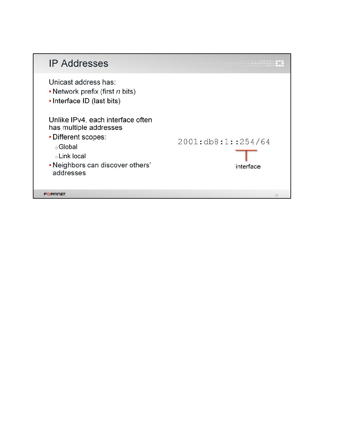
Like in IPv4, each network interface card has a unicast address. A unicast address is composed of a
network ID (the first n bits, depending on the number of host addresses in the subnet) and an interface
ID (the remaining bits).
On a network, the first bits in every IP address are the same and the last part of the address is specific
to each interface. However, in IPv6, if the address is automatically generated, the address’s interface
ID may correspond to the network interface card’s physical MAC address. It’s also common to have
multiple addresses: one for each scope of communications. And oddly, depending on the scope of the
address, it is not guaranteed to be globally unique. It’s extremely unlikely that two IPv6 interfaces have
the same address due to the large number of addresses, but it is theoretically possible. However,
within each scope, there are no duplicates, and IPv6 has built-in mechanisms (which we’ll explain
soon) to detect and avoid duplicate addresses – avoiding the classic IPv4 problem of IP address
conflicts.
IPv6
FortiGate II Student Guide
563
DO NOT REPRINT
© FORTINET
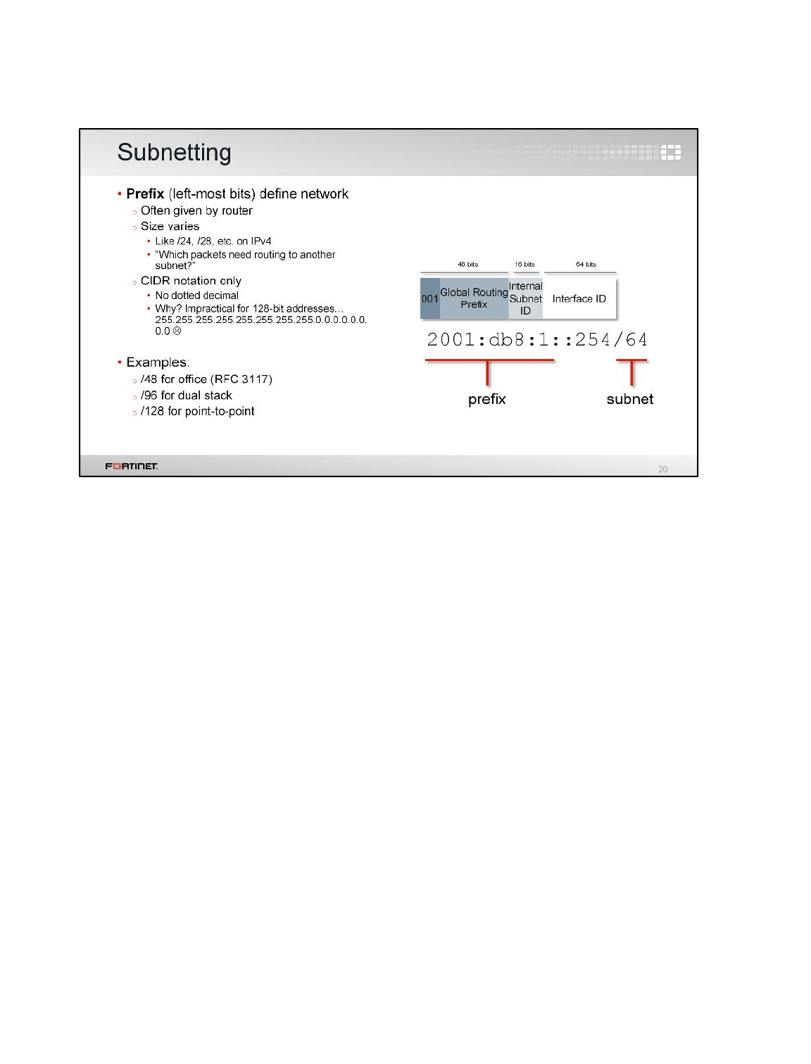
IPv6 subnets are defined like they are in IPv4, using the first bits in the IP address. In IPv6, it’s called
the prefix.
Unlike in IPv4, in IPv6, we only use classless inter-domain routing (CIDR) subnet notation, not dotted
decimal. Why? CIDR is shorter. With 128-bit addresses, dotted decimal netmasks are impractically
large.
Typical prefixes for IPv6 are:
• /48 or less for an office
• /48 for a home
• /128 for a point-to-point network, such as between two routers
In IPv6, the prefix is often automatically configured when the interface solicits the router. So, it can be
easy for entire subnets to be reconfigured to a new location – even if there is no DHCP server.
IPv6
FortiGate II Student Guide
564
DO NOT REPRINT
© FORTINET
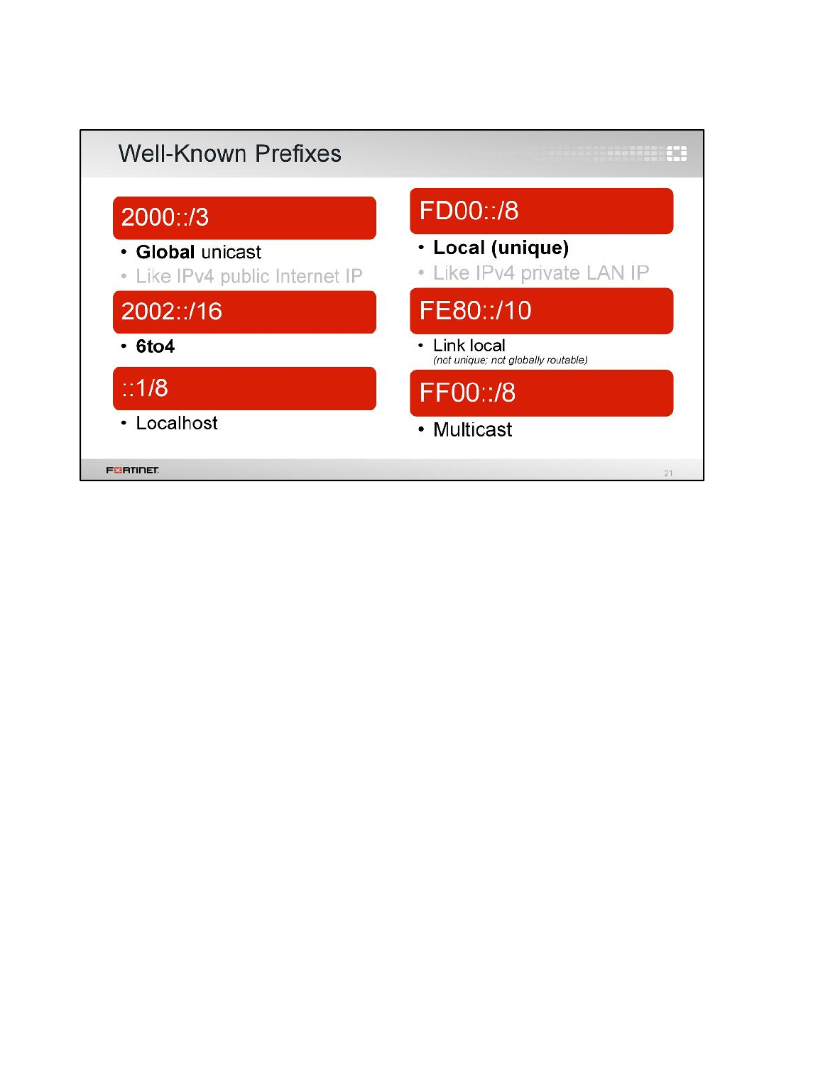
In IPv6 there are some reserved and common subnets. What are they? Global unicast prefixes come
from your ISP. Global addresses are like public IPv4 addresses: they’re routable on the Internet.
(Remember, IPv6 is designed to work without NAT as the divider between public and private, so the
names are not the same.) The global address format is:
001 + global routing prefix from your ISP + subnet ID + interface ID
What’s the equivalent for private network IPs? Unique-local addresses are equivalent to IPv4 private
network addresses. They are not routable on the IPv6 Internet. Global address and unique local
adresses have the same structure after the first 48 bits of the address: a unique-local address has the
format:
Prefix + randomly assigned global ID
Therefore, the same subnet ID used for global addresses can also be used for local addresses.
Link-local addresses are used by nodes when communicating with neighbors on the same link. This
happens during auto-address configuration, neighbor discovery, and when no routers are present.
Unlike unique-local addresses, routers don’t forward any packets with link-local source or destination
addresses to other links. IPv6 link-local addresses are similar to IPv4 link-local addresses that use the
169.254.0.0/16 prefix. Link-local addresses can be reused on each link. Because of this address reuse
capability, link-local addresses are not determinate. To address this, hosts use a zone identifier that
identifies the interface of the address or sending interface for a link-local destination. The syntax is
address%zone_id.
For example, a link-local address for interface ID 24 on a Windows host could be:
Link-local IPv6 Address . . . . . : fe80::8002:b44b:ca9e:5e09%24
IPv6
FortiGate II Student Guide
565
DO NOT REPRINT
© FORTINET
Like they did in IPv4, static routes in IPv6 have also become cumbersome to manage. Dynamic
routing protocols help to ease this administrative burden.
Almost every IPv4 dynamic routing protocol has an IPv6 version or extension. There are still interior
gateway protocols (IGPs) and exterior gateway protocols (EGPs), distance-vector-based, and link-
state-based routing protocol algorithms.
IPv6
FortiGate II Student Guide
566
DO NOT REPRINT
© FORTINET

What about addresses that aren’t unicast?
IPv6
FortiGate II Student Guide
567
DO NOT REPRINT
© FORTINET
An IPv6 anycast address is an address that’s assigned to more than one interface (typically belonging
to different nodes). A packet sent to an anycast address is routed to the nearest interface having that
address, according to the routing protocol’s measure of distance.
Anycast addresses are allocated from the unicast address space, so they can use any of the defined
unicast addresses. What makes an anycast address different from unicast? It’s configured on more
than one interface. The nodes to which the address is assigned must be explicitly configured to know
that the address is an anycast address.
IPv6
FortiGate II Student Guide
568
DO NOT REPRINT
© FORTINET
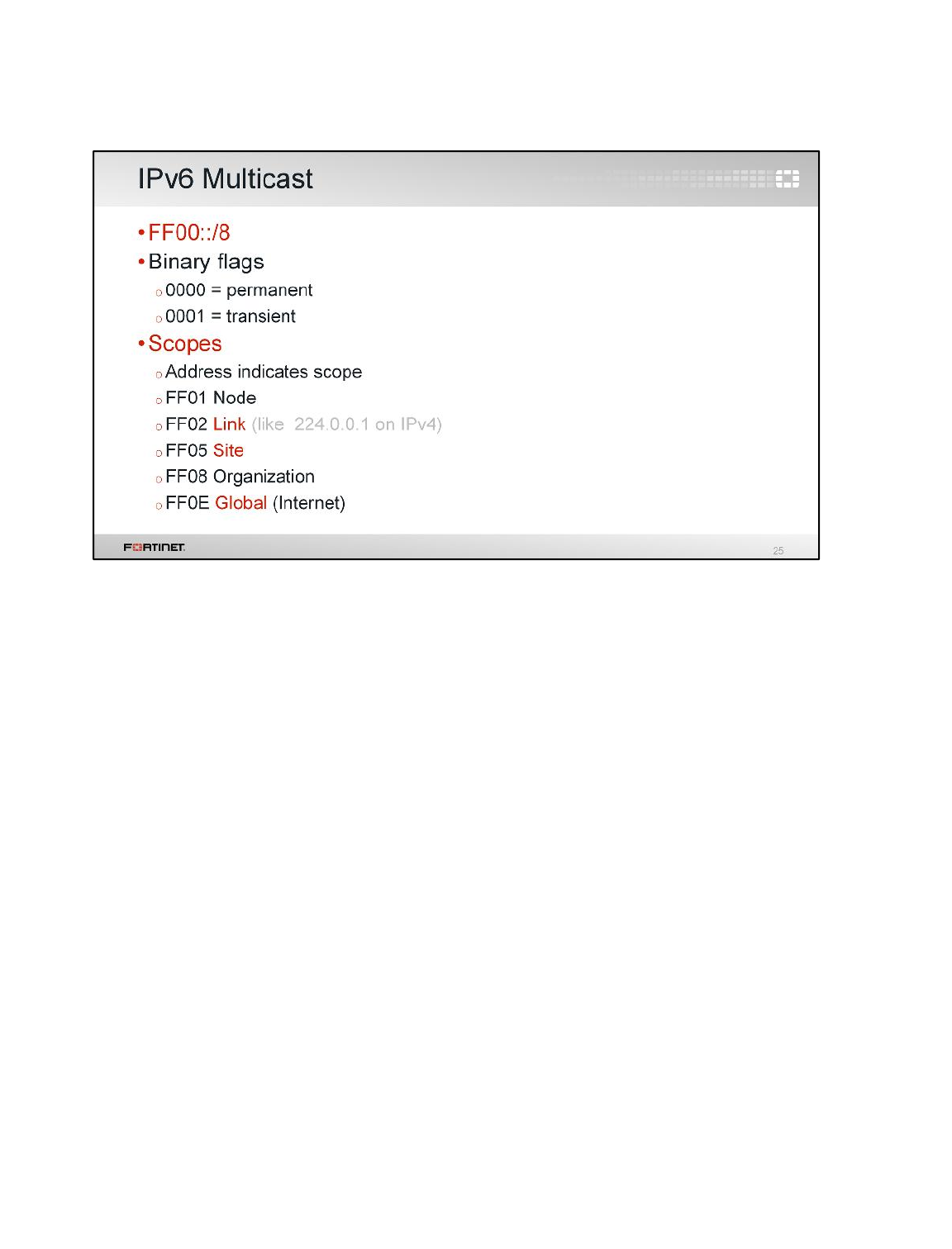
An IPv6 multicast address identifies a group of nodes. A node may belong to any number of multicast
groups.
In IPv6, multicast traffic operates like it does in IPv4. Multicast addresses have the FF00 prefix plus
112 bits in the group id. After the first 8 bits of the prefix (0xFF), the next four bits are the flags (the
first 0x0 of the prefix) and indicate a permanent (0x0) or transient (0x1) address. The next four bits
(the second 0x0 of the prefix) are the scope of the multicast group.
IPv6
FortiGate II Student Guide
569
DO NOT REPRINT
© FORTINET
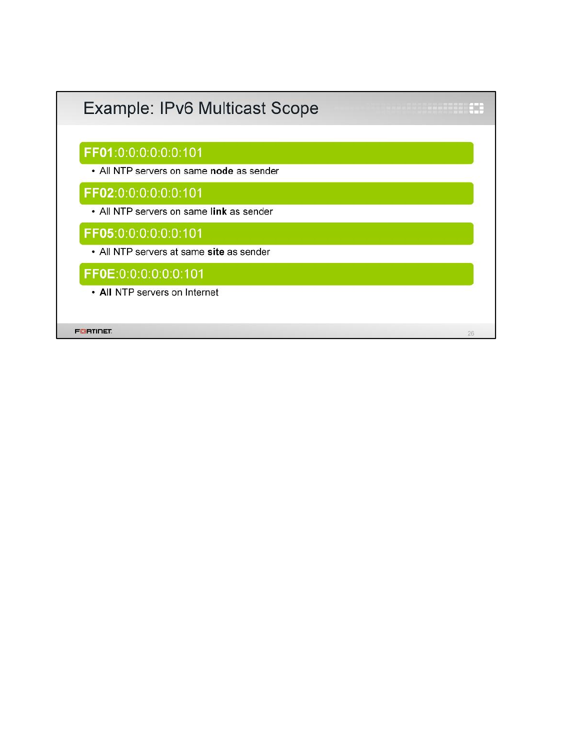
The meaning of a permanently-assigned multicast address is independent of the scope value. In the
example shown here, the NTP servers group is assigned a permanent multicast address with a group
ID of 101 (in hexadecimal).
Non-permanently-assigned multicast addresses are meaningful only within a given scope. For
example, a group identified by the non-permanent, site-local multicast address FF15:0:0:0:0:0:0:101 at
one site is unrelated to:
• a group using the same address at a different site,
• a non-permanent group using the same group ID with different scope, and
• a permanent group with the same group ID.
Multicast addresses must not be used as source addresses in IPv6 packets or appear in any routing
header.
IPv6
FortiGate II Student Guide
570
DO NOT REPRINT
© FORTINET

We mentioned that IPv6 has some auto-configuration mechanisms to help configure your network
devices with IPv6 addresses, and to avoid conflicts within each address scope.
Let’s talk about them now.
IPv6
FortiGate II Student Guide
571
DO NOT REPRINT
© FORTINET
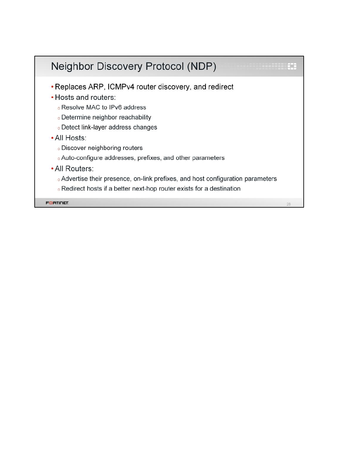
Within the link-local scope, hosts can use the Neighbor Discovery Protocol (NDP) to help configure
their own IP. NDP replaces multiple things in IPv4:
• ARP
• ICMPv4 router discovery
• ICMPv4 redirect
Nodes (hosts and routers) use NDP to determine their neighbor nodes’ link layer addresses – which
neighbors are reachable and which are not, and which addresses have changed.
Hosts also use NDP to find neighboring routers. When a route — or the path to a router — fails, a host
searches for functioning alternates.
NDP is defined in RFC 4861.
IPv6
FortiGate II Student Guide
572
DO NOT REPRINT
© FORTINET
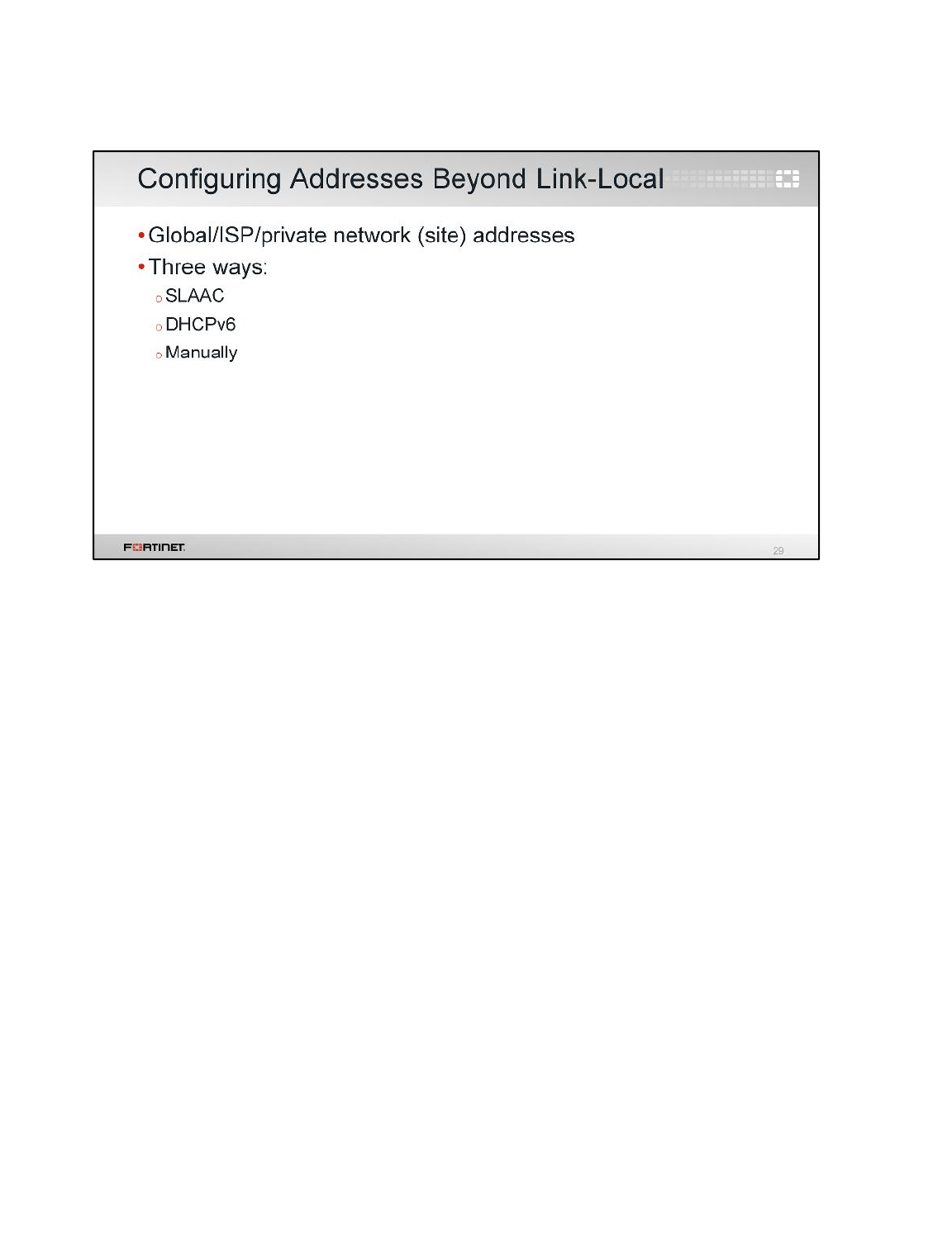
Within the global/site scope, unicast addresses must be unique beyond the local link. There are three
ways to do this:
• stateless address auto-configuration (SLAAC) (also called IPv6 auto-configuration, defined in RFC
4862)
• dynamic host configuration protocol v6 (DHCPv6)
• manually
IPv6
FortiGate II Student Guide
573
DO NOT REPRINT
© FORTINET
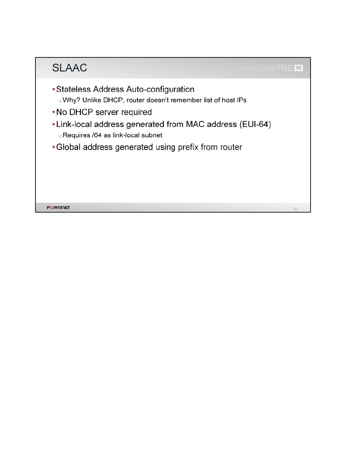
You can use stateless auto-configuration, or SLAAC, when hosts don’t need a specific predictable IP
address, so long as it is unique and properly routable.
SLAAC automatically configures addresses by using NDP and the router. Unlike DHCPv6, SLAAC
doesn’t require any additional servers. Minimal (if any) configuration is required on the router. How?
IPv6
FortiGate II Student Guide
574
DO NOT REPRINT
© FORTINET
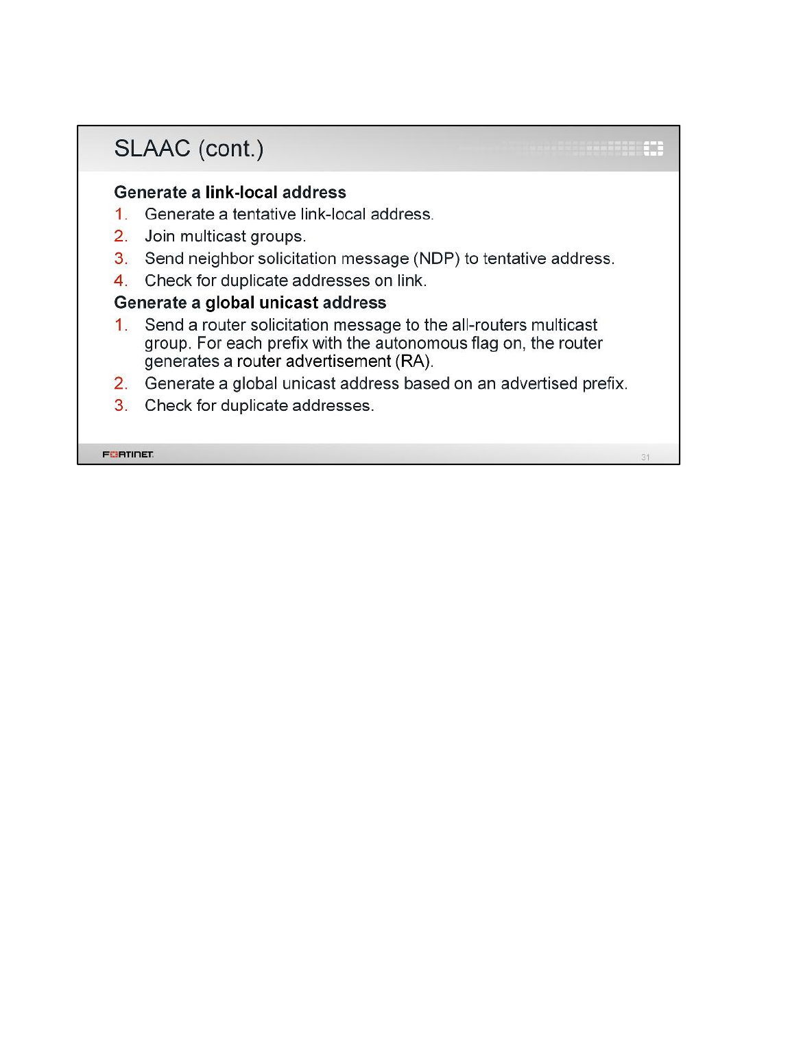
Let’s examine the steps involved in SLAAC.
The first group of steps describes the stateless autoconfiguration of the link-local address.
The second group of steps describes stateless autoconfiguration of the global unicast address.
In SLAAC, the host generates its own addresses using a combination of locally available information
(its MAC address) and information advertised by routers (the global prefix). So if there is no router, a
host can only generate link-local addresses. But if you have a small LAN, that may be enough: local
devices can use their link-local addresses to communicate.
Note that SLAAC doesn’t tell the host about any DNS servers, however. If hosts require DNS and you
don’t want to configure it manually, how can you solve this? Or, what if you need to assign specific IP
addresses to hosts?
Like with IPv4, you can also use DHCP with IPv6.
IPv6
FortiGate II Student Guide
575
DO NOT REPRINT
© FORTINET
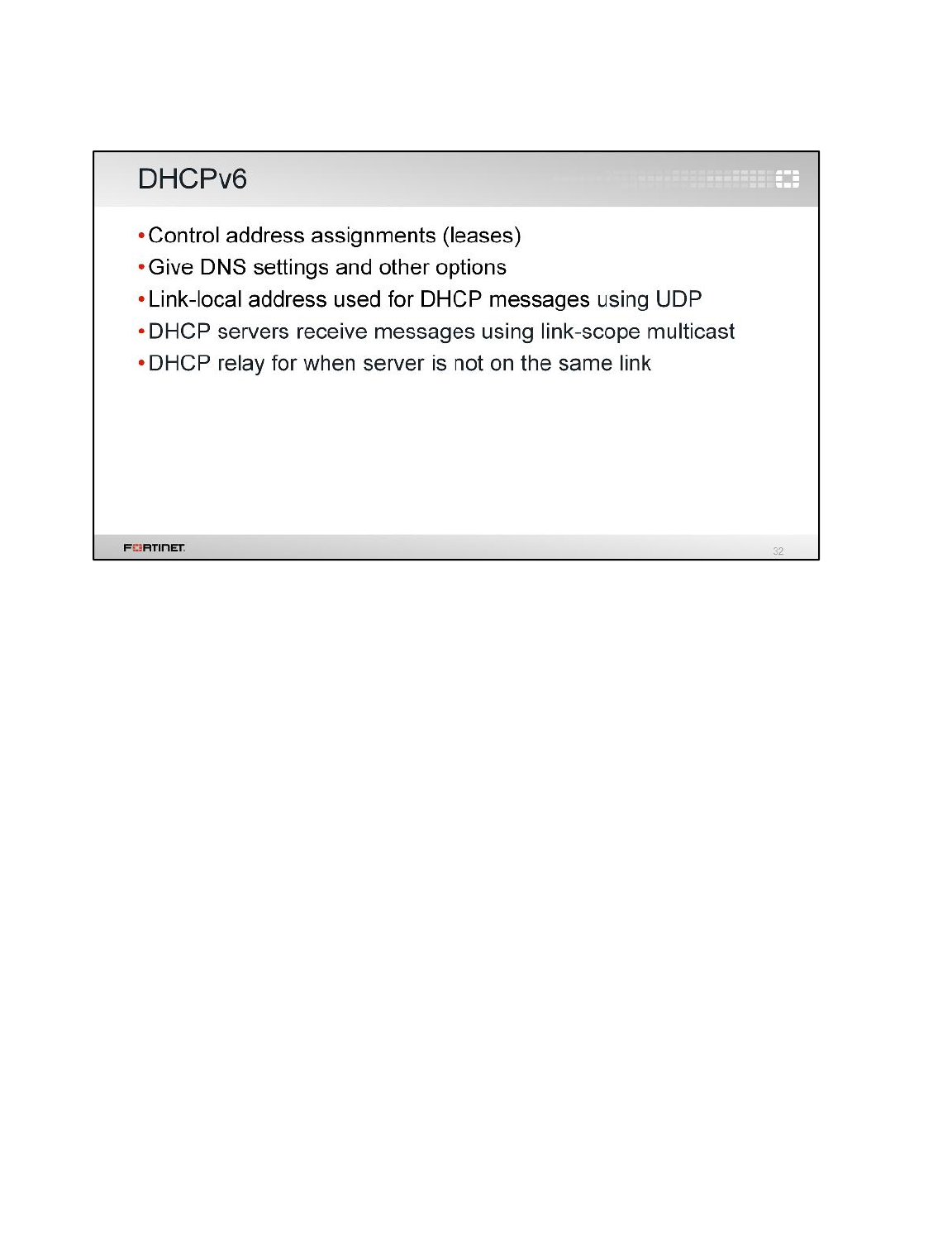
DHCP for IPv6 (DHCPv6; RFC 3315) can be used when you need to assign a specific IP address to
each host, or to provide DNS settings. (Although RFC 6106 defines DNS settings in RAs, this is not
currently supported.) DHCPv6 can also provide other settings, query a node, or change its address.
This is stateful DHCPv6.
Clients and servers exchange DHCPv6 messages using user datagram protocol (UDP). DHCP
servers receive messages from clients using a reserved, link-scoped multicast address. A DHCP
client transmits most messages to this reserved multicast address, so that you don’t need to configure
the DHCP server address.
To allow a DHCP client to send a message to a DHCP server that is not attached to the same link,
you can use a DHCP relay.
Note: The stateless DHCPv6 can provide additional configuration information, such as DNS recursive
name servers or SIP servers, to the hosts that obtained its IPv6 addresses through auto-configuration
(SLAAC) or manual addressing.
IPv6
FortiGate II Student Guide
576
DO NOT REPRINT
© FORTINET
Of course, if auto-configuration or DHCP is not appropriate (such as with servers), manual
configuration is still possible in IPv6, like it is in IPv4.
IPv6
FortiGate II Student Guide
577
DO NOT REPRINT
© FORTINET

Now that we understand how auto-configuration and manual addressing is possible in IPv6, let’s see
how to do that on FortiOS.
IPv6
FortiGate II Student Guide
578
DO NOT REPRINT
© FORTINET
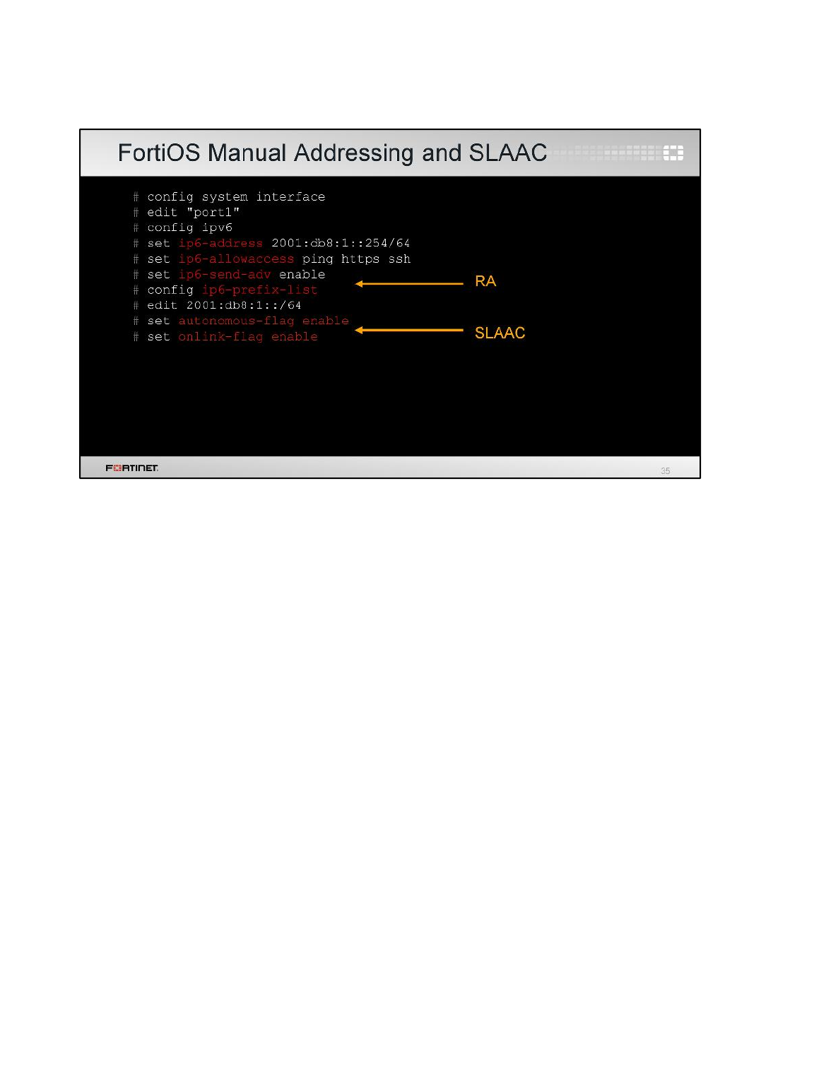
To get started, configure an interface with an IPv6 address and prefix. Remember: SLAAC, if you’re
using it, requires /64.
In the example CLI configuration shown here, an interface on FortiOS is configured manually. Also in
this example, SLAAC is enabled for clients by defining a network prefix that connected hosts can use
to create a global address. Because FortiOS in NAT/route mode is an OSI Layer 3 router, FortiOS
sends out router announcements (RAs).
Your IPv6-enabled devices will use this during their own SLAAC auto-configuration, and for other
settings based on RA. They include one or more 64-bit prefixes, each with the autonomous flag
enabled, indicating the address is in autonomous (or stateless) address configuration, and the onlink
flag enabled, indicating that the address is assigned to the interface this advertisement was received
on.
Note that the interface IPv6 configuration is a sub-branch of the interface CLI. You can configure a
dual stack implementation by configuring the IPv4 address and configuring an IPv6 address in the
sub-branch.
IPv6
FortiGate II Student Guide
579
DO NOT REPRINT
© FORTINET
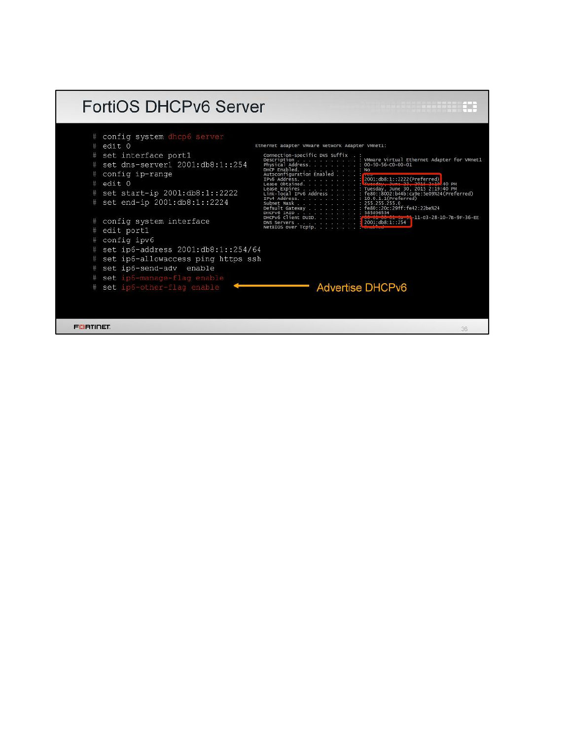
What if you want your hosts to use DHCPv6, not SLAAC?
FortiOS can provide a DHCPv6 server, or you can provide your own.
Hosts will send a DHCPv6 request to the link-scope multicast address. A host uses stateful auto-
configuration when it receives a router advertisement without any prefix information and you’ve
enabled managed address configuration (additional addresses) and/or other stateful configuration
(additional configuration parameters) flags. The response allocates an address from the range, and
other configuration settings such as DNS servers.
IPv6
FortiGate II Student Guide
580
DO NOT REPRINT
© FORTINET
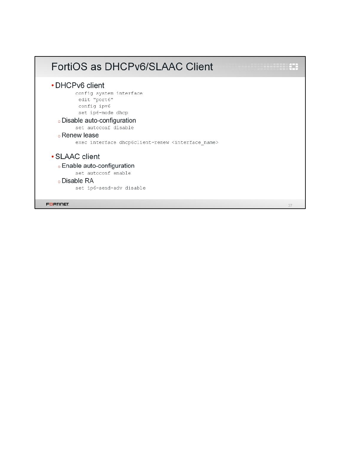
Although it’s less common, FortiOS can also be a DHCPv6 or SLAAC client.
To make FortiOS a DHCPv6 client, configure the interface to receive its global IPv6 address.
To make FortiOS a SLAAC client, configure the interface with autoconf enabled and ip6-send-
adv disabled.
IPv6
FortiGate II Student Guide
581
DO NOT REPRINT
© FORTINET
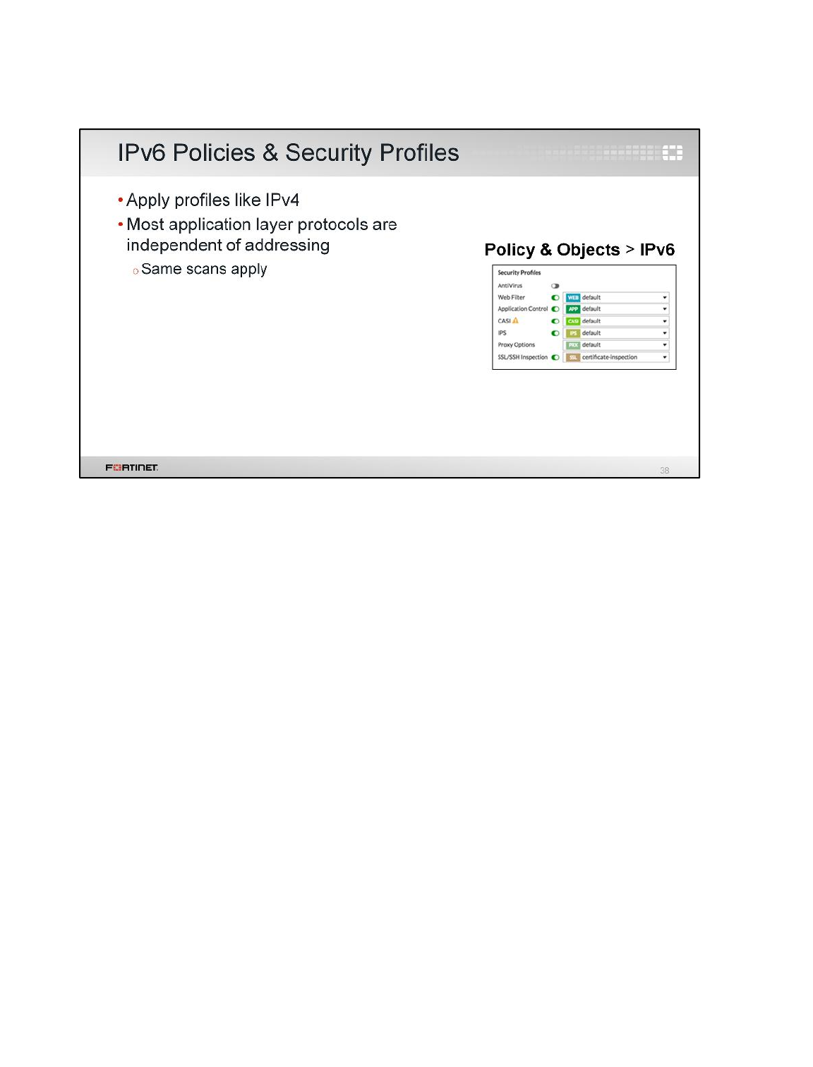
Of course, once the interfaces are configured for IPv6, you can apply security profiles to IPv6 firewall
polices in the same way as IPv4 firewall polices.
IPv6
FortiGate II Student Guide
582
DO NOT REPRINT
© FORTINET

Once you’ve configured the network interfaces on your FortiGate, with IPv4 the next step is often to
configure firewall policies that apply network address translation (NAT).
IPv6 does have NAT for interoperation with IPv4, but NAT is not required by pure IPv6.
NAT postponed IPv4 address exhaustion. Firewalls also arguably originated with NAT masquerading.
But NAT broke end-to-end connectivity, which has required workarounds such as NAT traversal in
IPsec VPN.
IPv6 was designed to restore one of the original design goals of IPv4: end-to-end connectivity. So you
won’t always need NAT. Let’s take a look.
IPv6
FortiGate II Student Guide
583
DO NOT REPRINT
© FORTINET
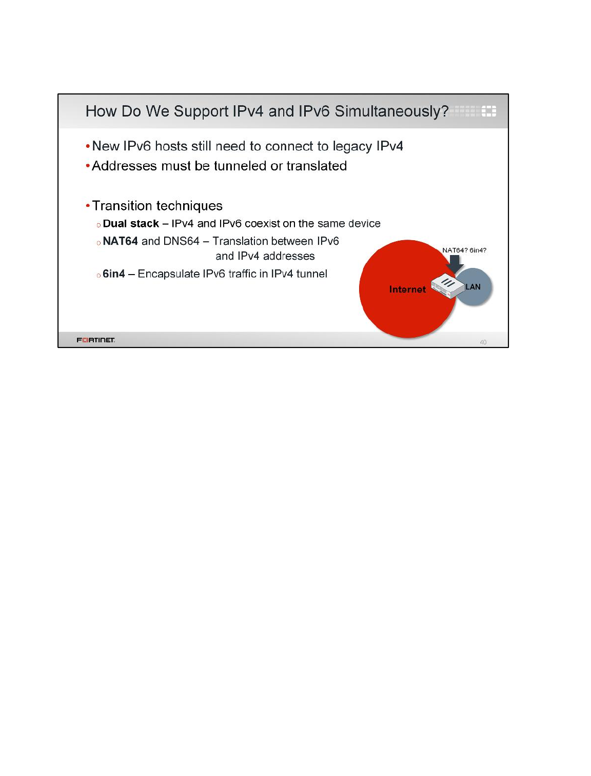
Today, most of the Internet uses IPv4, and there will be many IPv4 hosts for a long time. It’s not
realistic to instantly turn on IPv6 and turn off IPv4. We are in a transition period. During this time, we
need technologies to interconnect IPv6 and IPv4 hosts.
One of the ways we can do that is with NAT. So although IPv6 itself does not require NAT, it’s still
useful.
IPv6
FortiGate II Student Guide
584
DO NOT REPRINT
© FORTINET
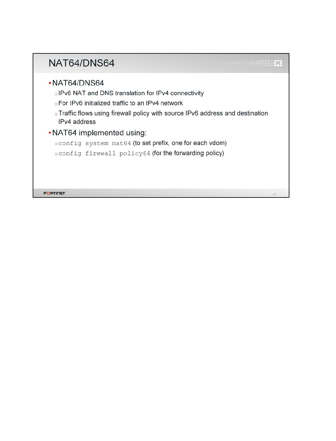
NAT64 is a mechanism for IPv4-IPv6 transition and IPv4-IPv6 coexistence. Together with DNS64,
these two mechanisms allow an IPv6-only client to initiate communications to an IPv4-only server.
They also enable peer-to-peer communication between an IPv4 and an IPv6 node, where the
communication is initiated when either end uses existing, NAT-traversal, peer-to-peer communication
techniques, such as Interactive Connectivity Establishment (ICE).
Stateful NAT64 also supports IPv4-initiated communications to a subset of the IPv6 hosts, through
statically configured bindings in the stateful NAT64, which could be achieved using VIP46 in FortiOS.
IPv6
FortiGate II Student Guide
585
DO NOT REPRINT
© FORTINET
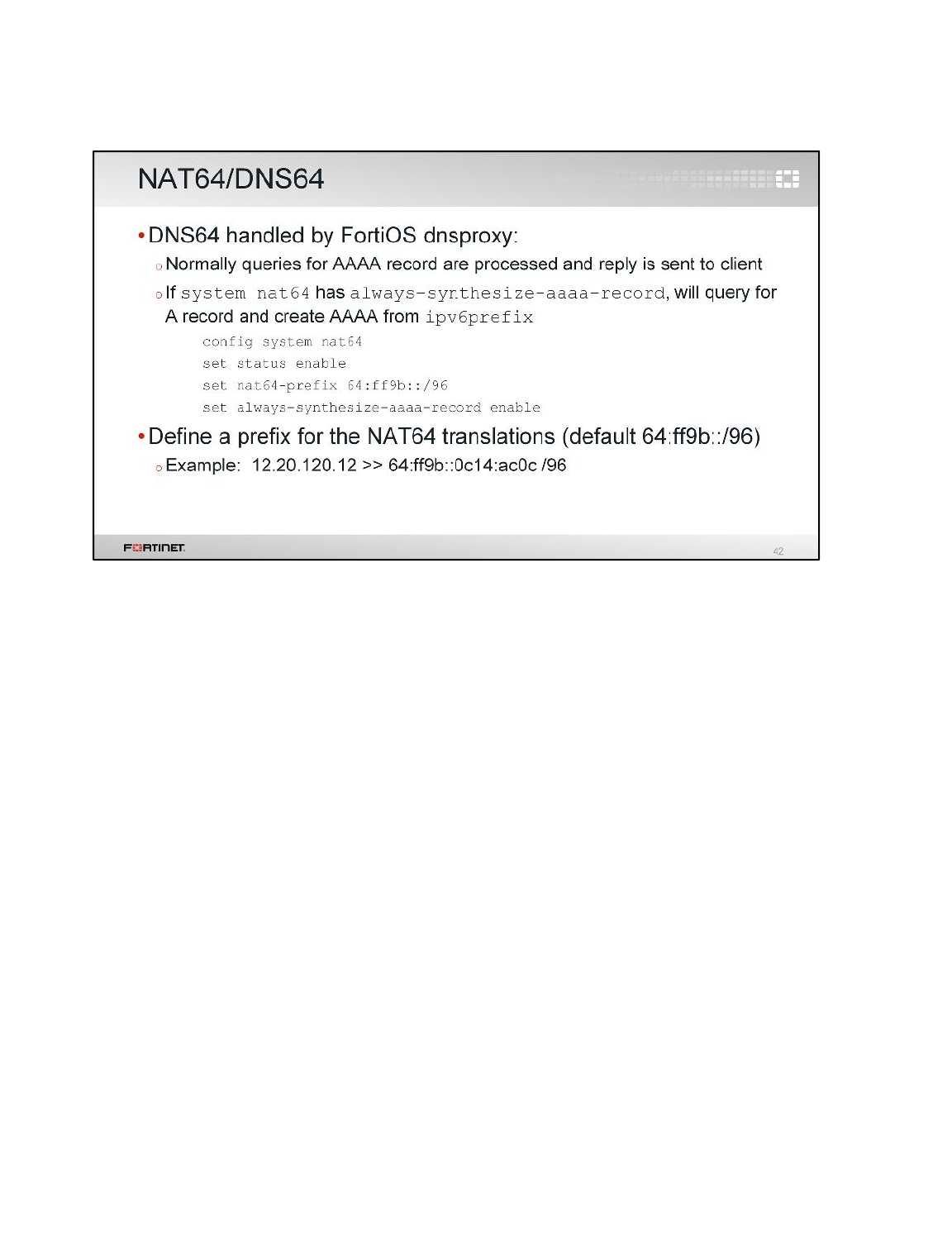
DNS64 is a mechanism for synthesizing AAAA resource records (RRs) from A RRs. The IPv6 address
contained in the synthetic AAAA RR is algorithmically generated from the IPv4 address and the IPv6
prefix assigned to a NAT64 device.
DNS64 is defined in RFC 6052.
IPv6
FortiGate II Student Guide
586
DO NOT REPRINT
© FORTINET
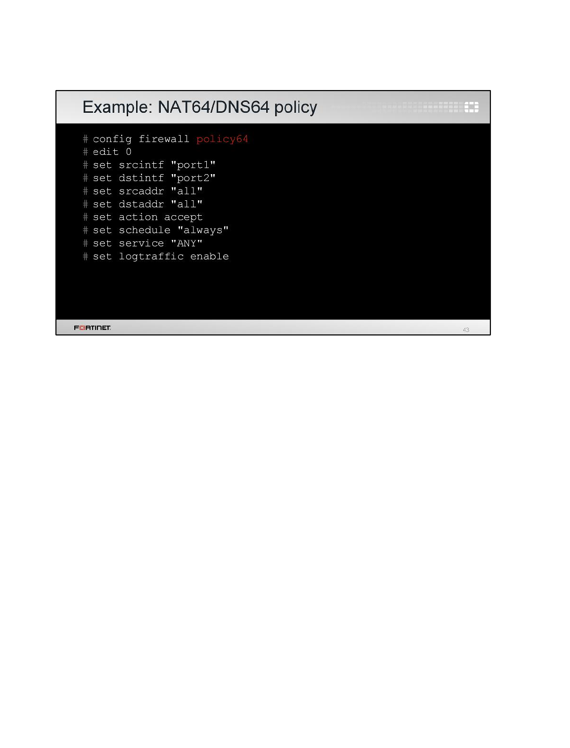
This configuration example shows a sample NAT64 policy. The source interface is an IPv6-enabled
interface and the destination interface is an IPv4-enabled interface.
IPv6
FortiGate II Student Guide
587
DO NOT REPRINT
© FORTINET
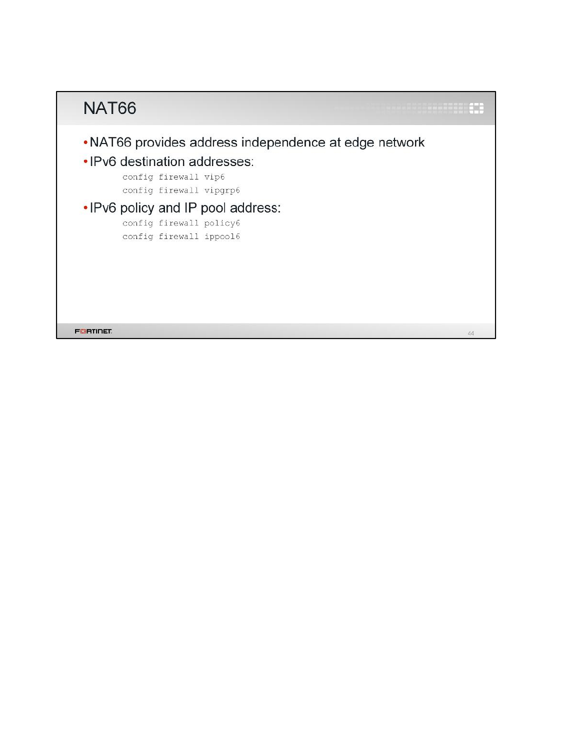
NAT66 is a stateless IPv6-to-IPv6 network prefix translation (NPTv6) function, designed to provide
address independence to the edge network. It is transport-agnostic with respect to transports that do
not checksum the IP header. NAT66 provides a 1:1 relationship between addresses in the inside and
outside prefixes, preserving end-to-end reachability at the network layer.
NAT66 is experimental and defined in RFC 6296. Note the IETF does not recommend the use of NAT
technology for IPv6.
IPv6
FortiGate II Student Guide
588
DO NOT REPRINT
© FORTINET
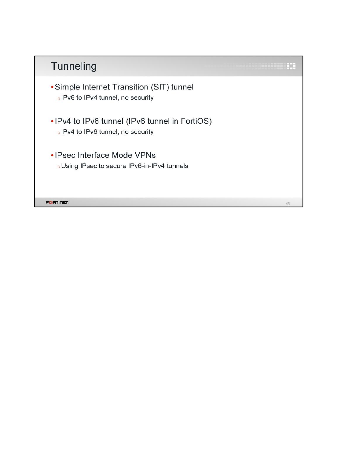
FortiOS implements several tunneling protocols that are part of the transition technologies, allowing
IPv6 communication to tunnel across an IPv4 network. FortiOS implementation includes IPsec to
secure IPv6 in IPv4 tunnels.
This mechanism is outlined in RFC 4891.
IPv6
FortiGate II Student Guide
589
DO NOT REPRINT
© FORTINET

Once IPv6 connectivity is configured – especially between IPv4 and IPv6 networks – you can use
IPv6 versions of your usual connectivity testing commands.
IPv6
FortiGate II Student Guide
590
DO NOT REPRINT
© FORTINET
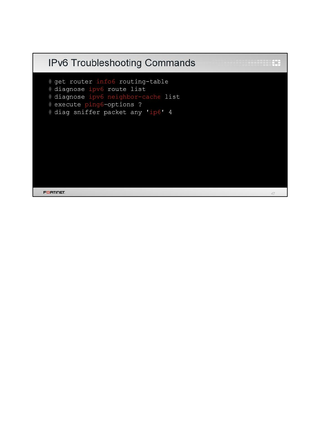
The diagnose command branch allows you to get status information and manually manipulate the
IPv6 configuration.
In the route list, note the link-local and multicast prefixes.
In the neighbor-cache list, look for the auto-configuration address for both FortiOS and any host. Note
how the MAC address is used in the auto-configuration addresses. Remember in IPv6 there is no
ARP, the neighbor mechanism replaces this. From a Windows host you can view the neighbor-cache
using the command netsh interface ipv6 show neighbors (or ip -6 neighbor show in
Linux).
The packet sniffer supports IPv6. The following are example IPv6 filters:
•ip6 and host 2000:5374:7564:656e:7431::3000 to capture IPv6 host
•ip6 and net 2000::/8 to capture IPv6 prefix
•ip6 and tcp port 80 to capture TCP port number
IPv6
FortiGate II Student Guide
591
DO NOT REPRINT
© FORTINET
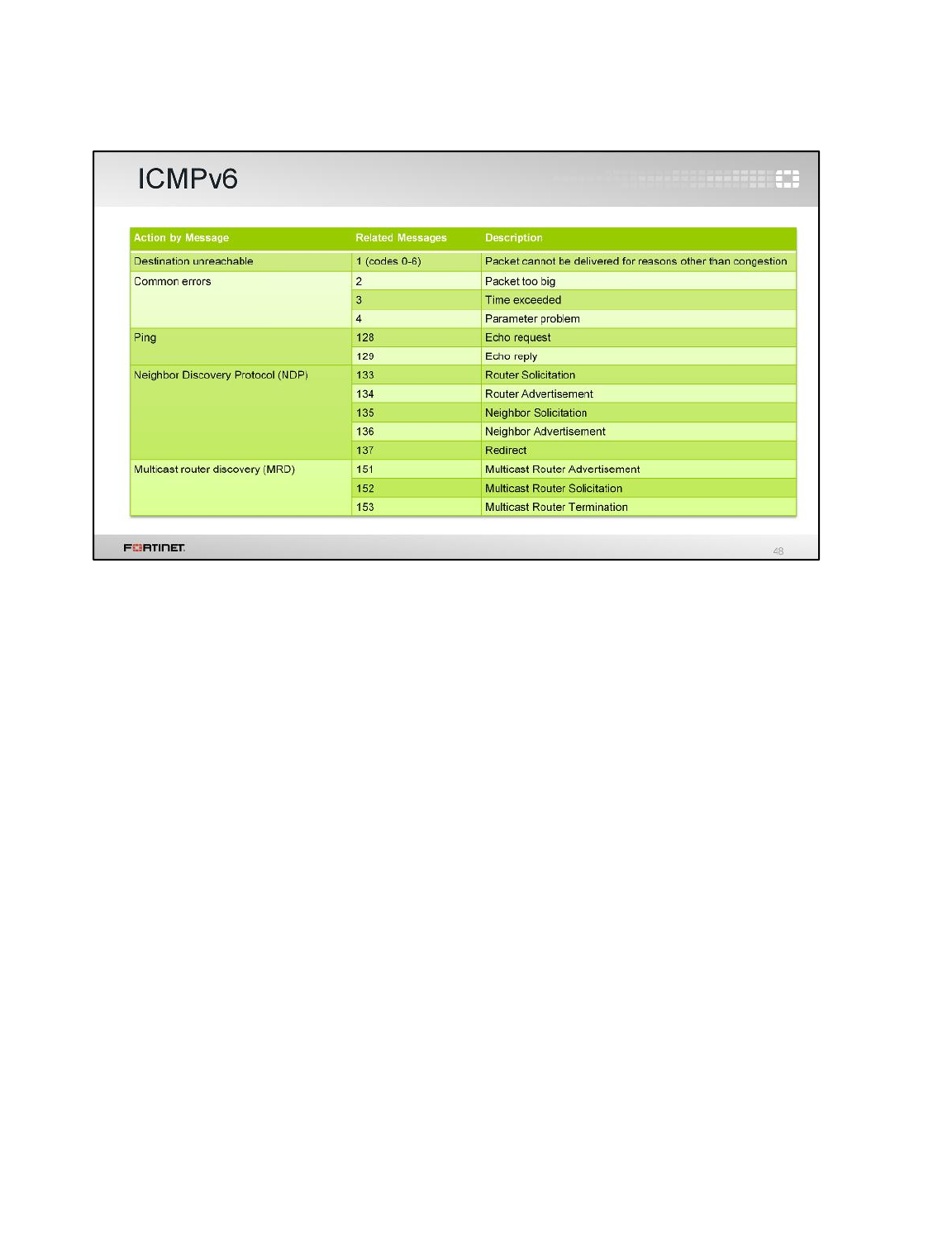
ICMPv6 (Next Header value 58) is similar to ICMP for IPv4. It is used by IPv6 nodes to report errors
encountered in processing packets and to perform other internet-layer functions, such as diagnostics
(ICMPv6 ping).
ICMPv6 is integral to IPv6. This table shows common IPv6 types and codes. The Related Messages
column indicates the message type. Its value determines the format of the remaining data. The code
field depends on the message type.
ICMPv6 messages are of two types: error messages or informational messages. Error messages are
identified by a zero in the high-order bit of their message Type field values. Thus, error messages
have message types from 0 to 127; informational messages have message types from 128 to 255.
ICMPv6 is defined in RFC 4443.
IPv6
FortiGate II Student Guide
592
DO NOT REPRINT
© FORTINET
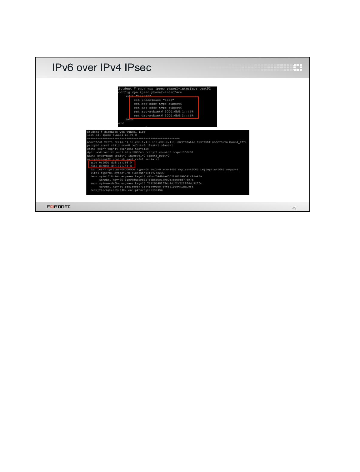
From a security perspective, we will focus on IPv6 tunneling over an IPv4 IPsec tunnel. To do this in
FortiOS, create an IPsec interface mode tunnel, as with the regular site-to-site VPN configuration.
Your Phase 2 selectors, routes, and firewall policies are all IPv6.
IPv6
FortiGate II Student Guide
593
DO NOT REPRINT
© FORTINET
In this lesson, we’ve looked at how to configure FortiOS in an IPv6 environment and enable features
such as transition technologies and security profiles. We’ve also reviewed common diagnostic
commands and new commands for IPv6 networks.
IPv6
FortiGate II Student Guide
594
DO NOT REPRINT
© FORTINET
