Fortran_Extended_4_Users_Guide_60499700A_Dec77 Fortran Extended 4 Users Guide 60499700A Dec77
Fortran_Extended_4_Users_Guide_60499700A_Dec77 Fortran_Extended_4_Users_Guide_60499700A_Dec77
User Manual: Pdf Fortran_Extended_4_Users_Guide_60499700A_Dec77
Open the PDF directly: View PDF ![]() .
.
Page Count: 112 [warning: Documents this large are best viewed by clicking the View PDF Link!]
60499700
T.
0^\
CONTRPL DATA
CORPORATION
FORTRAN EXTENDED VERSION 4
USER'S GUIDE
r
0$>,
CDC® OPERATING SYSTEMS:
NOS 1
NOS/BE 1
SCOPE 2
REVISION RECORD
REVISION DESCRIPTION
AOriginal release.
12/30/77
Publication No.
60499700
-*
, ^ \
REVISION LETTERS I, O. Q AND X ARE NOT USED
© 197?
Control Data Corporation
Printed in the United States of America
Address comments concerning
this manual to:
CONTROL DATA CORPORATION
Publications and Graphics Division
215 MOFFETT PARK DRIVE
SUNNYVALE, CALIFORNIA 94086
or use Comment Sheet in the
back of this manual
^^ls\
0£\
,#SN
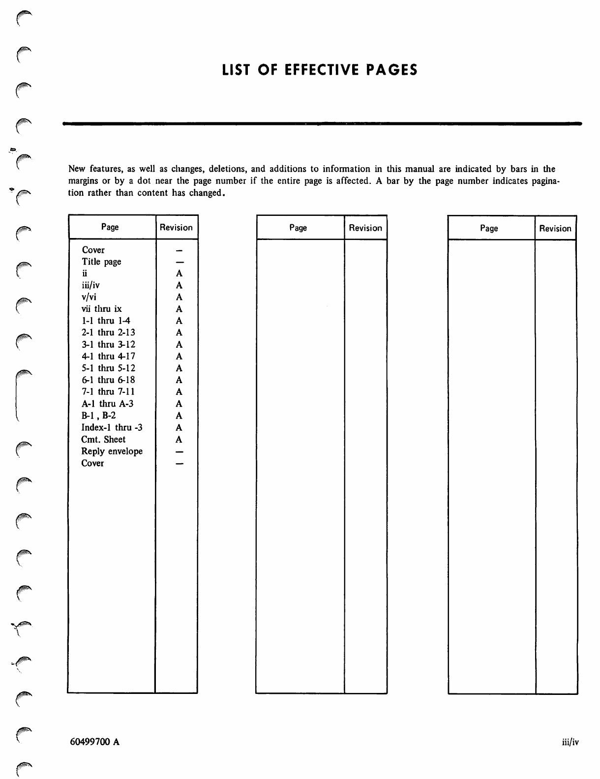
LIST OF EFFECTIVE PAGES
New features, as well as changes, deletions, and additions to information in this manual are indicated by bars in the
margins or by a dot near the page number if the entire page is affected. A bar by the page number indicates pagina
tion rather than content has changed.
0m\
Page
Cover
Title page
ii
iii/iv
v/vi
vii tliru ix
1-1 thru 1-4
2-1 thru 2-13
3-1 thru 3-12
4-1 thru 4-17
5-1 thru 5-12
6-1 thru 6-18
7-1 thru 7-11
A-l thru A-3
B-l, B-2
Index-1 thru -3
Cmt. Sheet
Reply envelope
Cover
Revision
A
A
A
A
A
A
A
A
A
A
A
A
A
A
A
Page Revision Page Revision
60499700 A iii/iv

/ ^ \
/*^\
0%\
r/S!%
PREFACE
0^\
/0fe\
This user's guide provides helpful information for the user of
CDC FORTRAN Extended. FORTRAN Extended is sup
ported by the following operating systems:
NOS 1 for the CONTROL DATA® CYBER 170 Models
171, 172, 173, 174, 175; CYBER 70 Models 71, 72, 73,
74; and 6000 Series Computer Systems
NOS/BE 1 for the CDC® CYBER 170 Series; CYBER 70
Models 71, 72, 73, 74; and 6000 Series Computer
Systems
SCOPE 2 for the CONTROL DATA CYBER 170 Model
176, CYBER 70 Model 76, and 7600 Computer Systems
This user's guide is written primarily for the FORTRAN
programmer who is unfamiliar with CDC operating systems.
It is a supplement to the FORTRAN Extended Version 4
Reference Manual, with minimal duplication of information.
This guide concentrates on the interfaces between
FORTRAN Extended and other software products, as well as
on programming, debugging, and optimization techniques of
particular interest to the FORTRAN Extended programmer.
Some topics of interest to the FORTRAN Extended
programmer are discussed in other user's guides. These
include the following:
9 I n t e r a c t i v e p r o g r a m c r e a t i o n a n d e x e c u t i on . F o r
NOS/BE, this topic is covered in the INTERCOM Guide
for FORTRAN Extended Users. For NOS users, parallel
material is included in the NOS Time-Sharing User's
Guide and the NOS Text Editor Reference ManuaK
e Input/output implementation. This topic, with partic
ular emphasis on the advanced input/output capabilities
available through the CYBER Record Manager interface
routines, is covered in the CYBER Record Manager
Version 1 Guide for Users of FORTRAN Extended
Version 4. SCOPE 2 users can find parallel information
in the SCOPE 2 User's Guide.
9 Debugging facility. The C$ DEBUG capability included
with the FORTRAN Extended compiler is described in
the FORTRAN Extended DEBUG User's Guide.
In addition, user's guides exist for SCOPE 2 and NOS/BE;
these guides are recommended for programmers new to
these systems.
/SjPN
Publication
NOS 1 Operating System Reference Manual, Volume 1
NOS/BE 1 Operating System Reference Manual
SCOPE 2 Reference Manual
NOS/BE 1 User's Guide
SCOPE 2 User's Guide
FORTRAN Extended Version 4 Reference Manual
CYBER Loader Version 1 Reference Manual
SCOPE 2 Loader Reference Manual
FORTRAN Extended DEBUG User's Guide
INTERCOM Interactive Guide for
Users of FORTRAN Extended
CYBER Record Manager Version 1 Guide for
Users of FORTRAN Extended Version 4
FORTRAN Common Library Mathematical Routines
UPDATE Reference Manual
CYBER Common Utilities Reference Manual
Publication Number
60435300
60493800
60342600
60494000
60372600
60497800
60429800
60454780
60498000
60495000
60495900
60498200
60449900
60495600
CDC manuals can be ordered from Control Data Literature and Distribution Services,
8001 East Bloomington Freeway, Minneapolis, MN 55420
This product is intended for use only as described in this document.
Control Data cannot be responsible for the proper functioning of
undescribed features or parameters.
60499700 A v/vi

^*
^
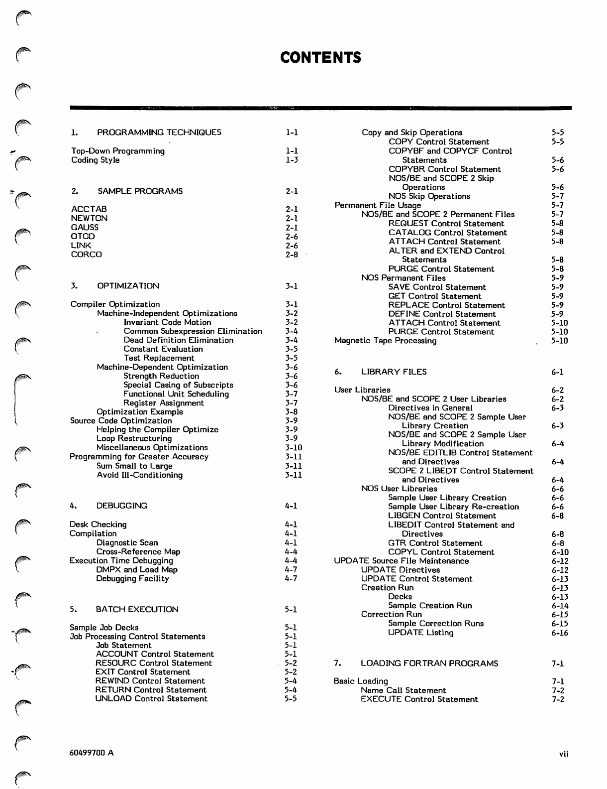
CONTENTS
1. PROGRAMMING TECHNIQUES
Top-Down Programming
Coding Style
SAMPLE PROGRAMS
ACCTAB
NEWTON
GAUSS
OTOD
LINK
CORCO
3. OPTIMIZATION
0U^S
Compiler Optimization
Machine-Independent Optimizations
Invariant Code Motion
Common Subexpression Elimination
Dead Definition Elimination
Constant Evaluation
Test Replacement
Machine-Dependent Optimization
Strength Reduction
Special Casing of Subscripts
Functional Unit Scheduling
Register Assignment
Optimization Example
Source Code Optimization
Helping the Compiler Optimize
Loop Restructuring
Miscellaneous Optimizations
Programming for Greater Accuracy
Sum Small to Large
Avoid Ill-Conditioning
4. DEBUGGING
Desk Checking
Compilation
Diagnostic Scan
Cross-Reference Map
Execution Time Debugging
DMPX and Load Map
Debugging Facility
5. BATCH EXECUTION
Sample Job Decks
Job Processing Control Statements
Job Statement
ACCOUNT Control Statement
RESOURC Control Statement
EXIT Control Statement
REWIND Control Statement
RETURN Control Statement
UNLOAD Control Statement
1-1
1-1
1-3
2-1
2-1
2-1
2-1
2-6
2-6
2-8
3-1
3-1
3-2
3-2
3-4
3-4
3-5
3-5
3-6
3-6
3-6
3-7
3-7
3-8
3-9
3-9
3-9
3-10
3-11
3-11
3-11
4-1
4-1
4-1
4-1
4-4
4-4
4-7
4-7
5-1
5-1
5-1
5-1
5-1
5-2
5-2
5-4
5-4
5-5
Copy and Skip Operations
COPY Control Statement
COPYBF and COPYCF Control
Statements
COPYBR Control Statement
NOS/BE and SCOPE 2 Skip
Operations
NOS Skip Operations
Permanent File Usage
NOS/BE and SCOPE 2 Permanent Files
REQUEST Control Statement
CATALOG Control Statement
ATTACH Control Statement
ALTER and EXTEND Control
Statements
PURGE Control Statement
NOS Permanent Files
SAVE Control Statement
GET Control Statement
REPLACE Control Statement
DEFINE Control Statement
ATTACH Control Statement
PURGE Control Statement
Magnetic Tape Processing
LIBRARY FILES
7. LOADING FORTRAN PROGRAMS
Basic Loading
Name Call Statement
EXECUTE Control Statement
5-5
5-5
5-6
5-6
5-6
5-7
5-7
5-7
5-8
5-8
5-8
5-8
5-8
5-9
5-9
5-9
5-9
5-9
5-10
5-10
5-10
6-1
User Libraries 6-2
NOS/BE and SCOPE 2 User Libraries 6-2
Directives in General 6-3
NOS/BE and SCOPE 2 Sample User
Library Creation 6-3
NOS/BE and SCOPE 2 Sample User
Library Modification 6-4
NOS/BE EDITLIB Control Statement
and Directives 6-4
SCOPE 2 LIBEDT Control Statement
and Directives 6-4
NOS User Libraries 6-6
Sample User Library Creation 6-6
Sample User Library Re-creation 6-6
LIBGEN Control Statement 6-8
LIBEDIT Control Statement and
Directives 6-8
GTR Control Statement 6-8
COPYL Control Statement 6-10
UPDATE Source File Maintenance 6-12
UPDATE Directives 6-12
UPDATE Control Statement 6-13
Creation Run 6-13
Decks 6-13
Sample Creation Run 6-14
Correction Run 6-15
Sample Correction Runs 6-15
UPDATE Listing 6-16
7-1
7-1
7-2
7-2
60499700 A
>*^ls
SLOAD Control Statement
LOAD Control Statement
NOGO Control Statement
LIBRARY Control Statement
LDSET Control Statement
Library Search Order
Field Length Control
7-2 Basic Load Examples
7-3 Segment Loading
7-3 Segmented Program Structure
7-4 Building a Segmented Program
7-4 Segment Directives
7-4 Loading and Executing a Segmented
7-5 Program
7-5
7-6
7-6
7-7
7-8
7-10
/S 5 \
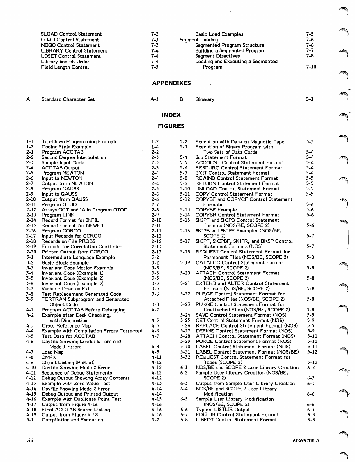
APPENDIXES
Standard Character Set A-l Glossary B-l
1-1 Top-Down Programming Example
1-2 Coding Style Example
2-1 Program ACCTAB
2-2 Second Degree Interpolation
2-3 Sample Input Deck
2-4 ACCTAB Output
2-5 Program NEWTON
2-6 Input to NEWTON
2-7 Output from NEWTON
2-8 Program GAUSS
2-9 Input to GAUSS
2-10 Output from GAUSS
2-11 Program OTOD
2-12 Arrays OCT and IA in Program OTOD
2-13 Program LINK
2-14 Record Format for INFIL
2-15 Record Format for NEWFIL
2-16 Program CORCO
2-17 Input Records for CORCO
2-18 Records on File PROBS
2-19 Formula for Correlation Coefficient
2-20 Printed Output from CORCO
3-1 Intermediate Language Example
3-2 Basic Block Example
3-3 Invariant Code Motion Example
3-4 Invariant Code (Example 1)
3-5 Invariant Code (Example 2)
3-6 Invariant Code (Example 3)
3-7 Variable Dead on Exit
3-8 Test Replacement Generated Code
3-9 FORTRAN Subprogram and Generated
Object Code
4-1 Program ACCTAB Before Debugging
4-2 Example after Desk Checking,
with Diagnostics
4-3 Cross-Reference Map
4-4 Example with Compilation Errors Corrected
4-5 Test Data for ACCTAB
4-6 Dayfile Showing Loader Errors and
Mode 1 Errors
4-7 Load Map
4-8 DMPX
4-9 Object Listing (Partial)
4-10 Dayfile Showing Mode 2 Error
4-11 Sequence of Debug Statements
4-12 Debug Output Showing Array Contents
4-13 Example with Zero Value Test
4-14 Dayfile Showing Mode 2 Error
4-15 Debug Output and Printed Output
4-16 Example with Duplicate Point Test
4-17 Output from Figure 4-16
4-18 Final ACCTAB Source Listing
4-19 Output from Figure 4-18
5-1 Compilation and Execution
INDEX
FIGURES
1-2 5-2
1-4 5-3
2-2
2-3 5-4
2-3 5-5
2-3 5-6
2-4 5-7
2-4 5-8
2-4 5-9
2-5 5-10
2-6 5-11
2-6 5-12
2-7
2-8 5-13
2-9 5-14
2-10 5-15
2-10
2-11 5-16
2-12
2-12 5-17
2-13
2-13 5-18
3-2
3-2 5-19
3-3
3-3 5-20
3-3
3-3 5-21
3-5
3-6 5-22
3-8 5-23
4-2
5-24
4-3 5-25
4-5 5-26
4-6 5-27
4-7 5-28
5-29
4-8 5-30
4-9 5-31
4-11 5-32
4-12
4-12 6-1
4-12 6-2
4-12
4-13 6-3
4-14 6-4
4-14
4-15 6-5
4-16
4-16 6-6
4-16 6-1
5-2 6-8
Execution with Data on Magnetic Tape 5-3
Execution of Binary Program with
Two Sets of Data Cards
Job Statement Format
ACCOUNT Control Statement Format
RESOURC Control Statement Format
EXIT Control Statement Format
REWIND Control Statement Format
RETURN Control Statement Format
UNLOAD Control Statement Format
COPY Control Statement Format
COPYBF and COPYCF Control Statement
Formats
COPYBF Example
COPYBR Control Statement Format
SKIPF and SKIPB Control Statement
Formats (NOS/BE, SCOPE 2)
SKIPB and SKIPF Examples (NOS/BE,
SCOPE 2)
SKIPF, SKIPBF, SKIPR, and BKSP Control
Statement Formats (NOS)
REQUEST Control Statement Format for
Permanent Files (NOS/BE, SCOPE 2)
CATALOG Control Statement Format
(NOS/BE, SCOPE 2)
ATTACH Control Statement Format
(NOS/BE, SCOPE 2)
EXTEND and ALTER Control Statement
Formats (NOS/BE, SCOPE 2)
PURGE Control Statement Format for
Attached Files (NOS/BE, SCOPE 2)
PURGE Control Statement Format for
Unattached Files (NOS/BE, SCOPE 2)
SAVE Control Statement Format (NOS)
GET Control Statement Format (NOS)
REPLACE Control Statement Format (NOS)
DEFINE Control Statement Format (NOS)
ATTACH Control Statement Format (NOS) 5-10
PURGE Control Statement Format (NOS) 5-10
LABEL Control State ment Format (NOS) 5-11
LABEL Control Statement Format (NOS/BE) 5-12
REQUEST Control Statement Format for
Tapes (SCOPE 2) 5-12
NOS/BE and SCOPE 2 User Library Creation 6-2
Sample User Library Creation (NOS/BE,
SCOPE 2) 6-3
Output from Sample User Library Creation 6-5
NOS/BE and SCOPE 2 User Library
Modification 6-6
Sample User Library Modification
(NOS/BE, SCOPE 2) 6-6
Typical LISTLIB Output 6-7
EDITLIB Control Statement Format 6-8
LIBEDT Control Statement Format 6-8
5-4
5-4
5-4
5-4
5-4
/■**%
5-5
5-5
s*v&\
5-5
5-5
5-6
5-6
5-6
,*SS\
5-6 A^&K
5-7
5-7
5-8
5-8 A ^ & \
5-8
5-8 /^S\
5-8
5-8
5-9
5-9
5-9
5-9
A ^ S
60499700 A
y*SS?V
0s*
0^- 6-9
6-10
6-11
/|Sv 6-12
6-13
/ig#r^ 6-14
v6-15
6-16
6-17
0^\ 6-18
6-19
6-20
6-21
y^^\ 6-22
6-23
6-24
6-25
/Sfcv 6-26
v6-27
6-28
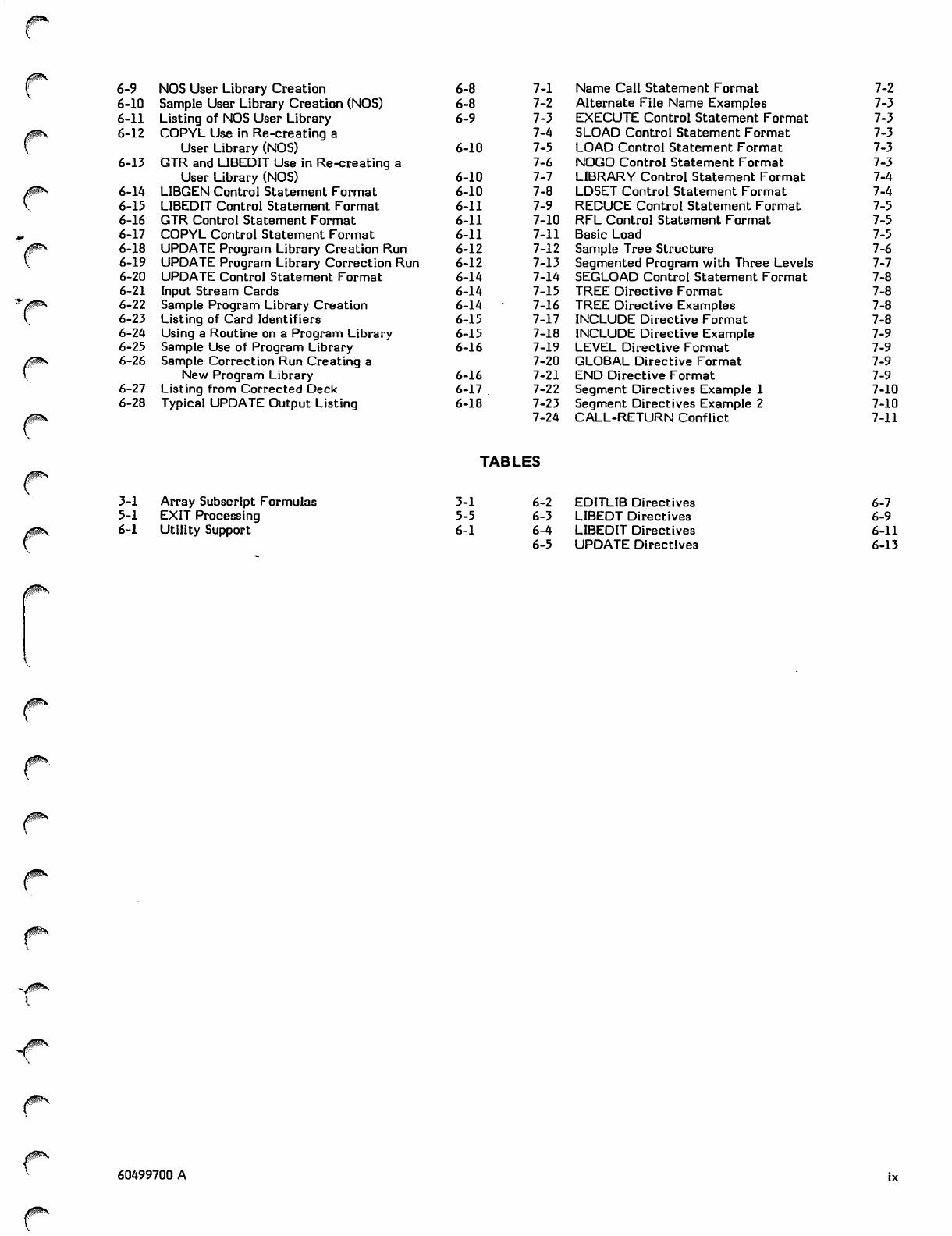
NOS User Library Creation
Sample User Library Creation (NOS)
Listing of NOS User Library
COPYL Use in Re-creating a
User Library (NOS)
GTR and LIBEDIT Use in Re-creating a
User Library (NOS)
LIBGEN Control Statement Format
LIBEDIT Control Statement Format
GTR Control Statement Format
COPYL Control Statement Format
UPDATE Program Library Creation Run
UPDATE Program Library Correction Run
UPDATE Control Statement Format
Input Stream Cards
Sample Program Library Creation
Listing of Card Identifiers
Using a Routine on a Program Library
Sample Use of Program Library
Sample Correction Run Creating a
New Program Library
Listing from Corrected Deck
Typical UPDATE Output Listing
6-8 7-1
6-8 7-2
6-9 7-3
7-4
6-10 7-5
7-6
6-10 7-7
6-10 7-8
6-11 7-9
6-11 7-10
6-11 7-11
6-12 7-12
6-12 7-13
6-14 7-14
6-14 7-15
6-14 • 7-16
6-15 7-17
6-15 7-18
6-16 7-19
7-20
6-16 7-21
6-17 7-22
6-18 7-23
7-24
Name Call Statement Format 7-2
Alternate File Name Examples 7-3
E X E C U T E C o n t r o l S t a t e m e n t F o r m a t 7 - 3
SLOAD Control Statement Format 7-3
LOAD Control Statement Format 7-3
NOGO Control Statement Format 7-3
LIBRARY Control Statement Format 7-4
LDSET Control Statement Format 7-4
REDUCE Control Statement Format 7-5
RFL Control Statement Format 7-5
Basic Load 7-5
Sample Tree Structure 7-6
Segmented P r o g r a m w i t h T h r e e L e v e l s 7 - 7
SEGLOAD Control Statement Format 7-8
TREE Directive Format 7-8
TREE Directive Examples 7-8
INCLUDE Directive Format 7-8
INCLUDE Directive Example 7-9
LEVEL Directive Format 7-9
GLOBAL Directive Format 7-9
END Directive Format 7-9
Segment Directives Example 1 7-10
Segment Directives Example 2 7-10
CALL-RETURN Conflict 7-11
TABLES
3-1 Array Subscript Formulas
5-1 EXIT Processing
6-1 Utility Support
3-1 6-2 EDITLIB Directives
5-5 6-3 LIBEDT Directives
6-1 6-4 LIBEDIT Directives
6-5 UPDATE Directives
6-7
6-9
6-11
6-13
60499700 A

/^In
0®&\
/^Slg
PROGRAMMING TECHNIQUES
0jB\
<|PK
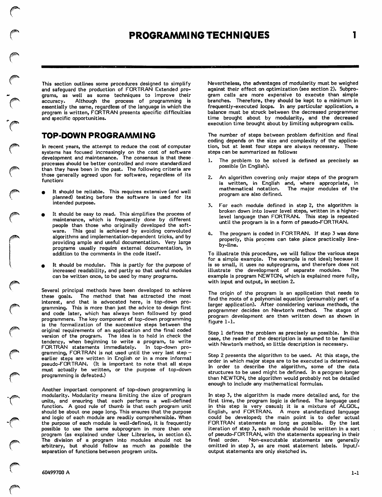
This section outlines some procedures designed to simplify
and safeguard the production of FORTRAN Extended pro
grams, as well as some techniques to improve their
accuracy. Although the process of programming is
essentially the same, regardless of the language in which the
program is written, FORTRAN presents specific difficulties
and specific opportunities.
TOP-DOWN PROGRAMMI NG
In recent years, the attempt to reduce the cost of computer
systems has focused increasingly on the cost of software
development and maintenance. The consensus is that these
processes should be better controlled and more standardized
than they have been in the past. The following criteria are
those generally agreed upon for software, regardless of its
function:
# It should be reliable. This requires extensive (and well
planned) testing before the software is used for its
intended purpose.
* It should be easy to read. This simplifies the process of
maintenance, which is frequently done by different
people than those who originally developed the soft
ware. This goal is achieved by avoiding convoluted
algorithms and implementation-dependent tricks, and by
providing ample and useful documentation. Very large
programs usually require external documentation, in
addition to the comments in the code itself.
0 It should be modular. This is partly for the purpose of
increased readability, and partly so that useful modules
can be written once, to be used by many programs.
Several principal methods have been developed to achieve
these goals. The method that has attracted the most
interest, and that is advocated here, is top-down pro
gramming. This is more than just the advice to design first
and code later, which has always been followed by good
programmers. The key component of top-down programming
is the formalization of the successive steps between the
original requirements of an application and the final coded
version of the program. The idea is to hold in check the
tendency, when beginning to write a program, to write
FORTRAN statements immediately. In top-down pro
gramming, FORTRAN is not used until the very last step -
earlier steps are written in English or in a more informal
pseudo-FORTRAN. (It is important to note that all steps
must actually be written, or the purpose of top-down
programming is defeated.)
Another important component of top-down programming is
modularity. Modularity means limiting the size of program
units, and ensuring that each performs a well-defined
function. A good rule of thumb is that each program unit
should be about one page long. This ensures that the purpose
and logic of each module are readily comprehensible. When
the purpose of each module is well-defined, it is frequently
possible to use the same subprogram in more than one
program (as explained under User Libraries, in section 6).
The division of a program into modules should not be
arbitrary, but should follow as much as possible the
separation of functions between program units.
Nevertheless, the advantages of modularity must be weighed
against their effect on optimization (see section 2). Subpro
gram calls are more expensive to execute than simple
branches. Therefore, they should be kept to a minimum in
frequently-executed loops. In any particular application, a
balance must be struck between the decreased programmer
time brought about by modularity, and the decreased
execution time brought about by limiting subprogram calls.
The number of steps between problem definition and final
coding depends on the size and complexity of the applica
tion, but at least four steps are always necessary. These
steps can be summarized as follows:
1. The problem to be solved is defined as precisely as
possible (in English).
2. An algorithm covering only major steps of the program
is written, in English and, where appropriate, in
mathematical notation. The major modules of the
program are also defined.
3. For each module defined in step 2, the algorithm is
broken down into lower level steps, written in a higher-
level language than FORTRAN. This step is repeated
until the program is in a form of pseudo-FORTRAN.
4. The program is coded in FORTRAN. If step 3 was done
properly, this process can take place practically line-
by-line.
To illustrate this procedure, we will follow the various steps
for a simple example. The example is not ideal; because it
is so small, it uses no subprograms, and therefore does not
illustrate the development of separate modules. The
example is program NEWTON, which is explained more fully,
with input and output, in section 2.
The origin of the program is an application that needs to
find the roots of a polynomial equation (presumably part of a
larger application). After considering various methods, the
programmer decides on Newton's method. The stages of
program development are then written down as shown in
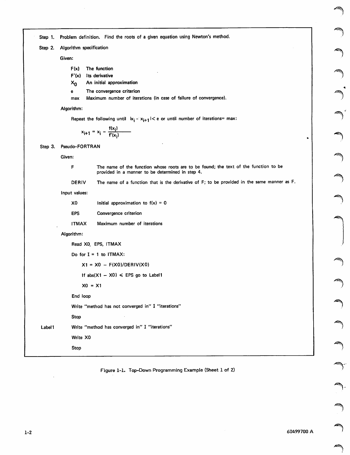
figure 1-1.
Step 1 defines the problem as precisely as possible. In this
case, the reader of the description is assumed to be familiar
with Newton's method, so little description is necessary.
Step 2 presents the algorithm to be used. At this stage, the
order in which major steps are to be executed is determined.
In order to describe the algorithm, some of the data
structures to be used might be defined. In a program longer
than NEWTON, the algorithm would probably not be detailed
enough to include any mathematical formulas.
In step 3, the algorithm is made more detailed and, for the
first time, the program logic is defined. The language used
in this step is very casual; it is a mixture of ALGOL,
English, and FORTRAN. A more standardized language
could be developed; the main point is to defer actual
FORTRAN statements as long as possible. By the last
iteration of step 3, each module should be written in a sort
of pseudo-FORTRAN, with the statements appearing in their
final order. Non-executable statements are generally
omitted in step 3, as are most statement labels. Input/-
output statements are only sketched in.
60499700 A 1-1
Step 1. Problem definition. Find the roots of a given equation using Newton's method.
Step 2. Algorithm specification
Given:
F(x) The function
F'(x) Its derivative
Xq An initial approximation
e The convergence criterion
max Maximum number of iterations (in case of failure of convergence).
Algorithm:
Repeat the following until Ixj - Xj+^ l< e or until number of iterations3 max:
f(X:)
xi+1 - *i
Step 3. Pseudo-FORTRAN
Given:
F
f'(xj)
Initial approximation to f(x) = 0
Convergence criterion
Maximum number of iterations
Label!
The name of the function whose roots are to be found; the text of the function to be
provided in a manner to be determined in step 4.
DERIV The name of a function that is the derivative of F; to be provided in the same manner as F.
Input values:
XO
EPS
ITMAX
Algorithm:
Read XO, EPS, ITMAX
Do for I = 1 to ITMAX:
X1 = XO - F(X0)/DERIV(X0)
If abs(X1 - XO) < EPS go to Label 1
XO = X1
End loop
Write "method has not converged in" I "iterations
Stop
Write "method has converged in" I "iterations"
Write XO
Stop
<?S\ '
•^^K
Figure 1-1. Top-Down Programming Example (Sheet 1 of 2)
-^%.
^
1-2 60499700 A
/ M % \
/ ^ \
/fp^*»
/$SN
Step 4. Completed Program:
PROGRAM NEWTON (INPUT. OUTPUT* TAPE5=0UTPUT)
C
cPROGRAM *NEWTON* FInDS THE ROOTS OF THE EQUATION DEFINED IN THE
cFUNCTION STATEMENT RY NEWTON*S METHOD. THE FOLLOWING VALUES ARE
cINPUT
c
cXO INITIAL APPROXIMATION
cEPS CONVERGFNCE CRITERION
c
c
c
c
c
c
c
c
ITMAX MAXIMUM NUMBER OF ITERATIONS
EQUATION TO BE SOLVFD
F(X) = SlN(X) - (X*f.0)/(X-1.0)
DERIVATIVE OF EQUATION
DERIV(X) = COS(X> ♦ 2.0/(X-1.0>*«2
REAO •. XO. EPS. ITMAX
IF (DERIV(XO) .FQ. 6.0) GO TO 300
DO 100 1=1.ITMAX
ITS = I
XI = XO - F(X0)/DFRIV(X0)
V = F(X1)
PRINT ». *X.Y #♦ vO. Y
IF (APS(XI - XO) .LE. EPS) GO TO 200
XO = Xl
100 CONTINUE
WRITE (5.20) ITMAX
STOP
200 WRITE <S»10) ITS. Xo
STOP
300 WRITE (S.30) XO
STOP
io FORMAT <* METHOO HAS CONVEPGED IN *.I3»* ITERATIONS*,//* X = **
1E12.4)
?0 FORMAT <* METHOD HAS NOT CONVERGED IN *.I3 • * ITERATIONS)*//
1.* EXECUTION TERMINATED*)
30 FORMAT (IX.F12.4. * IS INVALID VALUE FOR XO*)
ENO
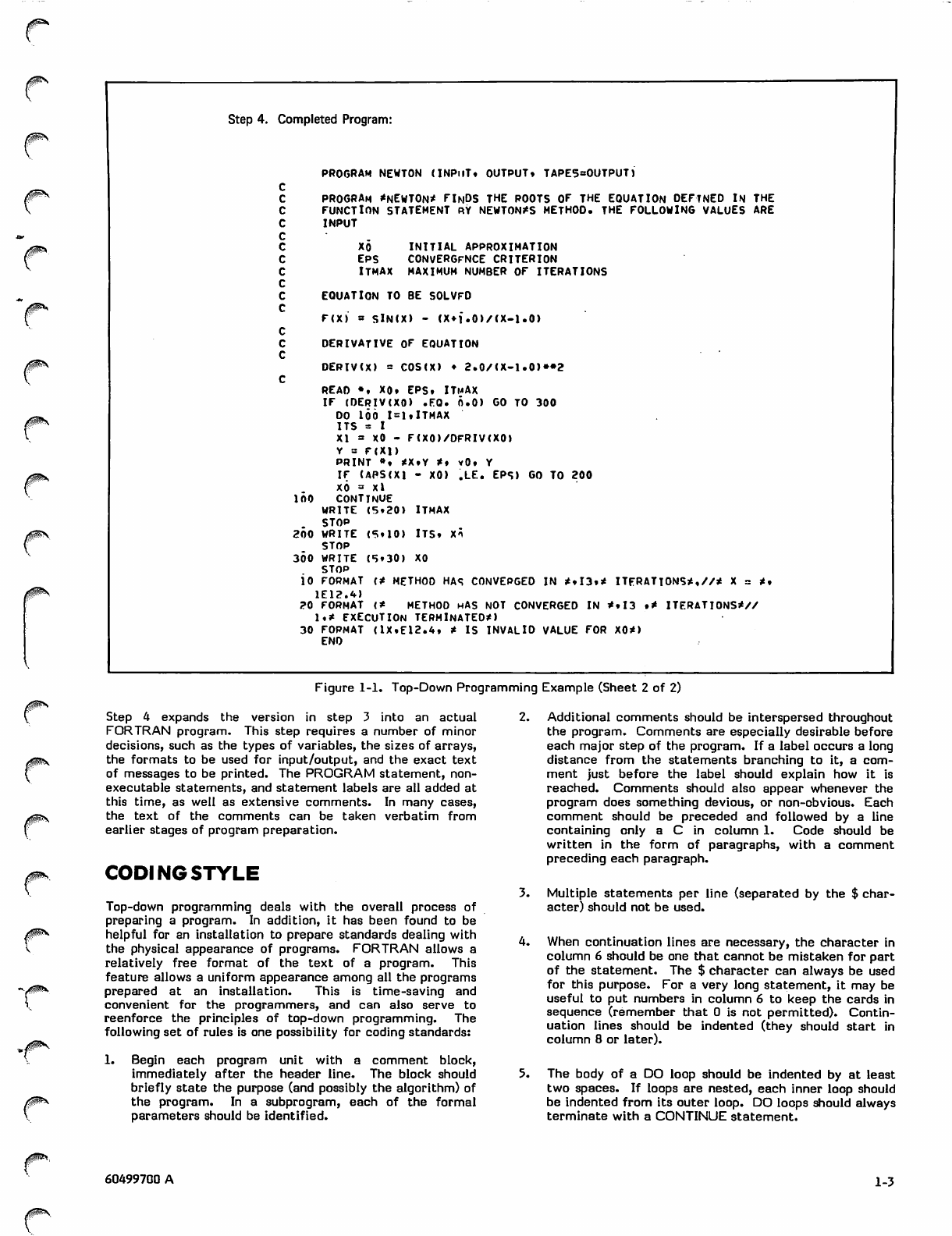
Figure 1-1. Top-Down Programming Example (Sheet 2 of 2)
/sP^V
Step 4 expands the version in step 3 into an actual
FORTRAN program. This step requires a number of minor
decisions, such as the types of variables, the sizes of arrays,
the formats to be used for input/output, and the exact text
of messages to be printed. The PROGRAM statement, non
executable statements, and statement labels are all added at
this time, as well as extensive comments. In many cases,
the text of the comments can be taken verbatim from
earlier stages of program preparation.
CODING STYLE
Top-down programming deals with the overall process of
preparing a program. In addition, it has been found to be
helpful for an installation to prepare standards dealing with
the physical appearance of programs. FORTRAN allows a
relatively free format of the text of a program. This
feature allows a uniform appearance among all the programs
prepared at an installation. This is time-saving and
convenient for the programmers, and can also serve to
reenforce the principles of top-down programming. The
following set of rules is one possibility for coding standards:
1. Begin each program unit with a comment block,
immediately after the header line. The block should
briefly state the purpose (and possibly the algorithm) of
the program. In a subprogram, each of the formal
parameters should be identified.
2. Additional comments should be interspersed throughout
the program. Comments are especially desirable before
each major step of the program. If a label occurs a long
distance from the statements branching to it, a com
ment just before the label should explain how it is
reached. Comments should also appear whenever the
program does something devious, or non-obvious. Each
comment should be preceded and followed by a line
containing only a C in column 1. Code should be
written in the form of paragraphs, with a comment
preceding each paragraph.
3. Multiple statements per line (separated by the $ char
acter) should not be used.
4. When continuation lines are necessary, the character in
column 6 should be one that cannot be mistaken for part
of the statement. The $ character can always be used
for this purpose. For a very long statement, it may be
useful to put numbers in column 6 to keep the cards in
sequence (remember that 0 is not permitted). Contin
uation lines should be indented (they should start in
column 8 or later).
5. The body of a DO loop should be indented by at least
two spaces. If loops are nested, each inner loop should
be indented from its outer loop. DO loops should always
terminate with a CONTINUE statement.
60499700 A 1-3
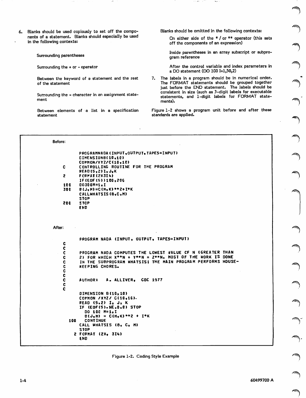
6. Blanks should be used copiously to set off the compo
nents of a statement. Blanks should especially be used
in the following contexts:
Surrounding parentheses
Surrounding the + or - operator
Between the keyword of a statement and the rest
of the statement
Surrounding the = character in an assignment state
ment
Between elements of a list in a specification
statement
Blanks should be omitted in the following contexts:
On either side of the * / or ** operator (this sets
off the components of an expression)
Inside parentheses in an array subscript or subpro
gram reference
After the control variable and index parameters in
a DO statement (DO 100 1=1,50,2)
7. The labels in a program should be in numerical order.
The FORMAT statements should be grouped together
just before the END statement. The labels should be
consistent in size (such as 3-digit labels for executable
statements, and 1-digit labels for FORMAT state
ments).
Figure 1-2 shows a program unit before and after these
standards are applied.
**^v
Before:
PRCGRAMNA0A(INPUT,OUTPUT,TAPE5=INPUT>
DIME NSI0NB( 10,10
COMMON/XYZ/C(10,10)
CCONTROLLING ROUTINE FOR THE PROGRAM
REA0(5,2>1,J,K
2 FCRPATC2X3IM
IF(EOF(5))10G,2G0
100 CO30QH-l«I
300 B<J,M>=C(M,K)»»2*I»K
CAILWHATSIS(B,C»M>
STOP
200 STOP
END
After:
C
PROGRAM NAOA (INPUT, OUTPUT, TAPE5-INPUT)
C
cPROGRAM NADA COMPUTES THE LOWEST VALUE CF N (GREATER THAN
c2) FOR WHICH X**N ♦ V»»N = Z*»N. MOST OF THE WORK IS DONE
cIN THE SUBPROGRAM WHATSIS; THE MAIN PROGRAM PERFORMS HOUSE-
c
cKEEPING CHORES.
c
c
cA U T H O R * A . A L L I V E R , C D C 1 9 7 7
c
DIMENSION 8(10,10)
COFMON /XYZ/ C(10,10).
R E A O ( 5 , 2 ) I , J , K
IF (EOF(5).NE.0.C) STOP
DO 10G M=1,I
B(J,M> = C(M,K>»»2 ♦ I»K
100 CONTINUE
CALL WHATSIS (B, C, M)
STOP
2 FORMAT (2X, 314)
END
A^$\
a&^\
Figure 1-2. Coding Style Example
1-4 60499700 A
SAMPLE PROGRAMS
The programs in this section are intended to illustrate the
programming practices discussed in section 1 through appli
cation of some commonly used mathematical procedures and
basic algorithms. The programs are typical of smaller
special-purpose FORTRAN programs, rather than larger,
more complex applications.
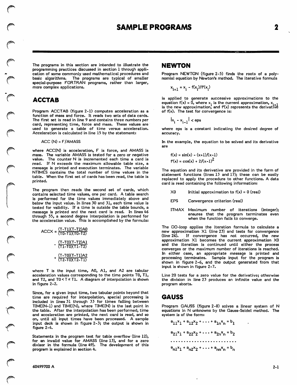
NEWTON
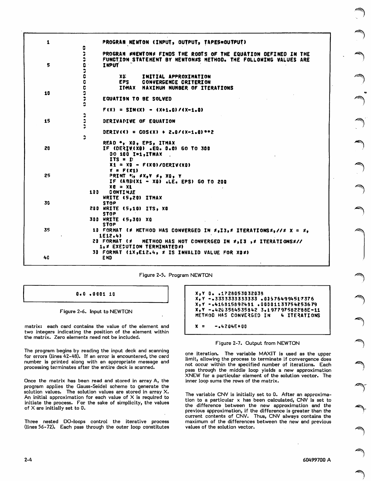
Program NEWTON (figure 2-5) finds the roots of a poly
nomial equation by Newton's method. The iterative formula
x. . = x. - f(x.)/f'(x.)
l + l i i i
ACCTAB
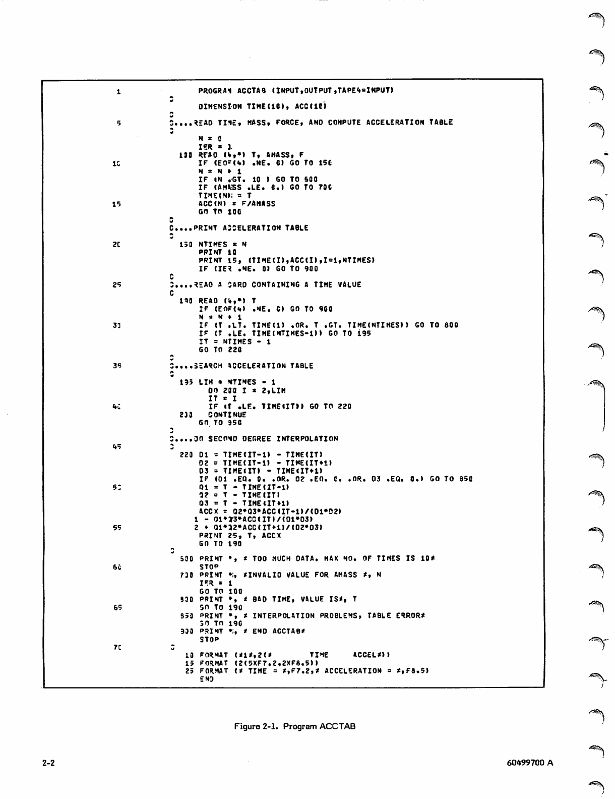
Program ACCTAB (figure 2-1) computes acceleration as a
function of mass and force. It reads two sets of data cards.
The first set is read in line 9 and contains three numbers per
card, representing time, force and mass. These values are
used to generate a table of time versus acceleration.
Acceleration is calculated in line 15 by the statement:
ACC (N) = F/AMASS
where ACC(N) is acceleration, F is force, and AMASS is
mass. The variable AMASS is tested for a zero or negative
value. The counter N is incremented each time a card is
read. If N exceeds the maximum allowable table size, a
message is printed and execution terminates. The variable
NTIMES contains the total number of time values in the
table. When the first set of cards has been read, the table is
printed.
The program then reads the second set of cards, which
contains selected time values, one per card. A table search
is performed for the time values immediately above and
below the input value. In lines 30 and 31, each time value is
tested for validity. If a time is outside the table bounds, a
message is printed and the next card is read. In lines 46
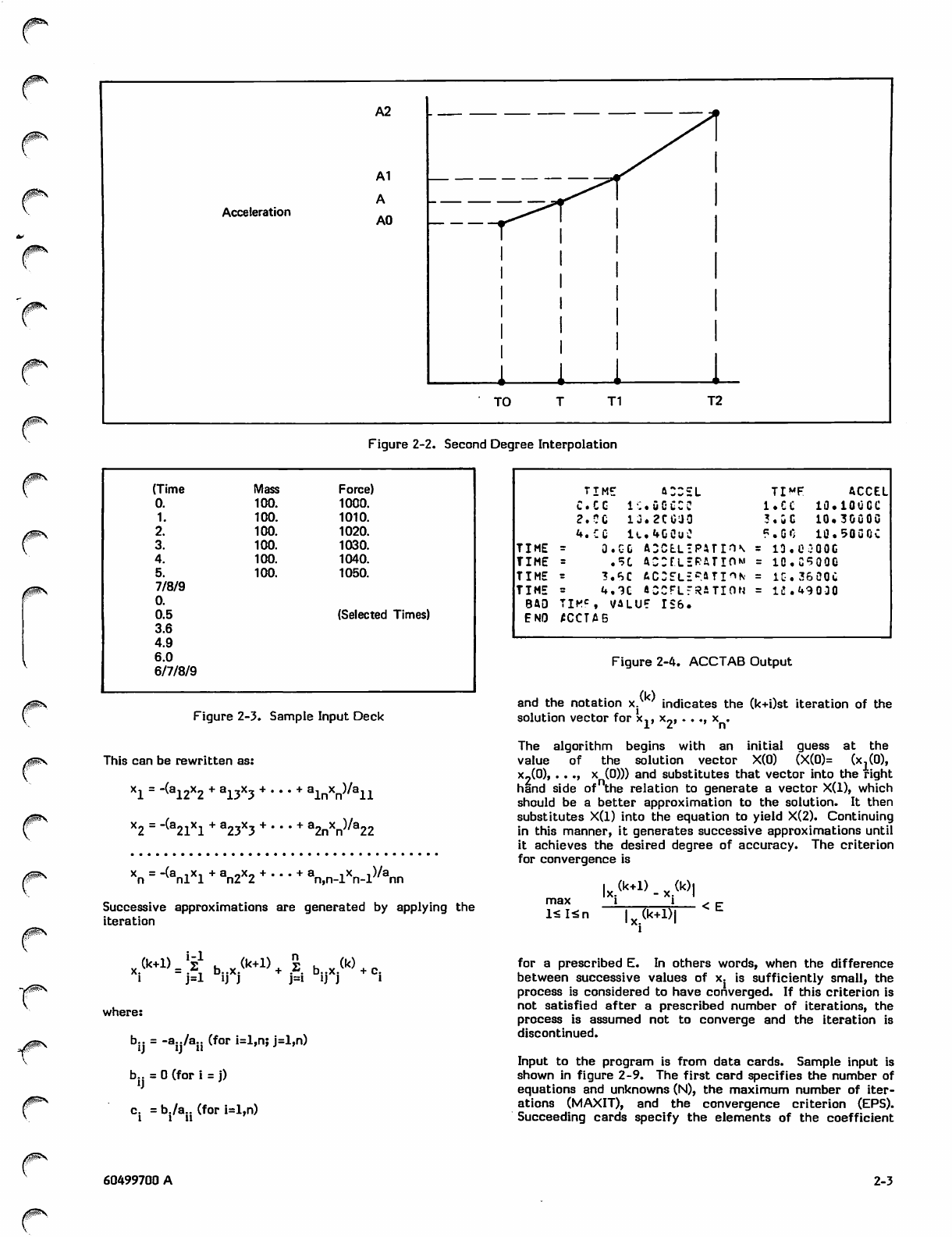
through 55, a second degree interpolation is performed for
the acceleration value. This is accomplished by the formula:
Amy (T-T1)(T-T2)A0
ACCX = (T0-T1)(T0-T2)
(T-T0)(T-T2)A1
" (T1-T0XT1-T2)
(T-T0)(T-T1)A2
+ (T2-T0XT2-T1)
where T is the input time, AO, Al, and A2 are tabular
acceleration values corresponding to the time points TO, Tl,
and T2, and TO < T £ Tl. A diagram of interpolation is shown
in figure 2-2.
Since, for a given input time, two tabular points beyond that
time are required for interpolation, special processing is
included in lines 31 through 33 for times falling between
TIME(N-l) and TIME(N), where TIME(N) is the last point in
the table. After the interpolation has been performed, time
and acceleration are printed, the next card is read, and so
on, until all input times have been processed. A sample
input deck is shown in figure 2-3; the output is shown in
figure 2-4.
Statements in the program test for table overflow (line 12),
for an invalid value for AMASS (line 13), and for a zero
divisor in the formula (line 49). The development of this
program is explained in section 4.
is applied to generate successive approximations to the
equation f(x) = 0, where x. is the current approximation, x. .
is the new approximation, and f*(x) represents the derivative
of f(x). The test for convergence is:
xi-l' < eps
where eps is a constant indicating the desired degree of
accuracy.
In the example, the equation to be solved and its derivative
are
f(x) = sin(x) - (x+l)/(x-l)
f(x) = cos(x) + 2/(x-l)2
The equation and its derivative are provided in the form of
statement functions (lines 13 and 17); these can be easily
replaced to apply the procedure to other functions. A data
card is read containing the following information:
XO Initial approximation to f(x) = 0 (real)
EPS Convergence criterion (real)
ITMAX Maximum number of iterations (integer);
ensures that the program terminates even
when the function fails to converge.
The DO-loop applies the iteration formula to calculate a
new approximation XI (line 23) and tests for convergence
(line 26). If convergence has not occurred, the new
approximation XI becomes the current approximation XO
and the iteration is continued until either the process
converges or the maximum number of iterations is reached.
In either case, an appropriate message is printed and
processing terminates. Sample input for the program is
shown in figure 2-6, and the output generated from that
input is shown in figure 2-7.
Line 20 tests for a zero value for the derivative; otherwise
the division in line 23 produces an infinite value and the
program aborts.
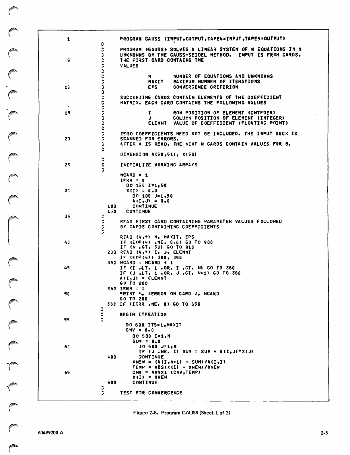
GAUSS
Program GAUSS (figure 2-8) solves a linear system of N
equations in N unknowns by the Gauss-Seidel method. The
system is of the form:
+ a. x = b.
I n n 1
21xl + a22x2 + ,2nxn!sb2
nl*l * dn2*2 n n n n
60499700 A 2-1
0m*.
15
2C
25
33
35
kC
V=>
55
65
7C
PR0GRA1 ACCTAB (INPUT,OUTPUT ,TAPE«»=INPUT>
DIMENSION TIME(10), ACC(IC)
*SAO THE, MASS, FORCE, ANO COMPUTE ACCELERATION TABLE
N * C
IER » 3
130 REAO (%,*) T, AMASS, F
IF <EO-(U) .NE. 0) GO TO 15C
N = H *■ 1
IF IN .GT. 10 ) GO TO 600
ZF (AMASS .LE. 0.) GO TO 70C
TIME(N»; = T
ACC(NI * F/AMASS
GO TO XOC
C....PRINT A3CELERATION TABLE
150 NTIMES * N
PRINT 10
PRINT 15, (TlMEm,ACCU),1 = 1,NTIMES)
IF (IE* .NE. 0) GO TO 900
C
S....REAO A SARD CONTAINING A TIME VALUE
C130 REAO (!»,*) T
IF C E OF U ) .N E. fi ) GO TO 90 0
N = N r 1
IF (T .'LT. TIME(l) .OR. T .GT. TINECNTIMES) ) GO TO 800
IF (T .LE. TIME(NTIHES-D) GO TO 195
IT = NTIMES - 1
GO TO 220
.SEARCH ACCELERATION TABLE
195 LIH * HTINES - 1
OO 200 I * 2,LIM
IT s I
IF if .LF. TIMEUTH GO TO 220
233 CONTINUE
GO TO 95C
DO SECOND DEGREE INTERPOLATION
223 DI = TIMECIT-1) - TIME(IT)
02 = TIME(IT-l) - TIME(IT*1)
03 = TIMEIITI - TIME<IT«-1)
I F ( D I . E Q . 0 . . O R . 0 2 . E O . C . . O R . 0 3 . E Q . 0 . ) G O TO 8 5 0
Ol = T - TIME(IT-l)
32 = T - TIME(IT)
03 = T - TIMEiIT»l)
ACCX = Q2»Q3»ACCCIT-1)/(01*D2>
1 - 01»I3*ACCCIT)/(01*03)
2 ♦ Ql*a2»ACC(IT*l)/(D2»03)
PRINT 25, T, ACCX
GO TO 190
SOD PRINT », * TOO MUCH OATA. MAX NO. OF TIMES IS 10*
STOP
730 PRINT •;, ^INVALID VALUE FOR AMASS *, N
I * R * t
GO TO 100
930 PRINT •, * BAD TIME, VftLUE IS*, T
SO TO 190
353 PRINT *, * INTERPOLATION PROBLEMS, TABLE ERROR*
30 TO 190
933 PRINT »;, t END ACCTAB*
STOP
13 FORMAT (*1*,2<* TIME ACCEL*))
15 FORMAT (2(5XF7.2,2XF8.5))
25 FORMAT <* TIME = *,F7.2,* ACCELERATION = *,F8.5)
END
A^S.
<^V
/"^(V
Figure 2-1. Program ACCTAB
2-2 60499700 A
^k^!»
/SiP^v
/fSN
Figure 2-2. Second Degree Interpolation
0m\
0§^S
(Time Mass Force)
0. 100. 1000.
1. 100. 1010.
2. 100. 1020.
3. 100. 1030.
4. 100. 1040.
5. 100. 1050.
7/8/9
0.
0.5 (Selected Times)
3.6
4.9
6.0
6/7/8/9
Figure 2-3. Sample Input Deck
This can be rewritten as:
x1 = -(a12x2 + a13X3 + ... + alnxn)/a11
x2 = -(a21x1 + a23x3 + ... + a2nxn)/a22
n n l 1 n Z Z n , n - l n - l n n
Successive approximations are generated by applying the
iteration
x.^«=:^b..x.<i<*»,s b,x.«.o.
i j = i i j j j = i i j j i
where:
yp&j^v
bj- = -aijA»ii (for i=l,n; j=l,n)
b.. = 0 (for i = j)
c. = b./a.. (for i=l,n)
time: a::sl TIMF ACCEL
ccc lc.aecce l.CC 10.100CC
2 . C C 1 3 . 2 C C a O 3 . G C 1 0 . 3 0 0 0 0
U . Z O l ( . , 4 C 0 u 0 F. G O 1 0. 5 0 C O C
TIME O . G C A 3 C t LT P 4 T i n \ = 13.0 3QOG
TIME = . S l A C : r . L s R A T I O M = 10.C500G
TIME = 3 . < S C A C : f L £ = , . a T I ^ N = 1C-.36 2QC
TIME = 4 . 1 C « C C F L f R A T I 0 N = 1 2 . 4 9 03 0
BAO TIKC, VALU? IS6.
ENO ACCTAB
Figure 2-4. ACCTAB Output
and the notation x
solution vector for x
(k) indicates the (k+i)st iteration of the
X o , • . . , x .
v «2
The algorithm begins with an
value of the solution vector
initial
X(0)
guess
(X(0)=
a t t h e
(x^O),
x?(0), .. ., x (0))) and substitutes that vector into the right
hand side of the relation to generate a vector X(l), which
should be a better approximation to the solution. It then
substitutes X(l) into the equation to yield X(2). Continuing
in this manner, it generates successive approximations until
it achieves the desired degree of accuracy. The criterion
for convergence is
lx5(k+1> - x<k>l
m a x l i
l<I<n T^kTITf
< E
for a prescribed E. In others words, when the difference
between successive values of x. is sufficiently small, the
process is considered to have converged. If this criterion is
not satisfied after a prescribed number of iterations, the
process is assumed not to converge and the iteration is
discontinued.
Input to the program is from data cards. Sample input is
shown in figure 2-9. The first card specifies the number of
equations and unknowns (N), the maximum number of iter
ations (MAXIT), and the convergence criterion (EPS).
Succeeding cards specify the elements of the coefficient
60499700 A 2-3
<*
*
PROGRAH NEKTON (INPUT, OUTPUT, TAPE5«0UTPUT)
PROGRAM JNEMTON* FINOS THE ROOTS OF THE EQUATION OEFINEO IN THE
FUNCTION STATEMENT BY NEHTON*S METHOO. THE FOLLOHIMG VALUES ARE
5cINPUT
-J
cX9. INITIAL APPROXIMATION
cEPS CONVERGENCE CRITERION
10 fx
I I'M AX MAXIMUM NUMBER OF ITERATIONS
rt
EQUATION TO BE SOLVED
rf
*FIX) = SIN(X) - <X»1.0)/<X-1.0)
15 rf DERIVATIVE OF EQUATION
rf
DERIV(X) = COS<X) ♦ 2.0'(X-1.0>**2
rf
REAO *, XO, EPS, ITNAX
20 IF (DE*|V(X0» .EQ. 0.0) GO TO 300
DO 100 1*1,ITMAX
I T S * I !
XI = XB - F(XQ)/OERIV(X0)
Y » FCC1)
25 PR I N T • ; , * x , v a , X 0 V V
IF CAQSKX1 - X0) .LE, EPS) GO TO 200
XO s XI
100 CONTINUE
HRITE (5,20) ITMAX
30 STOP
290 MRITE 15,10) ITS, XO
STOP
300 WRITE <5,30) X0
STOP
35 ia FORMAT (* METHOO HAS CONVERGEO IN *,I3,* ITERATIONS*,//* X = *,
LE12.4)
29 FORMAT <* METHOO HAS NOT CONVERGED IN *,I3 ,* ITERATIONS*//
1,* EXECUTION TERMINATED*)
30 FORMAT <1X,E12.4, * IS INVALIO VALUE FOR X0«)
40 ENO
0ztf®§\
S*^K
Figure 2-5. Program NEWTON
0.0 ,0001 10
Figure 2-6. Input to NEWTON
matrix: each card contains the value of the element and
two integers indicating the position of the element within
the matrix. Zero elements need not be included.
The program begins by reading the input deck and scanning
for errors (lines 42-48). If an error is encountered, the card
number is printed along with an appropriate message and
processing terminates after the entire deck is scanned.
Once the matrix has been read and stored in array A, the
program applies the Gauss-Seidel scheme to generate the
solution values. The solution values are stored in array X.
An initial approximation for each value of X is required to
initiate the process. For the sake of simplicity, the values
of X are initially set to 0.
Three nested DO-loops control the iterative process
(lines 56-72). Each pass through the outer loop constitutes
X,Y 0. .1728053032033
X,Y -.3333333333333 • 01 S76*»99«»5L7376
X,Y -,«»16815892«*31 .00Q0113375%253679
X,Y -.42035645358^2 3. t 977975822'88E-U
METHOO HAS CONVERGED IN h ITERATIONS
X = -.4204E*00
^*^\
Figure 2-7. Output from NEWTON
one iteration. The variable MAXIT is used as the upper
limit, allowing the process to terminate if convergence does
not occur within the specified number of iterations. Each
pass through the middle loop yields a new approximation
XNEW for a particular element of the solution vector. The
inner loop sums the rows of the matrix.
The variable CNV is initially set to 0. After an approxima
tion to a particular x has been calculated, CNV is set to
the difference between the new approximation and the
previous approximation, if the difference is greater than the
current contents of CNV. Thus, CNV always contains the
maximum of the differences between the new and previous
values of the solution vector.
^2£5N-'
2-4 60499700 A
■^^v
10
15
23
25
3C
35
40
45
50
55
6C
65
133
150
PROGRAH GAUSS <INPUT»0UTPUT,TAPE%*INPUT,TAPE5«0UTPUT)
PROGRA* 'GAUSS* SOLVES A LINEAR SYSTEM OF H EQUATIONS IN N
JNKNOUNS BY THE GAUSS-SEIOEL METHOD. INPUT IS FROM CARDS.
THE FIRST CARD CONTAINS THE
VALUES
N NUHBER OF EQUATIONS ANO UNKNOWNS
MAXIT MAXIMUM NUHBER OF ITERATIONS
EPS CONVERGENCE CRITERION
SUCCEEDING CAROS CONTAIN ELEMENTS OF THE COEFFICIENT
MATRIX. EACH CARO CONTAINS THE FOLLOWING VALUES
I ROW POSITION OF ELEMENT (INTEGER)
J COLUMN POSITION OF ELEMENT (INTEGER)
ELEMNT VALUE OF COEFFICIENT (FLOATING POINT)
ZERO COEFFICIENTS NEEO NOT BE INCLUDED. THE INPUT OECK IS
SCANNED FOR ERRORS.
AFTER A IS REAO, THE NEXT N CAROS CONTAIN VALUES FOR 8.
DIMENSION A(50,51), X(5C)
INITIALIZE WORKING ARRAYS
NCARD * 1
i r R R * 0
OO 150 1=1,50
XU) = 0.0
on ioo j=i,50
All,J) = 0.0
CONTINUE
CONTINUE
REAO FIRST CARO CONTAINING PARAMETER VALUES FOLLOWED
BY CARDS CONTAINING COEFFICIENTS
900
233
353
359
330
READ ( V , * ) N, M AXI T, EPS
IF »Ef>P(4I • NE. 0 . 0 ) GO TO
IF (N . G T. 50) G 0 TO 910
RFAO < '♦.»» I t J i ELEMNT
IF (EC -(4)) 333, 350
NCARO = NCARD ♦
IF (I .=LT. 1 .OR . I • GT. N
IF (J . L T . 1 .OR • J . G T. N
A(l, J » = ELEMNT
GO TO 200
IERR =
ORINT »., *ERROR ON CARD *,
GO TO 200
IF ( I ? RR .1* E . 0 ) GO 'TO 650
GO TO 360
Nfi ) GO TO 360
NCARO
'♦0 9
509
BEGIN ITERATION
DO 600 ITS=1,MAXIT
CNV = 0.0
DO 500 1=1,N
S U I = 0 . 0
DO 400 J=1,N
I F ( J . N E . I ) S U M = S U M ♦ A(I,J)*X(J)
CONTINUE
XNEW = (A(I,N+1) - SUM)/A(I,I)
TEMP = ABS(X(I) - XNEW)/XNEW
CN/ = AMAX1 (CNV,TEMP)
XU) = XNEW
CONTINUE
TEST F:rR CONVERGENCE
Figure 2-8. Program GAUSS (Sheet 1 of 2)
60499700 A 2-5
0m\
70
IF ONV .LE. EPS) GO TO 700
630 CONTINUE
PRINT », ^PROCESS HAS NOT CONVERGED IN *,MAXIT,* ITERATIONS*
650 PRINT *, *EXECUTION TERMINATED*
75 STOP
739 PRINT »:, *PROCESS HAS CONVERGED IN *,ITS,* ITERATIONS*
PRINT *, *SOLUTION VALUES ARE*
PRINT 30, (X(I),I=1,N>
33 FORMAT (1X,8E12.4)
80 STOP
930 PRINT *, *INSUFFICIENT INPUT OATA, CANNOT CONTINUE*
STOP
910 PRINT », *N * *,N,* IS TOO LARGE: MUST BE .LE. 50*
STOP
85 ENO
/*^\
Figure 2-8. Program GAUSS (Sheet 2 of 2)
3 50 .0001
1 1 10.
1 2 1.
13 1.
14 24.
2 1 1.
2 2 10.
2 3 1.
24 24.
31 1.
32 1.
3 3 10.
3 4 24.
Figure 2-9. Input to GAUSS
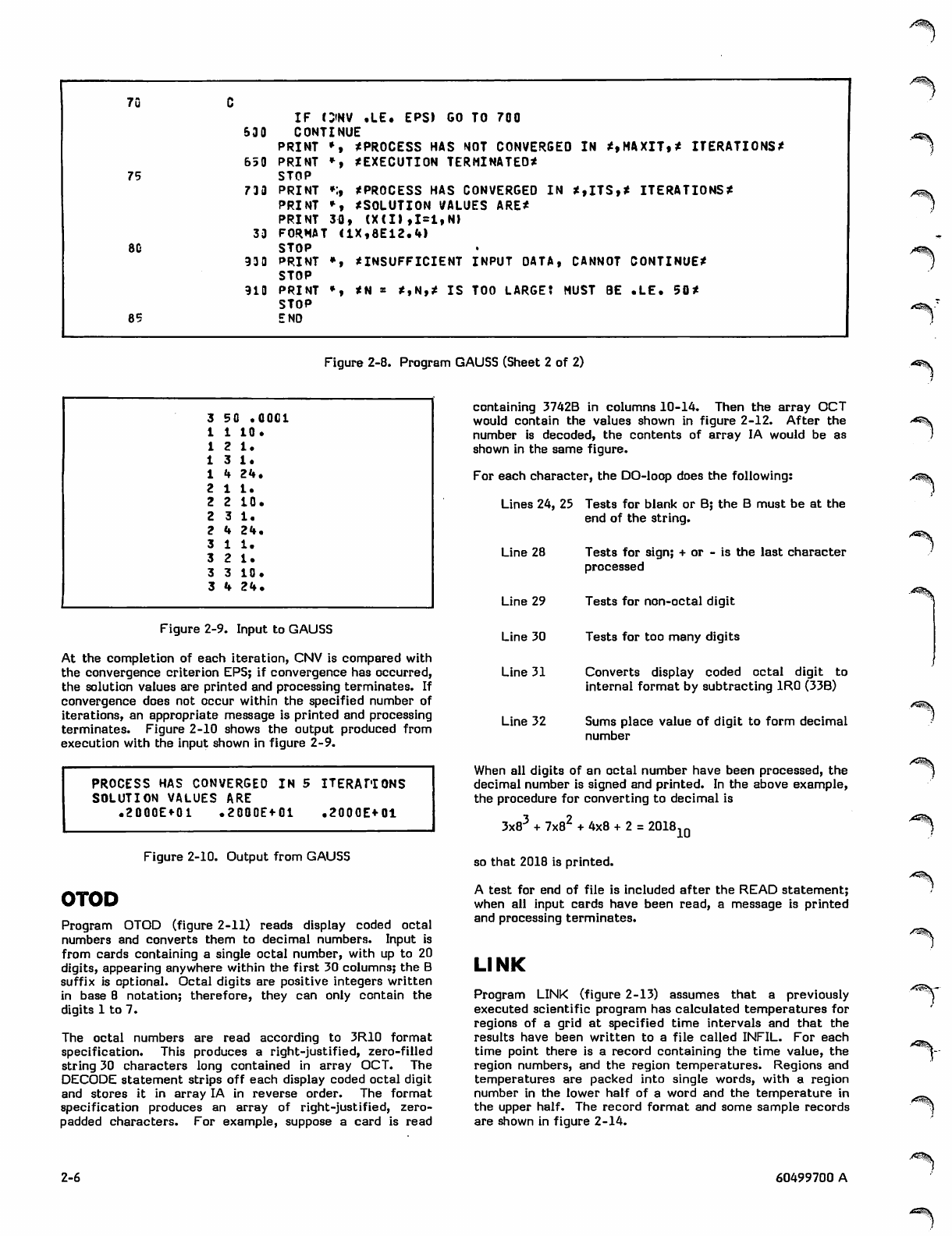
At the completion of each iteration, CNV is compared with
the convergence criterion EPS; if convergence has occurred,
the solution values are printed and processing terminates. If
convergence does not occur within the specified number of
iterations, an appropriate message is printed and processing
terminates. Figure 2-10 shows the output produced from
execution with the input shown in figure 2-9.
PROCESS HAS CONVERGED IN 5 ITERATIONS
SOLUTION VALUES ARE
.2000E«-01 .2000E+01 .2000E+01
containing 3742B in columns 10-14. Then the array OCT
would contain the values shown in figure 2-12. After the
number is decoded, the contents of array IA would be as
shown in the same figure.
For each character, the DO-loop does the following:
Lines 24, 25 Tests for blank or B; the B must be at the
end of the string.
Line 28 Tests for sign; + or - is the last character
processed
Line 29 Tests for non-octal digit
Line 30 Tests for too many digits
Line 31 Converts display coded octal digit to
internal format by subtracting 1R0 (33B)
Line 32 Sums place value of digit to form decimal
number
When all digits of an octal number have been processed, the
decimal number is signed and printed. In the above example,
the procedure for converting to decimal is
3x83 + 7x82 + 4x8 + 2 = 2018 10
Figure 2-10. Output from GAUSS so that 2018 is printed.
OTOD
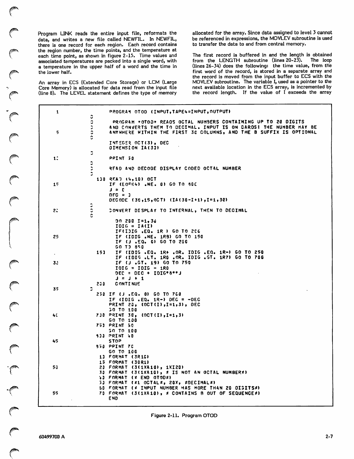
Program OTOD (figure 2-11) reads display coded octal
numbers and converts them to decimal numbers. Input is
from cards containing a single octal number, with up to 20
digits, appearing anywhere within the first 30 columns; the B
suffix is optional. Octal digits are positive integers written
in base 8 notation; therefore, they can only contain the
digits 1 to 7.
The octal numbers are read according to 3R10 format
specification. This produces a right-justified, zero-filled
string 30 characters long contained in array OCT. The
DECODE statement strips off each display coded octal digit
and stores it in array IA in reverse order. The format
specification produces an array of right-justified, zero-
padded characters. For example, suppose a card is read
A test for end of file is included after the READ statement;
when all input cards have been read, a message is printed
and processing terminates.
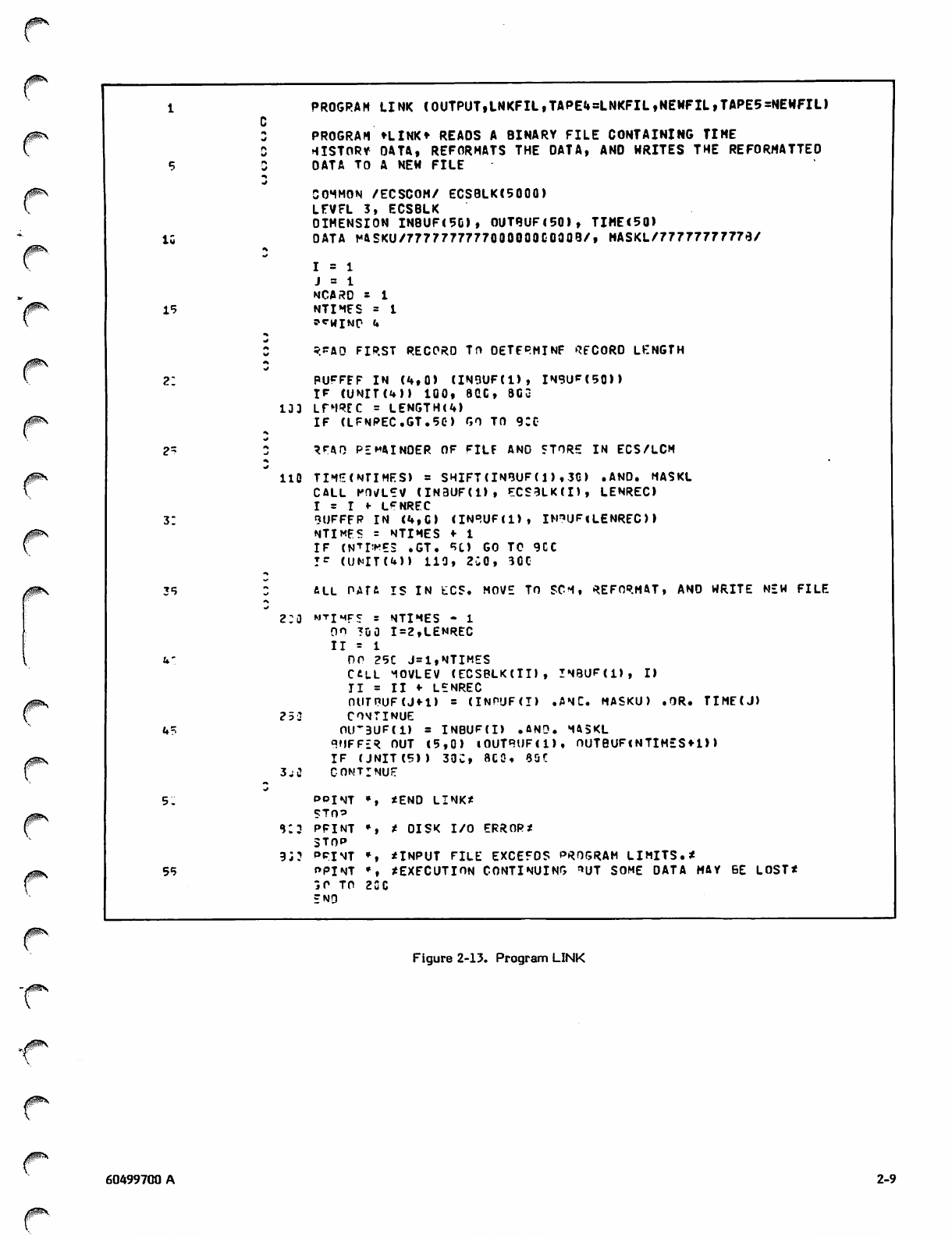
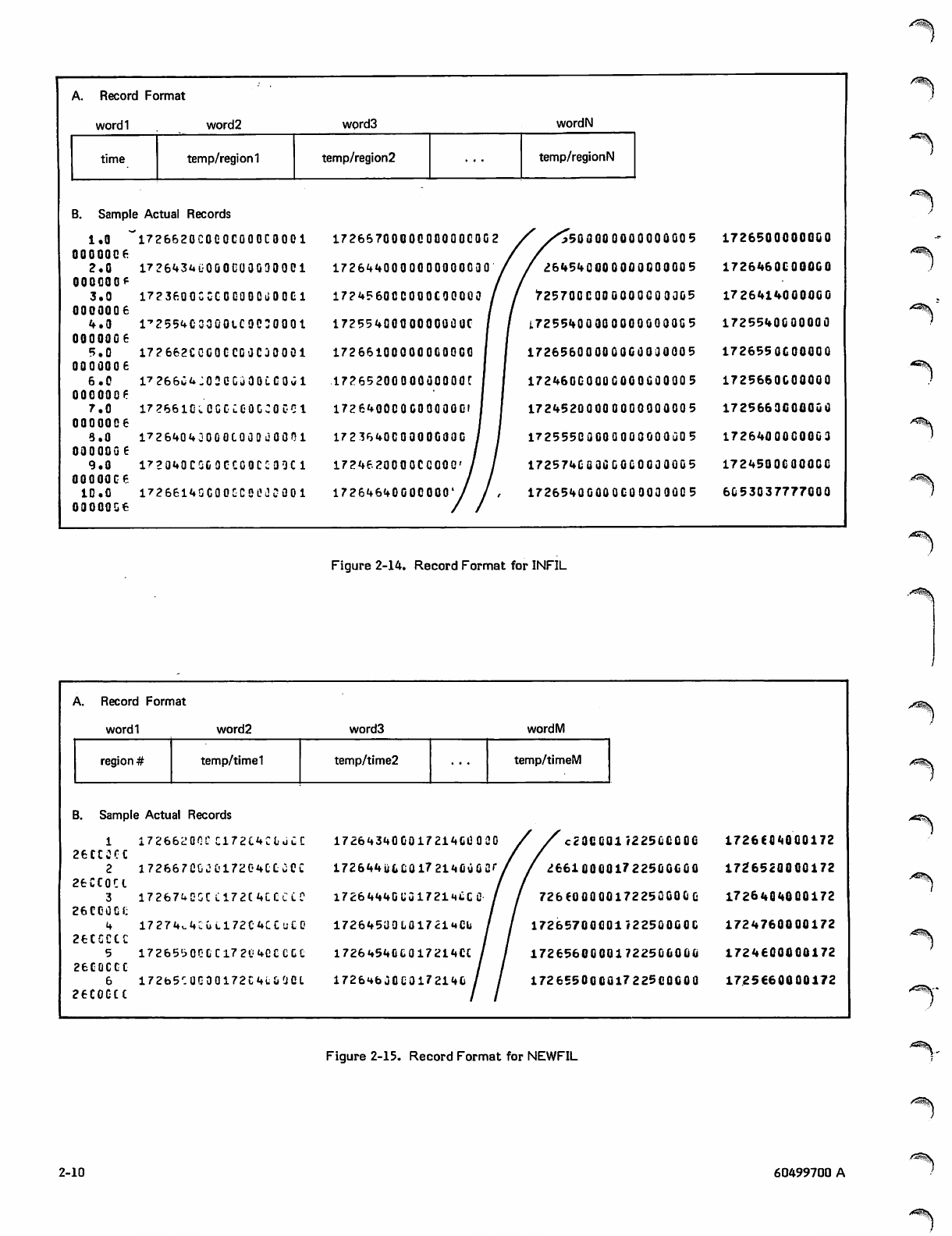
LINK
Program LINK (figure 2-13) assumes that a previously
executed scientific program has calculated temperatures for
regions of a grid at specified time intervals and that the
results have been written to a file called INFIL. For each
time point there is a record containing the time value, the
region numbers, and the region temperatures. Regions and
temperatures are packed into single words, with a region
number in the lower half of a word and the temperature in
the upper half. The record format and some sample records
are shown in figure 2-14.
/SisSV--
2-6 60499700 A
,i*3!|i
Program LINK reads the entire input file, reformats the
data, and writes a new file called NEWFIL. In NEWFIL,
there is one record for each region. Each record contains
the region number, the time points, and the temperature at
each time point, as shown in figure 2-15. Time values and
associated temperatures are packed into a single word, with
a temperature in the upper half of a word and the time in
the lower half.
An array in ECS (Extended Core Storage) or LCM (Large
Core Memory) is allocated for data read from the input file
(line 8). The LEVEL statement defines the type of memory
allocated for the array. Since data assigned to level 3 cannot
be referenced in expressions, the MOVLEV subroutine is used
to transfer the data to and from central memory.
The first record is buffered in and the length is obtained
from the LENGTH subroutine (lines 20-23). The loop
(lines 26-34) does the following: the time value, from the
first word of the record, is stored in a separate array and
the record is moved from the input buffer to ECS with the
MOVLEV subroutine. The variable I, used as a pointer to the
next available location in the ECS array, is incremented by
the record length. If the value of I exceeds the array
iijPx
r\
PROGRA"! OTOO (INPUT,TAPE4=INPUT,OUTPUT)
Irf
n
rf PROGRAM *OTO0* REAOS OCTAL NUM9ERS CONTAINING UP TO 20 OIGITS
rf AND CONVERTS THEM TO DECIMAL. INPUT IS ON CARDS? THE NUMBER MAY BE
5rf ANYWHERE WITHIN THE FIRST 3C COLUMNS, AND THE B SUFFIX IS OPTIONAL
rf
INTEGER OCTC3), OEC
DIMENSION IA(33)
i:
rf
PPINT 5 0
rf
RFAO AND OECOOE DISPLAY CODED OCTAL NUMBER
rf
130 RFAT 14,10) OCT
15 I F ( E 0 * ( 4 ) . N E . 0 ) G O TO 3 0 C
J s C
OFC = 3
DECODE (3C,l5,OCT) (IA ( 30-H-l) ,1 = 1, 30)
2;
rf
rfr,
CONVERT DISPLAY TO INTERNAL, THEN TO DECIMAL
u
OO 200 I=lt3U
IOIG = IA(I)
IP(IDIG .EQ. 1R ) GO TO 2CC
25 IF ( I DIG . N E . 1 R 9 ) G O T O 1 5 0
IF ( J . E Q . 0 ) GO TO 200
GO TD 850
153 IF ( I D I G . E Q . 1 R « - . O R . I D I G . E Q . 1R-) G O T O 2 5 0
I F ( I D I G . LT. 1 R 0 . O R . I O I G . G T. 1 R 7 ) G O T O 7 0 0
33 I F ( J . G T. 1 9 ) G O T O 75 0
I O I G = I O I G - 1 R 0
OEC = DEC «• IOIG*8»»J
J = J f 1
35 *% 223 CONTINUE
253 IF ( J .EQ. 0) G O TO 7G 0
IF (IOIG .EQ. 1R-) OEC = -DEC
P R I N T 2 0 , ( O C T ( I ) , I = l , 3 ) , O E C
SO TO 100
4£ 730 PRINT 30, (OCT(I),I=l,3l
GO TO 100
753 PRINT 30
sn TO 100
933 PRINT *0
45 STOP
35fl PPINT 7C
GO TO 100
13 FORMAT (3R1C)
15 FORMAT (30R1)
50 23 FORMAT (3(1XA10), 1X120)
33 FORMAT (3(1XA10), * IS NOT AN OCTAL NUMBER*)
♦ 3 FORMAT (* END OTOD*)
33 FORMAT (*1 OCTAL*, 20X, *OECIMAL*)
30 FORMAT (* INPUT NUMBER HAS MORE THAN 20 DISITS*)
55 73 FORMAT (3(1XA10), * CONTAINS B OUT OF SEQUENCE*)
ENO
Figure 2-11. Program OTOD
60499700 A 2-7
j$s^
boundary, a warning message is printed; no more data is read
but processing continues on the incomplete array. The next
record is read and the record counter NTIMES is incre
mented; if NTIMES exceeds its limit, a warning message is
printed and the incomplete array is processed. Records are
read and stored in this manner until either the end-of-file is
reached or the ECS array is full.
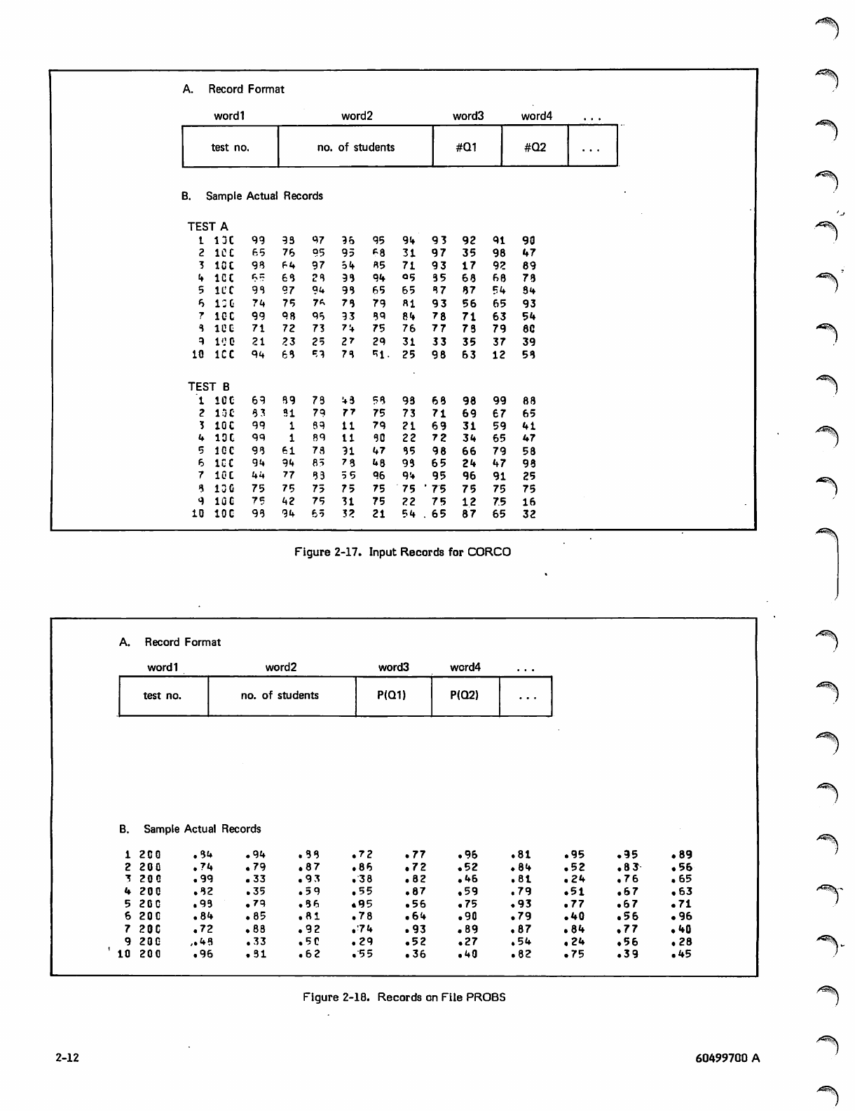
The program reads the two files and, for each test,
calculates the probability that a student will answer each
question correctly, calculates a correlation coefficient,
calculates a new probability for each question, and writes a
new file. The output file record contains the test number,
number of students, and the probability that a student will
answer each question correctly. The output record format,
along with some sample records, is shown in figure 2-18.
When the entire file, or as much of it as possible, has been
read and stored in ECS, lines 38 through 48 construct the
output records and write the output file NEWFIL. Each pass
through the outer DO-loop constructs a single output record;
each pass through the inner DO-loop stores a single word in
the output record. On the first pass through the inner loop,
the first input record is transferred to central memory via
MOVLEV; its time value is packed with the temperature
value of the first region and stored in the output buffer OUT
to form the second word of the output record. On the
second pass, the second input record is moved to central
memory, and the time value is packed with the temperature,
value for the first region to form the third word of the first
output record. When all times and temperatures for the
region have been stored in the output buffer (inner loop
completed), the region number is stored in the first word of
the output buffer and the new record is written. Then,
under control of the outer loop, the subsequent records are
constructed and written in a like manner, until the entire
array has been processed.
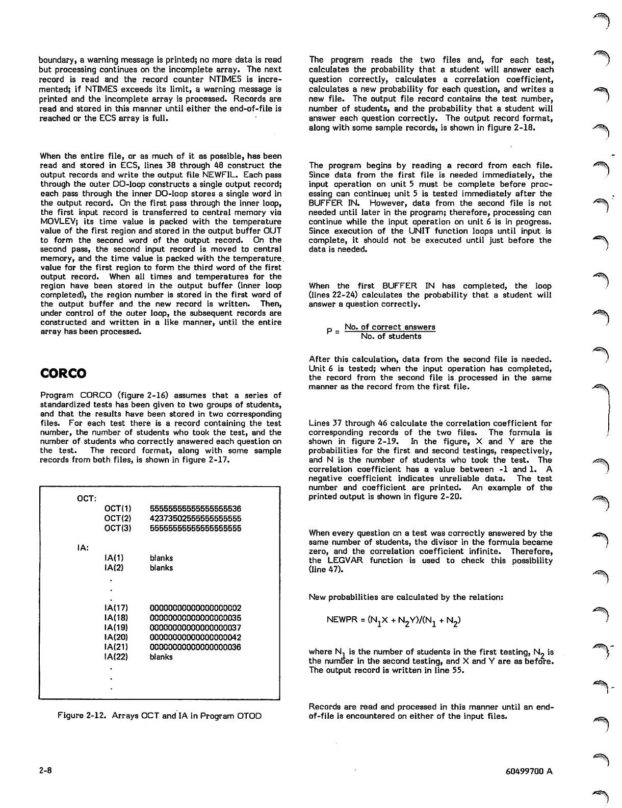
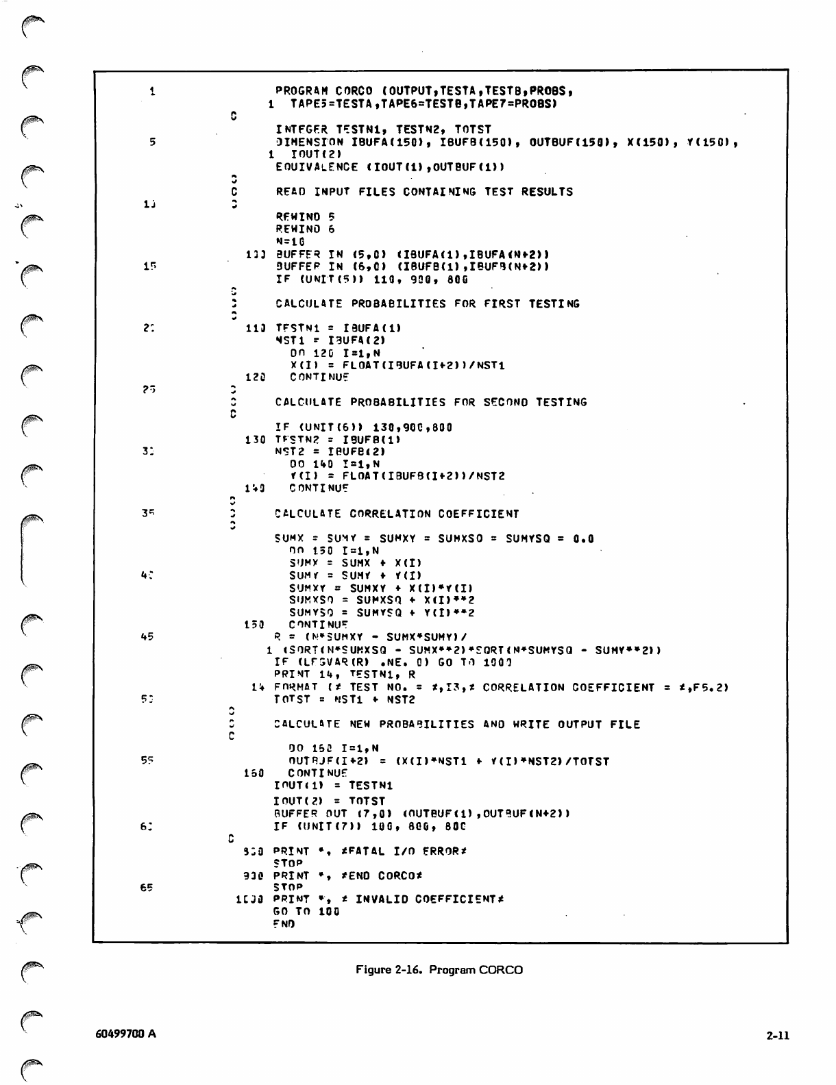
CORCO
Program CORCO (figure 2-16) assumes that a series of
standardized tests has been given to two groups of students,
and that the results have been stored in two corresponding
files. For each test there is a record containing the test
number, the number of students who took the test, and the
number of students who correctly answered each question on
the test. The record format, along with some sample
records from both files, is shown in figure 2-17.
OCT:
OCT(1) 55555555555555555536
OCT(2) 42373502555555555555
OCT(3) 55555555555555555555
IA:
IA(1) blanks
IA(2) blanks
IA(17) 00000000000000000002
IA(18) 00000000000000000035
IA(19) 00000000000000000037
IA(20) 00000000000000000042
IA(21) 00000000000000000036
IA(22) blanks
The program begins by reading a record from each file.
Since data from the first file is needed immediately, the
input operation on unit 5 must be complete before proc
essing can continue; unit 5 is tested immediately after the
BUFFER IN. However, data from the second file is not
needed until later in the program; therefore, processing can
continue while the input operation on unit 6 is in progress.
Since execution of the UNIT function loops until input is
complete, it should not be executed until just before the
data is needed.
When the first BUFFER IN has completed, the loop
(lines 22-24) calculates the probability that a student will
answer a question correctly.
P = No. of correct answers
No. of students
Figure 2-12. Arrays OCT and IA in Program OTOD
After this calculation, data from the second file is needed.
Unit 6 is tested; when the input operation has completed,
the record from the second file is processed in the same
manner as the record from the first file.
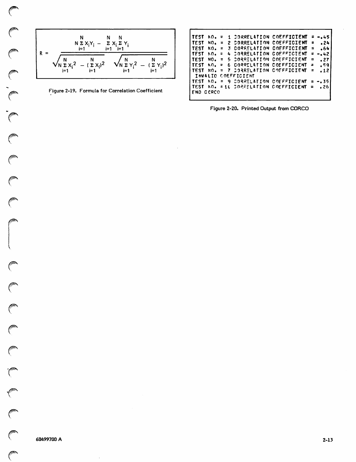
Lines 37 through 46 calculate the correlation coefficient for
corresponding records of the two files. The formula is
shown in figure 2-19. In the figure, X and Y are the
probabilities for the first and second testings, respectively,
and N is the number of students who took the test. The
correlation coefficient has a value between -1 and 1. A
negative coefficient indicates unreliable data. The test
number and coefficient are printed. An example of the
printed output is shown in figure 2-20.
When every question on a test was correctly answered by the
same number of students, the divisor in the formula became
zero, and the correlation coefficient infinite. Therefore,
the LEGVAR function is used to check this possibility
(line 47).
New probabilities are calculated by the relation:
NEWPR = (NXX + N2Y)/(N1 + N2)
where N, is the number of students in the first testing, N2 is
the number in the second testing, and X and Y are as before.
The output record is written in line 55.
Records are read and processed in this manner until an end-
of-file is encountered on either of the input files.
^n®£\
.'^^1
«*^§\
'<s%
<*s^jl
2-8 60499700 A
PROGRAH LINK (OUTPUT,LNKFIL,TAPE4=LNKFIL,NEWFIL,TAPE5=NEMFIL)
PROGRAM »LINK* READS A BINARY FILE CONTAINING TINE
4/ HISTORY OATA, REFORMATS THE DATA, ANO WRITES THE REFORMATTED
5 DATA TO A NEW FILE
^
COMMON /ECSCOM/ ECSBLK(5000)
LFVFL 3, ECSBLK
OIMENSION IN8UF(50), OUTBUF(50), TIHEC5Q)
IG DATA MASKU/777777777700000000003/, MASKL/77777777778/
1 = 1
J = 1
NCARD = 1
15 NTIMES = 1
^ W I NP t ,
A
wRPAD FIRST RECORD TO DETERMINE RECORD LENGTH
2: PUFFFF IN (4,0) (IN3UF(1), lN9U«r(50))
IP (UNIT (4 M 100, 8GC, 802
133 LFMREC = LENGTH(4»
^IF (LFNPEC.GT.5C) GO TO 9CC
2" r\ RFAO PEMAINDER OF FILF AND STORE IN ECS/LCM
*S
110 TIME(NTIMES) = SHIFT(INBUF(1),3C) .ANO. MASKL
CA LL MOV LEV (I N BUF (l) , E CS9 LK( I), LE NRE C )
I = I ♦■ LFNREC
3: 5UFFFP IN (4,C) (INRUF(l), IN?UF(LENREC>)
NTIMES = NTIMES ♦ 1
IF (NTI«MES .GT. ^C) GO TO 9GC
I r ( U M T C I I 1 1 0 , 2 C 0 , 3 C C
35 ALL OATA IS IN lCS. MOVE TO SCM, REFORMAT, ANO WRITE NEW FILE
2:o mtimpc = NTIMES - 1
OO 7ufl 1=2,LENREC
I I = 1
U~ OO 25C J=l,NTIMES
CALL MOVLEV (ECSBLKdl), INBUF(l), I)
I I = I I * L E N R E C
OUTPUFU + l) = (INPUF(I) .ANC. MASKU) .OR. TIME(J)
253 COMTINUE
U5 OU"3UF(l) = INBUF(I> .AND. MASKL
SUFFER OUT (5,0) lOUTBUF(l), OUTBUF(NTIMES*l))
IF (JNIT(5)) 30C, 8CQ, 80C
3j3 CONTINUE
5.
«r
POIN T * , * END L I N K *
313 PFINT ♦, * OISK I/O ERROR*
STOP
9i? PRINT ♦, *INPUT FILE EXCEFOS PROGRAM LIMITS.*
55 PPINT *, *EXECUTION CONTINUING ?»UT SOME DATA MAY BE LOST*
SO TO 2CC
END
0S&\
Figure 2-13. Program LINK
0^*,
60499700 A 2-9
A. Record Format
wordl word 2 word3 wordN
time temp/region 1 temp/region2 temp/regionN
B. Sample Actual Records
1.0 ~1726620C0CQCQ00C000i
0000006
2.0 17?643ul-00OC00QD0O01
0000006
3.0 17236QOCCC0GO00a00Gl
0000006
4.0 l72554C3COOLC0C:0O0t
0000006
5.0 17?662CCC0CC0aCJOOGl
0000006
6.C 17266C^:02CGj00uG0w1
0000006
7.0 1726610LCCCC00C:0C-C1
0000006
8.0 17264Q430C0CQGQO00IH
0000006
9.0 17'2040CC00CCC0Ce30Cl
00000G6
1D.0 1726614QC0OGCOL'JCa01
00000&6
1726670000000000CQG2
1726440000000000030
1724F60CC000C00000
1725540000000000C
172661000000COOCQ
172652000000000QC
172640000000000GI
1723640C0000G00C
1724620000CCOOC
17264640000000'
^500000000000005
264540000000000005
7257000000000000005
J.72554Q00Q000QGQ00G5
172656QQOOOQGG000005
172460G0OQCOGOC00005
17245200000000000005
17255500000000000005
1725740G0GCOCOO0QOG5
17265400000000000005
1726500000Q&0
1726460000000
1726414000OC0
1725540000000
172655OGOO000
1725660C0000Q
1725660000000
17264000G00G3
1724500C0OO0C
6053037777000 -^^•\
z''^.
Figure 2-14. Record Format for INFIL
A. Record Format
wordl word2 word3 wordM
region # temp/time 1 temp/time2 temp/timeM
B. Sample Actual Records
1 1726620QCC172C4Ctu£C
26CC0CC
2 17266?C&:-iJ172G4CC0eC
26CC0CI
3 17267U0GCC172C4CCCLC
26C00Ct
4 17274.4CGL172C4CCuC0
2€CCCCC
5 17265'30GCCl72C''tCeCCC
26CQCGC
6 172b5r.0G0Q172C4i;&fjei
26C0CCC
172643400017214GC
172644u(,C0l72140vi
l7264440U0172mtC
172645a0Lfll72lMCb
1726454GC017214CC
1726**6J0C0172140
c20CG01r£25i;COOO
6610000172250CG0O
6(0000017225000(10
65700001722500000
65600001722500000
6550G0017225GOCOO
1726(04000172
172*6520000172
1726404000172
1724760000172
1724600000172
17.25660000172
Figure 2-15. Record Format for NEWFIL
•^s
,/sffjtisv
2-10 60499700 A
0$S
PROGRAM CORCO (OUTPUTiTESTA,TESTB»PROBS,
c1 TAPE5=TESTA,TAPE6=TESTB,TAPE7=PROBS)
INTEGER TESTN1, TESTN2, TOTST
5 D I M E N S I O N I B U FA ( 1 5 0 ) , I B U F B ( 1 5 0 ) , O U T B U F ( 1 5 0 > , X ( 1 5 0 ) , Y ( 1 5 0 ) ,
1 IOUT(2»
r\
EOUIVALENCE (IOUT(l) ,OUTBUF(D)
IJ
READ INPUT FILES CONTAINING TEST RESULTS
w
RFWINO 5
REWIND 6
N=1G
133 BUFFER IN (5,0) (IBUFA(l) ,IBUFA (Nf 2) )
ir> 3 U F F E P I N ( 6 , 0 ) ( I B U F B ( l ) , I B U F 9 ( N » 2 ) )
IF (UNIT(5)) 110, 930, 800
-* CALCULATE PROBABILITIES FOR FIRST TESTING
2: •*
113 TFSTN 1 = I B U FA ( l )
NST1 - I9UFA(2)
OO 120 1=1,N
X(I) = FLOAT (IBUFA(Ifr2))/NSTl
?ri
120 CONTINUE
cCALCULATE PROBABILITIES FOR SECONO TESTING
IF (UNIT(6)) 130,900,800
130 TFSTN2 = IBUFB(l)
3: NST2 = IBUFB<2)
OO 140 1=1,N
Y ( I > = F L O AT ( I B U F B ( I * 2 ) ) / N S T 2
f*
143 CONTINUE
3* CALCULATE CORRELATION COEFFICIENT
*»
SUMX r SUMY = SUMXY = SUMXSO = SUMYSQ = 0.0
OO 150 1=1,N
SUMX s SUMX «■ X(I)
u: SUMY = SUMY * Y(I)
SUMXr = SUMXY ♦ X(I)*Y(I)
SUMXSO = SUMXSO ♦ X(I)**2
SUMYSO = SUMYSQ f Y(I)**2
150 CONTINUE
45 R = (M»SUMXY - SUMX*SUMY)/
1 (SORT(N*SUMXSQ - SUMX<^2>*EORT(N*SUMYSQ - SUMY»»2))
IF (LFSVAR(R) .NE. 0) GO TO 1000
PRINT 14, TFSTN1, R
14 FO R MAT ( * TES T NO. = * ,I3 ,* COR R ELAT ION CO E FFI CIE NT = *,F 5 .2)
?: TOTST = NSTl f NST2
C
CALCULATE NEW PROBABILITIES AND WRITE OUTPUT FILE
OO 150 1=1,N
5? OUTRJF(I*2) = (X(I)*NST1 *■ i(I) *NST2) /TOTST
150 CONTINUE
I O U T ( l ) = T E S TN1
I OUT (2) = TOTST
BUFFER OUT (7,0) (OUTBUF(l),OUT«UF(N*2))
6; IF (UNIT(7)) 100, 800, 80C
a;o P R I N T * , *FATAL I / O E R R O R *
STOP
930 PRINT ♦, *ENO CORCO*
65 STOP
ujo PR INT •", * INVA LID C OEF FIC IE NT*
GO TO 100
ENO
Figure 2-16. Program CORCO
60499700 A 2-11
A. Record Format
wordl word2 word3 word4
test no. no. of students #Q1 #Q2
B. Sample Actual Records
TESTA
t I j C 99 93 97 96 95 94 93 92 9 1 9 0
2 ICC 65 76 95 95 *8 31 97 35 9 8 4 7
3 ICC 93 64 97 54 65 71 93 17 9 2 8 9
4 ICC 65 66 26 98 94 °5 35 68 6 8 7 3
5 ICC 93 97 9U 93 65 65 87 87 5'+ 3 4
o 13 G 74 75 7*. 78 79 HI 93 56 6 5 9 3
7 IOC 99 98 95 9 3 89 84 78 71 6 3 5 4
3 ICC 71 72 73 74 75 76 77 73 7 9 8 0
9 10 0 21 23 25 27 29 31 33 35 3 7 3 9
10 ICC 94 66 59 73 *1- 25 98 63 1 2 5 8
TEST B
1 ICC 69 89 73 43 53 93 68 98 9 9 8 8
2 IOC 63 31 79 77 75 73 71 69 6 7 6 5
'S IOC 99 69 11 79 21 69 31 5 9 4 1
4 IOC 99 69 11 80 22 72 34 6 5 4 7
5 1GC 98 61 73 91 47 85 98 66 7 9 5 8
6 ICC 94 94 85 73 48 93 &5 24 4 7 9 3
7 IOC 44 77 83 55 96 94 95 96 9 1 2 5
9 13G 75 75 75 75 75 75 * 75 75 7 5 7 5
9 IOC 75 42 75 31 75 22 75 12 7 5 1 6
10 IOC 96 94 65 32 21 54 . 65 87 6 5 3 2
Figure 2-17. Input Records for CORCO
A. Record Format
wordl word2 word3 word4
test no. no. of students P(Q1) P(Q2)
B. Sample Actual Records
12C0 .84 .94 .38 72 .77 .96 .81 .95 .95 .89
2200 .74 .79 .87 86 .72 .52 • 84 . 5 2 .8 3- • 56
320Q .99 .33 . 9 3 38 .82 .46 .81 . 2 4 . 7 6 .65
4200 .32 .35 . 5 9 . 55 .87 .59 .79 .51 . 6 7 .63
5 2QG .9 3 .79 . 3 6 4 95 .56 .75 .93 .77 .67 . 7 1
620C .84 .85 .81 78 .64 .9 0 .79 .40 • 56 • 96
720C .72 .83 . 9 2 74 .93 .89 .87 .84 . 7 7 • 40
9200 ,.43 .33 .50 29 .52 .2 7 .54 .24 • 56 .28
' 10 200 . 96 .31 . 6 2 55 .36 .40 .82 .75 . 3 9 .45
Figure 2-18. Records on File PROBS
2-12 60499700 A
j0Ss..
R =
N N N
N 2 XjYj - 2 Xj 2 Yj
i=1 i=1 i=1
/ N „ N " /
Vn 2 X:2 - ( 2 X:)2 Vn 2 Y:^ - ( 2 Y:
i=1 i=1 i=1 i=1
Figure 2-19. Formula for Correlation Coefficient
TEST KO. aoRRELATION COEFFICIENT - . 4 5
TEST NO, CORRELATION COEFFICIENT .24
TEST KO. CORRELATION COEFFICIENT .64
TFST NO. :oRRELArroN COFFrjciENT - . 4 2
TEST NO. CORRELATION COEFFICIENT • 27
TEST KO. CORRELATION COEFFICIENT .59
TEST NO. CORRELATION COEFFICIENT .12
INVALID (^EFFICIENT
TEST KO. CORRELATION COEFFICIENT - . 3 5
TEST KO. IC CORRELATION COEFFICIENT .26
END CCRCO
Figure 2-20. Printed Output from CORCO
0^\
y$SN
60499700 A 2-13

0**s
1
ry
*>
/P^v
OPTIMIZATION
The purpose of optimizing a program is to reduce the cost of
executing it. This cost is literally a cost in money, whether
the cost is charged to the individual user or shared among all
the users. Because the cost of a job results from the use of
several kinds of system resources, the cost can be reduced
by reducing the use of one or more of these resources.
These resources include central processor time, central
memory field length, and the various resources used in
input/output operations.
Frequently, however, a reduced expenditure of one resource
requires an increased expenditure of another. For instance,
the amount of memory required by a program can be
reduced by using segmentation or overlays (section 7), but
more- central processor time is then required. Conversely,
some optimization techniques, such as loop unrolling
(described in this section), decrease central processor time
at the expense of field length. Only the requirements of a
particular application can determine whether specific
optimizations are worthwhile.
A resource cost that is frequently overlooked when optimi
zation is considered is programmer time. As discussed in
section 1, program development, debugging, and mainten
ance frequently contribute more to the overall cost of a
program than the computer resources required to execute it.
Therefore, a programmer should be very cautious about
optimizing a program in such a way as to make it less
comprehensible or maintainable. Unless a program is to be
executed repeatedly, or to use a lot of resources, not much
time should be spent on user optimization.
This section describes both the optimizations that the
compiler performs for the user as well as those the user can
embody in the source code. Most of these optimizations
decrease central processor time (not always at the expense
of field length), but some decrease field length, input/output
time, or real time (throughput).
It should be kept in mind that the best way to optimize code
is to use efficient algorithms. The higher the level at which
a program is optimized, the better the results.
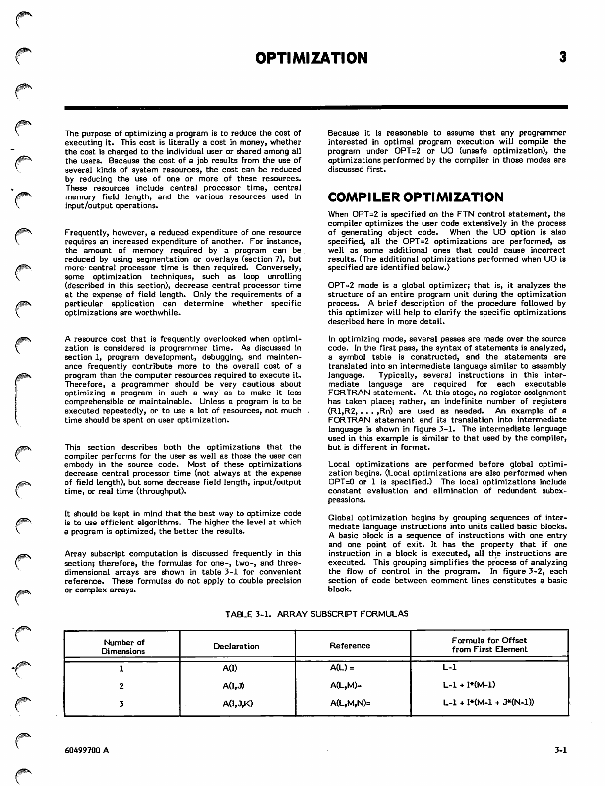
Array subscript computation is discussed frequently in this
section; therefore, the formulas for one-, two-, and three-
dimensional arrays are shown in table 3-1 for convenient
reference. These formulas do not apply to double precision
or complex arrays.
Because it is reasonable to assume that any programmer
interested in optimal program execution will compile the
program under OPT=2 or UO (unsafe optimization), the
optimizations performed by the compiler in those modes are
discussed first.
COMPILER OPTIMIZATION
When OPT=2 is specified on the FTN control statement, the
compiler optimizes the user code extensively in the process
of generating object code. When the UO option is also
specified, all the OPT=2 optimizations are performed, as
well as some additional ones that could cause incorrect
results. (The additional optimizations performed when UO is
specified are identified below.)
OPT=2 mode is a global optimizer; that is, it analyzes the
structure of an entire program unit during the optimization
process. A brief description of the procedure followed by
this optimizer will help to clarify the specific optimizations
described here in more detail.
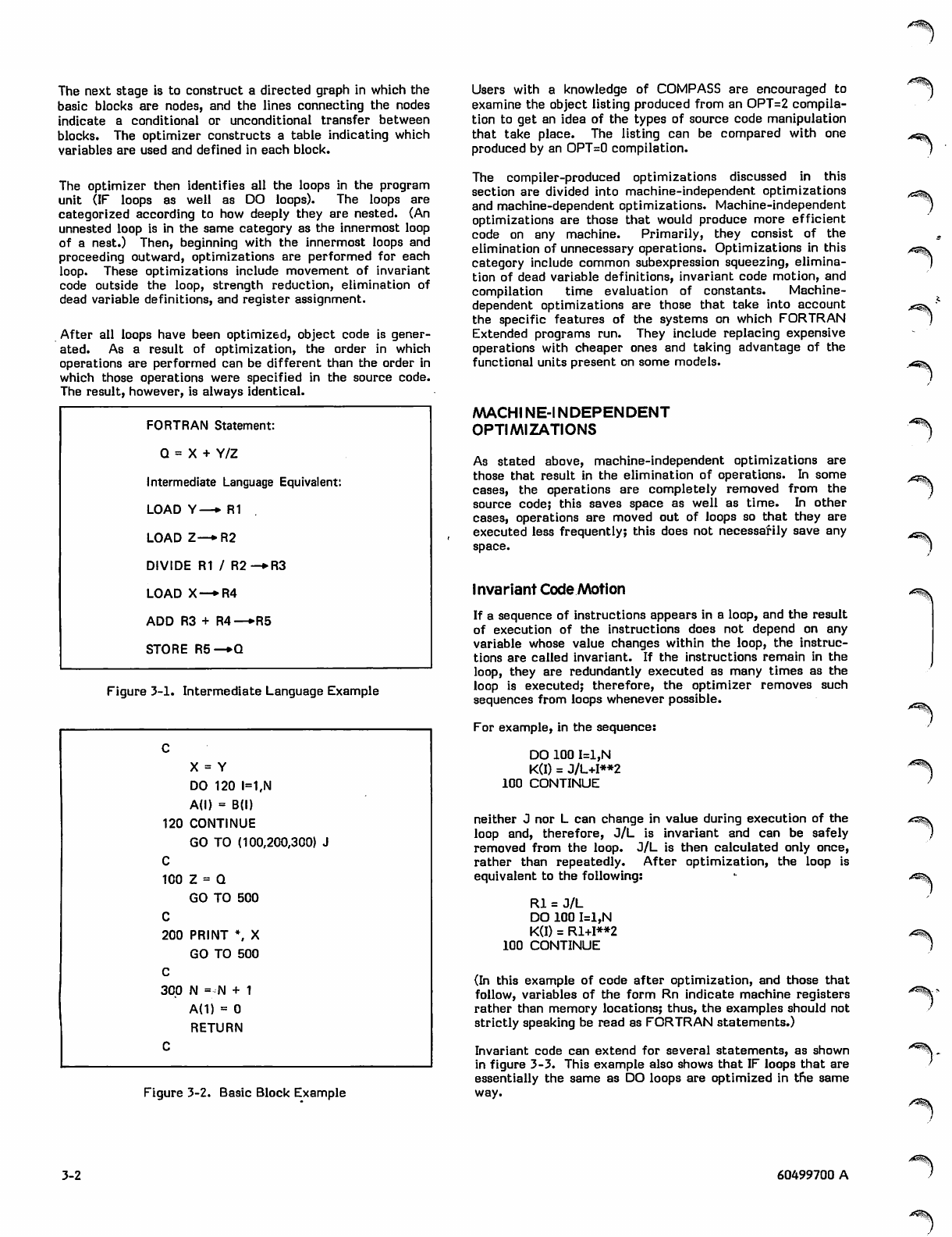
In optimizing mode, several passes are made over the source
code. In the first pass, the syntax of statements is analyzed,
a symbol table is constructed, and the statements are
translated into an intermediate language similar to assembly
language. Typically, several instructions in this inter
mediate language are required for each executable
FORTRAN statement. At this stage, no register assignment
has taken place; rather, an indefinite number of registers
(R1,R2, . .. ,Rn) are used as needed. An example of a
FORTRAN statement and its translation into intermediate
language is shown in figure 3-1. The intermediate language
used in this example is similar to that used by the compiler,
but is different in format.
Local optimizations are performed before global optimi
zation begins. (Local optimizations are also performed when
OPT=0 or 1 is specified.) The local optimizations include
constant evaluation and elimination of redundant subex
pressions.
Global optimization begins by grouping sequences of inter
mediate language instructions into units called basic blocks.
A basic block is a sequence of instructions with one entry
and one point of exit. It has the property that if one
instruction in a block is executed, all the instructions are
executed. This grouping simplifies the process of analyzing
the flow of control in the program. In figure 3-2, each
section of code between comment lines constitutes a basic
block.
TABLE 3-1. ARRAY SUBSCRIPT FORMULAS
0$S\
V
Number of
Dimensions Declaration Reference Formula for Offset
from First Element
1
2
3
A(I)
A(I,J)
A(I,J,K)
A(L) =
A(L,M)=
A(L,M,N)=
L-l
L-l + I*(M-1)
L-l + I*(M-1 + J*(N-D)
60499700 A 3-1
The next stage is to construct a directed graph in which the
basic blocks are nodes, and the lines connecting the nodes
indicate a conditional or unconditional transfer between
blocks. The optimizer constructs a table indicating which
variables are used and defined in each block.
The optimizer then identifies all the loops in the program
unit (IF loops as well as DO loops). The loops are
categorized according to how deeply they are nested. (An
unnested loop is in the same category as the innermost loop
of a nest.) Then, beginning with the innermost loops and
proceeding outward, optimizations are performed for each
loop. These optimizations include movement of invariant
code outside the loop, strength reduction, elimination of
dead variable definitions, and register assignment.
After all loops have been optimized, object code is gener
ated. As a result of optimization, the order in which
operations are performed can be different than the order in
which those operations were specified in the source code.
The result, however, is always identical.
FORTRAN Statement:
Q = X + Y/Z
Intermediate Language Equivalent:
LOAD Y—* R1
LOAD Z—*R2
DIVIDE R1 / R2-*R3
LOAD X—*R4
ADD R3 + R4—»R5
STORE R5—*Q
Figure 3-1. Intermediate Language Example
c
X = Y
DO 120 1=1,N
A(l) = B(l)
120 CONTINUE
GO TO (100,200,300) J
C
100 Z= Q
GO TO 500
C
200 PRINT \ X
GO TO 500
C
300 N = N + 1
A{1) = 0
RETURN
C
Figure 3-2. Basic Block Example
Users with a knowledge of COMPASS are encouraged to
examine the object listing produced from an OPT=2 compila
tion to get an idea of the types of source code manipulation
that take place. The listing can be compared with one
produced by an OPT=0 compilation.
The compiler-produced optimizations discussed in this
section are divided into machine-independent optimizations
and machine-dependent optimizations. Machine-independent
optimizations are those that would produce more efficient
code on any machine. Primarily, they consist of the
elimination of unnecessary operations. Optimizations in this
category include common subexpression squeezing, elimina
tion of dead variable definitions, invariant code motion, and
compilation time evaluation of constants. Machine-
dependent optimizations are those that take into account
the specific features of the systems on which FORTRAN
Extended programs run. They include replacing expensive
operations with cheaper ones and taking advantage of the
functional units present on some models.
MACHINE-INDEPENDENT
OPTIMIZATIONS
As stated above, machine-independent optimizations are
those that result in the elimination of operations. In some
cases, the operations are completely removed from the
source code; this saves space as well as time. In other
cases, operations are moved out of loops so that they are
executed less frequently; this does not necessarily save any
space.
Invariant Code Motion
If a sequence of instructions appears in a loop, and the result
of execution of the instructions does not depend on any
variable whose value changes within the loop, the instruc
tions are called invariant. If the instructions remain in the
loop, they are redundantly executed as many times as the
loop is executed; therefore, the optimizer removes such
sequences from loops whenever possible.
For example, in the sequence:
DO 100 I=1,N
K(I) = J/L+I**2
100 CONTINUE
neither J nor L can change in value during execution of the
loop and, therefore, J/L is invariant and can be safely
removed from the loop. J/L is then calculated only once,
rather than repeatedly. After optimization, the loop is
equivalent to the following:
Rl = J/L
DO 100 I=1,N
K(I) = Rl+I**2
100 CONTINUE
(In this example of code after optimization, and those that
follow, variables of the form Rn indicate machine registers
rather than memory locations; thus, the examples should not
strictly speaking be read as FORTRAN statements.)
Invariant code can extend for several statements, as shown
in figure 3-3. This example also shows that IF loops that are
essentially the same as DO loops are optimized in the same
way.
^^v
^ s \
3-2 60499700 A
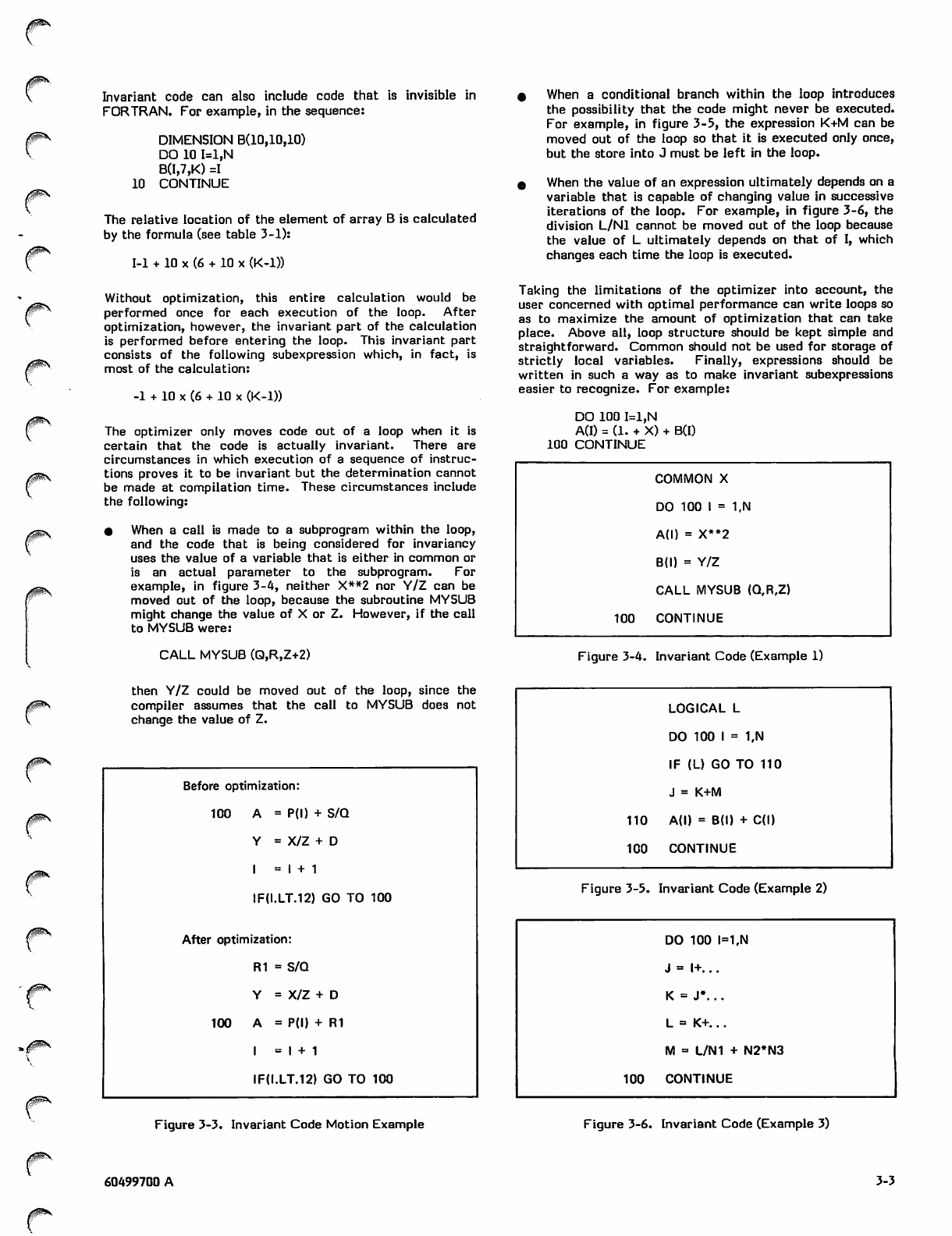
/fl^V
Invariant code can also include code that is invisible in
FORTRAN. For example, in the sequence:
DIMENSION B(10,10,10)
DO 10 I=1,N
B(I,7,K) =1
10 CONTINUE
The relative location of the element of array B is calculated
by the formula (see table 3-1):
1-1 + 10 x (6 + 10 x (K-l))
Without optimization, this entire calculation would be
performed once for each execution of the loop. After
optimization, however, the invariant part of the calculation
is performed before entering the loop. This invariant part
consists of the following subexpression which, in fact, is
most of the calculation:
-1 + 10 x (6 + 10 x (K-l))
The optimizer only moves code out of a loop when it is
certain that the code is actually invariant. There are
circumstances in which execution of a sequence of instruc
tions proves it to be invariant but the determination cannot
be made at compilation time. These circumstances include
the following:
• When a call is made to a subprogram within the loop,
and the code that is being considered for invariancy
uses the value of a variable that is either in common or
is an actual parameter to the subprogram. For
example, in figure 3-4, neither X**2 nor Y/Z can be
moved out of the loop, because the subroutine MYSUB
might change the value of X or Z. However, if the call
to MYSUB were:
CALL MYSUB (Q,R,Z+2)
« When a conditional branch within the loop introduces
the possibility that the code might never be executed.
For example, in figure 3-5, the expression K+M can be
moved out of the loop so that it is executed only once,
but the store into J must be left in the loop.
0 When the value of an expression ultimately depends on a
variable that is capable of changing value in successive
iterations of the loop. For example, in figure 3-6, the
division L/Nl cannot be moved out of the loop because
the value of L ultimately depends on that of I, which
changes each time the loop is executed.
Taking the limitations of the optimizer into account, the
user concerned with optimal performance can write loops so
as to maximize the amount of optimization that can take
place. Above all, loop structure should be kept simple and
straightforward. Common should not be used for storage of
strictly local variables. Finally, expressions should be
written in such a way as to make invariant subexpressions
easier to recognize. For example:
DO 100 I=1,N
A(I) = (1. + X) + B(I)
100 CONTINUE
COMMON X
DO 100 I = 1,N
A(l) = X**2
B(l) = Y/Z
CALL MYSUB (Q,R,Z)
100 CONTINUE
Figure 3-4. Invariant Code (Example 1)
then Y/Z could be moved out of the loop, since the
compiler assumes that the call to MYSUB does not
change the value of Z.
Before optimization:
100 = P(l) + S/Q
Y
I
= X/Z +
= 1 + 1
IF0.LT.12) GO TO 100
After optimization:
R1 = S/Q
Y= X/Z +
100 = PO) +
= 1 + 1
R1
IF0.LT.12) GO TO 100
LOGICAL L
DO 100 I = 1,N
IF (L) GO TO 110
J = K+M
110 A(l) = B(l) + C(l)
100 CONTINUE
Figure 3-5. Invariant Code (Example 2)
DO 100 l=1,N
J = l+...
K = J*...
L = K+...
M = L/N1 + N2*N3
100 CONTINUE
Figure 3-3. Invariant Code Motion Example Figure 3-6. Invariant Code (Example 3)
60499700 A 3-3
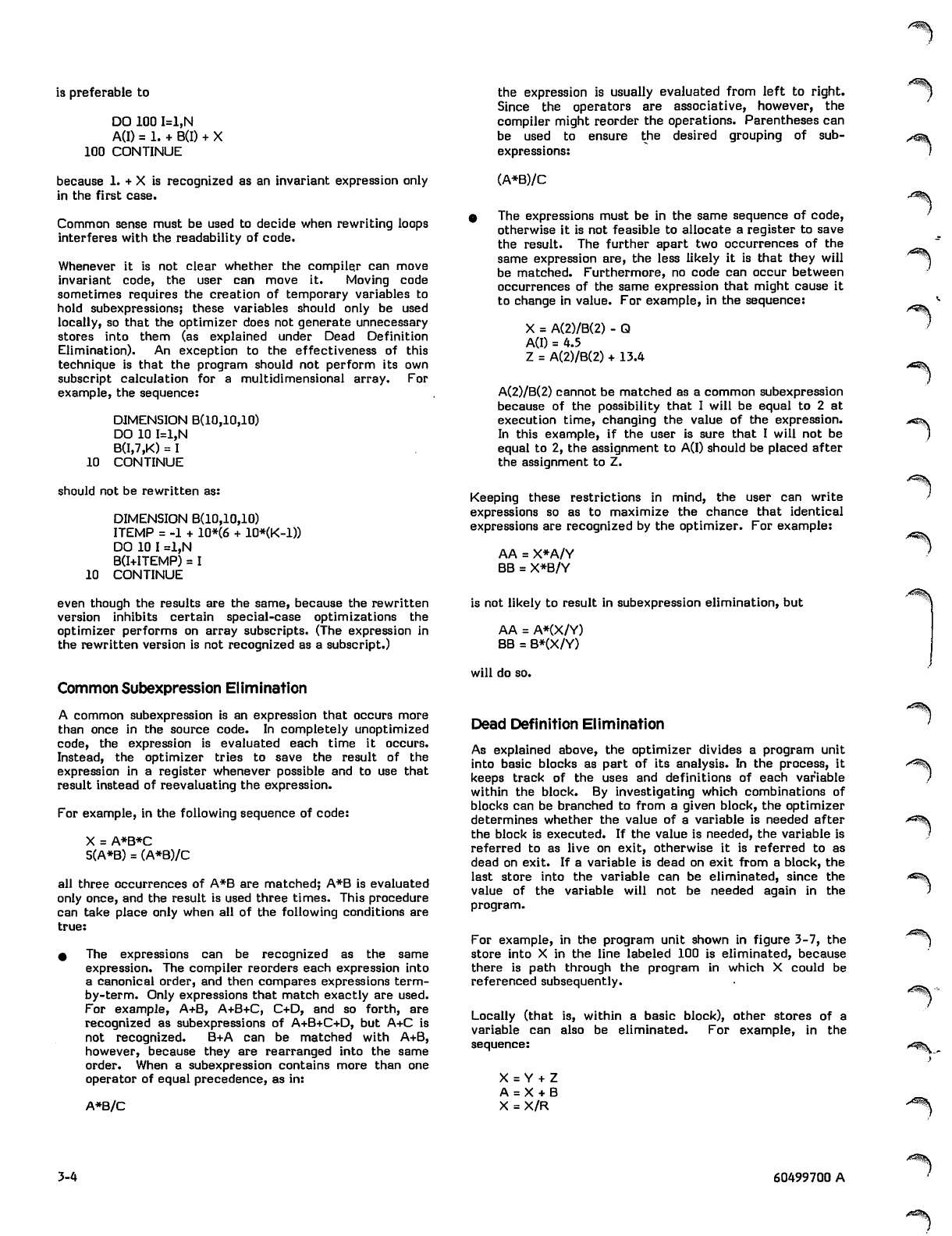
/*^^1
is preferable to
DO 100 I=1,N
A(I) = 1. + B(I) + X
100 CONTINUE
because 1. + X is recognized as an invariant expression only
in the first case.
Common sense must be used to decide when rewriting loops
interferes with the readability of code.
Whenever it is not clear whether the compiler can move
invariant code, the user can move it. Moving code
sometimes requires the creation of temporary variables to
hold subexpressions; these variables should only be used
locally, so that the optimizer does not generate unnecessary
stores into them (as explained under Dead Definition
Elimination). An exception to the effectiveness of this
technique is that the program should not perform its own
subscript calculation for a multidimensional array. For
example, the sequence:
DIMENSION B(10,10,10)
DO 10 I=1,N
B(I,7,K) = 1
10 CONTINUE
should not be rewritten as:
DIMENSION B(10,10,10)
ITEMP = -1 + 10*(6 + 10*(K-1))
DO 10 I =1,N
B(I+ITEMP) = I
10 CONTINUE
the expression is usually evaluated from left to right.
Since the operators are associative, however, the
compiler might reorder the operations. Parentheses can
be used to ensure the desired grouping of sub
expressions:
(A*B)/C
0 The expressions must be in the same sequence of code,
otherwise it is not feasible to allocate a register to save
the result. The further apart two occurrences of the
same expression are, the less likely it is that they will
be matched. Furthermore, no code can occur between
occurrences of the same expression that might cause it
to change in value. For example, in the sequence:
X = A(2)/B(2) - Q
A(I) = 4.5
Z = A(2)/B(2) + 13.4
A(2)/B(2) cannot be matched as a common subexpression
because of the possibility that I will be equal to 2 at
execution time, changing the value of the expression.
In this example, if the user is sure that I will not be
equal to 2, the assignment to A(I) should be placed after
the assignment to Z.
Keeping these restrictions in mind, the user can write
expressions so as to maximize the chance that identical
expressions are recognized by the optimizer. For example:
AA = X*A/Y
BB = X*B/Y
even though the results are the same, because the rewritten
version inhibits certain special-case optimizations the
optimizer performs on array subscripts. (The expression in
the rewritten version is not recognized as a subscript.)
Common Subexpression Elimination
A common subexpression is an expression that occurs more
than once in the source code. In completely unoptimized
code, the expression is evaluated each time it occurs.
Instead, the optimizer tries to save the result of the
expression in a register whenever possible and to use that
result instead of reevaluating the expression.
For example, in the following sequence of code:
X = A*B*C
S(A*B) = (A*B)/C
all three occurrences of A*B are matched; A*B is evaluated
only once, and the result is used three times. This procedure
can take place only when all of the following conditions are
true:
0 The expressions can be recognized as the same
expression. The compiler reorders each expression into
a canonical order, and then compares expressions term-
by-term. Only expressions that match exactly are used.
For example, A+B, A+B+C, C+D, and so forth, are
recognized as subexpressions of A+B+C+D, but A+C is
not recognized. B+A can be matched with A+B,
however, because they are rearranged into the same
order. When a subexpression contains more than one
operator of equal precedence, as in:
A*B/C
is not likely to result in subexpression elimination, but
AA = A*(X/Y)
BB = B*(X/Y)
will do so.
Dead Definition Elimination
As explained above, the optimizer divides a program unit
into basic blocks as part of its analysis. In the process, it
keeps track of the uses and definitions of each variable
within the block. By investigating which combinations of
blocks can be branched to from a given block, the optimizer
determines whether the value of a variable is needed after
the block is executed. If the value is needed, the variable is
referred to as live on exit, otherwise it is referred to as
dead on exit. If a variable is dead on exit from a block, the
last store into the variable can be eliminated, since the
value of the variable will not be needed again in the
program.
For example, in the program unit shown in figure 3-7, the
store into X in the line labeled 100 is eliminated, because
there is path through the program in which X could be
referenced subsequently.
Locally (that is, within a basic block), other stores of a
variable can also be eliminated. For example, in the
sequence:
X = Y + Z
A = X + B
X = X/R
3-4 60499700 A
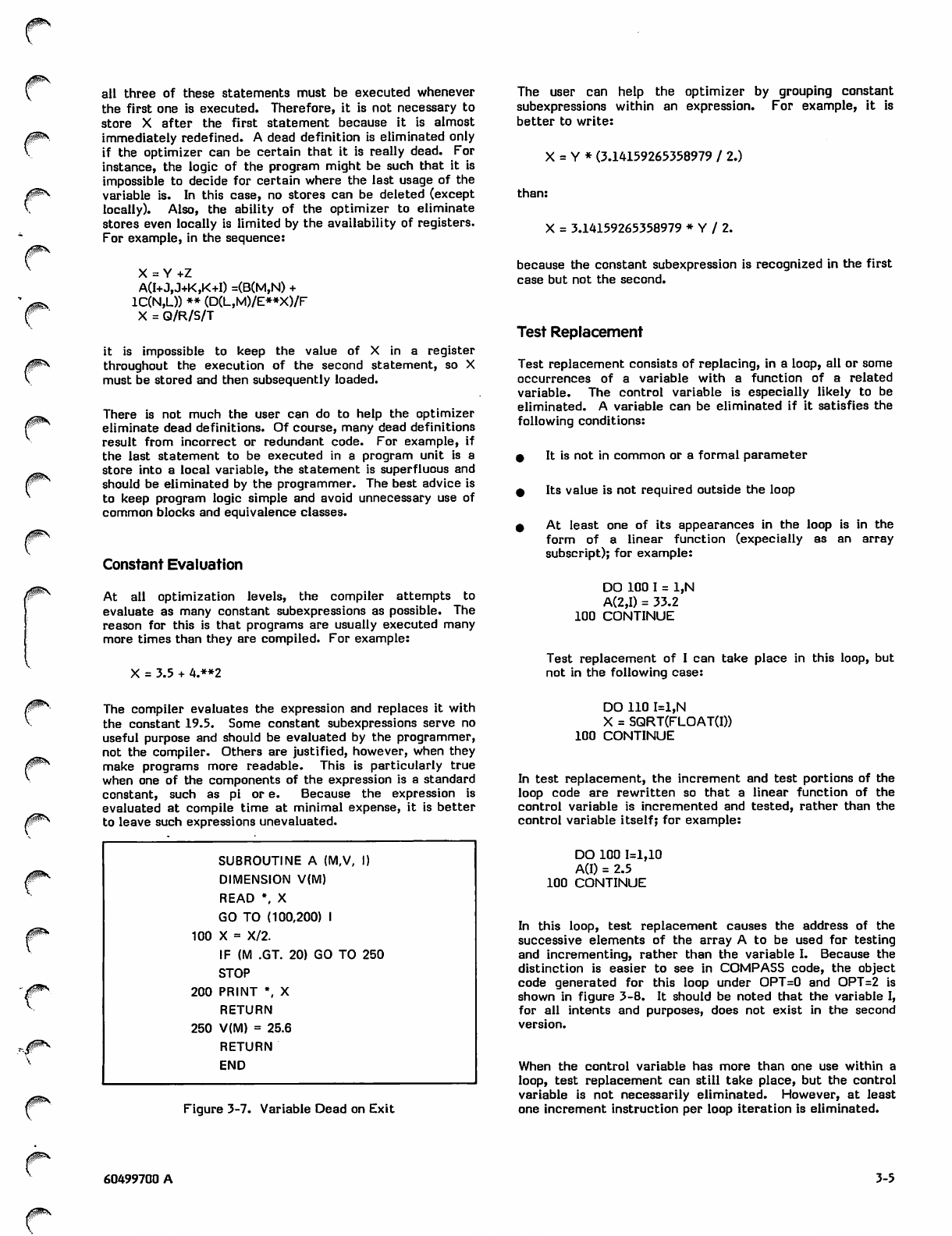
all three of these statements must be executed whenever
the first one is executed. Therefore, it is not necessary to
store X after the first statement because it is almost
immediately redefined. A dead definition is eliminated only
if the optimizer can be certain that it is really dead. For
instance, the logic of the program might be such that it is
impossible to decide for certain where the last usage of the
variable is. In this case, no stores can be deleted (except
locally). Also, the ability of the optimizer to eliminate
stores even locally is limited by the availability of registers.
For example, in the sequence:
X = Y+Z
A(I+J,J+K,K+I) =(B(M,N) +
1C(N,L)) ** (D(L,M)/E**X)/F
X = Q/R/S/T
it is impossible to keep the value of X in a register
throughout the execution of the second statement, so X
must be stored and then subsequently loaded.
There is not much the user can do to help the optimizer
eliminate dead definitions. Of course, many dead definitions
result from incorrect or redundant code. For example, if
the last statement to be executed in a program unit is a
store into a local variable, the statement is superfluous and
should be eliminated by the programmer. The best advice is
to keep program logic simple and avoid unnecessary use of
common blocks and equivalence classes.
Constant Evaluation
At al l o p ti miz ati on lev els , t he com pil er att emp ts to
evaluate as many constant subexpressions as possible. The
reason for this is that programs are usually executed many
more times than they are compiled. For example:
X = 3.5 + 4.**2
The user can help the optimizer by grouping constant
subexpressions within an expression. For example, it is
better to write:
X = Y * (3.14159265358979 / 2.)
than:
X = 3.14159265358979 * Y / 2.
because the constant subexpression is recognized in the first
case but not the second.
Test Replacement
Test replacement consists of replacing, in a loop, all or some
occurrences of a variable with a function of a related
variable. The control variable is especially likely to be
eliminated. A variable can be eliminated if it satisfies the
following conditions:
9 it is not in common or a formal parameter
0 Its value is not required outside the loop
0 At least one of its appearances in the loop is in the
form of a linear function (expecially as an array
subscript); for example:
DO 100 I = 1,N
A(2,I) = 33.2
100 CONTINUE
Test replacement of I can take place in this loop, but
not in the following case:
The compiler evaluates the expression and replaces it with
the constant 19.5. Some constant subexpressions serve no
useful purpose and should be evaluated by the programmer,
not the compiler. Others are justified, however, when they
make programs more readable. This is particularly true
when one of the components of the expression is a standard
constant, such as pi or e. Because the expression is
evaluated at compile time at minimal expense, it is better
to leave such expressions unevaluated.
SUBROUTINE A (M,V, I)
DIMENSION V(M)
READ \ X
GO TO (100,200) I
100 X = X/2.
IF (M .GT. 20) GO TO 250
STOP
200 PRINT \ X
RETURN
250 V(M) = 25.6
RETURN
END
Figure 3-7. Variable Dead on Exit
DO 110 I=1,N
X = SQRT(FLOAT(I))
100 CONTINUE
In test replacement, the increment and test portions of the
loop code are rewritten so that a linear function of the
control variable is incremented and tested, rather than the
control variable itself; for example:
DO 100 1=1,10
A(I) = 2.5
100 CONTINUE
In this loop, test replacement causes the address of the
successive elements of the array A to be used for testing
and incrementing, rather than the variable I. Because the
distinction is easier to see in COMPASS code, the object
code generated for this loop under OPT=0 and OPT=2 is
shown in figure 3-8. It should be noted that the variable I,
for all intents and purposes, does not exist in the second
version.
When the control variable has more than one use within a
loop, test replacement can still take place, but the control
variable is not necessarily eliminated. However, at least
one increment instruction per loop iteration is eliminated.
60499700 A 3-5
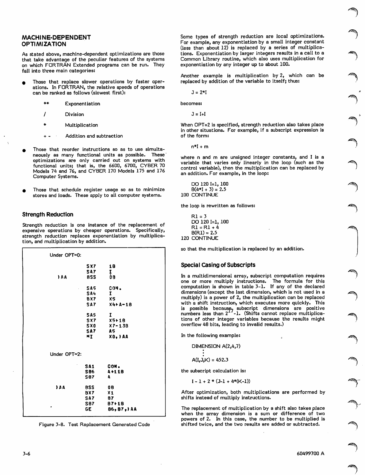
("'SSx
MACHINE-DEPENDENT
OPTIMIZATION
As stated above, machine-dependent optimizations are those
that take advantage of the peculiar features of the systems
on which FORTRAN Extended programs can be run. They
fall into three main categories:
* Those that replace slower operations by faster oper
ations. In FORTRAN, the relative speeds of operations
can be ranked as follows (slowest first):
** Exponentiation
/ Division
* Multiplication
+ - Addition and subtraction
* Those that reorder instructions so as to use simulta
neously as many functional units as possible. These
optimizations are only carried out on systems with
functional units; that is, the 6600, 6700, CYBER 70
Models 74 and 76, and CYBER 170 Models 175 and 176
Computer Systems.
% Those that schedule register usage so as to minimize
stores and loads. These apply to all computer systems.
Strength Reduction
Strength reduction is one instance of the replacement of
expensive operations by cheaper operations. Specifically,
strength reduction replaces exponentiation by multiplica
tion, and multiplication by addition.
Under OPT=0:
SX7 IB
SA7
)AA BSS 09
SA5 co*.
SA4
BX7 X5
SA7 X4*A-1B
SA5
SX7 X5f IB
SXO X7-13B
SA7 A5
MI X0, )AA
Under OPT=2:
SAl CON.
SB6 A+11B
SB7
)AA BSS OB
BX7 XI
SA7 B7
SB7 B7f IB
GE B6,B7,)AA
Figure 3-8. Test Replacement Generated Code
Some types of strength reduction are local optimizations.
For example, any exponentiation by a small integer constant
(less than about 12) is replaced by a series of multiplica
tions. Exponentiation by larger integers results in a call to a
Common Library routine, which also uses multiplication for
exponentiation by any integer up to about 100.
Another example is multiplication by 2, which can be
replaced by addition of the variable to itself; thus:
J = 2*1
becomes:
J = 1+1
When OPT=2 is specified, strength reduction also takes place
in other situations. For example, if a subscript expression is
of the form:
n*I + m
where n and m are unsigned integer constants, and I is a
variable that varies only linearly in the loop (such as the
control variable), then the multiplication can be replaced by
an addition. For example, in the loop:
DO 120 1=1, 100
B(4*I + 3) = 2.5
100 CONTINUE
the loop is rewritten as follows:
Rl = 3
DO 120 1=1, 100
Rl = Rl + 4
B(R1) = 2.5
120 CONTINUE
so that the multiplication is replaced by an addition.
Special Casing of Subscripts
In a multidimensional array, subscript computation requires
one or more multiply instructions. The formula for this
computation is shown in table 3-1. If any of the declared
dimensions (except the last dimension, which is not used in a
multiply) is a power of 2, the multiplication can be replaced
with a shift instruction, which executes more quickly. This
is possible because, subscript dimensions are positive
numbers less than 2 -1. (Shifts cannot replace multiplica
tions of other integer variables because the results might
overflow 48 bits, leading to invalid results.)
In the following example:
DIMENSION A(2,4,7)
A(I,J,K) = 452.3
the subscript calculation is:
I - 1 + 2 * (J-l + 4*(K-D)
After optimization, both multiplications are performed by
shifts instead of multiply instructions.
The replacement of multiplication by a shift also takes place
when the array dimension is a sum or difference of two
powers of 2. In this case, the number to be multiplied is
shifted twice, and the two results are added or subtracted.
^^S
^
^^v
3-6 60499700 A
^^iv
0^>
0j^\
"r
In the following example:
DIMENSION A(6,12,3)
A(I,J,K) = 452.3
the formula for the subscript is:
1-1 + 6*(J-1 + 12*(K-1))
or
I + 6*J + 72*K - 79
Both multiplications are performed using shift and add
instructions.
Another type of special casing takes place when the first
subscript expression of a subscript is a constant. In this case,
the constant is added to the base address of array, saving
one addition each time the subscript is calculated. For
example, in the following case:
DIMENSION A (10,10,10)
DO 100 I=1,N
A (4, J, I) = I
100 CONTINUE
the address of the array element in the assignment state
ment is calculated as follows:
Address = Base address + (3 + 10 * (J - 1 + 10 * (I - 1)))
where the base address is the address of the first element in
the array. Since the constant part of the calculation only
needs to be performed once, 3 is added to the base address
at compile time, effectively transforming the calculation to
the following form:
Address = Biased base address +
(10 * (J - 1 + 10 * (I - 1)))
The same principle can be applied to the case where the two
leftmost subscript expressions, or all three, are constants.
Functional Unit Scheduling
The central processor in several of the computer systems on
which FORTRAN Extended programs run has multiple
functional units. The optimizer takes advantage of this
feature whenever possible by scheduling instructions so as to
use units simultaneously. This optimization is performed
only when the program is compiled on a system with
functional units; the compiler assumes that the program is
to be executed on the same system on which it was
compiled. However, performance is not degraded if the
program is executed on a different system.
An important special case of functional unit scheduling is
array element prefetching. Prefetching takes place when
the elements of an array are used successively in a loop.
With prefetching, loading of the next element to be used
overlaps usage of the current element. For example:
DO 100 I=1,N
A(I) = B(I) + C(I)
100 CONTINUE
Without prefetching, both B(I) and C(I) would have to be
loaded before being added, so either the floating add unit or
the increment unit (which is responsible for loads and stores)
would be idle while the other unit was in use. With
prefetching, B(I+1) and C(I+1) are fetched at the same time
as B(I) and C(I) are added.
The potential danger with prefetching is that the last
iteration of a loop might attempt to load a nonexistent array
element. In the example, B(N+1) and C(N+1) are loaded (but
not used) even if the arrays only have N elements. If the
array is stored near the end of the user's field length, this
attempt might result in an address out-of-range (an arith
metic mode 1 error). Thus, a program that executes
correctly without prefetching might abort with prefetching.
For this reason, prefetching is not performed for compila
tions under OPT=2 unless there is no danger of exceeding
field length. However, when the UO (unsafe optimization)
option is specified in addition to OPT=2, the compiler can
prefetch for any array, without regard for the possibility of
exceeding field length. Therefore, UO should not be used
unless the user is sure that field length is not exceeded.
In the example above, field length is not exceeded because
the increment between prefetched elements is only one
word, and at least one word is guaranteed at the end of the
field length.
Register Assignment
As one of the last stages of code generation, the optimizer
decides which register to use for each variable and
temporary quantity in every sequence of code. As part of
the process, an attempt is made to minimize the number of
loads and stores required. Whenever a program uses more
quantities than there are registers, some of the quantities
not immediately in use must be stored and subsequently
loaded. To avoid this, the optimizer analyzes the register
usage of a sequence of code and decides whether to put each
quantity in an A, B, or X register.
For some quantities, no alternative is available. The value
of most variable or array elements must be in an X register
(which is 60 bits long), and the address of an operand to be
loaded or stored must be in an A register. However, any
quantity known to be less than or equal to 18 bits long can
be kept in either a B register (which is 18 bits long) or an X
register. These quantities include DO-loop control vari
ables, limits, and increments, and any quantity used in array
subscript calculation.
In the following example:
DO 100 I=J,K,L
A(I) = B(M,N,I)
100 CONTINUE
I, J, K, L, M, and N can all be legally placed in B registers,
because none of these quantities are allowed to exceed
18 bits.
Usually, register assignment consists of reallocating
quantities from X registers to B registers, since X registers
are usually scarcer than B registers, but occasionally the
reverse is true. A special case of register assignment is
retention of B registers across calls to basic external
functions (library routines), which takes place only when the
UO option is specified. Normally, all registers are saved
whenever an external reference occurs, because it is
impossible to determine at compile time what registers are
used by the referenced function. However, when the UO
option is specified, the compiler assumes that certain
B registers are not used by basic external functions, and
does not bother to save those registers when such functions
are referenced. When the UO option is specified, the user
60499700 A 3-7
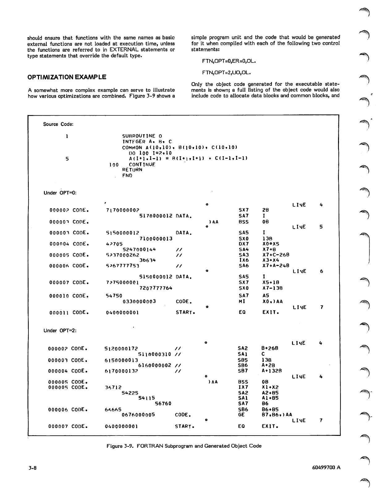
should ensure that functions with the same names as basic
external functions are not loaded at execution time, unless
the functions are referred to in EXTERNAL statements or
type statements that override the default type.
OPTIMIZATION EXAMPLE
A somewhat more complex example can serve to illustrate
how various optimizations are combined. Figure 3-9 shows a
simple program unit and the code that would be generated
for it when compiled with each of the following two control
statements:
FTN,OPT=0,ER=0,OL.
FTN,OPT=2,UO,OL.
Only the object code generated for the executable state
ments is shown; a full listing of the object code would also
include code to allocate data blocks and common blocks, and
Source Code:
1SUBROUTINE O
INTEGER A, B* C
COMMON A(10,10) • B(]0t 10) » C(10« 10)
1)0 100 I=2»10
5A{I♦1 . 1 - 1 J = B C l * i » I
100 CONTINUE
RETURN
FNO
♦1) > C ( I -■1 , 1 - 1 )
Under OPT=0:
LIME
00000? CORE. 717000000?
5170000012 DATA.
SX7
SA7
2B
I
00000^ CODE. ) AA BSS 0B LIME
000001 CODE. 5 1 5 0 0 0 0 0 1 ? D A T A .
7100000013
SA5
SXO 13B
000004 CODE. 4P705
524700014* //
DX7
SA4
X0»X5
X7 + 8
000005 CODE. 5 P 3 7 0 0 0 2 6 2 / /
36614
SA3
1X6 X7+C-26B
X3 + X4
000006 CODE. 5 * 6 7 7 7 7 7 5 3 / /
5150000012 DATA.
SA6
SA5
X7+A-24B
ILIME
000007 CODE. 7?75000001
7207777764
SX7
SXO
X5+1B
X7-13B
000010 CODE. 54750
0330000003 CODE.
SA7
MI
AS
X0,)AA
LIME
000011 CODE. 0400000001 START. EQ EXIT.
Under OPT=2:
LIME
00000? CODE. 5 1 2 0 0 0 0 1 7 2 / /
5110000310 //
SA2
SAl
B+268
C
000001 CODE. 6150000013
6160000002 //
SB5
SB6 13B
A + 2B
000004 CODE. 6 1 7 0 0 0 0 1 3 ? / / SB7 A+132B
LIME
000005 CODE. AA BSS 0B
000005 CODE. 36712
54225
54U556760
1X7
SA2
SAl
SA7
X1+X2
A2 + B5
A1+B5
B6
000006 CODE. 66665 SB6 B6 + B5
0676000005 CODE. GE B7,B6,)AA
«LIME
000007 CODE. 0400000001 START. EO EXIT.
Figure 3-9. FORTRAN Subprogram and Generated Object Code
3-8 60499700 A
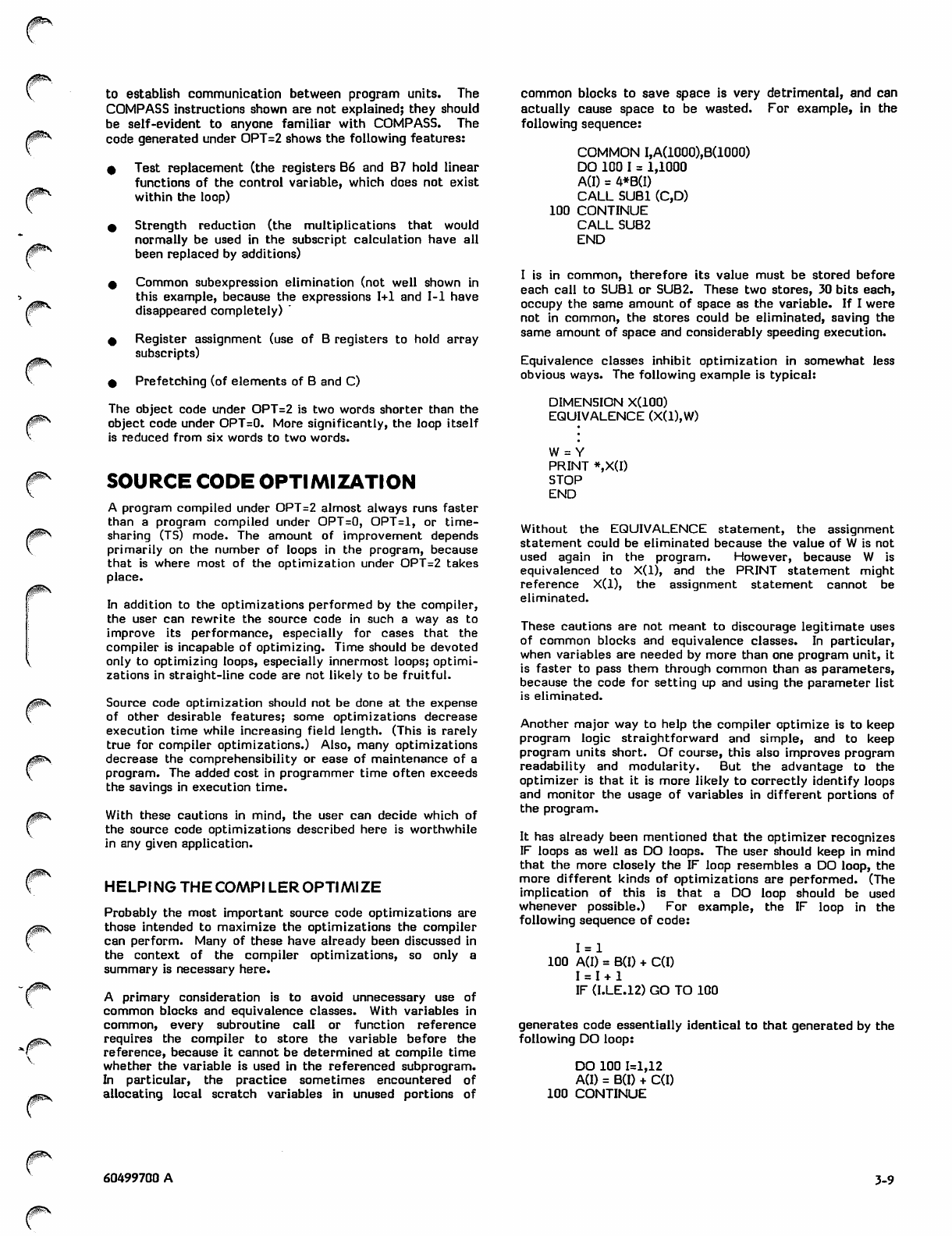
/|Ks
0SS
/$sfe\
/p^\
to establish communication between program units. The
COMPASS instructions shown are not explained; they should
be self-evident to anyone familiar with COMPASS. The
code generated under OPT=2 shows the following features:
0 Test replacement (the registers B6 and B7 hold linear
functions of the control variable, which does not exist
within the loop)
% Strength reduction (the multiplications that would
normally be used in the subscript calculation have all
been replaced by additions)
0 Common subexpression elimination (not well shown in
this example, because the expressions 1+1 and 1-1 have
disappeared completely) "
4 Register assignment (use of B registers to hold array
subscripts)
0 Prefetching (of elements of B and C)
The object code under OPT=2 is two words shorter than the
object code under OPT=0. More significantly, the loop itself
is reduced from six words to two words.
SOURCE CODE OPTIMIZATION
A program compiled under OPT=2 almost always runs faster
than a program compiled under OPT=0, OPT=l, or time
sharing (TS) mode. The amount of improvement depends
primarily on the number of loops in the program, because
that is where most of the optimization under OPT=2 takes
place.
In addition to the optimizations performed by the compiler,
the user can rewrite the source code in such a way as to
improve its performance, especially for cases that the
compiler is incapable of optimizing, time should be devoted
only to optimizing loops, especially innermost loops; optimi
zations in straight-line code are not likely to be fruitful.
Source code optimization should not be done at the expense
of other desirable features; some optimizations decrease
execution time while increasing field length. (This is rarely
true for compiler optimizations.) Also, many optimizations
decrease the comprehensibility or ease of maintenance of a
program. The added cost in programmer time often exceeds
the savings in execution time.
With these cautions in mind, the user can decide which of
the source code optimizations described here is worthwhile
in any given application.
HELPING THE COMPI LER OPTIMIZE
Probably the most important source code optimizations are
those intended to maximize the optimizations the compiler
can perform. Many of these have already been discussed in
the context of the compiler optimizations, so only a
summary is necessary here.
A primary consideration is to avoid unnecessary use of
common blocks and equivalence classes. With variables in
common, every subroutine call or function reference
requires the compiler to store the variable before the
reference, because it cannot be determined at compile time
whether the variable is used in the referenced subprogram.
In particular, the practice sometimes encountered of
allocating local scratch variables in unused portions of
common blocks to save space is very detrimental, and can
actually cause space to be wasted. For example, in the
following sequence:
COMMON I,A(1000),B(1000)
DO 100 I = 1,1000
A(I) = 4*B(I)
CALL SUB1 (C,D)
100 CONTINUE
CALL SUB2
END
I is in common, therefore its value must be stored before
each call to SUB1 or SUB2. These two stores, 30 bits each,
occupy the same amount of space as the variable. If I were
not in common, the stores could be eliminated, saving the
same amount of space and considerably speeding execution.
Equivalence classes inhibit optimization in somewhat less
obvious ways. The following example is typical:
DIMENSION X(100)
EQUIVALENCE (X(1),W)
W = Y
PRINT *,X(I)
STOP
END
Without the EQUIVALENCE statement, the assignment
statement could be eliminated because the value of W is not
used again in the program. However, because W is
equivalenced to X(l), and the PRINT statement might
reference X(l), the assignment statement cannot be
eliminated.
These cautions are not meant to discourage legitimate uses
of common blocks and equivalence classes. In particular,
when variables are needed by more than one program unit, it
is faster to pass them through common than as parameters,
because the code for setting up and using the parameter list
is eliminated.
Another major way to help the compiler optimize is to keep
program logic straightforward and simple, and to keep
program units short. Of course, this also improves program
readability and modularity. But the advantage to the
optimizer is that it is more likely to correctly identify loops
and monitor the usage of variables in different portions of
the program.
It has already been mentioned that the optimizer recognizes
IF loops as well as DO loops. The user should keep in mind
that the more closely the IF loop resembles a DO loop, the
more different kinds of optimizations are performed. (The
implication of this is that a DO loop should be used
whenever possible.) For example, the IF loop in the
following sequence of code:
1 = 1
100 A(I) = B(I) + C(I)
1 = 1 + 1
IF (I.LE.12) GO TO 100
generates code essentially identical to that generated by the
following DO loop:
100
DO 100 1=1,12
A(I) = B(I) + C(I)
CONTINUE
60499700 A 3-9
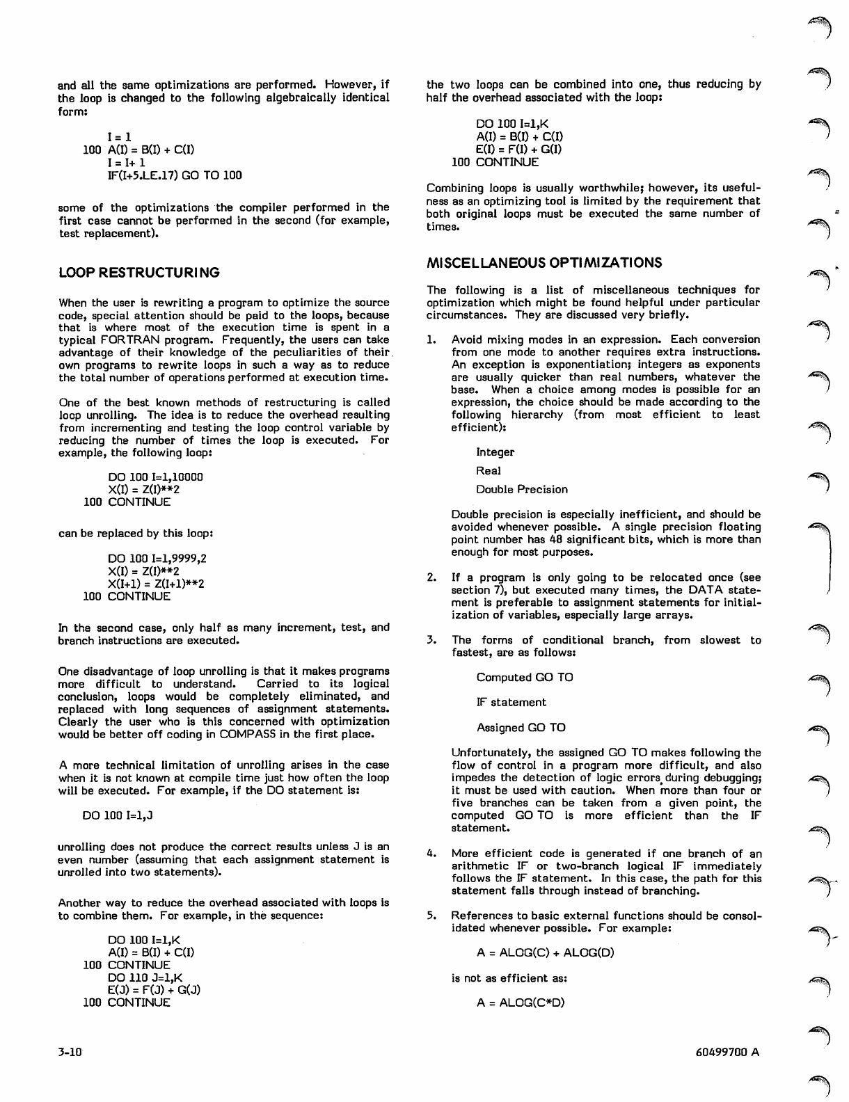
and all the same optimizations are performed. However, if
the loop is changed to the following algebraically identical
form:
1 = 1
100 A(I) = B(I) + C(I)
1 = 1+1
F(I+5.LE.17) GO TO 100
some of the optimizations the compiler performed in the
first case cannot be performed in the second (for example,
test replacement).
the two loops can be combined into one, thus reducing by
half the overhead associated with the loop:
DO 100 I=1,K
A(I) = B(I) + C(I)
E(I) = F(I) + G(I)
100 CONTINUE
Combining loops is usually worthwhile; however, its useful
ness as an optimizing tool is limited by the requirement that
both original loops must be executed the same number of
times.
LOOP RESTRUCTURING
When the user is rewriting a program to optimize the source
code, special attention should be paid to the loops, because
that is where most of the execution time is spent in a
typical FORTRAN program. Frequently, the users can take
advantage of their knowledge of the peculiarities of their,
own programs to rewrite loops in such a way as to reduce
the total number of operations performed at execution time.
One of the best known methods of restructuring is called
loop unrolling. The idea is to reduce the overhead resulting
from incrementing and testing the loop control variable by
reducing the number of times the loop is executed. For
example, the following loop:
DO 100 1=1,10000
X(I) = Z(I)**2
100 CONTINUE
can be replaced by this loop:
DO 100 1=1,9999,2
X(I) = Z(I)**2
X(I+1) = Z(I+1)**2
100 CONTINUE
In the second case, only half as many increment, test, and
branch instructions are executed.
One disadvantage of loop unrolling is that it makes programs
more difficult to understand. Carried to its logical
conclusion, loops would be completely eliminated, and
replaced with long sequences of assignment statements.
Clearly the user who is this concerned with optimization
would be better off coding in COMPASS in the first place.
A more technical limitation of unrolling arises in the case
when it is not known at compile time just how often the loop
will be executed. For example, if the DO statement is:
DO 100 1=1,3
unrolling does not produce the correct results unless J is an
even number (assuming that each assignment statement is
unrolled into two statements).
Another way to reduce the overhead associated with loops is
to combine them. For example, in the sequence:
DO 100 I=1,K
A(I) = B(I) + C(I)
100 CONTINUE
DO 110 J=1,K
E(J) = F(J) + G(J)
100 CONTINUE
MISCELLANEOUS OPTIMIZATIONS
The following is a list of miscellaneous techniques for
optimization which might be found helpful under particular
circumstances. They are discussed very briefly.
1. Avoid mixing modes in an expression. Each conversion
from one mode to another requires extra instructions.
An exception is exponentiation; integers as exponents
are usually quicker than real numbers, whatever the
base. When a choice among modes is possible for an
expression, the choice should be made according to the
following hierarchy (from most efficient to least
efficient):
Integer
Real
Double Precision
Double precision is especially inefficient, and should be
avoided whenever possible. A single precision floating
point number has 48 significant bits, which is more than
enough for most purposes.
2. If a program is only going to be relocated once (see
section 7), but executed many times, the DATA state
ment is preferable to assignment statements for initial
ization of variables, especially large arrays.
3. The forms of conditional branch, from slowest to
fastest, are as follows:
Computed GO TO
IF statement
Assigned GO TO
Unfortunately, the assigned GO TO makes following the
flow of control in a program more difficult, and also
impedes the detection of logic errors^ during debugging;
it must be used with caution. When more than four or
five branches can be taken from a given point, the
com p u t e d G O TO i s m o r e e f fi c i e n t th a n t h e I F
statement.
4. More efficient code is generated if one branch of an
arithmetic IF or two-branch logical IF immediately
follows the IF statement. In this case, the path for this
statement falls through instead of branching.
5. References to basic external functions should be consol
idated whenever possible. For example:
A = ALOG(C) + ALOG(D)
is not as efficient as:
A = ALOG(C*D)
A^m^s
r^S\
y*W-X
3-10 60499700 A
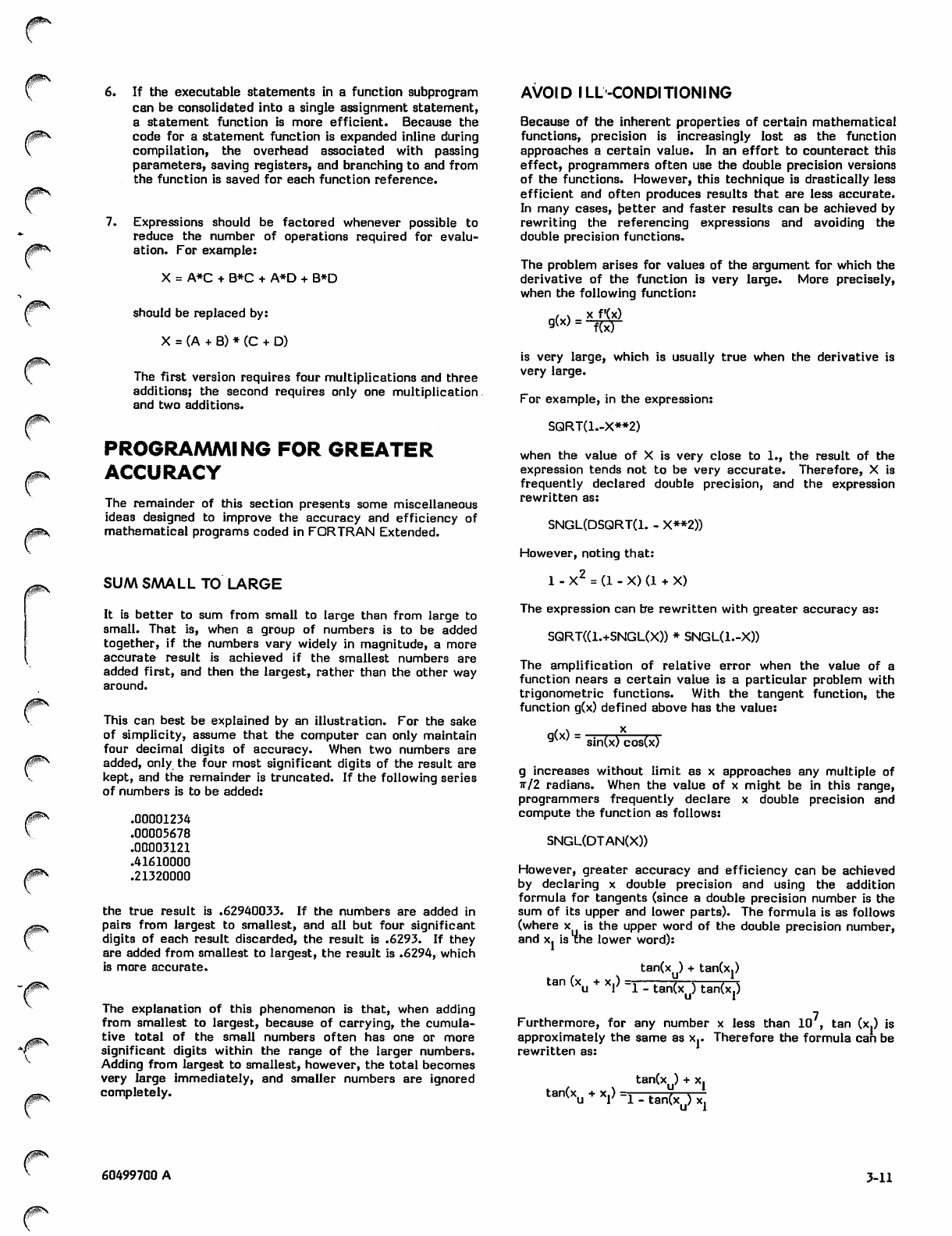
/fpSv
/pp^\
0$S
/$PN
"C
6. If the executable statements in a function subprogram
can be consolidated into a single assignment statement,
a statement function is more efficient. Because the
code for a statement function is expanded inline during
compilation, the overhead associated with passing
parameters, saving registers, and branching to and from
the function is saved for each function reference.
7. Expressions should be factored whenever possible to
reduce the number of operations required for evalu
ation. For example:
X = A*C + B*C + A*D + B*D
should be replaced by:
X = (A + B) * (C + D)
The first version requires four multiplications and three
additions; the second requires only one multiplication
and two additions.
PROGRAMMING FOR GREATER
ACCURACY
The remainder of this section presents some miscellaneous
ideas designed to improve the accuracy and efficiency of
mathematical programs coded in FORTRAN Extended.
SUM SMALL TO LARGE
It is better to sum from small to large than from large to
small. That is, when a group of numbers is to be added
together, if the numbers vary widely in magnitude, a more
accurate result is achieved if the smallest numbers are
added first, and then the largest, rather than the other way
around.
This can best be explained by an illustration. For the sake
of simplicity, assume that the computer can only maintain
four decimal digits of accuracy. When two numbers are
added, only the four most significant digits of the result are
kept, and the remainder is truncated. If the following series
of numbers is to be added:
.00001234
.00005678
.00003121
.41610000
.21320000
the true result is .62940033. If the numbers are added in
pairs from largest to smallest, and all but four significant
digits of each result discarded, the result is .6293. If they
are added from smallest to largest, the result is .6294, which
is more accurate.
The explanation of this phenomenon is that, when adding
from smallest to largest, because of carrying, the cumula
tive total of the small numbers often has one or more
significant digits within the range of the larger numbers.
Adding from largest to smallest, however, the total becomes
very large immediately, and smaller numbers are ignored
completely.
AVOID ILL-CONDITIONING
Because of the inherent properties of certain mathematical
functions, precision is increasingly lost as the function
approaches a certain value. In an effort to counteract this
effect, programmers often use the double precision versions
of the functions. However, this technique is drastically less
efficient and often produces results that are less accurate.
In many cases, better and faster results can be achieved by
rewriting the referencing expressions and avoiding the
double precision functions.
The problem arises for values of the argument for which the
derivative of the function is very large. More precisely,
when the following function:
nfv\ - x f'(x)
is very large, which is usually true when the derivative is
very large.
For example, in the expression:
SQRT(1.-X**2)
when the value of X is very close to 1., the result of the
expression tends not to be very accurate. Therefore, X is
frequently declared double precision, and the expression
rewritten as:
SNGL(DSQRT(1. - X**2))
However, noting that:
1 - X2 = (1 - X) (1 + X)
The expression can be rewritten with greater accuracy as:
SQRT((1.+SNGL(X)) * SNGL(l.-X))
The amplification of relative error when the value of a
function nears a certain value is a particular problem with
trigonometric functions. With the tangent function, the
function g(x) defined above has the value:
9 sin(x) cos(x)
g increases without limit as x approaches any multiple of
ir/2 radians. When the value of x might be in this range,
programmers frequently declare x double precision and
compute the function as follows:
SNGL(DTAN(X))
However, greater accuracy and efficiency can be achieved
by declaring x double precision and using the addition
formula for tangents (since a double precision number is the
sum of its upper and lower parts). The formula is as follows
(where x is the upper word of the double precision number,
and x. is the lower word):
tan(x ) + tan(x.)
tan (x + x.) =,—r—?—r-r—7—x
u r 1 - tan(x ) tan(x.)
Furthermore, for any number x less than 10 , tan (x.) is
approximately the same as x.. Therefore the formula can be
rewritten as:
tan(xu) + Xj
tan(x + x.) =i—z—7—^—
u V 1 - tan(x ) x.
60499700 A 3-11
/ ^ N
or, in FORTRAN:
DOUBLE PRECISION X
XU = SNGL(X)
XL = X - XU
RESULT = (TAN(XU) + XL) / (1. - TAN(XU) * XL)
using no double precision arithmetic.
Similar substitutions can be made for sine and cosine, using
the addition formulas and the information that sin(x.) is
approximately x., while cos(x.) is approximately 1.0.
An even better example is the exponentiation function EXP.
In this case, the larger the value of x, the larger the
function g(x) defined above. The addition formula in this
case is as follows:
exp(xu + Xj) = exp(xu) + Xj exp(xu)
or, in FORTRAN:
DOUBLE PRECISION X
RESULT = EXP(SNGL(X)) + (X - SNGL(X)) *
1(EXP(SNGL(X)))
>*S8>\
-/*^\
3-12 60499700 A
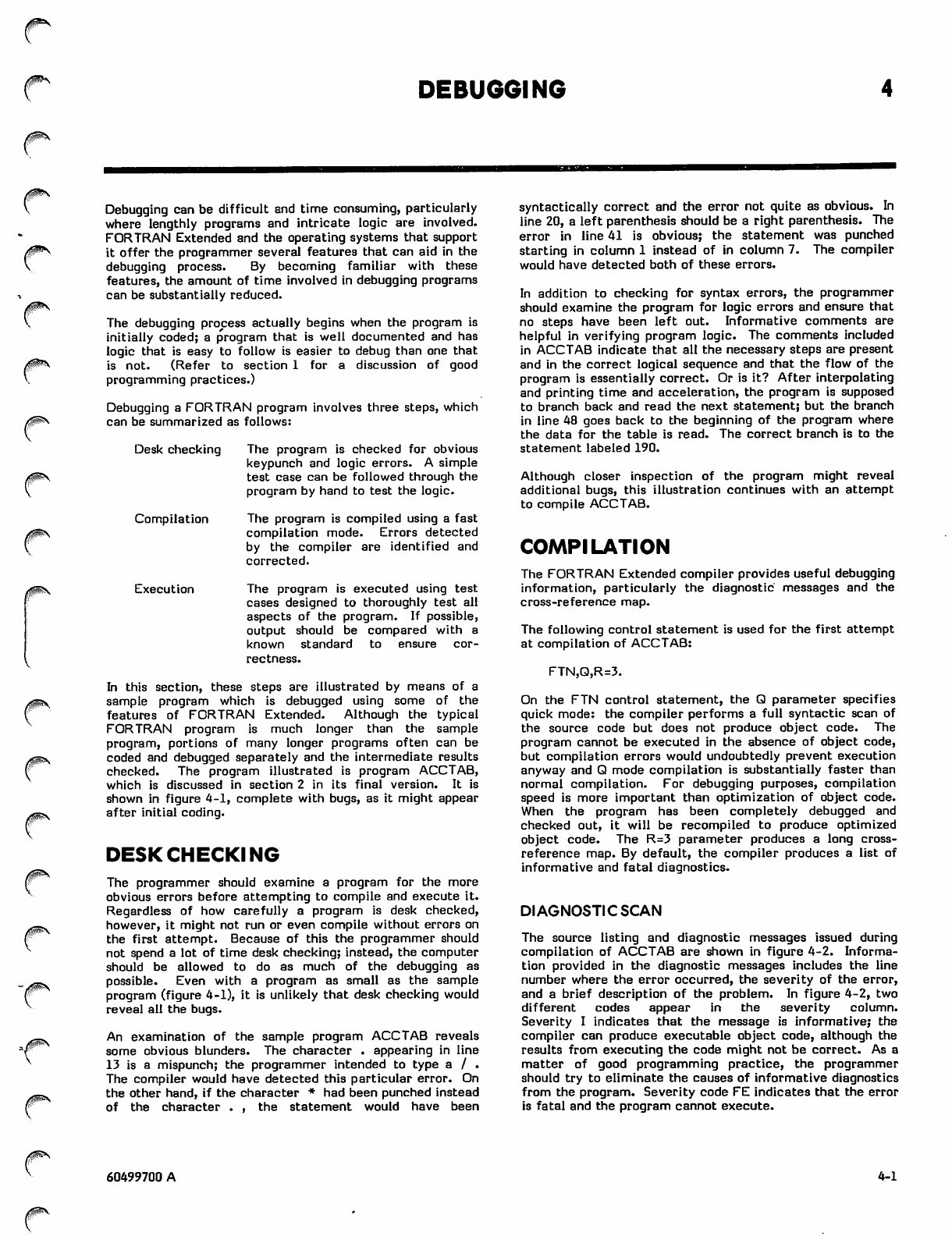
DEBUGGING
JpN
0^S
^0SS
Debugging can be difficult and time consuming, particularly
where lengthly programs and intricate logic are involved.
FORTRAN Extended and the operating systems that support
it offer the programmer several features that can aid in the
debugging process. By becoming familiar with these
features, the amount of time involved in debugging programs
can be substantially reduced.
The debugging process actually begins when the program is
initially coded; a program that is well documented and has
logic that is easy to follow is easier to debug than one that
is not. (Refer to section 1 for a discussion of good
programming practices.)
Debugging a FORTRAN program involves three steps, which
can be summarized as follows:
Desk checking The program is checked for obvious
keypunch and logic errors. A simple
test case can be followed through the
program by hand to test the logic.
Compilation The program is compiled using a fast
compilation mode. Errors detected
by the compiler are identified and
corrected.
Ex e c u t i o n T h e p r o g r a m i s e x e c u t e d u s i n g t e s t
cases designed to thoroughly test all
aspects of the program. If possible,
output should be compared with a
known standard to ensure cor
rectness.
In this section, these steps are illustrated by means of a
sample program which is debugged using some of the
features of FORTRAN Extended. Although the typical
FORTRAN program is much longer than the sample
program, portions of many longer programs often can be
coded and debugged separately and the intermediate results
checked. The program illustrated is program ACCTAB,
which is discussed in section 2 in its final version. It is
shown in figure 4-1, complete with bugs, as it might appear
after initial coding.
DESK CHECKING
The programmer should examine a program for the more
obvious errors before attempting to compile and execute it.
Regardless of how carefully a program is desk checked,
however, it might not run or even compile without errors on
the first attempt. Because of this the programmer should
not spend a lot of time desk checking; instead, the computer
should be allowed to do as much of the debugging as
possible. Even with a program as small as the sample
program (figure 4-1), it is unlikely that desk checking would
reveal all the bugs.
An examination of the sample program ACCTAB reveals
some obvious blunders. The character . appearing in line
13 is a mispunch; the programmer intended to type a / .
The compiler would have detected this particular error. On
the other hand, if the character * had been punched instead
of the character . , the statement would have been
syntactically correct and the error not quite as obvious. In
line 20, a left parenthesis should be a right parenthesis. The
error in line 41 is obvious; the statement was punched
starting in column 1 instead of in column 7. The compiler
would have detected both of these errors.
In addition to checking for syntax errors, the programmer
should examine the program for logic errors and ensure that
no steps have been left out. Informative comments are
helpful in verifying program logic. The comments included
in ACCTAB indicate that all the necessary steps are present
and in the correct logical sequence and that the flow of the
program is essentially correct. Or is it? After interpolating
and printing time and acceleration, the program is supposed
to branch back and read the next statement; but the branch
in line 48 goes back to the beginning of the program where
the data for the table is read. The correct branch is to the
statement labeled 190.
Although closer inspection of the program might reveal
additional bugs, this illustration continues with an attempt
to compile ACCTAB.
COMPILATION
The FORTRAN Extended compiler provides useful debugging
information, particularly the diagnostic messages and the
cross-reference map.
The following control statement is used for the first attempt
at compilation of ACCTAB:
FTN,Q,R=3.
On the FTN control statement, the Q parameter specifies
quick mode: the compiler performs a full syntactic scan of
the source code but does not produce object code. The
program cannot be executed in the absence of object code,
but compilation errors would undoubtedly prevent execution
anyway and Q mode compilation is substantially faster than
normal compilation. For debugging purposes, compilation
speed is more important than optimization of object code.
When the program has been completely debugged and
checked out, it will be recompiled to produce optimized
object code. The R=3 parameter produces a long cross-
reference map. By default, the compiler produces a list of
informative and fatal diagnostics.
DIAGNOSTIC SCAN
The source listing and diagnostic messages issued during
compilation of ACCTAB are shown in figure 4-2. Informa
tion provided in the diagnostic messages includes the line
number where the error occurred, the severity of the error,
and a brief description of the problem. In figure 4-2, two
different codes appear in the severity column.
Severity I indicates that the message is informative; the
compiler can produce executable object code, although the
results from executing the code might not be correct. As a
matter of good programming practice, the programmer
should try to eliminate the causes of informative diagnostics
from the program. Severity code FE indicates that the error
is fatal and the program cannot execute.
60499700 A 4-1
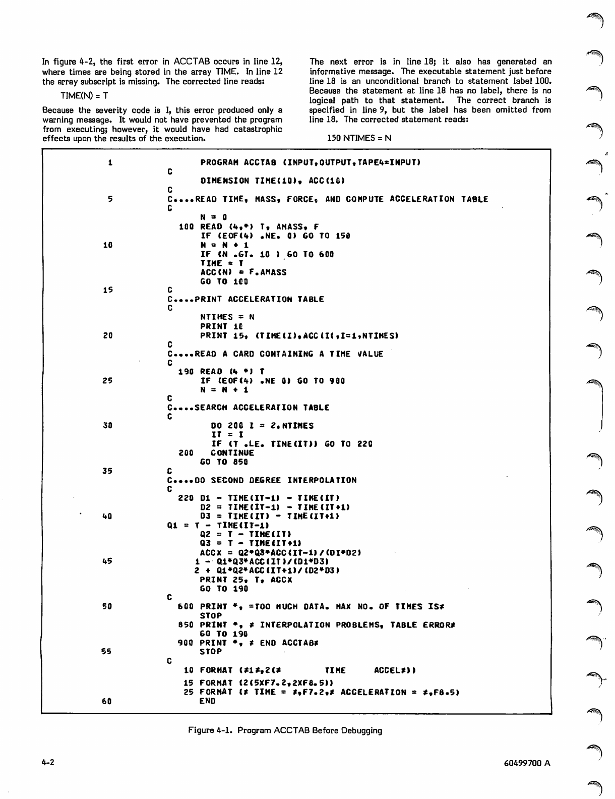
In figure 4-2, the first error in ACCTAB occurs in line 12,
where times are being stored in the array TIME. In line 12
the array subscript is missing. The corrected line reads:
TIME(N) = T
Because the severity code is I, this error produced only a
warning message. It would not have prevented the program
from executing; however, it would have had catastrophic
effects upon the results of the execution.
The next error is in line 18; it also has generated an
informative message. The executable statement just before
line 18 is an unconditional branch to statement label 100.
Because the statement at line 18 has no label, there is no
logical path to that statement. The correct branch is
specified in line 9, but the label has been omitted from
line 18. The corrected statement reads:
150 NTIMES = N
.-*^%v
1 PROGRAH ACCTAB CINPUT,OUTPUT,TAPE4*INPUT)
C
DIMENSION TIHE(IO), ACC(IC)
C
C....REA0 TIME, MASS, FORCE, ANO COMPUTE ACCELERATION TABLE
C
N s 0
5
100 READ (4,*) T, AMASS, F
IF (E OF( 4) .NE . 0 ) GO TO 150
10 N = N ♦ 1
IF CN .GT. 10 ) GO TO 600
TINE = T
ACCCN) * F.AMASS
GO TO 100
15
C. ..P RI NT ACC ELE RAT ION TABL E
C
NTIMES t H
PRINT IC
20 PRINT 15, (TIHE(I),ACC (K,1=1,NTIMES)
C
C....REAO A CARO CONTAINING A TIME VALUE
C
190 REAO (4 *) T
25 IF CE0FC4) .NE 0) GO TO 900
N a N ♦ 1
C
C....SEARCH ACCELERATION TABLE
C
DO 200 I t 2,NTIMES30
I T = I
IF (T .LE. TINECIT)) GO TO 220
2 0 0 C O N T I N U E
GO TO 650
35
C....DO SECOND OEGREE INTERPOLATION
C
220 DI - TIMECIT-1) - TIKE(IT)
D2 = TIMECIT-1) - TIMEUT+1)
40 03 = TIME(IT) - TIHECIT*1>
Q l * T - T I M E C I T- 11
Q 2 = T - T I M E ( I T )
Q3 = T - T IME C IT * 1)
ACCX = Q2*a3*ACCCIT-l)/CDI*D2>
45 1 - Qi*Q3»ACCCIT)/CDi»D3)
2 ♦ Q1*Q2»ACCCIT*1)/CD2»03)
PRINT 25, T, ACCX
GO TO 190
C
600 PRINT *, =TOO MUCH OATA. HAX NO. OF TIMES IS*50
STOP
850 PRINT ♦, * INTERPOLATION PROBLEMS, TABLE ERROR*
GO TO 190
900 PRINT ♦, * ENO ACCTAB*
55 STOP
C
10 FORMAT (*1*,2(* TIME ACCEL*))
15 FORMAT C2C5XF7.2,2XF0.5)>
25 FORMAT C* TIME = **F7.2,* ACCELERATION * *,F8.5)
60 END
■■^^N
Figure 4-1. Program ACCTAB Before Debugging
4-2 60499700 A
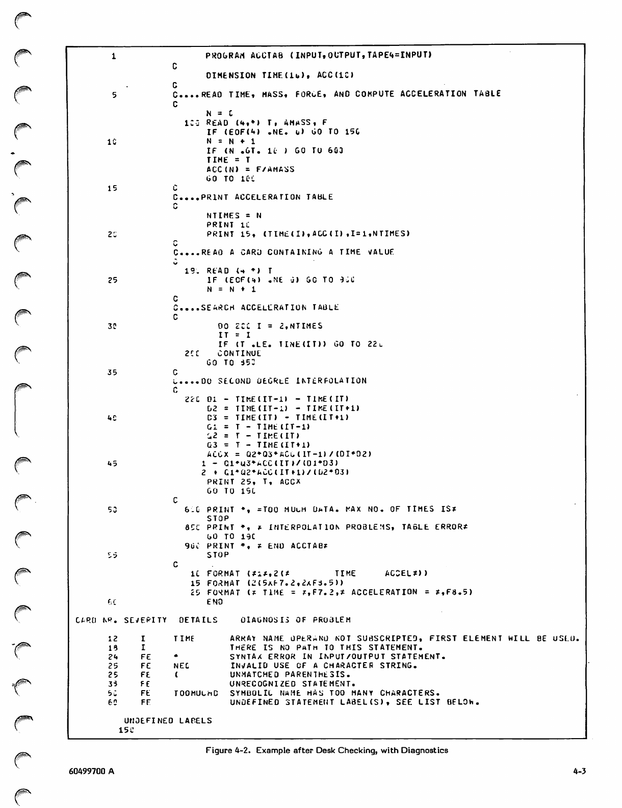
IC
15
25
3C
35
U5
S5
P. SErfEPITY DETAILS
1 2 I TIME
1 9 I
2 4 F E
2 5 F E NEC
2 5 F E
3 5 F E
5 C F E TOOMUChD
6 0 F F
UNDEFINEO LAPELS
15 C
PROGRAM ACCTAB < INPUT, OUTPUT, TAPE4=INPUT)
C
DIMENSION TIHF(lu), ACC(IC)
C
C....REAO TIME, MASS, FORoE, AND COMPUTE ACCELERATION TABLE
C
N = C
IC-j READ (<♦,♦) T, AMASS, F
I F ( E 0F( 4 ) . NE. u ) G O T O 1 50
N = N «• 1
IF (N . GT. l i- ) G O TU 6 03
T I M E = T
ACC(N> = F/AMASS
GO TO 10C
C
C...PRINT ACCELERATION TABLE
r-
tt
NTIMES = N
PRINT IC
PRINT 15, CTIMECI),AGC(I),1=1,NTIMES)
C-
C....REAQ A CARD CONTAINING A TIME VALUE
19. READ U ♦) T
IF CECFU) .NE a) GO TO 9 J \i
N = N ♦ 1
C
C....SEARCH ACCELERATION TABLE
C
O O 2 C C I = 2 , N T I M E S
I T = I
IF (T .LE. TINECIT)) GO TO 22u
2 C C C O N T I N U E
GO TO i53
C
L....00 SECOND OEGRtE INTERPOLATION
C
iiu 01 - TIHECIT-1I - TIME(IT)
D2 = TIME(IT-i) - TIMECIT + 1)
C3 = TIMECIT) - TIMECITtl)
C i = T - T I M E C I T - 1 )
i 2 = T - T I K E C I T )
G3 = T - TIMECIT + 1)
ACCX = Q2»Q3*ACuCIT-l> /C0I*02)
1 - C1*U3*ACCCIT*/C01»03)
2 ♦ Gl*Q2»ACCCITH)/ Cu2*03>
PRINT 25, T, ACCX
GO TO 19C
C
6.0 PRINT ♦, =TOO MULH U*TA. MAX NO. OF TIMES IS*
STOP
8CC PRINT ♦, f- INTERPOLATION PROBLEMS, TABLE ERROR*
GO TO 19C
90C PRINT *, * ENO ACCTAB*
STOP
C
IC FORMAT (*i*,2(* TIME ACCEL*))
15 FORMAT CwM5AE7.2,2xFi.5))
25 FORMAT C* TIME = *,F7.2,* ACCELERATION = *,F8.5)
ENO
DIAGNOSIS OF PR03LEM
ARRAY NAME OPtRANu NOT SUBSCRIPTED, FIRST ELEMENT HILL BE USLU.
THERE IS NO PATH TO THIS STATEMENT.
SYNTAX ERROR IN INPUT/OUTPUT STATEMENT.
INVALID USE OF A CHARACTER STRING.
UNMATCHED PARENThESIS.
UNRECOGNIZED STATEMENT.
SYMBOLIC NAHE HAS TOO MANY CHARACTERS.
UNDEFINED STATEMENT LA8ELCS), SEE LIST BELOW.
Figure 4-2. Example after Desk Checking, with Diagnostics
60499700 A 4-3
The error in line 24 is a fatal error: a comma is missing
from the READ statement. The corrected statement reads:
190 READ (4,*) T
The statement at line 25 has generated two fatal diag
nostics. Neither states explicitly what the problem is. It
often happens that error messages appear to have little
relation to the errors that caused them. In such cases, it is
sometimes necessary for the programmer to use some
imagination in determining the cause of the diagnostic. In
the example, it is easily seen that a period is missing from
the .NE. operator. This is clear from reading the FORTRAN
statement but not from reading the error message.
In line 38, the character = was mispunched as the - char
acter. The compiler could not recognize the statement and
generated a fatal error. The corrected line reads:
220 DI = TIME(I-l) - TIME(I)
If the statement had been mispunched with two equal signs
instead of two minus signs as follows:
220 DI = TIME(I-l) = TIME(I)
The EXTERNALS section of the reference map lists names
of functions and subroutines called from the program. The
programmer should check this section to make sure all
function and su br ou tine refe re nc es are co rrect. The
external names appearing in ACCTAB are EOF (the
FORTRAN function that tests for end-of-file) and TINE.
TINE is referenced in line 32 and appears to be a misspelling
of the array TIME. An error message has not been
generated, because the compiler has no way of knowing what
functions and subroutines will be loaded at execution time.
This error is left uncorrected to illustrate its effect on
further attempts to execute ACCTAB.
The last section of the cross-reference map lists each label
used in the program, the line numbers in which the label is
referenced, and the line where the label is defined.
Statement label 150 is referenced in line 9 of ACCTAB, but
does not appear as a statement label. This error, as
previously noted, is corrected by inserting the label in
line 18. This section of the map is also useful in locating
duplicate labels: a statement label defined in more than one
line generates a fatal error.
The corrected source listing is shown in figure 4-4.
it would have been interpreted as a multiple replacement
statement, and no diagnostic would have been generated.
The message referring to line 50 appears to have little
relation to the actual error. The opening & of the character
string was mispunched as an =. Once again, the message
gives little clue as to what is wrong with the statement;
however, it does indicate that something is wrong. If the
programmer is unable to determine the specific error from
the text of the message, the statement should be checked
for syntax errors.
The last message refers to a list of undefined labels. A
statement appearing in this list has been referenced in a
GO TO or other branching statement, but does not appear as
a statement label anywhere in the program. In locating the
cause of this error, the programmer can make use of the
cross-reference map.
CROSS-REFERENCE AAAP
The cross-reference map (figure 4-3) is a list of all symbols
used in the program, with the properties of each symbol and
the references to each symbol listed by source line number.
It can be used to detect errors that do not show up as
compilation errors. A typical listing is that for the
variable ACC; the map shows that it is located at address
12„ relative to the starting address of the program; is of
type real; is an array; is referenced once in line 3, twice in
line 20, and three times in line 44; and appears to the left of
an = in line 13.
For debugging purposes, it is useful to look at the column
under the heading SN. A stray name flag appears under SN
if the symbol appears only once in the program. Such
symbols are likely to be keypunch errors, misspellings, and
the like. In figure 4-3, the variables DI and DI both have
stray name flags. Also, they are both undefined; that is,
they do not appear to the left of an = , in a common block,
in an argument list, in an input statement, in an ASSIGN
statement or in a DATA statement. Both variables are
referenced in line 44. Apparently DI is a misspelling of DI.
The attempt to define DI, in line 38, failed because that
statement contained an error.
EXECUTION TIME DEBUGGING
Errors detected during the execution of a program can cause
abnormal termination or produce incorrect results. The
standard dump (DMPX), load map, and the FORTRAN
Extended debugging facility can help the programmer
determine the causes of execution-time errors.
With all I and FE compilation errors presumably cor
rected, ACCTAB is ready for another compilation attempt.
This time it is anticipated that the program will compile
without errors and produce executable object code. Because
the program is still in the testing phase, a compilation mode
resulting in quick compilation but unoptimized object code is
used; the input data is included in the deck.
The program is then compiled with the following control
statement:
FTN,R=3,OPT=0.
When OPT=0 is specified in the control statement, the ER
option is implied. When this option is specified and an
execution-time error is detected, the approximate line
number in the source program where the error occurred is
printed in the dayfile. When OPT=l or OPT=2 is specified,
the default is ER=0. The T option is also implied when
OPT=0 is specified; this option produces a full error
traceback when an execution-time error is detected.
An important consideration in execution-time debugging is
the use of test data. The programmer should design one or
more test cases that completely test the program, including
all options and all possible paths through the logic. It is
frequently a good idea to include data that tests the limits
of acceptable values. The programmer should determine
what data causes execution errors or incorrect results, and
then either correct the program or include program state
ments to check for invalid data.
Once satisfactory test data has been selected, the results
must still be verified. Verification can be performed by
comparing the results to a known standard, or, if none is
available, by comparing to hand calculations.
^ V ,
4-4 60499700 A
^^?\
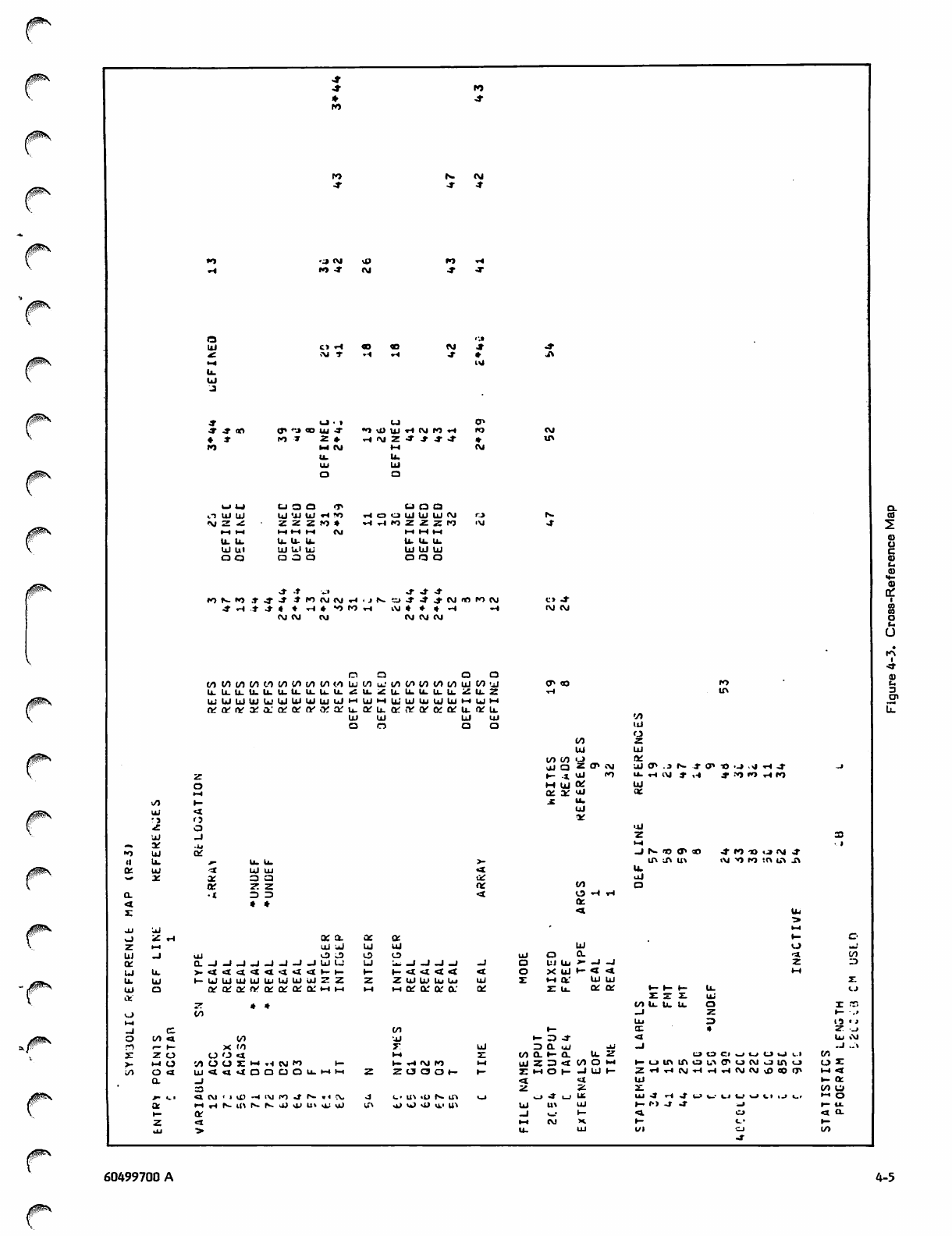
0$$S
^s
■o c m
o ui uj
<M Z *C
fi f t
U- U.
UJ u«
ezt a
I O t r t o
■X rH
(J l 'J ID Ul -J
c-i o a <r>
Ul 'X tX xH «0
Z Z Z t O x
H H H O J
u. u. u.
ul ui u>
□ a o
•O Ml Ml xH CM l>0 xH
■rH <M 2 •* ■* -T OT
to cn a
O O Ul Ul Ul <M
t* tn z z z TO
u> u. u.
Ul Ul Ul
O Q O
j - - t _ » j - o r S
O J ( V i O J C V J M O J
C> J"
IVJ OJ
n a a a
(At/)(/)C/)tOC/)(A{/1f/l</)|jj(/)uJ</>(/tt/)t/>(/)UJt/)uJ
U.U.U-U.b.U.U.U.lLU.<:U.ZU.lLlLU.|j.ZU.Z
UiUILJIUtitlLllilUIUJUjHUJHUJUJUJUJIiiHUJH
ofarivafa.'Qfcvtvofarb.Qfu.afi'KQroftvu.afu.
u i u i u i u i
o o a a
a.
co
2
U
k/# ^
•>
X
Ul _j
-. -VI
"> Ul Qi
II u. u. u.
a: Ul ■XUl Ul
"** oc ac
oc a a
z z
a■tza za
<t * *
s
jj Ul
Z ^
UJ
o
m z
Ul UJ
tn tn ta !*
l i J Q z tr i\l Ul tr .3 r- -X o>
t- -x ul <"> U- Ti c \ J » ,- t
M UJ OC Ul
&. ac ui ac
j : u .
Ul
*tt
_J N. V3 O1 CO
■O ._> J TH J-
*N)W rl«
A l ^ l > ) ! A b t A
o: a.
U i u l
U l k S I J 3
Q.JJJJJJ-IJUU
t— UJUIUIUIUlUJUJUIZZ
ttfQiOiftfaiCtrOiQ-l-ll-i
t— <t «I < <
Z Ul Ul Ui Ui
h k or a a'
cCO
t/l ca in -Jj
I— 1— x tn
z o o o xx ft
»-« o rA tn tn az f* ■,, tM to t- U- T* l\l tO
o a iu<<aDQaou.wH ZOOOH
a. _i
r - u. t 4 ( V I ' H O - l l \ I M J N - . ( ! V , <■• ^ -o N a\
QL HrlNU>NNJjOIU>ii;«J tf» viJ Vk > vO VL' Ul
Ul
u j O C L
a uj Ui >• -J -J
O X UJ l~ < «*
z : i - i a . ' u j u i
Z u . Q i a
i- 3 J-
MQ.i-a u, z
UJZ3«t(/)OH
j: t-i o i— -J u t-
f - f - f - u .
Z Z Z U i
i^illu. a
O O C l O U U O ( . . I
Z'HHN'HHrlWWvDOOIJ'
U J - J H J O U U U U l l . J L i
I — f > > J J " _ i
o z
H4 <X
i~ tx
m o
»-• o
f- u.
<l o.
60499700 A 4-5
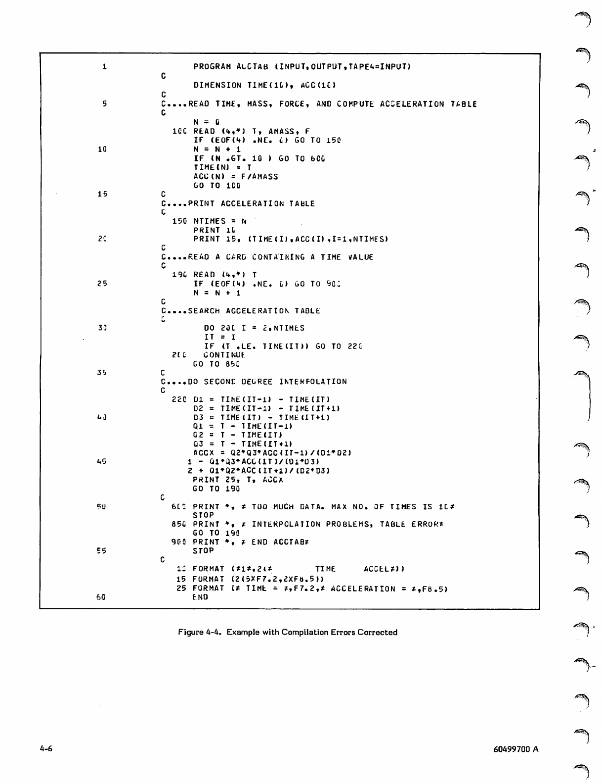
PROGRAM ACCTAB (INPUT,OUTPUT,TAPE4=INPUT)
C
DIMENSION TIME(lt), ACC(IC)
C
C....REAO TIME, MASS, FORCE, AND COMPUTE ACCELERATION TABLE
C
N = C
5
ICC READ (4,*) T, AMASS, F
IF (E0 F(4 ) .N E . C ) G O TO 1 5 0
IG N = N ♦ 1
IF (N .GT. 10 ) GO TO 6CG
TIME(N) = T
ACC(N) = F/AMASS
GO TO ICO
15
C....PRINT ACCELERATION TABLE
C
150 NTIMES - N
PRINT U
2C PRINT 15, CTIMEU),ACC<I) ,1 = 1,NTIMES)
C
C....REAO A CARD CONTAINING A TIME VALUE
C
190 READ («♦,*) T
25 I F ( E 0F (4) . N E . L ) G O TO 9 C ;
N = N *• 1
C
C...SEARCH ACCELERATION TAOLE
r
33 DO 20C I = 2,NTIMES
I T = I
IF (T .LE. TINEIIT)) GO TO 22G
2t£ CONTINUF.
GO TO 85C
35
C....DO SECOND DEGREE INTERPOLATION
C
2 2 C D I = T I M E ( I T - l ) - T I M E ( I T )
02 = TIME(IT-l) - TIMEtIT + 1)
4 0 D3 = TIME(IT) - TIME(IT + 1>
Q l = T - T I M E ( I T - I )
Q2 = T - TIMECIT)
03 = T - TIMECIT + i)
ACCX = Q2»Q3*ACC(IT-1)/(D1*D2)
45 1 - Ql»a3*ACC(IT)/(Ol*03)
2 ♦ 01*Q2*ACC(IT+1)/(D2*D3)
PRINT 25, T, ACCX
GO TO 190
C
6CC PRINT *, * TOO MUCH OATA. MAX NO. OF TIMES IS IC*5U
STOP
85C PRINT *, r INTERPOLATION PROBLEMS, TABLE ERROR*
GO TO 190
90Q PRINT *, * END ACCTAB?
55 STOP
C
IS FORMAT (*l*,2l* TIME ACCEL*))
15 F O R M AT ( 2 ( 5XF7.2 , 2 X F t t . 5 ))
25 F O R M AT i t T I M t =■ *,F7.2,* ACCE L E R ATI O N = * , F 8 . 5 )
60 ENO
-^^\
yC2*5\
/^^V
Figure 4-4. Example with Compilation Errors Corrected
4-6
j*SE^V
60499700 A
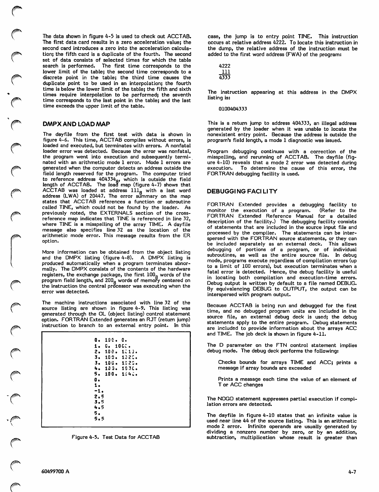
The data shown in figure 4-5 is used to check out ACCTAB.
The first data card results in a zero acceleration value; the
second card introduces a zero into the acceleration calcula
tion; the fifth card is a duplicate of the fourth. The second
set of data consists of selected times for which the table
search is performed. The first time corresponds to the
lower limit of the table; the second time corresponds to a
discrete point in the table; the third time causes the
duplicate point to be used in an interpolation; the fourth
time is below the lower limit of the table; the fifth and sixth
times require interpolation to be performed; the seventh
time corresponds to the last point in the table; and the last
time exceeds the upper limit of the table.
case, the jump is to entry point TINE. This instruction
occurs at relative address 4222. To locate this instruction in
the dump, the relative address of the instruction must be
added to the first word address (FWA) of the program:
4222
111
4333
The instruction appearing at this address in the DMPX
listing is:
0100404333
0SS
DMPX AND LOAD MAP
The dayfile from the first test with data is shown in
figure 4-6. This time, ACCTAB compiles without errors, is
loaded and executed, but terminates with errors. A nonfatal
loader error was detected. Because the error was nonfatal,
the program went into execution and subsequently termi
nated with an arithmetic mode 1 error. Mode 1 errors are
generated when the computer detects an address outside the
field length reserved for the program. The computer tried
to reference address 404334g, which is outside the field
length of ACCTAB. The load map (figure 4-7) shows that
ACCTAB was loaded at address 111„ with a last word
address (LWA) of 20447. The error summary on the map
states that ACCTAB references a function or subroutine
called TINE, which could not be found by the loader. As
previously noted, the EXTERNALS section of the cross-
reference map indicates that TINE is referenced in line 32,
where TINE is a misspelling of the array TIME. A dayfile
message also specifies line 32 as the location of the
arithmetic mode error. This message results from the ER
option.
More information can be obtained from the object listing
and the DMPX listing (figure 4-8). A DMPX listing is
produced automatically when a program terminates abnor
mally. The DMPX consists of the contents of the hardware
registers, the exchange package, the first 100„ words of the
program field length, and 200g words of memory centered on
the instruction the central processor was executing when the
error was detected.
The machine instructions associated with line 32 of the
source listing are shown in figure 4-9. This listing was
generated through the OL (object listing) control statement
option. FORTRAN Extended generates an RJT (return jump)
instruction to branch to an external entry point. In this
0. 10 0. 0.
1. G. 10CC.
2. 100. icia.
3. 100. 13 2C.
3. 10G. 1 G 2 S .
4. 103. 103C.
5. 100. 1G4J.
0.
1.
-1.
2 . 5
3 . 5
4 . 5
5.
5 . 5
Figure 4-5. Test Data for ACCTAB
This is a return jump to address 404333, an illegal address
generated by the loader when it was unable to locate the
nonexistent entry point. Because the address is outside the
program's field length, a mode 1 diagnostic was issued.
Program debugging continues with a correction of the
misspelling, and rerunning of ACCTAB. The dayfile (fig
ure 4-10) reveals that a mode 2 error was detected during
execution. To determine the cause of this error, the
FORTRAN debugging facility is used.
DEBUGGI NG FACI Ll TY
FORTRAN Extended provides a debugging facility to
monitor the execution of a program. (Refer to the
FORTRAN Extended Reference Manual for a detailed
description of the facility.) The debugging facility consists
of statements that are included in the source input file and
processed by the compiler. The statements can be inter
spersed with the FORTRAN source statements, or they can
be included separately as an external deck. This allows
debugging of portions of a program, or of individual
subroutines, as well as the entire source file. In debug
mode, programs execute regardless of compilation errors (up
to a limit of 100 errors), but execution terminates when a
fatal error is detected. Hence, the debug facility is useful
in locating both compilation and execution-time errors.
Debug output is written by default to a file named DEBUG.
By equivalencing DEBUG to OUTPUT, the output can be
interspersed with program output.
Because ACCTAB is being run and debugged for the first
time, and no debugged program units are included in the
source file, an external debug deck is used; the debug
statements apply to the entire program. Debug statements
are included to provide information about the arrays ACC
and TIME. The job deck is shown in figure 4-11.
The D parameter on the FTN control statement implies
debug mode. The debug deck performs the following:
Checks bounds for arrays TIME and ACC; prints a
message if array bounds are exceeded
Prints a message each time the value of an element of
T or ACC changes
The NOGO statement suppresses partial execution if compi
lation errors are detected.
The dayfile in figure 4-10 states that an infinite value is
used near line 44 of the source listing. This is an arithmetic
mode 2 error. Infinite operands are usually generated by
dividing a nonzero number by zero, or by an addition,
subtraction, multiplication whose result is greater than
60499700 A 4-7
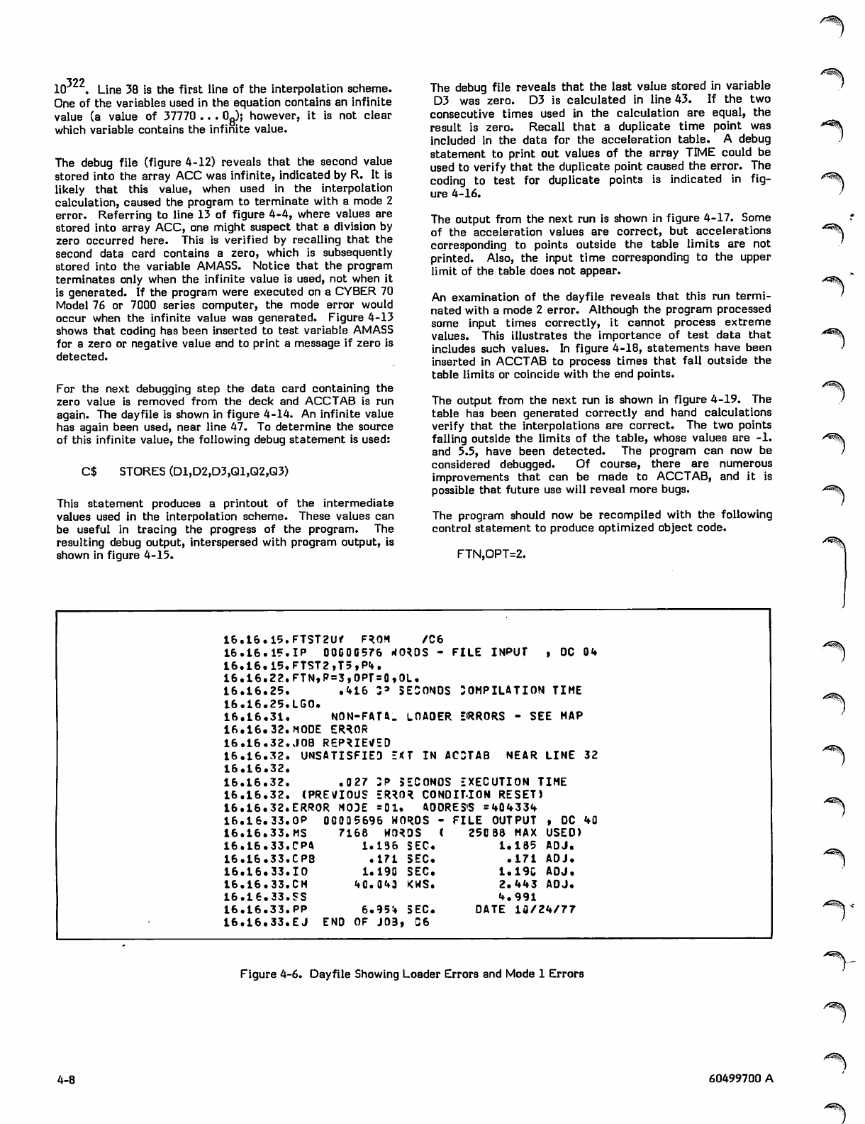
322
10 . Line 38 is the first line of the interpolation scheme.
One of the variables used in the equation contains an infinite
value (a value of 37770 ... 0fi); however, it is not clear
which variable contains the infinite value.
The debug file (figure 4-12) reveals that the second value
stored into the array ACC was infinite, indicated by R. It is
likely that this value, when used in the interpolation
calculation, caused the program to terminate with a mode 2
error. Referring to line 13 of figure 4-4, where values are
stored into array ACC, one might suspect that a division by
zero occurred here. This is verified by recalling that the
second data card contains a zero, which is subsequently
stored into the variable AMASS. Notice that the program
terminates only when the infinite value is used, not when it
is generated. If the program were executed on a CYBER 70
Model 76 or 7000 series computer, the mode error would
occur when the infinite value was generated. Figure 4-13
shows that coding has been inserted to test variable AMASS
for a zero or negative value and to print a message if zero is
detected.
For the next debugging step the data card containing the
zero value is removed from the deck and ACCTAB is run
again. The dayfile is shown in figure 4-14. An infinite value
has again been used, near line 47. To determine the source
of this infinite value, the following debug statement is used:
C$ STORES (D1,D2,D3,Q1,Q2,Q3)
This statement produces a printout of the intermediate
values used in the interpolation scheme. These values can
be useful in tracing the progress of the program. The
resulting debug output, interspersed with program output, is
shown in figure 4-15.
The debug file reveals that the last value stored in variable
D3 was zero. D3 is calculated in line 43. If the two
consecutive times used in the calculation are equal, the
result is zero. Recall that a duplicate time point was
included in the data for the acceleration table. A debug
statement to print out values of the array TIME could be
used to verify that the duplicate point caused the error. The
coding to test for duplicate points is indicated in fig
ure 4-16.
The output from the next run is shown in figure 4-17. Some
of the acceleration values are correct, but accelerations
corresponding to points outside the table limits are not
printed. Also, the input time corresponding to the upper
limit of the table does not appear.
An examination of the dayfile reveals that this run termi
nated with a mode 2 error. Although the program processed
some input times correctly, it cannot process extreme
values. This illustrates the importance of test data that
includes such values. In figure 4-18, statements have been
inserted in ACCTAB to process times that fall outside the
table limits or coincide with the end points.
The output from the next run is shown in figure 4-19. The
table has been generated correctly and hand calculations
verify that the interpolations are correct. The two points
falling outside the limits of the table, whose values are -1.
and 5.5, have been detected. The program can now be
considered debugged. Of course, there are numerous
improvements that can be made to ACCTAB, and it is
possible that future use will reveal more bugs.
The program should now be recompiled with the following
control statement to produce optimized object code.
FTN,OPT=2.
<*'^»k
/ ^ \
16 .16. 15. FTST2U* F*OM / C 6
16 .16. 15. IP OOC00576 rf0*DS - FILE INPUT , OC 04
16..16. 15. FTST2,T5,P4.
16 .16. 22. FTN, P = 3,OPT = 0,()L.
16 .16. 25. . 4 1 6 Z * SECONDS COMPILATION TIME
16 .16.,25. LGO.
16 ,16,.31. NON-FATA. LOAOER EfRRORS - SEE MAP
16 .16. 32. MODE ER*0R
16 .16,,32. JOB REPRIEVED
16 .16.,32. UNSATISFIED E(T IN ACSTAB NEAR LINE 32
16 .16 .32.
16 .16. 32. .027 3P SECONDS EXECUTION TIME
16 .16.,32. (PREVIOUS ER*0* C0NDIM0M RESET)
16 .16. 32. ERROR MODE =01 , ftOORES'S S404334
16..16. 33. OP 00035696 WOROS - FILE OUTPUT , DC 40
16 .16. 33. MS 7168 WO^DS ( 250 88 MAX USED)
16 .16.,33. CP4 1.136 SEC. 1 . 1 8 5 ADJ.
16 .16..33. CP3 . 1 7 1 SEC. .171 ADJ.
16 .16.,33. 10 1.190 SEC. 1.19C ADJ.
16 .16.,33. CM 40.043 KWS. 2.443 AOJ.
16 .16,.33. SS 4.991
16 .16.
,33. pp 6.954 SEC. DATE lfl/24/77
16 .16, 33. EJ END OF J03 t u 6
/■*s^V
Figure 4-6. Dayfile Showing Loader Errors and Mode 1 Errors
4-8 60499700 A
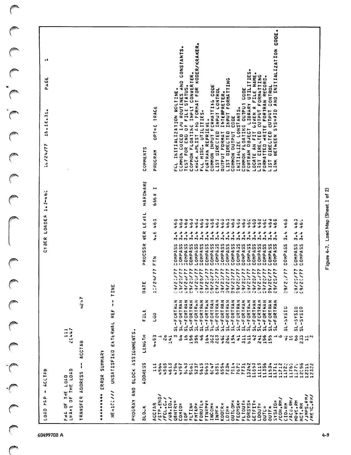
A^l\
0$&\
j^pN
UJ
o
o
•o
•or
V) Ul
h- xc
Z<x •H
ri
1-
oo
z
o
QC
XC
>»
or
UJ to _l
oor Ul U l O . 4
Ul U l o to 2 d M
oa»— xc *- • » m o r t -
•-t z • or Ul ft z f - t n - i f
0. • <x tn uior a-l 1- Ui -1 I - O O Z
U l 3 2» o o • 1 - O M Ul •X Ml OC UH
Zlfll- Z U . u or or«« o f - -J az oc u-
M U l 4 ▶-Ul z m za uh a r z o
f - Z f - O 1 - v D Z u- oc u. o z o z
-i t-t in «t *- tn U l o r - t r U . 4 C J 4
Ul o 1 - 1- M , J ar u. za QC <t ar
•ooc za u» _* or 1- a. tO Q. <t f - t - t - o
rl O _ J to t— t— or »- ▶-f I X . z za oc za fi
to or ZKH u. Ul a a U l 3 Ul za a Ul a. o a 4
.i— a u > u. t - l . z a. i- o. a <x O fi •> i - U . I - I I
ta M o f-UJXZ22 t— -1 i - » z a z a t n
xH 1 - V a . JC fi> O fi I H M (/J o ■JU|uO>-
.II * X fi O •o. -1 Ul u. z z t- t - m
X1- l-l IH • h a t - a i - O IH CJ l-OHQ
xH a. m a cn ^~ t— 1- CC 1- Ul <X uJ za f - U l IH ui or ui z
oJUJZ<I tn Z3 a za u- r i - a XX —1 U. 1 - X 1 - U l
4 C J U l UH Ul CL o or • j T- Ul tn a J o U l
Ut l - l o -1 -i orzui o U l za NI - I O U J O U l X
| x - IA I- 'J Of u. a. o ▶-» or u. or o UH u. ar ui ar h-
N. u- I H O X CO Z U H UH -1 HhHUJ
Jz<x zzu. IH 4 z o f - o z <x Ul U h C J H
CVJ aj a: m tn IC or o »H tn oc 1-
>» Z r - I - Z 1 - 0 . 1 - Z 1— Z 1 - 1 - X h - > r
-1 X. - I Z L O i.•5 -1 IX Z CO u- m UH z ot CJ io or co z
rH QC o ta ui ac -.> O O I H za ft o o O M O f t f t
o0, u. o »- o o U, C_> -I tn -i tn rt
UU. -J _ J U . _ l - I
Ul
oc
•X fi
..1
Xca
*
1
tx.
XX
"1
•
T,
-1
tx ai
Ul •» cx O ^3 ''3 r t i "3 - 3 O " 3 ' 3 O ■-Z3 •3 >_1 tzx o o ra is «3 e-» .»
oUl <J3 vO vJ3 X \ X ^o •£> vD v£> .0 >J3 >J3 X X xxxx JJ •J3 vD
<x
o-1 Jt 4- 4- 4- J- Jf J " J - J " J - J " 4- 4- 4 4- Jt & o r ■* 4 - 4- 4- -*
-J QC
Ui
•>
Ol 4^ 4" -J" J- J- J- J - J " J " 4 - J " 4- 4- -t 4- 4- 4- 4" 4- 4^ 4- 4" 4-
oc
UJ
m
4- ro io ro to «o ro «o fo ro ro ro ro ro ro ro ro ro ro ro ro ro ro
OC to to to in to to to to to CO IO IO CO CO CO io to to to 00 to CO CO
>- IA to to to to to to tn tn <.i to to to CO to to CO CO CO to CO CO to to
tn to 444<t •X < <r <i <r <x <x <a *t ^X <t 4 4 4 « *
tn 0-0.0. a. a. a. a a o . a. tv a. a. O . 0- a. Q- a. a o. Q- a. Q.
oZz z z X z zzzz z z z z z z z
QC l— ooooo o OOOo o ooo oooo
tx u. o c > tx ^ j t n U O ( ) ( ) i . l CJ O L l o cj cj o tn CJ
N. (X, N. h- *. t - t r r>- r>- N- r- n. N. N. r«- r- s. K N . ix . N. fx. N.
N. |x- r- r«- N- N.f- N- N. IV N . S. f>~ fs. |x- |x- r- SKSK fx. fx- fx.
N. X V s. N. V. S . N . ^ " ^ X >. »«* v s. >s N . - V X V V. N.
J<> C» -3 •.-> i r » i-» O t.J «-j i^j C.1 CJ t.3 I—I C3 • i ca eo c» ■', tl«- ■
Ul OJ f\J t\l CM CM CM CM CM CM <M CM CM CM CM CM CO CM CM CM CM CM CM Pvl CM
Ul i- ■s. X X N . "V N. N. V V s. >H "s, V. >* V *v N. N. N» N» N. S.
z«r ft rr tr t r tr rr rr tr tr tr (T> tr tr tr tr rr tr tr cr tr tr tr <T> tr
fi
t-
t4 K l : . l J r.J CJ '.J est CJ t-> ir> ca c> Cl r3 tj'.» 13 Cl CJ C.I ,Ju>
|x-
ZZZ zzzz z z z ZZZZ
CM •I <t <I <r -x «4 ■X <t <I « t -X <* <t « i i <x 4 4 4 * t
4or o; ar or ar or or or or oc ot U£ or or or ac or oc oc ac tn o o
u. al 1— H- 1— •— u- t- i— i— •— f - u - 1— i-u - f - t— u - u - f - u - i-i UH rt
Ul _l or ir or or ar oc oc oc ty 0C QC or or or or 0C QC OC QC OC CO IA tn
at —l <J> ooo OOOo tn ta o o tn tn m tn tn >- >-
-j
<r
u. -1 u. u_ u.
. 1 1 u. u. u. u. u. u. u. u. u. u. u. u. u. u. u. u. u. co IA
1 » • r | ■ v ■ I
_l_l-l_l_l-J-J-l_l - j _ i _i _ J - J -i iiii
- J _ i _ i _ i -1 -J _l
rH N- co to v) in ti to to co oo a i n tn to to 00 to to co to tn CO to OO
•■» .* Of cn
^ 4 " Oi 1— to •H rH KO 4" vi3 vO vO or cm ro >o >o 4- •rH »-l T* CM -h x »n Tt vo • J (_» • o IO xi fX
CJ f- 1— lt\ to 4- vD T-l in J- u0 o o x x in 4- ■H -H 4- j- m in * xH TO •ri
Mco
<x
t-
tn
o
ct
3-
txt
4
z
Ul
a
■a
u,
u.
Ul
r
z
i-.
to
uj
-J
4-
.4 •H ro rH -O <M 4" CM •H i>0 J3 O J Ti T i CM
1zto co . - 1 in •O 41 *- to .4N. IO f O ^ .-1 4 4 - .* c» -H CM »o in vO 4* *-i <\j rjt"l ,.t vO •H <M
1=> ft 'A rH J? iO rlin u\ j- ro Ti vP • » in in ro •^« N. ro 4" <n r l I f t n r l H N s£» K. in r l f J
aa to t— •* Ui r.tn in xO r^ s. -i »j CM . fl U N I in cm u% vD r*. cm ri ro in r— i*. fx. IX. (x. Ll
rx to
4•X tn <l IT J- -* 4- -» J- to ir» UN u> tn x x -iCM CM CM
1- a o in QC co
O •4. -J UJ -1
uooc a: Z3 a>
4
1
- 1 U i
X
u i 1 -
X
•X
a.'
Ul
*N. > . V .
a. 1— u. oc N. ■v>» Z Z
vt Ul i j ll II ii II ll I I I I 11 I I z ct or
2. u. u. Cj OR Ul o o a - l l ii li -1 > ii ii xc •- to 1- t i o o r Ql O; . .
o -• co ■rt Of XC UH « V O a. »— 0 . Z I I QC II tn za >- IH h m i h • or ar in o
o+z*TIt _i »- >-i •-• «*• k tn u U i z ■Jo to u. Z 3 O U . 4 Z •-O Ul a 7-
••4 •X. 4 <t UJ tn r— 00 z z u t-i - o r Z C J Q - O »H 1— »- or 1— Ol- KlrtO <_i ■»♦—Z U l
ot 3 . oc <y -J CJ f/> u. •3 4 0 O O -i f - Z z o a Ul -1 o UJ a za za a- tn b-l CJ -> z
—i U . -1 u- tx. CO "X, "X. >» a o ui U- u. u. U . H H * r _ j O u. u. u. tD r J O O t O V >. "x. "x.
60499700 A 4-9
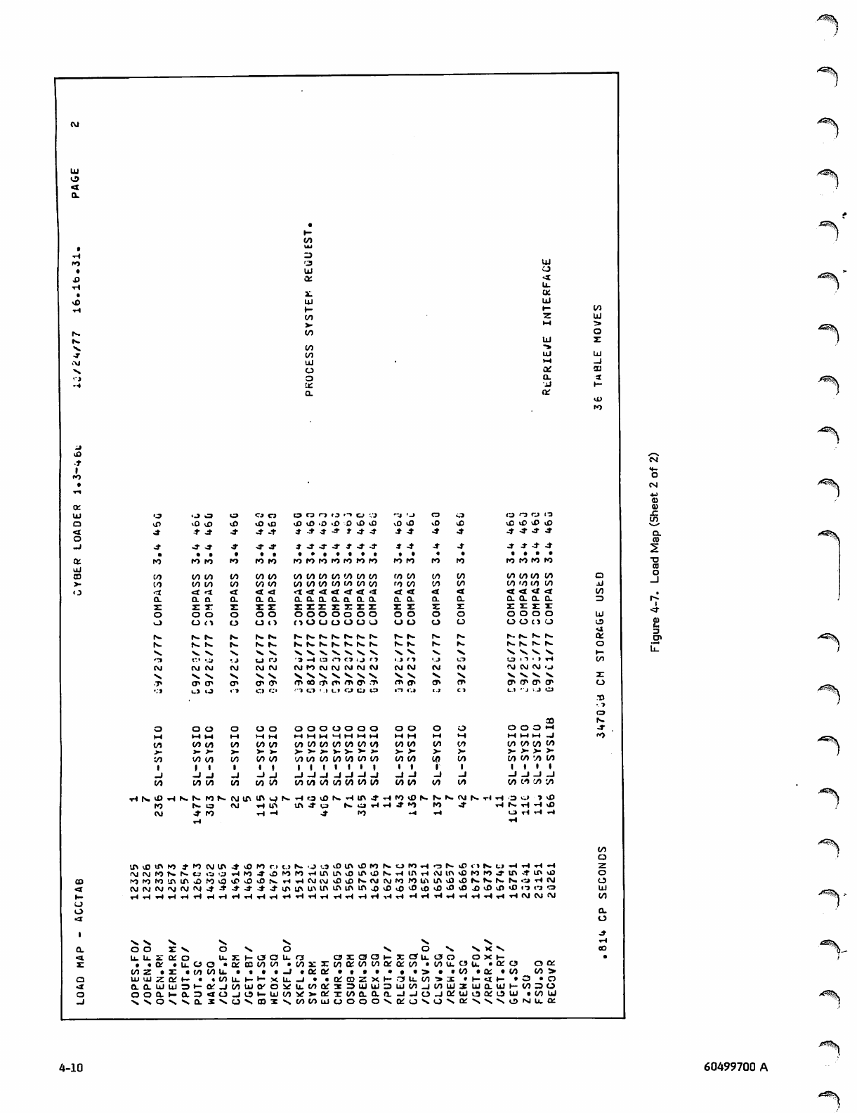
UJ
CJ
4
u.
or
Ul
i- to
zUJ
Jj
or
i**^V
vO X
•t 41
CO 00
CO CO
4 4
a a
z or
o o
CJ (1
fx. |x.
4-
4"
ro
00
to
4
a.
z
o
tn
fx.
r>.
Xx.
■.J
CM
CT>
oOo
M M M
to CO CO
3- y- .»-
'A 00 00
_l -1 -1
to oo 00
l O T i rx. fx. ro
to IX.
CM 4- ro
CJ Ci
X l Q
J- -t
4- 4-
ro ro
oo oo
oo tn
4 4
a. a.
z z
o o
CJ (1
fx. fx-
fx. fx.
V . V
U C 3
CM CM
xx. V
tT> CT
O O
vO vO ■£>
4 J- 4
13 •-» O '-.'J
.£» O \0 00
-4" J" 4" 4- vO X
4- 4-
4 4- J" 4- 4 4" 4-
.......
ro r o ro r o ro ro ro
to co oo to oo co co
oo oo to tn t n i n i n
4 4 4 4 4 4 4
a. a a. a. a o_ a.
zzzzzzz
O O o o o o o
t x tn li tn tn tn i-3
r» rs. r-. r>- f>» ix. rs.
n. n. r». rx. fx. N. n.
V N. V xx, V ♦>, V
-a -, a t-i <3 i j r->
CM fO CM CM CM CM CM
V X xs. V *x. "x. V
rr to tr ttt n\ fj\ -t\
o o o o o o o
CO 00 tn
ro 00 to to
4 4
a. a. a. a.
z z
o o
C J o
fx. rx. fx. | x -
fx- tx. f x - rs-
X * V x«. >.
i . J ' 1 'J CJ
CM CM CM CM
V x ».
er (xi tr CT»
00 oooo oo oo to cn co oo oo
> - f a - 3 - > - > • > - > » > - a -
00 oooo i/i to oo oo oo oo oo
I I I I I I I I I I
_i -i-i —* —i —i —i —i —I —r
00 00 00 00 00 00 00 CO 00 00
(\jiniftqrx.Hoa)ix.Hin4
C M r l i n t n 4 " W | x , O r l
• H - I 4 - r o
00 00 09
- 1 - J
00 to 00
rOsDfx.fx.lx.CMfx.rl
4 - » 0 r o 4 "
CO CJ 13
XXXX
4- 4- 4^
4- 4" 4-
....
ro ro ro to
tn mm to
CO '0 CO to
4 4
0. a. 0- a.
zzzz
oo o
O O C l CJ
fx- fx. rx. fx.
r- rx. fx. f x -
Xs, x*. Xs, N»
to 1 -> • » rl
CM CM CM ij
VXx, x*.
tr tr tr CT
Cl 123
Ol
Otn o •H
UH fiUi -1
00 00 CO to
>- >- 3- >-
00 00 oo
-1 -1 -1 _J
00 to 'A 00
'3 cl
r>. xH ■H
u> rl Tt
in 4* in ui
lfia}lflW*'0(Mlft4tOIOr.ic.ifx.'ji,3iOlft\CfOSoWHoS>Df>K
MIVJIONSCJia'JrlM^^MMrlinirNJIl^iflNrllftrliVJinvDNWjui.iii. «
.. «^lft^fi)katfi^)>0(s,HTlC\ll\J03iONCy(V)l«5l,Ob\lftU3»OSrxlx.Norirj
0jCM<MJ'-*4-4'4-4-unmU>inU>U,imk0vDi0v0<.0s0sDs0j)kDu0U3<3i-JO
^^rlrlrlrlrlrlrlrlrlrlrlrlrlrlrlrlrlrlrlrlrlrlrlrlrlrlCMCMCM
ro ro ro
CM CM CM
O O Z V 0 * x , O N . O * x " x , X * x .
u-uzoro u-zi-arau-o azaa^-zou-oo oxi-
. .or • u. o o • ar co co to .oozzooorooooororoo •oou.ou. •ore?
o o z * z . c o t o u . « • • - j .o r o r • . • * . . • > . . c o • o r • t o
uiujzari— « <(/) u.
o or
._-_.. oo >
• OrcDZXr->'3U.C03>3: * h- 4 I- • O • O
Qr3B3UlU)3UIC0_J00UI3UICLUll-003OO.O.UJUJ3l-ft:jMUJiyO«U.MI}r3!3UJUJ3lUCnjWU5LJQ.UJH(/)30
ooo.i-o.340_joi-uioovr>-arxooo.aa-J-io_iQruiojQrou) .ooui
SS0\SQ.I\UMDS\trtWWOOOO\KOSOM>;sSNv»NU,0;
■^*fy\
4-10
Z"^.
60499700 A
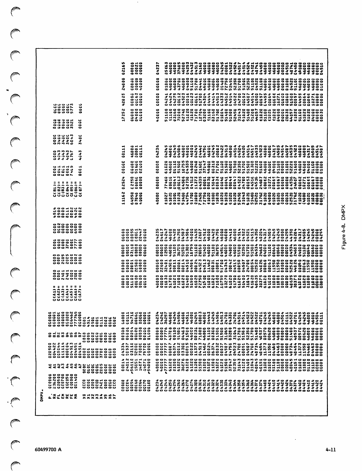
IA O r l O r». WooiAanNnQOoooiAHN<tN4*^<ioooooaoHoaaoooo
XJ orgs ra l0OOOOtAIOrl\0OOC9O^OCMCMHHCMCM^'tAOOOC»Orl4'IAC>OOOOr)
HOOO CM waaiooN^tn^oaooAiainiMniniiiuiKjaooooiiiNfaijoaoiA
CM 000 j- u\ig«N(ii4<T^4io<oisiii-To4«^'t««a«i<iioiSi0oJ;o»iaiSioipo^
Oooo ca-T-J'ro.j'ooo<n-T<T-r-3'ooooocaoo-*o-T<*'-J*-Too~*'oJ-*~-?-3*oo
O000 •aoocaoooorlcjooooocaoooooootaoooaocjcjoooooo
O n > 0 0 OOOOOOOO^OOOOOIAUIIAOOIAOCMOOOOOOOCMOOOOOOO
O000 oaoNoaHS'rooQaJNjnMAnHiAHoaoooalAHaooooci
4- 000 Hv0t0rOv04Hrl4c9c9<0>0c3CMCMCMHH(MH4-H>0«0Ull0OH4'Ht0«0«0l0Orl
CM 00* 044>4^0tAtAo^444arx.tAtAtAlAIAIA0IA^'4'4'^00OtA^^^^0a
Ul qNo r i - r i a c m r o m i 1 0 n a j - J J - r o r o < m - y m o m s ^ o M n j m H o o o M n - T u i h o u
(M O < 0 0 <fNNrlNHNjaa<'H«ll>IHHNOIAaHOiniAiB<IISaoalAIAll)«Nga
OQUO CM4CMc3tAOi3C>Kr0'44mi»ltAU\tAfx.l3IAIAIAo4'OoCMOOIAO<4OOCMOO
CM OOO 4*J04000tIJ J J" J- J" J" J" 4'^'O4'4'H04-O0O0Or|O^000OO
i a c a c a * j I O o 4- 000 (3 OOOOOOOOIAOOOOcaOoOCMOOOIAOcjOOHOQIAOOClOHOO
uaoas cj
joaoN a CM 000 000000004-0000^00 onaaosooa oooor-ooooooo
O O 1 3 O | A O IA
«M
tx.
000
000
J J - - J
OcavOOJ-CMCMOOOOtOOoOOtA^CMOOIACMOCMCMOOrOlACMOCMCMOOrO
nHrior«.ocJr.r>-(MHnix.aj-lnj-cjoJ,(MOoncaooooooriaoooo
HHnrtNHHHNf)rlHHHHHNrtHHH*HrtrtH*00*HHHHJ'00
o « o « ? r i « j 000 mi'oixuMJ«K Hou> oiAolAiAtAro<0 iniA'twiAwwaaojiuiAilxuaoa
u a a a i v o
aoouin o
c j o o a r o o
o a o u " ) v i
o o o o i t o
o 4 J - x T o 4
O » w > K > U > K J
rl
rl
OHH
O O x i
>0
IO
molfliOciOOlfttJOOlMVIMWo.J'.l-O ^MnnooMft J-MflMocjKlflJ'N
4-o4oOOOJ-J>tAO4o(MrlOHCMCMrlr<r0rMOOrlOrlor0CMC3OHOrlO
CUOlMlAOOOtMJ-r«.O<MO4-lAolAtAlAtAlAlAlAoo'0tAlAlAlAtAool0(AlAtA
o i o i o r o r > - r o O O H CM
o-r.j-.rvO 4- vo 0 0 .» ^J*4'iOJ)'0*.»*ifl.T04,*vO-J*»JJ;*^vOiO-»J,*J?.t.»iOvO****
a n ^ o n o JOO o-TooJ'^-'ocjtA-J'ooooj'ocaooooo-TJ'oraoooo-a'j-oooo
a ^ J ; J - o 4
CJ
O
ca cj ca
0 ' - 3 0
ooootniAoocjrs.oooooooooooooocjoooooaoooooo
(MoHoiAroo^a-YoHoooootAoooCMooooaoocMocjcaoooo
o H H H t A H ta O 10 <3 ooHUtMnaNiOgODKHiflaiMONinnivitooaariQaMvOooaHaa
o o - _ j o - j o O r l C M HlOaHa4<OoHKltOHrlH«HNHHHNHvOlP4HOTlNrllSl|)4<larl
a a a o T a ( 3 t A O iD4oinfloJaiAn«aMniA«iftiAiiMAtti|itm»J;0iACjalltiA^«oiAcia
o o o o r - , a
CM
0 t » 0
I A t O O
ou^n>voNioiAHaiutUar|ii'ixr)or)>voNNH<iiNaoON<viT|ii<ixaci
isn^HonHMoan^n^f^^iMaWrinaWNioidoonoiPMUiooQ
I I i l n l l l l I I l l IA u « 0 0 foooiflixoniAagoaaoooWKoiAiMDoNqaooiliiiioMaoaa
—. T. —. #S ^k —. T. CM I M O O N.OtAOJ-CM-T'rl^'OOCnoOOOOJ-^'O.a'J-J-OOOOOOJ-^-OOOOOO
ri CM I O 4 IA «0 N. C J 0 0 rx.OOOalAOrloOOOOC30aOOCMOOOCM<3Has300c3CMOrlOaca)l3
s * s * - t w w w s t f <M 000 r.ocaoo4ooooooooooooroooo(MoooooooCMoooooo
O O O O O O o vO
rl
rl
rl
I A 4 - O
I A 0 O
* i x . 0
lOO«
(MMO(MOlAOolAIA(MOCvl(MCM(MCMlA^'CMO<MvOCMOCMCMOrOCMt0tMOCMCMOrO'
aooof KNg^NQOooaoo jao JiriNoaooaonKooaaoo
HHHHH-THHUNHHHH<IHHNrlHHMHHJHHC(OmHHj>Hriao
vU«0OCU|A^tAO|wr.lVOwC0a)xUiOinrOi0tAIArO|0Oxl><0C3OIAl>OXVW«0XWOo
* O O r l t U « J C M
r l O O - 1 a « M o
I t t I t t o r ) a 0 1 o
4 - o o o o 4 ^ o
O t M O O O O O
o o o o o o a
o c j o o o t n o O O I A H i x . 0 IArx.fx.ooofx.c0otAKCMoooooOO^CMrllAo4'|x.lAmtAolAo4'rx.|AtA(Aocr
o o o O O U 3 o O O
O O
O O
I A 0 4 O
0 0 4 0
oooo
r0rl4ONinoOOr0orlOlMtf<OOT-IOrlCM<MHinOr!O-T4O(nmoHO<f4OU>
CMc9(MO4rx.|AU>O^v0tno4'N.ao4'OIAlAtAIArOCMrOIA(MCMOCMrOCviniA(virAI<3IM
4'^4tD4-t44;iS-tN4'i0 44i0v0J'va44'r4J;o^44 4o^«o4'444o<t
dOoouNa
o o o o o r . o
o o o r x . o i x . o
O Oca ca CM ca oo-ra>Aoojaria'ToinJJa4ciciao4JaciaoaoJJaciaaoc)
O O oooo oaaoiAoelliaoaoBiA4ooooooo4nooaaoo4l|iaggooo
aaonasa O O r l c a c a 0 oomoouootnococjoooHooooiAoorooooj-iOooroooo.J'cOoo
O O Hoog OlAoHrs.|nlON.rlo4'OHN.tAOOOIAror>tAIAl0CJrl«0«0OolA\0OrlcacaoO
O Oro 00 ca OONtSHiOrlHoHaHlllHig4l(«llHNHH««4HoOOO*4«HeOOO
o a u v v t a i u a O O c a 0 0 c a OOO.4'mr0miAHtACMtA.4>mr0a.4'O.»|AlA|AtAO<MolAoOOOO<MO|AOOOO
o a o a o o o
o o o o o a o O O r l 0 0 0 Qri>CHH-roiiijnniMHHanN^oSO'i'Ov0o'''oooooiDanaooo
eaNNooa O O
O O
oooo
O I A O O
aooaHoHHoNNHiDnooj^HiAealANNiSdlAUiaoNNOiSIAIAoo
O<0.*'IAoOOIAIAolAtA4'OON-fOoinQmr-.QIAOOOUMAOOIAOC3olAtAOO
O O O O O O 0CMCM4O00<44'O4'4'HOOrl^O^o^^0CM^O0Hr|O0(M^OOrlHO0
O O H H o a C 3 O O O C M O O CMIOOOaOOOOOOHOOlAOOooOCMOtA^OOrlrlOOIAxt'OOrlrloO
o o o o o o o
a a • * • * o o o O O OOOO CJ ooooooooooooootAooooorooiAinooooootAtnoooooo
O O M N O M O O O
O O
0 1 3 c a a
r l O O C J
OOrOQCMQCMOOCMIAOO (MO tnSNaNO^NmNNNaooO|l)NNNOOOO
QooNooa^iAOSinoaONNaKaiaoilina<JoDoa''naaaooa
O O rl OO 0 OHHHHHHHHNHHHHonHHHHHHoOHHHHOOOOHHH tXOJX
I I | | I I I I I I 1 1 I I O O t A O O O '4OOtAvOfx.cgiAtAi0f>.IAOv0h>Ha>OIAcgiA'O(0^rOi0(0OOOC3«IOiX)>0ooOf3
H M r l 4 - I A \ D t r
4 4 4 4 4 4 4
O O O O O O O
a W g O O N U t a O r l O r l O O r l .*ON-c3IAiOoHoiArOorotAcOIOoov3c9.4r')CMCMHIAinoo4'H<MHtniAOO-4rl
o o a a u i O > O o O H r l i O J O O n4no400H04 00««OHONOHHNNN04«oooHN04*OQOH
OOOOO^NOtHJ rl IM •a CM O r l N . C J C J a 0 (MCMCMOCMtA<3IAOCM004'CMIAIAN-rorx.lAIAtAIAtArx.CMIMCIOtAHlAlx.lMC\IOOtAH
OOOOOi0N-OoH CD CJ 0# O O 0 O *J'i0i0*J-v04v0J-Ov0*-*J-4'4rf44-444>4OJ-J-a)«0J-oJ-o4'-»>Oi04o
DUoaoaMioI A IA CD O 1 3 I A 0 O O 1 3 un^oo4a''uo4ciuojNoNooooo4ao4.roao^ooJ4oo
OOOOOoh-OO^OOOOOO
0 0 •* 0 0 0 a ooinoounoaoaooadoiltonooooosooooooosoooooo
0 0 I A O O 0 O ooN-cjooocjorooooocao\0o4oQtAooror.lMoooooror.CMoooo
o w m n ^ i M O s a CM O U i u a 0 0 0 O C J O ( 3 0 o s s H u i ^ i f t O N o e H n i A i A O M a M A n K fi n i fl i fi a a a a j i A i A d a o o a
03 CD CQ 00 tO CD CD CD cj u 0 ca ca O O O O r l ca sNnsHjHiOoHitHaHHHnHfiHNHHa 00 itiseorieeoOifloo
o o CJ 0 0 0 0 OOOOO oK4oioaiA4os«iAoiAifinoniAiniiiiJMA<rcjo4'tooiA4oo4j;oo
aoo
ON14JMH4 4 - r - 0 c j c j 0 c a ca oNN4C<ioinNnnN44NsKanotiNa4r^noanaoj4noonoo
OMJ'IOdlAH r o r o r l 0 O c j c a cjr.oix.HC3riCMr.rii0CMr^iorooiACMoiAooioinKU>di«0oa(oiAr«>tn\Ot0oo
IA J-urlolAvOmci CJ (O IA r l 0 c a r - O oosonunooniA«o»)aaiASiAKoinKK4niA'4QOKJ;ioiA44oo
aj-inwoj-^J-oca 0 0 * 0 r o c m 0 i n 0 or-Ol0OrOOOrl.^rlOC9OO4-4.*4O.*.*OOrlH.^^OOQC3rlrl4'.4OO
CMoorioooooo 0 r » a 0 • 3 c » 0 i a r . n . 0 Orx-OOOOOOrlOrlOOOoOIAOCMOaCM4i4Hr|0000^4-Hr|0000
ooooooooooooroooo
* C M CIHHHO Oors.OOOv0OOOOOOOOOO>x,ClfOOorOIArlOOOOQOlAnoc3OOOO
r l r l H I A I x. N. cs aSNONSNNOOaNaNNO'lAJNO^^IAOOOBOO^UIOaooDO
O rl NM JiniOKO i_> uainCl Cl O O r l 0 c a 0 0 OOrwOOOCJOOOIAOOCJOCJlAorOocj^OOHOGarlnOOoHOOrlrlOO
444444440000 O - T v O IA 4 - ■» * OOSHHHiOHHHHrlHHHHHSNHHHHOoHHHHOOQOflHHHOO
Oooo O CM U \ r l H r l I A ^j'NvOoianiOiaciiAoisoiOiouininnifluimj^ciciiMAooj'^cioiAinoo
o o o o i m o o o t . » . «.
0000000
0 0 0 0 i n 0 0
□ (MinSOOJ 0 13 O 4 - 3 * O . ? 0 O DJa4a4o4oJa4o4ofci4oJajO'JoJoJo4oja'oJoj
Cl iDOOUOrl It OCJU tatt c a 0 tn *0 1 0 r. c a MJ'JmiAlO\ONSc>.(Jrlrl<MCtinfi)4'JIMIMOlOlsNiaOH<4AIMr>SOCjnrll\IN
CMCMCMCMCMCMCMiMCMroroforororoiorororOfororo'Oiorod'a .r -J- .*• •! ro ro •» .x -j- j- j- .»
hmnoooo CJ CJ CJ CJ c a c j c a c a 0 a r l
O i M O C J C J O O c j oaoMoou c a c j 0 0 0 C J 0 4J-U'J.fJJ'.C44'*»*.JJ*4JJJ*JJJJJ4*^J.I4J*JJ44
X
0. '4JZUU« O
0 0 OOOOO oooooooooooooooutaoooocjoeooooooooooooooo
H CM IO 4- (A <0 rx.
x . a e u . w a : u . x x x
O
XXX
>^%
60499700 A 4-11
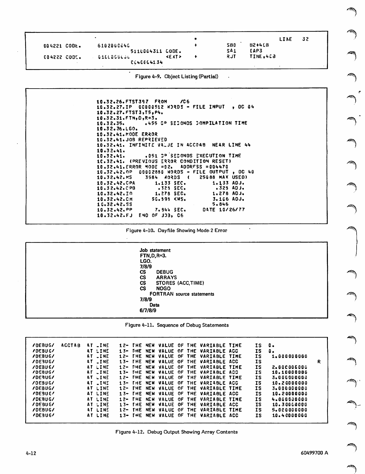
LINE 32
Q04221 CODb. 61 020 .Gi .4& SBO B2+4CB
5111QC4311 CODE. SAl [AP3
C04222 CODC. 0 l & L Q G U c J u < £ X T >
CC4CCC.4134
RJT TINE,4C3
Figure 4-9. Object Listing (Partial)
10 .32, 26. FTST39 7 F*OM / C 6
10 .32. 27. IP OC000512 »mDS - FI L E INPUT , OC 0 4
10 .32.,27. FTST3,T5,P4.
10 .32..31. FTN, D,R=3.
10 .32.,35. .45 5 C° 5 EDONOS SOMPILATIO*1 TIME
10 .32.,36. LGO.
10 .32. 41. KODE ER*0R
10 .32. 41. JOB REPRIEVEO
10 .32.,41. INFI N I T E V 4 - JE IN ACCT'AB NEAR LINE 44
10 .32..41.
10 .32,,41. .05 1 Z ° 5 ECONOS EXECUTION TIME
IC .32. 41. (PREVIOUS ER*OR CONDITIO*1 RESET)
10 .32 ,41. ERROR 1O0E =0 2. aOORFSS = 004470
10 .32 .42. OP 00002830 WORDS - F I LE OUTPUT , OC 40
10 .32.,42. HS 3 5 8 4 < I O * D S ( 25088 MAX USED)
10 .32 .42. CPA 1 . 1 3 3 SEC. 1.133 AOJ.
10 .32.,42. CPB .323 SEC. .323 ADJ.
10 .32 .42, in 1.278 SEC. 1.278 ADJ.
10 .32 .42. CM 50.399 <MS. 3.106 AOJ.
IG.32 .42. SS 5.846
10 .32 .42. pp 7.944 SEC. DftTE 1 0 / 2 6 / 7 7
10 .32 .42. FJ ENO OF J33, C6
•'*^\
/"^\
Figure 4-10. Dayfile Showing Mode-2 Error
Job statement
FTN,D,R=3.
LGO.
7/8/9
C S D E B U G
C$ ARRAYS
C$ STORES (ACCJIME)
C$ NOGO
FORTRAN source statements
7/8/9
Data
6/7/8/9
0Tjp^\
Figure 4-11. Sequence of Debug Statements
/ O E B UG / A C C TA B AT - I N E 12- THE NEW VALUE OF THE VARIABLE TIME IS 0.
/DEBUG/ •U LINE 13- T'HE NEW VALUE OF THE VARIABLE ACC IS 0.
/DEBUG/ AT - I N E 12- THE NEW VALUE OF THE VARIABLE TIME IS 1.000000000
/DEBUG/ S.T - I N E 13- THE NEW VALUE OF THE VARIABLE ACC IS
/0E3UC/ ftT LINE 12- THE NEW VALUE OF THE VARIABLE TIME IS 2.O0COOO00O
/OEBUG/ AT - I N E 13- THE NEW VALUE OF THE VARIABLE ACC IS 10.10000000
/DEBUG/ (VT LINE 12- riHE NEW VALUE OF THE VARIABLE TIME IS 3.Q0CQ0OOOO
/OEBUG/ *T - I N E 13- THE NEW VALUE OF THE VARIABLE ACC IS 10.20000000
/OEBUG/ AT LINE 12- THE NEW VALUE OF THE VARIABLE TIME IS 3.000000000
/DEBUG/ AT LINE 13- THE NEW VALUE OF THE VARIABLE ACC IS 10.20000000
/DEBUG/ AT LINE 12- THE NEW VALUE OF THE VARIABLE TIME IS 4.000000000
/DEBUG/ AT LINE 13- THE NEW VALUE OF THE VARIABLE ACC IS 10.300COOOO
/DEBUG/ ftT LINE 12- THE NEW VALUE OF THE VARIABLE TIME IS 5. OC00OOOOO
/DE3UG/ AT LINE 13- THE NEW VALUE OF THE VARIABLE ACC IS 10.40000000
Figure 4-12. Debug Output Showing Array Contents
4-12 60499700 A
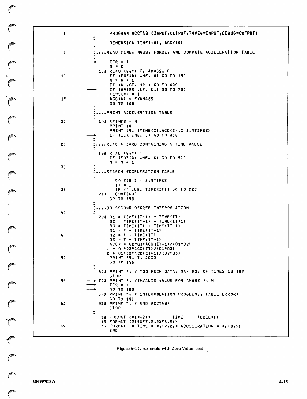
IC
15
2r>
3:
35
45
55
65
PR0GRA1 ACCTAB (INPUT,OUTPUT,TAPE4*INPUT,0EBUG=0UTPUT>
DIMENSION TIME(IC), ACC(10)
UAD TIME, MASS, FORCE, AND COMPUTE ACCELERATION TABLE
I F * = 3
N = C
103 REAO (4,») T, AMASS, F
I F i E 0 - < 4 ) . N E . 0 ) G O T O 1 5 0
N = N •• 1
IF (N .GT. 10 ) GO TO 600
IF (A MI SS .LE. C.) G O TO 7 0C
TIME(M) = T
ACC(N) = F/AMASS
GO TO 100
*RINT ACCELERATION TABLE
15J NTIMES = N
PRINT 10
PRINT 15, (TIM£(I),ACC(I),1=1,NTIMES)
IF <IE* .NE. 0) GO TO 9C0
....READ A CARO CONTAINING A TIME VALUE
1 9 3 R FA O U , » ) T
IF (E0 ~(4 ) , NE. C) GO TO 90C
N = N ♦• 1
I....SEARCH ACCELERATION TABLE
OO 200 I * 2,NTIMES
IT = I
I F ( T . L E . T I M E ( I T ) ) G O T O ? 2 3
2 3 J C O M T I N U f
a" TO 350
:....30 SECOND OEGREE INTERPOLATION
220 DI = TIME(IT-I) - TIME(IT)
02 = TIMElIT-1) - TIME<IT*1)
03 = TIMfCIT) - TIMECITU)
01 = T - TIME(IT-I)
02 = T - TIME(IT)
33 = T - TIMEUTH)
ACCX = Q 2 * Q 3 » A C C(IT- 1 ) / ( 01»D2)
1 - 01*33*ACC(IT)/<D1»D3)
2 *■ Ql*a2»ACC(IT«-l)/(D2»D3)
PRINT 25, T, ACCX
GO TO 190
5j3 PRINT *, * TOO MUCH OATA. MAX NO. OF TIMES IS 10*
STOP
▶ 733 PRINT *, *INVALIO VALUE FOR AMASS *, N
I E R - 1
r,0 TO 100
353 °RINT ♦, t INTERPOLATION PROBLEMS, TABLE ERROR*
GO TO 19C
933 PPINT *, * END ACCTAB*
STOP
13 FORMAT <*1*,2(* TIME ACCEL*))
15 FORMAT (2(5XF7.2,2XF3.5))
25 FORMAT C* TIME = *,F7.2f* ACCELERATION = *,F8.5)
ENO
Figure 4-13. Example with Zero Value Test
60499700 A
/f§^V
4-13
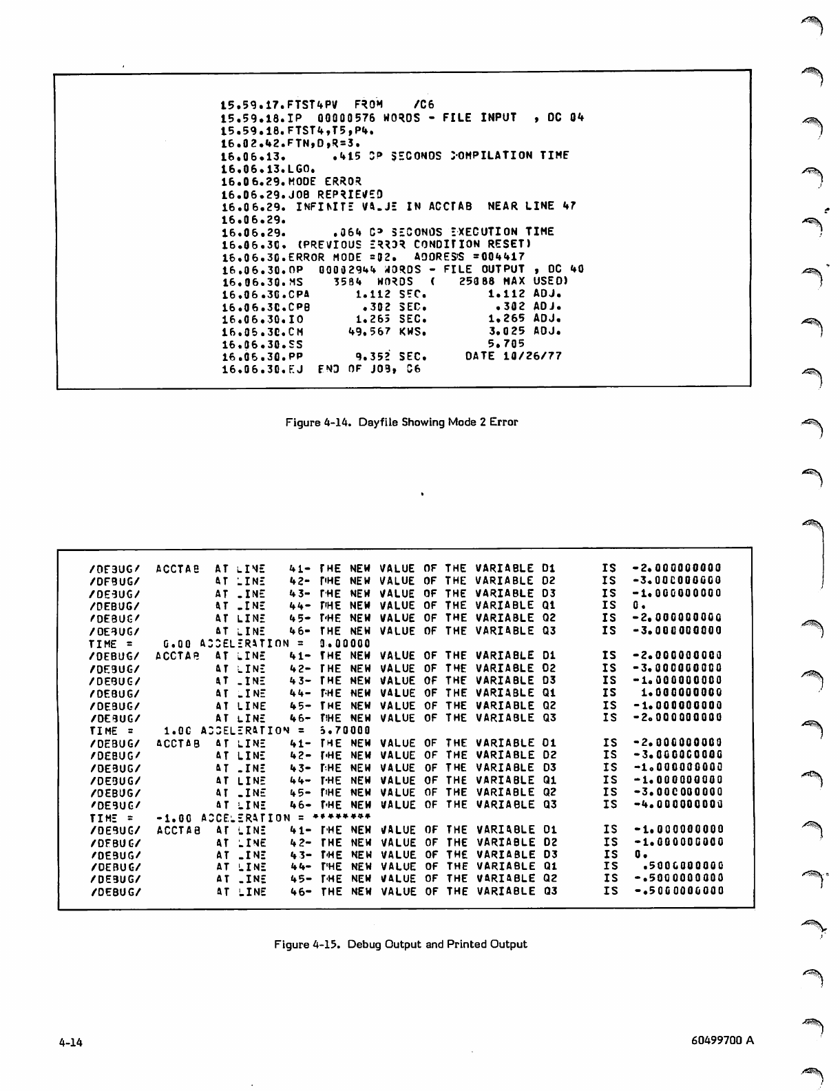
15.59.17.
15.59.18.
15.59.18.
16.02.42.
16.06.13.
16.06.13.
16.06.29.
16.06.29.
16.06.29.
16.06.29.
16.06.29.
16.06.3C.
16.06.30.
16.06.30.
16.06.30.
16.06.30.
16.06.3C.
16.06.30.
16.06.3C.
16.06.30.
16.06.30.
16.06.30.
FTST4PV FROM /C6
IP 00000576 WORDS - FILE INPUT , DC 04
FTST4,T5,P4.
FTN,D,R=3.
. 4 1 5 S P S E C O N O S C O M P I L AT I O N T I M E
LGO.
MODE ERROR
JOB REPRIEVED
INFIMTE V4.JE IN ACCTAB NEAR LINE 47
.064 C» SECONOS EXECUTION TIME
(PREVIOUS ERR3R CONDITION RESET)
ERROR MODE =02. AOORES'S =004417
O P 0 0 0 0 2 9 4 4 t f O R D S - F I L E O U T P U T , O C 4 0
MS 3584 WORDS (
C P A 1 . 1 1 2 S E C .
CPB .302 SEC.
IO 1.265 SEC.
CH 49.567 KWS.
SS
PP 9.352 SEC.
V . J E N D O F J 0 9 , C 6
250 88 HAX USEO)
1.112 ADJ.
.302 ADJ.
1 . 2 6 5 A D J .
3 . 0 2 5 A D J .
5.705
DATE 10/26/77
"*«^\
Figure 4-14. Dayfile Showing Mode 2 Error
/0E3UG/ ACCTAB AT LIME 41- THE NEW VALUE OF THE VARIABLE DI IS -2.000000000
/DFBUG/ AT LINE 42- PHE NEW VALUE OF THE VARIABLE D2 IS -3.Q0C0QQ000
/0E3UG/ AT - I N E 4 3- THE NEW VALUE OF THE VARIABLE D3 IS -1.000000000
/DEBUG/ AT - I N E 44- T'HE NEW VALUE OF THE VARIABLE Ql IS 0.
/OEBUG/ AT LINE 4 5- T'HE NEW VALUE OF THE VARIABLE Q2 IS -2.000000000 rt*-^\
/OEBUG/ AT LINE 4 6- THE NEW VALUE OF THE VARIABLE Q3 IS -3.000000000
TIME = COO A. CDEL ERATION = 3 . 0 0 0 0 0
/DEBUG/ ACCTAB AT LINE 41- THE NEW VALUE OF THE VARIABLE DI IS -2.000000000
/DE9UG/ AT LINE 4 2- THE NEW VALUE OF THE VARIABLE 02 IS -3.000000000 /i^jk
/DEBUG/ UT - I N E 4 3- THE NEW VALUE OF THE VARIABLE D3 IS -1.000000000
/OEBUG/ AT - I N E 44- THE NEW VALUE OF THE VARIABLE Ql IS 1.000000000
/DEBUG/ AT LINE 45- THE NEW VALUE OF THE VARIABLE Q2 IS -1.000000000
/DEBUG/ AT LINE 46- TiHE NEW VALUE OF THE VARIABLE Q3 IS -2.000000000 -^^\
TIME = 1.0C A CCEL ERATION = S.70000
/DEBUG/ ACCTAB AT LINE 41- THE NEW VALUE OF THE VARIABLE Ol IS -2.000000000
/DEBUG/ AT LINE 42- PHE NEW VALUE OF THE VARIABLE D2 IS -3.OOOOOOOOO
/DEBUG/ AT - I N E 4 3- THE NEW VALUE OF THE VARIABLE D3 IS -1.000000000
jrfSG^V
/0E3UG/ AT LINE 44- THE NEW VALUE OF THE VARIABLE Ql IS -1.000000000
/DEBUG/ AT - I N E 45- r'HE NEW VALUE OF THE VARIABLE Q2 IS -3.0OC0O000Q
/DE9UG/ AT LINE 46- T'HE NEW VALUE OF THE VARIABLE Q3 IS -4.000000000
TIME - -1.0C A2CE: ERATION = »»*»*♦»»
/0E9UG/ ACCTAB AT LINE 41- THE NEW VALUE OF THE VARIABLE Ol IS -1.000000000 A^$\
/DEBUG/ AT LINE 4 2- THE NEW VALUE OF THE VARIABLE 02 IS -1.ooooooooo
/DEBUG/ AT -INE 4 3- T'HE NEW VALUE OF THE VARIABLE D3 IS 0.
/DEBUG/ AT LINE 44- T'HE NEW VALUE OF THE VARIABLE Ql IS .5000000000
/DE9UG/ AT -INE 45- T'HE NEW VALUE OF THE VARIABLE Q2 IS -.5000000000 S^\
/DEBUG/ AT LINE 46- THE NEW VALUE OF THE VARIABLE Q3 IS -.5000000000
A***r™£$\
Figure 4-15. Debug Output and Printed Output
4-14 60499700 A
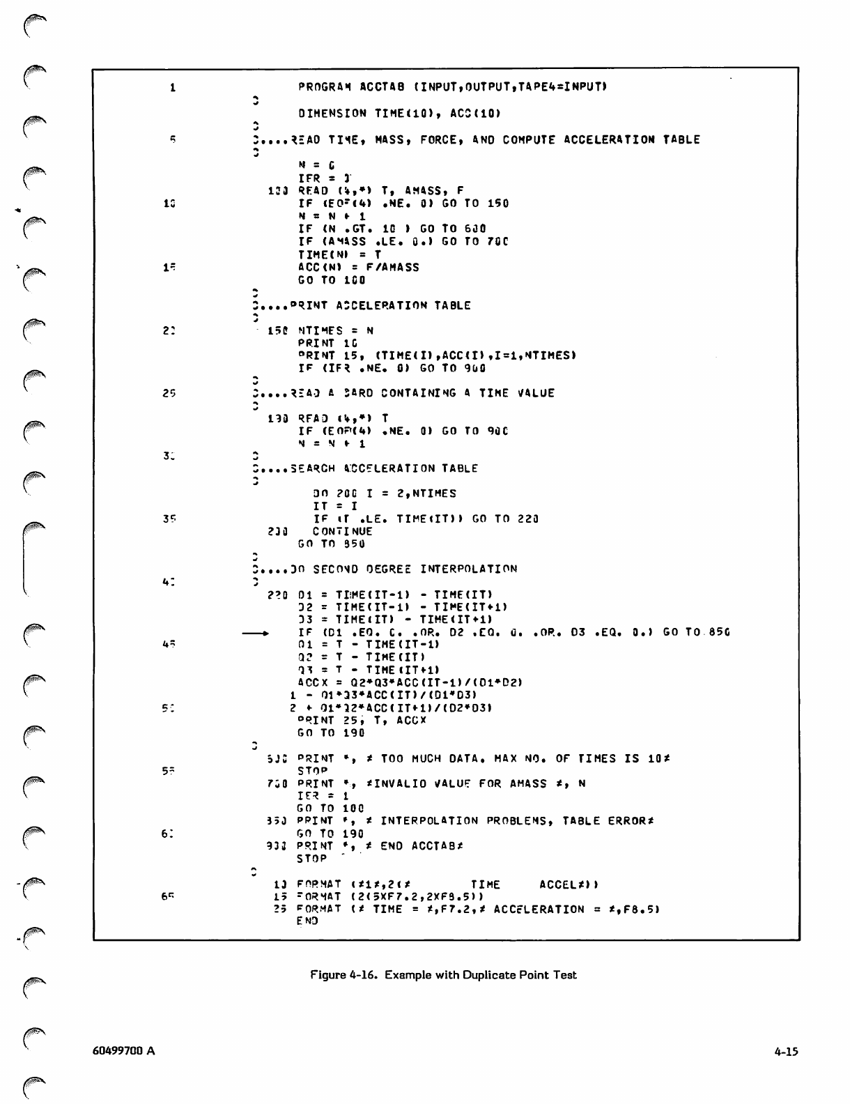
2:
3?
4:
5r
PROGRAM ACCTAB (INPUT,OUTPUT,TAPE4=INPUT>
DIMENSION TIME(IO), ACS(IO)
iH
xj
C....REA0 THE, MASS, FORCE, ANO COMPUTE ACCELERATION TABLE
•s
N s C
IFR = 3
133 READ U,») T, AMASS, F
IF <E0-<4) .NE. 0) GO TO 150
N = N r 1
IF (N .GT. IG ) GO TO 600
IF (AMVSS .LE. 0.) GO TO 70C
TIME(N) = T
ACC(N) s F/AMASS
GO TO 1C0
C....ORINT ACCELERATION TABLE
15C NTIMES = N
PRINT 10
°RINT L5, (TIME(I),ACC(I),1=1,NTIMES)
IF (IFR .NE. 0) GO TO 900
READ A SARD CONTAINING A TIME VALUE
190 RFAD !!»,♦) T
IF (E0F<<4) .NE. 0) GO TO 90C
N = N l- 1
....SEARCH ACCELERATION TABLE
DO ?0C I = 2,NTIMES
IT = I
IF iT .LE. TIME1IT)) GO TO 220
230 CONTINUE
GO TO 350
DO SECOMD DEGREE INTERPOLATION
.OP.. 03 .EQ. 0.) GO TO 8 5C
2?0 Ol = TI!ME(IT-1) - TIME(IT)
D2 = TIME(IT-I) - TIME(IT*1)
D3 - TIMElIT) - TIME<IT*i)
▶ I F ( D I . E O . C . . O R . D 2 . C Q . 0 .
0 1 = T - T I M E ( I T - l )
0 2 r T - T I M E ( I T )
Q 3 = T - T I M E C l T fl )
ACCX = Q2^Q3»ACC(IT-1)/(D1»D2)
1 - Q1*33*ACC(IT)/(D1*D3)
2 ♦■ Q1»32*ACC(IT*1)/(D2»03)
°RINT 25, T, ACCX
GO TO 190
SJC pRINT % * TOO MUCH DATA. MAX NO. OF TIMES IS 10*
STOP
7C0 PRINT », *INVALI0 VALUF FOR AMASS *, N
I E R ' 1
GO TO 100
353 PPINT ', * INTERPOLATION PROBLEMS, TABLE ERROR*
GO TO 190
93 3 PRINT ♦, * ENO ACCTAB*
STOP "
13 FORMAT (*1*,2(* TIME ACCEL*))
15 rORMAT (2(5XF7.2,2XF9.5))
25 F O R M AT < * T I M E = * , F 7 .2t* ACCELER ATIO N = * , F 8 . 5 )
END
Figure 4-16. Example with Duplicate Point Test
/ ^ \
60499700 A 4-15
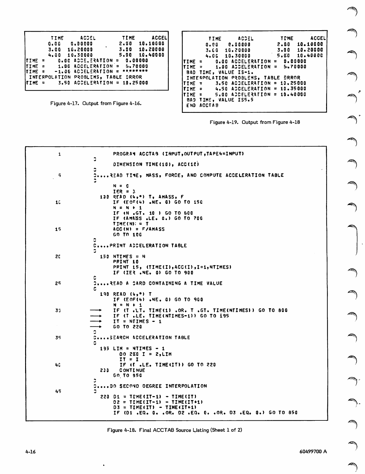
/*i|\
TIME ACCEL TIME ACCEL
O.OC .00000 2.00 10.10000
3.CO It1.20000 3.00 10.20000
4 . 0 0 IC1.30000 5.00 10.40000
TIME 0.OC ACCE.ERATION - 0.00000
TIME 1.OG ACCELERATION = 31.70000
TIME -1.OC ACCELERATION - *»»»*»#*
INTERPOLATION PROBLEMS, TABLE ERROR
TIME 3.50 ACCELERATION - 10.25000
Figure 4-17. Output from Figure 4-16.
TIME ACCEL TI'ME ACCEL
0 . 0 0 0 . 0 0 0 0 0 2 . 0 0 1 0 . 1 0 0 0 0
3 . C O 1 0 . 2 0 0 0 0 3 . 0 0 1 0 . 2 0 0 0 0
4.00 10.30000 5.0:0 10.4000C
TIME = 0.00 ACCELERATION = 0.00000
TIME = 1 . 0 0 A C C E L E R AT I O N = 31.70000
BAD TIME, VALUE 13-1.
INTERPOLATION PROBLEMS, TABLE ERROR
TIME a 3 . 5 0 A C C E L E R A T I O N = 1 3 . 2 5 0 0 0
TIME = 4.50 ACCELERATION = 10.35000
TIME - 5 . 0 0 A C C E L E R A T I O N = 1 0 .4 0 0 0 0
BAD TIM E , VA L U E I S 5 .5
ENO ACCTAB
Figure 4-19. Output from Figure 4-18
IC
15
2C
25
33
35
4C
45
PROGRAM ACCTAB (IMPUT,OUTPUT,TAPE4sINPUT)
DIMENSION TIME(IO), ACC(IC)
C....READ TI1E, MASS, FORCE, ANO COMPUTE ACCELERATION TABLE
t
N = G
IER = 3
130 REAO (4,*) T, AMASS, F
IF (EO"(4) .NE. 0) GO TO 15C
N = N r 1
IF IN .GT. 10 ) GO TO 600
IF (AMASS .LE. 0.) GO TO 70G
TIME(N): = T
ACC(N) = F/AMASS
GO TO 10C
C... PRINT ACCELERATION TABLE
150 NTIMES = N
PRINT 10
PRINT 15, (TIME(I),ACC(I),1=1,NTIMES)
IF (IER .NE. 0) GO TO 900
REAO A CARD CONTAINING A TIME VALUE
190 REAO (!»,♦> T
IF (E0F(4) .NE. 0) GO TO 900
N = N f 1
—▶ IF (T .LT. TIME(l) .OR. T .GT. TIME(NTIMES)) GO TO 800
—▶ IF (T .LE. TIME(NTIMES-D) GO TO i95
— * I T = N T I M E S - 1
—▶ GO TO 220
o
C....SEARCH ACCELERATION TABLE
C
195 LIM - NTIMES - 1
OO 2fl:0 I = 2,LIM
IT a I
IF <f .LE. TIMEtIT)) GO TO 220
23 3 CONTINUE
GO TO 350
C....DO SECOND DEGREE INTERPOLATION
220 DI = TIME(IT-l) - TIME(IT)
D2 = TIME(IT-l) - TIME(IT*1)
D3 = TIMElIT) - TIME<IT«-1)
IF (DI .EQ. 0. .OR. 02 .EQ. G. .OR. D3 .EQ. 0.) GO TO 850
/ ^ S \
^**3\
>^^\
/ r f ^ k
Figure 4-18. Final ACCTAB Source Listing (Sheet 1 of 2)
4-16 60499700 A
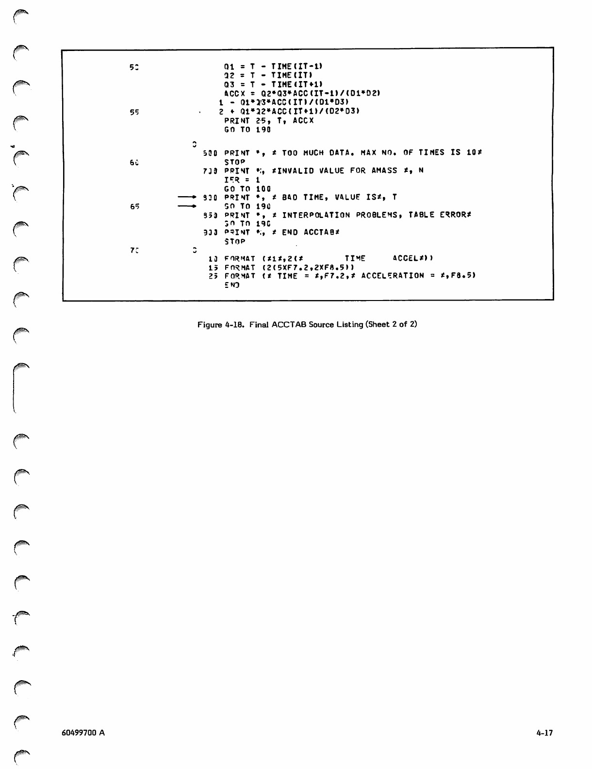
0SS
52 Q l a T - T I M E ( I T - l )
Q 2 a T - T I M E ( I T )
Q3 a T - TIME(IT*1)
ACCX a Q2^Q3»ACC(IT-1)/(01*D2)
L - Q1»JV3»ACC(IT)/(01»D3>
55 2 ♦ Qi»a2»ACC(im>/(D2»D3>
PRINT 25, T, ACCX
GO TO 190
rs
530 PRINT *, * TOO MUCH DATA. MAX NO. OF TIMES IS 10*
60 STOP
739 PRINT •:, *INVALID VALUE FOR AMASS *, N
I F R - 1
GO TO 100
▶330 PRINT •» * BAO TIME, VALUE IS*, T
65 *■50 TO 19C
353 PRINT *, * INTERPOLATION PROBLEMS, TABLE ERROR*
50 TO 19C
933 P=TNT »;, * END ACCTAB*
STOP
i:
13 FORMAT (*1*,2(* TIME ACCEL*))
15 FORMAT (2(5XF7.2,2XF8.5))
25 FORMAT (* TIME = *,F7.2,* ACCELERATION = *,F8.5)
END
Figure 4-18. Final ACCTAB Source Listing (Sheet 2 of 2)
<i!$R\
jfj$S\
60499700 A 4-17

.A%
1
0)
f%
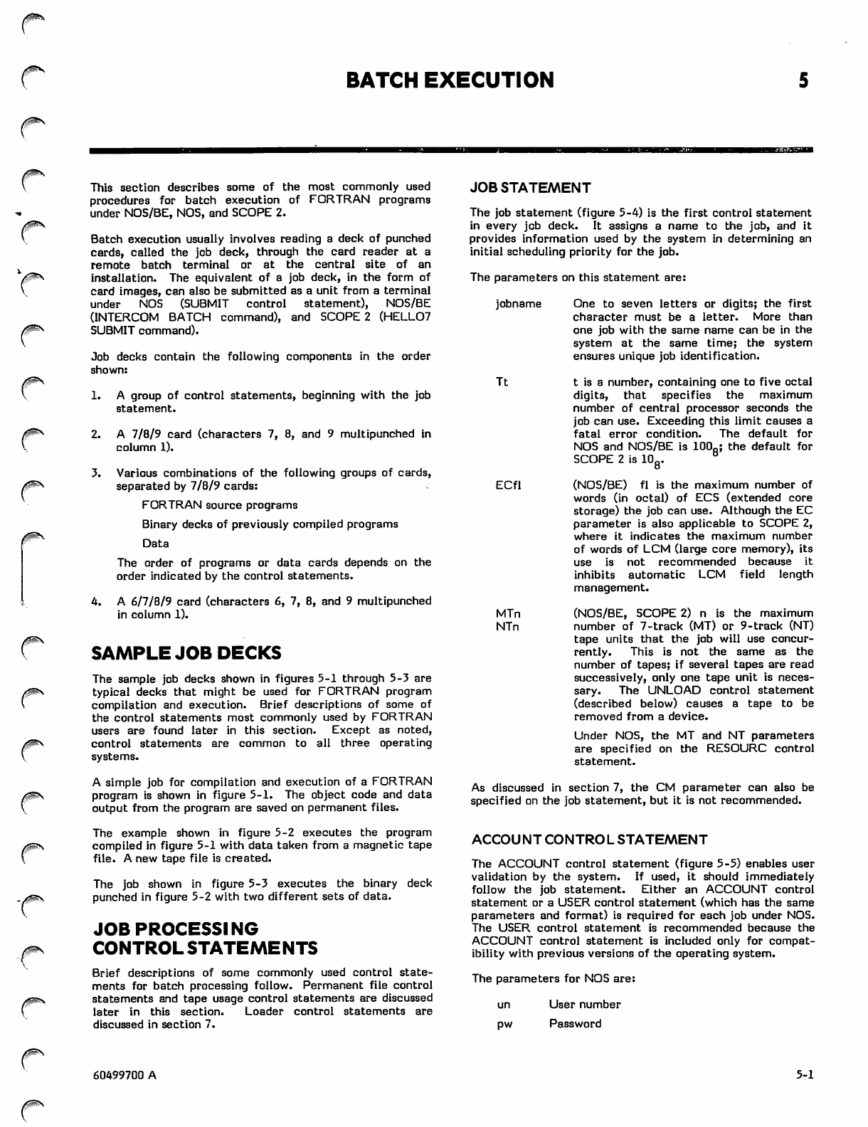
/P^N
/SjSfey
BATCH EXECUTION
/t!0vS
This section describes some of the most commonly used
procedures for batch execution of FORTRAN programs
under NOS/BE, NOS, and SCOPE 2.
Batch execution usually involves reading a deck of punched
cards, called the job deck, through the card reader at a
remote batch terminal or at the central site of an
installation. The equivalent of a job deck, in the form of
card images, can also be submitted as a unit from a terminal
under NOS (SUBMIT control statement), NOS/BE
(INTERCOM BATCH command), and SCOPE 2 (HELL07
SUBMIT command).
Job decks contain the following components in the order
shown:
1. A group of control statements, beginning with the job
statement.
2. A 7/8/9 card (characters 7, 8, and 9 multipunched in
column 1).
3. Various combinations of the following groups of cards,
separated by 7/8/9 cards:
FORTRAN source programs
Binary decks of previously compiled programs
Data
The order of programs or data cards depends on the
order indicated by the control statements.
4. A 6/7/8/9 card (characters 6, 7, 8, and 9 multipunched
in column 1).
SAMPLE JOB DECKS
The sample job decks shown in figures 5-1 through 5-3 are
typical decks that might be used for FORTRAN program
compilation and execution. Brief descriptions of some of
the control statements most commonly used by FORTRAN
users are found later in this section. Except as noted,
control statements are common to all three operating
systems.
A simple job for compilation and execution of a FORTRAN
program is shown in figure 5-1. The object code and data
output from the program are saved on permanent files.
The example shown in figure 5-2 executes the program
compiled in figure 5-1 with data taken from a magnetic tape
file. A new tape file is created.
The job shown in figure 5-3 executes the binary deck
punched in figure 5-2 with two different sets of data.
JOB PROCESSING
CONTROL STATEMENTS
Brief descriptions of some commonly used control state
ments for batch processing follow. Permanent file control
statements and tape usage control statements are discussed
later in this section. Loader control statements are
discussed in section 7.
JOB STATEMENT
The job statement (figure 5-4) is the first control statement
in every job deck. It assigns a name to the job, and it
provides information used by the system in determining an
initial scheduling priority for the job.
The parameters on this statement are:
jobname
Tt
One to seven letters or digits; the first
character must be a letter. More than
one job with the same name can be in the
system at the same time; the system
ensures unique job identification.
t is a number, containing one to five octal
digits, that specifies the maximum
number of central processor seconds the
job can use. Exceeding this limit causes a
fatal error condition. The default for
NOS and NOS/BE is 100Q; the default for
SCOPE 2 is 108*
ECfl
MTn
NTn
(NOS/BE) fl is the maximum number of
words (in octal) of ECS (extended core
storage) the job can use. Although the EC
parameter is also applicable to SCOPE 2,
where it indicates the maximum number
of words of LCM (large core memory), its
use is not recommended because it
inhibits automatic LCM field length
management.
(NOS/BE, SCOPE 2) n is the maximum
number of 7-track (MT) or 9-track (NT)
tape units that the job will use concur
re n tly. Th i s i s n o t t h e s ame as the
number of tapes; if several tapes are read
successively, only one tape unit is neces
sary. The UNLOAD control statement
(described below) causes a tape to be
removed from a device.
Under NOS, the MT and NT parameters
are specified on the RESOURC control
statement.
As discussed in section 7, the CM parameter can also be
specified on the job statement, but it is not recommended.
ACCOUNT CONTROL STATEMENT
The ACCOUNT control statement (figure 5-5) enables user
validation by the system. If used, it should immediately
follow the job statement. Either an ACCOUNT control
statement or a USER control statement (which has the same
parameters and format) is required for each job under NOS.
The USER control statement is recommended because the
ACCOUNT control statement is included only for compat
ibility with previous versions of the operating system.
The parameters for NOS are:
un
pw
User number
Password
/S^s
60499700 A 5-1
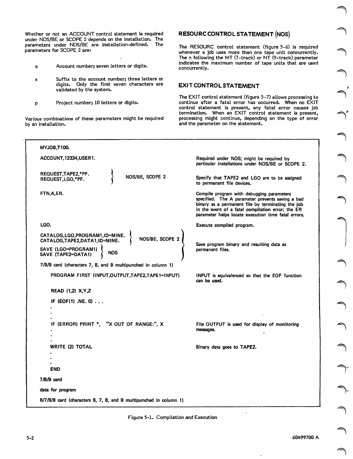
Whether or not an ACCOUNT control statement is required
under NOS/BE or SCOPE 2 depends on the installation. The
parameters under NOS/BE are installation-defined. The
parameters for SCOPE 2 are:
Account number; seven letters or digits.
Suffix to the account number; three letters or
digits. Only the first seven characters are
validated by the system.
Project number; 10 letters or digits.
Various combinations of these parameters might be required
by an installation.
RESOURC CONTROL STATEMENT (NOS)
The RESOURC control statement (figure 5-6) is required
whenever a job uses more than one tape unit concurrently.
The n following the MT (7-track) or NT (9-track) parameter
indicates the maximum number of tape units that are used
concurrently.
EXIT CONTRO L STATEMENT
The EXIT control statement (figure 5-7) allows processing to
continue after a fatal error has occurred. When no EXIT
control statement is present, any fatal error causes job
termination. When an EXIT control statement is present,
processing might continue, depending on the type of error
and the parameter on the statement.
MYJOB.T100.
ACCOUNT,12334,USER1.
REQUEST,TAPE2,*PF.
REQUEST,LGO,*PF. NOS/BE, SCOPE 2
FTN,A,ER.
LGO.
CATALOG,LGO,PROGRAM1,ID=MINE.
CATALOG,TAPE2,DATA1,ID=MINE. NOS/BE, SCOPE 2
SAVE (LGO=PROGRAM1)
SAVE (TAPE2=DATA1) NOS
7/8/9 card (characters 7, 8, and 9 multipunched in column 1)
PROGRAM FIRST (INPUT,OUTPUT,TAPE2,TAPE1=INPUT)
READ (1,2) X.Y.Z
F (EOF(T) .NE. 0) . . .
F (ERROR) PRINT \ "X OUT OF RANGE:", X
WRITE (2) TOTAL
END
7/8/9 card
data for program
6/7/8/9 card (characters 6, 7, 8, and 9 multipunched in column 1)
Required under NOS; might be required by
particular installations under NOS/BE or SCOPE 2.
Specify that TAPE2 and LGO are to be assigned
to permanent file devices.
Compile program with debugging parameters
specified. The A parameter prevents saving a bad
binary as a permanent file by terminating the job
in the event of a fatal compilation error; the ER
parameter helps locate execution time fatal errors.
Execute compiled program.
Save program binary and resulting data as
permanent files.
INPUT is equivalenced so that the EOF function
can be used.
File OUTPUT is used for display of monitoring
messages.
Binary data goes to TAPE2.
Figure 5-1. Compilation and Execution
5-2 60499700 A
^fi&&\
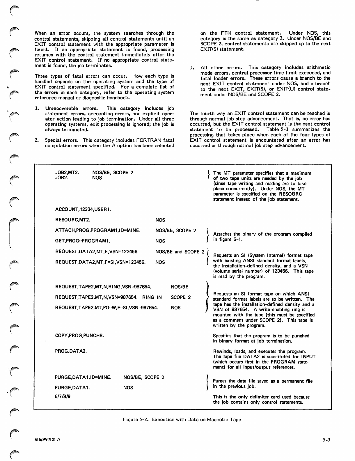
j$SS
r
/^f^N
When an error occurs, the system searches through the
control statements, skipping all control statements until an
EXIT control statement with the appropriate parameter is
found. If an appropriate statement is found, processing
resumes with the control statement immediately after the
EXIT control statement. If no appropriate control state
ment is found, the job terminates.
Three types of fatal errors can occur. How each type is
handled depends on the operating system and the type of
EXIT control statement specified. For a complete list of
the errors in each category, refer to the operating system
reference manual or diagnostic handbook.
1. Unrecoverable errors. This category includes job
statement errors, accounting errors, and explicit oper
ator action leading to job termination. Under all three
operating systems, exit processing is ignored; the job is
always terminated.
2. Special errors. This category includes FORTRAN fatal
compilation errors when the A option has been selected
on the FTN control statement. Under NOS, this
category is the same as category 3. Under NOS/BE and
SCOPE 2, control statements are skipped up to the next
EXIT(S) statement.
3. All other errors. This category includes arithmetic
mode errors, central processor time limit exceeded, and
fatal loader errors. These errors cause a branch to the
next EXIT control statement under NOS, and a branch
to the next EXIT, EXIT(S), or EXIT(U) control state
ment under NOS/BE and SCOPE 2.
The fourth way an EXIT control statement can be reached is
through normal job step advancement. That is, no error has
occurred, but the EXIT control statement is the next control
statement to be processed. Table 5-1 summarizes the
processing that takes place when each of the four types of
EXIT control statement is encountered after an error has
occurred or through normal job step advancement.
0mu..
JOB2.MT2.
JOB2. NOS/BE, SCOPE 2
NOS
The MT parameter specifies that a maximum
of two tape units are needed by the job
(since tape writing and reading are to take
place concurrently). Under NOS, the MT
parameter is specified on the RESOURC
statement instead of the job statement.
ACCOUNT,12334,USER1.
RESOURC,MT2.
ATTACH,PROG,PROGRAM1,ID=MINE.
GET,PROG=PROGRAM1.
REQUEST,DATA2,MT,E,VSN=123456.
REQUEST,DATA2,MT,F=SI,VSN=123456.
NOS
NOS/BE, SCOPE 2 )
N O S )
NOS/BE and SCOPE 2 |
N O S I
REQUEST,TAPE2,MT,N,RING,VSN=987654. NOS/BE
REQUEST,TAPE2,MT,N,VSN=987654. RING IN SCOPE 2
REQUEST,TAPE2,MT,PO=W,F=SI,VSN=987654. NOS
COPY,PROG,PUNCHB.
PROG.DATA2.
PURGE,DATA1,ID=MINE.
PURGE.DATA1.
6/7/8/9
NOS/BE, SCOPE 2
NOS
Attaches the binary of the program compiled
in figure 5-1.
Requests an SI (System Internal) format tape
with existing ANSI standard format labels,
the installation-defined density, and a VSN
(volume serial number) of 123456. This tape
is read by the program.
Requests an SI format tape on which ANSI
standard format labels are to be written. The
tape has the installation-defined density and a
VSN of 987654. A write-enabling ring is
mounted with the tape (this must be specified
as a comment under SCOPE 2). This tape is
written by the program.
Specifies that the program is to be punched
in binary format at job termination.
Rewinds, loads, and executes the program.
The tape file DATA2 is substituted for INPUT
(which occurs first in the PROGRAM state
ment) for all input/output references.
Purges the data file saved as a permanent file
in the previous job.
This is the only delimiter card used because
the job contains only control statements.
Figure 5-2. Execution with Data on Magnetic Tape
60499700 A 5-3
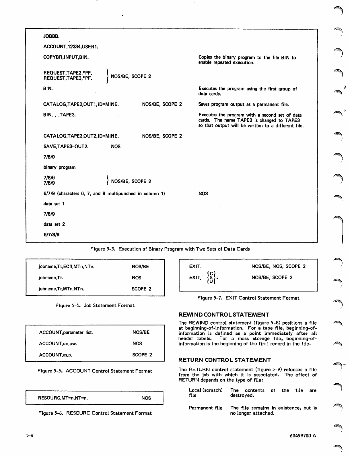
i^y^v
JOBBB.
ACCOUNT,12334,USER1.
COPYBR,INPUT,BIN. Copies the binary program to the file BIN to
enable repeated execution.
REQUEST,TAPE2,*PF. ) M/%otec 0^0„ „
REQUEST,TAPE3,*PF. \ N0S'BE' SC0PE 2
BIN. Executes the program using the first group of
data cards.
CATALOG,TAPE2,OUT1,ID=MINE. NOS/BE, SCOPE 2 Saves program output as a permanent file.
BIN, , ,TAPE3. Executes the program with a second set of data
cards. The name TAPE2 is changed to TAPE3
so that output will be written to a different file.
CATALOG,TAPE3,OUT2,ID=MINE. NOS/BE, SCOPE 2
SAVE,TAPE3=OUT2. NOS
7/8/9
binary program
7/8/9 I
7/8/9 J NOS/BE, SCOPE 2
6/7/9 (characters 6, 7, and 9 multipunched in column 1) NOS
data set 1
7/8/9
data set 2
6/7/8/9
,«£°^y
Figure 5-3. Execution of Binary Program with Two Sets of Data Cards
jobname,Tt,ECfl,MTn,NTn. NOS/BE
jobname,Tt. NOS
jobname,Tt,MTn,NTn. SCOPE 2
Figure 5-4. Job Statement Format
ACCOUNT,parameter list. NOS/BE
ACCOUNT,un,pw. NOS
ACCOUNT,as,p. SCOPE 2
Figure 5-5. ACCOUNT Control Statement Format
RESOURC,MT=n,NT=n. NOS
EXIT.
EXIT,
NOS/BE, NOS, SCOPE 2
NOS/BE, SCOPE 2
Figure 5-6. RESOURC Control Statement Format
Figure 5-7. EXIT Control Statement Format
REWI ND CONTROL STATEMENT
The REWIND control statement (figure 5-8) positions a file
at beginning-of-information. For a tape file, beginning-of-
information is defined as a point immediately after all
header labels. For a mass storage file, beginning-of-
information is the beginning of the first record in the file.
RETURN CONTROL STATEMENT
The RETURN control statement (figure 5-9) releases a file
from the job with which it is associated. The effect of
RETURN depends on the type of file:
Local (scratch) The contents of the file are
file destroyed.
Permanent file The file remains in existence, but is
no longer attached.
/SS5v
/^S-.
,A^S\
5-4 60499700 A
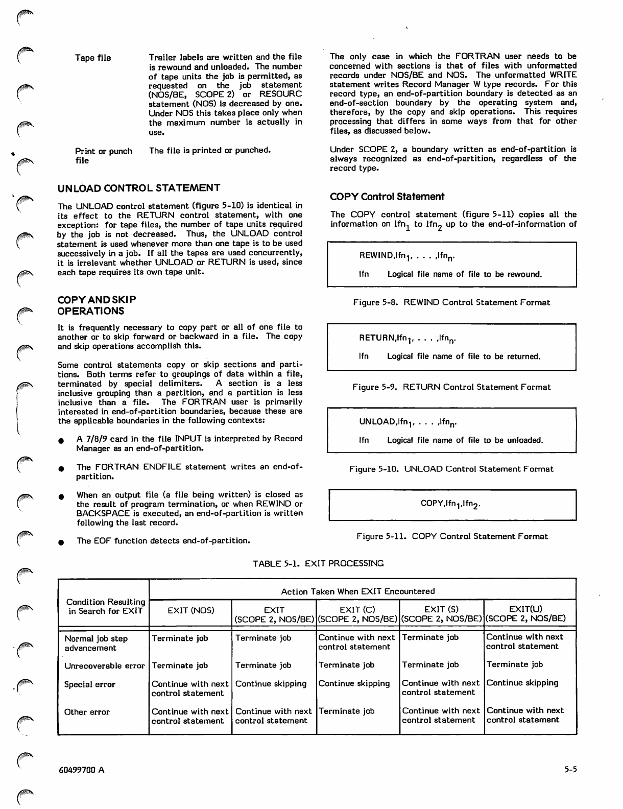
Tape file
z|P\
Print or punch
fi l e
Trailer labels are written and the file
is rewound and unloaded. The number
of tape units the job is permitted, as
requested on the job statement
(NOS/BE, SCOPE 2) or RESOURC
statement (NOS) is decreased by one.
Under NOS this takes place only when
the maximum number is actually in
The file is printed or punched.
UNLOAD CONTROL STATEMENT
The UNLOAD control statement (figure 5-10) is identical in
its effect to the RETURN control statement, with one
exception: for tape files, the number of tape units required
by the job is not decreased. Thus, the UNLOAD control
statement is used whenever more than one tape is to be used
successively in a job. If all the tapes are used concurrently,
it is irrelevant whether UNLOAD or RETURN is used, since
each tape requires its own tape unit.
COPY AND SKIP
OPERATIONS
It is frequently necessary to copy part or all of one file to
another or to skip forward or backward in a file. The copy
and skip operations accomplish this.
Some control statements copy or skip sections and parti
tions. Both terms refer to groupings of data within a file,
terminated by special delimiters. A section is a less
inclusive grouping than a partition, and a partition is less
inclusive than a file. The FORTRAN user is primarily
interested in end-of-partition boundaries, because these are
the applicable boundaries in the following contexts:
0 A 7/8/9 card in the file INPUT is interpreted by Record
Manager as an end-of-partition.
* The FORTRAN ENDFILE statement writes an end-of-
partition.
9 When an output file (a file being written) is closed as
the result of program termination, or when REWIND or
BACKSPACE is executed, an end-of-partition is written
following the last record.
^ The EOF function detects end-of-partition.
The only case in which the FORTRAN user needs to be
concerned with sections is that of files with unformatted
records under NOS/BE and NOS. The unformatted WRITE
statement writes Record Manager W type records. For this
record type, an end-of-partition boundary is detected as an
end-of-section boundary by the operating system and,
therefore, by the copy and skip operations. This requires
processing that differs in some ways from that for other
files, as discussed below.
Under SCOPE 2, a boundary written as end-of-partition is
always recognized as end-of-partition, regardless of the
record type.
COPY Control Statement
The COPY control statement (figure 5-11) copies all the
information on lfn, to lfn~ up to the end-of-information of
REWIND,!^ Ifnn.
lfn Logical file name of file to be rewound.
Figure 5-8. REWIND Control Statement Format
R E T U R N . I f n - , I f n n .
lfn Logical file name of file to be returned.
Figure 5-9. RETURN Control Statement Format
U N L O A D , l f n . , I f n n .
lfn Logical file name of file to be unloaded.
Figure 5-10. UNLOAD Control Statement Format
COPY,lfn1(lfn2.
Figure 5-11. COPY Control Statement Format
TABLE 5-1. EXIT PROCESSING
■r-
Condition Resulting
in Search for EXIT
Action Taken When EXIT Encountered
EXIT (NOS) EXIT
(SCOPE 2, NOS/BE)
EXIT (C)
(SCOPE 2, NOS/BE)
EXIT (S)
(SCOPE 2* NOS/BE)
EXIT(U)
(SCOPE 2, NOS/BE)
Normal job step
advancement
Terminate job Terminate job Continue with next
control statement
Terminate job Continue with next
control statement
Unrecoverable error Terminate job Terminate job Terminate job Terminate job Terminate job
Special error Continue with next
control statement
Continue skipping Continue skipping Continue with next
control statement
Continue skipping
Other error Continue with next
control statement
Continue with next
control statement
Terminate job Continue with next
control statement
Continue with next
control statement
60499700 A 5-5
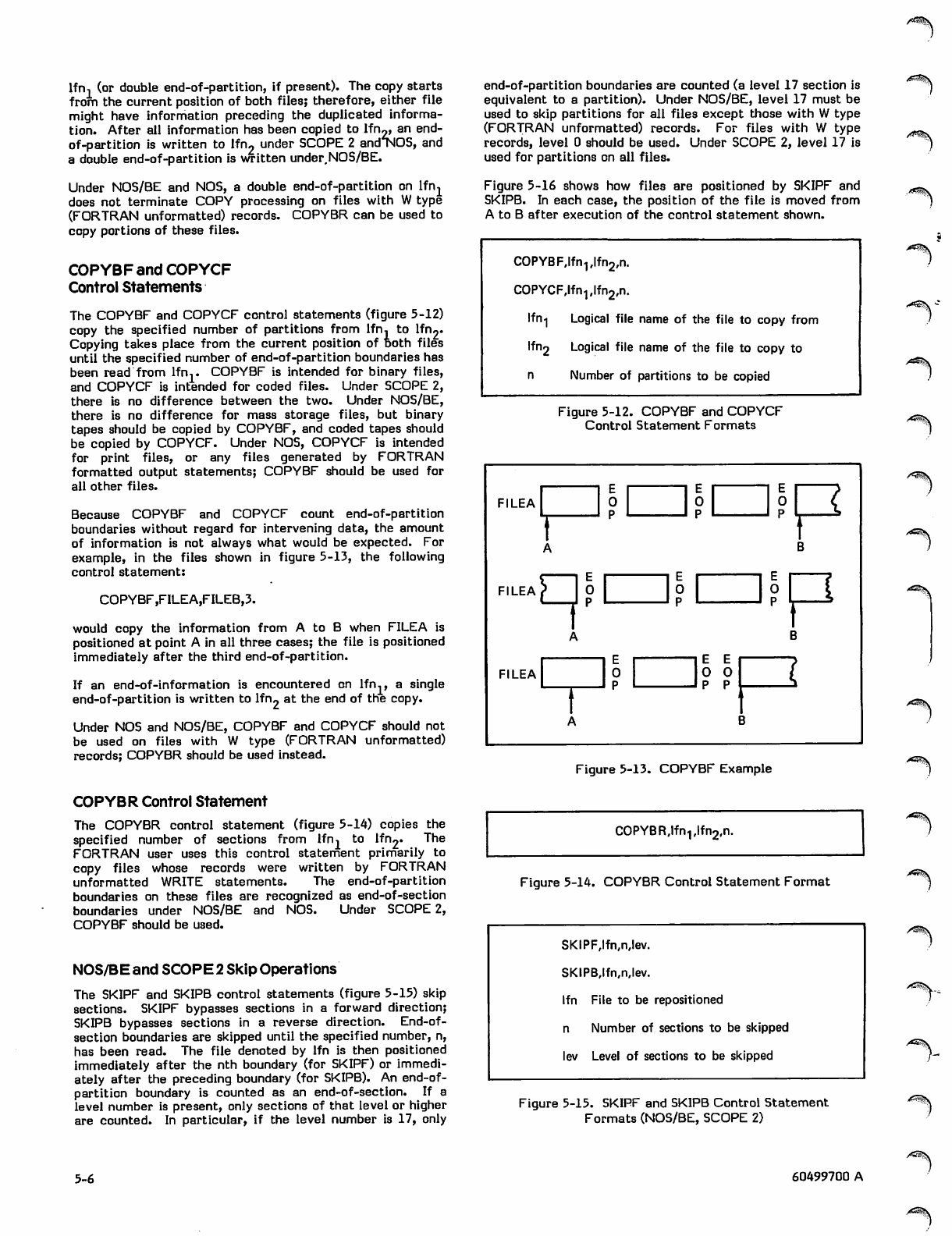
lfn, (or double end-of-partition, if present). The copy starts
from the current position of both files; therefore, either file
might have information preceding the duplicated informa
tion. After all information has been copied to lfn,,, an end-
of-partition is written to lfn2 under SCOPE 2 andTOS, and
a double end-of-partition is written under.NOS/BE.
Under NOS/BE and NOS, a double end-of-partition on lfn-L
does not terminate COPY processing on files with W type
(FORTRAN unformatted) records. COPYBR can be used to
copy portions of these files.
COPYBF and COPYCF
Control Statements
The COPYBF and COPYCF control statements (figure 5-12)
copy the specified number of partitions from lfn, to lfn««
Copying takes place from the current position of Both files
until the specified number of end-of-partition boundaries has
been read from lfn,. COPYBF is intended for binary files,
and COPYCF is intended for coded files. Under SCOPE 2,
there is no difference between the two. Under NOS/BE,
there is no difference for mass storage files, but binary
tapes should be copied by COPYBF, and coded tapes should
be copied by COPYCF. Under NOS, COPYCF is intended
fo r p r int fil e s, or any file s g e ner ate d b y FO RT RAN
formatted output statements; COPYBF should be used for
all other files.
Because COPYBF and COPYCF count end-of-partition
boundaries without regard for intervening data, the amount
of information is not always what would be expected. For
example, in the files shown in figure 5-13, the following
control statement:
COPYBF ,FILEA,FILEB,3.
would copy the information from A to B when FILEA is
positioned at point A in all three cases; the file is positioned
immediately after the third end-of-partition.
If an end-of-information is encountered on lfn., a single
end-of-partition is written to lfn2 at the end of the copy.
Under NOS and NOS/BE, COPYBF and COPYCF should not
be used on files with W type (FORTRAN unformatted)
records; COPYBR should be used instead.
end-of-partition boundaries are counted (a level 17 section is
equivalent to a partition). Under NOS/BE, level 17 must be
used to skip partitions for all files except those with W type
(FORTRAN unformatted) records. For files with W type
records, level 0 should be used. Under SCOPE 2, level 17 is
used for partitions on all files.
Figure 5-16 shows how files are positioned by SKIPF and
SKIPB. In each case, the position of the file is moved from
A to B after execution of the control statement shown.
COPYB F,lf n-,,If n2,n.
COPYCF,lfn.,,lfn2,n.
Ifn1 Logical file name of the file to copy from
lfn2 Logical file name of the file to copy to
n Number of partitions to be copied
Figure 5-12. COPYBF and COPYCF
Control Statement Formats /*«^v
1 E 1—
FILEA 0
L_^pL_
A
—i e r
0
1 P L ~1°R
_ j P p
B
-JPL_^
B
(
3
fi l e a ) | p
f
A
1 1 E i —
FILEA 0
rp
A
IE
0
P
rf^v
Figure 5-13. COPYBF Example .<^^s
COPYBR Control Statement
The COPYBR control statement (figure 5-14) copies the
specified number of sections from lfn, to lfn2« The
FORTRAN user uses this control statement primarily to
copy files whose records were written by FORTRAN
unformatted WRITE statements. The end-of-partition
boundaries on these files are recognized as end-of-section
boundaries under NOS/BE and NOS. Under SCOPE 2,
COPYBF should be used.
NOS/BE and SCOPE 2 Skip Operations
The SKIPF and SKIPB control statements (figure 5-15) skip
sections. SKIPF bypasses sections in a forward direction;
SKIPB bypasses sections in a reverse direction. End-of-
section boundaries are skipped until the specified number, n,
has been read. The file denoted by lfn is then positioned
immediately after the nth boundary (for SKIPF) or immedi
ately after the preceding boundary (for SKIPB). An end-of-
partition boundary is counted as an end-of-section. If a
level number is present, only sections of that level or higher
are counted. In particular, if the level number is 17, only
COPYB R,lfn1#lfn2,n.
Figure 5-14. COPYBR Control Statement Format
SKIPF,lfn,n,lev.
SKIPB,lfn,n,lev.
lfn File to be repositioned
n Number of sections to be skipped
lev Level of sections to be skipped
Figure 5-15. SKIPF and SKIPB Control Statement
Formats (NOS/BE, SCOPE 2)
/?«^>k
5-6 60499700 A
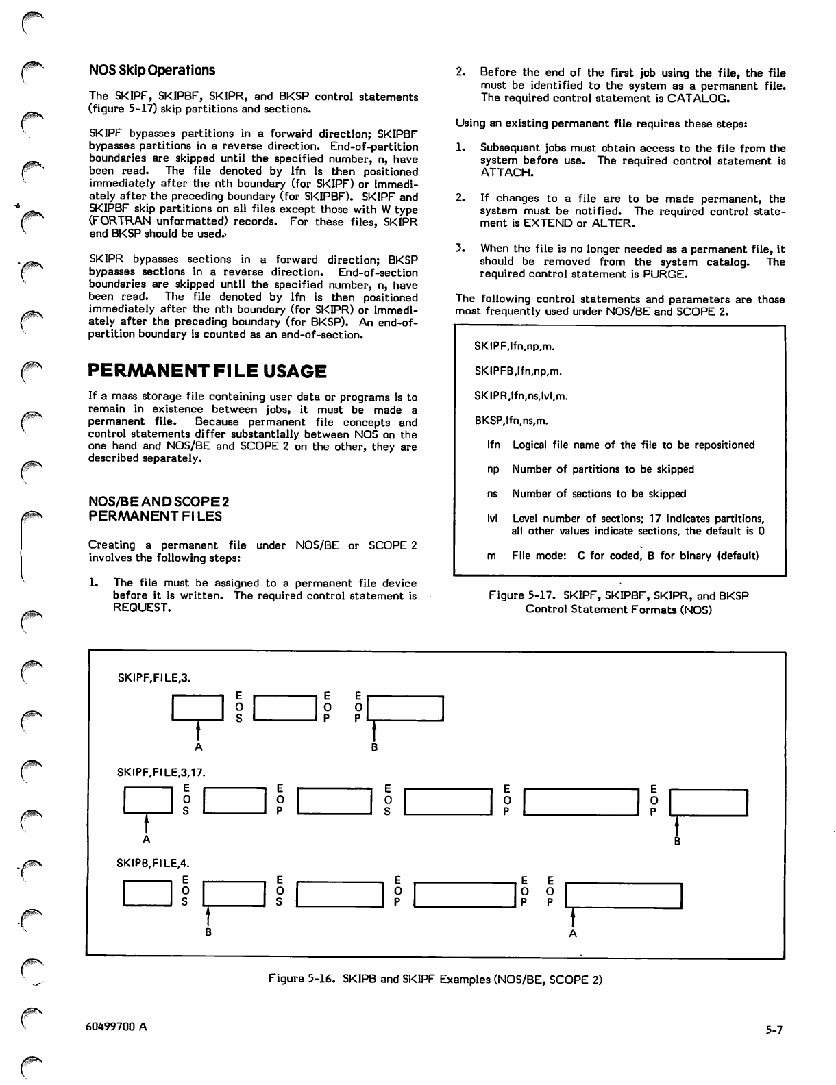
NOS Skip Operations
The SKIPF, SKIPBF, SKIPR, and BKSP control statements
(figure 5-17) skip partitions and sections.
SKIPF bypasses partitions in a forward direction; SKIPBF
bypasses partitions in a reverse direction. End-of-partition
boundaries are skipped until the specified number, n, have
been read. The file denoted by lfn is then positioned
immediately after the nth boundary (for SKIPF) or immedi
ately after the preceding boundary (for SKIPBF). SKIPF and
SKIPBF skip partitions on all files except those with W type
(FORTRAN unformatted) records. For these files, SKIPR
and BKSP should be used.>
SKIPR bypasses sections in a forward direction; BKSP
bypasses sections in a reverse direction. End-of-section
boundaries are skipped until the specified number, n, have
been read. The file denoted by lfn is then positioned
immediately after the nth boundary (for SKIPR) or immedi
ately after the preceding boundary (for BKSP). An end-of-
partition boundary is counted as an end-of-section.
PERMANENT Fl LE USAGE
If a mass storage file containing user data or programs is to
remain in existence between jobs, it must be made a
permanent file. Because permanent file concepts and
control statements differ substantially between NOS on the
one hand and NOS/BE and SCOPE 2 on the other, they are
described separately.
NOS/BE AND SCOPE 2
PERMANENT FILES
Creating a permanent file under NOS/BE or SCOPE 2
involves the following steps:
1. The file must be assigned to a permanent file device
before it is written. The required control statement is
REQUEST.
2. Before the end of the first job using the file, the file
must be identified to the system as a permanent file.
The required control statement is CATALOG.
Using an existing permanent file requires these steps:
1. Subsequent jobs must obtain access to the file from the
system before use. The required control statement is
ATTACH.
2. If changes to a file are to be made permanent, the
system must be notified. The required control state
ment is EXTEND or ALTER.
3. When the file is no longer needed as a permanent file, it
should be removed from the system catalog. The
required control statement is PURGE.
The following control statements and parameters are those
most frequently used under NOS/BE and SCOPE 2.
SKIPF,lfn,np,m.
SKIPFB,lfn,np,m.
SKIPR,lfn,ns,lvl,m.
BKSP,lfn,ns,m.
lfn Logical file name of the file to be repositioned
np Number of partitions to be skipped
ns Number of sections to be skipped
Ivl Level number of sections; 17 indicates partitions,
all other values indicate sections, the default is 0
m File mode: C for coded, B for binary (default)
Figure 5-17. SKIPF, SKIPBF, SKIPR, and BKSP
Control Statement Formats (NOS)
0m\
SKIPF,FILE,3.
SKIPF,FILE,3,17
E
0
S
SKIPB,FILE,4.
. E
O
S
Figure 5-16. SKIPB and SKIPF Examples (NOS/BE, SCOPE 2)
0!&\
60499700 A 5-7
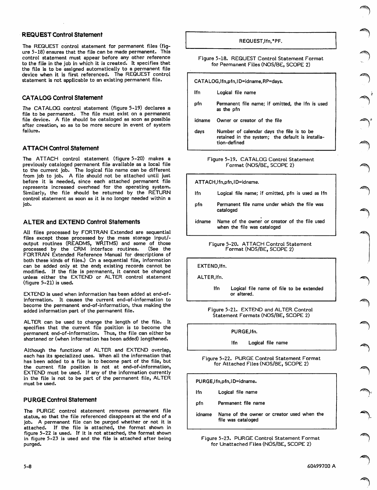
REQUEST Control Statement
The REQUEST control statement for permanent files (fig
ure 5-18) ensures that the file can be made permanent. This
control statement must appear before any other reference
to the file in the job in which it is created. It specifies that
the file is to be assigned automatically to a permanent file
device when it is first referenced. The REQUEST control
statement is not applicable to an existing permanent file.
CATALOG Control Statement
The CATALOG control statement (figure 5-19) declares a
file to be permanent. The file must exist on a permanent
file device. A file should be cataloged as soon as possible
after creation, so as to be more secure in event of system
failure.
ATTACH Control Statement
The ATTACH control statement (figure 5-20) makes a
previously cataloged permanent file available as a local file
to the current job. The logical file name can be different
from job to job. A file should not be attached until just
before it is needed, since each attached permanent file
represents increased overhead for the operating system.
Similarly, the file should be returned by the RETURN
control statement as soon as it is no longer needed within a
job.
ALTER and EXTEND Control Statements
All files processed by FORTRAN Extended are sequential
files except those processed by the mass storage input/-
output routines (READMS, WRITMS) and some of those
processed by the CRM interface routines. (See the
FORTRAN Extended Reference Manual for descriptions of
both these kinds of files.) On a sequential file, information
can be added only at the end; existing records cannot be
modified. If the file is permanent, it cannot be changed
unless either the EXTEND or ALTER control statement
(figure 5-21) is used.
EXTEND is used when information has been added at end-of-
information. It causes the current end-of-information to
become the permanent end-of-information, thus making the
added information part of the permanent file.
ALTER can be used to change the length of the file. It
specifies that the current file position is to become the
permanent end-of-information. Thus, the file can either be
shortened or (when information has been added) lengthened.
Although the functions of ALTER and EXTEND overlap,
each has its specialized uses. When all the information that
has been added to a file is to become part of the file, but
the current file position is not at end-of-information,
EXTEND must be used. If any of the information currently
in the file is not to be part of the permanent file, ALTER
must be used.
PURGE Control Statement
The PURGE control statement removes permanent file
status, so that the file referenced disappears at the end of a
job. A permanent file can be purged whether or not it is
attached. If the file is attached, the format shown in
figure 5-22 is used. If it is not attached, the format shown
in figure 5-23 is used and the file is attached after being
purged.
REQUEST,lfn,*PF.
Figure 5-18. REQUEST Control Statement Format
for Permanent Files (NOS/BE, SCOPE 2)
CATALOG,lfn,pfn,ID=idname,RP=days.
l f n L o g i c a l fi l e n a m e
pfn Permanent file name; if omitted, the lfn is used
as the pfn
idname Owner or creator of the file
days Number of calendar days the file is to be
retained in the system; the default is installa
tion-defined
y^S^k
Figure 5-19. CATALOG Control Statement
Format (NOS/BE, SCOPE 2)
ATTACH,lfn,pfn,ID=idname.
lfn Logical file name; if omitted, pfn is used as lfn
pfn Permanent file name under which the file was
cataloged
idname Name of the owner or creator of the file used
when the file was cataloged
■^8§\
Figure 5-20. ATTACH Control Statement
Format (NOS/8E, SCOPE 2)
EXTEND.Ifn.
ALTERJfn.
lfn Logical file name of file to be extended
or altered.
Figure 5-21. EXTEND and ALTER Control
Statement Formats (NOS/BE, SCOPE 2)
PURGE.Ifn.
lfn Logical file name ^m\
Figure 5-22. PURGE Control Statement Format
for Attached Files (NOS/BE, SCOPE 2)
PURGE,lfn,pfn,ID=idname.
l f n L o g i c a l fi l e n a m e
pfn Permanent file name
idname Name of the owner or creator used when the
file was cataloged
'*^\
Figure 5-23. PURGE Control Statement Format
for Unattached Files (NOS/BE, SCOPE 2)
5-8 60499700 A
./f*e^v
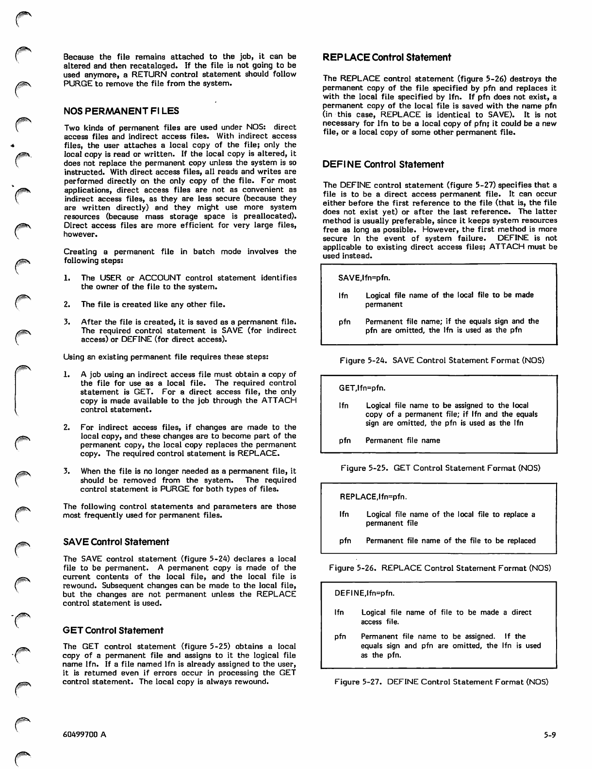
/tfp^\
0^\
0^s
/$#£\
Because the file remains attached to the job, it can be
altered and then recataloged. If the file is not going to be
used anymore, a RETURN control statement should follow
PURGE to remove the file from the system.
NOS PERMANENT Fl LES
Two kinds of permanent files are used under NOS: direct
access files and indirect access files. With indirect access
files, the user attaches a local copy of the file; only the
local copy is read or written. If the local copy is altered, it
does not replace the permanent copy unless the system is so
instructed. With direct access files, all reads and writes are
performed directly on the only copy of the file. For most
applications, direct access files are not as convenient as
indirect access files, as they are less secure (because they
are written directly) and they might use more system
resources (because mass storage space is preallocated).
Direct access files are more efficient for very large files,
however.
Creating a permanent file in batch mode involves the
following steps:
1. The USER or ACCOUNT control statement identifies
the owner of the file to the system.
2. The file is created like any other file.
3. After the file is created, it is saved as a permanent file.
The required control statement is SAVE (for indirect
access) or DEFINE (for direct access).
Using an existing permanent file requires these steps:
1. A job using an indirect access file must obtain a copy of
the file for use as a local file. The required control
statement is GET. For a direct access file, the only
copy is made available to the job through the ATTACH
control statement.
2. For indirect access files, if changes are made to the
local copy, and these changes are to become part of the
permanent copy, the local copy replaces the permanent
copy. The required control statement is REPLACE.
3. When the file is no longer needed as a permanent file, it
should be removed from the system. The required
control statement is PURGE for both types of files.
The following control statements and parameters are those
most frequently used for permanent files.
SAVE Control Statement
The SAVE control statement (figure 5-24) declares a local
file to be permanent. A permanent copy is made of the
current contents of the local file, and the local file is
rewound. Subsequent changes can be made to the local file,
but the changes are not permanent unless the REPLACE
control statement is used.
GET Control Statement
The GET control statement (figure 5-25) obtains a local
copy of a permanent file and assigns to it the logical file
name lfn. If a file named lfn is already assigned to the user,
it is returned even if errors occur in processing the GET
control statement. The local copy is always rewound.
REP LACE Control Statement
The REPLACE control statement (figure 5-26) destroys the
permanent copy of the file specified by pfn and replaces it
with the local file specified by lfn. If pfn does not exist, a
permanent copy of the local file is saved with the name pfn
(in this case, REPLACE is identical to SAVE). It is not
necessary for lfn to be a local copy of pfn; it could be a new
file, or a local copy of some other permanent file.
DEFINE Control Statement
The DEFINE control statement (figure 5-27) specifies that a
file is to be a direct access permanent file. It can occur
either before the first reference to the file (that is, the file
does not exist yet) or after the last reference. The latter
method is usually preferable, since it keeps system resources
free as long as possible. However, the first method is more
secure in the event of system failure. DEFINE is not
applicable to existing direct access files; ATTACH must be
used instead.
SAVE,lfn=pfn.
lfn Logical file name of the local file to be made
permanent
pfn Permanent file name; if the equals sign and the
pfn are omitted, the lfn is used as the pfn
Figure 5-24. SAVE Control Statement Format (NOS)
GET,lfn=pfn.
lfn Logical file name to be assigned to the local
copy of a permanent file; if lfn and the equals
sign are omitted, the pfn is used as the lfn
pfn Permanent file name
Figure 5-25. GET Control Statement Format (NOS)
REPLACE,lfn=pfn.
lfn Logical file name of the local file
permanent file
to replace a
pfn Permanent file name of the file to be replaced
Figure 5-26. REPLACE Control Statement Format (NOS)
DEFINErlfn=pfn.
lfn Logical file name of file> to be made direct
access file.
pfn Permanent file name to be assigned. If the
equals sign and pfn are omitted, the lfn is used
as the pfn.
Figure 5-27. DEFINE Control Statement Format (NOS)
60499700 A 5-9
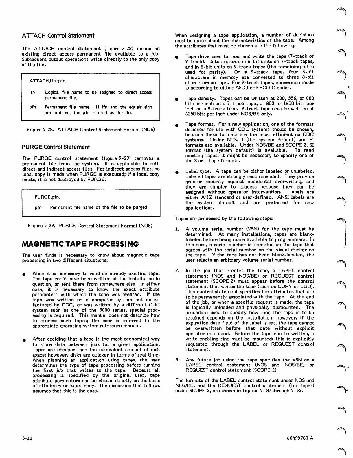
0^$$\
ATTACH Control Statement
The ATTACH control statement (figure 5-28) makes an
existing direct access permanent file available to a job.
Subsequent output operations write directly to the only copy
of the file.
ATTACH,lfn=pfn.
lfn Logical file name to be assigned to direct access
permanent file.
pfn Permanent file name. If lfn and the equals sign
are omitted, the pfn is used as the lfn.
Figure 5-28. ATTACH Control Statement Format (NOS)
PURGE Control Statement
The PURGE control statement (figure 5-29) removes a
permanent file from the system. It is applicable to both
direct and indirect access files. For indirect access files, no
local copy is made when PURGE is executed; if a local copy
exists, it is not destroyed by PURGE.
PURGE,pfn.
pfn Permanent file name of the file to be purged
Figure 5-29. PURGE Control Statement Format (NOS)
MAGNETIC TAPE PROCESSING
The user finds it necessary to know about magnetic tape
processing in two different situations:
• When it is necessary to read an already existing tape.
The tape could have been written at the installation in
question, or sent there from somewhere else. In either
case, it is necessary to know the exact attribute
parameters with which the tape was created. If the
tape was written on a computer system not manu
factured by CDC, or was written by a different CDC
system such as one of the 3000 series, special proc
essing is required. This manual does not describe how
to process such tapes; the user is referred to the
appropriate operating system reference manual.
0 After deciding that a tape is the most economical way
to store data between jobs for a given application.
Tapes are cheaper than the equivalent amount of disk
space; however, disks are quicker in terms of real time.
When planning an application using tapes, the user
determines the type of tape processing before running
the first job that writes to the tape. Because all
processing is specified by the original user, tape
attribute parameters can be chosen strictly on the basis
of efficiency or expediency. The discussion that follows
assumes that this is the case.
When designing a tape application, a number of decisions
must be made about the characteristics of the tape. Among
the attributes that must be chosen are the following:
$ Tape drive used to read and write the tape (7-track or
9-track). Data is stored in 6-bit units on 7-track tapes,
and in 8-bit units on 9-track tapes (the remaining bit is
u s e d f o r p a r i t y ) . O n a 9 - tra c k t ape , f our 6 - bit
characters in memory are converted to three 8-bit
characters on tape. For 9-track tapes, conversion mode
is according to either ASCII or EBCDIC codes.
e Tape density. Tapes can be written at 200, 556, or 800
bits per inch on a 7-track tape, or 800 or 1600 bits per
inch on a 9-track tape. 9-track tapes can be written at
6250 bits per inch under NOS/BE only.
9 Tape format. For a new application, one of the formats
designed for use with CDC systems should be chosen,
because these formats are the most efficient on CDC
systems. Under NOS, I (the system default) and SI
formats are available. Under NOS/BE and SCOPE 2, SI
format (the system default) is available. To read
existing tapes, it might be necessary to specify one of
the S or L tape formats.
9 Label type. A tape can be either labeled or unlabeled.
Labeled tapes are strongly recommended. They provide
greater security against accidental overwriting, and
they are simpler to process because they can be
assigned without operator intervention. Labels are
either ANSI standard or user-defined. ANSI labels are
the system default and are preferred for new
applications.
Tapes are processed by the following steps:
1. A volume serial number (VSN) for the tape must be
determined. At many installations, tapes are blank-
labeled before being made available to programmers. In
this case, a serial number is recorded on the tape that
agrees with the serial number on the visual sticker on
the tape. If the tape has not been blank-labeled, the
user selects an arbitrary volume serial number.
2. In the job that creates the tape, a LABEL control
statement (NOS and NOS/BE) or REQUEST control
statement (SCOPE 2) must appear before the control
statement that writes the tape (such as COPY or LGO).
This control statement specifies the attributes that are
to be permanently associated with the tape. At the end
of the job, or when a specific request is made, the tape
is logically unloaded and physically dismounted. The
procedure used to specify how long the tape is to be
retained depends on the installation; however, if the
expiration date field of the label is set, the tape cannot
be overwritten before that date without explicit
operator command. Before the tape can be written, a
write-enabling ring must be mounted; this is explicitly
requested through the LABEL or REQUEST control
statement.
3. Any future job using the tape specifies the VSN on a
LABEL control statement (NOS and NOS/BE) or
REQUEST control statement (SCOPE 2).
The formats of the LABEL control statement under NOS and
NOS/BE, and the REQUEST control statement (for tapes)
under SCOPE 2, are shown in figures 5-30 through 5-32.
y;/^\
/Z&*§\
■^^\
j^r^\
r^S\
•*c^\
^^?\
5-10 60499700 A
/tfi^N
yrtfi$£\
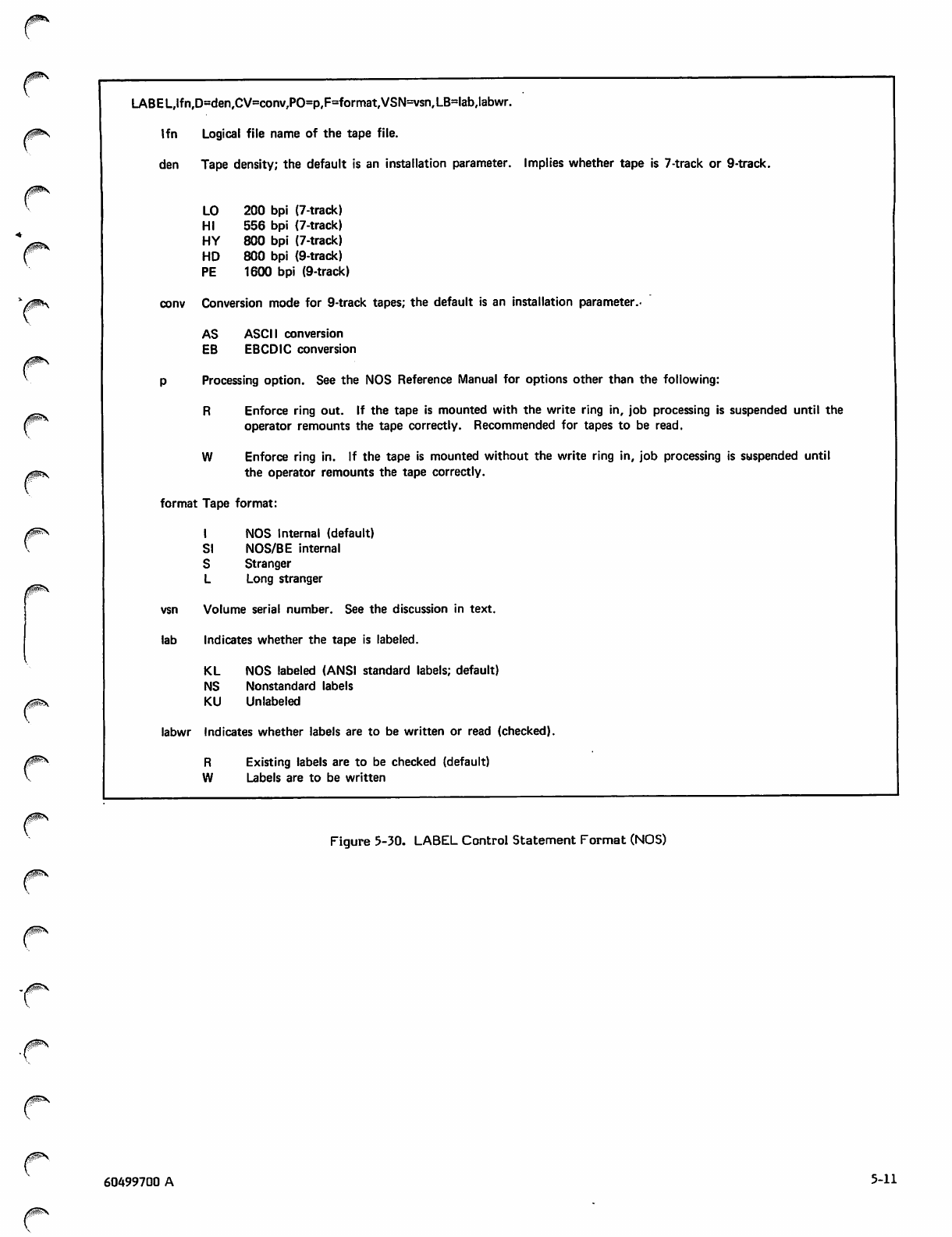
/KsN
/SS\
LABEL,lfn,D=den,CV=conv,PO=p,F=format,VSN=vsn,LB=lab,labwr.
lfn Logical file name of the tape file,
den Tape density; the default is an installation parameter. Implies whether tape is 7-track or 9-track.
LO 200 bpi (7-track)
HI 556 bpi (7-track)
HY 800 bpi (7-track)
HD 800 bpi (9-track)
PE 1600 bpi (9-track)
conv Conversion mode for 9-track tapes; the default is an installation parameter.
AS
EB
ASCII conversion
EBCDIC conversion
Processing option. See the NOS Reference Manual for options other than the following:
R Enforce ring out. If the tape is mounted with the write ring in, job processing is suspended until the
operator remounts the tape correctly. Recommended for tapes to be read.
W Enforce ring in. If the tape is mounted without the write ring in, job processing is suspended until
the operator remounts the tape correctly.
format Tape format:
I NO S Inte rn al (defaul t)
SI NOS/BE internal
S Stranger
L Long stranger
vsn Volume serial number. See the discussion in text.
lab Indicates whether the tape is labeled.
KL NOS labeled (ANSI standard labels; default)
NS Nonstandard labels
KU Unlabeled
labwr Indicates whether labels are to be written or read (checked).
R Existing labels are to be checked (default)
W Labels are to be written
Figure 5-30. LABEL Control Statement Format (NOS)
j^\
60499700 A 5-11
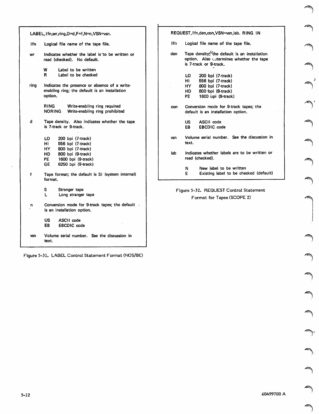
LABEL, If n,wr,ring,D=d,F=f,N=n,VSN=vsn.
lfn Logical file name of the tape file.
wr Indicates whether the label is'to be written or
read (checked). No default.
W Label to be written
R Label to be checked
ring Indicates the presence or absence of a write-
enabling ring; the default is an installation
option.
RING Write-enabling ring required
NOR ING Write-enabling ring prohibited
dTape density. Also indicates whether the tape
is 7-track or 9-track.
LO 200 bpi (7-track)
HI 556 bpi (7-track)
HY 800 bpi (7-track)
HD 800 bpi (9-track)
PE 1600 bpi (9-track)
GE 6250 bpi (9-track)
fTape format; the default is SI (system internal)
format.
S Stranger tape
L Long stranger tape
n Conversion mode for 9-track tapes; the default ;
is an installation option.
US ASCII code
EB EBCDIC code
vsn Volume serial number. See the discussion in
text.
Figure 5-31. LABEL Control Statement Format (NOS/BE)
REQUEST,lfn,den,con,VSN=vsn,lab. RING IN
lfn Logical file name of the tape file.
den Tape densityr''the default is an installation
option. Also '-jtermines whether the tape
is 7-track or 9-track.
LO 200 bpi (7-track)
HI 556 bpi (7-track)
HY 800 bpi (7-track)
HD 800 bpi (9-track)
PE 1600 !)pi (9-track)
con Conversion mode for 9-track tapes; the
default is an installation option.
US ASCII code
EB EBCDIC code
vsn Volume serial number. See the discussion in
text.
lab Indicates whether labels are to be written or
read (checked).
N New label to be written
E Existing label to be checked (default)
Figure 5-32. REQUEST Control Statement
Format for Tapes (SCOPE 2) y^^v
^^\
5-12 60499700 A
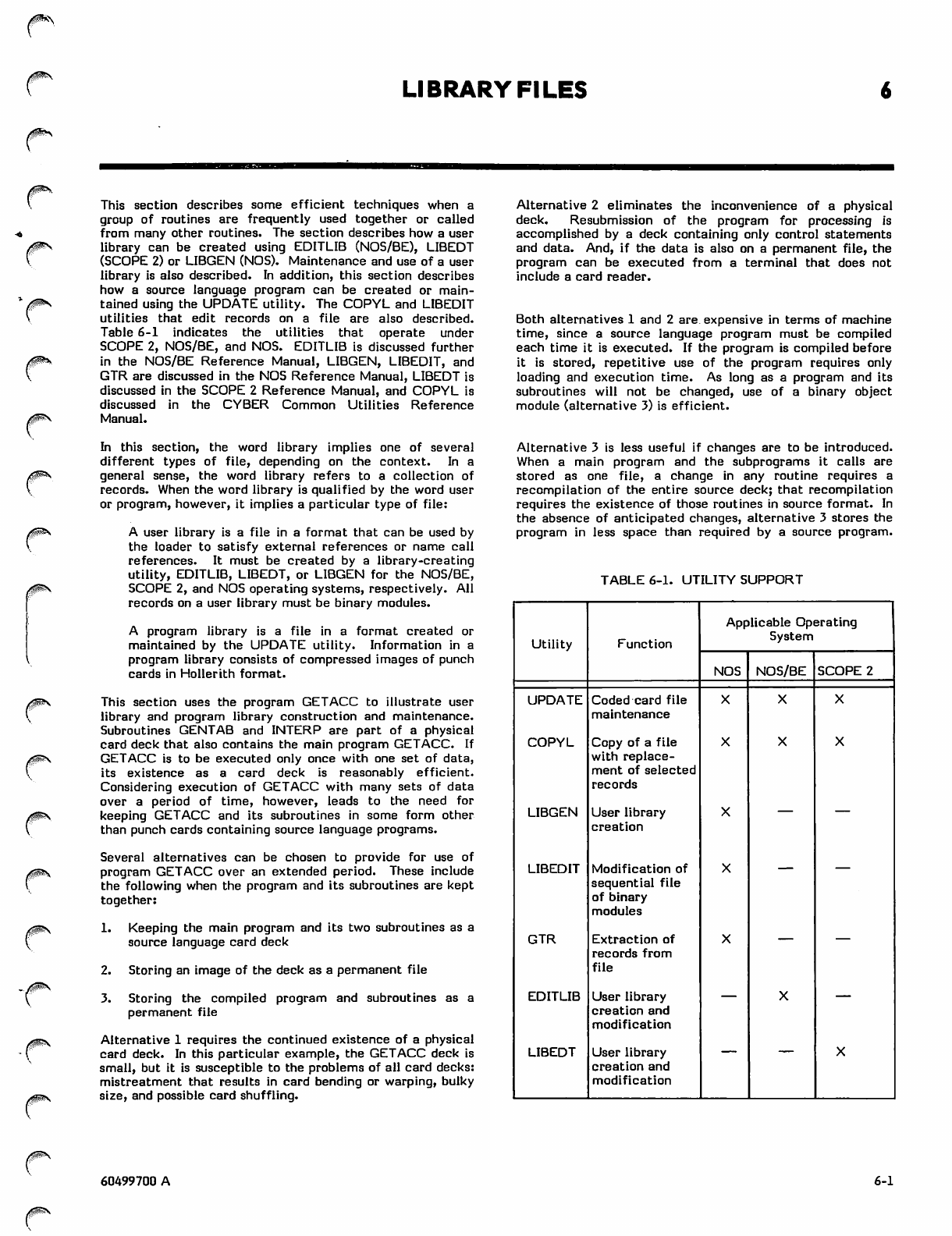
0i&<\
LIBRARY FILES
This section describes some efficient techniques when a
group of routines are frequently used together or called
from many other routines. The section describes how a user
library can be created using EDITLIB (NOS/BE), LIBEDT
(SCOPE 2) or LIBGEN (NOS). Maintenance and use of a user
library is also described. In addition, this section describes
how a source language program can be created or main
tained using the UPDATE utility. The COPYL and LIBEDIT
utilities that edit records on a file are also described.
Table 6-1 indicates the utilities that operate under
SCOPE 2, NOS/BE, and NOS. EDITLIB is discussed further
in the NOS/BE Reference Manual, LIBGEN, LIBEDIT, and
GTR are discussed in the NOS Reference Manual, LIBEDT is
discussed in the SCOPE 2 Reference Manual, and COPYL is
discussed in the CYBER Common Utilities Reference
Manual.
Alternative 2 eliminates the inconvenience of a physical
deck. Resubmission of the program for processing is
accomplished by a deck containing only control statements
and data. And, if the data is also on a permanent file, the
program can be executed from a terminal that does not
include a card reader.
Both alternatives 1 and 2 are expensive in terms of machine
time, since a source language program must be compiled
each time it is executed. If the program is compiled before
it is stored, repetitive use of the program requires only
loading and execution time. As long as a program and its
subroutines will not be changed, use of a binary object
module (alternative 3) is efficient.
In this section, the word library implies one of several
different types of file, depending on the context. In a
general sense, the word library refers to a collection of
records. When the word library is qualified by the word user
or program, however, it implies a particular type of file:
A user library is a file in a format that can be used by
the loader to satisfy external references or name call
references. It must be created by a library-creating
utility, EDITLIB, LIBEDT, or LIBGEN for the NOS/BE,
SCOPE 2, and NOS operating systems, respectively. All
records on a user library must be binary modules.
A program library is a file in a format created or
maintained by the UPDATE utility. Information in a
program library consists of compressed images of punch
cards in Hollerith format.
This section uses the program GETACC to illustrate user
library and program library construction and maintenance.
Subroutines GENTAB and INTERP are part of a physical
card deck that also contains the main program GETACC. If
GETACC is to be executed only once with one set of data,
its existence as a card deck is reasonably efficient.
Considering execution of GETACC with many sets of data
over a period of time, however, leads to the need for
keeping GETACC and its subroutines in some form other
than punch cards containing source language programs.
Several alternatives can be chosen to provide for use of
program GETACC over an extended period. These include
the following when the program and its subroutines are kept
together:
1. Keeping the main program and its two subroutines as a
source language card deck
2. Storing an image of the deck as a permanent file
3. Storing the compiled program and subroutines as a
permanent file
Alternative 1 requires the continued existence of a physical
card deck. In this particular example, the GETACC deck is
small, but it is susceptible to the problems of all card decks:
mistreatment that results in card bending or warping, bulky
size, and possible card shuffling.
Alternative 3 is less useful if changes are to be introduced.
When a main program and the subprograms it calls are
stored as one file, a change in any routine requires a
recompilation of the entire source deck; that recompilation
requires the existence of those routines in source format. In
the absence of anticipated changes, alternative 3 stores the
program in less space than required by a source program.
TABLE 6-1. UTILITY SUPPORT
Utility Function
Applicable Operating
System
NOS NOS/BE SCOPE 2
UPDATE Coded card file
maintenance
COPYL Copy of a file
with replace
ment of selected
records
LIBGEN User library
creation
LIBEDIT Modification of
sequential file
of binary
modules
GTR Extraction of
records from
fi l e
-—
EDITLIB User library
creation and
modification
LIBEDT User library
creation and
modification
60499700 A 6-1
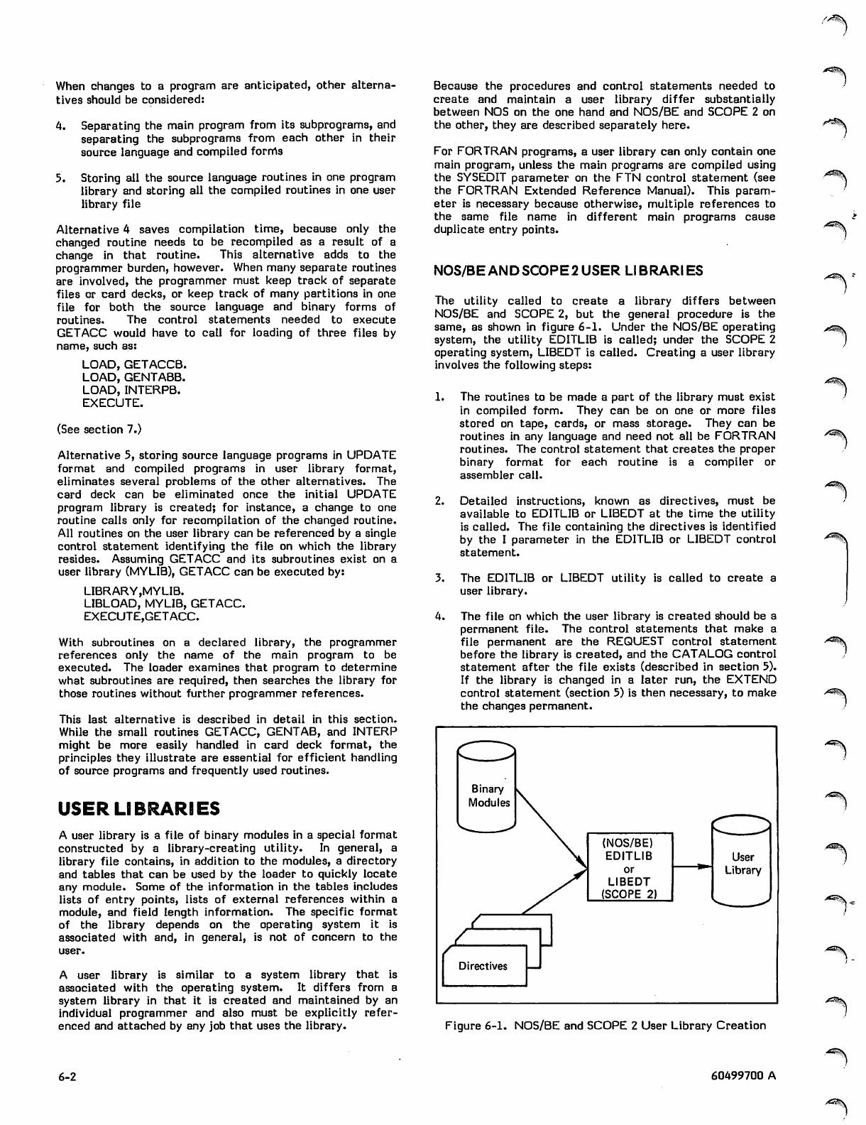
->^\
When changes to a program are anticipated, other alterna
tives should be considered:
4. Separating the main program from its subprograms, and
separating the subprograms from each other in their
source language and compiled forms
5. Storing all the source language routines in one program
library and storing all the compiled routines in one user
library file
Alternative 4 saves compilation time, because only the
changed routine needs to be recompiled as a result of a
change in that routine. This alternative adds to the
programmer burden, however. When many separate routines
are involved, the programmer must keep track of separate
files or card decks, or keep track of many partitions in one
file for both the source language and binary forms of
routine s. The control statemen ts needed to ex ec ute
GETACC would have to call for loading of three files by
name, such as:
LOAD, GETACCB.
LOAD, GENT ABB.
LOAD, INTERPB.
EXECUTE.
(See section 7.)
Alternative 5, storing source language programs in UPDATE
format and compiled programs in user library format,
eliminates several problems of the other alternatives. The
card deck can be eliminated once the initial UPDATE
program library is created; for instance, a change to one
routine calls only for recompilation of the changed routine.
All routines on the user library can be referenced by a single
control statement identifying the file on which the library
resides. Assuming GETACC and its subroutines exist on a
user library (MYLIB), GETACC can be executed by:
LIBRARY,MYLIB.
LIBLOAD, MYLIB, GETACC.
EXECUTE,GETACC.
With subroutines on a declared library, the programmer
references only the name of the main program to be
executed. The loader examines that program to determine
what subroutines are required, then searches the library for
those routines without further programmer references.
This last alternative is described in detail in this section.
While the small routines GETACC, GENTAB, and INTERP
might be more easily handled in card deck format, the
principles they illustrate are essential for efficient handling
of source programs and frequently used routines.
USER LIBRARIES
A user library is a file of binary modules in a special format
constructed by a library-creating utility. In general, a
library file contains, in addition to the modules, a directory
and tables that can be used by the loader to quickly locate
any module. Some of the information in the tables includes
lists of entry points, lists of external references within a
module, and field length information. The specific format
of the library depends on the operating system it is
associated with and, in general, is not of concern to the
user.
A user library is similar to a system library that is
associated with the operating system. It differs from a
system library in that it is created and maintained by an
individual programmer and also must be explicitly refer
enced and attached by any job that uses the library.
6-2
Because the procedures and control statements needed to
create and maintain a user library differ substantially
between NOS on the one hand and NOS/BE and SCOPE 2 on
the other, they are described separately here.
For FORTRAN programs, a user library can only contain one
main program, unless the main programs are compiled using
the SYSEDIT parameter on the FTN control statement (see
the FORTRAN Extended Reference Manual). This param
eter is necessary because otherwise, multiple references to
the same file name in different main programs cause
duplicate entry points.
NOS/BE AND SCOPE 2 USER LIBRARIES
The utility called to create a library differs between
NOS/BE and SCOPE 2, but the general procedure is the
same, as shown in figure 6-1. Under the NOS/BE operating
system, the utility EDITLIB is called; under the SCOPE 2
operating system, LIBEDT is called. Creating a user library
involves the following steps:
1. The routines to be made a part of the library must exist
in compiled form. They can be on one or more files
stored on tape, cards, or mass storage. They can be
routines in any language and need not all be FORTRAN
routines. The control statement that creates the proper
binary format for each routine is a compiler or
assembler call.
2. Detailed instructions, known as directives, must be
available to EDITLIB or LIBEDT at the time the utility
is called. The file containing the directives is identified
by the I parameter in the EDITLIB or LIBEDT control
statement.
3. The EDITLIB or LIBEDT utility is called to create a
user library.
4. The file on which the user library is created should be a
permanent file. The control statements that make a
file permanent are the REQUEST control statement
before the library is created, and the CATALOG control
statement after the file exists (described in section 5).
If the library is changed in a later run, the EXTEND
control statement (section 5) is then necessary, to make
the changes permanent.
Binary
Modules
(NOS/BE)
EDITLIB
or
LIBEDT
(SCOPE 2)
User
Library
Directives
Figure 6-1. NOS/BE and SCOPE 2 User Library Creation
■"^v
,^S^v
60499700 A
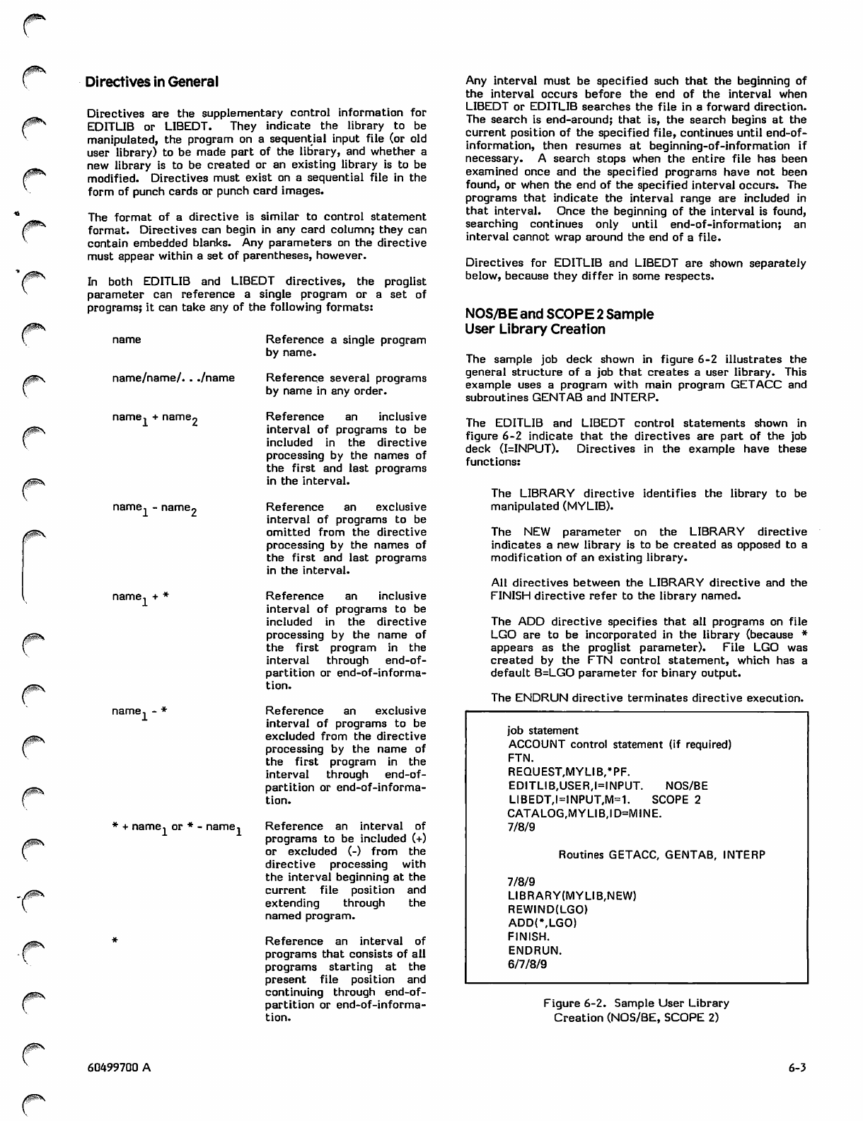
0m\
/$0$\
t"
Directives in General
Directives are the supplementary control information for
EDITLIB or LIBEDT. They indicate the library to be
manipulated, the program on a sequential input file (or old
user library) to be made part of the library, and whether a
new library is to be created or an existing library is to be
modified. Directives must exist on a sequential file in the
form of punch cards or punch card images.
The format of a directive is similar to control statement
format. Directives can begin in any card column; they can
contain embedded blanks. Any parameters on the directive
must appear within a set of parentheses, however.
In both EDITLIB and LIBEDT directives, the proglist
parameter can reference a single program or a set of
programs; it can take any of the following formats:
name Reference a single program
by name.
name/name/. . ./name
name, + name
1 -r I lean ItSrs
name, - name.
51 +
name.
* + name, or * - name.
Reference several programs
by name in any order.
Reference an inclusive
interval of programs to be
included in the directive
processing by the names of
the first and last programs
in the interval.
Reference an exclusive
interval of programs to be
omitted from the directive
processing by the names of
the first and last programs
in the interval.
Reference an inclusive
interval of programs to be
included in the directive
processing by the name of
the first program in the
interval through end-of-
partition or end-of-informa
tion.
Reference an exclusive
interval of programs to be
excluded from the directive
processing by the name of
the first program in the
interval through end-of-
partition or end-of-informa
tion.
Reference an interval of
programs to be included (+)
or excluded (-) from the
directive processing with
the interval beginning at the
current file position and
extending through the
named program.
Reference an interval of
programs that consists of all
programs starting at the
pr e sent file pos i tio n a n d
continuing through end-of-
partition or end-of-informa
tion.
Any interval must be specified such that the beginning of
the interval occurs before the end of the interval when
LIBEDT or EDITLIB searches the file in a forward direction.
The search is end-around; that is, the search begins at the
current position of the specified file, continues until end-of-
information, then resumes at beginning-of-information if
necessary. A search stops when the entire file has been
examined once and the specified programs have not been
found, or when the end of the specified interval occurs. The
programs that indicate the interval range are included in
that interval. Once the beginning of the interval is found,
searching continues only until end-of-information; an
interval cannot wrap around the end of a file.
Directives for EDITLIB and LIBEDT are shown separately
below, because they differ in some respects.
NOS/BE and SCOPE 2 Sample
User Library Creation
The sample job deck shown in figure 6-2 illustrates the
general structure of a job that creates a user library. This
example uses a program with main program GETACC and
subroutines GENTAB and INTERP.
The EDITLIB and LIBEDT control statements shown in
figure 6-2 indicate that the directives are part of the job
deck (I=INPUT). Directives in the example have these
functions:
The LIBRARY directive identifies the library to be
manipulated (MYLIB).
The NEW parameter on the LIBRARY directive
indicates a new library is to be created as opposed to a
modification of an existing library.
All directives between the LIBRARY directive and the
FINISH directive refer to the library named.
The ADD directive specifies that all programs on file
LGO are to be incorporated in the library (because *
appears as the proglist parameter). File LGO was
created by the FTN control statement, which has a
default B=LGO parameter for binary output.
The ENDRUN directive terminates directive execution.
job statement
ACCOUNT control statement (if required)
FTN.
REQUEST,MYLIB,#PF.
EDITLIB,USER,I=INPUT. NOS/BE
LIBEDT,I=INPUT,M=1. SCOPE 2
CATALOG,MYLIB,ID=MINE.
7/8/9
Routines GETACC, GENTAB, INTERP
7/8/9
LIBRARY(MYLIB,NEW)
REWIND(LGO)
ADD(\LGO)
FINISH.
ENDRUN.
6/7/8/9
Figure 6-2. Sample User Library
Creation (NOS/BE, SCOPE 2)
60499700 A 6-3
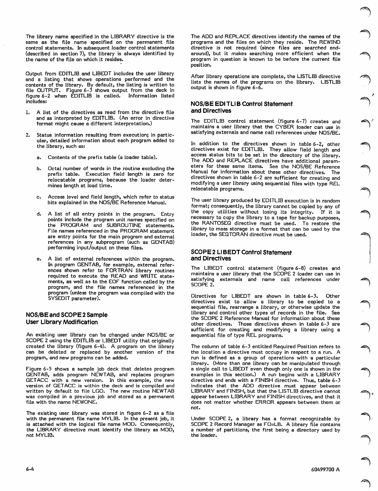
/*%-
The library name specified in the LIBRARY directive is the
same as the file name specified on the permanent file
control statements. In subsequent loader control statements
(described in section 7), the library is always identified by
the name of the file on which it resides.
Output from EDITLIB and LIBEDT includes the user library
and a listing that shows operations performed and the
contents of the library. By default, the listing is written to
file OUTPUT. Figure 6-3 shows output from the deck in
figure 6-2 when EDITLIB is called. Information listed
includes:
1. A list of the directives as read from the directive file
and as interpreted by EDITLIB. (An error in directive
format might cause a different interpretation.)
2. Status information resulting from execution; in partic
ular, detailed information about each program added to
the library, such as:
a. Contents of the prefix table (a loader table).
b. Octal number of words in the routine excluding the
prefix table. Execution field length is zero for
relocatable programs, because the loader deter
mines length at load time.
c. Access level and field length, which refer to status
bits explained in the NOS/BE Reference Manual.
d. A list of all entry points in the program. Entry
points include the program unit names specified on
the PROGRAM and SUBROUTINE statements.
File names referenced in the PROGRAM statement
are entry points for the main program and external
references in any subprogram (such as GENTAB)
performing input/output on these files.
e. A list of external references within the program.
In program GENTAB, for example, external refer
ences shown refer to FORTRAN library routines
required to execute the READ and WRITE state
ments, as well as to the EOF function called by the
program, and the file names referenced in the
program (unless the program was compiled with the
SYSEDIT parameter).
NOS/BE and SCOPE 2 Sample
User Library Modification
An existing user library can be changed under NOS/BE or
SCOPE 2 using the EDITLIB or LIBEDT utility that originally
created the library (figure 6-4). A program on the library
can be deleted or replaced by another version of the
program, and new programs can be added.
Figure 6-5 shows a sample job deck that deletes program
GENTAB, adds program NEWTAB, and replaces program
GETACC with a new version. In this example, the new
version of GETACC is within the deck and is compiled and
written by default to file LGO. The new routine NEWTAB
was compiled in a previous job and stored as a permanent
file with the name NEWONE.
The existing user library was stored in figure 6-2 as a file
with the permanent file name MYLIB. In the present job, it
is attached with the logical file name MOD. Consequently,
the LIBRARY directive must identify the library as MOD,
not MYUB.
The ADD and REPLACE directives identify the names of the
programs and the files on which they reside. The REWIND
directive is not required (since files are searched end-
around), but it makes searching more efficient when the
program in question is known to be before the current file
position.
After library operations are complete, the LISTLIB directive
lists the names of the programs on the library. LISTLIB
output is shown in figure 6-6.
NOS/BE EDI TLIB Control Statement
and Directives
The EDITLIB control statement (figure 6-7) creates and
maintains a user library that the CYBER loader can use in
satisfying externals and name call references under NOS/BE.
In addition to the directives shown in table 6-2, other
directives exist for EDITLIB. They allow field length and
access status bits to be set in the directory of the library.
The ADD and REPLACE directives have additional param
eters for these same items. See the NOS/BE Reference
Manual for information about these other directives. The
directives shown in table 6-2 are sufficient for creating and
modifying a user library using sequential files with type REL
relocatable programs.
The user library produced by EDITLIB execution is in random
format; consequently, the library cannot be copied by any of
the copy utilities without losing its integrity. If it is
necessary to copy the library to a tape for backup purposes,
the RANTOSEQ directive must be used. To restore the
library to mass storage in a format that can be used by the
loader, the SEQTORAN directive must be used.
SCOPE 2 LIBEDT Control Statement
and Directives
The LIBEDT control statement (figure 6-8) creates and
maintains a user library that the SCOPE 2 loader can use in
satisfying externals and name call references under
SCOPE 2.
Directives for LIBEDT are shown in table 6-3. Other
directives exist to allow a library to be copied to a
sequential file, rearrange a library, or otherwise update the
library and control other types of records in the file. See
the SCOPE 2 Reference Manual for information about these
other directives. Those directives shown in table 6-3 are
sufficient for creating and modifying a library using a
sequential file of type REL programs.
The column of table 6-3 entitled Required Position refers to
the location a directive must occupy in respect to a run. A
run is defined as a group of operations with a particular
library. (More than one library can be manipulated through
a single call to LIBEDT even though only one is shown in the
examples in this section.) A run begins with a LIBRARY
directive and ends with a FINISH directive. Thus, table 6-3
indicates that the ADD directive must appear between
LIBRARY and FINISH, but that the LISTLIB directive cannot
appear between LIBRARY and FINISH directives, and that it
does not matter whether ERROR appears between them or
not.
Under SCOPE 2, a library has a format recognizable by
SCOPE 2 Record Manager as FO=LB. A library file contains
a number of partitions, the first being a directory used by
the loader.
^^^\ ■
•^^\
<^^§\
6-4 60499700 A
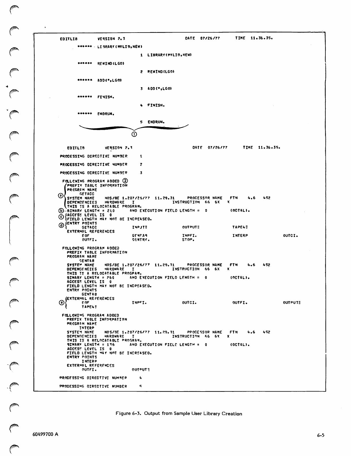
EOITLIB VERSION 2.3 DATE 07/26/77
••••»• LI9RARY(HYLI9,NEm
1 LIBRARY(FYLIB,NEM>
»»»•*• REWIND (LGO)
2 R E W I N O ( L G O )
••*•»• AD0<»»LGOI
3 A 0 D ( * , L G O >
*•••»• FINISH.
»♦ FINISH.
•••••» ENDRUN*
9 ENORUN.
TINE 11.36.3?.
EDITLIB VERSION 2.3
PROCESSING DIRECTIVE NUHBER 1
PROCESSING OIRE3TIVE NUMBER 2
PROCESSING OIRECTIVE NUH9ER 3
FOLLCHlNG PROGRAH AOOEO ©
I PREFIX TABLE INFORMATION
PRCGR*H NAHE
GETACC
SYSTEH NAHE NOS/BE 1.207/26/77
D E P E N D E N C I E S H A R D W A R E I
THIS TS A RELOCATABLE PROGRAH.
Q))-BINARY LENGTH = 210 AND EXECUTION FIELD LENGTH :
/rvlACCFSS LEVEL IS 0
^IFIELO LENGTH HAY NOT BE INCREASEO.
©/ENTRY POINTS
( GETACC INPJTr OUTPUT!
EXTERNAL REFERENCES
EOF GENTAB INPFI.
OUTFI. OINTRY. STOP.
FOLLCMIHG PROGRAH AOOEO
PREFIX TABLE INFORHATION
PRCGRAH NAME
GENTAB
SYSTEM NAHE NOS/BE 1.207/26/7*
DEPENDENCIES HARDWARE I
THI S TS A REL O CATABLE PR O GPA * .
B I N A R Y L E N G T H = 2 6 0 A N O E X E C U T I O N F I E L O L E N G T H
A C C E S S L E V E L I S 0
FIELO LENGTH HAY NOT BE INCPEASED.
ENTRY POINTS
GENTAB
(EXTERNAL REFERENCES
© < E O F
( T A P E * ?
OATE 07/26/77 T I H E 11 . 3 6 . 3 S .
11.29.31 PROCESSOR NAME
INSTRUCTION 66 6X
FTN t*,6 452
(OCTAL).
TAP£«f =
INTERP OUTCI.
11.29.31 PROCESSOR NAME
INSTRUCTION 66 6X
FTN If. 6 452
INP*I. OUTCI.
(OCTALI.
OUTFI. OUTPUT:
11.29.31 PROCESSOR NAHE
INSTRUCTION 66 6X
FOLLOWING PROGRAH AOOEO
PREFIX TABLE INFORMATION
PRCGR4H NAHE
INTERP
SYSTEH NAHE NOS/BE 1.207/26/77
DEPENDENCIES HAROWA3E I
THIS IS A RELOCATABLE PROGRAH.
9INARV LENGTH = 136 ANO EXECUTION FIELT LENGTH
ACCES? LEVEL IS 0
FIFLO LENGTH ««AY NOT BE INCREASEO.
ENTRY POINTS
INTERP
EXTERNAL REFERENCES
OUTFI. OUf»UT=
PROCESSING OIRECTIVE NUN9EP «»
PROCESSING OIRECTIVE NUMBER «?
FTN <f.6 i»S2
(OCTAL).
Figure 6-3. Output from Sample User Library Creation
60499700 A 6-5
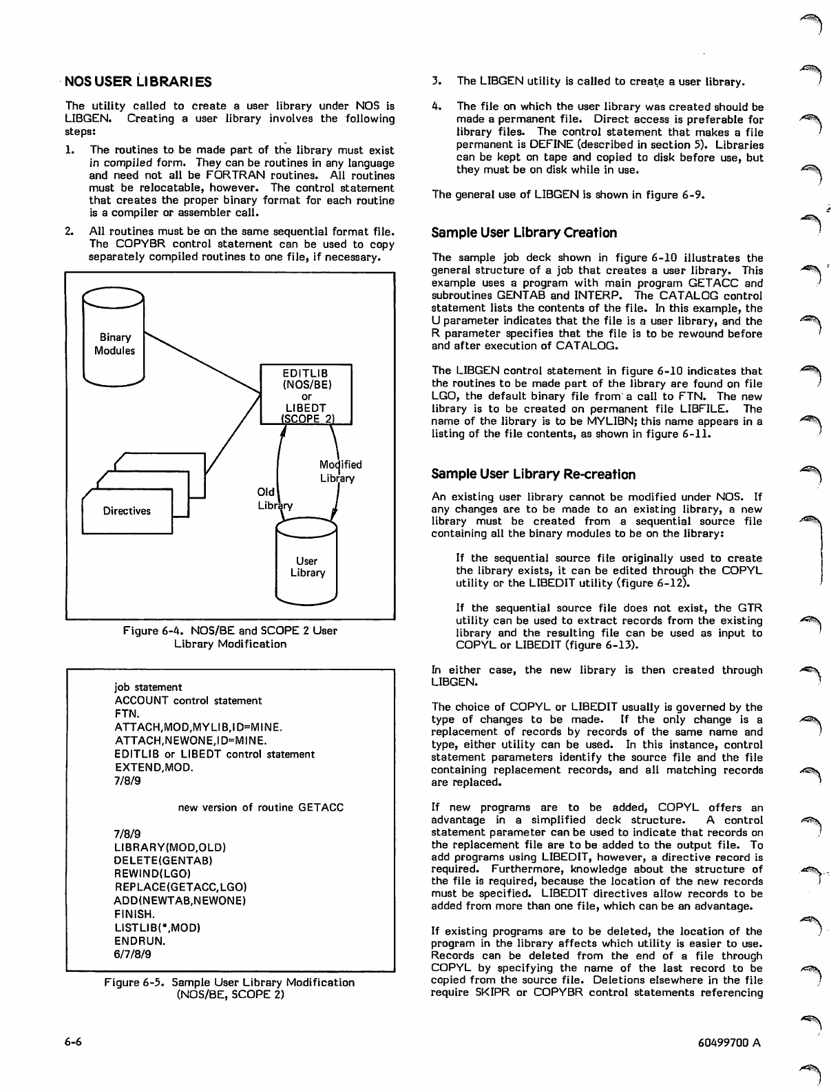
NOS USER LIBRARIES
The utility called to create a user library under NOS is
LIBGEN. Creating a user library involves the following
steps:
1. The routines to be made part of the library must exist
in compiled form. They can be routines in any language
and need not all be FORTRAN routines. All routines
must be relocatable, however. The control statement
that creates the proper binary format for each routine
is a compiler or assembler call.
2. All routines must be on the same sequential format file.
The COPYBR control statement can be used to copy
separately compiled routines to one file, if necessary.
Binary
Modules
EDITLIB
(NOS/BE)
or
LIBEDT
(SCOPE 2)
<-
<-
A
Directives
Modified
Library
User
Library
Figure 6-4. NOS/BE and SCOPE 2 User
Library Modification
job statement
ACCOUNT control statement
FTN.
ATTACH,MOD,MYLIB,ID=MINE.
ATTACH,NEWONE,ID=MINE.
EDITLIB or LIBEDT control statement
EXTEND,MOD.
7/8/9
new version of routine GETACC
7/8/9
LIBRARY(MOD,OLD)
DELETE(GENTAB)
REWIND(LGO)
REPLACE(GETACC,LGO)
ADD(NEWTAB,NEWONE)
FINISH.
LISTLIB(\MOD)
ENDRUN.
6/7/8/9
Figure 6-5. Sample User Library Modification
(NOS/BE, SCOPE 2)
6-6
3. The LIBGEN utility is called to create a user library.
4. The file on which the user library was created should be
made a permanent file. Direct access is preferable for
library files. The control statement that makes a file
permanent is DEFINE (described in section 5). Libraries
can be kept on tape and copied to disk before use, but
they must be on disk while in use.
The general use of LIBGEN is shown in figure 6-9.
Sample User Library Creation
The sample job deck shown in figure 6-10 illustrates the
general structure of a job that creates a user library. This
example uses a program with main program GETACC and
subroutines GENTAB and INTERP. The CATALOG control
statement lists the contents of the file. In this example, the
U parameter indicates that the file is a user library, and the
R parameter specifies that the file is to be rewound before
and after execution of CATALOG.
The LIBGEN control statement in figure 6-10 indicates that
the routines to be made part of the library are found on file
LGO, the default binary file from a call to FTN. The new
library is to be created on permanent file LIBFILE. The
name of the library is to be MYLIBN; this name appears in a
listing of the file contents, as shown in figure 6-11.
Sample User Library Re-creation
An existing user library cannot be modified under NOS. If
any changes are to be made to an existing library, a new
library must be created from a sequential source file
containing all the binary modules to be on the library:
If the sequential source file originally used to create
the library exists, it can be edited through the COPYL
utility or the LIBEDIT utility (figure 6-12).
If the sequential source file does not exist, the GTR
utility can be used to extract records from the existing
library and the resulting file can be used as input to
COPYL or LIBEDIT (figure 6-13).
In either case, the new library is then created through
LIBGEN.
The choice of COPYL or LIBEDIT usually is governed by the
type of changes to be made. If the only change is a
replacement of records by records of the same name and
type, either utility can be used. In this instance, control
statement parameters identify the source file and the file
containing replacement records, and all matching records
are replaced.
If new programs are to be added, COPYL offers an
advantage in a simplified deck structure. A control
statement parameter can be used to indicate that records on
the replacement file are to be added to the output file. To
add programs using LIBEDIT, however, a directive record is
required. Furthermore, knowledge about the structure of
the file is required, because the location of the new records
must be specified. LIBEDIT directives allow records to be
added from more than one file, which can be an advantage.
If existing programs are to be deleted, the location of the
program in the library affects which utility is easier to use.
Records can be deleted from the end of a file through
COPYL by specifying the name of the last record to be
copied from the source file. Deletions elsewhere in the file
require SKIPR or COPYBR control statements referencing
60499700 A
j^w^Sv
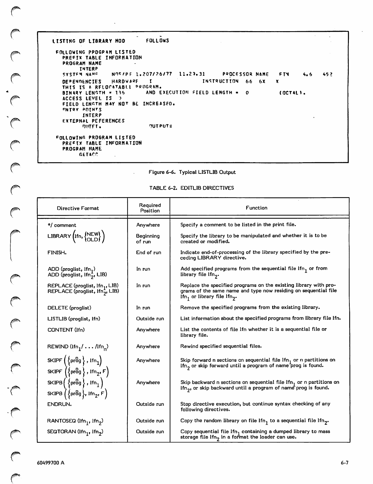
USTTNG OF LIBRARY MOD FOLLOWS
FOLLOWING PP0GP4H LISTED
PREFIX TABLE INFORMATION
PROGRAH NAHE
INTERP
5 Y S T P M N A M C N H W P F 1 . 2 0 7 / 2 6 / 7 7 1 1 . 2 3 . 3 1 P R O C E S S O R N A M E F T S 4 . 6 4 5 ?
DE"»EMOtNCIES HARDWARF I INSTRUCTION 66 6X
THIS IS ft RFLOf4TABI.l »»OGRftH.
BINARY LENGTH « 116 AND EXECUTION FIELD LENGTH ■ 0 (OCTan.
ACCESS LEVEL IS )
FIELD LENGTH HAY NOT ft£ INCREASFD.
cUJoy points
INTERP
EXTERNAL PEFERENCES
OUTFT. HUTPUTs
POLLOWING PROGRAH LISTED
PREFIX TABLE INFORMATION
PROGRAM NAME
GETACT
Figure 6-6. Typical LISTLIB Output
TABLE 6-2. EDITLIB DIRECTIVES
Directive Format Required
Position Function
*/ comment Anywhere Specify a comment to be listed in the print file.
UBRARY^I*™}) Beginning
of run Specify the library to be manipulated and whether it is to be
created or modified.
FINISH. End of run Indicate end-of-processing of the library specified by the pre
ceding LIBRARY directive.
ADD (proglist, lfn.)
ADD (proglist, lfn^, LIB)
In run Add specified programs from the sequential file lfn, or from
library file Ifru.
REPLACE (proglist, lfn., LIB)
REPLACE (proglist, lfn£, LIB)
In run Replace the specified programs on the existing library with pro
grams of the same name and type now residing on sequential file
lfn, or library file lfru.
DELETE (proglist) In run Remove the specified programs from the existing library.
LISTLIB (proglist, lfn) Outside run List information about the specified programs from library file lfn.
CONTENT (lfn) Anywhere List the contents of file lfn whether it is a sequential file or
library file.
REWIND (Ifn^ . .. /lfnp) Anywhere Rewind specified sequential files.
SKIPF/iprSgi, If nj
SKIPF [/prog i , lfn2, f\
Anywhere Skip forward n sections on sequential file lfn, or n partitions on
lfn? or skip forward until a program of name prog is found.
SKIPB/ jprogLlfn^
SKIPB (jprSgi, lfn2, FJ
Anywhere Skip backward n sections on sequential file lfn, or n partitions on
lfn?, or skip backward until a program of name prog is found.
ENDRUN. Outside run Stop directive execution, but continue syntax checking of any
following directives.
RANTOSEQ (lfn1, lfn2) Outside run Copy the random library on file lfn, to a sequential file lfn2.
SEQTORAN (lfnp lfn2) Outside run Copy sequential file lfn, containing a dumped library to mass
storage file lfn« in a format the loader can use.
0m\
60499700 A 6-7
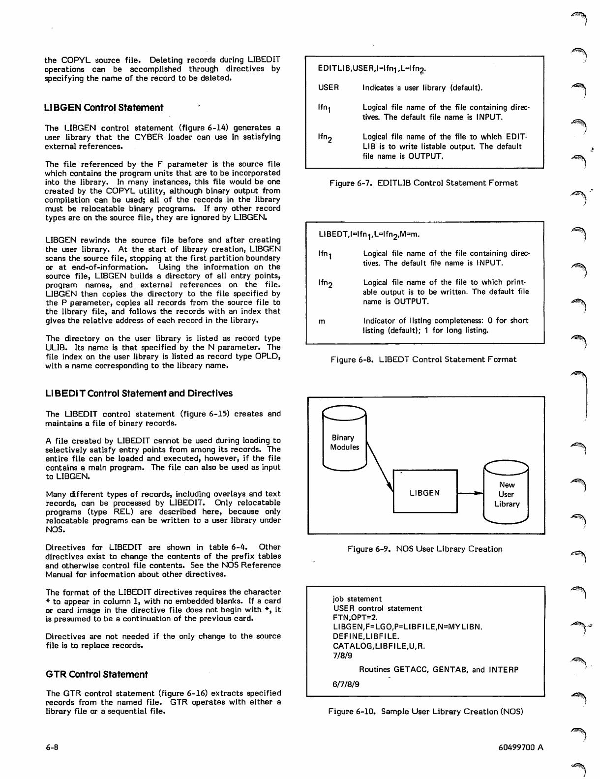
the COPYL source file. Deleting records during LIBEDIT
operations can be accomplished through directives by
specifying the name of the record to be deleted.
Ll BGEN Control Statement
The LIBGEN control statement (figure 6-14) generates a
user library that the CYBER loader can use in satisfying
external references.
The file referenced by the F parameter is the source file
which contains the program units that are to be incorporated
into the library. In many instances, this file would be one
created by the COPYL utility, although binary output from
compilation can be used; all of the records in the library
must be relocatable binary programs. If any other record
types are on the source file, they are ignored by LIBGEN.
LIBGEN rewinds the source file before and after creating
the user library. At the start of library creation, LIBGEN
scans the source file, stopping at the first partition boundary
or at end-of-information. Using the information on the
source file, LIBGEN builds a directory of all entry points,
program names, and external references on the file.
LIBGEN then copies the directory to the file specified by
the P parameter, copies all records from the source file to
the library file, and follows the records with an index that
gives the relative address of each record in the library.
The directory on the user library is listed as record type
ULIB. Its name is that specified by the N parameter. The
file index on the user library is listed as record type OPLD,
with a name corresponding to the library name.
Ll BEDIT Control Statement and Directives
The LIBEDIT control statement (figure 6-15) creates and
maintains a file of binary records.
A file created by LIBEDIT cannot be used during loading to
selectively satisfy entry points from among its records. The
entire file can be loaded and executed, however, if the file
contains a main program. The file can also be used as input
to LIBGEN.
Many different types of records, including overlays and text
records, can be processed by LIBEDIT. Only relocatable
programs (type REL) are described here, because only
relocatable programs can be written to a user library under
NOS.
Directives for LIBEDIT are shown in table 6-4. Other
directives exist to change the contents of the prefix tables
and otherwise control file contents. See the NOS Reference
Manual for information about other directives.
The format of the LIBEDIT directives requires the character
* to appear in column 1, with no embedded blanks. If a card
or card image in the directive file does not begin with *, it
is presumed to be a continuation of the previous card.
Directives are not needed if the only change to the source
file is to replace records.
GTR Control Statement
The GTR control statement (figure 6-16) extracts specified
records from the named file. GTR operates with either a
library file or a sequential file.
EDITLIB.USER.Mfn! ,L=lfn?.
USER Indicates a user library (default).
lfn
lfn.
Logical file name of the file containing direc
tives. The default file name is INPUT.
Logical file name of the file to which EDIT
LIB is to write listable output. The default
file name is OUTPUT.
./^tX
■Atf^sX
Figure 6-7. EDITLIB Control Statement Format
LIBEDT,l=lfn1,L=lfn2,M=m.
Ifn-j Logical file name of the file containing direc
tives. The default file name is INPUT.
Ifri2 Logical file name of the file to which print
able output is to be written. The default file
name is OUTPUT.
m Indicator of listing completeness: 0 for short
listing (default); 1 for long listing.
Figure 6-8. LIBEDT Control Statement Format
Binary
Modules
LIBGEN
New
User
Library
Figure 6-9. NOS User Library Creation
job statement
USER control statement
FTN,OPT=2.
LIBGEN,F=LGO,P=LIBFILE,N=MYLIBN.
DEFINE,LIBFILE.
CATALOG,LIBFILE,U,R.
7/8/9
Routines GETACC, GENTAB, and INTERP
6/7/8/9
Figure 6-10. Sample User Library Creation (NOS)
6-8 60499700 A
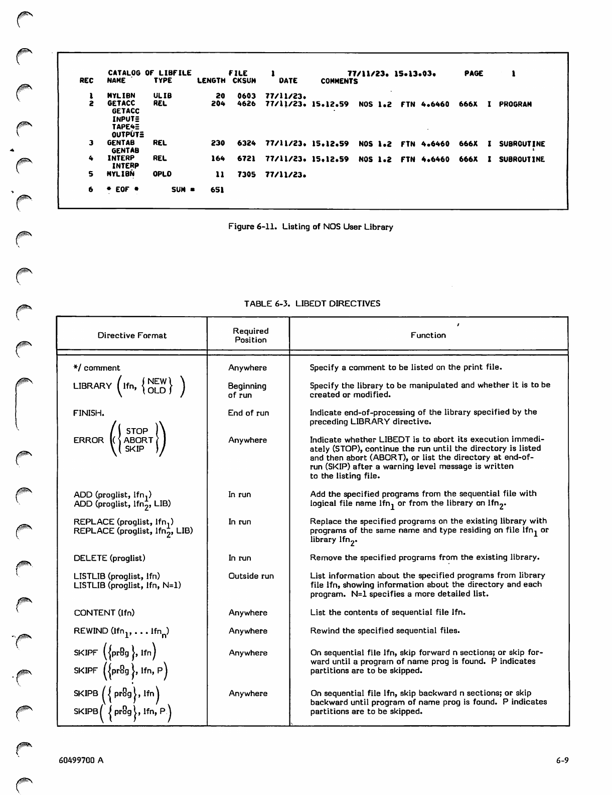
0$^
/fi®\
CATALOG OF LIBFILE FILE 77/11/23. 15.13.03. P A G E 1
REC NAHE TYPE LENGTH CKSUM DATE COMMENTS
1MYLIBN ULIB 20 0603 77/11/23.
2 GETACC
GETACC
INPUTr
TAPE4E
OUTPUTS
REL 204 4626 77/11/23. 1 5 . 1 2 . 5 9 N O S 1 . 2 F T N 4 . 6 4 6 0 6 66X I PROG R AH
3 GENTAB
GENTAB REL 230 6324 77/11/23. 1 5 . 1 2 . 5 9 N O S 1 . 2 F T N 4 . 6 4 6 0 6 6 6X I SU BR O U T IN E
4INTERP
INTERP REL 164 6721 77/11/23. 1 5 . 1 2 . 5 9 N O S 1 . 2 F T N 4 . 6 4 6 0 66 6X I SUBR OUT INE
5NYLIBN OPLD 11 7305 77/11/23.
6• EOF • SUH ■651
Figure 6-11. Listing of NOS User Library
/fP^v TABLE 6-3. LIBEDT DIRECTIVES
0SS
c
/^S
/P&v
Directive Format Required
Position Function
*/ comment Anywhere Specify a comment to be listed on the print file.
L I B R A R Y ( l f n , { ^ W | ^ Beginning
of run Specify the library to be manipulated and whether it is to be
created or modified.
FINISH.
/ ( S T O P ) \
ERROR l( \ ABORT ( 1
\ ( S K I P ) /
End of run
Anywhere
Indicate end-of-processing of the library specified by the
preceding LIBRARY directive.
Indicate whether LIBEDT is to abort its execution immedi
ately (STOP), continue the run until the directory is listed
and then abort (ABORT), or list the directory at end-of-
run (SKIP) after a warning level message is written
to the listing file.
ADD (proglist, lfn,)
ADD (proglist, lfn2, LIB)
In run Add the specified programs from the sequential file with
logical file name lfn, or from the library on lfn2-
REPLACE (proglist, lfn,)
REPLACE (proglist, lfn2, LIB)
In run Replace the specified programs on the existing library with
programs of the same name and type residing on file lfn, or
library lfn2»
DELETE (proglist) In run Remove the specified programs from the existing library.
LISTLIB (proglist, lfn)
LISTLIB (proglist, lfn, N=l)
Outside run List information about the specified programs from library
file lfn, showing information about the directory and each
program. N=l specifies a more detailed list.
CONTENT (lfn) Anywhere List the contents of sequential file lfn.
REWIND (lfnlf . . . lfnn) Anywhere Rewind the specified sequential files.
SKIPF UprBg J, lfn)
SKIPF /|pr9g 1, lfn, p)
Anywhere On sequential file lfn, skip forward n sections; or skip for
ward until a program of name prog is found. P indicates
partitions are to be skipped.
SKIPB /iprogi,lfn\
SKIPB ( j prog I, lfn, P.\
Anywhere On sequential file lfn, skip backward n sections; or skip
backward until program of name prog is found. P indicates
partitions are to be skipped.
0®r\
60499700 A 6-9
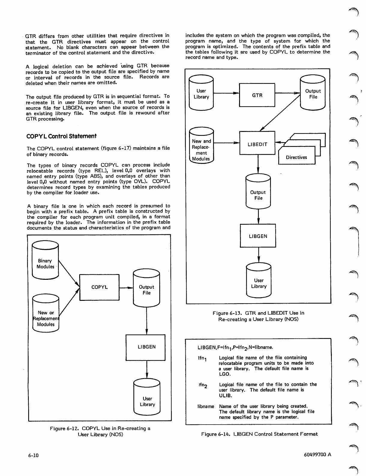
GTR differs from other utilities that require directives in
that the GTR directives must appear on the control
statement. No blank characters can appear between the
terminator of the control statement and the directive.
A logical deletion can be achieved using GTR because
records to be copied to the output file are specified by name
or interval of records in the source file. Records are
deleted when their names are omitted.
The output file produced by GTR is in sequential format. To
re-create it in user library format, it must be used as a
source file for LIBGEN, even when the source of records is
an existing library file. The output file is rewound after
GTR processing.
COPYL Control Statement
The COPYL control statement (figure 6-17) maintains a file
of binary records.
The types of binary records COPYL can process include
relocatable records (type REL), level 0,0 overlays with
named entry points (type ABS), and overlays of other than
level 0,0 without named entry points (type OVL). COPYL
determines record types by examining the tables produced
by the compiler for loader use.
A binary file is one in which each record is presumed to
begin with a prefix table. A prefix table is constructed by
the compiler for each program unit compiled, in a format
required by the loader. The information in the prefix table
documents the status and characteristics of the program and
includes the system on which the program was compiled, the
program name, and the type of system for which the
program is optimized. The contents of the prefix table and
the tables following it are used by COPYL to determine the
record name and type.
Binary
Modules
New or
Replacemem
Modules
COPYL Output
File
LIBGEN
User
Library
New and
Replace
ment
Modules Directives
^ s \
Figure 6-13. GTR and LIBEDIT Use in
Re-creating a User Library (NOS)
LIBGEN,F=lfn1,P=lfn2,N=libname
lfn
'1
ffn*
Logical file name of the file containing
relocatable program units to be made into
a user library. The default file name is
LGO.
Logical file name of the file to contain the
user library. The default file name is
ULIB.
libname Name of the user library being created.
The default library name is the logical file
name specified by the P parameter.
,*3sSS
Figure 6-12. COPYL Use in Re-creating a
User Library (NOS) Figure 6-14. LIBGEN Control Statement Format
6-10 60499700 A
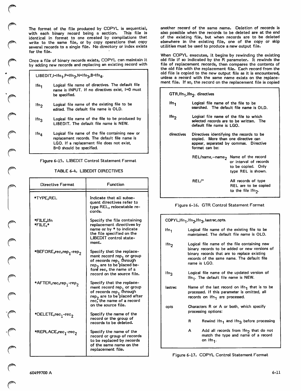
/0^s..
The format of the file produced by COPYL is sequential,
with each binary record being a section. This file is
identical in format to one created by compilations that
write to the same file, or by copy operations that copy
several records to a single file. No directory or index exists
for the file.
Once a file of binary records exists, COPYL can maintain it
by adding new records and replacing an existing record with
LIBEDIT,l=lfn1,P=lfn2,N=lfn3,B=lfn4.
lfn
lfn2
lfn3
lfn,.
Logical file name of directives. The default file
name is INPUT. If no directives exist, l=0 must
be specified.
Logical file name of the existing file to be
edited. The default file name is OLD.
Logical file name of the file to be produced by
LIBEDIT. The default file name is NEW.
Logical file name of the file containing new or
replacement records. The default file name is
LGO. If a replacement file does not exist,
B=0 should be specified.
Figure 6-15. LIBEDIT Control Statement Format
TABLE 6-4. LIBEDIT DIRECTIVES
0m\
/S^\
Directive Format
*TYPE,REL
*FILE,lfn
*FILE,*
*BEFORE,rec,rep.-rep2
*AFTER,rec,rep, -rep2
*DELETE,rec, -rec2
*REPLACE,rec1-rec2
Function
Indicate that all subse
quent directives refer to
type REL, relocatable re
cords.
Specify the file containing
replacement directives by
name or by * to indicate
the file specified on the
LIBEDIT control state
ment.
Specify that the replace
ment record rep, or group
of records rep, through
rep2 are to be placed be
fore rec, the name of a
record on the source file.
Specify that the replace
ment record rep, or group
of records rep. through
rep2 are to be placed after
rec, the name of a record
on the source file.
Specify the name of the
record or the group of
records to be deleted.
Specify the name of the
record or group of records
to be replaced by records
of the same name on the
replacement file.
another record of the same name. Deletion of records is
also possible when the records to be deleted are at the end
of the existing file, but when records are to be deleted
elsewhere in the existing file, one of the copy or skip
utilities must be used to produce a new output file.
When COPYL executes, it begins by rewinding the existing
old file if so indicated by the R parameter. It rewinds the
file of replacement records, then compares the contents of
the old file with the replacement file. Each record from the
old file is copied to the new output file as it is encountered,
unless a record with the same name exists on the replace
ment file. If so, the record on the replacement file is copied
GTR,lfn},lfn2. directives
lfni
lfn*
directives
Logical file name of the file to be
searched. The default file name is OLD.
Logical file name of the file to which
selected records are to be written. The
default file name is LGO.
Directives identifying the records to be
copied. More than one directive can
appear, separated by commas. Directive
format can be:
REL/name,—name2 Name of the record
or interval of records
to be copied. Only
type REL is shown.
REL/* All records of type
REL are to be copied
to the file lfn2.
Figure 6-16. GTR Control Statement Format
COPYL.Ifn 1 ,lfn2,lfn3# lastrec,opts.
lfn-, Logical file name of the existing file to be
maintained. The default file name is OLD.
lfn2 Logical file name of the file containing new
binary records to be added or new versions of
binary records that are to replace existing
records of the same name. The default file
name is LGO.
lfn3 Logical file name of the updated version of
Ifn-j. The default file name is NEW.
lastrec Name of the last record on Ifn-j that is to be
processed. If this parameter is omitted, all
records on lfn-| are processed.
opts Characters R or A or both, which specify
processing options:
R Rewind lfn-] and lfn3 before processing
A Add all records from lfn2 that do not
match the type and name of a record
on Ifn-j.
Figure 6-17. COPYL Control Statement Format
60499700 A 6-11
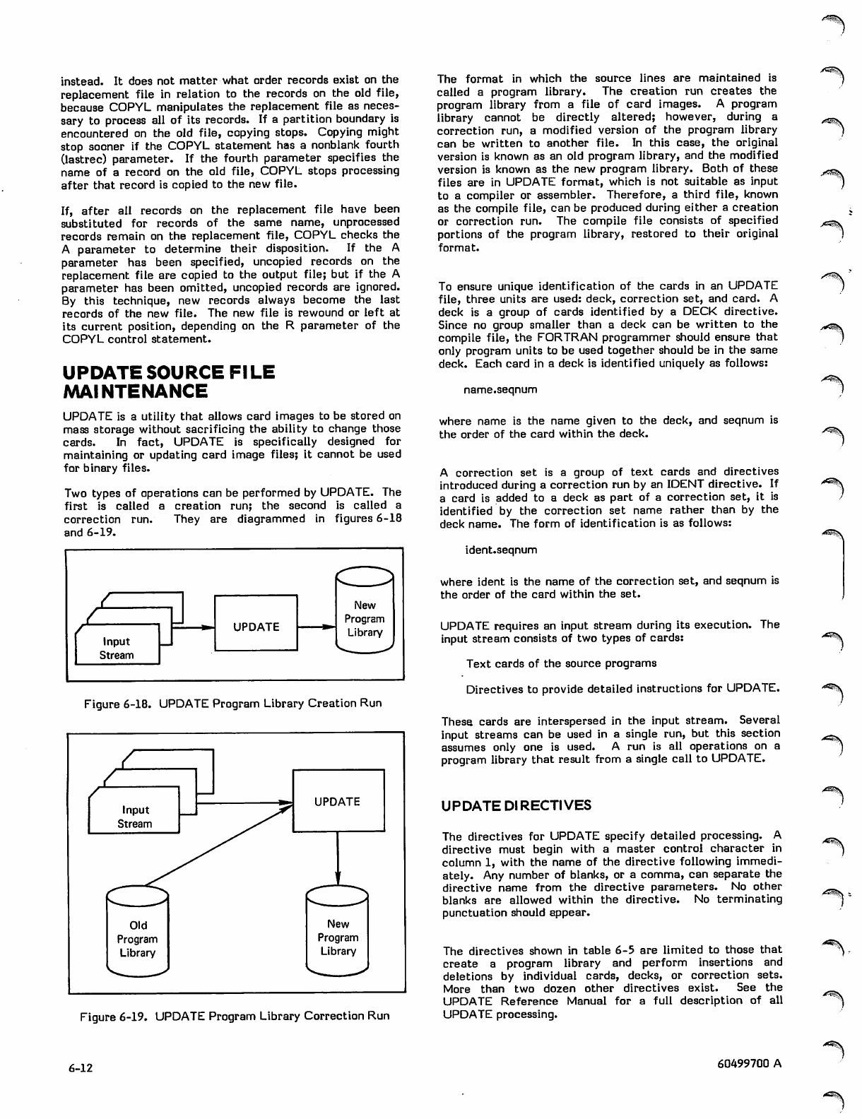
instead. It does not matter what order records exist on the
replacement file in relation to the records on the old file,
because COPYL manipulates the replacement file as neces
sary to process all of its records. If a partition boundary is
encountered on the old file, copying stops. Copying might
stop sooner if the COPYL statement has a nonblank fourth
(lastrec) parameter. If the fourth parameter specifies the
name of a record on the old file, COPYL stops processing
after that record is copied to the new file.
If, after all records on the replacement file have been
substituted for records of the same name, unprocessed
records remain on the replacement file, COPYL checks the
A parameter to determine their disposition. If the A
parameter has been specified, uncopied records on the
replacement file are copied to the output file; but if the A
parameter has been omitted, uncopied records are ignored.
By this technique, new records always become the last
records of the new file. The new file is rewound or left at
its current position, depending on the R parameter of the
COPYL control statement.
UPDATESOURCE FILE
MAINTENANCE
UPDATE is a utility that allows card images to be stored on
mass storage without sacrificing the ability to change those
cards. In fact, UPDATE is specifically designed for
maintaining or updating card image files; it cannot be used
for binary files.
Two types of operations can be performed by UPDATE. The
first is called a creation run; the second is called a
correction run. They are diagrammed in figures 6-18
and 6-19.
Zr
Input
Stream
UPDATE
New
Program
Library
Figure 6-18. UPDATE Program Library Creation Run
Zz
Input
Stream
UPDATE
Old
Program
Library
New
Program
Library
Figure 6-19. UPDATE Program Library Correction Run
The format in which the source lines are maintained is
called a program library. The creation run creates the
program library from a file of card images. A program
library cannot be directly altered; however, during a
correction run, a modified version of the program library
can be written to another file. In this case, the original
version is known as an old program library, and the modified
version is known as the new program library. Both of these
files are in UPDATE format, which is not suitable as input
to a compiler or assembler. Therefore, a third file, known
as the compile file, can be produced during either a creation
or correction run. The compile file consists of specified
portions of the program library, restored to their original
format.
To ensure unique identification of the cards in an UPDATE
file, three units are used: deck, correction set, and card. A
deck is a group of cards identified by a DECK directive.
Since no group smaller than a deck can be written to the
compile file, the FORTRAN programmer should ensure that
only program units to be used together should be in the same
deck. Each card in a deck is identified uniquely as follows:
name.seqnum
where name is the name given to the deck, and seqnum is
the order of the card within the deck.
A correction set is a group of text cards and directives
introduced during a correction run by an IDENT directive. If
a card is added to a deck as part of a correction set, it is
identified by the correction set name rather than by the
deck name. The form of identification is as follows:
ident.seqnum
where ident is the name of the correction set, and seqnum is
the order of the card within the set.
UPDATE requires an input stream during its execution. The
input stream consists of two types of cards:
Text cards of the source programs
Directives to provide detailed instructions for UPDATE.
These cards are interspersed in the input stream. Several
input streams can be used in a single run, but this section
assumes only one is used. A run is all operations on a
program library that result from a single call to UPDATE.
UPDATE DIRECTIVES
The directives for UPDATE specify detailed processing. A
directive must begin with a master control character in
column 1, with the name of the directive following immedi
ately. Any number of blanks, or a comma, can separate the
directive name from the directive parameters. No other
blanks are allowed within the directive. No terminating
punctuation should appear.
The directives shown in table 6-5 are limited to those that
create a program library and perform insertions and
deletions by individual cards, decks, or correction sets.
More than two dozen other directives exist. See the
UPDATE Reference Manual for a full description of all
UPDATE processing.
r*£$y\
**^v
tmt
6-12 60499700 A
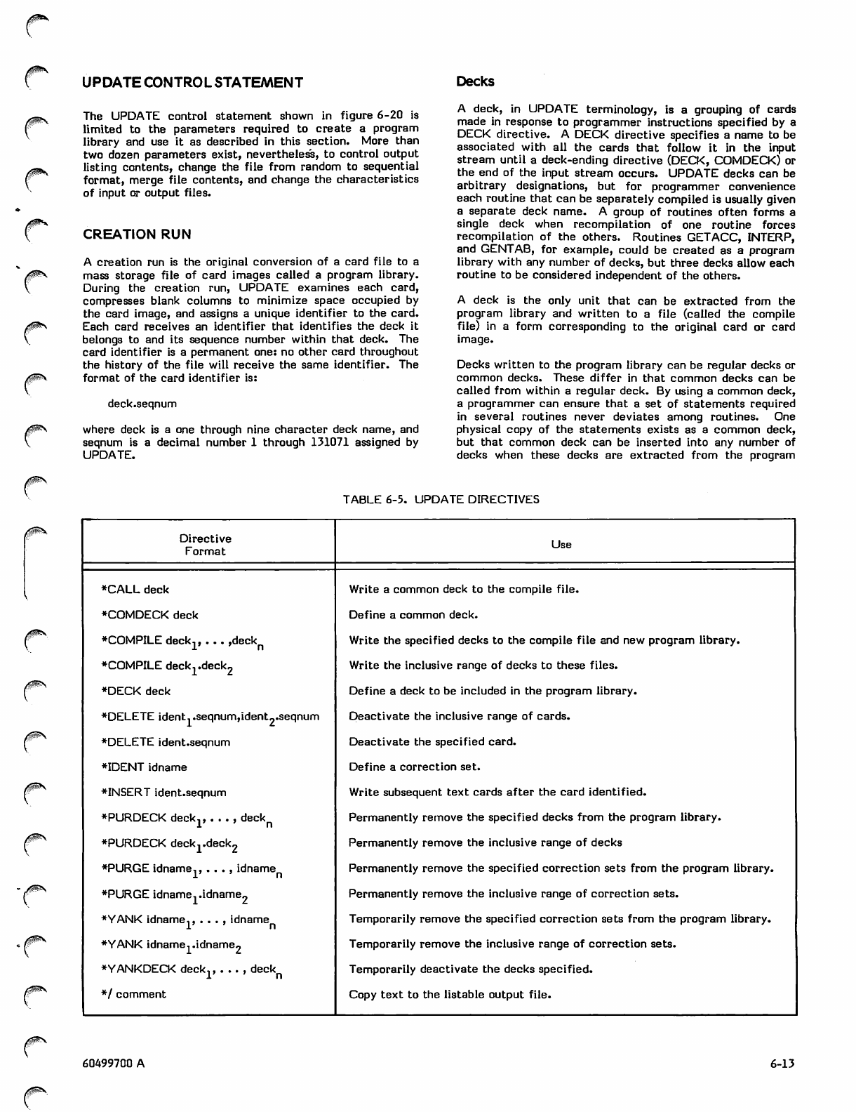
UPDATE CONTROL STATEMENT Decks
0m\
0$S
The UPDATE control statement shown in figure 6-20 is
limited to the parameters required to create a program
library and use it as described in this section. More than
two dozen parameters exist, nevertheless, to control output
listing contents, change the file from random to sequential
format, merge file contents, and change the characteristics
of input or output files.
CREATION RUN
A creation run is the original conversion of a card file to a
mass storage file of card images called a program library.
During the creation run, UPDATE examines each card,
compresses blank columns to minimize space occupied by
the card image, and assigns a unique identifier to the card.
Each card receives an identifier that identifies the deck it
belongs to and its sequence number within that deck. The
card identifier is a permanent one: no other card throughout
the history of the file will receive the same identifier. The
format of the card identifier is:
deck.seqnum
where deck is a one through nine character deck name, and
seqnum is a decimal number 1 through 131071 assigned by
UPDATE.
A deck, in UPDATE terminology, is a grouping of cards
made in response to programmer instructions specified by a
DECK directive. A DECK directive specifies a name to be
associated with all the cards that follow it in the input
stream until a deck-ending directive (DECK, COMDECK) or
the end of the input stream occurs. UPDATE decks can be
arbitrary designations, but for programmer convenience
each routine that can be separately compiled is usually given
a separate deck name. A group of routines often forms a
single deck when recompilation of one routine forces
recompilation of the others. Routines GETACC, INTERP,
and GENTAB, for example, could be created as a program
library with any number of decks, but three decks allow each
routine to be considered independent of the others.
A deck is the only unit that can be extracted from the
program library and written to a file (called the compile
file) in a form corresponding to the original card or card
image.
Decks written to the program library can be regular decks or
common decks. These differ in that common decks can be
called from within a regular deck. By using a common deck,
a programmer can ensure that a set of statements required
in several routines never deviates among routines. One
physical copy of the statements exists as a common deck,
but that common deck can be inserted into any number of
decks when these decks are extracted from the program
TABLE 6-5. UPDATE DIRECTIVES
/giSiV Directive
Format Use
T
/i^N
♦CALL deck
♦COMDECK deck
♦COMPILE deck.,... ,deck
i ' n
♦COMPILE deck1.deck2
♦DECK deck
♦DELETE ident. .seqnum,ident2.seqnum
♦DELETE ident.seqnum
♦IDENT idname
♦INSERT ident.seqnum
♦PURDECK deck., . .. , deck
in
♦PURDECK deck1.deck2
♦PURGE idname,,. . . , idname
1 ' n
♦PURGE idname. .idname2
♦YANK idname,, . . . , idname
1 n
♦YANK idname..idname2
♦YANKDECK deck,, . .. , deck
1 n
♦/ comment
Write a common deck to the compile file.
Define a common deck.
Write the specified decks to the compile file and new program library.
Write the inclusive range of decks to these files.
Define a deck to be included in the program library.
Deactivate the inclusive range of cards.
Deactivate the specified card.
Define a correction set.
Write subsequent text cards after the card identified.
Permanently remove the specified decks from the program library.
Permanently remove the inclusive range of decks
Permanently remove the specified correction sets from the program library.
Permanently remove the inclusive range of correction sets.
Temporarily remove the specified correction sets from the program library.
Temporarily remove the inclusive range of correction sets.
Temporarily deactivate the decks specified.
Copy text to the listable output file.
60499700 A 6-13
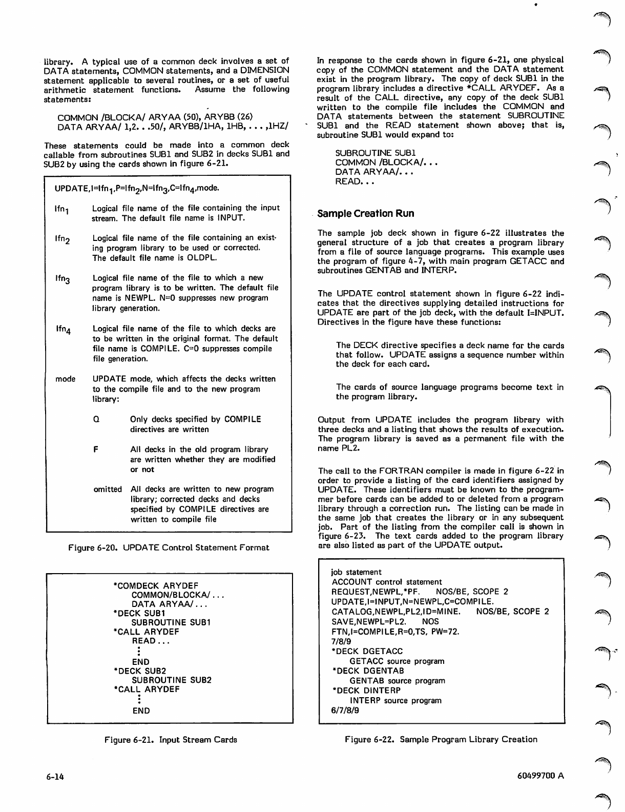
library. A typical use of a common deck involves a set of
DATA statements, COMMON statements, and a DIMENSION
statement applicable to several routines, or a set of useful
arithmetic statement functions. Assume the following
statements:
COMMON /BLOCKA/ ARYAA (50), ARYBB (26)
DATA ARYAA/ 1,2. . .50/, ARYBB/1HA, IHB, . . . ,1HZ/
These statements could be made into a common deck
callable from subroutines SUB1 and SUB2 in decks SUB1 and
SUB2 by using the cards shown in figure 6-21.
UPDATE, l=lfn1 ,P=lf n2,N=lf n3,C=lf n4,mode.
Ifn-j Logical file name of the file containing the input
stream. The default file name is INPUT.
Ifn2 Logical file name of the file containing an exist
ing program library to be used or corrected.
The default file name is OLDPL.
Ifn3 Logical file name of the file to which a new
program library is to be written. The default file
name is NEWPL. N=0 suppresses new program
library generation.
Ifn4 Logical file name of the file to which decks are
to be written in the original format. The default
file name is COMPILE. C=0 suppresses compile
file generation.
mode UPDATE mode, which affects the decks written
to the compile file and to the new program
library:
Q Only decks specified by COMPILE
directives are written
F All decks in the old program library
are written whether they are modified
or not
omitted All decks are written to new program
library; corrected decks and decks
specified by COMPILE directives are
written to compile file
Figure 6-20. UPDATE Control Statement Format
•COMDECK ARYDEF
COMMON/BLOCKA/.
DATA ARYAA/ .. .
•DECK SUB1
SUBROUTINE SUB1
•CALL ARYDEF
READ ...
END
♦DECK SUB2
SUBROUTINE SUB2
•CALL ARYDEF
END
In response to the cards shown in figure 6-21, one physical
copy of the COMMON statement and the DATA statement
exist in the program library. The copy of deck SUB1 in the
program library includes a directive #CALL ARYDEF. As a
result of the CALL directive, any copy of the deck SUB1
written to the compile file includes the COMMON and
DATA statements between the statement SUBROUTINE
SUB1 and the READ statement shown above; that is,
subroutine SUB1 would expand to:
SUBROUTINE SUB1
COMMON /BLOCKA/. . .
DATA ARYAA/. . .
READ. . .
Sample Creation Run
22 illustrates the
a program library
The sample job deck shown in figure 6
general structure of a job that creates
from a file of source language programs. This example uses
the program of figure 4-7, with main program GETACC and
subroutines GENTAB and INTERP.
The UPDATE control statement shown in figure 6-22 indi
cates that the directives supplying detailed instructions for
UPDATE are part of the job deck, with the default I=INPUT.
Directives in the figure have these functions:
The DECK directive specifies a deck name for the cards
that follow. UPDATE assigns a sequence number within
the deck for each card.
The cards of source language programs become text in
the program library.
Output from UPDATE includes the program library with
three decks and a listing that shows the results of execution.
The program library is saved as a permanent file with the
name PL2.
The call to the FORTRAN compiler is made in figure 6-22 in
order to provide a listing of the card identifiers assigned by
UPDATE. These identifiers must be known to the program
mer before cards can be added to or deleted from a program
library through a correction run. The listing can be made in
the same job that creates the library or in any subsequent
job. Part of the listing from the compiler call is shown in
figure 6-23. The text cards added to the program library
are also listed as part of the UPDATE output.
job statement
ACCOUNT control statement
REQUEST,NEWPL,*PF. NOS/BE, SCOPE 2
UPDATE,l=INPUT,N=NEWPL,C=COMPILE.
CATALOG,NEWPL,PL2,ID=MINE. NOS/BE, SCOPE 2
SAVE,NEWPL=PL2. NOS
FTN,I=COMPILE,R=0,TS. PW=72.
7/8/9
•DECK DGETACC
GETACC source program
•DECK DGENTAB
GENTAB source program
•DECK DINTERP
INTERP source program
6/7/8/9
'"^^v
^SS|>
"^V
,^^v
Art^vS.
A^\„
Figure 6-21. Input Stream Cards Figure 6-22. Sample Program Library Creation
6-14 60499700 A
•^^\
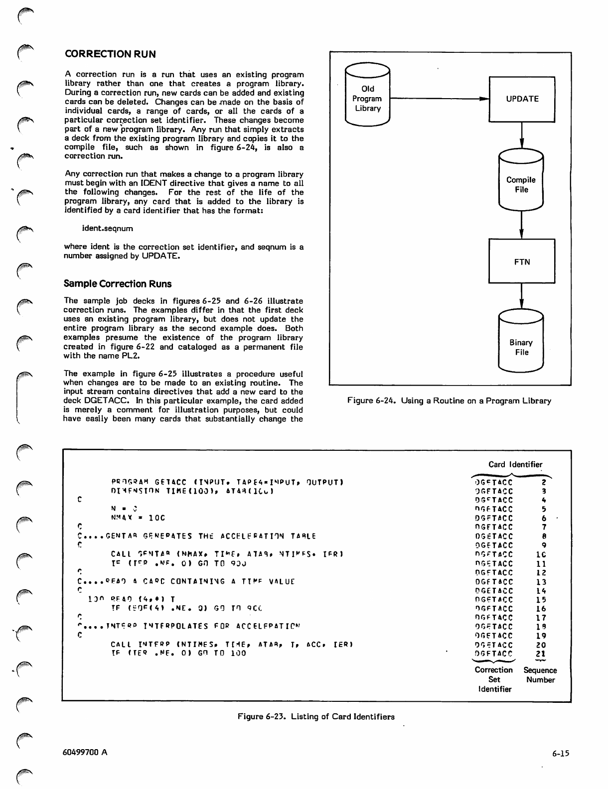
/$p^>
CORRECTION RUN
A correction run is a run that uses an existing program
library rather than one that creates a program library.
During a correction run, new cards can be added and existing
cards can be deleted. Changes can be .made on the basis of
individual cards, a range of cards, or all the cards of a
particular correction set identifier. These changes become
part of a new program library. Any run that simply extracts
a deck from the existing program library and copies it to the
compile file, such as shown in figure 6-24, is also a
correction run.
Any correction run that makes a change to a program library
must begin with an IDENT directive that gives a name to all
the following changes. For the rest of the life of the
program library, any card that is added to the library is
identified by a card identifier that has the format:
ident.seqnum
where ident is the correction set identifier, and seqnum is a
number assigned by UPDATE.
Sample Correction Runs
The sample job decks in figures 6-25 and 6-26 illustrate
correction runs. The examples differ in that the first deck
uses an existing program library, but does not update the
entire program library as the second example does. Both
examples presume the existence of the program library
created in figure 6-22 and cataloged as a permanent file
with the name PL2.
The example in figure 6-25 illustrates a procedure useful
when changes are to be made to an existing routine. The
input stream contains directives that add a new card to the
deck DGETACC. In this particular example, the card added
is merely a comment for illustration purposes, but could
have easily been many cards that substantially change the
Figure 6-24. Using a Routine on a Program Library
Card Identifier
P R O G R A M G E TA C C ( I N P U T. TA P f 4 « I M P U T » O U T P U T ) 0G«=TACC
OUFMSIHN TIME(100)» iT^IKU OGFTACC
c05CTACC
N ■ C HG FTAC C
N M A X » I O C QGFTACC
cOGFTACC
. . . G £ N TA « G P W E P 4 T E S T H t A C C E L E R AT I O N TA R L E 0 5 6 TA C C fl
rOGFTACC
CALL r»eNTJ5«* <NKAX» TI*P# ATA<U NTI^S. IFR) hGF TA C C IC
I c ( I C P . N ' F . 0 ) G O T O 9 0 0 nGE TA CC 11
rOGFTACC 12
c. . . . O F A 9 A C A O C C O N TA I N I N G A T T * f V A L U E 0G F T6 C C 13
rDGETACC 14
1 3 « P F 4 0 ( 4 t * | T OGFTACC 15
I F C e O F ( 4 > . N E . 0 ) G O T O Q C C OGFTACC 16
rOGfTACC 17
r....TNTCRP INTERPOLATES FOR ACCELFPATIP* OGFTACC 19
cOGFTACC 19
C A L L I N T F B P ( N T I M E S * T H E * A T A « , T » A C C » I E R ) OGFTAC C 20
I F C T E 9 . N E . 0 1 G H T O 1 0 0 OGFTACC 21
Correction Sequence
Set Number
Identifier
Figure 6-23. Listing of Card Identifiers
/(jjjpSV
60499700 A 6-15
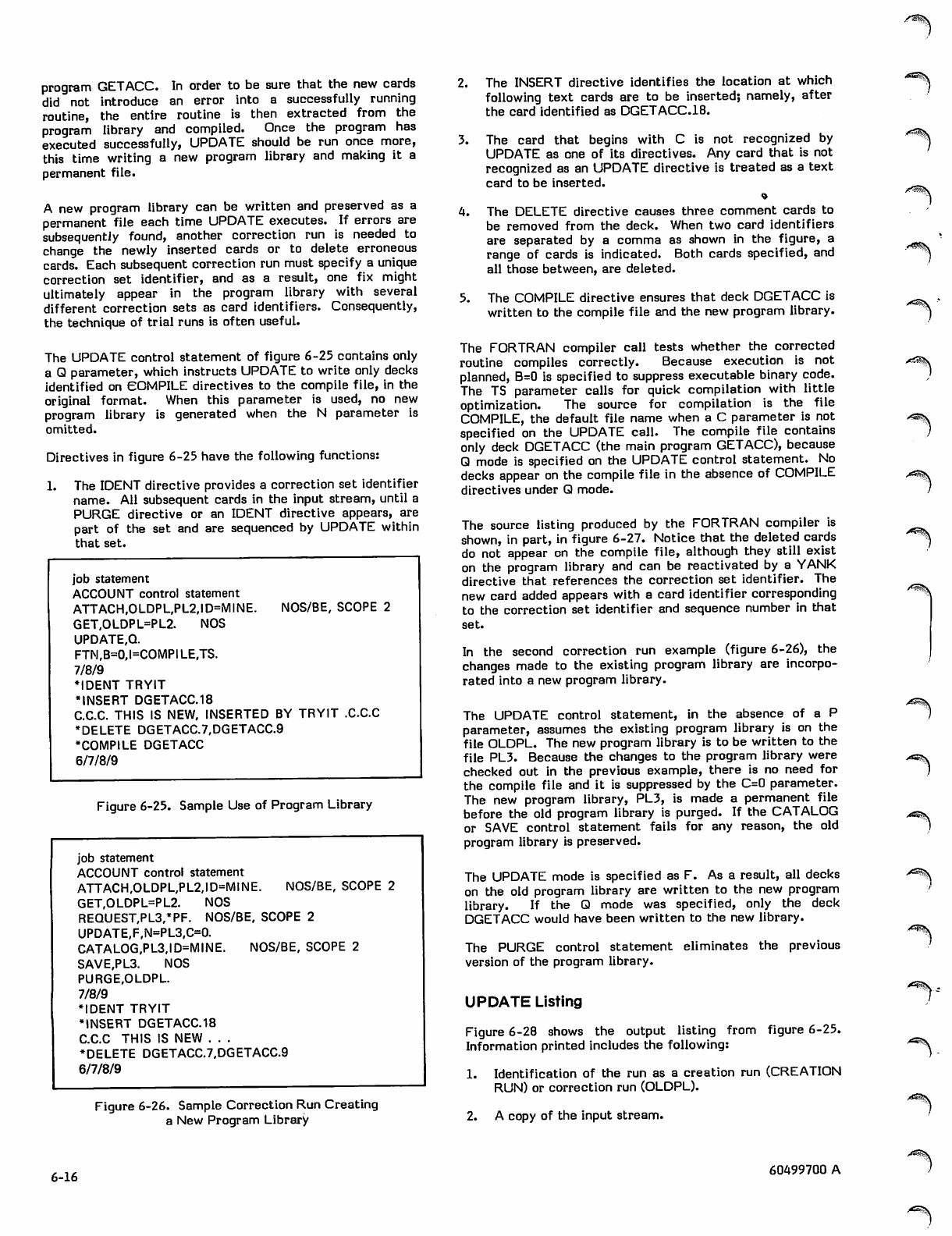
program GETACC. In order to be sure that the new cards
did not introduce an error into a successfully running
routine, the entire routine is then extracted from the
program library and compiled. Once the program has
executed successfully, UPDATE should be run once more,
this time writing a new program library and making it a
permanent file.
A new program library can be written and preserved as a
permanent file each time UPDATE executes. If errors are
subsequently found, another correction run is needed to
change the newly inserted cards or to delete erroneous
cards. Each subsequent correction run must specify a unique
correction set identifier, and as a result, one fix might
ultimately appear in the program library with several
different correction sets as card identifiers. Consequently,
the technique of trial runs is often useful.
The UPDATE control statement of figure 6-25 contains only
a Q parameter, which instructs UPDATE to write only decks
identified on COMPILE directives to the compile file, in the
original format. When this parameter is used, no new
program library is generated when the N parameter is
omitted.
Directives in figure 6-25 have the following functions:
1. The IDENT directive provides a correction set identifier
name. All subsequent cards in the input stream, until a
PURGE directive or an IDENT directive appears, are
part of the set and are sequenced by UPDATE within
that set.
NOS/BE, SCOPE 2
job statement
ACCOUNT control statement
ATTACH,OLDPL,PL2,ID=MINE.
GET,OLDPL=PL2. NOS
UPDATE,Q.
FTM,B=0,I=COMPI LE.TS.
7/8/9
•IDENT TRYIT
•INSERT DGETACC.18
CCC. THIS IS NEW, INSERTED BY TRYIT .CCC
•DELETE DGETACC7,DGETACC9
•COMPILE DGETACC
6/7/8/9
Figure 6-25. Sample Use of Program Library
job statement
ACCOUNT control statement
ATTACH,OLDPL,PL2,ID=MINE. NOS/BE, SCOPE 2
GET,OLDPL=PL2. NOS
REQUEST,PL3,*PF. NOS/BE, SCOPE 2
UPDATE,F,N=PL3,C=0.
CATALOG,PL3,ID=MINE. NOS/BE, SCOPE 2
SAVE,PL3. NOS
PURGE,OLDPL.
7/8/9
•IDENT TRYIT
•INSERT DGETACC.18
CCC THIS IS NEW . . .
•DELETE DGETACC7,DGETACC9
6/7/8/9
Figure 6-26. Sample Correction Run Creating
a New Program Library
2. The INSERT directive identifies the location at which
following text cards are to be inserted; namely, after
the card identified as DGETACC.18.
3. The card that begins with C is not recognized by
UPDATE as one of its directives. Any card that is not
recognized as an UPDATE directive is treated as a text
card to be inserted.
4. The DELETE directive causes three comment cards to
be removed from the deck. When two card identifiers
are separated by a comma as shown in the figure, a
range of cards is indicated. Both cards specified, and
all those between, are deleted.
5. The COMPILE directive ensures that deck DGETACC is
written to the compile file and the new program library.
The FORTRAN compiler call tests whether the corrected
routine compiles correctly. Because execution is not
planned, B=0 is specified to suppress executable binary code.
The TS parameter calls for quick compilation with little
optimization. The source for compilation is the file
COMPILE, the default file name when a C parameter is not
specified on the UPDATE call. The compile file contains
only deck DGETACC (the main program GETACC), because
Q mode is specified on the UPDATE control statement. No
decks appear on the compile file in the absence of COMPILE
directives under Q mode.
The source listing produced by the FORTRAN compiler is
shown, in part, in figure 6-27. Notice that the deleted cards
do not appear on the compile file, although they still exist
on the program library and can be reactivated by a YANK
directive that references the correction set identifier. The
new card added appears with a card identifier corresponding
to the correction set identifier and sequence number in that
set.
In the second correction run example (figure 6-26), the
changes made to the existing program library are incorpo
rated into a new program library.
The UPDATE control statement, in the absence of a P
parameter, assumes the existing program library is on the
file OLDPL. The new program library is to be written to the
file PL3. Because the changes to the program library were
checked out in the previous example, there is no need for
the compile file and it is suppressed by the C=0 parameter.
The new program library, PL3, is made a permanent file
before the old program library is purged. If the CATALOG
or SAVE control statement fails for any reason, the old
program library is preserved.
The UPDATE mode is specified as F. As a result, all decks
on the old program library are written to the new program
library. If the Q mode was specified, only the deck
DGETACC would have been written to the new library.
The PURGE control statement eliminates the previous
version of the program library.
UPDATE Listing
Figure 6-28 shows the output listing from figure 6-25.
Information printed includes the following:
1. Identification of the run as a creation run (CREATION
RUN) or correction run (OLDPL).
2. A copy of the input stream.
>**SS\
^^\
<^3\
6-16 60499700 A
T ^ \
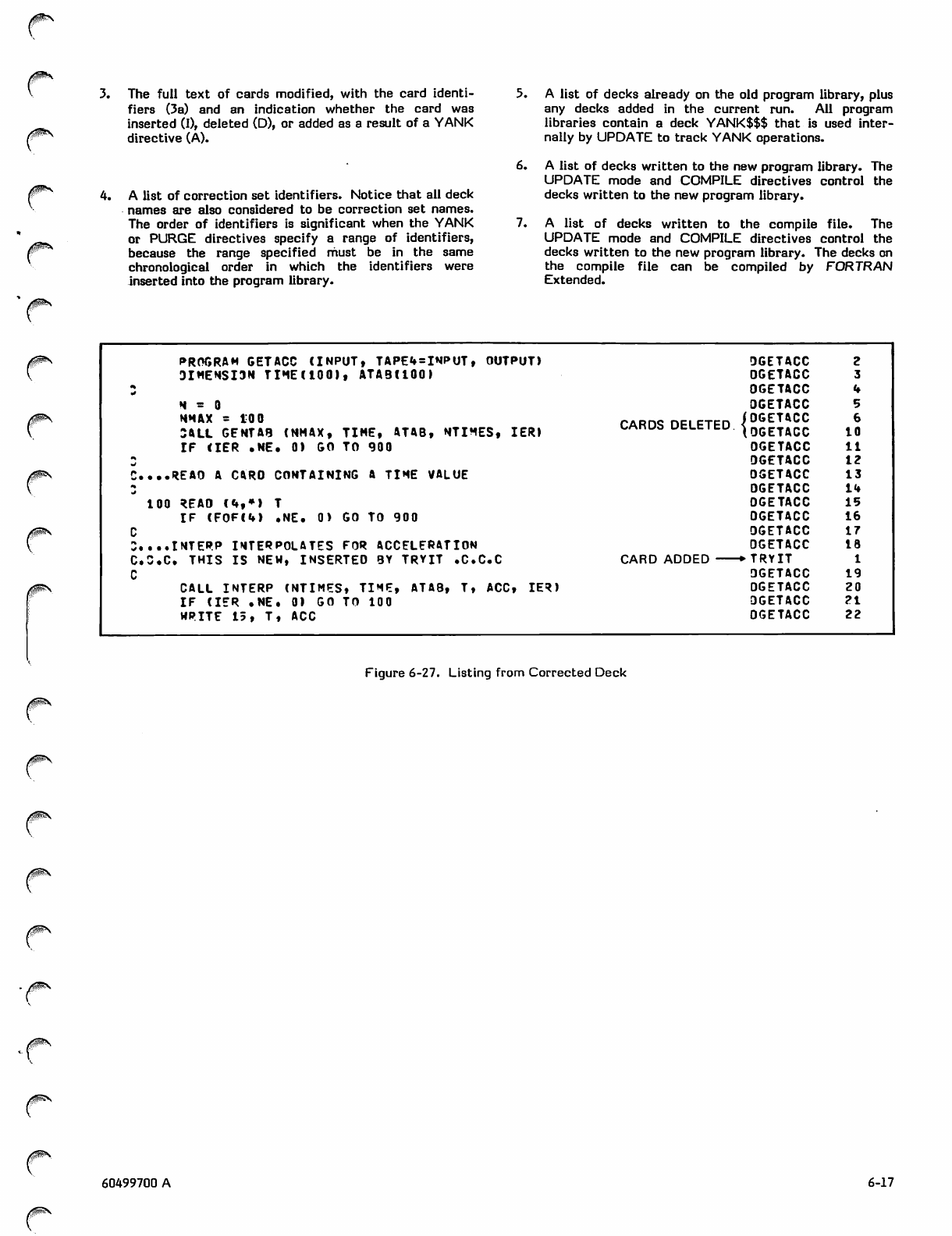
3. The full text of cards modified, with the card identi
fiers (3a) and an indication whether the card was
inserted (I), deleted (D), or added as a result of a YANK
directive (A).
4. A list of correction set identifiers. Notice that all deck
names are also considered to be correction set names.
The order of identifiers is significant when the YANK
or PURGE directives specify a range of identifiers,
because the range specified must be in the same
chronological order in which the identifiers were
inserted into the program library.
5. A list of decks already on the old program library, plus
any decks added in the current run. All program
libraries contain a deck YANK$$$ that is used inter
nally by UPDATE to track YANK operations.
6. A list of decks written to the new program library. The
UPDATE mode and COMPILE directives control the
decks written to the new program library.
7. A list of decks written to the compile file. The
UPDATE mode and COMPILE directives control the
decks written to the new program library. The decks on
the compile file can be compiled by FORTRAN
Extended.
0&fe\ PROGRAM GETACC (INPUT, TAPE4=INPUT, OUTPUT) DGETACC
DIMENSI3N TIME(IOO), ATAB(IQO) DGETACC
tOGETACC
H = 0 DGETACC
NMAX = 10 0
3ALL GENTAB (NMAX, TIME, ATAB, NTIMES, IER) CARDS DELETED {iS£ 10
IF < IER . NE . 0) GO TO 900 OGETACC 11
tJ DGETACC 12
C....REA0 A CARO CONTAINING A TIME VALUE OGETACC 13
DGETACC 14
100 READ (4,») T OGETACC 15
IF (F0F C 4 ) . N E. 0 > G O TO 9 00 DGETACC 16
CDGETACC 17
3....INTERP INTERPOLATES FOR ACCELERATION DGETACC 18
C C C . T H I S I S N E W, I N S E R T E D B Y T R Y I T . C C C C A R D A D D E D + T RY I T
CDGETACC 19
CAL L INTE R P ( N TIME S , T I ME, ATAB, T, ACC , IER) DGETACC 20
I F ( IER . N E. 0 ) G O T O 1 00 DGETACC 21
WR ITE 1 5, T, ACC OGETACC 22
Figure 6-27. Listing from Corrected Deck
0m\
60499700 A 6-17
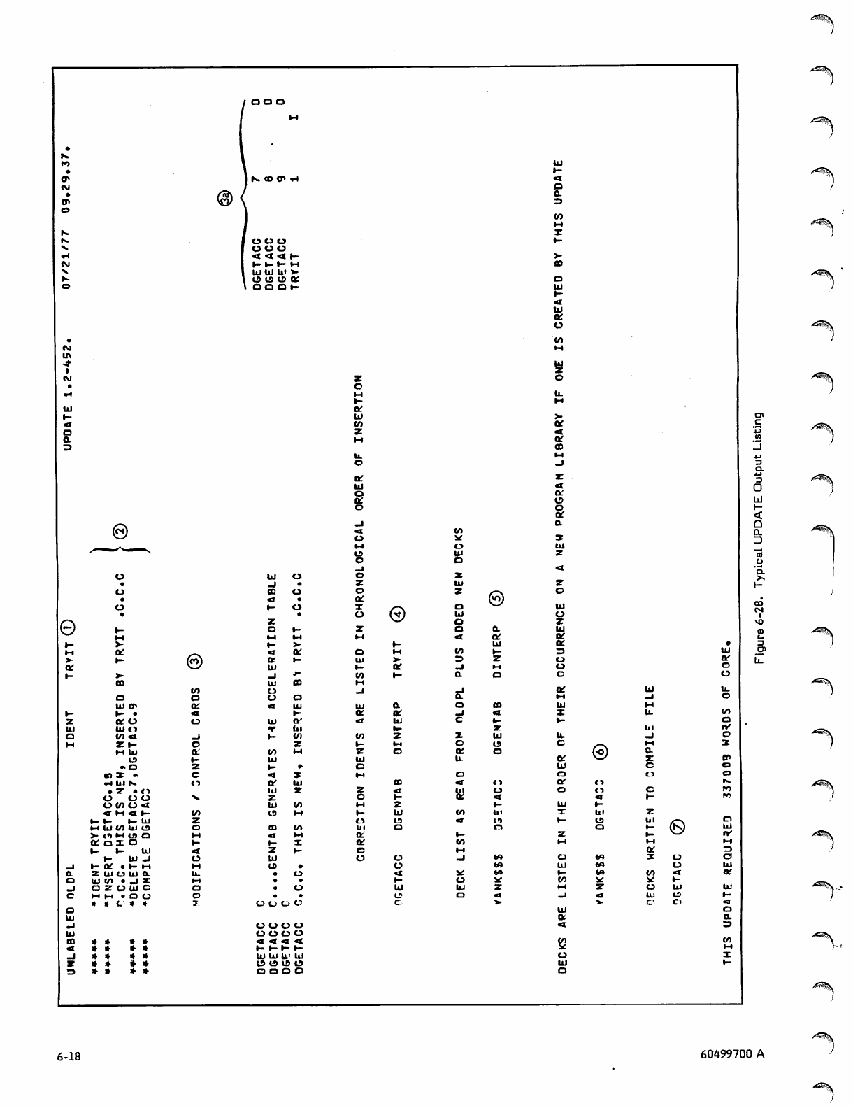
ooo
ooo
UUU
<<<l-
l-l-l-H
ui uj ui v
o to u> or
OO O H-
ec
Ul
tn
z
oc
Ul
o
ec
o
©
e
Oi
oc
O
uj tr
V- r ~ •
ZtfO
Ul UIO
o tn «t
Mz >-
M UJ
O
• O
e n x «
xH Ul N.
• Z • ( >
o o u
o </) o «x
4 M 4 t -
▶- f- T- in
t-t iu tn ui tn
Xu 11 ft Ut ex
O C O I o
» - 1 - U J
1 - U l - J
_J Ktt »hH
0. Z Ul O UJ CL
tn Ul IO • -J X
-J OZUUIO
cM M • O O
* » O * *
o
UJ
-J
UJ
m* * * *
4* * * *
-1 » * * *
*# * * »
3* * * *
Ul
-J
00
4
f-
ae
o*-
M M
»-
4tt
Ck! •-
UJ
-1 *-
UJ CD
o
uO
4Ui
h-
Ul tv
*r ttt
\~ tn
z
tn
Ul
\t ••
4Z%
Of Ul
IU ar
i-
z1-
Ul
u> a
.
.
.
OOOO
oooo
oooo
4 4 4
x~ f-r- T~
UJ UJ U> Ul
is is id tn
OOOO
_l
o
z
o
ac
X/-\
u®
z
M
1-
oM
Ul
1- or
t/> h-
l - «
_J
UJ 0.
aOC
4UJ
b.
to
l~ IH
Z o
UJ
o
tH
z<r
o•-
M Z
1- UJ
o«J»
Ul
OC
OC
e
o
H-
UJ
to
c
UJ
o
Ul
z
o
Ul
o
o
4
trt
=>
_i
a
x
o
U
0.
zn
tn
M
X
a
UJ
4
UJ
DC
U
UJ
z
o
u.
ec
4
Of
OD
z
4
o
o
ar
a
x
UJ
z
z
o
UJ
u
z
UJ
a
zn
o
o
c
u.
c
or
UJ
o
oc
/^a$\
/ ^ ^ k
©
ui
oc
o
tn
tn
cn
iv
o
3
z
CO
oUl
*-
1-
cn
UJ
tv
»H »H
oc
UH
zn
oOT ZZ
UJ <A UJ
1- (A tn oc
tn sc »-
Mz o UJ Ul
-J Uj to T-
*- C" Ci <l
UJ
aa.
4zn
tn
xc UH
uX
UJ y~
o
tzn
•-s<?\
/^5!S
6-18 60499700 A
LOADING FORTRAN PROGRAMS
After a FORTRAN program has been compiled, it must be
put in the proper format and placed in memory before
execution can take place. These functions are performed by
an operating system utility called the loader. For NOS and
NOS/BE, the loader is called the CYBER Loader; for
SCOPE 2, the loader is called the SCOPE 2 Loader. These
two loaders have many common features, and some incom
patibilities, which are pointed out where necessary.
In the simplest type of loading, the binary object code for an
executable program, consisting of a main program and its
associated subprograms, is written to a file. The program is
then loaded and executed by a control statement containing
the name of the file (LGO is the default file name from a
call to the FORTRAN Extended compiler). Use of more
advanced features of the loader can provide the following
advantages for the user:
• Reduction of field length requirements by dividing large
programs into smaller portions that need not all be in
memory at the same time. This can be accomplished
with overlays or segments.
# Increased code modularity by grouping frequently used
routines into libraries that can be referenced by more
than one program. Creation of user libraries is
described in section 6.
# Faster execution time for repeatedly executed pro
grams by eliminating the necessity for relocation each
time the program is executed.
0 More information for program debugging by requesting
a detailed load map.
Which loader features to use is a decision that can only be
made based on the requirements of a given application. In
particular, segments and overlays, while reducing field
length requirements, can increase execution time because of
the time required to move programs into and out of memory.
Three types of loading are of particular interest to the
FORTRAN user:
0 Basic loading. This is accomplished through control
statements, and consists of loading all the necessary
object code into memory at the same time. This is the
commonest type of loading, because most programs are
small compared to the amount of central memory
available.
• Segment loading. This is accomplished by the
SEGLOAD control statement in conjunction with seg
mentation directives. Programs are divided into units
called segments; the segments are linked into any
number of tree structures. At execution time, when a
segment not already in memory is required, it is loaded
automatically.
* Overlay loading. This is accomplished by OVERLAY
directives in the source program. Programs are divided
into smaller units called overlays. At execution time,
the overlays are loaded as specified by the user through
the OVERLAY subroutine. Because overlays are fully
described in the FORTRAN Extended Reference
Manual, they are not described further here.
Overlays and segments have comparative advantages and
disadvantages. Segments provide more flexibility in the
type of structure that can be constructed; overlay structure
is restricted to a single tree. Furthermore, segments are
loaded automatically, while overlays must be loaded
explicitly. On the other hand, segmentation poses certain
problems related to interprogram communication, especially
for the FORTRAN user. (These problems are described
below.) Also, overlays are generally faster to load than
segments, and segments cannot be put into libraries.
Several processes take place for any kind of loading; one of
these processes is relocation. When a program unit is
compiled, the object code is produced in relocatable format.
The addresses of variables and instructions are only tempo
rary, and are defined relative to the beginning of the
program unit, or of a common block. Before the program
can be executed, the addresses must be made absolute; that
is, defined relative to the beginning of the user's field
length. Relocation is the function of the loader, and takes
place in different ways depending on the type of load. One
of the advantages of overlays and segmentation is that
relocation is performed only once, reducing the time
required for subsequent loads of the same program.
Another process that takes place during loading is the
satisfaction of external references. An external reference
is a reference by one program unit to an entry point in
another program unit. In a FORTRAN program, external
references include names of referenced subprograms,
whether user-defined subprograms or library subprograms.
In addition, input/output statements generate references to
FORTRAN Common Library and Record Manager routines,
as well as to the file information tables for all files used.
Although the user is not concerned with these external
references when specifying the simplest types of loads, some
situations that can arise in more advanced types of loading
require the user to be aware of the existence of these
external references.
When a file is loaded, external references are satisfied by
matching them with entry points on the file whenever
possible. If unsatisfied externals remain after this process,
they are satisfied by searching library files until a matching
entry point is found. The library files associated with a job
are called the library set. When the same entry point occurs
on more than one file, or more than once on the same file,
the loader must use the search order that has been
established to determine which entry point to use to satisfy
the external reference. The order in which libraries are
searched is defined below, under Library Search Order.
BASIC LOADING
A basic load is a load that does not involve dividing the
object code into smaller units. All the object code for an
execution is present in memory at the same time. A basic
load is accomplished entirely through control statements,
without the need for special loader directives or subroutine
calls.
The control statements that define the processing for one
complete load operation are referred to as a load sequence.
The control statements in a load sequence are recognized by
the system as loader control statements, and cannot be
interrupted by any other control statements (except for
60499700 A 7-1
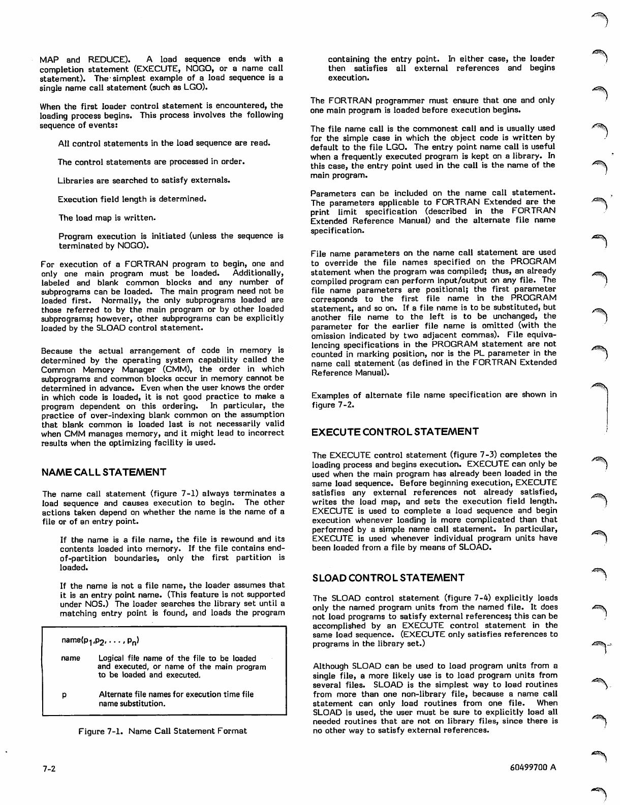
MAP and REDUCE). A load sequence ends with a
completion statement (EXECUTE, NOGO, or a name call
statement). The-simplest example of a load sequence is a
single name call statement (such as LGO).
When the first loader control statement is encountered, the
loading process begins. This process involves the following
sequence of events:
All control statements in the load sequence are read.
The control statements are processed in order.
Libraries are searched to satisfy externals.
Execution field length is determined.
The load map is written.
Program execution is initiated (unless the sequence is
terminated by NOGO).
For execution of a FORTRAN program to begin, one and
only one main program must be loaded. Additionally,
labeled and blank common blocks and any number of
subprograms can be loaded. The main program need not be
loaded first. Normally, the only subprograms loaded are
those referred to by the main program or by other loaded
subprograms; however, other subprograms can be explicitly
loaded by the SLOAD control statement.
Because the actual arrangement of code in memory is
determined by the operating system capability called the
Common Memory Manager (CMM), the order in which
subprograms and common blocks occur in memory cannot be
determined in advance. Even when the user knows the order
in which code is loaded, it is not good practice to make a
program dependent on this ordering. In particular, the
practice of over-indexing blank common on the assumption
that blank common is loaded last is not necessarily valid
when CMM manages memory, and it might lead to incorrect
results when the optimizing facility is used.
NAME CALL STATEMENT
The name call statement (figure 7-1) always terminates a
load sequence and causes execution to begin. The other
actions taken depend on whether the name is the name of a
file or of an entry point.
If the name is a file name, the file is rewound and its
contents loaded into memory. If the file contains end-
of-partition boundaries, only the first partition is
loaded.
If the name is not a file name, the loader assumes that
it is an entry point name. (This feature is not supported
under NOS.) The loader searches the library set until a
matching entry point is found, and loads the program
name(p1(p2,. • ,Pn)
Logical file name of the file to be loaded
and executed, or name of the main program
to be loaded and executed.
Alternate file names for execution time file
name substitution.
Figure 7-1. Name Call Statement Format
containing the entry point. In either case, the loader
the n satisfies all extern al refe rences and beg ins
execution.
The FORTRAN programmer must ensure that one and only
one main program is loaded before execution begins.
The file name call is the commonest call and is usually used
for the simple case in which the object code is written by
default to the file LGO. The entry point name call is useful
when a frequently executed program is kept on a library. In
this case, the entry point used in the call is the name of the
main program.
Parameters can be included on the name call statement.
The parameters applicable to FORTRAN Extended are the
pri n t l i m it s p eci fi c a tio n (de s c ribe d in t he F ORT RAN
Extended Reference Manual) and the alternate file name
specification.
File name parameters on the name call statement are used
to override the file names specified on the PROGRAM
statement when the program was compiled; thus, an already
compiled program can perform input/output on any file. The
file name parameters are positional; the first parameter
correspond s to th e first fil e name in the PR OGRAM
statement, and so on. If a file name is to be substituted, but
another file name to the left is to be unchanged, the
parameter for the earlier file name is omitted (with the
omission indicated by two adjacent commas). File equiva-
lencing specifications in the PROGRAM statement are not
counted in marking position, nor is the PL parameter in the
name call statement (as defined in the FORTRAN Extended
Reference Manual).
Examples of alternate file name specification are shown in
figure 7-2.
EXECUTE CONTROL STATEMENT
The EXECUTE control statement (figure 7-3) completes the
loading process and begins execution. EXECUTE can only be
used when the main program has already been loaded in the
same load sequence. Before beginning execution, EXECUTE
satisfies any external references not already satisfied,
writes the load map, and sets the execution field length.
EXECUTE is used to complete a load sequence and begin
execution whenever loading is more complicated than that
performed by a simple name call statement. In particular,
EXECUTE is used whenever individual program units have
been loaded from a file by means of SLOAD.
SLOAD CONTROL STATEMENT
The SLOAD control statement (figure 7-4) explicitly loads
only the named program units from the named file. It does
not load programs to satisfy external references; this can be
accomplished by an EXECUTE control statement in the
same load sequence. (EXECUTE only satisfies references to
programs in the library set.)
Although SLOAD can be used to load program units from a
single file, a more likely use is to load program units from
several files. SLOAD is the simplest way to load routines
from more than one non-library file, because a name call
statement can only load routines from one file. When
SLOAD is used, the user must be sure to explicitly load all
needed routines that are not on library files, since there is
no other way to satisfy external references.
yifl^S
.-*^sV
7-2 60499700 A
"^
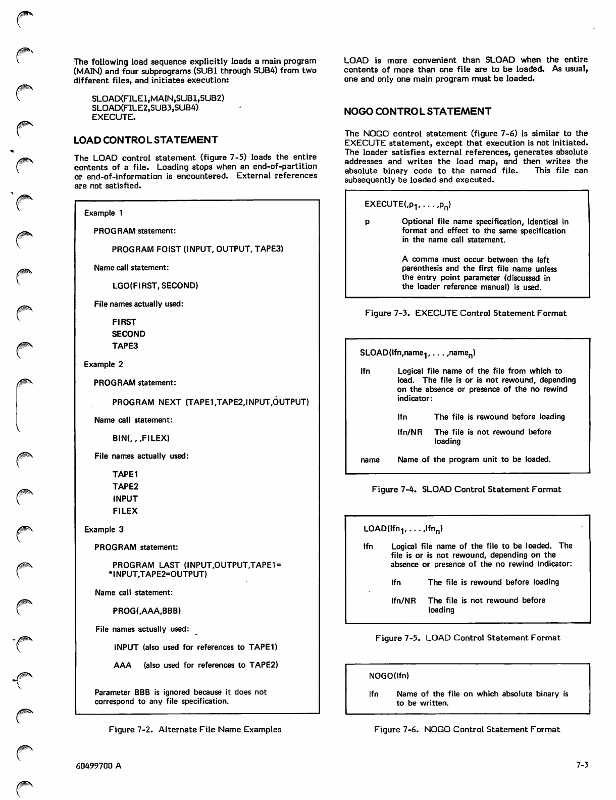
The following load sequence explicitly loads a main program
(MAIN) and four subprograms (SUB1 through SUB4) from two
different files, and initiates execution:
SLOAD(FILEl,MAIN,SUBl,SUB2)
SLOAD(FILE2,SUB3,SUB4)
EXECUTE.
LOAD CONTROL STATEMENT
The LOAD control statement (figure 7-5) loads the entire
contents of a file. Loading stops when an end-of-partition
or end-of-information is encountered. External references
are not satisfied.
Example 1
PROGRAM statement:
PROGRAM FOIST (INPUT, OUTPUT, TAPE3)
Name call statement:
LGO(FI RST, SECOND)
File names actually used:
FIRST
SECOND
TAPE3
Example 2
PROGRAM statement:
PROGRAM NEXT (TAPE1,TAPE2,INPUT,OUTPUT)
Name call statement:
BIN(,,,FILEX)
File names actually used:
TAPE1
TAPE2
INPUT
FILEX
Example 3
PROGRAM statement:
PROGRAM LAST (INPUT,OUTPUT,TAPE1 =
•|NPUT,TAPE2=OUTPUT)
Name call statement:
PROG(,AAA,BBB)
File names actually used:
INPUT (also used for references to TAPED
AAA (also used for references to TAPE2)
Parameter BBB is ignored because it does not
correspond to any file specification.
LOAD is more convenient than SLOAD when the entire
contents of more than one file are to be loaded. As usual,
one and only one main program must be loaded.
NOGO CONTROL STATEMENT
The NOGO control statement (figure 7-6) is similar to the
EXECUTE statement, except that execution is not initiated.
The loader satisfies external references, generates absolute
addresses and writes the load map, and then writes the
absolute binary code to the named file. This file can
subsequently be loaded and executed.
EXECUTE(,P1 pn)
Optional file name specification, identical in
format and effect to the same specification
in the name call statement.
A comma must occur between the left
parenthesis and the first file name unless
the entry point parameter (discussed in
the loader reference manual) is used.
Figure 7-3. EXECUTE Control Statement Format
SLOAD(lfn,name-|,... ,namen)
lfn Logical file name of the file from which to
load. The file is or is not rewound, depending
on the absence or presence of the no rewind
indicator:
lfn The file is rewound before loading
Ifn/NR The file is not rewound before
loading
name Name of the program unit to be loaded.
Figure 7-4. SLOAD Control Statement Format
LOAD(lfn1(.. ,lfnn)
lfn Logical file name of the file to be loaded. The
file is or is not rewound, depending on the
absence or presence of the no rewind indicator:
lfn The file is rewound before loading
Ifn/NR The file
loading
is not rewound before
Figure 7-5. LOAD Control Statement Format
NOGO(lfn)
lfn Name of the file on which absolute binary is
to be written.
Figure 7-2. Alternate File Name Examples Figure 7-6. NOGO Control Statement Format
60499700 A 7-3
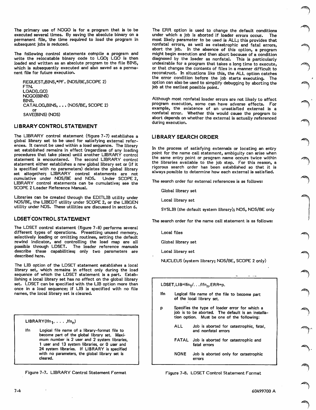
y5iw^|k
The primary use of NOGO is for a program that is to be
executed several times. By saving the absolute binary on a
permanent file, the time required to load the program in
subsequent jobs is reduced.
The following control statements compile a program and
write the relocatable binary code to LGO; LGO is then
loaded and written as an absolute program to the file BINS,
which is subsequently executed and also saved as a perma
nent file for future execution.
REQUEST,BINS,*PF. (NOS/BE,SCOPE 2)
FTN.
LOAD(LGO)
NOGO(BINS)
BINS.
CATALOG.BINS, . . . (NOS/BE, SCOPE 2)
or
SAVE(BINS) (NOS)
Ll BRARY CONTROL STATEMENT
The LIBRARY control statement (figure 7-7) establishes a
global library set to be used for satisfying external refer
ences. It cannot be used within a load sequence. The library
set established remains in effect (regardless of any loading
procedures that take place) until another LIBRARY control
statement is encountered. The second LIBRARY control
statement either establishes a new global library set or (if it
is specified with no parameters) deletes the global library
set altogether; LIBRARY control statements are not
cumulative under NOS/BE and NOS. Under SCOPE 2,
LIBRARY control statements can be cumulative; see the
SCOPE 2 Loader Reference Manual.
Libraries can be created through the EDITLIB utility under
NOS/BE, the LIBEDT utility under SCOPE 2, or the LIBGEN
utility under NOS. These utilities are discussed in section 6.
LDSET CONTROL STATEMENT
The LDSET control statement (figure 7-8) performs several
different types of operations. Presetting unused memory,
selectively loading or omitting routines, setting the default
rewind indicator, and controlling the load map are all
possible through LDSET. The loader reference manuals
describe these capabilities; only two parameters are
described here.
The LIB option of the LDSET statement establishes a local
library set, which remains in effect only during the load
sequence of which the LDSET statement is a part. Estab
lishing a local library set has no effect on the global library
set. LDSET can be specified with the LIB option more than
once in a load sequence; if LIB is specified with no file
names, the local library set is cleared.
LIBRARYtlfn-,, . . . ,lfnn)
lfn Logical file name of a library-format file to
become part of the global library set. Maxi
mum number is 2 user and 2 system libraries,
1 user and 13 system libraries, or 0 user and
24 system libraries. If LIBRARY is specified
with no parameters, the global library set is
cleared.
Figure 7-7. LIBRARY Control Statement Format
7-4
The ERR option is used to change the default conditions
under which a job is aborted if loader errors occur. The
most likely parameter to be used is ALL; this provides that
nonfatal errors, as well as catastrophic and fatal errors,
abort the job. In the absence of this option, a program
might begin execution and then abort because of a condition
diagnosed by the loader as nonfatal. This is particularly
undesirable for a program that takes a long time to execute,
or that changes the contents of files in a manner difficult to
reconstruct. In situations like this, the ALL option catches
the error condition before the job starts executing. The
option can also be used to simplify debugging by aborting the
job at the earliest possible point.
Although most nonfatal loader errors are not likely to affect
program execution, some can have adverse effects. For
example, the existence of an unsatisfied external is a
nonfatal error. Whether this would cause the program to
abort depends on whether the external is actually referenced
during execution.
LIBRARY SEARCH ORDER
In the process of satisfying externals or locating an entry
point for the name call statement, ambiguity can arise when
the same entry point or program name occurs twice within
the libraries available to the job step. For this reason, a
rigorous search order has been established so that it is
always possible to determine how each external is satisfied.
The search order for external references is as follows:
Global library set
Local library set
SYSLIB (the default system library); NOS, NOS/BE only
The search order for the name call statement is as follows:
Local files
Global library set
Local library set
NUCLEUS (system library; NOS/BE, SCOPE 2 only)
LDSET,LIB=lfn-,/.. ./lfnn,ERR=p.
lfn Logical file name of the file to become part
of the local library set.
Specifies the type of loader error for which a
job is to be aborted. The default is an installa
tion option. Must be one of the following:
AL L Job is aborted for catastrophic, fatal,
and nonfatal errors
FATAL Job is aborted for catastrophic and
fatal errors
NONE Job is aborted only for catastrophic
errors
Figure 7-8. LDSET Control Statement Format
60499700 A
A9g^S
ATt!i\
A^\
>r^\
/WT^V
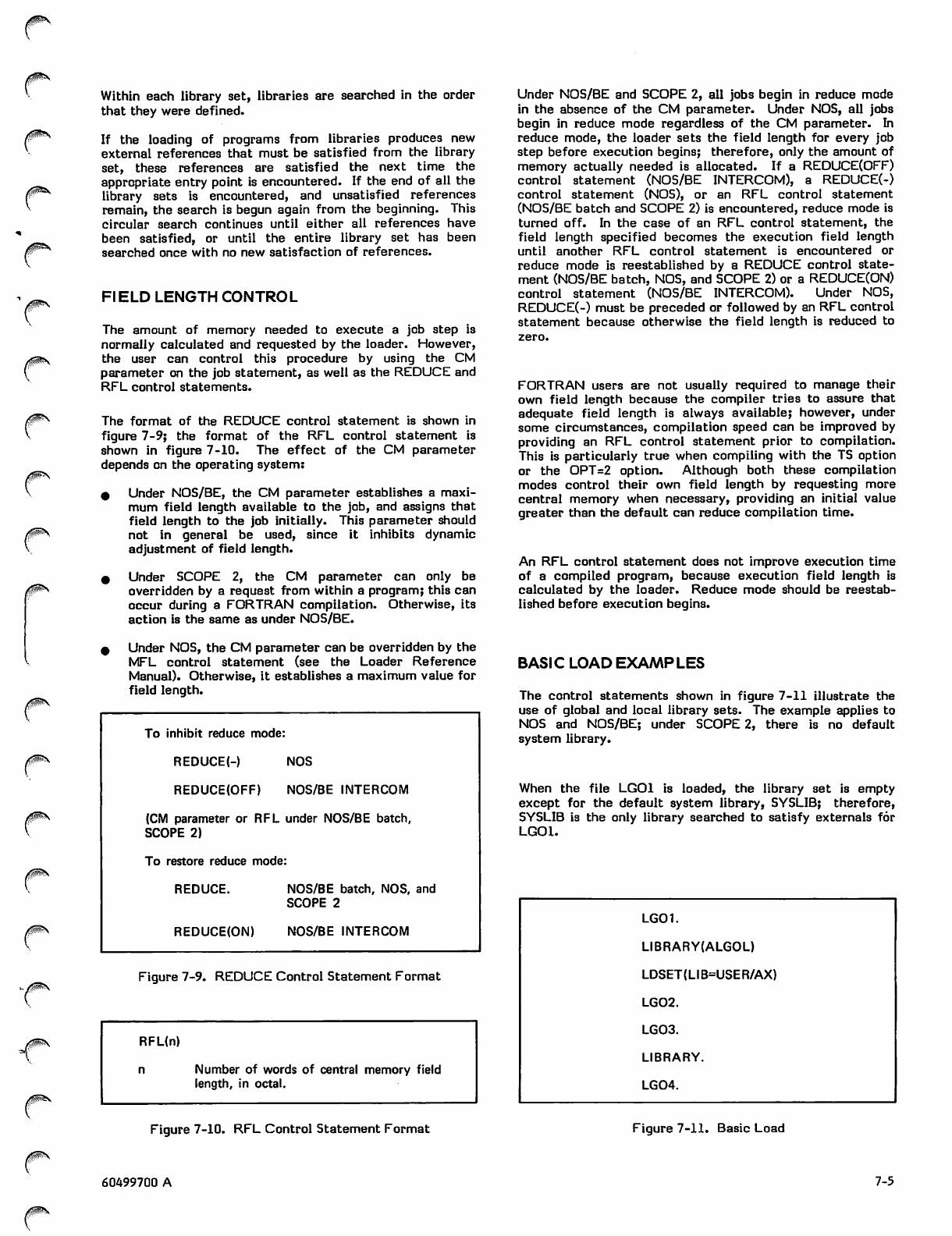
0$*s
Within each library set, libraries are searched in the order
that they were defined.
If the loading of programs from libraries produces new
external references that must be satisfied from the library
set, these references are satisfied the next time the
appropriate entry point is encountered. If the end of all the
library sets is encountered, and unsatisfied references
remain, the search is begun again from the beginning. This
circular search continues until either all references have
been satisfied, or until the entire library set has been
searched once with no new satisfaction of references.
Fl ELD LENGTH CONTROL
The amount of memory needed to execute a job step is
normally calculated and requested by the loader. However,
the user can control this procedure by using the CM
parameter on the job statement, as well as the REDUCE and
RFL control statements.
The format of the REDUCE control statement is shown in
figure 7-9; the format of the RFL control statement is
shown in figure 7-10. The effect of the CM parameter
depends on the operating system:
^ Under NOS/BE, the CM parameter establishes a maxi
mum field length available to the job, and assigns that
field length to the job initially. This parameter should
not in general be used, since it inhibits dynamic
adjustment of field length.
* U n der S COP E 2, t he C M p a r ame t e r c a n o n l y b e
overridden by a request from within a program; this can
occur during a FORTRAN compilation. Otherwise, its
action is the same as under NOS/BE.
0 Under NOS, the CM parameter can be overridden by the
MFL control statement (see the Loader Reference
Manual). Otherwise, it establishes a maximum value for
field length.
To inhibit reduce mode
REDUCE(-) NOS
REDUCE(OFF) NOS/BE INTERCOM
(CM parameter or RFL under NOS/BE batch,
SCOPE 2)
To restore reduce mode
REDUCE. NOS/BE batch, NOS, and
SCOPE 2
REDUCE(ON) NOS/BE INTERCOM
Figure 7-9. REDUCE Control Statement Format
RFL(n)
Number of words of central memory field
length, in octal.
Under NOS/BE and SCOPE 2, all jobs begin in reduce mode
in the absence of the CM parameter. Under NOS, all jobs
begin in reduce mode regardless of the CM parameter. In
reduce mode, the loader sets the field length for every job
step before execution begins; therefore, only the amount of
memory actually needed is allocated. If a REDUCE(OFF)
control statement (NOS/BE INTERCOM), a REDUCE(-)
control statement (NOS), or an RFL control statement
(NOS/BE batch and SCOPE 2) is encountered, reduce mode is
turned off. In the case of an RFL control statement, the
field length specified becomes the execution field length
until another RFL control statement is encountered or
reduce mode is reestablished by a REDUCE control state
ment (NOS/BE batch, NOS, and SCOPE 2) or a REDUCE(ON)
control statement (NOS/BE INTERCOM). Under NOS,
REDUCE(-) must be preceded or followed by an RFL control
statement because otherwise the field length is reduced to
FORTRAN users are not usually required to manage their
own field length because the compiler tries to assure that
adequate field length is always available; however, under
some circumstances, compilation speed can be improved by
providing an RFL control statement prior to compilation.
This is particularly true when compiling with the TS option
or the OPT=2 option. Although both these compilation
modes control their own field length by requesting more
central memory when necessary, providing an initial value
greater than the default can reduce compilation time.
An RFL control statement does not improve execution time
of a compiled program, because execution field length is
calculated by the loader. Reduce mode should be reestab
lished before execution begins.
BASIC LOAD EXAMPLES
The control statements shown in figure 7-11 illustrate the
use of global and local library sets. The example applies to
NOS and NOS/BE; under SCOPE 2, there is no default
system library.
When the file LGOl is loaded, the library set is empty
except for the default system library, SYSLIB; therefore,
SYSLIB is the only library searched to satisfy externals for
LGOl.
LGOl.
LIBRARY(ALGOL)
LDSET(LIB=USER/AX)
LG02.
LG03.
LIBRARY.
LG04.
Figure 7-10. RFL Control Statement Format Figure 7-11. Basic Load
60499700 A 7-5
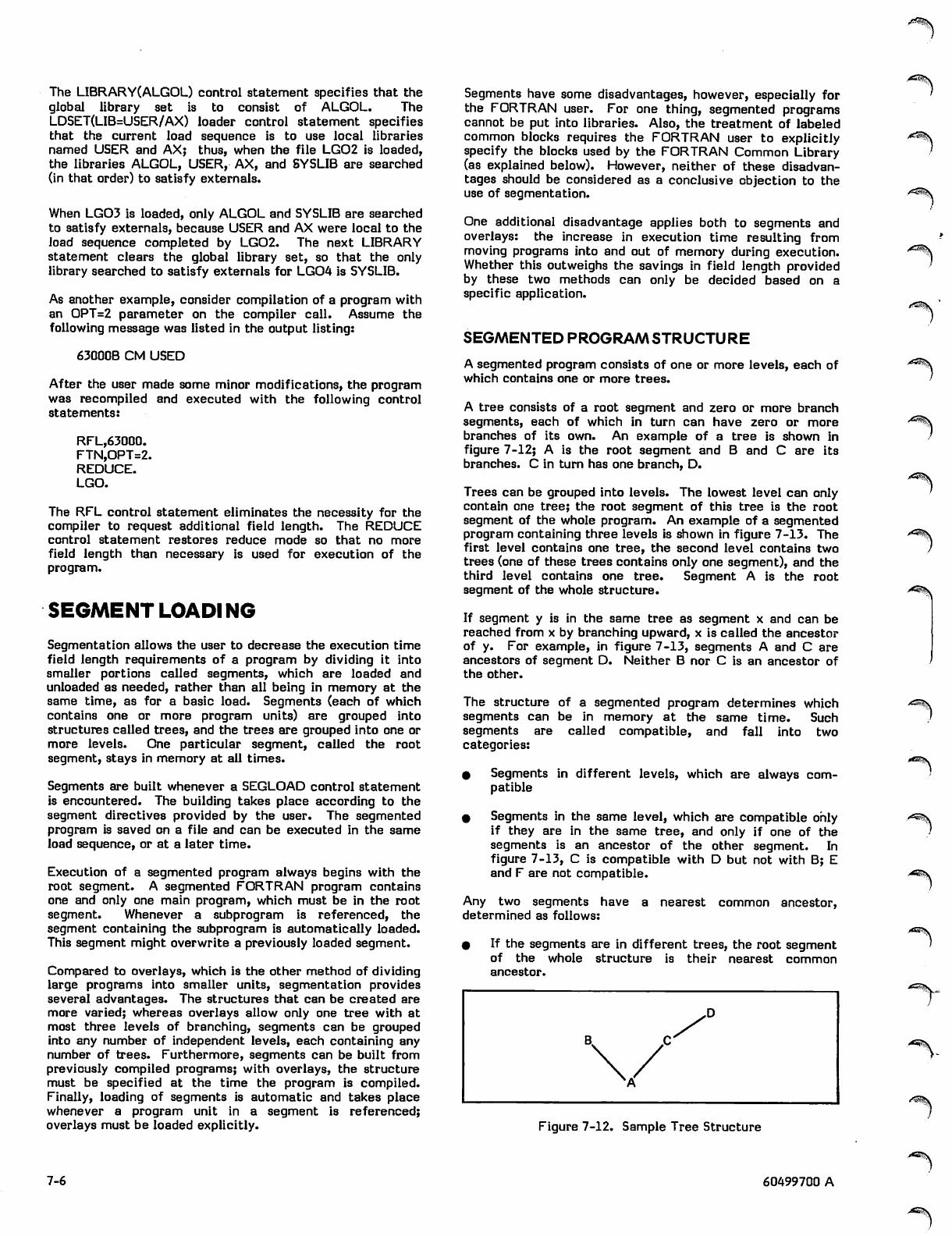
The LIBRARY(ALGOL) control statement specifies that the
global library set is to consist of ALGOL. The
LDSET(LIB=USER/AX) loader control statement specifies
that the current load sequence is to use local libraries
named USER and AX; thus, when the file LG02 is loaded,
the libraries ALGOL, USER, AX, and SYSLIB are searched
(in that order) to satisfy externals.
When LG03 is loaded, only ALGOL and SYSLIB are searched
to satisfy externals, because USER and AX were local to the
load sequence completed by LG02. The next LIBRARY
statement clears the global library set, so that the only
library searched to satisfy externals for LG04 is SYSLIB.
As another example, consider compilation of a program with
an OPT=2 parameter on the compiler call. Assume the
following message was listed in the output listing:
63000B CM USED
After the user made some minor modifications, the program
was recompiled and executed with the following control
statements:
RFL,63000.
FTN,OPT=2.
REDUCE.
LGO.
The RFL control statement eliminates the necessity for the
compiler to request additional field length. The REDUCE
control statement restores reduce mode so that no more
field length than necessary is used for execution of the
program.
SEGMENT LOADING
Segmentation allows the user to decrease the execution time
field length requirements of a program by dividing it into
smaller portions called segments, which are loaded and
unloaded as needed, rather than all being in memory at the
same time, as for a basic load. Segments (each of which
contains one or more program units) are grouped into
structures called trees, and the trees are grouped into one or
more levels. One particular segment, called the root
segment, stays in memory at all times.
Segments are built whenever a SEGLOAD control statement
is encountered. The building takes place according to the
segment directives provided by the user. The segmented
program is saved on a file and can be executed in the same
load sequence, or at a later time.
Execution of a segmented program always begins with the
root segment. A segmented FORTRAN program contains
one and only one main program, which must be in the root
segment. Whenever a subprogram is referenced, the
segment containing the subprogram is automatically loaded.
This segment might overwrite a previously loaded segment.
Compared to overlays, which is the other method of dividing
large programs into smaller units, segmentation provides
several advantages. The structures that can be created are
more varied; whereas overlays allow only one tree with at
most three levels of branching, segments can be grouped
into any number of independent levels, each containing any
number of trees. Furthermore, segments can be built from
previously compiled programs; with overlays, the structure
must be specified at the time the program is compiled.
Finally, loading of segments is automatic and takes place
whenever a program unit in a segment is referenced;
overlays must be loaded explicitly.
Segments have some disadvantages, however, especially for
the FORTRAN user. For one thing, segmented programs
cannot be put into libraries. Also, the treatment of labeled
common blocks requires the FORTRAN user to explicitly
specify the blocks used by the FORTRAN Common Library
(as explained below). However, neither of these disadvan
tages should be considered as a conclusive objection to the
use of segmentation.
One additional disadvantage applies both to segments and
overlays: the increase in execution time resulting from
moving programs into and out of memory during execution.
Whether this outweighs the savings in field length provided
by these two methods can only be decided based on a
specific application.
SEGMENTED PROGRAM STRUCTURE
A segmented program consists of one or more levels, each of
which contains one or more trees.
A tree consists of a root segment and zero or more branch
segments, each of which in turn can have zero or more
branches of its own. An example of a tree is shown in
figure 7-12; A is the root segment and B and C are its
branches. C in turn has one branch, D.
Trees can be grouped into levels. The lowest level can only
contain one tree; the root segment of this tree is the root
segment of the whole program. An example of a segmented
program containing three levels is shown in figure 7-13. The
first level contains one tree, the second level contains two
trees (one of these trees contains only one segment), and the
third level contains one tree. Segment A is the root
segment of the whole structure.
If segment y is in the same tree as segment x and can be
reached from x by branching upward, x is called the ancestor
of y. For example, in figure 7-13, segments A and C are
ancestors of segment D. Neither B nor C is an ancestor of
the other.
The structure of a segmented program determines which
segments can be in memory at the same time. Such
segments are called compatible, and fall into two
categories:
# Segments in different levels, which are always com
patible
0 Segments in the same level, which are compatible only
if they are in the same tree, and only if one of the
segments is an ancestor of the other segment. In
figure 7-13, C is compatible with D but not with B; E
and F are not compatible.
Any two segments have a nearest common ancestor,
determined as follows:
0 If the segments are in different trees, the root segment
of the wh ole str uct ure is the ir nea res t c omm on
ancestor.
y^^v
.J"^^V
^v
Figure 7-12. Sample Tree Structure
7-6 60499700 A
>^\
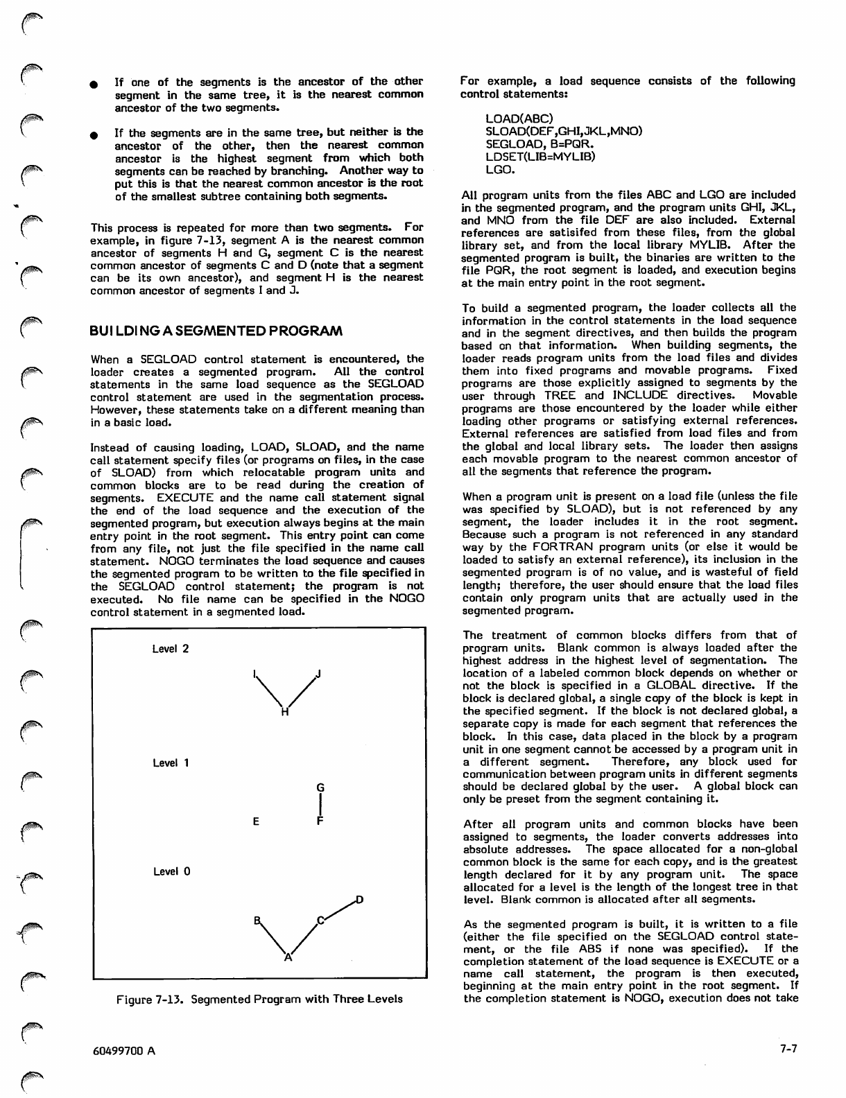
/pss
0O®\
0^\
/flSs.
0 If one of the segments is the ancestor of the other
segment in the same tree, it is the nearest common
ancestor of the two segments.
0 If the segments are in the same tree, but neither is the
ancestor of t he o ther, t hen the nearest com mon
ancestor is the highest segment from which both
segments can be reached by branching. Another way to
put this is that the nearest common ancestor is the root
of the smallest subtree containing both segments.
This process is repeated for more than two segments. For
example, in figure 7-13, segment A is the nearest common
ancestor of segments H and G, segment C is the nearest
common ancestor of segments C and D (note that a segment
can be its own ancestor), and segment H is the nearest
common ancestor of segments I and J.
BUI LDI NG A SEGMENTED PROGRAM
When a SEGLOAD control statement is encountered, the
loader creates a segmented program. All the control
statements in the same load sequence as the SEGLOAD
control statement are used in the segmentation process.
However, these statements take on a different meaning than
in a basic load.
Instead of causing loading, LOAD, SLOAD, and the name
call statement specify files (or programs on files, in the case
of SLOAD) from which relocatable program units and
common blocks are to be read during the creation of
segments. EXECUTE and the name call statement signal
the end of the load sequence and the execution of the
segmented program, but execution always begins at the main
entry point in the root segment. This entry point can come
from any file, not just the file specified in the name call
statement. NOGO terminates the load sequence and causes
the segmented program to be written to the file specified in
the SEGLOAD control statement; the program is not
executed. No file name can be specified in the NOGO
control statement in a segmented load.
Level 2
Level 1
Level 0
Figure 7-13. Segmented Program with Three Levels
For example, a load sequence consists of the following
control statements:
LOAD(ABC)
SLOAD(DEF,GHI,JKL,MNO)
SEGLOAD, B=PQR.
LDSET(LIB=MYLIB)
LGO.
All program units from the files ABC and LGO are included
in the segmented program, and the program units GHI, JKL,
and MNO from the file DEF are also included. External
references are satisifed from these files, from the global
library set, and from the local library MYLIB. After the
segmented program is built, the binaries are written to the
file PQR, the root segment is loaded, and execution begins
at the main entry point in the root segment.
To build a segmented program, the loader collects all the
information in the control statements in the load sequence
and in the segment directives, and then builds the program
based on that information. When building segments, the
loader reads program units from the load files and divides
them into fixed programs and movable programs. Fixed
programs are those explicitly assigned to segments by the
user through TREE and INCLUDE directives. Movable
programs are those encountered by the loader while either
loading other programs or satisfying external references.
External references are satisfied from load files and from
the global and local library sets. The loader then assigns
each movable program to the nearest common ancestor of
all the segments that reference the program.
When a program unit is present on a load file (unless the file
was specified by SLOAD), but is not referenced by any
segment, the loader includes it in the root segment.
Because such a program is not referenced in any standard
way by the FORTRAN program units (or else it would be
loaded to satisfy an external reference), its inclusion in the
segmented program is of no value, and is wasteful of field
length; therefore, the user should ensure that the load files
contain only program units that are actually used in the
segmented program.
The treatment of common blocks differs from that of
program units. Blank common is always loaded after the
highest address in the highest level of segmentation. The
location of a labeled common block depends on whether or
not the block is specified in a GLOBAL directive. If the
block is declared global, a single copy of the block is kept in
the specified segment. If the block is not declared global, a
separate copy is made for each segment that references the
block. In this case, data placed in the block by a program
unit in one segment cannot be accessed by a program unit in
a different segment. Therefore, any block used for
communication between program units in different segments
should be declared global by the user. A global block can
only be preset from the segment containing it.
After all program units and common blocks have been
assigned to segments, the loader converts addresses into
absolute addresses. The space allocated for a non-global
common block is the same for each copy, and is the greatest
length declared for it by any program unit. The space
allocated for a level is the length of the longest tree in that
level. Blank common is allocated after all segments.
As the segmented program is built, it is written to a file
(either the file specified on the SEGLOAD control state
ment, or the file ABS if none was specified). If the
completion statement of the load sequence is EXECUTE or a
name call statement, the program is then executed,
beginning at the main entry point in the root segment. If
the completion statement is NOGO, execution does not take
60499700 A 7-7
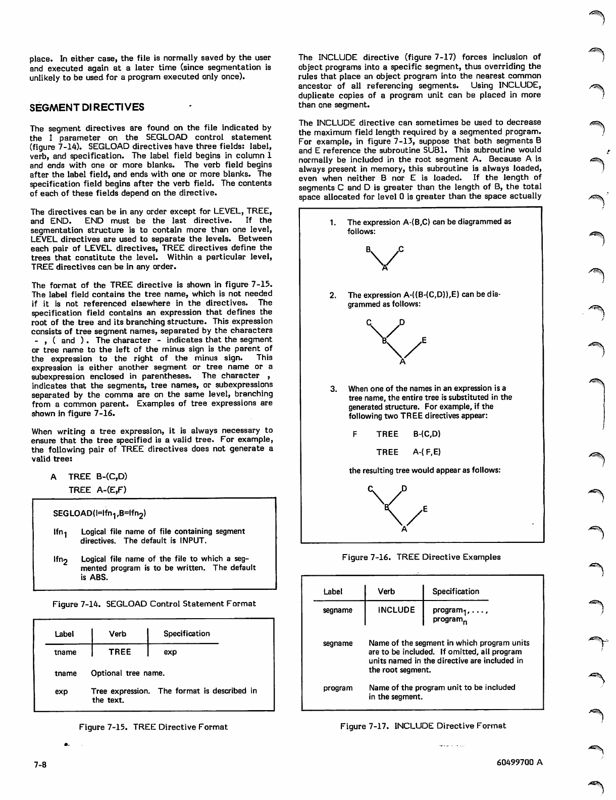
place. In either case, the file is normally saved by the user
and executed again at a later time (since segmentation is
unlikely to be used for a program executed only once).
SEGMENT DI RECTI VES
The segment directives are found on the file indicated by
the I parameter on the SEGLOAD control statement
(figure 7-14). SEGLOAD directives have three fields: label,
verb, and specification. The label field begins in column 1
and ends with one or more blanks. The verb field begins
after the label field, and ends with one or more blanks. The
specification field begins after the verb field. The contents
of each of these fields depend on the directive.
The directives can be in any order except for LEVEL, TREE,
and END. END must be the last directive. If the
segmentation structure is to contain more than one level,
LEVEL directives are used to separate the levels. Between
each pair of LEVEL directives, TREE directives define the
trees that constitute the level. Within a particular level,
TREE directives can be in any order.
The format of the TREE directive is shown in figure 7-15.
The label field contains the tree name, which is not needed
if it is not referenced elsewhere in the directives. The
specification field contains an expression that defines the
root of the tree and its branching structure. This expression
consists of tree segment names, separated by the characters
- , ( and ). The character - indicates that the segment
or tree name to the left of the minus sign is the parent of
the expression to the right of the minus sign. This
expression is either another segment or tree name or a
subexpression enclosed in parentheses. The character ,
indicates that the segments, tree names, or subexpressions
separated by the comma are on the same level, branching
from a common parent. Examples of tree expressions are
shown in figure 7-16.
When writing a tree expression, it is always necessary to
ensure that the tree specified is a valid tree. For example,
the following pair of TREE directives does not generate a
valid tree:
A TREE B-(C,D)
TREE A-(E,F)
SEGLOADfMfn^BHfnj)
lfn .j Logical file name of file containing segment
directives. The default is INPUT.
Ifn2 Logical file name of the file to which a seg
mented program is to be written. The default
is ABS.
Figure 7-14. SEGLOAD Control Statement Format
Label Verb Specification
tname TREE exp
tname Optional tree name
exp Tree expression. The format is described in
the text.
The INCLUDE directive (figure 7-17) forces inclusion of
object programs into a specific segment, thus overriding the
rules that place an object program into the nearest common
ancestor of all referencing segments. Using INCLUDE,
duplicate copies of a program unit can be placed in more
than one segment.
The INCLUDE directive can sometimes be used to decrease
the maximum field length required by a segmented program.
For example, in figure 7-13, suppose that both segments B
and E reference the subroutine SUBl. This subroutine would
normally be included in the root segment A. Because A is
always present in memory, this subroutine is always loaded,
even when neither B nor E is loaded. If the length of
segments C and D is greater than the length of B, the total
space allocated for level 0 is greater than the space actually
/^%.
/*^\
1. The expression A-(B,C) can be diagrammed as
follows:
V
2. The expression A-((B-(C,D)),E) can be dia
grammed as follows:
When one of the names in an expression is a
tree name, the entire tree is substituted in the
generated structure. For example, if the
following two TREE directives appear:
F T R E E B - ( C , D )
T R E E A - ( F, E )
the resulting tree would appear as follows:
X/
Figure 7-16. TREE Directive Examples
Label Verb Specification
segname INCLUDE program-],...,
programn
segname Name of the segment in which program units
are to be included. If omitted, all program
units named in the directive are included in
the root segment.
program Name of the program unit to be included
in the segment.
Figure 7-15. TREE Directive Format Figure 7-17. INCLUDE Directive Format
7-8 60499700 A
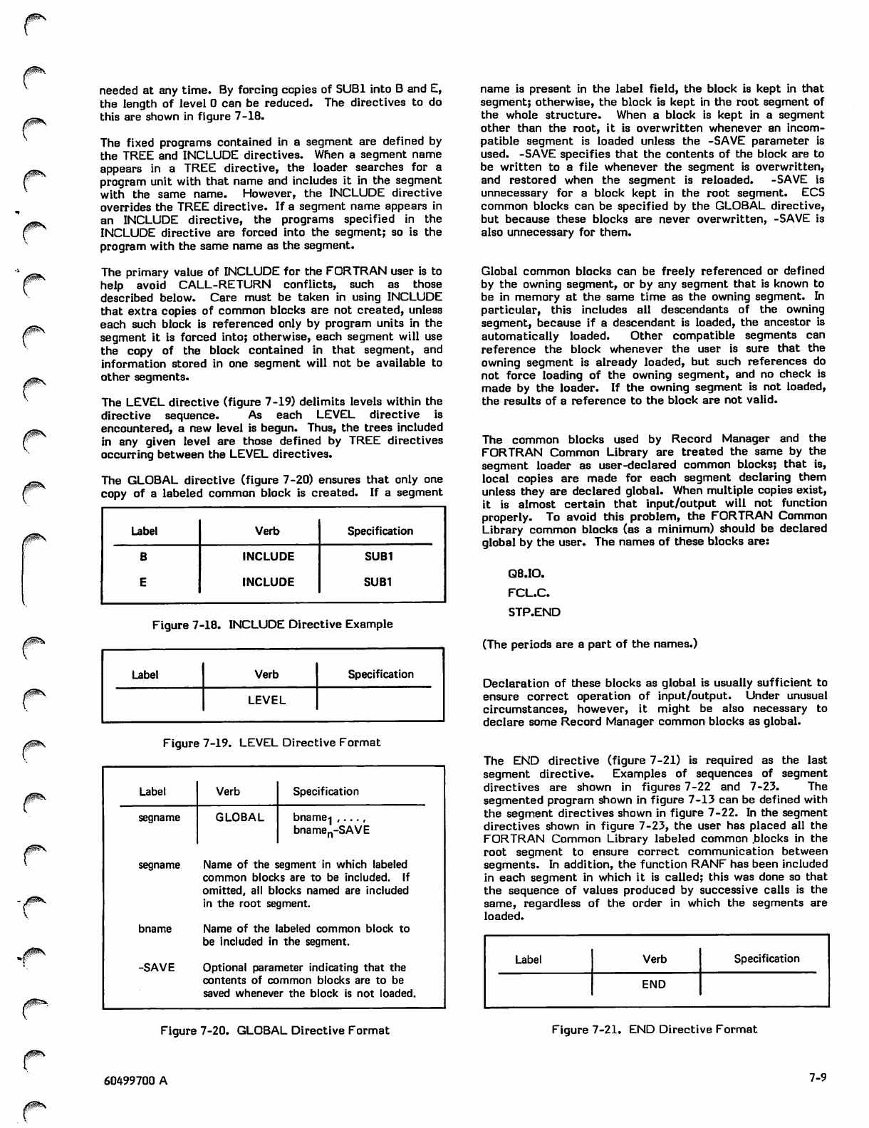
0ffiS
needed at any time. By forcing copies of SUB1 into B and E,
the length of level 0 can be reduced. The directives to do
this are shown in figure 7-18.
The fixed programs contained in a segment are defined by
the TREE and INCLUDE directives. When a segment name
appears in a TREE directive, the loader searches for a
program unit with that name and includes it in the segment
with the same name. However, the INCLUDE directive
overrides the TREE directive. If a segment name appears in
an INCLUDE directive, the programs specified in the
INCLUDE directive are forced into the segment; so is the
program with the same name as the segment.
The primary value of INCLUDE for the FORTRAN user is to
help avoid CALL-RETURN conflicts, such as those
described below. Care must be taken in using INCLUDE
that extra copies of common blocks are not created, unless
each such block is referenced only by program units in the
segment it is forced into; otherwise, each segment will use
the copy of the block contained in that segment, and
information stored in one segment will not be available to
other segments.
The LEVEL directive (figure 7-19) delimits levels within the
directive sequence. As each LEVEL directive is
encountered, a new level is begun. Thus, the trees included
in any given level are those defined by TREE directives
occurring between the LEVEL directives.
The GLOBAL directive (figure 7-20) ensures that only one
copy of a labeled common block is created. If a segment
Label Verb Specification
B
E
INCLUDE
INCLUDE
SUB1
SUB1
Figure 7-18. INCLUDE Directive Example
Label Verb Specification
LEVEL
Figure 7-19. LEVEL Directive Format
Label Verb Specification
segname GLOBAL bname-] ,...,
bnamen-SAVE
segname Name of the segment in which labeled
common blocks are to be included. If
omitted, all blocks named are included
in the root segment.
bname Name of the labeled common block to
be included in the segment.
-SAVE Optional parameter indicating that the
contents of common blocks are to be
saved whenever the block is not loaded.
name is present in the label field, the block is kept in that
segment; otherwise, the block is kept in the root segment of
the whole structure. When a block is kept in a segment
other than the root, it is overwritten whenever an incom
patible segment is loaded unless the -SAVE parameter is
used. -SAVE specifies that the contents of the block are to
be written to a file whenever the segment is overwritten,
and restored when the segment is reloaded. -SAVE is
unnecessary for a block kept in the root segment. ECS
common blocks can be specified by the GLOBAL directive,
but because these blocks are never overwritten, -SAVE is
also unnecessary for them.
Global common blocks can be freely referenced or defined
by the owning segment, or by any segment that is known to
be in memory at the same time as the owning segment. In
particular, this includes all descendants of the owning
segment, because if a descendant is loaded, the ancestor is
automatically loaded. Other compatible segments can
reference the block whenever the user is sure that the
owning segment is already loaded, but such references do
not force loading of the owning segment, and no check is
made by the loader. If the owning segment is not loaded,
the results of a reference to the block are not valid.
The common blocks used by Record Manager and the
FORTRAN Common Library are treated the same by the
segment loader as user-declared common blocks; that is,
local copies are made for each segment declaring them
unless they are declared global. When multiple copies exist,
it is almost certain that input/output will not function
properly. To avoid this problem, the FORTRAN Common
Library common blocks (as a minimum) should be declared
global by the user. The names of these blocks are:
Q8.IO.
FCL.C.
STP.END
(The periods are a part of the names.)
Declaration of these blocks as global is usually sufficient to
ensure correct operation of input/output. Under unusual
circumstances, however, it might be also necessary to
declare some Record Manager common blocks as global.
The END directive (figure 7-21) is required as the last
segment directive. Examples of sequences of segment
directives are shown in figures 7-22 and 7-23. The
segmented program shown in figure 7-13 can be defined with
the segment directives shown in figure 7-22. In the segment
directives shown in figure 7-23, the user has placed all the
FORTRAN Common Library labeled common blocks in the
root segment to ensure correct communication between
segments. In addition, the function RANF has been included
in each segment in which it is called; this was done so that
the sequence of values produced by successive calls is the
same, regardless of the order in which the segments are
loaded.
Label Verb Specification
END
Figure 7-20. GLOBAL Directive Format Figure 7-21. END Directive Format
0m\
60499700 A 7-9
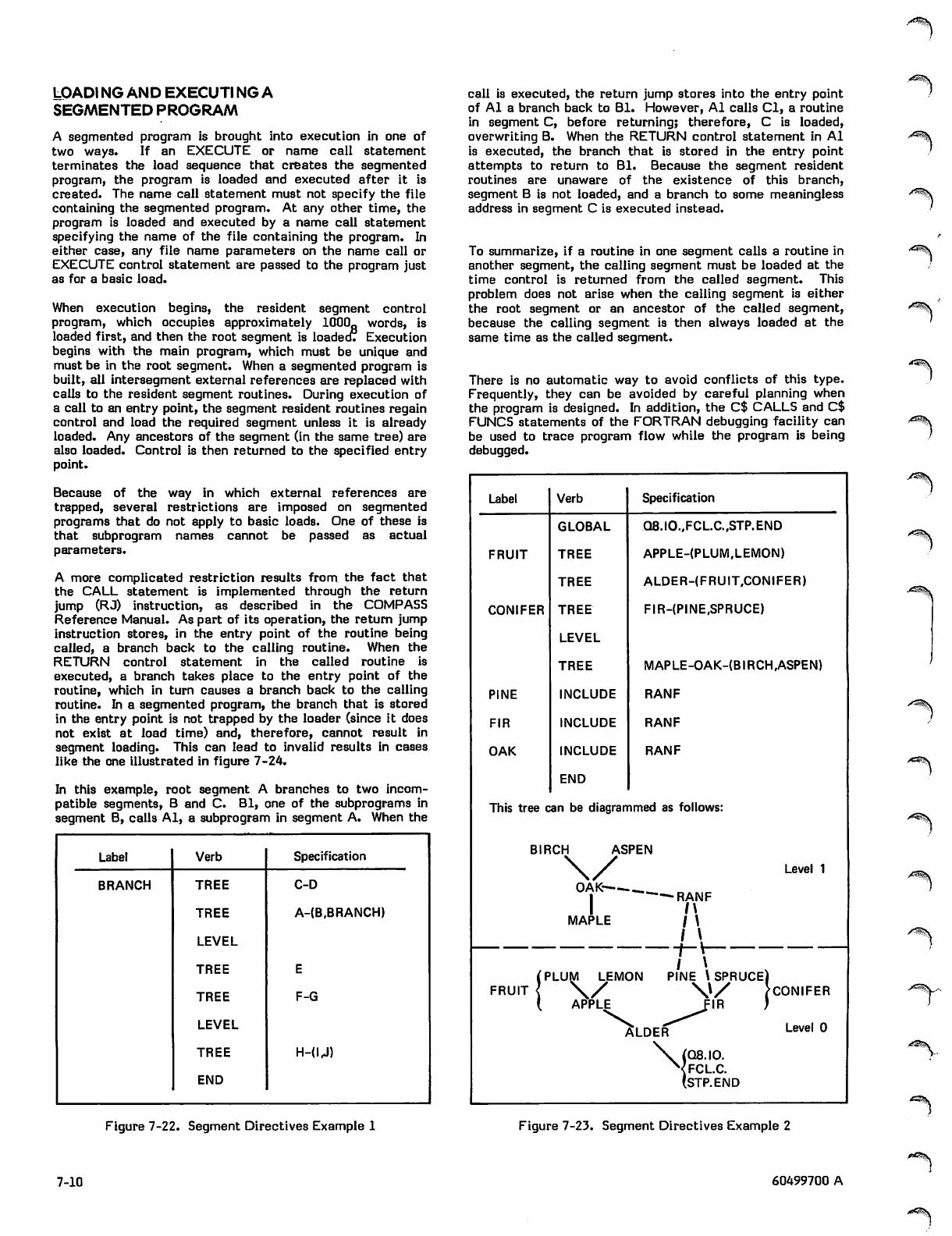
LOADI NG AND EXECUTI NG A
SEGMENTED PROGRAM
A segmented program is brought into execution in one of
two ways. If an EXECUTE or name call statement
terminates the load sequence that creates the segmented
program, the program is loaded and executed after it is
created. The name call statement must not specify the file
containing the segmented program. At any other time, the
program is loaded and executed by a name call statement
specifying the name of the file containing the program. In
either case, any file name parameters on the name call or
EXECUTE control statement are passed to the program just
as for a basic load.
When execution begins, the resident segment control
program, which occupies approximately 1000fl words, is
loaded first, and then the root segment is loaded! Execution
begins with the main program, which must be unique and
must be in the root segment. When a segmented program is
built, all intersegment external references are replaced with
calls to the resident segment routines. During execution of
a call to an entry point, the segment resident routines regain
control and load the required segment unless it is already
loaded. Any ancestors of the segment (in the same tree) are
also loaded. Control is then returned to the specified entry
point.
Because of the way in which external references are
trapped, several restrictions are imposed on segmented
programs that do not apply to basic loads. One of these is
that subprogram names cannot be passed as actual
parameters.
A more complicated restriction results from the fact that
the CALL statement is implemented through the return
jump (RJ) instruction, as described in the COMPASS
Reference Manual. As part of its operation, the return jump
instruction stores, in the entry point of the routine being
called, a branch back to the calling routine. When the
RETURN control statement in the called routine is
executed, a branch takes place to the entry point of the
routine, which in turn causes a branch back to the calling
routine. In a segmented program, the branch that is stored
in the entry point is not trapped by the loader (since it does
not exist at load time) and, therefore, cannot result in
segment loading. This can lead to invalid results in cases
like the one illustrated in figure 7-24.
In this example, root segment A branches to two incom
patible segments, B and C. Bl, one of the subprograms in
segment B, calls Al, a subprogram in segment A. When the
Label Verb Specification
BRANCH TREE C-D
TREE A-(B.BRANCH)
LEVEL
TREE
TREE F-G
LEVEL
TREE H-(U)
END
Figure 7-22. Segment Directives Example 1
call is executed, the return jump stores into the entry point
of Al a branch back to Bl. However, Al calls Cl, a routine
in segment C, before returning; therefore, C is loaded,
overwriting B. When the RETURN control statement in Al
is executed, the branch that is stored in the entry point
attempts to return to Bl. Because the segment resident
routines are unaware of the existence of this branch,
segment B is not loaded, and a branch to some meaningless
address in segment C is executed instead.
To summarize, if a routine in one segment calls a routine in
another segment, the calling segment must be loaded at the
time control is returned from the called segment. This
problem does not arise when the calling segment is either
the root segment or an ancestor of the called segment,
because the calling segment is then always loaded at the
same time as the called segment.
There is no automatic way to avoid conflicts of this type.
Frequently, they can be avoided by careful planning when
the program is designed. In addition, the C$ CALLS and C$
FUNCS statements of the FORTRAN debugging facility can
be used to trace program flow while the program is being
debugged.
Label Verb Specification
GLOBAL Q8.I0.,FCL.C.,STP.END
FRUIT TREE APPLE-(PLUM.LEMON)
TREE ALDER-(FRUIT,CONIFER)
CONIFER TREE
LEVEL
FIR-(PINE,SPRUCE)
TREE MAPLE-OAK-(BIRCH,ASPEN)
PINE INCLUDE RANF
FIR INCLUDE RANF
OAK INCLUDE
END
RANF
This tree can be diagrammed as follows:
BIRCH ASPEN
\ / L e v e l 1
O A K - .
1 -RANF
1 ' \
M A P L E / \
' \ _
(PLUM LEMON PINE \ SPRUCE)
FRUIT { \/ \\/ >CONIFER
( A P P L E F I R )
a l d e f T " ^ L e v e l °
\ (Q8.IO.
Nfclc.
(STP.END
Figure 7-23. Segment Directives Example 2
/<<3^\
*^^\
A*^\s-.
7-10 60499700 A
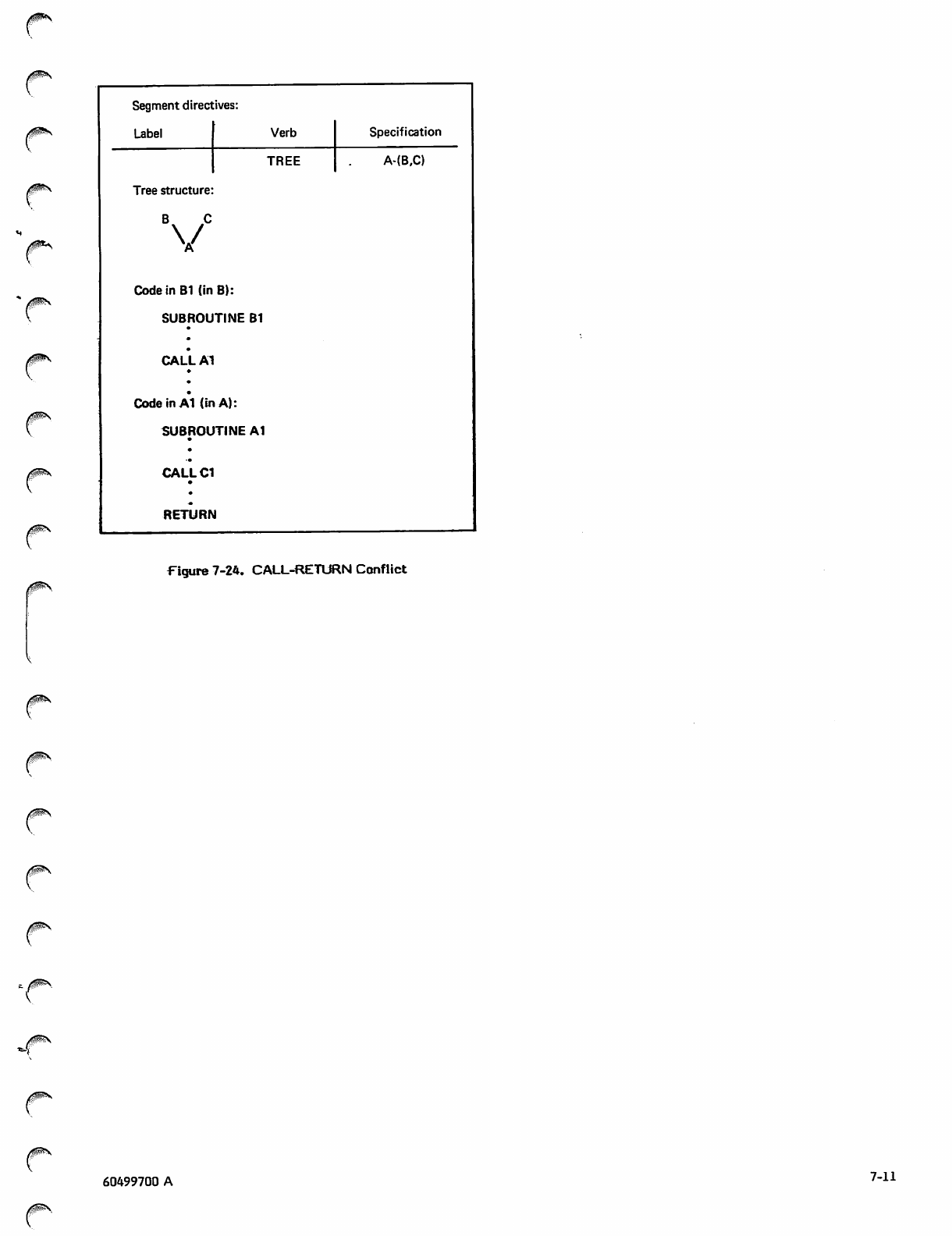
Segment directives:
rfgp^N Label Verb Specification
TREE A-(B,C)
Tree structure:
/P*>
B C
V
Code in B1 (in B):
SUBROUTINE Bl
CALLA1
•
(0$S
Code in A1 (in A):
SUBROUTINE A1
•
CALLC1
•
•
RETURN
Figure 7-24. CALL-RETURN Conflict
60499700 A 7-11

~.
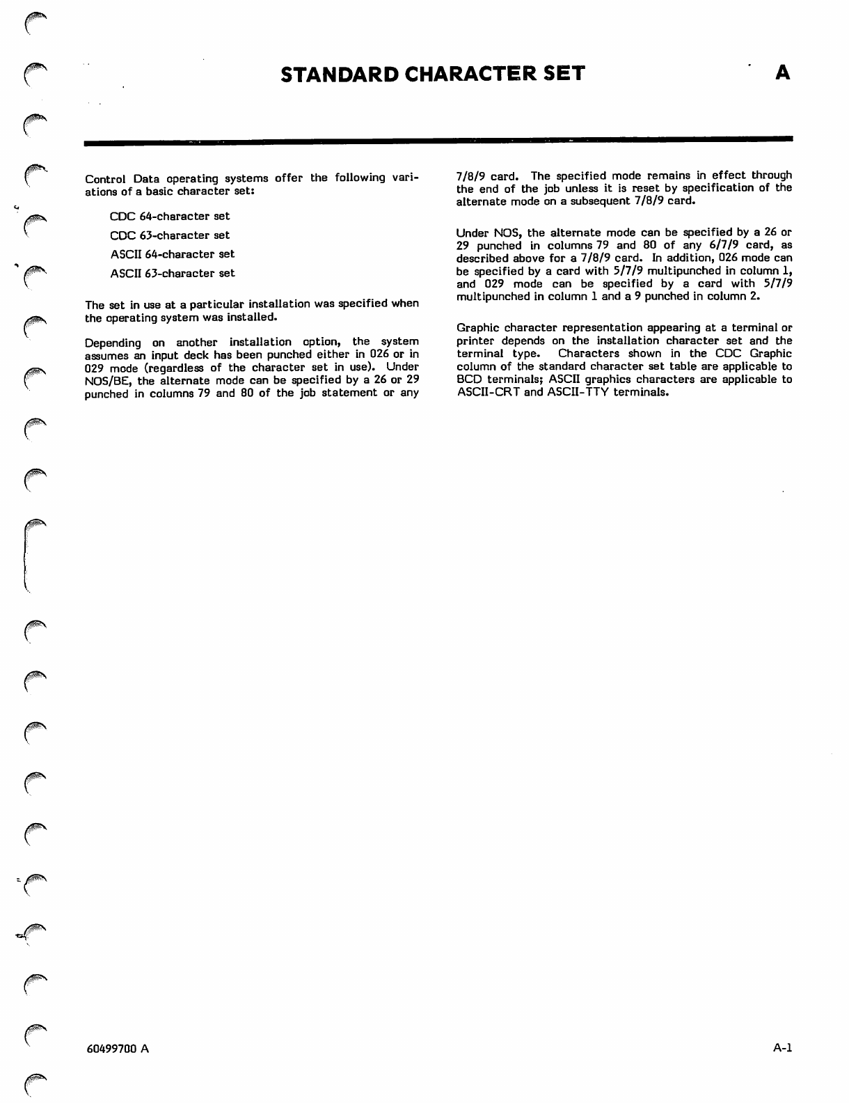
STANDARD CHARACTER SET
r
Control Data operating systems offer the following vari
ations of a basic character set:
CDC 64-character set
CDC 63-character set
ASCII 64-character set
ASCII 63-character set
The set in use at a particular installation was specified when
the operating system was installed.
Depending on another installation option, the system
assumes an input deck has been punched either in 026 or in
029 mode (regardless of the character set in use). Under
NOS/BE, the alternate mode can be specified by a 26 or 29
punched in columns 79 and 80 of the job statement or any
7/8/9 card. The specified mode remains in effect through
the end of the job unless it is reset by specification of the
alternate mode on a subsequent 7/8/9 card.
Under NOS, the alternate mode can be specified by a 26 or
29 punched in columns 79 and 80 of any 6/7/9 card, as
described above for a 7/8/9 card. In addition, 026 mode can
be specified by a card with 5/7/9 multipunched in column 1,
and 029 mode can be specified by a card with 5/7/9
multipunched in column 1 and a 9 punched in column 2.
Graphic character representation appearing at a terminal or
printer depends on the installation character set and the
terminal type. Characters shown in the CDC Graphic
column of the standard character set table are applicable to
BCD terminals; ASCII graphics characters are applicable to
ASCII-CRT and ASCII-TTY terminals.
0S\
0^S
0m*.
/SN
60499700 A A-l
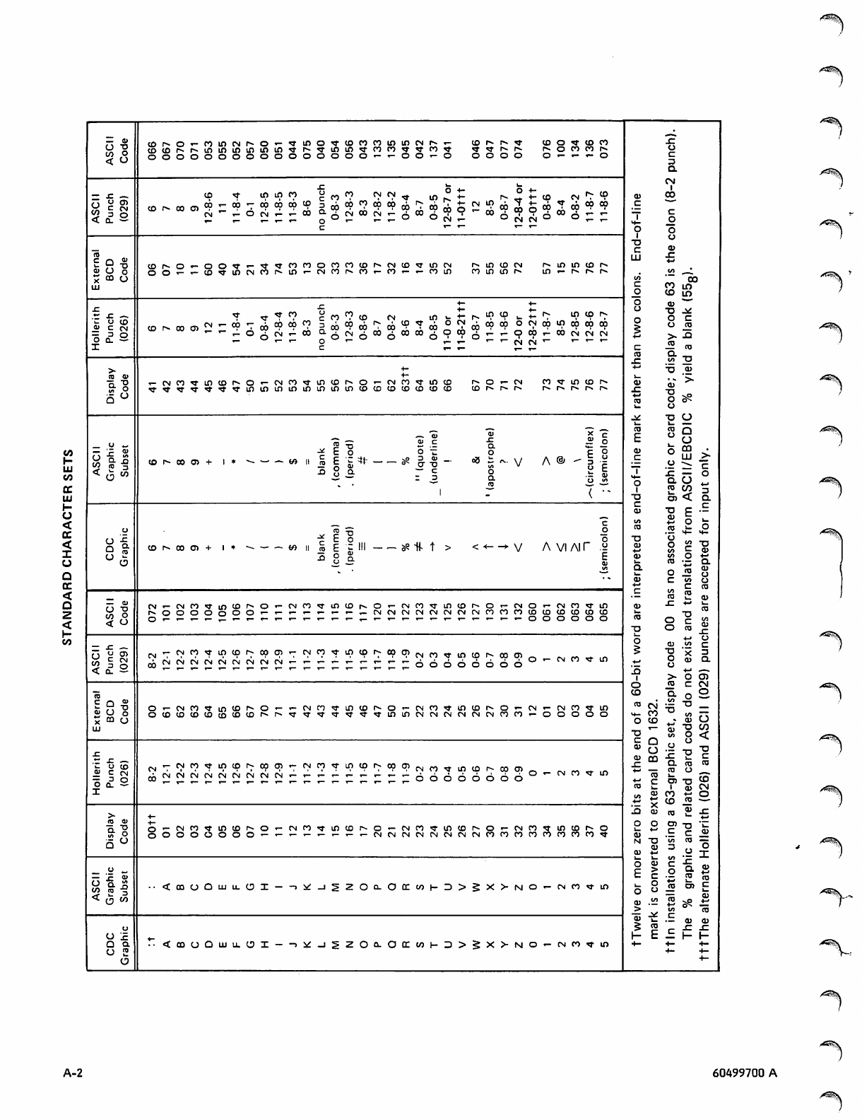
< a -
I-
LU
tn
tc
m
\-
o
<
cc
<
I
CJ
Q
or
<
Q
Z
<
r-
tn
91
•ta
o
o
cor-O'-coincNr-O'-rr in tn rr C O C O co in in cn f » » T- CO r» r- rr CD rr CD CO sz
CDtor«.r-ininminininrr i-» XT m r r co co rr rr C O r T rr rr Is. I s - r«. CO CO I s - ta
CO
<ooooooooooo o o ,-,-00 x - O *~ *~ *" za
a
CM
— J = c o r r i n u p r o
St
o
cCO CO <V <? rr •9 r-
°P ob
0 C N
-t-
+- n* "^
CO
CN
4-
t - C D CN r* co 0) 00
< 0 -
ox
CN
o«Df-cocnc9^0P^c?0?0?
C M x - t n f N r - x -
CD
CO
CO
6
ob to
C N C O
co co oj r-
C N r - £ C O
t-
9CN in
cb cb
6O °P
C N O
rr
ob cb
6
CO CO
14—
c*~ r" *" *~
03
<0
£ o TJ cDrs-o«-oon-«-rrrrco CO CO C O C O r - c n c o r r i n c n r-» in CO CN r^ in in CO r- LU SZ
tt
v O OO'-'-IO^lDlNOMfl
I— CN CO r - c o r - C O r - r - c o i n CO CO I s - in r- r* Is- r-- in -*.
x o3 CO 00
UJ CO
to
01
in
10
JZ
u
c
•(- •♦-
.c _. ? r r " T < ? CO <? CO CN t o f
• 1 -
r^- in CO t^ in CD Is-
it
■a
0
<u c
= 3
O Q .
(0
CM
o
CO
CO ob
6
°9 cb
2 o
r - » • c o r r
■ 00 • 1
CO £ CO CO cb °
69
CN
CO cb
6
CO CO
CN
C N 0 0
C O t -
C N ' "
in
ob CO
CN
CO
CN
00
CN ro
CO
IcT- *~
CO
sz Q.
sn
CO
T3
>+- tt T3 CD
CO
a
01
•o .-CNC0^-in<Dfs-O«-CNC0 rr in CO r - O
+-
* - c n c o r r m co r- ,_ CN CO rr in CD r«. I—
01 <U
T3
O
'>•
o<q-rrvrj-r}-rrrrinmmm in in in co C O C O C O C O C O C D CO I s - I s - I s - I s - Is - Is- Is- Is- sz
Qo(a 6s-
OC
CJ
•a
1— u.
_ o
w ra
41 6 J3
3
CO
c o r - c o o > + I * t n ii ra
X
raE
E
o
o
T5
O
0)
3-
"so
0
— *I
"S
c
ai
TJ
c
3
o3
"aJ
a
0
V)
0
a
-2
r v . A ©
'x
OJ
1
3
0
0
(
a>
(O
E
91
C
"5
1
-a
0 L U >
cn < Q.
c_ C
<u "D E -
cl/l QJ
■f2 0
T - t -
o"ra TJ ca to
o
Q
O
in
a
ra
a
C D I s - 0 0 C T ) + i * - ~ - — — O T ii ra
X
•2 111
0) --ae*t > «— -" A VI AIT
0)
cu
■w
93
u.
a
'tl
0
en
en
CO
O
•2 S
CL)
Cin
" > 0
C C O
(0
__ •— 03 i z c u
o
CO
<
0)
tj
o
o
CN«-CMC0rrinC0r--O«-CN CO xf in CO |- » O r - C N C O * r i n CO i - » t— CN 0 t - CN CO rr in a> JC
c c u
C O «
CN CN CN C N CN CN CM CN CO CO CO CO CO CO CO CO CD u.
0 0 CD
■O
O
— X
u t
< 0 .
CN
o
^v-cNCOrrincor^opq)^
^CNCNCNCNCNCNCNCNCN.^-
CN 00 rr I f ) C O t y to t 7 > r ^
^ " 6
C O r r
6 6 in
6CO
6
1 s -
600
60)
60 «- CM CO rr in
0)
O
O
.*2 c
cu Q.
>O O)
003 C CM
"!5 to 0 s
E Q
c o U
Q>
TJ 0'-CNCOrrmcors-o«-'- CN CO rr in co I s - O r - C N C O r r in CO I s - ,_ C N • - CN CO rr in «5 O) T J _
oOCOCOCOCOcOCOCDr-f-rr rr rr rr rr rr ^t in in cn CN CN CN CN CN CO CO « - O »♦-00 01 CJ
x ^ CD
UJ CU
in
TD CO
Ca8<
L . ( J
< U C
i
CN
o
(Nr-cNCO'»intDr^ooq>'7
j^cncncncncncncncncn'^-
CN CO rr in co T °9 °? CN
^ ^ 6
C O r r
6 6 in
6
CO
600
6O)
6O x - CN CO rr
QJ
CU
SZ
tt
tt
CO
CO
"ro
c
1_
CJ
'sz
a
CO
1_
O)
1
co ro
0
- 0 ^
a> CM
in QJ CO £ O
ff
X
cu
CO CO ■—■
>■1- la CO ££
raa
91
TJ t-
cnr-tstoxtxtxr^tnr-oi CO rr in co r- O « - C N C O T i n CO r» r- CN
CO CO
in Is- O)
c"S •
oCN CM CN C N CN CN CN CN CO co CO CO CO rr QJ
oN■asn 03 -s
Q
CD
0)
4-" za .S2I
_ o
O a
C O C O
at
X
3
CO
■■ <oouOujiiOI- -i •aC _l 2 O C L O D C C O t - D >- 0 — CN CO rr in
CD
>
CU
>
c
0
0
sn
OC
1—
CO
"to
it
sn
CZ
"q. a>
2 ro
» £
QJ
\ p + - >
°^ -zz
CO
QJ 0 3 0 3
u$to SZ sz
u'x ^_ \ - r -
Qa•- <C0OOUJU.OI —> xC _1 Z O a . a C C c o \- 3 >- O r - CN CO rr in ■1- +- • 4 -
Ora6+- ■t-
-1-
A-2 60499700 A
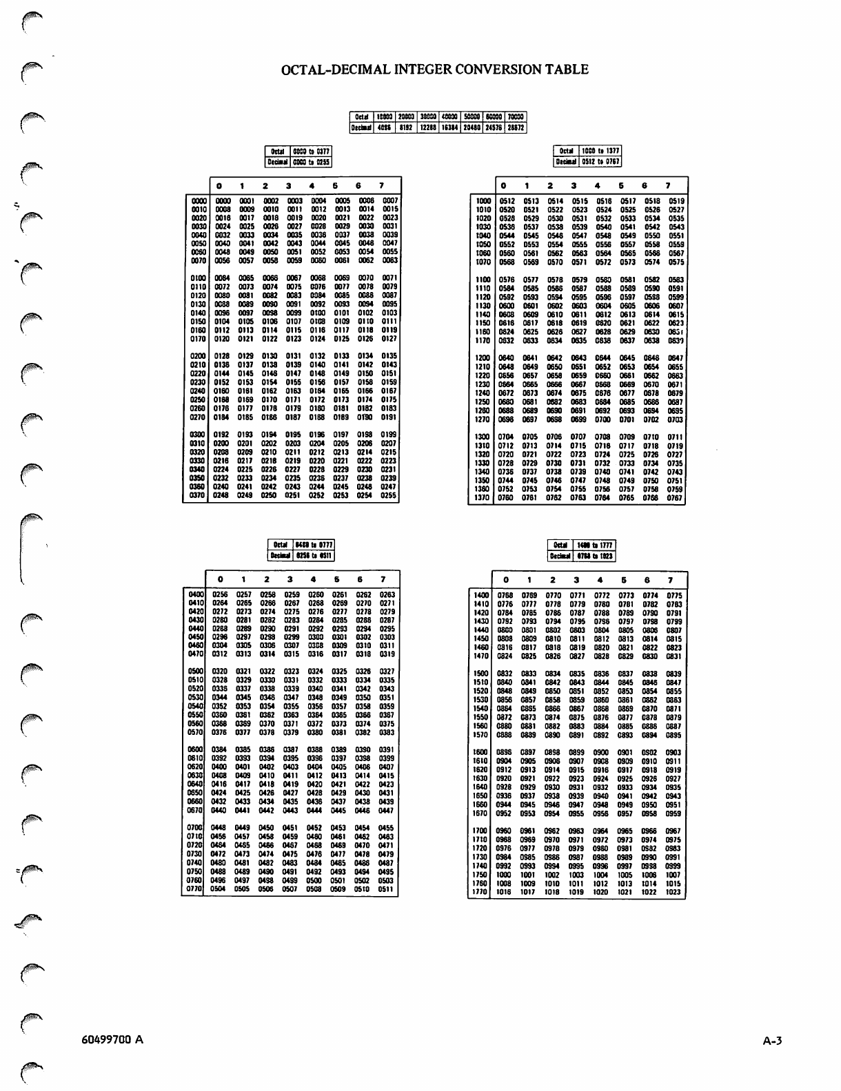
OCTAL-DECIMAL INTEGER CONVERSION TABLE
OcM totoo 20000 30000 40000 SOSOQ K080 70009
Otetail 40K I1S2 122IJ 1SJI4 20410 24578 28872
<gPv
Otttl 80S0 to 0377
Oltiail COCO tt 0255
Octal 1000 tt 1377
Otdetl 0512 tt 0787
01234667
OOOO OOOO 0001 0002 0003 0004 0005 0008 0007
0010 0008 0009 0010 0011 0012 0013 0014 0015
0020 0016 0017 0018 0019 0020 0021 0022 0023
0030 0024 0025 0026 0027 0028 0029 0030 0031
0040 0032 0033 0034 0035 0036 0037 0038 0039
0050 0040 0041 0042 0043 0044 0045 0046 0047
0060 0048 0049 0050 0051 0052 0053 0054 0055
0070 0056 0057 0058 0059 0060 0061 0062 0083
otoo 0084 0065 0068 0067 0068 0069 0070 0071
0110 0072 0073 0074 0075 0076 0077 0078 0079
0120 0080 0081 0082 0083 0084 0085 0086 0087
0130 0088 0089 0030 0091 0092 0093 0094 0095
0140 0036 0097 0038 0099 otoo 0101 0102 0103
0150 0104 0105 0106 0107 0108 0109 0110 0111
0160 0112 0113 0114 0115 0116 0117 0118 0119
0170 0120 0121 0122 0123 0124 0125 0126 0127
0200 0128 0129 0130 0131 0132 0133 0134 0135
0210 0138 0137 0138 0139 0140 0141 0142 0143
0220 0144 0145 0146 0147 0148 0149 0150 0151
0230 0152 0153 0154 0155 0156 0157 0158 0159
0240 0160 0161 0162 0163 0164 0165 0166 0167
0250 0168 0169 0170 0171 0172 0173 0174 0175
0260 0176 0177 0178 0179 0180 0181 0182 0183
0270 0184 0185 0tS8 0187 0188 01B9 01190 0191
0300 0192 01S3 0194 01S5 0196 0197 0198 0199
0310 0200 0201 0202 0203 0204 0205 0206 0207
0320 0208 0209 0210 0211 0212 0213 0214 0215
0330 0216 0217 0218 0219 0220 0221 0222 0223
0340 0224 0225 0226 0227 0228 0229 0230 0231
0350 0232 0233 0234 0235 0236 0237 0238 0239
0360 0240 0241 0242 0243 0244 0245 0248 0247
0370 0248 0249 0250 0251 0252 0253 0254 0255
1000 0512 0513 0514 0515 0516 0517 0518 0519
1010 0520 0521 0522 0523 0524 0525 0526 0527
1020 0528 0529 0530 0531 0532 0533 0534 0535
1030 0536 0537 0538 0539 0540 0541 0542 0543
1040 0544 0545 0546 0547 0548 0549 0550 0551
1050 0552 0553 0554 0555 0556 0557 0558 0559
1060 0560 0561 0562 0563 0564 0565 0566 0567
1070 0568 0569 0570 0571 0572 0573 0574 0575
1100 0576 0577 0578 0579 0580 0581 0582 0583
1110 0584 0585 0586 0587 0588 0589 0590 0591
1120 0592 0593 0594 0595 0596 0597 0538 0599
1130 0600 0601 0602 0603 0604 0605 0606 0607
1140 0608 0609 0610 0611 0612 0613 0614 0615
1150 06t6 0617 0618 0619 0620 0621 0622 0623
1160 0824 0625 0626 0627 0628 0629 0630 0631
1170 0832 0633 0634 0635 0638 0637 0638 0631
1200 0640 0641 0642 0643 0644 0645 0646 0647
1210 0648 0649 0650 0651 0652 0653 0654 0655
1220 0656 0657 0658 0659 0660 0661 0662 0663
1230 0664 0665 0666 0667 0668 0669 0670 0671
t240 0672 0873 0674 0675 0876 0677 0678 0879
1250 0680 0681 0632 0683 0684 0685 0686 0687
1260 0688 0689 0690 0691 0S92 0693 0694 0695
1270 0698 0697 0638 0699 0700 0701 0702 0703
1300 0704 0705 0708 0707 0708 0709 0710 0711
13t0 0712 0713 0714 0715 0716 0717 0718 0719
1320 0720 0721 0722 0723 0724 0725 0728 0727
1330 0728 0729 0730 0731 0732 0733 0734 0735
1340 0736 0737 0738 0739 0740 0741 0742 0743
1350 0744 0745 0746 0747 0748 0749 0750 0751
1360 0752 0753 0754 0755 0756 0757 0758 0759
1370 0760 0761 0762 0763 0764 0765 0766 0767
S(UI HMtll777
OttJMl ITU tl I82J
0 1 2 3 4 S 6 7
0400 0256 0257 0258 0259 0260 0261 0262 0263
0410 0264 0265 0266 0267 0268 0269 0270 0271
042C 0272 0273 0274 0275 0276 0277 0278 0279
O430 0280 0281 0282 0283 0284 0285 0286 0287
04*0 0268 0289 0290 0291 0292 0293 0234 0295
0450 0296 0297 0298 0299 0300 0301 0302 0303
0460 0304 0305 0306 0307 0308 0309 0310 0311
0470 0312 0313 0314 0315 0316 0317 0318 0319
0500 0320 0321 0322 0323 0324 0325 0326 0327
0510 0328 0329 0330 0331 0332 0333 0334 0335
0520 0336 0337 0338 0339 0340 0341 0342 0343
0530 0344 0345 0348 0347 0348 0349 0350 0351
0540 0352 0353 0354 0355 0358 0357 0358 0359
0550 0380 0381 0362 0363 0364 0365 0366 0367
0560 0368 0389 0370 0371 0372 0373 0374 0375
0570 0376 0377 0378 0379 0380 0381 0382 0383
0600 0384 0385 0386 0387 0388 0389 0330 0391
0810 0392 0393 0394 0395 0396 0397 0398 0399
0620 0400 0401 0402 0403 0404 0405 0406 0407
0630 0408 0409 0410 0411 0412 0413 0414 0415
0640 0416 0417 0418 0419 0420 0421 0422 0423
0650 0424 0425 0426 0427 0426 0429 0430 0431
0660 0432 0433 0434 0435 0436 0437 0438 0439
0670 0440 0441 0442 0443 0444 0445 0446 0447
0700 0448 0449 0450 0451 0452 0453 0454 0455
0710 0456 0457 0458 0459 0480 0481 0462 0463
0720 0464 0485 0466 0467 0468 0469 0470 0471
0730 0472 0473 0474 0475 0476 0477 0478 0479
0740 0480 0481 0482 0483 0484 0485 0488 0487
0750 0488 0489 0490 0491 0492 0493 0494 0495
0760 0496 0497 0438 0499 0500 0501 0502 0503
0770 0504 0505 0506 0507 0508 0509 osto 0511
1400 0768 0769 0770 0771 0772 0773 0774 0775
1410 0776 0777 0778 0779 0780 0781 0782 0783
1420 0784 0785 0786 0787 0788 0789 0790 0791
1430 0792 0793 0794 0795 0796 0797 0738 0799
1440 0800 0801 0802 0803 0804 0805 0806 0807
1450 0808 0809 0810 0811 0812 0813 0814 0315
1460 0818 0817 0818 0819 0820 0821 0822 0823
1470 0824 0825 0826 0827 0828 0829 0830 0831
1500 0832 0833 0834 0835 0836 0837 0838 0839
1510 0840 0841 0842 0643 0844 0845 0348 0847
1520 0848 0849 0850 0851 0852 0853 0854 0855
1530 0858 0857 0858 0859 0860 0861 0862 0863
1540 0864 0885 0866 0867 0868 0869 0870 0871
1550 0872 0873 0874 0875 0876 0877 0878 0879
1560 0880 0881 0882 0883 0884 0885 0886 0887
1570 0888 0839 0890 0891 0892 0893 0894 0895
1600 0896 0897 0898 0899 0900 0901 0302 0903
1610 0904 0905 0906 0907 0908 0909 0910 0911
1620 0912 0913 0914 0915 0916 0917 0918 0919
1630 0920 0921 0922 0923 0924 0925 0926 0927
1640 0928 0929 0930 0931 0932 0933 0934 0935
1650 0936 0937 0938 0939 0940 0941 0942 0943
1660 0944 0945 0346 0947 0948 0949 0950 0951
1670 0952 0953 0954 0355 0956 0957 0358 0959
1700 0960 0961 0362 0363 0964 0965 0966 0967
wto 0968 0969 0970 0371 0972 0373 0974 0975
1720 0976 0977 0978 0373 0980 0381 0S82 0383
1730 0984 0985 0386 0387 0988 0939 0930 0391
1740 0992 0993 0994 0995 0996 0997 0998 0999
1750 1000 1001 1002 1003 1004 1005 1006 1007
1760 1008 1009 toto 1011 1012 1013 1014 1015
1770 1016 1017 1018 1019 1020 1021 1022 1023
jgpsv
60499700 A A-3

V.
ry
1
0 ^ t
?)
/=%*
**%
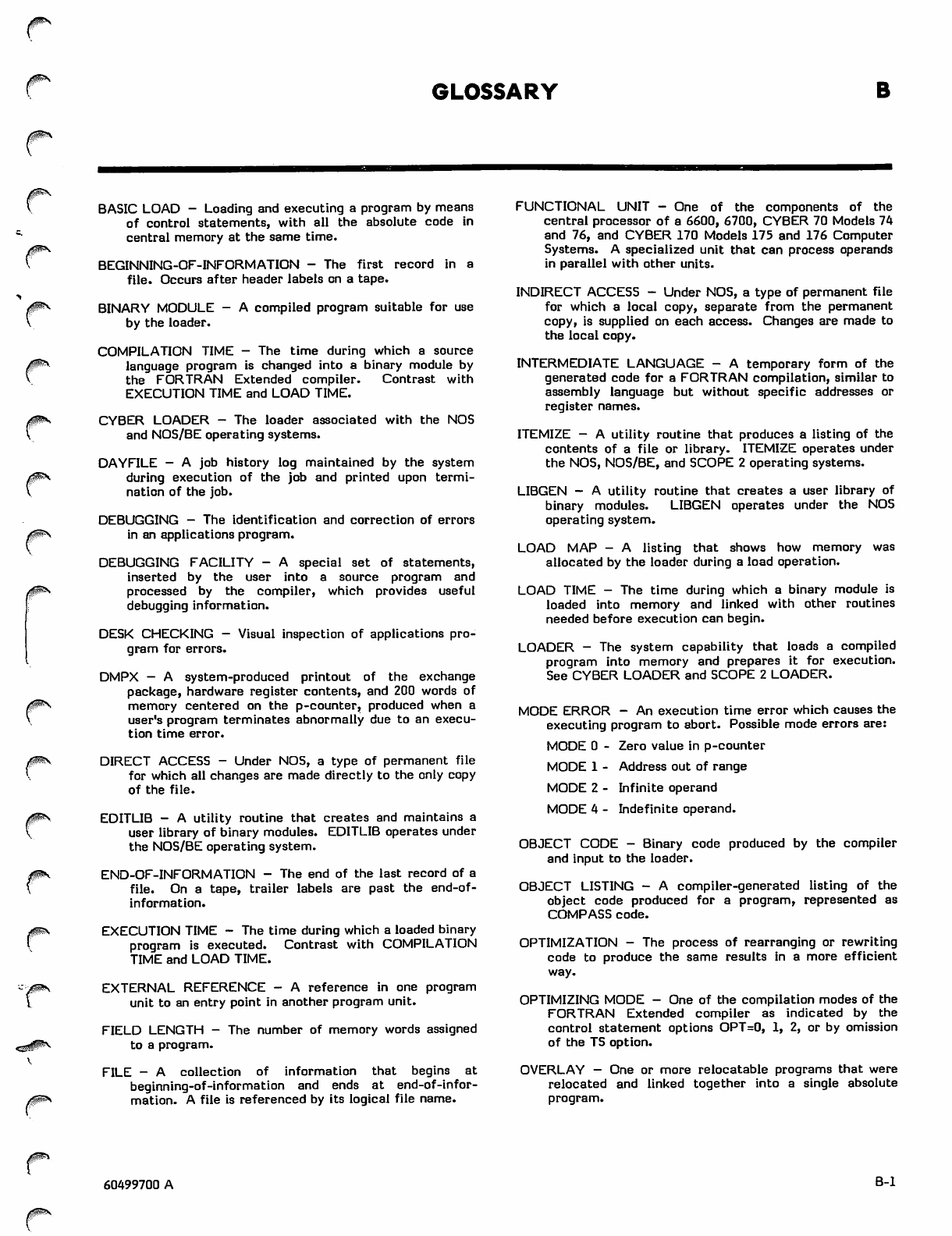
GLOSSARY
<^p\
BASIC LOAD - Loading and executing a program by means
of control statements, with all the absolute code in
central memory at the same time.
BEGINNING-OF-INFORMATION - The first record in a
file. Occurs after header labels on a tape.
BINARY MODULE - A compiled program suitable for use
by the loader.
COMPILATION TIME - The time during which a source
language program is changed into a binary module by
the FORTRAN Extended compiler. Contrast with
EXECUTION TIME and LOAD TIME.
CYBER LOADER - The loader associated with the NOS
and NOS/BE operating systems.
DAYFILE - A job history log maintained by the system
during execution of the job and printed upon termi
nation of the job.
DEBUGGING - The identification and correction of errors
in an applications program.
DEBUGGING FACILITY - A special set of statements,
inserted by the user into a source program and
processed by the compiler, which provides useful
debugging information.
DESK CHECKING - Visual inspection of applications pro
gram for errors.
DMPX — A system-produced printout of the exchange
package, hardware register contents, and 200 words of
memory centered on the p-counter, produced when a
user's program terminates abnormally due to an execu
tion time error.
DIRECT ACCESS - Under NOS, a type of permanent file
for which all changes are made directly to the only copy
of the file.
EDITLIB - A utility routine that creates and maintains a
user library of binary modules. EDITLIB operates under
the NOS/BE operating system.
END-OF-INFORMATION - The end of the last record of a
file. On a tape, trailer labels are past the end-of-
information.
EXECUTION TIME - The time during which a loaded binary
program is executed. Contrast with COMPILATION
TIME and LOAD TIME.
EXTERNAL REFERENCE - A reference in one program
unit to an entry point in another program unit.
FIELD LENGTH - The number of memory words assigned
to a program.
FILE - A collection of information that begins at
beginning-of-information and ends at end-of-infor
mation. A file is referenced by its logical file name.
FUNCTIONAL UNIT - One of th e components of the
central processor of a 6600, 6700, CYBER 70 Models 74
and 76, and CYBER 170 Models 175 and 176 Computer
Systems. A specialized unit that can process operands
in parallel with other units.
INDIRECT ACCESS - Under NOS, a type of permanent file
for which a local copy, separate from the permanent
copy, is supplied on each access. Changes are made to
the local copy.
INTERMEDIATE LANGUAGE - A temporary form of the
generated code for a FORTRAN compilation, similar to
assembly language but without specific addresses or
register names.
ITEMIZE - A utility routine that produces a listing of the
contents of a file or library. ITEMIZE operates under
the NOS, NOS/BE, and SCOPE 2 operating systems.
LIBGEN - A utility routine that creates a user library of
binary modules. LIBGEN operates under the NOS
operating system.
LOAD MAP - A listing that shows how memory was
allocated by the loader during a load operation.
LOAD TIME - The time during which a binary module is
loaded into memory and linked with other routines
needed before execution can begin.
LOADER - The system capability that loads a compiled
program into memory and prepares it for execution.
See CYBER LOADER and SCOPE 2 LOADER.
MODE ERROR - An execution time error which causes the
executing program to abort. Possible mode errors are:
MODE 0 - Zero value in p-counter
MODE 1 - Address out of range
MODE 2 - Infinite operand
MODE 4 - Indefinite operand.
OBJECT CODE - Binary code produced by the compiler
and input to the loader.
OBJECT LISTING - A compiler-generated listing of the
object code produced for a program, represented as
COMPASS code.
OPTIMIZATION - The process of rearranging or rewriting
code to produce the same results in a more efficient
way.
OPTIMIZING MODE - One of the compilation modes of the
FORTRAN Extended compiler as indicated by the
control statement options OPT=0, 1, 2, or by omission
of the TS option.
OVERLAY - One or more relocatable programs that were
relocated and linked together into a single absolute
program.
60499700 A B-l
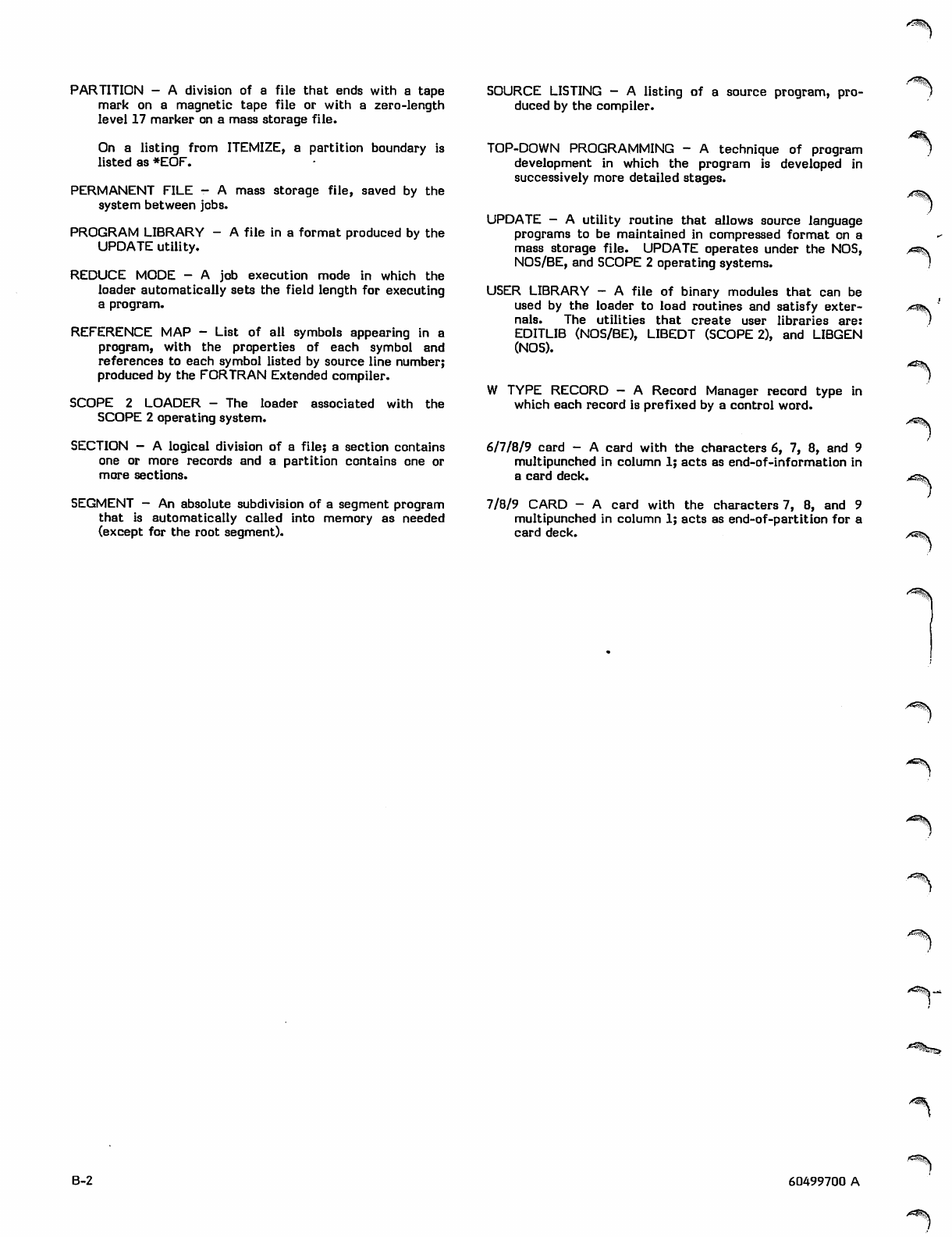
PARTITION - A division of a file that ends with a tape
mark on a magnetic tape file or with a zero-length
level 17 marker on a mass storage file.
On a listing from ITEMIZE, a partition boundary is
listed as *EOF.
PERMANENT FILE - A mass storage file, saved by the
system between jobs.
PROGRAM LIBRARY - A file in a format produced by the
UPDATE utility.
REDUCE MODE - A job execution mode in which the
loader automatically sets the field length for executing
a program.
REFERENCE MAP - List of all symbols appearing in a
program, with the properties of each symbol and
references to each symbol listed by source line number;
produced by the FORTRAN Extended compiler.
SCOPE 2 LOADER - The loader associated with the
SCOPE 2 operating system.
SECTION — A logical division of a file; a section contains
one or more records and a partition contains one or
more sections.
SEGMENT — An absolute subdivision of a segment program
that is automatically called into memory as needed
(except for the root segment).
SOURCE LISTING - A listing of a source program, pro
duced by the compiler.
TOP-DOWN PROGRAMMING - A technique of program
development in which the program is developed in
successively more detailed stages.
UPDATE - A utility routine that allows source language
programs to be maintained in compressed format on a
mass storage file. UPDATE operates under the NOS,
NOS/BE, and SCOPE 2 operating systems.
USER LIBRARY - A file of binary modules that can be
used by the loader to load routines and satisfy exter
nals. The utilities that create user libraries are:
EDITLIB (NOS/BE), LIBEDT (SCOPE 2), and LIBGEN
(NOS).
W TYPE RECORD - A Record Manager record type in
which each record is prefixed by a control word.
6/7/8/9 card - A card with the characters 6, 7, 8, and 9
multipunched in column 1; acts as end-of-information in
a card deck.
7/8/9 CARD - A card with the characters 7, 8, and 9
multipunched in column 1; acts as end-of-partition for a
card deck.
aG^S.
A^S,
/^SSiSs.jt
B-2 60499700 A
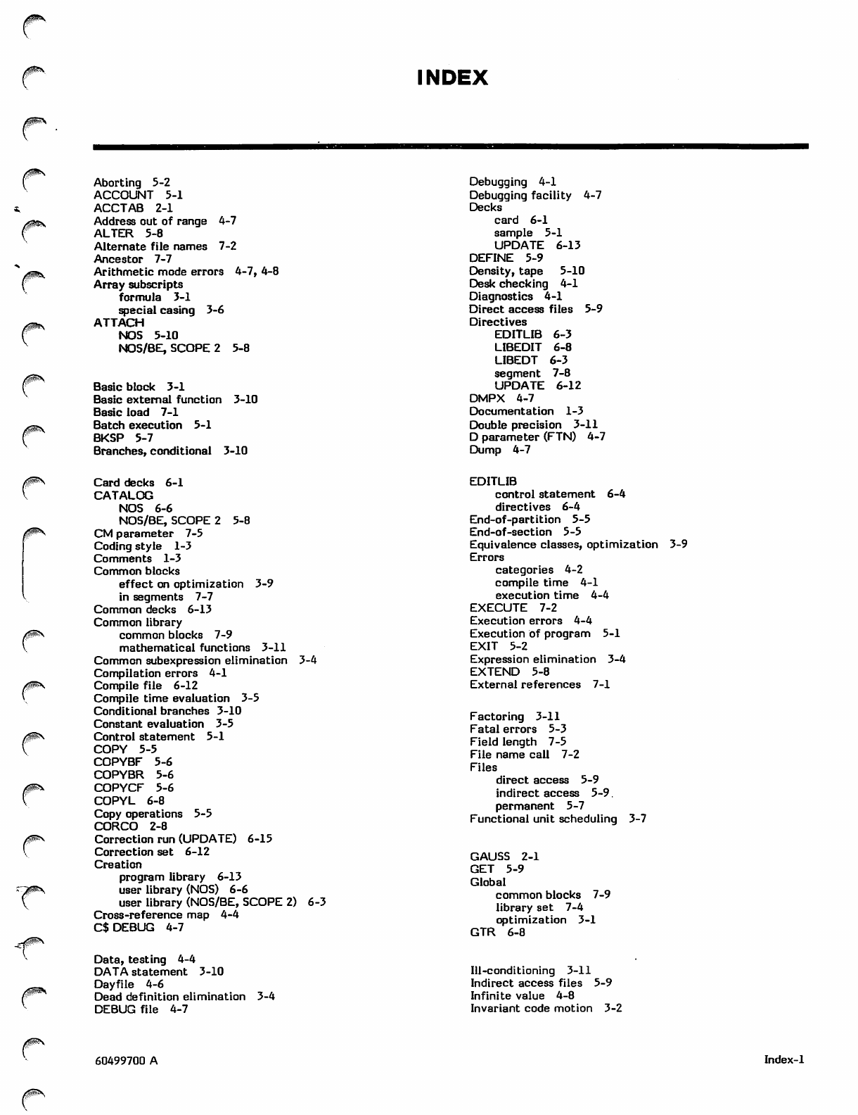
INDEX
Aborting 5-2
ACCOUNT 5-1
ACCTAB 2-1
Address out of range 4-7
ALTER 5-8
Alternate file names 7-2
Ancestor 7-7
Arithmetic mode errors 4-7, 4-8
Array subscripts
formula 3-1
special casing 3-6
AT TA C H
NOS 5-10
NOS/BE, SCOPE 2 5-8
Basic block 3-1
Basic external function 3-10
Basic load 7-1
Batch execution 5-1
BKSP 5-7
Branches, conditional 3-10
Debugging 4-1
Debugging facility 4-7
Decks
card 6-1
sample 5-1
UPDATE 6-13
DEFINE 5-9
Density, tape 5-10
Desk checking 4-1
Diagnostics 4-1
Direct access files 5-9
Directives
EDITLIB 6-3
LIBEDIT 6-8
LIBEDT 6-3
segment 7-8
UPDATE 6-12
DMPX 4-7
Documentation 1-3
Double precision 3-11
D parameter (FTN) 4-7
Dump 4-7
/ ^ N
Card decks 6-1
CATALOG
NOS 6-6
NOS/BE, SCOPE 2 5-8
CM parameter 7-5
Coding style 1-3
Comments 1-3
Common blocks
effect on optimization 3-9
in segments 7-7
Common decks 6-13
Common library
common blocks 7-9
mathematical functions 3-11
Common subexpression elimination 3-4
Compilation errors 4-1
Compile file 6-12
Compile time evaluation 3-5
Conditional branches 3-10
Constant evaluation 3-5
Control statement 5-1
CO PY 5 -5
COPYBF 5-6
COPYBR 5-6
COPYCF 5-6
COPYL 6-8
Copy operations 5-5
CORCO 2-8
Correction run (UPDATE) 6-15
Correction set 6-12
Creation
program library 6-13
user library (NOS) 6-6
user library (NOS/BE, SCOPE 2) 6-3
Cross-reference map 4-4
C$ DEBUG 4-7
EDITLIB
control statement 6-4
directives 6-4
End-of-partition 5-5
End-of-section 5-5
Equivalence classes, optimization 3-9
Errors
categories 4-2
compile time 4-1
execution time 4-4
EXECUTE 7-2
Execution errors 4-4
Execution of program 5-1
EXIT 5-2
Expression elimination 3-4
EXTEND 5-8
External references 7-1
Factoring 3-11
Fatal errors 5-3
Field length 7-5
File name call 7-2
Files
direct access 5-9
indirect access 5-9.
permanent 5-7
Functional unit scheduling 3-7
GAUSS 2-1
GE T 5-9
Global
common blocks 7-9
library set 7-4
optimizati on 3 -1
GTR 6-8
Data, testing 4-4
DATA statement 3-10
Dayfile 4-6
Dead definition elimination
DEBUG file 4-7
3-4
Ill-conditioning 3-11
Indirect access files 5-9
Infinite value 4-8
Invariant code motion 3-2
60499700 A Index-1
00>S
Job decks, sample 5-1
LABEL 5-10
Labels 5-10
LDSET 7-4
Levels 7-6
LGO 7-2
LIBEDIT 6-8
LIBEDT
control statement 6-4
directives 6-4
LIBGEN
control statement 6-8
Libraries
program 6-12
search order 7-4
user 6-2
LIBRARY 7-4
Library set
global 7-4
local 7-4
LI N K 2 - 6
LOAD 7-3
Loader errors 4-7
Loading 7-1
Load map 4-7
Local library set 7-4
Local optimization 3-1
Loop restructuring 3-10
L tapes 5-10
Machine-dependent optimization -
Machine-independent optimization
Magnetic tapes 5-10
Map load 4-7
reference 4-4
Mathematical programming 3-11
Memory 7-5
Messages, diagnostic 4-1
Mixed mode 3-10
Mode, mixed 3-10
Mode errors 4-7, 4-8
Modularity 1-1
-6
3-2
Name call statement
New program library
NEWTON 2-1
NOGO 7-3
NOS
permanent files
skip operations
user libraries 6-
NOS/BE
permanent files
skip operations
7-2
6-12
5-9
5-7
•6
5-7
5-6
user libraries
NUCLEUS 7-4
6-2
3-8
Object code
listing 4-7
optimization example
Old program library 6-12
Optimizations
example 3-8
global 3-1
local 3-1
machine-dependent 3-6
machine-independent 3-2
source code 3-9
OPT=2 3-1
OTOD 2-6
Overlays 7-1
Partition 5-5
Permanent files
NOS 5-9
NOS/BE, SCOPE 2 5-7
Prefetching 3-7
Program, segmented, see Segments
Program library 6-2
Programming techniques 1-1
PURGE
NOS 5-10
NOS/BE, SCOPE 2 5-8
Record manager
common blocks 7-9
W type records 5-5
REDUCE 7-5
Reduce mode 7-5
Reference map 4-4
References, external 7-1
Register assignment 3-7
Relocation 7-1
REPLACE 5-9
REQUEST
permanent files 5-8
tapes 5-10
RESOURC 5-2
RETURN 5-4
REWIND 5-4
RFL 7-5
Satisfaction of references 7-1
SAVE 5-9
SCOPE 2
permanent files 5-7
skip opeations 5-6
user libraries 6-2
Search, library 7-4
Section 5-5
SEGLOAD 7-8
Segments
building 7-7
directives 7-8
executing 7-10
loading 7-10
structure 7-6
SI tapes 5-10
SKIPB 5-6
SKIPBF 5-7
SKIPF
NOS 5-7
NOS/BE, SCOPE 2 5-6
Skip operations
NOS 5-7
NOS/BE, SCOPE 2 5-6
SKIPR 5-7
SLOAD 7-2
Source code optimization 3-9
S tapes 5-10
Strength reduction 3-6
Subscripts, see Array Subscripts
Symbolic dump 4-7
Symbolic reference map 4-4
SYSLIB 7-4
"*>
>w^\
■<*^\
■■^^IV—
^s^k
Index-2 60499700 A
-*^\
.AtA
00^*
Tapes 5-10
Testing 4-4
Test replacement 3-5
Top-down programming 1-1
Trees 7-6
User libraries
NOS 6-6
NOS/BE, SCOPE 2
User optimization 3-9
Utilities 6-1
6-2
Unformatted records 5-5
UNLOAD 5-5
Unsatisfied externals 7-1
UO option
prefetching 3-7
register assignment 3-7
UPDATE
control statement 6-13
directives 6-12
listing 6-16
USER 5-1
Volume serial number
VSN 5-10
W type records 5-5
6/7/8/9 card 5-1
7-track 5-10
7/8/9 card 5-1
9-track 5-10
5-10
0ms,
■^-0X\
60499700 A Index-3

' ^ | V
/^%
I COMMENT SHEET
f * I / 2 5 \ C O N T R p L D A T A
1 I \oieS/ corporation
I TITLE: FORTRAN Extended Version 4 User's Guide
; ^ f
iaij0&\
/$P*N
Jp*S
flJ j
Z|
_J
0^S 2I
X
H
7-\
°
i-'
*>!
PUBLICATION NO. 60499700 REVISION A
V • This form is not intended to be used as an order blank. Control Data Corporation solicits your comments about this
manual with a view to improving its usefulness in later editions.
jpsK ' Applications for which you use this manual.
Do you find it adequate for your purpose?
What improvements to this manual do you recommend to better serve your purpose?
Note specific errors discovered (please include page number reference).
General comments:
FROM NAME: POSITION:
COMPANY
NAME:
ADDRESS:
NO POSTAGE STAMP NECESSARY IF MAILED IN U.S.A.
FOLD ON DOTTED LINES AND STAPLE
STAPLE STAPLE
s ^ \
A*^\
('•OLD F^?__|
FIRST CLASS
PERMIT NO. 8241
MINNEAPOLIS, MINN.
BUSINESS REPLY MAIL
NO POSTAGE STAMP NECESSARY IF MAILED IN U.S.A.
POSTAGE WILL BE PAID BY
CONTROL DATA CORPORATION
Publications and Graphics Division
115 Moffett Park Drive
Sunnyvale, California 94086
FOLD
"^ ^^
^5^(*
STAPLE STAPLE
