FTK_User_Guide FTK UG 4
2012-09-27
: Pdf Ftk Ug 4 FTK_UG_4 ftk
Open the PDF directly: View PDF ![]() .
.
Page Count: 286 [warning: Documents this large are best viewed by clicking the View PDF Link!]
- AccessData Legal and Contact Information
- Table of Contents
- Introducing AccessData® (AD) Forensic Toolkit® (FTK®)
- Administrating AccessData® (AD) Forensic Toolkit® (FTK®)
- Application Administration
- Creating an Application Administrator account
- Changing Your Password
- Setting Database Preferences
- Managing Database Sessions
- Managing Shared KFF Settings
- Recovering and Deleting Processing Jobs
- Restoring an Image to a disk
- Adding New Users to a Database
- About Assigning Roles to Users
- Restrictions to the Case Reviewer Role
- About Assigning Permissions to Users
- Assigning Users Shared Label Visibility
- Setting Additional Preferences
- Managing Global Features
- Application Administration
- Case Management
- Introducing Case Management
- Starting New Cases
- Opening an Existing Case
- Creating a Case
- Configuring Case Detailed Options
- Evidence Processing Options
- About Fuzzy Hashing
- Compound Files
- dtSearch Text Indexing Options
- Data Carving
- Running Optical Character Recognition (OCR)
- About Explicit Image Detection
- Including Registry Reports
- Send Email Alert on Job Completion
- Custom File Identification Options
- Evidence Refinement (Advanced) Options
- Selecting Index Refinement (Advanced) Options
- Adding Evidence to a New Case
- Converting a Case from versions 2.2+
- Managing Case Data
- Working with Evidence Image Files
- Verifying Drive Image Integrity
- Mounting an Image to a Drive
- Benefits of Image Mounting
- Characteristics of a Logically Mounted Image
- Characteristics of a Physically Mounted Image
- Mounting an Image as Read-Only
- Mounting a Drive Image as Writable
- Unmounting an Image
- Restoring an Image to a Disk
- Performing Final Carve Processing
- Recovering Processing Jobs
- Working with Static Evidence
- Working with Live Evidence
- About Live Evidence
- Adding Local Live Evidence
- Methods of Adding Remote Live Evidence
- Requirements for Adding Remote Live Evidence
- Adding Evidence with the Temporary Agent
- Adding Data with the FTK Enterprise Agent
- Methods of Deploying the FTK Enterprise Agent
- Creating Self-signed Certificates for Agent deployment
- Configuring Communication Settings for FTK Enterprise Agent push
- Pushing the FTK Enterprise Agent
- Removing the FTK Enterprise Agent
- Connecting to an FTK Enterprise Agent
- Adding Remote Data with the FTK Enterprise Agent
- Acquiring Drive Data
- Acquiring RAM Data
- Importing Memory Dumps
- Unmounting an Agent Drive or Device
- Filtering Evidence
- Working with Labels
- Running Cerberus Malware Analysis
- Decrypting EFS and Other Encrypted Files
- Understanding EFS
- Decrypting EFS Files and Folders
- Decrypting MS Office Files
- Decrypting Lotus Notes Files
- Decrypting S/MIME Files
- Viewing Decrypted Files
- Decrypting Credant Files
- Decrypting Safeguard Utimaco Files
- Decrypting SafeBoot Files
- Decrypting Guardian Edge Files
- Decrypting an Image Encrypted With PGP® Whole Disk Encryption (WDE)
- Exporting Data from the Examiner
- Reviewing Cases
- Tabs of the Examiner Interface
- Exploring Evidence
- Examining Evidence in the Overview Tab
- Examining Email
- Examining Graphics
- Bookmarking Evidence
- Using the Bookmarks Tab
- Creating a Bookmark
- Viewing Bookmark Information
- Bookmarking Selected Text
- Adding to an Existing Bookmark
- Creating Email or Email Attachment Bookmarks
- Adding Email and Email Attachments to Existing Bookmarks
- Moving a Bookmark
- Copying a Bookmark
- Deleting a Bookmark
- Deleting Files from a Bookmark
- Searching Evidence with Live Search
- Searching Evidence with Index Search
- Examining Volatile Data
- Using Visualization
- Customizing the Examiner Interface
- Working with Evidence Reports
- Creating a Case Report
- Adding Case Information to a Report
- Adding Bookmarks to a Report
- Adding Graphics Thumbnails and Files to a Report
- Adding a File Path List to a Report
- Adding a File Properties List to a Report
- Adding Registry Selections to a Report
- Selecting the Report Output Options
- Customizing the Report Graphic
- Viewing and Distributing a Report
- Modifying a Report
- Exporting and Importing Report Settings
- Writing a Report to CD or DVD
- Appendencies
- Appendix A Working with Windows Registry Evidence
- Appendix B Supported File Systems and Drive Image Formats
- Appendix C Recovering Deleted Material
- Appendix D Working with the KFF Library
- Appendix E Managing Security Devices and Licenses
- Appendix F Configuring for Backup and Restore
- Appendix G AccessData Oradjuster
- Appendix H AccessData Distributed Processing
AccessData
Forensic Toolkit
User Guide
| 1

AccessData Legal and Contact Information Legal Information | 2
AccessData Legal and Contact
Information
Document date: February 8, 2012
Legal Information
©2011 AccessData Group, LLC All rights reserved. No part of this publication may be reproduced, photocopied,
stored on a retrieval system, or transmitted without the express written consent of the publisher.
AccessData Group, LLC makes no representations or warranties with respect to the contents or use of this
documentation, and specifically disclaims any express or implied warranties of merchantability or fitness for any
particular purpose. Further, AccessData Group, LLC reserves the right to revise this publication and to make
changes to its content, at any time, without obligation to notify any person or entity of such revisions or changes.
Further, AccessData Group, LLC makes no representations or warranties with respect to any software, and
specifically disclaims any express or implied warranties of merchantability or fitness for any particular purpose.
Further, AccessData Group, LLC reserves the right to make changes to any and all parts of AccessData
software, at any time, without any obligation to notify any person or entity of such changes.
You may not export or re-export this product in violation of any applicable laws or regulations including, without
limitation, U.S. export regulations or the laws of the country in which you reside.
AccessData Group, LLC.
384 South 400 West
Suite 200
Lindon, Utah 84042
U.S.A.
www.accessdata.com
AccessData Trademarks and Copyright Information
-AccessData® is a registered trademark of AccessData Group, LLC.
-Distributed Network Attack® is a registered trademark of AccessData Group, LLC.
-DNA® is a registered trademark of AccessData Group, LLC.
-Forensic Toolkit® is a registered trademark of AccessData Group, LLC.
-FTK® is a registered trademark of AccessData Group, LLC.
-Password Recovery Toolkit® is a registered trademark of AccessData Group, LLC.
-PRTK® is a registered trademark of AccessData Group, LLC.
-Registry Viewer® is a registered trademark of AccessData Group, LLC.

AccessData Legal and Contact Information Documentation Conventions | 3
A trademark symbol (®, ™, etc.) denotes an AccessData Group, LLC. trademark. With few exceptions, and
unless otherwise notated, all third-party product names are spelled and capitalized the same way the owner
spells and capitalizes its product name. Third-party trademarks and copyrights are the property of the trademark
and copyright holders. AccessData claims no responsibility for the function or performance of third-party
products.
Third party acknowledgements:
-FreeBSD ® Copyright 1992-2011. The FreeBSD Project .
-AFF® and AFFLIB® Copyright® 2005, 2006, 2007, 2008 Simson L. Garfinkel and Basis Technology
Corp. All rights reserved.
-Copyright © 2005 - 2009 Ayende Rahien
Documentation Conventions
In AccessData documentation, a number of text variations are used to indicate meanings or actions. For
example, a greater-than symbol (>) is used to separate actions within a step. Where an entry must be typed in
using the keyboard, the variable data is set apart using [variable_data] format. Steps that required the user to
click on a button or icon are indicated by Bolded text. This Italic font indicates a label or non-interactive item in
the user interface.
A trademark symbol (®, ™, etc.) denotes an AccessData Group, LLC. trademark. Unless otherwise notated, all
third-party product names are spelled and capitalized the same way the owner spells and capitalizes its product
name. Third-party trademarks and copyrights are the property of the trademark and copyright holders.
AccessData claims no responsibility for the function or performance of third-party products.
Registration
The AccessData product registration is done at AccessData after a purchase is made, and before the product is
shipped. The licenses are bound to either a USB security device, or a Virtual CmStick, according to your
purchase.
Subscriptions
AccessData provides a one-year licensing subscription with all new product purchases. The subscription allows
you to access technical support, and to download and install the latest releases for your licensed products during
the active license period.
Following the initial licensing period, a subscription renewal is required annually for continued support and for
updating your products. You can renew your subscriptions through your AccessData Sales Representative.
Use LicenseManager to view your current registration information, to check for product updates and to download
the latest product versions, where they are available for download. You can also visit our web site,
www.accessdata.com anytime to find the latest releases of our products.
For more information, see Managing Licenses in your product manual or on the AccessData web site.
AccessData Contact Information
Your AccessData Sales Representative is your main contact with AccessData Group, LLC. Also, listed below are
the general AccessData telephone number and mailing address, and telephone numbers for contacting
individual departments.

AccessData Legal and Contact Information AccessData Contact Information | 4
Mailing Address and General Phone Numbers
You can contact AccessData in the following ways:
Technical Support
Free technical support is available on all currently licensed AccessData products.
You can contact AccessData Customer and Technical Support in the following ways:
TABLE 1-1
AD Mailing Address, Hours, and Department Phone Numbers
Corporate Headquarters: AccessData Group, LLC.
384 South 400 West
Suite 200
Lindon, UT 84042 USA
Voice: 801.377.5410
Fax: 801.377.5426
General Corporate Hours: Monday through Friday, 8:00 AM – 5:00 PM (MST)
AccessData is closed on US Federal Holidays
State and Local
Law Enforcement Sales: Voice: 800.574.5199, option 1
Fax: 801.765.4370
Email: Sales@AccessData.com
Federal Sales: Voice: 800.574.5199, option 2
Fax: 801.765.4370
Email: Sales@AccessData.com
Corporate Sales: Voice: 801.377.5410, option 3
Fax: 801.765.4370
Email: Sales@AccessData.com
Training: Voice: 801.377.5410, option 6
Fax: 801.765.4370
Email: Training@AccessData.com
Accounting: Voice: 801.377.5410, option 4
TABLE 1-2
AD Customer & Technical Support Contact Information
Domestic Support Americas/Asia-Pacific
Standard Support: Monday through Friday, 5:00 AM – 6:00 PM (MST),
except corporate holidays.
Voice: 801.377.5410, option 5
Voice: 800.658.5199 (Toll-free North America)
Email: Support@AccessData.com
After Hours Phone Support: Monday through Friday 6:00 PM to 1:00 AM (MST),
except corporate holidays.
Voice: 801.377.5410, option 5
After Hours Email-only Support: Monday through Friday 1:00 AM to 5:00 AM (MST),
except corporate holidays.
Email: afterhours@accessdata.com
International Support Europe/Middle East/Africa
Standard Support: Monday through Friday, 8:00 AM – 5:00 PM (UK-
London), except corporate holidays.
Voice: +44 207 160 2017 (United Kingdom)
Email: emeasupport@accessdata.com

AccessData Legal and Contact Information Professional Services | 5
Note: All support inquiries are typically responded to within one business day. If there is an urgent need for
support, contact AccessData by phone during normal business hours.
Documentation
Please email AccessData regarding any typos, inaccuracies, or other problems you find with the documentation:
documentation@accessdata.com
Professional Services
The AccessData Professional Services staff comes with a varied and extensive background in digital
investigations including law enforcement, counter-intelligence, and corporate security. Their collective
experience in working with both government and commercial entities, as well as in providing expert testimony,
enables them to provide a full range of computer forensic and eDiscovery services.
At this time, Professional Services provides support for sales, installation, training, and utilization of FTK, FTK
Pro, Enterprise, eDiscovery, and Lab. They can help you resolve any questions or problems you may have
regarding these products
After Hours Support: Monday through Friday, 5:00 PM to 1:00 AM (UK/
London), except corporate holidays.
Voice: 801.377.5410 Option 5*.
After Hours Email-only Support: Monday through Friday, 1:00 AM to 5:00 AM (UK/
London), except corporate holidays.
Email: afterhours@accessdata.com
Other
Web Site: http://www.AccessData.com/Support
The Support web site allows access to Discussion
Forums, Downloads, Previous Releases, our
Knowledgebase, a way to submit and track your
“trouble tickets”, and in-depth contact information.
AD SUMMATION Americas/Asia-Pacific:
800.786.2778 (North America).
415.659.0105.
Email: support@summation.com
Standard Support: Monday through Friday, 6:00 AM– 6:00 PM (PST),
except corporate holidays.
After Hours Support: Monday through Friday by calling 415.659.0105.
After Hours Email-only Support: Between 12am and 4am (PST) Product Support is
available only by email at
afterhours@accessdata.com.
AD Summation CaseVault 866.278.2858
Email: support@casevault.com
Monday through Friday, 8:00 AM – 6:00 PM (EST),
except corporate holidays.
AD Summation Discovery Cracker 866.833.5377
Email: dcsupport@accessdata.com
Support Hours: Monday through Friday, 7:00 AM – 7:00 PM (EST,
except corporate holidays.
TABLE 1-2
AD Customer & Technical Support Contact Information (Continued)

AccessData Legal and Contact Information Professional Services | 6
Contact Information for Professional Services
Contact AccessData Professional Services in the following ways:
TABLE 1-3
AccessData Professional Services Contact Information
Contact Method Number or Address
Phone Washington DC: 410.703.9237
North America: 801.377.5410
North America Toll Free: 800-489-5199, option 7
International: +1.801.377.5410
Email adservices@accessdata.com

Table of Contents | 7
Table of Contents
AccessData Legal and Contact Information
. . . . . . . . . . . . . . . . . . . . . . . . . . . . . . .2
Legal Information . . . . . . . . . . . . . . . . . . . . . . . . . . . . . . . . . . . . . . . . . . .2
AccessData Trademarks and Copyright Information . . . . . . . . . . . . . . . . . . . .2
Documentation Conventions . . . . . . . . . . . . . . . . . . . . . . . . . . . . . . . . . . . .3
Registration . . . . . . . . . . . . . . . . . . . . . . . . . . . . . . . . . . . . . . . . . . . . . . .3
Subscriptions . . . . . . . . . . . . . . . . . . . . . . . . . . . . . . . . . . . . . . . . .3
AccessData Contact Information . . . . . . . . . . . . . . . . . . . . . . . . . . . . . . . . .3
Mailing Address and General Phone Numbers . . . . . . . . . . . . . . . . . . . . .4
Technical Support . . . . . . . . . . . . . . . . . . . . . . . . . . . . . . . . . . . . . .4
Documentation . . . . . . . . . . . . . . . . . . . . . . . . . . . . . . . . . . . . . . . .5
Professional Services . . . . . . . . . . . . . . . . . . . . . . . . . . . . . . . . . . . . . . . .5
Contact Information for Professional Services . . . . . . . . . . . . . . . . . . . . .6
Table of Contents
. . . . . . . . . . . . . . . . . . . . . . . . . . . . . . . . . . . . . . . . . . . . . . . .7
Part I: Introducing AccessData® (AD) Forensic Toolkit® (FTK®)
. . . . . . . . .20
Chapter 1: Introducing AccessData® (AD) Forensic Toolkit® (FTK®)
. . . . . . . . . . . . . . . . . . 21
Overview of Investigating Digital Evidence. . . . . . . . . . . . . . . . . . . . . . . . . . 21
About Aquiring Digital Evidence. . . . . . . . . . . . . . . . . . . . . . . . . . . . . . . . . 22
Types of Digital Evidence. . . . . . . . . . . . . . . . . . . . . . . . . . . . . . . . . 22
Acquiring Evidence . . . . . . . . . . . . . . . . . . . . . . . . . . . . . . . . . . . . 22
About Acquiring Static Evidence . . . . . . . . . . . . . . . . . . . . . . . 23
About Acquiring Live Evidence . . . . . . . . . . . . . . . . . . . . . . . . 23
About Acquiring Remote Evidence. . . . . . . . . . . . . . . . . . . . . . 23
About Examining Digital Evidence . . . . . . . . . . . . . . . . . . . . . . . . . . . . . . . 23
About Managing Cases and Evidence. . . . . . . . . . . . . . . . . . . . . . . . . . . . . 24
What you can do with the Examiner . . . . . . . . . . . . . . . . . . . . . . . . . . . . . . 24
About Indexing and Hashing . . . . . . . . . . . . . . . . . . . . . . . . . . . . . . . 24
About the Known File Filter Database . . . . . . . . . . . . . . . . . . . . . . . . . 25
About Searching . . . . . . . . . . . . . . . . . . . . . . . . . . . . . . . . . . . . . . 25
About Bookmarking . . . . . . . . . . . . . . . . . . . . . . . . . . . . . . . . . . . . 25
About Presenting Evidence. . . . . . . . . . . . . . . . . . . . . . . . . . . . . . . . 25
Chapter 2: Getting Started with the User Interface
. . . . . . . . . . . . . . . . . . . . . . . . . . . . . . . . . . . . . . 26

Table of Contents | 8
Part II: Administrating AccessData® (AD) Forensic Toolkit® (FTK®)
. . . . . .27
Chapter 3: Application Administration
. . . . . . . . . . . . . . . . . . . . . . . . . . . . . . . . . . . . . . . . . . . . . . . . . . 28
Creating an Application Administrator account . . . . . . . . . . . . . . . . . . . . . . . 28
Changing Your Password . . . . . . . . . . . . . . . . . . . . . . . . . . . . . . . . . . . . . 29
Setting Database Preferences. . . . . . . . . . . . . . . . . . . . . . . . . . . . . . . . . . 29
Managing Database Sessions. . . . . . . . . . . . . . . . . . . . . . . . . . . . . . . . . . 29
Managing Shared KFF Settings. . . . . . . . . . . . . . . . . . . . . . . . . . . . . . . . . 30
Recovering and Deleting Processing Jobs. . . . . . . . . . . . . . . . . . . . . . . . . . 30
Restoring an Image to a disk. . . . . . . . . . . . . . . . . . . . . . . . . . . . . . . . . . . 30
Adding New Users to a Database . . . . . . . . . . . . . . . . . . . . . . . . . . . . . . . 31
About Assigning Roles to Users. . . . . . . . . . . . . . . . . . . . . . . . . . . . . . . . . 31
Assigning Initial Database-level Roles to Users. . . . . . . . . . . . . . . . . . . . 31
Assigning Additional Case-level Roles to Users . . . . . . . . . . . . . . . . . . . 32
Restrictions to the Case Reviewer Role. . . . . . . . . . . . . . . . . . . . . . . . . . . . 32
About Assigning Permissions to Users . . . . . . . . . . . . . . . . . . . . . . . . . . . . 33
Assigning Users Shared Label Visibility. . . . . . . . . . . . . . . . . . . . . . . . . . . . 33
Setting Additional Preferences . . . . . . . . . . . . . . . . . . . . . . . . . . . . . . . . . 33
Choosing a Temporary File Path . . . . . . . . . . . . . . . . . . . . . . . . . . . . 33
Providing a Network Security Device Location . . . . . . . . . . . . . . . . . . . . 34
Optimizing the Case Database . . . . . . . . . . . . . . . . . . . . . . . . . . . . . 34
Managing Global Features . . . . . . . . . . . . . . . . . . . . . . . . . . . . . . . . . . . . 34
Managing Carvers . . . . . . . . . . . . . . . . . . . . . . . . . . . . . . . . . . . . . 34
Managing Custom Identifiers. . . . . . . . . . . . . . . . . . . . . . . . . . . . . . . 35
Managing Columns . . . . . . . . . . . . . . . . . . . . . . . . . . . . . . . . . . . . 35
Managing File Extension Maps . . . . . . . . . . . . . . . . . . . . . . . . . . . . . 36
Managing Filters . . . . . . . . . . . . . . . . . . . . . . . . . . . . . . . . . . . . . . 36
Managing Labels. . . . . . . . . . . . . . . . . . . . . . . . . . . . . . . . . . . . . . 37
Part III: Case Management
. . . . . . . . . . . . . . . . . . . . . . . . . . . . . . . . . . . . . . . . . . .38
Chapter 4: Introducing Case Management
. . . . . . . . . . . . . . . . . . . . . . . . . . . . . . . . . . . . . . . . . . . . . . 39
About Case Management. . . . . . . . . . . . . . . . . . . . . . . . . . . . . . . . . . . . . 39
The User Interfaces. . . . . . . . . . . . . . . . . . . . . . . . . . . . . . . . . . . . . . . . . 39
About the Cases List . . . . . . . . . . . . . . . . . . . . . . . . . . . . . . . . . . . . . . . . 39
Menus of the Case Manager . . . . . . . . . . . . . . . . . . . . . . . . . . . . . . . . . . 40
Options of the Case Manager’s File Menu . . . . . . . . . . . . . . . . . 40
Options of the Case Manager’s Database Menu. . . . . . . . . . . . . 41
Options of the Case Manager’s Case Menu . . . . . . . . . . . . . . . . 41
Options of the Case Manager’s Tools Menu . . . . . . . . . . . . . . . 42
Options of the Case Manager’s Manage Menu. . . . . . . . . . . . . . 43
Options of the Case Manager’s Help Menu. . . . . . . . . . . . . . . . . 43
Menus of the Examiner . . . . . . . . . . . . . . . . . . . . . . . . . . . . . . . . . . . . . . 44

Table of Contents | 9
Options of the Examiner’s File Menu . . . . . . . . . . . . . . . . . . . . 45
Options of the Examiner’s Edit Menu . . . . . . . . . . . . . . . . . . . . 46
Options of the Examiner’s View Menu . . . . . . . . . . . . . . . . . . . 46
Options of the Examiner’s Evidence Menu . . . . . . . . . . . . . . . . . 48
Options of the Examiner’s Filter Menu . . . . . . . . . . . . . . . . . . . 50
Options of the Examiner’s Tools Menu . . . . . . . . . . . . . . . . . . . 51
Options of the Examiner’s Manage Menu . . . . . . . . . . . . . . . . 53
Options of the Examiner’s Help Menu . . . . . . . . . . . . . . . . . . . 54
Chapter 5: Starting New Cases
. . . . . . . . . . . . . . . . . . . . . . . . . . . . . . . . . . . . . . . . . . . . . . . . . . . . . . . . . 55
Opening an Existing Case . . . . . . . . . . . . . . . . . . . . . . . . . . . . . . . . . . . . 55
Creating a Case . . . . . . . . . . . . . . . . . . . . . . . . . . . . . . . . . . . . . . . . . . . 56
Configuring Case Detailed Options. . . . . . . . . . . . . . . . . . . . . . . . . . . . . . . 56
Evidence Processing Options . . . . . . . . . . . . . . . . . . . . . . . . . . . . . . . . . . 57
About Fuzzy Hashing . . . . . . . . . . . . . . . . . . . . . . . . . . . . . . . . . . . . . . . 59
Creating a Fuzzy Hash Library. . . . . . . . . . . . . . . . . . . . . . . . . . . . . . 59
Selecting Fuzzy Hash Options During Initial Processing . . . . . . . . . . . . . . 60
Additional Analysis Fuzzy Hashing . . . . . . . . . . . . . . . . . . . . . . . . . . . 60
Creating Fuzzy Hash Groups . . . . . . . . . . . . . . . . . . . . . . . . . . . . . . 60
Exporting Fuzzy Hash Groups . . . . . . . . . . . . . . . . . . . . . . . . . . . . . . 61
Importing Fuzzy Hash Groups . . . . . . . . . . . . . . . . . . . . . . . . . . . . . . 61
Modifying Fuzzy Hash Lists within Fuzzy Hash Groups . . . . . . . . . . . . . . . 61
Add to Fuzzy Hash Library Group from File List View . . . . . . . . . . 62
Comparing Files Using Fuzzy Hashing. . . . . . . . . . . . . . . . . . . . . . . . . 62
Viewing Fuzzy Hash Results . . . . . . . . . . . . . . . . . . . . . . . . . 63
Compound Files . . . . . . . . . . . . . . . . . . . . . . . . . . . . . . . . . . . . . . . . . . . 63
dtSearch Text Indexing Options . . . . . . . . . . . . . . . . . . . . . . . . . . . . . . . . . 65
Indexing a Case . . . . . . . . . . . . . . . . . . . . . . . . . . . . . . . . . . . . . . 65
dtSearch Indexing Space Requirements . . . . . . . . . . . . . . . . . . . . . . . . 66
New Case Indexing Options . . . . . . . . . . . . . . . . . . . . . . . . . . . . . . . 66
Data Carving . . . . . . . . . . . . . . . . . . . . . . . . . . . . . . . . . . . . . . . . . . . . . 67
Selecting Data Carving Options . . . . . . . . . . . . . . . . . . . . . . . . . . . . . 68
Custom Carvers . . . . . . . . . . . . . . . . . . . . . . . . . . . . . . . . . . . . . . 68
Running Optical Character Recognition (OCR) . . . . . . . . . . . . . . . . . . . . . . . 70
About Explicit Image Detection . . . . . . . . . . . . . . . . . . . . . . . . . . . . . . . . . 71
Including Registry Reports . . . . . . . . . . . . . . . . . . . . . . . . . . . . . . . . . . . . 72
Send Email Alert on Job Completion. . . . . . . . . . . . . . . . . . . . . . . . . . . . . . 72
Custom File Identification Options . . . . . . . . . . . . . . . . . . . . . . . . . . . . . . . 72
Creating Custom File Identifiers . . . . . . . . . . . . . . . . . . . . . . . . . . . . . 72
Custom Case Extension Maps. . . . . . . . . . . . . . . . . . . . . . . . . . . . . . 73
Evidence Refinement (Advanced) Options. . . . . . . . . . . . . . . . . . . . . . . . . . 74
Refining Evidence by File Status/Type . . . . . . . . . . . . . . . . . . . . . . . . . 74
Refining Evidence by File Date/Size . . . . . . . . . . . . . . . . . . . . . . . . . . 75
Selecting Index Refinement (Advanced) Options. . . . . . . . . . . . . . . . . . . . . . 76

Table of Contents | 10
Refining an Index by File Status/Type . . . . . . . . . . . . . . . . . . . . . . . . . 76
Refining an Index by File Date/Size . . . . . . . . . . . . . . . . . . . . . 77
Adding Evidence to a New Case . . . . . . . . . . . . . . . . . . . . . . . . . . . . . . . . 77
Converting a Case from versions 2.2+ . . . . . . . . . . . . . . . . . . . . . . . . . . . . 77
Chapter 6: Managing Case Data
. . . . . . . . . . . . . . . . . . . . . . . . . . . . . . . . . . . . . . . . . . . . . . . . . . . . . . . . . 79
Backing Up a Case . . . . . . . . . . . . . . . . . . . . . . . . . . . . . . . . . . . . . . . . . 79
Performing a Backup and Restore on a Two-Box Installation. . . . . . . . . . . . 79
Performing a Backup of a case . . . . . . . . . . . . . . . . . . . . . . . . . . . . . 79
Archiving a Case . . . . . . . . . . . . . . . . . . . . . . . . . . . . . . . . . . . . . . . . . . 80
Archiving and Detaching a Case . . . . . . . . . . . . . . . . . . . . . . . . . . . . . . . . 81
Attaching a Case . . . . . . . . . . . . . . . . . . . . . . . . . . . . . . . . . . . . . . . . . . 81
Restoring a Case . . . . . . . . . . . . . . . . . . . . . . . . . . . . . . . . . . . . . . . . . . 82
Deleting a Case . . . . . . . . . . . . . . . . . . . . . . . . . . . . . . . . . . . . . . . . . . . 82
Storing Case Files . . . . . . . . . . . . . . . . . . . . . . . . . . . . . . . . . . . . . 82
Migrating Cases Between Database Types . . . . . . . . . . . . . . . . . . . . . . . . . 82
Upgrading 3.x Cases From Oracle to 3.x PostgreSQL. . . . . . . . . . . . . . . . 82
Moving 3.4.x Cases from Oracle to PostgreSQL . . . . . . . . . . . . . . . . . . . 83
. . . . . . . . . . . . . . . . . . . . . . . . . . . . . . . . . . . . . . . . . . . . . . . . . . . . . . 83
Chapter 7: Working with Evidence Image Files
. . . . . . . . . . . . . . . . . . . . . . . . . . . . . . . . . . . . . . . . . . 84
Verifying Drive Image Integrity. . . . . . . . . . . . . . . . . . . . . . . . . . . . . . . . . . 84
Mounting an Image to a Drive . . . . . . . . . . . . . . . . . . . . . . . . . . . . . . . . . . 85
Benefits of Image Mounting . . . . . . . . . . . . . . . . . . . . . . . . . . . . . . . . . . . 85
Characteristics of a Logically Mounted Image. . . . . . . . . . . . . . . . . . . . . . . . 85
Characteristics of a Physically Mounted Image . . . . . . . . . . . . . . . . . . . . . . . 86
Mounting an Image as Read-Only . . . . . . . . . . . . . . . . . . . . . . . . . . . . . . . 86
Mounting a Drive Image as Writable . . . . . . . . . . . . . . . . . . . . . . . . . . . . . . 87
Unmounting an Image . . . . . . . . . . . . . . . . . . . . . . . . . . . . . . . . . . . . . . . 87
Restoring an Image to a Disk . . . . . . . . . . . . . . . . . . . . . . . . . . . . . . . . . . 87
Performing Final Carve Processing . . . . . . . . . . . . . . . . . . . . . . . . . . . . . . 88
Recovering Processing Jobs. . . . . . . . . . . . . . . . . . . . . . . . . . . . . . . . . . . 88
Chapter 8: Working with Static Evidence
. . . . . . . . . . . . . . . . . . . . . . . . . . . . . . . . . . . . . . . . . . . . . . . . 89
Static Evidence compared to Remote Evidence . . . . . . . . . . . . . . . . . . . . . . 89
Acquiring and Preserving Static Evidence . . . . . . . . . . . . . . . . . . . . . . . . . . 89
Adding Evidence . . . . . . . . . . . . . . . . . . . . . . . . . . . . . . . . . . . . . . . . . . 90
Evidence Groups . . . . . . . . . . . . . . . . . . . . . . . . . . . . . . . . . . . . . . . . . . 92
Selecting Evidence Processing Options . . . . . . . . . . . . . . . . . . . . . . . . . . . 93
Selecting a Language . . . . . . . . . . . . . . . . . . . . . . . . . . . . . . . . . . . . . . . 94
Additional Analysis . . . . . . . . . . . . . . . . . . . . . . . . . . . . . . . . . . . . . . . . . 94

Table of Contents | 11
Hashing . . . . . . . . . . . . . . . . . . . . . . . . . . . . . . . . . . . . . . . . . . . . . . . . 96
Data Carving . . . . . . . . . . . . . . . . . . . . . . . . . . . . . . . . . . . . . . . . . . . . . 97
Data Carving Files When Processing a New Case . . . . . . . . . . . . 97
Viewing the Status and Progress of Data Processing and Analysis. . . . . . . . . . 97
Viewing Processed Items . . . . . . . . . . . . . . . . . . . . . . . . . . . . . . . . . . . . . 99
Chapter 9: Working with Live Evidence
. . . . . . . . . . . . . . . . . . . . . . . . . . . . . . . . . . . . . . . . . . . . . . . . 100
About Live Evidence . . . . . . . . . . . . . . . . . . . . . . . . . . . . . . . . . . . . . . . 100
Types of Live Evidence . . . . . . . . . . . . . . . . . . . . . . . . . . . . . . . . . 101
Adding Local Live Evidence . . . . . . . . . . . . . . . . . . . . . . . . . . . . . . . . . . 101
Methods of Adding Remote Live Evidence. . . . . . . . . . . . . . . . . . . . . . . . . 101
Requirements for Adding Remote Live Evidence. . . . . . . . . . . . . . . . . . . . . 102
Adding Evidence with the Temporary Agent . . . . . . . . . . . . . . . . . . . . . . . . 102
Pushing the Temporary Agent . . . . . . . . . . . . . . . . . . . . . . . . . . . . . 102
Manually Deploying the Temporary Agent . . . . . . . . . . . . . . . . . . . . . . 103
Adding Data with the FTK Enterprise Agent . . . . . . . . . . . . . . . . . . . . . . . . 104
Methods of Deploying the FTK Enterprise Agent . . . . . . . . . . . . . . . . . . 104
Creating Self-signed Certificates for Agent deployment . . . . . . . . . . . . . . 104
Configuring Communication Settings for FTK Enterprise Agent push. . . . . . 105
Pushing the FTK Enterprise Agent . . . . . . . . . . . . . . . . . . . . . . . . . . 106
Removing the FTK Enterprise Agent . . . . . . . . . . . . . . . . . . . . . . . . . 106
Connecting to an FTK Enterprise Agent . . . . . . . . . . . . . . . . . . . . . . . 107
Adding Remote Data with the FTK Enterprise Agent. . . . . . . . . . . . . . . . 107
Acquiring Drive Data. . . . . . . . . . . . . . . . . . . . . . . . . . . . . . . . . . . 110
Acquiring RAM Data. . . . . . . . . . . . . . . . . . . . . . . . . . . . . . . . . . . 110
Importing Memory Dumps . . . . . . . . . . . . . . . . . . . . . . . . . . . . . . . 111
Unmounting an Agent Drive or Device . . . . . . . . . . . . . . . . . . . . . . . . 111
Chapter 10: Filtering Evidence
. . . . . . . . . . . . . . . . . . . . . . . . . . . . . . . . . . . . . . . . . . . . . . . . . . . . . . . . . 112
Managing Filters. . . . . . . . . . . . . . . . . . . . . . . . . . . . . . . . . . . . . . . . . . 112
Using Filters . . . . . . . . . . . . . . . . . . . . . . . . . . . . . . . . . . . . . . . . . . . . 113
Applying a Filter . . . . . . . . . . . . . . . . . . . . . . . . . . . . . . . . . . . . . 113
Activating and Deactivating Filters . . . . . . . . . . . . . . . . . . . . . . . . . . 113
Customizing Filters . . . . . . . . . . . . . . . . . . . . . . . . . . . . . . . . . . . . . . . . 113
Creating Compound Filters. . . . . . . . . . . . . . . . . . . . . . . . . . . . . . . 113
Applying Compound Filters. . . . . . . . . . . . . . . . . . . . . . . . . . . . . . . 114
Creating a Filter . . . . . . . . . . . . . . . . . . . . . . . . . . . . . . . . . . . . . . . . . . 114
Refining a Filter . . . . . . . . . . . . . . . . . . . . . . . . . . . . . . . . . . . . . . . . . . 114
Deleting a Filter . . . . . . . . . . . . . . . . . . . . . . . . . . . . . . . . . . . . . . . . . . 115
Copying a Filter . . . . . . . . . . . . . . . . . . . . . . . . . . . . . . . . . . . . . . . . . . 115
Importing a Filter . . . . . . . . . . . . . . . . . . . . . . . . . . . . . . . . . . . . . . . . . 115
Exporting a Filter . . . . . . . . . . . . . . . . . . . . . . . . . . . . . . . . . . . . . . . . . 115

Table of Contents | 12
Sharing a Filter. . . . . . . . . . . . . . . . . . . . . . . . . . . . . . . . . . . . . . . . . . . 116
Using Predefined Filters. . . . . . . . . . . . . . . . . . . . . . . . . . . . . . . . . . . . . 116
Chapter 11: Working with Labels
. . . . . . . . . . . . . . . . . . . . . . . . . . . . . . . . . . . . . . . . . . . . . . . . . . . . . . 120
What you can do with Labels . . . . . . . . . . . . . . . . . . . . . . . . . . . . . . . . . 120
Creating a Label. . . . . . . . . . . . . . . . . . . . . . . . . . . . . . . . . . . . . . . . . . 121
Applying a Label. . . . . . . . . . . . . . . . . . . . . . . . . . . . . . . . . . . . . . . . . . 121
Managing Labels . . . . . . . . . . . . . . . . . . . . . . . . . . . . . . . . . . . . . . . . . 121
Managing Label Groups. . . . . . . . . . . . . . . . . . . . . . . . . . . . . . . . . . . . . 122
Chapter 12: Running Cerberus Malware Analysis
. . . . . . . . . . . . . . . . . . . . . . . . . . . . . . . . . . . . . . 124
About Cerberus Malware Analysis . . . . . . . . . . . . . . . . . . . . . . . . . . . . . . 124
About Cerberus Stage 1 Threat Analysis . . . . . . . . . . . . . . . . . . . . . . 124
About Cerberus Stage 2 Static Analysis . . . . . . . . . . . . . . . . . . . . . . . 126
Running Cerberus Analysis. . . . . . . . . . . . . . . . . . . . . . . . . . . . . . . . . . . 127
Reviewing Results of Cerberus . . . . . . . . . . . . . . . . . . . . . . . . . . . . . . . . 128
Exporting a Cerberus Report. . . . . . . . . . . . . . . . . . . . . . . . . . . . . . . . . . 129
Chapter 13: Decrypting EFS and Other Encrypted Files
. . . . . . . . . . . . . . . . . . . . . . . . . . . . . . . . 130
Understanding EFS. . . . . . . . . . . . . . . . . . . . . . . . . . . . . . . . . . . . . . . . 130
Decrypting EFS Files and Folders . . . . . . . . . . . . . . . . . . . . . . . . . . . . . . 131
Requirements. . . . . . . . . . . . . . . . . . . . . . . . . . . . . . . . . . . . . . . 131
Windows 2000 and XP Systems Prior to SP1 . . . . . . . . . . . . . . 131
Windows XP SP1 or Later. . . . . . . . . . . . . . . . . . . . . . . . . . 131
Decrypting EFS. . . . . . . . . . . . . . . . . . . . . . . . . . . . . . . . . . . . . . 131
Decrypting MS Office Files . . . . . . . . . . . . . . . . . . . . . . . . . . . . . . . . . . . 131
Decrypting Lotus Notes Files . . . . . . . . . . . . . . . . . . . . . . . . . . . . . . . . . 132
Decrypting S/MIME Files . . . . . . . . . . . . . . . . . . . . . . . . . . . . . . . . . . . . 133
Viewing Decrypted Files. . . . . . . . . . . . . . . . . . . . . . . . . . . . . . . . . . . . . 133
Decrypting Credant Files . . . . . . . . . . . . . . . . . . . . . . . . . . . . . . . . . . . . 134
Using an Offline Key Bundle . . . . . . . . . . . . . . . . . . . . . . . . . . . . . . 134
Using an Online Key Bundle . . . . . . . . . . . . . . . . . . . . . . . . . . . . . . 135
Decrypting Safeguard Utimaco Files. . . . . . . . . . . . . . . . . . . . . . . . . . . . . 135
Safeguard Easy . . . . . . . . . . . . . . . . . . . . . . . . . . . . . . . . . . . . . 136
SafeGuard Enterprise . . . . . . . . . . . . . . . . . . . . . . . . . . . . . . . . . . 136
Retrieving the Recovery Token . . . . . . . . . . . . . . . . . . . . . . . 137
Decrypting SafeBoot Files . . . . . . . . . . . . . . . . . . . . . . . . . . . . . . . . . . . 137
Decrypting Guardian Edge Files . . . . . . . . . . . . . . . . . . . . . . . . . . . . . . . 137
Decrypting an Image Encrypted With
PGP® Whole Disk Encryption (WDE) . . . . . . . . . . . . . . . . . . . . . . . . . 138
About PGP® Corporation and PGP® Whole Disk Encryption . . . . . . . . . . 138
PGP® WDE Decryption. . . . . . . . . . . . . . . . . . . . . . . . . . . . . . . . . 138

Table of Contents | 13
Chapter 14: Exporting Data from the Examiner
. . . . . . . . . . . . . . . . . . . . . . . . . . . . . . . . . . . . . . . . . 140
Copying Information from the Examiner. . . . . . . . . . . . . . . . . . . . . . . . . . . 140
Exporting Files . . . . . . . . . . . . . . . . . . . . . . . . . . . . . . . . . . . . . . . . . . . 141
Exporting Case Data to an Image . . . . . . . . . . . . . . . . . . . . . . . . . . . . . . 142
Exporting File List Information . . . . . . . . . . . . . . . . . . . . . . . . . . . . . . . . . 144
Exporting a Word List . . . . . . . . . . . . . . . . . . . . . . . . . . . . . . . . . . . . . . 144
Exporting Recycle Bin Index Contents . . . . . . . . . . . . . . . . . . . . . . . . . . . 145
Exporting hashes from a case . . . . . . . . . . . . . . . . . . . . . . . . . . . . . . . . . 145
Exporting Custom Groups from the KFF Library . . . . . . . . . . . . . . . . . . . . . 146
Exporting All Hits in a Search to a CSV file . . . . . . . . . . . . . . . . . . . . . . . . 146
Part IV: Reviewing Cases
. . . . . . . . . . . . . . . . . . . . . . . . . . . . . . . . . . . . . . . . . .147
Chapter 15: Tabs of the Examiner Interface
. . . . . . . . . . . . . . . . . . . . . . . . . . . . . . . . . . . . . . . . . . . . 148
Tabs of the Examiner. . . . . . . . . . . . . . . . . . . . . . . . . . . . . . . . . . . . . . . 148
Chapter 16: Exploring Evidence
. . . . . . . . . . . . . . . . . . . . . . . . . . . . . . . . . . . . . . . . . . . . . . . . . . . . . . . 149
Explorer Tree Pane. . . . . . . . . . . . . . . . . . . . . . . . . . . . . . . . . . . . . . . . 149
File List Pane. . . . . . . . . . . . . . . . . . . . . . . . . . . . . . . . . . . . . . . . . . . . 149
File List View Right-Click Menu. . . . . . . . . . . . . . . . . . . . . . . 152
The File Content Viewer Pane. . . . . . . . . . . . . . . . . . . . . . . . . . . . . . . . . 154
The Filter Toolbar . . . . . . . . . . . . . . . . . . . . . . . . . . . . . . . . . . . . . . . . . 160
Using QuickPicks . . . . . . . . . . . . . . . . . . . . . . . . . . . . . . . . . . . . . . . . . 161
Chapter 17: Examining Evidence in the Overview Tab
. . . . . . . . . . . . . . . . . . . . . . . . . . . . . . . . . 162
Using the Overview Tab . . . . . . . . . . . . . . . . . . . . . . . . . . . . . . . . . . . . . 162
Evidence Groups Container . . . . . . . . . . . . . . . . . . . . . . . . . . . . . . 162
File Items Container . . . . . . . . . . . . . . . . . . . . . . . . . . . . . . . . . . . 162
File Extension Container . . . . . . . . . . . . . . . . . . . . . . . . . . . . . . . . 162
File Category Container. . . . . . . . . . . . . . . . . . . . . . . . . . . . . . . . . 163
File Status Container . . . . . . . . . . . . . . . . . . . . . . . . . . . . . . . . . . 164
Email Status container . . . . . . . . . . . . . . . . . . . . . . . . . . . . . . . . . 165
Labels container . . . . . . . . . . . . . . . . . . . . . . . . . . . . . . . . . . . . . 165
Bookmarks container . . . . . . . . . . . . . . . . . . . . . . . . . . . . . . . . . . 165
Chapter 18: Examining Email
. . . . . . . . . . . . . . . . . . . . . . . . . . . . . . . . . . . . . . . . . . . . . . . . . . . . . . . . . . 166
Using the Email Tab . . . . . . . . . . . . . . . . . . . . . . . . . . . . . . . . . . . . . . . 166
Email Status Tree . . . . . . . . . . . . . . . . . . . . . . . . . . . . . . . . . . . . 166
Email Archives Tree . . . . . . . . . . . . . . . . . . . . . . . . . . . . . . . . . . . 166
Email Tree. . . . . . . . . . . . . . . . . . . . . . . . . . . . . . . . . . . . . . . . . 166

Table of Contents | 14
Chapter 19: Examining Graphics
. . . . . . . . . . . . . . . . . . . . . . . . . . . . . . . . . . . . . . . . . . . . . . . . . . . . . . . 168
Using the Graphics Tab . . . . . . . . . . . . . . . . . . . . . . . . . . . . . . . . . . . . . 168
The Thumbnails Size Setting . . . . . . . . . . . . . . . . . . . . . . . . . . . . . . . . . 169
Moving the Thumbnails Pane . . . . . . . . . . . . . . . . . . . . . . . . . . . . . . . . . 170
Evaluating Explicit Material. . . . . . . . . . . . . . . . . . . . . . . . . . . . . . . . . . . 171
Filtering EID Material. . . . . . . . . . . . . . . . . . . . . . . . . . . . . . . . . . . . . . . 171
EID Scoring . . . . . . . . . . . . . . . . . . . . . . . . . . . . . . . . . . . . . . . . . . . . . 172
Chapter 20: Bookmarking Evidence
. . . . . . . . . . . . . . . . . . . . . . . . . . . . . . . . . . . . . . . . . . . . . . . . . . . . 174
Using the Bookmarks Tab. . . . . . . . . . . . . . . . . . . . . . . . . . . . . . . . . . . . 174
Creating a Bookmark. . . . . . . . . . . . . . . . . . . . . . . . . . . . . . . . . . . . . . . 175
Viewing Bookmark Information . . . . . . . . . . . . . . . . . . . . . . . . . . . . . . . . 176
Bookmarking Selected Text. . . . . . . . . . . . . . . . . . . . . . . . . . . . . . . . . . . 176
Adding to an Existing Bookmark . . . . . . . . . . . . . . . . . . . . . . . . . . . . . . . 177
Creating Email or Email Attachment Bookmarks . . . . . . . . . . . . . . . . . . . . . 177
Adding Email and Email Attachments to Existing Bookmarks. . . . . . . . . . . . . 178
Moving a Bookmark . . . . . . . . . . . . . . . . . . . . . . . . . . . . . . . . . . . . . . . 178
Copying a Bookmark . . . . . . . . . . . . . . . . . . . . . . . . . . . . . . . . . . . . . . . 178
Deleting a Bookmark . . . . . . . . . . . . . . . . . . . . . . . . . . . . . . . . . . . . . . . 178
Deleting Files from a Bookmark. . . . . . . . . . . . . . . . . . . . . . . . . . . . . . . . 178
Chapter 21: Searching Evidence with Live Search
. . . . . . . . . . . . . . . . . . . . . . . . . . . . . . . . . . . . . 180
Conducting a Live Search. . . . . . . . . . . . . . . . . . . . . . . . . . . . . . . . . . . . 180
Live Text Search. . . . . . . . . . . . . . . . . . . . . . . . . . . . . . . . . . . . . . . . . . 180
Live Hex Search. . . . . . . . . . . . . . . . . . . . . . . . . . . . . . . . . . . . . . . . . . 182
Live Pattern Search. . . . . . . . . . . . . . . . . . . . . . . . . . . . . . . . . . . . . . . . 183
Simple Pattern Searches . . . . . . . . . . . . . . . . . . . . . . . . . . . . . . . . . . . . 184
Complex Pattern Searches . . . . . . . . . . . . . . . . . . . . . . . . . . . . . . . . . . . 184
Predefined Regular Expressions . . . . . . . . . . . . . . . . . . . . . . . . . . . . . . . 185
Social Security Number . . . . . . . . . . . . . . . . . . . . . . . . . . . . . . . . . 186
U.S. Phone Number . . . . . . . . . . . . . . . . . . . . . . . . . . . . . . . . . . . 186
IP Address. . . . . . . . . . . . . . . . . . . . . . . . . . . . . . . . . . . . . . . . . 186
Creating Custom Regular Expressions . . . . . . . . . . . . . . . . . . . . . . . . . . . 187
Chapter 22: Searching Evidence with Index Search
. . . . . . . . . . . . . . . . . . . . . . . . . . . . . . . . . . . . 189
Conducting an Index Search. . . . . . . . . . . . . . . . . . . . . . . . . . . . . . . . . . 189
Using Search Terms . . . . . . . . . . . . . . . . . . . . . . . . . . . . . . . . . . . . . . . 190
Defining Search Criteria. . . . . . . . . . . . . . . . . . . . . . . . . . . . . . . . . . . . . 190
Exporting and Importing Index Search Terms . . . . . . . . . . . . . . . . . . . . . . . 191
Selecting Index Search Options. . . . . . . . . . . . . . . . . . . . . . . . . . . . . . . . 191

Table of Contents | 15
Viewing Index Search Results. . . . . . . . . . . . . . . . . . . . . . . . . . . . . . . . . 193
Documenting Search Results . . . . . . . . . . . . . . . . . . . . . . . . . . . . . . . . . 193
Using Copy Special to Document Search Results . . . . . . . . . . . . . . . . . . . . 194
Bookmarking Search Results . . . . . . . . . . . . . . . . . . . . . . . . . . . . . . . . . 195
Chapter 23: Examining Volatile Data
. . . . . . . . . . . . . . . . . . . . . . . . . . . . . . . . . . . . . . . . . . . . . . . . . . . 196
Using the Volatile Tab . . . . . . . . . . . . . . . . . . . . . . . . . . . . . . . . . . . . . . 196
Understanding Memory . . . . . . . . . . . . . . . . . . . . . . . . . . . . . . . . . . . . . 197
Viewing Memory Dump Data. . . . . . . . . . . . . . . . . . . . . . . . . . . . . . . . . . 198
Viewing Hidden Processes . . . . . . . . . . . . . . . . . . . . . . . . . . . . . . . 198
Viewing Input/Output Request Packet Data . . . . . . . . . . . . . . . . . . . . . 198
Viewing Virtual Address Descriptor (VAD) Data . . . . . . . . . . . . . . . . . . 199
Chapter 24: Using Visualization
. . . . . . . . . . . . . . . . . . . . . . . . . . . . . . . . . . . . . . . . . . . . . . . . . . . . . . . . 200
Understanding What Data Can be Viewed. . . . . . . . . . . . . . . . . . . . . . . . . 200
Visualizing File Data . . . . . . . . . . . . . . . . . . . . . . . . . . . . . . . . . . . . . . . 201
About the Charts Tab . . . . . . . . . . . . . . . . . . . . . . . . . . . . . . . . . . 201
Narrowing Scope with the File Timeline . . . . . . . . . . . . . . . . . . . . . . . 202
Changing the view of the timeline . . . . . . . . . . . . . . . . . . . . . 202
Visualizing File Extension Distribution . . . . . . . . . . . . . . . . . . . . . . . . 203
Visualizing File Category Distribution. . . . . . . . . . . . . . . . . . . . . . . . . 203
Using the File Data List . . . . . . . . . . . . . . . . . . . . . . . . . . . . . . . . . 204
Visualizing Email Data . . . . . . . . . . . . . . . . . . . . . . . . . . . . . . . . . . . . . . 206
Narrowing the Scope with the Email Timeline. . . . . . . . . . . . . . . . . . . . 207
Using History items in the email file timeline . . . . . . . . . . . . . . . 207
Changing the view of the timeline . . . . . . . . . . . . . . . . . . . . . 207
Viewing Mail Statistics. . . . . . . . . . . . . . . . . . . . . . . . . . . . . . . . . . 208
Using the Email Details List . . . . . . . . . . . . . . . . . . . . . . . . . . . . . . 208
Viewing Social Analysis. . . . . . . . . . . . . . . . . . . . . . . . . . . . . . . . . 210
Viewing Traffic Details. . . . . . . . . . . . . . . . . . . . . . . . . . . . . . . . . . 211
Chapter 25: Customizing the Examiner Interface
. . . . . . . . . . . . . . . . . . . . . . . . . . . . . . . . . . . . . . . 213
About Customizing the Examiner User Interface . . . . . . . . . . . . . . . . . . . . . 213
The Tab Layout Menu . . . . . . . . . . . . . . . . . . . . . . . . . . . . . . . . . . . . . . 213
Moving View Panels . . . . . . . . . . . . . . . . . . . . . . . . . . . . . . . . . . . . . . . 214
Creating Custom Tabs . . . . . . . . . . . . . . . . . . . . . . . . . . . . . . . . . . . . . . 215
Managing Columns . . . . . . . . . . . . . . . . . . . . . . . . . . . . . . . . . . . . . . . . 216
Customizing File List Columns . . . . . . . . . . . . . . . . . . . . . . . . . . . . . . . . 216
Creating User-Defined Custom Columns for the File List view . . . . . . . . . . . . 217
Deleting Custom Columns . . . . . . . . . . . . . . . . . . . . . . . . . . . . . . . . . . . 218
Navigating the Available Column Groups. . . . . . . . . . . . . . . . . . . . . . . . . . 219

Table of Contents | 16
Chapter 26: Working with Evidence Reports
. . . . . . . . . . . . . . . . . . . . . . . . . . . . . . . . . . . . . . . . . . . 221
Creating a Case Report . . . . . . . . . . . . . . . . . . . . . . . . . . . . . . . . . . . . . 221
Adding Case Information to a Report . . . . . . . . . . . . . . . . . . . . . . . . . . . . 222
Adding Bookmarks to a Report . . . . . . . . . . . . . . . . . . . . . . . . . . . . . . . . 222
Adding Graphics Thumbnails and Files to a Report . . . . . . . . . . . . . . . . . . . 223
Adding a File Path List to a Report . . . . . . . . . . . . . . . . . . . . . . . . . . . . . . 224
Adding a File Properties List to a Report . . . . . . . . . . . . . . . . . . . . . . . . . . 224
Adding Registry Selections to a Report . . . . . . . . . . . . . . . . . . . . . . . . . . . 225
Selecting the Report Output Options. . . . . . . . . . . . . . . . . . . . . . . . . . . . . 226
Customizing the Report Graphic . . . . . . . . . . . . . . . . . . . . . . . . . . . . . . . 227
Using Cascading Style Sheets. . . . . . . . . . . . . . . . . . . . . . . . . . . . . 228
Viewing and Distributing a Report . . . . . . . . . . . . . . . . . . . . . . . . . . . . . . 228
Modifying a Report . . . . . . . . . . . . . . . . . . . . . . . . . . . . . . . . . . . . . . . . 228
Exporting and Importing Report Settings . . . . . . . . . . . . . . . . . . . . . . . . . . 229
Writing a Report to CD or DVD . . . . . . . . . . . . . . . . . . . . . . . . . . . . . . . . 229
Part V: Appendencies
. . . . . . . . . . . . . . . . . . . . . . . . . . . . . . . . . . . . . . . . . . . . .230
Appendix A
Working with Windows Registry Evidence
. . . . . . . . . . . . . . . . . . . . . . . . . . . 231
Understanding the Windows Registry . . . . . . . . . . . . . . . . . . . . . . . . . . . . 231
Windows 9x Registry Files . . . . . . . . . . . . . . . . . . . . . . . . . . . . . . . 232
Windows NT and Windows 2000 Registry Files . . . . . . . . . . . . . . . . . . 232
Windows XP Registry Files. . . . . . . . . . . . . . . . . . . . . . . . . . . . . . . 233
Possible Data Types. . . . . . . . . . . . . . . . . . . . . . . . . . . . . . . . . . . 234
Additional Considerations. . . . . . . . . . . . . . . . . . . . . . . . . . . . . . . . 234
Seizing Windows Systems. . . . . . . . . . . . . . . . . . . . . . . . . . 235
Windows XP Registry Quick Find Chart. . . . . . . . . . . . . . . . . . . . . . . . . . . 235
System Information . . . . . . . . . . . . . . . . . . . . . . . . . . . . . . . . . . . 236
Networking . . . . . . . . . . . . . . . . . . . . . . . . . . . . . . . . . . . . . . . . 236
User Data . . . . . . . . . . . . . . . . . . . . . . . . . . . . . . . . . . . . . . . . . 238
User Application Data . . . . . . . . . . . . . . . . . . . . . . . . . . . . . . . . . . 238
Appendix B
Supported File Systems and Drive Image Formats
. . . . . . . . . . . . . . . . . . . . . . 240
File Systems . . . . . . . . . . . . . . . . . . . . . . . . . . . . . . . . . . . . . . . . . . . . 240
Whole Disk Encrypted Products. . . . . . . . . . . . . . . . . . . . . . . . . . . . . . . . 240
Hard Disk Image Formats. . . . . . . . . . . . . . . . . . . . . . . . . . . . . . . . . . . . 241
CD and DVD Image Formats. . . . . . . . . . . . . . . . . . . . . . . . . . . . . . . . . . 241

Table of Contents | 17
Appendix C
Recovering Deleted Material
. . . . . . . . . . . . . . . . . . . . . . . . . . . . . . . . . . . . 242
FAT 12, 16, and 32 . . . . . . . . . . . . . . . . . . . . . . . . . . . . . . . . . . . . . . . . 242
NTFS . . . . . . . . . . . . . . . . . . . . . . . . . . . . . . . . . . . . . . . . . . . . . . . . . 242
Ext2 . . . . . . . . . . . . . . . . . . . . . . . . . . . . . . . . . . . . . . . . . . . . . . . . . . 243
Ext3 . . . . . . . . . . . . . . . . . . . . . . . . . . . . . . . . . . . . . . . . . . . . . . . . . . 243
HFS . . . . . . . . . . . . . . . . . . . . . . . . . . . . . . . . . . . . . . . . . . . . . . . . . . 243
Appendix D
Working with the KFF Library
. . . . . . . . . . . . . . . . . . . . . . . . . . . . . . . . . . . . 244
Managing the KFF Library . . . . . . . . . . . . . . . . . . . . . . . . . . . . . . . . . . . 244
Importing KFF Hashes. . . . . . . . . . . . . . . . . . . . . . . . . . . . . . . . . . . . . . 244
Defining KFF Groups. . . . . . . . . . . . . . . . . . . . . . . . . . . . . . . . . . . . . . . 245
About the KFF Library . . . . . . . . . . . . . . . . . . . . . . . . . . . . . . . . . . . . . . 246
How the KFF Works . . . . . . . . . . . . . . . . . . . . . . . . . . . . . . . . . . . 246
Status Values . . . . . . . . . . . . . . . . . . . . . . . . . . . . . . . . . 246
Sets . . . . . . . . . . . . . . . . . . . . . . . . . . . . . . . . . . . . . . . 246
Groups . . . . . . . . . . . . . . . . . . . . . . . . . . . . . . . . . . . . . 247
Higher Level Structure and Usage . . . . . . . . . . . . . . . . . . . . . 247
Customizing KFF Hash Sets . . . . . . . . . . . . . . . . . . . . . . . . . . . . . . . . . . 248
Creating Sets and Groups . . . . . . . . . . . . . . . . . . . . . . . . . . . . . . . 248
Importing KFF Hashes . . . . . . . . . . . . . . . . . . . . . . . . . . . . . . . . . 248
Deleting Hash Sets From A Defined Group . . . . . . . . . . . . . . . . . . . . . 249
Exporting KFF Hashes . . . . . . . . . . . . . . . . . . . . . . . . . . . . . . . . . 249
KFF Library Sources. . . . . . . . . . . . . . . . . . . . . . . . . . . . . . . . . . . 249
NDIC/HashKeeper . . . . . . . . . . . . . . . . . . . . . . . . . . . . . . 250
NIST NSRL. . . . . . . . . . . . . . . . . . . . . . . . . . . . . . . . . . . 253
DHS . . . . . . . . . . . . . . . . . . . . . . . . . . . . . . . . . . . . . . . 253
Appendix E
Managing Security Devices and Licenses
. . . . . . . . . . . . . . . . . . . . . . . . . . . . 254
AccessData Product Licenses. . . . . . . . . . . . . . . . . . . . . . . . . . . . . . . . . 254
Installing and Managing Security Devices . . . . . . . . . . . . . . . . . . . . . . 254
Installing the Security Device . . . . . . . . . . . . . . . . . . . . . . . . 254
Installing Keylok Dongle Drivers . . . . . . . . . . . . . . . . . . . . . . 256
Installing LicenseManager . . . . . . . . . . . . . . . . . . . . . . . . . . . . . . . . . . . 257
Starting LicenseManager . . . . . . . . . . . . . . . . . . . . . . . . . . . . . . . . 257
Using LicenseManager . . . . . . . . . . . . . . . . . . . . . . . . . . . . . . . . . 258
The LicenseManager Interface . . . . . . . . . . . . . . . . . . . . . . . 259
Opening and Saving Dongle Packet Files . . . . . . . . . . . . . . . . 261
Adding and Removing Product Licenses . . . . . . . . . . . . . . . . . 261
Adding and Removing Product Licenses Remotely . . . . . . . . . . . 262
Updating Products . . . . . . . . . . . . . . . . . . . . . . . . . . . . . . . . . . . . 264
Checking for Product Updates . . . . . . . . . . . . . . . . . . . . . . . 264

Table of Contents | 18
Downloading Product Updates . . . . . . . . . . . . . . . . . . . . . . . 264
Purchasing Product Licenses . . . . . . . . . . . . . . . . . . . . . . . . 264
Sending a Dongle Packet File to Support . . . . . . . . . . . . . . . . . . . . . . 264
Virtual CodeMeter Activation Guide . . . . . . . . . . . . . . . . . . . . . . . . . . . . . 265
Introduction . . . . . . . . . . . . . . . . . . . . . . . . . . . . . . . . . . . . . . . . 265
Preparation . . . . . . . . . . . . . . . . . . . . . . . . . . . . . . . . . . . . . . . . 265
Setup for Online Systems. . . . . . . . . . . . . . . . . . . . . . . . . . . . . . . . 265
Setting up VCM for Offline Systems. . . . . . . . . . . . . . . . . . . . . . . . . . 266
Creating a Virtual CM-Stick with Server 2003/2008 Enterprise Editions . . . . 266
Additional Instructions for AD LAB WebUI and eDiscovery . . . . . . . . . . . . 267
Virtual CodeMeter FAQs . . . . . . . . . . . . . . . . . . . . . . . . . . . . . . . . 268
Network License Server (NLS) Setup Guide. . . . . . . . . . . . . . . . . . . . . . . . 269
Introduction . . . . . . . . . . . . . . . . . . . . . . . . . . . . . . . . . . . . . . . . 269
Preparation Notes . . . . . . . . . . . . . . . . . . . . . . . . . . . . . . . . . . . . 269
Setup Overview. . . . . . . . . . . . . . . . . . . . . . . . . . . . . . . . . . . . . . 270
Network Dongle Notes . . . . . . . . . . . . . . . . . . . . . . . . . . . . . . . . . 270
NLS Server System Notes . . . . . . . . . . . . . . . . . . . . . . . . . . . . . . . 270
NLS Client System Notes. . . . . . . . . . . . . . . . . . . . . . . . . . . . . . . . 271
Appendix F
Configuring for Backup and Restore
. . . . . . . . . . . . . . . . . . . . . . . . . . . . . . . 272
Configuration for a Two-box Backup and Restore . . . . . . . . . . . . . . . . . . . . 272
Configuration Overview . . . . . . . . . . . . . . . . . . . . . . . . . . . . . . . . . . . . . 272
Create a Service Account. . . . . . . . . . . . . . . . . . . . . . . . . . . . . . . . . . . . 272
Instructions for Domain User Accounts. . . . . . . . . . . . . . . . . . . . . . . . 273
Share the FTK Case Folder . . . . . . . . . . . . . . . . . . . . . . . . . . . . . . . . . . 273
Configure Database Services . . . . . . . . . . . . . . . . . . . . . . . . . . . . . . . . . 274
Share the Backup Destination Folder . . . . . . . . . . . . . . . . . . . . . . . . . . . . 274
Test the New Configuration. . . . . . . . . . . . . . . . . . . . . . . . . . . . . . . 274
Appendix G
AccessData Oradjuster
. . . . . . . . . . . . . . . . . . . . . . . . . . . . . . . . . . . . . . . . 276
Oradjuster System Requirements . . . . . . . . . . . . . . . . . . . . . . . . . . . . . . 276
Introduction . . . . . . . . . . . . . . . . . . . . . . . . . . . . . . . . . . . . . . . . . . . . . 276
The First Invocation . . . . . . . . . . . . . . . . . . . . . . . . . . . . . . . . . . . . . . . 276
Subsequent Invocations . . . . . . . . . . . . . . . . . . . . . . . . . . . . . . . . 277
One-Box FTK Deployment . . . . . . . . . . . . . . . . . . . . . . . . . . . . . . . 277
Two-Box FTK Deployment . . . . . . . . . . . . . . . . . . . . . . . . . . . . . . . 278
Tuning for Large Memory Systems . . . . . . . . . . . . . . . . . . . . . . . . . . . . . 278
Appendix H
AccessData Distributed Processing
. . . . . . . . . . . . . . . . . . . . . . . . . . . . . . . 281
Distributed Processing Prerequisites . . . . . . . . . . . . . . . . . . . . . . . . . . . . 281

Table of Contents | 19
Installing Distributed Processing . . . . . . . . . . . . . . . . . . . . . . . . . . . . . . . 282
Configuring Distributed Processing. . . . . . . . . . . . . . . . . . . . . . . . . . . . . . 284
Using Distributed Processing . . . . . . . . . . . . . . . . . . . . . . . . . . . . . . . . . 285
Checking the Installation . . . . . . . . . . . . . . . . . . . . . . . . . . . . . . . . 286

| 20
Part I
Introducing AccessData® (AD) Forensic
Toolkit® (FTK®)
This part contains introductory information about AccessData® (AD) Forensic Toolkit® (FTK®) and contains
the following chapters:
-Introducing AccessData® (AD) Forensic Toolkit® (FTK®) (page 21)
-Getting Started with the User Interface (page 26)

Overview of Investigating Digital Evidence | 21
Chapter 1
Introducing AccessData® (AD) Forensic
Toolkit® (FTK®)
AccessData® (AD) Forensic Toolkit® (FTK®) lets you do thorough computer forensic examinations. It includes
powerful file filtering and search functionality, and access to remote systems on your network.
AccessData forensic investigation software tools help law enforcement officials and corporate security, and IT
professionals access and evaluate the evidentiary value of files, folders, and computers.
This chapter includeds the following topics:
-Overview of Investigating Digital Evidence (page 21)
-About Aquiring Digital Evidence (page 22)
-About Examining Digital Evidence (page 23)
-About Managing Cases and Evidence (page 24)
-What you can do with the Examiner (page 24)
Overview of Investigating Digital Evidence
This section describes aquiring, preserving, analyzing, presenting, and managing digital evidence and cases.
Forensic digital investications include the following process:
-Acquisition
Involves identifying and securing the evidence and creating and storing a forensic image of it.
About Aquiring Digital Evidence (page 22)
-Analysis
Involves creating a case and processing the evidence with tools to properly investigate the evidence.
About Examining Digital Evidence (page 23)
-Presentation
Involves creating a case report that documents and synthesizes the investigation.
About Presenting Evidence (page 25)
-Management
Involves maintanance tasks such as backing up, archiving, detaching, attaching, restoring, and deleting
cases and evidence.
About Managing Cases and Evidence (page 24)

About Aquiring Digital Evidence | 22
About Aquiring Digital Evidence
The admissiblility of digital evidence in a court of law, can be dependent on preservering the integrity of the
source data when it is aquired.
When digitial evidence is aquired, Forensic examiners create clones of the digital evidence to prevent any
possiblility of the digital evidence being changed or modified in any way. This aquired duplication is called a
forensic image. If there is question to the authenticity of the evidence, the image can be compared to the orginal
source data to prove or to disprove its reliability.
To create a forensic image, the data must be acquired in such a way that ensures that no changes are made to
the original data or to the cloned data. The aquired data must be an exact “bit-by-bit” duplication of the source
data. You can use AccessData’s Imager tool to acquires exact duplicates of digital evidence.
Preserving the evidence is accomplished both in the method of acquisition and the storage of the acquired data.
Creating an exact replica of the original source is critical in forensic investigations. Keeping that replica safe from
any source of corruption or unauthorized access involves both physical and electronic security. Once a case is
created and the evidence is added to it, the case becomes just as critical. Acquired 001, E01, S01, and AD1 can
be encrypted using ADEncryption.
Types of Digital Evidence
Digital evidence is data such as documents and emails that can be transmitted and stored on electronic media,
such as a computer hard drives, mobile phones, and USB devices.
The following are types of digital evidence:
-Static evidence
The data that is imaged before it is added to a case is known as static evidence because it statys the
same. Images can be stored and remain available to the case at all times because the image is an exact
replica of evidence data in a file format.
-Live evidence
Live evidence can be data that is acquired from a machine while it is running. It is often saved to an
image as it is acquired. Sometimes, this is necessary in a field acquisition. Other times, it can be an
original drive or other electronic data source that is attached to the investigation computer. All
connections to the evidence should be made through a hardware write-blocking device. Live evidence
that is attached to the investication computer evidence must remain connected to the investigation
machine throughout the entire investigation. It is best to create an image of any evidence source outside
of your network, rather than risk having the source removed during the course of the investigation.
-Remote evidence
Another type of live evidence is data acquired directly from machines that are connected to your
corporate network. This live evidence is referred to as Remote evidence. The process of adding it to your
case for investigation is known as Remote Data Acquisition.
Acquiring Evidence
Some aspects of acquiring evidence are dependent on local or federal law. Be aware of those requirements
before you acquire the evidence. You can utilize static evidence as well as acquire and use live and remote
evidence from computers on your network.

About Examining Digital Evidence | 23
About Acquiring Static Evidence
For digital evidence to be valid, it must be preserved in its original form. The evidence image must be
forensically sound, in other words, identical in every way to the original. The data cannot be modified by the
acquisition method used.
The following tools can do such an acquisition:
-Hardware Acquisition Tools
Duplicate, or clone, disk drives and allow read-only access to the hard drive. They do not necessarily use
a CPU, are self-contained, and are often hand-held.
-Software Acquisition Tools
Create a software duplication of the evidence called a disk image. Imager lets you choose the image file
format, the compression level, and the size of the data segments to use.
FTK Imager is a software acquisition tool. It can quickly preview evidence. If the evidence warrants further
investigation, you can create a forensically sound disk image of the evidence drive or source. It makes a bit-by-
bit duplicate of the media, rendering a forensic disk image identical in every way to the original, including file
slack and allocated or free space.
You should use a write-blocking device when using software aquisition tools. Some operating systems, such as
Windows, make changes to the drive data as it reads the data to be imaged.
You can process static evidence, and acquire live data from local network machines for processing. You can also
view and preview evidence on remote drives, including CDs and DVDs.
About Acquiring Live Evidence
You can collect evidence from a live machine when you must. For criminal investigations, it is especially
important to be aware of the data compromises you will face in such a situation, however sometimes there is no
other choice. One such example is when the suspect drive is encrypted and you must acquire the image in-place
while the machine is running. Another example is when imaging a RAID array; it must be live to be properly
acquired.
About Acquiring Remote Evidence
You can acquire live evidence from your active networked computers, including information in RAM, and drive
data. In addition, using Remote Drive Management System (RDMS), you can mount any drive through a
mapping and browse its contents, then make a custom image of what you find. This type of evidence is known
as remote evidence because it is not stored on the examiner computer but is within your network.
About Examining Digital Evidence
Analyzing evidence is a process to locate and identifying meaningful data to make it available to the appropriate
parties in an easy-to-understand medium.
After you have completed installation and created a case, you can add evidence for analysis. Evidence can
include images of hard drives, floppy drives, CDs and DVDs, portable media such as USB drives, and/or live
(un-imaged data from any common electronic source
The data can be hashed and indexed. You can run searches in the index for specific words like names and email
addresses, or you can run live searches.
You can Use the Known File Filter Library (KFF) to categorize specific information during evidence analysis. The
KFF lets you automatically assign files an Alert, an Ignore, or a Disregard status.

About Managing Cases and Evidence | 24
About Managing Cases and Evidence
As you work with cases, it is a best practice to backup the cases and the evidence. Backup of evidence files is
as easy as copying them to a secure location and to secure media. Backup of cases can be more complicated,
but is equally important in the event of a crash or other catastrophic data loss.
Backup of a case requires the same amount of drive space as the case itself. This is an important consideration
when planning your network resources for investigations.
Some of the case management features include: Archive, Archive and Detach, and Attach. These features give
you control over your cases.
See Administrating Global Features (page 44).
What you can do with the Examiner
You can use tab views to locate data such as the following:
-The Overview tab lets you to narrow your searching to look through specific document types, or to look
for items by status, or by file extension.
-The Graphics tab lets you quickly scan through thumbnails of the graphics in the case.
-The Email tab lets you veiw emails and attachments.
As you find items of interest, you can do the following:
-Create and assign labels to files, and view them easily in a sorted file list view.
-Use searches and filters to find helpful items.
-Create bookmarks to easily group the items by topic or keyword, find those items again, and make the
bookmarked items easy to add to reports.
-Export files as necessary for password cracking or decryption, then add the decrypted files back as
evidence.
-Add external files that are not otherwise part of the case to bookmarks as supplemental files.
About Indexing and Hashing
When you are preparing to create a case, or add evidence to an existing case, you have options for creating an
index of the data and for creating hashes numbers of all files contained in the data as it is added to the case.
Indexing is simply the process of creating an index, a searchable list of the discrete words, or strings of
characters in a case. The index instantaneously provides results. However, it is sometimes necessary to use a
live search to find things not contained in the index.
Hashing a file or files refers to the process of using an algorithm to generate a unique value based on a file’s
contents. Hash values are used to verify file integrity and identify duplicate and known files. Known files can be
standard system files that can be ignored in the investigation or they can be files known to contain illicit or
dangerous materials. Ignore and alert statuses provide the investigator with valuable information at a glance.
Three hash functions are available: Message Digest 5 (MD5) and Secure Hash Algorithms 1 and 256 (SHA-1
and SHA-256).
Typically, individual file hashes (each file is hashed as it is indexed and added to a case) compare the results
with a known database of hashes, such as the KFF. However, you can also hash multiple files or a disk image to
verify that the working copy is identical to the original.

What you can do with the Examiner | 25
About the Known File Filter Database
The Known File Filter (KFF) is an AccessData utility used to compare file hashes in a case against a database of
hashes from files known to be ignorable (such as known system and program files) or with alert status (such as
known contraband or illicit material), or those designated as disregard status (such as when a search warrant
does not allow inspection of certain files within the image that have been previously identified). The KFF allows
quick elimination or pinpointing of these files during an investigation.
Files which contain other files, such as ZIP, CAB, and email files with attachments are called container files.
When KFF identifies a container file as either ignorable or alert, the component files are not extracted. If
extraction is desired, the files must be manually extracted and added to the case.
Appendix D Working with the KFF Library (page 244)
About Searching
You can conduct live searches or index searches of acquired images.
A live search is a bit-by-bit comparison of the entire evidence set with the search term and takes slightly more
time than an Index search. Live searches allow you to search non-alphanumeric characters and to perform
pattern searches, such as regular expressions and hex values.
See Searching Evidence with Live Search (page 180)
The Index search compares search terms to an index file containing discrete words or number strings found in
both the allocated and unallocated space in the case evidence. The investigator can choose to generate an
index file during preprocessing.
See Searching Evidence with Index Search (page 189)
AccessData products use dtSearch, one of the leading search tools available, in the index search engine.
dtSearch can quickly search gigabytes of text.
About Bookmarking
As important data is identified from the evidence in the case, bookmarking that data enables you to quickly find
and refer to it, add to it, and attach related files, even files that are not processed into the case. These files are
called “supplementary files.” Bookmarks can be included in reports at any stage of the investigation and
analysis.
About Presenting Evidence
You can present digital evidence by creating a case report containing the evidence and investigation results in a
readable, accessible format.
Use the report wizard to create and modify reports. A report can include bookmarks (information selected during
the examination), customized graphic references, and selected file listings. Selected files, such as bookmarked
files and graphics, can be exported to make them available with the report. The report can be generated in
several file formats, including HTML and PDF and can be generated in multiple formats simultaneously.
See Working with Evidence Reports (page 221).
| 26
Chapter 2
Getting Started with the User Interface
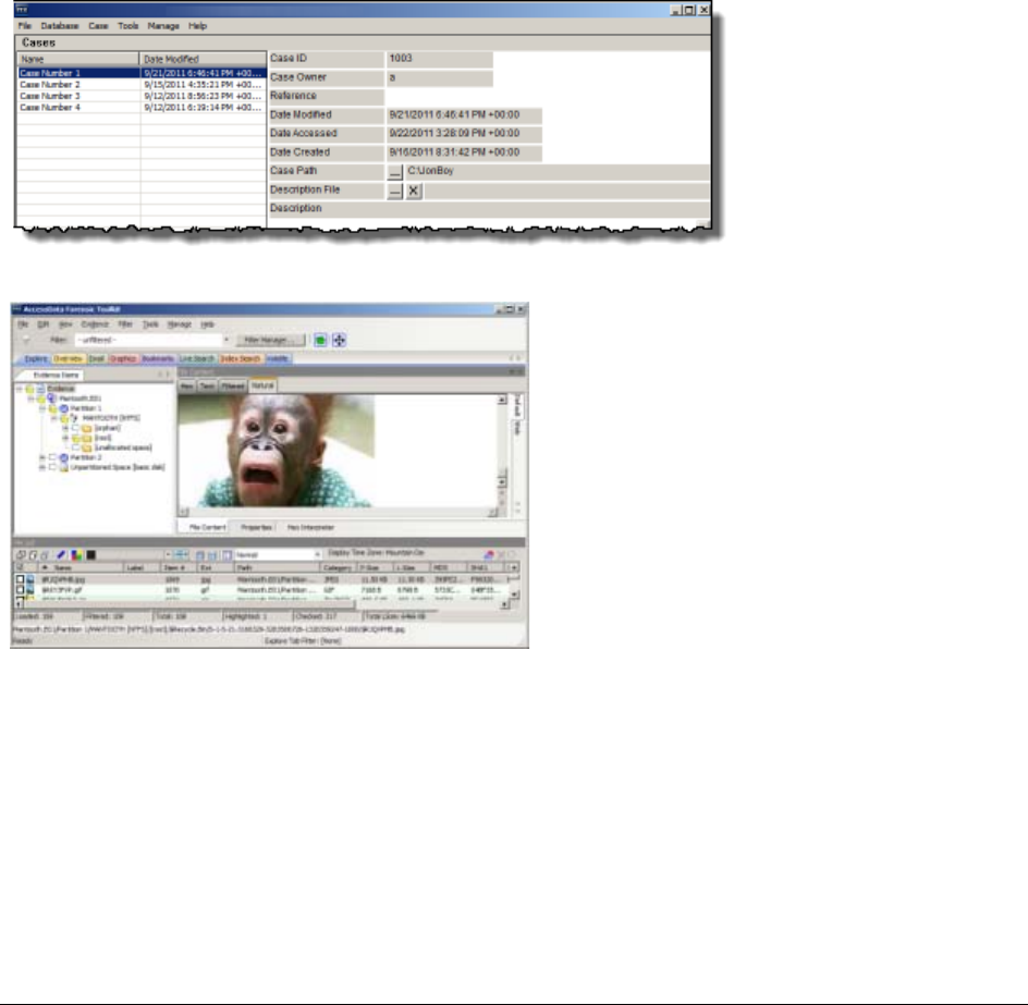
AccessData Forensic Toolkit includes interfaces that you use use to work with cases and evidence. The two
primary interfaces you use are the Case Manager and the Examiner. You use the Case Manager to manage
application settings that apply to multple cases. You use the Examiner to locate and interperate case data.
The following is an example of the Case Manager Interface:
The following is an example of the Examiner Interface:
For more information, see the following
-See Introducing Case Management (page 39)
-See Tabs of the Examiner Interface (page 148)


Creating an Application Administrator account | 28
Chapter 3
Application Administration
This section includes topics that discuss administration tasks that you can do within the Case Manager interface.
See the following topics:
-See Creating an Application Administrator account on page 28.
-See Changing Your Password on page 29.
-See Setting Database Preferences on page 29.
-See Managing Database Sessions on page 29.
-See Managing Shared KFF Settings on page 30.
-See Recovering and Deleting Processing Jobs on page 30.
-See Restoring an Image to a disk on page 30.
-See Adding New Users to a Database on page 31.
-See About Assigning Roles to Users on page 31.
-See Restrictions to the Case Reviewer Role on page 32.
-See About Assigning Permissions to Users on page 33.
-See Assigning Users Shared Label Visibility on page 33.
-See Setting Additional Preferences on page 33.
-See Managing Global Features on page 34.
Creating an Application Administrator account
Before you can use the Case Manager you must create and Application Administrator account and connect to
the database.The Case Manger lets you create other user accounts and perform other administrative tasks.
To create an Application Administrator account and connect to the database:
1. Launch the program.
2. If an existing database connection is not detected, you are prompted to Add Database.
3. In the RDBMS drop-down menu, select the type of database that you are connecting to.
4. Enter the IP address or DNS host name of the server hosting the database in the Host field. If the
database is on the same computer as the Examiner, you can leave this field empty.
5. (Optional) In the Display name field give the database connection a nickname.
6. Unless you have a custom database configuration, do not change the values for Oracle SID,
PostgreSQL dbname, or Port number.
7. Click OK.
8. If the connection attempt to the database is successful, the database is initialized.

Changing Your Password | 29
9. When the initialization process completes, create the Application Administrator account for that version
of the database schema. Enter the credentials for the account and click OK.
10. In the Please Authenticate dialog, enter the Application Administrator account credentials.
The Case Manager opens.
Changing Your Password
When you have authenticated into the system you can change your password.
To change your password
1. In Case Manager, click Database > Change Password.
2. In the Change Password dialog box, enter your current password.
3. Enter your new password in the New Password text box.
4. Verify your new password by entering it again in the Re-enter text box.
5. Click OK.
Setting Database Preferences
The preferences dialog lets you specify where to store the temporary file, the location of a network license and
whether you want to optimize the database after you process evidence.
To set database preferences
1. In the Case Manager, click Tools > Preferences. Type in or browse to the folder you want temporary
files to be written to.
2. Select a location for the temporary file folder.
The Temporary File Folder stores temporary files, including files extracted from Zip and email archives.
The folder is also used as scratch space during text filtering and indexing. The Temporary File Folder is
used frequently and should be on a drive with plenty of free space, and should not be subject to drive
space allocation limits.
3. If your network uses AccessData Network License Service (NLS), you must provide the IP address and
port for accessing the License Server.
4. Specify if you want to optimize the case database.
This is set to Optimize by default. Unmark the check box to turn off automatic optimization. This causes
the option to be available in Additional Analysis for those cases that were processed with Optimize
Database turned off initially. The Restore Optimization option in Additional Analysis does not appear if
Database Optimization is set in the New Case Wizard to be performed following processing, or if it has
been performed already on the current case from either place.
5. In the Preferences dialog, click OK.
Managing Database Sessions
You use the Sessions Management dialog to manage and track database sessions from in the Case Manager.
You can also use the Manage DB Sessions dialog to terminate cases that are open and consuming sessions,
but are inactive. This lets open file handles close so that processing can be restarted.
To open the Manage DB Sessions dialog, in the Case Manager, click Database > Session Management.

Managing Shared KFF Settings | 30
Managing Shared KFF Settings
The AccessData Known Files Filter can be managed from the Case Manager > Database menu. Click Manage
KFF to open the KFF Admin dialog box.
This functionality is also found in the Examiner main window under Manage menu. Click KFF > Manage to open
the KFF Admin dialog box.
The difference between the two is that sets and groups defined from Case Manager are automatically shared.
Those defined from the Examiner are local to the case. Otherwise, the functionality is the same.
Edit or delete existing custom defined groups or custom defined or imported sets, or add new groups; import a
selected group or set; export a group.
Recovering and Deleting Processing Jobs
Jobs that are started but unable to finish be restarted or deleted. Click Tools > Recover Processing Jobs. Click
Continue to see the Recover Processing Jobs dialog box. If it is empty there are no jobs that remain unfinished.
Click Close. If there are jobs in the list, you can choose whether to Restart or Delete those jobs.
To recover incomplete processing jobs
1. Click Tools > Recover Processing Jobs. If no jobs remain unfinished, an error message pops up.
Click Continue to see the Recover Processing Jobs dialog box. It is be empty. Click Close. If there are
jobs in the list, you can choose whether to Restart or Delete those jobs.
2. Click Select All, Unselect All, or mark the check box for each job to be recovered.
3. Do one of the following:
-Click Restart. In the Recovery Type dialog, choose the recovery type that suits your needs.
-Click Delete. Click Yes to confirm that you want to delete the job permanently
4. Click Close.
Restoring an Image to a disk
You can restore a disk image (001 (RAW/dd), E01, or S01) to a physical disk. The target disk must be the same
size or larger than the original, uncompressed disk.
To restore an image to a disk
1. In the Case Manager or in the Examiner, click Tools > Restore Image to Disk. The Restore Image to
Disk dialog opens.
2. Browse to and select the source image (must be RAW-dd/001, E01, or S01).
3. Click the Destination drive drop down to choose the drive to restore the image to.
If you have connected an additional target drive and it does not appear in the list, click Refresh to
update the list.
4. If the target (destination) drive is larger than the original, uncompressed data, and you don’t want the
image data to share the drive space with old data, mark the Zero-fill remainder of destination drive
check box.
5. If you need the operating system to see the target drive by drive letter, mark the Notify operating
system to rescan partition table when complete check box.
6. Click Restore Image.

Adding New Users to a Database | 31
Adding New Users to a Database
The Application Administrator can add new users to a database. The Add New user dialog lets you add users,
disable users, change a user’s password, set roles, and show disabled users.
To add a new user
1. Click Database > Administer Users > Create User.
2. In the Add New User dialog, enter information for the following:.
3. Click OK to apply the selected role to the new user.
4. Click OK to exit the Add New User dialog.
About Assigning Roles to Users
A user can have are two levels of roles assigned to him or her. A user can have initial roles granted that apply
globally across all cases in a database, and a user can also have specific roles granted for a specific case.
Roles can be granted as follows:
-Roles that apply to all cases in a database are granted from the Database > Administer Users dialog.
-Roles that apply to a specific case are granted from the Case > Assign Users dialog.
The permissions that are applied through roles are cumulative, meaning that if you apply more than one, the
greatest amount of rights and permissions become available.
When you assign roles that apply global accross the database, you cannot reduce the rights on a case-by-case
basis.
AccessData recommends that when you first create a user account, save the account and close the dialog
without setting a role. Then click Case > Assign Users to assign Roles on a case-by-case basis. You can also
assign all new users the Case Reviewer role for the database and, then selectively add additional roles roles as
needed on a case-by-base basis.
Assigning Initial Database-level Roles to Users
You can use the case manager to assign roles to users. Although the default roles can all be selected
concurrently, AccessData recommends that only one of these be selected for any user to avoid granting either
redundant or excessive permissions.
To assign initial database-level roles users:
1. In the Case Manager, click Database > Administer Users.
Field Description
User Name Enter the name that the user is known in program logs and other system
information.
Full Name Enter the full name of the user as it is to appear on case reports.
Password Enter and verify a password for this user.
Role Assign rights to the selected user name using roles. The default Roles are:
-Application Administrator: can perform all types of tasks, including add-
ing and managing users.
-Case Administrator: can perform all of the tasks an Application Adminis-
trator can perform, with the exception of creating and managing users.
-Case Reviewer: cannot create cases; can only process cases.

Restrictions to the Case Reviewer Role | 32
2. Do one of the following:
-If the user does not yet exist in the system click Create User to create the user.
-If the user does exist in the system, select the user's name and click Set Roles.
3. Click Set Roles to assign a role that limits or increases database and administrative access.
4. To assign a default role, mark the check box next to that role. The default roles are as follows:
-Application Administrator: can perform all types of tasks, including adding and managing users.
-Case Administrator: can perform all of the tasks an Application Administrator can perform, with the
exception of creating and managing users.
-Case Reviewer: cannot create cases; can only process cases.
5. Click OK to apply the selected role to the new user, save the settings, and return to the Add New User
dialog.
Assigning Additional Case-level Roles to Users
You can use the Case Manager to assign specific roles to users on a case-by-case basis.
To assign additional case-level roles to users:
1. In the Case Manager, select the case for which you want to grant additional roles to a user.
2. Click Case > Assign Users.
3. In the Assigned Users pane, select the user that you want to grant additional roles to.
4. Click Additional Roles.
5. In the Additional Roles dialog, under Additional Roles for this Case, select the roles that you want to
grant.
6. Click OK.
7. Click Done.
Restrictions to the Case Reviewer Role
The case reviewer role does not have all of the permissions that an application adminsistrator or the database
administrator have. The following tasks are unavailable to Case Reviewers:
TABLE 3-1
Permissions Denied to Case Reviewer Users
Create, Add, or Delete cases Use FTK Imager
Administer Users Use Registry Viewer
Data Carve Use PRTK
Manually data carve Use Find on Disk
Assign Users to cases Use the Disk Viewer
Add Evidence View file sectors
Access Credant Decryption from the
Tools Menu Define, Edit, Delete, Copy, Export, or Import
Filters
Decrypt Files from the Tools Menu Export files or folders
Mark or View Items Flagged as
“Ignorable” or “Privileged” Access the Additional Analysis Menu
Manage the KFF Backup or Restore Cases
Manage Fuzzy Hash Add a Database

About Assigning Permissions to Users | 33
About Assigning Permissions to Users
It is important to understand that when you create user accounts (Database > Administer Users) and assign
roles to users from that dialog, the roles you assign are global for this database; you cannot reduce their rights
on a case-by-case basis.
If you decide to limit that users rights by assigning a different role, you must return to the Database >
Administer Users dialog, select that user and choose Set Roles. Unmark the current role and click OK with no
role assigned here, or choose a different role that limits access, then click OK to save the new setting.
AccessData recommends that you first create the user account, save the account and close the dialog without
setting a Role. Then click Case > Assign Users to assign Roles on a case-by-case basis.
Or you could assign all new users the global Case Reviewer role, then selectively add the Case Administrator or
Application Administrator role as needed. The permissions that are applied through Roles are cumulative,
meaning that if you apply more than one, the greatest amount of rights and permissions become available.
Assigning Users Shared Label Visibility
Shared Labels give Application Administrators the added benefit of assigning Visibility to only specific users on a
case-by-case basis.
To assign Label Visibility
1. In Case Manager, click Case > Assign Users. The Assign Users for Case dialog opens, and a list of
users that have permissions in the currently selected case appears.
2. Highlight a User.
3. Click Label Visibility to open the Manage Label Visibility dialog.
To show or hide Labels
1. Select a User in the User List pane. The Shared Labels dialog opens. Initially all are set as Visible.
2. Move Labels as needed, based on the following:
-Select a Label you want that User not to see in any case, and click the > button.
-To move a Hidden Label into the Visible Labels pane, select it, and click the < button.
Setting Additional Preferences
Choosing a Temporary File Path
The Temporary File Folder stores temporary files, including files extracted from Zip and email archives. The
folder is also used as scratch space during text filtering and indexing. The Temporary File Folder is used
frequently and should be on a drive with plenty of free space, and should not be subject to drive space allocation
limits.
Enter Session Management Create Custom Data Views
TABLE 3-1
Permissions Denied to Case Reviewer Users (Continued)

Managing Global Features | 34
To specify a location for the Temporary File Folder
1. In the Case Manager, click Tools > Preferences. Type in or browse to the folder you want temporary
files to be written to.
2. Select the folder, then click OK.
3. In the Preferences dialog, verify the path is what you wanted, then click OK.
Providing a Network Security Device Location
If your network uses AccessData Network License Service (NLS), provide the IP address and port for accessing
the License Server.
Optimizing the Case Database
This is set to Optimize by default. Unmark the check box to turn off automatic optimization. This causes the
option to be available in Additional Analysis for those cases that were processed with Optimize Database turned
off initially.
Note: The Restore Optimization option in Additional Analysis will not appear if Database Optimization was set
in the New Case Wizard to be performed following processing, or if it has been performed already on the
current case from either place.
Managing Global Features
Several features that were previously available only in a case are now fully implemented for global application,
and are known as “Shared.” Since they are available globally, they are managed from the Case Manager
interface, under the Tools menu.
The Application Administrators manage all Shared features. It is a good practice to set these up to the extent you
are able, prior to creating your first case. Of course, new ones can be added at any time and copied to existing
cases, and can be created within cases by both Application and Case Administrators, and Shared (added to the
global list).
Since each Shared feature has been documented to some extent in other chapters of the User Guide, only the
parts of the features that apply specifically to Application Administrators are explained here. Cross-references
are added to provide quick access to more complete information.
Managing Carvers
Carvers provides a comprehensive tool that allows you to customize the carving process to access hidden data
exactly the way you need it.
To manage shared Carvers, from the Case Manager, click Manage > Carvers. The Manage Shared Custom
Carvers dialog opens. Here you can see, manage, and define Shared Custom Carvers.
You can create new, and edit or delete existing Shared Carvers. In addition, you can import and exported
carvers, and copy Carvers to cases that were previously processed without a particular Custom Carver.
There are no default carvers listed here. This list contains only custom-designed carvers that are Shared.
To create a Shared Custom Carver
1. From the Manage Shared Custom Carvers dialog shown above, click New.
2. Set the data carving options to use.

Managing Global Features | 35
3. Click Save when the new carver has been defined to meet your needs. You will see the new carver in
this list and when you mark the Carving option in the New Case Wizard.
4. In the Manage Shared Carvers dialog, click the appropriate button to:
-Create New shared custom carvers
-Edit existing shared custom carvers
-Delete shared custom carvers
-Import shared custom carvers that have been exported from cases
-Export shared custom carvers
-Copy shared custom carvers to a case
5. Click OK to close the Carving Options dialog.
Managing Custom Identifiers
Custom File Identification provides the examiner a way to specify which file category or extension should be
assigned to files with a certain signature.
While Custom Identifiers can be created and/or selected by a Case Administrator in the New Case Wizard,
Shared Custom Identifiers are created and managed from a separate menu.
To create a Shared Custom Identifier
1. In the Case Manager, click Manage > Custom Identifiers.
Initially, the Custom Identifiers List pane is empty, and the rest of the window is grayed-out.
2. Click Create New. The window activates.
3. Type a name for the new Custom Identifier. Notice that the name you type is also typed into the Custom
Identifiers List.
4. Type a description to help others know if this is the identifier file they are looking for.
5. Create the Custom Identifier by defining Operations and using the AND and OR buttons in a way similar
to if you were creating a filter.
6. When you are done defining this Custom Identifier, click Apply.
You can also do the following
-Click Delete to delete an unwanted or outdated identifier.
-Click Export to save the selected identifier as a .TXT file.
-Click Import to add an external identifier file.
-Click Close to close the Custom Identifiers dialog.
Managing Columns
Shared Columns use the same windows and dialogs that Local Columns use.
To create a Shared Column Template
1. In Case Manager, click Manage > Columns.
The Manage Shared Column Settings dialog opens.
2. Highlight a default Column Template to use as a basis for a Custom Column Template.
3. Click New.
4. Enter a new name in the Column Template Name field.

Managing Global Features | 36
5. Select the Columns to add from the Available Columns pane, and click Add >> to move them to the
Selected Columns pane.
6. Select from the Selected Columns pane and click Remove to clear an unwanted column from the
Selected Columns.
7. When you have the new column template defined, click OK.
See also Customizing File List Columns (page 216).
Managing File Extension Maps
Extension Maps can be used to define or change the category associated to any file with a certain file extension.
For example, files with .BAG extension which would normally be categorized as “Unknown Type” can be
categorized as an AOL Bag File, or a files with a .MOV extension that would normally be categorized as Apple
QuickTime video files can be changed to show up under a more appropriate category since they can sometimes
contain still images.
To create a Shared Custom Extension Mapping
1. In the Case Manager, click Manage > File Extension Maps.
2. In the Custom Extension Mapping dialog, click Create New.
3. Type a name for the new mapping.
4. Enter a description for easier identification.
5. In the Category pane, select a file type you want to map an extension to.
6. Click Add Extension.
The Add New Extension dialog box opens.
7. Type the new extension to add.
8. Click OK.
You can also do the following:
-Click Delete to remove an unwanted or outdated mapping.
-Click Import to add an external Custom Extension Mapping file for Shared use.
-Click Export to save a Custom Extension Mapping file.
-Click Close to close the Custom Extension Mapping dialog.
See also Custom Case Extension Maps (page 73).
Managing Filters
Filters consist of a name, a description, and as many rules as you need. A filter rule consists of a property, an
operator, and one or two criteria. (You may have two criteria in something like a date range.)
To create a new Shared filter
1. From Case Manager, click Manage > Filters.
The Manage Shared Filters dialog opens.
2. Do one of the following:
-If there is an existing Filter in the Filters list that you want to use as a pattern, or template, highlight
that Filter and click Copy.
-If there is no Filter that will work as a pattern, Click New.
3. Type a name and a short description of the new Filter.

Managing Global Features | 37
4. Select a property from the drop-down menu.
5. Select an operator from the Properties drop-down menu.
6. Select the applicable criteria from the Properties drop-down menu.
7. Each property has its own set of operators, and each operator has its own set of criteria. The possible
combinations are vast.
8. Select the Match Any operator to filter out data that satisfies any one of the filter rules or the Match All
operator to filter out data that satisfies all rules of the filter.
You can test the filter without having to save it first. Check the Live Preview box to test the filter as you
create it.
9. Click Save.
10. Click Close.
The new Custom Shared Filter now appears in the Manage Shared Filters list.
See also Filtering Evidence (page 112).
Managing Labels
To create a Shared Label
1. In Case Manager, click Manage > Labels.
The Manage Shared Labels dialog opens.
2. Click New. A text entry box opens on the first available line in the Name list.
3. Type a name for this Label, and press Enter. The Label is saved with the default color (black).
4. Click Change Color. The Color dialog opens. You can use any color from the default palette, or click
Define Custom Colors to create a unique color for this Label. Use the cross-hairs and the slide to
create the color you want, then click Add to Custom Colors, then select the custom color from the
Custom colors palette.
5. Click OK. The Manage Labels dialog reopens. You can see your new Label listed with the color you
defined or selected.
6. Click Close.
See also Working with Labels (page 120).

| 38
Part III
Case Management
This part contains information about managing cases. It contains the following chapters:
-Introducing Case Management (page 39)
-Starting New Cases (page 55)
-Managing Case Data (page 79)
-Working with Evidence Image Files (page 84)
-Working with Static Evidence (page 89)
-Working with Live Evidence (page 100)
-Filtering Evidence (page 112)
-Working with Labels (page 120)
-Running Cerberus Malware Analysis (page 124)
-Decrypting EFS and Other Encrypted Files (page 130)
-Exporting Data from the Examiner (page 140)

About Case Management | 39
Chapter 4
Introducing Case Management
This chapter includes the following topics:
-About Case Management (page 39)
-The User Interfaces (page 39)
-About the Cases List (page 39)
-Menus of the Case Manager (page 40)
-Menus of the Examiner (page 44)
About Case Management
Case management includes creating new cases, as well as performing backup, archive, detach, restore and
attach functions for cases, deleting cases from the database, and managing case and evidence files.
Case management tasks are performed from the Case Manager.
Note: Multiple user names in a case are correctly automatically assigned to Original User Names when a case
is Archived, or Archived and Detached, and then restored. They can also be reassigned if necessary.
See Creating a Case (page 56)
See Managing Case Data (page 79)
The User Interfaces
The Case Manager lets you add and manage cases, users, roles and permissions, and do other management
tasks. You can use the Case Manager to apply settings globally to all cases in the system.
Menus of the Case Manager (page 40)
You can use the Examiner to locate, bookmark, and report on evidence.
Menus of the Examiner (page 44)
About the Cases List
The Cases List shows all of the cases that are available to the currently authenticated user. The right pane
displays information about the cases. The information that is shown for Case File, Description File, and
Description are determined by the either the Application Administrator or the Case Administrator.
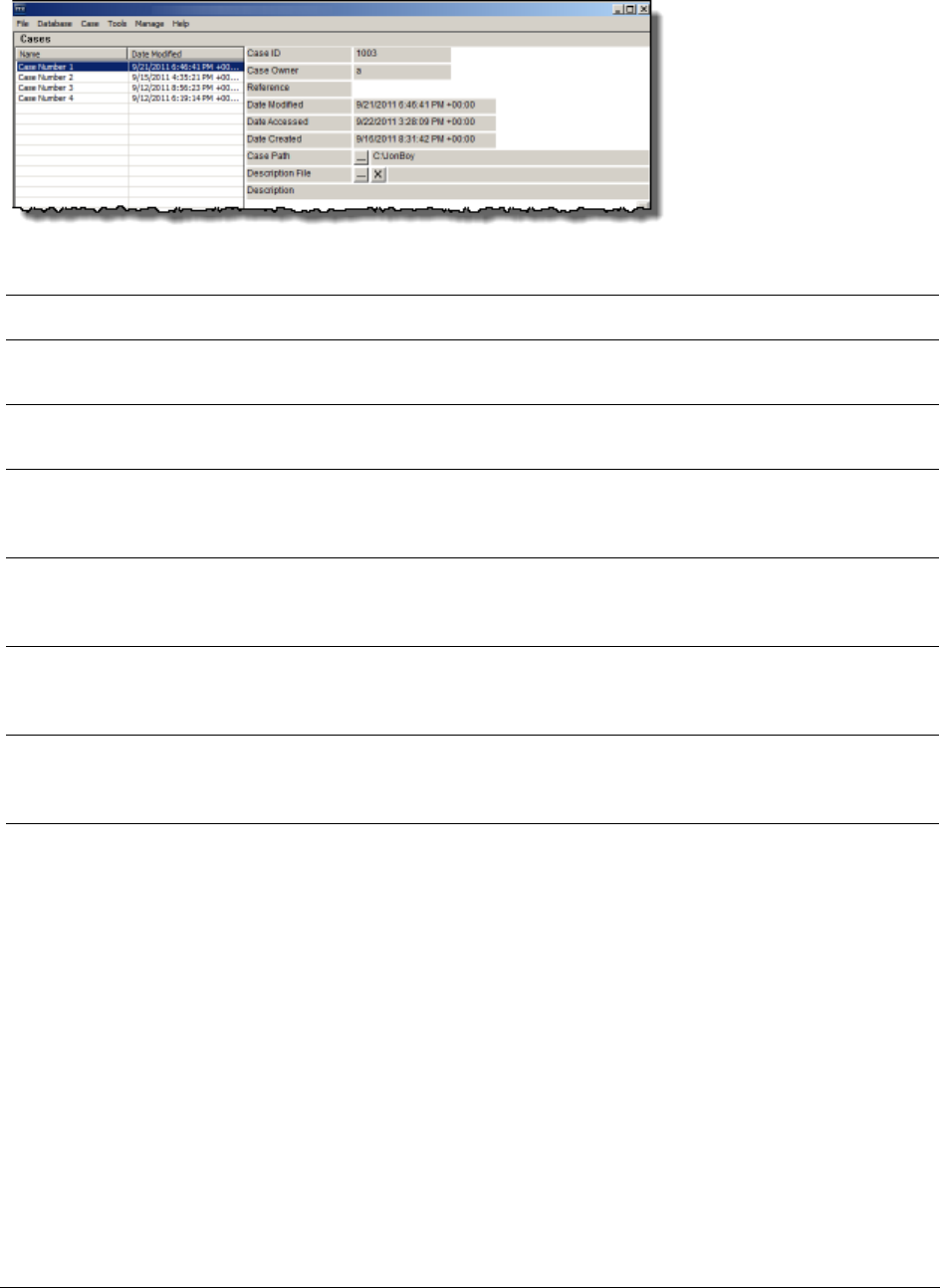
Menus of the Case Manager | 40
File The File menu lets you exit the Case Manager.
See Options of the Case Manager’s File Menu (page 40)
Database The Database menu lets you administer users and roles.
See Options of the Case Manager’s Database Menu (page 41)
Case The Case menu lets you create, backup, and delete cases. You can also assign users to
roles.
See Options of the Case Manager’s Case Menu (page 41)
Tools The Tools menu lets you configure the processing engine, recover interupted jobs and
restore images to a disk.
See Options of the Case Manager’s Tools Menu (page 42)
Manage The Manage menu lets you adminstrate shared objects such as columns, labels and
carvers.
See Options of the Case Manager Manage Menu (page 43)
Help The Help menu lets you access the user guide as well as view version and copyright
information.
See Options of the Case Manager’s Help Menu (page 43)
Menus of the Case Manager
Options of the Case Manager’s File Menu
TABLE 4-1
Case Manager Menus
Menu More Information
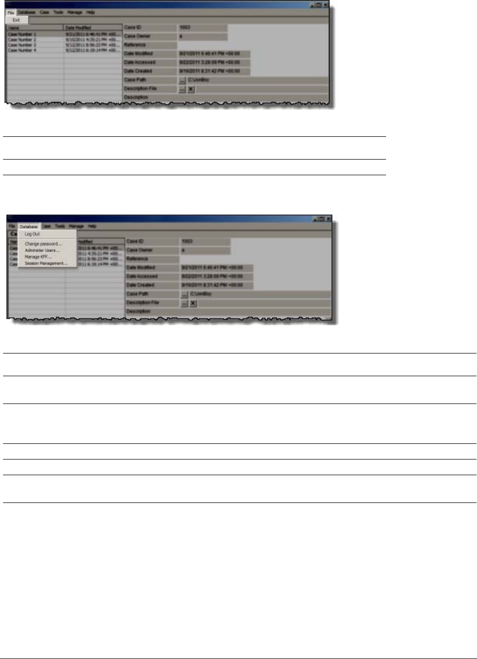
Menus of the Case Manager | 41
Options of the Case Manager’s Database Menu
Log In/ Log Out Opens the authentication dialog for users to log into the database. You can log out the
currently authenticated user without closing the program.
Change password Opens the Change Password dialog. The currently authenticated user can change their
own password by providing the current password, then typing and re-typing the new
password.
Administer Users Lets you manage user accounts. The Application Administrator can change Users’ roles
Manage KFF Opens the KFF Admin dialog
Session
Management
Opens the Manage Database Sessions dialog. Click Refresh to update the view of current
sessions. Click Terminate to end sessions that are no longer active.
Options of the Case Manager’s Case Menu
TABLE 4-2
Options of the Case Manager’s File Menu
Option Description
Exit Exits and closes the program.
TABLE 4-3
Options of the Case Manager’s Database Menu
:Option Description
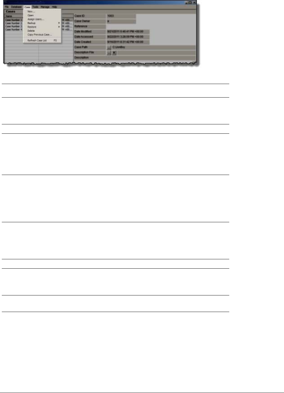
Menus of the Case Manager | 42
New Start a new case with the currently authenticated user as the Case
Administrator. Case Reviewers cannot create a new case.
See Creating a Case (page 56)
Open Opens the highlighted case with its included evidence.
Assign Users Allows the Application Administrator or the Case Administrator to
adjust or control the rights of other users to access a particular case.
Also allows the Administrator to control which users can see which
of the Shared Labels that are available.
See What you can do with Labels (page 120)
Backup Opens a dialog for specifying names and locations for backup of
selected cases. Options are:
Backup
Archive
Archive and Detach
Restore Opens a Windows Explorer instance for locating and restoring a
selected, saved case. Options are:
Restore an archived case.
Attach an archived and detached case.
Delete Deletes the selected case. Pop-up appears to confirm deletion.
Copy Previous Case Copy a case from a previous version into the database.
The use of a UNC folder path is no longer required beginning with
version 3.2 and newer.
Refresh Case List Right-click in the Cases List area and select Refresh Case List, or
click F5 to refresh the case list with any new information.
Options of the Case Manager’s Tools Menu
TABLE 4-4
Options of the Case Manager’s Case Menu
Option Description
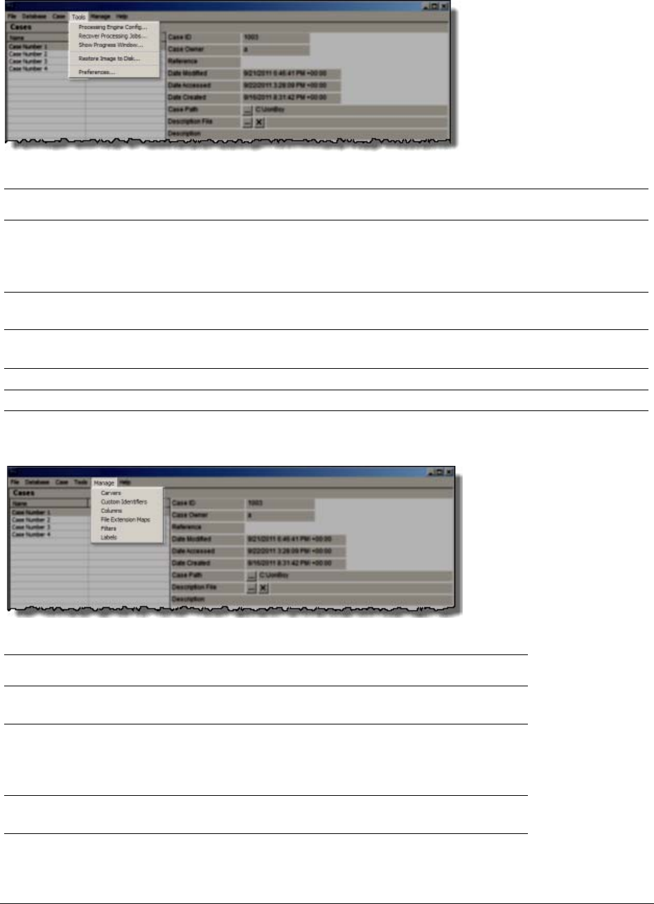
Menus of the Case Manager | 43
Processing Engine
Config
Opens the Processing Engine Configuration dialog. Configure Remote Processing
Engines here. Specify Computer Name/IP Address, and Port. Add new Remove,
Enable or Disable configured Processing Engines. For more information see the
Installation Guide.
Recover Processing
Jobs
Allows you to recover jobs that were interrupted during processing so the processing
can be completed.
Show Progress
Window
Opens the Progress window so you can check the Processing Status.
Restore Image to Disk Copies a disk image to a disk other than the original.
Preferences Opens Preferences dialog.
Options of the Case Manager’s Manage Menu
Options of the Case Manager’s Help Menu
TABLE 4-5
Options of the Case Manager’s Tools Menu
Option Description
TABLE 4-6
Options of the Case Manager Manage Menu
Option Description
Carvers Manage Shared Custom Carvers. Custom Carvers created here can
be copied to cases.
Custom Identifiers Manage Shared Custom Identifiers. Custom Identifiers created here
are automatically made available to all new cases, but cannot be
copied directly to earlier cases. They must be exported and then
imported into such cases.
Columns Manage Shared Column Settings. Custom Columns created here
can be copied to cases.
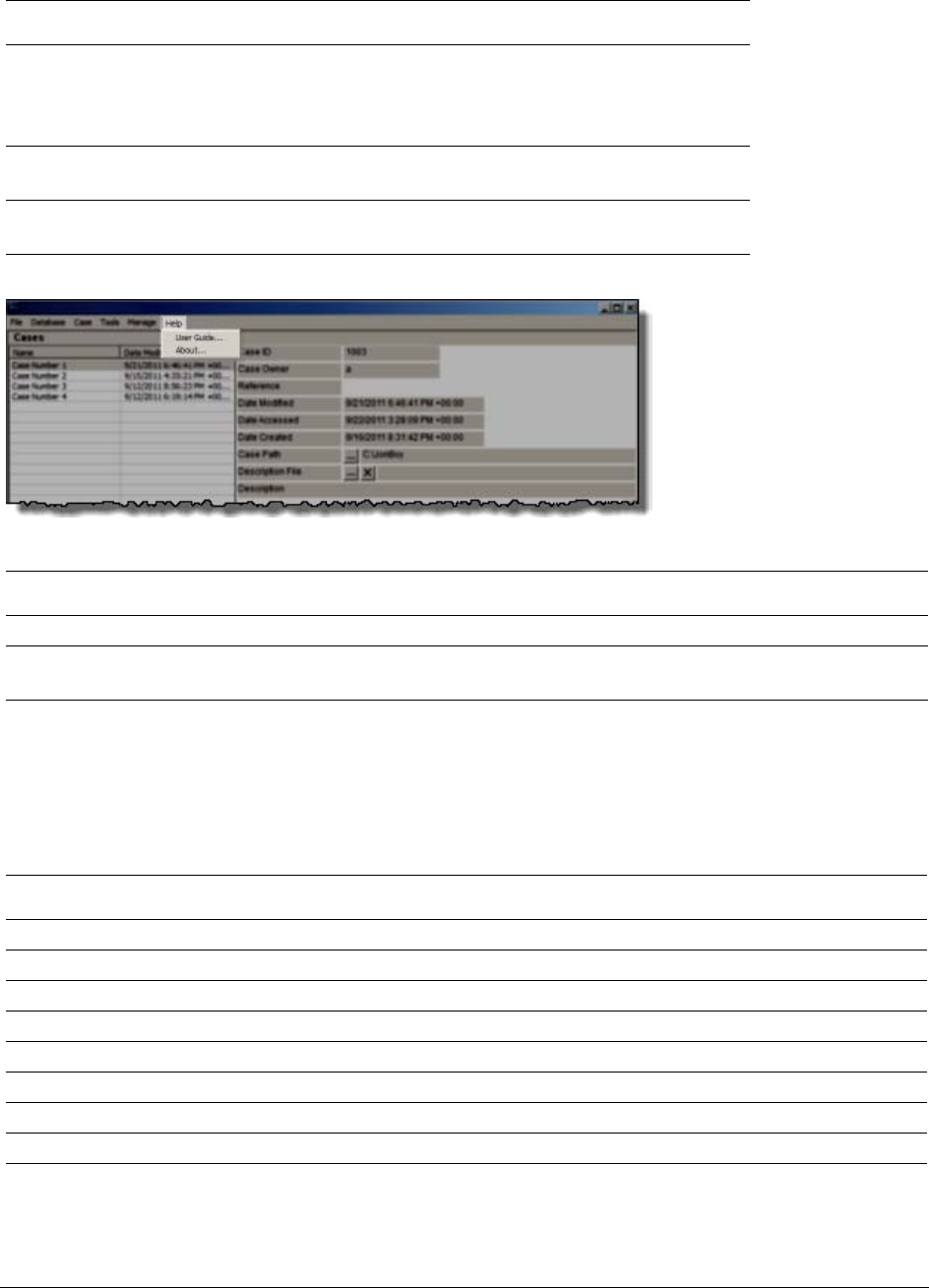
Menus of the Examiner | 44
Menus of the Examiner
When a case is created and assigned a user, the Examiner window opens with the following menus:
File See Options of the Examiner’s File Menu (page 45)
Edit See Options of the Examiner’s Edit Menu (page 46)
View See Options of the Examiner’s View Menu (page 46)
Evidence See Options of the Examiner’s Evidence Menu (page 48)
Filter See Options of the Examiner’s Filter Menu (page 50)
Tools See Options of the Examiner’s Filter Menu (page 50)
Manage See Options of the Examiner’s Manage Menu (page 53)
Help See Options of the Examiner’s Help Menu (page 54)
File Extension Maps Manage Shared File Extension Mappings. File Extension Maps
created here are automatically made available to all new cases, but
cannot be copied directly to earlier cases. They must be exported
and then imported into such cases.
Filters Manage Shared Filters. Custom Filters created here can be copied
to cases.
Labels Manage Shared Labels. Custom Labels created here can be copied
to cases.
User Guide Opens the user guide in PDF format.
About Provides version and build information, copyright and trademark information, and other
copyright and trade acknowledgements.
TABLE 4-7
Options of the Case Manager Help Menu
Option Description
TABLE 4-8
Examiner Menus
Menu Description
TABLE 4-6
Options of the Case Manager Manage Menu
Option Description
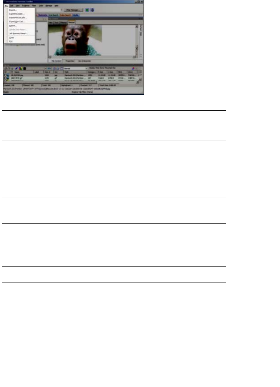
Menus of the Examiner | 45
Options of the Examiner’s File Menu
Export Exports selected files and associated evidence to a designated
folder.
Export to Image Exports one or more files as an AD1 image to a storage
destination.
When exporting to AD1 the image's file path is added under a
root directory. This speeds the process of gathering data for the
AD1, and for shortening the path to AD1 content.
Export File List Info Exports selected file information to files formatted as the
Column List in .CSV, .TSV, and .TXT formats.
Export Word List Exports the discrete words from the index as a text file from
which a dictionary for PRTK can be created.
See Exporting a Word List (page 144)
Report Opens the Report Options dialog for creating a case report.
See Creating a Case Report (page 221)
Volatile Data Report Opens a Volatile Data Report created from live data collected
remotely and added to this case. This option is grayed out
unless Volatile Data has been added to the case.
Close Closes the Examiner and returns to the FTK Case Manager
window.
Exit Closes both the Examiner and Case Manager windows.
TABLE 4-9
Options of the Examiner’s File Menu
Option Description
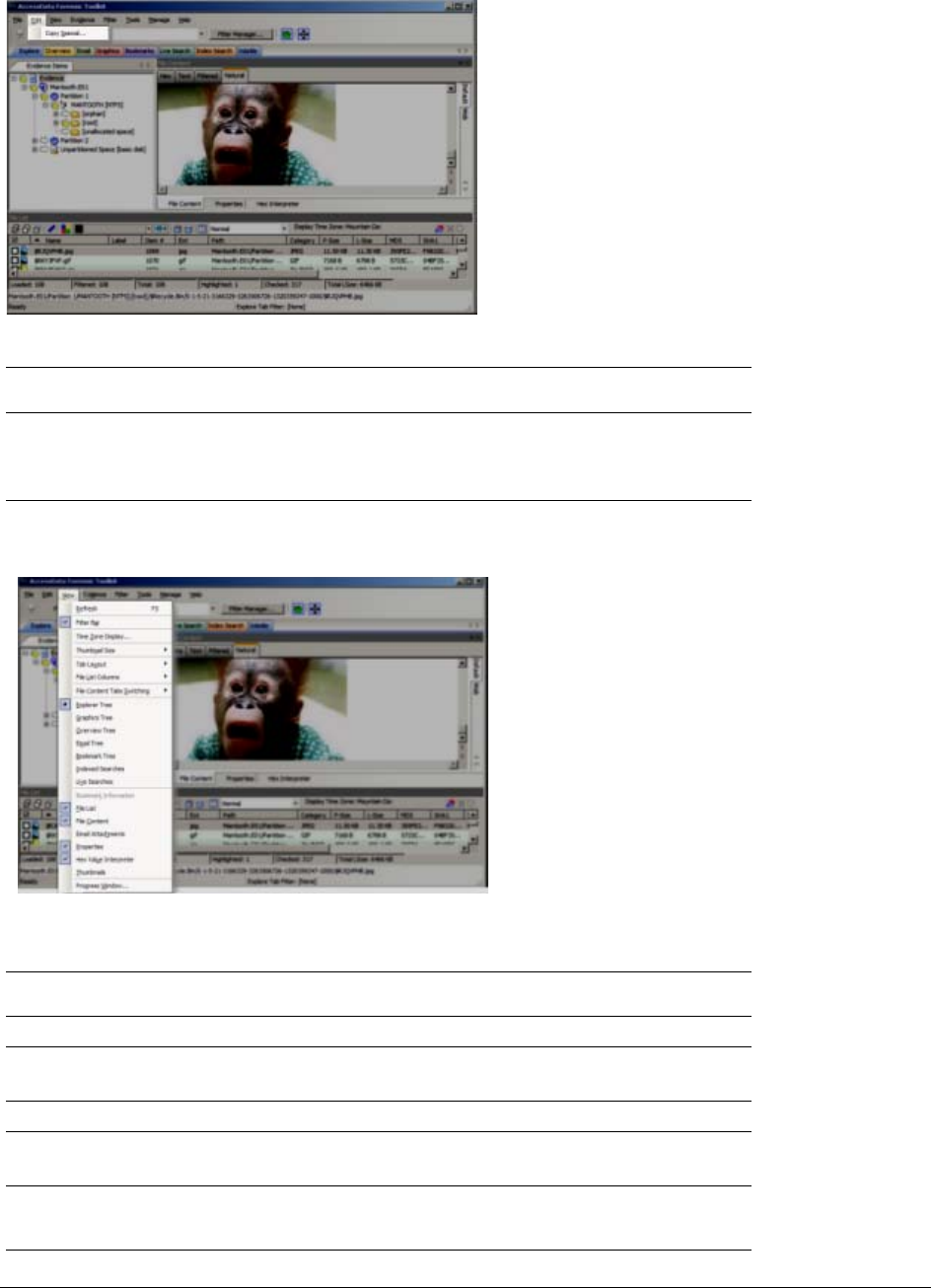
Menus of the Examiner | 46
Options of the Examiner’s Edit Menu
Copy Special Duplicates information about the object copied as well as the
object itself, and places the copy in the clipboard.
See Copying Information from the Examiner (page 140)
Options of the Examiner’s View Menu
TABLE 4-10
Options of the Examiner’s Edit Menu
Option Description
TABLE 4-11
Options of the Examiner’s View Menu
Option Description
Refresh Reloads the current view with the latest information.
Filter Bar Inserts the filter toolbar into the current tab. These features are
also available from the Filter menu.
Time Zone Display Opens the Time Zone Display dialog.
Thumbnail Size Selects the size of the thumbnails displayed from the Graphics
tab. Select from:
Large-default
Medium
Small
Tiny

Menus of the Examiner | 47
Tab Layout Manages tab settings: the user can lock an existing setting, add
and remove settings, and save settings one tab at a time or all
at once. The user can also restore previous settings. or reset
them to the default settings. These options are in the following
list:
Save
Restore
Reset to Default
Remove
Save All Tab Layouts
Lock Panes
Add New Tab Layout
FIle List Columns Specifies how to treat the current File List. Options are:
Save As Default
Save All as Default
Reset to Factory Default
Reset All To Factory Default
File Content Tabs
Switching
Specifies the behavior of file content when a different tab is
selected. Options are:
Auto Manual
Explore Tree Exclusive. Displays the Explore Tree in the upper-left pane.
Graphics Tree Exclusive. Displays the Graphics Tree in the upper-left pane.
Overview Tree Exclusive. Displays the Overview Tree in the upper-left pane.
Email Tree Exclusive. Displays the Email Tree in the upper-left pane.
Bookmark Tree Exclusive. Displays the Bookmark Tree in the upper-left pane.
Index Searches Exclusive. Displays the Index Search Results pane in the upper-
left pane.
Live Searches Exclusive. Displays the Live Search Results pane in the upper-
left pane.
Bookmark Information Adds the Bookmark Information pane into the current tab.
File List Adds the File List pane into the current tab.
File Content Adds the File Content pane into the current tab.
Email Attachments Displays the attachments to email objects found in the case.
Available only in the Email and Overview tabs.
Properties Inserts the Object Properties pane into the current tab view.
Hex Value Interpreter Displays a pane that provides an interpretation of Hex values
selected from the Hex View pane.
Thumbnails Displays a pane containing thumbnails of all graphics found in
the case.
Progress Window Opens the Progress dialog, from which you can monitor tasks
and/or cancel them.
TABLE 4-11
Options of the Examiner’s View Menu (Continued)
Option Description
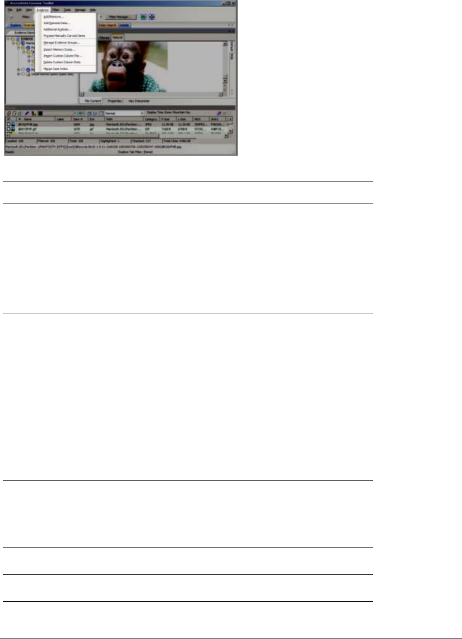
Menus of the Examiner | 48
Options of the Examiner’s Evidence Menu
TABLE 4-12
Options of the Examiner’s Evidence Menu
Option Description
Add/Remove Opens the Manage Evidence dialog, used to add and remove
evidence. From Manage Evidence, choose from the following:
Time Zone — Choose Time Zone for evidence item.
Refinement Options — Select Evidence Refinement Options.
Language Setting — Choose the language of the evidence item.
Define and Manage Evidence Groups
Select Case KFF Options
Add Remote Data Opens the Add Remote Data dialog from which you can
remotely access volatile, memory, and/or drive data and add it
to the case. To Collect remote data from another computer on
the network, provide the following:
Remote IP Address
Remote Port
Select any or all of the following:
Physical Drives (Can be mapped using RDMS)
Logical Drives (Can be mapped using RDMS)
Memory Analysis
Click OK or Cancel.
Additional Analysis Opens the Additional Analysis dialog with many of the same
processing options available when the evidence was added.
Allows the user to reprocess using available options not
selected previously.
See Additional Analysis (page 94).
Process Manually
Carved Items
Initiates the processing of items that have been manually
carved, using the selected options.
Manage Evidence
Groups
Opens the dialog where you can create and manage Evidence
Groups.

Menus of the Examiner | 49
Import Memory Dump Opens the Import Memory Dump File dialog which allows you to
select memory dumps from other case files or remote data
acquisitions, and import them into the current case. The
memory dump file must have been previously created.
See Importing Memory Dumps (page 111)
Import Custom Column
File
When a Custom Column settings file has been created, import it
into your case using this tool.
Delete Custom Column
Data
If you have imported or created a Custom Column settings file,
use this tool to delete the associated column and its data from
the view
Merge Case Index Merges fragmented index segments to improve performance of
index-related commands, such as Index Searching.
TABLE 4-12
Options of the Examiner’s Evidence Menu (Continued)
Option Description
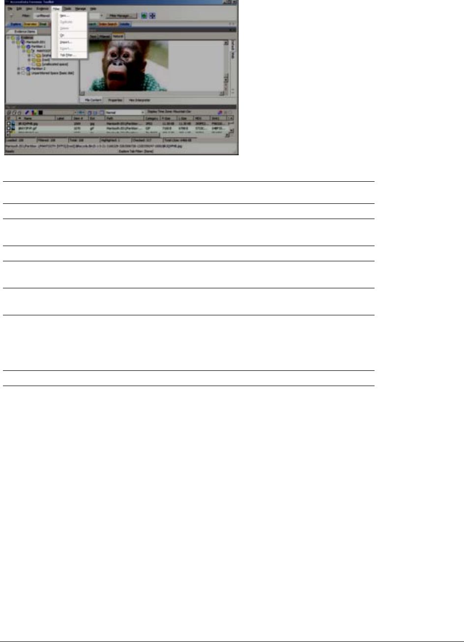
Menus of the Examiner | 50
Options of the Examiner’s Filter Menu
New Opens the Filter Definition dialog to define a temporary filter.
Duplicate Duplicates a selected filter. A duplicated filter serves as a
starting point for customizing a new filter.
Delete Deletes a selected filter.
On Applies the selected filter globally in the application. The File
List changes color to indicate that the filter is applied.
Import Opens the Windows file manager allowing the user to import a
pre-existing filter.
Export Opens the Windows File Manager allowing the user to save a
filter.
The name of the filter cannot have any special or invalid
characters or the export will not work.
Tab Filter Allows the selection of a filter to apply in the current tab.
TABLE 4-13
Options of the Examiner’s Filter Menu
Option Description
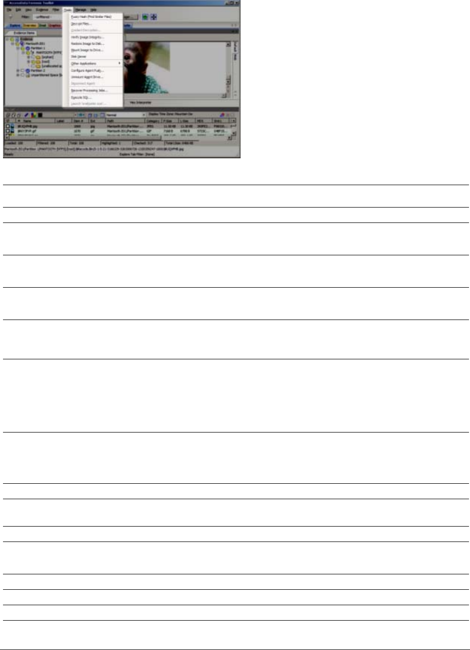
Menus of the Examiner | 51
Options of the Examiner’s Tools Menu
TABLE 4-14
Options of the Examiner’s Tools Menu
Option Description
Fuzzy Hash Allows you to Find Similar Files
Decrypt Files Decrypts EFS and Office files using passwords you enter.
See Decrypting EFS and Other Encrypted Files (page 130)
Credant Decryption Opens the Credant Decryption dialog where you enter the decryption information.
See Decrypting Credant Files (page 134)
Verify Image Integrity Generates hash values of the disk image file for comparison.
See Verifying Drive Image Integrity (page 84)
Restore Image to Disk Restores a Physical image to a disk. If the original drive was on a bootable partition,
the restored image may also be bootable. This feature is disabled for Case
Reviewers.
Mount Image to Drive Allows the mounting of a physical or logical image read-only viewing. Logically
mounting images allows them to be viewed as a drive-letter in Windows Explorer.
Mounted logical drives now show the user the correct file, even when a deleted file
with the same name exists in the same directory.
See Mounting an Image to a Drive (page 85)
Disk Viewer Opens a hex viewer that allows you to see and search contents of evidence items.
Search Text for a term using Match Case, ANSI, Unicode, Regular Expression or
Search Up instead of down; Search Hex using Search Up. Specify a logical sector or
a cluster.
Other Applications Opens other AccessData tools to complement the investigational analysis.
Configure Agent Push Opens configuration dialog for pushing the FTK Agent to remote machines for data
acquisition.
Unmount Agent Drive Unmount a remote drive that is mounted through RDMS.
Push Agents Push, or install, an Agent to a remote machine. You can Add, Remove, Import, or
Export a single machine or a list of machines here.
Disconnect Agent Disconnect a remote agent.
Recover Processing Jobs Restarts processing so jobs that were interrupted can be completed.
Execute SQL Executes a user-defined SQL script from within FTK.

Menus of the Examiner | 52
Launch ‘oradjuster.exe’ Runs Oradjuster.exe to temporarily optimize the available memory on the FTK &
database machine (does not work on a two-box install).
See Appendix G AccessData Oradjuster (page 276)
TABLE 4-14
Options of the Examiner’s Tools Menu (Continued)
Option Description
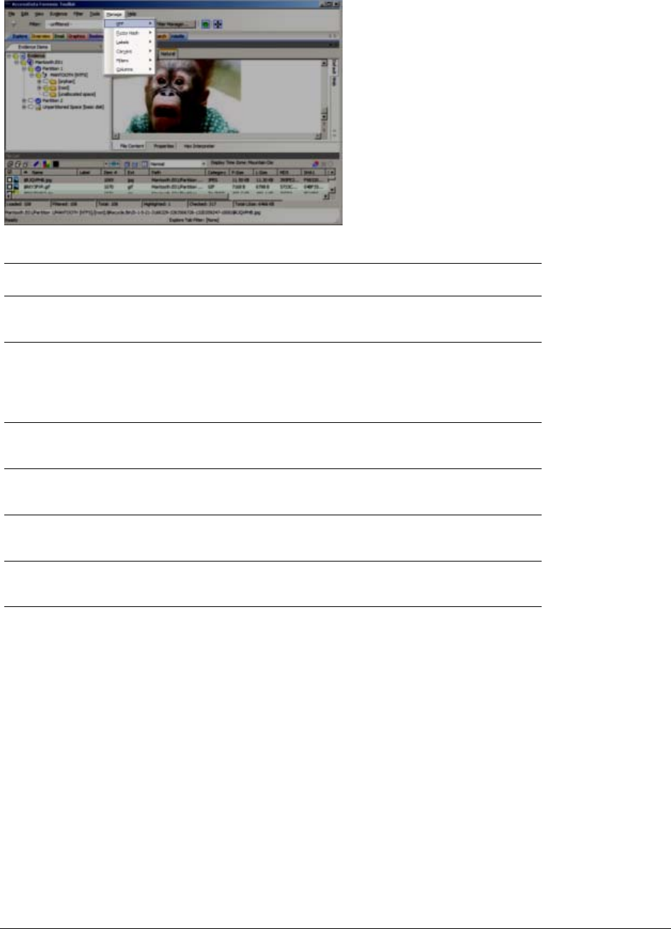
Menus of the Examiner | 53
Options of the Examiner’s Manage Menu
KFF Library Manage Known File Filter (KFF) Library, sets, and groups.
See Appendix D Working with the KFF Library (page 244).
Fuzzy Hash Fuzzy Hashing allows you to find files that are similar, rather
than exact matches that the KFF or any normal MD5 hash tool
finds.
See About Fuzzy Hashing (page 59)
Labels Manage Local and Shared Labels as well as Label Groups.
See What you can do with Labels (page 120).
Carvers Manage Local and Shared Custom Carvers.
See Data Carving (page 67).
Filters Manage Local and Shared Filters.
See Filtering Evidence (page 112).
Columns Manage Local and Shared Columns.
See Customizing File List Columns (page 216).
TABLE 4-15
Options of the Examiner’s Manage Menu
Tool Type Description
Menus of the Examiner | 54
Options of the Examiner’s Help Menu
User Guide Provides a link to the User Guide.
About Provides version and copyright information about this release,
and acknowledgements for third-party resources and licenses
used in production.
TABLE 4-16
Options of the Examiner’s Help Menu
Option Description

Opening an Existing Case | 55
Chapter 5
Starting New Cases
This chapter explains how to create a new case. If you have cases that were created in version 2.2 or later, you
can convert them to the latest version. See Converting a Case from versions 2.2+ on page 77.
This chapter includes the following topics:
-Opening an Existing Case (page 55)
-Creating a Case (page 56)
-Configuring Case Detailed Options (page 56)
-Evidence Processing Options (page 57)
-About Fuzzy Hashing (page 59)
-Compound Files (page 63)
-dtSearch Text Indexing Options (page 65)
-Data Carving (page 67)
-Running Optical Character Recognition (OCR) (page 70)
-About Explicit Image Detection (page 71)
-Including Registry Reports (page 72)
-Send Email Alert on Job Completion (page 72)
-Custom File Identification Options (page 72)
-Evidence Refinement (Advanced) Options (page 74)
-Adding Evidence to a New Case (page 77)
-Converting a Case from versions 2.2+ (page 77)
Opening an Existing Case
After cases are created, it is likely that you will need to shut down the case and the program and return to it in the
future.
To open an existing case
1. Open the Case Manager.
2. In the Case Manager, highlight and double-click the case to open it.
Note: If you attempt to open a case you have not been assigned to, you will receive a message saying, “You
have not been assigned to work on this case.” This is because you must be authenticated to open the
case.

Creating a Case | 56
Creating a Case
Case information is stored in a database, and allows case administration as each new case is created.
To start a new case
1. Open the Case Manager.
2. Click Case > New. The New Case Options dialog opens.
3. Enter a name for the case in the Case Name field.
4. (Optional) Enter any specific reference information in the Reference field.
5. (Optional) Enter a short description of the case in the Description field.
6. You can use the Description File option to can attach a file to the case. For example you can use this
field to attach a work request document or a warrant to the case.
7. In the Case Folder Directory field specify where to store the case files. If you wish to specify a different
location for the case, click the Browse button.
Note: If the case folder directory is not shared, an error occurs during case creation.
8. (Optional) In the Database Directory field you can specify a location for where to store database
directory files. You can check the In the case folder option to save the database directory in the case
folder. If you do not specify these options, the database directory is saved to the default location of the
database.
Note: The location that you specify for Database Directory is relative to your database computer. If you
intend to specify a location that is on a different computer than your database, for example in a
multi-box scenario, then you must enter a network path.
9. If you wish to create the case in Field Mode, mark the Field Mode box. Field Mode disables the
Detailed Options button when creating a case.
In addition to disabling Detailed Options, the Field Mode option bypasses file signature analysis. This
can speed up processing.
Note: The Job Processing screen always shows 0 for Queued when Field Mode is enabled, because
items move directly from Active Tasks to Completed.
10. If you wish to open the case as soon as it is created, mark Open the case.
11. If you do not select Field Mode, click Detailed Options to specify how you want the evidence to be
treated as it is processed and added to the case. The case creation steps are continued in the following
section.
12. Configure the case Detailed Options.
See Configuring Case Detailed Options on page 56.
13. Click OK to create the new case.
Configuring Case Detailed Options
Create a case using the default Detailed Options, or select options to fit your needs.
Note: One factor that may influence which processes to select is your schedule. If you disable indexing, it
shortens case processing time. The case administrator can return at a later time and index the case if
needed. The fastest way to create a case and add evidence is to use Field Mode.
To define the evidence processing options
1. From the New Case Options dialog, click Detailed Options.
1a. Click the Evidence Processing icon in the left pane, and select the processing options to run on the
evidence currently being added.

Evidence Processing Options | 57
Note: Select File Listing Database here in pre-processing to create a .CSV database of the evidence
files to use in MS Excel or MS Access.
1b. Click the Evidence Discovery icon to specify the location of the Custom Identifier File, if one is to
be used. For more information, see Custom File Identification Options (page 72).
1c. Click the Evidence Refinement (Advanced) icon to select the custom file identification file to use on
this case. For more information, see Custom File Identification Options (page 72).
1d. Click the Index Refinement (Advanced) icon to select which types of evidence to not index. For
more information, see Evidence Refinement (Advanced) Options (page 74).
2. Click OK.
3. When you are satisfied with your evidence refinement options, click OK to continue to the Evidence
Processing screen.
Evidence Processing Options
The following table outlines the Evidence Processing options:
TABLE 5-1
Evidence Processing Options
Process Description
MD5 Hash Creates a digital fingerprint using the Message Digest 5
algorithm, based on the contents of the file. This fingerprint
can be used to verify file integrity and to identify duplicate
files.
SHA-1 Hash Creates a digital fingerprint using the Secure Hash Algorithm-
1, based on the contents of the file. This fingerprint can be
used to verify file integrity and to identify duplicate files.
SHA-256 Hash Creates a digital fingerprint using the Secure Hash Algorithm-
256, based on the contents of the file. This fingerprint can be
used to verify file integrity and to identify duplicate files. SHA-
256 is a hash function computed with 32-bit words, giving it a
longer digest than SHA-1.
Fuzzy Hash Fuzzy hashes are hash values that can be compared to
determine how similar two pieces of data are. See About
Fuzzy Hashing (page 59).
Note: The Hash fields in the case may be empty for files carved from
unallocated space.
Match Fuzzy Hash Library Activated when Fuzzy Hash is marked. Match new evidence
against the Fuzzy Hash Library with this option.
Flag Duplicate Files Identifies files that are found more than once in the evidence.
This is done by comparing file hashes.

Evidence Processing Options | 58
KFF Using a database of hashes from known files, this option flags
insignificant files as ignorable files and flags known illicit or
dangerous files as alert files, alerting the examiner to their
presence in the case
Both AD KFF Alert and AD KFF Ignore groups are selected by
default. If you have custom groups and you want them to be
enabled, specify them under the Case KFF Options. If
evidence is processed before KFF is installed, then after
installing KFF Additional Analysis is performed for KFF, there
is no prompt to go into Case KFF Options and select the KFF
groups to process. This may leave the user thinking that the
evidence has reprocessed with KFF but it hasn’t.
For more information about using and managing the Known
File Filter (KFF), see Appendix D Working with the KFF
Library (page 244).
Expand Compound Files Automatically opens and processes the contents of
compound files such as .ZIP, email, and .OLE files.
When choosing Additional Analysis options, Expand Compound
Files, with or without Include Deleted Files, the option File Signature
Analysis is no longer forced to be selected. However, checking
Flag Bad Extensions forces File Signature Analysis to be checked.
This allows the user to see the contents of compound files
without necessarily having to process them. Processing can
be done later, if it is deemed necessary or beneficial to the
case.
Include Deleted Files Checked by default. Un-check to exclude deleted files from
the case.
File Signature Analysis Analyzes files to indicate whether their headers or signatures
match their extensions. This option must be selected if you
choose Registry Summary Reports.
Flag Bad Extensions Identifies files whose types do not match their extensions,
based on the file header information.
Entropy Test Identifies files that are compressed or encrypted.
Note: Compressed and encrypted files identified in the
entropy test are not indexed.
dtSearch® Text Index Stores the words from evidence in an index for quick retrieval.
Additional space requirement is approximately 25% of the
space required for all evidence in the case.
Click Indexing Options for extensive options for indexing the
contents of the case.
Generated text that is the result of a formula in a document or
spreadsheet is indexed, and can be filtered.
Create Thumbnails for
Graphics Creates thumbnails for all graphics in a case.
Note: Thumbnails are always created in .JPG format,
regardless of the original graphic file type.
HTML File Listing Creates an HTML version of the File Listing in the case folder.
CSV File Listing The File Listing Database is now created in .CSV format
instead of an MDB file and can be added to Microsoft Access.
Data Carve Carves data immediately after pre-processing. Click Carving
Options, then select the file types to carve. Uses file
signatures to identify deleted files contained in the evidence.
All available file types are selected by default.
For more information on Data Carving, see “Data Carving” on
page 67.
TABLE 5-1
Evidence Processing Options (Continued)
Process Description

About Fuzzy Hashing | 59
About Fuzzy Hashing
Traditional forensic or cryptographic hashes (MD5, SHA-1, SHA-256, etc.) are useful to quickly identify known
data, to indicate which files are identical, and to ensure that files have been forensically preserved. However,
these types of hashes cannot indicate how closely two non-identical files match. This is when fuzzy hashing is
useful.
Fuzzy hashing is a tool which provides the ability to compare two distinctly different files and determine a
fundamental level of similarity. This similarity is expressed as score from 0-100. The higher the score reported
the more similar the two pieces of data. A score of 100 would indicate that the files are close to identical.
Alternatively a score of 0 would indicate no meaningful common sequence of data between the two files.
In AccessData applications fuzzy hashes are organized into a library. This library is very similar in concept to the
AccessData KFF library. The fuzzy hash library contains a set of hashes for known files that can be compared to
evidence files in order to determine if there are any files which may be relevant to a case. Fuzzy hash libraries
are organized into groups.
Each group contains a set of hashes and a threshold. The group threshold is a number the investigator chooses,
to indicate how closely an evidence item must match a hash in the group to be considered a match and to be
included as evidence.
Creating a Fuzzy Hash Library
There are two ways to create a fuzzy hash library. The first way is to drag and drop a file, or files, from a disk into
the Fuzzy Hash Library screen. The second way is to right click on a file, or files, in the File List view and select,
Add to Fuzzy Hash Library.
Meta Carve Carves deleted directory entries and other metadata. The
deleted directory entries often lead to data and file fragments
that can prove useful to the case, that could not be found
otherwise.
Optical Character
Recognition (OCR) Scans graphics files for text and converts graphics-text into
actual text. That text can then be indexed, searched and
treated as any other text in the case.
For more detailed information regarding OCR settings and
options, see Running Optical Character Recognition (OCR)
(page 70).
Explicit Image Detection Click EID Options to specify the EID threshold for suspected
explicit material found in the case.
Registry Reports Creates Registry Summary Reports (RSR) from case content
automatically. Click RSR Directory to specify the location of
the RSR Templates. When creating a report, click the RSR
option in the Report Wizard to include the RSR reports
requested here. RSR requires that File Signature Analysis
also be selected. If you try to select RSR first, an error will pop
up to remind you to mark File Signature Analysis before
selecting RSR.
Include Deleted Files Marked by default; to force exclusion of deleted files, unmark
this check box.
Send Email Alert on Job
Completion Opens a text box that allows you to specify an email address
where job completion alerts will be sent.
Note: Outgoing TCP traffic must be allowed on port 25.
TABLE 5-1
Evidence Processing Options (Continued)
Process Description

About Fuzzy Hashing | 60
To access the Fuzzy Hash Library dialog box
Click Manage > Fuzzy Hash > Manage Library.
A set of fuzzy hash values can be compared against a process list in a memory dump.
To compare a set of fuzzy hash values against a process list in a memory dump
1. With the Fuzzy Hash set already imported, select the process list.
2. Click Evidence > Additional Analysis. Choose Fuzzy Hashing options, and process.
Selecting Fuzzy Hash Options During Initial Processing
Fuzzy hashing can be done during initial processing or when adding additional evidence to a case.
To initialize Fuzzy Hashing during initial case processing
1. After choosing to create a new case, click Detailed Options.
2. In the Detailed Options > Evidence Processing dialog box, select Fuzzy Hash.
2a. (Optional) If you already have a fuzzy hash library referenced, you can select to match the new
evidence against the existing library by selecting Match Fuzzy Hash Library.
2b. Click Fuzzy Hash Options to set additional options for fuzzy hashing.
2c. Set the size limit of files to hash. The size defaults to 20 MB, 0 indicates no limit.
2d. Click OK to set the value.
3. Select OK to close the detailed options dialog.
Note: If no Fuzzy Hash Library has been created, or no Fuzzy Hash Groups have been defined, mark only
Fuzzy Hash here in the New Case Wizard. After the case is created follow the steps for creating Fuzzy
Hash Groups before adding and processing evidence. Then you can mark the other options if you choose
to at the time you add evidence, or whenever you choose, using the Evidence > Add/Remove, or the
Evidence >Additional Analysis dialog.
Additional Analysis Fuzzy Hashing
You can define new Fuzzy Hash Groups, or modify existing ones.
To perform fuzzy hashing as an Additional Analysis task on existing evidence
1. Click Evidence > Additional Analysis.
2. Select Fuzzy Hash.
3. (Optional) Select if the evidence needs to matched against the fuzzy hash library.
3a. Mark Fuzzy Hash under File Hashes. This activates the Fuzzy Hash options.
3b. (Optional) Click Fuzzy Hash Options to open the Fuzzy Hash Options dialog.
3c. Set the file size limit on the files to be hashed.
3d. If you have created or imported other hash groups, select the ones to use from the list of hash
groups.
4. Click OK to close the Additional Analysis dialog and begin the fuzzy hashing.
Creating Fuzzy Hash Groups
You can define new Fuzzy Hash Groups, or modify existing ones.

About Fuzzy Hashing | 61
To create a new Fuzzy Hash Group
1. From the Examiner, click Manage > Fuzzy Hash > Manage Library.
2. In the Fuzzy Hash Library dialog, click New.
3. Type a name for the new group.
4. Assign the Minimum match similarity (1 is least similar, 99 is most similar).
5. Select a Match Status (Alert or Ignore) from the drop-down.
6. From the list of Available Hashes, make your selections using left-click, shift-click and/or ctrl-click.
7. Click on the < button to add hashed files into the new group on the left.
8. Click OK when you are done defining this group.
9. Notice that the new Fuzzy Hash Group is now in the list of Hash groups in the Fuzzy Hash Library.
Note: The <Unassigned hashes> group is a default group. It cannot be deleted or edited. However, files
in the group can be changed, added, or removed, just as they can with other Groups.
Exporting Fuzzy Hash Groups
Fuzzy Hash Groups can be exported as .CSV files for import and use in this or other cases.
To Export a Fuzzy Hash Group
1. In the Fuzzy Hash Library dialog, in the Hash Groups pane, mark the box next to any groups to be
exported.
2. Click Export.
3. Type a name in the Export File Name text box.
4. Click Browse to locate and select a destination folder.
5. Mark additional groups for export if you need to.
6. Click OK. The Fuzzy Hash Group is exported. Browse to the destination folder to verify.
Importing Fuzzy Hash Groups
Fuzzy Hash Groups that have been exported can be imported and used in cases.
To Import a Fuzzy Hash Group
1. In the Fuzzy Hash Library dialog, click Import.
2. Locate the [FuzzyHashGroup].CSV file. Click on it to populate the File Name box at the bottom of the
dialog. Verify it is correct.
The File type box should show CSV (Comma delimited)(.csv). If it shows something different, click
the drop-down and select CSV.
3. Click Open.
Modifying Fuzzy Hash Lists within Fuzzy Hash Groups
There are several ways to add files to Groups in the Fuzzy Hash Library. This section discusses the ways to
modify, add, and delete files in the Fuzzy Hash Groups.

About Fuzzy Hashing | 62
Add to Fuzzy Hash Library Group from File List View
Add to the Fuzzy Hash Library from the File List View by first identifying the files that belong in a particular group.
Keep in mind, you will set the groups according to Alert or Ignore status, regardless of other group criteria you
may have in mind.
To Add to a Fuzzy Hash Group From the File List View
1. When the files that match the goals of your group are listed, select them, a few at a time or all at once if
there are not very many.
2. Right-click on a selected file and choose Add to Fuzzy Hash Library.
3. In the Select Fuzzy Hash Group dialog, click the drop-down and select the Fuzzy Hash Group to add to.
4. Click OK.
To Add to a Fuzzy Hash Group From the Fuzzy Hash Library dialog
1. From the Examiner, click Manage > Fuzzy Hash > Manage Library, click New below the Hashes pane.
2. Click From File. This opens a window like Windows Explorer. The file you choose can literally be any
file. However, it should be one that you are familiar with as it relates to the current case.
3. Navigate to and select a file. A Fuzzy Hash for that file is calculated on the fly. The Description box is
populated with the selected filename, and the Hash Value is populated with the BlockSize 1 and Fuzzy
Hash data.
4. Click the Hash Group drop-down and select the Hash Group to add this file to.
5. Click OK.
To see the files that were added to the Fuzzy Hash Group/Library
1. Click Manage > Fuzzy Hash > Manage Library.
2. in the Fuzzy Hash Library Hash Groups pane, click on the Group you added the files to.
3. The new hash files are displayed in the Hashes pane on the right side of the screen.
To change a hash file within a Fuzzy Hash Group
1. Highlight a hash file name and click Edit to change the group this file belongs to.
2. Click the Hash Group drop-down to select the new Group Assignment. Notice that the Fuzzy Hash
dialog shows the Hash Properties, including BlockSizes and Hashes.
3. Click OK to finalize the settings and return to the Fuzzy Hash Library dialog.
To delete a hash file from a Fuzzy Hash Group
1. Highlight the hash files to delete from this group.
2. Click Delete.
3. The file is deleted. No prompt is given to confirm the action.
Comparing Files Using Fuzzy Hashing
To compare a file to another file or group of files, whether part of this case or external to the case, go to Tools >
Fuzzy Hash > Find Similar Files. This option allows you to select a file to compare. If no hash is created for the
file you select, then a hash is generated.
You can specify the minimum match similarity that you want in this screen; 100 indicates the highest probability
of an exact match, 0 indicates little or no similarity between the compared files. The results are displayed as a
Similarity Rating.

Compound Files | 63
To compare a file within the case to other evidence in the case, select the file you want to compare in the File List
view. Right-click on that file and choose Find Similar Files. Notice that the Fuzzy Hash of the selected file is
already populating the Fuzzy Hash text box.
After setting the file to compare, click Search. The results display in the Fuzzy Hash list, including the filename,
the case Object ID, and the Similarity rating.
Click Save Results to Bookmark to create a new bookmark or add to an existing bookmark for tracking these
particular files.
See also Using the Bookmarks Tab (page 174).
Viewing Fuzzy Hash Results
To view the fuzzy hash results, several pre-defined column settings can be selected in the Column Settings field
under the Common Features category. Those settings are:
-Fuzzy Hash
-Fuzzy Hash blocksize
-Fuzzy Hash library group
-Fuzzy Hash library score
-Fuzzy Hash library status
The following table shows the column settings and the description of each:
Compound Files
You can expand individual compound file types. This lets you see child files that are contained within a container
such as .ZIP files. You can access this feature from the Case Manager’s new case wizard, or from the Add
Evidence or Additional Analysis dialogs.
You can expand the following compound files:
TABLE 5-2
Fuzzy Hash Column Settings
Column Setting Description
Fuzzy Hash blocksize Dictates which fuzzy hash values can be used to compare
against a file. Fuzzy hashes can only be compared to another
fuzzy hash value which is half the fuzzy hash value, equal to
the actual fuzzy hash value, or two times the fuzzy hash
value.
Fuzzy Hash Library Group The highest matching group value for a file. To find all of the
library groups which have been used to compare a file
against, double click on the value in column settings.
Fuzzy Hash The actual fuzzy hash value given to a file.
Fuzzy Hash Library Score The value of the highest group score a file has been
compared against. To find all of the library scores, double click
on the value in the column settings.
Fuzzy Hash Library Status Set to either alert or ignore, which is similar to the KFF alert or
ignore settings.
7-Zip GZIP PST
Active Directory Internet Explorer Files RAR
AOL Files Lotus Notes (NSF) RFC822 Internet Email

Compound Files | 64
Before you expand compound files, be aware of the following:
-If you have labeled or hashed a family of files, then later choose to expand a compound file type that is
contained within that label or family, the newly expanded files do not inherit the labeling from the parent,
and the family hashes are not automatically regenerated.
-Many Lotus Notes emails, *.NSF, are being placed in the wrong folders in the Examiner.
This is a known issue wherein Lotus Notes routinely deletes the collection indexes. Lotus Notes client
has the ability to rebuild the collections from the formulas, but Examiner cannot. So if Lotus Notes data is
acquired shortly after the collections have been cleared, then the Examiner does not know where to put
the emails. These emails are all placed in a folder named "[other1]."
To Workaround: Open the NSF file in the Lotus Notes client, and then close (you may need to save), then
acquire the data and process it. The emails will all be in the right folder because the view collections got
recreated.
To expand compound files:
1. Do one of the following:
-For new cases, in the New Case Options dialog click Detailed Options.
-For existing cases, in the Examiner, click Evidence > Additional Analysis.
2. Select Expand Compound Files.
The option File Signature Analysis is no longer forced to be checked when you select Expand
Compound Files. This lets you see the contents of compound files without necessarily having to
process them. You can choose to process them later, if it is deemed necessary or beneficial to the case.
3. Select Include Deleted Files if you also want to expand deleted compound files.
4. Click Expansion Options.
5. In the Compound File Expansions Options dialog do the following:
-If you do not want to expand office documents that do not have embedded items, select Only
expand office documents with embedded items.
-Select the types of compound files that you want expand.
Only the file types that you select are expanded. For example, if you select ZIP, and a RAR file is
contained within the ZIP file, then the RAR is not expanded.
6. In the Compound File Expansions Options dialog, click OK.
7. Click OK.
Compound file types such as AOL, Blackberry IPD Backup, EMFSpool, EXIF, MSG, PST, RAR, and Zip, to name
a few, can be selected individually for expansion. This feature is available from the Case Manager new case
wizard, or from the Add Evidence or Additional Analysis dialogs.
Blackberry IPD backup file MBOX SQLite Databases
BZIP2 Microsoft Exchange TAR
DBX MS Office, OLE and OPC
documents Windows Thumbnails
EMFSPOOL MSG ZIP
EXIF PKCS7 and S/MIME Files

dtSearch Text Indexing Options | 65
Note: Now, when choosing Additional Analysis options > Expand Compound Files, with or without Include
Deleted Files, the option File Signature Analysis is no longer forced to be checked. However, checking
Flag Bad Extensions forces File Signature Analysis to be checked.
This allows the you to see the contents of compound files without necessarily having to process them.
Processing can be done later, if it is deemed necessary or beneficial to the case.
The currently supported file types for expansion are listed in the following table:
Only the file types selected will be expanded. For example, if you select ZIP, and a RAR file is found within the
ZIP file, the RAR will not be expanded.
Note: If you have labeled or hashed a family of files, then later choose to expand a compound file type that is
contained within that label or family, the newly expanded files will not inherit the labeling from the parent,
and family hashes will not be automatically regenerated.
Note: Many Lotus Notes emails, *.NSF, are being placed in the wrong folders in the Examiner.
This is a known issue wherein Lotus Notes routinely deletes the collection indexes. Lotus Notes client has
the ability to rebuild the collections from the formulas, but Examiner cannot. So if Lotus Notes data is
acquired shortly after the collections have been cleared, then the Examiner does not know where to put
the emails. These emails are all placed in a folder named "[other1]."
Workaround: Open the NSF file in the Lotus Notes client, and then close (you may need to save), then
acquire the data and process it. The emails will all be in the right folder because the view collections got
recreated.
dtSearch Text Indexing Options
You can use the following indexing options to choose from when creating a new case.
Indexing a Case
All evidence should be indexed to aid in searches. Index evidence when it is added to the case by checking the
dtSearch Text Index box on the Evidence Processing Options dialog, or index after the fact by clicking and
specifying indexing options.
Another factor that can determine which processes to select is schedule. Time restraints may not allow for all
tasks to be performed initially. For example, if you disable indexing, it shortens the time needed to process a
case. You can return at a later time and index the case if needed.
TABLE 5-3
Compound Files Supported for Expansion
-Active Directory -AOL Files -Blackberry IPD
Backup
-BZIP2 -DBX -EMFSPOOL
-EXIF -GZIP -Internet Explorer Files
-Lotus Notes (NSF) (See
Note)
-MBOX -Microsoft Exchange
-Microsoft OLE -MS Office & OPC Documents -MSG
-PKCS7 and S/MIME Files -PST -RAR
-RFC822 Internet email -SQLite Databases -TAR
-Windows Thumbnails -ZIP

dtSearch Text Indexing Options | 66
dtSearch Indexing Space Requirements
To estimate the space required for a dtSearch Text index, plan on approximately 25% of the space needed for
each case’s evidence.
New Case Indexing Options
This new feature gives you almost complete control over what goes in your case index. These options can be
applied globally from Case Manager by clicking Case > New > Detailed Options to bring up the Detailed
Options dialog. In the Evidence Processing dialog box, mark the dtSearch Text Index box and then click
Indexing Options to bring up the Indexing Options screen.
Note: Search terms for pre-processing options support only ASCII characters.
These options must be set prior to case creation.
To set Indexing Options as the global default
1. In Case Manager, click Case > New > Detailed Options.
2. In the Evidence Processing window, mark the dtSearch Text Index check box.
3. Click Indexing Options to bring up the Indexing Options dialog box.
4. Set the options using the information in the following table:.
TABLE 5-4
dtSearch Indexing Options
Option Description
Letters Specifies the letters and numbers to index. Specifies Original,
Lowercase, Uppercase, and Unaccented. Choose Add or
Remove to customize the list.
Noise Words A list of words to be considered “noise” and ignored during
indexing. Choose Add or Remove to customize the list.
Hyphens Specifies which characters are to be treated as hyphens. You
can add standard keyboard characters, or control characters.
You can remove items as well.
Hyphen Treatment Specifies how hyphens are to be treated in the index. Options
are:
-Ignore Hyphens will be treated as if they never existed. For example,
the term “counter-culture” would be indexed as
“counterculture”.
-Hyphen Hyphens will be treated literally. For example, the term
“counter-culture” would be indexed as “counter-culture”.
-Space Hyphens will be replaced by a non-breaking space. For
example the term “counter-culture” would be indexed as two
separate entries in the index being “counter” and “culture”.
-All Terms with hyphens will be indexed using all three hyphen
treatments. For example the term “counter-culture” will be
indexed as “counterculture”, “counter-culture”, and as two
separate entries in the index being “counter” and “culture”.
Spaces Specifies which special characters should be treated as
spaces. Remove characters from this list to have them
indexed as any other text. Choose Add or Remove to
customize the list.
Ignore Specifies which control characters or other characters to
ignore. Choose Add or Remove to customize the list.

Data Carving | 67
Note: The Indexing Options dialog does not support some Turkish characters.
5. When finished setting Indexing Options, click OK to close the dialog.
6. Complete the Detailed Options dialog.
7. Click Save as My Defaults at the bottom of the Detailed Options dialog.
8. Click OK to close the Detailed Options dialog.
9. Specify the path and filename for the Default Options settings file.
10. Click Save.
11. In Case Manager, click Case > New.
12. Proceed with case creation as usual. There is no need to click Detailed Options again in creating the
case to select options, unless you wish to use different settings for this case.
In addition to performing searches within the case, you can also use the Index to export a word list to use as a
source file for custom dictionaries to improve the likelihood of and speed of password recovery related to case
files when using the Password Recovery Toolkit (PRTK). You can export the index by selecting File > Export
Word List.
See also Searching Evidence with Index Search (page 189)
Data Carving
Data carving is the process of looking for data on media that was deleted or lost from the file system. Often this
is done by identifying file headers and/or footers, and then “carving out” the blocks between these two
boundaries.
AccessData provides several specific pre-defined carvers that you can select when adding evidence to a case.
In addition, Custom Carvers allow you to create specific carvers to meet your exact needs.
Data carving can be selected in the New Case Wizard as explained below, or from within the Examiner. In
addition, because Custom Carvers are now a Shared feature, they can be access through the Manage menu.
These are explained below.
Max. Word Length Allows you to set a maximum word length to be indexed.
Index Binary Files Specify how binary files will be indexed. Options are:
-Index all
-Skip
-Index all (Unicode)
Enable Date Recognition Choose to enable or disable this option.
Presumed Date Format For
Ambiguous Dates If date recognition is enabled, specify how ambiguous dates
should be formatted when encountered during indexing.
Options are:
-MM/DD/YY
-DD/MM/YY
-YY/MM/DD
Set Max. Memory Allows you to set a maximum size for the index.
Auto-Commit Interval (MB) Allows you to specify an Auto-Commit Interval while indexing
the case. When the index reaches the specified size, the
indexed data is saved to the index. The size resets, and
indexing continues until it reaches the maximum size, and
saves again, and so forth.
TABLE 5-4
dtSearch Indexing Options (Continued)
Option Description

Data Carving | 68
Selecting Data Carving Options
If you are unfamiliar, please review Creating a Case (page 56) and Configuring Case Detailed Options (page 56)
before beginning this section.
When you are in the New Case Wizard in Detailed Options > Evidence Processing, click Data Carve >
Carving Options to open the dialog shown below.
If you already have a case open with evidence added and processed, click the following:
-Evidence > Additional Analysis > Data Carve > Carving Options
Standard Data Carving gives you a limited choice of which file types to carve.
Choose which types of data to carve according to the information below.
To set Data Carving options
1. Select Data Carve.
2. Click Carving Options.
3. Select the types of files you want carved.
-Click Select All to select all file types to be carved.
-Click Clear All to unselect all file types.
-Click on individual file types to toggle either selected or unselected.
Note: It may help to be aware of the duplicate files and the number of times they appear in an evidence
set to determine intent.
4. Depending on the file type highlighted, the Selected Carver Options may change. Define the optional
limiting factors to be applied to each file:
-Define the minimum byte file size for the selected type.
-Define the minimum pixel height for graphic files.
-Define the minimum pixel width for graphic files
5. Mark the box, Exclude KFF Ignorable files if needed.
6. If you want to define Custom Carvers, click Custom Carvers. (Custom Carvers are explained in the
next section.) When you are done with Custom Carvers, click Close.
7. In the Carving Options dialog, click OK.
Custom Carvers
The Custom Carvers dialog allows you to create your own data carvers in addition to the built-in carvers. Custom
Carvers can be created and shared from within a case, or from the Case Manager.
Application Administrators have the necessary permissions to access the Manage Shared Carvers dialog. Case
Administrators can manage the Custom Carvers in the cases they administer. Case Reviewers are not allowed
to manage Custom Carvers.
Shared Custom Carvers are automatically available globally; but can be copied to a case when needed. Carvers
created within a case are automatically available to the case, but can be shared and thus made available
globally.

Data Carving | 69
To access Manage Custom Carvers dialogs
1. Click Manage > Carvers > Manage Custom Carvers (or Manage Shared Carvers if you are an
Application Administrator).
The Manage Shared Custom Carvers and Manage Custom Carvers dialogs are very similar.
In fact, the only real difference is that the Manage Shared Custom Carvers dialog has a Copy to Case
button, and in its place, the Manage (Local) Custom Carvers dialog has a Make Shared button.
The New, Edit, Delete, Import, Export, and Close buttons all do the same things in both dialogs.
The Custom Carvers dialog allows you to define carving options for specific file types or information
beyond what is built-in. Once defined, these carving options files can be Shared with the database as
well as exported and imported for use in other cases. The original, local copy, remains in the case
where it was created, for local management.
The Definition details and options include the following:
-Carver Information:
Name (Name of the Carver)
Author (Name of the Creator)
Description (Summarizes the intended use of the carver)
Minimum File Size in bytes (Optional)
Maximum File Size in bytes (Optional)
Note: The default Custom Carver Maximum File Size is 2147483647 bytes. The carver Max File Size in
bytes must be populated with any size larger than the defined Minimum File Size in bytes (default
is 0). A Maximum File Size equal to or less than the minimum size, or <no entry>, results in an
error prompting for a valid number to be entered.
File extension (Defining the extension of the carved file helps with categorization, sorting, and
filtering carved files along with other files in the case.)
-Key Signatures (Enter the ASCII text interpretation of the file signature as seen in a hex viewer. Many
can be defined, but at least one key signature must be present in the file in order to be carved.)
-(Enter the ASCII text interpretation of the file signature as seen in a hex viewer. Multiple signatures
can be defined, but all of these signatures must be present in the file in order to be carved.)
Click the + icon to begin defining a new Key Signature or Other Signature.
Click the - icon to remove a defined Key Signature or Other Signature.
-File Category the carved item will belong to once it is carved. (The specified category must be a leaf
node in the Overview tab.)
-End of File Information, use one of the following:
File Length
Offset (Use decimal value)
Length (in bytes)
Little Endian (if not marked, indicates Big Endian)
End File Tag
Signature (Enter the ASCII text interpretation of the file signature as seen in a hex viewer.)
Case Insensitive Compare (Default is case sensitive. Mark to make the end File Tag Signature
not case sensitive.)
To create a Custom Data Carver
1. Click New.
2. Complete the data fields for the Custom Carver you are creating.
3. When done defining the Custom Carver, click Close.
Note: When adding signatures to a carver, the Signature is case sensitive check box is used when
carving for signatures that can be both upper or lower case. For example, <HTML> and <html>

Running Optical Character Recognition (OCR) | 70
are both acceptable headers for HTML files, but each of these would have a different signature in
hex, so therefore they are case sensitive.
-The objects and files carved from default file types are automatically added to the case, and can be
searched, bookmarked, and organized along with the existing files.
However, custom carved data items are not added to the case until they are processed, and they
may not sort properly in the File List view. They are added to the bottom of the list, or at the top for a
Z-to-A search, regardless of the filename.
Running Optical Character Recognition (OCR)
The Optical Character Recognition (OCR) process lets you extract text that is contained in graphics files. The
text is then indexed so that it can be, searched, and bookmarked.
Running OCR against a file type creates a new child file item. The graphic files are processed normally, and
another file with the parsed text from the graphic is created. The new OCR file is named the same as the parent
graphic, [graphicname.ext], but with the extension .OCR, for example, graphicname.ext.ocr.
You can view the graphic files in the File Content View when selected in the File List View. The Natural tab
shows the graphic in its original form. The Filtered tab shows the OCR text that was added to the index.
Before running OCR, be aware of the following:
-OCR is only a helpful tool for the investigator to locate images from index searches. OCR results should
not be considered evidence without further review.
-OCR can have inconsistent results. OCR engines by nature have error rates. This means that it is
possible to have results that differ between processing jobs on the same machine with the same piece of
evidence.
-Some large images can cause OCR to take a very long time to complete. Under some circumstances
they may not generate any output.
-Graphical images that have no text or pictures with unaligned text can generate bad output.
-OCR is best on typewritten text that is cleanly scanned or similarly generated. All other picture files can
generate unreliable output that can vary from run to run.
To run Optical Character Recognition:
1. Do one of the following:
-For new cases, in the New Case Options dialog click Detailed Options.
-For existing cases, in the Examiner, click Evidence > Additional Analysis.
2. Select Optical Character Recognition. OCR requires File Signature Analysis and dtSearch Indexing
to be selected. When Optical Character Recognition is marked, the other two options are automatically
marked and grayed-out to prevent inadvertent mistakes, and ensure successful processing.
3. Click OCR Options.
4. In the OCR Options dialog, select from the following options:
Options Description
File Types Let’s you specify which file types to include in the OCR process during case
processing. For PDF files, you can also control the maximum filtered text size for
which to run OCR against.
Filtering Options Let’s you specify a range in file size to include in the OCR process. You can also
specify whether-or-not to only run OCR against black and white, and grayscale.
The Restrict File Size option is selected by default. By default, OCR file
generation is restricted to files larger than 5K. If you do not want to limit the size
of OCR files, you must disable this option.

About Explicit Image Detection | 71
5. In the OCR Options dialog, click OK.
6. In the Evidence Processing dialog, click OK.
About Explicit Image Detection
Explicit Image Detection (EID) reads all graphics in a case and assigns both the files and the folders they are
contained within a score according to what it interprets as being possibly illicit content. The score ranges are
explained later in this section.
To add EID evidence to a case
1. Click Evidence > Add/Remove.
2. In the Detailed Options > Evidence Processing dialog, ensure that File Signature Analysis is
marked.
3. Select Explicit Image Detection to activate EID Options. The three EID Options are profiles that
indicate the type of filtering each one does. You can choose between profiles depending on your needs:
4. When the profile is selected, click OK to return to the Evidence Processing dialog and complete your
selections.
AccessData recommends that you run Fast (X-FST) for folder scoring, and then follow with Less False
Negatives (X-ZFN) on high-scoring folders to achieve the fastest, most accurate results.
After you select EID in Evidence Processing or Additional Analysis, and the processing is complete, you must
select or modify a filter to include the EID related columns in the File List View.
Engine Let’s you choose the OCR engine to use. The default Optical Character
Recognition engine is Tesseract. The Tesseract engine for OCR is a learning
engine and can generate different results on different computers. AccessData
also provides the option to upgrade the OCR engine to one which has better
performance and a higher accuracy rate based on testing. To obtain the
GlyphReader OCR engine that has an additional cost please contact
sales@accessdata.com.
TABLE 5-5
Explicit Image Detection Profile Types
Profile
Name Level Description
X-DFT Default (XS1) This is the most generally accurate, It is always selected.
X-FST Fast (XTB) This is the fastest. It scores a folder by the number of files it
contains that meet the criteria for a high likelihood of explicit
material.
It is built on a different technology than X-DFT and does not
use “regular” DNAs. It is designed for very high volumes, or
real-time page scoring. Its purpose is to quickly reduce, or
filter, the volume of data to a meaningful set.
X-ZFN Less False
Negatives
(XT2)
This is a profile similar to S-FST but with more features and
with fewer false negatives than X-DFT.
Apply this filter after initial processing to all evidence, or to
only the folders that score highly using the X-FST option.
Check-mark or highlight those folders to isolate them for
Additional Analysis.
In Additional Analysis, File Signature Analysis must be
selected for EID options to work correctly.
Options Description

Including Registry Reports | 72
Including Registry Reports
Registry Viewer now supports Registry Summary Report (RSR) generation as part of case processing.
To generate Registry Summary Reports and make them available for the case report
1. Ensure that File Signature Analysis is marked.
2. Mark Registry Reports.
3. Click RSR Directory.
4. Browse to the location where your RSR templates are stored.
5. Click OK.
Send Email Alert on Job Completion
You can select to send an email notification when a job completes.
This option is also available from Evidence > Additional Analysis. Type the email address of the recipient in
the Job Completion Alert Address box, then click OK.
Note: Outgoing TCP traffic must be allowed on port 25.
Custom File Identification Options
Custom File Identification provides the examiner a way to specify which file category or extension should be
assigned to files with a certain signature. These dialogs are used to manage custom identifiers and extension
maps specific to the case.
In Detailed Options the Custom File Identification dialog lets you select the Custom Identifier file to apply to the
new case. This file is stored on the system in a user-specified location. The location can be browsed to, by
clicking Browse, or reset to the root drive folder by clicking Reset.
Creating Custom File Identifiers
Custom File Identifiers are used to assign categories to files that may or may not already be automatically
categorized in a way that is appropriate for the case. For example a file that is discovered, but not categorized
will be found under the “Unknown Types” category. You can prevent this categorization before the evidence is
processed by selecting a different category and sub-category.
Custom Identifiers provide a way for you to create and manage identifiers, and categorize the resulting files into
any part of the category tree on the Overview tab. You can select from an existing category, or create a new one
to fit your needs.
You can define identifiers using header information expected at a specific offset inside a file, as is now the case,
but in addition, you can categorize files based on extension.
To create a Custom Identifier file
1. From Case Manager, click Case > New > Detailed Options.
2. Click Custom File Identification.
3. Below the Custom Identifiers pane on the left of the Custom File Identification dialog, click New. The
Custom Identifier dialog opens.

Custom File Identification Options | 73
4. Fill in the fields with the appropriate values. The following table describes the parameters for Custom
File Identifiers:
Note: The Offset must be in decimal format. The Value must be in hexadecimal bytes. Otherwise, you will see
the following error: Hex strings in the Offset field cause an exception error.
“Exception: string_to_int: conversion failed was thrown.”
Important:
After creating a Case Custom File Identifier, you must apply it, or it will not be saved.
5. When you are done defining the Custom File Identifier, click Make Shared to share it to the database.
This action saves it so the Application Administrator can manage it.
6. Click OK to close the dialog. Select the identifier you just created and apply it to the case you are
creating. Otherwise it will not be available locally in the future.
Custom Case Extension Maps
Extension Maps can be used to define or change the category associated to any file with a certain file extension.
For example, files with .BAG extension which would normally be categorized as “Unknown Type” can be
categorized as an AOL Bag File, or a files with a .MOV extension that would normally be categorized as Apple
QuickTime video files can be changed to show up under a more appropriate category since they can sometimes
contain still images.
To create a Case Custom Extension Mapping
1. Within the Detailed Options dialog of the New Case wizard, select Custom File Identification on the
left hand side.
2. Under the Extension Maps column, click New.
3. Fill in the fields with the appropriate values.
4. Mark Make Shared to share this Custom Extension Mapping with the database.
Shared features such as Custom Extension Mappings are managed by the Application Administrator.
Your copy remains in the case for you to manage as needed.
The following table describes the parameters for Custom Extension Mappings
Table 6: Custom File Identification File Parameters
Parameter Description
Name The value of this field defines the name of the sub-category that will
appear below the selected Overview Tree category and the category
column.
Description Accompanies the Overview Container’s tree branch name.
Category The general file category to which all files with a matching file signature
should be associated.
Offset The decimal offset of where the unique signature (see Value) can be
found within the file given that the beginning of the file is offset 0.
Value Any unique signature of the file expressed in hexadecimal bytes.
TABLE 5-1
Custom Extension Mapping Parameters
Parameter Description
Name The value of this field defines the name of the sub-category that will
appear below the selected Overview Tree category and the category
column.

Evidence Refinement (Advanced) Options | 74
Note: You must use at least one offset:value pair (hence the [...]+), and use zero or more OR-ed offset:value
pairs (the [...]*). All of the offset:value conditions in an OR-ed group are OR-ed together, then all of those
groups are AND-ed together.
Evidence Refinement (Advanced) Options
The Evidence Refinement Options dialogs allow you to specify how the evidence is sorted and displayed. The
Evidence Refinement (Advanced) option allows you to exclude specific data from being added to the case when
found in an individual evidence item type.
Many factors can affect which processes to select. For example, if you have specific information otherwise
available, you may not need to perform a full text index. Or, if it is known that compression or encryption are not
used, an entropy test may not be needed.
Important:
After data is excluded from an evidence item in a case, the same evidence cannot be added back
into the case to include the previously excluded evidence. If data that was previously excluded is
found necessary, the user must remove the related evidence item from the case, then add the
evidence again, using options that will include the desired data.
To set case evidence refining options
1. Click the Evidence Refinement (Advanced) icon in the left pane.
The Evidence Refinement (Advanced) menu is organized into two dialog tabs:
-Refine Evidence by File Status/Type
-Refine Evidence by File Date/Size
2. Click the corresponding tab to access each dialog.
3. Set the needed refinements for the current evidence item.
4. To reset the menu to the default settings, click Reset.
5. To accept the refinement options you have selected and specified, click OK.
Refining Evidence by File Status/Type
Refining evidence by file status and type allows you to focus on specific files needed for a case.
The following table outlines the options in the Refine Evidence by File Status/Type dialog:
Category The general file category to which all files with a matching file signature
should be associated.
Description Accompanies the Overview Container’s tree branch name.
Extensions: Any file extension that should be associated to the selected Category.
Table 6: Refine by File Status/Type Options
Options Description
Include File Slack Mark to include file slack space in which evidence may be
found.
Include Free Space Mark to include unallocated space in which evidence may be
found.
Include KFF Ignorable
Files (Recommended) Mark to include files flagged as ignorable in
the KFF for analysis
TABLE 5-1
Custom Extension Mapping Parameters (Continued)

Evidence Refinement (Advanced) Options | 75
Refining Evidence by File Date/Size
Refine evidence further by making the addition of evidence items dependent on a date range or file size that you
specify. However, once in the case, filters can also be applied to accomplish this.
The following table outlines the options in the Refine Evidence by File Date/Size dialog:
Table 7: Refine by File Date/Size Options
Include OLE Streams
and Office 2007 package
contents
Mark to include Object Linked and Embedded (OLE) data
streams, and Office 2007 (.DOCX, and .XLSX) file contents that
are layered, linked, or embedded.
Deleted Specifies the way to treat deleted files.
Options are:
-Ignore Status
-Include Only
-Exclude
Defaults to “Ignore Status.”
Encrypted Specifies the way to treat encrypted files.
Options are:
-Ignore Status
-Include Only
-Exclude
Defaults to “Ignore Status.”
From Email Specifies the way to treat email files.
Options are:
-Ignore Status
-Include Only
-Exclude
Defaults to “Ignore Status.”
File Types Specifies which types of files to include and exclude
Only add items to the
case that match both File
Status and File Type
criteria
Applies selected criteria from both File Status and File Types
tabs to the refinement. Will not add items that do not meet all
criteria from both pages.
Exclusion Description
Refine Evidence
by File Date To refine evidence by file date:
1. Check Created, Last Modified, and/or Last Accessed.
2. In the two date fields for each date type selected, enter beginning and ending date
ranges.
Refine Evidence
by File Size To refine evidence by file size:
1. Check At Least and/or At Most (these are optional settings).
2. In the corresponding size boxes, specify the applicable file size.
3. In the drop-down lists, to the right of each, select Bytes, KB, or MB.
Table 6: Refine by File Status/Type Options (Continued)
Options Description

Selecting Index Refinement (Advanced) Options | 76
Selecting Index Refinement (Advanced) Options
The Index Refinement (Advanced) feature allows you to specify types of data that you do not want to index. You
may choose to exclude data to save time and resources, or to increase searching efficiency.
Note: AccessData strongly recommends that you use the default index settings.
To refine an index
1. Open the Detailed Options dialog.
2. Click Index Refinement (Advanced) in the left pane.
The Index Refinement (Advanced) menu is organized into two dialog tabs:
-Refine Index by File Status/Type
-Refine Index by File Date/Size
3. Click the corresponding tab to access each dialog.
4. Define the refinements you want for the current evidence item.
5. Click Reset to reset the menu to the default settings.
6. Click OK when you are satisfied with the selections you have made.
Refining an Index by File Status/Type
Refining an index by file status and type allows the investigator to focus attention on specific files needed for a
case through a refined index defined in a dialog.
At the bottom of the two Index Refinement tabs you can choose to mark the box for Only index items that
match both File Status AND File Types criteria, if that suits your needs.
The following table outlines the Refine the Index by File Status/Type dialog options:
Table 8: Refine Index by File Status/Type Options
Options Description
Include File Slack Mark to include free space between the end of the file footer,
and the end of a sector, in which evidence may be found.
Include Free Space Mark to include both allocated (partitioned) and unallocated
(unpartitioned) space in which evidence may be found.
Include KFF Ignorable
Files Mark to include files flagged as ignorable in the KFF for
analysis.
Include Message
Headers Marked by default. Includes the headers of messages in filtered
text. Unmark this option to exclude message headers from
filtered text.
Include OLE Streams Includes Object Linked or Embedded (OLE) data streams that
are part of files that meet the other criteria.
Deleted Specifies the way to treat deleted files. Options are:
-Ignore status
-Include only
-Exclude
Encrypted Specifies the way to treat encrypted files. Options are:
-Ignore status
-Include only
-Exclude

Adding Evidence to a New Case | 77
Refining an Index by File Date/Size
Refine index items dependent on a date range or file size you specify.
The following table outlines the options in the Refine by File Date/Size dialog:
Table 9: Refine Index by File Date/Size Options
Adding Evidence to a New Case
If you marked Open the Case before clicking OK in the New Case Options dialog, when case creation is
complete, the Examiner opens. Evidence items added here will be processed using the options you selected in
pre-processing, unless you click Refinement Options to make changes to the original settings.
Converting a Case from versions 2.2+
If you have cases that were created in version 2.2 or later, you can convert them to the latest version. Refer to
the following guidelines for migrating 2.x cases.
From Email Specifies the way to treat email files. Options are:
-Ignore status
-Include only
-Exclude
Include OLE Streams Includes Object Linked or Embedded (OLE) files found within
the evidence.
File Types Specifies types of files to include and exclude.
Only add items to the
Index that match both
File Status and File Type
criteria
Applies selected criteria from both File Status and File Types
tabs to the refinement. Will not add items that do not meet all
criteria from both pages.
Exclusion Description
Refine Index by File Date To refine index content by file date:
1. Select Created, Last Modified, or Last Accessed.
2. In the date fields, enter beginning and ending dates within which to
include files.
Refine Index by File Size To refine evidence by file size:
1. Click in either or both of the size selection boxes.
2. In the two size fields for each selection, enter minimum and maximum
file sizes to include.
3. In the drop-down lists, select whether the specified minimum and
maximum file sizes refer to Bytes, KB, or MB.
Table 8: Refine Index by File Status/Type Options (Continued)
Options Description

Converting a Case from versions 2.2+ | 78
Important:
Consider the following information:
-Any case created with a version prior to 2.2 must be re-processed completely in the latest version.
-AccessData recommends reprocessing active cases instead of attempting to convert them, to
maximize the features and capabilities of the new release.
-AccessData recommends that no new evidence be added to any case that has been converted from
an earlier version. This is because newer versions of processing gathers more information than was
done in versions prior to 2.x.
Therefore, if evidence is added to a converted 2.2 case, the new evidence will have all the info
gathered by the newest version; however, the data from the converted 2.2 case will not have this
additional information. This may cause confusion and bring forensic integrity into question in a court
of law.
For more information, see the webinar that explains Case Portability in detail. This webinar can be found under
the Core Forensic Analysis portion of the web page: http://www.accessdata.com/Webinars.
The AccessData website works best using Microsoft Windows Explorer. You will be required to create a
username and password if you have not done so in the past. If you have used this website previously, you will
need to verify your email address. The website normally remembers the rest of the information you enter.
To convert a case
7. From the Case Manager, click Case > Copy Previous Case.
8. If prompted, enter your database username and password, the click OK.
9. The Copy Case dialog opens, displaying a list of cases that can be converted from earlier versions.
10. Select the case you choose to copy with a single click, or use Shift-Click or Ctrl-Click to select multiple
cases
11. When the cases to be copied are selected, click OK.
The Data Processing Status screen appears while the copy preparations are made.
12. For each case to be copied, associate the old user name with the new user name. Click Associate To,
to select a new user name to associate with the old one.
13. When done associating users, click OK.
14. The Data Processing Status screen appears, showing the progress of the case copy.
15. When the copy process is complete, you will see the cases in the Case List in Case Manager.
Note: If you see an error during the case conversion, verify that the Evidence Processing Engine is installed.

Backing Up a Case | 79
Chapter 6
Managing Case Data
This chapter includes the following topics:
-Backing Up a Case (page 79)
-Archiving a Case (page 80)
-Archiving and Detaching a Case (page 81)
-Attaching a Case (page 81)
-Restoring a Case (page 82)
-Deleting a Case (page 82)
-Migrating Cases Between Database Types (page 82)
Backing Up a Case
Performing a Backup and Restore on a Two-Box Installation
If you have installed FTK and the database on separate boxes, there are special considerations you must take
into account. For instructions on how to back up and restore in this environment, see “Configuring FTK for a
Two-box Back-up and Restore.”
Performing a Backup of a case
At certain milestones of an FTK investigation, it is recommended that you back up your case to mitigate the risk
of an irreversible processing mistake or perhaps case corruption. It is important to understand that a case
backup must be restored to the same version of the database from which it was created. Case backup can also
be used when migrating case data from one database type to another. For example, if you have created cases
in FTK 3.4 running an Oracle database and you want to move the case(s) to the same version of FTK that is
running a PostgreSQL database.
When you back up a case, FTK copies case information and database files (but not evidence) to the selected
destination folder. AccessData recommends that you store copies of your drive images and other evidence
separate from the backed-up case.
Important:
Case Administrators back up cases and must maintain and protect the library of backups against
unauthorized restoration, because the user who restores an archive becomes that case’s
administrator.
Note: FTK does not compress the backup file. A backed-up case requires the same amount of space as that
case’s database tablespace and the case folder together.

Archiving a Case | 80
To back up a case
1. In the Case Manager window, select the case to back up.
2. Do one of the following:
-Click Case > Back up.
-Right-click on the case in the Cases list, and click Back up.
3. In the field labeled Back up folder, enter a destination path for the backup files.
Important:
Choose a folder that does not already exist. The backup will be saved as a folder, and when
restoring a backup, you will point to this folder (not the files it contains) in order to restore the case to
FTK.
4. (Optional) Select the option Use intermediate folder for DB data transfer if the database services have
not been configured with write access to the destination folder.
To use an intermediate folder:
4a. Mark the checkbox Use intermediate folder for DB data transfer.
4b. Identify the path to a folder to which the database has write access. Enter that path in the field
labeled DB local folder.
4c. On the system hosting the database, share the folder (C:\sharename) that was specifed as the DB
local folder.
4d. Enter the UNC path (\\servername\sharename) to the DB local folder in the field labeled Path from
FTK to the ‘DB local folder’ above.
5. (Optional) Select the option Use database independent format if this case will potentially need to be
restored to a different brand of supported database (e.g. Oracle, PostgreSQL, etc).
6. Click OK.
Note: The following information may be useful as you use FTK:
-Each case you back up should have its own backup folder to ensure all data is kept together and
cannot be overwritten by another case backup. In addition, it is recommended that backups be
stored on a separate drive or system from the case, to reduce space consumption and to reduce the
risk of total loss in the case of catastrophic failure (drive crash, etc.).
-FTK now records the absolute path of the case folder. When restoring a case, the default path is the
original path. The user can choose the default path, or enter a different path for the case restore.
Archiving a Case
When work on a case is completed and immediate access to it is no longer necessary, that case can be
archived.
The Archive and Detach function copies that case’s database table space file to the case folder, then deletes it
from the database. This prevents two people from making changes to the same case at the same time,
preserving the integrity of the case, and the work that has been done on it. Look for filename DB fn. Archive
keeps up to four backups, DB f0, DB f1, DB f2, and DB f3.
To Archive a case
1. In the Case Manager, select the case to archive.
2. Click Case > Backup > Archive.
3. A prompt asks if you want to use an intermediate folder.
The processing status dialog appears, showing the progress of the archive. When the archive
completes, close the dialog.

Archiving and Detaching a Case | 81
To view the resulting list of backup files
1. Open the cases folder.
Note: The cases folder is no longer placed in a default path; instead it is user-defined.
2. Find and open the sub-folder for the archived case.
3. Find and open the sub-folder for the archive (DB fn).
4. You may view the file names as well as Date modified, Type, and Size.
Archiving and Detaching a Case
When work on a case is not complete but it must be accessible from a different computer, archive and detach
that case.
The Archive and Detach function copies that case’s database table space file to the case folder, then deletes it
from the database. This prevents two people from making changes to the same case at the same time,
preserving the integrity of the case, and the work that has been done on it.
To Archive and Detach a case
1. In the Case Manager, click Case > Backup > Archive and Detach.
The case is archived.
2. You will see a notice informing you that the specified case will be removed from the database. Click OK
to continue, or Cancel to abandon the removal and close the message box.
3. A prompt asks if you want to use an intermediate folder.
The processing status dialog appears, showing the progress of the archive. When the archive
completes, close the dialog.
To view the resulting list of files
1. Open the folder for the archived and detached cases.
2. Find and open the sub-folder for the archived case.
Note: The cases folder is no longer placed in a default path; instead it is user-defined.
3. Find and open the sub-folder for the archive (DB fn).
You may view the file names as well as Date modified, Type, and Size.
Attaching a Case
Attaching a case is different from Restoring a case. Restore a case from a backup to its original location, in the
event of corruption or other data loss. Attach a case to the same or a different machine/database than the one
where it was archived and detached from.
The Attach feature copies that case’s database tablespace file into the database on the local machine.
Note: The database must be compatible and must contain the AccessData schema.
To attach a detached case
1. Click Case > Restore > Attach.
Important:
Do NOT use “Restore” to re-attach a case that was detached with “Archive.” Instead, use
“Attach.” Otherwise, your case folder may be deleted.
2. Browse to and select the case folder to be attached.
3. Click OK.

Restoring a Case | 82
Restoring a Case
A case backup can only be restored to the same version of FTK as was used to create the backup files. Do not
use the Restore... function to attach an archive (instead use Attach...). When your case was backed up, it was
saved as a folder. The folder selected for the backup is the folder you must point to when restoring the backup.
To restore a case
1. Open the Case Manager window.
2. Do either of these:
-Click Case > Restore > Restore.
-Right-click on the Case Manager case list, and select Restore > Restore.
3. Browse to and select the backup folder to be restored.
4. A prompt asks if you would like to specify a different location for the case folder. The processing status
dialog appears, showing the progress of the archive. When the archive completes, close the dialog.
Deleting a Case
To delete a case from the database
1. In the Case Manager window, highlight the name of the case to be deleted from the database.
2. Do either of these:
-Click Case > Delete.
-Right-click on the name of the case to deleted, and click Delete.
3. Click Yes to confirm deletion.
W A R N I N G:
This procedure also deletes the case folder. It is recommended to make sure you have a backup
of your case before you delete the case or else the case is not recoverable.
Storing Case Files
Storing case files and evidence on the same drive substantially taxes the processors’ throughput. The system
slows as it saves and reads huge files. For desktop systems in laboratories, you can increase the processing
speed by saving evidence files to a separate server. For more information, see the separate installation guide.
If taking the case off-site, you can choose to compromise some processor speed for the convenience of having
your evidence and case on the same drive, such as on a laptop.
Migrating Cases Between Database Types
If you have decided to migrate your Oracle cases to PostgreSQL, the migration paths vary depending on your
starting point.
Upgrading 3.x Cases From Oracle to 3.x PostgreSQL
Cases created (version 3.0 or newer) with an Oracle database can be upgraded (and converted) for use with
PostgreSQL database support by using the case copy function.
Note: Migrating from a PostgreSQL database to Oracle is not supported.

| 83
Moving 3.4.x Cases from Oracle to PostgreSQL
3.4 cases can be moved from Oracle to PostgreSQL. In order to do so, you must do the following:
-Backup each case that you want moved using the “Database Independent Format.”
-Restore each case to the new database.
To migrate cases from Oracle to PostgrSQL
1. Open the Case Management interface.
2. Back up ALL cases that need to be migrated using the database independent format. For help on this
step, see “Backing Up a Case.”
3. Connect to the new database. If the instance you are running has been connected to a database
previously, you will need to follow these steps to switch default databases:
3a. After all cases have been backed up successfully, close the Case Management Interface
completely.
3b. Shut down the database service(s). (In Windows, you can use the services.msc managment
snap-in to stop the database services.)
3c. Ensure the new database is up and accepting connection requests.
3d. Launch the application (you should receive a message stating that it was unable to connect to the
database).
3e. Connect to the new database and complete the initialization process. For help, see “Initializing the
FTK Database.”
4. Open the Case Management interface (connected to the new database).
5. Restore your cases to the new database. For help, see “Restoring a Case.”

Verifying Drive Image Integrity | 84
Chapter 7
Working with Evidence Image Files
This chapter contains the following topics:
-Verifying Drive Image Integrity (page 84)
-Mounting an Image to a Drive (page 85)
-Benefits of Image Mounting (page 85)
-Characteristics of a Logically Mounted Image (page 85)
-Characteristics of a Physically Mounted Image (page 86)
-Mounting an Image as Read-Only (page 86)
-Mounting a Drive Image as Writable (page 87)
-Unmounting an Image (page 87)
-Restoring an Image to a Disk (page 87)
-Performing Final Carve Processing (page 88)
-Recovering Processing Jobs (page 88)
Verifying Drive Image Integrity
A drive image can be altered or corrupted due to bad media, bad connectivity during image creation, or by
deliberate tampering. This feature works with file types that store the hash within the drive image itself, such as
EnCase (E01) and SMART (S01) images.
To verify an evidence image’s integrity, a hash of the current file is generated and allows you to compare that to
the hash of the originally acquired drive image.
To verify that a drive image has not changed
1. Select Tools > Verify Image Integrity.
In case the image file does not contain a stored hash, one can be calculated. The Verify Image Integrity
dialog provides the following information:
2. Click either Calculate, or Verify according to what displays in the Command column, to begin hashing
the evidence file.
TABLE 7-1
Verify Image Integrity
Column Description
Image Name Displays the filename of the evidence image to be verified.
Path Displays the path to the location of the evidence image file.
Command Click Verify or Calculate to begin hashing the evidence image
file.

Mounting an Image to a Drive | 85
The Progress Dialog appears and displays the status of the verification. If the image file has a stored hash, when
the verification is complete, the dialog shows and compares both hashes. Completing the processes may take
some time, depending on the size of the evidence, the processor type, and the amount of available RAM.
Mounting an Image to a Drive
Image Mounting allows forensic images to be mounted as a drive or physical device, for read-only viewing. This
action opens the image as a drive and allows you to browse the content in Windows and other applications.
Supported types are RAW/dd images, E01, S01, AD1, and L01.
Full disk images RAW/dd, E01, and S01 can be mounted Physically. Partitions contained within full disk images,
as well as Custom Content Images of AD1 and L01 formats can be mounted Logically. The differences are
explained in this section.
Note: Encrypted images cannot be mounted as either a drive or physical device.
Note: Mounted logical drives now show the user the correct file, even when a deleted file with the same name
exists in the same directory.
Benefits of Image Mounting
The ability to mount an image with AccessData forensic products provides the following benefits:
-Mount a full disk image with its partitions all at once; the disk is assigned a PhysicalDriven name and the
partitions are automatically assigned a drive letter beginning with either the first available, or any
available drive letter of your choice.
-A full disk image mounted physically, and assigned a Physical Drive n name can be read using Imager or
with any Windows application that performs Physical Name Querying.
-Mount images of multiple drives and/or partitions. The mounted images remain mounted until unmounted
or until Imager is closed.
-Mounted images can be easily unmounted in any order, individually, or all at once.
-A logically mounted image may be viewed in Windows Explorer as though it were a drive attached to the
computer, providing the following benefits:
File types with Windows associations can be viewed in their native or associated application, when
that application is installed locally.
Anti-virus applications can be run on the mounted image.
Because the logically mounted image is seen as a drive in Windows Explorer, it can be shared, and
viewed from remote computers when Remote Access has been configured correctly.
Files can be copied from the mounted image to another location.
-Mount NTFS / FAT partitions contained within images as writable block devices. This feature caches
sections of a read-only image to a temporary location allowing the user to “write” to the image without
compromising the integrity of the original image.
Once mounted via the write cache mount method, the data can then be leveraged by any 3rd party tools
which require write access.
Characteristics of a Logically Mounted Image
AD1 and L01 are both custom content images, and contain full file structure, but do not contain any drive
geometry or other physical drive data. Thus, these images do not have the option of being mounted Physically.

Characteristics of a Physically Mounted Image | 86
Note: When Logically mounting an image, the drive or partition size displays incorrectly in the Windows Start >
Computer view. However, when you open the “drive” from there, the folders and files contained within the
mounted image do display correctly.
Characteristics of a Physically Mounted Image
When you mount an image physically, while it cannot be viewed by Windows Explorer, it can be viewed outside
of Imager using any Windows application that performs Physical Name Querying.
E01, S01, and RAW/dd images are drive images that have the disk, partition, and file structure as well as drive
data. A physical disk image can be mounted Physically; the disk image partitions can be mounted Logically.
Mounting an Image as Read-Only
To mount an image
1. If you already have the desired image added as evidence in the case, select that item, then do Step 2 to
auto-populate the Source box with the image file to be mounted, as shown in Step 3.
If you do not already have the desired image added as evidence, begin with Step 2.
2. Do one of the following:
-Right-click and choose Mount Image to Drive.
-Select the image from the Evidence tree. Right-click and choose Mount Image to Drive.
-Click Tools > Mount Image to Drive, then browse to the image on your local drive or on a network
drive you have access to.
3. Type in the path and filename, or click Browse to populate the Source box with the path and filename of
the image to be mounted.
After selecting an image, the Mount Type will default to the supported mapping based on the image type
selected. Click the drop-down to display other available mount types. After selecting an image, the Map
Type will default to the supported mapping based on the image type selected. Click the drop-down to
display other available map types.
4. Select the Mount Type to use for mounting.
Available Mount Types are Physical & Logical, Physical Only, and Logical Only.
If the Mount Type selected includes Logical, you can select the Drive Letter to assign as the
mount point.
5. Click the Drive Letter drop-down to see all drive letters that are available for assignment to the mounted
image.
6. Click the Mount Method drop-down to select Block Device / Read Only or
File System / Read Only.
Note: If you are mounting an HFS image of a Mac drive, you must choose
File System / Read Only to view contents of the drive. Otherwise, it will appear empty, and may
prompt you to format the drive.
7. Click Mount.
All the related mount information will be displayed in the Mapped Image List.
To mount another image, repeat the process. You can continue to mount images as needed,
until you run out of evidence to add, or mount points to use. Mounted images remain available
until unmounted, or until the program is closed.
8. Click Close to return to the main window.

Mounting a Drive Image as Writable | 87
Mounting a Drive Image as Writable
When mounting an image as writable, you must be working with a physical image, and the mount type you select
must be Physical & Logical. This is the only option that provides the Block Device /Writable Mount Method.
To mount a drive image as writable
1. From the FTK main window, click Tools > Mount Image to Drive.
2. Select a full disk image such as 001/Raw dd, E01, or S01 file type.
3. In the Mount Type drop-down, select Physical & Logical.
4. In the Drive Letter drop-down, select Next Available (default), or select a different drive letter.
Note: Check your existing mappings. If you map to a drive letter that is already in use, the original will
prevail and you will not be able to see the mapped image contents.
5. In the Mount Method drop-down, select Block Device / Writable.
6. In the Write Cache Folder text box, type or click Browse to navigate to the folder where you want the
Write Cache files to be created and saved.
7. Click Mount.
You will see the mapped images in the Mapped Image List.
To view or add to the writable mapped drive image
1. On your Windows desktop, click Start > Computer (or My Computer).
2. Find the mapped drive letter in your Hard Disk Drives list. It should be listed by the name of the Image
that was mounted, then the drive letter.
3. Double-click on it as you would any other drive.
4. As a test, right-click and choose New > Folder.
5. Type a name for the folder and press Enter.
6. The folder you created is displayed in the Folder view.
7. Mapped images remain mapped until unmapped, or until the application is shut down.
Unmounting an Image
To unmount a mounted image
1. Click File > Image Mounting. The Map Image to Drive dialog opens.
2. Highlight the images to unmount, click Unmount. To unmount multiple mappings, click the first, then
Shift-click the last to select a block of contiguous mappings. Click a file, then Ctrl-click individual files to
select multiple non-contiguous mappings.)
3. Click Done to to close the Map Image to Drive dialog.
Restoring an Image to a Disk
A physical image such as .001 (RAW/dd), .E01, or .S01, can be restored to a drive of equal or greater size to the
original, un-compressed drive.
To restore an image to a disk
1. Connect a target drive to your computer.
2. In the Examiner, click Tools > Restore Image to Disk.

Performing Final Carve Processing | 88
3. Click Browse to locate and select the source image. It must be a full-disk image such as .001 (Raw/dd),
.E01, or .S01.
The source image must be a disk image. A custom content image such as AD1 will not work for this
feature.
4. Click the Destination Drive drop-down, select the target drive you connected in Step 1. If you do not see
that drive in the list, click Refresh.
5. Mark the Zero-fill remainder of destination drive check box if the drive is larger than the original un-
compressed drive.
6. Mark the Notify operating system to rescan partition table when complete check box to allow the
new drive to be seen by the OS. If you plan to connect the drive in a different computer there is no need
to do this step.
When you are finished selecting options, click Restore Image to continue.
Performing Final Carve Processing
When you have selections saved as carved files from any file in the Hex viewer, performing Final Carve
Processing carves the files, saves them, adds them to the case, and even creates or assigns them to bookmarks
you specified when the data was selected.
Final Carve Processing jobs can be monitored in the Progress Window as Additional Analysis Jobs.
Recovering Processing Jobs
Jobs that are started but unable to finish for whatever reason can be deleted or restarted. Click Tools > Recover
Processing Jobs. If no jobs remain unfinished, the Recover Processing Jobs dialog box is empty. Click Close.
If there are jobs in the list, you can choose whether to Restart or Delete those jobs.
To recover incomplete processing jobs
1. Click Select All, Unselect All, or mark the check box for each job to be recovered.
2. Click Restart.
3. In the Recovery Type dialog, choose the recovery type that suits your needs:
-Continue processing from where the job ended.
-Restart the job from the beginning.
4. Click Close.
5. To verify the progress of a restarted or continued job, click Tools > Show Progress Window.
To remove incomplete processing jobs
1. Click Select All, Unselect All, or mark the check box for each job to discard.
2. Click Delete.
3. Click Yes to confirm that you want to delete the job permanently.
4. Click Close.

Static Evidence compared to Remote Evidence | 89
Chapter 8
Working with Static Evidence
This chapter includes the following topics:
-Static Evidence compared to Remote Evidence (page 89)
-Acquiring and Preserving Static Evidence (page 89)
-Adding Evidence (page 90)
-Evidence Groups (page 92)
-Selecting Evidence Processing Options (page 93)
-Selecting a Language (page 94)
-Additional Analysis (page 94)
-Hashing (page 96)
-Data Carving (page 97)
-Viewing the Status and Progress of Data Processing and Analysis (page 97)
-Viewing Processed Items (page 99)
Static Evidence compared to Remote Evidence
Static evidence describes evidence that has been captured to an image before being added to the case.
Live evidence describes any data that is not saved to an image prior to being added to a case. Such evidence is
always subject to change, and presents risk of data loss or corruption during examination. For example, a
suspect’s computer—whether because a password is not known, or to avoid the suspect’s knowing that he or
she is under suspicion—may be imaged live if the computer has not yet been or will not be confiscated.
Remote evidence describes data that is acquired from remote live computers in the network after the case has
been created.
This chapter covers working with static evidence. For more information regarding acquisition and utilization of
remote evidence, see Working with Live Evidence (page 100).
Acquiring and Preserving Static Evidence
For digital evidence to be valid, it must be preserved in its original form. The evidence image must be
forensically sound, in other words, identical in every way to the original.
See also About Aquiring Digital Evidence (page 22)

Adding Evidence | 90
Adding Evidence
When case creation is complete, the Manage Evidence dialog appears. Evidence items added here will be
processed using the options you selected in pre-processing. Please note the following information as you add
evidence to your case:
-You can now drag and drop evidence files from a Windows Explorer view into the Manage Evidence
dialog.
-You can repeat this process as many times as you need to, for the number of evidence items and types
you want to add.
-.DMG (Mac) images are sometimes displayed as “Unrecognized File System.” This happens only when
the files are not “Read/Write” enabled.
If the DMG is a full disk image or an image that is created with the read/write option, then it is identified
properly. Otherwise the contents will not be recognized properly.
-After processing, the Evidence Processing selected options can be found in the case log. You can also
view them by clicking Evidence > Add/Remove. Double-click on any of the evidence items to open the
Refinement Options dialog.
-Popular mobile phone formats (found in many MPE images) such as .M4A, MP4, AMR, and 3GP can be
recognized. These file types will play now inside the Media tab as long as the proper codecs are installed
that would also allow those files to play in Windows Media Player.
To add static evidence (an exact image, or “snapshot” of electronic data found on a hard disk or other data
storage device) to an existing case, select Evidence > Add/Remove from the menu bar and continue.
Note: Use Universal Naming Convention (UNC) syntax in your evidence path for best results.
If you are not creating this case in Field Mode, the Detailed Options button will be available. Click Detailed
Options to override settings that were previously selected for evidence added to this case. If you do not click
Detailed Options here, the options that were specified when you created the case will be used.
After evidence has been added, you can perform many processing tasks that were not performed initially.
Additional evidence files and images can be added and processed later, if needed.
Complete the Manage Evidence dialog based on information in the following table:
Table 1: Manage Evidence Options
Option Description
Add Opens the Select Evidence Type dialog. Click to select the evidence
type, and a Windows Explorer instance will open, allowing you to
navigate to and select the evidence you choose.
Remove Displays a caution box and asks if you are sure you want to remove
the selected evidence item from the case. Removing evidence items
that are referenced in bookmarks and reports will remove references
to that evidence and they will no longer be available. Click Yes to
remove the evidence, or click No to cancel the operation.
Display Name The filename of the evidence being added.

Adding Evidence | 91
When you are satisfied with the evidence options selected, click OK.
Note: To remove evidence from the list either before processing, or after it has been added to the case, select
the evidence item in the list, then click Remove.
State The State of the evidence item:
-“ ” (empty) Indicates that processing is complete.
-“+” Indicates the item is to be added to the case
-“–” Indicates the item is to be removed from the case.
-“*” Indicates the items is processing.
-“!” Indicates there was a failure in processing the item.
If you click Cancel from the Add Evidence dialog, the state is ignored
and the requested processing will not take place.
Note: If the State field is blank and you think the item is still
processing, from any tab view, click View > Progress Window to
verify.
Path The full pathname of the evidence file.
Note: Use universal naming convention (UNC) syntax in your evidence
path for best results.
ID/Name The optional ID/Name of the evidence being added.
Description The options description of the evidence being added. This can be the
source of the data, or other description that may prove helpful later.
Evidence Group Click the drop-down to assign this evidence item to an Evidence
Group. For more information regarding Evidence Groups, see
Evidence Groups (page 92).
Time Zone The time zone of the original evidence. Select a time zone from the
drop-down list.
Field Mode Selecting Field Mode disables Detailed Options, and bypasses File
Signature Analysis and the database communication queue. These
things vastly speed the processing of evidence into a case.
Note: The Job Processing screen will always show 0 for Queued
when Field Mode is enabled, because items move directly from
Active Tasks to Completed.
Merge Case Index Merge Case Index allows the user to set this option when evidence
jobs are processed. It causes the index data from each core/thread
that processes separate data to be merged together to increase speed
and efficiency of Index utilization, such as for searches.
Language Setting Select the code page for the language to view the case in. The
Language Selection dialog contains a drop-down list of available code
pages. Select a code page and click OK.
Case KFF Options Opens the KFF Admin box for managing KFF libraries, groups, and
sets for this case.
Refinement
Options Displays the Refinement Options for Evidence Processing. This dialog
has limited options compared to the Refinement Options selectable
prior to case creation. You cannot select Save as My Defaults, nor can
you select Reset to reset these options to the Factory Defaults.
Select the options to apply to the evidence being added, then click OK
to close the dialog.
Table 1: Manage Evidence Options (Continued)
Option Description

Evidence Groups | 92
To add new evidence to the case
1. Do one of the following:
-Drag and drop the evidence file into the Manage Evidence > Evidence Name list field.
-Click Add to choose the type of evidence items to add into a new case.
Important:
Consider the following:
-Evidence taken from any physical source that is removable, whether it is a “live” drive or an image,
will become inaccessible to the case if the drive letters change or the evidence-bearing source is
moved. Instead, create a disk image of this drive, save it either locally, or to the drive you specified
during installation, then add the disk image to the case. Otherwise, be sure the drive will be available
whenever working on the case.
-To add physical or logical drives as evidence on any 64-bit Windows system you must run the
application as an Administrator. Otherwise, an empty drive list displays. If you encounter this
problem on a 64-bit system, log out, then run again as Administrator.
-While it is possible to add a .CUE file as a valid image type, when adding a .CUE file as “All images
in a directory”, although adding the BIN and the .CUE are actually the same thing the user gets
double of everything.
Workaround: Remove duplicates before processing.
2. Mark the type of evidence to add, and then click OK.
3. Click the Browse button at the end of the Path field to browse to the evidence folder. Select the
evidence item from the stored location.
4. Click OK.
Note: Folders and files not already contained in an image when added to the case will be imaged in the
.AD1 format and stored in the case folder. If you select .AD1 as the image type, you can add
these without creating an image from the data.
5. Fill in the ID/Name field with any specific ID or Name data applied to this evidence for this case.
6. Use the Description field to enter an optional description of the evidence being added.
7. Select the Evidence Group this evidence Item belongs to. Click Manage to create and manage
evidence groups.
8. Select the Time Zone of the evidence where it was seized from the drop-down list in the Time Zone
field. This is required to save the added evidence.
After selecting an Evidence Type, and browsing to and selecting the evidence item, the selected
evidence displays under Display Name. The Status column shows a plus (+) symbol to indicate that the
file is being added to the case.
Evidence Groups
Evidence Groups enable you to create and modify groups of evidence, and share that group with its assigned
evidence items with other cases, or make them specific to a single case.
To open the Manage Evidence Group dialog
1. In Examiner, click Evidence > Add/Remove.
Each evidence item in the case can be assigned to only one group. To manage groups, do the following:
2. With an evidence item selected in the Display Name box, click Manage to the right of Evidence Group.
3. In the Manage Evidence Group dialog, click Create New to create a new Evidence Group.
4. Provide a name for the new evidence group, and mark the Share With Other Cases box to make this
group available to other cases you may be working on.
5. Click Create to create and save this new group; click Cancel to abandon the group creation.

Selecting Evidence Processing Options | 93
6. To modify a group, highlight it in the list, and click Modify.
7. Make the changes to the group, then click Update, or click Cancel to abandon changes and close the
dialog.
8. To delete a group, highlight it in the list, and click Delete.
9. Click Close when you are done creating, modifying, or deleting groups.
Selecting Evidence Processing Options
The Evidence Processing options allow selection of processing tasks to perform on the current evidence. Select
only those tasks that are relevant to the evidence being added to the case.
After processing, the Evidence Processing options selected for this case can be found in the case log. You can
also view them by clicking Evidence > Add/Remove. Double-click on any of the evidence items to open the
Refinement Options dialog.
Some pre-processing options require others to be selected. For example:
-Data Carving depends on Expand
-KFF depends on MD5 hashing
-Flag Duplicates depends on MD5 hashing
-Indexing depends on Identification
-Flag bad extension depends on File Signature Analysis.
Different processing options can be selected and unselected depending on the specific requirements of the
case.
At the bottom of every Refinement Options selection screen you will find five buttons:
-Reset: resets the current settings to the currently defined defaults.
-Save as My Defaults: saves current settings as the default for the current user.
-Reset to Factory Defaults: Resets current settings to the factory defaults.
-OK: accepts current settings without saving for future use.
-Cancel: cancels the entire Detailed Options dialog without saving settings or changes, and returns to the
New Case Options dialog.
If you choose not to index in the Processing Options page, but later find a need to index the case, click
Evidence > Additional Analysis. Choose All Items, and check dtSearch* Index.
To set Evidence Refinement Options for this case
1. Click Refinement Options to open the Refinement Options dialog. Refinement Options are much the
same as Detailed Options.
The sections available are:
-Evidence Processing: For more information on Evidence Processing options, see Selecting Evidence
Processing Options (page 93).
-Evidence Refinement (Advanced): For more information on Evidence Refinement (Advanced)
options, seeEvidence Refinement (Advanced) Options (page 74).
-Index Refinement (Advanced): For more information on Index Refinement (Advanced), see Selecting
Index Refinement (Advanced) Options (page 76).
2. Click OK to accept the settings and to exit the Manage Evidence dialog.
3. Select the KFF Options button to display the KFF Admin dialog.
Note: The AD Alert and the AD Ignore Groups are selected by default.

Selecting a Language | 94
4. Click Done to accept settings and return to the Manage Evidence dialog.
5. Click Language Settings to select the code page for the language to be used for viewing the evidence.
More detail is given in the following section.
6. Click OK to add and process the evidence.
Selecting a Language
If you are working with a case including evidence in another language, or you are working with a different
language Operating System, click Language Settings from the Manage Evidence dialog.
The Language Setting dialog appears, allowing you to select a code page from a drop-down list. When the
setting is made, click OK.
Additional Analysis
After evidence has been added to a case and processed, you may wish to perform other analysis tasks. To
further analyze selected evidence, click Evidence > Additional Analysis.
Most of the tasks available during the initial evidence processing remain available with Additional Analysis.
Specific items can also be targeted. Multiple processing tasks can be performed at the same time.
Make your selections based on the information in the table below. Click OK when you are ready to continue.
TABLE 8-1
Additional Analysis Options
Field Description
File Hashes These options create file hashes for the evidence. The Options are:
-MD5 Hash: This hash option creates a digital fingerprint based on the
contents of the file. This fingerprint can be used to verify file integrity
and to identify duplicate files.
-SHA-1 Hash: This hash option creates a digital fingerprint based on the
contents of the file. This fingerprint can be used to verify file integrity
and to identify duplicate files.
-SHA-256: This hash option creates a digital fingerprint based on the con-
tents of the file. This fingerprint can be used to verify file integrity and to
identify duplicate files.
-Fuzzy Hash: Mark to enable Fuzzy Hash options.
-Flag Duplicates: Mark to flag duplicate files. This applies to all files in the
case, regardless of the Target Items selected
Note: A blank hash field appears for unallocated space files, the same as if
the files had not been hashed at all. To notate in the hash field the
reason for it being blank would slow the processing of the evidence into
the case.
Search
Indexes Choose dtSearch® Index to create a dtSearch index that enables
instantaneous index searches. Marking dtSearch Index activates the
Entropy Test check box.
Select Entropy Test to exclude compressed or encrypted items from the
indexing process.
Select Merge Case Index When Finished to merge the fragmented Index.
See Table 1 on page 90 for information regarding Merge Case Index.

Additional Analysis | 95
Field Mode Choose to do File Signature Analysis, which is not normally done in Field
Mode.
Note: The Job Processing screen will always show 0 for Queued when
Field Mode is enabled, because items move directly from Active Tasks
to Completed.
Note: In addition to disabling Detailed Options, Field Mode bypasses file
signature analysis and the database communication queue. These
things vastly speed the processing.
KFF When KFF is selected, the user can select to Recheck previously
processed items when searching for new information, or when a KFF
group is added or changed.
Mark Recheck previously processed items if changes have been made to
the KFF since the last check.
For more information, see Appendix D Working with the KFF Library
(page 244).
Fuzzy
Hashing Choose either Fuzzy Hash, or both Fuzzy Hash and Match Fuzzy Hash
Library; marking Fuzzy Hash activates Match Fuzzy Hash Library.
Click Fuzzy Hash Options to select Fuzzy Hash groups, and specify file
limitations for matching.
Mark Recheck previously processed items if changes have been made to
the Fuzzy Hash library since the last check.
See also About Fuzzy Hashing (page 59).
Carving Choose to run the Meta Carve process, and if you also choose Expand
Compound Files under Miscellany, you can choose to run Data Carving,
and select which Carving Options to use.
Target Items Select the items on which to perform the additional analysis. Highlighted,
and Checked items will be unavailable if no items in the case are
highlighted or checked. The following list shows the available options:
-Highlighted Items: Performs the additional analysis on the items high-
lighted in the File List pane when you select Additional
Analysis.
-Checked Items: Performs the additional analysis on the checked evi-
dence items in the File List pane when you select Additional Analysis.
-Currently Listed Items: Performs the additional analysis on all the evi-
dence items currently listed in the File List pane when you select Addi-
tional Analysis.
-All Items: Performs the additional analysis on all evidence items in the
case.
TABLE 8-1
Additional Analysis Options (Continued)
Field Description

Hashing | 96
Hashing
When the MD5 Hash option is chosen for evidence processing, the MD5 hash value for every file item
discovered within the evidence is computed. The same is true for SHA-1 Hash and SHA-256 options. In general,
a hash value can be used (in most situations) to uniquely identify a digital file - much like a finger print can
uniquely identify the person to whom it belongs.
Several specific purposes are served by enabling hashing during processing. First and foremost, when the MD5
Hash and/or SHA-1 Hash options are chosen along with the KFF option, each file item’s MD5 (and/or SHA-1)
value can be found within the KFF Library. (Note that the KFF Library does not contain any SHA-256 values.) All
of the file items within the evidence that have been encountered and reliably cataloged by other investigators or
US Federal Government archivists can be identified. This feature lets you find the “known” files within the
evidence, which brings some intriguing advantages to the investigator.
These are described in Appendix D Working with the KFF Library (page 244).
The Fuzzy Hashing feature can be viewed as an expansion on the KFF “lookup” feature. Fuzzy Hashing allows
FTK to find files that are similar to, not just identical to, files encountered previously. See also About Fuzzy
Hashing (page 59).
Miscellany -Expand Compound Files (Email, OLE, Zip, etc.): Expands and indexes files
that contain other files.
-Include Deleted Files. Checked by default. Uncheck to exclude deleted
files from the case.
-Create Thumbnails for Graphics: Generates thumbnails for graphic files
found in the evidence. Thumbnails are always .JPG format, regardless
of the original graphic format.
-Flag Bad Extensions: Flags files that have extensions that do not match
the file headers.
-HTML File Listing: Generate a list of files contained in the case, in HTML
format.
-CSV File Listing: Generate a list of files contained in the case, in CSV for-
mat. This list can be used in any .CSV supported spreadsheet applica-
tion.
-Optical Character Recognition: Parses text from graphics images and adds
them to the Index. Creates an additional file with the .OCR extension.
Click OCR Options to select specific graphics files to run the OCR pro-
cess on, or to set limiting factors such as size, or grayscale.
-Explicit Image Detection: Enables EID Options button. The EID license is
purchased separately. This item will be disabled unless the license is
detected on your CmStick. Click EID Options to select the processes to
run. Choose default, speed, or accuracy settings.
-Registry Reports: Enables Registry Summary Reports (RSRs) to be used
directly from Registry Viewer if it is installed. Click RSR Directory to
specify the location of any RSR templates you have saved or down-
loaded from the AccessData web site.
Send Email
Alert on Job
Completion
Opens a text box for the entry of an email address destination for a
notification email when these jobs complete.
Note: Outgoing TCP traffic must be allowed on port 25.
TABLE 8-1
Additional Analysis Options (Continued)
Field Description

Data Carving | 97
Data Carving
Data carving is the process of locating files and objects that have been deleted or that are embedded in other
files.
You can recover and add embedded items and deleted files that contain information that may be helpful in
forensic investigations.
The data carving feature allows the recovery of previously deleted files located in unallocated space. Users can
also carve directory entries to find information about data or metadata.
Note: You can create custom carvers. In addition, you can manually carve for any file type for which you have
the correct header/footer/file length information, then save that file and add it to the case. In addition, you
can carve any data from any file, and save the selected data as a separate file and add it to the case.
See also Custom Carvers (page 68).
To recover embedded or deleted files, the case evidence is searched for specific file headers. Using the data
from a file header for a recognized file type the length of that file is determined, or the file footer is found, and
“carves” the associated data, then saves it as a distinct file. A child object is created with a name reflecting the
type of object carved and its offset into the parent object’s data stream. Embedded or deleted items can be found
as long as the file header still exists.
Data carving can be done when adding evidence to a case, or by clicking Evidence > Additional Analysis >
Data Carve from within a case. You can search all items for the following file types:
Table 9: Recognized File Types for Data Carving
You can set additional options to refine the data carving process for the selected file types.
Data Carving Files When Processing a New Case
Data Carving can be done during initial case creation by setting preprocessing options, or later, as an Additional
Analysis task.
Viewing the Status and Progress of Data Processing and Analysis
The Data Processing Status screen lets you view the status of any processing, analysis, or searching that is
being done on evidence in a case. This screen is also called the Progress Window.
-AOL Bag Files -LNK Files
-BMP Files -OLE Archive Files (Office Documents)
-EMF Files -PDF Files
-GIF Files -PDF Files
-HTML Files -PNG Files
-JPEG Files

Viewing the Status and Progress of Data Processing and Analysis | 98
To view the status and progress of data processing and analysis:
1. In the examiner, click View > Progress Window to open the Data Processing Status screen.
Processing is categorized according to the following job types:
-Add Evidence
-Additional Analysis
-Live Search
-Other
2. Click on a job type in the left pane, to view aggregate progress statistics for all of the items in a job type.
3. Click the expand icon to the left of a job type and then selecting an individual job or task to view the
status of jobs and tasks.
Details about each task in a job are displayed in the right hand pane under Messages.
You can also view the following status information about job processing:
4. You can select from the following options:
-Job Folder lets you open the location where the JobInformation.log for this job is stored. You can
view detailed information about the processing tasks and any errors or failures in the
JobInformation.log file.
-Remove when finished lets you remove a task or job from the job list when it has completed
processing.
-Cancel lets you stop the current task from running.
Table 10: Status information about job processing
Information Description
Overall The percentage complete as each task
progresses.
Discovered The number of items that have been
discovered.
Processed The number of items that have been processed.
If you compare the numbers in the Data
Processing Status screen with the numbers
shown in Overview tab > Case Overview >
File Category, for example, you may notice
that the numbers are not the same. If there is a
difference, the numbers in the case are
accurate; the numbers in the Data Processing
Screen on the progress bar items are not.
Indexed The number of items that have been indexed.
Process State The current status of a job’s processing. When
the job is complete, this field displays Finished,
and the Message box in the right pane also
displays Job Finished.
Name The file name of the evidence item that is
processing in a task.
Path The path to where the evidence item is stored.
Process Manager The Process Manager computer is listed by its
name or by its IP Address. If your Evidence
Processing Engine runs on the same computer
as FTK and Oracle, then “localhost” is the
default Process Manager. If you are using
Distributed Processing, the Process Manager
or the Remote Processing computer is listed.

Viewing Processed Items | 99
5. Click Close to closes the display but not cancel any current tasks.
Viewing Processed Items
It is not necessary to wait for the program to finish processing the case to begin viewing data. The metadata—
the information about the evidence—can be viewed in several modes before the evidence image has completed
processing.
Important:
Do not attempt to do any search prior to processing completion. You can view processed items from
the tabbed views, but searching during indexing may corrupt the index and render the case useless.

About Live Evidence | 100
Chapter 9
Working with Live Evidence
You can acquire live evidence from local and remote network computers. Adding and using both local and
remote live evidence is covered in this chapter.
See also About Aquiring Digital Evidence (page 22) for a details on the ways that evidence can be acquired, and
precautions to take before acquiring evidence.
This chapter includes the following topics:
-About Live Evidence (page 100)
-Adding Local Live Evidence (page 101)
-Methods of Adding Remote Live Evidence (page 101)
-Requirements for Adding Remote Live Evidence (page 102)
-Adding Evidence with the Temporary Agent (page 102)
-Adding Data with the FTK Enterprise Agent (page 104)
About Live Evidence
Data that you gather and process from an active data source is called live evidence. You can gather this data
from either local or remote sources.
You can remotely acquire forensic snapshots of the following live evidence:.
Table 1: Types of Remote Data to Acquire
Some live evidence like processes and services information may fluctuate and change frequently. This evidence
is called volatile data. Volatile data is different than memory data and does not contain the same information as a
Memory Data (RAM) acquisition. A RAM acquisition downloads all the RAM data into a memory dump, and then
it is read and processed when you add it to a case.
Drive data includes physical drives and devices, logical drives and devices, mounted devices on a remote
computer.
Data Types found in RAM Memory Data Drive Data
-Process Info
-DLL Info
-Sockets
-Driver List
-Open Handles
-Processors
-System Descriptor Tables
-Devices
-RAM
-Memory Search
-Physical Drives
-Logical Drives
-Mounted Devices

Adding Local Live Evidence | 101
Administrative rights and permissions are required on the remote computer to collect remote live evidence. See
Requirements for Adding Remote Live Evidence on page 102.
Types of Live Evidence
Live evidence is data that you gather and process from an active data source. It is important to understand any
implications of acquiring data live. See About Aquiring Digital Evidence on page 22.
You can acquire and investigate the following types of live evidence:
-Local live evidence.
An example of local live evidence is an original drive or other electronic data source that is attached to
the investigation computer. It can also be data aquired from a device on a remote computer while the
device is mounted to the system as Read/Write.
See Adding Local Live Evidence on page 101.
-Remote live evidence.
You can acquire data directly from computers on your network. This data is called remote live evidence.
The process of adding the data into a case is called remote data acquisition.
See Methods of Adding Remote Live Evidence on page 101.
Adding Local Live Evidence
You can add live evidence and then create a static image of that data. You can also add the data without creating
an image, but realize that as the files are read, the operating system makes changes to the file statuses, the
Read date and time stamps, and the Accessed time and date stamps. You can add the entire contents of a folder
or a single file from a device that is attached to the Examiner machine.
To add live evidence to a case
1. In Examiner, click Evidence > Add/Remove.
2. In the Manage Evidence dialog box, click Add.
3. Do one of the following:
-Click Contents of a Directory, then click OK. Browse to and select the directory. Read the warning. To
continue click Yes.
-Click Individual Files, then click OK. Browse to the location, select one or more files. You can use
Shift-Click or use Ctrl-Click to select multiple files. Read the warning. To continue click Yes.
-Click Physical Drive, then click OK. Read the warning. To continue, click Yes. Select a drive. The
drives are listed in UNC format and are pre-pended with the string: PHYSICALDRIVE. Click OK.
-Click Logical Drive, then click OK. Read the warning. To continue, click Yes. Select a drive. The
drives are listed by drive letter. Click OK.
4. A job is created and the Data Processing Status window opens. Live Evidence Jobs are displayed
under Other Jobs.
5. Click Close.
Methods of Adding Remote Live Evidence
There are two agent applications that you can install on networked computers to add remote live evidence.
The following agents are included:

Requirements for Adding Remote Live Evidence | 102
-Temporary Agent.
The Temporary FTK Agent is an application for short-term use on client computers to access and acquire
specific remote live evidence. It is set to expire after a period of inactivity and then it automatically
uninstalls itself.
-Enterprise Agent.
The Enterprise FTK Agent is a persistent agent application for client computers that lets you remotely
perform administrative tasks such as memory searches, memory dumps, memory analysis, remote
device mounting and device acquisition.
Requirements for Adding Remote Live Evidence
To use Add Remote Data the following requirements must be met:
-Your user account must have the Application Administrator or the Case Administrator role. Case
Reviewers cannot access the Add Remote Evidence dialog.
-Your Windows user account must have local administrator rights on the computer from which you want to
acquire the data.
-An Agent must be installed on the target remote computer.
Note: On Windows Vista, Windows 7, and Windows Server 2008 systems, the application must be run
As Administrator in order to push agents to remote computers. To run as administrator, you can
right-click on the desktop icon and click, run as administrator.
-Simple File Sharing must be disabled on Windows XP targets. The default setting is enabled.
Adding Evidence with the Temporary Agent
The Temporary Agent can acquire forensic images of the physical and logical drives, acquire non-proprietary
images of memory, and forensically mount physical devices or logical volumes to the Examiner computer. You
can remotely mount up to three devices simultaneously.
When you deploy the Temporary Agent, it automatically creates and uses temporary certificate for secure
communications. This certificate automatically expires and is only valid for a limited scope.
Pushing the Temporary Agent
You can push the Temporary Agent to a remote computer to acquire data. The temporary agent remains active
until it has not had any activity for a short period of time. After the period of time is over, the Temporary Agent
automatically uninstalls itself. You can also manually disconnect the agent from the Tools menu in Examiner.
Certain requirements must be met in order to deploy the temporary agent. See Requirements for Adding Remote
Live Evidence on page 102.
To push the Temporary Agent:
1. In the Examiner, click Evidence > Add Remote Data.
2. Enter either the IP Address or the DNS hostname of the target computer.
3. Make sure that a Remote Port is designated to use. The default port is 3999.
4. Choose Install a Temporary Agent.
5. Click OK.

Adding Evidence with the Temporary Agent | 103
Note: In Windows, if the user has defined a TEMP\TMP path different from the system default
TEMP\TMP path, the agent will push successfully to the machine, but will not run properly.
To workaround, make sure that the TEMP / TMP environment variables are set to:
%USERPROFILE%\AppData\Local\Temp
6. Enter the credentials of a user who is a member of the local administrators group on the target
computer.
Note: The authentication domain is required for both domain accounts and local accounts. If using a
local account, enter the IP address or the DNS hostname of a local administrator account.
7. Click Add to add the set of credentials to the list.
8. Click OK.
9. In the Remote Data dialog, select from the following options to acquire and click OK.
Image Drives: Lets you create an image of a drive or device on the remote system. You can store the
image on the remote computer or on the Examiner computer. You can also automatically add the
image into a case.
Acquire RAM: Lets you acquire the data currently held in memory on the target machine. You can also
capture and automatically import a memory dump, or save the memory dump to a location. See also
Importing Memory Dumps (page 111)
Mount Device: lets you mount a remote drive or device and view it in Windows Explorer as if it were
attached to your drive. It can be a CD or DVD, a USB storage device, or a drive or partition. See also
Unmounting an Agent Drive or Device (page 111)
Note: The Preview Information Only option is not available for the Temporary Agent.
The job begins and the Data Processing Status window opens. Acquire Remote Data jobs are displayed under
Other Jobs. Click Close to close the Data Processing Status window.
Manually Deploying the Temporary Agent
You can manually install the agent and the required certificate key.
Requirements for Manually Deploying the Temporary Agent
-Either a self-signed certificate, or a CA-signed certificate to run the manual deployment from a thumb
drive.
-Administrator privileges on the target computer.
-Network connectivity to the target computer.
To manually deploy the Temporary Agent:
1. Copy the appropriate Agent.exe (32-bit, or 64-bit) from
C:\Program Files\AccessData\Forensic Toolkit\<version>\bin\Agent\x32 (or x64)
to a thumb drive or a shared network resource that is available to both the host and the target machines.
2. Copy the public key certificate file to the same thumb drive or a shared network resource. If you used
the Examiner to create a certificate, the file is stored by default at:
C:\Program Files\AccessData\Forensic Toolkit\<version>\bin\
3. Create a new folder on the target machine.
4. Copy the .CRT and agent files from the thumb drive or shared resource to the new folder.
5. Open a command line and navigate to the path of the Agent2 folder.

Adding Data with the FTK Enterprise Agent | 104
6. Run one of the following command lines, depending on if the agent is 32-bit or 64-bit.
ftkagent.exe -cert [certname.crt] -port [portnumber]
ftkagentx64.exe -cert [certname.crt] -port [portnumber]
7. Depending on which agent file you deployed, you will see either FTKAgent.exe or FTKAgentx64.exe
in the Task Manager. Do not close the command line, or the agent uninstalls.
Adding Data with the FTK Enterprise Agent
The FTK Enterprise Agent lets you acquire data from remote systems in your network. You can map to a remote
drive and preview the contents before adding it to the case.
Methods of Deploying the FTK Enterprise Agent
You can use the following methods to deploy the FTK Enterprise Agent to remote computers:
-Push agent: You can use FTK Examiner to deploy the FTK Enterprise Agent from the FTK Server to
remote computers.
-Manual installation: You can manually install the agent executable and the required public certificate key
on the target machine.
-Network deployment: The FTK Enterprise Agent can be also deployed with other means. For example
with Active Directory, or with third-party software management utilities.
Creating Self-signed Certificates for Agent deployment
Communication between the FTK Enterprise Agents and FTK are transmitted on a Secure Socket Layer (SSL)
encrypted channel. The SSL certificates can be either self-signed by FTK, or signed by a Certificate Authority
(CA).
You must have three types of communications certificates to use the Enterprise FTK Agent. These include a
private key, a corresponding public key, and trusted certificate that AccessData provides when you install FTK.
Once you have the certificates, you must configure the communications settings before FTK can push the agent
to remote computers.
For more information see Configuring Communication Settings for FTK Enterprise Agent push (page 105)
You can use FTK to create self-signed certificates with FTK.
To create self-signed certificates for agent deployment
1. Create the certificates. You can use the certman utility, which ships with FTK, to create a self-signed
certificate or certificates for an existing self-signed certificate.
2. Create a new folder on your FTK Examiner computer.
3. Copy the certman.exe utility from C:\Program Files\AccessData\Forensic Toolkit\<version>\bin
to the new folder.
4. Copy the FTKagent.exe from C:\Program Files\AccessData\Forensic
Toolkit\<version>\bin\Agent\[32- or 64-bit folder] to the new folder.
5. Do the following to create the certificates:
Open a command window and type the following command line:
Certman –n [name of issuer] [base name of cert]
Example:
Certman -n DellComputer.domainname.com InvestigatorCert

Adding Data with the FTK Enterprise Agent | 105
Which generates the following certificates:
InvestigatorCert.crt <public>
InvestigatorCert.p12 <private>
Store the certificate files in a secure location where you have adequate permissions to access and use them.
Configuring Communication Settings for FTK Enterprise Agent push
You must setup the FTK Enterprise Agent communications settings before you can push the agent to target
computers.
To use the FTK Enterprise Agent, you must provide certificates for a public and private key.
For more information see Creating Self-signed Certificates for Agent deployment (page 104)
To configure communications settings for FTK Enterprise Agent push
1. In FTK Examiner, click Tools > Configure Agent Push.
2. In the Configure Agent Push dialog, configure the following options:
Table 2: Configure Agent Push options
Option Description
Path to UNC share The network path to the share formatted as a
UNC. Do not include the server name portion of
the path.
For example, if the path is
\\TARGETSYSTEM\SHARE\, then enter
\SHARE\.
It is recommended to use a path that is
ubiquitous across all target systems. For
example, the ADMIN$ share.
Local path to shared folder The same directory specified in the Path to
UNC Share field, but written in a local folder
syntax. The agent requires a local path in order
to execute its tasks.
Path to trusted modules
certificate This is an AccessData supplied certificate that
is automatically added when you install FTK.
You should not normally need to modify this
location.
Path to agent modules This is the location on the FTK computer where
FTK stores the agent modules files. You should
not normally need to modify this location.
Path to public key The public key that is to be used by the agent.
The public key can be either a .CERT or a .P7B.
A .P7B file is a container of certificates with a
chain of public keys up to the Certificate
Authority.
Path to private key This is the location of the private key certificate.
For example this can be .PXCS12, .PFX, .PEM,
.P12, PEM.ADP12, or P12.ADP12. ADP12 is
an AccessData protected and encrypted P12
certificate.
FTK automatically creates and uses ADP12
private keys when you supply it with a .PEM or
.P12 private key.

Adding Data with the FTK Enterprise Agent | 106
3. Click OK.
Pushing the FTK Enterprise Agent
You can push the FTK Enterprise Agent from the FTK server to remote computers.
Before you can do this task, you must first configure your FTK Enterprise Agent settings.
See Configuring Communication Settings for FTK Enterprise Agent push on page 105.
To push the FTK Enterprise Agent:
1. In FTK Examiner, click Tools > Push Agents.
2. Do one of the following:
-In the Machines to install field, enter an IP address, or a DNS hostname for target computer and click
Add.
-Click Import to add a list computers from a file.
3. Choose from the following options:
4. Click OK.
Removing the FTK Enterprise Agent
You can use FTK Examiner to remotely uninstall the FTK Enterprise Agent from target computers.
Agent port By default the agent is configured to listen on
port 3999. You can use this field to configure
the agent to use a different port.
Table 3: Agent Installation options
Option Description
Uninstall Agent Lets you uninstall the agent from a computer
that already has it installed. See also
Removing the FTK Enterprise Agent (page 106)
Use custom agent name Lets you rename the agent process. For
example you can use the field to rename the
process to something more descriptive, or less
descriptive.
You can change the following names:
-Service name
-Executable name
Update the agent if it is present Checks if an existing agent is already installed
and upgrades it to the most current version on
your FTK server.
Allow manual uninstall Lets the user on the target computer remove
the agent from the Windows Add or Remove
programs window.
Table 2: Configure Agent Push options
Option Description

Adding Data with the FTK Enterprise Agent | 107
To remove the FTK Enterprise Agent:
1. In FTK Examiner, click Tools > Push Agents.
2. Do one of the following:
-In the Machines to install field, enter an IP address, or a DNS hostname of the target computer and
click Add.
-Click Import to add a list computers from a file.
3. Select Uninstall Agent.
4. Click OK.
Connecting to an FTK Enterprise Agent
To connect to the FTK Enterprise Agent
1. In FTK Examiner, Click Evidence > Add Remote Data.
2. Enter the IP Address of hostname or target machine where Agent is deployed.
3. Enter the port to connect to the agent. By default the agent uses port 3999.
4. Select Use Existing Agent.
5. Click OK.
6. Browse to the Agent folder and choose the certificate file and click OK.
7. Choose from the list of options the ones to use during this session.
Adding Remote Data with the FTK Enterprise Agent
To add remote data, in FTK Examiner, click Evidence > Add Remote Data. Once the remote data is added to
the case, you can view it in the Volatile tab.
The FTK Enterprise Agent can add the following types of remote data:
-Volatile Data
-Memory Data
-Drive Data
-Mounted Device Data
You can make these selections each time you do an acquisition, or you can set defaults that are applied
automatically. Default preferences still let you change your final selections before you submit the job.
FTK can dump processes and .DLLs into a file. It can acquire and add RAM data immediately, or save it to a
memory dump file to import later. Page files and swap files are also supported.
To add remote data with the FTK Enterprise Agent
1. Connect to an FTK Enterprise Agent. See Connecting to an FTK Enterprise Agent on page 107.
2. In the Add Remote Data dialog, in the Selection Information pane, choose from the following remote
data options to acquire:

Adding Data with the FTK Enterprise Agent | 108
Note: It is recommended to do RAM acquisitions separately from Volatile Data acquisitions. A volatile
acquisition pulls may override the RAM acquisition settings, and prevent the proper acquisition of
data such as the system descriptor tables.
Table 4: Add Remote Data - Selection Information
Option Description
Include Volatile Data Lets you select to include from the following
volatile data types:
-Process Info - Shows details of all pro-
cesses. For example the process name,
time, and hash.
-Service Info - Returns details about services
are available according to the operating sys-
tem. For example this includes the status
such as stopped and running, and the
startup type such as manual and automatic.
-DLL Info - Returns details about load-time
specific DLLs for a process. This does not
return run-time DLLs.
-Driver Info - Returns the drivers on the target
computer.
-User Info - Returns details about the users
that have a local account on the computer.
This option also returns the shares that each
user has mounted at the time of log-on.
-Open Handles - Returns the open handles
of a specific process. For example registry,
files, sockets, and other items that can be
associated by a handle.
-Network Sockets - Returns the open sockets
for a process.
-Network Devices - Returns devices from the
target such as NICs, Gateways, and routing.
-Registry Info - Lets you discover if specific
keys are present. This opens the “Acquire
Registry Keys” dialog where you can select
from predefined options or create your own
customer path to retrieve.
Include Memory Data Lets you select from the following memory
information:
-RAM – lets you either run a memory analy-
sis, or capture a memory dump. A memory
analysis instructs the agent to analyze live
memory and returns a volatile snapshot of it
to FTK. A memory dump lets you capture
the live memory into a file. You can specify a
path to store the file or to automatically add
and analyze the dump in your case.
-Memory Search – Lets you search for items
in memory such as specific processes,
DLLs, text, or even Hexadecimal values.

Adding Data with the FTK Enterprise Agent | 109
3. In the Acquisition Options pane, choose from the following options:
4. In the Resource Usage pane, select the resource usage option that you want to use. For certain
operations like memory capture and drive imaging, this setting restricts the amount of CPU usage on
the target computer. For example you can use this option to lower the CPU usage and avoid
performance impacts to the target computer.
5. (Optional) Click Preferences to create a set of options to be automatically selected when you open the
Add Remote Data dialog.
6. Click OK.
Note: Depending on the options that you select in Selection Information pane, you may need to provide
additional details. For example, Registry Info has a dialog opens to define specific keys to check
for.
Include Drive Data Lets you capture or preview either a logical or
physical view of the drive. Some drive
configurations require viewing them from a
logical perspective or from a physical
perspective. For example drives configured in
software RAID array versus drives configured in
a hardware RAID array.
You can either create an image of the drive or a
preview of the drive. The Image option creates
a forensic image of the drives. You can
automatically add it to FTK or store it in a
location.
The preview option adds the metadata of the
drive as an evidence item. You can use this to
quickly view the file system within the FTK
interface to determine if more action is required.
-Physical Drive Info – This option includes
the drives as they are determined by the
BIOS.
-Logical Drive Info - This option includes the
drive information as it is determined by the
operating System.
See also Acquiring Drive Data (page 110)
Mount a Device Lets you mount a disk or device onto you FTK
computer that represents the targeted disk of
the remote computer.
Table 5: Add Remote Data - Acquisition Options
Option Description
Include hidden processes When you select a process view, this option
compares it with a memory analysis view. You
can use this option to see differences between
what the operating system reports running
compared to what is reported as running in
memory.
Include Injected DLLs This option returns data to help you determine
whether or not a DLL has been substituted
during the run-time of a process.
Table 4: Add Remote Data - Selection Information
Option Description

Adding Data with the FTK Enterprise Agent | 110
7. The Data Processing Status screen opens and the Other Jobs group is open, showing progress on
each of the tasks you have requested.
You can close the Data Processing Status window at any time. Click View > Progress Window to
check job processing status. When the status indicates that all data has been collected, click the
Evidence tab to view acquired physical and logical drives or drive images. Click the Volatile tab in the
Enterprise Examiner UI to view the Volatile information.
For more information, see Using the Overview Tab (page 162) and see Using the Volatile Tab
(page 196).
Acquiring Drive Data
When examining drive data, you can choose to acquire information for previewing only, or you can acquire a
complete disk image. A separate job is created for each selected data source associated with the machine, but
does not include memory. These jobs can be monitored in the View > Progress Window > Data Processing
Status > Other Jobs list.
To include drive data in an acquisition
This task is accomplished as part of a procedure for adding remote data.
For more information, See Adding Remote Data with the FTK Enterprise Agent on page 107.
1. Drive Data requires you to make the drive selections. In the Select Drives pane, expand the drive list for
that Agent machine and select a drive to view that drive’s information in the Details pane.
Click OK.
2. In the Drive Data group box, select the type of drive data to be examined .
Preview Information Only: Provides a list of the files in the drives, not the actual files themselves.
2a. Select Include Slack to detect fragments of files that have not been completely overwritten and/or
Recover Deleted Files to recover deleted files that have not been overwritten.
2b. Complete Disc Image: Creates an image of the drives. This process may take a long time and
can impact the CPU usage of the remote computer.
2c. Specify the Disk Image Path information relative to This (local) machine or Remote source
machine.
2d. Type or browse to locate the File Path for the disk image.
2e. If you chose Remote source machine, type a user name and password for a location where you
have permissions to write the image.
2f. Mark Add image to case when complete to begin investigating the data as soon as the
acquisition is complete. The evidence processor uses the default analysis options.
3. Click OK to start the acquisition.
Acquiring RAM Data
1. In the Add Remote Data > Browse and Select Nodes pane, select the Agent to acquire RAM data from.
2. In the Selection Information pane, click Include Memory Data if you want to acquire the RAM data and
perform a memory search at the same time. If not, choose the option that suits your needs.
3. Make other selections for Acquisition Options, Update Agent, and Resource Usage, then click OK.
4. Do one of the following:
-Choose either Memory Analysis to add the RAM data directly to the case you are working on.
-Choose Memory dump to save the dump file to a destination folder and name of your choosing.

Adding Data with the FTK Enterprise Agent | 111
5. Click OK.
If you chose Memory Analysis, the Data Processing Status dialog opens to display the memory
acquisition jobs you requested. If you chose Memory dump, the Memory Dump dialog opens and you
can continue to specify the options for the memory dump file.
5a. Specify a Memory Dump Location. This can be a destination local to your Examiner machine, or
on the remote Agent machine, but must be a location where you have full access permissions.
5b. Choose a file type for the memory dump file. Options are RAW and AD1.
5c. Select the box labeled Add memory analysis to case if you wish to do so.
5d. Select the box labeled Get memory page file to make the memory page file available to the case.
5e. Click OK to save settings and continue.
The processing requests are added, the memory is acquired, and the search is performed as three
separate jobs in the Data Processing Status window.
Importing Memory Dumps
The Import Memory Dump feature allow you to import memory dump files from this or other case file in to the
current case. It is possible to compare a set of previously imported fuzzy hash values against a process list in a
memory dump.
Note: If importing a memory dump from a 64-bit target machine with more than 4 GB of RAM, it is strongly
recommended that you use a 64-bit Examiner. The analysis may fail on a 32-bit Examiner.
To import a memory dump
1. In the Examiner, click Evidence > Import Memory Dump.
2. Select the system from the dropdown list. If the system is not listed, select the <Add new Agent> item
from the list, and enter a hostname name or an IP Address.
3. Click the Browse button to locate the memory dump file you want to add to your case and click Open.
4. Click OK to add the memory dump to your case.
The memory dump data appears in the Volatile tab in the Examiner window under the Agent name and
acquisitions date and time. Each acquisition is displayed separately under its data and time stamp,
grouped by Agent, Acquisition Time, or Operation Type. See also Using the Volatile Tab (page 196).
Unmounting an Agent Drive or Device
To Unmount a drive or device
1. Click Tools > Unmount Agent Drive.
2. In the Unmount Agent Drive dialog, do one of the following:
-Select a drive to unmount.
-Select All Agents to unmount all drives from all agents at the same time.
3. Click OK.

Managing Filters | 112
Chapter 10
Filtering Evidence
You can filter files by their metadata to find specific evidence. For example, you can filter a large number of
graphics by creation date to see only those created on the suspect machine during a certain time frame.
Note: Normal filters do not work on the Volatile tab. The Volatile tab has its own filters
Each interface for the Filter function is intended to work as a handy side-utility. It can be dragged to any part of
the screen and used at any time.
The Filtering features are designed to be very flexible and customizable. There are several ways to accomplish
filtering tasks, including creating and managing Shared Filters
This chapter includes the following topics:
-Managing Filters (page 112)
-Using Filters (page 113)
-Customizing Filters (page 113)
-Creating a Filter (page 114)
-Refining a Filter (page 114)
-Deleting a Filter (page 115)
-Copying a Filter (page 115)
-Importing a Filter (page 115)
-Exporting a Filter (page 115)
-Sharing a Filter (page 116)
-Using Predefined Filters (page 116)
Managing Filters
Several features can be customized and shared. When an item is Shared it is copied into the database. All new
cases inherit Shared items. Cases created before an item was Shared can have the Application Administrator
copy the Shared items to individual cases after the fact.
The Manage menu provides access to tools for managing both case and Shared filters, as well as other tools
that are now Shared. What you see depends on your assigned Roles and permissions.
To access the filter management tools, click Manage > Filters. Case Administrators can choose Manage Filters
for managing case filters, or Application Administrators can choose Manage Shared Filters for managing
Shared (global) filters.
To define a new filter from either of these dialogs, click New. The Filter Definition dialog referenced earlier
opens, and filters can be created in exactly the same way. Once the custom filter is defined and saved, it will
show up in one list or the other.

Using Filters | 113
To share a local case filter, in the Manage Filters dialog, highlight the local case filter you want to make Shared,
then click Copy to Shared. To copy a global shared filter to a case, click Copy to Case. You will notice that both
dialogs provide for Editing, Copying, Deleting, Importing, and Exporting of defined and saved Filters.
Using Filters
There are two parts to using filters: Select filters, and Apply filters (turn a filter on or off).
Use individual predefined filters, create your own, or edit existing filters to make them more general or more
precise to fit your needs. You can select and apply multiple filters at the same time. Such filters are called
Compound Filters.
For information, see Creating Compound Filters (page 113) and Applying Compound Filters (page 114).
For a list of predefined filters and what each does, see Using Predefined Filters (page 116).
In addition, the new Filter Manager dialog allows you to either include by filter, or exclude by filter, and you can
choose AND/OR options to make your compound filters even more effective to meet your needs.
Applying a Filter
To apply a filter
1. From the Examiner UI, select a filter from the Filter drop-down on the Filter toolbar, shown below.
2. Click to select the desired filter.
3. Click Apply.
Activating and Deactivating Filters
Activate the Filter (on) or deactivate the filter (off) by clicking the Filter button to the left of the Filter drop-down.
When a filter is applied and active (on), the File List view displays with a different color background.
To apply an existing filter, use the Filter drop-down list on the Filter toolbar, shown below. Click to select the
desired filter.
Customizing Filters
You can create or modify your own filters. This section provides information for doing so.
Creating Compound Filters
In addition to the features already discussed, filters can be combined to more easily hone-in on data. You can
select and apply multiple filters at the same time. Such filters are called Compound Filters.
This Filter Manager dialog provides a display of your compound filter to help you to visualize the resulting
Include filter, or Exclude filter, and you can choose AND/OR options to make your compound filters even more
effective to meet your needs.
Compound Filters are not saved; they are only combined and applied as needed. As they are applied, the File
List view automatically displays the results of the applied filter. The filter remains applied until it is changed.

Creating a Filter | 114
Applying Compound Filters
To apply a compound filter
1. On the Filter toolbar, click Filter Manager.
2. Select a filter from the list of predefined filters to use as a template.
3. Choose from the following as needed:
-Click the >> button, or drag and drop into the Include or Exclude box.
-Click the << button to remove an individual item from either the Include or Exclude box.
-Click Clear in either the Include or Exclude box to clear all items from that box and start over.
4. Click Apply at the bottom of the dialog. The results are immediately displayed in the File List view.
Creating a Filter
These custom filters are saved with the case in which they were created. You can create a filter from scratch,
copy an existing filter to use as a basis for a new filter, export a filter to an .XML file, and import a filter that has
been exported and/or saved to .XML format.
Filters consist of a name, a description, and as many rules as you need. A filter rule consists of a property, an
operator, and one or two criteria. (You may have two criteria in something like a date range.)
To create a new filter
1. Click Filter > New, or click the New Filter button on the Filter toolbar.
2. Enter a name and a short description of the filter.
3. Select a property from the drop-down menu.
4. Select an operator from the Properties drop-down menu.
5. Select the applicable criteria from the Properties drop-down menu.
6. Each property has its own set of operators, and each operator has its own set of criteria. The possible
combinations are vast.
7. Select the Match Any operator to filter out data that satisfies any one of the filter rules or the Match All
operator to filter out data that satisfies all rules of the filter.
8. Click Save.
9. Click Close.
You can test the filter without having to save it first. Check the Live Preview box to test the filter as you create it.
Refining a Filter
As your investigation progresses, you will become more familiar with patterns and file types in the case and can
adjust your filters to find specific data.
To modify an existing filter
1. Click the Filter Manager button on the Filter toolbar.
2. Select the filter to modify from the Filters list.
3. Click Define.
4. To make your filters more precise, click Add or Delete to create or remove Rules as needed.
5. When you are satisfied with the filter you have created or modified, click Save, then Close.

Deleting a Filter | 115
6. Select the newly created filter from the Filter drop-down in the toolbar to apply it.
Deleting a Filter
You can delete a custom filter if you no longer need it. Predefined system filters cannot be modified or deleted.
See Copying a Filter, below, to modify a system filter to meet your needs.
To delete a filter
1. Select the filter you want to delete from the Filter drop-down menu list.
2. Do one of the following:
-Click Filter > Delete.
-From the Filter Manager dialog, select the filter to delete, then click Delete.
3. Confirm the deletion.
Copying a Filter
It is a good idea to copy an existing filter as a starting point for customizing a filter.
To copy a filter
1. In the Filters list, select the filter to copy.
2. Click the Copy Filter button.
3. The Filter Definition dialog opens, with all the Rules already defined for the filter you chose to copy.
4. Change the Name and Description of the filter to reflect its purpose.
5. Click Add or Delete rules as needed.
6. Define the criteria for each Rule.
Note: Remember to click Live Preview to see how your changes reflect the File List view data.
7. Choose Match Any or Match All to fit your needs.
8. Click Save, then Close when you are done customizing the filter.
Importing a Filter
If filters have been defined earlier or from other cases, you can import them.
To import a filter
1. In the Filter Manager, click Import Filter.
The Open File dialog displays and you can navigate to the location of the .XML filter files to import.
2. Select the files to import by clicking, or Shift- or Ctrl-Clicking to import multiple files at the same time.
3. Click Open.
Exporting a Filter
Filters can be exported for use in other cases. The name of the filter cannot have any special or invalid
characters or the export will not work.

Sharing a Filter | 116
To export a filter
1. Click the Export Filter button to give the filter a filename and to specify the location for the exported
filter.
2. Click Save when done.
Sharing a Filter
Filters can be shared, making them globally available to all cases. To share a filter, click Manage > Filters >
Manage Filters, or Manage Shared Filters
Shared filters are fully managed by the Application Administrator. However, the filters you create, whether
shared or not, remain in the case for you to manage as you see fit.
If the filter to be shared has already been created, highlight it in the list, and click Copy to Shared.
If the filter to be shared has not been created, click New. Create the filter you need using the information in this
chapter, and give it a name. Click Save > Close.
Using Predefined Filters
Five predefined filters have been added for this version:
-Email Delivery Time
-File Created Time
-File Modified Time
-File Extension
-File Category
These five categories are predefined, however, the user must input the values. To do so, select the filter name,
and click Define. Modify the Criteria by clicking the Open Criteria Arguments button, and inputting or selecting
text, values, or arguments to suit your needs.
Provide a new name that reflects the purpose or function of the new filter, and click Save. The options Live
Preview, Match Any and Match All can be applied as with any other filter.
The table below lists a description for each of the pre-defined filters to make it easier for you to decide whether
something already exists that will meet your needs, or which one presents the best starting place for customizing
or combining filters to get exactly what you need.
Table 1: Predefined Filters
Filter Description
Actual Files Shows the actual files, as opposed to All Files. All Files is the
default and includes metadata, OLE files, and alternate data
stream files.
Alternate Data Streams Shows files with alternate data streams (additional data
associated with a file object).
Archive Files Shows only archive-type file items, such as .ZIP and thumbs.db.
Bad Extension Files Shows only the files with extensions that don’t match the file
header.
Bookmarked Shows only the items that are contained in a bookmark.
Carved Files Shows only the items that have been carved.

Using Predefined Filters | 117
Checked Files Shows only the items that you have selected with a checkmark.
Decrypted Files Shows only the items that have been decrypted by AccessData
tools within the case. This indicates that FTK has had control of
this file and its decryption since it was added to the case in its
original encrypted form.
Deleted Files Shows only those items that have the deleted status.
Duplicate Files Shows only files that have duplicates in the case.
Email Attachments Shows all email items that are not email messages.
Email Delivery Time Allows definition of specific date/time range of email deliveries.
Email Files Shows only those items that have the email status.
Email Files and
Attachments Shows all email items, both messages and attachments.
Encrypted Files Shows only those items flagged as EFS files or other encrypted
files.
Evidence Items Shows all evidence items added to the case.
Explicit Images Folder
(High Score) Shows folders with EID scores of 60 or higher using FST or ZFN
(high) criteria.
Explicit Images Folder
(Medium Score) Shows folders with EID scores of 40 or higher using FST or ZFN
(medium) criteria.
Files with Alternate Data
Streams Shows files that contain Alternate Data Streams (additional data
associated with a file system object).
Flagged Ignorable Shows only those items you have identified as Ignorable.
Flagged Privileged Shows only those items you have identified as Privileged.
File Category Allows user to set a filter by file category (is a member of).
Relates to File Category tree under Overview tab.
File Created Time Allows definition of specific date/time range of file creation.
File Extension Allows filtering of files by a defined extension or set of
extensions
File Modified Time Allows definition of specific date/time range of file modification.
Folders Shows only folder items.
From Free Space Shows only those items found in (carved from) free space.
From Recycle Bin Shows only those items taken from the recycle bin.
Graphic Files Shows only those items that have been identified as graphics.
Indexed Shows items that have been indexed.
Is Forwarded Shows any email item that has been forwarded.
Is Reply Shows any email item that is a reply to another email.
KFF Alert Files Shows all files with KFF Alert status that are in a case.
KFF Ignore Files Shows all files with KFF Ignore status that are in a case.
Labeled Files Shows files that have a Label assigned to them.
Microsoft Office Files Shows Word, Access, PowerPoint, and Excel files.
Mobile Phone: Call Shows call information acquired from a mobile phone.
Mobile Phone: Contact Shows contact information acquired from a mobile phone.
Mobile Phone: Event Shows event information acquired from a mobile phone.
Table 1: Predefined Filters (Continued)
Filter Description

Using Predefined Filters | 118
Viewing Duplicate Files Using Filters
This section serves as an example of how to customize filters to view content selected in pre-processing. The
sections that follow provide step-by-step instructions for filter management activities.
When processing a case, if it is important to see files that appear more than once in the evidence, select Flag
Duplicates in the pre-processing options.
To set the Flag Duplicates option
1. In Case Manager, click Case > New.
2. Provide a name for the case (required).
Mobile Phone: SMS Shows SMS information acquired from a mobile phone.
Mobile Phone Files Shows files and data from mobile devices added to the case
using AccessData Mobile Phone Examiner.
No Deleted Shows all except deleted items.
No Duplicate Shows only one instance of every item in the case.
No File Slack Shows all except files found in (carved from) file slack.
No Files with Duplicates Shows only files that have no duplicates in the case.
No KFF Ignore Files Shows all items except KFF ignore files.
No KFF Ignore or OLE
Subitems Shows all items except KFF ignore files or OLE subitems.
No KFF Ignore or OLE
Subitems or Duplicates Shows all items except KFF ignore files, OLE subitems, or
duplicate items.
No OLE Subitems Shows all items except OLE subitems.
No Unimportant OLE
Data Streams Shows all items including OLE subitems, except that
unimportant OLE data streams are not shown.
Not Flagged Ignorable Shows all items except those you indicated Ignorable.
Not Flagged Privileged Shows all items except those you flagged Privileged.
OCR Graphics Graphic files that have been parsed by the OCR engine. For
more information on Optical Character Recognition (OCR),
OLE Subitems Shows only OLE archive items and archive contents.
Reclassified Files Shows only those items whose classification you have changed.
Registry Files Shows Windows 9x, NT, and NTFS registry files.
Thumbs.db Files Shows Thumbs.db files.
Unchecked Files Shows only those items that you have not checked.
Unimportant OLE Stream
Categories Shows only Unimportant OLE Stream Categories.
Unimportant OLE
Streams Shows only Unimportant OLE Streams.
User-decrypted Files Shows only those items that you have decrypted and added to
the case. Decrypted by User status is always applied to filed
added using the Add Decrypted Files feature. FTK cannot
confirm validity, content, or origin of such files.
Web Artifacts Shows HTML, Index.dat, and empty Index.dat files.
Table 1: Predefined Filters (Continued)
Filter Description

Using Predefined Filters | 119
3. Provide reference and description information (optional).
4. Verify the Case Folder Directory listed is where you want to store the case information.
5. Click Detailed Options.
6. In the Evidence Processing dialog, select Flag Duplicate Files along with the other options you need.
7. When you are done selecting options for this case, click OK.
8. Open the case, and in the File List toolbar, click Column Settings .
9. In the Available Columns drop-down, expand All Features.
10. Scroll down to, and select Duplicate Files.
11. Click the Add button. The Duplicate Files column appears in the Selected Columns list.
12. Rename the Column Template, then click Save.
13. Click Apply.
14. In the Filter toolbar, click the drop-down arrow and select the Duplicate Files filter.
15. The File List view now displays only files that are found more than once in the evidence. The Duplicate
File column shows you whether it is a Primary or Secondary file.
A Primary File is the first instance of a file with a hash that matches any file with the same hash
subsequently found during processing.
A Secondary File is any additional instance of a file with a matching hash that has already been found.

What you can do with Labels | 120
Chapter 11
Working with Labels
Labels let you group files in the way that makes the most sense to you. Initially, there are no default Labels. All
are customized. Labels you create are saved locally and you have complete control over them within your case.
However, Labels can be created and Shared to the database for use by all who have been granted access to do
so.
This chapter includes the following topics:
-What you can do with Labels (page 120)
-Creating a Label (page 121)
-Applying a Label (page 121)
-Managing Labels (page 121)
-Managing Label Groups (page 122)
What you can do with Labels
You can use Labels to do the following
-Create bookmarks that contain only files with the labels that you specify.
-Apply Labels according to common criteria, such as the following:
All Highlighted
All Checked
All Listed
Extend Labels to associated (family) files; i.e., a Label applied to a child file can also be easily applied
to its parent. Thus, Labels applied to a parent file can easily be applied to all of its children.
-Customize a Column Template to contain a Labels column and sort on that column to view all of your
case files according to the Labels that are applied to them.
-Apply multiple Labels to a single file.
-Multiple local Labels can be selected and shared in one operation.
-Create Group Labels according to whatever criteria make sense to you.
-View Labels in the Overview tab by the Labels category and see all files with Labels applied in the File
List view.
-Share Labels you create with the database to make them available for other cases, according to user
permissions.
Shared Labels do not affect existing local labels.
Once a label is Shared, it is managed by either the Application Administrator, or the Case
Administrator.

Creating a Label | 121
Shared Labels can be pushed to cases, and can be saved (exported) and then added (imported) into
other databases.
Only Application Administrators can delete, import, or export Shared Labels.
Shared Labels, once pushed to a case, become local, and are fully managed by the Case
Administrator.
Administrators can specify which Shared Labels are visible to which users.
Case Administrators can change local Labels and re-share them. If there is a duplicate name, you are
given the choice to rename or cancel the operation.
Case Administrators can update Shared Labels from the database to their cases.
Care Reviewers do not have permissions to Share local Labels.
Creating a Label
You can use the File List view to create a new Label.
To create a Label
1. In the File List view, click Create Labels.
2. Click Manage Local. The Manage Labels dialog opens.
3. Click New. A text entry box opens on the first available line.
4. Enter a name for the Label, and press Enter. The Label is saved with the default color; black.
5. Click Change Color. The Color dialog opens. You can use any color from the default palette, or click
Define Custom Colors to create a unique color for this Label. Use the cross-hairs and the slide to
create the color you want, then click Add to Custom Colors, then select the custom color from the
Custom colors palette.
6. Click OK. The Manage Labels dialog reopens. You can see your new Label listed with the color you
defined or selected.
7. Click Close.
8. Click OK.
Applying a Label
You can apply a label to a file or group of files to make them easy to locate.
To apply a Label
1. In the File List view, highlight, check, or select the files you want to apply a label to.
2. Click the Apply Label To drop-down.
3. Choose whether to apply the label that you will select to Highlighted, Checked, or Listed files.
4. Click the Apply This Label drop-down and click on the label to apply to the selected files.
The name of the Label is displayed in that Label’s color.
Managing Labels
When you click the Labels button on the File List toolbar, and the Labels dialog opens, you see four buttons
across the bottom.
The two buttons open separate dialogs that appear very much alike.

Managing Label Groups | 122
Aside from the different list of Labels you may see, the only other difference you will see is the button that in
Manage (Local) Labels says Make Shared, and in the Manage Shared Labels says Copy to Case.
All the other buttons have identical functions, as described in the following table:
Managing Label Groups
Label Groups are created by selecting Labels that are shown in the Label Groups pane. Selection is done by a
toggle method: click once to select, click again to deselect.
To create a new Label Group
1. In the Manage Label Groups dialog, Click New.
2. Provide a name for the new group.
3. Click OK.
Select any or all of the Groups to create new Groups. However, to add individual Labels to groups, work in the
Group Definition area, where there are two windows. On the Left you will see Labels Available to Add to Group,
and on the right, Labels in Current Group.
You must create a label before you can add it to the group. If the label you need is not listed in the Group
Definition area, click Close. In the Manage Labels dialog, click New and create a label as explained in What you
can do with Labels (page 120).
To add a Label to a Group
1. In the Label Groups window, select the Group you want to add labels to.
2. Select a Label in the left window and click the >> button to move it into the right window.
3. Repeat until the Labels in the Current Group meets your satisfaction.
4. Changes are saved as they are made. When you are finished adding labels to the group, click Close.
TABLE 11-1
Managing (Local) Labels and Managing Shared Labels Dialog Options
Button Description
New Click New to create another Label.
Rename Click Rename to change the name of any Label you select.
Change Color Click Change Color to select a different color for any Label you
select.
Delete Click Delete to remove a Label from the case. Deleting a Label
removes all instances of the Label’s application. The files
remain, but the Label itself is gone
Import Click Import to bring a label definition into your list from another
source.
Export Click Export to save a selected Label definition for use in a
different case.
Make Shared Click Make Shared (from Manage (Local) Labels) to Share a
Label definition to the database for others to use.
Copy to Case Click Copy to Case (from Manage Shared Labels) to copy a
global Label to a case that was created before that Label was
available.
Group Click Group to create a Labels Group that can be used locally or
Shared to the database for others to use according to their
permissions.

Managing Label Groups | 123
To remove a Label from a Group
1. In the Manage Label Groups dialog, from the Labels in Current Group pane, highlight the Label to be
removed.
2. Click the << button to move that Label back to the Labels Available to Add pane.

About Cerberus Malware Analysis | 124
Chapter 12
Running Cerberus Malware Analysis
Cerberus ilets you do malware triage against executable binaries.
Note: This feature is available as an add-on license. Please contact your sales rep for more information.
For more information, see the following topics:
-About Cerberus Malware Analysis (page 124)
-Running Cerberus Analysis (page 127)
-Reviewing Results of Cerberus (page 128)
-Exporting a Cerberus Report (page 129)
About Cerberus Malware Analysis
Cerberus lets you do a malware analysis on executable binaries. You can use Cerberus to analyze executable
binaries that are on a disk, on a network share, on are unpacked in system memory.
Cerberus consists of the following stages of analysis:
-Stage 1: Threat Analysis
Cerberus stage 1 is a general file and metadata analysis that identifies potentially malicious code.
Cerberus generates and assigns a threat score to the executable binary.
See About Cerberus Stage 1 Threat Analysis on page 124.
-Stage 2: Static Analysis
Cerberus stage 2 is a disassembly analysis that examines elements of the code. It learns the capabilities
of the binary without running the actual executable.
See About Cerberus Stage 2 Static Analysis on page 126.
About Cerberus Stage 1 Threat Analysis
Cerberus stage 1 analysis is a general analysis for executable binaries. It examines several attributes from the
file's metadata and file information to determine its potential to contain malicious code within it. For each
attribute, Cerberus assigns a score to the file. The sum of all of the file’s scores is the file’s total threat score.
The existence of any particular attribute does not necessarily indicate threat. However, if a file contains several
attributes then it may indicate that the executable binary may warrant further investigation. The higher the threat
score, the more likely a file may be to contain malicious code.
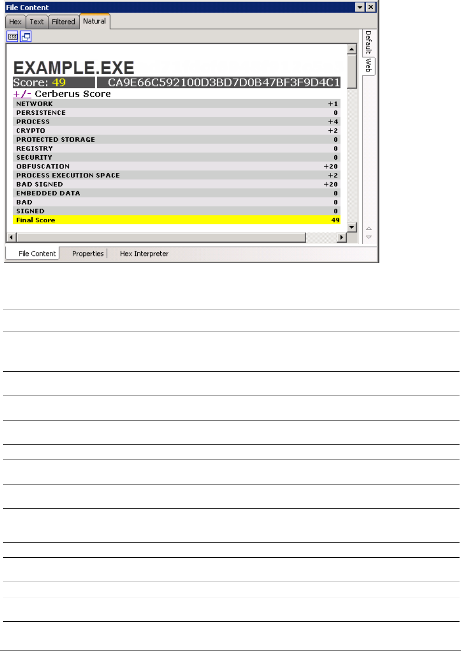
About Cerberus Malware Analysis | 125
Cerberus stage 1 analyzes the following information about executable binaries:
TABLE 12-1
Cerberus stage 1 threat score attributes
Attribute Threat Score Description
Network +1 Imports networking functions.
Persistence +4 Indicates signs of persistent behavior. For example, the ability to keep a binary
running across computer restarts.
Process +4 Imports functions to programmatically interact with processes. For example, reading
or writing into a process’s memory, or injecting code into another process.
Crypto +2 Imports Microsoft Cryptographic Libraries. For example, the ability to encrypt and
decrypt data.
Protected
Storage +5 Imports functions used to access protected storage. For example, Internet Explorer
stores a database for form-filling in protected storage.
Registry +2 Imports functions used to access or change values in the registry.
Security +4 Imports functions used to modify user tokens. For example, attempting to clone a
security token to impersonate another logged on user.
Obfuscation +20 Contains a packer signature, contains sections of high entropy, or imports a low
number of functions.
Process
Execution
Space
+2 Unusual activity in the Process Execution Space header. For example, a zero length
raw section, unrealistic linker time, or the file size doesn't match the Process
Execution Space header.
Bad Signed +20 Contains a signature but the signature is bad.
Embedded
Data +5 Contains an embedded executable code.
Bad / Bit-Bad +20 Contains an IRC or shellcode signature.
Signed / Bit
Signed -20 Contains a valid signature.
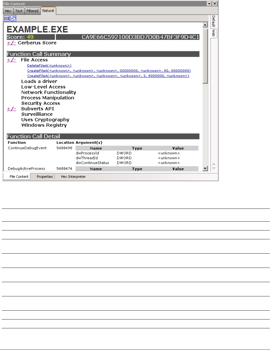
About Cerberus Malware Analysis | 126
About Cerberus Stage 2 Static Analysis
Cerberus stage 2 disassembles the code of an executable binary without running the actual executable. It
returns its results of the file’s functions in a categorized report.
Cerberus stage 2 analyzes the following categories of information about executable binaries:
TABLE 12-2
Cerberus Stage 2 Function Call categories
Category Description
File Access Functions that manipulate (read, write, delete, modify) files on the local file system.
Loads a driver Functions that load drivers into a running system.
Low-level Access Functions that access low level operating system resources, for example reading sectors
directly from disk.
Networking
functionality Functions that enable sending and receiving data over the Internet or other networks.
Process
Manipulation May contain functions to manipulate processes.
Security Access Functions that allow the program to change its security settings or impersonate other
logged on users.
Subverts API Undocumented API functions, or unsanctioned usage of Windows APIs (for example,
using native API calls).
Uses Cryptography Usage of the Microsoft CryptoAPI functions.
Surveillance Usage of functions that provide audio/video monitoring, keylogging, etc.
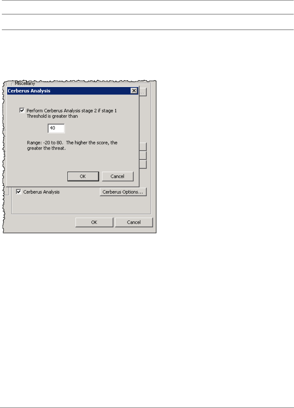
Running Cerberus Analysis | 127
Running Cerberus Analysis
Cerberus Analysis consists of two stages of analysis that help you to locate potentially malicious files. You can
run this analysis from the Examiner’s Additional Analysis dialog under Miscellany.
Stage 1 is called a threat analysis and quickly examines an executable binary file for common attributes it may
possess. Stage 2 is called static analysis. Static analysis is a disassembly analysis that takes more time to
examine the details of the code within the file.
For more information See About Cerberus Malware Analysis on page 124.
Cerberus first runs a threat analysis. After it completes Stage 1 analysis it can then automatically run a static
analysis against binaries with a threat score that is higher than a certain threshold.
Cerberus analysis may slow down the speed of your overall processing. Depending on the size of your data set
and the amount of executable binaries that you must examine, it may be advisable to run Cerberus analysis in
two steps after you complete initial case processing. In this case you can first only run Cerberus analysis stage 1
and then after stage 1 is completed you can then choose to run Cerberus Analysis stage 2.
By default you must be a Case Manager to run Cerberus analysis.
To run a Cerberus Analysis
1. In the Examiner, go to Evidence > Additional Analysis.
2. In the Additional Analysis dialog, under the section Miscellany, select Cerberus Analysis.
3. Next to the Cerberus Analysis option, click Cerberus Options.
Windows Registry Functions that manipulate (read, write, delete, modify) the local Windows registry. This
also includes the ability to modify autoruns to persist a binary across boots.
TABLE 12-2
Cerberus Stage 2 Function Call categories
Category Description
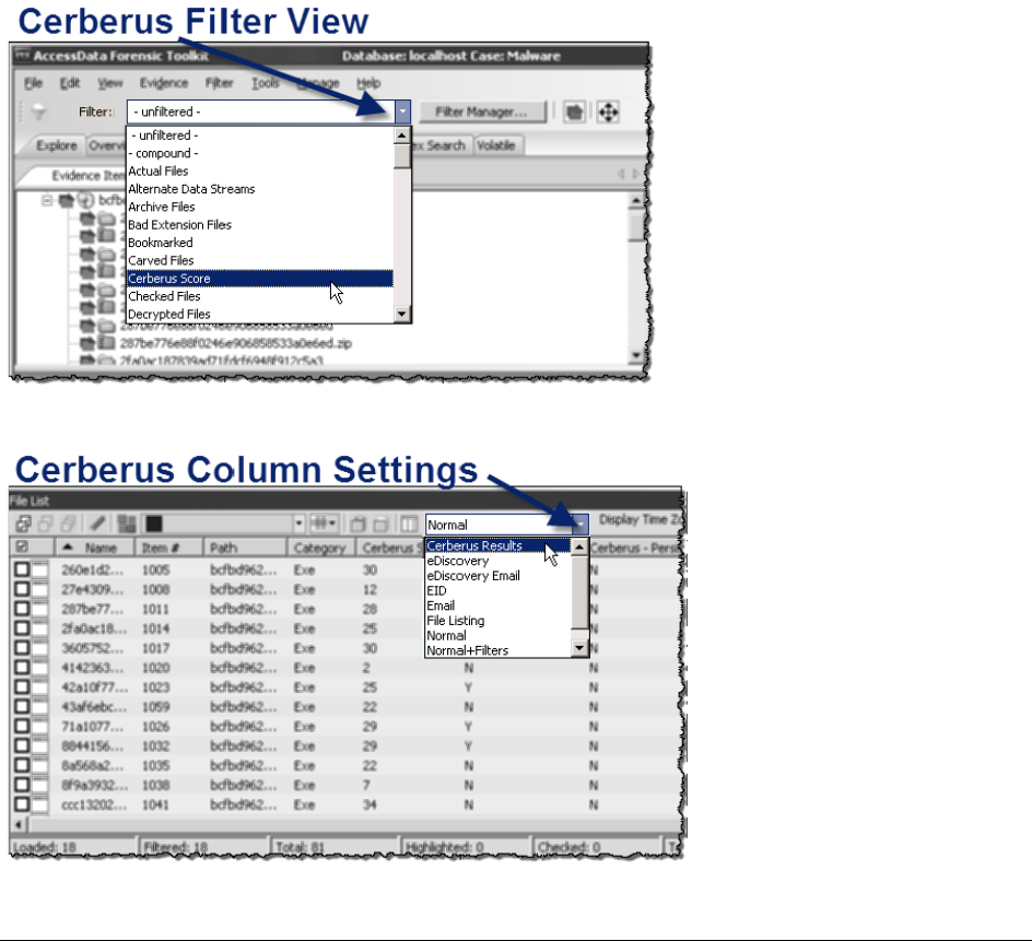
Reviewing Results of Cerberus | 128
4. In the Cerberus Analysis dialog, you can choose the option Perform Cerberus Analysis stage 2 if stage
1 threshold is greater than.
This option lets you choose to automatically run stage 2 analysis after stage 1 analysis completes.
You can specify a threshold for a minimum threat score against which you want to run the stage 2
analysis. If a file’s threat score is higher than the threshold value that you set, then stage 2 is run. If a
file’s threat score is lower than the threshold value then stage 2 analysis is not run. By default the
threshold automatically runs stage 2 analysis against files with a threat score greater than +40.
If you deselect the option to Perform Cerberus Analysis stage 2 if stage 1 threshold is greater than, then
only Cerberus Analysis stage 1 is run.
5. Click OK.
6. In the Additional Analysis dialog, click OK.
Reviewing Results of Cerberus
You can use the Examiner to locate executable binaries that have had Cerberus analysis run against them. For
executable binaries to have a Cerberus Score, a Case Administrator must first run a Cerberus Analysis.
The Examiner includes Cerberus filters that let you only display files that have had Cerberus run against them.
In the File List pane there are Cerberus column settings.
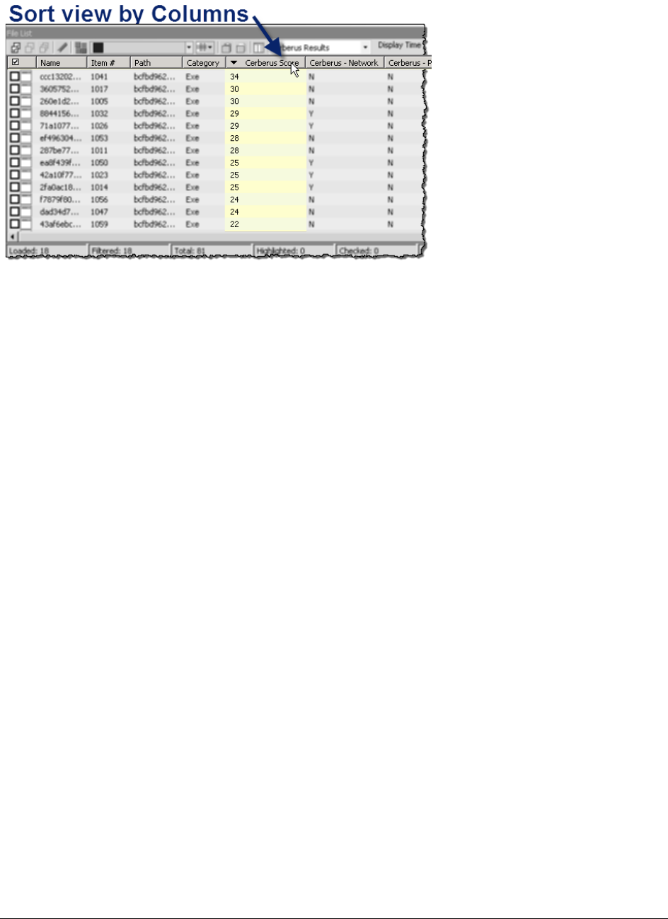
Exporting a Cerberus Report | 129
You can you sort the list of files based on the threat score or attributes from a the Cerberus Stage 1 analysis.
To view files with a Cerberus score:
1. In the Examiner, open the Explore tab.
2. In the Evidence Items pane, use Quick Picks to select the evidence.
3. In the Filter drop-down menu, select Cerberus Score.
4. In the File List pane, in the Column Setting drop-down, select Cerberus Results.
The File List pane shows all files that have been analyzed by Cerberus stage 1. It displays columns for
each attribute that Cerberus 1 analyzes. If a file contained an attribute, the column cell displays a Y. If
the file did not contain an attribute the column cell displays an N. You can sort the files by clicking on a
column heading. You can sort the displayed results by clicking a column header.
5. To view more details about the file, select it in the File List pane.
Additional details about the Cerberus analysis are displayed in the File Content viewer in the Natural
tab.
Exporting a Cerberus Report
You can export the view of Cerberus results into an HTML file.
To export a Cerberus Report:
1. In the File List pane, right click a file that has Cerberus results.
2. Click Export.
3. In the Export dialog, under File Options, select Save HTML view (if available).
4. In the Destination base path field, browse to the location where you want to save the export.
5. Click OK.

Understanding EFS | 130
Chapter 13
Decrypting EFS and Other Encrypted Files
There are decryption capabilities for several encryption types. This chapter provides information about those
programs and how to decrypt them so that additional evidence can be uncovered.
Several decryption key files are identified and categorized for ease of use. Find them in the Overview tab under
File Category > Other Encryption Files > Certificates. Having these files identified and available makes it
easier to quickly access files that may have been unavailable before.
This chapter includes the following topics:
-Understanding EFS (page 130)
-Decrypting EFS Files and Folders (page 131)
-Decrypting MS Office Files (page 131)
-Decrypting Lotus Notes Files (page 132)
-Decrypting S/MIME Files (page 133)
-Viewing Decrypted Files (page 133)
-Decrypting Credant Files (page 134)
-Decrypting Safeguard Utimaco Files (page 135)
-Decrypting SafeBoot Files (page 137)
-Decrypting Guardian Edge Files (page 137)
-Decrypting an Image Encrypted With PGP® Whole Disk Encryption (WDE) (page 138)
Understanding EFS
Windows 2000, XP Professional, 2003, and Vista include the ability to encrypt files and folders. This feature is
known as Encrypting File System (EFS). It is not supported in Windows XP Home Edition.
EFS files, as well as Microsoft® Office, and Lotus® Notes (NSF) files and folders can be decrypted. To do so,
the password must already be known.
In Windows, EFS-encrypted files or folders can be viewed only by the user who encrypted them or by the user
who is the authorized Recovery Agent. When the user logs in, encrypted files and folders are decrypted and the
files are automatically displayed.
Note: There are certain files that cannot be encrypted, including system files; NTFS compressed files, and files
in the [drive]:\[Windows_System_Root] and its subdirectories.
Important:
When a user marks an encrypted file as privileged and that file is later decrypted, all associated data
with the newly decrypted file are able to be found in an index search as hits. When a user attempts to
view the hits in a different list, an error is displayed that the path is invalid.

Decrypting EFS Files and Folders | 131
Decrypting EFS Files and Folders
To find EFS passwords, export encrypted files and add them as jobs in PRTK or DNA. When passwords are
found, you are ready to decrypt the encrypted files.
Requirements
Different versions of Windows OS have different requirements for decrypting EFS.
Windows 2000 and XP Systems Prior to SP1
EFS files on Windows 2000 prior to Service Pack 4 and Windows XP systems prior to Service Pack 1 are
automatically decrypted. Simply select the Decrypt EFS Files option when adding evidence to a case and
PRTK technology decrypts the EFS files.
Windows XP SP1 or Later
For systems running Windows XP Service Pack 1 or later, or Windows 2000 Service Pack 4 or later, the user’s
or the Recovery Agent’s password is needed before the EFS files can be decrypted.
Click Tools > Decrypt Files to begin decryption. The following sections review the requirements to decrypt EFS
files on Windows systems.
Decrypting EFS
To decrypt EFS
1. In a case, click Tools > Decrypt Files.
2. In the Decrypt Files dialog box, type a password in the Password box.
2a. Confirm the password by typing it again in the Confirm Password box.
3. Mark Permanently Mask to display the password as asterisks in the Saved Passwords list, hiding the
actual password.
4. Click Save Password to save the password into the Saved Password List.
5. Mark Attempt Blank Password to decrypt files with no password, or whose password is blank.
Note: EFS encrypted files in the case are automatically detected. Decrypt File Types will automatically
be marked according to the file types found. Unselect any file types you wish not to decrypt.
6. Choose one of the following:
-Click Decrypt to begin the decryption process,
-Click Cancel to abandon the decryption and return to the case.
Note: The Decrypt button is disabled until at least one password is entered, or until Attempt Blank
Password is marked.
7. When decryption is complete, click Cancel to return to the case.
Decrypting MS Office Files
Many MS Office files can be decrypted

Decrypting Lotus Notes Files | 132
Note: Some Excel (.XLS) files display as encrypted when the file itself is not passworded, but one or more cells
contained in the file are protected. Such files will not be indexed, and cannot be viewed until they are
decrypted. However, exporting these files does allow them to be opened in Excel.
To decrypt a Microsoft Office file
1. Process an encrypted MS Office file into your case.
2. Click Tools > Decrypt Files.
3. In the Decrypt File dialog, ensure that the Microsoft Office check box is marked.
4. Enter the correct password for the evidence and click Save Password.
5. Click Decrypt.
Decrypting Lotus Notes Files
Lotus Notes stores files in a container called an NSF file. Both the NSF container file and the individual files and
emails within the NSF file can be encrypted. To decrypt Lotus Notes files, you may need to first decrypt the NSF
container file, and then decrypt its contents.
When an NSF file is created, Lotus Notes also creates a user.id file. Lotus Notes uses the user.id file to identify
the user. You must have the user.id file to decrypt the NSF container file and to decrypt its contents.
Lotus Notes versions 7 through 8.5, including NSF and ODS formats 48 and 51 are supported.
To decrypt a Lotus Notes NSF file:
1. Process the encrypted NSF file and its corresponding user.id file as evidence in the same case.
When an NSF file is created, the user.id file is created at the same time. You need both files.
2. When processing is complete, click Tools > Decrypt Files.
3. Enter the password to the user.id file.
Note: Some files do not have a password applied. In these cases, you should click Attempt Blank
Password.
4. Click Save Password.
5. Enable Lotus Notes (whole NSF).
6. Click Decrypt.
To decrypt Lotus Notes notes and emails:
1. Process the encrypted notes and emails and the corresponding user.id file as evidence in the same
case.
2. When processing is complete, click Tools > Decrypt Files.
3. Enter the password to the user.id file
Note: Some files do not have a password applied. In these cases, you should click Attempt Blank
Password.
4. Click Save Password.
5. Enable Lotus Notes (notes/emails).
6. Click Decrypt.

Decrypting S/MIME Files | 133
Decrypting S/MIME Files
AccessData Forensic Toolkit now supports the decryption of RSA standard PKCS7 S/MIME email items. This
includes support for MBOX, DBX, RFC822, and some PST/EDB archives.
This support does not apply to PGP encrypted emails, Lotus Notes proprietary encryption, and items with S/
MIME signatures — only the S/MIME encryption.
Supported Key files will be .PFX and .PEM, which are also supported by AD Encryption.
Key files are flagged and kept track of during processing the same way EFS and NSF key files are currently
treated. S/MIME emails will be flagged as encrypted during processing, and the Tools > Decrypt Files dialog
has an added check box for S/MIME emails.
In addition, a new class has been added in the Overview tab for S/MIME encrypted emails.
Viewing Decrypted Files
The decrypted files are displayed in the Overview tree, in the File Status > Decrypted container. Click on an
individual file in the File List to view the file in the File Content pane.
Note: Regardless of the encryption type, once decrypted, the files will appear in the File List Name column as
[filename]decryped.[ext].
To decrypt and view EFS files taken from live evidence
1. Create a new case with no evidence added.
2. In the main menu, click Evidence > Add/Remove.
3. Click Add.
4. Select Individual Files and click OK.
5. Do one of the following:
-Navigate to the .PFX file (domain recovery key).
-Type the file’s full path including the filename into the File Name field of the Open dialog.
6. Click Open.
7. Click No when asked if you want to create an image of the evidence you are adding.
8. Select the proper time zone for the PFX file from the Time Zone drop-down list in the Manage Evidence
Dialog.
9. Click OK.
10. Processing begins and the .PFX file and the progress dialog appears.
11. Remote Preview (Add Remote Data) the computer that contains the EFS files you want to decrypt or
view (you can also preview multiple machines simultaneously).
12. In the Explore Tab navigate to the desired drive or drives.
13. Use Quick Picks on the top folder of the target system. This shows the evidence items on that system.
14. In the Filter drop-down list, click Encrypted Files.
The file list now displays only the encrypted files found on the target system
15. From the main menu, select Evidence > Additional Analysis.
16. In the Additional Analysis window, select Listed Items and File Signature Analysis.
17. Click OK.
The Data Processing Status dialog appears. A blue bar indicates status and activity.
18. When all processing has completed, go to the main menu and click Tools > Decrypt Files.

Decrypting Credant Files | 134
19. In the Add Passwords window, enter <EFS recovery passwords> in the Passwords text box. Select
the EFS check box (if it not selected by default), and click OK.
The files begin to be decrypted and a decryption process dialog appears.
20. When decryption completes, click OK.
21. Apply Quick Picks on the [ROOT] folder of the target system.
22. Select the files you want to view.
-To view only the decrypted files, choose Decrypted files in the Filter drop-down list.
-If you want to see all files (not just decrypted files), choose -unfiltered- from the Filter drop-down list.
23. Click OK to close the dialog. Decryption will continue.
Note: When completed, decrypted files will appear in the File List Name column as “Decrypted copy of <file
name>.”
The following graphic illustrates the File List view of decrypted files:
Decrypting Credant Files
Credant encryption is file-based and works much like EFS. Process drives with Credant encryption normally.
The Credant Decryption option in the tools menu is unavailable unless the image contains Credant encryption.
The integration allows two options for decryption: offline, and online. For a key bundle located on the user’s local
machine or network, use the offline option. For a key bundle located on a remote server within your network, use
the online option.
The first time a user decrypts Credant files and provides the Credant server credentials, that information is
encrypted and stored in the database. Later, if that user needs to decrypt Credant files in that or another case,
the credentials field populates automatically.
The credentials are stored separately for each user, so while one user may have the credentials stored others
may not, until the others have processed a case with Credant files that need to be decrypted.
Important:
If you click Cancel to process the evidence without decrypting, you will not be able to decrypt at a
later time. Also, the evidence cannot be added to the same case a second time. You will have to
create a new case to decrypt and process this evidence.
Using an Offline Key Bundle
Offline decryption is a quicker and more convenient option if the key bundle can be placed on the investigator’s
local computer. To decrypt an encrypted image offline select the key bundle file and enter the password used to
decrypt it.
To decrypt Credant files using an offline key bundle
1. Click Tools > Credant Decryption to open the Credant decryption options dialog.
2. Select the key bundle file by entering its location or browsing to it.
3. Enter the password.
4. Re-enter the password.
5. Click OK.
Both the Online and Offline Credant Decryption dialog boxes have a Decryption Threads drop-down box. This
dictates the total number of threads assigned to decryption, not the number of decryption threads per core.

Decrypting Safeguard Utimaco Files | 135
In the past, the number of threads has been one per processor core. The new default is the nearest increment of
five for double the number of detected processor cores, and can be increased in increments of five, up to 40
threads total.
There will be a point of diminishing return, based on the speed of your hard drive, such as 7200 rpm, your
processor speed, and the total number of processors detected. If you have a high-end system, you may benefit
from a higher setting. If you choose too high a setting, the benefit may be less than a lower setting would
provide. At this time, it is not possible to cancel the processing once it has begun.
Using an Online Key Bundle
Online decryption can occur only when the machine processing the image can directly access the server over
the network.
Usually the Machine ID and Shield ID fields are automatically populated. The Machine ID can be found on the
server as the Unique ID on the Properties tab. The Shield ID can be found as the “Recovery ID” on the “Shield”
tab. It looks similar to this: “ZE3HM8WW”.
The Server Data group box contains information on how to contact the server. It includes the Credant Server
user name, password, and IP address. The port should be 8081, and is auto-populated.
Offline decryption requires you to get a key bundle file from the server. Then select the key bundle file and enter
the password used to decrypt it. Get the key bundle file by executing the CFGetBundle.exe file with a command
like that looks like this:
CFGetBundle -Xhttps://10.1.1.131:8081/xapi -asuperadmin -Achangeit
-dxp1.accessdata.lab -sZE3HM8WW -oKeyBundle.bin -ipassword
-X for the server address
-a for administrator name
-A for the administrator password
-d for the Machine ID
-s for the Shield ID
-o for the output file
-i for the password used to encrypt the key bundle
Note: All command line switches are case sensitive. Also, as in the example above, there is no space between
the switch and the accompanying data.
Once you have used either the online or the offline method, the files will be decrypted immediately and the
decrypted file will become a child of the encrypted file. After decryption, the files will be processed with the same
settings last used to process a file.
Once the key has been added and the appropriate partitions selected, click OK to return to the Manage Evidence
dialog. Select a time zone from the Time Zone drop-down, then click OK to begin processing.
Important:
If you click Cancel to process the evidence without decrypting, you will not be able to decrypt at a
later time. Also, the evidence cannot be added to the same case a second time. You will have to
create a new case to decrypt and process this evidence.
Decrypting Safeguard Utimaco Files
Both AccessData FTK and AccessData Imager can decrypt boot drives that were encrypted with SafeGuard by
Utimaco.

Decrypting Safeguard Utimaco Files | 136
Safeguard Easy
Safeguard Easy works only with an image of a complete drive or a live drive. Imaged partitions cannot be
decrypted because the information needed to decrypt the partition exists in the boot record of the drive.
When a live drive or drive image is added as evidence, it is checked to determine if SafeGuard Easy encryption
is used on the drive. If it is used, a dialog will appear asking for the user name and password required to access
the drive. If the correct user name and pass word are entered, the drive will be decrypted transparently during
processing and the user can access information on the drive as though the drive were not encrypted. Incorrect
passwords will result in long waits between attempts -- waits that grow exponentially for each failure. Hitting the
cancel button on the dialog will allow the drive to be added as evidence, but the encrypted portions will not be
processed.
Secondary hard drives and removable media that have been encrypted with SafeGuard Easy are not currently
supported. The problem with secondary drives and removable media is that they contain NO information that
indicates how they are encrypted. The encryption information for secondary drives and removable media is
contained on the boot drive of the computer that encrypted them. In order to support them in FTK 2+ or Imager,
we would need to add the boot drive as evidence and then link the secondary or removable drives to the boot
drive so the encryption data may be accessed.
FTK 2+ and later, and all Imager versions since then support SafeGuard Easy drives encrypted with the
following algorithms: AES128, AES256 (the default), DES, 3DES, and IDEA.
The Safeguard dialog box appears only when FTK reads a valid Utimaco-encrypted image.
The username and password used to create the encrypted image are required for decryption. Once the
credentials have been added, click OK to return to the Manage Evidence dialog. Select a time zone from the
Time Zone drop-down, then click OK to begin processing.
Important:
The following important information applies when using SafeGuard Decryption:
-Type the User Name and Password carefully and verify both before clicking OK. If this information is
entered incorrectly, FTK checks the entire image for matching information before returning with an error
message. Each wrong entry results in a longer wait.
-If you click Cancel to process the evidence without decrypting, you will not be able to decrypt at a later
time. Also, the evidence cannot be added to the same case a second time. You will have to create a new
case to decrypt and process this evidence.
SafeGuard Enterprise
FTK and later provides SafeGuard Enterprise (SGN) support. Utimaco supplied libraries to access the
decryption keys for SGN via their recovery mechanism. This involves a somewhat cumbersome challenge/
response system with the server to access the decryption keys. Each partition may be decrypted with a different
key. The challenge/response process needs to be done for each encrypted partition. In order to enable the
challenge/response system for FTK, a file called recoverytoken.tok needs to be retrieved from the server and
selected in the decryption dialog. FTK will automatically select a recoverytoken.tok file if it is in the same
directory as the evidence file.
SafeGuard Enterprise decryption was developed using version 5.x.
AccessData uses SafeGuard-provided the BE_Sgn_Api.DLL and the BE_KBRDLLn.DLL. These libraries are
32-bit libraries. The 32-bit process is used to retrieve keys in 64-bit FTK. FTK does the actual decryption of the
drive, but the SafeGuard libraries are needed to generate the key from the username/password.
To recognize that a drive is encrypted with SafeGuard Enterprise FTK looks for “UTICRYPT” at the beginning of
the first sector of each partition.

Decrypting SafeBoot Files | 137
Retrieving the Recovery Token
Before the decryption process can occur, the recoverytoken.tok file must be retrieved from the server.
To retrieve the Recovery Token
1. From the server, you must create a virtual client.
2. Then you must export the virtual client. This is where the recoverytoken.tok file is created.
3. This file must be copied to a place where FTK can access the file.
When a SafeGuard Enterprise-encrypted drive is selected, a dialog like this will appear
4. Click the Recovery button next to each partition to retrieve that partition’s key. A dialog like the one that
follows will open, telling you which key to retrieve:
4a. On the server, select Tools > Recovery from the menu.
14. Select the virtual client you exported (the recoverytoken.tok file)
5. Select Key requested
6. Find the requested key (in this case 0x1C3A799F48FB4B199903FB5730314ABF). You can use Find >
Key IDs from the drop-down, and enter a partial key into Search Name to help find the correct key.
7. FTK will offer a challenge code of 6 segments of 5 characters each. From FTK, the following dialog will
appear with the challenge code and a place to enter the response code:
8. Enter the characters from the challenge portion of the dialog into the server’s dialog as shown:
FIGURE 13-1
9. Click Next.
10. The server will then offer a response code consisting of 12 segments of 5 characters each.
11. Enter these into the corresponding dialog in FTK and that provides the decryption key for FTK.
12. Click OK. The drive is decrypted and added as evidence to your FTK case.
Decrypting SafeBoot Files
SafeBoot is a program that encrypts drives and/or partitions. When FTK detects a SafeBoot-encrypted drive or
partition, the following dialog is displayed.
The encryption key must be available to enter into the Key field. All recognized partitions are selected by default,
up to a maximum of eight. You can unselect any partition you wish not to add to the case.
Important:
The following important information applies when using SafeBoot Decryption:
-If you click Cancel to process the evidence without decrypting, you will not be able to decrypt at a later
time. Also, the evidence cannot be added to the same case a second time. You will have to create a new
case to decrypt and process this evidence.
-You must add all partitions and decrypt the encrypted partitions when first adding the evidence to the
case or you will be unable to see them. Encrypted partitions do not display in the Evidence list.
Once the key has been added and the appropriate partitions selected, click OK to return to the Manage
Evidence dialog. Select a time zone from the Time Zone drop-down, then click OK to begin processing.
Decrypting Guardian Edge Files
When a Guardian Edge-encrypted image is added to a case, it is automatically detected as a Guardian Edge
image and a dialog will appear asking for credentials. The dialog has a drop-down list box with the user names

Decrypting an Image Encrypted With PGP® Whole Disk Encryption (WDE) | 138
that have been found to be associated with the image. Select the user name for which you have a password and
enter that password. Enter the password in one of two ways:
-Enter it twice with dots appearing for each character (to keep it hidden from on-lookers).
-Check the Show in plain text box and enter it once.
Click OK to proceed with the decryption process.
Important:
If you click Cancel to process the evidence without decrypting, you will not be able to decrypt at a
later time. Also, the evidence cannot be added to the same case a second time. You will have to
create a new case to decrypt and process this evidence.
Decrypting an Image Encrypted With
PGP® Whole Disk Encryption (WDE)
You can aquire images from disks that have been protected with PGP® Whole Disk Encryption. This section
describes the support for, and the process of specifying the credentials necessary to decrypt the image. Note
that decryption is only possible if an existing credential, such as a user passphrase or a previously-configured
Whole Disk Recovery Token, is available.
About PGP® Corporation and PGP® Whole Disk Encryption
PGP® Corporation’s origins date back to the early 1990’s, when Phil Zimmermann released his seminal
encryption program, “Pretty Good Privacy.” PGP® Corporation is now a world leader in encryption solutions, with
products for securing email, network files, removable media, and hard disks, all centrally managed by the PGP®
Universal™ Server console.
Individuals and organizations typically use PGP® Whole Disk Encryption (PGP® WDE) to protect the
information on their laptop computers in case of loss or theft. Encrypted disks prompt for a user’s passphrase
before Windows loads, allowing data to be decrypted on the fly as it is read into memory or encrypted just before
being written to disk. Disks remain encrypted at all times.
Administrators can instruct PGP® WDE devices that are managed by a PGP®. Universal™ Server to
automatically secure an encrypted disk to additional credentials based on a company’s central policy. These
could include a WDE Administrator key (for IT support purposes), an Additional Decryption Key (also called a
corporate recovery key) and/or a Whole Disk Recovery Token (“WDRT”). WDRTs are commonly used to reset a
forgotten passphrase and, can also be used by authorized administrators or examiners to decrypt an acquired
image of a PGP® WDE encrypted drive.
PGP® WDE Decryption
PGP® WDE functions a supported similarly to Access Data’s support for other full-disk encryption products.
Note: PGP® WDE decryption was developed using version 9.9 of the product.
To decrypt a PGPWDE Image and add it to a case
1. After creating a case, click Evidence > Add / Remove Evidence > Add > Acquired Image s > OK.
2. Browse to the location of the image files and select the first of the set to add to this case.

Decrypting an Image Encrypted With PGP® Whole Disk Encryption (WDE) | 139
3. You may enter any user’s boot password or passphrase, or use the Whole Disk Recovery Token
(WDRT) to decrypt a drive or image. Use one of the following methods:
-Boot passwords: The users for the drive are displayed in the drop-down list in the PGP® Encryption
Credentials box. Select the user and enter that user’s boot password.
-Whole Disk Recovery Token (WDRT): Obtain the WDRT by doing the following:
3a. Log into the PGP® Universal™ Server
3b. Select the Users tab
3c. Click on the User Name having a recovery icon for the system being examined.
3d. In the popup that appears, you will find a list of computers. The far right column contains a link for
the WDRT. Click the link to display a popup that shows the WDRT. The WDRT will look similar to
this:
ULB53-UD7A7-1C4QC-GPDZJ-CRNPA-X5A
3e. You can enter the key, with or without the dashes, in the Passphrase/WDRT text field as the
credential to decrypt a drive or image. The WDRT can be copied and pasted into the text field to
avoid errors.
3f. Click OK.
Important:
If you click Cancel to process the evidence without decrypting, you will not be able to decrypt at a
later time. Also, the evidence cannot be added to the same case a second time. You will have to
create a new case to decrypt and process this evidence.
4. Verify that the PGP® WDE encrypted image is added to the case Manage Evidence list.
5. Continue from this point as you would for any other evidence in any other case.
6. When all options have been selected, click OK to begin processing the evidence into the case.

Copying Information from the Examiner | 140
Chapter 14
Exporting Data from the Examiner
This section contains the following topics:
-Copying Information from the Examiner (page 140)
-Exporting Files (page 141)
-Exporting Case Data to an Image (page 142)
-Exporting File List Information (page 144)
-Exporting a Word List (page 144)
-Exporting Recycle Bin Index Contents (page 145)
-Exporting hashes from a case (page 145)
-Exporting Custom Groups from the KFF Library (page 146)
Copying Information from the Examiner
You can use the Copy Special dialog to copy information about the files in a case to the computer clipboard. The
file information can include any or all column items, such as Filename, File Path, File Category etc. The data is
copied in a tab-delimited format.
To copy file information
1. Select the files for the Copy Special task by doing either of the following:
-In the File List on any tab, select the files that you want to copy information about.
-Right-click the file in the file list.
2. Open the Copy Special dialog in any of these ways:
-Select Edit > Copy Special.
-Click the Copy Special button on the file list pane.
-Click Copy Special.
3. In the Copy Special dialog, select from the following:
TABLE 14-1
Copy Special Dialog Options
Item Description
Choose Columns Choose the column template definition that you want to use for
the exported data.
Include header row Includes a header row that uses the column headings you
selected.
All Highlighted Copies all items highlighted in the current file list.

Exporting Files | 141
4. In the Choose Columns drop-down list, select the column template that contains the file information that
you want to copy.
5. To define a new column settings template click Column Settings to open the Column Settings Manager.
6. Click OK to copy the data to the clipboard.
Exporting Files
You can export files that you find in an investigation to process and distribute to other parties. For example, you
can export encrypted files that you need to decrypt with Password Recovery Toolkit (PRTK). You can also export
Registry files to analyze in the Registry Viewer.
To export items from a case:
1. Do either of the following:
-In the Examiner, click File > Export
-Right-click on a file in the File List pane and click Export
2. In the Export dialog, select from the following export options:
All Checked Copies all items checked in all file lists. You can check files in
multiple lists. Checked items remain checked until you uncheck
them.
Currently Listed Copies all items in the current file list.
All Copies all items in the case. Selecting this option can create a
very large TSV or CSV file, and may exceed the 10,000 item
capacity of the clipboard.
TABLE 14-2
Export Files Dialog Options
Option Description
Append Item number to
Filename
Adds the case’s unique File ID to the filename of the exported
item.
Append extension to
filename if bad/absent
Uses the file’s header information to add missing file
extensions.
Export Children Expands container-type files and exports their contents.
Exclude Slack Space
Children Files
Excludes all slack files from the export.
Save HTML view (if
available)
Saves applicable files in HTLM format.
Export emails as MSG Exports email files into the MSG format for broader
compatibility.
Export emails using Item
number for name
Substitutes the Item number in the case instead of the email
title to shorten the file paths.
TABLE 14-1
Copy Special Dialog Options (Continued)
Item Description

Exporting Case Data to an Image | 142
3. Select the items that you want to export from the following options:
4. In the Destination Base Path field, enter or browse to and select the location to export the file.
The default path is [Drive]:\case_folder\Report\Export\.
5. Click OK.
Exporting Case Data to an Image
You can export data from a case into the following types of images:
-AD1 (AD Custom Content)
-E01 (EnCase Compatible)
-S01 (Smart)
-001 (RAW/DD)
To export case data to an image:
1. In the Examiner select or highlight or check the items that you want to export.
Export directory as file Creates a file that contains the binary data of a directory that
you export.
If you select a folder to export, the Examiner does not export
the parent folder or empty sub-folders.
You can export folders as files, but any empty folders that are
not selected to be exported as files are not created during the
export. To work around this issue, export a folder structure
with its children, move up one folder level and mark Export
directory as file and Export children.
Include original path Includes the full path from the root to the file. The export
maintains the folder structure for the exported files.
Create Manifest files Generates manifest files that contain the details and options
that are selected for the exported data. The Export Summary
File is commonly called a Manifest file. If you select this option
the export creates the manifest file .CSV format. The export
saves the file in the same destination folder as the exported
files.
TABLE 14-3
Export Files Selection Options
Target Item Description
All Checked Selects all items checked in all file lists. You can check files in
multiple lists.
All Listed Selects all items in the current file list.
All Highlighted Selects all items highlighted in the current file list. Items
remain highlighted only as long as the same tab is displayed.
All Selects all items in the case.
TABLE 14-2
Export Files Dialog Options (Continued)
Option Description

Exporting Case Data to an Image | 143
2. Click File > Export to Image.
3. In the Create Custom Content Image dialog, specify if you want to export the selected, highlighted, or
checked items and then click OK.
4. In the Create Image dialog, under Image Destination(s), click Add.
5. In the Select Image Destination dialog, specify the following information:
6. Click OK.
7. In the Create Image dialog, choose if you want to Verify Images after they are created.
TABLE 14-4
Select Image Destination Options
Option Description
Case Number (Optional) Lets you enter a case number for the data that is to be exported.
Evidence Number (Optional) Lets you enter an evidence number for the data that is to be exported.
Unique Description (Optional) Lets you add a description to the data that is to be exported.
Examiner (Optional) Lets you add the name of the evidence examiner to the data that is to be
exported.
Notes (Optional) Lets you add notes to the data that is to be exported.
Image Destination
Type By default the default image type is AD1. When exporting to an .AD1, the image’s file path
is added under a root directory. This behavior speeds the process of gathering data for the
AD1, and shortens the path to the AD1 content.
Relative to The image can be saved locally (Relative to This machine), or remotely (Relative to
Remote source machine).
Folder Specify the path and the destination folder for the image on the target computer.
Username Specify the domain and the user name to access the target computer.
Password Specify the password of the user on the target computer.
Image Filename
(Excluding
Extensions)
Specify a filename for the image, but do not include an extension.
Image Fragment
Size
Specify the image fragment size in MB.
You can save RAW and E01 file types in a single segment by specifying 0 MB.
Compression Specify the compression level to use. 0 represents no compression, 9 represents the
highest compression. Compression level 1 is the fastest to create. Compression level 9 is
the slowest to create .
Use AD Encryption Select this option if you want to encrypt the image as it is created.
When exporting data to an image from an encrypted drive, create the image physically,
not logically. A physical image is often required for decrypting full disk encryption.
AD Encryption supports the following:
-Hash algorithm SHA-512.
-Crypto algorithms AES 128, 192, and 256.
-Key materials (for encrypting the AES key): pass phrases, raw key files, and
certificates.
A raw key file is any arbitrary file whose raw data is treated as the key material.
Certificates use public keys for encryption and corresponding private keys for
decryption.

Exporting File List Information | 144
8. Choose if you want to Precalculate progress statistics. This features estimates the progress of the
task as it is running.
9. Choose if you want to Add image to case when completed.
10. Specify the Time Zone of the evidence.
11. Click OK.
12. Click Start.
Exporting File List Information
You can use Copy Special functionality to save file list information into a file. You can save this file in TSV, TXT,
or CSV format. TXT files display in a text editor program like Notepad. Files saved in TSV or CSV can be
opened in a spreadsheet program.
To export file list information to a network/folder/etc. you must have rights to access and save infomation to the
location.
To export File List information
1. Do one of the following:
-In the Examiner, select File > Export File List Info,
-Right-click on a file in the File List pane and select Export File List Info.
2. Select the items to export.
Choose from
-All Highlighted (in the File List View)
-All Checked (in the case)
-All Listed (in the File List View)
-All (in the case)
3. Specify if you want to include a header row in the exported file.
4. From the Choose Columns drop-down, select the column template to use. You can click Column
Settings to create a column template to use for the export.
5. Specify the filename for the exported information.
6. Choose a file type for the exported file.
7. Browse to and select the destination folder for the exported file.
8. Click Save.
Exporting a Word List
You can export the contents of the case index or registry into a word list. You can use this word listas the basis
for a custom dictionary to aid in the password recovery process.
You must have indexed the case to export the word list. If you have not indexed the case, you can click
Evidence > Additional Analysis. In the Additional Analysis dialog, under Search Indexes, select dtSearch
Index, and then click OK.
You can only export Registry Viewer contents into a word list if the Registry Viewer is installed on the computer
where you are running the Examiner.

Exporting Recycle Bin Index Contents | 145
To export a word list:
1. In the Examiner, select File > Export Word List.
2. Select the Registry keys that you want to include in the word list.
3. Click Export.
4. Click Browse Folders and select the filename and location for the exported word list.
5. Click Save.
Exporting Recycle Bin Index Contents
You can export the indexed data from INFO2 files into TXT, TSV, or CSV format.
To export INFO2 files:
1. Locate an INFO2 file. In the Examiner you can find them in the Overview tab under OS/File System
Files > Recycle Bin Index.
2. In the File List, highlight the INFO2 files that you want to export.
3. Right-click on the selected files and choose Export Recycle Bin Index Contents.
4. Browse to and select the desired destination folder.
5. Type a filename for the exported data file.
6. In the Save as type drop-down, select the file type to use:
7. Mark Include header row if you want the column headings included in the exported file.
8. Click Save.
Exporting hashes from a case
You can export hashes from a case. You can add the hash list into the Known File Filter in the same case to
identify and set the KFF status on files of interest (Alert) or files of no interest (Ignore). You can use the
Disregard status to make it easier to use existing groups, ignoring certain sets in the group that may have Alert
status assigned.
To export hashes from the case
1. In the Examiner, in the File List view, select the files that you want to export the hashes for.
2. Right-click in the list and choose Export File List Info.
3. In the Save As dialog box, in the File name field, enter the name for the exported list.
4. In the Save as type drop-down, select either .TSV or .CSV.
5. Under File List items to export, select from the following:
-All highlighted
-All checked
-Currently listed
-All (In case)
6. Click Choose Columns and select the column settings to use.
If you do not find the correct column setting for this export, click Column Settings to customize a
column setting to include the file properties you want in this export.
You should include MD5 Hash, and it is recommended that you also include SHA1 Hash. It is optional to
include SHA 256 Hash.

Exporting Custom Groups from the KFF Library | 146
7. In the Selected Columns list, double-click on each item to add and removing the columns.
8. Click OK.
9. Click Save.
Exporting Custom Groups from the KFF Library
You can use the KFF Admin interface to export groups from the KFF Library. You cannot export a set, but instead
must choose the group to which a set applies.
To export custom groups from the KFF Library
1. In the Examiner, click Manage > KFF > Manage.
2. In the KFF Admin dialog, select the groups to export.
3. Click Export Groups.
Note: Note: You cannot export the default groups that are defined by AccessData. If the option to export
is unavailable, make sure to select a custom group.
4. Navigate to the destination directory where you want the file to be saved.
5. Enter the name.
Exporting All Hits in a Search to a CSV file
After you run a search for terms, words, or predefined patterns, you can export your results to a comma
delimited text file (CSV).
To Export All Hits in a Search to a CSV file:
1. Run either a Live Search or an Index Search.
2. From either the Index Search Results window or the Live Search Results window, right click the search
result and click Set Context Data Width.
3. Set the width value. For example, 32.
4. Right-click the search result and click Export to File > All Hits in Search.
5. In the Save As dialog, browse to the destination where you want to save the file.
6. In the File Name field, enter a name for the file.
7. In the Save as type field select Comma Delimited Text File (*.csv).
8. You can then import the CSV file into a program that supports CSV files such as Microsoft* Excel*.

| 147
Part IV
Reviewing Cases
This part contains information about reviewing cases and contains the following chapters:
-Tabs of the Examiner Interface (page 148)
-Exploring Evidence (page 149)
-Examining Evidence in the Overview Tab (page 162)
-Examining Email (page 166)
-Examining Graphics (page 168)
-Bookmarking Evidence (page 174)
-Searching Evidence with Live Search (page 180)
-Searching Evidence with Index Search (page 189)
-Examining Volatile Data (page 196)
-Using Visualization (page 200)
-Customizing the Examiner Interface (page 213)
-Working with Evidence Reports (page 221)
Tabs of the Examiner | 148
Chapter 15
Tabs of the Examiner Interface
Tabs of the Examiner
The Examiner interface contains tabs,each with a specific focus. Most tabs also contain a common toolbar and
file list with customizable columns. Additional tabs can be user-defined.
Explore Tab See Explorer Tree Pane (page 149)
Overview Tab See Using the Overview Tab (page 162)
Email Tab See Using the Email Tab (page 166)
Bookmarks Tab See Using the Bookmarks Tab (page 174)
Graphics Tab See Using the Graphics Tab (page 168)
Live Search Tab See Conducting a Live Search (page 180)
Index Tab See Conducting an Index Search (page 189)
Volatile Tab See Using the Volatile Tab (page 196)
TABLE 15-1
Option Description
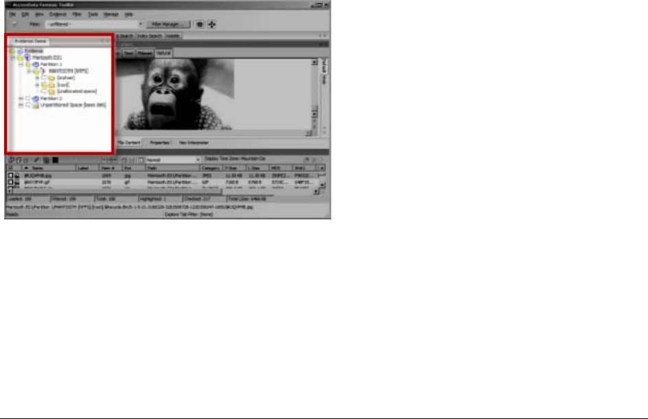
Explorer Tree Pane | 149
Chapter 16
Exploring Evidence
The Explore tab displays all the contents of the case evidence files and drives as the original user would have
seen them
This chapter includes the following topics:
-Explorer Tree Pane (page 149)
-File List Pane (page 149)
-The File Content Viewer Pane (page 154)
-The Filter Toolbar (page 160)
-Using QuickPicks (page 161)
Explorer Tree Pane
Lists directory structure of each evidence item, similar to the way one would view directory structure in Windows
Explorer. An evidence item is a physical drive, a logical drive or partition, or drive space not included in any
partitioned drive, as well as any file, folder, or image of a drive, or mounted image.
File List Pane
Displays case files and pertinent information about files, such as filename, file path, file type and many more
properties as defined in the current filter. The files here may display in a variety of colors.
They are as follows:
Black = Default
Grey = Deleted
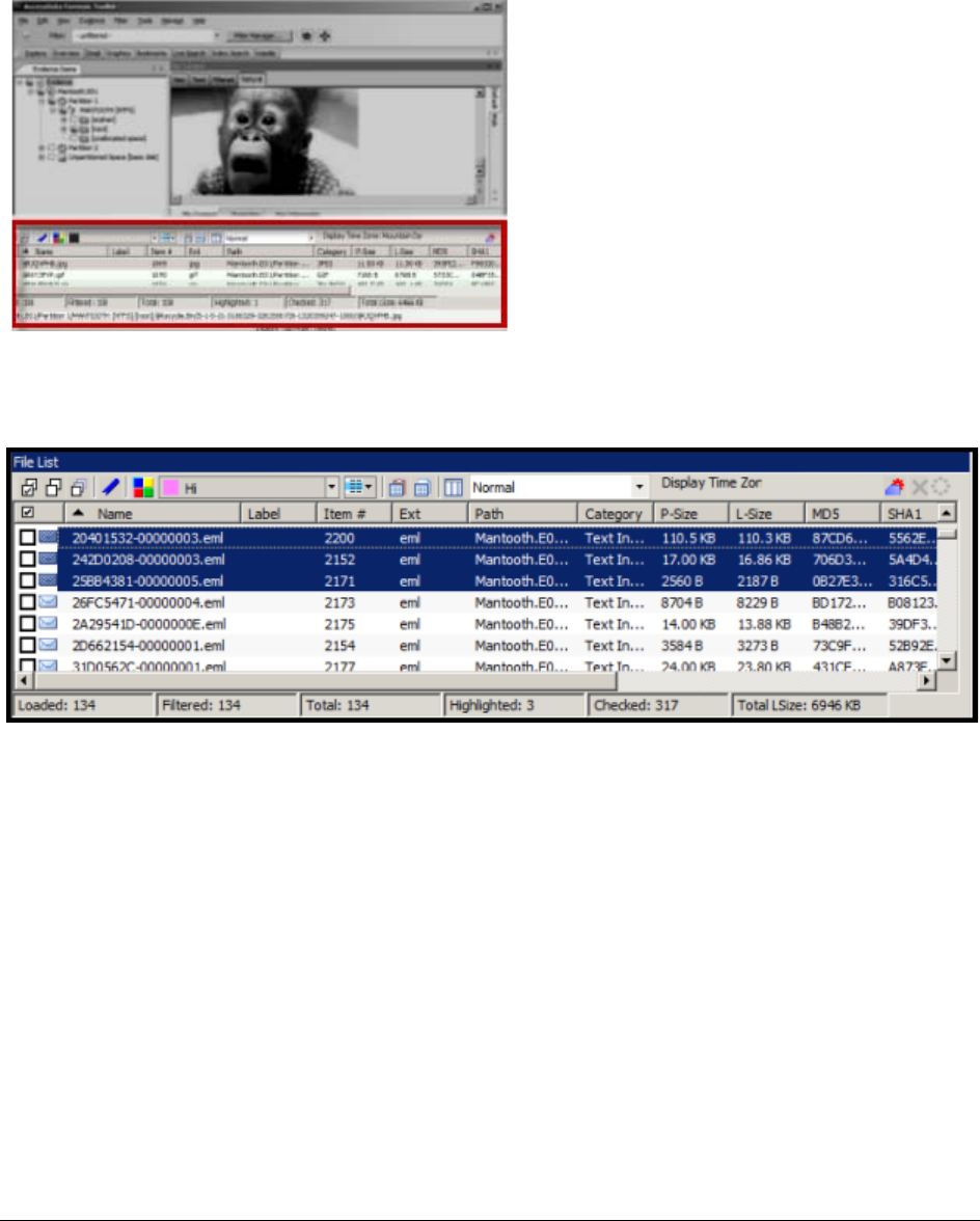
File List Pane | 150
Pink = Bookmarked
Red = Encrypted
The File List view reflects the files available for the current tabbed view and the properties that meet selected
Column templates, limited by any filters that may be applied. In this pane the user can choose which columns to
display, as well as the order of those columns, create Bookmarks, create Labels, Copy or Export File Lists. The
File List pane is included in all default tab views.
When viewing data in the File List, use the type-down control feature to locate sought information. When the list
is sorted by name, select an item in the list, then type the first letter of the desired file. The cursor will move down
the list to the first file beginning with that letter. As you continue to type, the file selector will move to the closest
match to what you have typed.
Click on a column heading in the File List view to sort on that column. Hold down the Shift key while clicking a
different column header to make the newly selected column the primary-sorted column, while the previous
primary-sorted column becomes the secondary-sorted column. There are only two levels of column sorting,
primary and secondary.
To undo a secondary sort, click on a different column header to make it the primary-sorted column.
Column widths in most view panes can be adjusted by hovering the cursor over the column heading borders,
and dragging the column borders wider or narrower.
See Customizing File List Columns (page 216)
A data box displays in the lower-right of the File List View that indicates the total logical size of the currently listed
files
File List Pane | 151
Icons of the File List Tool bar
TABLE 16-1
File List Tool bar
Component Description
Checks all of the files in the current list.
Unchecks all of the files in the current list.
Unchecks all of the files in the current case.
Opens Create New Bookmark dialog box.
Opens Manage Labels dialog box.
Apply Label drop-down allows you to select from the list of
defined labels and apply it to a single selected file or a group of
files as selected in the Apply Label To drop-down.
Select Label Target drop-down allows you to specify currently
Highlighted, Checked, or Listed files for the Label you choose
from the Apply Label drop-down.
Export File List allows the user to save selected files to another
folder.
Opens Copy Special dialog box.
Opens the Column Settings dialog box.
Sets the columns to a specific selection from the list of defined
column sets. Some Default Column Templates are:
-eDiscovery
-eDiscovery Mail
-Email
-Explicit Image Detection
-File Listing
-Normal (default)
-Reports: File Path Section
-Reports: Standard
Displays the selected Time Zone from the local machine.
Leave query running when switching tabs (May affect
performance of other tabs).

File List Pane | 152
Note: When checking files in a case, these two rules apply:
-Checked files are persistent and remain checked until the user unchecks them.
-Checked files are per-user; another user or an Administrator will not see your checked files as
checked when viewing the same case.
File List View Right-Click Menu
When you right-click on any item in the File List view, a menu with the following options appears. Some options
are enabled or disabled, depending on the tab you are in, the evidence that exists in the case, the item you have
selected, or whether bookmarks have been created.
Cancel retrieving row data. This is not a pause button. To
retrieve row data after clicking Cancel, you must begin again.
There is no way to pause and restart the retrieval of row data.
Active spinner indicates Processing activity.
TABLE 16-2
File List View Right-Click Menu Options
Option Description
Open Opens the selected file.
Launch in Content
Viewer Launches the file in the Content Viewer, formerly known as
Detached Viewer.
Open With Opens the file. Choose either Internet Explorer or an External
Program
Create Bookmark Opens the Create New Bookmark dialog for creating a new
bookmark.
Add to Bookmark Opens the Add to Bookmark dialog for adding selected files to
an existing bookmark.
Remove from Bookmark Removes a file from a bookmark. From the Bookmarks tab,
open the bookmark containing the file to be removed, then
select the file. Right-click and select Remove from Bookmark
Labels Opens the Labels dialog. View assigned Labels, create or delete
a Label, Apply a Labels to file, or Manage Local or Manage
Global Labels.
Review Labels Opens the Label Information dialog to display all labels
assigned to the selected file or files.
Mount Image to Drive Allows you to mount an image logically to see it in Windows
Explorer, or physically to view .
Add Decrypted File Right-click and select Add Decrypted File. Opens the Add
Decrypted File dialog. Browse to and select the file to add to the
case, click Add.
View File Sectors Opens a hex view of the selected file. Type in the file sector to
view and click Go To.
TABLE 16-1
File List Tool bar (Continued)
Component Description

File List Pane | 153
Find on Disk Opens the Disk Viewer and shows where the file is found in the
disk/file structure.
Note: Find on disk feature won’t find anything under 512 B
physical size. Files smaller than 1500 bytes may reside in the
MFT and do not have a start cluster. Find on disk depends on
that to work. This is working as designed.
Add to Fuzzy Hash
Library Opens Select Fuzzy Hash Group dialog. Click the drop-down list
to select the Fuzzy hash group to add to. The Fuzzy Hash group
must already have been created.
Find Similar Files Opens the Search for Similar Files dialog. The selected file’s
hash value is displayed. Click From File to see the filename the
hash is from. The Evidence Items to Search box shows all
evidence items in the case. Mark which ones to include in the
search. Select the Minimum Match Similarity you prefer, and
click Search or Cancel.
Open in Registry Viewer Opens a registry file in AccessData’s Registry Viewer. Choose
SAM, SOFTWARE, SYSTEM, SECURITY, or NTUSER.dat.
Export Opens the Export dialog with all options for file export, and a
destination path selection.
Export to Image Opens the Create Custom Content Image dialog.
Acquire to Disk Image Allows you to create a new disk image (.001, .AFF, E01, or .S01)
from a disk image in the case.
Export File List Info Opens the Save As dialog. Choose .TXT, .TSV, or .CSV. Default
name is FileList.txt.
Copy Special Opens the Copy Special dialog.
Check All Files Check-marks all files in the case.
Uncheck all Files in
Current List Unchecks all files in the current list.
Uncheck All Files in
Case Unchecks all files in the case.
Change “Flag as
Ignorable” Status Change Flag Status of all files as either Ignorable or Not
Ignorable according to Selection Options.
Change “Flag as
Privileged” Status Change Flag Status of all files as either Privileged or Not
Privileged according to Selection Options.
Re-assign File Category Change File Category assignment.
View This Item In a
Different List Changes the File List view from the current tab to that of the
selected tab from the pop-out.
TABLE 16-2
File List View Right-Click Menu Options (Continued)
Option Description
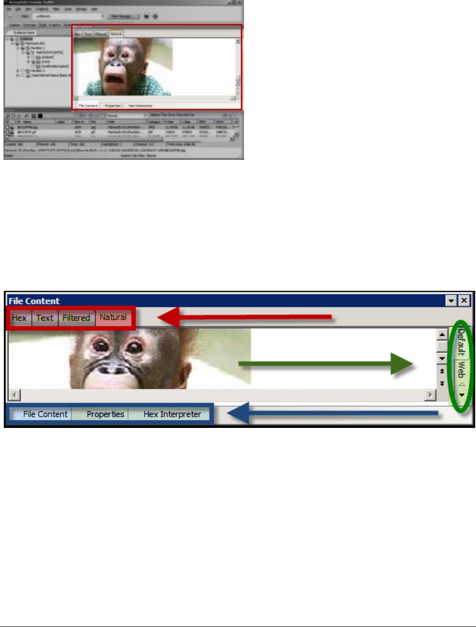
The File Content Viewer Pane | 154
The File Content Viewer Pane
Displays the contents of the currently selected file from the File List. The Viewer toolbar allows the choice of
different view formats.
The File Content pane tab has a Default tab and a Web tab for each of the following tabbed views”
-Hex tab
-Text Tab
-Filtered Tab
-Natural Tab
-Properties Tab
-Hex Interpreter
Note: The Find on Disk feature (in File List view, right-click an item) won’t find anything under 512 Bytes
physical size. Also, files smaller than 1500 bytes may reside in the MFT and thus do not have a start
cluster. Find on Disk depends on the start cluster information to work.
Note: In the File List view of any tab, a much-greater-than symbol (>>) denotes that the path is not an actual
path, but that the file came from another file or source, such as a zipped, compressed, or linked (OLE)
file, or that it was carved.
The File Content pane title changes depending on which tab is selected at the bottom of the window. The
available tabs are File Content, Properties, and Hex Interpreter. These three tabs default to the bottom left of the
File Content pane in any program tab where it is used.
The three tabs can be re-ordered by clicking on a tab and dragging-and-dropping it to the position in the linear
list where you want it. Click any of these tabs to switch between them. The information displayed applies to the
currently selected file in the Viewer pane.
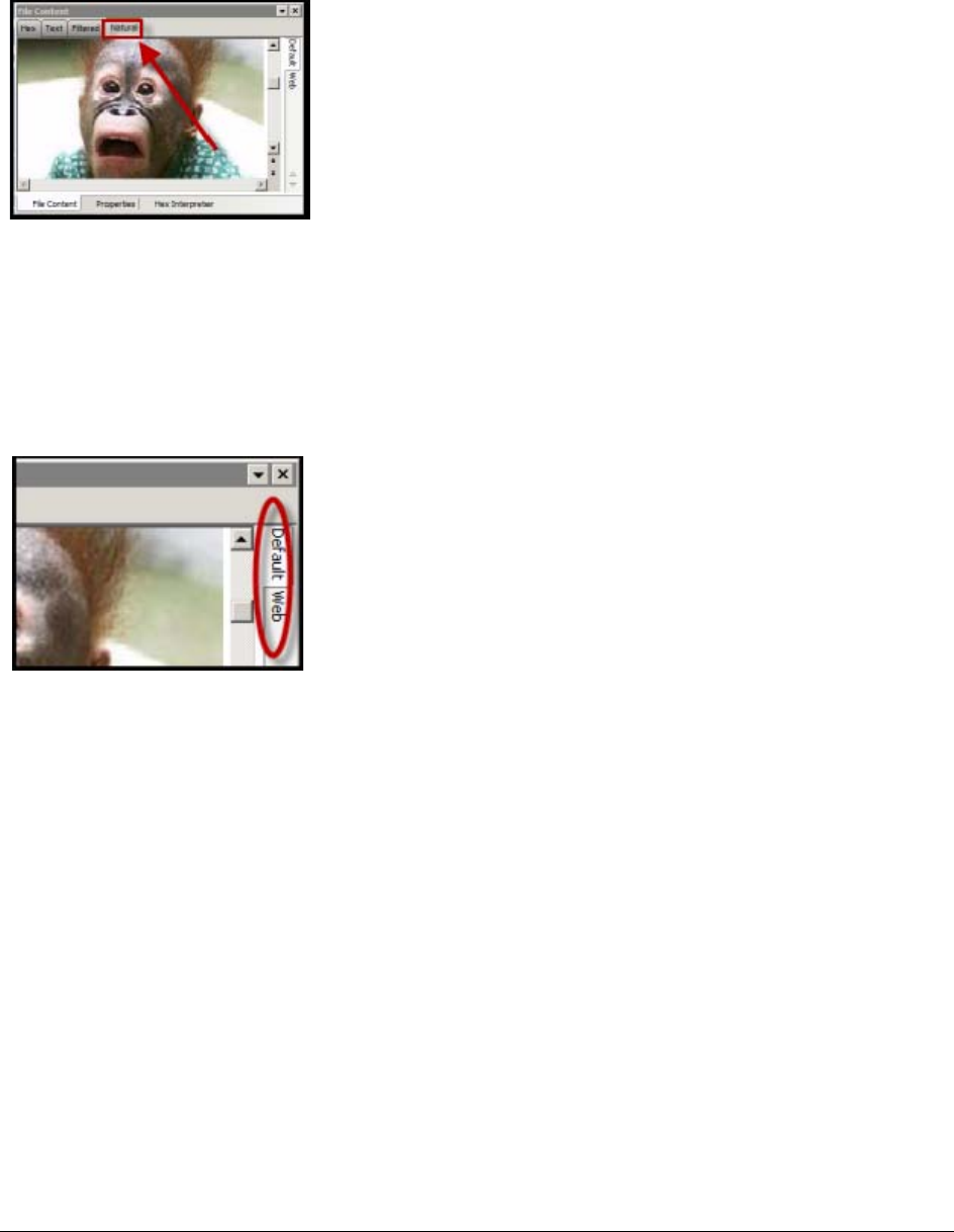
The File Content Viewer Pane | 155
The Natural Tab
The Natural tab displays a file’s contents as it would appear normally. This viewer uses the Oracle Stellent INSO
filters for viewing hundreds of file formats without the native application being installed.
Note: When highlighting terms in Natural View, each term throughout the document is highlighted, one term at a
time. When it reaches the limit of highlighting in that window, regardless of which term it is on (first,
second, third, etc.) it stops highlighting. There is no workaround.
Note: Viewing large items in their native applications may be faster than waiting for them to be rendered in the
Examiner viewer.
The Natural View top tab is the only one of the four that has additional tabs that provide for the viewing of Text,
Media, and Web files, in their native application environment.
-Natural Tab: Default
The Default tab displays documents or files in a viewer that uses Oracle INSO (Inside-Out) Technology,
according to their file type.
-Natural Tab: Media
Case audio and video files play using an embedded Windows Media Player.
The Examiner has added functionality to recognize popular mobile phone formats (found in many MPE
images) such as .M4A, MP4, AMR, and 3GP. These file types will play now inside the Media tab as long
as the proper codecs are installed that would also allow those files to play in Windows Media Player.
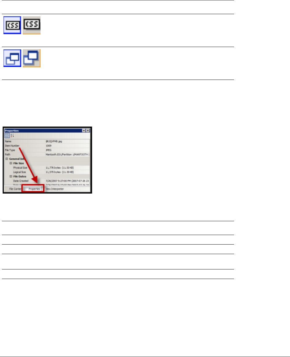
The File Content Viewer Pane | 156
-Natural Tab: Web
The Web view uses an embedded Internet Explorer instance to display the contents of the selected file in
a contained field.
In the Web view, the top-left border of the pane holds two toggle buttons for enabling or disabling HTML
content:
The Properties Tab
The Properties tab is found in the File Content View, and displays a pane, or window of information about a
selected file. The following figure displays the information contained in the Properties pane. This information
corresponds to the file selected in the File List pane.
The following table highlights the components of the Properties pane:
TABLE 16-3
Natural Tab: Web Tab Toggle Buttons
Component Description
Enable or Disable CSS Formatting. CSS formatting displays any fonts,
colors, and layout from cascading style sheets. HTML formatting not
part of a cascading style sheet might remain. Enabled feature is
indicated by a blue background; disabled feature is indicated by a gray
background.
Enable or Disable External Hyperlinks. Enabled hyperlinks in the file will
link to active internet pages. This may not accurately provide data that
was available using that link at the time the image was made, or the
evidence was acquired. Enabled feature is indicated by a blue
background; disabled feature is indicated by a gray background.
TABLE 16-4
Properties Pane Components
Option Description
Name The filename of the selected file.
Item Number A number assigned to the item during evidence processing.
File Type The type of a file, such as an HTML file or a Microsoft Word 98
document. The file header is used to identify each item’s file type.
Path The path from the evidence source down to the selected file.

The File Content Viewer Pane | 157
General Info General information about the selected file:
File Size: Lists the size attributes of the selected file as follows:
-Physical size of the file, including file slack.
-Logical size of the file, excluding file slack.
File Dates: Lists the Dates and Times of the following activities for that
file on the imaged source:
-Created
-Last accessed
-Last modified
Note: All dates with times are listed in UTC and local times.
File Attributes The attributes of the file:
General:
-Actual File: True if an actual file. False if derived from an actual file.
-From Recycle Bin: True if the file was found in the Recycle Bin. False
otherwise.
-Start Cluster: Start cluster of the file on the disk.
-Compressed: True if compressed. False otherwise.
-Original Name: Path and filename of the original file.
-Start Sector: Start sector of the file on the disk.
-File has been examined for slack: True if the file has been examined
for slack. False otherwise.
DOS Attributes:
-Hidden: True if Hidden attribute was set on the file. False otherwise.
-System: True if this is a DOS system file. False otherwise.
-Read Only: True or False value.
-Archive: True if Read Only attribute was set on the file. False other-
wise.
-8.3 Name: Name of the file in the DOS 8.3 naming convention, such
as [filename.ext].
Verification Hashes: True if Verification hashes exist. False otherwise.
NTFS Information:
-NTFS Record Number: The number of the file in the NTFS MFT
record.
-Record Date: UTC time and date record was created.
-Resident: True if the item was Resident, meaning it was stored in
the MFT and the entire file fit in the available space. False other-
wise. (If false, the file would be stored FAT fashion, and its record
would be in the $I30 file in the folder where it was saved.)
-Offline: True or False value.
-Sparse: True or False value.
-Temporary: True if the item was a temporary file. False otherwise.
-Owner SID: The Windows-assigned security identifier of the owner
of the object.
-Owner Name: Name of the owner of that file on the source system.
-Group SID: The Windows-assigned security identifier of the group
that the owner of the object belongs to.
-Group Name: The name of the group the owner of the file belongs to.
TABLE 16-4
Properties Pane Components (Continued)
Option Description
The File Content Viewer Pane | 158
The information displayed in the Properties tab is file-type-dependent, so the selected file determines what
displays.
The Hex Tab
The Hex tab shows the file content in Hex view. It is different from the Hex Interpreter tab at the bottom of the
screen.
The bar symbol indicates that the character font is not available, or that an unassigned space is not filled.
The following table lists the available options when right-clicking in the File Content Hex pane:
Click Save selection as carved file to manually carve data from files, and the Go to Offset dialog to specify
offset amounts and origins. Click OK to close Go To Offset dialog.
After Go to Offset has taken you to the desired offset, select the Hex data you want to save as a separate file to
be added to you case, perhaps in a bookmark. Right-click and select Save Selection as Carved File from the
menu. Name the file and click OK.
File Content Info The content information and verification information of the file:
-MD5 Hash: The MD5 (16 bytes) hash of the file (default).
-SHA-1 Hash: The SHA-1 (20 bytes) hash of the file (default).
-SHA-256 Hash: the SHA-256 (32 bytes) hash of the file (default).
Fuzzy hash Lists the following Fuzzy Hash information:
-Hash -Fuzzy Hash Block Size
TABLE 16-5
File Content Hex View Right-click Menu Options
-Select all -Show decimal offsets
-Copy text -Show text only
-Copy hex -Fit to window
-Copy Unicode -Save current settings
-Copy raw data -Go to offset
-Save selection -Save selection as carved file
TABLE 16-4
Properties Pane Components (Continued)
Option Description
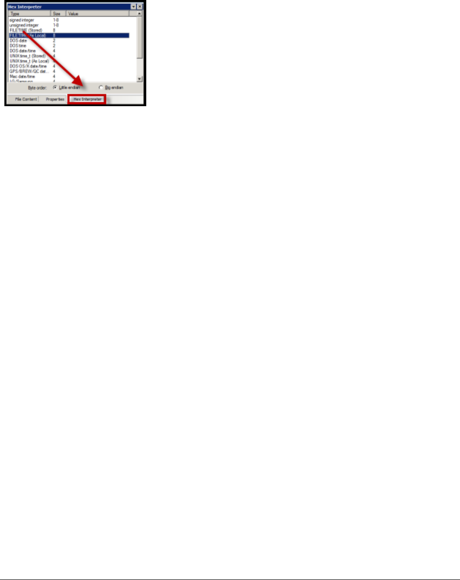
The File Content Viewer Pane | 159
The Hex Interpreter Tab
The Hex Interpreter tab shows interpreted hexadecimal values selected in the Hex tab viewer on the File
Content tab in the Viewer pane into decimal integers and possible time and date values as well as unicode
strings.
The Hex Value Interpreter reads date/time stamp values, including AOL date/time, GPS date/time, Mac date/
time, BCD, BCD Hex, and BitDate.
The Hex tab displays file contents in hexadecimal format. Use this view together with the Hex Interpreter pane.
The Hex View tab is also found in the File Content View.
This feature is most useful if the investigator is familiar with the internal code structure of different file types, and
knows where to look for specific data patterns or for time and date information.
Note: The bar symbol indicates that the character in that font is not available, or that an unassigned space is
not filled.
To convert hexadecimal values
1. Highlight one to eight contiguous bytes of hexadecimal code in the File Content pane > File Content
tab viewer > Hex tab. (Select two or more bytes for the Unicode string, depending on the type of data
you want to interpret and view.)
2. Switch to the Hex Interpreter tab at the bottom of the File Content Viewer > Hex tab, or open it next to,
or below the File Content tab > Hex tab view to see both concurrently.
3. The possible valid representations, or interpretations, of the selected code automatically display in the
Hex Value Interpreter.
Little-endian and big-endian refer to which bits are most significant in multi-byte data types, and describe the
order in which a sequence of bytes is stored in a computer’s memory. Microsoft Windows generally runs as Little
Endian, because it was developed on and mostly runs on Intel-based, or Intel-compatible machines.
In a big-endian system, the most significant bit value in the sequence is stored first (at the lowest storage
address). In a little-endian system, the least significant value in the sequence is stored first. These rules apply
when reading from left to right, as we do in the English language.
As a rule, Intel based computers store data in a little-endian fashion, where RISC-based systems such as
Macintosh, store data in a big-endian fashion. This would be fine, except that a) AccessData’s products image
and process data from both types of machines, and b) there are many applications that were developed on one
type of system, and are now “ported” to the other system type. You can’t necessarily apply one rule and
automatically know which it is.
Little-endian is used as the default setting. If you view a data selection in the Hex Interpreter and it does not
seem right, try choosing big-endian to see if the data displayed makes more sense.
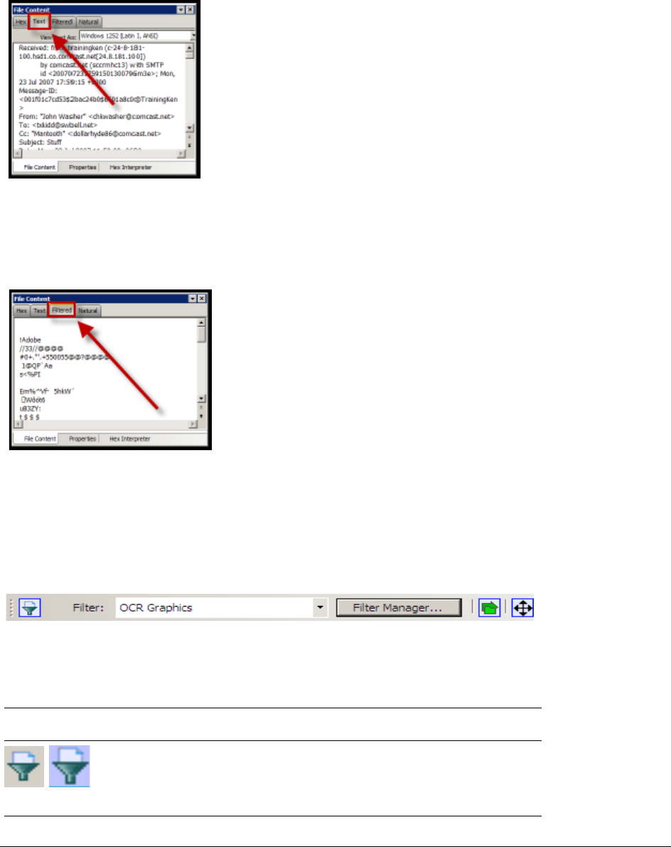
The Filter Toolbar | 160
The Text Tab
The Text tab displays the file’s content as text using the code page selected from the drop-down menu. The
following figure represents a portion of the drop-down selection list.
The File Content pane currently provides many code pages from which to choose. When the desired code page
is selected, the Text tab will present the view of the selected file in text using the selected code page language.
The Filtered Tab
The Filtered tab shows the file’s text created during indexing. The following figure represents content displayed
in the filtered tab. The text is taken from an index created for the current session if indexing was not previously
selected.
The Filter Toolbar
The interface provides a tool bar for applying. QuickPicks and Filters to the case. The following figure shows the
FTK Filter tool bar:
FIGURE 16-1
Filter Toolbar
The following table shows the available components of the tool bar.
See Filtering Evidence (page 112).
TABLE 16-6
Filter Tool bar Components
Component Description
Turns the filter on or off. Filtered data is shown in a colored pane
to indicate that it is filtered. In addition, if no filter is applied, the
icon is grayed out. When active, or ON, the Filter button has a
light blue background. When inactive, or OFF, the background is
gray.
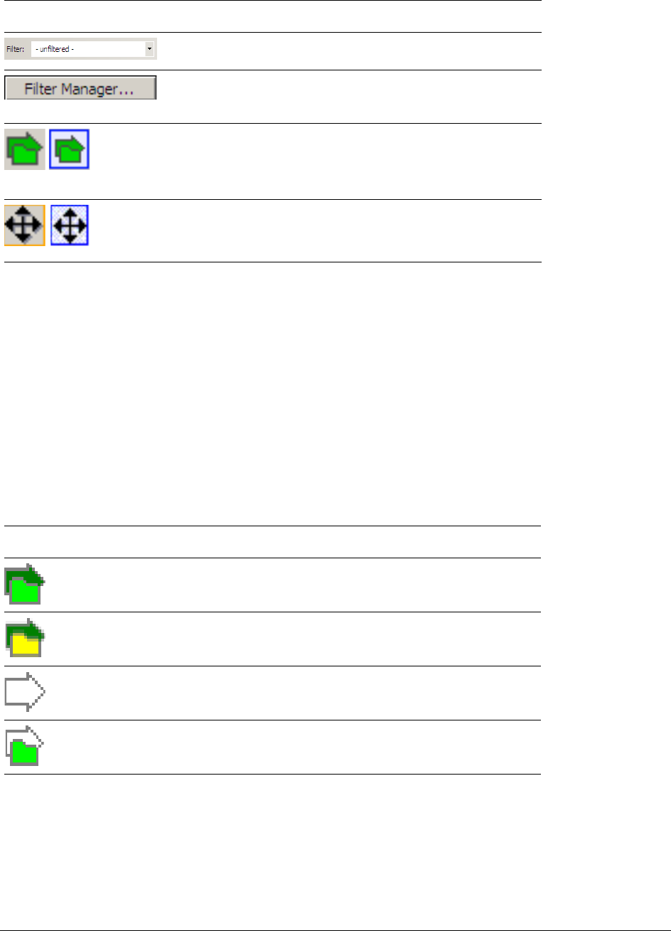
Using QuickPicks | 161
Using QuickPicks
QuickPicks is a type of filter that allows the selection of multiple folders and files in order to focus analysis on
specific content. The following figure represents the Explore Evidence Items tree with a partially selected set of
folders and sub-folders using the QuickPicks feature.
The QuickPicks filter simultaneously displays open and unopened descendent containers of all selected tree
branches in the File List at once. The colors of the compound icons indicate whether descendents are selected.
The icons are a combination of an arrow, representing the current tree level, and a folder, representing any
descendents.
The following table describes each QuickPicks icon:
The File List view reflects the current QuickPicks selections. When QuickPicks is active, or on, if no folders are
selected, the File List view show the currently selected item in the Tree view, including first level child objects.
When any item is selected, that selection is reflected in the File List view. When QuickPicks is not active, or off,
the File List view displays only items at the selected level in the tree view, with no children.
Opens the drop-down menu listing defined filters. Applies the
selected filter.
Opens the Filter Manager.
The Filter Manager allow multiple filters to be selected and
applied concurrently. These are known as Compound filters.
Turns the QuickPicks filter on or off. The QuickPicks filter is
used in the Explore tab to populate the file list with only items
the investigator wishes to analyze. When active, or ON, the
QuickPicks button is light blue. When inactive, or OFF, the
background is gray.
Locks or unlocks the movable panes in the application. When
the lock is applied, the box turns grey., and the panes are
locked. When unlocked, the box has a light blue background
and blue outline, indicating the panes can be moved.
TABLE 16-7
QuickPicks Icons
Icon Description
A dark green arrow behind a bright green folder means all
descendents are selected.
A dark green arrow behind a yellow folder means that although
the folder itself is not selected, some of its descendents are
selected.
A white arrow with no folder means neither that folder, nor any
of its descendents is selected.
A white arrow behind a bright green folder means that all
descendents are selected, but the folder is not.
TABLE 16-6
Filter Tool bar Components (Continued)
Component Description
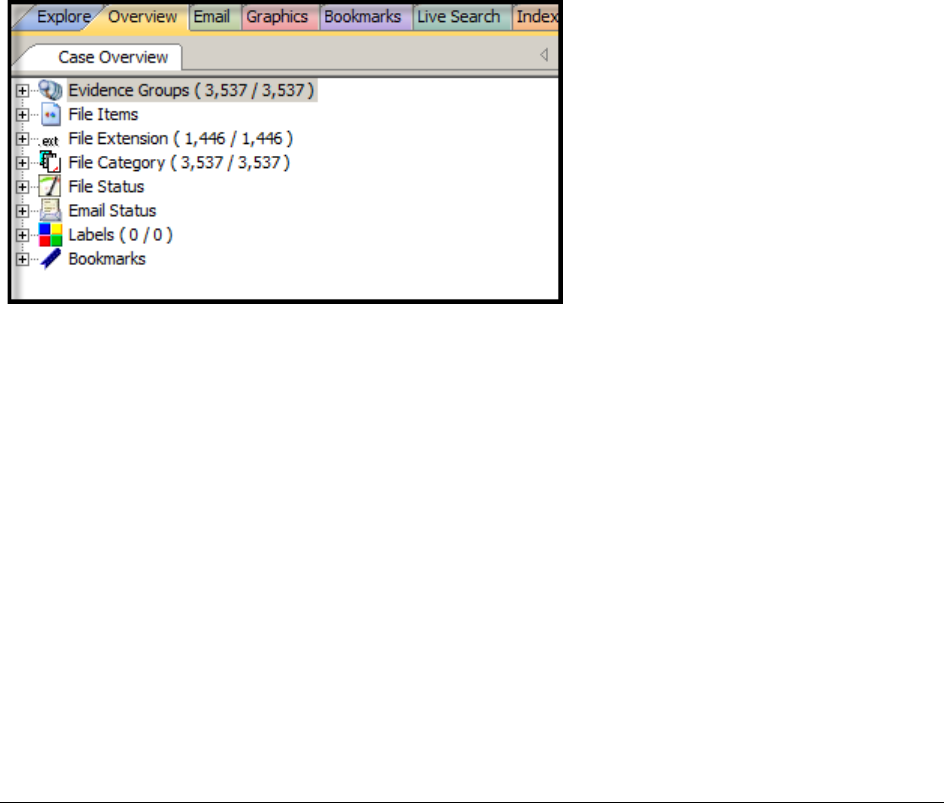
Using the Overview Tab | 162
Chapter 17
Examining Evidence in the Overview Tab
This chapter inlcludes the following topics:
-Using the Overview Tab (page 162)
Using the Overview Tab
The Overview tab provides a general view of a case. You can find the number of items in various categories,
view lists of items and lists of individual files by category, status, and extension. Evidence categories are
represented by trees in the upper-left Case Overview pane of the application.
Evidence Groups Container
Evidence items can be assigned to a group when they are added to a case. The Evidence Groups Container
shows at-a-glance which Evidence Groups are in use in a case, and the number of items associated with each.
Another group here is labeled Ungrouped. If you do not assign a group to your evidence, it will be found here.
File Items Container
The File Items container itemizes files by whether they have been checked and lists in an expandable tree view
the evidence files added to the case.
File Extension Container
The File Extension container itemizes files by their extensions, such as .TXT, .mapimail, and .DOC and lists
them in a tree view.

Using the Overview Tab | 163
The File Extension Container content numbers do not synchronize or match up with the overall number of case
items. This is because case items, such as file folders, do not have extensions and, therefore, are not listed in
the File Extension Container.
File Category Container
File Category container itemizes files by type, such as a word processing document, graphic, email, executable
(program file), or folder, and lists them in a tree view.
The statistics for each category are automatically listed. Expand the category tree view to see the file list
associated with it.
BlackBerry IPD files (the files created on your PC when you back up your BlackBerry device) are recognized and
categorized. Not every BlackBerry device has the same features as all the others, and everyone uses their
device differently so there is no guarantee that every type of data will be available from every set of backup IPD
files. You will most likely see HTML and XML files, Messages, and Pictures/Photos. Address Books, Tasks, and
Calendars will be extracted if available.
The following table provides detail for File Categories:
TABLE 17-1
File Categories
Category Description
Archives Archive files include Email archive files, Zip, Stuffit, Thumbs.db
thumbnail graphics, and other archive formats.
Databases Database files such as those from MS Access, Lotus Notes NSF,
and other database programs.
Documents Includes recognized word processing, HTML, WML, XML, TXT, or
other document-type files.
Email Includes Email messages from Outlook, Outlook Express, AOL,
Endoscope, Yahoo, Rethink, Udder, Hotmail, Lotus Notes, and
MSN.
Executables Includes Win32 executables and DLLs, OS/2, Windows VxD,
Windows NT, Java Script, and other executable formats.
Folders Folders or directories that are located in the evidence.
Graphics Lists files having the standard recognized graphic formats such as
.TIF, .GIF, .JPEG, and .BMP, as found in the evidence.
Internet/Chat Files Lists Microsoft Internet Explorer cache and history indexes.
Mobile Phone Data Lists data acquired from recognized mobile phone devices.
Multimedia Lists .AIF, .WAV, .ASF, and other audio and video files as found in
the evidence.
OS/File System Files Lists partitions, file systems, registry files, and so forth.
Other Encryption Files Lists found encrypted files, as well as files needed for decryption
such as EFS search strings, Public Keys, Private Keys, and other
RSA Keys.
For more information on Decrypting Encrypted Files, See
Decrypting EFS and Other Encrypted Files (page 130).
Other Known Types A miscellaneous category that includes audio files, help files,
dictionaries, clipboard files, link files, and alternate data stream
files such as those found in Word .DOC files, etc.
Note: Other Known Types includes NSF Misc Note (Calendar,
$profile data, and other miscellaneous file that in the past were
shown as HTML), and NSF Stub Note (a link to the same email
or calendar item in another view) sub categories.

Using the Overview Tab | 164
File Status Container
File Status covers a number of file categories that can alert the investigator to problem files or help narrow down
a search.
The statistics for each category are automatically listed. Click the category button to see the file list associated
with it. The following table displays the file status categories.
Presentations Lists multimedia file types such as MS PowerPoint or Corel
Presentation files.
Slack/Free Space Lists files, or fragments of files that are no longer seen by the file
system, but that have not been completely overwritten.
Spreadsheets Lists spreadsheets from Lotus, Microsoft Excel, QuattroPro, and
others, as found in the evidence.
Unknown Types Lists files whose types are not identified.
User Types Lists user-defined file types such as those defined in a Custom
File Identification File.
TABLE 17-2
File Status Categories
Category Contents Description
Bad Extensions Files with an extension that does not match the file type identified in
the file header, for example, a .GIF image renamed as [graphic].txt.
Data Carved Files The results of data carving when the option was chosen for
preprocessing.
Decrypted Files The files decrypted by applying the option in the Tools menu.
Note: Decrypted status means the file was decrypted from evidence
added to the case in its original form. The software has had control
of the file and knows it was originally encrypted, that it was
contained in the original evidence, and thus, is relevant to the case.
Deleted Files Complete files or folders recovered from slack or free space that were
deleted by the owner of the image, but not yet written over by new
data.
Duplicate Items Any items that have an identical hash.
Because the hash is independent of the filename, identical files may
actually have different filenames.
The first instance of a file found during processing is the primary item.
Any subsequently found files whose hash is identical is considered a
secondary item, regardless of how many of the same file are found.
Email Attachments Files attached to the email in the evidence.
Email Related
Items All email-related files including email messages, archives, and
attachments.
Encrypted Files Files that are encrypted or have a password. This includes files that
have a read-only password; that is, they may be opened and viewed,
but not modified by the reader.
If the files have been decrypted with EFS and you have access to the
user’s login password, you can decrypt these files.
Flagged Ignore Files that are flagged to be ignored are probably not important to the
case.
TABLE 17-1
File Categories (Continued)
Category Description

Using the Overview Tab | 165
Email Status container
The Email Status container lists email items by status, as follows:
-Email Attachments (contains only attachments to emails)
-Email Reply (contains emails with replies)
-Forwarded Email (contains only emails that have been forwarded)
-From Email (contains everything derived from an email source, i.e. email related)
Labels container
The Labels container has been added to enumerate Labels that have been applied to the evidence. It lists Label
Groups and evidence items assigned to each group.
Bookmarks container
The Bookmarks container lists bookmarks as they are nested in the shared and the user-defined folders.
Bookmarks are defined by the investigator as the case is being investigated and analyzed. Bookmarks are
viewed from the Bookmarks Tab.
Flagged Privileged Files that are flagged as privileged cannot be viewed by the case
reviewer.
From Recycle Bin Files retrieved from the Windows Recycle Bin.
KFF Alert Files Files identified as likely to be contraband or illicit in nature.
KFF Ignorable Files identified as likely to be forensically benign.
OCR Graphics Files with graphic text that have been interpreted by the Optical
Character Recognition engine.
OLE Sub-items Items or pieces of information that are embedded in a file, such as text,
graphics, or an entire file. This includes file summary information (also
known as metadata) included in documents, spreadsheets, and
presentations.
User Decrypted Files you’ve previously decrypted, and then added to the case.
Note: A user can add any file using Add Decrypted File, and it will be
set as decrypted by user. This status indicates that AccessData did
not decrypt this file, and cannot guarantee its validity or that such a
file has anything to do with the case.
TABLE 17-2
File Status Categories (Continued)
Category Contents Description
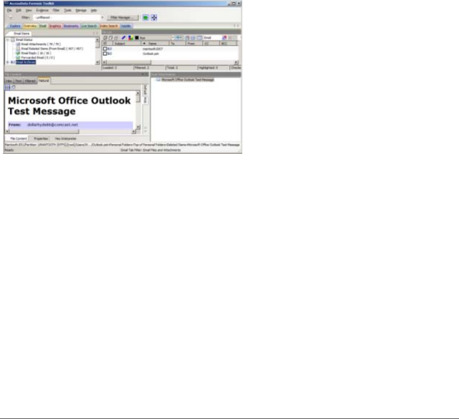
Using the Email Tab | 166
Chapter 18
Examining Email
This chapter includes the following topics
-Using the Email Tab (page 166)
Using the Email Tab
The Email tab displays email mailboxes and their associated messages and attachments. The display is a coded
HTML format.
Email Status Tree
The Email Status tree lists information such the sender of the email, and whether an email has attachments.
They are listed according to the groups they belong to.
Email Archives Tree
The Email Archives tree lists Email related files that are considered “containers”. Item types include .DBX, .MBX,
.PST, Saved Mail, Sent Mail, Trash, and so forth. The tree is limited to archive types found within the evidence
during processing.
Email Tree
The Email tree lists message counts, AOL DBX counts, PST counts, NSF counts, MBOX counts, and other such
counts.

Using the Email Tab | 167
Exchange and PST Emails can be exported to MSG format. In addition, MSG files resulting from an export of
internet email look the way they should.
The Email Tab > Email Items tree view contains two new groups: Email By Date (organized by Year, then by
Month, then by date, for both Submitted and Delivered); and Email Addresses (organized by Senders and
Recipients, and subcategorized by Email Domain, Display Name, and Email Addresses).
You can also export Tasks, Contacts, Appointments, Sticky Notes, and Journal Entries to MSG files.
Important:
If the Mozilla Firefox directory is added as evidence while in use, history, downloads, etc are
identified as zero-length files.
When an email-related item is selected in the File List, right-click and choose View this item in a different list >
Email to see the file in Email context.
Note: Email data parsed into the new nodes in the Email tree view will only be populated in new cases.
Converted cases will not have this data. To make this data available in older cases, re-process the case in
the new version.
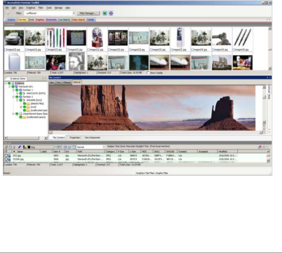
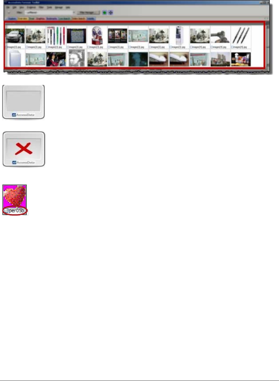
The Thumbnails Size Setting | 169
Each graphic file is shown in a thumbnail view. A graphic displays in the Graphics tab Thumbnail view when its
thumbnail is checked in the File Contents pane.
In the thumbnail viewer, if a graphic is not fully loaded, the following icon is displayed::
In the thumbnail viewer, if a graphic cannot be displayed, the following icon is displayed:
Beneath each thumbnail image is a check box. When creating a report, choose to include all of the graphics in
the case or only those graphics that are checked.
The Evidence Items pane shows the Overview tree by default. Use the View menu to change what displays
here. Only graphic files appear in the File List when the tab filter is applied. Turn off the tab filter to view
additional files.
The Thumbnails Size Setting
The thumbnail settings allow large amounts of graphic data to be displayed for evidence investigation, or larger
thumbnails to show more detail quickly. The investigator does not always need to see details to pick out
evidence; scan the thumbnails for flesh tones, photographic-type graphics, and perhaps particular shapes. Once
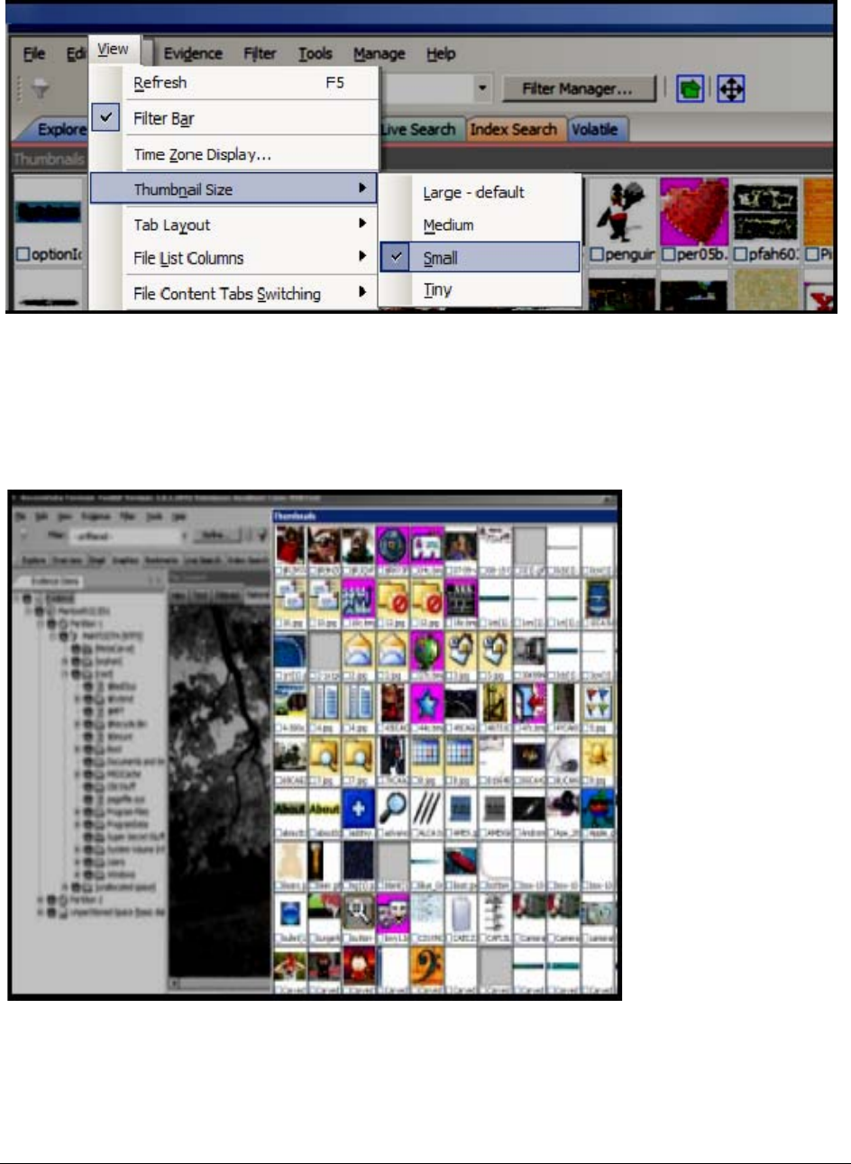
Moving the Thumbnails Pane | 170
found, the graphics can be inspected more closely in the Content Viewer. To change the thumbnails size setting,
in the Examiner, go to View > Thumbnail Size and select a size.
Moving the Thumbnails Pane
The detachable pane feature is especially useful when you undock the thumbnails graphics pane and move it to
a second monitor, thus freeing your first monitor to display the entire data set for the graphics files being
analyzed. You can Undock the Thumbnails pane, and expand it across the screen. Then you can open the
Thumbnails Settings sub-menu, and scale the thumbnails down to fit as many as possible in the pane.

Evaluating Explicit Material | 171
Evaluating Explicit Material
When explicit material is suspected in a case Explicit Image Detection allows for easier location and
identification of those files. When creating the case, you were given several choices as far as identifying explicit
material. See About Explicit Image Detection (page 71) for more information on setting the EID pre-processing
options prior to case creation.
When the pre-processing options are set and applied to evidence as it is processed, in the case you can easily
identify files that fit the criteria you set.
Filtering EID Material
There are a few steps you should take to make the most of the EID feature.
Create a Filter.
A Tab Filter must be used here to filter the folders from the Explore tab, but not filter out the Folders’ content from
the Graphics Tab. However, the filter itself must be created first, then the filter must be applied as a Tab Filter.
To create a filter for the EID folders in your case
1. Click the Explore tab.
2. Ensure that Filters are turned off, and the Filter drop-down displays “-unfiltered-”.
3. On the Menu bar, click Filter >New.
4. Create a Filter to include EID Folders that have high scores.
4a. Give the Filter a name that reflects its purpose.
4b. Provide a description with enough information to be helpful at a glance.
4c. Set up Rules as in the example. Check each Rule to include it in the filter.
4d. Mark Live Preview to see the effects of the filter on the current File List.
4e. Choose Match Any, or Match All, to fit your needs, according to the preview.
4f. Click Save > Close.
If you choose to, repeat Steps 3 and 4 for Medium folders with a criteria of 40, then move to Step 5.
5. From the Filter Manager, copy the new filters to the Include list on the top-right side of the view.
6. At the bottom of the dialog, click Apply and Close.
To apply the new filter as a Tab filter
1. Click the Explore tab.
2. Ensure that Filters are turned off, and the Filter drop-down displays “-unfiltered-”.
3. Click Filter >Tab Filter.
4. In the Tab Filter Selection dialog, click the drop-down to select Explicit images folder (high score) as
created earlier.
5. Click OK.
Change the Column List Settings
To view the Explicit Image Detection (EID) statistics for your case in the File List, do the following:
1. Click the Graphics tab.

EID Scoring | 172
2. In the File List, select the default EID column template from the drop down list, or add the EID columns
to the column template you choose. To customize a Columns Template for EID content, do the
following:
2a. Click Column Settings in the File List toolbar.
2b. In the Manage Column Settings dialog, click New, or highlight an existing template and click Copy
Selected.
2c. In the Column Settings dialog, select the EID related column headings to add to the template, and
click Add
2d. Make your selections.
2e. Move the selected columns up in the list to make them display closer to the left-most column in the
view, as it best works for you.
3. Click OK
4. From the Manage Column Settings, select the New Column template, and click Apply.
Later, to re-apply this column template, select it from the Column Setting drop-down.
The resulting columns are displayed in the File List view
5. In the File List view, arrange the column headings so you can see the EID data.
6. Click any column heading to sort on that column, to more easily see and evaluate the relevant data.
EID Scoring
EID filtering on folders is now more accurate. Each folder is given a score that indicates the percentage of files
within the folder that have an EID score above 50. For example, if the folder contains 8 files and three of them
score over 50, the folder score will be 38 (3 is 37.5% of 8). Now, a folder score of 38 does not mean there is no
objectionable material in that folder, it only means that there is not a high concentration of objectionable material
found there.
Explicit Image Detection filtering rates pictures according to the presence or absence of skin tones in graphic
files. In addition, it not only looks for flesh tone colors, but it has been trained on a library of approximately
30,000 actual pornographic images. Thus, it is assessing actual visual content. This capability greatly benefits
investigators who are working pornography cases, particularly those investigators working cases that involve
children. These types of cases sadly have inundated law enforcement agencies throughout the country, and this
capability increases the speed with which investigators can handle those cases.
Successfully filtered pictures are issued a score between 0 and 100 (0 being complete absence of skin tones, or
“clean” content, 100 being heavy presence of skin tones). A score above 100 indicates that no detection could
be made. When you set filters for analyzing the scored data, you specify your own acceptance threshold limit for
images you may consider inappropriate. Negative scores indicate a black and white, or grayscale image where
no determination can be made, or that some error occurred in processing the file.
EID scores can be roughly interpreted as follows:
0 to 100 = no skin tones detected, or heavy skin tones detected
--1 = File not found
--2 = License error
--3 = Wrong file format
--4 = No match found
--5 = Folder not found
--6 = Unknown error
--7 = Cannot load image (e.g., corrupt image)

EID Scoring | 173
--8 = Not enough information
--9 = Face detection profile path is null
--10 = Can’t open face detection directory
--11 = Face detection file not found
--12 = Input classifier not initialized
--13 = Init profile failed
--14 = File path is empty
--16 = Image data is empty
--17 = Null matching handle
--18 = Missing retrieval result
--100 = Unsupported file format.
--101 = Unsupported black & white image.
--102 = Unsupported grayscale image.
--103 = Unsupported monochrome image.
--1000 = Unknown error.
--1001 = EID score function threw an exception.
--1002 = EID score function threw an exception.
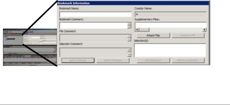
Using the Bookmarks Tab | 174
Chapter 20
Bookmarking Evidence
This chapter includes the following topics:
-Using the Bookmarks Tab (page 174)
-Creating a Bookmark (page 175)
-Viewing Bookmark Information (page 176)
-Bookmarking Selected Text (page 176)
-Adding to an Existing Bookmark (page 177)
-Creating Email or Email Attachment Bookmarks (page 177)
-Adding Email and Email Attachments to Existing Bookmarks (page 178)
-Moving a Bookmark (page 178)
-Copying a Bookmark (page 178)
-Deleting a Bookmark (page 178)
-Deleting Files from a Bookmark (page 178)
Using the Bookmarks Tab
A bookmark is a group of files that you want to reference in your case. These are user-created and the list is
stored for later reference, and for use in the report output. You can create as many bookmarks as needed in a
case. Bookmarks can be nested within other bookmarks for convenience and categorization purposes.
Bookmarks help organize the case evidence by grouping related or similar files. For example, you can create a
bookmark of graphics that contain similar or related graphic images. The Bookmarks tab lists all bookmarks that
have been created in the current case.

Creating a Bookmark | 175
The following table provides names and describes options found in the Bookmark Information pane:
Table 1: Options of the Bookmark Information Pane
Creating a Bookmark
To create a bookmark
1. Right-click on selected files in the File List View and click Create Bookmark .
2. Enter a name for the bookmark in the Bookmark Name field.
3. (Optional) In the Bookmark Comment field, enter comments about the bookmark or its contents.
4. Click one of the following options to specify which items to add to the bookmark:
-All Highlighted: Highlighted items from the current file list. Items remain highlighted only as long as
the same tab is displayed.
-All Checked: All items checked in the case.
-All Listed: Bookmarks the contents of the File List view.
5. (Optional) Enter a description for each file in the File Comment field.
6. Click Attach to add files external to the case that should be referenced from this bookmark. This opens
a Windows Explorer window where you can navigate to the files you want to Attach as Supplemental
Files for this bookmark.
Fields Descriptions
Bookmark Name The name of the bookmark. Click Save Changes to store any
changes made to this field.
Creator Name Displays the non-editable name of the user who created the
bookmark.
Bookmark Comment The investigator can assign a text comment to the bookmark. Click
Save Changes to store any changes made to this field at any time.
Supplementary Files Displays a list of external, supplementary files associated with the
bookmark. Options are:
-Attach: Allows the investigator to add external supplementary files
to the bookmark, these files are copied to a subdirectory within
the case folder and referenced from there.
-Remove: Removes a selected supplementary file from the book-
mark.
File Comments The investigator can assign a different comment to each file in the
bookmark. Click Save Changes to store any changes made to this
field.
Selection Comments Each file within the bookmark may contain an unlimited number of
selections, each of which the investigator may assign a comment.
These comments can be edited.
-Save Changes: Stores any changes made to this Selection Com-
ments field.
-Clear Changes: Clears any unsaved changes made to the book-
mark information.
Selections Displays a list of stored selections within the selected file.
-Add Selection: Stores the selection boundaries of the swept text in
the File Content pane. This button does not store selection infor-
mation for the Web tab.
-Remove Selection: Removes the highlighted selection from the
Selections list.

Viewing Bookmark Information | 176
7. The attached files appear in the Supplementary Files pane, and are copied to the case folder.
8. Check Bookmark Selection in File to have the highlighted text in a file automatically highlighted when
the bookmark is re-opened. The highlighted text also prints in the report.
9. Under the Also include heading, mark Email Attachments, Parent Email, OCR Extractions of
selected Graphics, and Exclude Selected OCR Extractions if applicable to this bookmark.
Note: The Exclude Selected OCR Extractions check box appears only when OCR- extracted files
have been selected when creating a new or adding to an existing bookmark. If, instead, you have
selected graphic files, and have not selected their OCR counterparts, the check box for OCR
Extractions of selected Graphics will be active and available.
10. If a file has selected text that you want added to the bookmark, mark the box Bookmark Selection in
File, and the selected text that will be included displays in the text box below the check box.
11. Select the parent bookmark under which you would like to save the bookmark.
A default shared tree for bookmarks available to all investigators is created, and a bookmark tree
specific to the case owner is created.
If the bookmark is related to an older bookmark it can be added under the older bookmark, with the
older bookmark being the parent, or it can be saved as a peer.
12. Click OK.
Note: Applying filters to a group of listed files for bookmarking can speed the process. The All
Highlighted setting does not work in this instance. Enabling this feature would significantly slow
the response of the program. Instead, use either the Checked Files filter, or the All Files Listed
filter.
Viewing Bookmark Information
The Bookmark Information pane displays information about the selected bookmark and the selected bookmark
file. The data in this pane is editable by anyone with sufficient rights.
Select a bookmark in the Bookmarks tree view of the Bookmarks tab, or in the Bookmarks node in the tree of the
Overview tab to view information about a bookmark. The Overview tab view provides limited information about
the bookmarks in the case. The Bookmark tab provides all information about all bookmarks in the case. In the
Bookmark tab, the Bookmark Information pane displays the Bookmark Name, Creator Name, Bookmark
Comment, and Supplementary files. When selected, a list of files contained in the bookmark displays in the File
List. If you select a file from the File List the comment and selection information pertaining to that file displays in
the Bookmark Information pane.
Bookmarked files display in a different color in the File List view than non-bookmarked files for easy
identification.
Change any of the information displayed from this pane. Changes are automatically saved when you change the
bookmark selection.
In the File List, bookmarked items display in a different color for easy identification. You may need to refresh the
view to force a rewrite of the screen for the different color to display. Forcing a rewrite would impact the overall
performance of the program.
Bookmarking Selected Text
Bookmarked selections are independent of the view in which they were made. Select hex data in the Hex view of
a bookmarked file and save it; bookmark different text in the Filtered view of the same file and save that
selection as well.

Adding to an Existing Bookmark | 177
To add selected text in a bookmark
1. Open the file containing the text you want to select.
2. From the Natural, Text, Filtered or Hex views, make your selection.
Note: If the file is a graphic file, you will not see, nor be able to make selections in the Text or the
Natural views.
3. Click Create Bookmark in the File List toolbar to open the Create New Bookmark dialog.
4. When creating your bookmark, check Bookmark Selection in File.
5. To save selected content, choose the view that shows what you want to save, then highlight the content
to save.
6. Right-click on the selected content. Click Save As.
7. In the Save As dialog, provide a name for the selection and click Save.
The selection remains in the bookmark.
Adding to an Existing Bookmark
Sometimes additional information or files are desired in a bookmark.
To add to an existing bookmark
1. Select the files to be added to the existing bookmark.
2. Right-click the new files.
3. Click Add to Bookmark.
4. When available (depending on the type of files you are adding), make selections for Files to Add, Also
Include, OCR Extractions of Selected Graphics, and Bookmark Selection in File.
5. Open the parent bookmark tree.
6. Select the child bookmark to add the file or information to.
7. Click OK.
Creating Email or Email Attachment Bookmarks
When bookmarking an email, you can also add and bookmark any attachments. You can also include a parent
email when you bookmark an email attachment.
To create a bookmark for an email, follow the steps for creating a bookmark. Select the email to include in the
bookmark. Right-click and choose Create Bookmark. Note that by default, the Email Attachments box is
active, but unmarked. If only the parent email is needed the Email Attachments box should remain unselected.
Complete the bookmark creation normally by naming the bookmark, selecting the bookmark parent, then
clicking OK.
If you need to bookmark only an attachment of the email, select and right-click on the attachment. Choose
Create Bookmark. For more information on creating bookmarks, see, Creating a Bookmark (page 175).
Notice that the Parent Email box is automatically active, allowing you to include the parent email if it is not part of
the selection you have already made. If the Parent Email box is checked, and there is more than one
attachment, the Email Attachments box becomes active as well, allowing you to also include all attachments to
the parent email. To add only the originally selected attachment to the bookmark, do not check the Parent Email
box.

Adding Email and Email Attachments to Existing Bookmarks | 178
Adding Email and Email Attachments to Existing Bookmarks
To add an email to a bookmark, select the email to add, then right-click on the email and choose Add To
Bookmark. Note that if emails are selected, but their attachments are not selected, the Email Attachments box
is active, but not marked. If only the parent email is needed the Email Attachments box can remain unselected.
If you have selected only the attachment, include the attachment’s parent email by marking the Parent Email
box.
One way to be sure to find the exact items you want is to highlight an interesting item in the File List view in one
tab, then right-click on it and select View This Item in a Different List. Click on Email and you are taken to the
Email tab with the selected email highlighted in the File List view, and displayed in the Natural tab in the File
Content pane. In the Email Attachments pane on the right that file is displayed, along with its role; whether it is a
parent email, part of the email thread, or an attachment.
If only an attachment of an email is needed to be added to the bookmark, select the attachment and follow the
instructions for adding to a bookmark.
Moving a Bookmark
To move a bookmark
1. From either the Bookmark tab or the Overview tab, select the bookmark you want to move.
2. Using the left mouse button, drag the bookmark to the desired location and release the mouse button.
Copying a Bookmark
To copy a bookmark
1. From either the Bookmark tab or the Overview tab, select the bookmark you want to copy.
2. Using the right mouse button, drag the bookmark to the desired location and release the mouse button.
Deleting a Bookmark
To delete a bookmark
1. In the Bookmark tab, expand the bookmark list and highlight the bookmark to be removed.
2. Do one of the following:
-Press the Delete key.
-Right-click on the bookmark to delete, and click the Delete Bookmark button.
Deleting Files from a Bookmark
To delete files from a bookmark
1. From either the Overview tab or the Bookmarks tab, open the bookmark containing the file you want to
delete.
2. Right-click the file in the Bookmark File List pane.

Deleting Files from a Bookmark | 179
3. Do one of the following:
-Select Remove from Bookmark.
-Press the Delete key on your keyboard, whereupon you will be prompted, “Are you sure you want to
delete files from this bookmark?” Click Yes.
-Deleting a file from a bookmark does not delete the file from the case.
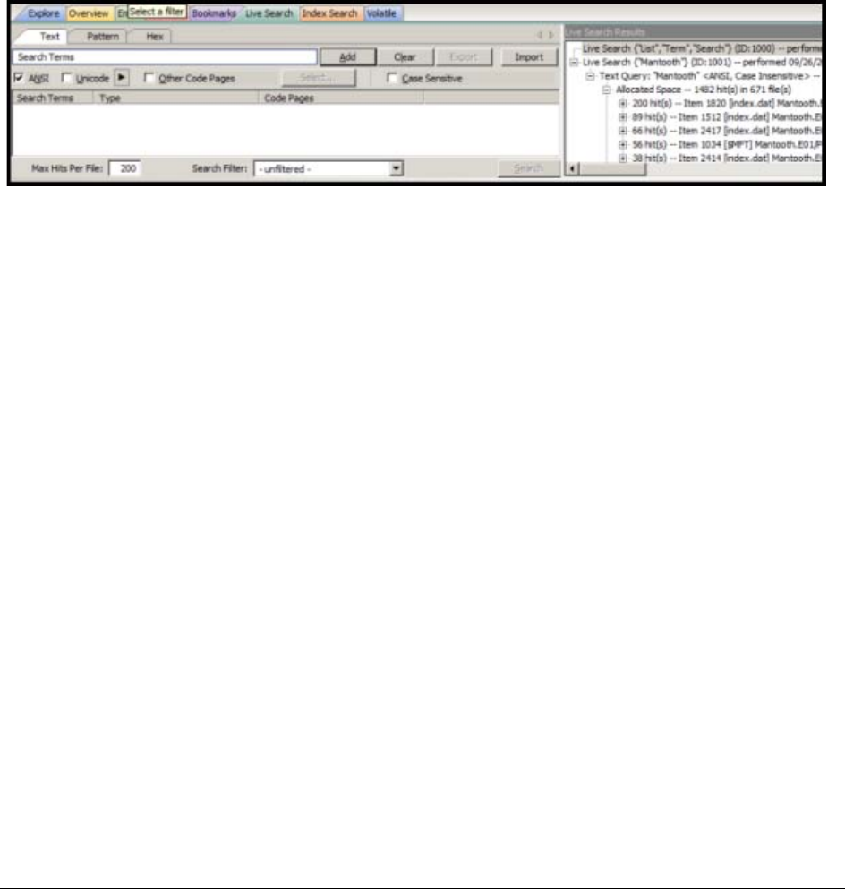
Conducting a Live Search | 180
Chapter 21
Searching Evidence with Live Search
Searching evidence for information pertaining to a case can be one of the most crucial steps in the examination.
An index search gives rapid results, and a live search includes options such as text searching and hexadecimal
searching. You can view search results from the File List and File Contents views of the Search tab.
The Live Search is a process involving a bit-by-bit comparison of the entire evidence set with the search term.
This chapter includes the following topics:
-Conducting a Live Search (page 180)
-Live Text Search (page 180)
-Live Hex Search (page 182)
-Live Pattern Search (page 183)
-Simple Pattern Searches (page 184)
-Complex Pattern Searches (page 184)
-Predefined Regular Expressions (page 185)
-Creating Custom Regular Expressions (page 187)
Conducting a Live Search
The live search takes slightly more time than an index search because it involves a bit-by-bit comparison of the
search term to the evidence. A live search is flexible because it can find patterns of non-alphanumeric
characters, including those that are not generally indexed. It is powerful because you can define those patterns
to meet your needs in an investigation.
Live Text Search
A Text search finds all strings that match an exact entry, such as a specific phone number (801-377-5410).
When conducting a Live Text Search, there are no arrows to click for operand selection.

Live Text Search | 181
A Live Text Search gives you options such as ANSI, Unicode with UTF-16 Little Endian, UTF-16 Big Endian, and
UTF-8. The latter two are always case-sensitive. You can also choose from a list of other Code Pages to apply to
the current search. In addition, you can select Case Sensitivity for any Live Text Search.
The difference between a Pattern search and a Text search is that a text search searches for the exact typed
text, there are no operands so the results return exactly as typed. For example, a simple Pattern search allows
you to find all strings that match a certain pattern, such as for any 10-digit phone number (nnn-nnn-nnnn), or a
nine-digit social security number (nnn-nn-nnnn).
More complex Pattern searches (“regex”) require specific syntax. See Live Pattern Search (page 183).
Search terms can be entered then exported as .XML files, then imported at any time, or with any case. Text
(.TXT) files can be imported and used in Live Search, however the Live Search Export feature supports only
.XML format.
Note: When importing .txt files that the search of those terms depend on the specific tab your in. (ie If I have a
few hex terms and import the .txt list into Live Search in the Patterns tab), the search will be ran as a
pattern search and not hex.
To Conduct a Live Text search
1. In the Live Search tab, click the Text tab.
In the Text or Pattern tabs, you can check the character sets to include in the search.
2. If you want to include sets other than ANSI and Unicode, check Other Code Pages and click Select.
3. Select the needed sets.
4. Click to include EBCDIC, Mac, and Multibyte as needed.
5. Click OK to close the dialog.
6. Check Case Sensitive if you want to search specifically uppercase or lowercase letters as entered.
Case is ignored if this box is not checked.
7. Enter the term in the Search Term field.
8. Click Add to add the term to the Search Terms window.
9. Click Clear to remove all terms from the Search Terms window.
10. Repeat Steps 7, 8, and 9 as needed until you have your search list complete.
When you have added the search terms for this search, it is a good idea to export the search terms to a
file that can be imported later, saving the time of re-entering every item, and the risk of errors. This is
particularly helpful for customized pattern searches.
11. In the Max Hits Per File field, enter the maximum number of search hits you want listed per file. The
default is 200. The range is 1 to 65,535. If you want to apply a filter, do so from the Filter drop-down list
in the bar below the Search Terms list. Applying a filter speeds up searching by eliminating items that do
not match the filter. The tab filter menu has no effect on filtering for searches.
12. Choose one of the following:
-Click Search.
-Click Cancel in the progress dialog to stop the search before it is complete.
13. Select the results to view from the Live Search Results pane. Click the plus icon (+) next to a search line
to expand the branch. Individual search results are listed in the Live Search Results pane, and the
corresponding files are listed in the File List. To view a specific item, select the hit in the search results.
Selected hits are highlighted in the Hex View tab.
14. When a search is running you can click View > Progress Window to see how the job is progressing.
Note: In the Progress Window notice that you can Pause, Resume, and Cancel jobs, in addition to
Closing the window. (Pause and Resume are the same button, but the label changes depending
on processing activity.)

Live Hex Search | 182
Note: Mark the Remove when finished check box to take completed jobs off the list for housekeeping
purposes.
15. When processing is complete, return to the Live Search tab to review the results.
Right-click on a search result in the Live Search Results pane to display more options. The available
right-click options are as follows:
Searching before the case has finished processing will return incomplete results. Wait to search until the case
has finished processing and the entire body of data is available.
Note: Search terms for pre-processing options support only ASCII characters.
Live Hex Search
Hexadecimal (Hex) format includes pairs of characters in a base 16 numeric scheme, 0-9 and a-f. Hex searching
allows you to search for repeating instances of data in Hex-format, and to save Hex-format data search strings to
an .XML file and re-use it in this or other cases.
Click the Hex (Hexadecimal) tab to enter a term by typing it directly into the search field, by clicking the
Hexadecimal character buttons provided, or by copying hex content from the hex viewer of another file and
pasting it into the search box. Click Add to add the hex string to the search terms list.
The instructions for conducting a live search on the hex tab are similar to conducting searches on the Pattern
tab. Remember, when searching for hexadecimal values, a single alphabetic or numeric text character is
represented by hex characters in pairs.
To do a Hex search
1. In the Live Search tab, click the Hex tab.
Table 1: Right-Click Options in Live Search Results Pane
Option Description
Create Bookmark Opens the Create New Bookmark dialog.
Copy to Clipboard Opens a new context-sensitive menu. Options are:
-All Hits In Case
-All Hits In Search
-All Hits In Term
-All Hits In File
-All File Stats In Case
-All File Stats In Search
-All File Stats In Term
Export to File Opens a new context-sensitive menu. Options are:
-All Hits In Case
-All Hits In Search
-All Hits In Term
-All Hits In File
-All File Stats In Case
-All File Stats In Search
-All File Stats In Term
Set Context Data
Width Opens the Data Export Options window. Allows you to set a
context width from 32 to 2000 characters within which to find and
display the search hit.
Export Search Term Select to export a search term list that can be imported into this or
other cases.
Delete All Search
Results Deletes all search results from the Live Search Results pane.
Delete this Line Deletes only the highlighted search results line from the Live
Search Results pane.

Live Pattern Search | 183
2. Add Hex search strings using the keyboard or using the Alpha-numeric bar above the Search Terms
box.
3. Click Add to add the term to the Search Terms window.
4. Click Clear to remove all terms from the Search Terms window.
5. Repeat Steps 2, 3, and 4 as needed until you have your search list complete.
6. When you have added the search terms for this search, it is a good idea to export the search terms to a
file that can be imported later, saving the time of re-entering every item, and reduces the risk of errors.
This is particularly helpful for customized pattern searches.
7. In the Max Hits Per File field, enter the maximum number of search hits you want listed per file. The
default is 200. The range is 1 to 65,535. If you want to apply a filter, do so from the Filter drop-down list
in the bar below the Search Terms list. Applying a filter speeds up searching by eliminating items that do
not match the filter. The tab filter menu has no effect on filtering for searches.
8. Do one of the following:
-Click Search.
-Click Cancel in the progress dialog to stop the search before it is complete.
9. Select the results to view from the Live Search Results pane. Click the plus icon (+) next to a search line
to expand the branch. Individual search results are listed in the Live Search Results pane, and the
corresponding files are listed in the File List. To view a specific item, select the file in the search results.
All search results are highlighted in the Hex View tab.
Live Pattern Search
The more complex Live Pattern “Regex” style search can be used to create pattern searches, allowing forensics
analysts to search through large quantities of text information for repeating strings of data such as:
-Telephone Numbers
-Social Security Numbers
-Computer IP Addresses
-Credit Card Numbers
In the Live Search tab, click the Pattern tab. Each has different options.
The patterns consist of precise character strings formatted as mathematical-style statements that describe a
data pattern such as a credit card or social security number. Pattern searches allow the discovery of data items
that conform to the pattern described by the expression, rather than a known and explicitly entered string are
looking for.
These pattern searches are similar to arithmetic expressions that have operands, operators, sub-expressions,
and a value. For example, the following table identifies the mathematical components in the arithmetic
expression, 5/((1+2)*3):
Table 2: Regex Pattern Search Components
Component Example
Operands 5, 1, 2, 3
Operators /, ( ), +, *
Sub-Expressions (1+2), ((1+2)*3)
Value Approximately 0.556

Simple Pattern Searches | 184
Like the arithmetic expression in this example, pattern searches have operands, operators, sub-expressions,
and a value.
Note: Unlike arithmetic expressions, which can only have numeric operands, operands in pattern searches can
be any characters that can be typed on a keyboard, such as alphabetic, numeric, and symbol characters.
Simple Pattern Searches
A simple pattern search can be made up entirely of operands. For example, the pattern search dress causes the
search engine to return a list of all files that contain the sequence of characters d r e s s. The pattern search
dress corresponds to a very specific and restricted pattern of text, that is, sequences of text that contain the sub-
string dress. Files containing the words “dress,” “address,” “dressing,” and “dresser,” are returned in a search for
the pattern search dress.
The search engine searches left to right. So in searching the pattern search dress, the search engine opens
each file and scans its contents line by line, looking for a d, followed by an r, followed by an e, and so on.
Complex Pattern Searches
Operators allow regular expressions to search patterns of data rather than specific values. For example, the
operators in the following expression enables the search engine to find all Visa and MasterCard credit card
numbers in case evidence files:
\<((\d\d\d\d)[\– ]){3}\d\d\d\d\>
Without the use of operators, the search engine could look for only one credit card number at a time.
The following table identifies the components in the Visa and MasterCard regular expression:
As the pattern search engine evaluates an expression in left-to-right order, the first operand it encounters is the
backslash less-than combination (\<). This combination is also known as the begin-a-word operator. This
operator tells the search engine that the first character in any search hit immediately follows a non-word
character such as white space or other word delimiter.
Note: A precise definition of non-word characters and constituent-word characters in regular expressions is
difficult to find. Consequently, experimentation may be the best way to determine if the forward slash less-
than (\<) and forward slash greater-than (\>) operators help find the data patterns relevant to a specific
searching task. The hyphen and the period are examples of valid delimiters or non-word characters.
The begin-a-word operator illustrates one of two uses of the backslash or escape character ( \ ), used for the
modification of operands and operators. On its own, the left angle bracket (<) would be evaluated as an operand,
requiring the search engine to look next for a left angle bracket character. However, when the escape character
immediately precedes the (<), the two characters are interpreted together as the begin-a-word operator by the
search engine. When an escape character precedes a hyphen (-) character, which is normally considered to be
TABLE 21-1
Visa and MasterCard Regular Expressions
Example Operands
Operands \–, spacebar space
Operators \, \<, <, ( ), [ ], {3}, \>
Sub-expressions (\d\d\d\d), ((\d\d\d\d)[\– ])
Value Any sequence of sixteen decimal digits that is delimited by three
hyphens and bound on both sides by non-word characters
(xxxx–xxxx–xxxx–xxxx).

Predefined Regular Expressions | 185
an operator, the two characters (\-) require the search engine to look next for a hyphen character and not apply
the hyphen operator (the meaning of the hyphen operator is discussed below).
The parentheses operator ( ) groups together a sub-expression, that is, a sequence of characters that must be
treated as a group and not as individual operands.
The \d operator, which is another instance of an operand being modified by the escape character, is interpreted
by the search engine to mean that the next character in search hits found may be any decimal digit character
from 0-9.
The square brackets ([ ]) indicate that the next character in the sequence must be one of the characters listed
between the brackets or escaped characters. In the case of the credit card expression, the backslash-hyphen-
spacebar space ([\-spacebar space]) means that the four decimal digits must be followed by either a hyphen or a
spacebar space.
The {3} means that the preceding sub-expression must repeat three times, back to back. The number in the
curly brackets ({ }) can be any positive number.
Finally, the backslash greater-than combination (\>), also know as the end-a-word operator, means that the
preceding expression must be followed by a non-word character.
Sometimes there are ways to search for the same data using different expressions. It should be noted that there
is no one-to-one correspondence between the expression and the pattern it is supposed to find. Thus the
preceding credit card pattern search is not the only way to search for Visa or MasterCard credit card numbers.
Because some pattern search operators have related meanings, there is more than one way to compose a
pattern search to find a specific pattern of text. For instance, the following pattern search has the same meaning
as the preceding credit card expression:
\<((\d\d\d\d)(\–| )){3}\d\d\d\d\>
The difference here is the use of the pipe (|) or union operator. The union operator means that the next character
to match is either the left operand (the hyphen) or the right operand (the spacebar space). The similar meaning
of the pipe (|) and square bracket ([ ]) operators give both expressions equivalent functions.
In addition to the previous two examples, the credit card pattern search could be composed as follows:
\<\d\d\d\d(\–| )\d\d\d\d(\–| )\d\d\d\d(\–| )\d\d\d\d\>
This expression explicitly states each element of the data pattern, whereas the {3} operator in the first two
examples provides a type of mathematical shorthand for more succinct regular expressions.
Predefined Regular Expressions
Many predefined regular expressions are provided for pattern searching, including the following:
Select regular expressions from drop-down lists under the arrows as described below:
-Click the black arrow to see a list of the basic components for regular expressions. You can create your
own pattern by combining these components into a longer expression.
FIGURE 21-1
Regular Expressions Basic Components
-Click the white arrow to see a list of predefined expressions.
TABLE 21-2
A Small Sampling of FTK Predefined Regular Expressions
-U.S. Social Security Numbers -IP Addresses
-U.S. Phone Numbers -Visa and MasterCard Numbers
-U.K. Phone Numbers -Computer Hardware MAC Addresses

Predefined Regular Expressions | 186
FIGURE 21-2
Live Search Tab Predefined Regular Expressions
The Social Security Number, U.S. Phone Number, and IP Address expressions are discussed in the following
sections.
Social Security Number
The pattern search for Social Security numbers follows a relatively simple model:
\<\d\d\d[\– ]\d\d[\– ]\d\d\d\d\>
This expression reads as follows: find a sequence of text that begins with three decimal digits, followed by a
hyphen or spacebar space. This sequence is followed by two more decimal digits and a hyphen or spacebar
space, followed by four more decimal digits. This entire sequence must be bounded on both ends by non-word
characters.
U.S. Phone Number
The pattern search for U.S. phone numbers is more complex:
((\<1[\–\. ])?(\(|\<)\d\d\d[\)\.\–/ ] ?)?\<\d\d\d[\.\– ]\d\d\d\d\>
The first part of the above expression,
((\<1[\–\. ])?(\(|\<)\d\d\d[\)\.\–/ ] ?)?,
means that an area code may or may not precede the seven digit phone number. This meaning is achieved
through the use of the question mark (?) operator. This operator requires that the sub-expression immediately to
its left appear exactly zero or one times in any search hits. This U.S. Phone Number expression finds telephone
numbers with or without area codes.
This expression also indicates that if an area code is present, a number one (1) may or may not precede the
area code. This meaning is achieved through the sub-expression (\<1[\–\. ])?, which says that if there is a “1”
before the area code, it will follow a non-word character and be separated from the area code by a delimiter
(period, hyphen, or spacebar space).
The next sub-expression, (\(|\<)\d\d\d[\)\.\–/ ] ?, specifies how the area code must appear in any search
hits. The \(|\<) requires that the area code begin with a left parenthesis or other delimiter. The left parenthesis
is, of necessity, escaped. The initial delimiter is followed by three decimal digits, then another delimiter, a right
parenthesis, a period, a hyphen, a forward slash, or a spacebar space. Lastly, the question mark (?) means that
there may or may not be one spacebar space after the final delimiter.
The latter portion of this expression, \<\d\d\d[\.\– ]\d\d\d\d\>, requests a seven-digit phone number with a
delimiter (period, hyphen, or spacebar space) between the third and fourth decimal digit characters. Note that
typically, the period is an operator. It means that the next character in the pattern can be any valid character. To
specify an actual period (.), the character must be escaped ( \ .). The backslash period combination is included in
the expression to catch phone numbers delimited by a period character.
IP Address
An IP address is a 32-bit value that uniquely identifies a computer on a TCP/IP network, including the Internet.
Currently, all IP addresses are represented by a numeric sequence of four fields separated by the period
character. Each field can contain any number from 0 to 255. The following pattern search locates IP addresses:
\<[1-2]?[0-9]?[0-9]\.[1-2]?[0-9]?[0-9]\.[1-2]?[0-9]?[0-9]\.[1-2]?[0-9]?[0-9]\>
The IP Address expression requires the search engine to find a sequence of data with four fields separated by
periods (.). The data sequence must also be bound on both sides by non-word characters.

Creating Custom Regular Expressions | 187
Note that the square brackets ([ ]) still behave as a set operator, meaning that the next character in the sequence
can be any one of the values specified in the square brackets ([ ]). Also note that the hyphen (-) is not escaped;
it is an operator that expresses ranges of characters.
Each field in an IP address can contain up to three characters. Reading the expression left to right, the first
character, if present, must be a 1 or a 2. The second character, if present, can be any value 0–9. The square
brackets ([ ]) indicate the possible range of characters and the question mark (?) indicates that the value is
optional; that is, it may or may not be present. The third character is required; therefore, there is no question
mark. However, the value can still be any number 0–9.
You can begin building your own regular expressions by experimenting with the default expressions. You can
modify the default expressions to fine-tune your data searches or to create your own expressions. Visit the
AccessData website, www.accessdata.com, to find a technical document on Regular Expressions. Click
Support. Under Download Resources, click > Regular Expressions. At the top of the list of Regular
Expressions, click on Click here to access the Regular Expressions Reference Guide.
Creating Custom Regular Expressions
Create your own customized regular expressions using the following list of common operators. The following list
can also be accessed by clicking the black arrow in the Pattern tab of the Live Search tab.
TABLE 21-3
Common Regular Expression Operators
Operator Description
.A period matches any character.
+Matches the preceding sub-expression one or more times. For example,
“ba+” will find all instances of “ba,” “baa,” “baaa,” and so forth; but it will
not find “b.”
$Matches the end of a line.
*Matches the preceding sub-expression zero or more times. For example,
“ba*” will find all instances of “b,” “ba,” “baa,” “baaa,” and so forth.
?Matches the preceding sub-expression zero or one times.
[ ] Matches any single value within the square brackets. For example,
“ab[xyz]” will find “abx,” “aby,” and “abz.”
-A hyphen (-) specifies ranges of characters within the brackets. For
example, “ab[0-3]” will find “ab0,” “ab1,” “ab2,” and “ab3.” You can also
specify case specific ranges such as [a-r], or [B-M].
”(Back quote) Starts the search at the beginning of a file.
‘(Single quote or apostrophe) Starts the search at the end of a file.
\< Matches the beginning of a word. In other words, the next character in
any search hit must immediately follow a non-word character.
\> Matches the end of a word. In other words, the last character in any
search hit must be immediately followed by a non-word character.
|Matches the sub-expression on either the left or the right. For example,
A|u requires that the next character in a search hit be “A” or “u.”
\b Positions the cursor between characters and spaces.
\B Matches anything not at a word boundary. For example, will find Bob in
the name Bobby.
\d Matches any single decimal digit.
\l Matches any lowercase letter.
\n Matches a new line.

Creating Custom Regular Expressions | 188
\r Matches a return.
\s Matches any whitespace character such as a space or a tab.
\t Matches a tab.
\u Matches any uppercase letter.
\w Matches any whole character [a-z A-Z 0-9].
^Matches the start of a line.
[[:alpha:]] Matches any alpha character (short for the [a-z A-Z] operator).
[[:alnum:]] Matches any alpha numerical character (short for the [a-z A-Z 0-9]
operator).
[[:blank:]] Matches any whitespace, except for line separators.
{n,m}Matches the preceding sub-expression at least n (number) times, but no
more than m (maximum) times.
TABLE 21-3
Common Regular Expression Operators (Continued)
Operator Description
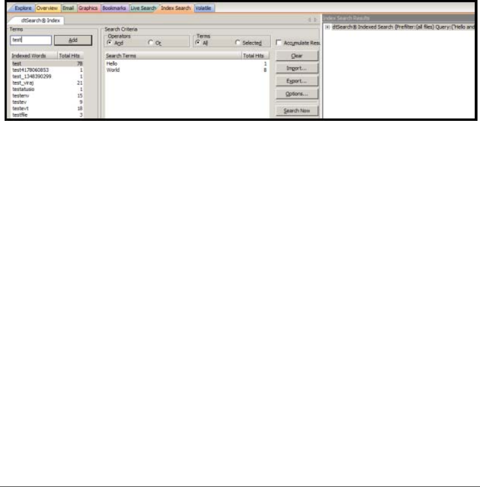
Conducting an Index Search | 189
Chapter 22
Searching Evidence with Index Search
Searching evidence for information pertaining to a case can be one of the most crucial steps in the examination.
Index Search gives instantaneous results, and Live Search supports modes like text and hexadecimal. Search
results are viewed from the File List and File Contents views in the Search tab.
This chapter details the use of the Index Search feature. It includes the following topics:
-Conducting an Index Search (page 189)
-Using Search Terms (page 190)
-Defining Search Criteria (page 190)
-Exporting and Importing Index Search Terms (page 191)
-Selecting Index Search Options (page 191)
-Viewing Index Search Results (page 193)
-Documenting Search Results (page 193)
-Using Copy Special to Document Search Results (page 194)
-Bookmarking Search Results (page 195)
Conducting an Index Search
The Index Search uses the index to find the search term. Evidence items may be indexed when they are first
added to the case or at a later time. Whenever possible, AccessData recommends indexing a case before
beginning analysis.
Index searches are instantaneous. In addition, in the Index Search Results List, the offset of the data in the hit is
no longer listed in the hit. You will see it when you look at the hit file in Hex view.
Running an Index search on large files or Index Searches resulting in a large number of hits may make the scroll
bar appear not to work. However, it will return when the search is complete. For more information about indexing
an evidence item, see Indexing a Case (page 65).

Using Search Terms | 190
The Search Criteria pane shows a cumulative total of all listed or all selected terms, based on the And or the Or
operator. The cumulative total displays at the bottom of the Search Terms list. This functionality has been added
to match the way the Search Terms list functioned in FTK 1.x.
Select none, one, several, or all search terms from the list, click either And or Or, then click either All or
Selected to see cumulative results. You can see this feature at work in the figure below.
Also in the figure below you will notice also that there are percentage signs to the left of individual items in the
Index Search Results pane. These are relevancy ratings.
Important:
If you start an index search and then refresh the interface before the search finishes, the search will
cancel and restart. This will cause a sizeable delay when searching in large or very large cases.
The Index contains all discrete words or number strings found in both the allocated and unallocated space in the
case evidence.
You can configure how special characters, spaces and symbols are indexed. (This is not done by default,
however. One benefit is that you can easily search on an exact email address using username@isp (the
extension, such as .COM or .NET, is not included automatically because a period (.) is not indexed).
In addition to performing searches within the case, you can also use the index to export a word list to use as a
source file for custom dictionaries to improve the likelihood of and speed of password recovery related to case
files when using the Password Recovery Toolkit (PRTK). You can export the index by selecting File > Export
Word List.
Using Search Terms
Type the word or term in the Search Term field. The term and terms like it appear in the Indexed Words column
displaying the number of times that particular term was found in the data. Click Add or press Enter to place the
term in the Search Terms list, or double-click the term in the indexed words column to add it to the Search Terms
list.
Defining Search Criteria
Refine a search even more by using the Boolean operators AND and OR. You can specify the terms to use in an
index search by selecting specific entries, or by searching against all entries.
You can also use the NOT operator to force the search criteria to exclude terms. To do this, in the Index Search
tab, in the Terms field, type NOT before the term that you want to exclude from the search criteria and then click
Add.
For example, if you do not want to include files with the term “apple” in your search, enter NOT apple into the
search criteria.
The Search Terms list now shows you a cumulative total for the search terms, individually, combined, or total.
You can use the operators All and Selected to see more specific results. This is helpful when refining lists and
terms to limit the results to a manageable number.
You can import a list of search terms to save having to type them multiple times. This is especially helpful when
the list is long, or the terms are complex. When you create a search terms document, each term begins on a new
line, and is followed immediately by a hard return. Save the file in .TXT format in any text editor and save it for
future use.
Important:
When creating your search criteria, try to focus your search to bring up the smallest number of
meaningful hits per search.

Exporting and Importing Index Search Terms | 191
Exporting and Importing Index Search Terms
You can export a list of search terms you have added to the list of search terms to save having to find them again
for later use, or to type them again, or for documentation purposes:
To export a set of search terms
1. Highlight the search terms to export to a file.
2. Click Export.
3. Provide a filename and location for the file (the .TXT extension is added automatically).
4. Click Save.
To import a saved search terms file
1. Click Import to import a set of search terms.
2. Select the search terms file you previously saved.
3. Click Open.
Note: An imported term cannot be edited, except to delete a term and re-add it to your satisfaction.
Selecting Index Search Options
To refine an index search, from the Index Search tab, in the Search Criteria area click Options.
Important:
As recommended by dtSearch, this feature has changed. The Search Options, Stemming, Phonic,
Synonym, and Fuzzy cannot be combined. You may choose only one at a time.
The following tables review the individual index search and index result options
TABLE 22-1
Index Search Options
Option Result
Stemming Words that contain the same root, such as raise and raising.
Phonic Words that sound the same, such as raise and raze.
Synonym Words that have similar meanings, such as raise and lift.
Fuzzy Words that have similar spellings, such as raise and raize.
Click the arrows to increase or decrease the number of letters in a
word that can be different from the original search term. Use this
feature carefully; too many letter differences may make the search
less useful.

Selecting Index Search Options | 192
TABLE 22-2
Index Result Options
Option Result
Max Files to List Maximum number of files with hits that are to be listed in the results
field. You can change this maximum number in the field. Searches
limited in this way will be indicated by an asterisk (*) and the text
“(files may be limited by “Max files to list” option)” which may be cut
off if the file name exceeds the allowed line length. The maximum
number of possible files with hits per search is 65,535. If you exceed
this limit, the remaining hits will be truncated, and your search results
will be unreliable. Narrow your search to limit the number of files with
hits.
Note: Limiting the number of files to display does not work with some images.
This is caused by dtSearch counting the chunks of files as individual files that are
coming from the breaking of large unallocated space files into 10MB chunks. Since
Those chunks are combined back into single files, the resulting file count will be
less.
Max Hits per File Maximum number of hits per file. You can change the maximum
number in this field. Searches limited in this way will be indicated by
an asterisk (*) and the text “(files may be limited by “Max hits per file”
option)” which may be cut off if the file name and this text together
exceed the allowed line length. The maximum number of possible
hits per file is 10,000.
Max Words to
Return The maximum number of words to be returned by the search.
Table 23: Files to Search
Option Description
All Files Searches all the files in the case.
File Name Pattern Limits the search to files that match the filename pattern.
Operand characters can be used to fill-in for unknown characters.
The asterisk (*) and question-mark (?) operands are the only special
characters allowed in an index search. The pattern can include “?” to
match any single character or “*” to match an unknown number of
contiguous characters.
For example, if you set the filename pattern to “d?ugl*”, the search
could return results from files named “douglas”, “douglass”, or
“druglord.”
To enter a filename pattern:
1. Check the File Name Pattern box.
2. In the field, type the filename pattern.
Note: Search by date range is now limited to be between Jan 1,
1970 and Dec 31, 3000.
Files Saved
Between Beginning and ending dates for the time frame of the last time a file
was saved.
1. Check the Files Saved Between box.
2. In the date fields, type the beginning and ending dates that you want to search
between.
Note: Search by date range is now limited to be between Jan 1,
1970 and Dec 31, 3000.

Viewing Index Search Results | 193
Click Search Now when search criteria are prepared and you are ready to perform the search.
Viewing Index Search Results
Index Search results are returned instantaneously. The Index Search Results pane displays the results of your
query in a tree-type view. The tree expands to show whether the resulting items were found in allocated or
unallocated space. Further, when found in allocated space, the results are separated by file category. They are
then sorted by relevancy, a percentage of the hits found per search term.
Documenting Search Results
Once a search is refined and complete, it is often useful to document the results.
Right-click an item in the Search Results list to open the quick menu with the following options:
-Create Bookmark: Opens the Create Bookmark dialog. For more information on creating and using
Bookmarks, see Using the Bookmarks Tab (page 174).
-Copy to Clipboard: Copies the selected data to the clipboard (buffer) where it can be copied to another
Windows application, such as an Excel (2003 or earlier) spreadsheet.
Note: The maximum number of lines of data that can be copied to the clipboard is 10,000.
-Export to File: Copies information to a file. Select the name and destination folder for the information file.
Uses the same criteria as Copy to Clipboard.
-Set Context Data Width: Context data width is the number of characters that come before and after the
search hit.
-Delete All Search Results: Use this to clear all search results from the Index Search Results pane.
Copy or export the hits and the statistics of a search result using the options on the following table:
Files Created
Between Beginning and ending dates for the time frame of the creation of a
file on the suspect’s system.
1. Check the Files Created Between box.
2. In the date fields, enter the beginning and ending dates that you want to
search between.
Note: Search by date range is now limited to be between Jan 1,
1970 and Dec 31, 3000.
File Size Between Minimum and maximum file sizes, specified in bytes.
1. Check the File Size Between box.
2. In the size fields, enter the minimum and maximum file size in bytes that you
want to search between.
Save as Default Check this box to make your settings apply to all index searches.
TABLE 22-1
Copy or Export Search Results
Option Description
All Hits in Case Saves all the current search terms’ hits found from the entire case.
All Hits in Search Saves all the search hits found in each search branch.
Table 23: Files to Search (Continued)
Option Description

Using Copy Special to Document Search Results | 194
After the information is copied to the clipboard, it can be pasted into a text editor or spreadsheet and saved.
Choose Export to File to save the information directly to a file. Specify a filename and destination folder for the
file, then click OK
Search results can then be added to the case report as supplementary files.
Important:
With FTK, when exporting Index Search result hits to a spreadsheet file, the hits are exported as a
.CSV file in UTF-16LE data format. When opening in Excel, use the Text to Columns function to
separate the Index Search hit values into columns.
Using Copy Special to Document Search Results
The Copy Special feature copies specific information about files to the clipboard.
To copy information about the files in your search results
Method 1
1. Click in the search results list.
2. From the menu bar, select Edit > Copy Special.
Method 2
1. Find that file highlighted in the File List view.
2. Right-click on the desired file.
3. Select Copy Special.
4. Choose the column settings template to use from the drop-down list. Click Column Settings to define a
new column settings template.
4a. Modify the column template in the Column Settings Manager. For more information on customizing
column templates, see Customizing File List Columns (page 216).
4b. Click Apply to return to the Copy Special dialog.
5. Select the customized column template if you created one.
6. Choose whether you want to include the header row in the file.
All Hits in Term (Live search only) saves the instances of individual terms found from
the list of search terms.
For example, if a live search consisted of the list “black,” “hole,”
“advent,” and “horizon,” this option would copy information on each
of the terms individually.
All Hits in File Records the instances of the search term in the selected file only.
All File Stats in Case Creates a .CSV file of all information requested in the case.
All File Stats in
Search Creates a .CSV file of the information requested in the search.
All File Stats in Term (Live search only) Creates a .CSV file of the instances of individual
terms found from the list of search terms.
TABLE 22-1
Copy or Export Search Results (Continued)
Option Description

Bookmarking Search Results | 195
7. Under File List Items to Copy, select the option that best fits your needs:
-All Highlighted to copy only the items currently highlighted in the list.
-All Checked to copy all the checked files in the case.
-Currently Listed to copy all currently listed items, but no others.
-All to copy all items in the case.
8. The dialog states the number of files that your selection contains.
9. Click OK.
Bookmarking Search Results
To keep track of particular search results, add them to new or existing bookmarks. Search results in the file list
can be selected and added to a newly-created bookmark, or added to an existing bookmark as with any other
data.
To create a bookmark from the file list
1. Select the files you want to include in the bookmark.
2. Right-click any of the selected files then choose Create Bookmark.
3. Complete the Create New Bookmark dialog.
4. Click OK.
The bookmark now appears in the Bookmark tab.
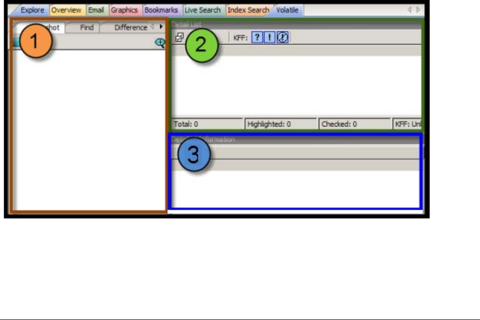
Using the Volatile Tab | 196
Chapter 23
Examining Volatile Data
This chapter includes the following topics:
-Using the Volatile Tab (page 196)
-Understanding Memory (page 197)
-Viewing Memory Dump Data (page 198)
Using the Volatile Tab
The Volatile tab provides tools for viewing, finding, and comparing data gathered from the memory of live agent
systems in your network. Other data acquired remotely, such as from a Mounted Image Drive or a Mounted
Device is viewable from other tabs. The Volatile tab is specifically for remote memory data acquired as a
memory dump. It can be added directly to a case upon acquisition, or saved as a dump file to be added to any
case at a later time.
See Working with Live Evidence (page 100).
When you have acquired volatile (Memory) data as a dump file the resulting acquisition data is displayed in the
Volatile tab.
There are three main areas in the Volatile tab:
1. Tabbed Data View
2. Detail List View
3. Detailed Information View
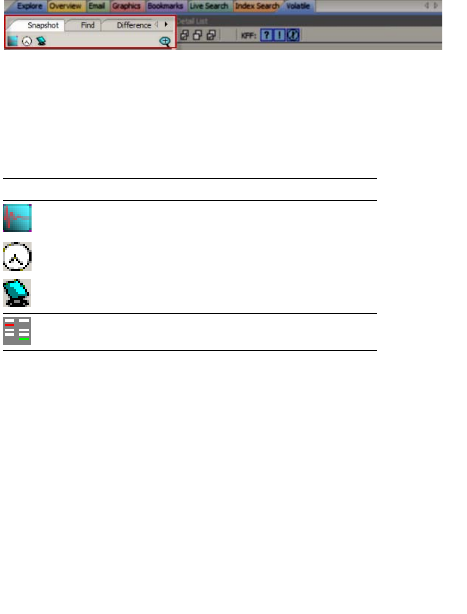
Understanding Memory | 197
It is important to remember that the views relate clockwise. When an item is selected in the Tabbed Data view,
the related information is displayed in the Detail List view. An item selected in the Detail List view will display
relevant information in the Detailed Information view, within the data tab that relates to the type of item that is
selected.
The Tabbed Data view has three tabs:
-Snapshot
-Find
-Difference
Each Tabbed Data View displays a summary of acquired volatile data.
The data can be sorted according to the following criteria:
Table 1: Data View Sort Options
The Detail List View provides information specific to the item currently selected in the Data View. The content of
the Detail List changes as different items are selected.
The Detailed Information View shows more specific information about the item in the Data View, and its selected
component in the Detail List view.
Understanding Memory
Memory can include the physical “sticks” of memory that we put into the machine, commonly referred to as
physical memory. However, video cards, network cards, and various other devices use memory that the
Operating System (OS) must be able to access in order for the devices to work properly. Both physical memory
and device memory are organized by the OS in a linear address map. For 32-bit operating systems, the linear
address map is naturally 4GB. Traditionally the OS will put physical memory at the bottom of this map and the
device memory at the top.
When a system has a full 4GB of physical memory, using all 4GB wouldn’t leave any room to address the device
memory.
Since the OS can’t function without access to the device memory, it simply doesn’t use all 4GB of physical
memory. Evidence of this fact can be seen on the main Properties window of My Computer. If you have a 32-bit
Button Description
Sort acquired volatile data by Operation Type, such as those selectable from
the Evidence > Add Remote Evidence > Selection Information dialog box.
Found on Snapshot, Find, and Difference tabs.
Sort acquired volatile data by the Time of Acquisition, displayed in the local
machine’s time. Found on Snapshot, Find, and Difference tabs.
Sort acquired volatile data by the Source Machine or Agent. Found on
Snapshot, Find, and Difference tabs.
Display saved comparisons. When a comparison of found data is done, the
results can be saved and viewed later. Found only on the Difference tab

Viewing Memory Dump Data | 198
Windows XP system with 4GB of physical memory, you may notice that the Properties window will show that you
have only 3.25GB of physical RAM. That limitation allows for addressing of devices within the 4GB address
space.
Most acquisition products check how much physical memory is available (4GB using our example above), open
a handle to the OS’s memory map (referred to as \Device\PhysicalMemory) and start reading, one page at a
time. Thus, in an attempt to read all of the physical memory, what they are actually reading is the OS’s linear
address map of both physical and device memory. However, some device memory is not meant to be read and
the simple act of reading it could cause system instability. In fact, if the OS is 64-bit, this algorithm would miss
the physical memory that was placed beyond the 4GB range.
The approach AccessData takes is to query the OS’s memory map for the regions that correspond to physical
memory and only acquire those regions - filling the other regions with zeros. This method not only avoids any
issue with system instability but also guarantees that it acquires all the physical memory that the OS is able to
use — the memory that anyone would normally be interested in.
Viewing Memory Dump Data
A Memory Dump file includes all the Processes, .DLLs, Sockets, Drivers, Open Handles, Processors, System
Descriptor Tables and Devices in use at the time of the acquisition. The Volatile tab provides a view of all this
data by type.
Right-click on any dump file in the Snapshot view to choose View Memory or Search Memory.
Viewing Hidden Processes
Hidden processes are automatically detected. There is no way to disable or turn off this feature. The detection
compares a list of processes in memory to the operating systems’s processes list to determine whether any
running processes do not belong. These are the processes that are highlighted in yellow.
Hidden processes, when detected in a Memory Dump file, and found only in the Process List. Click on a dump
file in the Process List, then scroll down the Detail List to locate any lines highlighted in yellow.
Click on a yellow-highlighted line in the Detail List to display related information in the Detailed Information list.
Scroll across the columns list to see all the data.
Viewing Input/Output Request Packet Data
Input/Output Request Packet (IRP) data, also known as memory hooks, when detected in a Memory Dump file,
are indicated in the Snapshot view by a yellow warning indicator . Memory hooks can be used for both legitimate
and non-legitimate purposes.
In the Detail list, the items that contain memory hooks are highlighted in pink. Click on a pink-highlighted item to
open that item in the Detailed Information view. Click on the IRP tab to show the items and properties that are
related to the IRP data that was detected. This data does not identify whether the IRP was bad or good, only that
it was there, so you can determine its nature.
Tabs in the Detailed Information list provide additional related data for the selected data type. Notice that some
data types have several tabbed pages, and some have only a few. Each tabbed page contains different
information related to the selected item, and each displays properties specific to the tabbed page for that
information type. The property column headings are sortable to make it easier to locate critical information.
In addition to the IRP data view, access is provided to Service Descriptor Tables (SDT), and System Service
Descriptor Tables (SSDT).

Viewing Memory Dump Data | 199
Notice that up to four SSDT tables are available. The four tabs are placeholders only; their existence does not
indicate nor guarantee they will be populated. Notice that the names of the populated tables’ tabs are longer
than those that are not populated. Only the data that is found in the evidence can be displayed.
Viewing Virtual Address Descriptor (VAD) Data
In the Windows operating system every object opened by a program (example files, screens, sections of
memory, etc) is assigned a handle that the process in which the program is running can use. These handles are
stored in a table that is managed by the process. This table is called the virtual address descriptor table (VAD).\
A single process normally contains many VADs. Each VAD describes a range of virtual pages and tell the
Memory Manager what those virtual pages represent. For example, a typical process will consist of an
executable image (the program) and a set of dynamic link libraries (DLLs) that are used within that process, as
well as data that is unique to the program. Each of these separate items exists somewhere within the address
space of the program.
When each component is first loaded into the address space the Memory Manager creates a new VAD entry for
each such range of addresses. These VAD entries are in turn linked together in a special type of binary tree that
optimizes access to the most recently accessed VAD. This representation makes it is easy to describe a sparse
address space using a tree of VADs, it is fast to find entries within the VAD tree, and it is easy to reorganize VAD
entries as necessary.
Investigating the VAD tree lets you view resources allocated by a program. The VAD tree constantly changes
during execution of a program. Each time the VAD tree is read, the results are different.
To view Virtual Address Descriptor (VAD) Data
1. In the Examiner, select the Volatile tab.
2. In the Snapshot tab, expand Process List.
3. Expand the date of the snapshot.
4. Select the computer name.
5. In the upper-right pane, under Detail List, select a process.
6. In the lower-right pane, under Detailed Information, click the VAD tab.
7. The Virtual Address Descriptor (VAD) information is displayed in the Detailed Information pane.
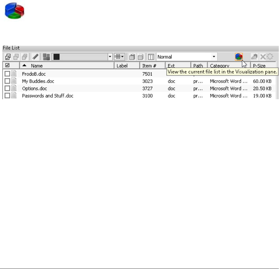
Understanding What Data Can be Viewed | 200
Chapter 24
Using Visualization
Visualization is an add-on component that provides a graphical interface to enhance understanding and analysis
of cases. It lets you view data sets in nested dashboards that quickly communicate information about the
selected data profile and its relationships.
Note: This feature is available as an add-on license. Please contact your sales rep for more information.
To launch visualization, you click the following pie chart icon in the File List pane:
The data that is sent to the visualization module is constrained to the information that you currently have
contained in the file list pane.
Understanding What Data Can be Viewed
Visualization supports the following data types:
-File Data. You can view file data from either the Explore tab or the Overview tab in the Examiner
interface.
For more information see Visualizing File Data (page 201).
-Email Data. You can view email data from the Email tab in the Examiner interface.
For more information see Visualizing Email Data (page 206).
Visualization can only display data that has an associated date. If a file or an email does not contain a valid
Created, Modified, Last Accessed, Sent or Received date, it is not displayed in Visualization. For example,
carved files do not have an associated date so they are not displayed in Visualization.
Information can only be displayed for the date that you have selected. If you attempt to visualize a data set that
does not have dates, the time line pane displays the text “No data Series.” If a file contains a Created date but
not a Modified date, and you change the pane to display the file by Modified date, the file is no longer displayed
in the visualization pane.
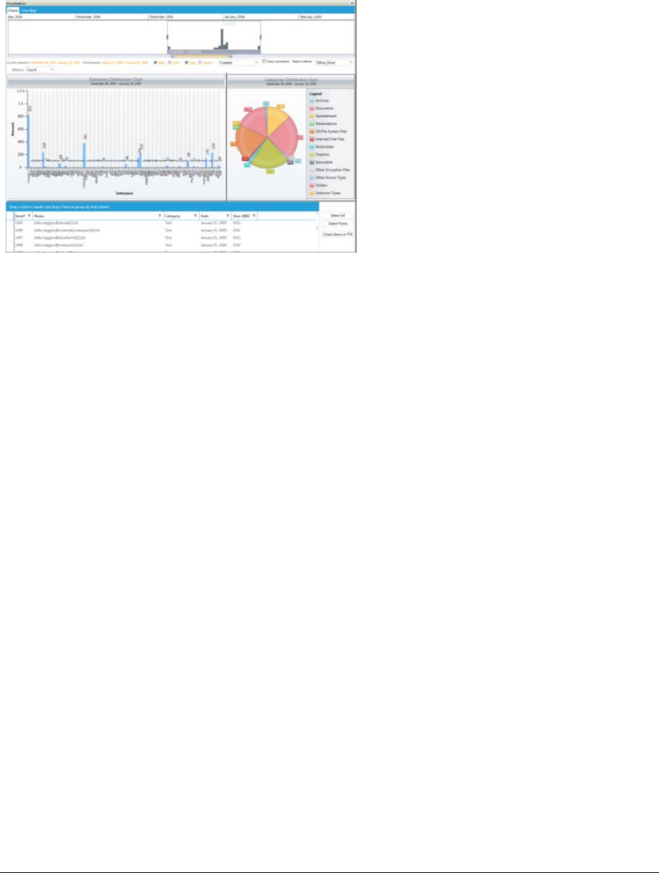
Visualizing File Data | 201
Visualizing File Data
The file data dashboard ilets you view bar graphs, pie charts, and details about the files in the data set.
About the Charts Tab
The Charts tab lets you view graphical statistics of the data set that you define.
The charts tab is organized into the following sections:
-File Timeline
See Narrowing Scope with the File Timeline on page 202.
-File extension distribution chart
See Visualizing File Extension Distribution on page 203.
-Category Distribution chart
See Visualizing File Category Distribution on page 203.
-File data list
See Using the File Data List on page 204.
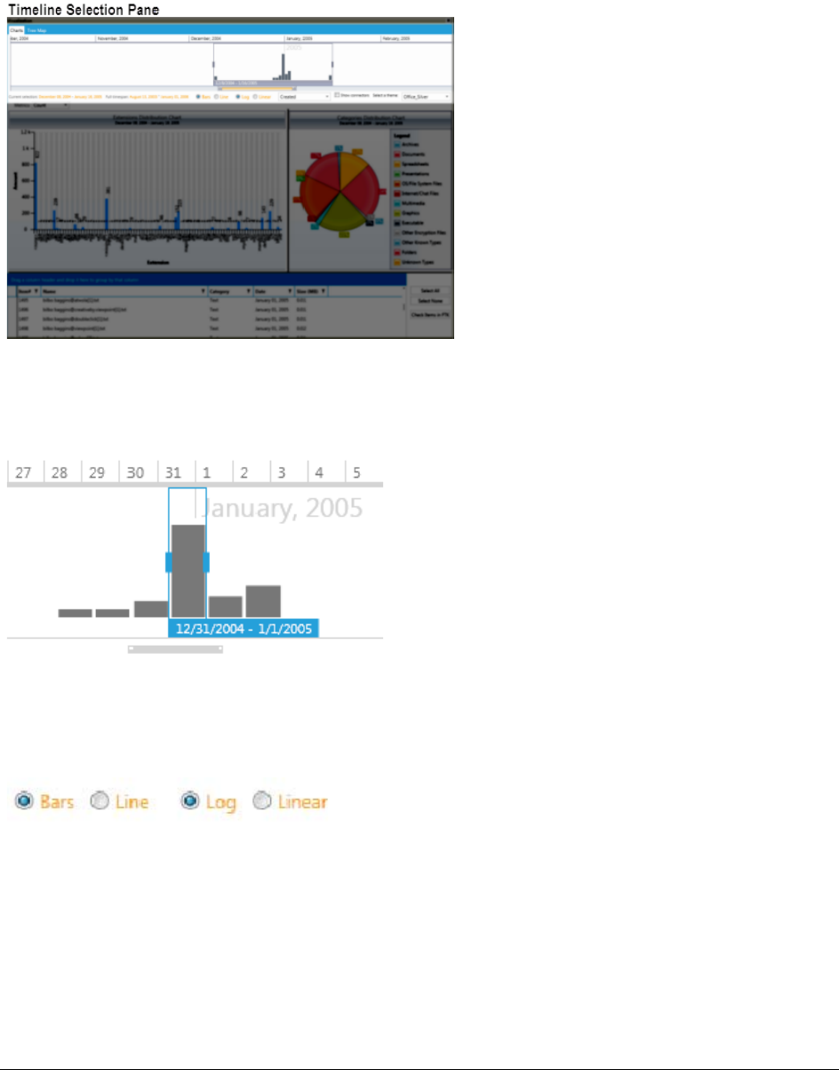
Visualizing File Data | 202
Narrowing Scope with the File Timeline
The information that is displayed in visualization is organized by the oldest date in the data set and ends with the
latest date. You can sort by dates including the created, accessed, and last modified dates for file data and the
sent and received dates for email data.
You can adjust the range and the scope of the data set by adjusting the time and focus in a timeline tool. The
information in the visualization charts and maps change when you adjust the date sliders in the timeline tool. You
can change the scope and scale of the data set by adjusting the gray slider tool. You can change the focus of the
data set by adjusting the blue slider tool.
Changing the view of the timeline
You can use the radio buttons below the timeline to change the appearence of the timeline.
You can select the following options:
-Bars (default)
The Bars option makes the timeline show evenly spaced bars to represent the data in the timeline.
-Line
The Line view makes the timeline show the data as an unbroken line with peaks and valleys representing
increases and decreases in the amount of data over time.
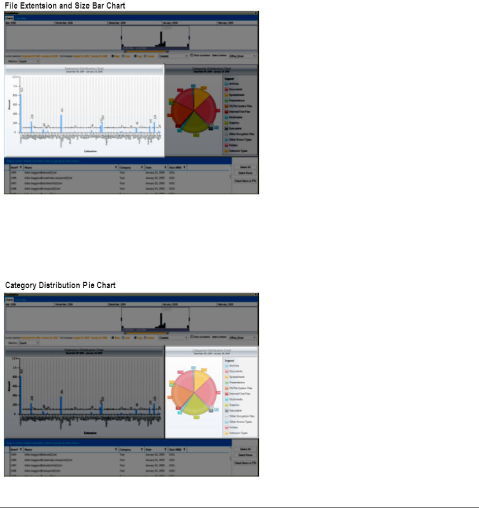
Visualizing File Data | 203
-Log (default)
The Log (logrithmic) view changes the data in the time line to raise the low points and lower the highs so
that both are easier to view on a chart. It smoothes out the peaks and valleys in the chart.
-Linear
The Linear view returns the view from Log to an unchanged representation of the data. Changing from
the Log view to the Linear view shows more of the variance and spikes in the data.
Visualizing File Extension Distribution
The extension distribution chart lets you view the data in the date range. You can view it by either the file counts
in the data set or the file sizes in the data set. File counts and sizes are rounded to two decimal places. You can
select a bar in the extension distribution chart to further refine the data that is displayed in the file data list.
Visualizing File Category Distribution
The category distribution chart displays a pie chart of the dataset. It is organized according to the categories of
the FTK overview tab and displays the percentages of each category in the data set.
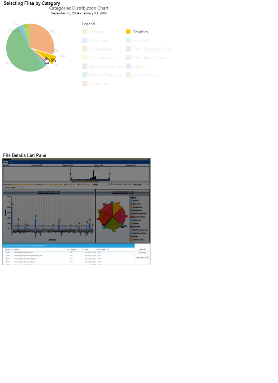
Visualizing File Data | 204
You can select a category in the pie chart to further refine that data that is displayed in the file data list.
Using the File Data List
The file data list displays detail about the files in the data set. The pane is similar to the File List Pane in the
Examiner interface. The information that is displayed in the file data list is generated based on the data that you
refine through the use of the timeline pane, the file extension distribution chart and the categories distribution
chart.
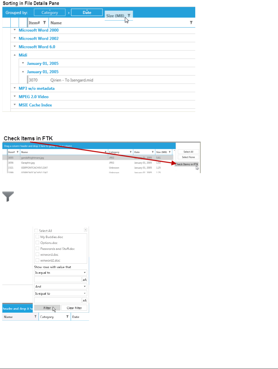
Visualizing File Data | 205
Within the file data list you can sort, group, and sub-group, items according to columns including; ID, Name,
Category, Date, and Size. To sort, drag and drop the desired column heading onto the blue bar. Any column
heading that includes a filter icon can be used to sort the file list data set.
You can check specific items in FTK from the file data list by selecting the files and then clicking the Check
Selected Items button.
You can use the filter Icon on any of the collumn headings to create filters in the File Details List
When you select the filter icon, a filter dialog is displayed that lets you select items that apply to the column and
add flitering expressions.
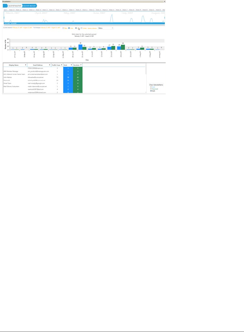
Visualizing Email Data | 206
Visualizing Email Data
The email visualization dashboard consists of the following items:
-Email Timeline
See Narrowing the Scope with the Email Timeline on page 207.
-Mail Statistics graph
See Viewing Mail Statistics on page 208.
-Email details list
See Using the Email Details List on page 208.
-Social Analyzer chart
See Viewing Social Analysis on page 210.
-Traffic Details chart
See Viewing Traffic Details on page 211.
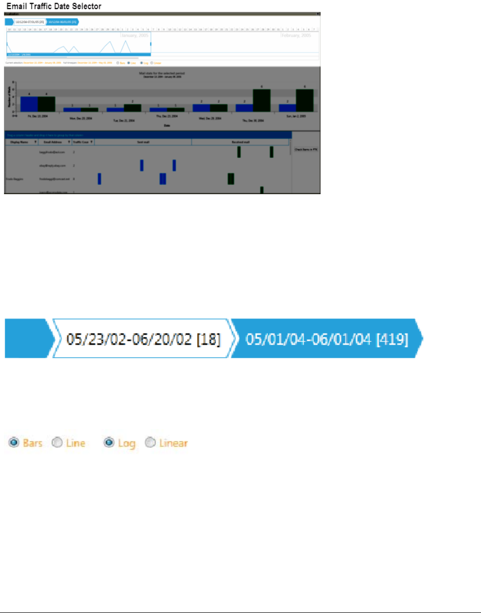
Visualizing Email Data | 207
Narrowing the Scope with the Email Timeline
The timeline provides an aggregate view of email items sent and received in the data set. You can scale and
refocus the scope of the timeline to a specific data range. You can change the scope and scale of the data set by
adjusting the gray slider tool. You can change the focus of the data set by adjusting the blue slider tool.
See also Narrowing Scope with the File Timeline (page 202).
Using History items in the email file timeline
In the Email visualization pane, when you alter the selection in the timeline, a history item, also called a
“breadcrumb,” is added to the top of the time line. Each history item is lated according to the date range that you
have selected in the timeline. You can use these history items to move forward or backward through different
views that you have created.
Changing the view of the timeline
You can use the radio buttons below the timeline to change the appearence of the timeline.
You can select the following options:
-Bars
The Bars option makes the timeline show evenly spaced bars to represent the data in the timeline.
-Line
The Line view makes the timeline show the data as an unbroken line with peaks and valleys representing
increases and decreases in the amount of data over time.
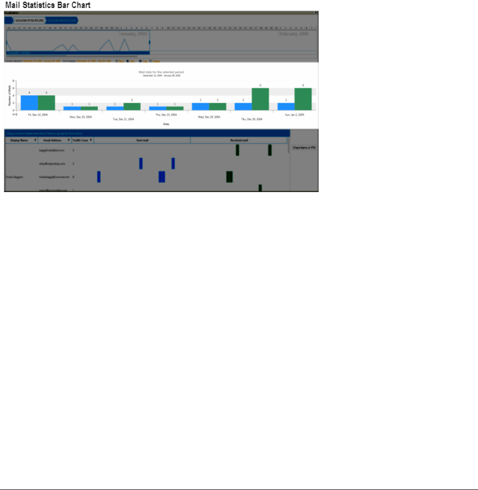
Visualizing Email Data | 208
-Log
The Log view changes the data in the time line to raise the low points and lower the highs so that both are
easier to view on a chart. It smoothes out the peaks and valleys in the chart.
-Linear
The Linear view returns the view from Log to an unchanged representation of the data. Changing from
the Log view to the Linear view shows more of the variance and spikes in the data.
Viewing Mail Statistics
The mail statistics graph displays the sent and received mail statistics in a bar charts. The data contained within
the date range in the email timeline determines the data that is displayed in the mail statistics graph.
You can select a bar in the statistics graph you can further refine the data that is displayed in the Email details
list. that is below the mail statistics bar chart.
Using the Email Details List
The email details list displays custodian-level sent and received statistics for email itms. The list contains a
column for the custodian's name, column for the custodians sent mail (displayed as a bar chart or line graph),
and a column for the custodians sent mail (displayed as a bar chart or line graph),
You can sort group and subgroup the emails according to the columns including Sender, Address, Traffic Count,
Sent Mail, and Received Mail. To group the list of emails, you can drag and drop the column headers onto the
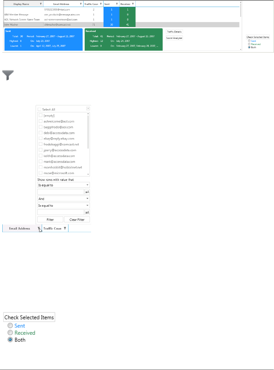
Visualizing Email Data | 209
table heading of the details list. The list will sort first by the first columns that you drop, and then in the order of
any preceding columns that drop into the table heading.
You can use the filter Icon on any of the collumn headings to create filters in the Email Details List
When you select the filter icon, a filter dialog is displayed that lets you select items that apply to the column and
add flitering expressions.
In visualization, Email addresses that are similar but not exactly the same are displayed as two different
addresses, even though they may be the same address. For example, the quotation marks for 'John Doe' and
"John Doe" are not the same. These slight changes in text can happen from different email servers/software
during email transit, and FTK cannot guess for matches.
If an email item is sent to multiple recipients, it is counted as a single item in the email details pane. In the Traffic
Details chart you can see that the same email was sent to multiple recipients. To view specific information about
the reciepiants of that email item, you can click the Traffic Details button.
You can check specific emails in the examiner from the email details list by selecting the emails and then
choosing one of the Check Selected Items options, Sent, Recieved, and Both.
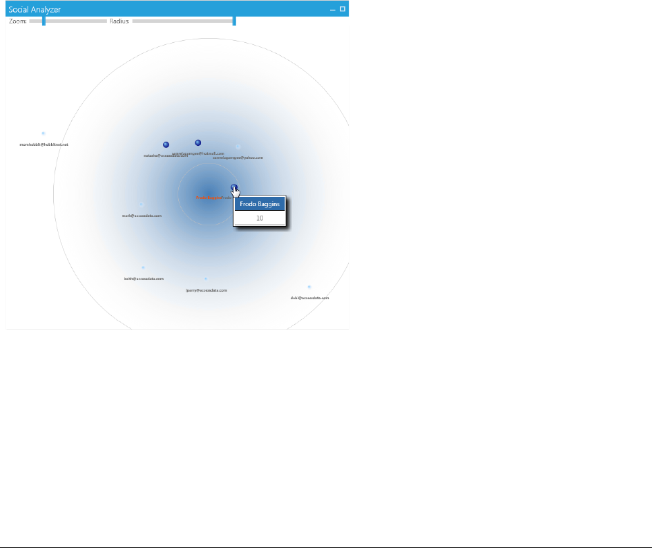
Visualizing Email Data | 210
When you expand a specific email item, you can run additional functionality. This functionality includes the Social
Analyzer chart and the Traffic Details chart. The buttons to open the Traffic Details chart and the Social Analyzer
chart are loceted on the right side of a custodian’s email item in the list.
For more information see the following:
Viewing Social Analysis (page 210)
Viewing Traffic Details (page 211)
Viewing Social Analysis
The social analysis chart provides a contextual view of an individual's social network, based on the email volume
contained in the data set.
The individual custodian is displayed in the center of the chart and icons representing peers are displayed
around the custodian. The closer the proximity of a peer is to a custodian at the center of the chart, the greater
the volume of communication between them.
You can adjust the appearance of the Social Analyzer by using the Zoom and Radius tools. You use the Zoom
tool, you can look move your view closer or further away from a specific location in the chart. You use the Radius
tool to change the size of the circle in the chart. For example, if you have several custodians displayed in a
similar location, you can increase the radius to add space between the custodians. You can then use the Zoom
tool to view the specific location closer and in more detail.
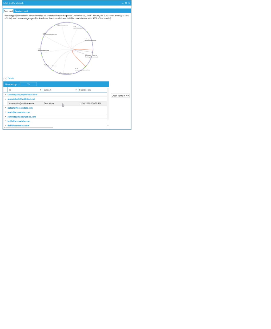
Visualizing Email Data | 211
Viewing Traffic Details
The traffic details analysis chart shows the counts of sent and recieved emails to individuals over a time period.
It provides a contextual view of a custodian’s email traffic to and from individuals. If an email contains multiple
recipient addresses, then each reciepient is displayed in the chart.
If an email does not contain a recipient address, for example if the email was a Draft and it was never sent, then
the email is not displayed in the Traffic Details chart.
There are two tabs in the Traffic Details Chart. The Sent Mail tab displays the chart with lines representing the
emails that the custodian sent to other individulas. The Recieved Mail tab displays the chart with lines
representing the emails that were recieved by the custodian from other individuals. Below the chart is a list of
items. You can group and subgroup the items in the list by dragging and dropping the column headers in the list
unto the table heading. If you select specific items in the list, the traffic details chart displays a colored line
representing the items that you have selected. If you select a line in the traffic details chart, the items are
selected in the details list. After you have selected items, you can click Check Selected Items to have the items
you have selected synchronized with the data in the Examiner.

Visualizing Email Data | 212

About Customizing the Examiner User Interface | 213
Chapter 25
Customizing the Examiner Interface
This chapter includes the following topics:
-About Customizing the Examiner User Interface (page 213)
-The Tab Layout Menu (page 213)
-Moving View Panels (page 214)
-Creating Custom Tabs (page 215)
-Managing Columns (page 216)
-Customizing File List Columns (page 216)
-Creating User-Defined Custom Columns for the File List view (page 217)
-Deleting Custom Columns (page 218)
-Navigating the Available Column Groups (page 219)
About Customizing the Examiner User Interface
You can use the View menu to control the pane views displayed in each tab. FTK provides several tabs by
default, but you can create an interface view that best suits your needs.
Add or remove panes from the current tab using the View menu. Click View and click the unchecked pane to add
it to the current view, or click a checked item on the list to remove that pane from the current view.
To save the new arrangement
Click View > Tab Layout > Save.
The View menu lets you do the following:
-Refresh the current view’s data.
-View the Filter Bar
-Display the Time Zone for the evidence.
-Choose the display size for graphic thumbnails.
-Manage Tabs.
-Select Trees and viewing panes to include in various tabs.
-Open the Progress Window.
The Tab Layout Menu
Use the options in the Tab Layout menu to save changes to tabs, restore original settings, and lock settings to
prevent changes.
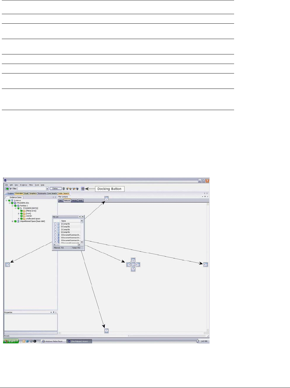
Moving View Panels | 214
The following table describes the options in the Tab Layout menu.
Moving View Panels
Move view panes on the interface by placing the cursor on the title of the pane, clicking, dragging, and dropping
the pane on the location desired. Holding down the mouse button undocks the pane. Use the guide icons to dock
the pane in a pre-set location. The pane can be moved outside of the interface frame.
FIGURE 25-1
Moving View Panels
To place the view panel at a specific location on the application
1. Place the mouse (while dragging a view pane) onto a docking icon. The icon changes color.
TABLE 25-1
Tab Layout Menu Options
Option Description
Save Saves the changes made to the current tab.
Restore Restores the FTK window to the settings from the last saved layout.
Custom settings can be restored.
Reset to Default Sets the FTK window to the setting that came with the program.
Custom settings will be lost.
Remove Removes the selected tab from the FTK window.
Save All Layouts Saves the changes made to all tabs.
Lock Panes Locks the panes in place so that they cannot be moved until they are
unlocked.
Add New Tab Layout Adds a new tab to the FTK window. The new tab will be like the one
selected when this option is used. Customize the tab as needed and
save it for future use.
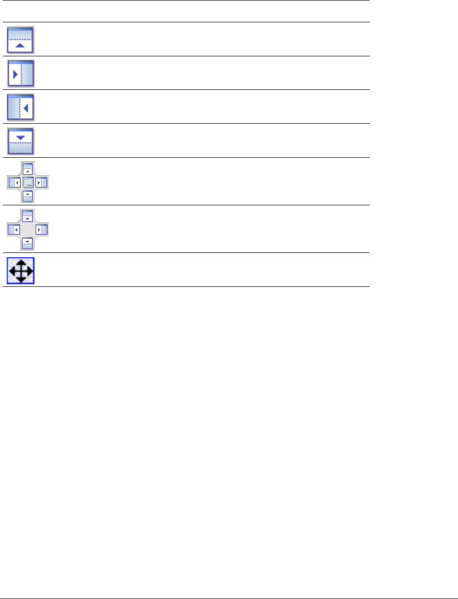
Creating Custom Tabs | 215
2. Release the mouse button and the panel seats in its new position.
The following table indicates the docking options available:
Creating Custom Tabs
Create a custom tab to specialize an aspect of an investigation, add desired features, and apply filters as
needed to accommodate conditions specific to a case.
To create a custom tab
1. Click on the tab that is most like the tab you want to create.
2. Click View > Tab Layout > Add New Tab Layout.
3. Enter a name for the new tab and click OK. The resulting tab is a copy of the tab you were on when you
created the new one.
4. From the View menu, select the features you need in your new tab.
Note: Features marked with diamonds are mutually exclusive; only one can exist on a tab at a time.
Features with check marks can coexist in more than one instance on a tab.
5. Choose from the following:
-Click Save to save this new tab’s settings
-Click View > Tab Layout > Save.
-Click View > Tab Layout > Save All to save all changes and added features on all tabs.
To remove tabs
1. Highlight the tab to be removed
TABLE 25-2
Docking Icons
Docking Icon Description
Docks the view panel to the top half of the tab.
Docks the view panel to the right half of the tab.
Docks the view panel to the left half of the tab.
Docks the view panel to the bottom half of the tab.
Docks the view panel to the top, right, left, bottom, or center of the pane.
When docked to the center, the new pane overlaps the original pane, and
both are indicated by tabs on the perimeter of the pane.
Docks the view panel to the top, right, left, or bottom of the tree pane.
The tree panes cannot be overlapped.
Locks the panels in place, making them immovable. When the lock is
applied, the blue box turns grey. This button is found on the toolbar.

Managing Columns | 216
2. Click View > Tab Layout > Remove.
Managing Columns
Shared Columns use the same familiar windows and dialogs that Local Columns use.
To create a Shared Column Template
1. In Case Manager, click Manage > Columns.
The Manage Shared Column Settings dialog opens.
2. Highlight a default Column Template to use as a basis for a Custom Column Template.
3. Click New.
4. Enter a new name in the Column Template Name field.
5. Select the Columns to add from the Available Columns pane, and click Add >> to move them to the
Selected Columns pane.
6. Select from the Selected Columns pane and click Remove to clear an unwanted column from the
Selected Columns.
7. When you have the new column template defined, click OK.
Customizing File List Columns
The Column Settings dialog box allows the modification or creation of new definitions for the file properties and
related information that display in the File List, and in what order. Columns display specific information about, or
properties of, the displayed files.
Column settings are also used to define which file information appears in case reports. Use custom column
settings in defining reports to narrow the File List Properties information provided in the Bookmark and File List
sections.
Additional states have been added to keep track of users’ Label selections. For example, if the user has already
checked a Label name, that filename and path will turn red, and it remains red as long as it remains different
from the original status. Clicking it again will cycle it back to its original status and its color will return to black.
Note: Checking the Label name before choosing Apply Labels To, unchecks the Label name. Choose Apply
Labels To first, then check or select the files to apply the Label to.
Column Settings can be customized and shared.
To define or customize Column Settings
1. From the File List, click Column Settings to open the Manage Column Settings dialog.
From the Manage Column Settings dialog you can do any of the following tasks:
TABLE 25-3
Manage Column Settings Dialog Options
Button Action
New Create a new column template. This option opens a blank template you
can use to create a new template from scratch.
Edit Edit existing custom column templates. Use this option to make changes
to an existing custom column template. You cannot edit default
templates.

Creating User-Defined Custom Columns for the File List view | 217
2. To define column settings using a new or copied template, click New, Edit, or Copy Selected to open
the familiar Column Settings dialog.
3. In the Column Template Name field, type a name for the template.
4. In the Available Columns list, select a category from which you want to utilize a column heading.
-You can add the entire contents of a category or expand the category to select individual headings.
-You can move any item in the list up or down to position that column in the File List view. The top
position is the first column from left to right.
5. When you are finished defining the column setting template, click OK to save the template and return to
the Manage Column Settings dialog.
6. Highlight the template you just defined, and click Apply to apply those settings to the current File List
view.
Creating User-Defined Custom Columns for the File List view
You can define your own custom columns for use in the File List view. You must first export a file list to a .TSV or
a .CSV file from a case, then populate the spreadsheet with custom column names and your own data as it
relates to items that are listed by the ObjectID. To add the resulting custom columns to the File List view, you
simply import the .TSV or .CSV file that you created, add the custom columns to the template, and apply the
template.
If you import a custom column sheet that contains a column that you do not want to import, but you do not want
to delete the column, you can type IGNORE in the first row of the column.
Files saved as TSV or CSV are encoded UTF-8.
To define custom columns for the File List view
1. Open CCExample.csv in a spreadsheet program. The default path to the file is
C:\Program Files\AccessData\Forensic Toolkit\[version_number]\bin.
Use this example file to help you create your own custom columns.
2. In the File List, select the files that you want to add to your custom columns settings template.
Copy Selected Copy existing default or custom column templates. Start with the settings
in an existing template to customize it to your exact needs without
starting from scratch.
Delete Delete existing custom column templates. You cannot delete default
templates
Import Import custom column templates .XML files from other cases. Use Import
to utilize a template from another source or that was created after you
created your case.
Export Export custom column templates to .XML files for others to use. Export a
custom column to use in another system.
Make Shared Case Administrators can Share custom column templates to the
database so they are available to all new cases. Once custom columns
are Shared, the Application Administrator manages them. However, the
original remains in the case so the Case Administrator has full control of
it. Case Reviewers do not have sufficient permissions to create custom
column templates.
Apply Apply the selected column template
TABLE 25-3
Manage Column Settings Dialog Options (Continued)
Button Action

Deleting Custom Columns | 218
3. From the File List, click Export File List .
4. In the Save in text box, browse to and select the destination folder for the exported file.
5. In the File name text box, type the first name of the file, but do not specify the extension.
Note: FTK allows the user to overwrite user created column setting files by giving the column template
the same name as an existing user created template. Be sure you provide a file name that is
unique if you don’t want to overwrite the original or existing column template file.
6. In the Save As type text box, click the drop-down and choose CSV (Comma delimited) (*.CSV)
7. In the File List items to export group box, click All Highlighted.
8. Click Column Settings.
9. In the Column Settings dialog box, ensure that Item Number is in the Selected Columns list. If
desired, you can move it to the top of the list, or remove all other columns headings that are listed in the
Selected Columns list.
10. Click OK.
11. In the Choose Columns drop-down, select the Column Setting you just created or modified.
12. Click Save.
13. Open the .CSV file that you just created with the Export File List.
14. Copy the item numbers in the Item Number column.
15. In the opened CCexample.csv file, paste the item numbers in the OBJECTID column.
16. Edit the column headings the way you want them.
For example, the spreadsheet column, “MyCustomInt:INT” displays as the column heading
“MyCustomInt” in the File List view of FTK.
-Edit “MyCustomInt” to be whatever you want:
-The INT portion allows integer values in the column
-MyCustomBool:BOOL column allows true or false values
-CustomStr:STRING heading allows text values.
17. Save the CCExample.csv file with a new name, and in a place where you have rights to save and
access the file as needed.
18. Close the FileList.csv (or whatever name you gave the Export File List file.
19. In FTK, on the Evidence menu, click Import Custom Column File.
20. Navigate to the .CSV file that you just saved, then click Open.
21. In the “Custom column data imported” dialog box, click OK.
22. In FTK, on the Manage menu, click Column > Manage Columns, or click Column Settings on the File
List toolbar.
23. Choose a column template to copy, or create a new one.
24. Add the custom column headings to a new or existing template.
25. In the Column Settings dialog box, click OK.
26. In the Manage Column Settings dialog box, select the template that contains the custom headings, and
then click Apply.
Deleting Custom Columns
You can remove and delete custom columns that you have added to any column templates. You can delete
custom columns even if the File List view is turned off.

Navigating the Available Column Groups | 219
Note: The data is not deleted; only the custom columns that allowed you to see that specific data are deleted.
To delete custom column data
1. On the Evidence menu, click Delete Custom Column Data.
2. Click Yes to confirm the deletion.
Navigating the Available Column Groups
The Column Settings dialog box groups column settings according to the following:
Within each grouping, you can choose from a list of various column headings that you want to add. You can also
delete selected columns or arrange them in the order you want them to appear in the File List view.
To view the name, short name, and description of each available column
1. On the Manage menu, click Columns > Managed Shared Columns.
2. Do one of the following:
-Select a category.
-Open a category and select an individual column setting name.
3. Do either of the following:
-Click Add >> to move your selection to the Selected Columns list.
-Double-click your selection to add it to the Selected Columns list.
4. Do either of the following.
-Use standard Windows column sizing methods to resize the column margins, thereby allowing you to
read each description.
- Click anywhere in the Select Columns list box, and then hover over a column description to see the
entire description.
5. Click OK.
Note: The following information may be useful when navigating or viewing Available Columns and Groups.
-When you view data in the File List view, use the type-down control feature to locate the information you
are looking for. Sort on the Filename column, then select the first item in the list.
Type the first letter of the filename you are searching for. FTK will move down the list to the first filename
beginning with that letter. As you continue to type, next filename that matches the letters you have typed
will be highlighted in the list.
If at some point you see the file you are looking for displayed in the list, simply click on it. You may type
the entire file name for the exact name to be fully highlighted in the list.
-A new column has been added, “Included by Filters” within the All Features group. This column tells you
which filter caused a file to display in the File List pane. The Included by Filters column is not sortable.
TABLE 25-4
Available Column Groups
-Common Features -Custom Columns (When a custom col-
umn template has been created or
imported.)
-Disk Image Features -Email Features
-Entropy Stats -File Status Features
-File System Features -Mobile Phone (When an MPE AD1
image has been processed.)
-Zip-specific Features -All Features

Navigating the Available Column Groups | 220
-In the past, the “Processed” column was able to display only two states, Yes, and No. It has been
changed to display different states, such as the following:
P = Default (may be a null value)
C = Complete
Note: M = User’s manually carved items

Creating a Case Report | 221
Chapter 26
Working with Evidence Reports
You can create a case report about the relevant information of a case any time during or after the investigation
and analysis of a case. Reports can be generated in different formats, including HTML and PDF. The PDF report
is designed specifically for printing hard copies with preserved formatting and correct organization. The HTML
report is better for electronic distribution.
For information about reports, see the following topics:
-Creating a Case Report (page 221)
-Adding Case Information to a Report (page 222)
-Adding Bookmarks to a Report (page 222)
-Adding Graphics Thumbnails and Files to a Report (page 223)
-Adding a File Path List to a Report (page 224)
-Adding a File Properties List to a Report (page 224)
-Adding Registry Selections to a Report (page 225)
-Selecting the Report Output Options (page 226)
-Customizing the Report Graphic (page 227)
-Viewing and Distributing a Report (page 228)
-Modifying a Report (page 228)
-Exporting and Importing Report Settings (page 229)
-Writing a Report to CD or DVD (page 229)
Creating a Case Report
You can use the Report Wizard to create a report. The the settings that you specify in the Report Wizard are
persistent, and remain until they are changed by the user. You do not need to click OK until all the report creation
information is entered or selected. If you inadvertently close the Report Wizard, you can re-open it by clicking
File > Report.
To Create a Case Report:
1. In the Examiner, click File > Report to run the Report Wizard.
2. Define your requirements for the following:
TABLE 26-1
Options for reports
Option Description
Case Information See Adding Case Information to a Report (page 222)
Bookmarks See Adding Bookmarks to a Report (page 222)

Adding Case Information to a Report | 222
3. When you have completed defining the report, click OK to open the Report Output options dialog.
See Selecting the Report Output Options (page 226)
Adding Case Information to a Report
The Case Information dialog lets you add basic case information to a report, such as the investigator and the
organization that analyzed the case.
For information about other items you can define for a report, See Creating a Case Report (page 221).
To Add Case Information to a Report:
1. In the Examiner, click File > Report.
2. In the left pane, under Report Outline, highlight Case Information to display the Case Information
options in the right pane.
You can select the Case Information check box to include a case information section in the report. You
can deselect the Case Information check box to exclude a case information section from the report.
3. In the Default Entries pane, deselect any entries that you do not want to include in the report.
If you inadvertently remove a default entry that you require, close and reopen the case to have the
default entries displayed again.
4. Double-click the Value field to enter information.
5. Add and remove entries with the Add and Remove buttons under the Default Entries section.
6. Provide a label (Name) and a value (Information) for the included entries.
7. (Optional) Select the Include File Extensions option to include a file extensions list and count in the
File Overview portion of the report.
The list of file extensions appears in the report under Case Information, after File Items and File
Category, and before File Status. The File Extensions List can be very long and may span many pages.
If you intend to print the report, this may not be desirable.
Adding Bookmarks to a Report
The Bookmarks dialog lets you create a section in the report that lists the bookmarks that were created during
the case investigation. Each bookmark can have a unique sorting option and a unique column setting.
For information about other items you can define for a report, See Creating a Case Report (page 221).
To add Bookmarks to a Report:
1. In the Examiner, click File > Report.
Graphics See Adding Graphics Thumbnails and Files to a Report (page 223)
File Path List See Adding a File Path List to a Report (page 224)
File Properties
ListSee See Adding a File Properties List to a Report (page 224)
Registry Selections See Adding Registry Selections to a Report (page 225)
TABLE 26-1
Options for reports
Option Description

Adding Graphics Thumbnails and Files to a Report | 223
2. In the left pane, under Report Outline, highlight Bookmarks to display the Bookmarks options in the
right pane.
You can select the Bookmarks check box to include bookmarks in the report. You can deselect the
Bookmarks check box to exclude bookmarks from the report.
3. In the right pane, click Filter to open the filters list.
4. Select one the filters from the list. The empty line at the top of the list lets you apply no filter to the
bookmarks.
5. Select the options to indicate which bookmarks you want to include. Choose Shared and/or User
bookmarks by group, or individually.
6. For each bookmark you choose to include, you can choose options from the Bookmark section on the
right. Options include:
-Include Bookmarked Email Attachments in Reports. This setting applies to all email children, not only
common attachments.
-Export files & include links.
-Include thumbnail for each object.
7. Choose a Thumbnail Arrangement option for each bookmark or bookmark group as follows:
-Number of thumbnails per row
-Include all thumbnails at end of each bookmark section
-Group all file paths at the end of thumbnails
8. Specify if you want to to export the bookmared files and include links to them in the report when it is
generated.
9. Specify if you want to include graphic thumbnails that may be part of any bookmarks. If you want to
create links to original files in the report, choose both to export the original files and to include graphic
thumbnails when the report is generated.
10. In the Report Options dialog, click Bookmarks.
11. Click Sort Options and do the following:
-Click the plus (+) to add a criterion, or click minus (-) to delete a criterion.
-Click the down arrow button on the right side of each line to open the drop down of available sort
columns.
-Click OK to save the selected Sort Options and close the dialog.
Note: The sort options you see are determined by the Columns Template you have selected
For more information on customizing columns, see Customizing File List Columns (page 216).
12. Specify if you want to apply all settings for this bookmark to child files.
Adding Graphics Thumbnails and Files to a Report
The Graphics section in the Report Options dialog lets you define whether-or-not to create a section in the report
that displays thumbnail images of the case graphics. You can also link the thumbnails to a full sized version of
the original graphics if desired.
For information about other items you can define for a report, See Creating a Case Report (page 221).
To Add Graphics Thumbnails and Files to a report:
1. In the Examiner, click File > Report.

Adding a File Path List to a Report | 224
2. In the left pane, under Report Outline, highlight Graphics to display the Graphics options in the right
pane.
You can select the Graphics check box to include graphics in the report. You can deselect the
Graphics check box to exclude graphics from the report.
3. To apply a filter to any included graphics files in a report, click Filter and select a filter to apply to the
graphics.
4. To export and link full-sized graphics in the report, click the Export and link full-size graphics to
thumbnails option.
5. Select one of the the following options:
-Include checked graphics only
-Include all graphics in the case
6. To sort the graphics by name or by path, click Sort Options. In the Sort Options dialog, use the Plus (+)
and Minus (-) buttons to add and remove sort options. Click the drop-down arrow on the right side of the
line to select either Name or Path.
7. Specify the number of graphics thumbnails to display per row and choose whether-or-not to Group all
filenames at end of report.
Adding a File Path List to a Report
The File Paths dialog lets you create a section in the report that lists the file paths of files in selected categories.
The File Paths section displays the files and their file paths; it does not contain any additional information.
For information about other items you can define for a report, See Creating a Case Report (page 221).
To add a File Path List to a Report:
1. In the Examiner, click File > Report.
2. In the left pane, under Report Outline, highlight File Path to display the File Path options in the right
pane.
You can select the File Path check box to include a file path section in the report. You can deselect the
File Path check box to exclude a file path section from the report.
3. Select a filter from the Filter drop-down, to apply a filter to the items you want to include a file path list.
You can leave the filter option empty to not apply a filter.
4. Select from the Available Categories list to include the category or categories in the report by dragging
the category to the Selected Categories list.
5. To also export and link to the selected files in the File Path list, select the check-boxes box next to the
items in the Selected Categories box.
If you do not select a check-box Selected Categories list, the File Path is included in the report, but the
files themselves are not exported and linked to the File Path in the report.
Adding a File Properties List to a Report
The File Properties dialog lets you create a section in the report that lists the file properties of files in selected
categories. Several options let you make the File Properties List in the report as specific or as general as you
want it to be.
For information about other items you can define for a report, See Creating a Case Report (page 221).

Adding Registry Selections to a Report | 225
To Add a File Properties List to a Report
1. In the Examiner, click File > Report.
In the left pane, under Report Outline, highlight File Properties to display the File Properties options in
the right pane.
You can select the File Properties check box to include a file properties section in the report. You can
deselect the File Properties check box to exclude a file properties section from the report.
2. Either click the Filter drop-down arrow and selecting the desired filter, or choose no filter by selecting
the blank entry at the top of the filter drop-down list.
3. Drag and drop the categories that you want to include from the Available Categories window into the
Selected Categories window.
4. Check a category in the Selected Categories window to export related files and link them to the File
Properties list in the report.
Checking an item automatically selects the files and folders under it. If you do not want to include all
sub-items, expand the list and select and deselect each item individually.
5. In the Report Options dialog, click File Properties.
6. In the File Properties options area, click Columns.
7. In the Manage Column Settings dialog, select the Settings Template to copy or edit.
For detailed information on creating and modifying Columns Templates, see Customizing File List
Columns (page 216).
8. When you are done defining the columns settings, click OK.
You might want to define how the data is sorted, according to column heading. In the File List view you
are limited to a primary and secondary search. In the Report wizard, you can define many levels of
sorting.
9. In the Report Options dialog, click File Properties.
10. In the File Properties options area, click Sort Options and do the following:
-Click the plus (+) to add a criterion, or click minus (-) to delete a criterion.
-Click the down arrow button on the right side of each line to open the drop down of available sort
columns.
-Click OK to save the selected Sort Options and close the dialog.
Note: The sort options you see are determined by the Columns Template you have selected
For more information on customizing columns, see Customizing File List Columns (page 216).
Adding Registry Selections to a Report
If your drive image contains Registry files, you can include them in your report.
When creating a Report that includes Registry files, a .DAT extension is being added to the link. If the link does
not open in the report, it can be exported and opened in Notepad.
For information about other items you can define for a report, See Creating a Case Report (page 221).
To Add Registry Selections to a Report:
1. In the Examiner, click File > Report.
In the left pane, under Report Outline, highlight Registry Selections to display the registry selections
options in the right pane.
You can select the Registry Selections check box to include a Registry Selections section in the
report. You can deselect the Registry Selections check box to exclude a Registry Selections section
from the report.

Selecting the Report Output Options | 226
2. In the Registry File Types window, check the file types for which you want to include headings for in your
report.
3. In the right window, check the registry file paths that you want included in your report.
4. Mark the box Include user generated reports (if any) if you have generated Registry Reports using
Registry Viewer, and you want to include them in this report.
Note: User-generated reports must exist in the case before generating the report, otherwise, this option
is disabled. These reports are generated in Registry Viewer and can be collected from the
Registry data found on the source drive.
5. Mark the box Select Auto Reports, to view and select which registry reports to include in the report
from those that were generated automatically based on the registry reports selection in Case Manager
> Case > New > Detailed Options > Evidence Refinement.
Note: If you did not select this option during pre-processing, this option is disabled in the Report
Options dialog.
Selecting the Report Output Options
The Report Output dialog lets you select the location, language, report formats, and other details of the report.
You can also recreate the directory structure of exported items.
For information about other items you can define for a report, See Creating a Case Report (page 221).
To select the report output options
1. When you have completed defining the report, from the Report Options dialog, click OK to open the
Report Output options dialog.
2. Type the destination folder name for the saved report, or use the Browse button to locate and select a
location.
3. Use the drop-down arrow to select the language for the written report. Available languages are as
follows:
4. Indicate the formats for publishing the report. You can choose any or all of the output formats.
To view a report made in any of the supported formats, you must have the appropriate application
installed on your computer. Options are as follows:
TABLE 26-2
Available Report Languages
Arabic (Saudi Arabia) Chinese (Simplified, PRC)
English (United States) German (Germany)
Japanese (Japan) Korean (Korea)
Portuguese (Brazil) Russian (Russia)
Spanish (Spain, Traditional Sort) Swedish (Sweden)
Turkish (Turkey)
TABLE 26-3
Available Report Output Formats
PDF (Adobe Reader) HTML (Windows Web Browser)
XML (Windows Web Browser) RTF (Rich Text Format: Most Text Editors)
WML (Unix Web Browser) DOCX (MS Office Word 2007)
ODT (Open Document Interchange: Sun Microsystems OpenOffice Documents)

Customizing the Report Graphic | 227
Note: Some report output formats require J#, either 1.1 or 2.0. If you select .RTF format, for example, and J# is
not installed, you will see an error.
5. Under Export Options do the following:
-Check the Use object identification number for filename to shorten the paths to data in the report.
Links are still created for proper viewing of the files.
-The unique File ID numbers, when used in a report, keep the pathnames shorter. This makes burning
the report to a CD or DVD more reliable.
-Check the Append extension to filename if bad/absent box to add the correct extension where it is
not correct, or is missing.
6. Under HTML Report Customization, choose from the following:
-If you wish to use your own custom graphic or logo, mark the Use custom logo graphic box, then
browse to the file and select it. Use .GIF, .JPG, .JPEG, .PNG, or .BMP file types.
-If you wish to use a custom CSS file, mark the Use custom CSS box. Select the folder where the
custom CSS files have been saved. Click OK. The folder you selected displays in the “Use Custom
CSS” text box.
7. Click OK to run the report.
If the report folder you selected is not empty, you will see the following error message:
Choose to Delete or Archive the contents of the folder, or to Cancel the report. Delete the contents of
the current destination folder, or change to a different destination folder, then recreate the report or
import it if you saved it during creation.
Customizing the Report Graphic
When you select HTML as an output format, you can add your own graphic or logo to the report.
To add your own graphic or logo
1. In the Examiner, click File > Report to open the Report wizard.
2. From the Report Options dialog, after you are done making selections for the Report Outlineclick OK.
3. In the Report Output dialog, under Formats, mark HTML. This activates the HTML Report
Customization options.
4. Under HTML Report Customization, mark Use custom logo graphic.
5. Click the Browse button to open the Windows Explorer view and browse to the graphic file to use for
the report. The file format can be .JIF, .JPG, .JPEG, .PNG, or .BMP.
6. Click Open.
7. When all Report options have been selected, click OK.
The progress bar dialog indicates the progress of the report.
Note: When selected, the finished HTML and/or PDF reports open automatically.
You can process only one set of reports at a time. If you select the options to create several different
report formats before clicking OK to generate the report, all will process concurrently. However, if you
start that process and then decide to create a new report, you will not be able to until the current report
is finished generating.
If you start another report too soon, you will be prompted to wait, if you chose to create either HTML or
PDF format for the report, it will automatically open when creation is complete. Otherwise, to view the
report, click Yes when prompted.

Viewing and Distributing a Report | 228
Using Cascading Style Sheets
The formatting of reports can be customized with Cascading Style Sheets (CSS). Reports stores a file path you
select (default or custom) to the folder containing the custom CSS files. When CSS is not selected, Reports use
the default settings.
For reports to utilize the cascading style sheets, three CSS files are necessary, and must all be located in the
specified CSS folder:
-Common.css
-Bookmarks.css
-Navigation.css
The original CSS files are found in the following path if no changes were made to the default:
C:\Program Files\AccessData\Forensic Toolkit\<version>\bin\ReportResources
Copy the *.CSS files to a different directory before making changes to any of these files. Do not make changes to
the original files.
To utilize the customized .CSS files, click Use custom CSS, and select the path to the folder where the
customized .CSS files are stored.
When CSS is selected, FTK Reports checks for those files in the specified directory. If any of the three files is
missing you are notified and the report does not proceed.
Note: The UI option consists of a check box and a text path string. The path string points to the path directory
that contains the three needed .CSS files.
Note: The UI options settings are persistent per Windows login user. Thus, your selections will be persistent
across the Case List for the currently authenticated user.
Viewing and Distributing a Report
The report contains the information that you selected in the Report Wizard. When included in the report, files
appear in both raw data and in the report format.
To view the report outside of Examiner
1. Browse to the report file
2. Click on the report file:
-Click on index.htm to open an HTML document in your Web browser.
-Click on the file [report].pdf to open the report in a PDF viewer.
Modifying a Report
Modify the report by changing the report settings, and recreating it. Add the new evidence or change report
settings to modify the report to meet your needs.
Change the report settings for each report as needed.
All previously distributed reports should be retracted to keep all recipients current.
Note: If you want to keep a previous report, save the new report to a different folder that is empty.

Exporting and Importing Report Settings | 229
Exporting and Importing Report Settings
Report settings are automatically saved whenever you generate a report. You can export the settings that you
used as an XML file. You can then later import and reapply those same settings to use with new reports that you
generate.
To export report settings:
1. In the Examiner, click File > Report.
2. In the Report Options dialog box, click Export.
3. In the Export Sections dialog, select the sections that you want to export.
4. Click OK.
5. Click Browse to select a folder to save the settings.
6. You can accept the default name for the report settings file, or you can type a name for the settings file.
An XML extension is automatically added when the report is created.
7. Click Save for each item you have selected in the Report Outline list.
8. Click OK.
To import saved settings for a new report:
1. In the Examiner, click File > Report.
2. In the Report Options dialog, click Import.
3. Browse to a settings XML file that you want to apply, and select it.
4. Click Open to import and apply the settings file to your current report.
Writing a Report to CD or DVD
You can write a report to a CD or DVD, depending on the report’s size. It is recommended that you select Use
object identification number for filename, in the Report Output options dialog. This option keeps paths
shorter, so they do not exceed the limits of the media format.
After you create the report, write only the contents from the root of the report folder, and not the report folder
itself. The autorun automatically launches the report’s main page (index.htm) using the default browser when the
CD is read on a Windows computer.
Note: The following information pertains to burning reports to a CD or DVD.
-When burning some reports to a CD, some Registry Viewer Auto Reports links may be broken, where
they work when viewing on the computer. To avoid this issue, make sure that longer Joliet filenames are
enabled when burning report to a CD.
-To launch the report, the computer must be configured to automatically execute autorun files.
-If you burn the folder that contains the report to the CD or DVD, the autorun will not be at the root of the
disk, and will not work properly.
-To prevent broken links to report files, use File Item numbers instead of names to keep paths short, and /
or use the Joliet file naming to allow longer file paths.

| 230
Part V
Appendencies
This part contains additional reference information and contains the following appendencies:
-Appendix A Working with Windows Registry Evidence (page 231)
-Appendix B Supported File Systems and Drive Image Formats (page 240)
-Appendix C Recovering Deleted Material (page 242)
-Appendix D Working with the KFF Library (page 244)
-Appendix E Managing Security Devices and Licenses (page 254)
-Appendix F Configuring for Backup and Restore (page 272)
-Appendix G AccessData Oradjuster (page 276)
-Appendix H AccessData Distributed Processing (page 281)

Appendix A Working with Windows Registry Evidence Understanding the Windows Registry | 231
Appendix A
Working with Windows Registry Evidence
This appendix contains information about the Windows Registry and what information can be gathered from it for
evidence. It includes the following topics:
-Understanding the Windows Registry (page 231)
-Windows XP Registry Quick Find Chart (page 235)
Understanding the Windows Registry
For forensic work, registry files are particularly useful because they can contain important information such as
the following:
-Usernames and passwords for programs, email, and Internet sites
-A history of Internet sites accessed, including dates and times
-A record of Internet queries (i.e., searches performed on Internet search engines like Google, Yahoo,
etc.)
-Lists of recently accessed files (e.g., documents, images, etc.)
-A list of all programs installed on the system
AccessData Registry Viewer allows you to view the contents of Windows operating system registries. Unlike the
standard Windows Registry Editor, which only displays the current system’s registry, Registry Viewer lets you
examine registry files from any Windows system or user. Registry Viewer also provides access to a registry’s
protected storage, which contains passwords, usernames, and other information not accessible from within
Windows Registry Editor.
The files that make up the registry differ depending on the version of Windows. The tables below list the registry
files for each version of Windows, along with their locations and the information they contain.

Appendix A Working with Windows Registry Evidence Understanding the Windows Registry | 232
Windows 9x Registry Files
The following table describes each item on the Windows 9x registry files.
Windows NT and Windows 2000 Registry Files
The following table describes each item in the Windows NT and Windows 2000 registry files.
TABLE 27-1
Windows 9x Registry Files
Filename Location Contents
system.dat \Windows Protected storage for all users on the system. Protected Storage is an
access-restricted area of the registry that stores confidential user infor-
mation including usernames and passwords for Internet websites, email
passwords for Microsoft Outlook or Outlook Express, and a record of
Internet queries (i.e., searches performed on Internet search engines like
Google, Yahoo, etc.), including the time and date when they were per-
formed.
Lists installed programs, their settings, and any usernames and pass-
words associated with them.
Contains the System settings.
user.dat \Windows
If there are multiple user
accounts on the system,
each user has a user.dat file
located in
\Windows\profiles\user
account
-MRU (Most Recently Used) list of files. MRU Lists maintain a
list of files so users can quickly re-access files. Registry
Viewer allows you to examine these lists to see what files
have been recently used and where they are located. Regis-
try Viewer lists each program’s MRU files in order from most
recently accessed to least recently accessed.
User preference settings (desktop configuration, etc.).
TABLE 27-2
Windows NT and Windows 2000 Registry Files
Filename Location Contents
NTUSER.DAT \Documents and
Settings\[user account]
If there are multiple user
accounts on the system,
each user has an ntuser.dat
file.
Protected storage for all users on the system. Protected Storage is an
access-restricted area of the registry that stores confidential user infor-
mation including usernames and passwords for Internet websites, email
passwords for Microsoft Outlook or Outlook Express, and a record of
Internet queries (i.e., searches performed on Internet search engines like
Google, Yahoo, etc.), including the time and date when they were per-
formed.
All installed programs, their settings, and any usernames and passwords
associated with them.
User preference settings (desktop configuration, etc.).
default \Winnt\system32\config System settings.
SAM \Winnt\system32\config User account management and security settings.
SECURITY \Winnt\system32\config Security settings.
software \Winnt\system32\config All installed programs, their settings, and any usernames and
passwords associated with them.
system \Winnt\system32\config System settings.

Appendix A Working with Windows Registry Evidence Understanding the Windows Registry | 233
Windows XP Registry Files
The following table describes each item in the Windows XP registry files.
The logical registry is organized into the following tree structure:
The top level of the tree is divided into hives. A hive is a discrete body of keys, subkeys, and values that is rooted
at the top of the registry hierarchy. On Windows XP systems, the registry hives are as follows:
-HKEY_CLASSES_ROOT (HKCR)
-HKEY_CURRENT_USER (HKCU)
-HKEY_LOCAL_MACHINE (HKLM)
-HKEY_USERS (HKU)
-HKEY_CURRENT_CONFIG (HKCC)
-HKEY_DYN_DATA (HKDD)
HKEY_LOCAL_MACHINE and HKEY_USERS are the root hives. They contain information that is used to
create the HKEY_CLASSES_ROOT, HKEY_CURRENT_USER, and HKEY_CURRENT_CONFIG hives.
HKEY_LOCAL_MACHINE is generated at startup from the system.dat file and contains all the configuration
information for the local machine. For example, it might have one configuration if the computer is docked, and
another if the computer is not docked. Based on the computer state at startup, the information in
HKEY_LOCAL_MACHINE is used to generate HKEY_CURRENT_CONFIG and HKEY_CLASSES_ROOT.
HKEY_USERS is generated at startup from the system User.dat files and contains information for every user on the
system.
Based on who logs in to the system, the information in HKEY_USERS is used to generate HKEY_CURRENT_USER,
HKEY_CURRENT_CONFIG, and HKEY_CLASSES_ROOT.
Keys and sub-keys are used to divide the registry tree into logical units off the root.
When you select a key, Registry Editor displays the key’s values; that is, the information associated with that
key. Each value has a name and a data type, followed by a representation of the value’s data. The data type tells
TABLE 27-3
Windows XP Registry Files
Filename Location Contents
NTUSER.DAT \Documents and
Settings\[user account]
If there are multiple user
accounts on the system,
each user has an ntuser.dat
file.
Protected storage for all users on the system. Protected Storage is an
access-restricted area of the registry that stores confidential user infor-
mation including usernames and passwords for Internet websites, email
passwords for Microsoft Outlook or Outlook Express, and a record of
Internet queries (i.e., searches performed on Internet search engines like
Google, Yahoo, etc.), including the time and date when they were per-
formed.
All installed programs, their settings, and any usernames and passwords
associated with them.
User preference settings (desktop configuration, etc.)
default \Winnt\system32\config System settings.
SAM \Winnt\system32\config User account management and security settings.
SECURITY \Winnt\system32\config Security settings.
software \Winnt\system32\config All installed programs, their settings, and any usernames and
passwords associated with them.
system \Winnt\system32\config System settings.

Appendix A Working with Windows Registry Evidence Understanding the Windows Registry | 234
you what kind of data the value contains as well as how it is represented. For example, values of the REG_BINARY
type contain raw binary data and are displayed in hexadecimal format.
Possible Data Types
The following table lists the Registry’s possible data types.
Additional Considerations
If there are multiple users on a single machine, you must be aware of the following issues when conducting a
forensic investigation:
-If there are individual profiles for each user on the system, you need to locate the USER.DAT file for the
suspects.
-If all the users on the system are using the same profile, everyone’s information is stored in the same
USER.DAT file. Therefore, you will have to find other corroborating evidence because you cannot associate
evidence in the USER.DAT file with a specific user profile.
-On Windows 9x systems, the USER.DAT file for the default user is used to create the USER.DAT files for new
user profiles. Consequently, the USER.DAT files for new profiles can inherit a lot of junk.
TABLE 27-4
Registry Data Types
Data Type Name Description
REG_BINARY Binary Value Raw binary data. Most hardware component information is stored as
binary data and is displayed in hexadecimal format.
REG_DWORD DWORD Value Data represented by a number that is 4 bytes long (a 32-bit integer).
Many parameters for device drivers and services are this type and are
displayed in binary, hexadecimal, or decimal format. Related values are
REG_DWORD_LITTLE_ENDIAN (least significant byte is at the lowest
address) and REG_DWORD_BIG_ENDIAN (least significant byte is at the
highest address).
REG_EXPAND_SZ Expandable
String Value A variable-length data string. This data type includes variables that are
resolved when a program or service uses the data.
REG_MULTI_SZ Multi-String
Value A multiple string. Values that contain lists or multiple values in a format
that people can read are usually this type. Entries are separated by
spaces, commas, or other marks.
REG_SZ String Value A text string of any length.
REG_RESOURCE_LI
ST Binary Value A series of nested arrays designed to store a resource list used by a
hardware device driver or one of the physical devices it controls. This
data is detected by the system and is displayed in hexadecimal format
as a Binary Value.
REG_RESOURCE_
REQUIREMENTS_LIS
T
Binary Value A series of nested arrays designed to store a device driver’s list of
possible hardware resources that it, or one of the physical devices it
controls, can use. This data is detected by the system and is displayed
in hexadecimal format as a Binary Value.
REG_FULL_RESOUR
CE_
DESCRIPTOR
Binary Value A series of nested arrays deigned to store a resource list used by a
physical hardware device. This data is displayed in hexadecimal format
as a Binary Value.
REG_NONE None Data with no particular type. This data is written to the registry by the
system or applications and is displayed in hexadecimal format as a
Binary Value.
REG_LINK Link A Unicode string naming a symbolic link.
REG_QWORD QWORD Value Data represented by a number that is a 64-bit integer.

Appendix A Working with Windows Registry Evidence Windows XP Registry Quick Find Chart | 235
To access the Windows registry from an image of the suspect’s drive, you can do any of the following:
-Load the suspect’s drive image and export his or her registry files to view them in Registry Editor.
-Mount a restored image as a drive, launch Registry Editor at the command line from your processing
machine, export the registry files from the restored image, then view them in a third-party tool.
Note: The problem with this method is that you can only view the registry as text. Registry
Editor displays everything in ASCII so you can’t see hex or binary values in the registry.
-Use Registry Viewer. Registry Viewer integrates seamlessly with FTK 2.3 to display registry files within
the image and create reports.
Important:
Registry Viewer shows everything you normally see in live systems using the Windows Registry
Editor. However, unlike Registry Editor and other tools that use the Windows API, Registry Viewer
decrypts protected storage information so it displays values in the Protected Storage System Provider
key (PSSP). Registry Viewer also shows information that is normally hidden in null-terminated keys.
Seizing Windows Systems
Information stored in the registry—Internet Messenger sessions, Microsoft Office MRU lists, usernames and
passwords for internet Web sites accessed through Internet Explorer, and so forth—are temporarily stored in
HKEY_CURRENT_USER. When the user closes an application or logs out, the hive’s cached information is
pulled out of memory and written to the user’s corresponding USER.DAT.
Note: Passwords and MRU lists are not saved unless these options are enabled.
Important:
Because normal seizure procedures require that there be no alteration of the suspect’s computer in
any way, you must be able to articulate why you closed any active applications before pulling the plug
on the suspect’s computer. Sometimes it is better to simply pull the plug on the computer; other times,
it makes more sense to image the computer in place while it is on. It may depend on what is the most
important type of data expected to be found on the computer.
For example, Windows updates some program information in the registry when the changes are
made. Other information is not updated until a program is closed. Also, if the computer’s drive is
encrypted and you cannot decrypt it or don’t have the Key or password, you may have no choice
except to image the live drive.
The Registry Quick Find Chart shown below gives more information.
Windows XP Registry Quick Find Chart
The following charts describe common locations where you can find data of forensic interest in the Windows
Registry.

Appendix A Working with Windows Registry Evidence Windows XP Registry Quick Find Chart | 236
System Information
Networking
TABLE 27-5
Windows XP Registry System Information
Information File or Key Location Description
Registered Owner Software Microsoft\Windows NT\
CurrentVersion This information is entered during
installation, but can be modified later.
Registered
Organization Software Microsoft\Windows NT\
CurrentVersion This information is entered during
installation, but can be modified later.
Run Software Microsoft\Windows\Current
Version\Run Programs that appear in this key run
automatically when the system boots.
Logon Banner
Message Software Microsoft\Windows\Current
Version\Policies\System\Legal
NoticeText
This is a banner that users must click
through to log on to a system.
Mounted Devices System MountedDevices Database of current and prior mounted
devices that received a drive letter.
Current Control Set System Select Identifies which control set is current.
Shutdown Time System ControlSetXXX\Control\Windows System shutdown time.
Event Logs System ControlSetXXX\Services\Eventlo
gLocation of Event logs.
Dynamic Disk System ControlSetXXX\Services\DMIO\
Boot Info\Primary Disk Group Identifies the most recent dynamic disk
mounted in the system.
Pagefile System ControlSetXXX\Control\
Session Manager\Memory
Management
Location, size, set to wipe, etc.
Last User Logged In Software Microsoft\Windows NT\
CurrentVersion\Winlogon Last user logged in - can be a local or
domain account.
Product ID Software Microsoft\Windows NT\
CurrentVersion
O\S Version Software Microsoft\Windows NT\
CurrentVersion
Logon Banner Title Software Microsoft\Windows\Current
Version\Policies\System\Legal
NoticeCaption
User-defined data.
Logon Banner
Message Software Microsoft\Windows\Current
Version\Policies\System\Legal
NoticeCaption
User-defined data.
Time Zone System ControlSet001(or002)\Control\
TimeZoneInformation\Standard
Name
This information is entered during
installation, but can be modified later.
TABLE 27-6
Windows XP Registry Networking Information
Information File or Key Location Description
Map Network Drive
MRU NTUSER.DA
T
Software\Microsoft\Windows\
CurrentVersion\Explorer\Map
Network Drive MRU
Most recently used list of mapped
network drives.
TCP\IP data System ControlSetXXX\Services\
TCPIP\Parameters
Domain, hostname data.

Appendix A Working with Windows Registry Evidence Windows XP Registry Quick Find Chart | 237
TCP\IP Settings of a
Network Adapter System ControlSetXXX\Services\
adapter\Parameters\TCPIP
IP address, gateway information.
Default
Printer NTUSER.DA
T
Software\Microsoft\Windows
NT\CurrentVersion\Windows
Current default printer.
Default
Printer NTUSER.DA
T
\printers Current default printer.
Local Users SAM Domains\Account\Users\
Names
Local account security identifiers.
Local Groups SAM Domains\Builtin\Aliases\
Names
Local account security identifiers.
Profile list Software Microsoft\Windows NT\
CurrentVersion\ProfileList
Contains user security identifiers (only
users with profile on the system).
Network Map NTUSER.DA
T
Documents and
Settings\username
Browser history and last-viewed lists
attributed to the user.
TABLE 27-6
Windows XP Registry Networking Information (Continued)

Appendix A Working with Windows Registry Evidence Windows XP Registry Quick Find Chart | 238
User Data
User Application Data
TABLE 27-7
Windows XP Registry User Data
Information File or Key Location Description
Run NTUSER.DAT Software\Microsoft\Windows\
CurrentVersion\Run Programs that appear in this key run
automatically when the user logs on.
Media Player
Recent List NTUSER.DAT Software\Microsoft\Media
Player\Player\ RecentFileList This key contains the user's most
recently used list for Windows Media
Player.
O\S Recent
Docs NTUSER.DAT Software\Microsoft\Windows\
CurrentVersion\Explorer\
RecentDocs
MRU list pointing to shortcuts located in
the recent directory.
Run MRU NTUSER.DAT \Software\Microsoft\Windows\
CurrentVersion\Explorer\RunMR
U
MRU list of commands entered in the
“run” box.
Open And Save As
Dialog
Boxes MRU
NTUSER.DAT \Software\Microsoft\Windows\
CurrentVersion\Explorer\
ComDlg32
MRU lists of programs\files opened with
or saved with the “open” or “save as”
dialog boxes.
Current Theme NTUSER.DAT Software\Microsoft\Windows\
CurrentVersion\Themes Desktop theme\wallpaper.
Last Theme NTUSER.DAT Software\Microsoft\Windows\
CurrentVersion\Themes\Last
Theme
Desktop theme\wallpaper.
File Extensions\
Program
Association
NTUSER.DAT Software\Microsoft\Windows\
CurrentVersion\Explorer\
FileExts
Identifies associated programs with file
extensions.
TABLE 27-8
Windows XP Registry User Application Data
Information File or Key Location Description
Word User Info
NTUSER.DAT
Software\Microsoft\office\
version\Common\UserInfo
This information is entered during
installation, but can be modified later.
Word Recent Docs
NTUSER.DAT
Software\Microsoft\office\
version\Common\Data
Microsoft word recent documents.
IE Typed URLs
NTUSER.DAT
Software\Microsoft\Internet
Explorer\TypedURLs
Data entered into the URL address bar.
IE Auto- Complete
Passwords NTUSER.DAT
\Software\Microsoft\
Internet Explorer\IntelliForms
Web page auto complete password-
encrypted values.
IE Auto-Complete
Web Addresses NTUSER.DAT
\Software\Microsoft\Protected
Storage System Provider
Lists Web pages where auto complete
was used.
IE Default
Download Directory NTUSER.DAT
Software\Microsoft\Internet
Explorer
Default download directory when
utilizing Internet Explorer.
Outlook Temporary
Attachment
Directory NTUSER.DAT
Software\Microsoft\office\
version\Outlook\Security
Location where attachments are stored
when opened from Outlook.

Appendix A Working with Windows Registry Evidence Windows XP Registry Quick Find Chart | 239
AIM
NTUSER.DAT
Software\America Online\AOL
Instant Messenger\
CurrentVersion\Users\username
IM contacts, file transfer information,
etc.
Word User Info
NTUSER.DAT
Software\Microsoft\office\
version\Common\UserInfo
This information is entered during
installation, but can be modified later.
ICQ
NTUSER.DAT \Software\Mirabilis\ICQ\*
IM contacts, file transfer information,
etc.
MSN Messenger
NTUSER.DAT
Software\Microsoft\MSN
Messenger\ListCache\.NET
MessngerService\*
IM contacts, file transfer information,
etc.
Kazaa
NTUSER.DAT Software\Kazaa\*
Configuration, search, download, IM
data, etc.
Yahoo
NTUSER.DAT Software\Yahoo\Pager\ Profiles\*
IM contacts, file transfer information,
etc.
Google Client
History NTUSER.DAT
Software\Google\NavClient\
1.1\History
Adobe NTUSER.DAT Software\Adobe\* Acrobat, Photo deluxe, etc.
TABLE 27-8
Windows XP Registry User Application Data (Continued)
Information File or Key Location Description

Appendix B Supported File Systems and Drive Image Formats File Systems | 240
Appendix B
Supported File Systems and Drive Image
Formats
This appendix lists the file systems and image formats that FTK analyzes. It includes the following topics:
-File Systems (page 240)
-Whole Disk Encrypted Products (page 240)
-Hard Disk Image Formats (page 241)
-CD and DVD Image Formats (page 241)
File Systems
The following table lists AccessData FTK-identified and analyzed file systems.
Whole Disk Encrypted Products
The following table lists AccessData FTK-identified and analyzed Whole Disk Encryption (WDE) decryption
products (these all require the investigator to enter the password, AccessData forensic products don’t “crack”
these).
TABLE 28-1
Identified and Analyzed File Systems
FAT 12, FAT 16, FAT 32 NTFS
Ext2FS HFS, HFS+
Ext3FS CDFS
Ext4FS exFAT
ReiserFS 3
VxFS (Veritas File System)
TABLE 28-2
Recognized and Analyzed Whole Disk Encryption Formats
AFF (Advanced Forensic Format) Utimaco Safeguard Easy
PGP® Utimaco SafeGuard Enterprise
Credant Guardian Edge
SafeBoot EFS
JFS LVM
VMWare LVM2
UFS1 UFS2

Appendix B Supported File Systems and Drive Image Formats Hard Disk Image Formats | 241
Hard Disk Image Formats
The following table lists AccessData FTK-identified and analyzed hard disk image formats.
CD and DVD Image Formats
The following table lists AccessData FTK-identified and analyzed CD and DVD image formats.
TABLE 28-3
Supported Hard Disk Image Formats
Encase SnapBack
Safeback 2.0 and under Expert Witness
Linux DD ICS
Ghost (forensic images only) SMART
AccessData Logical Image (AD1)MSVHD (MS Virtual Hard Disk)
DMG (Mac)
TABLE 28-4
Identified and Analyzed CD and DVD File Systems and Formats
Alcohol (*.mds) IsoBuster CUE
PlexTools (*.pxi) CloneCD (*.ccd)
Nero (*.nrg) Roxio (*.cif)
ISO Pinnacle (*.pdi)
Virtual CD (*.vc4) CD-RW,
VCD CD-ROM
DVD+MRW DVCD
DVD-RW DVD-VFR
DVD+RW Dual Layer DVD-VR
BD-R SRM-POW BD-R
BD-R SRM BD-R DL
HD DVD-R HD DVD-RW DL
SVCD HD DVD
HD DVD-RW DVD-RAM,
CD-ROM XA CD-MRW,
DVD+VR DVD+R
DVD+R Dual Layer BD-RE
DVD-VRW BD-ROM
HD DVD-R DL BD-R RRM
BDAV Virtual CD (*.vc4)
HD DVD-RAM DVD+RW
CD-R VD-R
SACD DVD-R Dual Layer
DVD-ROM BD-R SRM+POW
DVD-VM BD-RE DL
DVD+VRW

Appendix C Recovering Deleted Material FAT 12, 16, and 32 | 242
Appendix C
Recovering Deleted Material
FTK finds deleted files on supported file systems by their file header.
This appendix inlcudes the following topics:
-FAT 12, 16, and 32 (page 242)
-NTFS (page 242)
-Ext2 (page 243)
-Ext3 (page 243)
-HFS (page 243)
FAT 12, 16, and 32
When parsing FAT directories, FTK identifies deleted files by their names. In a deleted file, the first character of
the 8.3 filename is replaced by the hex character 0xE5.
The file’s directory entry provides the files’s starting cluster (C) and size. From the size of the file and the starting
cluster, FTK computes the total number of clusters (N) occupied by the file.
FTK then examines the File Allocation Table (FAT) and counts the number of unallocated clusters starting at C
(U). It then assigns the recovered file [min (N, U)] clusters starting at C.
If the deleted file was fragmented, the recovered file is likely to be incorrect and incomplete because the
information that is needed to find subsequent fragments was wiped from the FAT system when the file was
deleted.
FTK uses the long filename (LFN) entries, if present, to recover the first letter of the deleted file’s short filename.
If the LFN entries are incomplete or absent, it uses an exclamation mark (“!”) as the first letter of the filename.
FTK meta carves, or searches the volume free space for deleted directories that have been orphaned. An
orphaned directory is a directory whose parent directory or whose entry in its parent directory has been
overwritten.
NTFS
FTK examines the Master File Table (MFT) to find files that are marked deleted because the allocation byte in a
record header indicates a deleted file or folder. It then recovers the file’s data using the MFT record’s data
attribute extent list if the data is non-resident.
If the deleted file’s parent directory exists, the recovered file is shown in the directory where it originally existed.
Deleted files whose parent directories were deleted are shown in their proper place as long as their parent
directory’s MFT entry has not been recycled.

Appendix C Recovering Deleted Material Ext2 | 243
Ext2
FTK searches to find inodes that are marked deleted: the link count is zero and the deletion timestamp is
nonzero.
For each deleted inode, FTK processes the block pointers as it does for a normal file and adds blocks to the
deleted file. However, if an indirect block is marked allocated or references an invalid block number, the
recovered file is truncated at that point because the block no longer contains a list of blocks for the file that the
application is attempting to recover.
FTK does not recover the filenames for files deleted on ext2 systems. Instead, deleted files are identified by
inode number because ext2 uses variable-length directory entries organized in a linked list structure. When a file
is deleted, its directory entry is unlinked from the list, and the space it occupied becomes free to be partially or
completely overwritten by new directory entries. There is no reliable way to identify and extract completely
deleted directory entries.
Ext3
FTK does not recover deleted files from ext3 volumes because ext3 zeroes out a file’s indirect block pointers
when it is deleted.
HFS
FTK does not recover deleted files from HFS.

Appendix D Working with the KFF Library Managing the KFF Library | 244
Appendix D
Working with the KFF Library
This appendix includes the following topics:
-Managing the KFF Library (page 244)
-Importing KFF Hashes (page 244)
-Defining KFF Groups (page 245)
-About the KFF Library (page 246)
-Customizing KFF Hash Sets (page 248)
Managing the KFF Library
The Known File Filter (KFF) is a database utility that compares known file hash values against those in your
case files. Using the KFF during your analysis can provide the following benefits:
-Immediately identify and ignore 40-70% of files irrelevant to the case.
-Immediately identify known contraband files.
Hashes, such as MD5, SHA-1, etc., are based on the file’s content, not on the file name or extension. For a more
in-depth explanation of Hashing and KFF content and library sources, see About the KFF Library (page 246).
The KFF Library includes hash values in .TSV, .CSV, .HKE, .HKE.TXT, .HDI, .HDB, .hash, .NSRL, or .KFF file
formats. The .KFF files are created when you export KFF data from the KFF Manager, and exports groups.
Once imported, the hash set must be added to a group before it can be utilized in a case. Groups are used to
categorize the hashes according to the types of files the hashes came from and what you intend to identify by
using them in the case.
The three default hash groups are as follows:
-Ignore (lowest priority)
-Alert (medium priority)
-Disregard (highest priority)
Access the KFF Management dialog from either the Case Manager or the Examiner window. In the Case
Manager, find it at Database > Manage KFF. In the Examiner window, click Manage > KFF > Manage.
Note: Default sets and groups cannot be modified. However, you can modify custom groups and their
membership sets, and you can modify the Status and the Name of custom sets, or delete custom sets
listed in the Defined Sets list.
Importing KFF Hashes
Using the KFF Admin feature, you can import hashes from other databases or update the KFF database.

Appendix D Working with the KFF Library Defining KFF Groups | 245
Note: The HashKeeper database is updated periodically. Because the size of the KFF database has grown too
large for general downloading, contact your AccessData sales representative for information on getting
updates for your system.
To import hashes to the KFF database
1. Click Manage > KFF > Manage.
2. In the KFF Admin dialog, click Import.
3. Click Add File.
4. In the Add KFF Source File to Import List dialog, select the status this hash set will be assigned. Options
are:
-Alert
-Ignore
5. Click the Browse icon.
6. In the Open dialog, browse to the hash file you want to import.
7. Browse to and select one of the following file types:
7a. AccessData Hash Database (.KFF) Imports only a group, not a single set.
7b. FTK Imager Hash List (.CSV or .TSV)
Note: To import a Hash list from a .CSV file, the column headings must contain at least one of the
following values: MD5, MD5 HASH, SHA1, SHA1 HASH, SHA1 Base32, SHA1 ExtHex.
7c. HashKeeper Hash Set (.HKE)
8. Click Open.
9. In the Name field, you can leave the filename including its extension (default), or change the name to
make it more descriptive. The name entered here is what displays in the KFF Sets list.
10. If you have several hash files in a single folder, click Import Entire Directory to add them to the KFF in
the same hash set in one operation.
11. When finished, click OK.
12. In the KFF Hash Import Tool, the file you added is listed under Files to Import. Highlight the file, then
click Process Files.
The imported hash sets are merged into the KFF Library and saved.
Defining KFF Groups
Before you can use any imported hash set, it must be added to a group. Hash groups are used to categorize
hash sets for processing against case data. For example, you might want to group hash sets by function, such
as keystroke logging, or hacker-related hash sets.
To define a KFF group
1. In the KFF Admin dialog box, click New.
2. In the Create New KFF Group dialog box, in the Name field, type a name for this new group.
3. Select the Status to assign to this group. Options are:
-Alert
-Ignore
-Disregard
4. In the Available Sets list, find and select the sets you want to add to the new group.

Appendix D Working with the KFF Library About the KFF Library | 246
Note: Available sets can be sorted alphanumerically by Name, Status, or SetID by clicking on the
column heading. One click sorts top-to-bottom; a second click toggles the sort setting, reversing it
to bottom-to-top.
5. When you have selected the sets to add and they are listed in the Items in Group list, click OK.
6. In the KFF Admin dialog box, mark the check box next to the sets you want to apply when you process
the case against the KFF.
Note: The set you want to use must be marked. Each time you process evidence in the case against
the KFF, the results are re-written to apply only the groups you have marked.
7. Click Done.
To process Case Evidence against KFF selections in Additional Analysis
1. In the Examiner window, click Evidence > Additional Analysis.
2. In the Additional Analysis dialog box, mark the KFF check box under KFF.
3. Mark Recheck previously processed items.
4. Click OK.
5. The Data Processing Status window opens. The job you just started is listed under Additional Analysis
Jobs. You can watch as the processing progresses, or close this window and return to it later by clicking
View > Progress Window.
About the KFF Library
The Known File Filter (KFF) is a body of MD5 and SHA1 hash values computed from electronic files that are
gathered and cataloged by several US federal government agencies. The KFF is used to locate files residing
within case evidence that have been previously encountered by other investigators or archivists. Identifying
previously cataloged (known) files within a case can expedite its investigation.
How the KFF Works
When evidence is processed with the MD5 Hash (and/or SHA-1 Hash) and KFF options, FTK computes a hash
value for each file item within the evidence, and then looks for that newly computed hash value within the KFF
data. Every file item whose hash value is found in the KFF is considered to be a known file.
Status Values
In order to accelerate an investigation, FTK labels each known file as either Alert or Ignore, meaning that the file
is likely to be forensically interesting (Alert) or uninteresting (Ignore). This Alert/Ignore designation can assist the
investigator to hone in on files that are relevant, and avoid spending inordinate time on files that are not relevant.
Known files are presented in the Overview Tab’s File Status Container, under “KFF Alert files” and “KFF
Ignorable”. There is an additional status value that can be applied to hash sets, particularly investigator-created
sets, called Disregard, which is discussed below.
Sets
The hash values comprising the KFF are organized into sets. Each hash set has a name, a status, and a listing
of hash values. Consider two examples. The hash set “ZZ00001 Suspected child porn” has a status of Alert and
contains 12 hash values. The hash set “BitDefender Total Security 2008 9843” has a status of Ignore and
contains 69 hash values. If, during the course of evidence processing, a file item’s hash value were found to
belong to the “ZZ00001 Suspected child porn” set, then that file item would be presented in the KFF Alert files

Appendix D Working with the KFF Library About the KFF Library | 247
list. Likewise, if another file item’s hash value were found to belong to the “BitDefender Total Security 2008 9843”
set, then that file would be presented in the KFF Ignorable list.
In order to determine whether any Alert file is truly relevant to a given case, and whether any Ignore file is truly
irrelevant to a case, the investigator must understand the origins of the KFF’s hash sets, and the methods used
to determine their Alert and Ignore status assignments.
Groups
Above hash sets, the KFF is partitioned into two hash set groups. The AD_Alert group contains all default sets
with Alert status, and AD_Ignore contains all default sets with Ignore status. When the MD5/SHA-1 and KFF
options are chosen for processing, the AD_Alert and AD_Ignore groups are selected by default. This causes
hash set “look-ups” to be executed against the entire KFF. If the investigator selected only one of these two
groups, say AD_Ignore, then the hash value queries conducted during processing would be applied only to the
sets with Ignore status.
Important:
If no group is selected, then KFF processing is voided.
In addition, hash set groups are assigned a status value, and each group’s status supersedes that of any of its
individual sets.
Higher Level Structure and Usage
Because hash set groups have the properties just described, and because custom hash sets and groups can be
defined by the investigator, the KFF mechanism can be leveraged in creative ways. For example, the
investigator may define a group of hash sets created from encryption software, and another group of hash sets
created from child pornography files, and apply only those groups while processing. Another example involves
the Disregard status. Suppose an investigator is about to process a hard drive image, but her search warrant
does not allow inspection of certain files within the image that have been previously identified. She might follow
this procedure to observe the warrant:
1. Open the image in FTK Imager, navigate to each of the prohibited files, and cause an MD5 hash value
to be computed for each.
2. Within FTK, import these hash values into custom hash sets (one or more), add those sets to a custom
group, and give the group Disregard status.
3. Process the image in FTK with the MD5 and KFF options, and with AD_Alert, AD_Ignore, and the new,
custom group selected.
4. During post-processing analysis, filter file lists to eliminate rows representing files with Disregard status.
The highest level of the KFF’s logical structure is the categorizing of hash sets by owner and scope. The
categories are AccessData, Case Specific, and Shared.
TABLE 30-1
Hash Set Categories
Table Description
AccessData The sets shipped with FTK as the KFF Library. Custom groups can be
created from these sets, but the sets and their status values are read
only.
Case Specific Sets and groups created by the investigator to be applied only within an
individual case.
Shared Sets and groups created by the investigator for use within multiple cases
all stored in the same database, and within the same FTK application
schema.

Appendix D Working with the KFF Library Customizing KFF Hash Sets | 248
Important:
Coordination among colleagues is essential when altering Shared groups in a lab deployment. Each
investigator must consider how other investigators will be affected when Shared groups are modified.
Customizing KFF Hash Sets
KFF hash sets can be customized by importing hash sets, by exporting hash sets to use in other
cases, or by removing hash sets from a current hash set group in the KFF Library.
Creating Sets and Groups
The toolkit also provides a mechanism for you to add your own hashes to the KFF database. When you select a
hash set in FTK, generally, the source reporting agency is displayed in a text box.
Note: It is good practice when creating sets to put your own agency in the source field so that other examiners
know where the hashes came from.
To create sets and organize them into groups, follow these steps:
1. Select Tools > KFF > Manage.
2. Click New.
3. Name the group.
4. Assign the group a status.
5. Select the sets you want in the group from the Available Sets list and move them to the Items in Group
list by clicking the double-arrow button.
6. Click Apply to create the group without closing the Create New KFF dialog.
7. Click OK to save the group and close the dialog.
Importing
KFF
Hashes
When using the Import KFF Hashes feature, you can import hashes from several supported formats.
To import hashes to the KFF database:
1. Click Tools > KFF > Manage to open the KFF Administration dialog.
Both the AD Alert group and the AD Ignore group are marked by default.
2. Click Import to open the KFF Hash Import dialog.
3. Click Add File and select one of the following file types:
-AccessData Hash Database (.hdb)
-FTK Imager Hash List (.csv)
-Hashkeeper Hash Set (.hke, hke.txt)
-Tab Separated Value (.tsv)
-National Software Reference Library (.nsrl)
-Hash (.hash)
-FTK(.KFF)
4. Click the Status drop-down list to select either Alert or Ignore status for the list you are importing.
5. Browse to the path where the new source file is found.
6. Type a name for the new source.

Appendix D Working with the KFF Library Customizing KFF Hash Sets | 249
7. Include a description of the new source file.
8. Mark the Import Entire Directory box if all the files in the source path are to be included in this import.
9. In the KFF Hash Import Tool dialog, click Process Files.
Note: You must process the imported hashes to complete the import.
10. When processing is complete, click Done to return to the KFF Hash Import dialog.
11. Close the dialogs back to the KFF Administration dialog. Verify the information, and click Import. The
imported hash set is merged into the existing hash set and saved.
Note: Duplicate hashes are not added.
12. Click Done when you are finished with the KFF Admin dialog.
Deleting Hash Sets From A Defined Group
1. Click Tools > KFF > Manage to open the KFF Administration dialog.
Note: Both the AD Alert and the AD Ignore groups are marked by default.
2. Click or shift+click to select the defined sets to delete from the selected group.
3. Click Delete
4. Click Done when you are finished deleting defined sets.
Note: Default hash sets and groups cannot be deleted.
Exporting
KFF
Hashes
To export a KFF hash file, follow these steps:
1. Click Tools > KFF > Manage.
2. Click Export.
3. Select the location to which you want to save the exported KFF file. FTK saves the file as .KFF by
default.
4. Click Save.
5. Click Done when you are finished exporting KFF Hashes.
KFF Library Sources
This section includes a description of the hash collections that make up the AccessData KFF Library.
All of the hash sets currently within the KFF come from one of three federal government agencies:
-NDIC HashKeeper
-NIST NSRL
-DHS
Note: Because the KFF Library is now multi-sourced, it is no longer maintained in HashKeeper format.
Therefore, you cannot modify the KFF in the HashKeeper program. However, the HashKeeper format
continues to be compatible with the AccessData KFF Library.
Use the following rules of thumb to identify the origin of any hash set within the KFF
1. All HashKeeper Alert sets begin with “ZZ”, and all HashKeeper Ignore sets begin with “Z”. (There are a
few exceptions. See below.) These prefixes are often followed by numeric characters (“ZZN” or “ZN”

Appendix D Working with the KFF Library Customizing KFF Hash Sets | 250
where N is any single digit, or group of digits, 0-9), and then the rest of the hash set name. Here are two
examples of HashKeeper Alert sets:
-“ZZ00001 Suspected child porn” and “ZZ14W”.
Here’s a HashKeeper Ignore set:
-“Z00048 Corel Draw 6”.
2. The NSRL hash sets do not begin with “ZZN” or “ZN”. In addition, in the AD Lab KFF, all the NSRL hash
set names are appended (post-fixed) with multi-digit numeric identifier. For example: “Password
Manager & Form Filler 9722.”
3. The DHS collection is broken down as follows:
- In FTK 1.81.4+ there are two sets named “DHS-ICE Child Exploitation JAN-1-08 CSV” and “DHS-ICE
Child Exploitation JAN-1-08 HASH”.
-In AD Lab there is just one such set, and it is named “DHS-ICE Child Exploitation JAN-1-08”.
Once an investigator has identified the vendor from which a hash set has come, he/she may then need to
consider the vendor’s philosophy on collecting and categorizing hash sets, and the methods used by the vendor
to gather hash values into sets, in order to determine the relevance of Alert (and Ignore) hits to his/her case. The
following descriptions may be useful in assessing hits.
NDIC/HashKeeper
NDIC’s HashKeeper collection uses the Alert/Ignore designation. The Alert sets are hash values contributed by
law enforcement agents working in various jurisdictions within the US - and a few that apparently come from
Luxemburg. All of the Alert sets were contributed because they were believed by the contributor to be one form
of child pornography or another. The Ignore sets within HashKeeper are computed from files belonging to
application software.
During the creation of the KFF, AccessData staff retains the Alert and Ignore designations given by the NDIC,
with the following exceptions. AccessData labels the following sets Alert even though HashKeeper had assigned
them as Ignore: “Z00045 PGP files”, “Z00046 Steganos”, “Z00065 Cyber Lock”, “Z00136 PGP Shareware”,
“Z00186 Misc Steganography Programs”, “Z00188 Wiping Programs”. The names of these sets may
suggest the intent to conceal data on the part of the suspect, and AccessData marks them Alert with the
assumption that investigators would want to be “alerted” to the presence of data obfuscation or elimination
software that had been installed by the suspect.
The following table lists actual HashKeeper Alert Set origins:
TABLE 30-2
A Sample of HashKeeper KFF Contributions
Hash Set Name Contributor Name Contributor
Location Contributor Contact
Information Notes
ZZ00001 Suspected
child porn Det. Mike McNown &
Randy Stone Wichita PD
ZZ00002 Identified
Child Porn Det. Banks Union County (NJ)
Prosecutor's Office (908) 527-4508 case 2000S-0102
ZZ00003 Suspected
child porn Illinois State Police
ZZ00004 Identified
Child Porn SA Brad Kropp,
AFOSI, Det 307 (609) 754-3354 Case # 00307D7-
S934831
ZZ00000,
suspected child
porn
NDIC
ZZ00005 Suspected
Child Porn Rene Moes,
Luxembourg Police rene.moes@police.etat.l
u

Appendix D Working with the KFF Library Customizing KFF Hash Sets | 251
ZZ00006 Suspected
Child Porn Illinois State Police
ZZ00007b
Suspected KP (US
Federal)
ZZ00007a
Suspected KP
Movies
ZZ00007c
Suspected KP
(Alabama 13A-12-
192)
ZZ00008 Suspected
Child Pornography
or Erotica
Sergeant Purcell Seminole County
Sheriff's Office
(Orlando, FL, USA)
(407) 665-6948,
dpurcell@seminolesherif
f.org
suspected child
pornogrpahy from
20010000850
ZZ00009 Known
Child Pornography Sergeant Purcell Seminole County
Sheriff's Office
(Orlando, FL, USA)
(407) 665-6948,
dpurcell@seminolesherif
f.org
200100004750
ZZ10 Known Child
Porn Detective Richard
Voce CFCE Tacoma Police
Department (253)594-7906,
rvoce@ci.tacoma.wa.us
ZZ00011 Identified
CP images Detective Michael
Forsyth Baltimore County
Police Department (410)887-1866,
mick410@hotmail.com
ZZ00012 Suspected
CP images Sergeant Purcell Seminole County
Sheriff's Office
(Orlando, FL, USA)
(407) 665-6948,
dpurcell@seminolesherif
f.org
ZZ0013 Identified
CP images Det. J. Hohl Yuma Police
Department 928-373-4694 YPD02-70707
ZZ14W Sgt Stephen May
Tamara.Chandler@oag.
state.tx.us, (512)936-
2898
TXOAG 41929134
ZZ14U Sgt Chris Walling
Tamara.Chandler@oag.
state.tx.us, (512)936-
2898
TXOAG 41919887
ZZ14X Sgt Jeff Eckert
Tamara.Chandler@oag.
state.tx.us, (512)936-
2898
TXOAG Internal
ZZ14I Sgt Stephen May
Tamara.Chandler@oag.
state.tx.us, (512)936-
2898
TXOAG 041908476
ZZ14B Robert Britt, SA, FBI
Tamara.Chandler@oag.
state.tx.us, (512)936-
2898
TXOAG 031870678
ZZ14S Sgt Stephen May
Tamara.Chandler@oag.
state.tx.us, (512)936-
2898
TXOAG 041962689
TABLE 30-2
A Sample of HashKeeper KFF Contributions (Continued)
Hash Set Name Contributor Name Contributor
Location Contributor Contact
Information Notes

Appendix D Working with the KFF Library Customizing KFF Hash Sets | 252
Contact Aaron Read of DHS (read.aaron@gmail.com), who delivered the DHS collection to us via our own Chris
Mellen of AD Professional Services.
When an FTK product shows a KFF hit, either Alert or Ignore, what does that mean for the user/investigator?
In general, it means the investigator has been presented with something that is very likely to be authentically
Alert-able or Ignore-able, but is not necessarily a definitive authentic. In other words, the hit could be a false
positive.
To determine the relevance of a hit, the investigator should consider the origin of the hash set to which the hit
belongs. In addition, the investigator should consider the underlying nature of hash values in order to evaluate a
hit’s authenticity.
An MD5 value is 16 bytes in length. As each byte can store 256 different integer values (0-255), there are 256 ^
16 = approx. 3.4 x 10 ^ 38 possibilities. So there is a huge, but finite number of distinct MD5 values. However,
since files stored on a computer can have arbitrary length, there are certainly more files in the universe (as it
were) than there are MD5 values to cover them. Although 3.4 x 10 ^ 38th computer files are very likely not yet in
existence here on planet earth, there are documented flaws in the MD5 algorithm that cause it to be not “collision
resistant,” meaning that the MD5 algorithm can compute the same MD5 value for two different input files. See
http://en.wikipedia.org/wiki/MD5, which states that the SHA1 algorithm is not collision resistant either.
So, what if you’re investigating a case and FTK 2.2.1(+) presents you with a KFF Alert hit from the set named
“ZZ00007b Suspected KP (US Federal)”? How do you evaluate that? Well, you now know that this is a
HashKeeper Alert set, and since these come originally from law enforcement agents in the field, you may well be
dealing with a file containing child pornography. Can you confirm this supposition? Although it may harm your
own soul and psyche, the best way to confirm that the file contains child porn may be to look at it and decide for
yourself.
Visual inspection may be the best litmus test for Alert hits coming from HashKeeper’s “ZZN*” sets, and the lone
DHS set. However, if you only get one Alert hit, seemingly of the child porn kind, in a folder(s) full of apparently
related files, this may be a false positive - especially if it doesn’t look at all like child porn to you. It is logical to
conclude that the more hits you have in a group of suspect files, especially if those files are related (on some
logical level, or by file system proximity, etc.), you’re less and less likely to be dealing with a false positive. It is
also logical to conclude that false positives are more likely to be seen in isolated, singular hits. And as stated
earlier, when you’re dealing with Alert hits that come from sets originating in child porn prosecutions, you can
contact the original contributors for cross checking purposes.
Another way to evaluate a singular (or other smallish number) hit may be to compute multiple cryptographic
hashes for it. If the MD5, SHA1, RIPEMD, etc. (see http://en.wikipedia.org/wiki/
Cryptographic_hash_function for others), values computed for the suspect file in question are equivalent to
the couterpart values computed from the file investigated/reviewed by the hash set’s contributor, then it may be
ZZ14Q Sgt Cody Smirl
Tamara.Chandler@oag.
state.tx.us, (512)936-
2898
TXOAG 041952839
ZZ14V Sgt Karen McKay
Tamara.Chandler@oag.
state.tx.us, (512)936-
2898
TXOAG 41924143
ZZ00015 Known CP
Images Det. J. Hohl Yuma Police
Department 928-373-4694 YPD04-38144
ZZ00016 Marion County
Sheriff's Department (317) 231-8506 MP04-0216808
TABLE 30-2
A Sample of HashKeeper KFF Contributions (Continued)
Hash Set Name Contributor Name Contributor
Location Contributor Contact
Information Notes

Appendix D Working with the KFF Library Customizing KFF Hash Sets | 253
more likely to be an authentic hit. A reasonable technique for verifying the validity of a hit on a file would be to
run two or more different hash functions, with differenct vulnerability characteristics. The different hash functions
are less likely to compute false positives on the same input... This kind of exercise may require you to export the
file in question from FTK, and to run it through external utility programs to compute the additional hash values for
the alternate hash functions you’ve chosen. You’ll likely have to ask the hash set’s original contributor to do the
same...
What if you get some Alert hits from a HashKeeper “ZN*” set, or an NSRL set?
You may be dealing with files that constitute a data obfuscation or data deletion/sanitizing program. This may
highten your suspicions and give you reason to look for signs of data concealment or destruction that may lead
to more and more relevant evidence.
What if you get one or more Ignore hits from HashKeeper or NSRL sets? Does this mean you can ignore the
suspect files corresponding to the hits and refrain from reviewing them? The answer could conceivably be yes if
you can confidently rule out false positive hits. However, you must keep in mind the weakness in the NIST NSRL
method of contructing hash sets by unpacking installer programs in improper ways as described above. After all,
NSRL Ignore sets are the largest component of the KFF. You therefore would probably not categorically assert
that Ignore hits can literally be ignored by an investigator, but you might be content with a less thorough review
of files with Ignore hits. However, this question, like the others above, should probably be posed to AD’s Training
and Professional Services departments - the folks with the credentials - for the most authoritative answer.
I’ve heard that there have been some interesting discussions amongst AccessData staff comparing and
contrasting Alert hits and Ignore hits to debate which kind are more useful to the investigator. Are Alert hits more
helpful because they call attention to that which shows culpability? Or, are Ignore hits more helpful because they
are (a) more common and (b) may allow the investigator to effectively reduce the volume of data he/she is
obligated to review, which may lead to a more rapidly completed investigation? Each investigator must make this
decision with every case they pursue.
NIST NSRL
The NIST NSRL collection is described here: http://www.nsrl.nist.gov/index.html. This collection is much larger
than HashKeeper in terms of the number of sets and the total number of hashes. It is composed entirely of hash
sets being generated from application software. So, all of its hash sets are given Ignore status by AccessData
staff except for those whose names make them sound as though they could be used for illicit purposes.
The NSRL collection divides itself into many sub-collections of hash sets with similar names. In addition, many of
these hash sets are “empty”, i.e. they are not accompanied by any hash values. The size of the NSRL collection,
combined with the similarity in set naming and the problem of empty sets, gives AccessData motive to take a
certain liberty in modifying (or selectively altering) NSRL’s own set names to remove ambiguity and redundancy.
Find contact info at http://www.nsrl.nist.gov/Contacts.htm.
DHS
The DHS collection is new to AccessData. It was released for the first time with FTK 1.81.4 and FTK 3.0. The
DHS sets are marked Alert in both 1.81.4+ and 3.0+.

Appendix E Managing Security Devices and Licenses AccessData Product Licenses | 254
Appendix E
Managing Security Devices and Licenses
This appendix expands on the licensing information needed to run AccessData products, including AccessData
product licenses, Virtual CodeMeter activation, and Network License Server configurations. It includes the
following topics:
-AccessData Product Licenses (page 254)
-Installing LicenseManager (page 257)
-Virtual CodeMeter Activation Guide (page 265)
-Network License Server (NLS) Setup Guide (page 269)
AccessData Product Licenses
This section acquaints you with the managing AccessData product licenses. Here you will find details regarding
the LicenseManager interface and how to manage licenses and update products using LicenseManager.
Installing and Managing Security Devices
Before you can manage licenses with LicenseManager, you must install the proper security device software and/
or drivers. This section explains installing and using the Wibu CodeMeter Runtime software and USB CmStick,
as well as the Keylok USB dongle drivers and dongle device.
Installing the Security Device
As discussed previously, AccessData products require a licensing security device that communicates with the
program to verify the existence of a current license. The device can be the older Keylok dongle, or the newer
WIBU-SYSTEMS (Wibu) CodeMeter (CmStick). Both are USB devices, and both require specific software to be
installed prior to connecting the devices and running your AccessData products. You will need:
-The WIBU-SYSTEMS CodeMeter Runtime software with a WIBU-SYSTEMS CodeMeter (CmStick),
either the physical USB device, or the Virtual device.
-The WIBU-SYSTEMS CodeMeter Runtime software, and the AccessData Dongle Drivers with a Keylok
dongle
Note: Without a license security device and its related software, you can run PRTK or DNA in Demo mode only.
The CmStick or dongle should be stored in a secure location when not in use.
You can install your AccessData product and the CodeMeter software from the shipping CD or from
downloadable files available on the AccessData website at www.accessdata.com.
Click Support > Downloads, and browse to the product to download. Click the download link and save the file
locally prior to running the installation files.

Appendix E Managing Security Devices and Licenses AccessData Product Licenses | 255
Installing the CodeMeter Runtime Software
When you purchase the full PRTK package, AccessData provides a USB CmStick with the product package.
The green Keylok dongles are no longer provided, but can be purchased separately through your AccessData
Sales Representative.
To use the CmStick, you must first install the CodeMeter Runtime software, either from the shipping CD, or from
the setup file downloaded from the AccessData Web site.
Locating the Setup File
To install the CodeMeter Runtime software from the CD, you can browse to the setup file, or select it from the
Autorun menu.
To download the CodeMeter Runtime software
1. Go to www.accessdata.com and do the following:
2. Click Support > Downloads.
3. Find one of the following, according to your system:
-CodeMeter Runtime 4.20b (32 bit)
MD5: 2e658fd67dff9da589430920624099b3
(MD5 hash applies only to this version)
-CodeMeter Runtime 4.20b (64 bit)
MD5: b54031002a1ac18ada3cb91de7c2ee84
(MD5 hash applies only to this version)
4. Click the Download link.
5. Save the file to your PC and run after the download is complete.
When the download is complete, double-click on the downloaded file.
To run the CodeMeter Runtime Setup
1. Double-click the CodeMeterRuntime[32 or 64]_4.20b.exe.
2. In the Welcome dialog, click Next.
3. Read and accept the License Agreement
4. Enter User Information.
5. uses this computer.
6. Click Next.
7. Select the features you want to install.
8. Click Disk Cost to see how much space the installation of CodeMeter software takes, and drive space
available. This helps you determine the destination drive.
9. Click OK.
10. Click Next.
11. When you are satisfied with the options you have selected, click Next.
12. Installation will run its course. When complete, you will see the “CodeMeter Runtime Kit v4.20b has
been successfully installed” screen. Click Finish to exit the installation.

Appendix E Managing Security Devices and Licenses AccessData Product Licenses | 256
The CodeMeter Control Center
When the CodeMeter Runtime installation is complete, the CodeMeter Control Center pops up. This is a great
time to connect the CmStick and verify that the device is recognized and is Enabled. Once verified, you can
close the control center and run your AccessData products.
For the most part there is nothing you need to do with this control center, and you need make no changes using
this tool with very few exceptions. If you have problems with your CmStick, contact AccessData Support and an
agent will walk you through any troubleshooting steps that may need to be performed.
Installing Keylok Dongle Drivers
To install the Keylok USB dongle drivers
1. Choose one of the following methods:
-If installing from CD, insert the CD into the CD-ROM drive and click Install the Dongle Drivers.
If auto-run is not enabled, select Start > Run. Browse to the CD-ROM drive and select Autorun.exe.
-If installing from a file downloaded from the AccessData Web site, locate the
Dongle_driver_1.6.exe setup file, and double-click it.
2. Click Next.
3. Select the type of dongle to install the drivers for.
4. Click Next.
5. If you have a USB dongle, verify that it is not connected.
6. Click OK.
A message box appears telling you that the installation is progressing.
7. When you see the Dongle Driver Setup window that says, “Finished Dongle Installation,” click Finish.
8. Connect the USB dongle. Wait for the Windows Found New Hardware wizard, and follow the prompts.
Important:
If the Windows Found New Hardware wizard appears, complete the wizard. Do not close without
completing, or the dongle driver will not be installed.
Windows Found New Hardware Wizard
When you connect the dongle after installing the dongle drivers, you should wait for the Windows Found New
Hardware Wizard to open. It is not uncommon for users to disregard this wizard, and then find that the dongle is
not recognized and their AccessData software will not run.
To configure the dongle using the Found New Hardware Wizard
1. When prompted whether to connect to Windows Update to search for software, choose, “No, not this
time.”
2. Click Next.
3. When prompted whether to install the software automatically or to install from a list of specific locations,
choose, “Install the software automatically (Recommended).”
4. Click Next.
5. Click Finish to close the wizard.
Once you have installed the dongle drivers and connected the dongle and verified that Windows recognizes it,
you can use LicenseManager to manage product licenses.

Appendix E Managing Security Devices and Licenses Installing LicenseManager | 257
Installing LicenseManager
LicenseManager lets you manage product and license subscriptions using a security device or device packet
file.
To download the LicenseManager installer from the AccessData web site
1. Go to the AccessData download page at:
http://www.accessdata.com/downloads.htm.
2. On the download page, click the LicenseManager Download link.
3. Save the installation file to your download directory or other temporary directory on your drive.
To install LicenseManager
1. Navigate to, and double-click the installation file.
2. Wait for the Preparing to Install processes to complete.
3. Click Next on the Welcome screen
4. Read and accept the License Agreement.
5. Click Next.
6. Accept the default destination folder, or select a different one.
7. Click Next.
8. In the Ready to Install the Program dialog, click Back to review or change any of the installation
settings. When you are ready to continue, click Install.
9. Wait while the installation completes.
10. If you want to launch LicenseManager after completing the installation, mark the
Launch AccessData LicenseManager check box.
11. Select the Launch AccessData LicenseManager check box to run the program upon finishing the
setup. The next section describes how to run LicenseManager later.
12. Click Finish to finalize the installation and close the wizard.
Starting LicenseManager
To launch LicenseManager
1. Launch LicenseManager in any of the following ways:
-Execute LicenseManager.exe from C:\Program Files\AccessData\Common Files\AccessData
LicenseManager\.
-Click Start > All Programs > AccessData > LicenseManager > LicenseManager.
-Click or double-click (depending on your Windows settings) the LicenseManager icon on your
desktop.
-From some AccessData programs, you can run LicenseManager from the Tools > Other
Applications menu. This option is not available in PRTK or DNA.
When starting, LicenseManager reads licensing and subscription information from the installed and connected
WIBU-SYSTEMS CodeMeter Stick, or Keylok dongle.
If using a Keylok dongle, and LicenseManager either does not open or displays the
message, “Device Not Found”
1. Make sure the correct dongle driver is installed on your computer.

Appendix E Managing Security Devices and Licenses Installing LicenseManager | 258
2. With the dongle connected, check in Windows Device Manager to make sure the device is recognized.
If it has an error indicator, right click on the device and choose Uninstall.
3. Remove the dongle after the device has been uninstalled.
4. Reboot your computer.
5. After the reboot is complete, and all startup processes have finished running, connect the dongle.
6. Wait for Windows to run the Add New Hardware wizard. If you already have the right dongle drivers
installed, do not browse the internet, choose, “No, not this time.”
7. Click Next to continue.
8. On the next options screen, choose, “Install the software automatically (Recommended)
9. Click Next to continue.
10. When the installation of the dongle device is complete, click Finish to close the wizard.
11. You still need the CodeMeter software installed, but will not need a CodeMeter Stick to run
LicenseManager.
If using a CodeMeter Stick, and LicenseManager either does not open or displays the
message, “Device Not Found”
1. Make sure the CodeMeter Runtime 4.20b software is installed. It is available at www.accessdata.com/
support. Click Downloads and browse to the product. Click on the download link. You can Run the
product from the Website, or Save the file locally and run it from your PC. Once the CodeMeter Runtime
software is installed and running, you will see a gray icon in your system tray.
2. Make sure the CodeMeter Stick is connected to the USB port.
If the CodeMeter Stick is not connected, LicenseManager still lets you to manage licenses using a security
device packet file if you have exported and saved the file previously.
To open LicenseManager without a CodeMeter Stick installed
1. Click Tools > LicenseManager.
LicenseManager displays the message, “Device not Found”.
2. Click OK, then browse for a security device packet file to open.
Note: Although you can run LicenseManager using a packet file, AccessData products will not run with a packet
file alone. You must have the CmStick or dongle connected to the computer to run AccessData products
that require a license.
Using LicenseManager
LicenseManager provides the tools necessary for managing AccessData product licenses on a WIBU-
SYSTEMS CodeMeter Stick security device, a Keylok dongle, a Virtual Dongle, or in a security device packet
file.
LicenseManager displays license information, allows you to add licenses to or remove existing licenses from a
dongle or CmStick. LicenseManager, and can also be used to export a security device packet file. Packet files
can be saved and reloaded into LicenseManager, or sent via email to AccessData support.
In addition, you can use LicenseManager to check for product updates and in some cases download the latest
product versions.
LicenseManager displays CodeMeter Stick information (including packet version and serial number) and
licensing information for all AccessData products. The Purchase Licenses button connects directly to the
AccessData website and allows you to browse the site for information about products you may wish to purchase.
Contact AccessData by phone to speak with a Sales Representative for answers to product questions, and to
purchase products and renew licenses and subscriptions.

Appendix E Managing Security Devices and Licenses Installing LicenseManager | 259
The LicenseManager Interface
The LicenseManager interface consists of two tabs that organize the options in the LicenseManager window: the
Installed Components tab and the Licenses tab.
The Installed Components Tab
The Installed Components tab lists the AccessData programs installed on the machine. The Installed
Components tab is displayed in the following figure.
The following information is displayed on the Installed Components tab:
The following buttons provide additional functionality from the Installed Components tab:
Use the Installed Components tab to manage your AccessData products and stay up to date on new releases.
The Licenses Tab
The Licenses tab displays CodeMeter Stick information for the current security device packet file and licensing
information for AccessData products available to the owner of the CodeMeter Stick, as displayed in the following
figure.
TABLE 31-1
LicenseManager Installed Components Tab Features
Item Description
Program Lists all AccessData products installed on the host.
Installed Version Displays the version of each AccessData product installed on the
host.
Newest Version Displays the latest version available of each AccessData product
installed on the host. Click Newest to refresh this list.
Product Notes Displays notes and information about the product selected in the
program list.
AccessData Link Links to the AccessData product page where you can learn more
about AccessData products.
TABLE 31-2
LicenseManager Installed Components Buttons
Button Function
Help Opens the LicenseManager Help web page.
Install Newest Installs the newest version of the programs checked in the product
window, if that program is available for download. You can also get
the latest versions from our website using your Internet browser.
Newest Updates the latest version information for your installed products.
About Displays the About LicenseManager screen. Provides version,
copyright, and trademark information for LicenseManager.
Done Closes LicenseManager.

Appendix E Managing Security Devices and Licenses Installing LicenseManager | 260
The Licenses tab provides the following information:
The following license management actions can be performed using buttons found on the License tab:
TABLE 31-3
LicenseManager Licenses Tab Features
Column Description
Program Shows the owned licenses for AccessData products.
Expiration Date Shows the date on which your current license expires.
Status Shows these status of that product’s license:
-None: the product license is not currently owned
-Days Left: displays when less than 31 days remain on the
license.
-Never: the license is permanently owned. This generally applies
to Hash Tables and Portable Office Rainbow Tables.
Name Shows the name of additional parameters or information a product
requires for its license.
Value Shows the values of additional parameters or information a product
contained in or required for its license.
Show Unlicensed When checked, the License window displays all products, whether
licensed or not.
TABLE 31-4
License Management Options
Button Function
Remove License Removes a selected license from the Licenses window and from the
CodeMeter Stick or dongle. Opens the AccessData License Server
web page to confirm success.
Refresh Device Connects to the AccessData License Server. Downloads and
overwrites the info on the CodeMeter Stick or dongle with the latest
information on the server.
Reload from Device Begins or restarts the service to read the licenses stored on the
CodeMeter Stick or dongle.
Release Device Click to stop the program reading the dongle attached to your
machine, much like Windows’ Safely Remove Hardware feature.
Click this button before removing a dongle.
This option is disabled for the CodeMeter Stick.
Open Packet File Opens Windows Explorer, allowing you to navigate to a .PKT file
containing your license information.
Save to File Opens Windows Explorer, allowing you to save a .PKT file containing
your license information. The default location is My Documents.
Finalize Removal Finishes the removal of licenses in the unbound state. Licenses
must be unbound from the CmStick or dongle before this button
takes effect.
View Registration
Info Displays an HTML page with your CodeMeter Stick number and other
license information.
Add Existing License Allows you to bind an existing unbound license to your CodeMeter
Stick, through an internet connection to the AccessData License
Server.
Purchase License Brings up the AccessData product page from which you can learn
more about AccessData products.
About Displays the About LicenseManager screen. Provides version,
copyright, and trademark information for LicenseManager.

Appendix E Managing Security Devices and Licenses Installing LicenseManager | 261
Opening and Saving Dongle Packet Files
You can open or save dongle packet files using LicenseManager. When started, LicenseManager attempts to
read licensing and subscription information from the dongle. If you do not have a dongle installed,
LicenseManager lets you browse to open a dongle packet file. You must have already created and saved a
dongle packet file to be able to browse to and open it.
To save a security device packet file
1. Click the Licenses tab, then under License Packets, click Save to File.
2. Browse to the desired folder and accept the default name of the .PKT file; then click Save.
Note: In general, the best place to save the .PKT files is in the AccessData LicenseManager folder. The
default path is C:\Program Files\AccessData\Common Files\AccessData LicenseManager\.
To open a security device packet file
1. Select the Licenses tab.
2. Under License Packets, click Open Packet File.
3. Browse for a dongle packet file to open. Select the file and click Open.
Adding and Removing Product Licenses
On a computer with an Internet connection, LicenseManager lets you add available product licenses to, or
remove them from, a dongle.
To move a product license from one dongle to another dongle, first remove the product license from the first
dongle. You must release that dongle, and connect the second dongle before continuing. When the second
dongle is connected and recognized by Windows and LicenseManager, click on the Licenses tab to add the
product license to the second dongle.
Removing a License
To remove (unassociate, or unbind) a product license
1. From the Licenses tab, mark the program license to remove.
This action activates the Remove License button below the Program list box.
2. Click Remove License to connect your machine to the AccessData License Server through the
internet.
3. When you are prompted to confirm the removal of the selected licenses from the device, click Yes to
continue, or No to cancel.
4. Several screens appear indicating the connection and activity on the License Server, and when the
license removal is complete, the following screen appears.
1. Click OK to close the message box.
Another internet browser screen appears from LicenseManager with a message that says, “The
removal of your licenses from Security Device was successful!” You may close this box at any time.
Done Closes LicenseManager.
TABLE 31-4
License Management Options (Continued)
Button Function

Appendix E Managing Security Devices and Licenses Installing LicenseManager | 262
Adding a License
To add a new or released license
1. From the Licenses tab, under Browser Options, click Add Existing License.
The AccessData LicenseManager Web page opens, listing the licenses currently bound to the
connected security device, and below that list, you will see the licenses that currently are not bound to
any security device. Mark the box in the Bind column for the product you wish to add to the connected
device, then click Submit.
2. An AccessData LicenseManager Web page will open, displaying the following message, “The
AccessData products that you selected has been bound to the record for Security Device nnnnnnn
within the Security Device Database.
“Please run LicenseManager’s “Refresh Device” feature in order to complete the process of binding
these product licenses to this Security Device.” You may close this window at any time.
3. Click Yes if LicenseManager prompts, “Were you able to associate a new product with this device?”
4. Click Refresh Device in the Licenses tab of LicenseManager. Click Yes when prompted.
You will see the newly added license in the License Options list.
Adding and Removing Product Licenses Remotely
While LicenseManager requires an Internet connection to use some features, you can add or remove licenses
from a dongle packet file for a dongle that resides on a computer, such as a forensic lab computer, that does not
have an Internet connection.
If you cannot connect to the Internet, the easiest way to move licenses from one dongle to another is to
physically move the dongle to a computer with an Internet connection, add or remove product licenses as
necessary using LicenseManager, and then physically move the dongle back to the original computer. However,
if you cannot move the dongle—due to organization policies or a need for forensic soundness—then transfer the
packet files and update files remotely.
Adding a License Remotely
To remotely add (associate or bind) a product license
1. On the computer where the security device resides:
1a. Run LicenseManager.
1b. From the Licenses tab, click Reload from Device to read the dongle license information.
1c. Click Save to File to save the dongle packet file to the local machine.
2. Copy the dongle packet file to a computer with an Internet connection.
3. On the computer with an Internet connection:
3a. Remove any attached security device.
3b. Launch LicenseManager. You will see a notification, “No security device found”.
3c. Click OK.
3d. An “Open” dialog box will display. Highlight the .PKT file, and click Open.
3e. Click on the Licenses tab.
3f. Click Add Existing License.
3g. Complete the process to add a product license on the Website page.
3h. Click Yes when the LicenseManager prompts, “Were you able to associate a new product with this
dongle?”

Appendix E Managing Security Devices and Licenses Installing LicenseManager | 263
3i. When LicenseManager does not detect a dongle or the serial number of the dongle does not
match the serial number in the dongle packet file, you are prompted to save the update file,
[serial#].wibuCmRaU.
3j. Save the update file to the local machine.
4. After the update file is downloaded, copy the update file to the computer where the dongle resides:
5. On the computer where the dongle resides:
5a. Run the update file by double-clicking it. ([serial#].wibuCmRaU is an executable file.)
5b. After an update file downloads and installs, click OK.
5c. Run LicenseManager.
5d. From the Licenses tab, click Reload from Device to verify the product license has been added to
the dongle.
Removing a License Remotely
To remotely remove (unassociate, or unbind) a product license
1. On the computer where the dongle resides:
1a. Run LicenseManager.
1b. From the Licenses tab, click Reload from Device to read the dongle license information.
1c. Click Save to File to save the dongle packet file to the local machine.
2. Copy the file to a computer with an Internet connection.
3. On the computer with an Internet connection:
3a. Launch LicenseManager. You will see a notification, “No security device found”.
3b. Click OK.
3c. An “Open” dialog box will display. Highlight the .PKT file, and click Open.
3d. Click on the Licenses tab.
3e. Mark the box for the product license you want to unassociate; then click Remove License.
3f. When prompted to confirm the removal of the selected license from the dongle, click Yes.
3g. When LicenseManager does not detect a dongle or the serial number of the dongle does not
match the serial number in the dongle packet file, you are prompted save the update file.
3h. Click Yes to save the update file to the local computer.
3i. The Step 1 of 2 dialog details how to use the dongle packet file to remove the license from a
dongle on another computer.
3j. Save the update file to the local machine.
4. After the update file is downloaded, copy the update file to the computer where the dongle resides.
5. On the computer where the dongle resides:
5a. Run the update file by double-clicking it. This runs the executable update file and copies the new
information to the security device.
5b. Run LicenseManager
5c. On the Licenses tab, click Reload from Device in LicenseManager to read the security device and
allow you to verify the product license is removed from the dongle.
5d. Click Save to File to save the updated dongle packet file to the local machine.
6. Copy the file to a computer with an Internet connection.

Appendix E Managing Security Devices and Licenses Installing LicenseManager | 264
Updating Products
You can use LicenseManager to check for product updates and download the latest product versions.
Checking for Product Updates
To check for product updates, on the Installed Components tab, click Newest. This refreshes the list to display
what version you have installed, and the newest version available.
Downloading Product Updates
To install the newest version, mark the box next to the product to install, then click Install Newest.
Note: Some products, such as FTK 2.x, Enterprise, and others, are too large to download, and are not
available. A notification displays if this is the case.
To download a product update
1. Ensure that LicenseManager displays the latest product information by clicking the Installed
Components tab. Click Newest to refresh the list showing the latest releases, then compare your
installed version to the latest release.
If the latest release is newer than your installed version, you may be able to install the latest release
from our Website.
2. Ensure that the program you want to install is not running.
3. Mark the box next to the program you want to download; then click Install Newest.
4. When prompted, click Yes to download the latest install version of the product.
4a. If installing the update on a remote computer, copy the product update file to another computer.
5. Install the product update. You may need to restart your computer after the update is installed.
Purchasing Product Licenses
Use LicenseManager to link to the AccessData Web site to find information about all our products.
Purchase product licenses through your AccessData Sales Representative. Call 801-377-5410 and follow the
prompt for Sales, or send an email to sales@accessdata.com.
Note: Once a product has been purchased and appears in the AccessData License Server, add the product
license to a CodeMeter Stick, dongle, or security device packet file by clicking Refresh Device.
Sending a Dongle Packet File to Support
Send a security device packet file only when specifically directed to do so by AccessData support.
To create a dongle packet file
1. Run LicenseManager
2. Click on the Licenses tab.
3. Click Load from Device.
4. Click Refresh Device if you need to get the latest info from AD’s license server.
5. Click Save to File, and note or specify the location for the saved file.

Appendix E Managing Security Devices and Licenses Virtual CodeMeter Activation Guide | 265
6. Attach the dongle packet file to an e-mail and send it to:
support@accessdata.com.
Virtual CodeMeter Activation Guide
Introduction
A Virtual CodeMeter (VCM) allows the user to run licensed AccessData products without a physical CodeMeter
device. A VCM can be created using AccessData License Manager, but requires the user to enter a
Confirmation Code during the creation process.
The latest revision of this guide can be found at:
http://accessdata.com/downloads/media/VCM_Activation_Guide.pdf
Preparation
-Contact your AccessData sales rep to order a VCM confirmation code.
-Install CodeMeter Runtime 4.10b or newer (available on the AccessData download page).
-Install the latest release of License Manager (available on the AccessData download page).
-The following steps are to be run on the system where you want to permanently attach the VCM.
Note: Once created, the VCM cannot be moved to any other system.
-AD LAB WebUI and eDiscovery administrators, please also follow steps outlined under in Additional
Instructions for AD LAB WebUI and eDiscovery (page 267) in order to enable VCM licensing on the
AccessData License Service.
Setup for Online Systems
To setup a Virtual CodeMeter
1. Unplug any AccessData dongles you currently have connected.
2. Launch License Manager.
Note: When creating a VCM on Windows Server 2003 or 2008, please refer to the special set of steps
written for those platforms. See Creating a Virtual CM-Stick with Server 2003/2008 Enterprise
Editions (page 266).
3. Select Create A Local Virtual CMStick
4. Click OK.
The Confirmation Code Required dialog appears.
5. Enter your confirmation code.
6. Click OK, AccessData License Manager will automatically synchronize with the License Server over the
Internet.
7. Click OK when the update completes. License Manager will then create the VCM on your system.
8. At this point, AccessData License Manager now displays a serial number for the VCM on the Licenses
tab and the VCM can now operate in a similar way to a hardware CodeMeter device.

Appendix E Managing Security Devices and Licenses Virtual CodeMeter Activation Guide | 266
Setting up VCM for Offline Systems
You can setup a Virtual CodeMeter on a system that is not connected to the internet (offline). You must also have
one machine that connects to the internet to perform certain steps. This section details what to do on which
machine.
Perform these steps on the Online system
1. Unplug any AccessData dongles you currently have connected.
2. Launch License Manager.
Note: When creating a VCM on Windows Server 2003 or 2008 Enterprise Edition, please refer to the
special set of steps written for those platforms. See Creating a Virtual CM-Stick with Server 2003/
2008 Enterprise Editions (page 266).
3. Select Create Empty Virtual CMStick (offline).
4. Click OK.
5. The resulting dialog prompts you to save the *.wibucmrau file. Enter a name and path for the file, then
click Save.
6. Transfer the *.wibucmrau to the Online system.
Perform these steps on the Online system
7. Unplug any AccessData dongles you currently have connected.
8. Launch License Manager.
9. Select Create Activation File (online).
10. Click OK.
11. In the Confirmation Code Required dialog, enter your confirmation code and click OK.
12. AccessData License Manager will automatically synchronize with the License Server over the internet.
Data synchronized from the server will be written to the *.wibucmrau file. Click OK when the update
completes.
13. Transfer *.wibucmrau back to the offline system.
Perform these steps on the Offline system
14. Unplug any AccessData dongles you currently have connected.
15. Launch License Manager.
16. Select Create Activate Virtual CMStick (offline).
17. Click OK.
18. The resulting dialog prompts you to browse to the location of the newly updated *.wibucmrau file.
Locate the file, then click Open. License Manager creates the VCM on your system.
19. 19.At this point, AccessData License Manager should now display a serial number for the VCM on the
“Licenses” tab and the VCM can now operate in a similar way to a hardware CodeMeter device.
Creating a Virtual CM-Stick with Server 2003/2008 Enterprise Editions
This section contains special instructions for using a VCM with Windows Server 2003 or 2008 Enterprise
Editions. Complete each section in order.
To Create an Empty CodeMeter License Container
1. On the Server 2003/2008 machine, unplug any CodeMeter devices.

Appendix E Managing Security Devices and Licenses Virtual CodeMeter Activation Guide | 267
2. Open the CodeMeter Control Center. Make sure the window on the License tab is, empty indicating that
no licenses are currently loaded.
3. Select File > Import License.
4. Browse to the License Manager program files directory.
-32 bit systems: C:\Program Files\AccessData\LicenseManager\
-64 bit systems: C:\Program Files (x86)\ AccessData\LicenseManager\
5. Highlight the TemplateDisc5010.wbb file, then click Import.
6. Click the Activate License button.
7. When the CmFAS Assistant opens, click Next.
8. Select Create license request, and click Next.
9. Confirm the desired directory and filename to save .WibuCmRaC. (Example: Test1.WibuCmRaC)
10. Click Commit.
11. Click Finish.
To Copy to another machine
1. Copy the new .WibuCmRaC to another machine that is not running Windows Server 2003/2008
Enterprise.
Note: The destination system must have an active internet connection.
2. Unplug any AccessData dongles you currently have connected.
3. Launch License Manager.
4. Select Create Activation File (online).
5. Click OK.
6. In the Confirmation Code Required dialog enter your confirmation code and click OK.
7. AccessData License Manager will automatically synchronize with the License Server over the internet.
Data synchronized from the server will be written to the *.wibucmrau file. Click OK when the update
completes.
To Finish the activation on the Windows Server 2003/2008 Enterprise system
1. Copy the activated .WibuCmRaC file to the Server 2003/2008 machine.
2. On the Server 2003/2008 machine, unplug any CodeMeter devices.
3. Open the CodeMeter Control Center. Make sure the window on the License tab empty indicating that no
licenses are currently loaded.
4. Select File > Import License.
5. Browse to the location where the activated .WibuCmRaC is stored. Click Import.
6. AccessData License Manager now displays a serial number for the VCM on the Licenses tab and the
VCM can now operate in a similar way to a hardware CodeMeter device.
Additional Instructions for AD LAB WebUI and eDiscovery
This section provides additional information for enabling the Web User Interface to recognize a VCM.
To enable AD Lab WebUI and eDiscovery to use VCM
1. Open Registry Editor.

Appendix E Managing Security Devices and Licenses Virtual CodeMeter Activation Guide | 268
2. Navigate to the following key:
HKEY_LOCAL_MACHINE\SOFTWARE\AccessData\Products
Add the following DWORD registry string to the key and set the value to 1:
HKEY_LOCAL_MACHINE\SOFTWARE\AccessData\Products | EnableACTTest
The AccessData License Service will know to expect a VCM when EnableACTTest is set to “1.”
Virtual CodeMeter FAQs
Q: How do I get a Virtual CodeMeter (VCM)?
A: Contact your AccessData product sales representative. They will provide you with a VCM confirmation code.
Q: How do VCMs work?
A: A VCM operates in almost exactly the same way as a hardware CodeMeter device, except that they exist as
a file stored on the hard disk. During activation, the VCM file (named with a WBB extension) is tied to the
hardware of the system using unique hardware identifiers. Those unique identifiers make VCMs non-portable.
When AccessData License Manager is launched, it will automatically load the VCM and display its license
information. From there, you can refresh, remove, add existing licenses, etc just the same you would with a
hardware security device.
Q: Are VCMs supported on virtual machines (VM)?
A: No. Due to the fact that virtual machines are portable and VCMs are not, VCMs are not supported on virtual
machines. Currently it is recommended to use AccessData Network License Service (NLS) to license systems
running as virtual machines. CLICK HERE for more information.
Q: Does the AccessData Network License Service (NLS) support VCMs?
A: The current release of NLS does not support using VCM as a network dongle. AccessData is considering this
support for a future release.
Q: How can I “unplug” a VCM?
A: If you want to prevent License Manager from automatically loading the VCM you can "unplug" it by stopping
the CodeMeter Runtime Service server and then moving (cut and paste) the WBB file to a new location
(renaming the file does not suffice). By default the WBB file is located at:
32 bit systems:
C:\Program Files\CodeMeter\CmAct\
64 bit systems:
C:\Program Files (x86)\CodeMeter\CmAct\
Q: I have activated a VCM on my system, but now I need to activate it on a different system. What should I do?
A: Since a VCM is uniquely tied to the system on which it is activated, it cannot be moved to any other system. If
you need to activate a VCM on a different system, you need to contact your AccessData Sales Representative.
Q: What if I need to reinstall Windows, format my drive, change my system's hardware, or back up my VCM in
case of a disaster? Will the VCM still work?

Appendix E Managing Security Devices and Licenses Network License Server (NLS) Setup Guide | 269
A: The VCM can be backed up by simply copying the WBB file to a safe location. It can be restored by copying
the WBB file to the CmAct folder. The VCM cannot be restored without a WBB file. If you do not have a back up
of your WBB file, you will need to get a new confirmation code from your AccessData Sales Representative.
Q: My AccessData product does not seem to recognize the license stored on a VCM. What am I doing wrong?
A: VCMs are supported by the following versions of AccessData products:
-FTK 1.81.6 and newer
-FTK 3.1.0 and newer
-PRTK 6.5.0 and newer
-DNA 3.5.0 and newer
-RV 1.6.0 and newer
-eDiscovery 3.1.2 and newer
-AD Lab 3.1.2 and newer
-AD Enterprise 3.1.0 and newer
-MPE+ 4.0.0.1 and newer
Ensure that the version of the product you are running support VCMs. If the version you are running is listed as
supported, verify that according to License Manager, the release date of the version you are running falls before
the expiration date of the license.
Network License Server (NLS) Setup Guide
Introduction
This section discusses the installation steps and configuration notes needed to successfully setup an
AccessData Network License Server (NLS).
Note: Click on this link to access the latest version of this guide:
Network License Server (NLS) Setup Guide.
Preparation Notes
-CodeMeter Runtime 3.30a or newer must be installed on all Client and Server systems
-AccessData License Manager must be used to prepare the network dongle. The system running License
Manager must have internet access and have CodeMeter Runtime installed.
-The current release of NLS supports the following versions of Windows:
Windows XP 32/64 bit
Windows Server 2003 32/64 bit
Windows Vista 32/64 bit
Windows Server 2008 R1 32/64 bit
Windows 7 32/64 bit
Windows Server 2008 R2 64 bit

Appendix E Managing Security Devices and Licenses Network License Server (NLS) Setup Guide | 270
Setup Overview
To setup NLS
1. Download the latest release of NLS located in the utilities section of the AccessData download page.
2. Extract contents of ZIP to a folder of your choice.
3. On the NLS server system, run through the NLS Installation MSI and accept all defaults.
4. Prepare network dongle:
4a. Provide the serial number to AD Support and request to have the “Network Dongle Flag” applied.
4b. Migrate any additional licenses to the network dongle
4c. Refresh the network dongle device using AccessData License Manager.
5. Launch the AccessData product on the NLS client system.
6. Enter the NLS server configuration information:
- IP address or hostname of NLS server system
-Port 6921
7. Click, OK.
If you encounter any problems, please read the notes below for troubleshooting information.
Network Dongle Notes
-AccessData License Manager 2.2.6 or newer should be installed in order to manage licenses on the
network dongle.
-Network dongles can hold up to 120 physical licenses. Each License has a capacity to hold thousands of
sub licenses (i.e. Client count or worker count).
-Contact AccessData Technical Support to have your CodeMeter device flagged as a Network Dongle
(required for NLS).
NLS Server System Notes
-Make sure the CodeMeter device is flagged as Network Dongle (i.e. License Manager will show the serial
as “1181234N”. To have this flag set on your CodeMeter device, please contact AccessData Technical
Support).
-Server system must be configured to allow incoming and outgoing traffic on TCP port 6921.
-A web interface to view and revoke licenses all licenses is accessible at
http://localhost:5555
This page can be reached only from a web browser running locally on the NLS server system.
-A Network Dongle cannot be used to run AccessData products locally unless the NLS server is running
locally.
-Some versions of Windows may not find a local NLS server when the DNS hostname of the server is
provided. In those cases, it is recommended to use a static IP address.
-When using the NLS across domains, users must have permissions to access resources on both
domains (either by dual-domain membership or cross-domain trust).
-When running NLS on Windows Server 2008, Terminal Services must be installed and accepting
connections. If Terminal Services is not configured it will not open the port and share out the licenses
correctly.
-The name of the service according to Windows is “AccessData Network License Service.”

Appendix E Managing Security Devices and Licenses Network License Server (NLS) Setup Guide | 271
NLS Client System Notes
-When launched, any NLS client application that needs to lease a license from the NLS server will
automatically check for the following values within the Windows Registry.
NetDonglePath: The IP address or DNS hostname of the system hosting the Network License Server
service which is found in the following registry key on the client system:
HKEY_LOCAL_MACHINE\SOFTWARE\AccessData\Products\Common
NetDonglePort: The TCP port number through which the client and server systems have been
configured to use. This value is located in the same key as NetDonglePath.
uniqueId: In order to lease a license from the server, the client system must first posses a unique
identification value. This value is automatically generated by applications such as FTK 3, PRTK, or
DNA. (Registry Viewer and FTK 1.x cannot be used setup initial client NLS configuration at this time.)
You can find the each client system’s uniqueId by inspecting the following registry key:
HKEY_LOCAL_MACHINE\SOFTWARE\AccessData\Shared
-The Client system must be configured to allow all incoming and outgoing traffic on TCP port 6921.
-The following products support the ability to lease a license from a NLS server:
FTK 2.2.1 and newer
FTK 1.81.2 and newer
FTK Pro 3.2 and newer
PRTK 6.4.2 and newer
DNA 3.4.2 and newer
Registry Viewer 1.5.4 and newer
AD Enterprise 3.0.3 and newer
AD Lab 3.0.4 and newer
AD Lab Lite 3.1.2 and previous
Mobile Phone Examiner 3.0 and newer
Explicit Image Detection (EID) Add-on
Glyph Add-on
-Use AccessData License Manager (ver. 2.2.4 or newer) to migrate licenses off other devices and onto a
network device.
-When running AccessData products on Windows Vista, 7, or Server 2008 you must choose Run as
administrator at least once in order to lease a license from a NLS server.
-If the NLS client application is having trouble leasing a license either from the NLS server, AccessData
recommends that you reset the licensing configuration to default.
-To reset the licensing configuration, delete and recreate the NLS registry key located at:
HKEY_LOCAL_MACHINE\SOFTWARE\AccessData\Products\Common

Appendix F Configuring for Backup and Restore Configuration for a Two-box Backup and Restore | 272
Appendix F
Configuring for Backup and Restore
This appendix includes the following topics:
-Configuration for a Two-box Backup and Restore (page 272)
-See Configuration Overview on page 272.
-See Create a Service Account on page 272.
-See Share the FTK Case Folder on page 273.
-See Configure Database Services on page 274.
-See Share the Backup Destination Folder on page 274.
Configuration for a Two-box Backup and Restore
By default, a two-box installation (also known as a distributed installation, where the application and its
associated database have been installed on separate systems) is not configured to allow the user to back up
and restore case information. Some configuration changes must be performed manually by the system
administrator to properly configure a two-box installation. Please note that the steps required to complete this
configuration differ slightly for domain systems than for workgroup systems.
Configuration Overview
The following steps are required before you can perform two-box case back ups and restoration.
-Create a service account common to all systems involved. See Create a Service Account on page 272.
-Share the case folder and assign appropriate permissions. See Share the FTK Case Folder on page 273.
-Configure the database services to run under service account. See Configure Database Services on
page 274.
-Share back up destination folder with appropriate permissions. See Share the Backup Destination Folder
on page 274.
Note: When prompted to select the backup destination folder, always use the UNC path of that shared folder,
even when the backup destination folder is local.
Each of these items is explained in detail later in this chapter.
Create a Service Account
To function in a distributed configuration, all reading and writing of case data should be performed under the
authority of a single Windows user account. Throughout the rest of this appendix, this account will be referred to
as the “service account.” If all the systems involved are members of the same domain, choosing a domain user

Appendix F Configuring for Backup and Restore Share the FTK Case Folder | 273
account is the recommended choice. If not, all systems are members of the same domain, then you can
configure “Mirrored Local Accounts” (see Microsoft KB 998297) as detailed in the following steps:
To set up Mirrored Local Accounts
1. On the Examiner host system, create (or identify) a local user account.
2. Ensure that the chosen account is a member of the Local Administrators group.
3. On the database host system, create a user that has the exact same username and password as that
on the Examiner host system.
4. Ensure that this account is also a member of the Local Administrators group on the database host
system.
Instructions for Domain User Accounts
Choose (or create) a domain user account that will function as the service account. Verify that the chosen
domain user has local administrator privilege on both the Examiner host system and the database host system.
To verify the domain user account privileges
1. Open the “Local Users and Groups” snap-in.
2. View the members of the Administrators group.
3. Ensure that the account selected earlier is a member of this group (either explicitly or by effective
permissions).
4. Perform this verification for both the FTK and the database host systems.
Share the FTK Case Folder
On the system hosting the Examiner, create a network share to make the main case folder available to other
users on the network. The case folder is no longer assigned by default. The user creating the case creates the
case folder. It is that folder that needs to be shared.
For this example, it is located at the root of the Windows system volume, and the pathname is:
C:\FTK-Cases.
To share the case folder
1. Before you can effectively share a folder in Windows you must make sure that network file sharing is
enabled. Windows XP users should disable Simple File Sharing before proceeding. Windows Vista/7
users will find the option in the Sharing and Discovery section of the Network and Sharing Center. If you
encounter any issues while enabling file sharing, please contact your IT administrator.
2. Open the Properties dialog for the case folder.
3. Click the Sharing tab to share the folder.
4. Edit the permissions on both the Sharing and Security tabs to allow the one authoritative user Full
Control permissions.
5. Test connectivity to this share from the database system:
5a. Open a Windows Explorer window on the system hosting the database.
5b. Type \\servername\sharename in the address bar, where “servername” = the hostname of the
Examiner host system, and “sharename” = the name of the share assigned in Step 1.
For example: If the name of the system hosting the Examiner is ForensicTower1 and you named the
share “FTK-Cases” in Step #1 above, the UNC path would be \\forensictower1\FTK-Cases.

Appendix F Configuring for Backup and Restore Configure Database Services | 274
5c. Click OK. Check to see if the contents of the share can be viewed, and test the ability to create
files and folders there as well.
Configure Database Services
To ensure access to all the necessary resources, the services upon which the database relies must be
configured to log on as a user with sufficient permissions to access those resources.
To configure the database service(s) to Run As [ service account ]
1. On the database server system, open the Windows Services Management console:
1a. Click Start > Run.
1b. Type services.msc.
1c. Press Enter.
2. Locate the following services:
Oracle
Oracle TNS Listener service listed as OracleFTK2TNSListener or
OracleAccessDataDBTNSListener (Found on Oracle System)
OracleServiceFTK2 (Found on Oracle System)
PostgreSQL
postgresql-x64-9.0
or
postgresql-x86-9.0
3. Open the properties of the service and click the Log On tab.
4. Choose This account.
5. Click Browse to locate the service account username on the local system or domain. Ensure that “From
this location” displays the appropriate setting for the user to be selected. Note that “Entire Directory” is
used to search for a domain user account, while the name of your system will be listed for a workgroup
system user.
6. In the object name box, type in the first few letters of the username and click Check Names. Highlight
the desired username. Click OK when finished.
7. Enter the current password for this account and then enter it again in the Confirm Password box. Click
Apply and then OK.
8. Repeat Steps #3-8 for each database service.
9. Restart database service(s) when finished.
Share the Backup Destination Folder
Using the same steps as when sharing the main case folder, share the backup destination folder. Use the UNC
path to this share when performing backups. For a two-box backup to work correctly, you must use a single UNC
path that both the FTK application, and the database application have read/write access to.
Test the New Configuration
To test the new configuration
1. Launch the Case Manager and log in normally.

Appendix F Configuring for Backup and Restore Share the Backup Destination Folder | 275
2. Select (highlight) the name of the case you want to back up.
2a. Click Case > Back up.
2b. Select a back up destination folder.
Note: The path to the backup location must be formatted as a UNC path.
The Data Processing window opens, and when the progress bar turns green, the backup is complete. If the Data
Processing window results in a red progress bar (sometimes accompanied by “Error 120”), the most likely cause
is that the database service does not have permission to write to the backup location. Please double check all
the steps listed in this document.

Appendix G AccessData Oradjuster Oradjuster System Requirements | 276
Appendix G
AccessData Oradjuster
AccessData Oradjuster.exe optimizes certain settings within the AccessData Oracle database, and this allows
FTK to achieve peak performance during investigative analysis. This utility is particularly useful for 64-bit
systems with large amounts of RAM on board. It is included in the AD Lab Database install disc.
This document describes Oradjuster’s role in making maximum use of AD Oracle. To see a webinar that
demonstrates Oradjuster, look under the Core Forensic Analysis portion of the web page: http://
www.accessdata.com/Webinars.html.
This chapter includes the following topics:
-See Oradjuster System Requirements on page 276.
-See Introduction on page 276.
-See The First Invocation on page 276.
-See Tuning for Large Memory Systems on page 278.
Oradjuster System Requirements
Oradjuster operates on all FTK supported Windows platforms (both 32 and 64-bit) where AD Oracle has been
installed.
Introduction
The Oracle database system’s behavior is governed, in part, by its numerous Initialization Parameters, which
define many internal database settings. Oradjuster is concerned with two small groups of these parameters. The
first group regulates the memory usage of oracle.exe, and the second group controls the number of client
programs that can be connected simultaneously to the database.
Although Oradjuster is not mandatory, it is very helpful. For many investigators, it is ideal to run Oradjuster
immediately following the AD Oracle install by clicking the Optimize the Database button on the Database
installation autorun menu. Later on, Oradjuster can be invoked again (one or more times) in order to fluctuate
database memory usage and derive even greater FTK performance gains throughout the several phases of an
investigation.
The First Invocation
When Oradjuster is invoked for the first time, it does the following:
1. Detect AD Oracle.
2. Query Windows to discover the size of RAM.

Appendix G AccessData Oradjuster The First Invocation | 277
3. If necessary, prompt for the database’s administrative password.
4. Display the current values of the parameters of interest.
5. Compute new values (based on the size of RAM) and modify the parameters with them.
6. Shut down and restart the database.
7. Display the updated parameter values.
8. Record the new values in a Windows Registry key.
Some of these steps will be treated in greater detail in what follows.
Note: When Oradjuster is invoked from the install autorun menu, it does not linger on screen. It disappears as
soon as it has completed successfully, which is done in deference to those who may not take an interest
in its esoteric display information.
Oradjuster’s first invocation brings great improvement to FTK’s performance, and many investigators may find
this satisfactory. However, as mentioned previously, subsequent use of Oradjuster can yield additional
performance improvements.
Subsequent Invocations
The use case scenarios described in this section illustrate how to employ Oradjuster to greatest effect in the two
FTK deployment configurations knows as One-Box and Two-Box.
Note: Some of the instructions below describe the invocation of Oradjuster from the command prompt. Working
from the command prompt may be a foreign experience for many, but any time/effort spent becoming
familiar with the command prompt and command line programs is worthwhile because it facilitates
advanced use of Oradjuster, and it opens a door to the large number of valuable and intriguing command
line programs available (serving many diverse purposes, including digital forensics).
One-Box FTK Deployment
Oradjuster’s default behavior is to assume that FTK and AD Oracle are installed on the same computer. The
settings it applies on its first run strikes a balance between the memory needs of FTK, AD Oracle, and the
operating system. Additional performance gains can be won by reducing oracle.exe memory consumption
during FTK’s evidence processing and then increasing oracle.exe’s memory consumption during investigative
analysis after automatic processing has completed.
To accomplish this fluctuating of oracle.exe memory usage
1. After creating a case, but before adding and processing evidence, launch Oradjuster from the Case
Manager’s Tools menu.
2. Oradjuster will display its normal output and then prompt the user to make a temporary change to
SGA_TARGET (one of the Oracle database parameters having direct impact on memory consumption).
The value for SGA_TARGET is specified as a percentage of the size of physical memory, and the
allowable range is typically between 10% and 50%. Enter a percentage in the lower half of the allowed
range.
3. Add and process the case’s evidence.
4. After processing is complete, launch Oradjuster again from the Case Manager’s Tools menu.
5. Modify SGA_TARGET to a percentage in the upper half of the allowed range.
6. Complete the investigation of the case without modifying SGA_TARGET again unless more evidence is
added and processed.
Some trial-and-error experimenting is required to find the most optimal percentages. For example, it may be
desirable to set SGA_TARGET to the maximum allowable percentage in Step 5, rather than just some

Appendix G AccessData Oradjuster Tuning for Large Memory Systems | 278
percentage in the upper half of the range, so that FTK’s case window is most responsive. Also, it may be good to
reduce SGA_TARGET during Live searching (in spite of Step 6) as Live searching is similar in nature to
evidence processing.
Two-Box FTK Deployment
When FTK is installed on computer A, and AD Oracle is installed on computer B, oracle.exe should be even
more aggressive in consuming memory on computer B since it does not need to share memory resources with
FTK. The following procedure should be conducted.
To begin, log in to computer B.
Note: If Oradjuster has been run on this computer before (as part of AD Oracle install and setup), then its
Registry key must be deleted before proceeding. Select Start Menu > Run. Enter “regedit” in the Run
prompt and press Enter. Within the Registry Editor dialog, navigate to and delete the following key:
HKEY_LOCAL_MACHINE\Software\AccessData\Shared\Version Manager\sds\oradjuster
Important:
Do not delete or modify any other Registry keys or your system may become unstable.
Open the command prompt (select Start Menu > All Programs > Accessories > Command Prompt). Then,
issue the following commands (press the Enter key after each one):
As with Step 6 in section The First Invocation, and the database will be restarted. Some of the Oracle
parameters managed by Oradjuster cannot be modified “on the fly,” so the database must be restarted in order
for their changes to take effect. Therefore, when invoking Oradjuster from the command prompt, first close FTK
(by closing all case windows and the case management window).
Tuning for Large Memory Systems
When AD Oracle resides on a computer with a 64-bit Windows operating system, and with a large quantity of
RAM (from 8 GB to 128 GB, or higher), additional considerations are in order. As was hinted in section One-Box
FTK Deployment, Oradjuster’s first run assigns oracle.exe’s maximum memory consumption to roughly ½ the
size of RAM. (That is why the upper limit for SGA_TARGET is typically 50%.) Instead of sharing memory
proportionally between AD Oracle and the operating system (and possibly FTK), Oradjuster can be used to give
oracle.exe the lion’s share of memory, which would not be safe on a computer with a lesser quantity of RAM.
This is best accomplished by editing Oradjuster’s key in the Registry and then running Oradjuster again, which
causes Oradjuster to apply the new, manually-entered values in the Registry key to AD Oracle.
Consider an investigative computer with 64 GB of RAM that hosts AD Oracle and FTK. Suppose that the
investigator ran Oradjuster in conjunction with the AD Oracle install, and has since conducted several large
cases (containing millions of discovered items each) in FTK. The investigator is generally content with the FTK
case window’s responsiveness in loading and sorting its File List pane, but wonders if that responsiveness could
TABLE 33-1
Oradjuster Command Line Options
Command Explanation
C:\> cd “Program
Files\AccessData\
Oracle\Oradjuster”
Move to the directory containing Oradjsuter.exe. On a 64-bit
version of Windows, the directory path should be “Program
Files(x86)\AccessData\Oracle\Oradjuster”.
C:\[path]>
Oradjuster.exe -mem
remoteworker
Assign parameter values appropriate for a dedicated AD
Oracle database.

Appendix G AccessData Oradjuster Tuning for Large Memory Systems | 279
be improved. So, she prepares to edit the SGA_MAX_SIZE and SGA_TARGET values in the Oradjuster key in
the Registry. When she opens Registry Editor and first navigates to the key, she sees that current values read:
These values represent quantities expressed in Bytes, and therefore the investigator can see that Oradjuster
has set SGA_MAX_SIZE to about 37 GB, and SGA_TARGET value of roughly 13 GB. She knows that she can
temporarily alter the value of SGA_TARGET using the technique shown in One-Box FTK Deployment, but she
can only increase it to the upper limit imposed by SGA_MAX_SIZE. So, she decides to make the following edits:
By modifying only the first two digits of Data field for each value, the investigator has paved the way for
Oradjuster to make the desired change to AD Oracle. (If she had wanted, the investigator could have edited the
Data field to contain a number that would be easier to read, such as “48000000000,” but the net effect would be
the same. And, the smaller the edit, the less chance of loosing a digit or inserting an extra one, both of which
may require a troubleshooting effort to repair.) As soon as Oradjuster is again invoked, the new upper limit for
oracle.exe memory usage will be approximately 48 GB (a jump from about ½ to about ¾ of RAM), and
SGA_TARGET will be set to about ½ of RAM by default.
The investigator closes FTK (knowing that her edit of SGA_MAX_SIZE in the Registry will cause Oradjuster to
restart AD Oracle) and runs Oradjuster again. (In this context, she can do so either by invoking it from the
command prompt, or by launching it with a double-click.) When Oradjuster completes its assignment changes,
and prompts the investigator to make a temporary change to SGA_TARGET if desired, she pauses to review the
before and after values in the Oradjuster output to confirm that the changes to SGA_MAX_SIZE and
SGA_TARGET are correct.
Note: When Oradjuster assigns a new value to SGA_MAX_SIZE, oracle.exe will modify it rounding it up the
nearest multiple of 16 MB. Therefore, when inspecting Oradjuster output, remember to confirm that the
first (or left-most) digits of SGA_MAX_SIZE are correct. Do not be alarmed if trailing digits have been
altered.
Finally, the investigator creates several more large FTK cases with her new settings. She observes that the FTK
case window is in fact more responsive and she pays attention to evidence processing times to see whether or
not oracle.exe’s increased claim on system memory appears to slow down evidence processing...
In conclusion, and although the vast majority of tuning needs have been addressed by the preceding
information, additional explanation will allow a curious investigator to go even further in using Oradjuster.
First, the list of supported command line arguments can be displayed with the command:
C:\[path]> Oradjuster.exe -help
TABLE 33-2
Example of Oradjuster Settings
Name Type Data
... ... ...
sga_max_size REG_SZ 37795712204
sga-target REG_SZ 13743895347
... ... ...
TABLE 33-3
Example of User-Modified Oradjuster Settings
Name Type Data
... ... ...
sga_max_size REG_SZ 48795712204
sga-target REG_SZ 32743895347
... ... ...

Appendix G AccessData Oradjuster Tuning for Large Memory Systems | 280
Second, the following table provides a listing of the values Oradjuster records in its Registry key.
TABLE 33-4
Oradjuster Values Found in its Registry Key
Value Name Provokes DB Restart Type
_pga_max_size NO Memory Usage
_smm_max_size NO Memory Usage
commit_write NO Memory Usage
open_cursors NO Memory Usage
pga_aggregate_target NO Memory Usage
processes YES Number of Concurrent Connections
session_cached_cursors YES Memory Usage
sessions YES Number of Concurrent Connections
sga_max_size YES Memory Usage
sga_target NO Memory Usage
Transactions YES Number of Concurrent Connections
VERSION N/A Oradjuster Version Information — Do
not edit

Appendix H AccessData Distributed Processing Distributed Processing Prerequisites | 281
Appendix H
AccessData Distributed Processing
Distributed Processing allows the installation of the Distributed Processing Engine (DPE) on additional
computers in your network, allowing you to apply additional resources of up to three additional computers at a
time to the processing of your cases.
Distributed Processing may not help reduce processing times unless the number of objects to be processed
exceeds 1,000 times the number of cores. For example, on a system with eight cores, the additional distributed
processing engine machines may not assist in the processing unless the evidence contains greater than 8,000
items.
This appendix includes the following topics:
-See Distributed Processing Prerequisites on page 281.
-See Installing Distributed Processing on page 282.
-See Configuring Distributed Processing on page 284.
-See Using Distributed Processing on page 285.
Distributed Processing Prerequisites
Before installing the AccessData (AD) Distributed Processing Engine, the following prerequisites must be met (if
you are not familiar with any one of these tasks, contact your IT administrator):
-The following software must be installed:
AD FTK program.
Evidence Processing Engine installed on the local FTK Machine.
CodeMeter Runtime software and either a USB or a Virtual CmStick.
(For more information regarding the CmStick, see Appendix E Managing Security Devices and
Licenses (page 254).)
Oracle, either on the same computer as FTK, or on a second computer.
KFF Library.
McAfee Virus Scan must have an exception added for processes added to and run from the Temp
Directory.
The Windows Temp directory must be set as default.
-A New user account that is a member of the Administrators group on the FTK machine. If you are
installing on a Microsoft network with a Domain Controller, this is easily accomplished. If you are on a
non-domain network or workgroup, create this same user account and password on each DPE machine,
as well as on the machine holding the Case Folder and the machine holding the Evidence Folder.
Make a note of the user account, domain or workgroup, and the IP address of each machine.

Appendix H AccessData Distributed Processing Installing Distributed Processing | 282
-A familiarity with UNC paths. UNC paths are required whenever a path statement is needed during
installation and configuration of the DPE, and when the path to the Case Folder, or the path to the
Evidence Folder is required.
The UNC format is \\[machine name or IP address]\[pathname]\[casefolder].
-Computers that are all on the same network, and in the same domain or workgroup.
-A familiarity with the Windows Services.msc to ensure appropriate Login rights for the DPE, and for
restarting the service, if necessary.
-A familiarity with IP addresses and how to find them on a computer.
-A knowledge of the case folder path. The case folder must be shared for DPE to access it and write to it
as it processes case data.
Installing Distributed Processing
Important:
Do not install the Distributed Processing Engine on the machine where FTK is installed. The FTK
Install required the installation of the local Evidence Processing Engine on that machine.
Installing the Distributed Processing Engine on the FTK machine disables both processing engines.
Remedy: If you have already installed both the Evidence Processing Engine and the Distributed
Processing Engine on a single machine, you must:
a) stop the processes
b) uninstall both FTK and the Evidence Processing Engine
c) restart your machine
d) install FTK
e) start the Evidence Processing Engine again
To install AccessData Distributed Processing
1. Install the Distributed Processing Engine (AccessData Distributed Processing Engine.exe) on the
computers that are to participate in case processing, (record the IP address of each one for use when
configuring the DPE on the FTK machine).
The DPE install file can be found on the installation disc in the following path:
[Drive]:\FTK\AccessData Distributed Processing Engine.exe
If you do not know the IP address of the machine you are installing on, do the following:
1a. Click Start on the Windows Startbar.
1b. Click Run.
1c. Enter cmd.exe in the Run text box.
1d. If the prompt is not c:\>, type c: and press Enter.
At the new prompt, type cd\ and press Enter.
The resulting prompt should be c:\>.
1e. At the c:\> prompt, type ipconfig /all.
1f. From the resulting information, locate the Ethernet adapter Local Area Connection, and find the
associated IP address. That is what you will need when you configure the Distributed Processing
Engine from FTK.
Note: AccessData recommends that you write down the IP addresses for all machines on which the
DPE will be installed.
1g. At the prompt, type exit and press Enter to close the cmd.exe box.

Appendix H AccessData Distributed Processing Installing Distributed Processing | 283
Note: The domain listed here is not necessarily the correct one to use in installation. To find the correct
domain or workgroup name, right-click My Computer (On Vista or Server 2008, click Computer),
click Properties > Computer Name. The Domain or Workgroup name is listed midway down the
page. Please make a note of it for future use.
2. If a Security Warning appears, click Run to continue.
3. If you want to stop the install, click Cancel on the Preparing to Install screen.
4. Click Next on the Welcome screen to continue the install.
5. Read and accept the License Agreement.
6. Click Next to continue.
7. Accept the default destination folder (recommended), or click Change to specify a different destination
folder.
8. Click Next to continue.
9. Enter the credentials to be used for running the service.
-User name: This user account must be a member of the Administrators group on the DPE machine,
and must also have access to both the case folder, and the evidence folder. If this user account is not
a member of the Administrators group, or if you are not sure, check with your IT services
department.
-While it is not generally necessary on a domain, it is recommended that whether you are on a domain
network, a non-domain network, or a workgroup network, you create this same user account with the
same password as a member of the Administrators group on all machines involved. This acts as a
fail-safe in case the domain server goes down.
-Domain: The name of the domain all related computers are on. If a non-domain or workgroup
network is in place, use the local DPE’s machine name or IP address in place of the domain name
for this step in the installation.
-Password: This user account’s password for authenticating to the domain, or to the machine on the
non-domain network or workgroup. The password must be the same for this user account on each
machine.
The figure below illustrates the user name and password setup.
The components on the top row of the figure can be all on one machine, all on separate machines, or on
any combination of machines. The key is that the administrator account and password (or user account
in the Administrators group—it can be any name as long as the correct permissions are assigned, and
the same name/password combination is used on each machine) must exist on all the machines related
to the DPE installation, including the FTK and database machines, and on both the Case Folder
machine and on the Evidence Folder machine. This means physically going to those machines and
adding the correct user accounts manually.
10. When you have finished adding the User Credentials, click Next to continue.
11. Click Install when the Ready to Install the Program screen appears.
12. Wait while the AccessData Distributed Processing Engine files are copied into the selected path on the
local machine.
13. The default path is:
[Drive]:\Program Files\AccessData\Distributed Processing Engine\<Version>.
14. Click Finish to complete the install and close the wizard.
If the service fails to start
1. Leave the Retry/Quit dialog open and launch the Services (services.msc) dialog from the run
command.
2. Open the Properties dialog for the AccessData Processing Engine Service.
3. Click the Log On tab.
4. Verify that the logon credentials used have full Administrative rights.

Appendix H AccessData Distributed Processing Configuring Distributed Processing | 284
5. Save the settings and exit the Properties dialog.
6. Stop and start the service manually.
7. Click Retry on the installer screen.
Configuring Distributed Processing
Once the AccessData Distributed Processing Engine is installed on the non-FTK machines, configure
Distributed Processing to work with the local AD Lab Processing Engine.
To configure Distributed Processing to work with the local Lab Processing Engine
1. Run FTK.
2. In Case Manager, click Tools > Processing Engine Config.
3. Enter the appropriate information in each field, according to the following guidelines:
-Computer Name/IP: Enter the IP address of the computers where the Distributed Processing Engine
is installed. The computer name can also be used if the name can be resolved.
-Port: The default port is 34097. This is the port the processing host will use to communicate with the
remote processing engines.
-Add: Adds the computer and port to the list. You can add up to three remote processing engines (for
a total of 4 engines). When the maximum number of DPE machines is reached, the Add button will
become inactive.
-Remove: Removes a processing engine from the list of available engines. The localhost engine
cannot be removed.
-Enable: Enables the engine for use by the processing host. Until implemented, each engine you add
will be set to enabled (Disabled = False) by default. When implemented, you will be able to change
the selected computer’s status from Disabled to Enabled.
-Disable: Makes the engine unavailable for use in processing. When implemented, you will be able to
change the selected computer’s status from Enabled to Disabled. The disabled remote engine will
remain on the list, but will not be used.
-Disabled = True: Displays for that engine in the DPE list.
-Maintain UI performance while processing: Allows you to decide whether processing speed or UI
performance is more important.
Note: This will slow processing, and when selected, applies to all Remote DPEs.
4. When all DPE machines have been added to the Processing Engine Configuration dialog, click Close.
If you have not yet configured the Distributed Processing Engine on the remote computers, or if you have, but it
is not working properly, you will see the warning shown in the following figure.
To correct this
1. On the remote computer having the Distributed Processing Engine installed, click Start.
1a. Right-click My Computer.
1b. Click Manage.
1c. Under System Tools, click Local Users and Groups.
1d. Click Groups.
1e. Double-click Administrators.
1f. Verify that the user account name that was used in installation is in this group.
1g. Click OK to close this dialog.
2. Under Local Users and Groups, click Users.

Appendix H AccessData Distributed Processing Using Distributed Processing | 285
2a. Find the user account name in the list, and double-click it.
2b. Mark the box User cannot change password.
2c. Mark the box Password never expires.
2d. Click Apply.
2e. Click OK.
3. Do one of the following:
-Under Services and Applications, click Services.
-If you already closed the Computer Management dialog, launch the Services (services.msc) dialog
from the Run command on the Start menu.
3a. Open the Properties dialog for the AccessData Processing Engine Service.
3b. In the General tab, find Startup Type. If it says Automatic, proceed to the next step. If it says
anything else, click the drop-down on the right side of the text box and select Automatic from the
list. Click Apply and proceed to the next step.
3c. Open the Log On tab.
3d. Verify that the Log On information is set to the user name, domain or DPE machine name, and
password that matches the user account you just verified (should be the one that was entered
during installation).
3e. Click OK.
4. Right-click on the AccessData Processing Engine Service.
5. Click Stop to stop the service.
6. Click Start to re-start the service manually.
7. Click Retry on the installer screen.
8. Ensure that the user name provided during installation is a member of the Administrators account.
9. Return to the FTK computer and retry Step 1.
Using Distributed Processing
To utilize the Distributed Processing Engine when adding evidence to a case
1. Make sure the case folder is shared before trying to add and process evidence.
2. Enter the path to the case folder in the Create New Case dialog in UNC format.
3. Click Detailed Options, and select options as you normally would.
4. Click OK to return to the New Case Options dialog.
5. Mark Open the case and then click OK to create the new case and open it.
6. The new case is opened and the Manage Evidence dialog is automatically opened. Click Add. Select
the evidence type to add. Select the evidence file to add and then click Open.
7. The path to the evidence is designated by drive letter by default. Change the path to UNC format by
changing the drive letter to the machine name or IP address where the evidence file is located,
according to the following syntax:
\\[computername_or_IP_address]\[pathname]\[filename]
8. Leave the remaining path as is.
9. Click OK.

Appendix H AccessData Distributed Processing Using Distributed Processing | 286
Checking the Installation
When you have completed the installation, open the Task Manager on the remote computer, and keep it open
while you add the evidence and begin processing. This will allow you to watch the activity of the
ProcessingEngine.exe in the Processes tab.
The Distributed Processing Engine does not activate until a case exceeds approximately 30,000 items. When it
does activate, you will see the CPU percentage and Memory usage increase for the ProcessingEngine.exe in
Task Manager.
