GEM2000 Manual Rev1203 GEM2000_Plus_Manual Plus
User Manual: Pdf GEM2000_Plus_Manual
Open the PDF directly: View PDF ![]() .
.
Page Count: 54

GEM™2000
GAS ANALYZER & EXTRACTION MONITOR
OPERATION MANUAL
For Sales & Service Contact
2650 E. 40th Ave. • Denver, CO 80205
Phone 303-320-4764 • Fax 303-322-7242
1-800-833-7958
www.geotechenv.com

GEM™2000 Operation Manual
Page ii
©Copyright 2003 by CES-LANDTEC
All rights reserved. Printed in the United States of America. No part of this book may be used or
reproduced in any form or by any means, or stored in a database or retrieval system, without consent of the
publisher. Making copies of any part of this book for any purpose other than your own personal use is a
violation of United States copyright laws.
LANDTEC, GEM and DataField are registered with the U.S. Patent and Trademark Office.
DataField software ©Copyright 1995-2003
For further information contact:
CES-LANDTEC
850 S. Via Lata, Suite 112
Colton, CA 92324
Telephone: (800) 821-0496 or (909) 783-3636
Fax: (909) 825-0591
www.CES-LANDTEC.com
CES-LANDTEC Release Date: December 24, 2003

GEM™2000 Operation Manual
Page iii
Contents
1 INTRODUCTION........................................................................................................................1
2 GENERAL OPERATIONAL FEATURES ..................................................................................2
2.1 PHYSICAL CHARACTERISTICS OF THE GEM™2000 ..............................................................................2
2.2 TURNING THE INSTRUMENT ON/OFF.....................................................................................................3
2.3 WARM-UP SELF TEST ..........................................................................................................................3
2.4 WARNING AND ERROR DISPLAY ...........................................................................................................4
2.4.1 WARNING Displayed .................................................................................................................4
2.4.2 ERROR Displayed......................................................................................................................4
2.5 STORAGE............................................................................................................................................4
2.6 BATTERY/CHARGING ...........................................................................................................................5
2.7 READ GAS LEVELS SCREEN (GA MODE OF OPERATION)........................................................................5
2.8 OPTIONAL GAS PODS ..........................................................................................................................6
2.9 COLD START .......................................................................................................................................6
3 GENERAL OPERATIONS MENU .............................................................................................7
3.1 ZERO TRANSDUCERS...........................................................................................................................7
3.2 UPDATE SITE DATA .............................................................................................................................7
3.3 DATA LOGGING (GA MODE ONLY).........................................................................................................7
3.4 PRINT DATA ........................................................................................................................................7
3.5 ADJUST CONTRAST .............................................................................................................................7
3.6 FIELD CALIBRATION .............................................................................................................................7
3.6.1 Zero Channels............................................................................................................................8
3.6.2 Span Channels...........................................................................................................................8
3.6.3 Factory Settings .........................................................................................................................8
3.6.4 Last Field Cal .............................................................................................................................8
3.7 MODE OF OPERATION..........................................................................................................................8
4 TAKING PROBE READINGS (GA MODE) ...............................................................................9
4.1 PRELIMINARY CHECKS.........................................................................................................................9
4.2 UPDATE SITE DATA .............................................................................................................................9
4.3 TAKING READINGS – WITH ID ..............................................................................................................9
4.4 TAKING READINGS – WITHOUT ID ......................................................................................................10
4.5 TEMPERATURE PROBE READING........................................................................................................11
4.6 CROSS-GAS EFFECTS .......................................................................................................................11
4.6.1 Methane, Carbon Dioxide and Oxygen ....................................................................................11
4.6.2 H2S, CO and other Optional Gas Pods ....................................................................................12
4.7 MEMORY ...........................................................................................................................................12
5 TAKING EXTRACTION WELL READINGS (GEM MODE).....................................................13
5.1 PRELIMINARY CHECKS.......................................................................................................................13
5.2 UPDATE SITE DATA ...........................................................................................................................13
5.3 TAKING GAS AND FLOW READINGS (GEM MODE)...............................................................................13
6 DATAFIELD CS SOFTWARE .................................................................................................15
6.1 INSTALLING DATAFIELD CS................................................................................................................15
6.2 ESTABLISHING COMMUNICATIONS ......................................................................................................16
6.3 MAIN SCREEN ...................................................................................................................................18
6.4 CLOSE THE PROGRAM .......................................................................................................................18
6.5 COMMUNICATIONS.............................................................................................................................18
6.6 FUNCTIONS .......................................................................................................................................19

GEM™2000 Operation Manual
Page iv
6.6.1 Comments................................................................................................................................19
6.6.2 Entering IDs .............................................................................................................................21
6.6.3 Editing IDs................................................................................................................................24
6.6.4 Delete IDs ................................................................................................................................26
6.6.5 Re-sequencing .........................................................................................................................27
6.6.6 Readings ..................................................................................................................................29
6.6.7 Site Questions..........................................................................................................................31
6.7 SETTINGS .........................................................................................................................................35
6.7.1 Instrument Settings ..................................................................................................................35
6.7.2 Resource Links ........................................................................................................................41
7 FIELD OPERATIONS ..............................................................................................................42
7.1 LANDFILL GAS GENERATION ..............................................................................................................42
7.2 SUBSURFACE FIRES ..........................................................................................................................42
7.3 TECHNIQUES FOR CONTROLLING LANDFILL GAS.................................................................................43
7.3.1 Controlling by Wellhead Valve Position ................................................................................... 43
7.3.2 Controlling by Wellhead Vacuum ............................................................................................. 43
7.3.3 Controlling by Gas Composition...............................................................................................43
7.3.4 Controlling by Flow Rate ..........................................................................................................43
7.4 WELL FIELD MONITORING ..................................................................................................................44
7.5 TYPICAL FIELD READINGS..................................................................................................................44
7.6 ABBREVIATED FIELD READINGS .........................................................................................................45
7.7 WELL FIELD ADJUSTMENT CRITERIA...................................................................................................45
7.8 ESTABLISHING TARGET FLOWS..........................................................................................................46
7.9 WELL FIELD OPTIMIZATION ................................................................................................................ 46
7.10 MIGRATION CONTROL—DEALING WITH POOR METHANE QUALITY ................................................... 46
7.11 WELL FIELD ADJUSTMENT—PURPOSE AND OBJECTIVES .................................................................47
8 TROUBLESHOOTING .............................................................................................................48
9 TECHNICAL SPECIFICATIONS..............................................................................................49
9.1 PHYSICAL .........................................................................................................................................49
9.2 GENERAL..........................................................................................................................................49
9.3 POWER SUPPLY ................................................................................................................................49
9.4 GAS RANGES ....................................................................................................................................49
9.5 PUMP ...............................................................................................................................................50
9.6 OPERATING CONDITIONS................................................................................................................... 50
9.7 OPTIONAL GAS PODS ........................................................................................................................50

GEM™2000 Operation Manual
Page 1
1 Introduction
CES-LANDTEC is the premier manufacturer of products, instruments and software for landfill gas extraction
and for regulatory monitoring compliance. CES-LANDTEC has provided the landfill industry with a
technologically innovative family of products for more than a decade. These products are the result of field-
proven experience in design, operation and maintenance of landfills for environmental compliance.
The GEM™2000, designed by CES-LANDTEC, is specifically for use on landfills to monitor landfill gas
(LFG) extraction systems, flares and migration control systems. The GEM™2000 samples and analyses
the Methane, Carbon Dioxide and Oxygen content of LFG. The readings are displayed and can be stored
in the instrument or downloaded to a personal computer for reporting, analysing and archiving.
The GEM™2000 instrument is frequently shipped in an optional protective hard case with a foam interior
offers additional protection, transportation convenience and component hardware storage. When properly
sealed, the hard case is watertight. The hard case is equipped with a pressure relief valve (located under
the handle on the case) that is normally kept closed. If there is a change in elevation, the hard case may
not open until turning the pressure relief valve equalizes internal pressure. When shipping a GEM™2000
back to CES-LANDTEC for calibration or service, always ship it in the original packaging to protect unit from
damage.
Carefully unpack the contents of the GEM™2000, inspect and inventory them. The following items should
be contained in your package:
¾ The GEM™2000 instrument
¾ GEM™2000 Operation Manual
¾ Registration/Warranty Card
¾ Soft carrying case with replaceable protective window and carrying strap
¾ Clear ¼” vinyl sampling hose assembly (5 ft.) with external water trap filter assembly
¾ Blue ¼” vinyl pressure sampling hose (5 ft.)
¾ Spare internal particulate filter element
¾ Polypropylene male connector (hose barb) connects to blue vinyl tubing
¾ Spare external water trap filter element
¾ 100-240 volt battery charger
¾ DataField CS software on CD-ROM
¾ RS-232 serial cable for computer/printer data downloading
¾ Temperature probe (optional)
¾ Hard carrying case (optional)
Complete the Registration/Warranty Card and return it to CES-LANDTEC. The model and serial numbers
are located on the back of the GEM™2000 instrument.
Immediately notify shipping company if the GEM™2000 unit or accessories are damaged due to
shipping. Contact CES-LANDTEC immediately if any items are missing.
For questions regarding instrument operation and procedures, please contact CES-LANDTEC at:
Customer Service or Technical Support
Factory Service
Spare Parts and Calibration Gas
DataField Software Support
(800) 821-0496
GEM™2000 Operation Manual
Page 2
2 General Operational Features
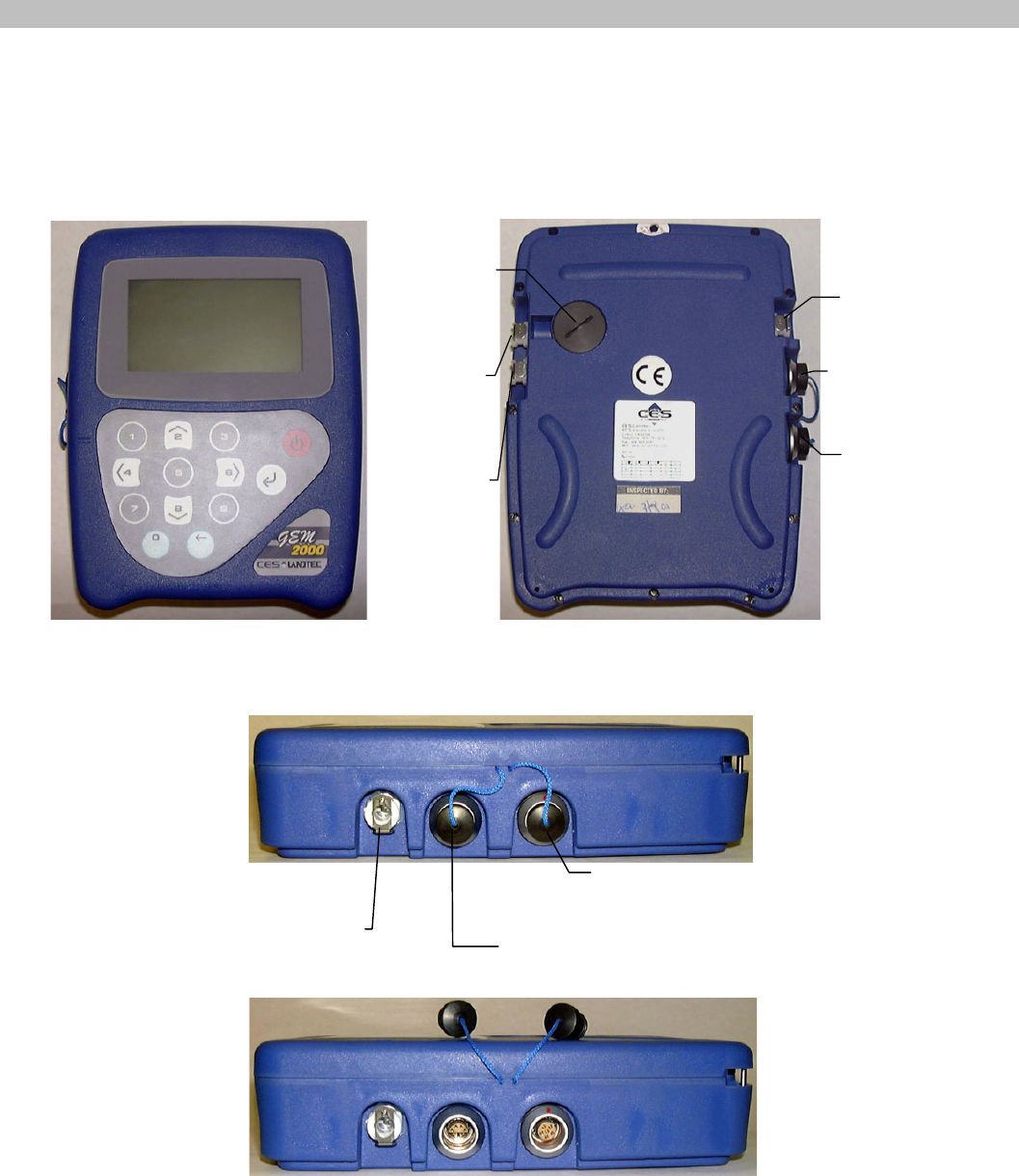
2.1 Physical Characteristics of the GEM™2000
Front View
Back View
Sample
Inlet
or Static
Pressure
Port
Exhaust
Port
RS232
Communication
Socket
Charger
Socket
Particulate
Filte
r
Housing
Impac
t
Pressure
Port
Left Side View
Charger Socket
RS232 Communication
Socket for Computer Cable,
optional Temperature Probe
or optional Gas Pod
Exhaust Port
GEM™2000 Operation Manual
Page 3
Right Side View
Sample Inlet o
r
Static Pressure Port
Impact Pressure Port
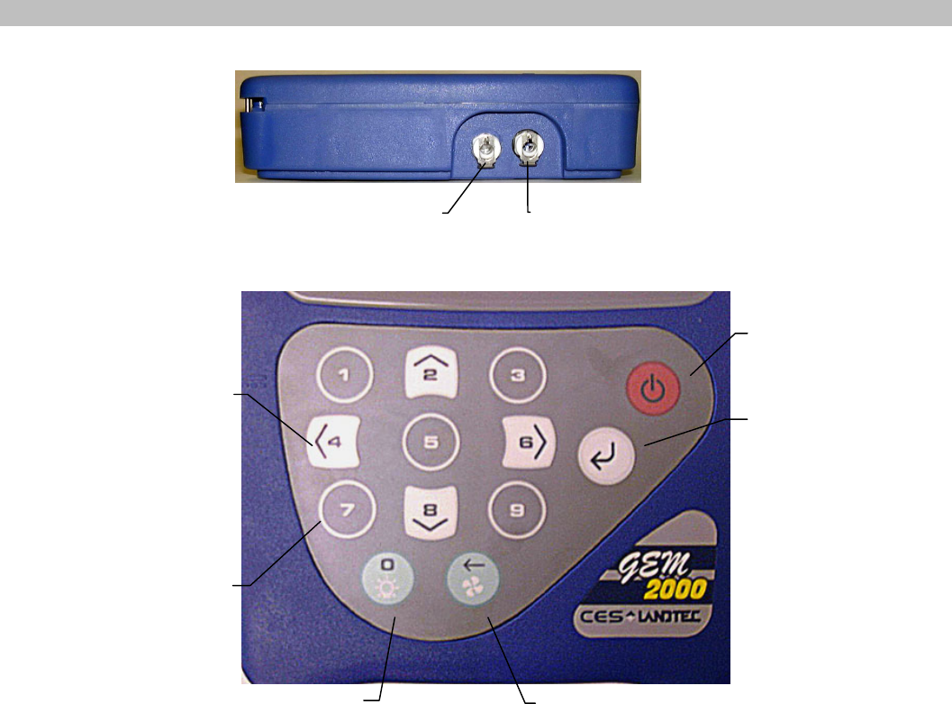
On/Off Key
Enter/Store
Key
Pump operation and
Back Space Key
Backlight operation and
‘0’ (zero) Key
Number entry
Keys
Number entry,
Navigation
and Curso
r
Keys
Keypad
Whenever a key is pressed the unit will emit a short ‘beep’ as an acknowledgement. This function cannot be
turned off.
2.2 Turning the Instrument On/Off
When switching the instrument on, a long beep will sound, followed by the CES-LANDTEC logo being
displayed and the self-test will commence.
When switching the instrument off, the On/Off button must be held down for approximately 15 seconds, at
which point a clean air purge will be carried out. If for any reason the instrument ‘locks-up’ and will not
switch off, press and hold the On/Off button for 15 seconds. This will force the instrument to switch off.
2.3 Warm-up Self Test
When switched on, the instrument will perform a predetermined self-test sequence taking approximately 20
seconds, during this time many of the instrument’s functions are tested, including:
• General operation
• Pump function
• Gas flow measurement
• Calibration
• Backlight function
• Solenoid function

GEM™2000 Operation Manual
Page 4
During the self-test, the following information is also displayed:
• Calibration due date.
• Software version.
• Lifetime guarantee covered (or not).
• Date format.
• Serial Number.
• Operating language.
Upon self-test completion, the GEM™2000 should automatically enter the read gas levels screen.
2.4 Warning and Error Display
During the self-test, if any operational parameters are out of specification or the pre-programmed
recommended calibration/service date has passed errors or warnings may be displayed. Only three
errors/warnings can be displayed at any time. To ascertain if more errors occurred, use the ‘∧’ and ‘∨’ key to
scroll up/down the list.
2.4.1 WARNING Displayed
All warnings displayed will be prefixed by the word ‘WARNING‘ followed by a relevant description. Two
types of warnings may be displayed.
1. General warnings that may not have an effect on the instrument’s function and those where the self-
test has detected a function that is outside the usual programmed operating criteria (e.g. Battery
charge low, memory nearly full, etc.).
2. Specific warnings of operational parameters that can affect the performance of the instrument (e.g.
O2 Cell out of calibration, CH4 out of calibration, CO2 out of calibration, etc.).
The most likely reason for the errors is either an incorrect user calibration, or sensor failure. If an incorrect
user calibration has caused the warning, it should be correctable by way of returning the instrument to
factory settings, zeroing or carrying out a user calibration as necessary for the relevant function.
2.4.2 ERROR Displayed
All errors displayed will be prefixed by the word ‘ERROR‘ followed by a number and description. The errors
detected by the self-test are usually caused by a user calibration being out of specification or possibly
memory corruption. This will have an effect on the functionality of the instrument and should be corrected
before use (e.g. 01 - User cal data, CH4 reading or channel out of specification, 02 - User cal data, CO2
reading out of specification).
If any other Warnings or Errors are displayed, contact CES-LANDTEC for further information.
CES-LANDTEC is the ONLY authorized service center for the GEM™2000 instruments in the
Americas
2.5 Storage
Do not keep the instrument in the trunk of a car or shed because it may be exposed to temperature
extremes.
When not in use, instruments should be kept in a clean, dry and warm environment such as an office.
The instrument batteries should be discharged and fully charged at least once every four weeks regardless
of indicated charge state. The discharge function may be carried out with the use of the Data Logging
Function in GA mode of operation.
GEM™2000 Operation Manual
Page 5
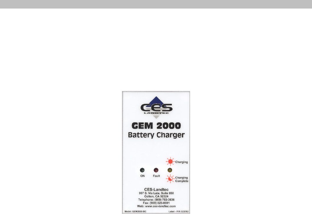
2.6 Battery/Charging
The Battery Charger IS NOT covered by the unit UL certification. Therefore, when connected to the
Battery Charger, the instrument IS NOT intrinsically safe and should not be used in confined
spaces.
The battery used in the GEM™2000 is a Nickel Metal Hydride manufactured as an encapsulated pack from
six individual cells. This type of battery is not so susceptible to “memory effects” as Nickel Cadmium
batteries, although it is not recommended that the unit be given short-term charges. When the flashing LED
indicates “Charging Complete”, disconnect the charger.
The battery charger indicates when the unit is charging, charged or if there is a fault. A full charge should
take approximately 2 hours. Charge the batteries until the ‘Charging Complete’ indicator is flashing.
2.7 Read Gas Levels Screen (GA mode of operation)
The read gas levels screen is also considered the normal operation screen and all operations are carried
out from this starting point. The following information is displayed in various boxed sections at this time:
• Current programmed time and date.
• Current selected ID code.
• Pump status.
• Pump run time.
• Three main constituent gases – CH4, CO2, O2 (in %).
• Balance gas.
• Last read time/date (if previous data is in memory), the benefits of this are, 1 – it is easily noted if a
reading has been taken/stored, 2 – the current and previous readings can be easily compared.
• External Gas Pod “Not Fitted” (displays pod type when attached).
• Peak CH4 reading (in %) (GA mode only).
• LEL CH4 (GA mode only).
• Current barometric pressure reading.
• Current relative pressure reading (GA mode only).
• Gas Pod or Temperature Probe reading (if connected).
• Battery Charge graph (5 segment, flashes at 20% remaining).
• Memory Usage graph (5 segment, flashes at 5% remaining).

GEM™2000 Operation Manual
Page 6
Other options:
c Menu Allows access to all instrument user functions.
e Next ID Allows the next ID to be selected (if data available).
iPrevious Reading Allows the previous reading of the selected ID to be viewed (if data available).
↵ Store Reading Stores the current displayed reading. (GA mode only)
2.8 Optional Gas Pods
Optional gas pods are available for use with the GEM™2000. These pods are available in seven different
gases with nine different PPM ranges. Connection to the instrument is made via the data port and exhaust
port. The detected PPM level is displayed in the upper right area of the gas read screen and is saved in the
same manner as the other gas readings.
Gas Type Range (PPM) Resolution (PPM)
H2S 0-50 0.1
0-200 1.0
CO 0-1000 1.0
SO2 0-20 0.1
0-100 1.0
NO2 0-20 0.1
CL2 0-20 0.1
H2 0-1000 1.0
HCN 0-100 1.0
Gas pods are intended for use as an inexpensive detection means and not for regulatory reporting
purposes. If the GEM™2000, fitted with a Gas Pod, indicates the presence of the selected gas, further
testing should be performed with regulatory approved instrumentation. CES-LANDTEC recommends that
field calibration be performed using the relevant gas and concentration, prior to sampling with a gas pod.
2.9 Cold Start
THIS FUNCTION SHOULD BE USED ONLY AS A LAST RESORT.
(For Gas Calibration Error Massages, confirm that Factory Setting and User Calibration is done).
A Cold Start should only be carried out to correct an instrument if no other course of action has proved
successful. This function WILL ERASE the instrument memory entirely. After a cold start is performed the
user will need to reset the instrument to factory settings, perform a field calibration and reset the internal
time/date to the default settings. Please note, the time/date may only be updated through DataField
software. It cannot be updated manually.
To carry out a cold start, turn the instrument on, during the self-test press and continue to hold the ‘↵’ key
until the self-test has been completed. Upon completion of the self-test, a pass code entry screen will be
displayed. At this point the ‘↵’ key may be released. Enter the code 12345 and press ‘↵’ to confirm.
After the pass-code entry has been accepted, the instrument serial number will be displayed along with the
hours of operation and two options:
1 - Cold Start
0 - Continue
ONLY select option ‘1’ if a Cold Start is to be carried out. Press key ‘1’ to confirm this operation. The cold
start menu will be displayed again, press key ‘0’ to continue with normal operation.

GEM™2000 Operation Manual
Page 7
3 General Operations Menu
The following features and functions are selectable from the main menu via key ‘c Menu’ from the read gas
levels screen. Various options are available to the user including:
3.1 Zero Transducers
This function allows the user to zero the pressure transducer(s). Upon selection, the current pressure
reading is displayed. The operation will be carried out when the ‘↵’ is pressed.
3.2 Update Site Data
Allows the user to answer questions (pre-defined in DataField software) relating to the site (e.g. name of
operator, weather conditions, etc.). Site Questions are different from Site Comments.
This is covered in detail in Section 6 of this manual.
3.3 Data Logging (GA mode only)
Enables the user to leave the Instrument unattended to take samples at a pre-determined time. The reading
interval and pump run time may be edited prior to commencing the logging cycle. The ID code may ONLY
be set in DataField communication software.
Once the logging function is activated, the instrument will carry out a 30 second ‘Warm-up’ countdown
(displayed bottom right) and begin the first sample. After each sample, the unit will shut down (sleep) to
conserve power if the time between the pump ending and the next sample is greater than 30 seconds.
The instrument is reactivated (awakened) during a logging cycle, the company logo will be displayed for a
few seconds and the read gas levels screen will be displayed. This will initiate a 30 second countdown to
the next sample being taken unless the operator stops the logging function.
If for any reason during a logging cycle the inlet port were to become blocked the Instrument will sense this
as a flow fail during the ‘pump on’ time and will automatically retry until a reading can be obtained.
Therefore, position the sample tubing carefully to ensure no blockage due to water/moisture can occur.
3.4 Print Data
Allows ALL the data currently stored to be printed. This may ONLY be carried out with an appropriate
RS232 cable (included with new instruments & available from CES-LANDTEC) and a printer with a serial
port connection.
3.5 Adjust Contrast
The GEM™2000 automatically adjusts the screen contrast according to the ambient temperature to
maintain normal viewing.
The contrast can be manually adjusted by using the ‘<’ and ‘>’ cursor keys. The manual contrast setting is
stored when the instrument is switched off.
3.6 Field Calibration
Whenever carrying out a user calibration function it is important to ensure the correct value is entered.
Additionally, in the case of a zeroing function, ensure only ambient air is used and no connection is made to
a probe or wellhead fitting. The calibration cylinders sold by CES-LANDTEC have a volume of 17 liters.
The regulator, sold by same, is set to 0.5 liters per minute. A normal field calibration usually requires the
gas to be running for about two minutes.

GEM™2000 Operation Manual
Page 8
Upon selecting this option, the Field Calibration screen is displayed. A brief description of the user span
calibration procedure and the current reading (row ‘R’) and user span calibration gas values (row ‘S’) are
displayed.
The span gas values may be changed via the ‘e Edit Target Concentrations’ option. Once this option has
been selected, all the gas values will require entry. Each entry is to be confirmed by pressing the ‘↵’ key.
3.6.1 Zero Channels
Selected from the ‘Field Calibration’ - ‘↵-Calibration Menu’ allows the relevant reading to be zeroed.
When selected, a list of the available options will be displayed, this usually includes CH4, and O2, also the
Gas Pod (if fitted).
Supply a zero gas mixture to the instrument for the gas to be zeroed. Insure the reading for the selected
gas has settled to its lowest value before selecting the zero function. When the required option is selected,
the user zero function will be carried out automatically. The operation will be carried out when the ‘↵’ key is
pressed.
3.6.2 Span Channels
Spanning Channels should be carried out prior to use or when the ambient operating temperature changes
greater than +/- 20 degrees. Selected from the ‘Field Calibration’ - ‘↵-Calibration Menu’, allows the
relevant reading to be span calibrated (in accordance with the calibration value entered). When selected, a
list of the available options will be displayed, which includes CH4, CO2, O2, and Gas Pod (if fitted).
When the required option is selected from the list, the span calibration function will be carried out
automatically. When carrying out this procedure, ensure the span calibration procedure (as outlined below)
is followed:
1. Apply the relevant known certified gas concentration through the inlet port of the Instrument.
2. Wait until the current gas reading has stabilized.
3. Select the required calibration option via the ‘↵-Calibration Menu’.
3.6.3 Factory Settings
This will clear any user zero and span calibration data. It will also restore the pre-programmed factory
settings for ALL channels – CH4, CO2, O2 or Gas Pod (if fitted) and pressure transducers.
3.6.4 Last Field Cal
Displays the date the last field calibration was carried out (zero or span).
3.7 Mode of Operation
Allows changing instrument between GA mode and GEM mode of operation.

GEM™2000 Operation Manual
Page 9
4 Taking Probe Readings (GA Mode)
CES-LANDTEC classifies non-extraction wells as Probes when NOT connected to an active vacuum
extraction system. Probes, (commonly known as migration probes), may be placed on the perimeter of
the landfill to test for gas migration or may be placed next to a building or road to test for the presence
of Methane. The GEM™2000 instrument may be configured as a Gas Analyzer (GA mode) for
sampling probes. To access this function from the gas read screen press ‘c’ for menu and scroll down
to Mode of Operation, press the ‘↵’ key and highlight Landfill Gas Analyzer, pressing the ‘↵’ key
again will select GA mode of operation.
4.1 Preliminary Checks
Prior to going to the test site, it is good practice to ensure:
• All necessary ID codes and readings have been uploaded via DataField software.
• The time and date are correct.
• The water trap has a clean and dry filter fitted.
• The inlet-port particulate filter is clean and dry.
• A supply of spare filters is available in case of accidental water blockage or contamination.
• The battery has a good charge (minimum 25% charge, even if only a few readings are required).
• The memory has sufficient space available.
• The CH4, CO2, and O2 readings have been auto-zeroed, without gas concentration present.
• Check the span calibration with a known concentration calibration gas.
Travel to site with the analyzer in the vehicle's interior - not in the trunk or truck bed, where it may be
subjected to extremes of temperature and possible shock damage. Do not place the analyzer against
anything hot (e.g. gas extraction pipe, car body or in an unattended car during the summer). This may
cause erroneous readings.
When moving around a site, protect the instrument from strong direct sunlight, heavy rain or wind-chill.
Strong direct sunlight can raise the temperature of the instrument beyond its operating range. If this occurs,
the LCD display will appear almost black and the contrast setting cannot alter the contrast.
Always use the water trap! If the water trap becomes flooded, change the filter immediately and ensure all
tubes are clear before re-use.
4.2 Update Site Data
Prior to taking the readings at a particular site, the Site Data should be updated (if programmed). This is
accessed via the General Menu ‘c Update Site Data’. This function removes the need for the site
conditions to be recorded manually.
A series of up to five questions can be pre-programmed with the use of DataField and answered at this
time. The answers to these questions are stored and appended to each reading stored thereafter, until the
site data is updated for another site.
4.3 Taking Readings – With ID
For this function to be used it is essential that the relevant ID and if required, previous readings are
uploaded to the Instrument. An ID cannot be entered from the Instrument.
1. When the read gas levels screen is displayed, option ‘e Next ID’ should be selected. A list of stored
IDs is displayed for selection via the ‘∧’ and ‘∨’ cursor keys, the ‘next’ ID on the list is automatically
highlighted. To confirm selection, press the ‘↵’ key. The display may be toggled to display any
relevant ID information such as a description of the probe location, work to be carried out, etc.

GEM™2000 Operation Manual
Page 10
2. A reminder is displayed to disconnect sample tubes, as a clean air purge will automatically remove
the previous sample from the instrument. Purge time may be set via DataField (default is 30
seconds). Once the ‘↵’ key is pressed, purge will begin and the Read Gas Levels screen will be
displayed upon completion. The purge may be aborted by pressing the ‘1EXIT’ key.
3. The ID number selected and the pump runtime is displayed in the upper left corner of the read gas
levels display.
4. At this point, connect the sample tube (with water trap) from the sample point to the inlet port of the
instrument, ensuring the connector ‘clicks’ into place. Then connect the sample tube to the probe
sample port. Do not connect the sample tube to the probe port before connecting to the
instrument as this will cause any pressure in the probe to dissipate and a proper pressure
reading will not be taken.
5. As soon as the connection is made, the relative/static pressure reading will be displayed. No
sample is taken from the probe at this time. Once the reading stabilizes and the pump starts, the
relative/static pressure reading is stored. The relative/static reading will remain displayed as the
pressure last taken.
6. The pump will run for the pre-programmed time and a countdown timer will be displayed. The pump
may be stopped or started at anytime by way of the ‘!’ (pump) key. The reading may be stored at
anytime with the use of the ‘↵’ key. When the pump automatically stops this should be used as a
prompt to store the reading.
7. Upon storing the reading, any pre-programmed questions will be displayed for response. This may
require a numeric, alphanumeric selectable comment, or exclusive comment answer. A maximum of
eight selectable and exclusive comments may be entered.
8. Disconnect the sample tubing from the probe and proceed to Step 1 for the next probe.
For each reading, the following information will be stored:
• ID code.
• Current time/date.
• Site data (if entered).
• All gas readings and balance (CH4, CO2, O2).
• LEL CH4.
• Barometric Pressure.
• Relative Pressure.
• Questions/comments.
• Temperature (if temperature probe is connected).
• Gas Pod (if connected).
When the instrument is switched off, a clean air purge is automatically started for a pre-determined period.
This may be aborted with the use of the ‘↵’ key, although it is not recommended.
A tone will sound and a flashing bell will be displayed next to the appropriate gas reading value if a preset
alarm condition has been exceeded.
4.4 Taking Readings – Without ID
1. From the ID list press ‘g Select No ID’ or, if ID information has not been uploaded to the instrument,
an ID list will not be available. In either case, the ID will be displayed and stored as ‘- - - - - - - -‘.
9. A reminder is displayed to disconnect sample tubes, as a clean air purge will automatically remove
the previous sample from the instrument. Purge time may be set via DataField (default is 30
seconds). Once ‘↵’ is pressed, purge will begin and the Read Gas Levels screen will be displayed
upon completion. The purge may be aborted by pressing the ‘1EXIT’ key.
2. At this point, connect the sample tube (with water trap) from the sample point to the inlet port of the
instrument, ensuring the connector ‘clicks’ in to place.

GEM™2000 Operation Manual
Page 11
3. Now connect the sample tube to the probe sample port. Do not connect the sample tube to the
probe port before connecting to the instrument as this will cause any pressure in the probe
to dissipate and a proper pressure reading will not be taken.
4. The pump may be started or stopped at anytime by way of the ‘!’ (pump) key and a ‘time-on’ timer
will be displayed. The pump should always be stopped using the ‘↵’ key, before storing a reading.
5. Upon storing the reading, a virtual keyboard will be displayed for any alphanumeric comments to be
entered.
6. Disconnect the sample tubing from the probe and proceed from step 1 for the next probe.
Except for the ID code information, which will be stored as ‘- - - - - - - -‘, and probe questions, for each
reading the information stored will be the same as that for a reading with an ID.
A tone will sound and a flashing bell will be displayed next to the appropriate gas reading value if a preset
alarm condition has been exceeded.
4.5 Temperature Probe Reading
The GEM™2000 has the facility to automatically display and record the probe temperature via an optional
temperature probe (TP-100). When a temperature probe is fitted to the RS232 Communication Socket, the
temperature will be displayed in the read gas levels screen and recorded with all other data. The
temperature probe is part of the GEM™2000 UL certification and is therefore certified for use under the
same conditions as the instrument.
4.6 Cross-Gas Effects
4.6.1 Methane, Carbon Dioxide and Oxygen
The Methane reading is filtered to an infrared absorption frequency of 3.41µm (nominal), the frequency
specific to hydrocarbon bonds. Instruments are calibrated using certified Methane mixtures and will give
correct readings provided there are no other hydrocarbon gasses present within the sample (e.g. ethane,
propane, butane, etc.). If there are other hydrocarbons present, the Methane reading will be higher (never
lower) than the actual Methane concentration being monitored.
The extent to which the Methane reading is affected depends upon the concentration of the Methane in the
sample and the concentration of the other hydrocarbons. The effect is non-linear and difficult to predict.
The Carbon Dioxide reading is filtered to an infrared absorption frequency of 4.29µm (nominal), the
frequency specific to Carbon Dioxide. Therefore, any other gases usually found on landfill sites will not
affect the Carbon Dioxide reading.
The Oxygen sensor is a newly developed galvanic cell type and suffers virtually no influence from CO2, CO,
H2S, NO2, SO2 or H2, unlike many other types of Oxygen cell.
The infrared sensors will not be "poisoned" by other hydrocarbons. Normal operation will resume as soon
as the gas sample has been purged.
Note - there has been one reported incident of a high reading due to the presence of Carbon Disulphide,
which has a similar absorption frequency to Carbon Dioxide.
GEM™2000 Operation Manual
Page 12
4.6.2 H2S, CO and other Optional Gas Pods
The Gas Pods used to measure H2S and CO do suffer from cross-gas effects. Such effects are not
accurately specified. However, the following table may be useful as a guide. This table represents how
many ppm would be read by a Gas Pod if 100ppm of the interfering gas was applied, (with no other cross-
contaminates being present in the sample).
Cell CO H2S SO2 NO2 CL2 H
2 CH4 CO2
CO 100 <3 0 <-20 0 <40 0 0
H2S <0.5 100 ~20 ~-20 ~0.1 0 0
NOTE: All readings are given in parts per million (ppm). The life of an electrochemical cell is determined by
exposure to gasses, typical life being one to two years. It is recommended that Gas Pods be field calibrated
at regular intervals.
4.7 Memory
The instrument's memory is volatile. It is maintained by a battery back-up system, which will maintain the
memory while the battery is being changed.
The memory is not to be used as a permanent storage medium and any data should be transferred to a
more permanent storage medium as soon as possible. An Instrument should never be stored for prolonged
periods with valuable data in its memory.
Although unlikely, sudden shocks, high levels of electromagnetic interference or static discharge may cause
memory corruption or loss. If this occurs, the instrument should be Cold Started and the calibration reset to
factory settings before further use. Cold starting will erase all data in the instrument including
resetting the time and date to the default value.

GEM™2000 Operation Manual
Page 13
5 Taking Extraction Well Readings (GEM Mode)
CES-LANDTEC classifies gas-producing penetrations on landfills as wells when used with vacuum
extraction systems and flow determining devices such as the Accu-Flo wellheads, orifice plates or pitot
tubes. The GEM™2000 may be configured as a Gas Extraction Monitor (GEM mode) for the purpose
of sampling wells and obtaining flow measurements. To access this function from the gas read screen
press ‘c’ and scroll down to Mode of Operation, press the ‘↵’ key and highlight Gas Extraction
Monitor, pressing the ‘↵’ key again will select GEM mode of operation.
5.1 Preliminary Checks
Prior to going to site, it is good practice to ensure:
• All necessary ID codes and readings have been uploaded via DataField software.
• The time and date are correct.
• The water trap has a clean and dry filter fitted.
• The inlet-port particulate filter is clean and dry.
• A supply of spare filters is available in case of accidental water blockage or contamination.
• The battery has a good charge (minimum 25% charge, even if only a few readings are required).
• The memory has sufficient space available.
• The CH4, CO2 and O2 readings have been auto-zeroed without gas concentration present.
• Check the span calibration with a known concentration calibration gas.
Travel to the site with the analyzer in the vehicle's interior - not in the trunk or truck bed, where it may be
subjected to extremes of temperature and possible shock damage. Do not place the analyzer against
anything hot (e.g. gas extraction pipe, car body or in an unattended car during the summer). This may
cause erroneous readings.
When moving around a site, protect the instrument from strong direct sunlight, heavy rain or wind-chill.
Strong direct sunlight can raise the temperature of the instrument beyond its operating range. If this occurs,
the LCD display will appear almost black and the contrast setting cannot alter the contrast.
Always use the water trap! If the water trap becomes flooded, change the filter immediately and ensure all
tubes are clear before re-use.
5.2 Update Site Data
Prior to taking the readings at a particular site, the Site Data should be updated (if programmed). This is
accessed via the General Menu ‘c’. This function removes the need for the site conditions to be recorded
manually. A series of up to five questions can be pre-programmed with the use of DataField and answered
at this time. The answers to these questions are stored and appended to each reading stored thereafter,
until the site data is updated for another site.
5.3 Taking Gas and Flow Readings (GEM Mode)
The GEM mode of operation is designed to allow for gas flow (SCFM) and energy measurements (BTU) to
be calculated at the wellhead. This function requires the use of an ID that has been uploaded from
DataField software with the type of flow device defined. Gas flow and BTU will not be calculated if this
action has not been performed.
1. When the gas read screen is displayed select ‘e Next ID’. A list of stored IDs will be displayed for
selection via the ‘∧’ and ‘∨’ cursor keys, the ‘next’ ID is automatically highlighted, to confirm the selection
press the ‘↵’ key. The screen may be toggled to display any relevant ID information such as a
description of the well location, work to be carried out, etc.

GEM™2000 Operation Manual
Page 14
2. A reminder is displayed to disconnect sample tubes, as a clean air purge will automatically remove the
previous sample from the instrument. Purge time may be set via DataField (default is 30 seconds). Once
the ‘↵’ key is pressed, purge will begin and the Read Gas Levels screen will be displayed upon
completion. The purge may be aborted by pressing the ‘1EXIT’ key.
3. Connect the sample tubes (with water trap filter) to the wellhead ensuring the gas sample tube and
impact pressure tubes are properly oriented. Insert the temperature probe if used.
4. Press the ‘!’ key to start the sample pump; a countdown timer will be displayed in the upper left area of
the display. The pump may be stopped and restarted and any time by pressing the ‘!’ key. The pump
run time is set in DataField software. Allow the gas readings to stabilize and press ‘5Measure Flow’
key, this will store the gas level readings and display the ‘PRESSURE READINGS’ screen. Note; a
flashing bell will be displayed next to the appropriate gas and a beeping tone will be heard, if a preset
alarm condition has been exceeded.
5. The ‘PRESSURE READINGS’ screen will prompt the user to disconnect the sample tubes and allow the
pressure to stabilize. Once the pressure has stabilized press ‘↵ Zero Transducers’. Press ‘1’ to
continue. Note; if Accu-Flo wellheads are used this zero function may be performed prior to connecting
the sample tubes to the well head by selecting ‘1 MENU’ and highlighting ‘ZERO TRANSDUCERS’.
This eliminates the need to disconnect and re-connect the sample tubes on the same wellhead.
6. If a temperature probe is not connected, the user is prompted to manually input the gas temperature,
press the ‘↵’ key when entry is finished.
7. The gas flow and energy screen is now displayed showing all the gas level readings taken in the gas
read screen as well as the level of gas flow (SCFM) and power (BTU). In addition, Adjusted, Current
and Previous (if downloaded) readings are displayed so modifications may be made to the well if
required.
8. Pressing ‘↵ STORE’ will save the readings to memory. Then, the comments screen (if comments were
loaded) will display and allow you to answer questions or select comments about the condition of the
well. A total of seven comments and one exclusive comment may be stored with each ID.
9. Press ‘3 NEXT ID’ and proceed to the next wellhead. An automatic purge will be performed at this time
to ensure the sample has been exhausted from the instrument.
For each reading, the following information will be stored:
• ID code.
• Current time/date.
• Site data (if entered).
• All gas readings and balance gas (CH4, CO2, O2).
• Barometric Pressure.
• Temperature.
• Gas Pod (if connected).
• Gas flow (SCFM) and Power (BTU).
• Comments and exclusive comment.
When the Instrument is switched off, a clean air purge is automatically started for a pre-determined global
period. This may be aborted by pressing the ‘↵’ key, although we do not recommend this action.
GEM™2000 Operation Manual
Page 15
6 DataField CS Software
DataField CS is an integrated software program designed to communicate with the GEM™2000,
GEM™500 and GA-90 instruments. The software will create files used for storing gas read data, ID data,
comments and instrument configuration data. The files created are significantly different from the files
created with GEM_COMM or GA_COMM software and are not compatible with these versions of software.
DataField CS is browser based (Java enabled) and will operate on Windows98 and higher Windows
operating systems. Recommended hardware requirements are:
• Pentium III 500 MHz microprocessor or equal.
• 64 MB RAM.
• 120 MB of free hard disk space.
• CDROM drive.
• Mouse or pointer system.
• Standard keyboard.
• Installed printer.
6.1 Installing DataField CS
Be sure your computer is turned on and all software programs have been properly closed. Place the
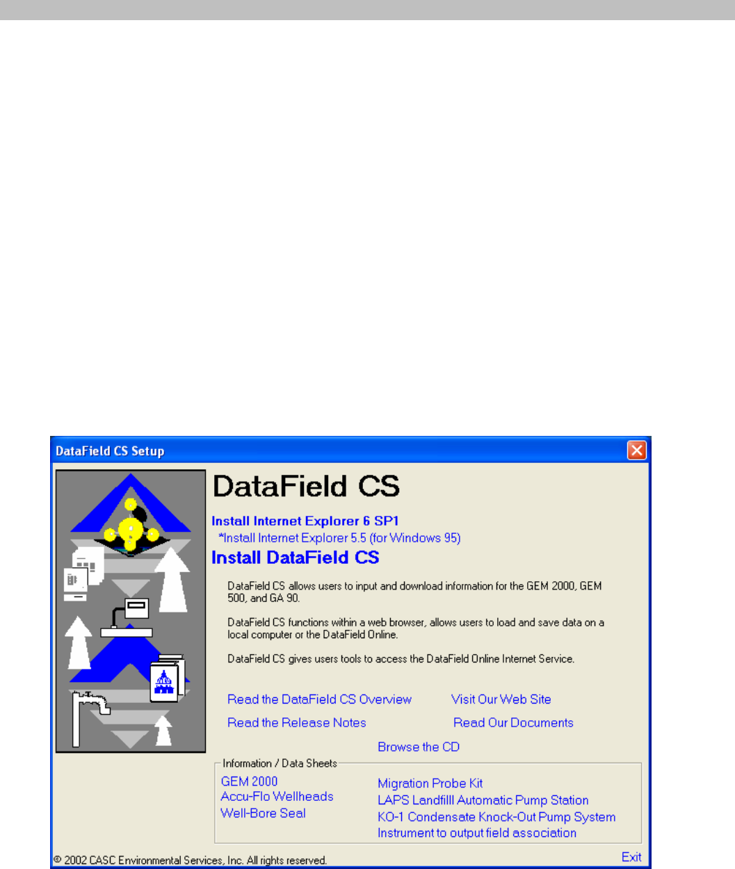
program disk in the CD ROM drive and close the tray. DataField CS will self start and display the DataField
CS set-up screen.*
Install the Internet Explorer 6 SP1 by clicking on the corresponding link in the DataField CS set-up screen.
If you are using Windows 95, install the Internet Explorer 5.5. Follow the onscreen instructions until the
Internet Explorer is installed successfully.
Reboot the computer after the installation of the Internet Explorer is completed.
Re-insert CD Rom to start autorun again.
GEM™2000 Operation Manual
Page 16
Install the DataField CS by clicking on the corresponding link in the DataField CS set-up screen. Follow the
onscreen instructions.*
Other useful links on the DataField CS set-up screen:
Read the DataField CS Overview link will open a presentation with an overview of DataField CS.
Read the Release Notes link has information on the system requirements, application compatibility and
other important issues.
Visit Our Web Site link will open the CES-LANDTEC web site.
Read Our Documents link will open a new window with manuals and user guides for GEM Instruments, as
well as several viewers and 3rd party tools that can be downloaded.
Browse the CD link will open a file browser.
Information / Data Sheets set of links provides information on various Landfill instruments.
* If the DataField CS set-up screen hasn’t appeared, open a file browser (ex. right-click on the Start button
on your desktop and choose open) and navigate to your CD-ROM drive. Double-click on the Autorun.exe.
6.2 Establishing Communications
Connect the RS-232 download cable to an open COM port on your computer. Connect the other end of the
RS-232 download cable to the GEM™2000 data port. DataField CS has the ability to automatically scan
the different COM ports on your computer to find where the instrument is connected.
Turn the instrument on, wait for the self-test function to finish. The Gas Readings screen will display, if not,
then turn off the GEM and re-start the instrument. The GEM™2000 must be in the Gas Reading screen in
order to establish communications.
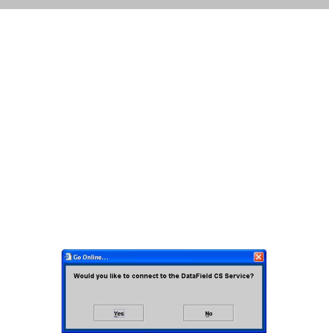
Once the instrument is in the proper communications mode, click on the Start menu then All Programs
menu. Scroll to DataField and then DataField CS to initialize the software. The following screen will appear
on the computer.
Click Yes to run DataField CS online or No to run it offline.
GEM™2000 Operation Manual
Page 17
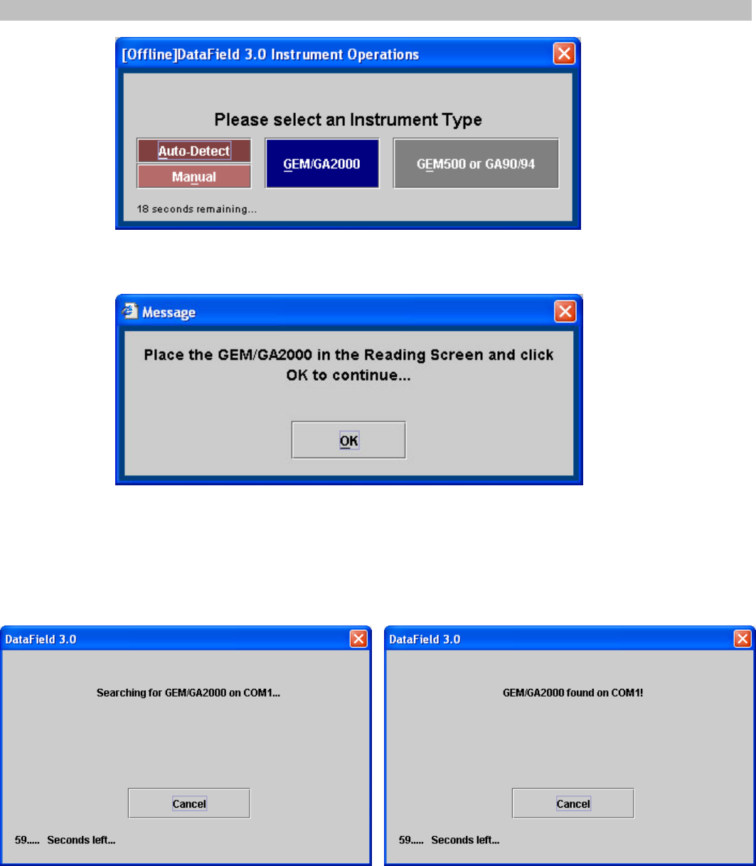
Click on the GEM/GA2000 button. You can also click on the Auto-Detect button for the DataField CS to
automatically detect the instrument.
Click OK and DataField CS will automatically search for the instrument. This may take a few minutes.
When the instrument is found and the communication is established, the software will display a box that
indicates what type of instrument was found. If the software does not find the instrument, it will display a
box that indicates that no instrument was found.
GEM™2000 Operation Manual
Page 18
6.3 Main Screen
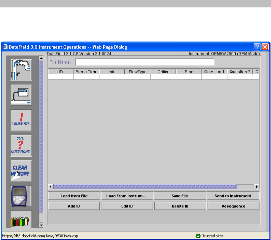
Once DataField CS establishes the communication with the instrument, the main software screen will
appear.
Seven main categories (buttons) are listed down the left side of the screen: ID Functions, Readings,
Comments, Site Questions, Clear Memory, Instrument Settings and Resource Links. Clicking on any one of
the buttons will take the user to that functionality of the application.
6.4 Close the program
Clicking on the Close button in the top right corner of the screen will exit the program. This will close all
files and exit the program.
6.5 Communications
It is not possible to change instruments and establish communications without re-starting the software.
GEM™2000 Operation Manual
Page 19
6.6 Functions
Each button has a specific function as listed below:
1. Comments – Allows entry of comments that may be selected for the IDs. A total of seven
comments and one exclusive comment may be selected for each ID.
2. IDs – Used for adding new IDs, editing IDs or deleting IDs and entry of ID parameters such as pump
run time, flow device, comments and questions for the ID.
3. Readings – Allows downloading and viewing data from instrument and uploading of previous data to
the instrument.
4. Site Questions – DataField CS supports a total of five site questions that are answered by the
technician and saved to the ID data.
5. Clear Memory – Allows the deletion if selective IDs, readings, comments, site questions or all
memory loaded in instrument memory.
6. Resource Links – Allows the user to directly access information via the www.
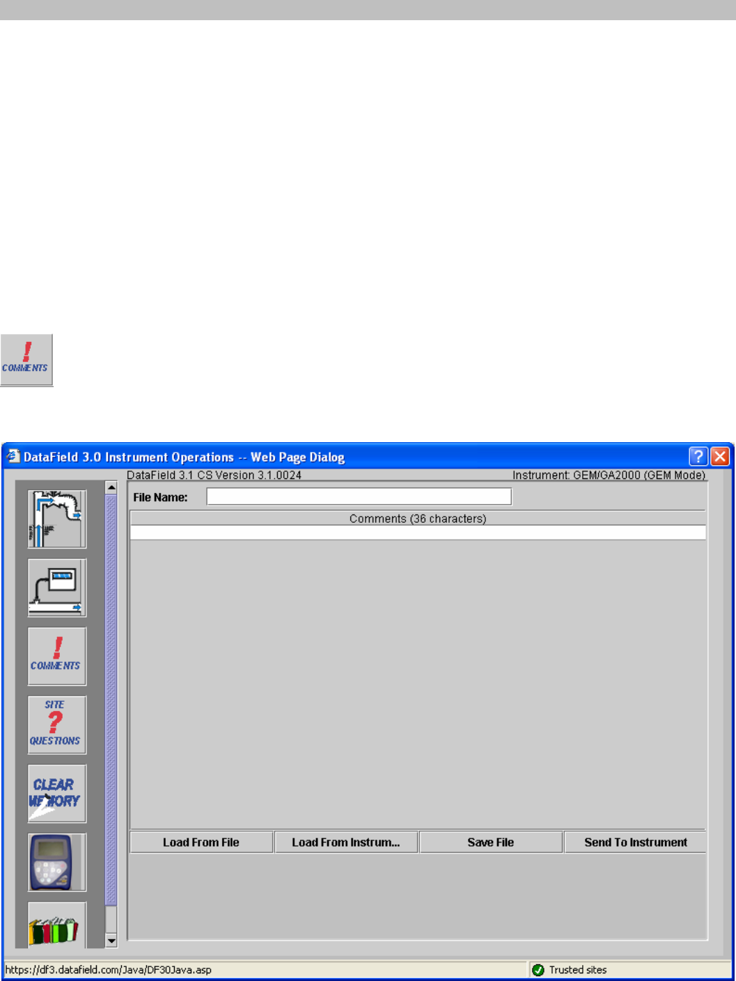
6.6.1 Comments
DataField CS allows up to 64 comments to be created for upload to the GEM™2000. Each
comment may be up to 36 characters in length and may be alphanumeric or any character on the
computer keyboard. Select Comment or Exclusive Comment must be turned on for comments
to be selected for that ID. See section 6.6.2. Click on the Comments button to open the following
screen.
GEM™2000 Operation Manual
Page 20
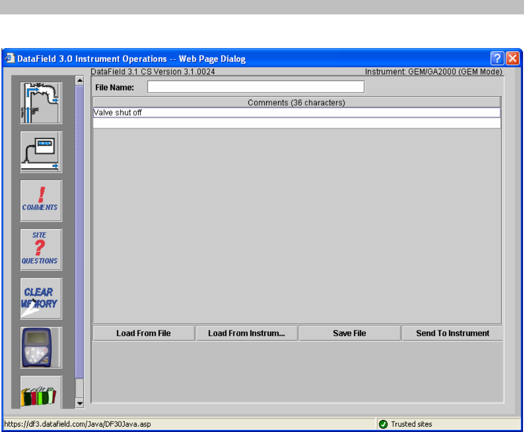
Enter the comment on the comment line and press Enter to continue entering comments until all the
desired comments have been entered. Click on Save File to save the data to disk and then click on Send
to Instrument to save the comments in the instrument. To delete a comment, click on the comment to
highlight the comment and press the Delete key on the computer keyboard to remove the highlighted
comment. It is always suggested to save the comment file because of the potential size and time required to
recreate the comments. Once created, the comment file may be modified and saved under a different file
name at any time.
Note: Comments must be created and sent to the instrument through the software. They can not be hand
input into the instrument in the field.
GEM™2000 Operation Manual
Page 21
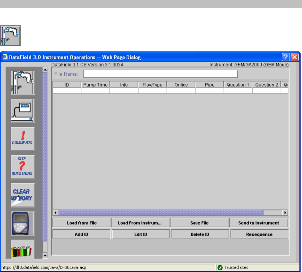
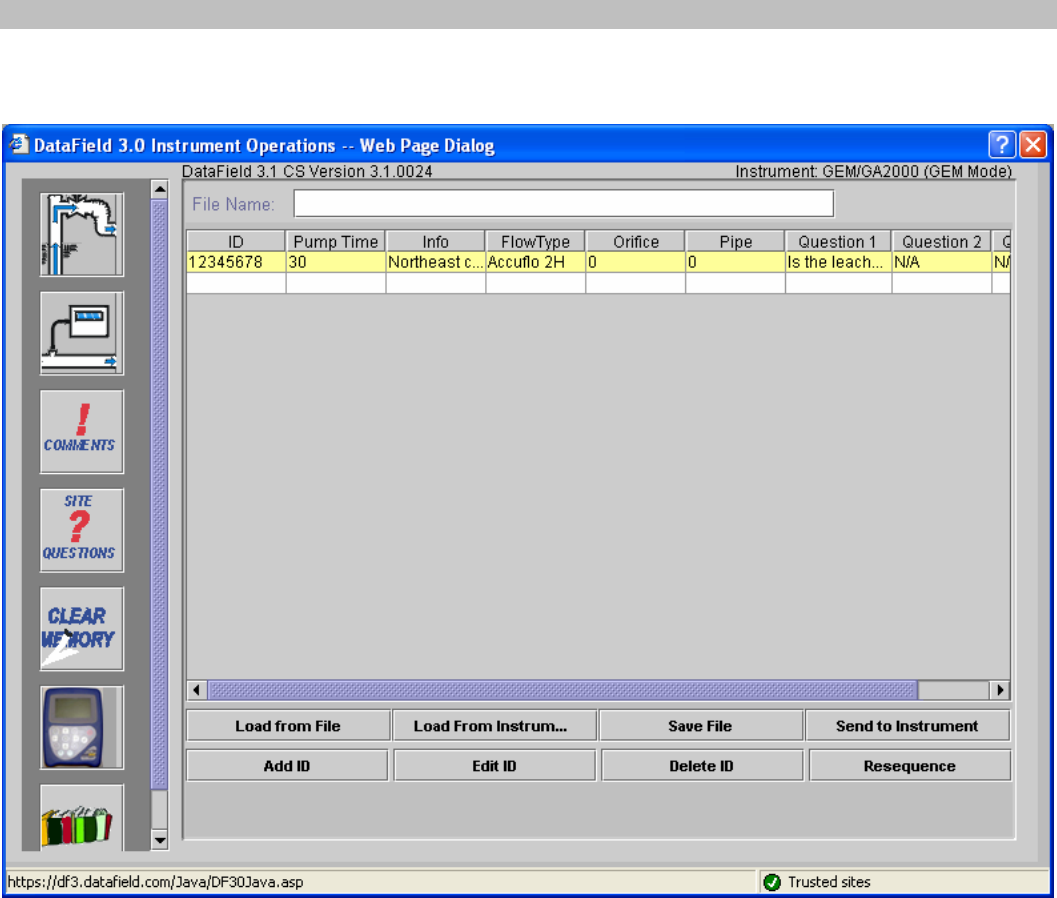
6.6.2 Entering IDs
From the opening screen select the ID button. The following screen will open:
Selecting the Save File button will allow you to enter the name for the file you wish to save. The naming of
files follows the extended naming convention for Windows.
Selecting the Load from File button will allow a previously created file to be loaded from the computer disk
drive.
Selecting the Load from Instrument button will allow previously loaded IDs in the instrument to be
downloaded for modification such as increasing the pump run time or adding additional comments to a
specific ID. CAUTION: Loading IDs from an instrument can be a dangerous practice and is not
recommended if using DF online service. The possibility exists of introducing into a project IDs from
another project. When the IDs are downloaded from the instrument and stored online all IDs that are
present in the instrument will be stored to the current project IRRESPECTIVE of if the IDs belong to the
project.
Add ID button is used for the creation of a new ID or multiple IDs that may be sent to the instrument or
saved to a new file for later use.
GEM™2000 Operation Manual
Page 22
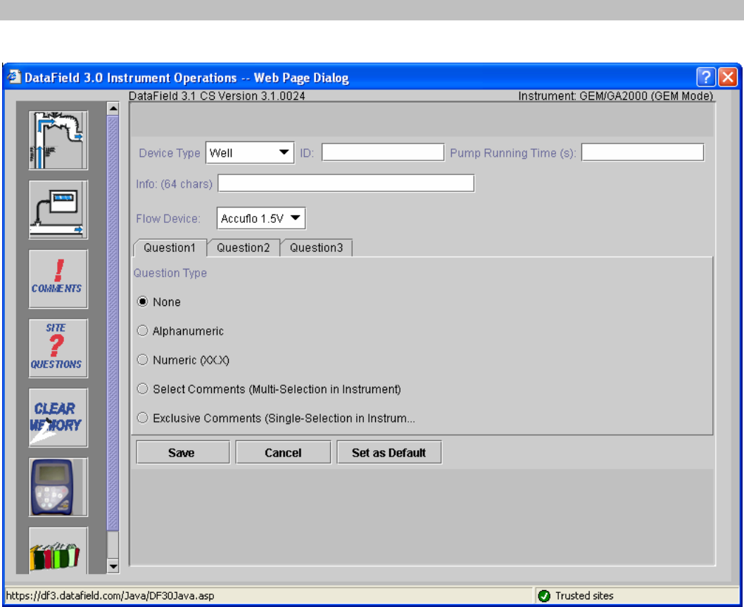
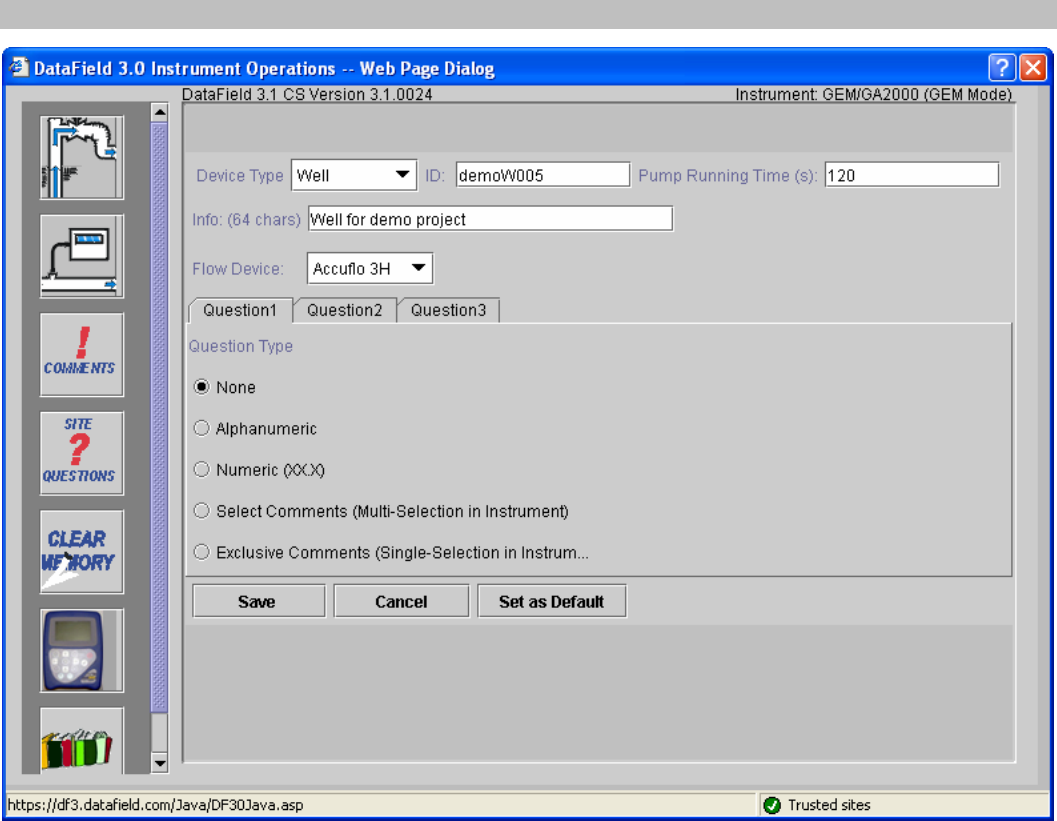
To enter a new ID or create a new ID set, click on the Add ID button and the following screen will open:
Enter the Well ID in any combination of alpha or numeric characters for a maximum of eight characters. All
eight characters must be used. Enter the pump run time in seconds (maximum of 999 seconds), pump
run time must be entered in order for the pump to be turned on for gas sampling. Enter information about
the well, such as its location, previous problems, etc or leave blank. Enter the type of flow device used with
the well (Accu-Flo wellhead, Pitot tube, or orifice plate); user input may also be selected. If Pitot tube or
orifice plate is selected, the inside pipe diameter and orifice diameter must be entered. If the pump run
time and the flow device are going to be the same for multiple wells, click on Set as Default to lock these
two values. Three questions may be asked about the well for reply by the technician at the time a sample is
taken. These can take the form of alphanumeric, numeric, selected comments or exclusive comments. If
none is selected then no questions will be asked for this ID. Note: If Select Comments or Exclusive
Comments is selected, Comments must be created and sent to the instrument. See section 6.6.1.
GEM™2000 Operation Manual
Page 23
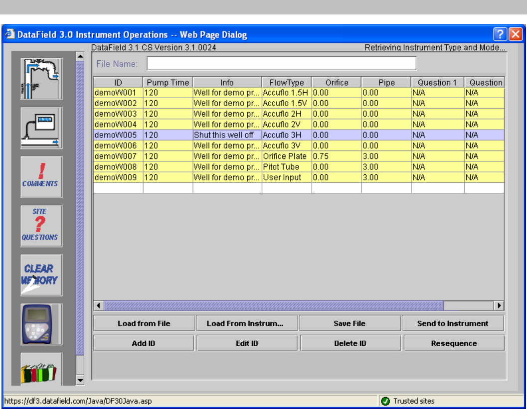
Click on Save to add this ID to the editor screen seen below. If additional IDs need to be entered, simply
click on Add ID and enter the data as before.
Once all the IDs have been entered, click Save File button to save the ID data to a file or Send to
Instrument button if data is to be uploaded to an instrument for field sampling.
GEM™2000 Operation Manual
Page 24
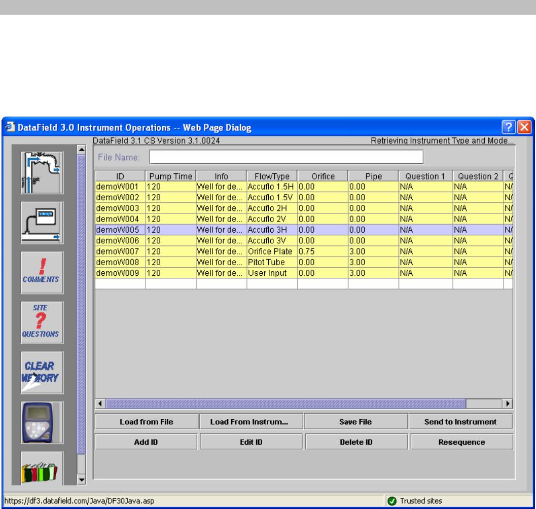
6.6.3 Editing IDs
IDs may be edited in a similar manner to entering a new ID. Click on the ID button. Click on the Load from
File button if the IDs to be edited are in a saved file on disk or click on Load from Instrument if the IDs to
be edited reside in the instrument. Once the IDs have been opened, the ID Editor screen will appear as
shown below.
To select an ID for editing, click on the ID to highlight the ID, and then click on the Edit ID button. The Edit
ID screen will open and allow information for the selected ID to be changed. When finished with the
changes, click on Save to save the edited ID to the ID list.
GEM™2000 Operation Manual
Page 25
When editing is completed, click on Save to return to the previous screen. Click on Save File to save the
edited data to disk or click on Send to Instrument to append the IDs to the IDs in the instrument.
Note: IDs are only appended to the unit. It is strongly recommended to erase/clear IDs from unit prior to
sending new IDs to the unit. One obvious exception is in the case of loading IDs for multiple sites in an
instrument.
GEM™2000 Operation Manual
Page 26
6.6.4 Delete IDs
Select an ID to delete and click on it to highlight it. Click on the Delete ID button. A prompt will appear to
verify the action. Clicking Yes will delete the ID. To select multiple IDs use Ctrl and Shift buttons on your
keyboard. When deleting multiple IDs after clicking on the Delete ID button a prompt will appear: “Would
you like to verify each deletion?” Clicking No will delete all the selected IDs. Clicking Yes will prompt on the
deletion of each ID in the selection. In this case the deletion of some IDs in the selection can be cancelled.
Click on Save File to save the updated file to disk or click on Send to Instrument to update the instrument
for field sampling.
Note: We suggest clearing the ID information from the instrument prior to uploading the revised ID list.
Otherwise the new ID list will be appended to the existing list. Clearing IDs in the instrument will clear IDs in
the both GEM & GA modes of operation.
GEM™2000 Operation Manual
Page 27
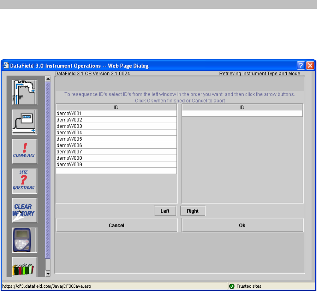
6.6.5 Re-sequencing
With DataField CS it is possible to change the order of the IDs in a file to put them in the same order as they
are sampled in the field. This is called Re-sequencing. To re-sequence an ID data set, click on the ID
button to open the ID editor. Load the ID data set from a file or download the data set from the instrument.
Click on the Re-sequence button to open the screen shown below.
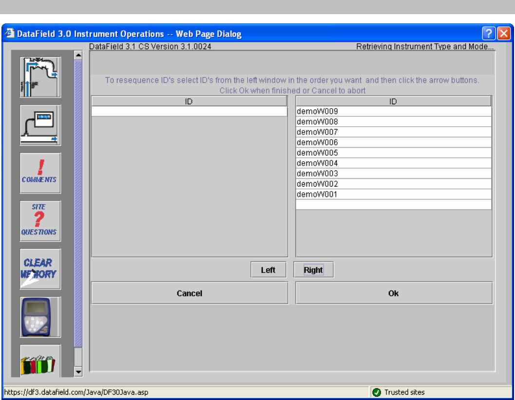
Select the ID from the left side window and click on the Right button to move ID to the right window to
create the new sequence order. Repeat this process moving all IDs to the right side in the desired order.
GEM™2000 Operation Manual
Page 28
Click OK when the desired new sequence is obtained, this will return you to the well ID screen. Click on the
Save File button to save the new data set to a file on disk or click on Send to Instrument to upload the
new data to the instrument.
Note: It is suggested to clear ID information from the instrument prior to uploading the re-sequenced ID list.
Otherwise the new ID list will be appended to the existing list. Clearing IDs in the instrument will clear IDs in
the both GEM & GA modes of operation.
GEM™2000 Operation Manual
Page 29
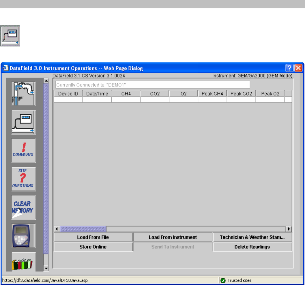
6.6.6 Readings
The Readings screen provides the capability to download, upload, view, save data to a file and
delete individual or multiple readings from a data set. Click on the Readings button to open the
screen shown below.
GEM™2000 Operation Manual
Page 30
Click on Load from File to open a file folder of saved data on the disk drive or click on Load from
Instrument to download data from the instrument. Either action will open the following screen. All readings
should be downloaded on a daily basis. While the instrument can hold readings for an extended period of
time, it is recommended to download them to a non-volatile memory device (e.g. hard drive, CD, etc.).
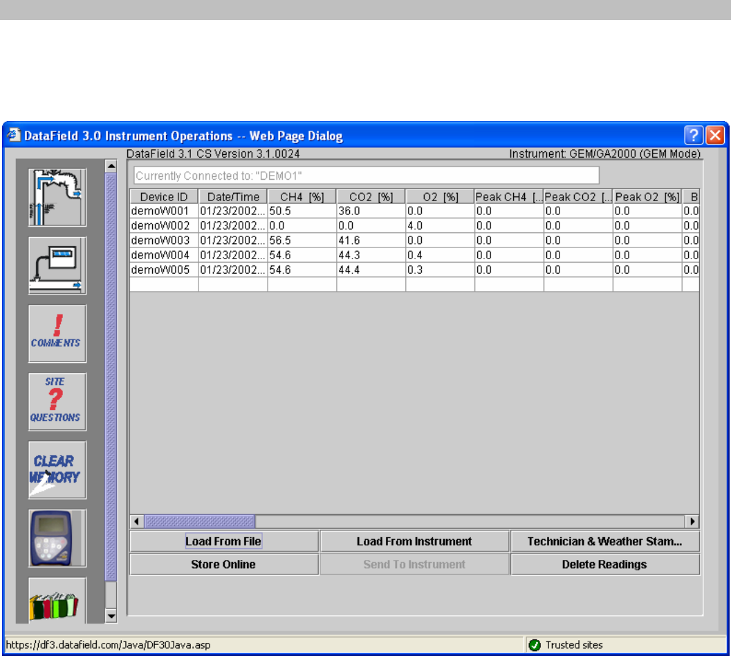
Once the file has been opened or data downloaded from the instrument, the readings can be either stored
online (only with the online version) or saved to a file (only with the offline version). When the instrument
is in the GA Mode the readings can also be sent to the instrument. Send to Instrument button will be
disabled when the instrument is in the GEM Mode. The screenshot above shows the online version with the
instrument in the GEM mode.
To delete an ID from the data set, click on this ID to highlight it and then click on the Delete Readings
button. Only one ID can be deleted at a time.
GEM™2000 Operation Manual
Page 31
6.6.7 Site Questions
DataField CS supports up to five site questions. Site questions are answered only when Update
Site Data is selected from the GEM menu screen and appended to all IDs taken thereafter until
Update Site Data is selected again. This is a useful feature if conditions change in various
locations on the landfill site or for selected wells/probes. Site questions can be either
alphanumeric, numeric, select comment (the technician selects the comment from a list of ten answers) or
exclusive comments (the technician may select only ONE exclusive question from a list of 10 answers).
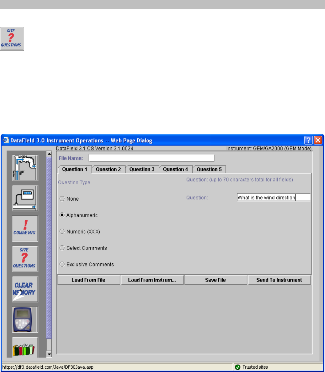
From the opening screen, click on the Site Questions button to open the following screen.
Note: Site questions must be created and sent to the instrument by the software prior to going into the
field. They can not be hand inputted into the instrument in the field.
Click on the open spot, to the left of the alphanumeric category in Question Type to define Question 1 and
type in the question.
GEM™2000 Operation Manual
Page 32
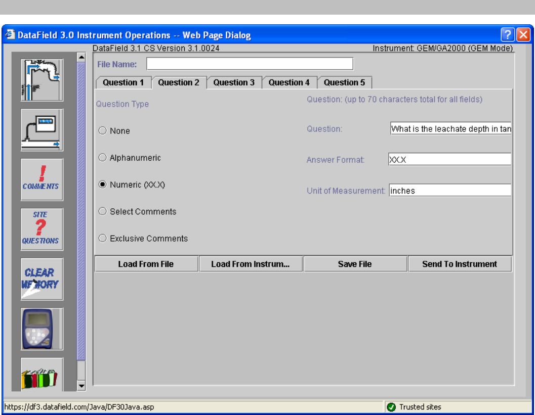
Click on Question 2 and then select Numeric as the Question Type. Note that Answer Format and Unit of
Measurement fields appear for this type of question. Answer format refers to the number of digits and
decimal places required for the answer. Unit of Measurement refers to inches, feet, yards, etc. for the
answer. In this example, XX.X could be equal to 20.5 inches as per the question ‘What is the leachate
depth in tank?’
GEM™2000 Operation Manual
Page 33
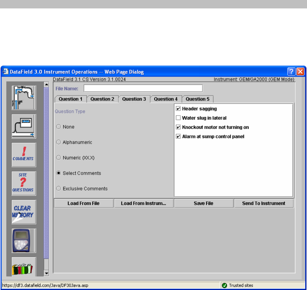
Comments may also be used as a site question, however comments must be downloaded from an
instrument that has already had comments loaded in it. Connect the GEM™2000 and be sure it is in the
read gas screen. Click on Select Comments and the list of comments from the instrument will open in the
window for selection. Ten comments may be selected from the list to become Site Questions. Click on the
box to the left of the comment to select it. The operator may choose any or all of the ten comments when
Update Site Data is selected on the instrument.
GEM™2000 Operation Manual
Page 34
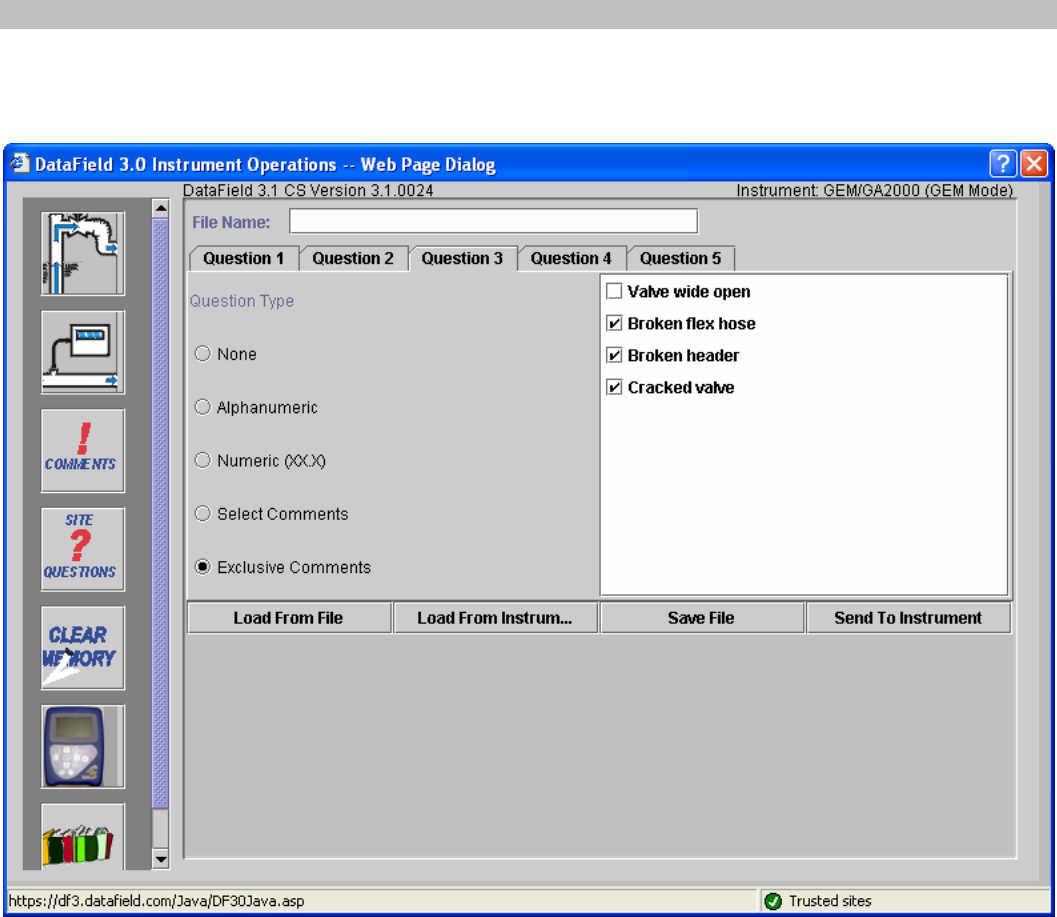
Exclusive comments are treated in a similar manner as select comments in that they also must be
downloaded from the instrument. Ten exclusive comments may be selected, however only ONE may be
chosen by the operator to become an Exclusive Comment.
When all the desired questions have been entered, click on Save File to retain the information for later use
and then click on Send to Instrument to update site data in the instrument.
GEM™2000 Operation Manual
Page 35
6.7 Settings
Clicking on the Settings button on the main screen will display the Instrument Settings. The
Instrument settings provides the capability to set or change optional controls in the instrument,
such as time/date, data logging (GA mode only), purge times, etc.
6.7.1 Instrument Settings
Set the instrument for RS-232 communications and click on the Settings button and the following screen
will open. The software will establish communications and download the current instrument settings.
Once the current settings have been obtained, the following screen will open.
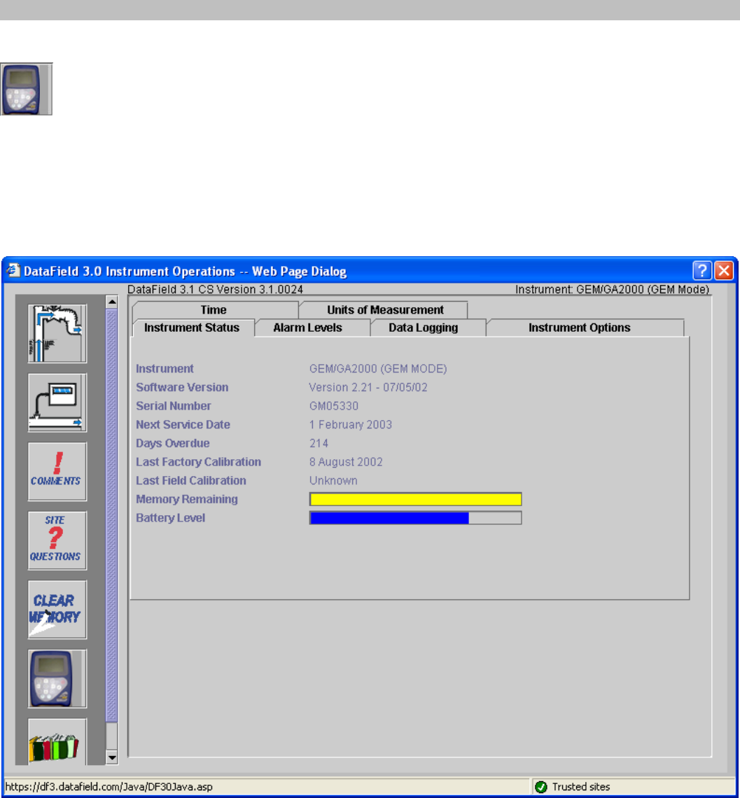
There are six different “Menu Cards” under instrument settings. Each card provides different information or
instrument settings that may be changed to update the operation of the GEM™2000. The instrument status
card will always be shown first, providing calibration and maintenance information in addition to instrument
serial number and software version number.
Click on the card tab for Alarm Levels to open the alarm levels screen. Both a maximum alarm and a
minimum alarm may be set. Note these are global settings and will be the same for all IDs entered in the
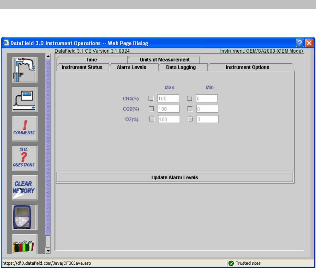
GEM™2000 Operation Manual
Page 36
instrument. Turn off the alarm by clicking off the check mark next to the gas. Click on Update Alarm
Levels to send the new settings to the instrument.
GEM™2000 Operation Manual
Page 37
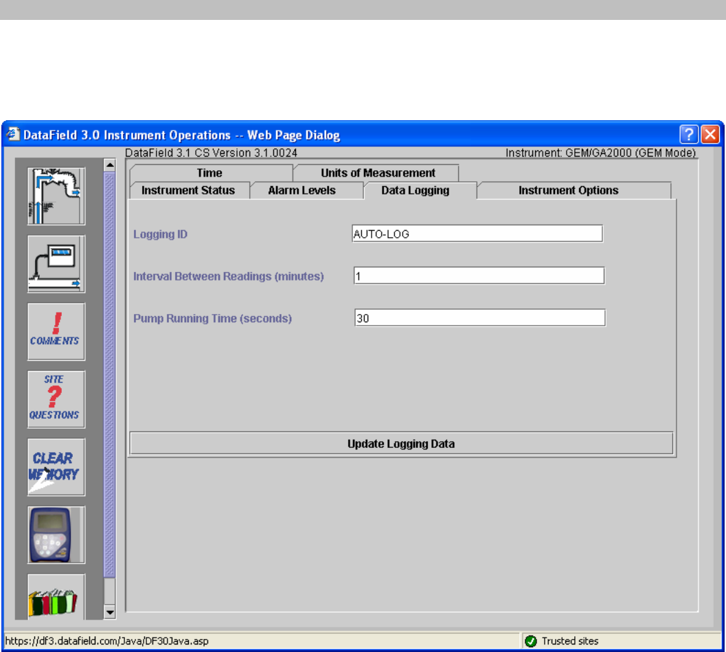
Click on the Data Logging card tab to open the data-logging screen. In this screen enter the Logging ID;
this may be any alphanumeric combination of eight characters. Enter the interval between readings in
minutes and pump run time in seconds. Click on Update Logging Data to send to instrument. Only one
logging ID may be loaded to the instrument.
GEM™2000 Operation Manual
Page 38
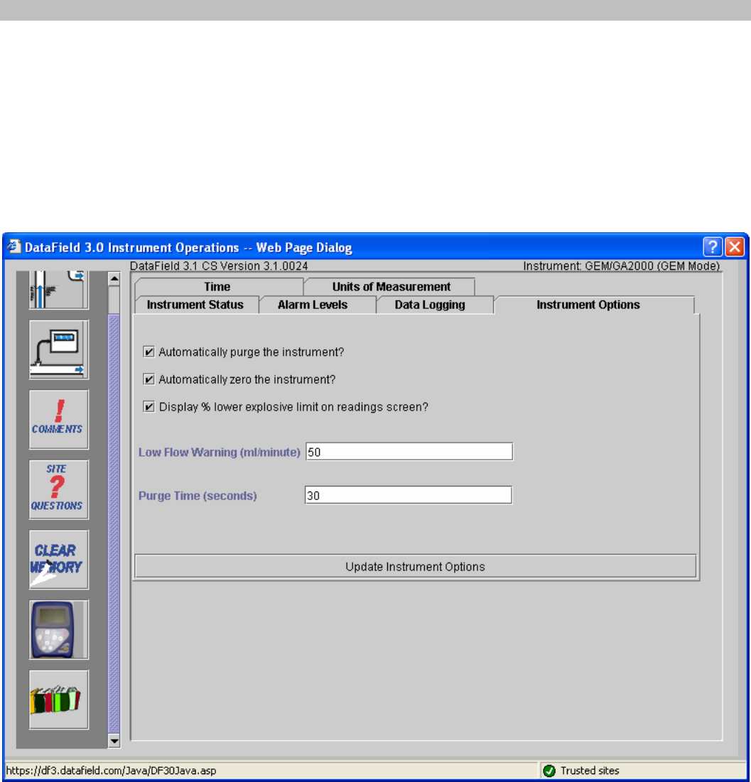
Click on the Instrument Options card tab to open the instrument options screen. The settings in this
screen affect different global functions of the instrument. Check the corresponding boxes in order to do the
following: automatically purge the instrument during a shut down, automatically zero the instrument, display
the percent lower explosive limit on readings screen. Unchecking the last feature will disable % LEL
display in both GA and GEM modes of operation. The Low Flow Warning setting controls the point at
which the pump is shut off due to low flow conditions. The default setting for this feature is 50 milliliters per
minute but may be set to a lower number or even to zero, if sampling on high vacuum systems. The default
value for the Purge Time is 30 seconds and may be reset to any length required. Turning off this feature is
not recommended. Click on the Update Instrument Options button to send the new settings to the
instrument.

GEM™2000 Operation Manual
Page 39
Click on the Time card tab to open the time and date setting screen. Time and date may be set to the
computer time and date settings by clicking on the Click to Retrieve the Computer’s Time and Date
button. Manual setting of the time and date may be accomplished by clicking on the Update Instrument
Time to Above Time and Date. Any time updates must be done through the software. The instrument
time can not be manually updated in the field.
GEM™2000 Operation Manual
Page 40
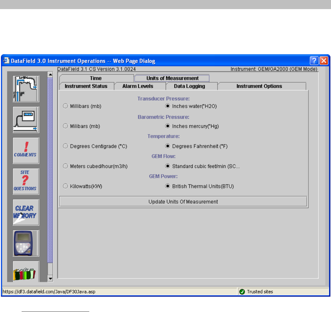
Units of Measurement screen allows the units to be changed.
This screen is protected by the password. If you need to change the units of measurement, please contact
our technical support team.
Note: EXTREME CAUTION should be taken if changing the Units of Measurement. All data from the
instrument should be downloaded and stored in both, the GEM and the GA modes before updating the
Units of Measurement. Updating Units of Measurement will erase readings from the instrument. The
instrument should be turned off and restarted once the units of measurement have been updated.
GEM™2000 Operation Manual
Page 41
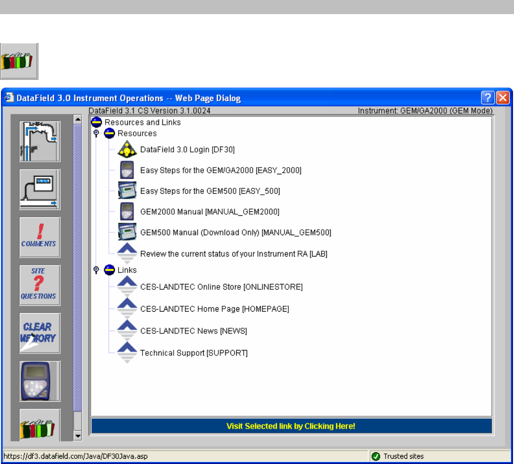
6.7.2 Resource Links
Clicking on the Resource Links button on the main screen will display the Resources and Links
screen.
By clicking on the supplied link the user is taken directly to the www and the information listed.

GEM™2000 Operation Manual
Page 42
7 Field Operations
7.1 Landfill Gas Generation
A brief overview of the theory of landfill gas generation and Methane recovery follows. Initially, when
decomposable refuse is placed into a solid waste landfill, the refuse is entrained with air from the
surrounding atmosphere. Through a natural process of bacterial decomposition, the Oxygen from the air is
consumed and an anaerobic (Oxygen free) environment is created within the landfill. This anaerobic
environment is one of several conditions necessary for the formation of Methane-CH4.
If Oxygen is reintroduced into the landfill, those areas are returned to an aerobic (Oxygen present) state and
the Methane-producing bacteria population are destroyed. A period of time must pass before the productive
capacity is returned to normal. Since there is some Methane of a given quality within the landfill void space,
a decline in Methane quality is only gradually apparent depending upon the size of the landfill.
Carbon Dioxide is also produced under either an aerobic or anaerobic condition. Under static conditions,
the landfill gas will be composed of roughly half Methane and half Carbon Dioxide with a little Nitrogen.
As air is introduced into the landfill, the Oxygen is initially converted to Carbon Dioxide and residual
Nitrogen remains. Measurement of residual Nitrogen is usually a good indicator of the anaerobic state of
the landfill; however, it cannot be directly measured. It can, however, be assumed and estimated using a
subtraction basis as the balance gas. Hence, the measurement of Carbon Dioxide is an intermediary step.
Because Carbon Dioxide levels may fluctuate depending on the changing concentrations of the other
constituent gases, Carbon Dioxide levels are not evaluated directly but are considered in light of other data.
In evaluation of residual Nitrogen, allowances must be made if there has been any air leakage into the gas
collection system or if there has been serious over pull. If enough air is drawn into the landfill, not all
Oxygen is converted into Carbon Dioxide and the Oxygen is apparent in the sample. It is ideal to perform
routine analysis of individual wells, as well as an overall well field composite sample, by a gas
chromatography. This is not always practical at every landfill.
Under some conditions there may be a small amount of hydrogen in the LFG, (about 1 percent, usually
much less). This may affect field monitoring response factors, but otherwise it can be ignored.
7.2 Subsurface Fires
If very large quantities of air are introduced into the landfill, either through natural occurrence or overly
aggressive operation of the LFG system, a partly unsupported subsurface combustion of the buried refuse
may be initiated. Subsurface fire situations are difficult to control or extinguish once started, present health
and safety hazards, and can be quite costly. Therefore, prevention by good operation of the collection
system and maintenance of the landfill cover is the best course of action. The presence of Carbon
Monoxide, Carbon Dioxide, and Hydrogen Sulphide are indicators of poorly supported combustion within
the landfill.

GEM™2000 Operation Manual
Page 43
7.3 Techniques for Controlling Landfill Gas
There are many techniques for controlling landfill gas extraction. These techniques represent tools, which
are used together to control landfill gas. The Accu-Flo wellhead is designed to work with all of these
techniques. Below is a discussion of the individual techniques, how to use them, and their limitations.
Reliance on only a few of the techniques discussed can lead to misinterpretation of field data and improper
operation of the well field. Later the best use of these techniques to optimize landfill gas control will be
discussed.
7.3.1 Controlling by Wellhead Valve Position
Unless the valve handle is calibrated for a given flow rate, this method is unreliable. The position of the
valve handle alone does not provide sufficient information about the well to control it. It is useful to note the
relative position of the valve, and essential to know which valves are fully open or fully closed.
7.3.2 Controlling by Wellhead Vacuum
This technique relies on the relationship of well pressure/vacuum to flow for a given well. Reliance upon
this method, however, can be misleading. This is because the square root relationship between flow and
pressure is difficult to affect while performing day-to-day well field adjustments. As decomposition,
moisture, and other conditions change, this method shows itself to be inadequate and imprecise.
7.3.3 Controlling by Gas Composition
This method determines Methane, Nitrogen (balance gas) and other gas composition parameters at
wellheads and at recovery facilities using portable field instruments and, sometimes, analytical laboratory
equipment. Complete knowledge of gas composition (i.e., major fixed gases: Methane, Carbon Dioxide,
Oxygen and Nitrogen) is desirable. It is also necessary to check other gas parameters, such as Carbon
Monoxide, to fully evaluate the condition of the well field. Reliance on this information can lead to improper
operation of the well field. Indications of excessive extraction often do not show up right away. This
method often leads to a cycle of damage to the Methane producing bacteria population and then to over-
correction. This cycling of the well and producing area of the landfill is not a good practice. It leads to
further misinterpretation of the condition of the well field and has a disruptive effect on the operation of the
well field. The use of analytical laboratory instrumentation such as a gas chromatograph is a valuable
supplementary tool to verify gas composition. This normally requires collection of samples at the wellhead
and analysis at some fixed location where the equipment is located. The drawbacks of this method as a
primary means of obtaining information for well field adjustment are the time expended, cost, and probably
most important, responsiveness to the needs of the well field for timely adjustment. The laboratory
equipment required is also very costly. Some analysis is recommended for verification of field readings
from time to time. It is recommended a monthly sample of the composite gas be taken at the inlet to the
flare or gas recovery facility.
7.3.4 Controlling by Flow Rate
This is a more exacting technique for determining and adjusting gas flow at individual wells. It requires
using a fixed or portable flow measurement device at each wellhead to obtain the data needed to calculate
volumetric (or mass) flow rates. It is normally convenient to use cubic feet per minute or per day, as a
standard unit of measure for volumetric flow. It is important to distinguish between the volumetric quantity
of landfill gas and the volumetric quantity of Methane extracted from each well and the landfill in total. The

GEM™2000 Operation Manual
Page 44
two variables are somewhat independent of each other and it is the total quantity of Methane extracted we
are interested in. It is possible for the total quantity of landfill gas extracted to increase while the total
quantity of Methane extracted decreases. To monitor this, the quantity of Methane extracted (LFG flow x
percent Methane) or the quantity of BTUs recovered per hour (LFG flow x percent Methane x BTUs per
cubic foot of Methane x 60 minutes per hour) can be calculated. It is conventional to measure BTUs per
hour as a unit of time. There are approximately 1012 BTUs of heat per cubic foot of pure Methane (like
natural gas), although this figure varies a little among reference texts.
Measuring flow is an essential part of monitoring and adjusting a well field. The well should be adjusted
until the amount of Methane recovered is maximized for the long term. A greater amount of Methane or
energy can usually be recovered over the short term; however, this ultimately leads to diminishing returns.
This is seen in stages as increased CO2 and gas temperature and later as increased Oxygen from well
over-pull. In time, the Methane will also decline. This is the result of a portion of the landfill, usually at the
surface, being driven aerobic. In this portion of the landfill, the Methane-producing bacteria will have been
destroyed (due to the presence of Oxygen). With the Methane-producing capacity of the landfill reduced,
the pore space in the area no longer producing may become filled with landfill gas equilibrating (moving in)
from an unaffected producing area. This leaves the impression that more gas can be recovered from this
area, and may lead to the operator opening the well or increasing flow.
7.4 Well field Monitoring
The frequency of LFG well field monitoring varies depending upon field requirements and conditions.
Normal monitoring frequency for a complete field monitoring session with full field readings (suggested
normal and abbreviated field readings list follows) will vary from typically once a month to once a week.
Well field monitoring should not normally be extended beyond one month. The importance of regular, timely
monitoring cannot be overemphasized.
7.5 Typical Field Readings
• Name of person taking readings
• Date/time of each reading
• Methane (CH4)
• Oxygen (O2)
• Carbon Dioxide (CO2)
• Balance Gas (primarily Nitrogen N2)
• Wellhead gas temperature (flowing)
• Ambient air temperature
• Static pressure (PS) (from GEM™2000 or magnehelic) or other device(anemometer/velometer)
• Velocity head (P or PT) (from GEM™2000 or pitot tube and magnehelic)
• Wellhead gas flow (from GEM™2000, or pitot tube & magnehelic, or anemometer/velometer)
• Wellhead adjustment valve position (initial and adjusted)
• New wellhead vacuum and flow information after adjustment
• Calculation of each well’s LFG and Methane flow and sum total
• Observations/comments
Additionally, Carbon Monoxide (CO) or Hydrogen Sulphide (H2S) readings may be taken if problems are
suspected. Supplementary monitoring once to several times a week may be performed using an
abbreviated form of field readings.

GEM™2000 Operation Manual
Page 45
7.6 Abbreviated Field Readings
• Name of person taking readings
• Date/time of each reading
• Methane (CH4)
• Oxygen (O2)
• Wellhead gas temperature (flowing)
• Ambient air temperature
• Static pressure (PS) (from GEM™2000 or magnehelic)
• Velocity head (P or Pt) (from GEM™2000 or pitot tube and magnehelic)
• Wellhead gas flow (from GEM™2000, or pitot tube and magnehelic, or anemometer/velometer)
• Wellhead adjustment valve position (initial and adjusted)
• New wellhead vacuum and flow information after adjustment
• Observations/comments
Line vacuums and gas quality may be taken at key points along the main gas collection header and at
subordinate branches. This helps to identify locations of poor performance, excessive pressure drop, or
leakage. Perform systematic monitoring of the well field, taking and logging measurements at each
wellhead and major branch junction in the collection system.
During monitoring, examine landfill and gas collection system for maintenance issues. Record needed
maintenance or unusual conditions. Examples of unusual occurrences or conditions are unusual settlement,
signs of subsurface fires, cracks and fissures, liquid ponding, condensate/leachate weeping from side
slopes, surface emissions and hot spots, and liquid surging and blockage in the gas collection system.
Field readings should be kept in a chronological log and submitted to management on a timely basis.
7.7 Well field Adjustment Criteria
There are several criteria used in well field adjustment. The primary criterion is Methane quality. Methane
quality is an indicator of the healthy anaerobic state of the landfill and thus proper operation of the LFG
collection system. However, a decline in the healthy productive state of the landfill is usually not
immediately apparent from Methane quality. Due to this, several criteria must be considered at once.
Conditions within the landfill favor Methane production. Following are well field adjustment criteria and
typical conditions for consideration:
• Methane quality (ranging from 26 percent upwards)
• pH
• Temperature
• General overall quality
• Moisture conditions
• Waste stream characteristics
• Placement chronology
• Insulation characteristics
• Oxygen quality (ranging below 1 percent, preferably less then ½ percent)
• Landfill cover porosity and depth in the proximity of the well
• Landfill construction factors including:
• Type of fill
• Size and shape of refuse mass
• Depth of fill

GEM™2000 Operation Manual
Page 46
• Compaction
• Leachate control methods
• Seasonal, climatic, geographical, and recent weather, or other considerations, including
seasonally arid or wet conditions, precipitation, drainage, groundwater
• Surrounding topography and geologic conditions
• Proximity of the well to side slopes (within 150 to 200 feet and less may require conservative
operation of the well)
• Nitrogen (typically 8 to 12 percent and less)
• Temperature (between ambient and about 130 °F)
• LFG and Methane flow from the wellhead
• Design of the gas collection system
• Landfill perimeter gas migration and surface emission control, or energy recovery objectives
• Diurnal fluctuation (day to night) of atmospheric pressure
7.8 Establishing Target Flows
The goal is to establish a target flow which will likely produce the best possible Methane quality and
minimum Oxygen levels while maximizing the recovery of landfill gas. Typically, small adjustments are
made in flow to achieve and maintain quality objectives. The well must not be allowed to over pull. High
well temperatures, (130° to 140°F and greater), are an indication of aerobic activity and, thus, well over-pull.
These effects may not be immediately apparent.
Well adjustment should be made in as small an increment as possible, preferably an increment of ten
percent of the existing flow or less. There may be obvious conditions when this is not appropriate, such as
when first opening up a well or when serious over-pull is recognized. Every effort should be made to make
adjustments and operations as smooth as possible. Dramatic adjustments, or operating while switching
between a high flow mode and a well shutoff mode, should be avoided.
7.9 Well field Optimization
Every effort should be made to continuously locate and correct or eliminate conditions (e.g., gas
condensate, surging and blockage, settlement, etc.), which inhibit efficient operation of the gas collection
system. This allows well monitoring and adjustment to be significantly more effective.
7.10 Migration Control—Dealing with Poor Methane Quality
If Methane and Oxygen quality objectives cannot be maintained at a given well, such as a perimeter
migration control well, then an attempt should be made to stabilize the well as closely as is practical,
avoiding significant or rapid down trending of Methane or up trending of Oxygen.
It is not uncommon for perimeter migration control wells to be operated at less than 40 percent Methane or
greater than one-percent Oxygen. It should be recognized that these wells are likely in a zone where some
aerobic action is being induced, and that there is some risk of introducing or enhancing the spread of a
subsurface fire. Sometimes a judicious compromise is necessary to achieve critical migration control
objectives or because existing conditions do not allow otherwise. Such situations should be monitored
closely.

GEM™2000 Operation Manual
Page 47
7.11 Well field Adjustment—Purpose and Objectives
The objective of well field adjustment is to achieve a steady state of operation of the gas collection system
by stabilizing the rate and quality of extracted LFG in order to achieve one or several goals. Typical
reasons for recovery of LFG and close control of the well field are:
• Achieve and maintain effective subsurface gas migration control.
• Achieve and maintain effective surface gas emissions control.
• Assist with proper operation of control and recovery equipment.
• Avoid well “over-pull” and maintain of a healthy anaerobic state within the landfill.
• Optimize LFG recovery for energy recovery purposes.
• Control nuisance landfill gas odors.
• Prevent or control subsurface LFG fires.
• Protect structures on and near the landfill.
• Meet environmental and regulatory compliance requirements.
Well field adjustment is partly subjective and can be confusing because it involves judgment calls based on
simultaneous evaluation of several variables, as well a general knowledge of site specific field conditions
and historical trends. Well field evaluation and adjustment consist of a collection of techniques, which may
be used, in combination, to achieve a steady state of well field operation.

GEM™2000 Operation Manual
Page 48
8 Troubleshooting
Unit does not turn on or operation is erratic Battery charge is too low-recharge batteries.
Unit is too hot - cool down unit and try again.
Contact Factory Service.
“Flow Fail” is displayed and an audible alarm
is heard
The inlet is blocked.
Remove blockage and retry.
The particulate filter or water trap filter needs replacing.
Readings taken are not what was expected Unit may be out of calibration. Calibrate unit with
known gas concentration.
Water trap or particulate filters are clogged. Replace
filter(s).
Unit displays***** or >>>>> These symbols are substituted when the measured
reading is out of range of the instruments capabilities in
some fields or when a value needs to be entered
manually such as temperature.
Oxygen reading is high on all wells Check that the water trap housing is screwed on tight.
Check or replace O-rings on the water trap and
instrument inlet.
Check the wellhead inset for cracks, replace O-ring on
insert.
Field calibrate Oxygen channel.
Unit will not download readings or an error
occurs while downloading.
Verify that the communications software is the right
version for the instrument being used.
Check that the proper serial port is selected in the
software.
Contact Factory Service.
Methane and Carbon Dioxide readings drift Perform a field calibration and check well again. Verify
cal gas is flowing when regulator is turned on.
Verify all connections are tight and filters are not
clogged.
Contact Factory Service.
Oxygen readings drift Perform a field calibration - zero and span.
Contact Factory Service.
Black screen displayed when unit turned On Charge unit over night and try again.
Unit too hot - cool down and try again.
Try adjusting contrast level.
Contact Factory Service.
Nothing happens when the Gas Pod is
installed
Remove and re-seat the Gas Pod.
Contact Factory Service.
Temperature does not update when
temperature probe is installed
Check the probe fitting is fully seated.
Check the probe plug is screwed together tightly.
Contact Factory Service.
Problem Corrective Action/Reason

GEM™2000 Operation Manual
Page 49
9 Technical Specifications
9.1 Physical
Weight 4.4 lbs.
Size L 2.48” x W 7.48’’ x D 9.92”.
Case material Anti-static ABS.
Keys Membrane panel.
Display Liquid Crystal Display 40 x 16 characters. Fibre optic woven
backlight for low light conditions.
Filters User replaceable integral fibre filter at inlet port and an external
PTFE water trap filter.
9.2 General
Certifications UL Certified to Class 1, Zone 1, AEx Ib d IIa T4
Temperature measurement With optional probe 14°F to 167°F.
Temperature accuracy ±0.4ºF (± probe accuracy).
Visual and audible alarm User selectable CO2, CH4 and O2 Min/Max levels via DataField
CS software.
Communications RS232 protocol via download lead with variable baud rate.
Relative pressure ±250 mbar from calibration pressure
9.3 Power supply
Battery type Rechargeable Nickel Metal Hydride battery pack containing six
4AH cells. Not user replaceable.
Lithium Manganese battery for data retention.
Battery life Typical use 10 hours from fully charged condition.
Battery charger Separate intelligent 2A battery charger powered from AC
voltage supply (110-230V).
Charge time Approximately 2 hours from complete discharge.
Alternative power Can be powered externally for fixed-in-place applications only.
Contact CES-LANDTEC for further information.
Battery lifetime Up to 1,000 charge/discharge cycles.
9.4 Gas Ranges
Detection principle CO2 and CH4 by dual wavelength infrared cell with reference
channel.
O2 by internal electrochemical cell.
Oxygen cell lifetime Approximately 18 months in air.
Typical Accuracy
0 - Full Scale
Gas 0-5% volume 5-15% volume 15%-FS
CH4 ±0.5% ±1% ±3% (100%)
CO2 ±0.5% ±1% ±3% (60%)
O2 ±1% ±1% ±1% (21%)
Response time, T90 CH4 ≤20 seconds
CO2 ≤20 seconds
O2 ≤20 seconds
Range CH4 0-70% to specification, 0-100% reading.
CO2 0-40% to specification, 0-100% reading.
O2 0-25%
GEM™2000 Operation Manual
Page 50
9.5 Pump
Typical flow 300 cc/min.
Flow fail point 50 cc/min approximately.
Flow with 200 mbar vacuum 250 cc/min approximately.
Vacuum 70 inches H20.
9.6 Operating Conditions
Operating temp range 32°F to 104°F.
Relative humidity 0-95% non-condensing.
Atmospheric pressure range 700-1200 mbar.
Displayed in Inches of Mercury (5.9 – 35.4“Hg).
Not corrected for sea level.
Atmospheric pressure accuracy ±5 mbar approximately.
Case seal IP65.
9.7 Optional Gas Pods
Typical Accuracy
(Subject to User calibration).
Gas 0-Full Scale
CO ±10% FS
H2S ±10% FS
SO2 ±10% FS
NO2 ±10% FS
CL2 ±10% FS
H2 ±10% FS
HCN ±10% FS
Response time, T90 CO ≤60 seconds
H2S ≤60 seconds
SO2 ≤60 seconds
NO2 ≤60 seconds
CL2 ≤60 seconds
H2 ≤60 seconds
HCN ≤60 seconds
Range CO 0-500ppm
H2S 0-50 or 0-200ppm
SO2 0-20 or 0-100ppm
NO2 0-20ppm
CL2 0-20ppm
H2 0-1000ppm
HCN 0-100ppm
