GE Dryer 31 9136
2013-04-09
: Pdf Ge Dryer 31-9136 GE Dryer 31-9136 GE, Camco, Hotpoint, Mofat
Open the PDF directly: View PDF ![]() .
.
Page Count: 50
GE Appliances
General Electric Company
Louisville, Kentucky 40225
31-9136
GE Dryer
DBVH512
DCVH515
DHDVH52
Technical Service Guide
DECEMBER 2005
GE Consumer & Industrial

– 2 –
IMPORTANT SAFETY NOTICE
The information in this service guide is intended for use by
individuals possessing adequate backgrounds of electrical,
electronic, and mechanical experience. Any attempt to repair a
major ap pli ance may result in personal injury and property
damage. The man u fac tur er or seller cannot be responsible for the in ter pre ta tion
of this in for ma tion, nor can it assume any liability in connection with its use.
WARNING
If the information in this manual is not followed exactly, fi re or ex plo sion may
result causing property damage, personal injury or death. If you smell gas:
– Do not try to light any appliance.
– Do not touch any electrical switch; do not use any phone in the
building.
– Immediately call the gas supplier from a neighbor’s phone. Follow the
gas supplier’s instructions.
– If you cannot reach the gas supplier, call the fi re department.
WARNING
To avoid personal injury, disconnect power before ser vic ing this prod uct. If
electrical power is required for di ag no sis or test pur pos es, disconnect the power
immediately after per form ing the nec es sary checks.
RECONNECT ALL GROUNDING DEVICES
If grounding wires, screws, straps, clips, nuts, or washers used to complete a
path to ground are removed for service, they must be returned to their original
position and properly fastened.
GE Consumer & Industrial
Technical Service Guide
Copyright © 2005
All rights reserved. This service guide may not be reproduced in whole or in part in
any form without written permission from the Gen er al Electric Com pa ny.
– 3 –
Airfl ow ....................................................................................................................................................................................23
Air Duct Assembly ............................................................................................................................................................42
Belt Switch ...........................................................................................................................................................................34
Blower Housing ..................................................................................................................................................................34
Component Locator Views ...........................................................................................................................................24
Control Board Assembly ...............................................................................................................................................44
Control Panel ......................................................................................................................................................................28
Control Features ...............................................................................................................................................................6
Cycle Options ......................................................................................................................................................................9
Door Switch .........................................................................................................................................................................42
Drive Belt ...............................................................................................................................................................................29
Drum .......................................................................................................................................................................................30
Drum Shaft Bearing .........................................................................................................................................................31
Drum Slide Assembly ......................................................................................................................................................41
Dryer Components ..........................................................................................................................................................28
Dryer Features ...................................................................................................................................................................11
Error Codes ..........................................................................................................................................................................47
Flame Detector ..................................................................................................................................................................37
Front Panel ........................................................................................................................................................................... 29
Gas Valve .............................................................................................................................................................................35
Gas Valve Coil Assembly ...............................................................................................................................................36
Heater Assembly ...............................................................................................................................................................35
High Limit Thermostat ....................................................................................................................................................40
Idler Assembly ....................................................................................................................................................................31
Ignitor .....................................................................................................................................................................................37
Ignitor Circuit Operation ................................................................................................................................................38
Inlet Control Thermistor .................................................................................................................................................39
Inlet Safety Thermostat .................................................................................................................................................39
Introduction .........................................................................................................................................................................5
LP Conversion .....................................................................................................................................................................36
Moisture Sensor ................................................................................................................................................................43
Motor and Blower Wheel Assembly ......................................................................................................................... 32
Nomenclature ....................................................................................................................................................................4
Operation Overview .........................................................................................................................................................22
Outlet Control Backup Thermostat ........................................................................................................................... 41
Outlet Control Thermistor .............................................................................................................................................40
Pedestal Installation (Washer and Dryer) ..............................................................................................................16
Power Board ........................................................................................................................................................................43
Reversing the Door Swing ............................................................................................................................................12
Schematics and Wiring Diagrams ............................................................................................................................ 48
Service Test Mode .............................................................................................................................................................45
Stacking Instructions ......................................................................................................................................................19
Top Panel ..............................................................................................................................................................................28
Warranty ..............................................................................................................................................................................50
Table of Contents
– 4 –
Nomenclature
The letter des ig nat ing
the year re peats every
12 years.
Example:
T - 1974
T - 1986
T - 1998
Serial Number
The fi rst two characters of the serial number
identify the month and year of manufacture.
Example: AH123456S = January, 2005
A - JAN 2005 - H
D - FEB 2004 - G
F - MAR 2003 - F
G - APR 2002 - D
H - MAY 2001 - A
L - JUN 2000 - Z
M - JUL 1999 - V
R - AUG 1998 - T
S - SEP 1997 - S
T - OCT 1996 - R
V - NOV 1995 - M
Z - DEC 1994 - L
The nomenclature tag is lo cat ed on
the front panel inside the door.
Note: The technical sheet is located
inside the control panel.
Model Number
Capacity/Confi guration
V = Very Big
D C V H 5 1 5 E F 0 W W
Brand
D = General Electric
Feature Packages
B = Base
C = Contract/HPS
HD = Brand Feature Pack
Backsplash Control/Platform
H = Horizontal
Color
WW - White
GG - Granite
Engineering Revision
Alpha or Numeric
Model Year
F - 2005
G - 2006
H - 2007
J - 2008
K - 2009
Fuel/Voltage
E = 220V/208V 60 Hz.
G = Gas 120V 60Hz.
Nomenclature
Control
Features
– 5 –
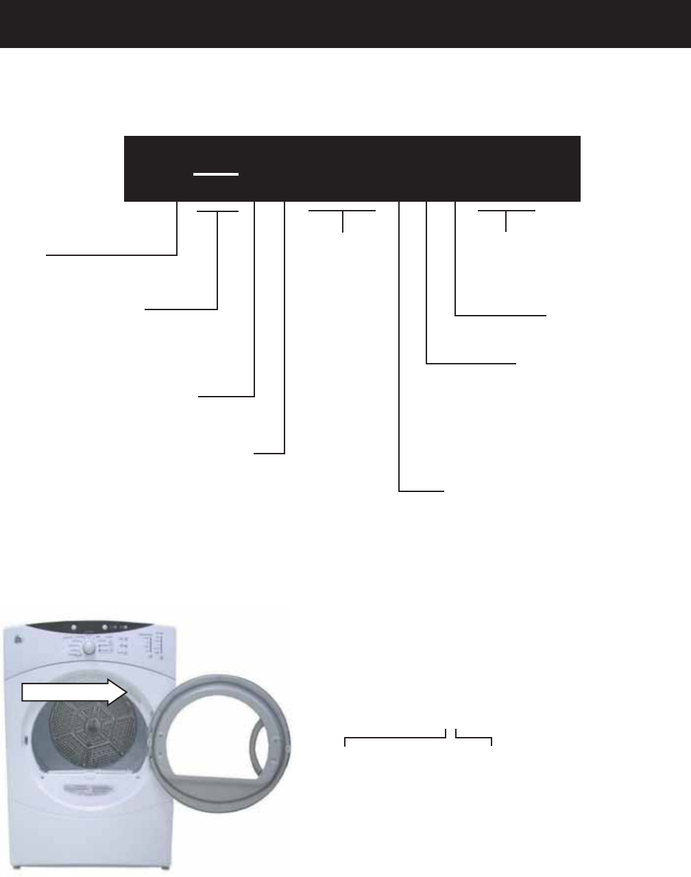
The new GE dryer has the following features:
Large 7.0-cubic foot dryer drum
Drying Rack - Available on some models, for drying delicate items such as washable sweaters.
Drum Lamp
My Cycle selection saves a favorite cycle for future use.
Built-in service test mode. Specifi c dryer components can be operated. Error codes are recorded and
accessible on the control panel's 7-segment display.
Dual Thermistors - Thermistors are more sensitive to temperature changes and can relay the
information faster than thermostats. The dryer utilizes dual thermistors to monitor incoming air
temperature as well as air temperature leaving the drum. The sensors work together with the variable
heater and the blower to provide consistent, even heat.
Moisture Sensor - The moisture sensor allows the control to monitor the fabric for moisture content and
end the cycle at the desired moisture level.
Flush Door Handle
Reversible Door
UV Stabilizers - The control panel, control panel cover, and door outer panel have UV stabilizers to
prevent yellowing when exposed to sunlight.
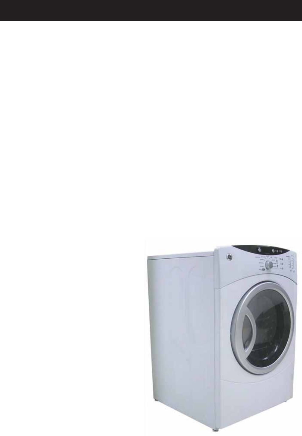
The GE dryer can be installed on top of the GE
Front Load Washer. (Stacking kit supplied with
washer.)
Pedestal available at additional cost. White
(model number SBSD227FWW) and granite
(model number SBSD227FGG).
•
•
•
•
•
•
•
•
•
•
•
•
Introduction
– 6 –
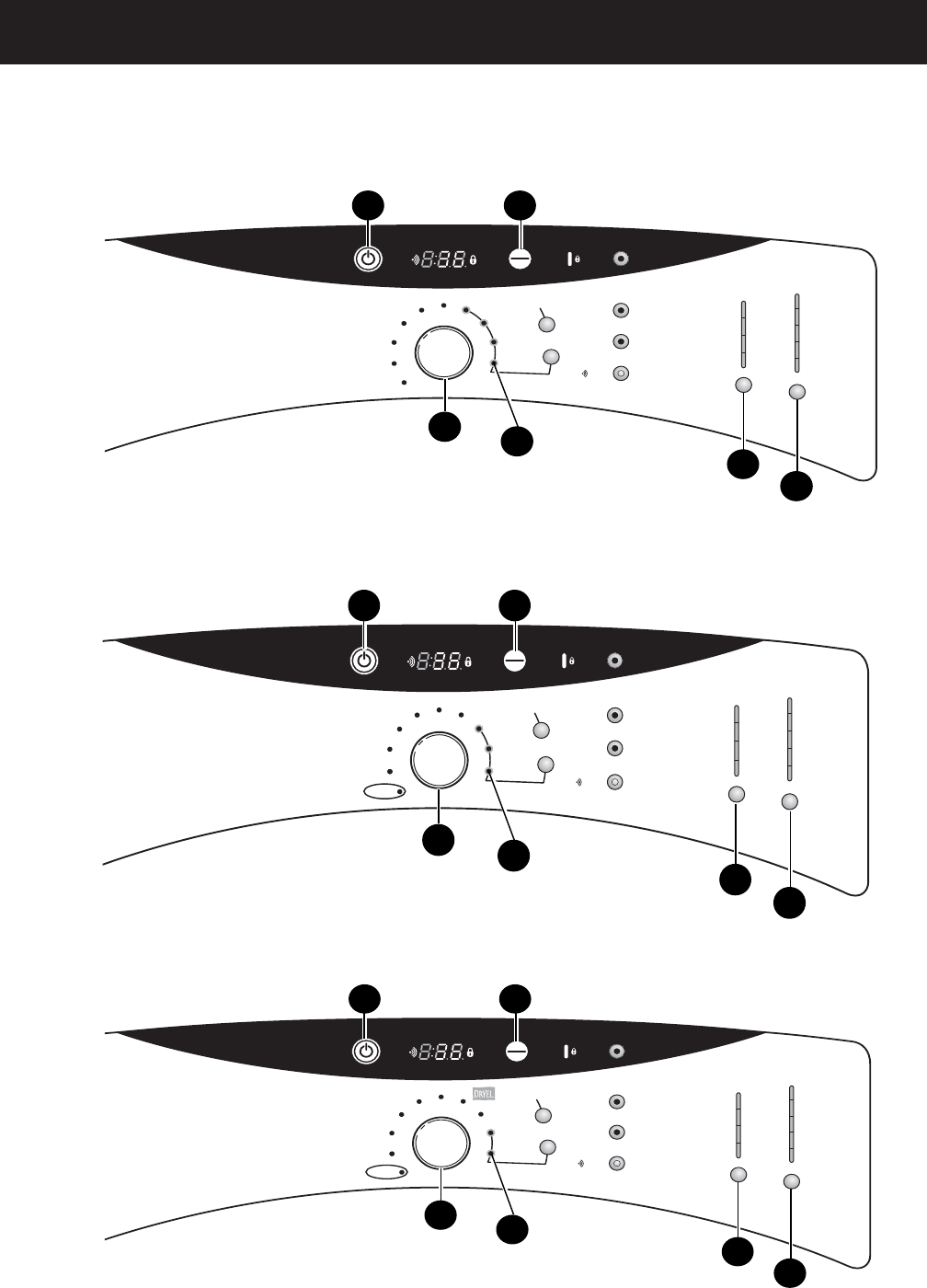
Control Features
(Continued Next Page)
D
ELAY
S
TART
H
OLD
3 S
EC
TO
L
OCK
C
ONTROL
S
TART
P
AUSE
E
STIMATED
T
IME
R
EMAINING
DELAY CLEAN LINT FILTER
DRYING DAMP COOL DOWN
P
OWER
ADJUST
TIME
T
IME
D
RY
A
CTIVE
W
EAR
S
ENSOR
D
RY
E
AST
C
ARE
M
IXED
L
OAD
C
OTTONS
T
IMED
D
RY
(NO HEAT)
A
IR
F
LUFF
S
PEED
D
RY
D
EWRINKLE
D
ELICATES
H
OLD
3 S
EC
TO
S
TORE
M
Y
C
YCLE
E
XTEND
T
UMBLE
D
AMP
A
LERT
S
IGNAL
M
ORE
D
RY
D
RY
L
ESS
D
RY
D
AMP
SENSOR DRY LEVEL
M
EDIUM
H
IGH
L
OW
E
XTRA
L
OW
A
NTI-
B
ACTERIAL
D
RY
T
EMP
1
5
34
6
2
Model DCVH515
P
OWER
S
TART
P
AUSE
ADJUST
TIME
T
IME
D
RY
A
CTIVE
W
ARE
S
ENSOR
D
RY
E
AST
C
ARE
M
IXED
L
OAD
C
OTTONS
T
IMED
D
RY
D
EWRINKLE
S
PEED
D
RY
D
ELICATES
HOLD 3 SEC
TO STORE
M
Y
C
YCLE
HOLD 3 SEC
TO LOCK
CONTROL
D
ELAY
S
TART
E
XTEND
T
UMBLE
D
AMP
A
LERT
S
IGNAL
M
ORE
D
RY
D
RY
L
ESS
D
RY
D
AMP
S
ENSOR
D
RY
L
EVEL
M
EDIUM
H
IGH
L
OW
E
XTRA
L
OW
(TIMED DRY)
N
O
H
EAT
D
RY
T
EMP
E
STIMATED
T
IME
R
EMAINING
DELAY CLEAN LINT FILTER
DRYING DAMP COOL DOWN
1
5
34
6
2
Model DHDVH52
6
D
ELAY
S
TART
HOLD 3 SEC
TO LOCK
CONTROL
S
TART
P
AUSE
E
STIMATED
T
IME
R
EMAINING
DELAY CLEAN LINT FILTER
DRYING DAMP COOL DOWN
P
OWER
ADJUST
TIME
TIME DRY
T
IMED
D
RY
(NO HEAT)
A
IR
F
LUFF
D
EWRINKLE
W
ARM
U
P
S
PEED
D
RY
D
ELICATES
A
CTIVE
W
EAR
E
AST
C
ARE
M
IXED
L
OAD
C
OTTONS
SENSOR DRY
E
XTEND
T
UMBLE
D
AMP
A
LERT
S
IGNAL
M
ORE
D
RY
D
RY
L
ESS
D
RY
D
AMP
S
ENSOR
D
RY
L
EVEL
M
EDIUM
H
IGH
LOW
E
XTRA
L
OW
A
NTI-
B
ACTERIAL
D
RY
T
EMP
1
5
34
6
2
Model DBVH512

– 7 –
1
2
Power
Press to “wake up” the display. If the display is active, press to put the dryer in the standby mode.
NOTE: Pressing POWER does not disconnect the appliance from the power supply.
Dry Cycles
The dry cycle controls the length and tumble speed of the drying process. The chart below will
help you match the dry setting with the loads.
Sensor Cycles
COTTONS For cottons and most linens.
MIXED LOAD For loads consisting of cottons and poly-blends.
EASY CARE For wrinkle-free and permanent press items.
ACTIVE WEAR Clothing worn for active sports exercise and some casual wear. Fabrics include new technology finishes
and stretch fibers such as Spandex.
DELICATES For lingerie and special-care fabrics.
DRYEL™Designed for use with the DRYEL™“dry clean only” fabric care system. See product package for directions.
For questions or issues related to use and performance of DRYEL™, see the Website at: www.dryel.com.
SPEED DRY For small loads that are needed in a hurry, such as sports or school uniforms. Can also be used if the
previous cycle left some items damp, such as collars or waistbands.
Timed Dry Cycles
DEWRINKLE For removing wrinkles from items that are dry or slightly damp. This cycle is not recommended for
delicate fabrics.
WARM UP Provides 10 minutes of warming time to warm up clothes.
AIR FLUFF Use this feature to tumble items without heat.
My Cycle (on some models)
MY CYCLE Press to use, create or modify custom dry cycles.
Timed Dry
Use to set your own dry time. TIMED DRY is also recommended for small loads.
To use TIMED DRY:
1. Turn dry cycle dial to TIMED DRY.
2. Select the drying time by pressing the +and –buttons.
3. Select the DRY TEMP.
4. Close the door.
5. Press START.
Sensor Dry Level
The sensor continuously monitors the amount of moisture in the load. When the moisture in your
clothes reaches your selected dry level, the dryer will stop.
MORE DRY Use for heavy or mixed type of fabrics.
DRY Use for normal dryness level suitable for most loads. This is the preferred cycle
for energy saving.
LESS DRY Use for lighter fabric (ideal for ironing).
DAMP For leaving items partially damp.
3
4
(Continued Next Page)
– 8 –
Dry Temp
You can change the temperature of your dry cycle.
ANTI-BACTERIAL This option may only be used with COTTONS or MIXED LOAD cycles. This option reduces certain
types of bacteria by 99.9%, including: Staphylococcus aureus, Pseudomonas aeruginosa and Klebsiella
pneumoniae*. The anti-bacterial process occurs when high heat is used during a portion of this
drying cycle.
NOTE: Do not use this cycle on delicate fabrics.
* The Anti-Bacterial Cycle is Certified by NSF International (formerly National Sanitation Foundation)
to NSF Protocol P154 Sanitization Performance of Residential Clothes Dryers.
HIGH For regular to heavy cottons.
MEDIUM For synthetics, blends and items labeled permanent press.
LOW For delicates, synthetics and items labeled Tumble Dry Low.
EXTRA LOW For lingerie and special-care fabrics.
NO HEAT Can only be used with TIMED DRY.
START
Press to start a dry cycle. If the dryer is running, press it once and it will pause the dryer.
Press it again to restart the dry cycle.
My Cycle (on some models)
Set up your favorite combination of settings and save them here for one touch recall.
These custom settings can be set while a cycle is in progress.
To store a MY CYCLE combination of settings:
1. Select your drying cycle.
2. Change DRY TEMP and SENSOR DRY LEVEL settings to fit your needs.
3. Select any drying OPTIONS you want.
4. Press and hold the pad for three seconds to store your selection. A beep will sound
and the pad will light up.
To recall your stored MY CYCLE combination:
Press the MY CYCLE button before drying a load.
To change your stored MY CYCLE combination:
Follow steps 1–4 in “To store a MY CYCLE combination of settings”.
MYCYCLE
5
6
– 9 –
Extend Tumble
Minimizes wrinkles by adding
approximately 60 minutes of no-heat
tumbling after clothes are dry. The beeper
will sound every 2 minutes to remind you
to remove the clothes. The ESTIMATED
TIME REMAINING display will show 00.
Damp Alert
This option causes the dryer to beep when
clothes have dried to a damp level. Remove
items that you wish to hang dry. The DAMP
ALERT will only beep when this option
is selected.
Removing clothes and hanging them when
they are damp can reduce the need to iron
some items.
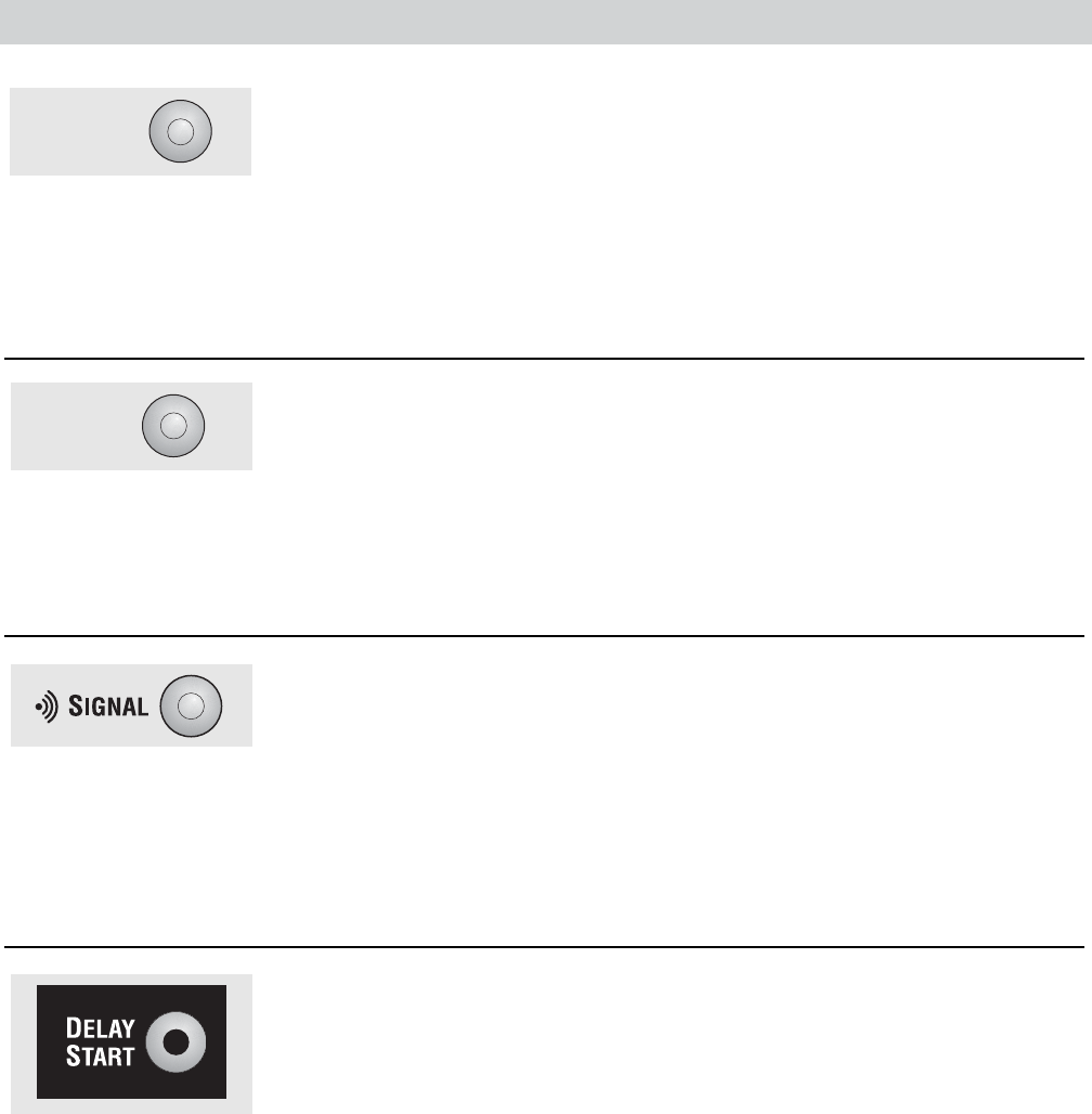
Signal
Alerts you that the cycle is complete. The
beeper will continue to sound every two
minutes for the next 6 minutes, until the
clothes have been removed. The clothes
should be removed when the beeper goes
off so wrinkles don’t set in.
Press SIGNAL to select low, medium or high
volume, or to turn the beeper off.
Delay Start
Use to delay the start of your dryer.
1. Choose your dry cycle and any options.
2. Press DELAY START. You can change the
delay time in 1 hour increments using
the +or –arrow pads.
3. Press the START pad to start the
countdown.
The countdown time will be shown in the
ESTIMATED TIME REMAINING display.
NOTE: If the door is opened while the dryer is
in DELAY, the countdown time will not restart
unless the door is closed and START has been
pressed again.
DAMP
ALERT
EXTEND
TUMBLE
(Continued Next Page)
Cycle Options

– 10 –
Lock
You can lock the controls to prevent any
selections from being made. Or you can
lock the controls after you have started
a cycle.
Children cannot accidentally start the dryer
by touching pads with this option selected.
To lock the dryer, press and hold the lock
icon for 3 seconds. To unlock the dryer,
press and hold the lock icon for 3 seconds.
The icon of the lock next to the timer will
light up when the controls are locked.
H
OLD
3 S
EC
TO
S
TORE
M
Y
C
YCLE
My Cycle (on some models)
To save a favorite cycle, set the desired
settings and hold down the MY CYCLE
button for 3 seconds. A beep will sound
to indicate the cycle has been saved.
To use your custom cycle, press the MY
CYCLE button before drying a load.
To change the saved cycle, set the desired
settings and hold down the MY CYCLE
button for 3 seconds.
See page 8 for more details.
DELAY CLEAN LINT FILTER
DRYING DAMP COOL DOWN
Estimated Time Remaining
Displays the approximate time remaining
until the end of the cycle.
As the cycle begins, you will see an initial
approximate total cycle time in the display.
Then lights will “race” in the display. This
means the dryer is continuously monitoring
the amount of moisture in the load. The
lights will continue until the dryer senses
a low level of moisture in the load. At that
point, the dryer will calculate and display
the approximate time remaining.
– 11 –
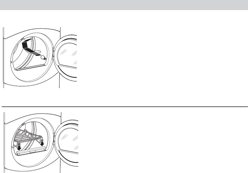
Drying Rack (on some models)
A handy drying rack may be used for drying delicate items such as
washable sweaters. Place items flat on the drying rack and block such
items as wool sweaters and delicate fabrics. Dry with low heat.
To install the drying rack, pull up the lint filter slightly. Insert the drying
rack into the slots, then push the filter back down.
NOTE:
■The drying rack must be used with the TIMED DRY or RACK DRY
(on some models) cycles.
■Do not use this drying rack when there are other clothes in the dryer.
Drum Lamp
Before replacing the light bulb, be sure to unplug the dryer power cord or
disconnect the dryer at the household distribution panel by removing the
fuse or switching off the circuit breaker. Reach above dryer
opening from
inside the drum. Remove the
bulb and replace with the same size bulb.
Dryer Features
– 12 –
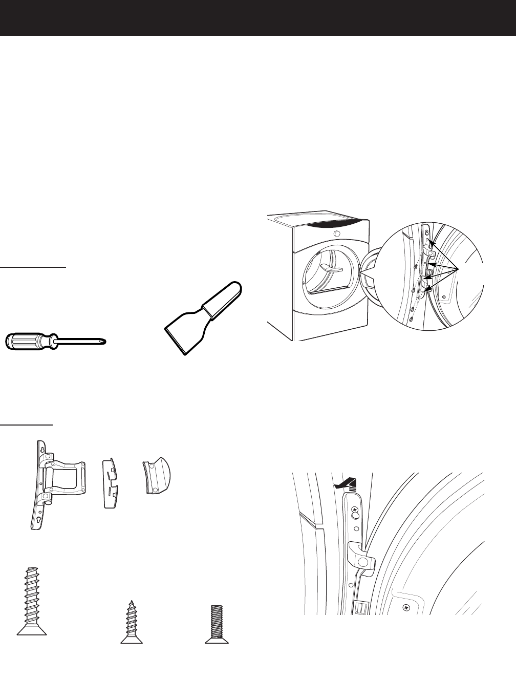
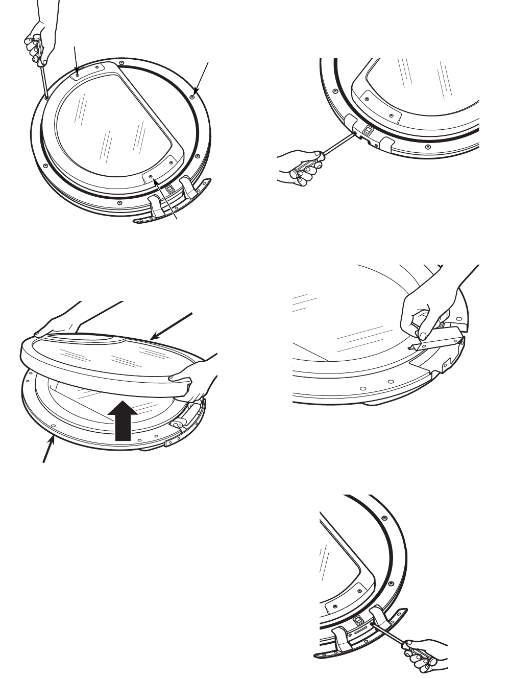
Reversing the Door Swing
When viewed from the front, the dryer is shipped
so the door opens from the left. Due to utility
confi gurations or customer preferences, the door
can be set up to open from the right by reversing
the door swing.
Note: These instructions are for changing the dryer
so the door opens from the right side. To change the
door back so that it opens from the left side, follow
these same instructions and reverse all references
to left and right.
Remove the
four screws.
Note: To ease removal of the door, the hinge has a
keyhole that allows a partially loosened screw to be
used as a hook.
Loosen the top Phillips-head screw, then lift and
unhook the door from the front panel. Remove
the top screw.
3.
To reverse the door swing:
Unplug the dryer from its electrical outlet.
Open the door to approximately 90 degrees.
Starting from the bottom to the top, remove the
bottom 4 Phillips-head screws from the hinge.
Note: Make sure the door is supported while
removing the screws.
1.
2.
Phillips Head
Screwdriver
Putty Knife or Thin-
Blade Screwdriver
Tools Needed
Hinge
Assembly
Hinge
Cover
Window
Retainer
Large Tapping
Screw (#10) – 6
Tapping
Screw (#8) – 2
Machine
Screw (#8) – 6
Door Parts
Lay the door on a soft protected fl at surface so
that the inside faces upward (door resting on the
handle side).
4.
(Continued Next Page)
– 13 –
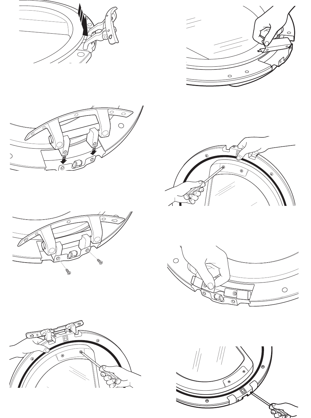
Remove the 6 large tapping screws (#10) located
around the perimeter of the door outlining the
gasket and the 4 machine screws (#8).
5.
6 #10 Large
Screws
2 #8 Machine
Screws
2 #8 Machine
Screws
IMPORTANT: Note the location of the hinge (left or
right) before removing.
Note: The hinge cover is located at the opposite side
of the hinge assembly.
Turn the door over. Remove the 2 (#8) tapping
screws and the hinge cover from the frame.
7.
Remove the window retainer located on the side
opposite the hinge assembly and underneath
the plastic cover.
8.
Turn the door over, separate the door cover
from the door frame and set the cover aside.
6.
Door Frame
Door Cover
Remove the 2 (#8) machine screws that attach
the hinge assembly to the side of the door
frame. Pull the hinge assembly out of the
opening in the door.
9.
(Continued Next Page)
– 14 –
Insert the hinge assembly in the opening on the
opposite side of the door.
10.
Push the hinge assembly into place until the
hinge holes align with the door frame holes.
11.
Install the 2 (#8) machine screws that attach the
hinge assembly to the side of the door frame.
12.
Hold the door on its side with one hand and
install 2 (#8) machine screws that secure the
hinge assembly to the door frame.
13.
Place the door fl at and insert the window
retainer. Align the window retainer holes with
the holes in the door frame.
14.
Place the door on its edge. Install the remaining
2 (#8) machine screws that attach the window
retainer to the door frame.
15.
Insert and align the hinge cover with the holes in
the door frame.
16.
Install the 2 (#8) tapping screws that attach the
hinge cover to the door frame.
17.
(Continued Next Page)
– 15 –
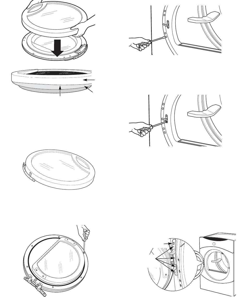
After reversing the door, there will be a mismatch
between the door cover and door frame.
Make sure that the handle part of the door cover is
opposite the hinge as shown.
Turn the door over. Install the 6 (#10) tapping
screws that attach the door cover to the door
frame.
19.
Using a putty knife or fl at tool, remove the
5 plastic screw caps located near the strike
bracket on the front panel. Install the caps on
the opposite side.
20.IMPORTANT: Make sure there is no dirt or any other
foreign material in between the window panes.
Place the door cover onto the door frame. 18.
Outer
Door
Inner
Door
Top of Door
Top of Door
Door
Frame
Door
Cover
Remove the 4 Philllips-head screws that attach
the strike bracket and cover to the front panel.
Reinstall both on the opposite side.
21.
Note: To ease installation of the door, the hinge has
a keyhole that allows a partially fastened screw to
be used as a hook.
Partially fasten a Phillips-head screw to the
uppermost screw hole. Hook the door on the
partially fastened screw.
Fasten the hinge by installing the remaining 4
Phillips-head screws and tightening the partially
fastened top screw.
22.
23.
Partially
Inserted Screw
Tighten All
Screws
Plug the dryer into its electrical outlet.24.
– 16 –
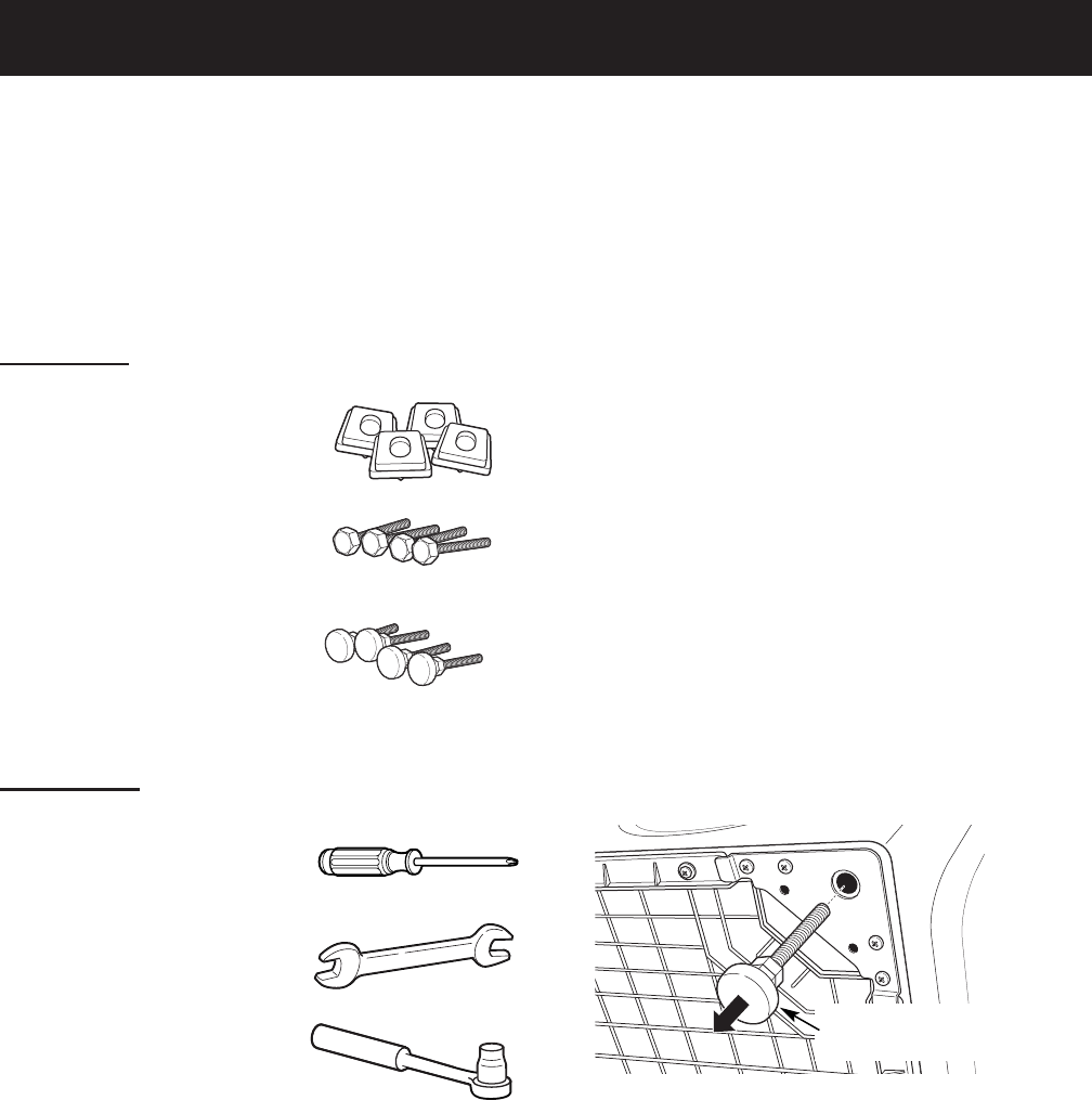
Pedestal Installation (Washer and Dryer)
Optional 12-inch high storage drawer pedestals with
dividers are available to provide convenience and
extra storage space for detergent, dryer sheets and
other cleaning supplies. The pedestal installation kit
includes 4 support pads, 4 mounting screws, and 4
leveling legs with locknuts.
WARNING: Due to the size and weight of the
washer or dryer, and to reduce the risk of personal
injury or damage, 2 people are required for proper
installation.
Note:
DO NOT remove washer shipping bolts prior to
pedestal installation. Shipping bolts MUST be
reinstalled, if previously removed.
Care should always be taken when laying
the washer or dryer on its side to prevent
component damage.
Do not lay washer or dryer on its back. Use a
pad or protective surface when laying washer or
dryer on its side.
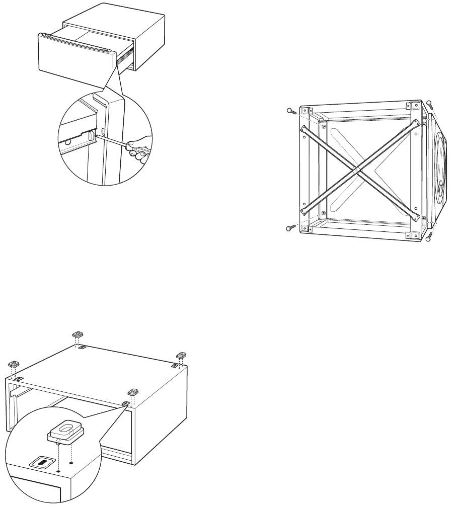
To install the pedestal:
Lay the washer or dryer on its side.
Remove the 4 leveling legs.
•
•
•
1.
2.
(Continued Next Page)
4 Support Pads
4 Mounting Screws
Kit Contents
Phillips-head Screwdriver
9/16" Open End Wrench
or Adjustable Wrench
8-mm Socket Wrench
Tools Needed
Back out and remove
all 4 leveling legs
4 Leveling Legs
with Locknuts
– 17 –
Place the pedestal against the bottom of the
washer or dryer. Ensure that the drawer front is
at the front of the washer or dryer.
Align the holes in the pedestal with the holes in
the bottom of the washer or dryer base.
Use a Phillips-head screwdriver to install the 4
(8-mm) bolts through the pedestal and into the
unit. DO NOT tighten the bolts.
Align the pedestal with the unit. Use an 8-mm
socket wrench to securely tighten the bolts.
7.
8.
9.
10.
Note: The support pads should be installed on the
dryer only. DO NOT INSTALL THE PADS ON THE
WASHER PEDESTAL.
Install a support pad at each top corner of the
pedestal. Ensure both protrusions on each pad
are inserted in the holes on top of the pedestal.
6.
(Continued Next Page)
Pull the drawer out to its stop position.
Remove the screws from the drawer slides.
Slide the drawer out of the base and set it aside.
3.
4.
5.
– 18 –
Ensure that the slides are closed, then slide the
drawer into the opening.
Align the drawer supports to the slides on each
side.
Reinstall the original screws in each drawer
slide.
Note: The drawer should slide smoothly when you
push it closed.
16.
17.
18.
Remove the 4 shipping screws from the back of
the washer.
Note: Refer to the washer or dryer installation
instructions to complete the installation.
19.
Stand the washer or dryer upright. Move it close
to its fi nal location.
Make sure that the washer or dryer is level by
placing a spirit level on top. Check side to side
and front to back.
Use an open end or adjustable wrench to adjust
the legs in or out. Tighten the locknuts against
the bottom of the pedestal.
Note: To minimize vibration, the locknuts must be
tight.
13.
14.
15.
Screw locknuts onto the supplied leveling legs.
Turn the nuts toward the bottom and against
the rubber part of the leg.
Install the leveling legs, with locknuts, in each
corner support. Screw the legs all the way into
the pedestal. Do not tighten.
11.
12.
– 19 –
Stacking Instructions
The GE dryer is designed to allow placement
(stacking) on top of certain GE front load washers.
Washer models that currently qualify are:
WBVH6240
WCVH6260
WHDVH626
The parts and instructions necessary to convert the
separate units to a stack unit are included with the
washer installation parts.
Note: The stacking parts and instructions are NOT
included with the GE dryers but can be ordered
separately. (Part # WE25X10018)
Note: Reverse the dryer door swing (if desired)
BEFORE stacking. The washer door swing is NOT
reversible.
•
•
•
WARNING!
• Make sure the dryer is unplugged.
• More than 2 people are recommended to safely
lift the dryer into position.
• Avoid damage to the existing utility services.
DO NOT place the washer on top of the dryer.
Stacking of a gas dryer is NOT permitted in a
mobile home or a manufactured home.
Location Requirements
When installed in a location other than an alcove
or closet, the minimal clearances to combustible
surfaces and for air opening are: 0 inches on both
sides, and 1 inch at the rear.
Note: If your dryer is approved for installation in an
alcove or a closet, it will be stated on a label on the
back.
When installed in an alcove or closet:
Minimum clearance between dryer cabinet
and adjacent walls or other surfaces is 0 inches
either side, and 3 inches front and rear.
•
•
•
Minimum vertical space from fl oor to overhead
cabinets, ceiling, etc. is 43 inches without
pedestal, 55 inches with pedestal, and 84
inches stacked. Closet doors must be louvered
or otherwise ventilated and must contain a
minimum of 120 square inches of open area,
equally distributed.
The dryer MUST be vented to the outdoors.
(Refer to dryer installation instructions for
details.)
•
•
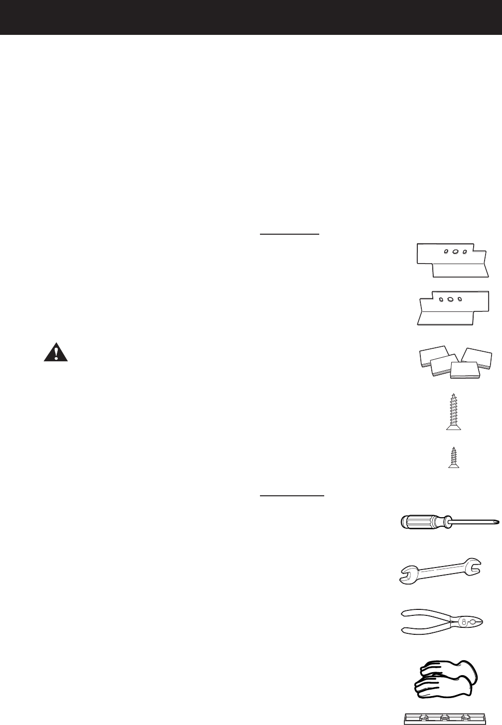
Tools Needed
Kit Contents
(Continued Next Page)
Right Bracket
Left Bracket
4 Rubber Pads
4 #12 x 1" Screws
4 #8 x ½" Screws
Phillips Screwdriver
Open End Wrench
Pliers
Gloves
Level
– 20 –
To stack the dryer:
Caution: Do not lay dryer on its back. Use the
packing material or a protective surface when
laying dryer on its side.
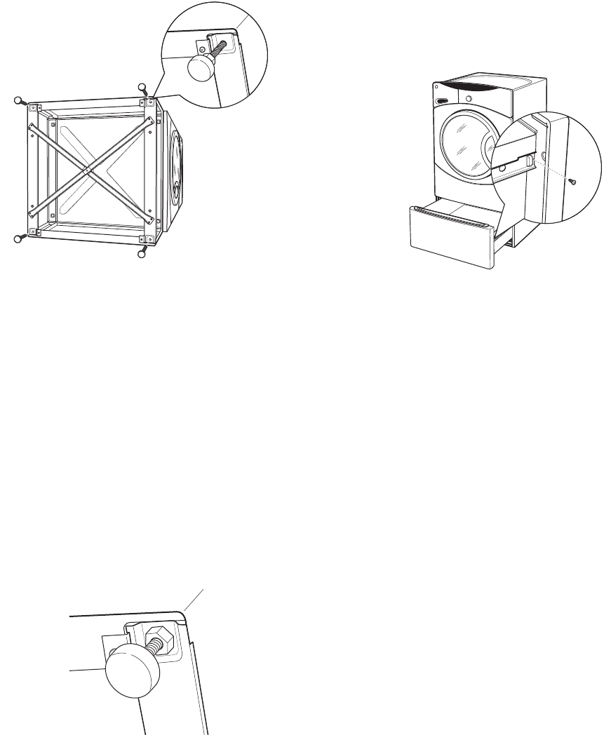
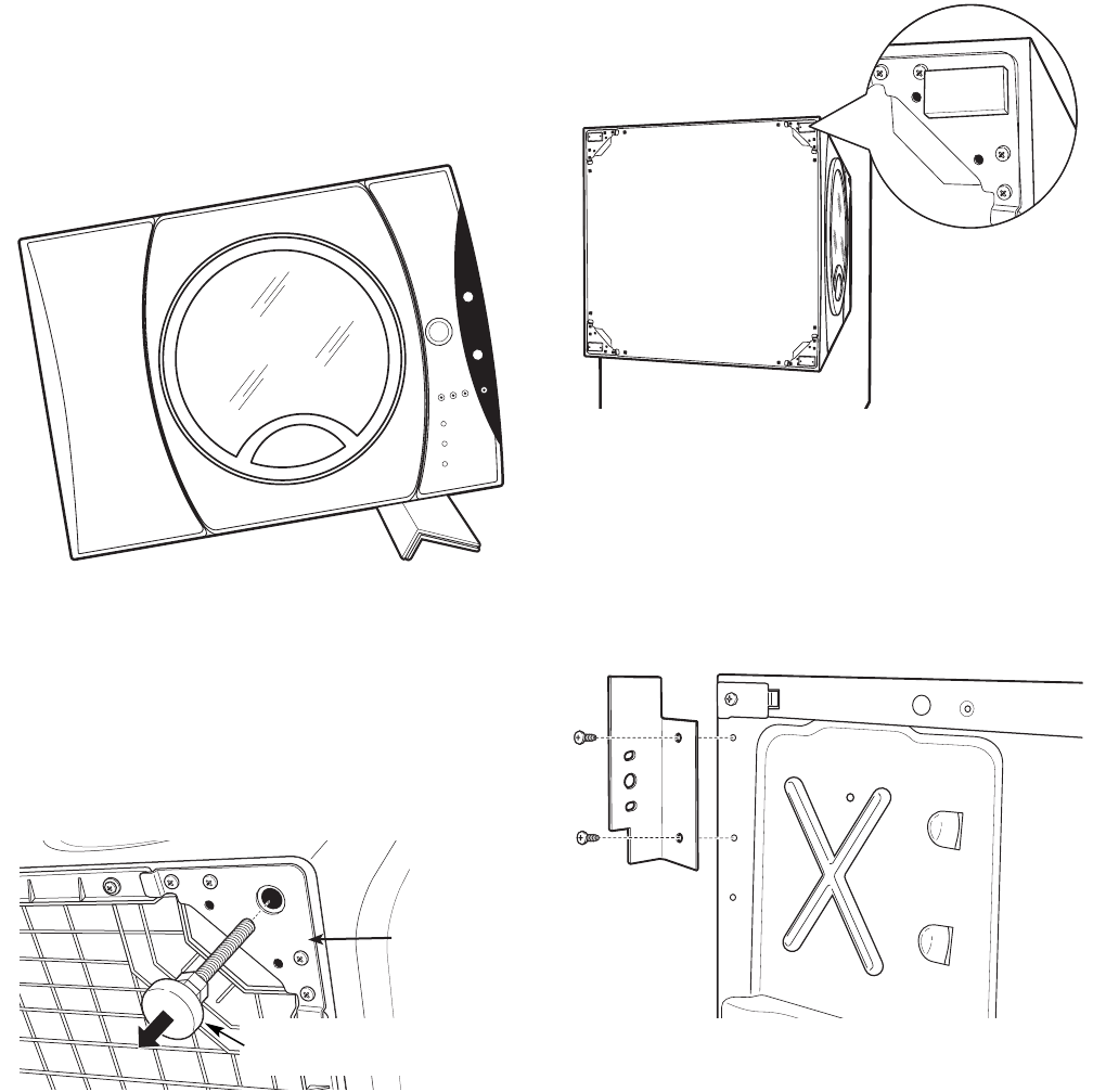
Carefully lay the dryer on its side. 1.
Use an open end wrench or pliers to remove the
4 dryer leveling legs from the leg brackets.
2.
ygg
Back out and remove
all 4 leveling legs
Remove the adhesive backing and fi rmly place
the 4 rubber pads over the leg brackets.
3.
Leg bracket
Align the holes in the left bracket with the holes
in the bottom left corner of the dryer. Attach
the bracket using 2 (#12 x 1-in.) Phillips-head
screws.
4.
(Continued Next Page)
Align the holes in the right bracket with the holes
in the bottom right corner of the dryer. Attach
the bracket using 2 (#12 x 1-in.) Phillips-head
screws.
5.
– 21 –
Set the dryer upright using packing material or a
protective surface that ensures the brackets do
not damage the fl oor.
Place and level the washer in the approximate
location. (Refer to washer installation
instructions for details.)
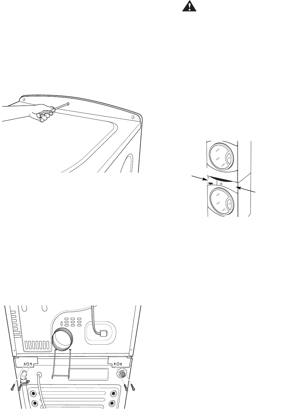
Remove the 3 Phillips-head screws that attach
the top cover, then pull the cover rearward.
6.
7.
8.
Caution: Protect the washer control panel with
cardboard or other protection to prevent damage
caused by contact with the dryer brackets.
Lift the dryer high enough to clear the washer
control panel and place the dryer on top of the
washer.
Align the holes in the brackets with the holes
in the back of the washer. Attach the brackets
to the washer using 4 (#8 x ½-in.) Phillips-head
screws.
9.
10.
WARNING!
Do not push on the dryer after it is stacked on the
washer. Pushing on the dryer may result in pinched
fi ngers.
Caution: Use felt pads or other sliding device to
assist moving and to protect fl ooring.
Note: Ensure that the washer and the dryer are
in compliance with their respective installation
instructions.
Carefully slide or walk the stacked washer and
dryer into place.
11.
Place hands here
Place hands here
– 22 –
Operation Overview
Air enters the dryer cabinet, passing thru the heating elements and into the drum. The hot air heats the
wet clothes, gradually removing their moisture in the form of water vapor. The moist air is vented through
the dryer exhaust. Overall heater temperature is regulated by means of two temperature sensors, an inlet
sensor, located near the heating elements, and an outlet sensor, located at the blower. An additional safety
thermostat, located near the heating elements, shuts off the heating elements if they overheat. Also, the
outlet backup thermostat, located near the blower, provides additional safety and cycles the heaters if
temperature goes above the outlet temperature range.
The typical dryer cycle progresses as follows:
1. A cycle is selected and the start key is pressed.
2. The motor is activated.
3. The heater coils (burner for gas models) are activated. The coils (burner) cycle on and off to achieve the
desired temperature throughout the heating portion of the cycle.
4. If sensor drying is selected, the heater coils (burner for gas models) are activated. The coils (burner) cycle
on and off until the load has achieved the desired dryness level.
5. If timed drying is selected, the heater coils (burner for gas models) are activated and cycle on and off for
the selected time at the selected temperature.
6. The heater coils (burner for gas models) discontinue operation after the dryness level or elapsed time has
been achieved.
7. The motor continues operating until the clothes temperature drops below specifi ed temperature (Cool
Down).
9. The display turns off.
Dryer
Cabinet
Diffuser
Drum Lint trap Blower Exhaust
Safety thermostat
Safety thermostat
Outlet backup
Inlet temperature sensor
t°
t° t°
Outlet temperature sensor
Inlet temperature
sensor
Heater
Pan/Electric
Coils
Gas
Combustion
Chamber
Dryer Air Flow System


– 28 –
Dryer Components
Top Panel
WARNING: Sharp edges may be exposed when
servicing the dryer. Use caution to avoid injury.
Wear Kevlar gloves or equivalent protection.
Note: Combined Phillips-head/square-drive recess
screws are utilized throughout this appliance. Either
Phillips or square-drive screwdrivers can be used to
extract or install these screws.
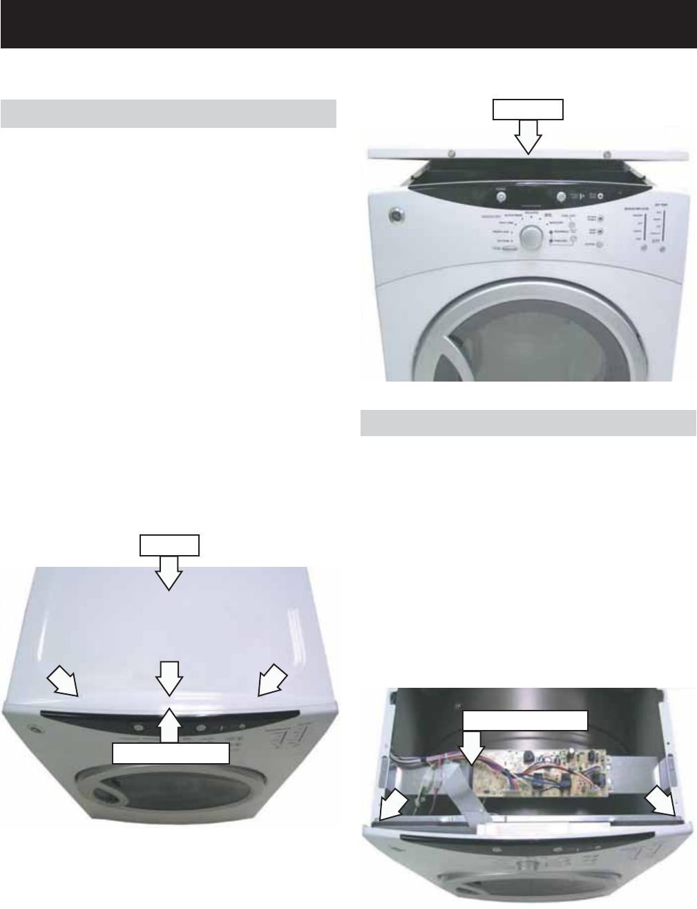
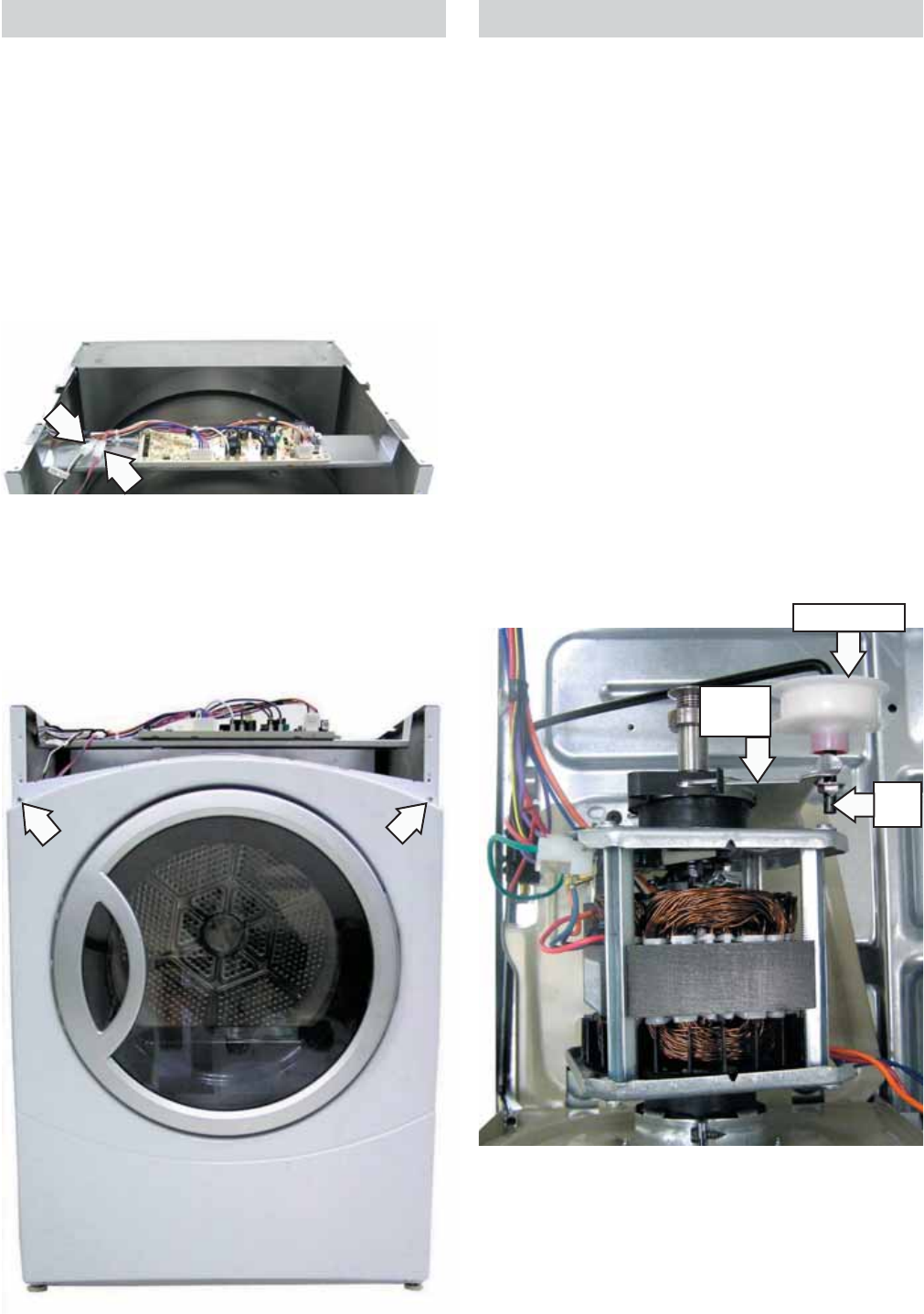
Removal of the top panel provides access to the
power board. The top panel is held in place with
2 Phillips-head screws (located under the control
panel cover) and 2 rear tabs.
To remove the top panel:
Remove the 3 Phillips-head screws that attach
the control panel cover. Pull the cover rearward.
Note: It may be helpful to place a putty knife along
the top seam between the cover and the control
panel, then tap lightly rearward.
1. Control Panel
Removal of the control panel provides access to the
control board assembly. The control panel is held in
place with 2 screws on the top and 4 bottom tabs.
To remove the control panel:
Remove the top panel. (See Top Panel.)
Disconnect the control board ribbon from the
power board at connection CN110 .
Remove the 2 Phillips-head screws that attach
the top of the control panel to the cabinet.
1.
2.
3.
Remove the 2 Phillips-head screws that attach
the top panel to the cabinet.
Raise the front of the top panel approximately 3
inches, then pull forward to clear the rear tabs.
2.
3.
Raise the control panel vertically.4.
Control Board Ribbon
Top Panel
Control Panel Cover
Top Panel
– 29 –
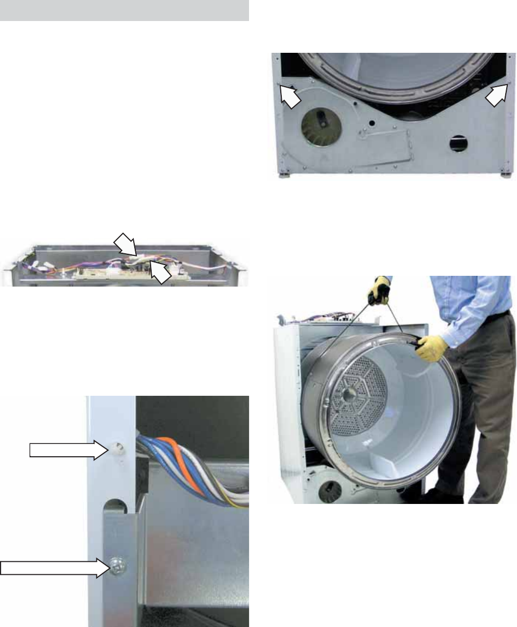
Front Panel
Removal of the front panel provides access to the
drum and drive belt. The front panel is held in place
by 4 screws.
To remove the front panel:
Remove the top panel. (See Top Panel.)
Remove the control panel. (See Control Panel.)
Disconnect the door switch wire harness and
the sensor rod wire harness to the power board.
1.
2.
3.
Note: In the following step it may be necessary to
raise the front of the dryer to gain access to the
screws.
Remove the 4 Phillips-head screws that hold the
front panel to the cabinet.
4.
Remove the belt from the motor pulley and
idler pulley. Guide the belt past the front of the
cabinet base.
3.
Drive Belt
WARNING: Sharp edges may be exposed when
servicing the dryer. Use caution to avoid injury and
wear Kevlar gloves or equivalent protection.
The drive belt (part # WE12M22) extends from the
motor pulley, past the idler pulley, and around
the perimeter of the dryer drum. Belt tension is
maintained by the idler pulley and driven by a
pulley attached to the rear of the motor shaft.
To remove the drive belt:
Remove the top, control, and front panels. (See
Top Panel, Control Panel and Front Panel.)
WARNING: The idler arm is under high tension. To
prevent injury, do not let the idler arm snap back.
Reach under the left side of the drum, push the
idler pulley down and to the right, then lock
the idler arm on the top corner of the motor
support.
1.
2.
Locked Position
Motor
Support
Idler Pulley
Idler
Arm
– 30 –
Drum
The drum is made of 304 stainless steel and
has three replaceable baffl es. The drum rotates
counterclockwise, as viewed from the front, at a
speed of 47 to 51 RPM.
To remove the drum:
Remove the top, control, and front panels. (See
Top Panel, Control Panel and Front Panel.)
On gas models, disconnect the inlet control
thermistor and the inlet safety thermostat wire
harnesses.
1.
2.
Gas Model
Disengage the front plastic wire retainer from
the cabinet by pressing the tabs inward.
Remove the 2 Phillips-head screws that attach
the power board bracket to the cabinet.
Carefully place the bracket on the rear plate.
3.
4.
Wire Retainer
Bracket Screw (1 of 2)
Remove 1 Phillips-head screw from each side of
the cabinet, then gently spread the sides apart
to provide clearance for the drum.
5.
Remove the drive belt from the motor and idler
pulley. (See Drive Belt.)
Using the belt as a handle, pull the drum
forward and guide it out of the cabinet.
6.
7.
– 31 –
Idler Assembly
The idler assembly maintains proper tension on the
belt to minimize belt slippage. The idler assembly
consists of an idler pulley that rotates on an idler
arm. The pulley is retained on the arm using a
cap nut. The idler arm is positioned on the chassis
and inserted in a slot in the motor base plate. The
assembly is located to the left of the motor.
WARNING: Sharp edges may be exposed when
servicing the dryer. Use caution to avoid injury.
Wear Kevlar gloves or equivalent protection.
To remove the idler assembly:
Remove the drive belt. (See Drive Belt.)
WARNING: The idler arm is under high tension. To
prevent injury, do not let the idler arm snap back.
Release tension on the idler assembly by
unlocking the idler arm from the top right
corner of the motor support.
Remove the idler arm from the slot in the motor
base plate.
1.
2.
3.
Remove the idler assembly from the dryer.4.
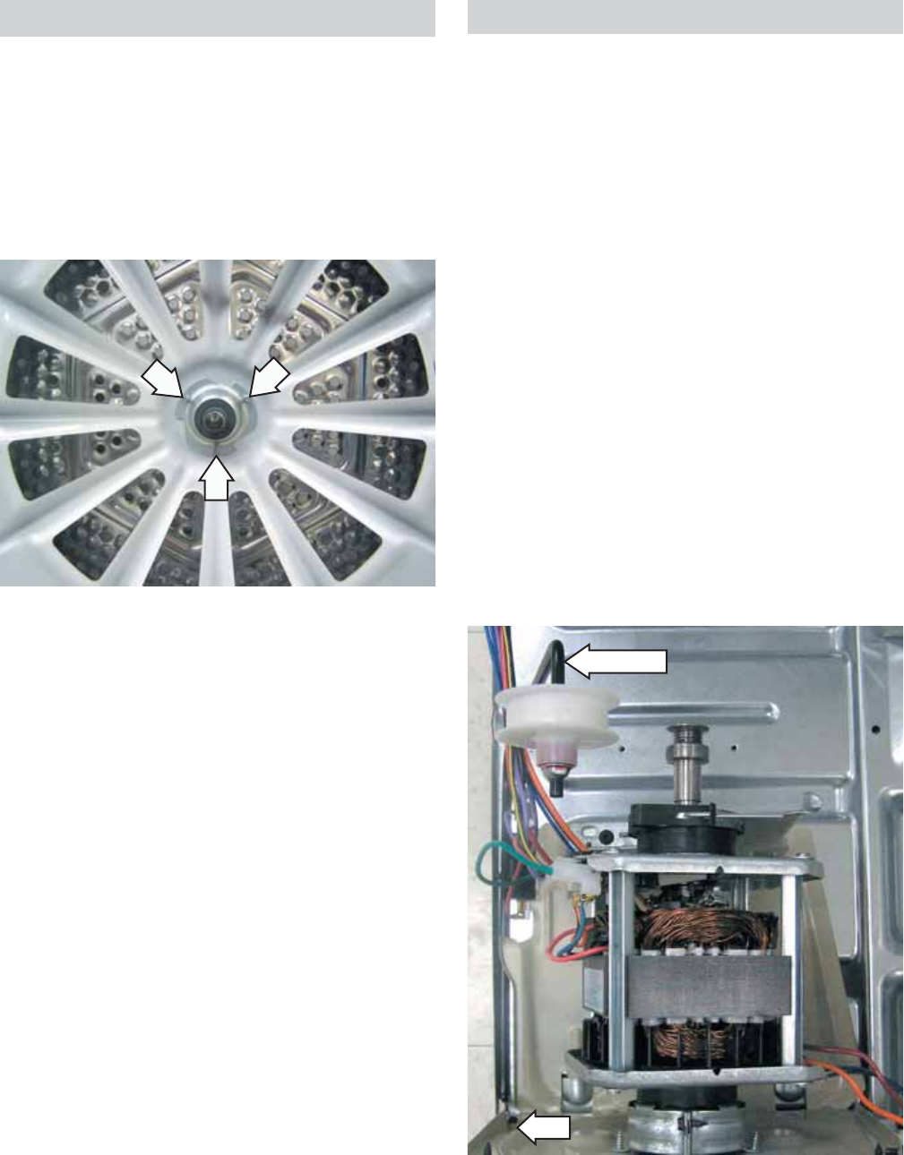
Drum Shaft Bearing
The drum shaft bearing is mounted on the drum
shaft at the rear of the drum. The bearing fi ts into
the bearing retainer in the center of the heater
assembly.
To remove the drum shaft, remove the drum (See
Drum.) then remove the 3 Torx screws (T-20) that
attach the drum shaft to the rear of the drum.
Idler Arm
Slot
– 32 –
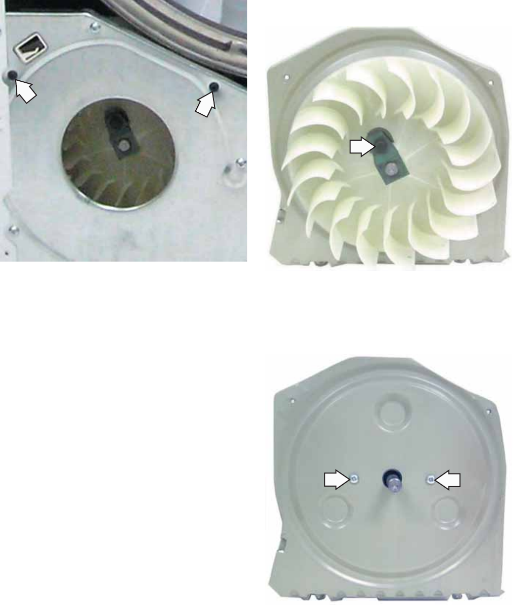
Motor and Blower Wheel Assembly
The motor is a single speed, 120 VAC, ¼-hp, 5.2
amp rated motor with an automatic reset overload
protector. The overload protector is an internal
component of the motor and cannot be replaced
separately. The motor contains a centrifugal switch
that serves three purposes:
Disengages the motor start winding (M6).
Engages the motor run winding (M5).
Closes the circuit contacts for the heat source.
The switch is an internal component of the motor
and cannot be replaced separately.
The blower wheel is held to the motor shaft utilizing
a blower wheel clamp.
Motor resistance values:
Start winding = approximately 5 Ω
Run winding = approximately 4 Ω
Note: The motor and blower wheel assembly must
be removed to replace the motor or blower wheel
separately.
To remove the motor and blower wheel assembly:
Remove the top, control, and front panels. (See
Top Panel, Control Panel and Front Panel.)
Remove the drum. (See Drum.)
Remove the idler assembly. (See Idler Assembly.)
•
•
•
1.
2.
3.
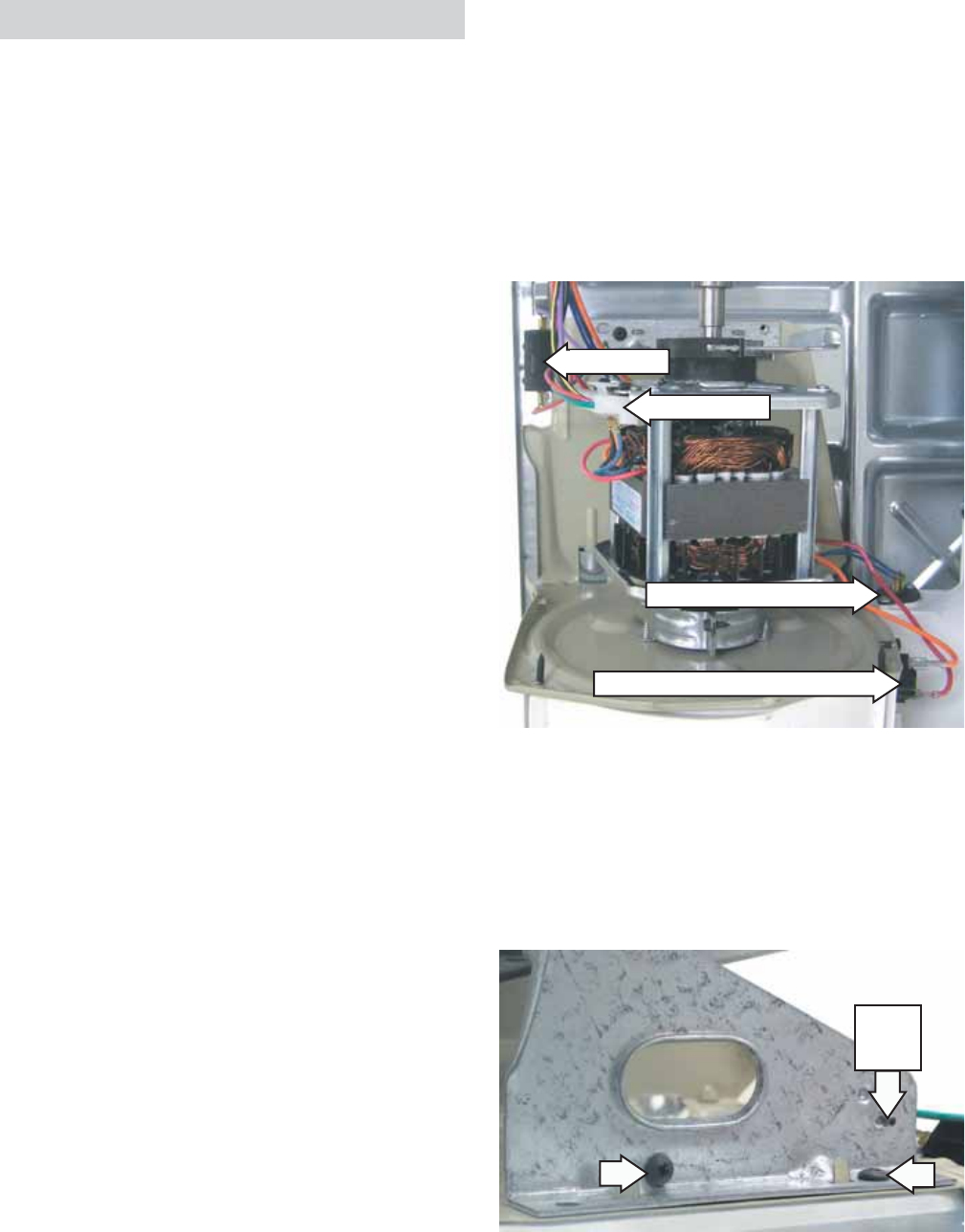
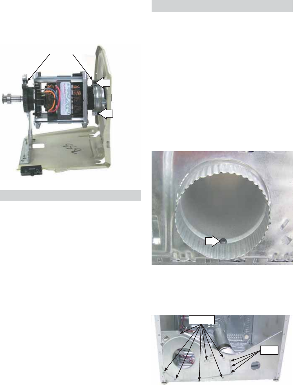
Outlet Control Backup Thermostat
Outlet Control Thermistor
Motor Harness
Belt Switch
Remove the ¼-in hex-head screw that attaches
the ground wire to the motor support.
Remove the single vertical and single horizontal
Phillips-head screws that attach the motor
support to the base plate.
8.
9.
Ground
Wire
Screw
(Continued Next Page)
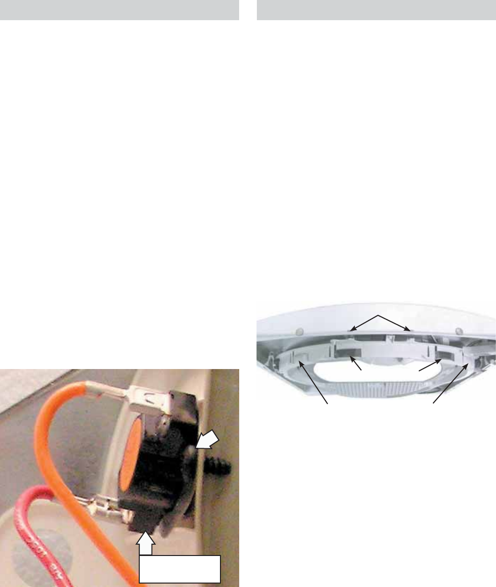
Disconnect the 2 blue wires from the outlet
control thermistor.
Remove the single Phillips-head screw that
attaches the outlet control backup thermostat
to the blower housing.
Disconnect the purple and the brown wires from
the belt switch.
Disconnect the motor wire harness.
4.
5.
6.
7.
– 33 –
Remove the 2 Phillips-head screws that hold
the top of the motor base plate to the blower
housing.
10.
Raise the rear of the motor bracket to clear the
tab protruding from the bottom of the base
plate. Pull rearward and remove the motor and
blower wheel assembly from the base plate.
Note: When installing the motor and blower wheel
assembly, ensure that the 2 front tabs and the 2
rear tabs on the motor bracket are inserted into
slots provided in the bottom of the base plate.
11.
To replace the blower wheel:
Loosen the 3/8-in. hex-head screw that secures the
blower wheel clamp to the motor shaft. Pull the
blower wheel off the shaft.
To replace the motor:
Remove the 2 Phillips-head screws that hold the
front motor strap to the motor base plate.
1.
(Continued Next Page)
– 34 –
Belt Switch
The belt switch is fastened to the motor baseplate
with 2 Phillips-head screws. The belt switch is
activated by the movement of the idler arm. If the
drive belt breaks or comes off the idler pulley, the
belt switch opens power to the motor interrupting
dryer operation. The drum lamp will operate with an
open belt switch.
To remove the belt switch:
Remove the top, control, and front panels. (See
Top Panel, Control Panel and Front Panel.)
Remove the drum. (See Drum.)
Remove the motor and blower wheel assembly.
(See Motor and Blower wheel Assembly.)
Remove the 2 Phillips-head screws that attach
the belt switch to the motor baseplate.
1.
2.
3.
4.
Motor Straps
Remove the 2 hex-head screws that hold the
front motor strap to the motor.
Compress then remove the rear motor strap
from the motor base plate.
2.
3.
Remove the 7 Phillips-head screws that attach
the blower housing to the base plate.
Slide the blower housing to the right.
6.
7.
Note: When reinstalling the blower housing, ensure
the 3 tabs are inserted into the front base plate.
Screws
Tabs
Blower Housing
The blower housing is attached to the dryer with 7
screws and 3 tabs.
To remove the blower housing:
Remove the top, control, and front panels. (See
Top Panel, Control Panel and Front Panel.)
Remove the drum. (See Drum.)
Remove the idler assembly. (See Idler Assembly.)
Remove the motor and blower wheel assembly.
(See Motor and Blower wheel Assembly.)
Remove the single Phillips-head screw located
inside the outlet of the exhaust pipe. Remove the
exhaust pipe from the blower housing.
1.
2.
3.
4.
5.
– 35 –
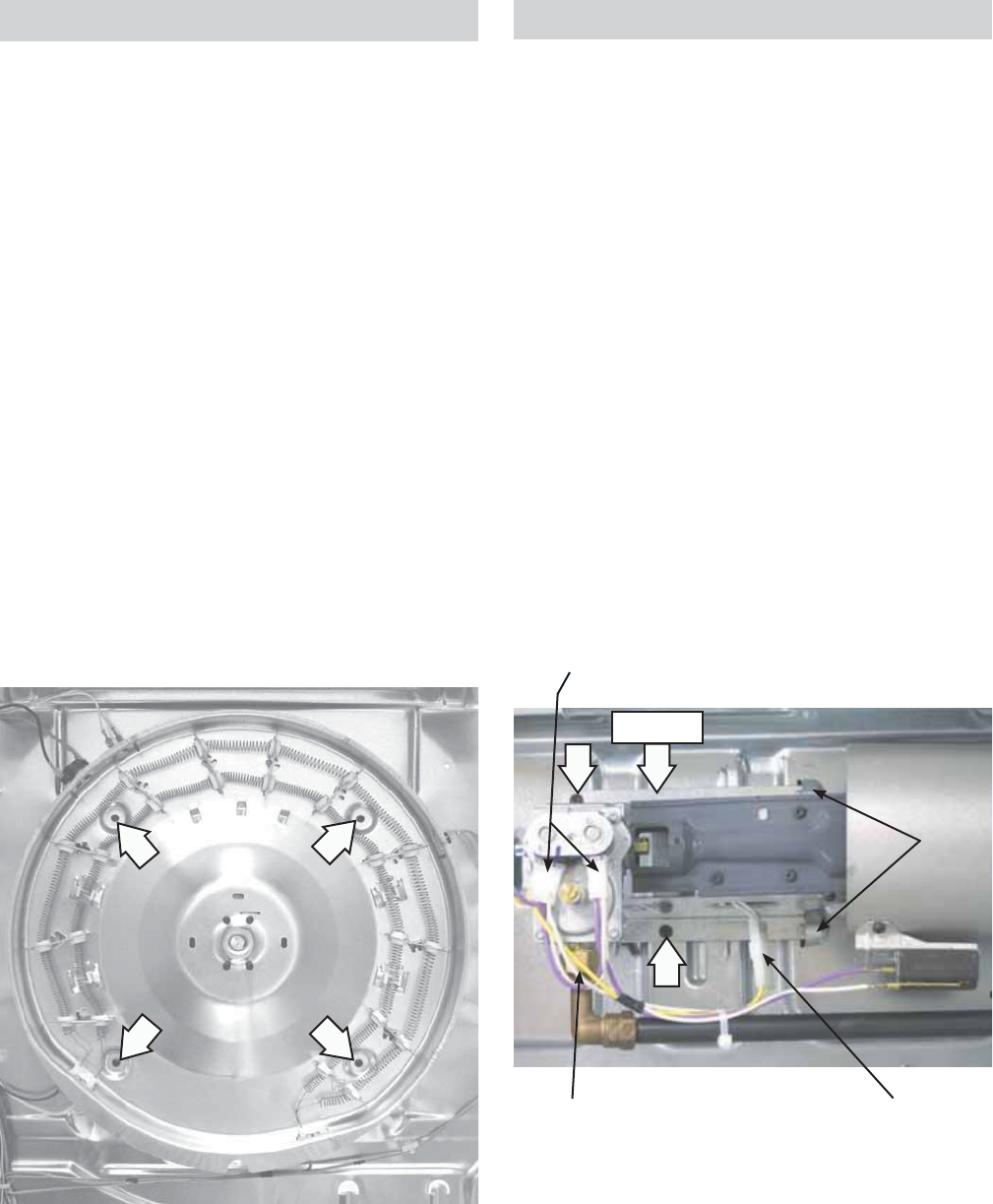
Heater Assembly
The heater assembly is located behind the drum.
It consists of 2 open coils fastened to a single
housing. The inner coil and the outer coil are each
individually controlled by separate relays on the
power board. When energized, each coil draws 12.5
amps at 240 VAC. Each coil has an approximate
resistance value of 19.2 Ω.
To remove the heater assembly:
WARNING: Sharp edges may be exposed when
servicing the dryer. Use caution to avoid injury.
Wear Kevlar gloves or equivalent protection.
Remove the top, control, and front panels. (See
Top Panel, Control Panel and Front Panel.)
Remove the drum. (See Drum.)
Disconnect the lead wires from the heaters, inlet
safety thermostat, inlet control thermistor, and
the high limit thermostat,
Remove the 4 Phillips-head screws that attach
the heater housing to the cabinet.
1.
2.
3.
4.
Remove the coils from the gas valve. (See Coils.)
Turn the bracket over. Remove the 2 Phillips-
head screws that attach the gas valve to the
gas valve bracket.
Note: Upon reassembly, ensure the gas valve
bracket is inserted under the 2 tabs located in the
chassis bottom.
8.
9.
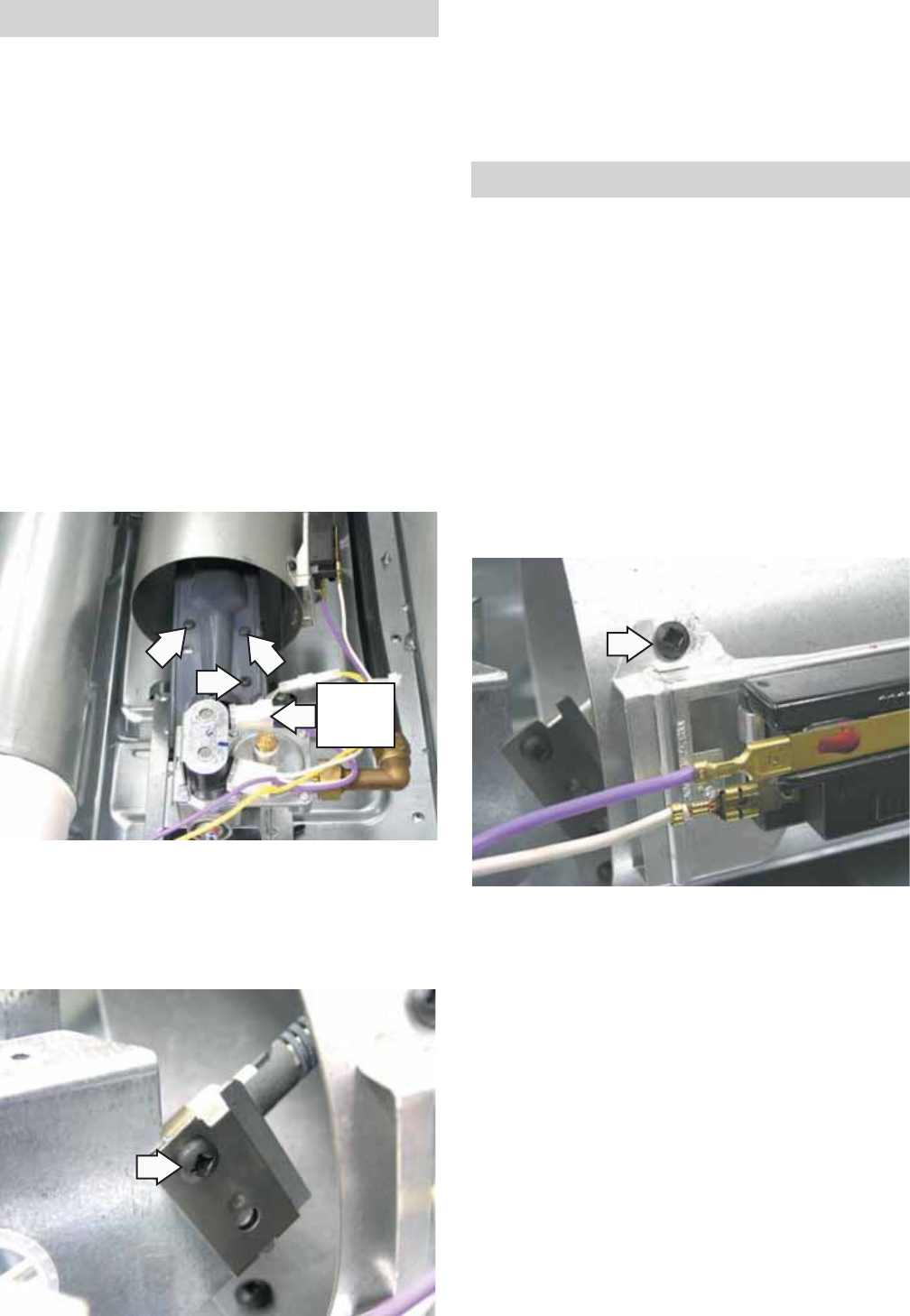
Gas Valve
The gas valve is attached to a bracket located in the
bottom, right, front corner of the dryer cabinet.
To remove the gas valve:
Shut the gas off to the unit.
Remove the top, control, and front panels. (See
Top Panel, Control Panel and Front Panel.)
Remove the drum. (See Drum.)
Disconnect the coil wire harness from each coil.
Disconnect the ignitor wire harness.
Disconnect the elbow coupling from the gas
valve by turning counterclockwise (toward the
rear of the dryer).
Remove the 2 Phillips-head screws that attach
the gas valve bracket to the chassis bottom and
pull bracket toward the front of the dryer and
remove.
1.
2.
3.
4.
5.
6.
7.
Coil Wire Harnesses
Tabs
Elbow Coupling Ignitor Wire Harness
Bracket
– 36 –
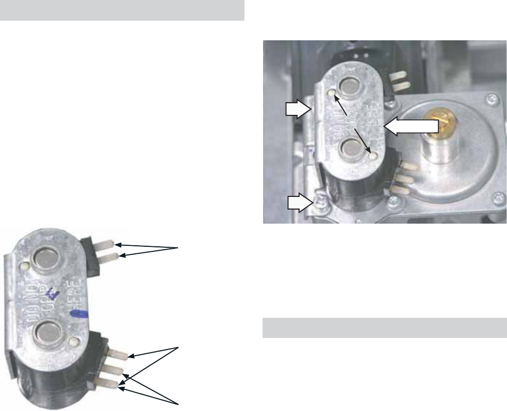
Gas Valve Coil Assembly
The gas valve coil assembly is located on top of
the gas valve in front of the combustion chamber
opening. The assembly consists of a double coil
(saftey and booster coils combined) and a single
main coil. The coil assemblies can be replaced
separately.
Gas valve coil assembly resistance values:
Saftey coil terminals - 1350 Ω
Booster coil terminals - 550 Ω
Main coil terminals - 1300 Ω
•
•
•
Main Coil
Booster Coil
Safety Coil
To remove the coils:
Remove the top, control, and front panels. (See
Top Panel, Control Panel and Front Panel.)
Remove the drum. (See Drum.)
Disconnect the wire harness from both coils.
1.
2.
3.
(Continued Next Page)
Bracket
Locator Pins
Lift the bracket vertically. Lift coils to remove.
Note: Upon reassembly, ensure the locator pins are
inserted into the holes provided in the coil bracket.
5.
LP Conversion
The gas dryer comes equipped for natural gas.
The dryer can be converted to LP gas by using
the conversion kit WE25X217. Should you need to
convert an LP dryer back to natural gas and the
original parts are missing, a WE25X218 kit contains
all the parts required to convert back to natural gas.
Remove the 2 Phillips-head screws that attach
the coil bracket to the valve body.
4.
– 37 –
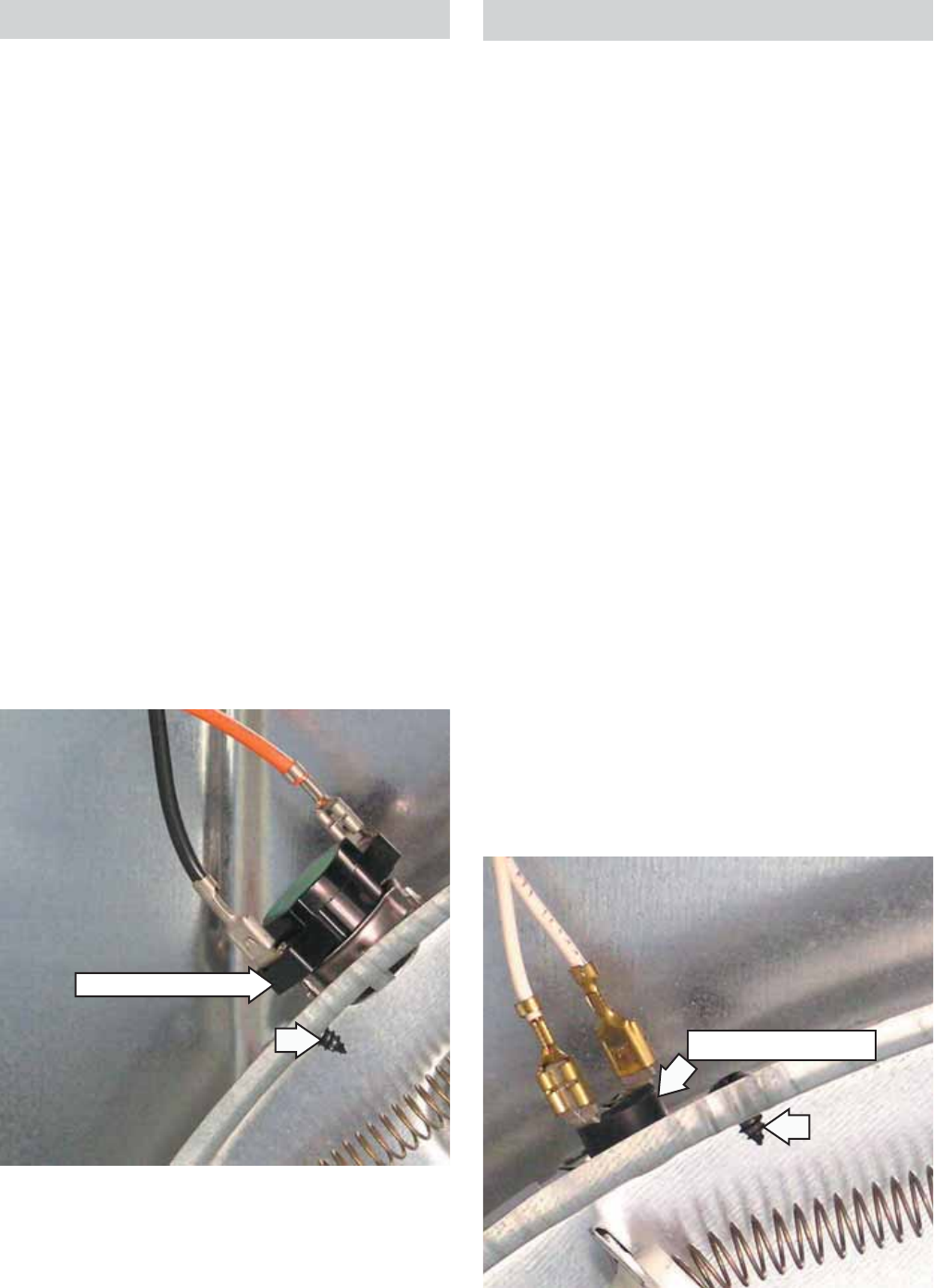
Remove the fl ame detector from the tab at the
bottom.
Note: Upon reassembly, ensure the tab at the
bottom of the fl ame detector is inserted into the slot
located on the combustion chamber.
5.
Flame Detector
The fl ame detector is attached to the right side of
the combustion chamber.
To remove the fl ame detector:
Remove the top, control, and front panels. (See
Top Panel, Control Panel and Front Panel.)
Remove the drum. (See Drum.)
Disconnect the 2 wires from the fl ame detector.
Remove the single Phillips-head screw that
holds the fl ame detector to the combustion
chamber.
1.
2.
3.
4.
Rotate the base of the ignitor clockwise. Remove
the ignitor.
Note: The ignitor is very fragile. Care must be taken
to avoid breaking the ignitor when reinstalling the
burner.
7.
Ignitor
Wire
Harness
Remove the burner.
Remove the Phillips-head screw that attaches
the ignitor to the bracket.
5.
6.
Ignitor
The ignitor is located at the end of the gas valve
assembly in the combustion chamber opening and
has a maximum rating of 4 amps. The ignitor has an
approximate resistance value of 300 to 500 Ω.
WARNING: Sharp edges may be exposed when
servicing the dryer. Use caution to avoid injury.
Wear Kevlar gloves or equivalent protection.
To remove the ignitor:
Remove the top, control, and front panels. (See
Top Panel, Control Panel and Front Panel.)
Remove the drum. (See Drum.)
Disconnect the ignitor wire harness.
Remove the 3 Phillips-head screws that attach
the burner to the bracket.
1.
2.
3.
4.
– 38 –
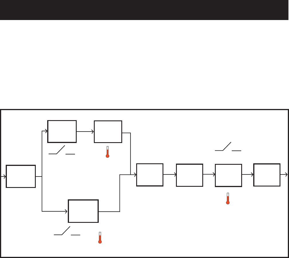
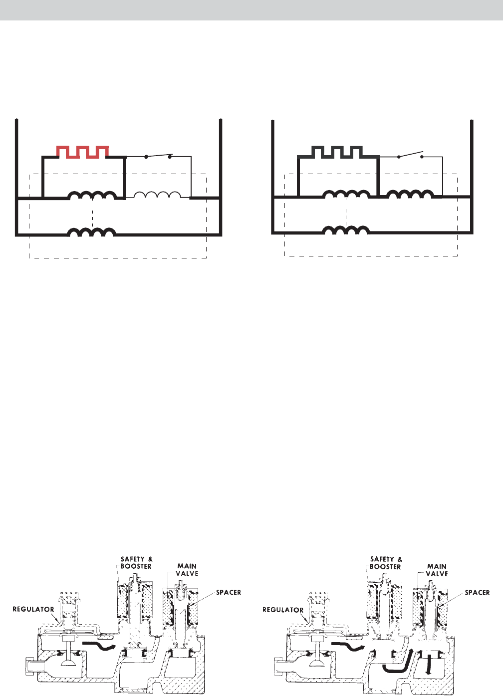
Ignitor Circuit Operation
The glo-bar ignitor circuit is made up of the following components: a gas valve with safety and main valves,
ignitor, and a fl ame detector. The safety valve is actuated by a double coil that comprises a safety coil
(resistance approximately 1350 ohms) and a booster coil (resistance approximately 550 ohms). Both coils
are needed to open the safety valve. Once energized, the safety coil alone will hold the valve open. The main
valve has a single coil (resistance approximately 1300 ohms).
The fl ame detector (< 1 ohm) is mounted on the combustion chamber. It is normally in the closed position
(N.C.). The fl ame detector is opened by the radiant heat produced by the glo-bar and once open, the fl ame
detector will be held open by the radiant heat produced by the gas fl ame.
When the control system calls for heat, the following circuits are energized:
1. N- through detector, ignitor, outlet control backup, inlet safety thermostats to L1
2. N- through detector, booster coil, outlet control backup, inlet safety thermostats to L1
3. N- through safety coil and outlet control backup, inlet safety thermostats to L1
When the glo-bar is heating, the booster and safety coils are both energized and will open the safety valve.
The main valve is closed as its coil is bypassed by the N.C. fl ame detector. When the glo-bar reaches ignition
temperature, in approximately 60 seconds or less, the fl ame detector is heated and opens, which places the
main coil in series with the glo-bar. The main valve opens, allowing gas to fl ow into the combustion chamber
and ignite. The main coil, now in series with the glo-bar, causes the glo-bar to cool down. However, the fl ame
detector is held open by the radiant heat from the gas fl ame. The booster coil is now also in series with the
main coil and is essentially inoperative. Should a momentary power failure occur, the gas valve will shut
off and an attempt to restart will not occur until the fl ame detector cools and resets, in approximately 30
seconds.
IGNITOR
(GLOWING RED) DETECTOR
MAIN
SAFETY
BOOSTER
L1 N
Ignitor On
IGNITOR
(NOT GLOWING) DETECTOR
MAIN
SAFETY
BOOSTER
L1 N
Gas Valve Open
Valves Closed Valves Open
– 39 –
Inlet Control Thermistor
The inlet control thermistor is located on the
top left area of the heater housing. It is right
of the inlet safety thermostat. The thermistor
monitors incoming air temperature and relays the
information to the power board.
Inlet control thermistor resistance values:
80 Ω at 86°F (30°C)
100 Ω at 77°F (25°C)
120 Ω at 69°F (20.5°C)
Operation of the inlet control thermistor can be
checked by using service test mode t08. (See Service
Test Mode.)
Specifi c failures associated with the outlet control
thermistor can initiate error codes E02 and E04. (See
Service Test Mode.)
To remove the inlet control thermistor:
Remove the top, control, and front panels. (See
Top Panel, Control Panel and Front Panel.)
Remove the drum. (See Drum.)
Disconnect the 2 white wires from the inlet
control thermistor.
Remove the single Phillips-head screw, then
lift and slide the thermistor from the heater
assembly.
•
•
•
1.
2.
3.
4.
Inlet Safety Thermostat
The inlet safety thermostat is located on the top
left area of the heater housing. It is left of the
inlet control thermistor. The thermostat monitors
incoming air temperature.
If the thermostat reaches a temperature beyond its
maximum temperature rating, it will trip and disable
power to the heating elements.
On electric dryers, the inlet safety thermostat opens
at 210°F (99°C) and will automatically reset at 180°F
(82°C). On gas dryers, the inlet safety thermostat
opens at 300°F (149°C) and will automatically reset
at 260°F (127°C).
To remove the inlet safety thermostat:
Remove the top, control, and front panels. (See
Top Panel, Control Panel and Front Panel.)
Remove the drum. (See Drum.)
Disconnect the black and orange wires from the
inlet safety thermostat.
Remove the single Phillips-head screw then
lift and slide the thermostat from the heater
assembly.
1.
2.
3.
4.
Inlet Safety Thermostat
Inlet Control Thermistor
– 40 –
High Limit Thermostat
The high limit thermostat is located on the top
right area of the heater housing. The high limit
thermostat monitors incoming air temperature.
If the thermostat reaches a temperature beyond its
maximum temperature rating, it will trip and disable
power to the motor, elements, and the drum light.
The high limit thermostat opens at 315°F (157°C)
and will automatically reset at 250°F (121°C).
To remove the inlet high limit thermostat:
Remove the top, control, and front panels. (See
Top Panel, Control Panel and Front Panel.)
Remove the drum. (See Drum.)
Disconnect the 2 orange wires from the high
limit thermostat.
Remove the single Phillips-head screw, then slide
the thermistor from the heater assembly.
1.
2.
3.
4.
High Limit Thermostat
Outlet Control Thermistor
The outlet control thermistor is located on the lower
rear area of the blower housing. It is below the
outlet control backup thermostat. The outlet control
thermistor measures outgoing air temperature
and responds to temperature changes. The outlet
control thermistor provides temperature change
information to the power board. The power board
makes heating decisions based on this information.
The outlet control thermistor has the same
resistance values as the inlet control thermistor. (See
Inlet Control Thermistor.)
Operation of the outlet control thermistor can be
checked by using service test mode t07. (See Service
Test Mode.)
Specifi c failures associated with the outlet control
thermistor can initiate error codes E03 and E05. (See
Service Test Mode.)
To remove the outlet control thermistor:
Remove the top, control, and front panels. (See
Top Panel, Control Panel and Front Panel.)
Remove the drum. (See Drum.)
Disconnect the 2 blue wires from the outlet
control thermistor.
Remove the 2 Phillips-head screws that attach
the outlet control thermistor to the blower
housing.
1.
2.
3.
4.
Outlet Control Thermistor
– 41 –
Outlet Control Backup Thermostat
The outlet control backup thermostat is located
on the upper rear area of the blower housing. It
is above the outlet control thermistor. The outlet
control backup thermostat monitors the outgoing
air temperature.
If the thermostat reaches a temperature beyond its
maximum temperature rating, it will trip and disable
power to the heating elements.
The outlet control backup thermostat opens at
165°F (74°C) and will automatically reset at 155°F
(68°C).
To remove the outlet control backup thermostat:
Remove the top, control, and front panels. (See
Top Panel, Control Panel and Front Panel.)
Remove the drum. (See Drum.)
Disconnect the red and orange wires from the
outlet control backup thermostat.
Remove the single Phillips-head screw that
attaches the outlet control backup thermostat
to the blower housing.
1.
2.
3.
4.
Remove the single Phillips-head screw that
attaches the drum light receptacle and remove
the receptacle from the drum glide assembly.
Caution: Upon reassembly, ensure that the door
switch, drum light and sensor wiring are retained
and routed properly to avoid contact with the drum.
3.
Tabs
Support Slides
Guide Slide Guide Slide
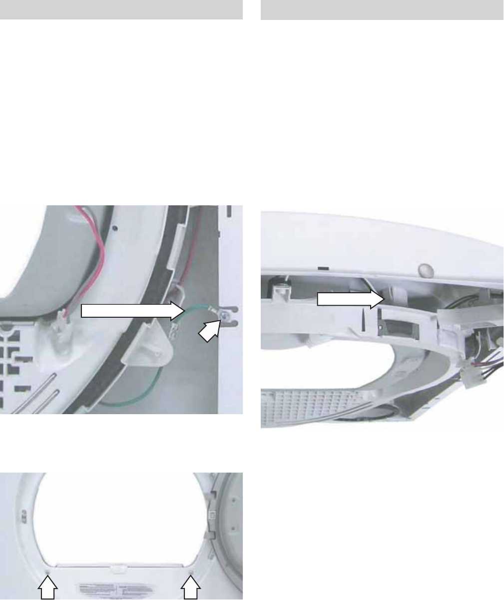
Drum Slide Assembly
The drum slide assembly is located on the back
side of the front panel and utilizes 4 drum slides.
Two white outer slides are used as guides, and 2
dark color center (top) slides are used to support the
weight of the drum. When replacing the slides, the
dark colored support slides must be replaced with
the support slide replacements. Guide slides may
also be replaced with support slides.
Caution: Do not replace the center (top) support
slides with the white guide slides. Damage to the
dryer will result. (See photo)
To remove the drum slide assembly:
Remove the top, control, and front panels. (See
Top Panel, Control Panel and Front Panel.)
Grasp the top of the drum slide assembly and
pull down and inward to release from the 2 tabs
located at the top of the front panel.
1.
2.
Outlet Control
Backup Thermostat
– 42 –
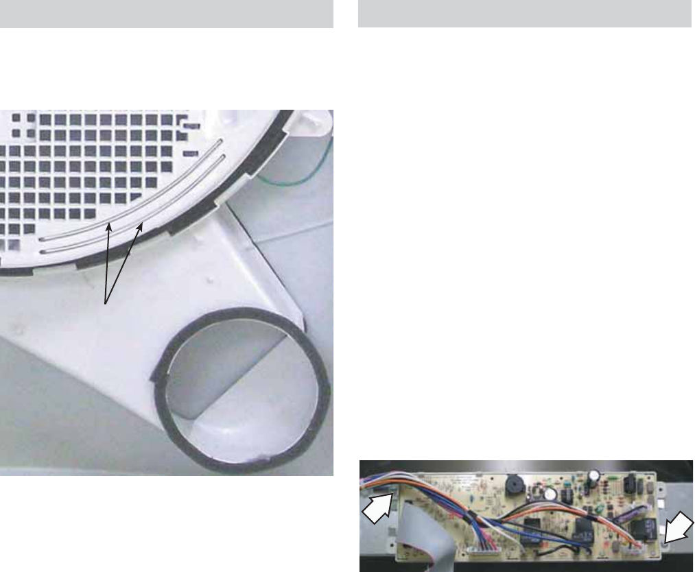
Air Duct Assembly
The air duct assembly houses the lint fi lter, drum
seal, and the 2 sensor rods. It is located on the back
side of the front panel.
To remove the air duct assembly:
Remove the top, control, and front panels. (See
Top Panel, Control Panel and Front Panel.)
Remove the drum slide assembly. (See Drum
Slide Assembly.)
Remove the single Phillips-head screw that
attaches the sensor ground wire to the cabinet.
1.
2.
3.
Remove the 2 Phillips-head screws that attach
the air duct assembly to the front panel.
4.
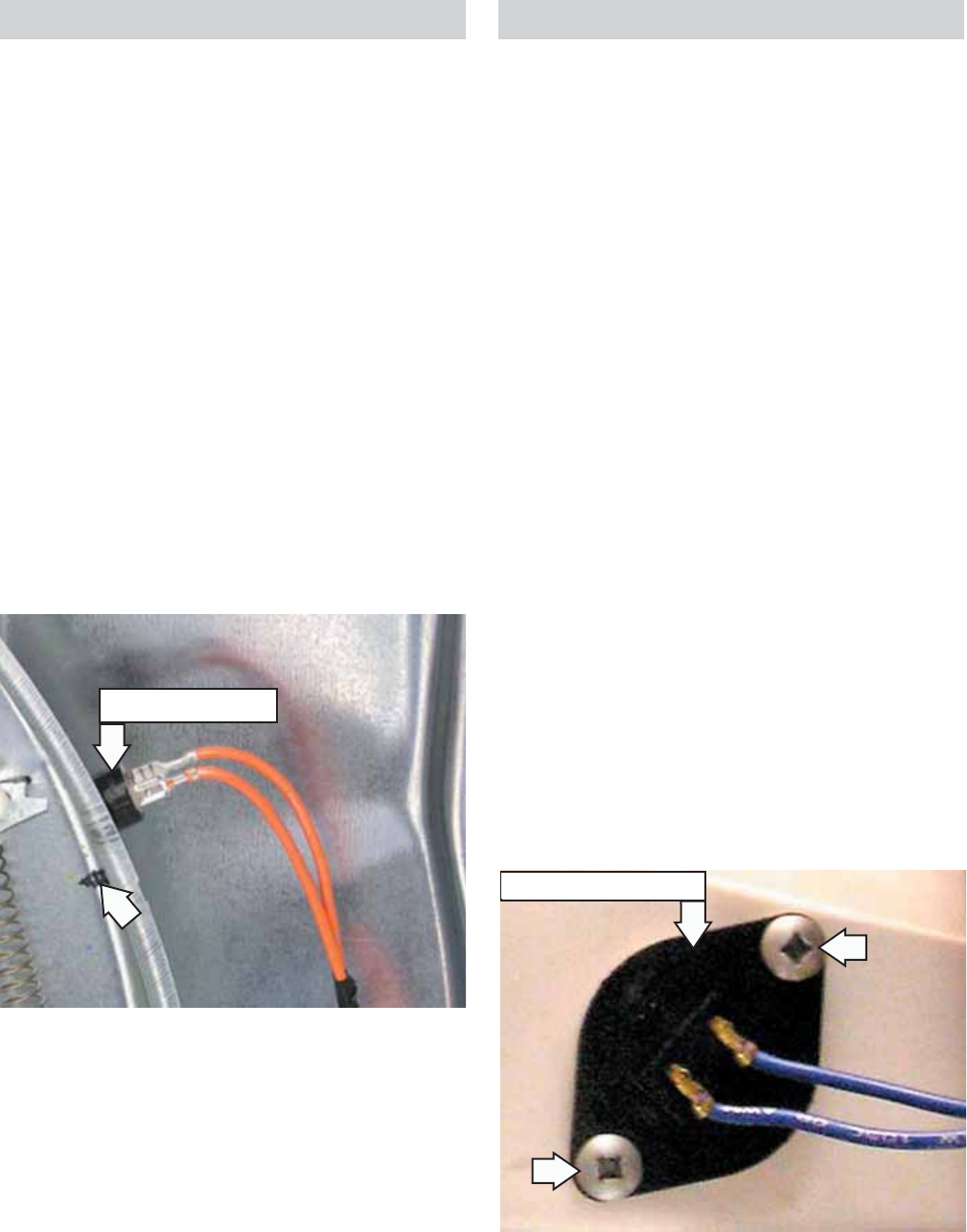
Door Switch
The door switch is fastened to the front panel
by 2 locking tabs and is common to all dryer
functions. When the dryer door is closed, the switch
will complete the motor circuit, allowing dryer
operation. When the door is open, the switch will
open the motor circuit, interrupting dryer operation.
Opening the dryer door will also cause the door
switch to close the drum light circuit, allowing the
drum light to be energized.
Specifi c failures associated with the door switch can
initiate error codes E03 and E05. (See Service Test
Mode.)
Sensor Ground Wire
Door Switch
Note:
The 2 sensor rods in the air duct assembly are
not replaceable. To replace the sensor rods,
replace the air duct assembly.
The drum seal can be replaced by extracting the
seal from the channel located on the air duct
assembly.
•
•
– 43 –
Note: The 2 sensor rods in the air duct assembly are
not replaceable. To replace the sensor rods, replace
the air duct assembly. (See Air Duct Assembly.)
The sensor rods are connected to the
main control board. The rods are spaced
approximately ½-in. apart, which creates an
open circuit to the control.
The control board utilizes a low-voltage
capacitor that charges to approximately 5 VDC
when the circuit is open and discharges to less
than 1 VDC when the circuit is shorted.
When wet clothes tumble across the two
rods, the clothes create a very low resistance
between the rods, which discharges the
capacitor.
As the clothes become dry, their resistance
value increases and the charge across the
capacitor builds to approximately 5 VDC.
Proper leveling of the dryer is vital for accurate
sensor drying. If the front of the dryer is raised
too high, clothes will tumble toward the rear of
the drum, preventing contact with the sensor
rods. This could produce a false dryness reading.
•
•
•
•
•
Moisture Sensor
The moisture-sensing circuit consists of 2 sensor
rods. They are mounted beneath the lint fi lter on the
drum side of the air duct.
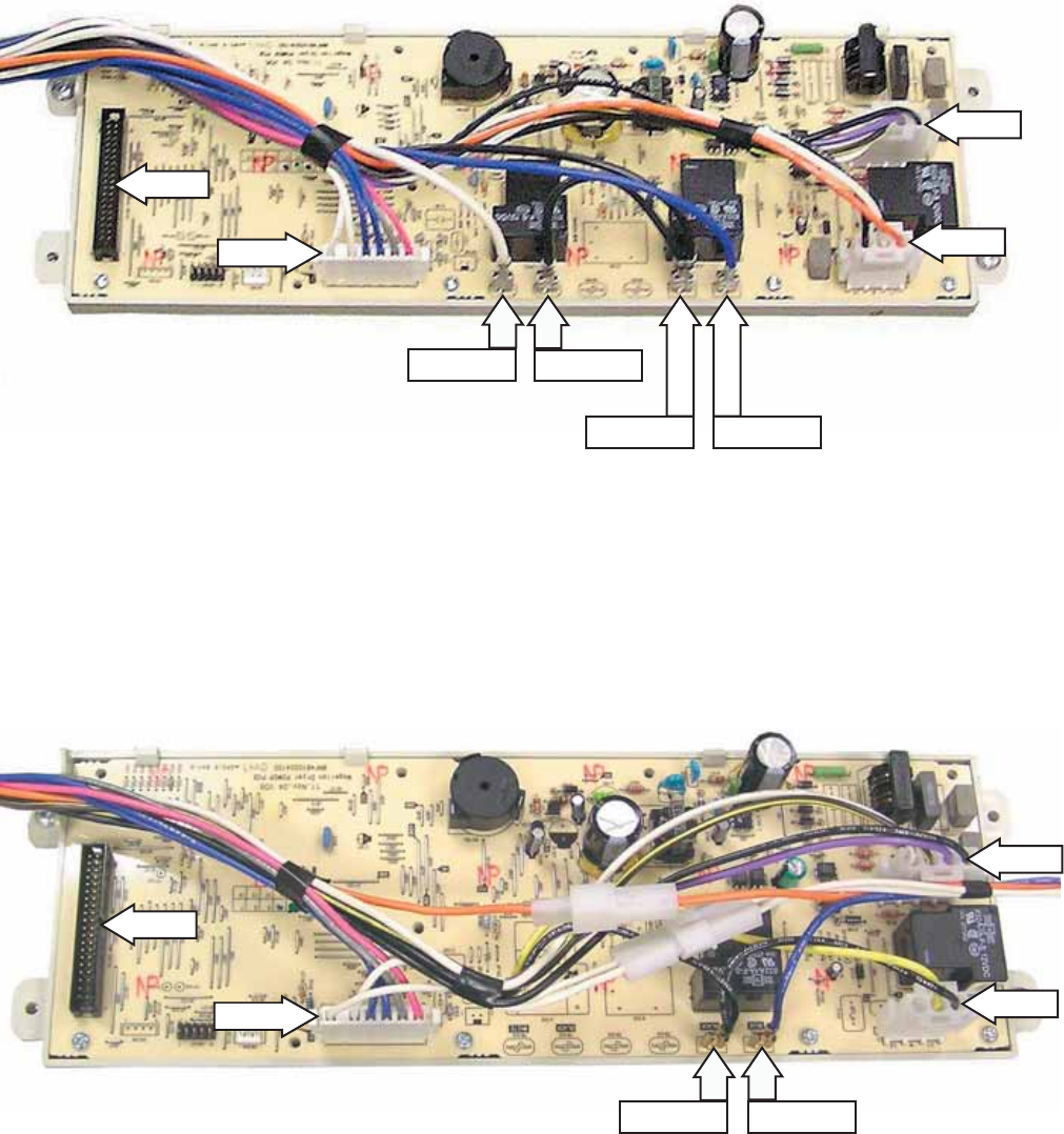
Power Board
The power board is mounted in a plastic housing
that is attached to a bracket located under the top
panel.
To remove the power board:
Remove the top panel. (See Top Panel.)
Remove the ribbon connector from power board
connection CN110.
Remove the wire harness from the power board
connections CN100, CN101, and CN111.
Remove the blue wire from power board
connection TB100, and the 2 black wires from
TB101.
On electric models, remove the single black wire
from power board connection TB102, and the
white wire from TB103.
Remove the 2 Phillips-head screws that attach
the power board to the power board support.
1.
2.
3.
4.
5.
6.
Sensor
Rods
– 44 –
Remove the 3 Phillips-head screws that attach
the control board assembly to the control board
housing. Remove the control board.
6.
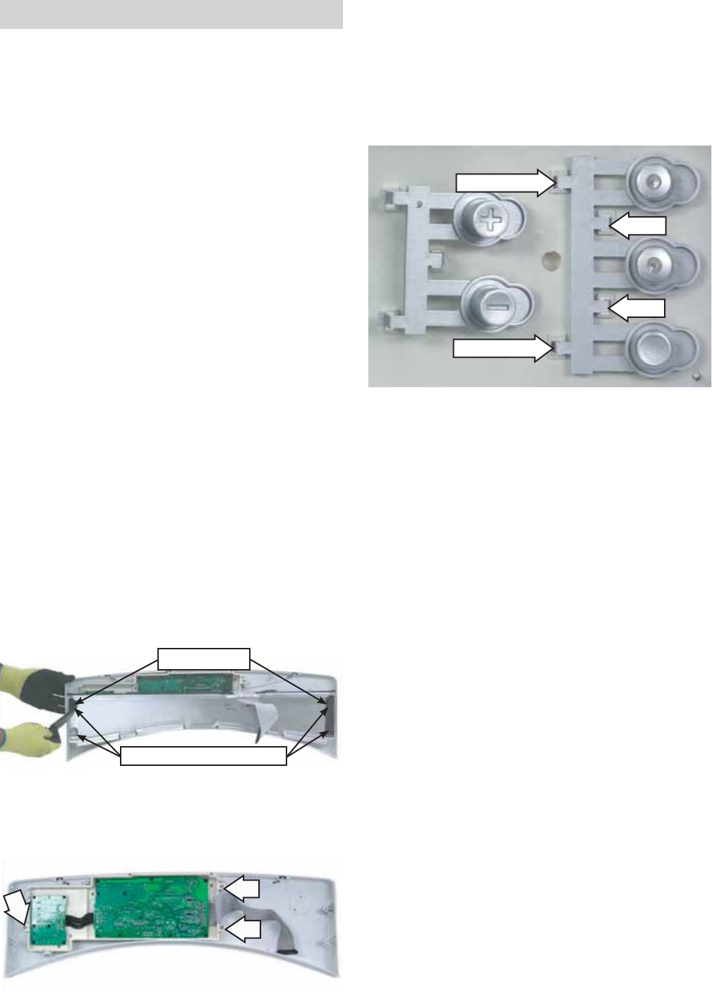
Control Board Assembly
The control board assembly is mounted in a plastic
housing that is attached to the inside of the control
panel. It consists of 2 circuit boards connected by
a ribbon. The boards and the plastic housing are
replaced as an assembly.
Operation of the control board assembly can be
checked by using the service test mode. (See Service
Test Mode.)
Error codes that are specifi c to the control board
can initiate error codes E01, E61, E80, and E81. (See
Service Test Mode.)
To remove the control board assembly:
Caution: To avoid marring the control panel, place
the panel face down on a protective surface.
Remove the top panel and the control panel.
(See Top Panel and Control Panel.)
Remove the control knob by pulling outward.
Remove the plastic wire tie that attaches
the control board ribbon to the control panel
mounting bracket.
Remove the gasket seals from the right and left
ends of the control panel mounting bracket.
Remove the 4 Phillips-head screws that attach
the control panel mounting bracket to the
control panel. Remove the bracket.
1.
2.
3.
4.
5.
Note: Each cycle selection button assembly is held
to the plastic housing with a locking tab(s) and
strut(s) system.
Press the locking tab(s) then carefully lift each
cycle selection button to clear the strut(s) from
the plastic housing.
7.
Note:
The replacement control board will always enter
into test mode t01 on initial power-up.
If replacing the control board, the dryer will not
function until the replacement control board has
been programmed.
To program the replacement control board:
Reconnect power to the dryer. (The display will
now show "---", which means no model has
been selected.)
Rotate the cycle knob until the correct model
number is displayed:
Select 1 for model DHDVH52EF/GF
Select 2 for model DBVH512EF/GF
Select 3 for model DCVH515EF/GF
Press and hold the Start/Pause key for 3
seconds. (The control will beep, indicating the
new model number has been successfully
programmed.)
Press the Power button to return to the test
selection mode.
Note: If an error is made in programming the
control, enter test mode and select T01. Then repeat
steps 1 thru 3.
•
•
1.
2.
•
•
•
3.
4.
Strut
Strut
Locking Tab
Locking Tab
Concealed Screw Locations
Gasket Seals
– 45 –
Service Test Mode
The dryer control has a service test mode that can be utilized by the service technician in order to test
critical components and to access error codes. This test mode will help the service technician to quickly
identify failed or improperly operating dryer components.
Test Mode Description
t01 Model ID Verifi es (or sets on new board) the proper model id.
t02 Error Codes Lists up to 10 control-detected problems.
t03 Software ID Displays the software version number and the non-
volatile memory version number.
t04 Program Non-volatile Memory Test Control computes and compares the 16-bit CRC of
the non-volatile memory with the pre-computed
version stored in the non-volatile memory.
t05 User Interface Control turns on all LEDs and the 7-segment display.
t06 Keys Continuity Verifi es that all displays and buttons work.
t07 Outlet Thermistor Displays outlet thermistor temperature.
t08 Inlet Thermistor Displays inlet thermistor temperature.
t09 Moisture Sensor Displays voltage read from the moisture sensor.
t10 Exhaust Detection Verifi es status of the exhaust system.
To enter the test mode: To exit the test mode:
Disconnect the power for 30 seconds.
Reconnect power and within 30 seconds of
reconnecting power:
Press signal button.
Press delay start button.
Press signal button.
Press delay start button. (Displays t01)
1.
2.
a.
b.
c.
d.
Press the power button during the test selection
mode.
Note: A dryer left in the test mode will exit the test
mode after a period of 30 minutes.
(Continued Next Page)

– 46 –
Test
Mode Press Displays Exit
t01 Start/
Pause
Displays UI model number (01-16) that corresponds to the UI model
the control is currently confi gured for. Always displays"---" when no
model is set in the control board. Proper model must be set when
control board replaced. Rotate knob until desired UI model number
is displayed (01-03), then press and hold Start/Pause until beep.
Press Power
Returns to t01
t02 Start/
Pause
Displays the most recent error code. Control will store 8 error codes
(E00=none). Press Start/Pause to clear each error code and display
the next. Press and hold Start/Pause to clear all error codes (will
then display E00).
Press Power
Returns to t02
t03 Start/
Pause
Displays software and non-volatile revision numbers. Presents
software revision number fi rst. Press and hold Start/Pause to select
non-volatile revision number.
Press Power
Returns to t03
t04 Start/
Pause
Non-volatile memory test. The control will compute and compare
the 16-bit CRC of the non-volatile memory with the pre-computed
16-bit CRC stored in the non-volatile memory. The control will sound
the key press beep and display "EEP" after successful comparison,
or sound the invalid key beep and display "Err" if unsuccessful.
Press Power
Returns to t04
t05 Start/
Pause
Turns on all LEDs and the 7-segment display. Press Power
Returns to t05
t06 Start/
Pause
The control will sound a beep as long as any key is pressed. Press Power
Returns to t06
t07 Start/
Pause
Turns on motor and inner coil (electric) or burner (gas). Displays
outlet thermistor temperature in degrees Fahrenheit.
Press Power
Returns to t07
t08 Start/
Pause
Turns on motor and inner coil (electric) or burner (gas). Displays inlet
thermistor temperature in degrees Fahrenheit.
Press Power
Returns to t08
t09 Start/
Pause
Displays voltage read from the moisture sensor in volts. Press Power
Returns to t09
t10 Start/
Pause
Displays the condition of the exhaust system. The test takes
approximately 2 minutes to complete. The control measures
the rate of temperature increase through the inlet thermistor
for a duration of 30 seconds. An acceptable increase is 48°F
(9°C) for electric and 62°F (17°C) for gas. “LO” = exhaust too
small or restricted. “HI” = exhaust adequate. (Note: “HOT”
indicates the test was not completed normally. This test must
be initiated when the inside of the dryer is cool).
Press Power
Returns to t10

– 47 –
Error Code Component,
System, or Test Description Critical
Failure
E00
All No error
No
E01
EEPROM EEPROM failure
Yes
E02
Inlet thermistor Inlet thermistor short circuit
No
E03
Outlet thermistor Outlet thermistor short circuit
No
E04
Inlet thermistor Open circuit
No
E05
Outlet thermistor Open circuit
No
E60 Door switch Door switch malfunction No
E61 Control board L2 and N incorrectly wired (ac input too high) Yes
E80 Control board Invalid UI model No
E81 Control board Invalid power model No
Error Codes
NOTE: It’s important to note error codes should only be used to help identify those components which
require testing. Never replace a part based solely on an error code. The control can generate a false error
if the right conditions exist. Use the code only as a reference and always check the component before
replacing.


– 50 –
Warranty
■Service trips to your home to teach you how to use
the product.
■Improper installation, delivery or maintenance.
■Failure of the product if it is abused, misused or used for
other than the intended purpose or used commercially.
■Replacement of house fuses or resetting of circuit
breakers.
■Damage to the product caused by accident, fire, floods
or acts of God.
■Incidental or consequential damage caused by possible
defects with this appliance.
■Damage caused after delivery.
What Is Not Covered:
This warranty is extended to the original purchaser and any succeeding owner for products purchased for home
use within the USA. In Alaska, the warranty excludes the cost of shipping or service calls to your home.
Some states do not allow the exclusion or limitation of incidental or consequential damages. This warranty gives
you specific legal rights, and you may also have other rights which vary from state to state. To know what your
legal rights are, consult your local or state consumer affairs office or your state’s Attorney General.
Warrantor: General Electric Company. Louisville, KY 40225
All warranty service provided by our Factory Service Centers,
or an authorized Customer Care®technician. To schedule service,
on-line, 24 hours a day, visit us at ge.com, or call 800.GE.CARES
(800.432.2737).
Staple your receipt here.
Proof of the original purchase
date is needed to obtain service
under the warranty.
For The Period Of: We Will Replace:
One Year Any part of the dryer which fails due to a defect in materials or workmanship. During this
From the date of the full one-year warranty, GE will also provide, free of charge, all labor and related service costs
original purchase to replace the defective part.
