GE Refrig Monogram Btm Mount Inverter Comp ZIC 31 9122
2013-04-09
: Pdf Ge - Refrig - Monogram Btm Mount Inverter Comp - Zic - 31-9122 GE - Refrig - Monogram Btm Mount Inverter Comp - ZIC - 31-9122 GE, Camco, Hotpoint, Mofat
Open the PDF directly: View PDF ![]() .
.
Page Count: 51
PUB # 31-9122 6/04
MODEL SERIES:
ZIC360NR
ZICS360NR
TECHNICAL SERVICE GUIDE
Monogram Bottom Mount Inverter
Compressor Refrigerators with
Electronic Controls
GE Consumer & Industrial

– 2 –
IMPORTANT SAFETY NOTICE
The information in this service guide is intended for use by
individuals possessing adequate backgrounds of electrical,
electronic, and mechanical experience. Any attempt to repair a
major appliance may result in personal injury and property
damage. The manufacturer or seller cannot be responsible for the
interpretation of this information, nor can it assume any liability in
connection with its use.
WARNING
To avoid personal injury, disconnect power before servicing this
product. If electrical power is required for diagnosis or test
purposes, disconnect the power immediately after performing the
necessary checks.
RECONNECT ALL GROUNDING DEVICES
If grounding wires, screws, straps, clips, nuts, or washers used to
complete a path to ground are removed for service, they must be
returned to their original position and properly fastened.
GE Consumer & Industrial
Technical Service Guide
Copyright © 2004
All rights reserved. This service guide may not be reproduced in whole or in part
in any form without written permission from the General Electric Company.

– 3 –
TABLE OF CONTENTS
TECHNICAL DATA .................................................................................................................... 5
MODEL NOMENCLATURE ........................................................................................................ 6
MINI-MANUAL .......................................................................................................................... 6
RATING PLATE........................................................................................................................ 6
COMPONENT AND CONNECTOR LOCATOR VIEWS .............................................................. 7
CABINET ................................................................................................................................... 8
Cabinet ............................................................................................................................... 8
Machine Compartment ..................................................................................................... 8
Door Closure Mechanism.................................................................................................. 9
Fresh Food Door and Hinges .......................................................................................... 10
Door .................................................................................................................................. 10
Freezer Drawer ............................................................................................................... 10
Door and Drawer Gaskets.............................................................................................. 10
Rollers and Leveling ........................................................................................................11
ICEMAKER ...............................................................................................................................11
Water Valve and Water Line ...........................................................................................11
AIRFLOW ............................................................................................................................... 13
Damper ............................................................................................................................ 13
Evaporator Fan ................................................................................................................ 14
Condenser Fan ................................................................................................................ 17
Drain Pan Fan ................................................................................................................. 18
DEFROST SYSTEM ................................................................................................................ 18
Adaptive Defrost .............................................................................................................. 18
Defrost Heater ..................................................................................................................20
Evaporator Thermistor .................................................................................................... 20
Defrost Overtemperature Thermostat ............................................................................ 20
CONTROL SYSTEM ............................................................................................................... 21
Touch Panel and Temperature Control Board .............................................................. 21
Main Control Board ......................................................................................................... 22
Main Control Board Locator Tables ............................................................................... 26
Thermistors ...................................................................................................................... 28
ELECTRICAL SYSTEM ........................................................................................................... 29
Door and Drawer Switches............................................................................................. 29
Master Light Switch ........................................................................................................ 29
Temperature Overload Device (TOD)............................................................................. 29
Schematic ........................................................................................................................ 30
REFRIGERATION SYSTEM ............................................................................................... 31
Inverter Compressor........................................................................................................ 33

– 4 –
Inverter ............................................................................................................................. 35
Condenser ........................................................................................................................ 37
Condenser Loop .............................................................................................................. 37
Drier.................................................................................................................................. 38
Evaporator ....................................................................................................................... 38
Auxiliary Line ..................................................................................................................39
Refrigerant Charge ......................................................................................................... 39
DIAGNOSTIC MODE............................................................................................................... 40
ILLUSTRATED PARTS ........................................................................................................... 41
WARRANTY ............................................................................................................................ 51
Table of Contents (cont.)
– 5 –
TECHNICAL DATA
Temperature Control...........................WR55X10098
Lamp Overtemperature Thermostat..WR50X10003
Defrost Heater Overtemperature
Thermostat.............WR50X10030
Defrost Heater....................................WR51X10015
Condenser Fan Motor.........................WR60X10053
Condenser Fan Blade........................WR60X10049
Evaporator Fan Motor.........................WR60X10043
Evaporator Fan Blade.........................WR60X10050
Main Board..........................................WR55X10433
Thermistors (2-FF, 1-FZ, 1-EV)..........WR55X10028
Drain Pan Fan Motor...........................WR60X10106
Damper...............................................WR09X10065
Evaporator...........................................WR85X10007
Compressor........................................WR87X10064
Condenser..........................................WR84X10030
Dryer.....................................................WR86X0096
Inverter................................................WR55X10155
DISCONNECT POWER CORD BEFORE SERVICING
IMPORTANT - RECONNECT ALL GROUNDING DEVICES
All parts of this appliance capable of conducting
electrical current are grounded. If grounding wires,
screws, straps, clips, nuts or washers used to
complete a path to ground are removed for service,
they must be returned to their original position and
properly fastened.
CAUTION
To avoid personal injury when servicing the
condensing unit, stand on a ladder which will give
enough support to allow removal of the top panel
and safely allow access to service the unit.
Max Defrost Control
W/No Door Openings ..................... 60 hrs @ 40 min
Evap Defrost Thermo Disc ............................... 65-45°F
Light Thermostat. .......................................... 190-130°F
Electrical Rating: 115V AC 60 Hz ..................... 9.0 amp
Maximum Current Leakage............................. 0.75 mA
Maximum Ground Path Resistance .......... 0.14 Ohms
Energy Consumption .......................... 39 KWhr/month
ELECTRICAL SPECIFICATIONS
NO LOAD PERFORMANCE
CONTROL POSITION 37-0°F and
AMBIENT TEMPERATURE OF
70°F90°F
Fresh Food, °F .............................. 35-39 ............... 35-39
Frozen Food, °F .......................... (-4) +4 ............. (-4) +4
Percent Running Time ...................... 60 .................... 80
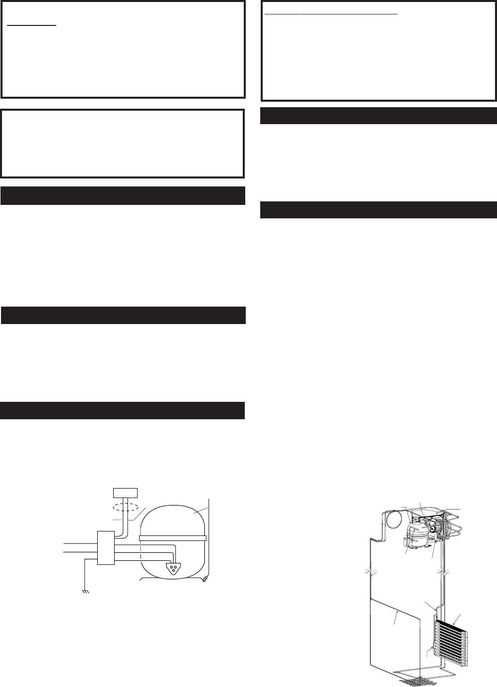
REFRIGERATION DIAGNOSIS
To access the low pressure side of the system, install a
WJ56X61 valve only on the process tube extending
from the compressor case.
COMPRESSOR
GREEN/YELLOW
GREEN/YELLOW
BLACK
ORANGE
GROUND
TO CABINET
WIRING
COMMUNICATION
SIGNAL
RED
WHITE
GROUND
INVERTER
BLACK
BLUE
BROWN
IMPORTANT SAFETY NOTICE
This information is intended for use by individuals
possessing adequate backgrounds of electrical,
electronic and mechanical experience. Any attempt
to repair a major appliance may result in personal
injury and property damage. The manufacturer or
seller cannot be responsible for the interpretation
of this information, nor can it assume any liability
in connection with its use.
REPLACEMENT PARTS
Compressor ................................................. 833 BTU/hr
Minimum Compressor Capacity
Vacuum, ..................................................... 22 inches
Minimum Equalized Pressure
@ 70°F..................................................... 60/65 PSIG
@ 90°F..................................................... 79/80 PSIG
R134a Refrig. Chg. ........................................... 13.00 oz
REFRIGERATION SYSTEM
Sealed System
CONDENSER
COMPRESSOR
INVERTER*
PROCESS TUBE DRYER
SUCTION TUBE
EVAPORATOR
CONDENSER LOOP
CAPILLARY
*Approximate
location of
inverter
– 6 –
MODEL NOMENCLATURE
Brand/Product
Z - Monogram
Style
I - Built In
Configuration
C - Bottom Mount
Color
S - Stainless
Blank - Trim Model
Size
360 - 36 Inches Wide
Engineering
A - Initial Design
B - 1st Revision
C - 2nd Revision
D - 3rd Revision
Etc.
Door Type
F - Flat
R H- Right Door Swing
LH - Left Door Swing
Icemaker/Exterior
N - Non Dispenser
Model Year
R - 2004 Energy
ZI
CS360 NRA LH
Serial Number
The first two numbers of the serial number
identify the month and year of manufacture.
Example: AG123456S = January, 2004
A
- JAN 2005 - H
D - FEB 2004 -
G
F - MAR 2003 - F
G - APR 2002 - D
H - MAY 2001 - A
L - JUN 2000 - Z
M - JUL 1999 - V
R - AUG 1998 - T
S - SEP 1997 - S
T - OCT 1996 - R
V - NOV 1995 - M
Z - DEC 1994 - L
The letter designating
the year repeats every
12 years.
Example:
T - 1974
T - 1986
T - 1998
MINI-MANUAL
The mini-manual is located behind the
grille panel at the top of the unit. It is taped
to the left side wall of the machine
compartment. When done, return the
mini-manual to its original location for
future use.
RATING PLATE
The rating plate, located inside the
fresh food compartment under the
right-hand storage drawer, contains
the model and serial numbers.
Additionally, the rating plate specifies
the minimum installation clearances,
electrical voltage, frequency,
maximum amperage rating,
refrigerant charge, and type.

– 7 –
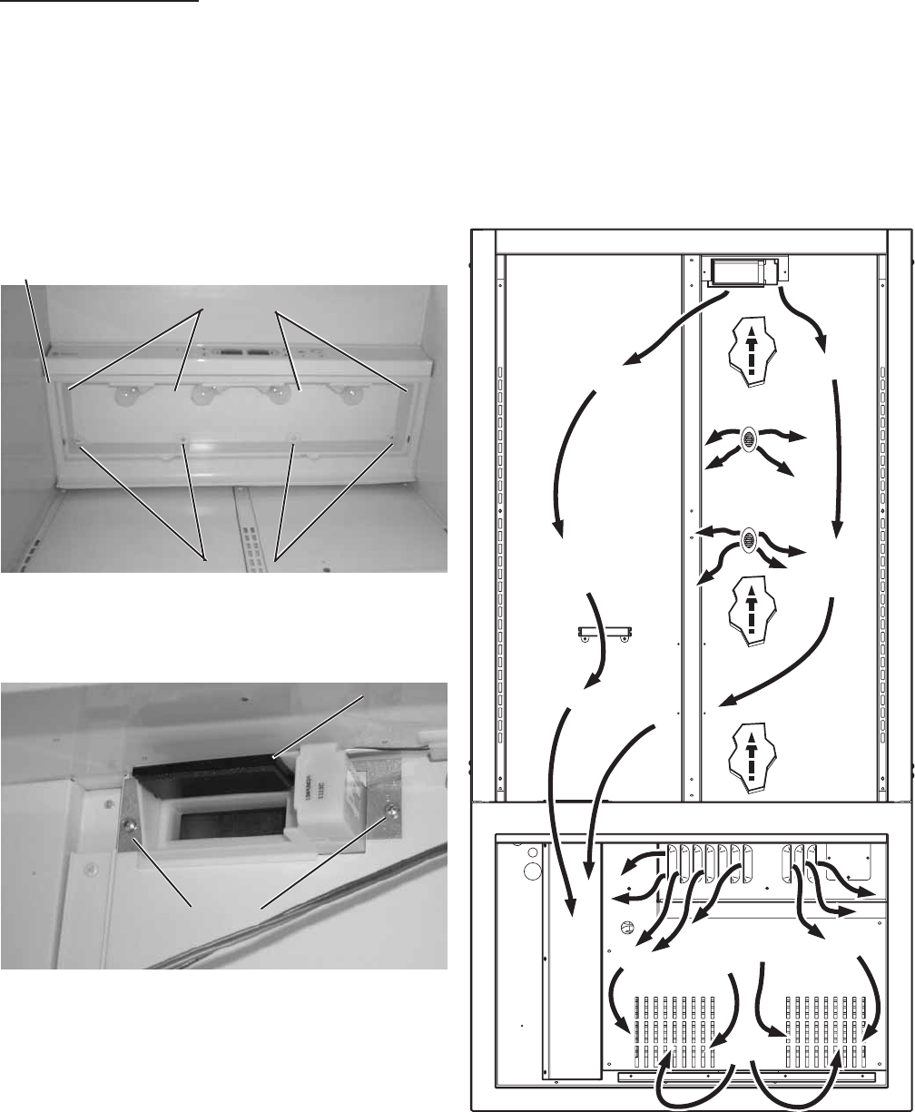
Fresh Food Compartment
P000337
6
Freezer Drawer Switch
Icemaker
Freezer Thermistor
Freezer Compartment
P0003329
Fresh Food
Thermistors
Temperature Touch Panel
Door Switch
Damper
Air Duct
Cold Air
Outlets
COMPONENT AND CONNECTOR LOCATOR VIEWS
– 8 –
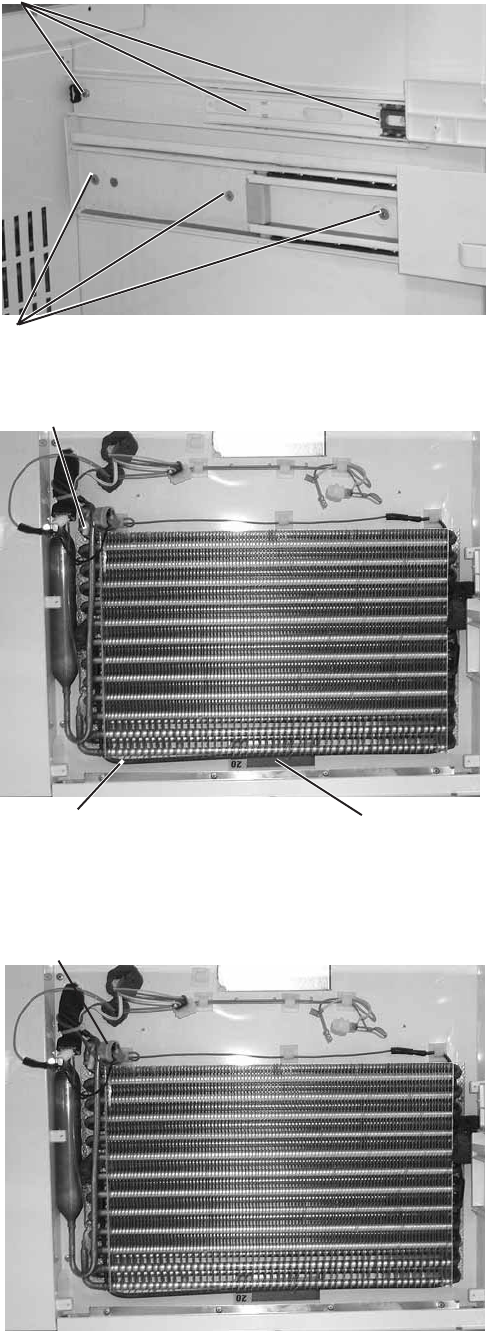
Bolts Track Bolt
Right Side of Machine Compartment
Bolt
Track Bolt Screws
Left Side of Machine Compartment
Raise
Grille
Panel
to Stop
Position
Remove 2 Screws
Each Side to
CABINET
Cabinet
The outer case is made of galvanized steel. The
fresh food and freezer liners are painted metal with
a smooth finish. Individual fresh food and freezer
compartments provide separation and enhanced
individual control between the compartments. The
metal liner provides a thermal break between the
interior of the refrigerator and freezer
compartments and reduces the transfer of heat
from the room into the fresh food and freezer
compartments. The liner is not removable or
replaceable.
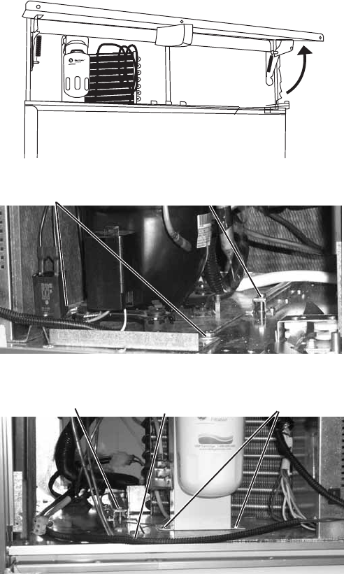
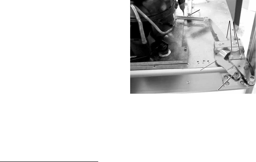
Machine Compartment
The machine compartment is located on the top of
the unit and has a movable chassis that can be
extended from the front of the unit to provide
access to the refrigeration system and
components.
Caution: Avoid kinking the refrigeration lines when
sliding the chassis out and back in.
To extend the chassis:
1. Raise the grille panel to stop position.
2. Remove the wire guard and door cover.
3. Remove the door switch.
4. Disconnect the door closure mechanism
spring from the pin and remove the pin by
turning it counterclockwise.
5. Remove the 2 screws securing the inverter.
6. Remove the door spring.
7. Remove the 2 front (7/16-in.) bolts from tray.
8. Loosen the 2 rear (7/16-in.) tray bolts.
9. Pull the chassis forward until it reaches the
stops in the tracks, working the refrigeration
tubing as you pull the chassis out.
Note. When sliding the chassis back into position,
be certain the lines and wiring have not fallen
behind the chassis.
– 9 –
Spring
Allen Head Bolt
Bolts
Actuator Arm
Door Closure Mechanism
The door closure mechanism uses a spring to
provide positive door closure from 30 degrees.
The door closure mechanism actuator arm has a
spring attached to the rear and is supported by
guide rollers on either side of the base channel.
The roller circumferences and the actuator arm
detents are matched for smooth operation. The
arm is attached to the door with an Allen head
shoulder bolt.
The closure mechanism allows easy opening to
approximately 90 degrees, where the arm has a
detent to permit the door to remain open at 90
degrees with minimal tension. Once the door is
opened beyond 90 degrees, the closure
mechanism pulls the door open until the closure
arm engages the door stop at approximately 130
degrees. The reverse action occurs when the door
is closed.
Note: The door closure mechanism and the top
door hinge are held by the same bolts. Take the
necessary precautions to secure the fresh food
door when the door closure mechanism is being
removed.
• The actuator arm is spring loaded with moderate
spring tension.
To remove the door closure mechanism
1. Remove the 3/16-in. Allen head bolt and
spacer from the door and actuator arm.
2. Disconnect the spring from the pin on the top
of the cabinet and pull the actuator arm from
the closure mechanism.
3. Remove 4 (3/8-in.) bolts and the door closure
mechanism.
Shown with Inverter Removed for Clarity
– 10 –
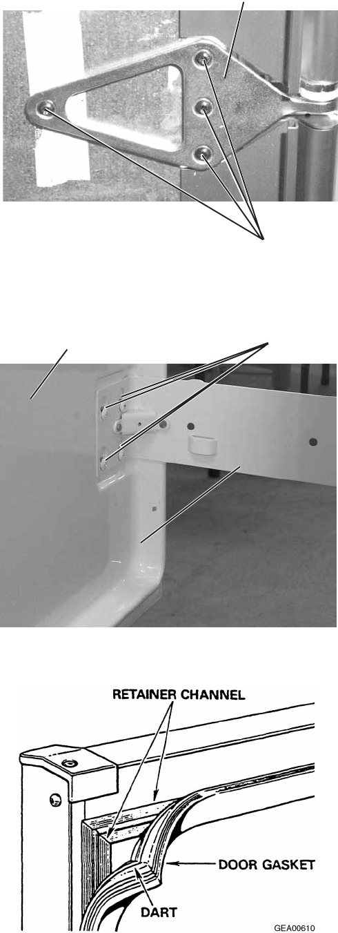
P0003336
Center Hinge
Screws
Screws
Slide/Support
Assembly
Door
Left Side of Freezer Door
Fresh Food Door and Hinges
WARNING: Use the appropriate safety equipment
and lifting techniques.
Caution: Use wood or a heavy plastic sheet to
protect the floor where the door will be placed.
Note: Unit must be removed from its installation
to remove center hinge.
Door
The door is of one-piece construction with foam
insulation. One-piece construction provides
superior thermal performance and reduces air
infiltration.
The inner door panel and outer door panel cannot
be separated and must be replaced as an
assembly.
1. Remove all food and bins from the inner door
liner.
2. Tape door to cabinet.
3. Remove the door closure mechanism (see
previous procedure).
4. Remove the upper hinge.
5. Remove tape and lift the door off center hinge.
6. Remove 4 T-27 Torx screws and center hinge.
Freezer Drawer
1. Loosen 4 screws connecting each side of the
freezer door to the slide/support assemblies.
2. Lift door up and out to remove.
Door and Drawer Gaskets
The fresh food door and freezer drawer have
magnetic gaskets that create a positive seal to the
front of the steel cabinet. The magnetic door
gaskets are secured to the fresh food door and
freezer drawer by a barbed edge that locks into a
retainer channel.
1. Starting at any corner, pull the old gasket out of
the retainer channel.
2. Soak the new gasket in warm water to make it
pliable.
3. Push the barbed edge of the gasket into the
retainer channel.
– 11 –
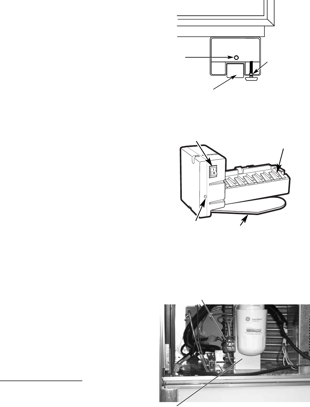
Icemaker
Feeler Arm
Power Switch
Green
Power Light
Hex Nut
Wheel
Leveling Leg
P0003393
Water Valve
Water Filter Bracket
Rollers and Leveling
This model has 4-point leveling provided by
adjustable rollers on the rear and leveling legs on
the front. It also has 2 nonadjustable front rollers
that are used only for unit positioning.
To level the unit:
1. Turn the 7/16-in. hex nut located above the
front rollers to adjust the roller on the rear of
the unit. Turn clockwise to raise,
counterclockwise to lower.
2. Turn the front legs with a 1-1/4 in. open end
wrench to adjust the front of the unit. Turn
clockwise to raise, counterclockwise to lower.
ICEMAKER
The icemaker is mounted to the upper left wall of
the freezer cabinet. Under normal operating
conditions, temperatures, door openings, and food
load, the icemaker is capable of producing
approximately 100 to 130 cubes in a 24-hour
period.
Note: The freezer door light switch, located on
the back wall of the freezer, also serves as an
icemaker interlock (or kill) switch. It will open the
circuit to the icemaker any time the freezer drawer
is open.
To service the icemaker, refer to GE Publication
31-9063.
Water Valve and Water Line
The water valve is mounted to the side of the
water filter bracket in the machine compartment.
A plastic water line is routed from under the unit,
up the back of the cabinet, into the machine
compartment, and to the water valve.
A low-pressure plastic water line supplies water to
the icemaker from the water valve. The plastic
water line is routed from the water valve, out the
back of the machine compartment, down the back
of the cabinet to the fill tube grommet. The
icemaker fill tube is also plastic.
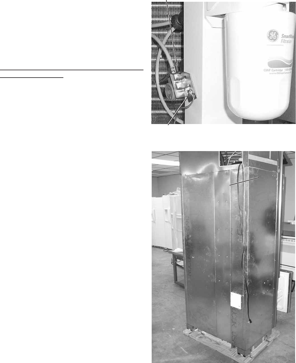
To Replace the Water Valve
Note: Some water may leak from the water supply
line and valve when they are disconnected.
1. Shut off the water supply to the freezer.
– 12 –
P0003413
P
Screw
Water Valve
Access Cover
2. Raise the machine compartment cover panel.
3. Remove 2 Phillips screw attaching the water
valve cover.
4. Remove 2 Phillips screw attaching the water
valve to the filter bracket.
5. Disconnect the wiring harness connector and
2 water lines from the water valve and remove.
To Replace the Water Line from the Water Valve to
the Fill Tube Grommet
Note: Some water may leak from the water supply
line and valve when they are disconnected.
1. Shut off the water supply to the freezer.
2. Remove the unit from its installation.
3. Remove 14 (1/4-in.) screws and the metal
access cover.
4. Disconnect the water line at the quick
connector by pushing in the white collar on the
quick connector while pulling the water line out.
5. Loosen the clamp at the fill tube grommet and
remove the water line.
– 13 –
P0003387
Screws
Screws
Light Assembly
P0003380
Screws
Damper
AIRFLOW
Damper
The fresh food compartment receives chilled air via an electronic damper that is positioned at the top
rear of the fresh food compartment. The damper is controlled by the main control board and when
open, allows the evaporator fan to push chilled air from the evaporator into the fresh food compartment.
To remove the damper
1. Remove the light cover.
2. Remove 8 Phillips screws and the light
assembly.
3. Disconnect the damper wiring.
4. Remove 2 Phillips screws and the damper.
– 14 –
The evaporator fan is the same fan used on previous models; however a significant difference is that the
main control board does not require, nor receive, input from the fan feedback/rpm (blue) wire. The fan
utilizes a permanent magnet, 4-pole, DC motor that operates at three different speeds: high, medium,
and low. The speed of the fan is controlled by the voltage output from the main control board. Voltage
output from the control board to the fan is 13.2 VDC; however to regulate the speed of the fan, the main
control board uses pulse width modulation (PWM). When operating, voltage is sent in pulses (much like
a duty cycle) as opposed to an uninterrupted flow. This pulsing of 13.2 VDC produces effective voltage
being received at the motor, which is the equivalent to a reduction in voltage. Fan speed will be selected
and maintained by the main control board regulating the length and frequency of the 13.2 VDC pulse.
Temperature may cause some fan speed variation. Fan speed may vary +/- 5%, depending on the
temperature, with higher temperatures causing slightly higher speeds.
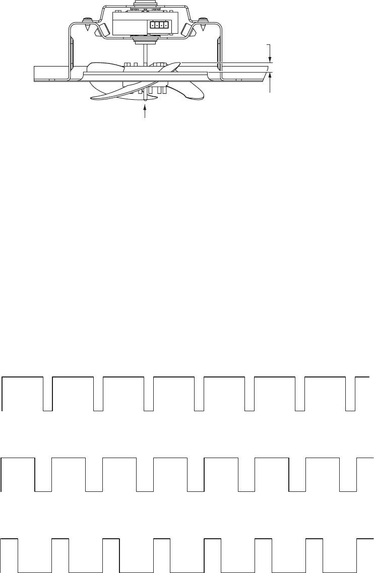
Evaporator Fan
The position of the fan blade in relation to the shroud is important. Refer to illustration for specifications.
5/16 +/- .03
Airflow
High Speed (12 VDC measured)
Medium Speed (9.2 VDC measured)
Low Speed (8 VDC measured)
EVAPORATOR FAN SPEEDS
12 VDC
9.2 VDC
8 VDC
13.2 VDC
0 VDC
0 VDC
0 VDC
13.2 VDC
13.2 VDC
– 15 –
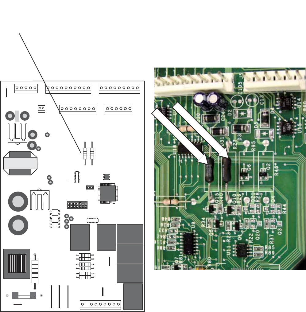
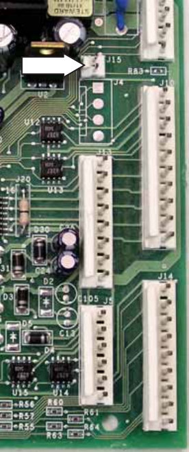
Evaporator and Condenser Fan Resistors
If the fan shorts, it will damage the main control
board. If the resistor on the main control board is
burnt, you must replace the fan and the board (see
photo).
1
5
1
10
1
9
J1 or J14
J5
6
J3 or J10
J2 or J13
1
DEFROST
K4
21
J6
K5
CUSTOM COOL
K7
PAN
HEATER
CRUSHER
K2
WATER
K3
J4 or J16
1
8
J7
AUGER
K1
1
J2
EARTH
EARTH
J1
J18
J12
J15
1
J19
J11
J9
Comm. 2-Way Digital
Comm. +12V
Comm. Common
Damper - Blue
Damper - White
Damper - Red
Damper - Yellow
FF1 Thermistor
FF2 Thermistor
FZ Thermistor
Evaporator Thermistor
+5V
Custom Cool Damper1 +
Custom Cool Damper1 -
+5V
Custom Cool Thermistor
Evaporator Fan Tach.
Fan Common
Evaporator Fan
Condenser Fan
Custom Cool Fan
Fan +12V
Inverter Common
Inverter Output
Drain Pan Heater
Not Used
Defrost Heater
Line (L1)
Neutral
FZ Door Switch
FF Door Switch
Custom Cool Heater
Auger Motor Interlock
Water Valve
Crusher Solenoid
Auger Motor
J8
Not Used
Evaporator Fan Resistor
Condenser Fan Resistor

– 16 –
White Wire (DC Common)
The white wire is the DC common wire used for
testing. During repairs, DC polarity must be
observed. Reversing the DC polarity will cause a
shorted motor and/or board.
Red Wire (Supply)
Each motor uses an internal electronic controller
to operate the motor. Supply voltage from the
main control board remains at a constant
12 VDC.
Blue Wire (Feedback/RPM)
The blue wire feeds rpm (speed) information to
the main control board, allowing the board to
maintain consistent fan speeds. Loss of feedback
from the blue wire will result in the fan accelerating
to maximum speed. Measure the fan rpm using
the frequency between the blue and white wires.
High speed - 205 to 215 Hz (3140 RPM)
Medium speed - 155 to 165 Hz (2415 RPM)
Low speed - 140 to 150 Hz (2160 RPM)
Yellow Wire (Signal)
The yellow wire is the input wire from the main
control board. The main control board provides
8 VDC effective voltage for low speed, 9.2 VDC
effective voltage for medium speed, and 12 VDC
for high speed. The fan will operate in low speed
only when the fresh food thermistor is satisfied.
Note: When testing these motors:
• You cannot test with an ohmmeter.
• DC common is not AC common.
• Verify 2 voltage potentials:
a. Red to white - power for internal controller.
b. Yellow to white - power for fan.
• Observe circuit polarity.
• Motors can be run for short periods using a
9-volt battery. Connect the white wire to the
negative (-) battery terminal only. Connect the
red and yellow wires to the positive (+) battery
terminal.
Some of the low voltage DC
connector labeling on this model
may differ from other models. The
function and diagnostics for these
connectors are identical for all
models.
1
5
1
10
1
9
J1 or J14
J5
6
J3 or J10
J2 or J13
1
DEFROST
K4
21
J6
K5
CUSTOM COOL
K7
PAN
HEATER
CRUSHER
K2
WATER
K3
J4 or J16
1
8
J7
AUGER
K1
1
J2
EARTH
EARTH
J1
J18
J12
J15
1
J19
J11
J9
Comm. 2-Way Digital
Comm. +12V
Comm. Common
Damper - Blue
Damper - White
Damper - Red
Damper - Yellow
FF1 Thermistor
FF2 Thermistor
FZ Thermistor
Evaporator Thermistor
+5V
Custom Cool Damper1 +
Custom Cool Damper1 -
+5V
Custom Cool Thermistor
Evaporator Fan Tach.
Fan Common
Evaporator Fan
Condenser Fan
Custom Cool Fan
Fan +12V
Inverter Common
Inverter Output
Drain Pan Heater
Not Used
Defrost Heater
Line (L1)
Neutral
FZ Door Switch
FF Door Switch
Custom Cool Heater
Auger Motor Interlock
Water Valve
Crusher Solenoid
Auger Motor
J8
Not Used
J4 or J16 J3 or J10 J1 or J14
J2 OR J13
– 17 –
Screws
Wiring Harness Connector
Housing
Fan
Motor
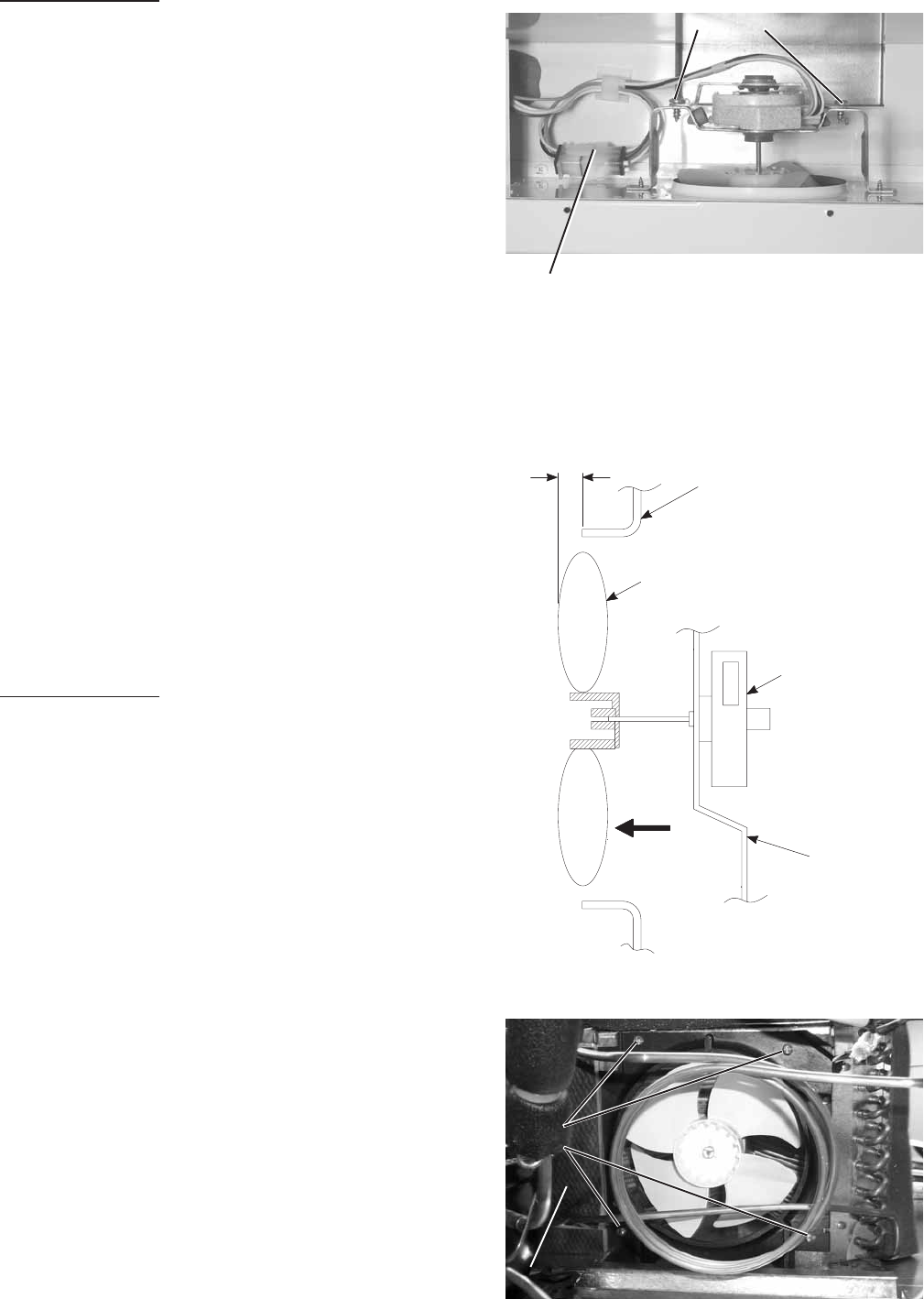
0.375"
1/2"
Air Flow
0.50" ± 0.05
Bracket
GEA01148
Condenser Fan Adjustment
+/- .100
Airflow
P0003374
Screws
Insulation
To remove the fan
1. Remove the drawer (see procedure).
2. Remove 5 screws securing the rear duct.
3. Disconnect the freezer light and light thermostat
wiring and the remove duct.
4. Disconnect the wire connector from the fan motor.
5. Remove 2 screws from the fan motor bracket and
remove the evaporator fan motor.
Condenser Fan
The condenser fan is a permanent-magnet, 4-pole,
DC motor that will operate at 3 speeds. Fan speed
(low, medium, high) corresponds with compressor
speed to minimize pressure variations in the sealed
system. The speed of the fan is controlled by the
voltage output from the main control board. Voltage
output from the control board to the fan is 13.2 VDC;
however to regulate the speed of the fan, the main
control board uses pulse width modulation (PWM).
Inlet air is available through the left front and left rear of
the machine compartment.
If the fan shorts, it will damage the main control board.
If the resistor on the main control board is burnt, you
must replace the fan and the board.
The condenser fan is mounted with screws to a fan
shroud and mounting bracket in back of the
condenser.
To remove the fan
1. Extend the machine compartment chassis (see
Machine Compartment).
2. Disconnect the condenser fan wiring at the
harness connector.
3. Remove 4 screws and fan assembly.
4. Remove fan blade, 2 screws from the fan
mounting bracket, and fan motor.
Note: A magnetic tip screwdriver may be required to
install the condenser fan mounting screws.
To install lower fan mounting screw:
1. Pull back foam insulation to visually locate screw
hole.
2. Locate hole with fingers of left hand.
3. Place screw on the tip of the screwdriver.
4. Use your right hand to maneuver the screwdriver
and use your left hand to guide the screw into the
hole.

– 18 –
Drain Pan Fan
The Monogram Bottom Mount has an auxiliary
evaporation fan located under the unit. The
purpose of this fan is to improve the evaporation
rate of drain water should extreme conditions
occur.
Should this fan malfunction, there is no
replacement procedure. The absence of this fan
will not affect drain water evaporation under
normal conditions. A stainless steel hot gas loop
routed through the drain pan will provide ample
evaporation.
To remove the fan
1. Remove toe kick (2 screws).
2. Slide out and remove drain pan.
3. Disconnect harness from fan motor.
4. Remove fan by unscrewing 2 screws
accessible from within the pan housing.
DEFROST SYSTEM
Adaptive Defrost
Adaptive Defrost can be described as a defrost
system that adapts to a refrigerator’s surrounding
environment and household usage.
Unlike conventional defrost systems that use
electromechanical timers with a fixed defrost cycle
time, Adaptive Defrost utilizes an intelligent,
electronic control to determine when the defrost
cycle is necessary. In order to accomplish the
correct defrost cycle time, the main control board
monitors the following refrigerator operations:
•Length of time the refrigerator doors were open
since the last defrost cycle
• Length of time the compressor has run since
the last defrost cycle
• Amount of time the defrost heaters were on in
the last defrost cycle
Adaptive Defrost is divided into 4 separate cycles.
Those operations are:
•Cooling Operation
• Pre-Chill Operation
• Defrost Heater Operation
• Dwell Period

– 19 –
Adaptive Defrost (Cooling Operation)
During the cooling operation, the main control
board monitors door opening (fresh food door and
freezer drawer) and compressor run times. The
board counts the time the doors are open. It
reduces the length of time between defrosts by
300 seconds (multiplication factor) for each
second that each door is open (if both doors are
open, it reduces it by twice the amount). The
multiplication factor reduces compressor run time.
If the doors are not opened, the compressor will
run up to 60 hours between defrosts. If the doors
are opened frequently and/or for long periods of
time, the compressor run time between defrosts
will be reduced to as little as 8 hours.
Adaptive Defrost (Pre-Chill Operation)
When the main control board determines that
defrost is necessary, it will force the refrigerator
into a continuous cool mode (pre-chill). During pre-
chill, the freezer temperature may be driven below
the set point. However, the fresh food temperature
will be regulated by the evaporator fan running at
low speed. Pre-chill will last for 30 minutes. These
models do have an 8-hour defrost hold-off.
Adaptive Defrost (Defrost Heater Operation)
After 30 minutes of pre-chill operation, the main
control board turns off the compressor, condenser
fan, and evaporator fan.
During defrost operation, the main control board
monitors the evaporator temperature using
evaporator thermistor inputs. Typically, the
evaporator thermistor will sense a temperature of
45°F within 16 minutes. When the thermistor
senses 45°F, the main control board will terminate
defrost heater operation. Maximum defrost cycle
(heater on) time is 35 minutes (main control board
time out).
The defrost system is protected by a defrost
overtemperature thermodisc (bimetal switch). The
thermostat opens when the evaporator
temperature raises to 60°F and closes when the
evaporator temperature lowers to 45°F.
Adaptive Defrost (Dwell Period)
After defrost heater operation has been terminated
by the main control board, a 20-minute dwell
period occurs. During this period, the
compressor, condenser fan, and evaporator fan
remain off. The remaining frost melting from the
evaporator will continue to drip and drain so that,
prior to the cooling operation, the evaporator will be
totally clear of any moisture. The pan heater is on
for the entire 20 minute dwell period.
Normal Operating Characteristics
• The fill tube heater is on when the defrost
heaters are on.
• Pan heaters are on when the defrost heaters
are on and during dwell period (25 minutes
plus defrost time).
– 20 –
P0003343
Defrost Heater
Evaporator Thermistor
P0003407
Screws
Screws
Clip
P0003343
Defrost Overtemperature Thermostat
Defrost Heater
Caution: Use care to avoid scratching the finish
on unit walls.
The defrost heater is a single-calrod type, radiant
heater mounted under the evaporator.
To remove the defrost heater:
1. Remove the drawer (see procedure).
2. Remove upper right slide/support assembly by
removing 3 Phillips screws.
3. Remove lower right slide/support assembly by
removing 3 Torx screws.
4. Remove 5 screws, disconnect light and light
thermostat wiring, and remove rear duct.
5. Remove 4 screws and evaporator cover.
6. Disconnect the heater lead wires.
7. Remove the clip securing the heater to the
evaporator and remove the heater.
Evaporator Thermistor
The evaporator thermistor is mounted on the
upper left side of the evaporator. The defrost cycle
will terminate when the main control board detects
45°F from the evaporator thermistor. The main
control board must sense 45°F in less than 40
minutes, or the defrost cycle will time out. Average
time to defrost is 20 minutes. Defrost time should
not exceed 40 minutes. Defrost time does not
include dwell and post dwell periods.
Defrost Overtemperature Thermostat
The defrost overtemperature thermostat (bimetal
switch) is mounted on the evaporator and provides
overtemperature protection during defrost. This
thermostat will open at 65°F and will close
at 45°F.
Note: The main control board will not know if the
heater does not come on due to a broken heater,
open defrost overtemperature thermostat, or open
wiring harness. The defrost heater is controlled by
maximum time on the main control board or
temperature at the evaporator thermistor.
– 21 –
P0003340
P0003387
Screws
Screws
Light Assembly
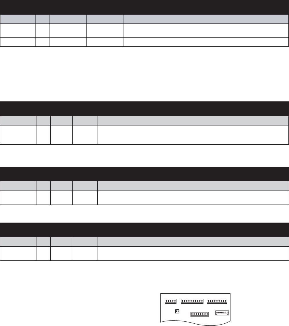
CONTROL SYSTEM
Touch Panel and
Temperature Control Board
The temperature control assembly is located at
the top front of the fresh food compartment and
contains the touch panel and temperature control
board.
The temperature control board receives switched
DC voltage from the main control board. Input
consists of pins 2 to 3. Failure of input results in
default to most recent setting. Pin 1 provides
digital communication between the temperature
control board and the main control board. Failure
of communication results in erratic control.
To remove the temperature control assembly:
1. Remove the light cover.
2. Remove 8 Phillips screws and the light
assembly.
Note: Temperature control assembly is mounted
on 3 slotted fasteners. Fasteners do not need to
be loosened or removed.
3. Carefully cut RTV seal between temperature
control assembly and cabinet.
4. Slide the temperature control assembly back
to release it from the slotted fasteners and
lower the assembly.
5. Disconnect the wiring connector from the
temperature control board.
6. Slide the touch panel out of the temperature
control assembly.
7. Remove 2 screws and the temperature control
board.
Note: Use RTV 102 to reseal temperature control
assembly when reassembling.
Touch Panel
Temperature Control Assembly

– 22 –
Main Control Board
The main control board, located behind a metal cover at the top of the refrigerator in the machine
compartment, manages the operation of the refrigerator by calculating response from various inputs.
J4 or J16 J3 or J10 J1 or J14
J2 OR J13
Some of the low voltage DC
connector labeling on this model
may differ from other models. The
function and diagnostics for these
connectors are identical for all
models.
1
5
1
10
1
9
J1 or J14
J5
6
J3 or J10
J2 or J13
1
DEFROST
K4
21
J6
K5
CUSTOM COOL
K7
PAN
HEATER
CRUSHER
K2
WATER
K3
J4 or J16
1
8
J7
AUGER
K1
1
J2
EARTH
EARTH
J1
J18
J12
J15
1
J19
J11
J9
Comm. 2-Way Digital
Comm. +12V
Comm. Common
Damper - Blue
Damper - White
Damper - Red
Damper - Yellow
FF1 Thermistor
FF2 Thermistor
FZ Thermistor
Evaporator Thermistor
+5V
Custom Cool Damper1 +
Custom Cool Damper1 -
+5V
Custom Cool Thermistor
Evaporator Fan Tach.
Fan Common
Evaporator Fan
Condenser Fan
Custom Cool Fan
Fan +12V
Inverter Common
Inverter Output
Drain Pan Heater
Not Used
Defrost Heater
Line (L1)
Neutral
FZ Door Switch
FF Door Switch
Custom Cool Heater
Auger Motor Interlock
Water Valve
Crusher Solenoid
Auger Motor
J8
Not Used

– 23 –
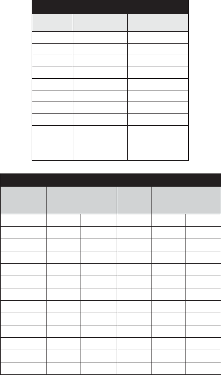
SNOITINIFEDNIPDRAOBLORTNOC
ROTCENNOC NIP TUPNI TUPTUO NOITCNUF
J1 or J14 CDV
CDV
CDV
CD
V
1
J1 or J14 2
J1 or J14 3
J1 or J14 4
5
J1 or J14
Feedback of fresh food thermistor value. Thermistor is NTC, when temperature drops, resistance
value increases, causing return voltage reduction. This value is used to cycle fresh food fan
(when used), evaporator fan, compressor, and condensor fan. Feedback is filtered to respond to
8 degrees of change per minute.
Feedback of second fresh food thermistor value (when used). Thermistor is NTC, when
temperature drops, resistance value increased, causing return voltage reduction. This value is
used to cycle fresh food fan (when used), evaporator fan, compressor, and condensor fan.
Feedback is filtered to respond to 8 degrees of change per minute.
Feedback of freezer thermistor value. Thermistor is NTC, when temperature drops, resistance
value increases, causing return voltage reduction. This value is used to cycle evaporator fan,
compressor, and condensor fan, and will not cycle fresh food fan (when used). Feedback is
filtered to respond to 8 degrees of change per minute.
Feedback of evaporator thermistor value. Thermistor is NTC, when temperature drops, resistance
value increases, causing return voltage reduction. This thermistor value is used to cycle the
heater on during defrost when temperature is below defrost value and off when the temperature
is above defrost value. This value is also read during power-up to determine if refrigerator goes
into pulldown mode or cycle continuation. Feedback is unfiltered, responds immediately.
Provides 5 VDC for thermistors and personality pins on J1.VDC
SNOITINIFEDNIPDRAOBLORTNOC
ROTCENNOC NIP TUPNI TUPTUO NOITCNUF
zH nafrofMWPehtlortnocotdesusiycneuqerfkcabdeefsihT.nafrotaropavemorfkcabdeeF
.sdeeps
CDV.dnuorgCD
V-nommocnaF
CDV .MWPybdenimretedsiegatlovevitceffE.noitareporotomrofnafrotaropaveottuptuO
CDV tesdeeps,MW
PybdenimretedsiegatlovevitceffE.noitareporotomrofnafrosnednocottuptuO
.MORPEEni
CDV ybdenimretedsiegatlo
vevitceffE.noitareporotomrofnaf)llihCkciuQ(llihCsserpxEottuptuO
.MWP
CDV. e.gatlovtnatsnoc,snafllaotegatlov
ylppusCDV-21sedivorP
J2 or J13 1
J2 or J13 3
J2 or J13 4
5J2 or J13
J2 or J13 7
8
J2 or J13
SNOITINIFEDNIPDRAOBLORTNOC
ROTCENNOC NIP TUPNI TUPTUO NOITCNUF
CDV.rotomreppetsrepmaD
CDV.rotomreppetsrepmaD
CDV.rotomreppetsrepmaD
CDV.rotomreppetsrepma
D
J3 or J10
J3 or J10
J3 or J10
J3 or J10
1
2
4
3

– 24 –
SNOITINIFEDNIPDRAOBLORTNOC
ROTCENNOC NIP TUPNI TUPTUO NOITCNUF
latigiD
noitacinummoC
latigiD
noitacinummoC
lortnocerutarepmet,draoblortnocniamneewtebnoitacinumm
oclatigidyaw-owT
.draobllihCkciuQdna,draobresnepsid,)draob(
CDV.ylppusCDV-21
CDV.nommocC
D
J4 or J16
J4 or J16
J4 or J16
1
2
3
SNOITINIFEDNIPDRAOBLORTNOC
ROTCENNOC NIP TUPNI TUPTUO NOITCNUF
5J1 CDV .detcelessi)llihCkciuQ(llihCsserpxEnehwrepmadrewarDlortnoCetamilCotCDV21
.detcelessiwahtss
erpxenehwdnuorgCDV-nommoC
5J2 CDV .detcelessiwahTsserpxEnehwrepmadrewarDlortnoCetamilCotCDV21
.detcelessi)l
lihCkciuQ(llihCsserpxEnehwdnuorgCDV-nommoC
5J5 CDV. rotsimreht)llihCkciuQ(llihCsserpxErofCDV5sedivorP
5J6CDV ,sp
orderutarepmetnehw,CTNsirotsimrehT.rotsimreht)llihCkciuQ(llihCsserpxEfokcabdeeF
.egatlovnruterninoitcu
deragnisuac,sesaercnieulavecnatsiser
SNOITINIFEDNIPDRAOBLORTNOC
ROTCENNOC NIP TUPNI TUPTUO NOITCNUF
7J1 CAV. CAV021-rotomreguaehtotegatlov1LdehctiwS
7J2 CAV. CAV021-dionelosrehsurcehtotegatlov1LdehctiwS
7J3 CAV. C
AV021-evlavretawehtotegatlov1LdehctiwS
7J4CAV .desolcsiroodrezeerfnehwhctiwsroodrezeerfmorftupni1Lseviece
R
7J5 CAV .CAV021-retaeh)llihCkciuQ(llihCsserpxEehtotegatlov1LdehctiwS
7J6CAV
desusitupnisihT.)neporood(sesolc
hctiwsnehwhctiwsrooddoofhserfmorftupni1LsevieceR
dna,sno
i
taluclacmralarood,snoitaluclacedomnoitcetorpr
enil,lortnocnafrotaropaverof
.snoitaluclactsorfedevitpada
7J7CAV
desusitupnisihT.)neporood(sesolchctiwsneh
whctiwsroodrezeerfmorftupni1LsevieceR
rood,snoitaluclactsorfedevitpada,snoitaluclacedomnoitcetorprenil
,lortnocnafrotaropaverof
desolcroodnidesolcebtsumhctiwS.snoitcnufkcolretniroodemosdna,snoitaluclacmral
a
.ezigreneottengamroodtcuddnathgilresnepsidrof)desserpedhctiws(noitisop
7J9CAV.nilartuenC
A
J4 or J16 J3 or J10 J1 or J14
J2 OR J13
Some of the low voltage DC
connector labeling on this model
may differ from other models. The
function and diagnostics for these
connectors are identical for all
models.
– 25 –
Note: The J15 connector controls compressor speed through voltage AND frequency. When the main
board calls for compressor operation, J15 output between pins 1 and 2 should be approximately 5 VDC
with the harness connected and approximately 12 VDC with the harness disconnected. The voltage will
not change regardless of compressor speed. A change in frequency controls the compressor speed.
J4 or J16 J3 or J10 J1 or J14
J2 OR J13
Some of the low voltage DC
connector labeling on this model
may differ from other models. The
function and diagnostics for these
connectors are identical for all
models.
SNOITINIFEDNIPDRAOBLORTNOC
ROTCENNOC NIP TUPNI TUPTUO NOITCNUF
J15
J15
1
2
VDC
Common
12V variable frequency square wave to control compressor speed.
SNOITINIFEDNIPDRAOBLORTNOC
ROTCENNOC NIP TUPNI TUPTUO NOITCNUF
9J1 CAV
sitiucricsihtgnolwohstnuocremitA.CAV021-tiucrictsorfedehtotegatlov1LdehctiwS
roevitpadasie
lcyctsorfedtxenehtfienimretedotnoitamrofnisihtsesudnadezigrene
.evitpadano
n
SNOITINIFEDNIPDRAOBLORTNOC
ROTCENNOC NIP TUPNI TUPTUO NOITCNUF
11J1CAV .slanimret1LdehctiwsroflaitnetoptupniCAV021-stiucricdraoblortnocotegatlov1Ltnatsno
C
SNOITINIFEDNIPDRAOBLORTNOC
ROTCENNOC NIP TUPNI TUPTUO NOITCNUF
21J1 CAV. retaehnapniardehtotegatlov1
L
– 26 –
11J,9J,8JdraoBlortnoCniaM
)ediSegatloV-hgiH(srotcennoC
niP roloCeriW tuptuO/tupnI gnidaeRegatloVniP-ot-niP
9JdeRtup
t
u
O
AV021=9nip7Jot9J
11JnworBtupn
IAV021=9nip7Jot11J
21JkcalBtuptu
O
AV021=9nip7J
ot21J
J4 or J16 J3 or J10 J1 or J14
J2 OR J13
Some of the low voltage DC
connector labeling on this model
may differ from other models. The
function and diagnostics for these
connectors are identical for all
models.
Main Control Board Locator Tables

– 27 –
1
5
1
10
1
9
J1 or J14
J5
6
J3 or J10
J2 or J13
1
J4 or J16
1
8
J2
EARTH
J15
1
Custom Cool Damper1 +
Custom Cool Damper1 -
+5V
Custom Cool Thermistor
Evaporator Fan Tach.
Fan Common
Evaporator Fan
Condenser Fan
Custom Cool Fan
Fan +12V
Inverter Common
Inverter Output
draoBlortnoCniaM )ediSCDegatloV-woL(rotcennoC4J
niP roloCeriW tnenopmoC noitanimreT tuptuO/tupnI gnidaeRegatloVniP-ot-niP
1deRerutarepmeT lortnoc noitacinummoCnoitacinummoclatigidyaw-owT ,draoblortnocniamn
eewteb ,)draob(lortnocerutarepmet dna,draobresnepsid .draobllihCkciuQ
2nworBerutarepmeT lortnoc CDV.ylppusCDV-
21
3egnarOerutarepmeT lortnoc CDV.nommocCD
draoBlortnoCniaM )ediSCDegatloV-woL(rotcennoC3J
niP roloCeriW tnenopmoC noitanimreT /tupnI tuptuO gnidaeRegatloVniP-ot-niP
1eulBrotoMreppetSrepmaD=3nip4Jot1nip3J CDV3.2egatloVgnidnatS CDV0.6=egatloVgnileva
rT
2etihWrotoMreppetSrepmaD=3nip4Jot2nip3J CDV3.2egatloVgnidnatS CDV0.6=egatloVgnilevarT
3deRrotoMreppetSrepma
D=3nip4Jot3nip3J CDV3.2egatloVgnidnatS CDV0.6=egatloVgnilevarT
4wolleYrotoMreppetSrepmaD=3nip4Jot4nip3J CDV3.
2egatloVgnidnatS CDV0.6=egatloVgnilevarT
draoBlortnoCniaM )ediSCDegatloV-woL(rotcennoC1J
niP roloCeriW tnenopmoC noitanimreT /tupnI tuptuO gnidaeRegatloVniP-ot-niP
1elpruPdoofhserF 1rotsimreht tupnI5.3ot8.2=5nipot1nip1J CDV
2eulBdoofhserF 2rotsimreht t
upnI5.3ot8.2=5nipot2nip1J CDV
3deRrotsimrehtrezeerFtupnI5.3ot8.2=5nipot3nip1J CDV
4kcalBrotaropavE rotsimreht tupn
I5.3ot8.2=5nipot4nip1J CDV
5nworBylppusrotsimrehT )CDV5(egatlov tuptuOCDV5=3nip4Jot5nip1J
draoBlortnoCniaM )ediSCDegatloV-woL(rotcennoC5J
niP eriW roloC tnenopmoC noitanimreT /tupnI tuptuO gnidaeRegatloVniP-ot-niP
1wolleY llihCkciuQ )looCmotsuC( repmaD
/tupnI tuptuO )ytiralopgnisrever(CDV21=2nipot
1nip5J
2yarG llihCkciuQ )looCmotsuC( repmaD
/tupnI tuptuO )ytiralopgnisrever(CDV21=1nipot2nip5J
5nworB egatloVyl
ppuS )CDV5( tuptuOCDV5=3nip2Jot01nip5J
6eulB llihCkciuQ )looCmotsuC( rotsimrehT tupnIA/N
draoBlortnoCniaM )ediSCDegatloV-woL(rotcennoC2J
niP roloCeriW tnenopmoC noitanimreT /tupnI tuptuO gnidaeRegatloVniP-ot-niP
1eulBnafrotaropavE retemohcat tupnICDV3.6=3nipot1nip2J
3etihWnommocnaFnommoCCDV21=8nipo
t3nip2J
4wolleYnafrotaropavEtuptuOCDV6.21=3nipot4nip2J ,).dem(CDV1.8,)hgih( )wol(CDV1.8
5kniPnafresnednoCtuptuOCD
V4.31=3nipot5nip2J elgnissinafresnednoc( )deeps
6kcalBnafnapniarDdnuorGdnuorgCDV
7kcalBnafllihCkciuQnommoCCDV21=7
nipot8nip2J
8deRegatlovylppusnaF )CDV21( tuptuOCDV21=3nipot8nip2J
J4 or J16 J3 or J10 J1 or J14
J2 OR J13
Some of the low voltage DC
connector labeling on this model
may differ from other models. Th
e
function and diagnostics for these
connectors are identical for all
models.
– 28 –
Thermistors
This main control board uses input from 4 thermistors. These thermistors are located in the fresh food
section, the freezer section, and on the evaporator. The main control board monitors the thermistors to
determine the temperature in these areas of the unit and determines which components to run and
when to run them based on this information.
seulaVrotsimrehT
erutarepmeT )C(seergeD erutarepmeT )F(seergeD ecnatsiseR smho-oliKni
04-04-k8.661 Ω
03-22-k88 Ω
02-4-k4.84 Ω
01-41k6.72 Ω
023k3.61 Ω
0105k01 Ω
0286k2.6 Ω
0368k4Ω
04401k6.2 Ω
05221k8.1 Ω
06041k2.1 Ω
trahCtnioPteSerutarepmeT
dooFhserF lortnoC gnitteS
dooFhserF rotsimrehT egnaRerutarepmeT
rezeerF lortnoC gnitteS
rotsimrehTrezeerF egnaRerutarepmeT
muminiMmumixaMmuminiMmumixaM
F°43F°23F°63F°5-F°01-F°0
F°53F°33F°73F°4-F°9-F°1
F°63F°4
3F°83F°3-F°8-F°2
F°73F°53F°93F°2-F°7-F°3
F°83F°63F°04F°1-F°6-F°4
F°93F°73F°14F°0F°5-F°5
F°04F°83F°24F°1F°4-F°6
F°14F°93F°34F°2F°3-F°7
F°
24F°04F°44F°3F°2-F°8
F°34F°14F°54F°4F°1-F°9
F°44F°24F°64F°5F°0F°01
F°54F°34F°74F°6F°1F°11
– 29 –
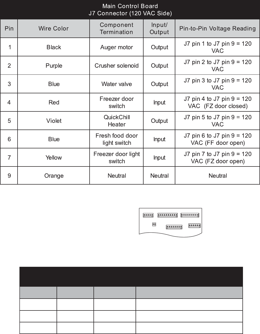
ELECTRICAL SYSTEM
Door and Drawer Switches
The door switch (fresh food door or freezer drawer) closes when the door is open. When the door
switch is closed, L1 is provided to the compartment light(s). The main control board receives L1 input
on pin 6, J7 when the fresh food door switch is closed (door open). The main control board receives L1
input on pin 7, J7 when the freezer drawer switch is closed (door open).
Master Light Switch
The Master light switch is located behind the grille panel on the control board cover. The master light
switch will open the light circuit preventing the interior lights from receiving L1; therefore, the lights will
not operate when either door is open.
Temperature Overload Device (TOD)
A temperature overload device is wired in series with both the fresh food light and the freezer light. If
either light should reach excessive temperatures due to a door/drawer being open for an extended
period, the corresponding TOD will open the light circuit. The TOD will open at 190°F and close
at 130°F.
– 30 –
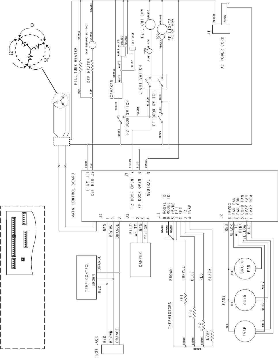
Schematic
J4 OR J16 J3 OR J10 J1 OR J14
J2 OR J13
SOME OF THE LOW VOLTAGE
DC CONNECTOR LABELING ON
THIS MODEL MAY DIFFER FROM
OTHER MODELS. THE
FUNCTION AND DIAGNOSTICS
FOR THESE CONNECTORS ARE
IDENTICAL FOR ALL MODELS.
J15
1
2
BROWN COMPRESSOR
INVERTER
BLUE
RED
WHITE
BLACK
R=1323
R=38
GREEN
6.4
6.4
6.4
– 31 –
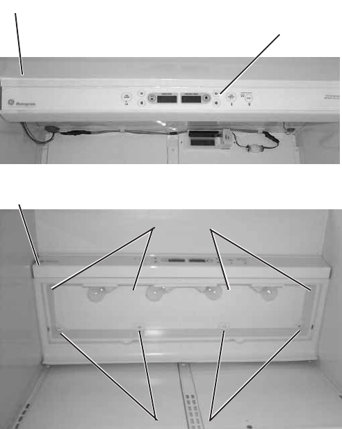
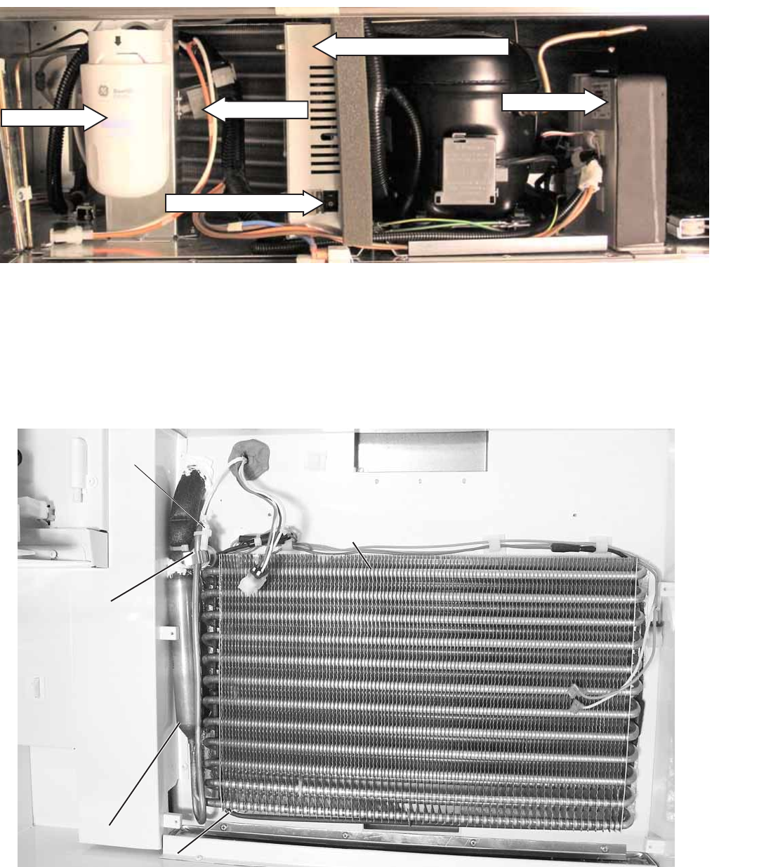
REFRIGERATION SYSTEM
Evaporator
Machine Compartment
Front View
Master Light Switch
Water Filter Inverter
Water Valve
Main Control Board Cover
Evaporator
Defrost Heater
Defrost
Overtemperature
Thermostat
Accumulator
Evaporator
Thermistor

– 32 –
Evaporator Fan Motor
Evaporator Fan
Connector
Evaporator Fan
Compressor and Inverter

– 33 –
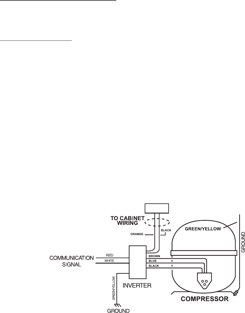
Inverter Compressor
The new inverter compressor is not
controlled by 120 VAC output from the
main control board, as in previous
models. The compressor is controlled
by the inverter.
Warning: Disconnecting the 6-pin
connector does not disconnect power
(120 VAC) from the inverter. The
refrigerator must be unplugged before
servicing the inverter or compressor.
Caution: Do not attempt to direct-
start the compressor. The
compressor operates on a
3-phase power supply. Applying 120 VAC to the compressor will permanently damage the unit.
It is not possible to start the compressor without an inverter.
The compressor is a reciprocating, variable speed, 4-pole type. It operates on 3-phase, 80 to 230 VAC
within a range of 57 to 104 Hz. Compressor speed is controlled by voltage frequency and pulse width
modulation. Increasing frequency from the inverter will produce an increase in compressor speed.
• Frequency of 57 Hz will produce low speed operation at 1710 rpm.
• Frequency of 70 Hz will produce medium speed at 2100 rpm.
• Frequency of 104 Hz will produce 3120 rpm.
Note: Certain voltmeters will not be able to read voltage output or frequency from the inverter.
Compressor wattages at various speeds are:
• LOW - 65 watts
• MED - 100 watts
• HIGH - 150 watts
BTU rating also varies according to operating speed.
Compressor speed is based on the temperature set-point in conjunction with the cabinet temperature.
Speeds are selected according to the following cabinet temperatures:
• 8°F to 19.5°F above set-point = high speed
• 6°F to 8°F above set-point = medium speed
• 3.5°F to 6°F above set-point = low speed
Note: The compressor will run at medium speed if the cabinet temperature is 20°F or more above the
set-point.
The use of 3-phase power eliminates the need for the PTCR relay, capacitor, and individual start and run
windings; therefore the start, run, and common pins found on conventional compressors are not
applicable on this 3-phase model. Compressor pin functions are identical and compressor lead wire
configuration is of no importance. A resistance of 9Ω to 11Ω should be read between any 2 of the 3 pins.
Should an open occur in the compressor winding or should one of the compressor lead wires become
open or disconnected, the inverter will stop voltage output to the compressor.
– 34 –
High compressor torque enables the compressor to start against high pressure in the sealed system.
When power has been disconnected from an operating unit, the high torque may enable the
compressor to start immediately upon power restoration. The compressor, if unable to start after 12
times, will wait for 8 minutes before trying again.
Compressor and sealed system operation is extremely smooth and cool. The compressor exterior may
be room temperature while operating; therefore a running unit may be difficult to detect.
To verify that the compressor is running:
Disconnect power from the unit and place a hand on the compressor. Reconnect power and feel for a
vibration when the compressor tries to start. It may take up to 8 seconds before the compressor
attempts to start.
To determine motor rpm:
Measure the frequency of the voltage being applied to the compressor and multiply this number by 30.
For example, a frequency measurement of 70 Hz would show a compressor speed of 2100 rpm (30 x
70 = 2100).
Note: If the compressor fails to start, the inverter will briefly stop voltage output. The inverter will make
12 consecutive attempts to start the compressor (once every 12 seconds). If, after 12 attempts, the
compressor has not started, an 8-minute count will occur. After 8 minutes, the inverter will attempt to
start the compressor again. If the compressor starts, normal operation will resume. If the compressor
fails to start, the process will be repeated. Removing power from the unit will reset the inverter count.
When power is restored, the inverter will attempt to start the compressor within 8 seconds.
Note:
• When ordering a replacement compressor, order both the compressor and inverter. Replace the
compressor first. If, after compressor installation, the compressor fails to start, replace the inverter.
• When servicing the compressor, it is important to dress the wiring to keep low voltage DC wiring and
120 VAC wiring separate.
– 35 –
Inverter
Warning: Disconnecting the 6-pin connector does not disconnect power (120 VAC) from the
inverter. The refrigerator must be unplugged before servicing the inverter.
Note: Certain voltmeters will not be able to read voltage output from the inverter. If no voltage or erratic
voltage is measured, it does not necessarily indicate a faulty inverter.
The inverter receives 120 VAC line-in from the power supply. The inverter converts this single-phase,
60 Hz, 120 VAC into 3-phase, 230 VAC, with frequency variations between 57 Hz and 104 Hz. This
voltage is delivered to the compressor through 3 lead wires. Each wire will carry identical voltage and
frequency. When checking inverter voltage output, connect the test-meter leads to any 2 of the 3
compressor lead wires. The same reading should be measured between any 2 of the 3 wires.
Note: The compressor leads must be connected to measure voltage output. If the compressor wires
are not connected, or if an open occurs in one of the 3 lead wires or in the compressor, the inverter will
stop voltage output.
The inverter controls compressor speed by frequency variation and by pulse width modulation (PWM).
Changing frequency and PWM will cause an effective voltage between 80 and 230 VAC to be received at
the compressor.
• Low speed (1710 rpm) - 57 Hz
• Medium speed (2100 rpm) - 70 Hz
• High Speed (3120 rpm) - 104 Hz
The inverter receives commands from the main control board. The
main control board will send a (PWM) run signal between 1.5 and 3.5
VDC effective voltage to the inverter. The signal voltage at the inverter
should be equal to the signal voltage sent by the main control board.
The inverter will select compressor speed (voltage output) based on
this signal. A signal voltage from the main control board (J15
connector ) lower than 5 VDC indicates a faulty main control board.
The main control board will only send a run signal to the inverter when
the compressor should be on.
Note: When measuring signal voltage (from the main control board)
at the inverter, disconnect the wire harness connector at the inverter
and measure the voltage at the connector.
The inverter will monitor compressor operation and if the compressor
fails to start or excessive current draw (4 amps maximum) is
detected, the inverter will briefly stop voltage output. The inverter will
then make 12 consecutive compressor start attempts (once every 12
seconds). If after 12 attempts the compressor has not started, an 8-
minute count will initiate. After the 8-minute count, the inverter will
attempt to start the compressor again. If the compressor starts,
normal operation will resume. If the compressor fails to start, this
process will be repeated. Removing power to the unit will reset the inverter count. When power is
restored, the inverter will attempt to start the compressor within 8 seconds.
The inverter has a built-in circuit protection to guard against damage from a failed or shorted
compressor. However, if a failed compressor is diagnosed, order a new compressor and inverter. If the
compressor fails to start after replacement, replace the inverter.
J15
– 36 –
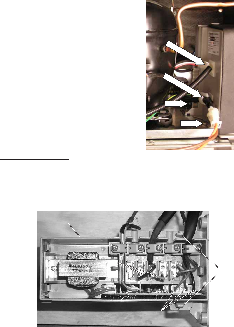
Note: When servicing the inverter, it is important
to dress the wiring to keep low-voltage DC wiring
and 120 VAC wiring separate.
To remove the inverter:
1. Unplug the unit.
2. Open access cover.
3. Loosen the 2 hex-head bolts that hold the
inverter in place.
4. Disconnect the 2 wiring harnesses from the
left side of the inverter.
4. Slide the inverter to the right to disengage the
holding tabs.
Note: It may be necessary to bend the process
tube in order to remove the inverter. If it is
necessary to bend the process tube, use extreme
care.
5. Slide the inverter out of the machine
compartment.
To remove the inverter cover:
Use a small screwdriver to release the two small
tabs and carefully remove the inverter cover.
Wiring Harness
Wiring Harness
Bolt
Bolt
Compressor Lead
Wires
Compressor Lead
Wires
Signal Wire Connector
(From Main Control Board)
Inverter
Inverter
Signal Wire Connector
(From Main Control Board)
Line-In (L1)
Line-In (L1)
Tabs

– 37 –
Condenser
The condenser is located behind the grille panel at the top of the refrigerator and is made of steel tubing.
The outlet of the condenser is connected to a copper jumper tube that is connected to the inlet of the
condenser loop. In a normal home environment, there is no need for routine condenser cleaning.
However, in environments that may be particularly dusty or greasy, the condenser should be cleaned
periodically for efficient refrigeration operation. An ordinary appliance brush should be all that is needed.
Functionally, the condenser does the same job as previous models. Air is drawn through the condenser
by the condenser fan from the front left and rear left of the machine compartment. Air exits only from the
right side of the machine compartment.
Condenser Loop
The condenser loop, made of copper tubing, is foamed in place behind the breaker frame and across
the mullion. It is not accessible for replacement. The tubing is routed from the machine compartment
forward to the mullion, down to the freezer compartment, around the front perimeter of the freezer, and
back into the machine compartment. The outlet of the condenser loop is connected to the dryer inlet.
CONDENSER
COMPRESSOR
INVERTER*
PROCESS TUBE DRYER
SUCTION TUBE
EVAPORATOR
CONDENSER LOOP
CAPILLARY

– 38 –
P0003343
Defrost Overtemperature Thermostat
Evaporator Thermistor
Drier
The drier is positioned vertically in the center of the
machine compartment. A copper process tube,
connected to the inlet of the drier, provides access
to the high-pressure side of the refrigeration
system. The capillary is connected to the outlet of
the drier.
Evaporator
The evaporator is made of copper and aluminum
and is located above the evaporator fan at the top
of the freezer compartment.
To replace the evaporator
1. Recover the refrigerant.
2. Remove the evaporator fan (see procedure).
3. Remove the defrost heater (see procedure).
4. Remove the defrost overtemperature
thermodisc and evaporator thermistor.
5. Disconnect the ground wire from the
evaporator and position all wiring to allow for
evaporator removal.
6. Remove the screws securing the evaporator to
the cabinet.
Caution: Protect wiring from heat during
desoldering and resoldering.
7. Desolder the capillary tube from the
evaporator.
8. Desolder the suction line.
9. Remove the evaporator.
10. Using a file, score the capillary tube just above
the old solder and break the solder-covered
section off. This will help prevent the capillary
tube from becoming plugged when resoldering.
11. Position the new evaporator in the cabinet.
Insert the suction line and capillary tube into
the evaporator.
12. Solder the suction line to the evaporator.
13. Solder the capillary tube to the evaporator.
14. Install a replacement drier WR86X93.
15. Evacuate and recharge the system using
currently accepted procedures.
Note: Mastic should be replaced on evaporator
discharge line after replacing the evaporator.
Shown with Inverter Removed
Drier
– 39 –
Auxiliary Line
A stainless steel hot gas loop is routed from the machine compartment down the back of the unit into
the drain pan and back up to the machine compartment. Hot refrigerant gas flows through the gas loop
to assist the evaporation of drain water collected in the drain pan.
Refrigerant Charge
The refrigerant used in this model is type R134a. Refer to the mini-manual or model tag for the exact
refrigerant charge quantity.

– 40 –
rezeerF yalpsiD dooFhserF yalpsiD scitsongaiDstluseRstnemmoC
01 .edoMmoorwohS.edommoorwohsnitinU otdenepoerdnades
olcebtsumroodFF .edommoorwohstrats
02 neewtebkcehcnoitacinummoC dnalortnocerutarepmet .draoblortnocniam
.KOf
iyalpsidZFno"P" .dnuofsimelborpsnaemyalpsidZFno"F"
03 neewtebkcehcnoitacinummoC .resnepsiddnalortnocerutar
epmet .KOfiyalpsidZFno"P" .dnuofsimelborpsnaemyalpsidZFno"F"
04 neewtebkcehcnoitacinummoC .draoblortnocniam
dnaresnepsid .KOfiyalpsidZFno"P" .dnuofsimelborpsnaemyalpsidZFno"F"
06 )lortnocerutarepmet(IMH .tseTfleS .et
animullilliwstnemgesciremundnas'DELllA
desserpsidap"wahTsserpxE"nehW .ffonrutlliws'DEL"wahTsserpxE" dess
erpsidap"llihCsserpxE"nehW .ffonrutlliws'DEL"llihCsserpxE"
07 fleSmetsySrosneSdnalortnoC .tseT rof"P"syalps
iddnarotsimrehthcaeskcehC .liafrof"0"dnassap .woleb1etoneeS
08 .rooDtcuDnepO.sesolcnehtsdnoces01rofsneporood
tcuD
09 .tseTretaeHsseceRresnepsiD 06rofnoretaehssecerresnepsidehtsnruT .sdnoces
10 .tseTsrepmaD neht,ylfierbesu
ap,nepolliwrepmadhcaE .esolc
12 .emiTnuR%001 semiT.emitehtfo%001nometsysdelaeS .ruoh1retfatuo ottessirotaregi
rferfideretneebtonnaC .ffo
13 .tseTllihc-erP nolamronotsnrutertinU.edomllihc-erpstratS .nwosti ottessirotareg
irferfideretneebtonnaC .ffo
14 .tseTtsorfeD.woleb2etoneeS.elcyctsorfedehtselggoT .ffosretaehnrutotniagasserp
tsuM ottessirotaregirferfideretneebtonnaC .woleb2etoneeS.ffo
15 .teseRlortnoCniaM.tesermetsysasesuaC
16 .edoMcit
songaiDtixE.teserdraoblortnocerutarepmetasesuaC
17 .F/CeergeD.CotFmorfyalpsiderutarepmetsegnahC
Enter the diagnostic mode by pressing both the freezer temperature pads (plus and minus) and the
refrigerator temperature pads (plus and minus) simultaneously. All 4 pads must be held for
approximately 3 seconds. A blinking “0” in both displays indicate the refrigerator has entered the test
mode.
Enter the appropriate display numbers as
shown below and press any pad other than the
temperature pads to activate that test mode.
Note 1: Display order is: 1) Fresh Food 1, 2) Fresh Food 2, 3) Freezer, 4) Evaporator,
5) Custom Cool. Thermistor test results are P = pass, 0 = fail, S = short to 5 VDC, B = bad amplifier
(replace main control).
Note 2: You must enter the defrost test again to toggle the defrost heater off at the end of the test.
The heater will not come on if the evaporator thermistor or overtemperature thermodisc is warm.
Diagnostic Mode
– 41 –
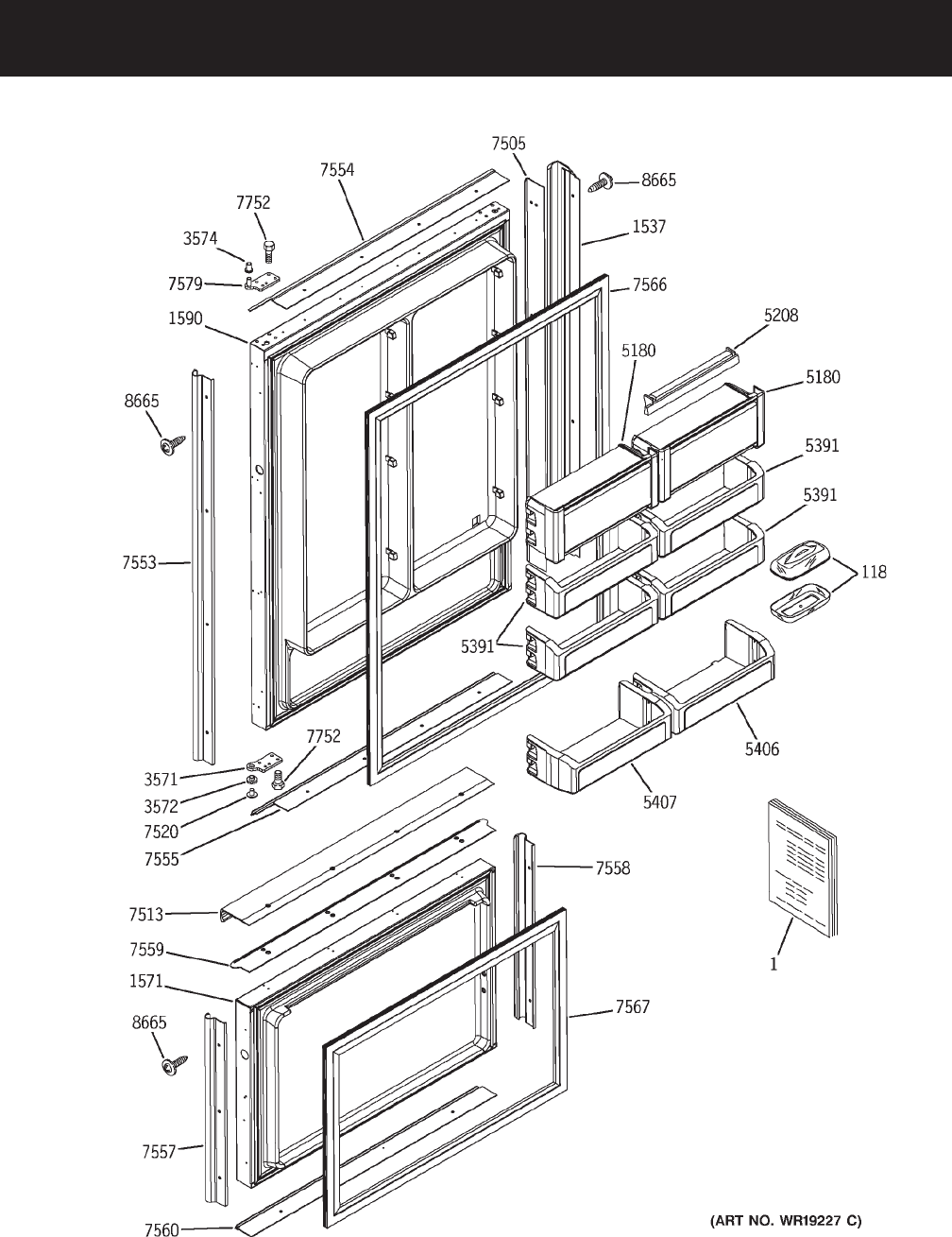
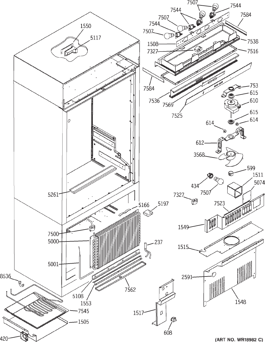
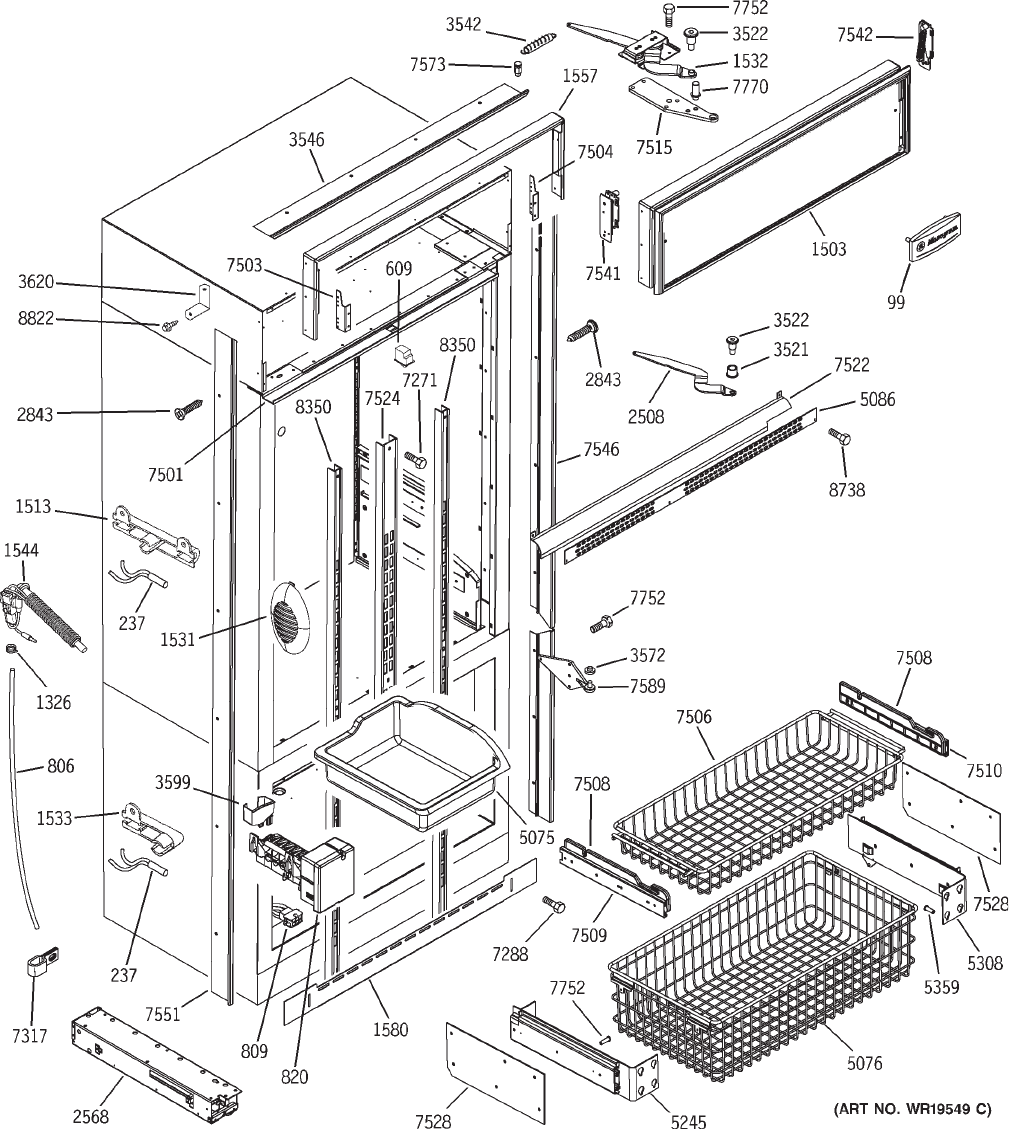
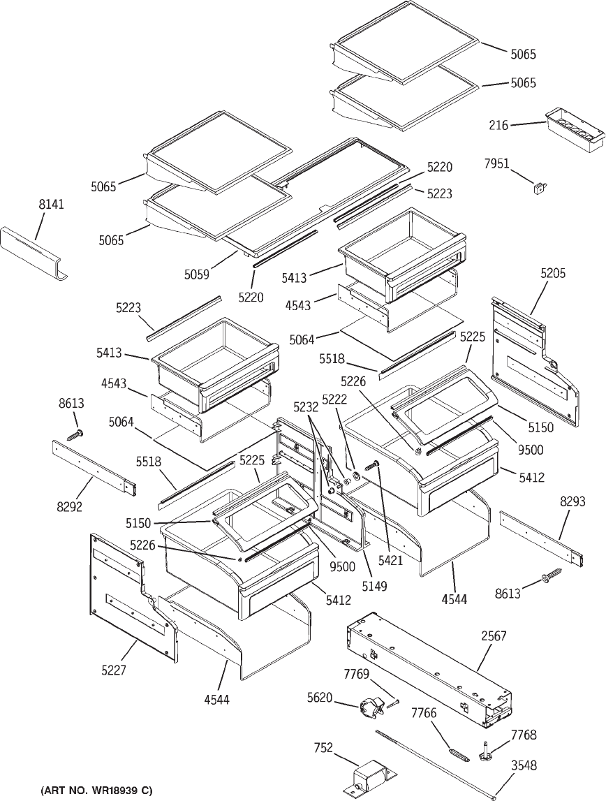
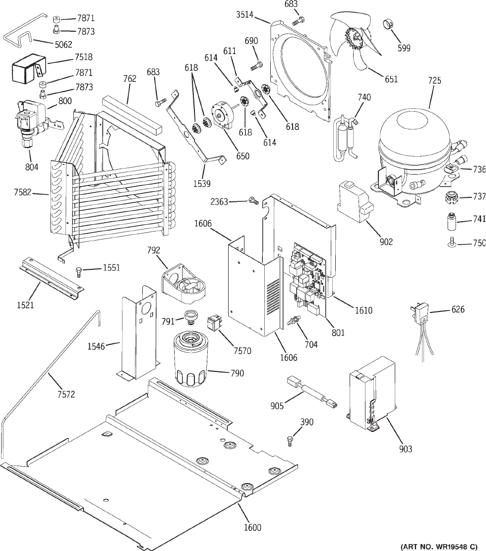
Illustrated Parts
– 42 –
– 43 –
– 44 –
– 45 –
– 46 –
VIEW NUMBER CATALOG NUMBER DESCRIPTION QUANTITY
0001 31-51562 MINI MANUAL DATA SHEET 1
0001 49-60316 OWNER’S MANUAL 1
0001 49-60320 INSTALL INSTRUCTION 1
0099 WB02X10831 MG LOGO LARGE ADHESIVE 1
0118 WR19X0035 DISH BUTTER ASM 1
0200 WR17X11561 SWITCH PLATE LH 1
0216 WR32X1435 BUCKET EGG 1
0237 WR55X10028 SENSOR TEMP 4
0237 WR55X10025 SENSOR TEMP 4
0390 WR01X1826 SCREW 4
0420 WR60X10106 DC FRESH FOOD FAN 1
0434 WR02X10732 SOCKET STRAIGHT LIGHT FZ 1
0599 WR02X10509 RING COMPRESSION FAN 2
0608 WR23X10286 SWITCH LIGHT FZ 1
0609 WR23X10143 SWITCH LIGHT FF 1
0610 WR60X10083 MOTOR DC EVAP FAN 1
0611 WR02X10521 BRACKET COND FAN (MTG) 1
0610 WR60X10043 MOTOR DC EVAP FAN 1
0612 WR02X10653 BRACKET ORIFICE FAN 1
0614 WH01X2722 BUMPER LID 4
0615 WR02X10519 GROMMET EVAP FAN 2
0618 WR02X10520 GROMMET COND FAN 2
0626 WR23X0108 POWER CORD 1
0650 WR60X10053 MOTOR DC COND FAN 1
0651 WR60X10049 BLADE COND FAN ASM 1
0626 WR23X10300 POWER CORD 1
0683 WR01X1716 SCREW, FAN MOTOR 8
0690 WR01X1466 SCR 8-32 T HXW 3/8 S 4
0704 WR01X10301 MAIN BOARD STAND OFFS 4
0725 WR87X10064 COMPRESSOR REPL ASM 1
0736 WR02X8583 CLIP COMP MTNG 4
0690 WZ5X158D SCR 8-32 T HXW 3/8 S 4
0737 WR02X10099 GROMMET 4
0740 WR86X93 DRIER 1
0741 WR01X1779 STUD MTG COMPR 4
0750 WR01X1786 SCR 10-32 TR T 1/2 4
0752 WR02X8470 FT WHEEL BKT 2
0753 WR02X10548 BRACKET EVAP FAN BTM 1
0762 WR14X0313 FOAM STRIP 2
0790 GWF FILTER CANISTER 1
0791 WR02X10577 PLUG BYPASS FILTER 1
0792 WR17X10707 FILTER MNT & TUBE ASM 1
0753 WR01X10287 BRACKET EVAP FAN BTM 1
0753 WR02X10764 BRACKET EVAP FAN BTM 1
0800 WR57X10034 VALVE WATER 1
0801 WR55X10433 MOTHER BOARD 1
0804 WR57X0057 NUT SLEEVE 1/4 1
0791 WR02X11705 PLUG BYPASS FILTER 1
– 47 –
VIEW NUMBER CATALOG NUMBER DESCRIPTION QUANTITY
0806 WR17X2107 WATER LINE 1
0809 WR02X11452 AMP J10 CONNECTOR 1
0820 WR30X10012 ELECTRONIC IM-DOM 1
0902 WR02X11262 RELAY COVER 1
0903 WR55X10155 INVERTER ASM 1
0905 WR23X10381 HARNESS INVERTER COMM 1
1326 WR02X3736 CLAMP TUBE 2
1503 WR74X10159 GRILLE PANEL ASM. 1
0806 WR17X11349 WATER LINE 1
1505 WR17X11006 HOUSING DRAIN PAN 1
0809 WR02X11453 AMP J10 CONNECTOR 1
1508 WR02X11023 FIXTURE LIGHTING 1
1511 WR74X10085 BRACKET LIGHT SOCKET FZ 1
0902 WR02X11262 RELAY COVER 1
1513 WR02X10942 FF THERMISTOR HOLDER 1
1515 WR74X10096 PLATE FAN MOTOR MTG. 1
1517 WR74X10086 FILL TUBE COVER 1
1521 WR02X10941 BRKT REFRIG PAN GUIDE 2
1530 WR02X10980 CLOSURE ASM TOP DOOR LH 1
1531 WR71X10325 FF AIR DIFFUSER 2
1533 WR02X10944 FZ THERMISTOR CLIP 1
1537 WR12X10644 HANDLE FF 1
1539 WR02X10945 BRKT COND FAN MOTOR LG 1
1544 WR49X10093 FILL TUBE KIT BM/SXS(D) 1
1546 WR02X10946 FILTER BRACKET 1
1548 WR74X10097 EVAPORATOR COVER 36" BM 1
1549 WR74X10098 EVAPORATOR FAN COVER 1
1550 WR17X11009 BRACKET DAMPER MTG 1
1521 WR02X10941 BRKT REFRIG PAN GUIDE 2
1551 WR01X5645 SCREW IM STRAP, PAN 17
1553 WR17X11010 WATER COLLECTOR 1
1557 WR74X10081 HOOD HINGE MOUNT 36 1
1571 WR78X10497 FZ DRAWER FOAMED ASM 1
1580 WR74X10089 TOE KICK 36 BM 1
1591 WR78X10514 FF DR FOAM ASM LH 1
1600 WR17X11794 PAN SYSTEM 1
1606 WR02X11933 MOTHER BOARD COVER 1
1610 WR17X11795 BAFFLE CONDENSER 1
2363 WR01X5684 6-32 X 3/8 PHIL S/S TYPE 2
2567 WR13X10200 CHANNEL BASE ASM (RH) 1
2568 WR13X10201 CHANNEL BASE ASM (LH) 1
2591 WR02X10154 PLUG BUTTON #413 I/M 1
2843 WR01X1903 SCREW CASE TRIM 12
3514 WR17X11011 HOUSING COND FAN 1
1571 WR78X10889 FZ DRAWER FOAMED ASM 1
3521 WR02X10951 BHNG ARM NYLON FF DR CL 1
3522 WR01X10254 BOLT SHOULDER FF DOOR 1
1591 WR78X10887 FF DR FOAM ASM LH 1
– 48 –
VIEW NUMBER CATALOG NUMBER DESCRIPTION QUANTITY
3542 WR01X10255 SPRING FF DOOR CLOSURE 1
3546 WR17X11354 CASE TRIM TOP 36 1
3548 WR01X10256 BASE SHAFT 2
3568 WR60X10050 BLADE FAN MOTOR 1
3571 WR13X10202 HINGE DOOR BOTTOM 1
3572 WR02X10953 BUSHING HINGE BOTTOM 1
3574 WR02X10954 BUSHING HINGE TOP 1
3599 WR29X10021 CUP FILL IM 1
3620 WR02X11335 TRIM CORNER KEY 2
4543 WR02X10149 PAN SUPPORT SNACK PAN 2
4544 WR02X10150 PAN SUPPORT ASM VEG PAN 2
5000 WR85X10007 EVAP COIL 1
5001 WR51X10015 DEFROST HEATER 36BM 1
5059 WR32X10072 SNACK PAN COVER 1
5062 WR02X10141 TUBE - WATER VALVE INLET 1
5064 WR32X10073 VEG PAN COVER 2
5065 WR32X10074 ENCAP SHELF ASSY 4
5074 WR17X10347 LIGHT SHIELD FZ 1
5075 WR32X10075 ICE BUCKET 1
5076 WR21X10007 FZ BASKET LG 1
5086 WR02X10142 VENT GUARD 36BM 1
3599 WR29X10046 CUP FILL IM 1
5108 WR17X10349 DRAIN BAFFLE 1
5117 WR09X10065 DAMPER MOTORIZED 1
5149 WR72X10011 DIVIDER ASM VEG. PANS 1
5150 WR32X10076 SHOWCASE LID ASM. 2
5166 WR01X10045 WIRE RETAINER EVAP HEATE 2
5180 WR71X10142 ASM DAIRY COMP 2
5197 WR02X10145 BAFFLE EVAP LH 1
5205 WR72X10012 SUPPORT, SLIDE RH 1
5208 WR22X10007 SEAL DAIRY ASM 1
5220 WB07X10461 SEAL, FRONT SNACK PAN 2
5222 WR01X10046 WASHER SHOWCASE PIVOT 2
5223 WR14X10011 SEAL, RR SNACK PAN 2
5225 WR14X10012 SEAL, FRT VEG PAN GLASS 2
5226 WR01X10047 BUTTON GLIDE 4
5227 WR72X10013 SUPPORT, SLIDE LH 1
5232 WR01X10048 BUSHING, SHOWCASE PIVOT 2
5117 WR09X10050 DAMPER MOTORIZED 1
5245 WR72X10084 FZ SLIDE/SUPPORT ASM LH 1
5261 WR49X10015 MULLION BLOCK KIT BTM.MT 1
5308 WR72X10014 FZ SLIDE/SUPPORT ASSY RH 1
5359 WR01X10049 SCREW, TRUSS HD 1/4-20 X 8
5391 WR71X10138 BIN, FF DOOR W/WINDOW 4
5406 WR71X10139 BIN, DOOR FF DEEP RH 1
5407 WR71X10140 BIN, DOOR FF DEEP LH 1
5412 WR32X10077 VEG PAN ASM 2
5413 WR32X10078 SNACK PAN ASM 2
– 49 –
VIEW NUMBER CATALOG NUMBER DESCRIPTION QUANTITY
5421 WR01X10050 SCREW, #8 18 X 7/8 2
5518 WR14X10014 SEAL REAR VEG PAN GLASS 2
5620 WR02X8377 WHEEL ASM REAR 2
7271 WR01X10051 10-24*7/8 PHIL P-HD TAP 9
7288 WR01X1831 SCREW GRILLE MTG. 2
7317 WR17X3046 1/4 CLAMP NYLON 4
7327 WR50X10003 THERMOSTAT 2
5245 WR72X10124 FZ SLIDE/SUPPORT ASM LH 1
7500 WR50X10030 EVAP. THERMODISC 1
7503 WR02X10956 BRACKET GRILLE LH 1
5308 WR72X10125 FZ SLIDE/SUPPORT ASSY RH 1
7504 WR02X10957 BRACKET GRILLE RH 1
7505 WR12X10492 DR HNDL TRIM FF LH/RH 1
7506 WR21X10043 BASKET UPPER FRZ 1
7507 40A15 LAMP 40W 4
7508 WR72X10080 SUPPORT BASKET UPPER FZ 2
7509 WR72X10081 SLIDE LINER UPPER FZ 2
7510 WR72X10082 SLIDE BASKET UPPER FZ 2
7513 WR17X11560 FF DOOR BTM- RH HINGE 1
7515 WR13X10203 HINGE UPPER FF CASE 1
7516 WR17X11014 LIGHT SHIELD FF 1
7518 WR02X10958 WATER VALVE BRKT 1
7288 WR01X5686 SCREW GRILLE MTG. 2
7520 WR01X10257 PIN BTM. LOWER HINGE 1
7523 WR38X10247 EDGE TRIM FZ REAR DUCT 1
7524 WR17X11097 SHELF TRACK CENTER 1
7525 WR17X11036 CTRL. PANEL TEMP. CTRL. 1
7528 WR72X10085 FREEZER SLIDE SHIM 2
7533 WR17X11180 CASE TRIM FF SIDE 1
7534 WR17X11558 FF DOOR TRIM RH HINGE 1
7535 WR17X11559 FF DOOR TRIM TOP- RH HIN 1
7536 WR74X10082 HOUSING CONTROL 1
7538 WR17X11015 TRIM LIGHTING FF 1
7541 WR13X10204 HINGE ASM GRILLE LEFT 1
7542 WR13X10205 HINGE ASM GRILLE RIGHT 1
7544 WR02X11024 SOCKET LAMP FF 4
7545 WR17X11016 DRAIN PAN 1
7546 WR17X11562 RH HINGE SIDE TRIM 1
7557 WR17X11553 FZ DOOR TRIM RH 1
7558 WR17X11554 FZ DOOR TRIM LH 1
7559 WR17X11555 FZ DOOR HANDLE TRIM 1
7560 WR17X11556 FZ DOOR TRIM BOTTOM 1
7561 WR12X10642 FZ DOOR HANDLE 1
7562 WR17X11098 EVAPORATOR TROUGH 1
7524 WR17X11027 SHELF TRACK CENTER 1
7566 WR24X10147 GASKET FF DOOR BM 1
7567 WR24X10148 GASKET FZ DOOR BM 1
7569 WR55X10098 BOARD ASM TEMP CONTROL 1
– 50 –
VIEW NUMBER CATALOG NUMBER DESCRIPTION QUANTITY
7570 WR23X10220 MASTER LIGHT SWITCH 1
7572 WR86X10016 CAP/SUCTION TUBE ASM 1
7573 WR01X10258 STUD SPRING FF DOOR 1
7580 WR13X10210 HINGE DOOR TOP FF LH 1
7581 WR02X11612 EYEBROW LH 1
7582 WR84X10030 CONDENSER MONOGRAM BM 2
7584 WR38X10255 GASKET FF LIGHT TRIM 2
7590 WR13X10211 HINGE CENTER LH 1
7595 WR02X10979 LINK ACTUATOR LH 1
7752 WR01X1845 SCREW 12-24TT OHT .900 12
7766 WR02X8799 SPRING WHEEL #LE022C4 2
7768 WR02X10479 LEVELING LEG 2
7769 WR02X8800 AXLE REAR 2
7770 WR13X0637 STOP DOOR 1
7871 WR57X10016 COMPRESSION NUT 1/4 1
7873 WR57X10017 BRASS FERRULE 1
7951 WR02X10151 TWIST SUPPORT 4
8141 WR17X4141 WINE RACK 1
8292 WR72X0269 SLIDE FULL EXT10 4
7569 WR55X10159 BOARD ASM TEMP CONTROL 1
8293 WR72X0270 SLIDE FULL EXT12 4
7570 WR49X10070 MASTER LIGHT SWITCH 1
8350 WR17X4140 TRACK SHELF FF 2
8536 WR17X10675 DRAIN TRAP AUX. COND. 1
8613 WR01X10052 #8-18AB X 1/2 PHILS TRUS 19
8665 WR01X2130 TRIM SCREW 24
8738 WR01X10053 #8-18 TYPE AB X 3/8 BLK 2
8822 WR01X10326 #6-32 X 3/16 MACH SCR. 4
9500 WR14X10040 SEAL FRONT SHOWCASE LID 2

– 51 –
WARRANTY
YOUR MONOGRAM REFRIGERATOR WARRANTY
Staple sales slip or cancelled check here. Proof of original purchase
date is needed to obtain service under warranty.
WHAT IS
COVERED
From the Date
of the Original
Purchase
FULL TWO-YEAR WARRANTY
For two years from date of original purchase, we will provide, free of charge, parts and service labor in
your home to repair or replace any part of the refrigerator that fails because of a manufacturing defect.
FULL FIVE-YEAR WARRANTY
For five years from date of original purchase, we will provide, free of charge, parts and service labor
in your home to repair or replace any part of the sealed refrigerating system (the compressor, condenser,
evaporator and all connecting tubing) that fails because of a manufacturing defect.
LIMITED ADDITIONAL SEVEN-YEAR WARRANTY ON THE SEALED SYSTEM
For the sixth through twelfth year from the date of the original purchase, we will provide, free of
charge, replacement parts for any part of the sealed refrigerating system (the compressor, condenser,
evaporator and all connecting tubing) that fails because of a manufacturing defect. You pay for
the service trip to your home and for service labor charges.
LIMITED LIFETIME WARRANTY ON ACCURIDE® SLIDES
From the date of the original purchase we will provide, free of charge, replacement parts for
any part of the Accuride Slides that fails because of a manufacturing defect. You pay for the service
trip to your home and for service labor charges.
This warranty is extended to the original purchaser and any succeeding owner for products
purchased for ordinary home use in the 48 mainland states, Hawaii and Washington, D.C.
In Alaska the warranty is the same except that it is LIMITED because you must pay to ship
the product to the service shop or for the service technician’s travel costs to your home.
All warranty service will be provided by our Factory Service Centers or by our authorized Customer
Care® servicers during normal working hours.
Should your appliance need service, during warranty period or beyond, in the U.S.A.
call 800.444.1845. In Canada: 888.880.3030.
Some states do not allow the exclusion or limitation of incidental or consequential damages, so the
above limitation or exclusion may not apply to you. This warranty gives you specific legal rights, and
you may also have other rights which vary from state to state. To know what your legal rights are in
your state, consult your local or state consumer affairs office or your state’s Attorney General.
Warrantor: General Electric Company, Louisville, KY 40225
WHAT IS NOT
COVERED
• Service trips to your home to teach you how
to use the product.
• Replacement of house fuses or resetting of
circuit breakers.
• Damage to the product caused by accident,
fire, floods or acts of God.
• Failure of the product if it is used for
other than its intended purpose or used
commercially.
• Improper installation.
If you have an installation problem, contact
your dealer or installer. You are responsible for
providing adequate electrical, plumbing and
other connecting facilities.
• Loss of food due to spoilage.
• Incidental or consequential damage caused by
possible defects with this appliance.
