GE Refrig PDCF 31 9154
2013-04-09
: Pdf Ge - Refrig - Pdcf - 31-9154 GE - Refrig - PDCF - 31-9154 GE, Camco, Hotpoint, Mofat
Open the PDF directly: View PDF ![]() .
.
Page Count: 56
GE Appliances
General Electric Company
Louisville, Kentucky 40225
31-
9154
9154
Profi le Bottom Mount
Refrigerators
Technical Service Guide
October 2007
GE Consumer & Industrial
PDCF1NBW
PDCS1NBW
PDSF5NBW
PDSS5NBW
PFCF1NFW
PFCF1NJW
PFCS1NFW
PFCS1NJW
PFIC1NFW
PFSF5NFW
PFSF5NJW
PFSS5NFW
PFSS5NJW

– 2 –
IMPORTANT SAFETY NOTICE
The information in this service guide is intended for use by
individuals possessing adequate backgrounds of electrical,
electronic, and mechanical experience. Any attempt to repair a
major ap pli ance may result in personal injury and property
damage. The man u fac tur er or seller cannot be responsible for the
in ter pre ta tion of this in for ma tion, nor can it assume any liability in
connection with its use.
WARNING
To avoid personal injury, disconnect power before servicing
this prod uct. If electrical power is required for diagnosis or test
purposes, disconnect the power immediately after performing the
necessary checks.
RECONNECT ALL GROUNDING DEVICES
If grounding wires, screws, straps, clips, nuts, or washers used to
complete a path to ground are removed for service, they must be
returned to their original position and properly fastened.
GE Consumer & Industrial
Technical Service Guide
Copyright © 2007
All rights reserved. This service guide may not be reproduced in whole or in part
in any form without written permission from the General Electric Company.
– 3 –
Table of Contents
Airfl ow..................................................................................................................................................................................32
Anti-Tip Floor Bracket (on 21 ft. models) ............................................................................................................. 9
Articulating Door Mullion (French Door Models) .............................................................................................49
Components .....................................................................................................................................................................33
Components Locator Views ......................................................................................................................................26
Condenser Fan ................................................................................................................................................................39
Control Board Connector Locator ..........................................................................................................................28
Control Diagnostics Using the Temperature Display ....................................................................................53
Control Features .............................................................................................................................................................20
Defrost Cycle ....................................................................................................................................................................25
Defrost Heater .................................................................................................................................................................46
Dispenser Lock ................................................................................................................................................................25
Drawer Closure Mechanisms ...................................................................................................................................52
EMI Filter .............................................................................................................................................................................52
Evacuation and Charging Procedure ...................................................................................................................31
Evaporator ........................................................................................................................................................................43
Evaporator Fan ...............................................................................................................................................................38
Freezer Drawer Handle ..............................................................................................................................................15
Freezer Shelves and Baskets ....................................................................................................................................36
Fresh Food and Freezer Light Thermostats .......................................................................................................38
Fresh Food Crispers and Pans .................................................................................................................................35
Fresh Food Damper ......................................................................................................................................................48
Fresh Food Door Handle ............................................................................................................................................12
Fresh Food Shelves and Bins ....................................................................................................................................33
Icemaker Fill Tube Heater ..........................................................................................................................................46
Installation ....................................................................................................................................................................... 7
Introduction ...................................................................................................................................................................... 4
Inverter ...............................................................................................................................................................................41
Inverter Compressor .....................................................................................................................................................42
Liner Protection Mode ..................................................................................................................................................25
Nomenclature .................................................................................................................................................................. 5
Refrigeration Components ........................................................................................................................................30
Refrigeration System ...................................................................................................................................................30
Removing and Installing Double Doors (Some Models) ...............................................................................16
Removing and Installing the Freezer Drawer (Some Models) ..................................................................18
Replacing Evaporator Using the Brazing Method...........................................................................................47
Return Duct Heaters .....................................................................................................................................................46
Reversing the Door Swing (Single Door Refrigerator Models only) .........................................................13
Schematic ..................................................................................................................... .....................................................55
Technical Data ................................................................................................................................................................. 6
Thermistors .......................................................................................................................................................................37
Troubleshooting ..............................................................................................................................................................53
Warranty ...........................................................................................................................................................................56
Water Dispenser and Interface ...............................................................................................................................50
– 4 –
*The new Profi le Bottom Mount Refrigerators have the following features:
Available in 21 and 25 cubic foot capacity with fresh food single or french door confi gurations.•
Icemaker ready or factory installed icemaker.•
French door models feature optional fi ltered external water dispenser. •
Two coil water tanks provide added •
storage volume with increased
surface area for quick temperature
recovery.
ENERGY STAR• ®, variable speed
inverter compressor and fans for all
models.
Up front, electronic touch •
temperature controls with digital
temperature display.
An external "air" thermistor changes •
the control setting based on ambient
condition to keep the fresh food and
freezer at the correct temperature.
• Damper/air inlet assembly in the
fresh food section creates more
usable space on the top shelf.
An articulating door mullion attached •
to the right side door (french door
models), provides a movable center
mullion that maximizes access to the
fresh food compartment.
Two self closing freezer drawer •
cam and lever mechanisms that automatically pull the drawer shut when it's within 1 inch of the closed
position.
• Anti-tip kit will be required for 21 cu. ft. models.
BrightSpace™ Interior with GE Reveal™ Lighting. •
Available in white, black, bisque, or stainless fi nish.•
Trim kits are available that allow adding decorator or wood panels to match kitchen cabinets. •
New nomenclature, (PDSF5NBWABB instead of PDSF25NBWABB). Cubic foot volume previously specifi ed •
as 25, now shows as only 5.
Introduction
* Features may vary by model.
– 5 –
Nomenclature
The nomenclature plate is located on the upper
right wall of the fresh food compartment. It
contains the following information:
The letter des ig nat ing
the year re peats every
12 years.
Example:
T - 1974
T - 1986
T - 1998
Exterior Color
WW - White on White
BB - Black on Black
CC - Bisque on Bisque
SS - Stainless Steel
BV - Black IT
WV - White IT
Model Year
W - 2007
Brand/Product
P - Profi le
Capacity
1 - 21 Cubic Foot
5 - 25 Cubic Foot
Mini-Manual Location
• Model and Serial
Number
• Minimum Installation
Clearances
• Electrical Voltage,
Frequency
• Maximum Amperage
Rating
• Refrigerant Charge
and Type
Nomenclature
P F C S 1 N J W A S S
Serial Number
The fi rst two numbers of the serial number
identify the month and year of manufacture.
Example: AM123456S = January, 2007
A - JAN 2007 - M
D - FEB 2006 - L
F - MAR 2005 - H
G - APR 2004 - G
H - MAY 2003 - F
L - JUN 2002 - D
M - JUL 2001 - A
R - AUG 2000 - Z
S - SEP 1999 - V
T - OCT 1998 - T
V - NOV 1997 - S
Z - DEC 1996 - R
Exterior
C -
Color
F - High Gloss
L - Laminate (Cleansteel)
M - Metallic
S - Stainless
W - Wrapped
Ice/Water
B - Icemaker Ready
F - 1 Year Filter
J - External Dispenser
- Water only
Style
S - Standard Depth
C - Custom Style
I - Custom Style Installed Trim
Confi guration
D - Drawer
F - French Door
Feature Pack
H - Upgrade Glass Shelves
I - Deluxe Glass Shelves
K - Spill Proof, Glass Shelves
L - Spill Proof, Slideout
M - Spill Proof, Slideout, Quickspace™
N - Spill Proof, Slideout, F/W Meat Pan
Engineering
A - Initial Design
B - First Revision
C - Second Revision
Etc.
– 6 –
Technical Data
4;42CA820;B?4285820C8>=B
CT\_TaPcdaT2^]ca^[?^bXcX^]$& 5
3TUa^bc2^]ca^[f]^S^^a^_T]X]Vb (%Wab/#$\X]
CWTa\Xbc^aZX[^^W\aTbXbcP]RT /5#!$
/"&5 #
/&&5$
>eTacT\_TaPcdaTCWTa\^bcPc # 5
3TUa^bcCWTa\Xbc^a$5
4[TRcaXRP[APcX]V) $E02%7i %0\_
<PgX\d\2daaT]c;TPZPVT &$\0
<PgX\d\6a^d]S?PcWATbXbcP]RT #>W\b
=>;>03?4A5>A<0=24
2^]ca^[?^bXcX^]$$P]S0\QXT]c^U%$5c^(5
5aTbW5^^S5 "#c^#
5a^iT]5^^S5 "c^"5
Ad]CX\T/%$5 "c^$
Ad]CX\T/(5 $c^'
08A5;>F
8<?>AC0=CB054CH=>C824
CWXbX]U^a\PcX^]XbX]cT]STSU^adbTQhX]SXeXSdP[b_^bbTbbX]V
PST`dPcTQPRZVa^d]Sb^UT[TRcaXRP[T[TRca^]XRP]S\TRWP]XRP[
Tg_TaXT]RT0]hPccT\_cc^aT_PXaP\PY^aP__[XP]RT\PhaTbd[c
X]_Tab^]P[X]YdahP]S_a^_TachSP\PVTCWT\P]dUPRcdaTa^a
bT[[TaRP]]^cQTaTb_^]bXQ[TU^acWTX]cTa_aTcPcX^]^UcWXbX]U^a\P
cX^]]^aRP]XcPbbd\TP]h[XPQX[XchX]R^]]TRcX^]fXcWXcbdbT
A45A864A0C8>=BHBC4<
2^\_aTbb^a! !$<^ST[b'""1CDWa/"A?<
<X]X\d\2^\_aTbb^a2P_PRXch !!X]RWTb7V
<X]X\d\4`dP[XiTS?aTbbdaT
/&5 #$c^#'?B86
/(5 $#c^%?B86
A45A864A0=C270A64A "#P
! !$\^ST[b$$^d]RTb
38B2>==42C?>F4A2>A3145>A4B4AE828=6
8<?>AC0=CA42>==42C0;;6A>D=38=634E824B
0[[_Pacb^UcWXbP__[XP]RTRP_PQ[T^UR^]SdRcX]VT[TRcaXRP[Rda
aT]cPaTVa^d]STS8UVa^d]SX]VfXaTbbRaTfbbcaP_bR[X_b]dcb
^afPbWTabdbTSc^R^\_[TcT
P_PcWc^Va^d]SPaTaT\^eTSU^abTaeXRTcWTh\dbcQTaTcda]TS
c^cWTXa^aXVX]P[_^bXcX^]P]S_a^_Ta[hUPbcT]TS
– 7 –
Installation
Trim Kits and Decorator Panels
(Continued next page)
15
Read these instructions completely and carefully.
Before You Begin
Some models are equipped with trim kits that allow you to install door panels. You can order
pre-cut black or white decorator panels from GE Parts and Accessories, 800.626.2002, or you can
add wood panels to match your kitchen cabinets.
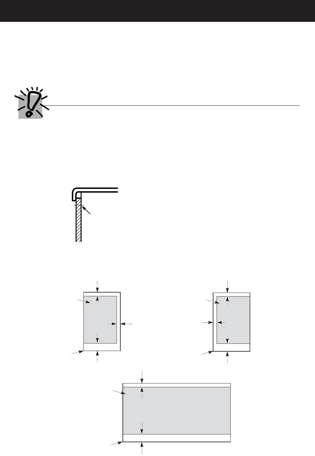
Panels less than 1/4″(6 mm) thick
When installing wood panels less than 1/4″ (6 mm) thick, you need to create a filler panel, such as 1/8″
cardboard, that will fit between the face of the door and the wood panel. If you are installing the pre-cut
decorator panels, pre-cut filler panels are included in the kit. The combined thickness of the decorator
or wood panel and the filler panel should be 11/32″(8.7 mm) with the panel itself being no larger than
1/4″(6 mm).
For panel required models
Panels 1/4″thick or less
1/4″max
The handle and the top and bottom trim stand in front of the surface of the door, which requires that the
filler be smaller in length and width than the panel. Use the guidelines below and tape the filler onto the
back of the panel.
Left Fresh Food Door
Freezer Door
Filler
2 1/2″ (63.5 mm)
3/4″(19 mm)
3/4″(19 mm)
Panel
Filler
2 1/2″ (63.5 mm)
3/4″(19 mm)
Panel
Right Fresh Food Door
Filler
2 1/2″ (63.5 mm)
3/4″(19 mm)
3/4″(19 mm)
Panel
– 8 –
16
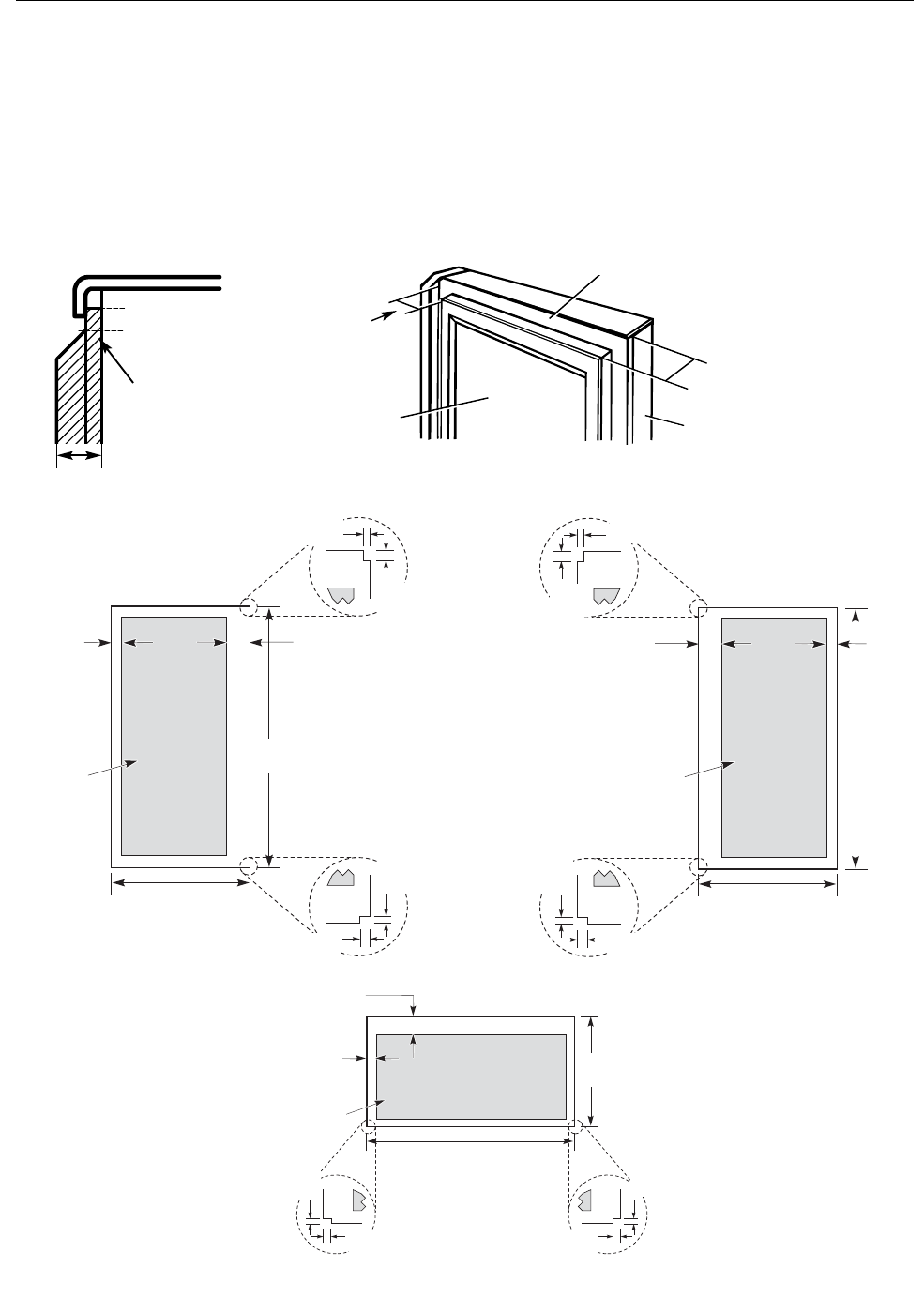
Dimensions for Custom Wood Panels
3/4″ (19 mm) or Raised Panel
A raised panel design screwed or glued to a 1/4″ (6 mm) thick backing, or a 3/4″ (19 mm) routed board
can be used. The raised portion of the panel must be fabricated to permit clearances of at least 2″ (5.1 cm)
from the handle side for fingertip clearance.
Panels thicker than 1/4″ (6 mm), up to 3/4″ (19 mm) max., will require that the outer 5/16″ (8 mm) of
panel perimeter be no thicker than 1/4″ (6 mm).
Weight limitations for custom panels:
Fresh Food 10 lbs. (4.5 kg) max. for each door
Freezer Door 18 lbs. (8 kg) max.
2″(5.1 cm)
Clearance
Handle Side
Appearance
Panel Refrigerator
Door
1/4″(6 mm)
Thick Backing
3/4″
(19 mm)
Panels thicker than 1/4″(6 mm)
1/4″(6 mm) max
3/4″(19 mm)
5/16″ (8 mm)
Left Fresh Food Door
Freezer Door
Top, left and
bottom
16 29/32″(42.9 cm)
5/16″(8 mm)
minimum at
1/4″(6 mm)
thickness
Raised portion
of panel
2″(51 mm)
minimum at
1/4″(6 mm)
thickness
Handle side
26 3/32″
(66.3 cm)
2″(51 mm) minimum at
1/4″(6 mm) thickness
Handle side
Left, right and
bottom sides
5/16″(8 mm) minimum
at 1/4″(6 mm) thickness
35 29/32″(91.2 cm)
Raised
portion
of panel
28 15/16″
(73.5 cm)
Right Fresh Food Door
Top, left and
bottom
16 29/32″(42.9 cm)
5/16″(8 mm)
minimum at
1/4″(6 mm)
thickness
Raised portion
of panel
2″(51 mm)
minimum at
1/4″(6 mm)
thickness
Handle side
28 15/16″
(73.5 cm)
1/8″
(3 mm)
1/8″
(3 mm)
1/8″
(3 mm)
1/8″
(3 mm)
1/8″
(3 mm)
1/4″
(6 mm)
1/4″
(6 mm)
1/4″
(6 mm)
1/4″
(6 mm)
1/4″
(6 mm)
1/8″
(3 mm)
1/4″
(6 mm)
– 9 –
REFRIGERATOR LOCATION
•Do not install the refrigerator where the
temperature will go below 60°F (16°C) because it
will not run often enough to maintain proper
temperatures.
•Do not install the refrigerator where the
temperature will go above 100°F (37°C) because it
will not perform properly.
•Install it on a floor strong enough to support it fully
loaded.
CLEARANCES
Allow the following clearances for ease of installation,
proper air circulation and plumbing and electrical
connections.
Standard Depth Counter Depth
Models Models
Sides 1/8″(3 mm) 1/8″(3 mm)
Top 1″(25 mm) 1″(25 mm)
Back 1″(25 mm) 1/2″(13 mm)
Anti-Tip Floor Bracket (on 21 ft. models)
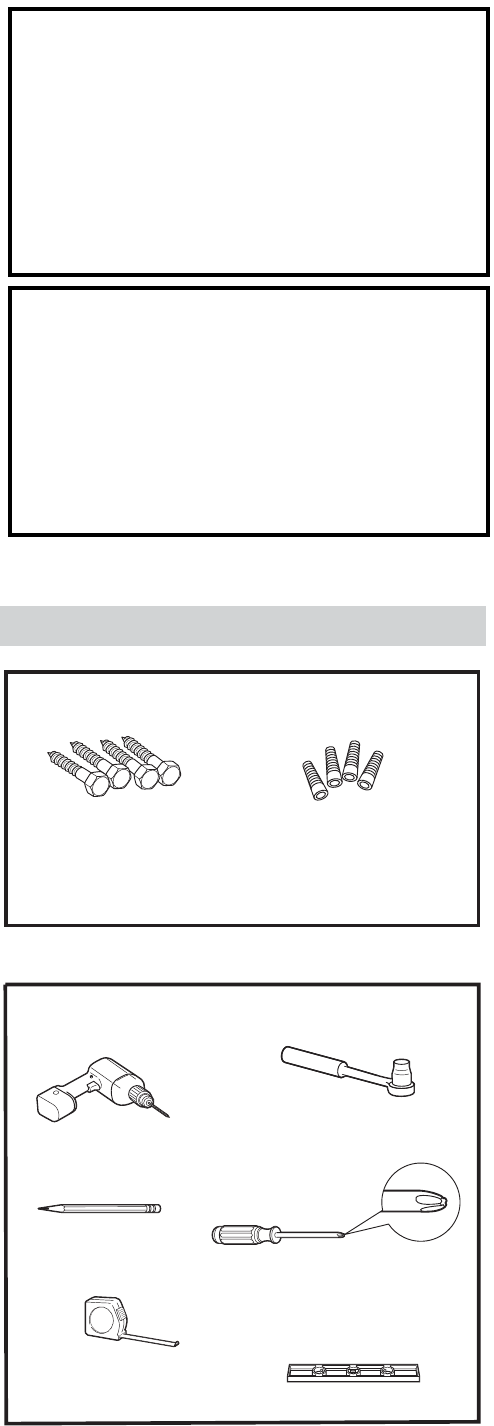
TOOLS YOU MAY NEED
Phillips Head Screwdriver
3/8 and 5/16 Socket
Ratchet/Driver
Pencil
1/8 Drill Bit and
Electric or Hand Drill
Tape Measure
Level
MATERIALS YOU MAY NEED (not included)
Lag Bolts Anchor Sleeves
For Anti-Tip Bracket Mounted on CONCRETE Floors Only
Drill Bit Appropriate for Anchors
(Continued next page)
POWER CORD
The power cord of this appliance is equipped with
a 3-prong (grounding) plug, which mates with a
standard 3-prong (grounding) wall outlet to minimize
the possibility of electric shock hazard from this
appliance.
Have the wall outlet and circuit checked by a
qualifi ed electrician to make sure the outlet is
properly grounded.
If the outlet is a standard 2-prong outlet, it is your
personal responsibility and obligation to have it
replaced with a properly grounded 3-prong wall
outlet.
WARNING: Do not, under any circumstances, cut
or remove the third (ground) prong from the power
cord. For personal safety, this appliance must be
properly grounded.
The refrigerator should always be plugged into its
own individual electrical outlet, which has a voltage
rating that matches the rating plate.
USE OF EXTENSION CORDS
Because of potential safety hazards under certain
conditions, we strongly recommend against the use
of an extension cord.
However, if you must use an extension cord, it is
absolutely necessary that the extension cord be:
UL-listed (in the United States) or CSA-listed (in •
Canada).
A 3-wire grounding type appliance extension •
cord having a grounding type plug and outlet.
A cord with an electrical rating of 15 amperes •
(minimum) and 120 volts.
– 10 –
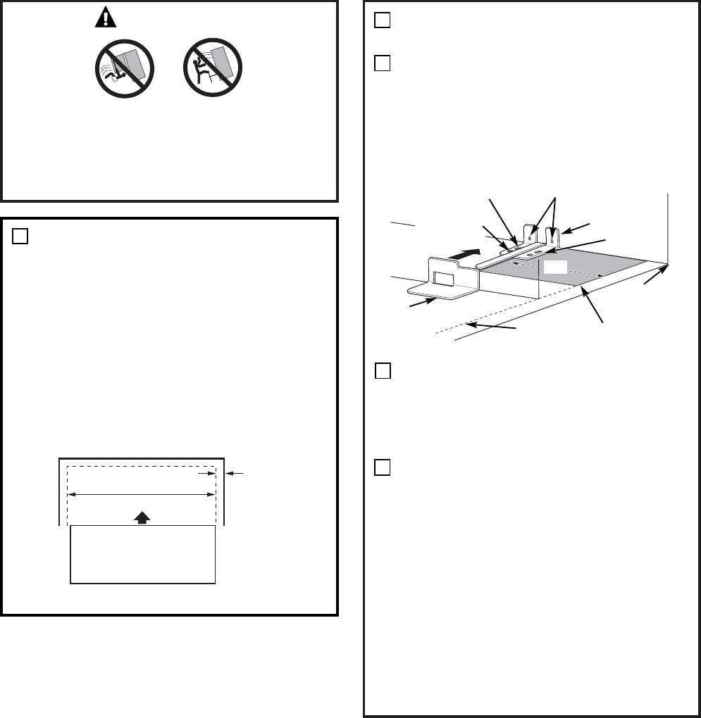
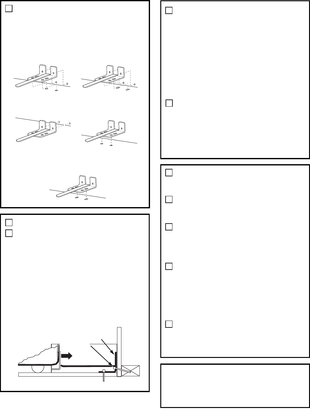
LOCATING THE ANTI-TIP
FLOOR BRACKET
Place the anti-tip floor bracket locator
template (included inside the anti-tip kit)
onto the floor up against the rear wall,
within W, and in line with the desired
location of the RH side of the refrigerator
(see Figure 1).
Place the anti-tip floor bracket onto the
locator template with its RH floor holes
lined up with the floor holes indicated
on the template sheet, approximately 71⁄4”
from the edge of the sheet or the RH side
of the refrigerator.
Hold down in position and use the anti-tip
floor bracket as a template for marking
the holes based upon your configuration
and type of construction as shown in Step
3. Mark the hole locations with a pencil,
nail or awl.
NOTE:
•It is REQUIRED to use at least 2 screws
to mount the floor bracket (one on each
side of the anti-tip floor bracket). Both
must be into either the wall or the floor.
Figure 2 indicates all the acceptable
mounting configurations for screws.
Identify the screw holes on the anti-tip
floor bracket for your configuration.
MEASURE CABINET OPENING
AVAILABLE VS. REFRIGERATOR
WIDTH
Measure width of cabinet opening where
refrigerator will be placed, W.
Be sure to account for any countertop
overhang, baseboard thickness and any
clearance desired. Width, W, should not
be less than 36 inches. The refrigerator
will be placed approximately in the
middle of this opening.
WARNING
Under certain circumstances, this refrigerator
can tip forward.
Injury to persons can result.
Install Anti-Tip Bracket packed with this
refrigerator.
1
Baseboard
Thickness
or Countertop
Overhang
(Whichever
Is Greater)
Plus Any
Desired
Clearance
Rear Wall
Front
RH Side
2
A
B
C
W
Base
Bracket
on the
Refrigerator
2 Wall Holes
RH Side of
Refrigerator
Floor – Concrete
(2 Holes)
Floor – Wood
(2 Holes)
71⁄4”
Locator
Template Sheet
Floor
Bracket
to Install
RH Holes
Rear RH
Corner of
Cabinet Wall
REFRIGERATOR
Figure 1 – Installation Overview
(Continued next page)
– 11 –
LOCATING THE ANTI-TIP
FLOOR BRACKET (cont.)
2
Preferred Installation –
Wood
Preferred Installation –
Concrete
Minimum Acceptable #1 –
Wall Plate Stud
Minimum Acceptable #2 –
Wood Floor
Minimum Acceptable #3 –
Concrete Floor
Figure 2 – Acceptable Screw
Placement Locations
CONCRETE Wall and Floor Construction:
•Anchors required (not provided):
4 each 1/4” x 1 1/2” lag bolts
4 each 1/2” O.D. sleeve anchors
•Drill the recommended size holes for
the anchors into the concrete at the
center of the holes marked in Step 2.
•Install the sleeve anchors into the drilled
holes. Place the anti-tip floor bracket as
indicated in Step 2. Remove the locator
template from the floor.
•Install the lag bolts through the anti-tip
floor bracket and tighten appropriately.
WOOD Wall and TILE Floor Construction:
•For this special case, locate the 2 wall
holes identified in Fig. 1. Drill an angled
1/8” pilot hole (approx. as shown in
Fig. 3) in the center of each hole.
•Mount the anti-tip floor bracket using
the Minimum Acceptable Installation #1,
as illustrated in Fig. 2.
C
B
ANTI-TIP BRACKET INSTALLATION
WOOD Wall and Floor Construction:
•Drill the appropriate number of 1/8”
pilot holes in the center of each floor
bracket hole being used (a nail or awl
may be used if a drill is not available)
AND remove the locator template from
the floor.
•Mount the anti-tip floor bracket by
fastening the 2, or preferably 4, #10-16
hex-head screws tightly into place as
illustrated in Figure 3.
3
A
POSITIONING THE REFRIGERATOR
TO ENGAGE THE ANTI-TIP FLOOR
AND BASE BRACKETS
Before pushing the refrigerator into the
opening, plug the power cord into the
receptacle and connect waterline (if
equipped). Check for leaks.
Locate the refrigerator’s RH side and
move back approximately in line with the
RH side of the cabinet opening, W. This
should position the anti-tip floor bracket
to engage the anti-tip base bracket on the
refrigerator.
Gently roll the refrigerator back into
the cabinet opening until it comes
to a complete stop. Check to see if
the refrigerator front lines up with the
cabinet front face. If not, carefully rock
the refrigerator forward and backward
until engagement occurs and you notice
that the refrigerator is fully pushed up
against the rear wall.
OPTIONAL: Adjust the rear (and front)
wheel height settings to fully engage the
rear anti-tip brackets, while also aligning
the refrigerator front with the cabinet
front face.
4
A
C
B
D
Figure 3 – Attachment to
Wall and Floor
NOTE:
If you pull the refrigerator out and away from
the wall for any reason, make sure the anti-tip
floor bracket is engaged when the refrigerator
is pushed back against the rear wall.
Rear RH
Corner of the
Refrigerator
Floor
Wall
Plate
Stud
Floor
Bracket
2 Screws
Must Enter
Wood or
Metal Stud
Wall
19
– 12 –
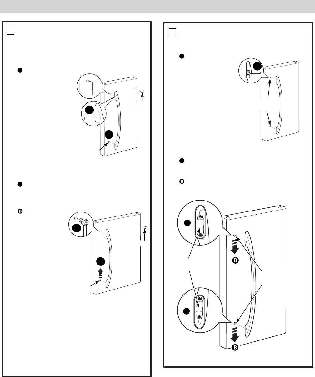
Fresh Food Door Handle
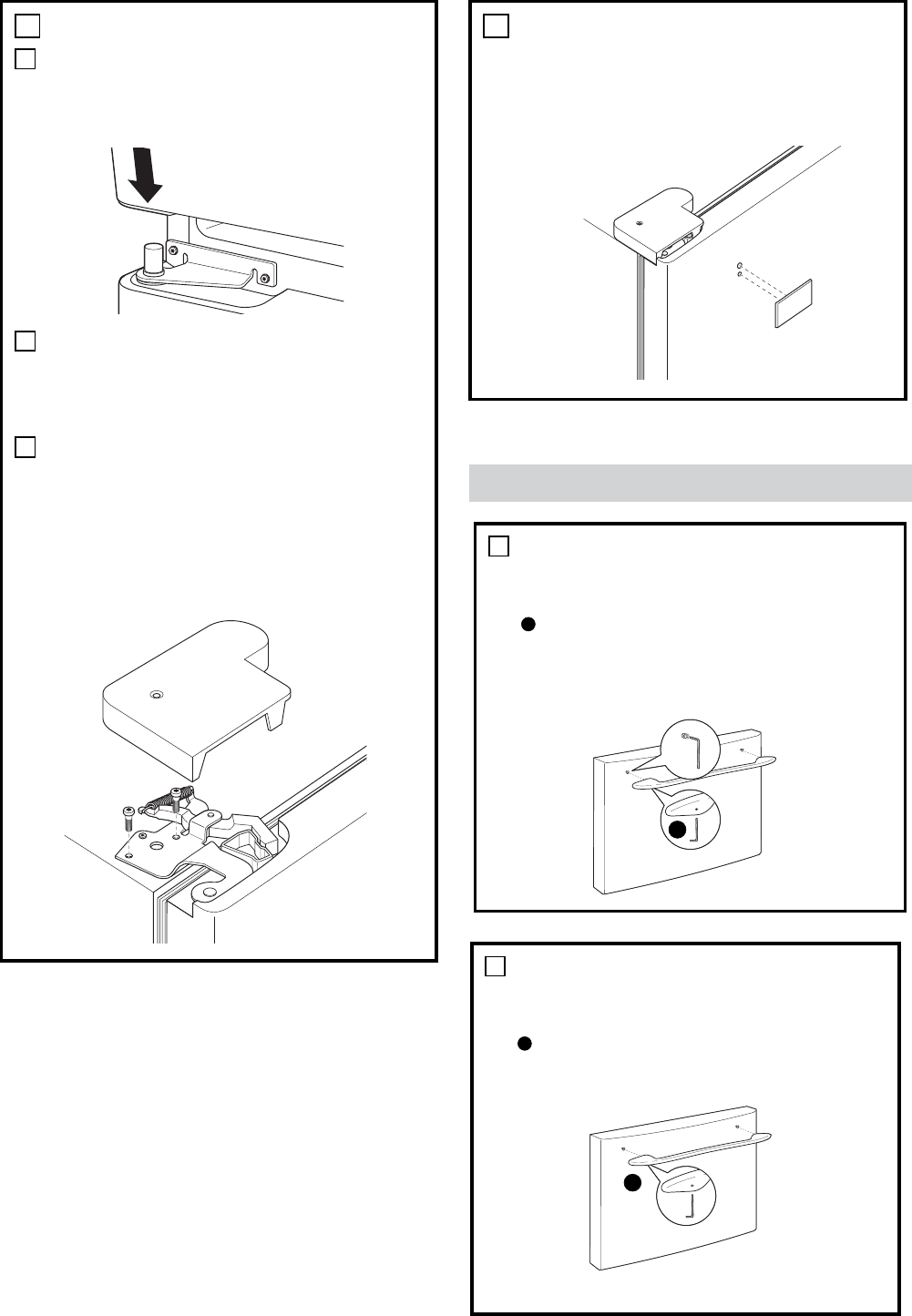
REMOVE THE FRESH FOOD
DOOR HANDLE
(For placement in the installation location or
reversal of the handles – on some models)
Stainless steel (on some models):
REMOVING
THE DOOR
HANDLE: Loosen
the set screws
with the 3/32″
Allen wrench
and remove
the handle. NOTE:
For Double Door
models follow the
same procedure
on the opposite
door.
Plastic handle (on some models):
REMOVING THE DOOR HANDLE: Depress the
tab on the underside of the handle and slide
the handle up and off of the mounting
fasteners.
REVERSING
THE DOOR
HANDLE (on
some models):
•Remove
the handle
mounting
fasteners with
a 1/4″Allen
wrench and
transfer the
handle
mounting
fasteners to
the right side.
•Remove the
logo badge.
•Remove and transfer the plug button to
the left side of the fresh food door. NOTE:
Use a flat plastic edge to prevent damaging
the door. Remove any adhesive on the door
with a mild detergent. Remove the paper
covering on the adhesive backing on the logo
badge prior to carefully attaching the badge
to the door.
A
A
6
A
B
A
B
Mounting
Fasteners
Mounting
Fasteners
Badge
Badge
(appearance may vary)
(appearance may vary)
1
1
ATTACH THE FRESH FOOD
DOOR HANDLE
Stainless steel handle:
Attach the handle
to the handle
mounting
fasteners and
tighten the set
screws with a
3/32″Allen
wrench.
NOTE: For Double
Door models
follow the same
procedure on the
opposite door.
Plastic handle:
Attach the handle to the handle mounting
fasteners by aligning the slots with the handle
mounting fasteners.
Slide it down until it is firmly locked into
position.
A
A
8
A
Mounting
Fasteners
(appearance may vary)
(appearance may vary)
Mounting
fasteners
Slots on back
of handle
A
A
2
2
– 13 – (Continued next page)
Reversing the Door Swing (Single Door Refrigerator Models only)
TOOLS YOU WILL NEED
IMPORTANT NOTES
When reversing the door swing:
NOTE: Door swing is not reversible on stainless
steel models.
•Read the instructions all the way through
before starting.
•Parts are included in the door hinge kit.
•Handle parts carefully to avoid scratching
paint.
•Set screws down by their related parts to
avoid using them in the wrong places.
•Provide a non-scratching work surface for
the doors.
IMPORTANT: Once you begin, do not move the
cabinet until door-swing reversal is completed.
These instructions are for changing the hinges
from the right side to the left side—if you ever
want to change the hinges back to the right side,
follow these same instructions and reverse all
references to left and right.
•Once door swing is finalized, ensure
the logo badge is properly aligned and
permanently secured to the door by removing
the adhesive cover on the back side.
NOTE: A replacement logo badge is included
in the hinge kit.
Unplug the refrigerator from its electrical outlet.
Empty all door shelves, including the dairy
compartment.
Thin-blade Screwdriver
Masking Tape
Adjustable Wrench 5/16″ Socket
Ratchet/Driver
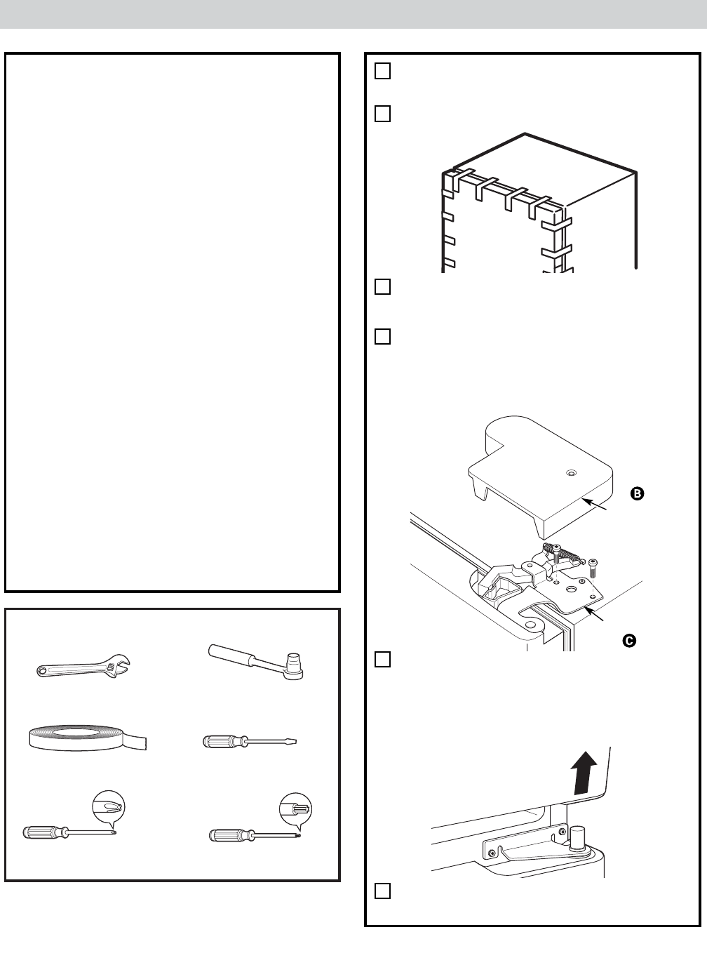
REMOVE THE
REFRIGERATOR DOOR
Tape the door shut with masking tape.
Remove the hinge cover on top of the
refrigerator door by removing the Phillips
head screws and pulling it up.
Using a 5/16″socket ratchet/driver,
remove the bolts securing the top hinge to
the cabinet. Then lift the hinge straight up
to free the hinge pin from the socket in
the top of the door.
Remove the tape and tilt the door away
from the cabinet. Lift the door off the
center hinge pin. Ensure that the plastic
hinge pin thimble remains on the hinge pin
or inside door hinge pin hole located in the
bottom of the door.
Set the door on a non-scratching surface
with the inside up.
1
A
B
C
Hinge Cover
Top Hinge
Phillips Screwdriver
27
Torx T-20 Driver
D
E
MAY
– 14 –
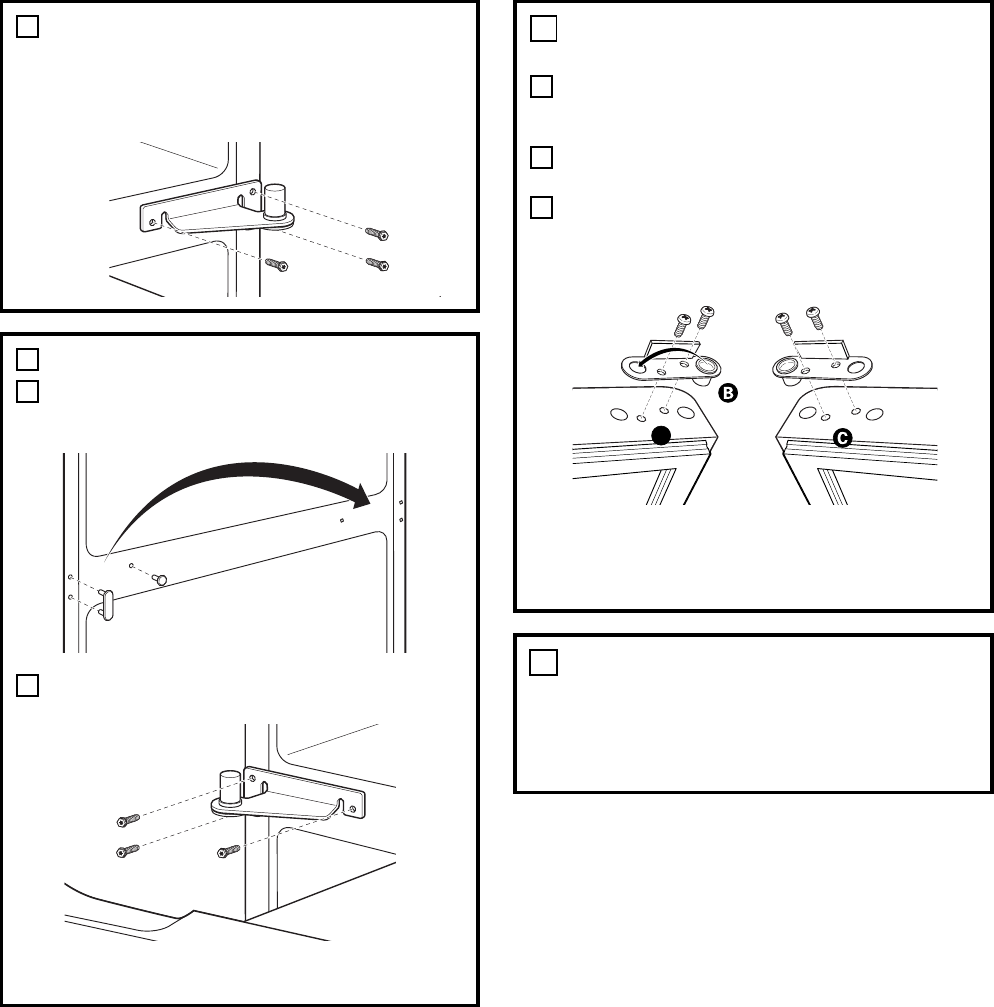
REMOVE CENTER HINGE
Using a 5/16″socket ratchet/driver,
remove the bolts securing the center
hinge to the cabinet. Set the hinge
and bolts aside.
2
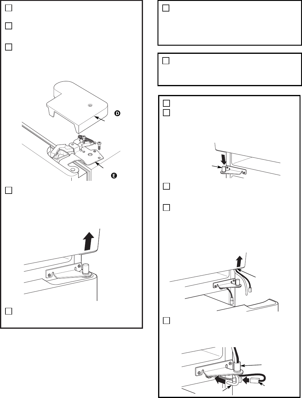
INSTALL CENTER HINGE
Transfer the plug button and screw hole
cover in the hinge holes on the left side to
the right side.
Install the center hinge from the kit on the
left side.
NOTE: A new hinge will be required for the
left side (supplied in the door hinge kit).
3
A
B
TRANSFER REFRIGERATOR
DOOR STOP
Remove the door stop on right side of
the bottom of the refrigerator door by
removing the two screws.
Move the plastic hinge hole thimble to the
opposite hole.
Install the door stop on the left side,
making sure to line up the screw holes
in the door stop with the holes in the
bottom of the door.
4
A
B
C
Bottom of
Refrigerator Door
(Right Side)
Bottom of
Refrigerator Door
(Left Side)
A
TRANSFER REFRIGERATOR
DOOR HANDLE TO RIGHT
Refer to Remove the Fresh Food Door
Handle and Attach the Fresh Food Door
Handle sections for instructions.
5
(Continued next page)
– 15 –
REHANG REFRIGERATOR DOOR
Lower the refrigerator door onto the
center hinge pin. Ensure that the plastic
hinge pin thimble is on the center hinge
pin or inside door hinge pin hole located
in the bottom of the door.
Insert the top hinge pin into the hinge hole
on top of the refrigerator door. Make sure
the door is aligned with the cabinet.
Attach the hinge to the top of the cabinet
loosely with the bolts.
Make sure the gasket on the door is
flush against the cabinet and is not folded.
Support the door on the handle side and
make sure the door is straight and the gap
between the doors is even across the
front. While holding the door in place,
tighten the top hinge bolts. Replace the
hinge cover.
6
A
B
C
INSTALL THE LOGO BADGE
Remove the adhesive backing paper
and align the pins on the back of the
badge with the holes in the door. Apply
pressure to the badge to ensure it sticks
to the door.
7
REMOVE THE FREEZER DOOR
HANDLE
Stainless steel and plastic handles:
Loosen the set screws located on the underside
of the handle with the 1/8″Allen wrench and
remove the handle.
NOTE: If the handle mounting fasteners need to
be tightened or removed use a 1/4″Allen wrench.
A
7
A
1
1
ATTACH THE FREEZER DOOR
HANDLE
Stainless steel and plastic handles:
Attach the handle firmly to the mounting
fasteners and tighten the set screws on the
bottom of the handle with a 1/8″Allen wrench.
A
9
A
(appearance may vary)
2
2
Freezer Drawer Handle
– 16 – (Continued next page)
Removing and Installing Double Doors (Some Models)
IMPORTANT NOTES
NOTE: Door swing is not reversible.
•Read the instructions all the way through
before starting.
•Handle parts carefully to avoid scratching
paint.
•Set screws down by their related parts to
avoid using them in the wrong places.
•Provide a non-scratching work surface for
the doors.
IMPORTANT: Once you begin, do not move
the cabinet.
These instructions are for removing the
doors.
Unplug the refrigerator from its electrical
outlet.
Empty all door shelves, including the dairy
compartment.
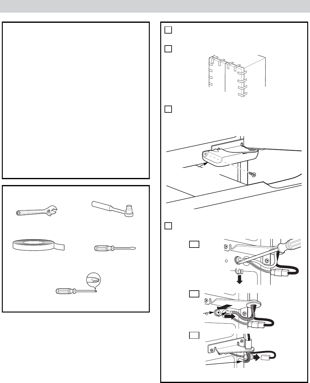
REMOVE THE
REFRIGERATOR DOORS
Tape the doors shut with masking tape.
Start with right-hand door first: Remove
the screw securing the center hinge cover,
lift the hinge cover and place to the side
on top of the refrigerator.
Remove water coupling and power
coupling.
1
A
B
TOOLS YOU WILL NEED
Thin-blade Screwdriver
Masking Tape
Adjustable Wrench 3/8″ and 10 mm Socket
Ratchet/Driver
Phillips Screwdriver
Remove hinge cover
(1 Phillips screw)
C
Water Coupling
Remove the metal spring
clip. Use a screwdriver to
push the red plastic locking
clip down and off.
C1
Water Coupling
Push red collar
and hold. Pull tube.
Power Coupling
Black mark
flush with
collar assembly Pull apart power
coupling to
disconnect
C2
C3
(for water dispenser models)
(for water dispenser models)
MAY
– 17 – (Continued next page)
REMOVE THE
REFRIGERATOR DOORS (cont.)
Remove the hinge cover on top of the
refrigerator door by removing the Phillips
head screws and pulling it up.
Using a 5/16″socket ratchet/driver,
remove the bolts securing the top hinge to
the cabinet. Then lift the hinge straight up
to free the hinge pin from the socket in
the top of the door.
Remove the tape and tilt the door away
from the cabinet. Lift the door off the
center hinge pin. Ensure that the plastic
hinge pin thimble remains on the hinge pin
or inside door hinge pin hole located in the
bottom of the door.
Set the door on a non-scratching surface
with the inside up.
F
G
1
D
Hinge Cover
Top Hinge
E
REMOVE OPPOSITE DOOR
Follow the same procedure on the
opposite door. There are no wires, water
lines or center hinge covers on the
opposite side.
3
REMOVE FREEZER DRAWER
Refer to the Removing the Freezer Drawer
section for instructions.
4
2
2
3
3
REHANG REFRIGERATOR DOORS
Lower the refrigerator door onto the
center hinge pin. Ensure that the plastic
hinge pin thimble is on the center hinge
pin or inside door hinge pin hole located
in the bottom of the door.
Securely tape the door shut with masking
tape or have a second person support
the door.
Route wires through bottom right hinge
pin slot. Insert the top hinge pin into the
hinge hole on top of the refrigerator door.
Make sure the door is aligned with the
cabinet and opposite door. Attach the
hinge to the top of the cabinet loosely
with the bolts.
On right-hand doors, pass the wires and
water line through the center hinge pin.
Then connect the water line and 4-pin
connector.
A
B
C
Hinge Pin
Bottom
Right Hinge
Pin Slot
4-Pin
Connector
Water Line
D
3
(appearance may vary)
2
Center
Hinge Pin
4
4
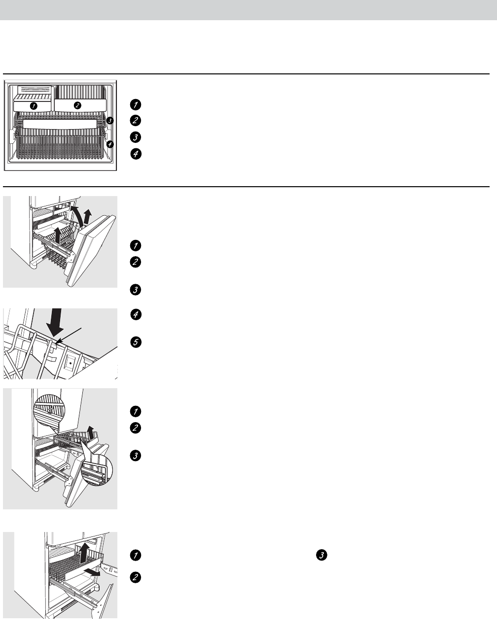
– 18 –
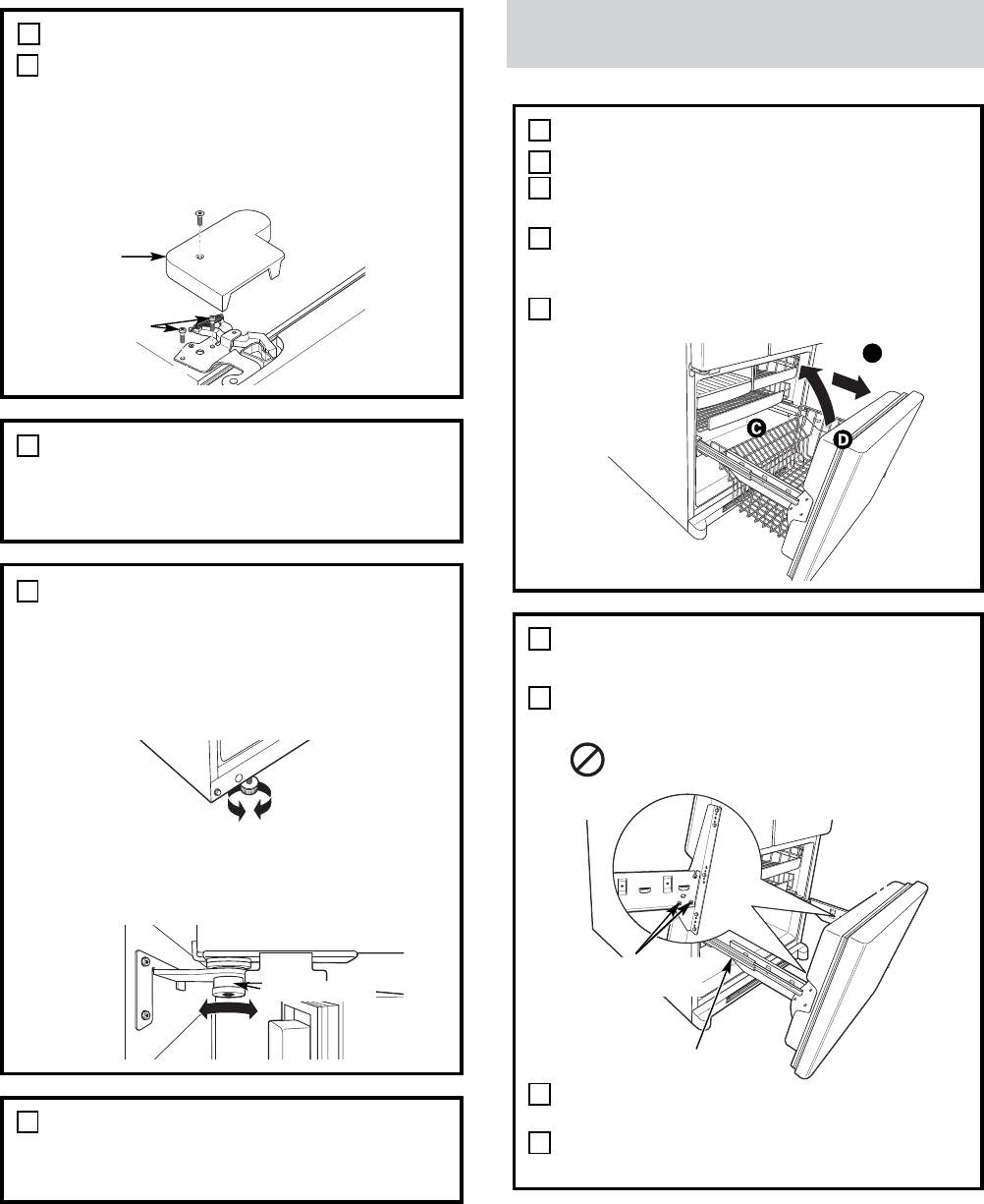
REMOVE THE BASKET
Open the freezer drawer until it stops.
Cut the 2 wire ties off of the basket with
wire cutters.
The freezer basket rests inside 4 tabs on
the freezer slides. Lift the basket up and
out of the 4 tabs.
Tilt the front up and lift the entire basket
up and out of the drawer.
1
A
C
D
REMOVE THE DRAWER FRONT
FROM THE SLIDES
Remove the 10 hex head screws from the
door and remove the door.
DO NOT remove the torx screws
from the rail assemblies.
Set the drawer front on a non-scratching
surface.
Push the rail assemblies back into the
cabinet.
2
A
DO NOT remove
torx screws
Rail Assembly
A
B
C
B
Removing and Installing the Freezer Drawer
(Some Models)
REHANG REFRIGERATOR DOORS (CONT.)
Make sure the gasket on the door is
flush against the cabinet and is not folded.
Make sure the door is straight and the gap
between the doors is even across the front.
While holding the aligned door in place,
tighten the top hinge bolts. Replace the
hinge cover and screw.
E
Top Hinge Bolts
Hinge Cover
ALIGN DOUBLE DOORS
If the top of the doors are uneven, first
try to raise the lowest door by turning the
leveling leg on the same side as the door
until the doors are even. If the unit rocks,
re-adjust the leveling legs to the extent
that the unit is stable.
If the doors remain uneven, turn the
adjustable pin to raise, or lower, the left
door to match the right door. Use a 1/4″
Allen wrench to turn the pin.
Adjustable pin
REPLACE FREEZER DRAWER
Refer to the Replacing the Freezer Drawer
section for instructions.
5
2
REPLACE OPPOSITE DOOR
Follow the same procedure on the
opposite door. There is no water line or
hinge cover.
(appearance may vary)
4
3
2
5
5
6
6
7
7
8
8
(Continued next page)
– 19 –
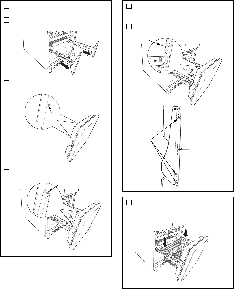
ATTACH AND SECURE THE
DRAWER FRONT TO THE SLIDES
Pull out the rail assemblies to the full
length on each side of the cabinet.
Drive the top screw into the door on each
side until it is 1/2 way in.
Hang the drawer front onto open slots on
the slides.
1
A
B
Screw
Slot
C
3
3
6
REPLACE THE FREEZER BASKET
Replace the lower freezer basket by
lowering it into the frame.
2
ATTACH AND SECURE THE
DRAWER FRONT TO THE SLIDES
(CONT.)
Drive screws fully. (There are 10 screws.)
1
Screw
D
Step D2:
Drive
fully.
Step D3:
Drive
screws
in these
holes.
Step D1:
Line up
screw
hole in
freezer
drawer
and
drive
fully.
4
4
5
5
– 20 –
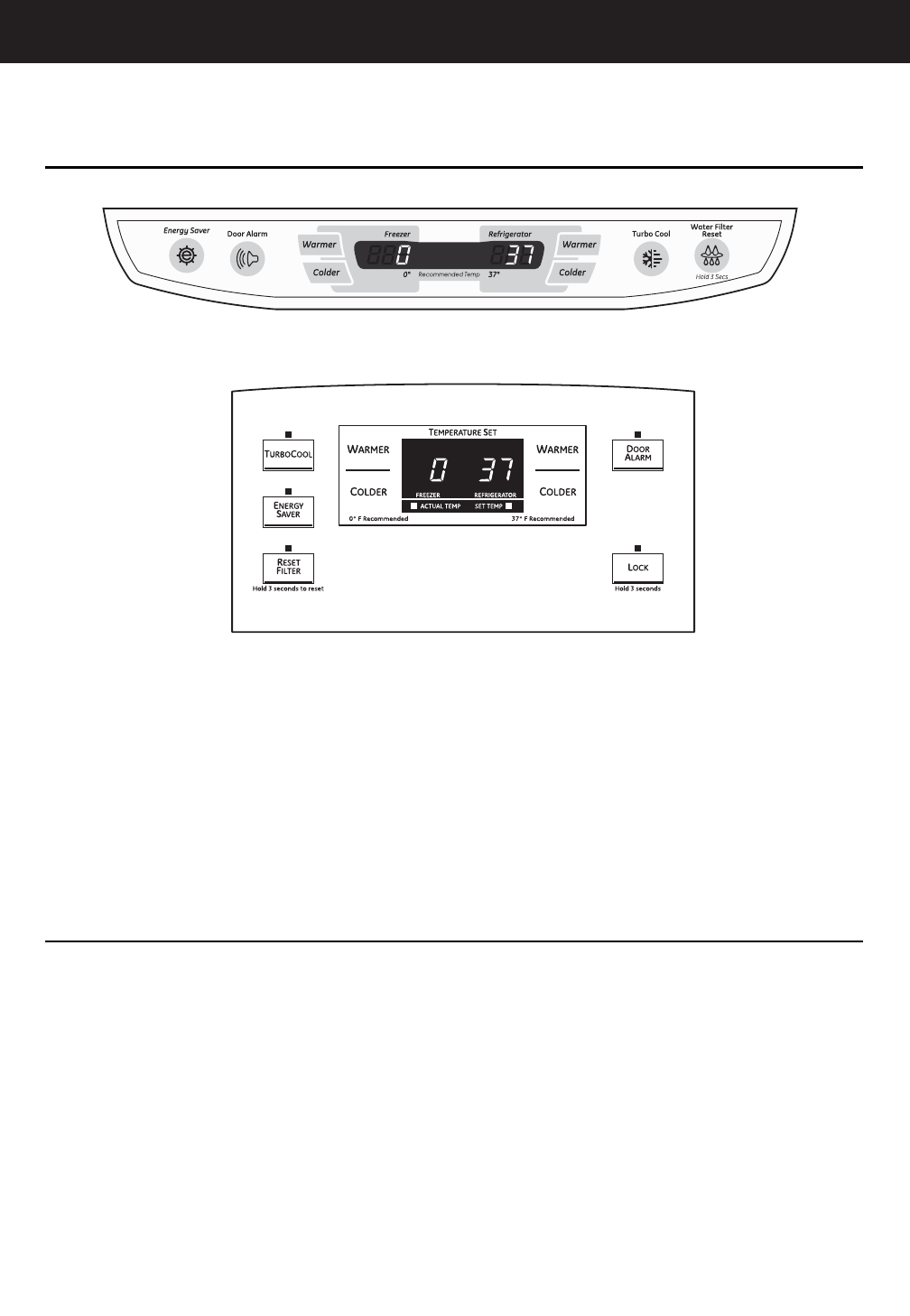
Control Features
4
About the controls with temperature settings.
The temperature controls are preset in the factory at 37°F for the refrigerator compartment
and 0°F for the freezer compartment. Allow 24 hours for the temperature to stabilize to the
preset recommended settings.
The temperature controls can display both the SET temperature as well as the actual
temperature in the refrigerator and freezer. The actual temperature may vary slightly from
the SET temperature based on usage and operating environment.
Setting either or both controls to OFF stops cooling in both the freezer and refrigerator
compartments, but does not shut off electrical power to the refrigerator.
For Controls-on-the-Door Models:
To change the temperature, press and release the
WARMER or COLDER pad. The ACTUAL TEMP light
will come on and the display will show the actual
temperature. To change the temperature, tap
either the WARMER or COLDER pad until the
desired temperature is displayed.
For Controls Inside the Refrigerator:
Opening the door displays the actual temperature.
To change the temperature, press either the
WARMER or COLDER touch pads until the
desired temperature is displayed.
Once the desired temperature has been set,
the temperature display will return to the actual
refrigerator and freezer temperatures after 5
seconds. Several adjustments may be required.
Each time you adjust controls, allow 24 hours for the
refrigerator to reach the temperature you have set.
To turn the cooling system off, tap the WARMER pad
for either the refrigerator or the freezer until the
display shows OFF.To turn the unit back on, press the
COLDER pad for either the refrigerator or freezer.
Then press the COLDER pad again and it will go to
the preset points of 0°F for the freezer and 37°F for
the refrigerator. Setting either or both controls
to OFF stops cooling in both the freezer and
refrigerator compartments, but does not shut
off electrical power to the refrigerator.
Changing the Temperature
NOTE: The refrigerator is shipped with protective film covering the temperature controls.
If this film was not removed during installation, remove it now.
(on some models)
(on some models)
– 21 –
5
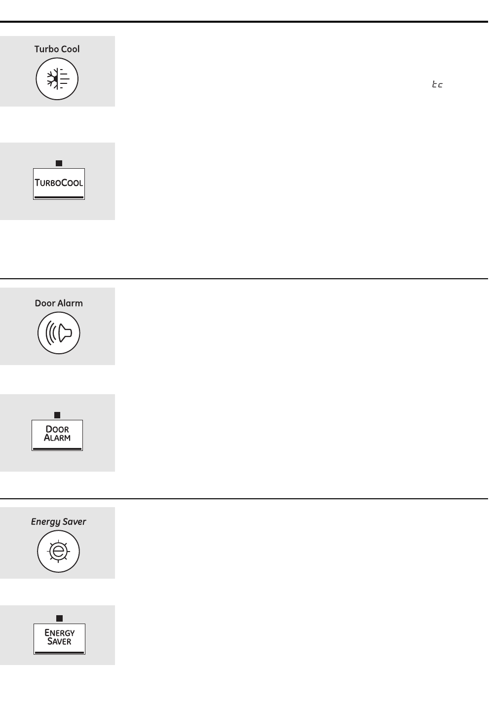
About TurboCool.™(on some models) ge.com
How it Works
TurboCool rapidly cools the refrigerator
compartment in order to more quickly
cool foods. Use TurboCool when adding a
large amount of food to the refrigerator
compartment, putting away foods after they
have been sitting out at room temperature
or when putting away warm leftovers. It can
also be used if the refrigerator has been
without power for an extended period.
Once activated, the compressor will turn on
immediately and the fans will cycle on and
off at high speed as needed for eight hours.
The compressor will continue to run until
the refrigerator compartment cools to
approximately 34°F (1°C), then it will cycle
on and off to maintain this setting. After 8
hours, or if TurboCool is pressed again, the
refrigerator compartment will return to
the original setting.
How to Use
Press TurboCool. The refrigerator
temperature display will show .
After TurboCool is complete, the
refrigerator compartment will return
to the original setting.
NOTES: The refrigerator temperature
cannot be changed during
TurboCool.
The freezer temperature is not
affected during TurboCool.
When opening the refrigerator
door during TurboCool, the fans
will continue to run if they have
cycled on.
About Door Alarm (on some models)
The door alarm will sound if any
door is open for more than 2 minutes.
The beeping stops when you close
the door.
(on some models)
(on some models)
(on some models)
(on some models)
About Energy Saver (on some models)
This product is equipped with an Energy
Saver feature. The refrigerator is shipped
with the Energy Saver feature enabled.
Over time, moisture can form on the front
surface of the refrigerator cabinet and
cause rust. If moisture does appear on the
front surface of the refrigerator cabinet,
turn off the Energy Saver feature by
pressing and releasing the ENERGY SAVER
pad on the control panel.
(on some models)
(on some models)
– 22 –
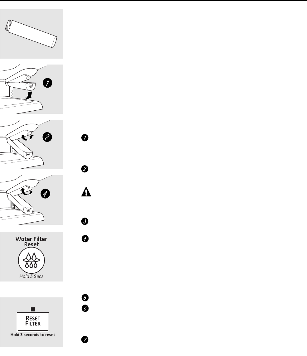
Water Filter Cartridge
The water filter cartridge is located in the
back upper right corner of the refrigerator
compartment.
When to Replace the Filter
There is a replacement indicator
light for the water filter cartridge on the
temperature display. This light will turn
orange to tell you that you need to replace
the filter soon. The filter cartridge should
be replaced when the replacement
indicator light turns red or if the flow
of water to the dispenser or icemaker
decreases.
Installing the Filter Cartridge
If you are replacing the cartridge,
first remove the old one. Open the
cartridge cover by pressing in on the
tab at the front and pulling down.
Remove the cartridge by slowly rotating
it counterclockwise. A small amount of
water may drip down.
CAUTION: If air has been trapped
in the system, the filter cartridge may be ejected as
it is removed. Use caution when removing.
Remove the protective foil from the
end of the cartridge.
Lining up the arrow on the cartridge
and the cartridge holder, slowly rotate
the cartridge clockwise until it stops.
When the cartridge is properly
installed, you will feel it “click” as it
locks into place. The grip on the end
of the cartridge should be positioned
vertically. Do not overtighten.
Close the cartridge cover.
Run water from the dispenser for
3 minutes (about 11⁄2gallons) to clear
the system and prevent sputtering.
See To Use the Dispenser section.
Press and hold the RESET WATER FILTER
pad for 3 seconds.
NOTE: A newly-installed water filter cartridge
may cause water to spurt from the dispenser.
Filter Bypass Plug
You must use the filter bypass plug when a
replacement filter cartridge is not available.
The icemaker will not operate without the
filter or filter bypass plug.
Replacement Filters:
To order additional filter cartridges
in the United States, visit our Website,
ge.com, or call GE Parts and Accessories,
800.626.2002.
Filter Model GSWF
Customers in Canada should consult
the yellow pages for the nearest Mabe
Service Center.
About the water filter. (on some models)
(on some models)
(on some models)
– 23 –
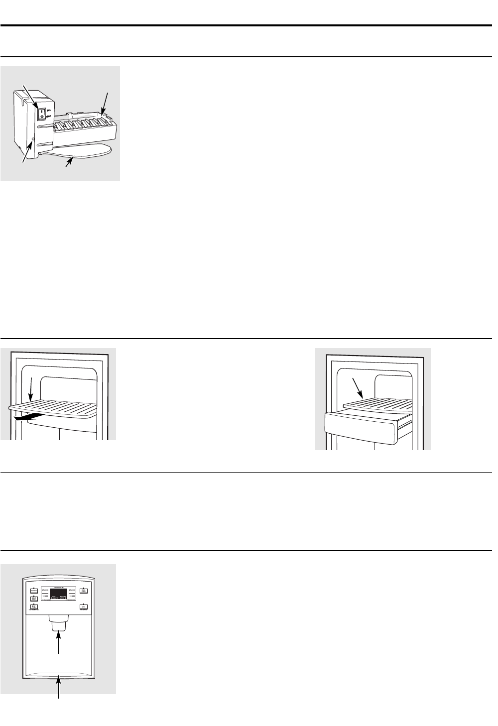
About the automatic icemaker. ge.com
Automatic Icemaker (on some models)
The icemaker will produce seven cubes
per cycle—approximately 100–130 cubes
in a 24-hour period, depending on freezer
compartment temperature, room
temperature, number of door openings
and other use conditions.
See below for how to access ice and reach
the power switch.
If the refrigerator is operated before the
water connection is made to the icemaker,
set the power switch in the O (off) position.
When the refrigerator has been connected
to the water supply, set the power switch to
the l (on) position. The icemaker power
light will turn green when the freezer light
switch is pressed in or when the freezer
door is closed.
The icemaker will fill with water when it
cools to 15°F (–10°C). A newly installed
refrigerator may take 12 to 24 hours to
begin making ice cubes.
You will hear a buzzing sound each time
the icemaker fills with water.
Throw away the first few batches of ice to
allow the water line to clear.
Be sure nothing interferes with the sweep
of the feeler arm.
When the bin fills to the level of the feeler
arm, the icemaker will stop producing
ice. It is normal for several cubes to be
joined together.
If ice is not used frequently, old ice cubes
will become cloudy, taste stale and shrink.
NOTE: In homes with lower-than-average water
pressure, you may hear the icemaker cycle multiple
times when making one batch of ice.
NOTE: Set the power switch to the O (off) position
if the water supply is shut off.
A newly installed refrigerator may take 12 to 24 hours to begin making ice.
Icemaker
Feeler Arm
Power
Switch
Green
Power Light
Accessing Ice and Reaching
the Power Switch
To reach the icemaker power switch, pull the
shelf above the ice bin straight out. Always
be sure to replace the shelf.
To access ice, simply pull the bin forward.
To access ice.
Shelf
Ice Bin
To reach the power switch.
Shelf
Ice Bin
Icemaker Accessory Kit
If your refrigerator did not come already
equipped with an automatic icemaker,
an icemaker accessory kit is available at
extra cost.
Check the back of the refrigerator for
the specific icemaker kit needed for
your model.
To Use the Dispenser
Press the glass gently against the top of the
dispenser cradle.
The spill shelf is not self-draining. To
reduce water spotting, the shelf should be
cleaned regularly.
If no water is dispensed when the refrigerator is first
installed, there may be air in the water line system.
Press the dispenser arm for at least two minutes to
remove trapped air from the water line and to fill the
water system. To flush out impurities in the water
line, throw away the first six glassfuls of water.
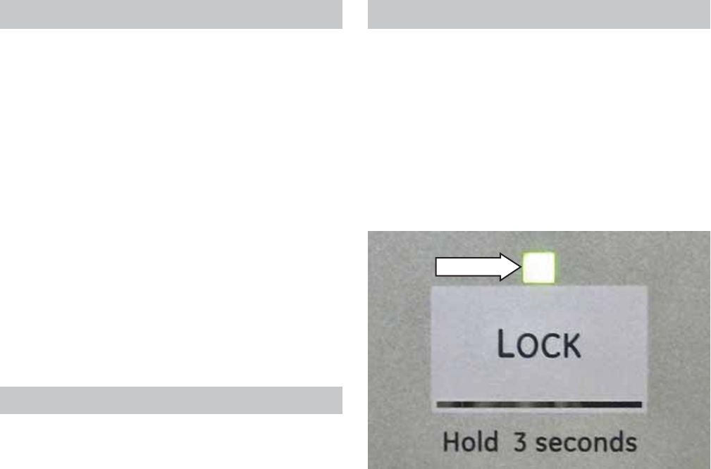
Locking the Dispenser
Press the LOCK pad for 3 seconds to lock
the dispenser and control panel. To unlock,
press and hold the pad again for 3 seconds.
Door Alarm
To set the alarm, press the DOOR ALARM
pad. The indicator light will illuminate.
This alarm will sound if either door is
open for more than 2 minutes. The
beeping stops when you close the door.
Spill Shelf 11
Dispenser Cradle
– 24 –
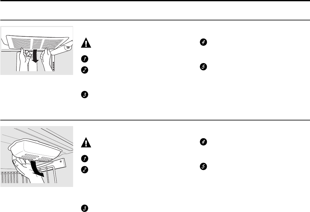
Refrigerator Lights
CAUTION: Light bulbs may be hot.
Unplug the refrigerator.
To remove the light shield, grasp the
shield at the back and pull out to
release the tabs at the back.
Rotate the shield down and then
forward to release the tabs at the front
of the shield.
After replacing with an appliance bulb
of the same or lower wattage, replace
the shield.
Plug the refrigerator back in.
NOTE: Appliance bulbs may be ordered
from GE Parts and Accessories,
800.626.2002.
Freezer Light
Replacing the light bulbs.
Turning the control to the 0 (off) position does not remove power to the light circuit.
Appearance may vary
CAUTION: Light bulbs may be hot.
Unplug the refrigerator.
The bulb is located at the top of the
freezer inside a light shield. To remove
the shield, grasp the shield at the back
and pull out to release the tabs at the
back.
Rotate the shield down and then
forward to release the tabs at the front
of the shield.
After replacing with an appliance bulb
of the same or lower wattage, replace
the shield.
Plug the refrigerator back in.
– 25 –
Defrost Cycle
The refrigerator utilizes an adaptive defrost cycle
that operates a glass enclosed heater to remove
frost from the evaporator. Defrost time has changed
from 60 hours adaptive defrost to 96 hours adaptive
defrost.
The control board determines the length of time the
heater is energized. It does this by monitoring the
freezer evaporator thermistor. Once the temperature
of the thermistor reaches 75°F, the control cycles
the defrost heater off. A bi-metal safety thermostat
provides a backup in the event the evaporator
thermistor fails. The safety thermostat prevents the
temperature from exceeding 140°F.
Note: Refer to Pub# 31-9062 for information about
basic adaptive defrost.
Dispenser Lock
When the dispenser system is locked, actual and
set temperatures can be viewed but no dispenser
command will be accepted. This includes the
dispenser cradle and will prevent accidental
dispensing that may be caused by children or pets.
If a pad or the cradle is depressed with the system
locked, it will be acknowledged with three pulses of
the LOCK LED accompanied by an audible tone.
Liner Protection Mode
The refrigerator incorporates a liner protection
mode for the freezer section. The freezer evaporator
fan will start and run on high speed if the door
has been open for 3 minutes. Air will circulate into
the fresh food section if the damper is in the open
position.
This mode is controlled by 2 timers. Timer #1
monitors door-open time. A 3-minute door-open
count begins when the door is opened. If 3 minutes
elapse before the door is closed, the liner protection
mode will become active. Once the door is closed,
timer #1 resets and liner protection mode goes into
standby. In standby, normal fan operation resumes
and timer #2 begins a 3-minute door-closed count.
If 3 minutes elapse without a door opening, liner
protection mode will completely deactivate. If a door
is opened within the timer #2 door-closed count,
the remaining time in the door-closed count will be
deducted from the timer #1 door-open count.
Lock LED
– 26 –
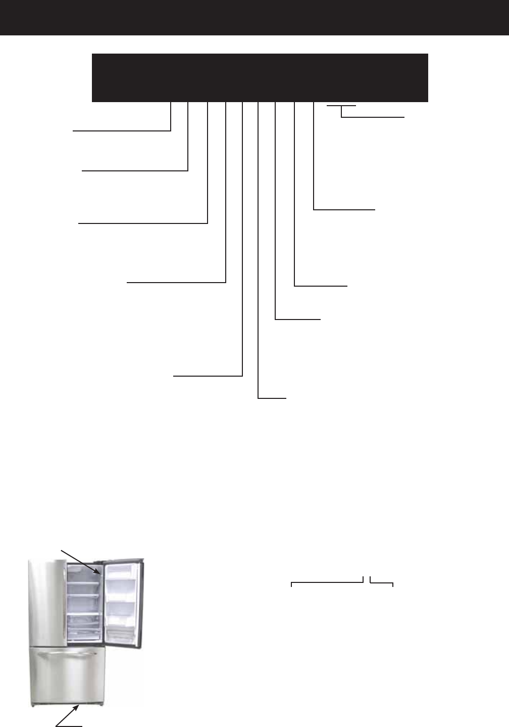
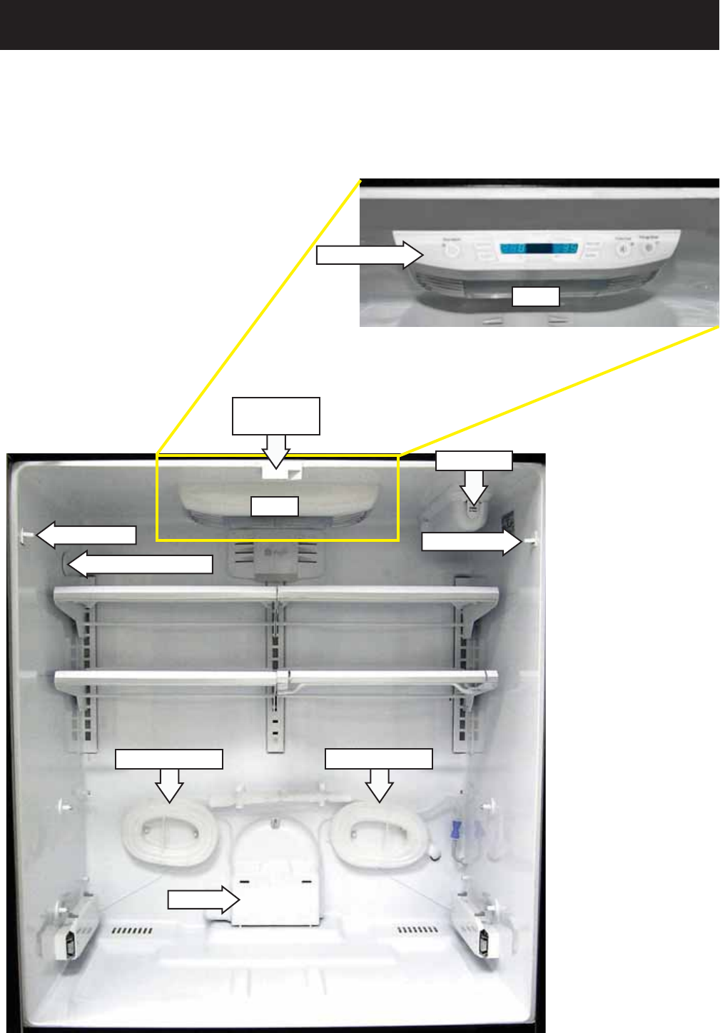
Components Locator Views
Fresh Food Compartment
Water Line Coil Water Line Coil
Water Filter
Light Switch Light Switch
Damper
Lights
Thermistor Location
(Continued next page)
Single Door Model
Lights
Control Panel
Note: Single door
models eliminate the
articulating mullion
track. On non-dispenser
models, the control
panel is located in front
of the light housing at
the top of fresh food
compartment.
Articulating
Mullion Track
French Door Model
– 27 –
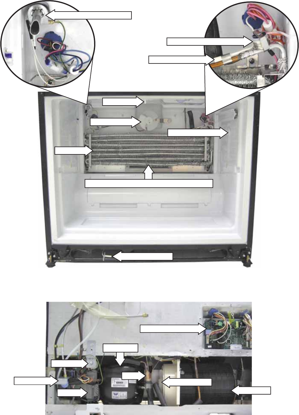
Freezer Compartment
Over Temperature Thermostat
Icemaker Fill Tube and Heater
Evaporator
Evaporator Fan
Defrost Heater (recessed in bottom of evaporator)
Rear View
Main Control Board
Water Valve Drier
EMI Filter
Condensor Fan
Condenser
Inverter
Light Switch
Thermistor Location
Compressor
Ambient Thermistor
Note: The EMI
fi lter is not
utilized on
20/22' single
and French
door models.
Evaporator Thermistor
– 28 –
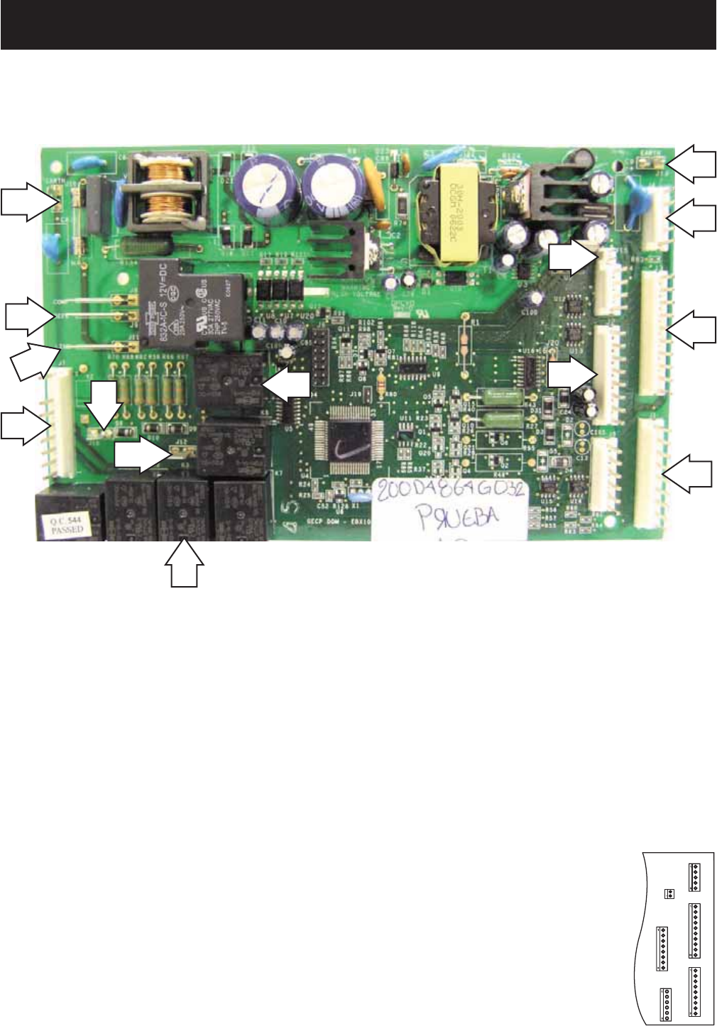
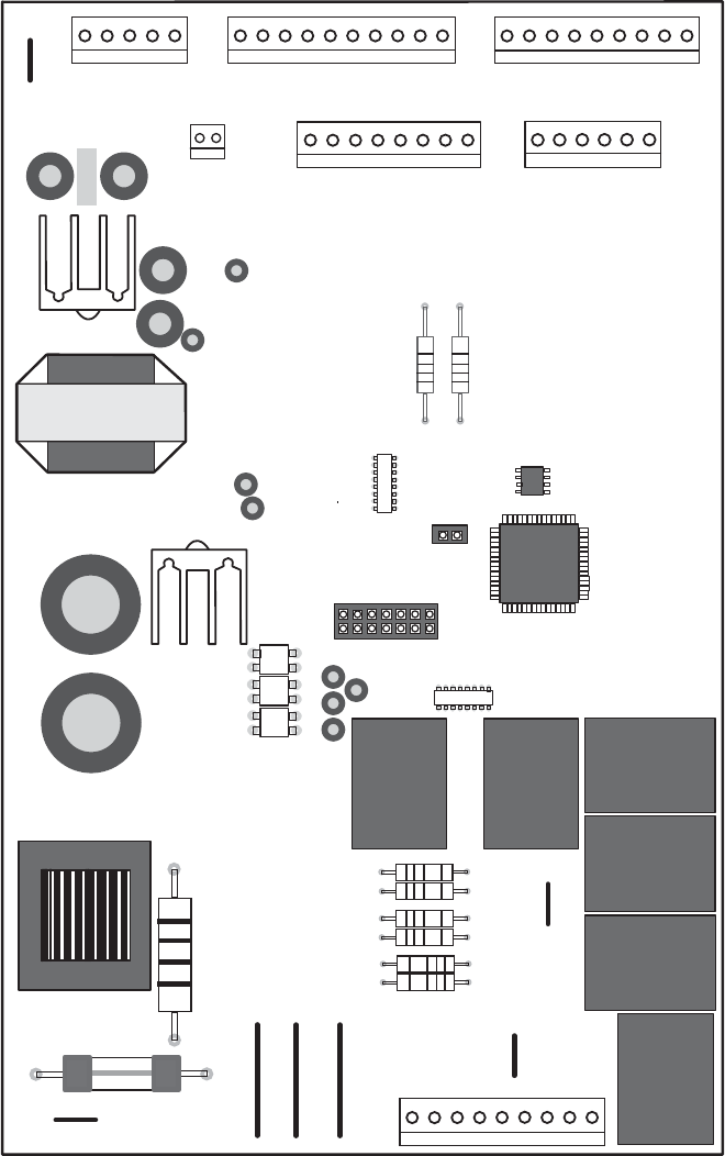
Control Board Connector Locator
Main Control Board
J4 or J16 J3 or J10 J1 or J14
J2 OR J13
(Continued next page)
Some of the low voltage DC
connector labeling on this model
may differ from other models.
The function and diagnostics for
these connectors are identical for
all models.
J10
J13
J9
J11
J7
K3
K4
J12
J18
J4
J3
J1
J15
J2
J4 - Display Board
J3 - Damper
J1 - Fresh Food Thermistor, Ambient Thermistor,
Freezer Thermistor, Evaporator
Thermistor, Model Selector
J15 - Inverter
J2 - Fan Common, Evaporator Fan, Condenser
Fan, Mullion Bar Heater, Model Selector
J10 and J13 - Earth (Ground)
J9 - Defrost Heater, Fill Tube Heater, Return Duct
Heaters
J11 - Line (L1)
J7 - FF and FZ Interior Lighting Circuits, Dispenser
Water Valve (French Door Models Only)
J12 - Mullion Heater
J18 - Icemaker Water Valve (Icemaker Ready Models
Only)
K3 - Water
K4 - Defrost
– 29 –
1
5
1
10
1
9
J1
J5
6
J3
J2
1
DEFROST
K4
21
J6
K5
K7
NOT
USED
K2
WATER
K3
J4
1
8
J7
K1
1
J13
EARTH
EARTH
J10
J18
J12
J15
1
J19
J11
J9
Comm. 2-Way Digital
Comm. +12V
Comm. Common
FF Thermistor
Ambient Thermistor
FZ Thermistor
FZ Evaporator Thermistor
+5V
Evaporator Fan (RPM)
Fan Common
Evaporator Fan
Condenser Fan
Fan +12V
Inverter Common
Inverter Output
Icemaker
Defrost Heater
Line (L1)
FZ Light Thermostat
FF Light Thermostat
Dispenser Water Valve
J8
Mullion Heater
Mullion Bar Htr
Model Selector
Not Used
Model Selector
Model Selector
Water Valve
Damper
Damper
Damper
Damper
NOT
USED
NOT
USED
NOT
USED
– 30 –
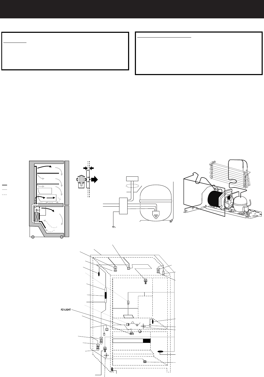
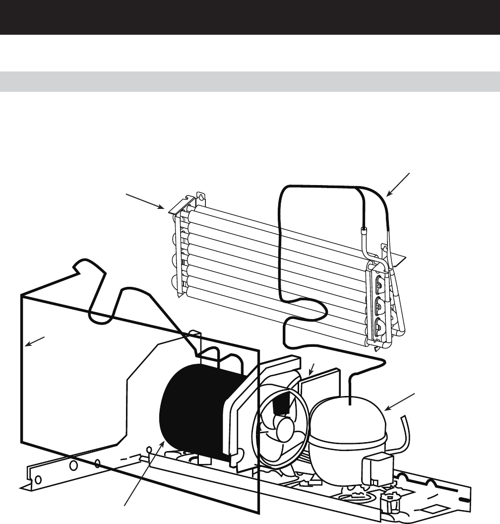
Refrigeration System
Refrigeration Components
Condenser Loop
Evaporator
Compressor
Condensor
Capillary Tube
*Dryer
* The dryer (not shown), is vertically positioned between the compressor and the condensor fan motor.

– 31 –
Evacuation and Charging Procedure
WARNING:
• Before cutting or using a torch on
refrigerant tubes, recover the refrigerant
from the system using approved recovery
equipment.
• Never charge new refrigerant through the
purge valve. This valve is always located on
the high pressure side of the system.
• Never apply heat from any source to a
container of refrigerant. Such action will
cause excessive pressure in the container.
• Always wear goggles when working with
refrigerants and nitrogen holding charge in
some replacement parts. Contact with these
gases may cause injury.
1. Attach the hose from the R-134a charging
cylinder to the process tube port on the
compressor.
2. Evacuate the system to a minimum 20-in.
vacuum using the refrigerator compressor and
recovery pump, which is attached to the new
drier assembly.
3. Turn off the recovery pump. Close the ball valve
on the hose connected to the high-side port
connection. Add 3 ounces of R-134a refrigerant
to the system. Let the refrigerator operate and
circulate the refrigerant for 5 minutes.
4. Open the ball valve. Recover the purge/sweep
charge using the recovery pump and the
refrigerator compressor until a 20-in. vacuum
is attained. Close the ball valve and remove the
recovery hose.
5. Charge the system with the exact amount of R-
134a refrigerant specifi ed.
6. Disconnect the power cord to the refrigerator.
This allows the pressure to equalize. After 3 to
5 minutes, the low side pressure will be positive
and then the hose-to-charging port can be
disconnected.
7. Using an electronic leak detector, check all
brazed joints and both schrader ports. Reinstall
caps to schrader.
– 32 –
Evaporator
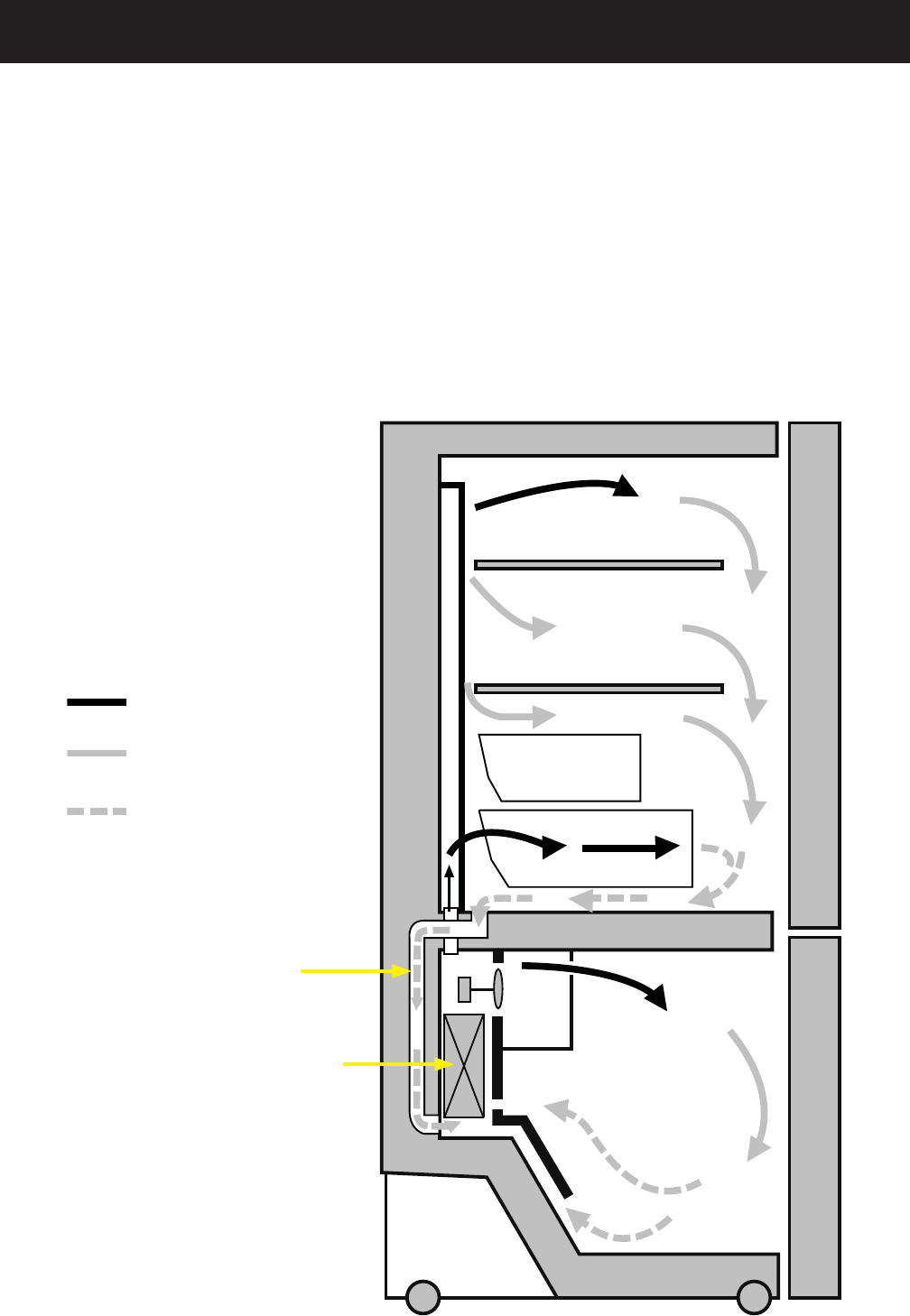
Cold Air
Mixed Air
Air Return To
Evaporator
Fresh Food
Freezer
Airfl ow
The evaporator fan forces air through the evaporator into the freezer compartment.
Air from the evaporator can also pass through the electronic damper to the air tunnel outlet, through the
fresh food compartment, and return to the evaporator.
The damper is controlled by the main control board. When open, the damper allows the chilled air from the
freezer to move into the fresh food compartment.
Air returns from the fresh food compartment to the freezer compartment via two vents located to the left
and right of the electronic damper.
Return Duct (1 of 2)
– 33 –
Components
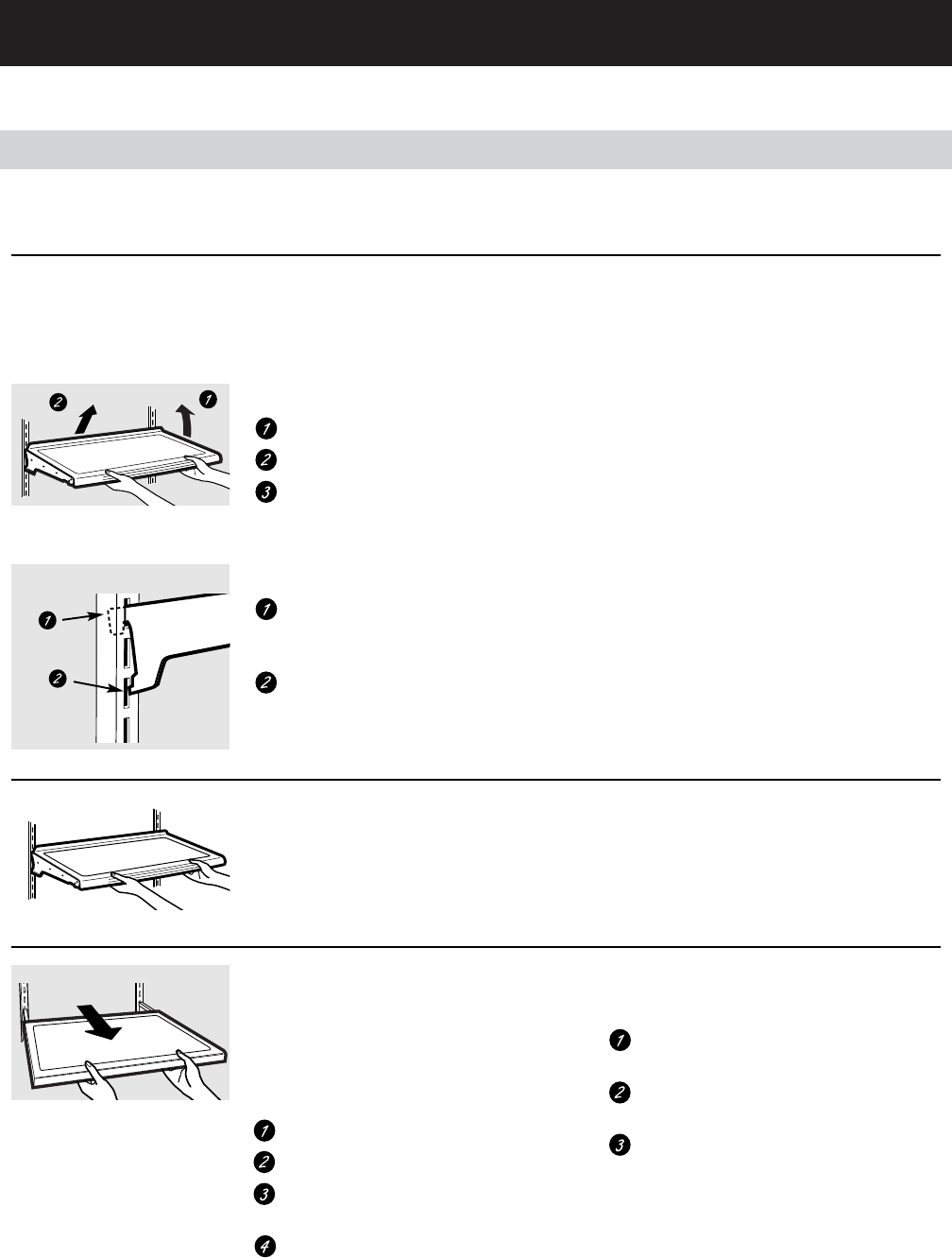
Rearranging the Shelves
To remove:
Remove all items from the shelf.
Tilt the shelf up at the front.
Lift the shelf up at the back and
bring the shelf out.
To replace:
While tilting the shelf up, insert the top
hook at the back of the shelf in a slot
on the track.
Lower the front of the shelf until the
bottom of the shelf locks into place.
Spillproof Shelves (on some models)
Spillproof shelves have special edges to
help prevent spills from dripping to lower
shelves. To remove or replace the shelves,
see Rearranging the Shelves.
Some models have wire shelves that
can be adjusted in the same manner.
Shelves in the refrigerator compartment are adjustable.
Refrigerator Compartment
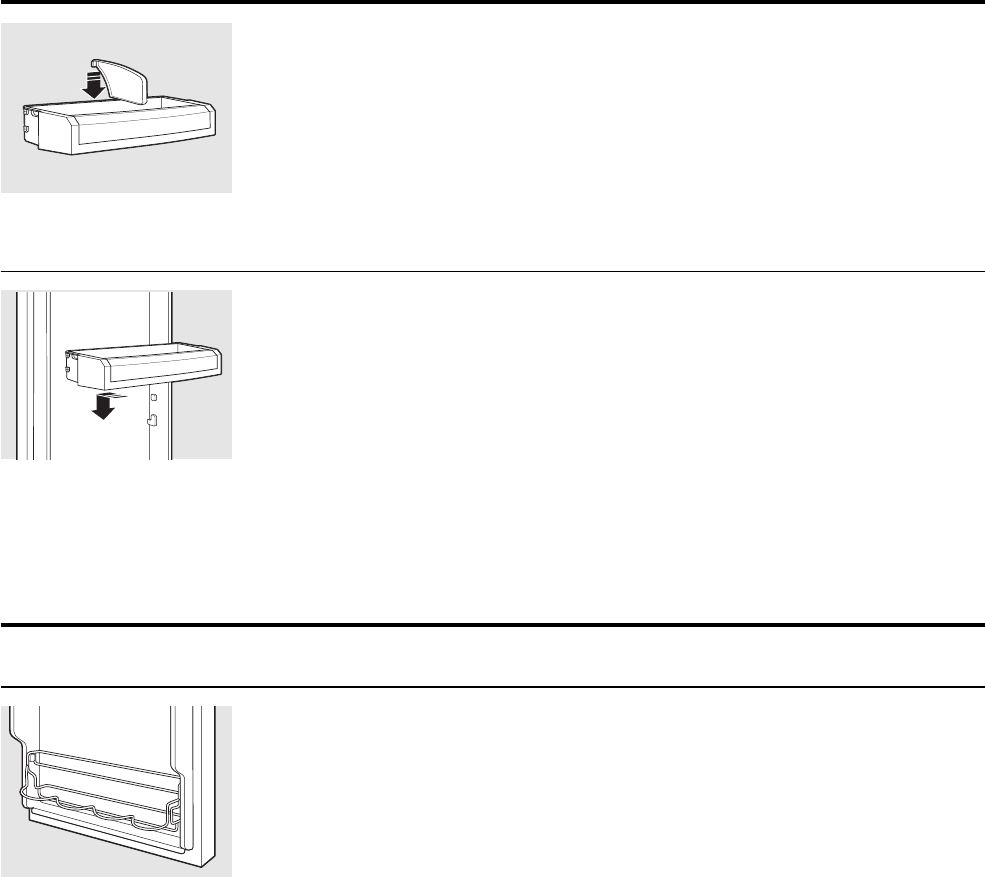
Slide-Out Spillproof Shelf (on some models)
The slide-out spillproof shelf allows you
to reach items stored behind others. The
special edges are designed to help prevent
spills from dripping to lower shelves.
To remove:
Remove all items from shelf.
Slide the shelf out until it stops.
Lift the front edge of the shelf until the
central tabs are above the front bar.
Continue pulling the shelf forward
until it can be removed.
To replace:
Place the rear shelf tabs just in front of
the central notches on the shelf frame.
Slide the shelf in until the central tabs
are slightly behind the front bar.
Lower the shelf into place until it is
horizontal and slide the shelf in.
Make sure that the shelf sits flat after reinstallation
and doesn’t move freely from side to side.
Make sure you push the shelves all the way in
before you close the door.
Fresh Food Shelves and Bins
Note: Not all features are on all models.
(Continued next page)
– 34 –
Non-Adjustable Bins on the Door
To remove: Lift the bin straight up, then
pull out.
To replace: Engage the bin in the molded
supports on the door and push down.
It will lock in place.
Adjustable Bins on the Door
Adjustable bins can easily be carried from
refrigerator to work area.
To remove: Lift bin straight up, then
pull out.
To replace or relocate: Slide in the bin just
above the molded door supports, and push
down. The bin will lock in place.
The snugger helps prevent tipping, spilling
or sliding of small items stored on the door
shelf. Grip the finger hold near the rear of
the snugger and move it to fit your needs.
About the additional features.
Not all features are on all models.
Non-Adjustable Beverage Rack
To remove: Lift the rack straight up, then
pull out.
To replace: Engage the rack in the molded
supports on the door and push down.
It will lock in place.
– 35 –
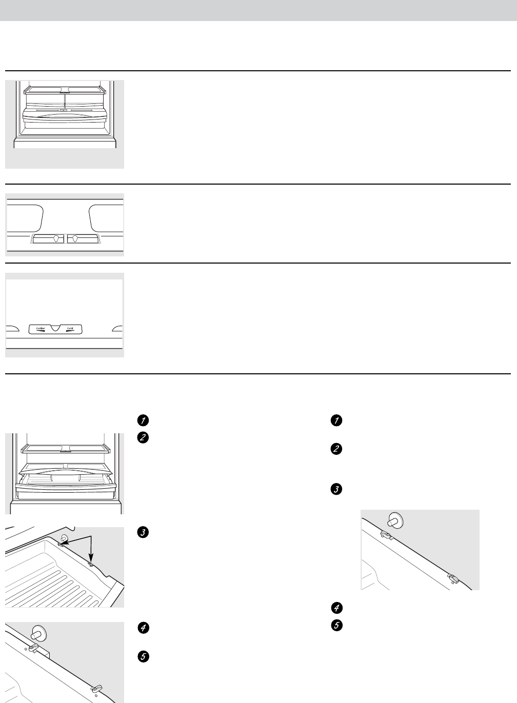
Fresh Food Crispers and Pans
Note: Not all features are on all models.
Fruit and Vegetable Crisper
Excess water that may accumulate in the
bottom of the drawers or under the drawers
should be wiped dry.
Adjustable Humidity Crisper (on some models)
Slide the control all the way to the
HIGH setting to provide high humidity
recommended for most vegetables.
Slide the control all the way to the LOW
setting to provide lower humidity levels
recommended for most fruits.
Adjustable Temperature Deli Pan (on some models)
Slide the control all the way to the left for
the coldest temperature.
To remove:
Remove the fruit and vegetable drawers.
Pull the drawer out to the stop position.
Lift the lid to access the 4 swing locks.
Rotate all four swing locks to the unlock
position.
Lift the front of the drawer up and out.
To replace:
Make sure all four swing locks are in the
unlock position.
Place the sides of the drawer into the
drawer supports, making sure the swing
locks fit on the drawer slots.
Lock all four swing locks by rotating
them to the lock position.
Lower the lid and slide in the drawer.
Replace the fruit and vegetable drawers.
How to Remove and Replace the Deli Pan
Swing Locks
– 36 –
Freezer Shelves and Baskets
Note: Not all features are on all models.
Freezer Shelves and Baskets
A shelf above the ice storage bin
A half-width basket
A shallow full-width basket
A deep full-width basket
Basket Removal
To remove the shallow full-width basket:
Pull the basket out to the stop location.
Lift the front up and over the stop
location.
Lift the basket up and out.
To remove the deep full-width basket on
freezer drawer models:
Open the freezer drawer until it stops.
The freezer basket rests on the inside
tabs on the drawer slides.
Lift the basket so that all 4 tabs are out
of the slide bracket.
Tilt the basket and lift out of the
drawer.
Make sure the plastic sleeves remain
attached to the 4 tabs on the slide
brackets.
When replacing the deep full-width basket:
Tilt the basket back and lower it down
into the drawer. Rotate the basket to a
horizontal position and press it down into
the 4 alignment tabs.
NOTE: Always be sure that all 4 basket tabs
are engaged in the slide brackets before
sliding back into the freezer.
To remove the half-width basket:
Pull the basket out to the stop location.
Lift the basket up at the front to release
it from the slides.
Lift the back up and out of the slide.
When replacing the basket, make sure that
the wire tabs and wire hooks on the sides
of the basket go into the slots in the top
of the upper basket slides.
NOTE: Always be sure to fully close this
basket.
Appearance and features may vary
Appearance may vary
Appearance may vary
Appearance may vary
Tab
– 37 –
Fresh Food and Freezer Thermistors
The fresh food thermistor is located in the left
wall of the fresh food compartment. The freezer
thermistor is located in the right wall of the freezer
compartment.
Note: The fresh food and freezer thermistors are
removed in the same manner.
To remove the thermistor cover, insert a fl at-blade
screwdriver under the front of the cover and gently
lift the bottom edge until it releases from the
compartment wall.
Note: To accurately test a thermistor, place
the thermistor in a glass of ice and water
(approximately 33°F) for several minutes and check
for approximately 16K Ω.
Ambient Thermistor
The ambient thermistor is located under the freezer
compartment and connected at J1-2 on the main
control board. (See Component Locator Views.) It
assists the main control board in compensating for
room ambient that is higher or lower than 60°F.
(Continued next page)
Thermistor Resistance
Temperature
(°F)
Temperature
(°C)
Resistance in Kilo-
Ohms
-40 -40 166.8 kΩ
-31 -35 120.5 kΩ
-22 -30 88 kΩ
-13 -25 65 kΩ
-4 -20 48.4 kΩ
5 -15 36.4 kΩ
14 -10 27.6 kΩ
23 -5 21 kΩ
32 0 16.3 kΩ
41 5 12.7 kΩ
50 10 10 kΩ
59 15 7.8 kΩ
68 20 6.2 kΩ
77 25 5 kΩ
86 30 4 kΩ
95 35 3.2 kΩ
104 40 2.6 kΩ
113 45 2.2 kΩ
122 50 1.8 kΩ
131 55 1.5 kΩ
140 60 1.2 kΩ
Thermistors For example, in ambient below 60°F, the fresh food
temperature control will shut down properly. The
cooler room ambient assists in keeping fresh food
temperatures at the preset temperature. However,
the compressor does not get enough run time to
bring the freezer down to 0°F.
At lower room temperatures, the ambient thermistor
alters the main control board’s calculations for the
target temperature. The main control board then
runs the compressor at higher speeds to get the
freezer, as well as the fresh food, to an acceptable
temperature.
If the external thermistor is not functioning, the
main control board default will assume the ambient
temperature is 90°F and there will be no adjustment
to the fresh food or freezer set point.
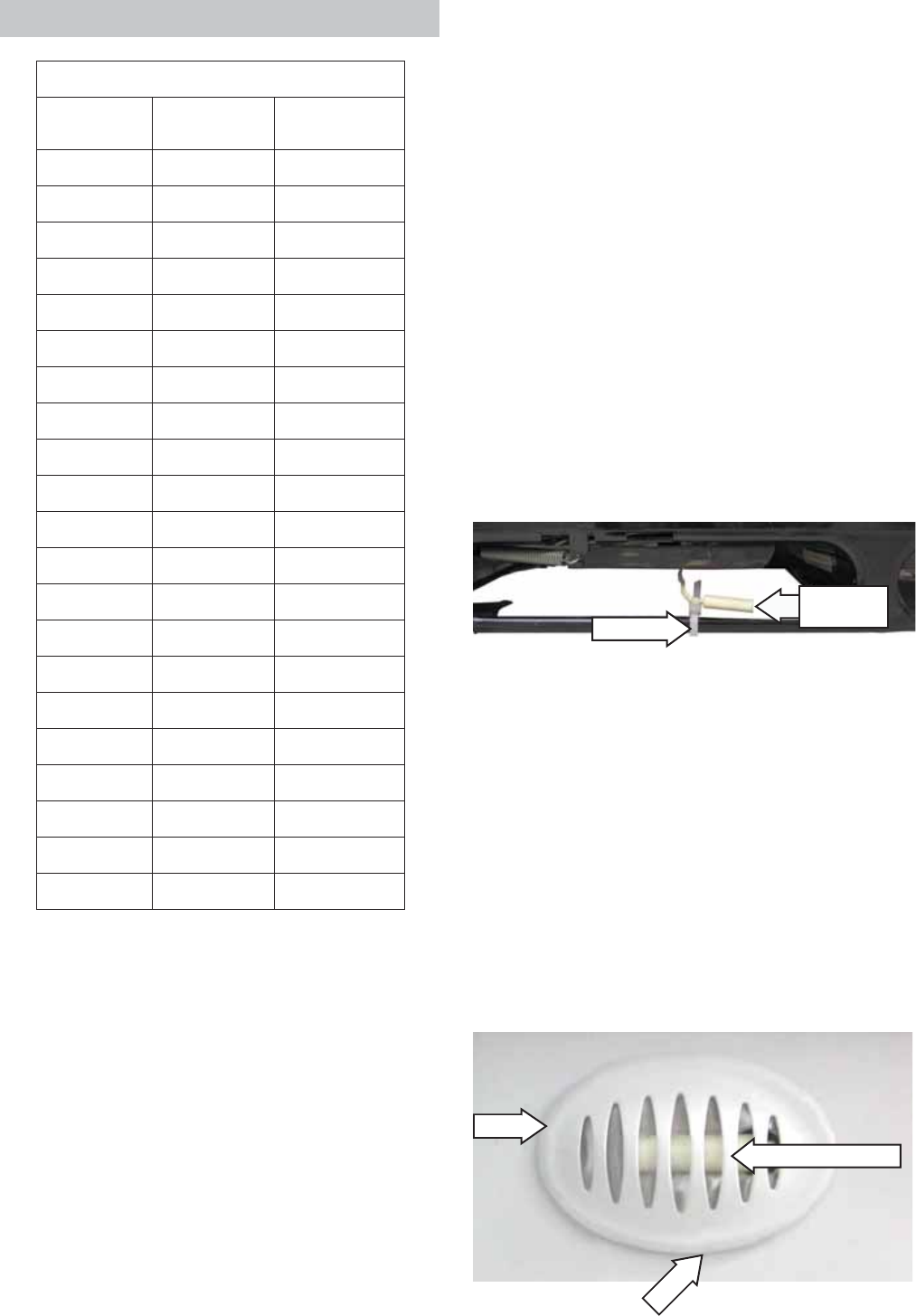
The ambient thermistor is attached to the front
of the cabinet (under the left side of the freezer
compartment) with a plastic wire tie.
Wire Tie
Ambient
Thermistor
Insert
Lift
Thermistor Cover
– 38 –
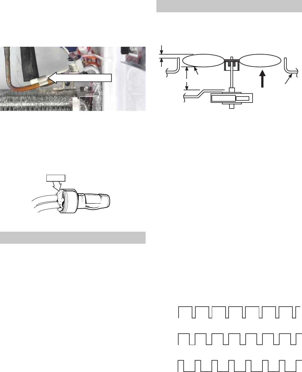
Evaporator Thermistor
The evaporator thermistor is clipped to the suction
tube line of the evaporator. See Evaporator for
accessing instructions.
Evaporator Thermistor
Replacement
Should a thermistor require replacement, use
plastic bell connectors (part # WR01X10466). Fill
each connector with RTV102 silicone then splice a
new thermistor into the harness as shown in the
illustration.
RTV102
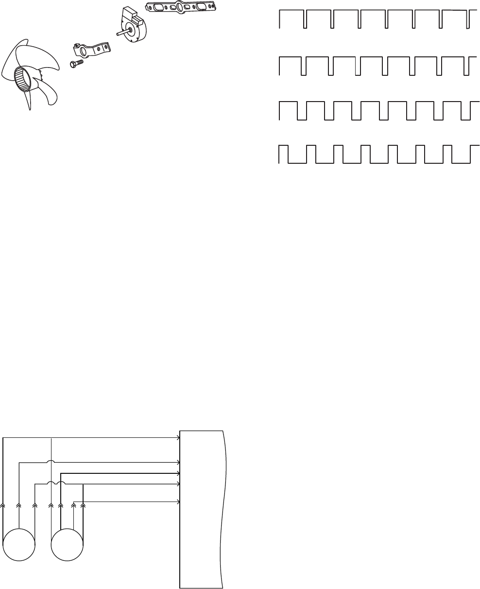
The evaporator fan is the same fan used on previous
models; however, a signifi cant difference is that the
main control board neither requires nor receives
input from the fan feedback/rpm (blue) wire. The fan
utilizes a permanent magnet, 4-pole, DC motor that
operates at three different speeds: high, medium,
and low.
The speed of the fan is controlled by the voltage
output from the main control board. Voltage output
from the main control board to the fan is 13.6 VDC;
however, to regulate the speed of the fan, the main
control board uses pulse width modulation (PWM).
When operating, voltage is sent in pulses (much like
a duty cycle) as opposed to an uninterrupted fl ow.
This pulsing of 13.6 VDC produces effective voltage
being received at the motor, which is equivalent to a
reduction in voltage.
Evaporator Fan
The position of the fan blade in relation to the
shroud is important.
5/16" ± 0.03
Blade tip
1.0" ± 0.05 Target
Motor
Air Flow
Orifice
High Speed (9.5 VDC measured)
Medium Speed (8 VDC measured)
Low Speed (6.5 VDC measured)
9.5 VDC
8 VDC
6.5 VDC
13.6 VDC
0 VDC
0 VDC
0 VDC
13.6 VDC
13.6 VDC
(Continued next page)
Fresh Food and Freezer Light Thermostats
The fresh food and the freezer light thermostats
interrupt power to the lights when the thermostat
temperature reaches 175°F. Power is restored when
the thermostat temperature cools to 155°F.
Each thermostat is attached to the back of each
light housing with an 11/32-in. nut.
To access each thermostat, remove the light cover
and light housing. The fresh food light housing is
held in place by 3 Phillips-head screws. The freezer
light housing is held in place by a single Phillips-
head screw.
Note: It is necessary to remove the freezer light bulb
to access the freezer light housing screw.
Replacement
Should a thermostat require replacement, use
plastic bell connectors (part # WR01X10466). Fill
each connector with RTV102 silicone then splice a
new thermostat into the harness.
– 39 –
Fan speed is selected and maintained by the main
control board regulating the length and frequency
of the 13.6 VDC pulse. Temperature can cause
some fan speed variation. Fan speed can vary
+/- 5%, depending on the temperature, with higher
temperatures causing slightly higher speeds.
The evaporator fan has a 4-wire connection:
White Wire (DC Common)
The white wire is the DC common wire used
for testing. During repairs, DC polarity must be
observed. Reversing the DC polarity causes a
shorted motor and/or board.
Red Wire (Supply)
Each motor uses an internal electronic controller to
operate the motor. Supply voltage from the main
control board remains at a constant 13.6 VDC.
Blue Wire (Feedback/RPM)
On previous Arctica models, the blue wire reported
rpm (speed) information to the main control board
for speed control purposes. On this model, the board
does not require or read any feedback information
from the fan motor.
Yellow Wire (Signal)
The yellow wire is the input wire from the main
control board. The main control board provides
6.5 VDC effective voltage for low speed, 8 VDC
effective voltage for medium speed, and 9.5 VDC
effective voltage for high speed. The fan operates
in low speed only when the fresh food thermistor is
satisfi ed.
Note: When testing these motors:
• You cannot test with an ohmmeter.
• DC common is not AC common.
• Verify 2 voltage potentials:
a. Red to white - power for internal controller
b. Yellow to white - power for fan
• Observe circuit polarity.
• Motors can be run for short periods using a
9 volt battery. Connect the white wire to the
negative (-) battery terminal only. Connect the
red and yellow wires to the positive (+) battery
terminal.
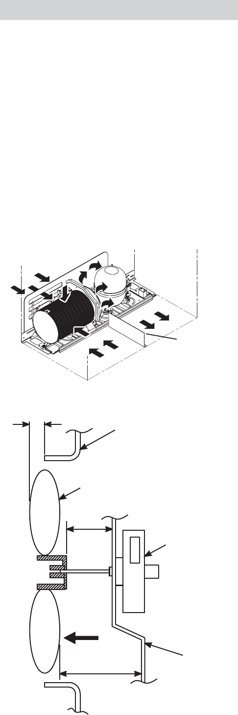
Condenser Fan
The fan is mounted in the machine compartment
with the no-clean condenser. The fan and fan
shroud are mounted on one end of the condenser,
and the other end of the condenser is blocked.
When the fan is operating, air is pulled from the
center of the condenser, drawing air in through the
coils. The air is then exhausted over the compressor
and out the right side of the refrigerator.
Inlet air is available through the left front and left
rear of the machine compartment. A rubber divider
strip underneath the refrigerator divides the inlet
and outlet sides of the machine compartment.
Rear
Front
Divider Strip
Housing
Fan
Motor
0.375"
1/2"
Air Flow
0.50" ± 0.05
Bracket
(Continued next page)
– 40 –
The rear access cover must be tightly fi tted to
prevent air from being exhausted directly out of the
rear of the machine compartment, bypassing the
compressor.
The condenser fan is mounted with screws to a fan
shroud and mounting bracket that is attached to
the condenser.
Condenser fan speed corresponds with compressor
speed (low, medium, high) to minimize pressure
variations in the sealed system except when the
freezer temperature is 20°F above the set point. If
this condition exists (such as during initial startup),
the condenser fan operates at super high speed
while the compressor operates at medium speed.
The speed of the fan is controlled by the voltage
output from the main control board. Voltage output
from the control board to the fan is 13.6 VDC;
however, to regulate the speed of the fan, the main
control board uses pulse width modulation (PWM).
When operating, voltage is sent in pulses (much like
a duty cycle) as opposed to an uninterrupted fl ow.
This pulsing of 13.6 VDC produces effective voltage
being received at the motor, which is equivalent to a
reduction in voltage.
Fan speed is selected and maintained by the main
control board regulating the length and frequency
of the 13.6 VDC pulse.
Temperature can cause some fan speed variation.
Fan speed can vary +/- 5%, depending on the
temperature, with higher temperatures causing
slightly higher speeds.
Condenser fan speed is controlled by Pulse Width
Modulation (PWM), the same method used to control
fan speeds for the evaporators.
High Speed (10.5 VDC measured)
Medium Speed (7.5 VDC measured)
Low Speed (5.5 VDC measured)
10.5 VDC
7.5 VDC
5.5 VDC
13.6 VDC
0 VDC
0 VDC
0 VDC
13.6 VDC
13.6 VDC
Super High Speed (12.0 VDC measured)
12.0 VDC
13.6 VDC
0 VDC
BLUE
WHITE/SILVER (COMM)
YELLOW/BLACK
YELLOW
+12V RED
COND FAN EVAP FAN
RED
YELLOW
WHITE
RED
YELLOW
BLUE
WHITE
J2-1 J2-3 J2-4 J2-5 J2-8
MAIN CONTROL BOARD
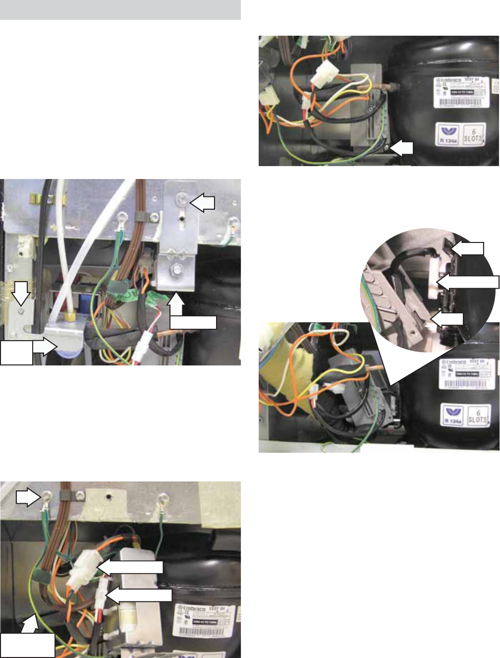
– 41 – (Continued next page)
Carefully pull the water valve and the EMI fi lter 2.
out from the cabinet.
Disconnect the 2 wire harnesses to the inverter.3.
Remove the ¼-in. hex-head screw and the 4.
inverter ground wire from the cabinet.
Inverter
The inverter is accessed from the back of the
refrigerator and is located on the left side of the
compressor behind the water valve. The water valve
and the EMI fi lter (if utilized) must be removed to
access the inverter.
To remove the Inverter:
Remove the ¼-in. hex-head screw that holds the 1.
water valve and the 5
/
16-in. hex-head screw that
holds the EMI fi lter to the cabinet.
Note: The inverter is attached to the compressor by
a lip above the compressor terminals, a tab (located
at the bottom rear corner), and a Phillips-head
screw.
EMI Filter
Water
Valve
Disconnect
Inverter
Ground Wire
Disconnect
WARNING: When the refrigerator is plugged in, 120
VAC is always present at the inverter.
Note: Certain voltmeters will not be able to read
voltage output from the inverter. If no voltage or
erratic voltage is measured, it does not necessarily
indicate a faulty inverter.
The inverter receives 120 VAC line-in from the power
supply. The inverter converts this single-phase, 60
Hz, 120 VAC into 3-phase, 230 VAC, with frequency
variations between 57 Hz and 104 Hz. This voltage
is delivered to the compressor through 3 lead wires.
Each wire will carry identical voltage and frequency.
Note: The compressor leads must be connected to
measure voltage output. If the compressor wires are
not connected, or if an open occurs in one of the 3
lead wires or in the compressor, the inverter will stop
voltage output.
Remove the Phillips-head screw from the 5.
inverter.
Lift and rotate the inverter counterclockwise.6.
Disconnect the compressor harness from the 7.
compressor terminals.
Tab
Lip
Disconnect
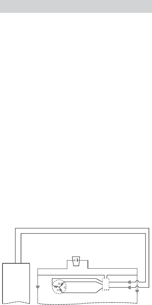
– 42 –
When checking inverter voltage output, connect
the test-meter leads to any 2 of the 3 compressor
lead wires at the inverter plug (plug should be
connected). The same reading should be measured
between any 2 of the 3 wires.
The inverter controls compressor speed by
frequency variation and by Pulse Width Modulation
(PWM). Changing frequency and PWM will cause
an effective voltage between 80 and 230 VAC to be
received at the compressor.
• Low speed (1710 rpm) - 57 Hz
• Medium speed (2100 rpm) - 70 Hz
• High speed (3120 rpm) - 104 Hz
The inverter receives commands from the main
control board. The main control board will send
a PWM run signal from the J15 connector of
between 4-6 VDC effective voltage to the inverter
(all wires must be connected). The inverter will select
compressor speed (voltage output) based on this
signal.
The main control board will only send a run signal to
the inverter when the compressor should be on.
Note: When measuring signal voltage (from the
main control board) at the inverter, a reading of 4-6
VDC will be measured with all wires connected. If the
inverter wiring is disconnected, the board output will
measure between 10-12 VDC.
The inverter will monitor compressor operation
and if the compressor fails to start or excessive
current draw (4 amps maximum) is detected,
the inverter will briefl y stop voltage output. The
inverter will then make 12 consecutive compressor
start attempts (once every 12 seconds). After 12
attempts, if the compressor has not started, an 8-
minute count will initiate. After the 8-minute count,
the inverter will attempt to start the compressor
again. If the compressor starts, normal operation
will resume. If the compressor fails to start, this
process will be repeated. Removing power to the
unit will reset the inverter count. When power
is restored, the inverter will attempt to start the
compressor within 8 seconds.
The inverter has a built-in circuit protection to
guard against damage from a failed or shorted
compressor. However, if a failed compressor is
diagnosed, order a new compressor and inverter.
If the compressor fails to start after replacement,
replace the inverter.
Inverter Compressor
Caution: Do not attempt to direct-start the
compressor. The compressor operates on a 3-phase
power supply. Applying 120 VAC to the compressor
will permanently damage the unit. It is not possible
to start the compressor without an inverter.
The compressor is a reciprocating, variable speed,
4-pole type. It operates on 3-phase, 80 to 230 VAC
within a range of 57 to 104 Hz.
Note: Certain voltmeters will not be able to read
voltage output or frequency from the inverter.
Compressor wattages at various speeds are:
• LOW - 65 watts
• MED - 100 watts
• HIGH - 150 watts
The compressor is controlled by the inverter, which
receives its signal from the main control board.
Varying the frequency to the inverter changes the
compressor speed.
Compressor speed is based on the temperature
set point in conjunction with the specifi c cabinet
temperature. Speeds are selected according to
the following cabinet temperatures, with freezer
temperature being the primary:
• 7°F to 19.5°F above freezer set point = high
speed.
• 4.5°F to 6.5°F above freezer set point = medium
speed.
• 1°F to 4°F above freezer set point = low speed.
• 1°F to 2.5°F above refrigerator set point = low
speed.
(Continued next page)
TAB 1
J15-1 J15-2
AC
BROWN
BLACK
BROWN
COMPRESSOR
BLACK
BLUE
ORANGE
WHITE
RED
INVERTER
ORANGE
WHITE
RED
10
10
10
Main Control
Board
BROWN
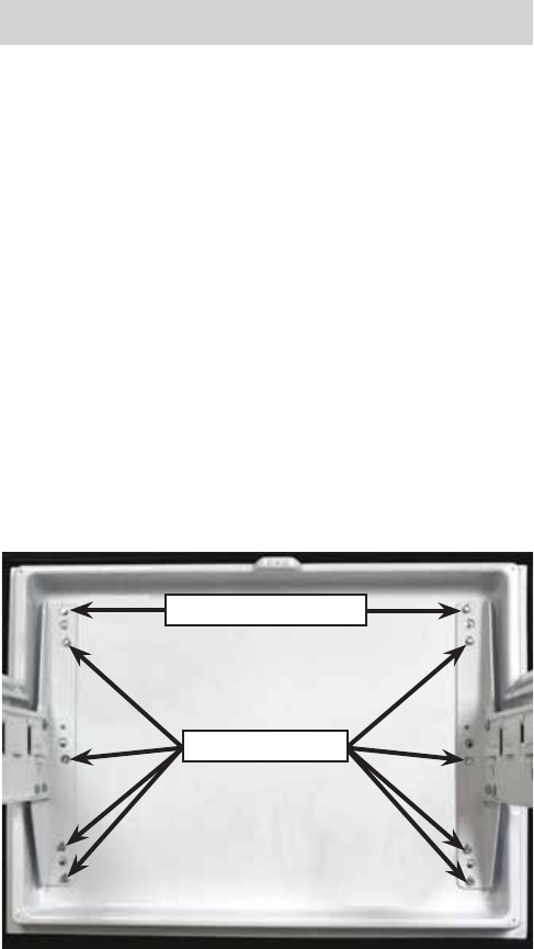
– 43 –
• 3°F to 5°F above refrigerator set point - medium
speed.
• 5.5°F to 7°F above refrigerator set point - high
speed.
Note: The compressor will run at medium speed if
the freezer temperature is 20°F or more above the
setpoint.
The use of 3-phase power eliminates the need for
the relay, capacitor, and individual start and run
windings; therefore, the start, run, and common
pins found on conventional compressors are not
applicable on this 3-phase model. Compressor pin
functions are identical and compressor lead wire
confi guration is of no importance. A resistance of
9 Ω to 11 Ω should be read between any 2 of the
3 pins. Should an open occur in the compressor
winding or should one of the compressor lead wires
become open or disconnected, the inverter will stop
voltage output to the compressor.
High compressor torque enables the compressor
to start against high pressure in the sealed system.
When power has been disconnected from an
operating unit, the high torque will enable the
compressor to start immediately upon power
restoration.
Compressor operation is extremely smooth and
cool. The compressor exterior may be slightly higher
than room temperature while operating; therefore, it
may be diffi cult to detect a running unit.
To verify that the compressor is running:
Disconnect power from the unit and place a hand
on the compressor. Reconnect power and feel for
a vibration when the compressor tries to start. It
may take up to 8 seconds before the compressor
attempts to start.
Note:
When ordering a replacement compressor, order •
both the compressor and inverter. Replace
the compressor fi rst. If, after compressor
installation, the compressor fails to start,
replace the inverter.
When servicing the compressor, it is important •
to dress the wiring to keep low voltage DC wiring
and 120 VAC wiring separate.
Evaporator
The following components must be removed in the
appropriate order to access the evaporator:
Unplug the refrigerator.1.
Pull out and remove the ice bin and shelf. 2.
Remove the freezer shelves and baskets. (See 3. Freezer Shelves and Baskets.)
Loosen the top two 4. 3
/
8
-in. hex-head screws 1
full turn, then remove the remaining eight 3
/
8
-in.
hex-head screws that attach the drawer front to
the rail assemblies.
Note: Do not remove the torx screws from the rail
assemblies.
Lift and remove the drawer front and place it on 5.
a protected surface.
Note: To ensure correct alignment when installing
the drawer front, place the top two 3
/
8
-in. hex-
head screws into the open slots on top of each rail
assembly, then install the center screws.
Install the remaining six 3
/
8
-in. hex-head screws, then
tighten all screws fi rmly. Check drawer operation.
Loosen Top Screws
Remove Screws
(Continued next page)
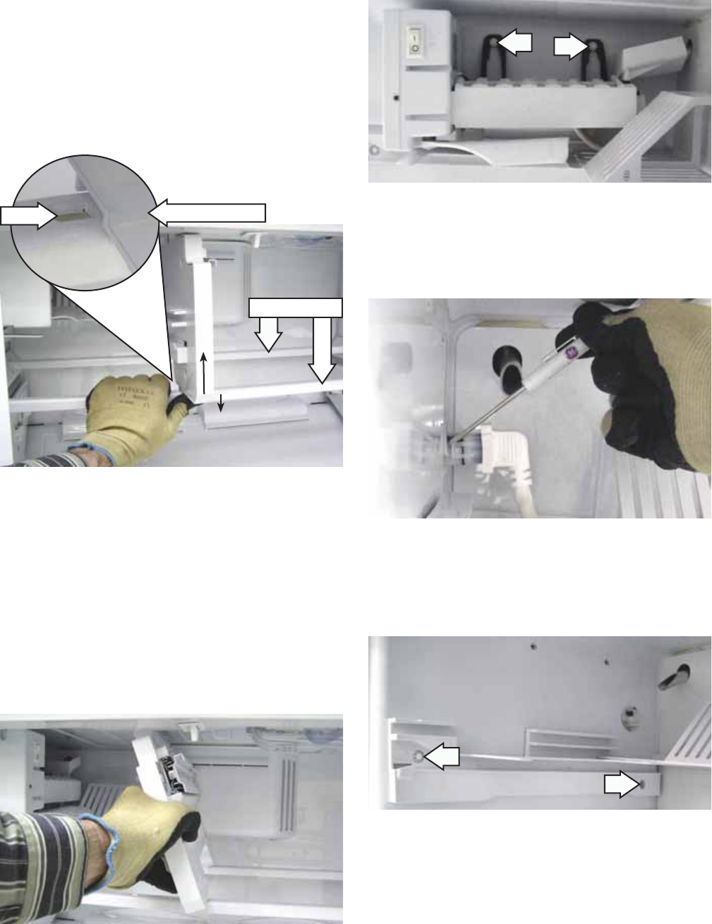
– 44 – (Continued next page)
b. Carefully rotate the divider slightly
counterclockwise to clear the tab from the
notch in the rail.
c. Repeat the above procedure to release the
rear of the divider from the rear support rail.
Note: When installing the vertical divider, position
the top of the divider into the recess in the freezer
ceiling before positioning the bottom over the
notches in the support rails.
Note: The top of the vertical divider is inserted in
a molded recess in the freezer ceiling. The bottom
of the divider has a front and rear tab that are
captured in a notch in each of the 2 support rails.
Remove the vertical divider from the support 6.
rails:
a. Release the front of the vertical divider by
pressing down on the front support rail while
pressuring the front of the divider up.
Verticle Divider
Notch
Support Rails
Remove the two ¼-in. hex-head screws that 7.
attach the icemaker to the freezer wall.
Remove the two ¼-in. hex-head screws that 9.
attach the icemaker bin support to the left
freezer wall.
Using a small fl at-blade screwdriver, expand 8.
the 2 clips and disconnect the icemaker wire
harness.
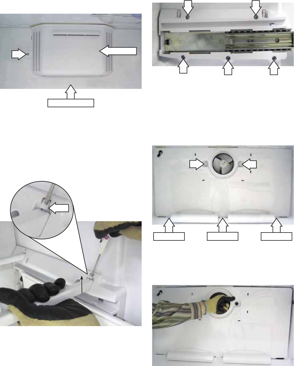
– 45 –
Note: The freezer fan cover is attached to the
evaporator cover with a Phillips-head screw, 3 cover
tabs, and 2 right side hinge tabs.
Remove the single Phillips-head screw.10.
Pull the left side of the fan cover out to 11.
approximately 90 degrees, then remove the fan
cover.
Using a fl at-blade screwdriver, press in the tab 12.
and forcefully lift up one end of each support
rail and remove each rail.
Fan Cover
Tab
Evaporator Cover
Extend each drawer rail fully, then remove the 13.
fi ve ¼-in. hex-head screws that attach each
drawer rail assembly to the freezer side walls.
Note: The evaporator cover is attached to the
evaporator compartment with two ¼-in. hex-head
screws, 3 bottom tabs, and 8 snap tabs located on
the back of the cover.
Remove the two ¼-in. hex-head screws that 14.
attach the evaporator cover to the fan bracket.
Grasp and pull the right side of the fan opening 15.
towards the front of the freezer to release the
right side snap tabs.
Pull out the left side of the cover and carefully 16.
remove it from the evaporator compartment.
Bottom Tab Bottom Tab Bottom Tab
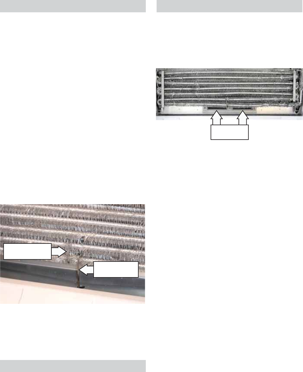
– 46 –
Defrost Heater
The defrost heater is a single-tube, glass-enclosed
radiant heater. It is held in place by 2 tabs on the
evaporator (1 on each side) and by a ceramic and
wire support.
To remove the defrost heater:
Access the freezer evaporator. (See 1. Evaporator.)
Note:
During defrost, the heat conducting clip assists •
in preventing the drain from icing closed. During
assembly, the clip must be installed on the
evaporator and inserted in the drain to prevent
drain freeze-up.
A ceramic and wire support prevents the heater •
from sagging and touching the metal drain
trough if the glass is broken.
2. Remove the ceramic and wire support and the
heat conducting clip from the evaporator.
Bend the aluminum tabs back (located at each 3.
end of the defrost heater) and lower the heater
out of the evaporator.
Disconnect 2 lead wires and remove the heater.4.
Heat Conducting
Clip
Ceramic and Wire
Support
Return Duct Heaters
A return duct heater has been added to each of
the 2 fresh food compartment return air ducts. The
heaters prevent water from freezing and blocking
the air fl ow in the ducts. Restricted ducts can cause
warm fresh food temperatures. (See Airfl ow.)
Return Duct
Outlets
Icemaker Fill Tube Heater
The fi ll tube heater is energized during the
defrost cycle when the defrost thermostat is
closed. Remove the evaporator cover to access
the icemaker fi ll tube heater. (See Evaporator.)
Disconnect the fi ll tube heater wire harness. The
resistance of the fi ll tube heater is approximately
2644 Ω.
The heaters operate with 120 VAC and each heater
has an approximate resistance value of 440 Ω.
The heaters are in a parallel circuit consisting of
2 duct heaters, icemaker fi ll tube heater, and the
defrost heater. The line voltage wires of the duct
heaters and the fi ll tube heater are connected to
the blue wire of the defrost heater. The neutral wires
of the heaters go through the over temperature
thermostat. The 2 duct heaters and the fi ll tube
heater are energized (along with the defrost heater)
during the defrost cycle when the over temperature
thermostat is closed.
Return Duct Heaters Test
If open duct heaters are suspected, perform the
following:
With the over temperature thermostat closed, 1.
test for approximately 27 Ω (the equivalent
resistance of this parallel circuit) between J9
and J7-9 .
For a resistance reading other than 2.
approximately 27 Ω, remove the evaporator
cover (See Evaporator.), disconnect the fi ll tube
heater, and one lead from the defrost heater.
Insert a volt ohm meter into the fi ll tube heater
receptacle. A reading of approximately 220
ohms at 70°F indicates both heaters are good.
Note: The return duct heaters are integral to the
foamed in place internal ductwork of the refrigerator
and are not replaceable.

– 47 –
Replacing Evaporator Using the Brazing
Method
Parts Needed:
Freezer Evaporator •
Drier Assembly •
Access Tube (part # WJ56X61) •
Heat Shield Kit (part # WX5X8926)•
Caution: A heat shield kit is required for this
procedure to prevent damage to the plastic interior
(liner) of the freezer compartment.
Unplug the refrigerator.1.
Remove the rear access cover and evacuate the 2.
sealed system.
Remove components necessary to expose the 3.
evaporator. (See Evaporator.)
Note the location of the thermistor and over 4.
temperature thermostat on top of the old
evaporator and remove.
Remove heater from bottom of evaporator and 5.
discard. Bundle remaining wires and tape high
on the back wall of freezer.
Apply a liberal amount of thermal paste to 6.
suction line where it enters the rear wall of
freezer.
Insert the brazing shield behind the joints of the 7.
evaporator inlet and outlet to protect the liner.
Use torch to heat the joints of the evaporator 8.
inlet and outlet, separate the joints and clean
the suction line and the capillary surface.
Loosen the 2 Phillips-head screws that hold the 9.
evaporator in place. Note locations of the heat
transfer wires at the sides of old evaporator.
These are needed to transfer heat to the turns of
the evaporator during the defrost cycle. Remove
the transfer wires and save for new evaporator
installation. Remove the old evaporator.
Install the new evaporator and tighten the 2 10.
Phillips-head screws.
Connect the evaporator inlet and outlet to the 11.
suction line and capillary tubes.
Check that the thermal paste is still on the 12.
suction line where it enters the rear wall of the
freezer. If not, apply paste. In addition, apply
thermal paste around epoxy joints on the new
evaporator to prevent the heat from damaging
joint integrity.
Move the brazing shield behind the capillary and 13.
suction line joints. Protect the freezer fl oor from
molten solder during brazing.
Angle torch so that fl ame is directed away from 14.
rear wall when brazing. Braze suction line and
capillary to new evaporator.
Remove the brazing shield. Clean and inspect all 15.
joints.
Remove the old drier by cutting the halo loop 16.
as close as possible to the drier. Install the
new drier assembly making sure that there is
suffi cient space between the tubing.
Install the access tube. Clean and inspect joints.17.
Replace the 18. heater supplied with the evaporator.
Reinstall the over temperature thermostat,
thermistor, and heat transfer wires at the sides
of new evaporator. Dress wiring.
Evacuate and charge the system. Use original 19.
factory charge quantity of R-134a. (See
Evacuation and Charging Procedure.)
Replace all component parts in the freezer.20.
Reinstall the rear access cover.21.
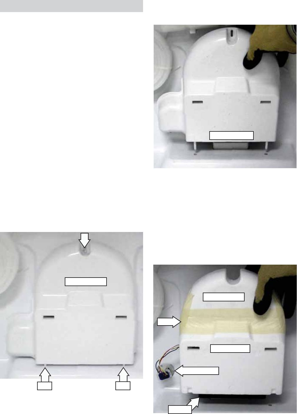
– 48 –
Pin Pin
Pull up on the damper assembly then remove 5.
the air tower cover.
Disconnect the damper motor wire harness.6.
Remove the gasket from the bottom of the air 7.
tower.
Note: In the following step, care should be taken to
prevent damage to the air tower.
Carefully cut or peel off the tape that seals the 8.
front to the back of the air tower.
Air Tower Cover
Wire Harness
Fresh Food Damper
A damper assembly is used to control airfl ow
from the freezer into the fresh food compartment.
It is located on the back wall of the fresh food
compartment, behind the deli and crisper drawers.
The damper assembly consists of a 12 VDC
motorized damper sealed inside the styrofoam air
tower, and a plastic cover. The assembly is held in
place with one ¼-in. hex-head screw at the top, and
2 pins at the bottom that fi t into the liner.
To remove the fresh food damper:
Remove the fruit and vegetable crisper drawers 1.
and the crisper drawer cover and frame
assembly.
Caution: The glass inserted in the deli pan cover
and frame may easily separate. Care should be
taken when removing the deli pan cover and frame
assembly.
Partially open the deli pan, lift and remove the 2.
deli pan cover and frame.
Pull the deli pan out to the fully open position. 3.
Remove the ¼-in. hex-head screw from the top 4.
of the air tower cover.
Gasket
(Continued next page)
Air Tower Front
Air Tower Back
Tape
Air Tower Cover
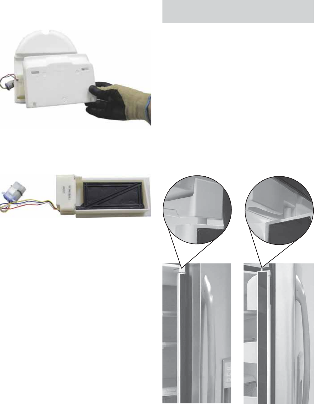
– 49 –
Separate the styrofoam air tower that houses 9.
the damper.
Motorized Damper Removed
Remove the damper from the separated 10.
styrofoam air tower.
Articulating Door Mullion (French Door
Models)
The articulating door mullion is attached to the
right side door, and provides a movable center
mullion that maximizes access to the fresh food
compartment. With both refrigerator doors closed
or only the left side door opened, the mullion stays
in position. When the right side door is opened, the
spring-loaded mullion is activated to fold against
the handle side of the door liner.
The pin on top of the mullion and the track, located
at the top center front of the refrigerator, ensure
proper mullion bar alignment upon closure of the
right side door.
Door Closed -
Pin in Track Door Opening -
Pin Exiting Track
Note: To prevent moisture and ice from
accumulating in the fresh food compartment:
It is imperative to properly seal the front to the •
back of the air tower.
Ensure the gasket is placed between the bottom •
of the air tower and the liner.
(Continued next page)
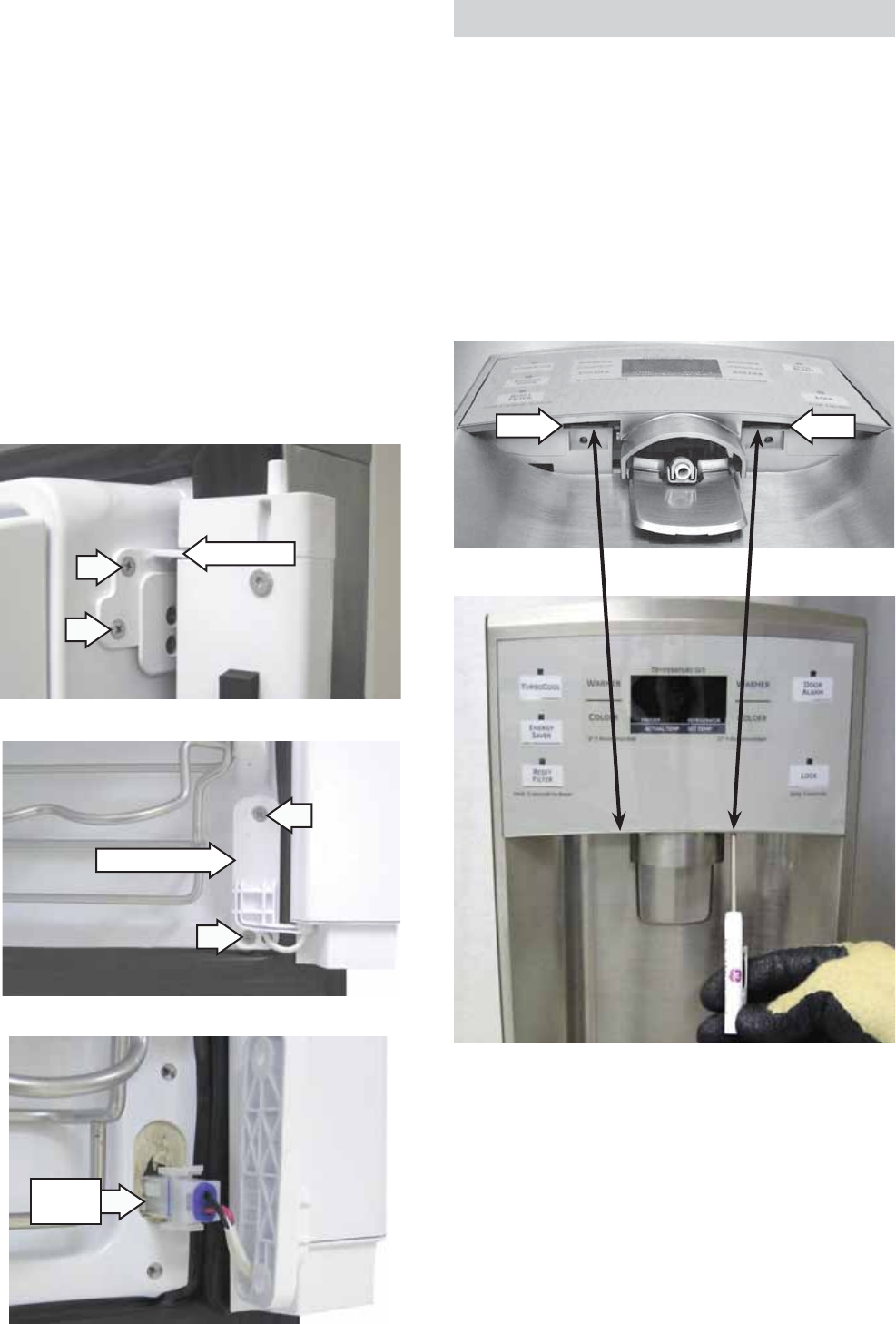
– 50 –
The articulating door mullion consists of the mullion,
heater, internal spring, and 2 hinges. It is available
only as an assembly.
Note: If the Energy Saver light is lit, then the heaters
in the vertical and horizontal mullions are disabled.
The heater operates on 13.6 VDC when both doors
are closed. It is necessary to close the left side door
and close the right side light switch to test for the
operating voltage of 13.6 VDC. The resistance of the
heater is approximately 4400 Ω.
To replace the articulating door mullion assembly it
is necessary to remove the 2 Phillips-head screws
from the top and bottom hinges. The wire harness
can be pulled out from the recess in the bottom of
the door and disconnected.
Top Hinge
Bottom Hinge
Wire
Harness
Water Dispenser and Interface
The water dispenser assembly incorporates the
interface used for temperature control and features.
The interface has 2 tabs that hold it to the cradle
support. The tabs are located above 2 slots located
behind the bottom of the interface.
To remove the water dispenser assembly:
Using a fl at-blade screwdriver, push up on each 1.
tab, then pry the bottom of the interface away
from the dispenser recess.
Slot
Slot
Slot
(Continued next page)
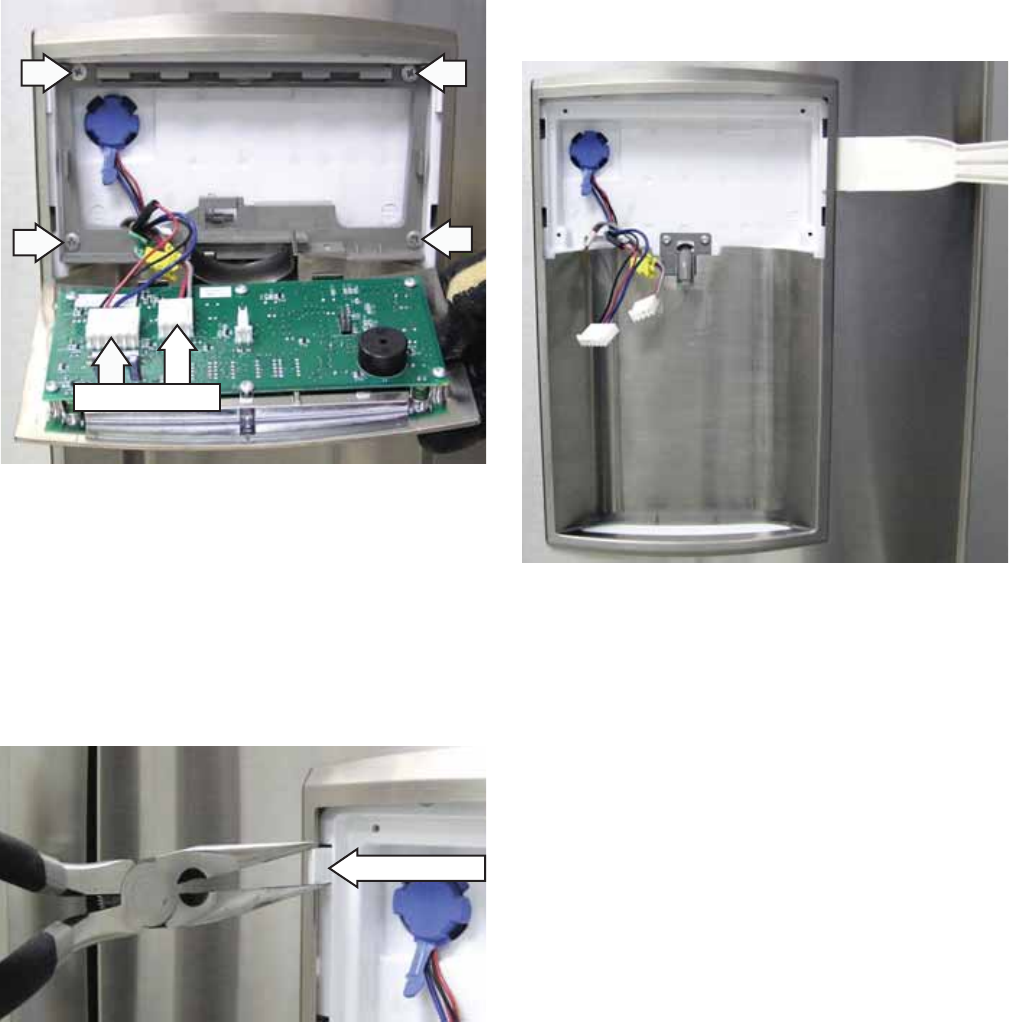
– 51 –
Carefully lower the interface and disconnect the 2.
2 wire harnesses.
Remove the 4 Phillips-head screws and the 3.
cradle support from the dispenser recess.
Lift and remove the drip tray.4.
Note: There are 2 plastic wedges that help hold the
top of the trim fl ush against the door panel. If the
wedges are not installed the trim will fi t loosely.
Using a pair of long-nose pliers, pull out the 2 5.
plastic wedges.
Wire Harnesses
Wedge (1 of 2)
Note: The dispenser trim is held to the dispenser
recess by 5 retaining tabs along each side and 2 at
the top.
Using your hands or a plastic putty knife, 6.
carefully lift or pry the dispenser trim away from
the dispenser recess.
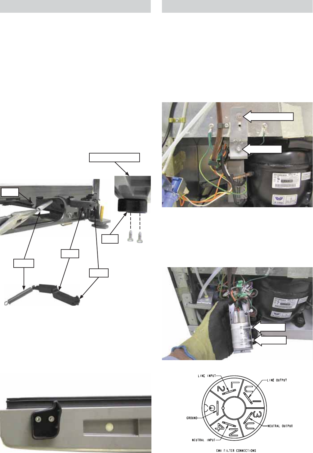
– 52 –
Hook
Spring
Lever
Roller
Cam
Note: Each door closer cam can be installed
incorrectly. Ensure each cam is installed on the
bottom of the drawer with the hooked end towards
the center of the drawer.
Bottom View of Drawer and Right Side Cam
Bottom of Drawer
Drawer Closure Mechanisms
Two self closing freezer drawer cam and lever
mechanisms automatically pull the drawer shut
when it's within 1 inch of the closed position. The
closure mechanisms are located on the lower corner
areas of the drawer and cabinet.
Each closure mechanism consists of a lever, spring,
and cam. The lever is attached with a spring to a
hook in the base channel. The cam is mounted to
the bottom of the drawer with two T-20 Torx screws.
The lever interacts with the cam to complete the
closing of the drawer.
A pair of pliers can be used to remove the spring
from the hook. The spring and lever can then be
pulled out through the hole in the base channel.
EMI Filter
The EMI Filter is accessed from the back of the
refrigerator and is located on the left side of the
compressor.
To remove the EMI fi lter:
Remove the 1. 5
/
16
-in. hex-head screw that
attaches the bracket to the cabinet.
Pull the bracket out and remove the 2. 1
/
2
-in. nut.
Cut the 2 plastic wire ties that hold the EMI fi lter 3.
to the bracket.
Mark and disconnect the wires from the EMI 4.
fi lter.
5/16-in. Screw
1/2-in. Nut
Wire Tie
Wire Tie

– 53 –
Troubleshooting
(Continued next page)
Control Diagnostics Using the Temperature Display
The temperature display has a self-diagnosis mode that can be accessed and will help the technician to test
certain functions of the temperature display, defrost heater, damper, and interior fans. This mode can aid the
service technician in quickly identifying failed or improper operation of certain components and systems.
Control diagnostics using the display does not use error codes to identify problems. Instead, the temperature
display allows access to components or systems to be checked if a problem is detected.
The temperature display must be in an active mode before entering the self-diagnosis test. If the display is
blank, press any temperature button once, then release it. The display will show actual temperatures.
Enter the diagnostic mode by pressing both the freezer temperature (COLDER and WARMER) pads and
the refrigerator temperature (COLDER and WARMER) pads simultaneously. All four pads must be held for
approximately 3 seconds. Blinking "00"s in both the freezer and refrigerator sections of the display indicate
the refrigerator has entered the test mode. Remove fi ngers within 5 seconds and press any pad to lock-in
the test mode. The blinking "00"s will change over to solid (non-blinking) "0"s when the test mode is locked-
in. Failure to lock-in the test mode within 30 seconds will time out the test and return the refrigerator to the
normal cooling mode.
FZ
Display FF
Display Mode Comments
0 1 Showroom Mode When activated, a tone will sound briefl y and the display
will fl ash 1 time. The cooling system stops operation. All
HMI functions will operate normally.
0 2 Display Combined HMI
Software Version
Temperature to main controls communications test. A
coded software version is displayed. Dispenser model
will show two numbers. See Note 1. Internal display
model will test for Pass/Fail. Should show "P". If the
format is violated, the display will read "99".
0 3 Display Main Control
Software Version
Temperature to dispenser communications test. A coded
software version is displayed. Dispenser model will show
two numbers. See Note 1. Internal display model will
show "F" (no dispenser board). If the format is violated,
the display will read "99".
0 4 Combined HMI to Main
communications
Dispenser to main controls communications test.
Dispenser model will test for Pass/Fail. Should show "P".
Internal display will show "F" (no dispenser board).
0 6 HMI Self Test Illuminates all LEDs and numerical segments. FF and FZ
displays will initially display "88". Pressing temperature
pads will change initial display. Remaining pads pressed
will toggle the LED associated with that pad. Filter pad
repeatedly pressed will toggle red, green, and amber
LEDs. To exit HMI Self Test, press and hold both FF
temperature pads simultaneously for 3 seconds, then
release.
0 7 Sensor Self Test Checks each thermistor in order and displays "P" for
pass, "0" for open circuit, or "S" for shorted circuit. See
Note 2.

– 54 –
FZ
Display FF
Display Mode Comments
1 0 Open Damper Damper will open, pause briefl y, and then close.
1 1 Fan Speed Test Cycles through each fan for 5 seconds.
1 2 100% Run Time This mode runs the sealed system 100% of the time.
This test will automatically time out after 1 hour of run
time. A refrigerator reset may exit this mode.
1 3 Enter Pre-chill This places the freezer in pre-chill mode essentially
issuing a “Force Prechill” command to the main control.
It will return to normal operation on its own. This
command will be ignored if the refrigerator is set to
OFF/Standby mode.
1 4 Toggle the State of
Defrost
Each time any button on the temperature board other
than four temperature adjust buttons is pressed, the
status of the FZ defrost heater will toggle. See Note 3.
1 5 Refrigerator Reset Causes a soft reset to occur at both the Combined HMI
and the Main board.
1 6 Test Mode Exit Causes a soft reset to occur at the Combined HMI
board. Note: This will not terminate test modes that the
main board is maintaining as a result of the service
diagnostics mode. To terminate test modes, Refrigerator
Reset should be used.
1 7 Degree C/F Internal display model only. Used to set the temperature
unit of measure. The current mode is displayed on the
FF display (“C” of “F”). Use either of the FF slew keys
to adjust the mode. Press any key other than the FF
slew keys to set the unit of measure to the displayed
selection.
Note 1: The fi rst two digits are numbers. The second two digits are numbers that correspond to a letter (01=a,
02=b, 03=c,...26=z). For example, 61 and 9= a software version of 61i. 41 and 10=a software version of 41j.
Note 2: Display order: #1 = Fresh Food Thermistor, #2 = Air Thermistor, #3 = Freezer Thermistor, #4 =
Evaporator Thermistor. 05 displayed = No Thermistor installed at this location.
Note 3: The heater will not come on if the evaporator thermistor is above 70°F.
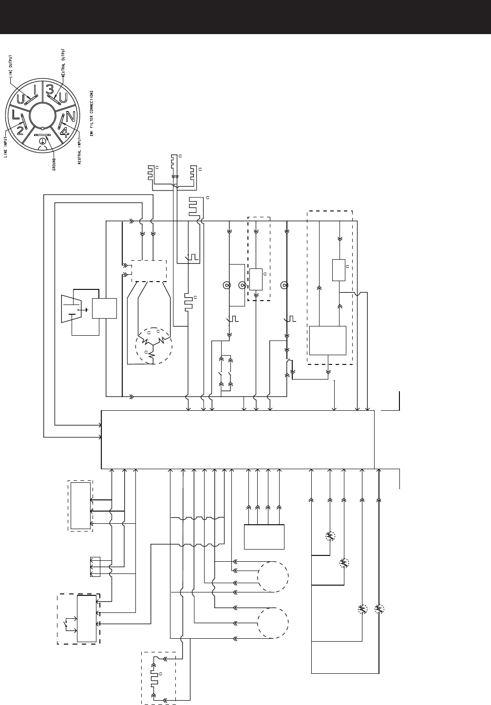
– 55 –
Schematic
# !!#!$(%
)%# $" $#! *
$#%%#!*
!
'#*!(
&!!
'#
(%
*!(
*!(
(%$'#!
#!
&(%#"
*!(
&(%
#(%
(%#
(%#
%#$%!##
%#$%!#
%#$%!#+
& '&
%#$%!#+'"
(%&
(%&
(%
(%
(%#
(%#
$'#
&#
(%
(%
#
(%
!#
!#
!# !#
!#
!#
!#
!#
!#
!#
!#
&%#!&%"&%
&%# "&%
%#
!# !# !# !#
"&#""
+%#!$%%
"&#""
"
%#!$%%
+!!#
%#!
##*!$! *
# !!#!$(%
)%# $" $#! *
(%#
''
(%#
''
#+#
%
#$!!
%
#$!!
%
#!$%
%# !'#%"#%&#
%#!$%%
#
$
#
!&$ !#
#!( "&#"
#
*!(
"&#"
(%
&
&
#!(
!"#$$!#
#!(
#!(
#!(
(%
#
!&%"&%
"&%
'#%#
#
(% #%&# &%
%#
%&
%#
#%&# &%
%##
&!
%#
$(%
$(%
# !!#!$! *
'!%
!('!%
$$#&%$
*!(
$
'&
#
##
#
*!(
(%
#
*!(
&
(%
(%#!( (%
&*!(
*!(
&
'"
"#
!
% %
! %#!!#
%
$ !!#!$ #
!!#!$(%!&%
)%# $" $#$! *
%"#%&#
! %#!
!#
$"$(%
# !!#!$! *
&! #%#
#
#
#
#
#
#
#
#
Note: 21’ and 25’ models have the white wire of the water valve connected to the main board at J18. The main board senses the water valve
turning on and then runs the evaporator fan for 120 minutes. If the water valve cycles again in 120 minutes, the timer is reset to count another
120 minutes. Otherwise the fan will cycle off and on in a normal mode. This logic provides increased ice production.
Note: The EMI fi lter
is on all 21’ and 25’
single and French
door models. The
20’/22’ single and
French door models
do not have this
fi lter.
– 56 –
Warranty
Refrigerator Warranty. (For customers in the United States)
All warranty service provided by our Factory Service Centers,
or an authorized Customer Care®technician. To schedule service,
on-line, 24 hours a day, visit us at ge.com, or call 800.GE.CARES
(800.432.2737). Please have serial number and model number
available when calling for service.
For The Period Of: GE Will Replace:
GE and GE PROFILE MODELS:
One Year Any part of the refrigerator which fails due to a defect in materials or workmanship.
From the date of the During this limited one-year warranty, GE will also provide, free of charge, all labor and
original purchase related service to replace the defective part.
Thirty Days Any part of the water filter cartridge which fails due to a defect in materials or workmanship.
(Water filter, if included) During this limited thirty-day warranty, GE will also provide, free of charge, a replacement water
From the original filter cartridge.
purchase date of
the refrigerator
GE PROFILE MODELS ONLY:
Five Years Any part of the sealed refrigerating system (the compressor, condenser, evaporator
(GE Profile models only) and all connecting tubing) which fails due to a defect in materials or workmanship.
From the date of the During this limited five-year sealed refrigerating system warranty, GE will also provide,
original purchase free of charge, all labor and related service to replace the defective part in the sealed
refrigerating system.
■Service trips to your home to teach you how to use
the product.
■Improper installation, delivery or maintenance.
■Failure of the product if it is abused, misused, or used for
other than the intended purpose or used commercially.
■Loss of food due to spoilage.
■Replacement of house fuses or resetting of circuit
breakers.
■Damage caused after delivery.
■Replacement of the water filter cartridge, if included,
due to water pressure that is outside the specified
operating range or due to excessive sediment in the
water supply.
■Replacement of the light bulbs, if included, or water filter
cartridge, if included, other than as noted above.
■Damage to the product caused by accident, fire, floods
or acts of God.
■Incidental or consequential damage caused by possible
defects with this appliance.
■Product not accessible to provide required service.
What GE Will Not Cover:
This warranty is extended to the original purchaser and any succeeding owner for products purchased for home
use within the USA. If the product is located in an area where service by a GE Authorized Servicer is not available,
you may be responsible for a trip charge or you may be required to bring the product to an Authorized GE Service
location for service. In Alaska, the warranty excludes the cost of shipping or service calls to your home.
Staple your receipt here.
Proof of the original purchase
date is needed to obtain service
under the warranty.
EXCLUSION OF IMPLIED WARRANTIES—Your sole and exclusive remedy is product repair as provided in this
Limited Warranty. Any implied warranties, including the implied warranties of merchantability or fitness for a
particular purpose, are limited to one year or the shortest period allowed by law.
