GE Refrigeration R 410A Refrigerant Chg Recovery 31 9192
2013-04-09
: Pdf Ge - Refrigeration - R-410A Refrigerant - Chg - Recovery - 31-9192 GE - Refrigeration - R-410A Refrigerant - Chg - Recovery - 31-9192 GE, Camco, Hotpoint, Mofat
Open the PDF directly: View PDF ![]() .
.
Page Count: 21
GE Appliances
General Electric Company
Louisville, Kentucky 40225
31-9192
R-410A
Refrigerant
Charging and
Recovery Process
Technical Service Guide
OCTOBER 2009
GE Consumer & Industrial
R410a

– 2 –
SYSTEM PRESSURES
Technicians with R-22 experience will need to become familiar working
with high and low side pressures that are much higher when using
R-410A. A typical R-22 system operates normally with a high side
pressure of approximately 260 psi at a 120°F condensing temperature
and a low side pressure of approximately 76 psi at 45°F evaporator
saturation temperature.
A normally operating R-410A system with the same condensing
temperature of 120°F and 45 degree evaporator saturation temperature
will have a high side pressure of approximately 418 psi and a low side
pressure of approximately 130 psi.
IMPORTANT SAFETY NOTICE
The information in this service guide is intended for use by
individuals possessing adequate backgrounds of air conditioning
and heat pump experience. Any attempt to repair an air conditioning
or heat pump system may result in personal injury and property
damage. The man u fac tur er or seller cannot be responsible for the
in ter pre ta tion of this in for ma tion, nor can it assume any liability in
connection with its use.
WARNING
To avoid personal injury, disconnect power before servicing air conditioning
or heat pump systems. If electrical power is required for diagnosis or test
purposes, disconnect the power immediately after performing the
necessary checks.
RECONNECT ALL GROUNDING DEVICES
If grounding wires, screws, straps, clips, nuts, or washers used to
complete a path to ground are removed for service, they must be
returned to their original position and properly fastened.
GE Consumer & Industrial
Technical Service Guide
Copyright © 2009
All rights reserved. This service guide may not be reproduced in whole or in part
in any form without written permission from the General Electric Company.
– 3 –
Table of Contents
Charging Procedures ......................................................................................................................................................14
Charging of R-410A .........................................................................................................................................................12
Common Questions About R-410A ..........................................................................................................................18
Digital Refrigerant Scale ................................................................................................................................................12
Hose Connection Diagrams .........................................................................................................................................19
Introduction to R-410A ................................................................................................................................................... 4
Manifold Gauges ...............................................................................................................................................................13
Purging Non-Condensable Gasses from the Recovery Cylinder ...............................................................17
Recovery of R-4120A ...................................................................................................................................................... 7
Recovery Procedures ...................................................................................................................................................... 9
Recovery Pump ................................................................................................................................................................. 7
Refrigerant Charging Connections ...........................................................................................................................21
Refrigerant Recovery Connections ..........................................................................................................................20
Refrigerant Sub Cooling Recovery Tank Connections .....................................................................................19
Self-purge/Auto Evacuate ............................................................................................................................................10
Sub Cooling the Recovery Tank ................................................................................................................................. 8
Summary for Normal System Recovery ................................................................................................................11
Tools ........................................................................................................................................................................................ 6
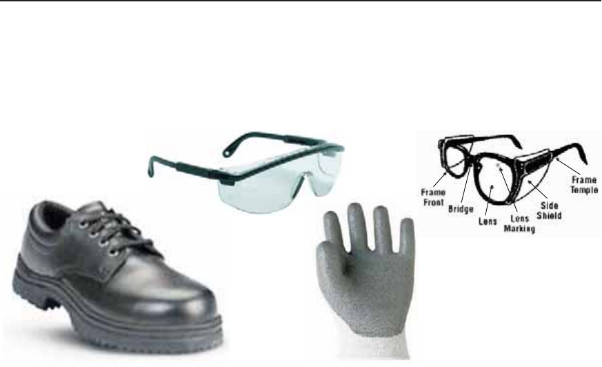
WARNING: GE Factory Service Employees are required to use safety glasses with side shields,
cut resistant (Dyneema®) gloves & steel toe shoes for all repairs.
Safety Glasses must be compliant with ANSI Z87.1-2003
Dyneema®
Cut Resistant Glove
Steel Toe Shoes
Plano Safety Glasses Prescription Safety Glasses

– 4 –
R-410A refrigerant is the leading HFC replacement
for R-22 refrigerant in new residential and light-
commercial air conditioning and heat pump
systems. R-410A has been around since 1995
and in 2010 it will become the most important
refrigerant in this industry. R-410A refrigerant is the
leading choice of most major original equipment
manufacturers as the replacement for R-22
refrigerant.
What is R-410A
R-410A is an ASHREA product designation for a
two-component hydro fl uorocarbon refrigerant
blend consisting of 50% HFC-32 and 50% HFC-125.
R-410A is nontoxic. It can be charged in gas form,
but liquid form is recommended. R-410A is marketed
under various brand names such as DuPontTM
Suva® 410A, Carrier Puron®, and Genetron® AZ-20.
For instant identifi cation, all brands of R-410A are
shipped in a rose colored tank.
It is a refrigerant blend, but R-410A acts like a single-
component refrigerant. It is nonfl ammable under
any reasonably, foreseeable leak scenarios, but can
become combustible when mixed with air.
R-410A has a much higher cooling capacity and a
higher operating pressure than R-22. As a higher
pressure refrigerant, it must be used only in
equipment specifi cally designed for R-410A.
R-410A systems can provide higher energy
effi ciency to meet and exceed U.S. Department
of Energy guidelines. These new systems have
up to 60% greater cooling capacity than the R-22
systems.
Ozone Depletion Potential
In use since the 1940's, R-22 is being phased
out due to its ozone depletion potential. The
manufacturing of R-22 in the U.S. stops in 2009.
The zero chlorine content of R-410A ensures no
ozone depletion potential and just a modest global
warming potential. According to experts, however,
the overall global warming potential of R-410A will
decrease because its higher effi ciency reduces
power plant emissions.
Introduction to R-410A
The Preferred Refrigerant
R-410A features greater capacity, higher effi ciency,
and a better TEWI [total equivalent warming impact]
rating than other non-chlorinated HFC refrigerants
for air conditioning applications. This refrigerant was
specifi cally designed for the latest high-effi ciency
systems.
R-410A allows the industry manufacturers to
improve system performance, while addressing
tough new energy and environmental standards
against refrigerant leakage and greenhouse gas
emissions.
In the Field Since 1995
R-410A refrigerant was invented in the early 1990s.
Air conditioners using R-410A have been available
in the U.S. since 1995, so they're not at all new.
Most manufacturers have had their R-410A air
conditioners and heat pumps on the market for
several years.
Every major manufacturer in the U.S. and Canada
now offers a R-410A brand. Because of the terrifi c
reliability track record of R-410A air conditioners,
R-410A has quickly become the new industry
standard.
If you understand its characteristics and handle it
properly, R-410A is as safe as the R-22 you have
been using.
Leak Detection
R-410A is an HFC refrigerant. Therefore, any leak
detection device or method that works for other HFC
refrigerants will work for R-410A.
Like R-22, R-410A is nonfl ammable at room
temperatures. Also like R-22, it becomes
combustible if mixed with air at elevated
temperature and/or pressure.
It is important that you do not mix R-410A with air
for leak testing or other purposes.
(Continued Next Page)

– 5 –
Higher Operating Pressures
In general, R-410A should be handled the same as
R-22 with the exception of the higher pressures.
When using R-410A, technicians with R-22
experience will need to become familiar with
working with both high and low side pressures that
are much higher. A typical R-22 system operates
normally with a head pressure of 260 psi at a
120°F condensing temperature and a low side
pressure of 76 psi at a 45°F evaporator saturation
temperature. Technicians will fi nd the equivalent
pressures in a R-410A system to be much higher.
A normally operating R-410A system with the
same condensing temperature of 120°F and a 45°F
evaporator saturation temperature will have a high
side pressure of 418 psi and a low side pressure of
130 psi.
Air conditioners using R-410A are specially designed
for these higher pressures. These systems have
been rigorously tested by their manufacturers, as
well as by independent safety testing labs, such as
Underwriters Laboratories.
Relative Refrigerant Pressures (psi)
Temp.
in °F Freon®
R-22 Suva®
R-410A Suva®
R-134a Temp.
in °C
32 °F 57.7 101 28.0 0 °C
34 °F 60.4 105 29.7 1.1 °C
36 °F 63.1 109 31.5 2 °C
38 °F 65.9 114 33.4 3.3 °C
40 °F 68.7 118 35.3 4.4 °C
42 °F 71.7 123 37.3 5.6 °C
44 °F 74.7 127 39.3 6.7 °C
46 °F 77.8 132 41.4 7.8°C
48 °F 81.0 137 43.5 8.9°C
50 °F 84.2 142 45.7 10.0°C
55 °F 92.7 156 51.5 12.8 °C
60 °F 102 170 57.7 15.6 °C
65 °F 111 185 64.3 18.3 °C
70 °F 122 200 71.3 21.1 °C
75 °F 132 217 78.9 23.9 °C
80 °F 144 235 86.9 26.7 °C
85 °F 156 254 95.4 29.4 °C
90 °F 168 274 104 32.2 °C
95 °F 182 295 114 35.0 °C
100 °F 196 317 124 37.8 °C
With over a million R-410A-based air conditioners
operating worldwide, and nearly a decade of fi eld
testing and product history, there is no evidence
to suggest that R-22 systems are any safer than
systems that contain R-410A.
Sealed System Reliability
Air conditioners and heat pumps that use R-22 use
a mineral oil that circulates through the system to
keep the compressor and other parts lubricated.
Systems containing R-410A usually use a synthetic
oil. Some of these synthetic oils can absorb moisture
more readily than mineral oils. Here is why this is
not an issue for sealed system reliability:
As long as technicians follow the manufacturers' 1. directions in installing and servicing R-410A
systems, the oils will remain clean and dry.
These procedures may be required to make sure
your warranty stays valid during the life of your
R-410A system.
Nearly all air conditioners and heat pumps that 2. use R-410A have a device called a "fi lter drier".
This important part fi lters, cleans, and dries
the refrigerant and oil as it circulates through
the sealed system. The fi lter drier has been an
important reason why air conditioners with
R-410A are considered, by some manufacturers,
to be the most reliable product they make.
Brazed Connections
The higher operating pressures encountered
by R-410A systems require the use of brazing
materials rated to withstand these pressures. Some
technicians may have used lower temperature
solders when making tubing connections on R-22
systems. This cannot be the practice on R-410A
systems. Only high temperature brazing materials,
such as Silphos type brazing rod or one of the
silver solders should be used on any R-22 system.
It is even more important, due to the much higher
pressures, to use these suitable brazing materials on
R-410A systems.
System Conversions
System conversions are not feasible. The differences
in construction of R-410A systems exceed the
practical and economic limits of converting an R-22
system to R-410A.
– 6 –
WARNING: Gauge manifold sets, hoses, recovery
cylinders and the recovery machine must be rated
for the higher pressures encountered with R-410A.
An attempt to use standard refrigerant service tools
on R-410A systems is very dangerous and foolish.
Such a mistake could cause serious injury or death.
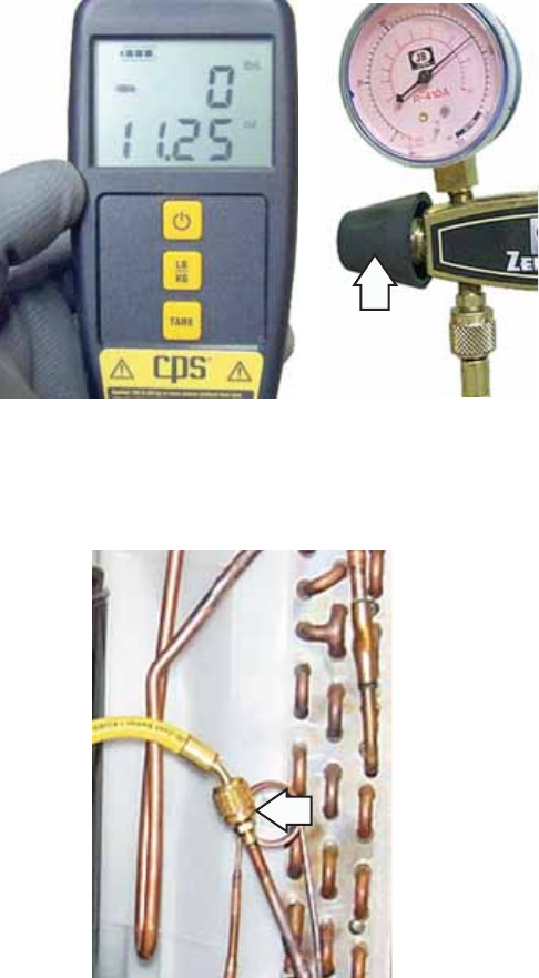
Tap Valve
Part number WX5X328 tap valve is used to tap
the sealed system for R-410A recovery. The
recommended placement of the tap is the process
stub at the outlet of the condenser.
R-410A Recovery Pump
The recovery pump must have an EPA certifi cation
notice showing the use for designated refrigerants
include R-410A. The high side gauge should read up
to 800 psi.
R-410A Recovery Cylinder
Recovery cylinders must be rated for R-410A use.
These cylinders, DOT-4BA 400 or DOT-4BW 400,
meet the Department Of Transportation standards
for R-410A recovery cylinders. Be very careful. It
would be easy and convenient to use whatever
recovery cylinder was handy rather than the correct
cylinder. This is a safety issue of great concern to
the industry and is one reason the AC&R Safety
Coalition was formed, and R-410A safety & handling
certifi cation was established.
In-Line Filter
The recovery pump can be exposed to debris
that can damage it. Contamination can also be
introduced from the refrigerant storage tanks. An
in-line fi lter, such as the Catch All C-032, is to be
used for all refrigerants, including 410A. Change the
in-line fi lter as needed.
R-410A Gauge Manifold Set
R-410A systems require higher pressure gauges and
hoses. Look for R-410A printed on the center of the
dial. The high side pressure gauge should read up to
800 psi and the low side up to 500 psi.
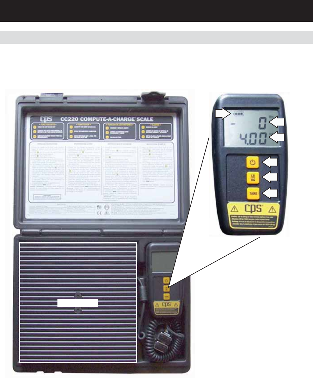
Digital Refrigerant Scale
A CPS® Compute-a-Charge CC220 digital scale is
used when charging R-410A.
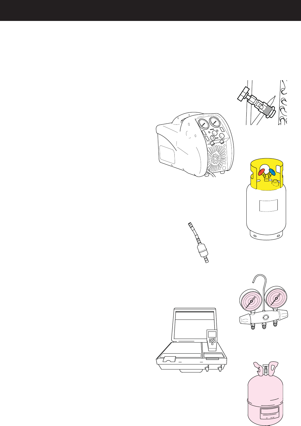
Tools
R41
0a
In-Line Filter
No. WX10X10003
R-410A Rated Tools
R-410A Recovery Pump
with 800 psi gauge
for the High Side
R-410A Cylinder
Gauge Manifold
R-410A Recovery Cylinder
DOT–4BA400 or
DOT–4BW400
Digital Refrigerant Scale
#CC220
R-410A Refrigerant
Tap Valve
R-410A Refrigerant Cylinder
For instant identifi cation, all brands of R-410A are
shipped in a rose colored tank.
– 7 –
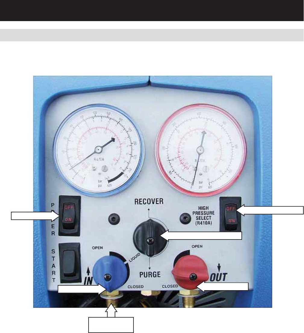
Recovery of R-410A
Main power “OFF”
“IN” port CLOSED
Recover/Purge set to “RECOVER”
High Pressure switch “OFF"
“OUT” port CLOSED
Recovery Pump
Note: The pressure gauge for the high side reads up to 800 psi.
In-line Filter
During the recovery process, the recovery machine
may be exposed to debris that can damage it.
This includes brazing spatter and copper or brass
slithers. Contamination can also be introduced from
the refrigerant storage tanks. To prolong the life of
your recovery pump, always use an in-line fi lter at
the inlet port. The Catch All C-032 in-line fi lter (Part
No. WX10X10003) is acceptable for all refrigerants,
including 410A. When installing the in-line fi lter,
be sure the directional arrows on the fi lter point
towards the pump. Change the in-line fi lter as
needed.
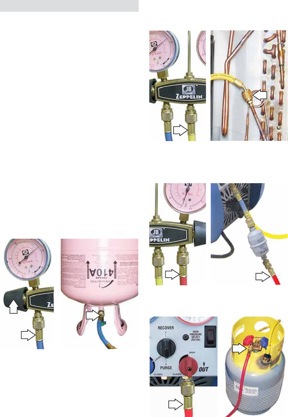
Connect In-line
Filter Here
– 8 –
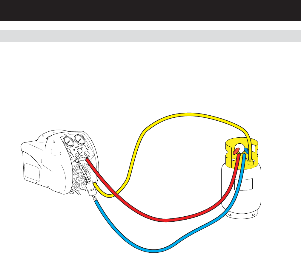
Sub Cooling the Recovery Tank
When working in extreme ambient temperatures,
the recovery tank can be sub cooled before the
recovery procedures are performed. This sub
cooling can speed up the recovery process.
Note: To sub cool the recovery tank, it is necessary
for the tank to contain a minimum of 5 pounds of
liquid R-410A in the tank.
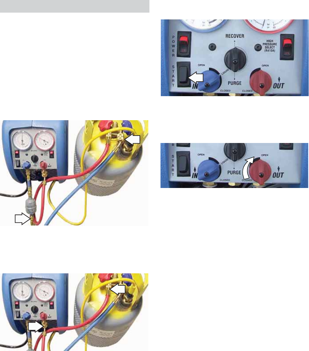
Connect one end of the blue hose to the pump 1. inlet port and the other end to the vapor port on
the recovery tank.
Connect one end of the red hose to the pump 2. outlet port and the other end to the liquid port
on the recovery tank.
Start the recovery pump.3.
Throttle the output valve so that the output 4. pressure is 100psi greater than the input
pressure, but not more than 300psi.
Run until the recovery tank is cold.5.
– 9 – (Continued Next Page)
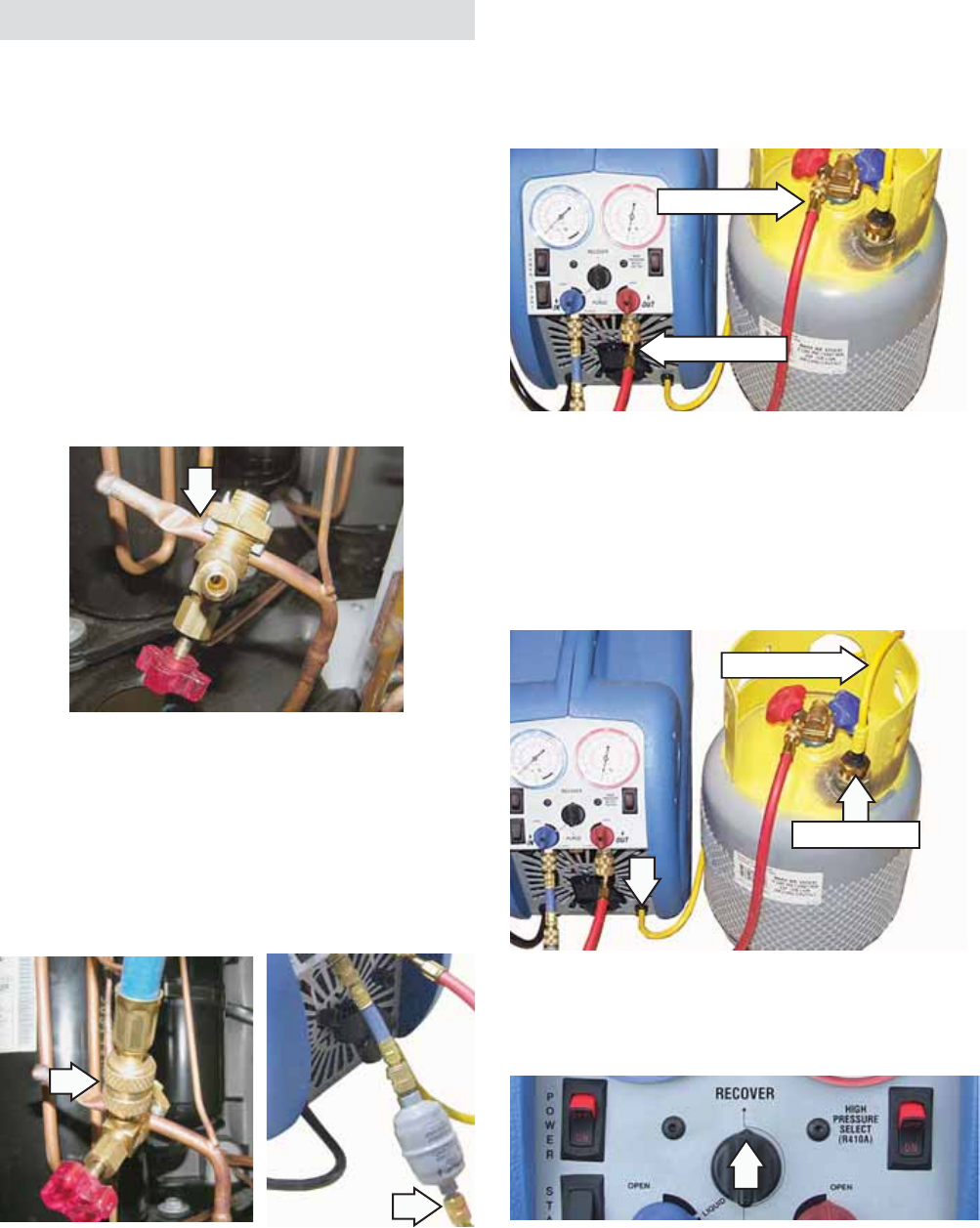
Close the red outlet port of the recovery pump.3.
Attach one end of the red hose to the outlet port 4. of the recovery pump and the other end to the
liquid port of the recovery tank.
Note: The compressor on the recovery pump will
fail to start if the yellow overfi ll safety lead is not
connected.
Connect the yellow overfi ll safety lead from the 5. recovery pump to the tank limit safety switch on
the recovery tank.
Set the black Recover/Purge valve of the 6. recovery pump to RECOVER.
With all hoses connected and tight, open the 7. liquid port of the recovery tank slowly to check
hoses and connections for leaks.
Safety Lead
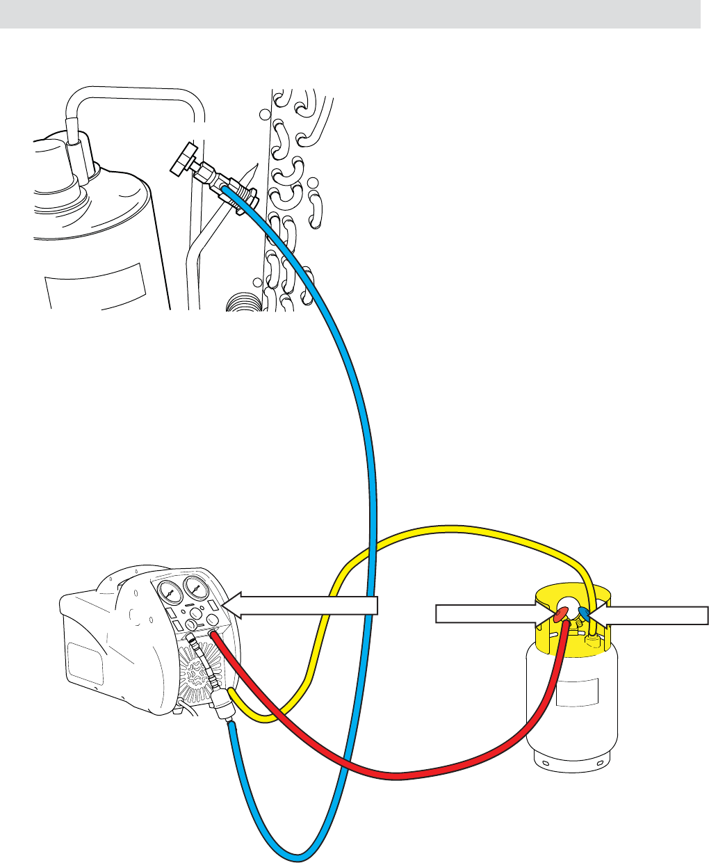
Recovery Procedures
Standard recovery procedures remain unchanged.
The only difference is the necessity to use a
recovery machine and cylinders approved for the
higher pressures of R-410A.
WARNING: When working in extreme ambient
temperatures, the recovery tank can be sub cooled
before the recovery procedures are performed. (See
Sub Cooling the Recovery Tank.)
Note: Check all hoses to make sure the “O” rings are
in place before connecting to system.
Tap the sealed system at the process stub tube, 1. using the WX5X328 tap valve.
Note: When installing the in-line fi lter, be sure the
directional arrows on the fi lter point towards the
pump.
Attach one end of the blue recovery hose to the 2. tap valve and the other end to the in-line fi lter
attached to the recovery pump.
Liquid Port
Red Outlet Port
Safety Switch
– 10 –
Self-purge/Auto Evacuate
The hygroscopic nature of the oils used in R-410A
systems cannot be over-emphasized. Moisture
can be a signifi cant problem affecting the proper
operation and life expectancy of any system
operating on the mechanical refrigerant cycle.
Therefore, it is more important than in the past to
take precautions to keep moisture out of a system
during installation and service. Evacuate to 15-inch
vacuum and replace fi lter-driers when a system
has been opened. Questionable workmanship that
may have been acceptable when working on R-22
systems cannot be tolerated by R-410A systems.
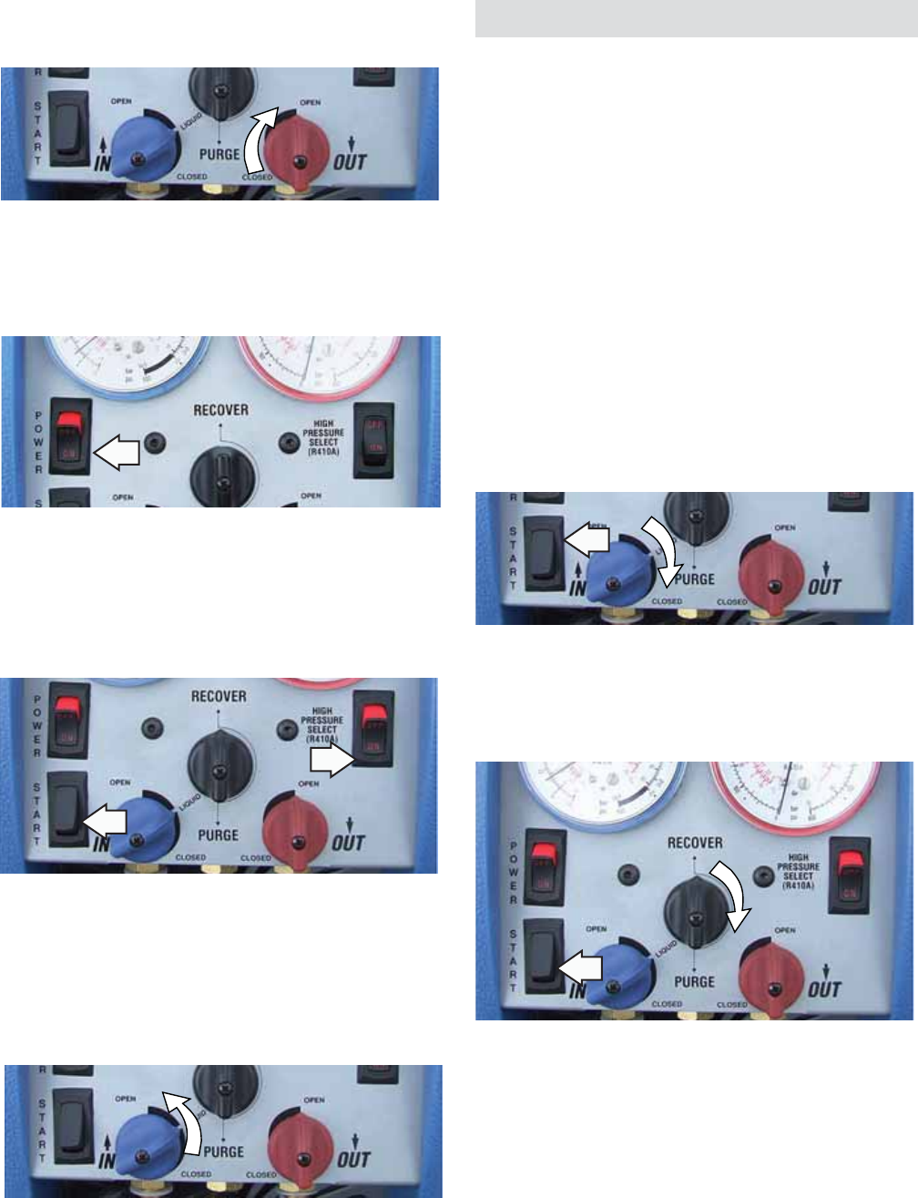
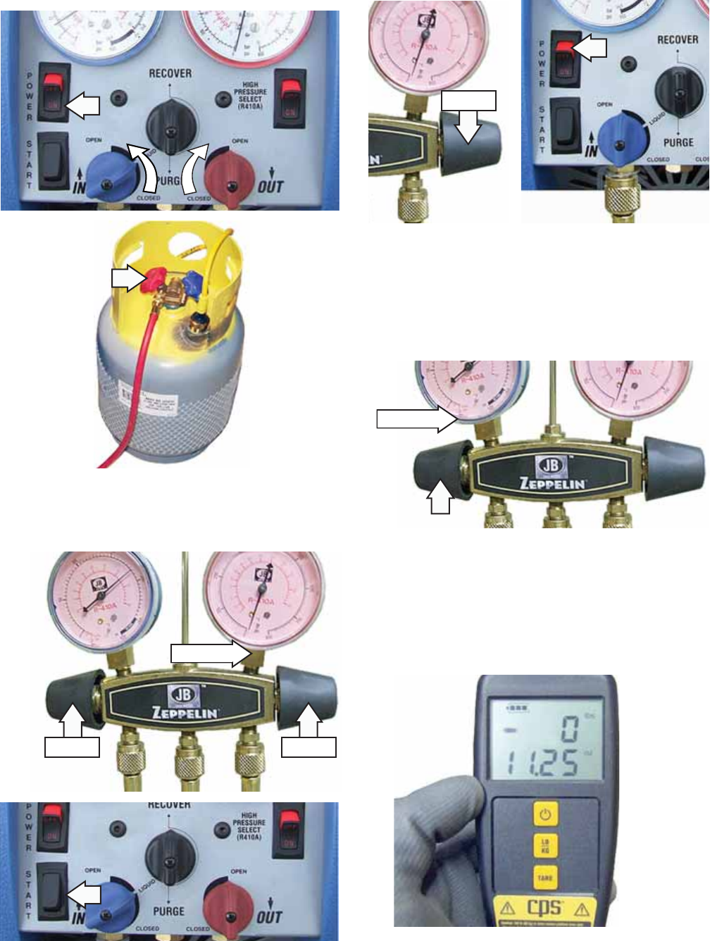
After recovery is complete:
Close the input port valve. 1.
Turn the recovery pump off.2.
Set the Recover/Purge valve to Purge.3.
Restart the recovery pump until a 15-inch 4. vacuum is achieved.
Turn unit off, reset Recover/Purge to Recover, 5. and remove the tap valve from the process stub
tube.
The pump is now ready for another recovery.
Open the tap valve on the high pressure side of 9. the sealed system.
Press recover pump power switch to ON. 10.
Note: The fan should be running.
Press the high pressure select switch to the 11. ON position, and press the compressor START
switch.
Note: If the pump begins to knock, slowly throttle
back the input valve until the knocking stops.
Slowly open the input port of the recovery 12. pump. Once the liquid has been recovered, fully
open the input valve.
Run the recovery pump until a 15-inch vacuum 13. is achieved.
After recovery is complete, self-purge the 14. recovery pump.
Rotate the output port of the recovery pump to 8. the OPEN position.
– 11 –
Summary of Normal System Recovery
1. Inspect the recovery pump thoroughly to
ensure that it is in good operating condition.
2. Connect recovery tank to recovery pump and
make sure all connections are correct and
tight.
3. Open the liquid port of the recovery cylinder.
(Always open valves slowly to check hoses
and connections for leaks.)
4. Make sure the Recovery/Purge valve is set on
Recover.
5. Open the output port of the recovery pump.
6. Open the tap valve on the sealed system.
7. Switch the main power to ON. The fan should
be running.
8. Press the compressor START switch.
9. Slowly open the input port on the recovery
pump.
a. If the compressor begins to knock, slowly
throttle back the input valve until the
knocking stops.
b. If the input valve was throttled back, it
should be fully opened once the liquid has
been removed from the system.
10. Run recovery pump until the desired vacuum
is achieved.
11. Close tap valve.
12. Close the recovery pump input port.
13. Turn off recovery pump.
14. Turn the Recover/Purge valve to the Purge
position.
15. Restart the recovery pump.
16. Run until the desired vacuum is achieved.
17. Close the ports on the recovery tank and the
recovery pump.
18. Turn off the recovery pump and return the
Recover/Purge valve to Recover.
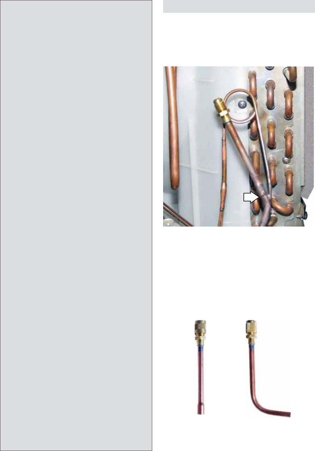
Installation of Charge Valve
After the system recovery and self purge/auto
evacuate is completed, cut the process stub tube
below the piercing valve hole. Braze a Schrader
charge valve onto the process stub tube prior to
charging.
Charge Valve
There are 2 basic types of Schrader charge valves
available to the service technician. The fi rst type
(Part No. WJ56X10008) is swaged to fi t over 1/4-inch
tubing. The second type (Part No. WJ56X61) has a
90° bend to ease access to the Schrader valve in
certain installations.
Part No. WJ56X10008 Part No. WJ56X61
– 12 – (Continued Next Page)
Digital Refrigerant Scale
1
2
3
4
5
6
Scale Platform
Battery Level Indicator1.
Pounds of Refrigerant2.
Ounces of Refrigerant 3. (in .25 oz. increments)
Power Button4.
LB/KG (select LB for 5. pounds and ounces)
TARE (button allows you 6. to zero the scale)
Controller
Charging of R-410A
– 13 –
The CPS CC220 Scale
The CPS CC220 scale is used to add the required
amount of 410A refrigerant.
There are two 9-Volt batteries supplied with the
scale. Insert these in the back of the controller. The
back of the controller has a magnetic surface, which
allows the controller to be attached to any metal
surface. If a metal surface is unavailable, use the
hook located in the case under the controller to
hang the controller. The base of the hook attaches
to the top of the controller.
Digital Scale Operating Instructions
Note: All objects should be removed from the scale
platform.
Place the scale on a level, rigid surface.1.
Press the power button key to turn the unit 2. on. Wait for the LCD to display a zero weight
reading.
Note: Change batteries when all segments of the
battery level indicator are off.
Press the unit selection key, LB/KG, to select LB 3. (pounds and ounces).
The scale is now ready for weighing.4.
Caution: An overload (OL) message will be displayed
if the rated capacity is exceeded. Reduce the load
immediately to avoid damaging the scale.
Refrigerant Charging:
Caution: Carefully place the R-410A refrigerant
cylinder on the scale platform to avoid subjecting
the scale to mechanical shock.
Place the R-410a cylinder on the digital scale 1. platform and allow the liquid refrigerant to come
to rest in the tank.
Connect the charging hose to the cylinder. 2.
Bleed the air out of the hose. 3.
Press the TARE key (LCD will now read zero). 4.
Open the R-410A cylinder valve. The LCD will 5. indicate the amount of R-410a refrigerant being
transferred in negative numbers.
Close the R-410A cylinder valve when the 6. desired charge amount is displayed.
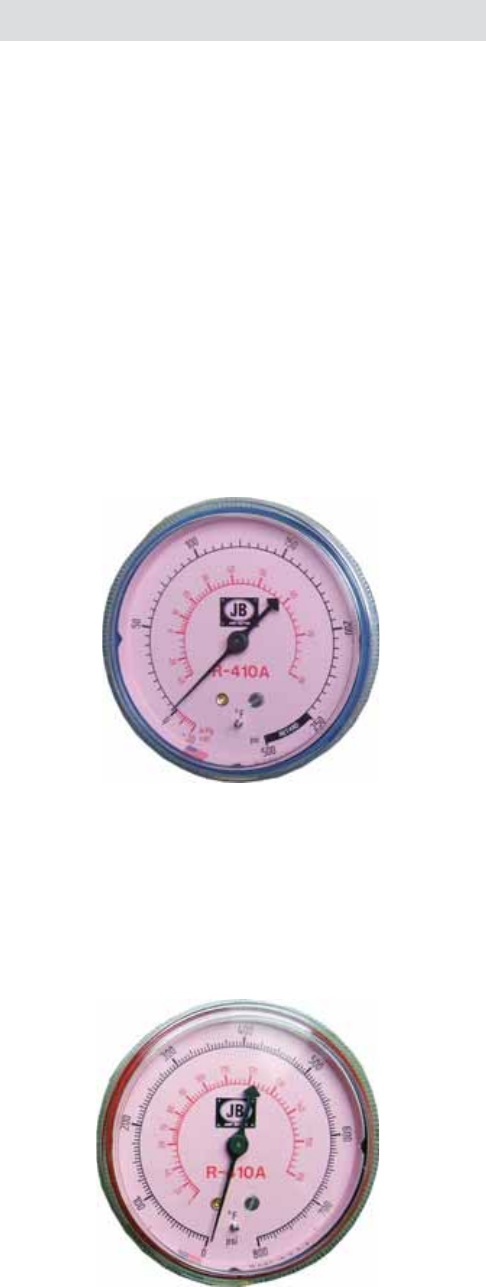
Manifold Gauges
The R-410A system requires higher pressure
gauges. Be sure that R-410A is printed on the face
of the gauge you are using.
A normally operating R-410A system with a
condensing temperature of 120° and 45°F
evaporator saturation temperature has a high side
pressure of approximately 418 psi, and a low side
pressure of approximately 130 psi.
Low Side Pressure Gauge
The inner dial of the low side pressure gauge reads
the temperature in °F from 80 to -40.
The outer dial reads pressure in PSI from 0 to 500.
The outer dial also reads vacuum in Inches Hg.
High Side Pressure Gauge
The inner dial of the high side pressure gauge reads
the temperature in °F from 0 to 160.
The outer dial reads pressure in PSI from 0 to 800.
– 14 –
Connect the yellow hose from manifold to the 4. charge valve on the high pressure side of the
sealed system.
Charging Procedures
IMPORTANT: The R-410A system can only be
charged on the high pressure side of the system,
and only with liquid refrigerant.
The amount of refrigerant used in the charge is
measured by weight with a digital scale. If the
R-410A cylinder does not have a dip tube, the
cylinder must be turned upside down when placed
on the digital scale.
A 15-inch vacuum is required in the sealed system
before the charging process begins. This permits
the system's compressor to remain off during the
charging process. Pressures are monitored by
manifold gauges. The high side pressure gauge
must be capable of reading pressures up to 800psi.
Note: Using the recovery pump, achieve a 15-Inch
vacuum prior to charging the system.
Set up recovery pump, recovery tank, gauge 1. manifold, and scale. (See 410A Refrigerant
Charging Connections.)
Connect the blue hose from the refrigerant 2. cylinder to the low side port of the manifold.
Open the R-410A refrigerant cylinder to purge 3. the air from the blue refrigerant hose using the
low side port manifold valve.
Connect the red hose from the manifold gauge 5. to the fi lter on the inlet port of the recovery
pump.
Connect the outlet port of the recovery pump to 6. the liquid port of the recovery cylinder.
(Continued Next Page)
– 15 –
Open the high pressure valve on the manifold 8. and start the recovery pump.
After a 15-inch vacuum is achieved, close the 9. high pressure valve on the manifold, then turn
the recovery pump off.
Note: Make sure to press the TARE key on the digital
scale controller to set the scale to zero.
Open the low pressure valve on the manifold to 10. allow the refrigerant to enter the sealed system.
Low Side
Open the inlet and the outlet ports on the 7. recovery pump and turn the power on. Open
recovery cylinder liquid valve.
High Side
Closed Open
Closed
When the proper charge weight is displayed, 11. add 0.25 oz. for each 5 ft. length of hose in the
sealed system line that has not been purged. (In
this case, only 0.25 oz. would need to be added
for the 5 ft yellow hose.)
(Continued Next Page)
– 16 –
Disconnect the yellow hose attached to the 13. sealed system.
When the proper charge weight has been 12. reached, close the low pressure manifold valve
to stop the refrigerant fl ow.
Run the recovery pump to achieve a vacuum. 14. (See Recovery Procedures.) Then, run a purge
on the recovery pump. (See Self Purge/Auto
Evacuate.) Carefully disconnect all hoses.
Note: The system should now be fully charged and
ready for operation. To be certain, complete the
following check list:
Double check the sealed system valve and the 1. sealed system for leaks.
Secure the cap on the charge valve.2.
Check the system for proper operation.3.
Complete all of the EHS Safety requirements.4.

– 17 –
Purging Non-Condensable Gasses from the
Recovery Cylinder
Allow the recovery cylinder to sit undisturbed for 1. 24 hours to allow the air to rise to the top.
Determine the ambient temperature in the 2. room.
Connect the high pressure manifold gauge to 3. the vapor port of the recovery cylinder and
compare the pressure reading to the ambient
temperature.
If the pressure reading is higher than the 4. pressure listed for the ambient temperature,
slowly open the manifold to release the non-
condensable gas until the pressure reading is
within 5psi of the corresponding chart pressure.
Close vapor port and allow the recovery cylinder 5. to sit for 10 minutes; then, check the cylinder
pressure again.
Repeat the process if necessary.6.
Relative Refrigerant Pressures (psi)
Temp.
in °F Freon®
R-22 Suva®
R-410A Suva®
R-134a Temp.
in °C
32 °F 57.7 101 28.0 0 °C
34 °F 60.4 105 29.7 1.1 °C
36 °F 63.1 109 31.5 2 °C
38 °F 65.9 114 33.4 3.3 °C
40 °F 68.7 118 35.3 4.4 °C
42 °F 71.7 123 37.3 5.6 °C
44 °F 74.7 127 39.3 6.7 °C
46 °F 77.8 132 41.4 7.8°C
48 °F 81.0 137 43.5 8.9°C
50 °F 84.2 142 45.7 10.0°C
55 °F 92.7 156 51.5 12.8 °C
60 °F 102 170 57.7 15.6 °C
65 °F 111 185 64.3 18.3 °C
70 °F 122 200 71.3 21.1 °C
75 °F 132 217 78.9 23.9 °C
80 °F 144 235 86.9 26.7 °C
85 °F 156 254 95.4 29.4 °C
90 °F 168 274 104 32.2 °C
95 °F 182 295 114 35.0 °C
100 °F 196 317 124 37.8 °C

– 18 –
Common Questions About R-410A
Are the higher pressures of R-410A safe?1.
Actually, air conditioners that use R-410A are
specially designed for the higher pressures of
R-410A. These systems have typically been
rigorously tested by their manufacturers, as well as
by independent safety testing laboratories, such as
Underwriters Laboratories.
With over a million R-410A-based air conditioners
operating worldwide, and nearly a decade of fi eld
testing and product history, there is no evidence
to suggest that R-22 systems are any safer than
systems that contain R-410A.
Will the higher pressures of R-410A cause air 2. conditioners to break down more often?
Evidence shows that R-410A air conditioners are
remarkably more reliable than air conditioners that
use R-22.
Air conditioners that use R-410A are designed
to be more robust, with a thicker compressor
shell. Usually this results in a smaller, sturdier unit
that vibrate less, putting less strain on the piping
connections that are the source of most leaks.
Isn’t R-410A technology too new and risky?3.
The refrigerant 410A was invented in the early
1990s. Air conditioners using R-410A have been
available in the U.S. since 1995, so they're not at all
new. They're just new to people who haven't heard
about them!
It's taken several years for some air conditioner
dealers to learn about these products and for some
air conditioner manufacturers to design and offer
their own R-410A systems. Most manufacturers
have had their R-410A air conditioners and heat
pumps on the market for several years.
Every major manufacturer in the U.S. and Canada
now offers an R-410A brand, and because of the
terrifi c track record of the reliability of R-410A air
conditioners, they have quickly become the new
industry standard.
But won’t the lubricating oil used in R-410A 4. systems absorb water and make the systems
break down?
Many air-conditioning technicians who haven't
learned about R-410A often hear this myth and
repeat it to others.
Air conditioners and heat pumps that use R-22 use
a mineral oil that circulates through the system to
keep the compressor and other parts lubricated.
Systems containing R-410A usually use a synthetic
oil . Some of these synthetic oils do absorb moisture
more readily than mineral oils, but there are several
reasons why this is not an issue for home owners.
As long as technicians follow the manufacturers'
directions in installing and servicing R-410A
systems, then the oil will remain clean and dry.
These procedures may also be required to make
sure the warranty stays valid during the life of a
R-410A system.
Second, nearly all air conditioners and heat pumps
that use R-410A have a device called a "fi lter drier".
This important part does exactly what the name
implies - it fi lters, cleans, and dries the refrigerant
and oils as it circulates through a system just like
the oil fi lter in a car. Use of this device has been an
important reason why air conditioners with R-410A
are considered by some manufacturers to be the
most reliable product they make.
– 19 – (Continued Next Page)
Hose Connection Diagrams
In-Line Filter
Recovery Pump with
800 psi gauge
for the High Side
DOT – 4BA400 or
DOT – 4BW400
Recovery Cylinder
Refrigerant Sub Cooling Recovery Tank Connections
– 20 – (Continued Next Page)
In-Line Filter
Recovery Pump with
800 psi gauge
for the High Side
DOT – 4BA400 or
DOT – 4BW400
Recovery Cylinder
Safety Switch
Tap Valve
Refrigerant Recovery Connections
High Pressure switch ON Liquid Port OPEN Vapor Port CLOSED
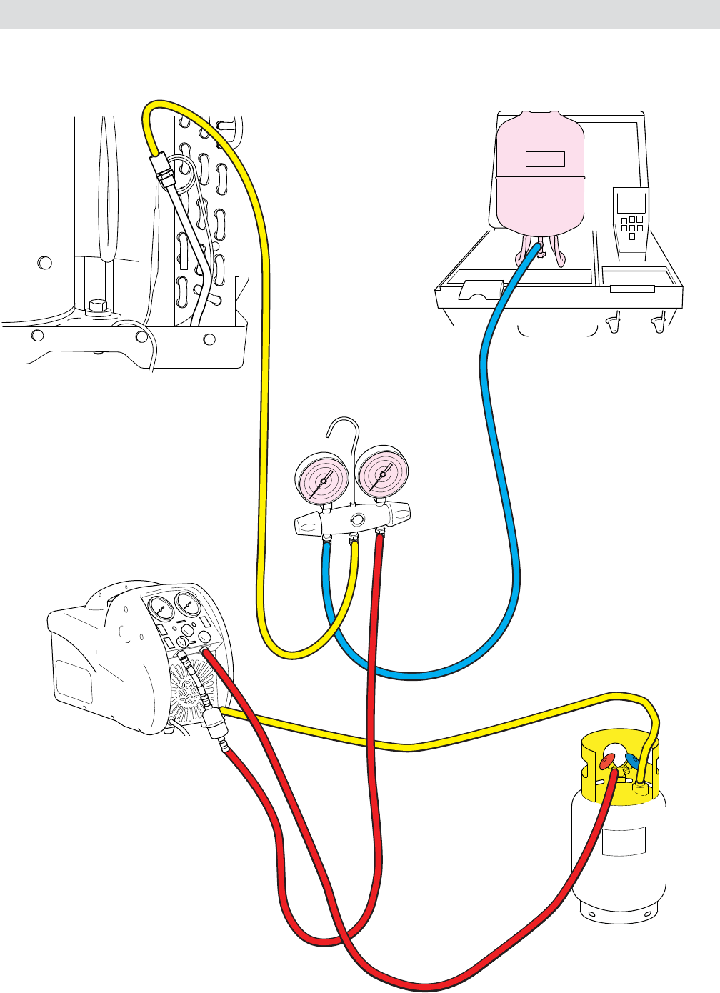
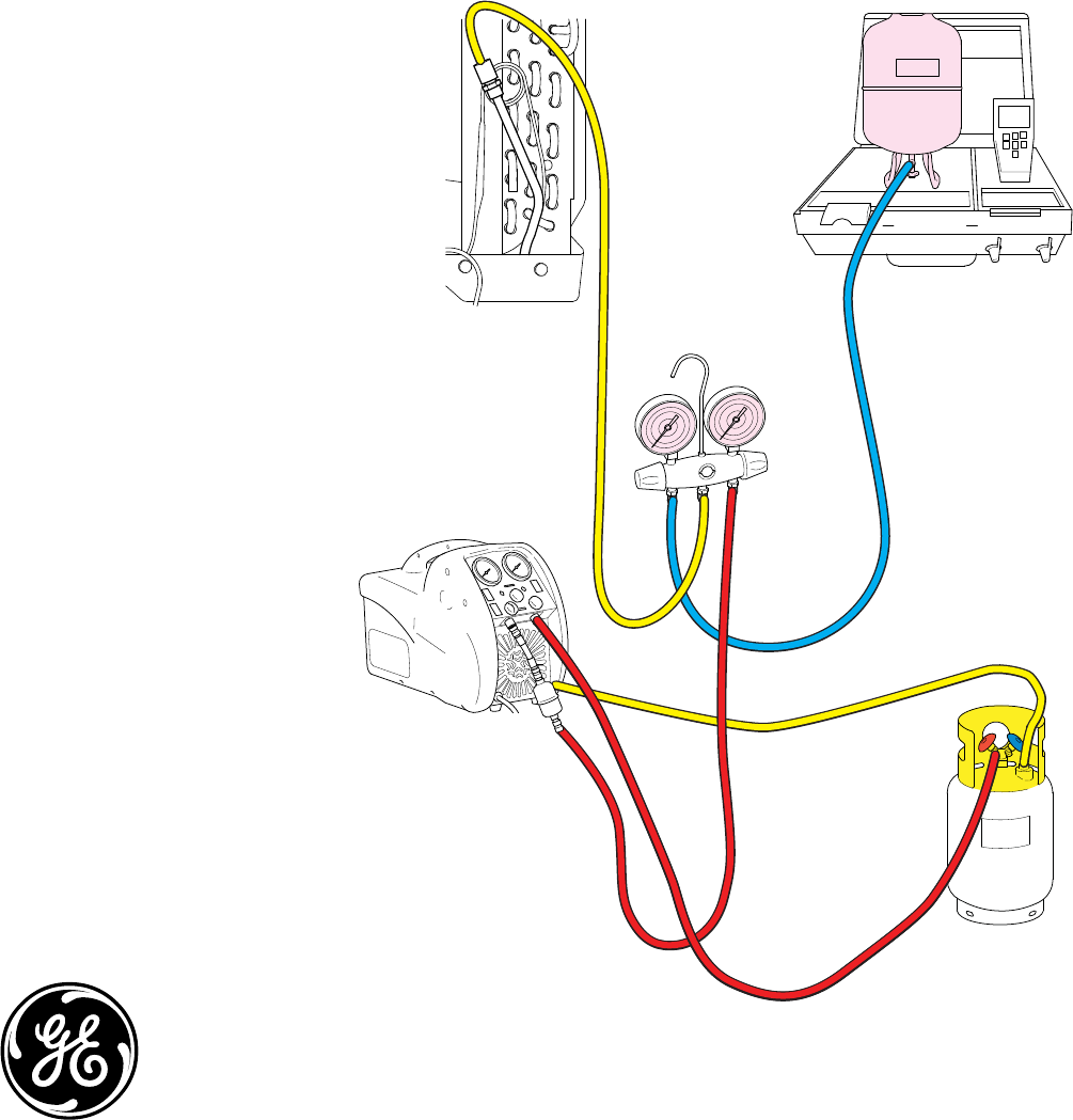
– 21 –
R410a
In-Line Filter
Recovery Pump with
800 psi gauge
for the High Side
Gauge Manifold Set
with Hoses
DOT – 4BA400 or
DOT – 4BW400
Recovery Cylinder
Digital Refrigerant Scale
410A Refrigerant
Safety Switch
Refrigerant Charging Connections
