Geotech Geocontrol 2 Logic Unit Installation And Operation Manual
User Manual: Pdf Geotech Geocontrol 2 Logic Unit
Open the PDF directly: View PDF ![]() .
.
Page Count: 20
Rev. 4/24/2013 Part # 11150170
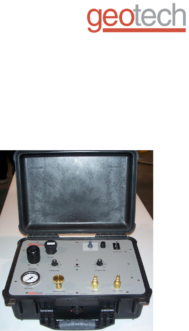
Geotech
Geocontrol 2
Logic Unit
Installation and Operation Manual
1
Table of Contents
Section 1: System Description …………………………………………..…….. 3
Section 2: System Installation …………………………………………….……. 4
Section 3: System Operation ………………………………..………………… 6
Section 4: System Maintenance ………………………………………….…… 8
Section 5: System Troubleshooting ………………………….………………... 9
Section 6: System Specifications ………………………………………….….. 10
Section 7: System Schematics ………………………..………………………. 11
Section 8: Replacement Parts List …………………….…….………………… 13
Warranty and Repair ……..…………………….……………..………………… 16

2
NOTE
DOCUMENTATION CONVENTIONS
This uses the following conventions to present information:
An exclamation point icon indicates a WARNING of a situation
or condition that could lead to personal injury or death. You
should not proceed until you read and thoroughly understand the
WARNING message.
WARNING
CAUTION
A raised hand icon indicates CAUTION information that relates to
a situation or condition that could lead to equipment malfunction
or damage. You should not proceed until you read and thoroughly
understand the CAUTION message.
A note icon indicates NOTE information. Notes provide additional
or supplementary information about an activity or concept.
3
Section 1: System Description
Function and Theory
Geotech's Geocontrol 2 utilizes advanced electronic logic to control both high
rate purging and gentle low flow sampling. Simple to use, accurate
microprocessor controlled on/off timers are utilized to recreate expert techniques
for low-flow sampling.
The Geocontrol 2 high-pressure solenoid activated valve delivers even in the
deepest sampling applications.
The Geocontrol 2 can be used with any bladder pump system with the use of
simple quick-disconnect adapters.

4
Section 2: System Installation
THE GEOCONTROL 2 REQUIRES DRY MOISTURE FREE AIR. TO
DISREGARD WILL INCREASE THE LIKELIHOOD OF UNNECESSARY
MAINTENANCE!
Determine your power source, either 115 VAC or 12 VDC.
Selecting Air Source
The following explanation is based on the Geotech Bladder Pump Model
GEO1.66SS36 with .170 (4.3mm) ID air supply tubing. To determine the required
capacity of the air source used, calculate the air consumption as follows. With
100 ft. of air line tubing in or out of the well, the air consumption is 125 cubic
inches per cycle, with 6 cycles per minute (average).
Example: For 100 ft. (30.5m) of tubing you will need 125 cu. in. (2L) x 6 per min.
which equals 750 cu. in. (12L) / min. or 45,000 cu. in. (737L) / hr. For each
additional 100 ft. add 59 cu. in. (or 1 liter for every additional 30m).
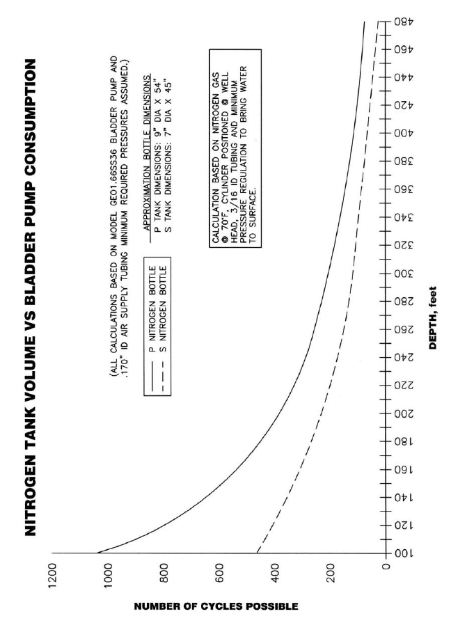
If you plan to use an air compressor, we advise that you use one with a reserve
tank to insure proper air supply to the pump. If you plan to use a Nitrogen Tank,
see figure 2 for Nitrogen Tank Volume vs. Bladder Pump consumption.
Determining PSI
Determine the air pressure needed to operate the Bladder Pump based on the
length of the air supply line to the pump (well depth). Use the simplified formula
of (1/2 PSI per foot) + 10 PSI for friction, or (.1 bar per meter) + .7 bar.
Example: For a pump 100 ft. away from the air source, use 100 ft. divided by 2
then add 10 PSI, this equals 60 PSI (100' / 2 + 10 = 60 PSI).
In metric: For a pump 30m away from the air source, use 30m divided by 2 then
add .7 bar, this equals 15.7 bar (30m / 2 + .7 = 15.7 bar).
The additional 10 PSI (.7 bar) is to account for the pump itself and friction loss
along the air line tubing.
Where the length of the air line to the Bladder Pump is 50 ft. (15m) or less, an
additional 10 PSI (.7 bar) need not be added.
READ BEFORE PROCEEDING ANY FURTHER
5
Figure 2-1 – Nitrogen tank volume vs. bladder pump consumption

6
NOTE
Section 3: System Operation
To determine minimum operating pressures for the specific Bladder Pump model
you are using, consult Pumps Specifications. Typically the minimum operating
pressure will be 5 PSI (.35 bar) above static head.
Example: Bladder Pump depth is 50 feet. 50 / 2 = 25 + 5 = 30 PSI.
In metric: Bladder Pump depth is 15m. 15m / 2 = 7.5 + .35 bar = 7.85 bar
(The previous formula is not absolute and is meant to provide baseline information.)
At the wellhead, connect the air supply line from the air source (compressor,
bottle, etc.) to the quick disconnect marked AIR INLET (see Section 2 on
selecting an air source). Next, connect the air supply line hose whip to the air line
at the well cap and the quick disconnect marked AIR OUTPUT.
Adjust the air source regulator to the appropriate psi, (see Section 2 on
determining psi).
Switch the toggle from ON/OFF, depending on power supply selected.
Adjusting Cycle Timers
Adjust Charge Time knob to approx. 5 seconds, adjust Exhaust Time knob to
approximately 15 seconds.
A 15 second exhaust cycle will be enough time to fill bladder at approximately
100 ft. (30.5m).
The charge cycle can be adjusted by watching the sample line. When a steady
stream of water stops, set the charge cycle back about one second.
DO NOT OVER CHARGE this will cause excessive bladder wear. Once the
charge cycle is adjusted, measure the volume of the sample. Adjust the exhaust
cycle back by one second at a time. Let the pump cycle a few times after each
modification before adjusting again. Measure the volume of sample to make sure
it is not decreasing. Continue to reduce the exhaust time back until the sample
volume decreases. A decrease in sample volume indicates that the exhaust cycle
is not long enough for the pump bladder to fill to its maximum. Add one second to
the exhaust cycle at this point to make sure the maximum volume in the bladder
is achieved.
The Geocontrol 2 has a red indicator LED labeled POWER. When the red LED is
constant, the controller is in CHARGE TIME. When the red LED is blinking the
controller is in EXHAUST TIME.
Charge times will vary depending on the depth of well.
The following guidelines are based on a 0.5” ID tube:
- Standard Sampling: 0-30 second charge time (up to 172 ft.)
- *Deep Well Sampling: 0-60 second charge time (up to 345 ft.)
- *Max. Depth Sampling: 0-120 second charge time (up to 690 ft.)
* Custom timer range
7
Low Flow Sampling
The Geocontrol 2 includes a flow control valve, marked EXHAUST FLOW. The
flow control valve ensures a true low flow of the sample by controlling the speed
with which the bladder fills, regardless of the depth of the pump. Tightening the
control knob clockwise will reduce the flow of the exhaust and slow the filling of
the bladder. Turning the control knob counter-clockwise will increase the flow of
exhaust thus increasing the speed of the flow of water into the bladder.
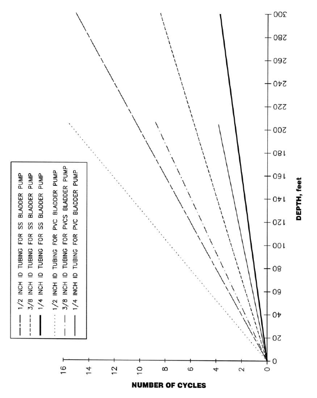
Figure 3-1 – Cycles vs. Depth
8
Section 4: System Maintenance
The Geocontrol 2 does not require a regular maintenance program.
As stated in installation and operation, this unit requires dry, moisture-free air. To
disregard will increase the likelihood of unnecessary maintenance.
9
Section 5: System Troubleshooting
Problem: Unit will not turn on.
Solution:
Check power source and cables for damage.
If using DC, verify that you have a 12 VDC power source. If on AC,
verify that you are getting a consistent 115 VAC current.
Problem: Unit turns on but cycles rapidly, no pumping.
Solution:
Charge and exhaust times not set correctly.
Check and adjust charge and exhaust cycle times (i.e., if charge time
too long and exhaust time too short, or charge time too short). Review
Section 3 for correct cycle times.
Problem: Turns on, cycles correctly but does not pump water.
Solutions:
Check for tubing kinks.
Check pressure on gauge, may be too low. Calculate based on .5 PSI
per foot (.1 bar per meter) of head and add 10 PSI (.7 bar) for friction.
If psi is good, check your exhaust flow, may be completely shut, try
turning three times to the left. (Exhaust is the brass valve).
Problem: Unit was working but quit cycling.
Solutions:
Check power source.
If power source is good, check air source.
Air source is good - have you been using clean dry air? If not contact
Geotech at 1-800-833-7958

10
Section 6: System Specifications
Model: Geocontrol 2
Maximum Ratings
Input DC Power Source 0.5-13.8 VDC
DC Current Draw 0.5 Amps
DC Input Surge Current <50 Amps
Input AC Power Source 105-130 VAC
AC Current Draw 0.1 Amps
AC Input Surge Current <15 Amps
Input AC Line Frequency 45-65 Hz
Maximum Power 15 Watts
Performance
Input Air Pressure 300 PSI (20.5 bar)
Operating Depth 0-690 Feet (0-210m)
* On Timer Range 0.125 to 30 Seconds
* Off Timer Range 0.125 to 30 Seconds
Timer Resolution 0.125 Seconds
Timer Accuracy ±0.125 Seconds
Environmental
Operating Temperature Range 32° – 158°F (0-70º C)
Storage Temperature Range -4° – 185°F (-20° to 85º C)
Position Effect 0.10% change at any angle
Vibration No change after 10G RMS
20 to 2000 Hz
Shock No change after 50Gs for 11minutes
EMI Emissions Class A
Physical
Enclosure 7 x 16 x 12 in. (18 x 41 x 30.5 cm)
Weight 14 Pounds (6.3 kg)
Enclosure Material Structural resin
* Custom timer ranges available
11
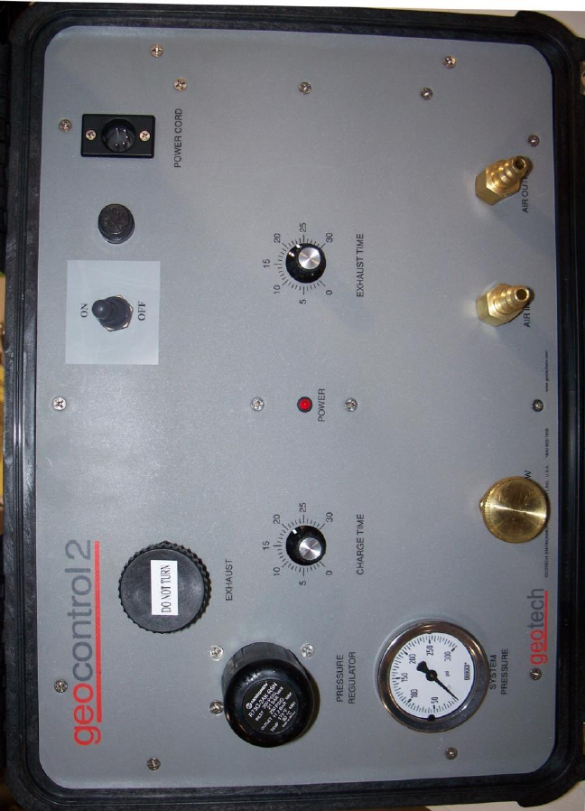
Section 7: System Schematic
Figure 7-1 – Example of Geocontrol 2 panel.
12
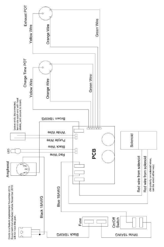
Figure 7-2 – Geocontrol 2 Wiring Diagram
13
Section 8: Replacement Parts List
Part Number Part Description
81150104 New Unit
51150064 Assy, AC Power Cord
57500008 Assy, DC Power Cord
51150038 Assy, Air Inlet Hose
51150039 Assy, Air Exhaust Hose
11150170 Manual
PPE011026 Fuse
51150048 Potted PCB

14
NOTES
15
DOCUMENT REVISIONS
EDCF#
DESCRIPTION
REV/DATE
-
Initial Release
10/18/02
1565
Added charge time ranges for varying well depths
(page 6),
Added revision history table (page 15) - SP
04/24/13
16
The Warranty
For a period of one (1) year from date of first sale, product is warranted to be free
from defects in materials and workmanship. Geotech agrees to repair or replace,
at Geotech’s option, the portion proving defective, or at our option to refund the
purchase price thereof. Geotech will have no warranty obligation if the product is
subjected to abnormal operating conditions, accident, abuse, misuse,
unauthorized modification, alteration, repair, or replacement of wear parts. User
assumes all other risk, if any, including the risk of injury, loss, or damage, direct
or consequential, arising out of the use, misuse, or inability to use this product.
User agrees to use, maintain and install product in accordance with
recommendations and instructions. User is responsible for transportation charges
connected to the repair or replacement of product under this warranty.
Equipment Return Policy
A Return Material Authorization number (RMA #) is required prior to return of any
equipment to our facilities, please call our 800 number for appropriate location.
An RMA # will be issued upon receipt of your request to return equipment, which
should include reasons for the return. Your return shipment to us must have this
RMA # clearly marked on the outside of the package. Proof of date of purchase
is required for processing of all warranty requests.
This policy applies to both equipment sales and repair orders.
FOR A RETURN MATERIAL AUTHORIZATION, PLEASE CALL OUR
SERVICE DEPARTMENT AT 1-800-833-7958.
Model Number: ________________
Serial Number: ________________
Date of Purchase: ________________
Equipment Decontamination
Prior to return, all equipment must be thoroughly cleaned and decontaminated.
Please make note on RMA form, the use of equipment, contaminants equipment
was exposed to, and decontamination solutions/methods used. Geotech
reserves the right to refuse any equipment not properly decontaminated.
Geotech may also choose to decontaminate the equipment for a fee, which will
be applied to the repair order invoice.

Geotech Environmental Equipment, Inc.
2650 East 40th Avenue Denver, Colorado 80205
(303) 320-4764 ● (800) 833-7958 ● FAX (303) 322-7242
email: sales@geotechenv.com website: www.geotechenv.com
