Geotech Sipper Installation And Operation Manual Geotech_Sipper
User Manual: Pdf Geotech_Sipper
Open the PDF directly: View PDF ![]() .
.
Page Count: 48
Rev 01/05/2015 Part # 16550176
Geotech Sipper
Installation and Operation Manual
0
1
Table of Contents
DOCUMENTATION CONVENTIONS ................................................................................................................ 2
Section 1: System Description ........................................................................................................................... 5
Section 2: System Installation ............................................................................................................................ 7
Section 3: Timer/Cycle Settings and Display Descriptions .............................................................................. 16
Section 4: System Operation ........................................................................................................................... 24
Section 5: System Maintenance....................................................................................................................... 27
Section 6: System Troubleshooting ................................................................................................................. 32
Section 7: System Specifications ..................................................................................................................... 35
Section 8: System Schematics......................................................................................................................... 37
Section 9: Parts and Accessories .................................................................................................................... 41
The Warranty .................................................................................................................................................... 45

2
NOTE
DOCUMENTATION CONVENTIONS
This manual uses the following conventions to present information:
An exclamation point icon indicates a WARNING of a situation or condition
that could lead to personal injury or death. You should not proceed until you
read and thoroughly understand the WARNING message.
A raised hand icon indicates CAUTION information that relates to a situation or
condition that could lead to equipment malfunction or damage. You should not
proceed until you read and thoroughly understand the CAUTION message.
A note icon indicates NOTE information. Notes provide additional or
supplementary information about an activity or concept.
WARNING
CAUTION
3
In order to ensure your Solar Sipper has a long service life and operates
properly, adhere to the following cautions and read this manual before use.
Controller power input source must not exceed specified ratings.
Controller may not operate properly with wiring not supplied by
manufacturer.
Avoid spraying fluid directly at controller.
Never submerge controller.
Avoid pulling on wires to unplug controller wiring.
Avoid using a controller with obvious physical damage.
To prevent damage, DO NOT drop the controller.
WARNING
Do not operate this equipment if it has visible signs of significant physical
damage other than normal wear and tear.

4
The following applies only to users in European countries:
This product is designated for separate collection at an appropriate collection point. Do
not dispose of as household waste.
For more information, contact the seller or the local authorities in charge of waste
management.
Notice for consumers in Europe:
This symbol indicates that this product is to be collected separately.

5
Section 1: System Description
Function and Theory
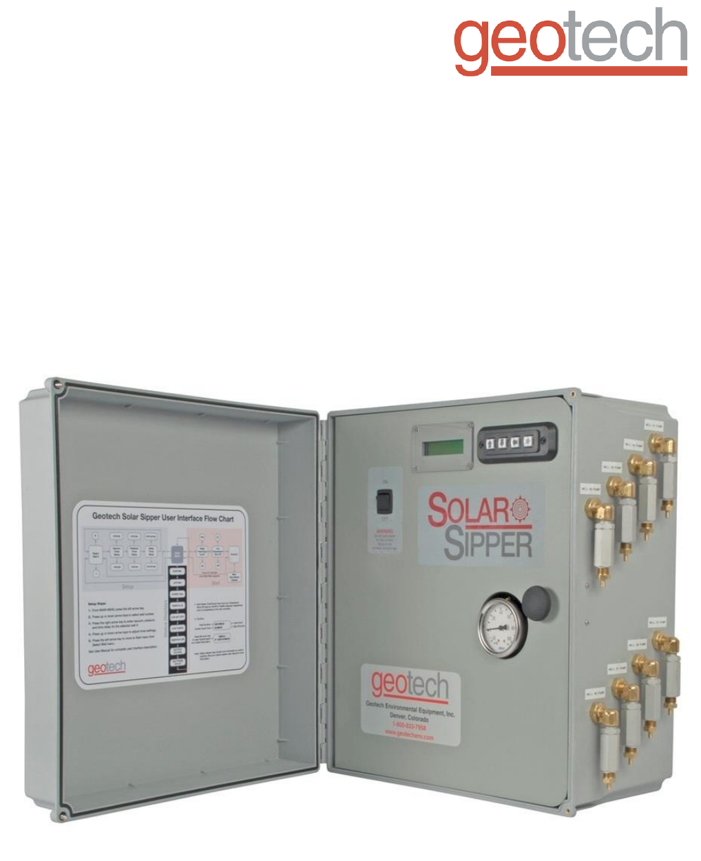
The Geotech Solar Sipper (Sipper) is a unique solar powered hydrocarbon recovery system used for
operating an active downwell remediation pump with an attached Skimmer. It is designed for
applications where electrical power is not available or not economically feasible. Electrical power used
to run the Solar Sipper is generated on-site by solar panels. The internal compressor is capable of
producing up to 20-inches Hg vacuum and 100 psig pressure. This alternating vacuum/pressure
process allows the user to recover a wide range of fluids, from very viscous to ultra light Non-Aqueous
Phase Liquid (NAPL), from depths as deep as 180 feet below ground surface. Optional multiple
channel controllers can operate up to eight pumps in separate recovery wells.
The standard Solar Sipper uses a 12VDC, 75 amp hour battery that is charged with an attached 85
Watt solar panel. Systems can be expanded to utilize several solar panels and larger capacity batteries.
Multiple channel controllers can be implemented in areas where there are multiple recovery wells within
close proximity of each other. Up to eight separate wells can be operated per controller.
In general, Geotech recommends a maximum distance of 500 feet (including the well depth) between
the Sipper controller and the pump. Longer runs can be accommodated but are not recommended.
Careful consideration must be given to additional power requirements as well as protecting the tubing
from damage. In certain situations, multiple controllers with separate solar panels and batteries may be
a better solution on sites of a relatively larger area. The optional AC Sipper is designed for locations
where line voltage is readily available.
Ease of Deployment
The Solar Sipper can reduce overall project costs and dramatically improve deployment as follows:
Reduces the time and cost for a power line to be run to a site.
Eliminates the need for electricians to do install work and permitting.
The simple and safe low voltage system can be installed without special training or licensing
and requires minimal experience.
No trenching or transformer equipment is required.
Relocating equipment to follow a plume or to adjust to new site characterization information is
fast and easy.
Sipper Operation
The Sipper controller has an integrated programmable cycle timer for controlling the internal
compressor vacuum, pressure, and the time between cycles. This allows the user to calibrate the
Sipper to run at its most efficient rate based on the downwell product recharge rate, product viscosity,
and Skimmer depth.
In this manual, a stainless steel pump with Skimmer, or any other downwell
assembly used with a Sipper system, will be referred to as a pump. A chart
containing a range of viscous products can be found in Section 4.
6
During the vacuum timer cycle, vacuum is applied to the air line tubing, stainless steel pump, and
intake; helping the product to flow through the oleophilic/hydrophobic mesh screen and into the pump
cavity. When the programmed vacuum time expires, the system initiates the pressure timer cycle.
During the pressure timer cycle, air is compressed into the air line tubing, evacuating the product from
the pump. Once the programmed pressure time has expired the compressor shuts down and the
system initiates the programmed delay timer. Upon expiration of the delay timer the process is
repeated.
On multiple channel Sippers the vacuum, pressure, and delay cycles are set individually per well. This
accommodates recharge and recovery rates unique to individual wells on the same site. A variety of
timer setups can be implemented to maximize recovery. For example; different wells can be pumped
more or less often than others to maximize recovery. The programming prioritizes the pumps so one
pump is operational at a time.
The Sipper controller has several feedback data recording mechanisms that can be used to gauge
effectiveness of the remediation system. Two cycle counter screens are available, one records the total
lifetime cycles of the controller, the other counter is resettable by the user for monitoring purposes.
These cycle counts can be compared with total recovered fluid to determine how much fluid is being
recovered per pump cycle. There is also a runtime clock which only increments when the battery is
charged and when the system is operating. This clock can be compared with actual recorded
deployment time to determine if more solar panels are required to keep the system up and running.
More on this can be found within the troubleshooting section of this manual.
The Solar Sipper Controller is dependent upon the annual average solar resources, which can vary
from region to region. Geotech can assist in determining how much potential recovery can be expected
depending on where the site is and how many solar panels will be required. More information about
solar panel location can be found in Section 2.
Recovery Rates
The available solar energy and number of solar panels will determine how quickly available product can
potentially be recovered. Recovery will ultimately be limited by the recharge rate of the product layer in
the well. Repeatedly removing the entire product layer can reduce fluid conductivity to the well and in
turn reduce recovery rates overall.
When the product layer is completely depleted, air is invited into the well screen and surrounding sub
surface soil or strata. This air can act to block fluid conductivity as well as to promote bacteria growth
and breakdown of the product being recovered. This will eventually ‘clog’ the fluid path to the well and
so reduce the product layer recharge rate. Geotech recommends recovering smaller amounts of
product more frequently. This will promote continued fluid conductivity to the well.
In the event that the intake screen, discharge line or check valve should get blocked, remove the
Skimmer and clean the intake cartridge and connections as described within the System Maintenance
Section of the Geotech Pump and Skimmer Assembly Manual.
Geotech offers a variety of tools and training to provide you with information on properly maintaining
your Sipper system and on obtaining a recharge rate. Contact Geotech to discuss your specific
application in detail.

7
Section 2: System Installation
Solar Sipper systems can be modularized and delivered on pallets that can be quickly and easily
deployed. This can simplify deployment where existing concrete pads or other infrastructure, which
could serve as a mounting base for the equipment, do not already exist. It is more efficient to have the
equipment ready for immediate deployment upon delivery. Geotech also offers training on proper
installation of your Sipper system at its Denver, Colorado manufacturing headquarters.
Installation of the Solar Sipper
Because the solar array and battery have live voltage, caution should be exercised when dealing with
either item. Special attention is required to ensure that the correct polarity is observed when making
connections to the battery and solar panels. Even though the system runs on a safe low voltage, the
battery is capable of storing very large amounts of energy from a low impedance source. This can pose
a fire and burn hazard.
Special care must be taken to avoid shorting out (making contact between both positive and negative
terminals) the battery with any tool or bare grounding wire. Leave protective caps in place and only
terminate a wire when you have verified it is the correct polarity (positive or negative.) The system can
tolerate reverse polarity connections as long as the ON/OFF switch remains in the OFF position.
Solar Panel Location
The annual average solar resources will vary from region to region. Geotech can assist you in
determining how much recovery you can expect (depending on where the site is located in the world)
and how many solar panels will be required. The site latitude will determine seasonal differences in
recovery rate. For example, in the northern hemisphere recovery rates will decline over the winter
months and increase during the summer months.
Sipper installations are to be performed by qualified personnel. If you are not
familiar with electrical power equipment, contact a qualified technician to assist
you with your installation.
AC Sipper Controller - Ensure the main line is turned off at the breaker and
that the ON/OFF switch for the control panel is in the OFF position before
proceeding with ANY external or internal wiring.
The standard Geotech Sipper is designed for installation and operation in a non-
hazardous, non-classified location with intrinsically safe extension into a hazardous
classified location. Geotech does not determine classification of a location.
Classification of location is subject to local jurisdiction enforcement of NFPA
regulations. All installations should be performed in accordance with NEC.
FPN: NEC 2008 section 500.5 (A) classification of locations says:
Through the exercise of ingenuity in the layout of electrical installations for
hazardous (classified) locations, it is frequently possible to locate much of the
equipment in an unclassified location and, thus, to reduce the amount of special
equipment required. FPNs are informational only and are not enforceable as
requirements of the NEC.
8
Other location specific information must be considered as well. Large objects like trees or building
structures can block sunlight from reaching the solar panels. In such cases the solar panels can be
mounted atop poles or other available structures to maximize sun exposure. Other unpredictable
factors, such as more or less cloud cover, must also be considered when estimating potential recovery
rates.
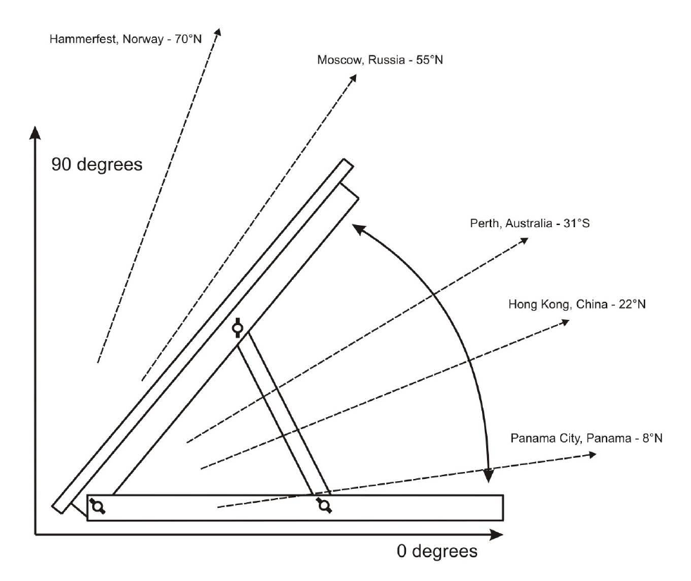
Pick a location with a maximum exposure to sunlight. Avoid shadows, especially during the middle of
the day. Orient the module so that the surface will receive the maximum sun exposure over the year for
your particular site. The general guideline for positioning is as follows:
Solar panels should face south in the northern hemisphere and north in the southern
hemisphere.
A solar panel's angle should be set to the equivalent of your location’s latitude; plus 15 degrees
during the winter or minus 15 degrees in the summer.
For example; Denver, Colorado’s latitude is around 39 degrees. In winter the panel should be raised to
54 degrees (from 0°) for optimum sun. For permanent installations, setting the panel angle equal to
your latitude will suffice.
Figure 2-1 – Side view of solar panel assembly.

9
Mounting the Control Panel
The enclosure for the Solar Sipper allows the customer the option to place the control panel in a
convenient and accessible location. If possible, it is recommended the control panel enclosure be
placed out of the direct path of weather and sun light whenever possible. If power is to be plumbed to
the enclosure, then all conduit runs are to be rigid metal and grounded to an equipment conductor
common for non-current carrying metal parts.
The enclosure also needs to be elevated above the height of the well heads to prevent kinks to the
exhaust line and the various air lines to the pumps. When selecting a location for your Sipper controller,
consider the placement of air lines to and from the unit to prevent kinks, damage, or the buildup of fluid
in sagging lines.
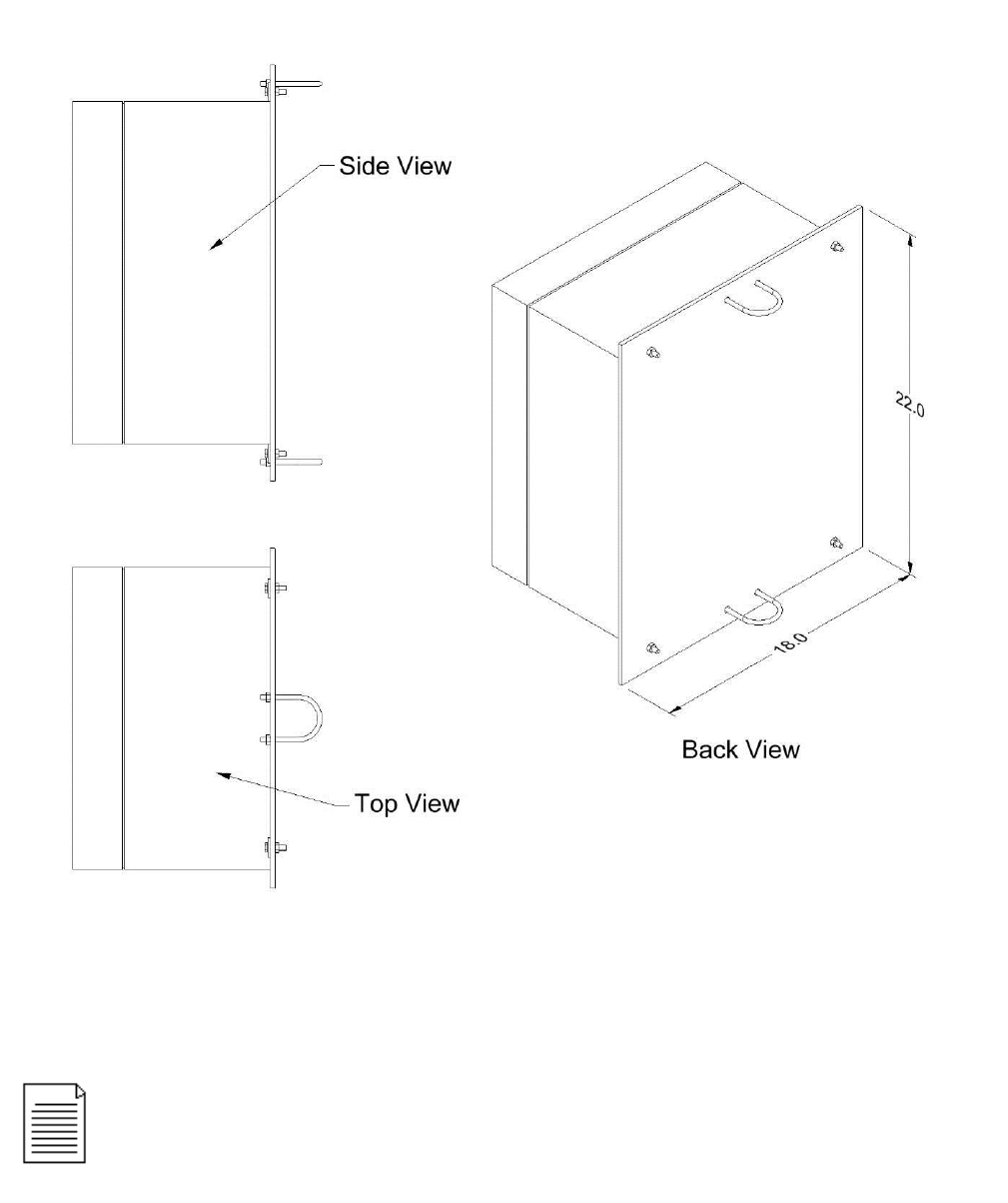
Figure 2-2 is an example of a Sipper control panel mounted to a back panel with 2” u-bolts. Using a
back panel will support the enclosure while giving you the ability to pole mount the unit.
NEVER drill mounting holes from, or through the inside of the enclosure when
attaching the controller to another surface. It is advised that you mount the
enclosure to a strong back panel, using the brackets supplied, before attaching
the unit to a pole or other surface.
10
Figure 2-2 – Example of Sipper enclosure mounted to back panel with additional u-bolts for pole
attachment.
Diagram is an example only. Mounting hardware shown is available through
Geotech – see Section 9: Parts and Accessories . Always avoid drilling
through the enclosure body.
11
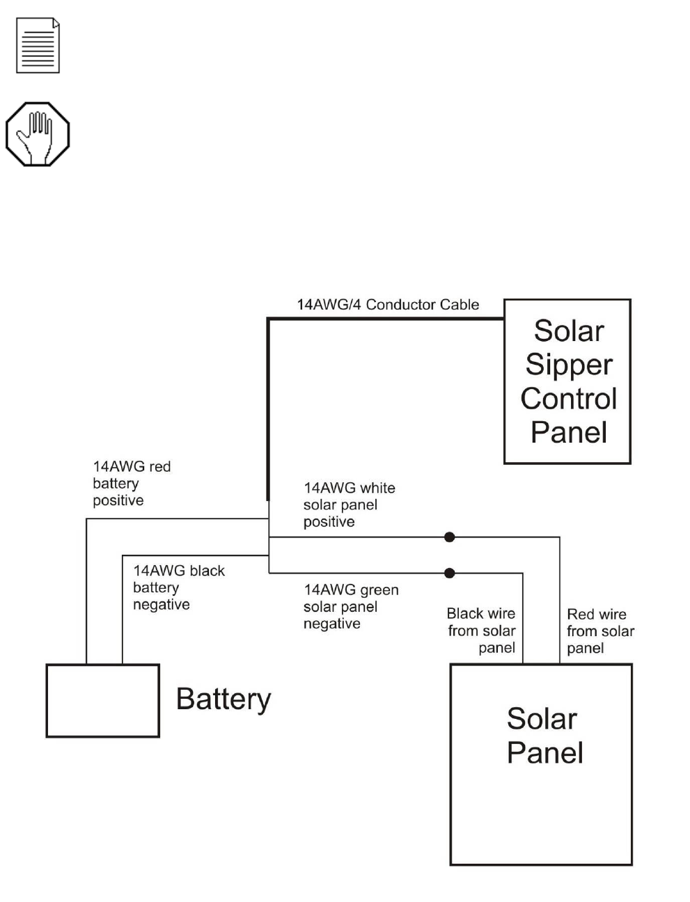
Solar Sipper Wiring
Solar Sipper systems are supplied with 25 feet of 4 conductor 14 AWG cable. DO NOT extend or add
to the length of this power cable. After ensuring the power switch on the controller is set to OFF, make
all external power connections as shown in Figure 2-3.
Figure 2-3 – Example of external wiring for a Solar Sipper system.
A full size, internal wiring diagram accompanies new Sipper controllers when
delivered (pg. 39 or 40). Also, operational flow charts are affixed to the inside door of
each controller (pg. 22). Contact Geotech for a replacement wiring diagram as
needed.
Before installing the solar panel for the Solar Sipper controller, cover the array with
an opaque material before making your wiring connections. This will prevent the
modules from producing electricity while making the connections and reduce the
risk of sparks. Observe safe electrical practices at all times. Make connections in
well-ventilated areas free from flammable gas vapors and open flames.
12
Adding Additional Panels
During the winter months when the sunlight decreases, additional solar panels can easily be added to
the Solar Sipper system. The addition of one or two more panels will boost production during the winter
months, with fewer hours of sunlight, and the excess energy will not be used in the summer. As a
general guideline, up to 4 – 80W panels may be connected to the Solar Sipper System.
To wire an additional panel to the system configuration, use the wiring diagram shown in Figure 2-3.
Using insulated wire nuts, connect all red wires (positive) from the solar panel(s) to the white wire on
the Sipper controller, then connect all black wires (negative) from the solar panel to the green wire on
the Sipper controller.
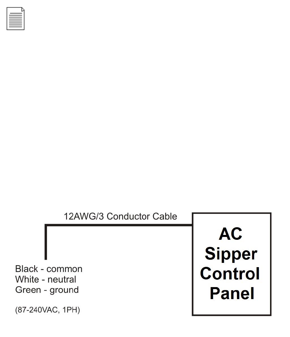
AC Sipper Wiring
AC Sipper systems are supplied with 25 feet of 3 conductor 12 AWG cable. DO NOT extend or add to
the length of this power cord. After ensuring that the power switch is set to OFF, make the power
connections using the following wiring diagram:
Figure 2-4 – Example of external wiring for a AC Sipper system.
A brand new or replacement battery may not be fully charged. This will cause the
Solar Sipper to go into low voltage shutdown when initially powered up. Allowing the
battery to fully charge before deployment will accelerate initial startup. Otherwise, the
system could take several days to begin operating depending on the number of solar
panels used and the amount of sun exposure. If freeze conditions exist, insulate your
battery. A frozen battery will not charge until it is thawed. See Section 3 for minimum
voltage requirements.

13
Always double-check that live voltage is not present at terminals to be worked on. Shut off all circuit
breakers and disconnects and use a volt meter or voltage detector to verify power has been removed.
Verify the meter is functional by turning the power on and off once or twice before proceeding. Only
proceed wiring to AC power terminals when you are certain it is safe.
Grounding
If no earth ground terminal is available, then a ground spike must be installed. Connect all non-current
carrying metal parts to the common ground. An earth ground terminal can be purchased from Geotech
with your Sipper. See Section 9 for a complete listing of available accessories.
Connect All Tubing Runs
Lay out all tubing lengths to the well heads and secure the ends to the hose barbs using adequate
clamps. Geotech can supply your Sipper system with a variety of tubing and clamp choices. See
Section 9 for a list of available parts.
When installing your tubing runs, DO NOT hang or situate air lines in such a way that they are left
sagging with low points in which fluid can collect. Avoid sharp bends which can kink your line.
It is recommended that air lines and hoses be protected. Conduit or PVC pipe can provide protection.
However, check local and state regulations regarding fuel transmission lines before installing the
product discharge lines.
The last line connected will be from the compressor air intake and exhaust port, on the side of the
Sipper controller, to the top of the recovery tank. The Sipper controller will use this line as an air source
and as a failsafe should product be vacuumed into the compressor and solenoids.
Deploy the Stainless Steel Pump and Skimmer
The oleophilic/hydrophobic mesh screen discriminates between water and product when it is properly
“conditioned”. To condition (or prime) a cartridge, use a soft brush and coat the mesh screen with the
same or a like product found in the well. DO NOT use baby oil, lamp oil or other similar dyed, perfumed
or hydrogenated oils.
Dangerous shock and fire hazard will exist with any line/mains voltage wiring
termination. Sipper installations are to be performed by qualified personnel. If you
are not familiar with electrical power equipment, contact a qualified electrician to
assist you with your installation.
Special care must be taken not to damage the float or screened intake before or
during deployment. Use a scrap piece of plywood or card board (something that
can be properly disposed of if contaminated) on which to set the pump and
Skimmer assembly on instead of the ground.
Read User Manual “Geotech Pump and Skimmer Assembly” (P/N 16550181)
for more information on Skimmers, their parts, and functions.
If there is a chance the Sipper system will be exposed to freezing conditions (see
temperature range in Section 7, System Specifications), then it is suggested all
discharge lines, including the battery, be insulated or your system be kept within a
temperature controlled shelter during operation.
14
Good site characterization is important for successfully placing the pump and Skimmer assembly at the
optimal level in the well. If seasonal or tidal fluctuations in the groundwater table exceed the travel of
the Skimmer, periodic manual adjustment may be required. Otherwise, and in most cases, the Skimmer
should be placed such that its center of travel is at the nominal ground water level (refer to Figures 8-1
and 8-2.) If the groundwater table level is unknown, Geotech can provide you with an oil/water interface
probe to determine the current water level and product layer thickness. Contact Geotech for more
information on this important device for site characterization.
Using a separate measuring tape, measure from the middle of the center rod on the Skimmer (also the
center of vertical travel of the Skimmer intake float) to where the discharge tubing will exit the well cap.
Using contrasting tape or chalk, mark the discharge tubing at this point. The lower end of the Skimmer
assembly will displace fluid in the well causing the fluid level to rise initially. The float travel will
accommodate this rise in fluid level. The fluid level will take some time to return to normal depending on
permeability/hydraulic conductivity of the formation surrounding the well.
In some cases the initial displacement of fluid can ‘displace’ the product layer from the well and back
into the formation. This can happen especially where there is low fluid conductivity surrounding the well.
It’s best to trust the site characterization data and test with a Geotech oil/water interface probe to verify
that the float is at the expected level within the well. If you cannot access an oil/water interface probe,
or are deploying pumps in a 2” well without enough clearance for the probe, you can judge productivity
by how much product is in the recovery tank.
Implementing the use of a Geotech oil/water interface probe and keeping a record of the water level
and product layer thickness is recommended for maintaining optimal system performance.
Product Recovery Tank
A product recovery tank is not provided with the Solar Sipper system. A tank, preferably a 55 gallon
drum or larger, must be provided by the customer with the following attributes:
A ¾” or 2” threaded bung opening in which the Tankfull probe will be attached.
A product inlet opening for the system discharge hose.
A vent opening.
A fluid discharge fitting for draining.
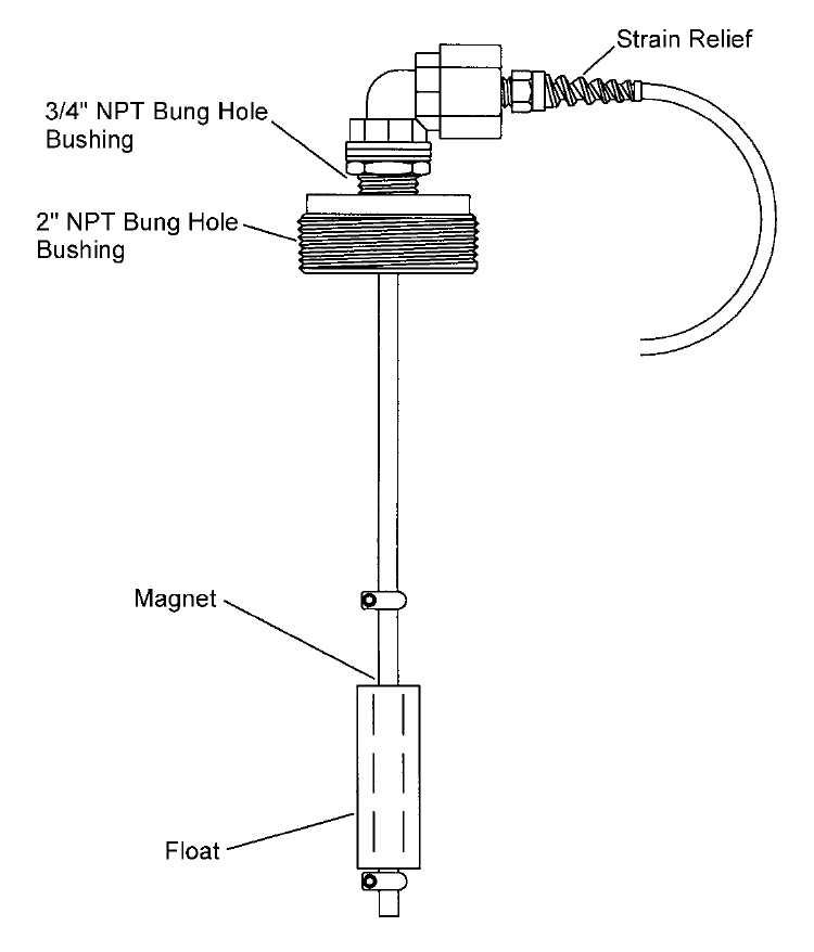
A Tankfull probe, shown in Figure 2-5, is provided with new Solar Sipper systems. Additional probes
can be ordered from Geotech. See Section 9, Parts and Accessories.
Simply guessing or feeling for placement of the Skimmer within the well column is
a recipe for failure. Use a Geotech oil/water interface probe to measure water level
and product layer thickness, then record this information to your
remediation/characterization log.
Read User Manual “Geotech Pump and Skimmer Assembly” (P/N 16550181) for
more information on Skimmer operation, float travel, and other dimensions.
Ensure that the compressor air intake and exhaust air line is secured to the top of
the recovery tank prior to turning on the Sipper controller. Do not allow the end of
this tubing to reach the product already collected.
15
Figure 2-5 – Example of Tankfull Probe

16
Section 3: Timer/Cycle Settings and Display Descriptions
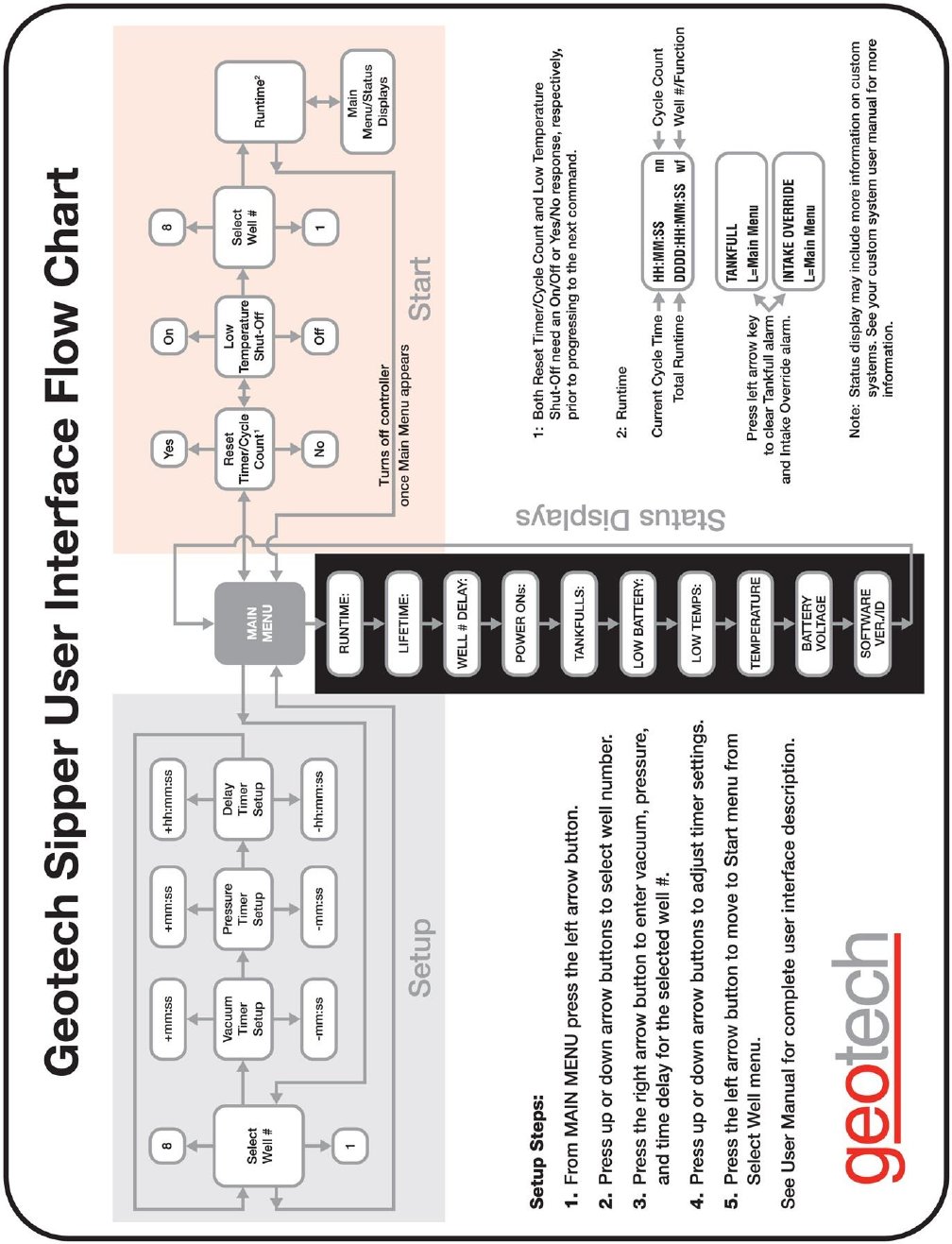
This section describes the display functions and the operation of the Sipper controller. Each controller
comes with a User Interface Flowchart (shown in Figure 3-1) inside the enclosure lid. The flowchart,
used in conjunction with the arrow buttons on the control panel (shown in Figure 3-2) is designed to
provide the following operator functions:
Setting the cycle time (vacuum, pressure, and delay) for each pump and Skimmer assembly.
Initiating the run time for Sipper system.
Accessing system status and diagnostic displays.
The following pages show examples of all controller displays and a brief description of their function.
Contact Geotech Technical Sales for any assistance in operating your Sipper controller.
Setup Displays
Once the Sipper system has been installed and all wiring to the controller is complete, turn on the main
power switch to the Sipper controller. The unit will perform a quick internal self check and memory
configuration, after which the Main Menu will appear on the display as follows:
Geotech Sipper
L=Setup R=Start
If the internal self check fails then the screen will display the appropriate alarm condition. See Alarm
(condition) and Fault Displays on page 21.
The first task will be to set your timer/cycle settings using the Setup displays. The Setup displays allow
you to select each pump individually and assign a unique cycle time (vacuum, pressure, and delay) for
the pump based on the performance of the well it resides. (See Section 4 on System Operation for
more information on evaluating the appropriate cycle time.) The cycle time range for each function is as
follows:
Vacuum 0 second minimum to a 30 second maximum.
Pressure 30 second minimum to a 4 minute maximum.
Delay 30 second minimum to a maximum of 24 hours.
To access the Setup displays, press the left arrow button. The following display will appear:
Select Well
n L=Main Menu where n = the well number
Using the up and down arrow buttons, select the well number for which cycle time you wish to set (the
number of wells per Sipper controller can be between 1 and 8, depending on the configuration.) After
selecting a well number, press the right arrow. The Vacuum display will appear:
Set Vacuum mm:ss
00:10
Factory default for all timer settings, for each pump installed, are: 1 second of
vacuum, 30 seconds of pressure, 5 minutes of delay.
Please set timers based on site requirements.

17
Using the up and down arrow buttons, scroll to the time required for the vacuum phase of the cycle,
then press the right arrow button. The Pressure display will appear:
Set Pres mm:ss
00:30
Using the up and down arrow buttons, scroll to the time required for the pressure phase of the cycle,
then press the right arrow button. The Delay display will appear:
Set Del hh:mm:ss
00:05:00
Using the up and down arrow buttons, scroll to the time required for the delay time of the cycle, then
press the right arrow button one more time. The system will return you to the Select Well display from
which you can set the cycle time for any remaining wells.
After all cycle times have been entered, press the left arrow button (while on the Select Well display) to
return to the Main Menu.
Start (Runtime) Displays
The Start (Runtime) displays allow you to:
Reset the cycle count and runtime (see also “Runtime” display under System Status).
Turn ON/OFF the low temperature shutoff.
Set the well number to start pumping with.
Start and activate the preset cycle times for all the pumps attached.
Once the Sipper has been started (Runtime activated for all pumps), you can do one of two things:
Press the down arrow button (to review and page through the System Status displays).
Press the left arrow button (which will complete the current pump’s cycle time, then return you to
the Main Menu).
To start the Solar Sipper and activate the runtime to all pumps attached, proceed as follows:
From the Main Menu, press the right arrow button. The following display will appear:
Reset Timer?
YES
The Reset Timer display allows you to clear the cycle count and runtime shown in both the system
Runtime and the Status Runtime displays. Use the up and down arrow buttons to change this setting to
YES or NO then press the right arrow button for the next screen.
If the left arrow button is pressed at any time while setting the vacuum, pressure,
and delay times, the new or adjusted setting entered will not be retained. To lock in
the cycle time entered, press the right arrow button.

18
Low Temp ShutOff
OFF
The Low Temp Shutoff display (when enabled), will shutdown the Sipper controller at 0°C (32°F). Since
the Sipper system primarily operates above ground, this feature prevents the controller from operating
during a time when product lines could freeze. The Sipper will automatically restart at a temperature of
3.3°C (38°F). Use the up and down arrow buttons to change this setting to ON or OFF.
Start with Well
n
Where n = the number of well (between 1 and 8).
The Start with Well display allows the user to choose the well to pump first upon startup. The well
number selection is limited by the number of channels in use. Use the up and down arrow buttons to
change the well number to start with.
Once all cycle times have been entered and the previous three screens have been entered, press the
right arrow button one more time to start the Sipper. The Sipper controller will begin cycling the first
pump in the series and give you the following Runtime display:
00:00:00 nn
0000:00:00:00 wf
Where nn = the total number of cycles since activation (1 to 99999)
w = the well number currently activated
f = the pump function currently in progress (V for vacuum, P for pressure, D for Delay)
After verifying all pumps are running, you can re-verify the System Status at any time by pressing the
down arrow button during operation. After viewing the status displays, leave the last display as is and
the system will automatically return to the Runtime display.
Stopping Sipper Operation (Runtime)
If further adjustments are needed to the cycle time of a particular pump or when the Sipper controller
needs to be shut down, press the left arrow button once during the Runtime mode. If the Sipper is
currently in the middle of a pump’s cycle time, it will give you the following display:
Please wait for
Main Menu mm:ss
This display will show how much time is left with the current well. Once the pressure phase of the cycle
completes, the unit will stop all processes and display the Main Menu. Further adjustments can then be
made to the pump cycle times, information retrieved from the Status Displays, or the unit can be turned
off for service.
The Sipper system is now ready for Start up (Runtime). However, before proceeding,
thoroughly read Section 4 on System Operation to better understand the required
timer adjustments needed for the product being recovered.

19
System Status and Diagnostic Displays
While at the Main Menu, system Status Displays can be viewed by pressing the up and down arrow
buttons. These displays contain a variety of information which can be used to record important activity
to your Solar Sipper system. These displays can also be viewed during the system’s Runtime by
pressing the up or down arrow buttons at any time during operation. After viewing a status display,
leave the system as is. Within 20 seconds the Main Menu (or Runtime display) will reappear.
The following status displays (as shown on the Interface Flowchart) will appear with each press of the
down arrow button. The following pages will show you an example of each status display (as they
appear) followed by a definition and use of the display.
Runtime: nn
0000:00:00:00
The Runtime display shows the number of completed cycles (for all pumps attached) along with the
total runtime of the Sipper system since the controller was last reset. These values can be cleared with
the Reset Timer display during initial startup.
Lifetime: nn
0000:00:00:00
The Lifetime display shows the total number of completed cycles (for all pumps attached) along with the
total runtime of the Sipper system since the unit was first put into service. Lifetime values cannot be
cleared. Many of the status displays will retrieve their time stamps from this display when something
occurs, such as the last time there was a low battery, the last time a tankfull alarm was activated, the
last time a low temp shutoff occurred, etc.
Well n Delay:
hh:mm:ss
Where n = the Delay time for the well number shown (between 1 and 8) followed by the time.
The Well Delay display shows how much delay time is left for each well assigned to the Sipper. Use the
down arrow button to page through all eight displays. Channels not in use will have a display value of 0.
Power Ons: nn
0000:00:00:00
The Power Ons display shows the total number of times the unit has been powered ON/OFF (since
being put into service) along with a time record of when the unit was last powered on.
The value “nn” within this section can represent a count anywhere from 1 to 99999.
20
Tankfulls: nn
0000:00:00:00
The Tankfulls display shows the total number of times the tankfull alarm has been activated (since
being put into service), due to a full recovery tank, along with a time record of when the unit last had a
tankfull alarm. This display can be used to determine how long it takes the recovery tank to fill or if a
larger tank is required.
Low Batts: nn
0000:00:00:00
The Low Batts display shows the total number of times the unit has experienced a low battery condition
(since being put into service) along with a time record of when the unit last had a low battery condition.
This display can help in evaluating battery usage (in comparison to how much product is being
recovered) showing the need for either a cycle adjustment or the need for additional solar panels. It can
also help in determining if the battery is losing its ability to maintain a charge.
The Solar Sipper controller is designed to shut itself down when the battery voltage reaches 11.4V and
will resume operation when the battery charge reaches 12.1V. The Solar Sipper is designed to charge
the battery to a maximum of 14.5V. The system will also display a low battery condition when the
battery becomes frozen. Allow the battery to thaw prior to re-charging.
Low Temps: nn
0000:00:00:00
The Low Temps display (when Low Temp Shutoff is enabled during the Start up process) shows the
total number of times the unit has experienced a low temperature condition (since being put into
service) along with a time record of when the unit last had a low temperature condition. A low
temperature shutoff (when enabled) will occur at 0°C (32°F).
Temperature:
nnC xxx
The Temperature display shows the current temperature of the unit in Celsius followed by a diagnostic
number.
Battery Voltage:
nn.nV xxxx
The Battery Voltage display shows the current battery voltage for the Sipper system followed by a
diagnostic number.
Ver: v.v Wls: n
ID: iii SS: sss
This final display contains the following information for the Sipper controller:
Where v.v = software version
n = number of wells for which the unit was designed (1 thru 8)
iii = controller ID
SS = Signal Strength (used on wireless Sippers)
sss = signal strength in a numeric value (used on wireless Sippers)

21
Alarm (Condition) and Fault Displays
Besides low battery, low temperature, a blown fuse, or no battery connection, only a few other
conditions will cause the Sipper controller to shut down. The following display alarms will require
attention from the user before the system can be restarted:
TANKFULL
L=Main Menu
The TANKFULL display will appear when the recovery tank becomes full or when there is damage to
the tankfull probe cable. When this display appears the Sipper controller will stop all activity until the
alarm is addressed. To clear the alarm and restart the Sipper controller, press the left arrow button (to
obtain the Main Menu), then initiate the Start up process.
INTAKE OVERRIDE
L=Main Menu
The INTAKE OVERRIDE display will appear when the float on the Intake Float Switch (located on the
side of the control box) rises. This will usually happen when product is pulled through the air line from
the well (due to an excessive vacuum time or when a directional solenoid becomes stuck on the
compressor) or from an accumulation of moisture during operation. See Section 6, Trouble Shooting
procedures, for information on resolving an Intake Float Switch alarm.
When the INTAKE OVERRIDE display appears, the Sipper controller will stop all activity until the alarm
is addressed. After draining the Intake Float Switch and clearing all effected lines, clear the alarm and
restart the Sipper controller by pressing the left arrow button (to obtain the Main Menu), then initiate the
Start up process.
Battery Fault
Check Cables
The Battery Fault display will appear when the voltage on the battery cables is 14.7VDC or greater.
This may occur if the solar panel has been miss-wired to the battery input cables. This display will also
appear if an overcharged battery has been installed. In any case, when this display is shown, turn the
unit off and disconnect all voltage sources immediately. Review Solar Sipper Wiring on page 11.
Contact Geotech with any questions on wiring and installation.
PCB Damage
On rare occasions the following display may appear:
Bad display val:
The Bad Display Value message will only appear when damage has occurred to the PCB within the
Sipper controller. Should this display appear, contact Geotech about the fault. Inform the Geotech
Technical Sales Representative of all conditions (weather, temperature, vibration, etc.) and when the
fault occurred. A fault message of this kind will usually require the unit be sent to Geotech for
diagnostics and repair.
You may also need to clear the air line by setting the vacuum to 0 and allowing the
pressure cycle to push any residual fluid out of the line and into the pump reservoir.
See Section 6, Trouble Shooting, for more information.
22
Figure 3-1 – Flowchart of User Interface Label
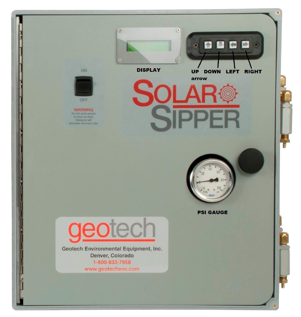
23
Figure 3-2 – Example of Solar Sipper front panel.

24
Section 4: System Operation
Establishing the Product Recovery Cycle Time
The first thing to consider will be a product recovery rate target. The maximum product amount that can
be recovered is determined by the recharge rate of each individual well. You can size and adjust your
system for optimal recovery rate potential based on the parameters obtained from the well.
The best measure of success is the average measured recovery of fluid in the recovery tank, over a
specific time frame, compared to the recovery rate target. Due to seasonal and weather related
variability in available solar energy it may be very difficult to schedule site visits to coincide with the
system pumping product. If observation of the system in action is desired, schedule a visit in the mid
afternoon. Otherwise, record your cycle counter value and total run time and compare these with the
amount of product recovered.
The vacuum cycle pulls the product into the pump housing. The system compressor will then switch to
pressure mode. The compressor is capable of providing up to 100 PSIG pressure to the pump and the
discharge line. The pressure cycle pushes the intake valve shut and forces the product past the
discharge valve and up the discharge line to the surface.
It is important that you verify that all product is being pushed out of the pump housing before the next
vacuum cycle begins. If the vacuum time interval is set too long, or the pressure cycle set for too short
of a period, it is possible for the pump to overfill and for the product to be pulled up the air line and into
the Intake Float Switch. If this happens, set the vacuum time back to 0 seconds and the pressure to 30
seconds and evacuate all the fluid from the float switch housing. After the system is clear of excess
fluid, try setting the vacuum time to a lower setting and increase your pressure time to a higher setting
for better operation. It’s better to start with a higher pressure and lower vacuum setting and adjust over
time.
The standard stainless steel pump is capable of holding .2 gallons (750 ml) or 46 cubic inches of fluid
per cycle. That translates into over 14 inches of product layer in a 2 inch well and about 3.5 inches of
product layer in a 4” well. This represents the minimum product layer thickness required to achieve one
full pump housing of product per cycle. Even if there is that much product in the well, it is not advisable
to pump the product layer all the way down. See Recovery Rates (pg. 6) in Section 1 for further
explanation.
If Sipper system is to be deployed in humid conditions, it is recommended to install
the optional Desiccant Dryer to prevent frequent solenoid maintenance. See Section
9: Parts and Accessories for part information.

25
Initiating the Sipper Runtime
Once Runtime has been started, the Solar Sipper system will initiate the vacuum cycle for well number
one (or whichever well is selected to start), complete that well’s cycle, then continue on through any
remaining wells as per the individual user input settings.
As mentioned before, the amount of product per cycle will depend on how much product is in the well.
Also, depending on the viscosity of the fluid and temperature, the product layer could have a somewhat
slower recharge rate. This can make it difficult to determine what the best cycle times should be for a
particular site.
If you have a less than one gallon per hour recharge rate, then simply increase the delay time
proportionally. For example; if your product recharge rate is ½ gallon per hour, double the delay time.
After you account for more or less recharge rate, you can account for additional tubing and
depth to fluid.
Add 2 seconds per 25 feet of tubing for vacuum and 3 seconds per 25 feet of tubing for
pressure.
Add an additional 2 seconds per 25 feet depth to product vacuum (the product only needs to be
lifted at most to the top of the pump housing).
Add an additional 3 seconds per 25 feet depth to product pressure to start. You will have to
adjust this setting to account to the specific viscosity of the product and the amount of product in
the discharge tubing.
It is tempting to want to see product at the recovery tank end of the discharge tube but it is not
necessary to empty the entire length of discharge tubing per cycle. It will be a waste of energy to pump
air through the lines when it isn’t acting to move product. If you observe air flow from the discharge line
after the product has stopped flowing, reduce your pressure time by approximately the same amount of
time as the extra air flow.
Example: You have a pressure time of 50 seconds; it takes 20 seconds for product to reach the exit
end of the discharge tube, product flows for only 20 seconds then air flows freely for 10 seconds. You
can reduce your pressure time by 10 seconds. That’s an immediate 20% reduction in pressure time.
This will increase your battery life and, in turn, improve your recovery potential.
The vacuum timer limits are 0 seconds minimum, 30 second maximum.
The pressure timer limits are 30 seconds minimum, 4 minutes maximum.
Custom timer settings outside of these min/max parameters can be adjusted through
restricted access menus (contact Geotech for more information.) Timer settings outside
of the default min/max warrant special consideration to avoid damage to the equipment
and otherwise unsatisfactory performance of the system.

26
Fluid Viscosity
The following chart has been compiled based on lab testing as well as real world Sipper deployments. It
is impossible to account for the many site specific variables in this manual. If you have a higher
recharge rate and require higher production rates than those shown below, then please contact
Geotech so that we can determine if more solar panels or batteries are necessary. In some cases, such
as in the southwest United States, the standard Solar Sipper can easily outperform the rates shown in
the following chart.
Depth
to Fluid
(feet)
Intake
Type
Air Line
Length
(feet)
Product Weight/
Viscosity (SSU)
@ 70° F
Product
Recharge
Rate (GPH)
Vacuum
Time
(mm:ss)
Pressure
Time
(mm:ss)
Delay
Time
(hh:mm:ss)
10
100 mesh
25
Gasoline - Light/27.7
1
0:00:15
0:00:30
0:11:00
10
100 mesh
25
Transformer Oil - Light/80
2
0:00:15
0:00:30
0:05:00
10
60 mesh
25
No. 4 Fuel Oil - Medium/170
1
0:00:30
0:01:00
0:11:00
10
60 mesh
25
Hydraulic Oil - Medium/200
2
0:00:30
0:01:00
0:05:00
10
Heavy oil
25
SAE 30 Oil - Heavy/1000
1
0:01:30*
0:03:00*
0:11:00
10
Heavy oil
25
SAE 50 Oil - Heavy/3000
2
0:01:30*
0:03:00*
0:05:00
*Contact Geotech for instructions on how to enable timer settings beyond the standard limits. The
standard limits are in place to protect against accidentally setting vacuum or pressure times that could
reduce system up time and potentially damage the equipment.
Recovery Tank is Full
When the tankfull probe detects a full recovery tank, the Sipper will complete the current cycle before
shutting the Sipper controller off. The following message will appear:
TANKFULL
L=Main Menu
During this time the unit will continue to charge the battery, and if enabled, monitor the temperature.
Once the recovery tank is emptied, press the left arrow button for the Main Menu and restart the unit as
described in the beginning of Section 3.
The viscosity range shown is based on an average ground water temperature of
50° to 70° F.

27
Section 5: System Maintenance
Sipper Controller
Weekly Maintenance
Turn the Sipper controller off and drain the Intake Float Switch (if needed).
Record the level of the recovery tank (depending on the recovery rate).
Visually inspect all air lines and power cords for damage.
Monthly Maintenance
Rinse debris off the solar panel with clean water – DO NOT use anything abrasive on the panel
surface. Clean the front surface of the solar panel and controller enclosure as needed with mild
soap and water and a soft cloth.
Inspect the product pump and Skimmer. Visually inspect the Skimmer, making sure that the
coiled hose is not tangled and that the intake assembly moves freely over its travel range.
Inspect the Intake Float Switch assembly and clean it as needed using the methods described
within your Geotech Pump and Skimmer Assembly User Manual.
Visually inspect the vent plugs in the bottom of the controller enclosure. Clean if obstructed with
debris.
Record the uptime counter from the Lifetime display monthly during the first year. This
information can be used to schedule yearly maintenance for the least productive times of the
year (due to local variations in the weather and solar exposure).
Record the level of the recovery tank (depending on the recovery rate).
Check to see if wildlife (insects, birds, mice, etc.) have not taken up residence in the controller
or battery enclosures. Nests and debris can result in vent plug blockage in the battery box,
allowing hazardous and explosive gas to build up. Build-up on the controls can result in
overheating the electronics and possible failure of components.
Verify fluid levels in the well using a Geotech Interface Probe. Make sure the pump and
Skimmer are set at the correct interval for collection of product.
Verify pump vacuum, pressure, and delay settings. Make sure the cycling rate of the system is
correct for the amount of product available. If the well is slow to recharge and/or there is only a
small volume of product to pump, the pumping rate should be decreased to conserve air and
minimize controller and battery wear. Consult Geotech Technical Sales and this User Manual
for guidance on how to properly set these times. DO NOT adjust if unsure.
If using the optional Desiccant Dryer for the Sipper system, check the saturation of the
desiccant packs and replace packs if necessary.
Quarterly Maintenance
Verify fluid (or air flow if no product in the well) is being discharged into the recovery tank to
ensure pump check valves and tubing are free from blockage and that the discharge hose is not
kinked or cut.
Verify that the Tankfull and Intake Switch floats move freely and operate to shut off the Sipper
controller when activated.
Sipper controllers must be returned to Geotech for internal repairs or service.
28
Inspect the exterior of the controller for loose fittings. Over time, vibration may cause some
fittings to loosen and air leaks to develop. If uncorrected, excess air consumption and shortened
controller life will result.
Verify that your solar panel is correctly positioned for maximum sunlight. Panels can be out of
place from either the wind, shade from tall structures near the panel, or sun position due to the
time of the year.
Yearly Maintenance
Turn off Sipper controller.
Remove and test the battery. Replace it if needed.
Replace the inline particle filters on the air lines if needed.
Contact Geotech for solar panel warranty confirmation and extension.
For technical assistance, call Geotech Environmental Equipment, Inc. at 1-800-833-7958.
Stainless Steel Pump and Skimmer
In order to provide a full and long service life, keep the Skimmer intake cartridge clear of debris or bio
growth. The floating intake cartridge on the Skimmer is the heart of the Sipper system. Therefore, the
intake cartridge (oleophilic/hydrophobic screen, float, float shaft, flexible intake hose and clamps)
should receive periodic thorough inspections. The floating height of the intake screen should always
stay above the waterline. The intake cartridge screen will not pass water unless:
1. The intake cartridge has risen to the top of its travel allowing water to rise above the top of the
cartridge (thus indicating that the system should be raised to a height at which the intake is
floating within its 12” to 24” of working travel).
2. An inordinate amount of debris is allowed to build up on the surface of the screen.
3. A detergent (surfactant) contacts the screen. (A detergent will “wet” the screen and allow water
to pass.)
If the screen is found to be clogged with debris or has been submerged in water, a gentle rinsing in
kerosene or gasoline is recommended. When the presence of detergents is suspected, samples should
be taken and tested.
Since the pump and Skimmer assembly must be removed from the well to perform maintenance on the
intake screen, such occasions should be used to carry out a general inspection of the entire assembly.
Use the maintenance procedures found in the Geotech Pump and Skimmer Assembly User Manual to
properly care for your pump and Skimmer assemblies.
Solar Panel
On Solar Sipper applications, it is important to keep all debris, dust and dirt from accumulating on the
solar panel surface. Clean the front surface of the solar panel as needed with mild soap and water. DO
NOT use abrasive cleaners, solvents or pads. Simply rinsing off the panel with clean, clear water will
usually suffice.
29
Solenoid Maintenance (Stuck Solenoid)
The following procedure outlines how to remove, dis-assemble, and clean a stuck solenoid plunger.
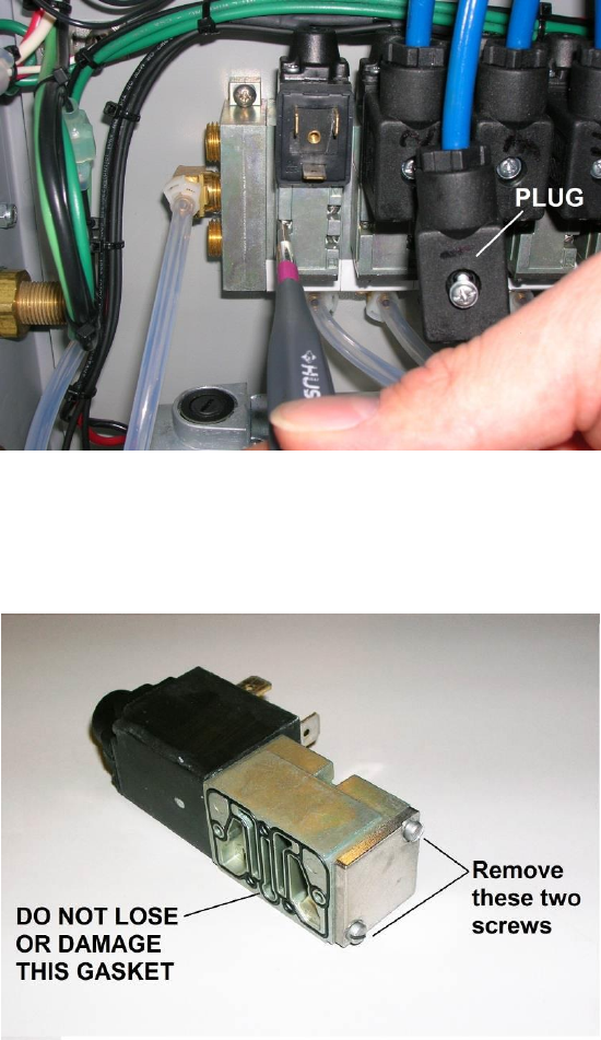
1. Remove plug on solenoid with Phillips screwdriver (do not lose the gasket for the plug)
(Figure 5-1).
Figure 5-1
2. Remove the three screws and solenoid with a small flathead screwdriver (Figure 5-1). Note the
black gasket on the underside Figure 5-2). Do not lose or damage this gasket.
Figure 5-2
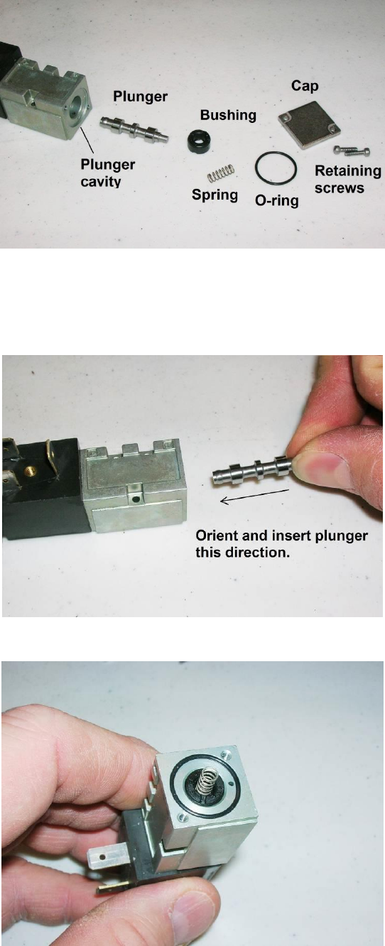
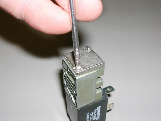
3. Using the small flathead screwdriver, remove the two screws to the square metal cap (Figure 5-
2). Carefully remove the spring, the o-ring, the bushing, and the plunger (Figure 5-3). Clean the
plunger and plunger cavity with a spray lubricant and cotton swab (silicon based or aerosol
lubricant OK).
30
Figure 5-3
4. Orient and insert the plunger as shown in Figure 5-4. Place the o-ring and bushing back into the
opening (no orientation needed) followed by the spring (Figure 5-5).
Figure 5-4
Figure 5-5
31
5. Carefully place the square cap onto the end, compressing the spring, and re-attach the two
screws. Make the connection snug but do not over-tighten (Figure 5-6).
Figure 5-6
6. Verify that the plunger will move easily by depressing the small black button on the other end of
the solenoid with a small Phillips screwdriver.
7. After verifying the solenoid gasket is in place, re-attach the solenoid with the three screws (be
very careful not to lose or allow the gasket to fall out of place and get crushed.) After securing
the solenoid, re-attach the plug with gasket to the solenoid.
If this procedure does not resolve a suspected vacuum/pressure problem, then please call
Geotech Technical Sales for further troubleshooting advice @ 1-800-833-7953.
32
Section 6: System Troubleshooting
Problem:
No product is being recovered but system cycles and gauge indicates vacuum and pressure
generation.
Solution:
Inspect product hose for kinks and blockage. Replace if needed. If freezing conditions have
occurred check the discharge lines for frozen product.
Remove and inspect the check valve at the top of the stainless steel pump. If the check ball is
stuck in the up position, clean and gently dislodge the ball. (Periodic replacement of the check
valve may be required depending on duty cycle.)
The check valve in the top of the pump may have been re-installed upside down. The arrow on
the check valve should point away from the pump and toward the discharge tubing.
The directional solenoid plumbed directly to the compressor could be stuck. If it is locked up it
may be cleared by depressing the small button on the black end of the solenoid using a small
Phillips screwdriver or paper clip to actuate the solenoid manually. If this doesn’t work, remove
the small plate at the other end of the solenoid and clean the plunger and plunger cavity using
the procedure found in Section 5.
Visually inspect the wiring connections to see that they are not loose or otherwise compromised.
Problem:
System cycles but gauge does not indicate vacuum or pressure generation.
Solution:
Verify the valve on the intake float assembly is closed.
Inspect product hose for abrasion, cuts or open connections. Replace if needed.
Make sure the air line connection goes to the pump and that the vent connection (the exhaust)
is plumbed to the recovery tank.
Verify that there is product in the well. If so, verify that the Skimmer intake is at the correct level
in the well so that product is able to be recovered.
Open the controller panel and verify that all air line connections are intact.
Problem:
A pump is stuck in either vacuum or pressure.
Solution:
Inspect the solenoid for residue or debris. If it is locked up it may be cleared by depressing the
small button on the black end of the solenoid using a small Phillips screwdriver or paper clip to
actuate the solenoid manually. If this doesn’t work, remove the small plate at the other end of
the solenoid and clean the plunger and plunger cavity using the procedure found in Section 5.
Visually inspect the wiring connections to see that they are not loose or otherwise compromised.
Problem:
Solenoid continues to stick, even with frequent cleaning (as per Section 5 – Solenoid Maintenance).
Solution:
System is operating in humid conditions which can cause residue or debris to accumulate within
the solenoid. System may be installed with optional Desiccant Dryers. See Section 9: Parts and
Accessories for Desiccant Dryer information, or contact Geotech Technical Sales for assistance.

33
Problem:
The screen is blank.
Solution:
Press the up arrow button. If the system is currently in a low voltage shut down, a low voltage
display will be present. If all equipment is functional, then allow the unit time to recharge. See
also the low battery definition in Section 3.
Check for loose or damaged battery connections and solar panel connections.
Use a volt meter to test the battery voltage. If it is below 10 volts remove the battery and charge
it on a separate charger to verify that a charge can be retained. Reconnect the battery and test
the system. Otherwise, when the solar panel is exposed to enough sun, the battery will
eventually recharge and the system will automatically resume normal operation.
Turn off the power and check the main fuse.
Problem:
The screen shows unintelligible characters.
Solution:
Use a volt meter and ensure the battery voltage is over 12.1 volts, if not, remove the battery and
charge it on a separate charger. Otherwise, when the solar panel is exposed to enough sun the
battery will eventually recharge and the system will automatically resume normal operation.
The screen display has no effect on the other hardware functions. If the voltage is over 12.1
volts, turn the ON/OFF switch to OFF and wait 60 seconds before switching on again.
Problem:
System is displaying a Battery Fault Check Cables alarm.
Solution:
Disconnect all voltage sources (battery, solar panel) and check Figure 2-3 and re-wire the solar
panel and battery to the correct terminals.
The fuse may have blown, check the fuse with a Multimeter and replace if necessary.
Battery may have been overcharged by another charging system and may need to be replaced.
Verify battery voltage with a volt meter.
Visually inspect the wiring connections to see that they are not loose or otherwise compromised.
Problem:
System is displaying a TANKFULL alarm.
Solution:
Recovery tank is full. Empty and restart the system.
Tankfull probe is disconnected or cable is damaged. Inspect probe and cable. Replace if
needed.
Verify the tankfull float is not stuck in the up position.
If the tankfull alarm will not clear then contact Geotech for assistance.
DO NOT TURN THE SIPPER SWITCH OFF AND ON AGAIN TO FORCE A CYCLE.
34
Problem:
System is displaying an INTAKE OVERRIDE alarm.
Solution:
The float on the Intake Float Switch is high. This is caused when product or moisture is pulled
through the air line due to:
1. Too long of vacuum time in the cycle.
2. The directional solenoid on the compressor is stuck.
3. An accumulation of moisture in the air line during operation.
Drain the intake and restart the system. Allow the system to clear product out of the manifold
and past the air filter. Disconnect the line and use a standalone air source (with no more than
100 PSI of pressure) to finish evacuating the air line of product.
Temporarily set the vacuum to 0 and the pressure to 30 or more seconds and allow the Sipper
controller to force the line to empty, after which you can restore (or adjust) the vacuum and
pressure to previous settings.
Problem:
A pump and Skimmer assembly is not functioning, or has been removed from service, on a multiple
pump system.
Solution:
Set the vacuum, pressure, and delay for the inoperable pump to the lowest setting possible.
Then disconnect the air line at the air filter on the side of the Sipper enclosure. The unit will
continue to run all pumps in sequence with minimal use of battery power on the out of service
pump.
Problem:
Controller displays a low battery condition and the battery will not recharge.
Solution:
If the system experienced freezing conditions, then the battery may be frozen. Place the battery
in a warm spot and allow it time to thaw, then reconnect and let it re-charge as normal.
Battery may need to be replaced. See wiring schematics in Section 2.
Additional solar panels may be required to keep the system up and running.
Turn unit off and back on to rest the clock crystal.
Problem:
Counters running slow.
Solution:
Turn unit off and back on to reset the clock crystal.
If your solution cannot be found within this section, please call Geotech Technical Sales for
expert troubleshooting advice @ 1-800-833-7958.

35
Section 7: System Specifications
Applications 2" (5.8cm) or larger recovery wells
Recovery Rate .2 gallons (.750 ml) per cycle
Max. Operating Depth 180 feet (54.86m)
Max. Pressure 100 PSIG (7 bar)
Max. Vacuum 20" Hg @ MSL
Oil/Water Separation Oleophilic/hydrophobic mesh screen
Power
Power Maximums (AC Sipper) 87 to 240VAC, 2.7 to 1 Amp(s)
(Solar Sipper) 12-15VDC input @ up to 14.5 Amps
90 ~240 Watts continuous
Controller
Operating Temperature 0° to 40° C (32° to 104º F)
Storage Temperature Range -29° to 66° C (-20º to 150º F)
Humidity 90% non-condensing (max)
Size 10" D x 18" T x 16” W (25cm D x 46cm T x 40.5cm W)
Rating NEMA 3R
Approximate Weight 35 lbs (single channel AC Sipper)
Approximate Weight 34 lbs (single channel Solar Sipper)
Approximate Weight 51 lbs (eight channel AC Sipper)
Approximate Weight 49 lbs (eight channel Solar Sipper)
Pump Assembly
Size: 23.5”L x 1.75” OD (60cm L x 4.5cm OD)
Weight: 4.5 lbs. (2 kg)
Materials: 303 and 304 SS, flexible rubber tubing, PVC, Brass
Skimmer Assembly 2” Model 4”Model
Effective travel range: 12” 24”
Size: 35.5” L x 1.75” OD 35.5” L x 3.75” OD
Weight: 1.75 lbs. (.8 kg) 2.25 lbs. (1 kg)
Operating Temperature: 0° to 40° C (32° to 104º F)
Storage Temperature: -29° to 66° C (-20º to 150º F)
Materials: 304 SS, Polyethylene, PVC, Polypropylene, Brass
Tubing - Air: .17" ID x .25" OD (4.32mm ID x 6.35mm OD)
Tubing - Discharge: .375" ID x .5" OD (9.53mm ID x 12.7mm OD)
Power usage will vary depending on application.
Additional customizations and accessories could add more weight.
36
Solar Panel:
Rated Power 100 Watts (standard unit)
Operating Voltage 17.4 VDC
Maximum Voltage 21.5 VDC
Operating Amperage 4.88 Amps (standard unit)
Maximum Amperage 5.8 Amps
Size: 41.2” H x 27.5” W (105 cm H x 70 cm W)
Approx. Weight: 23.3 lbs (10.5 kg)
Mounting System:
Module Tilt Range
15 to 65 degrees
Pole Size
2", 4", and 6"
Max Wind Speed
90
Module Orientation
Landscape/Portrait
Wind Exposure
Category B & C
Materials
5052-H32 Aluminum
Powder Coated Steel
Stainless Steel Fasteners
37
Section 8: System Schematics
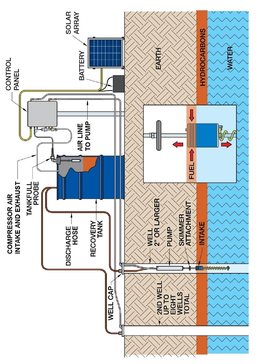
Figure 8-1 - Solar Sipper Schematic
38
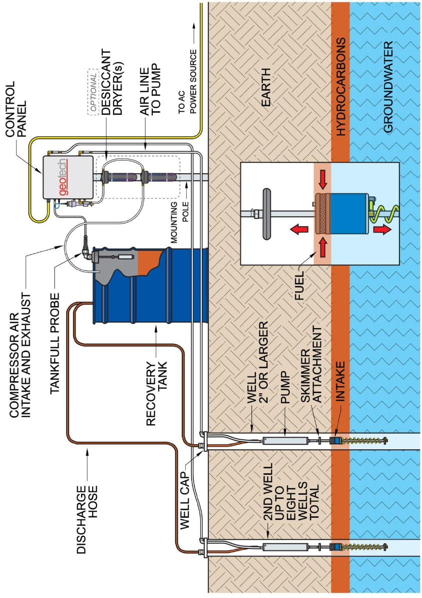
Figure 8-2 - AC Sipper Schematic, shown with optional Desiccant Dryers
39
Figure 8-3 – 3 Well Solar Sipper Internal Wiring DiagraM
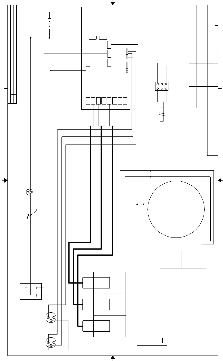
40
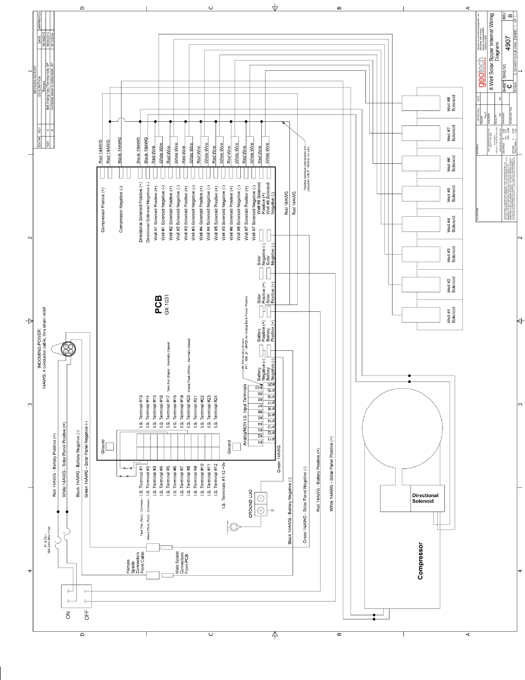
Figure 8-4 – 8 Well Solar Sipper Internal Wiring Diagram
1
1
2
2
3
3
4
4
A A
B B
White Wire
Incoming
14AWG 4 conductor cable
from strain relief
Black 14AWG
Red 14AW G
Black 18AWG
Black 18AWG
15AMP Slow-Blow Fuse
Green 14AWG - S olar Panel Negative (-)
White 14AWG - Solar P anel Positive (+)
Black 14AWG - Battery Negative (-)
Red 14AWG - Battery Positive (+)
White 20AWG
Well #3
Solenoid
Red 14AWG - Battery Positive (+)
ON / OFF Switch
Directional
Solenoid
Well #2
Solenoid
Well #1
Solenoid
Compressor
Solar Panel Negative (-)
Battery Negative (-)
Solar Panel
Positive (+)
Solar Panel
Positive (+)
Compressor
Negative (-)
Compressor
Positive (+)
Battery
Positive (+)
Directional
Solenoid Positive (+)
Directional
Solenoid Negative (-)
Well #2
Solenoid Negative (-)
Well #2
Solenoid Positive (+)
Well #1
Solenoid Positive (+)
Well #1
Solenoid Negative (-)
PCB
Well #3
Solenoid Negative (-)
Well #3
Solenoid Positive (+)
Red Wire
White Wire
Red Wire
White Wire
Red Wire
J8 J7
43
Tankfull
Amphenol
Connector
1
2 2
1
3
4
Intake Float Switch
Amphenol
Connector
White 14AWG - Solar Panel Positive (+)
Red 20AWG
Black 20AWG
GROUND LUG
GREEN
14AWG
PANEL
Black 20AWG
Ju mpe r
Red Wire
White Wire Black 20AWG
Red 20AWG
Conductivity
Probe
Panel Terminal
Strip
Conductivity
Probe
Fred R
1:1
B
±.02
±.01
±.005
0°30'
1/32
.X
.XX
.XXX
±
±
DE CIMALS
ANGLES
F RA CTI ONS
MATERI AL
THIS DRA WING CONTAIN S INF ORMATION WHICH IS PRO PRIET ARY T O
GEOT ECH ENV IRON MENT AL EQUIP MENT. US E OR DISS EMINATIO N OF TH IS
M ATERIAL FOR ANY PURPO SE O THER T HAN T HAT FOR WHICH IT IS
SUB MITT ED IS NOT AUT HORIZE D WITHOUT THE PRI OR WRIT TEN CONSE NT
OF GEO TECH ENVIRO NMENT AL EQUIPM ENT. GEOTE CH ENVIRONM ENTAL
EQUIPM ENT R ESERV ES ALL R IGHTS TO SUCH PROP RIETAR Y INFO RMAT ION.
DWG NO. 5293
-DO NOT SCAL E DWG-
-
3 Well Solar Sipper Internal Wiring
Diagram
SH EET 1 OF1
SHEET
SC ALE
INVENTORY P /N
86550012
DA TE G eotech Enviromental Equipment , Inc .
2650 East 40th Avenue
Denv er , Colorado 80205
1-800-833-7958
REV
N/A
DWG INTERPRET ATIO N PE R
ANS I Y1 4.5M-1 994
- TOL ERA NCE -
UNLES S OTHE RWISE S PECI FIED
DIM ENSIO NS ARE IN INC HES
DRA WN
APPROV A LS
QUALIT Y
CHE CKE R
ENG MGNT
N/A
REVISION HISTORY
DA N u REV DESCRIPTION DATE APPROVED
14 46 -RELEASED. MG 1 1/13/2012
41
Section 9: Parts and Accessories
Description
Part Number
MANUAL, SOLAR SIPPER
16550176
MANUAL, SIPPER PUMP & SKIMMER ASSEMBLY
MOUNTING HARDWARE TABS (FEET)
16550181
16110181
FUSE,15A,MDL TYPE
PPE011035
FUSE HOLDER ASSEMBLY
2010029
COMPRESSOR,PRO,SIPPER
11150325
SOL/SPRING,2POS,12VDC,1/8"NPT 031SA4004000060
16550262
SOLENOID,GEOCONTROL PRO
11150249
AC Sipper
CABLE,MOTORLEAD,12/3,SEOPRENE SEOOW,YELLOW
17050002
POWER SUPPLY,12V,100W, CE APPROVED,GEOCONTROL PRO
11150010
Solar Sipper
CABLE,SEO,14/4,YELLOW
10014
Solar Panel
SOLAR PANEL WITH FRAME,100 WATT
86550007
SOLAR PANEL,100 WATT
16550251
MOUNTING RACK,SOLAR PANEL
16550252
CABLE,THW,12AWG SUBMERSIBLE PUMP,BLACK/RED,RIBBON
11200479
BATTERY,SOLAR AGM,104 AH,12V
16550253
Float Switch Assemblies
SOLAR SIPPER INTAKE FLOAT SWITCH
86600095
PROBE, TANKFULL, SOLAR SIPPER 25'
56650100
Sipper Well Cap and Tubing Accessories
WELL CAP,2",SLIP W/ CMPRSN FTG SIPPER
86600061
WELL CAP,4",SLIP W/ CMPRSN FTG SIPPER
86600062
Sipper Tubing (Air) – available by the foot or in 500’ rolls.
TUBING,PE,.170x1/4,FT POLYETHYLENE
87050501
TUBING,TLPE,.170x1/4,FT FEP LINED POLYETHYLENE
87050529
TUBING,FEP,.170x1/4,FT FEP
87050509
Sipper Tubing (Discharge) – available by the foot or in 500’ rolls.
TUBING,RBR,3/8x5/8,FT PRODUCT DISHCARGE
16600019
TUBING,TLPE,3/8x1/2,FT FEP LINED POLYETHYLENE
87050506
TUBING,FEP,3/8x1/2,FT FEP
87050511
42
Tubing Clamps
CLAMP,NYL,1/4" SNAPPER
11150259
CLAMP,SS,STEPLESS EAR,17MM
16600004
CLAMP,SS6,WORM,7/32-5/8"
16600063
Optional Parts and Accessories
REBUILD KIT, COMPRESSOR, SIPPER PRO
DESICCANT DRYER, SIPPER
SILICA GEL, DESICCANT DRYER REFILL, 8 PACK
11150334
56550048
16600323
Sipper Pump and Skimmer Parts and Accessories
See “Geotech Pump and Skimmer Assembly Installation and Operation Manual” (P/N 16550181), for a
complete description and listing of available pumps, skimmers, and their accessories.

43
Installation Guide: Desiccant Dryer Kit for Geotech Sipper (Solar or AC)
If operating in humid environments, it is recommended to install a desiccant dryer kit with the Geotech
Sipper (Solar or AC) to minimize the amount of moisturized air that enters the pneumatic system. This
will minimize solenoid maintenance and optimize compressor performance.
Install the desiccant dryers on the Compressor Air Intake and Exhaust line;
1. Locate the “IN” and “OUT” ports on the dryers.
2. Stack the two dryer’s together by connecting an “OUT” port on one dryer to an “IN” port on the
other dryer using .17” ID tubing.
3. Connect the remaining “OUT” port to the Intake/Exhaust fitting on the Sipper Enclosure using
.17” ID tubing.
4. Connect the .17” ID tubing to the remaining “IN” port on the dryer. The end of this tubing will
terminate to the recovery tank (position above tankfull probe), or to where site requirements
permit.
5. Mount the desiccant dryers to a pole using the provided worm-drive clamps. Desiccant dryers
should remain vertical for optimal moisture recovery.
The Desiccant Dryer’s silicone beads will change from blue to pink as the dryer is saturated. Replace
desiccant as necessary.

44
DOCUMENT REVISIONS
EDCF#
DESCRIPTION
REV/DATE
-
Previous Release
02/15/2013
1583
Added Compressor Repair Kit to Replacement Parts List.
Added Revision History Table - SP
05/24/2013
1713
Edited Section 9: Parts and Accessories – Solar Panel now 100 Watts (was
85 Watts), updated Solar Panel Specs - SP
12/18/2013
1725
Edited Section 3: Timer/Cycle Settings and Display Descriptions – Factory
Default timers will be set to 0 seconds for vacuum, pressure, and delay – SP
1/10/2014
Project 1377
Added Desiccant Dryer Kit details to Section 4: System Operation, Section
6: System Troubleshooting, and Section 9: Parts and Accessories – SP
1/10/2014
Project 1411
Edited Section 3: Timer/Cycle Settings and Display Descriptions – Factory
Default timers will be set to 1 second of vacuum, 30 seconds of pressure, 5
minutes of delay – SP
3/21/14
-
Added Desiccant Dryer Installation Guide, updated 8- well wiring diagram
(rev B), SP
1/5/2014
45
The Warranty
For a period of one (1) year from date of first sale, product is warranted to be free from defects in
materials and workmanship. Geotech agrees to repair or replace, at Geotech’s option, the portion
proving defective, or at our option to refund the purchase price thereof. Geotech will have no warranty
obligation if the product is subjected to abnormal operating conditions, accident, abuse, misuse,
unauthorized modification, alteration, repair, or replacement of wear parts. User assumes all other risk,
if any, including the risk of injury, loss, or damage, direct or consequential, arising out of the use,
misuse, or inability to use this product. User agrees to use, maintain and install product in accordance
with recommendations and instructions. User is responsible for transportation charges connected to the
repair or replacement of product under this warranty.
Equipment Return Policy
A Return Material Authorization number (RMA #) is required prior to return of any equipment to our
facilities, please call our 800 number for appropriate location. An RMA # will be issued upon receipt of
your request to return equipment, which should include reasons for the return. Your return shipment to
us must have this RMA # clearly marked on the outside of the package. Proof of date of purchase is
required for processing of all warranty requests.
This policy applies to both equipment sales and repair orders.
FOR A RETURN MATERIAL AUTHORIZATION,
PLEASE CALL OUR SERVICE DEPARTMENT AT 1-800-833-7958
Model Number: ________________
Serial Number: ________________
Date of Purchase: ________________
Equipment Decontamination
Prior to return, all equipment must be thoroughly cleaned and decontaminated. Please make note on
RMA form, the use of equipment, contaminants equipment was exposed to, and decontamination
solutions/methods used.
Geotech reserves the right to refuse any equipment not properly decontaminated. Geotech may also
choose to decontaminate equipment for a fee, which will be applied to the repair order invoice.
Geotech Environmental Equipment, Inc
2650 East 40th Avenue Denver, Colorado 80205
(303) 320-4764 ● (800) 833-7958 ● FAX (303) 322-7242
email: sales@geotechenv.com website: www.geotechenv.com
