Grant Vortex Blue Supplementary Instructions DOC 0108 Rev 2.1 November 2016
User Manual: Pdf
Open the PDF directly: View PDF ![]() .
.
Page Count: 32
UK | DOC 0108 | Rev 2.1 | November 2016
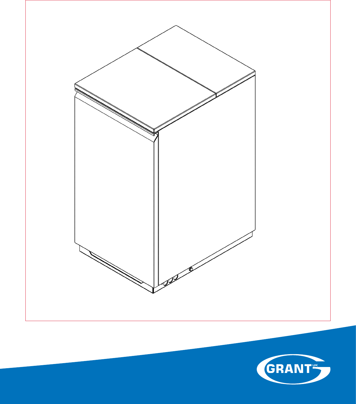
Grant UK VortexBlue
21, 26 and 36kW Blue Flame Oil Boiler Range
Supplementary User, Installation and Servicing Instr
uctions

GRANT ENGINEERING (UK) LIMITED
Hopton House, Hopton Industrial Estate, Devizes, Wiltshire, SN10 2EU
Tel: +44 (0)1380 736920 Fax: +44 (0)1380 736991
Email: info@grantuk.com www.grantuk.com
This manual is accurate at the date of printing but will be superseded and should be disregarded if specifications and/or appearances
are changed in the interests of continued product improvement. However, no responsibility of any kind for any injury, death, loss, damage
or delay however caused resulting from the use of this manual can be accepted by Grant Engineering (UK) Limited, the author or others
involved in its publication.
All good sold are subject to our official Conditions of Sale, a copy of which may be obtained on application.
© Grant Engineering (UK) Limited 2016. No part of this manual may be reproduced by any means without prior written consent.

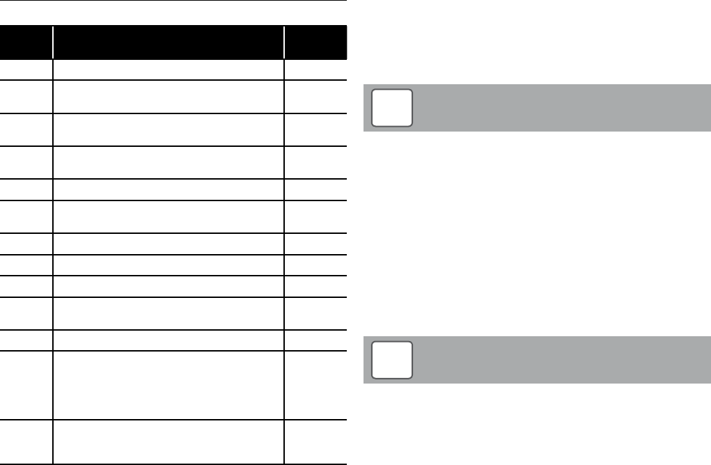
Contents Page 3
Contents
1 User Instructions 4
1.1 VortexBlue Kitchen/Utility, Kitchen/Utility 4
System Boilers and External Modules
1.2 VortexBlue Combi Boilers (Internal and 4
External models)
1.3 Control Panels 5
2 Introduction 6
2.1 Update to Main Installation Instructions 6
2.2 General 6
2.3 Low NOx Technology 6
2.4 Boiler Controls 6
2.5 Fuel Type 6
3 Technical Data 7
3.1 Boiler Technical Data 7
3.2 Boiler Clearances 8
3.3 Burner Settings 9
3.4 Boiler Dimensions 10
4 Installation 13
4.1 General 13
5 Electrical 13
5.1 General 13
5.2 Frost Protection 13
5.3 VortexBlue Kitchen Utility and 13
Kitchen/Utility System models
5.4 VortexBlue External Modules 14
5.5 VortexBlue Combi Boilers and 20
External Combi Boilers
6 Commissioning 22
6.1 General 22
6.2 Ignition Electrode Setting 22
6.3 Air Damper Adjustment 22
6.4 Air Adjuster Disc - 21kW only 22
7 Servicing 23
7.1 General 23
8 Burner 24
8.1 General 24
8.2 Burner Features 24
8.3 Digital Control Box 25
8.4 Burner Operation 27
9 Fault Finding 28
9.1 Burner Fault Indication 28
9.2 Burner Fault Diagnostics 28
9.3 Riello RDB BLU Fault Finding Chart 29
10 Spare Parts 30
10.1 Riello RDB BLU Burner Parts List 30
10.2 Exploded View of Riello RDB BLU Burner 31
Page 3

User InstructionsPage 4
These User Instructions are intended to assist the user in the
operation of the Grant VortexBlue range of high efficiency oil fired
boilers. Please refer to the section that applies to your particular
boiler model.
1.1 VortexBlue Kitchen/Utility, Kitchen/Utility
System Boilers and External Modules
The boiler is fully automatic once switched on, providing central
heating (and also heating your domestic hot water if you have a hot
water cylinder fitted).
For guidance on how to use your Grant VortexBlue Kitchen/Utility
boiler (or Kitchen/Utility System boiler) please refer to the User
Instructions for the Grant Vortex Kitchen/Utility boiler.
These are to be found at the back of the Installation Instructions
supplied with the boiler.
The Grant VortexBlue Kitchen/Utility (and Kitchen/Utility
System) boilers differ from the standard version of the Grant
Vortex, as follows:
a) The use of the Riello RDB BLU blue flame burner – refer
to Section 7 (installer section) of these Supplementary
Instructions for details.
b) A new boiler control system with electronic temperature
control and LED boiler function indication.
NOTE
!
1.1.1 Boiler Controls
Please refer to the following for details of the boiler control panels.
For all other details refer to the User Instructions supplied with the
boiler.
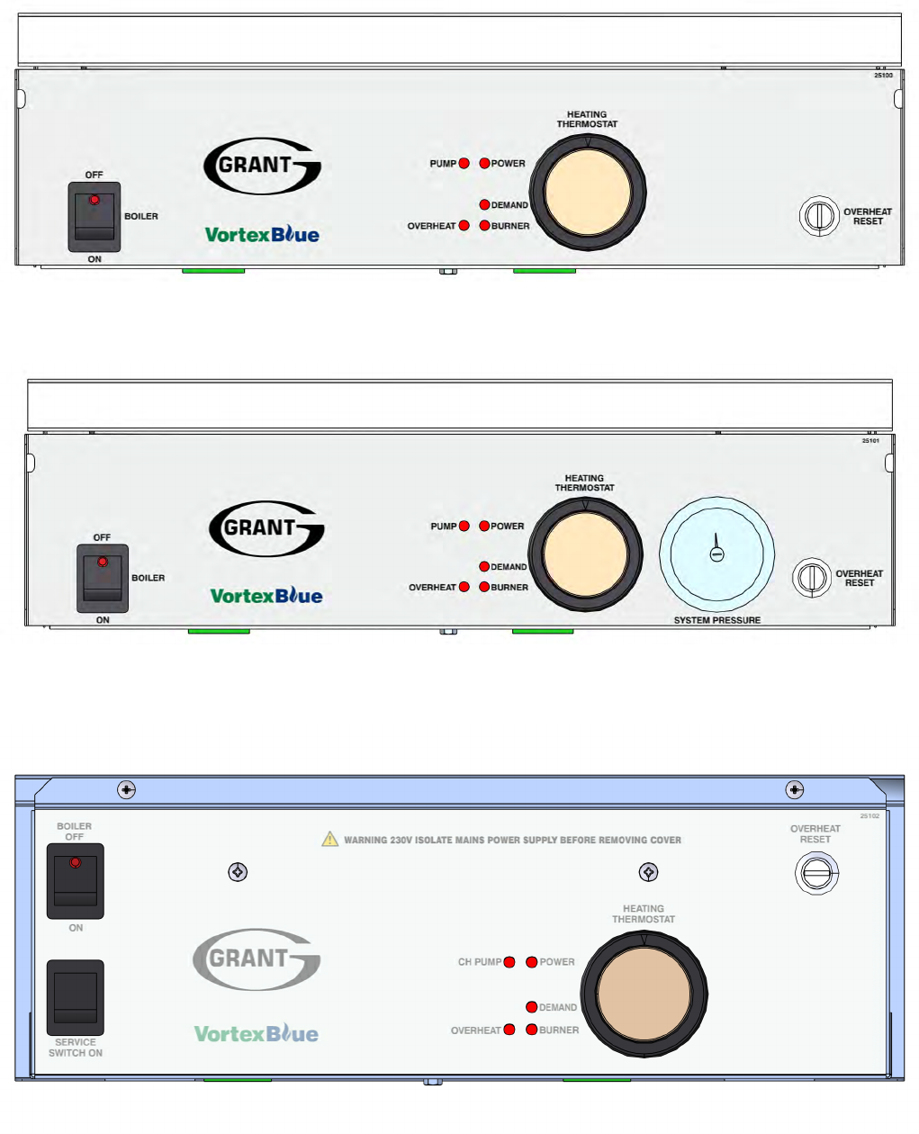
To access the control panel, pull off the front door panel from the
boiler. The controls on the panel are as follows (refer to Figures 1-1
to 1-3 as appropriate).
• Boiler On/Off switch
This switches the boiler on and off. The boiler ON/OFF switch
incorporates a 'mains on' neon which lights when the boiler
is switched on. Please note that the 'mains on' neon does not
necessarily indicate that the burner if firing. See Boiler Indicator
Lights information in the next column.
When the ON/OFF switch is set to on, the POWER indicator LED
on the control panel will also light. This also does not necessarily
indicate that the boiler is firing.
If the ON/OFF switch is set to off the boiler will NOT supply
central heating or heat domestic hot water (if a hot water
cylinder is connected to the boiler). The built-in frost
thermostat will also not operate.
NOTE
!
• Service Switch (External Modules only)
A Service switch is fitted to the control panel to allow the Service
Engineer to test-fire the boiler.
1 User Instructions
• Heating Thermostat
This control allows the temperature of the water leaving the boiler
to heat the radiators (and domestic hot water) to be adjusted. This
will be set by the installer to the optimum temperature for efficient
operation of the boiler. It should be left set in this position.
• Boiler Indicator Lights
These five red LEDs, located on the boiler control panel, indicate the
operating situation of the boiler as below:
PUMP Power to the system circulating pump
POWER Mains power to the boiler is switched on
DEMAND Demand for heating (and/or hot water) from the
heating system controls.
OVERHEAT Boiler overheat thermostat has operated and
switched the boiler off.
BURNER Power to the burner for it to operate.
• Overheat Thermostat (Overheat Reset)
The boiler is fitted with a safety overheat thermostat which
will automatically switch off the boiler in the case of a control
malfunction causing overheating.
• System Pressure Gauge
(Kitchen/Utility System models only)
This is to indicate the water pressure in the sealed heating system.
1.1.2 Lighting the Boiler
Please follow the guidance for lighting the boiler given in the User
Instructions supplied with the boiler.
If the reset push-button LED on the burner indicates a lockout (refer
to Section 8.3.3), press the reset button to attempt to re-start the
burner. If the burner then operates correctly the lockout may have
been caused by a temporary fault that has now cleared. If the
lockout persists the cause of the fault should be diagnosed and
rectified.
To operate the reset push-button it must be pressed in and
briefly held (for at least one second) before releasing.
NOTE
!
1.2 VortexBlue Combi Boilers (Internal and External
models)
For guidance on how to use your Grant VortexBlue Combi boiler,
please refer to the User Instructions for the Grant Vortex Combi
boiler (or External Combi boiler).
These are to be found at the back of the Installation Instructions
supplied with the boiler.
User Instructions Page 5
Figure 1-1: VortexBlue Kitchen/Utility Control Panel
Figure 1-2: VortexBlue Kitchen/Utility System Control Panel
Figure 1-3: VortexBlue External Module Control Panel
1.3 Control Panels

These supplementary Instructions must be read in
conjunction with the Vortex boiler Installation Instructions
supplied with the boiler.
Both the Vortex boiler Installation Instructions and these
Supplementary Instructions must be left with the User on
completion of Installation and Commissioning.
NOTE
!
2.1 Update to Main Installation Instructions
These Supplementary Instructions are designed to cover the
differences between the Grant Vortex and the new Grant VortexBlue
low NOx boilers, as much of the installation, commissioning,
servicing and operation is identical to the standard Vortex boilers.
The following sections of the Vortex Installation Instructions
(supplied with the boiler) have not been changed and should be
referred to during the installation and commissioning of this boiler:
• Section 3 Oil Supply and Storage
• Section 5 Pipe Connections
• Section 6 Condensate Disposal
• Section 7 Sealed Systems
• Section 9 Flues and Air Supply
• Section 14 Health and Safety Information
• Section 16 Guarantee
2.2 General
The new Grant VortexBlue range of high efficiency low NOx oil fired
boilers consists of 15 models including Kitchen/Utility, Kitchen/Utility
System and External Modules as well as both Internal and External
Combi boilers.
All models are available in three outputs – 21kW, 26kW and 36kW.
The Kitchen/Utility, Kitchen/Utility System and External Modules are
supplied factory set at the maximum outputs of 21kW, 26kW and
36kW but can be de-rated to a lower output on commissioning if
required. Refer to Section 3.3 of these Supplementary Instructions
for a full list of all models and outputs.
Internal and External Combi boilers must be left at the factory
set output and not de-rated to a lower output.
NOTE
!
2.3 Low NOx Technology
Grant VortexBlue boilers are designed to meet both the forthcoming
European Ecodesign (ErP) emissions limits due to be introduced in
September 2018, and to maintain the high efficiencies expected of
Grant Vortex oil fired boilers.
They combine the proven Grant condensing boiler technology with
the Riello RDB BLU compact low NOx blue flame burners.
Grant VortexBlue boilers can be used with all the Grant flue system
options available for the standard Vortex boilers. Refer to the
Installation Instructions supplied with the boiler for details.
2 Introduction
2.4 Boiler Controls
2.4.1 Combi Boilers
The Grant VortexBlue Combi boilers (internal and external) have
the same electronic control system as fitted to the standard Vortex
Combi models.
All wiring details for external controls (programmers, room
thermostats, etc.) are given in Section 8 of the Vortex Combi
Installation Instructions provided with the boiler.
2.4.2 Kitchen/Utility boilers and External Modules
The Grant VortexBlue Kitchen/Utility boilers and External Modules
incorporate a new electronic control system based on the one used
in the Grant Vortex Combi boilers.
This uses an electronic boiler thermostat and has LED lights to
indicate the operating status of the boiler. For details on how to
operate the boiler please refer to Section 1.
Refer to Section 5 of these Supplementary Instructions for further
details and electrical connection diagrams.
A service switch is fitted to the control panel of the external
modules to allow the service engineer to test-fire the boiler.
When set to 'ON' the switch temporarily by-passes the
external control system to operate the boiler.
This is a 'momentary' or non-latching switch that cannot be
left set to 'ON'. The boiler will automatically revert to normal
operation when 15 minutes have elapsed since it was last
operated.
If required, this 15 minute override period can be stopped by
switching the boiler ON/OFF switch 'OFF' and then back to
'ON'.
The boiler will then operate as normal under control of the
external heating/hot water controls (timer, room thermostat
or programmer).
NOTE
!
2.5 Fuel Type
All VortexBlue boilers are designed for use with Kerosene (Class C2)
only.
The use of any other fuel, e.g. Gas Oil (Class D), is not permitted
with any of the VortexBlue boilers and may invalidate the product
guarantee.
Section 2: IntroductionPage 6
Section 3: Technical Data Page 7
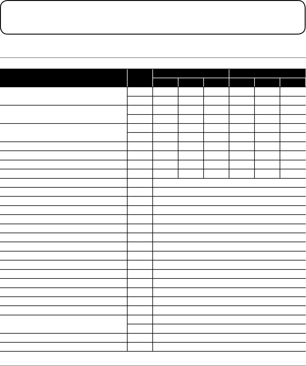
3.1 Boiler Technical Data
3.1.1 Kitchen/Utility, Kitchen/Utility System and External Modules
Table 3-1: Kitchen/Utility, Kitchen/Utility System and External Modules Technical Data
Units Kitchen/Utility and System External Module
21kW 26kW 36kW 21kW 26kW 36kW
Water content
litres 19 19 21 19 19 21
gall 4.2 4.2 4.7 4.2 4.2 4.7
Weight (dry)*
kg 130 130 144 143 143 162
lbs 287 287 318 315 315 357
Maximum heat output (Kerosene)**
kW 21 26 36 21 26 36
Btu/h 71 650 88 700 122 840 71 650 88 700 122 840
Flow connection 22mm 22mm 28mm 22mm 22mm 28mm
Return connection 22mm 22mm 28mm 22mm 22mm 28mm
Minimum flow rate (∆T=10°C) l/h 1 800 2 200 3 000 1 800 2 200 3 000
Minimum flow rate (∆T=20°C) l/h 900 1 100 1 500 900 1 100 1 500
Condensate connection 22 mm plastic pipe
Flue diameter (conventional) 100 mm (4 inches)
Waterside resistance (∆T=10°C) mbar 26
Waterside resistance (∆T=20°C) mbar 9.5
Maximum static head m 28
Minimum circulating head m 1
Boiler thermostat range °C 65 to 78
Limit (safety) shut off temperature °C 111±3
Maximum hearth temperature °C Less than 50
Electricity supply 230/240V 1ph 50Hz fused at 5A
Burner motor power W 90
Absorbed motor power W 0.15
Starting current A 2.0
Running current A 0.85
Oil connection ¼" BSP male (on end of flexible fuel hose)
Conventional flue draught
N/m² Minimum: 8.7 - maximum: 37
in wg Minimum: 0.035 - maximum: 0.15
Maximum operating pressure - sealed/open system bar 2.0
Maximum operating pressure - pressure relief valve bar 2.5
* Weight includes burner but excludes flue.
** Factory setting (maximum output). Refer to Section 3.3 for other boiler outputs.
3 Technical Data
Section 3: Technical DataPage 8
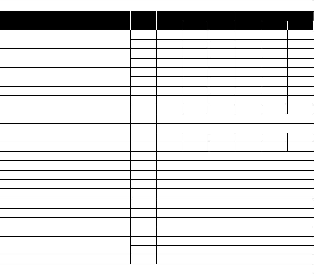
3.1.2 Combi and External Combi
Table 3-2: Combi and External Combi Technical Data
Units Combi External Combi
21kW 26kW 36kW 21kW 26kW 36kW
Water content (including 32 litre primary store)
litres 48.5 48.5 53.5 48.5 48.5 53.5
gall 10.7 10.7 11.8 10.7 10.7 11.8
Weight (dry)*
kg 160 177 200 181 206 225
lbs 353 390 441 399 454 496
Maximum heat output (Kerosene)
kW 21 26 36 21 26 36
Btu/h 71 650 88 700 122 840 71 650 88 700 122 840
Flow and return connections mm 22 22 28 22 22 28
Minimum flow rate ∆T=10°C l/h 1 800 2 200 3 000 1 800 2 200 3 000
Minimum flow rate ∆T=20°C l/h 900 1 100 1 500 900 1 100 1 500
Condensate connection 22 mm plastic pipe
Flue diameter (conventional) 100 mm (4 inches)
Waterside resistance ∆T=10°C mbar 28.5 28.5 26 28.5 28.5 26
Waterside resistance ∆T=20°C mbar 10.0 10.0 9.5 10.0 10.0 9.5
Boiler stat range °C 65 to 78
Limit stat shut off temperature °C 111±3
Maximum hearth temperature °C Less than 50
Electricity supply 230/240V 1ph 50Hz fused at 5A
Burner motor power W 90
Absorbed motor power W 0.15
Starting current A 2.0
Running current A 0.85
Oil connection ¼" BSP male (on end of flexible fuel hose)
Conventional flue draught
N/m² Minimum: 8.7 - maximum: 37
in wg Minimum: 0.035 - maximum: 0.15
Maximum operating pressure - pressure relief valve bar 2.5
* Weight includes burner but excludes flue
3.2 Boiler Clearances
Adequate clearance must be left for servicing the boiler.
For guidance on the clearances required, please refer to the 'Boiler Location' information given in the 'Installation Information' section of the
Installation Instructions supplied with the boiler.
Section 3: Technical Data Page 9
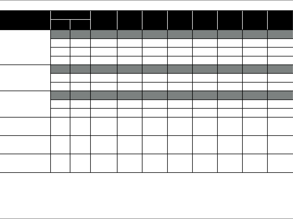
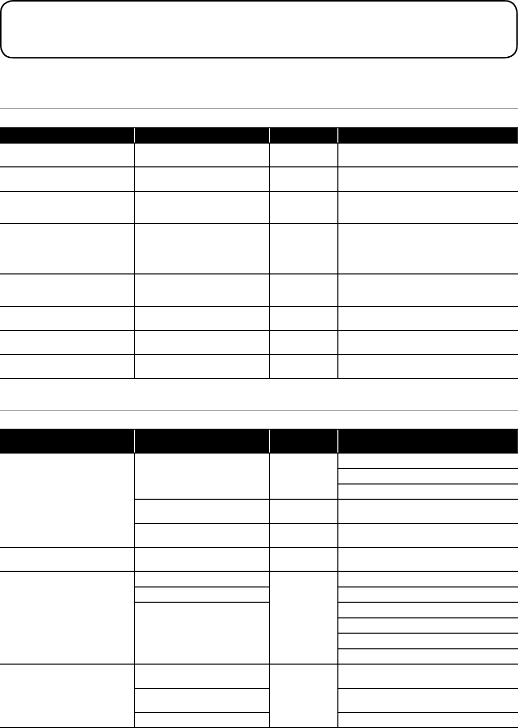
3.3 Burner Settings
Table 3-3: Burner settings
Boiler models
(burner type)
Heat output
Nozzle
Oil
pressure
(bar)
Smoke
No.
Burner
head type
Burner
head/disc
setting
Fuel
flow rate
(kg/h)
Flue gas
temp.
(°C)
CO2
(%)
(kW) (Btu/h)
Kitchen/Utility 21
Kitchen/Utility System 21
External Module 21
(RDB2.2 BG1 BLU)
* 21 * 71 650 0.60/80°ES 8.5 0 - 1 BG1 N/A 1.78 75 - 85 12.0
18 61 400 0.55/80°ES 8 0 - 1 BG1 N/A 1.53 70 - 80 12.0
16 54 600 0.40/80°ES 10.5 0 - 1 BG1 B 1.36 65 - 75 12.0
15 51 200 0.40/80°ES 9 0 - 1 BG1 B 1.28 65 - 75 12.0
Kitchen/Utility 26
Kitchen/Utility System 26
External Module 26
(RDB2.2 BG1 BLU)
* 26 * 88 700 0.65/80°ES 10 0 - 1 BG1 N/A 2.19 75 - 80 12.0
23 78 475 0.65/80°ES 8.5 0 - 1 BG1 N/A 1.94 70 - 75 12.0
21 71 650 0.60/80°ES 8.5 0 - 1 BG1 N/A 1.78 65 - 70 12.0
Kitchen/Utility 36
Kitchen/Utility System 36
External Module 36
(RDB2.2 BG3 BLU)
* 36 * 123 000 0.85/80°ES 11 0 - 1 BG3 N/A 2.99 75 - 80 12.0
31.5 107 500 0.85/80°ES 9 0 - 1 BG3 N/A 2.62 70 - 75 12.0
26 88 700 0.65/80°ES 10 0 - 1 BG3 N/A 2.19 65 - 70 12.0
Combi 21
External Combi 21
(RDB2.2 BG1 BLU)
21.0 71 650 0.60/80°ES 8.5 0 BG1 N/A 1.8 73 12.0
Combi 26
External Combi 26
(RDB2.2 BG1 BLU)
26.0 88 700 0.65/80°ES 10.0 0 BG1 N/A 2.0 72 12.0
Combi 36
External Combi 36
(RDB2.2 BG3 BLU)
36.0 123 000 0.85/80°ES 11.0 0 BG3 N/A 2.8 78 12.0
Notes:
1. The data given above is approximate only.
2. The above settings may have to be adjusted on site for the correct operation of the burner.
3. Gas Oil and Bio Kerosene are NOT suitable for use with Grant VortexBlue boiler range
4. The flue gas temperatures given above are ± 10%.
5. When commissioning, the air damper must be adjusted to obtain the correct CO2 level.
6. * Factory settings: 15/21 - 21kW, 21/26 - 26kW, 26/36 - 36kW
7. When setting the 15/21 to 15kW or 16kW, the burner air adjuster disc requires repositioning. Refer to Section 6 (Commissioning).
8. The installer must amend the boiler data label if the output is changed.
Section 3: Technical DataPage 10
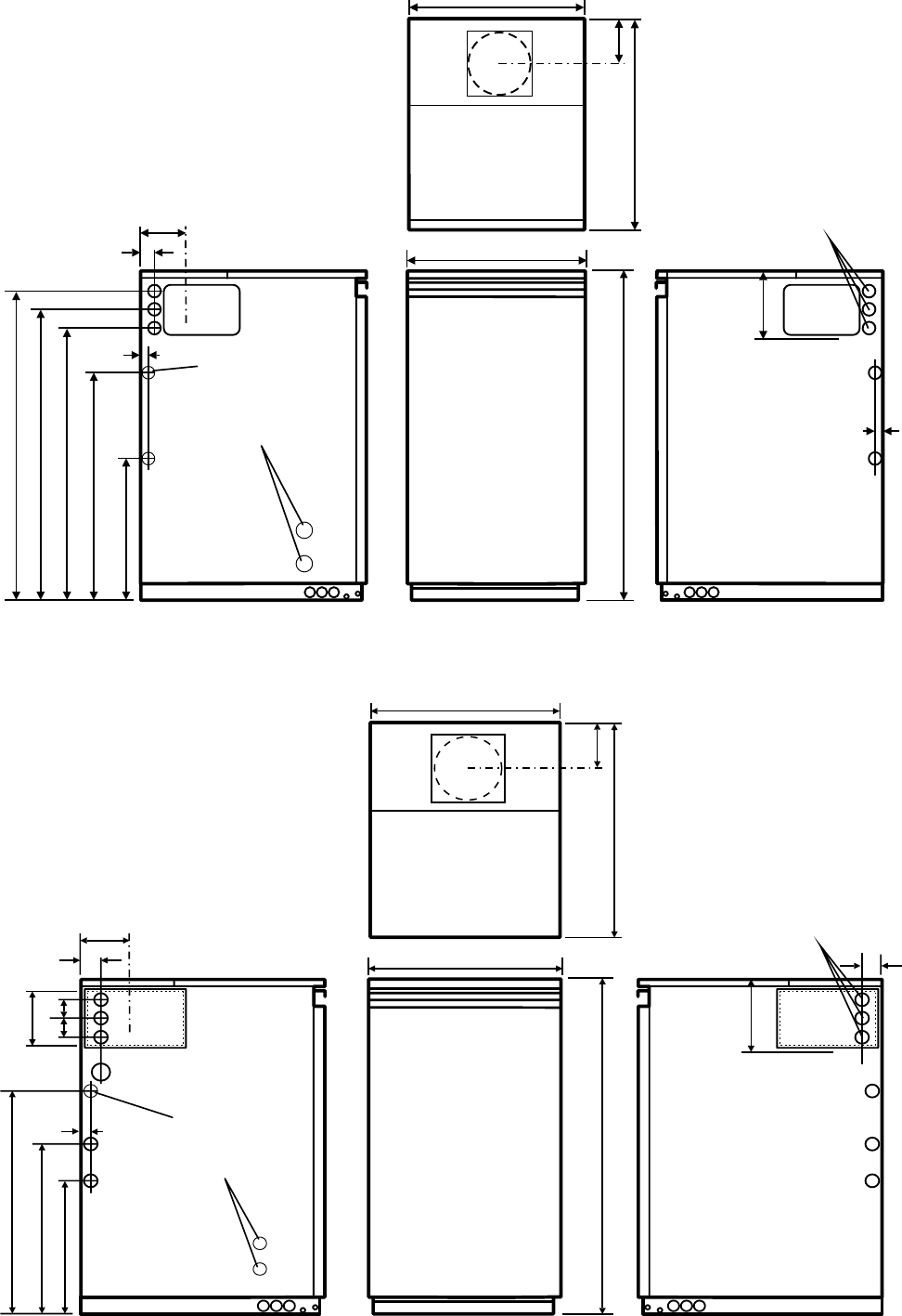
3.4 Boiler Dimensions
All dimensions in the following diagrams are in millimetres.
Alternative
condensate
drain outlets
FRONT VIEW
470
860
LEFT SIDE
VIEW
813
759
709
587
352
18
17
110
30 Flue centre line
RIGHT SIDE VIEW
PLAN VIEW
470
603 11 0
Safety valve
Cold fill
Flow - 22mm push-fit
170
Flue
spigot
Figure 3-4: 21 and 26kW Kitchen/Utility and System dimensions
Safety valve
Flow - 28mm push-fit
Cold fill
61
170 61
LEFT SIDE VIEW
455
555
311
24
115
63 63
Flue centre line
RIGHT SIDE VIEW
PLAN VIEW
470
603 150
FRONT VIEW
470
900
205
Flue
spigot
Alternative
condensate
drain outlets
Figure 3-5: 36kW Kitchen/Utility and System dimensions
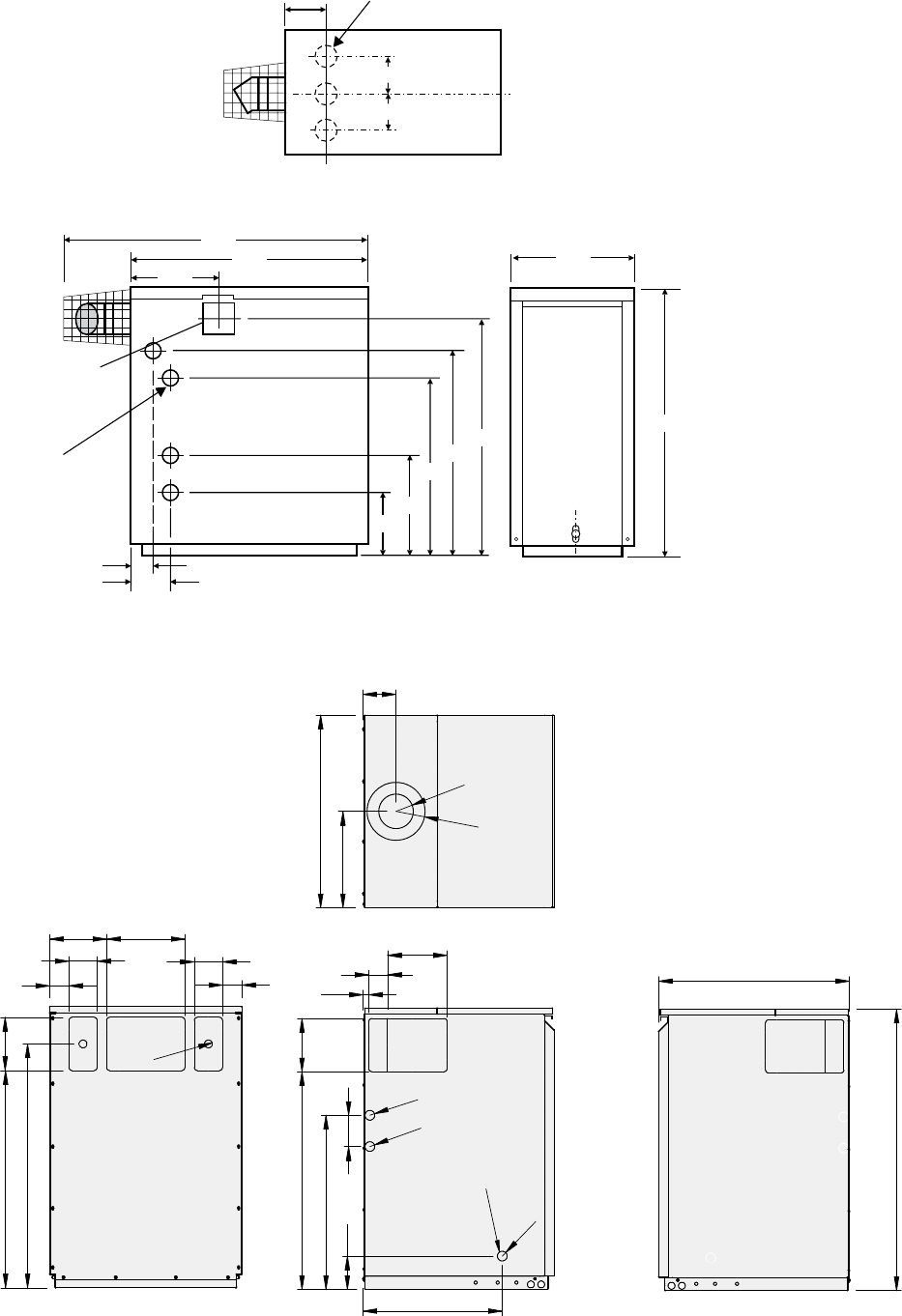
Section 3: Technical Data Page 11
Pre-cut hole
for side flue exit
if required
4 pre-cut
holes 50 mm dia.
in sidesboth
1005
509
797
269
908
117
50
757
A
660
418
179
21 and 26kW: A = 804
36kW: A = 824
Plan View
132
180
180
=
=
3 pre-cut holes
76 mm dia. in base
of boiler enclosure
Figure 3-6: 21, 26 and 36kW External Module dimensions
RIGHT SIDE VIEW
LEFT SIDE VIEW
PLAN VIEW
REAR VIEW
90
75
75
90
202210
760
690 140
614
307
105
ø
110
ø
155
17
35
227
588
100
699125
444
99
609
ø
31
ø
31
ø
31
INTERNAL DRAIN
TRAP EXIT
(LEFTSIDE
PANEL ONLY)
ø
25
858
Figure 3-7: 21 and 26kW Internal Combi dimensions
Section 3: Technical DataPage 12
RIGHT SIDE VIEW
LEFT SIDE VIEW
PLAN VIEW
REAR VIEW
90
62
62
90
182250
779
694 170
614
307
106
ø
110
ø
185
18
60
190
556
100
695170
445
106
609
ø
31
ø
31
ø
31
INTERNAL DRAIN
TRAP EXIT
(LEFTSIDE
PANEL ONLY)
ø
25
900
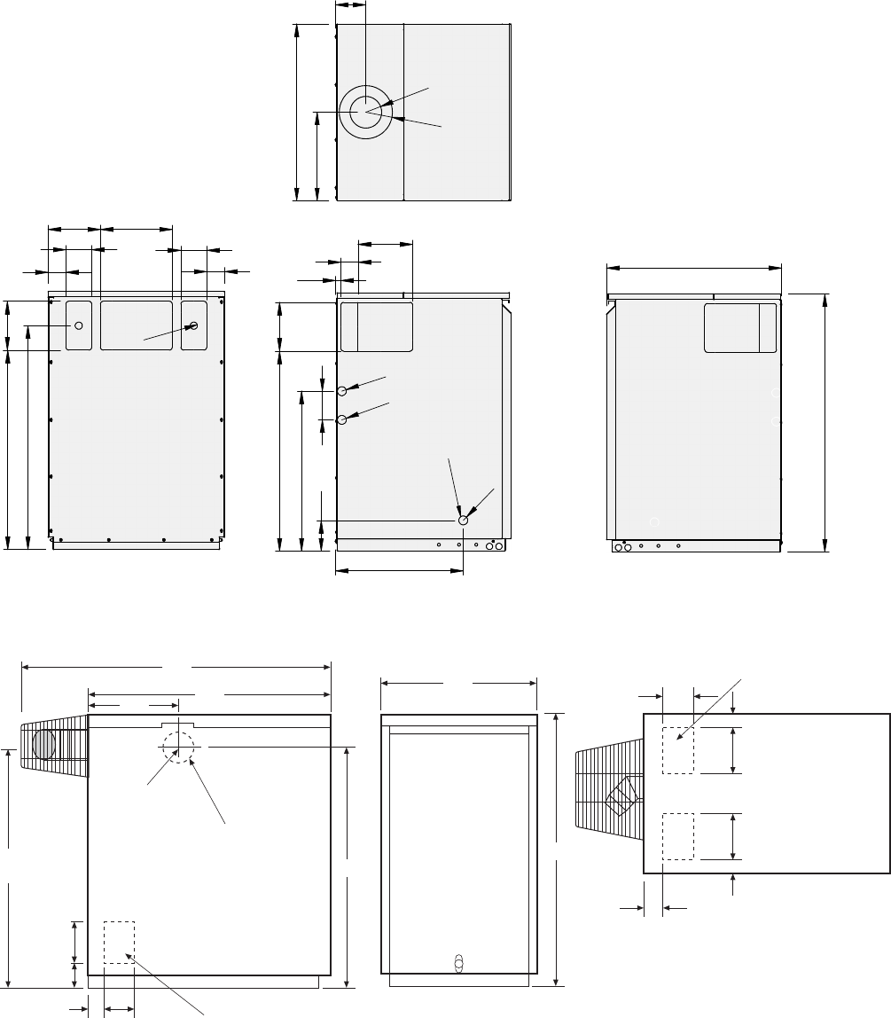
Figure 3-8: 36kW Internal Combi dimensions
966
239
Combi 21e, 26e
Combi 36e
Side flue exit
if required
Pre-cut hole 75 x 150mm in
each side of boiler enclosure
2 pre-cut holes in base
of boiler enclosure
115mm dia.
754
836
150
73
7533
945
33
75
150
49
49
150
658
Plan View
Figure 3-9: 21, 26 and 36kW External Combi dimensions
Section 4: Installation and Section 5: Electrical Page 13
4.1 General
For full details on the installation of this boiler, please refer to the
following sections of the Installation Instructions supplied with the
boiler:
• Installation Information
• Pipe Connections
• Condensate Disposal
• Sealed Systems
• Flue System & Air Supply
4 Installation
5.1 General
For details on the electrical installation requirements for this boiler
please refer to the Installation Instructions supplied with this boiler in
conjunction with the information given below.
5.2 Frost Protection
The Kitchen/Utility, Kitchen/Utility System and External Modules are
all fitted with pre-set internal frost protection.
This will automatically start the circulating pump if either:
a) The air temperature (sensed on the boiler control PCB) falls
below 5°C, or
b) The water temperature (sensed by the boiler control thermistor)
falls below 8°C
If after fifteen minutes the air temperature exceeds 10°C or the water
temperature exceeds 15°C the circulating pump will stop.
However, if after fifteen minutes either the air or water temperature
is less than 10°C, the burner is automatically fired until the water
temperature reaches 30°C, when the burner stops and there is a
pump overrun of two minutes.
Also, to protect any exposed heating system pipework, it is
recommended that an 'external' frost thermostat is also installed.
This frost thermostat will operate in parallel with the internal frost
protection of the boiler.
It should be sited within the house in such a place that it can detect
any rise and fall in the ambient air temperature, i.e. in a room with a
radiator.
Where the frost thermostat is installed outside the house (to protect
a boiler installed in an external boiler room or garage) or in an
attic, it is recommended that it be used in conjunction with a pipe
thermostat to avoid unnecessary and wasteful overheating of the
property. The pipe thermostat should be located on the boiler return
pipe, and set to operate at 30°C.
For connection details please refer to Figures 5-4 and 5-5
For total system protection against freezing, particularly
during extended periods without electrical power, Grant
recommend the use of a combined heating system antifreeze
and corrosion inhibitor, used in accordance with the
manufacturer's instructions.
NOTE
!
5 Electrical
5.3 VortexBlue Kitchen/Utility and Kitchen/Utility
System models
5.3.1 Connecting Power Supply, Pump and Control System
The boiler requires both a switched mains power supply, from an
external programmer or control system, in addition to a permanent
live supply.
Do not interrupt the permanent mains supply to the boiler
with any external control, e.g. a timer, programmer, or room
thermostat.
NOTE
!
There is no facility in the Grant VortexBlue Kitchen/Utility and
Kitchen/Utility System boilers for the fitting of a plug-in timer or
programmer.
A 4-core cable (3-core and earth) is required to connect the power
supply and heating controls to the boiler.
On Kitchen/Utility models a 3-core cable (2-core and earth) is
required to connect the circulating pump to the boiler.
For control system wiring please refer to Figures 5-4 and 5-5
Ensure that the route and length of the supply and pump
cables are such that the boiler control panel can be fully
hinged down without needing to disconnect them from the
terminal block.
NOTE
!
The procedure is as follows:
1. Lift off the boiler top front casing panel, if it has not already
been removed.
2. Loosen (do not remove) the four screws securing the control
panel to the side panels, hinge the panel forward and allow it to
drop down to gain access to the top of the panel.
3. Remove the two screws securing the terminal block cover and
lift off the cover.
4. Remove the screws securing the cable clamp and open clamp.
5. Route the supply cable through the hole in the rear panel (using
the grommet supplied) and up to the control panel
6. Pass the 4-core cable through the cable clamp and connect to
the boiler control panel terminals as follows:
• Green/Yellow to mains earth (terminal 1)
• Blue to mains neutral (terminal 2)
• Brown to mains live (terminal 3)

Section 5: ElectricalPage 14
• Black to switched live (terminal 19)
On Kitchen/Utility models - pass the 3-core cable from the
pump through the cable clamp and connect to the boiler
control panel terminals as follows:
• Green/Yellow to pump earth (terminal 4)
• Blue to pump neutral (terminal 5)
• Brown to pump live (terminal 6)
7. Tighten the cable clamp and refit the terminal block cover
8. Re-connect the electrical supply and check operation of
heating system controls (programmer, room thermostats, etc.).
9. Refer to Instructions provided with the programmer for
operation and setting.
10. Leave the Programmer and Thermostat Instructions with the
user after installation for their future reference.
5.3.2 Circulating Pump
On the Kitchen/Utility System models, the circulating pump is
factory fitted within the boiler enclosure and the pump is wired to the
pump terminals on the control panel terminal block.
On Kitchen/Utility models the pump should also be connected
directly to the control panel terminal block. Refer to Section 5.3.1.
Connected this way allows the pump to be isolated using the
Boiler ON/OFF switch, on the boiler control panel, for servicing or
maintenance work.
Also, the boiler control automatically provides a short pump 'overrun'
(two minutes) after the burner is shut down (when the heat demand
is interrupted), e.g. when the room thermostat is satisfied. This
pump overrun will not occur if the boiler power supply is interrupted,
e.g. if the boiler ON/OFF switch is set to off.
5.4 VortexBlue External Modules
5.4.1 Connecting Power Supply, Pump and Control System
The boiler requires both a switched mains power supply, from an
external programmer or control system, in addition to a permanent
live supply.
Do not interrupt the permanent mains supply to the boiler
with any external control, e.g. a timer, programmer, or room
thermostat.
NOTE
!
There is no facility in the Grant VortexBlue External Module for the
fitting of a plug-in timer or programmer.
A 4-core cable (3-core and earth) is required to connect the power
supply and heating controls to the boiler.
A 3-core cable (2-core and earth) is required to connect the
circulating pump to the boiler.
For control system wiring, refer to Figures 5-8 and 5-9.
Ensure that the route and length of the supply cable is such
that the boiler control panel can be fully hinged down without
disconnecting the supply cable from the terminal block.
NOTE
!
The procedure is as follows:
1. Remove the module front door panel, if it has not already been
removed.
2. Remove the four screws securing the front of the control panel
and allow it to drop down to gain access to the top of the
panel.
3. Remove the screws securing the cable clamp and open clamp.
4. Route the supply and pump cables up to the control panel.
5. Pass the 4-core cable through the cable clamp and connect to
the boiler control panel terminals as follows:
• Green/Yellow to mains earth (terminal 1)
• Blue to mains neutral (terminal 2)
• Brown to mains live (terminal 3)
• Black to switched live (terminal 19)
6. Pass the 3-core cable from the pump through the cable clamp
and connect to the boiler control panel terminals as follows:
• Green/Yellow to pump earth (terminal 4)
• Blue to pump neutral (terminal 5)
• Brown to pump live (terminal 6)
7. Tighten the cable clamp and refit the front of the control panel.
8. Re-connect the electrical supply and check operation of
heating system controls (programmer, room thermostats, etc.).
9. Refer to Instructions provided with the programmer for
operation and setting.
10. Leave the Programmer and Thermostat Instructions with the
user after installation for their future reference.
5.4.2 Connection of the Circulating Pump
The circulating pump should be connected directly to the control
panel terminal block. Refer to Section 4.4.1.
Connecting the pump in this way allows it to be isolated using the
Boiler On/Off switch, on the boiler control panel, for servicing or
maintenance work.
Also, when the pump is connected this way, the boiler control
automatically provides a short pump 'overrun' (2 minutes) after the
burner has shut down (when the heat demand is interrupted), e.g.
when the room thermostat is satisfied. This pump overrun will not
occur if the boiler power supply is interrupted, e.g. if the boiler ON/
OFF switch is set to off.
Section 5: Electrical Page 15
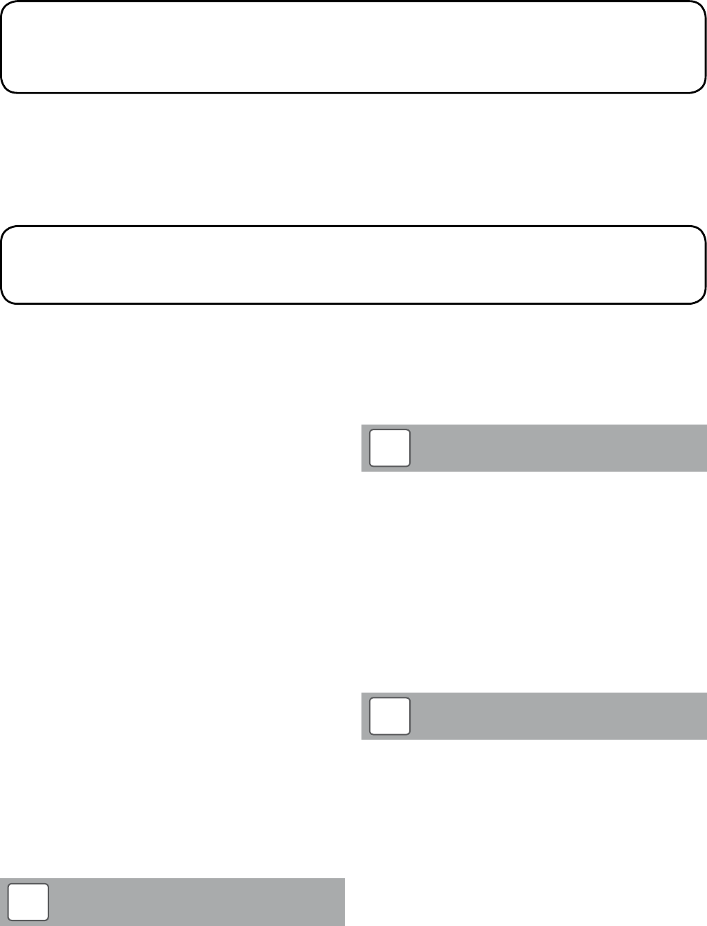
1 2 3
E N L
4 5 6
E N L
7 8 9
E N L
10 11 12
E N L
18 20 21 22
15 1613 14 25 26
23 24
17 19 27 28
PUMP EARTH
PUMP NEUTRAL
PUMP LIVE
DO NOT CONNECT
DO NOT CONNECT
DO NOT CONNECT
BURNER EARTH
BURNER NEUTRAL
BURNER LIVE
DO NOT CONNECT
DO NOT CONNECT
DO NOT REMOVE LINK
DO NOT
REMOVE
LINK
DO NOT CONNECT
SWITCHED
LIVE SUPPLY
TIMER NEUTRAL
TIMER LIVE
STORE
THERMISTOR
(TO FRONT POCKET)
FLOW
THERMISTOR
(TO TOP POCKET)
MAINS
1A 2A
4B 5B
Boiler
On/Off
Off Off
Constant
Timed Timed
Constant
Central
Heating
Switch
Domestic
Hot Water
Switch
2 C
Limit
Thermostat
Earth connection
boiler top bracket
Printed Circuit Board
FUSE 5 X 20
N L
230V 5A Fused
Supply
N
E
Flow
Thermistor
Black shroud
indicates
Flow
Thermistor
Link Link Link
Burner
Resistor
BURNER
PERMANENT LIVE
DO NOT CONNECT
DO NOT CONNECT
DO NOT CONNECT
DO NOT REMOVE LINK
DO NOT REMOVE LINK
SL
L
Figure 5-1: VortexBlue Kitchen/Utility control panel wiring diagram
Section 5: ElectricalPage 16
1 2 3
E N L
4 5 6
E N L
7 8 9
E N L
10 11 12
E N L
18 20 21 22
15 1613 14 25 26
23 24
17 19 27 28
PUMP EARTH
PUMP NEUTRAL
PUMP LIVE
DO NOT CONNECT
DO NOT CONNECT
DO NOT CONNECT
BURNER EARTH
BURNER NEUTRAL
BURNER LIVE
DO NOT CONNECT
DO NOT CONNECT
DO NOT REMOVE LINK
DO NOT
REMOVE
LINK
DO NOT CONNECT
SWITCHED
LIVE SUPPLY
TIMER NEUTRAL
TIMER LIVE
STORE
THERMISTOR
(TO FRONT POCKET)
FLOW
THERMISTOR
(TO TOP POCKET)
MAINS
1A 2A
4B 5B
Boiler
On/Off
Off Off
Constant
Timed Timed
Constant
Central
Heating
Switch
Domestic
Hot Water
Switch
2 C
Limit
Thermostat
Earth connection
boiler top bracket
Printed Circuit Board
FUSE 5 X 20
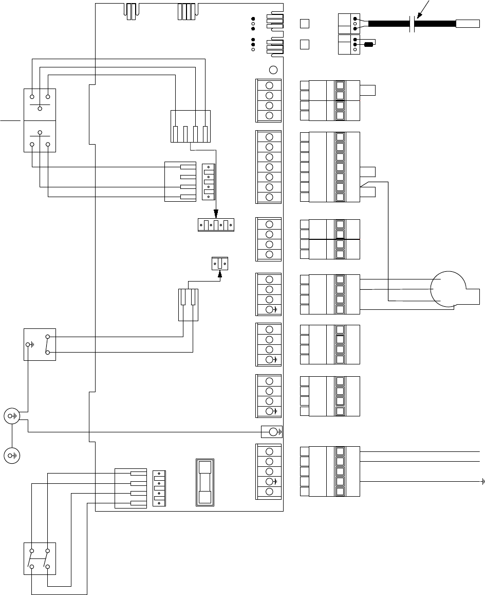
E N L
N L
Black
Cable
230V 5A Fused
Supply
N
E
Flow
Thermistor
Black shroud
indicates
Flow
Thermistor
Link Link Link
Pump Burner
Resistor
BURNER
PERMANENT LIVE
DO NOT CONNECT
DO NOT CONNECT
DO NOT CONNECT
DO NOT REMOVE LINK
DO NOT REMOVE LINK
SL
L
Figure 5-2: VortexBlue Kitchen/Utility System control panel wiring diagram
Section 5: Electrical Page 17
1 2 3
E N L
4 5 6
E N L
7 8 9
E N L
10 11 12
E N L
18 20 21 22
15 1613 14 25 26
23 24
17 19 27 28
PUMP EARTH
PUMP NEUTRAL
PUMP LIVE
DO NOT CONNECT
DO NOT CONNECT
DO NOT CONNECT
BURNER EARTH
BURNER NEUTRAL
BURNER LIVE
DO NOT CONNECT
DO NOT CONNECT
DO NOT REMOVE LINK
DO NOT
REMOVE
LINK
DO NOT CONNECT
SWITCHED
LIVE SUPPLY
TIMER NEUTRAL
TIMER LIVE
STORE
THERMISTOR
(TO FRONT POCKET)
FLOW
THERMISTOR
(TO TOP POCKET)
MAINS
1A 2A
4B 5B
Boiler
On/Off
2 C
Limit
Thermostat
Earth connection
boiler top bracket
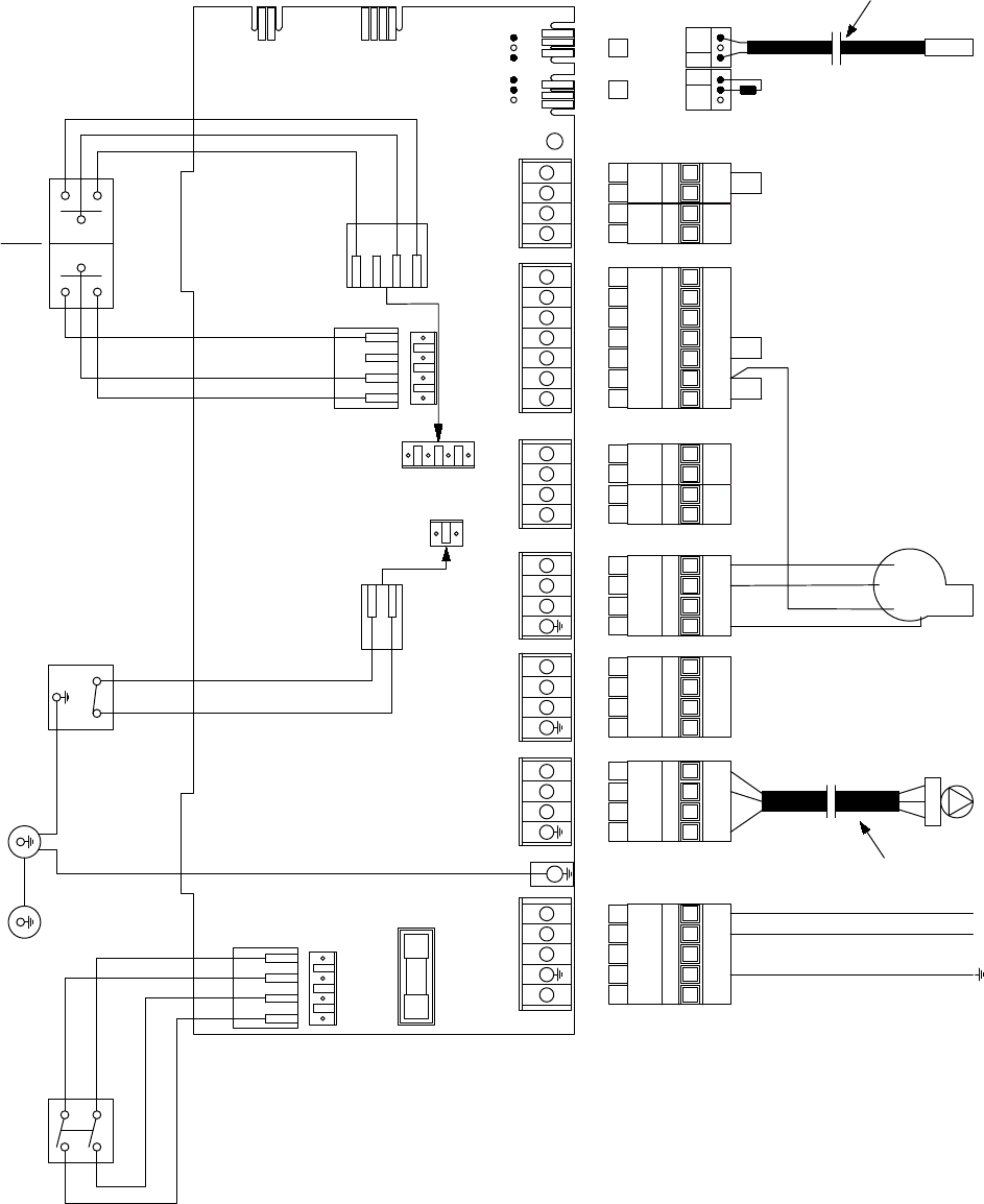
Service Switch
Printed Circuit Board
FUSE 5 X 20
N L
230V 5A Fused
Supply
N
E
Flow
Thermistor
Black shroud
indicates
Flow
Thermistor
Link Link Link
Burner
Resistor
BURNER
PERMANENT LIVE
DO NOT CONNECT
DO NOT CONNECT
DO NOT CONNECT
DO NOT REMOVE LINK
DO NOT REMOVE LINK
SL
L
Link
Link
Figure 5-3: VortexBlue External Module control panel wiring diagram
Section 5: ElectricalPage 18
Cylinder
Stat
N
Grant 2-Channel
Wall Mounted
Programmer ESKIT
L N E
240V
50HZ
5A
1 2 345 6 78 9 10
L 1 2 34
Frost
Stat
Pipe Stat
(If fitted)
Wiring Centre
OFF OFF ON ON
HW HT HW HT
2
C
1
2 1 3
Room
Stat
1 2 3 4 5 6 7 8 9 10 11 12 18 20 21 2215 1613 14 25 2623 2417 19
N L
- -
- - - - -
4 Core cable from
Controls Wiring
Centre to Boiler
Brown
Blue
Green/Yellow
Brown
Blue
Green/Yellow
Red (Switch Live)
2-Port Zone Valve
2-Port Zone Valve
Motor HW
HTG
Link Link
Blue
Green/Yellow
Motor
Blue
Green/Yellow
Grey
Grey
Orange
Orange
Brown
Brown
Pump
Brown
Blue
Green/Yellow E
N
L
Remove Link from
terminals 19 & 20
Brown Red
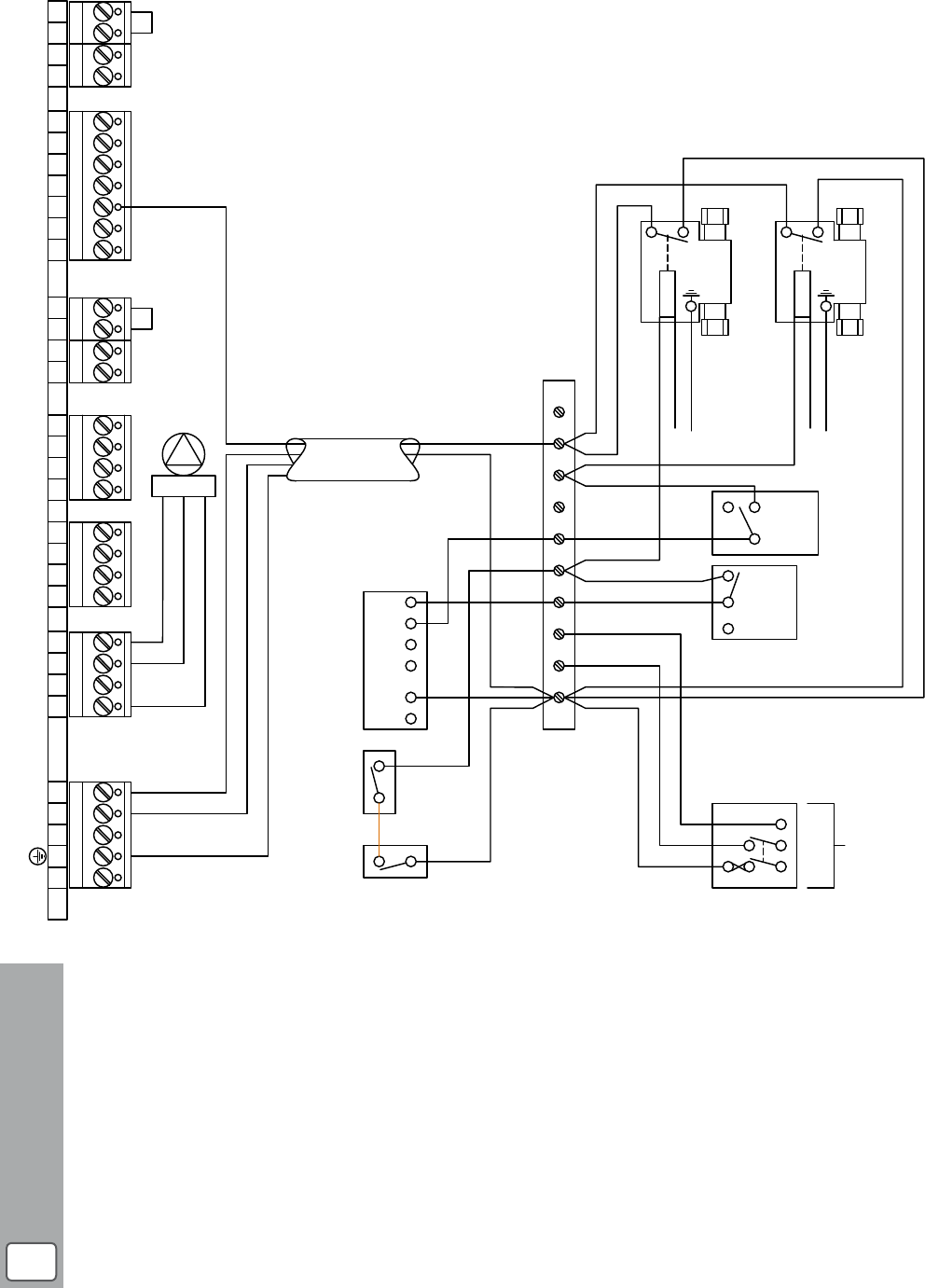
Figure 5-4: VortexBlue Kitchen/Utility, Kitchen/Utility System and External Module with S-plan type control system wiring diagram
Earth and some Neutral connections have
been excluded for clarity.
All switches are shown in the closed
position.
NOTE
!
Section 5: Electrical Page 19
Cylinder
Stat
N
Grant 2-Channel
Wall Mounted
Programmer ESKIT
L N E
240V
50HZ
5A
1 2 345678 9 10
L 1 2 34
Frost
Stat
Pipe Stat
(If fitted)
Wiring Centre
Link
OFF OFF ON ON
HW HT HW HT
3-Port Mid Position
Zone Valve
2
C
1
2 1 3
Room
Stat
1 2 3 4 5 6 7 8 9 10 11 12 18 20 21 2215 1613 14 25 2623 2417 19
N L
- -
- - - - -
4 Core cable from
Controls Wiring
Centre to Boiler
Motor
13k
2W
270k
0.25W
Brown
Blue
Green/Yellow
Brown
Blue
Green/Yellow
Orange
Grey
White
Blue
Green/Yellow
Red (Switch Live)
Link Link
Remove Link from
terminals 19 & 20
Brown
Blue
Green/Yellow E
N
L
1 2 345
RB1 Relay
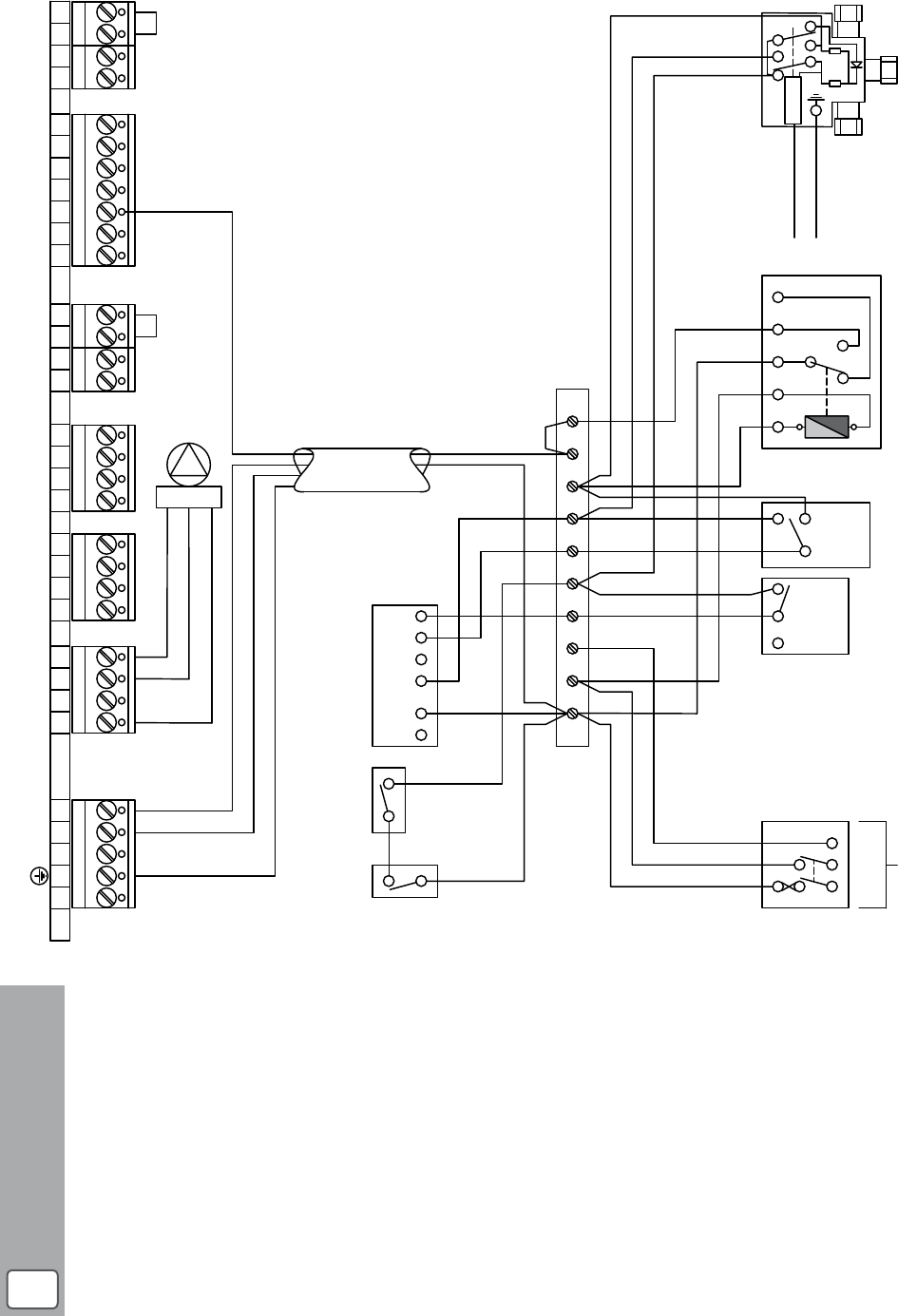
Figure 5-5: VortexBlue Kitchen/Utility, Kitchen/Utility System and External Module with Y-plan type control system wiring diagram
Earth and some Neutral connections have
been excluded for clarity.
All switches are shown in the closed
position.
NOTE
!
Section 5: ElectricalPage 20
5.5 VortexBlue Combi and External Combi Boilers
5.5.1 Connecting the Power Supply and Control System
For details on the electrical installation requirements for the Combi
or External Combi, please refer to Section 8 of the Installation
Instructions supplied with this boiler.
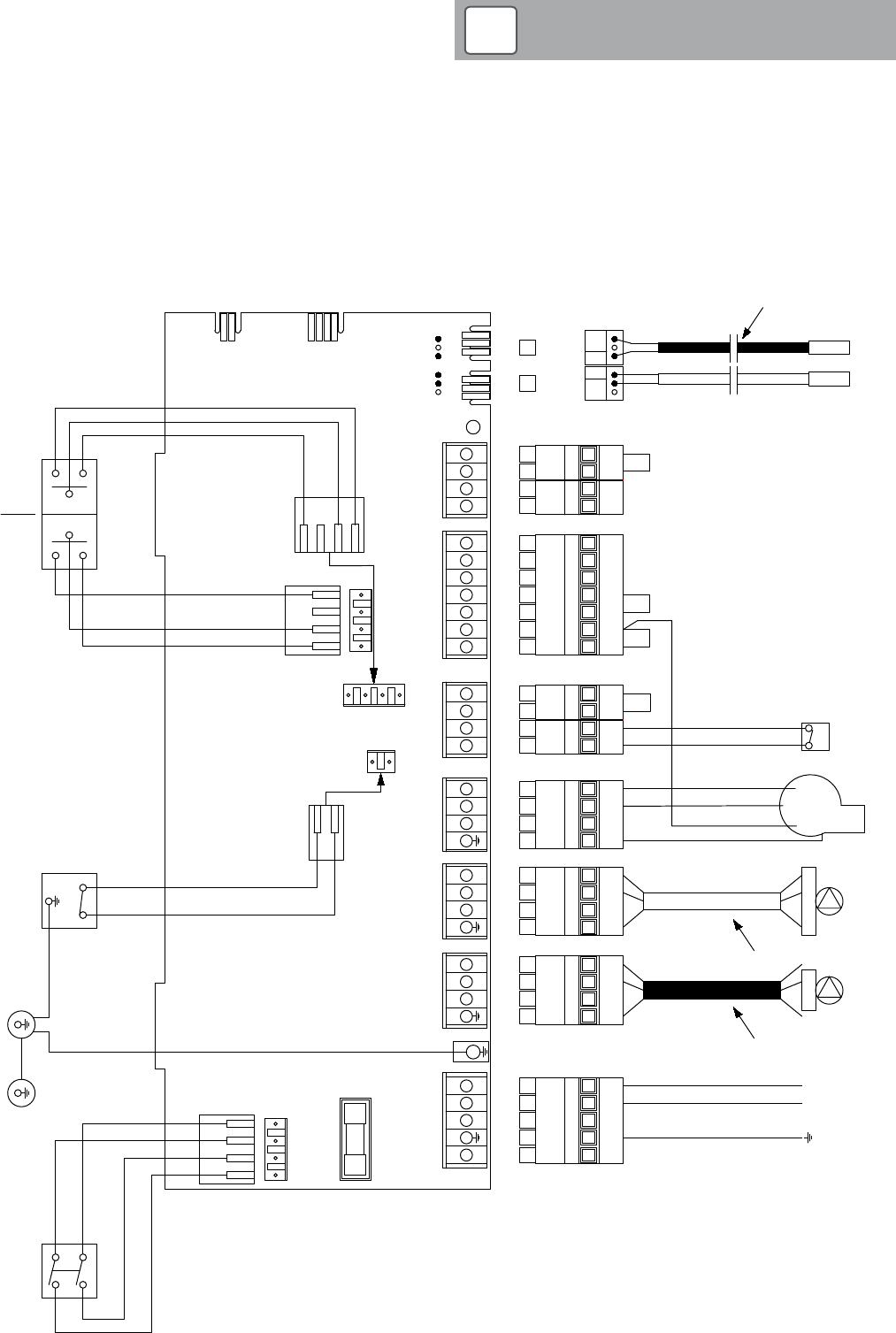
Figure 5-6: VortexBlue Internal Combi control panel wiring diagram
Figure 5-6 below replaces Figure 8-1 in the Combi boiler
Installation Instructions.
NOTE
!
1 2 3
E N L
4 5 6
E N L
7 8 9
E N L
10 11 12
E N L
18 20 21 22
15 16
13 14 25 26
23 24
17 19 27 28
CH PUMP EARTH
CH PUMP NEUTRAL
CH PUMP LIVE
DHW PUMP EARTH
DHW PUMP NEUTRAL
DHW PUMP LIVE
BURNER EARTH
BURNER NEUTRAL
BURNER LIVE
FLOW SWITCH
FLOW SWITCH
DHW TIMED ON
CH TIMED ON
TIMER NEUTRAL
TIMER LIVE
EXT. FROST STAT
EXT. FROST STAT
ROOM STAT
ROOM STAT
STORE
THERMISTOR
(TO FRONT POCKET)
FLOW
THERMISTOR
(TO TOP POCKET)
MAINS
1A 2A
4B 5B
Boiler
On/Off
Off Off
Constant
Timed Timed
Constant
Central
Heating
Switch
Domestic
Hot Water
Switch
2 C
Limit
Thermostat
Earth connection
boiler top bracket
Printed Circuit Board
FUSE 5 X 20
E N L E N L
CH
Pump
DHW
Pump
N L
Black
Cable
230V 5A Fused
Supply
White
Cable
SL
N
E
Flow
Switch
Store
Thermistor
Flow
Thermistor
Black shroud
indicates
Flow
Thermistor
Link Link Link
L
BURNER
PERMANENT LIVE
Link
Section 5: Electrical Page 21
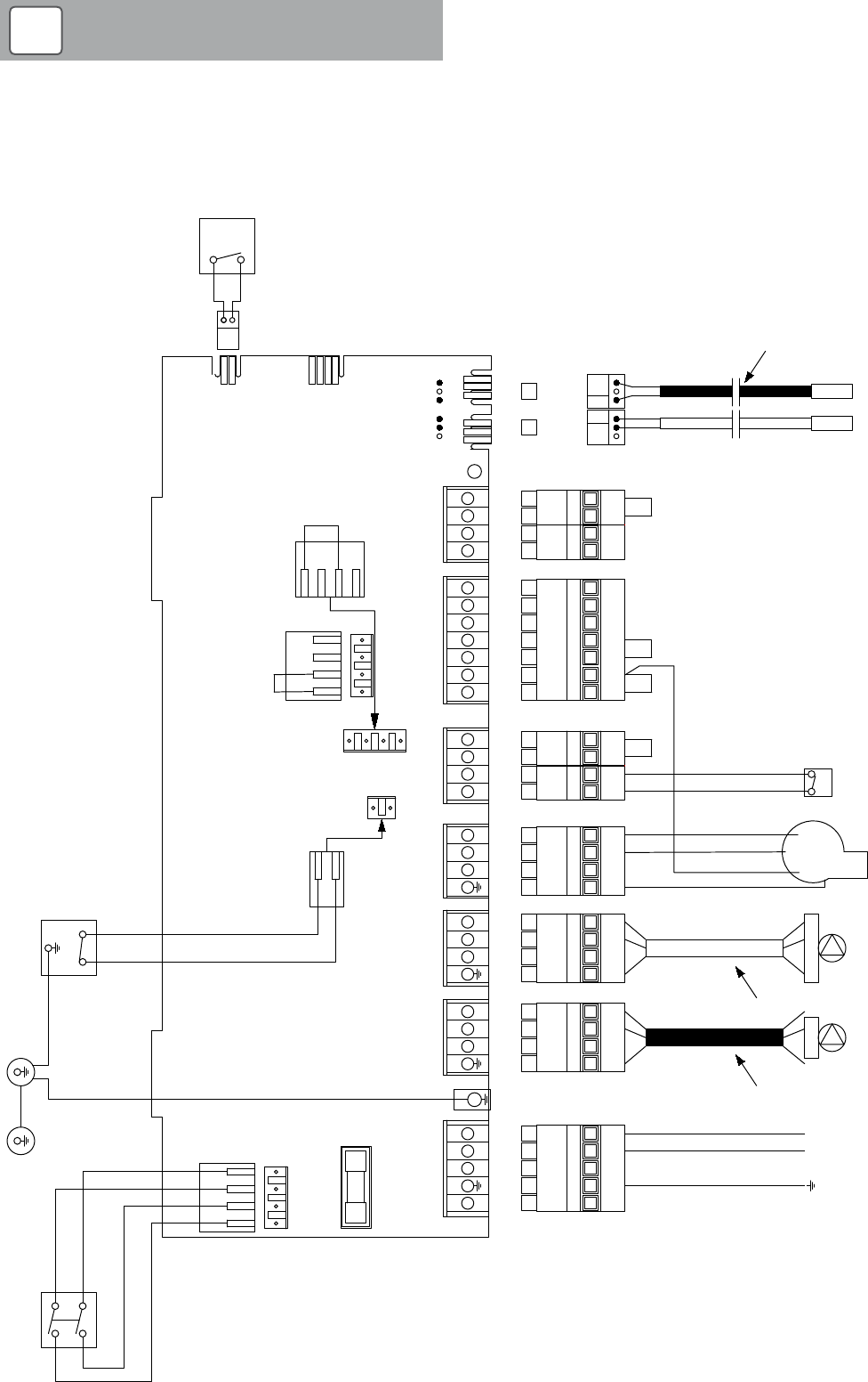
Figure 5-7: VortexBlue External Combi control panel wiring diagram
1 2 3
E N L
4 5 6
E N L
7 8 9
E N L
10 11 12
E N L
18 20 21 22
15 16
13 14 25 26
23 24
17 19 27 28
CH PUMP EARTH
CH PUMP NEUTRAL
CH PUMP LIVE
DHW PUMP EARTH
DHW PUMP NEUTRAL
DHW PUMP LIVE
BURNER EARTH
BURNER NEUTRAL
BURNER LIVE
FLOW SWITCH
FLOW SWITCH
DHW TIMED ON
CH TIMED ON
TIMER NEUTRAL
TIMER LIVE
EXT. FROST STAT
EXT. FROST STAT
ROOM STAT
ROOM STAT
STORE
THERMISTOR
(TO FRONT POCKET)
FLOW
THERMISTOR
(TO TOP POCKET)
MAINS
1A 2A
4B 5B
Boiler
On/Off
2 C
Limit
Thermostat
Earth connection
boiler top bracket
Printed Circuit Board
FUSE 5 X 20
E N L E N L
CH
Pump
DHW
Pump
N L
Black
Cable
230V 5A Fused
Supply
White
Cable
SL
N
E
Flow
Switch
Store
Thermistor
Flow
Thermistor
Black shroud
indicates
Flow
Thermistor
Link Link Link
L
Service Switch
BURNER
PERMANENT LIVE
Link
Link
Link
Figure 5-7 below replaces Figure 8-1 in the External Combi
boiler Installation Instructions.
NOTE
!
Section 6: CommissioningPage 22
6.1 General
To commission the boiler and burner follow the procedure given
in the Section 10 of the Vortex (or Vortex Combi ) Installation
Instructions supplied with the boiler.
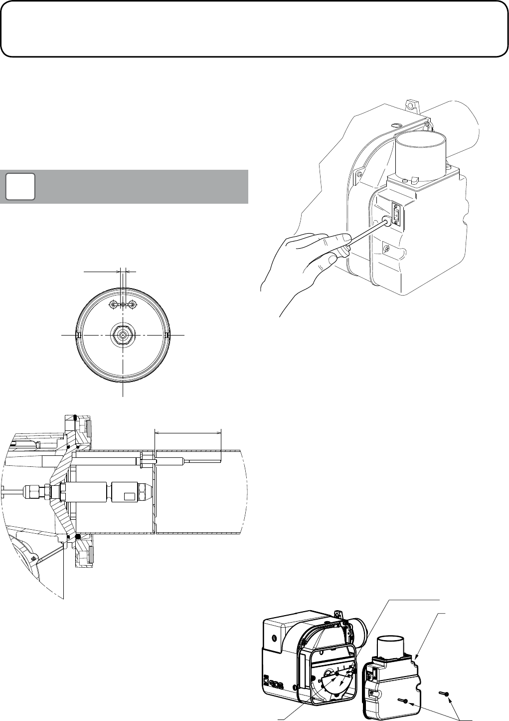
6.2 Ignition Electrode Setting
Before first firing the boiler ensure that the burner ignition electrodes
are correctly set.
The ignition electrode details given in Figure 6-1 below
replaces that given in the Installation Instructions supplied
with the boiler.
NOTE
!
Figure 6-1: Riello RDB BLU ignition electrode setting
±0.5
6 3
±0.5
5
6 Commissioning
6.3 Air Damper Adjustment
Use a 3mm Allen key to adjust the air damper. Refer to Figure 6-2.
Figure 6-2: Air damper adjustment
6.4 Air Adjuster Disc – 21kW only
The boiler is supplied with an air adjuster disc loose in the
accessories bag.
To fit and position the air adjuster disc when downrating the 21kW
boiler to 15 or 16kW output:
1. Ensure the boiler is isolated from the electrical supply.
2. Remove the burner from the boiler.
3. Undo the two screws (1) and remove the air damper assembly
from the side of the burner.
4. Remove the screw (2) from the centre of where the air adjuster
disc will be fitted.
5. Position the disc such that the disc setting ‘B’ (corresponding
to 15 or 16kW output setting – refer to Section 3.3) is located
against the cast boss on the fan housing.
6. Replace the screw in the centre of the air adjuster disc and
tighten.
7. Re-fit the air damper assembly to the side of the burner and
reassemble in reverse order.
Air adjuster disc
Air damper assembly
1
2
Figure 6-3: Fitting the air adjuster disc

Section 7: Servicing Page 23
7.1 General
To service the boiler and burner follow the procedure given in the
Section 11 of the Vortex boiler (or Vortex Combi boiler) Installation
Instructions supplied with the boiler.
7 Servicing
Section 8: BurnerPage 24
8.1 General
All Grant VortexBlue boilers are fitted with a Riello RDB BLU blue
flame burner. This has been designed to operate with reduced
NOx emissions that meet the forthcoming European Ecodesign
emissions regulations.
From September 2018 the maximum permissible NOx level for oil
fired boilers is 120mg/kWh. All Grant VortexBlue boilers, fitted with
the Riello RDB BLU burner, will operate well below this minimum
level and thus fully comply with these emissions regulations when
they come into effect.
8.2 Burner Features
The Riello RDB BLU blue flame burner fitted to the Grant VortexBlue
boilers is very similar to the Riello RDB 'yellow flame' burners, such
as those fitted to the Vortex range of oil fired boilers.
The main differences with the blue flame burner are as follows:
• An Ultra Violet (UV) sensor is used – the blue flame cannot be
detected by the usual photocell.
• A digital control box is used – the UV cell cannot be used with
the usual 'analogue' control box.
• A clear reset button (on the control box) with burner status and
fault identification by different coloured indicator lights.
• A longer combustion head – to allow the necessary
recirculation of the combustion gases.
• A post purge following flame shut off – requiring a permanent
live to the burner in addition to the usual switched live.
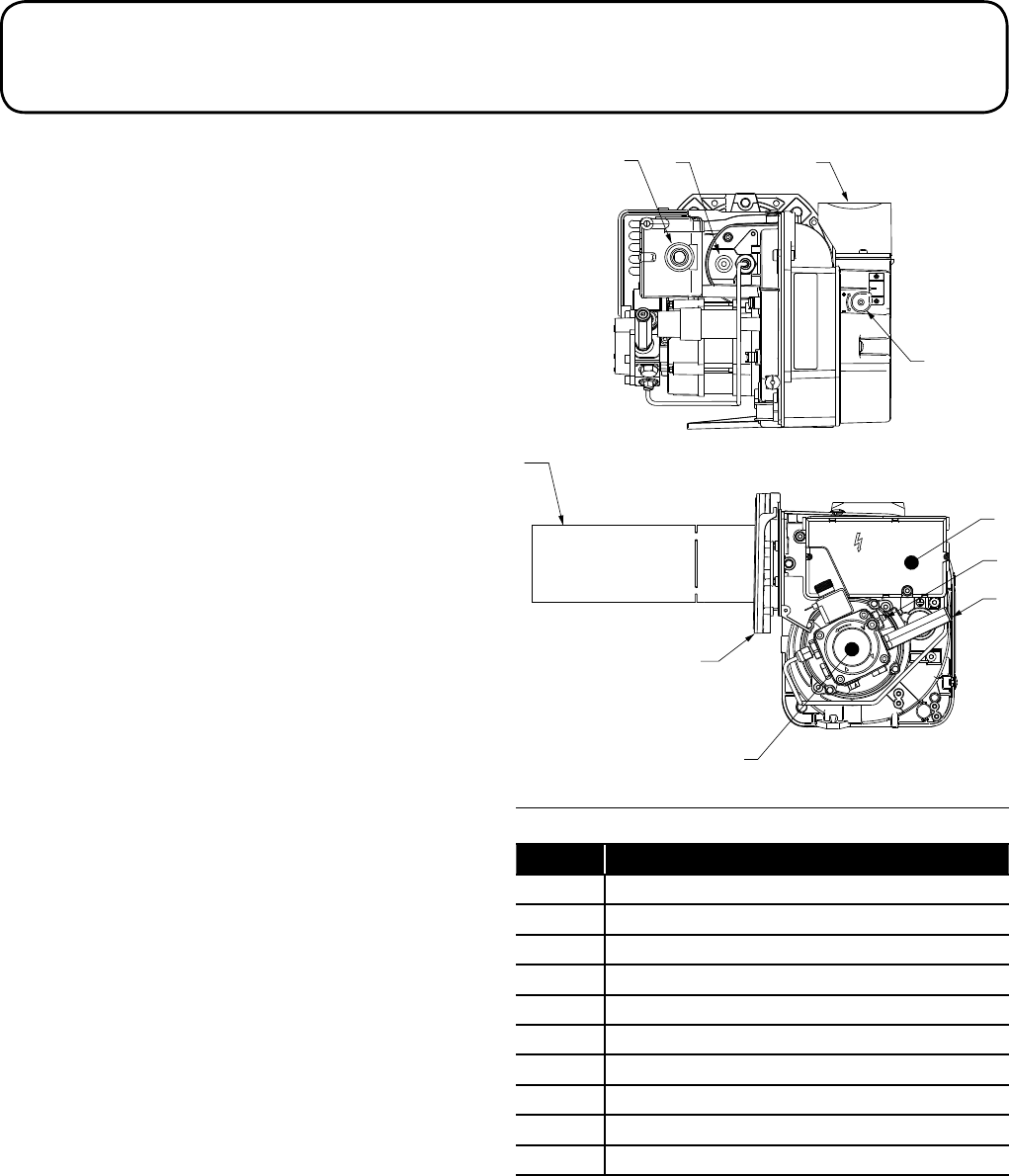
8 Burner
39
5
6
10
4
1
7
8
2
Figure 8-1: Burner components
Table 8-2: Burner components key
Key Description
1 Oil pump
2 Digital control box
3 Reset push-button with lockout lamp
4 Flange with insulating gasket
5 Air damper adjustment screw
6 Snorkel (balanced flue)
7 Pump pressure adjustment screw
8 Pressure gauge port
9 UV sensor
10 Combustion head
Section 8: Burner Page 25
8.3 Digital Control Box
The digital control box fitted to this burner has several different
features compared to the more commonly used 'analogue' control
box.
8.3.1 Reset Push-button
This is a clear (transparent) button that will indicate the operating
status of the burner and also burner faults depending on the colour
of the indicator LED visible through the reset button.
If there is no heat demand to fire the burner, the indicator LED will
be off, i.e. no colour visible though the reset push button.
Refer to Figure 8-1 for the location of the control box and reset push-
button.
If the reset push-button LED is indicating a lockout (refer to Section
8.3.3), press the reset button to attempt to re-start the burner. If the
burner then operates correctly the lockout may have been caused
by a temporary fault that has now cleared. If the lockout persists the
cause of the fault should be diagnosed and rectified.
To operate the reset push-button it must be pressed in and
briefly held (for at least one second) before releasing.
NOTE
!
The burner can only be reset 5 times consecutively, after
which the mains power supply has to be switched off and
then back on for a further 5 reset attempts to be available.
NOTE
!
8.3.2 Operating Status Indication
From start up the operating status of the burner is displayed via the
reset push-button indicator LED on the control box. Refer to Table
8-3.
8.3.3 Burner Fault Indication
Whenever a burner lockout occurs the cause is displayed via the
reset push-button indicator LED on the control box. Refer to Table
8-4.
8.3.4 Last Lockout Display
The control box memorises the details of the last lockout that
occurred and this information can be recalled and displayed by the
reset push-button indicator LED.
To operate this function:
• Press and hold the reset push-button for 25 seconds
• During this time the reset push button indicator LED will first
flash RED (twice) and then flash GREEN (once) and then
GREEN again (three times)
• As soon as it flashes GREEN four times release the reset push-
button immediately
• The reset push-button indicator LED will then display the last
lockout indication, e.g. constant red.
• Refer to the Fault Diagnostics table (Table 9-2) in Section 9 of
these Supplementary Instructions to identify the fault from the
indicator LED sequence.
The lockout fault will only be displayed for a period of 10 seconds. If
required, this period can be extended by re-pressing the reset push-
button during the display of the lockout. The lockout display will then
be extended by a further 10 seconds.
Table 8-3: Burner operating status indicator
Status Reset push-button colour Seconds Notes
OFF OFF - -
Pre-purge ORANGE blinking 0.5 0.5
Safety time GREEN blinking 0.5 0.5
Normal operating position GREEN - - Steady ON
Table 8-4: Burner operating status indicator
Status Reset push-button colour Seconds Notes
Extraneous light (false flame signal) GREEN, RED blinking alternately 0.5 0.5
Frequency supply error ORANGE - - Steady ON
Voltage monitor error ORANGE, GREEN fast blinking alternately 0.2 0.2
Reset push-button / remote reset anomaly GREEN, RED fast blinking alternately 0.2 0.2
Lockout for no flame after safety time RED - - Steady ON
Go to box A*
Lockout for false flame signal RED blinking 0.5 0.5 Go to box B*
Lockout for maximum number of re-cycles RED fast blinking 0.2 0.2 Go to box C*
Lockout for fan motor error RED, ORANGE blinking inverted 2.5 0.5 Go to box D*
Lockout for oil valve error RED, GREEN blinking inverted 2.5 0.5 Go to box E*
Lockout for eeprom error ORANGE, GREEN blinking alternately 0.5 0.5 Go to box F*
* Refer to the fault finding chart - Section 8.3.
Section 8: BurnerPage 26
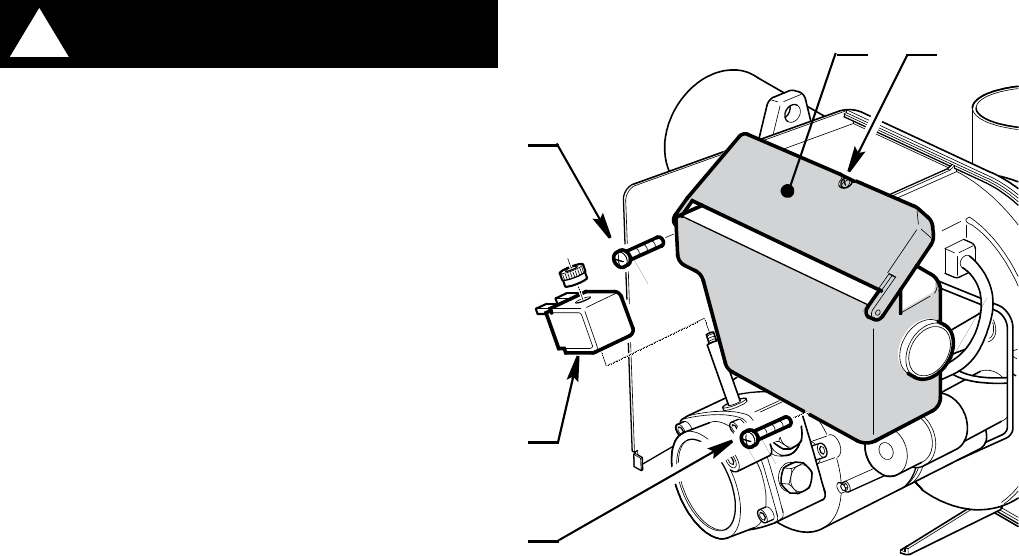
8.3.5 Removal of Control Box
Before removing the control box from the burner, or opening
the control box cover, isolate the electrical supply to the
boiler.
!WARNING
To remove the control box proceed as follows (referring to Figure
8-5):
• Unscrew and remove screw (1) and open control box cover (2).
• Disconnect all plugs from the control box terminals.
• Unscrew the retaining finger nut and remove the solenoid coil
(3) from the oil pump.
• Unscrew and remove the two screws (4) and remove the
control box from the burner.
• Disconnect the two ignition leads from the ignition connections
on rear of control box.
• Refit the control box to the burner using the reverse of the
above procedure.
4
4
3
12
Figure 8-5: Removal of control box
Section 8: Burner Page 27
8.4 Burner Operation
8.4.1 Burner Operating Times
Table 8-6: Burner operating times
Symbol Description Value
(seconds)
t0 Standby: the burner is waiting for a heat request -
t1 Standby time for an input signal: reaction time,
control box remains in waiting status for t1 ≤ 1
t2 Initialisation standby time: check time following
the main power start-up 3.5
t2l Checks extraneous light during t2: waiting mode
for t2l, then lockout: the motor does not start 25
t3 Pre-purge time: the fan motor is working 15
t3l Checks extraneous light during pre-purging:
control box goes into lockout at the end of t3l 25
t3i Spark pre-ignition time 2
ts Safety time 5
t4i Total spark ignition time 10
t4l Reaction time to achieve safety shut-down due
to flame failure ≤ 1
t5i Spark post-ignition time 3
tr
Re-cycles: Max. no. 3 repetitions of complete
start-up sequence if there is a flame failure
during
operation; the final action at the last attempt fol-
lowing flame failure is a lock-out
3 re-cycles
tpp
Post-purge time: additional purge time at the end
of a heat request. Can be interrupted by a new
heat request
60
8.4.2 Presence of Extraneous light or Flame
On burner start up, when the fan starts to pre-purge the burner/
boiler, if an extraneous light or flame is detected in the combustion
chamber by the UV sensor the burner fan continues to run until
either:
a) The extraneous light or flame disappears, or
b) 25 seconds elapses, a burner lockout occurs and the fault
indicator LED flashes Green/Red
If an extraneous light or flame is detected after the fan has started
(i.e. at some time during the pre-purge period) the pre-purge time
of 15 seconds is reset, and the 25 second time for checking for the
presence of extraneous light or flame starts and the fan continues
to run.
As above, if the extraneous light or flame does not disappear after
25 seconds a burner lockout occurs. This function is cumulative and
can operate a maximum of two times during the burner pre-purge
period.
If the extraneous light or flame disappears after 24 seconds (or less)
the pre-purge period and the 25 second countdown for checking for
extraneous light or flame re-starts. If the extraneous light or flame
re-appears the process is repeated. If the extraneous light or flame
appears for a third time, the burner goes into lockout.
If during a burner recycle operation due to Flame failure (refer to
Section 8.4.4 – Burner Recycle Function) an extraneous light or
flame is detected, the 25 second countdown starts for checking for
extraneous light or flame.
The presence of extraneous light or flame can also be detected
when the burner is in:
c) The standby condition waiting for a heating demand to start the
burner.
d) The Initialisation period (t2) after the heating demand but
before the burner fan starts.
8.4.3 Spark Ignition Duration
The 'pre-ignition' spark time starts 2 seconds before the oil valve
opens (the start of the 5 second 'safety time' period).
The 'post-ignition' spark time ends 3 seconds after the end of the
safety time period, i.e. 8 seconds after the oil valve opens.
The ignition spark is present throughout the 'safety time' period (5
seconds) making a total spark ignition period of 10 seconds.
In the case of continuous ignition sequence recycling
after flame failure, or heat demands close to one another,
the maximum number of cycle repetitions of the ignition
transformer is one attempt every minute.
NOTE
!
8.4.4 Burner Recycle Function
In event of flame failure during burner operation the control box will
allow the burner to recycle and repeat the start-up sequence for
the burner to attempt to re-fire. This can occur up to a total of three
attempts to re-fire the burner. If it fails a fourth time in operation it will
cause a burner lockout and the reset push-button indicator LED will
be RED.
After 8½ minutes of continuous burner operation the control
box regains one attempt to re-fire (should it be required).
If the power supply to the boiler is disconnected and then
reconnected, when the next heat demand is applied to the
burner all three possible attempts to re-fire are restored.
NOTE
!
8.4.5 Post Purge Function
This function allows air flow through the burner for a pre-set time
after the burner flame is switched off (on the loss of demand for the
burner to fire).
The loss of demand from either the heating system controls, or
boiler temperature control, interrupts the switched live to the burner
resulting in the fuel supply being shut off and the flame stopped.
The permanent supply to the burner maintains the fan operation for
a short period to provide the post purging of the burner and boiler
prior to the burner re-firing again.
The post-purge function does not operate:
e) After a burner lockout has occurred
f) If the heat demand is interrupted during the pre-purge period
However, the post-purge function will operate if the heat demand is
interrupted:
g) During the safety time period (i.e. immediately after burner
ignition)
h) During normal operation of the burner
If the UV cell detects any extraneous light or flame during the pre-
purge period the burner will go to 'lockout' after 25 seconds.
If there is a new heat demand during the post-purge period, the
post-purge function is halted (the fan stops) and a new burner
operating cycle starts.
Section 9: Fault FindingPage 28
9.1 Burner Fault Indication
Whenever a burner lockout occurs the cause is displayed via the reset push button indicator LED on the control box. The colour, sequence
and speed of the indicator LED flashes identify the specific lockout type and the possible causes are listed in Table 8-1.
Table 9-1: Burner fault indication
Lockout description Lockout time LED colour Probable cause
Presence of extraneous light during
standby After 25 seconds RED
blinking
•Presenceofafalseflamesignalbeforetheheat
request
Presence of extraneous light detected
during pre-purging After 25 seconds RED
blinking •Presenceoffalseflamesignalduringpre-purging
Extraneous light detected during
post-purging After 25 seconds RED
blinking
•Presenceoffalseflamesignalduringpost-purging
(or pre-heating if the short-circuit socket is not
connected
The flame is not detected after the
safety time After 5 seconds from oil-valve starts RED
steady ON
•UVsensordefectiveordirty
•Oilvalvedefectiveordirty
•Faultyignitiontransformer
•Badlyregulatedburner
•Oilfuelnotpresent
Flame failure during operation After 3 recycles RED
blinking
•Badlyadjustedburner
•Oilvalvedefectiveordirty
•UVsensordefectiveordirty
Fan motor error Immediate (during pre-purge) RED, ORANGE
blinking inverted
•Faultyfanmotor
•Fanmotornotconnected
Malfunction in the internal control
circuit that drives the oil valve Immediate (during pre-purge) RED, GREEN
blinking inverted
•Faultyoilvalve
•Internalcontrolcircuitthatdrivestheoilvalvefaulty
Eeprom error Immediate (during pre-purge) ORANGE, GREEN
blinking inverted •Faultyinternalmemory
9.2 Burner Fault Diagnostics
Table 9-2: Burner faults
Faults Possible cause Fault
diagnostics Solutions
The burner does not start when there
is heat demand
Lack of electrical supply OFF
Check presence of voltage in the L - N the pin plug
Check the conditions of the fuses.
Check that safety thermostat is not in lockout
The UV sensor sees an extraneous
light
GREEN, RED
blinking Eliminate the extraneous light.
The connections in the control box are
wrongly inserted OFF Check and connect all the plugs and sockets
properly.
The burner goes into lockout mode
before or during the pre-purging The UV sensor sees extraneous light RED blinking Eliminate the extraneous light.
Burner runs normally in the pre-purge
and ignition cycle and locks out after
about 5 seconds
The UV sensor is dirty
RED steady ON
Clear it
The UV sensor is faulty Replace it
Flame moves away or fails
Check pressure and output of the fuel
Check air output
Change nozzle
Check the coil of solenoid valve
Burner starts with an ignition delay
The ignition electrodes are wrongly
positioned
GREEN blinking
Adjust them according to the instructions of this
manual
Air output is too high Set the air output according to the instructions of this
manual
Nozzle dirty or worn Replace it
9 Fault Finding
Section 9: Fault Finding Page 29
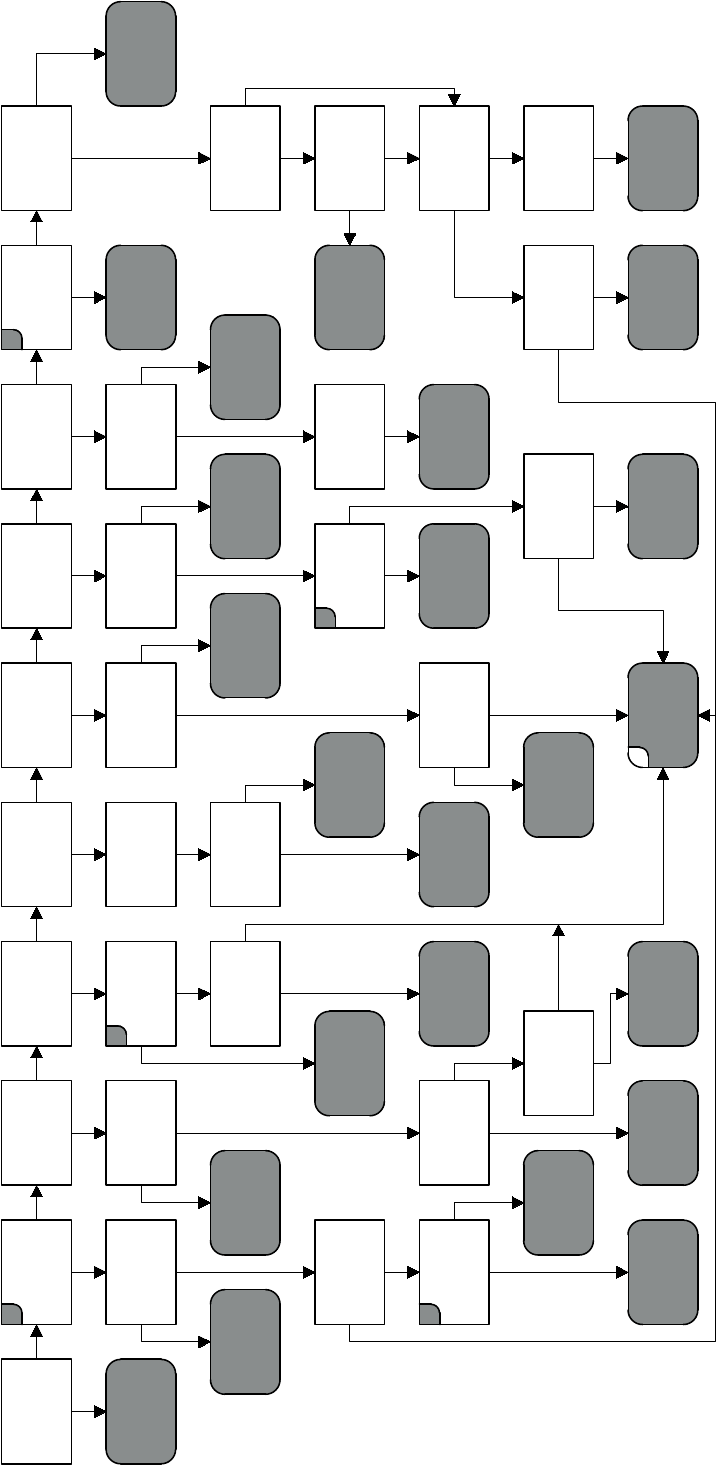
9.3 Riello RDB BLU Fault Finding Chart
Figure 9-3: Riello RDB BLU Fault Finding
Contaminated
fuel
filters?
Control box
is supplied
with heat
demand
Fan runs for
less than
12 seconds
Burner locks
out after
25 seconds
Washing
pressure
1 - 2 bar
Ignition
spark
present
Coil releases
working
pressure?
Nozzle
atomising
the fuel?
Combustion
head set
correctly?
Motor starts
after initialisation
Check time 3.5sec?
A
Check boiler
and system
controls
B
Fan motor
or oil
pump seized?
Motor gives
50V AC across
white and
black wire?
Burner
fires when
UV sensor is
covered?
Check oil
supply to
oil pump
Are electrodes
OK and
set correctly?
Clean or
replace
filters
Nozzle
new?
Adjust
combustion air
setting
Reset
combustion
head
Replace
seized
component
Replace
fan
motor
Is the UV sensor
faulty?
Drive
coupling
broken?
Replace or
reset
electrodes
Replace
nozzle
Flame goes
out then
relights?
230V to motor
across blue and
black wire?
Remove
extraneous
light
Replace
pump
coupling
Check oil pipe
from pump to
nozzle holder
Clear
blockage
Boiler or
flue
blocked?
Approx.
35 Ω across blue
and black motor
wire?
DCoil
lead
OK?
Replace
UV sensor
Replace
oil
pump
Ignition
leads
OK?
Replace
coil
Clean or replace
pump and fuel
line filters
If balanced flue:
remove snorkel
and test - now OK?
Coil
resistance
90 to 110Ω?
E
Coil
resistance
90 to 110 Ω?
Replace
ignition
leads
After 15 seconds
25-30V DC to coil?
(coil connected)
Is the UV sensor
faulty?
Balanced flue can
recirculate gases
causing recycling
Replace
motor
capacitor
Replace
coil
lead
Replace
coil
Replace
oil
pump
Replace
UV sensor
Check flue
position
and seals
YAir
set
correctly?
C
Y N N Y Y Y Y Y N
Y
Y
N
NN
N
YN
N
Y N Y N Y N
Y
N Y
Y
N N Y Y N N N N N Y
N
N
Y
Y Y
N
Y
Y N Y
N Y
Y N
Y
Y N
N
N
FReplace
control
box
Replace fan
motor and check
control box
Section 10: Spare PartsPage 30
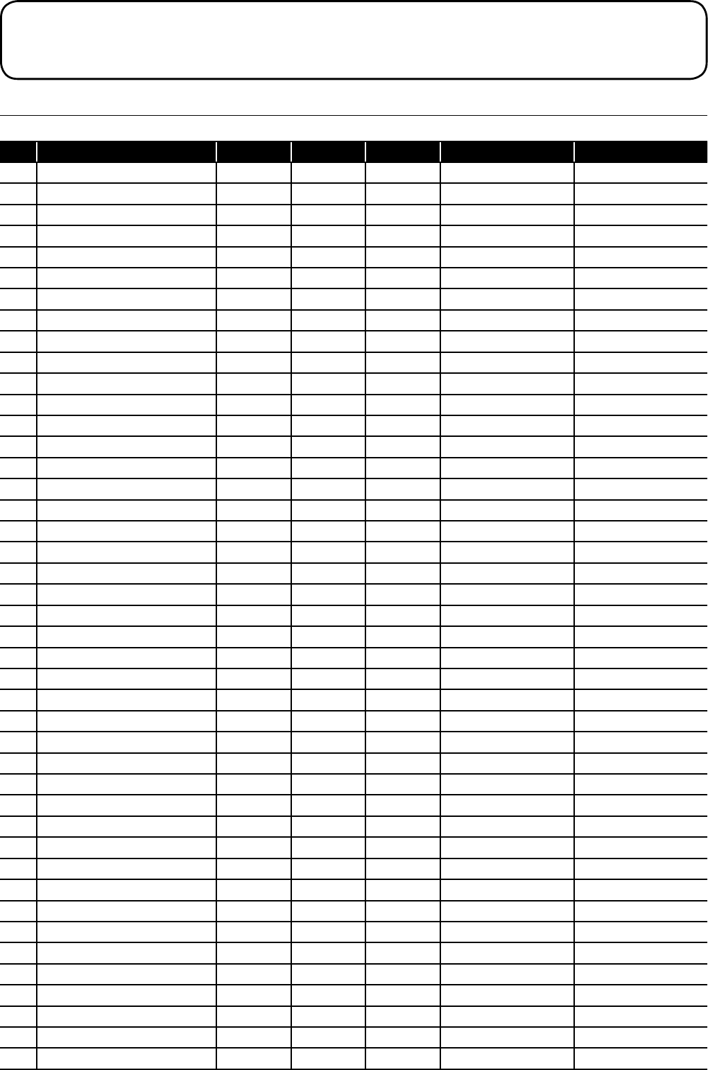
10.1 Riello RDB BLU Burner Parts List
Table 10-1: Riello RDB BLU burner parts list
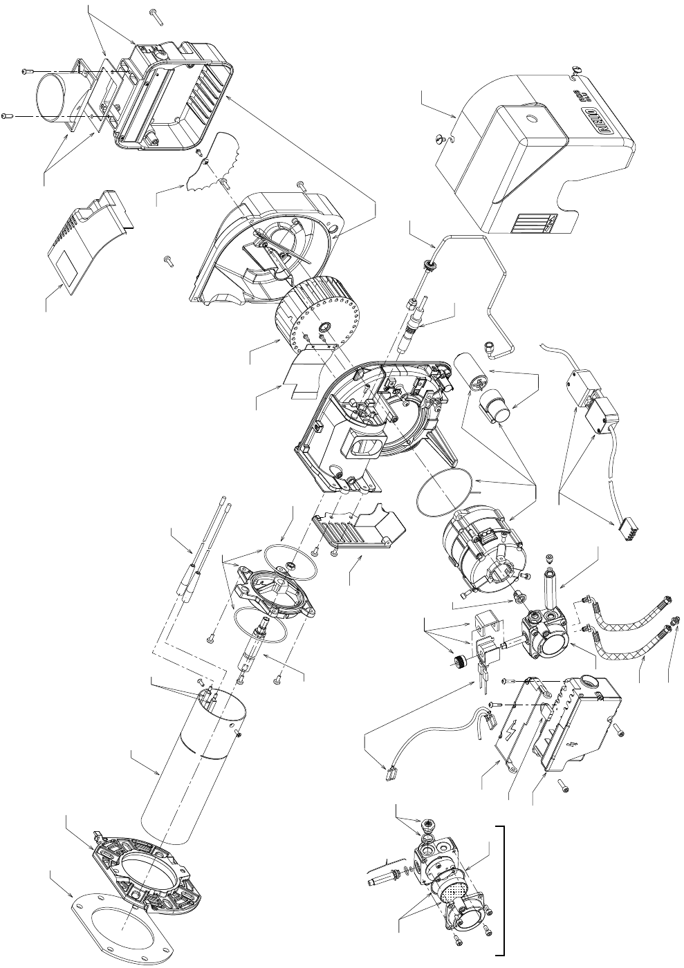
Key Description 21kW burner 26kW burner 36kW burner Riello product code Grant UK product code
1 Gasket ü ü N/A 3005787 RBS27
1 Gasket N/A N/A ü20117411 RBS200
2 4-pin connector üN/A N/A 20117417 RBS201
2 4-pin connector N/A ü ü 20117432 RBS202
3 Combustion head - BG1 ü ü N/A 20117435 RBS203
3 Combustion head - BG3 N/A N/A ü20117437 RBS204
4 Ignition electrodes üüü 20117455 RBS205
5 Pre-heater jumper üüü 20045862 RBS206
6 Nozzle holder ü ü N/A 20117459 RBS207
6 Nozzle holder N/A N/A ü20117461 RBS208
7 Collar (including o-rings) ü ü N/A 20117472 RBS209
7 Collar (including o-rings) N/A N/A ü20117476 RBS210
8 Ignition HT lead üüü 20105111 RBS211
9 Air damper assembly üN/A N/A 3008647 RBS116
9 Air damper assembly N/A ü ü 3008839 RBS166
10 Fan üüü 3005788 RBS151
11 UV sensor üüü 20095126 RBS212
12 Capacitor 4.5 μF üüü 20071576 RBS149A
13 Solenoid valve üüü 3007871 RBS213
14 Pump pressure regulator üüü 20032135 RBS214
15 Air adjuster disc üN/A N/A 20094349 RBS215
16 Oil pump üüü 20030953 RBS101
17 O-ring (pump filter) - 10 pack üüü 3007175 RBS216
18 Pump filter and o-ring üüü 3020436 RBS217
19 Oil hose connector - 3/8 x 1/4 üüü 3009068 RBS218
20 Flexible oil hose üüü 3007621 RBS219
21 Oil pipe üüü 20117488 RBS220
22 Pressure gauge connector üüü 3008876 RBS138
23 Oil pump drive coupling - 10 pack üüü 3000443 RBS16
24 Solenoid coil üüü 3008648 RBS117
25 Motor and capacitor 4.5 μF üüü 20071577 RBS102A
26 Control box cover üüü 20094351 RBS221
27 Control box üüü 20117694 RBS222
28 Solenoid coil lead üüü 3008682 RBS223
29 Cover üüü 20117497 RBS224
30 O-ring kit üüü 3008878 RBS140
31 Front shield üüü 3020306 RBS225
32 Air intake - balanced flue üüü 3020281 RBS226
33 Air baffle ü ü N/A 20117504 RBS227
33 Air baffle N/A N/A ü20117506 RBS228
34 Flange ü ü N/A 3006384 RBS119
34 Flange N/A N/A ü20094352 RBS229
35 Air intake - conventional flue üüü 20012046 RBS230
10 Spare Parts
Section 10: Spare Parts Page 31
Figure 10-2: Exploded view of Riello RDB BLU burner
10.2 Exploded View of Riello RDB BLU Burner
2
1
34
3
4
8
7
30
33 10
30
15
32
9
6
31
26
23
25 12
24
22
16
11
21 29
20
19
5
27
28
14
13
18
17
35
16

GRANT ENGINEERING (UK) LIMITED
Hopton House, Hopton Industrial Estate, Devizes, Wiltshire, SN10 2EU
Tel: +44 (0)1380 736920 Fax: +44 (0)1380 736991
Email: info@grantuk.com www.grantuk.com
