HP UEFI System Utilities User Guide For ProLiant Gen9 Servers Pro Liant
User Manual: Pdf
Open the PDF directly: View PDF ![]() .
.
Page Count: 99
- HP UEFI System Utilities User Guide for HP ProLiant Gen9 Servers
- Contents
- 1 Introduction
- 2 Getting started with UEFI System Utilities
- 3 Using the System Configuration menu options
- BIOS/Platform Configuration (RBSU)
- System Options
- Boot Options
- Network Options
- Storage Options
- Embedded UEFI Shell options
- Power Management
- Performance Options
- Server Security
- Set Power On Password
- Set Admin Password
- One-Time Boot Menu (F11 Prompt)
- Intelligent Provisioning (F10 Prompt)
- Embedded Diagnostics
- Embedded Diagnostics Mode
- No-Execute Protection
- Processor AES-NI Support
- Intel (R) TXT Support
- Secure Boot Settings
- Trusted Platform Module options
- PCI Device Enable/Disable
- Server Availability
- BIOS Serial Console and EMS
- Server Asset Information
- Advanced Options
- Date and Time
- System Default Options
- BIOS/Platform Configuration (RBSU)
- 4 Using the iLO 4 Configuration Utility
- Accessing the iLO 4 Configuration Utility menu
- Configuring Network Options
- Configuring Advanced Network Options
- Managing iLO users by using the iLO 4 Configuration Utility
- Configuring access settings by using the iLO 4 Configuration Utility
- Viewing information about iLO
- Resetting iLO to the factory default settings by using the iLO 4 Configuration Utility
- Resetting iLO by using the iLO 4 Configuration Utility
- Accessing the iLO 4 Configuration Utility menu
- 5 Viewing Smart Array Controller information
- 6 Viewing and configuring NIC and FCoE settings
- 7 Using the One-Time Boot Menu
- 8 Working with Embedded Applications
- 9 Viewing System Information and System Health
- 10 Rebooting the system and selecting a language
- 11 Configuration flows (manual and scripted)
- 12 Troubleshooting
- 13 Support and other resources
- Glossary
- Index

HP UEFI System Utilities User Guide for HP
ProLiant Gen9 Servers
Abstract
This guide details how to access and use the Unified Extensible Firmware Interface (UEFI) that is embedded in the system ROM
of all UEFI-based HP ProLiant Gen9 servers. It details how to access and use both UEFI and Legacy BIOS options provided in
BIOS/Platform Configuration menus that were formerly known as the ROM-Based Setup Utility (RBSU). All options and available
responses are defined. This document is for the person who installs, administers, and troubleshoots servers and storage systems.
HP Part Number: 794200-004
Published: October 2015
Edition: 1

© Copyright 2014, 2015 Hewlett-Packard Development Company, L.P.
Confidential computer software. Valid license from HP required for possession, use or copying. Consistent with FAR 12.211 and 12.212, Commercial
Computer Software, Computer Software Documentation, and Technical Data for Commercial Items are licensed to the U.S. Government under
vendor's standard commercial license.
The information contained herein is subject to change without notice. The only warranties for HP products and services are set forth in the express
warranty statements accompanying such products and services. Nothing herein should be construed as constituting an additional warranty. HP shall
not be liable for technical or editorial errors or omissions contained herein.
Acknowledgments
Intel®, Itanium®, Pentium®, Intel Inside®, and the Intel Inside logo are trademarks or registered trademarks of Intel Corporation or its subsidiaries
in the United States and other countries.
Microsoft®, Windows®, Windows® XP, and Windows NT® are trademarks of the Microsoft group of companies.
® is a registered trademark of the UEFI Forum, Inc.

Contents
1 Introduction...............................................................................................7
What is UEFI?..........................................................................................................................7
2 Getting started with UEFI System Utilities.......................................................8
Launching and navigating the HP UEFI System Utilities menus.........................................................8
Overview of the System Utilities screen........................................................................................9
Common setup and configuration tasks......................................................................................10
Updating firmware or system ROM.......................................................................................12
Updating firmware from the System Utilities.......................................................................12
3 Using the System Configuration menu options...............................................13
BIOS/Platform Configuration (RBSU).........................................................................................13
System Options..................................................................................................................13
Serial Port Options........................................................................................................14
Embedded Serial Port...............................................................................................14
Virtual Serial Port......................................................................................................14
USB Options................................................................................................................15
USB Control.............................................................................................................15
USB Boot Support.....................................................................................................15
Removable Flash Media Boot Sequence......................................................................15
Virtual Install Disk.....................................................................................................16
Embedded User Partition...........................................................................................16
Internal SD Card Slot................................................................................................17
USB 3.0 Mode.........................................................................................................17
Processor Options.........................................................................................................17
Intel (R) Hyperthreading Options................................................................................17
Processor Core Disable.............................................................................................18
Processor x2APIC Support.........................................................................................18
SATA Controller Options................................................................................................19
Embedded SATA Configuration..................................................................................19
SATA Secure Erase...................................................................................................19
Virtualization Options....................................................................................................20
Virtualization Technology...........................................................................................20
Intel (R) VT-d............................................................................................................20
SR-IOV....................................................................................................................20
Boot Time Optimization..................................................................................................21
Dynamic Power Capping Functionality.........................................................................21
Extended Memory Test..............................................................................................21
Memory Fast Training...............................................................................................22
Memory Operations......................................................................................................22
Advanced Memory Protection....................................................................................22
Boot Options.....................................................................................................................22
Boot Mode...................................................................................................................23
UEFI Optimized Boot.....................................................................................................23
Boot Order Policy..........................................................................................................24
UEFI Boot Order...........................................................................................................24
Advanced UEFI Boot Maintenance..................................................................................25
Add Boot Option......................................................................................................25
Delete Boot Option...................................................................................................25
Legacy BIOS Boot Order................................................................................................25
Network Options...............................................................................................................26
Network Boot Options...................................................................................................26
Contents 3
UEFI PXE Boot Policy.................................................................................................26
IPv6 DHCP Unique Identifier......................................................................................27
Network Boot Retry Support.......................................................................................27
Network Interface Cards (NICs).................................................................................27
PCIe Slot Network Boot.............................................................................................28
Pre-Boot Network Settings..............................................................................................28
iSCSI Boot Configuration................................................................................................29
iSCSI Initiator Name.................................................................................................30
Add an iSCSI Boot Attempt........................................................................................30
Delete iSCSI Boot Attempts........................................................................................30
iSCSI Attempts.........................................................................................................31
VLAN Configuration......................................................................................................31
Storage Options................................................................................................................31
Fibre Channel/FCoE Scan Policy.....................................................................................31
Embedded Storage Boot Policy.......................................................................................32
PCIe Storage Boot Policy................................................................................................32
Embedded UEFI Shell options..............................................................................................32
Embedded UEFI Shell....................................................................................................33
Add Embedded UEFI Shell to Boot Order.........................................................................33
UEFI Shell Script Auto-Start.............................................................................................33
Shell Auto-Start Script Location........................................................................................34
Network Location for Shell Auto-Start Script......................................................................34
Power Management...........................................................................................................35
Power Profile.................................................................................................................35
Power Regulator............................................................................................................36
Minimum Processor Idle Power Core C-State.....................................................................37
Minimum Processor Idle Power Package C-State.................................................................37
Advanced Power Options...............................................................................................37
Intel QPI Link Power Management...............................................................................38
Intel QPI Link Frequency............................................................................................38
Energy/Performance Bias..........................................................................................38
Maximum Memory Bus Frequency..............................................................................39
Channel Interleaving.................................................................................................39
Maximum PCI Express Speed.....................................................................................39
Dynamic Power Savings Mode Response.....................................................................40
Collaborative Power Control.......................................................................................40
Redundant Power Supply Mode..................................................................................40
Intel DMI Link Frequency............................................................................................41
Performance Options..........................................................................................................41
Intel (R) Turbo Boost Technology......................................................................................41
ACPI SLIT Preferences.....................................................................................................42
Advanced Performance Tuning Options............................................................................42
Node Interleaving....................................................................................................42
Intel NIC DMA Channels (IOAT).................................................................................43
HW Prefetcher.........................................................................................................43
Adjacent Sector Prefetcher.........................................................................................43
DCU Stream Prefetcher..............................................................................................44
DCU IP Prefetcher.....................................................................................................44
QPI Bandwidth Optimization (RTID).............................................................................44
Memory Proximity Reporting for I/O...........................................................................45
I/O Non-posted Prefetching.......................................................................................45
NUMA Group Size Optimization................................................................................45
Intel Performance Monitoring Support..........................................................................46
Server Security..................................................................................................................46
Set Power On Password..................................................................................................46
4 Contents
Set Admin Password......................................................................................................47
One-Time Boot Menu (F11 Prompt)...................................................................................47
Intelligent Provisioning (F10 Prompt).................................................................................47
Embedded Diagnostics..................................................................................................48
Embedded Diagnostics Mode.........................................................................................48
No-Execute Protection....................................................................................................48
Processor AES-NI Support..............................................................................................49
Intel (R) TXT Support......................................................................................................49
Secure Boot Settings......................................................................................................49
Secure Boot Enforcement...........................................................................................50
Advanced Secure Boot Options..................................................................................50
Trusted Platform Module options......................................................................................54
PCI Device Enable/Disable.................................................................................................55
Server Availability..............................................................................................................55
ASR Status...................................................................................................................56
ASR Timeout.................................................................................................................56
Wake-On LAN.............................................................................................................56
POST F1 Prompt............................................................................................................57
Power Button Mode.......................................................................................................57
Automatic Power-On......................................................................................................57
Power-On Delay............................................................................................................58
BIOS Serial Console and EMS.............................................................................................58
BIOS Serial Console Port................................................................................................59
BIOS Serial Console Emulation Mode..............................................................................59
BIOS Serial Console Baud Rate.......................................................................................59
EMS Console................................................................................................................60
Server Asset Information.....................................................................................................60
Server Information.........................................................................................................61
Administrator Information...............................................................................................61
Service Contact Information............................................................................................61
Custom POST Message .................................................................................................62
Advanced Options.............................................................................................................62
ROM Selection.............................................................................................................62
Video Options..............................................................................................................62
Embedded Video Connection.........................................................................................63
Fan and Thermal Options...............................................................................................63
Thermal Configuration...............................................................................................64
Thermal Shutdown....................................................................................................64
Fan Installation Requirements.....................................................................................64
Fan Failure Policy.....................................................................................................65
Extended Ambient Temperature Support......................................................................65
Advanced System ROM Options.....................................................................................65
NMI Debug Button...................................................................................................66
PCI Bus Padding Options...........................................................................................66
Consistent Device Naming.........................................................................................66
Mixed Power Supply Reporting...................................................................................67
Serial Number.........................................................................................................67
Product ID...............................................................................................................67
Date and Time...................................................................................................................67
System Default Options.......................................................................................................68
Restore Default System Settings........................................................................................68
Restore Default Manufacturing Settings.............................................................................69
Default UEFI Device Priority............................................................................................69
User Default Options.....................................................................................................69
Contents 5
4 Using the iLO 4 Configuration Utility...........................................................71
Accessing the iLO 4 Configuration Utility menu...........................................................................71
Configuring Network Options..............................................................................................71
Configuring Advanced Network Options..............................................................................72
Managing iLO users by using the iLO 4 Configuration Utility...................................................73
Adding user accounts....................................................................................................73
Editing or removing user accounts...................................................................................74
Configuring access settings by using the iLO 4 Configuration Utility..........................................75
Viewing information about iLO.............................................................................................76
Resetting iLO to the factory default settings by using the iLO 4 Configuration Utility.....................77
Resetting iLO by using the iLO 4 Configuration Utility..............................................................77
5 Viewing Smart Array Controller information.................................................79
6 Viewing and configuring NIC and FCoE settings..........................................80
Enabling NPAR .....................................................................................................................80
7 Using the One-Time Boot Menu..................................................................81
8 Working with Embedded Applications........................................................82
Embedded UEFI Shell..............................................................................................................82
Integrated Management Log (IML).............................................................................................82
Active Health System Log.........................................................................................................83
Firmware Update....................................................................................................................83
Embedded Diagnostics............................................................................................................83
Intelligent Provisioning.............................................................................................................84
9 Viewing System Information and System Health............................................85
System Information..................................................................................................................85
System Health........................................................................................................................86
10 Rebooting the system and selecting a language..........................................87
Exit and resume system boot....................................................................................................87
Reboot the System...................................................................................................................87
Select Language.....................................................................................................................87
11 Configuration flows (manual and scripted)..................................................88
Manual configuration flow.......................................................................................................88
Scripted configuration flow......................................................................................................88
Configuration Replication Utility (CONREP)...........................................................................88
CONREP –l (Load from Data File)....................................................................................88
HP RESTful API support for UEFI...........................................................................................89
HP Smart Storage Administrator (HP SSA).............................................................................89
12 Troubleshooting......................................................................................90
Unable to boot devices in UEFI Mode.......................................................................................90
Restoring system defaults..........................................................................................................90
13 Support and other resources.....................................................................92
Contacting HP........................................................................................................................92
Access to HP support materials............................................................................................92
Subscription service............................................................................................................92
Related information.................................................................................................................92
Websites..........................................................................................................................92
Typographic conventions.........................................................................................................93
HP Insight Remote Support.......................................................................................................93
Glossary....................................................................................................94
Index.........................................................................................................96
6 Contents

1 Introduction
The HP UEFI System Utilities is embedded in the system ROM. The UEFI System Utilities enable you
to perform a wide range of configuration activities, including:
•Configuring system devices and installed options.
•Enabling and disabling system features.
•Displaying system information.
•Selecting the primary boot controller or partition.
•Configuring memory options.
•Launching other pre-boot environments, such as the Embedded UEFI Shell and Intelligent
Provisioning.
HP ProLiant Gen9 servers that are configured for UEFI Mode can provide:
•Support for boot partitions larger than 2.2 TB. Such configurations could previously only be
used for boot drives when using RAID solutions such as HP Smart Array.
•Secure Boot that enables the system firmware, option card firmware, operating systems, and
software collaborate to enhance platform security.
•An Embedded UEFI Shell that provides a pre-boot environment for running scripts and tools.
•Operating system specific functionality, such as Microsoft Windows 2012, which supports
several features only when installed in UEFI Mode.
•Boot support for option cards that only support a UEFI option ROM.
IMPORTANT: UEFI system configuration options vary by Gen9 platform. This guide documents
all available UEFI System Utilities options on an HP ProLiant Gen9 server. You might not see some
of the options that are documented in this guide if they are not available on your particular server.
What is UEFI?
Unified Extensible Firmware Interface (UEFI) defines the interface between the operating system and
platform firmware during the boot, or start-up process. Compared to BIOS, UEFI supports advanced
pre-boot user interfaces. The UEFI network stack enables implementation on a richer network-based
OS deployment environment while still supporting traditional PXE deployments. UEFI supports both
IPv4 and IPv6 networks. In addition, features such as Secure Boot enable platform vendors to
implement an OS-agnostic approach to securing systems in the pre-boot environment.
The HP ROM-Based Setup Utility (RBSU) functionality is available from the UEFI interface along
with additional configuration options.
What is UEFI? 7
2 Getting started with UEFI System Utilities
The following information describes how to launch and navigate the HP UEFI System Utilities, how
to complete common configuration tasks, and how to update system firmware.
Launching and navigating the HP UEFI System Utilities menus
To launch and navigate the System Utilities:
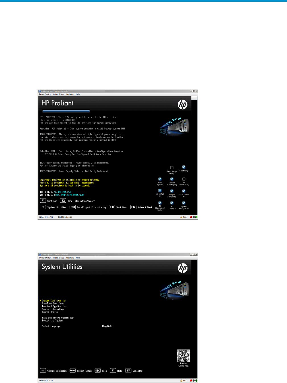
1. Reboot the server.
The server restarts and the HP ProLiant POST screen appears.
2. Press F9.
The System Utilities screen appears.
8 Getting started with UEFI System Utilities

3. Do any of the following:
•To navigate and modify settings in the menu-driven interface, press the following keys:
◦Up or down arrow—Selects a menu option. When selected, the color of a menu
option changes from white to yellow text.
◦Enter—Selects an entry. When a submenu is available, the submenu appears.
◦Esc—Returns to the previous screen.
◦F1—Displays online help about a selection.
◦F7—Loads default UEFI configuration settings and prompts you to:
–Press Enter to apply defaults.
–Press Esc to cancel.
–Reboot the system for changes to take effect.
•To access HP UEFI System Utilities and Shell Command Mobile Help for HP ProLiant Gen9
Servers, scan the QR code on the bottom of the System Utilities screen with your mobile
device.
•To exit the System Utilities screen and reboot the server, press Esc until the main menu is
displayed, and then select one of the following options:
◦Exit and resume system boot—Exits the system and continues the normal boot process.
The system continues through the boot order list and launches the first bootable option
in the system.
◦Reboot the System—Exits the system and reboots the system without continuing the
normal boot process.
The screen displays the booting process, and the HP ProLiant POST screen appears.
Toward the end of the boot process, the boot options screen is displayed. It is visible for
several seconds before the system attempts to boot from a supported boot device. .
Overview of the System Utilities screen
IMPORTANT: UEFI system configuration options vary by Gen9 platform. This guide documents
all available UEFI System Utilities options on an HP ProLiant Gen9 server. You might not see some
of the options that are documented in this guide if they are not available on your particular server.
The System Utilities screen is the main screen in the UEFI System Utilities menu-driven interface.
Press the up or down arrow keys to select a menu option. A selected option changes color from
white to yellow. Press Enter to display submenus and other configuration options for your selection.
The System Utilities screen displays menu options for the following configuration tasks:
•System Configuration—Displays options for viewing and configuring:
◦BIOS/Platform Configuration (RBSU)
◦iLO 4 Configuration Utility
◦Other system-specific devices, such as installed PCIe cards, NICs and Smart Arrays. For
example, Embedded FlexibleLOM Port 1.
Overview of the System Utilities screen 9

NOTE: Throughout the menus, the interface attempts to display the proper marketing
name for installed PCI devices. If the interface does not recognize a device, it assigns a
generic label to the device, such as a non-HP name. This generic labeling does not
affect the functionality or operation of the device.
•One-Time Boot Menu—Displays options for selecting a boot override option and running a
UEFI application from a file system.
•Embedded Applications—Displays options for viewing and configuring:
Embedded UEFI Shell◦
◦Integrated Management Log (IML)
◦Active Health System Log
◦Firmware Update
◦Embedded Diagnostics
◦Intelligent Provisioning
•System Information—Displays options for viewing the server name and generation, serial
number, product ID, BIOS version and date, power management controller, backup BIOS
version and date, system memory, and processors.
•System Health—Displays options for viewing the current health status of all devices in the
system.
•Exit and resume system boot—Exits the system and continues the normal booting process.
•Reboot the system—Exits the system and reboots it by going through the UEFI Boot Order list
and launching the first bootable option in the system. For example, you can launch the UEFI
Shell, if enabled and listed as the first bootable option in the list.
•Select Language—Enables you to select a language to use in the user interface. English is the
default language.
Common setup and configuration tasks
AnswerQuestion
See “Launching and navigating the HP UEFI System Utilities
menus” (page 8).
How do I access the UEFI System Utilities?
For a description of all methods you can use to update
firmware or system ROM, see “Updating firmware or
system ROM” (page 12).
How do I update the firmware or system ROM?
How do I use the Firmware Update application to upgrade
the system ROM to the version included on the USB key
already inserted into the server?
The BIOS/Platform Configuration (RBSU) menu replaces
the ROM-Based Setup Utility (RBSU) on HP ProLiant Gen9
How do I transition from RBSU settings to UEFI settings?
servers. Use this menu to access and use both UEFI and
Legacy BIOS options. See “BIOS/Platform Configuration
(RBSU)” (page 13).
Certain situations might require that you operate in Legacy
BIOS Mode, such as using VMware ESXi 5.5 on an HP
When would I want to choose Legacy BIOS Mode rather
than UEFI Mode, and vice versa?
10 Getting started with UEFI System Utilities

AnswerQuestion
ProLiant BL460c Gen9 Server Blade. UEFI Mode is enabled
by default and is required for certain options, including:
•Secure Boot, UEFI Optimized Boot, Generic USB Boot,
IPv6 PXE Boot, iSCSI Boot, and Boot from URL
•Fibre Channel/FCoE Scan Policy
•Booting to a hard disk drive larger than 2.2 TB
•Booting the Embedded User Partition.
See “Boot Mode” (page 23).How do I select between Legacy BIOS and UEFI Mode?
See “Boot Options” (page 22).How do I determine if a server has UEFI boot options?
To access the One-Time Boot Menu where you can select
an option for a one-time boot override, do one of following:
How do I select a boot device?
•Press F11 during server POST.
•On the System Utilities screen, select One-Time Boot
Menu. See Using the One-Time Boot Menu.
To modify the boot order for all boots, see UEFI Boot Order,
or Legacy BIOS Boot Order.
By default, Intel Hyperthreading is enabled. For information
about disabling or re-enabling this setting, see “Intel (R)
Hyperthreading Options” (page 17).
How do I enable or disable Intel Hyperthreading?
By default, this is set to Package C6 (retention) State, the
lowest processor idle power state. To change this setting,
How do I configure the Minimum Processor Idle Power
Package State to No Package State?
see “Minimum Processor Idle Power Package C-State”
(page 37).
See “Date and Time” (page 67).How do I configure the time zone?
How do I save my configuration changes and reboot the
system?
1. When you are done making changes, if you do not see
the prompt Changes are pending. Do you want
to save changes and exit?, press F10 to display
it.
2. Press Yto save your changes.
AChange saved confirmation prompt appears.
3. Select a reboot option and press Enter:
•Exit and resume system boot—Exits the system and
continues the normal boot process. The system
continues through the boot order list and launches
the first bootable option in the system.
•Reboot the System—Exits the system and reboots the
system without continuing the normal boot process.
See “Embedded UEFI Shell” (page 82).How do I enter the Embedded UEFI Shell?
See “Embedded Diagnostics” (page 48).How do I enter the Embedded Diagnostics, view
information, and then exit back to the System Utilities?
See “System Health” (page 86).How do I view the Device Health Status of all installed
options and devices?
See “Configuration Replication Utility (CONREP)”
(page 88).
How do I use CONREP to replicate UEFI settings?
Common setup and configuration tasks 11

Updating firmware or system ROM
You can use any of the following methods to update firmware or system ROM:
•The Firmware Update option in the System Utilities. See “Updating firmware from the System
Utilities” (page 12).
•The fwupdate command in the Embedded UEFI Shell. See “fwupdate” in the HP UEFI Shell
User Guide for HP ProLiant Gen9 Servers.
•HP Service Pack for ProLiant (SPP)
•HP online flash components
Updating firmware from the System Utilities
Use this option to update firmware components in the system, including the system BIOS, NICs,
and storage cards. Your system can be set to either Legacy BIOS Mode or UEFI Mode.
To update device firmware:
1. Access the System ROM Flash Binary component for your server from the HP Support Center
(http://www.hp.com/go/hpsc). When searching for the component, always select Cross
operating system to locate the binary file.
2. Copy the binary file to a USB media or iLO virtual media.
3. Attach the media to the server.
4. Launch the System Utilities.
5. From the System Utilities screen, select Embedded Applications→Firmware Update and press
Enter.
6. Select a device and press Enter.
The Firmware Updates screen lists details about your selected device, including the current
firmware version in use.
7. Select Select Firmware File and press Enter.
8. Select the flash file in the File Explorer list and press Enter.
The firmware file is loaded and the Firmware Updates screen lists details of the file in the
Selected firmware file field.
9. Select Image Description and press Enter, then select a firmware image and press Enter again.
A device can have multiple firmware images.
10. Select Start firmware update to update the firmware components in the system.
12 Getting started with UEFI System Utilities

3 Using the System Configuration menu options
The System Configuration menu displays options for:
•BIOS/Platform Configuration (RBSU)
•Using the iLO 4 Configuration Utility
•Viewing Smart Array Controller information
•Viewing and configuring NIC and FCoE settings
NOTE: You might see options for configuring your system devices, such as an embedded NIC.
For example, Embedded FlexibleLOM Port 1. These items reflect installed PCIe cards. Devices vary
based on your system.
To access System Configuration options:
1. From the System Utilities screen, select System Configuration and press Enter.
2. Select an option and press Enter.
BIOS/Platform Configuration (RBSU)
The BIOS/Platform Configuration (RBSU) menu replaces the ROM-Based Setup Utility (RBSU) on
HP ProLiant Gen9 servers. Use this menu to access and use both UEFI and Legacy BIOS options,
including:
•System Options
•Boot Options
•Network Options
•Embedded UEFI Shell options
•Power Management
•Performance Options
•Server Security
•PCI Device Enable/Disable
•Server Availability
•BIOS Serial Console and EMS
•Server Asset Information
•Advanced Options
•System Default Options
•Date and Time
To access BIOS/Platform Configuration (RBSU) options:
1. From the System Utilities screen, select System Configuration→BIOS/Platform Configuration
(RBSU).
2. Select an option and press Enter.
System Options
This menu displays the following options:
•Serial Port Options
•USB Options
•Processor Options
BIOS/Platform Configuration (RBSU) 13

•SATA Controller Options
•Virtualization Options
•Boot Time Optimization
•Memory Operations
To access System Options:
1. From the System Utilities screen, select System Configuration→BIOS/Platform
Configuration→System Options.
2. Select an option and press Enter.
Serial Port Options
This menu displays the following options:
•Embedded Serial Port
•Virtual Serial Port
NOTE: For proper screen resolution, set the console resolution in the terminal software to 100x31.
To access Serial Port Options:
1. From the System Utilities screen, select System Configuration→BIOS/Platform Configuration
(RBSU)→System Options→Serial Port Options.
2. Select an option and press Enter.
Embedded Serial Port
Use this option to assign a logical COM port address and associated default resources to a selected
physical serial port. The operating system can overwrite this setting.
To assign an Embedded Serial Port:
1. From the System Utilities screen, select System Configuration→BIOS/Platform Configuration
(RBSU)→System Options→Serial Port Options→Embedded Serial Port and press Enter.
2. Select a setting and press Enter. Options include:
•COM 1: IRQ4: I/0: 3F8h-3FFh (default)
•COM 2: IRQ3: I/0: 2F8h-2FFh
•Disabled
3. Press F10 to accept your selection.
Virtual Serial Port
Use this option to assign a logical COM port address and the associated default resources used
by the Virtual Serial Port (VSP). VSP enables the iLO Management Controller to appear as a physical
serial port to support the BIOS Serial Console and the operating system serial console.
To assign a Virtual Serial Port:
1. From the System Utilities screen, select System Configuration→BIOS/Platform Configuration
(RBSU)→System Options→Serial Port Options→Virtual Serial Port and press Enter.
2. Select a setting and press Enter. Options include:
•COM 1: IRQ4: I/0: 3F8h-3FFh
•COM 2: IRQ3: I/0: 2F8h-2FFh (default)
•Disabled
3. Press F10 to save your selection.
14 Using the System Configuration menu options
USB Options
This menu displays the following options:
•USB Control
•USB Boot Support
•Removable Flash Media Boot Sequence
•Virtual Install Disk
•Embedded User Partition
•Internal SD Card Slot
•USB 3.0 Mode
To access USB Options:
1. From the System Utilities screen, select System Configuration→BIOS/Platform Configuration
(RBSU)→System Options→USB Options and press Enter.
2. Select an option and press Enter.
USB Control
Use this option to configure how USB ports and embedded devices operate at startup.
To set USB Control:
1. From the System Utilities screen, select System Configuration→BIOS/Platform Configuration
(RBSU)→System Options→USB Options→USB Control and press Enter.
2. Select a setting and press Enter:
•USB Enabled (default)—Enables all USB ports and embedded devices.
•External USB Port Disabled—Disables external USB ports while maintaining full support
for embedded USB devices managed by the ROM and operating system.
3. Press F10 to save your selection.
USB Boot Support
Set this option to disabled to prevent the system from booting any USB devices connected to the
server. This includes preventing boot to virtual media devices and the embedded SD or SD card
slot, if supported.
To enable or disable USB Boot Support:
1. From the System Utilities screen, select System Configuration→BIOS/Platform Configuration
(RBSU)→System Options→USB Options→USB Boot Support and press Enter.
2. Select a setting and press Enter:
•Enabled (default)—The system can boot from USB devices connected to the server.
•Disabled—The system cannot boot from USB devices connected to the server.
3. Press F10 to save your selection.
Removable Flash Media Boot Sequence
Use this option to select which USB or SD Card devices to search first when enumerating boot
devices. You can select whether the system attempts to boot external USB drive keys, internal USB
drive keys, or the internal SD Card slot first. The Removable Flash Media Boot Sequence does not
override the device boot order in the Standard Boot Order (IPL) option. Configure this option when
Boot Mode is set to Legacy BIOS Mode because UEFI Mode enables you to boot from an USB
device available in the boot list. See “Boot Mode” (page 23).
To select the Removable Flash Media Boot Sequence:
BIOS/Platform Configuration (RBSU) 15

1. From the System Utilities screen, select System Configuration→BIOS/Platform Configuration
(RBSU)→System Options→USB Options→Removable Flash Media Boot Sequence and press
Enter.
2. Select a setting and press Enter:
•Internal SD Card First—Boots using the internal SD card slot.
•Internal Drive Keys First—Boots using the internal USB drive keys.
•External Drive Keys First (default)—Boots using external USB drive keys.
3. Press F10 to save your selection.
Virtual Install Disk
Use this option to enable or disable the virtual install disk. The virtual install disk contains drivers
specific to the server that an operating system can use during installation. When this option is
enabled, Microsoft Windows Server automatically locates required drivers and installs them,
eliminating the need for user intervention and the requirement that a driver be present on external
media during operating system installation. In some cases, the virtual install disk remains visible
from the installed operating system as a read-only drive. During manual installations using Intelligent
Provisioning, this option is disabled automatically.
To enable or disable Virtual Install Disk:
1. From the System Utilities screen, select System Configuration→BIOS/Platform Configuration
(RBSU)→System Options→USB Options→Virtual Install Disk and press Enter.
2. Select a setting and press Enter:
•Enabled—The Virtual Install Disk appears as a drive in the operating system.
•Disabled (default)—The Virtual Install Disk does not appear as a drive in the operating
system.
3. Press F10 to save your selection.
Embedded User Partition
Use this option to enable or disable the Embedded User Partition. This is a general purpose 1 GB
disk partition on non-volatile flash memory that is embedded on the system board. When the
Embedded User Partition is enabled, and your server is configured in UEFI Mode, you can use the
embedded partition to install and boot VMware ESXi.
NOTE:
•Booting the Embedded User Partition is only supported in UEFI Mode.
•HP recommends that you regularly back up data on the Embedded User Partition.
To enable or disable the Embedded User Partition:
1. From the System Utilities screen, select System Configuration→BIOS/Platform Configuration
(RBSU)→System Options→USB Options→Embedded User Partition and press Enter.
2. Select a setting and press Enter:
•Enabled—When the partition is formatted, enables the server to have read and write
access to the Embedded User Partition.
NOTE: After you enable the Embedded User Partition, you must format it by using the
server operating system software.
•Disabled (default)—The server does not have access to the Embedded User Partition.
3. Press F10 to save your selection.
16 Using the System Configuration menu options

NOTE: You can also configure the Embedded User Partition using the HP RESTful Interface Tool.
See the RESTful Interface Tool documentation at: http://www.hp.com/go/restfulinterface/docs.
Internal SD Card Slot
Use this option to enable or disable the internal SD (Secure Digital) card slot. The slot holds an SD
non-volatile flash memory card that is embedded on the system board.
To enable or disable the Internal SD Card Slot:
1. From the System Utilities screen, select System Configuration→BIOS/Platform Configuration
(RBSU)→System Options→USB Options→Internal SD Card Slot and press Enter.
2. Select a setting and press Enter:
•Enabled (default)—The server can access the internal SD card slot.
•Disabled—The server cannot access the internal SD card slot.
3. Press F10 to save your selection.
USB 3.0 Mode
Use this option is set the USB 3.0 Mode.
1. From the System Utilities screen, select System Configuration→BIOS/Platform Configuration
(RBSU)→System Options→USB Options→USB 3.0 Mode and press Enter.
2. Select a setting and press Enter:
•Auto (default)—USB 3.0-capable devices operate at USB 2.0 speeds in the pre-boot
environment and during boot. When a USB 3.0 capable OS USB driver loads, USB 3.0
devices transition to USB 3.0 speeds. This mode is compatible with operating systems
that do not support USB 3.0 while still allowing USB 3.0 devices to operate at USB 3.0
speeds with modern operating systems.
•Enabled—USB 3.0-capable devices operate at USB 3.0 speeds at all times (including the
pre-boot environment) when in UEFI Mode. Do not use this mode with operating systems
that do not support USB 3.0. When operating in Legacy BIOS Mode, the USB 3.0 ports
do not function in the pre-boot environment and are not bootable.
•Disabled—USB 3.0-capable devices function at USB 2.0 speeds at all times.
3. Press F10 to save your selection.
Processor Options
This menu displays the following options:
•Intel (R) Hyperthreading Options
•Processor Core Disable
•Processor x2APIC Support
NOTE: Options that appear on this menu vary by server model.
To access Processor Options:
1. From the System Utilities screen, select System Configuration→BIOS/Platform Configuration
(RBSU)→System Options→Processor Options and press Enter.
2. Select an option and press Enter.
Intel (R) Hyperthreading Options
Use this option to disable or enable the logical processor cores on processors supporting Intel
Hyperthreading technology. Intel Hyperthreading improves overall performance for applications
that benefit from a higher processor core count. The option is supported through the system BIOS.
BIOS/Platform Configuration (RBSU) 17

NOTE: Hyperthreading is not supported on all processors. For more information, see the
documentation for your processor model.
To disable or enable Intel (R) Hyperthreading:
1. From the System Utilities screen, select System Configuration→BIOS/Platform Configuration
(RBSU)→System Options→Processor Options→Intel (R) Hyperthreading Options and press
Enter.
2. Select a setting and press Enter:
•Enabled (default)—Enables the logical processor cores on processors supporting Intel
Hyperthreading technology.
•Disabled—Disables the logical processor cores on processors supporting Intel
Hyperthreading technology.
3. Press F10 to save your selection.
Processor Core Disable
Use this option to specify the number of cores to enable per processor socket. Unused cores are
disabled. Setting this option can:
•Reduce processor power usage
•Improve overall performance for applications that benefit from higher performance cores rather
than more processing cores
•Solve issues with software that is licensed on a per-core basis
To set the number of enabled processor cores:
1. From the System Utilities screen, select System Configuration→BIOS/Platform Configuration
(RBSU)→System Options→Processor Options→Processor Core Disable and press Enter.
2. Enter the number of cores to enable per processor socket and press Enter.
NOTE:
•If you enter an incorrect value, all cores are enabled.
•If you enter 0, all cores are enabled.
3. Press F10 to save your selection.
Processor x2APIC Support
Use this option to enable or disable x2APIC support. When enabled, processor x2APIC support
helps operating systems run more efficiently on high core count configurations and optimizes
interrupt distribution in virtualized environments. Enabled mode does not enable x2APIC hardware,
but provides the support necessary to the operating system. Unless you are using an older hypervisor
or operating system that is not compatible with x2APIC support, leave this option enabled.
To enable or disable Processor x2APIC Support:
1. From the System Utilities screen, select System Configuration→BIOS/Platform Configuration
(RBSU)→System Options→Processor Options→Processor x2APIC Support and press Enter.
2. Select a setting and press Enter:
•Enabled (default)—Generates the ACPI x2APIC control structures, and adds the option
of enabling x2APIC support to the operating system when it loads.
•Disabled—Disables x2APIC support.
3. Press F10 to save your selection.
18 Using the System Configuration menu options

SATA Controller Options
This menu displays the following Serial Advanced Technology Attachment options:
•Embedded SATA Configuration
•SATA Secure Erase
To access SATA Controller Options:
1. From the System Utilities screen, select System Configuration→BIOS/Platform Configuration
(RBSU)→System Options→SATA Controller Options and press Enter.
2. Select an option and press Enter.
Embedded SATA Configuration
Use this option to enable embedded chipset SATA controller support for your installed OS. You
can select AHCI or HP Dynamic Smart Array RAID support. Make sure that you are using the
correct operating system drivers for your selected option. Depending on your server model, either
SATA AHCI or HP Dynamic Smart Array RAID support are enabled by default.
CAUTION: HP Dynamic Smart Array is not supported when the boot mode is configured to Legacy
BIOS Mode. Enabling HP Dynamic Smart Array RAID results in data loss or data corruption on
existing SATA drives. Back up all drives before enabling this option.
See your operating system documentation before enabling SATA AHCI support to ensure your
base media drivers support this feature.
To enable Embedded SATA support:
1. From the System Utilities screen, select System Configuration→BIOS/Platform Configuration
(RBSU)→System Options→SATA Controller Options→Embedded SATA Configuration and press
Enter.
2. Ensure that you are using the correct AHCI or RAID system drivers for your SATA option.
3. Select a setting and press Enter:
•Enable SATA AHCI Support—Enables the embedded chipset SATA controller for AHCI.
•Enable HP Dynamic Smart Array RAID Support—Enables the embedded chipset SATA
controller for HP Dynamic Smart Array RAID.
4. Press F10 to save your selection.
SATA Secure Erase
Use this option to control whether SATA Secure Erase functionality is supported. This function
prevents the Secure Freeze Lock command from being sent to SATA hard drives.
NOTE: This option operates on hard drives when:
•The SATA controller is in AHCI mode
•The hard drive supports the Secure Erase command
1. From the System Utilities screen, select System Configuration→BIOS/Platform Configuration
(RBSU)→System Options→SATA Controller Options→SATA Secure Erase and press Enter.
2. Select a setting and press Enter:
•Enabled—The Security Freeze Lock command is not sent to supported SATA hard drives,
enabling Secure Erase to function.
•Disabled (default)—Disables Secure Erase.
3. Press F10 to save your selection.
BIOS/Platform Configuration (RBSU) 19

Virtualization Options
This menu displays the following options:
•Virtualization Technology
•Intel (R) VT-d
•SR-IOV
To access Virtualization Options:
• From the System Utilities screen, select System Configuration→BIOS/Platform Configuration
(RBSU)→System Options→Virtualization Options and press Enter.
Select an option and press Enter.
Virtualization Technology
Use this option to enable Intel Virtualization Technology on a Virtual Machine Manager (VMM).
NOTE: You do not need to disable Virtualization Technology if you are using a VMM or an
operating system that does not support AMD-V virtualization.
To enable Virtualization Technology:
1. From the System Utilities screen, select System Configuration→BIOS/Platform Configuration
(RBSU)→System Options→Virtualization Options→Virtualization Technology and press Enter.
2. Select a setting and press Enter:
•Enabled (default)—Enables a VMM supporting this option to use hardware capabilities
provided by UEFI Intel processors.
•Disabled—Does not enable a VMM to use hardware capabilities provided by UEFI Intel
processors.
3. Press F10 to save your selection.
Intel (R) VT-d
Use this option to enable Intel Virtualization Technology for Directed I/O (VT-d) on a Virtual Machine
Manager (VMM).
NOTE:
•If you are not using a hypervisor or an operating system that supports this feature, it is not
necessary to set the Intel (R) VT-d option to disabled. You can leave it enabled.
•Intel VT-d Coherency Support is disabled by default and is not configurable.
To enable Intel (R) VT-d:
1. From the System Utilities screen, select System Configuration→BIOS/Platform Configuration
(RBSU)→System Options→Virtualization Options→Intel (R) VT-d and press Enter.
2. Select a setting and press Enter:
•Enabled (default)—Enables a hypervisor or operating system supporting this option to
use hardware capabilities provided by Intel’s Virtualization Technology for directed I/O
•Disabled—Does not enable a hypervisor or operating system supporting this option to
use hardware capabilities provided by Intel’s Virtualization Technology for directed I/O
3. Press F10 to save your selection.
SR-IOV
The SR-IOV (Single root I/O virtualization) interface is an extension to the PCI express (PCIe)
specification. It enables the BIOS to allocates more PCI resources to PCIe devices. Enable this
20 Using the System Configuration menu options
option for a PCIe device or operating system that supports SR-IOV. Leave it enabled when using
a hypervisor.
To enable SR-IOV support:
1. From the System Utilities screen, select System Configuration→BIOS/Platform Configuration
(RBSU)→System Options→Virtualization Options→SR-IOV and press Enter.
2. Select a setting and press Enter:
•Enabled (default)—Enables a hypervisor to create virtual instances of a PCIe device,
potentially increasing performance.
•Disabled—Does not enable a hypervisor to create virtual instances of a PCIe device.
3. Press F10 to save your selection.
Boot Time Optimization
This menu displays the following options:
•Dynamic Power Capping Functionality
•Extended Memory Test
•Memory Fast Training
To access Boot Time Optimization options:
1. From the System Utilities screen, select System Configuration→BIOS/Platform Configuration
(RBSU)→System Options→Boot Time Optimization and press Enter.
2. Select an option and press Enter.
Dynamic Power Capping Functionality
Use this option to configure when the system ROM executes power calibration during the boot
process.
To configure Dynamic Power Capping Functionality:
1. From the System Utilities screen, select System Configuration→BIOS/Platform Configuration
(RBSU)→System Options→Boot Time Optimization→Dynamic Power Capping Functionality
and press Enter.
2. Select a setting and press Enter:
•Auto—Power calibration runs the first time the server is booted and is only run again
when the hardware configuration settings of the server change.
•Enabled (default)—Power calibration runs on every system boot.
•Disabled—Power calibration does not run, and Dynamic Power Capping is not supported.
3. Press F10 to save your selection.
Extended Memory Test
Use this option to configure whether the system validates memory during the memory initialization
process. When enabled and uncorrectable memory errors are detected, the memory is mapped
out, and the failed DIMMs are logged to the Integrated Management Log.
To enable or disable Extended Memory Test:
1. From the System Utilities screen, select System Configuration→BIOS/Platform Configuration
(RBSU)→System Options→Boot Time Optimization→Extended Memory Test and press Enter.
2. Select a setting and press Enter:
•Enabled (default)—Enables Extended Memory Test.
BIOS/Platform Configuration (RBSU) 21

NOTE: This setting might significantly increase system boot time.
•Disabled—Disables Extended Memory Test.
3. Press F10 to save your selection.
Memory Fast Training
Use this option to configure memory training on server reboots. When enabled, the platform uses
the previously saved memory training parameters determined from the last cold boot of the server,
which improves server boot time.
To enable or disable Memory Fast Training:
1. From the System Utilities screen, select System Configuration→BIOS/Platform Configuration
(RBSU)→System Options→Boot Time Optimization→Memory Fast Training and press Enter.
2. Select a setting and press Enter:
•Enabled (default)—Enables Memory Fast Training, enabling the server to use previously
saved memory training parameters.
•Disabled—The platform performs a full memory training on every server reboot.
NOTE: This setting might significantly increase system boot time.
3. Press F10 to save your selection.
Memory Operations
This menu displays the following option:
•Advanced Memory Protection
Advanced Memory Protection
Use this option to configure additional memory protection with Error Checking and Correcting
(ECC). Advanced ECC provides the largest memory capacity to the operating system.
To configure Advanced Memory Protection:
1. From the System Utilities screen, select System Configuration→BIOS/Platform Configuration
(RBSU)→System Options→Memory Operations→Advanced Memory Protection and press
Enter.
2. Select a setting and press Enter:
•Advanced ECC Support (default)—Provides the largest memory capacity to the operating
system while protecting the system against all single-bit failures and some multi-bit failures.
•Online Spare with Advanced ECC Support—Enables the system to automatically map out
a group of memory that is receiving excessive correctable memory errors. This memory
is replaced by a spare group of memory.
•Mirrored Memory with Advanced ECC Support—Provides the maximum protection against
uncorrected memory errors that might otherwise result in a system failure. You must install
additional memory to provide mirrored memory to the operating system.
3. Press F10 to save your selection.
Boot Options
This menu displays the following options:
•Boot Mode
•UEFI Optimized Boot
•Boot Order Policy
22 Using the System Configuration menu options

•UEFI Boot Order
•Advanced UEFI Boot Maintenance
•Legacy BIOS Boot Order
NOTE: Reboot the server after making changes to the boot mode.
To access Boot Options:
1. From the System Utilities screen, select System Configuration→BIOS/Platform Configuration
(RBSU)→Boot Options and press Enter.
2. Select an option and press Enter.
Boot Mode
Use this option to set the boot mode for the system. HP ProLiant Gen9 servers provide two boot
mode configurations: UEFI Mode and Legacy BIOS Mode. Certain boot options described in this
guide require that you select a specific boot mode.
By default, the boot mode is set to UEFI Mode. The system must boot in UEFI Mode to use the
following options:
•Secure Boot, UEFI Optimized Boot, Generic USB Boot, IPv6 PXE Boot, iSCSI Boot, and Boot
from URL
•Fibre Channel/FCoE Scan Policy
•Embedded User Partition
•BL140i Smart Array SW RAID controller
NOTE: The boot mode you use must match the operating system installation. If not, changing the
boot mode can impact the ability of the server to boot to the installed operating system.
To select a Boot Mode:
1. From the System Utilities screen, select System Configuration→BIOS/Platform Configuration
(RBSU)→Boot Options→Boot Mode and press Enter.
2. Select a setting and press Enter:
•UEFI Mode (default)—Configures the system to boot to a UEFI compatible operating system.
NOTE: Configure the system to use native UEFI graphic drivers when booting to the
UEFI Mode.
•Legacy BIOS Mode—Configures the system to boot to a traditional operating system in
Legacy BIOS compatibility mode. Certain situations, such as using VMware ESXi 5.5,
might require that you operate in this mode.
3. Press F10 to save your selection.
4. Reboot the server for the change to take effect.
UEFI Optimized Boot
Use this option to enable or disable UEFI Optimized Boot, which controls the video settings that
the system BIOS uses.
BIOS/Platform Configuration (RBSU) 23
Before changing this setting, consider the following:
•If you are running Microsoft Windows 2008 or Windows 2008 R2 operating systems, and
the system is configured for UEFI Mode, this option must be set to disabled. Legacy BIOS
Mode components are needed for video operations in Windows.
•Boot Mode must be set to UEFI Mode when this option is enabled. See “Boot Mode” (page 23).
•This option must be enabled to:
◦Enable and use Secure Boot. See “Secure Boot Settings” (page 49).
◦Operate VMware ESXi.
To enable or disable UEFI Optimized Boot:
1. From the System Utilities screen, select System Configuration→BIOS/Platform Configuration
(RBSU)→Boot Options→UEFI Optimized Boot and press Enter.
2. Select an option and press Enter:
•Enabled (default)—Configures the system BIOS to boot using native UEFI graphic drivers.
Select this setting for compatibility with VMware ESXi on a system configured for UEFI
Mode, and to enable and use Secure Boot Mode.
•Disabled—Configures the system BIOS to boot using INT10 legacy video expansion
ROM. Select this setting to boot Windows Server 2008 R2 in UEFI Mode.
3. Press F10 to save your selection.
4. Reboot the server for the change to take effect.
Boot Order Policy
Use this option to control the system behavior when attempting to boot devices per the UEFI Boot
Order list and no bootable device is found.
To set the Boot Order Policy:
1. From the System Utilities screen, select System Configuration→BIOS/Platform Configuration
(RBSU)→Boot Options→Boot Order Policy and press Enter.
2. Select a setting and press Enter:
•Retry Boot Order Indefinitely (default)—Configures the system to continuously attempt the
boot order until a bootable device is found.
•Attempt Boot Order Once—Configures the system to attempt to execute all items in the
boot menu once, and halts the system.
•Reset After Failed Boot Attempt—Configures the system to attempt to execute all items
once, and reboots the system.
3. Press F10 to save your selection.
4. Reboot the server for the change to take effect.
UEFI Boot Order
Use this option change the UEFI Boot Order list. This list shows you the order in which the server
attempts to boot various UEFI configured options. To boot to a particular option, the option must
be at the top of the list so that the server boots the option first.
1. From the System Utilities screen, select System Configuration→BIOS/Platform Configuration
(RBSU)→Boot Options→UEFI Boot Order and press Enter.
2. Use the arrow keys to navigate within the boot order list.
3. Press the +key to move an entry higher in the boot list.
4. Press the -key to move an entry lower in the list.
5. Press F10 to save your selection.
24 Using the System Configuration menu options

You can reboot the server to boot to the option at the top of the list.
NOTE: You can also configure the UEFI Boot Order list using the HP RESTful Interface Tool. See
the RESTful Interface Tool documentation at: http://www.hp.com/go/restfulinterface/docs.
Advanced UEFI Boot Maintenance
This menu displays the following options:
•Add Boot Option
•Delete Boot Option
To access Advanced UEFI Boot Maintenance options:
1. From the System Utilities screen, select System Configuration→BIOS/Platform Configuration
(RBSU)→Boot Options→Advanced UEFI Boot Maintenance and press Enter.
2. Select an option and press Enter.
Add Boot Option
Use this option to select an x64 UEFI application with an .efi extension, such as an OS boot
loader or other UEFI application, to add as a new UEFI boot option.
The new boot option is appended to the boot order list. When you select a file, you are prompted
to enter the boot option description (which is then displayed in the UEFI Boot Order list), as well
as any optional data to be passed to an .efi application.
To add a UEFI boot option to the boot order list:
1. Attach FAT16 or FAT32–partitioned media that contains the .efi file you want to add as an
option.
2. From the System Utilities screen, select System Configuration→BIOS/Platform Configuration
(RBSU)→Boot Options→Advanced UEFI Boot Maintenance→Add Boot Option and press Enter.
3. Browse for an .EFI application from the list and press Enter.
4. If necessary, continue to press Enter to drill-down through the menu options.
5. Enter a boot option description and optional data and press Enter.
The new boot option appears in the UEFI Boot Order list.
6. Select Commit changes and exit to save your selection.
You can reboot the server to boot to the new option.
Delete Boot Option
To delete a boot option from the UEFI Boot Order list:
1. From the System Utilities screen, select System Configuration→BIOS/Platform Configuration
(RBSU)→Boot Options→Advanced UEFI Boot Maintenance→Delete Boot Option and press
Enter.
2. Select one or more options from the list. Press Enter after each selection.
3. Select an option and press Enter:
•Commit Changes and Exit
•Discard Changes and Exit
Legacy BIOS Boot Order
When your server is configured in Legacy BIOS Mode, you can change the order of the Legacy
BIOS boot order. The boot order list defines how the server looks for OS boot firmware.
To change the Legacy BIOS Boot Order:
1. From the System Utilities screen, select System Configuration→BIOS/Platform Configuration
(RBSU)→Boot Options→Legacy BIOS Boot Order and press Enter.
BIOS/Platform Configuration (RBSU) 25

2. Use the arrow keys to navigate within the boot order list.
3. Press the +key to move an entry higher in the boot list.
4. Press the -key to move an entry lower in the list.
5. Press F10 to save your selection.
You can reboot the server to boot to the option at the top of the list.
Network Options
This menu displays the following options:
•Network Boot Options
•Pre-Boot Network Settings
•iSCSI Boot Configuration
•VLAN Configuration
To access Network Options:
1. From the System Utilities screen, select System Configuration→BIOS/Platform Configuration
(RBSU)→Network Options and press Enter.
2. Select an option and press Enter.
Network Boot Options
This menu displays the following options:
•UEFI PXE Boot Policy
•IPv6 DHCP Unique Identifier
•Network Boot Retry Support
•Network Interface Cards (NICs)
•PCIe Slot Network Boot
To access Network Boot Options:
1. From the System Utilities screen, select System Configuration→BIOS/Platform Configuration
(RBSU)→Network Options→Network Boot Options and press Enter.
2. Select an option and press Enter.
UEFI PXE Boot Policy
Use this option to set the order of network boot targets in the UEFI Boot Order list.
NOTE: When both IPv4 and IPv6 are enabled, each network boot target appears twice in the
UEFI Boot Order list (one for IPv4 and the other for IPv6). You can only configure this option when
Boot Mode is set to UEFI. For more information, see “Boot Mode” (page 23).
To set the UEFI PXE Boot Policy:
1. From the System Utilities screen, select System Configuration→BIOS/Platform Configuration
(RBSU)→Network Options→Network Boot Options→UEFI PXE Boot Policy and press Enter.
2. Select a setting and press Enter:
•IPv4 then IPv6—Modifies the UEFI Boot Order list to include all existing IPv4 targets before
any existing IPv6 targets. New network IPv4 boot targets are added before IPv6 targets.
•IPv4—Removes all existing IPv6 network boot targets in the UEFI Boot Order list. New
IPv6 network boot targets are not added to the list.
•IPv6—Removes all existing IPv4 network boot targets in the UEFI Boot Order list. New
IPv4 network boot targets are not added to the list.
26 Using the System Configuration menu options

•IPv6 then IPv4—Modifies the UEFI Boot Order list to include all existing IPv4 targets before
any existing IPv6 targets. New network IPv6 boot targets are added before IPv4 targets.
•Auto (default)—Modifies the order of the existing network boot targets in the UEFI Boot
Order list. New network boot targets are added to the end of the list using the system
ROM's default policy.
3. Press F10 to save your selection.
4. Reboot the server for the changes to take effect.
IPv6 DHCP Unique Identifier
Use this option to select how the UEFI BIOS obtains the DHCP Unique Identifier (DUID) for IPv6
PXE Boot. DHCPv6 clients use this identifier to get an IP address from a DHCPv6 server. By default,
the system uses the server's Unique Universal Identifier (UUID).
NOTE: Boot Mode must be set to UEFI Mode to configure these options. See “Boot Mode”
(page 23).
To set the IPv6 DHCP Unique Identifier:
1. From the System Utilities screen, select System Configuration→BIOS/Platform Configuration
(RBSU)→Network Options→Network Boot Options →IPv6 DHCP Unique Identifier and press
Enter.
2. Select a setting and press Enter:
•Auto (default)—Uses the server's UUID.
•DUID-LLT—Uses the DUID Link Layer address plus a Time value.
3. Press F10 to accept your selection.
Network Boot Retry Support
Use this option to enable or disable the network boot retry function. By default, the system BIOS
attempts to boot the network device, such as a PXE device, up to 20 times before attempting to
boot the next IPL device.
To enable or disable Network Boot Retry Support:
1. From the System Utilities screen, select System Configuration→BIOS/Platform Configuration
(RBSU)→Network Options→Network Boot Options →Network Boot Retry Support and press
Enter.
2. Select a setting and press Enter:
•Enabled (default)—Enables network boot retry.
•Disabled—Disables network boot retry.
3. Press F10 to accept your selection.
Network Interface Cards (NICs)
Use these options to enable network boot (PXE or FCoE) for an installed NIC. Devices listed vary
from system to system and can include, for example:
•Embedded LOM 1 Port 1
•Embedded FlexibleLOM 1 Port 1
NOTE: You might need to configure the NIC firmware to activate the boot option.
To configure network boot for a NIC:
1. From the System Utilities screen, select System Configuration→BIOS/Platform Configuration
(RBSU)→Network Options→Network Boot Options and press Enter.
2. Select a NIC and press Enter.
BIOS/Platform Configuration (RBSU) 27

3. Select a setting and press Enter:
•Network Boot (default)—Enables network boot.
•Disabled—Disables network boot
4. Press F10 to accept your selection.
5. If you selected Network Boot, reboot the server so that the NIC boot option appears in the
UEFI Boot Order list or the Legacy BIOS Boot Order list.
PCIe Slot Network Boot
Use this option to enable or disable UEFI PXE boot for NIC cards in PCIe slots. Devices listed vary
from system to system and can include, for example:
•Slot 3 NIC Port 1 Boot
•Slot 3 NIC Port 2 Boot
NOTE: Boot Mode must be set to UEFI to configure this option. See “Boot Mode” (page 23).
To configure PCIe Slot Network Boot:
1. From the System Utilities screen, select System Configuration→BIOS/Platform Configuration
(RBSU)→Network Options→Network Boot Options →PCIe Slot Network Boot and press Enter.
2. Select a PCIe slot entry and press Enter.
3. Select a setting and press Enter:
•PXE Boot (default)—Enables PXE boot.
•Disabled—Disables PXE boot
4. Press F10 to accept your selection.
Pre-Boot Network Settings
Use this option to configure a pre-boot network interface and related settings.
IMPORTANT: You do not need to use the Embedded UEFI Shell ifconfig command on a
network interface if you plan to run webclient or ftp over the same interface because these
interface and IP address settings are automatically selected by the Pre-Boot Network Settings
configured in the System Utilities.
If the interface used by ftp and webclient happens to be configured by ifconfig, that setting
is erased and, instead, the System Utilities Pre-Boot Network Settings menu is applied on the
interface when the commands are run.
To configure Pre-Boot Network Settings:
1. From the System Utilities screen, select System Configuration→BIOS/Platform Configuration
(RBSU)→Network Options→Pre-Boot Network Settings and press Enter.
28 Using the System Configuration menu options

2. Select and configure the network interface from the list of available interfaces in the system.
Press Enter after each selection. Options are:
•Pre-Boot Network Interface—Specifies the network interface used for pre-boot network
connections.
◦Auto (default)—The system uses the first available port with a network connection.
◦Embedded NIC—The system uses the selected NIC. If the selected NIC has more than
one port, the system only uses the first available port with a network connection.
•DHCPv4—Enables or disables obtaining the pre-boot network IPv4 configuration from a
DHCP server.
◦Enabled (default)—Enables DHCPv4 IPv4 network address configuration.
NOTE: This setting makes IPv4 address, subnet mask, gateway, and DNS settings
unavailable because values are supplied automatically.
◦Disabled—Disables DHCPv4 address configuration, requiring you to manually
configure the following static IP address settings.
–IPv4 Address
–IPv4 Subnet Mask
–IPv4 Gateway
–IPv4 Primary DNS
–IPv4 Secondary DNS
•Boot from URL—Specifies a network URL to a bootable ISO or EFI file. Enter a URL in
either HTTP or FTP format, using either an IPv4 server address or host name. IPv6 addresses
are not supported. When configured, this URL is listed as a boot option in the UEFI Boot
Order list. Then you can select this option from the boot order list to download the specified
file to the system memory and enable the system to boot from the file.
NOTE: To use this setting:
◦Configure the pre-boot network settings to access the URL location.
◦Leave the boot mode set to UEFI Mode.
When booting from an ISO file, use a file that the system can use to boot a preliminary
operating system environment, such as WinPE, mini-Linux, or VMware ESX installer. Doing
so enables further installation to proceed over an OS network connection. ISO files that
contain the full OS installation media are not supported.
iSCSI Boot Configuration
This menu displays the following UEFI iSCSI Software Initiator Boot options. For more information,
see “ISCI boot” in the HP UEFI Deployment Guide for HP ProLiant Gen9 Servers.
•iSCSI Initiator Name
•Add an iSCSI Boot Attempt
•Delete iSCSI Boot Attempts
•iSCSI Attempts
NOTE: Boot Mode must be set to UEFI Mode to configure these options. See “Boot Mode”
(page 23).
BIOS/Platform Configuration (RBSU) 29

To access iSCSI Boot Configuration options:
1. From the System Utilities screen, select System Configuration→BIOS/Platform Configuration
(RBSU)→Network Options→iSCSI Boot Configuration and press Enter.
2. Select an option and press Enter.
NOTE: You can also configure iSCSI Boot settings using the HP RESTful Interface Tool. See the
RESTful Interface Tool documentation at: http://www.hp.com/go/restfulinterface/docs.
iSCSI Initiator Name
Use this option to add an iSCSI initiator name.
1. From the System Utilities screen, select System Configuration→BIOS/Platform Configuration
(RBSU)→Network Options→iSCSI Boot Configuration→iSCSI Initiator Name and press Enter.
2. Enter a unique name for the iSCSI initiator using iSCSI Qualified Name (IQN) format. For
example: iqn.2001–04.com.example:uefi-13021088.
NOTE: EUI format is not supported.
3. Press Enter.
Add an iSCSI Boot Attempt
Use this option to configure an iSCSI boot target.
NOTE: When iSCSI is enabled on a network port, you must disable PXE for that port. See “PCIe
Slot Network Boot” (page 28).
1. From the System Utilities screen, select System Configuration→BIOS/Platform Configuration
(RBSU)→Network Options→iSCSI Boot Configuration→Add an iSCSI Boot Attempt and press
Enter.
A message appears stating that this boot attempt will not be in effect until the next server
reboot.
2. Press Enter.
3. Select a port on which to attempt iSCSI boot and press Enter.
4. Complete the configuration settings and press Enter to save each setting.
•iSCSI Attempt Name—Enter a name.
•iSCSI Boot Control—Select Enabled. (The default setting is Disabled).
•IP Address Type—Select IPv4.
•Connection Retry Count—Enter a value from 0 to 16. Default is 0 (no retries).
•Connection Timeout—Enter a value in milliseconds from 100 to 20000. Default is 1000.
•Initiator DHCP—Press Enter to enable configuring the iSCSI initiator address from DHCP.
•Target DHCP Config—Disable this option (clear the check box), and enter a target name,
IP address, port and boot LUN. This option is enabled by default.
•Optional: Authentication Type—If required, select CHAP and complete the CHAP entries.
5. Select Save Changes.
6. Reboot the server for the changes to take effect.
Delete iSCSI Boot Attempts
Use this option to delete one or more iSCSI boot targets.
1. From the System Utilities screen, select System Configuration→BIOS/Platform Configuration
(RBSU)→Network Options→iSCSI Boot Configuration→Delete iSCSI Boot Attempts and press
Enter.
30 Using the System Configuration menu options

2. Select an iSCSI boot target entry and press Enter.
3. Select Commit Changes and Exit.
4. Reboot the server for the changes to take effect.
iSCSI Attempts
Use this option to view iSCSI boot attempts.
1. From the System Utilities screen, select System Configuration→BIOS/Platform Configuration
(RBSU)→Network Options→iSCSI Boot Configuration→iSCSI Attempts and press Enter.
2. Select an entry from the list and press Enter to view or modify the details about the boot
attempt.
VLAN Configuration
Use this option to set the global VLAN configuration for all enabled network interfaces, including
those used in PXE boot, iSCSI boot, and HTTP boot, and for all pre-boot network access from the
Embedded UEFI Shell.
To configure global VLAN settings:
1. From the System Utilities screen, select System Configuration→BIOS/Platform Configuration
(RBSU)→Network Options→VLAN Configuration and press Enter.
2. Complete the following and press Enter after each selection or data entry.
•VLAN Control—Select Enabled to enable VLAN tagging on all enabled network interfaces.
This setting is disabled by default.
•VLAN ID—When VLAN Control is enabled, enter a global VLAN ID of 0 to 4094 for all
enabled network interfaces.
•VLAN Priority—When VLAN Control is enabled, enter a priority value of 0 to 7 for VLAN
tagged frames.
3. Press F10 to save your settings.
Storage Options
This menu displays the following options:
•Fibre Channel/FCoE Scan Policy
•Embedded Storage Boot Policy
•PCIe Storage Boot Policy
To access Storage Options:
1. From the System Utilities screen, select System Configuration→BIOS/Platform Configuration
(RBSU)→Storage Options and press Enter.
2. Select an option and press Enter.
Fibre Channel/FCoE Scan Policy
Use this option to change the default policy for scanning for valid FC/FCoE (or boot from SAN)
boot targets.
NOTE:
•This setting is only available in UEFI Mode. For Fibre Channel controllers in PCIe slots, this
setting is overridden by the PCIe Storage Boot Policy setting.
•Changing the Fibre Channel boot scan setting from the default setting might significantly
increase boot time.
To set the Fibre Channel/FCoE Scan Policy:
BIOS/Platform Configuration (RBSU) 31

1. From the System Utilities screen, select System Configuration→BIOS/Platform Configuration
(RBSU)→Storage Options→Fibre Channel/FCoE Scan Policy and press Enter.
2. Select a setting and press Enter:
•Scan All Targets—Each installed FC/FCoE adapter scans all available targets.
•Scan Configured Targets Only (default)—Each installed FC/FCoE adapter only scans
targets that are preconfigured in the device settings. This setting overrides any individual
device settings configured in the device-specific setup.
3. Press F10 to save your selection.
4. Reboot the server for the change to take effect.
Embedded Storage Boot Policy
Use this option to select the UEFI BIOS boot targets for embedded storage controllers.
NOTE: This setting is only available in UEFI Mode.
To set the Embedded Storage Boot Policy:
1. From the System Utilities screen, select System Configuration→BIOS/Platform Configuration
(RBSU)→Storage Options→Embedded Storage Boot Policy and press Enter.
2. Select a storage controller and press Enter.
3. Select a setting and press Enter:
•Boot All Targets (default)—All valid boot targets attached to the storage controller are
available to the UEFI Boot Order list.
•Boot Limit to 3 Targets—A maximum of three boot targets attached to the storage controller
are available to the UEFI Boot Order list.
•Boot No Targets—No boot targets attached to the storage controller are available to the
UEFI Boot Order list.
4. Press F10 to save your selection.
PCIe Storage Boot Policy
Use this option to select the UEFI BIOS boot targets for storage controllers in PCIe slots.
NOTE: This setting is only available in UEFI Mode. It overrides the Fibre Channel/FCoE Scan
Policy setting for Fibre Channel controllers in PCIe slots.
To set the PCIe Storage Boot Policy:
1. From the System Utilities screen, select System Configuration→BIOS/Platform Configuration
(RBSU)→Storage Options→PCIe Storage Boot Policy and press Enter.
2. Select a storage controller and press Enter.
3. Select a setting and press Enter.
4. Press F10 to save your selection.
Embedded UEFI Shell options
This menu displays the following options:
•Embedded UEFI Shell
•Add Embedded UEFI Shell to Boot Order
•UEFI Shell Script Auto-Start
•Shell Auto-Start Script Location
•Network Location for Shell Auto-Start Script
See the HP UEFI Shell User Guide for HP ProLiant Gen9 Servers for details on running Shell scripts.
32 Using the System Configuration menu options

To access the Embedded UEFI Shell options:
1. From the System Utilities screen, select System Configuration→BIOS/Platform Configuration
(RBSU)→Embedded UEFI Shell and press Enter.
2. Select an option and press Enter.
Embedded UEFI Shell
Use this option to enable or disable the Embedded UEFI Shell. The Embedded UEFI Shell is a pre-boot
command line environment for scripting and running UEFI applications, including UEFI boot loaders.
The Embedded UEFI Shell also provides CLI-based commands you can use to obtain system
information, and to configure and update the system BIOS. Enabling this option adds the Embedded
UEFI Shell to the UEFI boot options.
NOTE: Boot Mode must be set to UEFI to configure this option. See “Boot Mode” (page 23).
To enable or disable the Embedded UEFI Shell:
1. From the System Utilities screen, select System Configuration→BIOS/Platform Configuration
(RBSU)→Embedded UEFI Shell→Embedded UEFI Shell and press Enter.
2. Select a setting and press Enter:
•Enabled (default)—Launches the Embedded UEFI Shell from the pre-boot environment. You
can add the Embedded UEFI Shell to the UEFI Boot Order list if the boot mode is configured
to UEFI. See “Add Embedded UEFI Shell to Boot Order” (page 33).
•Disabled—The Embedded UEFI Shell is not available in the pre-boot environment and you
cannot add it to the UEFI Boot Order list.
3. Press F10 to save your selection.
See the HP UEFI Shell User Guide for HP ProLiant Gen9 Servers for details on running Shell scripts.
Add Embedded UEFI Shell to Boot Order
Use this option to add the Embedded UEFI Shell as an entry in the UEFI Boot Order list.
NOTE:
•This option is only available when the Embedded UEFI Shell is enabled and Boot Mode is set
to UEFI Mode.
•After you enable this option, you must Reboot the server for the Embedded UEFI Shell to appear
in the UEFI Boot Order list.
To add the Embedded UEFI Shell to the boot order list:
1. From the System Utilities screen, select System Configuration→BIOS/Platform Configuration
(RBSU)→Embedded UEFI Shell→Add Embedded UEFI Shell to Boot Order and press Enter.
2. Select a setting and press Enter:
•Enabled (default)—Adds the embedded UEFI Shell to the boot order list.
•Disabled—The embedded UEFI Shell is not added to the boot order list.
3. Press F10 to save your selection.
4. Reboot the server for the Embedded UEFI Shell to appear in the UEFI Boot Order list.
UEFI Shell Script Auto-Start
Use this option to enable or disable automatic execution of the Embedded UEFI Shell startup script
during Shell startup. You can use the startup script to create a RAM disk, download files from the
network, collect data, upload results back to network, and then boot to the OS without rebooting
the system. You can store the script file on local media, or access it from a network location. You
must name the script file startup.nsh and place it on local media or a network location accessible
BIOS/Platform Configuration (RBSU) 33

to the server. When auto-start is enabled, the Shell Auto-Start Script Location option is set to Auto,
the Shell looks for the script file in any of the FAT16 or FAT32 file systems available.
NOTE:
•This option is only available when the Embedded UEFI Shell is enabled and Boot Mode is set
to UEFI Mode.
•It is recommended that you have only one startup.nsh file on one file system. See “Boot
Mode” (page 23), and the HP UEFI Shell User Guide for HP ProLiant Gen9 Servers.
To enable or disable UEFI Shell Script Auto-Start:
1. From the System Utilities screen, select System Configuration→BIOS/Platform Configuration
(RBSU)→Embedded UEFI Shell→UEFI Shell Script Auto-Start and press Enter.
2. Select a setting and press Enter:
•Enabled—The UEFI Shell startup script executes during Shell startup.
•Disabled (default)—The UEFI Shell startup script does not execute during Shell startup.
3. Press F10 to save your selection.
4. Reboot the server for the change to take effect.
Shell Auto-Start Script Location
Use this option to select the location of the Embedded UEFI Shell startup script. When UEFI Shell
Script Auto-Start is enabled, this setting specifies where the Shell looks for the startup.nsh file.
To set the Shell Auto-Start Script Location:
1. From the System Utilities screen, select System Configuration→BIOS/Platform Configuration
(RBSU)→Embedded UEFI Shell→Shell Auto-Start Script Location and press Enter.
2. Select a setting and press Enter:
•Auto (default)—The Shell looks for the script file in any of the FAT16 or FAT32 file systems
available.
•File Systems on Attached Media—The Shell looks for the script file in a specific FAT16 or
FAT32 file system.
•Network Location—The Shell looks for the script file at a specific URL.
3. Press F10 to save your selection.
4. Reboot the server for the change to take effect.
Network Location for Shell Auto-Start Script
Use this option to set the network URL location of the UEFI Shell startup script. You can specify a
URL in HTTP or FTP format using either an IPv4 server address or host name. The script file at the
location must end with a .nsh file extension. When UEFI Shell Script Auto-Start is enabled, and
the Shell Auto-Start Script Location is set to Network Location, the Shell attempts to load and execute
the startup script from the network location pointed to by the specified URL.
To set the Network Location for Shell Script Auto-Start:
1. From the System Utilities screen, select System Configuration→BIOS/Platform Configuration
(RBSU)→Embedded UEFI Shell→Network Location for Shell Script-Auto Start and press Enter.
2. Enter a network location and press Enter. Use HTTP or FTP format and an IPv4 server address
or host name.
NOTE: IPv6 server addresses are not supported.
3. Press F10 to save your selection.
4. Reboot the server for the change to take effect.
34 Using the System Configuration menu options

Power Management
This menu displays the following options:
•Power Profile
•Power Regulator
•Minimum Processor Idle Power Core C-State
•Minimum Processor Idle Power Package C-State
•Advanced Power Options
To access Power Management options:
1. From the System Utilities screen, select System Configuration→BIOS/Platform Configuration
(RBSU)→Power Management and press Enter.
2. Select an option and press Enter.
Power Profile
Use this option to select a power profile based on power and performance characteristics.
The following table shows Power Profile settings available on HP ProLiant Gen9 servers and the
Power Management options supported by each profile. For a description of each option, see the
following procedures.
NOTE:
•Not all of the options in this table are adjustable on all servers. However, even if you do not
have the option of adjusting some of these settings, they default to the values shown here.
•When you select Custom as your Power Profile setting, all available settings for the Power
Management options are available to customize your configuration.
Power Profile settings
Power Management
option
CustomMaximum
Performance
Minimum Power
Usage
Balanced Power and
Performance
All available options.Static High
Performance Mode
HP Static Low Power
Mode
Dynamic Power
Savings Mode
Power Regulator
All available options.No C-statesC6 StateC6 StateMinimum Processor
Idle Power Core
C-State
All available options.No Package StatePackage C6
(retention) State
Package C6
(retention) State
Minimum Processor
Idle Power Package
C-State
Advanced Power Management option
All available options.DisabledEnabledEnabledIntel QPI Link Power
Management
All available options.AutoMinimum QPI SpeedAutoIntel QPI Frequency
All available options.Maximum
Performance
Power Savings ModeBalanced PerformanceEnergy/Performance
Bias
All available options.Auto1333 MHzAutoMaximum Memory
Bus Frequency
All available options.EnabledDisabledEnabledChannel Interleaving
BIOS/Platform Configuration (RBSU) 35

Power Profile settings
Power Management
option
CustomMaximum
Performance
Minimum Power
Usage
Balanced Power and
Performance
All available options.Maximum SupportedPCIe Generation 1Maximum SupportedMaximum PCI Express
Speed
All available options.AutoAutoAutoIntel DMI Link
Frequency
You can configure Power Management settings in either of two ways:
•Use Intelligent Provisioning Quick Configs to select a basic policy for performance versus
power usage. See the HP Intelligent Provisioning User Guide for HP ProLiant Gen9 Servers
on the HP web site (http://www.hp.com/go/intelligentprovisioning/docs).
•Use the System Utilities Power Management options to configure individual settings as described
in the following procedures.
To set the Power Profile from the System Utilities:
1. From the System Utilities screen, select System Configuration→BIOS/Platform Configuration
(RBSU)→Power Management→Power Profile and press Enter.
2. Select a setting and Enter:
•Balanced Power and Performance (default)—Provides optimum settings to maximize power
savings with minimal impact to performance for most operating systems and applications.
•Minimum Power Usage—Enables power reduction mechanisms that can negatively affect
performance. This mode guarantees a lower maximum power usage by the system.
•Maximum Performance—Disables all power management options that can affect negatively
affect performance.
•Custom—Enables you to configure a custom profile for your environment.
Selecting this as your Power Profile setting makes all available settings for the Power
Management options available.
3. Press F10 to save your selection.
Power Regulator
Use this option to set the Power Regulator mode for ProLiant support. These settings can help you
increase server efficiency and manage power consumption.
NOTE: Certain processors support only one power state and operate at their initialized frequency,
regardless of the selected Power Regulator mode.
To set the Power Regulator mode:
1. From the System Utilities screen, select System Configuration→BIOS/Platform Configuration
(RBSU)→Power Management→Power Regulator and press Enter.
2. Select a setting and Enter:
•Dynamic Power Savings Mode (default)—Automatically varies processor speed and power
usage based on processor utilization. This mode uses an HP ROM-based algorithm to
monitor processor activity. It can reduce overall power consumption with little or no impact
to performance, and does not require OS support.
•Static Low Power Mode—Reduces processor speed and power usage. Guarantees a
lower maximum power usage for the system. This mode is useful in environments where
power availability is constrained and it is critical to lower the maximum power use of the
system.
36 Using the System Configuration menu options

•Static High Performance Mode—Processors run in the maximum power and performance
state, regardless of the OS power management policy. This mode is useful in environments
where performance is critical and power consumption is less important.
•OS Control Mode—Processors run in their maximum power and performance state at all
times, unless the OS enables a power management policy.
3. Press F10 to save your selections.
Minimum Processor Idle Power Core C-State
Use this option to select the lowest idle power (C-State) of the processor that the operating system
uses. The higher the C-State, the lower the power usage of that idle state.
To set the Minimum Processor Idle Power Core C-State:
1. From the System Utilities screen, select System Configuration→BIOS/Platform Configuration
(RBSU)→Power Management→Minimum Processor Idle Power Core C-State and press Enter.
2. Select a setting and press Enter:
•C6 State (default—lowest)
•C3 State
•C1E State
•No C-states
3. Press F10 to save your selection.
Minimum Processor Idle Power Package C-State
Use this option to configure the lowest processor idle power state (C-State). The processor
automatically transitions into package C-States based on the Core C-States in which cores on the
processor have transitioned. The higher the package C-State, the lower the power usage of that
idle package state. Package C6 (non-retention) is the lowest power idle package state supported
by the processor.
NOTE: This option is available on servers with Intel processors.
To set the Minimum Processor Idle Power Package C-State:
1. From the System Utilities screen, select System Configuration→BIOS/Platform Configuration
(RBSU)→Power Management→Advanced Power Options→Minimum Processor Idle Power
Package C-State and press Enter.
2. Select an option and press Enter:
•Package C6 (retention) State (default—lowest)
•Package C6 (non-retention) State
•No Package State
3. Press F10 to save your selection.
Advanced Power Options
This menu displays the following options:
•Intel QPI Link Power Management
•Intel QPI Link Frequency
•Energy/Performance Bias
•Maximum Memory Bus Frequency
•Channel Interleaving
•Maximum PCI Express Speed
BIOS/Platform Configuration (RBSU) 37

•Dynamic Power Savings Mode Response
•Collaborative Power Control`
•Redundant Power Supply Mode
•Intel DMI Link Frequency
To access Advanced Power Options:
1. From the System Utilities screen, select System Configuration→BIOS/Platform Configuration
(RBSU)→Power Management→Advanced Power Options and press Enter.
2. Select an option and press Enter.
Intel QPI Link Power Management
Use this option to enable or disable power management for QPI (Quick Path Interconnect) links.
When enabled, QPI links are put into a low power state when the links are not being used. This
lowers power usage with minimal performance effect.
NOTE: This option is available on servers with multiple Intel processors. You can configure it on
systems with two or more CPUs.
To enable or disable Intel QPI Link Power Management:
1. From the System Utilities screen, select System Configuration→BIOS/Platform Configuration
(RBSU)→Power Management→Advanced Power Options→Intel QPI Link Power Management
and press Enter.
2. Select a setting and press Enter:
•Enabled (default)—Enables power management on QPI links.
•Disabled—Disables power management on QPI links.
3. Press F10 to save your selection.
Intel QPI Link Frequency
Use this option to set the QPI link frequency to a low speed. Doing so can reduce power
consumption, but can also impact system performance.
NOTE: You can configure this option on systems with two or more CPUs.
To set the Intel QPI Link Frequency:
1. From the System Utilities screen, select System Configuration→BIOS/Platform Configuration
(RBSU)→Power Management→Advanced Power Options→Intel QPI Link Frequency and press
Enter.
2. Select a setting and press Enter:
•Auto (default)
•Min QPI Speed
3. Press F10 to save your selection.
Energy/Performance Bias
Use this option to configure several processor subsystems to optimize the processor’s performance
and power usage.
NOTE: Options vary by installed processors.
To set Energy/Performance Bias:
1. From the System Utilities screen, select System Configuration→BIOS/Platform Configuration
(RBSU)→Power Management→Advanced Power Options→Energy/Performance Bias and
press Enter.
38 Using the System Configuration menu options
2. Select a setting and press Enter:
•Maximum Performance—Provides the highest performance and lowest latency. Use this
setting for environments that are not sensitive to power consumption.
•Balanced Performance (default)—Provides optimum power efficiency and is recommended
for most environments.
•Balanced Power—Provides optimum power efficiency based on server utilization.
•Power Savings Mode—Provides power savings for environments that are power sensitive
and can accept reduced performance.
3. Press F10 to save your selection.
Maximum Memory Bus Frequency
Use this option to configure the system to run memory at a lower maximum speed than that supported
by the installed processor and DIMM configuration.
To set the Maximum Memory Bus Frequency:
1. From the System Utilities screen, select System Configuration→BIOS/Platform Configuration
(RBSU)→Power Management→Advanced Power Options→Maximum Memory Bus Frequency
and press Enter.
2. Select a setting and press Enter:
•Auto (default)—Memory runs at the maximum speed supported by the system configuration
•1333MHz
•1066MHz
•800MHz
3. Press F10 to save your selection.
Channel Interleaving
Use this option to enable or disable a higher level of memory interleaving. Typically, higher levels
of memory interleaving result in maximum performance. However, reducing the level of interleaving
can result in power savings.
To set Channel Interleaving:
1. From the System Utilities screen, select System Configuration→BIOS/Platform Configuration
(RBSU)→Power Management→Advanced Power Options→Channel Interleaving and press
Enter.
2. Select a setting and press Enter:
•Enabled (default)—Enables the highest level of interleaving for which the system memory
is configured.
•Disabled—Does not enable memory interleaving.
3. Press F10 to save your selection.
Maximum PCI Express Speed
Use this option to lower the maximum PCI-express speed at which the server enables PCI-express
devices to operate. Doing so can resolve issues with problematic PCI-express devices.
To set the Maximum PCI Express Speed:
1. From the System Utilities screen, select System Configuration→BIOS/Platform Configuration
(RBSU)→Power Management→Advanced Power Options→Maximum PCI Express Speed and
press Enter.
BIOS/Platform Configuration (RBSU) 39

2. Select a setting and press Enter:
•Maximum Supported (default)—Configures the platform to run at the maximum speed
supported by the platform or the PCIe device (whichever is lower.)
•PCIe Generation 1.0—Configures the platform to run at PCIe Generation 1.0, the lowest
speed possible in the PCIe links.
NOTE: This setting might affect the performance of high-end cards, such as 10GbE NIC
cards and I/O accelerators.
3. Press F10 to save your selection.
Dynamic Power Savings Mode Response
Use this option to enable the system ROM to control processor performance and power state
depending on the processor workload. This option configures the response time for switching
between these states.
To set Dynamic Power Savings Mode Response:
1. From the System Utilities screen, select System Configuration→BIOS/Platform Configuration
(RBSU)→Power Management→Advanced Power Options→Dynamic Power Savings Mode
Response and press Enter.
2. Select a setting and press Enter:
•Fast (default)—Sets a fast response time. This setting is optimal for most workloads where
low latency response to an increase in processor demand is a requirement.
•Slow—Sets a slow response time. This setting is optimal for workloads where a longer
latency response to an increase in processing demand is an acceptable trade-off for
reduced power consumption.
NOTE: Depending on your processor workload, selecting this option can negatively
affect performance.
3. Press F10 to save your selection.
Collaborative Power Control
Use this option to enable or disable Collaborative Power Control. For operating systems that support
the Processor Clocking Control (PCC) interface, enabling this option configures the operating system
to request processor frequency changes, even when the Power Regulator option is set to Dynamic
Power Savings Mode on the server. For operating systems that do not support the PCC Interface,
or when the Power Regulator mode is not configured for Dynamic Power Savings Mode, this option
has no impact on system operation.
To enable or disable Collaborative Power Control:
1. From the System Utilities screen, select System Configuration→BIOS/Platform Configuration
(RBSU)→Power Management→Advanced Power Options→Collaborative Power Control and
press Enter.
2. Select a setting and press Enter:
•Enabled (default)—The operating system requests processor frequency changes.
•Disabled—The operating system does not request processor frequency changes.
3. Press F10 to save your selection.
Redundant Power Supply Mode
Use this option to set how the system handles redundant power supply configurations. All High
Efficiency Mode settings provide the most power efficient operation when you are using redundant
power supplies by keeping half of the power standby mode at lower power usage levels
40 Using the System Configuration menu options

To set the Redundant Power Supply Mode:
1. From the System Utilities screen, select System Configuration→BIOS/Platform Configuration
(RBSU)→Power Management→Advanced Power Options→Redundant Power Supply Mode
and press Enter.
2. Select a setting and press Enter:
•Balanced Mode (default)—Shares the power delivery equally between all installed power
supplies.
•High Efficiency Mode (Auto)—The system selects between the odd or even power supply
based on a semi-random distribution within a group of systems.
•High Efficiency Mode (Odd Supply Standby)—The system places the odd power supply
in standby.
•High Efficiency Mode (Even Supply Standby)—The system places the even power supply
in standby.
3. Press F10 to save your selection.
Intel DMI Link Frequency
Use this option to force the link speed between the processor and south bridge to run at slower
speeds. Doing so can reduce power consumption, but can also impact system performance.
NOTE: You can configure this option on systems with two or more CPUs.
To set the Intel DMI Link Frequency:
1. From the System Utilities screen, select System Configuration→BIOS/Platform Configuration
(RBSU)→Power Management→Advanced Power Options→Intel DMI Link Frequency and press
Enter.
2. Select a setting and press Enter:
•Auto (default)
•Min QPI Speed
3. Press F10 to save your selection.
Performance Options
This menu displays the following options:
•Intel (R) Turbo Boost Technology
•ACPI SLIT Preferences
•Advanced Performance Tuning Options
To access Performance Options:
1. From the System Utilities screen, select System Configuration→BIOS/Platform Configuration
(RBSU)→Performance Options and press Enter.
2. Select an option and press Enter.
Intel (R) Turbo Boost Technology
Use this option to enable or disable Intel Turbo Boost Technology. The technology controls whether
the processor transitions to a higher frequency than the processor's rated speed if the processor
has available power and is within temperature specifications.
To configure Intel (R) Turbo Boost Technology:
1. From the System Utilities screen, select System Configuration→BIOS/Platform Configuration
(RBSU)→Performance Options→Intel (R) Turbo Boost Technology and press Enter.
BIOS/Platform Configuration (RBSU) 41

2. Select a setting and press Enter:
•Enabled (default)—Enables the logical processor cores on processors supporting
hyperthreading technology.
•Disabled—Reduces power usage and also reduces the system’s maximum achievable
performance under some workloads.
3. Press F10 to save your selection.
ACPI SLIT Preferences
Use this option to enable or disable ACPI SLIT. The ACPI SLIT (Advanced Configuration and Power
Interface System Locality Information Table) defines the relative access times between processors,
memory subsystems, and I/O subsystems. Operating systems that support the SLIT can use this
information to improve performance by allocating resources and workloads more efficiently.
To enable or disable ACPI SLIT Preferences:
1. From the System Utilities screen, select System Configuration→BIOS/Platform Configuration
(RBSU)→Performance Options→ACPI SLIT Preferences and press Enter.
2. Select a setting and press Enter:
•Enabled—Enables ACPI SLIT.
•Disabled (default)—Does not enable ACPI SLIT.
3. Press F10 to save your selection.
Advanced Performance Tuning Options
This menu displays the following options:
•Node Interleaving
•Intel NIC DMA Channels (IOAT)
•HW Prefetcher
•Adjacent Sector Prefetcher
•DCU Stream Prefetcher
•DCU IP Prefetcher
•QPI Bandwidth Optimization (RTID)
•Memory Proximity Reporting for I/O
•I/O Non-posted Prefetching
•NUMA Group Size Optimization
•Intel Performance Monitoring Support
To access Advanced Performance Tuning Options:
1. From the System Utilities screen, select System Configuration→BIOS/Platform Configuration
(RBSU)→Performance Options→Advanced Performance Tuning Options and press Enter.
2. Select an option and press Enter.
Node Interleaving
Use this option to enable or disable NUMA node interleaving. Typically, you can obtain optimum
performance on NUMA nodes by leaving this option disabled (the default setting). When this
option is enabled, memory addresses are interleaved across the memory installed for each processor
and some workloads might experience improved performance.
IMPORTANT: Enabling Node Interleaving can impact operating system performance.
To enable or disable Node Interleaving:
42 Using the System Configuration menu options

1. From the System Utilities screen, select System Configuration→BIOS/Platform Configuration
(RBSU)→Performance Options→Advanced Performance Tuning Options→Node Interleaving
and press Enter.
2. Select a setting and press Enter:
•Enabled—Memory addresses are interleaved across the memory installed for each
processor. All nodes must be of equal memory size. System performance might be
impacted.
•Disabled (default)—Disables Node Interleaving, providing optimum performance in most
environments.
3. Press F10 to accept your selection.
Intel NIC DMA Channels (IOAT)
Use this option to enable or disable DMA acceleration on Intel NICs. If your server does not have
Intel NICs, leave this setting disabled
To enable or disable Intel NIC DMA Channels (IOAT):
1. From the System Utilities screen, select System Configuration→BIOS/Platform Configuration
(RBSU)→Performance Options→Advanced Performance Tuning Options→Intel NIC DMA
Channels (IOAT) and press Enter.
2. Select a setting and press Enter:
•Enabled
•Disabled (default)
3. Press F10 to save your selection.
HW Prefetcher
Use this option to disable or enable the processor prefetch function. In most environments, leave
it enabled for optimal performance. With certain workloads, disabling this option might provide
a performance benefit. Do so only after performing application benchmarking to verify improved
performance in a particular environment.
NOTE: This option is available on servers with Intel processors. Disabling this option is not
recommended because it can degrade system performance.
To enable or disable HW Prefetcher:
1. From the System Utilities screen, select System Configuration→BIOS/Platform Configuration
(RBSU)→Performance Options→Advanced Performance Tuning Options→HW Prefetcher and
press Enter.
2. Select a setting and press Enter:
•Enabled (default)
•Disabled
3. Press F10 to save your selection.
Adjacent Sector Prefetcher
Use this option to disable or enable the adjacent sector prefetch function. In most environments,
leave the option enabled for optimal performance. With certain workloads, disabling it might
provide a performance benefit. Do so only after performing application benchmarking to verify
improved performance in a particular environment.
IMPORTANT: Disabling this option is not recommended because it typically degrades system
performance.
To enable or disable Adjacent Sector Prefetch:
BIOS/Platform Configuration (RBSU) 43
1. From the System Utilities screen, select System Configuration→BIOS/Platform Configuration
(RBSU)→Performance Options→Advanced Performance Tuning Options→Adjacent Sector
Prefetch and press Enter.
2. Select a setting and press Enter:
•Enabled (default)
•Disabled
3. Press F10 to save your selection.
DCU Stream Prefetcher
Use this option to enable or disable the DCU stream prefetch function. In most environments, leave
the option enabled for optimal performance. With certain workloads, disabling it might provide
a performance benefit. Do so only after performing application benchmarking to verify improved
performance in a particular environment.
To enable or disable DCU Stream Prefetcher:
1. From the System Utilities screen, select System Configuration→BIOS/Platform Configuration
(RBSU)→Performance Options→Advanced Performance Tuning Options→DCU Stream Prefetcher
and press Enter.
2. Select a setting and press Enter:
•Enabled (default)
•Disabled
3. Press F10 to save your selection.
DCU IP Prefetcher
Use this option to enable or disable the DCU IP stream prefetch function. In most environments,
leave the option enabled for optimal performance. With certain workloads, disabling it might
provide a performance benefit. Do so only after performing application benchmarking to verify
improved performance in a particular environment.
To enable or disable DCU IP Prefetcher:
1. From the System Utilities screen, select System Configuration→BIOS/Platform Configuration
(RBSU)→Performance Options→Advanced Performance Tuning Options→DCU IP Prefetcher
and press Enter.
2. Select a setting and press Enter:
•Enabled (default)
•Disabled
3. Press F10 to save your selection.
QPI Bandwidth Optimization (RTID)
Use this option to configure the QPI link between two processor for optimal performance.
To set QPI Bandwidth Optimization (RTID):
1. From the System Utilities screen, select System Configuration→BIOS/Platform Configuration
(RBSU)→Performance Options→Advanced Performance Tuning Options→QPI Bandwidth
Optimization (RTID) and press Enter.
2. Select a setting and press Enter:
•Balanced Performance (default)—Provides the best performance for most applications
and benchmarks.
•Optimized for I/O (Alternate RTID)—Increases bandwidth from I/O devices, such as
GPUs, that rely on direct access to system memory.
44 Using the System Configuration menu options

NOTE:
◦This setting is available on systems with two or more CPUs.
◦Using this setting can have a negative impact on memory and system performance.
3. Press F10 to save your selection.
Memory Proximity Reporting for I/O
Use this option to set whether the system ROM reports the proximity relationship between I/O
devices and system memory to the operating system. Most operating systems can use this information
to efficiently assign memory resources for devices, such as network controllers and storage devices.
NOTE: Certain I/O devices might not be able to take advantage of I/O handling benefits if their
OS drivers are not properly optimized to support this feature. For more information, see your
operating system and I/O device documentation.
To enable or disable Memory Proximity Reporting for I/O:
1. From the System Utilities screen, select System Configuration→BIOS/Platform Configuration
(RBSU)→Performance Options→Advanced Performance Tuning Options→Memory Proximity
Reporting for I/O and press Enter.
2. Select a setting and press Enter:
•Enabled (default)
•Disabled
3. Press F10 to save your selection.
I/O Non-posted Prefetching
Use this option to enable or disable the I/O non-posted prefetch function. In most environments,
leave the option enabled for optimal performance. With certain workloads, disabling it might
provide a performance benefit. Do so only after performing application benchmarking to verify
improved performance in a particular environment.
To enable or disable I/O Non-posted Prefetching:
1. From the System Utilities screen, select System Configuration→BIOS/Platform Configuration
(RBSU)→Performance Options→Advanced Performance Tuning Options→I/O Non-posted
Prefetching and press Enter.
2. Select a setting and press Enter:
•Enabled (default)
•Disabled
3. Press F10 to save your selection.
NUMA Group Size Optimization
Use this option to configure how the system ROM reports the number of logical processors in a
NUMA (Non-Uniform Memory Access) node. The resulting information helps the operating system
group processors for application use.
To set NUMA Group Size Optimization:
1. From the System Utilities screen, select System Configuration→BIOS/Platform Configuration
(RBSU)→Performance Options→Advanced Performance Tuning Options→NUMA Group Size
Optimization and press Enter.
BIOS/Platform Configuration (RBSU) 45

2. Select a setting and press Enter:
•Clustered (default)—Optimizes groups along NUMA boundaries, providing better
performance.
•Flat—Enables applications that are not optimized to take advantage of processors
spanning multiple groups to utilize more logical processors.
3. Press F10 to save your selection.
Intel Performance Monitoring Support
Use this option to provide Intel Performance Monitoring Toolkit support to certain chipset devices
.This option does not impact system performance.
To enable or disable Intel Performance Monitoring Support:
1. From the System Utilities screen, select System Configuration→BIOS/Platform Configuration
(RBSU)→Performance Options→Advanced Performance Tuning Options→Intel Performance
Monitoring Support and press Enter.
2. Select a setting and press Enter:
•Enabled—Enables support.
•Disabled (default)—Disables support.
3. Press F10 to save your selection.
Server Security
This menu displays the following options:
•Set Power On Password
•Set Admin Password
•One-Time Boot Menu (F11 Prompt)
•Intelligent Provisioning (F10 Prompt)
•Embedded Diagnostics
•Embedded Diagnostics Mode
•No-Execute Protection
•Processor AES-NI Support
•Intel (R) TXT Support
•Secure Boot Settings
•Trusted Platform Module options
To access Server Security options:
1. From the System Utilities screen, select System Configuration→BIOS/Platform Configuration
(RBSU)→Server Security and press Enter.
2. Select an option and press Enter.
Set Power On Password
Use this option to set a password for accessing the server during the boot process. When
powering-on the server, a prompt appears where you enter the password to continue. To disable
or clear the password, enter the password followed by a /(slash) when prompted.
NOTE: In the event of an Automatic Server Recovery (ASR) reboot, the power-on password is
bypassed and the server boots normally.
To set the power-on password:
46 Using the System Configuration menu options
1. From the System Utilities screen, select System Configuration→BIOS/Platform Configuration
(RBSU)→Server Security→Set Power On Password and press Enter.
2. If you are resetting the password, enter your old password, and press Enter.
3. Enter a new password and press Enter. A password can be:
•31 characters maximum
•Any combination of numbers, letters, and special characters
A message appears telling you the password setting is successful.
4. Confirm the password and press Enter.
A message appears confirming that the password is set.
5. Press F10 to save your entry.
Set Admin Password
Use this option to set an administrator password to protect the server configuration. If enabled,
you are prompted for this password before being allowed to modify the configuration.
To set the administrator password:
1. From the System Utilities screen, select System Configuration→BIOS/Platform Configuration
(RBSU)→Server Security→Set Admin Password and press Enter.
2. If you are resetting the password, enter your old password, and press Enter.
3. Enter a new password and press Enter. A password can be:
•31 characters maximum
•Any combination of numbers, letters, and special characters
4. Confirm the password and press Enter.
A message appears confirming that the password is set.
5. Press F10 to save your entry.
One-Time Boot Menu (F11 Prompt)
Use this option to control whether you can press the F11 key to boot directly to the One-Time Boot
Menu during the current boot. This option does not modify the normal boot order settings. By
default, this option is enabled, and you can boot directly into the One-Time Boot Menu in the
System Utilities by pressing F11 in the HP ProLiant main screen after a server reboot. See “Using
the One-Time Boot Menu” (page 81).
To enable or disable the One-Time Boot Menu F11 Prompt:
1. From the System Utilities screen, select System Configuration→BIOS/Platform Configuration
(RBSU)→Server Security→One-Time Boot Menu (F11 Prompt) and press Enter.
2. Select a setting and press Enter:
•Enabled (default)
•Disabled
3. Press F10 to save your selection.
4. Reboot the server for the change to take effect.
Intelligent Provisioning (F10 Prompt)
Use this option to control whether you can press the F10 key to access Intelligent Provisioning from
the HP ProLiant POST screen.
To enable or disable the Intelligent Provisioning F10 Prompt:
1. From the System Utilities screen, select System Configuration→BIOS/Platform Configuration
(RBSU)→Server Security→Intelligent Provisioning (F10 Prompt) and press Enter.
BIOS/Platform Configuration (RBSU) 47

2. Select a setting and press Enter:
•Enabled (default)
•Disabled
3. Press F10 to save your selection.
4. Reboot the server for the change to take effect.
Embedded Diagnostics
Use this option to enable or disable UEFI Embedded Diagnostics functionality. When enabled, you
can launch it from the System Utilities→Embedded Applications→Embedded Diagnostics menu.
See “Embedded Diagnostics” (page 83).
To enable or disable Embedded Diagnostics:
1. From the System Utilities screen, select System Configuration→BIOS/Platform Configuration
(RBSU)→Server Security→Embedded Diagnostics and press Enter.
2. Select a setting and press Enter:
•Enabled (default)—Enables you to launch Embedded Diagnostics.
•Disabled—Prevents you from launching Embedded Diagnostics.
3. Press F10 to save your selection.
Embedded Diagnostics Mode
Use this option select whether to view Embedded Diagnostics in auto or text console mode. See
“Embedded Diagnostics” (page 83).
NOTE: If you connect to the server using a BIOS serial console, you must view Embedded
Diagnostics in text mode and not in auto (graphical) mode.
To set the Embedded Diagnostics Mode:
1. From the System Utilities screen, select System Configuration→BIOS/Platform Configuration
(RBSU)→Server Security→Embedded Diagnostics Mode and press Enter.
2. Select a setting and press Enter:
•Auto (default)—Displays Embedded Diagnostics in graphical mode.
•Text Mode—Displays Embedded Diagnostics in text mode.
3. Press F10 to save your selection.
No-Execute Protection
Use this option to enable or disable protection against malicious code and viruses on your system.
When enabled, memory is marked as non-executable unless the location contains executable code.
If viruses attempt to insert and execute code from non-executable memory locations, these viruses
are intercepted and an exception is generated. This option is enabled by default.
NOTE:
•Your operating system must support this option for you to enable it.
•Be sure this option is enabled if you are using a Virtual Machine Manager, such as VMware
ESX/ESXi and Windows Hyper-V.
To enable or disable No-Execute Protection:
1. From the System Utilities screen, select System Configuration→BIOS/Platform Configuration
(RBSU)→System Options→Server Security→No-Execute Protection and press Enter.
48 Using the System Configuration menu options

2. Select a setting and press Enter:
•Enabled (default)
•Disabled
3. Press F10 to save your selection.
Processor AES-NI Support
Use this option to enable or disable the Advanced Encryption Standard Instruction Set in the
processor.
1. From the System Utilities screen, select System Configuration→BIOS/Platform Configuration
(RBSU)→Server Security→Processor AES-NI Support and press Enter.
2. Select a setting and press Enter:
•Enabled (default)—Enables AES-NI support.
•Disabled—Disables AES-NI support.
3. Press F10 to save your selection.
Intel (R) TXT Support
Use this option to enable or disable Intel TXT (Trusted Execution Technology) support for servers
with Intel processors.
NOTE: Enabling the TXT support option automatically enables:
•All Intel processor cores
•Hyperthreading. See “Intel (R) Hyperthreading Options” (page 17).
•VT-d. See “Intel (R) VT-d” (page 20).
•TPM. See “Trusted Platform Module options” (page 54).
Disabling any of these features while TXT is enabled can prevent TXT from working properly.
To enable or disable TXT support:
1. From the System Utilities screen, select System Configuration→BIOS/Platform Configuration
(RBSU)→Server Security→Intel (R) TXT Support and press Enter.
2. Select a setting and press Enter:
•Enabled—Enables TXT support.
•Disabled (default)—Disables TXT support.
3. Press F10 to save your selection.
Secure Boot Settings
Secure Boot is a server security feature that is completely implemented in the BIOS and does not
require special hardware. Secure Boot ensures that each component launched during the boot
process is digitally signed and that the signature is validated against a set of trusted certificates
embedded in the UEFI BIOS. Secure Boot validates the software identity of the following components
in the boot process:
•UEFI drivers loaded from PCIe cards
•UEFI drivers loaded from mass storage devices
•Pre-boot UEFI shell applications
•OS UEFI boot loaders
BIOS/Platform Configuration (RBSU) 49

When Secure Boot is enabled:
•Firmware components and operating systems with boot loaders must have an appropriate
digital signature to execute during the boot process.
•Operating systems must support Secure Boot and have an EFI boot loader signed with one of
the authorized keys to boot.
For more information about supported operating systems, see the HP UEFI System Utilities and
Shell Release Notes for HP ProLiant Gen9 Servers on the HP website (http://www.hp.com/
go/ProLiantUEFI/docs).
You can customize the certificates embedded in the UEFI BIOS by adding or removing your own
certificates, either from a management console directly attached to the server, or by remotely
connecting to the server using the iLO 4 Remote Console.
You can configure Secure Boot using:
•The System Utilities options described in the following sections.
•The HP RESTful API. For more information, see the HP website http://www.hp.com/support/
restfulinterface/docs.
You can use the secboot command in the Embedded UEFI Shell to display Secure Boot databases,
keys, and security reports.
Before you enable Secure Boot, make sure you:
•Select UEFI Mode. See “Boot Mode” (page 23).
•Enable UEFI Optimized Boot. See “UEFI Optimized Boot” (page 23).
The Secure Boot Settings menu displays the Current Secure Boot State (disabled is the default) and
the following options:
•Secure Boot Enforcement
•Advanced Secure Boot Options
To access Secure Boot Settings:
1. From the System Utilities screen, select System Configuration→BIOS/Platform Configuration
(RBSU)→Server Security→Secure Boot Settings and press Enter.
2. Select an option and press Enter.
Secure Boot Enforcement
To enable or disable Secure Boot:
1. From the System Utilities screen, select System Configuration→BIOS/Platform Configuration
(RBSU)→Server Security→Secure Boot Settings→Secure Boot Enforcement and press Enter.
2. Select a setting and press Enter:
•Enabled—Enables Secure Boot.
•Disabled (default)—Disables Secure Boot.
3. Reboot the server for the Secure Boot settings to take effect.
Advanced Secure Boot Options
This menu displays the following options:
•Platform Key (PK) Options
•Key Exchange Key (KEK) Options
•Allowed Signatures Database (DB) Options
•Forbidden Signatures Database (DBX) Options
50 Using the System Configuration menu options

•Delete all keys (PK, KEK, DB, DBX)
•Reset all keys to platform defaults
NOTE: Changing the default security certificates can cause the system to fail booting from some
devices. It can also cause the system to fail launching certain system software such as Intelligent
Provisioning.
To access Advanced Secure Boot Options:
1. From the System Utilities screen, select System Configuration→BIOS/Platform Configuration
(RBSU)→Server Security→Secure Boot Settings→Advanced Secure Boot Options and press
Enter.
2. Select an option and press Enter.
Platform Key (PK) Options
A Platform Key protects the next key from uncontrolled modification. This menu displays the following
options:
•Enroll PK
•Delete Platform Key (PK)
To access Platform Key (PK) Options:
1. From the System Utilities screen, select System Configuration→BIOS/Platform Configuration
(RBSU)→Server Security→Secure Boot Settings→Advanced Secure Boot Options→Platform
Key (PK) Options and press Enter.
2. Select an option and press Enter.
Enroll PK
Use this option to enroll a PK certificate.
1. From the System Utilities screen, select System Configuration→BIOS/Platform Configuration
(RBSU)→Server Security→Secure Boot Settings→Advanced Secure Boot Options→Platform
Key (PK) Options→Enroll PK and press Enter.
2. Select Enroll PK Using File and press Enter.
3. Enter the name of a file on an attached media device. Supported formats include .der, .cer,
and .crt.
4. (Optional) To apply a signature GUID to this key:
a. Select Signature GUID (optional) and press Enter.
b. Enter an ID and press Enter. Use the following GUID format (36 characters):
11111111-2222-3333-4444-1234567890ab.
•For Hewlett Packard certificates, enter
F5A96B31-DBA0-4faa-A42A-7A0C9832768E
•For Microsoft certificates, enter 77fa9abd-0359-4d32-bd60-28f4e78f784b
•For SUSE certificates, enter 2879c886-57ee-45cc-b126-f92f24f906b9
5. Select Commit changes and exit to save your changes.
Delete Platform Key (PK)
Use this option to delete a PK certificate.
NOTE: Deleting the Platform Key forces Secure Boot to be disabled until you enroll a new PK.
1. From the System Utilities screen, select System Configuration→BIOS/Platform Configuration
(RBSU)→Server Security→Secure Boot Settings→Advanced Secure Boot Options→Platform
Key (PK) Options→Delete Platform Key (PK) and press Enter.
BIOS/Platform Configuration (RBSU) 51
2. Select a key from the list and press Enter.
3. Press Enter to delete the key.
4. Reboot the server.
Key Exchange Key (KEK) Options
The Key Exchange Key protects the signature database from unauthorized modifications. No
changes can be made to the signature database without the private portion of this key. This menu
displays the following options:
•Enroll KEK Entry
•Delete KEK Entry
To access Key Exchange Key (KEK) Options:
1. From the System Utilities screen, select System Configuration→BIOS/Platform Configuration
(RBSU)→Server Security→Secure Boot Settings→Advanced Secure Boot Options→Key Exchange
Key (KEK) Options and press Enter.
2. Select an option and press Enter.
Enroll KEK Entry
Use this option to enroll a Key Exchange Key certificate.
1. From the System Utilities screen, select System Configuration→BIOS/Platform Configuration
(RBSU)→Server Security→Secure Boot Settings→Advanced Secure Boot Options→Key Exchange
Key (KEK) Options→Enroll KEK Entry and press Enter.
2. Select Enroll KEK using File and press Enter.
3. Enter the name of a file on an attached media device. Supported formats include .der, .cer,
and .crt.
4. (Optional) To apply a signature GUID to this key:
a. Select Signature GUID (optional) and press Enter.
b. Enter an ID and press Enter. Use the following GUID format (36 characters):
11111111-2222-3333-4444-1234567890ab.
•For Hewlett Packard certificates, enter
F5A96B31-DBA0-4faa-A42A-7A0C9832768E
•For Microsoft certificates, enter 77fa9abd-0359-4d32-bd60-28f4e78f784b
•For SUSE certificates, enter 2879c886-57ee-45cc-b126-f92f24f906b9
5. Select Commit changes and exit to save your changes.
Delete KEK Entry
Use this option to delete a Key Exchange Key.
1. From the System Utilities screen, select System Configuration→BIOS/Platform Configuration
(RBSU)→Server Security→Secure Boot Settings→Advanced Secure Boot Options→Platform
Key (PK) Options→Delete KEK Entry and press Enter.
2. Select a key from the list and press Enter.
3. Press Enter to delete the key.
Allowed Signatures Database (DB) Options
The Allowed Signatures Database maintains signatures of codes that are authorized to run on the
platform. This menu displays the following options:
•Enroll Signature
•Delete Signature
To access Allowed Signatures Database (DB) Options:
52 Using the System Configuration menu options
1. From the System Utilities screen, select System Configuration→BIOS/Platform Configuration
(RBSU)→Server Security→Secure Boot Settings→Advanced Secure Boot Options→Allowed
Signatures Database (DB) Options and press Enter.
2. Select an option and press Enter.
Enroll Signature
Use this option to enroll a signature in the Allowed Signatures Database.
1. From the System Utilities screen, select System Configuration→BIOS/Platform Configuration
(RBSU)→Server Security→Secure Boot Settings→Advanced Secure Boot Options→Allowed
Signatures Database (DB) Options→Enroll Signature and press Enter.
2. Select Enroll Signature Using File and press Enter.
3. Enter the name of a file on an attached media device. Supported formats include .der, .cer,
and .crt.
4. (Optional) To apply a signature GUID to this signature:
a. Select Signature GUID (optional) and press Enter.
b. Enter an ID and press Enter. Use the following GUID format (36 characters):
11111111-2222-3333-4444-1234567890ab.
•For Hewlett Packard certificates, enter
F5A96B31-DBA0-4faa-A42A-7A0C9832768E
•For Microsoft certificates, enter 77fa9abd-0359-4d32-bd60-28f4e78f784b
•For SUSE certificates, enter 2879c886-57ee-45cc-b126-f92f24f906b9
5. Select Commit changes and exit to save your changes.
Delete Signature
Use this option to delete a signature from the Allowed Signatures Database.
1. From the System Utilities screen, select System Configuration→BIOS/Platform Configuration
(RBSU)→Server Security→Secure Boot Settings→Advanced Secure Boot Options→Allowed
Signatures Database (DB) Options→Delete Signature and press Enter.
2. Select a signature from the list and press Enter.
3. Press Enter to delete the signature.
Forbidden Signatures Database (DBX) Options
The Forbidden Signatures Database maintains signatures of codes that are not authorized to run
on the platform. This menu displays the following options:
•Enroll Signature
•Delete Signature
To access Forbidden Signatures Database (DBX) Options:
1. From the System Utilities screen, select System Configuration→BIOS/Platform Configuration
(RBSU)→Server Security→Secure Boot Settings→Advanced Secure Boot Options→Forbidden
Signatures Database (DBX) Options and press Enter.
2. Select an option and press Enter.
Enroll Signature
Use this option to enroll a signature in the Forbidden Signatures Database.
1. From the System Utilities screen, select System Configuration→BIOS/Platform Configuration
(RBSU)→Server Security→Secure Boot Settings→Advanced Secure Boot Options→Forbidden
Signatures Database (DBX) Options→Enroll Signature and press Enter.
2. Select Enroll Signature Using File and press Enter.
BIOS/Platform Configuration (RBSU) 53

3. Enter the name of a file on an attached media device. Supported formats include .der, .cer,
and .crt.
4. (Optional) To apply a signature GUID to this signature:
a. Select Signature GUID (optional) and press Enter.
b. Enter an ID and press Enter. Use the following GUID format (36 characters):
11111111-2222-3333-4444-1234567890ab.
•For Hewlett Packard certificates, enter
F5A96B31-DBA0-4faa-A42A-7A0C9832768E
•For Microsoft certificates, enter 77fa9abd-0359-4d32-bd60-28f4e78f784b
•For SUSE certificates, enter 2879c886-57ee-45cc-b126-f92f24f906b9
5. Select Commit changes and exit to save your changes.
Delete Signature
Use this option to delete a signature from the Forbidden Signatures Database.
1. From the System Utilities screen, select System Configuration→BIOS/Platform Configuration
(RBSU)→Server Security→Secure Boot Settings→Advanced Secure Boot Options→Forbidden
Signatures Database (DBX) Options→Delete Signature and press Enter.
2. Select a signature from the list and press Enter.
3. Press Enter to delete the signature.
Delete all keys (PK, KEK, DB, DBX)
Use this option to delete all keys in the system, including the Platform Key.
NOTE: Changing the default security certificates can cause the system to fail booting from some
devices, or to fail launching certain software such as Intelligent Provisioning.
1. From the System Utilities screen, select System Configuration→BIOS/Platform Configuration
(RBSU)→Server Security→Secure Boot Settings→Advanced Secure Boot Options→Delete all
keys (PK, KEK, DB, DBX) and press Enter.
2. Press Enter to delete all keys.
Reset all keys to platform defaults
Use this option to reset all keys to platform defaults.
1. From the System Utilities screen, select System Configuration→BIOS/Platform Configuration
(RBSU)→Server Security→Secure Boot Settings→Advanced Secure Boot Options→Reset all
keys to platform defaults and press Enter.
2. Press Enter to reset all keys.
Trusted Platform Module options
Use this menu to access Trusted Platform Module (TPM) options for servers configured with a TPM.
TPM enables the firmware and operating system to take measurements of all phases of the booting
process. For information on installing and enabling the TPM module option, see the user
documentation for your server model.
CAUTION: A TPM locks all data access if you do not follow proper procedures for modifying
the server, including updating system or option firmware, replacing hardware such as the system
board and hard drive, and modifying TPM OS settings.
To configure Trusted Platform Module options:
1. From the System Utilities screen, select System Configuration→BIOS/Platform Configuration
(RBSU)→Server Security→Trusted Platform Module options and press Enter.
54 Using the System Configuration menu options

2. Select an option and press Enter, then select a setting for that option and press Enter again.
On servers configured with an optional TPM, you can set the following:
•TPM Operation—Sets the operational state of TPM. Options are:
No Action (default)—There is no TPM configured.◦
◦Enabled—TPM and Secure Boot (when enabled) are fully functional.
◦Disabled—TPM is visible but functionality is limited. This option also resets TPM to
factory settings, clearing assigned passwords, keys, or ownership data.
NOTE: Disabling TPM can prevent the server from booting to the TPM-aware
operating system if the OS uses TPM measurements.
•TPM Visibility (default)—Sets whether TPM is hidden form the operating system. Options
are:
◦Visible (default)
◦Hidden—Hides TPM from the operating system. Secure Boot is disabled and TPM
does not respond to any commands. Use this setting to remove TPM options from
the system without having to remove the actual hardware.
•TPM Binding—Sets whether data is encrypted using a TPM bind key, which is a unique
RSA key. Options are:
◦Enabled
◦Disabled (default)
•TPM UEFI Option ROM Measurement—Enables or disables (skips) measuring UEFI PCI
operation ROMs. Options are:
◦Enabled (default)
◦Disabled
3. Verify that your new Current TPM Type and Current TPM State settings appear at the top of
the screen.
4. Press F10 to save your selection.
PCI Device Enable/Disable
Use this option to enable or disable embedded and add-in PCI devices. Disabling devices
re-allocates the resources (memory, I/O, and ROM space and power) that are normally allocated
to the device. By default, all devices are enabled.
To enable or disable devices:
1. From the System Utilities screen, select System Configuration→BIOS/Platform Configuration
(RBSU)→PCI Device Enabled/Disable and press Enter.
2. Select a device on the system from the list and press Enter.
3. Select Enable or Disable and press Enter.
4. Press F10 to save your selection.
Server Availability
This menu displays the following options:
•ASR Status
•ASR Timeout
BIOS/Platform Configuration (RBSU) 55

•Wake-On LAN
•POST F1 Prompt
•Power Button Mode
•Automatic Power-On
•Power-On Delay
To access Server Availability options:
1. From the System Utilities screen, select System Configuration→BIOS/Platform Configuration
(RBSU)→Server Availability and press Enter.
2. Select an option and press Enter.
ASR Status
Use the option to enable or disable ASR (Automatic Server Recovery). When enabled, the system
automatically reboots if the server locks up. ASR is enabled by default.
NOTE: The System Management driver must be loaded to use this option.
To enable or disable ASR:
1. From the System Utilities screen, select System Configuration→BIOS/Platform Configuration
(RBSU)→Server Availability→ASR Status and press Enter.
2. Select a setting and press Enter.
•Enabled (default)
•Disabled—Disables all ASR functionality.
3. Press F10 to save your selection.
ASR Timeout
When ASR is enabled, you can use this option to set the time to wait before rebooting the server
in the event of an operating system crash or server lockup. When the server has not responded in
the selected amount of time, the server automatically reboots.
To set ASR Timeout:
1. From the System Utilities screen, select System Configuration→BIOS/Platform Configuration
(RBSU)→Server Availability→ASR Timeout and press Enter.
2. Select a setting and press Enter:
•5 Minutes
•10 Minutes (default)
•15 Minutes
•20 Minutes
•30 Minutes
3. Press F10 to save your selection.
Wake-On LAN
Use this option to enable or disable the ability of the server to power on remotely when it receives
a special packet. When enabled, Wake-On LAN powers up the system remotely using a
WOL-capable NIC. This option requires a WOL-capable NIC, NIC driver, and operating system.
NOTE: If you enable this option, remove all power cords before adding or removing any adapters.
Some adapters can cause the system to power on when added or removed.
To enable or disable Wake-On LAN:
56 Using the System Configuration menu options
1. From the System Utilities screen, select System Configuration→BIOS/Platform Configuration
(RBSU)→Server Availability→Wake-On LAN and press Enter.
2. Select a setting and press Enter:
•Enabled
•Disabled (default)
3. Press F10 to save your selection.
POST F1 Prompt
Use this option to configure how the system displays the F1 key in the server POST screen. When
enabled and an error occurs, you can press the F1 key to continue with the server power up
sequence.
To configure the POST F1 Prompt:
1. From the System Utilities screen, select System Configuration→BIOS/Platform Configuration
(RBSU)→Server Availability→POST F1 Prompt and press Enter.
2. Select a setting and press Enter:
•Delayed 20 seconds (default)—If an error occurs, the system pauses for 20 seconds at
the F1 prompt, and then continues to boot the OS.
•Delayed 2 seconds—If an error occurs, the system pauses for two seconds at the F1
prompt, and then continues to boot the OS.
•Disabled—If an error occurs, the system bypasses the F1 prompt and continues to boot.
3. Press F10 to save your selection.
A series of system tests execute during POST and:
•If failures occur that allow the system to continue operating, the system continues to boot and
then posts a message.
•If critical components fail or are missing, the server attempts to boot. If it can boot, it posts a
message and an F1 prompt.
•If the system cannot run with the missing or failed components, it halts until those components
are replaced.
Power Button Mode
Use this option to enable or disable momentary power button functionality. Power Button Mode
does not affect the four-second power button override or the remote power control functionality.
To set the Power Button Mode:
1. From the System Utilities screen, select System Configuration→BIOS/Platform Configuration
(RBSU)→Server Availability→Power Button Mode and press Enter.
2. Select a setting and press Enter:
•Enabled (default)—Enables the momentary power button functionality.
•Disabled—Disables the momentary power button functionality.
3. Press F10 to save your selection.
Automatic Power-On
Use this option to configure the server to automatically power on when AC power is applied to
the system. By default, the system returns to its previous power state when AC power is restored
after an AC power loss. This option sets the system to always return to the “on” state, even if it
was in the “off” state when power was lost.
To set Automatic Power-On:
BIOS/Platform Configuration (RBSU) 57

1. From the System Utilities screen, select System Configuration→BIOS/Platform Configuration
(RBSU)→Server Availability→Automatic Power-On and press Enter.
2. Select a setting and press Enter:
•Always Power On—The system automatically returns to a power on state.
•Always Power Off—The system automatically returns to a power off state.
•Restore Last Power State (default)—The system automatically returns to its previous power
off state.
3. Press F10 to save your selection.
Power-On Delay
Use this option to set whether or not to delay the server from turning on for a specified time. This
enables staggering when servers power up after a power loss, which can prevent power usage
spikes.
NOTE: These events override the Power-On Delay setting and immediately power on the server:
•Pressing the power button using the iLO Virtual Power Button
•Wake-ON LAN events
•RTC (Real-Time Clock) wake-up events
To set Power-On Delay:
1. From the System Utilities screen, select System Configuration→BIOS/Platform Configuration
(RBSU)→Server Availability→Power-On Delay and press Enter.
2. Select a setting and press Enter:
•No Delay (default)
•Random Delay
•15 Second Delay
•30 Second Delay
•45 Second Delay
•60 Second Delay
3. Press F10 to save your selection.
BIOS Serial Console and EMS
BIOS Serial Console and EMS console redirection enable you to view POST error messages and
run RBSU remotely through a serial connection to the server COM port or iLO Virtual Serial port.
To do so, you do not need a keyboard or mouse. This menu displays the following options:
•BIOS Serial Console Port
•BIOS Serial Console Emulation Mode
•BIOS Serial Console Baud Rate
•EMS Console
NOTE: Some languages or characters might require that you use a specific emulation mode.
To access BIOS Serial Console and EMS options:
1. From the System Utilities screen, select System Configuration→BIOS/Platform Configuration
(RBSU)→BIOS Serial Console and EMS and press Enter.
2. Select an option and press Enter.
58 Using the System Configuration menu options

BIOS Serial Console Port
Use this option to configure how to redirect video and keystrokes through the serial port. When
set, this option can interfere with non-terminal devices attached to the serial port. If this occurs, set
it to disabled.
NOTE: When setting this option, ensure your terminal software is using a Unicode character set
(for example: UTF-8).
IMPORTANT: This option is not supported on Japanese or Simplified Chinese systems.
To set the BIOS Serial Console Port:
1. From the System Utilities screen, select System Configuration→BIOS/Platform Configuration
(RBSU)→BIOS Serial Console and EMS→BIOS Serial Console Port and press Enter.
2. Select a setting and press Enter:
•Auto (default)
•Disabled
•Physical Serial Port
•Virtual Serial Port
3. Press F10 to save your selection.
4. If you enabled BIOS Serial Console, connect a null modem cable to the serial port/COM port
on which it is enabled.
BIOS Serial Console Emulation Mode
Use this option to select a serial console emulation mode type. Your selection depends on the
emulation you want to use in your serial terminal program (for example, Hyper Terminal or PuTTY).
The BIOS emulation mode must match the selected mode in the terminal program. When you select
ANSI mode, some special characters are displayed in the serial console (for example, a degree
symbol °).
To set the BIOS Serial Console Emulation Mode:
1. From the System Utilities screen, select System Configuration→BIOS/Platform Configuration
(RBSU)→BIOS Serial Console and EMS→BIOS Serial Console Emulation Mode and press Enter.
2. Select a setting and press Enter:
•VT100 (default)
•ANSI
•VT100+
3. Press F10 to save your selection.
BIOS Serial Console Baud Rate
Use this option to set the transfer rate at which data is transmitted through the serial port.
To set the BIOS Serial Console Baud Rate:
1. From the System Utilities screen, select System Configuration→BIOS/Platform Configuration
(RBSU)→BIOS Serial Console and EMS→BIOS Serial Console Baud Rate and press Enter.
2. Select a setting and press Enter:
•9600
•19200
•38400
BIOS/Platform Configuration (RBSU) 59
•57600
•115200 (default)
3. Press F10 to save your selection.
EMS Console
Use this option to configure the ACPI serial port settings for redirecting the Windows Server
Emergency Management (EMS) console.
When setting this option for redirecting EMS through a network connection, do the following:
•If you are using iLO 4, select the value (COM1 or COM2) that corresponds to the resources
assigned to the Virtual Serial Port in the System Options→Serial Port Options menu.
•If you are redirecting EMS through a physical serial port, select the value (COM1 or COM2)
that corresponds to the resources assigned to the Embedded Serial Port in the System
Options→Serial Port Options menu.
To configure the EMS Console:
1. From the System Utilities screen, select System Configuration→BIOS/Platform Configuration
(RBSU)→BIOS Serial Console and EMS→EMS Console and press Enter.
2. Select a setting and press Enter:
•Disabled (default)
•COM1
•COM2
3. Press F10 to save your selection.
EMS provides input and output support for all Microsoft Windows kernel components, including
the loader, setup, recovery console, OS kernel, blue screens, and the Special Administration
Console. The Special Administration Console is a text mode management console that is available
after Windows Server 2008 or 2012 OS is initialized.
Microsoft enables EMS in the OS, and you must also enable EMS in the ROM. When enabled,
EMS assumes the serial port for redirection and can cause interference with other devices attached
to the serial port. To avoid interference, EMS is disabled in the system ROM by default on HP
ProLiant ML and DL servers. If EMS is disabled in Windows Server 2008 or 2012, perform the
following steps to update the boot.ini file:
1. Enable the EMS console on a COM port.
2. Press F10 to save your selection.
3. Reboot the server.
Server Asset Information
This menu displays the following options:
•Server Information
•Administrator Information
•Service Contact Information
•Custom POST Message
To access Server Asset Information options:
1. From the System Utilities screen, select System Configuration→BIOS/Platform Configuration
(RBSU)→Server Asset Information and press Enter.
2. Select an option and press Enter.
60 Using the System Configuration menu options

Server Information
Use this option to enter reference information for the server administrator.
1. From the System Utilities screen, select System Configuration→BIOS/Platform Configuration
(RBSU)→Server Asset Information→Server Information and press Enter.
2. Select a setting and press Enter, then complete or select an entry and press Enter again:
NOTE: For text settings, enter a maximum of 14 characters. By default, all values are blank.
•Server Name—Enter a server name.
•Server Asset Tag—Enter a server asset number.
•Asset Tag Protection—Select a setting:
Unlocked(default)◦
◦Locked—Locks asset tag information. The asset tag is not erased if you restore default
system settings.
•Server Primary OS—Enter a description of the primary OS of the server.
•Server Other Information—Enter additional text describing the server.
•Power-On Logo—Select a setting:
◦Enabled (default)—Displays the logo during system boot.
◦Disabled—Does not display the logo during system boot.
NOTE: This setting does not affect system boot times.
3. Press F10 to save your selection.
Administrator Information
Use this option to enter contact information for the server administrator.
1. From the System Utilities screen, select System Configuration→BIOS/Platform Configuration
(RBSU)→Server Asset Information→Administrator Information and press Enter.
2. Select a setting and press Enter, then complete an entry and press Enter again:
NOTE: The number of characters allowed for each entry varies by server model. By default,
all values are blank.
•Administrator Name—Enter the server administrator’s name.
•Administrator Phone Number—Enter the server administrator’s phone number.
•Administrator E-mail Address—Enter the server administrator’s e-mail address.
•Administrator Other Information—Enter additional text relating to the server administrator.
3. Press F10 to save your selection.
Service Contact Information
Use this option to enter service contact information for the server administrator.
1. From the System Utilities screen, select System Configuration→BIOS/Platform Configuration
(RBSU)→Server Asset Information→Service Contact Information and press Enter.
2. Select a setting and press Enter, then complete an entry and press Enter again:
BIOS/Platform Configuration (RBSU) 61

NOTE: The number of characters allowed for each entry varies by server model. By default,
all values are blank.
•Service Contact Name—Enter the service contact’s name.
•Service Phone Number—Enter the service contact’s phone number.
•Service Contact E-mail Address—Enter the service contact’s e-mail address.
•Service Contact Other Information—Enter additional text relating to the service contact.
3. Press F10 to save your selection.
Custom POST Message
Use this option to enter a custom message to display during server POST on the HP ProLiant POST
screen.
1. From the System Utilities screen, select System Configuration→BIOS/Platform Configuration
(RBSU)→Server Asset Information→Custom POST Message and press Enter.
2. Enter a message of up to 60 characters and press Enter.
3. Press F10 to save your settings.
Advanced Options
This menu displays the following options:
•ROM Selection
•Video Options
•Embedded Video Connection
•Fan and Thermal Options
•Advanced System ROM Options
To access Advanced Options:
1. From the System Utilities screen, select System Configuration→BIOS/Platform Configuration
(RBSU)→Advanced Options and press Enter.
2. Select an option and press Enter.
ROM Selection
On a server with redundant ROMs, you can use this option to revert the server to a previous BIOS
ROM image.
To set the ROM Selection:
1. From the System Utilities screen, select System Configuration→BIOS/Platform Configuration
(RBSU)→Advanced Options→ROM Selection and press Enter.
2. Select a setting and press Enter:
•Use Current ROM (default)
•Switch to Backup ROM—Reverts to the image in use before the last flash event.
3. Press F10 to save your selection.
Video Options
Use this option to configure the video display. By default, the system BIOS disables the embedded
video controller when an optional video controller is installed in the system. You can use this option
to leave the embedded video controller enabled so that the iLO remote video functions properly
and also provides dual-head video support. Early system startup video is always displayed to the
embedded video controller.
62 Using the System Configuration menu options

NOTE:
•The ability to support dual-head video between the embedded and a stand-up device depends
on support from the operating system. For more information, see your operating system
documentation.
•When multiple optional video cards are installed, the card that is selected as primary is based
on PCI enumeration, which varies by platform. You might have to remove and reinstall the
cards in a different order to control which card is the primary controller.
To set Video Options:
1. From the System Utilities screen, select System Configuration→BIOS/Platform Configuration
(RBSU)→Advanced Options→Video Options and press Enter.
2. Select a setting and press Enter:
•Add-in Video Enabled, Embedded Video Disabled (default)—The system only displays
video to the first discovered add-in video controller.
•Both Add-in and Embedded Video Enabled—The system displays video to the embedded
and the first discovered add-in video controller.
3. Press F10 to save your selection.
Embedded Video Connection
Use this option to configure an external video connection to the embedded video connection.
To set the Embedded Video Connection:
1. From the System Utilities screen, select System Configuration→BIOS/Platform Configuration
(RBSU)→Advanced Options→Embedded Video Connection and press Enter.
2. Select a setting and press Enter:
•Auto (default)—The external video connection to the embedded video controller is
automatically disabled to save power when a monitor is not attached. It is enabled
automatically when a monitor is attached (including when the server is operating).
•Always Disabled—The external video connection to the embedded video controller is
disabled and a monitor connected to this port does not display except during system
boot.
•Always Enabled—The external video connection to the embedded video controller is
always enabled. This option is only required if a monitor is attached with a monitor
detection that does not function, causing Auto mode to not work properly.
3. Press F10 to save your selection.
Fan and Thermal Options
This menu displays the following options:
•Thermal Configuration
•Thermal Shutdown
•Fan Installation Requirements
•Fan Failure Policy
To access Fan and Thermal Options:
1. From the System Utilities screen, select System Configuration→BIOS/Platform Configuration
(RBSU)→Advanced Options→Fan and Thermal Options and press Enter.
2. Select an option and press Enter.
BIOS/Platform Configuration (RBSU) 63

Thermal Configuration
Use this option to select the fan cooling method for the system.
1. From the System Utilities screen, select System Configuration→BIOS/Platform Configuration
(RBSU)→Advanced Options→Fan and Thermal Options→Thermal Configuration and press
Enter.
2. Select a setting and press Enter:
•Optimal Cooling (default)—Provides the most efficient solution by configuring fan speeds
to the minimum required to provide adequate cooling.
•Increased Cooling—Operates fans at a higher speed.
NOTE: This setting is only advised for configurations that differ from typical HP-supported
configurations that cannot be cooled adequately via Optimal Cooling, the default setting.
•Maximum Cooling—Provides the maximum cooling available for the system.
3. Press F10 to save your selection.
Thermal Shutdown
Use this option to configure the system to shut down when a fan failure occurs in non-redundant
fan mode. A shutdown is initiated due to non-redundant fan failures or temperature increases
beyond the pre-set threshold. If disabled, the System Management Driver ignores thermal events
and the system immediately powers off in data-destructive situations.
To enable or disable Thermal Shutdown:
1. From the System Utilities screen, select System Configuration→BIOS/Platform Configuration
(RBSU)→Advanced Options→Fan and Thermal Options→Thermal Shutdown and press Enter.
2. Select a setting and press Enter:
•Enabled (default)—The server automatically shuts down when the internal server
temperature reaches within five degrees of the critical level.
•Disabled—The server does not automatically shut down when the internal server
temperature reaches within five degrees of the critical level. Shutdown occurs when the
temperature reaches the critical level.
3. Press F10 to save your selection.
Fan Installation Requirements
Use this option to configure how the server reacts when all required fans are not installed. Operating
the server without the required fans can result in damage to the hardware components.
To set Fan Installation Requirements:
1. From the System Utilities screen, select System Configuration→BIOS/Platform Configuration
(RBSU)→Advanced Options→Fan and Thermal Options→Fan Installation Requirements and
press Enter.
Select a setting and press Enter:
•Enable Messaging (default)—The server displays messages and log events to the Integrated
Management Log (IML) when required fans are not installed. The server can still boot and
operate. This is the recommended setting.
•Disable Messaging—The server does not display message and log events when required
fans are not installed. All indications that the server is operating without required fans
are removed.
2. Press F10 to save your selection.
64 Using the System Configuration menu options

Fan Failure Policy
Use this option to configure how the server reacts when fans fail, resulting in the server not having
required fans in operation.
NOTE: Operating a server without the required fans installed and operating is not recommended
and can impact the ability for the system to cool components properly. It can also result in damage
to hardware components.
To set the Fan Failure Policy:
1. From the System Utilities screen, select System Configuration→BIOS/Platform Configuration
(RBSU)→Advanced Options→Fan and Thermal Options→Fan Failure Policy and press Enter.
2. Select a setting and press Enter:
•Shutdown/Halt on Critical Fan Failures (default)—The server cannot boot or operate if it
does not have required fans operating due to one or more fan failures. This is the
recommended setting.
•Allow Operation with Critical Fan Failures—The server can boot and operate if it does
not have required fans operating due to one or more fan failures.
Press F10 to save your selection.
Extended Ambient Temperature Support
Use this option to enable the server to operate at higher ambient temperatures than are normally
supported.
NOTE: This option is only supported by specific hardware configurations. See your HP server
documentation before enabling extended ambient temperature support. Improper system operation
or damage to hardware components can result from enabling these features in unsupported
configurations.
To enable or disable Extended Ambient Temperature Support:
1. From the System Utilities screen, select System Configuration→BIOS/Platform Configuration
(RBSU)→Advanced Options→Fan and Thermal Options→Extended Ambient Temperature
Support and press Enter.
2. Select a setting and press Enter:
•Disabled (default)
•Enabled for 40c Ambient (ASHRAE 3)—Enables the server to operate in environments with
ambient temperatures up to 40 degrees Celsius.
•Enabled for 45c Ambient (ASHRAE 4)—Enables the server to operate in environments with
ambient temperatures up to 45 degrees Celsius.
NOTE: Not all Gen9 servers support both 40c Ambient (ASHRAE 3) and 45c Ambient
(ASHRAE 4).
3. Press F10 to save your selection.
Advanced System ROM Options
This menu displays the following options:
•NMI Debug Button
•PCI Bus Padding Options
•Consistent Device Naming
•Mixed Power Supply Reporting
BIOS/Platform Configuration (RBSU) 65

•Serial Number
•Product ID
To access Advanced System ROM Options:
1. From the System Utilities screen, select System Configuration→BIOS/Platform Configuration
(RBSU)→Advanced Options→Advanced System ROM Options and press Enter.
2. Select an option and press Enter.
NMI Debug Button
Use this function to enable or disable debug functionality when the system experiences a software
lock-up. The NMI Debug Button generates an NMI to enable the use of the operating system
debugger.
NOTE: When enabled, pressing the NMI Debug Button on the system board during normal
operation halts the system.
To enable or disable the NMI Debug Button:
1. From the System Utilities screen, select System Configuration→BIOS/Platform Configuration
(RBSU)→Advanced Options→Advanced System ROM Options→NMI Debug Button and press
Enter.
2. Select a setting and press Enter:
•Enabled (default)
•Disabled
3. Press F10 to save your selection.
PCI Bus Padding Options
Use this option to enable or disable the default PCI Bus padding, which provides each expansion
slot with an extra PCI Bus number. By default, the System BIOS pads one PCI bus for each expansion
slot to allow expansion cards with PCI-PCI bridges to not affect current bus numbering schemes.
Do not disable this option unless you encounter a specific problem with your expansion card.
To enable or disable PCI Bus Padding Options:
1. From the System Utilities screen, select System Configuration→BIOS/Platform Configuration
(RBSU)→Advanced Options→Advanced System ROM Options→PCI Bus Padding Options and
press Enter.
2. Select a setting and press Enter:
•Enabled (default)
•Disabled
3. Press F10 to save your selection.
Consistent Device Naming
Use this option to set the level of Consistent Device Naming. On supported operating systems,
device naming controls how NIC ports are named based on their locations in the system.
NOTE: Existing NIC connections retain their names until reinstalled under the OS environment.
To set device naming:
1. From the System Utilities screen, select System Configuration→BIOS/Platform Configuration
(RBSU)→Advanced Options→Advanced System ROM Options→Consistent Device Naming and
press Enter.
66 Using the System Configuration menu options
2. Select a setting and press Enter:
•CDN Support for LOMs only—Embedded NICs and FlexibleLOM (not NICs installed in
expansion slots) are named based on their locations in the system.
•Disabled (default)—All NIC ports are named based on their locations in the system.
3. Press F10 to save your selection.
Mixed Power Supply Reporting
Use this option to set whether the server logs messages when a mixed supply configuration is
present.
To enable or disable Mixed Power Supply Reporting:
1. From the System Utilities screen, select System Configuration→BIOS/Platform Configuration
(RBSU)→Advanced Options→Advanced System ROM Options→Mixed Power Supply Reporting
and press Enter.
2. Select a setting and press Enter:
•Enabled (default)
•Disabled
3. Press F10 to save your selection.
Serial Number
Use this option to re-enter the server serial number after replacing the system board. Consult a
qualified IT service specialist for assistance in modifying this value. This ID must match the ID located
on the chassis.
To enter a chassis Serial Number:
1. From the System Utilities screen, select System Configuration→BIOS/Platform Configuration
(RBSU)→Advanced Options→Advanced System ROM Options→Serial Number and press Enter.
2. Enter the serial number and press Enter.
3. Press F10 to save your entry.
4. Press Enter to confirm your change.
Product ID
Use this option to re-enter the server product ID after replacing the system board. This ID must
match the ID located on the chassis.
To enter a Product ID:
1. From the System Utilities screen, select System Configuration→BIOS/Platform Configuration
(RBSU)→Advanced Options→Advanced System ROM Options→Product ID and press Enter.
2. Enter the product ID and press Enter.
3. Press F10 to save your entry.
4. Press Enter to confirm your change.
Date and Time
Use this option to set the system date and time on the server.
1. From the System Utilities screen, select System Configuration→BIOS/Platform Configuration
(RBSU)→Date and Time and press Enter.
2. Select a setting and press Enter, then complete your entry and press Enter again:
•Date (mm-dd-yyyy)—Enter the date in a month-day-year (mm-dd-yyyy) format.
•Time (hh:mm:ss)—Enter the time in a 24–hour format (hh:mm:ss) format.
•Time Zone—Use the up and down arrow keys to select your current time zone for the
system
BIOS/Platform Configuration (RBSU) 67

•Daylight Savings Time:
Enabled—Adjusts the local time displayed by one hour for Daylight Savings Time.◦
◦Disabled (default)—Does not adjust the local time displayed for Daylight Savings
Time.
•Time Format:
◦Coordinated Universal Time (UTC) (default)—Calculates the time stored in the hardware
Real Time Clock (RTC) from the associated Time Zone setting.
◦Local Time—Removes the use of the Time Zone setting. This option is useful for
addressing interaction issues between Windows operating systems set in Legacy
BIOS Mode.
3. Press F10 to save your settings.
System Default Options
This menu displays the following options:
•Restore Default System Settings
•Restore Default Manufacturing Settings
•Default UEFI Device Priority
•User Default Options
To access System Default Options:
1. From the System Utilities screen, select System Configuration→BIOS/Platform Configuration
(RBSU)→System Default Options and press Enter.
2. Select an option and press Enter.
Restore Default System Settings
Use this option to reset all BIOS configuration settings to their default values and immediately and
automatically restart the server.
Selecting this option resets all platform settings except:
•Secure Boot BIOS settings
•Date and Time settings
•Primary and redundant ROM Selection (if supported)
You can save a custom default configuration to use during a system restore. Doing so saves settings
you might otherwise lose. See “User Default Options” (page 69).
CAUTION: When you select use this option to reset configuration settings, any modifications that
you have made might be lost.
1. From the System Utilities screen, select System Configuration→BIOS/Platform Configuration
(RBSU)→System Default Options→Restore Default System Settings and press Enter.
2. Select a setting and press Enter:
•No, cancel the restore procedure.
•Yes, restore the default settings.
3. Press Enter to reboot the server for changes to take effect.
68 Using the System Configuration menu options
Restore Default Manufacturing Settings
Use this option to reset all BIOS configuration settings to their default manufacturing values and
delete all UEFI non-volatile variables, such as boot configuration and Secure Boot security keys (if
Secure Boot is enabled). Previous changes that you have made might be lost.
The difference between this action and the Restore Default System Settings option described in the
previous section is that Restore Default Manufacturing Settings erases all UEFI variables. An OS
can write UEFI variables that store such things as entries in the boot order and key database
information for Secure Boot. When you Restore Default Manufacturing Settings, this information
is cleared, whereas it is retained when you Restore Default System Settings.
You can save a custom default configuration to use during a system restore. Doing so saves settings
you might otherwise lose. See “User Default Options” (page 69).
To restore default manufacturing settings:
1. From the System Utilities screen, select System Configuration→BIOS/Platform Configuration
(RBSU)→System Default Options→Restore Default Manufacturing Settings and press Enter.
2. Select a setting and press Enter:
•No, cancel the restore procedure.
•Yes, restore the default settings.
3. Press Enter to reboot the server for your changes to take effect.
Default UEFI Device Priority
Use this option to change the UEFI device priority that is used when default system settings are
restored. The initial UEFI Boot Order list is created based on the priorities defined here. Before you
change the priority list, you must configure and save user defaults as described in the next section,
User Default Options. When the default configuration settings are loaded, the settings from the
saved Default UEFI Device Priority list are used instead of the system or factory defaults.
To configure the Default UEFI Device Priority:
1. From the System Utilities screen, select System Configuration→BIOS/Platform Configuration
(RBSU)→System Default Options→Default UEFI Device Priority and press Enter.
2. Select an entry and press Enter.
3. Use the +key to move the entry higher in the list. Use the -key to move it lower in the list. Use
the arrow keys to navigate through the list.
4. Press F10 to save your settings.
User Default Options
Use these options to save or erase a configuration as the custom default configuration. Configure
the system as necessary and then enable this option to save the configuration as the default
configuration. When the system loads the default settings, the custom default settings are used
instead of the manufacturing defaults.
To save or erase custom default settings:
1. From the System Utilities screen, select System Configuration→BIOS/Platform Configuration
(RBSU)→System Default Options→User Default Options and press Enter.
BIOS/Platform Configuration (RBSU) 69
2. Select an option and press Enter, then select a setting for the option and press Enter again:
•Save User Defaults
Yes, Save—Saves the current settings as the system default settings.◦
◦No, Cancel (default)—Does not save the current settings as the system default settings.
•Erase User Defaults
◦Yes, erase the current settings—Erases (deletes) the current user-defined default
settings. Once deleted, you can only restore these setting manually.
◦No, Cancel (default)—Does not erase the current user-defined default settings
3. Press F10 to save your settings.
70 Using the System Configuration menu options

4 Using the iLO 4 Configuration Utility
The iLO 4 Configuration Utility is available in the HP UEFI System Utilities. The utility has the
following options:
•Network Options
•Advanced Network Options
•User Management
•Setting Options
•About
•Set to Factory Defaults
For more information, see the HP iLO 4 User Guide at http://www.hp.com/go/ilo/docs.
Accessing the iLO 4 Configuration Utility menu
The iLO 4 Configuration Utility is embedded in the system ROM of HP ProLiant servers that support
UEFI.
You can access the iLO 4 Configuration Utility from the physical system console, or by using an
iLO remote console session.
1. Optional: If you access the server remotely, start an iLO remote console session.
You can use the .NET IRC or Java IRC.
2. Restart or power on the server.
3. Press F9 in the ProLiant POST screen to start the UEFI System Utilities.
4. From the System Utilities screen, select System Configuration→iLO 4 Configuration Utility.
5. From the iLO 4 Configuration Utility screen, select an option and press Enter.
Use the iLO 4 Configuration Utility to perform the following tasks:
•Configuring Network Options
•Configuring Advanced Network Options
•Managing iLO users by using the iLO 4 Configuration Utility
•Configuring access settings by using the iLO 4 Configuration Utility
•Viewing information about iLO
•Resetting iLO to the factory default settings by using the iLO 4 Configuration Utility
•Resetting iLO by using the iLO 4 Configuration Utility
Configuring Network Options
Use the iLO 4 Configuration Utility Network Options menu to configure basic iLO network options.
1. Optional: If you access the server remotely, start an iLO remote console session.
You can use the .NET IRC or Java IRC.
2. Restart or power on the server.
3. Press F9 in the ProLiant POST screen to start the UEFI System Utilities.
4. From the System Utilities screen, select System Configuration→iLO 4 Configuration
Utility→Network Options.
Accessing the iLO 4 Configuration Utility menu 71
5. From the Network Options screen, view or update the following values:
•MAC Address (read-only)—The MAC address of the selected iLO network interface.
•Network Interface Adapter—Specifies the iLO network interface adapter to use. Select
ON to enable the iLO Dedicated Network Port. Select Shared Network Port to use the
Shared Network Port. OFF disables all network interfaces to iLO.
The Shared Network Port option is available only on supported servers.
For more information about the iLO NIC settings, see the HP iLO 4 User Guide.
•Transceiver Speed Autoselect (iLO Dedicated Network Port only)—Enables iLO to negotiate
the highest supported link speed and duplex settings when connected to the network. This
option is available only when Network Interface Adapter is set to ON.
•Transceiver Speed Manual Setting (iLO Dedicated Network Port only)—Sets the link speed
for the iLO network interface. This option is available only when Network Interface Adapter
is set to ON and Transceiver Speed Autoselect is set to OFF.
•Transceiver Duplex Setting (iLO Dedicated Network Port only)—Sets the link duplex setting
for the iLO network interface. This option is available only when Network Interface Adapter
is set to ON and Transceiver Speed Autoselect is set to OFF.
•VLAN Enable (Shared Network Port only)—Enables the VLAN feature.
When the Shared Network Port is active and VLAN is enabled, the iLO Shared Network
Port becomes part of a VLAN. All network devices with different VLAN tags will appear
to be on separate LANs, even if they are physically connected to the same LAN. This
option is available only when Network Interface Adapter is set to Shared Network Port.
•VLAN ID (Shared Network Port only)—If you enabled VLAN, enter a VLAN tag. All network
devices that you want to communicate with each other must have the same VLAN tag.
The VLAN tag can be any number between 1 and 4094. This option is available only
when Network Interface Adapter is set to Shared Network Port.
•DHCP Enable—Configures iLO to obtain its IP address (and many other settings) from a
DHCP server.
•DNS Name—The DNS name of the iLO subsystem (for example, ilo instead of
ilo.example.com).
This name can be used only if DHCP and DNS are configured to connect to the iLO
subsystem name instead of the IP address.
•IP Address—The iLO IP address. If DHCP is used, the iLO IP address is supplied
automatically. If DHCP is not used, enter a static IP address.
•Subnet Mask—The subnet mask of the iLO IP network. If DHCP is used, the subnet mask
is supplied automatically. If DHCP is not used, enter a subnet mask for the network.
•Gateway IP Address—The iLO gateway IP address. If DHCP is used, the iLO gateway IP
address is supplied automatically. If DHCP is not used, enter the iLO gateway IP address.
6. Press F10 to save your changes.
7. Press Esc until the main menu is displayed.
8. Select Exit and Resume Boot in the main menu, and then press Enter.
9. When prompted to confirm the request, press Enter to exit the utility and resume the boot
process.
Configuring Advanced Network Options
Use the iLO 4 Configuration Utility Advanced Network Options menu to configure advanced iLO
network options.
72 Using the iLO 4 Configuration Utility
1. Optional: If you access the server remotely, start an iLO remote console session.
You can use the .NET IRC or Java IRC.
2. Restart or power on the server.
3. Press F9 in the ProLiant POST screen to start the UEFI System Utilities.
4. From the System Utilities screen, select System Configuration→iLO 4 Configuration
Utility→Advanced Network Options.
5. From the Advanced Network Options screen, view or update the following values, as needed:
•Gateway from DHCP—Specifies whether iLO uses a DHCP server-supplied gateway.
•Gateway #1,Gateway #2, and Gateway #3—If Gateway from DHCP is disabled, enter
up to three iLO gateway IP addresses.
•DHCP Routes—Specifies whether iLO uses the DHCP server-supplied static routes.
•Route 1,Route 2, and Route 3—If DHCP Routes is disabled, enter the iLO static route
destination, mask, and gateway addresses.
•DNS from DHCP—Specifies whether iLO uses the DHCP server-supplied DNS server list.
•DNS Server 1,DNS Server 2,DNS Server 3—If DNS from DHCP is disabled, enter the
primary, secondary, and tertiary DNS servers.
•WINS from DHCP—Specifies whether iLO uses the DHCP server-supplied WINS server
list.
•Register with WINS Server—Specifies whether iLO registers its name with a WINS server.
•WINS Server #1 and WINS Server #2—If WINS from DHCP is disabled, enter the primary
and secondary WINS servers.
•Domain Name—The iLO domain name. If DHCP is not used, enter a domain name.
6. Press F10 to save the changes.
7. Press Esc until the main menu is displayed.
8. Select Exit and Resume Boot in the main menu, and then press Enter.
9. When prompted to confirm the request, press Enter to exit the utility and resume the normal
boot process.
Managing iLO users by using the iLO 4 Configuration Utility
You can use the iLO 4 Configuration Utility to perform the following user management tasks:
•“Adding user accounts” (page 73)
•“Editing or removing user accounts” (page 74)
Adding user accounts
Use the iLO 4 Configuration Utility User Management menu to configure local iLO user accounts.
1. Optional: If you access the server remotely, start an iLO remote console session.
You can use the .NET IRC or Java IRC.
2. Restart or power on the server.
3. Press F9 in the ProLiant POST screen to start the UEFI System Utilities.
4. From the System Utilities screen, select System Configuration→iLO 4 Configuration Utility→User
Management.
5. From the User Management screen, select Add User, and then press Enter.
Accessing the iLO 4 Configuration Utility menu 73
6. From the Add User screen, select from the following privileges.
To enable a privilege, set it to YES. To disable a privilege, set it to NO.
•Administer User Accounts—Enables a user to add, edit, and delete local iLO user accounts.
A user with this privilege can change privileges for all users. If you do not have this
privilege, you can view your own settings and change your own password.
•Remote Console Access—Enables a user to remotely access the host system Remote
Console, including video, keyboard, and mouse control.
•Virtual Power and Reset—Enables a user to power-cycle or reset the host system. These
activities interrupt the system availability. A user with this privilege can diagnose the
system by using the Generate NMI to System button.
•Virtual Media—Enables a user to use the Virtual Media feature on the host system.
•Configure Settings—Enables a user to configure most iLO settings, including security
settings, and to remotely update the iLO firmware. This privilege does not enable local
user account administration.
7. Enter the following user account details:
•New User Name appears in the user list on the User Administration page. It does not
have to be the same as the Login Name. The maximum length for a user name is 39
characters. The user name must use printable characters. Assigning descriptive user names
can help you to easily identify the owner of each login name.
•Login Name is the name you must use when logging in to iLO. It appears in the user list
on the User Administration page, on the iLO Overview page, and in iLO logs. The Login
Name does not have to be the same as the User Name. The maximum length for a login
name is 39 characters. The login name must use printable characters.
•Password and Password Confirm set and confirm the password that is used for logging
in to iLO. The maximum length for a password is 39 characters. Enter the password twice
for verification.
8. Create as many user accounts as needed, and then press F10 to save the changes.
9. Press Esc until the main menu is displayed.
10. Select Exit and Resume Boot in the main menu, and then press Enter.
11. When prompted to confirm the request, press Enter to exit the utility and resume the boot
process.
Editing or removing user accounts
Use the iLO 4 Configuration Utility User Management menu to edit or remove local iLO user accounts.
1. Optional: If you access the server remotely, start an iLO remote console session.
You can use the .NET IRC or Java IRC.
2. Restart or power on the server.
3. Press F9 in the ProLiant POST screen to start the UEFI System Utilities.
4. From the System Utilities screen, select System Configuration→iLO 4 Configuration Utility→User
Management.
5. From the User Management screen, select Edit/Remove User, and then press Enter.
6. From the User Management→Edit/Remove User screen, select the Action menu for the user
name you want to edit or delete, and then press Enter.
7. Select one of the following, and then press Enter.
•No Change—Returns you to the main menu.
•Delete—Deletes this user.
•Edit—Edits the user.
74 Using the iLO 4 Configuration Utility
8. Depending on your selection in Step 7, do one of the following:
•If you selected No Change, no further action is needed.
•If you selected Delete, the user name is marked to be deleted when you save the changes
on this page.
•If you selected Edit, update the login name, password, or user permissions.
9. Update as many user accounts as needed, and then press F10 to save the changes.
10. Press Esc until the main menu is displayed.
11. Select Exit and Resume Boot in the main menu, and then press Enter.
12. When prompted to confirm the request, press Enter to exit the utility and resume the boot
process.
Configuring access settings by using the iLO 4 Configuration Utility
Use the iLO 4 Configuration Utility Setting Options menu to configure iLO access settings.
1. Optional: If you access the server remotely, start an iLO remote console session.
You can use the .NET IRC or Java IRC.
2. Restart or power on the server.
3. Press F9 in the ProLiant POST screen to start the UEFI System Utilities.
4. From the System Utilities screen, select System Configuration→iLO 4 Configuration
Utility→Setting Options.
5. From the Setting Options screen, view or update the following values, as needed:
•iLO 4 Functionality—Enables or disables the iLO 4 features. The iLO network and
communications with operating system drivers are terminated when iLO functionality is
disabled.
For ProLiant Gen8 servers only: To re-enable iLO functionality, disable iLO security with
the system maintenance switch, and then set iLO 4 Functionality to Enabled. For more
information about using the system maintenance switch, see the Maintenance and Service
Guide for your server model.
For ProLiant Gen9 servers only: To re-enable iLO functionality, set iLO 4 Functionality to
Enabled.
The iLO functionality cannot be disabled on blade servers.
•iLO 4 Configuration Utility—Enables or disables the iLO 4 Configuration Utility. If this
option is set to Disabled, the iLO 4 Configuration Utility menu item is not available when
you access the UEFI System Utilities.
•Require Login for iLO 4 Configuration—Determines whether a user-credential prompt is
displayed when a user accesses the iLO 4 Configuration Utility. If this setting is Enabled,
a login dialog box opens when you access the iLO 4 Configuration Utility.
•Show iLO 4 IP Address during POST—Enables the display of the iLO network IP address
during host server POST.
•Local Users—Enables or disables local user account access.
Accessing the iLO 4 Configuration Utility menu 75

•Serial CLI Status—This setting enables you to change the login model of the CLI feature
through the serial port. The following settings are valid:
◦Enabled-Authentication Required—Enables access to the iLO CLP from a terminal
connected to the host serial port. Valid iLO user credentials are required.
◦Enabled-No Authentication Required—Enables access to the iLO CLP from a terminal
connected to the host serial port. iLO user credentials are not required.
◦Disabled—Disables access to the iLO CLP from the host serial port. Use this option
if you are planning to use physical serial devices.
•Serial CLI Speed (bits/second)—This setting lets you change the speed of the serial port
for the CLI feature. The following speeds (in bits per second) are valid: 9600,19200,
57600, and 115200. You need to set the serial port configuration to no parity, 8 data
bits, and 1 stop bit (N/8/1) for correct operation.
NOTE: The 38400 speed is supported in the iLO web interface, but is not currently
supported by the iLO 4 Configuration Utility.
6. Press F10 to save the changes.
7. Press Esc until the main menu is displayed.
8. Select Exit and Resume Boot in the main menu, and then press Enter.
9. When prompted to confirm the request, press Enter to exit the utility and resume the boot
process.
Viewing information about iLO
Use the iLO 4 Configuration Utility About menu to view iLO information.
1. Optional: If you access the server remotely, start an iLO remote console session.
You can use the .NET IRC or Java IRC.
2. Restart or power on the server.
3. Press F9 in the ProLiant POST screen to start the UEFI System Utilities.
4. From the System Utilities screen, select System Configuration→iLO 4 Configuration
Utility→About.
The About screen includes the following information:
•Firmware Date—The iLO firmware revision date.
•Firmware Version—The iLO firmware version.
•iLO CPLD Version—The iLO complex programmable logic device version.
•Host CPLD Version—The ProLiant server complex programmable logic device version.
•Serial Number—The iLO serial number.
•RBSU Date—The iLO 4 Configuration Utility revision date.
•PCI BUS—The PCI bus to which the iLO processer is attached.
•Device—The device number assigned to iLO in the PCI bus.
5. Press Esc until the main menu is displayed.
6. Select Exit and Resume Boot in the main menu, and then press Enter.
7. When prompted to confirm the request, press Enter to exit the utility and resume the boot
process.
76 Using the iLO 4 Configuration Utility

Resetting iLO to the factory default settings by using the iLO 4 Configuration Utility
Use the iLO 4 Configuration Utility Set to Factory Defaults menu to reset iLO to the factory default
settings.
CAUTION: This operation clears all user and license data.
1. Optional: If you access the server remotely, start an iLO remote console session.
You can use the .NET IRC or Java IRC.
2. Restart or power on the server.
3. Press F9 in the ProLiant POST screen to start the UEFI System Utilities.
4. From the System Utilities screen, select System Configuration→iLO 4 Configuration Utility→Set
to factory defaults.
The iLO 4 Configuration Utility prompts you to select YES or NO.
5. Select YES, and then press Enter.
The iLO 4 Configuration Utility prompts you to confirm the reset request.
The iLO system is reset, and you cannot access the iLO 4 Configuration Utility until after the
next system reboot.
You can press Enter to confirm, or press Esc to cancel.
6. Press Enter.
iLO resets to the factory default settings. If you are managing iLO remotely, the remote console
session is automatically ended.
7. Resume the boot process:
a. Optional: If you are managing iLO remotely, wait for the iLO reset to finish, and then
start the iLO remote console.
The iLO 4 Configuration Utility screen is still open from the previous session.
b. Press Esc until the main menu is displayed.
c. Select Exit and Resume Boot in the main menu, and then press Enter.
d. When prompted to confirm the request, press Enter to exit the screen and resume the
boot process.
NOTE: If a server has an installed iLO Advanced license when you perform this procedure, the
iLO Advanced icon might be selected when the server boot process finishes. The icon will be set
correctly after POST completes, or after the server is shut down, powered off, and then powered
on again.
Resetting iLO by using the iLO 4 Configuration Utility
If iLO is slow to respond, you can use the iLO 4 Configuration Utility Reset iLO menu to perform a
reset.
Resetting iLO does not make any configuration changes, but it ends all active connections to iLO.
You must have the Configure iLO Settings privilege to reset iLO using this method.
1. Optional: If you access the server remotely, start an iLO remote console session.
You can use the .NET IRC or Java IRC.
2. Restart or power on the server.
3. Press F9 in the ProLiant POST screen to start the UEFI System Utilities.
4. From the System Utilities screen, select System Configuration→iLO 4 Configuration Utility→Reset
iLO.
The iLO 4 Configuration Utility prompts you to select YES or NO.
Accessing the iLO 4 Configuration Utility menu 77
5. Select YES, and then press Enter.
The iLO 4 Configuration Utility prompts you to confirm the reset request.
When you reset iLO, the iLO 4 Configuration Utility is not available again until the next reboot.
6. Press Enter.
iLO resets. If you are managing iLO remotely, the remote console session is automatically
ended.
7. Resume the boot process:
a. Optional: If you are managing iLO remotely, wait for the iLO reset to finish, and then
start the iLO remote console.
The UEFI System Utilities are still open from the previous session.
b. Press Esc until the main menu is displayed.
c. Select Exit and Resume Boot in the main menu, and then press Enter.
d. When prompted to confirm the request, press Enter to exit the utility and resume the
normal boot process.
78 Using the iLO 4 Configuration Utility

5 Viewing Smart Array Controller information
You can use the System Configuration menu to view device information about installed Smart Array
Controllers. HP 12 Gb/s capable SAS Smart Array controllers (for example, the HP Smart Array
P44ar controller) support UEFI-based servers.
NOTE: Install only HP Smart Array Controllers that are listed as supported for your server and
that are running the latest versions of HP Smart Array Controller firmware. Other HP Smart Array
controllers are not supported and might not function properly in this server. Before installing the
operating system, use the latest HP Service Pack for ProLiant in Offline mode to upgrade the
firmware to the latest version. Supported controllers not using the proper firmware display as an
unknown device in the system configuration. For more information, see the HP Smart Array
Controllers compatibility matrix at http://www.hp.com/go/smartarray/gen8compat.
To view information about a Smart Array Controller:
1. From the System Utilities screen, select System Configuration and press Enter.
2. Select a Smart Array controller and press Enter.
The System Configuration screen displays information about the embedded device.
3. Select an option and press Enter:
•Device Information—View firmware version, firmware release date, UEFI driver version,
PCI device ID, and PCI slot number.
•Enable/Disable Smart Array Debug Messages—View whether debug messages are
enabled for this device. An Xindicates that the option is enabled.
•Exit and launch HP Smart Storage Administrator (HPSSA)—Select to access options for
HP Smart Storage Administrator, including configuring and monitoring the status of Smart
Array controllers.
79

6 Viewing and configuring NIC and FCoE settings
You can use the System Configuration menu to view information about and to configure installed
system devices, such as embedded NICs and FCoEs. Devices listed and configuration options
available vary by system.
To view NIC and FCoE configuration settings:
1. From the System Utilities screen, select System Configuration and press Enter.
2. Select an Embedded FlexibleLOM and press Enter.
The System Configuration screen displays information about the embedded device.
Enabling NPAR
Enabling NPAR (NIC Partitioning multi-function mode) is one of the configuration settings you can
set from the System Configuration menu. NPAR enables you to partition a NIC into multiple virtual
NICs with multiple PCI physical functions per port. Each PCI function is associated with a different
virtual NIC. To the OS and the network, each physical function appears as a separate NIC port.
NOTE: The following procedure shows how to enable NPAR on an Embedded FlexibleLOM card.
NIC options vary by system.
To enable NPAR:
1. From the System Configuration screen, select an Embedded FlexibleLOM and press Enter.
Information and configuration options related to the embedded device appear.
2. Select Multi-Function Mode and press Enter.
3. Select NPAR1.5 and press Enter.
4. Press F10 to save your settings.
Up to eight virtual NICs for this device are now available.
80 Viewing and configuring NIC and FCoE settings

7 Using the One-Time Boot Menu
Use the One-Time Boot Menu to select a UEFI boot option for a one-time boot override. The option
you select does not modify your predefined boot order settings.
If you use a USB key or virtual media through the iLO 4 Remote Console, you must refresh this
menu so the devices appear. To do so, press Esc to exit the System Utilities, then re-enter the
One-Time Boot Menu selection from the System Utilities menu.
To configure a One-Time Boot Menu:
1. From the System Utilities screen, select One-Time Boot Menu and press Enter.
2. Select an option to use as a one-time boot override and press Enter:
•OS boot manager, such as Windows Boot Manager—Lists the boot manager for your
installed OS.
•Generic USB Boot—Provides a placeholder for any USB device that is bootable in UEFI.
You can set the boot priority of this option, and retain this priority for use with USB devices
you might install in the future. Setting this priority does not affect priorities set for individual
USB devices in the UEFI Boot Order list. Newly-added USB devices appear at the bottom
of the list by default, and you can move those entries in the list and boot from them as
well.
NOTE: This option is only available in UEFI Mode. The system attempts to boot all UEFI
bootable USB devices in the order you specify in the Generic USB Boot entry, even if
installed individual USB devices are configured lower in the boot order.
•Embedded Flexible LOMs
•Embedded UEFI Shell
•Embedded SATA Port
•Run a UEFI Application from a file system—Enables you to select a UEFI application to
run from a file system. You can browse all FAT file systems that are available in the system.
You can also select an x64 UEFI application (with a .EFI extension) to execute (can be
an OS boot loader or any other UEFI application).
•Legacy BIOS One-Time Boot Menu—Exits and launches the Legacy BIOS One-Time Boot
Menu, where you can select a specific override option for this boot only. This option does
not modify your boot order mode settings. Reboot the server for this change to take effect.
The system boots automatically to the selected option.
81

8 Working with Embedded Applications
This menu displays the following options:
•Embedded UEFI Shell
•Integrated Management Log (IML)
•Active Health System Log
•Firmware Update
•Embedded Diagnostics
•Intelligent Provisioning
To access Embedded Applications:
1. From the System Utilities screen, select Embedded Applications and press Enter.
2. Select an option and press Enter.
Embedded UEFI Shell
Use this option to launch the Embedded UEFI Shell screen. Before doing so, make sure you have:
•Selected UEFI Mode from the Boot Options menu. See “Boot Mode” (page 23).
•Enabled the Embedded UEFI Shell. See “Embedded UEFI Shell” (page 33).
To launch the Embedded UEFI Shell:
1. From the System Utilities screen, select Embedded Applications→Embedded UEFI Shell and
press Enter.
The HP Embedded UEFI Shell screen appears.
2. Press any key to acknowledge that you are physically present.
This step ensures that certain features, such as disabling Secure Boot or managing the Secure
Boot certificates using third-party UEFI tools, are not restricted.
3. If an administrator password is set, enter it at the prompt and press Enter.
The Shell> prompt appears.
4. Enter the commands required to complete your task.
5. Enter the exit command to exit the Shell.
For information on running commands, see the HP UEFI Shell User Guide for HP ProLiant Gen9
Servers.
Integrated Management Log (IML)
Use this option to view or clear the Integrated Management Log (IML). The IML provides a record
of historical events that have occurred on the server. Entries in the IML can help you diagnose
issues or identify potential issues. The IML timestamps each event with one-minute granularity.
To view or clear the Integrated Management Log (IML):
1. From the System Utilities screen, select Embedded Applications→Integrated Management Log
and press Enter.
2. Select an option and press Enter:
•View IML—Displays the Integrated Management Log records.
•Clear IML—Clears all entries in the Integrated Management Log.
82 Working with Embedded Applications

Active Health System Log
To download an Active Health System Log:
1. From the System Utilities screen, select Embedded Applications→Active Health System Log
and press Enter.
2. Select Download Active Health System Log and press Enter.
3. Complete the following and press Enter after each selection or data entry.
•Download Entire Log—Unless you are advised by support personnel to download AHS
records for the life of the server, leave this disabled (not selected). The default setting is
disabled.
•Range Start Date—Enter a starting date for log collection.
•Range End Date—Enter an ending date for log collection.
NOTE: By default, the system downloads logs from the previous seven days. Use the
Range Start Date and Range End Date fields to specify a different time period.
•Select File Location—Select this to open a File Explorer screen and select the FAT16 FAT32
partition on local or virtual writable media on which to download the AHS log.
NOTE: HP recommends storing AHS logs on USB or HDD media. Storing logs on SD
cards is not supported.
•Optional: Add your customer information, including support case number, and contact
information.
4. Select Start Download and press Enter.
The HP UEFI firmware communicates with iLO to download the requested AHS log files and
package them into one .ahs file.
5. When requested by HP Customer Support, copy your stored .ahs file, and email it to your
customer support representative.
NOTE: You can also download AHS log files by selecting System Utilities→System
Health→Download Active Health System Log.
Firmware Update
Use this option to update firmware components in the system, including the system BIOS, NICs,
and storage cards. For more information, see “Updating firmware from the System Utilities”
(page 12).
Embedded Diagnostics
Use this option to launch the HP ProLiant Hardware Diagnostics menu. From there, you can view
health summary status, run system tests and component tests, and view test logs.
To enable launching Embedded Diagnostics from the System Utilities, see “Embedded Diagnostics”
(page 48). To select the Embedded Diagnostics Mode, see “Embedded Diagnostics Mode” (page 48)
To launch Embedded Diagnostics:
1. From the System Utilities screen, select Embedded Applications→Embedded Diagnostics and
press Enter.
The HP ProLiant Hardware Diagnostics screen appears.
Active Health System Log 83

2. Select an option and press Enter:
•System Health—Lists a Health Summary (status for BIOS hardware, fans, temperature,
battery, memory, network, and storage), Fans (zone, label, status, and speed), Temperature
(label, location, status, current reading, and cautions), Power Supplies (power supply
summary and smart storage battery), Processors, Memory, NIC Information, Storage, and
Firmware Information
•System Tests—Lists information and gives you options for checking hardware subsystems
to ensure they are working properly. The Quick Test option performs a 10-minute check
of the hardware. The Extensive Test option performs a full check of the hardware and
can take two or more hours to complete.
•Component Tests—Lists information and gives you options for checking Processor, Memory,
Hard Drive, Keyboard, Mouse, Network, Optical Drive, System Board, USB Port, and
Video tests.
•Test Logs—Displays test logs, which contain information about test type and results,
including failures.
•IML Log—Displays all IML log files, which include information about the severity, class,
initial time, and update time.
•Language—Selects your language for the Embedded Diagnostics.
•Exit—Exits the Embedded Diagnostics menu and returns you to the System Utilities screen.
Intelligent Provisioning
Use this option to launch Intelligent Provisioning. Intelligent Provisioning is a single-server deployment
tool embedded in HP ProLiant Gen9 servers that simplifies HP ProLiant server setup, providing a
reliable and consistent way to deploy HP ProLiant server configurations. This option lets you select
the Intelligent Provisioning host override option for this boot only. It does not modify the normal
boot order or boot mode settings. For more information, see the HP Intelligent Provisioning User
Guide for HP ProLiant Gen9 Servers on the HP web site (http://www.hp.com/go/
intelligentprovisioning/docs).
To launch Intelligent Provisioning:
1. From the System Utilities screen, select Embedded Applications and press Enter.
2. Select Intelligent Provisioning and press Enter.
3. Reboot the server to return to the System Utilities menu.
84 Working with Embedded Applications

9 Viewing System Information and System Health
Use the System Utilities screen to access options for viewing:
•System Information
•System Health
To view System Information and System Health:
• From the System Utilities screen, select System Information or System Health and press Enter.
System Information
Use the System Information screen to view detailed information about your server and to check
that the firmware version is updated after you apply an update.
1. From the System Utilities screen, select System Information and press Enter.
2. Select any of the following to display related information, and press Enter.
•Summary—Shows a summary of system settings, including:
System Name◦
◦Serial Number
◦Product ID
◦BIOS Version and Backup BIOS Version
◦Power Management Controller FW Version
◦User Defaults
◦Boot Mode
◦System Memory
◦Processor types
◦iLO IPv4 and IPv6 IP addresses
◦Embedded Network Devices
•Processor—Shows detailed processor information. including:
CPU number, Socket number and Socket Locator label◦
◦Whether the CPU socket is Populated with a CPU package
◦A brief CPU Manufacturer Description and a list of Characteristics that the CPU supports
◦The Core Count, the number of enabled cores, and Thread Count (number of logical cores)
in the CPU package
◦The Rated Speed and External Clock Speed of the CPU
◦The Voltage of the CPU package
◦A list of Microcode Patches being installed by the BIOS
◦L1, L2, and L2 cache size and speed
System Information 85

•Memory Information—Shows detailed memory information, including
Total System Memory◦
◦Total Memory Slots
◦Operating frequency and voltage
◦The Number of Slots connected to the CPU
◦The number of Installed Modules that are directly connected to the CPU
•PCI Device Information—Shows detailed information about each PCI device.
•Firmware Information—Shows detailed firmware information, including:
System ROM and Redundant System ROM◦
◦Power Management Controller Firmware and boot loader
◦Hardware PAL/CPLD, SPS, and APML firmware
◦Smart Storage Battery Firmware
◦Smart Array and NIC firmware
NOTE: You can also view firmware information using the HP RESTful Interface Tool. See the
RESTful Interface Tool documentation at: http://www.hp.com/go/restfulinterface/docs.
System Health
Use the System Health screen to check the health status of all devices in the system. This screen
shows, for example, the presence of any unsupported devices found during the boot process. You
can also use this screen to collect Active Health System (AHS) logs, which enable you to better
address system issues.
To check system health:
1. From the System Utilities screen, select System Health and press Enter.
2. Select View System Health and press Enter.
To download an Active Health System Log:
1. From the System Utilities screen, select System Health and press Enter.
2. Select Download Active Health System Log and press Enter.
The Active Health System Log screen appears. This is the same screen that appears when you
select System Utilities→Embedded Applications→Active Health System Log.
3. Follow steps 3 through 5 in Active Health System Log.
86 Viewing System Information and System Health

10 Rebooting the system and selecting a language
Use the System Utilities screen to:
•Exit and resume system boot
•Reboot the System
•Select Language
To access screens for rebooting the system and selecting a language:
• From the System Utilities screen, select Exit and resume system boot,Reboot the system or
Select Language and press Enter.
Exit and resume system boot
Use this option to exit the system and continue the normal boot process. The system continues
through the boot order list and launches the first bootable option in the system. For example, you
can launch the UEFI Embedded Shell, if it is enabled and selected as first bootable option in the
UEFI Boot Order list.
To exit and resume boot:
1. From the System Utilities screen, select Exit and resume system boot and press Enter.
A confirmation message appears.
2. Press Enter to exit and resume normal boot.
Reboot the System
Use this option to exit the system and reboot the system without continuing with the normal boot
process.
To reboot the system:
1. From the System Utilities screen, select Reboot the System and press Enter.
A confirmation message appears.
2. Press Enter to reboot the system.
Select Language
Use this option to select the current language for the system.
To select a system language:
1. From the System Utilities screen, select Select Language and press Enter.
2. Select an option and press Enter:
•English
•Japanese
•Simplified Chinese
3. Press F10 to save your selection.
Exit and resume system boot 87

11 Configuration flows (manual and scripted)
You can configure a server using either of the following methods:
•Manual configuration flow
•Scripted configuration flow
Manual configuration flow
You can use BIOS/Platform Configuration (RBSU) to configure an HP server manually. When the
server is powered up in an unconfigured state, BIOS/Platform Configuration (RBSU) executes when
you press F9, to configure the server.
NOTE:
•Manual flow does not apply for servers with an integrated ATA RAID IDE controller.
•Manual flow is not necessary for servers with Embedded Server Setup.
After the server is configured using the BIOS/Platform Configuration (RBSU):
1. Restart or power up the server.
2. Press F9 to enter the System Utilities screen.
3. Select BIOS Platform/Configuration (RBSU) to configure BIOS settings.
4. Select iLO 4 to configure iLO settings.
Scripted configuration flow
You can use BIOS/Platform Configuration (RBSU) with the Scripting Toolkit (STK) to create standard
server configuration scripts to automate many of the manual steps in the server configuration
process. You can find the Scripting Toolkit on the HP website (http://www.hp.com/go/ProLiantSTK).
The following utilities are provided in the toolkit:
•Configuration Replication Utility (CONREP)
•HP Smart Storage Administrator (HP SSA)
Configuration Replication Utility (CONREP)
CONREP with HP ProLiant Gen9 and other UEFI enabled servers is shipped in the Scripting Toolkit
(STK) and is a utility that operates with the BIOS/Platform Configuration (RBSU) to replicate hardware
configuration on ProLiant Gen8 and later servers. This utility is run during State 0, Run Hardware
Configuration Utility when performing a scripted server deployment. CONREP reads the state of
the system environment variables to determine the configuration and then writes the results to an
editable script file. This file can then be deployed across multiple servers with similar hardware
and software components. For more information, see the HP Scripting Toolkit User Guide for your
operating system environment on the HP website (http://www.hp.com/go/stk/docs).
CONREP –l (Load from Data File)
This is an example of usage for HP ProLiant servers not using the Oxx ROM family. To load the
BIOS configuration settings from a previously captured/edited data file (in this case
“sl160zconrep.dat”) to an SL160z G6 server:
[root@ilo002481b08134 conrep]# ./conrep -l -xconrepSL160zg6_20090728.xml -fsl160zconrep.dat
conrep 3.00 - Scripting Toolkit Configuration Replication Program
Copyright (c) 2007-2012 Hewlett-Packard Development Company, L.P.
System Type: ProLiant SL160z G6
ROM Date : 07/28/2009
88 Configuration flows (manual and scripted)

ROM Family : O33
Processor Manufacturer : Intel
XML System Configuration : conrep_SL160zg6_20090728.xml
Hardware Configuration : sl160zconrep.dat
Loading configuration from sl160zconrep.dat.
ASM values not set! aborting
CONREP Return code: 0
HP RESTful API support for UEFI
HP ProLiant Gen9 servers include support for configuring UEFI BIOS settings using the HP RESTful
API, a management interface that server management tools can use to perform configuration,
inventory, and monitoring of an HP ProLiant server. A REST client uses HTTPS operations to configure
supported server settings, such as iLO 4 and UEFI BIOS settings. For more information about the
HP RESTful API and the HP RESTful Interface Tool, see the HP website (http://www.hp.com/support/
restfulinterface/docs).
HP Smart Storage Administrator (HP SSA)
HP ProLiant Gen9 servers support Smart Storage Administrator (HP SSA). HP SSA Scripting is a
standalone application that is distributed with the HP SSA CLI application. For more information,
see the HP Scripting Toolkit for Windows User Guide at http://www.hp.com/support/
STK_Windows_UG_en, and the HP SSA guides at http://www.hp.com/go/smartstorage/docs.
Scripted configuration flow 89

12 Troubleshooting
This section has troubleshooting information about:
•Unable to boot devices in UEFI Mode
•Restoring system defaults
Unable to boot devices in UEFI Mode
Symptom: You see a message that the option or device you want to boot cannot be found, or it is
listed in the system configuration as an unknown device.
Possible causes and solutions
•You are attempting to boot to an option that does not have a UEFI Option ROM driver.
Verify that your option card has a UEFI option driver (Option ROM) that supports either x64
or EFI Byte Code for boot functionality.
NOTE:
◦UEFI drivers do not display messages on the System Utilities screen or provide function
key prompts.
◦If you replace the motherboard, UEFI variables are lost.
◦You must configure PXE servers with a boot image. For x64 EFI machines, you must also
configure the DHCP server to support x64 EFI DHCP boot requests. For more information,
see the UEFI Information Library: http://www.hp.com/go/ProLiantUEFI/docs.
•You are attempting to boot to an option that is not supported or is not running the latest
firmware.
1. Refer to the Quick Specs or Read This First card for your server to make sure your card
is supported before you install it. Although third-party UEFI cards might work, they are
not optimized for HP ProLiant Gen9 servers running HP UEFI System Utilities.
2. Verify that the correct information is listed in System Utilities Health Settings for the option.
See “System Health” (page 86).
3. If necessary, use the latest HP Service Pack for ProLiant in Offline mode to upgrade the
firmware to the latest version.
•You are booting Microsoft Windows 2008 R2, and UEFI Optimized Boot is enabled.
Disable UEFI Optimized Boot. See “UEFI Optimized Boot” (page 23).
•You are booting VMware ESX, and UEFI Optimized Boot is disabled.
Enable UEFI Optimized Boot. See “UEFI Optimized Boot” (page 23).
•Your default boot mode settings are different than your user-defined settings.
Save a custom default configuration to use during a system restore. See “User Default Options”
(page 69).
Restoring system defaults
Symptoms:
After moving a drive from one server to another in Windows, you see an error message that certain
settings cannot be found.
After replacing a motherboard, you lose your configuration settings, such as Secure Boot.
90 Troubleshooting
Possible causes and recommendations
Moving drives and replacing system hardware can disrupt pointers to previously-configured settings.
Try the following:
•Restore default system settings. See “Restore Default System Settings” (page 68).
•Restore factory defaults. See “Restore Default Manufacturing Settings” (page 69).
You can save a custom default configuration to use during a system restore. Doing so saves settings
you might otherwise lose. See “User Default Options” (page 69).
Restoring system defaults 91

13 Support and other resources
Contacting HP
For worldwide technical support information, see the HP Support Center:
http://www.hp.com/go/hpsc
Before contacting HP, collect the following information:
•Product model names and numbers
•Technical support registration number (if applicable)
•Product serial numbers
•Error messages
•Operating system type and revision level
•Detailed questions
Access to HP support materials
Access to some updates might require product entitlement when accessed through the HP Support
Center. You must have an HP Passport set up with relevant entitlements. For more information, see
the website:
www.hp.com/support/AccessToSupportMaterials
Subscription service
Receive, by email, support alerts announcing product support communications, driver updates,
software releases, firmware updates, and customer-replaceable component information by signing
up at http://www.hp.com/go/myadvisory.
To change options for support alerts you already receive, click the Sign in link on the right.
Related information
The latest documentation for the HP UEFI System Utilities and Embedded Shell is available at:
http:// www.hp.com/go/ProLiantUEFI/docs. Available documents include:
•HP UEFI Shell User Guide for HP ProLiant Gen9 Servers
•HP UEFI Shell Quick Reference Card for HP ProLiant Gen9 Servers
•HP UEFI System Utilities and Shell Release Notes for HP ProLiant Gen9 Servers
•HP UEFI Deployment Guide for HP ProLiant Gen9 Servers
HP UEFI System Utilities and Shell Command Mobile Help for HP ProLiant Gen9 Servers is available
by scanning the QR code located at the bottom of the System Utilities screen, or at http://
www.hp.com/qref/ProLiantUEFI/Help.
Websites
•UEFI Specification: http://www.uefi.org/specifications
•UEFI Learning Resources: http://www.uefi.org/learning_center
•UEFI EDK2 project on SourceForge (download specifications and code): http://sourceforge.net/
apps/mediawiki/tianocore
92 Support and other resources

Typographic conventions
Table 1 Document conventions
ElementConvention
Blue text: Table 1 (page 93) •Cross-reference links and e-mail addresses
•A cross reference to the glossary definition of the term
in blue text
email addressesBlue, bold, underlined text
Website addressesBlue, underlined text: http://www.hp.com
Bold text •Keys that are pressed
•Text typed into a GUI element, such as a box
•GUI elements that are clicked or selected, such as menu
and list items, buttons, tabs, and check boxes
Text emphasisItalic text
Monospace text •File and directory names
•System output
•Code
•Commands, their arguments, and argument values
Monospace, italic text •Code variables
•Command variables
Emphasized monospace textMonospace, bold text
WARNING! Indicates that failure to follow directions could result in bodily harm or death.
CAUTION: Indicates that failure to follow directions could result in damage to equipment or data.
IMPORTANT: Provides clarifying information or specific instructions.
NOTE: Provides additional information.
TIP: Provides helpful hints and shortcuts.
HP Insight Remote Support
HP strongly recommends that you register your device for remote support to enable enhanced
delivery of your HP Warranty, HP Care Pack Service, or HP contractual support agreement. HP
Insight Remote Support supplements your monitoring continuously to ensure maximum system
availability by providing intelligent event diagnosis, and automatic, secure submission of hardware
event notifications to HP, which will initiate a fast and accurate resolution, based on your product’s
service level. Notifications can be sent to your authorized HP Channel Partner for onsite service,
if configured and available in your country.
HP Insight Remote Support is available as part of your HP Warranty, HP Care Pack Service, or HP
contractual support agreement. For more information, see the product documentation on the HP
website (http://www.hp.com/go/insightremotesupport/docs).
Typographic conventions 93

Glossary
ACR Array Configuration Replication Utility
AHCI Advanced Host Controller Interface
ASR Automatic Server Recovery
CHAP Challenge-Handshake Authentication Protocol
CNA Converged Network Adapter
CONREP Configuration Replication utility
CPLD Complex Programmable Logic Device. Controls the write access to the secure NVRAM using a
write-once register that BIOS programs with a password during boot.
ECP Extended Capabilities Port Mode
EFI Extensible Firmware Interface
EMS Emergency Management Services
EPP Enhanced Parallel Port Mode
EUI Extended Unique Identifier
IDE Integrated Device Electronics
iLO Integrated Lights-Out
IMD Integrated Management Display
IML Integrated Management Log
IOMMU I/O Memory Management Unit
IPL Initial Program Load
IRQ Interrupt Request
iSCSI Internet Small Computer System Interface
LPT Local Port
MEMBIST Memory Built-in Self Test
MPS Multi-Processor Specification
NMI Non-Maskable Interrupt
NUMA Non-Uniform Memory Architecture
NVRAM Non-Volatile Memory
ORCA Option ROM Configuration for Arrays
PCC Processor Clocking Control
PCI Peripheral Component Interface
PCI-X Peripheral Component Interconnect Extended
PCIe Peripheral Component Interconnect Express
POST Power-On Self-Test
PXE Pre-Boot Execution Environment
QPI Intel’s QuickPath Interconnect
RBSU ROM-Based Setup Utility
ROM Read-Only Memory
RTC Real-Time Clock
SATA Serial Advanced Technology Attachment
SPP Standard Parallel Port Mode
TPM Trusted Platform Module
UEFI Unified Extensible Firmware Interface
94 Glossary
VSP Virtual Serial Port
95

Index
A
accessing the BIOS Platform Configuration (RBSU) menu,
13
accessing the Embedded UEFI Shell, 81, 82
accessing the System Configuration menu, 13
accessing the System Options menu, 13
ACPI SLIT, 42
adding a boot option, 25
adjacent sector prefetch, 43
administrator information, 61
administrator password, 47
Advanced ECC Support, 22
Advanced Memory Protection, 22
Advanced Options menu, 62
Advanced Power Options, 37
Advanced UEFI boot maintenance options, 25
AES-NI Support, 49
Allowed Signatures Database (DB), 52
ASR Status, 56
ASR timeout, 56
Automatic Power-On, 57
automatic server recovery, 56
B
BIOS Platform Configuration menu
accessing, 13
BIOS serial console baud rate, 59
BIOS serial console emulation mode, 59
BIOS serial console port, 59
boot maintenance options, 25
Boot Mode, 23
boot options, 22
adding, 25
deleting, 25
UEFI Optimized Boot, 23
boot order list, 24, 33
Boot Order Policy, 24
boot retry, 27
C
C-state, 37
changing the UEFI Boot Order list, 24
Channel Interleaving, 39
chassis serial number, 67
Collaborative Power Control, 40
configuration flow, 88
Configuration Replication Utility, 88
configuring NICs, 27
CONREP, 88
Load from Data file example
HP ProLiant 100 series, 88
consistent device naming, 66
contacting HP, 92
conventions
document, 93
text symbols, 93
custom HP Profile, 35
custom POST message, 62
Custom Power Profile, 35
D
date set, 67
DCU IP prefetcher, 44
DCU prefetcher, 44
default manufacturing settings, 69
default settings, 69
default system settings, 68
Default UEFI Device Priority, 69
deleting a boot option, 25
device information for Smart Array Controllers, 79
DIMM, 39
disable power management options, 35
disabling Intelligent Provisioning (F10 Prompt), 47
document
conventions, 93
related information, 92
drive keys, 15
DUID, 27
Dynamic Power Capping Functionality, 21
Dynamic Power Savings Mode Response, 40
E
EFI application, 25
Embedded Applications, 82
embedded devices, 15
Embedded Diagnostics, 83
setting, 48
Embedded Diagnostics Mode, 48
Embedded Diagnostics, setting, 48
Embedded FCoEs, 80
Embedded NICs, 80
Embedded SATA Configuration, 19
Embedded Serial Port option, 14
Embedded Storage Boot Policy, 32
Embedded UEFI Shell, 81, 82
adding to boot order list, 33
enabling, 33
Embedded UEFI Shell options, 32
Embedded User Partition, 16
Embedded Video Connection, 63
EMS console, 60
Energy/Performance Bias, 38
exit and resume boot, 87
Extended Ambient Temperature Support, 65
external drive keys, 15
external USB port, 15
F
F11 boot menu prompt
disabling, 47
FAT16, 33, 34
96 Index
FAT32, 33, 34
Fibre Channel/FCoE scan policy, 31
Firmware Update, 12, 83
Forbidden Signatures Database (DBX), 53
H
help
obtaining, 92
HP
subscription service, 92
technical support, 92
HP Power Profile, 35
HP ProLiant POST screen, 8
HP RESTful API, 89
HP Smart Storage Administrator (HP SSA), 89
HP SSA, 89
HW prefetcher, 43
I
I/O Non-posted Prefetching, 45
iLO 4 Configuration Utility menu
accessing, 71
iLO access settings
configuring, 75
iLO advanced network options
configuring, 72
iLO factory default settings
resetting, 77
iLO information
viewing, 76
iLO network options
configuring, 71
iLO reset
accessing, 77
iLO user accounts
adding, 73
deleting, 74
editing, 74
managing, 73
Insight Remote Support, 93
INT10 Legacy video expansion ROM, 23
Integrated Management Log, 82
Intel Core Multi-Processing (CMP) Technology, 18
Intel DMI Link Frequency, 41
Intel Hyperthreading option, 17
Intel Performance Monitoring Support, 46
Intel QPI Link Frequency, 38
Intel QPI Link Power Management, 38
Intel Turbo Boost Technology, 41
Intel TXT support, 49
Intel Virtualization Technology, 20
Intelligent Provisioning
disabling the F10 prompt, 47
Intelligent Provisioning (F10 Prompt)
launching, 84
Intelligent Provisioning Quick Configs, 35
interleaving, 39
internal drive keys, 15
Internal SD Card Slot, 17
IPv4, 26
IPv6, 26
IPv6 DHCP Unique Identifier, 27
iSCSI Boot Configuration, 29
K
Key Exchange Key (KEK), 52
L
language selection, 87
Legacy BIOS boot options, 22
Legacy BIOS Boot Order, 25
Legacy BIOS Mode, 23
Legacy BIOS One-Time Boot menu, 81
M
manual configuration flow, 88
Maximum Memory Bus Frequency, 39
Maximum PCI Express Speed, 39
Memory Proximity Reporting for I/O, 45
memory speed, 39
Minimum Processor Idle Power Core C-State, 37
Minimum Processor Idle Power Package C-State, 37
Mixed Power Supply Reporting, 67
N
Network Boot Options
accessing, 26
Network Boot Retry Support, 27
Network Interface Card (NIC), 27
Network Location for UEFI Shell Script Auto-Start Location,
34
Network Options
accessing, 26
NIC DMA channels, 43
NMI Debug button, 66
No-Execute Protection, 48
Node Interleaving, 42
NPAR, 80
NUMA Group Size Optimization, 45
O
One-Time Boot menu, 47, 81
Online Spare Memory with Advanced ECC Support, 22
Overview, 7
overview of the System Utilities, 8
P
package C6 states, 37
password
administrator, 47
PCI Bus Padding Options, 66
PCI devices, 55
PCI-Express device, 39
PCIe Slot Network Boot, 28
PCIe Storage Boot Policy, 32
Platform Key (PK), 51
POST F1 Prompt, 57
POST message, 62
97
Power Button mode, 57
Power Management, 35
power management policy, 36
power on password, 46
Power Regulator, 36
power savings mode, 36
power settings
profiles, 35
Power-On Delay, 58
Pre-Boot Network Settings
accessing, 28
Processor Clocking Control (PCC), 40
Processor Core Disable, 18
Processor Hyperthreading, 17
processor idle power, 37
processor idle power state, 37
Processor Options
configuring, 17
Processor options, 13
processor performance, 40
processor power usage, 38
processor rate speed, 41
processor speed, 36
Processor x2APIC Support, 18
product ID, 67
profiles
power settings, 35
protecting system from viruses, 48
Q
QPI Bandwidth Optimization (RTID), 44
QPI link frequency , 38, 41
QPI link power management, 38
Quick Path Interconnect links, 38
R
Redundant Power Supply Mode, 40
related documentation, 92
remote support, 93
remotely power on server, 56
Removable Flash Media Boot Sequence option, 15
reset boot order, 24
Restore Default Manufacturing Settings, 68
Restore Default System Settings, 68
restoring, 68
default manufacturing settings, 69
restoring default RBSU default settings, 68
retry boot, 27
retry boot order, 24
ROM options, 65
ROM selection, 62
S
SATA Controller options, 19
SATA Secure Erase, 19
saving default settings, 69
Scripted configuration flow, 88
SD Card devices, 15
Secure Boot Enforcement, 50
Secure Boot options
enabling, 49
serial console port, 59
serial number, 67
Serial Port options, 13
accessing, 14
Server Asset Information menu, 60
Server Availability menu, 55
server information, 61
server recovery status, 56
Server Security menu, 46
service contact, 61
setting PCI Devices, 55
setting the power-on password, 46
Shell see UEFI Embedded Shell
Shell script auto start, 33, 34
Smart Array Controllers, 79
SR-IOV support, 20
startup.nsh, 33, 34
static power modes, 36
Storage Options
accessing, 31
subscription service, HP, 92
symbols in text, 93
System Configuration menu, 13
system date and time, 67
system default options, 68
System Health, 86
system information, 85
System Locality Information Table, 42
System Options menu
accessing, 13
system ROM, 40
system ROM options, 65
System Utilities
accessing, 8
overview, 8
T
technical support, 92
HP, 92
text symbols, 93
thermal shutdown, 64
time set, 67
time zone, 67
Troubleshooting, 90
Trusted Platform Module (TPM), 54
turbo mode, 41
typographic conventions, 93
U
UEFI, 24
boot options, 25
UEFI application, 25
UEFI Boot Order list, 24
UEFI defined, 7
UEFI Embedded Shell see Embedded UEFI Shell
UEFI graphic drivers, 23
UEFI Mode, 23
98 Index
UEFI Optimized Boot, 23
UEFI PXE Boot Policy option, 26
UEFI Shell options, 13
UEFI Shell Script Auto-Start, 33
UEFI Shell Script Auto-Start Location, 34
USB 3.0 Mode, 17
USB Boot Support option, 15
USB Control option, 15
USB options, 13, 15
USB ports, 15
V
video options, 62
Virtual Install Disk, 16
Virtual Machine Manager, 20
Virtual Serial Port option, 14
Virtualization Technology, 20
virus protection, 48
VLAN Configuration, 31
W
Wake On LAN, 56
web sites
HP subscription service, 92
websites, 92
WOL see Wake On LAN
99
