HY GAIN CD 45IIX ROTATOR
User Manual: Pdf HY-GAIN--CD-45IIX-ROTATOR
Open the PDF directly: View PDF ![]() .
.
Page Count: 22
hy-gain
308IndustrialParkRoad
Starkville, MS 39759 USA
Ph. (662) 323-9538 FAX: (662) 323-6551
CD
-
4511 / CD
-
4511X
Antenna Rotator CD-451I
has 110 VAC Controller CD-
45IIX has 220 VAC Controller
INSTRUCTION MANUAL
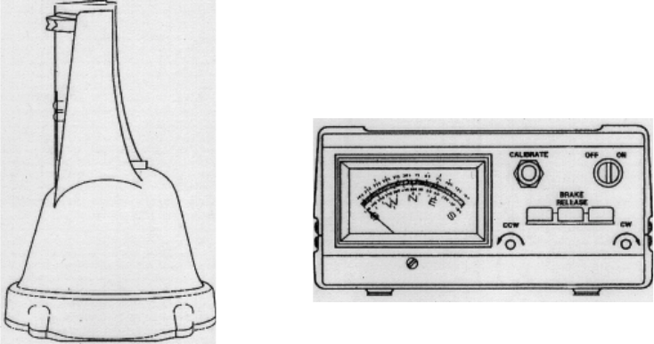
GENERAL DESCRIPTION
The CD-45-II Rotator consists of a bell-type rotator,
a metered control unit and the necessary mounting
hardware. The rotator is designed to mount on a
plate inside a tower or on a mast. The rotator unit
must be wired to the control unit with a 7 or 8 wire
cable. The control unit must be placed inside the
house or another
p
rotected location.
The CD-45-II now features a NEW 8 pin connector
on the rear panel of the control unit for easy
connection to your cable.
Included with this product are the following:
A. Instruction Manual
B. Rotator Unit
C. Controller Unit
D. Mountin
g
Hardware Pack E.
Due to the wide variety of towers available, each
installation will have different requirements. The
gauge of the cable to connect the control unit to the
rotator depends upon the distance between the
rotator and control. The longer the distance, the
larger the diameter of the wire required. Various
antennas or beams require different installation
methods. For this reason, the owner must procure
the remainder of the ,components after checking
their com
p
atibilit
y
. In
g
eneral
,
these will be:
A. The beam or antenna desired and a suitable
antenna mast
B. A tower or other mechanism to position the
rotator and beam for safe and effective rotation
(
see CAUTIONS
)
:
C. 7-wire cable to connect the control to the rotator
(
see Section V
)
.
D. Coaxial cable to connect the beam to the
communications e
q
ui
p
ment.
E. Appropriate guy wires as required.
F. Ground Hardware.
Figure 1
Rotator and Control Unit

CAUTIONS
• Towers, often the highest metal parts in the vicinity, require extreme caution during erection and
placement. Extreme care must be taken during erection so that metal towers and beams do not
contact power lines even if the beams slip or rotate, towers fall or fracture or metal wires blow in
the wind, etc.,
• Metal towers or other
p
osition mechanisms must be
p
latted so that if the
y
fracture or blow over in
high winds, they cannot contact power lines, be a hazard to individuals, or endanger property.
• When not mounted within a tower with a thrust bearing as shown in Figure 4, the rotutor must be
DEBATED.
SPECIFICATIONS
Input Voltage 120 VAC 50/60 Hz
Optional 220 VAC 50/60 Hz
Motor 24 VAC, 2.25 Amp, split phase
Power Transformer 120 VAC/26 VAC
10% duty, thermal switch protected
Optional 220 VAC/26 VAC
10% duty, thermal switch protected
Meter Transformer 120 VAC/23 VAC
Optional 220 VAC/23 VAC continuous duty
Meter DC Voltmeter 1000 ohms/volts
1 MA full scale
Meter Scale Direct Reading:
North centered, 5 degree increments
Optional Direct Reading:
South centered, 5 degree increments
Maxumim Antenna Size:
A. Tower mounted as per Figure 3 8.5 square feet (.79 sq. m) of wind surface area
B. Outside tower or mast mounted as per Fig. 5 or 7 5.0 square feet (.46 sq. m) of wind surface area
Operational Temperature Range -30 degrees to 210 degrees F (-34 to 99 degrees Celsius)
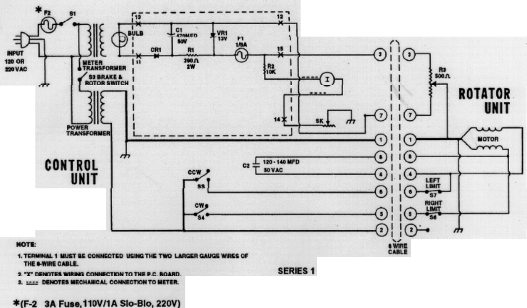
Maximum Interconnect Cable Resistance:
A. Terminal 1 1.0 ohms
B. Terminals 3, 4, 5, 6, 7, 8 2.5 ohms
Rotation Time 45-60 seconds with 60 Hz input
Brake Automatic Disc Type
Rotator Size 8 inches (20 cm)
Maximum diameter by 17 3/8 inches (44 cm) high
Maximum Antenna Mast Size 2 1/16” O.D. (52 mm)
Mounting Hardware Plated Steel Hardware and Plated Steel Clamps
Control Unit Size 8.5 inches (21.6 cm) wide by 9.0 inches (22.8 cm) deep
Shipping Volume 2411.02 cubic inches (0.0395 cu. M)
Shipping Weight 22.0 pounds (9.98kg)
• Metal towers must be grounded properly at the tower location before the tower Is erected.
This is to minimize electrical hazard and the possibility of lightning damage. Do not bury
bare aluminum wires or stakes in the ground. Use copper ground stakes. The service
entrance ground should be checked. The household convenience outlet should be the 3-
p
ron
g
t
yp
e
(g
rounded back to the service entrance
)
.
• The Control Box is not weatherproof and must be located in the house, ham shack or other
protected location.
The CD-45II Rotator has been carefully designed and manufactured to give many years of
trouble-free service when carefully and professionally installed. It consists of the strongest
and best commerciall
y
available com
p
onents.
TYPES OF INSTALLATIONS
There are three general types of installation (see Fig-
ures 4, 6, and 7).
UNBALANCED WEIGHT AND WIND
PRESSUR
E
1. The recommended installation is an "Inside"
Tower Mount, as shown in Figure 4, with a top
bushing or bearing to provide lateral support and
resist hi
g
h wind loads.
1. Unbalanced Weight: Weight should be as closely
balanced as possible. Unbalanced wight creates a
bending moment of force which is concentrated
on the mast at the point where it is clamped to
the rotator.
When the rotator is properly mounted this way, it
can be rotated to turn an antenna or beam of 8.5
square feet wind surface area. The wind loading
during storms, the rotational inertia of the beam,
and unbalanced weight are more important than
the dead weight of the beam. It is important to
minimize the height of the beam above the rotator
to minimize the overturning force induced in a
high wind ( see "Unbalanced Weight" and "Wind
Pressure"
)
.
2. An "Outside" Tower Mount, as per Figure 7, is the
best type of installation when not using an inside
tower mount. The rotator is not as well protected
but the installation is sim
p
ler.
3. A telescoping or other type mast, as shown in
Figure 6, can also be used. The lower mast
su
pp
ort is re
q
uired for this installation.
There are variations of mounting, generally into one
of the above categories. For example, the rotator may
be mounted lower in the tower than shown in Figure
4. In that case, more than one bushing or thrust
bearing for the beam mast may be required and
longer coast down time allowed in operation. These
factors are interrelated and the components must be
matched together.
This moment tends to strain the mast at that
point and also to bind the ball bearings by
creating excessive downward pressure on one
side and upward pressure on the other. Such
unbalance places additional stress on the motor
and gear train. Unbalanced weight becomes
critical as the distance from the antenna boom to
the clamping point at the rotator is increased.
2. Wind Pressure: Wind pressure against the boom
and elements produces a bending force on the
mast which can cause the same stresses as
unbalanced weight. To strengthen the installation
to withstand unbalanced weight and pressure the
top mast should be as short and as strong as
possible. In multiple arrays the heaviest should be
closest to the rotator. In order to distribute the
bending stress and prevent fracture of the mast,
the CD-45-1I Rotator includes two specially
designed steel clamps to secure the mast to the
rotator.
After procuring the type of tower or other
positioning mechanism of the owner's choice, the
next step is to wire the rotator to the control box
and check out its o
p
eration
p
rior to installation.
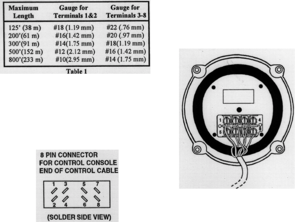
WIRING AND CHECK-OUT C. With the Control Unit and Rotator on the work
table, connect the cable between the Rotator
and Control Unit using the full length ofcable
that will be used in the installation. It is
important that Terminal #I on the Rotator is
connected to Terminal #1 on the Control Unit
and so on. Attach and solder the ends of the
cable to the 8 pin connector supplied in the
connector parts pack Plug this connector into
the control unit when done.
NOTE: The specifications call for heavier gauge
wire on Terminal #1. Lead #1 must be heavier
gauge and less total lead resistance (see
Specifications, page 2). Wire the control to the
rotator as shown in Figure 3.
A preliminary operation check should be made prior
to installation. We recommend the following
NOTE: The CD-45-1I requires only 7 wires to
operate properly since Terminal 2 in the rotator is
unterminated. However, if an 8-wire cable is used,
the Ham IV rotator can be installed at a later time
without changing the cable or control.
If the Hy-Gain Ham IV is required, due to a larger
antenna being installed, it will only be necessary to
purchase the Ham 1V Rotator, Part Number
5137201. The control units and cable requirements
are identical, therefore, only the installation of the
heavier duty rotator will be necessary.
A. Decide the wire gauge (size) required and obtain
the number of feet of the proper cable (see Table 1).
CAUTION
Shorts between terminals or grounded leads may
damage the rotator.
B. Strip and tin 3/8" on each wire end after removing
about 4 inches of the jacket from one end of
cable. Tinning can be accomplished, after
twisting the strands together, with an ordinary
soldering iron and radio solder, being careful not
to melt the insulation. On the end to be
connected to the control unit, strip the jacket
about 2 inches and strip the insulation from each
wire end 3/8".
Figure 3 Rotator Wiring
(Base)
Figure 2 Rotator Wiring
(control)

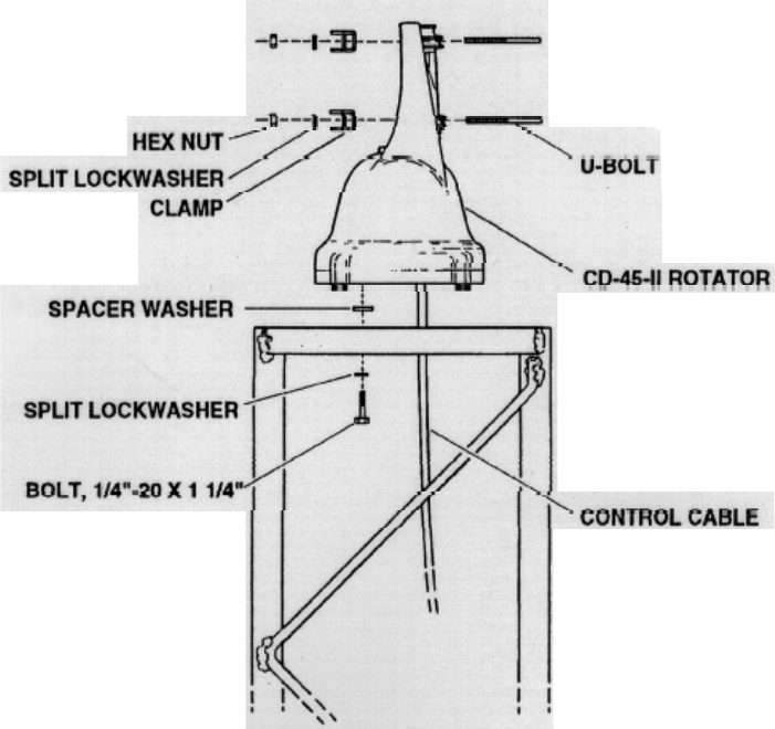
D. Install four 1/4"-20x 11/4" bolts in the four
mounting holes in the bottom of the bell
housing. Run them in about a 1/2" and leave
them as close to equal length as possible.
E. With the rotator sitting in the upright position,
resting on the four 1/4"-20 x 1 1/4" bolt heads
and connected to the control unit by the cable,
plug the power cord into a 120 VAC 50/60 Hz
or 220 VAC 50/60 Hz wall socket, depending
on which unit
y
ou have.
MOUNTING INSIDE THE TOWER
CAUTION
The rotator is designed for vertical, operation
with the bell shaped housing in the up position.
Water and other contamination will get into the
motor unit if it is mounted horizontally, at any
angle, or upside down.
The rotator is mounted inside a tower (see Figure 3)
to the flat tower plate by means of four bolts
furnished in the hardware kit. Use the following
p
rocedure:
F. Turn the power switch on. The meter should be
illuminated.
G. Depress the "Brake Release" (Center) lever, hold
it, and simultaneously depress the CCW
direction switch (left). The rotator should turn
CCW (looking from the top). This is S-E-N-W-
S: Release the CCW direction switch; the
rotator will coast down and stop. Now release
the brake switch. The rotator is now locked into
position.
H. Repeat Step G for CW direction by depressing
the brake switch first, then the CW direction
switch (Right).
CAUTION
It is best to release the direction switch just prior
to the end of rotation (extreme CW or CCW
position) in order not to cause undue stress on
the stop arm and/or the gears.
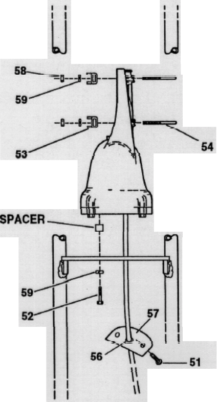
1. Locate the rotator in the tower directly under the
bushing. Note that the tower plate must be cut out
to allow the connecting cable to pass through the
plate
2. Reattach the wires in the same manner as used in
the trial assembly and secure the wires to the
tower in such a manner that the wires will not be
strained.
3. The rotator is attached to the tower plate by
means of fourbolts and lockwashers (see Figure
3). Spacer washers must be used between the
rotator and plate for clearance of the rotator
housing bolt heads. The flat tower plate must be
drilled in four places using the template
provided with this manual unless the tower plate
is already properly drilled. A fifth hole must be
drilled or cut to clear the control cable.
4. Tighten the four bolts, but not to final tightness.
Observe how the rotator turns. It must rotate in
such a manner as to turn the mast concentrically
to the top bushing.
I. Return the rotator to full CW
p
osition.
FOR CUSTOMER'S USE ,
Enter the number/color of each lead connected to the
terminals, and pins of the plug.
1234
5678
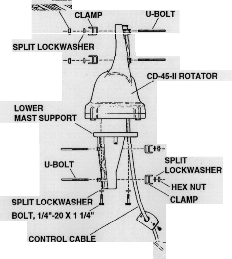
5. Trial assemble the mast to the top of the rotator
using the U-bolts, nuts and lockwashers through
the rotator and clamps as shown in Figure 3. The
maximum mast diameter that may be used is 2
1/16" O.D.. We recommend 1 1/2" nominal steel
pipe with 1/9" O.D. in standard wall thickness
of .145". For stacked arrays or very large beams,
we recommend extra heavy-duty wall
thickness.200". Both steel pipes can be
purchased to specification ASTM-120.
On any inside tower installation, care must be
exercised to get the antenna mast shimmed to the
exact rotational center of the rotator. The
geometry is such that a mast of 2.062" (21/16")
(52 mm) O.D. pipe will be exactly centered. If
the O.D. of your mast is less than this, you
should shim out to these dimensions.
6. If the rotator, top bushing and mast are properly
aligned, there should be unrestricted rotation
through 360°. If not, the rotator may have to
be moved slightly on the flat plate. If a high
quality bearing is used in the top of the tower
(recommended), the shimming procedure must
be done more carefully as closer tolerances are
required. It is important that the rotator does
not try to turn the mast eccentrically with the
to
p
bushin
g
or bearin
g
.
7. Tighten the four bolts carefully-to approximately
100 inch-
p
ounds of tor
q
ue.
8. Return the rotator to the full CW "S" position.
Mount the beam pointing South. The coaxial
cable should be looped in such a manner that it
will not foul or tangle when the beam turns
around in a circle to the full 3600
counterclockwise position. (The antenna rotates
"S" to "F' [counterclockwise] on the first turn,
therefore slack should wrap counterclockwise
around the mast.) Tighten the U-bolts securely.
Item
No.
51
Description
Screw, Pan head, 6-32 x 3/8"
Qt
y2
52 Bolt, 1/4 - 20 x 1 1/4" 4
53 Clamp 4
54 U-bolt 4
55 Flat washer 4
56 Grommet 1
57 Terminal cover 1
58 Nut, 1/4" - 20 8
59 Lockwasher, s
p
lit, l/4" 1
Figure 4
Rotator Mounted Inside Tower
MAST MOUNTING
1. Mount the rotator to the lower mast support and to
the mast.
(
See Fi
g
ures 5 & 6.
)
2. Attach one end of the control cable to the rotator
terminals. Use the same sequence as used on the
pre-installation check. The cover and grommet
must be slipped over the cable prior to attaching
it to the terminals on the rotator.
(
See Fi
g
ure 4.
)
3. Tape the rotator control cable to the mast at points
18" to 24" apart.
4. Connect the antenna cable to the antenna (follow
manufacturer's recommendation). Make sure
you have enough slack for the 360° rotation.
(The antenna rotates "S" to "E"
[counterclockwise] during its first turn,
therefore, slack should wrap counterclockwise
around the mast.) See Figure 6.
5. Attach the mast guy wires to the rotator lower
mast support or mast ring
Figure 5
Rotator Mounting with Lower Mast Support
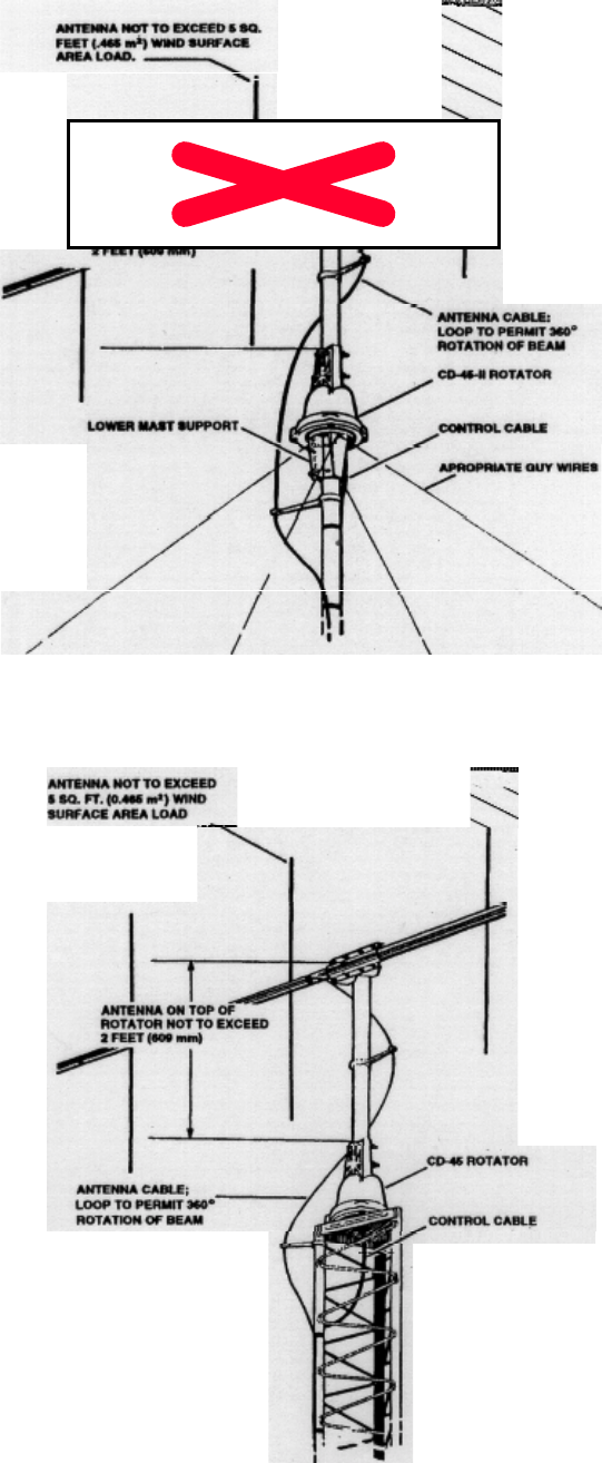
Figure 6 Mast
Mounted Rotator
Figure 7
Rotator Mounted on Tower Top Plate
6. Raise the mast into position. Rotate the mast by
hand until the antenna director is headed North.
Tighten the base clamp. Line up the mast in the
vertical
p
osition and ti
g
hten the
g
u
y
wires.
TOP OF TOWER INSTALLATION
1. Mounting the rotator on top of a tower is similar
to the mast mounting except the lower mast
support is not used. (See Figure 8.)
2. The rotator is attached to the tower plate by means
of four bolts and lockwashers (see Figure 7).
Spacer washers must be used between the
rotator and plate for clearance of the rotator
housing bolt heads. The flat tower plate must be
drilled in four places using the template
provided with this manual unless the tower plate
is already properly drilled. A fifth hole must be
drilled to cut to clear the control cable.
3. Connect the control cable to the rotator after pass-
ing it through the tower plate. Tighten the
mountin
g
bolts securel
y
.
4. Assemble the mast and antenna to the top of the
rotator using the U-bolts, nuts and lockwashers
through the rotator and clamps as shown in
Figure 7. The maximum mast diameter that may
be used is 2 1/16" O.D.. Turn the antenna by
hand until the director is pointed North, then
ti
g
hten the U-bolts securel
y
.
5. Tape the rotator control cable to the tower at
p
oints 18" to 24" a
p
art.
6. Connect the antenna cable to the antenna
(
follow
manufacturer's recommendation). Make sure you
have enough slack for the 360° rotation. (the an-
tenna rotates "S" to "E" [counterclockwise] on
the first turn, therefore, slack should wrap
counterclockwise around the mast.) See Figure 7.
Figure 8
Rotator Mountin
g
on a Tower To
p
Plate
9
OPTIONAL ACCESSORIES
Product 121B is a thrust bearing that utilizes a
bronze/oil bearing. It will clear up to a 2 3/16"
diameter mast. It can be bolted to all Hy-Gain crank-
up towers when the rotator is mounted inside the
tower.
3. With the rotator in its full CCW position, if the
meter is not at its full left position, carefully
adjust the zero (CCW South) position with the
screw directl
y
under the meter to exactl
y
South.
The Tower Mounting/Spacing Kit is a flat plate
equipped with four 0.5 inch standard bushings
drilled to match the hold-down screw holes in the
bottom of a Hy-Gain bell type rotator.
The plate is designed to allow enough clearance
under the bottom of the rotator to clear the rotator
housing bolt heads and control cable.
PRELIMINARY
CHECK AND CALIBRATION
4. Meter Calibration Procedure: Operate the rotator
to its full clockwise position. Adjust the calibra-
tion potentiometer until the meter indicates full
scale to the right. The meter is now calibrated.
Do not adjust the calibration potentiometer when
the rotator is in any position other than full
clockwise.
When the control unit is turned "OFF", the meter
needle will fall to the left "S" position and return to
indicate the rotator position as soon as the control uit
is turned "ON' again. It will not damage the unit to
leave it turned "ON' for extended
p
eriods.
IMPORTANT
THERMAL PROTECTION: If the rotator fails
to turn after 4 or 5 minutes of continuous
operation, the thermal switch comes into play.
This protective device in the transformer
automatically shuts off power if the rotator is
used continuously for too long. It will
automatically reset after 10 minutes.
1. Tom the Control Unit Power "ON' with the upper
right "ON-OFF" switch. The meter should be
illuminated and the needle should be to the ri
g
ht.
2. Depress the brake lever (center) and hold.
Depress the CCW lever (left) and operate the
rotator to its full CCW position. Observe the
antenna cable on the first rotation to insure it
does not get fouled.
To operate this rotator, depress the brake lever, then
depress either the CCW lever or CW lever. Hold both
levers down until the antenna reaches the desired
heading. Release the direction lever, then the brake
lever.
GROUNDING
The tower, or other metal support device, must be
grounded to an
earth
ground at its location. Use
heavy copper cable looped so that if the tower comes
down for any reason, there will be adequate slack to
prevent the ground wire from breaking. Use one or
more 8 foot copper clad steel stakes driven into the
moist earth and fasten the wire securely at the stake
and at the tower.
As mentioned in the "Cautions" portion, the steel
chassis of the control box should be either
grounded to a metal cold water pipe in the house or
back to the electric service entrance box where the
power comes into the house. This normally is
accomplished with the wire of the 3-prong plug
which then depends on the wall outlet being
adequately grounded back to the service entrance
as to the utility ground. If there is any doubt, have
this checked by a licensed electrician.
SOUTH CENTERED METER
SCALE COVERSION
The stock CD-45-II Control Unit is shipped with the
meter scale installed for "North" center operation;
ends of rotation are at the "South" position. Some
geographic locations and/or popular working areas
may favor having the meter "South" center; ends of
rotation are at the "North" position. We have
provided the CD-45-I1 with an interchangeable
meter scale. See the note following Step #11.
8. Carefully slip a knife blade under each corner of
the lower edge of the white meter scale and twist
slightly until the scale clears the two small
indexing pins. Remove the scale and install the
new one. Make sure the scale fits over the
indexing pins and that it is flush and tight
against the black housing. This will assure free
movement of the indicator needle.
We recommend the following
1. Disconnect the
p
ower
9. Reinstall the meter (remove the temporary
jumper), the P.C. Board and lamp hardware.
Check for pinched, shorted end, or over-stressed
wires.
2. Remove the control cable, carefully label' g each
wire with its corresponding terminal number.
This operation may be omitted if the control
box can be worked on easily without removing
the leads.
10. Reinstall the to
p
and bottom
l 1. Reconnect the control cable in the exact
se
q
uence as the
y
were removed.
3. Remove the to
p
and bottom covers.
4. Slip the lamp and holder off the lamp holder
bracket. Loosen the hex nut on the transformer
that is holding the lamp holder bracket and
swing the bracket clear of the wires leading to
the printed circuit board.
If your beam was installed originally using the CD-
45II with a "North" center scale, the antenna mast
must be loosened and repositioned. In order for the
meter to indicate properly, the front of your beam
must point "North" when the rotator is at the ends of
rotation.
Recalibrate the meter.
5. Carefully remove the hex nuts on the meter studs
to free the printed circuit board. Slip the P.C.
Board off the studs and pull it down under the
chassis.
CAUTION
It is good practice to use a short test lead or jumper
wire to short the meter studs when it is not in the
circuit.
NOTE: In the past, the South Centered meter scale
was on the reverse side of the factory installed North
Center scale. The unit is now provided with a
separate South Centered scale. This will help to
avoid damage to the face of the meter scale during
removal of the North Centered scale.
6. Loosen the meter retaining clips and remove the
meter from the chassis.
7. Insert a small knife blade between the clear
meter cover and black housing at either corner
of the top edge and gently pry the cover loose
from that corner. Repeat for the other corner.
The meter cover should pop off.
ROTATOR CONSTRUCTION
(
Refer to Fi
g
ures 12
)
TROUBLESHOOTING
1. Outer Housing: The upper mast support (Bell)
and the brake housing are cast aluminum. The
upper mast support is secured to the brake
housing by four #12-24 x 3/4" self-tapping hex
head screws.
2. Position Sensor: The position sensing potentiome-
ter is located in the to
p
of the bell castin
g
.
3. Drive: A low voltage AC motor and its associated
gears drive the output ring gear at about 1 RPM.
The ring gear in turn is mechanically
interlocked in the u
pp
er mast su
pp
ort
(
Bell
)
.
4. Brake: The brake is a disc type which is an
integral part of the motor armature. When power
is applied to the motor, the armature lifts pulling
the two disc pads apart which allows the gear
train to operate freely. With no power applied,
the weight of the motor armature forces the two
brake pads together which in turn brakes the
rotator.
5. Rotation Limits: Activated by the stop arm are
two electrical end of rotation switches which dis-
connect the motor power just before the rotating
bell housing reaches its full CW (0°) or CCW
(
360°
)
p
ositions.
6. Bearings: Two rows of ball bearings are provided.
Lubricate sparingly with factory approved
special low temperature grease. This grease
allow normal o
p
eration to -30°F
(
-34°C
)
.
CAUTION
This unit has been thoroughly tested and cycled
before shipment. Follow the terminal board
wiring carefully between Rotator and Control
Box. Incorrect wiring will burn out the rotator
potentiometer and void the warranty.
Be sure Rotator and Control Units are compat-
ible. Do not intermix models with different oper-
ating voltages. This results in sluggish or non-
operating performance, burned out motors,
overheated transformers and burned out rotator
potentiometers, etc.
Most operational difficulties with rotators are
traceable to broken, shorted or grounded wires
usually at the terminal strips. Time spent in cutting
the leads to exact lengths, tinning, forming and
wrapping around terminals, cutting insulation to
exact len
g
ths
,
and clam
p
in
g
to
p
revent strain on an
y
MECHANICAL PLAY
Frequently, the slight motion of the antenna array in
gusts of wind is due more to the natural flexing of
the elements and mast than it is due to actual play in
the rotator mechanism. A slight amount of "play" is
built into the rotator to avoid binding due to
environmental chan
g
es.
ANTENNA ROTATES IN HEAVY WIND
This is usually a matter of the mast slipping in the
support. If "slipping" or "turning" is suspected,
return the rotator to the end of rotation and visually
check to be sure that the antenna is in the original
stop location as installed. Check the nuts on the U-
bolts to insure that the
y
are ti
g
ht.
LACK OF POWER
If the antenna rotation is slow or sluggish or hard to
start, check for proper voltages. If the voltages are
correct, the 140 MFD motor start capacitor could be
at fault. It is recommended that a new capacitor be
tried before any other action is taken. If the electrical
circuit is okay, then check for. mechanical binding.
Pay particular attention to bearings and alignment of
the shaft on an inside tower mount. On any inside
tower installation, care must be exercised to get the
top mast shimmed to the exact rotational center of
the rotator upper mast support. If temperatures are at
-30°F (34°C) or lower, operation will be slow or
sluggish. This is normal!
IMPROPER METER INDICATION CHECKING THE CONTROL UNIT
The brake and motor operate independently of the
indicating system. If the pilot light bums at proper
brilliancy, the instrument transformer is okay and the
output is not shorted. Check the 1/8 amp meter circuit
fuse with an ohmmeter. Check for about 13 VDC
across Terminal No. 3 and No. 7 with the switch
'operated. If the proper voltage is not obtained, check
the individual components in the meter circuit. If the
13 VDC is present, check for 500 ohms across rotator
leads No. 3 and No. 7. If 500 ohms is present from
No. 3 and No. 7, see if the readings from No.3 to
ground and No. 7 to ground total 500 ohms.
NOTE: An intermittent condition in any component
in the rectifier or meter circuits within the control
box, as well as in the cable or potentiometer circuit
in the rotator itself can cause meter fluctuation or
error. Possible cause of such trouble may be
localized by placing a test DC meter across Terminal
No. 1 and No. 3 or No. 1 and No. 7 comparing the
action of the test meter with the panel meter.
NO ROTATION - INDICATION OK
Either the thermal cut-out in the power transformer
has opened or there is actually trouble in the motor
circuit. After allowing time for the thermal cut-out to
restore service, proceed to "Checking the Control
Unit" and "Checkin
g
the Rotator from Ground".
GROUND WIRES
Grounds on cable leads can bum out either the line
fuse or the small fuse in the meter circuit. If lead No.
3 or lead No. 7 is grounded, it shorts out part of the
potentiometer so that as rotation progresses to the
other end, the full DC voltage is applied across a
decreasing portion until current becomes so high that
the potentiometer burns out. Note also that any
grounds may put an overload on the power
transformer which could cause the line fuse to blow
or overload the rectifier circuit so that the 1/8 amp
fuse blows. For full explanations, refer to Figure 8
HELPFUL SUGGESTIONS
Be sure to check your rotator cable for shorting,
open circuits, incorrect wiring, intermittent
connections, shorted terminals, poor lead dress at
terminals, rodent damage, and mast support or thrust
b i bi di
1. Voltages with Unit Plugged In.
To check the control unit, plug the line cord into
AC power. With no connections to the connector,
turn the on-off switch to the "ON' position, the
meter light will illuminate. The meter needle will
remain on the left hand "S".
Connector pins 1 and 2 should show 30 volts AC
(approximately) when the brake lever is
depressed.
Connector pins 1 and 5 should show 30 volts AC
with brake release lever depressed and CW lever
de
p
ressed.
Connector pins 1 and 6 should show 30 volts AC
with brake release lever depressed and CCW
lever de
p
ressed.
Connector pins 3 and 7 should show
approximately 13 VDC.
2. Resistances with Unit Not Plugged In.
Disconnect the AC power source and remove
the control cable.
The control box can be checked without
removing the cover by using a volt-ohmmeter to
check values across connector pins. Resistances
across Connector pins 1 thru 5 with clockwise
switch lever (right hand) depressed and across
Connector pins 1 thru 6 with counterclockwise
switch lever (left hand) depressed. Resistance
across input line cord with on-off switch in the
"ON'
p
osition and the brake lever de
p
ressed
CHECKING THE ROTATOR FROM THE
GROUND
You may possibly avoid bringing the rotator down
by making electrical checks from the control box
position. This is done by disconnecting the cable
connector from the control unit. From the schematic
diagram, it is apparent that the resistance of the lead
wires will be added to the resistance of the motor
windings and potentiometer strip in making the
resistance checks as shown in Table 2.

To Read Between
Check Resistance Terminals
1/2 Motor Winding
1/2 Motor Winding
1/2 Motor + Switch
1.5 ohms
1.5 ohms
1.5 ohms
1-8
1-4
1-6
10. Sandpaper or wire brush the terminal strip. Rust
causes high resistance causing control/rotator not
to work properly.
Entire Motor 3.0 ohms 4-8 Service Information
Ri
g
ht Limit Switch 0 ohms + leads 8-5
Left Limit Switch 0 ohms + leads 4-6 If you are encounter technical problems and need
Entire Pot Strip 500 ohms 3-7 assistance, you should contact Hy-Gain Customer
Service Department.
Pot Arm to + End 0 to 500 ohms 1-3
Pot Arm to - End 0 to 500 ohms 1-7 All requests, inquires, warranty claims, or for
plus leads ordering replacement parts, contact:
ADDITIONAL CHECK LIST
Table 2 Hy-Gain
308 Industrial Park Road Starkville,
Mississippi 39759 USA Phone:
662
-
323
-
9538
1. Check continuity of control wires for loose
connections caused by wind.
2. Tape down control cable securely all the way to
rotator.
3. Check motor winding through control cable as
outlined in Table 2
4. Check cable between leads. Static lightning charges
or direct hits will cause carbon arcs in control cable
at numerous spots along the cable that cannot be
seen. This resistive path will break down with
voltage applied to rotator (Replace cable.)
5. Check both control and rotator terminal strips for
shorts.
6. Rotation in one direction usually indicates a loose or
broken cable wire, bad relay, and bad sensing
transistors in some units.
7. Be sure cable is of proper size for length used.
Refer to Table 1.
8. Substitute a 3 foot piece of new rotator cable to
bench test unit. Proper operation will indicate a
defective rotator cable on the mast or tower, or a
cable not large enough to create proper turning
torque.
9. Low line voltage and cold weather will slow
rotation. Using an extra long or small wire
extension cord can lower line voltage.
PARTS LIST
CD-45-II Control Unit Replacement Parts
Item Part
1 5156502 Control Unit, 220VAC, com
p
lete .......................................................1
2 5156500 Control Unit, 120VAC, complete .......................................................1
3 5139000 Printed Circuit Board .......................................................................1
4 55135200 Capacitor, 470 mfd, 50V, C-1.................................................... ..... 1
5 5051314 Resistor, 390 ohms, 5% 2W, R-1..................................................... 1
6 5015300 Diode, Zener, VR-1..........................................................................1
7 85759002 Diode, CR-1.....................................................................................1
8 52154257 Resistor, IOK olun, 1/4 W, R-2.................... ................................... 1
9 5056300 Fuse, 1/8 Amp, F-1 ..........................................................................1
10 52874001 Holder Fuse......................................................................................2
11 1034403 Fuse, 3 Amp, F-2 (110V version) ............................................ ........ 1
12 5089501 Bulb, Meter, #1819 ..........................................................................1
13 710053 Fuse, 1 Amp, S16-Blo, F-2 (220V version) ...................................... 1
14 5138600 Switch, Snap, S03, S-4, S-5 ............................................................ 1
15 5141100 Cover, Top .......................................................................................1
16 5141200 Cover, Bottom..................................................................................4
17 5152700 Pads, Skid.........................................................................................9
18 520057 Screw, #6-32 x 3/8", Pan Head ....................................................... 1
19 567105 Washer.............................................................................................1
20 640076 Socket, 8-pin....................................................................................1
21 5088400 Lever, Switch, for S-3, S-4 & S-5.................................................... 1
22 450403 Relief, Strain, Heyco 3772 (220 V version) ..................................... 2
23 506665 Screw, #6-32 x 1/4", round head ...................................................... 2
24 560068 Washer, Back-up (220V version)........ ............................................1
25 1073501 Transformer, Power (220V version) . ..............................................1
26 1073301 Transformer, Power (120V version) ................................................1
27 5020200 Transformer, Meter (220V version) ................................................. 1
28 5017700 Transformer, Meter (120V version) ................................................. 1
29 5151501 Capacitor, Motor Start..................................................................... 1
30 5086100 Cord, Line, 3-wire (120V version) ................................................... 1
31 450431 Relief, Strain, Heyco 1217 (120V version) ...................................... 1
32 5079800 Cord, Line, 3-wire (220 VAC; European Plug) ............................... 1
33 5147702 Meter................................................................................................1
34 5175200 Switch, On/Off S-1 ..........................................................................1
35 723406 Potentiometer...................................................................................1
36 1056300 Holder, Fuse, for F-2; (120V version) ....... :......... ........................... 1
37 710054 Holder, Fuse, for F-2; (220V version) ............................................ 1
38 5156100 Plate, Face........................................................................................1
39 5089103 Chassis.............................................................................................1
HAM IV/CD-45-II Control Unit Re
p
lacement Parts
(
Continued
)
Item Part
No. No. Description Qty
40 506325 Bolt, Hex Head, 1/4"-20 x 3/4" .......................................................1
41 567110 Lockwasher, Int. 1/4" ..................................................................... 2
42 567120 Flatwasher, 1/4" ..............................................................................2
43 556960 Nut, Hex, 1/4"-20.............................................................................1
44 550029 Nut, Wing, 1/4"-20...........................................................................1
45 710083 Holder, Bulb.....................................................................................1
46 .567125 Lockwasher, #10 Internal................................................................ 4
Figure 9
Wiring Schematic
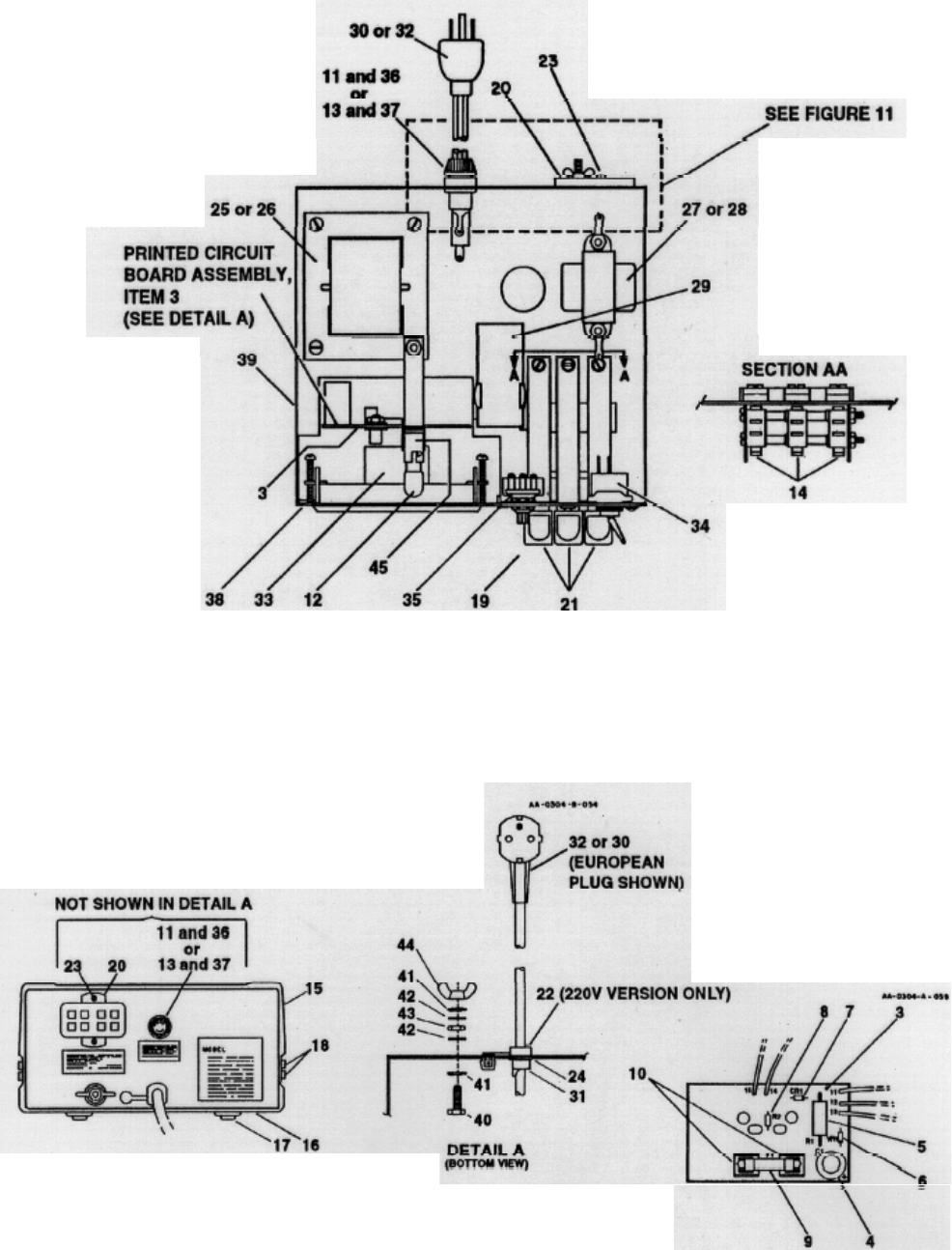
Figure 11
Control Unit-Back View
Figure 10
Control Unit-Top View
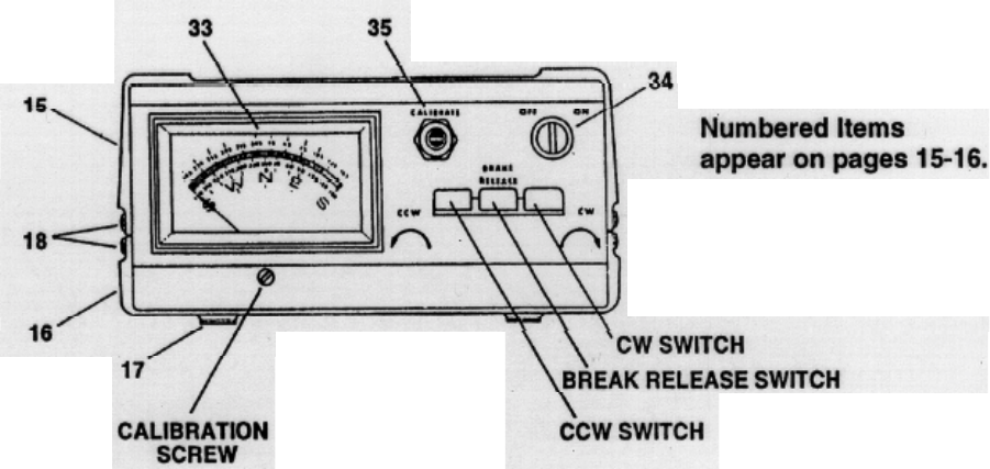
Figure 12
Control Unit - Front Panel
CD-45-II Rotator
Item
No. Part No. Description Qty
7 5011300 Retainer, ball bearing ...................................................................... 2
11 5023100 Potentiometer Assy. ......................................................................... l
12 -5030400 Support, upper mast (bell casting) ...................................................1
13 5030600 Ring, retaining..................................................................................1
15 5031300 Gear, driving ....................................................................................1
16 5033501 Bearings, ball .................................................................................50
24 5037406 Motor Assy....................................................................................... l
25 5039800 Board, Terminal ...............................................................................1
30 5105700 Screw, #12-24 x 3/4"....................................................................... 4
5042510 Accessory Kit......................................................................................1
51 107632061 Screw, round head............................................................................2
52 110820035 Bolt, 1/4-20 x 1 1/4" ....................................................................... 4
53 -5035100 Clamp, mast.....................................................................................4
54 5035200 U-bolt...............................................................................................4
55 5050200 Flat washer.......................................................................................4
56 5091400 Grommet..........................................................................................1
57 5033900 Terminal cover.................................................................................1
58 556960 1/4"-20, Nut .....................................................................................8
59 567115 1/4", split lockwasher.................................................................... 12
870598 Parts Pack, Connectors....................................................................... 1
60 640077 Plug, cinch, 8 pin .............................................................................1
61 650082 Amp socket......................................................................................8
62 650180 Shell amp .........................................................................................1
63 650181 Plug, amp .........................................................................................1
64 650293 Amp socket......................................................................................8
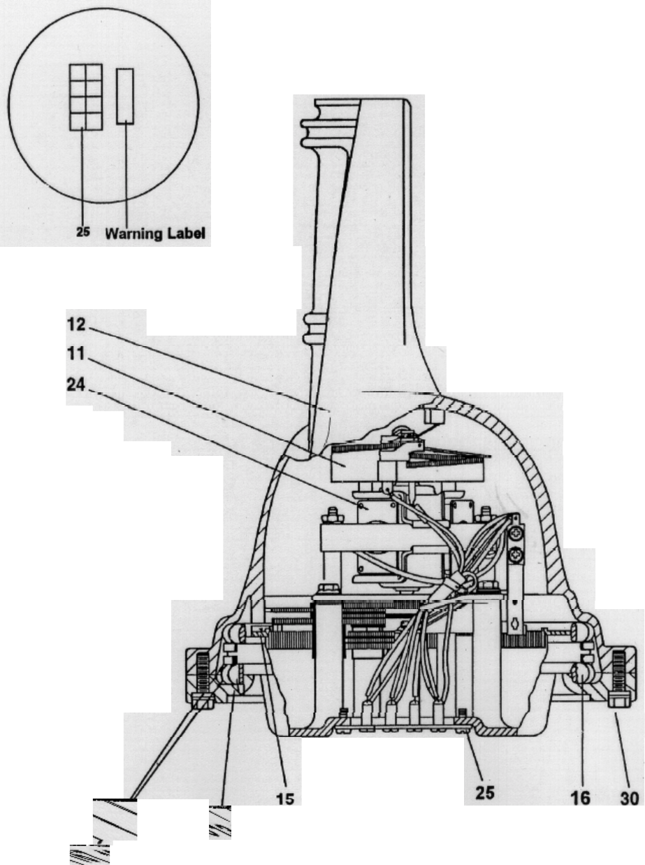
Figure 13
Overall View of CD-45II Rotator
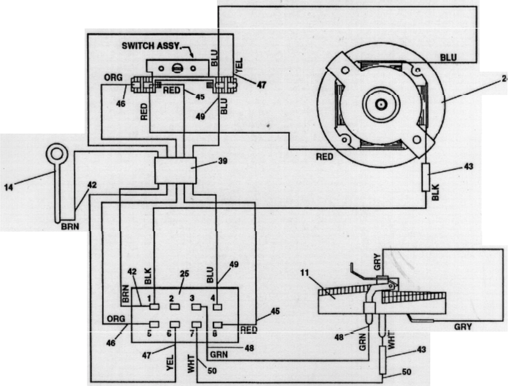
Figure 14
Wiring Diagram
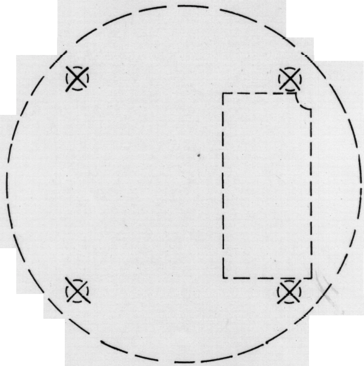
Tower Drilling Template
This information is believed correct, but no warranty is given or implied and no liability is
assumed by Hy-Gain as to its accuracy or completeness. Changes maybe made from time to
time so the user should verify all factors that may be critical. This information is not to be
construed as to authorizing or advising use of any patented invention.
HOLES TO BE 17/64” CLEARANCE DRILL

Hy-Gain Warrants to the original owner of this product, if manufactured by Hy-Gain
and purchased from an authorized dealer or directly from Hy-Gain
to be free from
defects in material and workmanship for a period of 12 months for rotator products and
24 months for antenna products from date of purchase provided the following terms of
this warrant
y
are satisfied.
1. The purchaser must retain the dated proof-of-purchase (bill of sale, canceled check,
credit card or money order receipt, etc.) describing the product to establish the
validity of the warranty claim and submit the original or machine reproduction of
such proof of-purchase to Hy-Gain at the time of warranty service. Hy-Gain
shall
have the discretion to deny warranty without dated proof-of-purchase. Any evidence
of alteration, erasure, or forgery shall be cause to void any and all warranty terms
immediately.
2.
Hy-Gain
agrees to repair or replace at Hy-Gain’s
option without charge to the
original owner any defective product under warranty, provided the product is
returned postage prepaid to Hy-Gain
with a personal check, cashiers check, or
mone
y
order for $8.00 coverin
g
p
osta
g
e and handlin
g
.
3. Under no circumstances is Hy-Gain
liable for consequential damages to
p
erson or
p
ro
p
ert
y
b
y
the use of an
y
H
y
-Gain
p
roducts.
4. Out-of-warranty Service: Hy-Gain
will repair any out-of-warranty product
provided the unit is shipped prepaid. All repaired units will be shipped COD to
the owner. Repair charges will be added to the COD fee unless other
arran
g
ements are made.
5. This warranty is given in lieu of any other warranty expressed or implied.
6.
Hy-Gain
reserves the right to make changes or improvements in design or
manufacture without incurring any obligation to install such changes upon any of
the products previously manufactured.
7. All H
y
-Gain
p
roducts to be serviced in-warrant
y
or out-of-warrant
y
should be
addressed to hy-gain, 308 Industrial Park Road,
Mississippi 39759, USA and must be accompanied by a letter describing
the problem in detail along with a copy of your dated proof-of-purchase.
8. This warranty gives you specific rights, and you may also have other rights which
vary from state to state.
LIMITED WARRANTY
