HY GAIN HG V 4S VERTICAL
User Manual: Pdf HY-GAIN--HG-V-4S-VERTICAL
Open the PDF directly: View PDF ![]() .
.
Page Count: 6
IkEfEX N
TELEX COMMUNICATIONS, INC.
3600 ALDRICH LIVE SO. MINNEAPOLIS. MN 55420 U S A
/~g-~~~~r”iu IORDER NO. 337s
MAN’ ‘A’
I
MODEL V4S
Collinear Gain Vertical
for 420450 MHz
PN801910
General Description The new Hy-Gain V-4s 70 cm antenna is a collinear, dual % wave, omnidirectional,
vertical antenna for the 420-450 MHz Amateur band. The V-4s features two sets of %
wave radials which properly decouple the lower % wave radiator from the mast. It also
features a 100 watt enclosed coil that matches the antenna to a normal 50 ohms. The
feedpoint is a high quality “fY type connectorthat is protected from the weather within the
lower radiator. The V-4s also features a mast-to-mast bracket that will accept up to a two
inch O.D. mast.
The V-4s can also be used outside of the 7.0 cm Amateur band. Graphs are supplied so _ that the antenna can be set to any frequency between 420 and 470 MHz.
Specifications VSWR at resonance ............................................. less than 1.51
2:l VSWR bandwidth .......................................... 27 MHz minimum
Power gain ..................................................... 3 dBd, 5.2 dEii
Antenna/ Mast isolation. ................................................. 20 dl3
Power input .............................................. 100 watts continuous
Lightning protection ................................................. DC ground
Height. .................................................... .45 inches (1 .I 4 m)
Wind area .................................................. 0.28 sq. ft. (0.026)
Maximum mast O.D. ......................................... 2 inches (5.08 cm)
Hardware ................................. 18-8 stainless steel except for U-bolts
Assembly Unpack the antenna and check the parts against the Parts List and drawings.
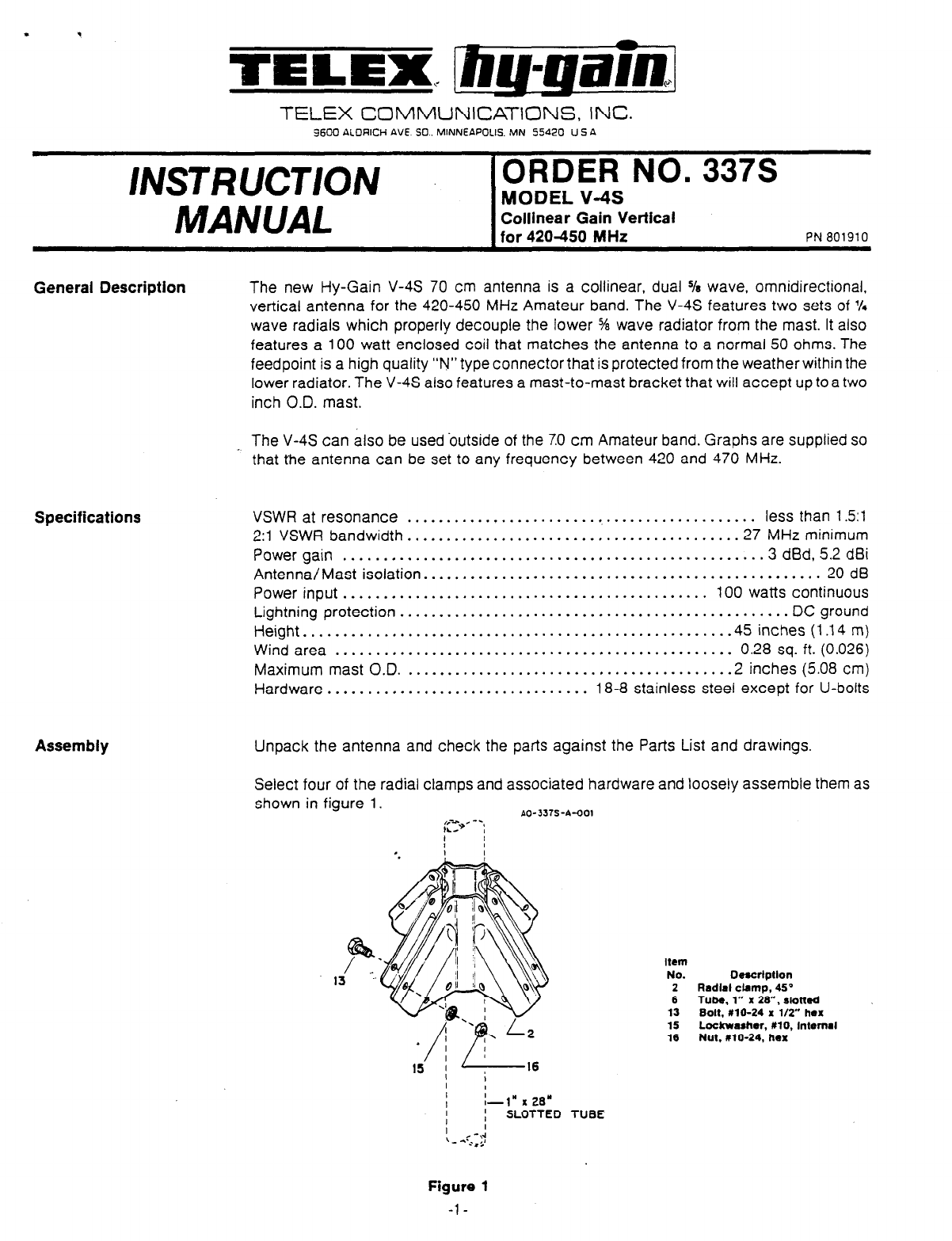
Select four of the radial clamps and associated hardware and loosely assemble them as
shown in figure 1.
PO-3315-A-001
t
I
I-l” x 28’
; SLOTTED TUBE
I
< -\-A
- - ;*$A
Item
No. Oexcrlption
2 Redlel cbmp, 4S0
6 Tube 1” x 26”. slotted
13 Bolt,‘#lO-24 x t/2” hex
15 Lo&washer, X10, Intemel
16 Nut, 010-24, hex
Figure 1
-l-
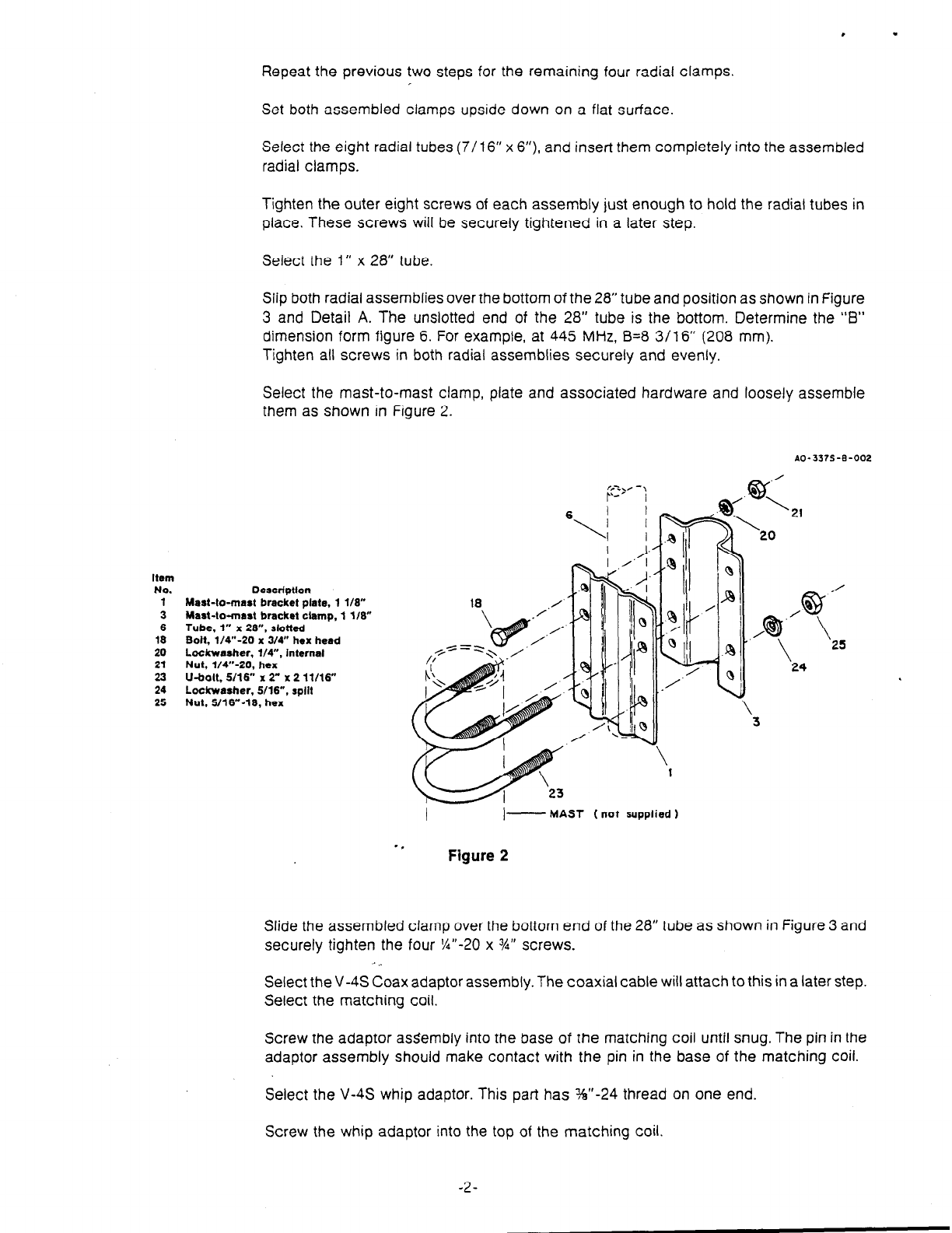
Select the mast-to-mast clamp, plate and associated hardware and loosely assemble
them as shown in Figure 2.
Item
No. Detcriptton
1 Mart-to-mart bracket plate, 1 l/E”
3 Maat-to-maat bracket clamp, 1 118”
6 Tube 1” x 28”. slotted
18 Bait, ;/V-20 x 3/W hex head
20 Lockwasher. l/4”, internal
21 Nut l/4”-20 hex
23 u&a, s/16:’ x 2” x 2 11116”
24 Lo&washer. S/lb”, split
25 Nut. Y16”-10, hex
, .
Repeat the previous two steps for the remaining four radial clamps.
Set both assembled clamps upside down on a flat surface.
Select the eight radial tubes (7/l 6” x 6”) and insert them completely into the assembled
radial clamps.
Tighten the outer eight screws of each assembly just enough to hold the radial tubes in
place. These screws will be securely tightened in a later step.
Select the 1“ x 28” tube.
Slip both radial assemblies over the bottom of the 28” tube and position as shown in Figure
3 and Detail A. The unslotted end of the 28” tube is the bottom. Determine the “B”
dimension form figure 6. For example, at 445 MHz, B=8 3/16” (208 mm).
Tighten all screws in both radial assemblies securely and evenly.
AO-3375-B-002
\
I I-
MAST (not supplied 1
Figure 2
Slide the assembled clamp over the bottom end of the 28” tube as shown in Figure 3 and
securely tighten the four %I’-20 x %” screws.
Select the V-4s Coax adaptor assembly. The coaxial cable will attach to this in a later step.
Select the matching coil.
Screw the adaptor assembly into the base of the matching coil until snug. The pin in the
adaptor assembly should make contact with the pin in the base of the matching coil.
Select the V-4s whip adaptor. This part has %I’-24 thread on one end.
Screw the whip adaptor into the top of the matching coil.
-2-
14
8
11
6
15 16
SEE DETAIL 8
I I
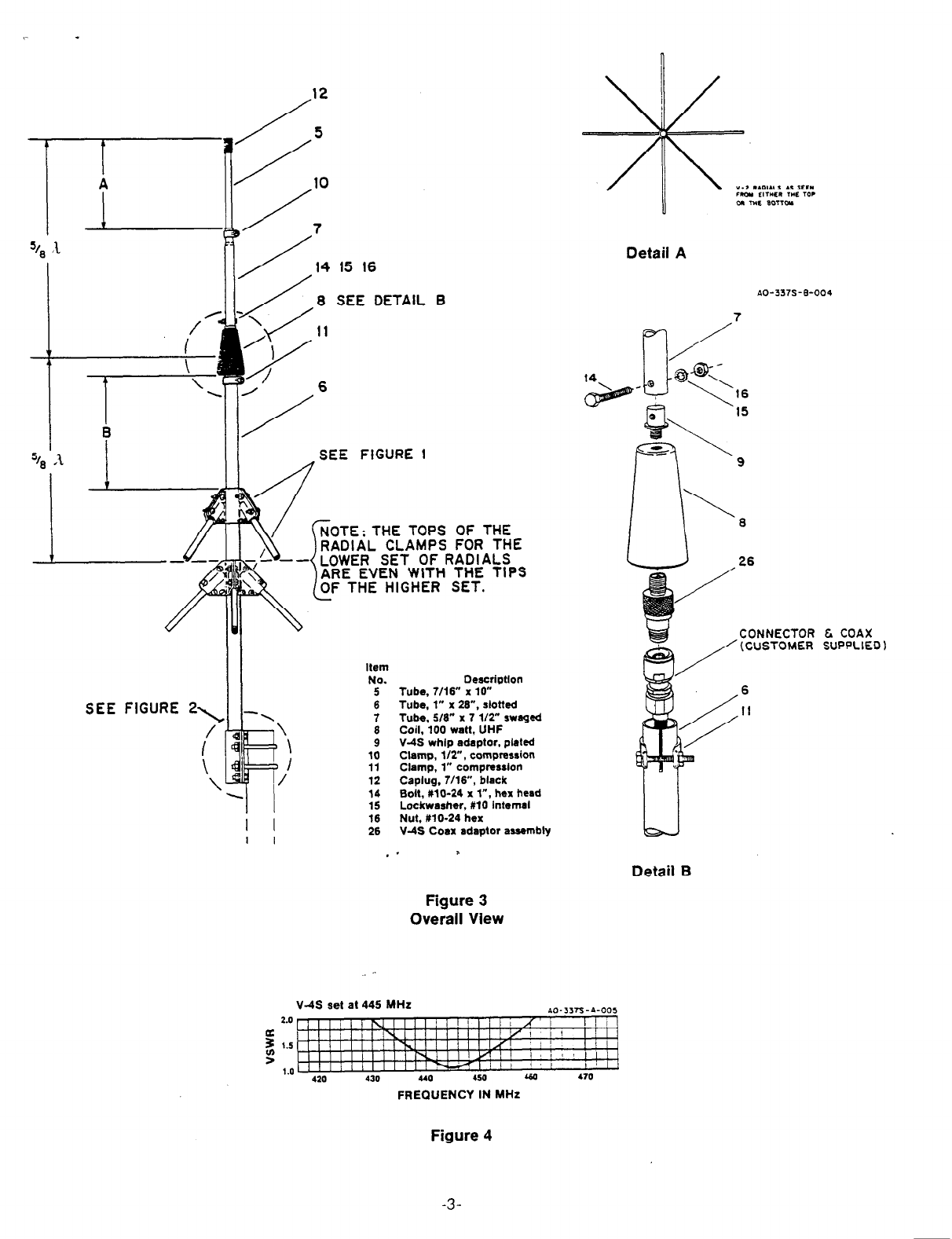
SEE FIGURE 1
NOTE: THE TOPS OF THE
RADIAL CLAMPS FOR THE
- LOWER SET OF RADIALS
ARE EVEN WITH THE TIPS
OF THE HIGHER SET.
SEE FIGURE 2\
I/
\ \
Item
No.
5
6
7
6
9
10
11
12
14
15
16
26
Deacrtptlon
Tube, 7/16” x 10”
Tube, 1” x 26”, slotted
Tube, 516” x 7 l/2” swagsd
Coil, 100 watt, UHF
V-IS whlp adaptor, plated
Clamp, l/T, compression
Clamp, 1” comprerslon
Caplug. 7/W’, black
Bolt, MO-24 x l”, hex hcsd
Lockwasher, MO internal
Nut. #lo-24 hex
V-4S Coax adaptor assembly
Detail A
26
CONNECTOR t COAX
(CUSTOMER SUPPLIED 1
6
II
Detail B
Figure 3
Overall View
V-4S set at 445 MHz AD-3,Js-A-005
2.0
5
f
1.5
1.0 420 430 440 450 440 470
FREQUENCY IN MHz
Figure 4
-3-
.
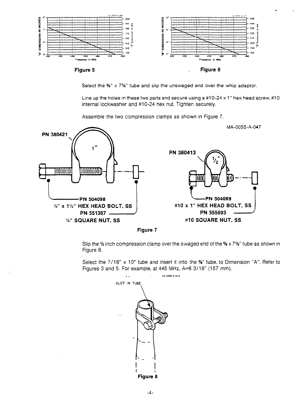
Figure 5
Select the YE” x 7%” tube and slip the unswaged end over the whip adaptor,
Line up the holes in these two parts and secure using a #l O-24 x 1” hex head screw, #lO
internal lockwasher and #l O-24 hex nut. Tighten securely.
Assemble the two compression clamps as shown in Figure 7.
-PN 504098
VP”
x
1’/2”
HEX HEAD BOLT, SS
PN 551367
9’4”
SQUARE NUT, SS
Figure 7
MA-OOSS-A-047
-PN 504069
#lo x 1” HEX HEAD BOLT, SS
PN 555693 --J
$10 SQUARE NUT, SS
Slip the % inch compression clamp over the s:vaged end of the Ye x 7%” tube as shown in
Figure 8.
Select the 7/l 6” x 10” tube and insert it into the
K”
tube, to Dimension “A”. Refer to
Figures 3 and 5. For example, at 445 MHz. A=6 3/16” (157 mm).
v. r.-oooo-.a*,
SLOT IN TUBE
I
Figure ‘e
-4-
. -
Tighten the compression clamp securely.
Select the 7/l 6” caplug and slip over the end of the 7/l 6” tube.
Select the assembled one inch compression clamp and slip it over the top end of the 1” x
28” tube. Position it as shown in Figure 8 and tighten it just enough to prevent it from sliding
down the tube.
There are two ways to attach your coax to the V-4s antenna. The first method involves
attaching a short length of coax to the antenna before attaching the antenna to the
supporting mast. The remaining lenght of coax can then be attached and routed to the
-radio. The short length of coax must be a least 3 feet long so the connection between coax
lengths can be made below the mast-to-mast bracket.
The second method involves attaching the complete length of coax to the antenna before
attaching the antenna to the supporting mast. In this method, the antenna and entire coax
length must be carried up the tower or mast.
Choose one of the suggested methods of attaching the coax to the V-4s.
Insert one end of the coax into the bottom of the 1” x 28” tube. Push the coax through until
the connector emerges from the top to the tube.
Screw the connector onto the V-4s coax adaptor.
Push the coax adaptor into the top of the 1” x 28” tube until the matching coil rests on the
one inch tube. Tighten the one inch compression clamp.
The antenna can now be mounted on a mast (2” O.D. max.). For adequate lightning
protection, the antenna supporting structure must be well grounded.
WARNING: /nstal/atlon of this product near power
lines Is dangerous. For your safety, follow the
lnstallatlon directions.
Several antennas may be mounted on the same mast. Your V-4s should be mounted
above the other antenna for best performance. When side mounting the V-4s on a tower, it ’
should be kept at least 10 inches away from the tower.
- *
-5-
Item
No.
1
3
4
5
6
7
8
9
10
11
12
13
14
1.5
16
17
18
19
20
21
22
23
24
25
26
LI l
1
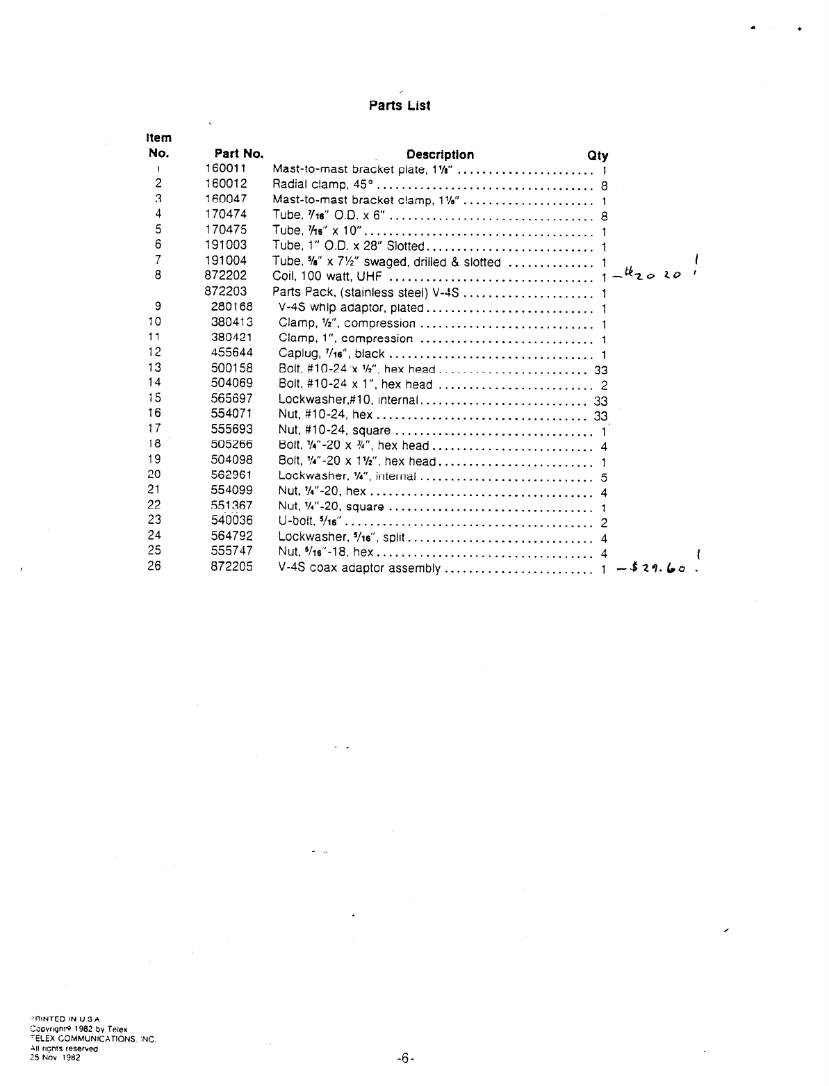
Parts List
-‘RINTED IN U S A
Ccxwyht~ 1982 by Telex
-ELEX COMMUNICATIONS ‘NC
All rlqnrs reSer”W
25 NOV 1982
-6-
Part No.
160011
160012
160047
170474
170475
191003
191004
872202
872203
280168
380413
380421
455644
500158
504069
565697
554071
555693
505266
504098
562961
554099
551367
540036
564792
555747
872205
Description QtY
Mast-to-mast bracket plate, 1%” ...................... i
Radial clamp, 45’. .................................. 8
Mast-to-mast bracket clamp, 1%” ..................... 1
Tube. 7/rs” O.D. x 6
................................... 8
Tube,W’x 10”. .................................... 1
Tube, l)( O.D. x 28” Slotted ........................... 1
Tube. 5Ia’t x 7%” swaged, drilled & Slotted I
..............
Coil, 100 watt, UHF ................................. :A! to 10 ’
Parts Pack, (stainless steel) V-4s ..................... 1
V-4s whip adaptor, plated ........................... 1
Clamp,
l/2”,
compression ............................ 1
Clamp, l”, compression ............................ 1
Caplug, ‘/w”, black ................................. 1
Bolt, #lo-24 x ‘A”, hex head.. ...................... 33
Bolt, #lo-24 x l”, hex head ......................... 2
Lockwasher,#lO, internal ........................... 33
Nut, #lo-24, hex .................................. 33
Nut, #lo-24, square.. .............................. 1’
Bolt, %“-20 x %“, hex head .......................... 4
Bolt, %“-20 x l%“, hex head ......................... 1
Lockwasher. %“, internal ............................ 5
Nut, %..-20. hex .................................... 4
Nut, %“-20, square ................................. 1
U-bolt.
‘/I6 ..........................................
2
Lockwasher, %s”, split .............................. 4
Nut, %s”-18, hex ................................... 4 (
V-4s coax adaptor assembly ........................ 1 -4 2 9.6 J .
- .
