Hummer Bot Instruction Manual
User Manual: Pdf
Open the PDF directly: View PDF ![]() .
.
Page Count: 108 [warning: Documents this large are best viewed by clicking the View PDF Link!]
Hummer-Bot Instruction
Manual
Github https://github.com/keywish/keywish-hummer-bot

1
Data
Versio
n
Description
Author
2017/9/16
V-1.0
Create
Baron.li
2017/9/23
V-1.1
modify
Ken.chen
2017/10/18
V-1.2
Review
Ken.chen
2017/11/15
V-1.3
Review
Zach.zhou
2017/12/8
V-1.4
Review
Baron.li
2018/3/11
V-1.5
Modify ir/blutooth module
Ken.chen
2018/4/20
V-1.6
Add device instructions
Baron.li
2018/5/3
V-1.7
Add installation details picture
Baron.li

2
table of Contents
Chapter1 Introduction ......................................................................... 1
1.1 Writing Purpose ...................................................................... 1
1.2 Product Introduction ............................................................... 2
Chapter2 Preparations ......................................................................... 8
2.1 About Arduino ........................................................................ 8
2.2 Why Choosing Arduino .......................................................... 8
Chapter3 Experiments ....................................................................... 11
3.1 Assembly of the Car ............................................................. 11
3.1.1 Bottom Mounting of the Car ....................................... 11
3.1.2 Surface Mounting of the Car ...................................... 28
3.2 Development of the Car ....................................................... 42
3.2.1 Walking Principle of the Car ...................................... 42
3.2.2 Infrared Obstacle Avoidance ...................................... 49
3.2.3 Infrared Tracing .......................................................... 57
3.2.4 Ultrasonic Obstacle Avoidance .................................. 65
3.2.5 Infrared Remote Control ............................................. 79
3.2.6 PS2 Handle (Optional) ................................................ 86
3.2.7 Mobile Phone Bluetooth Control ................................ 97

1
Chapter1 Introduction
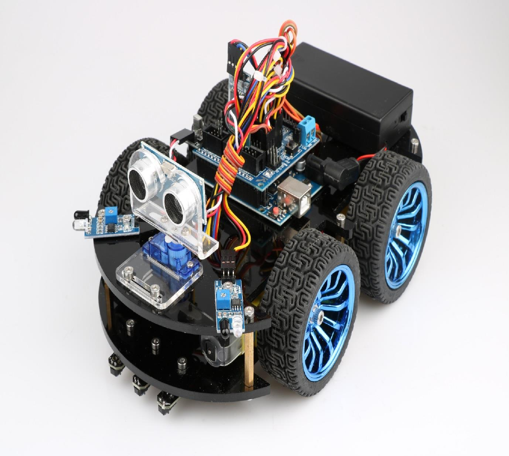
"Hummer-Bot" is a multi-function car based on Arduino UNO R3, which is composed of embedded
micro-controller, sensor, mechanical movement, wireless communication module and other parts. Although
it cannot sing and dance like the traditional robot, it is also very intelligent and a member of the family of
intelligent robot. By virtue of the inherent talent, Hummer-Bot can run on every corner, automatically avoid
obstacles and walk along the black and white lines freely, of course, people can also play it via such as
Bluetooth, infrared ray, PS2 remote sensing control, with passion and all kinds of attitude.
In the robot-prevalent era, sensor, wireless and power technologies are indispensable parts of people's
lives, such as infrared is widely used in industrial robot, ultrasonic wave is widely applied in the medical
industry, as to the wireless technology, it is beyond count. WIFI, Bluetooth, infrared, and ZigBee are
becoming irreplaceable parts in smart Home Furnishing. "Hummer-Bot" is a very product of the
development of the robot by combing these technologies perfectly, it can be used conveniently, developed
easily. In addition, "Hummer-Bot" has a variety of modes, can be switched freely and completed a variety of
development on one platform, which is the best choice for every electronic enthusiasts.
"Hummer-Bot" is a car which combines machine and electric, people can feel like in a competition
through wireless control, this is not only a test of endurance and confidence for enthusiasts, but also a
training to their response. The core of the car’ walking is motor control, a good motor and drive are the
necessary conditions for the car’ journey to success, "Hummer-Bot" contains 4 DC motors and a high power
drive chip, which enable the driving force of the car to a higher level.
The key to judgment depends on the sensor, just like the five senses of human beings, which is always
aware of everything around it, and avoids unnecessary mistakes, such as collision, migration and so on. The
combination of power and sensor makes the car more flexible and data acquisition more accurate.
1.1 Writing Purpose
The purpose of this manual is to create a fast, practical and convenient development learning platform
for the vast number of electronic enthusiasts and let them grasp the Arduino and its extended system design
methods and design principles, as well as the corresponding hardware debugging methods.
This manual will lead you to learn every function of "Hummer-Bot" step by step and open a new
"Hummer-Bot" journey for you. It is divided into two parts: 1, Preparation chapter, which mainly introduces
the use of common Arduino development software and some downloading and debugging skills. 2,
Experiment chapter, which contains hardware and software, the former mainly introduces the function and
principle of each module; the latter mainly introduces each part of the program and leads you to understand
and grasp the principle of Arduino and the car development through written examples step by step.

2
This manual is a specifications for "Hummer-Bot" , the file whose format is PDF which is in the CD
along with our product requires the corresponding software to open. It contains detailed schematic diagrams
and complete source codes for all instances, the codes won't have any mistake under our strict test. In
addition, the library files used in the source codes are put into the corresponding path, you only need to see
corresponding phenomenon of the car and personally experience the process of experiment by downloading
the source codes to Arduino via the serial port emulator.
This manual is not only very suitable for students and electronic enthusiasts, but also a good reference
for companies to develop products.
1.2 Product Introduction
"Hummer-Bot" is a multifunctional car based on the Arduino UNO and L298N motor. Compared with
the traditional car, "Hummer-Bot" is also equipped with wireless control (Bluetooth, infrared, WIFI and so
on); ultrasonic; infrared. It can trace and avoid obstacles automatically, of course, makers can also
automatically control the car with wireless and make full use of each module, as well as integrate all kinds
of related sensors to make the car more intelligent, which is more challenging. "Hummer-Bot" has various
types of information, technical manuals, routines, etc., which can teach you step by step. Each electronic fan
can use it easily to achieve their desired function.
Product Features
◆ Three groups of black line infrared tracing module
◆ Two group of infrared obstacle avoidance module
◆ Ultrasonic obstacle avoidance
◆ Four DC motor drive
◆ Two 3000mZh, 3.7V rechargeable lithium battery with longer endurance
◆ Remaining capacity of battery real-time detection
◆ Infrared remote control
◆ Bluetooth app control
◆ PS2 handle control (optional)
3
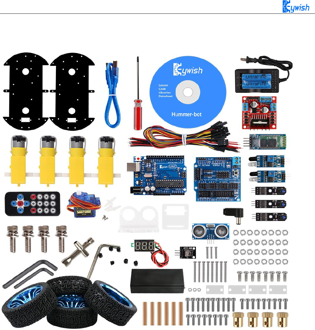
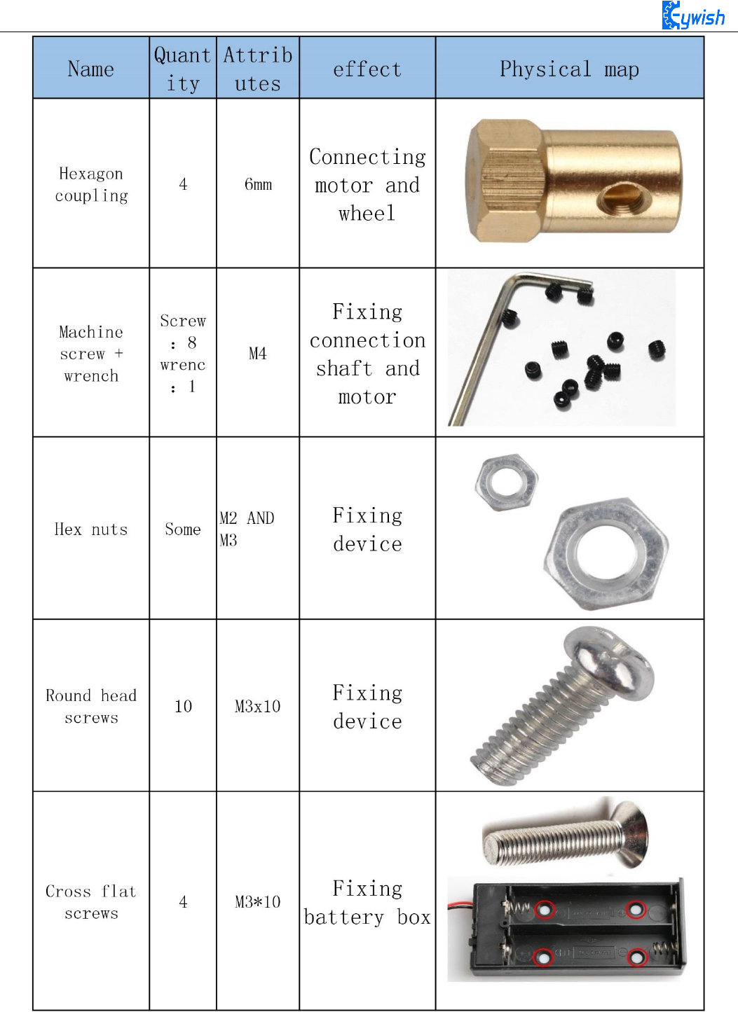
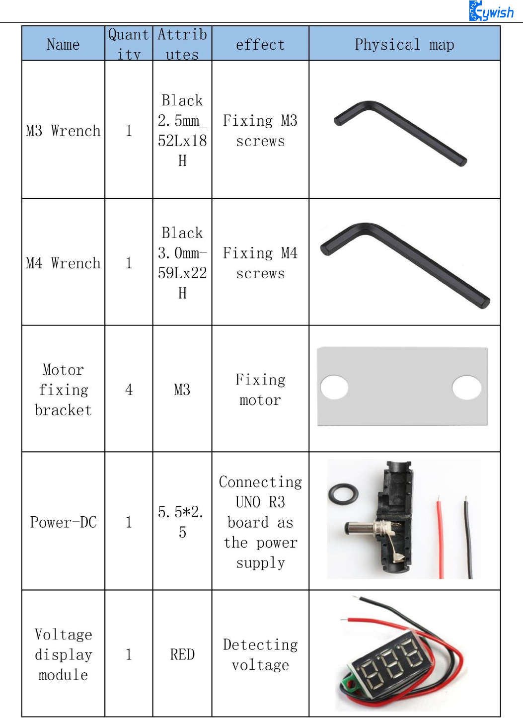
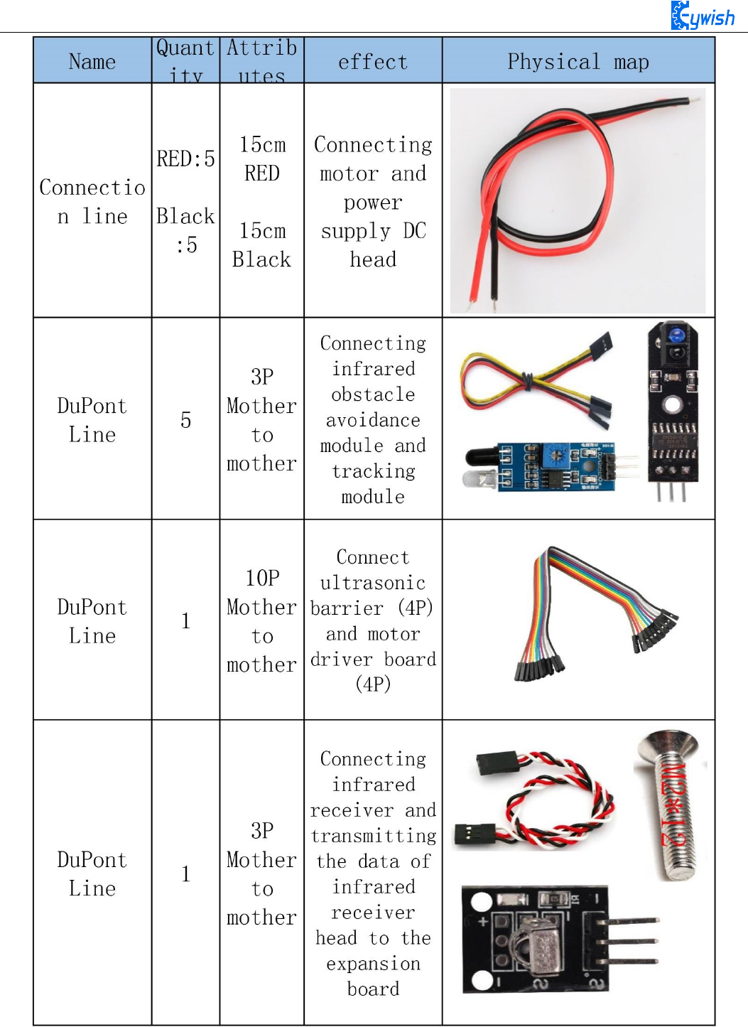
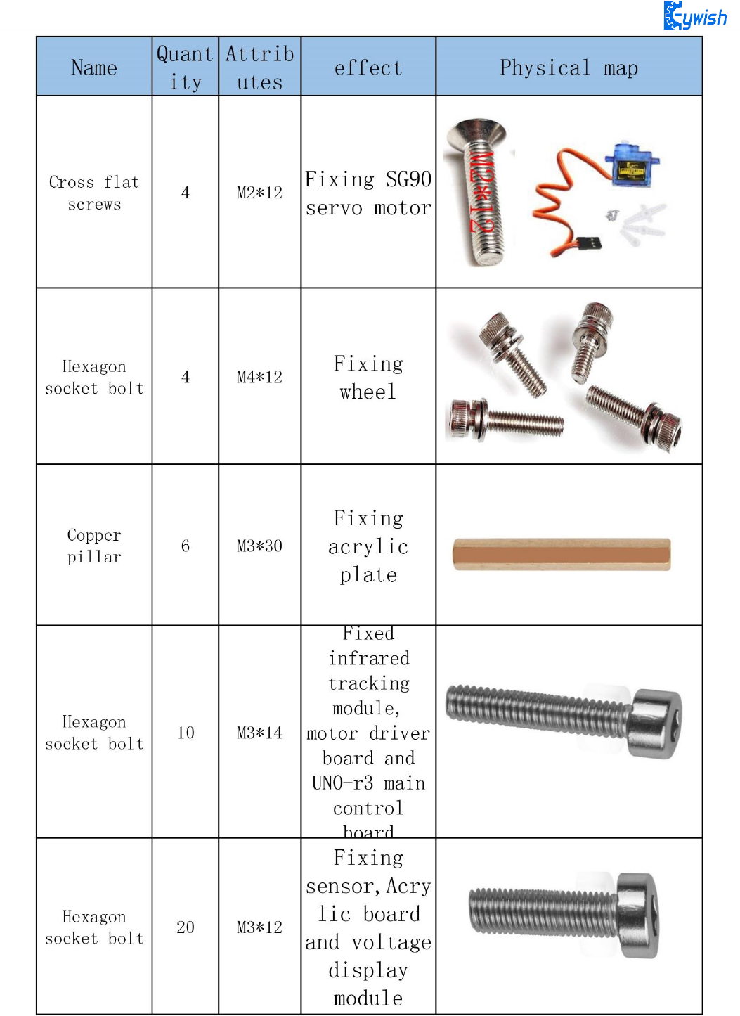
Product component invento
Note:
Please refer to the following table for instructions for use of
each accessory device:
4
5
6
7

8
Chapter2 Preparations
2.1 About Arduino
At the beginning of the study, let us read this little story: In the north of Italy, there is a picturesque
town which across the blue green Dora Baltea River whose name is Ivrea, it is a place full of colorful history
for it is where the king was born. In AD 1002, King Arduino became the ruler of the state, unfortunately two
years later he was deposed by the German King Henry II and became an oppressed king. Today, in a street
called cobblestone, there is a bar named di Re Arduino to commemorates the king appears in people's lives.
The bar owner Massimo Banzi (there is a saying: Massimo Banzi often comes to this bar) is an electronics
engineer in Italy, and later he named the electronic product Arduino in memory of this place. Arduino is a
convenient, flexible, open source electronic prototype platform, including hardware (various types of
Arduino board) and software (Arduino IDE). It is suitable for artists, designers, electronic lovers.
Arduino can perceive the environment through a variety of sensors, feedback, and influence the
environment by controlling lights, motors, and other devices. The microcontroller on the board can write
programs through Arduino programming language, compiled into binary files, burned into microcontroller.
The programming of Arduino is realized by Arduino programming language (based on Wiring) and Arduino
development environment (Based on Processing). Projects based on Arduino can either only contain
Arduino or contain Arduino and some other software on the PC, they can communicate via such as Flash,
Processing, MaxMSP.
You can do it yourself, or you can buy a finished kit, the software that Arduino uses can be downloaded
for free. The hardware reference design (CAD file) also follows the available open-source protocol, and you
can be very free to modify them according to your own requirements.
Arduino can not only use electronic components such as Switch or sensors or other controllers, LED,
stepping motors or other output devices that are developed, but also operate independently as an interface
that communicates with software, such as flash, processing, Max/MSP, VVVV, or other interactive
software.
In addition, Arduino is based on the AVR platform and does second compilation and packaging for
AVR library, the port is packaged, so you basically do not need to manage the register, address pointer and
so on, the difficulty of software development is greatly reduced, it is suitable for non professional
enthusiasts. Advantages and disadvantages coexist due to the second compilation and packaging, the code is
not conciser than original AVR code, and code execution efficiency and code volume is weaker than AVR
direct compilation.
2.2 Why Choosing Arduino
There are many SCM and SCM platform suitable for interactive system design. For example: Parallax
Basic Stamp, Netmedia 's BX-24, Phidgets, MIT' s Handyboard, and so on. All of these tools, you do not
need to care about the cumbersome details of SCM programming, they provide you with a set of easy-to-use

9
kit. Arduino also simplifies the working process of the microcontroller, but compared with other systems,
Arduino is more advantageous in many places, especially for teachers, students and some amateurs:
1, Cheap - compared with other platforms, the Arduino board is pretty cheap. The cheapest version of
Arduino can be made by hand, even if it's finished, the price will not exceed 200 yuan.
2, Cross platform - Arduino IDE can run in Windows, Macintosh, OSX, and Linux operating system.
Most other SCM software can only run on Windows.
3, Simple programming environment - beginners can easily learn to use the Arduino programming
environment, but it can also provide enough advanced applications for advanced users. As for the teachers,
the Processing programming environment can be used easily, so if students have learned how to use
Processing programming environment, then they will feel familiar when using the Arduino development
environment.
4, Open source software and extensible - Arduino software is open source, experienced programmers
can extend it. Arduino programming language can be extended through the C++ library, if someone wants to
understand the technical details, you can skip the Arduino language and use AVR C programming language
(because Arduino language is actually based on AVR C). Similarly, you can add AVR C code directly to
your Arduino program if necessary.
5, Open source hardware can be extended - Arduino is based on the ATMEGA8 and ATMEGA168/328
MCU of Atmel, it is also based on the Creative Commons license agreement, so experienced circuit
designers can design their own modules by extension or improvement according to their own requirements.
Even for some relatively less experienced users, they can also make a test board to understand how Arduino
works, which is money-saving and time-saving .
10
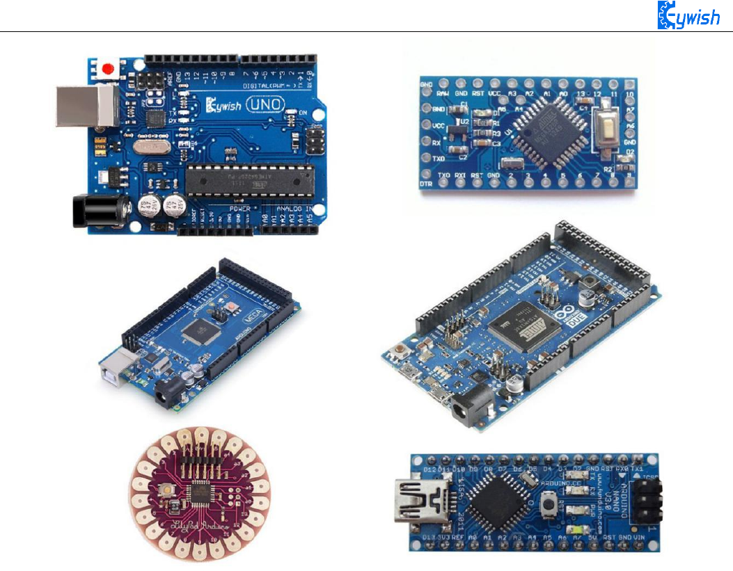
Fig 2.2 Several commonly usedArduino
11
Chapter3 Experiments
3.1 Assembly of the Car
3.1.1 Bottom Mounting of the Car
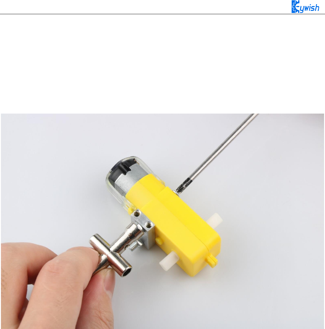
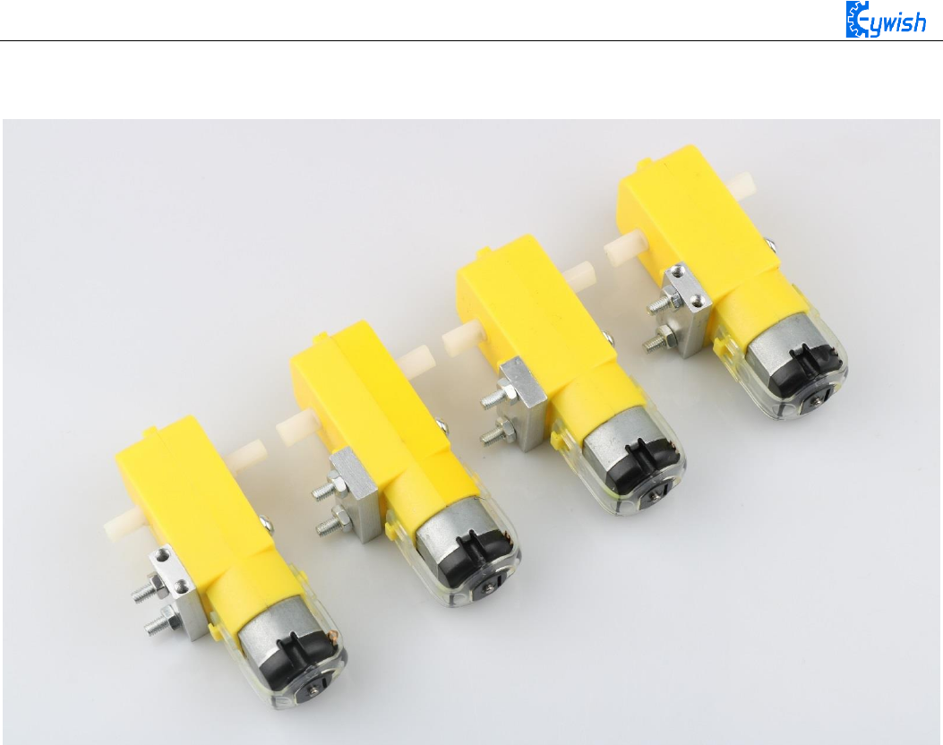
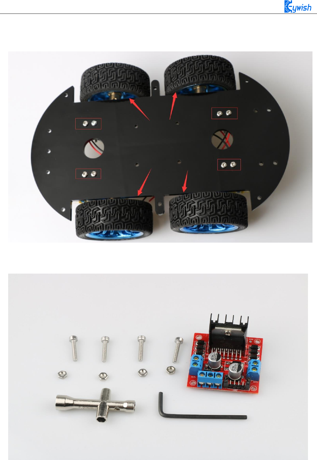
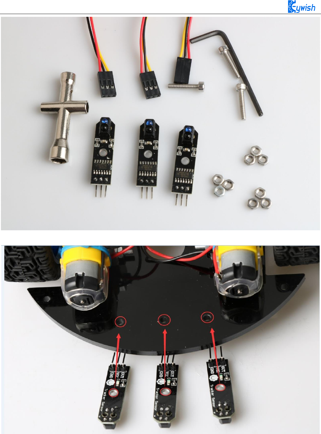
First we open the box, take out the car body (two black acrylic), screwdriver, M4x12 screws, six angle
coupling and matching set screws, four black&red welding wires and four motor and wheels.
The first step is to Mounting motor mount.
12
After the completion as shown.
13
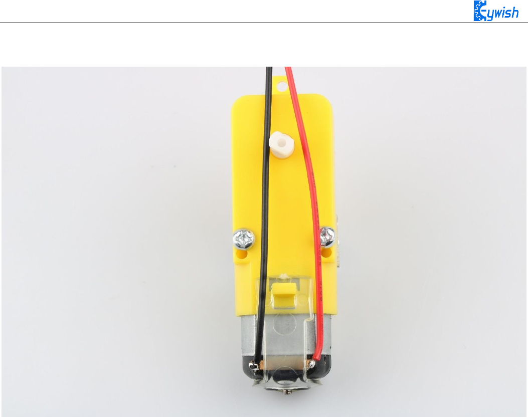
The second step is to Welding wire on the motor.
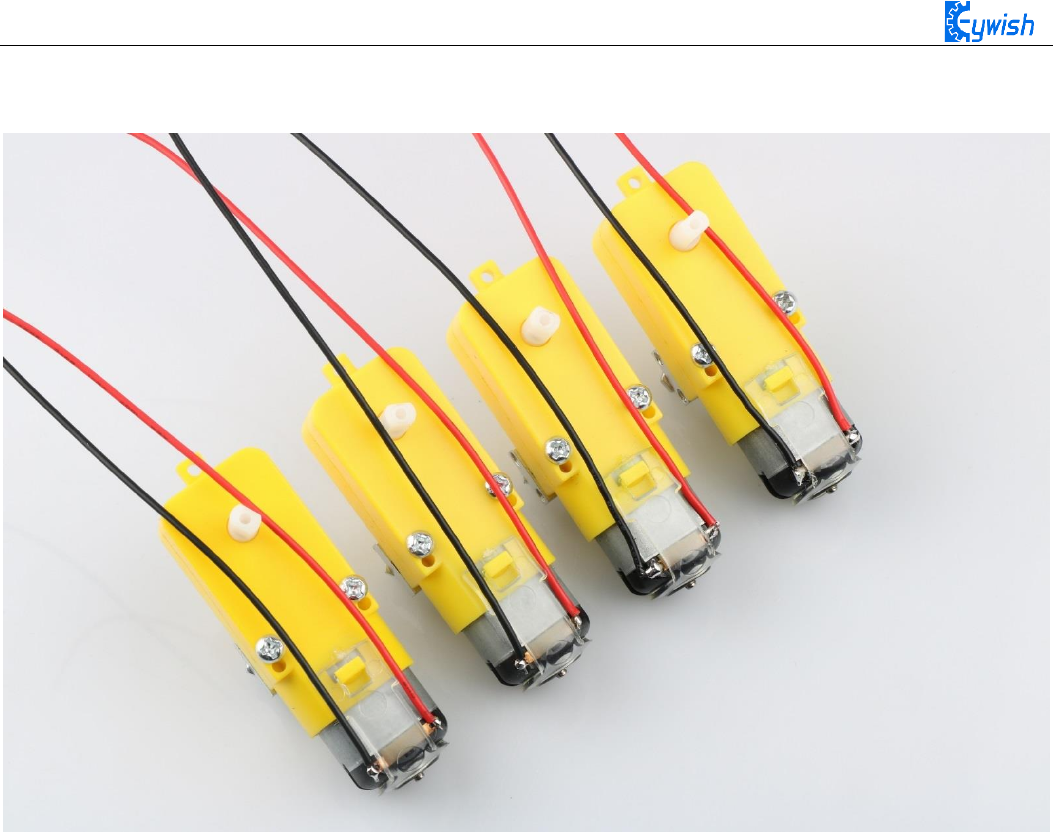
14
After the completion as shown.

15
The third step is to fix the wire on the motor with tie tape.
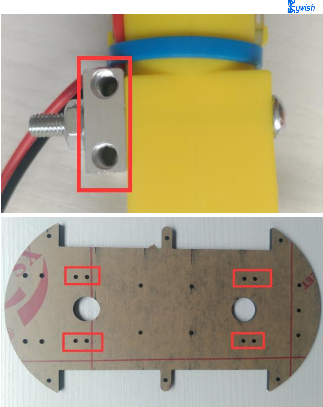
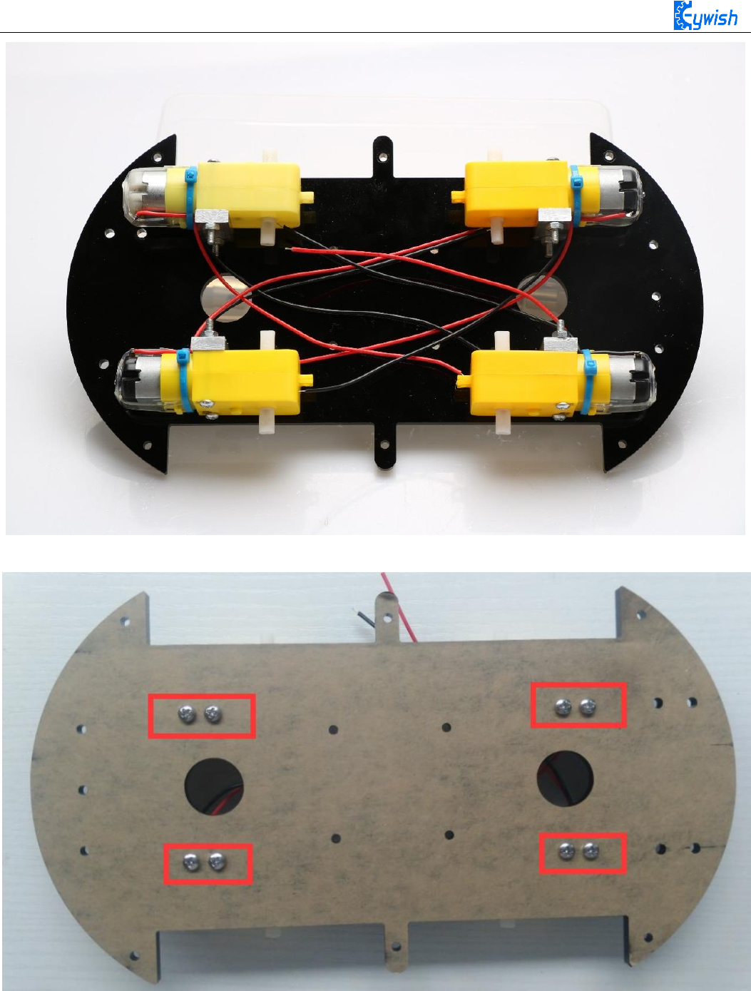
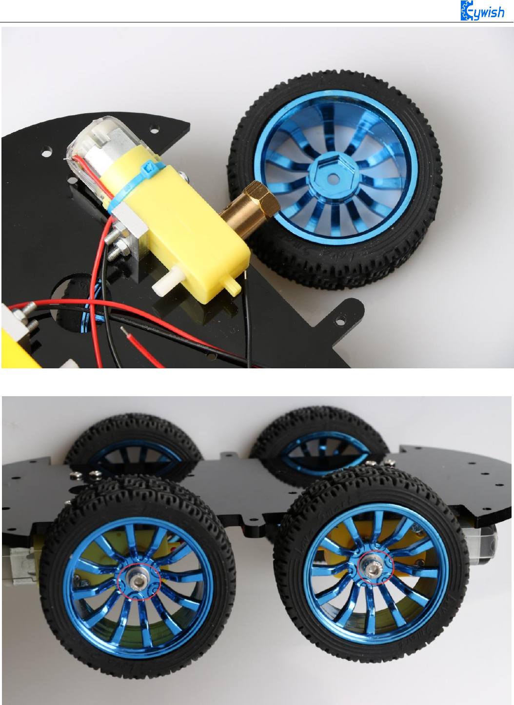
The fourth step is to Mount aluminum alloy brackets on acrylic plates. first removing the protective film on
the acrylic, and then fixing it according to the corresponding space. After the installation, the front face is
shown in Fig.3.1.4, and the back is shown in Fig.3.1.5.
Note: the screws in Fig.3.1.5 should not be screwed too tight, otherwise the wheels adjustment will be
affected. The screw of the motor holder is always installed from the outside to the inside. If it is installed in
the opposite direction, the protruding screw will affect the rotation of the wheel.
the installation must ensure that the screw hole on the bracket aligns with the screw hole on the acrylic
plate
16
Fig.3.1.3 Diagram of Aluminum Alloy Bracket Installation
17
Fig.3.1.4 Diagram of Motor Installation
Fig.3.1.5 Fixing Screw for Motor
18
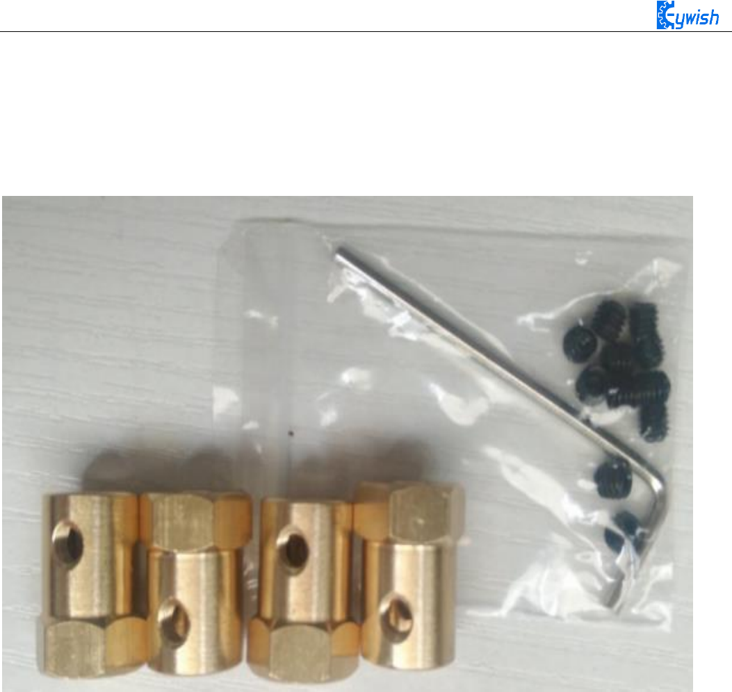
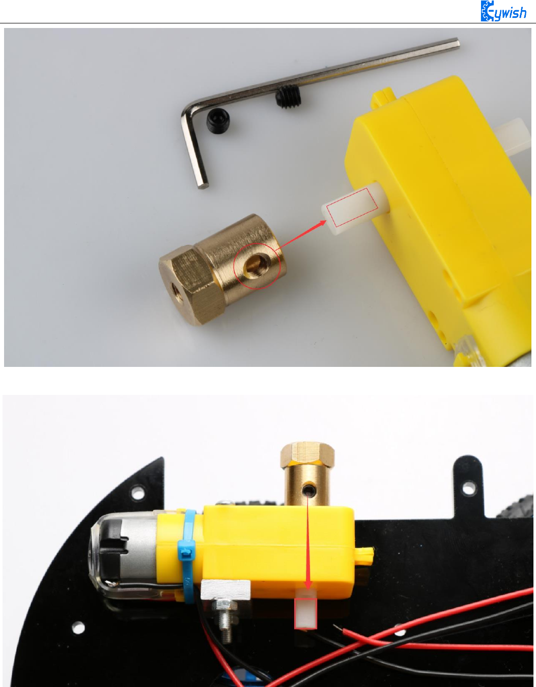
The fifth step is to install the connecting shaft for the purpose of fastening the connecting motor and the
wheel, and use the connecting shaft as the power transmission link. Fig.3.1.6 shows the connecting shaft and
the set screws, first screwing the screws into the connecting shaft (not too tight, otherwise the motor
transmission shaft cannot be inserted into the connecting shaft), Then insert the smooth side of the motor's
drive shaft into the machine screw, as shown in Figure 3.1.7. Turn the machine's meter screws to hold the
smooth side of the motor's drive shaft.
Fig.3.1.6 Connecting Shaft Kit
19
Fig.3.1.7 Diagram of Connecting Shaft Installation
Fig.3.1.8 After Installation (set screws must be stuck in the smooth side)
20
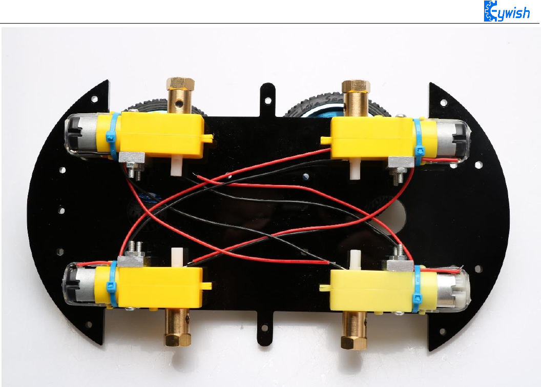
Fig.3.1.9 Diagram after Complete Installation
The sixth step is to install wheels, "Hummer-Bot" uses racing wheels which grip stronger, less friction,
more stable than the traditional wheels. The wheel mounting method is relatively simple. Then inserting the
connecting shafts into the wheels as shown in Fig.3.1.10 and screwing tightly as shown in Fig.3.1.11.
21
Fig.3.1.10 Diagram of Wheel Installation
Fig.3.1.10 Diagram of Wheel Screw Fixation
22
In the fourth step we said that don't screw too tight, because it is not convenient to adjust the wheels
later. As shown in Fig.3.1.11,the installed wheels would have some tilt, then we need to adjust the motor by
hand gently until the wheels and the acrylic become parallel, then tighten the screws.
Fig.3.1.11 Adjusting Wheels and Tightening Screws
The seventh step is to install the motor drive. As shown in Fig.3.1.12, fixing the motor on the acrylic.
23
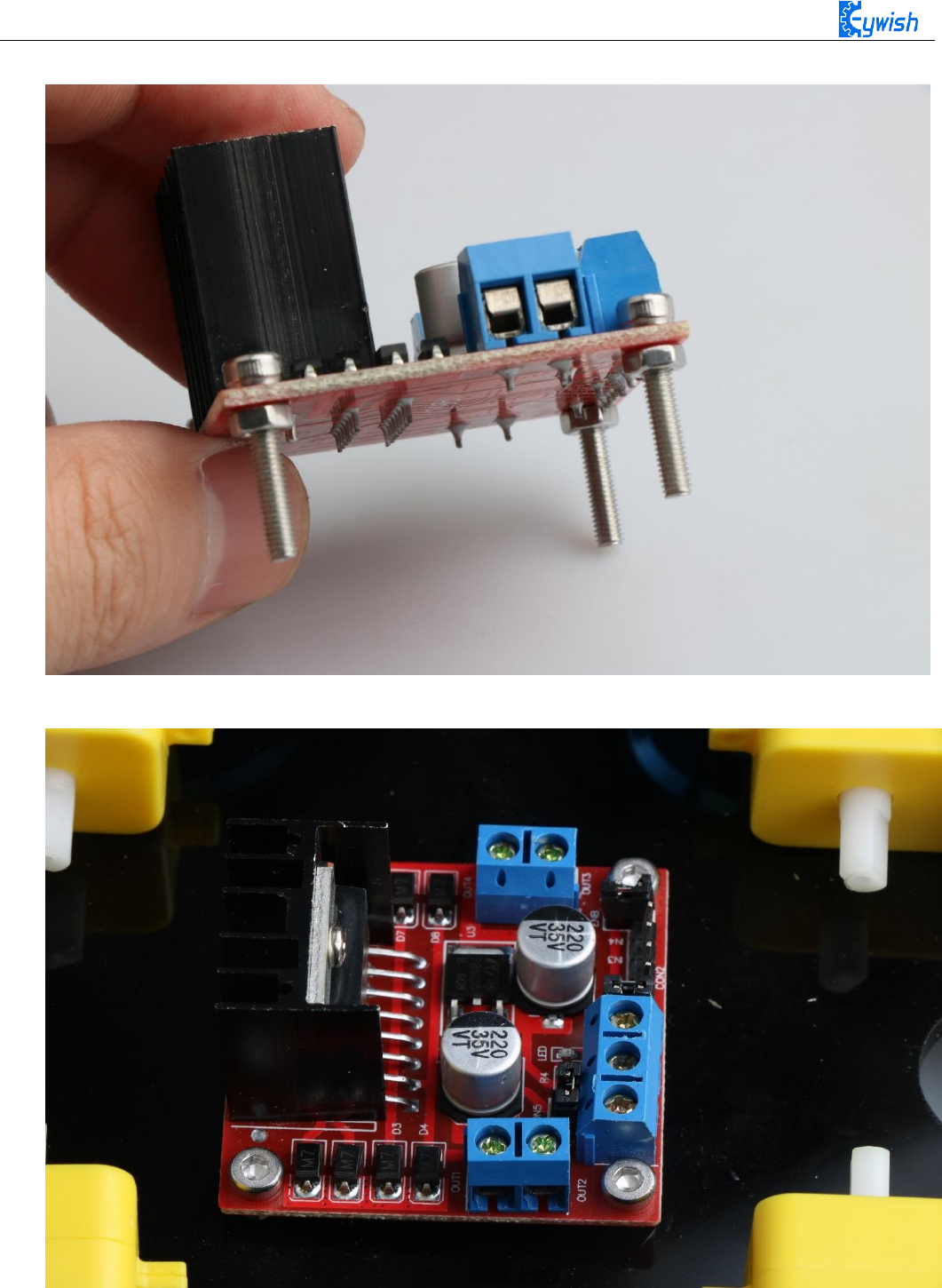
First fix the screw on the motor driver board, as shown below
Then install the motor driver board on the acrylic board, as shown below
Fig.3.1.12 Diagram of Motor Drive Installation
24
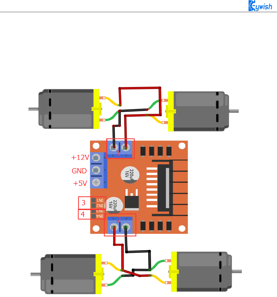
The eighth step is to connect the motor wires to the drive, note that the rotation direction of the two
motors require to be identical, so we should modify and debug the program first when wiring. Connecting the
motor to any motor driver board, as shown in Fig.3.1.13, then connecting the two wires on battery box to the
motor drive +12v (red) and GND (black), and leading a wire from +5V to "3" or "4" in the figure(IN1&IN2
is a motor set, IN3&IN4 is another set). Observing rotation directions of the motors, if the rotation directions
are not the same, you only need to change "1" and "2" in the figure. The physical map is shown in Fig.3.1.14.
Fig.3.1.13 Diagram of Connection Between Motors and Drive Board
25
Fig.3.1.14 Diagram of Connection Between Motors and Drive Board
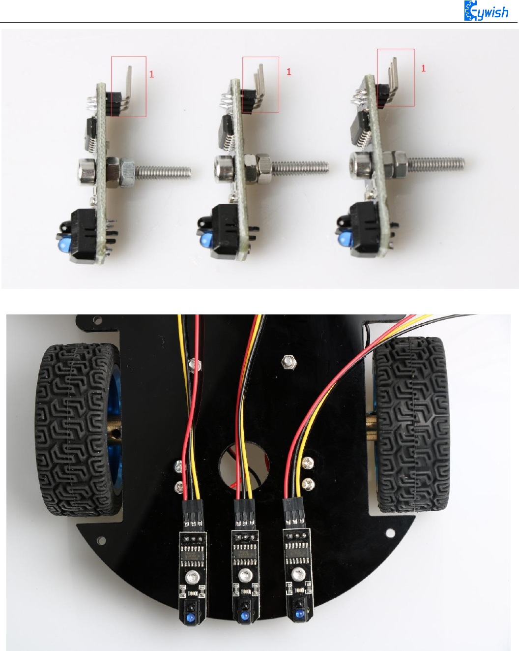
The ninth step is to install the tracing module and fix the module to the acrylic board according to the
Fig.3.1.15. First, screwing the screws to the tracing module(Use two nuts here), as shown in Fig.3.1.16, and
then connecting the 3Pin wire to the "1" in Fig.3.1.16. After the installation is completed, Finally, the tracking
module is fixed to the acrylic plate. the back is shown in Fig 3.1.17 .
26
Fig.3.1.15 Diagram of Tracing Module Installation
27
Fig.3.1.16 Diagram of Screw Brackets
Fig.3.1.17 The Back of Complete Installation

28
3.1.2 Surface Mounting of the Car
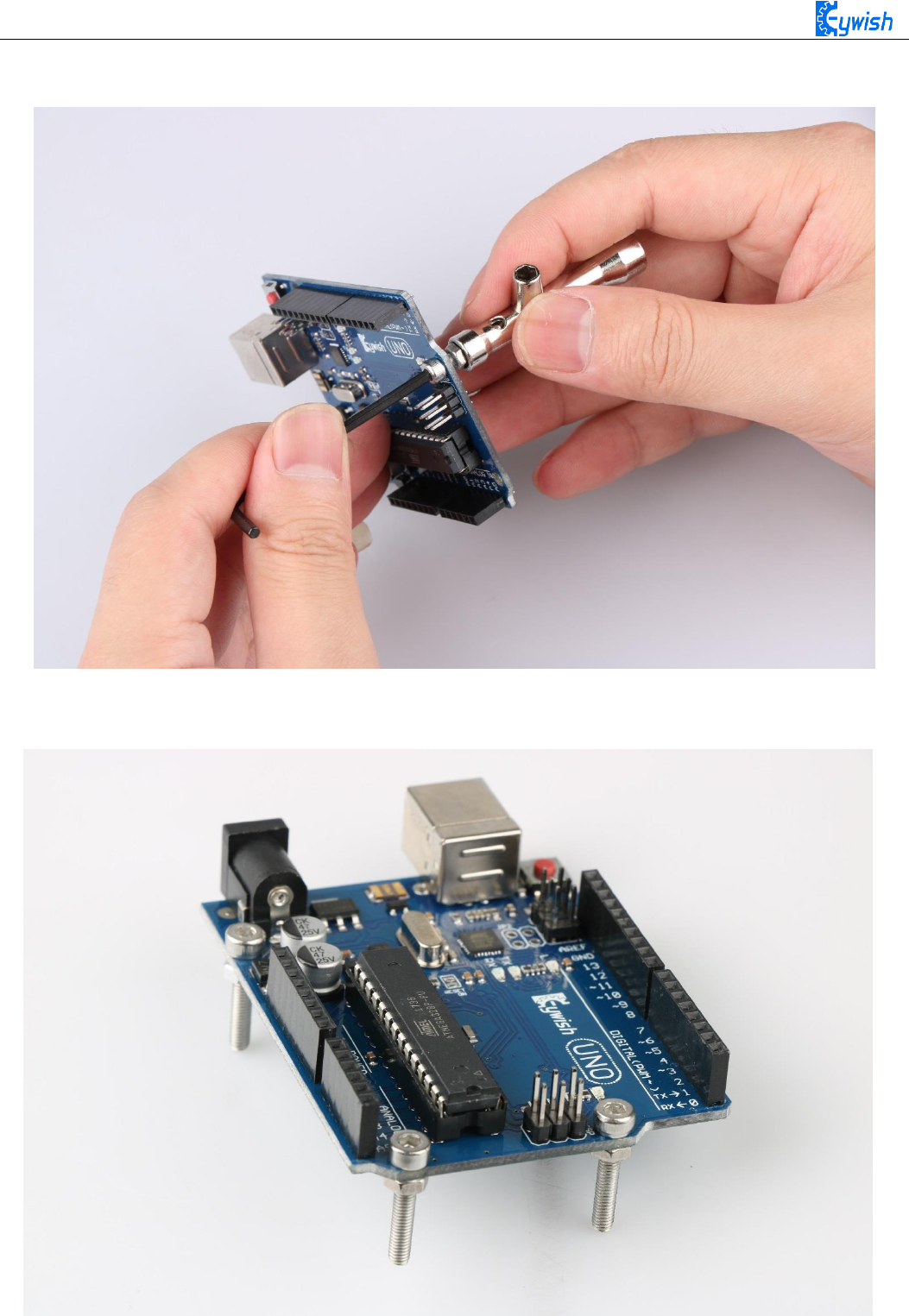
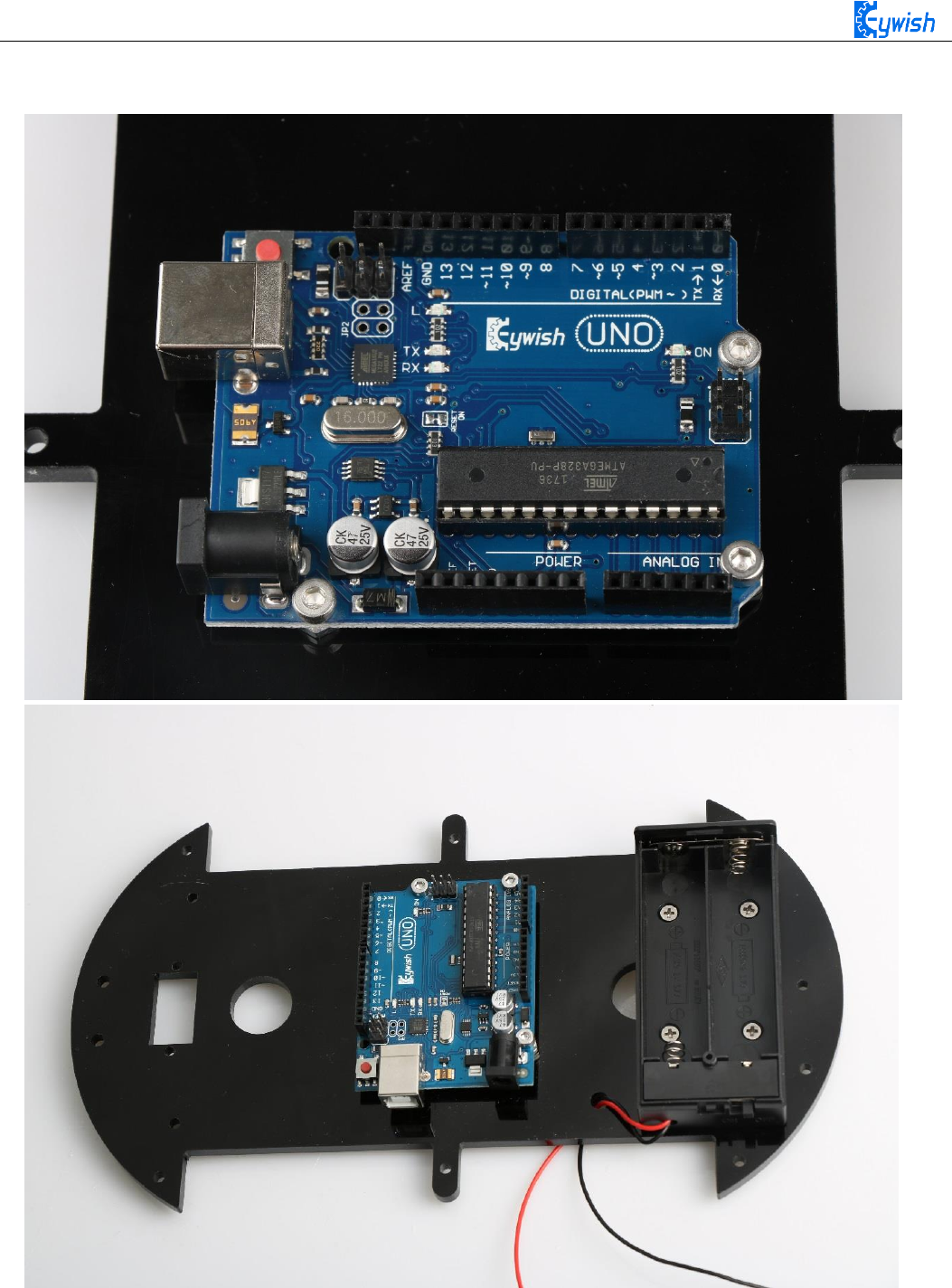
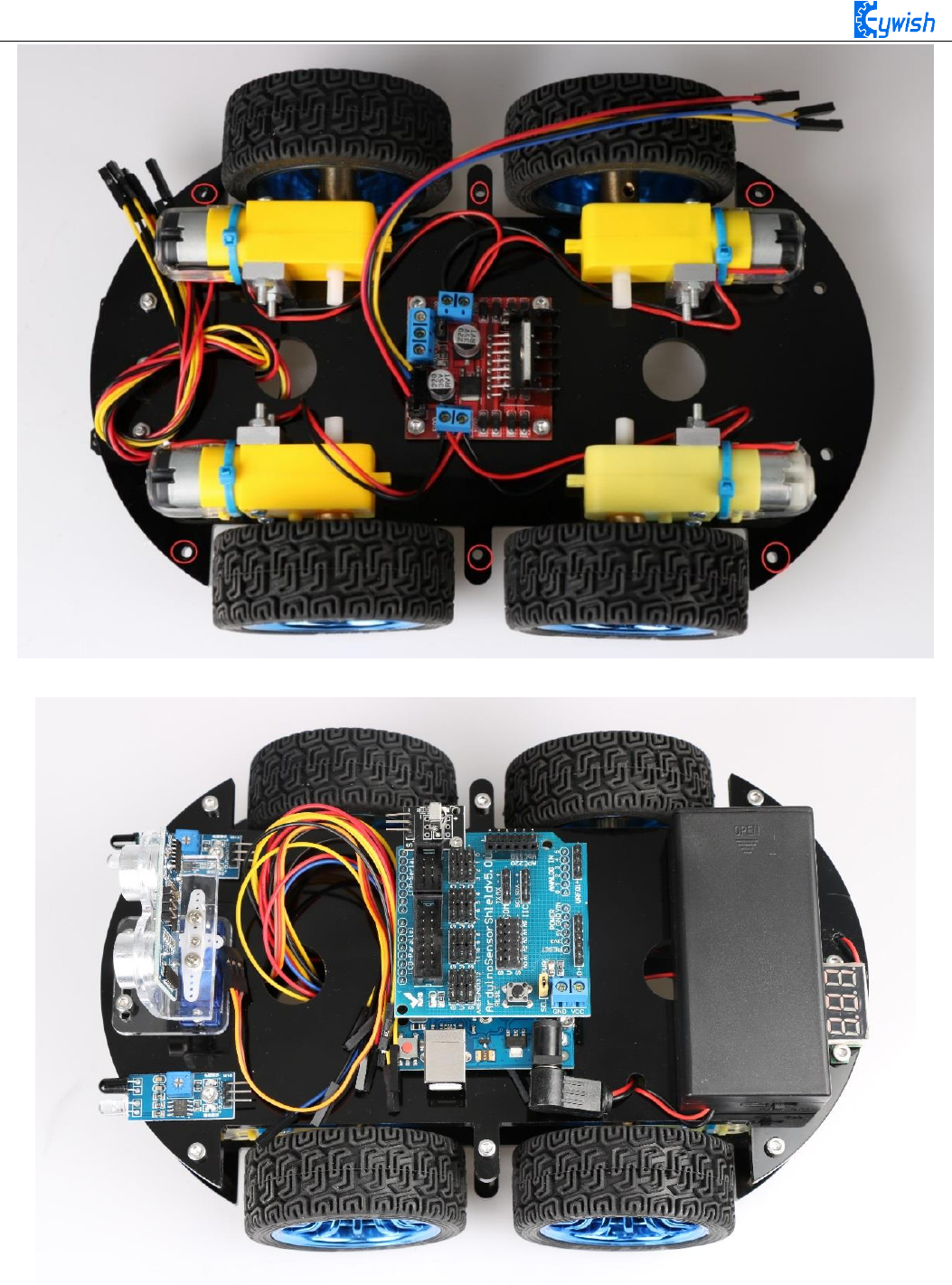
The first step is to install the battery box and the Arduino mainboard, this step is quite simple, install the
corresponding package to "3"and "2" in Fig.3.1.19, the complete installation is shown in Fig.3.1.20.
Fig.3.1.19 Diagram of Top Surface Device Installation
29
First install the screws on the UNO
After the completion as shown
30
Then install UNO on acrylic plates
Fig.3.1.20 Diagram of Arduino Mainboard and Battery Box Installation
31
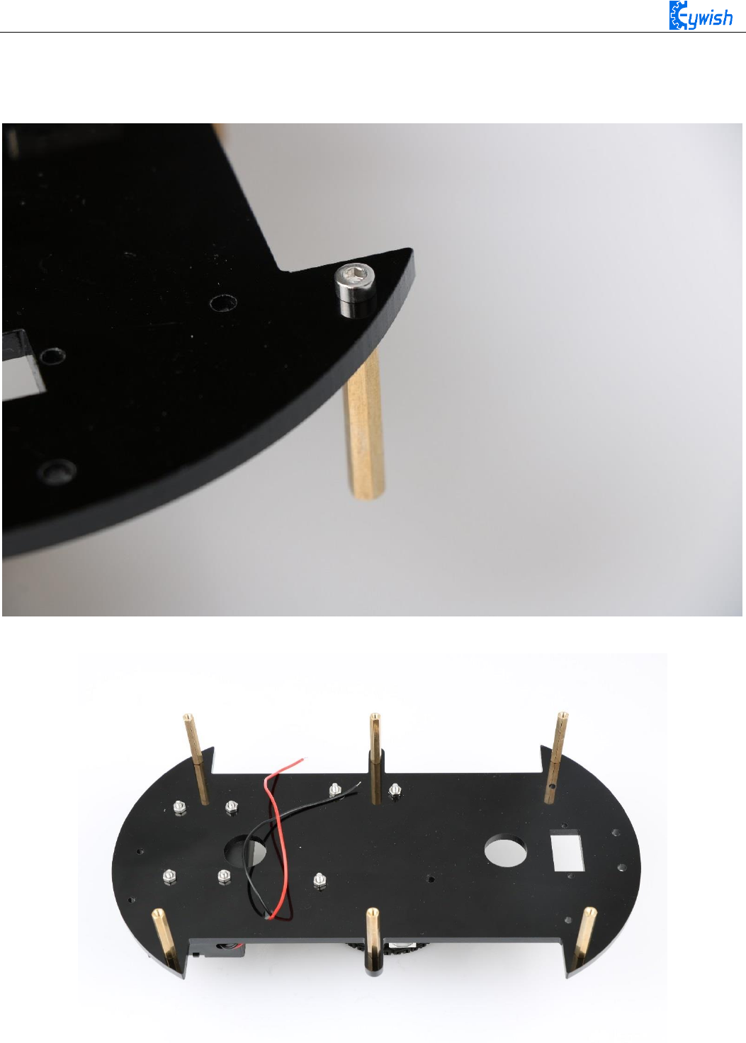
The second step is to install the total of 6 support screws which are mainly used to connect two piece
acrylic board. In Fig.3.1.19, we can see the "1" logo where there are 6 holes, these are the screw fixing holes,
The installation is shown in Fig.3.1.21and the complete installation is shown in Fig.3.1.22.
Fig.3.1.21 Installation diagram
Fig.3.1.22 Diagram of the Pillars
32
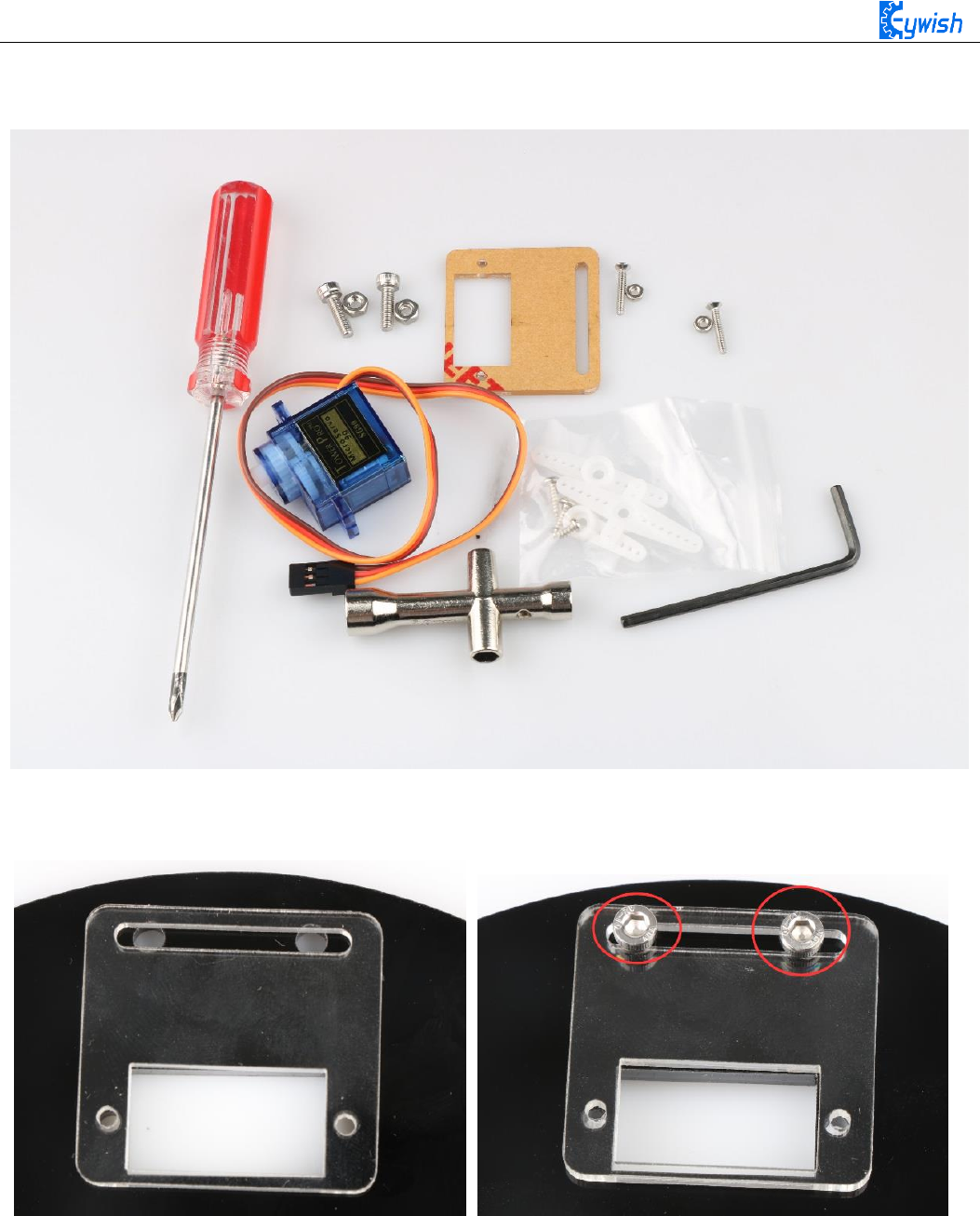
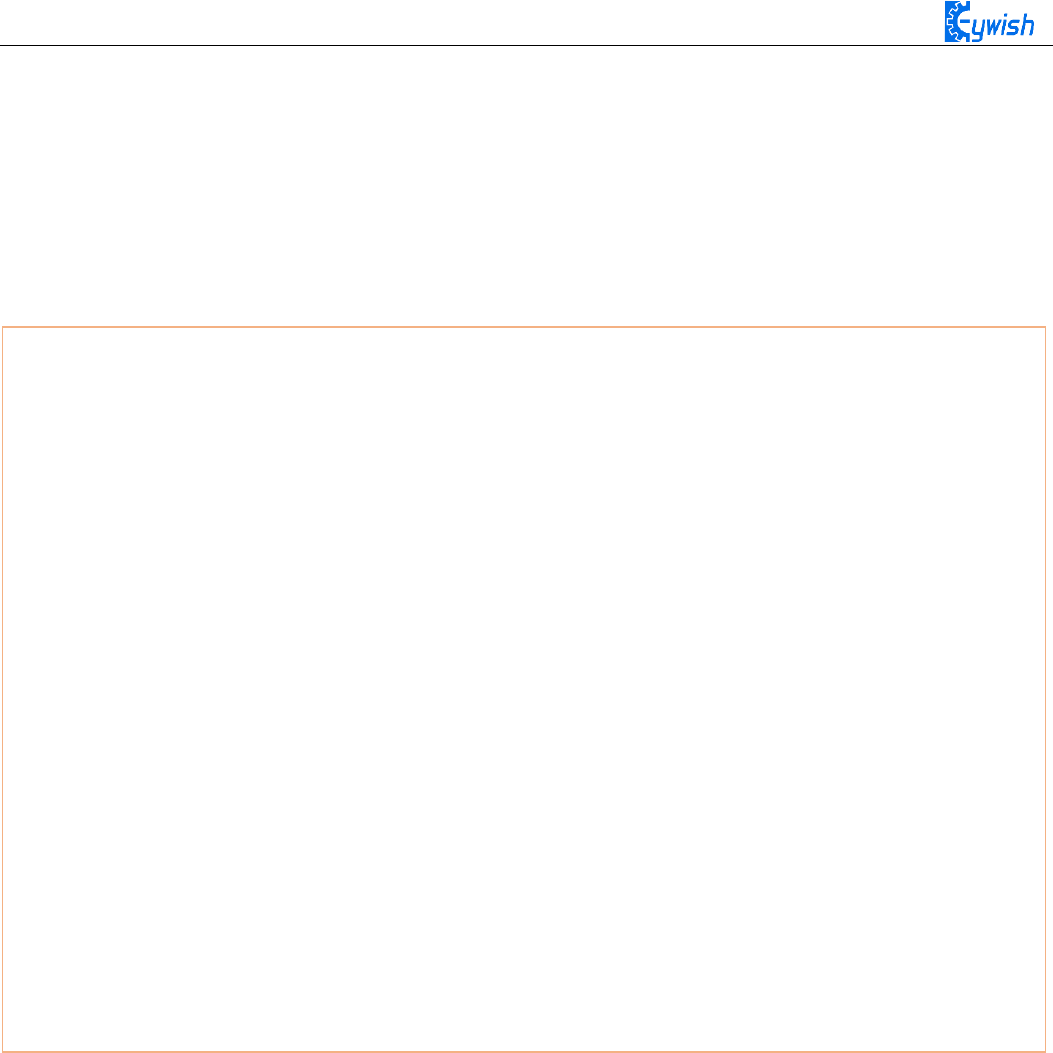
The third step is to install the steering gear and the bracket. In Fig.3.1.19, the "4" logo is the actuator
mounting position. The device used as shown ,The complete installation is shown in Fig.3.1.23.
First, install the servo fixing bracket, that is, install the bracket in the place as shown in the figure, and
add the fixing screw
33
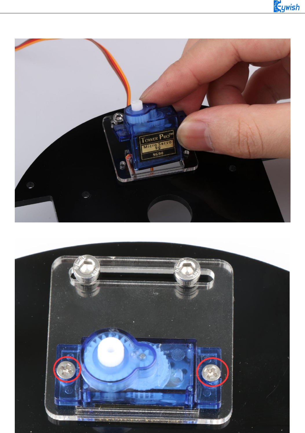
Step 2: Install the servo, install it as shown in the figure
The third step: use two screws to fix the servo.
Fig.3.1.23 Diagram of Steering Gear Installation
34
After installing the steering gear, you can add the ultrasonic module on it. In order to reduce the later
steering angle adjustment, we adjust the steering gear to 90 degrees, and copy the following program to the
compiler environment (you can also directly open the program in the CD), then connect the signal
line(Orange) on steering gear to the 13 IO port on Arduino, After the servo rotates to 90°, we can install the
servo bracket on the servo, and after the installation, we can fix it with screws., the installation is shown in
Fig.3.1.24.
#include <Servo.h>
Servo myservo; // create servo object to control a servo
int pos = 90; // variable to store the servo position
void setup()
{
myservo.attach(13); // attaches the servo on pin 9 to the servo object
}
void loop()
{
myservo.write(pos); // tell servo to go to position in variable 'pos'
delay(15); // waits 15ms for the servo to reach the position
}
}
35
Fig.3.1.24 Diagram of Steering Gear Angle Adjustment
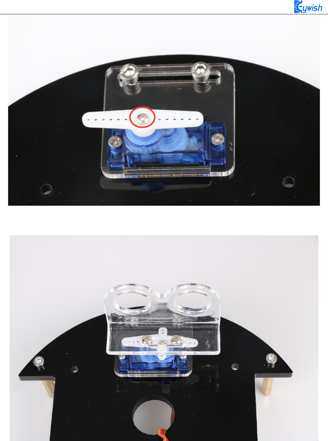
The fifth step is to install ultrasonic bracket, fix the bracket on the steering gear, as shown in Fig.3.1.25.
Fig.3.1.25 Diagram of Ultrasonic Bracket Installation

36
The sixth step is to install infrared obstacle avoidance module in the two holes marked as "6" in Fig.3.1.19,
as shown in Fig.3.1.26.
Fig.3.1.26 Diagram of Infrared Obstacle Avoidance Installation
37
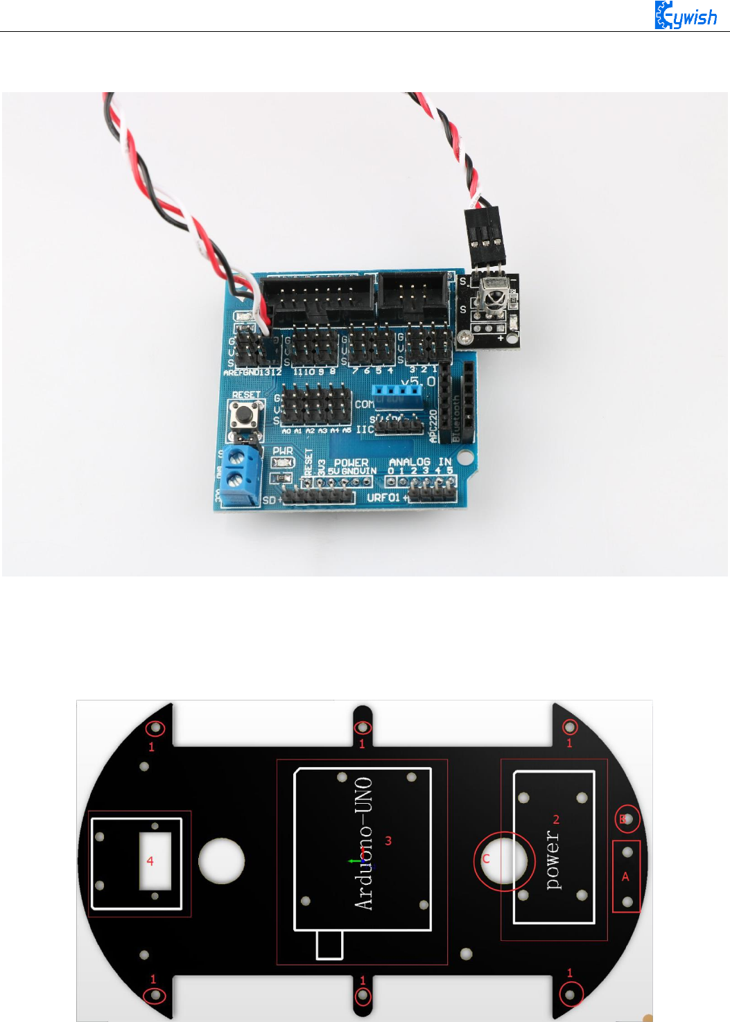
The seventh step is to install infrared remote control receiving head on the Arduino extended board and
fixed it with a screw, as shown in Fig.3.1.27. Pay attention to the installation direction.
Fig.3.1.27 Diagram of Infrared Remote Control Receiving Head Installation
The eighth step is to install the voltage display module in the back of battery box to logo "A"marked in
Fig.3.1.28, and insert the wire into the hole identified as "B" and out from the hole marked as "C". The
complete installation is as shown in Fig.3.1.29.
Fig.3.1.28 Diagram of Voltage Display Module Installation
38
Fig.3.1.29 Diagram of Voltage Display Module Installation
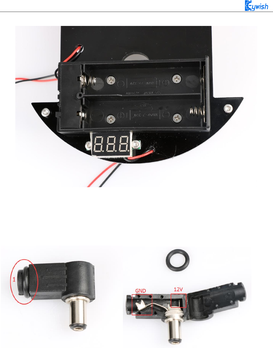
Connect the power cable: First find the matching two power cables (the same as the wires used by the
motor, one red and one black) and connect the two cables to the DC power head. The DC power connector is
shown in Figure 3.1.29. The rubber ring marked as "1" can be removed to open the shell, as shown in
Fig.3.1.31. Soldering the wires to the +12V and GND, as shown in Fig.3.1.32.
Fig.3.1.30&Fig.3.1.31 DC Power Head

39
Fig.3.1.32. Wire welding schematic
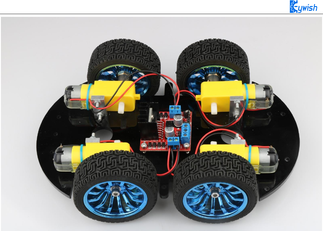
The tenth step is the whole assembly, first inserting the 4Pin wire into IN1-IN4 on the motor drive, and
threading the other end wire of the tracing module from the bottom to the top of the car. Then connecting two
wires of the battery box and the voltage display module 、DC power head to the +12V (red) and GND (black)
on the motor drive board. (And the other end of the wire in the ninth step is here) At last, aligning the six
columns with the six holes as shown in Fig.3.1.33, then screwing the screws tightly from the bottom and the
assembly is completed which is shown in Fig3.1.34 and Fig3.1.35(details of wires connection will be
introduced later).
40
Fig.3.1.33 Diagram of Wires Arrangement
Fig3.1.34 the Effect of Whole Assembly
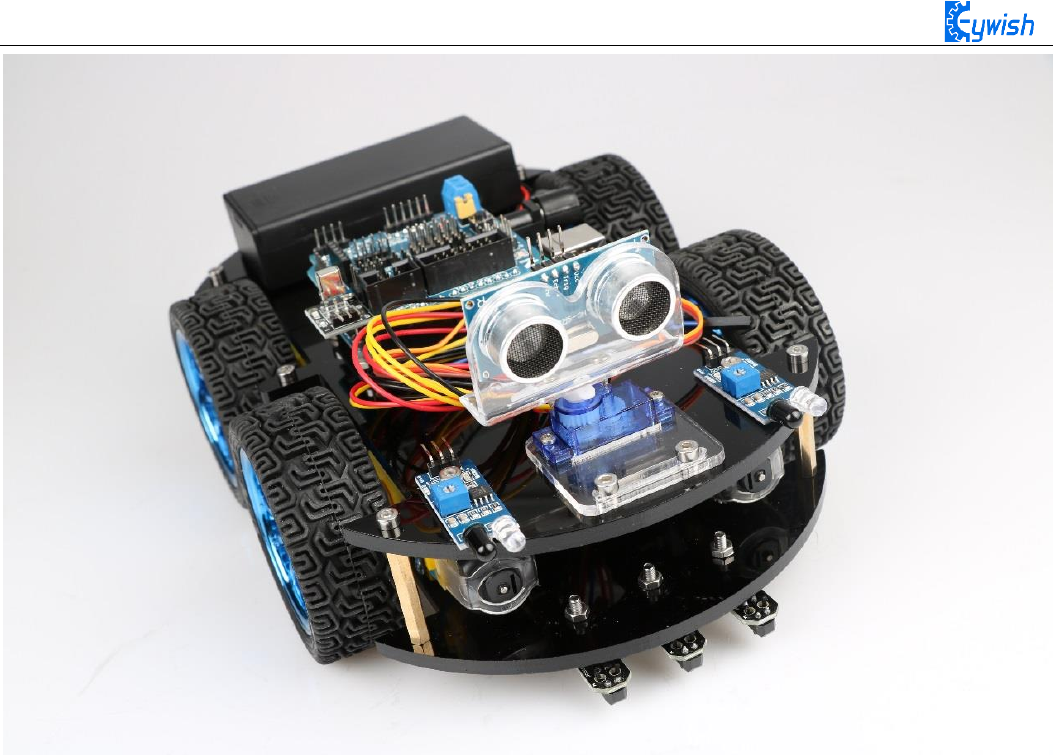
41
Fig3.1.35the Effect of Whole Assembly
So far, the basic assembly of car has been completed,we believe you have some basic knowledge of your
car’s structure, function and some modules through a short period of time, then you can achieve the
corresponding functions only by downloading the program to the development board, each function has a
corresponding program in CD , so please enjoy playing. However, if you can read the program and write your
own program,there will be more fun, now let's go to the software section!
42
Expansion board wiring diagram
After the car is assembled, the wire connection can be referenced as shown in
the figure. Of course, it will be described in detail later in the program.
3.2 Development of the Car
3.2.1 Walking Principle of the Car
"Motor" - I believe it is universally acknowledged. In today’ society, the power spreads every corner in
of our lives, the motor is widely used in their respective posts. It is a kind of electromagnetic device which
can achieve energy conversion or transfer according to electromagnetic induction, it has the advantages of
good speed regulation performance, easy-to-start, quick response, large starting torque, small volume, light
weight, easy-to-assemble which can server as power source for electrical appliances or machinery. Due to the
internal high speed motor can provide the original power, drive speed (deceleration) gear set and produce
43
greater torque,so it can meet the system requirements. Combined with these advantages, in the "Hummer-Bot"
car, we selected four DC motors as the power source.
Motor drive - it is a necessary condition for the motor to play its superior performance. Its main function
is to provide sufficient current and power for the motor. In the "Hummer-Bot" car, we choose the L298N as
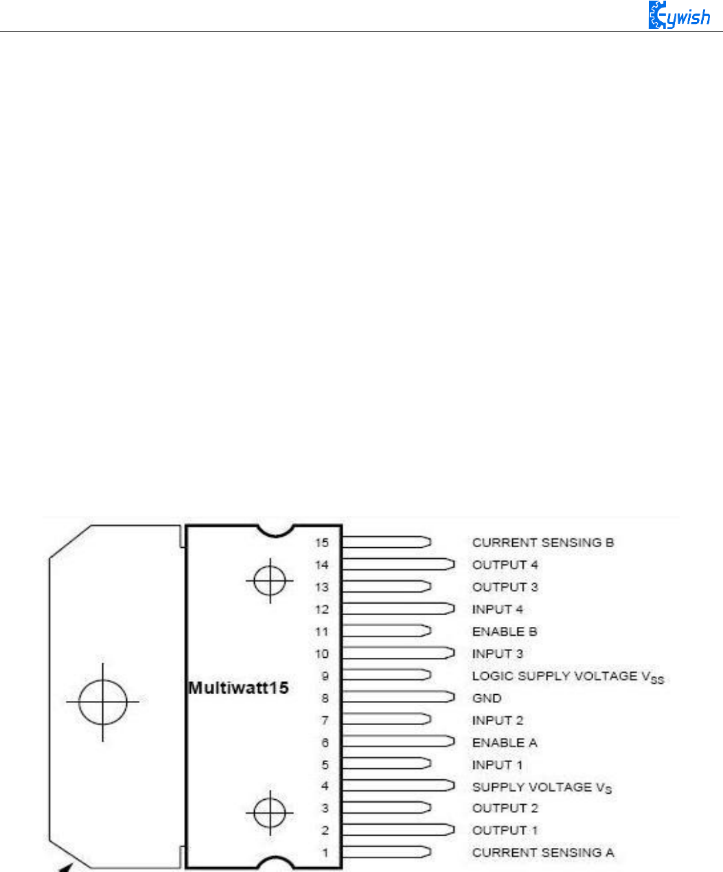
the motor driver chip for it is a high voltage and current full-bridge driver chip, the chip uses 15 pins package.
It is a special motor driven integrated circuit (two H bridges) with high voltage and current full-bridge
driver.And it contains 4 channel logic drive circuit, basically belongs to a kind of two-phase and four-phase
special motor drive which contains two H bridges of high voltage large current. The output current is 2A, the
maximum current is 4A, the maximum working voltage is 50V, which can drive the load under 46V and
2A,such as high power DC motor, stepper motor, solenoid valve and so on. The chip with two enable control
terminals uses the standard logic level to control signals, allows or prohibits the device to work when the input
signal is not interfered, it has a logic power input terminal which can enable the internal logic circuit to work
under low voltage, and feedback the variation to the control circuit. Especially, the input can be connected
directly with the MCU and easily controlled. When the DC motor is driven, the stepper motor can be directly
controlled, and it can be turned forward and reversely, which only needs to change the logic level of the input.
The pin arrangement is shown in Fig.3.2.1. The pin 1 and 15 can separately connect to the current sampling
resistor and form the current sensing signal.
Fig.3.2.1 Arrangement of Chip Pins
L298N can drive 2 motors which are connected between OUTl, OUT2 and OUT3, OUT4. 5, 7, 10 and
12 pin are connected to input control level for controlling the positive and negative rotation of the motor, ENA,
ENB are connected to control enable terminal for controlling the running and shutdown of the motor. Its
characteristics:
◆ Signal indicator
44
◆ The speed is adjustable
◆ The strong anti-interference ability with photoelectric isolation
◆ Overvoltage and overcurrent protection
◆ Controlling of two motors separately
◆ Controlling the stepper motor
◆ The speed control with PWM pulse width
◆ Positive and negative rotation
Fig.3.2.2 Logic Function Chart
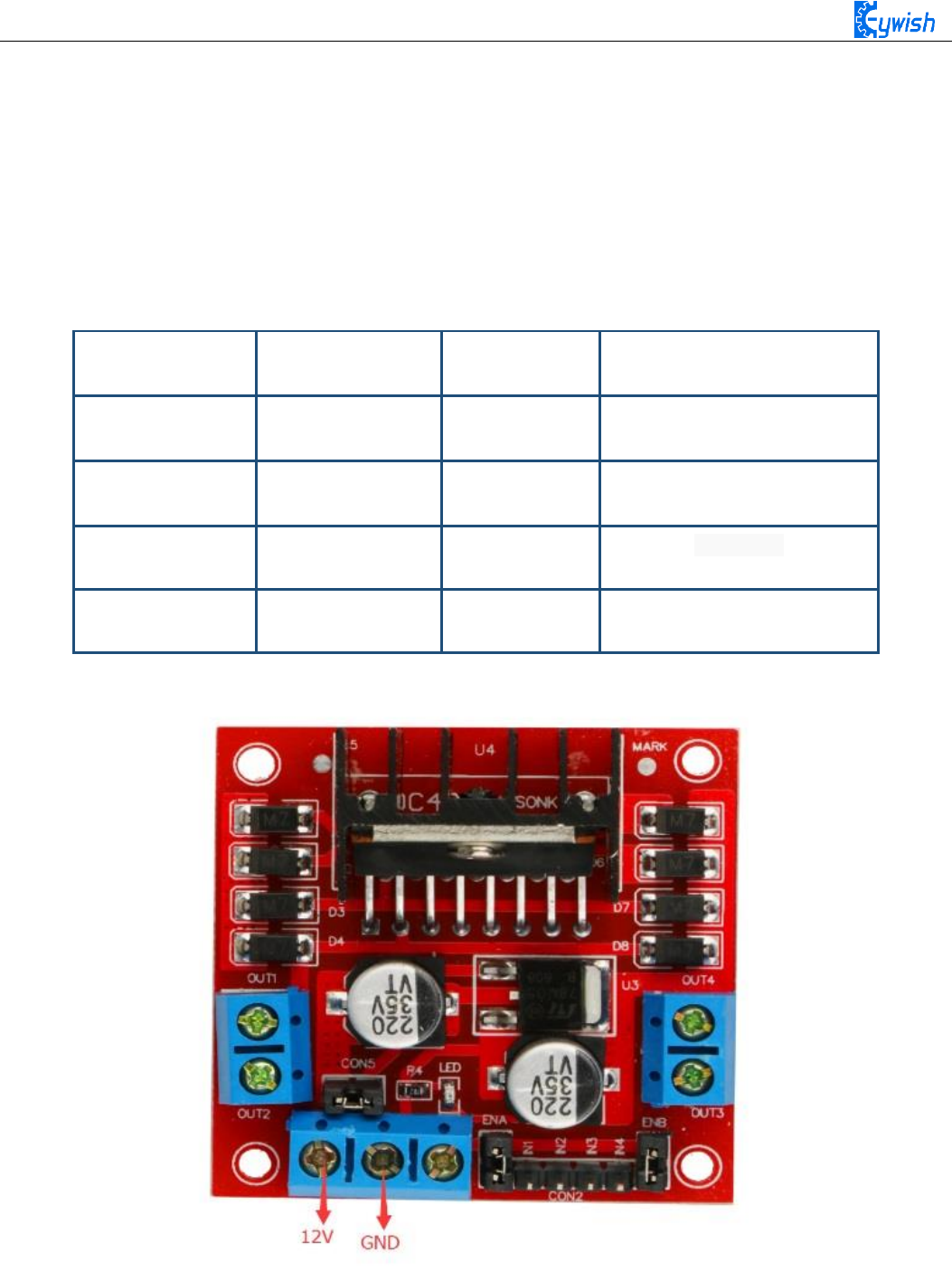
Fig.3.2.3 Module Physical Map
ENA
IN1
IN2
Motor status
H
H
L
Forward
H
L
H
Reversal
H
IN2
IN1
Quick stop
L
X
X
Stop
45
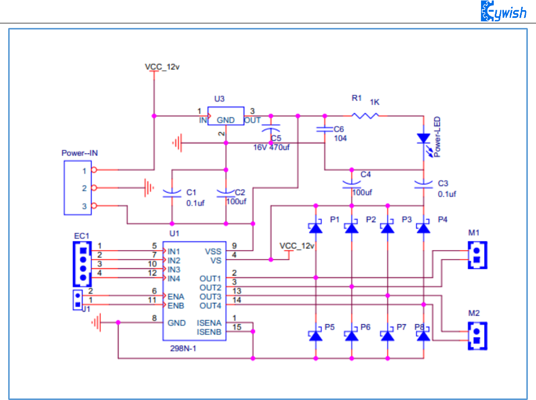
Fig.3.2.4 Schematic Diagram of Motor Drive
Four DC motors with high power L298N drive enable "Hummer-Bot" to run faster than conventional
two-wheel car, the acceleration time is shorter and the structure is more stable. However, in the actual
application, we need to adjust the speed of the car because of environmental or other factors, yet this does not
affect the forward, backward, stop, flexible steering of the car, so we use PWM to control the speed of the
motor(Note: PWM is a way to simulate the simulation output via square waves with different duty cycles.),
Arduino PWM port outputs a series of square waves with fixed frequency, the power and current of the motor
can be amplified after receiving the signal, thereby changing the motor’s speed. The speed coordination of
two motors on the right and left wheels can achieve the forward, backward, turning and other functions of the
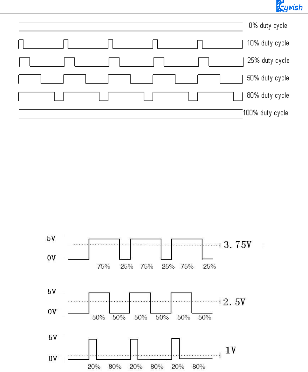
car. Figure 2.4.5 shows the sequence diagram of PWM duty cycles.
46
Fig.3.2.5 Sequence Diagram of PWM Duty Cycles
In Arduino, analog voltage can not be output, only 0 or 5V digital voltage value, we can use high
resolution counter and the duty cycles of the square wave modulation method to encode a specific level of
analog signal. The PWM signal is still digital, because at any given time, the full amplitude of DC power
supply is either 5V (ON) or 0V (OFF). The voltage or current source is added to the analog load with a ON
or OFF repetitive pulse sequence. When the DC power supply is added to the load, the power supply is on,
otherwise the power supply is off. As long as the bandwidth is enough, any analog value can use PWM to
encode. The output voltage value is calculated by the on and off time. Output voltage = (turn-on time / pulse
time) * maximum voltage. Fig.2.4.6 shows the corresponding voltage to the pulse change.
Fig.2.4.6 Relation between Pulse and Voltage
In the "Hummer-Bot" car experiment, we use Arduino UNO R3 as the main control board. By referring
to the chip data, we will know that Arduino UNO has 6 PWM pins, namely digital interfaces 3, 5, 6, 9, 10,
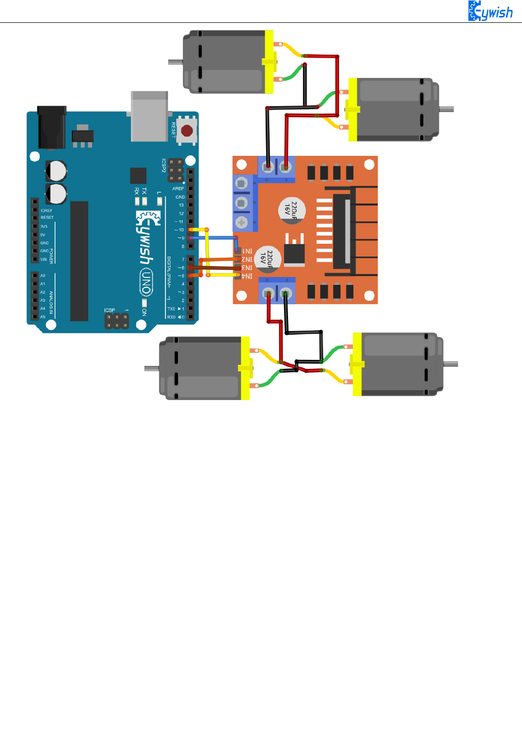
11, and we select 5, 6, 9, 10 as the motor control IO, the connection is shown in Fig.2.4.7.
47
Fig.2.4.7 Connection between Arduino and L298N Drive Board
After the connection, we do not know whether the motor can work normally or not, so we need to do a
simple test by copying the following code(you can also open the program in the CD directly) into the IDE
development environment and downloading to the development board. And turning on the power(power
connection is introduced the tenth and eleventh steps in 3.1.2) to observe the wheels rotation, if "going
forward 5s----stopping 1s---- going back 5s---- stopping 1s----turning left 3s----stop 1s----turning right 3s"
are normal,the connection is correct, otherwise the polarities of the motor may be reversed, then you need to
adjust slightly.
Note: this test and IO selection are only for reference, you can choose other IO ports or use other wiring
methods according to your own ideas.
int E1 = 5; //PWMA
int M1 = 9; //PWMA
int E2 = 6; //PWMB
int M2 = 10; //PWMB
void setup()
{
}
void loop()

48
{
analogWrite(M1,0);
analogWrite(E1, 150); //the speed value of motorA is 150
analogWrite(M2,0);
analogWrite(E2, 150); //the speed value of motorB is 150
delay(5000);
//******** ******************************//forward
analogWrite(M1,0);
analogWrite(E1, 0); //the speed value of motorA is 0
analogWrite(M2,0);
analogWrite(E2, 0); //the speed value of motorB is 0
delay(1000);
//********************************************//stop
analogWrite(M1, 150); //the speed value of motorA is 150
analogWrite(E1, 0);
analogWrite(M2, 150);//the speed value of motorA is 150
analogWrite(E2, 0);
delay(5000); //*********************************************//back
analogWrite(M1,0);
analogWrite(E1, 0); //the speed value of motorA is 0
analogWrite(M2,0);
analogWrite(E2, 0); //the speed value of motorB is 0
delay(1000);
//******* ***************************************//stop
analogWrite(M1, 0);
analogWrite(E1, 180); //the speed value of motorA is 180
analogWrite(M2, 180); //the speed value of motorB is 180
analogWrite(E2, 0);
delay(3000);
//*******************************************//left
analogWrite(M1, 0);
analogWrite(E1, 0); //the speed value of motorA is 0
analogWrite(M2, 0);
analogWrite(E2, 0); //the speed value of motorB is 0
delay(1000);
//***** **************************************//stop
analogWrite (M1,200); //the speed value of motorA is 200
analogWrite(E1, 0);
analogWrite (M2,0);
analogWrite(E2, 200); //the speed value of motorB is 200
delay(3000);//*** ***************************************//right
}
49
By now, the car can move normally, are you happy and excited? But this is just the beginning, the car
can just fool-turning without significance, there will be more fun if we add it some "organs".Now we will
equip the car with several commonly-used sensors, so it will have a new understanding of the world.
3.2.2 Infrared Obstacle Avoidance
3.2.2.1 Introduction of Infrared Obstacle Avoidance Sensor
Infrared obstacle avoidance module is a pair of infrared transmitting and receiving tubes, the former
launches a certain frequency infrared, the receiving tube will receive the reflected infrared when the infrared
detects the obstacles.After the signal is processed by the comparator circuit, the green LED lights, and the
signal output port outputs digital signal at the same time(a low level signal). The detection distance can be
adjusted through the potentiometer knob, the effective distance range is 2-30cm, the working voltage is 3.3V-
5V.Due to the sensor uses infrared, so the anti-interference ability is very strong, the measurement accuracy
is very high when the distance is moderate. In addition, the module can be assembled easily and used
conveniently, it can be widely used in robot obstacle avoidance,car obstacle avoidance and the black&white
line tracing and many other occasions.
3.2.2.2 Working Principle
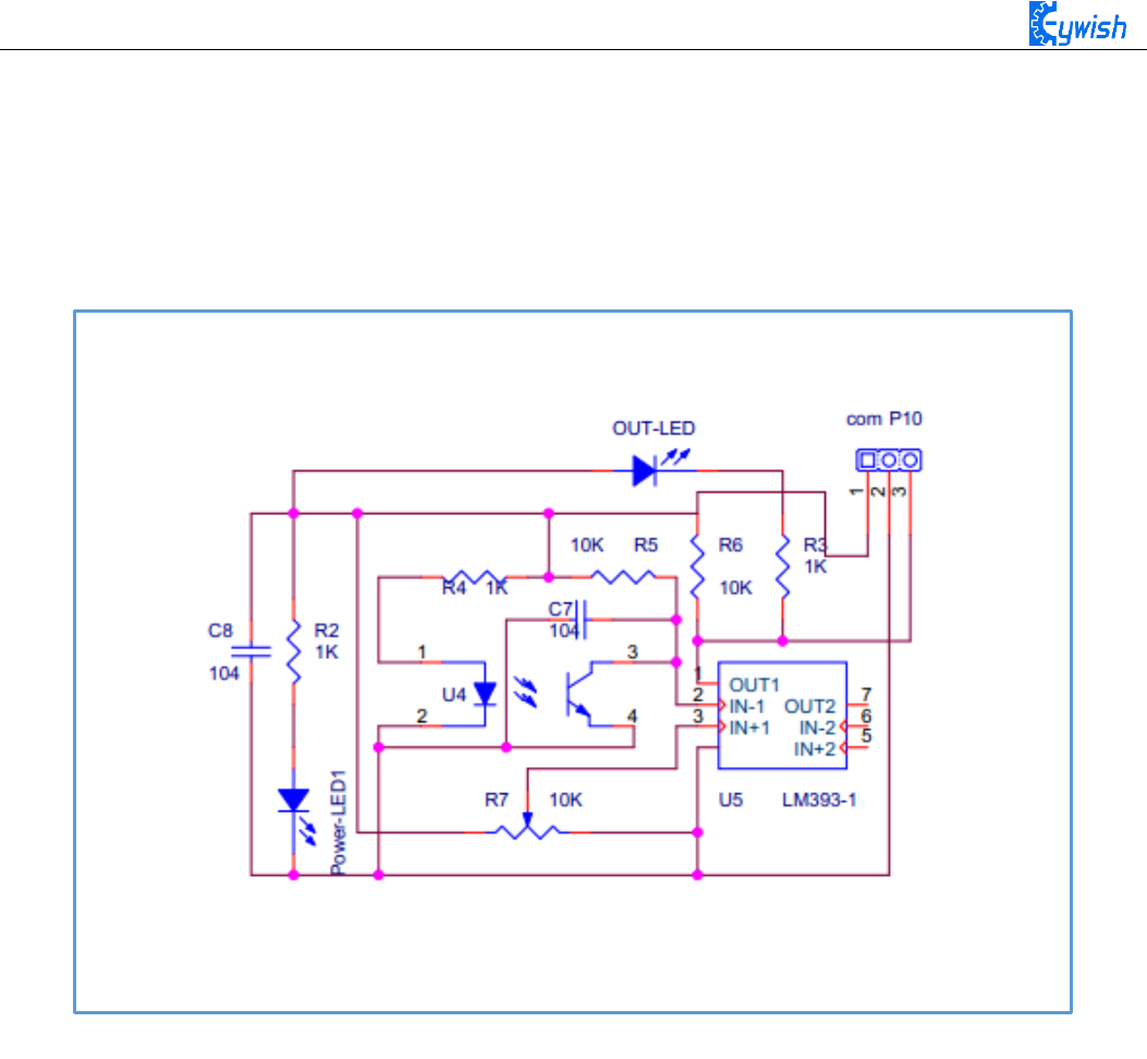
1, The module output port OUT can be directly connected with the IO port of the microcontroller, and
directly drive a 5V relay; the connection mode is: VCC-VCC; GND-GND; OUT-IO (A3 and A4), as shown
in Fig.3.2.9 and Chart 3.2.1.
2, The module uses the 3-5V DC power as power supply. When the power is on, the indicator will light.
3, The diameter of installation hole is 3mm, you can use the same size screws (screws in the kit).
Pin wiring definition (only for reference, you can define according to your own ideas):
arduino Uno
Infrared Obstacle Avoidance Module
VCC
VCC
GND
GND
A3
The left module
A4
The right module
Chart 3.2.1 Pin Wiring Definition
3.2.2.3 Module Parameters
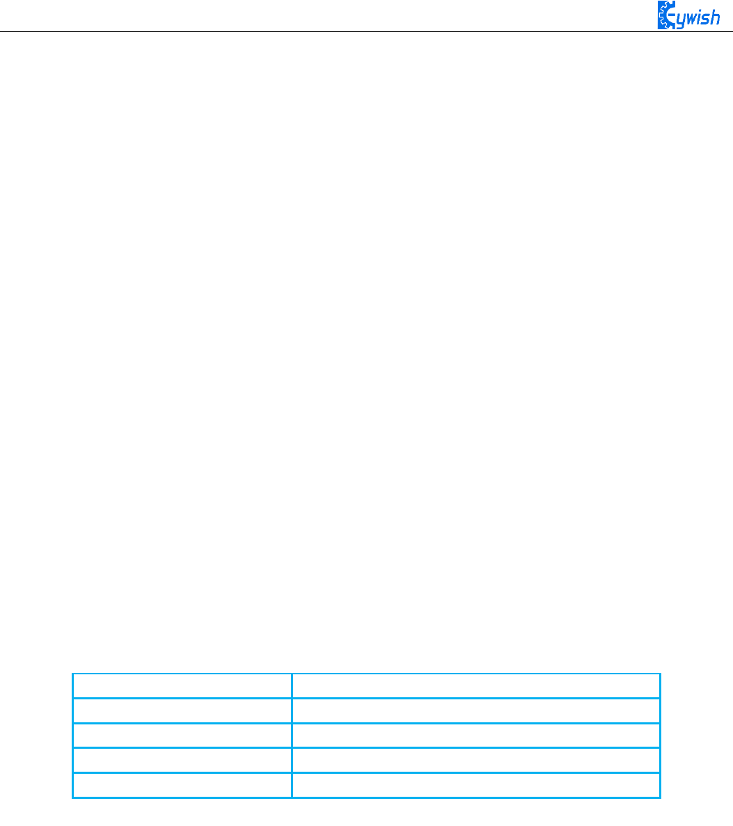
The working principle of infrared obstacle avoidance sensor is very simple, that is the reflection property
of objects. In a certain range, if there is no obstacle, the infrared ray emitted will gradually weaken because of
the farther distance of transmission, and finally disappear. If there are obstacles, the infrared will be reflected
to the receiving head. As soon as the sensor detects the signal, it can confirm that there are obstacles in front
of the circuit board, the green indicator will light, the OUT port continuously outputs low level signal to MCU
at the same time, the MCU conducts a series of analysis to ensure that the two wheels of car works properly
50
and avoids the obstacle beautifully. The schematic diagram of the sensor is shown in Fig.3.2.8. Infrared
detector can be divided into active and passive according to its working mode.
Active infrared detector is equipped with infrared light source, it can detect the location of the object
through covering the light source, reflection, refraction and other optical means.
Passive infrared detector has no light source, and it can measure the position, temperature, or infrared
imaging of the detected object by receiving the characteristic spectral radiation of the detected object.
Fig.3.2.8 Infrared obstacle avoidance schematic diagram
51
Fig.3.2.9 Connection of Arduino and Sensor
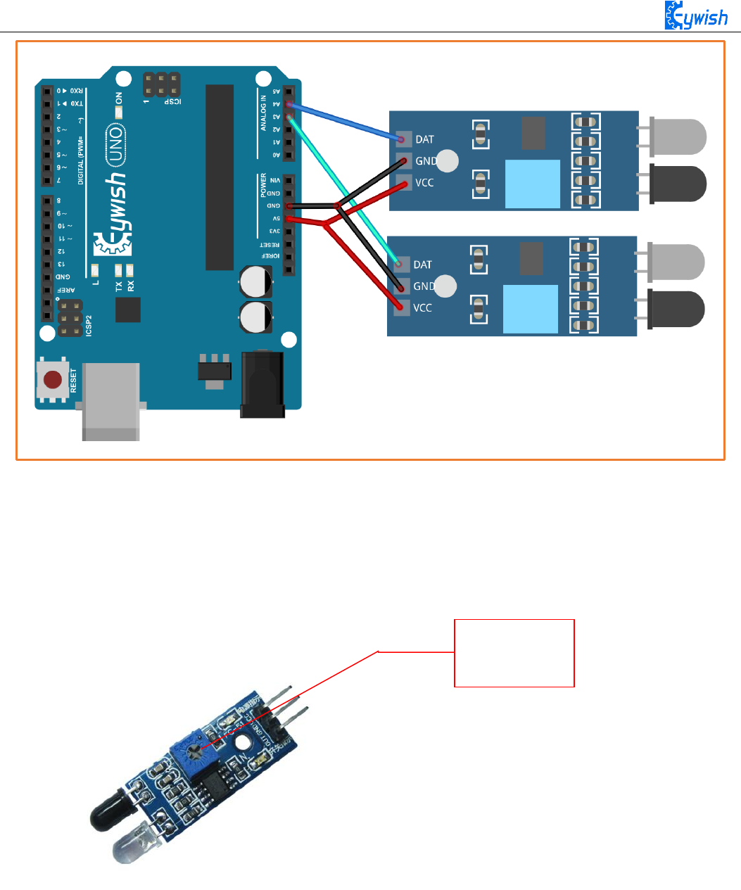
Note: This module can adjust the detection distance by the potentiometer, the detection distance is 2-
30cm, if it is found that the distance detection is not very sensitive, you can use the potentiometer to achieve
the desired results ( rotating the potentiometer clockwise will increase the detection distance;
counterclockwise will decrease), it is shown in Fig.3.2.10.
Manual adjustment is shown in the following diagram:
Fig.3.2.10 Diagram of Distance Detection Adjustment
3.2.2.4 Experimental Procedures
1, Fixing the two sensors on the car and connecting them to Arduino with wires.(Already done)
2, Testing the sensitivity of module, namely opening the switch on the battery box and the indicator will
light, placing obstacles the 10cm away from the infrared tubes, adjusting the potentiometer until the output
indicator lights up.
Adjustable
Potentiometer

52
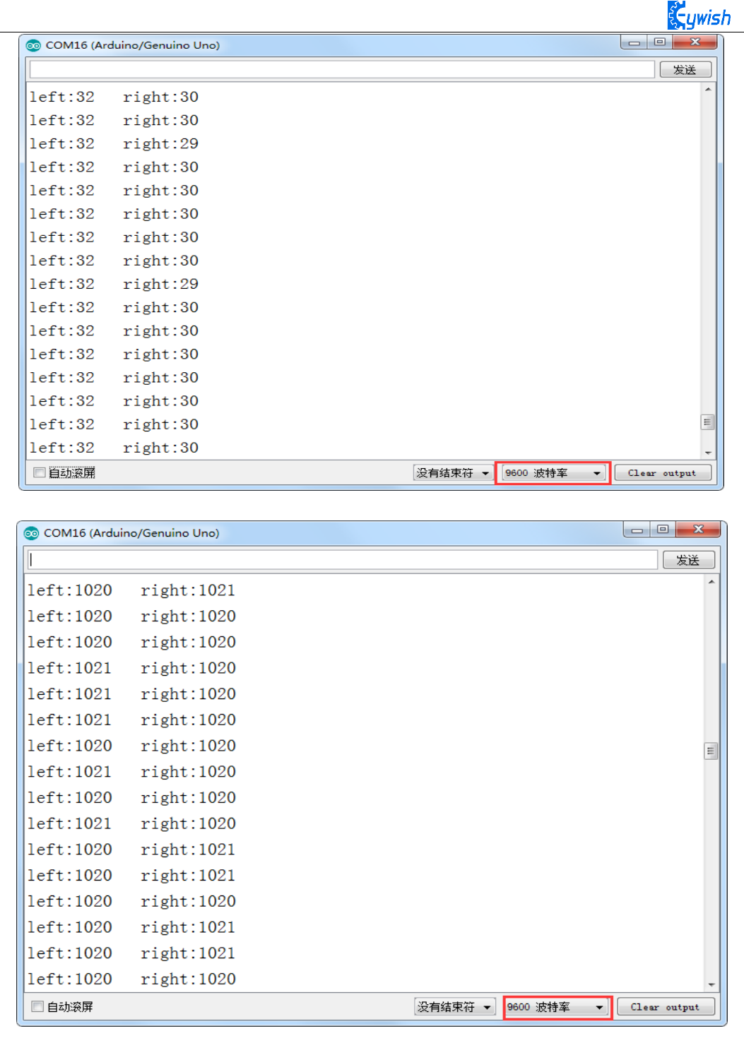
3, Module test.copying the following code to the IDE compiler environment (you can also open the
program directly in the CD), downloading it to the development board, opening the serial port monitor (baud
rate is 9600) and observing the changes of data when there is a obstacle (Figure 3.2.11) and no obstacle (Figure
3.2.12).
Note: Here we connect the infrared obstacle avoidance signal output port to the analog port on Arduino
(A0-A5), so the serial port prints out analog value, you can connect it to digital port (2-13), and the serial port
will only print out "0" and "1".
const int leftPin = A3;
const int rightPin = A4;
int dl;
int dr;
void setup()
{
Serial.begin(9600);
pinMode(leftPin, INPUT);
pinMode(rightPin, INPUT);
delay(1000);
}
void loop()
{
dl = analogRead(leftPin);
dr = analogRead(rightPin);
Serial.print("left:");
Serial.print(dl);
Serial.print(" ");
Serial.print("right:");
Serial.println(dr);
}
53
Fig.3.2.11 Diagram of Data with Obstacles
Fig.3.2.12 Diagram of Data without Obstacles

54
3.2.2.5 Software Design
In the above steps, we have tested the car’s driving and obstacle avoidance module respectively, they
have achieved the desired results, here the "infrared obstacle avoidance" actually has been explained in this
section, but we have not put the programs of two parts together, so we now integrates the program of the
two parts and complete this great "infrared obstacle avoidance" project. First, let's read the complete program:
int E1 = 5; //PWMA
int M1 = 9; //DIRA****************************************left
int E2 = 6; //PWMB
int M2 = 10; //DIRB****************************************right
/* Define 4 motor control terminals, connected to IN1-IN4 on the motor drive board。*/
const int leftPin = A3;
const int rightPin = A4; // Define the two signal receiving ends of the sensor
float dl;
float dr; // Define two margins to store the values read by both sensors
void setup()
{
Serial.begin(9600); // Set the serial port baud rate to 9600,
pinMode(leftPin, INPUT);
pinMode(rightPin, INPUT); // Set the working mode of two sensor pins, namely "input"
delay(1000);
}
void loop()
{
dl = analogRead(leftPin);
dr = analogRead(rightPin); // Read the values collected by both sensors and assign
them to the defined variables。
if (dl >= 38 && dr <= 38) /* If the value collected by the left sensor is greater than
or equal to 38 and the right value is less than or equal to 38, the following program
in {} is executed (dl> = 38, there is no obstacle on the left, dr <= 38 shows that
there is an obstacle on the right, so at this time the car is turning to the side
without obstacles (ie, turning to the left). From Figure 3.2.11, we know that the
simulated value will drop below about 35 in the event of an obstacle , But in order to
reduce the error, we set the threshold at 38 to prevent the car from judging the error
because of the error. We can also customize other values. If we use the digital port to

55
receive the value of the sensor, we only return "0" and "1" ", But the same way to
judge. The reason why I did not use digital IO, because we use the digital IO port in
other places.*/
{
analogWrite (M1,0);
analogWrite(E1, 180); //the speed value of motorA is 180
analogWrite (M2,180); //the speed value of motorB is 180
analogWrite(E2, 0); /* Set a PWM value, the maximum PWM is 255, but the speed of the
car should not be too fast when walking, otherwise it can not hit the obstacle in time
when the obstacles are suddenly encountered.*/
Serial.print(dl);
Serial.print(" ");
Serial.print(dr);
Serial.print(" ");
Serial.println("Turning left"); /* Through the "Serial Monitor" print the current
status of the car and the value collected by the sensor* /
delay(300);
analogWrite(M1, 0);
analogWrite(E1, 0);
analogWrite(M2, 0);
analogWrite(E2, 0); /* As the car left after about 300ms stop, after measuring, 300ms
time car just can rotate about 90 degrees, because the DC motor does not like the
steering angle can be precisely controlled, so can only give a rough estimate, of
course, different motor speed is not Similarly, the time used is not the same, so
everyone in the experiment can be based on their own ideas, but the angle of 90, but
also other values.*/
delay(1000); //************************************//Turning left
}
if (dl <= 38 && dr <= 38) /* If the value collected by the left sensor is less than
or equal to 38 and the right value is less than or equal to 38, the following program
in {} is executed (dl <= 38, indicating that there is an obstacle on the left and dr <=
38 shows that there is an obstacle on the right, so at this time the car is rotated 180
degrees backwards. In the experiment, the car can just turn around 180 degrees after
500ms of rotation. Because the DC motor can not precisely control the angle like the
steering gear, An approximate value, of course, different motor speed is not the same,
the time used is not the same, so everyone in the experiment can be based on the
circumstances may be.)*/

56
{
analogWrite(M1,255); //the speed value of motorA is 255
analogWrite(E1, 0);
analogWrite(M2, 0);
analogWrite(E2, 255); //the speed value of motorB is 255
Serial.print(dl);
Serial.print(" ");
Serial.print(dr);
Serial.print(" ");
Serial.println("Turning around");/* Through the "Serial Monitor" print the current
status of the car and the value collected by the sensor.*/
delay(500);
analogWrite (M1,0);
analogWrite (E1, 0);
analogWrite (M2,0);
analogWrite (E2, 0); /* Rotate 180 degrees and stop */
delay(1000); //*********************************//Turning around
}
if (dl <= 38 && dr >= 38) /* If the left sensor is less than or equal to 38 and the
right value is greater than or equal to 38, the following program in {} is executed (dl
<= 38, indicating that there is an obstacle on the left, dr> = 38 shows that there is
no obstacle on the left, so at this moment the car is turning to the side without
obstacle, that is, turning to the right)
{
analogWrite(M1, 180); //the speed value of motorA is val
analogWrite(E1, 0);
analogWrite(M2, 0);
analogWrite(E2, 180); //the speed value of motorA is val
Serial.print(dl);
Serial.print(" ");
Serial.print(dr);
Serial.print(" ");
Serial.println("Turning right");
delay(300);
analogWrite(M1, 0);
analogWrite(E1, 0);
analogWrite(M2, 0);

57
analogWrite(E2, 0); /* Car must stop after each rotation, if you do not stop there
will be the phenomenon of rotating around. * / delay(1000);
//*********************************//Turning right
}
if (dl >= 38 && dr >= 38) / * Judge two values collected by the sensor. If the value
collected by the left sensor is greater than or equal to 38 and the right value is
greater than or equal to 38, execute the following program in {} (dl> = 38, indicating
that there is no obstacle on the left and dr > = 38 that there is no obstacle on the
left, so the car at this time straight * /
{
int val=150; /* When the straight line has a PWM value of 150, if the value is too
large, the speed of the car will be very fast, which may lead to the car can not hit
the obstacle in time when it encounters the obstacle. * / analogWrite (M1,0);
analogWrite(E1, val); //the speed value of motorA is val
analogWrite (M2,0);
analogWrite(E2, val); //the speed value of motorB is val
Serial.print(dl);
Serial.print(" ");
Serial.print(dr);
Serial.print(" ");
Serial.println("go");//**********************************//forward
}
}
In the above program, we made comments on some part of the program in order to make you to learn
and understand the program easily, the program is relatively simple, you can write your own programs to give
the car more skills. Of course, if you want to use it directly, we have the corresponding source program in the
CD.
3.2.3 Infrared Tracing
3.2.3.1 Introduction of Infrared Tracing Sensor
After infrared obstacle avoidance, let us learn the infrared tracing, their nature of work are the same,
using basically the same module, just in different ways, to achieve different functions. In this section when
we study, we have to pay attention to the color of the line we trace( the black line or white line ), if your floor
is black, you should trace the white line ( pasting white line on the floor ); if it is white, then you should trace
the black line ( pasting black line on the floor ); you just need to make a distinct difference between the track
and the ground environment.
58
Black line tracking refers to the car drives along the black line on the white floor, it can know where to
drive according to the received reflected light due to the different light reflection coefficient on the black and
white floor.
White line tracking refers to the car drives along the white line on the black floor, it can know where to
drive according to the received reflected light due to the different light reflection coefficient on the white and
black floor.
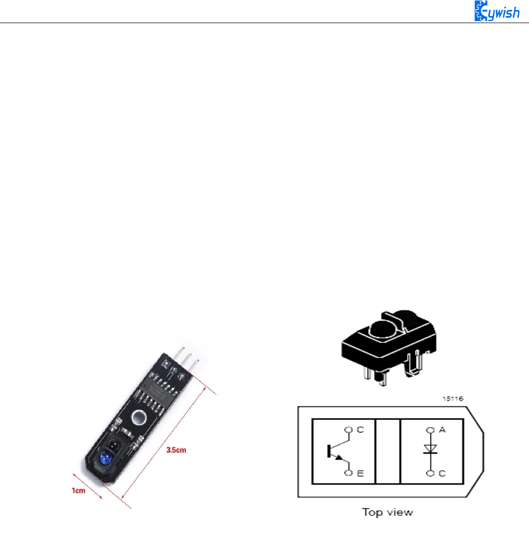
In the "Hummer-Bot" car, we use the TCRT5000 sensor as tracing module, TCRT5000 infrared reflection
sensor is a photoelectric sensor which consists of an infrared emitting diode and a NPN infrared photoelectric
transistor. The detectable reflective distance is 1mm-25mm, the sensor is specially equipped with M3 fixed
installation holes, so it is easy to adjust the direction, it also has the 74HC14 Schmidt trigger inverter which
ensure the clean signal, the good wave shape and the strong driving ability. It can be applied to robot obstacle
avoidance, robot tracing ( detecting black line in white background and detecting white line in black
background ), which is the necessary sensor for tracing line robot and other occasions. The PCB size is
3.5cm*1cm, and the physical map is shown in Fig.3.2.13.
Fig.3.2.13 Physical Map of the Module
3.2.3.2 Working Principle
In the above, we talked about two patterns of tracing-the white line and the black line. In fact, either the
black line or the white line, we usually adopt the infrared detection method.
Infrared detection method means that different objects with different colors have the different infrared
reflection characteristics. The car launches the infrared to the ground continually during driving process, the
infrared receiving tube will be in a shutdown state and the output of the module is low level when the emitted
infrared is not reflected or the reflected infrared is not strong enough, and indicating diode will be off; when
the diffuse reflection occurred on a white floor, the intense reflected infrared will be received by the receiving
tube on the car, the photosensitive triode will be saturated, the output end of the module is high level and the
indicating diode will light.

59
As is shown in the schematic diagram 3.2.14 (U1 is comparator, such as LM358, LM324, LM393, LM339
and a series of comparators, we use the 74HC14D comparator in TCRT5000), A and C are connected to the
light emitting diode, C and E to the receiving diode, as shown in Fig.3.2.13. In the "Hummer-Bot" car, we use
three modules, two in the left and right sides, one in the middle. Its installation is shown in Fig.3.2.16,the
tracing sensors are in a straight line.
Fig.3.2.14 Schematic Diagram of Tracing Module Fig.3.2.16 Diagram of Tracing Module Installation
The X1 and Y1 are the first direction control sensors, and the width of the two sensors on the same side
of the black line must not be greater than the width of the black line. When the car is moving forward, the
driving track is always between the two first level sensors X1 and Y1 (the black track as shown in Fig. 3.2.16),
when the car deviates from the black line:
If the left X1 detects the black line which can not be detected by the right Y1 and intermediate sensors,
the the car has shifted to the right, then the car will turn left slightly, and keeping intermediate sensor always
detecting the black line; if the right Y1 detects the black line which can not be detected by the left X1 and
intermediate sensors, the the car has shifted to the left, then the car will turn right slightly, and keeping
intermediate sensor always detecting the black line; if the car turns back on the track driving along the black
line, X1 and Y1 can all detect the white line, and send high level to the microcontroller.
3.2.3.3 Module Parameters
◆ Using TCRT5000 infrared reflection sensor
◆ The detection distance: 1mm~25mm, the focal distance is 2.5mm
◆ The comparator output signal waveform is clean, good-shape and it has more than 15mA strong drive
ability.
◆ The working voltage: 3.3V-5V
◆ Using wide voltage comparator 74HC14D, digital output (0 and 1)
◆ Easy-to-install fixed bolt holes

60
Note:
Correct wiring! Do connect the positive and negative pins correctly, or the mainboard and electronic
device may burn up. Connecting the VCC to 3.3V or 5V, the OUT output port to the microcontroller IO port
directly. The I/O port on Arduino should be set for input mode / receiving mode, otherwise it can not be used.
As for other MCU, such as ARM or more advanced control boards, if the I/O ports need to be used as the
input and output mode, they have to be set to the input mode / receiving mode. The 51 series microcontrollers
can be used directly, there is no need to set the input and output mode.
If you want to know more about TCRT5000, please refer to the file "TCRT5000.pdf" in the CD.
3.2.3.4 Experimental Procedures
1, Fixing the sensor on the car (the assembly is completed) and connecting it to the Arduino as shown in
Fig.3.2.17.
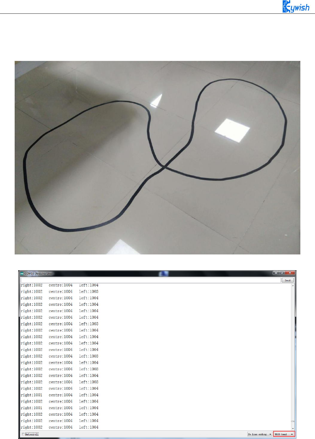
2, Making the track. if your floor is white, then you could stick a black tape to form a loop, otherwise
stick a white tape, the shape of track is based on your own desires, the best width of the tape is 13-18mm. In
this manual, we use the black track, as shown in Fig.3.2.18.
3, Module test.Copying the following codes to the IDE compiler environment (you can also open the
program in the CD directly) and downloading to the development board, opening the serial port monitor (baud
rate is 9600) to observe the changes of data when there is the white line (Fig. 3.2.19) and is not the white line
(Figure 3.2.20).
Note: Here we connect the signal output port of infrared obstacle avoidance to the analog port on Arduino
(A0-A5), so the serial port monitor prints analog values, you can connect it to the digital port(2-13), then the
serial port monitor will print out only "0" and "1".
void setup()
{
Serial.begin(9600);
}
void loop()
{
int left,centre,right;
left=analogRead(A0);
centre=analogRead(A1);
right=analogRead(A2);
Serial.print("right:");
Serial.print(right);
Serial.print(" ");
Serial.print("centre:");
Serial.print(centre);
Serial.print(" ");
61
Serial.print("left:");
Serial.print(left);
Serial.println(" ");
}
Fig.3.2.18 Example of the Black Track
Fig. 3.2.19 The Data When the Sensor Does Not Detect the Black Line

62
Figure 3.2.20 The Data When the Sensor Detects the Black Line
From Fig.3.2.19 and Fig.3.2.20 we can see that the output is high level when the sensor does not detect
the black line, low level when detects the black line. We use the analog port to collect the sensor’s signal, so
the printed value is analog that, the high level is reaching 1024, the low level is 0. After we master the
working principle of the sensor, our tracing car in this section comes to an end, then let us open a car
journey.
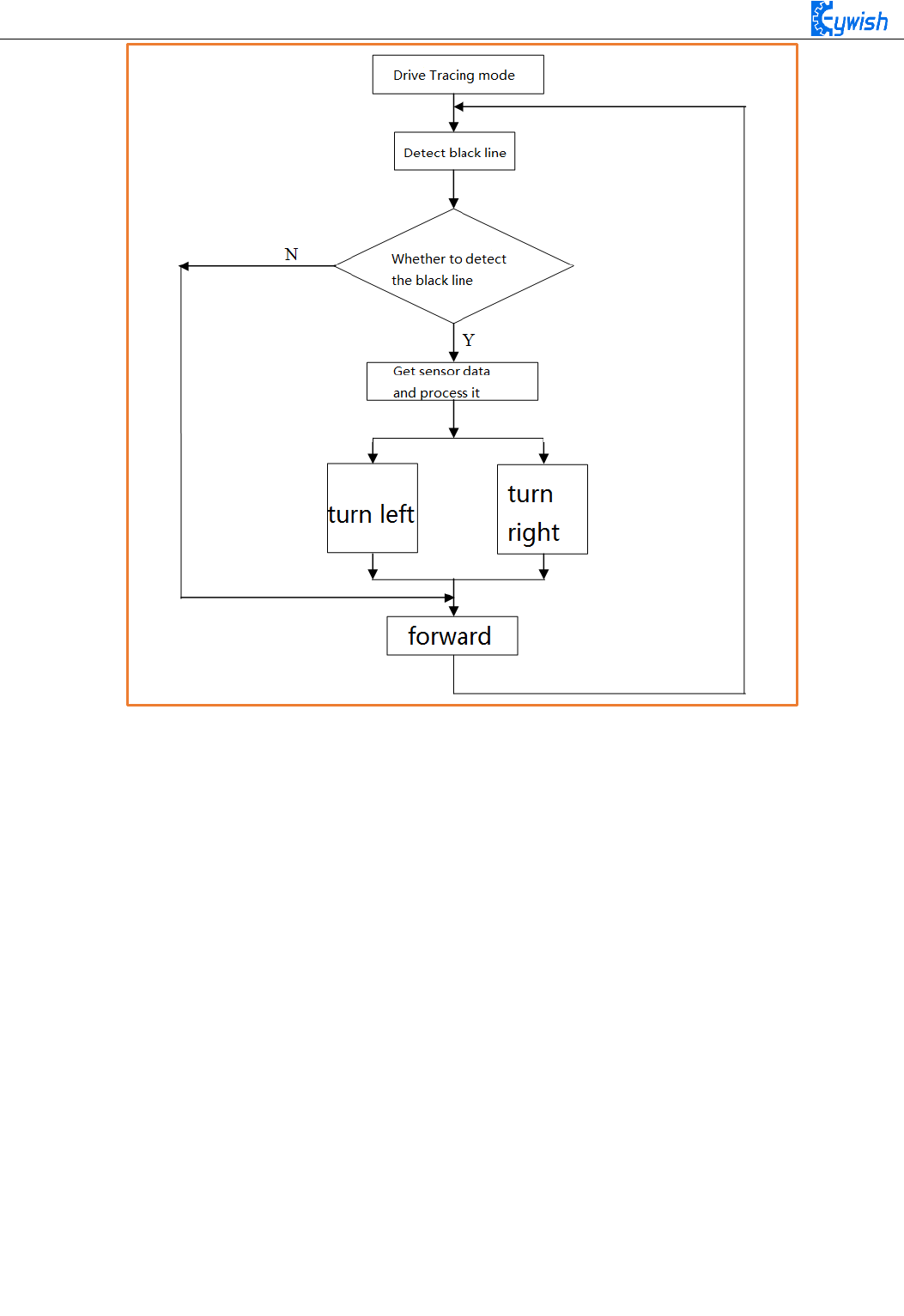
3.2.3.5 Software Design
1. Overall software flow chart
When the car enters the tracing mode, it keeps scanning the I/O port of the MCU connected to the
sensors, once detecting the changes in signal at the I/O port, the corresponding procedure will be
implemented, the corresponding signal will be sent to the motor so as to correct the status of the car.
2. The car tracing flow chart
When the car enters the tracing mode, it keeps scanning the I/O port of the MCU
connected to the sensors, once detecting the changes in signal at the I/O port, the corresponding procedure
will be implemented. If the left sensor detects the black line(the left half of the car walked across the black
line, the car body is trended right), the car should turn the left; If the right sensor detects the black line(the
right half of the car walked across the black line, the car body is trended left), the car should turn the right.
After the direction adjustment, the car walks forward, and continues to detect the black line repeatedly. The
tracing flow chart is shown in Fig.3.2.21.
63
Fig.3.2.21 the Tracing Flow Chart
3. Program Explanation
int E1 = 5; //PWMA
int M1 = 9; //DIRA****************************************left
int E2 = 6; //PWMB
int M2 = 10; //DIRB****************************************right
/* Define 4 motor control terminals, connected to IN1-IN4 on the motor drive board.*/
void setup()
{
Serial.begin(9600); /* Set the baud rate to 9600 * /}
void loop()
{
int left1,centre,right1; /* Define 3 sensors * /
left1=analogRead(A0);
centre=analogRead(A1);
right1=analogRead(A2); /* Read the value collected by 3 sensors * /

64
if((right1 >= 975)&&(centre <= 8)&&(left1 >= 975)) / * Judge the collected value, if
right1> = 975 and left1> = 975 are greater than 975, the left and right sensors do not
detect the black line, the center <= 8 shows that the middle sensor detects the black
line, so the car will Drive along the black line. From Figure 3.2.19 and Figure 3.2.20,
we know that when a black line is detected, the sensor captures a value that is low and
reads 0 after analog IO. However, to reduce the error, we set the threshold In 8, to
prevent the error caused by the car to determine the wrong, we can customize the other
values, if the use of digital port to receive the value of the sensor returns only "0"
and "1", but to determine the same way. The reason why I did not use digital IO,
because we use the digital IO port in other places. * /
{
int val=150; /* Set a PWM value, the maximum value of PWM is 255, but the speed
should not be too fast when tracing the car, otherwise the car will shake more in the
tracing process. analogWrite (M1,0);
analogWrite(E1, val); //the speed value of motorA is val
analogWrite (M2,0);
analogWrite(E2, val); //the speed value of motorB is val
}
else if((right1 <= 8)&&(centre >= 975)&&(left1 >= 975)) / * The value collected to
judge, if the center> = 975 and left1> = 975 are greater than 975, indicating that the
middle and left sensors did not detect the black line, right1 <= 8 shows the right
sensor detects a black line, then the car Has left to the left, or the black line has
been turning to the right, so the car should turn to the right. * /
{
int val=150;
analogWrite (E1,0);
analogWrite(M1, val); //the speed value of motorA is val
analogWrite (M2,0);
analogWrite(E2, val); //the speed value of motorB is val
}
else if((right1 >= 975)&&(centre >= 975)&&(left1 <= 8)) / * Judge the collected
value, if center> = 975 and right1> = 975 are greater than 975, indicating that the
middle and right sensors did not detect the black line, left1 <= 8 shows that the left
sensor detects the black line, then the car Has been to the right deviation, or the
black line has turned to the left, so the car should turn left at this time. * / {
int val=130;

65
analogWrite (M1,0);
analogWrite(E1, val); //the speed value of motorA is val
analogWrite (E2,0);
analogWrite(M2, val); //the speed value of motorB is val
}
if((right1 <= 8)&&(centre <= 8)&&(left1 <= 8)) / * The value collected to judge, if
the center <= 8, left1 <= 8 and right1 <= 8 are greater than 8, indicating 3 sensors
have detected a black line, then the car has reached the "ten" intersection, because We
have only 3 sensors, no way to make more sophisticated judgments, so only let the car
choose to go straight. * / {
int val=130;
analogWrite (M1,0);
analogWrite(E1, val); //the speed value of motorA is val
analogWrite (M2,0);
analogWrite(E2, val); //the speed value of motorB is val
}
}
3.2.4 Ultrasonic Obstacle Avoidance
In this product, we will integrate the ultrasonic module and steering engine together and make the two
part working at the same time, which greatly increases the effectiveness of the data and the flexibility of the
car, the main working flow: When the power is on, steering engine will automatically rotates to 90 degrees,
the MCU will read data from the reflected ultrasonic. If the data is greater than the security value, the car
will continue to drive forward, otherwise the car will stop, then the steering engine will rotate 90 degrees to
the right. After that, the MCU reads data from the reflected ultrasonic again, the steering engine rotates 180
degrees to the left, then reading data again, the steering engine rotate 90 degrees, the MCU will contrast the
two detected data, if the left data is greater than the right data, the car will turn left, otherwise turn right, if
the two data are both less than the safety value, the car will turn around.
3.2.4.1 Suite Introduction
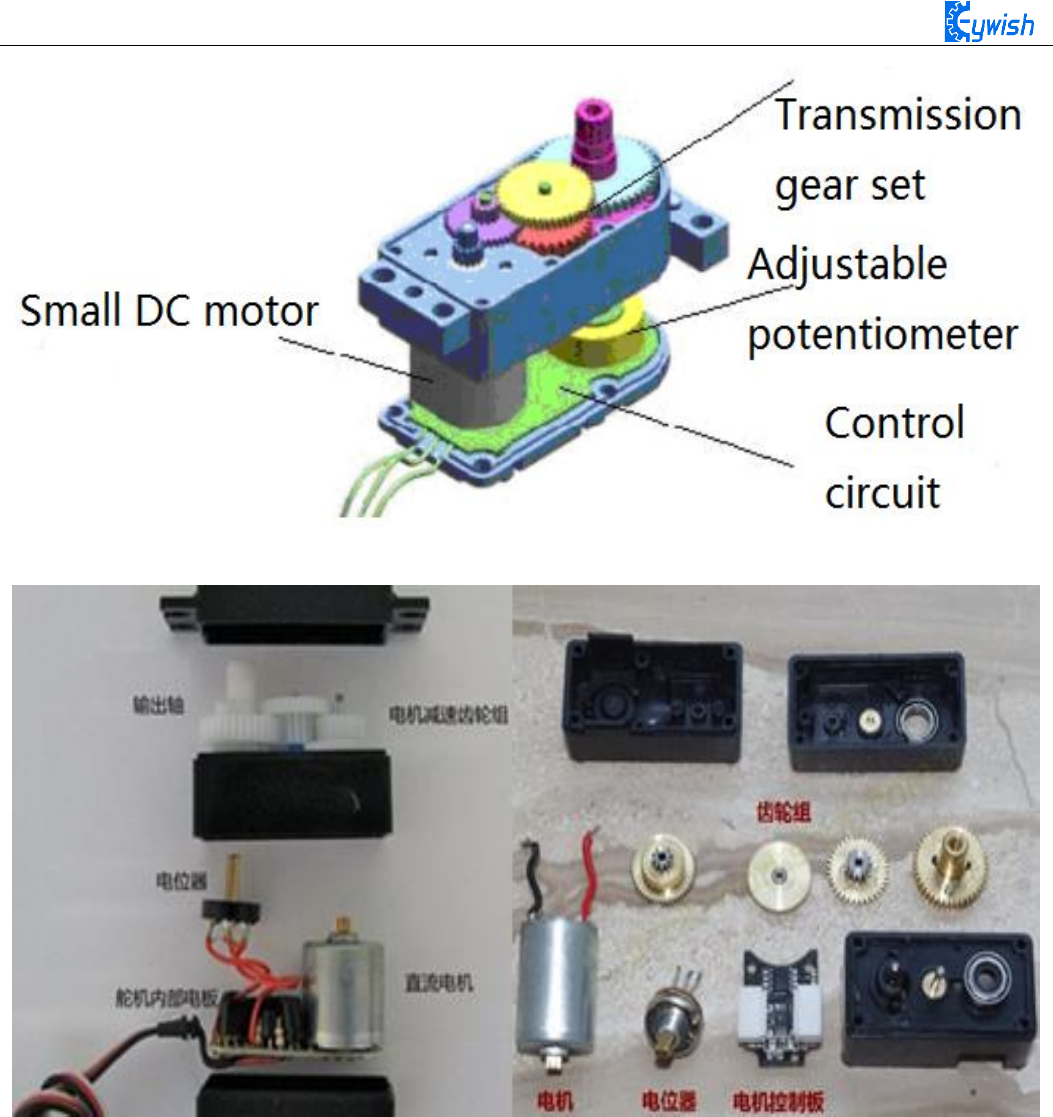
1. The steering gear
The steering gear is also called servo motor which is originally used in ships, since it can control the
angle continuously through the program, so it has been widely used in intelligent steering robot to achieve
all kinds of joint movement, the characteristics steering gear are small volume, large torque, high stability,
simple external mechanical design. Either in hardware or software design, the design of steering engine is an
important part of car controlling, the steering gear is mainly composed of the following parts in general,
steering wheels, gear group, position feedback potentiometer, DC motor and control circuit(shown in
Fig.3.2.22, Fig.3.2.23). Fig.3.2.24 shows the most commonly used 9G steering gear now.
66
Fig.3.2.22 Diagram of Steering Gear
Fig.3.2.23 Composition of Steering Gear
67
Fig.3.2.24 Physical Map of Steering Gear
2. The ultrasonic
An ultrasonic sensor is a device that transforms other forms of energies into ultrasonic energy with
desired frequency, or transforms the ultrasonic energy into other forms of energy with the same frequency.
The ultrasonic sensors are commonly classified into two categories, the acoustic type and the hydrodynamic
type. Acoustic type mainly has: 1, piezoelectric sensor; 2, magnetostrictive sensor; 3, electrostatic sensor.
The hydrodynamic type includes the gas whistle and the liquid whistle. At present most of the ultrasonic
sensors are working using piezoelectric sensors. Distance measurement with the ultrasonic is also a hot spot.
In the "Hummer-Bot" car, we use HC-SR04 ultrasonic module which has the 2cm-400cm non-contact
distance sensing function, the measurement accuracy can achieve to 3mm; the temperature sensor can
correct the measured results using the GPIO communication mode, the module has a stable and reliable
watchdog. The module includes an ultrasonic transmitter, receiver and control circuit, which can measure
distance and steer like in some projects. The smart car can detect obstacles in front of itself, so that the smart
car can change direction in time, avoid obstacles. A common ultrasonic sensor is shown in Fig.3.2.25.

68
Fig.3.2.25 Physical Map of Ultrasonic Module
3.2.4.2 Suite Parameters
1. Steering gear
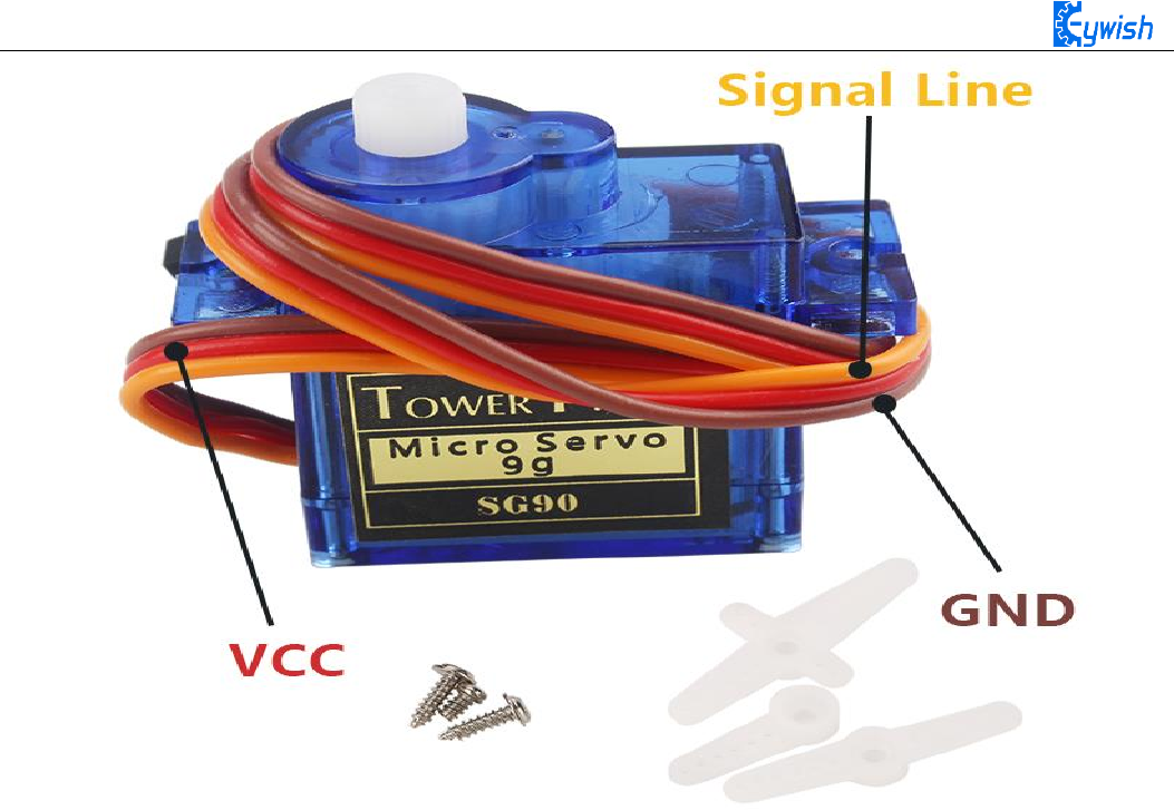
The steering gear has three input wires as shown in Fig.3.2.25, the red is power wire, while the brown
is the ground, which guarantee the basic energy supply for the steering gear. The power supply has two
kinds of specifications (one is 4.8V, the other is 6.0V)which are corresponding to different torque standards,
the 6.0V torque is higher than the 4.8V torque; and the another one is the signal control wire, which is
generally white in Futaba, orange in JR. Noticing that some of the SANWA's power wires are on the edge
rather than the middle which need to be identified, so you need to remember that the red is power wire, the
brown is ground wire.
2. Ultrasonic wave
1, Working voltage: 4.5V~5.5V. In particular, voltage above 5.5V is not allowed definitely
2, Power consumption current: the minimum is 1mA, the maximum is 20mA
3, Resonant frequency: 40KHz;
4, Detection range: 4 mm to 4 meters. Error: 4%. In particular, the nearest distance is 4mm, the longest
distance is 4 meters, and the data outputs continuously without setting anything. 5, Temperature
measurement range: 0℃to +100℃; precision: 1℃
6, Illumination measurement range: bright and dark;
7, Data output mode: icc and uart (57600bps), users can choose any of them; UART mode uses 7 bytes
as a group, and the 3 data stared with 0x55 are the distance values; the 2 data started with 0x66 are the
temperature value; the 2 data started with 0x77 are the illumination values. 0x55\0x66\0x77 are the data
headers in order to distinguish the 3 data;

69
8, Supporting the following 2 detection methods: 1, continuous detection; 2, controlled intermittent
detection;
9, Distance data format: using mm as the smallest data unit, double byte 16 hexadecimal transmission;
10, Temperature data format: using Celsius degree as the smallest unit, single byte hexadecimal
transmission;
11, Light data format: single byte 16 hexadecimal transmission; the value is big when it is dark, small
when it is bright;
12, Working temperature: 0℃~+100℃
13, storage temperature: -40 to +120 degrees Celsius
14, Size: 48mm*39mm*22mm (H)
15, The size of fixing holes: 3*Φ3mm; Gap:10mm
3.2.4.3 Working Principle
1. Steering gear
The control signal enters the signal modulation chip by the receiver channel, gets the DC bias voltage.
The steering gear has a reference circuit which generates a reference signal with a period of 20ms and a
width of 1.5ms. Comparing the obtained DC bias voltage with the voltage of the potentiometer, and
obtaining the output voltage difference. Finally, the positive and negative output voltage difference in the
motor driver chip decide the positive and negative rotation of motor. When the speed of motor is certain, the
cascade reducer gear will drive potentiometer to rotate so that the voltage difference is reducing to 0, the
motor will stop rotating.
When the control circuit receives the control signal, the motor will rotate and drive a series of gear sets,
the signal will move to the output steering wheel when the motor decelerates. The the output shaft of
steering gear is connected with the position feedback potentiometer, the potentiometer will output a voltage
signal to the control circuit board to feedback when the steering gear rotates, then the control circuit board
decides the rotation direction and speed of the motor according to the position, so as to achieve the goal. The
working process is as follows: control signal→control circuit board→motor rotation→gear sets deceleration
→steering wheel rotation→position feedback potentiometer→control circuit board feedback.
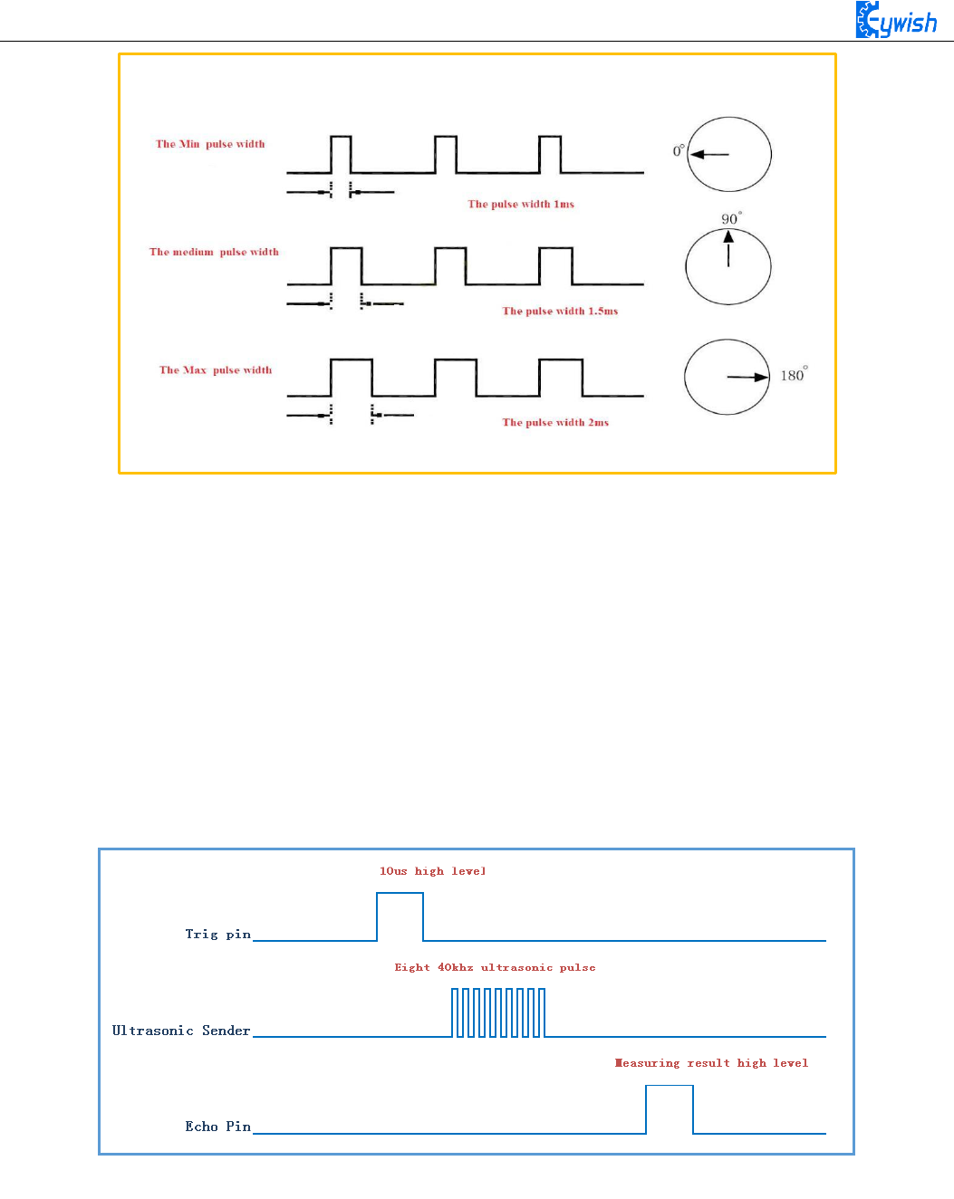
The control signal is 20MS pulse width modulation (PWM), in which the pulse width varies linearly
from 0.5-2.5MS, the corresponding steering wheel position varies from 0-180 degrees, which means the
output shaft will maintain a corresponding certain degrees if providing the steering gear with certain pulse
width. No matter how the external torque changes, it only changes position until a signal with different is
provided as shown in Fig.3.2.27. The steering gear has an internal reference circuit which can produce
reference signal with 20MS period and 1.5MS width, there is a comparator which can detect the magnitude
and direction of the external signal and the reference signal, thereby produce the motor rotation signal.
70
Fig.3.2.27 Relationship between the Motor Output Angle and Input Pulse
2. The ultrasonic
The most commonly used method of ultrasonic distance measurement is echo detection method, the
ultrasonic transmitter launches ultrasonic toward a direction and starting the time counter at the same time,
the ultrasonic will reflect back immediately when encountering a blocking obstacle, and stopping the
counter immediately as soon as the reflected ultrasonic is received by the receiver. The working sequence
diagram is shown in Fig.3.2.28. The velocity of the ultrasonic in the air is 340m/s, we can calculate the
distance between the transmitting position and the blocking obstacle according to the time t recorded by the
time counters, that is: s=340*t/2.
Fig.3.2.28 the Ultrasonic Working Sequence
Let us analyze the working sequence, first the trigger signal starts the HC-RS04 distance measurement
module, which means the MCU sends an at least 10us high level to trigger the HC-RS04,the signal sent
inside of the module is responded automatically by the module, so we do not have to manage it, the output
signal is what we need to pay attention to. The output high level of the signal is the transmitting and
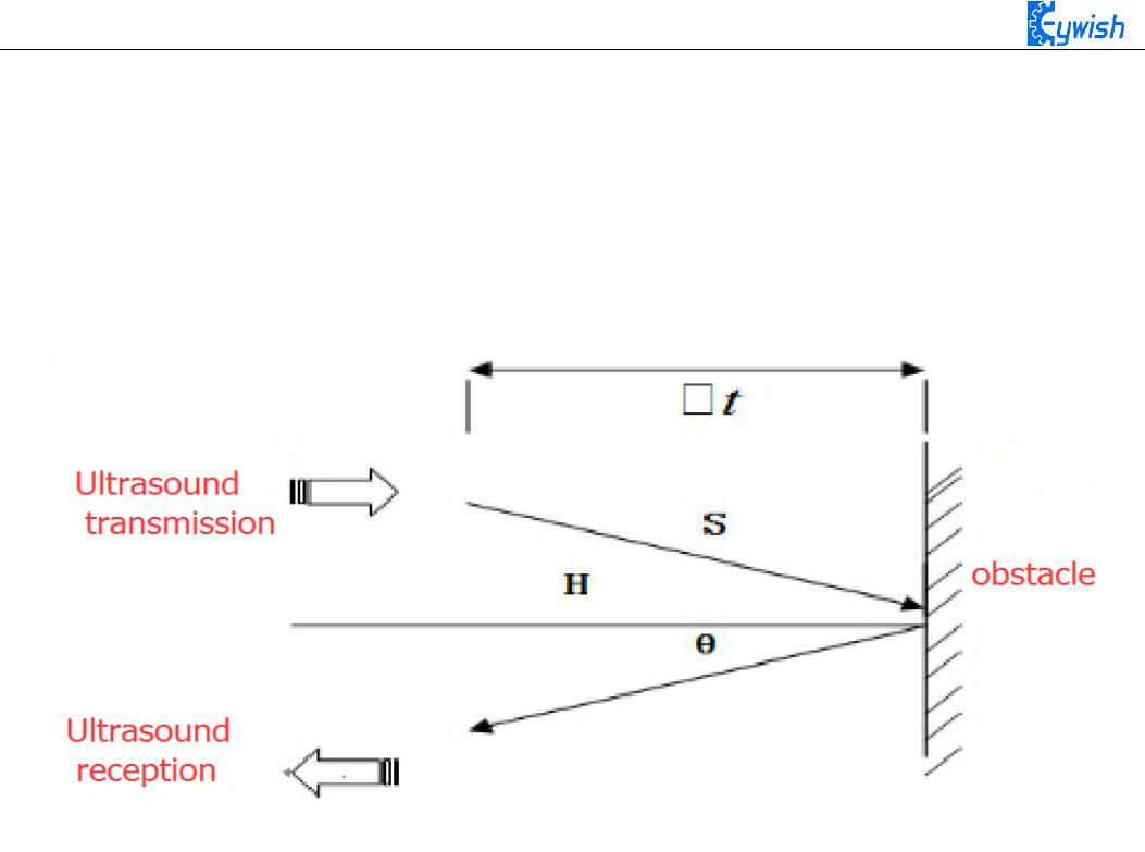
71
receiving time interval of the ultrasonic, which can be recorded with the time counter, and don't forget to
divided it with 2.
The ultrasonic is a sound wave which will be influenced by temperature. If the temperature changes
little, it can be approximately considered that the ultrasonic velocity is almost unchanged in the transmission
process. If the required accuracy of measurement is very high, the measurement results should be to
corrected with the temperature compensation. Once the velocity is determined, the distance can be obtained.
This is the basic principle of ultrasonic distance measurement module,which is shown in Fig.3.2.29:
Fig.3.2.29 the Principle of Ultrasonic Distance Measurement Module
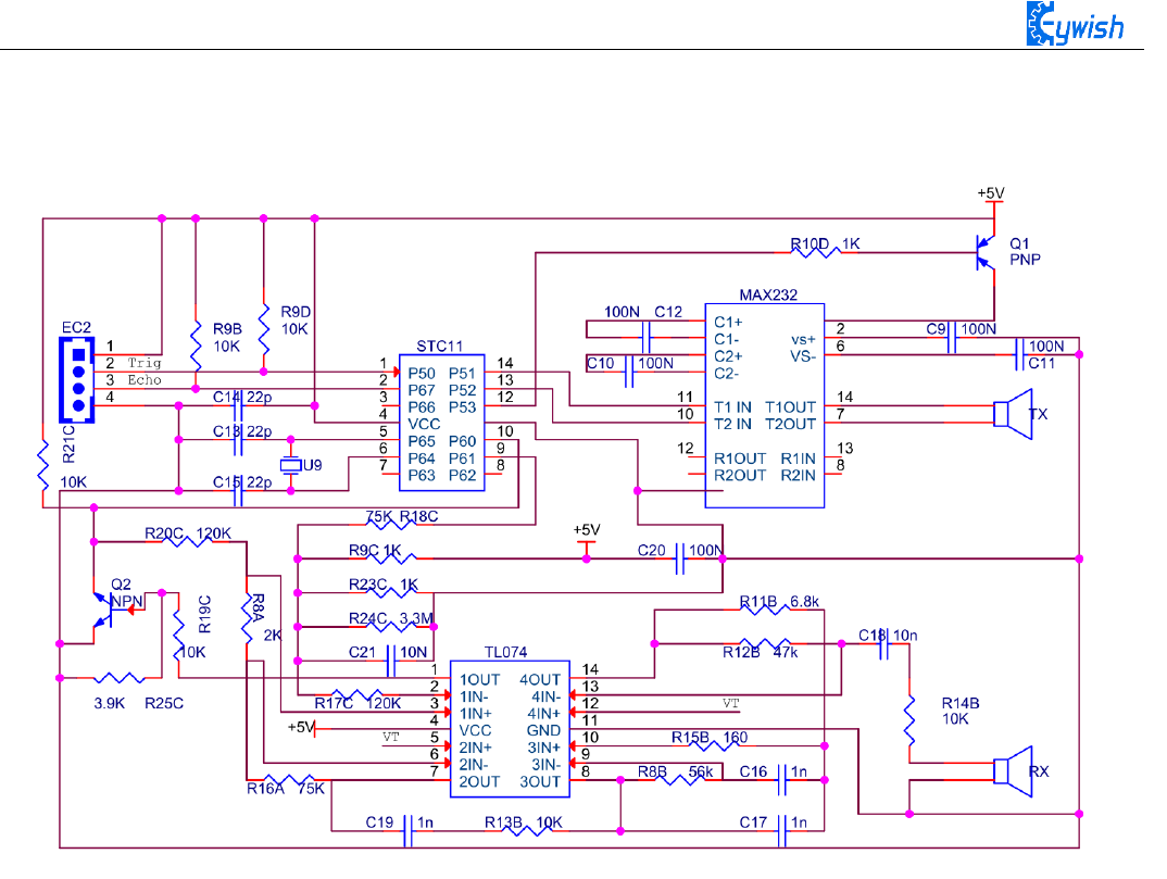
The ultrasonic is mainly divided into two parts, one is the transmitting circuit and the other is the
receiving circuit, as shown in Fig.3.2.30. The transmitting circuit is mainly composed of by the inverter
74LS04 and ultrasonic transducer T40, the first 40kHz square wave from the Arduino port is transmitted
through the reverser to the one electrode on the ultrasonic transducer, the second wave is transmitted to the
another electrode on ultrasonic transducer, this will enhance the ultrasonic emission intensity. The output
end adopts two parallel inverters in order to improve the driving ability. the resistance R1 and R2 on the one
hand can improve the drive ability of the 74LS04 outputting high level, on the other hand, it can increase the
damping effect of the ultrasonic transducer and shorten the free oscillation time.
The receiving circuit is composed of the ultrasonic sensor, two-stage amplifier circuit and a PLL
circuit. The reflected signal received by the ultrasonic sensor is very weak, which can be and amplified by
the two-stage amplifier. PLL circuit will send the interrupt request to the microcontroller when receiving the
signal with required frequency. The center frequency of internal VCO in the PLL LM567 is
, the locking bandwidth is associated with C3. Because the transmitted ultrasonic
frequency is 40kHz, the center frequency of the PLL is 40kHz, which only respond to the frequency of the
signal, so that the interference of other frequency signals can be avoided.
The ultrasonic sensor will send the received the signal to the two stage amplifier, the amplified signal
will be sent into the PLL for demodulation, if the frequency is 40kHz, then the 8 pin will send a low level
)211.1/(1
0CRf P
=
72
interrupt request signal to the microcontroller P3.3, the Arduino will stop the time counter when detecting
low level.
Fig.3.2.30 Schematic Diagram of Ultrasonic Transmitting and Receiving
3.2.4.4 Experimental Procedures
1, Installing the steering gear, ultrasonic module to the car which has been completed in fourth step to the
seventh step in 3.1.2) as shown in Fig.3.2.31.
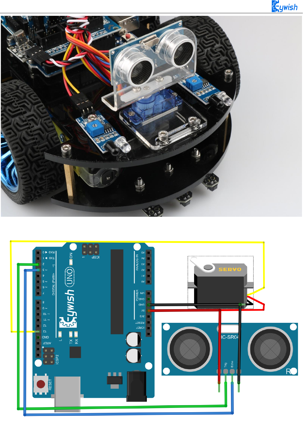
2. Connecting the steering gear and ultrasonic module to the Arduino motherboard as shown in
Fig.3.2.32.(you can choose other IO ports according to your own ideas).
73
Fig.3.2.31 Installation Diagram of the Steering Gear and Ultrasonic Module
Fig.3.2.32 Wiring of the Steering Gear and Ultrasonic Module

74
3.2.4.5 Software Design
1. Diagram of the program
2. Introduction of the program
#include <Servo.h>/* In this section, we use the steering gear, so we need to call the
steering gear library file. As for what is in the library file, we will not study it.
Interested friends can drive for research. We have put this library files on the CD-
ROM, we need to copy this folder to the Arduino IDE installation path "libraries"
folder, otherwise the program can not compile. * /
Servo head;
int E1 = 5; //PWMA
int M1 = 9; //DIRA****************************************left
int E2 = 6; //PWMB
int M2 = 10; //DIRB****************************************right
/* Define 4 motor control terminals, connected to IN1-IN4 on the motor drive board. * /
const int TrigPin = 2;
const int EchoPin = 3; /* Define the sensor's 2 control pins to connect to pins 2 and 3
on the Arduino. * /
float da;
float dl;
float dr; / * Define three variables, used to store the servo at 0,90,180 degrees, the
value collected by the ultrasonic module, da is the value collected by the ultrasonic
90 degrees servo, dl is the steering servo 180 degrees ultrasonic acquisition To the
value, at this point the steering gear has turned to the left of the car. da for the
servo 0 degrees ultrasonic collected value, then the steering gear has turned to the
right side of the car. * /
void setup()
{
Serial.begin(9600); / * Set the baud rate to 9600, use "Serial Monitor" to check the
data during debugging * /
head.attach(13); / * Define the control pin of the servo as pin 13* /
pinMode(E2, OUTPUT);
pinMode(E1, OUTPUT);
pinMode(M1, OUTPUT);
pinMode(M2, OUTPUT);
pinMode(TrigPin, OUTPUT);
pinMode(EchoPin, INPUT); / * Define two ultrasonic working mode. * /

75
head.write(90); / * The servos swivel to 90 (center) during initialization, because
some servos may have errors, so they are not necessarily centered at 90 degrees, so be
fine-tuned where the servos are centered at 90 degrees. * /
delay(1000);
}
void loop()
{
analogWrite(TrigPin, 0); // Low high and low send a short pulse to TrigPin)
delayMicroseconds(2);
analogWrite(TrigPin, 255);
delayMicroseconds(10);
analogWrite(TrigPin, 0);
da = pulseIn(EchoPin, HIGH) / 58.0; // Convert the echo time to cm
if (da >= 50 && da <= 2000) / * Judge the collected value, da> = 50 && da <= 2000,
meaning that when the distance between the current obstacle and the car is greater than
or equal to 50, and less than or equal to 2000cm, execute the following program in {} *
/
{
int val=150; / * When the straight line has a PWM value of 150, if the value is too
high, the speed of the car will be very fast, which may lead to the car can not hit the
obstacle in time when it encounters the obstacle. * / digitalWrite(M1,0);
analogWrite(E1, val); //the speed value of motorA is val
digitalWrite(M2,0);
analogWrite(E2, val); //the speed value of motorB is val
Serial.print("Distance = ");
Serial.print(da);
Serial.print(" ");
Serial.println("Moving advance 50");
delay(500); / * If the distance is more than 50cm, move forward and output "Moving
advance 50", indicating that the obstacle is more than 50cm from the car
}
if (da <40 && da >30) / * Judge the collected value, da <50 && da> 30, meaning that
when the distance between the frontal obstacle and the car is greater than 30, and less
than 40cm, execute the following program in {} * /
{
int val=130;

76
digitalWrite(M1,0);
analogWrite(E1, val); //the speed value of motorA is val
digitalWrite(M2,0);
analogWrite(E2, val); //the speed value of motorB is val
Serial.print("Distance = ");
Serial.print(da);
Serial.print(" ");
Serial.println("Moving advance40");
delay(500); / * If the distance is more than 40cm, move forward and output "Moving
advance 40", indicating that the obstacle is more than 40cm from the car
}
else if (da <= 20) / * The collected value is judged, da <= 20, meaning that when
the current obstacle and the car is less than 20cm, execute the following program in
{}, the distance between the car and the obstacle has exceeded the safety value, So the
car stopped forward * /
{
int val=0;
digitalWrite(M1,0);
analogWrite(E1, val); //the speed value of motorA is 0
digitalWrite(M2,0);
analogWrite(E2, val); //the speed value of motorB is 0
Serial.print("Distance = ");
Serial.print(da);
Serial.print(" ");
Serial.println("Stopped");// If the distance is less than 20cm, the car will stop
and output "Stopped"
delay(500);
head.write(180); / * Servo rotated 90 degrees from the original to 180 degrees, the
left side of the car * /
delay(1000);
analogWrite(TrigPin, 0); // Low high and low send a short pulse to TrigPin
delayMicroseconds(2);
analogWrite(TrigPin, 255);
delayMicroseconds(10);
analogWrite(TrigPin, 0);
dl = pulseIn(EchoPin, HIGH) / 58.0; // Convert the echo time to cm
Serial.print("Left distance = ");

77
Serial.print(dl);
Serial.print(" "); / * Ultrasonic acquisition of the left side of the car and
obstacles distance, and then assigned to dl, then print on the "Serial Monitor" * /
head.write(0); / * Servo steering from the original 180 degrees to 0 degrees, the
right side of the car * /
delay(1000);
analogWrite(TrigPin, 0); // Low high and low send a short pulse to TrigPin
delayMicroseconds(2);
analogWrite(TrigPin, 255);
delayMicroseconds(10);
analogWrite(TrigPin, 0);
dr = pulseIn(EchoPin, HIGH) / 58.0; // Convert the echo time to cm
Serial.print("Right distance = ");
Serial.print(dr);
Serial.print(" ");
Serial.println();/*Ultrasonic acquisition of the distance between the right side of
the car and the obstacle, and then assigned to dr, and then print the distance on the
"Serial Monitor" * /
head.write(80); // head steering back, that is, when the initialization 80
degrees position
if (dl >= 20 && dl <= 1000 && dl > dr)
{
digitalWrite(M1,0);
analogWrite(E1, 180); //the speed value of motorA is 180
digitalWrite(M2,180); //the speed value of motorB is 180
analogWrite(E2, 0);
Serial.println("Turning left1");
delay(200); // determine the left and right distance if the left is larger
than the left
}
else if (dl >= 1000)
{
digitalWrite(M1,180); //the speed value of motorA is 180
analogWrite(E1, 0);
digitalWrite(M2,0);
analogWrite(E2, 180); //the speed value of motorB is 180
Serial.println("Turning right1");
delay(200);

78
// Special case If the left return distance is greater than 1000, the probe is
blocked and turn right at this moment
}
else if (dr >= 20 && dr <= 1000 && dr > dl)
{
digitalWrite(M1,180); //the speed value of motorA is 180
analogWrite(E1, 0);
digitalWrite(M2,0);
analogWrite(E2, 180); //the speed value of motorB is 180
Serial.println("Turning right2");
delay(200); // Judge about the distance if the right side then turn right
}
else if (dr >= 1000)
{
digitalWrite(M1,0);
analogWrite(E1, 180); //the speed value of motorA is 180
digitalWrite(M2,180); //the speed value of motorB is 180
analogWrite(E2, 0);
Serial.println("Turning left2");
delay(200);
// Special case If the return distance on the right is more than 1000, then the
probe is blocked and turn left at this moment
}
else if (dr <= 20 && dl <= 20)
{
digitalWrite(M1,255); //the speed value of motorA is 255
analogWrite(E1, 0);
digitalWrite(M2,0);
analogWrite(E2, 255); //the speed value of motorB is 255
Serial.println("Turning around");
delay(700);
// turn around if both sides are less than 20cm in distance
}
}
}
In front the sections, we focus on the "automatic driving", and they are obstacle avoidance experiments.
We didn't seem to have relationship with the car, it is lack of fun. So in the next few sections, we will
develop the car from other aspects to make sure that we are able to control the car personally, then we will
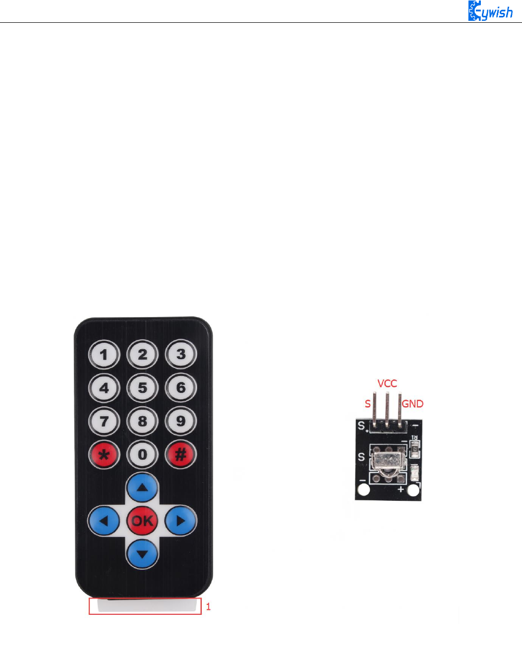
79
start from the "infrared remote control", followed by "2.4G handle remote control" and the last is "mobile
phone Bluetooth control".
3.2.5 Infrared Remote Control
3.2.5.1 Suite Introduction
Infrared remote control is widely used in every field which is known to everyone, since it can control
other electrical appliances, naturally it can control the Hummer-Bot car. Let us take a look at the infrared
remote control first:
Infrared wireless remote control kit includes Mini ultra-thin infrared remote controller and 38KHz
infrared receiving module, the remote controller has 17 function keys, the transmission distance is up to 8
meters which is very suitable for controlling equipment indoor. The infrared receiving module can receive
38KHz modulation remote control signal. Through the Arduino programming, the decoding operation of the
remote control signal can be realized so as to produce all kinds of remote control robot and interactive
works. The suite is shown in Fig.3.2.33.
Fig.3.2.33 Physical Map of Remote Control Suite
Infrared remotecontrol system is mainly divided into modulation, transmitting and receiving parts. The
transmitting part is mainly composed of keyboard, remote control specific integrated circuit, exciter and
infrared light emitting diode. The integrated circuit is the core part of the launch system which consists
internal oscillation circuit, timing circuit, scanning signal generator, key input encoder, instruction decoder,
user code converter, digital modulation circuit and buffer amplifier and so on. It can produce a key scanning
pulse signal, translate the key code, then obtain remote control commands of the keys by telecommand
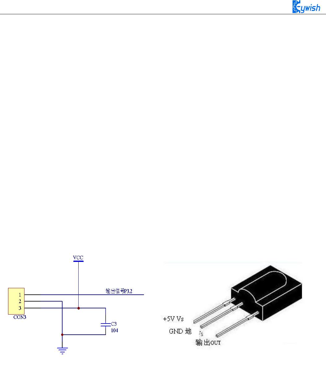
80
encoder (remote control encoding pulse). Through pulse amplitude modulation of the 38KHZ carrier signal,
the infrared diode can transmit infrared remote control signal.
In the infrared receiver, photoelectric converter (usually a photodiode or photoelectric triode, here we
use PIN photodiode) converts the received infrared light instruction signal into a corresponding electrical
signal. The received signal is very weak and interference is particularly large, in order to achieve the
accurate detection and signal conversion, in addition to the infrared photoelectric conversion device with
high performance, choosing the reasonable circuit design with good performance is also required. The most
common photoelectric conversion device is a photodiode. When the photosensitive surface of the PN
junction is irradiated by light, the semiconductor material of PN junction absorbs light energy and converts
the light energy into electric energy. When the reverse voltage is added to the photodiode, the reverse
current in the diode will change with the change of the incident light intensity. The larger the radiation
intensity is, the larger the reverse current will be, the reverse current of the photoelectric varies with the
incident light pulse.
In the Hummer-Bot car, the integrated infrared receiving head has three pins, including the power
supply pin, grounding and signal output pin. The circuit is shown in Fig.3.2.34. Ceramic capacitors is a
decoupling capacitor which can filter the output signal interference. The 1 end is the output of the
demodulation signal,which is directly connected to the number 2 port on the Arduino. When the infrared
coded signal is transmitted, it will be processed by the infrared joint, then outputs the square wave signal,
and directly supplied to the Arduino, and the corresponding operation is carried out to control the motor.
Fig.3.2.34 Circuit Diagram and Physical Map of Infrared Receiving Head
3.2.5.3 Working Principle
The remote control system in general composed of the remote controller (transmitter), and receiver,
when you press any button on the remote control, it will generate the corresponding encoding pulse,and
output various control pulse signals based on the infrared, infrared monitor diode sends the signal to the the
amplifier and the pulse amplitude limiter, the limiter controls the pulse amplitude at a certain level,
regardless of the distance of infrared transmitter and receiver. AC signal enters the band-pass filter which
can pass the 30KHZ to the load wave 60KHZ, and enters the comparator through the demodulation circuit.
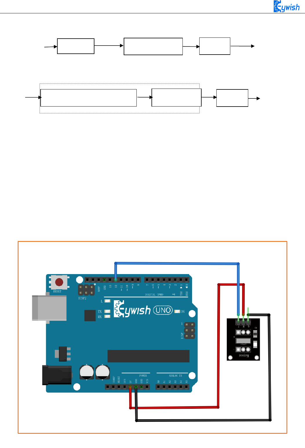
81
The comparator outputs high or low level and restores the output signal waveform. The system procedure
diagram is shown in Fig.3.2.35.
3.2.5.4 Experimental Procedures
1, Installing the infrared receiving head on the development board (if it has been installed in the the eighth
step in "3.1.2", please ignore. The complete installation is shown in Fig.3.1.26.
2, Referring to Fig.3.2.36 and connecting the infrared receiving module to the Arduino board (you can
choose other IO ports according to your own ideas)
Note: Do not reverse power line, otherwise the receiving head will burn up.
Fig.3.1.36 Infrared Module Connection Diagram
Keyboard
Code Modulation
LED
Light/electronic Amplification
Demodulation
Decode
Remote Control Receiver
Fig.3.2.35 Remote Control System Diagram
Remote Control Transmitter
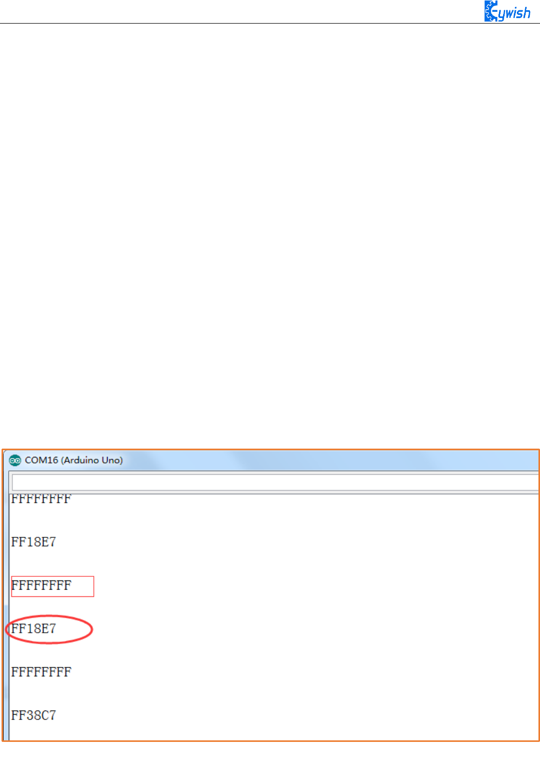
82
3, Copying the following program to IDE (you can also directly open the matching program in the CD), and
downloading to the development board, pulled out the transparent plastic sheet marked as "1" in the
Fig.3.2.33. Then opening the serial port monitor, observing and recording the values on it while pressing
keys on the remote control towards the receiving head as shown in Fig.3.2.37.
#include <IRremote.h>
int RECV_PIN = 12; // Define the IR receiver pin to be 12
IRrecv irrecv(RECV_PIN);
decode_results results;
void setup()
{
Serial.begin(9600);
irrecv.enableIRIn(); // Initialize the infrared receiver
}
void loop() {
if (irrecv.decode(&results))
{
Serial.println(results.value, HEX); // Output the receive code in hexadecimal
Serial.println();// Add a blank line for easy viewing of the output
irrecv.resume(); // Receive the next value }
}
Fig.3.2.37 Remote Encoding Query

83
In Fig.3.2.37, we can see the two value "FFFFFFFF" and "FF18E7", "FF18E7" is the code of a key on
the remote control, "FFFFFFFF" means that the code has been received, waiting to receive the next code.
3.2.5.5 Software Design
#include <IRremote.h>*/ In this section, we use infrared remote control, so we need to
call the corresponding library file, as for what is in the library file, we will not
study, and interested friends can drive research. We have put this library files on the
CD-ROM, we need to copy this folder to the Arduino IDE installation path "libraries"
folder, otherwise the program can not compile. * /
int E1 = 5; //PWMA
int M1 = 9; //DIRA****************************************left
int E2 = 6; //PWMB
int M2 = 10; //DIRB****************************************right
int RECV_PIN = 12;
long expedite1 = 0xFF6897; / * Define a long integer expedite1 variable, and assign
this variable 0xFF689, FF689 is the infrared remote control button encoding * /
long expedite2 = 0xFFB04F;
long advence = 0xFF18E7;
long back = 0xFF4AB5;
long stop = 0xFF38C7;
long left = 0xFF10EF;
long right = 0xFF5AA5;
IRrecv irrecv(RECV_PIN);
decode_results results;
void setup()
{
Serial.begin(9600);
irrecv.enableIRIn(); // Initialize the infrared receiver
}
void loop()
{
if (irrecv.decode(&results)) / * Read the value received by the infrared * / {
if(results.value == advence) / * Judgment on the received value, if this value is
advence, execute the following {} command, here is the forward instruction. * /
{

84
int val=150;
analogWrite (M1,0);
analogWrite(E1, val); //the speed value of motorA is val
analogWrite (M2,0);
analogWrite(E2, val); //the speed value of motorB is val
irrecv.resume(); // Receive the next value
}
if(results.value == expedite1) / * Judgment on the value received, if this value is
expedite1, execute the command in {} below, here is the acceleration 1 command. * /
{
int val=200;
analogWrite (M1,0);
analogWrite(E1, val);//the speed value of motorA is val
analogWrite (M2,0);
analogWrite(E2, val); //the speed value of motorB is val
irrecv.resume();
}
if(results.value == expedite2) / * Judgment on the received value, if the value is
expedite2, execute the command {} below, here for the acceleration 2 command. * /
{
int val=255;
analogWrite (M1,0);
analogWrite(E1, val); //the speed value of motorA is val
analogWrite (M2,0);
analogWrite(E2, val); //the speed value of motorB is val
irrecv.resume();
}
if(results.value == stop) / * To judge the value received, if this value is stop,
execute the command in the following {}, here is the stop instruction. * /
{
int val=0;
analogWrite (M1,0);
analogWrite(E1, val); //the speed value of motorA is val
analogWrite (M2,0);
analogWrite(E2, val);//the speed value of motorB is val
delay(500);
irrecv.resume();
}

85
if(results.value == left) / * Judgment on the received value, if the value is left,
execute the command in the following {}, here is the instruction to the left. * /
{
int val=150;
analogWrite (M1,0);
analogWrite(E1, val); //the speed value of motorA is val
analogWrite (E2,0);
analogWrite(M2, val); //the speed value of motorB is val
delay(500); / * Rotate 500ms to the left and stop, otherwise the car will always
be spinning around. * /
analogWrite (M1,0);
analogWrite(E1, 0); //the speed value of motorA is 0
analogWrite (M2,0);
analogWrite(E2, 0); //the speed value of motorB is 0
analogWrite(A1,180);
irrecv.resume();
}
if(results.value == right) / * Judgment on the received value, if the value is
right, execute the command in the following {}, here is the command to the right. * /
{
int val=150;
analogWrite (E1,0);
analogWrite(M1, val); //the speed value of motorA is val
analogWrite (M2,0);
analogWrite(E2, val); //the speed value of motorA is val
delay(500);
analogWrite (M1,0);
analogWrite(E1, 0); //the speed value of motorA is 0
analogWrite (M2,0);
analogWrite(E2, 0); //the speed value of motorB is 0
analogWrite(A2,180);
irrecv.resume();
}
if(results.value == back) / * Judgment on the received value, if the value is back,
execute the command {} below, here for the back instruction. * /
{
int val=150;
analogWrite (E1,0);
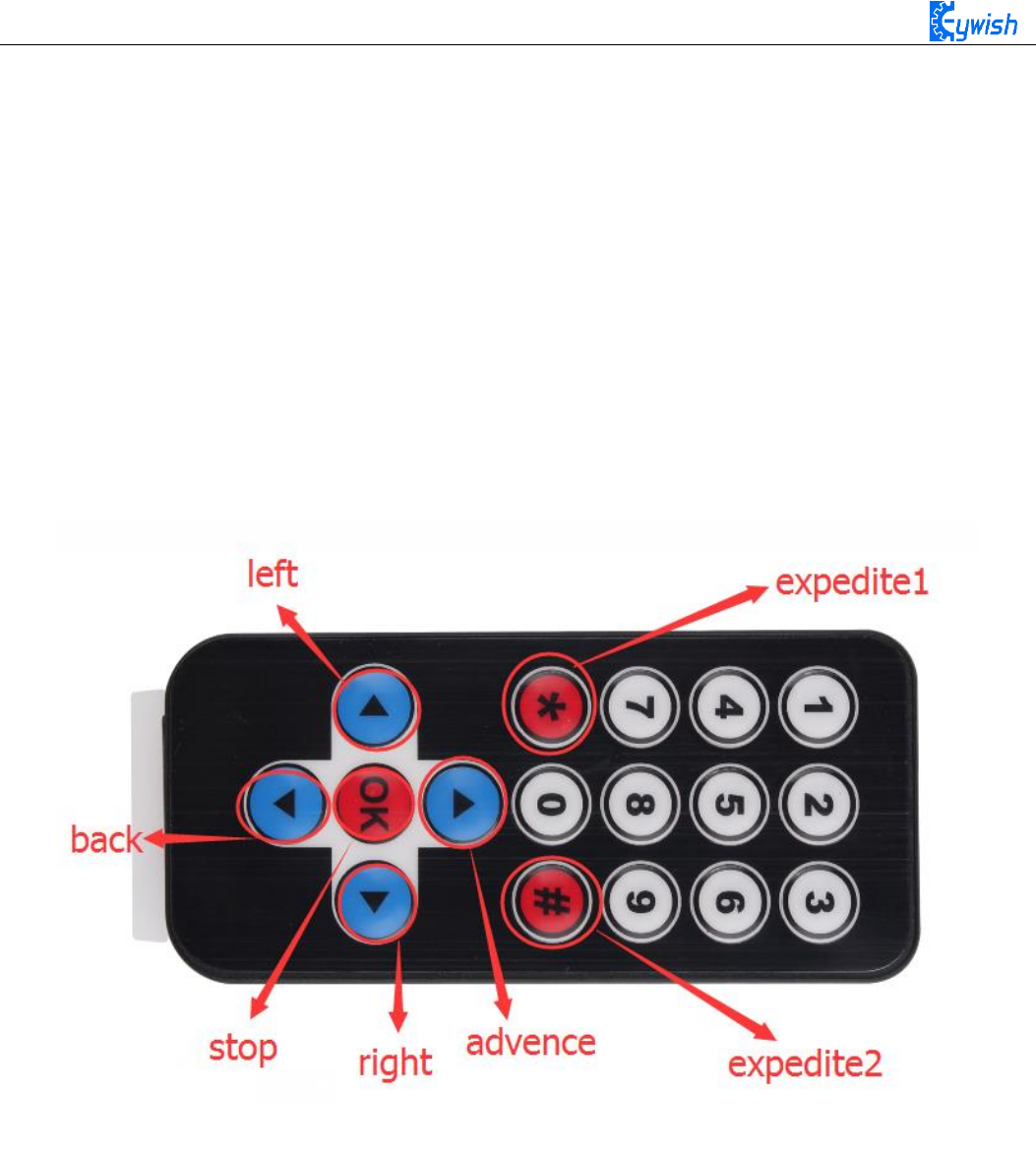
86
analogWrite(M1, val); //the speed value of motorA is val
analogWrite (E2,0);
analogWrite(M2, val); //the speed value of motorA is val
irrecv.resume(); // 接收下一个值
}
Serial.println(results.value, HEX); // Output the receive code in hexadecimal
Serial.println();// Add a blank line for easy viewing of the output
irrecv.resume();
}
}
The above is the infrared remote reference program, you can open it in the CD and download to the
development board, the instructions of remote control in shown in Fig.3.2.38.
Fig.3.2.38. Infrared Remote Control Instructions
3.2.6 PS2 Handle (Optional)
3.2.6.1 Suite Introduction
PS2 handle is SONY game remote control handle, SONY series game host is very popular in the world.
Someone has come up with the idea of the PS2 handle, cracked the communication protocol, so that the
handle can be connected to other devices for remote control, such as remote control of our familiar four
wheeled vehicles and robots. Its outstanding features are cost-effective,rich buttons and easy to extend to
other applications, Fig.3.2.39 shows a commonly used PS2 wireless handle.
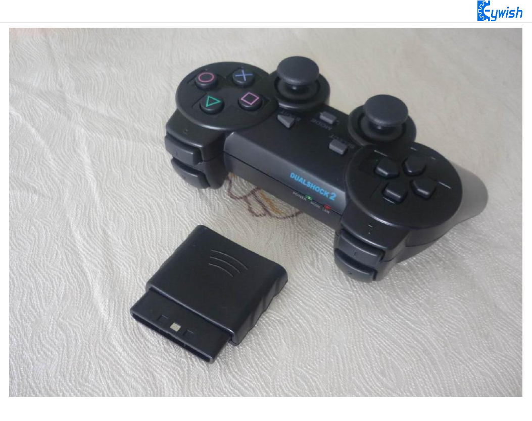
87
Fig.3.2.39 PS2 Wireless Handle
The PS2 handle is composed of the handle and the receiver, the handle uses two AAA batteries as
power supply. The controller and receiver use the same power supply whose voltage range is 3~5V,
overvoltage, reverse connection will cause the receiver to burn out. There is a power switch on the handle,
ON /OFF, when you switch it to ON, the light on handle will not stop flashing until the receiver is searched.
In a certain period of time, if the receiver can not be find, the handle will enter the standby mode and the
light will burn out, you can press "START" button to wake up the handle.
The receiver is powered by the Arduino as shown in Fig.3.2.40, in the absence of pairing, the green
light flashes. When the handle switch is opened, the handle and receiver will pair automatically, and the
light will be always on, and the handle is matched successfully. Button "MODE" (The above logo may be
"ANALOG" in different handles, but it will not affect the usefulness), you can choose "red light mode" or
"green light mode".
Some users see that the handle and receiver cannot match properly! Most of the problems are the
incorrect wiring of the receiver and the program problems.
Solution: The receiver should only be connected with power supply(power line must be connected
correctly), not any data lines and clock lines. The handle light will be always on when pairing is successful.
Then checking whether the wiring and program transplantation are correct again.
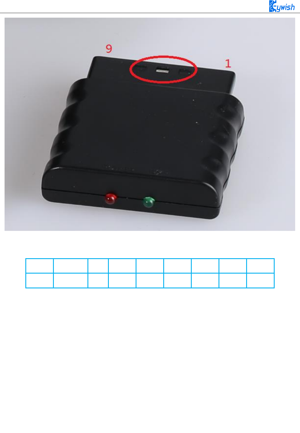
88
Fig.3.2.40 Remote Control Receiver Module
There are 9 interfaces at the end of the receiving head, each of which is shown in the following table:
1
2
3
4
5
6
7
8
9
DI/DAT
DO/CMD
NC
GND
VDD
CS/SEL
CLK
NC
ACK
Note: The appearance of the receiver will be different due to different batches, some with a power light, some
without, but the use and definition of the pins are the same.
DI/DAT: The signal flows from the handle to the host. This signal is a serial 8-bit data which is transmitted
synchronously to the falling edge of the clock. The read of the signal is completed in the process of clock
changing from high to low;
DO/CMD: The signal flows from the host to the handle. The signal is similar to the DI, a serial 8-bit data,
which is transmitted synchronously to the falling edge of the clock;
NC: Empty port; .
GND: Ground;
VDD: The 3~5V power supply;
CS/SEL: Providing trigger signals for handles, the level is low during communication;
CLK: The clock signal is sent by the host to maintain data synchronization;
NC: Empty port;
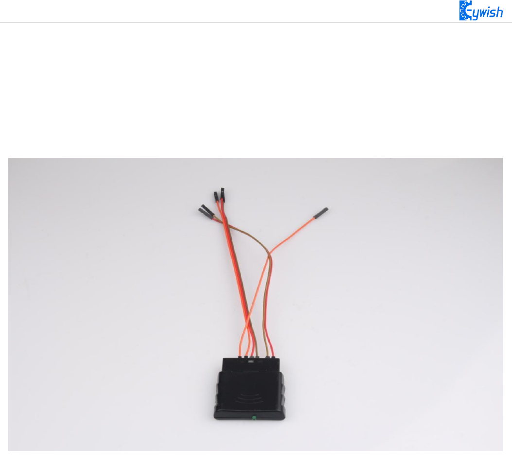
89
ACK: the response signal from the handle to the host. This signal changes to low in the last cycle of each 8-
bit data sending, and the CS remains low. If the CS signal do not remain low, the PS host will try another
device in about 60 microseconds. The ACK port is not used in programming.
3.2.6.4 Experimental Procedures
1, The wires are connected to the 1, 2, 4, 5, 6 and 7 pins of the receiving head respectively as shown in
Fig.3.2.41.
Fig.3.2.41 Wiring of the Receiver Head
2, Fixing the receiving head on the car with cable tie (the red frame area in Fig.3.2.42) as shown in
Fig.2.3.43.
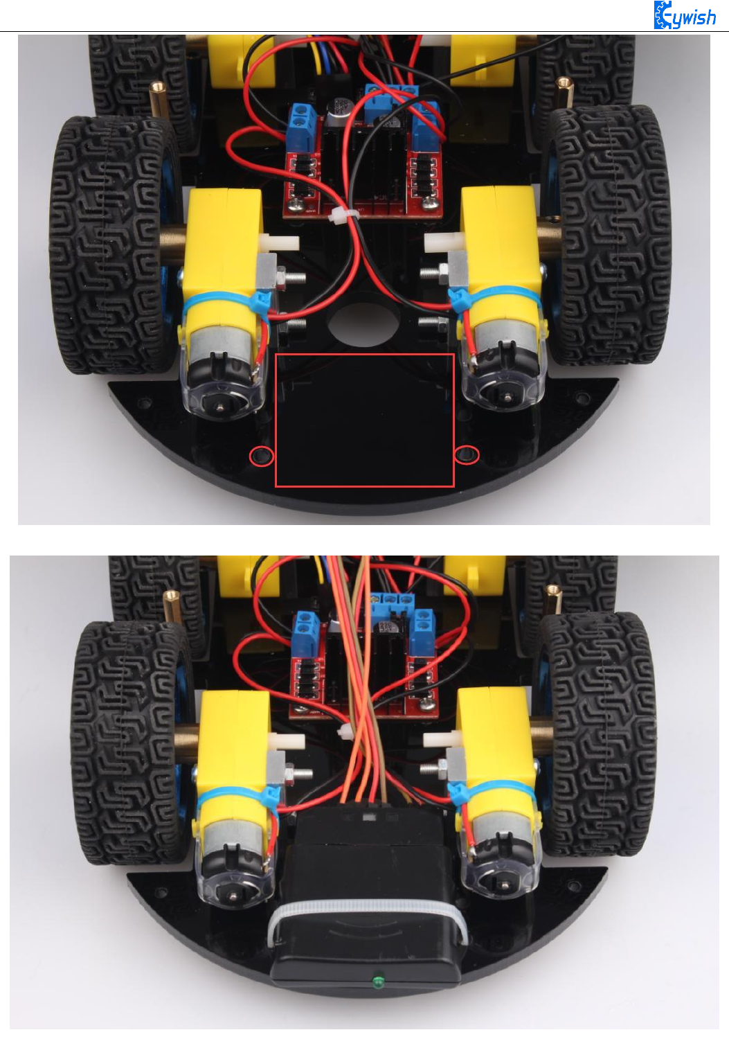
90
Fig.3.2.42 Receiving Head Position
Fig.2.3.43 Installation of Receiving Head
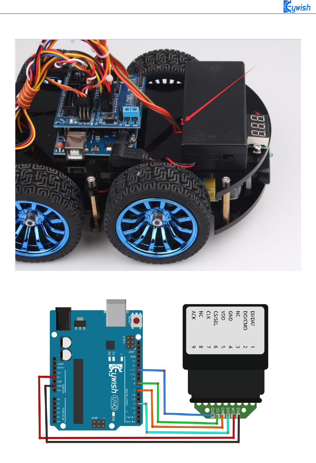
91
3, Drawing the wire according to the hole at "1" in Fig.3.2.44, the connecting the wire to the Aruino
extended board with reference to Fig.2.3.45 as shown in Fig.2.3.44.
Fig.3.2.44 Physical Map of Wiring
Fig.2.3.45 Diagram of Wiring between Arduino and Receiver Head

92
4, Opening the "remote control testing program" in the CD, and copying the library folder (PS2X_lib) to the
"libraries"folder in the Arduino IDE installation path, as shown in Fig.2.4.14, otherwise the compiler cannot
pass. In addition, downloading the program to the Arduino development board, opening the PS2 remote
control, if the receiving head and remote control has been connected (or pairing successfully), the receiver
head indicator will always be on, otherwise the LED lights will flash constantly. Finally, we open the serial
port monitor, press any button on the remote controller, and we can see the corresponding data on the serial
port monitor, such as shown Fig.3.2.45.
Fig.3.2.45 Data Display in Serial Port Monitor
3.2.6.5 Software Design
#include <PS2X_lib.h>/* Copy this file (PS2X_lib) folder to the "libraries" folder
under the Arduino IDE installation path or the program will not compile. * /
int E1 = 5; //PWMA
int M1 = 9; //DIRA****************************************left
int E2 = 6; //PWMB
int M2 = 10; //DIRB****************************************right
PS2X ps2x;
int error = 0;
byte type = 0;
byte vibrate = 0;

93
int vb;
int KK;
void setup()
{
Serial.begin(9600);
error = ps2x.config_gamepad(11,7,8,4, true, true);
/ * Set the receiving port on the Arduino * /
}
void loop()
{
ps2x.read_gamepad(false, vibrate); / * Read the signal received by the receiver * /
if(ps2x.Button(PSB_L3)) / * If the received signal is PSB_L3, execute the command in
{}, ie stop, "PSB_L3" is the code returned when the button on the PS2 handle is
pressed, and through the "fourth step in the experimental step" we can get All key
coding * /
{
int val=0 ;
analogWrite (M1,0);
analogWrite(E1, val); //the speed value of motorA is val
analogWrite (M2,0);
analogWrite(E2, val); //the speed value of motorA is val
}
if(ps2x.Button(PSB_PAD_UP)) / * If the received signal is PSB_PAD_UP, execute the
command in {}, ie forward, "PSB_PAD_UP" is the code returned when the button on the PS2
handle is pressed, and through the "fourth step in the experimental step" we can obtain
All key coding * /
{
int val=180 ;
analogWrite (M1,0);
analogWrite(E1, val); //the speed value of motorA is val
analogWrite (M2,0);
analogWrite(E2, val); //the speed value of motorA is val
}
if(ps2x.Button(PSB_R2)||(ps2x.Button(PSB_PAD_RIGHT)))
/ * If the received signal is PSB_R2 or PSB_PAD_RIGHT, execute the command in {}, ie,
turn right. The reason why two codes are used here is because we have set two buttons
on the PS2 handle for turning right, Just press one of them to complete the right turn
"PSB_R2 and PSB_PAD_RIGHT" is the code that is returned when the button on the PS2

94
handle is pressed. Through the "fourth step in the experimental step" we can get the
code of all the buttons * /
{
int val=200;
analogWrite (E1,0);
analogWrite(M1, val); //the speed value of motorA is val
analogWrite (M2,0);
analogWrite(E2, val); //the speed value of motorA is val
delay(200); analogWrite (M1,0);
analogWrite(E1, 0);
analogWrite (M2,0);
analogWrite(E2, 0);
}
if(ps2x.Button(PSB_L2)||(ps2x.Button(PSB_PAD_LEFT)))
/ * If the received signal is PSB_L2 or PSB_PAD_LEFT, execute the command in {}, ie
turn left. The reason why two codes are used here is because we have set two keys on
the PS2 handle for turning left, Just press one of them to complete the turn left * /
{
int val=200;
analogWrite (M1,0);
analogWrite(E1, val); //the speed value of motorA is val
analogWrite (E2,0);
analogWrite(M2, val); //the speed value of motorA is val
delay(200); analogWrite (M1,0);
analogWrite(E1, 0);
analogWrite (M2,0);
analogWrite(E2, 0);
}
if(ps2x.Button(PSB_PAD_DOWN)) / * If the received signal is PSB_PAD_DOWN, execute the
command in {} to stop. * /
{
int val=180;
analogWrite (E1,0);
analogWrite(M1, val); //the speed value of motorA is val
analogWrite (E2,0);
analogWrite(M2, val); //the speed value of motorA is val
}

95
if(ps2x.Button(PSB_L1)) / * If the received signal is PSB_L1, execute the command in
{}. * /
{
vb = ps2x.Analog(PSS_LY); / * Read the value of PSS_LY, that is, the joystick value,
and assign this value to the variable vb. The joystick range is 0-255. When you press
L1, you can toggle the joystick to generate the corresponding value. If L1 is not
pressed, dial rocker will not produce the corresponding value. Because PWM is also 0-
255, so we directly convert the value generated by the joystick into PWM, so as to
control the motor speed. Experimental results are: Press the L1, dial the left rocker,
the car can be accelerated or slowed down in the process of progress. * /
analogWrite (M1,0);
analogWrite(E1, vb); //the speed value of motorA is vb
analogWrite (M2,0);
analogWrite(E2, vb); //the speed value of motorB is vb
}
if(ps2x.Button(PSB_R1)) / * If the received signal is PSB_R1, execute the command in
{}. * /
{
KK = ps2x.Analog(PSS_RY); / * Read the value of PSS_RY, ie the joystick value, and
assign this value to the variable kk. The joystick range is 0-255. When you press R1,
you can toggle the joystick to generate the corresponding value. If R1 is not pressed,
dial rocker will not produce the corresponding value. Because PWM is also 0-255, so we
directly convert the value generated by the joystick into PWM, so as to control the
motor speed. The experimental result is: press R1, dial the right joystick, the car can
be accelerated or decelerated in the process of receding. * /
analogWrite(M1,KK); //the speed value of motorA is kk
analogWrite(E1, 0);
analogWrite(M2,KK); //the speed value of motorA is kk
analogWrite(E2,0);
}
delay(50);
}
In the above program, we used a lot of buttons, but they are all showed in code form and no details to
any keys. Now we will know about these buttons, if you download the above program directly to the
development board, you can control the car with PS2 handle in accordance with the instructions below as
shown in Fig.3.2.46. Of course, we encourage users to write programs, set keys according to their own ideas,
so the development of the car will be very meaningful.
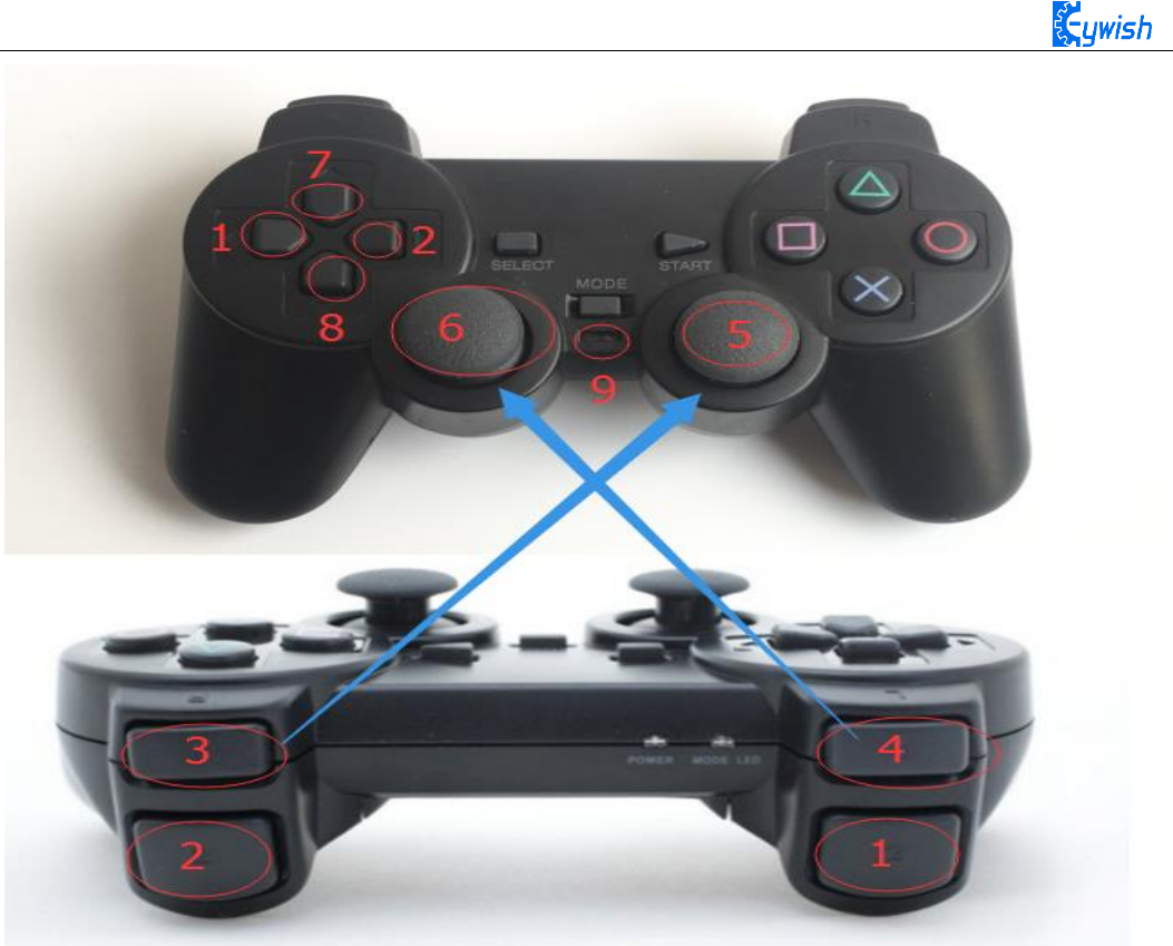
96
Fig.3.2.46 Functions of PS2 Handle Buttons
PS2 handle description:
Mark 1: turn left
Mark 2: turn right
Mark 3: right joystick (Mark 5) control key. When the R1 is pressed, the right joystick will work.
Mark 4: left joystick (Mark 6) control key. When L1 is pressed, the left joystick will work.
Mark 5: right joystick
Mark 6: left joystick
Mark 7: move forward
Mark 8: move backward
Mark 9: power switch (if you do not use the handle, the power switch should be turned off as soon as
possible to prevent the handle from sleep state)

97
3.2.7 Mobile Phone Bluetooth Control
3.2.7.1 Suite Introduction
Bluetooth is a wireless technology standard that enables short distance data exchange between fixed
devices, mobile devices and building personal domain networks (using 2.4~2.485GHz ISM band UHF radio
waves). Bluetooth technology was originally created by Ericsson in 1994 as an alternative to the RS232 data
cable. It is the best choice of wireless transmission which has been applied to all walks of life now.
Bluetooth module is mainly to realize the data transmission between host computer and slave computer,
there are two kinds of communication methods, one is parallel communication, the other is serial
communication.
Transmitting the data of each unit simultaneously is called parallel communication. Parallel
communication of Arduino relies on parallel I/O. The biggest advantage of parallel communication is the
fast speed of information transmission. The disadvantage is that every bit of the unit information needs a
signal line. Therefore, parallel communication wastes materials.
Transmitting the data of each unit bit by bit is called serial communication. Serial communication can
be realized by serial connection port. The outstanding advantage of serial communication is that only one
pair of transmission lines is needed to transmit information. The disadvantage is that it is slower than
parallel communication.
The design of the data transmission in this section is only for command transmission, the data volume
is not large,so we will use serial communication to realize the wireless communication between host
computer and slave computer, namely MCU serial communication.
Bluetooth module is the most important part of mobile phone Bluetooth control, it has the function of
receiving remote control commands. The selection of Bluetooth module should be based on the design
scheme, there are several hard demands in material selection: the reaction should be sensitive, easy to use,
cost-effective, reliable communication. Through the online information, it is found that HC-05 Bluetooth
module is more suitable for the design requirements, the purchase is also convenient and the effective
distance is wide.
HC-05 Bluetooth wireless communication module has two working modes, one is command response
mode, and the other is automatic connection mode. In the command response mode, the user sends the AT
work instruction to the module to set the control parameters of the module and give the control instructions.
In the automatic connection mode, the module has three working modes, namely the host(Master), the slave
(Slave) and the loop (Loopback) mode. When the work mode is selected, the module will transmit data
automatically according to the setting mode. The working state of the module can be dynamically converted
by adjusting the input level of the external pin of the module. The physical diagram of module is shown in
Fig.3.2.47.
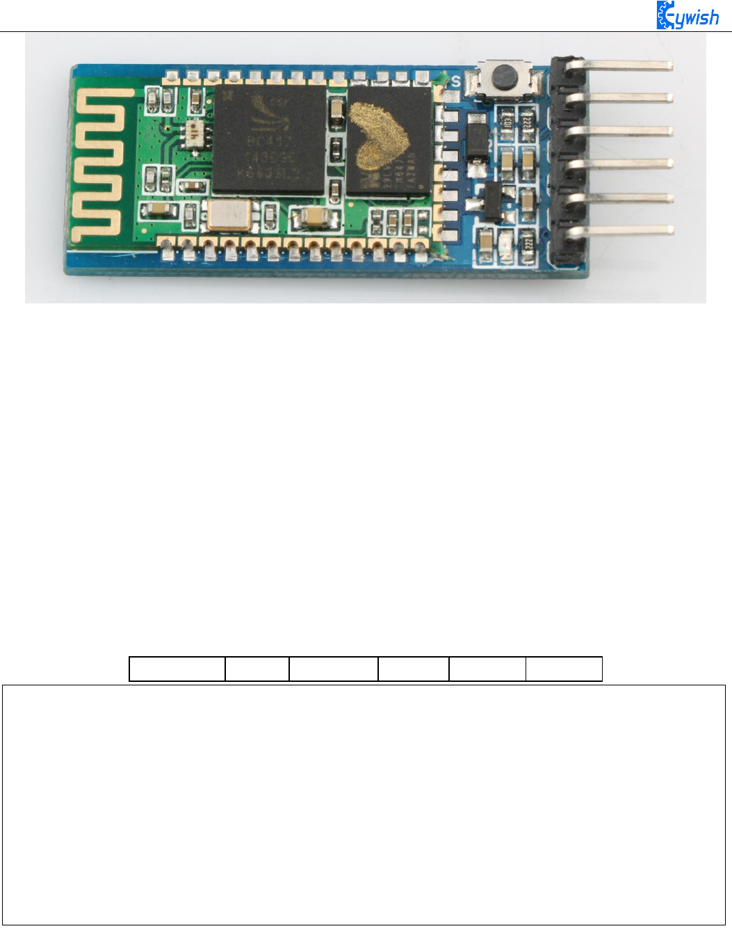
98
Fig.3.2.47 HC-05 Module
3.2.7.2 Bluetooth protocol
Using Bluetooth to control the car means we use the Android app to control the Bluetooth sending
instructions to the Arduino serial port, so as to control the motor's forwarding, reversing, speed and so on.
Since the wireless communication is involved, one of the essential issues is the communication problem
between the two terminals. But there is no common "language" between them, so designing communication
protocols are required to ensure a perfect interaction between Android and Arduino. The main process is: the
Android identification terminal packs the detected commands into the corresponding data packets, and then
sends them to the Bluetooth module (HC-05). When HC-05 receives the packets, it will transmit them to
Arduino through the serial port, then Arduino to analyze the data packets and execute the corresponding
actions. The data format sent by the upper computer end (Android) is as follows, which mainly contains 6
fields, we use a structure to represent it
Start_code
Length
Type
Data
Checksum
Tail
The start_code is the beginning part of the packet, for example, the unification is designated as 0xAA.
The type represents the type of the slave device.
The addr is the address of the controlling device.
The function means the functional types of device which need to control, we are currently supporting the
following functional types
typedef struct
{
unsigned char start_code ; // 8bit 0xAA
unsigned char type;
unsigned char addr;
unsigned short int function; // 16 bit
unsigned char *data; // n bit
unsigned short int sum; // check sum
unsigned char end_code; // 8bit 0x55
}ST_protocol;

99
The data means the specific control value of a car, such as speed, angle.
The checksum is the xor result of each data bit.
The tail is the end part of the packet. When receiving this data, it means that the packet has been sent, the
next packet is ready to be received. We uniformly designate it as 0x55. For example, a complete packet can
be such as "AA 01 01 06 50 00 58 55", in which:
"06" is the "device type", such as motor, LED, buzzer and so on. The 06 here refers to the transmission
speed, and the 05 refers to the transmission direction.
"50 (or 0050)" is the controlling data, 0x50 in hexadecimal is 80 when converted to binary, which means the
speed value is 80. If the data is 05, it means the controlling direction, that is 80 degrees (forward).
"0058" is the check sum, that is, 0x01+0x01+0x06+0x50=0x58.
"55" is the tail of the protocol, indicating the end of data transmission.
typedef enum
{
E_BATTERY = 1,
E_LED = 2,
E_BUZZER = 3,
E_INFO = 4,
E_ROBOT_CONTROL = 5,
E_ROBOT_CONTROL_SPEED = 6,
E_TEMPERATURE = 7,
E_IR_TRACKING = 8,
E_ULTRASONIC = 9,
E_VERSION = 10,
E_UPGRADE = 11,
}E_CONTOROL_FUNC ;
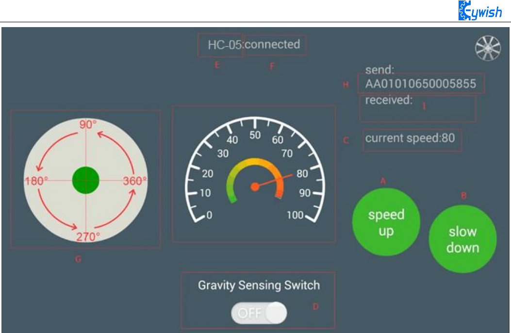
100
Fig.3.2.48 the Interface of Android APP
In the above Figure.3.2.48:
The "A, B" sections are the acceleration and deceleration buttons.
The "C" section includes the dashboard and the digital display area, and the two parts displaying
synchronously. They represents the current speed.
The "D" section is a gravity remote sensing switch which can be switched to the gravity remote sensing
mode.
The "E" section represents the Bluetooth name that is currently connected.
The "F" section indicates Bluetooth connection state. If the Bluetooth is not connected, the "disconnected" is
displayed here.
The "G" section is a manual rocker, and sliding it allows the car to rotate.
The "I" section is a data return area, such as the current state, speed of the car, etc. The "H" section is the
data packet, for example, the data is "AA 01 01 06 23 00 2B 55". At this time, the speed is 35 (23 is 16
hexadecimal data, which means 35 when converted to 10 hexadecimal).
If the transmitted data is "AA 01 01 05 00 5B 00 62 55", it means that the car is moving forward (05 is
the direction control instruction, and the 005B means 91 when converted to binary number. By the
Figure.3.2.48 we can know that 91 degree means the car is moving forward).
3.2.7.3 Experimental Procedures
Connect the Bluetooth module of the wire to "1" marked in Fig.3.2.50 Connection mode: HC-05 VCC port
on Bluetooth module is connected to Arduino 3.6V~6V DC power anode, GND port is connected to the
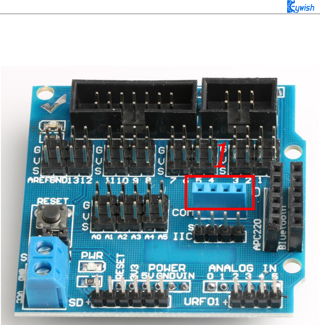
101
cathode of the DC power, the RXD port is connected to the TXD port on Arduino extended board, TXD port
is connected to RXD port on the board, as shown in Fig.3.2.51.
Note: Since Arduino UNO has only one serial port, the Bluetooth must be disconnected from the serial port
when downloading the program, otherwise the download will fail.
Fig.3.2.50 Wiring Positions of Bluetooth
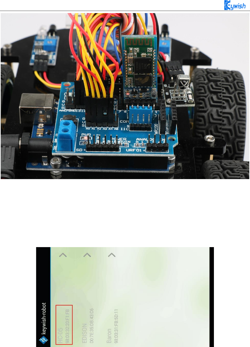
102
Fig.3.2.51 Installation of Bluetooth Module
3, Opening the mobile phone Bluetooth to find the Bluetooth name and connect (default Bluetooth name is
HC-05, password is 1234). When the connection is successful, opening the APP (there is a software for
Android mobile phone in the CD, latter we will launch the IOS version) and selecting Bluetooth name in
APP and connecting as shown in Fig.3.2.52. You will see that the flashing of the Bluetooth module indicator
slows down, if you have downloaded the program to the development board before, you can use the phone
to control the car directly, as shown in Fig.3.2.53.
Fig.3.2.52 Connection of Mobile Phone APP
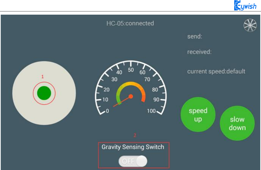
103
Fig.3.2.53. Diagram of APP Control
In Fig.3.2.53, we can see the logo "1" and "2". When the Bluetooth connection is successful, sliding
green dot marked as "1" in any direction, the car will move towards the corresponding direction. Switching
on the gravity sensor marked in "2", the APP is switched to the gravity induction mode, and you can control
the movement direction of the car by shaking the mobile phone.

104
Software Design
#include "protocol.h"
#include "hummerbot.h"
#include "process.h"
int E1 = 5; //PWMA
int M1 = 9; //DIRA --- left
int E2 = 6; //PWMB
int M2 = 10; //DIRB --- right
byte readbuff[32] = {};
int readlen = 0;
ST_protocol recv;
hummerbot hbot(E1,M1,E2,M2,13,A0);
void setup()
{
Serial.begin(9600);
hbot.init();
}
void read_data(void)
{
unsigned char avilable;
byte *p = readbuff ;
memset(p,0,32);
readlen = 0;
while (Serial.available()>0)
{
if(!avilable && Serial.peek()==START_CODE)
{
avilable = 1;
}
if (avilable)
{
if ((*p = Serial.read()) == END_CODE)
{
avilable =0;

105
readlen++;
//Serial.print(*p,HEX);
break;
}
// Serial.print(*p,HEX);
p++;
readlen++;
}
}
// Serial.print("\n");
}
void loop()
{
read_data();
if (!protocol_prase(readbuff,readlen,&recv))
{
switch(recv.function)
{
case E_BATTERY:
break ;
case E_LED:
break;
case E_INFO:
break;
case E_ROBOT_CONTROL:
hbot.drive(protocol_prase_degree(&recv));
break;
case E_ROBOT_CONTROL_SPEED:
hbot.setSpeed(protocol_prase_speed(&recv));
break ;
case E_VERSION:
break;
}
}
}
