HY50002
Hy50003 HY50003 HY50003 pdf hbfile
2014-06-24
: Pdf Hy50002 HY50002 pdf
Open the PDF directly: View PDF ![]() .
.
Page Count: 31
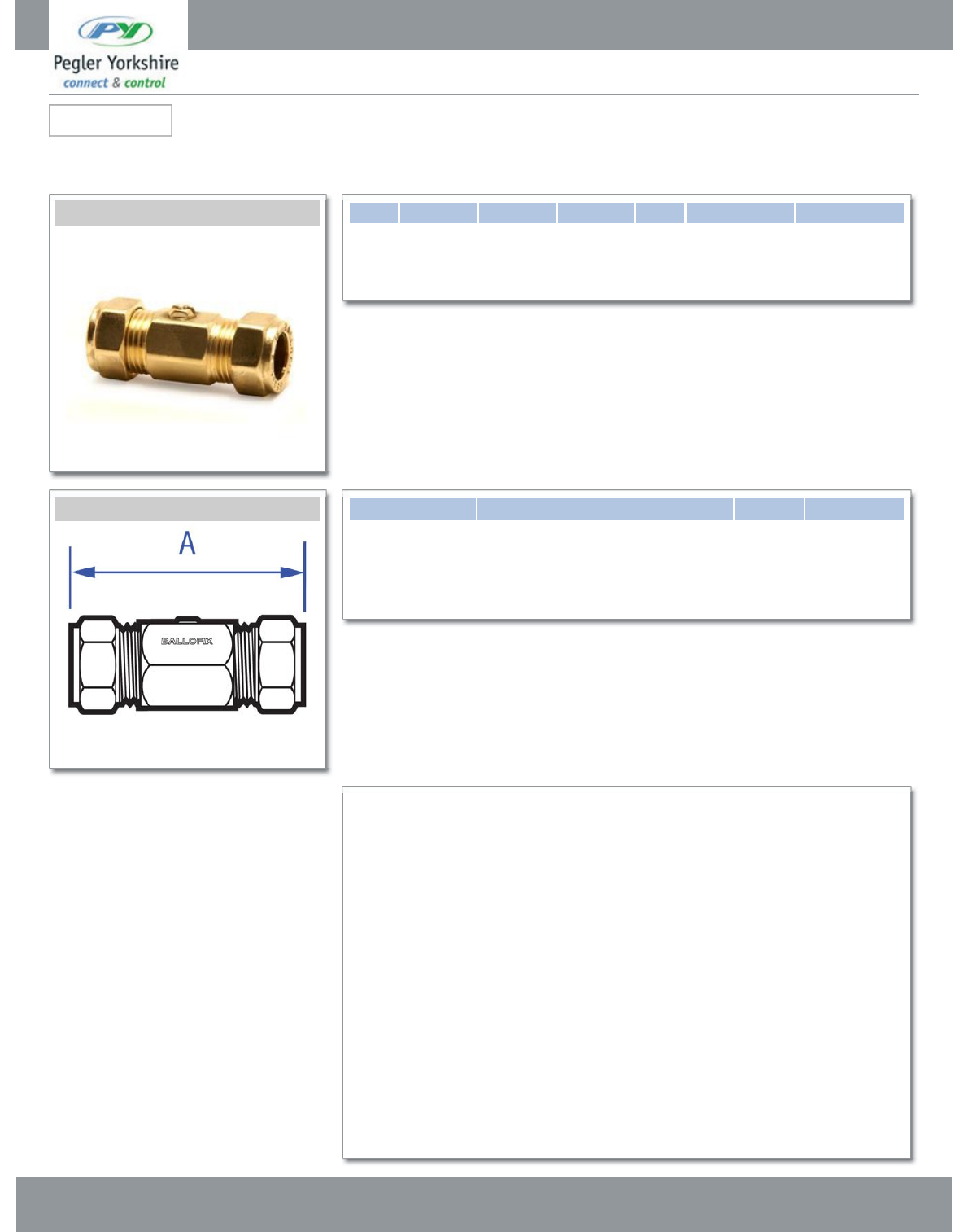
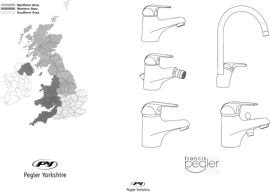
Ballofix isolating ball valve - straight pattern. Compression ends. Screwdriver operation. DZR
brass, plain finish.
CxC Brass Screw Driver Slot Size Pattern No. Pack 1 Qty Pack 2 Qty Code Barcode Price(£)exVAT
15mm 10 100 13540 5708537347081 £12.57
22mm 110 13563 5708537388565 £16.64
28mm 1513575 5708537388572 £59.20
CxC Brass Screw Driver Slot Code Description AKg
13540 15mm 3381YA 41 0.14
13563 22mm 3481YA 57 0.22
13575 28mm 3581YA 65 0.54
Pegler Yorkshire reserve the right to change specifications
5 Year Guarantee
Luxury Taps and Mixers
Pegler Yorkshire Customcare 5 Year Guarantee - Terms and Conditions
Product are subject to a 5 year guarantee that is between Pegler Yorkshire and the final purchaser of the
product.
The guarantee is subject to proof of purchase being supplied.
This guarantee does not affect any statutory rights the consumer may have in law.
The guarantee covers manufacturing or material defects and does not cover parts subject to normal wear
and tear.
Finishes other than chrome are covered for a period of 3 years only and the guarantee on the finish is
subject to the cleaning instructions being followed.
The guarantee is not applicable where the product is fitted contrary to the conditions in the fitting
instructions.
Abusive behaviour and accidental damage to the product are not covered by this guarantee.
The extent of this liability is limited to the cost of the replacement of the defective item and not to fitting or
consequential damages.
Pegler Yorkshire Group Ltd, St Catherine's Ave, Doncaster, S Yorkshire, DN4 8DF
Telephone: Phone +44 (0) 844 243 4400 Fax: +44 (0) 844 243 9870 Website: www.pegleryorkshire.co.uk
Registered office : Pegler Yorkshire Group Ltd, St Catherine's Ave, Doncaster, S Yorkshire, DN4 8DF Company no : 00401507
e x p e r i e n c e d e s I g n i n n o v a t i o n
For further information, please contact your appropriate sales office:
HEAD OFFICE UK
Pegler Limited Northern team:
St Catherines Avenue Tel: 0870 1200281
Doncaster, Fax: 01302 560108
South Yorkshire DN4 8DF
Tel: 01302 560560 Southern team:
Fax: 01302 367661 Tel: 0870 1200282
Fax: 01302 560458
EXPORT Western team:
Tel: 44 (0) 1302 855656 Tel: 0870 1200283
Fax: 44(0) 1302 730513 Fax: 01302 560109
Email:
export@pegler.co.uk
Email: uk.sales@pegler.co.uk
Technical customer care line 0870 1200285
www.pegler.co.uk
Showers are guaranteed for 5 years from the date of purchase. Full
guarantee details are available on request.
You’re Guide to the Installation, Care and maintenance of
Francis Pegler
Paramic
Single Sequential Exposed Thermostatic
Shower
Pegler Limited, St Catherine’s Avenue, Doncaster DN4 8DF
Telephone 01302 560560, Fax 01302 560459
22

Introduction
All Pegler thermostatic showers are designed to ensure a stable showering temperature
during showering even when other outlets in the system are being used e.g. washing
machines. The products will also close down in the event of cold-water failure reducing the
risk of scalding. These products are also designed from rugged engineering materials to
give you years of trouble free service and are backed by the Pegler Customer Promise.
Water Bylaw requirements.
It is important to ensure that the water supplies to your shower are connected in
accordance with the water regulations (WRAS) requirements and good plumbing practice.
It is Pegler’s recommendation and good plumbing practice that the supplies of hot and
cold water to the shower valve should be equal (balanced) pressure in order to provide a
consistent flow. Supplies should be from a commons source, either mains or tank fed. If
supplies are not equal pressures then a Non Return Valve (Pegler 801 Non Return Valve)
should be fitted.
Bylaw 17 (2) B
The shower head of any shower hose pipe should be fitted by a fixed or sliding attachment
so that it can only be discharged at a point not less that 25mm above the spill-over level of
the bath tray or fixed appliance.
Bylaw 30 (2)
Where the shower valve is supplied with hot water from a storage cistern and cold water
from the mains supply pipe a cold storage cistern that complies to bylaw 30 (2) must be
used.
Water Supply Operating Pressures.
Pegler thermostatic shower fittings have been designed to function under the following
conditions:
Maximum static water 5.0 bar
Minimum flowing water pressure 0.1 bar
Optimum operation pressures 1.0 bar
Recommended maximum hot supply temperature 85°C
Recommended minimum hot supply temperature 65°C
Please Note:
• Operating pressure (on hot and cold line) should be kept as balanced as possible in
order to assure maximum efficiency.
• When the supply is higher than 5 Bar a Pressure Reducing Valve should be fitted
before the shower valve. (Pegler PRV-2)
• Ensure all supply pipes are flushed before fitting the valve, as debris will prevent the
shower working to its optimum level.
• To prevent debris damaging the mixers we recommend that you fit the filters
provided.
• Your Pegler thermostatic shower has been designed to give you years of trouble free
showering. However, it may require servicing from time to time to retain optimum
performance. Therefore we recommend the fitting of in-line service valves upstream
of the shower valve to allow for servicing of the shower.
Care & Maintenance
To maintain the surface finishes, simply wipe occasionally with a mild detergent on soft
damp cloth. Dry using soft cloth, never use abrasive cleaners or chemical household
cleaners, and avoid contact with concentrated bleach.
Pegler products are manufactured to the highest standards and should require little or no
maintenance. In the unlikely event of any spare part requirements, please visit our
website: www.pegler.co.uk , contact you’re nearest stockist or the Pegler Technical Office
on telephone 0870 1200285
Customer Reference Data
Date of Purchase………………………………………………………
Supplier…………………………………………………………………
Supplier Tel. No………………………………………………………..
Model Type……………………………………………………………..
Serial No…………………………………………………………………
Installer………………………………………………………………….
Installer Contact Details…………………………………………….
TECHNICAL HELPLINE
Tel: 0870 1200285
Fax: 01302 560537
1
21
This valve performs well without flow limiters although it is recommended that they befitted
for the purpose of economical water usage. The valve can be used in conjunction with
many pumps currently in the market. If you are in doubt of require further information
contact us on 0870 1200285.
With certain permutations of Combi-boiler hot supply and mains supply it may be
necessary to fit the gray 6-litre limiter.
IMPORTANT: It is a requirement of instantaneous electric water heaters that a stable flow
of water passes through the heater. Using a flow stabiliser in the supply to the heater can
satisfy this requirement. It should be adjusted to give a flow temperature if 45-50˚C from
the heater.
MOUNTING – EXPOSED THERMOSTATIC SHOWER:
1. Use the backplate as the template for the fixing holes
2. Drill and plug the wall to suit screws provided.
3. Secure backplate to the wall
4. Plush out pipe work before connecting the valve.
5. Located valve body onto the backplate and lock in position with the 4 grub screws
provided.
6. Please note – Before connecting the inlet pipes you must read “TYPES OF
INSTALLATION” to ensure correct restrictors and filters are fitted.
7. Connect inlet pipes to the valve using the compression fittings on the elbows. Ensure
the two lose flanges are used to cover over the holes in the tiles around the exposed
pipes.
8. Check joints are watertight
9. Push in the four chrome plugs into the body holes.
SHOWER VALVE OPERATION
The handle adjusts temperature only. However, first turning the handle anti-clockwise will
switch on the water to the maximum flow. Further rotation will progressively increase the
temperature to the maximum factory set temperature of 45˚C (temperature measured with
an open outlet) Please note 45˚C with an open outlet is described as water flowing straight
form the valve. No hose or fixed pipe is involved. Once fitted with hose or concealed pipe
work the outlet temperature will be less due to heat lost in its travel.
• For exposed showers we recommend the purchase of Pegler 808 (order code
523007) Any standard sealant may be used on this product in accordance with the
manufactures recommendations.
• Please ensure that you have read and understood all sections of this manual before
installation
Water Bye Laws
The mixing valve should be installed in accordance with the water byelaws. For further
details refer to the latest copy of Water ByeLaws guide or your local water authority.
20
2
General Features
The purchased product is a thermostatic sequential exposed shower valve. The shower
has a single handle, which allows both the control of the temperature and the flow rate.
The cold water is obtained by turning the handle from the off position anti-clockwise
(NOTE: the temperature of the cold water depends on the system and the pre-set
temperature of the shower). By turning the handle both the flow rate and the temperature
will increase.
The maximum temperature has been pre-set under factory conditions at approx. 45˚C this
can be adjusted by following the instructions shown in the section headed REGULATIONS
OF THE MAXIMUM TEMPERATURE.
Read the instructions before installation.
The valve needs to be installed by trained staff.
Subject to correct installation, this mixer is suitable for any water heating system. In case
of instantaneous heaters, hot water flow must meet at least the minimum flow required by
the heater to start and go on burning (see heater specifications).
Technical Data
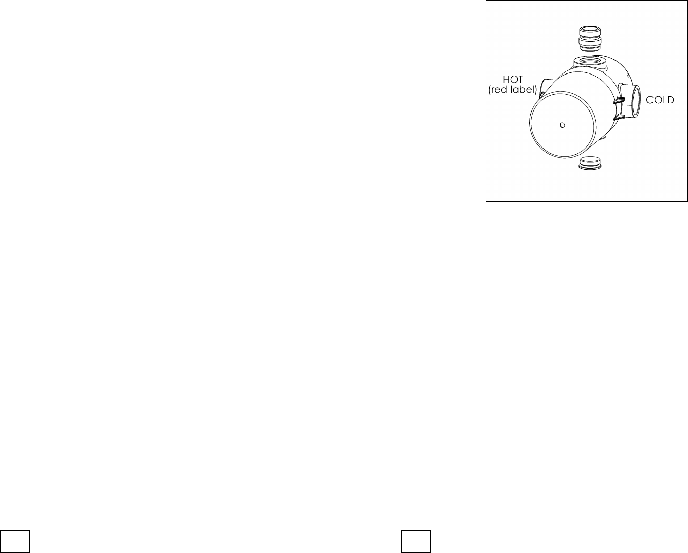
The water supplies are connected to the mixer via two elbows, which include compression
nuts and olives to suit 15mm supply pipes. The inlet cold water is on the right identified
with a red nut.
The temperature setting has been carried out under factory conditions and in accordance
with BS EN 1111.
The connection of the outlet is made by a straight connector provided with olive and nuts
for 15mm pipe. Generally this item has a bottom outlet. BE CAREFUL, it is not possible
to simply rotate the valve body in order to have a upper outlet.
1. If the bottom outlet is required, unscrew the plug clockwise with a 27mm spanner and
the seat with a 12m Allen Key.
SHOWER VALVE SERVICING/MAINTENANCE:
Please note – If your Pegler thermostatic shower fails to operate correctly upon installation
or after a short period of time, the following important points should be checked.
1. Check that the valve has been installed correctly in accordance with its particular feed
system (see TYPES OF INSTALLATION).
2. That the hot water temperature is adequate; the recommended minimum temperature
is 60˚C
3. Isolating the supplies and ensure that the filters are clean and that the check valves
are free to move and are unrestricted (i.e. Hot and Cold water are reaching the valve
body)
COMMON PROBLEMS WITH PUMPED SYSTEMS:
1. Insufficient head pressure or flow to initiate pump (Check for blockages in supply or at
valve inlets)
2. Airlocks within the pump impellers. Any air bubbles formed by hot water will tend to
cling to the top surface of the pipe and dissipate to atmosphere through the vent pipe.
19
3
TROUBLESHOOTING
1) REDUCED FLOW RATE
Cause: The inlet filters of the mixer and/or the cartridge are obstructed.
Solution: Cleaning filters and/or cartridge: refer to “CARTRIDGE CHANGE AND
CLEANING”
Cleaning mixer filters: refer to “FILTER CLEANING”.
2) WRONG SETTING OF THE CARTRIDGE
Causes: The mixer is factory preset at 3 bar and at a temperature of 60-65°C for
hot water and 10-15°C for the cold one correspondin g to a maximum
mixing temperature of 45°C. In every domestic insta llation temperatures
and inlets pressures can differ from those of production.
Solutions: Refer to “REGULATION OF THE MAXIMUM TEMPERATURE”
3) CONTINUOUS TEMPERATURE OSCILLATIONS
Cause: The mixer has been installed with the inverted inlets.
Solution: Close the main water supply Remove the valve body: refer to “FILTER
CLEANING” Rotate the valve body reverse the outlet Re-install the
valve body.
4) INCORRECT WORKING OF THE MIXING
Cause: The filters of the cartridge are dirty
Solution: Refer to the “CARTRIDGE CHANGE AND CLEANING”
2. Re-fix the plugs and seat in required position greasing the O-ring before installation.
PLUMBING RECOMMENDATIONS
• An independent hot and cold water supply is required for the shower system (do not
pipe off ring main) please refer to installation diagrams.
• Large runs of pipe work will cause frictional loss of pressure.
• The recommended pipe work from both cylinder and water tank should be 22mm
minimum for low-pressure systems.
• If more than one shower valve is installed the minimum feed from tank and cylinder
should be 28mm. (Ensure adequate supply of both hot and cold water can be
maintained).
• In installations where a pump is required, install pump before shower mixer inlets.
WATER BYE LAWS
The mixing valve should be installed in accordance with the water byelaws. For further
details refer to the latest copy of Water ByeLaws guide on your local water authority.
18
4
INSTALLATION
Please follow the instructions carefully. The hot water inlet much be on the left
Side of the mixer. The Pegler valve is manufacture against a standard type of installation,
which is for water supplies to be hot on the left and cold on the right when viewing the
valve from the front. If the existing pipe work is “hot on the right, cold on the left”, the
valve can be rotated through 180˚C. The outlet adapter and blanking plug can be
reversed to give top or bottom outlet as required.
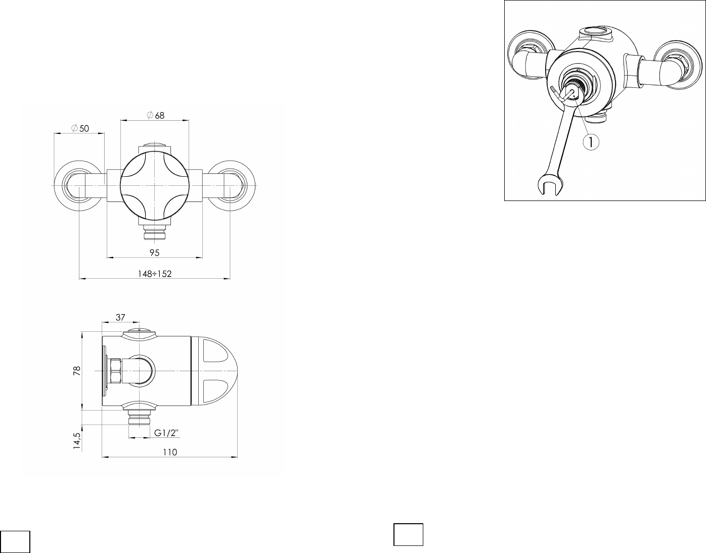
1. In order to install the mixer please carefully follow the instructions:
Please follow the dimensional drawing in order to fix the valve in the correct position.
Please not: the above drawing is generic so handle may vary from purchased valve
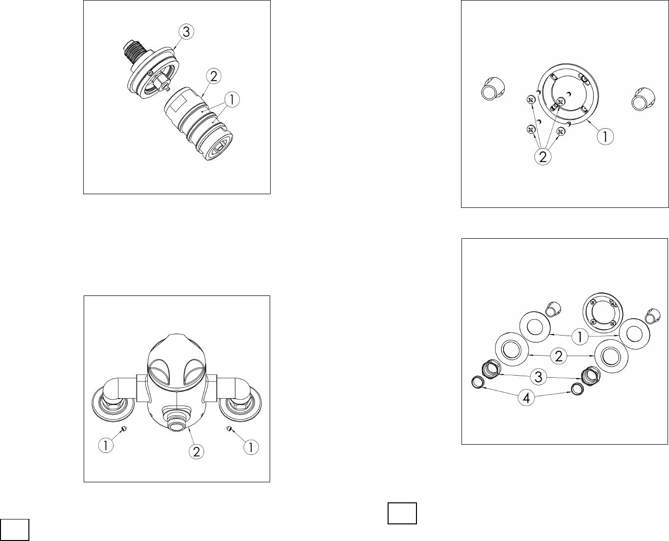
3. Slightly unscrew the ring nut (1) with a 13mm spanner.
Insert the supplied 2,5mm Allen key into the ring nut (1) and turn anti-clockwise in
order to increase the outlet water temperature, clockwise to decrease it.
ATTENTION: for the re-assembling please follow the given instruction backward.
5
17
Maximum Temperature Setting
In order to adjust the maximum temperature please proceed as follows:
Shut off the water supply to both inlets.
ATTENTION: the purchased mixer is a sequential thermostatic mixer, this means that if
the outlet maximum temperature is increased the value of the minimum temperature
increases as a consequence.
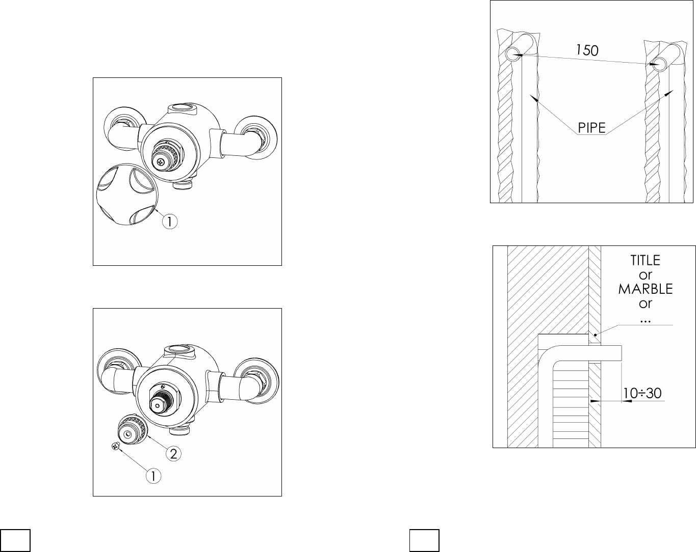
1. Unscrew the lever (2) and the grub screws (2) from the handles (3) with the supplied
2.5mm Allen key
2. Undo the screw (1) with the screwdriver and remove the temperature stop ring (2)
1. Position the two copper pipes on the wall to the desired height and at a distance of
150mm apart. Check the two pipes are lined up the same.
.
2. Position the copper pipe so it protrudes from the wall at 10-30mm. Also consider the
thickness of the covering. The first step has now been completed. Now the brick
work and tiling can take place
16
6
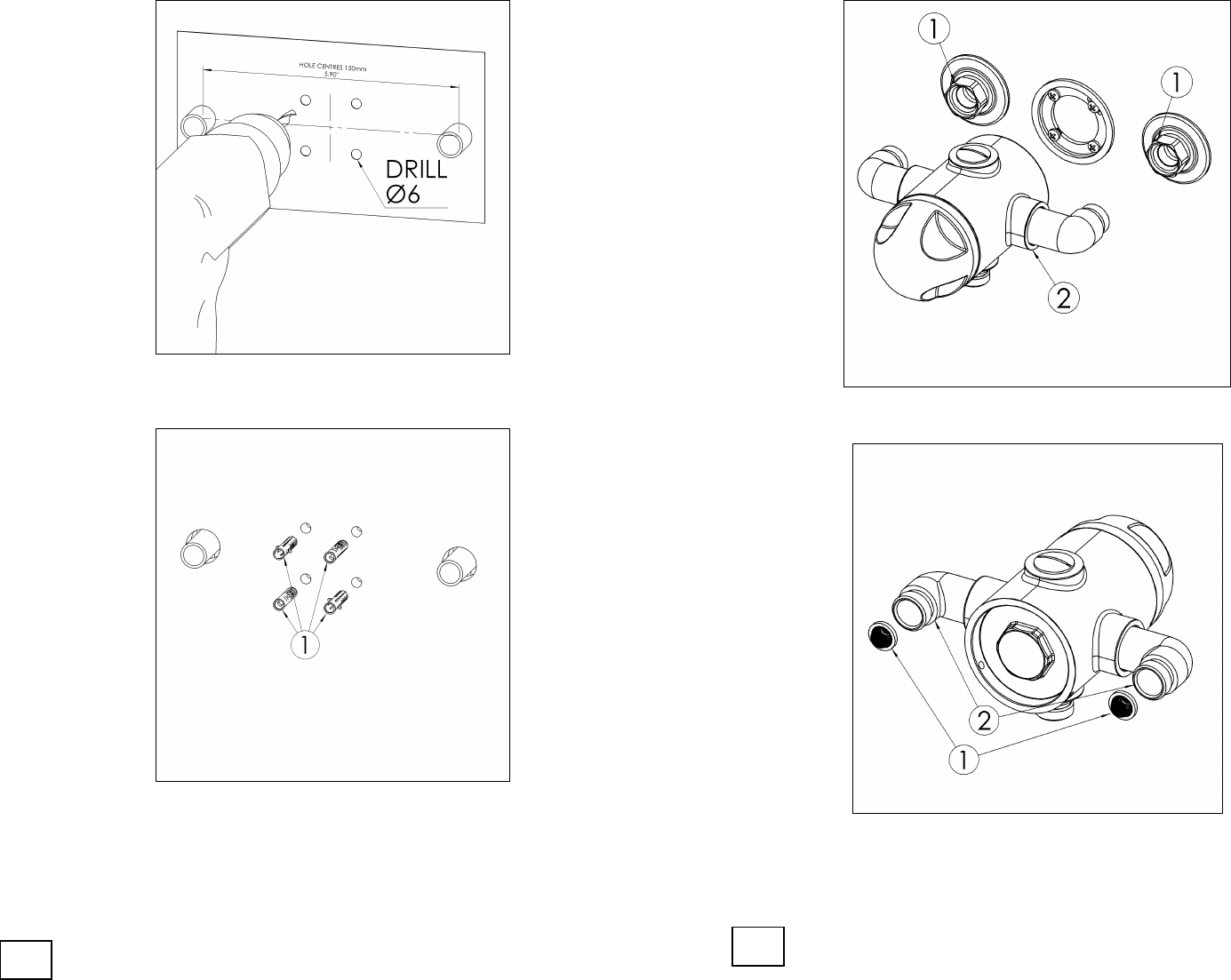
3. Position the available template label on the surface of the wall and drill four holes
6mm in diameter.
4. Insert the four plugs (1)
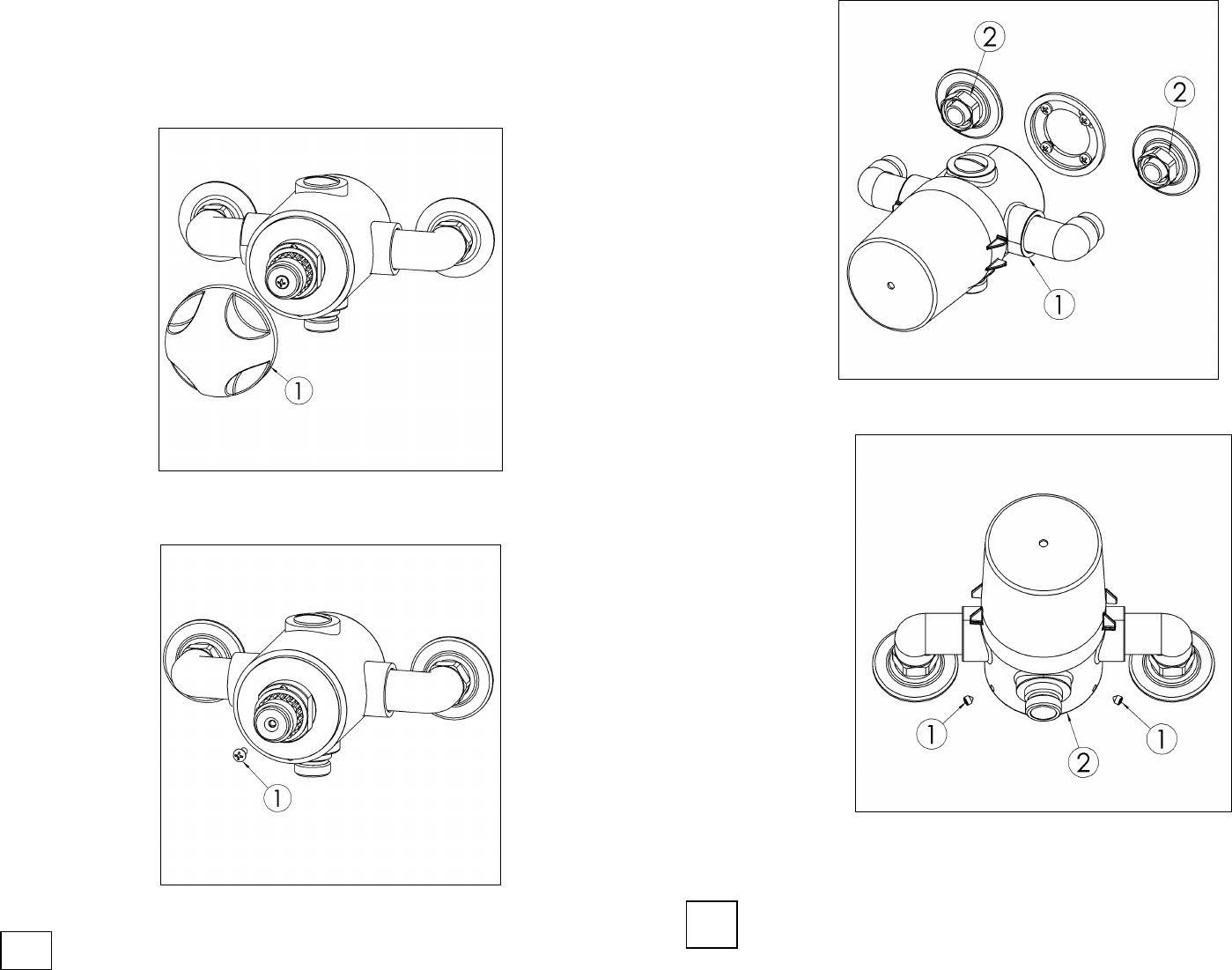
2. Unscrew the two caps (1) by using a 30mm spanner. Then remove the mixer (2).
3. Remove the filters (1) from the elbows (2) and replace or clean them under running
water. ATTENTION: For the re-assembling please follow the given instructions in
reverse.
7
15
5. Clean the filters (1) under running water or leave to soak in vinegar or de-
scaling agent. To replace filters, unscrew the body of the thermostatic
cartridge (2) from the flange (3) by turning clockwise. ATTENTION: For the
re-assembling please follow the instructions backward
CLEANING – REPLACEMENT OF THE FILTERS
Through years of use impurities and lime scale could restrict flow of water through the
filters. In order to clean or replace the filters please proceed as follows. Shut off water
supply to both inlets
1. Unscrew the grub screws (1) using the 2.5mm Allen key provided, which, sit in the
interior part of the body (2)
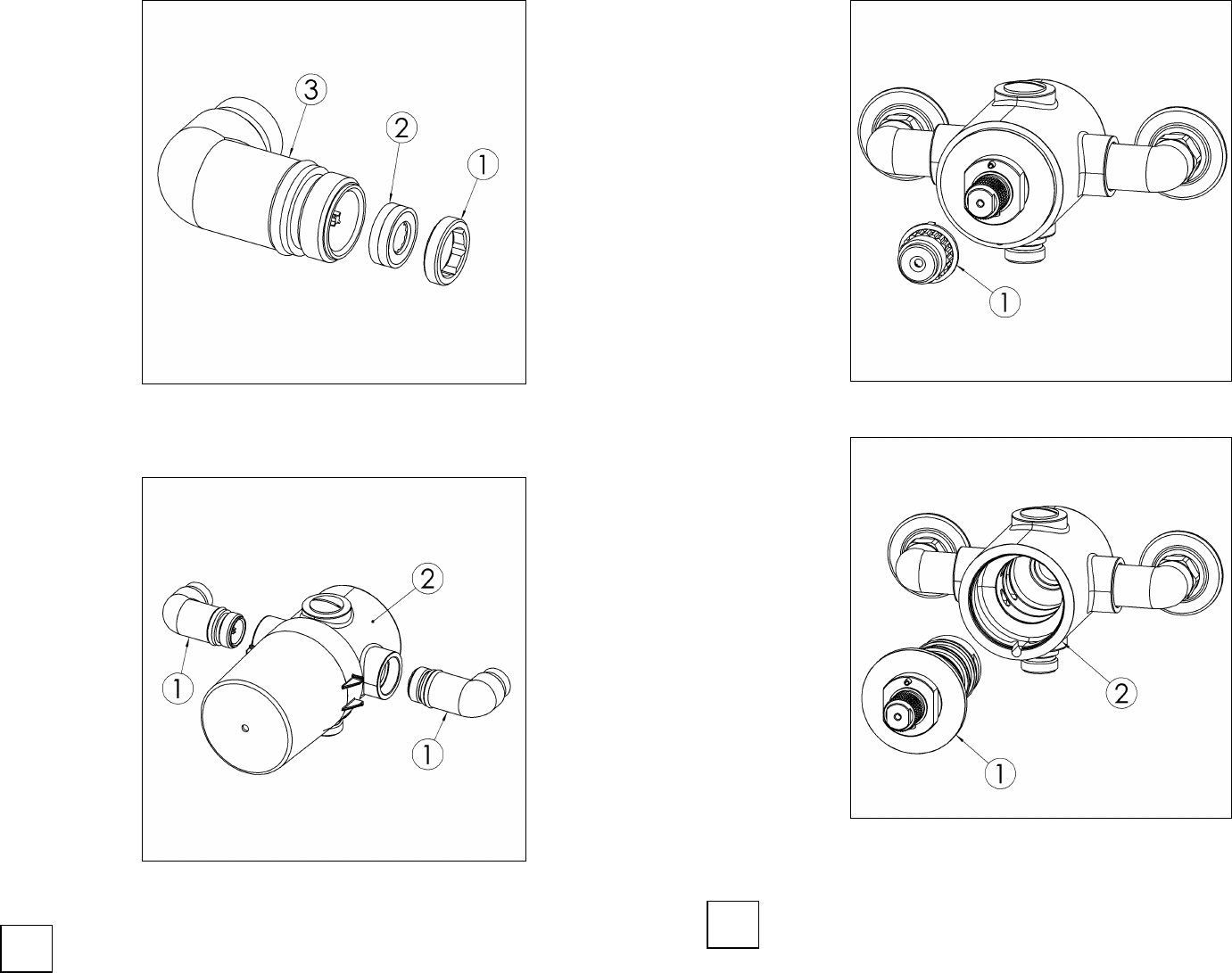
5. Position the flange to the wall and screw the four grapevines (2)
6. Inserts the gaskets (1) , the rosette (2), the caps (3) and the olive nuts (4) to the two
copper pipes
8
14
7. If there is a difference in pressure between hot and cold, we suggest the use of the
flow restrictor in the inlets: insert the limiter (2) in the elbow (3) as shown in figure,
then screw the nut (1) on the elbow (3).
8. Then proceed by screwing the two elbows (1) on the body (2).
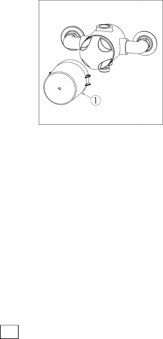
3. Remove the temperature stop ring (1) from the mixer.
4. By using a 30mm spanner unscrew anti-clockwise the flange (1) of the thermostatic
cartridge from the mixer valve (2).
9 13
CLEANING – REPLACEMENT OF THE CARTRIDGE:
Through years of use impurities and lime scale could restrict flow of water through the
filters of the cartridge.
In order to clean the cartridge and for its replacement, please proceed as per the following
instructions: - Shut off water supply to both inlets
1. Remove the handle (1)
2. Remove the screw (1) with a screwdriver
9. Position the mixer (1), and screw the two caps (2) with a 25mm spanner
10. Use the 2.5mm Allen key provided, screw the two grub screws (1) into the internal
part of the body (2).
12
10
11. Remove the plastic protection (1)
11
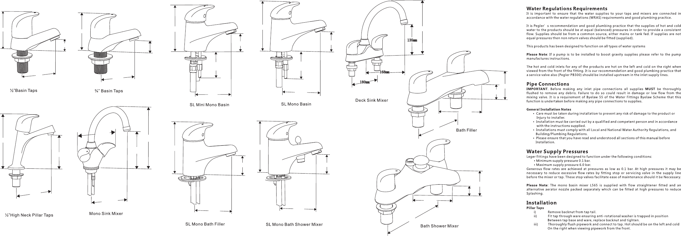
Water Regulations Requirements
It is important to ensure that the water supplies to your taps and mixers are connected in
accordance with the water regulations (WRAS) requirements and good plumbing practice.
It is Pegler’s recommendation and good plumbing practice that the supplies of hot and cold
water to the products should be at equal (balanced) pressures in order to provide a consistent
flow. Supplies should be from a common source, either mains or tank fed. If supplies are not
equal pressures then non return valves should be fitted (supplied).
This products has been designed to function on all types of water systems
: If a pump is to be installed to boost gravity supplies please refer to the pump
manufactures instructions.
The hot and cold inlets for any of the products are hot on the left and cold on the right when
viewed from the front of the fitting. It is our recommendation and good plumbing practice that
a service valve also (Pegler PB300) should be installed upstream in the inlet supply lines.
Please Note
Pipe Connections
IMPORTANT MUST
General Installation Notes
Please Note
Pillar Taps
. Before making any inlet pipe connections all supplies be thoroughly
flushed to remove any debris. Failure to do so could result in damage or low flow from the
mixing valve. It is a requirement of Byelaw 55 of the Water Fittings Byelaw Scheme that this
function is undertaken before making any pipe connections to supplies.
• Care must be taken during installation to prevent any risk of damage to the product or
Injury to installer.
• Installation must be carried out by a qualified and competent person and in accordance
with the instructions supplied.
• Installations must comply with all Local and National Water Authority Regulations, and
Building/Plumbing Regulations.
• Please ensure that you have read and understood all sections of this manual before
Installation.
Leger fittings have been designed to function under the following conditions:
• Minimum supply pressure 0.1 bar.
• Maximum supply pressure 6.0 bar.
Generous flow rates are achieved at pressures as low as 0.1 bar. At high pressures it may be
necessary to reduce excessive flow rates by fitting stop or servicing valve in the supply line
before the mixer or tap. These stop valves facilitate ease of maintenance should it be Necessary.
: The mono basin mixer L565 is supplied with flow straightener fitted and an
alternative aerator nozzle packed separately which can be fitted at high pressures to reduce
Splashing.
i) Remove backnut from tap tail.
ii) Fit tap through ware ensuring anti-rotational washer is trapped in position
Betweentapbaseandware,replacebacknutandtighten.
iii) Thoroughly flush pipework and connect to tap. Hot should be on the left and cold
On the right when viewing pipework from the front.
Water Supply Pressures
Installation
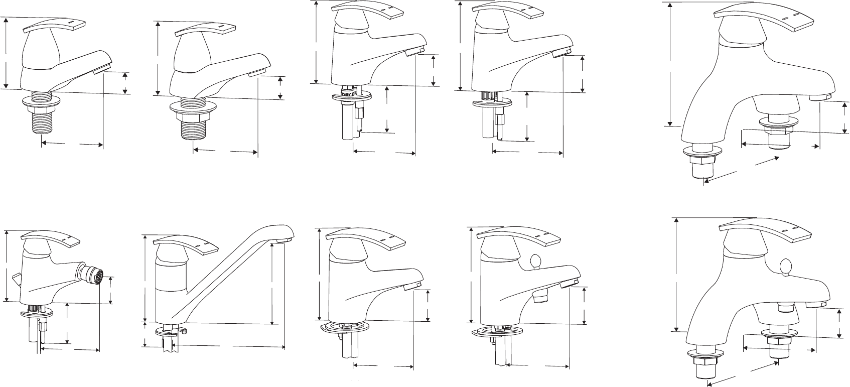
½”Basin Taps
¾” Basin Taps
Mono Sink Mixer
SL Mini Mono Basin SL Mono Basin
SL Mono Bath Filler SL Mono Bath Shower Mixer
SL BridgeBath Filler
SL Bridge Bath Shower Mixer
78mm
27mm
75mm
86mm
31mm
78mm
96mm
47mm
108mm
max thickness ofmax thickness of
ware/worktop 44ware/worktop 44
126mm
70mm
153mm
180mm
124mm
49mm
159mm
126mm
70mm
153mm
180mm
124mm
49mm
159mm
109mm109mm
54mm
106mm
max thickness ofmax thickness of
ware/worktop 44ware/worktop 44
159mm
159mm
159mm
max thickness ofmax thickness of
ware/worktop 44ware/worktop 44
116mm
54mm
106mm
max thickness ofmax thickness of
ware/worktop 44ware/worktop 44
SL Mono Bidet Mixer

You GuidetotheInstallation,Careandmaintenanceofr
Rossi
Pegler Limited, St Catherine’s Avenue, Doncaster DN4 8DF
Telephone 01302 560560, Fax 01302 560109
½”Basin Taps
¾”Basin Taps
Mono Sink Mixer
SL Bridge Bath Shower Mixer
SL Mono Bath Filler
SL Mono Bath
Shower Mixer
SL Mono Basin
SL Mini Mono Basin
Care & Maintenance
To maintain the surface finishes, simply wipe occasionally with a mild detergent on a soft damp
cloth. Dry using a soft cloth, never use abrasive cleansers or chemical household cleaners, and
avoid contact with concentrated bleach. Applause products are manufactured to the highest of
standards and should require little or no maintenance. In the unlikely event of any spare part
requirements, please contact your nearest stockist or the Pegler Sales Office, St Catherine’s
Avenue, Doncaster. DN4 8DF, Telephone 01302 368581.
To maintain the surface finishes, simply wipe occasionally with a mild detergent on soft damp
cloth. Dry using soft cloth, never use abrasive cleaners or chemical household cleaners, avoid
contact with concentrated bleach.
Pegler products are manufactured to the highest standards and should require little or no
maintenance. In the unlikely event of any spare part requirements, please visit our website:
www.pegler.co.uk , contact you’re nearest stockist or the Pegler Technical Office on telephone
0870 1200285
Customer Reference Data
Date of Purchase……………………………………………………
Supplier………………………………………………………………
Supplier Tel. No………………………………………………………
Model Type…………………………………………………………..
Serial No………………………………………………………………
Installer………………………………………………………………….
Installer Contact Details…………………………………
………………………………………………
…………………………………………………
……………………………………………..
………………………………………………..
………………………………………………..
……………………………………………...
………………………………………....………….
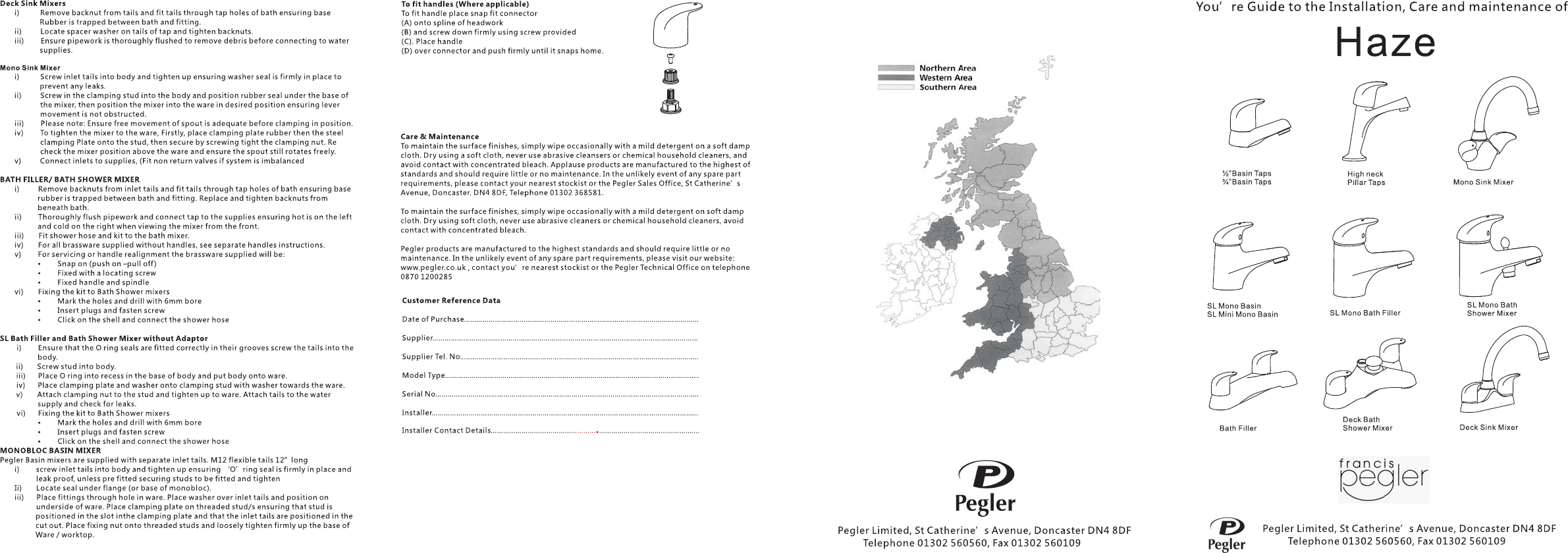
To fit handles (Where applicable)
To fit handle place snap fit connector
(A) onto spline of headwork
(B)andscrewdownfirmlyusingscrewprovided
(C). Place handle
(D) over connector and push firmly until it snaps home.
Pegler Limited, St Catherine’s Avenue, Doncaster DN4 8DF
Telephone 01302 560560, Fax 01302 560109
Mono Sink Mixer
i) Screw inlet tails into body and tighten up ensuring seal is firmly in place to
prevent any leaks.
ii) Screw in the clamping stud into the body and position rubber seal under the base of
the mixer, the position the mixer into the ware in desired position ensuring lever
movement is not obstructed.
iii) Please note: Ensure free movement of spout is adequate before clamping in position.
To tighten the mixer to the ware, Firstly, place clamping plate rubber then the steel
clamping Plate onto the stud, then secure by screwing tight the clamping nut. Re
check the mixer position above the ware and ensure the spout still rotates freely.
Connect inlets to supplies, (Fit non return valves if system is imbalanced
) Remove backnuts from inlet tails and fit tails through tap holes of bath ensuring base
rubber is trapped between bath and fitting. Replace and tighten backnuts from
beneath bath.
ii) Thoroughly flush pipework and connect tap to the supplies ensuring hot is on the left
and cold on the right when viewing the mixer from the front.
iii) Fit shower hose and kit to the bath mixer.
For all brassware supplied without handles, see separate handles instructions.
For servicing or handle realignment the brassware supplied will be:
• Snap on (push on –pull off)
• Fixed with a locating screw
• Fixed handle and spindle
Fixing the kit to Bath Shower mixers
• Mark the holes and drill with 6mm bore
• Insert plugs and fasten screw
• Click on the shell and connect the shower hose
) Ensure that the O ring seals are fitted correctly in their grooves screw the tails into the
body.
ii) Screw stud into body.
iii) Place O ring into recess in the base of body and put body onto ware.
Place clamping plate and washer onto clamping stud with washer towards the ware.
Attach clamping nut to the stud and tighten up to ware. Attach tails to the water
supply and check for leaks.
Fixing the kit to Bath Shower mixers
Marktheholesanddrillwith6mmbore
• Insert plugs and fasten screw
• Click on the shell and connect the shower hose
Pegler Basin mixers are supplied with separate inlet tails. M12 flexible tails 12”long
) screw inlet tails into body and tighten up ensuring ‘O’ring seal is firmly in place and
leak proof, unless pre fitted securing studs to be fitted and tighten
Ii) Locate seal under flange (or base of monobloc).
iii) Place fittings through hole in ware. Place washer over inlet tails and position on
underside of ware. Place clamping plate on threaded stud/s ensuring that stud is
positioned in the slot inthe clamping plate and that the inlet tails are positioned in the
cut out. Place fixing nut onto threaded studs and loosely tighten firmly up the base of
Ware / worktop.
Insert click waste
Ensure pipework is thoroughly flushed to remove debris before connecting to the
fitting,
Connect to the water supplies.
) Ensure that the O ring seals are fitted correctly in their grooves screw the tails into the
body.
washer
n
iv)
v)
i
iv)
v)
vi)
i
iv)
v)
vi)
•
i
iv)
v)
i
Bridge Bath Filler/Bath Shower Mixer
ono loc asin/Bidet ixer
Bath Filler and Bath Shower Mixer without Adaptor
MbB M
SL BridgeBath Filler
SL Mono Bidet Mixer
86mm
31mm
78mm
75mm
78mm
27mm
101mm
99mm
152mm
168mm
157mm
236mm
158mm
106mm
116mm
54mm
max thickness ofmax thickness of
ware/worktop 44ware/worktop 44
96mm
47mm
108mm
max thickness ofmax thickness of
ware/worktop 44ware/worktop 44
126mm
70mm
153mm
126mm
153mm
70mm
215mm
180mm
115mm
35mm
65mm
180mm
125mm
41mm
69mm
Pegler sees the ever increasing importance of
restricting water in places of need or conservation
and as such identifies the need to regulate flow
accordingly. Regulating the flow, specifically on basin
fittings where the restriction does not impact on daily
activities such as cleaning your teeth or washing your
hands makes an immediate impact of water
conservation, specifically when water is openly
flowing.
As such the use of this regulator on both hot and cold
basin taps conforms to the requirements of the
Enhanced Capital Allowance Scheme.
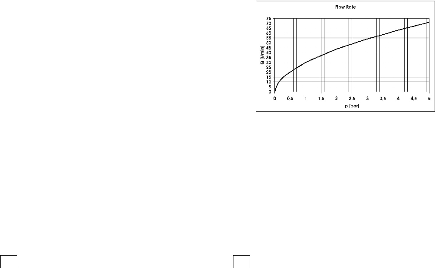
The use of this regulator will hold back the flow of
water to a limit of 4.0 (± 15%) litres per minute no
matter what the pressure. A restriction will be evident
at all pressures although full benefits are seen when
installed on higher pressures. This graph is only a
suggestion of the water saving you could experience.
Please Note: Each tap design will be different!
These regulators can be used in conjunction with any
Pegler 1/2” basin taps.
INSTRUCTIONS
It is important to ensure that the water supplies to
your taps are connected in accordance with water
regulation (WRAS) requirements and good plumbing
practise. Ensure that the system has been fully
flushed before installing any taps, as debris in the
system will impair the performance of both the
regulator and the tap. The fitting of isolating valves
upstream of the tap is also advised to aid
maintenance. Use Pegler 808 isolating valves.
Ensure ‘O’ ring is fitted around the outside diameter
of the regulator.
0
5
10
15
20
25
30
35
0.1 0.2 0.3 0.4 0.5 0.6 0.7 0.8 0.9 1.0 2.0 3.0 4.0 5.0
Pressure (Bar)
Litres per Minute
With Regulator
Without Regulator
eco tap 19/1/06 12:51 pm Page 1
Note:The internal ‘O’ ring is unlikely to get blocked
in hard water areas as the flowing water when in
operation oscillates and self cleans any build up.
Insert regulator into threaded tail of the tap, and
push inside the tail until it hits the internal pipe stop.
Use a Pegler tap adaptor (ref: Prestex 43 straight
connector order code: 713007 or 43B bent connector
order code: 714007) and then fit to tap to water
supply according to Pegler’s instructions.
PERFORMA 4.0 Litre
FLOW REGULATOR
PERFORMA 4.0 Litre
FLOW REGULATOR
Pegler products are manufactured to the highest
standard and should require little or no maintenance.
In the unlikely event of any spare parts
requirements, please visit our website
www.pegler.co.uk
contact your nearest stockiest or the
pegler Technical Office on
telephone 0870 1200285
Pegler Limited, St. Catherine’s Avenue,
Doncaster, South Yorkshire. DN4 8DF
Telephone: 01302 560560 Fax: 01302 560109
Installation
and User Guide
PERFORMA
eco tap 19/1/06 12:51 pm Page 2
Water Regulations Requirements
It is important to ensure that the water supplies to your taps and mixers are connected in
accordance with the water regulations (WRAS) requirements and good plumbing practice.
It is Pegler's recommendation and good plumbing practice that the supplies of hot and cold
water to the products should be at equal (balanced) pressures in order to provide a consistent
flow. Supplies should be from a common source, either mains or tank fed. If supplies are not
equal pressures then non return valves should be fitted (supplied).
This products has been designed to function on all types of water systems
: If a pump is to be installed to boost gravity supplies please refer to the pump
manufactures instructions.
The hot and cold inlets for any of the products are hot on the left and cold on the right when
viewed from the front of the fitting. It is our recommendation and good plumbing practice that
a service valve also (Pegler PB300) should be installed upstream in the inlet supply lines.
Please Note
Pipe Connections
IMPORTANT MUST
General Installation Notes
Please Note
Pillar Taps
. Before making any inlet pipe connections all supplies be thoroughly
flushed to remove any debris. Failure to do so could result in damage or low flow from the
mixing valve. It is a requirement of Byelaw 55 of the Water Fittings Byelaw Scheme that this
function is undertaken before making any pipe connections to supplies.
• Care must be taken during installation to prevent any risk of damage to the product or
Injury to installer.
• Installation must be carried out by a qualified and competent person and in accordance
with the instructions supplied.
• Installations must comply with all Local and National Water Authority Regulations, and
Building/Plumbing Regulations.
• Please ensure that you have read and understood all sections of this manual before
Installation.
Leger fittings have been designed to function under the following conditions:
• Minimum supply pressure 0.1 bar.
• Maximum supply pressure 6.0 bar.
Generous flow rates are achieved at pressures as low as 0.1 bar. At high pressures it may be
necessary to reduce excessive flow rates by fitting stop or servicing valve in the supply line
before the mixer or tap. These stop valves facilitate ease of maintenance should it be Necessary.
: The mono basin mixer L565 is supplied with flow straightener fitted and an
alternative aerator nozzle packed separately which can be fitted at high pressures to reduce
Splashing.
i) Remove backnut from tap tail.
ii) Fit tap through ware ensuring anti-rotational washer is trapped in position
Between tap base and ware, replace backnut and tighten.
iii) Thoroughly flush pipework and connect to tap. Hot should be on the left and cold
On the right when viewing pipework from the front.
Water Supply Pressures
Installation
½”Basin Taps
¾” Basin Taps
DC Mono Basin
SL Mini Mono Basin
Bath Filler
Bath Shower Mixer
78mm
27mm
80mm
86mm
31mm
84mm
96mm
108mm
47mm
max thickness ofmax thickness of
ware/worktop 44ware/worktop 44
180mm
125mm
41mm
69mm
180mm
115mm
35mm
65mm
213mm
231mm
352mm
max thickness ofmax thickness of
ware/worktop 44ware/worktop 44
237mm
168mm
153mm
max thickness ofmax thickness of
ware/worktop 44ware/worktop 44
115mm
70mm
max thickness ofmax thickness of
ware/worktop 44ware/worktop 44
116mm
106mm
max thickness ofmax thickness of
ware/worktop 44ware/worktop 44
54mm
SL Mono Basin
S/A Mono Sink Mixer
Mono Sink Mixer
You Guide to the nstallation, Care and maintenance ofri
Izzi
Pegler Limited, St Catherine’s Avenue, Doncaster DN4 8DF
Telephone 01302 560560, Fax 01302 560109
½”Basin Taps
¾”Basin Taps
Deck Bath
Shower Mixer
Bath Filler
Care & Maintenance
To maintain the surface finishes, simply wipe occasionally with a mild detergent on a soft damp
cloth. Dry using a soft cloth, never use abrasive cleansers or chemical household cleaners, and
avoid contact with concentrated bleach. Applause products are manufactured to the highest of
standards and should require little or no maintenance. In the unlikely event of any spare part
requirements, please contact your nearest stockist or the Pegler Sales Office, St Catherine’s
Avenue, Doncaster. DN4 8DF, Telephone 01302 368581.
To maintain the surface finishes, simply wipe occasionally with a mild detergent on soft damp
cloth. Dry using soft cloth, never use abrasive cleaners or chemical household cleaners, avoid
contact with concentrated bleach.
Pegler products are manufactured to the highest standards and should require little or no
maintenance. In the unlikely event of any spare part requirements, please visit our website:
www.pegler.co.uk , contact you’re nearest stockist or the Pegler Technical Office on telephone
0870 1200285
Customer Reference Data
Date of Purchase……………………………………………………
Supplier………………………………………………………………
Supplier Tel. No………………………………………………………
Model Type…………………………………………………………..
Serial No………………………………………………………………
Installer………………………………………………………………….
Installer Contact Details…………………………………
………………………………………………
…………………………………………………
……………………………………………..
………………………………………………..
………………………………………………..
……………………………………………...
………………………………………....………….
To fit handles (Where applicable)
To fit handle place snap fit connector
(A) onto spline of headwork
(B)andscrewdownfirmlyusingscrewprovided
(C). Place handle
(D) over connector and push firmly until it snaps home.
Pegler Limited, St Catherine’s Avenue, Doncaster DN4 8DF
Telephone 01302 560560, Fax 01302 560109
Mono Sink / Side Action Mono Sink Mixer
i) Screw inlet tails into body and tighten up ensuring seal is firmly in place to
prevent any leaks.
Please note: For standard mono sink go to point (iv)
ii) ForSideActionMonoSinkMixer–Locatethehandlefromtheboxandremovethe
indice (plastic bung) from under the lever part of the handle. Locate the handle onto
the square spindle of the exposed cartridge, then using the Allen Key provided screw
the grub screw (packaged with the clamping kit) into the handle and tighten onto the
cartridge.
Please note: The handle should be positioned pointing towards you (when viewing the tap
from the front) for its natural off position!
iii) Once in position relocate the indice (plastic bung) into the hole under the lever,
ensuring the red and blue printed on the indice is the correct way around.
i ) Screw in the clamping stud into the body and position rubber seal under the base of
the mixer, the position the mixer into the ware in desired position ensuring lever
movement is not obstructed.
v) Please note: Ensure free movement of spout is adequate before clamping in position.
To tighten the mixer to the ware, Firstly, place clamping plate rubber then the steel
clamping Plate onto the stud, then secure by screwing tight the clamping nut. Re
check the mixer position above the ware and ensure the spout still rotates freely.
Connect inlets to supplies, (Fit non return valves if system is imbalanced
) Remove backnuts from inlet tails and fit tails through tap holes of bath ensuring base
rubber is trapped between bath and fitting. Replace and tighten backnuts from
beneath bath.
ii) Thoroughly flush pipework and connect tap to the supplies ensuring hot is on the left
and cold on the right when viewing the mixer from the front.
iii) Fit shower hose and kit to the bath mixer.
For all brassware supplied wi thout handles, see separate handles instructions.
For servicing or handle realignment the brassware supplied will be:
• Snap on (push on –pull off)
• Fixed with a locating screw
• Fixed handle and spindle
Fixing the kit to Bath Shower mixers
• Mark the holes and drill with 6mm bore
• Insert plugs and fasten screw
• Click on the shell and connect the shower hose
Pegler Basin mixers are supplied with separate inlet tails. M12 flexible tails 12”long
) screw inlet tails into body and tighten up ensuring ‘O’ring seal is firmly in place and
leak proof, unless pre fitted securing studs to be fitted and tighten
Ii) Locate seal under flange (or base of monobloc).
iii) Place fittings through hole in ware. Place washer over inlet tails and position on
underside of ware. Place clamping plate on threaded stud/s ensuring that stud is
positioned in the slot inthe clamping plate and that the inlet tails are positioned in
the cut out. Place fixing nut onto threaded studs and loosely tighten firmly up the
base of Ware / worktop.
Insert click waste
Ensure pipework is thoroughly flushed to remove debris before connecting to the
fitting,
Connect to the water supplies.
) EnsurethattheOringsealsarefittedcorrectlyintheirgroovesscrewthetailsintothe
body.
washer
v
n
vi)
vii)
i
iv)
v)
vi)
i
iv)
v)
i
BF /BS M
MbB M
ath iller ath hower ixer
ono loc asin ixer
SL Mini Mono Basin SL Mono Basin
DC Mono Basin
Mono Sink Mixer
S/A Mono Sink Mixer
Water Regulations Requirements
It is important to ensure that the water supplies to your taps and mixers are connected in
accordance with the water regulations (WRAS) requirements and good plumbing practice.
It is Pegler’s recommendation and good plumbing practice that the supplies of hot and cold
water to the products should be at equal (balanced) pressures in order to provide a consistent
flow. Supplies should be from a common source, either mains or tank fed. If supplies are not
equal pressures then non return valves should be fitted (supplied).
This products has been designed to function on all types of water systems
: If a pump is to be installed to boost gravity supplies please refer to the pump
manufactures instructions.
The hot and cold inlets for any of the products are hot on the left and cold on the right when
viewed from the front of the fitting. It is our recommendation and good plumbing practice that
a service valve also (Pegler PB300) should be installed upstream in the inlet supply lines.
Please Note
Pipe Connections
IMPORTANT MUST
General Installation Notes
Please Note
. Before making any inlet pipe connections all supplies be thoroughly
flushed to remove any debris. Failure to do so could result in damage or low flow from the
mixing valve. It is a requirement of Byelaw 55 of the Water Fittings Byelaw Scheme that this
function is undertaken before making any pipe connections to supplies.
• Care must be taken during installation to prevent any risk of damage to the product or
Injury to installer.
• Installation must be carried out by a qualified and competent person and in accordance
with the instructions supplied.
• Installations must comply with all Local and National Water Authority Regulations, and
Building/Plumbing Regulations.
• Please ensure that you have read and understood all sections of this manual before
Installation.
Leger fittings have been designed to function under the following conditions:
• Minimum supply pressure 0.1 bar.
• Maximum supply pressure 6.0 bar.
Generous flow rates are achieved at pressures as low as 0.1 bar. At high pressures it may be
necessary to reduce excessive flow rates by fitting stop or servicing valve in the supply line
before the mixer or tap. These stop valves facilitate ease of maintenance should it be Necessary.
: The mono basin mixer L565 is supplied with flow straightener fitted and an
alternative aerator nozzle packed separately which can be fitted at high pressures to reduce
Splashing.
Water Supply Pressures
SL Mono Bidet Mixer
SL Mini Mono Basin
SL Mono Basin
SL Mono Bath Filler
SL Mono Bath Shower Mixer
106mm
54mm
116mm
max thickness ofmax thickness of
ware/worktop 44ware/worktop 44
96mm
47mm
108mm
max thickness ofmax thickness of
ware/worktop 44ware/worktop 44
126mm
70mm
153mm
126mm
70mm
153mm
109mm
54mm
106mm
max thickness ofmax thickness of
ware/worktop 44ware/worktop 44
213mm
231mm
352mm
S/A Mono Sink Mixer
Installation
i) Screw inlet tails into body and tighten up ensuring seal is firmly in place to
prevent any leaks.
Please note: For standard mono sink go to point (iv)
ii) For Side Action Mono Sink Mixer – Locate the handle from the box and remove the
indice (plastic bung) from under the lever part of the handle. Locate the handle onto
the square spindle of the exposed cartridge, then using the Allen Key provided screw
the grub screw (packaged with the clamping kit) into the handle and tighten onto the
cartridge.
Please note: The handle should be positioned pointing towards you (when viewing the tap
from the front) for its natural off position!
iii) Once in position relocate the indice (plastic bung) into the hole under the lever,
ensuring the red and blue printed on the indice is the correct way around.
i ) Screw in the clamping stud into the body and position rubber seal under the base of
the mixer, the position the mixer into the ware in desired position ensuring lever
movement is not obstructed.
v) Please note: Ensure free movement of spout is adequate before clamping in position.
i To tighten the mixer to the ware, Firstly, place clamping plate rubber then the steel
clamping Plate onto the stud, then secure by screwing tight the clamping nut. Re
check the mixer position above the ware and ensure the spout still rotates freely.
i Connect inlets to supplies, (Fit non return valves if system is imbalanced
) Ensure that the O ring seals are fitted correctly in their grooves screw the tails into the
body.
ii) Screw stud into body.
iii) Place O ring into recess in the base of body and put body onto ware.
Place clamping plate and washer onto clamping stud with washer towards the ware.
Attach clamping nut to the stud and tighten up to ware. Attach tails to the water
supply and check for leaks.
Fixing the kit to Bath Shower mixers
Marktheholesanddrillwith6mmbore
• Insert plugs and fasten screw
• Click on the shell and connect the shower hose
Pegler Basin mixers are supplied with separate inlet tails. M12 flexible tails 12”long
) screw inlet tails into body and tighten up ensuring ‘O’ring seal is firmly in place and
leak proof, unless pre fitted securing studs to be fitted and tighten
Ii) Locate seal under flange (or base of monobloc).
iii) Place fittings through hole in ware. Place washer over inlet tails and position on
underside of ware. Place clamping plate on threaded stud/s ensuring that stud is
positioned in the slot inthe clamping plate and that the inlet tails are positioned in
the cut out. Place fixing nut onto threaded studs and loosely tighten firmly up the
base of Ware / worktop.
Insert click waste
Ensure pipework is thoroughly flushed to remove debris before connecting to the
fitting,
Connect to the water supplies.
) Ensure that the O ring seals are fitted correctly in their grooves screw the tails into the
body.
washer
v
n
v)
Vi)
i
iv)
v)
vi)
•
i
iv)
v)
i
SL
ono loc asin/Bidet ixer
Bath Filler and Bath Shower Mixer without Adaptor
MbB M
Side Action Mono Sink Mixer
You Guide to the Installation, Care and maintenance ofr
Loko
Pegler Limited, St Catherine’s Avenue, Doncaster DN4 8DF
Telephone 01302 560560, Fax 01302 560109
Care & Maintenance
To maintain the surface finishes, simply wipe occasionally with a mild detergent on a soft damp
cloth. Dry using a soft cloth, never use abrasive cleansers or chemical household cleaners, and
avoid contact with concentrated bleach. Applause products are manufactured to the highest of
standards and should require little or no maintenance. In the unlikely event of any spare part
requirements, please contact your nearest stockist or the Pegler Sales Office, St Catherine’s
Avenue, Doncaster. DN4 8DF, Telephone 01302 368581.
To maintain the surface finishes, simply wipe occasionally with a mild detergent on soft damp
cloth. Dry using soft cloth, never use abrasive cleaners or chemical household cleaners, avoid
contact with concentrated bleach.
Pegler products are manufactured to the highest standards and should require little or no
maintenance. In the unlikely event of any spare part requirements, please visit our website:
www.pegler.co.uk , contact you’re nearest stockist or the Pegler Technical Office on telephone
0870 1200285
Customer Reference Data
Date of Purchase……………………………………………………
Supplier………………………………………………………………
Supplier Tel. No………………………………………………………
Model Type…………………………………………………………..
Serial No………………………………………………………………
Installer………………………………………………………………….
Installer Contact Details…………………………………
………………………………………………
…………………………………………………
……………………………………………..
………………………………………………..
………………………………………………..
……………………………………………...
………………………………………....………….
Pegler Limited, St Catherine’s Avenue, Doncaster DN4 8DF
Telephone 01302 560560, Fax 01302 560109
SL Mini Mono Basin
SL Mono Basin
SL Mono Bidet Mixer
SL Mono Bath Shower Mixer
SL Mono Bath Filler
S/A Mono Sink Mixer
Installation Instructions
and User Guide
15mm & 22mm
In-Line Thermostatic Mixing Valve-TMV2
Model P404
It is important that these guidance notes are read and fully understood prior to product installation
Installation Instructions and User Guide
15mm & 22MM
In-Line Thermostatic Mixing Valve-TMV2
Model P404
It is important that these guidance notes are read and fully
understood prior to product installation
2
Year
BSEN
1287
BSEN
1111
TMV3 Model P404.indd 1 13/2/09 15:02:45
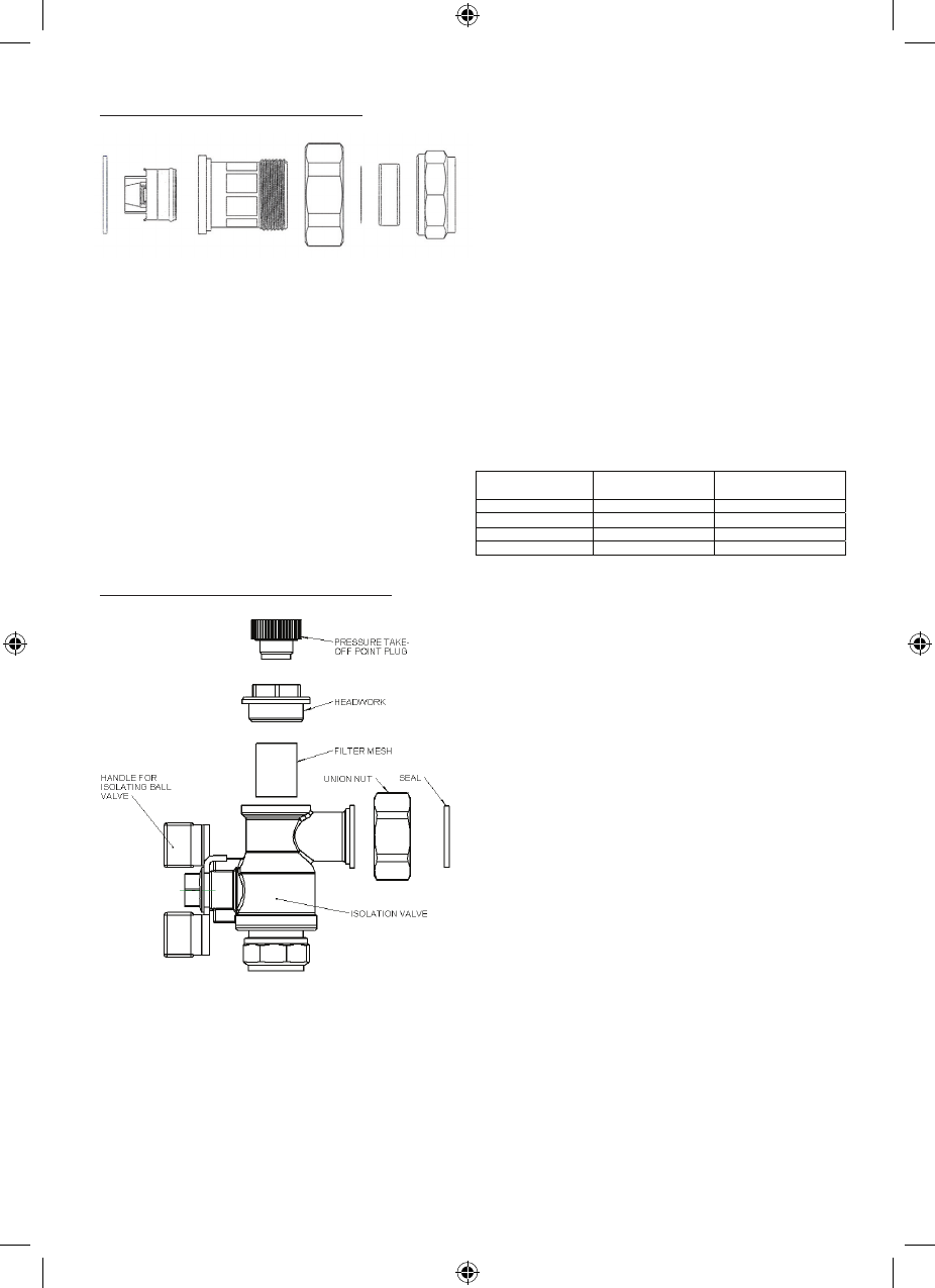
Installation
Separate isolation valves must be installed on
the hot and cold water inlet supplies.
To ensure proper performance of the
thermostatic mixing valve, the isolating valves
should preferably be full bore and always be
fully open during operation.
The mixing valve is supplied with filter
elements but it is advisable to additionally
install Y-strainers on the hot and cold water
supplies. The isolating valves and strainers
should be installed as close as practicable to
the location of the mixing valve and should
always be in an accessible location.
Before installation, the hot and cold water
supply systems must be thoroughly flushed
to remove any dirt/debris that may have
accumulated. Failure to do so may adversely
affect the performance of the mixing valve.
CONDITIONS OF NORMAL USE
Table 1
Minimum hot inlet to mixed outlet temperature
differential = 10oC
Note: Valves operating outside these
conditions can not be guaranteed by the
Scheme to operate as Type 2 valves.
The highest flow rates will be achieved under
balanced pressure conditions, but the pressure
at the valve inlets must be within a ratio of
5:1 under flow conditions and the size and
layout of pipework and fittings must take this
into account.
IMPORTANT INTRODUCTION NOTES
The valves covered by these instructions
have been tested and certified as being in
compliance with BS EN 1111:1999 and BS EN
1287:1999.
Valves operating outside the requirements of
these standards are not covered by the TMV2
Scheme and are not guaranteed to operate as
Type 2 valves.
The installer should be aware of his duty
of care and responsibility in ensuring that
compliance with regulations is maintained.
The valve is not guaranteed to function
correctly to the TMV2 specification unless it
is installed and used in accordance with these
instructions.
Regular servicing is essential to ensure
continued safe operation of this thermostatic
mixing valve. The recommended service
interval is no greater than 12 months.
This Prestex Model P404 in-line thermostatic
mixing valve, available in 15mm and 22mm
sizes, is intended to be fitted into applications
where the reliable control of hot water
temperature is necessary to prevent scalding.
In the event of cold water supply failure, the
product will shut off the hot water supply.
Water Regulations
The Prestex Model P404 mixing valve must be
installed in accordance with the regulations of
the local water company and the Water Supply
(Water Fittings) Regulations 1999.
Approvals
This product is certified under the BuildCert
TMV2 scheme and has been independently
tested by an approved testing laboratory
WRc-NSF and is a Water Regulations Advisory
Scheme (WRAS) approved product and listed in
the Water Fittings and Materials Directory.
IMPORTANT INTRODUCTION NOTES
The valves covered by these instructions have been tested and certified as being in compliance
with BS EN 1111:1999 and BS EN 1287:1999.
Valves operating outside the requirements of these standards are not covered by the TMV2
Scheme and are not guaranteed to operate as Type 2 valves.
The installer should be aware of his duty of care and responsibility in ensuring that compliance
with regulations is maintained. The valve is not guaranteed to function correctly to the TMV2
specification unless it is installed and used in accordance with these instructions.
Regular servicing is essential to ensure continued safe operation of this thermostatic mixing
valve. The recommended service interval is no greater than 12 months.
This Pegler Model P404 in-line thermostatic mixing valve, available in 15mm and 22mm sizes, is
intended to be fitted into applications where the reliable control of hot water temperature is
necessary to prevent scalding. In the event of cold water supply failure, the product will shut off
the hot water supply.
Water regulations
The Pegler Model P404 mixing valve must be installed in accordance with the regulations of the
local water company and the Water Supply(Water Fittings) Regulations 1999.
Approvals
This product is certified under the BuildCert TMV2 scheme and has been independently tested by
an approved testing laboratory WRc-NSF and is a Water Regulations Advisory Scheme (WRAS)
approved product and listed in the Water Fittings and Materials Directory.
Installation
Separate isolation valves must be installed on the hot and cold water inlet supplies. To ensure
proper performance of the thermostatic mixing valve, the isolating valves should preferably be
full bore and always be fully open during operation.
The mixing valve is supplied with filter elements but it is advisable to additionally install
Y-strainers on the hot and cold water supplies. The isolating valves and strainers should be
installed as close as practicable to the location of the mixing valve and should always be in an
accessible location.
.
Before installation, the hot and cold water supply systems must be thoroughly flushed to remove
any dirt/debris that may have accumulated. Failure to do so may adversely affect the
performance of the mixing valve.
CONDITIONS OF NORMAL USE
Table 1
Operating Range High Pressure Low Pressure
Maximum static pressure - bar 10 10
Hot & cold flow pressure - bar 1.0 to 5 0.1 to 1
Hot supply temperature - °C 55 to 65 55 to 65
Cold supply temperature - °C 25 25
Note: Valves operating outside these conditions can not be guaranteed by the Scheme to operate
as Type 2 valves.
TMV3 Model P404.indd 2 13/2/09 15:02:45
FITTING
Before installation, the system operating
conditions of inlet pressures, hot water
temperature and hot and cold water flow rates
should be determined and confirmed to be
within the expected conditions of normal use
shown in the table below.
Valves must operate in either a high pressure
setting or a low pressure setting. These valves
are not capable of operation with, for instance
hot water supply in one pressure range and
cold water supply in the other pressure range.
In these conditions it is necessary to either
boost one pressure or reduce the other so that
both supplies are within a common pressure
range. If your water supply cannot meet
these conditions then the valve cannot be
guaranteed to operate as a Type 2 valve.
Operating pressures above 5.0 Bar will require
the installation of a pressure reducing valve.
Correct location of the mixing valve is
important to ensure that it is accessible for
commissioning and servicing.
• Thevalvemustbeinstalledwithisolation
valves on both the hot and cold water
systems as close as possible to the valve; so
as to allow the valve to be commissioned
and tested correctly.
• Thevalveissuppliedwithintegralstrainers
on the hot and cold water supplies therefore
inline strainers should not be required.
• Thevalveisttedwithintegral“listed”non-
return valve cartridges which command the
water supply, therefore the thermostatic
valve is protected against cross-flow due to
unbalanced line pressures as required by
the Water Supply (Water Fittings)
Regulations 1999.
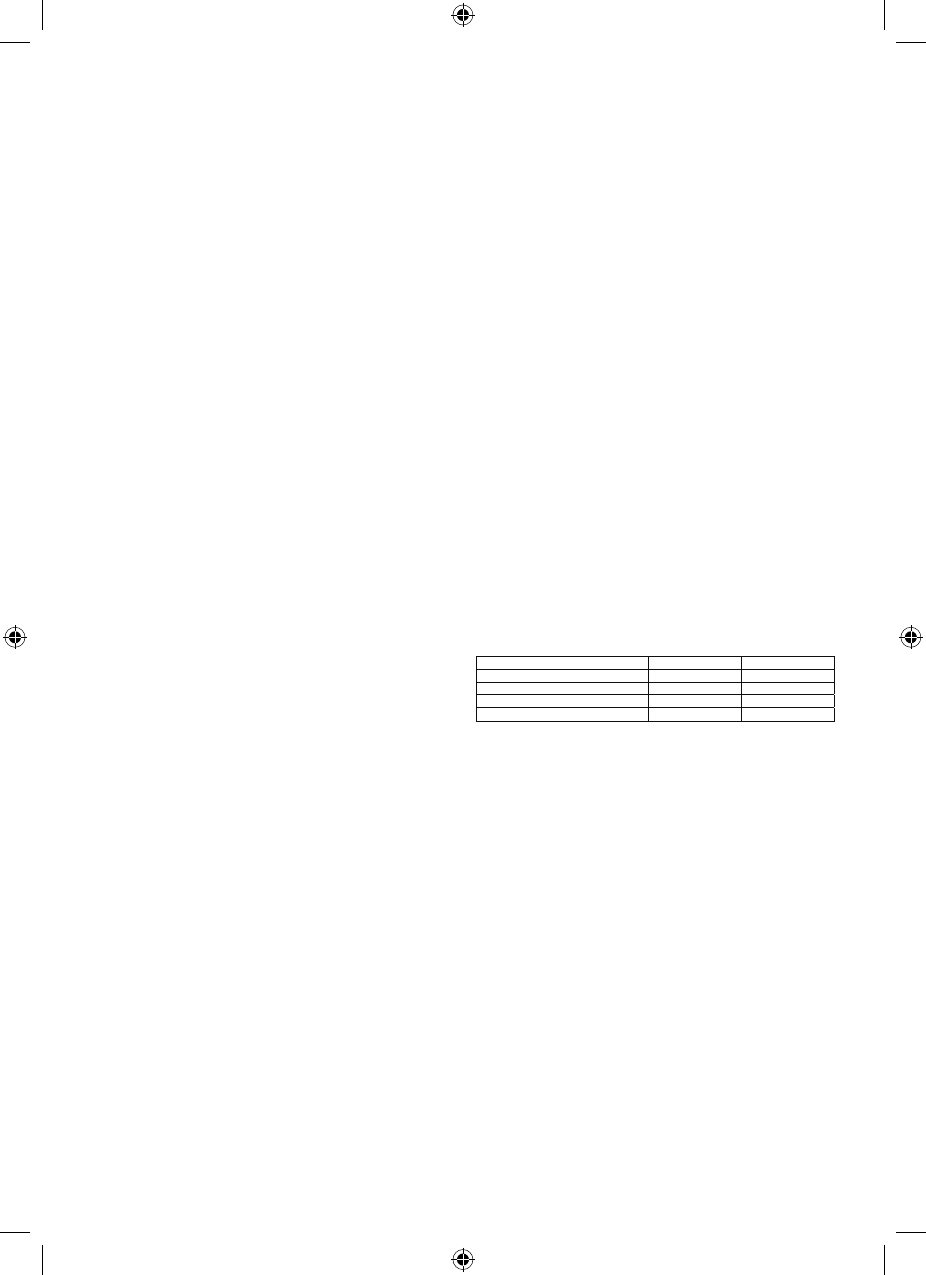
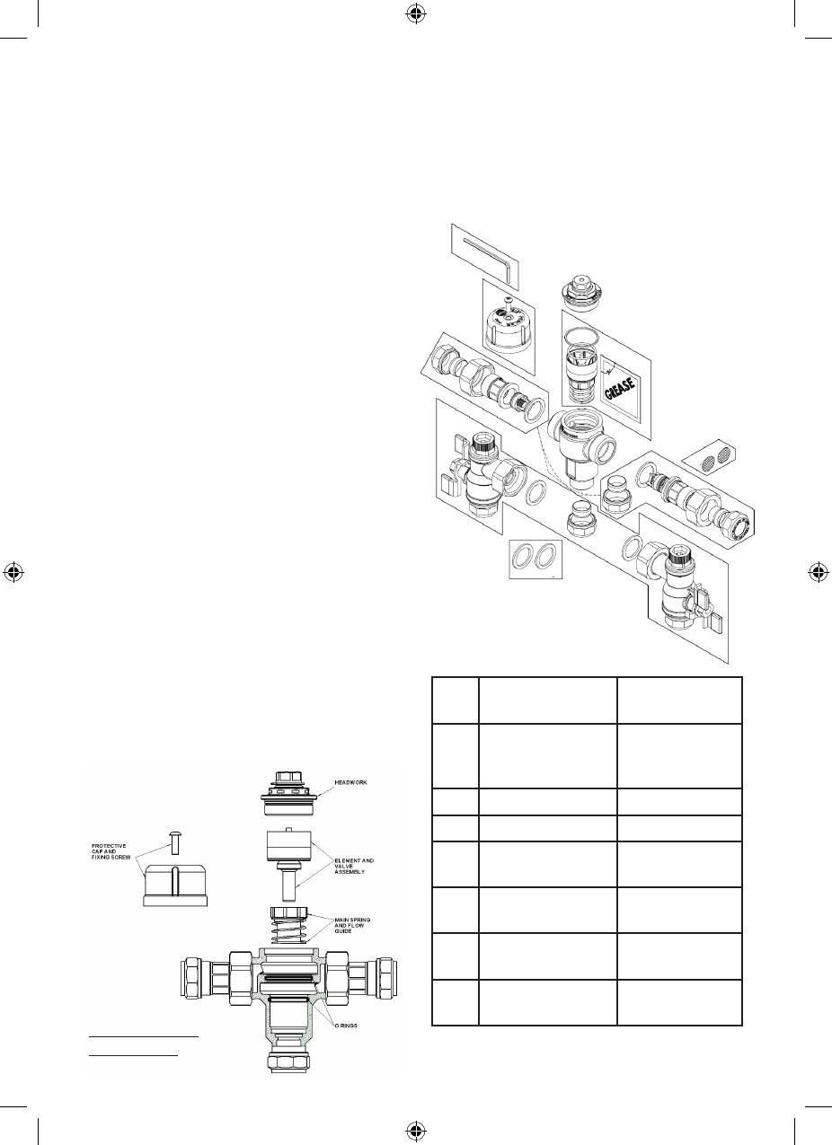
Assembly Procedure
• Unpackthemainvalveassembly,removethe
three plastic protection caps and check that
the bores are free of debris and the end
sealing faces are clean.
• Unpackthetwotailpiecesandconrm
they are complete with union nuts and
compression nuts and olives.
• Locatethesealinggaskets,inserttheminto
the union nuts against the faces of the
tailpieces and screw the union nuts onto the
valve until a tight seal has been made.
• Removethecompressionnutsandolives
from the tailpieces. Locate the inlet filter
screens and insert them into the bore of the
tailpieces up to the shoulder.
• Assemblethevalvetothepipeworkand
ensure the hot and cold water pipes have
full penetration into the tailpiece.
• Tightenthecompressionnutsensuringthat
the end of the pipe remains in contact with
the filter element.
The highest flow rates will be achieved under balanced pressure conditions, but the pressure at
the valve inlets must be within a ratio of 5:1 under flow conditions and the size and layout of
pipework and fittings must take this into account.
FITTING
Before installation, the system operating conditions of inlet pressures, hot water temperature and
hot and cold water flow rates should be determined and confirmed to be within the expected
conditions of normal use shown in the table below.
BS1287 BSEN1111
Maximum static pressure (bar) 10.0 10.0
Supply pressure hot and cold (bar) 0.1 – 1.0 1.0 – 5.0
Hot supply °C 55 - 65 55 – 65
Cold supply °C Maximum 25 Maximum 25
Mixed water temperature Maximum 46 Maximum 46
Valves must operate in either a high pressure setting or a low pressure setting. These valves are
not capable of operation with, for instance hot water supply in one pressure range and cold
water supply in the other pressure range. In these conditions it is necessary to either boost one
pressure or reduce the other so that both supplies are within a common pressure range.
If your water supply cannot meet these conditions then the valve cannot be guaranteed to
operate as a Type 2 valve.
Operating pressures above 5.0 Bar will require the installation of a pressure reducing valve.
Correct location of the mixing valve is important to ensure that it is accessible for commissioning
and servicing.
• The use of sealing compounds must be avoided since they may intrude into the water
supply and impair the valve performance.
• The valve must be so installed that it is readily accessible for commissioning and
maintenance when being installed in accordance with TMV2.
• The valve must be installed with isolation valves on both the hot and cold water systems as
close as possible to the valve; so as to allow the valve to be commissioned and tested
correctly.
• The valve is supplied with integral strainers on the hot and cold water supplies therefore in-
line strainers should not be required.
• The valve is fitted with integral “listed” non-return valve cartridges which command the water
supply, therefore the thermostatic valve is protected against cross-flow due to unbalanced
line pressures as required by the Water Supply (Water Fittings) Regulations 1999.
Assembly Procedure
•
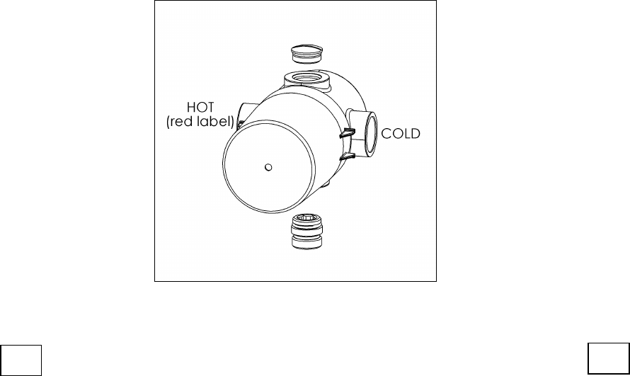
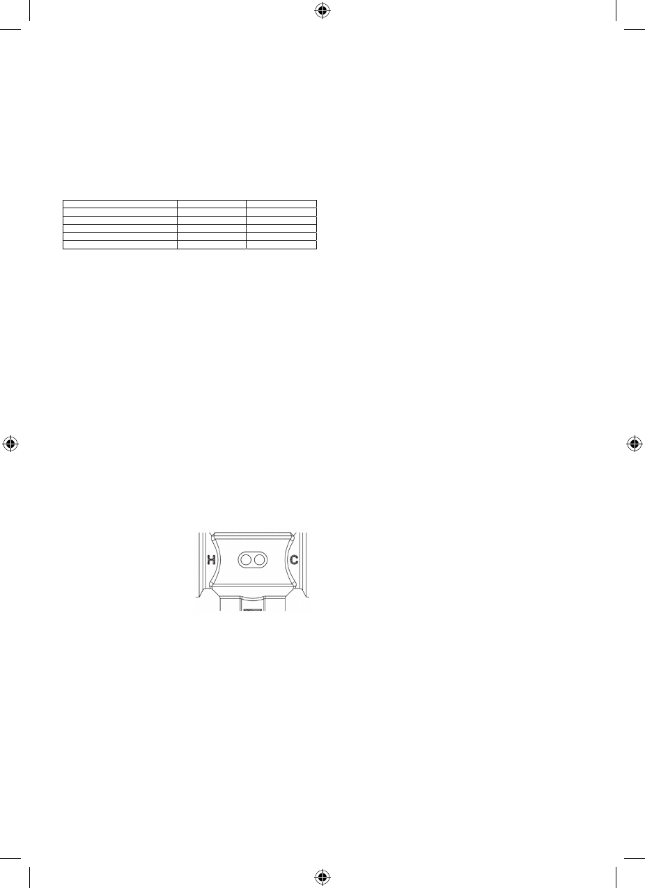
The valve body is clearly marked with ‘C’ for Cold and a blue
indicator and ‘H’ for Hot and a red indicator.
The valve must be correctly connected to the respective supplie
s
• Thevalvebodyis
clearly marked with
‘C’ for Cold and a
blue indicator and ‘H’
for Hot and a red
indicator.
The valve must be correctly connected
to the respective supplies
• Theuseofsealingcompoundsmustbe
avoided since they may intrude into
the water supply and impair the valve
performance.
• Thevalvemustbesoinstalledthatitis
readily accessible for commissioning and
maintenance when being installed in
accordance with TMV2.
TMV3 Model P404.indd 3 13/2/09 15:02:46
Exploded view of tailpiece assembly
ThePrestexModelP404UAmixingvalveis
optionally provided with angled assemblies in
lieu of the tailpiece arrangement shown above.
This allows the connections of the hot and
cold water supplies to be parallel to the mixed
water outlet for ease of piping layouts.
The assemblies comprise an integral full bore
ball valve and in-line strainer in an angled
housing.
When this arrangement is used, the
requirements for isolation valves and
Y-strainers previously mentioned are regarded
as fulfilled.
Exploded view of angled valve assembly
APPLICATION
The Prestex Model P404 thermostatic mixing
valve has been independently tested by
WRc-NSF against the requirements of BS EN
1287 (Low Pressure-LP) and BS EN 1111
(High Pressure-HP) and certified as complying
with the requirements of the TMV2 Scheme and
is suitable for use in the designations shown in
the table below.
Valves approved for designation for use ‘HP’
only:- If a water supply is fed by gravity then
the supply pressure should be verified to
ensure the conditions of use are appropriate
for the valve.
The above temperatures are recommended by
the Thermostatic Mixing Valve (manufacturers)
Association as relevant settings for the varying
applications shown. This is the maximum
commissioning temperature but valves may
exceed this by 2°C in use.
The range of available temperature adjustment
is 35°C to 48°C but 46°C is the maximum
recommended mixed water temperature
from a bath tap. The maximum temperature
takes account of the allowable temperature
tolerances inherent in thermostatic mixing
valves and temperature losses in metal baths.
46°C is not a safe bathing temperature for
adults or children.
The British Burns Association recommends
37°C to 37.5°C as a comfortable bathing
temperature for children. In premises covered
by the Care Standards Act 2000, the maximum
mixed water outlet temperature is 43°C.
• Unpack the main valve assembly and check that the bores are free of debris and the end
sealing faces are clean.
• Unpack the two tailpieces and confirm they are complete with union nuts and
compression nuts and olives.
• Locate the sealing gaskets, insert them into the union nuts against the faces of the
tailpieces and screw the union nuts onto the valve until a tight seal has been made.
• Remove the compression nuts and olives from the tailpieces. Locate the inlet filter
screens and insert them into the bore of the tailpieces up to the shoulder.
• Assemble the valve to the pipework and ensure the hot and cold water pipes have full
penetration into the tailpiece.
• Tighten the compression nuts ensuring that the end of the pipe remains in contact with
the filter element.
Exploded view of tailpiece assembly
The Pegler Model P404UA mixing valve is optionally provided with angled assemblies in lieu of
the tailpiece arrangement shown above. This allows the connections of the hot and cold water
supplies to be parallel to the mixed water outlet for ease of piping layouts.
The assemblies comprise an integral full bore ball valve and in-line strainer in an angled housing.
When this arrangement is used, the requirements for isolation valves and Y-strainers previously
mentioned are regarded as fulfilled.
Exploded view of angled valve assembly
APPLICATION
The Pegler Model P404 thermostatic mixing valve has been independently tested by WRc-NSF
against the requirements of BS EN 1287 (Low Pressure-LP) and BS EN 1111 (High Pressure-HP)
and certified as complying with the requirements of the TMV2 Scheme and is suitable for use in
the designations shown in the table below.
Valves approved for designation for use ‘HP’ only:- If a water supply is fed by gravity then
the supply pressure should be verified to ensure the conditions of use are appropriate for the
valve.
Table 2 – Recommended set outlet temperatures
Application Pressure Maximum set mixed
water temperature
Shower HP and LP 41°C
Wash basin HP and LP 41°C
Bidet HP and LP 38°C
Bath (Tub)* HP 44°C
*22mm only
The above temperatures are recommended by the Thermostatic Mixing Valve (manufacturers)
Association as relevant settings for the varying applications shown. This is the maximum
commissioning temperature but valves may exceed this by 2°C in use.
The range of available temperature adjustment is 35°C to 48°C but
46°C is the maximum recommended mixed water temperature from a bath tap. The maximum
temperature takes account of the allowable temperature tolerances inherent in thermostatic mixing
valves and temperature losses in metal baths.
46°C is not a safe bathing temperature for adults or children.
The British Burns Association recommends 37°C to 37.5°C as a comfortable bathing temperature for
children. In premises covered by the Care Standards Act 2000, the maximum mixed water outlet
temperature is 43°C.
COMMISSIONING
The valve must be commissioned under normal site system conditions and after establishing
supply conditions with the hot and cold water supplies open, leave the system running to allow
temperatures and pressures to stabilise and be checked.
Prior to commencing commissioning, the following checks should be carried out.
• The designation of the thermostatic mixing valve matches the application.
• The supply pressures and temperatures are within the operating range of the valve.
• Isolating valves and strainers are provided.
If all these conditions are met, proceed to set the temperature as described below.
The Pegler thermostatic mixing valve is supplied factory set at 43°C but the valve may be simply
adjusted after installation.
The mixed water temperature at the terminal fitting must never exceed 46°C
TMV3 Model P404.indd 4 13/2/09 15:02:46
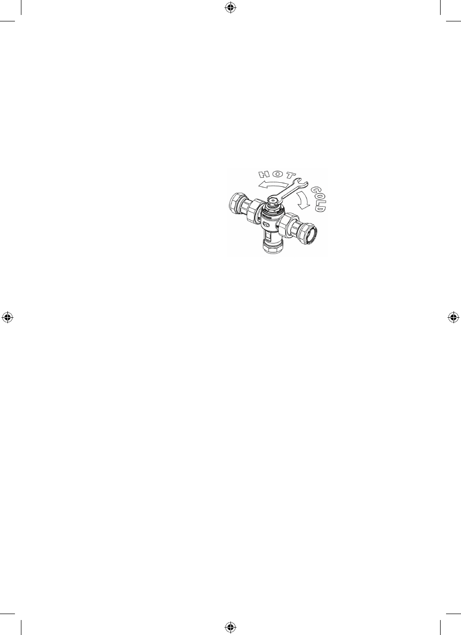
COMMISSIONING
The valve must be commissioned under normal
site system conditions and after establishing
supply conditions with the hot and cold water
supplies open, leave the system running to
allow temperatures and pressures to stabilise
and be checked.
Prior to commencing commissioning, the
following checks should be carried out.
• Thedesignationofthethermostaticmixing
valve matches the application.
• Thesupplypressuresandtemperaturesare
within the operating range of the valve.
• Isolatingvalvesandstrainersareprovided.
If all these conditions are met, proceed to
set the temperature as described below.
The Prestex thermostatic mixing valve is
supplied factory set at 43°C but the valve may
be simply adjusted after installation.
The mixed water temperature at the
terminal fitting must never exceed 46°C
When the valve has been installed with the
correct conditions of use it is advised that
the valve is subjected to exercise prior to the
commissioning at the application temperature.
Operate the valve from full cold to full hot at
least three times.
With the valve at the full cold position
bring the valve to the correct application
temperature by turning the spanner clockwise.
If the valve overshoots this temperature,
return the valve to the full cold condition,
and reset it to the correct temperature +0-2°C.
Do not set a valve on a lowered temperature as
this will not provide consistent operation.
When the valve is set to the required
temperature for the application carry out 5
cold water isolation tests to further exercise
the valve.
• Setthemixedwatertemperaturetothe
required value. It is advisable to use a
calibrated digital thermometer for checking
the inlet and outlet temperatures.
• Removetheplasticprotectivecapontopof
the valve with a suitable tool.
• Measureandrecordthetemperatureofthe
hot and cold water supplies at the inlets to
the valve.
• Measureandrecordthetemperatureof
the water discharging from the valve at the
greatest draw-off flow rate.
• Intheabsenceofothertemperaturesbeing
specified those detailed in Table 2 are the
desired settings
Once the required mixed outlet temperature
has been achieved, isolate the cold water
supply and monitor and record the mixed water
temperature including the maximum and final
temperatures achieved. The mixed water
temperature should never exceed 46°C.
Re-fit the cap.
Record all the equipment used during
commissioning.
• using a close fitting
spanner, reduce the
mixed outlet
temperature by
turning clockwise.
• increase the mixed
water outlet
temperature by
turning
counterclockwise.
TMV3 Model P404.indd 5 13/2/09 15:02:47

MAINTENANCE
The Prestex Model P404 thermostatic mixing
valve will provide satisfactory service and
a high level of protection, provided it is
maintained and subjected to In-Service
Testing.
Approximately 6-8 weeks after commissioning,
the following tests should be undertaken.
• Temperatureofthehotandcoldwater
supplies - RECORD
•Temperatureofthemixedwatertemperature
at the greatest draw off flow rate – RECORD
If the mixed water temperature has
significantly changed from that measured at
installation (e.g. > 1°C), RECORD the change
and before making any adjustments to the
valve confirm that:-
• Strainerelementsinthehotandcoldwater
supplies are clean and undamaged.
• Non-returnvalvesarecleanandoperating
correctly.
• Isolationvalvesareoperatingcorrectlyand
are set in the fully open position.
If the mixed water temperature is acceptable,
the following additional observations should
be made:-
Isolate the cold water supply and RECORD
the maximum temperature achieved. After 5
seconds, if water is still flowing RECORD the
final temperature.
• Ifthereisnosignicantchangetotheset
outlet temperature (±2°C or less deviation
from the original setting) and the fail safe
shut-off is functioning, then the valve is
working correctly and no further service work
is required.
• Ifthemaximummixedwatertemperature
exceeds the previous test results by more
than 2°C then the need for service work on
the valve is indicated.
• TheequipmentusedintheseIn-Service
Tests should be RECORDED and should
preferably be the same as that used at
installation.
Note:
If there is a residual flow during the
commissioning or the annual verification
(cold water supply isolation test) then this is
acceptable providing the temperature of the
water seeping from the valve is no more than
2°C above the designated maximum mixed
water outlet temperature setting of the valve.
Any higher temperatures should occur only
briefly. Temperature readings should be taken
at the normal flow rate after allowing the
system to stabilise. The sensing part of the
thermometer probe must be fully submerged
in the water that is to be tested. Any TMV
that has been adjusted or serviced must be
re-commissioned and re-tested in accordance
with the manufacturer’s instructions.
In the absence of any other instruction or
guidance, it is recommended that In-Service
Tests are carried out once every 12 months
as a minimum. If the temperature is outside
of the expected range it will be necessary to
remove and clean the valve in accordance with
the following instructions.
TMV Cleaning and Servicing Instructions
Most domestic water supplies contain calcium
which will separate out when the water is
heated in a system. The degree and speed of
scaling may vary depending on factors such as
water flow rates, system design, the hardness
of the water and the temperature to which the
water is heated.
Deposits of scale may over time form in the
valve, particularly at the hot inlet.
The formation of the scale may adversely affect
the performance of the valve which will be
detected during the in-service testing. If this
occurs it will be necessary to remove the valve
for de-scaling and servicing.
TMV3 Model P404.indd 6 13/2/09 15:02:47
SPARES
In order to ensure that the Model P404 thermostatic mixing valve continues to provide satisfactory
service, only GENUINE Pegler spare parts must be used.
Spare part order code Description
A 854453 Protective cap complete with screw
B 854447 Hexagon key
C 854454 Service kit
D 854449 (15mm), 854450 (22mm) Tailpiece Strainer kit
E 854451 (15mm), 854452 (22mm) Angle valve strainer kit
F 854456 (15mm), 854457 (22mm) Sealing washer
G 854455 (15mm), 817012 (22mm) Wafer Strainer
• Carefully remove the element and valve assembly and put to one side.
• Remove the main spring and flow guide and carefully put to one side.
• Inspect the components for contamination or damage.
• Clean or replace as necessary
• Remove the two o rings
• Clean the valve body and headwork using a propriety de-scaler
• Thoroughly rinse the body and headwork in clean water.
• Carefully fit new o rings from the service kit taking care to ensure they are not
damaged and are correctly located.
• Lubricate the o rings with the lubricant provided.
• Re-fit the flow guide and spring lubricating the flow guide around the greatest
diameter with the lubricant provided
• Lubricate the shuttle valve with the lubricant provided
• Re-fit the shuttle valve and element assembly.
• Re-fit the headwork ensuring correct tightening
• Re-fit the valve assembly
• If after cleaning the valve, and replacing the o ring seals, the valve does not function
correctly, it may be necessary to replace the thermal element.
Exploded view of TMV assembly
Exploded view of
TMV assembly
SPARES
In order to ensure that the Prestex Model P404
thermostatic mixing valve continues to provide
satisfactoryservice,onlyGENUINEPeglerspare
parts must be used.
Spare part order
code
Description
1 854453 Protective cap
complete with
screw
2 854447 Hexagon key
3 854454 Service kit
4 854449 (15mm)
854450 (22mm)
Tailpiece
Strainer kit
5 854451 (15mm)
854452 (22mm)
Angle valve
strainer kit
6 854456 (15mm),
854457 (22mm)
Sealing washer
7 854455 (15mm),
817012 (22mm)
Wafer Strainer
1
2
3
4
5
6
4
7
TO SERVICE THE VALVE:
• Isolatethehotandcoldsupply.
• Removethevalvetoacleanworkingarea.
• Removetheprotectivecap.
• Unscrewtheheadworkofthevalve.
• Carefullyremovetheelementandvalve
assembly and put to one side.
• Removethemainspringandowguideand
carefully put to one side.
• Inspectthecomponentsforcontamination
or damage.
• Cleanorreplaceasnecessary
• Removethetwoorings
• Cleanthevalvebodyandheadworkusinga
propriety de-scaler
• Thoroughlyrinsethebodyandheadworkin
clean water.
• Carefullytneworingsfromtheservicekit
taking care to ensure they are not damaged
and are correctly located.
• Lubricatetheoringswiththelubricant
provided.
• Re-ttheowguideandspringlubricating
the flow guide around the greatest diameter
with the lubricant provided
• Lubricatetheshuttlevalvewiththe
lubricant provided
• Re-ttheshuttlevalveandelement
assembly.
• Re-ttheheadworkensuringcorrect
tightening
• Re-ttheassembledvalveandperformthe
comissioning sequence.
• Ifaftercleaningthevalve,andreplacingthe
o ring seals, the valve does not function
correctly, it may be necessary to replace the
thermal element.
TMV3 Model P404.indd 7 13/2/09 15:02:47

UK Sales
Free Phone: 0800 156 0010
Free Fax: 0808 156 1011
Email: uk.sales@pegleryorkshire.co.uk
Export
Tel: +44 (0) 1302 855 656
Fax: +44 (0) 1302 730 513
Email: export@pegleryorkshire.co.uk
Technical Help
Free Phone: 0800 156 0050
Free Fax: 0808 156 1012
Email: tech.help@pegleryorkshire.co.uk
Brochure Hotline
Free Phone: 0800 156 0020
Free Fax: 0808 156 1011
Email: info@pegleryorkshire.co.uk
www.pegleryorkshire.co.uk
Our brands:
Also available from
Pegler Yorkshire:
LUXURYTAPSOLUTIONS
Pegler Limited, St Catherine’s Avenue,
Doncaster, South Yorkshire, DN4 8DF, England.
Registered Company No. 01194543
Place of Registration: England
Yorkshire Limited, Haigh Park Road, Stourton,
Leeds, West Yorkshire, LS10 1RT, England.
Registered Company No. 00401507
Place of Registration: England
All brand names and logo styles are registered trademarks.
Maintaining a policy of continual product development,
Pegler Yorkshire reserves the right to change specifications,
design and materials of products listed in this leaflet without
prior notice.
TMV3 Model P404.indd 8 13/2/09 15:02:49
