Designer Client Guide IBM Info Sphere Data Stage And Quality Version 11 Release 3
User Manual: Pdf
Open the PDF directly: View PDF ![]() .
.
Page Count: 279 [warning: Documents this large are best viewed by clicking the View PDF Link!]
- Contents
- Chapter 1. Tutorial: Designing your first job
- Chapter 2. Sketching your job designs
- Getting started with jobs
- Stages
- Links
- Developing the job design
- The Job Run Options dialog box
- Creating jobs by using assistants
- Chapter 3. Setting up your data connections
- Chapter 4. Defining your data
- Table definition window
- Importing a table definition
- Sharing metadata between projects
- Manually entering a table definition
- Viewing or modifying a table definition
- Stored procedure definitions
- Chapter 5. Making your jobs adaptable
- Chapter 6. Making parts of your job design reusable
- Chapter 7. Defining special components
- Chapter 8. Configuring your designs
- Chapter 9. Comparing objects
- Chapter 10. Searching and impact analysis
- Find facilities
- Quick find
- Advanced find
- Impact analysis
- Impact analysis and object types
- Running where used queries
- Running where used queries on column definitions
- Displaying data lineage for columns
- Disabling data lineage highlighting
- Running dependencies of queries
- Viewing query results
- Example of a where used query
- Example of a dependencies of query
- Reporting on an advanced find
- Find facilities
- Chapter 11. Sharing and moving your designs
- Chapter 12. Documenting your designs
- Chapter 13. Getting jobs ready to run
- Chapter 14. Building sequence jobs
- Creating sequence jobs
- Specifying triggers
- Restarting sequence jobs
- Creating parameters in your sequence jobs
- Creating environment variables in your sequence jobs
- Sequence job properties
- Sequence job activities
- General activity properties
- End Loop activity properties
- ExecCommand activity properties
- Exception activity properties
- Job Activity properties
- Nested condition activity properties
- Notification activity properties
- Oozie Workflow Activity properties
- Routine activity properties
- Sequencer activity properties
- Start Loop activity properties
- Terminator activity properties
- User variables activity properties
- Wait-For-File activity properties
- Chapter 15. Job control routine
- Chapter 16. Tools for managing and administering jobs
- Chapter 17. Creating repository tree objects
- Appendix A. Product accessibility
- Appendix B. Contacting IBM
- Appendix C. Accessing the product documentation
- Appendix D. Providing feedback on the product documentation
- Notices and trademarks
- Index

IBM InfoSphere DataStage and QualityStage
Version 11 Release 3
Designer Client Guide
SC19-4272-00

IBM InfoSphere DataStage and QualityStage
Version 11 Release 3
Designer Client Guide
SC19-4272-00


Contents
Chapter 1. Tutorial: Designing your first
job.................1
Setting up the exercise ...........4
Starting the Designer client .........4
Lesson checkpoint ...........7
Setting up your project ...........7
Lesson checkpoint ...........8
Creating a new job ............8
Lesson checkpoint ...........9
Adding stages and links to your job ......9
Adding stages .............9
Adding links .............11
Renaming stages and links ........11
Lesson checkpoint ...........12
Configuring your job ...........12
Configuring the data source stage ......12
Configuring the Transformer stage......14
Configuring the target file stage ......16
Lesson checkpoint ...........17
Compiling your job............17
Lesson checkpoint ...........17
Running your job and viewing results .....17
Running the job ............17
Viewing results ............19
Lesson checkpoint ...........20
Chapter 2. Sketching your job designs 21
Getting started with jobs ..........21
Creating a job ............21
Opening an existing job .........22
Saving a job .............22
Naming a job.............23
Stages ................23
Parallel job stages ...........23
Server job stages............24
Mainframe job stages ..........24
Naming stages and shared containers.....24
Links ................25
Linking parallel stages..........25
Linking server stages ..........26
Linking mainframe stages ........28
Link ordering.............28
Naming links .............29
Developing the job design .........29
Adding stages ............29
Moving stages ............30
Renaming stages............30
Deleting stages ............30
Linking stages ............31
Moving links .............31
Editing stages ............32
Cutting or copying and pasting stages ....37
Pre-configured stages ..........37
Annotations .............38
Using the Data Browser .........39
Using the performance monitor.......40
Running server jobs and parallel jobs.....41
The Job Run Options dialog box .......41
Parameters page ............41
Limits page .............42
General page .............42
Creating jobs by using assistants .......42
Chapter 3. Setting up your data
connections ............43
Creating a data connection object .......43
Creating a data connection object manually. . . 43
Creating a data connection object from a
metadata import............45
Creating a data connection object from a stage. . 46
Using a data connection object ........47
Using a data connection object with a stage . . 48
Using a Data Connection object for a metadata
import ...............49
Chapter 4. Defining your data .....51
Table definition window ..........51
General page .............51
Columns page ............52
Format page .............53
NLS page ..............54
Relationships page ...........54
Parallel page .............55
Layout page .............55
Locator page .............55
Analytical information page ........56
Importing a table definition .........56
Using the Data Browser .........57
Sharing metadata between projects ......58
Shared metadata............58
Importing metadata to the shared repository . . 59
Creating a table definition from shared metadata 60
Creating a table from a table definition ....61
Creating a table from a table definition ....62
Synchronizing metadata .........64
Managing shared metadata ........65
Manually entering a table definition ......66
Creating a table definition ........66
Viewing or modifying a table definition .....82
Editing column definitions ........82
Deleting column definitions ........82
Finding column definitions ........82
Propagating values ...........83
Stored procedure definitions.........83
Importing a stored procedure definition ....83
The table definition dialog box for stored
procedures .............84
Manually entering a stored procedure definition 85
Viewing or modifying a stored procedure
definition ..............87
© Copyright IBM Corp. 1997, 2014 iii
Chapter 5. Making your jobs adaptable 89
Adding parameters to your jobs .......90
Creating a parameter set ..........91
Adding environment variables to your jobs....92
Adding parameter sets to your jobs ......93
Inserting parameters and parameter sets as
properties ...............93
Specifying values for a parameter set in a sequence
job.................94
Chapter 6. Making parts of your job
design reusable ...........95
Local containers .............95
Creating a local container.........95
Viewing or modifying a local container ....96
Using input and output stages .......96
Deconstructing a local container ......97
Shared containers ............97
Creating a shared container ........98
Naming shared containers ........99
Viewing or modifying a shared container
definition ..............99
Editing shared container definition properties . . 99
Using a shared container in a job......100
Pre-configured components........102
Converting containers ..........103
Chapter 7. Defining special
components ............105
Special components for parallel jobs ......105
Parallel routines ...........105
Custom stages for parallel jobs ......107
Special components for server jobs ......122
Server routines ............122
Custom transforms ..........127
Data elements ............129
Special components for mainframe jobs.....133
Mainframe routines ..........133
Machine profiles ...........138
IMS databases and IMS viewsets ......139
Chapter 8. Configuring your designs 143
Configuring parallel jobs .........143
Specifying general options ........143
Enabling runtime column propagation ....145
NLS page .............145
Setting runtime options for your job.....145
Specifying default time and date formats . . . 146
Selecting a local message handler......146
Configuring server jobs ..........146
Specifying general options ........146
Setting National Language Support (NLS)
properties .............148
Optimizing job performance .......149
Configuring mainframe jobs ........150
Specifying general options ........150
Specifying a job parameter in a mainframe job 151
Controlling code generation .......152
Supplying extension variable values .....153
Configuring operational metadata .....153
Chapter 9. Comparing objects ....155
Comparing objects in the same project .....157
Comparing objects in different projects .....157
Compare command line tool ........157
Chapter 10. Searching and impact
analysis..............161
Find facilities .............161
Quick find .............161
Advanced find ............162
Impact analysis............166
Chapter 11. Sharing and moving your
designs ..............179
Importing objects ............179
Importing previously exported objects ....179
Importing external function definitions ....184
Importing web service function definitions . . 185
Importing metadata by using InfoSphere
Metadata Asset Manager ........185
Importing IMS definitions ........186
Exporting objects ............188
Exporting IBM InfoSphere DataStage
components .............188
Exporting from the export menu ......189
Specifying job dependencies .......190
Using export from the command line ....191
dsexport command ..........192
Chapter 12. Documenting your
designs ..............195
Generating a job report ..........196
Requesting a job report from the command line 197
Chapter 13. Getting jobs ready to run 199
Compiling server jobs and parallel jobs.....199
Compilation checks - server jobs ......199
Successful compilation .........200
Compile from the client command line ....200
Viewing generated OSH code .......202
Generating code for mainframe jobs ......202
Job validation ............202
Code generation ...........203
Job upload .............203
JCL templates ............203
Code customization ..........204
Compiling multiple jobs ..........204
Chapter 14. Building sequence jobs 207
Creating sequence jobs ..........208
Specifying triggers............208
Trigger types ............209
Trigger expression syntax ........210
Restarting sequence jobs..........212
Creating parameters in your sequence jobs . . . 213
Creating environment variables in your sequence
jobs ................214
Sequence job properties ..........215
General page ............215
iv Designer Client Guide
Parameters page ...........216
Job Control page ...........217
Dependencies page ..........217
Sequence job activities ..........218
General activity properties ........218
End Loop activity properties .......219
ExecCommand activity properties .....219
Exception activity properties .......220
Job Activity properties .........220
Nested condition activity properties .....221
Notification activity properties ......222
Oozie Workflow Activity properties .....223
Routine activity properties ........224
Sequencer activity properties .......224
Start Loop activity properties .......226
Terminator activity properties .......230
User variables activity properties ......231
Wait-For-File activity properties ......232
Chapter 15. Job control routine . . . 235
Chapter 16. Tools for managing and
administering jobs .........237
Intelligent assistants ...........237
Creating a template from a job ......237
Creating a job from a template ......238
Using the Data Migration Assistant .....238
Managing data sets ...........239
Structure of data sets ..........240
Starting the Data Set Manager .......241
Data set viewer............241
Creating and editing configuration files ....242
Message Handler Manager .........243
Using the Message Handler Manager ....244
Message handler file format .......245
JCL templates .............245
Chapter 17. Creating repository tree
objects ..............247
Repository tree .............247
Creating new objects ...........248
Create a new object on startup ......248
Create a new object from the repository tree . . 248
Create a new object from the main menu . . . 248
Create a new object from the toolbar ....249
Appendix A. Product accessibility . . 251
Appendix B. Contacting IBM .....253
Appendix C. Accessing the product
documentation ...........255
Appendix D. Providing feedback on
the product documentation .....257
Notices and trademarks .......259
Index ...............265
Contents v
vi Designer Client Guide

Chapter 1. Tutorial: Designing your first job
This exercise walks you through the creation of a simple job.
The aim of the exercise is to get you familiar with the Designer client, so that you
are confident to design more complex jobs. There is also a dedicated tutorial for
parallel jobs, which goes into more depth about designing parallel jobs.
In this exercise you design and run a simple parallel job that reads data from a text
file, changes the format of the dates that the file contains, and writes the
transformed data back to another text file.
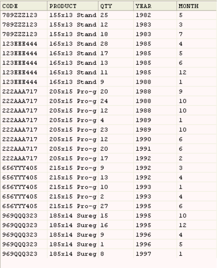
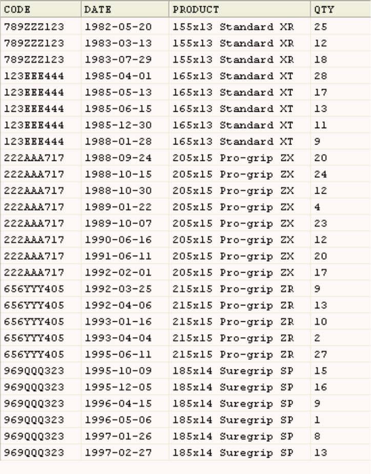
The source text file contains data from a wholesaler who deals in car parts. It
contains details of the wheels they have in stock. The data is organized in a table
that contains approximately 255 rows of data and four columns. The columns are
as follows:
CODE The product code for each type of wheel.
DATE The date new wheels arrived in stock (given as year, month, and day).
PRODUCT
A text description of each type of wheel.
QTY The number of wheels in stock.
The job that you create will perform the following tasks:
1. Extract the data from the file.
2. Convert (transform) the data in the DATE column from a complete date
(YYYY-MM-DD) to a year and month (YYYY, MM) stored as two columns.
3. Write the transformed data to a new text file that is created when you run the
job.
The following table shows a sample of the source data that the job reads.
© Copyright IBM Corp. 1997, 2014 1

The following table shows the same data after it has been transformed by the job.
Figure 1. Source data for exercise
2Designer Client Guide
Learning objectives
As you work through the exercise, you will learn how to do the following tasks:
vSet up your project.
vCreate a new job.
vDevelop the job by adding stages and links and editing them.
vCompile the job.
vRun the job.
Time required
This exercise takes approximately 60 minutes to finish. If you explore other
concepts related to this exercise, it could take longer to complete.
Figure 2. Data after transformation by the job
Chapter 1. Tutorial: Designing your first job 3

Audience
New user of IBM®Information Server.
System requirements
The exercise requires the following hardware and software:
vIBM InfoSphere®DataStage®clients installed on a Windows XP platform.
vConnection to an engine tier on a Windows or UNIX platform (Windows servers
can be on the same computer as the clients).
Prerequisites
Complete the following tasks before starting the exercise:
vObtain DataStage developer privileges from the InfoSphere DataStage
administrator.
vFind out the name of the project that the administrator has created for you to
work in.
vSet up the exercise data as described in the first lesson.
Setting up the exercise
Before you begin the exercise, you must copy the data that you will use to a folder.
To set up the exercise:
1. Insert the Installation CD into the CD drive or DVD drive of the client
computer.
2. Create a new folder on your client computer and name it exercise.
3. Copy the file on the CD named \TutorialData\DataStage\Example1.txt to the
folder that you created on the client computer.
You are now ready to start the exercise.
Starting the Designer client
The first step is to start the Designer client.
The Designer client is the tool that you use to set up your project, and to create
and design your job. The Designer client provides the tools for creating jobs that
extract, transform, load, and check the quality of data. The Designer client is like a
workbench or a blank canvas that you use to build jobs. The Designer client
palette contains the tools that form the basic building blocks of a job:
vStages connect to data sources to read or write files and to process data.
vLinks connect the stages along which your data flows.
The Designer client uses a repository in which you can store the objects that you
create during the design process. These objects can be reused by other job
designers.
To start the Designer client:
1. Select Start >Programs >IBM InfoSphere Information Server >IBM
InfoSphere DataStage and QualityStage Designer.
2. In the Attach window, type your user name and password.
4Designer Client Guide
3. Select your project from the Project list, and then click OK.
4. If you get a message that a security certificate from the server is not trusted,
accept the certificate:
a. To view the security certificate, click View Certificate.
b. Click the Certification Path tab, and then select the root certificate.
c. Click the General tab.
d. Click Install Certificate, and then click Next.
e. Select Place all certificates in the following store.
f. Click Browse, and then select Trusted Root Certification Authorities.
g. Click Next, and then click Finish to import the certificate.
5. Click Cancel to close the New window. (You will create your job later in this
exercise.)
The Designer client is now ready for you to start work.
The following figure shows the Designer client.
Chapter 1. Tutorial: Designing your first job 5
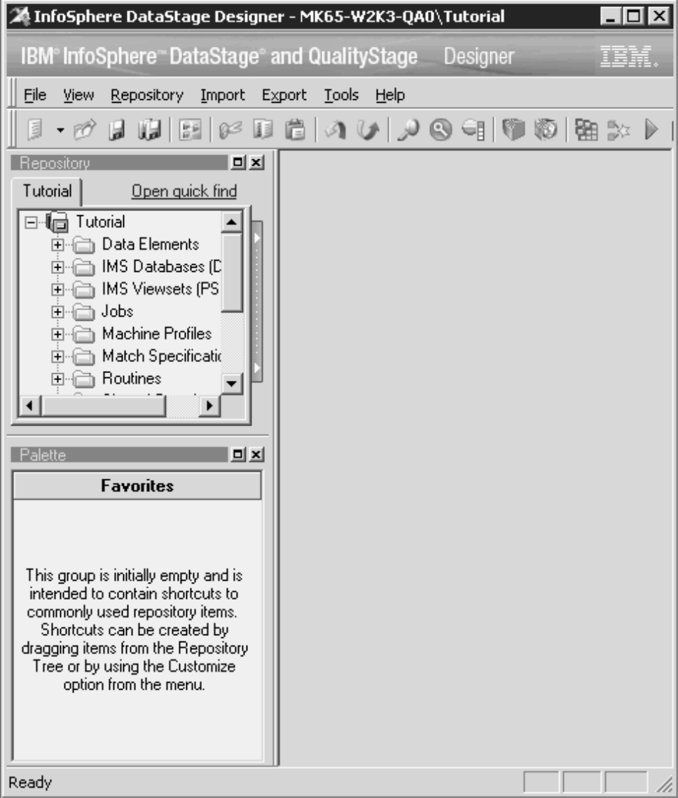
Figure 3. Designer client
6Designer Client Guide

Lesson checkpoint
In this lesson, you started the Designer client.
You learned the following tasks:
vHow to enter your user name and password in the “Attach” window.
vHow to select the project to open.
Setting up your project
The next step is to set up your project by defining the data that you will use.
Before you create your job, you must set up your project by entering information
about your data. This information includes the name and location of the tables or
files that contain your data, and a definition of the columns that the tables or files
contain. The information, also referred to as metadata, is stored in table definitions
in the repository. The easiest way to enter a table definition is to import it directly
from the source data. In this exercise you will define the table definition by
importing details about the data directly from the data file.
To define your table definition:
1. In the Designer client, select Import >Table definitions >Sequential File
Definitions.
2. In the “Import Metadata (Sequential)” window, do the following steps:
a. In the Directory field type, or browse for the exercise directory name.
b. Click in the Files section.
c. In the Files section, select Example1.txt.
d. Click Import.
3. In the “Define Sequential Metadata” window, do the following tasks:
a. In the “Format” page, select the First line is column names option.
b. Click the Define tab.
c. In the “Define” page, examine the column definitions. This is the metadata
that will populate your table definition.
d. Click OK.
4. In the “Import Metadata (Sequential)” window, click Close.
5. In the repository tree, open the Table Definitions\Sequential\Root folder.
6. Double-click the table definition object named Example1.txt to open it.
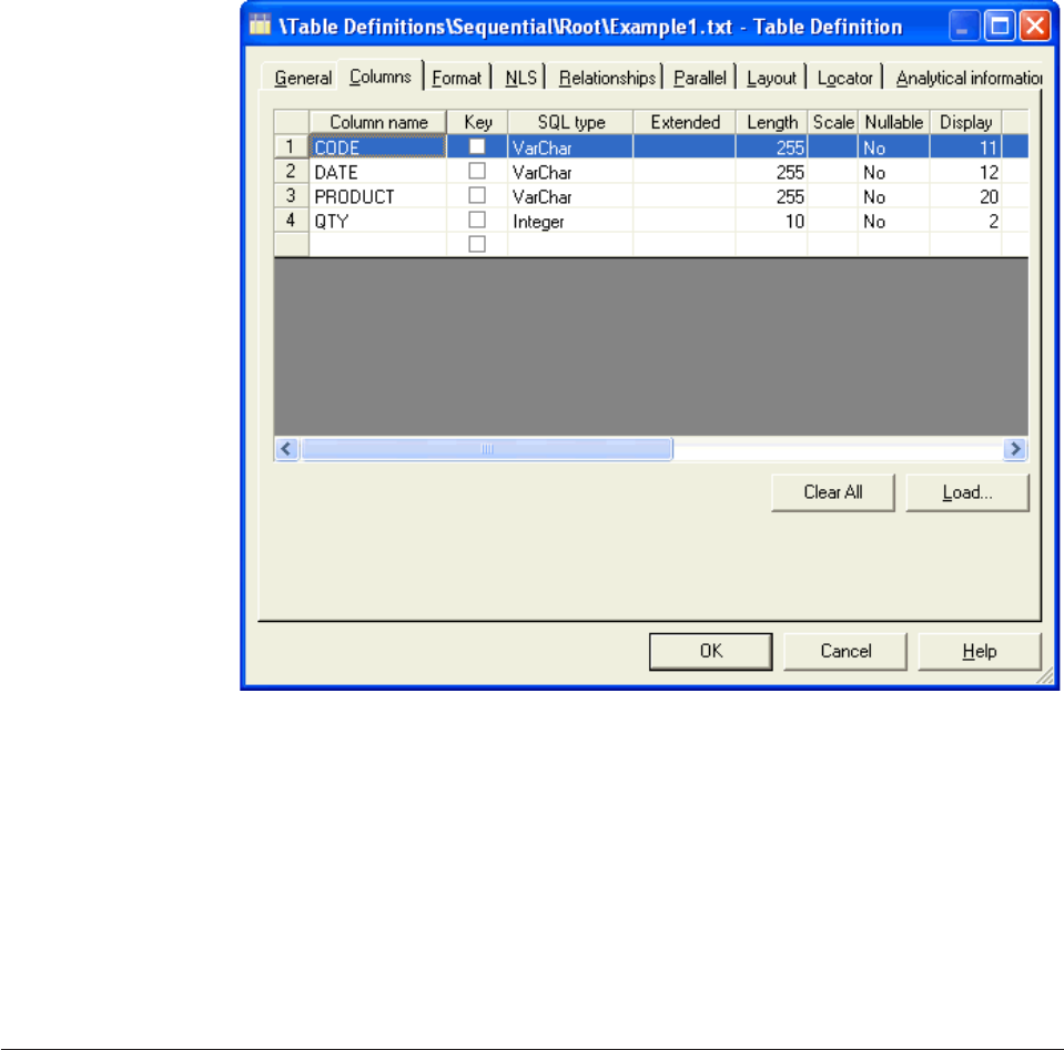
7. In the “Table Definition”, window, click the Columns tab.
8. Examine the column definitions in the “Columns” page. Note that these are the
same as the column definitions that you looked at in the “Define Sequential
Metadata” window.
The following figure shows the column definitions. Compare these to the
columns shown in the Figure 1 on page 2 figure.
Chapter 1. Tutorial: Designing your first job 7
9. Click OK to close the Table Definition window.
Lesson checkpoint
In this lesson you defined a table definition.
You learned the following tasks:
vHow to import metadata from a data file to create a table definition object in the
repository.
vHow to open the table definition that you created it and examine it.
Creating a new job
The first step in designing a job is to create an empty job and save it to a folder in
the repository.
When a new project is installed, the project is empty and you must create the jobs
that you need. Each job can read, transform, and load data, or cleanse data. The
number of jobs that you have in a project depends on your data sources and how
often you want to manipulate data.
In this lesson, you create a parallel job named Exercise and save it to a new folder
in the Jobs folder in the repository tree.
To create a new job:
1. In the Designer client, select File >New.
Figure 4. The column definition for the source data
8Designer Client Guide

2. In the “New” window, select the Jobs folder in the left pane, and then select
the parallel job icon in the right pane.
3. Click OK to open a new empty job design window in the design area.
4. Select File >Save.
5. In the “Save Parallel Job As” window, right-click the Jobs folder and select
New >Folder from the menu.
6. Type a name for the folder, for example, My Folder, and then move the cursor
to the Item name field.
7. Type the name of the job in the Item name field. Name the job Exercise.
8. Confirm that the Folder path field contains the path \Jobs\My Jobs, and then
click Save.
You have created a new parallel job named Exercise and saved it in the folder
Jobs\My Jobs in the repository.
Lesson checkpoint
In this lesson you created a job and saved it to a specified place in the repository.
You learned the following tasks:
vHow to create a job in the Designer client.
vHow to name the job and save it to a folder in the repository tree.
Adding stages and links to your job
You add stages and links to the job that you created. Stages and links are the
building blocks that determine what the job does when it runs.
Ensure that the job named Exercise that you created in the previous lesson is open
and active in the job design area. A job is active when the title bar is dark blue (if
you are using the default Windows colors). A job consists of stages linked together
that describe the flow of data from a data source to a data target. A stage is a
graphical representation of the data itself, or of a transformation that will be
performed on that data. The job that you are designing has a stage to read the
data, a stage to transform the data, and a stage to write the data.
Adding stages
This procedure describes how to add stages to your job.
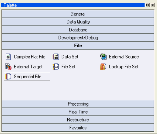
1. In the Designer client palette area, click the File bar to open the file section of
the palette.
2. In the file section of the palette, select the Sequential File stage icon and drag
the stage to your open job. Position the stage on the right side of the job
window.
The figure shows the file section of the palette.
Chapter 1. Tutorial: Designing your first job 9
3. In the file section of the palette, select another Sequential File stage icon and
drag the stage to your open job. Position the stage on the left side of the job
window.
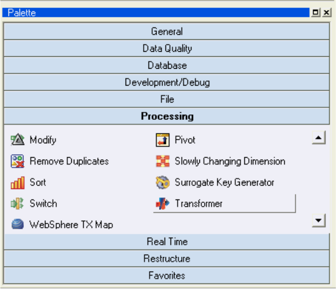
4. In the Designer client palette area, click the Processing bar to open the
Processing section of the palette.
5. In the processing section of the palette, select the Transformer stage icon and
drag the stage to your open job. Position the stage between the two Sequential
File stages.
The figure shows the Processing section of the palette.
Figure 5. File section of palette
10 Designer Client Guide
6. Select File >Save to save the job.
Adding links
This procedure describes how to add links to your job.
1. Right-click on the Sequential File stage on the left of your job and hold the
right button down. A target is displayed next to the mouse pointer to indicate
that you are adding a link.
2. Drag the target to the Transformer stage and release the mouse button. A black
line, which represents the link, joins the two stages.
Note: If the link is displayed as a red line, it means that it is not connected to
the Transformer stage. Select the end of the link and drag it to the Transformer
stage and release the link when it turns black.
3. Repeat steps 1 and 2 to connect the Transformer stage to the second Sequential
File stage.
4. Select File >Save to save the job.
Renaming stages and links
It is good design practice to give your links and stages names rather than to accept
the default names. Specifying names makes your job easier to document and
maintain.
Rename your stages and links with the names suggested in the table. This
procedure describes how to name your stages and links.
1. Select each stage or link.
2. Right-click and select Rename.
Figure 6. Processing section of palette
Chapter 1. Tutorial: Designing your first job 11
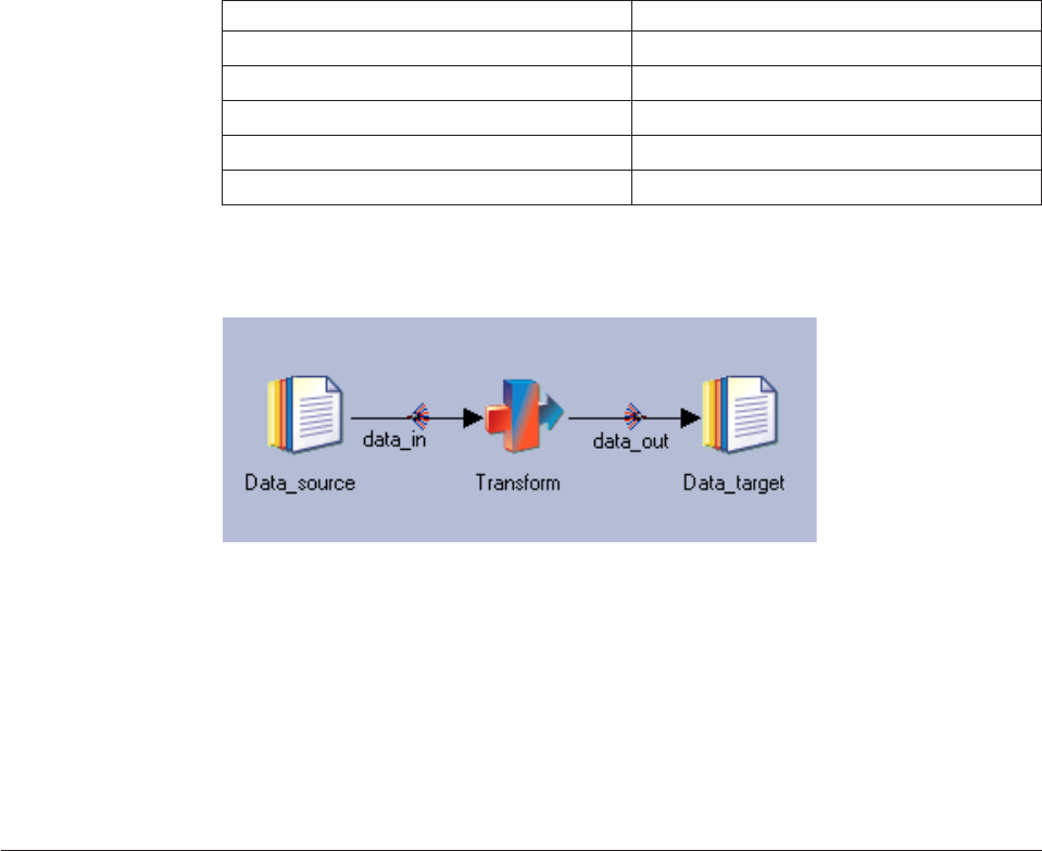
3. Type the new name:
Stage Suggested name
Left Sequential File Stage Data_source
Transformer Stage Transform
Right Sequential File Stage Data_target
Left link data_in
Right link data_out
Your job should look like the one in the following diagram:
Lesson checkpoint
You have now designed you first job.
You learned the following tasks:
vHow to add stages to your job.
vHow to link the stages together.
vHow to give the stages and links meaningful names.
Configuring your job
The next step is configuring your job and defining what tasks it will perform.
You configure the job by opening the stage editors for each of the stages that you
added in the previous lesson and adding details to them. You specify the following
information:
vThe name and location of the text file that contains the source data.
vThe format of the data that the job will read.
vDetails of how the data will be transformed.
vA name and location for the file that the job writes the transformed data to.
You will configure the Sequential File stage so that it will read the data from the
data file and pass it to the Transformer stage.
Configuring the data source stage
Ensure that the job is open in the Designer client.
You can configure the Sequential File stage named Data_source.
Figure 7. Example job with renamed stages and links
12 Designer Client Guide
1. Double-click the Sequential File stage named Data_source to open the stage
editor.
2. In the “Properties” tab of the “Output” page, select the property named File
in the Source category.
3. In the File field on the right of the “Properties” tab, type
C:\Exercise\Example1.txt and press Enter.
4. Select the First Line is Column Names property in the Options folder.
5. In the First Line is Column Names field on the right of the Properties tab,
select True.
6. Click the Columns tab.
7. In the “Columns” tab, click Load.
8. In the “Table Definitions” window, browse the tree to open the Table
Definitions/Sequential/Root folder and select the Example1.txt table
definition.
9. Click OK.
10. In the “Select Columns” window, verify that all four column definitions are
displayed in the Selected Columns list, and click OK.
11. Click View Data in the top right of the stage editor.
12. In the “Data Browser” window, click OK. The Data Browser shows you the
data that the source file contains. It is a good idea to view the data when you
have configured a source stage, because if you can view the data from the
stage you know that the stage can read the data when you run the job.
The figure shows the data that is displayed by the Data Browser.
Chapter 1. Tutorial: Designing your first job 13
13. Click Close to close the Data Browser and OK to close the stage editor.
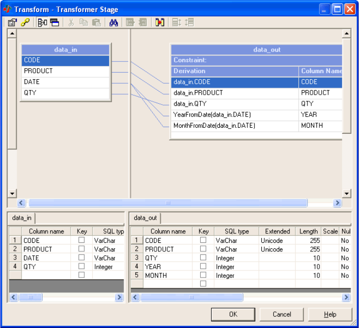
Configuring the Transformer stage
You can configure the Transformer stage.
1. Double-click the Transformer stage to open the Transformer stage editor.
2. In the top left pane of the transformer editor, click the CODE column and hold
the mouse button down.
3. Drag the CODE column to the table in the right pane that represents the
data_out link.
4. Release the mouse button. A CODE column appears on the data_out link.
5. Repeat these steps to copy the PRODUCT and the QTY columns from the
data_in link to the data_out link.
Figure 8. The data before transformation
14 Designer Client Guide
6. In the bottom left pane of the Transformer stage editor, add a new column to
the data_out link by doing the following tasks:
a. Double-click in the Column name field beneath the QTY column to add a
new row.
b. In the empty Column name field, type YEAR.
c. In the SQL type field, select Integer from the list.
d. In the Length field, type 10.
e. Repeat these steps to add another new column named MONTH, also with an
SQL type of Integer and a Length of 10.
The two new columns named YEAR and MONTH are displayed in red in the
data_out link in the top right pane. They are red because you have not yet
defined where the data to write into them will come from.
7. To define the source data for the YEAR column, do the following tasks:
a. Double-click the Derivation field to the left of YEAR in the data_out link to
open the expression editor.
b. In the expression editor, type YearFromDate(data_in.DATE).
c. Click outside the expression editor to close it.
You have specified that the YEAR column is populated by taking the data from
the DATE column and using the predefined function YearFromDate to strip the
year from it. The YEAR column is now black to indicate that it has a valid
derivation.
8. To define the source data for the MONTH column, do the following tasks:
a. Double-click the Derivation field to the left of MONTH in the data_out link
to open the expression editor.
b. In the expression editor, type MonthFromDate(data_in.DATE).
c. Click outside the expression editor to close it.
You have specified that the MONTH column is populated by taking the data
from the DATE column and using the predefined function MonthFromDate to
strip the month from it. The MONTH column is now black to indicate that it
has a valid derivation.
Chapter 1. Tutorial: Designing your first job 15
9. Click OK to close the Transformer stage editor.
You have configured the Transformer stage to read the data passed to it from the
Sequential File stage, and transform the data to split it into separate month and
year fields, and then pass the data to the target Sequential File stage.
Configuring the target file stage
You can configure the Sequential File stage named Data_target.
1. Double-click the Sequential File stage named Data_target to open the stage
editor.
2. In the “Properties” tab of the “Input” page, select the property named File in
the Target folder.
3. In the File field on the right of the “Properties” tab, type C:\Exercise\
data_out.txt and press Enter.
4. Select the First Line is Column Names property in the Options folder.
5. In the First Line is Column Names field on the right of the “Properties” tab,
select True.
6. Click the Columns tab, you can see that this has been populated with the
metadata that you defined in the Transformer stage. The Designer client
automatically propagates column definitions from stage to stage along the
connecting links.
7. Click OK to close the stage editor.
8. Select File >Save to save your job.
Figure 9. Transformer stage editor
16 Designer Client Guide

You have configured the Sequential File stage to write the data passed to it from
the Transformer stage to a new text file.
Lesson checkpoint
In this lesson, you configured your job.
You learned the following tasks:
vHow to edit a Sequential File stage.
vHow to import metadata into a stage.
vHow to edit a Transformer stage.
Compiling your job
You compile the job to prepare it to run on your system.
Ensure that the job named Exercise that you created in the previous lesson is open
and active in the job design area.
To compile your job:
1. Select File >Compile. The “Compile Job” window opens. As the job is
compiled, the window is updated with messages from the compiler.
2. When the “Compile Job” window displays a message that the job is compiled,
click OK.
The job is now compiled and ready to run.
Lesson checkpoint
In this lesson you compiled your job.
Running your job and viewing results
In this lesson, you use the Director client to run the job and to view the log that
the job produces as it runs. You also use the Designer client to look at the data that
is written by the sample job.
You run the job from the Director client. The Director client is the operating
console. You use the Director client to run and troubleshoot jobs that you are
developing in the Designer client. You also use the Director client to run fully
developed jobs in the production environment.
You use the job log to help debug any errors you receive when you run the job.
Running the job
You use this procedure to run a job.
1. In the Designer client, select Tools >Run Director. Because you are logged in
to the tutorial project through the Designer client, you do not need to start the
Director from the start menu and log on to the project. In the Director client,
your job has a status of compiled, which means that the job is ready to run.
Chapter 1. Tutorial: Designing your first job 17
2. Select your job in the right pane of the Director client, and select Job >Run
Now
3. In the “Job Run Options” window, click Run.
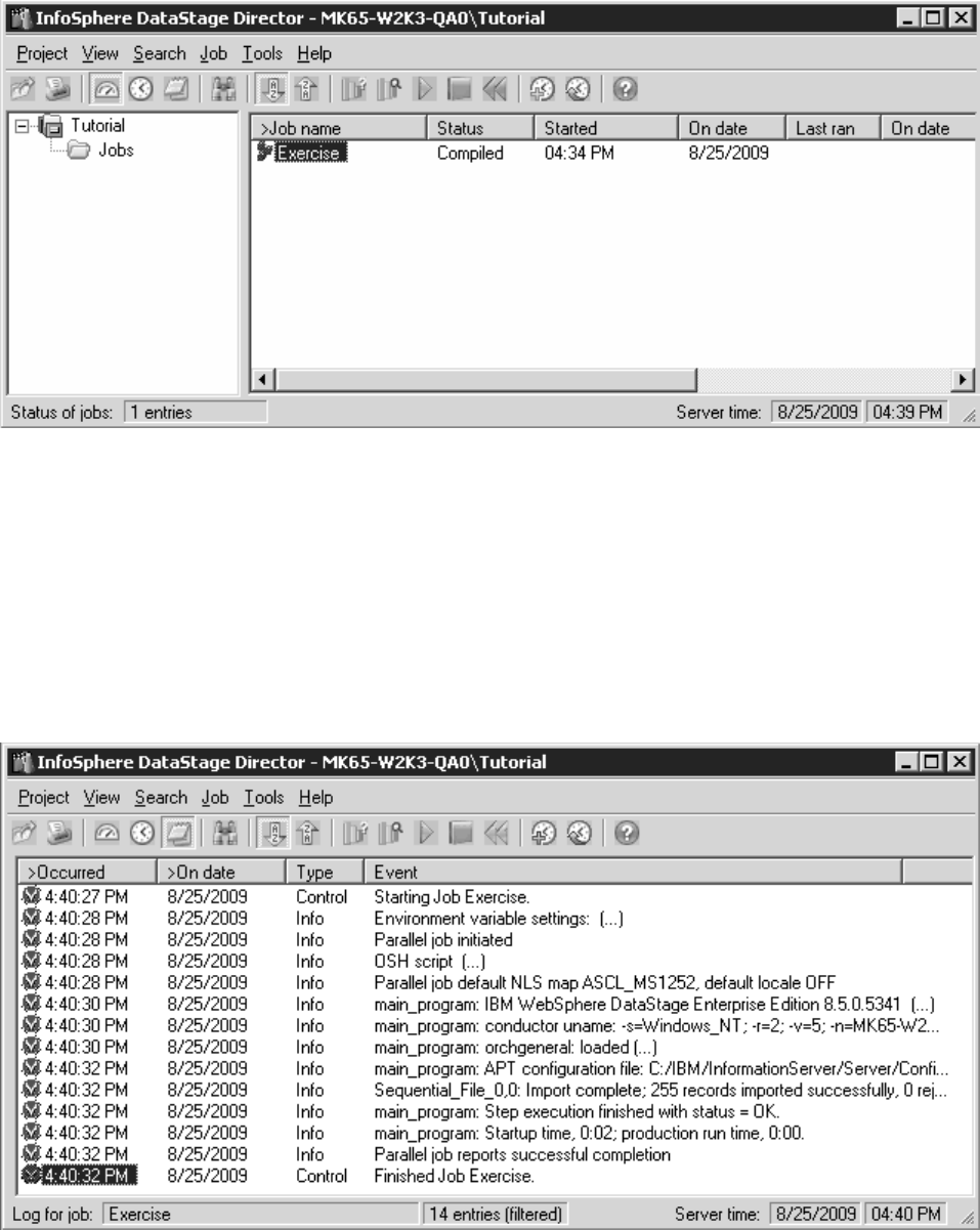
4. When the job status changes to Finished, select View >Log.
5. Examine the job log to see the type of information that the Director client
reports as it runs a job. The messages that you see are either control or
information type. Jobs can also have Fatal and Warning messages. The
following figure shows the log view of the job.
6. Select File >Exit to close the Director client.
Figure 10. Director client
Figure 11. The job log
18 Designer Client Guide

Viewing results
You can view the results of your job.
1. In the job in the Designer client, double-click the Sequential File stage named
Data_target to open the stage editor.
2. In the stage editor, click View Data.
3. Click OK in the “Data Browser” window to accept the default settings. A
window opens that shows up to 100 rows of the data written to the data set (if
you want to view more than 100 rows in a data browser, change the default
settings before you click OK).
4. Examine the data and observe that there are now five columns in the data
named CODE, PRODUCT, QTY, MONTH, and YEAR.
5. Click Close to close the “Data Browser” window.
6. Click OK to close the Sequential File stage.
Figure 12. The transformed data
Chapter 1. Tutorial: Designing your first job 19
Lesson checkpoint
In this lesson you ran your job and looked at the results.
You learned the following tasks:
vHow to start the Director client from the Designer client.
vHow to run a job and look at the log file.
vHow to view the data written by the job.
20 Designer Client Guide

Chapter 2. Sketching your job designs
Start your job designs by sketching out the data flow. You can then fill in the
details later.
A job design contains:
vStages to represent the processing steps required
vLinks between the stages to represent the flow of data
There are three different types of job in InfoSphere DataStage, depending on what
edition or editions you have installed:
vParallel jobs. These run on InfoSphere DataStage servers that are SMP, MPP, or
cluster systems.
vServer jobs. They run on the InfoSphere DataStage Server, connecting to other
data sources as necessary.
vMainframe jobs. Mainframe jobs are uploaded to a mainframe, where they are
compiled and run.
Note: Mainframe jobs are not supported in this version of IBM InfoSphere
Information Server.
There are two other entities that are similar to jobs in the way they appear in the
Designer, and are handled by it. These are:
vShared containers. These are reusable job elements. They typically comprise a
number of stages and links. Copies of shared containers can be used in any
number of server jobs and parallel jobs and edited as required. Shared
containers are described in “Shared containers” on page 97.
vJob Sequences. A job sequence allows you to specify a sequence of InfoSphere
DataStage server or parallel jobs to be executed, and actions to take depending
on results. Job sequences are described in Chapter 14, “Building sequence jobs,”
on page 207.
Getting started with jobs
Before you can start designing jobs, you must learn how to create new jobs or
open existing jobs.
Creating a job
You create jobs in the Designer client.
Procedure
1. Click File >New on the Designer menu. The New dialog box appears.
2. Choose the Jobs folder in the left pane.
3. Select one of the icons, depending on the type of job or shared container you
want to create.
4. Click OK.
© Copyright IBM Corp. 1997, 2014 21
Results
The Diagram window appears, in the right pane of the Designer, along with the
palette for the chosen type of job. You can now save the job and give it a name.
Opening an existing job
If you have previously worked on the job you want to open, then you can select it
from the list of most recently used jobs in the File menu in the Designer window.
About this task
Otherwise, to open a job, do one of the following:
vChoose File >Open... .
vClick the Open button on the toolbar.
The Open dialog box is displayed. This allows you to open a job (or any other
object) currently stored in the repository.
Procedure
1. Select the folder containing the job (this might be the Job folder, but you can
store a job in any folder you like).
2. Select the job in the tree.
3. Click OK.
Results
You can also find the job in the Repository tree and double-click it, or select it and
choose Edit from its shortcut menu, or drag it onto the background to open it.
The updated Designer window displays the chosen job in a Diagram window.
Saving a job
Save jobs in order to retain all parameters that you specified and reuse them in the
future.
Procedure
1. Choose File >Save. The Save job as dialog box appears:
2. Enter the name of the job in the Item name field.
3. Select a folder in which to store the job from the tree structure by clicking it. It
appears in the Folder path box. By default jobs are saved in the pre-configured
Job folder, but you can store it in any folder you choose.
4. Click OK. If the job name is unique, the job is created and saved in the
Repository. If the job name is not unique, a message box appears. You must
acknowledge this message before you can enter an alternative name (a job
name must be unique within the entire repository, not just the selected folder).
Results
To save an existing job with a different name choose File Save As... and fill in the
Save job as dialog box, specifying the new name and the folder in which the job is
to be saved.
22 Designer Client Guide

Organizing your jobs into folders gives faster operation of the IBM InfoSphere
DataStage Director when displaying job status.
Naming a job
The following rules apply to the names that you can give IBM InfoSphere
DataStage jobs.
Procedure
vJob names can be any length.
vThey must begin with an alphabetic character.
vThey can contain alphanumeric characters and underscores.
Results
Job folder names can be any length and consist of any characters, including spaces.
Stages
A job consists of stages linked together which describe the flow of data from a data
source to a data target (for example, a final data warehouse).
A stage usually has at least one data input or one data output. However, some
stages can accept more than one data input, and output to more than one stage.
The different types of job have different stage types. The stages that are available
in the Designer depend on the type of job that is currently open in the Designer.
Parallel job stages
IBM InfoSphere DataStage has several built-in stage types for use in parallel jobs.
These stages are used to represent data sources, data targets, or transformation
stages.
Parallel stages are organized into different groups on the palette:
vGeneral
vData Quality
vDatabase
vDevelopment/Debug
vFile
vProcessing
vReal Time
vRestructure
Stages and links can be grouped in a shared container. Instances of the shared
container can then be reused in different parallel jobs. You can also define a local
container within a job; this groups stages and links into a single unit, but can only
be used within the job in which it is defined.
Each stage type has a set of predefined and editable properties. These properties
are viewed or edited using stage editors. A stage editor exists for each stage type.
Chapter 2. Sketching your job designs 23
Server job stages
IBM InfoSphere DataStage has several built-in stage types for use in server jobs.
These stages are used to represent data sources, data targets, or conversion stages.
These stages are either passive or active stages. A passive stage handles access to
databases for the extraction or writing of data. Active stages model the flow of
data and provide mechanisms for combining data streams, aggregating data, and
converting data from one data type to another.
The Palette organizes stage types into different groups, according to function:
vGeneral
vDatabase
vFile
vProcessing
vReal Time
Stages and links can be grouped in a shared container. Instances of the shared
container can then be reused in different server jobs (such shared containers can
also be used in parallel jobs as a way of leveraging server job functionality). You
can also define a local container within a job, this groups stages and links into a
single unit, but can only be used within the job in which it is defined.
Each stage type has a set of predefined and editable properties. These properties
are viewed or edited using stage editors. A stage editor exists for each stage type.
Mainframe job stages
InfoSphere DataStage offers several built-in stage types for use in mainframe jobs.
These are used to represent data sources, data targets, or conversion stages.
Note: Mainframe jobs are not supported in this version of IBM InfoSphere
Information Server.
The Palette organizes stage types into different groups, according to function:
vGeneral
vDatabase
vFile
vProcessing
Each stage type has a set of predefined and editable properties. Some stages can be
used as data sources and some as data targets. Some can be used as both.
Processing stages read data from a source, process it and write it to a data target.
These properties are viewed or edited using stage editors. A stage editor exists for
each stage type.
Naming stages and shared containers
Specific rules apply to naming stages and shared containers.
The following rules apply to the names that you can give IBM InfoSphere
DataStage stages and shared containers:
vNames can be any length.
vThey must begin with an alphabetic character.
24 Designer Client Guide

vThey can contain alphanumeric characters and underscores.
Links
Links join the various stages in a job together and are used to specify how data
flows when the job is run.
Linking parallel stages
File and database stages in parallel jobs such as Data Set stages, Sequential File
stages, and DB2®Enterprise stages are used to read or write data from a data
source.
The read/write link to the data source is represented by the stage itself, and
connection details are given in the stage properties.
Input links typically carry data to be written to the data target. Output links carry
metadata that is read from the data source. The column definitions on an input
link define the data to be written to a data target. The column definitions on an
output link define the data to be read from a data source.
Processing stages generally have an input link carrying data to be processed, and
an output link passing on processed data.
Column definitions actually belong to, and travel with, the links that connect
stages. When you define column definitions for the output link of a stage, those
same column definitions are used as input to another stage. If you move either end
of a link to another stage, the column definitions are used in the stage that you
connect to. If you change the details of a column definition at one end of a link,
those changes are reflected in the column definitions at the other end of the link.
The type of link that you use depends on whether the link is an input link or an
output link, and on which stages you are linking. IBM InfoSphere DataStage
parallel jobs support three types of links:
Stream
Stream links represents the flow of data from one stage to another. Stream
links are used by all stage types.
Reference
Reference links represent a table lookup. Reference links can be input to
Lookup stages only, and send output to other stages.
Reject Reject links represent output records that are rejected because they do not
meet a specific criteria. Reject links derive their metadata from the
associated output link, so the metadata cannot be edited.
You can typically have only an input stream link or an output stream link on a File
stage or Database stage. The three link types are displayed differently in the
Designer Diagram window: stream links are represented by solid lines, reference
links by dotted lines, and reject links by dashed lines.
Link marking
For parallel jobs, metadata is associated with the links that connect stages. If you
enable link marking, a small icon is added to the link to indicate whether metadata
is currently associated with it.
Chapter 2. Sketching your job designs 25
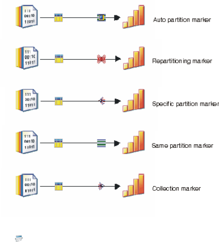
Link marking also shows you how data is partitioned, collected, and sorted
between stages. The following diagram shows the different types of link marking.
Link marking is enabled by default. To disable link marking, click the link markers
icon ( ) in the Designer client toolbar, or right-click the job canvas and click
Show link marking.
Unattached links
You can add links that are only attached to a stage at one end, although they will
need to be attached to a second stage before the job can successfully compile and
run.
Unattached links are shown in a special color (red by default - but you can change
this using the Options dialog).
By default, when you delete a stage, any attached links and their metadata are left
behind, with the link shown in red. You can choose Delete including links from the
Edit or shortcut menus to delete a selected stage along with its connected links.
Linking server stages
Certain stages in server jobs (for example, ODBC stages, Sequential File stages,
UniVerse stages), are used to read or write data from a data source.
26 Designer Client Guide
The read/write link to the data source is represented by the stage itself, and
connection details are given on the Stage general tabs.
Input links connected to the stage generally carry data to be written to the
underlying data target. Output links carry data read from the underlying data
source. The column definitions on an input link define the data that will be written
to a data target. The column definitions on an output link define the data to be
read from a data source.
An important point to note about linking stages in server jobs is that column
definitions actually belong to, and travel with, the links as opposed to the stages.
When you define column definitions for a stage's output link, those same column
definitions will appear at the other end of the link where it is input to another
stage. If you move either end of a link to another stage, the column definitions will
appear on the new stage. If you change the details of a column definition at one
end of a link, those changes will appear in the column definitions at the other end
of the link.
There are rules covering how links are used, depending on whether the link is an
input or an output and what type of stages are being linked.
IBM InfoSphere DataStage server jobs support two types of input link:
vStream. A link representing the flow of data. This is the principal type of link.
vReference. A link representing a table lookup. They are used to provide
information that might affect the way data is changed, but do not supply the
data to be changed.
The two link types are displayed differently in the Designer Diagram window:
stream links are represented by solid lines and reference links by dotted lines.
There is only one type of output link, although some stages permit an output link
to be used as a reference input to the next stage and some do not.
Link marking
For server jobs, metadata is associated with a link, not a stage. If you have link
marking enabled, a small icon attaches to the link to indicate if metadata is
currently associated with it.
Link marking is enabled by default. To disable it, click on the link mark icon in the
Designer toolbar, or deselect it in the Diagram menu, or the Diagram shortcut
menu.
Unattached links
You can add links that are only attached to a stage at one end, although they will
need to be attached to a second stage before the job can successfully compile and
run.
Unattached links are shown in a special color (red by default - but you can change
this using the Options dialog).
By default, when you delete a stage, any attached links and their metadata are left
behind, with the link shown in red. You can choose Delete including links from the
Edit or shortcut menus to delete a selected stage along with its connected links.
Chapter 2. Sketching your job designs 27
Linking mainframe stages
Target stages in Mainframe jobs are used to write data to a data target. Source
stages are used to read data from a data source. Some stages can act as a source or
a target. The read/write link to the data source is represented by the stage itself,
and connection details are given on the Stage general tabs.
Note: Mainframe jobs are not supported in this version of IBM InfoSphere
Information Server.
Links to and from source and target stages are used to carry data to or from a
processing or post-processing stage.
For source and target stage types, column definitions are associated with stages
rather than with links. You decide what appears on the outputs link of a stage by
selecting column definitions on the Selection page. You can set the Column Push
Option to specify that stage column definitions be automatically mapped to output
columns (this happens if you set the option, define the stage columns then click
OK to leave the stage without visiting the Selection page).
There are rules covering how links are used, depending on whether the link is an
input or an output and what type of stages are being linked.
Mainframe stages have only one type of link, which is shown as a solid line. (A
table lookup function is supplied by the Lookup stage, and the input links to this
which acts as a reference is shown with dotted lines to illustrate its function.)
Link marking
For mainframe jobs, metadata is associated with the stage and flows down the
links. If you have link marking enabled, a small icon attaches to the link to
indicate if metadata is currently associated with it.
Link marking is enabled by default. To disable it, click on the link mark icon in the
Designer toolbar, or deselect it in the Diagram menu, or the Diagram shortcut
menu.
Unattached links
Unlike server and parallel jobs, you cannot have unattached links in a mainframe
job; both ends of a link must be attached to a stage.
If you delete a stage, the attached links are automatically deleted too.
Link ordering
The Transformer stage in server jobs and various processing stages in parallel jobs
allow you to specify the execution order of links coming into or going out from the
stage.
When looking at a job design in IBM InfoSphere DataStage, there are two ways to
look at the link execution order:
vPlace the mouse pointer over a link that is an input to or an output from a
Transformer stage. A ToolTip appears displaying the message:
Input execution order = n
for input links, and:
Output execution order = n
28 Designer Client Guide

for output links. In both cases ngives the link's place in the execution order. If
an input link is no. 1, then it is the primary link.
Where a link is an output from the Transformer stage and an input to another
Transformer stage, then the output link information is shown when you rest the
pointer over it.
vSelect a stage and right-click to display the shortcut menu. Choose Input Links
or Output Links to list all the input and output links for that Transformer stage
and their order of execution.
Naming links
Specific rules apply to naming links.
The following rules apply to the names that you can give IBM InfoSphere
DataStage links:
vLink names can be any length.
vThey must begin with an alphabetic character.
vThey can contain alphanumeric characters and underscores.
Developing the job design
Jobs are designed and developed in the Diagram window.
Stages are added and linked together using the palette. The stages that appear in
the palette depend on whether you have a server, parallel, or mainframe job, or a
job sequence open, and on whether you have customized the palette.
You can add, move, rename, delete, link, or edit stages in a job design.
Adding stages
There is no limit to the number of stages you can add to a job.
We recommend you position the stages as follows in the Diagram window:
vParallel Jobs
– Data sources on the left
– Data targets on the right
– Processing stages in the middle of the diagram
vServer jobs
– Data sources on the left
– Data targets on the right
– Transformer or Aggregator stages in the middle of the diagram
vMainframe jobs
– Source stages on the left
– Processing stages in the middle
– Target stages on the right
There are a number of ways in which you can add a stage:
vClick the stage icon on the tool palette. Click in the Diagram window where you
want to position the stage. The stage appears in the Diagram window.
vClick the stage icon on the tool palette. Drag it onto the Diagram window.
Chapter 2. Sketching your job designs 29
vSelect the desired stage type in the repository tree and drag it to the Diagram
window.
When you insert a stage by clicking (as opposed to dragging) you can draw a
rectangle as you click on the Diagram window to specify the size and shape of the
stage you are inserting as well as its location.
Each stage is given a default name which you can change if required.
If you want to add more than one stage of a particular type, press Shift after
clicking the button on the tool palette and before clicking on the Diagram window.
You can continue to click the Diagram window without having to reselect the
button. Release the Shift key when you have added the stages you need; press Esc
if you change your mind.
Moving stages
After they are positioned, stages can be moved by clicking and dragging them to a
new location in the Diagram window.
About this task
If you have the Snap to Grid option activated, the stage is attached to the nearest
grid position when you release the mouse button. If stages are linked together, the
link is maintained when you move a stage.
Renaming stages
Stages can be renamed in the stage editor or the Diagram window.
About this task
There are a number of ways to rename a stage:
vYou can change its name in its stage editor.
vYou can select the stage in the Diagram window, press Ctrl-R, choose Rename
from its shortcut menu, or choose Edit Rename from the main menu and type
a new name in the text box that appears beneath the stage.
vSelect the stage in the diagram window and start typing.
vYou can select the stage in the Diagram window and then edit the name in the
Property Browser (if you are displaying it).
Deleting stages
Stages can be deleted from the Diagram window.
About this task
Choose one or more stages and do one of the following:
vPress the Delete key.
vChoose Edit >Delete.
vChoose Delete from the shortcut menu.
A message box appears. Click Yes to delete the stage or stages and remove them
from the Diagram window. (This confirmation prompting can be turned off if
required.)
30 Designer Client Guide
When you delete stages in mainframe jobs, attached links are also deleted. When
you delete stages in server or parallel jobs, the links are left behind, unless you
choose Delete including links from the edit or shortcut menu.
Linking stages
You can link stages in a job design.
About this task
You can link stages in three ways:
vUsing the Link button. Choose the Link button from the tool palette. Click the
first stage and drag the link to the second stage. The link is made when you
release the mouse button.
vUsing the mouse. Select the first stage. Position the mouse cursor on the edge of
a stage until the mouse cursor changes to a circle. Click and drag the mouse to
the other stage. The link is made when you release the mouse button.
vUsing the mouse. Point at the first stage and right click then drag the link to the
second stage and release it.
Each link is given a default name which you can change.
Moving links
Once positioned, you can move a link to a new location in the Diagram window.
About this task
You can choose a new source or destination for the link, but not both.
Procedure
1. Click the link to move in the Diagram window. The link is highlighted.
2. Click in the box at the end you want to move and drag the end to its new
location.
Results
In server and parallel jobs you can move one end of a link without reattaching it
to another stage. In mainframe jobs both ends must be attached to a stage.
Deleting links
Links can be deleted from the Diagram window.
About this task
Choose the link and do one of the following:
vPress the Delete key.
vChoose Edit >Delete.
vChoose Delete from the shortcut menu.
A message box appears. Click Yes to delete the link. The link is removed from the
Diagram window.
Chapter 2. Sketching your job designs 31
Note: For server jobs, metadata is associated with a link, not a stage. If you delete
a link, the associated metadata is deleted too. If you want to retain the metadata
you have defined, do not delete the link; move it instead.
Renaming links
You can rename a link.
About this task
There are a number of ways to rename a link:
vYou can select it and start typing in a name in the text box that appears.
vYou can select the link in the Diagram window and then edit the name in the
Property Browser.
vYou can select the link in the Diagram window, press Ctrl-R, choose Rename
from its shortcut menu, or choose Edit >Rename from the main menu and type
a new name in the text box that appears beneath the link.
vSelect the link in the diagram window and start typing.
Dealing with multiple links
If you have multiple links from one stage to another, you might want to resize the
stages in order to make the links clearer by spreading them out.
About this task
Resize stages by selecting each stage and dragging on one of the sizing handles in
the bounding box.
Editing stages
After you add the stages and links to the Diagram window, you must edit the
stages to specify the data you want to use and any aggregations or conversions
required.
About this task
Data arrives into a stage on an input link and is output from a stage on an output
link. The properties of the stage and the data on each input and output link are
specified using a stage editor.
To edit a stage, do one of the following:
vDouble-click the stage in the Diagram window.
vSelect the stage and choose Properties... from the shortcut menu.
vSelect the stage and choose Edit Properties.
A dialog box appears. The content of this dialog box depends on the type of stage
you are editing. See the individual stage descriptions for details.
The data on a link is specified using column definitions. The column definitions
for a link are specified by editing a stage at either end of the link. Column
definitions are entered and edited identically for each stage type.
Specifying column definitions
Each stage editor has a page for data inputs or data outputs (depending on stage
type and what links are present on the stage). The data flowing along each input
or output link is specified using column definitions.
32 Designer Client Guide
About this task
The column definitions are displayed in a grid on the Columns tab for each link.
The Columns grid has a row for each column definition. The columns present
depend on the type of stage. Some entries contain text (which you can edit) and
others have a drop-down list containing all the available options for the cell.
You can edit the grid to add new column definitions or change values for existing
definitions. Any changes are saved when you save your job design.
The Columns tab for each link also contains the following buttons which you can
use to edit the column definitions:
vSave... . Saves column definitions as a table definition in the Repository.
vLoad... . Loads (copies) the column definitions from a table definition in the
Repository.
Details of how to import or manually enter column definitions in the Repository
are given in Chapter 14, “Building sequence jobs,” on page 207.
Editing column definitions
Edit column definitions in the grid in order to specify the data that you want to
use.
About this task
To edit a column definition in the grid, click the cell you want to change then
choose Edit cell... from the shortcut menu or press Ctrl-E to open the Edit Column
Metadata dialog box.
Inserting column definitions
If you want to create a new output column or write to a table that does not have a
table definition, you can manually enter column definitions by editing the
Columns grid.
About this task
To add a new column at the bottom of the grid, edit the empty row.
To add a new column between existing rows, position the cursor in the row below
the desired position and press the Insert key or choose Insert row... from the
shortcut menu.
After you define the new row, you can right-click on it and drag it to a new
position in the grid.
Naming columns
The rules for naming columns depend on the type of job the table definition will
be used in:
Server jobs
Column names can be any length. They must begin with an alphabetic character or
$ and contain alphanumeric, underscore, period, and $ characters.
Chapter 2. Sketching your job designs 33
Parallel jobs
Column names can be any length. They must begin with an alphabetic character or
$ and contain alphanumeric, underscore, and $ characters.
Mainframe jobs
Column names can be any length. They must begin with an alphabetic character
and contain alphanumeric, underscore, #, @, and $ characters.
Deleting column definitions
If, after importing or defining a table definition, you subsequently decide that you
do not want to read or write the data in a particular column you must delete the
corresponding column definition.
About this task
Unwanted column definitions can be easily removed from the Columns grid. To
delete a column definition, click any cell in the row you want to remove and press
the Delete key or choose Delete row from the shortcut menu. Click OK to save
any changes and to close the Table Definition dialog box.
To delete several column definitions at once, hold down the Ctrl key and click in
the row selector column for the rows you want to remove. Press the Delete key or
choose Delete row from the shortcut menu to remove the selected rows.
Saving column definitions
If you edit column definitions or insert new definitions, you can save them in a
table definition in the repository. You can then load the definitions into other
stages in your job design.
About this task
Each table definition has an identifier which uniquely identifies it in the repository.
This identifier is derived from:
vData source type. This describes the type of data source holding the actual table
the table definition relates to.
vData source name. The DSN or equivalent used when importing the table
definition (or supplied by the user where the table definition is entered
manually).
vTable definition name. The name of the table definition.
In previous releases of IBM InfoSphere DataStage all table definitions were located
in the Table Definitions category of the repository tree, within a subcategory
structure derived from the three-part identifier. For example, the table definition
tutorial.FACTS is a table definition imported from a UniVerse database table called
FACTS into the tutorial project using the localuv connection. It would have been
located in the category Table definitions\UniVerse\localuv. It's full identifier would
have been UniVerse\localuv\tutorial.FACTS.
With InfoSphere DataStage Release 8.0, the table definition can be located
anywhere in the repository that you choose. For example, you might want a top
level folder called Tutorial that contains all the jobs and table definitions concerned
with the server job tutorial.
34 Designer Client Guide
Procedure
1. Click Save... . The Save Table Definition dialog box appears.
2. Enter a folder name or path in the Data source type field. The name entered
here determines how the definition will be stored in the repository. By default,
this field contains Saved.
3. Enter a name in the Data source name field. This forms the second part of the
table definition identifier and is the name of the branch created under the data
source type branch. By default, this field contains the name of the stage you are
editing.
4. Enter a name in the Table/file name field. This is the last part of the table
definition identifier and is the name of the leaf created under the data source
name branch. By default, this field contains the name of the link you are
editing.
5. Optionally enter a brief description of the table definition in the Short
description field. By default, this field contains the date and time you clicked
Save... . The format of the date and time depend on your Windows setup.
6. Optionally enter a more detailed description of the table definition in the Long
description field.
7. Click OK. The column definitions are saved under the specified branches in the
Repository.
Naming table definitions
When you save your column definitions as a table definition, the specific naming
rules apply.
The following rules apply:
vTable names can be any length.
vThey must begin with an alphabetic character.
vThey can contain alphanumeric, period, and underscore characters.
Loading column definitions
You can load column definitions from a table definition in the Repository.
About this task
For a description of how to create or import table definitions, see Chapter 4,
“Defining your data,” on page 51.
Most stages allow you to selectively load columns, that is, specify the exact
columns you want to load.
Procedure
1. Click Load... . The Table Definitions dialog box appears. This window displays
the repository tree to enable you to browse for the required table definition.
2. Double-click the appropriate folder.
3. Continue to expand the folders until you see the table definition you want.
4. Select the table definition you want.
Note: You can use Quick Find to enter the name of the table definition you
want. The table definition is selected in the tree when you click OK.
5. Click OK. One of two things happens, depending on the type of stage you are
editing:
Chapter 2. Sketching your job designs 35
vIf the stage type does not support selective metadata loading, all the column
definitions from the chosen table definition are copied into the Columns grid.
vIf the stage type does support selective metadata loading, the Select Columns
dialog box appears, allowing you to specify which column definitions you
want to load.
Use the arrow keys to move columns back and forth between the Available
columns list and the Selected columns list. The single arrow buttons move
highlighted columns, the double arrow buttons move all items. By default all
columns are selected for loading. Click Find... to open a dialog box which
lets you search for a particular column. The shortcut menu also gives access
to Find... and Find Next. Click OK when you are happy with your selection.
This closes the Select Columns dialog box and loads the selected columns
into the stage.
For mainframe stages and certain parallel stages where the column
definitions derive from a CFD file, the Select Columns dialog box can also
contain a Create Filler check box. This happens when the table definition the
columns are being loaded from represents a fixed-width table. Select this to
cause sequences of unselected columns to be collapsed into filler items. Filler
columns are sized appropriately, their data type set to character, and name
set to FILLER_XX_YY where XX is the start offset and YY the end offset.
Using fillers results in a smaller set of columns, saving space and processing
time and making the column set easier to understand.
If you are importing column definitions that have been derived from a CFD
file into server or parallel job stages, you are warned if any of the selected
columns redefine other selected columns. You can choose to carry on with
the load or go back and select columns again.
6. Click OK to proceed. If the stage you are loading already has column
definitions of the same name, you are prompted to confirm that you want to
overwrite them. The Merge Column Metadata check box is selected by default
and specifies that, if you confirm the overwrite, the Derivation, Description,
Display Size and Field Position from the existing definition will be preserved
(these contain information that is not necessarily part of the table definition and
that you have possibly added manually). Note that the behavior of the merge is
affected by the settings of the Metadata options in the Designer Options dialog
box.
7. Click Yes or Yes to All to confirm the load. Changes are saved when you save
your job design.
Importing or entering column definitions
If the column definitions you want to assign to a link are not held in the
repository, you might be able to import them from a data source into the
repository and then load them.
You can import definitions from a number of different data sources. Alternatively
you can define the column definitions manually.
You can import or enter table definitions from the Designer. For instructions, see
Chapter 4, “Defining your data,” on page 51.
Browsing server directories
When you edit certain parallel or server stages (that is, stages that access files), you
might need to specify a directory path on the IBM InfoSphere DataStage server
where the required files are found.
You can specify a directory path in one of three ways:
36 Designer Client Guide
vEnter a job parameter in the respective text entry box in the stage dialog box.
vEnter the directory path directly in the respective text entry box in the Stage
dialog box.
vUse Browse or Browse for file.
Tip: When you browse for files in a chosen directory on the server, populating
the files can take a long time if there are many files present on the server
computer. For faster browsing, you can set the DS_OPTIMIZE_FILE_BROWSE
variable to true in the Administrator client. By default, this parameter is set to
false.
If you choose to browse, the Browse directories or Browse files dialog box appears.
vLook in. Displays the name of the current directory (or can be a drive if
browsing a Windows system). This has a drop down that shows where in the
directory hierarchy you are currently located.
vDirectory/File list. Displays the directories and files on the chosen directory.
Double-click the file you want, or double-click a directory to move to it.
vFile name. The name of the selected file. You can use wildcards here to browse
for files of a particular type.
vFiles of type. Select a file type to limit the types of file that are displayed.
vBack button. Moves to the previous directory visited (is disabled if you have
visited no other directories).
vUp button. Takes you to the parent of the current directory.
vView button. Offers a choice of different ways of viewing the directory/file tree.
vOK button. Accepts the file in the File name field and closes the Browse files
dialog box.
vCancel button. Closes the dialog box without specifying a file.
vHelp button. Invokes the Help system.
Cutting or copying and pasting stages
You can cut or copy stages and links from one job and paste them into another.
You can paste them into another job canvas of the same type. This can be in the
same Designer, or another one, and you can paste them into different projects. You
can also use Paste Special to paste stages and links into a new shared container.
Note: Be careful when cutting from one context and pasting into another. For
example, if you cut columns from an input link and paste them onto an output
link they could carry information that is wrong for an output link and needs
editing.
To cut a stage, select it in the canvas and select Edit Cut (or press CTRL-X). To
copy a stage, select it in the canvas and select Edit Copy (or press CTRL-C). To
paste the stage, select the destination canvas and select Edit Paste (or press
CTRL-V). Any links attached to a stage will be cut and pasted too, complete with
metadata. If there are name conflicts with stages or links in the job into which you
are pasting, IBM InfoSphere DataStage will automatically update the names.
Pre-configured stages
There is a special feature that you can use to paste components into a shared
container and add the shared container to the palette.
Chapter 2. Sketching your job designs 37
This feature allows you to have pre-configured stages ready to drop into a job.
To paste a stage into a new shared container, select Edit Paste Special Into new
Shared Container. The Paste Special into new Shared Container dialog box appears.
This allows you to select a folder and name for the new shared container, enter a
description and optionally add a shortcut to the palette.
If you want to cut or copy metadata along with the stages, you should select
source and destination stages, which will automatically select links and associated
metadata. These can then be cut or copied and pasted as a group.
Annotations
You can use annotations for a wide variety of purposes throughout your job
design. For example, you can use annotations to explain, summarize, or describe a
job design or to help identify parts of a job design.
There are two types of annotations that you can use in job designs:
Annotation
You enter this text yourself and you can add as many of this type of
annotation as required. Use it to annotate stages and links in your job
design. These annotations can be copied and pasted into other jobs.
Description Annotation
You can add only one of these types of annotations for each job design.
When you create a description annotation, you can choose whether the
Description Annotation displays the full description or the short
description from the job properties. Description Annotations cannot be
copied and pasted into other jobs. The job properties short or full
description remains in sync with the text you type for the Description
Annotation. Changes you make in the job properties description display in
the Description Annotation, and changes you make in the Description
Annotation display in the job properties description.
Annotations do not obstruct the display of the stages, links, or other components
in your job design.
Annotating job designs
You can insert notes into your job design to make the design easier to understand
and maintain. You can include these annotations in all types of jobs, in job
sequences, and in shared containers.
Before you begin
Open a job for which you want to add annotations.
Procedure
1. In the General section of the palette, click Description Annotation or
Annotation.
2. Click the area of the canvas where you want to insert the annotation. You can
resize the annotation box as required.
3. Double-click the annotation box or right-click the annotation box, and click
Properties.
4. In the Annotation Properties dialog box, type the annotation text.
38 Designer Client Guide
5. Optional: Use the controls in the Annotation Properties dialog box to change
the appearance of the annotation. You can change the font, color, background
color, and text alignment.
6. Click OK.
What to do next
vYou can use the Toggle annotations button in the toolbar to show or hide
annotations in the canvas.
vWhen you create a description annotation, you can choose whether the
Description Annotation displays the full description or the short description
from the job properties.
Using the Data Browser
Use the Data Browser to view the actual data that will flow through a server job or
parallel stage.
You can browse the data associated with the input or output links of any server
job built-in passive stage or with the links to certain parallel job stages
The Data Browser is invoked by clicking the View Data... button from a stage
Inputs or Outputs page, or by choosing the View link Data... option from the
shortcut menu.
For parallel job stages a supplementary dialog box lets you select a subset of data
to view by specifying the following:
vRows to display. Specify the number of rows of data you want the data browser
to display.
vSkip count. Skip the specified number of rows before viewing data.
vPeriod. Display every Pth record where Pis the period. You can start after
records have been skipped by using the Skip property. Pmust equal or be
greater than 1.
If your administrator has enabled the Generated OSH Visible option in the IBM
InfoSphere DataStage Administrator, the supplementary dialog box also has a
Show OSH button. Click this to open a window showing the OSH that will be run
to generate the data view. It is intended for expert users.
The Data Browser displays a grid of rows in a window. If a field contains a
linefeed character, the field is shown in bold, and you can, if required, resize the
grid to view the whole field.
The Data Browser window appears.
The Data Browser uses the metadata defined for that link. If there is insufficient
data associated with a link to allow browsing, the View Data... button and shortcut
menu command used to invoke the Data Browser are disabled. If the Data Browser
requires you to input some parameters before it can determine what data to
display, the Job Run Options dialog box appears and collects the parameters (see
"The Job Run Options Dialog Box").
Note: You cannot specify $ENV or $PROJDEF as an environment variable value
when using the data browser.
The Data Browser grid has the following controls:
Chapter 2. Sketching your job designs 39
vYou can select any row or column, or any cell within a row or column, and
press CTRL-C to copy it.
vYou can select the whole of a very wide row by selecting the first cell and then
pressing SHIFT+END.
vIf a cell contains multiple lines, you can expand it by left-clicking while holding
down the SHIFT key. Repeat this to shrink it again.
You can view a row containing a specific data item using the Find... button. The
Find dialog box will reposition the view to the row containing the data you are
interested in. The search is started from the current row.
The Display... button invokes the Column Display dialog box. This allows you to
simplify the data displayed by the Data Browser by choosing to hide some of the
columns. For server jobs, it also allows you to normalize multivalued data to
provide a 1NF view in the Data Browser.
This dialog box lists all the columns in the display, all of which are initially
selected. To hide a column, clear it.
For server jobs, the Normalize on drop-down list box allows you to select an
association or an unassociated multivalued column on which to normalize the
data. The default is Un-normalized, and choosing Un-normalized will display the
data in NF2form with each row shown on a single line. Alternatively you can
select Un-Normalized (formatted), which displays multivalued rows split over
several lines.
In the example, the Data Browser would display all columns except STARTDATE.
The view would be normalized on the association PRICES.
Using the performance monitor
The Performance monitor is a useful diagnostic aid when designing IBM
InfoSphere DataStage parallel jobs and server jobs.
About this task
When you turn it on and compile a job it displays information against each link in
the job. When you run the job, either through the InfoSphere DataStage Director or
the Designer, the link information is populated with statistics to show the number
of rows processed on the link and the speed at which they were processed. The
links change color as the job runs to show the progress of the job.
Procedure
1. With the job open and compiled in the Designer choose Diagram Show
performance statistics. Performance information appears against the links. If the
job has not yet been run, the figures will be empty.
2. Run the job (either from the Director or by clicking the Run button. Watch the
links change color as the job runs and the statistics populate with number of
rows and rows/sec.
Results
If you alter anything on the job design you will lose the statistical information
until the next time you compile the job.
40 Designer Client Guide

The colors that the performance monitor uses are set via the Options dialog box.
Chose Tools Options and select Graphical Performance Monitor under the
Appearance branch to view the default colors and change them if required. You
can also set the refresh interval at which the monitor updates the information
while the job is running.
Running server jobs and parallel jobs
You can run server jobs and parallel jobs from within the Designer by clicking on
the Run button in the toolbar.
The job currently in focus will run, provided it has been compiled and saved.
The Job Run Options dialog box
Before you can run a job from the Designer client, you must supply information in
the Job Run Options dialog box.
The Job Run Options dialog box has three pages:
vThe Parameters page collects any parameters the job requires
vThe Limits page allows you to specify any run-time limits.
vThe General page allows you to specify settings for collecting operational
metadata and message handling settings.
This dialog box can appear when you are:
vrunning a job
vusing the Data Browser
vspecifying a job control routine
vusing the debugger (server jobs only)
Parameters page
The Parameters page lists any parameters or parameter sets that have been defined
for the job.
If default values have been specified, these are displayed too. You can enter a
value in the Value column, edit the default, or accept the default as it is. Click Set
to Default to set a parameter to its default value, or click All to Default to set all
parameters to their default values. Click Property Help to display any help text
that has been defined for the selected parameter (this button is disabled if no help
has been defined). Click OK when you are satisfied with the values for the
parameters.
When setting a value for an environment variable, you can specify one of the
following special values:
v$ENV. Instructs IBM InfoSphere DataStage to use the current setting for the
environment variable.
v$PROJDEF. The current setting for the environment variable is retrieved and set
in the job's environment (so that value is used wherever in the job the
environment variable is used). If the value of that environment variable is
subsequently changed in the Administrator client, the job will pick up the new
value without the need for recompiling.
v$UNSET. Instructs InfoSphere DataStage to explicitly unset the environment
variable.
Chapter 2. Sketching your job designs 41

Note that you cannot use these special values when viewing data on Parallel jobs.
You will be warned if you try to do this.
Limits page
The Limits page allows you to specify whether stages in the job should be limited
in how many rows they process and whether run-time error warnings should be
ignored.
To specify a row's limits:
Procedure
1. Click the Stop stages after option button.
2. Select the number of rows from the drop-down list box.
To specify that the job should abort after a certain number of
warnings:
Procedure
1. Click the Abort job after option button.
2. Select the number of warnings from the drop-down list box.
General page
Use the General page to specify that the job should generate operational metadata.
You can also disable any message handlers that have been specified for this job
run.
Creating jobs by using assistants
Use the Assistants to help you create basic job designs.
Use Assistants to perform the following tasks:
vCreate a template from a server, parallel, or mainframe job. You can
subsequently use this template to create new jobs. New jobs will be copies of the
original job.
vCreate a new job from a previously created template.
vCreate a simple parallel data migration job. This extracts data from a source and
writes it to a target.
42 Designer Client Guide

Chapter 3. Setting up your data connections
If your job will read or write an external data source, then you must set up data
connections.
You can save the details of these connections as data connection objects. Data
connection objects store the information needed to connect to a particular database
in a reusable form. See Connecting to data sources.
You use data connection objects together with related connector stages to define a
connection to a data source in a job design. You can also use data connection
objects when you import metadata.
If you change the details of a data connection when designing a job, these changes
are reflected in the job design. When you compile your job, however, the data
connection details are fixed in the executable version of the job. Subsequent
changes to the job design will once again link to the data connection object.
Creating a data connection object
You create a data connection object so you can use them together with related
connector stages to define a connection to a data source in a job design.
There are three ways of creating a data connection object:
vCreate the data connection object manually by entering details directly into IBM
InfoSphere DataStage.
vCreate the data connection object by saving the connection details you use when
importing metadata from a data source.
vCreate the data connection object by saving the connection details you have
defined when using a connector stage in a job design.
Creating a data connection object manually
You can create a data connection object.
Procedure
1. Choose File >New to open the New dialog box.
2. Open the Other folder, select the Data Connection icon, and click OK.
3. The Data Connection dialog box appears.
Enter the required details on each of the pages as detailed in the following
sections.
Data Connection dialog box - General page
Use the General page to specify a name for your data connection object and to
provide descriptions of it.
The Data Connection name must start with an alphabetic character and comprise
alphanumeric and underscore characters. The maximum length is 255 characters.
Data Connection dialog box - Parameters page
Use the Parameters page to specify what type of data connection object that you
are creating.
© Copyright IBM Corp. 1997, 2014 43
About this task
All data connection objects are associated with a particular type of stage. The
parameters associated with that stage are displayed and you can choose whether to
supply values for them as part of the data connection object. You can choose to
leave out some parameters; for example, you might not want to specify a
password as part of the object. In this case you can specify the missing property
when you design a job using this object.
You can create data connection objects associated with the following types of stage:
vConnector stages. You can create data connection objects associated with any of
the connector stages.
vParallel job stages. You can create data connection objects associated with any of
the following types of parallel job stages:
– DB2/UDB Enterprise stage
– Oracle Enterprise stage
– Informix®Enterprise stage
– Teradata Enterprise stage
vServer job stages. You can create data connection objects associated with any of
the following types of server job stages:
– ODBC stage
– UniData stage
– Universe stage
vSupplementary stages. You can create data connection objects associated with
any of the following types of supplementary stages:
– DRS stage
– DB2/UDB API stage
– Informix CLI stage
– MS OLEDB stage
– Oracle OCI 9i stage
– Sybase OC stage
– Teradata API stage
Procedure
1. Choose the type of stage that the object relates to in the Connect using Stage
Type field by clicking the browse button and selecting the stage type object
from the repository tree. The Connection parameters list is populated with the
parameters that the connector stage requires in order to make a connection.
2. For each of the parameters, choose whether you are going to supply a value as
part of the object, and if so, supply that value.
Results
You can also specify that the values for the parameters will be supplied via a
parameter set object. To specify a parameter set in this way, step 2 is as follows:
vClick the arrow button next to the Parameter set field, then choose Create from
the menu. The Parameter Set window opens.
For more details about parameter set objects, see Chapter 5, “Making your jobs
adaptable,” on page 89.
44 Designer Client Guide
Creating a data connection object from a metadata import
When you import metadata from a data source you can choose to save the
connection information that you used to connect to that data source as a data
connection object.
You can choose to do this when performing the following types of metadata
import:
vImport via connectors
vImport via supplementary stages (Import >Table Definitions >Plug-in
Metadata Definitions)
vImport via ODBC definitions (Import >Table Definitions >ODBC Table
Definitions)
vImport from UniVerse table (Import >Table Definitions >UniVerse Table
Definitions)
vImport from Orchestrate®Schema (Import >Table Definitions >Orchestrate
Schema Definitions)
In some of these cases IBM InfoSphere DataStage provides a wizard to guide you
through the import, in others the import is via a simple dialog box. The method
for creating a data connection object from the import varies according to the
import type.
Importing via connectors
When you import metadata via a connector, a wizard guides you through the
process. The wizard offers different properties depending on which connector you
are using for the import. You create a data connection object during the import.
About this task
In order to share imported metadata with other components, you must specify a
data connection. You can do this either by loading one that was created earlier, or
saving the current connection details as a new data connection. If you continue the
import without having specified a data connection, imported metadata may not be
visible or usable outside of IBM InfoSphere DataStage.
Procedure
1. On the Connections page of the wizard (where you specify information such as
user name and password), click the Save link. The Data Connection dialog box
appears with connection details already filled in.
2. Fill in the remaining details such as name and description, and folder to store
the object in.
3. Click OK to close the Data Connection dialog box, and continue with the
import wizard.
Importing via supplementary stages
When you import via a supplementary stage, a wizard guides you through the
process. The wizard is slightly different depending on which supplementary stage
you are using for the import. You create a data connection object during the
import.
Chapter 3. Setting up your data connections 45
Procedure
1. On the page that appears after the connection to the data source has been
made, click the Save Data Connection button. The Data Connection dialog box
appears with connection details already filled in.
2. Fill in the remaining details such as name and description, and folder to store
the object in.
3. Click OK to close the Data Connection dialog box, and continue with the
import wizard.
Importing via ODBC Definitions or from UniVerse tables
You import table definitions from ODBC Definitions or UniVerse by filling in a
dialog box. The dialog box is similar in both cases. You create a data connection
object during the import.
Procedure
1. After you have made a connection to the data source, the dialog box expands
to list all the tables that are candidates for import. Click the Save Connection
button. The Data Connection dialog box appears with connection details
already filled in.
2. Fill in the remaining details such as name and description, and folder to store
the object in.
3. Click OK to close the Data Connection dialog box, and continue with the
import dialog box.
Importing via Orchestrate schemas
When you choose to import table definitions using the Import >Table Definitions
>Orchestrate Schema Definitions, a wizard offer you the choice of importing
from an Orchestrate schema file, or using a parallel job stage to make a connection
to one of the following types of database:
About this task
vDB2
vInformix
vInformix XPS
vOracle
If you choose to import from a database, you can save the connection details you
use to a data connection object by using the following procedure.
Procedure
1. Supply the required database connection details and click the Save Data
Connection button. The Data Connection dialog box appears with connection
details already filled in.
2. Fill in the remaining details such as name and description, and folder to store
the object in.
3. Click OK to close the Data Connection dialog box, and continue with the
import wizard.
Creating a data connection object from a stage
When you use certain types of stages in your job designs, you supply connection
details for connecting to underlying data sources. In most cases you can save these
connection details as a data connection object.
46 Designer Client Guide

The method for creating a data connection object from a stage varies according to
whether you are creating it from a Connector stage, or any of the other supported
stages.
Creating a Data Connection object from a connector stage
You can create a data connection object from any of the Connector stages.
Procedure
1. Specify the required connection details in the connector stage editor (required
details vary with type of connector).
2. Click the Save button. The Data Connection dialog box appears with
connection details already filled in.
3. Fill in the remaining details such as name and description, and folder to store
the object in.
4. Click OK to close the Data Connection dialog box, and continue with your job
design.
Creating a Data Connection object from any other stage
You can create a data connection object from any supported stage, other than a
connector stage, either:
Procedure
1. Fill in the required connection details in the stage editor and then close it.
2. Select the stage icon on the job design canvas.
3. Right click and choose Save Data Connection from the shortcut menu. The
Data Connection dialog box appears with connection details already filled in.
4. Fill in the remaining details such as name and description, and folder to store
the object in.
5. Click OK to close the Data Connection dialog box, and continue with your job
design.
or:
6. Fill in the required connection details in the stage editor.
7. Go to the Stage page of the stage editor.
8. Click the arrow next to the Data Connection field and choose Save. The Data
Connection dialog box appears with connection details already filled in.
9. Fill in the remaining details such as name and description, and folder to store
the object in.
10. Click OK to close the Data Connection dialog box, and continue with your job
design.
Using a data connection object
You can use data connection objects in your job designs to supply connection
details to a stage in your job design and to supply connection details for a
metadata import.
Where you have previously imported a table definition using a data connection
object, you can use the table definition as follows:
vDrag table definition object to canvas to create a stage of the associated kind
with connection details filled in together with link carrying the table definition.
vDrag table definition to an existing link on the canvas. The Designer client will
ask if you want to use the connection details for the associated stage.
Chapter 3. Setting up your data connections 47
You can also drag a data connection object directly to the canvas. A stage of the
associated type is created.
Using a data connection object with a stage
The method of using a data connection object from a stage varies according to
whether you are using it in a Connector stage, or any of the other supported
stages.
Using a data connection object in a connector stage
You use a data connection object to supply connection details in a connector stage.
Procedure
1. In the connector stage editor click Load Connection.
2. Choose from the data connection objects that you have currently defined for
this type of connector stage.
3. Click OK. The data connection details are loaded.
Results
If the data connection object only supplies some of the connection properties
required you will have to supply the rest yourself. For example, the password
might be deliberately left out of the data connection object, in which case you can
supply it in the job design or specify a job parameter and specify it at run time.
Using a data connection object in any other stage
You use a data connection object to provide connection details.
Procedure
Choose one of the following two procedures to use a data connection object to
supply connection details in a stage other than a connector stage.
vOption 1:
1. Select the stage icon on the job design canvas.
2. Right click and choose Load Data Connection from the shortcut menu.
3. Choose from the data connection objects that you have currently defined for
this type of stage.
4. Click OK. The data connection details are loaded.
vOption 2:
1. Open the stage editor.
2. Click the arrow next to the Data Connection box on the Stage page and
choose Load from the menu. A browse dialog box opens showing the
repository tree.
3. Choose the data connection object you want to use and click Open. The
name of the data connection object appears in the Data Connection field and
the connection information for the stage is filled in from the object.
Results
If the data connection object only supplies some of the connection properties
required you will have to supply the rest yourself. For example, the password
might be deliberately left out of the data connection object, in which case you can
supply it in the job design or specify a job parameter and specify it at run time.
48 Designer Client Guide
Using a Data Connection object for a metadata import
You can use a data connection object to supply connection details for metadata
import via connectors.
About this task
When you import via a connector, a wizard guides you through the process. The
wizard is slightly different depending on which connector you are using for the
import.
Do the following steps to use a data connection object during the import.
Procedure
1. On the Connections page of the wizard (where you specify information such as
user name and password), click the Load link.
2. Choose from the data connection objects that you have currently defined for
this type of connector stage.
3. Click OK to proceed with the metadata import.
Importing directly from a data connection
About this task
You can also import metadata directly from a data connection object.
Procedure
1. Select the data connection object in the repository tree.
2. Right-click and select Import metadata from the shortcut menu.
Results
The appropriate imported wizard opens and guides you through the process of
importing metadata.
Chapter 3. Setting up your data connections 49
50 Designer Client Guide

Chapter 4. Defining your data
When transforming or cleansing data, you must define the data that you are
working with.
You define the data by importing or defining table definitions. You can save the
table definitions for use in your job designs.
Table definitions are the key to your IBM InfoSphere DataStage project and specify
the data to be used at each stage of a job. Table definitions are stored in the
repository and are shared by all the jobs in a project. You need, as a minimum,
table definitions for each data source and one for each data target in the data
warehouse.
When you develop a job you will typically load your stages with column
definitions from table definitions held in the repository. You do this on the relevant
Columns tab of the stage editor. If you select the options in the Grid Properties
dialog box, the Columns tab will also display two extra fields: Table Definition
Reference and Column Definition Reference. These show the table definition and
individual columns that the columns on the tab were derived from.
You can import, create, or edit a table definition using the Designer.
Table definition window
When you create, edit, or view a table definition using the Designer, the Table
Definition window is displayed.
The Table Definition window has up to eight pages:
vGeneral
vColumns
vFormat
vNLS
vRelationships
vParallel
vLayout
vLocator
vAnalytical Information
General page
The General page contains general information about the table definition.
The following fields are on this page:
vData source type. The type of data source, for example, UniVerse.
vData source name. If you imported the table definition, this contains a reference
to where the original data is found. For UniVerse and ODBC data sources, this is
the data source name. For hashed file data sources, this is an account name. For
sequential file sources, this is the last component of the directory path where the
sequential file is found.
© Copyright IBM Corp. 1997, 2014 51
vTable definition. The name of the table definition.
vMainframe platform type. The type of mainframe platform that the table
definition applies to. Where the table definition does not apply to a mainframe
data source, it displays <Not applicable>.
vMainframe access type. Where the table definition has been imported from a
mainframe or is applicable to a mainframe, this specifies the type of database. If
it is not a mainframe-type table definition, the field is set to <Not applicable>.
vMetadata supports Multi-valued fields. Select this check box if the metadata
supports multivalued data. If the check box is selected, three extra grid columns
used for multivalued data support will appear on the Columns page. The check
box is disabled for ODBC, mainframe, and stored procedure table definitions.
vFully Qualified Table Name. This read-only field shows the fully qualified table
name, as derived from the locator (see "Locator Page").
vODBC quote character. Allows you to specify what character an ODBC data
source uses as a quote character. Specify 000 to suppress the quote character.
vShort description. A brief description of the data.
vLong description. A full description of the data.
The combination of the data source type, data source name, and table or file name
forms a unique identifier for the table definition. The entire identifier is shown at
the top of the General page. No two table definitions can have the same identifier.
The table definition can be located anywhere in the repository that you choose. For
example, you might want a top level folder called Tutorial that contains all the jobs
and table definitions concerned with the server job tutorial.
Columns page
The Columns page contains a grid displaying the column definitions for each
column in the table definition.
The grid has these columns:
vColumn name. The name of the column.
vName alias. This field appears if it is enabled in the “Grid Properties ”window
(it is not visible by default). It displays a the name alias for the column, if one
has been defined. Name aliases are only available in table definitions that are
linked to tables in the shared repository.
vKey. Indicates whether the column is part of the primary key.
vSQL type. The SQL data type.
vLength. The data precision. This is the length for CHAR data and the maximum
length for VARCHAR data.
vScale. The data scale factor.
vNullable. Specifies whether the column can contain null values. This is set to
indicate whether the column is subject to a NOT NULL constraint. It does not
itself enforce a NOT NULL constraint.
vDisplay. The maximum number of characters required to display the column
data.
vData element. The type of data in the column.
vDescription. A text description of the column.
The following columns appear if you selected the Meta data supports
Multi-valued fields check box on the General page:
52 Designer Client Guide
vAssociation. The name of the association (if any) that the column belongs to.
vPosition. The field number.
vType. The nesting type, which can be S, M, MV, or MS.
The following column might appear if NLS is enabled:
vNLS Map. This property is visible only if NLS is enabled and Allow per-column
mapping has been selected on the NLS page of the Table Definition dialog box.
It allows you to specify a separate character set map for a column (which
overrides the map set for the project or table).
The following columns appear if the table definition is derived from a COBOL file
definition mainframe data source:
vLevel number. The COBOL level number.
Mainframe table definitions also have the following columns, but due to space
considerations, these are not displayed on the columns page. To view them, choose
Edit Row... from the Columns page shortcut menu, the Edit Column Metadata
dialog appears, displaying the following field in the COBOL tab:
vOccurs. The COBOL OCCURS clause.
vSign indicator. Indicates whether the column can be signed or not.
vSign option. If the column is signed, gives the location of the sign in the data.
vSync indicator. Indicates whether this is a COBOL-synchronized clause or not.
vUsage. The COBOL USAGE clause.
vRedefined field. The COBOL REDEFINED clause.
vDepending on. A COBOL OCCURS-DEPENDING-ON clause.
vStorage length. Gives the storage length in bytes of the column as defined.
vPicture. The COBOL PICTURE clause.
The Columns page for each link also contains a Clear All and a Load... button.
The Clear All button deletes all the column definitions. The Load... button loads
(copies) the column definitions from a table definition elsewhere in the Repository.
A shortcut menu available in grids allows you to edit a cell, delete a row, or add a
row.
Format page
The Format page contains file format parameters for sequential files used in server
jobs.
These fields are automatically set when you import a table definition from a
sequential file.
There are three check boxes on this page:
vFixed-width columns. Specifies whether the sequential file contains fixed-width
fields. This check box is cleared by default, that is, the file does not contain
fixed-width fields. When this check box is selected, the Spaces between columns
field is enabled.
vFirst line is column names. Specifies whether the first line in the file contains
the column names. This check box is cleared by default, that is, the first row in
the file does not contain the column names.
Chapter 4. Defining your data 53
vOmit last new-line. Specifies whether the last newline character in the file is
ignored. By default this check box is cleared, that is, if a newline character exists
in the file, it is used.
The rest of this page contains five fields. The available fields depend on the
settings for the check boxes.
vSpaces between columns. Specifies the number of spaces used between the
columns in the file. This field appears when you select Fixed-width columns.
vDelimiter. Contains the delimiter that separates the data fields. By default this
field contains a comma. You can enter a single printable character or a decimal
or hexadecimal number to represent the ASCII code for the character you want
to use. Valid ASCII codes are in the range 1 to 253. Decimal values 1 through 9
must be preceded with a zero. Hexadecimal values must be prefixed with &h.
Enter 000 to suppress the delimiter
vQuote character. Contains the character used to enclose strings. By default this
field contains a double quotation mark. You can enter a single printable
character or a decimal or hexadecimal number to represent the ASCII code for
the character you want to use. Valid ASCII codes are in the range 1 to 253.
Decimal values 1 through 9 must be preceded with a zero. Hexadecimal values
must be prefixed with &h. Enter 000 to suppress the quote character.
vNULL string. Contains characters that are written to the file when a column
contains SQL null values.
vPadding character. Contains the character used to pad missing columns. This is
# by default.
The Sync Parallel button is only visible if your system supports parallel jobs. It
causes the properties set on the Parallel tab to mirror the properties set on this
page when the button is pressed. A dialog box appears asking you to confirm this
action, if you do the Parallel tab appears and lets you view the settings.
NLS page
If NLS is enabled, this page contains the name of the map to use for the table
definitions.
The map should match the character set used in the definitions. By default, the list
box shows all the maps that are loaded and ready to use with server jobs. Show
all Server maps lists all the maps that are shipped with IBM InfoSphere DataStage.
Show all Parallel maps lists the maps that are available for use with parallel jobs
Note: You cannot use a server map unless it is loaded into InfoSphere DataStage.
You can load different maps using the Administrator client.
Select Allow per-column mapping if you want to assign different character set
maps to individual columns.
Relationships page
The Relationships page shows you details of any relationships this table definition
has with other tables, and allows you to define new relationships.
The page contains two grids:
vForeign Keys. This shows which columns in the table definition are foreign keys
and which columns and tables they reference. You can define foreign keys
manually by entering the information yourself. The table you reference does not
54 Designer Client Guide
have to exist in the IBM InfoSphere DataStage Repository, but you will be
informed if it doesn't. Referencing and referenced table do have to be in the
same category.
vTables which reference this table. This gives details of where other table
definitions in the Repository reference this one using a foreign key. You cannot
edit the contents of this grid.
Parallel page
This page is used when table definitions are used in parallel jobs and gives
detailed format information for the defined meta data.
The information given here is the same as on the Format tab in one of the
following parallel job stages:
vSequential File Stage
vFile Set Stage
vExternal Source Stage
vExternal Target Stage
vColumn Import Stage
vColumn Export Stage
The Defaults button gives access to a shortcut menu offering the choice of:
vSave current as default. Saves the settings you have made in this dialog box as
the default ones for your table definition.
vReset defaults from factory settings. Resets to the defaults that IBM InfoSphere
DataStage came with.
vSet current from default. Set the current settings to the default (this could be
the factory default, or your own default if you have set one up).
Click the Show schema button to open a window showing how the current table
definition is generated into an OSH schema. This shows how InfoSphere DataStage
will interpret the column definitions and format properties of the table definition
in the context of a parallel job stage.
Layout page
The Layout page displays the schema format of the column definitions in a table.
Select a button to view the data representation in one of three formats:
vParallel. Displays the OSH record schema. You can right-click to save the layout
as a text file in *.osh format.
vCOBOL. Displays the COBOL representation, including the COBOL picture
clause, starting and ending offsets, and column storage length. You can
right-click to save the file view layout as an HTML file.
vStandard. Displays the SQL representation, including SQL type, length, and
scale.
Locator page
Use the Locator page to view and edit the data resource locator associated with the
table definition.
Chapter 4. Defining your data 55

The data resource locator is a property of the table definition that describes the real
world object that the table definition was imported from. Note the following
points:
vTable definitions are only visible in the SQL Builder if they have a locator
defined.
vWhen capturing process metadata, you define a table containing the locator
information in the source or target database. This table provides some of the
information displayed in the Locator page.
vLocators are completed when table definitions are imported using metadata
import, and locators are changed when table definitions are copied, renamed, or
moved. The fields can be edited in the Locator page.
vLocators are used by the Shared Table Creation wizard when comparing table
definitions in the DataStage repository with tables in the shared repository.
The labels and contents of the fields in this page vary according to the type of data
source/target the locator originates from.
If the import data connection details were saved in a data connection object when
the table definition was created, then the data connection object is identified by the
Data Connection field.
If the table definition is related to a shared table, the name of the shared table is
given in the Created from Data Collection field.
If the table definition is related to a shared table with a Name Alias, then the alias
is listed in the Name alias field.
Analytical information page
This page shows information about the table definition that has been generated by
IBM InfoSphere Information Analyzer.
Importing a table definition
The easiest way to specify a table definition is to import it directly from the source
or target database.
About this task
A new table definition is created and the properties are automatically filled in with
the details of your data source or data target.
You can import table definitions from the following data sources:
vAssembler files
vCOBOL files
vDCLGen files
vODBC tables
vOrchestrate schema definitions
vPL/1 files
vData sources accessed using certain connectivity stages.
vSequential files
vStored procedures
vUniData files
56 Designer Client Guide
vUniVerse files
vUniVerse tables
vWeb services WSDL definitions
vXML table definitions
IBM InfoSphere DataStage connects to the specified data source and extracts the
required table definition metadata. You can use the Data Browser to view the
actual data in data sources from which you are importing table definitions.
Procedure
1. Choose Import >Table Definitions >Data Source Type from the main menu.
For most data source types, a dialog box appears enabling you to connect to
the data source (for some sources, a wizard appears and guides you through
the process).
2. Fill in the required connection details and click OK. Once a connection to the
data source has been made successfully, the updated dialog box gives details of
the table definitions available for import.
3. Select the required table definitions and click OK. The table definition metadata
is imported into the repository.
Results
Specific information about importing from particular types of data source is in
InfoSphere DataStage Developer's Help.
Using the Data Browser
When importing table definitions from a data source, you can view the actual data
in the tables using the Data Browser.
The Data Browser can be used when importing table definitions from the following
sources:
vODBC table
vUniVerse table
vHashed (UniVerse) file
vSequential file
vUniData file
vSome types of supplementary stages
The Data Browser is opened by clicking the View Data... button on the Import
Metadata dialog box. The Data Browser window appears.
The Data Browser uses the metadata defined in the data source. If there is no data,
aData source is empty message appears instead of the Data Browser.
The Data Browser grid has the following controls:
vYou can select any row or column, or any cell with a row or column, and press
CTRL-C to copy it.
vYou can select the whole of a very wide row by selecting the first cell and then
pressing SHIFT+END.
vIf a cell contains multiple lines, you can double-click the cell to expand it.
Single-click to shrink it again.
Chapter 4. Defining your data 57

You can view a row containing a specific data item using the Find... button. The
Find dialog box repositions the view to the row containing the data you are
interested in. The search is started from the current row.
The Display... button opens the Column Display dialog box. It allows you to
simplify the data displayed by the Data Browser by choosing to hide some of the
columns. It also allows you to normalize multivalued data to provide a 1NF view
in the Data Browser.
This dialog box lists all the columns in the display, and initially these are all
selected. To hide a column, clear it.
The Normalize on drop-down list box allows you to select an association or an
unassociated multivalued column on which to normalize the data. The default is
Un-Normalized, and choosing Un-Normalized will display the data in NF2form
with each row shown on a single line. Alternatively you can select Un-Normalize
(formatted), which displays multivalued rows split over several lines.
Sharing metadata between projects
You import metadata from a data source through a connector to have that
metadata available to the local project and to other projects and suite components.
About this task
You can also make table definitions in the IBM InfoSphere DataStage repository
available to other suite components.
Shared metadata
You can share metadata between the local project repository and the suite-wide
shared repository.
When you are working in a project repository, the metadata that is displayed in the
repository tree is local to that project. The metadata cannot be used by another
project or another suite component unless you make the metadata available as a
table in the shared repository.
You can share metadata across the suite in a number of ways:
vYou can import metadata by using connectors and store it in the shared
repository where it can be shared by projects and suite components. This
metadata can be made available as table definitions within the projects' local
repositories. You can use the advanced find facilities to find all the table
definitions in a project that are derived from the same source.
vYou can create table definitions in projects from metadata held in the shared
repository.
vYou can make table definitions in your project tree available as metadata in the
shared repository.
You can manage shared metadata using a tool in the Designer client. The shared
metadata is stored in a hierarchy of objects that reflect the data sources from which
the metadata was derived. The hierarchy has one of the following structures:
58 Designer Client Guide
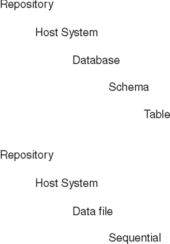
The table object in the hierarchy can represent a relational table, an IMS™table, or
a table from an object oriented database. The sequential object in the hierarchy can
represent a sequential file or an XML file.
Importing metadata to the shared repository
To place table definitions in the shared repository where they can be used by other
projects or suite components, you import metadata through a connector.
Chapter 4. Defining your data 59
Before you begin
Ensure that the Share metadata when importing from Connectors option is set for
the current project in the Administrator client. This option is selected by default. If
this option is not set, only the table definition in the project repository is created
when you import metadata by using a connector. You can subsequently associate a
table definition with a table in the shared repository by using the shared metadata
feature.
About this task
The metadata is imported from the external data source. A table is created in the
shared repository, and a table definition is created in your project repository tree.
Procedure
1. From the Designer client, open the Import Connector Metadata wizard.
2. On the Connector selection page, select the connector for the import process.
The connector that you want depends on the type of data source that you are
importing the metadata from.
3. On the Connection details page, enter the connection details for the data
source, and click Next. The next pages collect information that is specific to the
type of connector that you are using for the import process.
4. Specify the details for the type of connector that you selected, and click Next.
5. On the Data source location page, select the host name and database to identify
where you want to store the metadata in the shared repository. If the lists are
not populated, click New location to start the Shared Metadata Management
tool so that you can create host and database objects in the repository that
correspond to the data source that you are importing metadata from.
6. Click Next.
7. Confirm the import details and click Import.
8. Browse the repository tree and select the location in the project repository for
the table definition that you are creating, and then click OK.
Opening the Import Connector Metadata wizard
You use this wizard to import metadata by using a connector.
About this task
You do one of the following actions to open the wizard.
Procedure
vSelect Import >Table Definitions >Start connector import wizard from the
main menu.
vSelect Import Table Definition >Start connector import wizard from the
repository tree shortcut menu.
vFrom a stage editor Columns tab, click Load, and then select Import Table
Definition >Start connector import wizard from the repository tree shortcut
menu in the Table Definitions window.
Creating a table definition from shared metadata
You can create table definitions in your project from tables that have been placed
in the shared repository by other projects or suite components.
60 Designer Client Guide

About this task
The table definitions that are created from metadata in the shared repository have
a different icon from the table definitions that have been imported or created
locally in the project. Information about the source of the table definition is shown
in the Locator page of the Table Definition window.
Table definitions that are linked to tables in the shared repository are identified by
the following icon:
Table definitions can be linked for any of the following reasons:
vBecause the table definition was used to create a table in the shared repository.
vBecause the table definition was imported using a connector and a table in the
shared repository was created automatically at the same time.
vBecause the table definition was created from a table in the shared repository.
Table definitions that are local to the project are identified by the following icon:
Procedure
1. In the Designer client, select Repository >Metadata Sharing >Create Table
Definition from Table from the main menu.
2. Browse the tree in the Create Table Definition from Table window and select
the tables from which you want to build table definitions in your project. You
can select individual tables or select a schema, database, or host that is higher
in the tree to select all the contained tables.
3. In the Folder in which to create Table Definitions field, specify the folder in
your project repository where you want to store the table definitions.
4. Click Create.
Creating a table from a table definition
You can create a table in the shared repository from a table definition in a project.
Before you begin
You can create tables only from table definitions that do not have an existing link
with a shared table. Table definitions must have a valid locator. The locator
describes the real-world object that the table definition was derived from. A locator
is created automatically when you import the table definition from a data source,
or you can specify a locator in the Table Definition Properties window.
Procedure
1. In the Designer client, do one of the following:
vSelect the table definition that you want to share, right-click, and select
Shared Table Creation Wizard.
vSelect Repository >Metadata sharing >Shared Table Creation Wizard.
2. In the Select Table Definitions page of the Shared Table Creation wizard, click
Add to open a browse window.
3. In the browse window, select one or more table definitions that you want to
create tables for (if you opened the wizard by selecting a table definition and
Chapter 4. Defining your data 61
right-clicking, then that table definition is already listed). You can select a table
definition in the list and click View properties to view the properties of the
selected table definition.
4. Click OK to close the browse window and add the selected table definition to
the wizard page.
5. When you have selected all the table definitions that you want to share, click
Next. The wizard searches the tables in the shared repository and determines if
any of them match the table definitions that you specified. It links tables to
table definitions where they match. The wizard displays the results in the
Create or Associate Tables page. If no automatic link has been made for a table
definition, you have three choices:
vCreate a new table in the shared repository.
vCreate a link to an existing table in the shared repository.
vUse the wizard to review ratings for tables that might match the table
definitions.
To create a new table in the shared repository for a table definition:
a. Click the Association to Shared Table column.
b. Select Create New from the menu options.
c. In the Create New Table window, select the Host,Database, and Schema
details for the new table from the lists. The table name is derived from the
table definition name, but you can edit the name if required.
d. Click OK. If the wizard detects that a table with those details already exists,
it asks you if you want to link to that table, or change the details and create
a new table. Otherwise, the path name of the shared table appears in the
Association to Shared Table column, and New is shown in the Action
column.
To manually create a link to an existing table in the shared repository:
a. Click on the Association to Shared Table column.
b. Select Browse existing from the menu options.
c. In the Browse for shared table window, browse the tree structure to locate
the table that you want to link the table definition to.
d. Click OK. The path name of the shared table is shown in the Association to
Shared Table column, and Linking is shown in the Action column.
To view ratings for tables in the wizard:
a. Click the Association to Shared Table column.
b. Select Help me choose from the menu options. The Choose Candidate
window displays a list of tables in the shared repository, together with a
rating for the strength of the match to the selected table definition. The
higher the percentage rating, the closer the match.
c. Select the candidate in the list that you want to link the table definition to
and click OK. The path name of the shared table is shown in the
Association to Shared Table column, and Linking is shown in the Action
column.
6. Click Next. The Confirmation page displays details of the choices that you have
made.
7. If you want to make changes, click Back. To finish, click Create to create the
table or tables.
Creating a table from a table definition
You can create a table in the shared repository from a table definition in a project.
62 Designer Client Guide
Before you begin
You can create tables only from table definitions that do not have an existing link
with a shared table. Table definitions must have a valid locator. The locator
describes the real-world object that the table definition was derived from. A locator
is created automatically when you import the table definition from a data source,
or you can specify a locator in the Table Definition Properties window.
Procedure
1. In the Designer client, do one of the following:
vSelect the table definition that you want to share, right-click, and select
Shared Table Creation Wizard.
vSelect Repository >Metadata sharing >Shared Table Creation Wizard.
2. In the Select Table Definitions page of the Shared Table Creation wizard, click
Add to open a browse window.
3. In the browse window, select one or more table definitions that you want to
create tables for (if you opened the wizard by selecting a table definition and
right-clicking, then that table definition is already listed). You can select a table
definition in the list and click View properties to view the properties of the
selected table definition.
4. Click OK to close the browse window and add the selected table definition to
the wizard page.
5. When you have selected all the table definitions that you want to share, click
Next. The wizard searches the tables in the shared repository and determines if
any of them match the table definitions that you specified. It links tables to
table definitions where they match. The wizard displays the results in the
Create or Associate Tables page. If no automatic link has been made for a table
definition, you have three choices:
vCreate a new table in the shared repository.
vCreate a link to an existing table in the shared repository.
vUse the wizard to review ratings for tables that might match the table
definitions.
To create a new table in the shared repository for a table definition:
a. Click the Association to Shared Table column.
b. Select Create New from the menu options.
c. In the Create New Table window, select the Host,Database, and Schema
details for the new table from the lists. The table name is derived from the
table definition name, but you can edit the name if required.
d. Click OK. If the wizard detects that a table with those details already exists,
it asks you if you want to link to that table, or change the details and create
a new table. Otherwise, the path name of the shared table appears in the
Association to Shared Table column, and New is shown in the Action
column.
To manually create a link to an existing table in the shared repository:
a. Click on the Association to Shared Table column.
b. Select Browse existing from the menu options.
c. In the Browse for shared table window, browse the tree structure to locate
the table that you want to link the table definition to.
d. Click OK. The path name of the shared table is shown in the Association to
Shared Table column, and Linking is shown in the Action column.
Chapter 4. Defining your data 63

To view ratings for tables in the wizard:
a. Click the Association to Shared Table column.
b. Select Help me choose from the menu options. The Choose Candidate
window displays a list of tables in the shared repository, together with a
rating for the strength of the match to the selected table definition. The
higher the percentage rating, the closer the match.
c. Select the candidate in the list that you want to link the table definition to
and click OK. The path name of the shared table is shown in the
Association to Shared Table column, and Linking is shown in the Action
column.
6. Click Next. The Confirmation page displays details of the choices that you have
made.
7. If you want to make changes, click Back. To finish, click Create to create the
table or tables.
Synchronizing metadata
You can check that the table definition in your project repository is synchronized
with the table in the shared repository. You can check the synchronization state
manually to ensure that no changes have occurred since the last repository refresh.
About this task
A table definition is in the synchronized state when its modification time and date
match the modification time and date of the table in the shared repository to
which it is linked.
The synchronization state is checked whenever the project repository view is
refreshed. You can also check the synchronization state manually to ensure that no
changes have occurred since the last repository refresh.
A table definition that is no longer synchronized is identified by the following
icon:
Procedure
1. Select one or more table definitions in the project repository tree.
2. Select Repository >Metadata Sharing >Update table definition from shared
table from the main menu.
3. If any of the table definitions are not synchronized with the tables, you can do
one of the following actions for that table definition. You can perform these
actions on multiple tables if required:
vClick Update or Update All to update the table definition or table definitions
from the table or tables.
vClick Remove or Remove All to remove the link between the table definition
or table definitions and the table or tables.
4. If the table definitions are synchronized with the tables, you can either close the
window or click Remove to remove the link between the table definition and
the table.
64 Designer Client Guide
Managing shared metadata
You can use the Shared Metadata Management tool to manage the objects that
represent tables in the shared repository.
About this task
Use the Shared Metadata Management tool to add a new host system, add a new
database or data file, or add a new schema. You can also use the tool to delete
items from the shared repository.
You can open the quick find tool from the Shared Metadata Management tool to
search for objects in the shared repository.
Adding a new host system
You can use the Shared Metadata Management tool to add a new host system to
the shared repository tree.
About this task
The new host system object is shown in the tree in the Shared Metadata
Management tool. The details that you enter are shown in the right pane of the
Shared Metadata Management tool whenever this host system object is selected in
the tree.
Procedure
1. Select Repository >Metadata Sharing >Management from the main menu to
open the Shared Metadata Management tool.
2. Click the repository icon at the top of the tree.
3. Select Add >Add new host system.
4. In the Add new host system window, specify information about your host
system. The Name field and Network Node fields are mandatory; the other
fields are optional.
5. Click OK.
Adding a new database
You use the Shared Metadata Management tool to add a new database to the
shared repository tree.
About this task
The new database object is shown in the tree in the Shared Metadata Management
tool. The details that you enter are shown in the right pane of the Shared Metadata
Management tool whenever this database object is selected in the tree. Click the
Columns tab to view the table columns.
Procedure
1. Select Repository >Metadata Sharing >Management from the main menu to
open the Shared Metadata Management tool.
2. Select the host system where you want to add a database.
3. Select Add >Add new database.
4. In the Add new database window, specify information about your database.
The Name field is mandatory; the other fields are optional.
5. Click OK.
Chapter 4. Defining your data 65

Adding a new schema
You use the Shared Metadata Management tool to add a new schema to the shared
repository tree.
About this task
The new schema object is shown in the tree in the Shared Metadata Management
tool. The details that you enter are shown in the right pane of the Shared Metadata
Management tool whenever this schema object is selected in the tree.
Procedure
1. Select Repository >Metadata Sharing >Management from the main menu to
open the Shared Metadata Management tool.
2. Select the database where you want to add a schema.
3. Select Add >Add new schema.
4. In the Add new schema window, specify information about your schema. The
Name field is mandatory, the other fields are optional.
5. Click OK.
Adding a new data file
You use the Shared Metadata Management tool to add a new data file to the
shared repository tree.
About this task
The new data file object is shown in the tree in the Shared Metadata Management
tool. The details that you enter are shown in the right pane of the Shared Metadata
Management tool whenever this object is selected in the tree. Click the Columns
tab to view the data columns in the file.
Procedure
1. Select Repository >Metadata Sharing >Management from the main menu to
open the Shared Metadata Management tool.
2. Select the host system where you want to add a data file.
3. Select Add >Add new data file.
4. In the Add new data file window, specify information about your data file. The
Name field is mandatory, the other fields are optional.
5. Click OK.
Manually entering a table definition
If you are unable to import the table definitions for your source or target data, you
must enter this information manually.
To manually enter table definition properties, you must first create a new table
definition. You can then enter suitable settings for the general properties before
specifying the column definitions. You only need to specify file format settings for
a sequential file table definition.
Creating a table definition
You create table definitions in the Designer client.
66 Designer Client Guide
Procedure
1. Choose File >New to open the New dialog box.
2. Open the Other folder, select the Table definition icon, and click OK.
3. TheTable Definition dialog box appears. You must enter suitable details for each
page appropriate to the type of table definition you are creating. At a minimum
you must supply identification details on the General page and column
definitions on the Columns page. Details are given in the following sections.
Entering General page details
You can manually enter general information about your stored procedure
definition in the Table Definition dialog box.
Procedure
1. Enter the type of data source in the Data source type field. The name entered
here determines how the definition appears under the Table Definitions
branch.
2. Enter the name of the data source in the Data source name field. This forms
the second part of the table definition identifier and is the name of the branch
created under the data source type branch.
3. Enter the name of the table or file containing the data in the Table name field.
This is the last part of the table definition identifier and is the name of the leaf
created under the data source branch. The rules for name table definitions are
as follows:
vTable names can be any length.
vThey must begin with an alphabetic character.
vThey can contain alphanumeric, period, and underscore characters.
4. Where the Data source type specifies a relational database, type the name of
the database owner in Owner.
5. If you are entering a mainframe table definition, choose the platform type
from the Mainframe platform type drop-down list, and the access type from
the Mainframe access type drop-down list. Otherwise leave both of these
items set to <Not applicable>.
6. Select the Metadata supports Multi-valued fields check box if the metadata
supports multivalued data.
7. If required, specify what character an ODBC data source uses as a quote
character in ODBC quote character.
8. Enter a brief description of the data in the Short description field. This is an
optional field.
9. Enter a more detailed description of the data in the Long description field.
This is an optional field.
10. Click the Columns tab. The Columns page appears at the front of the Table
Definition dialog box. You can now enter or load column definitions for your
data.
Entering column definitions
You can enter column definitions directly in the Columns grid using the standard
controls or you can use the Edit Column Metadata dialog box to add one row at a
time.
Procedure
1. Do one of the following:
Chapter 4. Defining your data 67
vRight-click in the column area and choose Edit row... from the shortcut
menu.
vPress Ctrl-E.
vDouble-click on the row number cell at the left of the grid.
The Edit Column Metadata dialog box appears. It has a general area
containing fields that are common to all data source type, plus three tabs
containing fields specific to metadata used in server jobs and information
specific to COBOL data sources and information about formats used in
parallel jobs.
The exact fields that appear in this dialog box depend on the type of table
definition as set on the General page of the Table Definition dialog box.
2. Enter the general information for each column you want to define as follows:
vColumn name. Type in the name of the column. This is the only mandatory
field in the definition.
vKey. Select Yes or No from the drop-down list.
vNative type. For data sources with a platform type of OS390, choose the
native data type from the drop-down list. The contents of the list are
determined by the Access Type you specified on the General page of the
Table Definition dialog box. (The list is blank for non-mainframe data
sources.)
vSQL type. Choose from the drop-down list of supported SQL types. If you
are a adding a table definition for platform type OS390, you cannot manually
enter an SQL type, it is automatically derived from the Native type.
vLength. Type a number representing the length or precision of the column.
vScale. If the column is numeric, type a number to define the number of
decimal places.
vNullable. Select Yes or No from the drop-down list. This is set to indicate
whether the column is subject to a NOT NULL constraint. It does not itself
enforce a NOT NULL constraint.
vDate format. Choose the date format that the column uses from the
drop-down list of available formats.
vDescription. Type in a description of the column.
Entering column definitions for server jobs
If you are specifying metadata for a server job type data source or target, then the
Edit Column Metadata dialog bog box appears with the Server tab on top.
Enter any required information that is specific to server jobs:
vData element. Choose from the drop-down list of available data elements.
vDisplay. Type a number representing the display length for the column.
vPosition. Visible only if you have specified Meta data supports Multi-valued
fields on the General page of the Table Definition dialog box. Enter a number
representing the field number.
vType. Visible only if you have specified Meta data supports Multi-valued fields
on the General page of the Table Definition dialog box. Choose S,M,MV,MS,
or blank from the drop-down list.
vAssociation. Visible only if you have specified Meta data supports Multi-valued
fields on the General page of the Table Definition dialog box. Type in the name
of the association that the column belongs to (if any).
vNLS Map. Visible only if NLS is enabled and Allow per-column mapping has
been selected on the NLS page of the Table Definition dialog box. Choose a
68 Designer Client Guide
separate character set map for a column, which overrides the map set for the
project or table. (The per-column mapping feature is available only for
sequential, ODBC, or generic plug-in data source types.)
vNull String. This is the character that represents null in the data.
vPadding. This is the character used to pad missing columns. Set to # by default.
Entering column definitions for mainframe jobs
If you are specifying metadata for a mainframe job type data source, then the Edit
Column Metadata dialog box appears with the COBOL tab on top.
Note: Mainframe jobs are not supported in this version of IBM InfoSphere
Information Server.
Enter any required information that is specific to mainframe jobs:
vLevel number. Type in a number giving the COBOL level number in the range
02 - 49. The default value is 05.
vOccurs. Type in a number giving the COBOL occurs clause. If the column
defines a group, gives the number of elements in the group.
vUsage. Choose the COBOL usage clause from the drop-down list. This specifies
which COBOL format the column will be read in. These formats map to the
formats in the Native type field, and changing one will normally change the
other. Possible values are:
–COMP - Binary
–COMP-1 - single-precision Float
–COMP-2 - packed decimal Float
–COMP-3 - packed decimal
–COMP-5 - used with NATIVE BINARY native types
–DISPLAY - zone decimal, used with Display_numeric or Character native
types
–DISPLAY-1 - double-byte zone decimal, used with Graphic_G or Graphic_N
vSign indicator. Choose Signed or blank from the drop-down list to specify
whether the column can be signed or not. The default is blank.
vSign option. If the column is signed, choose the location of the sign in the data
from the drop-down list. Choose from the following:
–LEADING - the sign is the first byte of storage
–TRAILING - the sign is the last byte of storage
–LEADING SEPARATE - the sign is in a separate byte that has been added to
the beginning of storage
–TRAILING SEPARATE - the sign is in a separate byte that has been added to
the end of storage
Selecting either LEADING SEPARATE or TRAILING SEPARATE will
increase the storage length of the column by one byte.
vSync indicator. Choose SYNC or blank from the drop-down list to indicate
whether this is a COBOL-synchronized clause or not.
vRedefined field. Optionally specify a COBOL REDEFINES clause. This allows
you to describe data in the same storage area using a different data description.
The redefining column must be the same length, or smaller, than the column it
redefines. Both columns must have the same level, and a column can only
redefine the immediately preceding column with that level.
vDepending on. Optionally choose a COBOL OCCURS-DEPENDING ON clause
from the drop-down list.
Chapter 4. Defining your data 69

vStorage length. Gives the storage length in bytes of the column as defined. The
field cannot be edited.
vPicture. Gives the COBOL PICTURE clause, which is derived from the column
definition. The field cannot be edited.
The Server tab is still accessible, but the Server page only contains the Data
Element and Display fields.
The following table shows the relationships between native COBOL types and
SQL types:
Table 1. Relationships between native COBOL types and SQL types
Native Data
Type
Native Length
(bytes)
COBOL Usage
Representation SQL Type Precision (p) Scale (s)
Storage
Length (bytes)
BINARY 2 4 8 PIC S9 to S9(4)
COMP PIC
S9(5) to S9(9)
COMP PIC
S9(10) to S9(18)
COMP
SmallInt
Integer
Decimal
1to45to910
to 18
n/a n/a n/a 2 4 8
CHARACTER n n PIC X(n) Char n n/a n
DECIMAL (p+s)/2+1 PIC S9(p)V9(s)
COMP-3
Decimal p+s s (p+s)/2+1
DISPLAY_
NUMERIC
p+s PIC S9(p)V9(s) Decimal p+s s (p+s)/2+1
FLOAT (single)
(double)
4
8
PIC COMP-1
PIC COMP-2
Decimal
Decimal
p+s (default
18) p+s
(default 18)
s (default 4) s
(default 4)
4
8
GRAPHIC_G n*2 PIC G(n)
DISPLAY-1
NChar n n/a n*2
GRAPHIC_N n*2 PIC N(n) NChar n n/a n*2
GROUP n (sum of all
the column
lengths that
make up the
group)
Char n n/a n
NATIVE
BINARY
2 4 8 PIC S9 to S9(4)
COMP-5 PIC
S9(5) to S9(9)
COMP-5 PIC
S9(10) to S9(18)
COMP-5
SmallInt
Integer
Decimal
1to45to910
to 18
n/a n/a n/a 2 4 8
VARCHAR n+2 PIC S9(4)
COMP PIC
X(n)
VarChar n+2 n/a n+2
VARGRAPHIC
_G
(n*2)+2 PIC S9(4)
COMP PIC
G(n)
DISPLAY-1
NVarChar n+2 n/a (n*2)+2
VARGRAPHIC
_N
(n*2)+2 PIC S9(4)
COMP PIC
N(n)
NVarChar n+2 n/a (n*2)+2
70 Designer Client Guide
Entering column definitions for parallel jobs
If you are specifying metadata for a parallel job type data source or target, then the
Edit Column Metadata dialog bog box appears with the Parallel tab on top. This
allows you to enter detailed information about the format of the column.
Field Level
This has the following properties:
vBytes to Skip. Skip the specified number of bytes from the end of the previous
column to the beginning of this column.
vDelimiter. Specifies the trailing delimiter of the column. Type an ASCII character
or select one of whitespace, end, none, null, comma, or tab.
vwhitespace. Any whitespace characters (space, tab, or newline) at the end of a
column are skipped.
vend. The end of a field is taken as the delimiter, that is, there is no separate
delimiter. This is not the same as a setting of `None' which is used for fields
with fixed-width columns.
vnone. No delimiter (used for fixed-width).
vnull. ASCII Null character is used.
vcomma. ASCII comma character used.
vtab. ASCII tab character used.
vDelimiter string. Specify a string to be written at the end of the column. Enter
one or more characters. This is mutually exclusive with Delimiter, which is the
default. For example, specifying `, ` (comma space - you do not need to enter the
inverted commas) would have the column delimited by `, `.
vDrop on input. Select this property when you must fully define the metadata
for a data set, but do not want the column actually read into the data set.
vPrefix bytes. Specifies that this column is prefixed by 1, 2, or 4 bytes containing,
as a binary value, either the column's length or the tag value for a tagged
column. You can use this option with variable-length fields. Variable-length
fields can be either delimited by a character or preceded by a 1-, 2-, or 4-byte
prefix containing the field length. IBM InfoSphere DataStage inserts the prefix
before each field.
This property is mutually exclusive with the Delimiter, Quote, and Final
Delimiter properties, which are used by default.
vPrint field. This property is intended for use when debugging jobs. Set it to
have InfoSphere DataStage produce a message for each of the columns it reads.
The message has the format:
Importing N:D
where:
– N is the column name.
– D is the imported data of the column. Non-printable characters contained in
D are prefixed with an escape character and written as C string literals; if the
column contains binary data, it is output in octal format.
vQuote. Specifies that variable length columns are enclosed in single quotes,
double quotes, or another ASCII character or pair of ASCII characters. Choose
Single or Double, or enter a character.
vStart position. Specifies the starting position of a column in the record. The
starting position can be either an absolute byte offset from the first record
position (0) or the starting position of another column.
Chapter 4. Defining your data 71
vTag case value. Explicitly specifies the tag value corresponding to a subfield in a
tagged subrecord. By default the fields are numbered 0 to N-1, where N is the
number of fields. (A tagged subrecord is a column whose type can vary. The
subfields of the tagged subrecord are the possible types. The tag case value of
the tagged subrecord selects which of those types is used to interpret the
column's value for the record.)
String Type
This has the following properties:
vCharacter Set. Choose from ASCII or EBCDIC (not available for ustring type
(Unicode)).
vDefault. The default value for a column. This is used for data written by a
Generate stage. It also supplies the value to substitute for a column that causes
an error (whether written or read).
vExport EBCDIC as ASCII. Select this to specify that EBCDIC characters are
written as ASCII characters (not available for ustring type (Unicode)).
vIs link field. Selected to indicate that a column holds the length of another,
variable-length column of the record or of the tag value of a tagged record field.
vImport ASCII as EBCDIC. Select this to specify that ASCII characters are read
as EBCDIC characters (not available for ustring type (Unicode)).
vField max width. The maximum number of bytes in a column represented as a
string. Enter a number. This is useful where you are storing numbers as text. If
you are using a fixed-width character set, you can calculate the length exactly. If
you are using variable-length character set, calculate an adequate maximum
width for your fields. Applies to fields of all data types except date, time,
timestamp, and raw; and record, subrec, or tagged if they contain at least one
field of this type.
vField width. The number of bytes in a column represented as a string. Enter a
number. This is useful where you are storing numbers as text. If you are using a
fixed-width charset, you can calculate the number of bytes exactly. If it's a
variable length encoding, base your calculation on the width and frequency of
your variable-width characters. Applies to fields of all data types except date,
time, timestamp, and raw; and record, subrec, or tagged if they contain at least
one field of this type.
vPad char. Specifies the pad character used when strings or numeric values are
written to an external string representation. Enter a character (single-byte for
strings, can be multi-byte for ustrings) or choose null or space. The pad
character is used when the external string representation is larger than required
to hold the written field. In this case, the external string is filled with the pad
character to its full length. Space is the default. Applies to string, ustring, and
numeric data types and record, subrec, or tagged types if they contain at least
one field of this type.
Date Type
This has the following properties:
vByte order. Specifies how multiple byte data types are ordered. Choose from:
– little-endian. The high byte is on the right.
– big-endian. The high byte is on the left.
– native-endian. As defined by the native format of the machine.
vCharacter Set. Choose from ASCII or EBCDIC.
72 Designer Client Guide
vDays since. Dates are written as a signed integer containing the number of days
since the specified date. Enter a date in the form %yyyy-%mm-%ddor in the
default date format if you have defined a new one on an NLS system.
vData Format. Specifies the data representation format of a column. Choose from:
– binary
– text
For dates, binary is equivalent to specifying the julian property for the date
field, text specifies that the data to be written contains a text-based date in the
form %yyyy-%mm-%dd or in the default date format if you have defined a
new one on an NLS system.
vDefault. The default value for a column. This is used for data written by a
Generate stage. It also supplies the value to substitute for a column that causes
an error (whether written or read).
vFormat string. The string format of a date. By default this is %yyyy-%mm-%dd.
The Format string can contain one or a combination of the following elements:
– %dd: A two-digit day.
– %mm: A two-digit month.
– %year_cutoffyy: A two-digit year derived from yy and the specified four-digit
year cutoff, for example %1970yy.
– %yy: A two-digit year derived from a year cutoff of 1900.
– %yyyy: A four-digit year.
– %ddd: Day of year in three-digit form (range of 1- 366).
– %mmm: Three-character month abbreviation.
The format_string is subject to the following restrictions:
– It cannot have more than one element of the same type, for example it cannot
contain two %dd elements.
– It cannot have both %dd and %ddd.
– It cannot have both %yy and %yyyy.
– It cannot have both %mm and %ddd.
– It cannot have both %mmm and %ddd.
– It cannot have both %mm and %mmm.
– If it has %dd, it must have %mm or %mmm.
– It must have exactly one of %yy or %yyyy.
When you specify a date format string, prefix each component with the percent
symbol (%). Separate the string's components with any character except the
percent sign (%).
If this format string does not include a day, it is set to the first of the month in
the destination field. If the format string does not include the month and day,
they default to January 1. Note that the format string must contain a month if it
also contains a day; that is, you cannot omit only the month.
The year_cutoff is the year defining the beginning of the century in which all
twodigit years fall. By default, the year cutoff is 1900; therefore, a two-digit year
of 97 represents 1997.
You can specify any four-digit year as the year cutoff. All two-digit years then
specify the next possible year ending in the specified two digits that is the same
or greater than the cutoff. For example, if you set the year cutoff to 1930, the
two-digit year 30 corresponds to 1930, and the two-digit year 29 corresponds to
2029.
Chapter 4. Defining your data 73
vIs Julian. Select this to specify that dates are written as a numeric value
containing the Julian day. A Julian day specifies the date as the number of days
from 4713 BCE January 1, 12:00 hours (noon) GMT.
Time Type
This has the following properties:
vByte order. Specifies how multiple byte data types are ordered. Choose from:
– little-endian. The high byte is on the right.
– big-endian. The high byte is on the left.
– native-endian. As defined by the native format of the machine.
vCharacter Set. Choose from ASCII or EBCDIC.
vDefault. The default value for a column. This is used for data written by a
Generate stage. It also supplies the value to substitute for a column that causes
an error (whether written or read).
vData Format. Specifies the data representation format of a column. Choose from:
– binary
– text
For time, binary is equivalent to midnight_seconds, text specifies that the field
represents time in the text-based form %hh:%nn:%ss or in the default date
format if you have defined a new one on an NLS system.
vFormat string. Specifies the format of columns representing time as a string. By
default this is %hh-%mm-%ss. The possible components of the time format
string are:
– %hh: A two-digit hours component.
– %nn: A two-digit minute component (nn represents minutes because mm is
used for the month of a date).
– %ss: A two-digit seconds component.
– %ss.n: A two-digit seconds plus fractional part, where n is the number of
fractional digits with a maximum value of 6. If n is 0, no decimal point is
printed as part of the seconds component. Trailing zeros are not suppressed.
You must prefix each component of the format string with the percent symbol.
Separate the string's components with any character except the percent sign (%).
vIs midnight seconds. Select this to specify that times are written as a binary
32-bit integer containing the number of seconds elapsed from the previous
midnight.
Timestamp Type
This has the following properties:
vByte order. Specifies how multiple byte data types are ordered. Choose from:
– little-endian. The high byte is on the right.
– big-endian. The high byte is on the left.
– native-endian. As defined by the native format of the machine.
vCharacter Set. Choose from ASCII or EBCDIC.
vData Format. Specifies the data representation format of a column. Choose from:
– binary
– text
74 Designer Client Guide
For timestamp, binary specifies that the first integer contains a Julian day
count for the date portion of the timestamp and the second integer specifies
the time portion of the timestamp as the number of seconds from midnight. A
binary timestamp specifies that two 32-but integers are written. Text specifies
a text-based timestamp in the form %yyyy-%mm-%dd %hh:%nn:%ss or in the
default date format if you have defined a new one on an NLS system.
vDefault. The default value for a column. This is used for data written by a
Generate stage. It also supplies the value to substitute for a column that causes
an error (whether written or read).
vFormat string. Specifies the format of a column representing a timestamp as a
string. Defaults to %yyyy-%mm-%dd %hh:%nn:%ss. Specify the format as
follows:
For the date:
– %dd: A two-digit day.
– %mm: A two-digit month.
– %year_cutoffyy: A two-digit year derived from yy and the specified four-digit
year cutoff.
– %yy: A two-digit year derived from a year cutoff of 1900.
– %yyyy: A four-digit year.
– %ddd: Day of year in three-digit form (range of 1 - 366)
For the time:
– %hh: A two-digit hours component.
– %nn: A two-digit minute component (nn represents minutes because mm is
used for the month of a date).
– %ss: A two-digit seconds component.
– %ss.n: A two-digit seconds plus fractional part, where n is the number of
fractional digits with a maximum value of 6. If n is 0, no decimal point is
printed as part of the seconds component. Trailing zeros are not suppressed.
You must prefix each component of the format string with the percent symbol
(%). Separate the string's components with any character except the percent
sign (%).
Integer Type
This has the following properties:
vByte order. Specifies how multiple byte data types are ordered. Choose from:
– little-endian. The high byte is on the right.
– big-endian. The high byte is on the left.
– native-endian. As defined by the native format of the machine.
vCharacter Set. Choose from ASCII or EBCDIC.
vC_format. Perform non-default conversion of data from a string to integer data.
This property specifies a C-language format string used for reading/writing
integer strings. This is passed to sscanf() or sprintf().
vDefault. The default value for a column. This is used for data written by a
Generate stage. It also supplies the value to substitute for a column that causes
an error (whether written or read).
vData Format. Specifies the data representation format of a column. Choose from:
– binary
– text
Chapter 4. Defining your data 75
vField max width. The maximum number of bytes in a column represented as a
string. Enter a number. Enter a number. This is useful where you are storing
numbers as text. If you are using a fixed-width character set, you can calculate
the length exactly. If you are using variable-length character set, calculate an
adequate maximum width for your fields. Applies to fields of all data types
except date, time, timestamp, and raw; and record, subrec, or tagged if they
contain at least one field of this type.
vField width. The number of bytes in a column represented as a string. Enter a
number. This is useful where you are storing numbers as text. If you are using a
fixed-width charset, you can calculate the number of bytes exactly. If it's a
variable length encoding, base your calculation on the width and frequency of
your variable-width characters. Applies to fields of all data types except date,
time, timestamp, and raw; and record, subrec, or tagged if they contain at least
one field of this type.
vIn_format. Format string used for conversion of data from string to integer. This
is passed to sscanf(). By default, InfoSphere DataStage invokes the C sscanf()
function to convert a numeric field formatted as a string to either integer or
floating point data. If this function does not output data in a satisfactory format,
you can specify the in_format property to pass formatting arguments to sscanf().
vIs link field. Selected to indicate that a column holds the length of another,
variable-length column of the record or of the tag value of a tagged record field.
vOut_format. Format string used for conversion of data from integer to a string.
This is passed to sprintf(). By default, InfoSphere DataStage invokes the C
sprintf() function to convert a numeric field formatted as integer data to a string.
If this function does not output data in a satisfactory format, you can specify the
out_format property to pass formatting arguments to sprintf().
vPad char. Specifies the pad character used when the integer is written to an
external string representation. Enter a character (single-bye for strings, can be
multi-byte for ustrings) or choose null or space. The pad character is used when
the external string representation is larger than required to hold the written
field. In this case, the external string is filled with the pad character to its full
length. Space is the default.
Decimal Type
This has the following properties:
vAllow all zeros. Specifies whether to treat a packed decimal column containing
all zeros (which is normally illegal) as a valid representation of zero. Select Yes
or No.
vCharacter Set. Choose from ASCII or EBCDIC.
vDecimal separator. Specify the character that acts as the decimal separator
(period by default).
vDefault. The default value for a column. This is used for data written by a
Generate stage. It also supplies the value to substitute for a column that causes
an error (whether written or read).
vData Format. Specifies the data representation format of a column. Choose from:
– binary
– text
For decimals, binary means packed. Text represents a decimal in a string
format with a leading space or '-' followed by decimal digits with an
embedded decimal point if the scale is not zero. The destination string format
is: [+ | -]ddd.[ddd] and any precision and scale arguments are ignored.
76 Designer Client Guide
vField max width. The maximum number of bytes in a column represented as a
string. Enter a number. Enter a number. This is useful where you are storing
numbers as text. If you are using a fixed-width character set, you can calculate
the length exactly. If you are using variable-length character set, calculate an
adequate maximum width for your fields. Applies to fields of all data types
except date, time, timestamp, and raw; and record, subrec, or tagged if they
contain at least one field of this type.
vField width. The number of bytes in a column represented as a string. Enter a
number. This is useful where you are storing numbers as text. If you are using a
fixed-width charset, you can calculate the number of bytes exactly. If it's a
variable length encoding, base your calculation on the width and frequency of
your variable-width characters. Applies to fields of all data types except date,
time, timestamp, and raw; and record, subrec, or tagged if they contain at least
one field of this type.
vPacked. Select an option to specify what the decimal columns contain, choose
from:
vYes to specify that the decimal columns contain data in packed decimal format
(the default). This has the following sub-properties:
vCheck. Select Yes to verify that data is packed, or No to not verify.
vSigned. Select Yes to use the existing sign when writing decimal columns. Select
No to write a positive sign (0xf) regardless of the columns' actual sign value.
vNo (separate) to specify that they contain unpacked decimal with a separate
sign byte. This has the following sub-property:
vSign Position. Choose leading or trailing as appropriate.
vNo (zoned) to specify that they contain an unpacked decimal in either ASCII or
EBCDIC text. This has the following sub-property:
vSign Position. Choose leading or trailing as appropriate.
vNo (overpunch) to specify that the field has a leading or end byte that contains
a character which specifies both the numeric value of that byte and whether the
number as a whole is negatively or positively signed. This has the following
sub-property:
vSign Position. Choose leading or trailing as appropriate.
vPrecision. Specifies the precision where a decimal column is represented in text
format. Enter a number. When a decimal is written to a string representation,
InfoSphere DataStage uses the precision and scale defined for the source decimal
field to determine the length of the destination string. The precision and scale
properties override this default. When they are defined, InfoSphere DataStage
truncates or pads the source decimal to fit the size of the destination string. If
you have also specified the field width property, InfoSphere DataStage truncates
or pads the source decimal to fit the size specified by field width.
vRounding. Specifies how to round the source field to fit into the destination
decimal when reading a source field to a decimal. Choose from:
– up (ceiling). Truncate source column towards positive infinity. This mode
corresponds to the IEEE 754 Round Up mode. For example, 1.4 becomes 2,
-1.6 becomes -1.
– down (floor). Truncate source column towards negative infinity. This mode
corresponds to the IEEE 754 Round Down mode. For example, 1.6 becomes 1,
-1.4 becomes -2.
– nearest value. Round the source column towards the nearest representable
value. This mode corresponds to the COBOL ROUNDED mode. For example,
1.4 becomes 1, 1.5 becomes 2, -1.4 becomes -1, -1.5 becomes -2.
Chapter 4. Defining your data 77
– truncate towards zero. This is the default. Discard fractional digits to the right
of the right-most fractional digit supported by the destination, regardless of
sign. For example, if the destination is an integer, all fractional digits are
truncated. If the destination is another decimal with a smaller scale, truncate
to the scale size of the destination decimal. This mode corresponds to the
COBOL INTEGER-PART function. Using this method 1.6 becomes 1, -1.6
becomes -1.
vScale. Specifies how to round a source decimal when its precision and scale are
greater than those of the destination. By default, when the InfoSphere DataStage
writes a source decimal to a string representation, it uses the precision and scale
defined for the source decimal field to determine the length of the destination
string. You can override the default by means of the precision and scale
properties. When you do, InfoSphere DataStage truncates or pads the source
decimal to fit the size of the destination string. If you have also specified the
field width property, InfoSphere DataStage truncates or pads the source decimal
to fit the size specified by field width. Specifies how to round a source decimal
when its precision and scale are greater than those of the destination.
Float Type
This has the following properties:
vC_format. Perform non-default conversion of data from a string to floating-point
data. This property specifies a C-language format string used for reading
floating point strings. This is passed to sscanf().
vCharacter Set. Choose from ASCII or EBCDIC.
vDefault. The default value for a column. This is used for data written by a
Generate stage. It also supplies the value to substitute for a column that causes
an error (whether written or read).
vData Format. Specifies the data representation format of a column. Choose from:
– binary
– text
vField max width. The maximum number of bytes in a column represented as a
string. Enter a number. Enter a number. This is useful where you are storing
numbers as text. If you are using a fixed-width character set, you can calculate
the length exactly. If you are using variable-length character set, calculate an
adequate maximum width for your fields. Applies to fields of all data types
except date, time, timestamp, and raw; and record, subrec, or tagged if they
contain at least one field of this type.
vField width. The number of bytes in a column represented as a string. Enter a
number. This is useful where you are storing numbers as text. If you are using a
fixed-width charset, you can calculate the number of bytes exactly. If it's a
variable length encoding, base your calculation on the width and frequency of
your variable-width characters. Applies to fields of all data types except date,
time, timestamp, and raw; and record, subrec, or tagged if they contain at least
one field of this type.
vIn_format. Format string used for conversion of data from string to floating
point. This is passed to sscanf(). By default, InfoSphere DataStage invokes the C
sscanf() function to convert a numeric field formatted as a string to floating
point data. If this function does not output data in a satisfactory format, you can
specify the in_format property to pass formatting arguments to sscanf().
vIs link field. Selected to indicate that a column holds the length of a another,
variable-length column of the record or of the tag value of a tagged record field.
78 Designer Client Guide
vOut_format. Format string used for conversion of data from floating point to a
string. This is passed to sprintf(). By default, InfoSphere DataStage invokes the C
sprintf() function to convert a numeric field formatted as floating point data to a
string. If this function does not output data in a satisfactory format, you can
specify the out_format property to pass formatting arguments to sprintf().
vPad char. Specifies the pad character used when the floating point number is
written to an external string representation. Enter a character (single-bye for
strings, can be multi-byte for ustrings) or choose null or space. The pad
character is used when the external string representation is larger than required
to hold the written field. In this case, the external string is filled with the pad
character to its full length. Space is the default.
Nullable
This appears for nullable fields.
vActual field length. Specifies the number of bytes to fill with the Fill character
when a field is identified as null. When InfoSphere DataStage identifies a null
field, it will write a field of this length full of Fill characters. This is mutually
exclusive with Null field value.
vNull field length. The length in bytes of a variable-length field that contains a
null. When a variable-length field is read, a length of null field length in the
source field indicates that it contains a null. When a variable-length field is
written, InfoSphere DataStage writes a length value of null field length if the
field contains a null. This property is mutually exclusive with null field value.
vNull field value. Specifies the value given to a null field if the source is set to
null. Can be a number, string, or C-type literal escape character. For example,
you can represent a byte value by \ooo, where each o is an octal digit0-7and
the first o is < 4, or by \xhh, where each h is a hexadecimal digit0-F.Youmust
use this form to encode non-printable byte values.
This property is mutually exclusive with Null field length and Actual length. For
a fixed width data representation, you can use Pad char (from the general
section of Type defaults) to specify a repeated trailing character if the value you
specify is shorter than the fixed width of the field. On reading, specifies the
value given to a field containing a null. On writing, specifies the value given to
a field if the source is set to null. Can be a number, string, or C-type literal
escape character.
Generator
If the column is being used in a Row Generator or Column Generator stage, this
allows you to specify extra details about the mock data being generated. The exact
fields that appear depend on the data type of the column being generated. They
allow you to specify features of the data being generated, for example, for integers
they allow you to specify if values are random or whether they cycle. If they cycle
you can specify an initial value, an increment, and a limit. If they are random, you
can specify a seed value for the random number generator, whether to include
negative numbers, and a limit.
Vectors
If the row you are editing represents a column which is a variable length vector,
tick the Variable check box. The Vector properties appear, these give the size of the
vector in one of two ways:
Chapter 4. Defining your data 79
vLink Field Reference. The name of a column containing the number of elements
in the variable length vector. This should have an integer or float type, and have
its Is Link field property set.
vVector prefix. Specifies 1-, 2-, or 4-byte prefix containing the number of elements
in the vector.
If the row you are editing represents a column which is a vector of known length,
enter the number of elements in the Vector Occurs box.
Subrecords
If the row you are editing represents a column which is part of a subrecord the
Level Number column indicates the level of the column within the subrecord
structure.
If you specify Level numbers for columns, the column immediately preceding will
be identified as a subrecord. Subrecords can be nested, so can contain further
subrecords with higher level numbers (that is, level 06 is nested within level 05).
Subrecord fields have a Tagged check box to indicate that this is a tagged
subrecord.
Extended
For certain data types the Extended check box appears to allow you to modify the
data type as follows:
vChar, VarChar, LongVarChar. Select to specify that the underlying data type is a
ustring.
vTime. Select to indicate that the time field includes microseconds.
vTimestamp. Select to indicate that the timestamp field includes microseconds.
vTinyInt,SmallInt,Integer,BigInt types. Select to indicate that the underlying
data type is the equivalent uint field.
Use the buttons at the bottom of the Edit Column Metadata dialog box to continue
adding or editing columns, or to save and close. The buttons are:
vPrevious and Next. View the metadata in the previous or next row. These
buttons are enabled only where there is a previous or next row enabled. If there
are outstanding changes to the current row, you are asked whether you want to
save them before moving on.
vClose. Close the Edit Column Metadata dialog box. If there are outstanding
changes to the current row, you are asked whether you want to save them
before closing.
vApply. Save changes to the current row.
vReset. Remove all changes made to the row since the last time you applied
changes.
Click OK to save the column definitions and close the Edit Column Metadata
dialog box.
Remember, you can also edit a columns definition grid using the general grid
editing controls .
Loading column definitions
Instead of entering column definitions, you can load (copy) the column definitions
from an existing table definition.
80 Designer Client Guide
Procedure
1. Click Load... . The Table Definitions dialog box appears:
This dialog box displays the repository tree, allowing you to browse for the
table definition whose contents you want to copy.
Note: You can click Open quick find to enter the name of the table definition
you want. The table definition is automatically highlighted in the tree when
you click OK. You can use the Import button to import a table definition from
a data source.
2. When you locate the table definition whose contents you want to copy, select it
and click OK. The Select Columns dialog box appears. It allows you to specify
which column definitions from the table definition you want to load.
Use the arrow keys to move columns back and forth between the Available
columns list and the Selected columns list. The single arrow buttons move
highlighted columns, the double arrow buttons move all items. By default all
columns are selected for loading. Click Find... to open a dialog box which lets
you search for a particular column. The shortcut menu also gives access to
Find... and Find Next. Click OK when you are happy with your selection. This
closes the Select Columns dialog box and loads the selected columns into the
stage.
For mainframe stages and certain parallel stages where the column definitions
derive from a CFD file, the Select Columns dialog box might also contain a
Create Filler check box. This happens when the table definition the columns
are being loaded from represents a fixed-width table. Select this to cause
sequences of unselected columns to be collapsed into filler items. Filler columns
are sized appropriately, their data type set to character, and name set to
FILLER_XX_YY where XX is the start offset and YY the end offset. Using fillers
results in a smaller set of columns, saving space and processing time and
making the column set easier to understand.
If you are importing column definitions that have been derived from a CFD file
into server or parallel job stages, you are warned if any of the selected columns
redefine other selected columns. You can choose to carry on with the load or go
back and select columns again.
3. Save the table definition by clicking OK.
Results
You can edit the table definition to remove unwanted column definitions, assign
data elements, or change branch names.
Rules for name column definitions
The rules for naming columns depend on the type of job that the table definition is
used in.
vServer Jobs. Column names can be any length. They must begin with an
alphabetic character or underscore and contain alphanumeric, underscore,
period, and $ characters. If NLS is enabled, the column name can begin with
and contain characters from the extended character set, that is characters with an
ASCII value > 127.
vParallel Jobs. Column names can be any length. They must begin with an
alphabetic character or underscore and contain alphanumeric, underscore, and $
characters. If NLS is enabled, the column name can begin with and contain
characters from the extended character set, that is characters with an ASCII
value > 127.
Chapter 4. Defining your data 81

vMainframe Jobs. Column names can be any length up to a maximum of 30
characters. They must begin with an alphabetic, #, @, or $ character, and contain
alphanumeric, underscore, #, @, and $ characters. If NLS is enabled, the column
name can begin with and contain characters from the extended character set,
that is characters with an ASCII value > 127. The last character cannot be
underscore.
Note: Certain stages in server and parallel jobs do not accept particular characters
at run time, even though you can specify them in the IBM InfoSphere DataStage
and QualityStage®Designer client.
Viewing or modifying a table definition
You can view or modify any table definition in your project.
About this task
To view a table definition, select it in the repository tree and do one of the
following:
vChoose Properties... from the shortcut menu.
vDouble-click the table definition in the display area.
The Table Definition dialog box appears. You can edit any of the column definition
properties or delete unwanted definitions.
Editing column definitions
Edit column definitions in the grid in order to specify the data that you want to
use.
About this task
To edit a column definition in the grid, click the cell you want to change then
choose Edit cell... from the shortcut menu or press Ctrl-E to open the Edit Column
Metadata dialog box.
Deleting column definitions
If, after importing or defining a table definition, you subsequently decide that you
do not want to read or write the data in a particular column you must delete the
corresponding column definition.
About this task
Unwanted column definitions can be easily removed from the Columns grid. To
delete a column definition, click any cell in the row you want to remove and press
the Delete key or choose Delete row from the shortcut menu. Click OK to save
any changes and to close the Table Definition dialog box.
To delete several column definitions at once, hold down the Ctrl key and click in
the row selector column for the rows you want to remove. Press the Delete key or
choose Delete row from the shortcut menu to remove the selected rows.
Finding column definitions
Use the find facility to locate a particular column definition in a table definition.
82 Designer Client Guide

About this task
To find a particular column definition, choose Find row... from the shortcut menu.
The Find dialog box appears, allowing you to enter a string to be searched for in
the specified column.
Propagating values
You can propagate the values for the properties set in a column to several other
columns.
About this task
Select the column whose values you want to propagate, then hold down shift and
select the columns you want to propagate to. Choose Propagate values... from the
shortcut menu to open the dialog box.
In the Property column, click the check box for the property or properties whose
values you want to propagate. The Usage field tells you if a particular property is
applicable to certain types of job only (for example server, mainframe, or parallel)
or certain types of table definition (for example COBOL). The Value field shows
the value that will be propagated for a particular property.
Stored procedure definitions
You can access data in a database using a stored procedure, if required.
To do so, you use an ODBC stage in a server job, or the STP stage in a server or
parallel job (the STP stage has its own documentation, which is available when
you install the stage).
A stored procedure can:
vHave associated parameters, which might be input or output
vReturn a value (like a function call)
vCreate a result set in the same way as an SQL SELECT statement
Note: ODBC stages support the use of stored procedures with or without input
arguments and the creation of a result set, but do not support output arguments
or return values. In this case a stored procedure might have a return value
defined, but it is ignored at run time. A stored procedure might not have output
parameters.
The definition for a stored procedure (including the associated parameters and
metadata) can be stored in the Repository. These stored procedure definitions can
be used when you edit an ODBC stage or STP stage in your job design.
You can import, create, or edit a stored procedure definition using the Designer.
Importing a stored procedure definition
The easiest way to specify a definition for a stored procedure is to import it
directly from the stored procedure on the source or target database by using an
ODBC connection. A new definition for the stored procedure is created and stored
in the Repository.
Chapter 4. Defining your data 83
Procedure
1. ChooseImport >Table Definitions >Stored Procedure Definitions... from the
main menu. A dialog box appears enabling you to connect to the data source
containing the stored procedures.
2. Fill in the required connection details and click OK. Once a connection to the
data source has been made successfully, the updated dialog box gives details of
the stored procedures available for import.
3. Select the required stored procedures and click OK. The stored procedures are
imported into the IBM InfoSphere DataStage Repository.
Results
Specific information about importing stored procedures is in InfoSphere DataStage
Developer's Help.
The table definition dialog box for stored procedures
When you create, edit, or view a stored procedure definition, the Table Definition
dialog box is displayed.
This dialog box is described in "The Table Definition Dialog Box".
The dialog box for stored procedures has additional pages, having up to six pages
in all:
vGeneral. Contains general information about the stored procedure. The Data
source type field on this page must contain StoredProcedures to display the
additional Parameters page.
vColumns. Contains a grid displaying the column definitions for each column in
the stored procedure result set. You can add new column definitions, delete
unwanted definitions, or edit existing ones. For more information about editing
a grid, see Editing Column Definitions.
vParameters. Contains a grid displaying the properties of each input parameter.
Note: If you cannot see the Parameters page, you must enter StoredProcedures
in the Data source type field on the General page.
The grid has the following columns:
–Column name. The name of the parameter column.
–Key. Indicates whether the column is part of the primary key.
–SQL type. The SQL data type.
–Extended. This column gives you further control over data types used in
parallel jobs when NLS is enabled. Selecting a value from the extended
drop-down list is the equivalent to selecting the Extended option in the Edit
Column Metadata dialog box Parallel tab. The available values depend on the
base data type
–I/O Type. Specifies the type of parameter. Can be one of IN, INOUT, OUT, or
RETURN. Note that the ODBC stage only supports IN and INOUT
parameters. The STP stage supports all parameter types.
–Length. The data precision. This is the length for CHAR data and the
maximum length for VARCHAR data.
–Scale. The data scale factor.
–Nullable. Specifies whether the column can contain null values. This is set to
indicate whether the column is subject to a NOT NULL constraint. It does not
itself enforce a NOT NULL constraint.
84 Designer Client Guide
–Display. The maximum number of characters required to display the column
data.
–Data element. The type of data in the column.
–Description. A text description of the column.
vFormat. Contains file format parameters for sequential files. This page is not
used for a stored procedure definition.
vNLS. Contains the name of the character set map to use with the table
definitions.
vError codes. The Error Codes page allows you to specify which raiserror calls
within the stored procedure produce a fatal error and which produce a warning.
This page has the following fields:
–Fatal errors. Enter the raiserror values that you want to be regarded as a fatal
error. The values should be separated by a space.
–Warnings. Enter the raiserror values that you want to be regarded as a
warning. The values should be separated by a space.
Manually entering a stored procedure definition
If you are unable to import the definition for your stored procedure, you must
enter this information manually. You create a table definition.
About this task
To manually enter a stored procedure definition, first create the definition. You can
then enter suitable settings for the general properties, before specifying definitions
for the columns in the result set and the input parameters.
Note: You do not need to edit the Format page for a stored procedure definition.
Procedure
1. Choose File >New to open the New dialog box.
2. Open the Other folder, select the Table definition icon, and click OK.
3. TheTable Definition dialog box appears. You must enter suitable details for each
page appropriate to the type of table definition you are creating. At a minimum
you must supply identification details on the General page and column
definitions on the Columns page. Details are given in the following sections.
Entering General page details
Procedure
1. Enter StoredProcedures in the Data source type field. This specifies that the
new definition relates to a stored procedure. The additional pages appear in the
Table Definition dialog box.
2. Enter the name of the data source in the Data source name field. This forms
the second part of the table definition identifier.
3. Enter the name of the procedure in the Procedure name field. This is the last
part of the table definition identifier.
4. Optionally enter a brief description of the data in the Short description field.
5. Optionally enter a detailed description of the data in the Long description
field.
Specifying column definitions for the result set
To specify the column definitions for the result set, click the Columns tab in the
Table Definition dialog box.
Chapter 4. Defining your data 85
About this task
The Columns page appears at the front of the Table Definition dialog box. You can
now enter or load column definitions. For more information, see "Entering Column
Definitions" and "Loading Column Definitions".
Note: You do not need a result set if the stored procedure is used for input
(writing to a database). However, in this case, you must have input parameters.
Specifying input parameters
To specify input parameters for the stored procedure, click the Parameters tab in
the Table Definition dialog box. The Parameters page appears at the front of the
Table Definition dialog box.
About this task
You can enter parameter definitions are entered directly in the Parameters grid
using the general grid controls or you can use the Edit Column Metadata dialog
box.
Procedure
1. Do one of the following:
vRight-click in the column area and choose Edit row... from the shortcut
menu.
vPress Ctrl-E.
The Edit Column Metadata dialog box appears. The Server tab is on top,
and only contains a Data Element and a Display field.
2. In the main page, specify the SQL data type by choosing an appropriate type
from the drop-down list in the SQL type cell.
3. Enter an appropriate value for the data precision in the Length cell.
4. Enter an appropriate data scale factor in the Scale cell.
5. Specify whether the parameter can contain null values by choosing an
appropriate option from the drop-down list in the Nullable cell.
6. Enter text to describe the column in the Description cell. This cell expands to
a drop-down text entry box if you enter more characters than the display
width of the column. You can increase the display width of the column if you
want to see the full text description.
7. In the Server tab, enter the maximum number of characters required to
display the parameter data in the Display cell.
8. In the Server tab, choose the type of data the column contains from the
drop-down list in the Data element cell. This list contains all the built-in data
elements supplied with IBM InfoSphere DataStage and any additional data
elements you have defined. You do not need to edit this cell to create a
column definition. You can assign a data element at any point during the
development of your job.
9. Click APPLY and CLOSE to save and close the Edit Column Metadata dialog
box.
10. You can continue to add more parameter definitions by editing the last row in
the grid. New parameters are always added to the bottom of the grid, but you
can select and drag the row to a new position in the grid.
86 Designer Client Guide
Specifying error handling
When you manually enter stored procedure definitions, you must specify error
handling settings.
Procedure
1. Enter the raiserror values that you want to be regarded as a fatal error. The
values should be separated by a space.
2. Enter the raiserror values that you want to be regarded as a warning. The
values should be separated by a space.
Viewing or modifying a stored procedure definition
You can view or modify any stored procedure definition in your project.
About this task
To view a stored procedure definition, select it in the repository tree and do one of
the following:
vChoose Properties... from the shortcut menu.
vDouble-click the stored procedure definition in the display area.
The Table Definition dialog box appears. You can edit or delete any of the column
or parameter definitions.
Editing column or parameter definitions
You can edit the settings for a column or parameter definition by editing directly
in the Columns or Parameters grid.
About this task
To edit a definition, click the cell you want to change. The way you edit the cell
depends on the cell contents. If the cell contains a drop-down list, choose an
alternative option from the drop-down list. If the cell contains text, you can start
typing to change the value, or press F2 or choose Edit cell... from the shortcut
menu to put the cell into edit mode. Alternatively you can edit rows using the Edit
Column Meta Data dialog box.
Deleting column or parameter definitions
If, after importing or defining stored procedure columns, you subsequently decide
that you do not want to read or write the data in a particular column you must
delete the corresponding column definition.
About this task
Unwanted column or parameter definitions can be easily removed from the
Columns or Parameters grid. To delete a column or parameter definition, click any
cell in the row you want to remove and press the Delete key or choose Delete row
from the shortcut menu. (You can delete all the rows by clicking Clear All). Click
OK to save any changes and to close the Table Definition dialog box.
To delete several column or parameter definitions at once, hold down the Ctrl key
and click in the row selector column for the rows you want to remove. Press the
Delete key or choose Delete row from the shortcut menu to remove the selected
rows.
Chapter 4. Defining your data 87
88 Designer Client Guide

Chapter 5. Making your jobs adaptable
You can use parameters, parameter sets, and environment variables in your jobs to
specify information that your job requires at run time.
Parameters
Use job parameters to design flexible, reusable jobs. If you want to process data
based on the results for a particular week, location, or product, you can include
these settings as part of your job design. However, when you want to use the job
again for a different week or product, you must edit the design and recompile the
job.
Instead of entering variable factors as part of the job design, you can create
parameters that represent processing variables. When you run the job, you are
prompted to select values for each of the parameters that you define. For
mainframe jobs, the parameter values are placed in a file that is accessed when the
job is compiled and run on the mainframe.
You can supply default values for parameters, which are used unless another value
is specified when the job runs. For most parameter types, you enter a default value
into the Default Value cell. When entering a password or a list variable,
double-click the Default Value cell to open further dialog boxes to supply default
values.
Parameter sets
You can specify job parameters on a per-job basis by using the Parameters page of
the Job Properties window. For parallel jobs, server jobs, and sequences jobs, you
can also create parameter sets and store them in the repository. Use parameter sets
to define job parameters that you are likely to reuse in different jobs, such as
connection details for a particular database. Then, when you need this set of
parameters in a job design, you can insert them into the job properties from the
parameter set. You can also define different sets of values for each parameter set.
These are stored as files in the IBM InfoSphere DataStage server install directory,
and are available for you to use when you run jobs that use these parameter sets.
If you make any changes to a parameter set, these changes are reflected in job
designs that use this object up until the time the job is compiled. The parameters
that a job is compiled with are the ones that will be available when the job is run
(although if you change the design after compilation the job will once again link to
the current version of the parameter set).
Environment variables
Environment variable parameters use the concept of operating system environment
variables. These variables provide a mechanism for passing the value of an
environment variable into a job as a job parameter. Environment variable
parameters are similar to standard job parameters because they can also be used to
vary values for stage properties.
© Copyright IBM Corp. 1997, 2014 89

Environment variables that are defined as job parameters start with a dollar sign
($). For example, the $APT_CONFIG_FILE environment variable denotes the
InfoSphere DataStage configuration file that is used at run time.
Many environment variable parameters are defined by default. Your InfoSphere
DataStage and QualityStage can define additional parameters to enable or disable
features, tune performance, and specify runtime and design time functions.
Adding parameters to your jobs
Adding parameters help to make your jobs more flexible and reusable. After you
add parameters to your job, you can specify values at run time rather than hard
coding them.
Procedure
1. Open the job that you want to define parameters for.
2. Click Edit >Job Properties to open the Job Properties window.
3. Click the Parameters tab.
4. Enter the following information for the parameter that you are creating. Each
parameter represents a source file or a directory.
Parameter name
The name of the parameter.
Prompt
The text that displays for this parameter when you run the job.
Type
The type of parameter that you are creating, which can be one of the
following values:
Parameter type Description
String Used to specify a text string.
Encrypted Used to specify a password. The default
value is set by double-clicking the Default
Value cell to open the Setup Password
window. Type the password in the
Encrypted String field, then type it again in
the Confirm Encrypted String field.
Integer Used to specify a long integer. This value
can be -2147483648 up to 2147483647.
Float Used to specify a double integer. This value
can be 1.79769313486232E308 to
-4.94065645841247E-324, and
4.94065645841247E-324 to
-1.79769313486232E308.
Pathname Used to specify a path name or file name.
List Used to specify a list of string variables. To
create a list, double-click the Default Value
cell to open the Setup List and Default
window.
Date Used to specify the date in the format
yyyy-mm-dd.
Time Used to specify the time in the format
hh:mm:ss.
90 Designer Client Guide
Parameter type Description
Default value The default value for the parameter, such as
a directory path.
Help text The text that displays if you click Property
Help in the Job Run Options window when
you run the job.
5. Click OK to close the Job Properties window.
Results
Your parameter is added to your job. For stages that accept job properties as input,
such as the Sequential File stage, you can use the job parameter as input.
Creating a parameter set
You combine job parameters that you create into a parameter set so that you can
easily specify values for all of the parameters at run time. After you create a
parameter set, you can manage the parameters in that set from a single location.
About this task
Combining similar parameters into a parameter set simplifies the task of running a
job, and makes parameters easier to manage.
Procedure
1. Open the job that you want to create a parameter set for.
2. Click Edit >Job Properties to open the Job Properties window.
3. Click the Parameters tab.
4. Press and hold the Ctrl key, then select the parameters that you want to include
in the parameter set.
5. With your parameters highlighted, click Create Parameter Set. The Parameter
Set window opens.
a. Enter a name and short description for your parameter set.
b. Click the Parameters tab. All of the parameters that you selected are listed.
c. Click the Values tab.
d. Enter a name in the Value File name field, then press Enter. The value for
each of your parameters is automatically populated with the path name that
you entered.
e. If a default value is not already set, enter a value for each parameter. For
example, if the variable is a Pathname type, enter a default path name.
f. Click OK to close the Parameter Set window.
g. In the Save Parameter Set As window, select the folder where you want to
save your parameter set and click Save. When prompted to replace the
selected parameters with the parameter set, click Yes.
6. Click OK to close the Job Properties window.
Results
Your parameter set is created. If you need to modify any parameters in your
parameter set, expand the folder where you saved your parameter set, then
double-click your parameter set to open it in a new window. From this window,
Chapter 5. Making your jobs adaptable 91

you can add new parameters, modify existing parameters, and change values for
any parameters that are included in the parameter set.
Adding environment variables to your jobs
You can define an environment variables as a job parameter. When you run the
job, specify a runtime value for the environment variable.
About this task
To create system environment variables, your InfoSphere DataStage and
QualityStage uses the Administrator client.
Procedure
1. Open the job that you want to define environment variables for.
2. PressCtrl+Jtoopen the Job Properties window.
3. Click the Parameters tab.
4. In the lower right of the Parameters page, click Add Environment Variable.
The Choose environment variable window opens to display a list of the
available environment variables.
Option Description
To create a new environment variable 1. Click New. The Create new
environment variable window opens.
2. Enter a name and the prompt that you
want to display at run time, then click
OK.
3. In the list, click the environment variable
that you created.
To use an existing environment variable Click on the environment variable that you
want to override at runtime.
5. The environment variable is listed in the parameter grid, and is distinguished
from job parameters by a dollar sign ($).
6. Enter a value for the environment variable in the Default Value column. You
can edit this field only. Depending on the type of environment variable that
you specify, a window might open that prompts you for a value.
7. Click OK to close the Job Properties window.
What to do next
When you run the job and specify a value for the environment variable, you can
optionally specify one of the following special values:
$ENV
Use the current setting for the environment variable.
$PROJDEF
Retrieve the current setting for the environment variable, and set it in the job
environment. This value is then used in the job wherever the environment
variable is used. If the value of the environment variable is changed in the
Administrator client, the job retrieves the new value without recompiling.
$UNSET
Unset the environment variable.
92 Designer Client Guide

Adding parameter sets to your jobs
You can add an existing parameter set to your job. When you add a parameter set
to your job, you add the entire parameter set. You cannot select individual
parameters from the set.
Procedure
1. Open the job that you want to add a parameter set to.
2. Click Edit >Job Properties to open the Job Properties window.
3. Click the Parameters tab.
4. Click Add Parameter Set.
A window opens that lists all parameter sets for the current project.
5. Expand the folder that contains the parameter set that you want to add.
6. Click the parameter set, then click OK.
The parameter set is listed in the Parameters page of the Job Properties
window.
7. Click OK to close the Job Properties window.
Inserting parameters and parameter sets as properties
You insert parameters in your jobs to specify values at run time, rather than hard
coding the values. Specifying the value of the parameter each time that you run
the job ensures that you use the correct resources, such as the database to connect
to and the file name to reference.
About this task
After you add parameters and parameter sets to your job, you insert them into
properties for various stages. Properties that you can substitute a job parameter for
have an insert icon next to the property value field.
If you delete a parameter, ensure that you remove the references to the parameter
from your job design. If you do not remove the references, your job might fail.
Procedure
1. Open the stage that you want edit. For example, a Sequential File stage.
2. Click the property that you want to insert a parameter for. For example, click
the File property in a Sequential File stage.
3. To the right of the property, click the insert icon ( ), then click Insert job
parameter.
4. Select the parameter that you want to use, then press the Enter key.
The parameter is displayed in the property field, delimited by number signs
(#). For example, #Parameter_name#.
If you add a parameter that is included in a parameter set, the parameter set
name precedes the name of the parameter. For example,
#Parameter_set_name.Parameter_name#.
5. Click OK to close the stage editor.
Chapter 5. Making your jobs adaptable 93

Specifying values for a parameter set in a sequence job
You can run a job with a parameters set from within a sequence job. You define a
parameter set and assign values for the set in the properties of the sequence job.
About this task
Use the Parameters page of the sequence job Properties to add parameters and
parameter sets to your sequence job. This procedure is the same as that for an
ordinary job.
After you add a parameter set to the sequence job, you map the values to the job
activity.
Procedure
1. Open the activity that you want to modify the parameter values for.
2. In the Parameters section, select the parameter that you want to modify the
value of.
3. Click Insert Parameter.
The External Parameter Helper window opens.
4. Select the parameter set that you want to associate with the parameter, then
click OK.
5. Click OK to close the Job Activity window.
94 Designer Client Guide

Chapter 6. Making parts of your job design reusable
You can use containers to make parts of your job design reusable.
A container is a group of stages and links. Containers enable you to simplify and
modularize your job designs by replacing complex areas of the diagram with a
single container stage.
Containers are available in parallel jobs and server jobs.
IBM InfoSphere DataStage provides two types of container:
vLocal containers. These are created within a job and are only accessible by that
job. A local container is edited in a tabbed page of the job's Diagram window.
Local containers can be used in server jobs or parallel jobs. Their main use is to
'tidy up' a job design.
vShared containers. These are created separately and are stored in the Repository
in the same way that jobs are. They can be inserted into job design. There are
two types of shared container:
– Server shared container. Used in server jobs (can also be used in parallel jobs).
– Parallel shared container. Used in parallel jobs.
You can also include server shared containers in parallel jobs as a way of
incorporating server job functionality into a parallel stage.
In a server job, all of columns that are supplied by a local or a shared container
stage must be used by the stage that follows the container in the job.
In a parallel job, all of columns that are supplied by a server shared container
stage must be used by the stage that follows the container in the job.
In a parallel job, a subset of the columns that are supplied by a parallel shared
container or a local container can be used by the stage that follows the container in
the job.
Local containers
The main purpose of using a local container is to simplify a complex design
visually to make it easier to understand in the Diagram window.
If the job has lots of stages and links, it might be easier to create additional
containers to describe a particular sequence of steps. Containers are linked to other
stages or containers in the job by input and output stages.
You can create a local container from scratch, or place a set of existing stages and
links within a container. A local container is only accessible to the job in which it is
created.
Creating a local container
If your job design is becoming complex, you can modularize the design by
grouping stages and links into a container.
© Copyright IBM Corp. 1997, 2014 95
To save an existing group of stages and links in a local
container:
Procedure
1. Choose the stages and links by doing one of the following:
a. Click and drag the mouse over all the stages you want in the container.
b. Select a stage. Press Shift and click the other stages you want to add to the
container.
All the chosen stages are highlighted in the system highlight color.
2. Choose Edit >Construct Container >Local The group is replaced by a Local
Container stage in the Diagram window. A new tab appears in the Diagram
window containing the contents of the new Local Container stage. You are
warned if any link naming conflicts occur when the container is constructed.
The new container is opened and focus shifts onto its tab.
To insert an empty local container:
Procedure
Click the Container icon in the General group on the tool palette and click on the
Diagram window, or drag it onto the Diagram window. A Container stage is added
to the Diagram window, double-click on the stage to open it, and add stages and
links to the container.
Results
You can rename, move, and delete a container stage in the same way as any other
stage in your job design.
Viewing or modifying a local container
View or modify a local container that is part of your job design.
About this task
To view or modify the stages or links in a container, do one of the following:
vDouble-click the container stage in the Diagram window.
vClick the tab of the Container window to bring it to the front.
vSelect the container and choose Edit Properties... .
vSelect the container and choose Properties... from the shortcut menu.
You can edit the stages and links in a container in the same way you do for a job.
See Using Input and Output Stages for details on how to link the container to
other stages in the job.
Using input and output stages
When you use a local container in a job design, a link is displayed going into or
out of the container.
In the container itself, you cannot have a link hanging in mid-air, so input and
output stages are used to represent the stages in the main job to which the
container connects.
96 Designer Client Guide

The way in which the Container Input and Output stages are used depends on
whether you construct a local container using existing stages and links or create a
new one.
vIf you construct a local container from an existing group of stages and links, the
input and output stages are automatically added. The link between the input or
output stage and the stage in the container has the same name as the link in the
main job Diagram window.
vIf you create a new container, you must add stages to the container Diagram
window between the input and output stages. Link the stages together and edit
the link names to match the ones in the main Diagram window.
You can have any number of links into and out of a local container, all of the link
names inside the container must match the link names into and out of it in the job.
Once a connection is made, editing meta data on either side of the container edits
the metadata on the connected stage in the job.
Deconstructing a local container
If required you can convert a local container back into a group of discrete stages
and links in the job where it is used.
About this task
You can do this regardless of whether you created it from a group in the first
place. To deconstruct a local container, do one of the following:
vSelect the container stage in the Job Diagram window and click Deconstruct
from the shortcut menu.
vSelect the container stage in the Job Diagram window and click Edit >
Deconstruct Container on the main menu.
IBM InfoSphere DataStage prompts you to confirm the action (you can disable this
prompt if required). Click OK and the constituent parts of the container appear in
the Job Diagram window, with existing stages and links shifted to accommodate
them.
If any name conflicts arise during the deconstruction process between stages from
the container and existing ones, you are prompted for new names. You can select
the Use Generated Names checkbox to have InfoSphere DataStage allocate new
names automatically from then on. If the container has any unconnected links,
these are discarded. Connected links remain connected.
Deconstructing a local container is not recursive. If the container you are
deconstructing contains other containers, they move up a level but are not
themselves deconstructed.
Shared containers
Shared containers help you to simplify your design but, unlike local containers,
they are reusable by other jobs.
You can use shared containers to make common job components available
throughout the project. You can create a shared container from a stage and
associated metadata and add the shared container to the palette to make this
pre-configured stage available to other jobs.
Chapter 6. Making parts of your job design reusable 97
You can also insert a server shared container into a parallel job as a way of making
server job functionality available. For example, you could use it to give the parallel
job access to the functionality of a server transform function. (Note that you can
only use server shared containers on SMP systems, not MPP or cluster systems.)
Shared containers comprise groups of stages and links and are stored in the
Repository like IBM InfoSphere DataStage jobs. When you insert a shared container
into a job, InfoSphere DataStage places an instance of that container into the
design. When you compile the job containing an instance of a shared container, the
code for the container is included in the compiled job. You can use the InfoSphere
DataStage debugger on instances of shared containers used within server jobs.
When you add an instance of a shared container to a job, you will need to map
metadata for the links into and out of the container, as these can vary in each job
in which you use the shared container. If you change the contents of a shared
container, you will need to recompile those jobs that use the container in order for
the changes to take effect. For parallel shared containers, you can take advantage
of runtime column propagation to avoid the need to map the metadata. If you
enable runtime column propagation, then, when the jobs runs, metadata will be
automatically propagated across the boundary between the shared container and
the stage(s) to which it connects in the job.
Note that there is nothing inherently parallel about a parallel shared container -
although the stages within it have parallel capability. The stages themselves
determine how the shared container code will run. Conversely, when you include a
server shared container in a parallel job, the server stages have no parallel
capability, but the entire container can operate in parallel because the parallel job
can execute multiple instances of it.
You can create a shared container from scratch, or place a set of existing stages and
links within a shared container.
Note: If you encounter a problem when running a job which uses a server shared
container in a parallel job, you could try increasing the value of the
DSIPC_OPEN_TIMEOUT environment variable in the Parallel Operator specific
category of the environment variable dialog box in the InfoSphere DataStage
Administrator.
Creating a shared container
You can save an existing group of stages and links in a shared container.
Procedure
1. Choose the stages and links by doing one of the following:
vClick and drag the mouse over all the stages you want in the container.
vSelect a stage. Press Shift and click the other stages and links you want to
add to the container.
All the chosen stages are highlighted in the system highlight color.
2. Choose Edit >Construct Container >Shared. You are prompted for a name for
the container by the Create New dialog box. The group is replaced by a Shared
Container stage of the appropriate type with the specified name in the Diagram
window. You are warned if any link naming conflicts occur when the container
is constructed. Any parameters occurring in the components are copied to the
shared container as container parameters. The instance created has all its
parameters assigned to corresponding job parameters.
98 Designer Client Guide
Results
To create an empty shared container, to which you can add stages and links,
choose File >New on the Designer menu. The New dialog box appears, open the
Shared Container folder and choose the parallel shared container icon or server
shared container icon as appropriate and click OK.
A new Diagram window appears in the Designer, along with a Tool palette which
has the same content as for parallel jobs or server jobs, depending on the type of
shared container. You can now save the shared container and give it a name. This
is exactly the same as saving a job (see “Saving a job” on page 22).
Naming shared containers
Specific rules apply to naming shared containers.
The following rules apply to the names that you can give IBM InfoSphere
DataStage shared containers:
vContainer names can be any length.
vThey must begin with an alphabetic character.
vThey can contain alphanumeric characters.
Viewing or modifying a shared container definition
You can open a shared container to view or modify a shared container definition.
About this task
To view or modify a shared container definition, do one of the following:
vSelect its icon in the repository tree and select Edit from the shortcut menu.
vDrag its icon from the Designer repository tree to the diagram area.
vSelect its icon in the job design and select Open from the shortcut menu.
vChoose File >Open from the main menu and select the shared container from
the Open dialog box.
A Diagram window appears, showing the contents of the shared container. You can
edit the stages and links in a container in the same way you do for a job.
Note: The shared container is edited independently of any job in which it is used.
Saving a job, for example, will not save any open shared containers used in that
job.
Editing shared container definition properties
A shared container has properties in the same way that a job does.
To edit the properties, ensure that the shared container diagram window is open
and active and choose Edit Properties. If the shared container is not currently
open, select it in the Repository window and choose Properties from the shortcut
menu. The Shared Container Properties dialog box appears. This has two pages,
General and Parameters.
The General page contains these fields:
vVersion. The version number of the shared container. A version number has
several components:
Chapter 6. Making parts of your job design reusable 99
– The version number N.n.n. This number checks the compatibility of the
shared container with the version of IBM InfoSphere DataStage installed. This
number is automatically set when InfoSphere DataStage is installed and
cannot be edited.
– The bug fix number n.n.N. This number reflects minor changes to the shared
container design or properties. To change this number, select it and enter a
new value directly or use the arrow buttons to increase the number.
vEnable Runtime Column Propagation for new links. This check box appears
for parallel shared containers if you have selected Enable Runtime Column
propagation for Parallel jobs for this project in the Administrator client. Check it
to enable runtime column propagation by default for all new links in this shared
container.
vShort Container Description. An optional brief description of the shared
container.
vFull Container Description. An optional detailed description of the shared
container.
Shared containers use parameters to ensure that the container is reusable in
different jobs. Any properties of the container that are likely to change between
jobs can be supplied by a parameter, and the actual value for that parameter
specified in the job design. Container parameters can be used in the same places as
job parameters.
The Parameters page contains these fields and controls:
vParameter name. The name of the parameter.
vType. The type of the parameter.
vHelp text. The text that appears in the Job Container Stage editor to help the
designer add a value for the parameter in a job design (see "Using a Shared
Container in a Job").
vView parameter set. This button is available when you have added a parameter
set to the grid and selected it. Click this button to open a window showing
details of the selected parameter set.
vAdd parameter set. Click this button to add a parameters set to the container.
Using a shared container in a job
You can insert a shared container into a job design by dragging its icon from the
Shared Container branch in the Repository window to the job's Diagram window.
About this task
IBM InfoSphere DataStage inserts an instance of that shared container into the job
design. This is the same for both server jobs and parallel jobs.
The stages in the job that connect to the container are represented within the
container by input and output stages, in the same way as described for local
containers (see Using Input and Output Stages). Unlike on a local container,
however, the links connecting job stages to the container are not expected to have
the same name as the links within the container.
Once you have inserted the shared container, you need to edit its instance
properties by doing one of the following:
vDouble-click the container stage in the Diagram window.
vSelect the container stage and choose Edit Properties... .
100 Designer Client Guide
vSelect the container stage and choose Properties... from the shortcut menu.
The Shared Container Stage editor appears:
This is similar to a general stage editor, and has Stage, Inputs, and Outputs pages,
each with subsidiary tabs.
Stage page
All stage editors have a stage page. The page contains various fields that describe
the stage.
vStage Name. The name of the instance of the shared container. You can edit this
if required.
vShared Container Name. The name of the shared container of which this is an
instance. You cannot change this.
The General tab enables you to add an optional description of the container
instance.
The Properties tab allows you to specify values for container parameters. You need
to have defined some parameters in the shared container properties for this tab to
appear.
vName. The name of the expected parameter.
vValue. Enter a value for the parameter. You must enter values for all expected
parameters here as the job does not prompt for these at run time. (You can leave
string parameters blank, an empty string will be inferred.)
vInsert Parameter. You can use a parameter from a parent job (or container) to
supply a value for a container parameter. Click Insert Parameter to be offered a
list of available parameters from which to choose.
The Advanced tab appears when you are using a server shared container within a
parallel job. It has the same fields and functionality as the Advanced tab on all
parallel stage editors.
Inputs page
When inserted in a job, a shared container instance already has metadata defined
for its various links.
This metadata must match that on the link that the job uses to connect to the
container exactly in all properties. The inputs page enables you to map metadata
as required. The only exception to this is where you are using runtime column
propagation (RCP) with a parallel shared container. If RCP is enabled for the job,
and specifically for the stage whose output connects to the shared container input,
then metadata will be propagated at run time, so there is no need to map it at
design time.
In all other cases, in order to match, the metadata on the links being matched must
have the same number of columns, with corresponding properties for each.
The Inputs page for a server shared container has an Input field and two tabs,
General and Columns. The Inputs page for a parallel shared container, or a server
shared container used in a parallel job, has an additional tab: Partitioning.
vInput. Choose the input link to the container that you want to map.
The General page has these fields:
Chapter 6. Making parts of your job design reusable 101
vMap to Container Link. Choose the link within the shared container to which
the incoming job link will be mapped. Changing the link triggers a validation
process, and you will be warned if the metadata does not match and are offered
the option of reconciling the metadata as described below.
vValidate. Click this to request validation of the metadata on the two links. You
are warned if validation fails and given the option of reconciling the metadata. If
you choose to reconcile, the metadata on the container link replaces that on the
job link. Surplus columns on the job link are removed. Job link columns that
have the same name but different properties as a container column will have the
properties overwritten, but derivation information preserved.
Note: You can use a Transformer stage within the job to manually map data
between a job stage and the container stage in order to supply the metadata that
the container requires.
vDescription. Optional description of the job input link.
The Columns page shows the metadata defined for the job stage link in a standard
grid. You can use the Reconcile option on the Load button to overwrite metadata
on the job stage link with the container link metadata in the same way as
described for the Validate option.
The Partitioning tab appears when you are using a server shared container within
a parallel job. It has the same fields and functionality as the Partitioning tab on all
parallel stage editors.
The Advanced tab appears for parallel shared containers and when you are using a
server shared container within a parallel job. It has the same fields and
functionality as the Advanced tab on all parallel stage editors.
Outputs page
The Outputs page enables you to map metadata between a container link and the
job link which connects to the container on the output side.
It has an Outputs field and a General tab, Columns tab, and Advanced tab, that
perform equivalent functions as described for the Inputs page.
The columns tab for parallel shared containers has a Runtime column propagation
check box. This is visible provided RCP is enabled for the job. It shows whether
RCP is switched on or off for the link the container link is mapped onto. This
removes the need to map the metadata.
Pre-configured components
You can use shared containers to make pre-configured stages available to other
jobs.
Procedure
1. Select a stage and relevant input/output link (you need the link too in order to
retain metadata).
2. Choose Copy from the shortcut menu, or select Edit Copy.
3. Select Edit Paste special Into new shared container... . The Paste Special into
new Shared Container dialog box appears).
4. Choose to create an entry for this container in the palette (the dialog will do
this by default).
102 Designer Client Guide

Results
To use the pre-configured component, select the shared container in the palette and
Ctrl+drag it onto canvas. This deconstructs the container so the stage and link
appear on the canvas.
Converting containers
You can convert local containers to shared containers and vice versa.
About this task
By converting a local container to a shared one you can make the functionality
available to all jobs in the project.
You might want to convert a shared container to a local one if you want to slightly
modify its functionality within a job. You can also convert a shared container to a
local container and then deconstruct it into its constituent parts as described in
“Deconstructing a local container” on page 97.
To convert a container, select its stage icon in the job Diagram window and either
click Convert from the shortcut menu, or click Edit >Convert Container from the
main menu.
IBM InfoSphere DataStage prompts you to confirm the conversion.
Containers nested within the container you are converting are not affected.
When converting from shared to local, you are warned if link name conflicts occur
and given a chance to resolve them.
A shared container cannot be converted to a local container if it has a parameter
with the same name as a parameter in the parent job (or container) which is not
derived from the parent's corresponding parameter. You are warned if this occurs
and must resolve the conflict before the container can be converted.
Note: Converting a shared container instance to a local container has no affect on
the original shared container.
Chapter 6. Making parts of your job design reusable 103
104 Designer Client Guide

Chapter 7. Defining special components
You can define special components for use in your job designs.
Special components for parallel jobs
You can specify custom objects to help you design parallel jobs that transform or
cleanse data.
You can define these types of object:
vParallel routines
vCustom Parallel stage types
vQualityStage objects
Parallel routines
Parallel jobs can execute routines before or after a processing stage executes (a
processing stage being one that takes input, processes it then outputs it in a single
stage), or can use routines in expressions in Transformer stages.
These routines are defined and stored in the repository, and then called in the
Triggers page of the particular Transformer stage Properties dialog box. These
routines must be supplied in a shared library or an object file, and do not return a
value (any values returned are ignored).
Creating a parallel routine
You can define a parallel routine to be executed before or after a processing stage
in the job flow, or as part of an expression in a Transformer stage.
Procedure
1. Do one of:
a. Choose File >New from the Designer menu. The New dialog box appears.
b. Open the Routine folder and select the Parallel Routine icon.
c. Click OK. The Parallel Routine dialog box appears, with the General page
on top.
Or:
d. Select a folder in the repository tree.
e. Choose New >Parallel Routine from the pop-up menu. The Parallel
Routine dialog box appears, with the General page on top.
2. Enter general information about the routine as follows:
vRoutine name. Type the name of the routine. Routine names can be any
length. They must begin with an alphabetic character and can contain
alphanumeric and period characters.
vType. Choose External Function if this routine is calling a function to include
in a transformer expression. Choose External Before/After Routine if you are
defining a routine to execute as a processing stage before/after routine.
vObject Type. Choose Library or Object. This option specifies how the C
function is linked in the job. If you choose Library, the function is not linked
into the job and you must ensure that the shared library is available at run
time. For the Library invocation method, the routine must be provided in a
© Copyright IBM Corp. 1997, 2014 105
shared library rather than an object file. If you choose Object the function is
linked into the job, and so does not need to be available at run time. The
routine can be contained in a shared library or an object file. Note, if you use
the Object option, and subsequently update the function, the job must be
recompiled to pick up the update. If you choose the Library option, you
must enter the path name of the shared library file in the Library path field.
If you choose the Object option you must enter the path name of the object
file in the Library path field.
vExternal subroutine name. The C function that this routine is calling (must
be the name of a valid routine in a shared library).
vReturn Type. Choose the type of the value that the function returns. The
drop-down list offers a choice of native C types. This option is unavailable
for External Before/After Routines, which do not return a value. Note the
actual type definitions in function implementations might vary depending on
platform type. This consideration particularly applies to `long' and `unsigned
long' C native types. These types should be defined as `long long' and
`unsigned long long' in the actual code. Similarly a return type of `char'
should be defined as `signed char' in the code on all platforms.
vLibrary path. If you have specified the Library option, type or browse on the
computer that hosts the engine tier for the path name of the shared library,
or library archive, that contains the function. This path name is used at
compile time to locate the function. The path name must be the exact name
of the library or library archive, and must have the prefix lib and the
appropriate suffix. For example, /disk1/userlibs/libMyFuncs.so,
c:\mylibs\libMyStaticFuncs.lib, /disk1/userlibs/libMyLibArchive.a. Suffixes
are as follows:
– Solaris - .so or .a
– AIX - .so or .a
– HPUX - .sl or .a
– Windows - .lib
– Linux - .so or .a
The suffix .a denotes a library archive. On AIX systems, the suffix .a can
denote a library or a library archive.
For Windows systems, note that the Library path identifies a .lib file, but at
run time a .dll file is used. The compiled .dll file must be in the load library
search path at run time.
If you have specified the Object option, enter the path name of the object file.
Typically the file is suffixed with .o for UNIX or Linux systems, or .o or .obj
for Windows systems. This file must exist and be a valid object file for the
linker. There are no restrictions on the file name, other than the suffix.
vShort description. Type an optional brief description of the routine.
vLong description. Type an optional detailed description of the routine.
3. Next, select the Creator page to enter creator information:
The Creator page allows you to specify information about the creator and
version number of the routine, as follows:
vVendor. Type the name of the company who created the routine.
vAuthor. Type the name of the person who created the routine.
vVersion. Type the version number of the routine. This is used when the
routine is imported. The Version field contains a three-part version number,
for example, 3.1.1. The first part of this number is an internal number used
to check compatibility between the routine and the IBM InfoSphere
106 Designer Client Guide
DataStage system, and cannot be changed. The second part of this number
represents the release number. This number should be incremented when
major changes are made to the routine definition or the underlying code. The
new release of the routine supersedes any previous release. Any jobs using
the routine use the new release. The last part of this number marks
intermediate releases when a minor change or fix has taken place.
vCopyright. Type the copyright information.
4. The last step is to define routine arguments by selecting the Arguments page.
The underlying functions for External Functions can have any number of
arguments, with each argument name being unique within the function
definition. The underlying functions for External Before/After routines can
have up to eight arguments, with each argument name being unique within the
function definition. In both cases these names must conform to C variable name
standards.
Expected arguments for a routine appear in the expression editor, or on the
Triggers page of the transformer stage Properties dialog box, delimited by %
characters (for example, %arg1%). When actually using a routine, substitute the
argument value for this string.
Fill in the following fields:
vArgument name. Type the name of the argument to be passed to the routine.
vI/O type. All arguments are input arguments, so the I/O type can only be
set to I.
vNative type. Offers a choice of the C native types in a drop-down list. Note
that the actual type definitions in function implementations might vary
depending on platform type. This particularly applies to `long' and
`unsigned long' C native types. This consideration particularly applies to
`long' and `unsigned long' C native types. These types should be defined as
`long long' and `unsigned long long' in the actual code. Similarly a return
type of `char' should be defined as `signed char' in the code on all platforms.
vDescription. Type an optional description of the argument.
5. When you are happy with your routine definition, Click OK. The Save As
dialog box appears.
6. Select the folder in the repository tree where you want to store the routine and
click OK.
Custom stages for parallel jobs
In addition to the wide range of parallel stage types available, the Designer allows
you to define your own stage types, which you can then use in parallel jobs.
There are three different types of stage that you can define:
vCustom. This allows knowledgeable Orchestrate users to specify an Orchestrate
operator as an IBM InfoSphere DataStage stage. This is then available to use in
Parallel jobs.
vBuild. This allows you to design and build your own operator as a stage to be
included in Parallel Jobs.
vWrapped. This allows you to specify a UNIX command to be executed by a
stage. You define a wrapper file that in turn defines arguments for the UNIX
command and inputs and outputs.
The Designer client provides an interface that allows you to define a new Parallel
job stage of any of these types.
Chapter 7. Defining special components 107
Naming parallel stage types
Specific rules apply to naming parallel stage types.
The rules for naming parallel stage types are as follows:
vStage type names can be any length.
vThey must begin with an alphabetic character.
vThey can contain alphanumeric, period, and underscore characters.
Defining custom stages
You can define a custom stage in order to include an Orchestrate operator in a
stage which you can then include in a job.
About this task
The stage will be available to all jobs in the project in which the stage was defined.
You can make it available to other projects using the Designer Export/Import
facilities. The stage is automatically added to the job palette.
Procedure
1. Do one of:
a. Click File >New on the Designer menu. The New dialog box appears.
b. Open the Other folder and select the Parallel Stage Type icon.
c. Click OK. The Parallel Routine dialog box appears, with the General page
on top.
Or:
d. Select a folder in the repository tree.
e. Click New >Other >Parallel Stage >Custom on the shortcut menu. The
Stage Type dialog box appears, with the General page on top.
2. Fill in the fields on the General page as follows:
vStage type name. This is the name that the stage will be known by to IBM
InfoSphere DataStage. Avoid using the same name as existing stages.
vParallel Stage type. This indicates the type of new Parallel job stage you are
defining (Custom, Build, or Wrapped). You cannot change this setting.
vExecution Mode. Choose the execution mode. This is the mode that will
appear in the Advanced tab on the stage editor. You can override this mode
for individual instances of the stage as required, unless you select Parallel
only or Sequential only.
vMapping. Choose whether the stage has a Mapping tab or not. A Mapping
tab enables the user of the stage to specify how output columns are derived
from the data produced by the stage. Choose None to specify that output
mapping is not performed, choose Default to accept the default setting that
InfoSphere DataStage uses.
vPreserve Partitioning. Choose the default setting of the Preserve Partitioning
flag. This is the setting that will appear in the Advanced tab on the stage
editor. You can override this setting for individual instances of the stage as
required.
vPartitioning. Choose the default partitioning method for the stage. This is
the method that will appear in the Inputs page Partitioning tab of the stage
editor. You can override this method for individual instances of the stage as
required.
108 Designer Client Guide
vCollecting. Choose the default collection method for the stage. This is the
method that will appear in the Inputs page Partitioning tab of the stage
editor. You can override this method for individual instances of the stage as
required.
vOperator. Enter the name of the Orchestrate operator that you want the
stage to invoke.
vShort Description. Optionally enter a short description of the stage.
vLong Description. Optionally enter a long description of the stage.
3. Go to the Links page and specify information about the links allowed to and
from the stage you are defining.
Use this to specify the minimum and maximum number of input and output
links that your custom stage can have, and to enable the ViewData feature for
target data (you cannot enable target ViewData if your stage has any output
links). When the stage is used in a job design, a ViewData button appears on
the Input page, which allows you to view the data on the actual data target
(provided some has been written there).
In order to use the target ViewData feature, you have to specify an
Orchestrate operator to read the data back from the target. This will usually
be different to the operator that the stage has used to write the data (that is,
the operator defined in the Operator field of the General page). Specify the
reading operator and associated arguments in the Operator and Options
fields.
If you enable target ViewData, a further field appears in the Properties grid,
called ViewData.
4. Go to the Creator page and optionally specify information about the stage you
are creating. We recommend that you assign a version number to the stage so
you can keep track of any subsequent changes.
You can specify that the actual stage will use a custom GUI by entering the
ProgID for a custom GUI in the Custom GUI Prog ID field.
You can also specify that the stage has its own icon. You need to supply a 16 x
16 bit bitmap and a 32 x 32 bit bitmap to be displayed in various places in the
InfoSphere DataStage user interface. Click the 16 x 16 Bitmap button and
browse for the smaller bitmap file. Click the 32 x 32 Bitmap button and
browse for the large bitmap file. Note that bitmaps with 32-bit color are not
supported. Click the Reset Bitmap Info button to revert to using the default
InfoSphere DataStage icon for this stage.
5. Go to the Properties page. This allows you to specify the options that the
Orchestrate operator requires as properties that appear in the Stage Properties
tab. For custom stages the Properties tab always appears under the Stage
page.
6. Fill in the fields as follows:
vProperty name. The name of the property.
vData type. The data type of the property. Choose from:
Boolean
Float
Integer
String
Pathname
List
Input Column
Chapter 7. Defining special components 109
Output Column
If you choose Input Column or Output Column, when the stage is included
in a job a drop-down list will offer a choice of the defined input or output
columns.
If you choose list you should open the Extended Properties dialog box from
the grid shortcut menu to specify what appears in the list.
vPrompt. The name of the property that will be displayed on the Properties
tab of the stage editor.
vDefault Value. The value the option will take if no other is specified.
vRequired. Set this to True if the property is mandatory.
vRepeats. Set this true if the property repeats (that is, you can have multiple
instances of it).
vUse Quoting. Specify whether the property will haves quotes added when
it is passed to the Orchestrate operator.
vConversion. Specifies the type of property as follows:
-Name. The name of the property will be passed to the operator as the
option value. This will normally be a hidden property, that is, not visible in
the stage editor.
-Name Value. The name of the property will be passed to the operator as
the option name, and any value specified in the stage editor is passed as
the value.
-Value. The value for the property specified in the stage editor is passed to
the operator as the option name. Typically used to group operator options
that are mutually exclusive.
Value only. The value for the property specified in the stage editor is passed
as it is.
Input Schema. Specifies that the property will contain a schema string
whose contents are populated from the Input page Columns tab.
Output Schema. Specifies that the property will contain a schema string
whose contents are populated from the Output page Columns tab.
None. This allows the creation of properties that do not generate any osh,
but can be used for conditions on other properties (for example, for use in a
situation where you have mutually exclusive properties, but at least one of
them must be specified).
vSchema properties require format options. Select this check box to specify
that the stage being specified will have a Format tab.
If you have enabled target ViewData on the Links page, the following
property is also displayed:
vViewData. Select Yes to indicate that the value of this property should be
used when viewing data. For example, if this property specifies a file to
write to when the stage is used in a job design, the value of this property
will be used to read the data back if ViewData is used in the stage.
If you select a conversion type of Input Schema or Output Schema, you
should note the following:
vData Type is set to String.
vRequired is set to Yes.
vThe property is marked as hidden and will not appear on the Properties
page when the custom stage is used in a job design.
If your stage can have multiple input or output links there would be a
Input Schema property or Output Schema property per-link.
110 Designer Client Guide
When the stage is used in a job design, the property will contain the
following OSH for each input or output link:
-property_name record {format_props}
(column_definition {format_props}; ...)
Where:
vproperty_name is the name of the property (usually `schema')
vformat_properties are formatting information supplied on the Format page (if
the stage has one).
vthere is one column_definition for each column defined in the Columns tab
for that link. The format_props in this case refers to per-column format
information specified in the Edit Column Metadata dialog box.
Schema properties are mutually exclusive with schema file properties. If
your custom stage supports both, you should use the Extended Properties
dialog box to specify a condition of "schemafile= " for the schema property.
The schema property is then only valid provided the schema file property is
blank (or does not exist).
7. If you want to specify a list property, or otherwise control how properties are
handled by your stage, choose Extended Properties from the Properties grid
shortcut menu to open the Extended Properties dialog box.
The settings you use depend on the type of property you are specifying:
vSpecify a category to have the property appear under this category in the
stage editor. By default all properties appear in the Options category.
vSpecify that the property will be hidden and not appear in the stage editor.
This is primarily intended to support the case where the underlying
operator needs to know the JobName. This can be passed using a
mandatory String property with a default value that uses a DS Macro.
However, to prevent the user from changing the value, the property needs
to be hidden.
vIf you are specifying a List category, specify the possible values for list
members in the List Value field.
vIf the property is to be a dependent of another property, select the parent
property in the Parents field.
vSpecify an expression in the Template field to have the actual value of the
property generated at compile time. It is usually based on values in other
properties and columns.
vSpecify an expression in the Conditions field to indicate that the property is
only valid if the conditions are met. The specification of this property is a
bar '|' separated list of conditions that are AND'ed together. For example, if
the specification was a=b|c!=d, then this property would only be valid (and
therefore only available in the GUI) when property a is equal to b, and
property c is not equal to d.
8. If your custom stage will create columns, go to the Mapping Additions page.
It contains a grid that allows for the specification of columns created by the
stage. You can also specify that column details are filled in from properties
supplied when the stage is used in a job design, allowing for dynamic
specification of columns.
The grid contains the following fields:
vColumn name. The name of the column created by the stage. You can
specify the name of a property you specified on the Property page of the
dialog box to dynamically allocate the column name. Specify this in the
form #property_name#, the created column will then take the value of this
property, as specified at design time, as the name of the created column.
Chapter 7. Defining special components 111
vParallel type. The type of the column (this is the underlying data type, not
the SQL data type). Again you can specify the name of a property you
specified on the Property page of the dialog box to dynamically allocate the
column type. Specify this in the form #property_name#, the created column
will then take the value of this property, as specified at design time, as the
type of the created column. (Note that you cannot use a repeatable property
to dynamically allocate a column type in this way.)
vNullable. Choose Yes or No to indicate whether the created column can
contain a null.
vConditions. Allows you to enter an expression specifying the conditions
under which the column will be created. This could, for example, depend
on the setting of one of the properties specified in the Property page.
You can propagate the values of the Conditions fields to other columns if
required. Do this by selecting the columns you want to propagate to, then
right-clicking in the source Conditions field and choosing Propagate from
the shortcut menu. A dialog box asks you to confirm that you want to
propagate the conditions to all columns.
9. Click OK when you are happy with your custom stage definition. he Save As
dialog box appears.
10. Select the folder in the repository tree where you want to store the stage type
and click OK.
Defining build stages
You define a Build stage to enable you to provide a custom operator that can be
executed from a Parallel job stage.
About this task
The stage will be available to all jobs in the project in which the stage was defined.
You can make it available to other projects using the IBM InfoSphere DataStage
Export facilities. The stage is automatically added to the job palette.
When defining a Build stage you provide the following information:
vDescription of the data that will be input to the stage.
vWhether records are transferred from input to output. A transfer copies the input
record to the output buffer. If you specify auto transfer, the operator transfers
the input record to the output record immediately after execution of the per
record code. The code can still access data in the output buffer until it is actually
written.
vAny definitions and header file information that needs to be included.
vCode that is executed at the beginning of the stage (before any records are
processed).
vCode that is executed at the end of the stage (after all records have been
processed).
vCode that is executed every time the stage processes a record.
vCompilation and build details for actually building the stage.
Note that the custom operator that your build stage executes must have at least
one input data set and one output data set.
The Code for the Build stage is specified in C++. There are a number of macros
available to make the job of coding simpler. There are also a number of header
files available containing many useful functions. .
112 Designer Client Guide

When you have specified the information, and request that the stage is generated,
InfoSphere DataStage generates a number of files and then compiles these to build
an operator which the stage executes. The generated files include:
vHeader files (ending in .h)
vSource files (ending in .c)
vObject files (ending in .so)
The following shows a build stage in diagrammatic form:
Procedure
1. Do one of:
a. Choose File New from the Designer menu. The New dialog box appears.
b. Open the Other folder and select the Parallel Stage Type icon.
c. Click OK. The Parallel Routine dialog box appears, with the General page
on top.
Or:
d. Select a folder in the repository tree.
e. Choose New >Other >Parallel Stage >Build from the shortcut menu. The
Stage Type dialog box appears, with the General page on top.
2. Fill in the fields on the General page as follows:
vStage type name. This is the name that the stage will be known by to
InfoSphere DataStage. Avoid using the same name as existing stages.
vClass Name. The name of the C++ class. By default this takes the name of
the stage type.
vParallel Stage type. This indicates the type of new parallel job stage you are
defining (Custom, Build, or Wrapped). You cannot change this setting.
vExecution mode. Choose the default execution mode. This is the mode that
will appear in the Advanced tab on the stage editor. You can override this
mode for individual instances of the stage as required, unless you select
Parallel only or Sequential only.
Chapter 7. Defining special components 113
vPreserve Partitioning. This shows the default setting of the Preserve
Partitioning flag, which you cannot change in a Build stage. This is the
setting that will appear in the Advanced tab on the stage editor. You can
override this setting for individual instances of the stage as required.
vPartitioning. This shows the default partitioning method, which you cannot
change in a Build stage. This is the method that will appear in the Inputs
Page Partitioning tab of the stage editor. You can override this method for
individual instances of the stage as required.
vCollecting. This shows the default collection method, which you cannot
change in a Build stage. This is the method that will appear in the Inputs
Page Partitioning tab of the stage editor. You can override this method for
individual instances of the stage as required.
vOperator. The name of the operator that your code is defining and which
will be executed by the InfoSphere DataStage stage. By default this takes the
name of the stage type.
vShort Description. Optionally enter a short description of the stage.
vLong Description. Optionally enter a long description of the stage.
3. Go to the Creator page and optionally specify information about the stage you
are creating. We recommend that you assign a release number to the stage so
you can keep track of any subsequent changes.
You can specify that the actual stage will use a custom GUI by entering the
ProgID for a custom GUI in the Custom GUI Prog ID field.
You can also specify that the stage has its own icon. You need to supply a 16 x
16 bit bitmap and a 32 x 32 bit bitmap to be displayed in various places in the
InfoSphere DataStage user interface. Click the 16 x 16 Bitmap button and
browse for the smaller bitmap file. Click the 32 x 32 Bitmap button and browse
for the large bitmap file. Note that bitmaps with 32-bit color are not supported.
Click the Reset Bitmap Info button to revert to using the default InfoSphere
DataStage icon for this stage.
4. Go to the Properties page. This allows you to specify the options that the Build
stage requires as properties that appear in the Stage Properties tab. For custom
stages the Properties tab always appears under the Stage page.
Fill in the fields as follows:
vProperty name. The name of the property. This will be passed to the operator
you are defining as an option, prefixed with `-' and followed by the value
selected in the Properties tab of the stage editor.
vData type. The data type of the property. Choose from:
Boolean
Float
Integer
String
Pathname
List
Input Column
Output Column
If you choose Input Column or Output Column, when the stage is included
in a job a drop-down list will offer a choice of the defined input or output
columns.
If you choose list you should open the Extended Properties dialog box from
the grid shortcut menu to specify what appears in the list.
114 Designer Client Guide
vPrompt. The name of the property that will be displayed on the Properties
tab of the stage editor.
vDefault Value. The value the option will take if no other is specified.
vRequired. Set this to True if the property is mandatory.
vConversion. Specifies the type of property as follows:
-Name. The name of the property will be passed to the operator as the
option value. This will normally be a hidden property, that is, not visible in
the stage editor.
-Name Value. The name of the property will be passed to the operator as the
option name, and any value specified in the stage editor is passed as the
value.
-Value. The value for the property specified in the stage editor is passed to
the operator as the option name. Typically used to group operator options
that are mutually exclusive.
Value only. The value for the property specified in the stage editor is passed
as it is.
5. If you want to specify a list property, or otherwise control how properties are
handled by your stage, choose Extended Properties from the Properties grid
shortcut menu to open the Extended Properties dialog box.
The settings you use depend on the type of property you are specifying:
vSpecify a category to have the property appear under this category in the
stage editor. By default all properties appear in the Options category.
vIf you are specifying a List category, specify the possible values for list
members in the List Value field.
vIf the property is to be a dependent of another property, select the parent
property in the Parents field.
vSpecify an expression in the Template field to have the actual value of the
property generated at compile time. It is usually based on values in other
properties and columns.
vSpecify an expression in the Conditions field to indicate that the property is
only valid if the conditions are met. The specification of this property is a bar
'|' separated list of conditions that are AND'ed together. For example, if the
specification was a=b|c!=d, then this property would only be valid (and
therefore only available in the GUI) when property a is equal to b, and
property c is not equal to d.
Click OK when you are happy with the extended properties.
6. Click on the Build page. The tabs here allow you to define the actual operation
that the stage will perform.
The Interfaces tab enable you to specify details about inputs to and outputs
from the stage, and about automatic transfer of records from input to output.
You specify port details, a port being where a link connects to the stage. You
need a port for each possible input link to the stage, and a port for each
possible output link from the stage.
You provide the following information on the Input sub-tab:
vPort Name. Optional name for the port. The default names for the ports are
in0, in1, in2 ... . You can refer to them in the code using either the default
name or the name you have specified.
vAlias. Where the port name contains non-ascii characters, you can give it an
alias in this column (this is only available where NLS is enabled).
Chapter 7. Defining special components 115
vAutoRead. This defaults to True which means the stage will automatically
read records from the port. Otherwise you explicitly control read operations
in the code.
vTable Name. Specify a table definition in the InfoSphere DataStage
Repository which describes the metadata for the port. You can browse for a
table definition by choosing Select Table from the menu that appears when
you click the browse button. You can also view the schema corresponding to
this table definition by choosing View Schema from the same menu. You do
not have to supply a Table Name. If any of the columns in your table
definition have names that contain non-ascii characters, you should choose
Column Aliases from the menu. The Build Column Aliases dialog box
appears. This lists the columns that require an alias and let you specify one.
vRCP. Choose True if runtime column propagation is allowed for inputs to
this port. Defaults to False. You do not need to set this if you are using the
automatic transfer facility.
You provide the following information on the Output sub-tab:
vPort Name. Optional name for the port. The default names for the links are
out0, out1, out2 ... . You can refer to them in the code using either the default
name or the name you have specified.
vAlias. Where the port name contains non-ascii characters, you can give it an
alias in this column.
vAutoWrite. This defaults to True which means the stage will automatically
write records to the port. Otherwise you explicitly control write operations in
the code. Once records are written, the code can no longer access them.
vTable Name. Specify a table definition in the InfoSphere DataStage
Repository which describes the metadata for the port. You can browse for a
table definition. You do not have to supply a Table Name. A shortcut menu
accessed from the browse button offers a choice of Clear Table Name, Select
Table, Create Table,View Schema, and Column Aliases. The use of these is as
described for the Input sub-tab.
vRCP. Choose True if runtime column propagation is allowed for outputs from
this port. Defaults to False. You do not need to set this if you are using the
automatic transfer facility.
The Transfer sub-tab allows you to connect an input buffer to an output
buffer such that records will be automatically transferred from input to
output. You can also disable automatic transfer, in which case you have to
explicitly transfer data in the code. Transferred data sits in an output buffer
and can still be accessed and altered by the code until it is actually written to
the port.
You provide the following information on the Transfer tab:
vInput. Select the input port to connect to the buffer from the list. If you have
specified an alias, this will be displayed here.
vOutput. Select an output port from the list. Records are transferred from the
output buffer to the selected output port. If you have specified an alias for
the output port, this will be displayed here.
vAuto Transfer. This defaults to False, which means that you have to include
code which manages the transfer. Set to True to have the transfer carried out
automatically.
vSeparate. This is False by default, which means this transfer will be
combined with other transfers to the same port. Set to True to specify that
the transfer should be separate from other transfers.
The Logic tab is where you specify the actual code that the stage executes.
116 Designer Client Guide
The Definitions sub-tab allows you to specify variables, include header files,
and otherwise initialize the stage before processing any records.
The Pre-Loop sub-tab allows you to specify code which is executed at the
beginning of the stage, before any records are processed.
The Per-Record sub-tab allows you to specify the code which is executed
once for every record processed.
The Post-Loop sub-tab allows you to specify code that is executed after all
the records have been processed.
You can type straight into these pages or cut and paste from another editor.
The shortcut menu on the Pre-Loop, Per-Record, and Post-Loop pages gives
access to the macros that are available for use in the code.
The Advanced tab allows you to specify details about how the stage is
compiled and built. Fill in the page as follows:
vCompile and Link Flags. Allows you to specify flags that are passed to the
C++ compiler.
vVerbose. Select this check box to specify that the compile and build is done
in verbose mode.
vDebug. Select this check box to specify that the compile and build is done in
debug mode. Otherwise, it is done in optimize mode.
vSuppress Compile. Select this check box to generate files without compiling,
and without deleting the generated files. This option is useful for fault
finding.
vBase File Name. The base filename for generated files. All generated files will
have this name followed by the appropriate suffix. This defaults to the name
specified under Operator on the General page.
vSource Directory. The directory where generated .c files are placed. This
defaults to the buildop folder in the current project directory. You can also
set it using the DS_OPERATOR_BUILDOP_DIR environment variable in the
Administrator client.
vHeader Directory. The directory where generated .h files are placed. This
defaults to the buildop folder in the current project directory. You can also
set it using the DS_OPERATOR_BUILDOP_DIR environment variable
environment variable in the Administrator client.
vObject Directory. The directory where generated .so files are placed. This
defaults to the buildop folder in the current project directory. You can also
set it using the DS_OPERATOR_BUILDOP_DIR environment variable
environment variable in the Administrator client.
vWrapper directory. The directory where generated .op files are placed. This
defaults to the buildop folder in the current project directory. You can also
set it using the DS_OPERATOR_BUILDOP_DIR environment variable
environment variable in the Administrator client.
7. When you have filled in the details in all the pages, click Generate to generate
the stage. A window appears showing you the result of the build.
Defining wrapped stages
You define a Wrapped stage to enable you to specify a UNIX command to be
executed by an IBM InfoSphere DataStage stage.
About this task
You define a wrapper file that handles arguments for the UNIX command and
inputs and outputs. The Designer provides an interface that helps you define the
Chapter 7. Defining special components 117
wrapper. The stage will be available to all jobs in the project in which the stage
was defined. You can make it available to other projects using the Designer Export
facilities. You can add the stage to your job palette using palette customization
features in the Designer.
When defining a Wrapped stage you provide the following information:
vDetails of the UNIX command that the stage will execute.
vDescription of the data that will be input to the stage.
vDescription of the data that will be output from the stage.
vDefinition of the environment in which the command will execute.
The UNIX command that you wrap can be a built-in command, such as grep, a
third-party utility, or your own UNIX application. The only limitation is that the
command must be `pipe-safe' (to be pipe-safe a UNIX command reads its input
sequentially, from beginning to end).
You need to define metadata for the data being input to and output from the stage.
You also need to define the way in which the data will be input or output. UNIX
commands can take their inputs from standard in, or another stream, a file, or
from the output of another command via a pipe. Similarly data is output to
standard out, or another stream, to a file, or to a pipe to be input to another
command. You specify what the command expects.
InfoSphere DataStage handles data being input to the Wrapped stage and will
present it in the specified form. If you specify a command that expects input on
standard in, or another stream, InfoSphere DataStage will present the input data
from the jobs data flow as if it was on standard in. Similarly it will intercept data
output on standard out, or another stream, and integrate it into the job's data flow.
You also specify the environment in which the UNIX command will be executed
when you define the wrapped stage.
Procedure
1. Do one of:
a. Choose File >New from the Designer menu. The New dialog box appears.
b. Open the Other folder and select the Parallel Stage Type icon.
c. Click OK. The Parallel Routine dialog box appears, with the General page
on top.
Or:
d. Select a folder in the repository tree.
2. Choose New >Other >Parallel Stage >Wrapped from the shortcut menu. The
Stage Type dialog box appears, with the General page on top.
3. Fill in the fields on the General page as follows:
vStage type name. This is the name that the stage will be known by to
InfoSphere DataStage. Avoid using the same name as existing stages or the
name of the actual UNIX command you are wrapping.
vCategory. The category that the new stage will be stored in under the stage
types branch. Type in or browse for an existing category or type in the name
of a new one. The category also determines what group in the palette the
stage will be added to. Choose an existing category to add to an existing
group, or specify a new category to create a new palette group.
118 Designer Client Guide
vParallel Stage type. This indicates the type of new Parallel job stage you are
defining (Custom, Build, or Wrapped). You cannot change this setting.
vWrapper Name. The name of the wrapper file InfoSphere DataStage will
generate to call the command. By default this will take the same name as the
Stage type name.
vExecution mode. Choose the default execution mode. This is the mode that
will appear in the Advanced tab on the stage editor. You can override this
mode for individual instances of the stage as required, unless you select
Parallel only or Sequential only.
vPreserve Partitioning. This shows the default setting of the Preserve
Partitioning flag, which you cannot change in a Wrapped stage. This is the
setting that will appear in the Advanced tab on the stage editor. You can
override this setting for individual instances of the stage Advanced Tabas
required.
vPartitioning. This shows the default partitioning method, which you cannot
change in a Wrapped stage. This is the method that will appear in the Inputs
Page Partitioning tab of the stage editor. You can override this method for
individual instances of the stage as required. See in InfoSphere DataStage
Parallel Job Developer Guide for a description of the partitioning methods.
vCollecting. This shows the default collection method, which you cannot
change in a Wrapped stage. This is the method that will appear in the Inputs
Page Partitioning tab of the stage editor. You can override this method for
individual instances of the stage as required.
vCommand. The name of the UNIX command to be wrapped, plus any
required arguments. The arguments that you enter here are ones that do not
change with different invocations of the command. Arguments that need to
be specified when the Wrapped stage is included in a job are defined as
properties for the stage.
vShort Description. Optionally enter a short description of the stage.
vLong Description. Optionally enter a long description of the stage.
4. Go to the Creator page and optionally specify information about the stage you
are creating. We recommend that you assign a release number to the stage so
you can keep track of any subsequent changes.
You can specify that the actual stage will use a custom GUI by entering the
ProgID for a custom GUI in the Custom GUI Prog ID field.
You can also specify that the stage has its own icon. You need to supply a 16 x
16 bit bitmap and a 32 x 32 bit bitmap to be displayed in various places in the
InfoSphere DataStage user interface. Click the 16 x 16 Bitmap button and
browse for the smaller bitmap file. Click the 32 x 32 Bitmap button and browse
for the large bitmap file. Note that bitmaps with 32-bit color are not supported.
Click the Reset Bitmap Info button to revert to using the default InfoSphere
DataStage icon for this stage.
5. Go to the Properties page. This allows you to specify the arguments that the
UNIX command requires as properties that appear in the stage Properties tab.
For wrapped stages the Properties tab always appears under the Stage page.
Fill in the fields as follows:
vProperty name. The name of the property that will be displayed on the
Properties tab of the stage editor.
vData type. The data type of the property. Choose from:
Boolean
Float
Chapter 7. Defining special components 119
Integer
String
Pathname
List
Input Column
Output Column
If you choose Input Column or Output Column, when the stage is included
in a job a list will offer a choice of the defined input or output columns.
If you choose list you should open the Extended Properties dialog box from
the grid shortcut menu to specify what appears in the list.
vPrompt. The name of the property that will be displayed on the Properties
tab of the stage editor.
vDefault Value. The value the option will take if no other is specified.
vRequired. Set this to True if the property is mandatory.
vRepeats. Set this true if the property repeats (that is you can have multiple
instances of it).
vConversion. Specifies the type of property as follows:
-Name. The name of the property will be passed to the command as the
argument value. This will normally be a hidden property, that is, not visible
in the stage editor.
-Name Value. The name of the property will be passed to the command as
the argument name, and any value specified in the stage editor is passed as
the value.
-Value. The value for the property specified in the stage editor is passed to
the command as the argument name. Typically used to group operator
options that are mutually exclusive.
Value only. The value for the property specified in the stage editor is passed
as it is.
6. If you want to specify a list property, or otherwise control how properties are
handled by your stage, choose Extended Properties from the Properties grid
shortcut menu to open the Extended Properties dialog box.
The settings you use depend on the type of property you are specifying:
vSpecify a category to have the property appear under this category in the
stage editor. By default all properties appear in the Options category.
vIf you are specifying a List category, specify the possible values for list
members in the List Value field.
vIf the property is to be a dependent of another property, select the parent
property in the Parents field.
vSpecify an expression in the Template field to have the actual value of the
property generated at compile time. It is usually based on values in other
properties and columns.
vSpecify an expression in the Conditions field to indicate that the property is
only valid if the conditions are met. The specification of this property is a bar
'|' separated list of conditions that are AND'ed together. For example, if the
specification was a=b|c!=d, then this property would only be valid (and
therefore only available in the GUI) when property a is equal to b, and
property c is not equal to d.
Click OK when you are happy with the extended properties.
7. Go to the Wrapped page. This allows you to specify information about the
command to be executed by the stage and how it will be handled.
120 Designer Client Guide
The Interfaces tab is used to describe the inputs to and outputs from the stage,
specifying the interfaces that the stage will need to function.
Details about inputs to the stage are defined on the Inputs sub-tab:
vLink. The link number, this is assigned for you and is read-only. When you
actually use your stage, links will be assigned in the order in which you add
them. In this example, the first link will be taken as link 0, the second as link
1 and so on. You can reassign the links using the stage editor's Link Ordering
tab on the General page.
vTable Name. The metadata for the link. You define this by loading a table
definition from the Repository. Type in the name, or browse for a table
definition. Alternatively, you can specify an argument to the UNIX command
which specifies a table definition. In this case, when the wrapped stage is
used in a job design, the designer will be prompted for an actual table
definition to use.
vStream. Here you can specify whether the UNIX command expects its input
on standard in, or another stream, or whether it expects it in a file. Click on
the browse button to open the Wrapped Stream dialog box.
In the case of a file, you should also specify whether the file to be read is
given in a command line argument, or by an environment variable.
Details about outputs from the stage are defined on the Outputs sub-tab:
vLink. The link number, this is assigned for you and is read-only. When you
actually use your stage, links will be assigned in the order in which you add
them. In this example, the first link will be taken as link 0, the second as link
1 and so on. You can reassign the links using the stage editor's Link Ordering
tab on the General page.
vTable Name. The metadata for the link. You define this by loading a table
definition from the Repository. Type in the name, or browse for a table
definition.
vStream. Here you can specify whether the UNIX command will write its
output to standard out, or another stream, or whether it outputs to a file.
Click on the browse button to open the Wrapped Stream dialog box.
In the case of a file, you should also specify whether the file to be written is
specified in a command line argument, or by an environment variable.
The Environment tab gives information about the environment in which the
command will execute.
Set the following on the Environment tab:
vAll Exit Codes Successful. By default InfoSphere DataStage treats an exit
code of 0 as successful and all others as errors. Select this check box to
specify that all exit codes should be treated as successful other than those
specified in the Failure codes grid.
vExit Codes. The use of this depends on the setting of the All Exits Codes
Successful check box.
If All Exits Codes Successful is not selected, enter the codes in the Success
Codes grid which will be taken as indicating successful completion. All
others will be taken as indicating failure.
If All Exits Codes Successful is selected, enter the exit codes in the Failure
Code grid which will be taken as indicating failure. All others will be taken
as indicating success.
vEnvironment. Specify environment variables and settings that the UNIX
command requires in order to run.
Chapter 7. Defining special components 121

8. When you have filled in the details in all the pages, click Generate to generate
the stage.
Special components for server jobs
You can specify custom objects to help you design server jobs.
You can define these types of object:
vServer routines
vTransforms
vData elements
Server routines
You can define your own custom routines that can be used in various places in
your server job designs.
Server routines are stored in the repository, where you can create, view, or edit
them using the Routine dialog box. The following program components are
classified as routines:
vTransform functions. These are functions that you can use when defining custom
transforms. IBM InfoSphere DataStage has a number of built-in transform
functions but you can also define your own transform functions in the Routine
dialog box.
vBefore/After subroutines. When designing a job, you can specify a subroutine to
run before or after the job, or before or after an active stage. InfoSphere
DataStage has a number of built-in before/after subroutines but you can also
define your own before/after subroutines using the Routine dialog box.
vCustom UniVerse functions. These are specialized BASIC functions that have
been defined outside InfoSphere DataStage. Using the Routine dialog box, you
can get InfoSphere DataStage to create a wrapper that enables you to call these
functions from within InfoSphere DataStage. These functions are stored under
the Routines branch in the Repository. You specify the category when you create
the routine. If NLS is enabled, you should be aware of any mapping
requirements when using custom UniVerse functions. If a function uses data in a
particular character set, it is your responsibility to map the data to and from
Unicode.
vActiveX (OLE) functions. You can use ActiveX (OLE) functions as programming
components within InfoSphere DataStage. Such functions are made accessible to
InfoSphere DataStage by importing them. This creates a wrapper that enables
you to call the functions. After import, you can view and edit the BASIC
wrapper using the Routine dialog box. By default, such functions are located in
the Routines Class name branch in the Repository, but you can specify your
own category when importing the functions.
vWeb Service routines. You can use operations imported from a web service as
programming components within InfoSphere DataStage. Such routines are
created by importing from a web service WSDL file.
When using the Expression Editor in the server job, all of these components appear
under the DS Routines... command on the Suggest Operand menu.
Creating a server routine
You can create a new server routine in the Designer client.
122 Designer Client Guide
Procedure
1. Do one of:
a. Choose File New from the Designer menu. The New dialog box appears.
b. Open the Routine folder and select the Server Routine Type icon.
c. Click OK. The Server Routine dialog box appears, with the General page on
top.
Or:
d. Select a folder in the repository tree.
e. Choose New >Server Routine from the shortcut menu. The Server Routine
dialog box appears, with the General page on top:
2. Enter general information about the routine as follows:
vRoutine name. The name of the function or subroutine. Routine names can
be any length. They must begin with an alphabetic character and can contain
alphanumeric and period characters.
vType. The type of routine. There are three types of routine: Transform
Function, Before/After Subroutine, or Custom UniVerse Function.
vExternal Catalog Name. This is only visible if you have chosen Custom
UniVerse Function from the Type box. Enter the cataloged name of the
external routine.
vShort description. An optional brief description of the routine.
vLong description. An optional detailed description of the routine.
3. Next, select the Creator page to enter creator information:
The Creator page allows you to specify information about the creator and
version number of the routine, as follows:
vVendor. Type the name of the company who created the routine.
vAuthor. Type the name of the person who created the routine.
vVersion. Type the version number of the routine. This is used when the
routine is imported. The Version field contains a three-part version number,
for example, 3.1.1. The first part of this number is an internal number used
to check compatibility between the routine and the IBM InfoSphere
DataStage system, and cannot be changed. The second part of this number
represents the release number. This number should be incremented when
major changes are made to the routine definition or the underlying code. The
new release of the routine supersedes any previous release. Any jobs using
the routine use the new release. The last part of this number marks
intermediate releases when a minor change or fix has taken place.
vCopyright. Type the copyright information.
4. Next, select the Arguments page to define any arguments for your routine:
The default argument names and whether you can add or delete arguments
depends on the type of routine you are editing:
vBefore/After subroutines. The argument names are InputArg and Error
Code. You can edit the argument names and descriptions but you cannot
delete or add arguments.
vTransform Functions and Custom UniVerse Functions. By default these have
one argument called Arg1. You can edit argument names and descriptions
and add and delete arguments. There must be at least one argument, but no
more than 255.
5. Next, select the Code page to define the code for your routine:
The Code page is used to view or write the code for the routine. The toolbar
contains buttons for cutting, copying, pasting, and formatting code, and for
Chapter 7. Defining special components 123
activating Find (and Replace). The main part of this page consists of a multiline
text box with scroll bars. For more information on how to use this page, see
"Entering Code".
Note: This page is not available if you selected Custom UniVerse Function on
the General page.
6. When you are happy with your code, you should save, compile and test it (see
"Saving Code", "Compiling Code", and "Testing a Routine").
7. Select the Dependencies page to define the dependencies of your routine.
The Dependencies page allows you to enter any locally or globally cataloged
functions or routines that are used in the routine you are defining. This is to
ensure that, when you package any jobs using this routine for deployment on
another system, all the dependencies will be included in the package. The
information required is as follows:
vType. The type of item upon which the routine depends. Choose from the
following:
Local Locally cataloged BASIC functions and subroutines.
Global Globally cataloged BASIC functions and subroutines.
File A standard file.
ActiveX An ActiveX (OLE) object (not available on UNIX- based systems).
Web service A web service.
vName. The name of the function or routine. The name required varies
according to the type of dependency:
Local The catalog name.
Global The catalog name.
File The file name.
ActiveX The Name entry is actually irrelevant for ActiveX objects. Enter
something meaningful to you (ActiveX objects are identified by the Location
field).
vLocation. The location of the dependency. A browse dialog box is available to
help with this. This location can be an absolute path, but it is recommended
you specify a relative path using the following environment variables:
%SERVERENGINE% - Server engine account directory (normally
C:\IBM\InformationServer\Server\DSEngine on Windows and
/opt/IBM/InformationServer/Server/DSEngine on UNIX).
%PROJECT% - Currentproject directory.
%SYSTEM% - System directory on Windows or /usr/lib on UNIX.
Entering code:
You can enter or edit code for a routine on the Code page in the Server Routine
dialog box.
The first field on this page displays the routine name and the argument names. If
you want to change these properties, you must edit the fields on the General and
Arguments pages.
The main part of this page contains a multiline text entry box, in which you must
enter your code. To enter code, click in the box and start typing. You can use the
following standard Windows edit functions in this text box:
vDelete using the Del key
124 Designer Client Guide
vCut using Ctrl-X
vCopy using Ctrl-C
vPaste using Ctrl-V
vGo to the end of the line using the End key
vGo to the beginning of the line using the Home key
vSelect text by clicking and dragging or double-clicking
Some of these edit functions are included in a shortcut menu which you can
display by right clicking. You can also cut, copy, and paste code using the buttons
in the toolbar.
Your code must only contain BASIC functions and statements supported by IBM
InfoSphere DataStage.
If NLS is enabled, you can use non-English characters in the following
circumstances:
vIn comments
vIn string data (that is, strings contained in quotation marks)
The use of non-English characters elsewhere causes compilation errors.
If you want to format your code, click the Format button on the toolbar.
The return field on this page displays the return statement for the function or
subroutine. You cannot edit this field.
Saving code:
When you have finished entering or editing your code, the routine must be saved.
About this task
A routine cannot be compiled or tested if it has not been saved. To save a routine,
click Save in the Server Routine dialog box. The routine properties (its name,
description, number of arguments, and creator information) and the associated
code are saved in the Repository.
Compiling code:
When you have saved your routine, you must compile it.
About this task
To compile a routine, click Compile... in the Server Routine dialog box. The status
of the compilation is displayed in the lower window of the Server Routine dialog
box. If the compilation is successful, the routine is marked as "built" in the
Repository and is available for use. If the routine is a Transform Function, it is
displayed in the list of available functions when you edit a transform. If the
routine is a Before/After Subroutine, it is displayed in the drop-down list box of
available subroutines when you edit an Aggregator, Transformer, or plug-in stage,
or define job properties.
To troubleshoot any errors, double-click the error in the compilation output
window. IBM InfoSphere DataStage attempts to find the corresponding line of code
Chapter 7. Defining special components 125
that caused the error and highlights it in the code window. You must edit the code
to remove any incorrect statements or to correct any syntax errors.
If NLS is enabled, watch for multiple question marks in the Compilation Output
window. This generally indicates that a character set mapping error has occurred.
When you have modified your code, click Save then Compile... . If necessary,
continue to troubleshoot any errors, until the routine compiles successfully.
Once the routine is compiled, you can use it in other areas of InfoSphere DataStage
or test it.
Testing a routine:
Before using a compiled routine, you can test it using the Test... button in the
Server Routine dialog box.
About this task
The Test... button is activated when the routine has been successfully compiled.
Note: The Test... button is not available for a Before/After Subroutine. Routines of
this type cannot be tested in isolation and must be executed as part of a running
job.
When you click Test..., the Test Routine dialog box appears:
This dialog box contains a grid and buttons. The grid has a column for each
argument and one for the test result.
You can add and edit rows in the grid to specify the values for different test cases.
To run a test with a chosen set of values, click anywhere in the row you want to
use and click Run. If you want to run tests using all the test values, click Run All.
The Result... column is populated as each test is completed.
To see more details for a particular test, double-click the Result... cell for the test
you are interested in. The Test Output window appears, displaying the full test
results:
Click Close to close this window.
If you want to delete a set of test values, click anywhere in the row you want to
remove and press the Delete key or choose Delete row from the shortcut menu.
When you have finished testing the routine, click Close to close the Test Routine
dialog box. Any test values you entered are saved when you close the dialog box.
Viewing and editing a routine
You can view and edit any user-written server routines in your project.
About this task
To view or modify a routine, do one of the following:
vSelect it in the repository tree and choose Properties... from the shortcut menu.
vDouble-click it in the repository tree.
126 Designer Client Guide
The Server Routine dialog box appears. You can edit any of the fields and options
on any of the pages. If you make any changes to a server routine, you must save,
compile, and test the code before closing the Server Routine dialog box. See
"Saving Code" for more information.
As well as editing routines that you have created yourself, you can also edit
routines that were created by IBM InfoSphere DataStage when you imported
ActiveX functions or Web services routines. You can edit the BASIC wrapper code
that was created to run these routines as part of a job (to edit the routines
themselves, you would need to edit them outside of InfoSphere DataStage and
re-import them).
Copying a routine
You can copy an existing routine using the Designer.
Procedure
1. Select it in the repository tree
2. Choose Create copy from the shortcut menu.
Results
The routine is copied and a new routine is created in the same folder in the project
tree. By default, the name of the copy is called CopyOfXXX, where XXX is the
name of the chosen routine. An edit box appears allowing you to rename the copy
immediately. The new routine must be compiled before it can be used.
Custom transforms
You can create, view or edit custom transforms for server jobs using the Transform
dialog box.
Transforms specify the type of data transformed, the type it is transformed into,
and the expression that performs the transformation.
The IBM InfoSphere DataStage Expression Editor helps you to enter correct
expressions when you define custom transforms in the InfoSphere DataStage
Director. The Expression Editor can:
vFacilitate the entry of expression elements
vComplete the names of frequently used variables
vValidate variable names and the complete expression
When you are entering expressions, the Expression Editor offers choices of
operands and operators from context-sensitive shortcut menus.
InfoSphere DataStage is supplied with a number of built-in transforms (which you
cannot edit). You can also define your own custom transforms, which are stored in
the repository and can be used by other InfoSphere DataStage server jobs (or by
parallel jobs using server shared containers or BASIC transformer stages).
When using the Expression Editor, the transforms appear under the DS
Transform... command on the Suggest Operand menu.
Transforms are used in the Transformer stage to convert your data to a format you
want to use in the final data mart. Each transform specifies the BASIC function
used to convert the data from one type to another. There are a number of built-in
Chapter 7. Defining special components 127
transforms supplied with InfoSphere DataStage, but if these are not suitable or you
want a specific transform to act on a specific data element, you can create custom
transforms in the Designer. The advantage of creating a custom transform over just
entering the required expression in the Transformer Editor is that, once defined,
the transform is available for use from anywhere within the project. It can also be
easily exported to other InfoSphere DataStage projects.
To provide even greater flexibility, you can also define your own custom routines
and functions from which to build custom transforms. There are three ways of
doing this:
vEntering the code within InfoSphere DataStage (using BASIC functions).
vCreating a reference to an externally cataloged routine.
vImporting external ActiveX (OLE) functions or web services routines.
(See "Server Routines".)
Creating a custom transform
You can create a custom transform.
Procedure
1. Do one of:
a. Choose File >New from the Designer menu. The New dialog box appears.
b. Open the Other folder and select the Transform icon.
c. Click OK. The Transform dialog box appears, with the General page on top.
Or:
d. Select a folder in the repository tree.
e. Choose New >Other >Transform from the shortcut menu. The Transform
dialog box appears, with the General page on top. This dialog box has two
pages:
f. General. Displayed by default. Contains general information about the
transform.
g. Details. Allows you to specify source and target data elements, the function,
and arguments to use.
2. Enter the name of the transform in the Transform name field. The name
entered here must be unique; as no two transforms can have the same name.
Also note that the transform should not have the same name as an existing
BASIC function; if it does, the function will be called instead of the transform
when you run the job.
3. Optionally enter a brief description of the transform in the Short description
field.
4. Optionally enter a detailed description of the transform in the Long description
field. Once this page is complete, you can specify how the data is converted.
5. Click the Details tab. The Details page appears at the front of the Transform
dialog box.
6. Optionally choose the data element you want as the target data element from
the Target data element list box. (Using a target and a source data element
allows you to apply a stricter data typing to your transform. See "Data
Elements" for a description of data elements.)
7. Specify the source arguments for the transform in the Source Arguments grid.
Enter the name of the argument and optionally choose the corresponding data
element from the drop-down list.
128 Designer Client Guide
8. Use the Expression Editor in the Definition field to enter an expression which
defines how the transform behaves. The Suggest Operand menu is slightly
different when you use the Expression Editor to define custom transforms and
offers commands that are useful when defining transforms.
9. Click OK to save the transform and close the Transform dialog box.
Results
You can then use the new transform from within the Transformer Editor.
Note: If NLS is enabled, avoid using the built-in Iconv and Oconv functions to
map data unless you fully understand the consequences of your actions.
Viewing and editing a custom transform
You can view and edit any user-written custom transforms in your project.
About this task
To view or modify a transform, do one of the following:
vSelect it in the repository tree and choose Properties... from the shortcut menu.
vDouble-click it in the repository tree.
The Transform dialog box appears. You can edit any of the fields and options on
either of the pages.
Copying a custom transform
You can copy an existing transform by using the Designer client.
Procedure
1. Select it in the repository tree
2. Choose Create copy from the shortcut menu.
Results
The transform is copied and a new transform is created in the same folder in the
project tree. By default, the name of the copy is called CopyOfXXX, where XXX is
the name of the chosen transform. An edit box appears allowing you to rename the
copy immediately.
Data elements
Each column within a table definition can have a data element assigned to it. A
data element specifies the type of data a column contains, which in turn
determines the transforms that can be applied in a Transformer stage.
The use of data elements is optional. You do not have to assign a data element to a
column, but it enables you to apply stricter data typing in the design of server
jobs. The extra effort of defining and applying data elements can pay dividends in
effort saved later on when you are debugging your design.
You can choose to use any of the data elements supplied with IBM InfoSphere
DataStage, or you can create and use data elements specific to your application.
For a list of the built-in data elements, see "Built-In Data Elements".
Chapter 7. Defining special components 129
Application-specific data elements allow you to describe the data in a particular
column in more detail. The more information you supply to InfoSphere DataStage
about your data, the more InfoSphere DataStage can help to define the processing
needed in each Transformer stage.
For example, if you have a column containing a numeric product code, you might
assign it the built-in data element Number. There is a range of built-in transforms
associated with this data element. However, all of these would be unsuitable, as it
is unlikely that you would want to perform a calculation on a product code. In this
case, you could create a new data element called PCode.
Each data element has its own specific set of transforms which relate it to other
data elements. When the data elements associated with the columns of a target
table are not the same as the data elements of the source data, you must ensure
that you have the transforms needed to convert the data as required. For each
target column, you should have either a source column with the same data
element, or a source column that you can convert to the required data element.
For example, suppose that the target table requires a product code using the data
element PCode, but the source table holds product data using an older product
numbering scheme. In this case, you could create a separate data element for
old-format product codes called Old_PCode, and you then create a custom
transform to link the two data elements; that is, its source data element is
Old_PCode, while its target data element is PCode. This transform, which you
could call Convert_PCode, would convert an old product code to a new product
code.
A data element can also be used to "stamp" a column with SQL properties when
you manually create a table definition or define a column definition for a link in a
job.
Creating data elements
You can create data elements.
Procedure
1. Do one of:
a. Choose File >New from the Designer menu. The New dialog box appears.
b. Open the Other folder and select the Data Element icon.
c. Click OK. The Parallel Routine dialog box appears, with the General page
on top.
Or:
d. Select a folder in the repository tree.
e. Choose New >Other >Data Element from the shortcut menu. The Data
Element dialog box appears, with the General page on top.
This dialog box has four pages:
f. General. Displayed by default. Contains general information about the data
element.
g. SQL Properties. Contains fields that describe the properties of the
associated SQL data type. This page is used when this data element is used
to manually create a new column definition for use with an SQL data
source. If you import the column definition from an SQL data source, the
SQL properties are already defined.
130 Designer Client Guide
h. Generated From. Lists the transforms that result in this data element. You
cannot edit the field in this page, it is populated when you define the
transforms that use the data element.
i. Converts To. Lists the transforms that can be used to convert this data
element into another data element. You cannot edit the field in this page, it
is populated when you define the transforms that use the data element.
2. Enter the name of the data element in the Data element name field. This name
is used to create an icon under the category branch. The name entered here
must be unique as no two data elements can have the same name.
3. Choose the most appropriate base data type from the Base type drop-down list
box. The base types are the fundamental data types used internally by IBM
InfoSphere DataStage for processing.
There are five base types:
vDate. The column contains a date, represented in InfoSphere DataStage
internal format. There are many built-in transforms available to convert dates
to character strings.
vNumber. The column contains a numeric value.
vString. The column contains data as a string of characters. InfoSphere
DataStage interprets the string as a number if needed.
vTime. The column contains data as a time.
vDefault. The data has an SQL data type already assigned and the most
appropriate base type is used.
4. Optionally enter a brief description of the data in the Short description field.
5. Optionally enter a detailed description of the data in the Long description
field. This description is displayed only when you view the properties of a data
element.
6. Click OK to save the data element and to close the Data Element dialog box.
Results
You must edit your table definition to assign this new data element.
Naming data elements:
Specific rules apply to naming data elements.
The rules for naming data elements are as follows:
vData element names can be any length.
vThey must begin with an alphabetic character.
vThey can contain alphanumeric, period, and underscore characters.
Data element category names can be any length and consist of any characters,
including spaces.
Assigning data elements in table definitions
If you created a new data element or you want to use one of the data elements
supplied with IBM InfoSphere DataStage, you need to assign it.
About this task
Data elements are assigned by editing the column definitions which are then used
in your InfoSphere DataStage job, or you can assign them in individual stages as
Chapter 7. Defining special components 131
you design your job. If you want to set up the data elements before you develop
your job, you can edit the column definitions in the table definition.
Procedure
1. Select the table definition you want in the repository tree, and do one of the
following:
vChoose Properties... from the shortcut menu.
vDouble-click the table definition in the tree.
The Table Definition dialog box appears.
2. Click the Columns tab. The Columns page appears at the front of the Table
Definition dialog box.
3. Click the Data element cell for the column definition you want to edit.
4. Choose the data element you want to use from the drop-down list. This list
contains all the built-in data elements supplied with InfoSphere DataStage and
any data elements you created. For a description of the built-in data elements
supplied with InfoSphere DataStage, see "Built-In Data Elements".
5. Click OK to save the column definition and to close the Table Definition dialog
box.
Viewing or editing data elements
You can view the properties of any data element in your project.
About this task
To view the properties of a data element, select it in the repository tree and do one
of the following:
vChoose Properties... from the shortcut menu.
vDouble-click on it.
The Data Element dialog box appears. Click OK to close the dialog box.
If you are viewing the properties of a data element that you created, you can edit
any of the fields on the General or SQL Properties page. The changes are saved
when you click OK.
If you are viewing the properties of a built-in data element, you cannot edit any of
the settings on the General or SQL Properties page.
Copying a data element
You can copy an existing data element by using the Designer client.
Procedure
1. Select it in the repository tree
2. Choose Create copy from the shortcut menu.
Results
The data element is copied and a new transform is created in the same folder in
the project tree. By default, the name of the copy is called CopyOfXXX, where
XXX is the name of the chosen data element. An edit box appears allowing you to
rename the copy immediately.
132 Designer Client Guide

Built-in data elements
IBM InfoSphere DataStage has a number of built-in data elements.
There are six data elements that represent each of the base types used internally by
InfoSphere DataStage:
vDate. The column contains a date, represented in InfoSphere DataStage internal
format. There are many built-in transforms available to convert dates to
character strings.
vNumber. The column contains a numeric value.
vString. The column contains data as a string of characters. InfoSphere DataStage
interprets the string as a number if needed.
vTime. The column contains data as a time.
vDefault. The data has an SQL data type already assigned and the most
appropriate base type is used.
vTimestamp. The column contains a string that represents a combined date/time:
YYYY-MM-DD HH:MM:SS
In addition, there are some data elements that are used to express dates in
alternative ways:
vDATE.TAG. The data specifies a date and is stored in the following format:
1993-02-14 (February 14, 1993)
vWEEK.TAG. The data specifies a week and is stored in the following format:
1993W06 (week 6 of 1993)
vMONTH.TAG. The data specifies a month and is stored in the following format:
1993-02 (February 1993)
vQUARTER.TAG. The data specifies a quarter and is stored in the following
format:
1993Q1 (quarter 1, 1993)
vYEAR.TAG. The data specifies a year and is stored in the following format:
1993
Each of these data elements has a base type of String. The format of the date
complies with various ISO 8601 date formats.
You can view the properties of these data elements. You cannot edit them.
Special components for mainframe jobs
You can specify custom objects to help you design parallel jobs that transform or
cleanse data.
You can define these types of object:
vMainframe routines
vMachine profiles
vIMS Database definitions
vIMS Viewsets
Mainframe routines
You can define a mainframe routine to help you design parallel jobs to transform
data.
Chapter 7. Defining special components 133
There are three types of mainframe routines:
vExternal Routine. Calls a COBOL library function.
vExternal Source Routine. Calls a user-supplied program that allows a job to
access an external data source as the job runs on the mainframe.
vExternal Target Routine. Calls a user-supplied program that allows a job to write
to an external data source as the job runs on the mainframe.
The External Routine stage in a mainframe job enables you to call a COBOL
subroutine that exists in a library external to InfoSphere DataStage in your job. You
must first define the routine, details of the library, and its input and output
arguments. The routine definition is stored in the metadata repository and can be
referenced from any number of External Routine stages in any number of
mainframe jobs.
The External Source stage in a mainframe job allows you to read data from file
types that are not supported in InfoSphere DataStage MVS™Edition. After you
write an external source program, you create an external source routine in the
metadata repository. The external source routine specifies the attributes of the
external source program.
The External Target stage in a mainframe job allows you to write data to file types
that are not supported in InfoSphere DataStage MVS Edition. After you write an
external target program, you create an external target routine in the metadata
repository. The external target routine specifies the attributes of the external target
program.
Working with mainframe routines
In mainframe jobs, routines allow you to incorporate complex processing or
functionality specific to your environment in the COBOL programs generated by
IBM InfoSphere DataStage.
Some possible uses of an external routine could include a call to a statistical
analysis program, an interface to a database type not supported by InfoSphere
DataStage MVS Edition, or a call to an existing COBOL program that performs a
specialized function. Such a routine can be written in any language that can be
called by a COBOL program, such as COBOL, Assembler, or C.
When you create, view, or edit a mainframe routine, the Mainframe Routine dialog
box appears. This dialog box has up to four pages: General, Creator, and
Arguments, plus a JCL page if you are editing an External Source or External
Target routine.
There are three buttons in the Mainframe Routine dialog box:
vClose. Closes the Routine dialog box. If you have any unsaved changes, you are
prompted to save them.
vSave. Saves the routine.
vHelp. Starts the Help system.
Naming routines:
Routine names can be one to eight characters in length. They must begin with an
alphabetic character.
Creating a routine
You can create routines in the Designer client.
134 Designer Client Guide
Procedure
1. Do one of:
a. Choose File >New on the Designer menu. The New dialog box appears.
b. Open the Routines folder and select the Mainframe Routine icon. Click OK.
The Mainframe Routine dialog box appears, with the General page on top.
Or:
c. Select a folder in the repository tree.
d. Choose New >Mainframe Routine from the shortcut menu. The
Mainframe Routine dialog box appears, with the General page on top.
2. Enter general information about the routine, as follows:
vRoutine name. Type the name (up to 8 characters) of the function or
subroutine. In mainframe terms, the routine name is the name of an entry
point in a member of a load or object library. The library member might also
contain other entry points with other names. The routine name must match
the external subroutine name if dynamic invocation (the default) is selected,
and automatically appears in the External subroutine name field.
vType. Choose External Routine, External Source Routine or External Target
Routine from the drop-down list.
vPlatform. Select the operating system that the COBOL subroutine will run on.
(OS/390®is the only platform currently supported.)
vExternal subroutine name. Type the name of the load or object library
member that contains the subroutine or function entry point. If dynamic
invocation is selected, then the external subroutine name must match the
routine name and is entered automatically. If the invocation method is static,
then the two names need not match.
vLibrary path. Type the pathname of the library that contains the routine
member.
vInvocation method. Select the invocation method for the routine. Dynamic
invocation calls the routine at runtime. Static invocation embeds the routine
within a program. Dynamic is the default.
vShort description. Type an optional brief description of the routine. The text
entered in this field appears in the External Routine stage editor.
vLong description. Type an optional detailed description of the routine.
3. Select the Creator page:
Enter information as follows:
vVendor. Type the name of the company who created the routine.
vAuthor. Type the name of the person who created the routine.
vVersion. Type the version number of the routine. This is used when the
routine is imported. The Version field contains a three-part version number,
for example, 3.1.1. The first part of this number is an internal number used
to check compatibility between the routine and the IBM InfoSphere
DataStage system, and cannot be changed. The second part of this number
represents the release number. This number should be incremented when
major changes are made to the routine definition or the underlying code. The
new release of the routine supersedes any previous release. Any jobs using
the routine use the new release. The last part of this number marks
intermediate releases when a minor change or fix has taken place.
vCopyright. Type the copyright information.
4. Next define any required routine arguments on the Arguments page:
Chapter 7. Defining special components 135
Arguments are optional for mainframe routines. To load arguments from an
existing table definition, click Load. To create a new argument, type directly in
the Arguments page grid or, if you need to specify COBOL attributes, do one of
the following:
vRight-click in the column area and select Edit row... from the shortcut menu.
vPress Ctrl-E.
The Edit Routine Argument Metadata dialog box appears.
The top pane contains the same fields that appear on the Arguments page
grid. Enter the information for each argument you want to define as follows:
vArgument name. Type the name of the argument to be passed to the routine.
vI/O type. Only appears for External routines. Select the direction to pass the
data. There are three options:
Input. A value is passed from the data source to the external routine. The
value is mapped to an input row element.
Output. A value is returned from the external routine to the stage. The value
is mapped to an output column.
Both. A value is passed from the data source to the external routine and
returned from the external routine to the stage. The value is mapped to an
input row element, and later mapped to an output column.
vNative type. Select the native data type of the argument value from the
drop-down list.
vLength. Type a number representing the length or precision of the argument.
vScale. If the argument is numeric, type a number to define the number of
decimal places.
vNullable. Only appears for External Source and Target routines. Select Yes,
No, or Unknown from the drop-down list to specify whether the argument
can contain null values. The default is No on the Edit Routine Argument
Meta Data dialog box.
vDate Format. Only appears for External Source and Target routines. Choose
the date format from the drop-down list of available formats.
vDescription. Type an optional description of the argument.
The bottom pane of the Edit Routine Argument Metadata dialog box displays
the COBOL page by default. Use this page to enter any required COBOL
information for the mainframe argument:
vLevel Number. Only appears for External Source routines. Type in a number
giving the COBOL level number in the range 02 - 49. The default value is 05.
vOccurs. Only appears for External Source routines. Type in a number giving
the COBOL occurs clause. If the argument defines a group, gives the number
of elements in the group.
vUsage. Select the COBOL usage clause from the drop-down list.
vSign indicator. Select Signed or blank from the drop-down list to specify
whether the argument can be signed or not. The default is blank.
vSign option. If the argument is signed, select the location of the sign in the
data from the drop-down list.
vSync indicator. Select SYNC or blank from the drop-down list to indicate
whether this is a COBOL-synchronized clause or not. The default is blank.
vRedefined Field. Only appears for External Source routines. Optionally
specify a COBOL REDEFINES clause. This allows you to describe data in the
same storage area using a different data description.
136 Designer Client Guide
vDepending on. Only appears for External Source routines. Optionally choose
a COBOL OCCURS-DEPENDING ON clause from the drop-down list.
vStorage length. Gives the storage length in bytes of the argument as defined.
This field is derived and cannot be edited.
vPicture. Gives the COBOL PICTURE clause, which is derived from the
argument definition and cannot be edited.
5. If you are editing an External Source or Target routine, click the JCL tab to go
to the JCL page. This allows you to supply any additional JCL that your routine
might require. Type in the JCL or click Load JCL to load it from a file.
6. Click Save when you are finished to save the routine definition.
Viewing and editing a routine
You can view and edit any mainframe routines in your project.
About this task
To view or modify a routine, select it in the repository tree and do one of the
following:
vChoose Properties... from the shortcut menu.
vDouble-click on it.
The Routine dialog box appears. You can edit any of the fields and options on any
of the pages.
Copying a routine
You can copy an existing routine using the Designer.
Procedure
1. Select it in the repository tree
2. Choose Create copy from the shortcut menu.
Results
The routine is copied and a new routine is created in the same folder in the project
tree. By default, the name of the copy is called CopyOfXXX, where XXX is the
name of the chosen routine. An edit box appears allowing you to rename the copy
immediately.
Renaming a routine
You can rename any user-written routines using the Designer.
About this task
To rename an item, select it in the repository tree and do one of the following:
vClick the routine again. An edit box appears and you can enter a different name
or edit the existing one. Save the new name by pressing Enter or by clicking
outside the edit box.
vChoose Rename from the shortcut menu. An edit box appears and you can enter
a different name or edit the existing one. Save the new name by pressing Enter
or by clicking outside the edit box.
vDouble-click the routine. The Mainframe Routine dialog box appears and you
can edit the Routine name field. Click Save, then Close.
Chapter 7. Defining special components 137
Machine profiles
You can create a machine profile. Mainframe machine profiles are used when
InfoSphere DataStage uploads generated code to a mainframe.
About this task
They are also used by the mainframe FTP stage. They provide a reuseable way of
defining the mainframe IBM InfoSphere DataStage is uploading code or FTPing to.
You can create mainframe machine profiles and store them in the InfoSphere
DataStage repository. You can create, copy, rename, move, and delete them in the
same way as other repository objects.
Procedure
1. Do one of:
a. Choose File New from the Designer menu. The New dialog box appears.
b. Open the Other folder and select the Machine Profile icon.
c. Click OK. The Machine Profile dialog box appears, with the General page
on top.
Or:
d. Select a folder in the repository tree.
e. Choose New >Other >Machine Profile from the shortcut menu. The
Machine Profile dialog box appears, with the General page on top.
2. Supply general details as follows:
a. Enter the name of the machine profile in the Machine profile name field.
The name entered here must be unique as no two machine profiles can have
the same name.
b. Choose the type of platform for which you are defining a profile from the
Platform type drop-down list.
c. Optionally enter a brief description of the profile in the Short description
field.
d. Optionally enter a detailed description of the data in the Long description
field. This description is displayed only when you view the properties of a
machine profile.
3. Click the Connection tab to go to the Connection page.
Fill in the fields as follows:
vSpecify the IP Host name/address for the machine.
vSpecify the Port to connect to. The default port number is 21.
vChoose an Ftp transfer type of ASCII or Binary.
vSpecify a user name and password for connecting to the machine. The
password is stored in encrypted form.
vClick Active or Passive as appropriate for the FTP service.
vIf you are generating process metadata from mainframe jobs, specify the
target directory and dataset name for the XML file which will record the
operational metadata.
4. Click the Libraries tab to go to the Libraries page.
Fill in the fields as follows:
vIn Source library specify the destination for the generated code.
vIn Compile JCL library specify the destination for the compile JCL file.
vIn Run JCL library specify the destination for the run JCL file.
138 Designer Client Guide
vIn Object library specify the location of the object library. This is where
compiler output is transferred.
vIn DBRM library specify the location of the DBRM library. This is where
information about a DB2 program is transferred.
vIn Load library specify the location of the Load library. This is where
executable programs are transferred.
vIn Jobcard accounting information specify the location of identification
information for the jobcard.
5. Click OK to save the machine profile and to close the Machine Profile dialog
box.
IMS databases and IMS viewsets
IBM InfoSphere DataStage can store information about the structure of IMS
Databases and IMS Viewsets which can then be used by Mainframe jobs to read
IMS databases, or use them as lookups.
These facilities are available if you have InfoSphere DataStage MVS Edition
installed along with the IMS Source package.
The information is stored in the following repository objects:
vIMS Databases (DBDs). Each IMS database object describes the physical structure
of an IMS database.
vIMS Viewsets (PSBs/PCBs). Each IMS viewset object describes an application's
view of an IMS database.
Importing IMS definitions
You can import IMS definitions into the IBM InfoSphere DataStage repository from
Data Base Description (DBD) files and Program Specification Block (PSB) files.
A DBD file defines the physical structure of an IMS database. A PSB file defines an
application's view of an IMS database.
Details about how to do this are given in "Importing IMS Definitions".
Editing IMS definitions
You can edit IMS database or viewset objects that are stored in the IBM InfoSphere
DataStage repository.
About this task
To open an IMS database or viewset for editing, select it in the repository tree and
do one of the following:
vChoose Properties from the shortcut menu.
vDouble-click the item in the tree.
Depending on the type of IMS item you selected, either the IMS Database dialog
box appears or the IMS Viewset dialog box appears. Remember that, if you edit the
definitions, this will not affect the actual database it describes.
IMS database editor:
The IMS Database editor allows you to view, edit, or create IMS database objects.
Chapter 7. Defining special components 139
This dialog box is divided into two panes. The left pane displays the IMS database,
segments, and datasets in a tree, and the right pane displays the properties of
selected items. Depending on the type of item selected, the right pane has up to
two pages:
vDatabase. There are two pages for database properties:
– General. Displays the general properties of the database including the name,
version number, access type, organization, and short and long descriptions.
All of these fields are read-only except for the short and long descriptions.
– Hierarchy. Displays the segment hierarchy of the database. You can right-click
to view the hierarchy in detailed mode. This diagram is read-only.
vSegment. There are two pages for segment properties:
– General. Displays the segment name, the parent segment, its minimum and
maximum size in bytes, and a description. All of these fields are read-only
except for the description.
– Fields. Displays the fields of the selected segment. The field descriptions are
read-only.
vDataset. Properties are displayed on one page and include the DD names that
are used in the JCL to read the file. These names are read-only. You can
optionally enter a description of the dataset.
IMS viewset editor:
The IMS Viewset editor allows you to view, edit, or create IMS viewset objects.
This dialog box is divided into two panes. The left pane contains a tree structure
displaying the IMS viewset (PSB), its views (PCBs), and the sensitive segments.
The right pane displays the properties of selected items. It has up to three pages
depending on the type of item selected:
vViewset. Properties are displayed on one page and include the PSB name. This
field is read-only. You can optionally enter short and long descriptions.
vView. There are two pages for view properties:
– General. Displays the PCB name, DBD name, type, and an optional
description. If you did not create associated tables during import or you want
to change which tables are associated with PCB segments, click the
Segment/Table Mapping... button. The Segment/Associated Table Mapping
dialog box appears.
To create a table association for a segment, select a table in the left pane and
drag it to the segment in the right pane. The left pane displays available
tables in the Repository which are of type QSAM_SEQ_COMPLEX. The right
pane displays the segment names and the tables currently associated with
them; you can right-click to clear one or all of the current table mappings.
Click OK when you are done with the mappings, or click Cancel to discard
any changes you have made and revert back to the original table associations.
– Hierarchy. Displays the PCB segment hierarchy in a read-only diagram. You
can right-click to view the hierarchy in detailed mode.
vSensitive Segment. There are three pages for sensitive segment properties:
– General. Displays the segment name and its associated table. If you want to
change the associated table, click the browse button next to the Associate
table field to select another table.
– Sen Fields. Displays the sensitive fields associated with the sensitive segment.
These fields are read-only.
140 Designer Client Guide
– Columns. Displays the columns of the associated table. The column
descriptions are read-only.
Chapter 7. Defining special components 141
142 Designer Client Guide

Chapter 8. Configuring your designs
After you have sketched out your job design, and defined the data and any special
components that you need, you must configure the job.
You configure the job to specify all the properties for the individual stages you
have sketched. You also specify the data that flows down the links that connect the
stages.
Each job type supports many different types of stage, each with many properties.
Details of these stages and their properties can be found in the following places:
vDeveloping parallel DataStage and QualityStage jobs
vDeveloping server jobs
vDeveloping mainframe jobs
There are also job properties that you can set. These control how the whole job
behaves when it runs.
Configuring parallel jobs
You can specify options about how your parallel job runs by editing the job
properties.
Specifying general options
Use the General page to specify general characteristics of your job.
The General page has the following fields:
vJob version number. The version number of the job. A job version number has
several components:
– The version number N.n.n. This number checks the compatibility of the job
with the version of IBM InfoSphere DataStage installed. This number is
automatically set when InfoSphere DataStage is installed and cannot be
edited.
– The release number n.N.n. This number is automatically incremented every
time you release a job.
– The bug fix number n.n.N. This number reflects minor changes to the job
design or properties. To change this number, select it and enter a new value
directly or use the arrow buttons to increase the number.
vBefore-job subroutine and Input value. Optionally contain the name (and input
parameter value) of a subroutine that is executed before the job runs. For
example, you can specify a routine that prepares the data before processing
starts.
Choose a routine from the drop-down list box. This list box contains all the built
routines defined as a Before/After Subroutine under the Routines branch in the
Repository. Enter an appropriate value for the routine's input argument in the
Input value field.
If you use a routine that is defined in the Repository, but which was edited and
not compiled, a warning message reminds you to compile the routine when you
close the Job Properties dialog box.
© Copyright IBM Corp. 1997, 2014 143
If you installed or imported a job, the Before-job subroutine field might
reference a routine which does not exist on your system. In this case, a warning
message appears when you close the Job Properties dialog box. You must install
or import the "missing" routine or choose an alternative one to use.
A return code of 0 from the routine indicates success. Any other code indicates
failure and causes a fatal error when the job is run.
vAfter-job subroutine and Input value. Optionally contains the name (and input
parameter value) of a subroutine that is executed after the job has finished. For
example, you can specify a routine that sends an electronic message when the
job finishes.
Choose a routine from the drop-down list box. This list box contains all the built
routines defined as a Before/After Subroutine under the Routines branch in the
Repository. Enter an appropriate value for the routine's input argument in the
Input value field.
If you use a routine that is defined in the Repository, but which was edited but
not compiled, a warning message reminds you to compile the routine when you
close the Job Properties dialog box.
A return code of 0 from the routine indicates success. Any other code indicates
failure and causes a fatal error when the job is run.
vOnly run after-job subroutine on successful job completion. This option is
enabled if you have selected an After-job subroutine. If you select the option,
then the After-job subroutine will only be run if the job has successfully
completed running all its stages.
vEnable Runtime Column Propagation for new links. This check box appears if
you have selected Enable Runtime Column propagation for Parallel jobs for
this project in the Administrator client. Check it to enable runtime column
propagation by default for all new links on this job.
vAllow Multiple Instances. Select this to enable the Director client to run
multiple instances of this job.
vEnable hashed file cache sharing. Select this to enable multiple processes to
access the same hash file in cache (the system checks if this is appropriate). This
can save memory resources and speed up execution where you are, for example,
running multiple instances of the same job. This only applies to parallel jobs that
use server functionality in server shared container stages.
vEnabled for Information Services. Select this to make the job available for
deployment as a service.
vShort job description. An optional brief description of the job.
vFull job description. An optional detailed description of the job.
Before- and after-job routines
There are a few routine options available for use as before- or after-job routines.
The following routines are available for use:
vDSSendMail. This routine is an interlude to the local send mail program.
vDSWaitForFile. This routine is called to suspend a job until a named file either
exists, or does not exist.
vDSJobReport. This routine can be called at the end of a job to write a job report
to a file. The routine takes an argument comprising two or three elements
separated by semi-colons as follows:
–Report type. 0, 1, or 2 to specify report detail. Type 0 produces a text string
containing start/end time, time elapsed and status of job. Type 1 is as a basic
144 Designer Client Guide
report but also contains information about individual stages and links within
the job. Type 2 produces a text string containing a full XML report.
–Directory. Specifies the directory in which the report will be written.
–XSL stylesheet. Optionally specifies an XSL style sheet to format an XML
report.
If the job had an alias ID then the report is written to JobName_alias.txt or
JobName_alias.xml, depending on report type. If the job does not have an alias,
the report is written to JobName_YYYYMMDD_HHMMSS.txt or
JobName_YYYYMMDD_HHMMSS.xml, depending on report type.
vExecDOS. This routine executes a command via an MS-DOS shell. The
command executed is specified in the routine's input argument.
vExecDOSSilent. As ExecDOS, but does not write the command line to the job
log.
vExecTCL. This routine executes a command via a server engine shell. The
command executed is specified in the routine's input argument.
vExecSH. This routine executes a command via a UNIX Korn shell.
vExecSHSilent.AsExecSH, but does not write the command line to the job log.
Enabling runtime column propagation
You can use runtime column propagation to deal with the situation where your
data has many columns but you are only working on a subset of them.
When you design a job, you specify the column definitions for the data being read
and processed. When runtime column propagation is enabled, the job will pass all
the columns that it encounters in the data along the data flow, regardless of
whether these columns have been defined in your data flow. You can design jobs
that just specify a subset of the columns, but all the columns in the data will be
passed through the stages. If runtime column propagation is not enabled, you have
to specify all the columns in the data, otherwise the extra columns are dropped
when the job runs.
Runtime column propagation must be enabled for the project in the Administrator
client. You can then turn runtime column propagation on or off for individual jobs
on the General page.
NLS page
This page only appears if you have NLS installed with IBM InfoSphere DataStage.
It allows you to ensure that InfoSphere DataStage uses the correct character set
map and collate formatting rules for your parallel job
The character set map defines the character set InfoSphere DataStage uses for this
job. You can select a specific character set map from the list or accept the default
setting for the whole project.
The locale determines the order for sorted data in the job. Select the project default
or choose one from the list.
Setting runtime options for your job
Use the Execution page of the Job Properties window to specify how your job
behaves when it runs.
Chapter 8. Configuring your designs 145

You can switch tracing on for parallel jobs to help you debug them. You can also
specify a collation sequence file and set the default runtime column propagation
value setting for this job.
The Execution page has the following options:
vCompile in trace mode. Select this so that you can use the tracing facilities after
you have compiled this job.
vForce Sequential Mode. Select this to force the job to run sequentially on the
conductor node.
vLimits per partition. These options enable you to limit data in each partition to
make problems easier to diagnose:
–Number of Records per Link. This limits the number of records that will be
included in each partition.
vLog Options Per Partition. These options enable you to specify how log data is
handled for partitions. This can cut down the data in the log to make problems
easier to diagnose.
–Skip count. Set this to Nto skip the first Nrecords in each partition.
–Period. Set this to Nto print every Nth record per partition, starting with the
first record. Nmust be >= 1.
vAdvanced Runtime Options. This field is for experienced Orchestrate users to
enter parameters to be added to the OSH command line. Under normal
circumstances this field should be left blank.
Specifying default time and date formats
Use the Defaults page of the Job Properties window to specify default date and
time formats for your job.
The Defaults page shows the current defaults for date, time, timestamp, and
decimal separator. To change the default, clear the corresponding Project default
check box, then either select a new format from the drop-down list or type in a
new format.
Selecting a local message handler
You can select a local message handler for the job on the Defaults page of the Job
Properties window.
Use the Message Handler for Parallel Jobs field to select a message handler to be
included in the job. The message handler is compiled with the job and become part
of its executable. The drop-down list offers a choice of currently defined message
handlers.
Configuring server jobs
You can specify options about how your server job runs by editing the job
properties.
Specifying general options
Use the General page to specify general characteristics of your job.
The General page has the following fields:
vJob version number. The version number of the job. A job version number has
several components:
146 Designer Client Guide
– The version number N.n.n. This number checks the compatibility of the job
with the version of IBM InfoSphere DataStage installed. This number is
automatically set when InfoSphere DataStage is installed and cannot be
edited.
– The release number n.N.n. This field is obsolete.
– The bug fix number n.n.N. This number reflects minor changes to the job
design or properties. To change this number, select it and enter a new value
directly or use the arrow buttons to increase the number.
vBefore-job subroutine and Input value. Optionally contain the name (and input
parameter value) of a subroutine that is executed before the job runs. For
example, you can specify a routine that prepares the data before processing
starts.
Choose a routine from the list box. This list box contains all the built routines
defined as a Before/After Subroutine under the Routines branch in the
Repository. Enter an appropriate value for the routine's input argument in the
Input value field.
If you use a routine that is defined in the Repository, but which was edited and
not compiled, a warning message reminds you to compile the routine when you
close the Job Properties dialog box.
If you installed or imported a job, the Before-job subroutine field might
reference a routine which does not exist on your system. In this case, a warning
message appears when you close the Job Properties dialog box. You must install
or import the "missing" routine or choose an alternative one to use.
A return code of 0 from the routine indicates success. Any other code indicates
failure and causes a fatal error when the job is run.
vAfter-job subroutine and Input value. Optionally contains the name (and input
parameter value) of a subroutine that is executed after the job has finished. For
example, you can specify a routine that sends an electronic message when the
job finishes.
Choose a routine from the list box. This list box contains all the built routines
defined as a Before/After Subroutine under the Routines branch in the
Repository. Enter an appropriate value for the routine's input argument in the
Input value field.
If you use a routine that is defined in the Repository, but which was edited but
not compiled, a warning message reminds you to compile the routine when you
close the Job Properties dialog box.
A return code of 0 from the routine indicates success. Any other code indicates
failure and causes a fatal error when the job is run.
vOnly run after-job subroutine on successful job completion. This option is
enabled if you have selected an After-job subroutine. If you select the option,
then the After-job subroutine will only be run if the job has successfully
completed running all its stages.
vAllow Multiple Instances. Select this to enable the Director client to run
multiple instances of this job.
vEnable hashed file cache sharing. Check this to enable multiple processes to
access the same hash file in cache (the system checks if this is appropriate). This
can save memory resources and speed up execution where you are, for example,
running multiple instances of the same job.
vEnabled for Information Services. Select this to make the job available for
deployment as a service.
vShort job description. An optional brief description of the job.
vFull job description. An optional detailed description of the job.
Chapter 8. Configuring your designs 147
Before- and after-job routines
There are a few routine options available for use as before- or after-job routines.
The following routines are available for use:
vDSSendMail. This routine is an interlude to the local send mail program.
vDSWaitForFile. This routine is called to suspend a job until a named file either
exists, or does not exist.
vDSJobReport. This routine can be called at the end of a job to write a job report
to a file. The routine takes an argument comprising two or three elements
separated by semi-colons as follows:
–Report type. 0, 1, or 2 to specify report detail. Type 0 produces a text string
containing start/end time, time elapsed and status of job. Type 1 is as a basic
report but also contains information about individual stages and links within
the job. Type 2 produces a text string containing a full XML report.
–Directory. Specifies the directory in which the report will be written.
–XSL stylesheet. Optionally specifies an XSL style sheet to format an XML
report.
If the job had an alias ID then the report is written to JobName_alias.txt or
JobName_alias.xml, depending on report type. If the job does not have an alias,
the report is written to JobName_YYYYMMDD_HHMMSS.txt or
JobName_YYYYMMDD_HHMMSS.xml, depending on report type.
vExecDOS. This routine executes a command via an MS-DOS shell. The
command executed is specified in the routine's input argument.
vExecDOSSilent. As ExecDOS, but does not write the command line to the job
log.
vExecTCL. This routine executes a command via a server engine shell. The
command executed is specified in the routine's input argument.
vExecSH. This routine executes a command via a UNIX Korn shell.
vExecSHSilent.AsExecSH, but does not write the command line to the job log.
Setting National Language Support (NLS) properties
Use the NLS page of the Job Properties window to ensure that your server job uses
the required character set maps and locales.
The NLS page only appears if you have NLS enabled on your system.
Defining character set maps
You can select a specific character set map from a list or accept the default setting
for the whole project.
The list contains all character set maps that are loaded and ready for use. You can
view other maps that are supplied by clicking Show all maps, but these maps
cannot be used unless they are loaded using the Administrator client.
Defining data formats with locales
Use the Locale setting to specify how various types of data are formatted.
Different countries and territories have different formatting conventions for
common data types such as times, dates, numbers, and currency. The set of
conventions used in a particular place with a particular language is called a locale.
For example, there is a Canadian-French locale whose conventions differ from the
French-French locale.
148 Designer Client Guide
A default locale is set for each project during installation. You can override the
default for a particular job by selecting the locale you require for each category on
the NLS page of the Job Properties window:
vTime/Date specifies the locale to use for formatting times and dates.
vNumeric specifies the locale to use for formatting numbers, for example, the
thousands separator and radix character.
vCurrency specifies the locale to use for monetary amounts, for example, the
currency symbol and where it is placed.
vCType specifies the locale to use for determining character types, for example,
which letters are uppercase and which lowercase.
vCollate specifies the locale to use for determining the order for sorted data.
In most cases you should use the same locale for every category to ensure that the
data is formatted consistently.
Optimizing job performance
Use the settings on the Performance page and the General page of the Job
Properties window to optimize the performance of your server job.
You can improve the performance of the job by specifying the way the system
divides jobs into processes.
You can improve performance where you are running multiple instances of a job
by enabling hashed file cache sharing.
These settings can also be made on a project-wide basis using the Administrator
client.
The settings are:
vUse Project Defaults. Select this option to use whatever setting have been made
in the Administrator client for the project to which this job belongs.
vEnable Row Buffering. There are two types of mutually exclusive row
buffering:
–In process. You can improve the performance of most server jobs by turning
in-process row buffering on and recompiling the job. This allows connected
active stages to pass data via buffers rather than row by row.
–Inter process. Use this if you are running server jobs on an SMP parallel
system. This enables the job to run using a separate process for each active
stage, which will run simultaneously on a separate processor.
Note: You cannot use row-buffering of either sort if your job uses COMMON
blocks in transform functions to pass data between stages. This is not
recommended practice, and it is advisable to redesign your job to use row
buffering rather than COMMON blocks.
vBuffer size. Specifies the size of the buffer used by in-process or inter-process
row buffering. Defaults to 128 Kb.
vTimeout. This option only applies when inter-process row buffering is used. Use
the option to specify the time one process will wait to communicate with
another via the buffer before timing out. Defaults to 10 seconds.
vEnable hashed file cache sharing. This option is set on the General page of the
Job Properties window. Select this option to enable multiple processes to access
the same hash file in cache (the system checks if this is appropriate). This can
Chapter 8. Configuring your designs 149

save memory resources and speed up execution where you are, for example,
running multiple instances of the same job.
Configuring mainframe jobs
You can configure mainframe jobs by using the Job Properties dialog box.
Note: Mainframe jobs are not supported in this version of IBM InfoSphere
Information Server.
The Job Properties dialog box for mainframe jobs has the following pages:
vGeneral Page. Allows you to specify before and after job routines for the job,
enable or disable various job-wide features, and enter short and long
descriptions of the job.
vParameters Page. Allows you to specify job parameters. Job parameters allow
you to specify certain values used by a job at run time.
vEnvironment Page. Allows you to specify information that is used when code is
generated for mainframe jobs.
vExtension Page. If you have customized the JCL templates and added extension
variables, allows you to supply values for these variables.
vOperational Metadata Page. If your job is going to generate operational
metadata, you can specify the details of how the metadata will be handled on
this page
Specifying general options
You can specify general options that control how your mainframe job behaves on
the General page of the Job Properties window.
The mainframe job General page has these fields:
vJob version number. The version number of the job. A job version number has
several components:
– The version number N.n.n. This number checks the compatibility of the job
with the version of IBM InfoSphere DataStage installed. This number is
automatically set when InfoSphere DataStage is installed and cannot be
edited.
– The release number n.N.n. This number is automatically incremented every
time you release a job.
– The bug fix number n.n.N. This number reflects minor changes to the job
design or properties. To change this number, select it and enter a new value
directly or use the arrow buttons to increase the number.
vCentury break year. Where a two-digit year is used in the data, this is used to
specify the year that is used to separate 19nn years from 20nn years.
vDate format Specifies the default date format for the job. Choose a setting from
the drop-down list, possible settings are:
– MM/DD/CCYY
– DD.MM.CCYY
– CCYY-MM-DD
The default date is used by a number of stages to interpret the date field in
their column definitions. It is also used where a date type from an active
stage is mapped to character or other data types in a following passive stage.
150 Designer Client Guide
The default date is also specified at project level using the Administrator
client. The job default overrides the project default.
vPerform expression semantic checking. Click this to enable semantic checking
in the mainframe expression editor. Be aware that selecting this can incur
performance overheads. This is most likely to affect jobs with large numbers of
column derivations.
vGenerate operational metadata. Click this to have the job generate operational
metadata.
vNULL indicator location. Select Before column or After column to specify the
position of NULL indicators in mainframe column definitions.
vNULL indicator value. Specify the character used to indicate nullability of
mainframe column definitions. NULL indicators must be single-byte, printable
characters. Specify one of the following:
– A single character value (1 is the default)
– An ASCII code in the form of a three-digit decimal number from 000 to 255
– An ASCII code in hexadecimal form of %Hnn or %hnn where 'nn' is a
hexadecimal digit (0-9, a-f, A-F)
vNon-NULL Indicator Value. Specify the character used to indicate non-NULL
column definitions in mainframe flat files. NULL indicators must be single-byte,
printable characters. Specify one of the following:
– A single character value (0 is the default)
– An ASCII code in the form of a three-digit decimal number from 000 to 255
– An ASCII code in hexadecimal form of %Hnn or %hnn where 'nn'isa
hexadecimal digit (0-9, a-f, A-F)
vShort job description. An optional brief description of the job.
vFull job description. An optional detailed description of the job.
Click OK to record your changes in the job design. Changes are not saved to the
Repository until you save the job design.
Specifying a job parameter in a mainframe job
Use the Parameters page of the Job Properties window to specify one or more
parameters for your job.
Instead of entering inherently variable factors as part of the job design you can set
up parameters which represent processing variables.
For mainframe jobs the parameter values are placed in a file that is accessed when
the job is compiled and run on the mainframe.
Job parameters are defined, edited, and deleted in the Parameters page of the Job
Properties dialog box.
All job parameters are defined by editing the empty row in the Job Parameters
grid.
Note: Before you remove a job parameter definition, you must make sure that you
remove the references to this parameter in your job design. If you do not do this,
your job might fail to run.
The mainframe job Parameters page has these fields and columns:
vParameter file name. The name of the file containing the parameters.
Chapter 8. Configuring your designs 151
vCOBOL DD name. The DD name for the location of the file.
vName. The name of the parameter.
vSQL Type. The type of the parameter. It can be one of:
–Char. A fixed-length string where the Length attribute is used to determine
its length. The COBOL program defines this parameter with PIC X(length).
–Decimal. A COBOL signed zoned-decimal number, the precision is indicated
by Length and the scale by Scale. The COBOL program defines this
parameter with PIC S9(length-scale)V9(scale).
–Integer. A COBOL signed zoned-decimal number, where the Length attribute
is used to define its length. The COBOL program defines this parameter with
PIC S9(length).
vLength. The length of a char or a decimal parameter.
vScale. The precision of a decimal parameter.
vDescription. Optional description of the parameter.
vSave As... . Allows you to save the set of job parameters as a table definition in
the IBM InfoSphere DataStage Repository.
vLoad... . Allows you to load the job parameters from a table definition in the
InfoSphere DataStage Repository.
Using mainframe job parameters
You can use job parameters as part of mainframe expressions.
The Expression Editor offers a list of the job parameters that have been defined.
The actual values for job parameters are specified in a separate file which is
uploaded to the mainframe with the job.
Controlling code generation
Use the Environment page of the Job Properties window to control how code is
generated for your mainframe job.
The Environment page has these fields:
vDBMS. If your design includes relational stages, the code generation process
looks here for database details to include in the JCL files. If these fields are
blank, it will use the project defaults as specified in the IBM InfoSphere
DataStage Administrator.
–System name. The name of the database used by the relational stages in the
job. If not specified, the project default is used.
–User name and Password. These will be used throughout the job. If not
specified, the project default is used.
–Rows per commit. Defines the number of rows that are written to a DB2
database before they are committed. The default setting is 0, which means to
commit after all rows are processed. If you enter a number, the commit occurs
after the specified number of rows are processed. For inserts, only one row is
written. For updates or deletes, multiple rows might be written. However, if
an error is detected, a rollback occurs.
vTeradata. If your design includes Teradata stages, the code generation process
looks here for database details to include in the JCL files.
–TDP id and Account id. The connection details used in Teradata stages
throughout the job.
–User ID and Password. These will be used throughout the job.
152 Designer Client Guide
Supplying extension variable values
If you have customized the JCL templates and added extension variables, you can
supply values for these variables for a particular job in the Extension page of
theJob Properties window.
The Extension page contains a grid with these columns:
vName. The name of the extension variable. The name must begin with an
alphabetic character and can contain only alphabetic or numeric characters. It
can be upper or lowercase or mixed.
vValue. The value that the extension variable will take in this job. No validation
is done on the value.
Configuring operational metadata
If your mainframe job is going to generate operational metadata, you can specify
the details of how the metadata will be handled on the Operational Metadata page
of the Job Properties window.
The Operational Metadata page has the following fields:
vMachine Profile. If you have already specified a machine profile that contains
some or all of the required details, you can select it from the drop-down list and
the relevant fields will be automatically filled in.
vIP address. IP Host name/address for the machine running your program and
generating the operational metadata.
vFile exchange method. Choose between FTP and connect direct.
vUser name. The user name for connecting to the machine.
vPassword. The password for connecting to the machine
vXML file target directory and Dataset name for XML file. Specify the target
directory and dataset name for the XML file which will record the operational
metadata.
Chapter 8. Configuring your designs 153
154 Designer Client Guide

Chapter 9. Comparing objects
When you have many objects in your repository you might want to compare them
to keep track of the differences.
You can compare two objects of the same type. For example, you can compare a
parallel job with another parallel job. You can compare the following objects:
vParallel jobs
vServer jobs
vMainframe jobs
vJob sequences
vParallel shared containers
vServer shared containers
vParallel routines
vServer routines
vMainframe routines
vTable definitions
vData connections
You can compare two objects that are in the same project or compare two objects
that are in two different projects. For example, you can compare the table
definition named CA_address_data in the project named MK_team with the table
named Cal_addresses in the project named WB_team.
The Designer client displays descriptions of all the differences between the two
objects in a hierarchical tree structure. You can expand branches in the tree to view
the details. Click the underlined link in the description to view the changed object.
The details that are displayed depend on the types of object that you are
comparing. For example, the following picture shows the result of comparing two
table definitions.
© Copyright IBM Corp. 1997, 2014 155
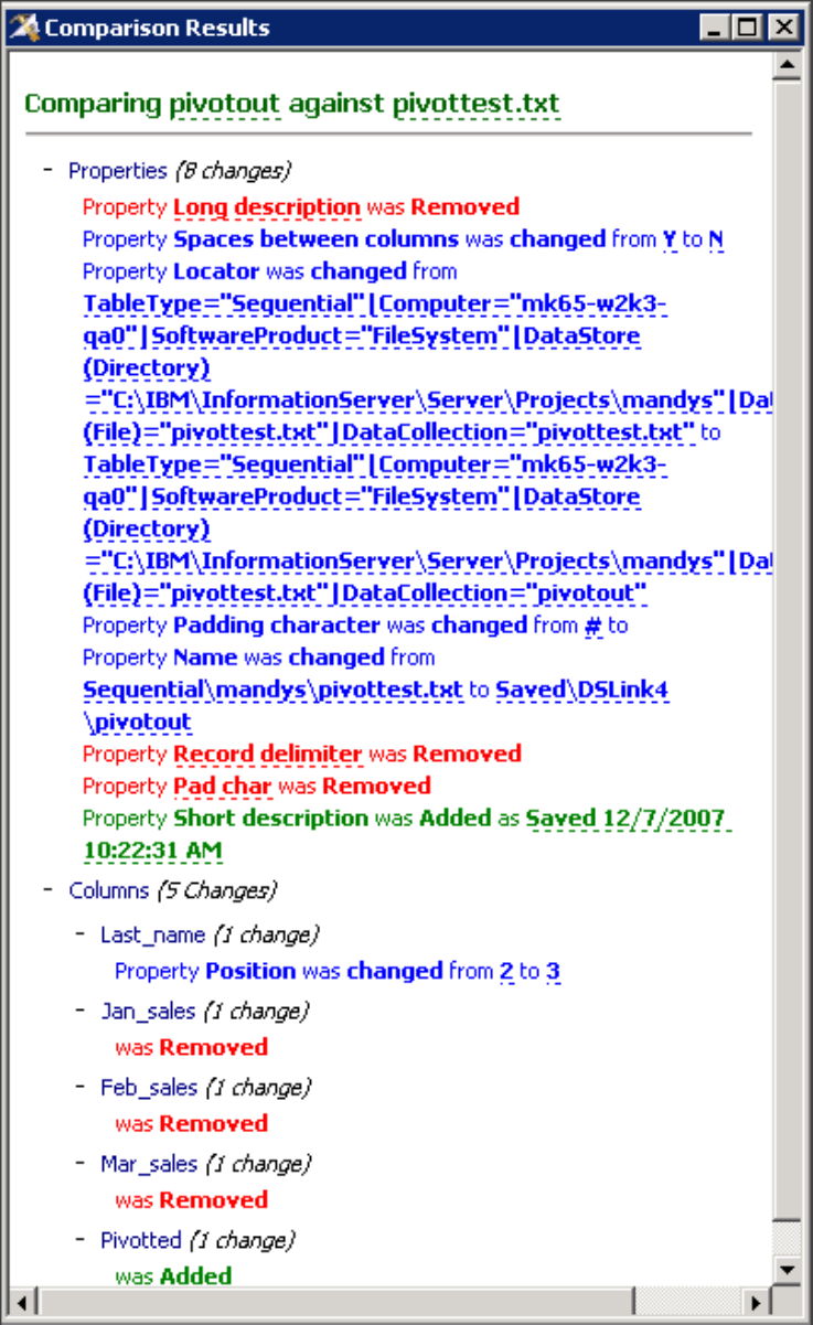
If you compare objects that contain differences in multi-line text (for example,
source code in routines), the change tree displays a View button. Click View to
view the source code. By default the source is displayed in Notepad, but you can
Figure 13. Results of comparing two table definitions
156 Designer Client Guide

choose a different application in the Designer client options. Select Tools >
Options and select Comparison Tool to view comparison tool options.
Comparing objects in the same project
You can compare objects in the same project either by selecting both objects in the
repository tree, or by selecting one object and then browsing for the other.
About this task
The Designer client compares the two objects and displays the results in a window.
These results show what the differences are between the two objects.
Procedure
1. Select the first object that you want compare in the repository tree and then do
one of: the following tasks:
vHold down the CTRL key and click the second object in the tree, then
right-click and select Compare selected.
vRight-click and select Compare against, and then browse for the object, select
it and click OK.
2. View the results in the window.
Comparing objects in different projects
You can compare two objects that are in different projects.
About this task
The Designer client compares two objects of the same type that are in different
projects and displays the results in a window. These results show what the
differences are between the two objects.
Procedure
1. In the repository tree, select the first object that you want to compare.
2. Right-click and select Cross Project Compare.
3. Click Attach.
4. In the “Attach to Project” window, type your user name and password, and
select the project that you want to attach to from the Project list.
5. Click OK to see a filtered view of the repository tree in the chosen project. The
filtered view displays only folders that contain eligible objects.
6. Browse the tree and select the object that you want to compare to the first
object.
7. Click OK.
Compare command line tool
The diffapicmdline command is a Microsoft Windows application that you use to
build compare operations into scripts. You can combine these scripts with other
command line tools that are available for manipulating objects and projects.
Chapter 9. Comparing objects 157
Syntax
diffapicmdline.exe /lhscd "left_side_connection_details"
/rhscd "right_side_connection_details"
/t difftype /ot output_type
/ol output_location
left_side_connection_details
The connection details for the left side of the comparison. These details relate
to the first object that you want to compare. Enclose the connections details in
double quotation marks.
/AF=authfile |
/URL=domainURL /H=hostname [/U=username [/P=password]] |
/D=domain /H=hostname [/U=username [/P=password]]
project_name object_name
authfile
Name of the encrypted credentials file that contains the connection details.
domainURL
The full format URL for the domain to log on to. The URL includes the
protocol, host, and port information for the domain in this format:
https://domain:port. The port defaults to 9443 if it is not specified.
domain | domain:port_number
Name of the application server. This parameter can also have a port
number.
hostname
The host name of the InfoSphere Information Server engine that compares
the objects.
username
The user name to use for connecting to the application server.
password
The password for the username that you are using to connect to the
application server.
project_name
the name of the project that contains the object.
object_name
The name of the object to be compared
The name of a table definition object must be specified as its data locator
name, not the name that is displayed in the repository tree. The data locator
name is displayed in the table definition properties window
If you specify only the domain and host name details, you are prompted for
the user name and password. (The password is hidden as you type in the
command window.) If you specify the domain, host name, and user name
details, you are prompted for the password..
right_side_connection_details
The connection details for the right side of the comparison. These details relate
to the second object that you want to compare. You must specify full
connection details only if you compare two objects in different projects.
Otherwise, you can specify only the object name. The syntax for the connection
details is the same as for the left_side_connection_details parameter.
difftype
The type of objects to compare. This parameter accepts any of the following
values:
158 Designer Client Guide
Job
SharedContainer
Routine
TableDef
output_type
The format of the output of the comparison. The format is always HTML.
output_location
The full path for the output file.
After you run the diffapicmdline command, one of the following codes is
returned:
v0indicates a successful comparison
v1indicates an error in the command line
v2indicates that the client cannot compare the objects
Example of comparison from the command line
The following command compares the exercise1 job with the new_exercise job .
Both jobs are located in the tutorial project. The output is sent to the
C:\compare_output.html file.
diffapicmdline.exe /lhscd "/d=localhost:9443 /h=R101 /u=billg /p=paddock
tutorial exercise1" /rhscd "new_exercise1" /t job /ot html /ol
C:\compare_output.html
Chapter 9. Comparing objects 159
160 Designer Client Guide

Chapter 10. Searching and impact analysis
When you want to change job designs, or reuse components, you might want to
search for them and perform an impact analysis to verify that none of your
changes affect other jobs.
Find facilities
Use the find facilities to search for objects in the repository and to find where
objects are used by other objects.
The repository tree has extensive search capabilities. Quick find is available
wherever you can see the repository tree: in browse windows as well the Designer
client window. Advanced find is available from the Designer client window.
Quick find
Use the quick find feature to search for a text string in the name of an object, or in
its name and its description.
About this task
You can restrict your search to certain types of object, for example you can search
for certain jobs. You can keep the quick find window open at the top of your
repository tree in the Designer client window and you can access it from any
windows in which the repository tree is displayed.
Quick find supports the use of wildcards. Use an asterisk to represent zero or more
characters.
Procedure
1. Open the quick find window by clicking Open quick find in the top right
corner of the repository tree.
2. Enter the name to search for in the Name to find field. If you are repeating an
earlier search, click the down arrow in the name box and select your previous
search from the drop-down list.
3. Select the Include descriptions check box if you want the search to take in the
object descriptions as well as the names (this will include long and short
description if the object type has both).
4. If you want to restrict the search to certain types of object, select that object
types from the drop-down list in Types to find.
5. After specifying the search details, click Find.
Example
Here is an example of a quick find where you searched for any objects called copy,
and IBM InfoSphere DataStage found one job meeting this criteria. The job it found
is highlighted in the tree. InfoSphere DataStage reports that there are two matches
because it also found the copy stage object. If you wanted to search only jobs then
you could select jobs in the Types to find list. If you want to find any jobs with
copy in the title you could enter *copy* in the Name to find field and the search
© Copyright IBM Corp. 1997, 2014 161
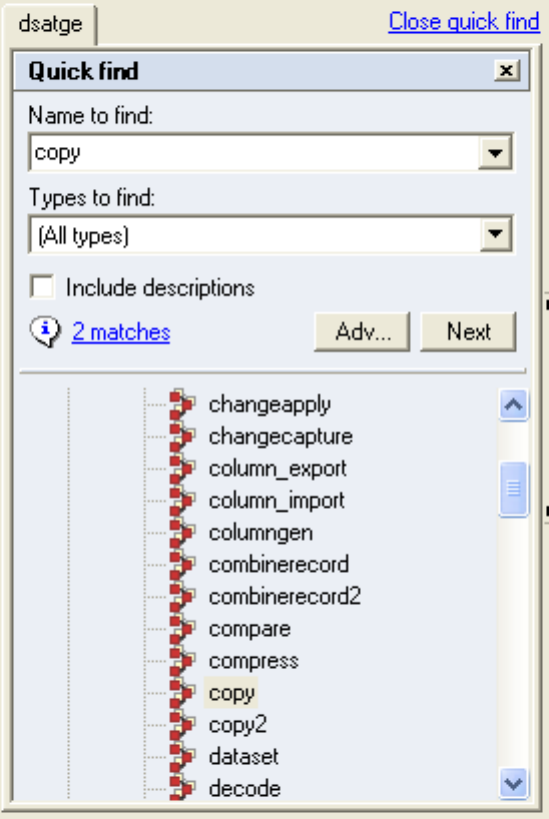
would find the jobs copy and copy2.
If quick find locates several objects that match your search criteria, it highlights
each one in the tree, with the folders expanded as necessary. To view the next
object, click Next. You can click the nmatches link to open the Advanced find
window and display all the found objects in the window.
Advanced find
You can use advanced find to carry out sophisticated searches.
About this task
Advanced find displays all the search results together in a window, independent of
the repository tree structure.
To access the advanced find facilities, do one of the following actions:
vOpen the quick find window in the main repository tree and click Adv....
vPerform a search using quick find, and then click the nmatches hyperlink.
vChoose Tools >Advanced Find from the main menu.
Figure 14. Example of quick find
162 Designer Client Guide
vSelect a folder in the repository tree, and then do one of the following actions:
– Select Repository >Find in this folder >Open Advanced Find from the
main menu.
– Select Find in this folder >Open advanced find from the pop-up menu.
– Choose Repository >Find in this folder >Objects that I created,Objects
that I created today,orObjects that I created up to a week ago from the
main menu
– Select Find in this folder >Objects that I created ,Objects that I created
today,orObjects that I created up to a week ago from the pop-up menu.
– Select Repository >Find in this folder >Objects that I last modified,
Objects that I last modified today,orObjects that I last modified up to a
week ago from the main menu.
– Select Find in this folder >Objects that I last modified,Objects that I last
modified today,orObjects that I last modified up to a week ago from the
pop-up menu.
Performing an advanced find
You can specify multiple search criteria in advanced find.
About this task
You can use all, or some, of the following search criteria:
vName. Enter the name of the object that you are searching for. A list offers a
choice of the last 50 names that you searched for, so you can choose one of those
if desired. You must supply a name for the search or enter the wildcard
character: asterisk (*).
vText in the object(s) descriptions. Enter text in this field to search for in the
object descriptions or choose from one of your 50 previous searches from the list.
vFolder to search. Specify the root folder from which to start the search. The top
project folder is selected by default, but you can browse the repository tree for
other folders. You can also choose from a list of folders that you previously
searched.
vType. Select one or more object types to search from the list. If you make a
selection here, a green circle containing a tick appears next to Type. This
criterion is optional, if you do not select a specific type or types, all objects will
be searched except column definitions.
vCreation. You can search for an object that as created by a specific user, or
created on a particular date or within a range of dates.
vLast modified. You can search for an object last modified by a specific user, or
last modified on a particular date or within a range of dates.
vType specific. You can specify a table definition and search for all other table
definitions in the project that are linked to the same table in the shared
repository.
vOptions. You can use options to add more details about a search.
You can search on Name or Text in the object(s) descriptions. The other items are
additive; if you specify more than one, the objects have to meet all the additional
criteria before they are deemed to have satisfied the search conditions.
Procedure
1. Type a name in the Name field.
2. Optionally specify one or more additional search criteria.
Chapter 10. Searching and impact analysis 163
3. Click Find.
Results
The names and details of the objects in the repository that match the search criteria
are listed in the Results - Details tab. You can select items in the list and perform
various operations on them from the shortcut menu. The available operations
depend on the object type, but include the following:
vFind dependencies and Find where used.
vExport. Opens the Repository Export window which allows you to export the
selected object in a .dsx or .xml file.
vMultiple job compile. Available for jobs and job sequences. Opens the multiple
job compiler tool.
vEdit. Available for jobs and job sequences. The selected job opens in the job
design canvas.
vAdd to palette. The object is added to the palette currently open so that it is
readily available for future operations.
vCreate copy. Creates a copy of the selected object named CopyOfObjectName.
vRename. Use this operation to rename the selected object.
vDelete. Use this operation to delete the selected object.
vProperties. Opens the Properties window for the selected object. All objects have
associated properties giving detailed information about the object.
You can save the results of an advanced search operation as an XML file or as a
report. You can view a report in the reporting console.
The following example shows a search for object names that start with the word
exercise and include descriptions that contain the word tutorial. The results
show that four objects match these criteria:
164 Designer Client Guide
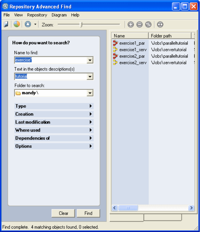
Finding shared table definitions
If you have table definitions that are derived from shared metadata, you can use
advanced find to locate all the table definitions in your project that are derived
from the same shared table.
Procedure
1. Select a table definition in the repository tree.
2. Right-click and select Find shared table definitions from the pop-up menu.
Results
You can also search in one of the following ways:
vOpen the Repository Advanced Find window from the repository tree and select
the source table definition using the Type specific filter.
vRight-click a table definition object in an existing advanced find or impact
analysis results display and select Find shared table definitions from the
pop-up menu.
Chapter 10. Searching and impact analysis 165
Finding column definitions
You can use the advanced find facilities to search for individual column
definitions.
About this task
You can search for column definitions within the table definitions that are stored in
the IBM InfoSphere DataStagerepository, or you can search for column definitions
in jobs and shared containers. You can narrow the search by specifying other
search criteria, such as folders to search in, when the column definition was
created or modified, or who created or modified the column definition.
Procedure
1. Type the name of the column that you want to find in the Name to find field.
You can use wildcard characters if you want to search for a number of columns
with similar names.
2. Select Columns in Table Definitions or Columns in Jobs or Shared
Containers in the Type list. Select both to search for the column in table
definitions and in jobs and shared containers.
3. Specify other search criteria as required.
4. Click Find to search for the column.
Impact analysis
Use the impact analysis features to discover where objects are used, and what
other objects they depend on.
The impact analysis features help you to assess the impact of changes you might
make to an object on other objects, or on job designs. For example, before you edit
a table definition, you could find the jobs that derive their column definitions from
the table definition and consider whether those jobs will need changing too.
There are four types of impact analysis queries:
where used
Finds where the selected object is used by other objects. For example, if the
selected object is a routine, a where used query lists all the jobs that use
that routine.
where used (deep)
Finds where the selected object is used by other objects, and also where
those objects in turn are used. For example if the selected object is a
routine, a where used (deep) query lists all the jobs that use that routine,
and also lists any job sequences that use those jobs.
dependencies of
Finds the objects that the selected object depends upon. For example, a job
might depend upon a particular routine.
dependencies of (deep)
Finds the objects that the selected object depends upon, and also what
objects they in turn depend upon. For example, a job sequence might
depend on a job which in turn depends on a routine.
Impact analysis and object types
Use an impact analysis find to discover where a particular object is used by other
objects, or what other objects a particular object depends on.
166 Designer Client Guide

You use a where used or a dependencies of query on different types of objects, and
the query can result in specific object types being identified:
Table 2. Impact analysis and objects
Object type Where used query Dependencies of query
Data element Parallel job, server job,
sequence job, parallel shared
container, server shared
container, table definition,
transform
None
IMS database Mainframe job Table definition
IMS viewset Mainframe job Table definition
Mainframe job None IMS database, IMS viewset,
machine profile, mainframe
routine, mainframe stage
type, table definition
Parallel job Sequence job Data element, parallel
routine, server routine,
parallel shared container,
server shared container, rule
specification, parallel stage
type, server stage type, table
definition transform,
parameter set, data
connection
Server job Sequence job Data element, server routine,
server shared container,
server stage type, table
definition, transform,
parameter set, data
connection
Sequence job Sequence job Data element, parallel job,
server job, sequence job,
parallel routine, server
routine, parallel shared
container, server shared
container, rule specification,
parallel stage type, server
stage type, table definition,
transform, parameter set,
data connection
Machine profile Mainframe job None
Rule specification Parallel job, sequence job,
parallel shared container,
rule specification
Rule specification
Mainframe routineM mainframe job None
Parallel routine Parallel job, sequence job,
parallel shared container
None
Server routine Parallel job, server job,
sequence job, server routine,
parallel shared container,
server shared container
Server routine
Chapter 10. Searching and impact analysis 167

Table 2. Impact analysis and objects (continued)
Object type Where used query Dependencies of query
Parallel shared Pcontainer parallel job, sequence job,
parallel shared container
Data element, parallel
routine, server routine,
parallel shared container,
server shared container, rule
specification, parallel stage
type, server stage type, table
definition, transform,
parameter set, data
connection
Server shared container Parallel job, server job,
sequence job, parallel shared
container, server shared
container
Data element, server routine,
server shared container,
server stage type, table
definition, transform,
parameter set, data
connection
Mainframe stage type Mainframe job None
Parallel stage type Parallel job, sequence job,
parallel shared container
None
Server stage type Server job, parallel job,
sequence job, server shared
container, parallel shared
container
None
Sequence stage type Sequence job None
Table definition Mainframe job, server job,
parallel job, sequence job,
server shared container,
parallel shared container,
table definition, IMS
database, IMS viewset
Table definition, data
element
Column definition Server job, parallel job,
sequence job, server shared
container, parallel shared
container
None
Transform Server job, parallel job,
sequence job, server shared
container, parallel shared
container
Data element
Data connection Server job, parallel job,
sequence job, server shared
container, parallel shared
container
Parameter set
Parameter set Server job, parallel job,
sequence job, server shared
container, parallel shared
container, data connection
None
Running where used queries
You can run a where used query directly from the repository tree or from within
the Repository Advanced Find window.
168 Designer Client Guide
About this task
You can run a where used query directly from the repository tree.
Procedure
1. Select the object in the repository tree.
2. Either right-click to open the pop-up menu or open the Repository menu from
the main menu bar.
3. Select Find where used >All types or Find where used (deep) >All types to
search for any type of object that uses your selected object.
4. Select Find where used >object type or Find where used (deep) >object type
to restrict the search to certain types of object.
Results
The search displays the results in the Repository Advanced Find window. The
results of a deep search show all the objects related to the ones that use your
search object.
Running a where used query from the Repository Advanced Find window:
About this task
You can run a where used query from the Repository Advanced Find window.
Procedure
1. Click the where used item in the left pane to open the where used tool.
2. Click Add.
3. In the Select items window, Browse for the object or objects that you want to
perform the where used query on and click OK.
4. You can continue adding objects to the where used window to create a list of
objects that you want to perform a where used query on.
5. Click Find when you are ready to perform the search. The results are displayed
in the Results - Details and the Results - Graphical tabs of the Repository
Advanced Find window.
6. View the results in the Repository Advanced Find window, click the Results -
Details tab to view the results as a text list, click the Results - graphical tab to
view a graphical representation of the results.
Results
If you view the results as a text list, note that the results only list the first three
dependency paths found for each object in the Sample dependency path field. To
view all the dependency paths for an object, right-click on the object and select
Show dependency path to object.
Running where used queries on column definitions
You can run a where used query on an individual column definition to find out
where a particular column definition is used.
Chapter 10. Searching and impact analysis 169
About this task
Running a where used query on a column definition is different from running a
where used query on other repository objects, because individual column
definitions are not displayed as separate objects in the repository tree. You can run
the query from the following places:
vThe results of an advanced find for a column.
vAfter selecting a table definition in the repository tree.
vThe Repository Advanced Find window.
Results
The query runs and displays the jobs or shared containers that use the selected
column or columns.
Running where used queries from the results of an advanced find for a
column:
About this task
You run a query from the results of an advanced find for a column.
Procedure
1. Select one or more columns in the results pane of the Repository Advanced
Find window.
2. Right-click and select Where used from the pop-up menu.
Running where used queries from the repository tree:
About this task
You run a query from the repository tree.
Procedure
1. In the repository tree, select the table definition that contains the column to
query.
2. Right-click and select Find where column used from the pop-up menu.
3. In the table column window, select one or more columns.
4. Click OK.
Running where used queries from the Repository Advanced Find window:
About this task
You run a query from the Repository Advanced Find window.
Procedure
1. Open the Repository Advanced Find window.
2. Click the where used item in the left pane.
3. Click Add.
4. In the Select Items window, select the column or columns that you want to
query.
5. Click OK.
6. Click Find.
170 Designer Client Guide
Displaying data lineage for columns
You can display the data lineage of specific data columns within job designs. Data
lineage traces the use of the column definition through the job.
About this task
You can display the data lineage of any column that you have previously searched
for, or you can open a job or shared container and select a column for which you
want to view the data lineage. In the job or shared container, stages and links that
use the column are highlighted. Text is added to the link which explains how the
column is used. Data lineage cannot be displayed for jobs that use runtime column
propagation.
You can enable the data lineage display in these ways:
vFrom the Repository Advanced Find window opened by a previous search for a
column.
vFrom the Diagram menu of the Designer client.
vFrom the stage pop-up menu in a job design.
Displaying data lineage from the Repository Advanced Find window:
About this task
You can open a job or shared container and display the data lineage for a column
that you previously searched for.
Procedure
1. Right-click a job or a shared container in the Repository Advanced Find
window.
2. Select Show Data Flow (design time) from the pop-up menu.
Displaying data lineage from the Designer client menu:
About this task
You can enable data lineage highlighting from the Designer client menu.
Procedure
1. In the Designer client, open the job or shared container in which you want to
highlight the data lineage of a column.
2. Select Diagram >Configure data flow view
3. In the Data Flow Analysis window, select one of the Type of analysis options
to specify whether you want to highlight where data in the selected column
originates, or highlight where the data flows to, or both.
4. Click Add to open a browser window that shows all the columns used in the
job. Select the column or columns that you want to display data lineage for.
Alternatively, click Select All to select all the columns.
Displaying data lineage from the stage pop-up menu:
About this task
You can enable data lineage highlighting from the stage pop-up menu.
Procedure
1. In the Designer client, open the job or shared container in which you want to
highlight the data lineage of a column.
Chapter 10. Searching and impact analysis 171
2. Select the stage that you want to see the data lineage for.
3. Select one of the following items from the pop-up menu:
vShow where data flows to
vShow where data originates from
vShow where data flows to and originates from
4. In the browser window, select the column or columns that you want to display
data lineage for. Alternatively, click Select All to select all the columns.
Disabling data lineage highlighting
If the data lineage of a column in a job or shared container is highlighted, you can
turn off the highlighting.
Procedure
1. In the Designer client, ensure that the job or shared container for which you
want to turn off the data lineage highlighting is currently on top of the canvas
and selected.
2. Select Diagram >Show Data Flow (design time) to turn off the highlighting.
Running dependencies of queries
You can run a dependencies of query directly from the repository tree or from the
Repository Advanced Find window.
About this task
IBM InfoSphere DataStage performs the search and displays the results in the
Repository Advanced Find window. The results of a deep search show all the
objects related to the ones that depend on your search object.
Running a dependencies of query directly from the repository tree:
About this task
You can run a dependencies of query directly from the repository tree.
Procedure
1. Select the object in the repository tree.
2. Either right click to open the pop-up menu or open the Repository menu from
the main menu bar.
3. Select Find dependencies >All types or Find dependencies (deep) >All types
to search for any type of object that your selected object depends on.
4. Select Find dependencies >object type or Find dependencies (deep) >object
type to restrict the search to certain types of object (the drop-down menu lists
all the types of object that the selected type of object can use).
Running a dependencies of query from the Repository Advanced Find window:
About this task
You can run a dependencies of query from the Repository Advanced Find window.
Procedure
1. Click the dependencies of item in the left pane to open the where used tool.
2. Click Add , a Select Items window opens.
3. In the Select Items window, browse for the object or objects that you want to
perform the dependencies of query on and click OK. The selected object or
172 Designer Client Guide
objects appear in the where used window. You can continue to add objects to
this window to create a list of objects that you want to perform a dependencies
of query on.
4. Click Find when you are ready to perform the search. The results are displayed
in the Results - Details and the Results - Graphical tabs of the Repository
Advanced Find window.
Results
If you view the results as a text list, note that the results only list the first three
dependency paths found for each object in the Sample dependency path field. To
view all the dependency paths for an object, right-click on the object and select
Show dependency path to object.
Viewing query results
The results of impact analysis queries are displayed in the Repository Advanced
Find window.
You can view the results in list form or as a graphical display. Use the tools in the
window tool bar to:
vSave the results to an XML file
vSave the results as an HTML report
vZoom in and out of the graphical display
Example of a where used query
The results of a where used query shows what other objects use the object.
In this example, the data element called TestDataElement is selected, and then a
where used query is run. The results show that there are three table definitions
that use this data element. The Results - Details tab lists the table definition
objects:
Chapter 10. Searching and impact analysis 173
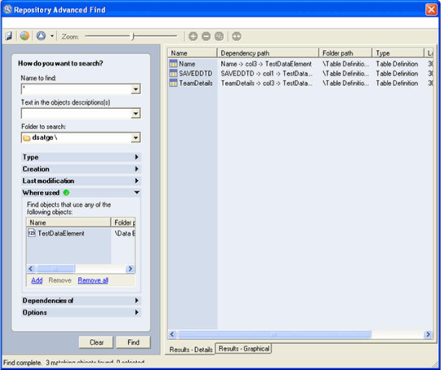
You can select any of the objects from the list and perform operations on them
from the pop-up menu as described for advanced find.
Impact analysis queries also display results in graphical form, showing the
relationships of the objects found by the query. To view the results in graphical
form, click the Results - Graphics tab:
Figure 15. Example of a where used query
174 Designer Client Guide
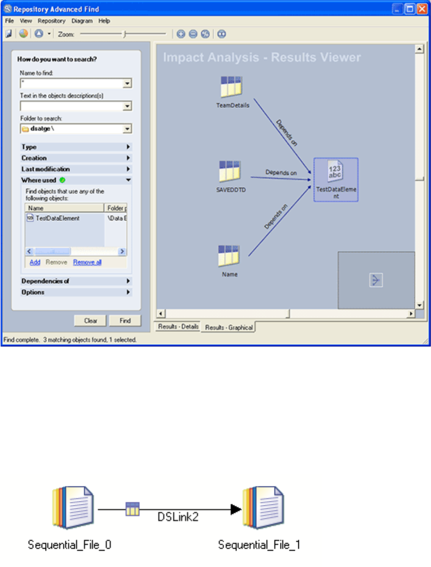
Example of a dependencies of query
The results of a dependencies of query show what other objects an object depends
on.
In this example, a dependencies of query is run on a simple job called seq2seq.
This is what the job looks like in the job design canvas:
The following figure shows the graphical view of the result:
Figure 16. Example of a where used query, showing the results in graphical view
Figure 17. The seq2seq job
Chapter 10. Searching and impact analysis 175
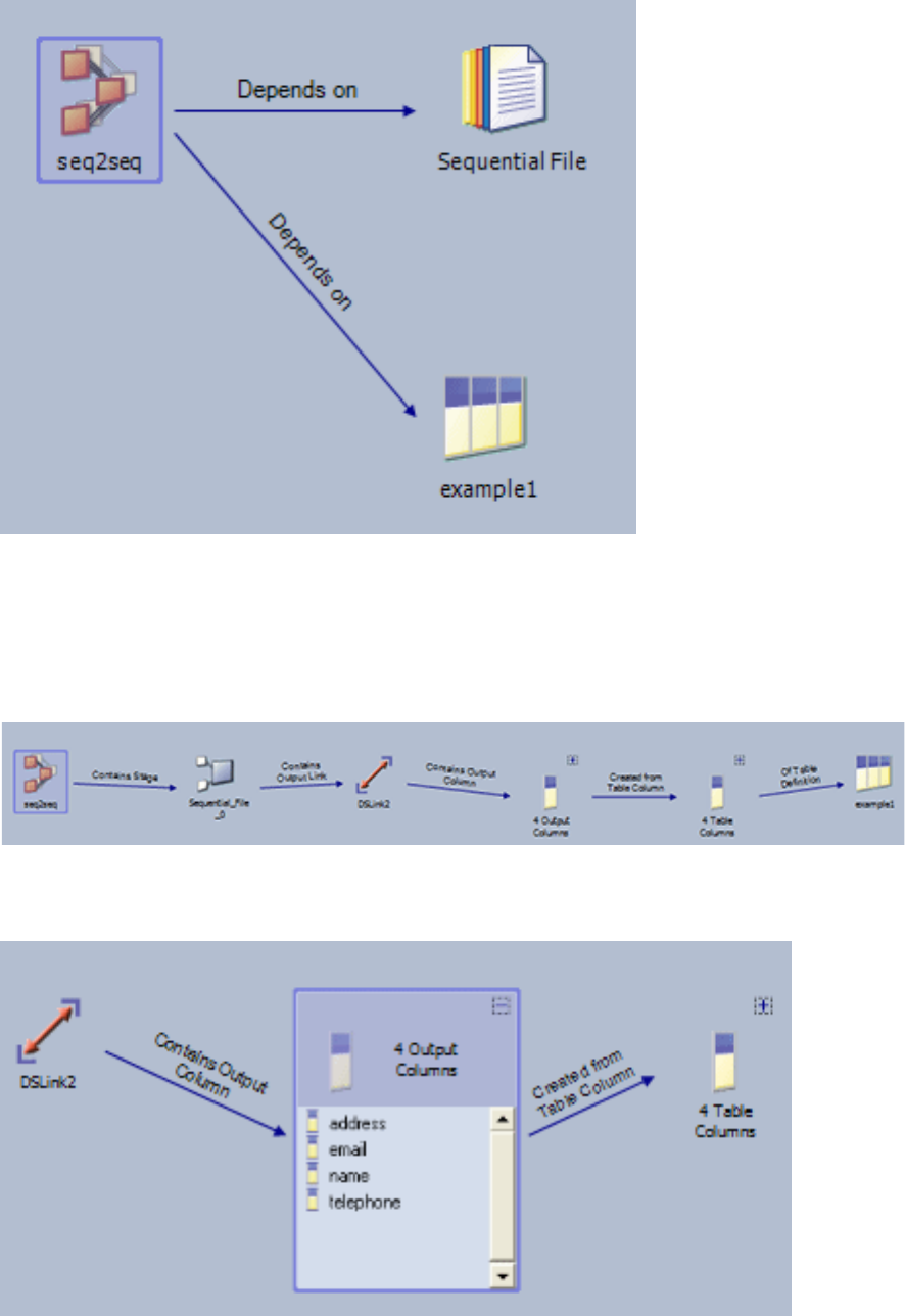
From this view you can invoke a view of the dependency path to a particular
object. Select that object in the graphical results viewer tab and choose Show
dependency path from ObjectName from the pop-up menu. This action opens
another tab, which shows the relationships between the objects in the job. Here is
the dependency path from the job to the table definition:
If an object has a plus sign (+) next to it, click the plus sign to expand the view:
Figure 18. Graphical result of dependencies of query
Figure 19. Graphical view of example dependency path
Figure 20. Object with dependency path expanded
176 Designer Client Guide
Click the minus sign (-) to return to the original view.
Reporting on an advanced find
You can generate a report for an advanced find or impact analysis operation.
About this task
The report is generated as an XML file. A style sheet is applied to the file to
convert it to HTML so that it can be displayed in an Interneet browser or the IBM
Information Server reporting console.
Procedure
1. Select File >Generate report.
2. Provide the following details in the Enter report details window:
a. A name for the report.
b. A description of the report.
c. Choose whether to use the default style sheet or to supply a custom style
sheet.
3. Click OK.
4. The report is generated and located in the reporting console folder. You can
view it using the reporting console or an Internet browser. Choose Tools >
Reporting Console to open the Reporting Console.
5. You can also generate an XML file from the report by selecting File >Generate
report and specify a file name and destination folder for the file.
Chapter 10. Searching and impact analysis 177
178 Designer Client Guide

Chapter 11. Sharing and moving your designs
You can share and move job designs and components by importing and exporting
them.
IBM InfoSphere DataStage allows you to import and export components in order
to move jobs and other objects between InfoSphere DataStage development
systems. When you import or export jobs, InfoSphere DataStage ensures that all
the components required for a particular job are included in the import/export.
You can also use the export facility to generate XML documents which describe
objects in the repository. You can then use a browser such as Microsoft Internet
Explorer to view the document. XML is a markup language for documents
containing structured information. It can be used to publish such documents on
the Web. For more information about XML, visit the following Web sites:
vhttp://www.xml.com
vhttp://webdeveloper.com/xml
InfoSphere DataStage also allows you to import objects from outside InfoSphere
DataStage in order to leverage investment in other resources. Besides table
definitions, you can import ActiveX (OLE) functions to use in server jobs (or in
parallel jobs via a BASIC transformer or server shared container). You can similarly
import web services functions to use in routines. You can import metadata from a
variety of third party tools by using IBM InfoSphere Metadata Asset Manager.
Importing objects
The Designer allows you to import various objects into the repository:
vIBM InfoSphere DataStage components previously exported from other
InfoSphere DataStage projects (in proprietary format or in XML).
vExternal function definitions
vWebService function definitions
vMetadata by using the IBM InfoSphere Metadata Asset Manager
vTable definitions
vIMS definitions
Importing previously exported objects
You can import complete projects, jobs, or job components that have been exported
from another IBM InfoSphere DataStage development environment. You can
import components from a text file or from an XML file.
About this task
You must copy the file from which you are importing to a directory you can access
from your local machine.
You can import components that support mainframe functionality only into an
InfoSphere DataStage system that has InfoSphere DataStage MVS Edition installed.
You should also ensure that the system to which you are importing supports the
required platform type.
© Copyright IBM Corp. 1997, 2014 179
When importing a large project into an HP system, you might run into the HP
limit of 32767 links to a file. This problem will result in the import failing with the
error: 'unable to create operating system file'.
There is a limit of 255 characters on object names. It is possible that exports from
earlier systems might exceed this limit.
When importing jobs or parameter sets with environment variable parameters, the
import adds that environment variable to the project definitions if it is not already
present. The value for the project definition of the environment variable is set to an
empty string. because the original default for the project is not known. If the
environment variable value is set to $PROJDEF in the imported component, the
import warns you that you need to set the environment variable value in the
project yourself.
Procedure
1. Choose Import >DataStage Components... to import components from a text
file or Import >DataStage Components (XML) ... to import components from
an XML file. The DataStage Repository Import window opens (the window is
slightly different if you are importing from an XML file, but has all the same
controls).
2. Type in the path or browse for the file to import from.
3. To import objects from the file into the repository, select Import all and click
OK. During import, you will be warned if objects of the same name already
exist in the repository and asked if you want to overwrite them. If you select
the Overwrite without query check box before importing you will not be
warned, and any existing objects will automatically be overwritten.
If you import job components, they are imported into the current project in the
Designer client.
4. To import selected components from the file into the repository, select Import
selected and click OK. The Import Selected dialog box appears. Select the
required items and click OK. The selected job components are imported into
the current project in the Designer.
5. To turn impact analysis off for this particular import, deselect the Perform
Impact Analysis checkbox. (By default, all imports are checked to see if they
are about to overwrite a currently used component, disabling this feature might
speed up large imports. You can disable it for all imports by changing the
impact analysis options).
Using import from the command line
You can use the command line to import components into the repository.
There are two ways of importing from the command line. The dsimport command
is a windows application and requires user interaction with message boxes (to
import XML files in this way, use XML2DSX). The dscmdimport command is a
command line application and can be run unattended (this imports both DSX and
XML files).
You can also import objects from a .dsx file, by using the DSXImportService
command.
dsimport command
The dsimport command is a Microsoft Windows application that you use to import
InfoSphere DataStage components from a DSX file into the repository.
180 Designer Client Guide
Syntax
The dsimport command includes the following syntax:
dsimport.exe /AF=authfile |
/URL=domainURL /H=hostname [/U=username [/P=password]] |
/D=domain /H=hostname [/U=username [/P=password]]
/NUA project | /ALL | /ASK
dsx_pathname1 dsx_pathname2 ...
authfile
Name of the encrypted credentials file that contains the connection details.
domainURL
The full format URL for the domain to log on to. The URL includes the
protocol, host, and port information for the domain in this format:
https://domain:port. The port defaults to 9443 if it is not specified.
domain | domain:port_number
The host name of the services tier. This parameter can also have a port
number.
hostname
The host name for the InfoSphere Information Server engine where you are
importing a file to.
username
The user name to use for connecting to the services tier.
password
The password for the username that you are using to connect to the services
tier.
project | /ALL | /ASK
Specify a project to import the components to, or specify /ALL to import to all
projects, or specify /ASK to be prompted for the project to which to import.
dsx_pathname
The .dsx file to import from. You can specify multiple files if required.
If you do not use the /AF option and you want to run the command without any
user interaction, you must supply all of the connection details on the command
line. If all of the connection details are not supplied on the command line, the
Logon dialog is displayed. The Logon dialog is pre-filled with the values from the
command line. Any missing values are pre-filled with the values from your most
recent successful connection, except for the Password field which you must supply.
The password is not displayed as you type in the Logon dialog.
The following command imports the components in the jobs.dsx file into the
dstage1 project on the R101 server:
dsimport.exe /D=domain:9443 /U=wombat /P=w1ll1am dstage1 /H=R101
C:\temp\jobs.dsx
By default, if a job or parameter set uses environment variables that are not
defined in the target project, this command adds them for you during the import.
You can disable this behavior by using the NOENV flag. For an imported
environment variable parameter, the value that is set in the target job or parameter
set is taken from the export value, not the current project default value (if any).
When an environment variable parameter that you are exporting is set to the value
$PROJDEF, the definition is added to the project, but the value is empty. You must
Chapter 11. Sharing and moving your designs 181
specify a project value for that environment variable after the import by using the
Administrator client or by using the dsadmin command.
dscmdimport command
The dscmdimport command is a command-line application that you run to import
InfoSphere DataStage components from a DSX file or an XML file into the
repository. You can run this command unattended.
Syntax
The dscmdimport command includes the following syntax. To view help options for
the command, enter dscmdimport at the command prompt.
dscmdimport /AF=authfile |
/URL=domainURL /H=hostname [/U=username [/P=password]] |
/D=domain /H=hostname [/U=username [/P=password]]
/NUA /NOENV project | /ALL | /ASK
pathname1 pathname2 ...
/V
authfile
Name of the encrypted credentials file that contains the connection details.
domain | domain:port_number
The host name of the services tier. This parameter can also have a port
number.
domainURL
The full format URL for the domain to log on to. The URL includes the
protocol, host, and port information for the domain in this format:
https://domain:port. The port defaults to 9443 if it is not specified.
hostname
The host name for the InfoSphere Information Server engine where you are
importing a file to.
username
The user name to use for connecting to the services tier.
password
The password for the username that you are using to connect to the services
tier.
NUA
Include this flag to disable usage analysis. If you are importing a large project,
enable this value.
NOENV
Include this flag to prevent the import from adding any environment variables
to the project definitions. Use this option if you want to add missing job
environment variable definitions to the project manually. If you omit this
option, by default, the import adds any missing environment variable
definitions to the project for you.
project | /ALL | /ASK
Specify a project to import the components to, or specify /ALL to import to all
projects, or specify /ASK to be prompted for the project to which to import.
pathname
The file to import from. You can specify multiple files if required. The files can
be .dsx files or .xml files, or a combination of both.
/V Use this flag to switch the verbose option on.
182 Designer Client Guide
If you specify only the domain and host name details, you are prompted for the
user name and password. (The password is hidden as you type in the command
window.) If you specify the domain, host name, and user name details, you are
prompted for the password.
The following command imports the components from the file jobs.dsx into the
project dstage1 on the R101 server:
dscmdimport /D=domain:9443 /U=wombat /P=w1ll1am dstage1 /H=R101
C:\temp\jobs.dsx
Messages from the import are sent to the console by default, but can be redirected
to a file by using the greater than symbol (>). In the following example, the
messages from the import are sent to the C:\temp\importlog directory.
dscmdimport /D=domain:9443 /U=wombat /P=w1ll1am /H=R101
/NUA dstage99 C:\temp\project99.dsx
/V > C:\temp\importlog
By default, if a job or parameter set uses environment variables that are not
defined in the target project, this command adds them for you during the import.
You can disable this behavior by using the NOENV flag. For an imported
environment variable parameter, the value that is set in the target job or parameter
set is taken from the export value, not the current project default value (if any).
When an environment variable parameter that you are exporting is set to the value
$PROJDEF, the definition is added to the project, but the value is empty. You must
specify a project value for that environment variable after the import by using the
Administrator client or by using the dsadmin command.
XML2DSX command
The XML2DSX command is a Microsoft Windows application that you use to import
InfoSphere DataStage components from an XML file into the repository.
Syntax
The XML2DSX command includes the following syntax:
XML2DSX.exe /AF=authfile |
/D=domain /H=hostname [/U=username [/P=password]]
/N /I /V project_name file_name
/T template_name
authfile
Name of the encrypted credentials file that contains the connection details.
domain | domain:port_number
Name of the application server. This parameter can also have a port number.
hostname
The host name for the InfoSphere Information Server engine where you are
importing a file to.
username
The user name to use for connecting to the services tier.
password
The password for the username that you are using to connect to the services
tier.
/N Flag indicating that the import runs silently.
Chapter 11. Sharing and moving your designs 183
CAUTION:
Any existing components with the same name in the InfoSphere DataStage
repository are overwritten.
/I Flag indicating that you want to open the Import DataStage Components
window in the Designer client. By using this flag, you can choose the
components that you want to import.
/V Flag indicating display details for the XML2DSX application, such as the version
number.
project_name
Name of the InfoSphere DataStage project to attach to on the InfoSphere
Information Server engine. This project is the one that exists on the hostname
that you are importing a file to.
file_name
Name of the XML file that contains the components that you want to import.
template_name
Name of the XSLT template to use when transforming the XML file. If this
parameter is blank, a default template is used. The default template is the one
used when InfoSphere DataStage exports components into XML.
If you do not use the /AF option and you want to run the command without any
user interaction, you must supply all of the connection details on the command
line. If all of the connection details are not supplied on the command line, the
Logon dialog is displayed. The Logon dialog is pre-filled with the values from the
command line. Any missing values are pre-filled with the values from your most
recent successful connection, except for the Password field which you must supply.
The password is not displayed as you type in the Logon dialog.
The following command imports the components in the jobs.xml file into the
dstage1 project on the R101 server:
XML2DSX.exe /D=domain:9443 /U=wombat /P=w1ll1am /N dstage1
/H=R101 C:\temp\jobs.xml
Importing external function definitions
This feature allows you to import ActiveX (OLE) functions for use as routines in
IBM InfoSphere DataStage server jobs.
About this task
On import InfoSphere DataStage creates a wrapper which enables the function to
be called in a job and stores the function as a server routine in the repository. You
can edit the wrapper (though not the ActiveX function itself) using the Server
Routine dialog box (see "Viewing and Editing a Routine").
Procedure
1. Choose Import External Function Definitions... . The Import Transform
Functions Definitions wizard appears and prompts you to supply the pathname
of the file containing the transforms to be imported. This is normally a DLL file
which must have already been installed on the server machine.
2. Enter or browse for the pathname, then click Next. The wizard queries the
specified DLL file to establish what automation classes it contains and presents
these in a drop-down list.
184 Designer Client Guide
3. Select an automation class and click Next. The wizard interrogates the
automation class to obtain details of the suitable functions it supports. It then
displays these.
4. Select the functions that you want to import. Click Next. The wizard displays
the details of the proposed import.
5. If you are happy with the details, click Import. InfoSphere DataStage starts to
generate the required routines and displays a progress bar. On completion a
summary screen appears.
Results
Click Finish to exit the wizard.
Importing web service function definitions
You can construct a routine from a web service WSDL file. This functionality is
only available if you have the Web Services pack installed.
About this task
You can construct IBM InfoSphere DataStage routines from operations defined in
WSDL files. You can then use these routines in derivation expressions in server
jobs. For example, you could use one in a Transformer stage to determine how a
column value within a row is computed from the column values of the input rows.
Note: Before you can use the Import Web Service routine facility, you must first
have imported the metadata from the operation you want to derive the routine
from. See "Importing a Table Definition".
Procedure
1. Import the metadata for the web service operation. This is done using Import
Table Definitions Web Services WSDL Definitions (see "Importing a Table
Definition").
2. Choose Import Web Service Function Definitions... . The Web Service Browser
appears.
The upper right panel shows the web services whose metadata you have
loaded. Select a web service to view the operations available in the web service
in the upper left pane.
3. Select the operation you want to import as a routine. Information about the
selected web service is shown in the lower pane.
4. Either click Select this item in the lower pane, or double-click the operation in
the upper right pane. The operation is imported and appears as a routine in the
Web Services category under a category named after the web service.
Results
Once the routine is imported into the Repository, you can open the Server Routine
dialog box to view it and edit it. See "Viewing and Editing a Routine".
Importing metadata by using InfoSphere Metadata Asset
Manager
You can use IBM InfoSphere Metadata Asset Manager to import metadata into the
metadata repository from databases, design tools, and business intelligence tools.
Chapter 11. Sharing and moving your designs 185
Procedure
Click Import >Metadata Asset Manager... to launch the InfoSphere Metadata
Asset Manager in your default browser. For more information, see Importing and
sharing assets.
Importing IMS definitions
IBM InfoSphere DataStage can store information about the structure of IMS
Databases and IMS Viewsets which can then be used by Mainframe jobs to read
IMS databases, or use them as lookups.
These facilities are available if you have InfoSphere DataStage MVS Edition
installed along with the IMS Source package.
You can import IMS definitions into the InfoSphere DataStage repository from Data
Base Description (DBD) files and Program Specification Block (PSB) files. A DBD
file defines the physical structure of an IMS database. A PSB file defines an
application's view of an IMS database.
During DBD import, the InfoSphere DataStage table name is created from the DBD
name and the segment name. Column names are created from the DBD field
names; however, only those fields that are defined in the DBD become columns.
Fillers are created where necessary to maintain proper field displacement and
segment size. If you have a definition of the complete IMS segment in the form of
a CFD, you can import it to create the completely defined table, including any
columns that were captured as fillers.
InfoSphere DataStage captures the following clauses from DBD files:
vDBD
vDATASET
vAREA
vSEGM
vLCHILD
vFIELD
vXDFIELD
vDBDGEN
vFINISH
vEND
The clauses captured from PSB files include:
vPCB
vSENSEG
vSENFLD
vPSBGEN
vEND
You can import IMS definitions from IMS version 5 and above. IMS field types are
converted to COBOL native data types during capture, as described in the table
below.
186 Designer Client Guide

Table 3. Conversion of IMS field types to COBOL native data types
IMS Field Type COBOL Native Type
COBOL Usage
Representation SQL Type
X CHARACTER PIC X(n)1Char
P DISPLAY_NUMERIC PIC S9(n)V9(0)
COMP-3
Decimal
C CHARACTER PIC X(n) Char
F BINARY PIC S9(9) COMP Integer
H BINARY PIC S9(4) COMP SmallInt
1(n) is equal to the number of bytes.
Choose Import IMS Definitions Data Base Description (DBD)...to import a DBD
or Import IMS Definitions Program Specification Block (PSB)... to import a PSB.
The Import Metadata dialog box appears.
This dialog box has the following fields:
vSeen from. Your computer's network identification name. The name is
automatically filled in and is read-only.
vIMS file description pathname. The pathname where the IMS file is located. You
can type the pathname or browse for it by clicking the ... (browse) button. The
IMS file must either reside on the InfoSphere DataStage client workstation or on
a network that is visible from the client workstation. The default capture file
extension is *.dbd for DBD files or *.psb for PSB files.
vPlatform type. The operating system for the mainframe platform. (OS/390 is the
only platform currently supported.)
vDatabase names or Viewset names. The databases or viewsets defined in the
selected DBD or PSB file. This list will appear after you enter the IMS pathname.
Click Refresh to refresh the list if necessary. Select a single item by clicking the
database or viewset name, or select multiple items by holding down the Ctrl key
and clicking the names. To select all items, click Select all.
To see a summary description of an item, select it and click Details. The Details
of dialog box appears, displaying the type, description, modification history, and
column names.
When importing from a PSB there is an additional field:
vCreate associated tables. Select this check box to have InfoSphere DataStage
create a table in the Repository that corresponds to each sensitive segment in the
PSB file, and columns in the table that correspond to each sensitive field. Only
those fields that are defined in the PSB become columns; fillers are created
where necessary to maintain proper field displacement and segment size. The
associated tables are stored in the Table Definitions branch of the project tree.
If you have a CFD with a definition of the complete IMS segment, you can
import it to create the completely defined table, including any columns that
were captured as fillers. You can then change the associated table for each
segment in the IMS Viewset Editor; see “Editing IMS definitions” on page 139
for details.
Chapter 11. Sharing and moving your designs 187

Click OK after selecting the items to import. The data is extracted and parsed. If
any syntactical or semantic errors are found, the Import Error dialog box appears,
allowing you to view and fix the errors, skip the import of the incorrect item, or
stop the import process altogether.
Viewing and Editing IMS Definitions
After you import IMS databases and viewsets, you can view and edit their
definitions in the Designer.
Editing of IMS definitions is limited to entering descriptions and creating
mappings between viewset segments and their associated tables. If you want to
edit columns, you must open the associated table definition, see “Viewing or
modifying a table definition” on page 82.
Exporting objects
The Designer allows you to export various objects from the repository. You can
export objects in text format or in XML.
Exporting IBM InfoSphere DataStage components
The Designer offer several methods of exporting objects from the repository.
From the Designer, you can:
vSelect items in the repository and choose Export from the shortcut menu
vSelect items in the repository tree and choose Export from the Repository menu
vChoose Export >DataStage Components without first choosing any objects
You should be aware that, when you export objects that contain encrypted values,
any default value that is entered is held as encrypted text can be viewed in the
export file. So, for example, if you exported a job design where a database
connection password is given as a stage property, then the encrypted value of that
password is visible in the file. This is true whether you export to a dsx or an xml
file. The solution is to specify passwords and other encrypted properties as job
parameters with no default setting, and only give their value at run time.
Exporting directly from the repository tree
You can export items directly from the repository tree.
Procedure
1. Select the objects that you want to export in the repository tree.
2. Do one of the following:
vChoose Export from the shortcut menu.
vChoose Repository >Export from the main menu.
The Repository Export dialog box appears, populated with the selected
items.
3. Use the Add,Remove, and Select all hyperlinks to change the selection if
necessary. Selecting Add opens a browse dialog box showing the repository
tree.
4. From the drop-down list, choose one of the following options to control how
any jobs you are exporting are handled:
vExport job designs with executables (where applicable)
vExport job designs without executables (this is the only option available
for XML export)
188 Designer Client Guide
vExport job executables without designs
5. Select the Exclude read-only objects check box to exclude such objects from
the export.
6. Select the Include dependent items check box to automatically include items
that your selected items depend upon.
7. Click the Options button to open the Export Options dialog box. This allows
you to change the exporter's default settings on the following:
Under the Default >General branch:
vWhether source code is included with exported routines (yes by default)
vWhether source code is included with job executables (no by default)
vWhether source content is included for data quality items.
Under the Default >Viewer branch:
vWhether the default viewer or specified viewer should be used (the default
viewer is the one Windows opens this type of file with, this is normally
Internet Explorer for XML documents, but you need to explicitly specify
one such as Notepad for .dsx files). Using the default viewer is the default
option.
Under the XML >General branch.
vWhether a DTD is to be included (no by default)
vWhether property values are output as internal values (which are numeric)
or as externalized strings (internal values are the default). Note that, if you
chose the externalized string option, you will not be able to import the file
that is produced.
Under the XML >Stylesheet branch:
vWhether an external stylesheet should be used (no by default) and, if it is,
the type and the file name and location of the stylesheet.
8. Specify the type of export you want to perform. Choose one of the following
from the drop-down list:
vdsx
vdsx 7-bit encoded
vlegacy XML
9. Specify or select the file that you want to export to. You can click the View
button to look at this file if it already exists (this will open the default viewer
for this file type specified in Windows or any viewer you have specified in the
Export Options dialog box).
10. Select Append to existing file if you wanted the exported objects to be
appended to, rather than replace, objects in an existing file. (This is not
available for export to XML.)
11. Examine the list of objects to be exported to assure yourself that all the ones
you want to export have Yes in the Included column.
12. Click Export to export the chosen objects to the specified file.
Exporting from the export menu
You can choose to export repository objects without selecting them first by using
the Export menu.
Procedure
1. Choose Export >DataStage Components. The Repository Export dialog box
appears, it is empty (even if you have objects currently selected in the
repository tree).
Chapter 11. Sharing and moving your designs 189
2. Click the Add hyperlink. The Select Items dialog box appears allowing you to
select objects in the repository tree.
3. Use the Add,Remove, and Select all hyperlinks to change the selection if
necessary. Selecting Add opens a browse dialog box showing the repository
tree.
4. From the drop-down list, choose one of the following options to control how
any jobs you are exporting are handled:
vExport job designs with executables (where applicable)
vExport job designs without executables (this is the only option available
for XML export)
vExport job executables without designs
5. Select the Exclude read-only objects check box to exclude such objects from
the export.
6. Select the Include dependent items check box to automatically include items
that your selected items depend upon.
7. Click the Options button to open the Export Options dialog box. This allows
you to change the exporter's default settings on the following:
Under the Default >General branch:
vWhether source code is included with exported routines (yes by default)
vWhether source code is included with job executables (no by default)
vWhether source content is included for data quality items.
Under the Default >Viewer branch:
vWhether the default viewer or specified viewer should be used (the default
viewer is the one Windows opens this type of file with, this is normally
Internet Explorer for XML documents, but you need to explicitly specify
one such as Notepad for .dsx files). Using the default viewer is the default
option.
Under the XML >General branch.
vWhether a DTD is to be included (no by default)
vWhether property values are output as internal values (which are numeric)
or as externalized strings (internal values are the default). Note that, if you
chose the externalized string option, you will not be able to import the file
that is produced.
Under the XML >Stylesheet branch:
vWhether an external stylesheet should be used (no by default) and, if it is,
the type and the file name and location of the stylesheet.
8. Specify or select the file that you want to export to. You can click the View
button to look at this file if it already exists (this will open the default viewer
for this file type specified in Windows or any viewer you have specified in the
Export Options dialog box).
9. Select Append to existing file if you wanted the exported objects to be
appended to, rather than replace, objects in an existing file. (This is not
available for export to XML.)
10. Examine the list of objects to be exported to assure yourself that all the ones
you want to export have Yes in the Included column.
Click Export to export the chosen objects to the specified file.
Specifying job dependencies
Use the Dependencies page of the Job Properties window to specify any
dependencies that a job has.
190 Designer Client Guide
Dependencies can be functions, routines, or other jobs that the job requires in order
to run successfully. You specify dependencies to ensure that, if the job is packaged
for use on another system, all the required components are included in the
package.
Enter details as follows:
vType. The type of item upon which the job depends. Choose from the following:
–Job. If you have added a job on the Job control page, this will automatically
be included in the dependencies. If you subsequently delete the job from the
job control routine, you must remove it from the dependencies list manually.
–Local. Locally cataloged BASIC functions and subroutines (that is, Transforms
and Before/After routines).
–Global. Globally cataloged BASIC functions and subroutines (that is, Custom
UniVerse functions).
–File. A standard file.
–ActiveX. An ActiveX (OLE) object (not available on UNIX-based systems).
vName. The name of the function or routine. The name required varies according
to the Type of the dependency:
–Job. The name of a released, or unreleased, job.
–Local. The catalog name.
–Global. The catalog name.
–File. The file name.
–ActiveX. Server jobs only. The Name entry is actually irrelevant for ActiveX
objects. Enter something meaningful to you (ActiveX objects are identified by
the Location field).
vLocation. The location of the dependency. A browse dialog box is available to
help with this. This location can be an absolute path, but it is recommended you
specify a relative path using the following environment variables:
– %SERVERENGINE% - server engine account directory (normally
C:\IBM\InformationServer\Server\DSEngine).
– %PROJECT% - Current®project directory.
– %SYSTEM% - System directory on Windows or /usr/lib on UNIX.
You cannot navigate to the parent directory of an environment variable in a
browse dialog box.
Using export from the command line
IBM InfoSphere DataStage also enables you to export components to a file from the
command line.
There are two ways of doing this. The dsexport command is a windows
application and requires user interaction with message boxes. The dscmdexport
command is a command line application and can be run unattended. Both
commands are run from the InfoSphere DataStage client directory (by default
c:\IBM\InformationServer\Clients\Classic).
dscmdexport command
The dscmdexport command is a command-line application that you use to export
InfoSphere DataStage components to a file from the command line. You can run
this command unattended.
Chapter 11. Sharing and moving your designs 191
Syntax
The dscmdexport command includes the following syntax. To view help options for
the command, enter dscmdexport at the command prompt.
dscmdexport /AF=authfile |
/URL=domainURL /H=hostname [/U=username [/P=password]] |
/D=domain /H=hostname [/U=username [/P=password]]
project pathname
/V
authfile
Name of the encrypted credentials file that contains the connection details.
domainURL
The full format URL for the domain to log on to. The URL includes the
protocol, host, and port information for the domain in this format:
https://domain:port. The port defaults to 9443 if it is not specified.
domain | domain:port_number
Name of the application server. This parameter can also have a port number.
hostname
Host name for the InfoSphere Information Server engine where you are
exporting the file to.
username
Name of the user that is connecting to the application server.
password
Password for the username that is connecting to the application server.
project
Name of the project that you are exporting components from.
pathname
Full path name of the file that you are exporting.
/V Flag that toggles whether the verbose option is used.
If you specify only the domain and host name details, you are prompted for the
user name and password. (The password is hidden as you type in the command
window.) If you specify the domain, host name, and user name details, you are
prompted for the password.
The following command exports the dstage2 project from the R101 server to the
dstage2.dsx file:
dscmdexport /D=domain:9443 /H=R101 /U=billg /P=paddock
dstage2 C:\temp\dstage2.dsx
Messages from the export are sent to the console by default, but can be redirected
to a file by using the greater than symbol (>). In the following example, the
messages from the export are sent to the C:\temp\exportlog directory:
dscmdexport /D=domain:9443 /H=R101 /U=billg /P=paddock dstage99
C:\temp\project99.dsx /V > C:\temp\exportlog
dsexport command
The dsexport command is a Microsoft Windows application that you use to export
InfoSphere DataStage components to a file. You can export an entire job by using
this command.
192 Designer Client Guide
Syntax
The dsexport command includes the following syntax:
dsexport.exe /AF=authfile |
/URL=domainURL /H=hostname [/U=username [/P=password]] |
/D=domain /H=hostname [/U=username [/P=password]]
/JOB=jobname
/XML /EXT /EXEC /APPEND /NODEPENDENTS
project pathname1
authfile
Name of the encrypted credentials file that contains the connection details.
domainURL
The full format URL for the domain to log on to. The URL includes the
protocol, host, and port information for the domain in this format:
https://domain:port. The port defaults to 9443 if it is not specified.
domain | domain:port_number
Name of the application server. This parameter can also have a port number.
hostname
Host name for the InfoSphere Information Server engine where you are
exporting the file to.
username
Name of the user that is connecting to the application server.
password
Password for the username that is connecting to the application server.
jobname
Name of the job that you want to export.
project
Name of the project that you are exporting components from.
pathname
Full path name of the file that you are exporting.
/XML
Exports the file in XML format. This option is available only when using the
/JOB=jobname option.
/EXT
Exports external values. This option is available only when using the /XML
option.
/EXEC
Exports job executables only. This option is available when using the
/JOB=jobname option, and cannot be used in conjunction with the /XML option.
/APPEND
Appends to an existing .dsx file. This option is available only when using the
/EXEC only.
/NODEPENDENTS
Exports the job without the functions, routines, and other jobs that are defined
as dependencies of the job.
If you do not use the /AF option and you want to run the command without any
user interaction, you must supply all of the connection details on the command
line. If all of the connection details are not supplied on the command line, the
Logon dialog is displayed. The Logon dialog is pre-filled with the values from the
Chapter 11. Sharing and moving your designs 193
command line. Any missing values are pre-filled with the values from your most
recent successful connection, except for the Password field which you must supply.
The password is not displayed as you type in the Logon dialog.
The following command exports the dstage2 project from the R101 server to the
dstage2.dsx file:
dsexport.exe /D=domain:9443 /H=R101 /U=billg /P=paddock
dstage2 C:\temp\dstage2.dsx
194 Designer Client Guide

Chapter 12. Documenting your designs
You can generate job reports in order to document your designs
The job reporting facility allows you to generate an HTML report of a server,
parallel, sequence, or mainframe job or shared containers. You can view this report
in the Reporting Console or in a standard Internet browser (such as Microsoft
Internet Explorer) and print it from the browser.
The report contains an image of the job design followed by information about the
job or container and its stages. Hotlinks facilitate navigation through the report.
The following illustration shows the first page of an example report, showing the
job image and the contents list from which you can link to more detailed job
component descriptions:
© Copyright IBM Corp. 1997, 2014 195
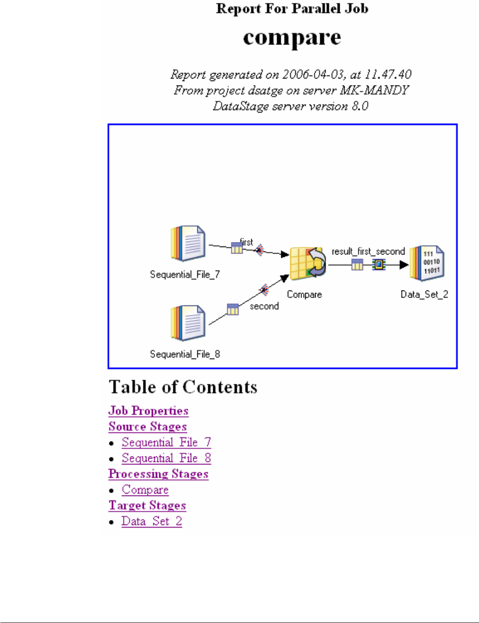
The report is not dynamic, if you change the job design you will need to
regenerate the report.
Note: Job reports work best using Microsoft Internet Explorer 6, they might not
perform optimally with other browsers.
Generating a job report
You can generate a job report.
196 Designer Client Guide

Procedure
1. Open the job you want to report on in the Designer and choose File >
Generate Report... (if you have updated the job since it was last saved, you are
prompted to save it). The Enter report details window opens.
2. Specify a name for the report. The Reporting Console folder field shows you
the location where the report is saved to.
3. Type a description of the report.
4. Choose Use Default Stylesheet to use the default XSLT stylesheet supplied
with IBM InfoSphere DataStage (the report is generated in XML, the stylesheet
converts it to HTML, suitable for viewing in a browser). You can also define a
custom stylesheet for this purpose, in which case choose Use custom stylesheet
and type in, or browse for, the pathname of your stylesheet. Any stylesheets
that you supply must use UTF-8 encoding. The default stylesheet is
DSJobReport.xsl or DSMainframeJobReport.xsl for mainframe jobs - both
located in the InfoSphere DataStage client directory for example,
C:\IBM\InformationServer\Clients\Classic.
5. Select Retain intermediate XML file to have InfoSphere DataStage retain the
XML file that it initially generates when producing a report. Specify the folder
in which to save the xml file.
6. Click OK to generate the report.
Requesting a job report from the command line
The dsdesign command is a Microsoft Windows application that you use to
request the generation of a job report from the command line on an InfoSphere
DataStage client machine.
Important: If you generate a job report from the command line, the report is not
available for viewing through the reporting console.
Syntax
The dsdesign command includes the following syntax:
dsdesign.exe /AF=authfile |
/D=domain /H=hostname [/U=username [/P=password]]
project (job_name |job_sequence_name | /SC shared_container_name)
/R
[/RP=report_pathname]
[/RT=stylesheet_pathname]
[/RX]
authfile
Name of the encrypted credentials file that contains the connection details.
domain | domain:port_number
Name of the application server. This parameter can also have a port number.
hostname
The host name of the InfoSphere Information Server engine that generates the
report.
username
The user name to use for connecting to the application server.
password
The password for the username that you are using to connect to the application
server.
Chapter 12. Documenting your designs 197
project
Name of the project that contains the job, job sequence, or shared container.
job_name | job_sequence_name | shared_container_name
Name of the job, job sequence, or shared container that you want to generate a
report for. The report is generated in HTML format.
/R Flag indicating that you want to generate a report.
report_pathname
Subdirectory where the report is written to. This subdirectory is named after
the job. If you do not specify a directory, the report is written to a subdirectory
in the client directory. For example, C:\IBM\InformationServer\Clients\
Classic\myjob.
stylesheet_pathname
Path name that indicates an alternate XSLT stylesheet. If you do not specify a
stylesheet, the default stylesheet is used.
/RX
Flag indicating that you want to retain the intermediate XML file.
If you do not use the /AF option and you want to run the command without any
user interaction, you must supply all of the connection details on the command
line. If all of the connection details are not supplied on the command line, the
Logon dialog is displayed. The Logon dialog is pre-filled with the values from the
command line. Any missing values are pre-filled with the values from your most
recent successful connection, except for the Password field which you must supply.
The password is not displayed as you type in the Logon dialog.
The following command creates the ServerJob1.htm report in the
C:\JobReports\ServerJob1 directory.
dsdesign /D=domain:9443 /H=R101 /U=william /P=wombat
dstage ServerJob1 /R /RP=C:\JobReports
The following command creates the ServerJob1.htm report and the ServerJob1.xml
intermediate file. Each of these files is saved in the C:\JobReports\ServerJob1
directory.
dsdesign /D=domain:9443 /H=R101 /U=william /P=wombat
dstage ServerJob1 /R /RP=C:\JobReports /RX
198 Designer Client Guide

Chapter 13. Getting jobs ready to run
Before you can run a job, you must compile it.
Compiling server jobs and parallel jobs
When you have finished developing a server or a parallel job, you need to compile
it before you can actually run it.
About this task
Server jobs and parallel jobs are compiled on the IBM InfoSphere DataStage server,
and are subsequently run on the server using the InfoSphere DataStage Director.
To compile a job, open the job in the Designer and do one of the following:
vChoose File Compile.
vClick the Compile button on the toolbar.
If the job has unsaved changes, you are prompted to save the job by clicking OK.
The Compile Job dialog box appears. This dialog box contains a display area for
compilation messages and has the following buttons:
vRe-Compile. Recompiles the job if you have made any changes.
vShow Error. Highlights the stage that generated a compilation error. This button
is only active if an error is generated during compilation.
vMore. Displays the output that does not fit in the display area. Some errors
produced by the compiler include detailed BASIC output.
vClose. Closes the Compile Job dialog box.
vHelp. Invokes the Help system.
The job is compiled as soon as this dialog box appears. You must check the display
area for any compilation messages or errors that are generated.
For parallel jobs there is also a force compile option. The compilation of parallel
jobs is by default optimized such that transformer stages only get recompiled if
they have changed since the last compilation. The force compile option overrides
this and causes all transformer stages in the job to be compiled. To select this
option:
vChoose File Force Compile
Compilation checks - server jobs
Job designs are verified during compilation checks.
The following criteria in the job design are checked during compilation:
vPrimary input. If you have more than one input link to a Transformer stage, the
compiler checks that one is defined as the primary input link.
vReference input. If you have reference inputs defined in a Transformer stage, the
compiler checks that these are not from sequential files.
vKey expressions. If you have key fields specified in your column definitions, the
compiler checks whether there are key expressions joining the data tables.
© Copyright IBM Corp. 1997, 2014 199
vTransforms. If you have specified a transform, the compiler checks that this is a
suitable transform for the data type.
Successful compilation
After a job was compiled successfully, you can begin working with the job.
If the Compile Job dialog box displays the message Job successfully compiled
with no errors. You can:
vValidate the job
vRun or schedule the job
vRelease the job
vPackage the job for deployment on other IBM InfoSphere DataStage systems
Jobs are validated and run using the Director client.
Compile from the client command line
You can compile IBM InfoSphere DataStage jobs from the command line on the
InfoSphere DataStage client by using the dscc command. You can also use the dscc
command to compile buildops or routines, or to provision InfoSphere QualityStage
objects such as rule sets.
Syntax
The dscc command has the following syntax:
dscc.exe /af authfile |
/url domainURL /h hostname [/u username [/p password]] |
/d domain /h hostname [/u username [/p password]]
project
[/j job_name [/f] [/mfcgb base_directory] [/mful upload_profile] [/ouc] [/qspa]]
[/jt job_type [/f] [/mfcgb base_directory] [/mful upload_profile] [/ouc] [/qspa]]
[/qs qualitystage_objects]
[/r routine_name]
[/rcf]
[/bo buildop_name]
[/rd report_name]
Parameters
/? Specify this parameter to show a complete list of options.
/af
Specify the name of the credentials file that contains the connection details.
This file can be encrypted. The dscc command is one of the commands that
supports the authfile option.
For important formatting details about the credentials file, see The credentials
file.
/bo
Specify the buildop (custom parallel stage) to compile. Use *to specify all
buildops or \folderName\* to specify all the buildops in the folder named
folderName.
/d Specify the host name of the services tier. This parameter can also have a port
number in the form domain:port_number.
200 Designer Client Guide
/f Specify this parameter to force compile for parallel jobs. This parameter
ensures that all parallel job transformers are recompiled even if they appear
unchanged since the last compilation.
/h Specify the host name of the engine tier.
/j Specify the name of the job to compile. Use jobname to specify a single job, *to
compile all jobs in the project, or category_name\* to compile all jobs in that
category (categories within that category are included). You can specify parallel
jobs, server jobs, or sequence jobs.
/jt
Specify this parameter to compile all jobs in the project that match the selected
job_type. The default value of -1 specifies that the client compile all types of
job. Use 0to specify all server jobs, 1to specify all mainframe jobs, 2to specify
all sequence jobs, or 3to specify all parallel jobs.
/mfcgb
Specify the mainframe code generation base directory location.
/mful
Specify the mainframe job upload profile.
/ouc
Specify this parameter to compile only uncompiled jobs.
/p Specify the password to use when you are attaching to the project.
project
Specify the name of the project to access.
/qs
Specify the InfoSphere QualityStage rule sets to provision. Use *to provision
all rule sets or \folderName\* to provision all rule sets in the folder named
folderName.
/qspa
Specify this parameter with a job compilation to provision all IBM InfoSphere
QualityStage rule sets that the job compilation references.
/r Specify the name of the routine or routines to be compiled.
vUse routinename to specify a single routine.
vUse *to compile all routines in the project.
vUse category_name\* to compile all routines in that category (categories
within that category are not included).
vUse \folderName\* to compile all the routines in the folder named
folderName
/rcf
Specify this parameter to have the system return a -1 if anything fails to
compile or deploy.
/rd
Specify the name and destination for a compilation report. Specify
DESKTOP\filename to write it to your desktop or .\filename to write it to the
current working directory.
/rt
Specify the type of report to produce. Use Xto produce a report in xml or Tto
produce a report in text format. Tis the default type.
/u Specify the user name to use when you attach to the project.
Chapter 13. Getting jobs ready to run 201

/url
Specify the full format URL for the domain to log on to. The URL includes the
protocol, host, and port information for the domain in this format:
https://domain:port. The port defaults to 9443 if it is not specified.
If you specify only the host name details, you are prompted for the user name and
password. (The password is hidden as you type in the command window.) If you
specify the host name and user name details, you are prompted for the password.
The following compiles the job mybigjob in the project dstageprj:
dscc /h r101 /u fellp /p plaintextpassword dstageprj /J mybigjob
Viewing generated OSH code
You can view the code that is generated when parallel jobs are compiled on the
Generated OSH page of the Job Properties window.
The Generated OSH page appears if you have selected the Generated OSH visible
option in the IBM InfoSphere DataStage Administrator.
Generating code for mainframe jobs
When you have finished developing a mainframe job, you need to generate the
code for the job. This code is then transferred to the mainframe machine, where
the job is compiled and run.
Note: Mainframe jobs are not supported in this version of IBM InfoSphere
Information Server.
You can also generate code from the command line or using the compile wizard.
To generate code for a job, open the job in the Designer and do one of the
following:
vChoose File Generate Code.
vClick the Generate Code button on the toolbar.
If the job has unsaved changes, you are prompted to save the job by clicking OK.
The Mainframe Job Code Generation dialog box appears. This dialog box contains
details of the code generation files and a display area for compilation messages. It
has the following buttons:
vGenerate. Click this to validate the job design and generate the COBOL code
and JCL files for transfer to the mainframe.
vView. This allows you to view the generated files.
vUpload job. This button is enabled if the code generation is successful. Clicking
it opens the Remote System dialog box, which allows you to specify a machine
to which to upload the generated code.
Status messages are displayed in the Validation and code generation status
window in the dialog box.
Job validation
Validate a mainframe job to check the stages and expressions used in the stages.
Validation of a mainframe job design involves:
202 Designer Client Guide
vChecking that all stages in the job are connected in one continuous flow, and
that each stage has the required number of input and output links.
vChecking the expressions used in each stage for syntax and semantic correctness.
A status message is displayed as each stage is validated. If a stage fails, the
validation will stop.
Code generation
Code generation first validates the job design. If the validation fails, code
generation stops.
Status messages about validation are in the Validation and code generation status
window. They give the names and locations of the generated files, and indicate the
database name and user name used by each relational stage.
Three files are produced during code generation:
vCOBOL program file which contains the actual COBOL code that has been
generated.
vCompile JCL file which contains the JCL that controls the compilation of the
COBOL code on the target mainframe machine.
vRun JCL file which contains the JCL that controls the running of the job on the
mainframe once it has been compiled.
Job upload
After you have successfully generated the mainframe code, you can upload the
files to the target mainframe, where the job is compiled and run.
About this task
To upload a job, choose File Upload Job. The Remote System dialog box appears,
allowing you to specify information about connecting to the target mainframe
system. Once you have successfully connected to the target machine, the Job
Upload dialog box appears, allowing you to actually upload the job.
JCL templates
IBM InfoSphere DataStage uses JCL templates to build the required JCL files when
you generate a mainframe job.
InfoSphere DataStage comes with a set of building-block JCL templates suitable for
various tasks.
The supplied templates are in a directory called JCL Templates under the engine
tier server install directory. There are also copies of the templates held in the
InfoSphere DataStage Repository for each InfoSphere DataStage project.
You can edit the templates to meet the requirements of your particular project. This
is done using the JCL Templates dialog box from the Designer. Open the JCL
Templates dialog box by choosing Tools >JCL Templates. It contains the following
fields and buttons:
vPlatform type. Displays the installed platform types in a drop-down list.
vTemplate name. Displays the available JCL templates for the chosen platform in
a drop-down list.
vShort description. Briefly describes the selected template.
Chapter 13. Getting jobs ready to run 203

vTemplate. The code that the selected template contains.
vSave. This button is enabled if you edit the code, or subsequently reset a
modified template to the default code. Click Save to save your changes.
vReset. Resets the template code back to that of the default template.
If there are system wide changes that will apply to every project, then it is possible
to edit the template defaults. Changes made here will be picked up by every
InfoSphere DataStage project on that InfoSphere DataStage engine tier. The JCL
Templates directory contains two sets of template files: a default set that you can
edit, and a master set which is read-only. You can always revert to the master
templates if required, by copying the read-only masters over the default templates.
Use a standard editing tool, such as Microsoft Notepad, to edit the default
templates.
Code customization
When you check the Generate COPY statement for customization box in the Code
generation dialog box, IBM InfoSphere DataStage provides four places in the
generated COBOL program that you can customize.
You can add code to be executed at program initialization or termination, or both.
However, you cannot add code that would affect the row-by-row processing of the
generated program.
When you check Generate COPY statement for customization, four additional
COPY statements are added to the generated COBOL program:
vCOPY ARDTUDAT. This statement is generated just before the PROCEDURE
DIVISION statement. You can use this to add WORKING-STORAGE variables or
a LINKAGE SECTION to the program.
vCOPY ARDTUBGN. This statement is generated just after the PROCEDURE
DIVISION statement. You can use this to add your own program initialization
code. If you included a LINKAGE SECTION in ARDTUDAT, you can use this to
add the USING clause to the PROCEDURE DIVISION statement.
vCOPY ARDTUEND. This statement is generated just before each STOP RUN
statement. You can use this to add your own program termination code.
vCOPY ARDTUCOD. This statement is generated as the last statement in the
COBOL program. You use this to add your own paragraphs to the code. These
paragraphs are those which are PERFORMed from the code in ARDTUBGN and
ARDTUEND.
InfoSphere DataStage provides default versions of these four COPYLIB members.
As provided, ARDTUDAT, ARDTUEND, and ARDTUCOD contain only comments,
and ARDTUBGN contains comments and a period.
You can either preserve these members and create your own COPYLIB, or you can
create your own members in the InfoSphere DataStage runtime COPYLIB. If you
preserve the members, then you must modify the InfoSphere DataStage compile
and link JCL templates to include the name of your COPYLIB before the
InfoSphere DataStage runtime COPYLIB. If you replace the members in the
InfoSphere DataStage COPYLIB, you do not need to change the JCL templates.
Compiling multiple jobs
IBM InfoSphere DataStage has a compiler wizard that guides you through the
process of compiling jobs.
204 Designer Client Guide
About this task
You can start the wizard from the Tools menu of the Designer or Director clients.
Select Tools >Multiple Job Compile . You can also select multiple items in the
repository tree or Advanced Find window and use the shortcut menu to start the
compiler wizard.
Procedure
1. If you started the wizard from the Tools menu, a screen prompts you to specify
the criteria for selecting jobs to compile. Choose one or more of:
vServer
vParallel
vMainframe
vSequence
vCustom server routines
vCustom parallel stage types
You can also specify that only currently uncompiled jobs will be compiled,
and that you want to manually select the items to compile.
2. Click Next>.
If you chose the Show manual selection page option, the Job Selection
Override screen appears. Choose jobs in the left pane and add them to the right
pane by using the Add buttons or remove them from the right pane by using
the Remove buttons. Clicking Add while you have a folder selected selects all
teh items in that folder and move them to the right pane. All the jobs in the
right pane will be compiled.
3. Click Next>, if you are compiling parallel or mainframe jobs, the Compiler
Options screen appears, allowing you to specify the following:
vForce compile (for parallel jobs).
vAn upload profile for mainframe jobs you are generating code for.
4. Click Next>. The Compile Process screen appears, displaying the names of the
selected items and their current compile status.
5. Click Start Compile to start the compilation. As the compilation proceeds the
status changes from Queued to Compiling to Compiled OK or Failed and
details about each job are displayed in the compilation output window as it
compiles. Click the Cancel button to stop the compilation, although you can
only cancel between compilations so the Designer client might take some time
to respond.
6. Click Finish. If the Show compile report checkbox was selected the job
compilation report screen appears, displaying the report generated by the
compilation.
Chapter 13. Getting jobs ready to run 205
206 Designer Client Guide

Chapter 14. Building sequence jobs
For more complex designs, you can build sequence jobs to run multiple jobs in
conjunction with other jobs. By using sequence jobs, you can integrate
programming controls into your job workflow, such as branching and looping.
IBM InfoSphere DataStage includes a special type of job, known as a sequence job,
that you use to specify a sequence of parallel jobs or server jobs to run. You specify
the control information, such as the different courses of action to take depending
on whether a job in the sequence succeeds or fails. After you create a sequence job,
you schedule it to run using the InfoSphere DataStage Director client, just like you
would with a parallel job or server job. The sequence job is listed in the InfoSphere
DataStage repository and in the InfoSphere DataStage Director client.
Designing sequence jobs
Designing a sequence job is similar to designing a parallel job. You create the
sequence job in the Designer client and add stages. The stages that you add are
known as activities. When you link two activities together, you define the triggers
that define the flow of control. The job sequence includes properties and can have
parameters, which are passed to the activities in the sequence job.
Each activity also contains properties that are passed to other activities in the
sequence job. As with stages, you can define job parameters for each activity. You
can test the parameters in the trigger expressions, and pass the parameters to other
activities in the sequence job.
The following sequence job shows a sequence that runs the Demo job. If this
sequence job runs successfully, the success trigger causes the Overnightrun
sequence job to run. If the Demo job fails, the Failure trigger causes the Failure
sequence job to run.
© Copyright IBM Corp. 1997, 2014 207
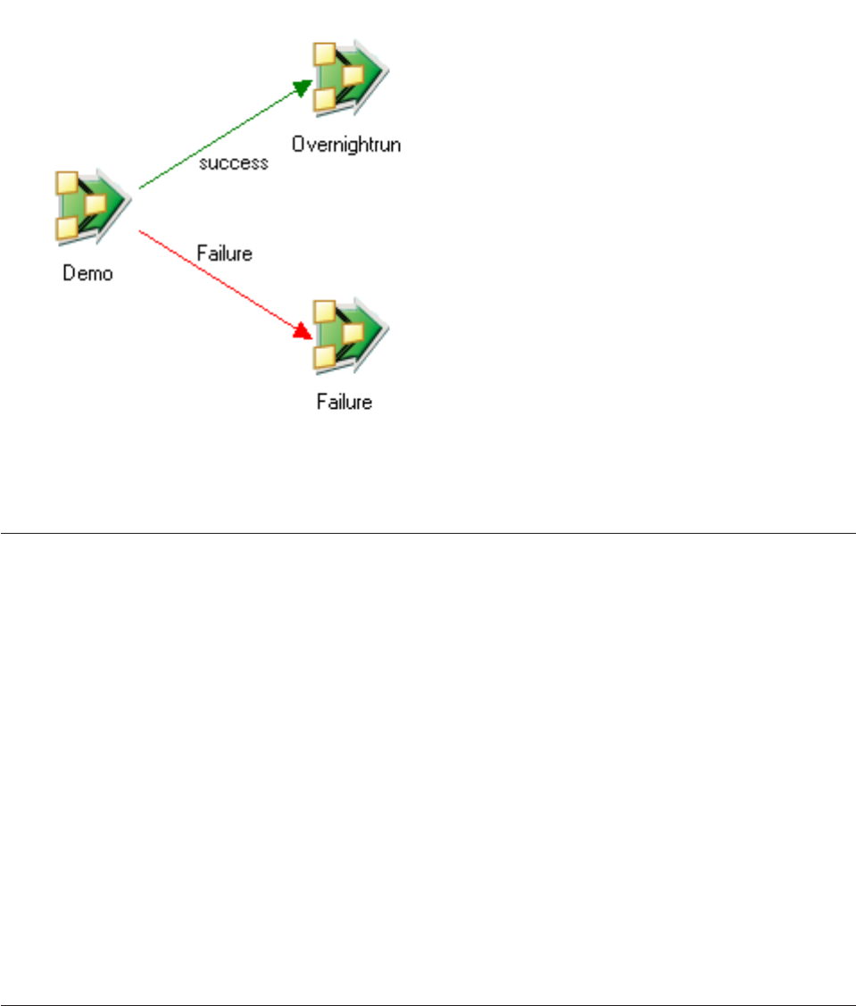
Creating sequence jobs
You create sequence jobs by adding activities, linking the activities, specifying
triggers for each activity, and optionally adding parameters for each activity.
Procedure
1. From the Designer client menu bar, click File >New. The New dialog box
appears.
2. Click the Job folder, then click Sequence Job.
3. Click OK.
4. From the Palette, add activities to your sequence job.
5. Specify the properties for each activity, such as the job or activity that occurs
when the activity is triggered.
6. Link the activities together.
7. Specify trigger information to define the actions that occur if the activity
succeeds or fails.
8. Save your sequence job. Sequence job names can be any length up to 255
characters, must begin with an alphabetic character, and can contain
alphanumeric characters and underscores. Spaces are not permitted.
Specifying triggers
Triggers determine what actions an activity takes when it runs as part of a
sequence job. You must link two activities together for the Triggers tab to be
available in the properties for an activity.
Figure 21. Sample sequence job
208 Designer Client Guide

About this task
Activities can have one input trigger only, but can have multiple output triggers.
Sequence jobs must run for the associated trigger to activate. If a sequence job fails
to run, the associated trigger is not activated. For example, if a sequence job has a
state of Aborted, the triggers for the activities in the sequence job fail to activate.
Procedure
1. Create a link between two activities.
2. Change the link name to represent the action that is triggered. For example, an
activity might have two output links: one link to represent success and one link
to represent failure. You might name the first link success and the other link
failure.
3. Open the properties for the activity that you want to specify a trigger for.
4. In the Expression Type field, select the trigger for the selected activity.
Option Description
OK Run the target activity if the source activity
succeeds
Failed Run the target activity if the source activity
fails
ReturnValue Return a routine or command when the
activity runs
Warning Return a message if the activity produces
warnings
Custom Run a customized trigger for the activity,
which you define as an expression
UserStatus Return a customized status message and
write it to the log
Unconditional Run the target activity when the source
activity completes, regardless of whether
other activities run the same trigger
Otherwise Run the source activity, regardless of
whether all conditional triggers ran
successfully
5. Optional: If you selected Custom or UserStatus for the Expression Type, enter
the syntax for your expression in the Expression field.
6. Click OK to close the properties window for your activity.
Trigger types
When you link activities in a sequence job, you specify triggers to determine the
actions that occur when the activity runs. Each activity can output different trigger
types. Three types of triggers are available, with some types having subtypes.
Conditional
A conditional trigger runs the target activity if the source activity fulfills
the specified condition. The condition is defined by an expression, and can
be one of the following types:
Chapter 14. Building sequence jobs 209

Table 4. Conditional trigger types
Conditional trigger Action
OK Runs the target activity if the source activity
succeeds
Failed Runs the target activity if the source activity
fails
ReturnValue Returns a routine or command when the
activity runs
Warnings Returns a message if the activity produces
warnings
Custom Runs a customized trigger for the activity,
which you define as an expression
User status Returns a customized status message and
write it to the log
Unconditional
An unconditional trigger runs the target activity once the source activity
completes, regardless of what other triggers are run from the same activity.
Otherwise
An otherwise trigger is used as a default where a source activity has
multiple output triggers, but none of the conditional triggers ran.
Trigger expression syntax
You can enter expressions for triggers in a sequence job to set values and define
custom values. The expression syntax is a subset of the full syntax that is available
in the BASIC Transformer stage for parallel jobs, and the Transformer stage for
server jobs.
Use the built-in expression editor to ensure that your expressions are valid. The
following list includes the values that you can enter to create valid expressions for
your triggers.
vLiteral strings enclosed in double-quotes or single-quotes
vNumeric constants (integer and floating point)
vParameters for the sequence job
vPrior activity variables, such as job exit status
vAll built-in BASIC functions in server jobs
vThe following macros and constants:
– DSHostName
– DSJobController
– DSJobInvocationId
– DSJobName
– DSJobStartDate
– DSJobStartTime
– DSJobStartTimestamp
– DSJobWaveNo
– DSProjectName
vArithmetic operators, such as the plus symbol (+), minus symbol (-),
multiplication symbol (*), and division symbol (/)
210 Designer Client Guide

vRelational operators, such as the greater than symbol (>), less than symbol (<),
and equals sign (=)
vLogical operators (AND or NOT) plus usual bracketing conventions
vTernary operators such as IF,THEN, and ELSE
Custom trigger expression syntax
You can use variables when defining trigger expressions for Custom,ReturnValue,
and UserStatus conditional triggers. The following table describes the variables
that you can use for each of the supported activity types.
In the table, activity_stage is name of the activity. You can also use the job
parameters from the sequence job.
Custom triggers in Nested Condition and Sequencer activities can use any of the
variables in the above table used by the activities connected to them.
Important: When you enter valid variable names in an expression, such as a job
parameter name or job exit status, do not delimit them with the hash symbol (#).
Table 5. Variables used in defining trigger expressions for different activity types
Activity type Variable Use
Exception Handler (these are
available for use in the
sequence of activities the
stage initiates, not the stage
itself)
activity_stage.$ErrMessage The text of the message that
will be logged as a warning
when the exception occurs.
activity_stage.$ErrNumber Returns an error code that
indicates the reason that the
Exception Handler activity
was invoked:
1The activity ran a job,
but it aborted because
no specific handler was
configured
-1 The job failed to run for
an unspecified reason
activity_stage.$ErrSource The stage label of the activity
that triggered the exception.
For example, an activity
stage called a job that failed
to run.
Execute Command activity_stage.$CommandName The name of the command
that the activity ran,
including the path name if
one was specified.
activity_stage.$CommandOutputThe output captured from
running the command.
activity_stage.$ReturnValue The command status.
Chapter 14. Building sequence jobs 211
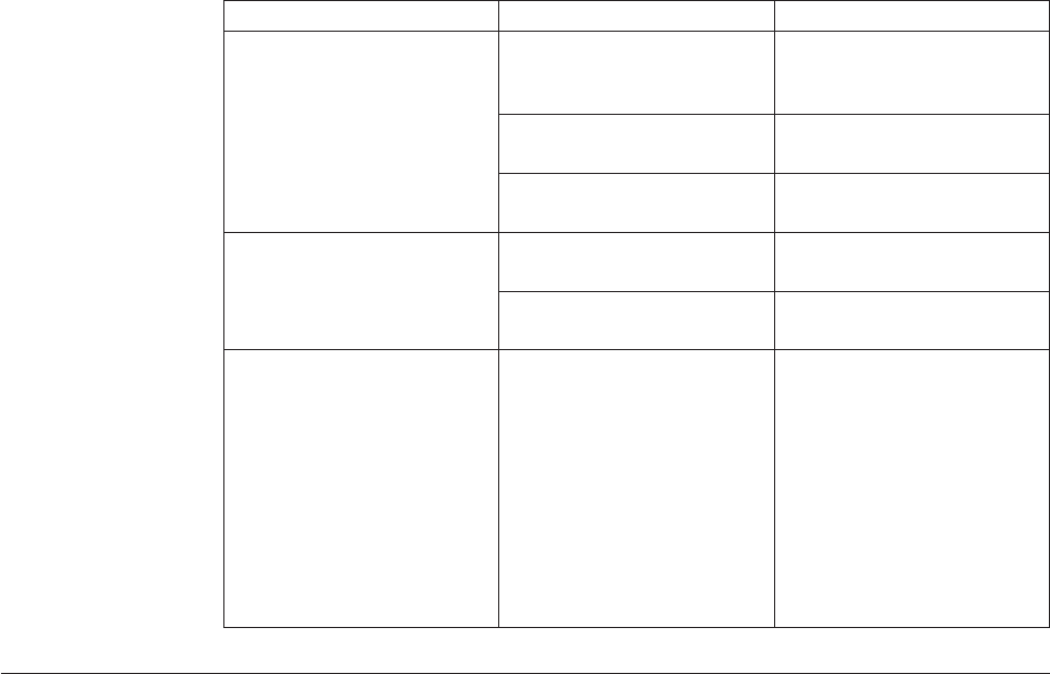
Table 5. Variables used in defining trigger expressions for different activity types (continued)
Activity type Variable Use
Job Activity activity_stage.$JobName The name of the job that was
run, including the invocation
ID if present.
activity_stage.$JobStatus The value of the job status
for the completed job.
activity_stage.$UserStatus The value of the user status
for the selected job.
Routine Activity activity_stage.$ReturnValue The value of the routine
return code.
activity_stage.$RoutineName The name of the routine that
was called.
Wait For File Activity activity_stage.$ReturnValue The value returned by the
DSWaitForFile subroutine:
0The DSWaitForFile
subroutine successfully
waited for the specified
file.
1The DSWaitForFile
subroutine timed out, or
an unspecified action
occurred.
Restarting sequence jobs
Sequence jobs record checkpoint information so that you can restart some sequence
jobs if they fail. If you run a restartable sequence and one of the jobs fails, you can
fix the problem, then run the sequence job again from the point at which it failed.
About this task
You can enable or disable checkpoint recording at a project-wide level, or for
individual sequence jobs. If you enable checkpoint recording for a sequence job,
you can specify that checkpoints for individual components within a sequence job
are not recorded. These components are forced to run whenever the sequence is
restarted, regardless of whether they were run successfully already.
You can also specify that the sequence job handle automatically any errors that
occur when the sequence job runs. By handling errors automatically, you do not
have to specify an error handling trigger for every activity in the sequence job. You
can enable or disable this setting on a project-wide basis, or for individual
sequence jobs.
Procedure
1. Ensure that the job is able to be restarted. If a sequence job is restartable, and
one of its jobs fail during a run, the following status appears in the Director
client:
Aborted/restartable
2. Choose one of the following actions for your sequence job.
212 Designer Client Guide
Option Description
Run job The sequence runs again using the
checkpoint information to ensure that only
the required components are run.
Reset job All checkpoint information is cleared. When
you run the sequence job again, the entire
sequence job runs.
Important: If the sequence job flow diverts to an error handling stage,
InfoSphere DataStage does not record additional checkpoint information. This
behavior ensures that activities in the error handling path are not be skipped if
the sequence job is restarted and another error is encountered.
Creating parameters in your sequence jobs
You use parameters in your sequence jobs to specify values at run time, rather
than hard coding the values. Specifying the value of the parameter each time that
you run the sequence job ensures that you use the correct resources, such as the
database to connect to and the file name to reference.
About this task
Values for parameters are collected when you run the sequence job. The
parameters that you define are available to all activities in your sequence job, so all
available parameters are listed in this page. For example, if you are scheduling
three jobs, each of which requires an input file at run time, you can specify a
distinct parameter for each of the input files. You then edit the Job for each activity
to use the parameters that you created. When you run the sequence job, the Job
Run Options window opens, prompting you to enter values for each parameter.
The appropriate file name is then passed to each job as it runs.
Procedure
1. Open the job that you want to define parameters for.
2. Click Edit >Job Properties to open the Job Properties window.
3. Click the Parameters tab.
4. Enter the following information for the parameter that you are creating. Each
parameter represents a source file or a directory.
Parameter name
The name of the parameter.
Prompt
The text that displays for this parameter when you run the job.
Type
The type of parameter that you are creating, which can be one of the
following values:
Parameter type Description
String Used to specify a text string.
Chapter 14. Building sequence jobs 213
Parameter type Description
Encrypted Used to specify a password. The default
value is set by double-clicking the Default
Value cell to open the Setup Password
window. Type the password in the
Encrypted String field, then type it again in
the Confirm Encrypted String field.
Integer Used to specify a long integer. This value
can be -2147483648 up to 2147483647.
Float Used to specify a double integer. This value
can be 1.79769313486232E308 to
-4.94065645841247E-324, and
4.94065645841247E-324 to
-1.79769313486232E308.
Pathname Used to specify a path name or file name.
List Used to specify a list of string variables. To
create a list, double-click the Default Value
cell to open the Setup List and Default
window.
Date Used to specify the date in the format
yyyy-mm-dd.
Time Used to specify the time in the format
hh:mm:ss.
Default value The default value for the parameter, such as
a directory path.
Help text The text that displays if you click Property
Help in the Job Run Options window when
you run the job.
5. Click OK to close the Job Properties window.
Creating environment variables in your sequence jobs
You can define an environment variables as a job parameter to use in your
sequence jobs. When you run the sequence job, specify a runtime value for the
environment variable.
About this task
To create system environment variables, your InfoSphere DataStage and
QualityStage uses the Administrator client.
Procedure
1. Open the job that you want to define environment variables for.
2. PressCtrl+Jtoopen the Job Properties window.
3. Click the Parameters tab.
4. In the lower right of the Parameters page, click Add Environment Variable.
The Choose environment variable window opens to display a list of the
available environment variables.
214 Designer Client Guide

Option Description
To create a new environment variable 1. Click New. The Create new
environment variable window opens.
2. Enter a name and the prompt that you
want to display at run time, then click
OK.
3. In the list, click the environment variable
that you created.
To use an existing environment variable Click on the environment variable that you
want to override at runtime.
5. The environment variable is listed in the parameter grid, and is distinguished
from job parameters by a dollar sign ($).
6. Enter a value for the environment variable in the Default Value column. You
can edit this field only. Depending on the type of environment variable that
you specify, a window might open that prompts you for a value.
7. Click OK to close the Job Properties window.
Sequence job properties
Sequence jobs contain basic properties just like parallel jobs and server jobs.
Specify these characteristics to determine how your sequence job runs.
General page
Use the General page to specify default parameters for your sequence job.
The General page contains the following fields.
Job version number
The version number of the sequence job, expressed as N.n.n, where Nis the
version number, and n.n is the bug fix number.
vThe version number checks the compatibility of the job with the version of
IBM InfoSphere DataStage installed. This number is set automatically when
InfoSphere DataStage is installed and cannot be edited.
vThe bug fix number reflects minor changes to the job sequence design or
properties. To change this number, select it and enter a new value directly or
use the arrow buttons to increase the number.
Allow Multiple Instance
Enables the Director client to run multiple instances of this sequence job.
Short job description
An optional brief description of the sequence job.
Full job description
An optional detailed description of the sequence job.
The following compilation options specify details about restarting the sequence job
if one of the jobs fails.
Add checkpoints so sequence is restartable
Enables this job to be restarted upon failure. If you enable this feature on a
project-wide basis in the InfoSphere DataStage Administrator client, this option
is selected by default when the sequence job is created.
Chapter 14. Building sequence jobs 215
Automatically handle activities that fail
Automatically handles failing jobs within a sequence (this means that you do
not have to have a specific trigger for job failure). If you enable this feature on
a project-wide basis in the InfoSphere DataStage Administrator client, this
option is selected by default when the sequence job is created.
Important: When using this feature, avoid using any routines within the
sequence job that return any value other than zero to indicate success. In
InfoSphere DataStage, non-zero values indicate a failure.
For each activity that does not have a specific trigger for error handling, code
is inserted that branches to an error handling point. If the compiler inserts
code to handle errors, the following sequence of actions occur if a job within
the job sequence fails:
vA warning is logged to indicate that the job finished with warnings.
vIf the sequence job has an exception handler defined, the code uses that
exception handler.
vIf there no exception handler is defined, the sequence job fails with a
message.
Log warnings after activities that finish with status other than OK
Generates a message in the sequence log if a job in the sequence job finishes
with a non-zero completion code (for example, warnings or fatal errors).
Messages are also logged for routine or command activities that fail.
Log report messages after each job run
Generates a status report for a job immediately after the sequence job runs. The
following example shows the type of information that is included in the report:
**************************************************
STATUS REPORT FOR JOB: jobname
Generated: 2003-10-31 16:13:09
Job start time=2003-10-31 16:13:07
Job end time=2003-10-31 16:13:07
Job elapsed time=00:00:00
Job status=1 (Finished OK)
Stage: stagename1, 10000 rows input
Stage start time=2003-10-31 16:17:27, end time=2003
-10-31 16:17:27, elapsed=00:00:00
Link: linkname1, 10000 rows
Stage: stagename2, 10000 rows input
Stage start time=2003-10-31 16:17:28, end time=2003
-10-31 16:17:28, elapsed=00:00:00
Link: linkname2, 10000 rows
Link: linkname3, 10000 rows
Parameters page
Use the Parameters page to specify parameters, parameter sets, and environment
variables for your sequence job.
The Parameters page contains the following columns:
Parameter name
The name of the parameter.
Prompt
The text that is used as the field name in the runtime dialog.
Type
The parameter type.
216 Designer Client Guide
Default Value
The default setting for the parameter.
Help Text
The text that displays if a user clicks Property Help in the Job Run Options
window when running the Sequence job.
You can refer to the parameters in the job sequence by name. When you are
entering an expression, you just enter the name directly. Where you are entering a
parameter name in an ordinary single-line text box, you need to delimit the name
with hash symbols, for example: #dayofweek#.
Job Control page
The Job Control page displays the code that is generated when the sequence job is
compiled.
This page includes information that is used to diagnose problems with sequence
jobs.
Dependencies page
Use the Dependencies page to view the dependencies of the sequence job, such as
functions, routines, or jobs that the sequence job runs.
Listing the dependencies of the sequence job here ensures that all required
components are included if the sequence job is packaged for use on another
system.
The Dependencies page contains the following fields:
Type
The type of item that the sequence job depends on, which can be any of the
following items:
Job
A released or unreleased job. If you added a job to the sequence job, this
field updates automatically to include the dependencies. If you delete a job
from the sequence job, you must remove it from the dependencies list
manually.
Local
Locally cataloged BASIC functions and subroutines (that is, Transforms
and Before/After routines).
Global
Globally cataloged BASIC functions and subroutines, such as Custom
UniVerse functions.
File
Name of a file.
ActiveX
The name of an ActiveX (OLE) object (not available on UNIX-based
systems).
Name
The name of the function or routine. The name required varies according to the
dependency Type:
Chapter 14. Building sequence jobs 217

Job
The name of a released or unreleased job.
Local
The catalog name.
Global
The catalog name.
File
The file name.
ActiveX
The name of an ActiveX object.
Location
The location of the dependency. A browse dialog box is available to help with
this. This location can be an absolute path, but it is recommended you specify
a relative path using the following environment variables:
%SERVERENGINE%
Server engine account directory. This directory is typically
C:\IBM\InformationServer\Server\DSEngine.
%PROJECT%
The current project directory.
%SYSTEM%
The system directory on Windows or the /usr/lib directory on UNIX.
Sequence job activities
Sequence jobs contain activities, which are special stages that indicate the actions
that occur when the sequence job runs. You interact with activities in the same way
that you interact with stages in parallel jobs and server jobs.
To add an activity to your job sequence, drag the corresponding icon from the
Palette to the sequence job canvas. After you design your sequence job by adding
activities and triggers, you define the properties for each activity. The properties
that you define control the behavior of the activity.
To view the properties of an activity, open the activity from the Designer client
canvas. The properties of each activity depend on the type of activity that you
work with. All activities have a General tab, and any activities that contain output
triggers have a Triggers tab.
You can also add jobs or routines to your design as activities by dragging the
associated icon from the Designer client Repository and dropping it on your
sequence job canvas.
General activity properties
After you design your sequence job by adding activities and specifying triggers,
you enter the details that determine how each activity operates.
The pages that are available for each activity vary depending on the type.
However, all activities have a General page, and any activities with output triggers
have a Triggers page.
General
218 Designer Client Guide
Name
The name of the activity.
Description
Optional description of the activity.
Logging text
The text that is written to the Director client log when the activity
runs.
Triggers
Name
The name of the output trigger.
Expression Type
The type of expression that is attached to the trigger.
Expression
The expression that is associated with the trigger. For most predefined
conditions, this field is fixed. You can enter custom expressions for
conditions you can enter an expression
End Loop activity properties
The end loop stage marks the end of the loop.
All the stages in between the Start Loop and End Loop stages are included in that
loop (as illustrated in Examples of Using Loop Stages). You draw a link back to the
Start Loop activity stage that this stage is paired with.
The stage has no special properties.
ExecCommand activity properties
Use the ExecCommand stage to specify information about an Execute Command
activity.
The ExecCommand stage contains the following fields in addition to the General
page and the Triggers page:
Command
The full pathname of the command to execute. This can be an operating
system command, a batch command file, or an executable file. You can use a
job parameter so that you can specify the actual command at run time.
Parameters entered in this field needs to be delimited with hashes (#).
Parameters selected from the External Parameter Helper will automatically be
enclosed in hash symbols. You can browse for a command or job parameter.
Parameters
Allows you to pass parameters to the command. These should be entered in
the format that the command expects them. You can also specify a parameter
whose value will be specified at run time. Click the Browse button to open the
External Parameter Helper, which shows you all parameters available at this
point in the job sequence. Parameters entered in these fields need to be
delimited with hashes (#). Parameters selected from the External Parameter
Helper will automatically be enclosed in hash symbols.
You can prefix the command parameters with the string /NOLOG/ to prevent
the parameters being displayed in the job log. This feature is useful where
your parameters include passwords or other confidential information.
Chapter 14. Building sequence jobs 219
Do not checkpoint run
Select this option to specify that checkpoint information for this particular
execute command operation will not be recorded. This means that, if a job later
in the sequence fails, and the sequence is restarted, this execute command
operation will be re-executed regardless of the fact that it was executed
successfully before. This option is only available if the sequence as a whole is
checkpointed.
Exception activity properties
An exception activity handles the situation where a job in the sequence fails to run
(other exceptions in the job sequence are handled by triggers).
An exception activity can only have a single unconditional output trigger, so does
not require a Triggers page. It has no input triggers. It serves as a starting point for
a sequence of activities to run if an exception has occurred somewhere in the main
sequence. Its Properties dialog box contains only a General page.
There are some exception handler variables that can be used in the sequence of
activities that the Exception Activity stage initiates. These are:
vstage_label.$ErrSource. This is the stage label of the activity stage that raised the
exception (for example, the job activity stage calling a job that failed to run).
vstage_label.$ErrNumber. Indicates the reason the Exception Handler activity was
invoked, and is one of:
– 1. Activity ran a job but it aborted, and there was no specific handler set up.
– -1. Job failed to run for some reason.
vstage_label.$ErrMessage. The text of the message that will be logged as a warning
when the exception is raised.
Job Activity properties
Use the Job Activity stage to specify information about the job that the job activity
runs.
The Job Activity stage contains the following fields:
Job name
Use this field to specify the name of the job that the activity runs. If you add
the activity by dragging a job from the Repository, the Job name field is
already populated.
Invocation Id Expression
Enter a name for the invocation or a job parameter that supplies the instance
name at run time. A job parameter name must be delimited by hashes (#). You
can also click the browse button choose from a list of available job parameters.
To set the Invocation Id to the value used by the calling job sequence, set this
field to the value DSJobInvocationId.
Important: This field is displayed only if the job identified by the Job name
property has the Allow Multiple Instance option enabled. You cannot leave
the Invocation Id Expression field blank.
Execution Action
Use this option to specify what action the activity takes when the job runs.
Choose one of the following options from the list:
vRun (the default)
220 Designer Client Guide
vReset if required then run
vValidate only
vReset only
Do not checkpoint job run
Select this option to specify that checkpoint information will not be recorded
for this job. This option specifies that if a job later in the sequence fails, and
the sequence is restarted, this job will run again, regardless of whether it
finished successfully in the original run. This option is only available if
checkpoint information is recorded for the entire sequence job.
Parameters
Use this grid to provide values for any parameters that the job requires. The
grid displays all parameters that are expected by the job. Choose one of the
following options to use this field:
vType an expression that specifies a value for the parameter in the Value
Expression column. Literal values must be enclosed in inverted commas.
vSelect a parameter and click Insert Parameter Value to use another
parameter or argument in the sequence to provide the value. A window
opens and displays all available parameters and arguments that occur in the
sequence job before the current activity. This window shows parameters that
you define for the job sequence in the Parameters stage of the Job Sequence
Properties window. Choose the required parameter or argument and click
OK. You can use this feature to determine control flow through the
sequence.
vClick Clear to clear the value expression from the selected parameter.
vClick Clear All to clear the expression values from all parameters.
vSelect a parameter and click Set to Default to enter the default for that
parameter as defined in the job itself.
vClick All to Default to set all parameters to their default values.
Nested condition activity properties
Use a Nested Condition stage to further branch the execution of a sequence job,
depending on a condition.
Each nested condition can have one input trigger and typically has multiple output
triggers. For example, you could use a Nested Condition stage to implement the
following control sequence.
Load/init jobA
Run jobA
If ExitStatus of jobA = OK then /*tested by trigger*/
If Today = "Wednesday" then /*tested by nested condition*/
run jobW
If Today = "Saturday" then
run jobS
Else
run JobB
You specify the conditions that determine the sequence of actions for each output
triggers in the Triggers page. For example, you might link an ExecCommand stage
to your Nested Condition stage. In the Triggers page of the Nested Condition
stage, you enter the following expression.
DayCommand.$CommandOutput = "Wednesday"
Chapter 14. Building sequence jobs 221
This expression indicates that the ExecCommand stage runs the DayCommand
activity, which returns the value of the $CommandOutput variable. In this case, the
value Wednesday is displayed as the command ouput.
Notification activity properties
Use the Notification stage to specify information about an email notification
activity.
An email template file called dssendmail_template.txt dictates the format of the
notification email that is sent. A copy of this file exists in every project directory,
such as C:\IBM\InformationServer\Server\projects\myproject. You edit this file
so that you can use different email formats for each project.
You can specify a parameter whose value you indicate at run time for the SMTP
Mail server name field, Senders email address field, Recipients email address
field, and Email subject field. Click Browse to open the External Parameter
Helper, which shows you all parameters available at this point in the job sequence.
Parameters entered in these fields need to be delimited with hashes (#). Parameters
that you select from the External Parameter Helper are automatically enclosed in
hash symbols.
The Notification stage includes the following fields.
SMTP Mail server name
The name of the server or its IP address. You can specify a parameter whose
value you indicate at run time.
Senders email address
The email address that the notification is sent from.
Recipients email address
The email address that the notification is sent to. You can specify multiple
email addresses, separated by a space.
Email subject
The text that is included in the subject line of the notification.
Attachments
Files to be sent with the notification. Specify a path name or a
comma-separated list of pathnames, which must be enclosed in single-quotes
or double-quotes. You can also specify an expression that resolves to a
pathname or comma-separated pathnames.
Email body
The text that is included in the body of the notification.
Include job status in email
Checkbox that specifies whether you want to include available job status
information in the message.
Do not checkpoint run
Checkbox that specifies whether you want to include checkpoint information
for this particular notification operation will not be recorded. This means that,
if a job later in the sequence fails, and the sequence is restarted, this
notification operation will be re-executed regardless of the fact that it was
executed successfully before. This option is only available if the sequence as a
whole is checkpointed.
222 Designer Client Guide
Oozie Workflow Activity properties
Use the Oozie Workflow Activity stage to invoke Oozie workflows from the
Designer client. Oozie workflows are a collection of actions that are arranged in a
control dependency. These actions are computation tasks that are written in Jaql,
MapReduce, or other frameworks that you use to write applications to process
large amounts of data.
Attention: This stage can be installed on Red Hat Linux 64-bit systems only.
The Oozie Workflow Activity stage contains the following fields:
Oozie Server
Specify the URL for the Oozie server to connect to. For example,
http://myserver:8280/oozie, where myserver is the name of the Oozie server
that you are connecting to. The port number 8020 is used for InfoSphere
BigInsights, but differs depending on the Hadoop system that you use.
Workflow Definition Path
Enter the location of the workflow definition that you want to run. A workflow
definition is a programmatic description of a workflow in XML format.
You must include the full path to the workflow definition, which is defined as
hdfs://host:Hadoop_port/HDFS_application_path/workflow_directory. For
example, hdfs://mymachine.host.com:8280/user/biadmin/workflows/aasd-
098098098.xml.
host
The machine where your Hadoop application is installed.
Hadoop_port
The port number that your Hadoop application is listening on.
HDFS_application_path
The application path to your Hadoop distributed file system application.
workflow_directory
The directory that contains the workflow.xml that you want to run.
Do not checkpoint job run
Select this option to specify that checkpoint information will not be recorded
for this activity. This option specifies that if an activity later in the sequence
fails, and the sequence is restarted, this activity will run again, regardless of
whether it finished successfully in the original run. This option is only
available if checkpoint information is recorded for the entire sequence job.
Workflow Parameters
Enter values for any parameters that the activity requires. The grid displays all
parameters that are expected by the activity.
Name
Type a name for your parameter.
Value Expression
Type an expression that specifies a value for the parameter. Literal values
must be enclosed in inverted commas.
You can also click the browse arrow to open a window that displays all
available parameters and arguments that occur in the sequence job before
the current activity. This window shows parameters that you define for the
job sequence in the Parameters stage of the Job Sequence Properties
Chapter 14. Building sequence jobs 223
window. Choose the required parameter or argument and click OK.You
can use this feature to determine control flow through the sequence.
Enter -pf file_name to specify a parameter file that the activity reads at
run time, where file_name is the name of the parameter file. All parameters
contained in this file will be added to the workflow configuration.
Routine activity properties
In addition to the General and Triggers pages, the Properties dialog box for a
routine activity contains a Routine page.
The Routine page contains:
vRoutine name. Allows you to specify the name of the routine the activity is to
execute. You can select a routine by browsing the Repository. If you have added
the activity by dragging a routine from the Repository window, the Routine
name will already be filled in.
vDo not checkpoint run. Set this to specify that IBM InfoSphere DataStage does
not record checkpoint information for the execution of this particular routine.
This means that, if a job later in the sequence fails, and the sequence is restarted,
this routine will be re-executed regardless of the fact that it was executed
successfully before. This option is only visible if the sequence as a whole is
check pointed.
vArguments. Allows you to provide values for any arguments that the routine
requires. The grid displays all the arguments expected by the routine. You can:
– Type in an expression giving the value for the argument in the Value
Expression column. Literal values must be enclosed in inverted commas. (For
details about expressions, see "Expressions".)
– Click Clear to clear the value expression from the selected parameter.
– Click Clear All to clear the expression values from all parameters.
– Select an argument and click Insert Parameter Value to use another parameter
or argument in the sequence to provide the value. A dialog box appears
displaying a tree of all the available parameters and arguments occurring in
the sequence before the current activity. Choose the required parameter or
argument and click OK. You can use this feature to determine control flow
through the sequence.
You can access routine arguments in the activity triggers in the form
routinename.argname. Such arguments can be also be accessed by other activities
that occur subsequently in the job sequence. This is most useful for accessing an
output argument of a routine, but note that BASIC makes no distinction between
input and output arguments, it is up to you to establish which is which.
When you select the icon representing a routine activity, you can choose Open
Routine from the shortcut menu to open the Routine dialog box for that routine
ready to edit.
Sequencer activity properties
You use the Sequencer stage to synchronize the control flow of multiple activities
in a job sequence. This stage can have multiple input triggers and multiple output
triggers.
The Sequencer stage contains a General page and a Sequencer page. In the
Sequencer page, you select the operation mode for the Sequencer stage:
224 Designer Client Guide
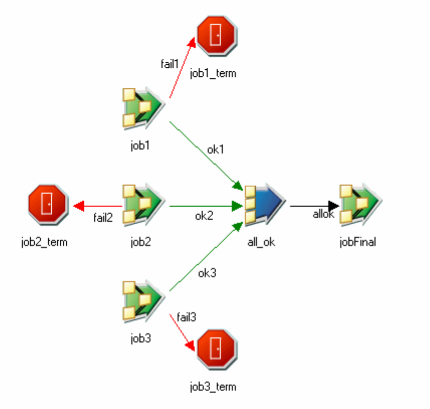
All
All of the inputs must be TRUE to trigger any of the sequencer activities.
Any
Activities are triggered if any of the inputs are TRUE.
You can also right-click the Sequencer stage to change the mode. The Sequencer
stage icon changes slightly depending on the mode that you select.
Examples of using the sequencer stage
A sequencer allows you to synchronize the control flow of multiple activities in a
job sequence.
The following is a job sequence that synchronizes the running of a job to the
successful completion of three other jobs. The sequencer mode is set to All. When
job1, job2, and job3 have all finished successfully, the sequencer will start jobfinal
(if any of the jobs fail, the corresponding terminator stage will end the job
sequence).
The following is section of a similar job sequence, but this time the sequencer
mode is set to Any. When any one of the Wait_For_File or job activity stages
Figure 22. Example of sequencer stage with mode set to all
Chapter 14. Building sequence jobs 225
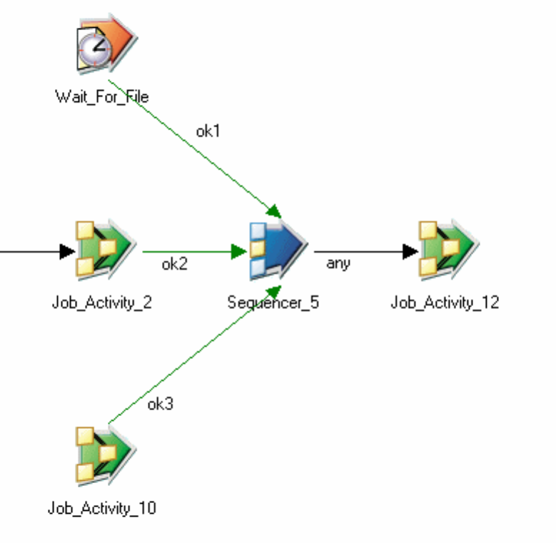
complete successfully, Job_Activity_12 will be started.
Start Loop activity properties
The Start Loop stage marks the beginning of the loop and defines it.
In addition to the General and Triggers pages, the Properties dialog box for a Start
Loop activity contains a Start Loop page.
You can have a numeric loop (where you define a counter, a limit, and an
increment value), or a List loop (where you perform the loop once for each item in
a list). You can pass the current value of the counter as a parameter into the stages
within your loop in the form stage_label.$Counter, where stage_label is the name of
the Start Loop activity stage as given in the Diagram window. You mark the end of
a loop with an End Loop Activity stage, which has a link drawn back to its
corresponding Start Loop stage.
You can nest loops if required.
You define the loop setting in the Start Loop page. The page contains:
vLoop type. Choose Numeric to implement a For...Next type loop, or List to
implement a For...Each type loop.
Figure 23. Example of sequencer stage with mode set to any
226 Designer Client Guide
When you choose Numeric, the page contains the following fields:
vFrom. The initialization value for the counter.
vStep. The increment value for the counter.
vTo. The final counter value.
You can use parameters for any of these, and specify actual values at run time. You
can click the Browse button to open the External Parameter Helper, which shows
you all parameters available at this point in the job sequence. Parameters entered
in this field needs to be delimited with hashes (#). Parameters selected from the
External Parameter Helper will automatically be enclosed in hash symbols.
When you choose List, the page has different fields:
vDelimited values. Enter your list with each item separated by the selected
delimiter.
vDelimiter. Specify the delimiter that will separate your list items. Choose from:
– Comma (the default)
– Space
– Other (enter the required character in the text field)
Examples of using loop stages
You can use loop stages to build loops into your job sequences.
The following is a section of a job sequence that makes repeated attempts to run a
job until either it succeeds, or until the loop limit is reached. The job depends on
network link that is not always available.
Chapter 14. Building sequence jobs 227
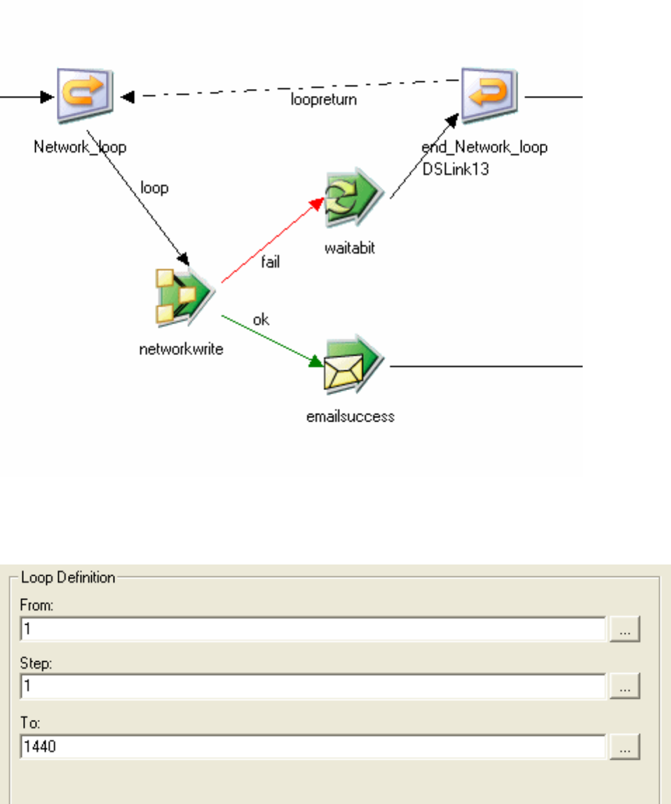
The Start Loop stage, networkloop, has Numeric loop selected and the properties
are set as follows:
This defines that the loop will be run through up to 1440 times. The action differs
according to whether the job succeeds or fails:
Figure 24. Example of using a loop in a sequence
Figure 25. Numeric loop properties
228 Designer Client Guide
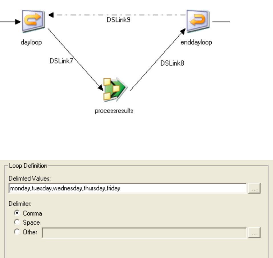
vIf it fails, the routine waitabit is called. This implements a 60 second wait time.
If the job continually fails, the loop repeats 1440 times, giving a total of 24 hours
of retries. After the 1440th attempt, the End Loop stages passes control onto the
next activity in the sequence.
vIf it succeeds, control is passed to the notification stage, emailsuccess, and the
loop is effectively exited.
The following is a section of a job sequence that makes use of the loop stages to
run a job repeatedly to process results for different days of the week:
The Start Loop stage, dayloop, has List loop selected and properties are set as
follows:
The Job Activity stage, processresults, properties are:
Figure 26. Example of loop used in list mode
Figure 27. List loop properties
Chapter 14. Building sequence jobs 229
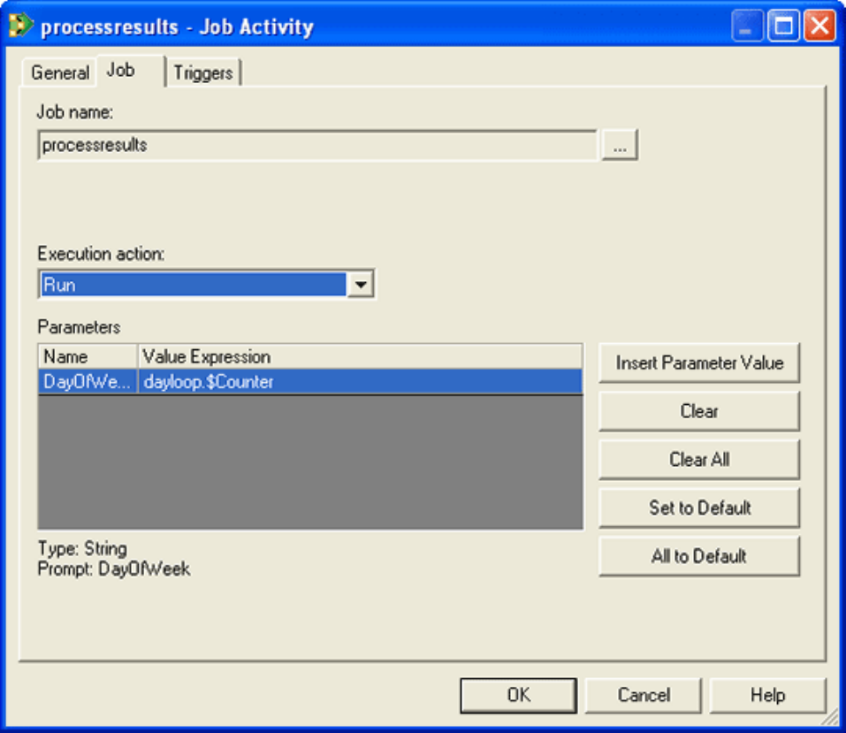
The job processresults will run five times, for each iteration of the loop the job is
passed a day of the week as a parameter in the order monday, tuesday, wednesday,
thursday, friday. The loop is then exited and control passed to the next activity in
the sequence.
Terminator activity properties
A terminator stage can be placed in a job sequence to ensure that the sequence is
stopped cleanly if certain situations arise.
The Terminator Properties dialog box has a General page and Terminator page. It
cannot have output links, and so has no Triggers page. The stage can have one
input.
You can have multiple Terminator activities and can place them anywhere in the
sequence. They are connected to other stages by triggers, which specify when a
terminator will be invoked.
Figure 28. Process results property
230 Designer Client Guide
The terminator stage allows you to specify that stop requests be sent to all running
jobs in the sequence (and optionally have the terminator wait for all jobs to finish),
or that the sequence is aborted without sending stop requests. If you specify some
final message text, this will be used as the text for the sequence abort message (this
is in addition to the logging text on the General page, which is output when the
activity starts). Do not enclose the message in inverted commas unless you want
them to be part of the message.
User variables activity properties
Use the user variable stage to define global variables within a sequence.
These variables can then be used elsewhere in the sequence, for example to set job
parameters. Variables are used in the form stage_label.parameter_name, where
stage_label is the name of the User Variable activity stage as given in the Diagram
window.
The values of the user variables are set by expressions in the stage's properties.
(For details, see "Expressions".)
You would most likely start a sequence with this stage, setting up the variables so
they can be accessed by subsequent sequence activities. The exit trigger would
initiate the sequence proper. You can also use a User Variable activity further into a
sequence to change the value of a variable previously defined by an earlier User
Variable activity.
The variables are defined in the Properties page for the stage. To add a variable:
vChoose Add Row from the shortcut menu.
vEnter the name for your variable.
vSupply an expression for resolving the value of the variable.
Chapter 14. Building sequence jobs 231
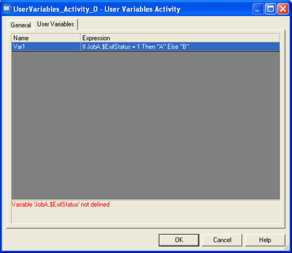
In this example, the expression editor has picked up a fault with the definition.
When fixed, this variable will be available to other activity stages downstream as
MyVars.VAR1.
Wait-For-File activity properties
In addition to the General and Triggers pages, The Properties dialog box for a
wait-for-file activity contains a Wait For File page.
The Wait For File page contains:
vFilename. The full pathname of the file that the activity is to wait for. The Arrow
button offer you the choice of browsing for a file or inserting a job parameter
whose value will be supplied at run time. For a job parameter, you can click the
Browse button to open the External Parameter Helper, which shows you all
parameters available at this point in the job sequence. Parameters entered in this
field needs to be delimited with hashes (#). Parameters selected from the
External Parameter Helper will automatically be enclosed in hash symbols.
Figure 29. User variable activity properties
232 Designer Client Guide
vWait for file to appear. Select this if the activity is to wait for the specified file to
appear.
vWait for file to disappear. Select this if the activity is to wait for the specified file
to disappear.
vTimeout Length (hh:mm:ss). The amount of time to wait for the file to appear or
disappear before the activity times out and completes.
vDo not timeout. Select this to specify that the activity should not timeout, i.e, it
will wait for the file forever.
vDo not checkpoint run. Set this to specify that IBM InfoSphere DataStage does
not record checkpoint information for this particular wait-for-file operation. This
means that, if a job later in the sequence fails, and the sequence is restarted, this
wait-for-file operation will be re-executed regardless of the fact that it was
executed successfully before. This option is only visible if the sequence as a
whole is checkpointed.
Chapter 14. Building sequence jobs 233
234 Designer Client Guide

Chapter 15. Job control routine
You can also implement a job sequence by specifying a job control routine on the
Job control page of the Job Properties window.
A job control routine provides the means of controlling other jobs from the current
job. A set of one or more jobs can be validated, run, reset, stopped, and scheduled
in much the same way as the current job can be. You can, if required, set up a job
whose only function is to control a set of other jobs. The graphical job sequence
editor produces a job control routine when you compile a job sequence (you can
view this in the Job Sequence properties), but you can set up you own control job
by entering your own routine on the Job control page of the Job Properties dialog
box. The routine uses a set of BASIC functions provided for the purpose. The Job
control page provides a basic editor to let you construct a job control routine using
the functions.
The toolbar contains buttons for cutting, copying, pasting, and formatting code,
and for activating Find (and Replace). The main part of this page consists of a
multiline text box with scroll bars. The Add Job button provides a drop-down list
box of all the server and parallel jobs in the current project. When you select a
compiled job from the list and click Add, the Job Run Options dialog box appears,
allowing you to specify any parameters or run-time limits to apply when the
selected job is run. The job will also be added to the list of dependencies. When
you click OK in the Job Run Options dialog box, you return to theJob control page,
where you will find that IBM InfoSphere DataStage has added job control code for
the selected job. The code sets any required job parameters or limits, runs the job,
waits for it to finish, then tests for success.
Alternatively, you can type your routine directly into the text box on the Job
control page, specifying jobs, parameters, and any runtime limits directly in the
code.
The following is an example of a job control routine. It schedules two jobs, waits
for them to finish running, tests their status, and then schedules another one. After
the third job has finished, the routine gets its finishing status.
* get a handle for the first job
Hjob1 = DSAttachJob("DailyJob1",DSJ.ERRFATAL)
* set the job’s parameters
Dummy = DSSetParam(Hjob1,"Param1","Value1")
* run the first job
Dummy = DSRunJob(Hjob1,DSJ.RUNNORMAL)
* get a handle for the second job
Hjob2 = DSAttachJob("DailyJob2",DSJ.ERRFATAL)
* set the job’s parameters
Dummy = DSSetParam(Hjob2,"Param2","Value2")
* run the second job
Dummy = DSRunJob(Hjob2,DSJ.RUNNORMAL)
* Now wait for both jobs to finish before scheduling the third job
Dummy = DSWaitForJob(Hjob1)
Dummy = DSWaitForJob(Hjob2)
* Test the status of the first job (failure causes routine to exit)
J1stat = DSGetJobInfo(Hjob1, DSJ.JOBSTATUS)
If J1stat = DSJS.RUNFAILED
Then Call DSLogFatal("Job DailyJob1 failed","JobControl")
End
* Test the status of the second job (failure causes routine to
© Copyright IBM Corp. 1997, 2014 235
* exit)
J2stat = DSGetJobInfo(Hjob2, DSJ.JOBSTATUS)
If J2stat = DSJS.RUNFAILED
Then Call DSLogFatal("Job DailyJob2 failed","JobControl")
End
* Now get a handle for the third job
Hjob3 = DSAttachJob("DailyJob3",DSJ.ERRFATAL)
* and run it
Dummy = DSRunJob(Hjob3,DSJ.RUNNORMAL)
* then wait for it to finish
Dummy = DSWaitForJob(Hjob3)
* Finally, get the finishing status for the third job and test it
J3stat = DSGetJobInfo(Hjob3, DSJ.JOBSTATUS)
If J3stat = DSJS.RUNFAILED
Then Call DSLogFatal("Job DailyJob3 failed","JobControl")
End
Possible status conditions returned for a job are as follows.
A job that is in progress is identified by:
vDSJS.RUNNING - Job running; this is the only status that means the job is
actually running.
Jobs that are not running might have the following statuses:
vDSJS.RUNOK - Job finished a normal run with no warnings.
vDSJS.RUNWARN - Job finished a normal run with warnings.
vDSJS.RUNFAILED - Job finished a normal run with a fatal error.
vDSJS.VALOK - Job finished a validation run with no warnings.
vDSJS.VALWARN - Job finished a validation run with warnings.
vDSJS.VALFAILED - Job failed a validation run.
vDSJS.RESET - Job finished a reset run.
vDSJS.STOPPED - Job was stopped by operator intervention (cannot tell run
type).
If a job has an active select list, but then calls another job, the second job will
effectively wipe out the select list.
236 Designer Client Guide

Chapter 16. Tools for managing and administering jobs
Use the Designer client tools to help with managing and administering jobs.
These topics describe the tools that are in the Designer client.
Intelligent assistants
IBM InfoSphere DataStage provides intelligent assistants which guide you through
basic InfoSphere DataStage tasks.
Specifically they allow you to:
vCreate a template from a server, parallel, or mainframe job. You can
subsequently use this template to create new jobs. New jobs will be copies of the
original job.
vCreate a new job from a previously created template.
vCreate a simple parallel data migration job. This extracts data from a source and
writes it to a target.
Creating a template from a job
You can create a template from a job.
Procedure
1. In the New window, select Assistants >New Template from Job or use the
toolbar. A dialog box appears which allows you to browse for the job you want
to create the template from. All the server, parallel, and mainframe jobs in your
current project are displayed. Since job sequences are not supported, they are
not displayed.
2. Select the job to be used as a basis for the template. Click OK. Another dialog
box appears in order to collect details about your template.
3. Enter a template name, a template category, and an informative description of
the job captured in the template. The restrictions on the template name and
category should follow Windows naming restrictions. The description is
displayed in the dialog for creating jobs from templates. Press OK. The
Template-From-Job Assistant creates the template and saves it in the template
directory specified during installation. Templates are saved in XML notation.
4. Enter a template name, a template category, and an informative description of
the job captured in the template. The restrictions on the template name and
category should follow Windows naming restrictions. The description is
displayed in the dialog for creating jobs from templates. Press OK.
Results
The Template-From-Job Assistant creates the template and saves it in the template
directory specified during installation. Templates are saved in XML notation.
Administrating templates
To delete a template, start the Job-From-Template Assistant and select the template.
© Copyright IBM Corp. 1997, 2014 237
About this task
Click the Delete button. Use the same procedure to select and delete empty
categories.
The Assistant stores all the templates you create in the directory you specified
during your installation of IBM InfoSphere DataStage. You browse this directory
when you create a new job from a template. Typically, all the developers using the
Designer save their templates in this single directory.
After installation, no dialog is available for changing the template directory. You
can, however change the registry entry for the template directory. The default
registry value is:
[HKLM/SOFTWARE/Ascential Software/DataStage Client/currentVersion/
Intelligent Assistant/Templates]
Creating a job from a template
You can create a job from a template that you created previously.
Procedure
1. In the New window, select Assistants >New Job from Template or use the
toolbar. A dialog box appears which allows you to browse for the template you
want to create the job from.
2. Select the template to be used as the basis for the job. All the templates in your
template directory are displayed. If you have custom templates authored by
Consulting or other authorized personnel, and you select one of these, a further
dialog box prompts you to enter job customization details until the Assistant
has sufficient information to create your job.
3. When you have answered the questions, click Apply. You can cancel at any
time if your are unable to enter all the information. Another dialog appears in
order to collect the details of the job you are creating:
4. Enter a new name and folder for your job. The restrictions on the job name
should follow IBM InfoSphere DataStage naming restrictions (that is, job names
should start with a letter and consist of alphanumeric characters).
5. Select OK.
Results
InfoSphere DataStage creates the job in your project and automatically loads the
job into the Designer.
Using the Data Migration Assistant
The Data Migration Assistant creates you a parallel job which extracts data from a
data source and writes it to a data target.
About this task
You can read from and write to data sets, sequential files, and all the databases
supported by parallel jobs.
238 Designer Client Guide

Procedure
1. In the New window, select Assistants >New Data Migration Job or use the
toolbar. A wizard-type dialog appears, welcoming you to the Data Migration
Assistant. Click Next to go to the select data source screen.
2. Select one of these stages to access your source table: Data Set, DB2,
InformixXPS, Oracle, Sequential File, or Teradata. For an RDBMS Stage, you
might need to enter a user name or database name or the host server to
provide connection details for the database.
3. When you have chosen your source, and supplied any information required,
click Next. The IBM InfoSphere DataStage Select Table dialog box appears in
order to let you choose a table definition. The table definition specifies the
columns that the job will read. If the table definition for your source data isn't
there, click Import in order to import a table definition directly from the data
source (see Chapter 4, “Defining your data,” on page 51 for more details).
4. Select a Table Definition from the tree structure and click OK. The name of the
chosen table definition is displayed in the wizard screen. If you want to
change this, click Change to open the Table Definition dialog box again. This
screen also allows you to specify the table name or file name for your source
data (as appropriate for the type of data source).
5. Click Next to go to the next screen. This allows you to specify details about
the target where your job will write the extracted data.
6. Select one of these stages to receive your data: Data Set, DB2, InformixXPS,
Oracle, Sequential File, or Teradata. Enter additional information when
prompted by the dialog.
7. Click Next. The screen that appears shows the table definition that will be
used to write the data (this is the same as the one used to extract the data).
This screen also allows you to specify the table name or file name for your
data target (as appropriate for the type of data target).
8. Click Next. The next screen invites you to supply details about the job that
will be created. You must specify a job name and optionally specify a job
folder. The job name should follow InfoSphere DataStage naming restrictions
(that is, begin with a letter and consist of alphanumeric characters).
9. Select Create Job to trigger job generation. A screen displays the progress of
the job generation. Using the information you entered, the InfoSphere
DataStage generation process gathers metadata, creates a new job, and adds
the created job to the current project
10. When the job generation is complete, click Finish to exit the dialog.
Results
All jobs consist of one source stage, one transformer stage, and one target stage.
In order to support password maintenance, all passwords in your generated jobs
are parameterized and are prompted for at run time.
Managing data sets
Parallel jobs use data sets to store data being operated on in a persistent form.
Data sets are operating system files, each referred to by a descriptor file, usually
with the suffix .ds.
Chapter 16. Tools for managing and administering jobs 239
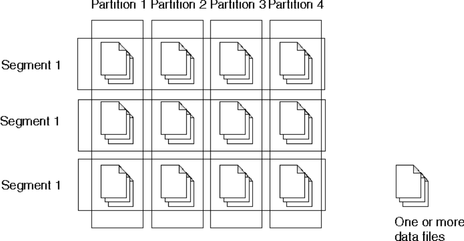
You can create and read data sets using the Data Set stage. The Designer client also
provides a utility for managing data sets from outside a job. (This utility is also
available from the Director client.)
Structure of data sets
A data set comprises a descriptor file and a number of other files that are added as
the data set grows.
These files are stored on multiple disks in your system. A data set is organized in
terms of partitions and segments. Each partition of a data set is stored on a single
processing node. Each data segment contains all the records written by a single
IBM InfoSphere DataStage job. So a segment can contain files from many
partitions, and a partition has files from many segments.
The descriptor file for a data set contains the following information:
vData set header information.
vCreation time and date of the data set.
vThe schema of the data set.
vA copy of the configuration file use when the data set was created.
For each segment, the descriptor file contains:
vThe time and date the segment was added to the data set.
vA flag marking the segment as valid or invalid.
vStatistical information such as number of records in the segment and number of
bytes.
vPath names of all data files, on all processing nodes.
This information can be accessed through the Data Set Manager.
Figure 30. Structure of data sets
240 Designer Client Guide
Starting the Data Set Manager
You start the Data Set Manager from the Designer client.
Procedure
1. Choose Tools Data Set Management, a Browse Files dialog box appears:
2. Navigate to the directory containing the data set you want to manage. By
convention, data set files have the suffix .ds.
3. Select the data set you want to manage and click OK. The Data Set Viewer
appears. From here you can copy or delete the chosen data set. You can also
view its schema (column definitions) or the data it contains.
Data set viewer
The Data set viewer displays information about the data set you are viewing.
Partitions
The partition grid shows the partitions the data set contains and describes their
properties.
v#. The partition number.
vNode. The processing node that the partition is currently assigned to.
vRecords. The number of records the partition contains.
vBlocks. The number of blocks the partition contains.
vBytes. The number of bytes the partition contains.
Segments
Click on an individual partition to display the associated segment details.
Segment details contain the following information:
v#. The segment number.
vCreated. Date and time of creation.
vBytes. The number of bytes in the segment.
vPathname. The name and path of the file containing the segment in the selected
partition.
Click the Refresh button to reread and refresh all the displayed information.
Click the Output button to view a text version of the information displayed in the
Data Set Viewer.
You can open a different data set from the viewer by clicking the Open icon on the
tool bar. The browse dialog open box opens again and lets you browse for a data
set.
Viewing the schema
Click the Schema icon from the tool bar to view the record schema of the current
data set.
About this task
The schema is displayed in text form in the Record Schema window.
Viewing the data
Click the Data icon from the tool bar to view the data held by the current data set.
Chapter 16. Tools for managing and administering jobs 241

The Data Set Viewer Options dialog box is displayed, which allows you to select a
subset of the data to view.
vRows to display. Specify the number of rows of data you want the data browser
to display.
vSkip count. Skip the specified number of rows before viewing data.
vPeriod. Display every Pth record where Pis the period. You can start after
records have been skipped by using the Skip property. Pmust equal or be
greater than 1.
vPartitions. Choose between viewing the data in All partitions or the data in the
partition selected from the drop-down list.
Click OK to view the selected data, the Data Viewer window appears.
Copying data sets
Click the Copy icon on the tool bar to copy the selected data set.
The Copy data set dialog box appears, allowing you to specify a path where the
new data set will be stored.
The new data set will have the same record schema, number of partitions and
contents as the original data set.
Note: You cannot use the UNIX cp command to copy a data set because IBM
InfoSphere DataStage represents a single data set with multiple files.
Deleting data sets
Click the Delete icon on the tool bar to delete the current data set. You will be
asked to confirm the deletion.
Note: You cannot use the UNIX rm command to remove a data set because IBM
InfoSphere DataStage represents a single data set with multiple files. Using rm
simply removes the descriptor file, leaving the much larger data files behind.
Creating and editing configuration files
The Designer client has a tool for creating and managing configuration files.
About this task
One of the great strengths of the IBM InfoSphere DataStage is that, when designing
parallel jobs, you don't have to worry too much about the underlying structure of
your system, beyond appreciating its parallel processing capabilities. If your
system changes, is upgraded or improved, or if you develop a job on one platform
and implement it on another, you do not necessarily have to change your job
design.
InfoSphere DataStage learns about the shape and size of the system from the
configuration file. It organizes the resources needed for a job according to what is
defined in the configuration file. When your system changes, you change the file
not the jobs. You can maintain multiple configuration files and read them into the
system according to your varying processing needs.
A full description of how to define configuration files is given in the guide to
developing parallel jobs. The Designer client provides a configuration file editor to
242 Designer Client Guide

help you define configuration files for the parallel engine, and this is described
here.
Procedure
1. To use the editor, choose Tools >Configurations. The Configurations dialog
box appears.
2. To define a new file, choose (New) from the Configurations list and type into
the upper text box.
3. Click Save to save the file at any point. You are asked to specify a configuration
name, the config file is then saved under that name with an .apt extension.
4. You can verify your file at any time by clicking Check. Verification information
is output in the Check Configuration Output pane at the bottom of the dialog
box.
Results
To edit an existing configuration file:
vchoose it from the Configurations list. You can delete an existing configuration
by selecting it and clicking Delete. You are warned if you are attempting to
delete the last remaining configuration file.
You specify which configuration will be used by setting the APT_CONFIG_FILE
environment variable. This is set on installation to point to the default
configuration file, but you can set it on a project wide level from the Administrator
client or for individual jobs from the Job Properties dialog .
Message Handler Manager
You can use the Message Handler Manager to control what error messages your
parallel jobs can generate.
What are message handlers? When you run a parallel job, any error messages and
warnings are written to an error log and can be viewed from the Director client.
You can choose to handle specified errors in a different way by creating one or
more message handlers.
A message handler defines rules about how to handle messages generated when a
parallel job is running. You can, for example, use one to specify that certain types
of message should not be written to the log.
You can edit message handlers in the Designer or in the IBM InfoSphere DataStage
Director. The recommended way to create them is by using the Add rule to
message handler feature in the Director client.
You can specify message handler use at different levels:
vProject Level. You define a project level message handler in the InfoSphere
DataStage Administrator, and this applies to all parallel jobs within the specified
project.
vJob Level. From the Designer you can specify that any existing handler should
apply to a specific job. When you compile the job, the handler is included in the
job executable as a local handler (and so can be exported to other systems if
required).
Chapter 16. Tools for managing and administering jobs 243
You can also add rules to handlers when you run a job from the Director
(regardless of whether it currently has a local handler included). This is useful, for
example, where a job is generating a message for every row it is processing. You
can suppress that particular message.
When the job runs it will look in the local handler (if one exists) for each message
to see if any rules exist for that message type. If a particular message is not
handled locally, it will look to the project-wide handler for rules. If there are none
there, it writes the message to the job log.
Note message handlers do not deal with fatal error messages, these will always be
written to the job log.
You can view, edit, or delete message handlers from the Message Handler
Manager. You can also define new handlers if you are familiar with the message
IDs (although InfoSphere DataStage will not know whether such messages are
warnings or informational). The preferred way of defining new handlers is by
using the add rule to message handler feature.
Using the Message Handler Manager
Open the Message Handler Manager to view, edit, or delete message handlers.
About this task
To open the Message Handler Manager, choose Tools Message Handler
Manager. The Edit Message Handlers dialog box appears.
To edit an existing handler:
Procedure
1. Choose an option to specify whether you want to edit the project-level message
handler, edit the handler for the currently selected job, or edit a specific
message handler. If you want to edit a specific message handler, select the
handler from the drop-down list. The settings for whichever handler you have
chosen to edit appear in the grid. (Note that the option to edit the project level
handler is only available if such a handler has been set up in the Administrator
client.)
2. Edit the grid as required, you can:
vChoose a new Action for a particular message. Select a new Action from the
drop-down list. Possible Actions are:
Suppress from log. The message is not written to the job's log as it runs.
Promote to Warning. Promote an informational message to a warning
message.
Demote to Informational. Demote a warning message to become an
informational one.
vDelete a message. Select the message in the grid, right-click and choose
Delete Row from the shortcut menu.
vAdd a new message. Right-click in the grid and choose Insert Row from the
shortcut menu. You can then type in details of the message you want to add
to the handler.
When you are done with your edits, click Save and choose Save Message
Handler to save the handler with its current name or Save Message Handler
As to save it as a new handler.
244 Designer Client Guide

To delete a handler:
Procedure
1. Choose an option to specify whether you want to delete the local runtime
handler for the currently selected job, delete the project-level message handler,
or delete a specific message handler. If you want to delete a specific message
handler, select the handler from the drop-down list. The settings for whichever
handler you have chosen to edit appear in the grid.
2. Click the Delete button.
To define a new handler:
Procedure
1. Choose Edit chosen message handler and select (New) from the drop-down list.
The grid clears, allowing new message rules to be added.
2. Type in the message ID for the first message you want to add to the handler.
3. Choose an Action from the drop-down list. Possible Actions are:
vSuppress from log. The message is not written to the job's log as it runs.
vPromote to Warning. Promote an informational message to a warning
message.
vDemote to Informational. Demote a warning message to become an
informational one.
4. Repeat this process until you have added all the required messages.
5. When you have defined all the required messages for the handler, click Save
and choose Save Message Handler As from the menu. A dialog box opens and
prompts you for the name of the new handler.
6. Type in the name for your new message handler.
Message handler file format
A message handler is a plain text file and has the suffix .msh.
The file is stored in the folder called MsgHandlers in the engine tier install
directory. The following is an example message file.
TUTL 000031 1 1 The open file limit is 100; raising to 1024...
TFSC 000001 1 2 APT configuration file...
TFSC 000043 2 3 Attempt to Cleanup after ABORT raised in stage...
Each line in the file represents message rule, and comprises four tab-separated
fields:
vMessage ID . Case-specific string uniquely identifying the message
vType. 1 for Info, 2 for Warn
vAction.1=Suppress,2=Promote, 3 = Demote
vMessage . Example text of the message
JCL templates
IBM InfoSphere DataStage uses JCL templates to build the required JCL files when
you generate a mainframe job. InfoSphere DataStage comes with a set of
building-block JCL templates suitable for a variety of tasks.
The supplied templates are in a directory called JCL Templates under the engine
tier install directory. There are also copies of the templates held in the InfoSphere
DataStage Repository for each InfoSphere DataStage project.
Chapter 16. Tools for managing and administering jobs 245
You can edit the templates to meet the requirements of your particular project. This
is done using the JCL Templates manager from the Designer. Open the JCL
Templates dialog box by choosing Tools >JCL Templates.
The JCL Templates dialog box contains the following fields and buttons:
vPlatform type. Displays the installed platform types in a drop-down list.
vTemplate name. Displays the available JCL templates for the chosen platform in
a drop-down list.
vShort description. Briefly describes the selected template.
vTemplate. The code that the selected template contains.
vSave. This button is enabled if you edit the code, or subsequently reset a
modified template to the default code. Click Save to save your changes.
vReset. Resets the template code back to that of the default template.
If there are system wide changes that will apply to every project, then it is possible
to edit the template defaults. Changes made here will be picked up by every
InfoSphere DataStage project on that InfoSphere DataStage server. The JCL
Templates directory contains two sets of template files: a default set that you can
edit, and a master set which is read-only. You can always revert to the master
templates if required, by copying the read-only masters over the default templates.
Use a standard editing tool, such as Microsoft Notepad, to edit the default
templates.
246 Designer Client Guide

Chapter 17. Creating repository tree objects
IBM InfoSphere DataStage uses the common repository which is shared by
InfoSphere DataStage and other tools in the IBM Information Server suite.
Create a repository tree and tree objects to help manage the objects in the
repository.
Repository tree
You can use the Repository tree to browse and manage objects in the repository.
The Designer enables you to store the following types of object in the repository
(listed in alphabetical order):
vData connections
vData elements (see Data Elements)
vIMS Database (DBD) (see IMS Databases and IMS Viewsets)
vIMS Viewset (PSB/PCB) (see IMS Databases and IMS Viewsets)
vJobs (see Developing a Job)
vMachine profiles (see Machine Profiles)
vMatch specifications
vParameter sets (see Parameter Sets)
vRoutines (see Parallel Routines,Server Routines , and Mainframe Routines)
vShared containers (see Shared Containers)
vStage types (see reference guides for each job types and Custom Stages for
Parallel Jobs)
vTable definitions (see Table Definitions)
vTransforms
When you first open IBM InfoSphere DataStage you will see the repository tree
organized with preconfigured folders for these object types, but you can arrange
your folders as you like and rename the preconfigured ones if required. You can
store any type of object within any folder in the repository tree. You can also add
your own folders to the tree. This allows you, for example, to keep all objects
relating to a particular job in one folder. You can also nest folders one within
another.
Note: Certain built-in objects cannot be moved in the repository tree.
Click the blue bar at the side of the repository tree to open the detailed view of the
repository. The detailed view gives more details about the objects in the repository
tree and you can configure it in the same way that you can configure a Windows
Explorer view. Click the blue bar again to close the detailed view.
You can view a sketch of job designs in the repository tree by hovering the mouse
over the job icon in the tree. A tooltip opens displaying a thumbnail of the job
design. (You can disable this option in the Designer Options.)
© Copyright IBM Corp. 1997, 2014 247

When you open an object in the repository tree, you have a lock on that object and
no other users can change it while you have that lock (although they can look at
read-only copies).
Creating new objects
There are several methods for creating new objects. These methods are described
individually for each object type, but are summarized here.
Create a new object on startup
You can create a new object of any type whenever you start the Designer client
(unless this feature has been disabled in the Designer client options).
Procedure
1. Start the Designer client. The New dialog box is displayed.
2. Open the folder for the type of object you want to create.
3. Select the exact type of object you require in the right pane.
4. Click OK.
5. If the object requires more information from you, another dialog box will
appear to collect this information. The type of dialog box depends on the type
of object (see individual object descriptions for details).
6. When you have supplied the required details, click OK. The Designer asks you
where you want to store the object in the repository tree.
Create a new object from the repository tree
The shortcut menu from the repository tree offers you the choice of creating a new
folder or any type of object:
About this task
To create a new folder at the top level:
vSelect the project icon at the top of the tree, right-click and choose New >Folder
from the shortcut menu. A new folder appears, and you can rename it
immediately by typing in the required name.
To create a new folder under an existing folder:
vSelect the parent folder, right-click and choose New >Folder from the shortcut
menu. A new folder appears, and you can rename it immediately by typing in
the required name.
Procedure
1. Select the folder that you want the new object to live in, right-click and choose
the type of object required from the shortcut menu.
2. If the object requires more information from you, another dialog box will
appear to collect this information. The type of dialog box depends on the type
of object (see individual object descriptions for details).
Create a new object from the main menu
You can create a new object from the main menu.
248 Designer Client Guide
Procedure
1. Choose File >New, the New dialog box appears.
2. Open the folder for the type of object you want to create.
3. Select the exact type of object you require in the right pane.
4. Click OK.
5. If the object requires more information from you, another dialog box will
appear to collect this information. The type of dialog box depends on the type
of object (see individual object descriptions for details).
6. When you have supplied the required details, click OK. The Designer asks you
where you want to store the object in the repository tree.
Create a new object from the toolbar
You can create multiple types of new objects from the toolbar.
About this task
The new icon in the toolbar allows you to create the following types of object:
vJob sequence
vMainframe job
vParallel job
vParallel shared container
vServer job
vServer shared container
You can also start the Intelligent Assistant from this menu to help you design
certain types of job (see "Creating Jobs Using Intelligent Assistants" on page 3-31).
Procedure
1. Click on the New icon in the toolbar.
2. Choose the desired object type from the drop-down menu:
3. A new instance of the selected job or container type opens in the Designer, and
from here you can save it anywhere you like in the repository.
Chapter 17. Creating repository tree objects 249
250 Designer Client Guide

Appendix A. Product accessibility
You can get information about the accessibility status of IBM products.
The IBM InfoSphere Information Server product modules and user interfaces are
not fully accessible.
For information about the accessibility status of IBM products, see the IBM product
accessibility information at http://www.ibm.com/able/product_accessibility/
index.html.
Accessible documentation
Accessible documentation for InfoSphere Information Server products is provided
in an information center. The information center presents the documentation in
XHTML 1.0 format, which is viewable in most web browsers. Because the
information center uses XHTML, you can set display preferences in your browser.
This also allows you to use screen readers and other assistive technologies to
access the documentation.
The documentation that is in the information center is also provided in PDF files,
which are not fully accessible.
IBM and accessibility
See the IBM Human Ability and Accessibility Center for more information about
the commitment that IBM has to accessibility.
© Copyright IBM Corp. 1997, 2014 251
252 Designer Client Guide
Appendix B. Contacting IBM
You can contact IBM for customer support, software services, product information,
and general information. You also can provide feedback to IBM about products
and documentation.
The following table lists resources for customer support, software services, training,
and product and solutions information.
Table 6. IBM resources
Resource Description and location
IBM Support Portal You can customize support information by
choosing the products and the topics that
interest you at www.ibm.com/support/
entry/portal/Software/
Information_Management/
InfoSphere_Information_Server
Software services You can find information about software, IT,
and business consulting services, on the
solutions site at www.ibm.com/
businesssolutions/
My IBM You can manage links to IBM Web sites and
information that meet your specific technical
support needs by creating an account on the
My IBM site at www.ibm.com/account/
Training and certification You can learn about technical training and
education services designed for individuals,
companies, and public organizations to
acquire, maintain, and optimize their IT
skills at http://www.ibm.com/training
IBM representatives You can contact an IBM representative to
learn about solutions at
www.ibm.com/connect/ibm/us/en/
© Copyright IBM Corp. 1997, 2014 253
254 Designer Client Guide

Appendix C. Accessing the product documentation
Documentation is provided in a variety of formats: in the online IBM Knowledge
Center, in an optional locally installed information center, and as PDF books. You
can access the online or locally installed help directly from the product client
interfaces.
IBM Knowledge Center is the best place to find the most up-to-date information
for InfoSphere Information Server. IBM Knowledge Center contains help for most
of the product interfaces, as well as complete documentation for all the product
modules in the suite. You can open IBM Knowledge Center from the installed
product or from a web browser.
Accessing IBM Knowledge Center
There are various ways to access the online documentation:
vClick the Help link in the upper right of the client interface.
vPress the F1 key. The F1 key typically opens the topic that describes the current
context of the client interface.
Note: The F1 key does not work in web clients.
vType the address in a web browser, for example, when you are not logged in to
the product.
Enter the following address to access all versions of InfoSphere Information
Server documentation:
http://www.ibm.com/support/knowledgecenter/SSZJPZ/
If you want to access a particular topic, specify the version number with the
product identifier, the documentation plug-in name, and the topic path in the
URL. For example, the URL for the 11.3 version of this topic is as follows. (The
⇒symbol indicates a line continuation):
http://www.ibm.com/support/knowledgecenter/SSZJPZ_11.3.0/⇒
com.ibm.swg.im.iis.common.doc/common/accessingiidoc.html
Tip:
The knowledge center has a short URL as well:
http://ibm.biz/knowctr
To specify a short URL to a specific product page, version, or topic, use a hash
character (#) between the short URL and the product identifier. For example, the
short URL to all the InfoSphere Information Server documentation is the
following URL:
http://ibm.biz/knowctr#SSZJPZ/
And, the short URL to the topic above to create a slightly shorter URL is the
following URL (The ⇒symbol indicates a line continuation):
http://ibm.biz/knowctr#SSZJPZ_11.3.0/com.ibm.swg.im.iis.common.doc/⇒
common/accessingiidoc.html
© Copyright IBM Corp. 1997, 2014 255
Changing help links to refer to locally installed documentation
IBM Knowledge Center contains the most up-to-date version of the documentation.
However, you can install a local version of the documentation as an information
center and configure your help links to point to it. A local information center is
useful if your enterprise does not provide access to the internet.
Use the installation instructions that come with the information center installation
package to install it on the computer of your choice. After you install and start the
information center, you can use the iisAdmin command on the services tier
computer to change the documentation location that the product F1 and help links
refer to. (The ⇒symbol indicates a line continuation):
Windows
IS_install_path\ASBServer\bin\iisAdmin.bat -set -key ⇒
com.ibm.iis.infocenter.url -value http://<host>:<port>/help/topic/
AIX®Linux
IS_install_path/ASBServer/bin/iisAdmin.sh -set -key ⇒
com.ibm.iis.infocenter.url -value http://<host>:<port>/help/topic/
Where <host> is the name of the computer where the information center is
installed and <port> is the port number for the information center. The default port
number is 8888. For example, on a computer named server1.example.com that uses
the default port, the URL value would be http://server1.example.com:8888/help/
topic/.
Obtaining PDF and hardcopy documentation
vThe PDF file books are available online and can be accessed from this support
document: https://www.ibm.com/support/docview.wss?uid=swg27008803
&wv=1.
vYou can also order IBM publications in hardcopy format online or through your
local IBM representative. To order publications online, go to the IBM
Publications Center at http://www.ibm.com/e-business/linkweb/publications/
servlet/pbi.wss.
256 Designer Client Guide

Appendix D. Providing feedback on the product
documentation
You can provide helpful feedback regarding IBM documentation.
Your feedback helps IBM to provide quality information. You can use any of the
following methods to provide comments:
vTo provide a comment about a topic in IBM Knowledge Center that is hosted on
the IBM website, sign in and add a comment by clicking Add Comment button
at the bottom of the topic. Comments submitted this way are viewable by the
public.
vTo send a comment about the topic in IBM Knowledge Center to IBM that is not
viewable by anyone else, sign in and click the Feedback link at the bottom of
IBM Knowledge Center.
vSend your comments by using the online readers' comment form at
www.ibm.com/software/awdtools/rcf/.
vSend your comments by e-mail to comments@us.ibm.com. Include the name of
the product, the version number of the product, and the name and part number
of the information (if applicable). If you are commenting on specific text, include
the location of the text (for example, a title, a table number, or a page number).
© Copyright IBM Corp. 1997, 2014 257
258 Designer Client Guide

Notices and trademarks
This information was developed for products and services offered in the U.S.A.
This material may be available from IBM in other languages. However, you may be
required to own a copy of the product or product version in that language in order
to access it.
Notices
IBM may not offer the products, services, or features discussed in this document in
other countries. Consult your local IBM representative for information on the
products and services currently available in your area. Any reference to an IBM
product, program, or service is not intended to state or imply that only that IBM
product, program, or service may be used. Any functionally equivalent product,
program, or service that does not infringe any IBM intellectual property right may
be used instead. However, it is the user's responsibility to evaluate and verify the
operation of any non-IBM product, program, or service.
IBM may have patents or pending patent applications covering subject matter
described in this document. The furnishing of this document does not grant you
any license to these patents. You can send license inquiries, in writing, to:
IBM Director of Licensing
IBM Corporation
North Castle Drive
Armonk, NY 10504-1785 U.S.A.
For license inquiries regarding double-byte character set (DBCS) information,
contact the IBM Intellectual Property Department in your country or send
inquiries, in writing, to:
Intellectual Property Licensing
Legal and Intellectual Property Law
IBM Japan Ltd.
19-21, Nihonbashi-Hakozakicho, Chuo-ku
Tokyo 103-8510, Japan
The following paragraph does not apply to the United Kingdom or any other
country where such provisions are inconsistent with local law:
INTERNATIONAL BUSINESS MACHINES CORPORATION PROVIDES THIS
PUBLICATION "AS IS" WITHOUT WARRANTY OF ANY KIND, EITHER
EXPRESS OR IMPLIED, INCLUDING, BUT NOT LIMITED TO, THE IMPLIED
WARRANTIES OF NON-INFRINGEMENT, MERCHANTABILITY OR FITNESS
FOR A PARTICULAR PURPOSE. Some states do not allow disclaimer of express or
implied warranties in certain transactions, therefore, this statement may not apply
to you.
This information could include technical inaccuracies or typographical errors.
Changes are periodically made to the information herein; these changes will be
incorporated in new editions of the publication. IBM may make improvements
and/or changes in the product(s) and/or the program(s) described in this
publication at any time without notice.
© Copyright IBM Corp. 1997, 2014 259
Any references in this information to non-IBM Web sites are provided for
convenience only and do not in any manner serve as an endorsement of those Web
sites. The materials at those Web sites are not part of the materials for this IBM
product and use of those Web sites is at your own risk.
IBM may use or distribute any of the information you supply in any way it
believes appropriate without incurring any obligation to you.
Licensees of this program who wish to have information about it for the purpose
of enabling: (i) the exchange of information between independently created
programs and other programs (including this one) and (ii) the mutual use of the
information which has been exchanged, should contact:
IBM Corporation
J46A/G4
555 Bailey Avenue
San Jose, CA 95141-1003 U.S.A.
Such information may be available, subject to appropriate terms and conditions,
including in some cases, payment of a fee.
The licensed program described in this document and all licensed material
available for it are provided by IBM under terms of the IBM Customer Agreement,
IBM International Program License Agreement or any equivalent agreement
between us.
Any performance data contained herein was determined in a controlled
environment. Therefore, the results obtained in other operating environments may
vary significantly. Some measurements may have been made on development-level
systems and there is no guarantee that these measurements will be the same on
generally available systems. Furthermore, some measurements may have been
estimated through extrapolation. Actual results may vary. Users of this document
should verify the applicable data for their specific environment.
Information concerning non-IBM products was obtained from the suppliers of
those products, their published announcements or other publicly available sources.
IBM has not tested those products and cannot confirm the accuracy of
performance, compatibility or any other claims related to non-IBM products.
Questions on the capabilities of non-IBM products should be addressed to the
suppliers of those products.
All statements regarding IBM's future direction or intent are subject to change or
withdrawal without notice, and represent goals and objectives only.
This information is for planning purposes only. The information herein is subject to
change before the products described become available.
This information contains examples of data and reports used in daily business
operations. To illustrate them as completely as possible, the examples include the
names of individuals, companies, brands, and products. All of these names are
fictitious and any similarity to the names and addresses used by an actual business
enterprise is entirely coincidental.
COPYRIGHT LICENSE:
260 Designer Client Guide

This information contains sample application programs in source language, which
illustrate programming techniques on various operating platforms. You may copy,
modify, and distribute these sample programs in any form without payment to
IBM, for the purposes of developing, using, marketing or distributing application
programs conforming to the application programming interface for the operating
platform for which the sample programs are written. These examples have not
been thoroughly tested under all conditions. IBM, therefore, cannot guarantee or
imply reliability, serviceability, or function of these programs. The sample
programs are provided "AS IS", without warranty of any kind. IBM shall not be
liable for any damages arising out of your use of the sample programs.
Each copy or any portion of these sample programs or any derivative work, must
include a copyright notice as follows:
© (your company name) (year). Portions of this code are derived from IBM Corp.
Sample Programs. © Copyright IBM Corp. _enter the year or years_. All rights
reserved.
If you are viewing this information softcopy, the photographs and color
illustrations may not appear.
Privacy policy considerations
IBM Software products, including software as a service solutions, (“Software
Offerings”) may use cookies or other technologies to collect product usage
information, to help improve the end user experience, to tailor interactions with
the end user or for other purposes. In many cases no personally identifiable
information is collected by the Software Offerings. Some of our Software Offerings
can help enable you to collect personally identifiable information. If this Software
Offering uses cookies to collect personally identifiable information, specific
information about this offering’s use of cookies is set forth below.
Depending upon the configurations deployed, this Software Offering may use
session or persistent cookies. If a product or component is not listed, that product
or component does not use cookies.
Table 7. Use of cookies by InfoSphere Information Server products and components
Product module
Component or
feature
Type of cookie
that is used Collect this data Purpose of data
Disabling the
cookies
Any (part of
InfoSphere
Information
Server
installation)
InfoSphere
Information
Server web
console
vSession
vPersistent
User name vSession
management
vAuthentication
Cannot be
disabled
Any (part of
InfoSphere
Information
Server
installation)
InfoSphere
Metadata Asset
Manager
vSession
vPersistent
No personally
identifiable
information
vSession
management
vAuthentication
vEnhanced user
usability
vSingle sign-on
configuration
Cannot be
disabled
Notices and trademarks 261

Table 7. Use of cookies by InfoSphere Information Server products and components (continued)
Product module
Component or
feature
Type of cookie
that is used Collect this data Purpose of data
Disabling the
cookies
InfoSphere
DataStage
Big Data File
stage
vSession
vPersistent
vUser name
vDigital
signature
vSession ID
vSession
management
vAuthentication
vSingle sign-on
configuration
Cannot be
disabled
InfoSphere
DataStage
XML stage Session Internal
identifiers
vSession
management
vAuthentication
Cannot be
disabled
InfoSphere
DataStage
IBM InfoSphere
DataStage and
QualityStage
Operations
Console
Session No personally
identifiable
information
vSession
management
vAuthentication
Cannot be
disabled
InfoSphere Data
Click
InfoSphere
Information
Server web
console
vSession
vPersistent
User name vSession
management
vAuthentication
Cannot be
disabled
InfoSphere Data
Quality Console
Session No personally
identifiable
information
vSession
management
vAuthentication
vSingle sign-on
configuration
Cannot be
disabled
InfoSphere
QualityStage
Standardization
Rules Designer
InfoSphere
Information
Server web
console
vSession
vPersistent
User name vSession
management
vAuthentication
Cannot be
disabled
InfoSphere
Information
Governance
Catalog
vSession
vPersistent
vUser name
vInternal
identifiers
vState of the tree
vSession
management
vAuthentication
vSingle sign-on
configuration
Cannot be
disabled
InfoSphere
Information
Analyzer
Data Rules stage
in the InfoSphere
DataStage and
QualityStage
Designer client
Session Session ID Session
management
Cannot be
disabled
If the configurations deployed for this Software Offering provide you as customer
the ability to collect personally identifiable information from end users via cookies
and other technologies, you should seek your own legal advice about any laws
applicable to such data collection, including any requirements for notice and
consent.
For more information about the use of various technologies, including cookies, for
these purposes, see IBM’s Privacy Policy at http://www.ibm.com/privacy and
IBM’s Online Privacy Statement at http://www.ibm.com/privacy/details the
section entitled “Cookies, Web Beacons and Other Technologies” and the “IBM
Software Products and Software-as-a-Service Privacy Statement” at
http://www.ibm.com/software/info/product-privacy.
262 Designer Client Guide
Trademarks
IBM, the IBM logo, and ibm.com®are trademarks or registered trademarks of
International Business Machines Corp., registered in many jurisdictions worldwide.
Other product and service names might be trademarks of IBM or other companies.
A current list of IBM trademarks is available on the Web at www.ibm.com/legal/
copytrade.shtml.
The following terms are trademarks or registered trademarks of other companies:
Adobe is a registered trademark of Adobe Systems Incorporated in the United
States, and/or other countries.
Intel and Itanium are trademarks or registered trademarks of Intel Corporation or
its subsidiaries in the United States and other countries.
Linux is a registered trademark of Linus Torvalds in the United States, other
countries, or both.
Microsoft, Windows and Windows NT are trademarks of Microsoft Corporation in
the United States, other countries, or both.
UNIX is a registered trademark of The Open Group in the United States and other
countries.
Java™and all Java-based trademarks and logos are trademarks or registered
trademarks of Oracle and/or its affiliates.
The United States Postal Service owns the following trademarks: CASS, CASS
Certified, DPV, LACSLink, ZIP, ZIP + 4, ZIP Code, Post Office, Postal Service, USPS
and United States Postal Service. IBM Corporation is a non-exclusive DPV and
LACSLink licensee of the United States Postal Service.
Other company, product or service names may be trademarks or service marks of
others.
Notices and trademarks 263
264 Designer Client Guide

Index
A
ActiveX (OLE) functions 138
importing 184
programming functions 122, 124
activities
properties 218
activity
nested condition 221
properties 221
activity properties
ExecCommand 219
notifications 222
adding
Sequential File stage 9
stages 29
Transformer stage 9
advanced find 161, 162, 163, 177
after-job subroutines 144, 147
annotations
using in job designs 38
assigning data elements 131
assistants 42
B
BASIC routines
copying 127
editing 126
entering code 124
name 123
renaming 137
saving code 125
testing 126
type 123
viewing 126
before-job subroutines 143, 147
browsing files on the DataStage server
optimizing 36
browsing server directories 36
built-in data elements 133
C
character set maps 148
character set maps, specifying 145, 148
code customization 204
column definitions 171, 172
column name 52
data element 52
defining for a stage 33
deleting 34, 82, 87
editing 33, 82, 87
using the Edit button 33
entering 67
inserting 33
key fields 52
length 52
loading 35, 81
name alias 52
running a where used query 170
column definitions (continued)
scale factor 52
searching for 166
Columns grid 33, 52
commenting job designs
using annotations 38
using description annotation 38
common repository 247
comparing objects 155, 157
in different projects 157
using the command line 158
compilation checks 199
compiling
code in BASIC routines 125
compiling job 17
components
exporting 188
configuration file editor 242
connectors 58, 60
containers 23, 24
editing 96
viewing 96
copying BASIC routine definitions 127
copying data elements 132
copying mainframe routine
definitions 137
copying Transform definitions 129
creating
data elements 130
stored procedure definitions 85
table definitions 67
currency formats 149
customer support
contacting 253
customizing
COBOL code 204
D
data browser 12
Data Browser 57
using 39
data connection object 47, 48
creating 43
data elements
assigning 131
built-in 133
copying 132
creating 130
defining 130
editing 132
viewing 132
data files
adding 66
data lineage 172
highlighting 171
data lineage highlighting
disabling 172
Data Migration Assistant 238
databases
adding 65
DataStage job
validation 202
date formats 149
defining
data elements 130
locales 145, 148
maps 145, 148
deleting
column definitions 34, 82, 87
links 32
stages 30
dependencies of query 166, 167, 172, 175
Designer client 161
importing metadata 186
starting 4
developing jobs 21, 29, 247
diff operation 155, 157, 158
diffapicmdline command
report 158
Director client 17
dscmdimport command
importing a job 182
importing a parameter set object 182
importing parameter set environment
variables 182
using the NOENV option 182
DSParams file
DS_OPTIMIZE_FILE_BROWSE
variable 36
E
editing
BASIC routine definitions 126
column definitions 33, 82, 87
using the Edit button 33
containers 96
data elements 132
stages 32
stored procedure definitions 87
table definitions 82
entering
code in BASIC routines 124
entering column definitions 67
environment variables
creating in jobs 92
creating in sequence jobs 214
error handling settings 87
example
advanced find 163
quick find 161
exercise
setting up 4
external ActiveX (OLE) functions 138
F
file browsing on the DataStage server
optimizing 36
find 161
© Copyright IBM Corp. 1997, 2014 265
Find dialog box 58
force compile 199
G
generating code
customizing code 204
generating job reports 195
H
highlighting data lineage 171
host systems
adding 65
I
impact analysis 166, 167, 169, 170, 172
examples 173, 175
impact analysis results 173
importing
external ActiveX (OLE) functions 184
stored procedure definitions 84
table definitions 56
input parameters, specifying 86
inserting column definitions 33
intelligent assistants 237
J
JCL templates 203
job
compiling 17
configuring 12
creating 8
designing 31
parallel 1
running 17
saving 8, 22
searching 161
job activity
properties 220
job compilation 200
job control routines 235
job designs
annotations 38
description annotations 38
job log 17
job parameters 90
inserting 93
using 90
job properties
saving 151
job reports 195
generating 195
stylesheets 197
job routines
before- or after 144, 148
jobs
compilation checks 199
creating environment variables 92
defining locales 145, 148
defining maps 145, 148
dependencies, specifying 191
developing 21, 29, 247
jobs (continued)
opening 22
version number 143, 146, 150
K
key field 52, 84
L
Layout page
of the Table Definition dialog box 55
legal notices 259
link
adding 9
linking stages 31
links
deleting 32
moving 31
multiple 32
loading column definitions 35, 81
locales
and jobs 148
specifying 145, 148
M
mainframe jobs
configuring 150
mainframe routines 134
copying 137
manually entering
stored procedure definitions 85
table definitions 66
Message Handler Manager
using 244
message handlers 42, 146
metadata 58
importing 7, 60
importing by using Metadata Asset
Manager 186
managing 65, 66
sharing 58
synchronizing 64
tables 64
wizard 60
monetary formats 149
moving
links 31
stages 30
multiple links 32
multivalued data 52
N
naming 81
column definitions 81
data elements 131
links 29
mainframe routines 134
parallel job routines 105
parallel stage types 108
server job routines 123
shared containers 24, 99
stages 24
New Job from Template 238
New Template from Job 237
NLS 148
NLS page
of the Table Definition dialog box 54
normalization 40
notifications 222
null values 52, 84
number formats 149
O
objects
creating new 248
importing and exporting 179
Oozie Workflow Activity
properties 223
opening a job 22
operational metadata 42
P
palette 4
parallel engine configuration file 242
parallel job
routines 105
parameter definitions
data element 85
key fields 84
length 84
scale factor 84
parameter sets 89
using in sequence jobs 94
parameters
creating in sequence jobs 213
inserting in jobs 93
Parameters grid 84
performance monitor 40
pre-configured stages 38, 97, 102
product accessibility
accessibility 251
product documentation
accessing 255
properties
job activity 220
nested condition 221
Q
quick find 161
R
reference links 25, 27
renaming
BASIC routines 137
link 9
stage 9
stages 30
report 177
Reporting Console 177
repository 4
Repository Advanced Find window 173
Routine dialog box 107
Dependencies page 124
266 Designer Client Guide
routine name 123
routines
parallel jobs 105
S
sample data 1, 4
saving code in BASIC routines 125
saving job properties 151
schemas
adding 66
search
advanced find 161, 162, 163
for column definitions 166
for table definitions 165
quick find 161
search criteria 163
search results 173
sequence jobs
creating environment variables 214
creating parameters 213
Oozie Workflow Activity 223
restarting 212
specifying parameter set values 94
triggers 209
Sequential File stage 12
server directories, browsing 36
setting up
exercise 4
shared container definition
modifying 99
viewing 99
shared metadata 58, 165
Shared Metadata Management tool 65
shared repository 58, 60, 61, 165
software services
contacting 253
sort order 145, 149
specifying
input parameters for stored
procedures 86
job dependencies 191
SQL
data precision 52, 84
data scale factor 52, 84
data type 52, 84
display characters 52, 85
stage
adding 9
stage editor 12
stage page
properties 101
stages 23
adding 29
column definitions for 33
deleting 30
editing 32
moving 30
renaming 30
specifying 29
stored procedure definitions 40, 58
creating 85
dialog box 67
editing 87
error handling 87
importing 84
manually defining 85
stored procedure definitions (continued)
result set 86
viewing 87
stored procedures 83
stream link 25, 27
stylesheets for job reports 197
support
customer 253
T
table definition 7, 51, 60, 61
Table Definition dialog box 51
for stored procedures 84
Format page 53
Layout page 55
NLS page 54
Parameters page 84
table definitions 34, 60, 61, 63, 64
creating 67
editing 82
importing 56
manually entering 66
naming 35
viewing 82
tables 60, 61, 63
testing BASIC routines 126
time formats 149
toolbar
creating new objects 249
trademarks
list of 259
Transformer stage 12
Transforms
copying 129
editing
transforms 129
triggers
specifying 209
U
using
Data Browser 39
V
version number for a job 143, 146, 150
viewing
BASIC routine definitions 126
containers 96
data elements 132
stored procedure definitions 87
table definitions 82
W
where used query 166, 167, 169, 170, 173
X
XSLT stylesheets for job reports 197
Index 267
268 Designer Client Guide

Printed in USA
SC19-4272-00
Spine information:
IBM InfoSphere DataStage and QualityStage Version 11 Release 3 Designer Client Guide
