IC R8500 ICOM User Manual
User Manual: Pdf ICOM--IC-R8500-user-manual
Open the PDF directly: View PDF ![]() .
.
Page Count: 48

INSTRUCTION MANUAL
iC- r8500
COMMUNICATIONS RECEIVER
The IC-R8500 complies with essential require-
ments of the 89/336/EEC directive for
Electromagnetic Compatibility. This compliance is
based on conformity with the ETSI specification prETS300
684 (EMC product standard for Commercially Available
Amateur Radio Equipment).
UNPACKING
PRECAUTIONS
IMPORTANT
READ THIS INSTRUCTION MANUAL
CAREFULLY before attempting to operate the
receiver.
SAVE THIS INSTRUCTION MANUAL. This
instruction manual contains important safety and oper-
ating instructions for the IC-R8500.
EXPLICIT DEFINITIONS
RINDOOR USE ONLY! NEVER expose the
IC-R8500 or AC adapter to rain, snow or any liquids.
RNEVER connect the receiver to an AC outlet
directly. This may pose a fire hazard or result in an
electric shock. Always use the supplied AC adapter or
connect to a 13.8 V DC power source.
RNEVER connect to an AC outlet that exceeds the
suggested voltage for each AC adapter version. This
could cause a fire or ruin the AC adapter and/or
receiver.
RNEVER use non-rated fuses. Non-rated fuses
could cause a fire or ruin the receiver.
NEVER let metal, wire or other objects touch any
internal part or connectors on the rear panel of the
receiver. This will cause electric shock.
AVOID using or placing the receiver in areas with tem-
peratures below –10°C (+14°F) or above +50°C
(+122°F).
AVOID placing the receiver in excessively dusty envi-
ronments or in direct sunlight.
AVOID placing the receiver against walls or putting
anything on top of the receiver. This will obstruct heat
dissipation.
RESPECT other people’s privacy. Information over-
heard but not intended for you cannot lawfully be used
in any way.
i
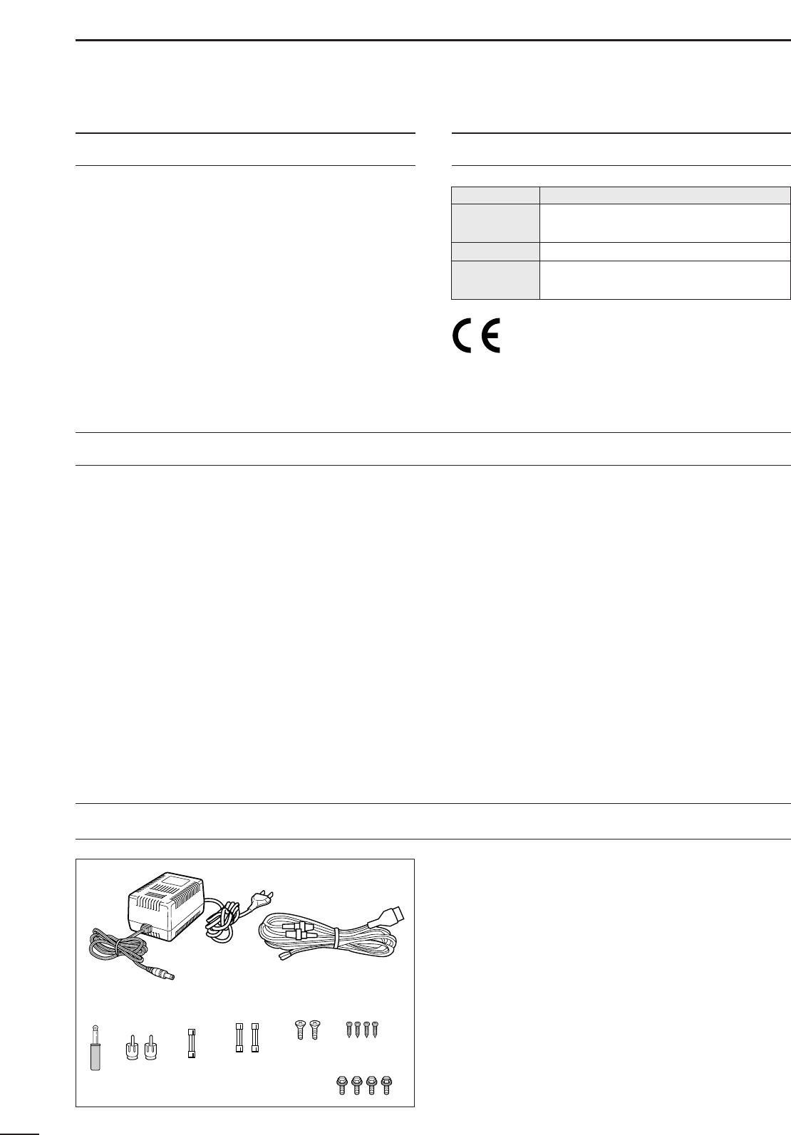
Accessories included with the IC-R8500: Qty.
➀AC adapter (AD-55A)* ...........................................1
➁DC power cable (OPC-023C) ................................1
➂Mini plug (2-conductor, 3.5d) ..................................1
➃Phono (RCA) plugs ................................................2
➄Fuse (FGMB 125 V 3 A; internal use) ...................1
➅Fuses (FGB 3 A; for DC cable) .............................2
➆Screws (M4×12 for optional MB-23) .....................2
➇Screws (C0 3×8 for optional MB-23 feet) .............4
➈Allen bolts (M5×8 for optional IC-MB12) ..............4
*Some versions are not supplied with an AC adapter.
➀
➁
➂➃➄ ➅ ➆ ➇
➈
WORD DEFINITION
RWARNING Personal injury, fire hazard or electric
shock may occur.
CAUTION Equipment damage may occur.
NOTE If disregarded, inconvenience only. No risk
of personal injury, fire or electric shock.

TABLE OF CONTENTS
IMPORTANT ............................................................. i
EXPLICIT DEFINITIONS .......................................... i
PRECAUTIONS ........................................................ i
UNPACKING............................................................. i
TABLE OF CONTENTS ............................................ ii
1 PANEL DESCRIPTION .....................................1–6
■Front panel ................................................................... 1
■Rear panel ................................................................... 5
■Function display ...........................................................6
2 CONNECTIONS ..............................................7–10
■Mounting installation .................................................... 7
■Required connections ..................................................8
■Antenna connection .....................................................9
■Grounding ....................................................................9
■Tape recorder connections ........................................10
■Transceive function .................................................... 10
■Connecting to a PC ...................................................10
■Data demodulation terminal .......................................10
3 FREQUENCY SETTING ................................11–12
■Read me first..............................................................11
■Using the keypad .......................................................11
■Using the main dial ....................................................12
■Lock function .............................................................. 12
4 RECEIVE FUNCTIONS .................................13–16
■Initial settings .............................................................13
■Mode selection ...........................................................13
■Squelch function ........................................................ 14
■Functions for FM ........................................................ 14
■Functions for SSB/CW ...............................................14
■Data communications.................................................16
5 MEMORY CHANNELS ..................................17–22
■General ......................................................................17
■Bank selection ...........................................................17
■Channel selection ...................................................... 18
■Programming .............................................................19
■Copy and paste (memory editing) .............................. 19
■Clearing .....................................................................19
■Channel/bank names .................................................20
■Assigning channels numbers .....................................21
6 SCANS ..........................................................23–28
■Operation ...................................................................23
■Mode select function .................................................. 25
■Specifying skip channel and frequency .....................25
■Automatic bank limit/skip functions ............................26
■Voice scan control function ........................................ 26
■Programming scan edge frequencies ........................27
■Scan speed/delay functions ....................................... 27
7 SLEEP TIMER .....................................................29
8 SET MODE .......................................................... 30
■General ......................................................................30
■Quick set mode items ................................................31
■Initial set mode items .................................................31
9 CONNECTOR INFORMATION ......................33–34
10 CONTROL COMMANDS ............................35–36
■Command table .........................................................35
■Data format ................................................................ 35
11 MAINTENANCE .................................................37
■Disassembly ..............................................................37
■Fuse replacement ......................................................37
■Level adjustments ......................................................37
■Memory backup ......................................................... 37
■CPU resetting ............................................................37
■Cleaning .....................................................................37
12 OPTIONAL INSTALLATIONS .....................38– 40
■UT-102
VOICE SYNTHESIZER UNIT
................................38
■FL-52A
CW NARROW FILTER
........................................38
■CR-293
HIGH STABILITY CRYSTAL UNIT
.........................39
■TV-R7100
TV RECEIVE ADAPTER
...................................40
13 TROUBLESHOOTING .................................41–42
14 SPECIFICATIONS .............................................43
15 OPTIONS ...........................................................44
ii

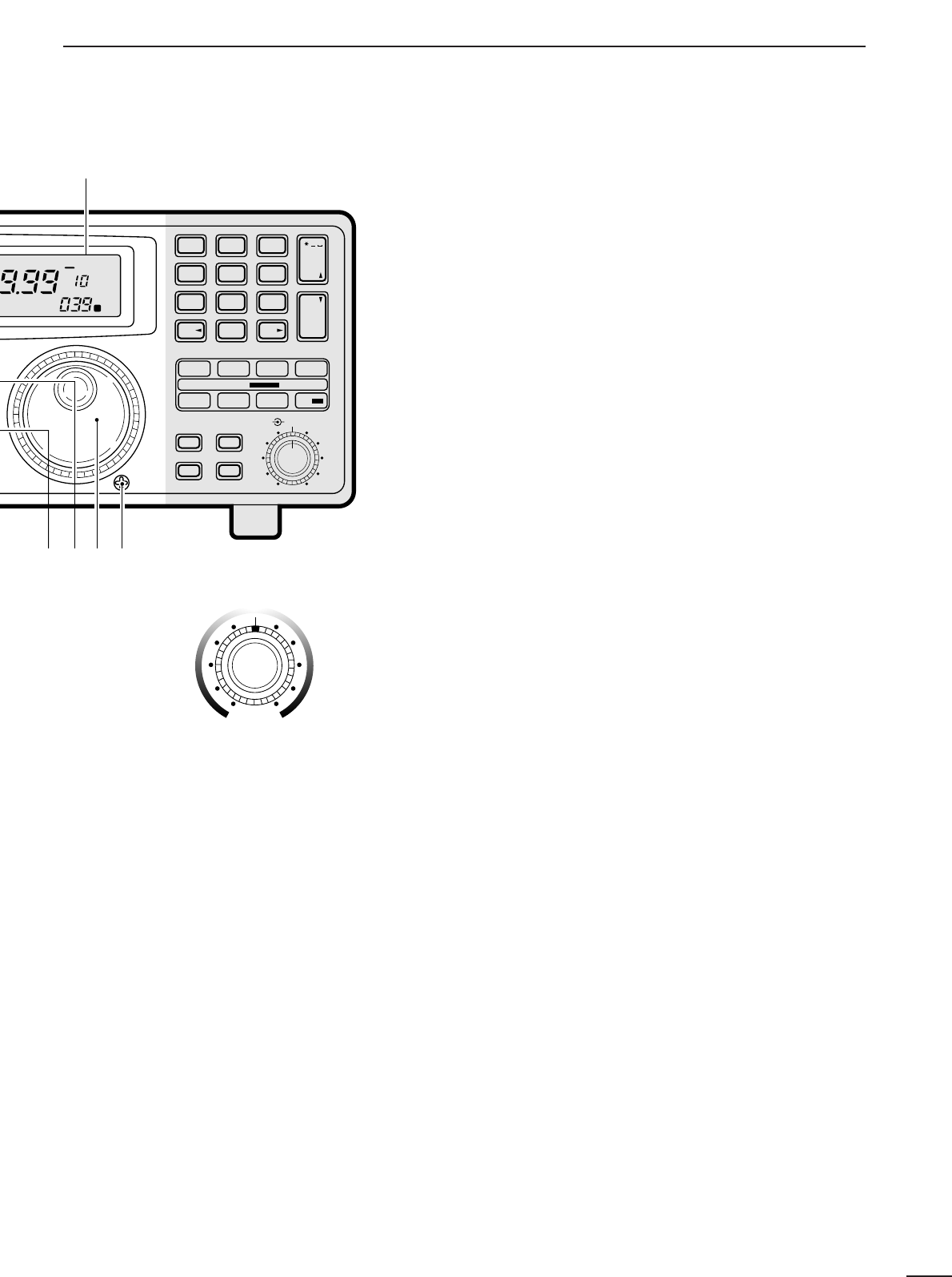
➊POWER SWITCH [POWER]
Turns power ON and OFF.
➋SLEEP/SET SWITCH [SLEEP/SET]
➥Push momentarily to set the sleep timer (p. 29).
•Selectable times are 30, 60, 90, 120 min. or OFF.
•“ ” appears in the function display when the
sleep timer is set.
➥Push for 1 sec. to enter quick set mode (p. 30).
•Use the [M-CH] selector and main dial to select items
and contents, respectively.
➌RECORDER REMOTE JACK [REC REMOTE] (p. 10)
Controls the running of a tape recorder for record-
ing. Connects to the REMOTE jack on a tape
recorder.
➍RECORDER JACK [REC OUT] (p. 10)
Outputs an audio signal. Connect to the AUX or
LINE IN jack on a tape recorder.
➎HEADPHONE JACK [PHONES]
Accepts headphones with 4–16 Ωimpedance.
•When headphones are connected, no receive audio comes
from the speaker.
•Stereo headphones can be connected, however, output
is monaural.
➏MODE SWITCHES [WFM]/[FM]/[AM]/[SSB/CW]
(p. 13)
➥Push to select an operating mode.
•The following keys toggle between several modes:
[FM] .................FM, FM narrow
[AM] .................AM, AM narrow, AM wide
[SSB/CW] ........USB, LSB, CW, optional CW narrow
➥When SSB/CW mode is selected, push [SSB/CW]
for 1 sec. to adjust the BFO frequency. (p. 15).
➐NOISE BLANKER/AFC SWITCH [NB]/[AFC]
Activates the noise blanker function or automatic fre-
quency control function.
•The noise blanker is used for removing pulse-type noise
when SSB, CW or AM mode is selected (p.15).
•The automatic frequency control tunes the displayed fre-
quency automatically when an off-center frequency is re-
ceived. It activates when FM or WFM is selected (p.14).
➑AUDIO FREQUENCY GAIN CONTROL
[AF GAIN] (p. 13)
Rotate clockwise to increase the audio output; rotate
counterclockwise to decrease the audio output.
➒AUTOMATIC GAIN CONTROL [AGC] (p. 15)
Toggles the time constant of the AGC circuit be-
tween “slow” and “fast.”
•When “fast” is selected, “AGC-F” appears.
•Cannot be used in FM or WFM modes.
➓SQUELCH CONTROL [SQUELCH] (p. 14)
Varies the squelch threshold level (to mute noise
when receiving no signal).
!1 IF SHIFT CONTROL [IF SHIFT] (p. 14)
Shifts the center frequency of the receiver’s IF pass-
band to reject interfering signals.
•Cannot be used in FM, WFM and AM modes.
SLEEP
1
1PANEL DESCRIPTION
MODE
WFM
NB/AFC AGC 10dB 20dB
FM AM
APF
TS
TS
SPCH
SSB/CW
AF GAIN SQUELCH
PHONES
REC OUT
SLEEP/
REC
REMOTE
IF SHIFTAPF
SET
LOCK
COMMUNICATION RECEIVER
iC- r8500
POWER
SIGNAL
S13579
+
20dB
+
60dB
@0
q
w
e
r
t
yio!0!1!2!3!4u
FM
RECV
BANK
10-ATT-20
APF-NAGC-FAFCNB
SLEEP
LOCK
ICOM I
S-meter squelch
threshold
Noise squelch
threshold (not
available in SSB,
CW, WFM and
AM narrow modes)
• Signals below the
S-meter level
are muted.
■Front panel
2
1
PANEL DESCRIPTION
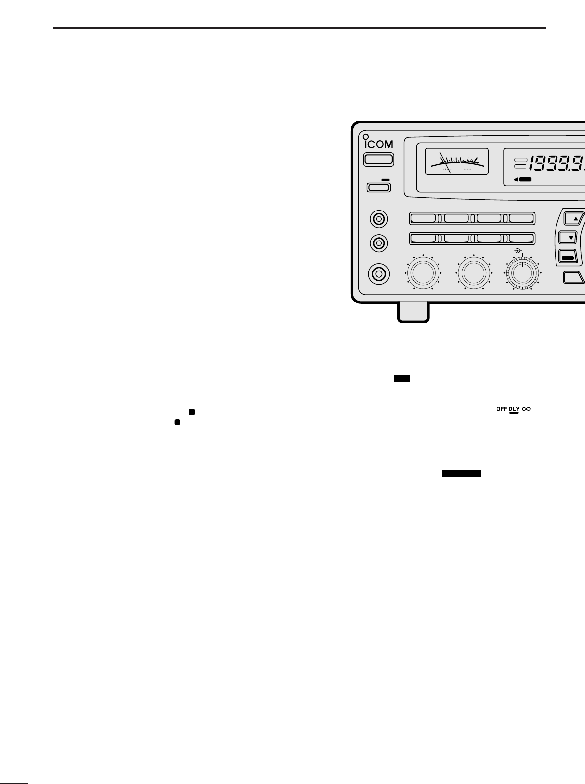
!2 AUDIO PEAK FILTER CONTROL [APF] (p. 15)
Adjusts the audio peak filter setting to pick up a de-
sired audio frequency. Only valid when the [APF]
switch is ON.
•Clockwise rotation adjusts the filter setting higher; coun-
terclockwise rotation adjusts the filter setting lower.
!3 ATTENUATOR SWITCHES [10dB]/[20dB]
Push to activate one of the attenuators.
➧Push [10dB] to activate the 10 dB attenuator.
➧Push [20dB] to activate the 20 dB attenuator.
➧Push [10dB]+ [20dB] to activate the 30 dB attenuator.
•10 dB and 30 dB attenuator cannot be used below 500 kHz.
!4 AUDIO PEAK FILTER SWITCH [APF] (p. 15)
➥Push momentarily to toggle the audio peak filter
circuit ON and OFF.
•Use the [APF] control to adjust the center of the audio
peak passband.
➥When the audio peak filter circuit is ON, push for
1 sec. to toggle the filter setting between
normal
and
narrow
.
•‘Narrow’ is available for SSB, CW and AM only.
!5 SPEECH/LOCK SWITCH [SPCH/LOCK]
➥Push momentarily to activate the voice synthesiz-
er function and have the displayed frequency
announced.
•An optional UT-102
SPEECH SYNTHESIZER UNIT
is nec-
essary to activate the voice synthesizer function (p.38).
•Automatic announcement at signal detection during
scan is available. Refer to the “REC SPCH” item on
p. 31 for details.
➥
Push for 1 sec. to activate the lock function (p.12).
•Push for 1 sec. again to cancel the lock function.
•The lock function action can be selected in set mode
to cover the main dial only, or to cover both the main
dial and front panel switches.
!6 TUNING STEP SWITCHES [TS▲]/[TS▼] (p. 12)
Select the tuning step for the main dial. Push [TS▲]
to select a larger tuning step; push [TS▼] to select
a smaller tuning step.
•10 Hz, 50 Hz, 100 Hz, 1 kHz, 2.5 kHz, 5 kHz, 9 kHz, 10
kHz, 12.5 kHz, 20 kHz, 25 kHz, 100 kHz and 1 MHz are
selectable.
•Programmable tuning steps can be set between 0.5 and
199.5 kHz.
➠To set programmable tuning steps, enter the desired
steps via the keypad, then push [TSY]or [TSZ].
!7 MAIN DIAL
Changes the operating frequency, set mode contents,
etc.
!8 BRAKE ADJUSTMENT SCREW
Adjusts the main dial tension.
!9 FUNCTION DISPLAY (p. 6)
Shows the selected frequency, mode, memory
name, etc.
@0 S-METER
➥Shows the strength of the received signal.
➥Shows the squelch threshold level when the
[SQUELCH] is rotated past the center position.
MEMO
SEL SKIP VSC DLY
SCAN/
NAME
SCAN SET
PROG AUTO PRIO
M-SET BANK
M-CL MW
DELAY/SPEEDM-CH
D/S
1QZ
GHI
PRS TUV WXY
ENT
BANK
BANK
JKL MNO
ABC DEF . ; ,
4
78
0CE
ENT
M-CH
.
9
56
23
!9
!5 !6 !8
!7
SEL-CH SKIP-CH
OFF
kHz
DLY ∞
M
IC-R8500
Center frequency
is shifted up.
Center frequency
is shifted down.
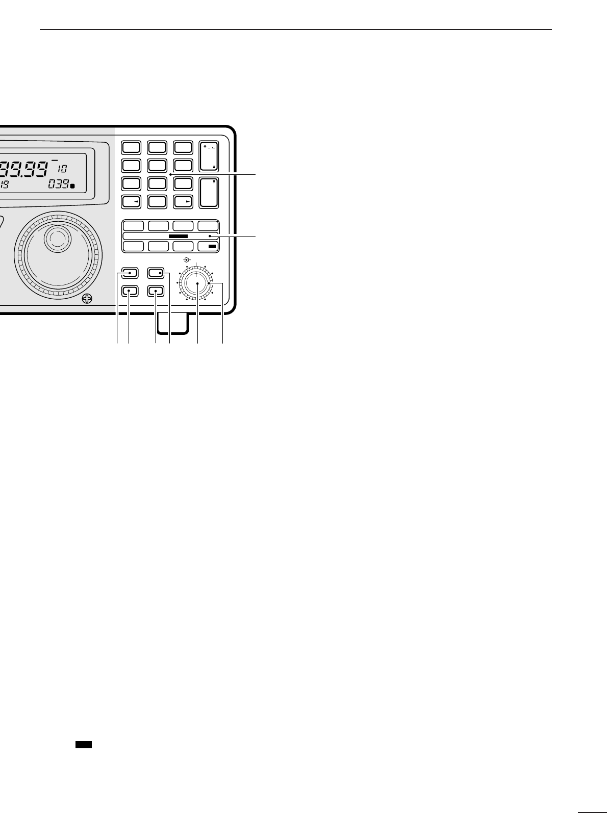
@1 MEMORY SET SWITCH [M-SET] (p. 19)
Used to ‘copy and paste’ the displayed frequency
into another memory channel.
•The first push is used to copy ( appears), and the sec-
ond push is used to paste ( disappears).
•Frequency, mode, tuning step, memory name, etc. can
be programmed into a temporary memory.
@2 MEMORY CLEAR SWITCH [M-CL] (p. 19)
Push and hold to clear the contents of the displayed
memory.
•Bank names cannot be cleared.
@3
MEMORY WRITE SWITCH [MW] (p. 19)
Push and hold to store the displayed frequency,
mode, tuning step, etc. into the selected memory
channel.
@4 BANK SWITCH [BANK] (p.17)
➥Push momentarily to toggle the bank limit func-
tion ON and OFF (p18).
•While “BANK” appears, only memory channels within
the selected bank can be selected via the [M-CH] se-
lector.
➥Push for 1 sec. to increase/decrease the number of
memory channels in the selected bank (p. 21).
@5 MEMORY CHANNEL SELECTOR [M-CH] (p.18)
➥Selects a memory channel in normal use.
•Clockwise rotation selects higher memory channel
numbers; counterclockwise rotation selects lower
memory channel numbers.
➥Selects a set mode item when quick set mode or
initial set mode is selected (p.30).
@6 DELAY/SPEED CONTROL [DELAY/SPEED] (p.28)
Adjusts the scan delay time or scan speed depend-
ing on the [DLY ] switch setting.
•When scan delay time is assigned, this control adjusts
the scan delay time (scan pausing interval) during signal
reception. This setting is effective when “ ” is
selected for the scan resume condition.
•When scan speed is assigned, this control adjusts the
scan speed. In this case, scan delay time is determined
while setting.
@7 SCAN SWITCHES [SCAN ]
All of these switches are related to the scan function
in some way as follows:
[MEMO] (p. 23)
➥Push momentarily to start/stop memory scan.
➥Push numeral keys, then this key to start memo-
ry scan in the specified bank.
➥Push this key, then a mode switch to activate
mode select scan function.
➥Push for 1 sec. to set automatic bank and skip
functions.
•The bank limit function and/or memory skip functions
are activated automatically when “AUTO” is selected
and scan is started.
[SEL] (p. 23)
➥Push momentarily to start/stop memory select
scan.
➥Push for 1 sec. to set the memory channel as a
select
channel.
[PROG] (p. 24)
➥
Push momentarily to start/stop programmed scan.
➥Push numeral keys, before or after pushing this
key to start programmed scan using the specified
scan edge group.
•10 scan edge groups are available.
➥Push for 1 sec. to program scan edges for pro-
SCAN SET
D/S
M
M
3
1PANEL DESCRIPTION
MODE
WFM
NB/AFC AGC 10dB 20dB
FM AM
APF
TS
TS
SPCH
SSB/CW
AF GAIN SQUELCH
PHONES
REC OUT
SLEEP/
REC
REMOTE
IF SHIFTAPC
SET
LOCK
COMMUNICATION RECEIVER
iC- r8500
POWER
SIGNAL
S13579
+
20dB
+
60dB
FM
RECV
BANK
10-ATT-20
APF-NAGC-FAFCNB
SLEEP
LOCK
ICOM
4
1
PANEL DESCRIPTION
grammed scan.
[SKIP] (p. 25)
➥Push momentarily to toggle the skip function ON
and OFF for any scan.
•Automatic skip activation is available with the [MEMO]
switch.
➥Push for 1 sec. to set the memory channel as a skip
channel.
[AUTO] (p. 24)
➥Push momentarily to start/stop auto write scan.
➥Push for 1 sec. to select the written memories
condition for the auto write scan.
•Two conditions are available, clear auto-written mem-
ories before scan starts; and, keep auto written mem-
ories before scan start.
[VSC] (p. 26)
Push to toggle the voice scan control function ON
and OFF.
•The VSC function resumes the scan when a detected sig-
nal does not contain voice components.
•“VSC” appears while the voice scan control function is
activated.
[PRIO] (p. 25)
➥Push momentarily to start/stop priority scan.
•Priority scan can be used in combination with other
scans.
➥Push for 1 sec. to enter the priority channel pro-
gramming condition.
[DLY ] (p. 27)
➥Push momentarily to select a scan resume condi-
tion.
➧“OFF” is underscored: scan pauses on a signal until it
disappears, then resumes 3 sec. after that.
➧“DLY” is underscored: scan resumes according to the
[DELAY/SPEED] control setting. When a signal dis-
appears, scan resumes 3 sec. later.
➧“∞” is underscored: scan is cancelled when receiving
a signal.
➥Push for 1 sec. to enter the delay time/scan speed
setting condition.
•The function of the [DELAY/SPEED] control can be se-
lected.
@8 KEYPAD
The keypad can be used for several functions as below:
•Keypad then [ENT] (then [MW])
—Direct frequency input.
•Keypad then [M-CH]
—Memory channel selection.
•[CE•NAME] then keypad
—Alphanumeric input for memory, bank names, etc.
•Keypad then [TSY] or [TSZ]
—Arbitrary tuning step setting.
•Keypad then [MEMO] or [SEL]
—Specify memory bank then start memory scan or se-
lect memory scan.
•Keypad then [PROG] or [AUTO]
—Specify scan edge group, then start programmed
scan or auto write scan.
D/S
MEMO
SEL SKIP VSC DLY
SCAN/
NAME
SCAN SET
PROG AUTO PRIO
M-SET BANK
M-CL MW
DELAY/SPEEDM-CH
D/S
1QZ
GHI
PRS TUV WXY
ENT
BANK
BANK
JKL MNO
ABC DEF . ; ,
4
78
0CE
ENT
M-CH
.
9
56
23
@2 @3@1 @4 @5 @6
@7
@8
SEL-CH SKIP-CH
OFF
kHz
DLY ∞
M
IC-R8500
5
1PANEL DESCRIPTION
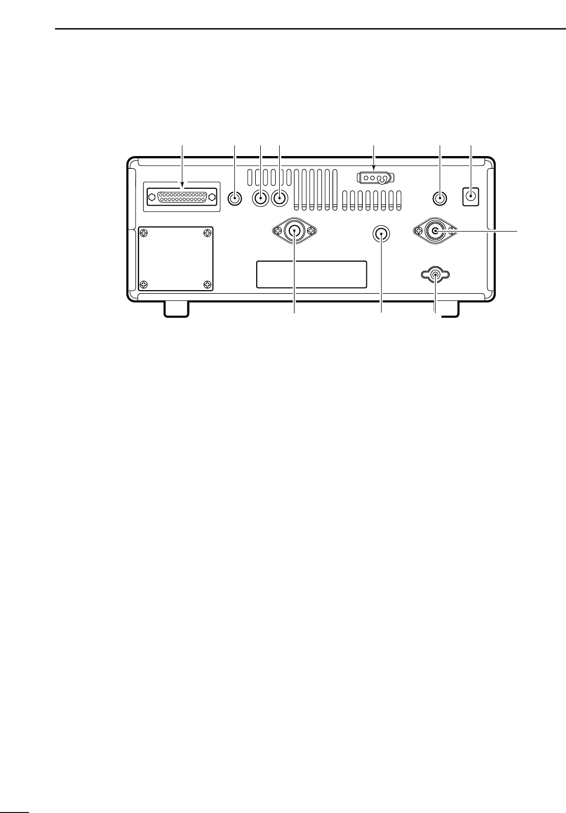
■Rear panel
q
RS-232C CONNECTOR (p. 10)
Connects an RS-232C cable. An RS-232C cable
can be used to connect the IC-R8500 to a PC. In this
way commands can be sent to the receiver via the
PC.
wCI-V REMOTE CONTROL JACK (p. 10)
Allows connection to an Icom CI-V system trans-
ceiver or another receiver for the transceive function.
Also connects to a PC with several receivers for
command control via an optional CT-17
CI
-
V LEVEL
CONVERTER
.
eIF OUT JACK (p. 40)
Outputs a 10.7 MHz IF signal with 9 V DC for an op-
tional TV-R7100
TV RECEIVE ADAPTER
.
rAGC JACK (pgs.16, 40)
This jack has functions which are selectable through
internal receiver settings.
•Outputs an AGC signal for an optional TV-R7100
TV RE
-
CEIVE ADAPTER
(default).
•Outputs audio detected signal without de-emphasis for
9600 bps data detection (FM mode only).
tDC 13.8 V JACK (p. 8)
➥Plug in the jumper connector here when using the
supplied* AC adapter.
➥Connects to a 13.8 V DC power source using the
supplied DC cable when the AC adapter is not
connected.
*Not supplied with some versions.
yEXTERNAL SPEAKER JACK
Connects an 8 Ωexternal speaker.
•When an external speaker is connected, the internal
speaker does not function.
uDC IN JACK (p. 8)
Connects the supplied* AC adapter.
•A regulator circuit has been designed between this con-
nector and the DC 13.8 V jack.
•Be sure the jumper connector is connected to the DC
13.8 V jack.
*Not supplied with some versions.
iHF 50 ΩANTENNA CONNECTOR (p. 8)
Connects an antenna to cover the frequency range
below 30 MHz.
•Use a coaxial cable and a PL-259 connector.
•Be sure this connector is selected in quick set mode
(p. 31).
oGROUND TERMINAL (p. 9)
Connect this terminal to a ground.
!0 HF 500 ΩANTENNA CONNECTOR (p. 8)
When a 500 Ωlong wire antenna is used for HF band
receiving, this connector is used instead of the 50 Ω
antenna connector.
•Set the “HF ANT” item to 500 to use this connector
(p. 31).
!1 VHF/UHF ANTENNA CONNECTOR (p. 8)
Connects an antenna to cover the frequency range
over 30 MHz.
•Use a coaxial cable and type-N connector.
q
w e r y u
t
o
i
!0!1
6
1
PANEL DESCRIPTION
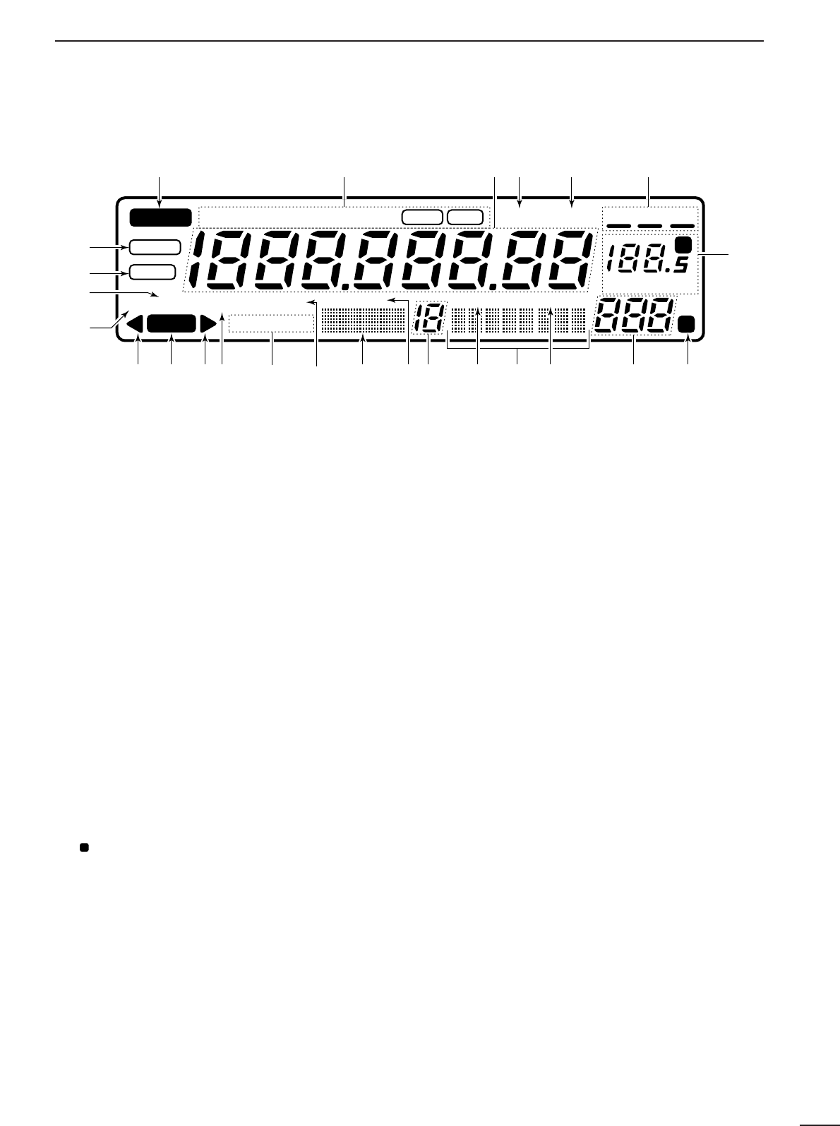
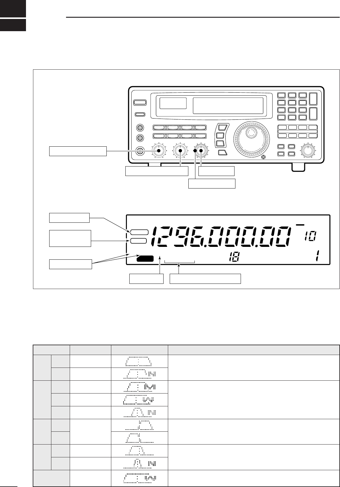
■Function display
q
REMOTE INDICATOR (p. 35)
Appears when a level control command is received from a
PC via CI-V data.
•When this indicator appears, the control knob’s setting is
ignored.
•This indicator will disappear when the control knob is rotated.
wMODE INDICATORS (p. 13)
Show the operating mode.
eFREQUENCY READOUT
Shows the operating frequency.
rSKIP INDICATOR (p. 25)
➥Appears when the skip function is activated.
➥Flashes during scan when the skip function is ac-
tivated by the auto skip function.
tVSC INDICATOR (p. 26)
Appears when the voice scan control function is
activated.
ySCAN RESUME CONDITION INDICATORS (p. 27)
Show the selected scan resume condition.
uTUNING STEP INDICATORS (p. 12)
Show the selected tuning step.
•
“ ” appears when a programmable tuning step is selected.
iTEMPORARY MEMORY INDICATOR (p. 19)
➥Appears when [M-SET] is pushed to indicate that
a frequency is being temporarily saved.
➥Disappears when the temporary memory is past-
ed into another memory channel.
oMEMORY CHANNEL READOUT (p. 17)
Shows the selected memory channel number.
!0 SKIP CHANNEL INDICATOR (p. 25)
Appears when the selected memory channel is set
as a skip channel.
!1 MEMORY NAME INDICATORS (p. 20)
Display names programmed into a memory, or scan
group.
!2 SELECT CHANNEL INDICATOR (p. 23)
Appears when the selected memory channel is set
as a select channel.
!3 BANK NUMBER INDICATOR (p. 17)
Shows the selected memory bank number.
!4 BANK INDICATOR (p. 18)
➥Appears when the bank limit function is activated.
➥Flashes during scan when the bank limit function
is activated by the auto bank function.
!5 BANK NAME INDICATOR (p. 20)
Displays names programmed into a bank.
!6 AUDIO PEAK FILTER INDICATOR (p. 15)
“APF” or “APF-N” appears when the audio peak fil-
ter function is activated.
!7 ATTENUATOR INDICATORS
Appear when the RF attenuator is activated.
!8 AUTOMATIC GAIN CONTROL INDICATOR (p. 15)
AGC-F appears when AGC fast is selected; no indi-
cation appears when AGC slow is selected.
!9 RECEIVE INDICATOR
Appears while receiving.
@0 FM CENTER INDICATORS (p. 14)
Appear when the received signal is not tuned to its
center frequency.
@1 NOISE BLANKER INDICATOR (p. 15)
Appears when the noise blanker circuit is activated.
@2 AFC INDICATOR (p. 14)
Appears when the automatic frequency control
function is activated in either FM or WFM modes.
@3 LOCK INDICATOR (p. 12)
Appears when the main dial or front panel switches
are locked.
@4 SLEEP INDICATOR (p. 29)
Appears when the sleep timer is set.
P
REMOTE
WFM
RECV
AMUSBLSBCW
BANK
10-ATT-20
APF-NAGC-FAFCNB SEL-CH SKIP-CH
WIDE NAR SKIP VSC OFF
MHz kHz
DLY ∞
SLEEP
LOCK
M
P
qwerty
u
io!0!1!2!3!4!5!6!7!8!9@0 @0
@1
@2
@3
@4
7
2CONNECTIONS
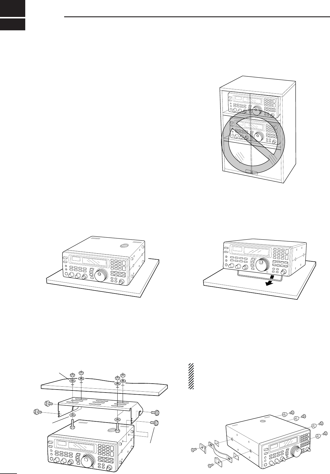
■Mounting installation
DLocation
Select a location for the receiver that allows adequate
air circulation and access to the front and rear panels.
Do not place in areas subject to extreme heat, cold, or
vibrations, or near TV sets, radios and electromagnetic
sources.
Be careful of the internal temperature of the receiver.
Installation into a rack or other enclosed area may in-
crease the internal temperature over the useable tem-
perature range. Specifications are not guaranteed
under such conditions.
DReceiver stand
The base of the IC-R8500 has an adjustable stand for
desktop use. Set the stand to one of two angles de-
pending on your operating conditions.
DOptional bracket and carrying handle
•Mounting bracket
An optional mounting bracket is available to install the
radio under a table, on a wall, in a vehicle, etc.
Select an area to mount the receiver keeping in mind
that the weight of the IC-R8500 is approx. 7 kg.
•Carrying handle
An optional handle allows you to easily carry and
transport the receiver.
Attach the MB-23
CARRYING HANDLE
with the supplied
rubber feet as shown.
CAUTION: The screws supplied with the MB-23
cannot be used with the IC-R8500. Use the screws
supplied with the IC-R8500 when attaching the
MB-23.
Flat washer
Spring
washer
Allen bolt
supplied with
the IC-R8500.
8
2
CONNECTIONS
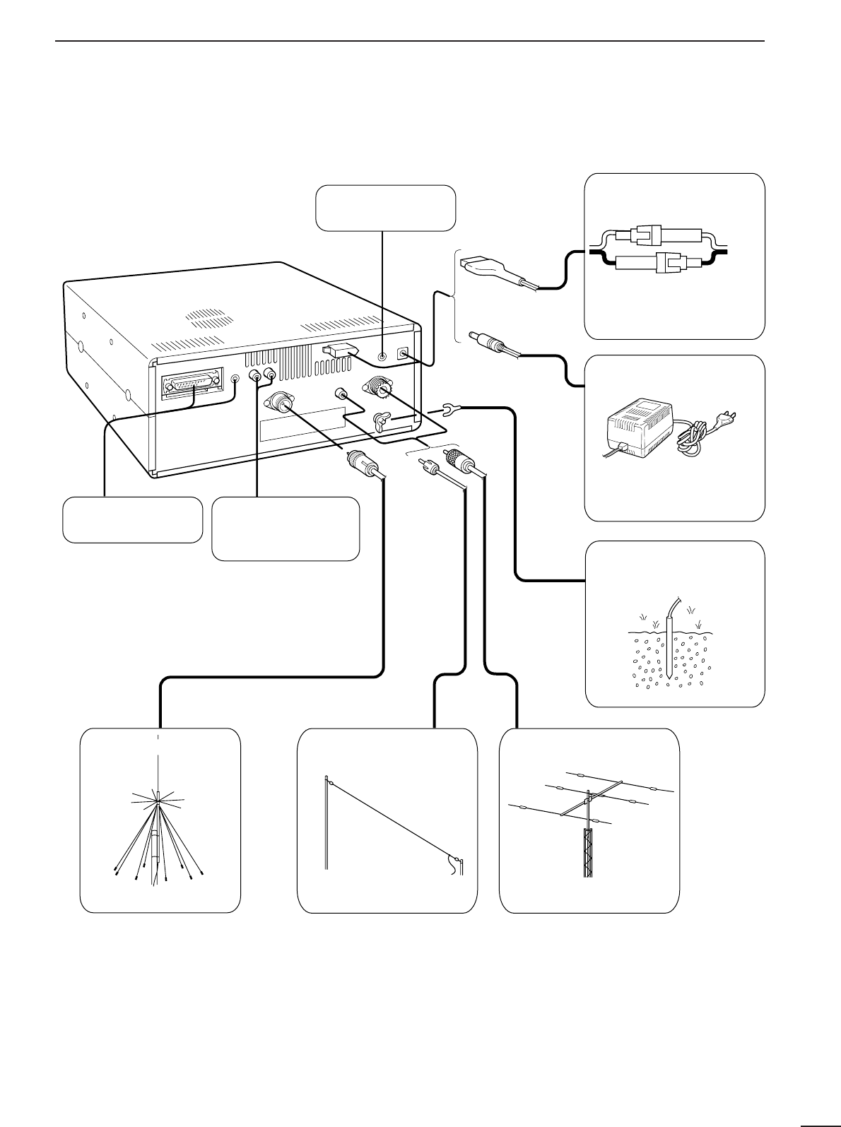
■Required connections
IC-R8500
Supplied DC power cable
Unplug the jumper plug
from the [DC13.8V] jack.
AC adapter AD-55/A/V
Connect
either power
source
The jumper plug must be
connected to the [DC 13.8V]
jack.
Ground connection (p. 9)
HF antennaLong wire antennaVHF/UHF wide band
antenna
Computer control
(p. 10)
External speaker
(p. 44)
TV adapter or high
speed data connection
(pgs. 16, 40)
0.1–30 MHz coverage0.1–30 MHz coverage30 MHz –2 GHz coverage
The optional AH-7000 is
available for 25 MHz to 1.3
GHz coverage.
Select the active antenna connector in quick set mode (p. 31)
9
2CONNECTIONS
■Antenna connection
Antennas play a very important role in receiver opera-
tion. Connecting a poor quality antenna to the
IC-R8500 will result in less than optimum perfor-
mance.
The IC-R8500 requires at least 2 antennas for full fre-
quency coverage: one for 0.1 to 30 MHz and one for
30 to 2000 MHz.
DUsing a long wire antenna for HF bands
The IC-R8500 has a 500 Ωphono (RCA) antenna
connector for the HF bands. When using a long wire
antenna, instead of a 50 Ωmatched antenna, use one
as long as possible (at least 10 m, 33 ft) and select the
active connector as follows:
➀Push [SLEEP/ ] for 1 sec. to enter quick set
mode.
➁Rotate the [M-CH] selector to select the “HF ANT”
item.
➂
Rotate the main dial to select the antenna connector.
➃Push [SLEEP/ ] momentarily to exit quick set
mode.
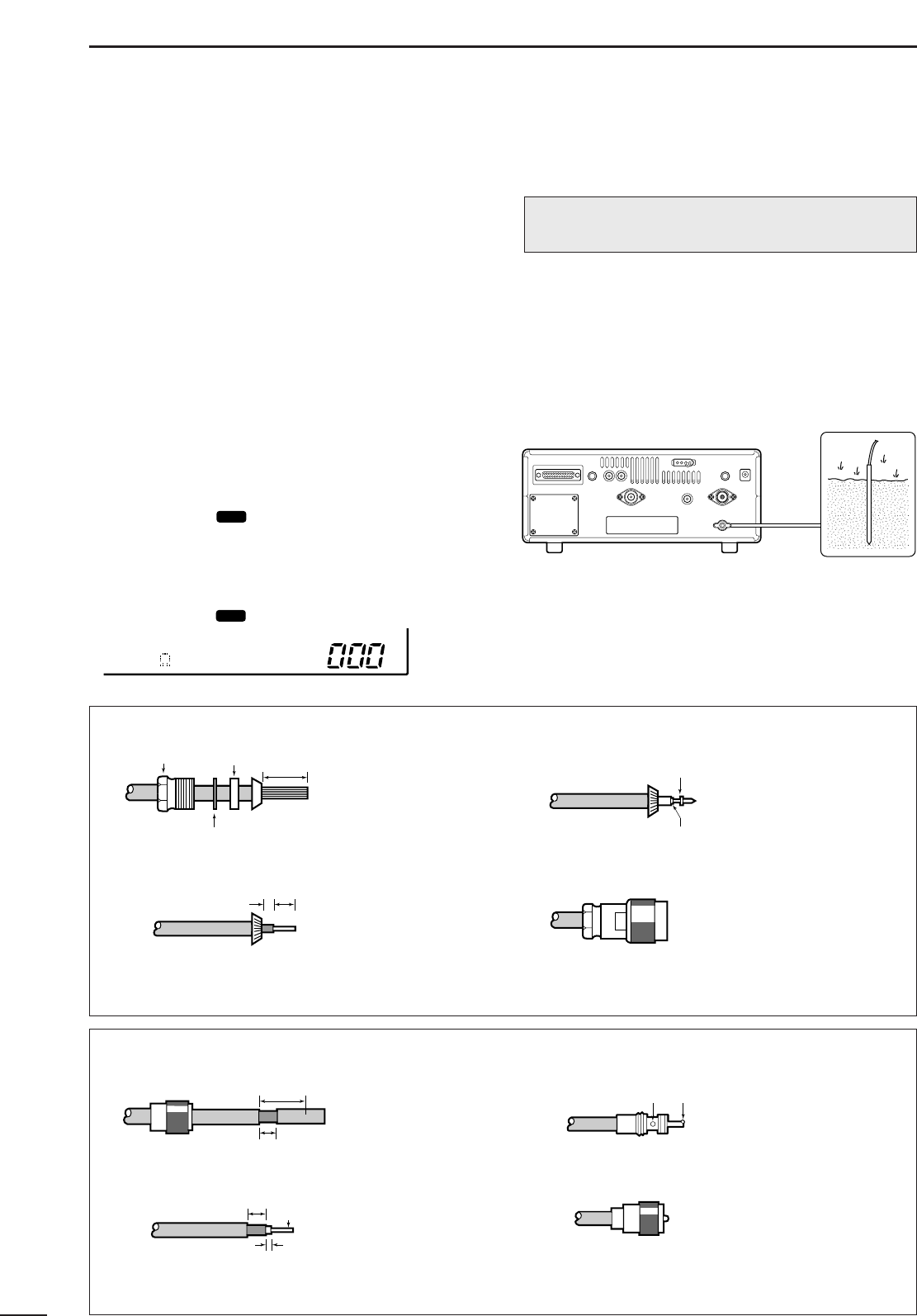
■Grounding
To prevent accidents involving electricity and interfer-
ence from transceivers, ground the receiver through
the [GND] terminal on the rear panel.
For best results, connect a heavy gauge cable to a
water pipe or long, earth-sunk copper rod. Make the
distance between the [GND] terminal and ground as
short as possible.
SET
SET
RWARNING: NEVER use a gas pipe or electri-
cal conduit pipe for grounding.
30 mm
10 mm (soft solder)
10 mm
1–2 mm
solder solder
Soft
solder
Coupling ring
PL-259 CONNECTOR INSTALLATION EXAMPLE
➀➂
➃
➁
Slide the coupling ring
down. Strip the cable
jacket and soft solder.
Slide the connector
body on and solder it.
Screw the coupling ring
onto the connector
body.
Strip the cable as
shown at left. Soft
solder the center con-
ductor.
(10 mm ≈ 3⁄8 in)
15 mm
Clamp
3 mm 6 mm
Center conductor
Washer
Nut Rubber gasket
TYPE-N CONNECTOR INSTALLATION EXAMPLE
➀➂
➃
➁
Slide the nut, washer,
rubber gasket and
clamp over the
coaxial cable, then
cut the end of the
cable evenly.
Soft solder the center
conductor. Install the
center conductor pin and
solder it.
Carefully slide the plug
body into place aligning
the center conductor pin
on the cable. Tighten the
nut onto the plug body.
• Be sure the center
conductor is the same
height as the plug body.
Strip the cable and
fold the braid back
over the clamp.
(10 mm ≈ 3⁄8 in)
Plug body
No space
Solder hole
500 HF ANT
10
2
CONNECTIONS
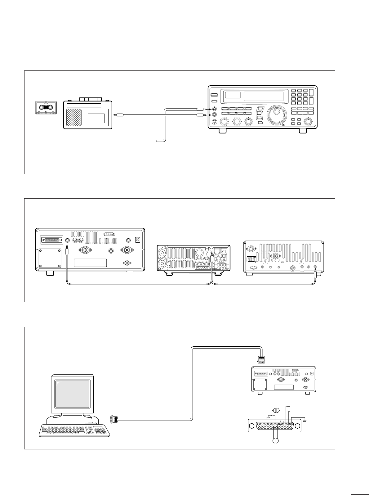
■Tape recorder connections
The [REC OUT] jack has 350 mV rms/4.7 kΩoutput
for connection to other audio equipment.
■Transceive function
Icom CI-V transceivers or receivers can be connect-
ed via the [REMOTE] jack. The frequency and mode
become the same* when either radio is changed.
*When a set frequency is out-of-range for one of the con-
nected transceivers or receivers, the connected radio’s
frequency/mode does not change.
■Connecting to a PC
■Data demodulation terminal
See p. 16 for details regarding connection and opera-
tion.
The IC-R8500 can connect directly to a personal
computer providing control of multiple functions such
as instant frequency/name programming using
appropriate software. See pgs. 35, 36 for the control
command table.
Personal computer
IC-R8500
RS-232C
cable
13
25 14
2.RXD (data input)
3.TXD (data output)
1
20 6
8
IC-R8500
SCAN SET
[REC
REMOTE]
[REC OUT]
350 mVrms
4.7 kΩ
[AUX IN] or
[LIVE IN] jack
✔
Convenient:
When an optional UT-102
VOICE SYNTHESIZER UNIT
is
installed, detected frequencies during scanning can
be recorded. See pgs. 31, 32 for settings.
[REC REMOTE] jack:Grounds when a signal is
received and squelch opens. If a tape recorder has
a control terminal, this jack can be used for record-
ing control. (2 A/DC max.)
Connect to [REMOTE] jack
•Be sure the “CIV TRAN” item is turned ON in initial set mode (p. 32).
A DB9/DB25 adapter may be
required depending on the PC’s
connector.
11
3FREQUENCY SETTING
■Read me first
The IC-R8500 uses memory channels for storage of
frequencies (as well as mode, tuning steps, etc.).
When turning power OFF or changing memory chan-
nels, the previously displayed frequency cannot be
recalled unless it has been stored into a memory
channel. Therefore, when you want to keep a dis-
played frequency for later recall, you must program it
into a memory channel by pushing [MW] for 1 sec.
✔
Convenient:
Use [M-SET] to program a displayed frequency (and
its mode, etc.) without overwriting the currently select-
ed memory. See p. 19.
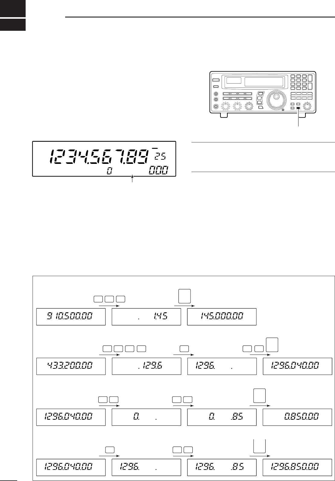
■Using the keypad
➀Push the numeral keys on the keypad to enter the
MHz digits for the desired frequency.
•If a key is mistakenly pushed, push [CE
s
] and start
again from the beginning.
•When entering the same MHz digits as the displayed
frequency, this step can be skipped.
➁Push [•
t
].
➂Push the numeral keys to enter the frequency digits
below 1 MHz.
•If a key is mistakenly pushed, push [CE
s
] and start
again from the beginning.
➃Push [ENT] to set the input frequency.
•When pushing [ENT] after entering the MHz digits, zeros
are automatically entered for the kHz digits.
[EXAMPLE]: SETTING THE FREQUENCY USING THE KEYPAD
• To set to 145.00 MHz
145 ENT
• To set to 1296.040 MHz
1296 •04
ENT
• To set to 850 kHz
(0.85 MHz)
08
5
•ENT
• To change from 1296.040
to 1296.850 MHz
85
•ENT
Push [MW] for 1 sec. after tuning.
FM OFF
kHz
DLY ∞
USR-A BLANK
“BLANK” appears in the memory name area until
[MW] is pushed for 1 sec.
12
3
FREQUENCY SETTING
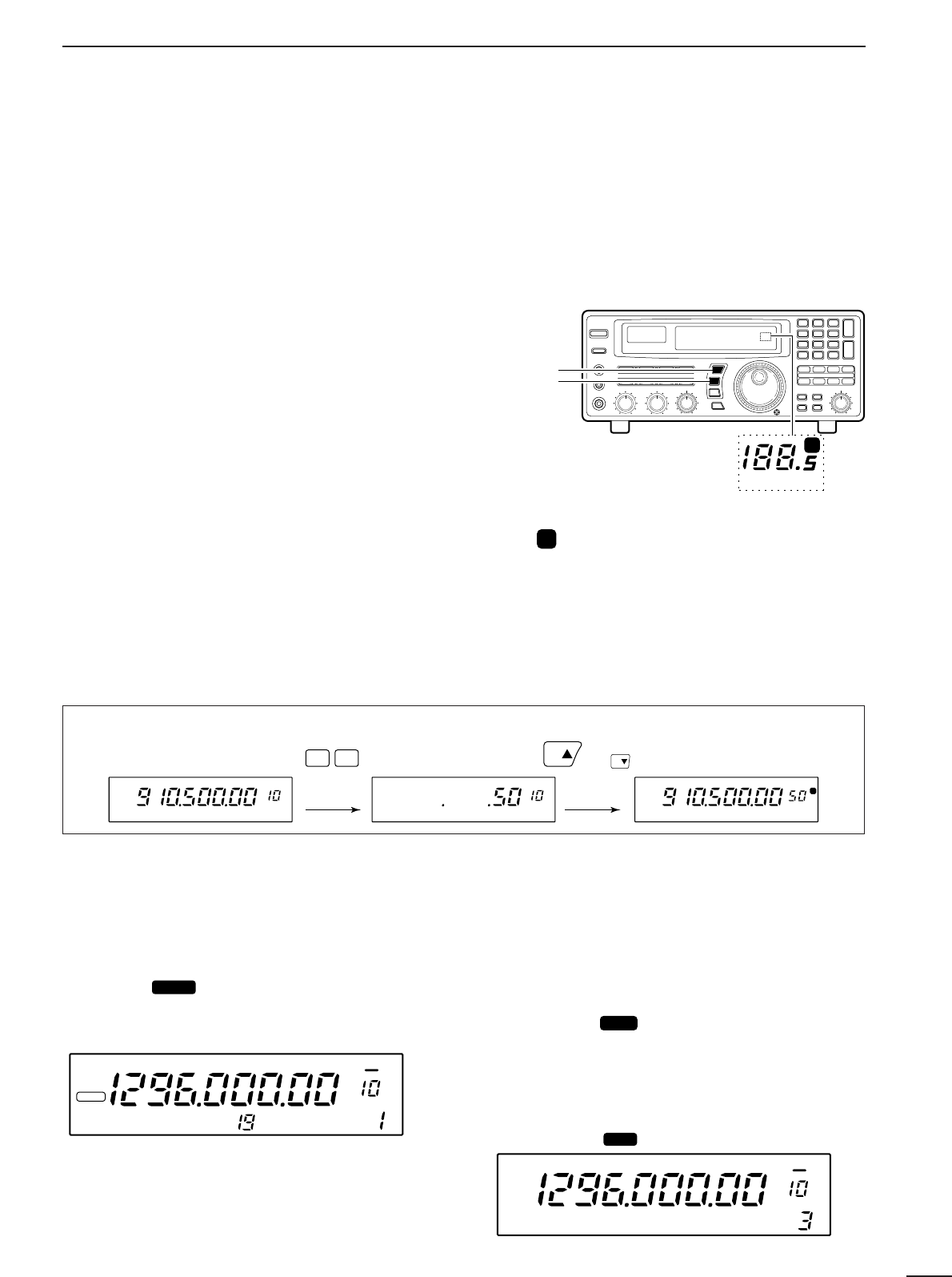
■Using the main dial
Rotate the main dial to change the frequency.
•The frequency changes in increments determined by the
selected tuning step (see below).
•When the lock function is activated (“LOCK” appears) the
frequency cannot be changed.
DSelecting a tuning step
13 preset tuning steps are available plus 1 programma-
ble tuning step (see below). The preset tuning steps are:
10 50 100 Hz
1 2.5 5 9 10 12.5 20 25 100 kHz
1 MHz
Push [TSY] or [TSZ] to change the selected tuning
step.
DSetting the programmable tuning step
The programmable tuning step can be set between the
range of 0.5–199.5 kHz (in 0.5 kHz steps) for each
memory independently.
➀Push the numeral keys on the keypad that corre-
spond to the tuning step you wish to program.
➁Push [TSY] or [TSZ] to set the programmable tun-
ing step to the selected value.
•The programmable tuning step is automatically selected
as the active tuning step.
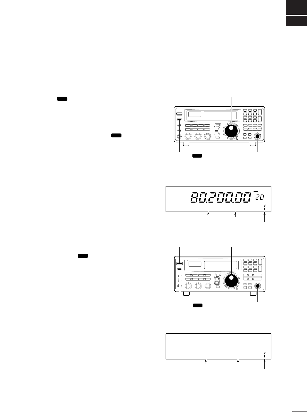
■Lock function
The lock function electronically locks the indicated fre-
quency from accidentally being changed.
Push [SPCH ] for 1 sec. to toggle the lock func-
tion ON and OFF.
•“LOCK” appears in the function display while the lock
function is activated.
DSetting the lock function coverage
The lock function can be set to lock the main dial only
or, the main dial and most of the front panel switches.
➀Push [SLEEP ] for 1 sec. to enter quick set
mode.
➁Rotate the [M-CH] selector to select the “LOCK”
indication.
➂Rotate the main dial to set the lock function cover-
age to “DIAL” or “PANEL.”
➃Push [SLEEP ] momentarily to exit quick set
mode.
SET
SET
LOCK
SCAN SET
[TSY]
[TSZ]
MHz kHz
P
Tuning step
indicators
MHz kHz
Pappears when the programmable tuning step
is selected.
or appears to indicate the units of
the selected tuning step.
[EXAMPLE]: Setting the programmable tuning step to 50 kHz.
(or )
kHz
P
kHzkHz
50TS TS
FM
kHz
LOCK
*ICOM IC-R8500
OFF DLY ∞
LOCK DIAL
kHz
FM OFF DLY ∞
13
4RECEIVE FUNCTIONS
■Initial settings
■Mode selection
Push one of the mode keys one or more times to
select the desired mode. Consult the table below for
basic characteristics of each mode.
The indications in the table appear in the bank name
area for 1 sec. after an operating mode is selected.
SCAN SET
FM
RECV
BANK
10-ATT-20
APF-NAGC-FAFCNB
OFF
kHz
DLY ∞
SLEEP
LOCK
*ICOM IC-R8500
[AF GAIN]: 10 o’clock
[APF]: center
[IF SHIFT]: center
Push [SLEEP]
Push [NB/AFC]
Push [AGC] Push [10dB] and/or [20 dB]
Push and hold
[SPCH • LOCK]
Before turning power ON,
set controls and switches as indicated below:
After turning power ON,
check the display for indications below and remove as follows:
[SQUELCH]: max. CCW
MODE BANDWIDTH INDICATION DESCRIPTION
FM 12 kHz/–6 dB Amateur bands, citizens band, utility communications, marine bands,
etc. FM-narrow can only receive narrow FM signals; normal FM can
receive both normal and narrow FM signals.
AM
5.5 kHz/–6 dB Broadcasting, amateur bands, citizens band, air band, etc. AM-wide
mode is used for clear audio reception. Signals however, may be
received with interference.
SSB 2.2 kHz/–6 dB Shortwave broadcasting, amateur bands, etc. Use USB for normal
SSB reception; LSB is not normally used.
CW 2.2 kHz/–6 dB Morse code communications. Use this mode to receive radio-tele-
type, etc. by shifting the receive frequency.
WFM 150 kHz/–6 dB TV broadcasting, FM broadcasting, etc. TV and FM broadcasting
cannot be accessed in FM mode because their signals are too wide.
5.5 kHz/–6 dB
normal
narrow
2.2 kHz/–6 dB
medium
narrow
12 kHz/–6 dB
wide
USB
LSB
normal
500 Hz/–6 dB
narrow
(option)
The IC-R8500 has 2 types of squelch, noise squelch
and S-meter squelch.
Noise squelch:
Only acts on noise; has good sensi-
tivity. It can be adjusted for reception of weak signals.
Strong signals exceeding a certain level will always
cause the squelch to open.
S-meter squelch:
S-meter squelch does not open for
weak signals but can be adjusted to open for signals
over a wide range of strengths. Once you have
selected a threshold point in a range, the IC-R8500
will open for all signals above this point.
To adjust the squelch, rotate [SQUELCH].
•Clockwise rotation closes the squelch (sets the threshold
point higher); counterclockwise rotation opens the
squelch (for reception of weak signals).
FM signals have a wide bandwidth which makes them
easy to receive. However, you may be tuned off-cen-
ter resulting in audio distortion. The IC-R8500’s off-
center indicators appear in such cases, making it
easy to fine tune to the center of the frequency.
AFC stands for automatic frequency control. The AFC
circuit automatically compensates the tuning when a
receive frequency drifts or goes off frequency.
When one of the off-center indicators appears, the
IC-R8500 can adjust the receive frequency automat-
ically—when the AFC function is turned ON and an
off-center frequency is received, the frequency in the
display automatically changes to reflect the center of
the signal.
14
4
RECEIVE FUNCTIONS
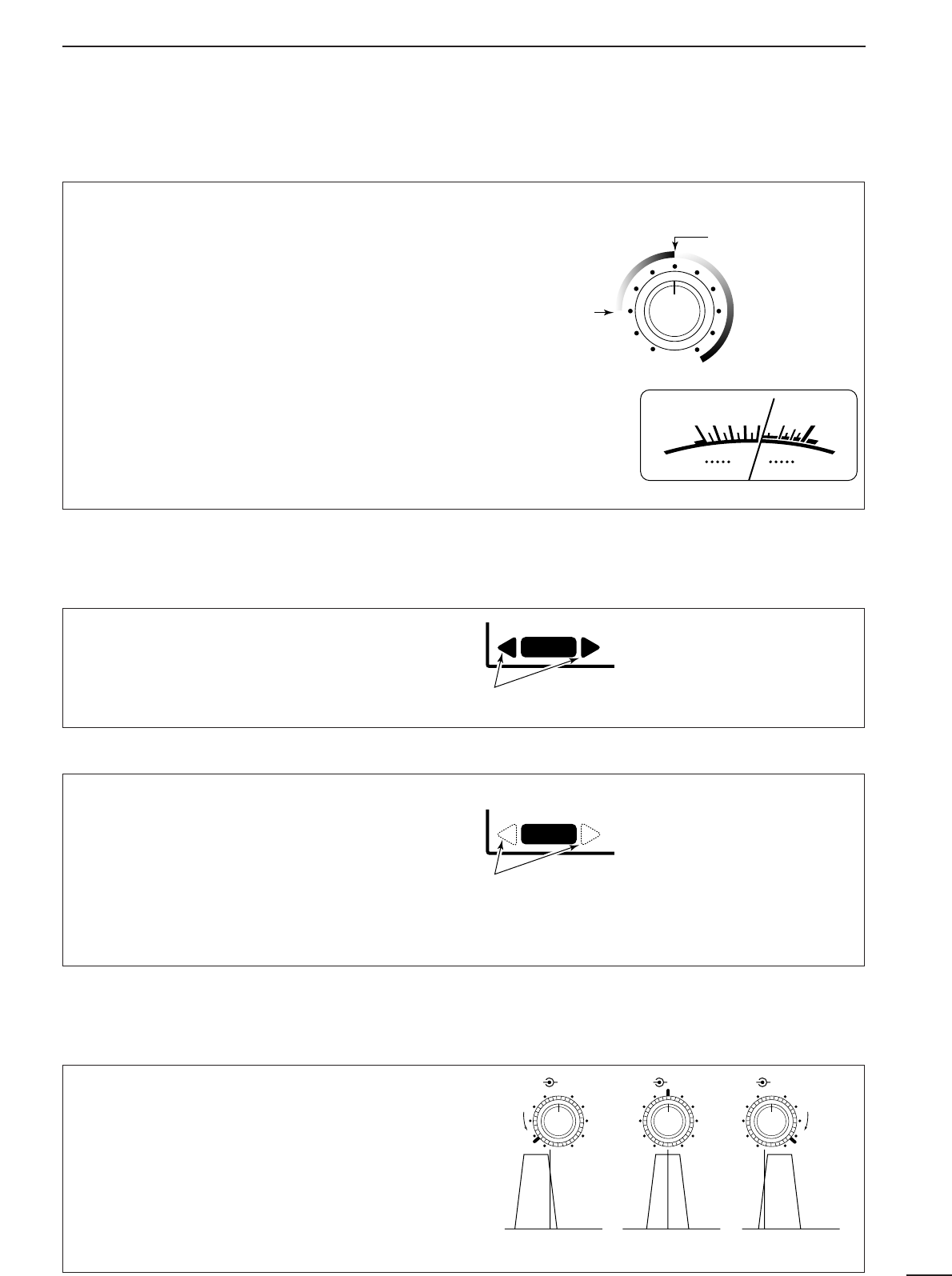
■Squelch function
■Functions for FM
DCenter indicator
S-meter squelch
threshold
Noise squelch
threshold (not
available in SSB,
CW, WFM and
AM narrow modes)
• Signals below the
S-meter level
are muted.
When [SQUELCH] is
rotated past center,
the S-meter shows
the signal strength
needed to open the
squelch.
SIGNAL
S13579
+
20dB
+
60dB
RECV
One of these indicators appears when the received
signal is off-center.
RECV
When one of these indicators appears, the
displayed frequency is automatically moved to the
center frequency.
AFC
DAFC
The
IF shift
function electronically changes the cen-
ter of the IF (intermediate frequency) passband fre-
quency to reject interference. The IF shift is not avail-
able in FM and AM modes.
➀Adjust the [SHIFT] control for a minimum interfer-
ence signal level.
•The audio tone may be changed while the IF shift is in
use.
➁Set the shift control to its center position when
there is no interference.
■Functions for SSB/CW
DIF shift
Shifts low Center Shifts high
IF SHIFTAPFIF SHIFTAPF IF SHIFTAPF
15
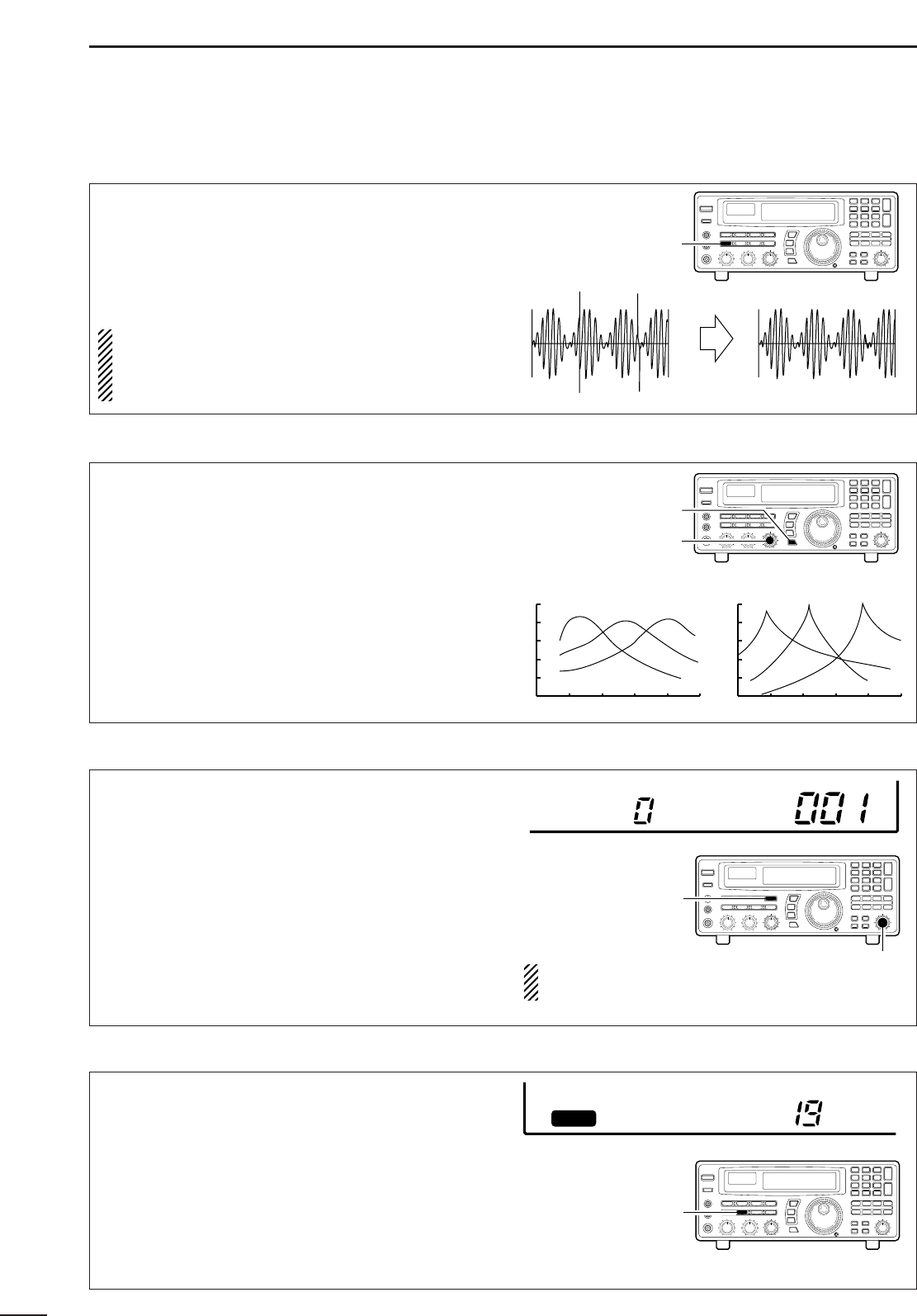
4RECEIVE FUNCTIONS
The
noise blanker
reduces pulse-type noise such as
that generated by automobile ignition systems. This
function is not effective for FM and WFM mode or for
non pulse-type noise and wide width pulses.
Push [NB] to toggle the noise blanker ON and OFF.
•“NB” appears when the noise blanker is activated.
NOTE: When a strong signal is received while the
noise blanker is ON, the output audio may be dis-
torted. In such cases, the noise blanker should be
turned OFF.
The APF (audio peak filter) adjusts the peak fre-
quency of the received audio. The APF can be used
for adjusting the audio response. The IC-R8500 has
two selectable width filters.* Use the appropriate filter
width for optimum receiving.
➀Push the [APF] switch.
➁Rotate the [APF] control to adjust the peak fre-
quency.
➂To change the filter width*, push [APF] for 1 sec.
*Available for SSB, CW and AM only.
BFO stands for beat frequency oscillator. This func-
tion is useful in conjunction with the IF shift function.
When eliminating interference with the IF shift func-
tion, the audio characteristics of the received signal
are often changed. Use the BFO adjustment function
to adjust the audio quality of the received signal to
that desired.
➀Push [SSB/CW] to select SSB or CW mode.
➁Push [SSB/CW] for 1 sec. to activate the function.
•BFO appears.
➂Rotate [M-CH] to adjust the BFO.
•–1.2 kHz to +1.2 kHz are selectable.
AGC stands for automatic gain control. This function
controls receiver gain to produce a constant audio
output level even when the received signal strength
is varied by fading, etc. Use AGC slow for normal
phone operation; AGC fast for receiving data and
searching for signals. AGC time constant cannot be
changed in FM and WFM modes.
Push [AGC] to toggle between AGC fast and slow.
•AGC-F appears when AGC fast is selected; no indi-
cator appears when AGC slow is selected.
DNoise blanker
DAudio peak filter
DBFO adjustment
DAGC function
BFO 0.00kHz
ICOM-
RECV
AGC-F
NB OFF NB ON
500 1k 2k 5k [Hz]
–40
–30
–20
–10
0
[dB]
500 1k 2k 5k [Hz]
–40
–30
–20
–10
0
[dB]
APF is selected APF-N is selected
[NB/AFC]
switch
SCAN SET
[APF] control
[APF]
switch SCAN SET
[SSB/CW]
switch
SCAN SET
[M-CH]
selector
[AGC]
switch
SCAN SET
BFO shift can be set for USB,
LSB and CW separately.
TU or TNC
AF IN
SQUELCH IN
to [REC OUT]
to [REC REMOTE]
SCAN SET
2-conductor 3.5(d) plugs Personal computer
16
4
RECEIVE FUNCTIONS
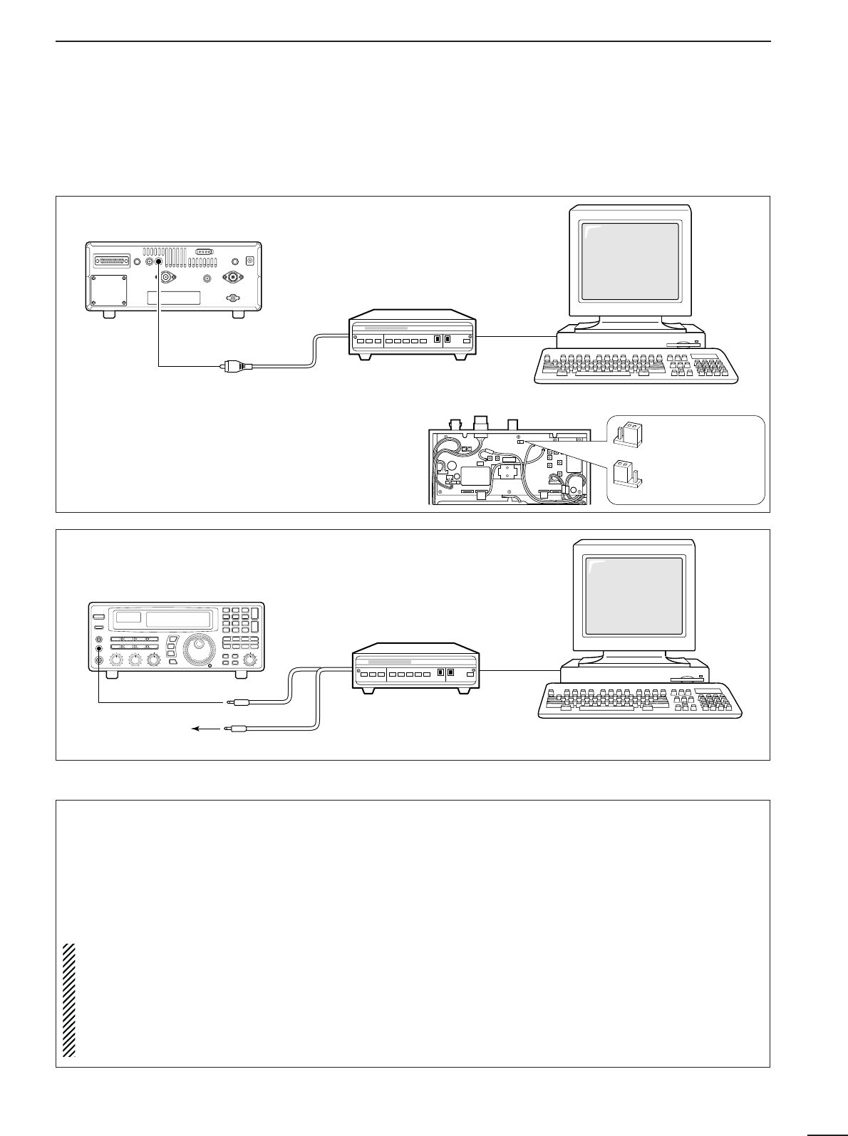
■Data communications
DConnections
DReceiving method
•To use the [AGC] socket for AF output
Change the internal jumper plug as illustrated at
right.
•The output is obtained for FM mode only.
•Usable for 9600 bps only.
•Refer to p. 37 for a description of opening the case.
➀Connect a terminal unit as above.
➁Select FM mode (or USB, CW modes for HF band
data communications).
➂Set the receiver to the desired frequency as below.
➃Set the connected terminal unit to the appropriate
settings.
•Refer to the terminal unit’s instructions.
Rear
panel
TU or TNC
to [AGC]
RCA plug Personal computer
[Audio IN] or
[Detector IN]
•For high speed data (9600 bps) reception in FM mode
•For regular speed data (1200 bps or lower) reception in any mode
Frequency settings depend on the mode used.
FM mode:
[Setting frequency(displayed freq.)]=[Desired freq.]
USB mode:
[Setting frequency(displayed freq.)]=[Desired freq.]–[Center of Mark and Space freq.]
CW narrow mode:
[Setting frequency(displayed freq.)]=[Desired freq.]–[Center of Mark and Space freq.]+[600 Hz]
LSB mode (for amateur RTTY):
[Setting frequency(displayed freq.)]=[Desired freq.]+[Mark freq.]
AGC output
(default)
AF direct detector
output
200 mVrms/4.7 kΩ
17
5MEMORY CHANNELS
To select regular channel banks:
Push [M-CH •BANK
▲
] or [ENT•BANK
▼
], one or more
times to select the desired channel bank.
•The bank indicator shows the selected bank.
•Push and hold [BANK
▲
] or [BANK
▼
] to quickly cycle
through the channel banks in the order to , FREE,
AUTO and SKIP.
NOTE: The FREE bank is initially blank and there-
fore cannot be selected. In order to select it at least
1 channel must be programmed into the FREE
bank. See p. 21.
✔
Convenient:
Bank names
The default names of “USR-A” to “USR-T” can be set
to your own preference. Refer to p. 20 for program-
ming.
To select the programmed scan edge:
Push [PROG] for 1 sec.
•PROG and channel number (0P1 to 9P2) appear.
■Bank selection
The IC-R8500 has 1000 regular memory channels,
plus 20 programmable scan edge channels and 1 pri-
ority channel. 8-digit memory names are programmed
into all 1000 channels and 5-digit bank names are
programmed into 20 user banks for convenient recall
and organisation of frequencies. Moreover, memory
channels can store mode information, a tuning step,
and ATT (attenuation) information.
NOTE: When memory channels without informa-
tion (blank channels) are selected, the frequency
is not displayed. Only the memory channel num-
ber appears.
The table below gives a general overview of the
IC-R8500’s memory channels.
BANK
INITIAL CONTENTS
USAGE
40 memories×
20 banks
For normal use. Frequency, mode, tuning step, name and ATT information can
be programmed. The number of channels in each bank is user-assignable.
Banks cannot be deleted (they must contain at least 1 channel).
100 memories
Frequencies detected during auto memory write scan are memorised into this
bank in sequence. Mode and tuning step are written at the same time. Note that
when the written memories condition is set as CL&START and auto write scan
is started, all memories in this bank are cleared.
100 memories
Undesired signals such as from beacons, control-coded signals, etc., can be pro-
grammed to be skipped during programmed scan and auto memory write scan.
When [MW] is pushed for 1 sec. while scan is paused, the displayed frequency
is programmed into this bank regardless of the selected bank.
Blank For temporary storage when assigning channels to banks. Deleted channels
(contents have been cleared) are stored in this bank until being assigned to
another bank. This bank does not appear when no channel are assigned.
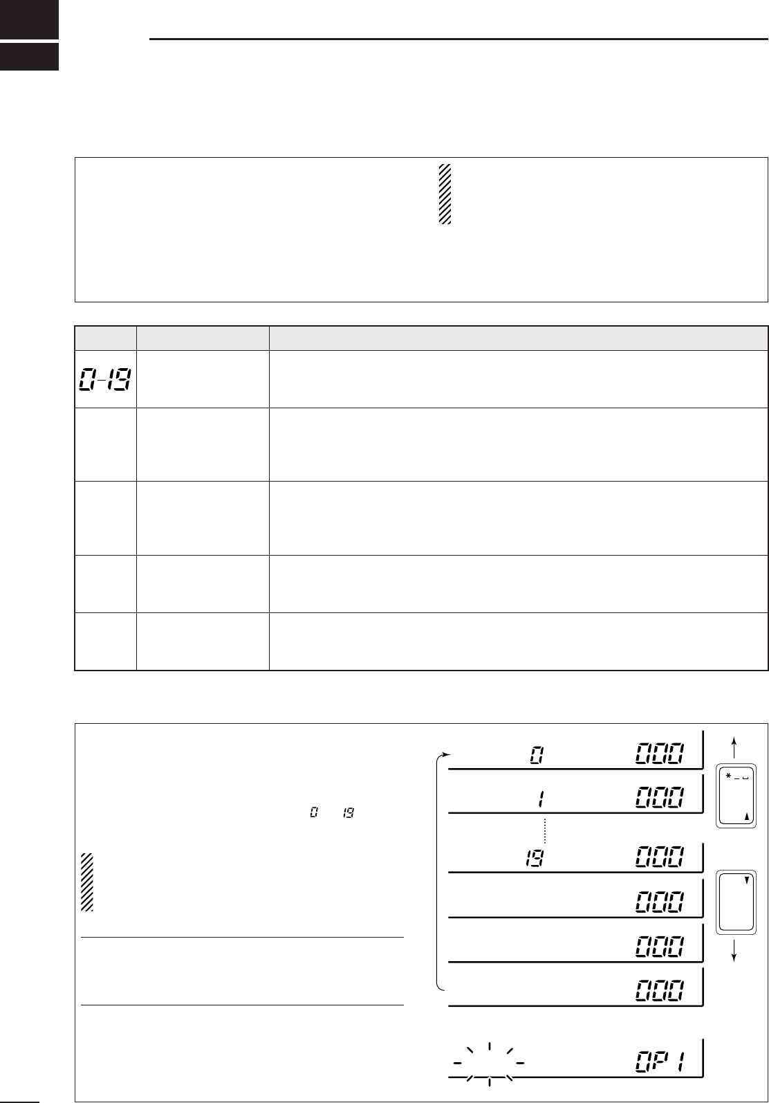
20 memories (fixed) Memorize scan edge frequencies. 10 pairs of scan edges (0P1 to 9P2) are pro-
grammable (upper and lower scan edges). Mode and tuning step are automati-
cally equalised to the last programmed channel in a pair.
■General
ENT
BANK
BANK
. ; ,
ENT
M-CH
BANK
BANK
BANK
BANK
USR-A BLANK
BLANK
BLANK
BLANK
USR-B
BANK BLANK
USR-T
AUTO
BANK BLANK
FREE
SKIP
*NONAME*
PROG
AUTO
SKIP
FREE
PROG
18
5
MEMORY CHANNELS
➀Select the desired bank using [M-CH •BANK
▲
] or
[ENT•BANK
▼
].
➁Rotate the [M-CH] selector to select the desired
channel.
•Bank limit function
While rotating the [M-CH] selector, memory channels
can be selected from within the current bank only; or
from any bank.
Push [BANK] to toggle the bank limit function ON and
OFF. ✔
Convenient:
Automatic bank limit
When starting memory scan, the bank limit function
is activated automatically. This automatic selection
can be deactivated. See p. 26.
Memory channels in the current bank can only be
selected via the keypad.
➀Select the desired bank using [M-CH•BANK
▲
]or
[ENT• BANK
▼
].
➁Push keys corresponding to the desired channel.
➂Push the [M-CH] key to set the selected memory
channel.
•Input for memory channels not available is cancelled.
■Channel selection
DUsing the [M-CH] selector
DUsing the keypad
[M-CH] selector
[BANK ]
[BANK ]
[M-CH] key
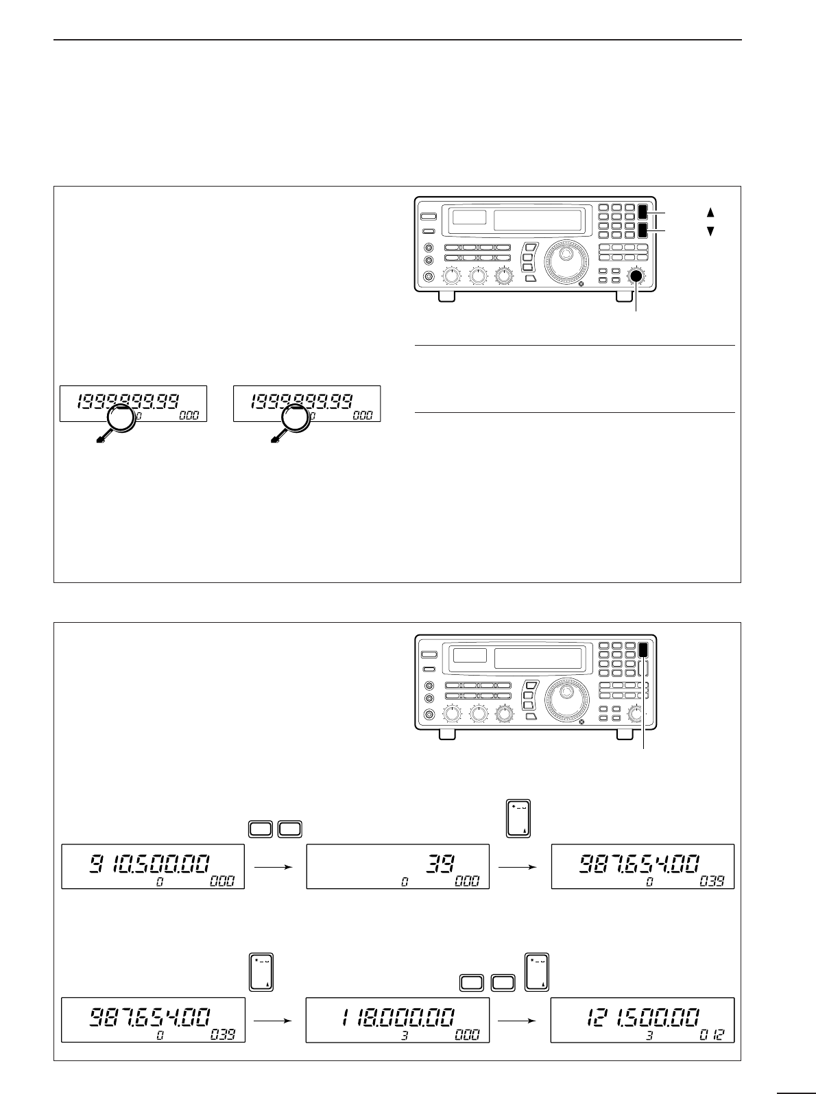
[EXAMPLE]: Selecting channel 39 from within the currently selected bank
BANK
M
USR-A
BANK appearsBANK doesn't
appear
BANK
M
USR-A
BANK
SR-
SR-
•
Bank limit OFF
All memory channels can be
selected via the [M-CH]
selector. [BANK
▲
]/[BANK
▼
]
can be used.
•
Bank limit ON
Only memory channels in
the current bank can be se-
lected. Banks can be se-
lected with the
[BANK
▲
]/[BANK
▼
] keys
only.
USR-A ABCD USR-A ABCD USR-A EFGH
WXY BANK
DEF
. ; ,
M-CH
9
3
[EXAMPLE]: Selecting channel 12 from a different bank (bank 3)
USR-A EFGH USR-D IJKL USR-D MNOP
BANK
. ; ,
M-CH
BANK
. ; ,
M-CH
1QZ ABC2
(3 times)
19
5MEMORY CHANNELS
■Programming
This is the method most often used to program mem-
ory channels.
➀Select the desired memory channel.
➁Set the desired frequency.
•
When the memory channel already contains information,
change the frequency using the main dial or the keypad.
•When the memory channel is blank, use keypad entry
only to set the frequency.
➂
Set operating mode (p. 13) and tuning steps (p. 12).
➃Push and hold [MW] until the receiver emits 3
beeps.
•The information is stored in the memory channel.
NOTE: When changing the memory channel
before pushing [MW], the set frequency (and
mode/tuning steps) is erased.
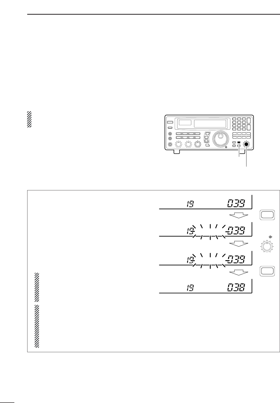
■Copy and paste (memory editing)
When the frequency (and mode/tuning steps) is set
for a channel; or, when you want to change a fre-
quency using the contents of another memory chan-
nel, the copy/paste function is helpful to keep (or con-
firm) the previously programmed contents.
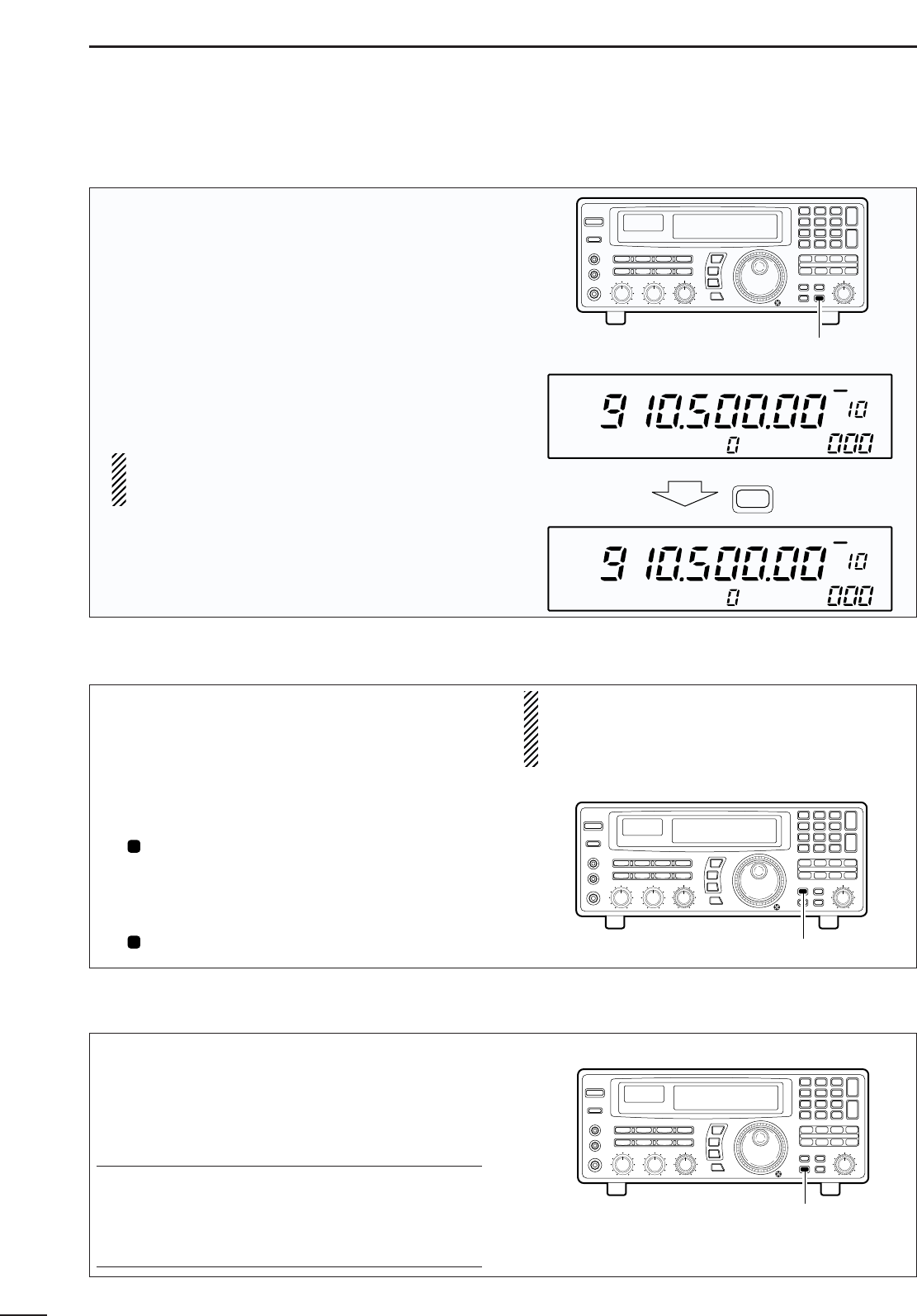
➀Push [M-SET] to temporarily store the displayed
frequency, mode, etc.
•“ ” appears.
•Only 1 channel can be stored in the temporary space.
➁Select the memory channel you wish to program
the frequency into.
➂Push [M-SET] again to paste the stored contents.
•“ ” disappears.
NOTE: Remember that pushing [MW] is always
necessary to program contents into a memory
channel. Pasted contents will be cleared if the
[MW] key is not pushed for 1 sec.
M
M
■Clearing
Information programmed into a memory channel can
be cleared (erased).
➀Select the memory channel to be cleared.
➁Push and hold [M-CL] until the receiver emits 3
beeps.
✔
Convenient:
Bank assign function
Using the bank assign function, memory channels
can be removed (along with their programmed con-
tents) from a particular memory bank and placed
temporarily in the ‘free’ bank. See p. 21.
[MW] key
Push for 1 sec.
USR-A
USR-A
BLANK
MW
FM OFF
kHz
DLY ∞
FM OFF
kHz
DLY ∞
[M-SET] key
[M-CL] key
20
5
MEMORY CHANNELS
■Channel/bank names
Channel names of up to 8 characters and bank names
of up to 5 characters can be programmed for conve-
nience. Programmed names can be easily copied to
other channels using the copy/paste function.
➀Select the desired memory channel.
➁Set the frequency (and mode/tuning steps), then
push and hold the [MW] key.
•When no data is programmed, “BLANK” appears and
memory names cannot be programmed.
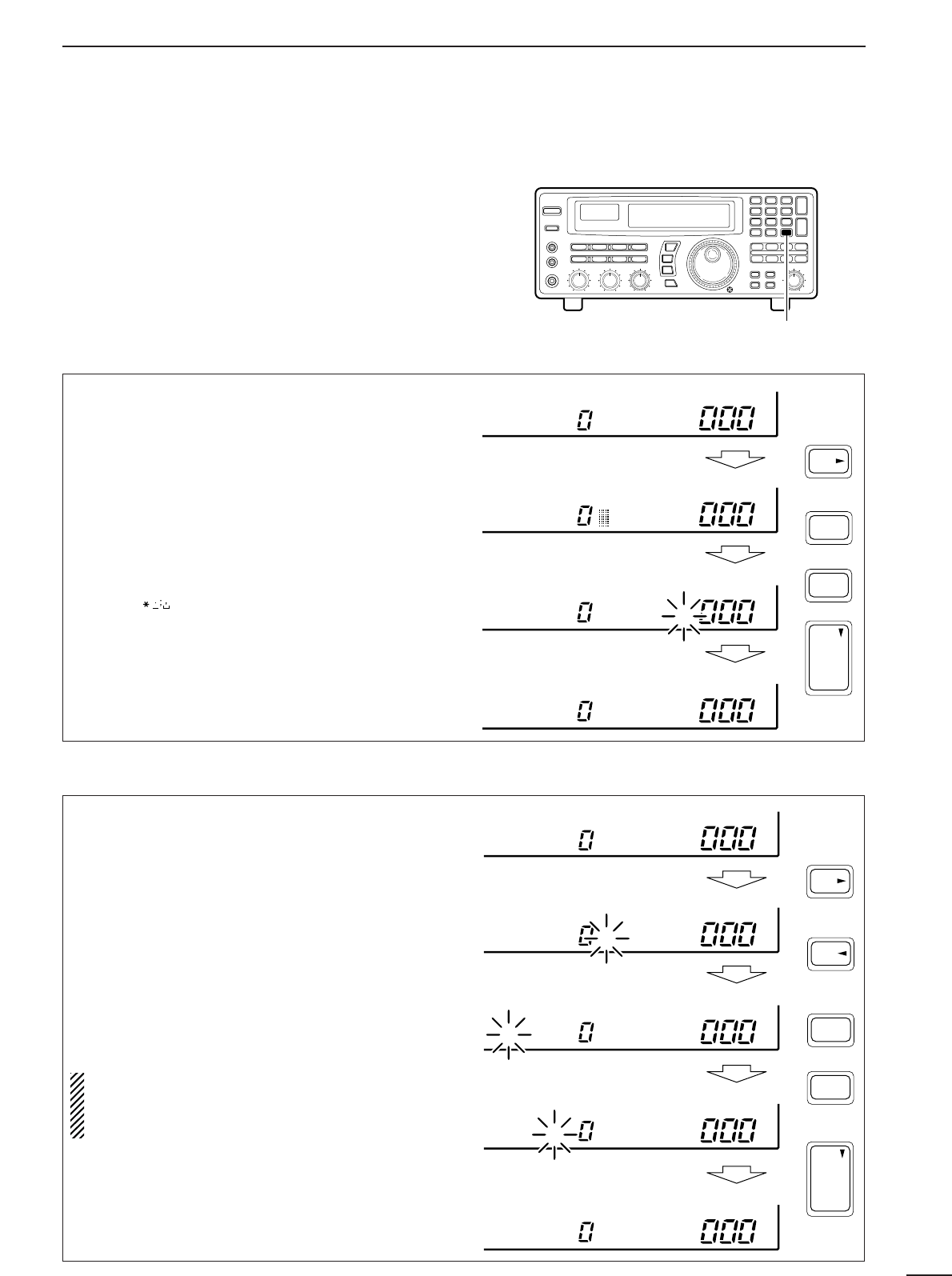
➂Push [CE
s
•NAME].
•A cursor appears at the first character space of the
name area.
➃Enter the desired name via the keypad.
•Push the appropriate keys to input the desired charac-
ters.
•To erase a character, overwrite with a ‘space’ using the
[M-CH • ] key.
•To move the cursor forwards or backwards, use the
[•
t
] or [CE
s
] key.
➄Push [ENT] to input the set name.
➀Select the desired bank using [M-CH •BANK
▲
] or
[ENT•BANK
▼
].
➁Push [CE
s
•NAME].
•A cursor appears at the first character space of the
name area.
•When no data is programmed, (“BLANK” appears) the
cursor does not appear. Program a frequency or
change the channel in such cases.
➂Push [•
t
] to move the cursor to the bank name
area.
➃Enter the desired name via the keypad.
•Use the same method as for channel names (see
above).
➄Push [ENT] to input the set name.
NOTE: When using [CE
s
] on the last digit of the
bank name, the current name is cleared and the
previous one is substituted. DO NOT forget to
push [ENT] after the bank name is set.
[CE
s
• NAME] key
1QZ
ENT
BANK
ENT
WXY
9
NAME
CE
to
USR-A
USR-A
USR-A MEMONAME
USR-A MEMONAME
DChannel name programming
DBank name programming
USR-A
USR-A
USR-A MEMONAME
MEMONAME
MEMONAME
BANKN MEMONAME
BANKN MEMONAME
ENT
BANK
ENT
.
NAME
CE
5 times
1QZ
WXY
9
to
21
5MEMORY CHANNELS
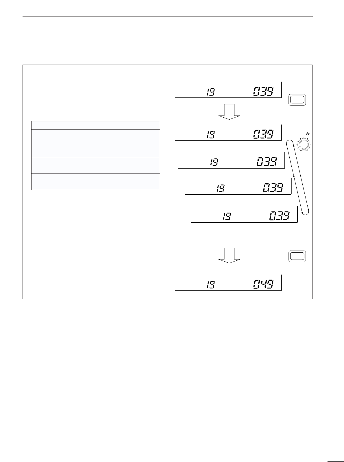
■Assigning channel numbers
The IC-R8500 has 20 banks in which memory chan-
nels can be programmed and arranged. By default,
each bank contains 40 memory channels, however,
channels can be deleted from or added (inserted) to
banks to suit your preferences and operating style.
Deleted channels are stored temporarily in the
“FREE” bank.
NOTE: When shipped from the factory or after
resetting the receiver’s CPU, the “FREE” bank has
no memory channels and cannot be selected.
To rearrange bank channel assignments:
➀Delete memory channels from banks that have
more memory channels than you need.
•Deleted channels are assigned to the ‘free’ bank auto-
matically.
➁Add (or insert) memory channels to banks in which
you want to add channels.
•Channels added to a bank are deleted from the ‘free’
bank.
➀Select the bank and memory channel you wish to
delete.
➁Push [BANK] for 1 sec.
•One of “INS. 1CH,” “DEL. 1CH,” “ADD.10CH,” or
“ADD. 1CH,”appears and flashes.
•Push [BANK] momentarily to exit the condition and
return to the previous display, if desired.
➂Rotate [M-CH] until “DEL. 1CH” appears in the
display.
➃Push [BANK] for 1 sec. to delete the selected
channel.
•The memory channel (but not its contents) is moved to
the “FREE” bank.
Memory channels can only be deleted one at a
time to prevent accidental deletion of multiple
channels; when you want to delete more than
one channel from a bank, repeat the above
steps as many times as necessary.
NOTE1: Deleted channels are moved to the
‘free’ bank, however, the programmed contents
are erased.
NOTE2: The number of banks cannot be
decreased. This means that if there is only one
channel in a bank, it cannot be moved to the
‘free’ bank.
DDeleting memory channels
[BANK] switch
[M-CH] control
USR-T DEL. 1CH
BLANK
USR-T
BANK
BANK
BANK
(for 1 sec.)
The number of channels in this bank is
decreased.
USR-T BLANK
INS. 1CH
USR-T
BANK
BANK
BANK
M-CH
(for 1 sec.)
22
5
MEMORY CHANNELS
➀Select the bank you wish to add memory chan-
nel(s) to.
➁Push [BANK] for 1 sec.
•One of “INS. 1CH,” “DEL. 1CH,” “ADD.10CH,” or
“ADD. 1CH,”appears and flashes.
•Push [BANK] momentarily to exit the condition and
return to the previous display, if desired.
➂Rotate [M-CH] to select the following:
➃Push [BANK] for 1 sec. to perform the selected
operation.
•The memory channel(s) are deleted from the “FREE”
bank and added/inserted to the selected bank.
•Memory channels cannot be added/inserted into a
memory bank when the “FREE” bank is empty.
DAdding/inserting memory channels
USR-T BLANK
USR-T
BANK
BANK
INS. 1CH
USR-T
BANK
BLANK
Insert 1 channel
USR-T
BANK
ADD. 1CH
Add 1 channel
USR-T
BANK
ADD.10CH
Add 10 channels
USR-T
BANK
DEL. 1CH
Delete channel
(see opposite page)
BANK
M-CH
(for 1 sec.)
BANK
(for 1 sec.)
INDICATION DESCRIPTION
INS. 1CH
1 channel will be inserted ‘in front’ of
the selected channel.
•Programmed contents after the inserted
channel are shifted accordingly.
ADD. 1CH 1 channel will be added ‘at the end’ of
the selected bank.
ADD.10CH 10 channels will be added ‘at the end’
of the selected bank.
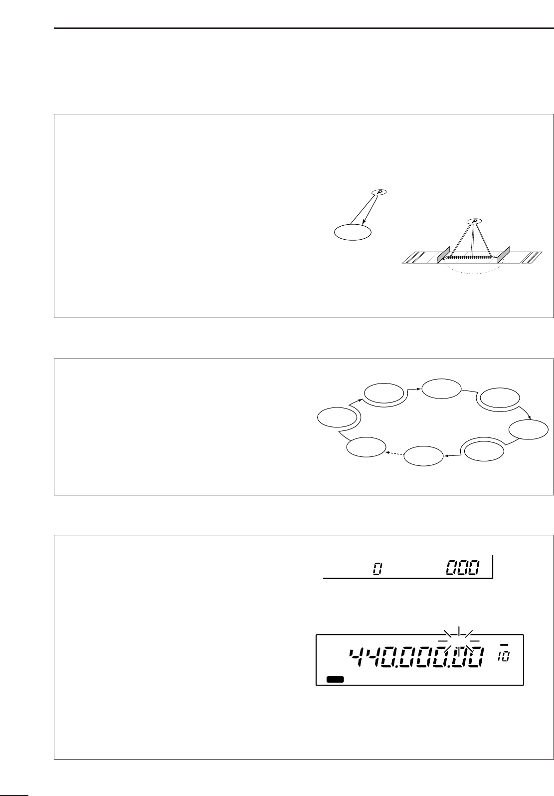
■Operation
DMemory scan
DMemory select scan
23
6SCANS
All memory channels (except skip channels) in the
selected bank are scanned at up to 40 ch/sec.
➀Push [M-CH •BANK
▲
] or [ENT •BANK
▼
] to select
the desired bank.
•Direct selection is also available as below.
➁Set the [SQUELCH] control to the threshold point.
➂Push [MEMO] to start the scan.
•“MEMO” appears in the bank name area.
➃Push [MEMO] again to stop the scan.
✔
Convenient:
Direct bank selection
—Memory scan can be started
in a specific bank without using [BANK
▲
/
▼
]:
➪Enter one or two digits for the bank number, then
push [MEMO].
Bank selection during memory scan
—The selected
bank can be changed without stopping the scan:
➪Enter one or two digits for the bank number, then
push [ENT].
Bank limit and skip scan release
—When starting
memory scan, the bank limit and channel skip functions
are activated automatically. Refer to p. 26.
Memory select scan allows you to increase scan effi-
ciency by searching for specified channels only,
thereby increasing the rate at which the scan cycles
through the memory channels. Set high priority chan-
nels as ‘select’ channels (memory select scan
searches for signals on these channels) while leaving
out lower priority channels.
Preparation—specifying select channels:
Select the channel you want to specify as a ‘select’
channel, then push [SEL] for 1 sec.
Start/stop:
➀Select the desired bank using [M-CH •BANK
▲
] or
[ENT•BANK
▼
].
➁Set the squelch control to the threshold point.
➂Push [SEL] momentarily to start scan.
•“SEL” appears in the bank name area.
➃Push [SEL] again to stop the scan.
NOTE:Memory select scan does not start unless
2 or more channels in the bank are specified as
select channels.
✔
Convenient:
The same convenient functions are available as de-
scribed above.
Mch 1
Mch 2 Mch 3 Mch 4
Mch 5
Mch 6
Mch 7
Mch 39
Skip
Select
Select
Select
Select
Push [MEMO]
FM OFF
kHz
DLY ∞
MEMO
MEMO appears
Push [SEL]
FM OFF
kHz
DLY ∞
SEL
SEL appears
Mch 1
Mch 2 Mch 3 Mch 4
Mch 5
Mch 6
Mch 7
Mch 39
Skip
Select
Select
Select
Select
Select
24
6
SCANS
DProgrammed scan DAuto memory write scan
Programmed scan (and auto memory write scan)
searches for signals within a specified frequency
range, using the selected tuning step increments. The
result is like an ‘automatic’ rotating of the main dial.
Preparation—setting the scan range:
Push and hold [PROG] to enter the ‘prog’ bank, then
input the desired edge frequencies, mode and tuning
steps. Refer to p. 27 for details.
Start/stop:
➀Set the [SQUELCH] control to the threshold point.
➁Push [PROG] to start the scan.
•“PROG” (and scan range number) appears in the bank
name area.
➂Push [PROG] again to stop the scan.
✔
Convenient:
Direct range selection
—The desired programmed
scan range can be selected using the keypad.
➪Push a numeral key before or after pushing the
[PROG] key.
Skip scan release
—Programmed scan skips all fre-
quencies specified as skip channels in all 1000 chan-
nels.
Auto memory write scan operates in the same way
as programmed scan. However, when a signal is
received, the received frequency is automatically
written into a memory channel in the auto write bank.
Preparation—written memories condition:
Push and hold [AUTO] to enter the written memory
setting condition, then rotate the main dial to select
the condition. :Previously written memories
in the ‘Auto’ bank are saved, then frequencies are
written into the next available channels.
:Previously written mem-
ories in the ‘Auto’ bank are cleared, then frequencies
are written into channels, starting from channel 0.
Start/stop:
➀Set the [SQUELCH] control to the threshold point.
➁Push [AUTO] momentarily or for 1 sec. to start the
scan.
•CAUTION:Be sure the written memories condition is set
as desired, otherwise previously written memories are
cleared.
•“AUTO” (and scan range number) appear in the bank
name area.
➂Push [AUTO] again to stop the scan.
✔
Convenient:
The same convenient functions are available as de-
scribed above.
Programmed edges
Push [PROG]
FM OFF
kHz
DLY ∞
PROG0 *NONAME*
PROG appears
AUTO bank
0
1
2
3
4
•
•
•
98
99
1234.567.00
1235.678.00
1235.890.00
1240.050.00
---------------
---------------
Push [AUTO]
FM OFF
kHz
DLY ∞
AUTO0 *NONAME*
AUTO appears
AUTO START
AUTO CL&START
25
6SCANS
DPriority scan
Priority scan monitors a specified frequency (the pri-
ority channel) once every 1–16 sec. (programmable)
during any operation, such as receiving, scanning
other channels, etc.
Preparation—priority channel programming:
➀Push [PRIO] for 1 sec.
•“*SET*” appears in the bank name area, then
changes to a flashing “PRIO.”
•Using this method, the priority channel can be called up
at any time with one push.
➁
Set the desired frequency, mode and memory
name.
➂Push [MW] for 1 sec. to write the contents into the
priority channel.
➃Push [PRIO] again to return to the previous chan-
nel.
Start/stop:
Push [PRIO] to start/stop the scan.
•Priority scan can be used in combination with other scan
types: start another scan type during priority scan; or,
push [PRIO] while operating another scan.
To operate memory scan or memory select scan in a
specific mode (ignoring other modes), the mode
select function is available.
➀Push [MEMO] or [SEL] to start memory scan or
memory select scan, respectively.
➁Select the desired mode to operate the scan in via
the mode switches.
•The mode select function is applied to memory or mem-
ory select scan.
➂Push [MEMO] or [SEL] again to stop the scan.
Priority scan
Programmed scan with priority scan
■Mode select function
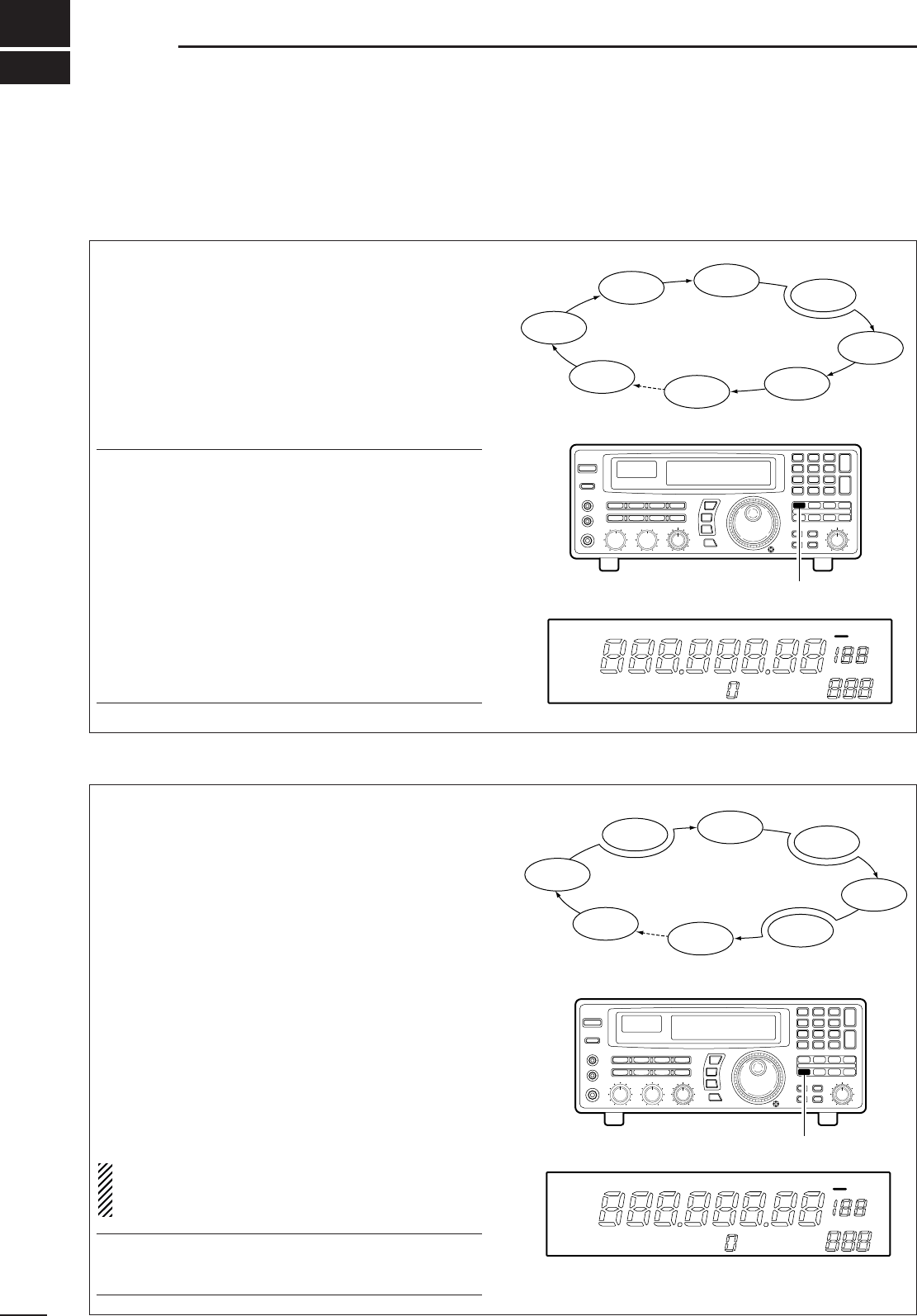
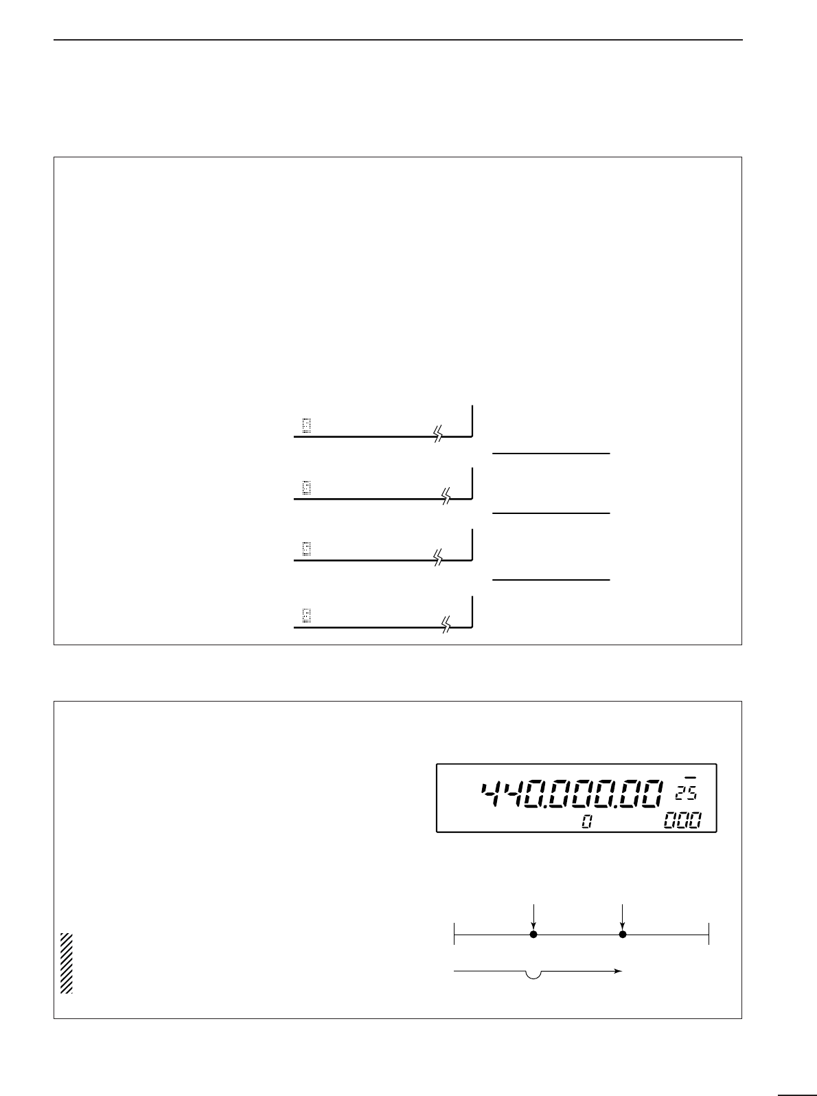
•Specifying skip channels
➀Select the memory channel to be specified as a
skip channel.
➁Push [SKIP] for 1 sec. to toggle the setting ON and
OFF.
•SKIP-CH appears when ‘skip’ is set.
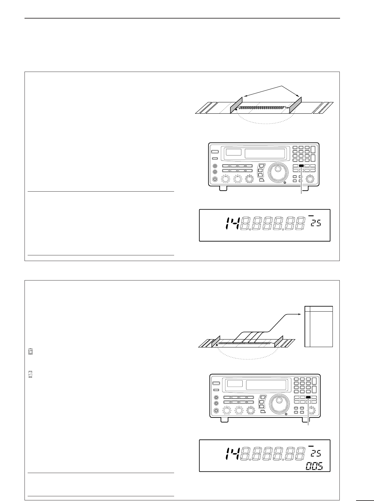
•Programming skip frequencies
(for programmed scan)
➀Start programmed scan.
➁When the scan pauses on an undesired signal,
push [MW] for 1 sec.
•The frequency is memorised into the skip bank as a
skip frequency.
•The specified channel is skipped during memory and
memory select scans.
•The programmed frequency is skipped during pro-
grammed and auto memory write scans.
■Specifying skip channel and frequency
ICOM IC-R8500
SKIP-CH
SKIP
kHz
The channel is specified as a ‘skip’ channel.
Push [MW] for 1 sec. while programmed scan pauses.
PROG0 IC-R8500
RECV
OFF DLY ∞
Mch 1
Mch 2 Mch 3 Mch 4
Mch 5
Mch 6
Mch 7
Mch 39
Skip
Select
FM
FM
WFM
USB
USB
USB
AM
USB
Select
Select
Select
26
6
SCANS
■Automatic bank limit/skip functions
When starting a scan, the following functions are
automatically turned ON by default; and the [SKIP]
and [BANK] switches are deactivated during scan.
•
The bank limit function
(for memory scan and select
memory scan)—The memory scan operates within
the selected bank only.
•Turning OFF the automatic function
➀Push [MEMO] for 1 sec.
•A display as at right appears.
➁Rotate the [M-CH] selector to
select the item, SKIP or
BANK.
➂Rotate the main dial to select
the function AUTO or MANU-
AL.
➃Push [MEMO] to return to the
previous display.
SKIP AUTO
SKIP MANUAL
BANK AUTO
BANK MANUAL
The skip function is turned ON automatical-
ly at scan start.
[SKIP] does not function during scan.
The bank limit function is turned ON au-
tomatically at scan start.
[BANK] does not function during scan.
The scan skip function is turned ON and
OFF by [SKIP] regardless of scan start.
The bank limit function is turned ON and
OFF by [BANK] regardless of scan start.
■Voice scan control function
This function is useful when you don’t want unmodu-
lated signals pausing or cancelling a scan. When
activated, the receiver checks received signals for
voice components.
If a receiver signal includes voice components, and
the tone of the voice components changes within 1
sec., scan pauses (or stops). If the received signal
includes no voice components or the tone of the
voice components does not change within 1 sec.,
scan resumes.
To toggle the function ON and OFF, push [VSC].
•“VSC” appears while it is activated.
•The VSC function activates for any scan.
•The VSC function resumes the scan on unmod-
ulated signals even when the resume condition is
set to “OFF” or “∞”.
Scan edge 1
Scan
Skip
Scan pauses or is
cancelled.
Unmodulated
signal Modulated
signal
Scan edge 2
FM VSC OFF
kHz
DLY ∞
ICOM- IC-R8500
VSC appears
•
The skip function
(for any scan except priority
scan)—memory channels specified as skip chan-
nels are not checked during memory scan and
select memory scan; the frequencies which are pro-
grammed into memory channels as skip channels
(not only in the skip bank but any memory chan-
nels) during programmed scan and auto memory
write scan.
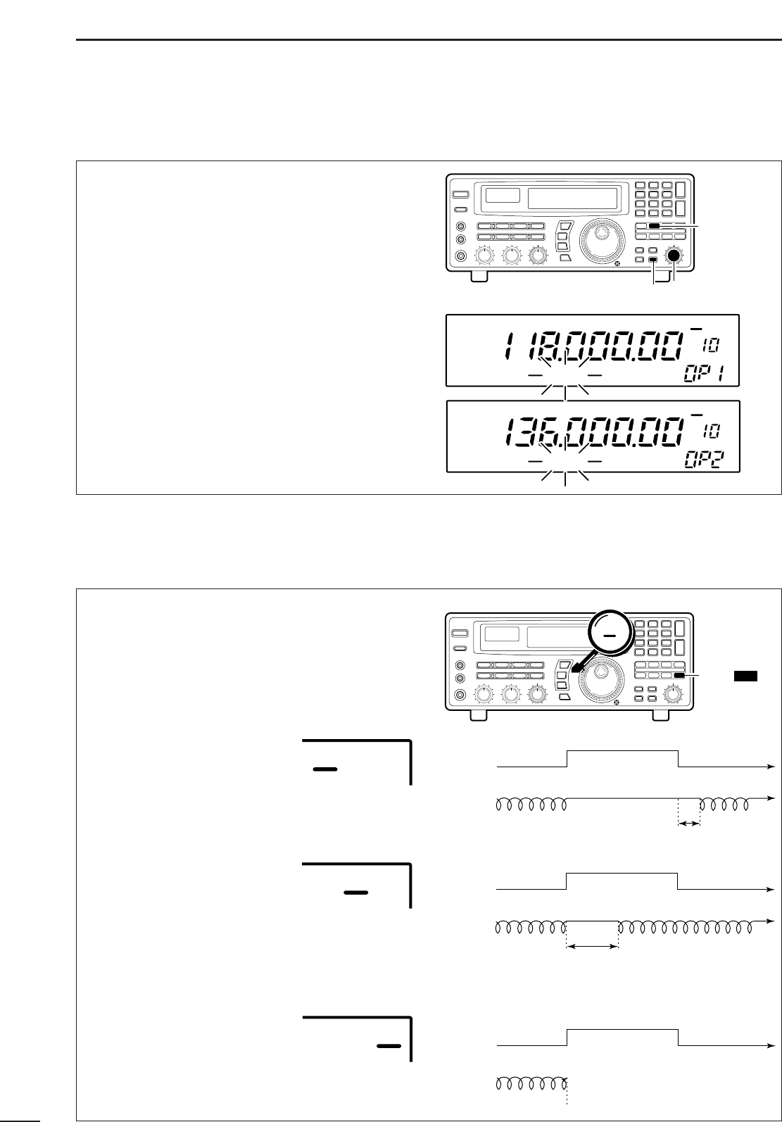
27
6SCANS
■Programming scan edge frequencies
A set of scan edge frequencies must be programmed
before starting the programmed or auto memory
write scans. 10 pairs of scan edges are available:
0P1 to 9P2.
➀Push [PROG] for 1 sec.
•“*SET*” appears in the bank name area, then
changes to a flashing “PROG.”
➁Rotate the [M-CH] selector to select the lower scan
edge in a pair e.g. 0P1.
•The keypad can also be used for selection.
➂Set the frequency, mode, tuning step and memory
name then push [MW] for 1 sec. to program one of
the scan edges.
➃Rotate the [M-CH] selector to select the other edge
in the pair e.g. 0P2.
➄
Set the frequency then push [MW] for 1 sec. to program.
•
Mode, tuning step and name are common to both scan edges.
➅Push [PROG] momentarily to return to the previous
channel; or repeat ➁to ➅for other scan edges.
Scan pauses when finding a signal, and then resumes
or is cancelled depending on the selected scan
resume condition. There are 3 resume conditions.
Push [DLY] one or more times to select a resume
condition.
•Scan resume OFF
Scan pauses until signal disap-
pears, then resumes 3 sec. after
that.
•Scan resume ON with adjusted
delay period
Scan pauses for the adjusted
delay period after receiving a signal, then resumes.
When the received signal disappears, scan resumes
approx. 3 sec. after that.
•Scan cancel
Scan is cancelled when a signal
is found during scan.
■Scan speed/delay functions
DScan resume condition
Signal no signal
scanning scanningpausing
3 sec.
receiving a signal no signal
Scan
[ ]
switch
OFF DLY ∞
DLY D/S
OFF DLY ∞
Signal no signal
scanning scanning
pausing
delay time
receiving a signal no signal
Scan
OFF DLY ∞
Signal no signal
scanning scan is cancelled
receiving a signal no signal
Scan
OFF DLY ∞
[ ]
switch
PROG
[MW] switch [M-CH] selector
AM
BANK
OFF
kHz
DLY ∞
PROG *NONAME*
AM
BANK
OFF
kHz
DLY ∞
PROG *NONAME*
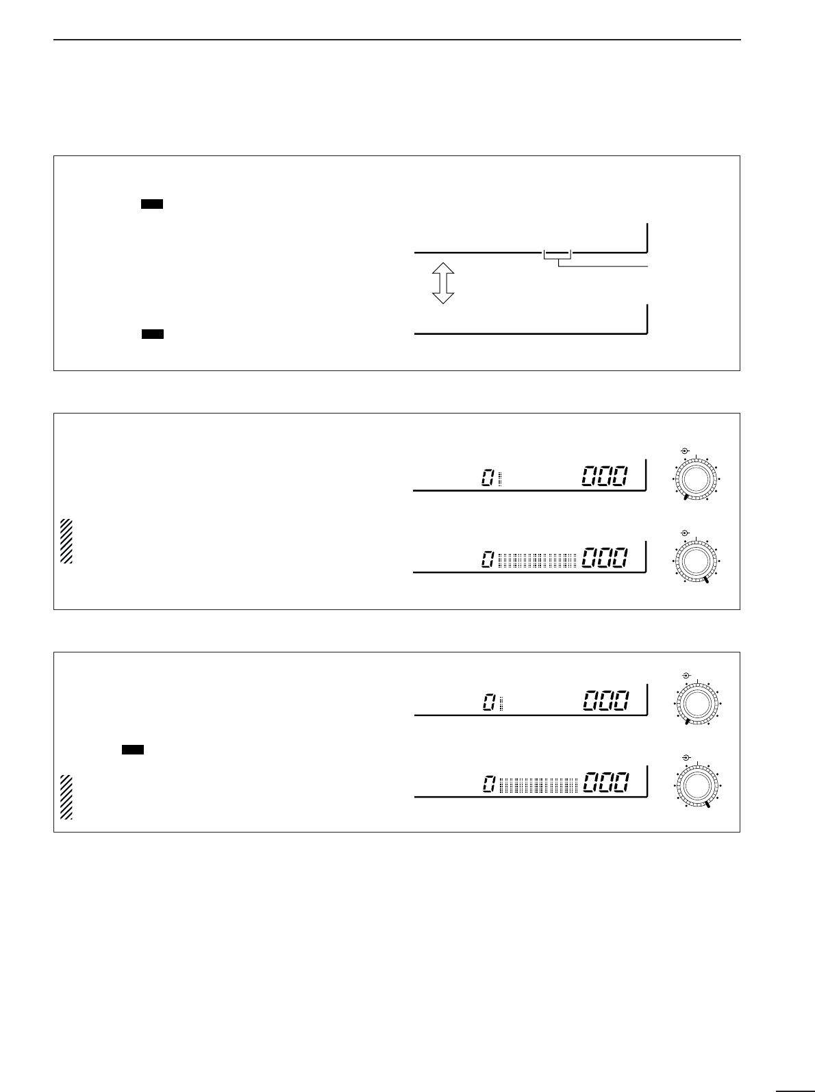
28
6
SCANS
When scan speed is assigned to the [DELAY/SPEED]
control (see above), the scan speed can be instantly
updated during scan operation.
The name area shows as at right for 1 sec. after
rotating the control.
When scan delay time is assigned to the
[DELAY/SPEED] control, the scan speed is fixed
at the maximum of 40 ch/sec.
Highest scan speed: 40 ch/sec.
Lowest scan speed: 1 ch/sec.
SPEED
SPEED
DELAY/SPEED
DELAY/SPEED
The [DELAY/SPEED] control adjusts the scan delay
period (scan resume period) when:
•The scan delay function is assigned to the
[DELAY/SPEED] control (see above).
•“DLY” is selected for the scan resume condition with
the [DLY ] switch.
When scan speed is assigned to the
[DELAY/SPEED] control, the scan delay is deter-
mined by the set value of 3 to 18 sec.
D/S
DScan delay
Longest delay time: 18 sec.
Shortest delay time: 3 sec.
DELAY
DELAY
DELAY/SPEED
DELAY/SPEED
The function of the [DELAY/SPEED] control is selec-
table, as shown below, to suit your operating style.
➀Push [DLY ] for 1 sec. to enter the setting con-
dition.
➁Rotate the main dial to select the function for the
[DELAY/SPEED] control.
➂When the scan speed is assigned to the
[DELAY/SPEED] control, the scan delay time is
determined while “VR:SPD DLY: 3S” appears.
•Rotate the [M-CH] selector to set the delay time.
➃Push [DLY ] to return to the previous display.
D/S
D/S
DAssigning a function to the [DELAY/SPEED] control
Scan speed is assigned to the [DELAY/SPEED] control
Toggle via the
main dial
Adjustable
via the [M-CH]
selector
Scan delay is assigned to the [DELAY/SPEED] control
VR:SPD DLY= 3S
VR:DLY SPD=MAX
DScan speed
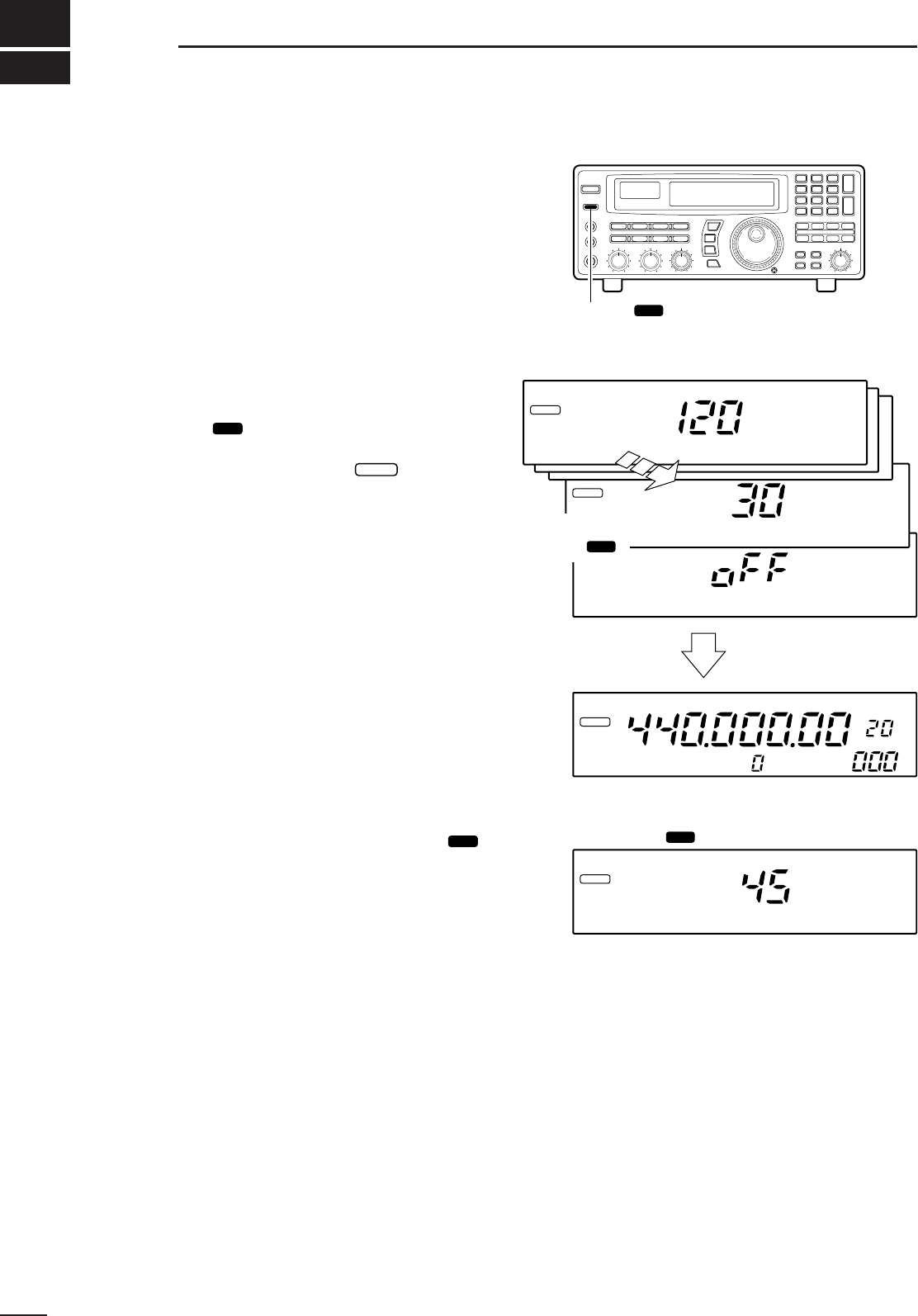
The IC-R8500 has a sleep timer function to automati-
cally turn the power OFF after a specified period.
DOperation
➀
Push [SLEEP/ ] momentarily, several times, to
activate the sleep timer and set the power OFF period.
•When the sleep timer is activated, “ ” appears in
the display.
•5 settings are available: 120, 90, 60, 30 min. and sleep
OFF.
➁2 sec. after performing step ➀above, the receiver
returns to the previous display.
➂To confirm the set sleep period, push [SLEEP/
] momentarily, one time.
•Be careful not to push the switch more than once, other-
wise the sleep period may be changed.
➃To turn ON the receiver after the sleep timer has
turned power OFF, push [POWER] OFF then ON
again.
•The sleep timer is cancelled.
SET
SLEEP
SET
29
7SLEEP TIMER
[SLEEP/ ] switch
SET
SLEEP
IC-R8500ICOM
SLEEP
Minutes
Minutes
Each push of
SLEEP/ SET
SLEEP/ SET
after 2 sec.
Previous display
Set time
Push once
kHz
SLEEP
Minutes
SLEEP
30
8
SET MODE
■General
Set mode is used for programming infrequently
changed values or conditions of functions. The
IC-R8500 has 2 separate set modes:
quick set mode
and
initial set mode
.
DSelecting quick set mode
➀Push [SLEEP/ ] for 1 sec.
•Quick set mode is selected and one of its items appears.
➁Rotate the [M-CH] control to select the desired item.
➂Rotate the main dial to set the values or conditions
for the selected item.
➃Repeat steps ➁and ➂to set other items.
➄To exit quick set mode, push [SLEEP/ ] again.
•Pushing any other switch will also exit quick set mode.
DSelecting initial set mode
➀Push [POWER] to turn power OFF.
➁While pushing [SLEEP/ ] push [POWER] to turn
power ON.
•Initial set mode is selected and one of its items appears.
➂Rotate the [M-CH] control to select the desired item.
➃Rotate the main dial to set the values or conditions
for the selected item.
➄Repeat steps ➂and ➃to set other items.
➅To exit initial set mode, push [POWER] to turn
power OFF.
➆Push [POWER] to turn power ON again.
•The conditions selected in initial set mode are now effec-
tive.
SET
SET
SET
SCAN SET
Main dial (for contents)
[SLEEP/ ]
(push for 1 sec.) [M-CH]
(for items)
SET
SCAN SET
[POWER] Main dial (for contents)
[SLEEP/ ] at power ON [M-CH]
(for items)
SET
WFM OFF
kHz
DLY ∞
HIGH DIMMER
Item number
Item
Value or
condition
[DISPLAY EXAMPLE: QUICK SET MODE]
ON REC REMO
Item number
Item
Value or
condition
[DISPLAY EXAMPLE: INITIAL SET MODE]

31
8SET MODE
■Quick set mode items ■Initial set mode items
DIMMER
This item toggles the intensity of the display back-
lighting between high or low.
Bright backlighting
(default).
HIGH
Dark backlighting.
LOW
BEEP
A beep sounds each time a switch is pushed for con-
firmation. This function can be turned OFF for silent
operation.
Confirmation beeps
ON (default).
ON
Confirmation beeps
OFF.
OFF
LOCK
This item sets the lock function to electronically lock
the main dial only or both the main dial and the panel
switches.
Only the main dial
can be locked (default).
DIAL
Both the main dial and panel
switches can be locked.
PANEL
AUTO TS
This item sets the auto tuning speed. The main dial
normally changes the frequency [400]×[tuning step]/
revolution. When auto tuning speed is turned on this
increases to [2000]×[tuning step]/revolution during
quick rotation of the dial.
The auto tuning speed
function is ON (default).
ON
The auto tuning speed
function is OFF.
OFF
HF ANT
This item sets the active HF antenna connector on
the rear panel. Either the 50 Ω(SO-239 coaxial) or
500 Ω(phono RCA connector) can be activated.
The SO-239 antenna con-
nector is activated (default).
50
The RCA (phono) connector
is activated.
500
REC REMO
This item activates/deactivates the REC REMOTE
jack on the front panel. When ON is selected, the
[REC REMOTE] jack is at a “low” level when the
squelch opens via the internal relay.
The REC REMOTE jack
can be used (default).
ON
The REC REMOTE jack has
no function and no relay
switching sound is heard.
OFF
REC SPCH
When the optional UT-102
VOICE SYNTHESIZER
is
installed and scan is in use, the detected frequency
is announced each time scan pauses, regardless of
the [SPCH/LOCK] switch. This announcement can
be turned ON and OFF.
The detected frequency is
announced when scan
pauses (default).
ON
The optional voice synthe-
sizer activates via the
[SPCH] switch only.
OFF

32
8
SET MODE
SPCH LAN
When the optional UT-102
VOICE SYNTHESIZER UNIT
is
installed, you can select between English and
Japanese as the language.
Voice synthesizer functions
in English (default).
ENG
Voice synthesizer functions
in Japanese.
JPN
SPCH SPD
When the optional UT-102
VOICE SYNTHESIZER UNIT
is
installed, you can select between faster or slower
synthesizer output.
Voice synthesizer output
is faster (default).
FAST
Voice synthesizer output
is slower.
SLOW
CIV ADDR
To distinguish equipment, each CI-V
transceiver/receiver has its own Icom standard
address in hexadecimal code. The IC-R8500’s
address is 4AH.
When 2 or more IC-R8500’s are connected to an
optional CT-17
CI
-
V LEVEL CONVERTER
, rotate the
main dial to select a different address for each IC-
R8500 in the range 01H to 7FH.
Address set to 4AH
(default).
4AH
Address set to 01H.
01H
CIV BAUD
This item sets the data transfer rate. When “AUTO”
is selected, baud rate is automatically set according
to the connected controller or other Icom CI-V radio.
Auto baud rate
(default).
AUTO
19200 bps
19200
CIV TRAN
Transceive operation is possible with the IC-R8500
connected to an Icom CI-V radio. When “ON” is
selected, changing the frequency, operating mode,
etc. on the IC-R8500 automatically changes those of
connected radios and vice versa.
Transceive ON
(default).
ON
Transceive OFF.
OFF
CIV 731
When connecting the IC-R8500 to the IC-735 for
transceive operation, you must change the operating
frequency data length to 4 bytes.
•This item
must
be set to “ON” only when operating trans-
ceive with the IC-735.
Frequency data set to
5 bytes (default).
OFF
Frequency data set to
4 bytes.
ON
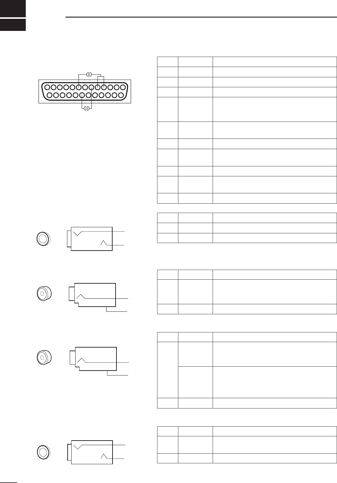
33
9CONNECTOR INFORMATION
DRS-232C socket
DRemote jack
DIF OUT jack
DAGC OUT jack
DExternal speaker
Pin Port name Description
1GND Grounded.
2RXD Input port for CI-V format data; +12V/–12V.
3 TXD Output port for CI-V format data; +12V/–12V.
4
5RTS
CTS
Shorten these ports inside.
Can be connected to pin 8 (DCD) via the inter-
nal circuit board (‘coffee beans’).
6DSR NC; can be connected to pin 20 (DTR) via the
internal circuit board (‘coffee beans’).
7GND Grounded.
8DCD
NC; can be connected to pins 4 and 5 (RTS/CTS)
via the internal circuit board (‘coffee beans’).
9–19 NC No connection.
20 DTR NC; can be connected to pin 6 (DSR) via the
internal circuit board (‘coffee beans’).
21–25 NC No connection.
13 1
25 14
Pin Port name Description
Inner REMOTE Input/output port for CI-V format data; +5 V/0 V.
Outer GND Grounded.
Pin Port name Description
Inner IF OUT
Frequency:10.7 MHz
Output level:–60 dBm (with –50 dBm input from
an antenna connector in WFM mode)
Outer GND Grounded.
*Output is selectable with an internal jumper pin (p. 16).
Pin Port name Description
Inner*
AGC out
Output voltage:1 to –2.4 V DC
(signal strength weak to strong)
Output impedance:2.2 MΩ
Audio detect
Output level:200 mV rms
(at Mod.=1 kHz, Dev.=3.5 kHz)
Output impedance:4.7 kΩ
•Before the frequency de-emphasis stage.
•Usable for FM only (not including WFM).
Outer GND Grounded.
Pin Port name Description
Inner AF out Output level:More than 2 W
Output impedance:4–8 Ω
Outer GND Grounded.
3.5 mm (diam.) 2-conductor
Outer
Inner
RCA (phono) jack
Inner
Outer
RCA (phono) jack
Inner
Outer
3.5 mm (diam.) 2-conductor
Outer
Inner
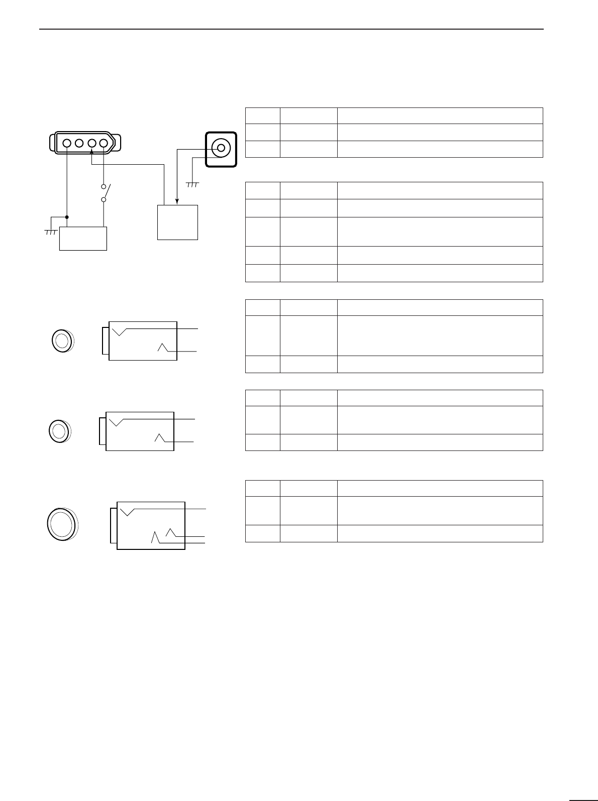
34
9
CONNECTOR INFORMATION
DDC 13.8 V and DC IN sockets
DREC REMOTE jack
•DC IN
•DC 13.8 V
DC 13.8 V
Inner
Outer
[POWER]
switch
Receiver
circuit
Internal
regulator
circuit
DC IN
41
Pin Port name Description
Inner DC IN Accepts connection to the AD-55A/V only
Outer GND Grounded.
Pin Port name Description
113.8 IN 13.8 V DC input; current consumption 2 A
212.5 OUT 12.5 V DC output when connecting AD-55/A/V
to [DC IN] socket. Max. 2 A
3NC —
4GND Grounded.
Pin Port name Description
Inner SQL
•Grounded when squelch opens.
•Can be deactivated via initial set mode. (p. 31)
•Max. current: 1 A/12 V DC
Outer GND —
Pin Port name Description
Inner DET •Output detected audio output.
•100–300 mV rms/4.7 kΩ
Outer GND Grounded.
Pin Port name Description
Inner,
Middle Audio •Outputs audio.
•Output impedance: 4–16 Ω
Outer GND Grounded.
3.5 mm (diam.) 2-conductor
Outer
Inner
DREC OUT jack
3.5 mm (diam.) 2-conductor
Outer
Inner
DPHONES jack
6 mm (diam.) 3-conductor
Middle
Inner
Outer

CONTROL COMMANDS
10
35
The IC-R8500 can be connected to a PC via the PC’s
RS-232C port. This allows you to control the receiver from the PC and/or transfer data from the receiver to
the PC.
Operation Cn Sc Remark
Reading freq. edges
Reading operating freq.
Reading operating mode
02
03
04
—
—
—
Reading M-ch contents package
Reading bank name
1A
1A
01
03
add bn+mc*
add bn*
Reading squelch condition
Reading S-meter level
Reading model ID
15
19
01
02
00
05 add fd*
Set operating
mode 06
0001
0101
0202
0201
0203
0301
0302
0501
0502
0601
Memory channel selection
Bank selection
Memory write
08
08
09
—
A0
—
mc*
bn*
Set M-ch contents & write package
Set bank name
Memory clear
1A
1A
0B
00
02
—
add dt*
add bn+nd*
Stop scan
0E
00
Programmed scan start
Auto memory write scan start
02
04
note 1
note 1
Memory scan start
Select memory scan start
Mode select scan start
22
23
24
note 2
note 2
note 2
Priority scan 42
SEL-CH release
SEL-CH tag
B0
B1
VSC deactivation
VSC activation
C0
C1
Scan resume selection “
∞
”
Scan resume selection “OFF”
Scan resume selection “DLY”
D0
D1
D3
LSB
USB
AM
AM narrow
AM wide
CW
CW narrow
FM
FM narrow
WFM
Operation Cn Sc Remark
Tuning step 10
00
01
02
03
04
05
06
07
08
09
10
11
12
13
11
00
10
20
30
13 00
01
03
04
05
add gd*
add gd*
add gd*
add gd*
Memory clear 16
10
11
20
21
30
31
Power OFF (activating sleep)
Power ON (from sleep active) 18 00
01
1 MHz
programmable
OFF
10 dB
20 dB
30 dB
frequency
10 Hz
50 Hz
100 Hz
1 kHz
2.5 kHz
5 kHz
9 kHz
10 kHz
12.5 kHz
20 kHz
25 kHz
100 kHz
Voice
synthesizer
Attenuator
AF gain setting
Squelch level setting
IF shift setting
APF control setting
14
AGC OFF
AGC ON
APF OFF
APF ON
NB OFF
NB ON
Note 1: Only scan group 0 is usable.
Note 2: Use these commands after sending a bank or mode
command.
Set frequency
■Command table
FE FE 4A E0 Cn Sc Data area (e.g. fd) FD
Preamble code (fixed)
PC’s address
IC-R8500’s address
(selectable in set mode)
Command number
(see table)
Sub command number
(see table)
BCD code area
(‘REMARK’ in table)
End of message code
FE FE E0 4A Cn Sc Data area (e.g. fd) FD
Preamble code (fixed)
PC’s address
IC-R8500’s address
(selectable in set mode)
Command number
Sub command number
BCD code area
End of message code
■Data format
•Basic format from PC to IC-R8500 •Answer from IC-R8500 to PC
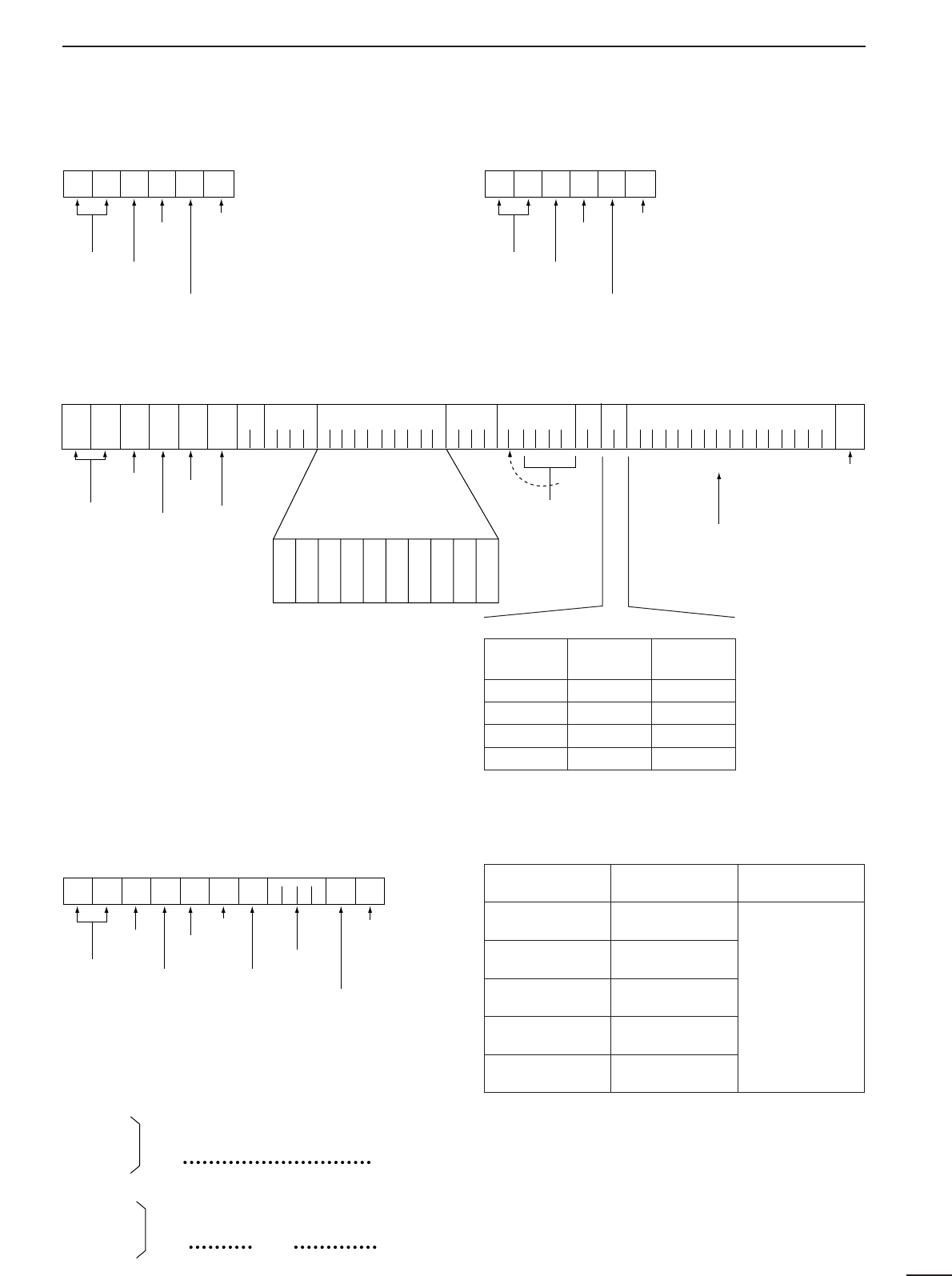
36
10
COMMAND LIST
•‘OK’ message from IC-R8500 to PC •‘NG’ message from IC-R8500 to PC
•Memory channel contents set & write (1A 00)
The above data packet is an example of programming
the following into memory channel 123 of bank num-
ber 19:
•Frequency:1,234,567,890 Hz
•Mode:FM
•Tuning step:199.5 kHz (programmable step)
•Attenuator:10 dB
•Scan select:specified
•Scan skip:specified
•Memory name:IC-R8500
Scan skip and select channels
FE FE E0 4A FB FD
Preamble code
PC’s address
IC-R8500’s address
OK code
End of message code
FE FE 4A E0 1A 00
1901239078563412
050113
9519
1003
4943205238353030
FD
Memory name
Tuning step
Mode(Sc)
FrequencyCH no.
Bank
SCN
ATT
Preamble code
IC-R8500’s address
PC’s address
Command number
Sub command
(IC-R8500’s command)
10 Hz
1 Hz
1 kHz
100 Hz
100 kHz
10 kHz
10 MHz
1 MHz
1 GHz
100 MHz
End of message code
ASCII code
BCD code area
(only needed when ‘13’
is selected)
IC-R8500
FE FE E0 4A FA FD
Preamble code
PC’s address
IC-R8500’s address
NG code
End of message code
Comment
number Scan select Scan skip
00 OFF OFF
01 OFF Specified
02 Specified OFF
03 Specified Specified
•Clearing the specified channel data
(Memory channel contents set & write) •Special bank number and channels (bn)
FE FE 4A E0 1A 00 19 0 1 2 3 FF FD
Preamble code
PC’s address
IC-R8500’s address
Command number
End of message code
Blank data
Memory channel
number
IC-R8500’s command
Bank number
Special bank Bank number
FREE 20
AUTO 21
SKIP 22
PROG 23
PRIO 24
Remarks
•For programmed
scan, channel num-
bers are as follows:
0P1=00, 0P2=01,
1P1=02, 1P2=03,
etc., up to 9P1=18
and 9P2=19.
•There is only one
channel in the prior-
ity bank.
•Gain and level data (gd; BCD data)
AF GAIN
SQUELCH
Max.
counterclockwise
0000
Max.
clockwise
0255
IF SHIFT
APF control
Max.
counterclockwise
0000
Max.
clockwise
0255
center
0128
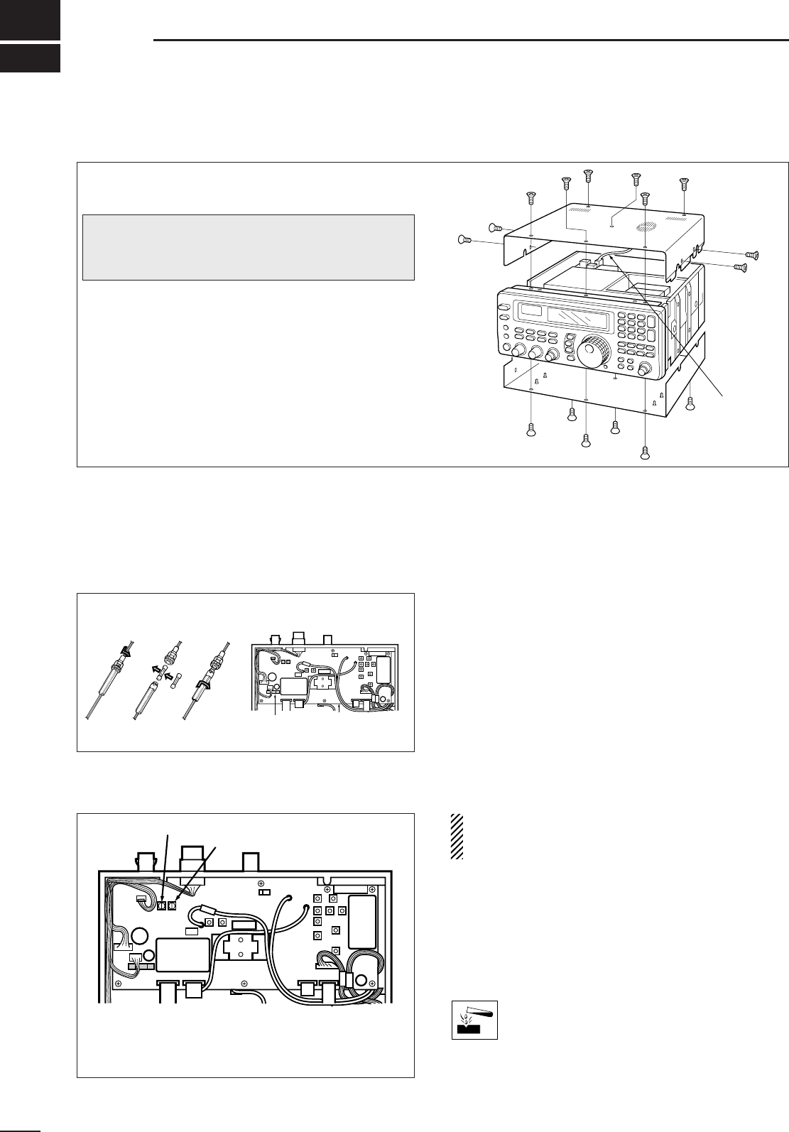
■Disassembly
■Fuse replacement
If a fuse blows or the receiver stops functioning, try to
find the source of the problem, and replace the dam-
aged fuse with a new, rated fuse.
■Level adjustments
3 A FGB
•For DC cable fuse •For internal fuse
37
11 MAINTENANCE
■Memory backup
All of the CPU’s memory is backed up by an EEP-
ROM (Electronically-Erasable Programmable Read-
Only Memory). All data you set, such as memory con-
tents, set mode contents, etc. is stored in this EEP-
ROM. There is no internal lithium battery.
■CPU resetting
If the IC-R8500 is behaving erratically, this may be an
indication of a CPU malfunction. In such cases, reset
the CPU.
While pushing [MW], push [POWER] in to turn on the
receiver power.
•The CPU is reset.
NOTE: Resetting the CPU clears all memory con-
tents and returns internal settings to their factory
defaults.
■Cleaning
If the receiver becomes dusty or dirty, wipe it clean
with a dry, soft cloth.
AVOID the use of strong chemical solvents such as
thinner, benzine or alcohol to clean the
receiver. These may damage the receiver’s
surfaces.
For internal maintenance and optional installations,
disassemble the receiver.
➀Remove 6 screws from the top of the receiver and
4 screws from its sides.
➁Carefully lift up the top cover while disconnecting
the plug from the speaker cable.
➂Turn the receiver upside down.
➃Remove 6 screws from the bottom cover, then lift
up the bottom cover.
Speaker
cable
MAIN unit
Fuse
(FGMB 125 V 3 A)
CAUTION: DISCONNECT the DC power cable
or AC adapter before performing any work on the
receiver.
R254 R252
R252 adjusts the beep level
R254 adjusts the UT-102 output level
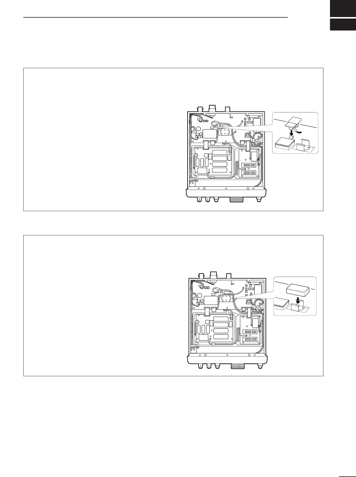
12
OPTIONAL INSTALLATIONS
■UT-102
VOICE SYNTHESIZER UNIT
The UT-102 announces the accessed frequency in a
clear, electronically generated voice, in English (or
Japanese) when pushing [SPCH] or when a signal is
detected during scan (see p. 31, 32 for settings).
➀Remove the top cover as shown opposite.
➁Remove the protected paper attached to the bot-
tom of the UT-102 to expose the adhesive strip.
➂Connect the UT-102 as shown in the diagram at
right.
➃Replace the top cover.
J12
UT-102
■FL-52A
CW NARROW FILTER
The IC-R8500 has a CW narrow mode which pro-
vides better S/N (signal-to-noise) and also rejects
nearby interference. The CW narrow filter is helpful
when receiving CW and radio-teletype signals.
➀Remove the top cover as shown opposite.
➁Connect the FL-52A as shown in the diagram at
right.
•Make sure it is connected in the proper orientation.
•Attached nuts on the FL-52A are not necessary. If you
want to install the filter more securely, open the MAIN
unit, then use the nuts on the bottom of the MAIN unit.
➂Replace the top cover.
FL-52A
Under the top cover
Under the top cover
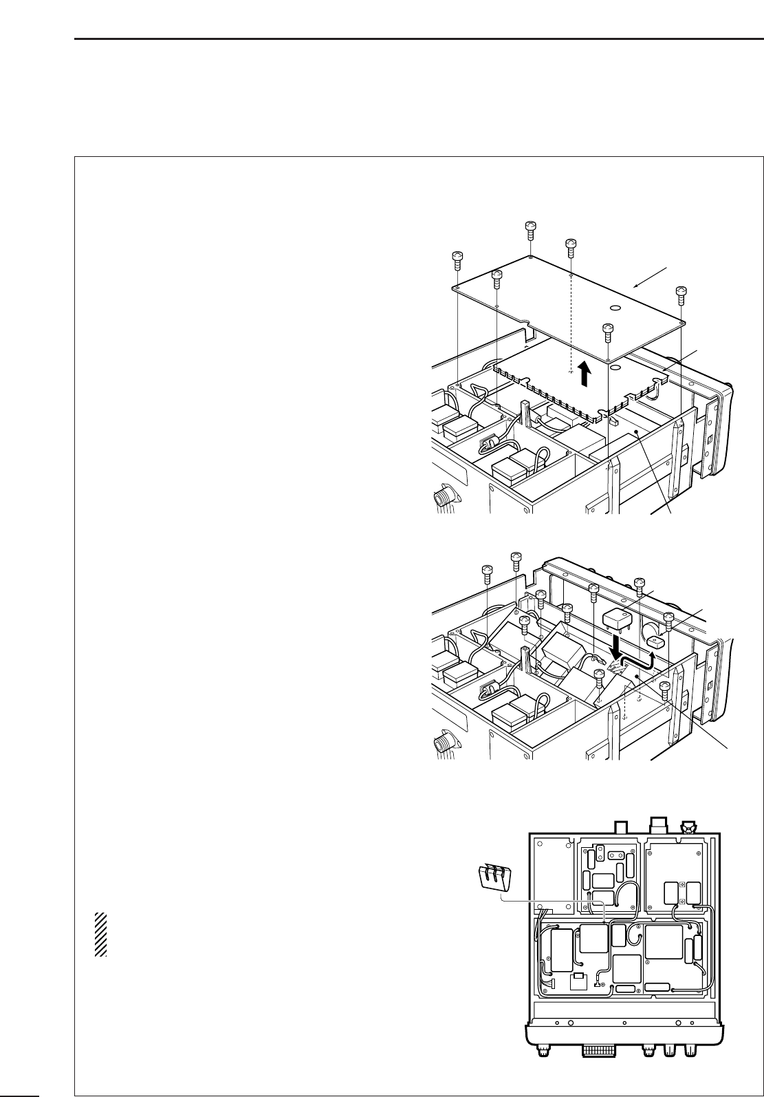
39
12 OPTIONAL INSTALLATIONS
■CR-293
HIGH STABILITY CRYSTAL UNIT
A temperature-compensating crystal with a stability of
±3 ppm is built-in to the receiver. For more demand-
ing operation, the CR-293
HIGH STABILITY CRYSTAL
UNIT
is available. It has a stability of ±0.5 ppm.
➀Remove the bottom cover as shown on p. 37.
➁Remove 6 screws from the metal plate, then
remove the metal plate and shield cover.
➂Remove 10 screws from the PLL unit, then open
the unit to expose the bottom.
➃Unsolder the feet of the internal crystal unit, then
remove it.
➄Place the CR-293 in the space available as shown
in the diagram, then solder its feet into place (6
points).
➅Adjust the reference frequency using a frequency
counter.
➆Replace the ground spring to its original position.
➇Return the shield cover, metal plate and bottom
cover to their original positions.
NOTE: The CR-293 is an oven-type crystal unit,
and the specified frequency stability described
above is guaranteed 1 min. after power ON.
Shield
cover
PLL unit
Ground
spring
PLL unit
CR-293
Internal
crystal
unit
Metal plate
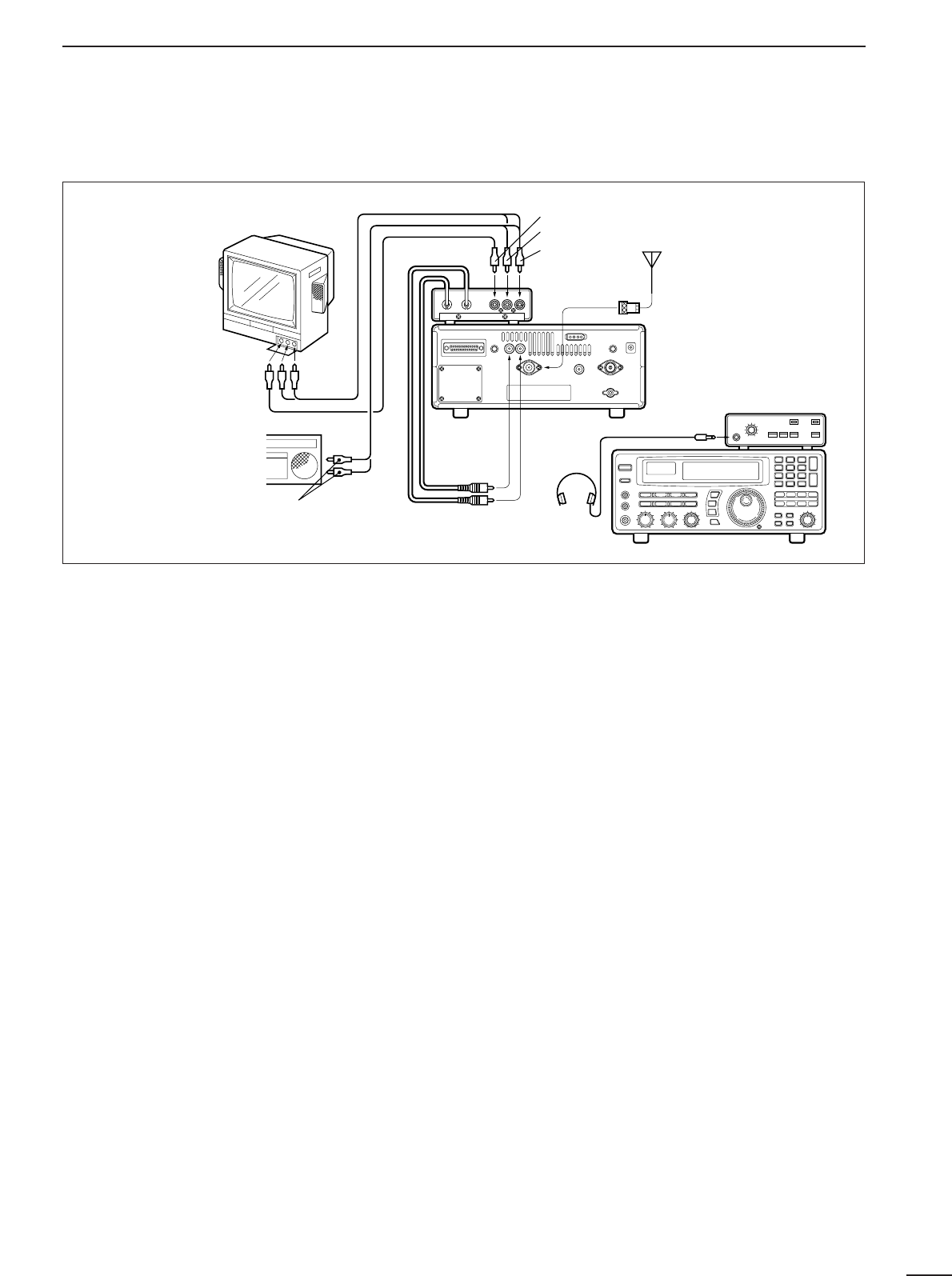
40
12
OPTIONAL INSTALLATIONS
■TV-R7100
TV RECEIVE ADAPTER
DConnections
DOperation
➀Turn on the TV-R7100, IC-R8500 and all connected
equipment.
➁Select WFM mode.
➂➥Push OUT [FM/TV] on the TV-R7100 to select
“TV” when receiving TV broadcasts or ATV.
➥Push IN [FM/TV] on the TV-R7100 to select “FM”
when receiving FM broadcasts in stereo.
➃Set the frequency of the audio center frequency of
the desired TV or FM signals by the main dial or di-
rect keypad entry.
•The FM center indicator on the IC-R8500’s function dis-
play is useful for tuning.
•Pictures appear on your TV screen and sound is emitted.
DTV-R7100 specifications
General
•Power supply requirement:9 V negative ground
(supplied from the IC-
R8500)
•Current drain: Approx. 100 mA
(when receiving no sig-
nal)
•Dimensions:110(W)×35(H)×200(D) mm;
4.3(W)×1.4(H)×7.9(D) in
(projections not included)
•Weight:750 g; 1.7 lb
•Headphone jack impedance:32 Ω(approx.)
TV receiver
•Video carrier input frequency:15.2 MHz
(U.S.A. ver-
sion)
16.2 MHz
(Europe ver-
sion)
•Audio carrier input frequency:10.7 MHz
•Audio intermediate frequency:4.5 MHz
(U.S.A. version)
5.5 MHz
(Europe version)
•Video output level:1 V p-p (75 Ω)
•Audio output level:300 mVrms/47 kΩload
(U.S.A. version)
400 mVrms/47 kΩload
(
Europe
version
)
FM receiver
•Intermediate frequency:10.7 MHz
•Selectivity:230 kHz/–6 dB
•Audio output level:300 mV/47 kΩ
•Stereo separation:More than 30 dB (1 kHz)
TV-R7100
stereo
headphones
Antenna
yellow
white*
red
[IF OUT]
red from
[IF IN]
black from
[TV CONTROL]
Red to right
White to left
Yellow: no connection
Red to right*
White to left
Yellow to video
*When the TV set
has only one audio
jack, connect the
white cable only.
[AGC]

41
13 TROUBLESHOOTING
The following chart is designed to help you correct
problems which are not equipment malfunctions. If
you are unable to locate the cause of a problem or
solve it through the use of this chart, contact your
nearest Icom Dealer or Service Center.
POSSIBLE CAUSE SOLUTION REF.
POWER
• DC power cable is improperly con-
nected.
• A fuse is blown.
• During AC adapter operation, the
jumper connector is not in use.
• External 12 V DC is connected to the
[DC IN] jack.
• Reconnect the DC power cable se-
curely.
• Check for the cause, then replace the
fuse with a spare one.
•
Connect the jumper connector to the
[DC13.8V] jack on the receiver’s rear panel.
• Connect the external power source to
the [DC13.8V] jack. The [DC IN] jack ac-
cepts an AC adapter (AD-55/A/V) only.
p. 8
p. 37
p. 8
p. 8
RECEIVE FUNCTIONS
• Volume level is too low.
• The squelch is closed.
• An external speaker or headphones are
connected.
• CW narrow mode is selected when no
optional filter is installed.
• Rotate [AF GAIN] clockwise to obtain a
suitable listening level.
• Rotate [SQUELCH] counterclockwise to
open the squelch.
• Disconnect the external speaker or
headphones.
• Select another mode or install the op-
tional CW narrow filter.
—
p. 14
—
pgs.
13, 38
• The coaxial cable is cut.
• No antenna is connected.
• The connected antenna is not matched
to the receive frequency.
• Wrong antenna connector is used for
V/UHF and HF antenna.
• Wrong antenna connector is selected in
set mode for HF antenna.
• An RF attenuator is activated.
• Fix the coaxial cable.
• Connect an antenna.
• Connect an antenna matched to the re-
ceiving frequency.
• Check the antenna connection.
• Select the proper antenna connector:
SO-239 or phono (RCA).
• Push [ATT 10 dB] or [ATT 20 dB] to can-
cel the function.
—
p. 8
p. 8
p. 8
p. 31
—
• [IF SHIFT] is rotated too far CCW or
CW.
• [APF] is rotated too far CCW or CW.
• The wrong mode switch is pushed.
• Set [IF SHIFT] to the center position.
•
Set the [APF] control to the center position
or push the [APF] switch to turn it OFF.
• Push the correct mode switch.
p. 14
p. 15
p. 13
• The operating frequency is lower than
30 MHz. (WFM mode cannot be se-
lected below 30 MHz.)
• Set the frequency above 30 MHz when
in WFM mode. p. 13
FRONT PANEL CONTROL
• The lock function is activated. • Push [LOCK] for 1 sec. to deactivate. p. 12
•DIAL LOCK is selected in quick set
mode. • Select PANEL LOCK in quick set
mode.
p. 31
PROBLEM
Power does not turn
ON when [POWER] is
pushed in.
No sound comes from
the speaker.
Sensitivity is low.
Receive signal is un-
clear or distorted.
WFM mode cannot be
set.
Main dial does not func-
tion.
[LOCK] does not lock
the keypad, function
switches, etc.
• The memory channel was changed be-
fore writing into memory. • Push [MW] for 1 sec. to write into a
memory before changing channels. p. 19The selected frequency
is erased.
• An optional UT-102
VOICE SYNTHESIZER
UNIT
is not installed. • Install the UT-102. p. 38The frequency is not
announced when push-
ing [SPCH].
• The sleep timer has been activated. • Turn power back ON, then push
[SLEEP] one or more times to turn the
sleep timer function OFF, if desired.
p. 29Receiver turns OFF by
itself.

42
13
TROUBLESHOOTING
MEMORY CHANNELS
• The bank limit function is activated and
“BANK” is indicated. • Push [BANK] to turn OFF the bank limit
function or use [BANK] or [BANK] to se-
lect the bank.
p. 18Memory channels in
another bank cannot be
selected.
SCAN
• [SQUELCH] is open and [∞] is selected. • Turn [SQUELCH] CW until noise disap-
pears. p. 14No scan will function.
• The same frequencies are programmed
into the selected scanning group. • Reprogram different frequencies into
scan edge channels or select a different
programmed scan group.
p. 27Programmed scan and
auto memory write scan
does not function.
• All channels are specified as “SKIP”
channels in the selected bank.
• No memory channels have yet been
programmed in the selected bank.
• Turn OFF the automatic skip function or
release the “SKIP” setting for 2 or more
channels in the selected bank.
• Program 2 or more channels in the se-
lected bank.
pgs.
25, 26
p. 19
Memory scan does not
function.
• Two or more “SEL-CH” are not specified
in the selected bank. • Set 2 or more channels as “SEL-CH” in
the selected bank. p. 23Select memory scan
does not function.
• All channels in the auto memory bank
have been programmed. • Erase some or all of the channels in the
auto write bank. p. 24Auto memory write
scan does not function.
• The AFC function is activated and an
off-center signal is received in FM or
WFM mode.
• Push [AFC] to turn the AFC function
OFF or wait until the center frequency is
selected.
p. 14Scan starts automati-
cally.
• Written memories condition is set as
CL&START.• Change the setting to START.p. 24Memory channels in the
‘AUTO’ bank are
cleared.
• [CE
s
] is pushed on the final name
character. • Push [ENT] after setting the name. p. 20Bank name is erased
after setting.
• A frequency has not yet been pro-
grammed into the memory channel.
• [MW] key is used for name programming.
• Push [MW] for 1 sec. in advance.
• Push [ENT] after setting the name.
p. 19
p. 20
Memory name cannot
be written.
POSSIBLE CAUSE SOLUTION REF.PROBLEM
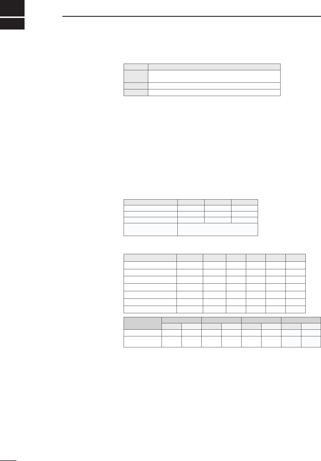
■General
•Frequency coverage :
•Mode :
FM (normal/narrow), AM (wide/normal/narrow), SSB (USB/LSB) CW (normal/narrow*), WFM
*Optional FL-52A is required.
•Number of memory channels :1000 (plus 20 scan edges and 1 priority channel)
•Antenna connector :Below 30 MHz SO-239 (50 Ω)/Phono (500 Ω)
Above 30 MHz Type-N (50 Ω)
•Usable temperature range :–10°C to +50°C (+14°F to +122°F)
•Frequency stability :Below 30 MHz ±100 Hz (±20 Hz*)
Above 30 MHz ± 0.0003 % (±0.00006%*)
*When an optional CR-293 is installed.
•Power supply requirement :13.8 V DC ±15% (negative ground)
117 V AC (U.S.A. version with supplied AD-55A)
230 or 240 V AC (other versions with the optional AD-55/V)
•Current drain (at 13.8 V DC) :Standby 1.8 A Max. audio 2.0 A
•Dimensions (projections not included) :287(W)×112(H) ×309(D) mm; 115⁄16(W)×413⁄32(H) ×123⁄16(D) in
•Weight :7.0 kg (15.4 lb)
•Intermediate frequencies :
■Receiver
•Receive system : Superheterodyne
•Sensitivity :
•Squelch sensitivity :
•Selectivity :WFM More than 150 kHz/–6 dB
FM/AM-W More than 12 kHz/–6 dB
FM-N/AM More than 5.5 kHz/–6 dB
AM-N/SSB/CW More than 2.2 kHz/–6 dB
CW narrow* More than 500 Hz/–6 dB
*Optional FL-52A is required.
•Spurious and image rejection ratio :Below 30 MHz More than 60 dB
30–1000 MHz 50 dB (typical)
1240–1300 MHz
•Audio output power :More than 2.0 W at 10% distortion with an 8 Ωload
•IF shift variable range :More than ±1.2 kHz
•External speaker connector :2-conductor 3.5 mm (1⁄8")/4–8 Ω
All specifications are subject to change without notice or obligation.
43
14 SPECIFICATIONS
Version Frequency Coverage (MHz)
U.S.A. 0.10000– 823.99999
849.00001– 868.99999 894.00001– 1999.99999*
Europe 0.10000– 1999.99999*
France 0.10000– 87.50000 108.00000– 1999.99999*
Frequency band 1st 2nd 3rd*
0.1– 29.99999 48.8 10.7 0.455
30.0– 499.99999 778.7 10.7 0.455
500.0– 1024.99999 266.7 10.7 0.455
Frequency band (MHz)
SSB/CW
0.1–0.49999 1.0 µV 6.3 µV — — — —
0.5–1.79999 2.0 µV 13.0 µV — — — —
1.8–1.99999 0.25 µV 3.2 µV 2.5 µV — — —
2.0–27.99999 0.2 µV 2.5 µV 2.0 µV — — —
28.0–29.99999 0.2 µV 2.5 µV 2.0 µV —0.5 µV —
30.0–999.99999 0.32 µV 2.5 µV 2.0 µV 3.2 µV 0.5 µV 1.4 µV
1240.0–1300.00000 0.32 µV 2.5 µV 2.0 µV 3.2 µV 0.5 µV 2.0 µV
*Specifications guaranteed 0.1–1000 MHz and 1240–1300 MHz
1025.0– 1999.99999 Utilizes converter method:
Local freq.:500, 1000 or 1010 MHz
Frequency band
(MHz) SSB/CW/AM-N
threshold tight threshold tight threshold tight
1.8–29.99999 10 µV 320 mV 0.5 µV 320 mV 0.5 µV* 320 mV*
30–1000
1240–1300 4.5 µV 320 mV 0.4 µV 320 mV 0.4 µV 320 mV
FMAM/AM-W WFM
threshold tight
— —
4.5 µV 320 mV
WFMFMAM-WAM-NAM
*FM mode can only be used above 28 MHz.
Unit:MHz
*Except WFM.

44
15
OPTIONS
AH-7000
SUPER WIDEBAND OM-
NIDIRECTIONAL AN-
TENNA
SP-7 EXTERNAL SPEAKER
TV-R7100 TV RECEIVE ADAPTER SP-21 EXTERNAL SPEAKER
MB-23 CARRYING HANDLE IC-MB12 MOBILE MOUNTING BRACKET
CT-17 CI-V LEVEL CONVERTER AD-55/A/V AC ADAPTER
CR-293 HIGH STABILITY CRYSTAL UNIT
Provides improved frequency stability.
•Frequency stability: ± 5 ppm (0°C–+60°C; 32°F–+140°F)
FL-52A CW NARROW FILTER
(455 kHz; 500Hz/–6 dB)
UT-102 VOICE SYNTHESIZER UNIT
Frequency coverage:
Receive 25–1300 MHz
Transmit 50, 144, 430, 900,
1200 MHz bands
Type of antenna: Discone
Weight: 1 kg
Provides TV broadcast reception and use of your TV set
and video recorder. Also provides FM stereo broadcast
reception. Does not comply with EMC directive.
Carrying handle, convenient for portable operation. Use
the screws supplied with the IC-R8500; DO NOT use the
screws supplied with the MB-23.
For remote control of up to 4 receivers from 1 PC. You can
set memory contents, including names, as well as read
data from the receivers.
Suitable for base station
operation.
Input impedance: 8 Ω
Max. input power: 5 W
Designed for base station
operation.
Input impedance: 8 Ω
Max. input power: 5 W
Receiver mounting bracket for mobile operation.
Provides AC operation.
(AD-55 Europe version only)

A-5395Y-1EX-➀
Printed in Japan
Copyright©1996 by Icom Inc. 1-1-32 Kamiminami, Hirano-ku, Osaka 547-0003 Japan
Count on us!
