ICOS User Manual
User Manual: Pdf
Open the PDF directly: View PDF ![]() .
.
Page Count: 342 [warning: Documents this large are best viewed by clicking the View PDF Link!]
- ICOS user manual
- Table of Contents
- Chapter 1. About This Document
- Chapter 2. ICOS modules
- 2.1. Management Features
- 2.1.1. Management Options
- 2.1.2. Management of Basic Network Information
- 2.1.3. Dual Software Images
- 2.1.4. File Management
- 2.1.5. FTP File Update
- 2.1.6. Malicious Code Detection
- 2.1.7. Automatic Installation of Firmware and Configuration
- 2.1.8. Warm Reboot
- 2.1.9. SNMP Alarms and Trap Logs
- 2.1.10. CDP Interoperability Through ISDP
- 2.1.11. Remote Monitoring (RMON)
- 2.1.12. Statistics Application
- 2.1.13. Log Messages
- 2.1.14. System Time Management
- 2.1.15. Source IP Address Configuration
- 2.1.16. Multiple Linux Routing Tables
- 2.1.17. Core Dump
- 2.1.18. Core Dump File Handling
- 2.1.19. Kernel Core Dump
- 2.1.20. Chef API Integration
- 2.1.21. Puppet API Integration
- 2.1.22. Zero-Touch Provisioning
- 2.1.23. Open Network Install Environment Support
- 2.1.24. Interface Error Disable and Auto Recovery
- 2.1.25. Network Instrumentation App—Visibility Into Packet Processing
- 2.1.26. CPU Traffic Filtering
- 2.2. Security Features
- 2.2.1. Configurable Access and Authentication Profiles
- 2.2.2. AAA Command Authorization
- 2.2.3. Password-Protected Management Access
- 2.2.4. Strong Password Enforcement
- 2.2.5. MAC-Based Port Security
- 2.2.6. RADIUS Client
- 2.2.7. TACACS+ Client
- 2.2.8. Dot1x Authentication (IEEE 802.1X)
- 2.2.9. MAC Authentication Bypass
- 2.2.10. Denial of Service
- 2.2.11. DHCP Snooping
- 2.2.12. Dynamic ARP Inspection
- 2.2.13. IP Source Address Guard
- 2.3. Switching Features
- 2.3.1. VLAN Support
- 2.3.2. Double VLANs
- 2.3.3. Switchport Modes
- 2.3.4. Spanning Tree Protocol (STP)
- 2.3.5. Rapid Spanning Tree
- 2.3.6. Multiple Spanning Tree
- 2.3.7. Bridge Protocol Data Unit (BPDU) Guard
- 2.3.8. BPDU Filtering
- 2.3.9. PVRSTP and PVSTP
- 2.3.10. Link Aggregation
- 2.3.11. Track LAG Member Port Flaps
- 2.3.12. Link Aggregate Control Protocol (LACP)
- 2.3.13. Virtual Port Channel (VPC)
- 2.3.14. Flow Control Support (IEEE 802.3x)
- 2.3.15. Asymmetric Flow Control
- 2.3.16. Alternate Store and Forward (ASF)
- 2.3.17. Jumbo Frames Support
- 2.3.18. Auto-MDI/MDIX Support
- 2.3.19. Unidirectional Link Detection (UDLD)
- 2.3.20. Expandable Port Configuration
- 2.3.21. VLAN-Aware MAC-based Switching
- 2.3.22. Back Pressure Support
- 2.3.23. Auto Negotiation
- 2.3.24. Storm Control
- 2.3.25. Port Mirroring
- 2.3.26. Remote Switch Port Analyzer (RSPAN)
- 2.3.27. sFlow
- 2.3.28. Static and Dynamic MAC Address Tables
- 2.3.29. Link Layer Discovery Protocol (LLDP)
- 2.3.30. Link Layer Discovery Protocol (LLDP) for Media Endpoint Devices
- 2.3.31. DHCP Layer 2 Relay
- 2.3.32. MAC Multicast Support
- 2.3.33. IGMP Snooping
- 2.3.34. Source Specific Multicasting (SSM)
- 2.3.35. Control Packet Flooding
- 2.3.36. Flooding to mRouter Ports
- 2.3.37. IGMP Snooping Querier
- 2.3.38. Multicast VLAN Registration
- 2.3.39. Management and Control Plane ACLs
- 2.3.40. Link Dependency
- 2.3.41. IPv6 Router Advertisement Guard
- 2.3.42. FIP Snooping
- 2.3.43. ECN Support
- 2.4. Data Center Features
- 2.5. Routing Features
- 2.5.1. IP Unnumbered
- 2.5.2. Open Shortest Path First (OSPF)
- 2.5.3. Border Gateway Protocol (BGP)
- 2.5.4. VLAN Routing
- 2.5.5. IP Configuration
- 2.5.6. ARP Table Management
- 2.5.7. BOOTP/DHCP Relay Agent
- 2.5.8. IP Helper and UDP Relay
- 2.5.9. Router Discovery
- 2.5.10. Routing Table
- 2.5.11. Virtual Router Redundancy Protocol (VRRP)
- 2.5.12. Bidirectional Forwarding Detection
- 2.5.13. VRF Lite
- 2.5.14. RFC 5549
- 2.5.15. Algorithmic Longest Prefix Match (ALPM)
- 2.6. Layer 3 Multicast Features
- 2.7. Quality of Service Features
- 2.1. Management Features
- Chapter 3. Getting Started with Switch Configuration
- 3.1. Accessing the Switch Command-Line Interface
- 3.2. Accessing the Switch CLI Through the Network
- 3.3. DHCP Option 61
- 3.4. Booting the Switch
- 3.4.1. Utility Menu Functions
- 3.4.1.1. 1 – Start ICOS Application
- 3.4.1.2. 2 – Load Code Update Package
- 3.4.1.3. 3 – Load Configuration
- 3.4.1.4. 4 – Select Serial Speed
- 3.4.1.5. 5 – Retrieve Error Log
- 3.4.1.6. 6 – Erase Current Configuration
- 3.4.1.7. 7 – Erase Permanent Storage
- 3.4.1.8. 8 – Select Boot Method
- 3.4.1.9. 9 – Activate Backup Image
- 3.4.1.10. 10 – Start Diagnostic Application
- 3.4.1.11. 11 – Reboot
- 3.4.1.12. 12 – Erase All Configuration Files
- 3.4.1. Utility Menu Functions
- 3.5. Understanding the User Interfaces
- Chapter 4. Configuring Switch Management Features
- 4.1. Managing Images and Files
- 4.1.1. Supported File Management Methods
- 4.1.2. Uploading and Downloading Files
- 4.1.3. Managing Switch Software (Images)
- 4.1.4. Managing Configuration Files
- 4.1.5. Editing and Downloading Configuration Files
- 4.1.6. Creating and Applying Configuration Scripts
- 4.1.7. Uncompressing Configuration Scripts
- 4.1.8. Non-Disruptive Configuration Management
- 4.1.9. Saving the Running Configuration
- 4.1.10. File and Image Management Configuration Examples
- 4.1.11. Managing Configuration Scripts
- 4.2. Enabling Automatic Image Installation and System Configuration
- 4.3. Downloading a Core Dump
- 4.4. Enabling Kernel Core Dump
- 4.5. Setting the System Time
- 4.6. Creating CPU Traffic Filters
- 4.7. Configuring a Packet Trace (Network Instrumentation App)
- 4.1. Managing Images and Files
- Chapter 5. Configuring Security Features
- 5.1. Controlling Management Access
- 5.1.1. Using RADIUS Servers for Management Security
- 5.1.2. RADIUS Dynamic Authorization
- 5.1.3. Using TACACS+ to Control Management Access
- 5.1.4. Configuring and Applying Authentication Profiles
- 5.1.5. Configuring Authentication Profiles for Port-Based Authentication
- 5.1.6. Configuring the Primary and Secondary RADIUS Servers
- 5.1.7. Configuring an Authentication Profile
- 5.2. Configuring DHCP Snooping, DAI, and IPSG
- 5.2.1. DHCP Snooping Overview
- 5.2.2. Populating the DHCP Snooping Bindings Database
- 5.2.3. DHCP Snooping and VLANs
- 5.2.4. DHCP Snooping Logging and Rate Limits
- 5.2.5. IP Source Guard Overview
- 5.2.6. IPSG and Port Security
- 5.2.7. Dynamic ARP Inspection Overview
- 5.2.8. Optional DAI Features
- 5.2.9. Increasing Security with DHCP Snooping, DAI, and IPSG
- 5.2.10. Configuring DHCP Snooping
- 5.2.11. Configuring IPSG
- 5.1. Controlling Management Access
- Chapter 6. Configuring Switching Features
- 6.1. VLANs
- 6.2. Switchport Modes
- 6.3. LAGs—Operation and Configuration
- 6.4. Virtual Port Channel — Operation and Configuration
- 6.5. Unidirectional Link Detection (UDLD)
- 6.6. Port Mirroring
- 6.7. Spanning Tree Protocol
- 6.7.1. Classic STP, Multiple STP, and Rapid STP
- 6.7.2. STP Operation
- 6.7.3. Optional STP Features
- 6.7.4. PVRSTP
- 6.7.4.1. DirectLink Rapid Convergence
- 6.7.4.2. IndirectLink Rapid Convergence Feature
- 6.7.4.3. Reacting to Indirect Link Failures
- 6.7.4.4. Interoperability Between PVSTP and PVRSTP Modes
- 6.7.4.5. Interoperability With IEEE Spanning Tree Protocols
- 6.7.4.6. Common Spanning Tree
- 6.7.4.7. SSTP BPDUs Flooding Across MST (CST) Regions
- 6.7.4.8. Interoperability with RSTP
- 6.7.4.9. Interoperability with MSTP
- 6.7.4.10. Native VLAN Inconsistent State
- 6.7.5. STP Configuration Examples
- 6.8. IGMP Snooping
- 6.9. Multicast VLAN Registration Configuration
- 6.10. LLDP and LLDP-MED
- 6.11. sFlow
- 6.12. Link Dependency
- 6.13. RA Guard
- 6.14. FIP Snooping
- 6.15. ECN
- Chapter 7. Configuring Data Center Features
- 7.1. Data Center Technology Overview
- 7.2. Priority-Based Flow Control
- 7.3. Data Center Bridging Exchange Protocol
- 7.4. CoS Queuing
- 7.5. Enhanced Transmission Selection
- 7.6. Quantized Congestion Notification (QCN)
- 7.7. OpenFlow Operation and Configuration
- 7.8. DCVPN Gateway Operation and Configuration
- 7.8.1. Overview
- 7.8.2. VXLAN
- 7.8.3. NVGRE
- 7.8.4. Functional Description
- 7.8.4.1. Switch Overlay Mode
- 7.8.4.2. VTEP to VN Association
- 7.8.4.3. Configuration of Remote VTEPs
- 7.8.4.4. VTEP Next-Hop Resolution
- 7.8.4.5. VXLAN UDP Destination Port
- 7.8.4.6. Tunnels
- 7.8.4.7. MAC Learning and Aging
- 7.8.4.8. Host Configuration
- 7.8.4.9. ECMP
- 7.8.4.10. MTU
- 7.8.4.11. TTL and DSCP/TOS
- 7.8.4.12. Packet Forwarding
- 7.8.5. Usage Scenarios
- 7.9. MPLS Operation and Configuration
- 7.9.1. Overview
- 7.9.2. ICOS MPLS Features
- 7.9.2.1. Static Layer-2 MPLS Labels
- 7.9.2.2. Static Layer-2 MPLS Label Configuration Examples
- 7.9.2.3. Static Layer-3 MPLS Labels
- 7.9.2.4. MPLS Status and Statistics
- 7.9.2.5. MPLS Label Distribution with BGP
- 7.9.2.6. “Per-Switch” Label BGP Distribution
- 7.9.2.7. Per Interface Label BGP Distribution
- 7.9.2.8. Bidirectional Forwarding Detection
- 7.9.2.9. MPLS-Ping and MPLS-Traceroute
- 7.9.3. ICOS MPLS Use Cases
- 7.9.4. MPLS Device Connectivity Diagnostics and Debugging
- Chapter 8. Configuring Routing
- 8.1. Basic Routing and Features
- 8.2. OSPF
- 8.3. VRRP
- 8.4. IP Helper
- 8.5. Border Gateway Protocol (BGP)
- 8.6. Bidirectional Forwarding Detection
- 8.7. VRF Lite Operation and Configuration
- 8.8. IPv6 Routing
- 8.9. ECMP Hash Selection
- Chapter 9. Configuring IPv4 and IPv6 Multicast
- 9.1. L3 Multicast Overview
- 9.1.1. IP Multicast Traffic
- 9.1.2. Multicast Protocol Switch Support
- 9.1.3. Multicast Protocol Roles
- 9.1.4. L3 Multicast Switch Requirements
- 9.1.5. Determining Which Multicast Protocols to Enable
- 9.1.6. Multicast Routing Tables
- 9.1.7. Multicast Tunneling
- 9.1.8. IGMP
- 9.1.9. MLD Protocol
- 9.1.10. PIM Protocol
- 9.1.11. DVMRP
- 9.2. Default L3 Multicast Values
- 9.3. L3 Multicast Configuration Examples
- 9.1. L3 Multicast Overview
- Chapter 10. Configuring Quality of Service
ICOS user manual

ICOS user manual

iii
Table of Contents
1. About This Document ......................................................................................................... 1
1.1. Purpose and Audience ............................................................................................ 2
1.2. Conventions ............................................................................................................ 3
1.3. Terms and Acronyms .............................................................................................. 4
2. ICOS modules ................................................................................................................... 8
2.1. Management Features ............................................................................................. 9
2.1.1. Management Options .................................................................................... 9
2.1.2. Management of Basic Network Information .................................................... 9
2.1.3. Dual Software Images .................................................................................. 9
2.1.4. File Management .......................................................................................... 9
2.1.5. FTP File Update ........................................................................................... 9
2.1.6. Malicious Code Detection ............................................................................. 9
2.1.7. Automatic Installation of Firmware and Configuration .................................... 10
2.1.8. Warm Reboot ............................................................................................. 10
2.1.9. SNMP Alarms and Trap Logs ...................................................................... 10
2.1.10. CDP Interoperability Through ISDP ............................................................ 10
2.1.11. Remote Monitoring (RMON) ...................................................................... 10
2.1.12. Statistics Application ................................................................................. 10
2.1.13. Log Messages .......................................................................................... 11
2.1.14. System Time Management ........................................................................ 11
2.1.15. Source IP Address Configuration ............................................................... 11
2.1.16. Multiple Linux Routing Tables .................................................................... 11
2.1.17. Core Dump ............................................................................................... 11
2.1.18. Core Dump File Handling .......................................................................... 11
2.1.19. Kernel Core Dump .................................................................................... 12
2.1.20. Chef API Integration ................................................................................. 12
2.1.21. Puppet API Integration .............................................................................. 12
2.1.22. Zero-Touch Provisioning ........................................................................... 13
2.1.23. Open Network Install Environment Support ................................................ 13
2.1.24. Interface Error Disable and Auto Recovery ................................................. 14
2.1.25. Network Instrumentation App—Visibility Into Packet Processing ................... 14
2.1.26. CPU Traffic Filtering ................................................................................. 14
2.2. Security Features .................................................................................................. 15
2.2.1. Configurable Access and Authentication Profiles .......................................... 15
2.2.2. AAA Command Authorization ...................................................................... 15
2.2.3. Password-Protected Management Access .................................................... 15
2.2.4. Strong Password Enforcement .................................................................... 15
2.2.5. MAC-Based Port Security ........................................................................... 15
2.2.6. RADIUS Client ........................................................................................... 15
2.2.7. TACACS+ Client ......................................................................................... 15
2.2.8. Dot1x Authentication (IEEE 802.1X) ............................................................ 16
2.2.9. MAC Authentication Bypass ........................................................................ 16
2.2.10. Denial of Service ...................................................................................... 16
2.2.11. DHCP Snooping ....................................................................................... 16
2.2.12. Dynamic ARP Inspection ........................................................................... 16
2.2.13. IP Source Address Guard ......................................................................... 16
2.3. Switching Features ................................................................................................ 17
2.3.1. VLAN Support ............................................................................................ 17
2.3.2. Double VLANs ............................................................................................ 17

ICOS user manual
iv
2.3.3. Switchport Modes ....................................................................................... 17
2.3.4. Spanning Tree Protocol (STP) ..................................................................... 17
2.3.5. Rapid Spanning Tree .................................................................................. 17
2.3.6. Multiple Spanning Tree ............................................................................... 17
2.3.7. Bridge Protocol Data Unit (BPDU) Guard ..................................................... 18
2.3.8. BPDU Filtering ........................................................................................... 18
2.3.9. PVRSTP and PVSTP .................................................................................. 18
2.3.10. Link Aggregation ....................................................................................... 18
2.3.11. Track LAG Member Port Flaps .................................................................. 18
2.3.12. Link Aggregate Control Protocol (LACP) .................................................... 18
2.3.13. Virtual Port Channel (VPC) ....................................................................... 19
2.3.14. Flow Control Support (IEEE 802.3x) .......................................................... 19
2.3.15. Asymmetric Flow Control .......................................................................... 19
2.3.16. Alternate Store and Forward (ASF) ............................................................ 19
2.3.17. Jumbo Frames Support ............................................................................. 20
2.3.18. Auto-MDI/MDIX Support ............................................................................ 20
2.3.19. Unidirectional Link Detection (UDLD) ......................................................... 20
2.3.20. Expandable Port Configuration .................................................................. 20
2.3.21. VLAN-Aware MAC-based Switching ........................................................... 20
2.3.22. Back Pressure Support ............................................................................. 20
2.3.23. Auto Negotiation ....................................................................................... 21
2.3.24. Storm Control ........................................................................................... 21
2.3.25. Port Mirroring ........................................................................................... 21
2.3.26. Remote Switch Port Analyzer (RSPAN) ..................................................... 22
2.3.27. sFlow ....................................................................................................... 22
2.3.28. Static and Dynamic MAC Address Tables .................................................. 22
2.3.29. Link Layer Discovery Protocol (LLDP) ........................................................ 22
2.3.30. Link Layer Discovery Protocol (LLDP) for Media Endpoint Devices ............... 23
2.3.31. DHCP Layer 2 Relay ................................................................................ 23
2.3.32. MAC Multicast Support ............................................................................. 23
2.3.33. IGMP Snooping ........................................................................................ 23
2.3.34. Source Specific Multicasting (SSM) ........................................................... 23
2.3.35. Control Packet Flooding ............................................................................ 23
2.3.36. Flooding to mRouter Ports ........................................................................ 23
2.3.37. IGMP Snooping Querier ............................................................................ 24
2.3.38. Multicast VLAN Registration ...................................................................... 24
2.3.39. Management and Control Plane ACLs ....................................................... 24
2.3.40. Link Dependency ...................................................................................... 24
2.3.41. IPv6 Router Advertisement Guard ............................................................. 24
2.3.42. FIP Snooping ........................................................................................... 25
2.3.43. ECN Support ............................................................................................ 25
2.4. Data Center Features ............................................................................................ 26
2.4.1. Priority-based Flow Control ......................................................................... 26
2.4.2. Data Center Bridging Exchange Protocol ..................................................... 26
2.4.3. Quantized Congestion Notification ............................................................... 26
2.4.4. CoS Queuing and Enhanced Transmission Selection .................................... 26
2.4.5. OpenFlow ................................................................................................... 27
2.4.6. DCVPN Gateway ........................................................................................ 27
2.4.7. MPLS ......................................................................................................... 27
2.4.8. Dynamic Topology Map and Prescriptive Topology Mapping ......................... 28
2.5. Routing Features ................................................................................................... 29

ICOS user manual
v
2.5.1. IP Unnumbered .......................................................................................... 29
2.5.2. Open Shortest Path First (OSPF) ................................................................ 29
2.5.3. Border Gateway Protocol (BGP) .................................................................. 29
2.5.4. VLAN Routing ............................................................................................ 30
2.5.5. IP Configuration .......................................................................................... 30
2.5.6. ARP Table Management ............................................................................. 30
2.5.7. BOOTP/DHCP Relay Agent ........................................................................ 30
2.5.8. IP Helper and UDP Relay ........................................................................... 30
2.5.9. Router Discovery ........................................................................................ 31
2.5.10. Routing Table ........................................................................................... 31
2.5.11. Virtual Router Redundancy Protocol (VRRP) .............................................. 31
2.5.12. Bidirectional Forwarding Detection ............................................................. 31
2.5.13. VRF Lite ................................................................................................... 31
2.5.14. RFC 5549 ................................................................................................ 31
2.5.15. Algorithmic Longest Prefix Match (ALPM) ................................................... 32
2.6. Layer 3 Multicast Features ..................................................................................... 33
2.6.1. Distance Vector Multicast Routing Protocol .................................................. 33
2.6.2. Internet Group Management Protocol .......................................................... 33
2.6.3. IGMP Proxy ................................................................................................ 33
2.6.4. Protocol Independent Multicast .................................................................... 33
2.6.4.1. Dense Mode (PIM-DM) .................................................................... 33
2.6.4.2. Sparse Mode (PIM-SM) .................................................................... 33
2.6.4.3. Source Specific Multicast (PIM-SSM) ................................................ 33
2.6.4.4. PIM IPv6 Support ............................................................................ 34
2.6.5. MLD/MLDv2 (RFC2710/RFC3810) ............................................................... 34
2.7. Quality of Service Features .................................................................................... 35
2.7.1. Access Control Lists (ACL) ......................................................................... 35
2.7.2. ACL Remarks ............................................................................................. 35
2.7.3. ACL Rule Priority ........................................................................................ 35
2.7.4. ACL Counters ............................................................................................. 35
2.7.5. Differentiated Services (DiffServ) ................................................................. 36
2.7.6. Class of Service (CoS) ............................................................................... 36
3. Getting Started with Switch Configuration .......................................................................... 37
3.1. Accessing the Switch Command-Line Interface ....................................................... 38
3.1.1. Connecting to the Switch Console ............................................................... 38
3.2. Accessing the Switch CLI Through the Network ...................................................... 40
3.2.1. Using the Service Port or Network Interface for Remote Management ............ 40
3.2.2. Configuring Service Port Information ............................................................ 40
3.2.3. Configuring the In-Band Network Interface ................................................... 41
3.3. DHCP Option 61 ................................................................................................... 42
3.3.1. Configuring DHCP Option 61 ...................................................................... 42
3.4. Booting the Switch ................................................................................................ 43
3.4.1. Utility Menu Functions ................................................................................. 43
3.4.1.1. 1 – Start ICOS Application ............................................................... 44
3.4.1.2. 2 – Load Code Update Package ....................................................... 44
3.4.1.3. 3 – Load Configuration ..................................................................... 46
3.4.1.4. 4 – Select Serial Speed ................................................................... 46
3.4.1.5. 5 – Retrieve Error Log ..................................................................... 47
3.4.1.6. 6 – Erase Current Configuration ....................................................... 47
3.4.1.7. 7 – Erase Permanent Storage .......................................................... 47
3.4.1.8. 8 – Select Boot Method ................................................................... 48

ICOS user manual
vi
3.4.1.9. 9 – Activate Backup Image ............................................................... 48
3.4.1.10. 10 – Start Diagnostic Application .................................................... 48
3.4.1.11. 11 – Reboot .................................................................................. 48
3.4.1.12. 12 – Erase All Configuration Files ................................................... 49
3.5. Understanding the User Interfaces ......................................................................... 50
3.5.1. Using the Command-Line Interface .............................................................. 50
3.5.2. Using SNMP .............................................................................................. 51
3.5.3. SNMPv3 ..................................................................................................... 51
3.5.4. Management via Net-SNMP ........................................................................ 51
3.5.5. Using RESTful APIs ................................................................................... 51
3.5.6. Using the RESTCONF Interface .................................................................. 52
4. Configuring Switch Management Features ......................................................................... 53
4.1. Managing Images and Files ................................................................................... 54
4.1.1. Supported File Management Methods .......................................................... 55
4.1.2. Uploading and Downloading Files ................................................................ 55
4.1.3. Managing Switch Software (Images) ............................................................ 55
4.1.4. Managing Configuration Files ...................................................................... 56
4.1.5. Editing and Downloading Configuration Files ................................................ 56
4.1.6. Creating and Applying Configuration Scripts ................................................. 56
4.1.7. Uncompressing Configuration Scripts ........................................................... 57
4.1.8. Non-Disruptive Configuration Management ................................................... 57
4.1.9. Saving the Running Configuration ............................................................... 58
4.1.10. File and Image Management Configuration Examples ................................. 58
4.1.10.1. Upgrading the Firmware ................................................................. 58
4.1.11. Managing Configuration Scripts ................................................................. 60
4.2. Enabling Automatic Image Installation and System Configuration ............................. 63
4.2.1. DHCP Auto Install Process ......................................................................... 63
4.2.1.1. Obtaining IP Address Information ...................................................... 63
4.2.1.2. Obtaining Other Dynamic Information ................................................ 63
4.2.1.3. Obtaining the Image ......................................................................... 64
4.2.1.4. Obtaining the Configuration File ........................................................ 64
4.2.2. Monitoring and Completing the DHCP Auto Install Process ........................... 66
4.2.2.1. Saving a Configuration ..................................................................... 66
4.2.2.2. Stopping and Restarting the Auto Install Process ............................... 66
4.2.2.3. Managing Downloaded Config Files .................................................. 66
4.2.3. DHCP Auto Install Dependencies ................................................................ 66
4.2.3.1. Default Auto Install Values ............................................................... 67
4.2.4. Enabling DHCP Auto Install and Auto Image Download ................................ 67
4.3. Downloading a Core Dump .................................................................................... 69
4.3.1. Using NFS to Download a Core Dump ........................................................ 69
4.3.2. Using TFTP or FTP to Download a Core Dump ............................................ 69
4.4. Enabling Kernel Core Dump .................................................................................. 71
4.5. Setting the System Time ....................................................................................... 72
4.5.1. Manual Time Configuration ......................................................................... 72
4.5.2. Configuring SNTP ....................................................................................... 73
4.6. Creating CPU Traffic Filters ................................................................................... 74
4.6.1. Configuration Example ................................................................................ 74
4.7. Configuring a Packet Trace (Network Instrumentation App) ...................................... 75
5. Configuring Security Features ........................................................................................... 77
5.1. Controlling Management Access ............................................................................ 78
5.1.1. Using RADIUS Servers for Management Security ......................................... 78

ICOS user manual
vii
5.1.2. RADIUS Dynamic Authorization ................................................................... 79
5.1.3. Using TACACS+ to Control Management Access ......................................... 80
5.1.4. Configuring and Applying Authentication Profiles .......................................... 81
5.1.5. Configuring Authentication Profiles for Port-Based Authentication .................. 82
5.1.6. Configuring the Primary and Secondary RADIUS Servers ............................. 83
5.1.7. Configuring an Authentication Profile ........................................................... 83
5.2. Configuring DHCP Snooping, DAI, and IPSG .......................................................... 85
5.2.1. DHCP Snooping Overview .......................................................................... 85
5.2.2. Populating the DHCP Snooping Bindings Database ...................................... 86
5.2.3. DHCP Snooping and VLANs ....................................................................... 86
5.2.4. DHCP Snooping Logging and Rate Limits .................................................... 87
5.2.5. IP Source Guard Overview ......................................................................... 87
5.2.6. IPSG and Port Security ............................................................................... 87
5.2.7. Dynamic ARP Inspection Overview .............................................................. 88
5.2.8. Optional DAI Features ................................................................................ 88
5.2.9. Increasing Security with DHCP Snooping, DAI, and IPSG ............................. 88
5.2.10. Configuring DHCP Snooping ..................................................................... 89
5.2.11. Configuring IPSG ...................................................................................... 90
6. Configuring Switching Features ......................................................................................... 92
6.1. VLANs .................................................................................................................. 93
6.1.1. VLAN Tagging ............................................................................................ 94
6.1.2. Double-VLAN Tagging ................................................................................ 94
6.1.3. Default VLAN Behavior ............................................................................... 95
6.1.4. VLAN Configuration Example ...................................................................... 96
6.1.4.1. Configure the VLANs and Ports on Switch 1 ...................................... 98
6.1.4.2. Configure the VLANs and Ports on Switch 2 ...................................... 99
6.2. Switchport Modes ................................................................................................ 101
6.3. LAGs—Operation and Configuration ..................................................................... 103
6.3.1. Static and Dynamic Link Aggregation ......................................................... 103
6.3.2. LAG Hashing ............................................................................................ 103
6.3.2.1. Resilient Hashing ........................................................................... 104
6.3.2.2. Hash Prediction with ECMP and LAG .............................................. 104
6.3.3. LAG Interface Naming Convention ............................................................. 105
6.3.4. LAG Interaction with Other Features .......................................................... 105
6.3.4.1. VLAN ............................................................................................. 105
6.3.4.2. STP ............................................................................................... 105
6.3.4.3. Statistics ........................................................................................ 106
6.3.5. LAG Configuration Guidelines .................................................................... 106
6.3.6. Link Aggregation Configuration Examples .................................................. 106
6.3.6.1. Configuring Dynamic LAGs ............................................................. 106
6.3.6.2. Configuring Static LAGs ................................................................. 107
6.4. Virtual Port Channel — Operation and Configuration ............................................. 109
6.4.1. Overview .................................................................................................. 109
6.4.2. Deployment Scenarios .............................................................................. 109
6.4.3. Definitions ................................................................................................ 110
6.4.4. Configuration Consistency ......................................................................... 111
6.4.5. VPC Fast Failover .................................................................................... 113
6.4.6. VPC Configuration .................................................................................... 114
6.5. Unidirectional Link Detection (UDLD) .................................................................... 119
6.5.1. UDLD Modes ............................................................................................ 119
6.5.2. UDLD and LAG Interfaces ......................................................................... 119

ICOS user manual
viii
6.5.3. Configuring UDLD ..................................................................................... 119
6.6. Port Mirroring ...................................................................................................... 122
6.6.1. Configuring Port Mirroring ......................................................................... 122
6.6.2. Configuring RSPAN .................................................................................. 123
6.6.2.1. Configuration on the Source Switch (SW1) ...................................... 123
6.6.2.2. Configuration on the Intermediate Switch (SW2) .............................. 124
6.6.2.3. Configuration on the Destination Switch (SW3) ................................ 124
6.6.3. VLAN-Based Mirroring .............................................................................. 125
6.6.4. Flow-Based Mirroring ................................................................................ 125
6.7. Spanning Tree Protocol ....................................................................................... 127
6.7.1. Classic STP, Multiple STP, and Rapid STP ................................................ 127
6.7.2. STP Operation .......................................................................................... 127
6.7.2.1. MSTP in the Network ..................................................................... 127
6.7.3. Optional STP Features .............................................................................. 130
6.7.3.1. BPDU Flooding .............................................................................. 130
6.7.3.2. Edge Port ...................................................................................... 130
6.7.3.3. BPDU Filtering ............................................................................... 131
6.7.3.4. Root Guard .................................................................................... 131
6.7.3.5. Loop Guard ................................................................................... 131
6.7.3.6. BPDU Protection ............................................................................ 131
6.7.4. PVRSTP ................................................................................................... 132
6.7.4.1. DirectLink Rapid Convergence ........................................................ 133
6.7.4.2. IndirectLink Rapid Convergence Feature ......................................... 133
6.7.4.3. Reacting to Indirect Link Failures .................................................... 134
6.7.4.4. Interoperability Between PVSTP and PVRSTP Modes ...................... 135
6.7.4.5. Interoperability With IEEE Spanning Tree Protocols ......................... 135
6.7.4.6. Common Spanning Tree ................................................................. 135
6.7.4.7. SSTP BPDUs Flooding Across MST (CST) Regions ......................... 136
6.7.4.8. Interoperability with RSTP .............................................................. 136
6.7.4.9. Interoperability with MSTP .............................................................. 138
6.7.4.10. Native VLAN Inconsistent State .................................................... 139
6.7.5. STP Configuration Examples ..................................................................... 139
6.7.5.1. Configuring STP ............................................................................. 140
6.7.5.2. Configuring MSTP .......................................................................... 141
6.7.5.3. Configuring PVRSTP ...................................................................... 142
6.8. IGMP Snooping ................................................................................................... 146
6.8.1. IGMP Snooping Querier ............................................................................ 146
6.8.2. Configuring IGMP Snooping ...................................................................... 146
6.8.3. IGMPv3/SSM Snooping ............................................................................. 149
6.9. Multicast VLAN Registration Configuration ............................................................ 150
6.9.1. Overview .................................................................................................. 150
6.9.2. MVR Configuration Example ...................................................................... 152
6.10. LLDP and LLDP-MED ........................................................................................ 154
6.10.1. LLDP and Data Center Applications ......................................................... 154
6.10.1.1. Configuring LLDP ......................................................................... 154
6.11. sFlow ................................................................................................................ 157
6.11.1. sFlow Sampling ...................................................................................... 158
6.11.2. Packet Flow Sampling ............................................................................. 158
6.11.3. Sampling in Hardware ............................................................................. 158
6.11.4. Counter Sampling ................................................................................... 159
6.11.5. Configuring sFlow in Software ................................................................. 159

ICOS user manual
ix
6.11.6. Configuring sFlow in Hardware ................................................................ 161
6.12. Link Dependency ............................................................................................... 163
6.13. RA Guard .......................................................................................................... 164
6.14. FIP Snooping .................................................................................................... 165
6.15. ECN .................................................................................................................. 168
6.15.1. Enabling ECN in Microsoft Windows ........................................................ 169
6.15.2. Example 1: SLA Example ........................................................................ 169
6.15.3. Example 2: Data Center TCP (DCTCP) Configuration ............................... 171
7. Configuring Data Center Features ................................................................................... 173
7.1. Data Center Technology Overview ....................................................................... 174
7.2. Priority-Based Flow Control .................................................................................. 176
7.2.1. PFC Operation and Behavior ..................................................................... 176
7.2.2. Configuring PFC ....................................................................................... 177
7.3. Data Center Bridging Exchange Protocol .............................................................. 178
7.3.1. Interoperability with IEEE DCBX ................................................................ 178
7.3.2. DCBX and Port Roles ............................................................................... 179
7.3.3. Configuration Source Port Selection Process .............................................. 180
7.3.4. Configuring DCBX .................................................................................... 181
7.4. CoS Queuing ...................................................................................................... 183
7.4.1. CoS Queuing Function and Behavior ......................................................... 183
7.4.1.1. Trusted Port Queue Mappings ........................................................ 183
7.4.1.2. Un-trusted Port Default Priority ....................................................... 184
7.4.1.3. Queue Configuration ...................................................................... 184
7.4.1.4. Traffic Class Groups ...................................................................... 184
7.4.2. Configuring CoS Queuing and ETS ........................................................... 185
7.5. Enhanced Transmission Selection ........................................................................ 188
7.5.1. ETS Operation and Dependencies ............................................................. 188
7.6. Quantized Congestion Notification (QCN) ............................................................. 189
7.7. OpenFlow Operation and Configuration ................................................................ 190
7.7.1. Enabling and Disabling OpenFlow ............................................................. 190
7.7.2. Interacting with the OpenFlow Manager ..................................................... 191
7.7.3. Deploying OpenFlow ................................................................................. 191
7.7.4. OpenFlow Scenarios ................................................................................. 191
7.7.5. OpenFlow Variants ................................................................................... 191
7.7.5.1. OpenFlow 1.0/1.3 ........................................................................... 191
7.7.5.2. Data Center Tenant Networking ...................................................... 192
7.7.6. OpenFlow Interaction with Other Functions ................................................ 192
7.7.7. Configuring OpenFlow ............................................................................... 192
7.8. DCVPN Gateway Operation and Configuration ...................................................... 197
7.8.1. Overview .................................................................................................. 197
7.8.2. VXLAN ..................................................................................................... 197
7.8.3. NVGRE .................................................................................................... 197
7.8.4. Functional Description ............................................................................... 198
7.8.4.1. Switch Overlay Mode ..................................................................... 198
7.8.4.2. VTEP to VN Association ................................................................. 198
7.8.4.3. Configuration of Remote VTEPs ..................................................... 198
7.8.4.4. VTEP Next-Hop Resolution ............................................................ 199
7.8.4.5. VXLAN UDP Destination Port ......................................................... 200
7.8.4.6. Tunnels ......................................................................................... 200
7.8.4.7. MAC Learning and Aging ............................................................... 201
7.8.4.8. Host Configuration ......................................................................... 201

ICOS user manual
x
7.8.4.9. ECMP ............................................................................................ 202
7.8.4.10. MTU ............................................................................................ 202
7.8.4.11. TTL and DSCP/TOS ..................................................................... 203
7.8.4.12. Packet Forwarding ....................................................................... 203
7.8.5. Usage Scenarios ...................................................................................... 203
7.8.5.1. VXLAN Gateway With Single Tunnel ............................................... 203
7.8.5.2. VXLAN Gateway With Multiple Tunnels ........................................... 205
7.9. MPLS Operation and Configuration ...................................................................... 208
7.9.1. Overview .................................................................................................. 208
7.9.2. ICOS MPLS Features ............................................................................... 208
7.9.2.1. Static Layer-2 MPLS Labels ........................................................... 209
7.9.2.2. Static Layer-2 MPLS Label Configuration Examples ......................... 209
7.9.2.3. Static Layer-3 MPLS Labels ........................................................... 210
7.9.2.4. MPLS Status and Statistics ............................................................ 211
7.9.2.5. MPLS Label Distribution with BGP .................................................. 212
7.9.2.6. “Per-Switch” Label BGP Distribution ................................................ 212
7.9.2.7. Per Interface Label BGP Distribution ............................................... 213
7.9.2.8. Bidirectional Forwarding Detection .................................................. 214
7.9.2.9. MPLS-Ping and MPLS-Traceroute .................................................. 214
7.9.3. ICOS MPLS Use Cases ............................................................................ 214
7.9.3.1. IPv6 Clos Network ......................................................................... 214
7.9.3.2. Switch Configuration ...................................................................... 215
7.9.3.3. Verifying Configuration ................................................................... 220
7.9.3.4. Traffic Forwarding Examples .......................................................... 222
7.9.3.5. IPv4 Network with IPv6 Subnets, VLANs, and LAGs ......................... 224
7.9.3.6. Traffic Forwarding Examples .......................................................... 231
7.9.4. MPLS Device Connectivity Diagnostics and Debugging ............................... 233
7.9.4.1. LFDB Lookup Failure Packet Trace ................................................. 233
7.9.4.2. MPLS and Port Counters ................................................................ 234
7.9.4.3. MPLS Packet Capture .................................................................... 235
7.9.4.4. Restrictions and Limitations ............................................................ 236
8. Configuring Routing ........................................................................................................ 238
8.1. Basic Routing and Features ................................................................................. 239
8.1.1. VLAN Routing ........................................................................................... 239
8.1.2. When To Configure VLAN Routing ............................................................ 240
8.1.3. IP Routing Configuration Example ............................................................. 240
8.1.3.1. Configuring Switch A ...................................................................... 241
8.1.3.2. Configuring Switch B ...................................................................... 242
8.1.4. IP Unnumbered Configuration Example ...................................................... 243
8.2. OSPF .................................................................................................................. 246
8.2.1. Configuring an OSPF Border Router and Setting Interface Costs ................. 246
8.3. VRRP ................................................................................................................. 249
8.3.1. VRRP Operation in the Network ................................................................ 249
8.3.2. VRRP Router Priority ................................................................................ 249
8.3.3. VRRP Preemption ..................................................................................... 249
8.3.4. VRRP Accept Mode .................................................................................. 250
8.3.4.1. VRRP Route and Interface Tracking ................................................ 250
8.3.5. VRRP Configuration Example .................................................................... 250
8.3.5.1. VRRP with Load Sharing ................................................................ 251
8.3.6. VRRP with Route and Interface Tracking ................................................... 253
8.4. IP Helper ............................................................................................................ 257

ICOS user manual
xi
8.4.1. Relay Agent Configuration Example ........................................................... 259
8.5. Border Gateway Protocol (BGP) ........................................................................... 261
8.5.1. BGP Topology .......................................................................................... 261
8.5.1.1. External BGP Peering .................................................................... 262
8.5.1.2. Internal BGP Peering ..................................................................... 262
8.5.1.3. Advertising Network Layer Reachability Information .......................... 262
8.5.2. BGP Behavior ........................................................................................... 263
8.5.2.1. BGP Route Selection ..................................................................... 263
8.5.3. BGP Dynamic Neighbors .......................................................................... 264
8.5.4. BGP Extended Communities ..................................................................... 264
8.5.5. VPNv4/VRF Route Distribution via BGP ..................................................... 265
8.5.5.1. Overview ....................................................................................... 265
8.5.5.2. VPNv4 Address Family ................................................................... 265
8.5.5.3. Controlling Route Distribution .......................................................... 265
8.5.5.4. The Route Target Attribute (RT) ...................................................... 265
8.5.5.5. The Site of Origin Attribute (SoO) ................................................... 266
8.5.6. BGP Configuration Examples .................................................................... 266
8.5.6.1. Two Autonomous Systems in a Network .......................................... 266
8.5.6.2. BGP with VRF ............................................................................... 271
8.5.6.3. Route Leaking between VRFs ........................................................ 273
8.5.6.4. BGP Dynamic Neighbors ................................................................ 277
8.6. Bidirectional Forwarding Detection ........................................................................ 279
8.6.1. Overview .................................................................................................. 279
8.6.2. Configuring BFD ....................................................................................... 279
8.7. VRF Lite Operation and Configuration .................................................................. 281
8.7.1. Overview .................................................................................................. 281
8.7.2. VRF Functionality ..................................................................................... 281
8.7.3. Route Leaking .......................................................................................... 282
8.7.3.1. Adding Leaked Routes ................................................................... 282
8.7.3.2. Using Leaked Routes ..................................................................... 282
8.7.3.3. CPU-Originated Traffic ................................................................... 282
8.7.4. VRF and ICOS Feature Support ................................................................ 282
8.7.5. VRF Lite Deployment Scenarios ................................................................ 284
8.7.5.1. VRF Configuration Example ............................................................ 287
8.8. IPv6 Routing ....................................................................................................... 289
8.8.1. How Does IPv6 Compare with IPv4? ......................................................... 289
8.8.2. How Are IPv6 Interfaces Configured? ........................................................ 289
8.8.3. Default IPv6 Routing Values ...................................................................... 290
8.8.4. Configuring IPv6 Routing Features ............................................................ 291
8.8.4.1. Configuring Global IP Routing Settings ............................................ 291
8.8.4.2. Configuring IPv6 Interface Settings ................................................. 292
8.8.4.3. Configuring IPv6 Neighbor Discovery .............................................. 292
8.8.4.4. Configuring IPv6 Route Table Entries and Route Preferences ........... 294
8.8.5. IPv6 Show Commands .............................................................................. 295
8.9. ECMP Hash Selection ......................................................................................... 297
9. Configuring IPv4 and IPv6 Multicast ................................................................................ 298
9.1. L3 Multicast Overview .......................................................................................... 299
9.1.1. IP Multicast Traffic .................................................................................... 299
9.1.2. Multicast Protocol Switch Support .............................................................. 299
9.1.3. Multicast Protocol Roles ............................................................................ 300
9.1.4. L3 Multicast Switch Requirements ............................................................. 300

ICOS user manual
xii
9.1.5. Determining Which Multicast Protocols to Enable ....................................... 300
9.1.6. Multicast Routing Tables ........................................................................... 300
9.1.7. Multicast Tunneling ................................................................................... 300
9.1.8. IGMP ....................................................................................................... 301
9.1.8.1. IGMP Proxy ................................................................................... 301
9.1.9. MLD Protocol ........................................................................................... 301
9.1.10. PIM Protocol ........................................................................................... 302
9.1.10.1. Using PIM-SM as the Multicast Routing Protocol ............................ 302
9.1.10.2. Using PIM-DM as the Multicast Routing Protocol ............................ 302
9.1.11. DVMRP .................................................................................................. 303
9.1.11.1. Understanding DVMRP Multicast Packet Routing ........................... 303
9.1.11.2. Using DVMRP as the Multicast Routing Protocol ............................ 304
9.2. Default L3 Multicast Values .................................................................................. 305
9.3. L3 Multicast Configuration Examples .................................................................... 307
9.3.1. Configuring Multicast VLAN Routing With IGMP and PIM-SM ...................... 307
9.3.2. Configuring DVMRP .................................................................................. 310
10. Configuring Quality of Service ....................................................................................... 311
10.1. ACLs ................................................................................................................. 312
10.1.1. MAC ACLs ............................................................................................. 312
10.1.2. IP ACLs .................................................................................................. 312
10.1.2.1. ACL Redirect Function ................................................................. 313
10.1.2.2. ACL Mirror Function ..................................................................... 313
10.1.2.3. ACL Logging ................................................................................ 314
10.1.2.4. Time-Based ACLs ........................................................................ 314
10.1.2.5. ACL Rule Remarks ...................................................................... 314
10.1.2.6. ACL Rule Priority ......................................................................... 315
10.1.2.7. ACL Limitations ............................................................................ 315
10.1.2.8. ACL Configuration Process ........................................................... 315
10.1.2.9. Preventing False ACL Matches ..................................................... 315
10.1.2.10. IPv6 ACL Qualifiers .................................................................... 316
10.1.3. ACL Configuration Examples ................................................................... 317
10.1.3.1. Configuring an IP ACL .................................................................. 317
10.1.3.2. Configuring a MAC ACL ............................................................... 318
10.1.3.3. Configuring a Time-Based ACL ..................................................... 319
10.2. CoS .................................................................................................................. 321
10.2.1. Trusted and Untrusted Port Modes .......................................................... 321
10.2.2. Traffic Shaping on Egress Traffic ............................................................. 321
10.2.3. Defining Traffic Queues ........................................................................... 321
10.2.3.1. Supported Queue Management Methods ....................................... 322
10.2.4. CoS Configuration Example ..................................................................... 322
10.3. DiffServ ............................................................................................................. 325
10.3.1. DiffServ Functionality and Switch Roles ................................................... 325
10.3.2. Elements of DiffServ Configuration ........................................................... 325
10.3.3. Configuring DiffServ to Provide Subnets Equal Access to External Net-
work ................................................................................................................... 326

xiii
List of Figures
4.1. File location .................................................................................................................. 59
4.2. Text editor .................................................................................................................... 61
5.1. RADIUS Topology ......................................................................................................... 79
5.2. DHCP Binding ............................................................................................................... 86
5.3. DHCP Snooping Configuration Topology ........................................................................ 89
6.1. Simple VLAN Topology .................................................................................................. 94
6.2. Double VLAN Tagging Network Example ........................................................................ 95
6.3. Network Topology for VLAN Configuration ...................................................................... 97
6.4. LAG Configuration ....................................................................................................... 103
6.5. STP Blocking .............................................................................................................. 109
6.6. VPC in a Layer-2 Network ........................................................................................... 110
6.7. VPC Components ........................................................................................................ 110
6.8. VOIP Phones in a VPC Topology ................................................................................. 114
6.9. VPC Configuration Diagram ......................................................................................... 115
6.10. UDLD Configuration Example ..................................................................................... 120
6.11. RSPAN Configuration Example .................................................................................. 123
6.12. STP in a Small Bridged Network ................................................................................ 128
6.13. Single STP Topology ................................................................................................. 128
6.14. Logical MSTP Environment ........................................................................................ 129
6.15. IRC Flow ................................................................................................................... 134
6.16. PVRSTP and IEEE Spanning Tree Interoperability ...................................................... 135
6.17. PVRSTP and RSTP Interoperability ............................................................................ 137
6.18. MSTP and PVRSTP Interoperability ............................................................................ 139
6.19. STP Example Network Diagram ................................................................................. 140
6.20. MSTP Configuration Example ..................................................................................... 141
6.21. Switch with IGMP Snooping ....................................................................................... 147
6.22. MVR-Enabled Network ............................................................................................... 151
6.23. sFlow Architecture ..................................................................................................... 157
7.1. DCBX Configuration .................................................................................................... 181
7.2. OpenFlow Network Example ........................................................................................ 192
7.3. VXLAN Gateway—One Tunnel Between a Pair of VTEPs .............................................. 203
7.4. VXLAN Gateway—Multiple Tunnels .............................................................................. 206
7.5. IPv6 Clos Network Example ......................................................................................... 214
7.6. MPLS Labels in IPv4/IPv6 Network with LAGs and VLAN Routing .................................. 224
8.1. Inter-VLAN Routing ...................................................................................................... 240
8.2. IP Routing Example Topology ...................................................................................... 241
8.3. IP Unnumbered Configuration Example ........................................................................ 243
8.4. OSPF Area Border Router ........................................................................................... 247
8.5. VRRP with Load Sharing Network Diagram .................................................................. 251
8.6. VRRP with Tracking Network Diagram ......................................................................... 254
8.7. L3 Relay Network Diagram .......................................................................................... 259
8.8. Example BGP Network ................................................................................................ 262
8.9. BGP Configuration Example ......................................................................................... 267
8.10. BGP with Virtual Routers ........................................................................................... 271
8.11. Route Leaking From Global Routing Table Into a VRF ................................................. 273
8.12. Routing Leaking Between Different VRFs of a Router .................................................. 276
8.13. VRF Scenarios .......................................................................................................... 285
8.14. VRF Routing With Shared Services ............................................................................ 286
9.1. Multicast VLAN Routing with IGMP and PIM-SM Example ............................................. 308

ICOS user manual
xiv
10.1. IP ACL Example Network Diagram ............................................................................. 317
10.2. CoS Mapping and Queue Configuration ...................................................................... 323
10.3. DiffServ Internet Access Example Network Diagram .................................................... 326

xv
List of Tables
4.1. Files to Manage ............................................................................................................ 54
4.2. Configuration File Possibilities ........................................................................................ 65
4.3. TFTP Request Types .................................................................................................... 65
4.4. Auto Install Defaults ...................................................................................................... 67
5.1. Authentication Method Summary .................................................................................... 81
6.1. VLAN Default and Maximum Values ............................................................................... 96
6.2. Example VLANs ............................................................................................................ 96
6.3. Switch Port Connections ................................................................................................ 97
7.1. DCB Features ............................................................................................................. 174
7.2. 802.1p-to-TCG Mapping ............................................................................................... 187
7.3. TCG Bandwidth and Scheduling ................................................................................... 187
8.1. IPv6 Routing Defaults .................................................................................................. 290
8.2. IPv6 Interface Defaults ................................................................................................ 290
8.3. Global IP Routing Settings ........................................................................................... 291
8.4. IPv6 Interface settings ................................................................................................. 292
8.5. IPv6 Neighbor Discovery Settings ................................................................................ 293
8.6. IPv6 Static Routes ....................................................................................................... 294
8.7. IPv6 Configuration Status ............................................................................................ 295
9.1. L3 Multicast Defaults ................................................................................................... 305
10.1. Common EtherType Numbers .................................................................................... 316
10.2. Common IP Protocol Numbers ................................................................................... 316

1
Chapter 1. About This Document

About This Document
2
1.1. Purpose and Audience
This guide describes the ICOS software features and provides configuration examples for many of
the features. ICOS software runs on a variety of platforms and is ideal for Layer 2/3 switching solu-
tions in the data center.
The information in this guide is intended for any of the following individuals:
• System administrators who are responsible for configuring and operating a network using ICOS
software
• Software engineers who are integrating ICOS software into a router or switch product
• Level 1 and/or Level 2 Support providers
To obtain the greatest benefit from this guide, you should have an understanding of the base soft-
ware and should have read the specification for your networking device platform. You should also
have basic knowledge of Ethernet and networking concepts.

About This Document
3
1.2. Conventions
The following conventions may be used in this document:
Parameters are order dependent.
The text in bold italics should be replaced with a name or number. To use spaces as part of a
name parameter, enclose it in double quotes like this: "System Name with Spaces".
Parameters may be mandatory values, optional values, choices, or a combination.
• <parameter>. The <> angle brackets indicate that a mandatory parameter must be entered in
place of the brackets and text inside them.
• [parameter]. The [] square brackets indicate that an optional parameter may be entered in place
of the brackets and text inside them.
• choice1 | choice2. The | indicates that only one of the parameters should be entered.
• [{}] Braces within square brackets. Optional parameter values. Indicates a choice within an op-
tional element. [{choice1 | choice2}]
The {} curly braces indicate that a parameter must be chosen from the list of choices.

About This Document
4
1.3. Terms and Acronyms
Term Definition
Access port A port where native (i.e. unencapsulated) packets are associated
with a DCVPN. May be a physical port or a LAG.
ACL Access Control List
Adj-RIB-In The collection of routing information received from peers
AS Autonomous System
BFD Bidirectional Forwarding Detection
BGP Border Gateway Protocol
BPDU Bridge Protocol Data Unit
CBS Committed Burst Size
CIR Committed Information Rate
CLI Command Line Interface
CN Congestion Notification, IEEE 802.1Qau
CoA Change of Authorization
CoS Class of Service
CS Class Selector (as in PHB)
DAC Dynamic Authorization Client
DAS Dynamic Authorization Server
DCB Data Center Bridging
DCPDP Dual Control Plane Detection Protocol
DCVPN Data center virtual private network. This term can refer to the over-
all data center L2 over L3 tunneling feature, realized through VXLAN
or NVGRE. This term may also be used to refer to the DC L2 over L3
tunnel application in ICOS.
DCVPN Gateway A VXLAN or NVGRE gateway
Default Router The legacy router. When the Virtual Routing feature is disabled on-
ly the Default Router is operational. When the Virtual Routing feature
is enabled the Default Router supports all routing protocols and fea-
tures, while the Virtual Routers support only a subset of features. Al-
so the default router is configured via CLI without specifying the “vrf”
keyword.
802.3ad IEEE Std for Link Aggregation
DSCP Differentiated Services Code Point
eBGP Exterior Border Gateway Protocol
ECMP Equal-Cost Multipath
ECN Explicit Congestion Notification
ENode FCoE End Node

About This Document
5
Term Definition
ETS Enhanced Transmission Selection, IEEE 802.1Qaz
FC Fibre Channel
FCF FCoE Forwarder
FCoE Fibre Channel Over Ethernet
FDB Forwarding Database
FIP Fibre Channel Initialization Protocol
iBGP Interior Border Gateway Protocol
IETF Internet Engineering Task Force
IGMP Internet Group Management Protocol
IP Internet Protocol
IP Interface An interface configured as an IP interface rather than a lay-
er 2 switching interface. An IP interface must be assigned one more
IP addresses.
LACP Link Aggregation Control Protocol
LAG Link aggregation
LFDB Label Forwarding Database
LSP Label Switched Path
MAC Media Access Control
MFDB Multicast Forwarding Database
MIB Management Information Base
VPC partner switch DUT that is VPC unaware and forms one end of the LAG (with VPC
aware switches on the other end)
VPC peer switches DUTs that are VPC aware and pair to form one end of the LAG
VPC peer-link Peer-Link between two MLAG peer switches
MAB MAC Authentication Bypass. This feature provides 802.1x-unaware
clients (such as printers and fax machines) controlled access to the
network using the devices' MAC address as an identifier.
MPLS Multi-Protocol Label Switching
MVR Multicast VLAN Registration
NAS Network Access Server
Network port (in DCVPN) A port where DCVPN tunnels originate or terminate.
Non-redundant ports Ports on the VPC aware switch that do not participate in VPC.
NSF Non-stop forwarding
NVE Network Virtualization Edge. NVGRE term for a device or software
module that bridges between the overlay and underlay networks.
Synonym for VTEP.
NVGRE Network Virtualization using Generic Routing Encapsulation

About This Document
6
Term Definition
PBS Peak Burst Size
PDU Protocol data unit
PFC Priority-based Flow Control,
PIR Peak Information Rate
QoS Quality of Service
RADIUS Remote Authentication Dial In User Services
RED Random Early Discard
RFC Request For Comments
Route Leaking The ability to inject routes belonging to one VR instance into another.
RTO Routing Table Object. The common routing table, or “RIB”, which col-
lects routes from all sources (local, static, dynamic) and determines
the most preferred route to each destination.
SDM Switch Database Management
SNMP Simple Network Management Protocol
STP Spanning Tree Protocol
TCP Transmission Control Protocol
Tenant An organization for which one or more virtual networks has been pro-
visioned.
Tenant System A physical or virtual resource, such as a compute or storage device,
that is assigned to a specific tenant.
TRILL Transparent Interconnect of Lots of Links
UDP User Datagram Protocol
UI User Interface
Underlay network IP network that carries tunnel encapsulated traffic from one VTEP/
NVE to another.
VLAN Virtual Local Area Network
VM Virtual Machine. A virtualized end host.
VN Virtual Network. The set of tunnels, VTEPs, and tenant systems
forming a closed user group. For VXLAN, all traffic in a VN car-
ries the same VNID. This document uses VN interchangeably with
DCVPN.
VNID Virtual network identifier. A 24-bit value that uniquely identifies a
VXLAN segment.
VoIP Voice over Internet Protocol
VPC Virtual Port Channel
VR Virtual Router
VR-aware Whether the feature is aware of and works independently in each Vir-
tual Router

About This Document
7
Term Definition
VR instance An instance of the virtual router
VRF Virtual Routing and Forwarding (unless otherwise specified, VRF
refers to VRF Lite solution in ICOS.
VRF Lite VRF Without MPLS
VRID Virtual Router Identifier
VRRP Virtual Router Redundancy Protocol
VSID Virtual Segment Subnet IdentifierD.ID. A 24-bit value used as a Virtu-
al network identifier in NVGRE.
VTEP Virtual Tunnel End Point. A device or module that does VXLAN tun-
nel initiation and termination. Synonym for NVE.
VXLAN Virtual Extensible Local Area Network
WRED Weighted Random Early Discard
ZTP Zero-Touch Provisioning. This feature enables automatic installation
of the Chef Client/Puppet Agent to support Auto Install functionality
upon switch bootup.

8
Chapter 2. ICOS modules
This section provides a brief overview of the supported ICOS features. The features are catego-
rized as follows:
• Section 2.1, “Management Features”
• Section 2.2, “Security Features”
• Section 2.3, “Switching Features”
• Section 2.4, “Data Center Features”
• Section 2.5, “Routing Features”
• Section 2.6, “Layer 3 Multicast Features”
• Section 2.7, “Quality of Service Features”
Not all modules are available for all platforms or software releases.

ICOS modules
9
2.1. Management Features
This section describes the management features ICOS software supports. For additional informa-
tion and configuration examples for some of these features, see Chapter 4, Configuring Switch
Management Features.
2.1.1. Management Options
You can use the following methods to manage the switch:
• Use a telnet client, SSH client, or a direct console connection to access the CLI. The CLI syntax
and semantics conform as much as possible to common industry practice.
• Use a network management system (NMS) to manage and monitor the system through SNMP.
The switch supports SNMP v1/v2c/v3 over the UDP/IP transport protocol.
2.1.2. Management of Basic Network Information
The DHCP client on the switch allows the switch to acquire information such as the IP address and
default gateway from a network DHCP server. You can also disable the DHCP client and configure
static network information. Other configurable network information includes a Domain Name Serv-
er (DNS), host name to IP address mapping, and a default domain name.
The switch also includes a DHCPv6 client for acquiring IPv6 addresses, prefixes, and other IPv6
network configuration information.
2.1.3. Dual Software Images
The switch can store up to two software images. The dual image feature allows you to upgrade the
switch without deleting the older software image. You designate one image as the active image
and the other image as the backup image.
2.1.4. File Management
You can upload and download files such as configuration files and system images by using FTP,
TFTP, Secure FTP (SFTP), or Secure Copy (SCP). Configuration file uploads from the switch to a
server are a good way to back up the switch configuration. You can also download a configuration
file from a server to the switch to restore the switch to the configuration in the downloaded file.
2.1.5. FTP File Update
This feature adds support for file transfers using FTP protocol. FTP Transfers are supported over
both IPv4 and IPv6. Upon failure of a FTP transfer operation, a LOG message is sent to the log-
ging component, the initiating application is notified of the failure, and any partial or temporary files
for the transfer are removed from persistent memory.
2.1.6. Malicious Code Detection
This feature provides a mechanism to detect the integrity of the image, if the software binary is cor-
rupted or tampered with while end user attempts to download the software image to the switch.

ICOS modules
10
This release addresses this problem by using digital signatures to verify the integrity of the binary
image. It also provides flexibility to download a digitally signed configuration script and verify the
digital signature to ensure the integrity of the downloaded configuration file.
2.1.7. Automatic Installation of Firmware and Configu-
ration
The Auto Install feature allows the switch to upgrade to a newer software image and update the
configuration file automatically during device initialization with the limited administrative configu-
ration on the device. The switch can obtain the necessary information from a DHCP server on the
network.
2.1.8. Warm Reboot
The Warm Reboot feature reduces the time it takes to reboot the switch thereby reducing the traf-
fic disruption in the network during a switch reboot. For a typical switch, the traffic disruption is re-
duced from about two minutes for a cold reboot to about 20 seconds for a warm reboot.
2.1.9. SNMP Alarms and Trap Logs
The system logs events with severity codes and timestamps. The events are sent as SNMP traps
to a trap recipient list.
2.1.10. CDP Interoperability Through ISDP
Industry Standard Discovery Protocol (ISDP) allows the switch to interoperate with Cisco devices
running the Cisco Discovery Protocol (CDP). ISDP is a proprietary Layer 2 network protocol which
inter-operates with Cisco network equipment and is used to share information between neighbor-
ing devices (routers, bridges, access servers, and switches).
2.1.11. Remote Monitoring (RMON)
RMON is a standard Management Information Base (MIB) that defines current and historical MAC-
layer statistics and control objects, allowing real-time information to be captured across the entire
network. The data collected is defined in the RMON MIB, RFC 2819 (32-bit counters), RFC 3273
(64-bit counters), and RFC 3434 (High Capacity Alarm Table).
2.1.12. Statistics Application
The statistics application collects the statistics at a configurable time interval. The user can spec-
ify the port number(s) or a range of ports for statistics to be displayed. The configured time inter-
val applies to all ports. Detailed statistics are collected between the specified time range in date
and time format. The time range can be defined as having an absolute time entry and/or a periodic
time. For example, a user can specify the statistics to be collected and displayed between 9:00 12
NOV 2011 (START) and 21:00 12 NOV 2011 (END) or schedule it on every MON, WED and FRI
9:00 (START) to 21:00 (END).
The user receives these statistics in a number of ways as listed below:

ICOS modules
11
• User requests through CLI for a set of counters.
• User can configure the device to display statistics using syslog or email alert. The syslog or
email alert messages are sent by the statistics application at END time.
The statistics are presented on the console at END time.
2.1.13. Log Messages
The switch maintains in-memory log messages as well as persistent logs. You can also configure
remote logging so that the switch sends log messages to a remote log server. You can also config-
ure the switch to send log messages to a configured SMTP server. This allows you to receive the
log message in an e-mail account of your choice. Switch auditing messages, CLI command log-
ging, and SNMP logging can be enabled or disabled.
2.1.14. System Time Management
You can configure the switch to obtain the system time and date through a remote Simple Network
Time Protocol (SNTP) server, or you can set the time and date locally on the switch. You can also
configure the time zone and information about time shifts that might occur during summer months.
The manually-configured local clock settings are not retained across a system reset if
the platform does not include a Real Time Clock (RTC).
2.1.15. Source IP Address Configuration
Syslog, TACACS, SNTP, sFlow, SNMP Trap, RADIUS, and DNS Clients allow the IP Stack to se-
lect the source IP address while generating the packet. This feature provides an option for the user
to select an interface for the source IP address while the management protocol transmits packets
to management stations. The source address is specified for each protocol.
2.1.16. Multiple Linux Routing Tables
On Linux systems, local and default IPv4 routes for the service port and network port are installed
in routing tables dedicated to each management interface. Locally-originated IPv4 packets use
these routing tables when the source IP address of the packet matches an address on one of
these interfaces. This feature allows the Linux IP stack to use default routes for different interfaces
simultaneously.
2.1.17. Core Dump
The core dump feature provides the ability to retrieve the state from a crashed box such that it can
be then loaded into a debugger and have that state re-created there.
2.1.18. Core Dump File Handling
A core dump file can be transferred to a debugger using several methods, depending on the sup-
ported switch interfaces and capabilities:

ICOS modules
12
• Via a USB connection (if supported)
• Stored locally on flash (if it is of sufficient size) and accessed from a remote system via NFS.
• Transferred via FTP to a remote FTP server.
Because the size of the core dump file can be several hundred megabytes, the file is compressed
using the bzip2 compression technique available in BusyBox. Compression is enabled by default
and can be enabled/ disabled using the CLI.
2.1.19. Kernel Core Dump
The kernel core dump feature enables the system to perform a warm reboot into a new kernel in
reserved memory, allowing the current state of the operating kernel to be captured for analysis.
This feature is available only on Ubuntu Linux distributions of the ICOS software.
2.1.20. Chef API Integration
ICOS provides a Chef agent that allows a Chef server to configure the switch. This configuration is
done via Chef Recipes. The recipes are written in Ruby and will interface to the ICOS OpEN API in
order to enact configuration changes.
The following items are supported:
• The standard Chef Client (version:11.4.0), available from OpsCode (www.opscode.com).
• Creating a set of RPMs for installing Chef Client.
• Integrating the ported Chef Client with the ICOS software.
• Providing a simple Broadcom API cookbook and role to make ICOS specific configurations.
The agent and dependent RPMs require 32 MB of NVRAM (flash). The agent requires approxi-
mately 23 MB of DRAM once initialized.
2.1.21. Puppet API Integration
ICOS provides a Puppet agent that allows a Puppet server to manage patches and configure/pro-
vision the switch.
Puppet is designed to deploy system configurations. It supports the following:
• Open source based on Ruby
• Policy-based
• Runs every 30 minutes
• An abstraction layer between the system administrator and the system
• Capable to run on any UNIX operating system
• The agent and dependent RPMs require 32 MB of NVRAM (flash)

ICOS modules
13
• The agent requires approximately 25 MB of DRAM once initialized
The following items are supported:
• Standard Puppet Agent (version: 3.1.1), available from Puppet Labs (https://puppetlabs.com/)
• Creating a set of RPMs for installing Puppet Agent.
• Integrating the ported Puppet Agent with ICOS.
• Providing a few Broadcom Netdev Providers which uses an API to perform ICOS specific config-
urations.
2.1.22. Zero-Touch Provisioning
The Zero Touch Provisioning (ZTP) feature is an enhancement to the existing AutoInstall feature
that supports the installation of Chef Client or Puppet Agent at the time of device bootup. ICOS re-
lease 3.0.1 and later support automatic installation of the Chef Client/Puppet Agent. In prior releas-
es, these can be installed manually.
ZTP uses DHCP option 125 to download an .ini file from a TFTP server and installs the Chef
Client/Puppet Agent as defined in the .ini file.
Automatic installation of Chef Client/Puppet Agent occurs when:
• The device boots with no saved configuration found in the designated storage areas.
• The device boots with a saved configuration that has AutoInstall enabled.
ZTP enables installing the device “Chef Client” or “Puppet Agent” ready without login into the de-
vice. Installing “Chef Client” or “Puppet Agent” is involved transferring necessary files (bootstrap-
ping and RPMs) to the device and executing Linux commands on the device. The feature takes
cares of retrieving necessary files and executes Linux commands automatically. However, DHCP
server, HTTP Server and RPM repositories must exist in the network to perform the actions auto-
matically.
The Zero Touch Provisioning feature on x86 platforms allows administrators to execute custom
script on Broadcom devices. Upon the first boot after a successful ONIE installation of ICOS, the
DHCP client requests the “Provisioning script URL” via DHCP Option 239. The provisioning script
is downloaded from the URL and executed by a ZTP service. The provisioning script execution is
performed only once, and the configuration mode is disabled. The script execution mode can be
re-enabled by modifying a ZTP-related configuration file. The provisional script can be used to per-
form basic operations, including but not limited to execute Linux commands, modify Linux applica-
tion configuration files.
2.1.23. Open Network Install Environment Support
Open Network Install Environment (ONIE) allows customers to install their choice of network op-
erating system (NOS) onto an ICOS platform. When the switch boots, ONIE enables the switch to
fetch a NOS stored on a remote server. The remote server can hold multiple NOS images, and the
administrator can specify which NOS to load and run on the switch. ONIE support in ICOS facili-
tates automated data center provisioning by enabling a bare-metal network switch ecosystem.

ICOS modules
14
ONIE is a small operating system. It is preinstalled as firmware and requires an ONIE-compliant
boot loader (U-Boot/BusyBox), a kernel (Linux) and the ONIE discovery and execution application
provided by the ODM.
2.1.24. Interface Error Disable and Auto Recovery
If ICOS software detects an error condition for an interface, it places the interface in diagnostic dis-
abled state by shutting down the interface. The error-disabled interface does not allow any traffic
until it is re-enabled. The interface can be manually re-enabled by the administrator or, when the
Auto Recovery feature is enabled, can be re-enabled automatically after a configurable time-out.
There are multiple reasons that may cause ICOS to place an interface in the error-disabled state.
Auto Recovery can be configured to take effect if an interface is error-disabled for any reason, or
for some reasons but not others.
2.1.25. Network Instrumentation App—Visibility Into
Packet Processing
The packet trace feature provides detailed information on how a specific packet is processed
through the ingress pipeline. The feature allows the user to send a special visibility loopback pack-
et into the Ingress Packet Processing Pipeline that is then processed as if it were received on one
of the front-panel ports, so that internal forwarding and packet processing states can be logged.
The internal forwarding and packet processing data retrieved for the packet as a part of the packet
trace feature is called a trace profile. The trace profile contains data such as the lookup resolution
results, lookup status, state of the ingress port, hashing info for the packet (i.e., LAG hash resolu-
tion, and ECMP route resolution). This information can be useful for detecting/diagnosing potential
network problems.
2.1.26. CPU Traffic Filtering
Packets and from the switch CPU can be sent to a remote Wireshark packet analyzer. These CPU
packets can also be saved in pcap format as a file, which can be uploaded to external server to
view the packets. ICOS provides an option to define filters that limit the captured data to packets
that match the filter criteria.
ICOS also provides a trace mechanism for packets received by CPU and matches the filter until
the packet is delivered to registered application. This can help determine whether a packet was
dropped or mishandled after being received by the CPU.

ICOS modules
15
2.2. Security Features
This section describes the security features ICOS software supports. For additional information
and configuration examples for some of these features, see Chapter 5, Configuring Security Fea-
tures
2.2.1. Configurable Access and Authentication Pro-
files
You can configure rules to limit access to the switch management interface based on criteria such
as access type and source IP address of the management host. You can also require the user to
be authenticated locally or by an external server, such as a RADIUS server.
2.2.2. AAA Command Authorization
This feature enables AAA Command Authorization in ICOS.
2.2.3. Password-Protected Management Access
Access to the CLI and SNMP management interfaces is password protected, and there are no de-
fault users on the system.
2.2.4. Strong Password Enforcement
The Strong Password feature enforces a baseline password strength for all locally administered
users. Password strength is a measure of the effectiveness of a password in resisting guessing
and brute-force attacks. The strength of a password is a function of length, complexity and ran-
domness. Using strong passwords lowers overall risk of a security breach.
2.2.5. MAC-Based Port Security
The port security feature limits access on a port to users with specific MAC addresses. These ad-
dresses are manually defined or learned on that port. When a frame is seen on a locked port, and
the frame source MAC address is not tied to that port, the protection mechanism is invoked.
2.2.6. RADIUS Client
The switch has a Remote Authentication Dial In User Service (RADIUS) client and can support up
to 32 authentication and accounting RADIUS servers.
2.2.7. TACACS+ Client
The switch has a TACACS+ client. TACACS+ provides centralized security for validation of users
accessing the switch. TACACS+ provides a centralized user management system while still retain-
ing consistency with RADIUS and other authentication processes.

ICOS modules
16
2.2.8. Dot1x Authentication (IEEE 802.1X)
Dot1x authentication enables the authentication of system users through a local internal server or
an external server. Only authenticated and approved system users can transmit and receive data.
Supplicants are authenticated using the Extensible Authentication Protocol (EAP). Also supported
are PEAP, EAP-TTL, EAP- TTLS, and EAP-TLS.
ICOS software supports RADIUS-based assignment (via 802.1X) of VLANs, including guest and
unauthenticated VLANs. The Dot1X feature also supports RADIUS-based assignment of filter IDs
as well as MAC-based authentication, which allows multiple supplicants connected to the same
port to each authenticate individually.
2.2.9. MAC Authentication Bypass
ICOS software also supports the MAC-based Authentication Bypass (MAB) feature, which pro-
vides 802.1x-unaware clients (such as printers and fax machines) controlled access to the net-
work using the devices' MAC address as an identifier. This requires that the known and allowable
MAC address and corresponding access rights be pre-populated in the authentication server. MAB
works only when the port control mode of the port is MAC-based.
2.2.10. Denial of Service
The switch supports configurable Denial of Service (DoS) attack protection for many different
types of attacks.
2.2.11. DHCP Snooping
DHCP Snooping is a security feature that monitors DHCP messages between a DHCP client and
DHCP server. It filters harmful DHCP messages and builds a bindings database of (MAC address,
IP address, VLAN ID, port) tuples that are specified as authorized. DHCP snooping can be en-
abled globally and on specific VLANs. Ports within the VLAN can be configured to be trusted or
untrusted. DHCP servers must be reached through trusted ports. This feature is supported for both
IPv4 and IPv6 packets.
2.2.12. Dynamic ARP Inspection
Dynamic ARP Inspection (DAI) is a security feature that rejects invalid and malicious ARP packets.
The feature prevents a class of man-in-the-middle attacks, where an unfriendly station intercepts
traffic for other stations by poisoning the ARP caches of its unsuspecting neighbors. The malicious
station sends ARP requests or responses mapping another station’s IP address to its own MAC
address.
2.2.13. IP Source Address Guard
IP Source Guard and Dynamic ARP Inspection use the DHCP snooping bindings database. When
IP Source Guard is enabled, the switch drops incoming packets that do not match a binding in the
bindings database. IP Source Guard can be configured to enforce just the source IP address or
both the source IP address and source MAC address. Dynamic ARP Inspection uses the bindings
database to validate ARP packets. This feature is supported for both IPv4 and IPv6 packets.

ICOS modules
17
2.3. Switching Features
This section describes the Layer 2 switching features ICOS software supports. For additional infor-
mation and configuration examples for some of these features, see Chapter 6, Configuring Switch-
ing Features
2.3.1. VLAN Support
VLANs are collections of switching ports that comprise a single broadcast domain. Packets are
classified as belonging to a VLAN based on either the VLAN tag or a combination of the ingress
port and packet contents. Packets sharing common attributes can be groups in the same VLAN.
ICOS software is in full compliance with IEEE 802.1Q VLAN tagging.
2.3.2. Double VLANs
The Double VLAN feature (IEEE 802.1QinQ) allows the use of a second tag on network traffic.
The additional tag helps differentiate between customers in the Metropolitan Area Networks (MAN)
while preserving individual customer’s VLAN identification when they enter their own 802.1Q do-
main.
2.3.3. Switchport Modes
The switchport mode feature helps to minimize the potential for configuration errors. The feature
also makes VLAN configuration easier by reducing the amount of commands needed for port con-
figuration. For example, to configure a port connected to an end user, the administrator can config-
ure the port in Access mode. Ports connected to other switches can be configured in Trunk mode.
VLAN assignments and tagging behavior are automatically configured as appropriate for the con-
nection type.
A third switchport mode, General mode, provides no configuration restrictions and allows the ad-
ministrator to configure the port with custom VLAN settings.
2.3.4. Spanning Tree Protocol (STP)
Spanning Tree Protocol (IEEE 802.1D) is a standard requirement of Layer 2 switches that allows
bridges to automatically prevent and resolve L2 forwarding loops. The STP feature supports a va-
riety of per-port settings including path cost, priority settings, Port Fast mode, STP Root Guard,
Loop Guard, TCN Guard, and Auto Edge. These settings are also configurable per-LAG.
2.3.5. Rapid Spanning Tree
Rapid Spanning Tree Protocol (RSTP) detects and uses network topologies to enable faster span-
ning tree convergence after a topology change, without creating forwarding loops. The port set-
tings supported by STP are also supported by RSTP.
2.3.6. Multiple Spanning Tree
Multiple Spanning Tree (MSTP) operation maps VLANs to spanning tree instances. Packets as-
signed to various VLANs are transmitted along different paths within MSTP Regions (MST Re-

ICOS modules
18
gions). Regions are one or more interconnected MSTP bridges with identical MSTP settings. The
MSTP standard lets administrators assign VLAN traffic to unique paths.
The switch supports IEEE 802.1Q-2005, which is a version of corrects problems associated with
the previous version, provides for faster transition-to-forwarding, and incorporates new features for
a port (restricted role and restricted TCN).
2.3.7. Bridge Protocol Data Unit (BPDU) Guard
Spanning Tree BPDU Guard is used to disable the port in case a new device tries to enter the al-
ready existing topology of STP. Thus devices, which were originally not a part of STP, are not al-
lowed to influence the STP topology.
2.3.8. BPDU Filtering
When spanning tree is disabled on a port, the BPDU Filtering feature allows BPDU packets re-
ceived on that port to be dropped. Additionally, the BPDU Filtering feature prevents a port in Port
Fast mode from sending and receiving BPDUs. A port in Port Fast mode is automatically placed in
the forwarding state when the link is up to increase convergence time.
2.3.9. PVRSTP and PVSTP
ICOS support both Rapid Spanning Tree Per VLAN (PVRSTP) and Spanning Tree Per VLAN
(PVSTP). PVRSTP is the IEEE 802.1w (RSTP) standard implemented per VLAN. A single in-
stance of rapid spanning tree (RSTP) runs on each configured VLAN. Each RSTP instance on a
VLAN has a root switch. PVSTP is the IEEE 802.1D (STP) standard implemented per VLAN.
2.3.10. Link Aggregation
Up to eight ports can combine to form a single Link Aggregated Group (LAG). This enables fault
tolerance protection from physical link disruption, higher bandwidth connections and improved
bandwidth granularity.
A LAG is composed of ports of the same speed, set to full-duplex operation.
2.3.11. Track LAG Member Port Flaps
This feature enables a user to track how many times a LAG member has flapped. The member
flap counter show the number of times a port member is INACTIVE, either because the link is
down, or the administrative state is disabled. The Link Down counter shows the number of times
the LAG is down because all its member ports are INACTIVE.
2.3.12. Link Aggregate Control Protocol (LACP)
Link Aggregate Control Protocol (LACP) uses peer exchanges across links to determine, on an on-
going basis, the aggregation capability of various links, and continuously provides the maximum
level of aggregation capability achievable between a given pair of systems. LACP automatically
determines, configures, binds, and monitors the binding of ports to aggregators within the system.

ICOS modules
19
2.3.13. Virtual Port Channel (VPC)
This feature enables a LAG to be created across two independent units, which creates a scenario
where some member ports of the VPC can reside on one unit and the other members of the VPC
can reside on the other unit. The partner device on the remote side can be an VPC unaware unit.
For the VPC unaware unit, the VPC appears to be a single LAG connected to a single unit.
VPC is also known as Multi-Switch Link Aggregation (MLAG).
2.3.14. Flow Control Support (IEEE 802.3x)
Flow control enables lower speed switches to communicate with higher speed switches by re-
questing that the higher speed switch refrains from sending packets. Transmissions are temporari-
ly halted to prevent buffer overflows.
2.3.15. Asymmetric Flow Control
Asymmetric Flow Control can only be configured globally for all ports on XGS4 silicon based
switches.
When in asymmetric flow control mode, the switch responds to PAUSE frames received from
peers by stopping packet transmission, but the switch does not initiate MAC control PAUSE
frames.
When the switch is configured in asymmetric flow control (or no flow control mode), the device is
placed in egress drop mode. Egress drop mode maximizes the throughput of the system at the ex-
pense of packet loss in a heavily congested system, and this mode avoids head of line blocking.
Asymmetric flow control is NOT supported on Fast Ethernet platforms as the support was intro-
duced to the physical layer with the Gigabit PHY specifications.
In asymmetric flow control mode, the switch advertises the symmetric flow control ca-
pability, but forces the Tx Pause to OFF in the MAC layer. At PHY level, Pause bit = 1,
and ASM_DIR =1 have to be advertised to the peer. At Driver level, Tx Pause = 0, and
Rx Pause = 1, as described in IEEE 802.3- 2005 Table 28B-2. The operational state
(MAC layer) of receive Flow Control (Rx) is based on the pause resolution in IEEE
802.3-2005 Table 28B-3. The operational state (MAC layer) of Flow Control on Send
side (Tx) is always Off.
2.3.16. Alternate Store and Forward (ASF)
The Alternate Store and Forward (ASF) feature, which is also known as cut-through mode, re-
duces latency for large packets. When ASF is enabled, the memory management unit (MMU) can
forward a packet to the egress port before it has been entirely received on the Cell Buffer Pool
(CBP) memory.
Support for ASF is not available on all platforms.

ICOS modules
20
2.3.17. Jumbo Frames Support
Jumbo frames enable transporting data in fewer frames to ensure less overhead, lower processing
time, and fewer interrupts. The maximum transmission unit (MTU) size is configurable per-port.
2.3.18. Auto-MDI/MDIX Support
Your switch supports auto-detection between crossed and straight-through cables. Media-Depen-
dent Interface (MDI) is the standard wiring for end stations, and the standard wiring for hubs and
switches is known as Media- Dependent Interface with Crossover (MDIX).
2.3.19. Unidirectional Link Detection (UDLD)
The UDLD feature detects unidirectional links physical ports by exchanging packets containing in-
formation about neighboring devices. The purpose of the UDLD feature is to detect and avoid uni-
directional links. A unidirectional link is a forwarding anomaly in a Layer 2 communication channel
in which a bidirectional link stops passing traffic in one direction.
2.3.20. Expandable Port Configuration
This feature is available only on platforms that contain expandable ports, which are
ports capable of being configured as a variable number of ports.
Expandable ports allow the administrator to configure a 40G port in either 4×10G mode or 1×40G
mode. When the 40G port is operating in 4×10G mode, the port operates as four 10G ports, each
on a separate lane. This mode requires the use of a suitable 4×10G to 1×40G pigtail cable.
Expandable port capability can be enabled on 40G ports using the CLI command [no] hardware
profile portmode. On switches based on the Broadcom BCM56850 and later devices, a change to
the port mode is made effective immediately. On switches based on other chips, the mode of the
expandable port takes place when the system boots, so if the mode is changed during switch op-
eration, the change does not take effect until the next boot cycle.
2.3.21. VLAN-Aware MAC-based Switching
Packets arriving from an unknown source address are sent to the CPU and added to the Hardware
Table. Future packets addressed to or from this address are more efficiently forwarded.
2.3.22. Back Pressure Support
On half-duplex links, a receiver may prevent buffer overflows by jamming the link so that it is un-
available for additional traffic. On full duplex links, a receiver may send a PAUSE frame indicating
that the transmitter should cease transmission of frames for a specified period.
When flow control is enabled, the switch will observe received PAUSE frames or jamming signals,
and will issue them when congested.

ICOS modules
21
2.3.23. Auto Negotiation
Auto negotiation allows the switch to advertise modes of operation. The auto negotiation function
provides the means to exchange information between two switches that share a point-to-point link
segment, and to automatically configure both switches to take maximum advantage of their trans-
mission capabilities.
The switch enhances auto negotiation by providing configuration of port advertisement. Port adver-
tisement allows the system administrator to configure the port speeds that are advertised.
2.3.24. Storm Control
When Layer 2 frames are forwarded, broadcast, unknown unicast, and multicast frames are flood-
ed to all ports on the relevant virtual local area network (VLAN). The flooding occupies bandwidth,
and loads all nodes connected on all ports. Storm control limits the amount of broadcast, unknown
unicast, and multicast frames accepted and forwarded by the switch.
Per-port and per-storm control type (broadcast, multicast, or unicast), the storm control feature can
be configured to automatically shut down a port when a storm condition is detected on the port;
or to send a trap to the system log. When configured to shut down, the port is put into a diag-dis-
abled state. The user must manually re-enable the interface for it to be operational. When config-
ured to send a trap, the trap is sent once in every 30 seconds. When neither action is configured,
the switch rate-limits the traffic when storm conditions occur.
See the ICOS CLI Command Reference for command examples.
2.3.25. Port Mirroring
Port mirroring monitors and mirrors network traffic by forwarding copies of incoming and outgoing
packets from up to four source ports to a monitoring port. The switch also supports flow-based mir-
roring, which allows you to copy certain types of traffic to a single destination port. This provides
flexibility—instead of mirroring all ingress or egress traffic on a port the switch can mirror a subset
of that traffic. You can configure the switch to mirror flows based on certain kinds of Layer 2, Layer
3, and Layer 4 information.
ICOS supports up to four monitor sessions. Port mirroring, flow based mirroring, RSPAN, and
VLAN mirroring can be configured at the same time on the switch using different sessions IDs and
in any combinations. Any two sessions cannot be identical. Multiple mirroring sessions are sup-
ported for all types of mirroring.
A given interface can be used as a source interface for different sessions. For example a mirroring
session can be created with source interface as port A and destination interface as port B. Another
session can be created with source interface as port A and destination interface as port C. An in-
terface cannot be configured as a destination interface for more than one session.
Traffic to and from the CPU can also be mirrored by specifying the CPU as the source interface.
An IP/MAC access-list can be attached to any mirroring session or to all sessions at the same
time.

ICOS modules
22
2.3.26. Remote Switch Port Analyzer (RSPAN)
Along with the physical source ports, the network traffic received/transmitted on a VLAN can be
monitored. A port mirroring session is operationally active if and only if both a destination (probe)
port and at least one source port or VLAN is configured. If neither is true, the session is inactive.
ICOS supports remote port mirroring and VLAN mirroring. Traffic from/to all the physical ports
which are members of that particular VLAN is mirrored.
The source for a port mirroring session can be either physical ports or VLAN.
For Flow-based mirroring, ACLs are attached to the mirroring session. The network traffic that
matches the ACL is only sent to the destination port. This feature is supported for remote monitor-
ing also. IP/MAC access-list can be attached to the mirroring session.
Flow-based mirroring is supported only if the QoS feature exists in the package.
Up to four RSPAN sessions can be configured on the switch and up to four RSPAN VLANs are
supported. An RSPAN VLAN cannot be configured as a source for more than one session at the
same time. To configure four RSPAN mirroring sessions, you must configure four RSPAN VLANs.
2.3.27. sFlow
sFlow is the standard for monitoring high-speed switched and routed networks. sFlow technology
is built into network equipment and gives complete visibility into network activity, enabling effective
management and control of network resources. The switch supports sFlow version 5.
ICOS supports packet sampling in hardware on BCM56960 platforms. Packet sampling in hard-
ware does not require the sampled packet to be copied to the CPU for processing and is, there-
fore, less CPU-intensive (However, the counter sampling mechanism is performed in software.)
2.3.28. Static and Dynamic MAC Address Tables
You can add static entries to the switch’s MAC address table and configure the aging time for
entries in the dynamic MAC address table. You can also search for entries in the dynamic table
based on several different criteria.
2.3.29. Link Layer Discovery Protocol (LLDP)
The IEEE 802.1AB defined standard, Link Layer Discovery Protocol (LLDP), allows the switch to
advertise major capabilities and physical descriptions. This information can help you identify sys-
tem topology and detect bad configurations on the LAN.

ICOS modules
23
2.3.30. Link Layer Discovery Protocol (LLDP) for Me-
dia Endpoint Devices
The Link Layer Discovery Protocol for Media Endpoint Devices (LLDP-MED) provides an exten-
sion to the LLDP standard for network configuration and policy, device location, Power over Ether-
net management, and inventory management.
2.3.31. DHCP Layer 2 Relay
This feature permits Layer 3 Relay agent functionality in Layer 2 switched networks. The switch
supports L2 DHCP relay configuration on individual ports, link aggregation groups (LAGs) and
VLANs.
2.3.32. MAC Multicast Support
Multicast service is a limited broadcast service that allows one-to-many and many-to-many con-
nections. In Layer 2 multicast services, a single frame addressed to a specific multicast address is
received, and copies of the frame to be transmitted on each relevant port are created.
2.3.33. IGMP Snooping
Internet Group Management Protocol (IGMP) Snooping is a feature that allows a switch to for-
ward multicast traffic intelligently on the switch. Multicast IP traffic is traffic that is destined to a
host group. Host groups are identified by class D IP addresses, which range from 224.0.0.0 to
239.255.255.255. Based on the IGMP query and report messages, the switch forwards traffic only
to the ports that request the multicast traffic. This prevents the switch from broadcasting the traffic
to all ports and possibly affecting network performance.
2.3.34. Source Specific Multicasting (SSM)
This mechanism provides the ability for a host to report interest in receiving a particular multicast
stream only from among a set of specific source addresses, or its interest in receiving a multicast
stream from any source other than a set of specific source addresses.
2.3.35. Control Packet Flooding
This feature enhances the MGMD Snooping functionality to flood multicast packets with
DIP=224.0.0.x to ALL members of the incoming VLAN irrespective of the configured filtering be-
havior. This enhancement depends on the ability of the underlying switching silicon to flood pack-
ets with DIP=224.0.0.x irrespective of the entries in the L2 Multicast Forwarding Tables. In plat-
forms that do not have the said hardware capability, 2 ACLs (one for IPv4 and another for IPv6)
would be consumed in the switching silicon to accomplish the flooding using software.
2.3.36. Flooding to mRouter Ports
This feature enhances the MGMD Snooping functionality to flood unregistered multicast streams
to ALL mRouter ports in the VLAN irrespective of the configured filtering behavior. This enhance-

ICOS modules
24
ment depends on the ability of the underlying switching silicon to flood packets to specific ports in
the incoming VLAN when there are no entries in the L2 Multicast Forwarding Tables for the spe-
cific stream. In platforms that do not have the this hardware capability, incoming multicast streams
will always be flooded in the ingress VLAN when there is a L2MC-MISS in the switching silicon.
2.3.37. IGMP Snooping Querier
When Protocol Independent Multicast (PIM) and IGMP are enabled in a network with IP multicast
routing, the IP multicast router acts as the IGMP querier. However, if it is desirable to keep the
multicast network Layer 2 switched only, the IGMP Snooping Querier can perform the query func-
tions of a Layer 3 multicast router.
2.3.38. Multicast VLAN Registration
The Multicast VLAN Registration (MVR) protocol, like IGMP Snooping, allows a layer-2 switch to
listen to IGMP frames and forward the multicast traffic only to the receivers that request it. Unlike
IGMP Snooping, MVR allows the switch to listen across different VLANs. MVR uses a dedicated
VLAN, which is called the multicast VLAN, to forward multicast traffic over the layer-2 network to
the various VLANs that have multicast receivers as members.
2.3.39. Management and Control Plane ACLs
This feature provides hardware-based filtering of traffic to the CPU. An optional management
feature is available to apply the ACL on the CPU port. Currently, control packets like BPDU are
dropped because of the implicit deny all rule added at the end of the list. To overcome this rule,
you must add rules that allow the control packets.
Support for user-defined simple rate limiting rule attributes for inbound as well as outbound traf-
fic is also available. This attribute is supported on all QoS capable interfaces - physical, lag, and
control-plane. Outbound direction is only supported on platforms with an Egress Field Processor
(EFP).
2.3.40. Link Dependency
The ICOS Link Dependency feature supports enabling/disabling ports based on the link state of
other ports (i.e., making the link state of some ports dependent on the link state of others). In the
simplest form, if port A is dependent on port B and switch detects link loss on B, the switch auto-
matically brings down link on port A. When the link is restored to port B, the switch automatically
restores link to port A. The link action command option determines whether link A will come up/go
down, depending upon the state of link B.
2.3.41. IPv6 Router Advertisement Guard
ICOS switches support IPv6 Router Advertisement Guard (RA-Guard) to protect against attacks
via rogue Router Advertisements in accordance with RFC 6105. ICOS RA Guard supports State-
less RA-Guard, where the administrator can configure the interface to allow received router adver-
tisements and router redirect message to be processed/forwarded or dropped.
By default, RA-Guard is not enabled on any interfaces. RA-Guard is enabled/disabled on physical
interfaces or LAGs. RA-Guard does not require IPv6 routing to be enabled.

ICOS modules
25
2.3.42. FIP Snooping
The FCoE Initialization Protocol (FIP) is used to perform the functions of FC_BB_E device discov-
ery, initialization, and maintenance. FIP uses a separate EtherType from FCoE to distinguish dis-
covery, initialization, and maintenance traffic from other FCoE traffic. FIP frames are standard Eth-
ernet size (1518 Byte 802.1q frame), whereas FCoE frames are a maximum of 2240 bytes.
FIP snooping is a frame inspection method used by FIP Snooping Bridges to monitor FIP frames
and apply policies based upon the L2 header information in those frames.
FIP snooping allows for:
• Auto-configuration of Ethernet ACLs based on information in the Ethernet headers of FIP
frames.
• Emulation of FC point-to-point links within the DCB Ethernet network.
• Enhanced FCoE security/robustness by preventing FCoE MAC spoofing.
• The role of FIP snooping-enabled ports on the switch falls under one of the following types:
• Perimeter or Edge port (connected directly to a Fibre Channel end node or ENode).
• Fibre Channel forwarder (FCF) facing port (that receives traffic from FCFs targeted to the EN-
odes).
The FIP Snooping Bridge feature supports the configuration of the perimeter port role
and FCF- facing port roles and is intended for use only at the edge of the switched
network.
The default port role in an FCoE-enabled VLAN is as a perimeter port. FCF-facing ports are config-
ured by the user.
2.3.43. ECN Support
Explicit Congestion Notification (ECN) is defined in RFC 3168. Conventional TCP networks sig-
nal congestion by dropping packets. A Random Early Discard scheme provides earlier notifica-
tion than tail drop by dropping packets already queued for transmission. ECN marks congested
packets that would otherwise have been dropped and expects an ECN capable receiver to signal
congestion back to the transmitter without the need to retransmit the packet that would have been
dropped. For TCP, this means that the TCP receiver signals a reduced window size to the trans-
mitter but does not request retransmission of the CE marked packet.
ICOS implements ECN capability as part of the WRED configuration process. It is configured as
parameter in the random-detect command. Eligible packets are marked by hardware based upon
the WRED configuration. The network operator can configure any CoS queue to operate in ECN
marking mode and can configure different discard thresholds for each color.

ICOS modules
26
2.4. Data Center Features
This section describes the data center features ICOS software supports. For additional information
and configuration examples for some of these features, see Chapter 7, Configuring Data Center
Features
2.4.1. Priority-based Flow Control
The Priority-based Flow Control (PFC) feature allows the user to pause or inhibit transmission of
individual priorities within a single physical link. By configuring PFC to pause a congested priority
(priorities) independently, protocols that are highly loss sensitive can share the same link with traf-
fic that has different loss tolerances. Priorities are differentiated by the priority field of the 802.1Q
VLAN header.
An interface that is configured for PFC is automatically disabled for 802.3x flow control.
Support for PFC is not available on all platforms.
2.4.2. Data Center Bridging Exchange Protocol
The Data Center Bridging Exchange Protocol (DCBX) is used by data center bridge devices to ex-
change configuration information with directly-connected peers. The protocol is also used to detect
misconfiguration of the peer DCBX devices and optionally, for configuration of peer DCBX devices.
Support for DCBX is not available on all platforms.
2.4.3. Quantized Congestion Notification
Quantized Congestion Notification (QCN) supports congestion management of long-lived data
flows within a network domain by enabling bridges to signal congestion information to end sta-
tions capable of transmission rate limiting to avoid frame loss. This mechanism enables support for
higher-layer protocols that are highly loss or latency sensitive. QCN helps to allow network storage
traffic, high performance computing traffic, and internet traffic to coexist within the same network.
QCN allows the flow of traffic to increase or decrease based on the behavior of the reaction point.
Support for QCN is not available on all platforms.
2.4.4. CoS Queuing and Enhanced Transmission
Selection
The CoS Queuing feature allows the switch administrator to directly configure certain aspects of
the device hardware queuing to provide the desired QoS behavior for different types of network

ICOS modules
27
traffic. The priority of a packet arriving at an interface can be used to steer the packet to the appro-
priate outbound CoS queue through a mapping table. CoS queue characteristics such as minimum
guaranteed bandwidth, transmission rate shaping, etc. are user configurable at the queue (or port)
level.
Enhanced Transmission Selection (ETS) allows Class of Service (CoS) configuration settings to
be advertised to other devices in a data center network through DCBX ETS TLVs. CoS information
is exchanged with peer DCBX devices using ETS TLVs.
Support for CoS Queuing and ETS is not available on all platforms.
2.4.5. OpenFlow
The OpenFlow feature enables the switch to be managed by a centralized OpenFlow Controller
using the OpenFlow protocol. ICOS supports the OpenFlow 1.0 standard and the OpenFlow 1.3
standard. ICOS uses the OpenFlow agent from the Open vSwitch (OVS) project. ICOS release 3.2
uses OVS version 2.3.0. The Open vSwitch code is licensed under the “Apache 2” license.
The OpenFlow 1.0 standard supports a single-table data forwarding path. However, ICOS sup-
ports Open Vswitch proprietary extensions to enable the OpenFlow controller to access multiple
forwarding tables.
The OpenFlow 1.3 standard enables a multi-table data forwarding path. However, as of release
3.2, ICOS supports a single-table OpenFlow 1.3 data forwarding path. Support for additional hard-
ware tables in the OpenFlow 1.3 data path may be added in future releases.
2.4.6. DCVPN Gateway
Logically segregated virtual networks in a data center are sometimes referred to as data center
VPNs (DCVPNs). VXLAN and NVGRE are two realizations of a DCVPN. The ICOS DCVPN Gate-
way is a solution that allows VXLAN and NVGRE to communicate with another network, particular-
ly a VLAN. It offers VXLAN Tunnel Endpoint (VTEP) functionality for VXLAN and Network Virtual-
ization Edge (NVE) functionality for NVGRE tunnels on the switch.
Both VXLAN and NVGRE are layer-3, IP-based technologies that prepend an existing layer-2
frame with a new IP header, providing layer-3 based tunneling capabilities for layer-2 frames. This
essentially enables a layer-2 domain to extend across a layer-3 boundary.
For the traffic from a VXLAN/NVGRE to use services on physical devices in a distant network, the
traffic must pass through a DCVPN Gateway.
The ICOS DCVPN Gateway feature is configurable through the CLI. It also offers an Overlay API
to facilitate programming from external agents.
2.4.7. MPLS
Multiprotocol Label Switching (MPLS) is a technique for forwarding data between network nodes
using short MPLS-assigned path labels instead of long network addresses associated with the
underlying forwarding protocol. MPLS may be deployed in data centers to enable multi-service

ICOS modules
28
networks, which deliver data transport services and IP routing services across the same pack-
et-switched network infrastructure. It may also improve network reliability and performance.
2.4.8. Dynamic Topology Map and Prescriptive Topol-
ogy Mapping
To easily identify ports where a network cabling error and/or other cabling complication (mis-
wiring) has occurred, a CLI command can be used to light the LED for a single port or multiple
ports and turn off all other port LEDs. The port-locator enable command is executed on individual
interfaces.
In the case where a port has two LEDs, one for link and a second for activity, only the link LED is
used for the port locator function. The activity LED will be turned off while the port locator is active.
If a port has link and activity combined on a single LED, the LED will not blink if activity is present
on the port, regardless of whether port-locator is enabled or disabled on the port.
The out-of-band port LED is not affected by this feature.
Prescriptive Topology Mapping (PTM) uses a topology file to verify the cabling on a switch. The
topology file can be distributed either by Chef or Puppet, or can be provided manually to all the
switches in the network to verify the entire topology. PTM relies on an open-source LLDP daemon
(LLDPD) to gather information about the partner switches and their links.

ICOS modules
29
2.5. Routing Features
This section describes the layer-3 routing features ICOS software supports. For additional informa-
tion and configuration examples for some of these features, see Chapter 8, Configuring Routing
2.5.1. IP Unnumbered
Each routing interface can be configured to borrow the IP address from the loopback interfaces
and use this IP for all routing activities.
The IP Unnumbered feature was initially developed to avoid wasting an entire subnet on point-to-
point serial links. Though VLSM (Variable Length Subnet Mask) or private addresses can be used
instead of IP Unnumbered, neither technique can be supported by classful routing protocols such
as RIPv1 and IGRP.
The IP Unnumbered feature can also be used in situations where adjacencies are transient and
adjacent interfaces cannot be easily configured with IPv4 addresses in the same subnet. It also
helps in reducing the configuration overhead in large scale Data-Center deployments.
2.5.2. Open Shortest Path First (OSPF)
Open Shortest Path First (OSPF) is a dynamic routing protocol commonly used within medium-to-
large enterprise networks. OSPF is an interior gateway protocol (IGP) that operates within a single
autonomous system.
2.5.3. Border Gateway Protocol (BGP)
BGP is an exterior routing protocol used in large-scale networks to transport routing information
between autonomous systems (AS). As an interdomain routing protocol, BGP is used when AS
path information is required to provide partial or full Internet routing downstream. ICOS supports
BGP version 4.
The following BGP features are supported:
• Proprietary BGP MIB support for reporting status variables and internal counters.
• Additional route map support:
• Match as-path
• Set as-path
• Set local-preference
• Set metric
• Support for inbound and outbound neighbor-specific route maps.
• Handling the BGP RTO full condition.
• Supports for the show ip bgp command.
• Supports for the show ip bgp traffic command.

ICOS modules
30
• Supports for the bgp always-compare-med command.
• Support for the maximum number of BGP neighbors: 128.
• A prefix list is supported to filter the output of the show ip bgp command.
• Configurable maximum length of a received AS_PATH.
• Show command to list the routes accepted from a specific neighbor.
• Show command to list the routes rejected from a specific neighbor.
• Support for BGP communities.
• Support for IPv6.
• IPv6 Transport and Prefix list
• Support for BGP peer templates to simplify neighbor configuration.
• VRF support
• Dynamic neighbor creation
• Extended communities
• Dynamic route leaking between VRF instances
2.5.4. VLAN Routing
ICOS software supports VLAN routing. You can also configure the software to allow traffic on a
VLAN to be treated as if the VLAN were a router port.
2.5.5. IP Configuration
The switch IP configuration settings to allow you to configure network information for VLAN rout-
ing interfaces such as IP address and subnet mask, MTU size, and ICMP redirects. Global IP con-
figuration settings for the switch allow you to enable or disable the generation of several types of
ICMP messages and enable or disable the routing mode.
2.5.6. ARP Table Management
You can create static Address Resolution Protocol (ARP) entries and manage many settings for
the dynamic ARP table, such as age time for entries, retries, and cache size.
2.5.7. BOOTP/DHCP Relay Agent
The switch BOOTP/DHCP Relay Agent feature relays BOOTP and DHCP messages between
DHCP clients and DHCP servers that are located in different IP subnets.
2.5.8. IP Helper and UDP Relay
The IP Helper and UDP Relay features provide the ability to relay various protocols to servers on a
different subnet.

ICOS modules
31
2.5.9. Router Discovery
For each interface, you can configure the Router Discovery Protocol (RDP) to transmit router ad-
vertisements. These advertisements inform hosts on the local network about the presence of the
router.
2.5.10. Routing Table
The routing table displays information about the routes that have been dynamically learned. You
can configure static and default routes and route preferences. A separate table shows the routes
that have been manually configured.
2.5.11. Virtual Router Redundancy Protocol (VRRP)
VRRP provides hosts with redundant routers in the network topology without any need for the
hosts to reconfigure or know that there are multiple routers. If the primary (master) router fails, a
secondary router assumes control and continues to use the virtual router IP (VRIP) address.
VRRP Route Interface Tracking extends the capability of VRRP to allow tracking of specific route/
interface IP states within the router that can alter the priority level of a virtual router for a VRRP
group.
2.5.12. Bidirectional Forwarding Detection
In a network device, Bidirectional Forwarding Detection (BFD) is presented as a service to its user
applications, providing them options to create and destroy a session with a peer device and report-
ing upon the session status. On ICOS switches, BGP and OSPF can use BFD for monitoring of
their neighbors' availability in the network and for fast detection of connection faults with them.
2.5.13. VRF Lite
The Virtual Routing and Forwarding (VRF) Lite feature enables a router to function as multiple
routers. Each virtual router (VR) manages its own routing domain. Specifically, each virtual router
maintains its own IP routes, routing interfaces, and host entries, which enables each virtual router
to make its own routing decisions, independent of other virtual routers. More than one virtual rout-
ing table may contain a route to a given destination. The network administrator can associate a
subset of the router’s interfaces with each virtual router. The router routes packets according to the
virtual routing table associated with the packet’s ingress interface. Each interface can be associat-
ed with at most one virtual router.
As part of the latest ICOS release, the OSPF, PING, BGP and Traceroute applications are VR-
aware.
2.5.14. RFC 5549
ICOS software supports RFC 5549, “Advertising IPv4 Network Layer Reachability Information with
an IPv6 Next Hop.” This specification enables the deployment of a mixed IPv4/IPv6 network with-
out having to assign IPv4 addresses to transit links between switches. Instead, IPv6 interfaces are
used for forwarding the IPv4 traffic.

ICOS modules
32
This feature enables IPv4 routes to use IPv6 NDPs to determine the next hop. No IPv6 tunneling
is needed. The IPv4 packets are routed as normal but they use next hops determined by the IPv6
protocol. RFC 5549 adds BGP extensions to insert these IPv4 routes with IPv6 next hops into the
routing table.
When this feature is present in software, it is applicable to port-based and VLAN-based routing in-
terfaces. RFC 5549 forwarding mode is enabled only when two neighbor routers use the BGP ca-
pabilities field to agree that the RFC 5549 forwarding mode is supported on the interface.
This feature enables the customers to minimize the use of IPv4 addresses. The IPv4 addresses
only need to be assigned to the routing interfaces to which the IPv4 servers are connected. All the
interconnect links in the network and the switch management IP addresses are IPv6.
The typical usage scenario for this feature is to interconnect IPv4 subnets at the edge of the net-
work via IPv6 core network.
There is no user configuration associated with this feature. When used, the show ip route com-
mand may show some IPv4 routes with IPv6 addresses as next hops.
2.5.15. Algorithmic Longest Prefix Match (ALPM)
ALPM is a protocol used by routers to select an entry from a forwarding table. When an exact
match is not found in the forwarding table, the match with the longest subnet mask, also called
longest prefix match, is chosen. It is called the longest prefix match because it is also the entry
where the largest number of leading address bits of the destination address match those in the ta-
ble entry.
ALPM is primarily a switch silicon feature and the algorithm for this is implemented in the SDK on
the chip. ALPM enables supporting for large number of routes (for BGP, 32k IPv4 routes and 24k
IPv6 are supported).
Support for ALPM is platform-dependent. For platforms that support ALPM, two SDM templates,
“dual-ipv4-and- ipv6 alpm-data-center” and “dual-ipv4-and-ipv6 alpm-mpls-data-center”, are made
available to accommodate the larger number of routes.

ICOS modules
33
2.6. Layer 3 Multicast Features
For information about configuring L3 multicast features, see Chapter 9, Configuring IPv4 and IPv6
Multicast
2.6.1. Distance Vector Multicast Routing Protocol
Distance Vector Multicast Routing Protocol (DVMRP) exchanges probe packets with all DVM-
RP-enabled routers, establishing two way neighboring relationships and building a neighbor table.
It exchanges report packets and creates a unicast topology table, which is used to build the multi-
cast routing table. This multicast route table is then used to route the multicast packets.
2.6.2. Internet Group Management Protocol
The Internet Group Management Protocol (IGMP) is used by IPv4 systems (hosts and routers) to
report their IP multicast group memberships to any neighboring multicast routers. For example,
Aurora Series switches perform the “multicast router part” of the IGMP protocol, which means it
collects the membership information needed by the active multicast router.
2.6.3. IGMP Proxy
The IGMP Proxy feature allows the switch to act as a proxy for hosts by sending IGMP host mes-
sages on behalf of the hosts that the switch discovered through standard IGMP router interfaces.
2.6.4. Protocol Independent Multicast
2.6.4.1. Dense Mode (PIM-DM)
Protocol Independent Multicast (PIM) is a standard multicast routing protocol that provides scal-
able inter-domain multicast routing across the Internet, independent of the mechanisms provided
by any particular unicast routing protocol. The Protocol Independent Multicast-Dense Mode (PIM-
DM) protocol uses an existing Unicast routing table and a Join/Prune/Graft mechanism to build a
tree. PIM-DM creates source-based shortest- path distribution trees, making use of reverse path
forwarding (RPF).
2.6.4.2. Sparse Mode (PIM-SM)
Protocol Independent Multicast-Sparse Mode (PIM-SM) is used to efficiently route multicast traf-
fic to multicast groups that may span wide area networks, and where bandwidth is a constraint.
PIM-SM uses shared trees by default and implements source-based trees for efficiency. This data
threshold rate is used to toggle between trees.
2.6.4.3. Source Specific Multicast (PIM-SSM)
Protocol Independent Multicast—Source Specific Multicast (PIM-SSM) is a subset of PIM-SM and
is used for one-to-many multicast routing applications, such as audio or video broadcasts. PIM-
SSM does not use shared trees.

ICOS modules
34
2.6.4.4. PIM IPv6 Support
PIM-DM and PIM-SM support IPv6 routes.
2.6.5. MLD/MLDv2 (RFC2710/RFC3810)
MLD is used by IPv6 systems (listeners and routers) to report their IP multicast addresses mem-
berships to any neighboring multicast routers. The implementation of MLD v2 is backward compat-
ible with MLD v1.
MLD protocol enables the IPv6 router to discover the presence of multicast listeners, the nodes
that want to receive the multicast data packets, on its directly attached interfaces. The protocol
specifically discovers which multicast addresses are of interest to its neighboring nodes and pro-
vides this information to the multicast routing protocol that make the decision on the flow of the
multicast data packets.

ICOS modules
35
2.7. Quality of Service Features
This section describes the Quality of Service (QoS) features ICOS software supports. For addition-
al information and configuration examples for some of these features, see Chapter 10, Configuring
Quality of Service
2.7.1. Access Control Lists (ACL)
Access Control Lists (ACLs) ensure that only authorized users have access to specific resources
while blocking off any unwarranted attempts to reach network resources. ACLs are used to provide
traffic flow control, restrict contents of routing updates, decide which types of traffic are forwarded
or blocked, and above all provide security for the network. The switch supports the following ALC
types:
• IPv4 ACLs
• IPv6 ACLs
• MAC ACLs
For all ACL types, you can apply the ACL rule when the packet enters or exits the physical port,
LAG, or VLAN interface.
2.7.2. ACL Remarks
Users can use ACL remarks to include comments for ACL rule entries in any MAC ACL. Remarks
assist the user in understanding ACL rules easily.
2.7.3. ACL Rule Priority
This feature allows user to add sequence numbers to ACL rule entries and re-sequence them.
When a new ACL rule entry is added, the sequence number can be specified so that the new ACL
rule entry is placed in the desired position in the access list.
2.7.4. ACL Counters
For the following ACL types, ICOS provides a counter for every ACL rule applied on physical inter-
face, LAG, and VLAN, with no additional configuration:
• IP standard ACLs
• IP extended ACLs
• IPv4 named ACLs
• IPv6 named ACLs
• MAC ACLs
These counter values can be viewed and reset using CLI show and clear commands for ACLs.

ICOS modules
36
2.7.5. Differentiated Services (DiffServ)
The QoS Differentiated Services (DiffServ) feature allows traffic to be classified into streams and
given certain QoS treatment in accordance with defined per-hop behaviors. ICOS software sup-
ports both IPv4 and IPv6 packet classification.
2.7.6. Class of Service (CoS)
The Class Of Service (CoS) queueing feature lets you directly configure certain aspects of switch
queuing. This provides the desired QoS behavior for different types of network traffic when the
complexities of DiffServ are not required. CoS queue characteristics, such as minimum guaran-
teed bandwidth and transmission rate shaping, are configurable at the queue (or port) level.

37
Chapter 3. Getting Started with
Switch Configuration

Getting Started with
Switch Configuration
38
3.1. Accessing the Switch Command-Line In-
terface
The command-line interface (CLI) provides a text-based way to manage and monitor the switch
features. You can access the CLI by using a direct connection to the console port or by using a
Telnet or SSH client.
To access the switch by using Telnet or Secure Shell (SSH), the switch must have an IP address
configured on either the service port or the network interface, and the management station you
use to access the device must be able to ping the switch IP address. DHCP is enabled by default
on the service port. It is disabled on the network interface.
By default, entry into Privileged EXEC mode requires a password for Telnet and SSH
access methods, and if the correct password is not supplied access is denied. Be-
cause no password is configured by default, access is always denied. For informa-
tion about changing the default settings for Telnet and SSH access methods, see Sec-
tion 5.1.4, “Configuring and Applying Authentication Profiles”
3.1.1. Connecting to the Switch Console
To connect to the switch and configure or view network information, use the following steps:
1. Using a straight-through modem cable, connect a VT100/ANSI terminal or a workstation to the
console (serial) port. If you attached a PC, Apple, or UNIX workstation, start a terminal-emula-
tion program, such as putty, HyperTerminal or TeraTerm.
2. Configure the terminal-emulation program to use the following settings:
• Baud rate: 115200 bps
• Data bits: 8
• Parity: none
• Stop bit: 1
• Flow control: none
3. Power on the switch. For information about the boot process, including how to access the boot
menu, see Section 3.4, “Booting the Switch” After the system completes the boot cycle, the
User: prompt appears.
4. At the User: prompt, type admin and press ENTER. The Password: prompt appears.
5. There is no default password. Press ENTER at the password prompt if you did not change the
default password. After a successful login, the screen shows the system prompt, for example
(Routing) >.
6. At the (Routing) > prompt, enter enable to enter the Privileged EXEC command mode.
7. There is no default password to enter Privileged EXEC mode. Press ENTER at the password
prompt if you did not change the default password. The command prompt changes to (Routing)
#.

Getting Started with
Switch Configuration
39
8. To view service port network information, type show serviceport and press ENTER.
(Routing) #show serviceport
Interface Status............................... Up
IP Address ..................................... 10.27.21.33
Subnet Mask. ................................... 255.255.252.0
Default Gateway ................................ 10.27.20.1
IPv6 Administrative Mode....................... Enabled
IPv6 Prefix is ................................ fe80::210:18ff:fe82
:157c/64
Configured IPv4 Protocol....................... DHCP
Configured IPv6 Protocol....................... None
IPv6 AutoConfig Mode........................... Disabled
Burned In MAC Address.......................... 00:10:18:82:15:7C
By default, the DHCP client on the service port is enabled. If your network has a DHCP server,
then you need only to connect the switch service port to your management network to allow the
switch to acquire basic network information.

Getting Started with
Switch Configuration
40
3.2. Accessing the Switch CLI Through the
Network
Remote management of the switch is available through the service port or through the network in-
terface. To use telnet, SSH, or SNMP for switch management, the switch must be connected to
the network, and you must know the IP or IPv6 address of the management interface. The switch
has no IP address by default. The DHCP client on the service port is enabled, and the DHCP client
on the network interface is disabled.
After you configure or view network information, configure the authentication profile for telnet or
SSH (see Section 5.1.4, “Configuring and Applying Authentication Profiles”) and physically and
logically connect the switch to the network, you can manage and monitor the switch remotely. You
can also continue to manage the switch through the terminal interface via the console port.
3.2.1. Using the Service Port or Network Interface for
Remote Management
The service port is a dedicated Ethernet port for out-of-band management. Broadcom recom-
mends that you use the service port to manage the switch. Traffic on this port is segregated from
operational network traffic on the switch ports and cannot be switched or routed to the operational
network. Additionally, if the production network is experiencing problems, the service port still al-
lows you to access the switch management interface and troubleshoot issues. Configuration op-
tions on the service port are limited, which makes it difficult to accidentally cut off management ac-
cess to the switch.
Alternatively, you can choose to manage the switch through the production network, which is
known as in-band management. Because in-band management traffic is mixed in with production
network traffic, it is subject to all of the filtering rules usually applied on a switched/routed port such
as ACLs and VLAN tagging. You can access the in-band network management interface through a
connection to any front-panel port.
3.2.2. Configuring Service Port Information
To disable DHCP/BOOTP and manually assign an IPv4 address, enter:
serviceport protocol none
serviceport ip ipaddress netmask [gateway]
For example, serviceport ip 192.168.2.23 255.255.255.0 192.168.2.1
To disable DHCP/BOOTP and manually assign an IPv6 address and (optionally) default gateway,
enter:
serviceport protocol none
serviceport ipv6 address address/prefix-length [eui64]
serviceport ipv6 gateway gateway
To view the assigned or configured network address, enter:
show serviceport

Getting Started with
Switch Configuration
41
To enable the DHCP client on the service port, enter:
serviceport protocol dhcp
To enable the BOOTP client on the service port, enter:
serviceport protocol bootp
3.2.3. Configuring the In-Band Network Interface
To use a DHCP server to obtain the IP address, subnet mask, and default gateway information,
enter:
network protocol dhcp
To use a BOOTP server to obtain the IP address, subnet mask, and default gateway information,
enter:
network protocol bootp
To manually configure the IPv4 address, subnet mask, and (optionally) default gateway, enter:
network parms ipaddress netmask [gateway]
For example, network parms 192.168.2.23 255.255.255.0 192.168.2.1
To manually configure the IPv6 address, subnet mask, and (optionally) default gateway, enter:
network ipv6 address address/prefix-length [eui64]
network ipv6 gateway gateway
To view the network information, enter:
show network.
To save these changes so they are retained during a switch reset, enter the following command:
copy system:running-config nvram:startup-config

Getting Started with
Switch Configuration
42
3.3. DHCP Option 61
DHCP Option 61 (client Identifier) allows the DHCP server to be configured to provide an IP ad-
dress to a switch based on its Media Access Control (MAC) Address or an ID entered into the sys-
tem. DHCP servers use this value to index their database of address bindings. This value is ex-
pected to be unique for all clients in an administrative domain. This option allows the system to
move from one part of the network to another while maintaining the same IP address.
DHCP client Identifier (Option 61) is used by DHCP clients to specify their unique identifier. The
client identifier option is optional and can be specified while configuring the DHCP on the inter-
faces. DHCP Option 61 is enabled by default.
3.3.1. Configuring DHCP Option 61
Configuring the DHCP with client-id (option 61) differs depending on the port or interface. Refer to
the information below:
Service Port:
To enable DHCP with client-id (option 61) on from the service port, issue the following command:
(Routing) #serviceport protocol dhcp client-id
Network Port:
To enable DHCP with client-id (option 61) on from the network port, issue the following command:
(Routing) #network protocol dhcp client-id
Routing Enabled Interface:
To enable DHCP with client-id (option 61) on from on the routing enabled interface, issue the fol-
lowing command in interface configuration mode.
(Routing) (Interface 0/1)#ip address dhcp client-id
Physical Interface:
To enable DHCP with client-id (option 61) on from on the physical interface, issue the commands
as shown below:
(Routing) #config
(Routing) (Config)#interface 0/4
(Routing) (Interface 0/4)#ip address dhcp client-id
VLAN Interface:
To enable DHCP with client-id (option 61) on from on the VLAN interface, issue the commands as
shown below:
(Routing) #config
(Routing) (Config)#interface vlan 10
(Routing) (Interface vlan 10)#ip address dhcp client-id

Getting Started with
Switch Configuration
43
3.4. Booting the Switch
When the power is turned on with the local terminal already connected, the switch goes through
Power-On Self-Test (POST). POST runs every time the switch is initialized and checks hardware
components to determine if the switch is fully operational before completely booting.
If a critical problem is detected, the program flow stops. If POST passes successfully, a valid exe-
cutable image is loaded into RAM.
POST messages are displayed on the terminal and indicate test success or failure.
To view the text that prints to the screen during the boot process, perform the following steps:
1. Make sure that the serial cable is connected to the terminal.
2. Connect the power supply to the switch.
3. Power on the switch. As the switch boots, the boot-up test first counts the switch memory avail-
ability and then continues to boot.
4. During boot, you can use the Utility menu, if necessary, to run special procedures. To enter the
Boot menu, press 2 within the first five seconds after the following message appears.
Select startup mode. If no selection is made within 5 seconds,
the FASTPATH Application will start automatically...
FASTPATH Startup -- Main Menu
1 - Start FASTPATH Application
2 - Display Utility Menu Select (1, 2):
For information about the Boot menu, see Section 3.4.1, “Utility Menu Functions”
5. If you do not start the boot menu, the operational code continues to load.
After the switch boots successfully, the User login prompt appears and you can use the local ter-
minal to begin configuring the switch. However, before configuring the switch, make sure that the
software version installed on the switch is the latest version.
3.4.1. Utility Menu Functions
Utility menu functions vary on different platforms. The following example might not
represent the options available on your platform.
You can perform many configuration tasks through the Utility menu, which can be invoked after the
first part of the POST is completed.
To display the Utility menu, boot the switch observe the output that prints to the screen. After vari-
ous system initialization information displays, the following message appears:
FASTPATH Startup Rev: 8.2
Select startup mode. If no selection is made within 5 seconds, the

Getting Started with
Switch Configuration
44
FASTPATH Application will start automatically...
FASTPATH Startup -- Main Menu
1 - Start FASTPATH Application
2 - Display Utility Menu Select (1, 2):
Press press 2 within five seconds to start the Utility menu. If you do not press 2, the system loads
the operational code.
After you press 2 the following information appears:
FASTPATH Startup -- Utility Menu
1 - Start FASTPATH Application
2 - Load Code Update Package
3 - Load Configuration
4 - Select Serial Speed
5 - Retrieve Error Log
6 - Erase Current Configuration
7 - Erase Permanent Storage
8 - Select Boot Method
9 - Activate Backup Image
10 - Start Diagnostic Application
11 - Reboot
12 - Rease All Configuration Files Q - Quit from FASTPATH Startup
Select option (1-12 or Q):
The following sections describe the Utility menu options.
3.4.1.1. 1 – Start ICOS Application
Use option 1 to resume loading the operational code. After you enter 1, the switch exits the Startup
Utility menu and the switch continues the boot process.
3.4.1.2. 2 – Load Code Update Package
Use option 2 to download a new software image to the switch to replace a corrupted image or to
update, or upgrade the system software.
The switch is preloaded with ICOS software, so these procedures are needed only for upgrading
or downgrading to a different image.
You can use any of the following methods to download the image:
• TFTP
• XMODEM
• YMODEM
• ZMODEM
If you use TFTP to download the code, the switch must be connected to the network, and the code
to download must be located on the TFTP server.

Getting Started with
Switch Configuration
45
When you use XMODEM, YMODEM, or ZMODEM to download the code, the code must be locat-
ed on an administrative system that has a console connection to the switch.
Use the following procedures to download an image to the switch by using TFTP: . From the Utili-
ty menu, select 2 and press ENTER. The switch creates a temporary directory and prompts you to
select the download method:
+ Creating tmpfs filesystem on tmpfs for download…done. Select Mode of Transfer (Press T/X/Y/Z
for TFTP/XMODEM/YMODEM/ZMODEM) []:
1. Enter T to download the image from a TFTP server to the switch.
2. Enter the IP address of the TFTP server where the new image is located, for example:
Enter Server IP []:192.168.1.115
3. Enter the desired IP address of the switch management interface, for example:
Enter Host IP []192.168.1.23
The switch uses the IP address, subnet mask, and default gateway information you
specify for the TFTP download process only. The switch automatically reboots after
the process completes, and this information is not saved. . Enter the subnet mask
associated with the management interface IP address or press ENTER to accept
the default value, which is 255.255.255.0. . Optionally, enter the IP address of the
default gateway for the switch management interface, for example:
Enter Gateway IP []192.168.1.1
. Enter the filename, including the file path (if it is not in the TFTP root directory), of the image to download, for example:
Enter Filename[]images/image0630.stk
4. Confirm the information you entered and enter y to allow the switch to contact the TFTP server.
After the download completes, you are prompted to reboot the switch. The switch loads the im-
age during the next boot cycle.
Use the following procedures to download an image to the switch by using XMODEM, YMODEM,
or ZMODEM.
1. From the Utility menu, select 2 and press ENTER.
The switch creates a temporary directory and prompts you to select the download method:
Creating tmpfs filesystem on tmpfs for download...done.
Select Mode of Transfer (Press T/X/Y/Z for TFTP/XMODEM/YMODEM/ZMODEM) []:
2. Specify the protocol to use for the download.
• Enter X to download the image by using the XMODEM file transfer protocol.
• Enter Y to download the image by using the YMODEM file transfer protocol.
• Enter Z to download the image by using the ZMODEM file transfer protocol.
3. When you are ready to transfer the file from the administrative system, enter y to continue.

Getting Started with
Switch Configuration
46
Do you want to continue? Press(Y/N): y
4. From the terminal or terminal emulation application on the administrative system, initiate the file
transfer. For example, if you use HyperTerminal, use the following procedures:
a. From the HyperTerminal menu bar, click Transfer > Send File. The Send File window dis-
plays.
b. Browse to the file to download and click Open to select it.
c. From the Protocol: field, select the protocol to use for the file transfer.
d. Click Send.
After you start the file transfer, the software is downloaded to the switch, which can take sev-
eral minutes. The terminal emulation application might display the loading process progress.
5. After software downloads, you are prompted to reboot the switch. The switch loads the image
during the next boot cycle.
3.4.1.3. 3 – Load Configuration
Use option 3 to download a new configuration that will replace the saved system configuration file.
You can use any of the following methods to download the configuration file:
• TFTP
• XMODEM
• YMODEM
• ZMODEM
Use the following procedures to download a configuration file to the switch.
1. From the Utility menu, select 3 and press ENTER.
2. Enter T to download the text-based configuration file to the switch.
3. Specify the protocol to use for the download.
4. Respond to the prompts to begin the file transfer.
The configuration file download procedures are very similar to the software image download pro-
cedures. For more information about the prompts and how to respond, see Section 3.4.1.2, “2 –
Load Code Update Package”
3.4.1.4. 4 – Select Serial Speed
Use option 4 to change the baud rate of the serial interface (console port) on the switch. When you
select option 4, the following information displays:
1 - 2400
2 - 4800

Getting Started with
Switch Configuration
47
3 - 9600
4 - 19200
5 - 38400
6 - 57600
7 - 115200
8 - Exit without change Select option (1-8):
To set the serial speed, enter the number that corresponds to the desired speed.
The selected baud rate takes effect immediately.
3.4.1.5. 5 – Retrieve Error Log
Use option 5 to retrieve the error log that is stored in nonvolatile memory and upload it from the
switch to your ASCII terminal or administrative system. You can use any of the following methods
to copy the error log to the system:
• TFTP
• XMODEM
• YMODEM
• ZMODEM
Use the following procedures to upload the error log from the switch:
1. From the Utility menu, select 5 and press ENTER.
2. Specify the protocol to use for the download.
3. Respond to the prompts to begin the file transfer.
If you use TFTP to upload the file from the switch to the TFTP server, the prompts and procedures
very similar to the steps described for the TFTP software image download. For more information
about the prompts and how to respond, see Section 3.4.1.2, “2 – Load Code Update Package”
If you use XMODEM, YMODEM, or ZMODEM to transfer the file, configure the terminal or terminal
emulation application with the appropriate settings to receive the file. For example, if you use Hy-
perTerminal, click Transfer > Receive File, and then specify where to put the file and which proto-
col to use.
3.4.1.6. 6 – Erase Current Configuration
Use option 6 to clear changes to the startup-config file and reset the system to its factory default
setting. This option is the same as executing the clear config command from Privileged EXEC
mode. You are not prompted to confirm the selection.
3.4.1.7. 7 – Erase Permanent Storage
Use option 7 to completely erase the switch software application, any log files, and any config-
urations. The boot loader and operating system are not erased. Use this option only if a file has

Getting Started with
Switch Configuration
48
become corrupt and your are unable to use option 2, Load Code Update Package, to load a new
image onto the switch. After you erase permanent storage, you must download an image to the
switch; otherwise, the switch will not be functional.
3.4.1.8. 8 – Select Boot Method
Use option 8 to specify whether the system should boot from the image stored on the internal
flash, from an image over the network, or from an image over the serial port. By default, the switch
boots from the flash image.
To boot over the network, the image must be located on a TFTP server that can be accessed by
the switch. To boot from the serial port, the switch must be connected through the console port to
a terminal or system with a terminal emulator. The image must be located on the connected de-
vice.
If you select option 8, the following menu appears:
Current boot method: FLASH
1 - Flash Boot
2 - Network Boot
3 - Serial Boot
4 - Exit without change Select option (1-4):
If you select a new boot method, the switch uses the selected method for the next boot cycle.
3.4.1.9. 9 – Activate Backup Image
Use option 9 to activate the backup image. The active image becomes the backup when you se-
lect this option. When you exit the Startup Utility and resume the boot process, the switch loads
the image that you activated, but Broadcom recommends that you reload the switch so it can per-
form an entire boot cycle with the newly active image.
After you active the backup image, the following information appears.
Image image1 is now active.
Code update instructions found!
Extracting kernel and rootfs from image1
Copying kernel/rootfs uimage to boot flash area
Activation complete
image1 activated -- system reboot recommended!
Reboot? (Y/N):
Enter y to reload the switch.
3.4.1.10. 10 – Start Diagnostic Application
Option 10 is for field support personnel only. Access to the diagnostic application is password pro-
tected.
3.4.1.11. 11 – Reboot
Use option 11 to restart the boot process.

Getting Started with
Switch Configuration
49
3.4.1.12. 12 – Erase All Configuration Files
Use option 12 to clear changes to the startup-config file and the factory-defaults file and reset the
system to its factory default (compile-time) setting. You are not prompted to confirm the selection.

Getting Started with
Switch Configuration
50
3.5. Understanding the User Interfaces
ICOS software includes a set of comprehensive management functions for configuring and moni-
toring the system by using one of the following methods:
• Command-Line Interface (CLI)
• Simple Network Management Protocol (SNMP)
• RESTful API Interface
• RESTCONF Interface
These standards-based management methods allows you to configure and monitor the compo-
nents of the ICOS software. The method you use to manage the system depends on your network
size and requirements, and on your preference.
Not all features are supported on all hardware platforms, so some CLI commands and
object identifiers (OIDs) might not available on your platform.
3.5.1. Using the Command-Line Interface
The command-line interface (CLI) is a text-based way to manage and monitor the system. You can
access the CLI by using a direct serial connection or by using a remote logical connection with tel-
net or SSH.
The CLI groups commands into modes according to the command function. Each of the command
modes supports specific software commands. The commands in one mode are not available un-
til you switch to that particular mode, with the exception of the User EXEC mode commands. You
can execute the User EXEC mode commands in the Privileged EXEC mode.
To display the commands available in the current mode, enter a question mark (?) at the com-
mand prompt. To display the available command keywords or parameters, enter a question mark
(?) after each word you type at the command prompt. If there are no additional command key-
words or parameters, or if additional parameters are optional, the following message appears in
the output:
<cr> Press Enter to execute the command
For more information about the CLI, see the ICOS CLI Command Reference.
The ICOS CLI Command Reference lists each command available from the CLI by the command
name and provides a brief description of the command. Each command reference also contains
the following information:
• The command keywords and the required and optional parameters.
• The command mode you must be in to access the command.
• The default value, if any, of a configurable setting on the device.
The show commands in the document also include a description of the information that the com-
mand shows.

Getting Started with
Switch Configuration
51
3.5.2. Using SNMP
SNMP is enabled by default. The show sysinfo command displays the information you need to
configure an SNMP manager to access the switch. You can configure SNMP groups and users
that can manage traps that the SNMP agent generates.
ICOS uses both standard public MIBs for standard functionality and private MIBs that support ad-
ditional switch functionality. All private MIBs begin with a “-” prefix. The main object for interface
configuration is in - SWITCHING-MIB, which is a private MIB. Some interface configurations also
involve objects in the public MIB, IF-MIB.
3.5.3. SNMPv3
SNMP version 3 (SNMPv3) adds security and remote configuration enhancements to SNMP.
ICOS has the ability to configure SNMP server, users, and traps for SNMPv3. Any user can con-
nect to the switch using the SNMPv3 protocol, but for authentication and encryption, you need to
configure a new user profile. To configure a profile by using the CLI, see the SNMP section in the
ICOS CLI Command Reference.
3.5.4. Management via Net-SNMP
Administrators can manage software with Net-SNMP server (snmpd) by proxy-forwarding SNMP
requests for select MIBs to the ICOS SNMP engine. Traps and notifications generated by ICOS
are handled by the Net-SNMP trap server (snmptrapd) and proxy-forwarded to configured external
trap receivers. The system administrator configures SNMP functionality on the Linux system using
familiar means, with minimal configuration of ICOS required. The proxy-forwarding feature is sup-
ported for SNMP v1 and SNMP v2c only.
This feature is available only on platforms with Intel x86-class CPUs.
3.5.5. Using RESTful APIs
The OpEN RESTful APIs provide a resource-oriented architecture that developers can use to
remotely access and configure a switch. REST is the underlying architectural principle of the
Web. It uses HTTP, which is oriented around verbs and resources. The verbs are the well-known
HTTP commands: POST, GET, PUT, and DELETE (which correspond to create, read, update,
and delete, or CRUD operations, respectively). The verbs are applied to ICOS resources such as
VLANs, LAGs, and interfaces.
Because the APIs are based on REST principles, writing and testing applications is easy. You can
use your browser to access URLs and an HTTP client in any programming language to interface
with the APIs.
The OpEN RESTful APIs provides an interface to the OpEN API for Linux processes running on
the same CPU to access control and status features of the main ICOS process (switchdrvr). These
includes APIs for:
• Setting and getting switch user configuration

Getting Started with
Switch Configuration
52
• Monitoring and changing switch operational state
An example application that uses this API is the Broadcom OpenStack Neutron ML2 plugin mech-
anism driver. The driver, which is written in Python and runs on the controller node in an OpenS-
tack cluster, must be able to issue commands to the switch to create and destroy VLANs and to
place and remove ports that participate in these VLANs. This core functionality is required for a ba-
sic mechanism driver that implements the ML2 L2/VLAN type driver model. The RESTful API pro-
vides the means by which this work can be done.
3.5.6. Using the RESTCONF Interface
RESTCONF is an HTTP-based network management protocol that allows the user to monitor,
read status, and configure a switch programmatically. It makes use of schema described by YANG
models to describe the data exposed by the device. It allows web-based applications to config-
ure a switch, create a back-up of its running configuration, and replicate its configuration to other
switches.
As of ICOS release 3.2, monitoring and notification features are not implemented. These features
may be added in future releases.

53
Chapter 4. Configuring Switch
Management Features

Configuring Switch
Management Features
54
4.1. Managing Images and Files
ICOS-based switches maintain several different types of files on the flash file system. Table be-
low describes the files that you can manage. You use the copy command to copy a source file to a
destination file. The copy command may permit the following actions (depending on the file type):
• Copy a file from the switch to a remote server.
• Copy a file from a remote server to the switch.
• Overwrite the contents of the destination file with the contents of the source file.
Table4.1.Files to Manage
File Description
active The switch software image that has been loaded and is currently run-
ning on the switch.
backup A second software image that is currently not running on the switch.
startup-config Contains the software configuration that loads during the boot
process.
running-config Contains the current switch configuration.
factory-defaults Contains the software configuration that can be used to load during
the boot process or after clearing the configuration.
backup-config An additional configuration file that serves as a backup. You can
copy the startup-config file to the backup-config file.
fastpath.cfg A binary configuration file.
Configuration script Text file with CLI commands. When you apply a script on the switch,
the commands are executed and added to the running-config.
CLI Banner Text file containing the message that displays upon connecting to the
switch or logging on to the switch by using the CLI.
Log files Trap, error, or other log files that provide Provides various informa-
tion about events that occur on the switch.
SSH key files Contains information to authenticate SSH sessions. The switch sup-
ports the following files for SSH:
• SSH-1 RSA Key File
• SSH-2 RSA Key File (PEM Encoded)
• SSH-2 Digital Signature Algorithm (DSA) Key File (PEM Encoded)
If you use the CLI to manage the switch over an SSH
connection, you must copy the appropriate key files to
the switch.
IAS Users List of Internal Authentication Server (IAS) users for IEEE 802.1X au-
thentication. You can configure the switch to use the local IAS user
database for port-based authentication instead of using a remote
server, such as a RADIUS server.

Configuring Switch
Management Features
55
4.1.1. Supported File Management Methods
For most file types, you can use any of the following protocols to download files from a remote sys-
tem to the switch or to upload files from the switch to a remote system:
• FTP
• TFTP
• SFTP
• SCP
• XMODEM
• YMODEM
• ZMODEM
The IAS Users file can be copied from a remote server to the switch only by using
FTP, TFTP, SFTP, or SCP.
4.1.2. Uploading and Downloading Files
To use FTP, TFTP, SFTP, or SCP for file management, you must provide the IP address of the re-
mote system that is running the appropriate server (FTP, TFTP, SFTP, or SCP). Make sure there
is a route from the switch to the remote system. You can use the ping command from the CLI to
verify that a route exists between the switch and the remote system.
If you are copying a file from the remote system to the switch, be sure to provide the correct path
to the file (if the file is not in the root directory) and the correct file name.
4.1.3. Managing Switch Software (Images)
The switch can maintain two software images: the active image and the backup image. When you
copy a new image from a remote system to the switch, you can specify whether to save it as the
active or backup image. The downloaded image overwrites the image that you specify. If you save
the new image as the active image, the switch continues to operate using the current (old) image
until you reload the switch. Once the switch reboots, it loads with the new image. If you download
the new image as the backup image, the file overwrites the current backup image, if it exists. To
load the switch with the backup image, you must first set it as the active image and then reload
the switch. The image that was previously the active image becomes the backup image after the
switch reloads.
If you activate a new image and reload the switch, and the switch is unable to complete the boot
process due to a corrupt image or other problem, you can use the boot menu to activate the back-
up image. You must be connected to the switch through the console port to access the boot menu.
To create a backup copy of the firmware on the switch, copy the active image to the backup im-
age. You can also copy an image to a file on a remote server.

Configuring Switch
Management Features
56
4.1.4. Managing Configuration Files
Configuration files contain the CLI commands that change the switch from its default configura-
tion. The switch can maintain three separate configuration files: startup-config, running-config, and
backup-config. The switch loads the startup-config file when the switch boots. Any configuration
changes that take place after the boot process completes are written to the running-config file. The
backup-config file does not exist until you explicitly create one by copying an existing configuration
file to the backup-config file or downloading a backup-config file to the switch.
You can also create configuration scripts, which are text files that contains CLI commands.
When you apply (run) a configuration script on the switch, the commands in the script are execut-
ed in the order in which they are written as if you were typing them into the CLI. The commands
that are executed in the configuration script are added to the running-config file.
You might upload a configuration file from the switch to a remote server for the following reasons:
• To create a backup copy
• To use the configuration file on another switch
• To manually edit the file
You might download a configuration file from a remote server to the switch for the following rea-
sons:
• To restore a previous configuration
• To load the configuration copied from another switch
• To load the same configuration file on multiple switches
Use a text editor to open a configuration file and view or change its contents.
4.1.5. Editing and Downloading Configuration Files
Each configuration file contains a list of executable CLI commands. The commands must be com-
plete and in a logical order, as if you were entering them by using the switch CLI.
When you download a startup-config or backup-config file to the switch, the new file replaces the
previous version. To change the running-config file, you execute CLI commands either by typing
them into the CLI or by applying a configuration script with the script apply command.
4.1.6. Creating and Applying Configuration Scripts
When you use configuration scripting, keep the following considerations and rules in mind:
If your switch is currently at ICOS software version 3.2 and you plan to downgrade the
switch to a version previous to ICOS 3.2, you must uncompress the scripts so they will
operate. See Section 4.1.7, “Uncompressing Configuration Scripts”

Configuring Switch
Management Features
57
• The application of scripts is partial if the script fails. For example, if the script executes four of
ten commands and the script fails, the script stops at four, and the final six commands are not
executed.
• Scripts cannot be modified or deleted while being applied.
• Validation of scripts checks for syntax errors only. It does not validate that the script will run.
• The file extension must be .scr.
• There is no limit on the maximum number of scripts files that can be stored on the switch within
a given storage space limit.
• The combined size of all script files on the switch cannot exceed 2048 Kbytes. The zlib com-
pression technique is applied to script files to decrease script file size.
You can type single-line annotations in the configuration file to improve script readability. The ex-
clamation point (!) character flags the beginning of a comment. Any line in the file that begins with
the “!” character is recognized as a comment line and ignored by the parser. Do not use a com-
ment character anywhere in a line that contains a command.
The following example shows annotations within a file (commands are bold):
!Configuration script for mapping lab hosts to IP addresses
!Enter Global Config mode and map host name to address configure
ip host labpc1 192.168.3.56
ip host labpc2 192.168.3.57
ip host labpc3 192.168.3.58 exit
! End of the script file
4.1.7. Uncompressing Configuration Scripts
If you plan to downgrade your switch from ICOS 3.2, you must use the following procedure to un-
compress the scripts.
1. Upload the scripts from the switch to an external server via FTP/TFTP. During the upload
process from the switch, the scripts are uncompressed.
2. Downgrade the software image on the switch.
3. Download the uncompressed script files to the switch.
4.1.8. Non-Disruptive Configuration Management
The Non-Disruptive Configuration feature can apply a new configuration file without disrupting the
operation of features that are unchanged by the new configuration.
In the datacenter network, where the network administrator may manage thousands of switches,
when the switch configuration is changed by uploading a new configuration file to it, the switch can
gracefully resolve any differences between the running configuration and the new configuration.
For example, if the switch has VLANs 10, 20, and 30 configured, and the new configuration has

Configuring Switch
Management Features
58
VLANs 10, 20, and 40, the switch deletes VLAN 30 and creates VLAN 40 without disturbing traffic
forwarding on VLANs 10 and 20.
Without this feature, to upgrade to a new configuration, the administrator must either provide a
new configuration file and restart the switch or upload a ‘delta’ configuration. Restarting the switch
is disruptive, and managing delta configurations is difficult on a large scale.
The following commands can be used to apply the configuration gracefully.
• reload configuration — Applies the startup-config gracefully.
• reload configuration <scriptfile> — Applies the given script file gracefully.
On platforms where ICOS runs as an application, management tools such as Puppet/Chef use the
ICOS-cfg command to copy the new configuration file to /mnt/fastpath/startup-config and apply it.
A new option is added to ICOS-cfg to load the configuration gracefully, as follows:
root@localhost:~# ICOS-cfg -h
Usage: ICOS-cfg [options]
-a, --apply script: apply CLI configuration script
-d, --debug: debug mode suppresses output, applicable for "apply",
"validate" and "generate"
-g, --generate script: generate running-config and writes to file
-s, --save: save running-config to startup-config
-n, --ndcm: gracefully apply CLI configuration script
-t, --timeout seconds: wait for ICOS process in seconds, default: 30
seconds
-v, --validate script: validate CLI configuration script
-h, --help: display this message
root@localhost:~#
4.1.9. Saving the Running Configuration
Changes you make to the switch configuration while the switch is operating are written to the run-
ning-config. These changes are not automatically written to the startup-config. When you reload
the switch, the startup- config file is loaded. If you reload the switch (or if the switch resets unex-
pectedly), any settings in the running- config that were not explicitly saved to the startup-config are
lost. You must save the running-config to the startup-config to ensure that the settings you config-
ure on the switch are saved across a switch reset.
To save the running-config to the startup-config from the CLI, use the write memory command.
4.1.10. File and Image Management Configuration Ex-
amples
4.1.10.1. Upgrading the Firmware
This example shows how to download a firmware image to the switch and activate it. The TFTP
server in this example is PumpKIN, an open source TFTP server running on a Windows system.
• TFTP server IP address: 10.27.65.112
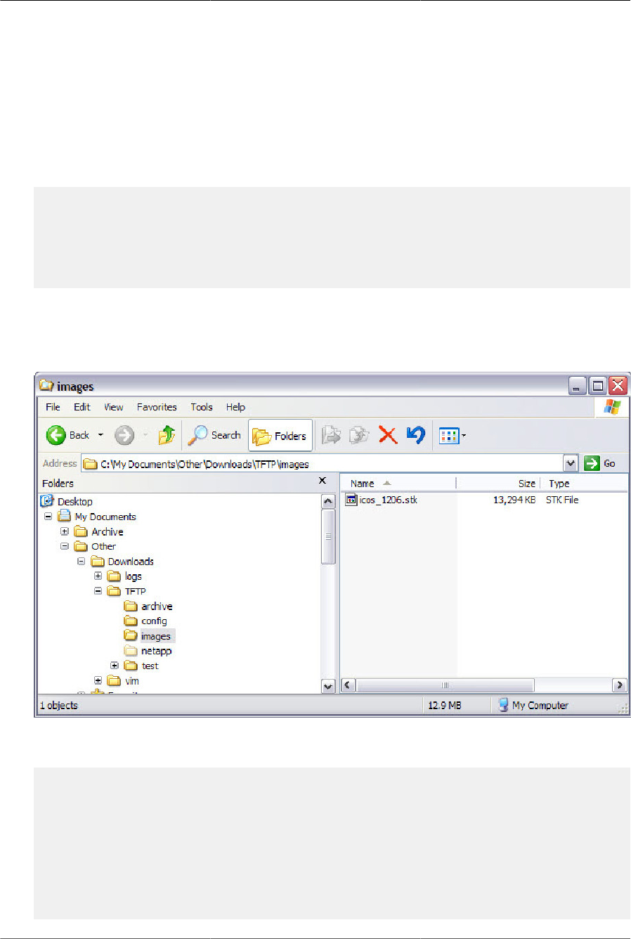
Configuring Switch
Management Features
59
• File path: \image
• File name: ICOS_1206.stk
Use the following steps to prepare the download, and then download and upgrade the switch im-
age.
1. Check the connectivity between the switch and the TFTP server.
(Routing) #ping 10.27.65.112
Pinging 10.27.65.112 with 0 bytes of data:
Reply From 10.27.65.112: icmp_seq = 0. time= 5095 usec.
----10.27.65.112 PING statistics----
1 packets transmitted, 1 packets received, 0% packet loss
round-trip (msec) min/avg/max = 5/5/5
2. Copy the image file to the appropriate directory on the TFTP server. In this example, the TFTP
root directory is C:\My Documents\Other\Downloads\TFTP, so the file path is images.
Figure4.1.File location
3. View information about the current image.
(Routing) #show bootvar
Image Descriptions
active : default image
backup :
Images currently available on Flash
--------------------------------------------------------------------
unit active backup current-active next-active
--------------------------------------------------------------------
1 I.12.5.1 11.21.16.52 I.12.5.1 I.12.5.1

Configuring Switch
Management Features
60
4. Download the image to the switch. After you execute the copy command, you must verify that
you want to start the download. The image is downloaded as the backup image.
(Routing) #copy tftp://10.27.65.112/images/icos_1206.stk backup
Mode........................................... TFTP
Set Server IP .................................. 10.27.65.112
Path........................................... images/
Filename....................................... icos_1206.stk
Data Type...................................... Code
Destination Filename........................... backup
Management access will be blocked for the duration of the transfer
Are you sure you want to start? (y/n)y
5. After the transfer completes, activate the new image so that it becomes the active image after
the switch resets.
(Routing) #boot system backup Activating image backup ..
6. View information about the current image.
(Routing) #show bootvar Image Descriptions
active : default image backup :
Images currently available on Flash
-------------------------------------------------------------------
unit active backup current-active next-active
--------------------------------------------------------------------
1 I.12.5.1 11.21.16.52 I.12.5.1 I.12.6.2
7. Copy the running configuration to the startup configuration to save the current configuration to
NVRAM.
(Routing) #write memory
This operation may take a few minutes.
Management interfaces will not be available during this time.
Are you sure you want to save? (y/n)y
Configuration Saved!
8. Reset the switch to boot the system with the new image.
(Routing) #reload
Are you sure you want to continue? (y/n)y
Reloading all switches...
4.1.11. Managing Configuration Scripts
This example shows how to create a configuration script that adds three host name-to-IP address
mappings to the host table.
To configure the switch:
1. Open a text editor on an administrative computer and type the commands as if you were enter-
ing them by using the CLI.
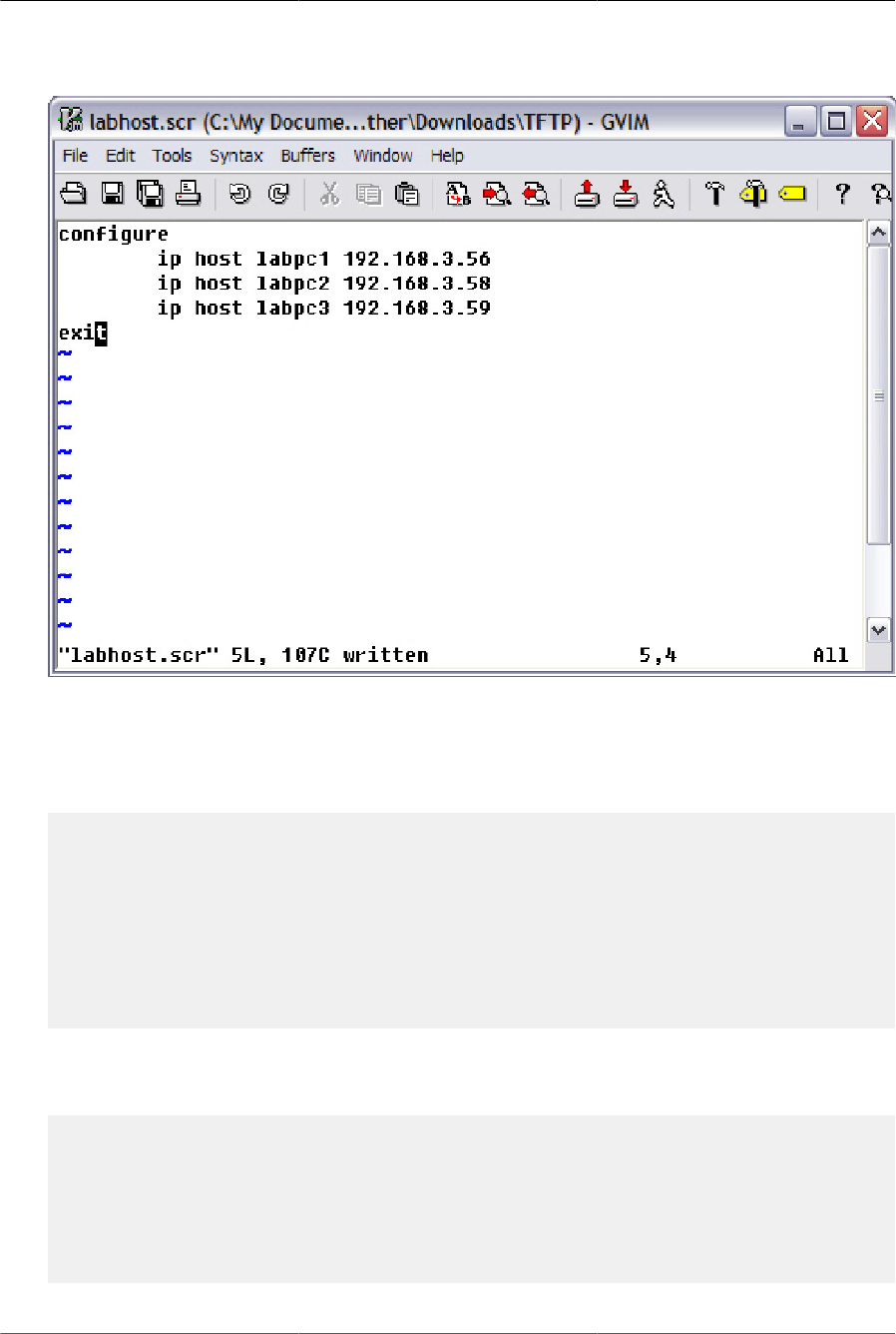
Configuring Switch
Management Features
61
Figure4.2.Text editor
2. Save the file with an *.scr extension and copy it to the appropriate directory on your TFTP serv-
er.
3. Download the file from the TFTP server to the switch.
(Routing) #copy tftp://10.27.65.112/labhost.scr nvram:script labhost.scr
Mode........................................... TFTP
Set Server IP .................................. 10.27.65.112
Path........................................... ./
Filename....................................... labhost.scr
Data Type...................................... Config Script
Destination Filename........................... labhost.scr
Management access will be blocked for the duration of the transfer
Are you sure you want to start? (y/n)
4. After you confirm the download information and the script successfully downloads, it is automat-
ically validated for correct syntax.
Are you sure you want to start? (y/n) y
135 bytes transferred
Validating configuration script... configure
exit configure
ip host labpc1 192.168.3.56
ip host labpc2 192.168.3.58
ip host labpc3 192.168.3.59

Configuring Switch
Management Features
62
Configuration script validated.
File transfer operation completed successfully.
5. Run the script to execute the commands.
(Routing) #script apply labhost.scr
Are you sure you want to apply the configuration script? (y/n)y
configure
exit
configure
ip host labpc1 192.168.3.56
ip host labpc2 192.168.3.58
ip host labpc3 192.168.3.59
Configuration script 'labhost.scr' applied.
6. Verify that the script was successfully applied.
(Routing) #show hosts
..
.
.
Configured host name-to-address mapping:
Host Addresses
------------------------ ------------------------
labpc1 192.168.3.56
labpc2 192.168.3.58
labpc3 192.168.3.59

Configuring Switch
Management Features
63
4.2. Enabling Automatic Image Installation
and System Configuration
The Auto Install feature can automatically update the firmware image and obtain configuration
information when the switch boots. Auto Install begins the automatic download and installation
process when the switch boots and loads a saved configuration that has the persistent Auto Install
mode enabled. Additionally, the switch supports a non-persistent Auto Install mode so that Auto In-
stall can be stopped or restarted at any time during switch operation.
4.2.1. DHCP Auto Install Process
The switch can use a DHCP server to obtain configuration information from a TFTP server. DHCP
Auto Install is accomplished in three phases:
1. Assignment or configuration of an IP address for the switch
2. Assignment of a TFTP server
3. Obtaining a configuration file for the switch from the TFTP server
Auto Install is successful when an image or configuration file is downloaded to the switch from a
TFTP server.
The downloaded configuration file is not automatically saved to startup-config. You
must explicitly issue a save request (write memory) in order to save the configuration.
4.2.1.1. Obtaining IP Address Information
DHCP is enabled by default on the service port. If an IP address has not been assigned, the
switch issues requests for an IP address assignment.
A network DHCP server returns the following information:
• IP address and subnet mask to be assigned to the interface
• IP address of a default gateway, if needed for IP communication
4.2.1.2. Obtaining Other Dynamic Information
The following information is also processed and may be returned by a BOOTP or DHCP server:
• Name of configuration file (the file field in the DHCP header or option 67) to be downloaded from
the TFTP server.
• Identification of the TFTP server providing the file. The TFTP server can be identified by name
or by IP address as follows:
• Host name: DHCP option 66 or the sname field in the DHCP header
• IP address: DHCP option 150 or the siaddr field in the DHCP header

Configuring Switch
Management Features
64
When a DHCP OFFER identifies the TFTP server more than once, the DHCP client selects one of
the options in the following order: sname, option 66, option 150, siaddr. If the TFTP server is iden-
tified by host name, a DNS server is required to translate the name to an IP address.
The DHCP client on the switch also processes the name of the text file (option 125, the V-I ven-
dor-specific Information option) which contains the path to the image file.
4.2.1.3. Obtaining the Image
Auto Install attempts to download an image file from a TFTP server only if the switch loads with
a saved configuration file that has Auto Install enabled (the boot host dhcp command) or if Auto
Install has been administratively activated by issuing the boot autoinstall start command during
switch operation.
The network DHCP server returns a DHCP OFFER message with option 125. When configuring
the network
DHCP server for image downloads, you must include Option 125 and specify the Broadcom En-
terprise Number, 4413. Within the Broadcom section of option 125, sub option 5 must specify the
path and name of a file on the TFTP server. This file is not the image file itself, but rather a text file
that contains the path and name of the image file. Upon receipt of option 125, the switch down-
loads the text file from the TFTP server, reads the name of the image file, and downloads the im-
age file from the TFTP server.
After the switch successfully downloads and installs the new image, it automatically reboots. The
download or installation might fail for one of the following reasons:
• The path or filename of the image on the TFTP server does not match the information specified
in DHCP option 125.
• The downloaded image is the same as the current image.
• The validation checks, such as valid CRC Checksum, fails.
If the download or installation was unsuccessful, a message is logged.
4.2.1.4. Obtaining the Configuration File
If the DHCP OFFER identifies a configuration file, either as option 67 or in the file field of the
DHCP header, the switch attempts to download the configuration file.
The configuration file is required to have a file type of *.cfg.
The TFTP client makes three unicast requests. If the unicast attempts fail, or if the DHCP OFFER
did not specify a TFTP server address, the TFTP client makes three broadcast requests.
If the DHCP server does not specify a configuration file or download of the configuration file fails,
the Auto Install process attempts to download a configuration file with the name fp-net.cfg. The
switch unicasts or broadcasts TFTP requests for a network configuration file in the same manner
as it attempts to download a host-specific configuration file.

Configuring Switch
Management Features
65
The default network configuration file consists of a set of IP address-to-host name mappings, us-
ing the command ip host hostname address. The switch finds its own IP address, as learned
from the DHCP server, in the configuration file and extracts its host name from the matching com-
mand. If the default network configuration file does not contain the switch’s IP address, the switch
attempts a reverse DNS lookup to resolve its host name.
A sample fp-net.cfg file follows:
config
...
ip host switch1 192.168.1.10
ip host switch2 192.168.1.11
... <other hostname definitions> exit
Once a host name has been determined, the switch issues a TFTP request for a file named
hostname.cfg, where hostname is the first thirty-two characters of the switch’s host name.
If the switch is unable to map its IP address to a host name, Auto Install sends TFTP requests for
the default configuration file host.cfg.
Table below summarizes the config files that may be downloaded and the order in which they are
sought.
Table4.2.Configuration File Possibilities
Order
Sought
File Name Description Final File
Sought
1 bootfile.cfg Host-specific config file, ending in a *.cfg file ex-
tension
Yes
2 fp-net.cfg Default network config file No
3 hostname.cfg Host-specific config file, associated with host
name.
Yes
4 host.cfg Default config file Yes
Table below displays the determining factors for issuing unicast or broadcast TFTP requests.
Table4.3.TFTP Request Types
TFTP Server Address
Available
Host-specific Switch
Config Filename
Available
TFTP Request Method
Yes Yes Issue a unicast request for the host-specific
router config file to the TFTP server
Yes No Issue a unicast request for a default network or
router config file to the TFTP server
No Yes Issue a broadcast request for the host-specific
router config file to any available TFTP server
No No Issue a broadcast request for the default net-
work or router config file to any available TFTP
server

Configuring Switch
Management Features
66
4.2.2. Monitoring and Completing the DHCP Auto In-
stall Process
When the switch boots and triggers an Auto Install, a message is written to the buffered log. After
the process completes, the Auto Install process writes a log message. You can use the show log-
ging buffered command to view information about the process. The following log message indi-
cates that the switch has broadcast a request to download the fp-net.cfg file from any TFTP server
on the network.
14 Jan 1 00:00:42 10.27.22.157-1 AUTO_INST[310234388]: auto_install_control.c(2427) 202 %%
AutoInstall<→TFTP : Downloading tftp://255.255.255.255/fp-net.cfg (via eth0)
Additionally, while the Auto Install is running, you can issue the show autoinstall command to
view information about the current Auto Install state.
When Auto Install has successfully completed, you can execute a show running-config com-
mand to validate the contents of configuration.
4.2.2.1. Saving a Configuration
The Auto Install feature includes an AutoSave feature that allows the downloaded configuration to
be automatically saved; however, AutoSave is disabled by default. If AutoSave has not been en-
abled, you must explicitly save the downloaded configuration in non-volatile memory. This makes
the configuration available for the next reboot. In the CLI, this is performed by issuing a write
memory command or copy system:running-config nvram:startup-config command and should
be done after validating the contents of saved configuration.
4.2.2.2. Stopping and Restarting the Auto Install Process
You can terminate the Auto Install process at any time before the image or configuration file is
downloaded. This is useful when the switch is disconnected from the network. Termination of the
Auto Install process ends further periodic requests for a host-specific file.
4.2.2.3. Managing Downloaded Config Files
The configuration files downloaded to the switch by Auto Install are stored in the nonvolatile mem-
ory as .scr files. The files may be managed (viewed or deleted) along with files downloaded by the
configuration scripting utility. If the Auto Install persistent mode is enabled (boot dhcp host) and
the switch reboots, the .scr configuration file created by the switch in the non-volatile memory is
overwritten during the Auto Install process.
To ensure that the downloaded configuration file is used during the next boot cycle, make sure that
the Auto Install persistent mode is disabled (no boot dhcp host) and save the configuration (write
memory).
4.2.3. DHCP Auto Install Dependencies
The Auto Install process from TFTP servers depends upon the following network services:
• A DHCP server must be configured on the network with appropriate services.

Configuring Switch
Management Features
67
• An image file and a text file containing the image file name for the switch must be available from
a TFTP server if DHCP image download is desired.
• A configuration file (either from bootfile (or) option 67 option) for the switch must be available
from a TFTP server.
• The switch must be connected to the network and have a Layer 3 interface that is in an UP
state.
• A DNS server must contain an IP address to host name mapping for the TFTP server if the
DHCP server response identifies the TFTP server by name.
• A DNS server must contain an IP address to host name mapping for the switch if a
<hostname>.cfg file is to be downloaded.
• If a default gateway is needed to forward TFTP requests, an IP helper address for TFTP needs
to be configured on the default gateway.
4.2.3.1. Default Auto Install Values
Table below describes the Auto Install defaults.
Table4.4.Auto Install Defaults
Feature Default Description
Retry Count 3 When the DHCP or BOOTP server returns information about the
TFTP server and bootfile, the switch makes three unicast TFTP
requests for the specified bootfile. If the unicast attempts fail or if
a TFTP server address was not provided, the switch makes three
broadcast requests to any available TFTP server for the speci-
fied bootfile.
AutoSave Disabled If the switch is successfully auto-configured, the running configu-
ration is not saved to the startup configuration.
AutoReboot Enabled After an image is successfully downloaded during the Auto Install
process, the switch automatically reboots and makes the down-
loaded image the active image.
4.2.4. Enabling DHCP Auto Install and Auto Image
Download
A network administrator is deploying three switches and wants to quickly and automatically install
the latest image and a common configuration file that configures basic settings such as VLAN cre-
ation and membership and RADIUS server settings. This example describes the procedures to
complete the configuration. The DHCP and TFTP servers in this example are reachable from the
service port on the switch.
To use DHCP Auto Install:
1. Log on to each switch and enable persistent Auto Install mode.
(Routing) #boot host dhcp

Configuring Switch
Management Features
68
. Save the running configuration to the startup configuration file.
(Routing) #write memory
2. Create a default config file for the switches named host.cfg. For information about creating con-
figuration files, see Section 4.1, “Managing Images and Files”
3. Upload the host.cfg file to the TFTP server.
4. Upload the image file to the TFTP server.
5. Configure an address pool on the DHCP server that contains the following information:
a. The IP address (yiaddr) and subnet mask (option 1) to be assigned to the interface
b. The IP address of a default gateway (option 3)
c. DNS server address (option 6)
d. Name of config file for each host
e. Identification of the TFTP server by host name (DHCP option 66 or the sname field in the
DHCP header) or IP address (DHCP option 150 or the siaddr field in the DHCP header)
f. Name of the text file (option 125, the V-I vendor-specific Information option) that contains the
path to the image file.
6. Connect the service port on each switch to the management network. This network must have a
route to the DHCP server and TFTP server that are used for Auto Install process.
7. Reboot each switch.
(Routing) #reload

Configuring Switch
Management Features
69
4.3. Downloading a Core Dump
The core dump file can be downloaded using the following methods:
• NFS
• TFTP
• FTP
On systems that have gigabytes of flash storage, the core dump file can also be copied to flash.
4.3.1. Using NFS to Download a Core Dump
Use the following commands to download a core dump file via NFS:
(Routing) #config
(Routing) (Config)#exception protocol nfs
(Routing) (Config)#exception dump nfs 192.168.1.10://home/nfs_test
(Routing) (Config)#show exception
Coredump file name............................. ASDF
Coredump filename uses hostname................ TRUE
Coredump filename uses time-stamp.............. TRUE
NFS mount point................................ 192.168.1.10://home/nfs_test
TFTP server IP .................................. 10.27.9.99
File path...................................... ./.
Protocol....................................... nfs
Switch-chip-register........................... TRUE
(Routing) (Config)#
(Routing) #write core test
The configured protocol nfs test PASS (Routing) #
4.3.2. Using TFTP or FTP to Download a Core Dump
Use the following commands to download a core dump file via TFTP. To use FTP, substitute ftp for
tftp in the commands.
(Routing) #config
(Routing) (Config)#exception protocol tftp
(Routing) (Config)#exception dump tftp-server 192.168.1.2
(Routing) (Config)#show exception
Coredump file name............................. core
Coredump filename uses hostname................ FALSE
Coredump filename uses time-stamp.............. TRUE
TFTP server IP .................................. 192.168.1.2
File path...................................... ./.
Protocol....................................... tftp
Switch-chip-register........................... FALSE
(Routing) (Config)#
(Routing) #write core test
The configured protocol tftp test PASS

Configuring Switch
Management Features
70
(Routing) #

Configuring Switch
Management Features
71
4.4. Enabling Kernel Core Dump
This feature is available only on Ubuntu Linux distributions of the ICOS software.
The kernel core dump feature enables the system to perform a warm reboot into a new kernel
in reserved memory, allowing the current state of the operating kernel to be captured for post-
mortem analysis. This feature involves configuring the underlying operating system to enable the
Linux kexec feature. The kernel-dump feature is implemented as a set of bash scripts in either a
RPM or DEB package that can be used with or without the ICOS application running. It provides
a convenient method to invoke the “crash” console kernel debugging utility without requiring com-
plex user configuration. This provides the necessary handling to allow debugging of the ICOS cus-
tomized Linux kernel. This feature is available only on platforms with Intel x86-class CPUs running
standard Ubuntu Linux.
The following commands can be executed in Global Config mode to enable the kernel-dump fea-
ture, which is disabled by default, and to configure the path for storing kernel-dump files:
(Routing) #config
(Routing) (Config)#exception kernel-dump (Routing)
(Config)#exception kernel-dump path path
You use the following commands in Privileged Exec mode to show kernel-dump settings, show the
list of saved kernel dumps, and show the dmesg log from a particular kernel dump.
(Routing) #show exception kernel-dump (Routing) #show exception kernel-dump list
(Routing) #show exception kernel-dump log record number
See the ICOS CLI Command Reference for a complete list of commands.

Configuring Switch
Management Features
72
4.5. Setting the System Time
The switch uses the system clock to provide time stamps on log messages. Additionally, some
show commands include the time in the command output. For example, the show users lo-
gin-history command includes a Login Time field. The system clock provides the information for
the Login Time field.
You can configure the system time manually, or you can configure the switch to obtain the time by
using a Simple Network Time Protocol (SNTP) server. A network SNTP server can provide more
accurate switch clock time synchronization than manually-configured time.
The manually-configured local clock settings are not retained across a system reset if
the platform does not include a Real Time Clock (RTC).
The SNTP client on the switch can request the time from an SNTP server on the network (unicast),
or you can allow the switch to receive SNTP broadcasts. Requesting the time from a unicast SNTP
server is more secure. Use this method if you know the IP address of the SNTP server on your
network. If you allow the switch to receive SNTP broadcasts, any clock synchronization informa-
tion is accepted, even if it has not been requested by the device. This method is less secure than
polling a specified SNTP server.
The switch also supports the following time configuration settings:
• Time Zone — Allows you to specify the offset from Coordinated Universal Time (UTC), which is
also known as Greenwich Mean Time (GMT).
• Summer Time/Daylight Saving Time (DST)— In some regions, the time shifts by one hour in the
fall and spring. The switch supports manual entry of one-time or recurring shifts in the time.
4.5.1. Manual Time Configuration
The example in this section shows how to manually configure the time, date, time zone, and sum-
mer time settings for a switch in Hyderabad, India.
1. Set the time. The system clock uses a 24-hour clock, so 6:23 PM is entered as 18:23:00.
(Routing) #configure
(Routing) (Config)#clock set 18:23:00
. Set the date. In this example, the date is April 30, 2012.
(Routing) (Config)#clock set 04/30/2012
2. Configure the time zone. In this example, the time zone is India Standard Time (IST), which is
UTC/GMT +5 hours and 30 minutes.
(Routing) (Config)#clock timezone 5 minutes 30 zone IST
3. Configure the offset for a hypothetical daylight saving time. In this example, the offset is one
hour. It occurs every year on Sunday in the first week of April and ends the fourth Sunday in Oc-
tober. The start and end times are 2:30 AM, and the time zone is India Standard Summer Time
(ISST).

Configuring Switch
Management Features
73
(Routing) (Config)#clock summer-time recurring 1 sun apr 02:30 4
sun oct 02:30 offset 60 zone ISST
(Routing) (Config)#exit
4. View the clock settings.
(Routing) #show clock detail 20:30:07 ISST(UTC+6:30) Apr 30 2012
No time source
Time zone: Acronym is IST Offset is UTC+5:30
Summertime: Acronym is ISST
Recurring every year
Begins at first Sunday of Apr at 02:30 Ends at fourth Sunday of Oct
at 02:30 offset is 60 minutes
4.5.2. Configuring SNTP
This example shows how to configure the system clock for a switch in New York City, which has a
UTC/GMT offset of –5 hours.
1. Specify the SNTP server the client on the switch should contact. You can configure the IP ad-
dress or host name of the SNTP server.
(Routing) #configure
(Routing) (Config)#sntp server time1.rtp.broadcom.com
2. Configure the UTC/GMT offset for the location.
(Routing) (Config)#clock timezone -5
3. Configure the time offset for DST.
(Routing) (Config)#clock summer-time recurring USA
4. Enable the SNTP client on the device in unicast mode.
(Routing) (Config)#sntp client mode unicast
5. View the time information.
(Routing) #show sntp
Last Update Time: Apr 27 16:42:23 2012
Last Unicast Attempt Time: Apr 27 16:43:28 2012
Last Attempt Status: Success
(Routing) #show clock
12:47:22 (UTC-4:00) Apr 27 2012
Time source is SNTP

Configuring Switch
Management Features
74
4.6. Creating CPU Traffic Filters
When mirroring traffic to and from the CPU, you can create filters that match only certain packets
and quickly see if there are packets to/from CPU that match the filters. Filters can be based on the
protocol along with IP address, MAC address, and TCP and UPD port numbers. In lieu of a named
protocol, a custom option can be used to specify the offset and data to match. The match condition
for the filter can be one or more of the following: STP, LACPDU, ARP, UDLD, BCAST, MCAST,
UCAST, LLDP, IP, OSPF, BGP, DHCP, SRCIP, DSTIP, SRCMAC, DSTMAC, SRCTCP, DSTTCP,
SRCUDP, DSTUDP, and custom data with offset.
ICOS supports using two software filters (one filter for Tx and one for Rx), and can configure the
filter to match one, multiple, or all of the supported protocols in the Tx or Rx direction, or both di-
rections.
CPU traffic either in the Rx or Tx direction is compared with the defined user-level filters. Filter sta-
tistics are updated for the packet matching the filter.
Statistics counters are available for each filter option per interface and direction. For example, if a
filter is defined for STP and LACPDU packets on port-1 for Rx and Tx direction, then each STP or
LACPDU packet received on port-1 increments STP and LACP counter statistics. Similarly, STP or
LACPDU packets sent by the switch from port-1 also increment the counter statistics. The counter
statistics for an interface are associated with the last updated timestamp to determine when the
counter on an interface was most recently updated.
4.6.1. Configuration Example
1. Enable the feature on interface:
(Routing) #cpu-traffic direction both interface 0/1
2. Enable a particular filter (in the following example, we are interested in packets with particular
SrcIP, 10.27.9.99):
(Routing) #cpu-traffic direction both match filter srcip
3. Configure additional parameters for the filter:
(Routing) #cpu-traffic direction both match srcip 10.27.9.99 mask
255.255.255.255
4. Enable the feature:
(Routing) #cpu-traffic mode
5. Use show commands to check the counters:
show cpu-traffic interface 0/1 srcip
show cpu-traffic summary

Configuring Switch
Management Features
75
4.7. Configuring a Packet Trace (Network In-
strumentation App)
The packet trace feature can be used to trace the egressing LAG member port/ECMP route for
a specified packet. This feature allows the network administrator to figure out the specific path
a specified network stream may take. The feature does not need to save any configuration and
is provided as a utility. On a system that has LAGs/ECMP routes set up (specific routes that the
packet may take), the following steps can be used to find the egress information.
a) Specify the packet fields for the packet to be traced. Appropriate packet-trace commands can
be used depending upon the type of packet to be traced. Show packet-trace packet-data can be
used to dump the currently configured packet fields.
(Routing) #packet-trace eth src-mac 00:00:00:00:07:00 dst-mac
00:00:00:00:06:00 vlan 10
(Routing) #show packet-trace packet-data
Packet header fields
--------------------
Ethernet header fields:
Src Mac Dst Mac Vlan
----------------- ---------------- ----
00:00:00:00:07:00 00:00:00:00:06:00 10
IPv4 header fields
Src IP Dst IP TOS
------- ------- ---
0.0.0.0 0.0.0.0 0
IPv6 header fields
Src IP Dst IP TOS
------- ------- ---
:: :: 0
TCP/UDP header fields
Src Port Dst Port
-------- --------
0 0
b) Use the show packet-trace packet-data command to dump the currently configured packet
fields.
(Routing) #show packet-trace port 0/34 eth
LAG Destination member Port
----------- -----------------------
6 0/55
Local Interface................................ 3/6
Channel Name................................... ch6
Link State..................................... Up
Admin Mode..................................... Enabled
Type........................................... Static

Configuring Switch
Management Features
76
Port-channel Min-links. ........................ 1
Load Balance Option. ........................... 3
(Src/Dest MAC, VLAN, EType, incoming port)
Mbr Device/ Port Port
Ports Timeout Speed Active
------- ------------- --------- -------
0/33 actor/long 10G Full True
partner/long
0/35 actor/long 10G Full True
partner/long
0/36 actor/long 10G Full True
partner/long
0/53 actor/long 10G Full True
partner/long
0/54 actor/long 10G Full True
partner/long
0/55 actor/long 10G Full True
partner/long
0/56 actor/long 10G Full True
partner/long

77
Chapter 5. Configuring Security
Features

Configuring Security Features
78
5.1. Controlling Management Access
A user can access the switch management interface only after providing a valid user name and
password combination that matches the user account information stored in the user database con-
figured on the switch.
ICOS software include several additional features to increase management security and help pre-
vent unauthorized access to the switch configuration interfaces.
5.1.1. Using RADIUS Servers for Management Security
Many networks use a RADIUS server to maintain a centralized user database that contains per-
user authentication information. RADIUS servers provide a centralized authentication method for:
• Telnet Access
• Console to Switch Access
• Access Control Port (802.1X)
RADIUS access control utilizes a database of user information on a remote server. Making use of
a single database of accessible information — as in an Authentication Server — can greatly sim-
plify the authentication and management of users in a large network. One such type of Authentica-
tion Server supports the Remote Authentication Dial In User Service (RADIUS) protocol as defined
by RFC 2865.
For authenticating users prior to access, the RADIUS standard has become the protocol of choice
by administrators of large accessible networks. To accomplish the authentication in a secure man-
ner, the RADIUS client and RADIUS server must both be configured with the same shared pass-
word or secret. This secret is used to generate one-way encrypted authenticators that are present
in all RADIUS packets. The secret is never transmitted over the network.
RADIUS conforms to a secure communications client/server model using UDP as a transport pro-
tocol. It is extremely flexible, supporting a variety of methods to authenticate and statistically track
users. RADIUS is also extensible, allowing for new methods of authentication to be added without
disrupting existing functionality.
As a user attempts to connect to the switch management interface, the switch first detects the con-
tact and prompts the user for a name and password. The switch encrypts the supplied information,
and a RADIUS client transports the request to a pre-configured RADIUS server.
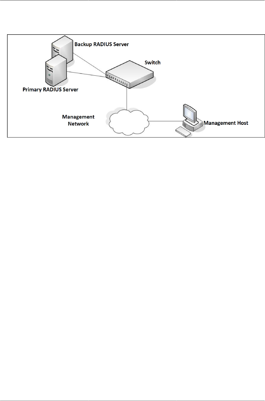
Configuring Security Features
79
Figure5.1.RADIUS Topology
The server can authenticate the user itself or make use of a back-end device to ascertain authen-
ticity. In either case a response may or may not be forthcoming to the client. If the server accepts
the user, it returns a positive result with attributes containing configuration information. If the server
rejects the user, it returns a negative result. If the server rejects the client or the shared secrets dif-
fer, the server returns no result. If the server requires additional verification from the user, it returns
a challenge, and the request process begins again.
If you use a RADIUS server to authenticate users, you must configure user attributes in the user
database on the RADIUS server. The user attributes include the user name, password, and privi-
lege level.
5.1.2. RADIUS Dynamic Authorization
The RADIUS Dynamic Authorization feature implements part of the Dynamic Authorization Server
(DAS) functionality defined in RFC 5176 (Dynamic Authorization Extensions to Remote Authenti-
cation Dial In User Services). This feature enables a RADIUS server or any other external server
to send messages to a Network Access Server (NAS) to terminate a user’s session. This is desir-
able when a device or user session is causing problems in normal network operation.
RFC 5176 defines the DAS and Dynamic Authorization Client (DAC) and the following types of
messages:
• Disconnect messages - This message from the DAC may result in terminating a user’s session.
• Change of Authorization messages—This message from a DAC results in changing authoriza-
tion status of the session.
As of current ICOS release, the DAS implementation handles Disconnect message only.
When ICOS DAS receives Disconnect Message from DAC, it looks for NAS identification and User
Identity attributes available in the Disconnect Message. If the match for the NAS attribute and
user’s identify is found then it disconnect matching sessions and when successful, sends an ACK
to DAC. The DAS sends a NAK with “Acct-Terminate-Cause” attribute (49) with value set to 6 if the
user’s session is not available or one or more sessions could not be disconnected by DAS.
The following example configures dynamic authorization on a DAC and server host.

Configuring Security Features
80
1. Enter RADIUS dynamic authorization configuration mode:
console(config)#aaa server radius dynamic-author
2. Configure the DAC. The server-key, if configured, overrides the global shared secret for this
client only:
console(config-radius-da)#client 10.130.191.89 server-key lvl7india
3. Set the accepted authorization types ({all | any | session-key}) for dynamic RADIUS clients:
console(config-radius-da)#auth-type any
4. Set the port on which to listen for CoA and disconnect requests:
console(config-radius-da)#port 4747 console(config-radius-da)#exit
5. Set the network access server (NAS) IP address for the RADIUS server
console(config)#radius-server attribute 4 10.130.65.4
6. Specify a RADIUS server host and type ({accounting | authentication}):
console(config)#radius-server host auth 10.130.191.89
7. Configure the server host:
console(config-auth-radius)#name "default-radius-server"
console(config-auth-radius)#key lvl7india
5.1.3. Using TACACS+ to Control Management Access
TACACS+ (Terminal Access Controller Access Control System) provides access control for net-
worked devices via one or more centralized servers. TACACS+ simplifies authentication by mak-
ing use of a single database that can be shared by many clients on a large network. TACACS+ us-
es TCP to ensure reliable delivery and a shared key configured on the client and daemon server to
encrypt all messages.
If you configure TACACS+ as the authentication method for user login and a user attempts to ac-
cess the user interface on the switch, the switch prompts for the user login credentials and re-
quests services from the TACACS+ client. The client then uses the configured list of servers for
authentication, and provides results back to the switch.
You can configure the TACACS+ server list with one or more hosts defined via their network IP
address. You can also assign each a priority to determine the order in which the TACACS+ client
will contact them. TACACS+ contacts the server when a connection attempt fails or times out for a
higher priority server.
You can configure each server host with a specific connection type, port, timeout, and shared key,
or you can use global configuration for the key and timeout.
The TACACS+ server can do the authentication itself, or redirect the request to another back-end
device. All sensitive information is encrypted and the shared secret is never passed over the net-
work; it is used only to encrypt the data.

Configuring Security Features
81
5.1.4. Configuring and Applying Authentication Pro-
files
A user can access the switch management interface only after providing a valid user name and
password combination that matches the user account information stored in the user database con-
figured on the switch.
ICOS software include several additional features to increase management security and help pre-
vent unauthorized access to the CLI.
An authentication profile specifies which authentication method or methods to use to authenticate
a user who attempts to access the switch management interface. The profile includes a method
list, which defines how authentication is to be performed, and in which order. The list specifies the
authentication method to use first, and if the first method returns an error, the next method in the
list is tried. This continues until all methods in the list have been attempted. If no method can per-
form the authentication, then the authentication fails. A method might return an error if, for exam-
ple, the authentication server is unreachable or misconfigured.
The authentication method can be one or more of the following:
• enable — Uses the enable password for authentication. If there is no enable password defined,
then the enable method returns an error.
• line — Uses the Line password for authentication. If there is no line password defined for the ac-
cess line, then the line method returns an error.
• local — Uses the ID and password in the Local User Database for authentication. If the user ID
is not in the local database, access is denied. This method never returns an error. It always per-
mits or denies a user.
• radius — Sends the user’s ID and password a RADIUS server to be authenticated. The method
returns an error if the switch is unable to contact the server.
• tacacs+ — Sends the user’s ID and password to a TACACS+ server to be authenticated. The
method returns an error if the switch is unable to contact the server.
• none — No authentication is used. This method never returns an error.
• deny — Access is denied. This method never returns an error.
An authentication method might require a user name and password to be supplied, a password
only, or no user information. Some methods return errors when authentication fails, while other
methods do not. The following table summarizes the method user name/password requirements
and error behavior.
Table5.1.Authentication Method Summary
Method User Name Required Password Required Error Returned
Local Yes Yes No
RADIUS Yes Yes Yes
TACACS+ Yes Yes Yes

Configuring Security Features
82
Method User Name Required Password Required Error Returned
Enable No Yes Yes
Line No Yes Yes
None No No No
Deny No No No
You can use the same Authentication Profile for all access types, or select or create a variety of
profiles based on how a user attempts to access the switch management interface. Profiles can be
applied to each of the following access types:
• Login — Authenticates all attempts to login to the switch.
• Enable — Authenticates all attempts to enter Privileged EXEC mode.
• Console — Authenticates access through the console port.
• Telnet — Authenticates users accessing the CLI by using telnet
• SSH — Authenticates users accessing the CLI by using an SSH client.
The following authentication profiles are configured by default:
• defaultList — Method is LOCAL, which means the user credentials are verified against the infor-
mation in the local user database.
• networkList — Method is LOCAL, which means the user credentials are verified against the in-
formation in the local user database.
• enableList — Method is ENABLE, followed by NONE, which means that if the "enable" pass-
word is not configured access is granted. If the enable password is configured and user fails to
authenticate then access is not granted.
• enableNetList — Method is ENABLE, followed by DENY, which means that if the enable pass-
word is not configured access is denied. This list is applied by default for telnet and SSH. In
ICOS the enable password is not configured by default. That means that, by default, telnet and
SSH users will not get access to Privileged EXEC mode. However, a console user always en-
ters the Privileged EXEC mode without entering the enable password in the default configura-
tion.
The methods can be changed, but the preconfigured profiles cannot be deleted or renamed.
5.1.5. Configuring Authentication Profiles for Port-
Based Authentication
In addition to authentication profiles to control access to the management interface, you can con-
figure an authentication profile for IEEE 802.1X port-based access control to control access to
the network through the switch ports. To configure a port-based authentication profile, you speci-
fy dot1x as the access type, and configure ias, local, none, or radius as the authentication method.
The ias method specifies that the 802.1X feature should use the Internal Authentication Serv-
er (IAS) database for 801X port-based authentication. The IAS database is stored locally on the
switch.

Configuring Security Features
83
5.1.6. Configuring the Primary and Secondary RADIUS
Servers
The commands in this example configure primary and secondary RADIUS servers that the switch
will use to authenticate access. The RADIUS servers use the same RADIUS secret.
To configure the switch:
1. Configure the primary and secondary RADIUS servers.
(Routing) #configure
(Routing) (Config)#radius server host auth 10.27.65.103
(Routing) (Config)#radius server host auth 10.27.65.114
2. Specify which RADIUS server is the primary.
(Routing) (Config)#radius server primary 10.27.65.103
(Routing) (Config)#radius server key auth 10.27.65.103
3. Configure a shared secret that the switch will use to authenticate with the RADIUS servers.
Enter secret (64 characters max):********
Re-enter secret:********
4. View the configured RADIUS servers.
(Routing) (Config)#exit (Routing) #show radius servers
Cur
rent Host Address Server Name Port Type
---- ----------------------- ------------------------ ----- ---------
10.27.65.114 Default-RADIUS-Server 1812 Secondary
* 10.27.65.103 Default-RADIUS-Server 1812 Primary
5.1.7. Configuring an Authentication Profile
The commands in this example create a new authentication profile named myList that uses the
RADIUS server configured in the previous example to authenticate users who attempt to access
the switch management interface by using SSH or Telnet. If the RADIUS authentication is unsuc-
cessful, the switch uses the local user database to attempt to authenticate the users.
To configure the switch:
1. Create an access profile list that uses RADIUS as the first access method and the local user
database as the second login method.
(Routing) #configure
(Routing) (Config)#aaa authentication login myList radius local
The switch attempts to contact the primary RADIUS server that has been config-
ured on the switch. To see an example of how to configure a RADIUS server on
the switch, see Section 5.1.6, “Configuring the Primary and Secondary RADIUS
Servers”

Configuring Security Features
84
2. Enter line configuration mode for Telnet and specify that any attempt to access the switch by
using Telnet are authenticated using the methods defined in the profile created in the previous
step.
(Routing) (Config)#line telnet
(Routing) (Config-telnet)#l#login authentication myList (Routing)
(Config-telnet)#l#exit
3. Enter line configuration mode for SSH and specify that any attempt to access the switch by us-
ing SSH are authenticated using the methods defined in the myList profile.
(Routing) (Config)#line ssh
(Routing) (Config-ssh)#login authentication myList
(Routing) (Config-ssh)#exit
(Routing) (Config)#exit
4. View the current authentication methods and profiles.
(Routing) #show authentication methods
Login Authentication Method Lists
---------------------------------
defaultList : local
networkList : local
myList : radius local
Enable Authentication Method Lists
----------------------------------
enableList : enable none
Line Login Method List Enable Method List
------- ----------------- ------------------
Console defaultList enableList
Telnet myList enableList
SSH myList enableList

Configuring Security Features
85
5.2. Configuring DHCP Snooping, DAI, and
IPSG
Dynamic Host Configuration Protocol (DHCP) Snooping, IP Source Guard (IPSG), and Dynamic
ARP Inspection (DAI) are layer 2 security features that examine traffic to help prevent accidental
and malicious attacks on the switch or network.
DHCP Snooping monitors DHCP messages between a DHCP client and DHCP server to filter
harmful DHCP messages and to build a bindings database. The IPSG and DAI features use the
DHCP Snooping bindings database to help enforce switch and network security.
IP Source Guard allows the switch to drop incoming packets that do not match a binding in the
bindings database. Dynamic ARP Inspection allows the switch to drop ARP packets whose sender
MAC address and sender IP address do not match an entry in the DHCP snooping bindings data-
base.
5.2.1. DHCP Snooping Overview
Dynamic Host Configuration Protocol (DHCP) Snooping is a security feature that monitors DHCP
messages between a DHCP client and DHCP server to accomplish the following tasks:
• Filter harmful DHCP messages
• Build a bindings database with entries that consist of the following information:
• MAC address
• IP address
• VLAN ID
• Client port
Entries in the bindings database are considered to be authorized network clients.
DHCP snooping can be enabled on VLANs, and the trust status (trusted or untrusted) is specified
on individual physical ports or LAGS that are members of a VLAN. When a port or LAG is config-
ured as untrusted, it could potentially be used to launch a network attack. DHCP servers must be
reached through trusted ports.
DHCP snooping enforces the following security rules:
• DHCP packets from a DHCP server (DHCPOFFER, DHCPACK, DHCPNAK, DHCPRELEASE-
QUERY) are dropped if they are received on an untrusted port.
• DHCPRELEASE and DHCPDECLINE messages are dropped if the MAC addresses in the
snooping database, but the binding’s interface is other than the interface where the message
was received.
• On untrusted interfaces, the switch drops DHCP packets with a source MAC address that does
not match the client hardware address. This is a configurable option.
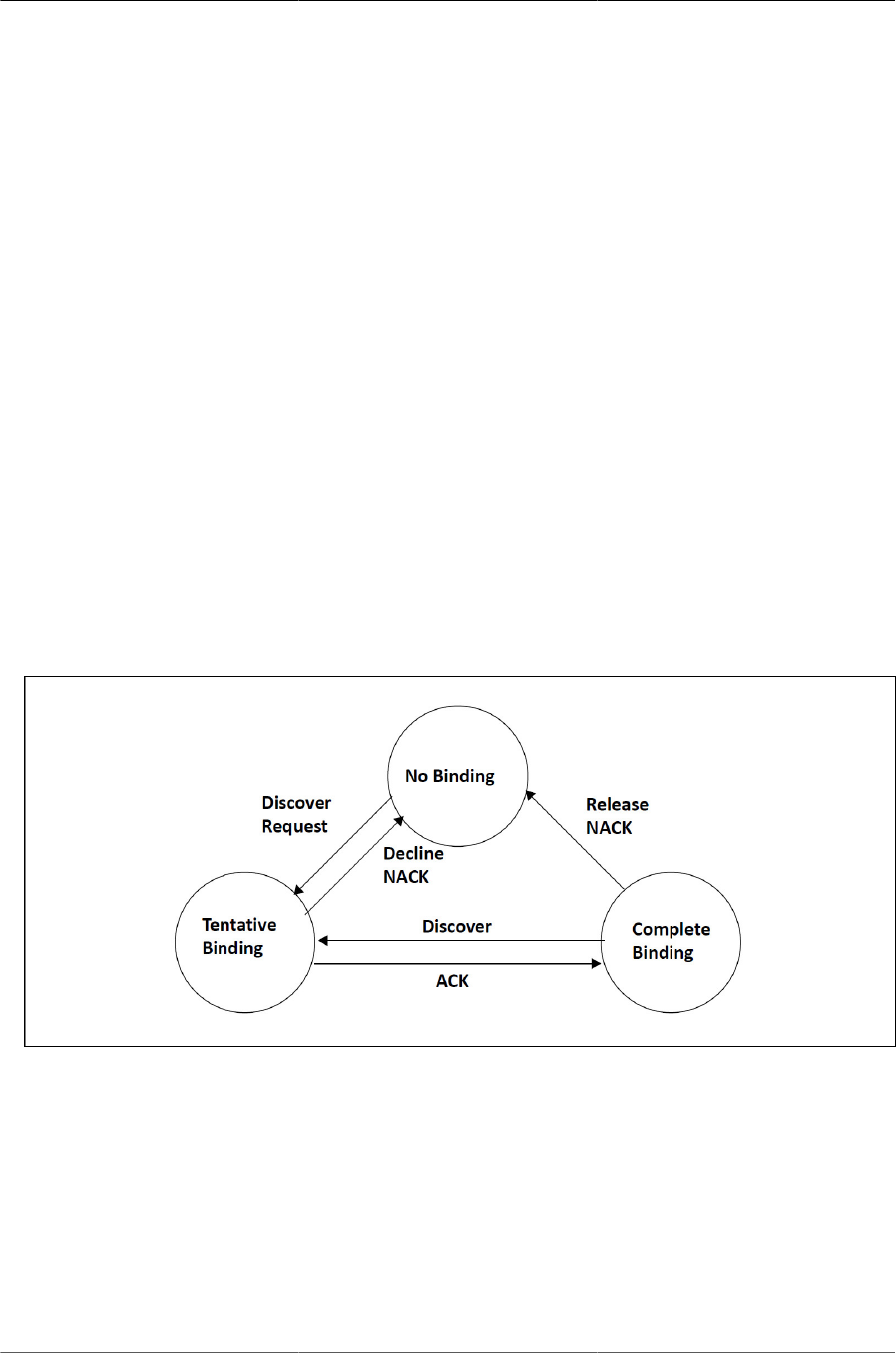
Configuring Security Features
86
5.2.2. Populating the DHCP Snooping Bindings Data-
base
The DHCP snooping application uses DHCP messages to build and maintain the binding’s data-
base. DHCP snooping creates a tentative binding from DHCP DISCOVER and REQUEST mes-
sages. Tentative bindings tie a client to a port (the port where the DHCP client message was re-
ceived). Tentative bindings are completed when DHCP snooping learns the client’s IP address
from a DHCP ACK message on a trusted port. DHCP snooping removes bindings in response to
DECLINE, RELEASE, and NACK messages. The DHCP snooping application ignores the ACK
messages as a reply to the DHCP Inform messages received on trusted ports. You can also enter
static bindings into the binding database.
When a switch learns of new bindings or loses bindings, the switch immediately updates the en-
tries in the database. The switch also updates the entries in the binding file. The frequency at
which the file is updated is based on a configurable delay, and the updates are batched.
If the absolute lease time of the snooping database entry expires, that entry is removed. Make
sure the system time is consistent across the reboots. Otherwise, the snooping entries will not ex-
pire properly. If a host sends a DHCP release while the switch is rebooting, when the switch re-
ceives the DHCP discovery or request, the client’s binding goes to the tentative binding as shown
in figure below.
Figure5.2.DHCP Binding
The binding database includes data for clients only on untrusted ports.
5.2.3. DHCP Snooping and VLANs
DHCP snooping forwards valid DHCP client messages received on non-routing VLANs. The mes-
sage is forwarded on all trusted interfaces in the VLAN.
DHCP snooping can be configured on switching VLANs and routing VLANs. When a DHCP pack-
et is received on a routing VLAN, the DHCP snooping application applies its filtering rules and up-
dates the bindings database. If a client message passes filtering rules, the message is placed into

Configuring Security Features
87
the software forwarding path where it may be processed by the DHCP relay agent, the local DHCP
server, or forwarded as an IP packet.
5.2.4. DHCP Snooping Logging and Rate Limits
The DHCP snooping application processes incoming DHCP messages. For DHCPRELEASE and
DHCPDECLINE messages, the application compares the receive interface and VLAN with the
client interface and VLAN in the bindings database. If the interfaces do not match, the application
logs the event and drops the message. For valid client messages, DHCP snooping compares the
source MAC address to the DHCP client hardware address. When there is a mismatch, DHCP
snooping drops the packet and generates a log message if logging of invalid packets is enabled.
If DHCP relay co-exists with DHCP snooping, DHCP client messages are sent to DHCP relay for
further processing.
To prevent DHCP packets from being used as a DoS attack when DHCP snooping is enabled, the
snooping application enforces a rate limit for DHCP packets received on interfaces. DHCP snoop-
ing monitors the receive rate on each interface separately. If the receive rate exceeds a config-
urable limit, DHCP snooping brings down the interface. Administrative intervention is necessary to
enable the port, either by using the no shutdown command in Interface Config mode.
5.2.5. IP Source Guard Overview
IPSG is a security feature that filters IP packets based on source ID. This feature helps protect the
network from attacks that use IP address spoofing to compromise or overwhelm the network.
The source ID may be either the source IP address or a {source IP address, source MAC address}
pair. You can configure:
• Whether enforcement includes the source MAC address
• Static authorized source IDs
The DHCP snooping bindings database and static IPSG entries identify authorized source IDs.
IPSG can be enabled on physical and LAG ports.
If you enable IPSG on a port where DHCP snooping is disabled or where DHCP snooping is en-
abled but the port is trusted, all IP traffic received on that port is dropped depending on the ad-
min-configured IPSG entries.
5.2.6. IPSG and Port Security
IPSG interacts with port security, also known as port MAC locking to enforce the source MAC
address. Port security controls source MAC address learning in the layer 2 forwarding database
(MAC address table). When a frame is received with a previously unlearned source MAC address,
port security queries the IPSG feature to determine whether the MAC address belongs to a valid
binding.
If IPSG is disabled on the ingress port, IPSG replies that the MAC is valid. If IPSG is enabled on
the ingress port, IPSG checks the bindings database. If the MAC address is in the bindings data-
base and the binding matches the VLAN the frame was received on, IPSG replies that the MAC is

Configuring Security Features
88
valid. If the MAC is not in the bindings database, IPSG informs port security that the frame is a se-
curity violation.
In the case of an IPSG violation, port security takes whatever action it normally takes upon receipt
of an unauthorized frame. Port security limits the number of MAC addresses to a configured max-
imum. If the limit n is less than the number of stations m in the bindings database, port security al-
lows only n stations to use the port. If n > m, port security allows only the stations in the bindings
database.
5.2.7. Dynamic ARP Inspection Overview
Dynamic ARP Inspection (DAI) is a security feature that rejects invalid and malicious ARP packets.
DAI prevents a class of man-in-the-middle attacks where an unfriendly station intercepts traffic for
other stations by poisoning the ARP caches of its unsuspecting neighbors. The malicious attacker
sends ARP requests or responses mapping another station’s IP address to its own MAC address.
When DAI is enabled, the switch drops ARP packets whose sender MAC address and sender IP
address do not match an entry in the DHCP snooping bindings database. You can optionally con-
figure additional ARP packet validation.
When DAI is enabled on a VLAN, DAI is enabled on the interfaces (physical ports or LAGs) that
are members of that VLAN. Individual interfaces are configured as trusted or untrusted. The trust
configuration for DAI is independent of the trust configuration for DHCP snooping.
5.2.8. Optional DAI Features
If you configure the MAC address validation option, DAI verifies that the sender MAC address
equals the source MAC address in the Ethernet header. There is a configurable option to veri-
fy that the target MAC address equals the destination MAC address in the Ethernet header. This
check applies only to ARP responses, since the target MAC address is unspecified in ARP re-
quests. You can also enable IP address checking. When this option is enabled, DAI drops ARP
packets with an invalid IP address. The following IP addresses are considered invalid:
• 0.0.0.0
• 255.255.255.255
• all IP multicast addresses
• all class E addresses (240.0.0.0/4)
• loopback addresses (in the range 127.0.0.0/8)
The valid IP check is applied only on the sender IP address in ARP packets. In ARP response
packets, the check is applied only on the target IP address.
5.2.9. Increasing Security with DHCP Snooping, DAI,
and IPSG
DHCP Snooping, IPSG, and DAI are security features that can help protect the switch and the net-
work against various types of accidental or malicious attacks. It might be a good idea to enable
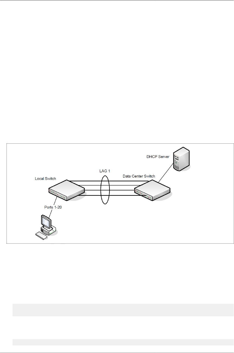
Configuring Security Features
89
these features on ports that provide network access to hosts that are in physically unsecured loca-
tions or if network users connect nonstandard hosts to the network.
For example, if an employee unknowingly connects a workstation to the network that has a DHCP
server, and the DHCP server is enabled, hosts that attempt to acquire network information from
the legitimate network DHCP server might obtain incorrect information from the rogue DHCP serv-
er. However, if the workstation with the rogue DHCP server is connected to a port that is config-
ured as untrusted and is a member of a DHCP Snooping-enabled VLAN, the port discards the
DHCP server messages.
5.2.10. Configuring DHCP Snooping
In this example, DHCP snooping is enabled on VLAN 100. Ports 1-20 connect end users to the
network and are members of VLAN 100. These ports are configured to limit the maximum number
of DHCP packets with a rate limit of 100 packets per second. LAG 1, which is also a member of
VLAN 100 and contains ports 21-24, is the trunk port that connects the switch to the data center,
so it is configured as a trusted port.
Figure5.3.DHCP Snooping Configuration Topology
The commands in this example also enforce rate limiting and remote storage of the bindings data-
base. The switch has a limited amount of storage space in NVRAM and flash memory, so the ad-
ministrator specifies that the DHCP snooping bindings database is stored on an external TFTP
server.
To configure the switch:
1. Enable DHCP snooping on VLAN 100.
(Routing) #config
(Routing) (Config)#ip dhcp snooping vlan 100
2. Configure LAG 1, which includes ports 21-24, as a trusted port. All other interfaces are untrust-
ed by default.
(Routing) (Config)#interface 3/1

Configuring Security Features
90
(Routing) (Interface 3/1))#ip dhcp snooping trust
(Routing) (Interface 3/1)#exit
3. Enter interface configuration mode for all untrusted interfaces (ports 1-20) and limit the number
of DHCP packets that an interface can receive to 100 packets per second. LAG 1 is a trusted
port and keeps the default value for rate limiting (unlimited).
(Routing) (Config)#interface 0/1-0/20
(Routing) (Interface 0/1-0/20)#ip dhcp snooping limit rate 100
(Routing) (Interface 0/1-0/20)#exit
4. Specify that the DHCP snooping database is to be stored remotely in a file called dsDb.txt on a
TFTP server with and IP address of 10.131.11.1.
(Routing) (Config)#ip dhcp snooping database tftp://10.131.11.1/dsDb.txt
5. Enable DHCP snooping for the switch
(Routing) (Config)#ip dhcp snooping
(Routing) (Config)#exit
6. View DHCP snooping information.
(Routing) #show ip dhcp snooping
DHCP snooping is Enabled
DHCP snooping source MAC verification is enabled
DHCP snooping is enabled on the following VLANs: 100
5.2.11. Configuring IPSG
This example builds on the previous example and uses the same topology shown in previous fig-
ure. In this configuration example, IP source guard is enabled on ports 1-20. DHCP snooping must
also be enabled on these ports. Additionally, because the ports use IP source guard with source IP
and MAC address filtering, port security must be enabled on the ports as well.
To configure the switch:
1. Enter interface configuration mode for the host ports and enable IPSG.
(Routing) #config
(Routing) (Config)#interface 0/1-0/20
(Routing) (Interface 0/1-0/20)#ip verify source port-security
2. Enable port security on the ports.
(Routing) (Interface 0/1-0/20)#port-security
(Routing) (Interface 0/1-0/20)#exit
(Routing) (Config)#exit
3. View IPSG information.
(Routing) #show ip verify source
Interface Filter Type IP Address MAC Address VLAN
----------- ----------- --------------- ----------------- -----

Configuring Security Features
91
0/1 ip-mac 192.168.3.45 00:1C:23:55:D4:8E 100
0/2 ip-mac 192.168.3.33 00:1C:23:AA:B8:01 100
0/3 ip-mac 192.168.3.18 00:1C:23:55:1B:6E 100
0/4 ip-mac 192.168.3.49 00:1C:23:67:D3:CC 100
--More-- or (q)uit

92
Chapter 6. Configuring Switching
Features

Configuring Switching Features
93
6.1. VLANs
By default, all switchports on the switch are in the same broadcast domain. This means when one
host connected to the switch broadcasts traffic, every device connected to the switch receives
that broadcast. All ports in a broadcast domain also forward multicast and unknown unicast traf-
fic to the connected host. Large broadcast domains can result in network congestion, and end
users might complain that the network is slow. In addition to latency, large broadcast domains are
a greater security risk since all hosts receive all broadcasts.
Virtual Local Area Networks (VLANs) allow you to divide a broadcast domain into smaller, logical
networks. Like a bridge, a VLAN switch forwards traffic based on the Layer 2 header, which is fast,
and like a router, it partitions the network into logical segments, which provides better administra-
tion, security, and management of multicast traffic.
Network administrators have many reasons for creating logical divisions, such as department or
project membership. Because VLANs enable logical groupings, members do not need to be physi-
cally connected to the same switch or network segment. Some network administrators use VLANs
to segregate traffic by type so that the time-sensitive traffic, like voice traffic, has priority over oth-
er traffic, such as data. Administrators also use VLANs to protect network resources. Traffic sent
by authenticated clients might be assigned to one VLAN, while traffic sent from unauthenticated
clients might be assigned to a different VLAN that allows limited network access.
When one host in a VLAN sends a broadcast, the switch forwards traffic only to other members of
that VLAN. For traffic to go from a host in one VLAN to a host in a different VLAN, the traffic must
be forwarded by a layer 3 device, such as a router. VLANs work across multiple switches, so there
is no requirement for the hosts to be located near each other to participate in the same VLAN.
ICOS software supports VLAN routing. When you configure VLAN routing, the switch
acts as a layer 3 device and can forward traffic between VLANs. For more information,
see Section 8.1.1, “VLAN Routing”
Each VLAN has a unique number, called the VLAN ID. The ICOS supports a configurable VLAN
ID range of 2–4093. A VLAN with VLAN ID 1 is configured on the switch by default. You can as-
sociate a name with the VLAN ID. In a tagged frame, the VLAN is identified by the VLAN ID in the
tag. In an untagged frame, the VLAN identifier is the Port VLAN ID (PVID) specified for the port
that received the frame. For information about tagged and untagged frames, see Section 6.1.1,
“VLAN Tagging”
ICOS supports adding individual ports and Link Aggregation Groups (LAGs) as VLAN members.
Figure below shows an example of a network with three VLANs that are department-based. The
file server and end stations for the department are all members of the same VLAN.
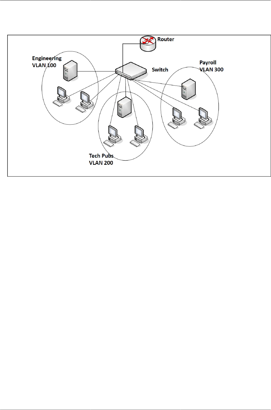
Configuring Switching Features
94
Figure6.1.Simple VLAN Topology
In this example, each port is manually configured so that the end station attached to the port is a
member of the VLAN configured for the port. The VLAN membership for this network is port-based
or static.
6.1.1. VLAN Tagging
ICOS supports IEEE 802.1Q tagging. Ethernet frames on a tagged VLAN have a 4-byte VLAN tag
in the header. VLAN tagging is required when a VLAN spans multiple switches, which is why trunk
ports transmit and receive only tagged frames.
Tagging may be required when a single port supports multiple devices that are members of differ-
ent VLANs. For example, a single port might be connected to an IP phone, a PC, and a printer (the
PC and printer are connected via ports on the IP phone). IP phones are typically configured to use
a tagged VLAN for voice traffic, while the PC and printers typically use the untagged VLAN.
When a port is added to a VLAN as an untagged member, untagged packets entering the switch
are tagged with the PVID (also called the native VLAN) of the port. If the port is added to a VLAN
as an untagged member, the port does not add a tag to a packet in that VLAN when it exits the
port. Configuring the PVID for an interface is useful when untagged and tagged packets will be
sent and received on that port and a device connected to the interface does not support VLAN tag-
ging.
When ingress filtering is on, the frame is dropped if the port is not a member of the VLAN identified
by the VLAN ID in the tag. If ingress filtering is off, all tagged frames are forwarded. The port de-
cides whether to forward or drop the frame when the port receives the frame.
6.1.2. Double-VLAN Tagging
For trunk ports, which are ports that connect one switch to another switch, ICOS software supports
double- VLAN tagging. This feature allows service providers to create Virtual Metropolitan Area
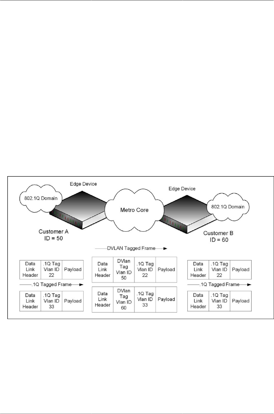
Configuring Switching Features
95
Networks (VMANs). With double-VLAN tagging, service providers can pass VLAN traffic from one
customer domain to another through a metro core in a simple and cost-effective manner. By using
an additional tag on the traffic, the switch can differentiate between customers in the MAN while
preserving an individual customer’s VLAN identification when the traffic enters the customer’s
802.1Q domain.
With the introduction of this second tag, customers are no longer required to divide the 4-byte
VLAN ID space to send traffic on a Ethernet-based MAN. In short, every frame that is transmitted
from an interface has a double- VLAN tag attached, while every packet that is received from an in-
terface has a tag removed (if one or more tags are present).
In figure below, two customers share the same metro core. The service provider assigns each
customer a unique ID so that the provider can distinguish between the two customers and apply
different rules to each. When the configurable EtherType is assigned to something different than
the 802.1Q (0x8100) EtherType, it allows the traffic to have added security from misconfiguration
while exiting the metro core. For example, if the edge device on the other side of the metro core is
not stripping the second tag, the packet would never be classified as a 802.1Q tag, so the packet
would be dropped rather than forwarded in the incorrect VLAN.
Figure6.2.Double VLAN Tagging Network Example
6.1.3. Default VLAN Behavior
One VLAN exists on the switch by default. The VLAN ID is 1, and all ports are included in the
VLAN as access ports, which are untagged. This means when a device connects to any port on
the switch, the port forwards the packets without inserting a VLAN tag. If a device sends a tagged
frame to a port, the frame is dropped. Since all ports are members of this VLAN, all ports are in the
same broadcast domain and receive all broadcast and multicast traffic received on any port.
When you add a new VLAN to the VLAN database, no ports are members. The configurable VLAN
range is 2–4093. VLANs 4094 and 4095 are reserved.

Configuring Switching Features
96
Table below shows the default values or maximum values for VLAN features.
Table6.1.VLAN Default and Maximum Values
Feature Value
Default VLAN ID 1
VLAN Name default
VLAN Range 2–4093
Frames accepted Untagged
Incoming untagged frames are classified into the VLAN whose
VLAN ID is the currently configured PVID.
Frames sent Untagged
Ingress Filtering On
PVID 1
Double-VLAN tagging Disabled
If double-VLAN tagging is enabled, the default EtherType value
is 802.1Q
6.1.4. VLAN Configuration Example
A network administrator wants to create the VLANs in Table below:
Table6.2.Example VLANs
VLAN ID VLAN Name VLAN Type Purpose
100 Engineering Port-based All employees in the Engineering de-
partment use this VLAN. Confining this
department’s traffic to a single VLAN helps
reduce the amount of traffic in the broad-
cast domain, which increases bandwidth.
200 Marketing Port-based All employees in the Marketing department
use this VLAN.
300 Payroll Port-based The payroll department has sensitive traffic
and needs its own VLAN to help keep that
traffic private.
Figure below shows the network topology for this example. As the figure shows, there are two
switches, two file servers, and many hosts. One switch has an uplink port that connects it to a lay-
er 3 device and the rest of the corporate network.
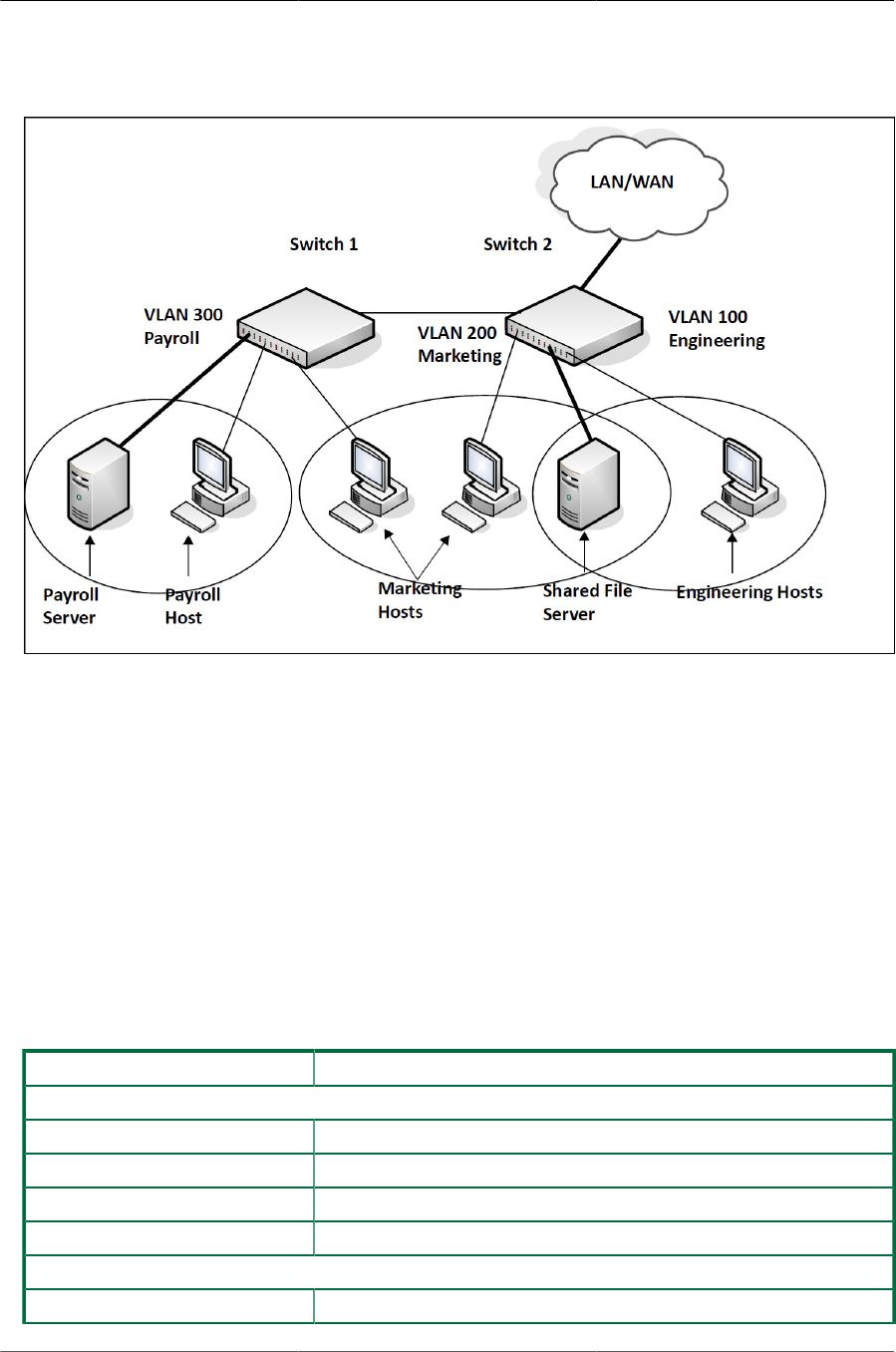
Configuring Switching Features
97
Figure6.3.Network Topology for VLAN Configuration
The network in this figure has the following characteristics:
• Each connection to a host represents multiple ports and hosts.
• The Payroll and File servers are connected to the switches through a LAG.
• Some of the Marketing hosts connect to Switch 1, and some connect to Switch 2.
• The Engineering and Marketing departments share the same file server.
• Because security is a concern for the Payroll VLAN, the ports and LAG that are members of this
VLAN will accept and transmit only traffic tagged with VLAN 300.
Table below shows the port assignments on the switches.
Table6.3.Switch Port Connections
Port/LAG Function
Switch 1
1 Connects to Switch 2
2–15 Host ports for Payroll
16–20 Host ports for Marketing
LAG1 (ports 21–24) Connects to Payroll server
Switch 2
1 Connects to Switch 1

Configuring Switching Features
98
Port/LAG Function
2–10 Host ports for Marketing
11–30 Host ports for Engineering
LAG1 (ports 35–39) Connects to file server
LAG2 (ports 40–44) Uplink to router.
6.1.4.1. Configure the VLANs and Ports on Switch 1
Use the following steps to configure the VLANs and ports on Switch 1. None of the hosts that con-
nect to Switch 1 use the Engineering VLAN (VLAN 100), so it is not necessary to create it on that
switch.
To configure Switch 1:
1. Create VLANs 200 (Marketing), 300 (Payroll), and associate the VLAN ID with the appropriate
name.
(Routing) #vlan database
(Routing) (Vlan)#vlan 200,300
(Routing) (Vlan)#vlan name 200 Marketing
(Routing) (Vlan)#vlan name 300 Payroll
(Routing) (Vlan)#exit
2. Assign ports 16–20 to the Marketing VLAN.
(Routing) #configure
(Routing) (Config)#interface 0/16-0/20
(Routing) (Interface 0/16-0/20)#vlan participation include 200
(Routing) (Interface 0/16-0/20)#exit
3. Assign ports 2–15 to the Payroll VLAN
(Routing) (Config)#interface 0/2-0/15
(Routing) (Interface 0/2-0/15)#vlan participation include 300
(Routing) (Interface 0/2-0/15)#exit
4. Assign LAG1 to the Payroll VLAN and configure the frames to always be transmitted tagged
with a PVID of 300.
(Routing) (Config)#interface 3/1
(Routing) (Interface 3/1)#vlan participation include 300
(Routing) (Interface 3/1)#vlan tagging 300
(Routing) (Interface 3/1)#vlan pvid 300
(Routing) (Interface 3/1)#exit
5. Configure port 1 as a trunk port and add VLAN 200 and VLAN 300 as members. Trunk ports ac-
cept and transmits tagged frames only and have ingress filtering enabled.
(Routing) (Config)#interface 0/1
(Routing) (Interface 0/1)#vlan acceptframe vlanonly
(Routing) (Interface 0/1)#vlan participation include 200,300

Configuring Switching Features
99
(Routing) (Interface 0/1)#vlan participation exclude 1
(Routing) (Interface 0/1)#vlan tagging 200,300
(Routing) (Interface 0/1)#vlan ingressfilter
(Routing) (Interface 0/1)#exit
(Routing) (Config)#exit
6. To save the configuration so that it persists across a system reset, use the following command:
(Routing) #copy system:running-config nvram:startup-config
7. View the VLAN settings.
(Routing) #show vlan
VLAN ID VLAN Name VLAN Type
------- -------------------------------- -------------------
1 default Default
200 Marketing Static
300 Payroll Static
(Routing) #show vlan 300
VLAN ID: 300
VLAN Name: Payroll VLAN Type: Static
Interface Current Configured Tagging
---------- -------- ----------- --------
0/1 Include Include Tagged
0/2 Include Include Untagged
0/3 Include Include Untagged
0/4 Include Include Untagged
0/5 Include Include Untagged
--More-- or (q)uit
8. View the VLAN information for a port.
(Routing) #show vlan port 0/1
Port Port Ingress Ingress
VLAN ID VLAN ID Acceptable Filtering Filtering Default
Interface Configured Current Frame Types Configured Current Priority
--------- ---------- -------- ----------- ---------- --------- --------
0/1 1 1 VLAN Only Enable Enable 0
Protected Port .............................. False
6.1.4.2. Configure the VLANs and Ports on Switch 2
Use the following steps to configure the VLANs and ports on Switch 2. Many of the procedures in
this section are the same as procedures used to configure Switch 1. For more information about
specific procedures, see the details and figures in the previous section.
To configure Switch 2:
1. Create the Engineering, Marketing, and Payroll VLANs.
Although the Payroll hosts do not connect to this switch, traffic from the Payroll department
must use Switch 2 to reach the rest of the network and Internet through the uplink port. For that
reason, Switch 2 must be aware of VLAN 300 so that traffic is not rejected by the trunk port.

Configuring Switching Features
100
2. Configure ports 2-10 to participate in VLAN 200.
3. Configure ports 11–30 to participate in VLAN 100.
4. Configure LAG 1 to participate in VLAN 100 and VLAN 200.
5. Configure port 1 and LAG 2 as participants in ports and add VLAN 100, VLAN 200, and VLAN
300 that accept and transit tagged frames only.
6. Enable ingress filtering on port 1 and LAG 2.
7. If desired, copy the running configuration to the startup configuration.
8. View VLAN information for the switch and ports.

Configuring Switching Features
101
6.2. Switchport Modes
You can configure each port on an ICOS switch to be in one of the following modes:
• Access—Access ports are intended to connect end-stations to the system, especially when the
end- stations are incapable of generating VLAN tags. Access ports support a single VLAN (the
PVID). Packets received untagged are processed as if they are tagged with the access port
PVID. Packets received that are tagged with the PVID are also processed. Packets received
that are tagged with a VLAN other than the PVID are dropped. If the VLAN associated with an
access port is deleted, the PVID of the access port is set to VLAN 1. VLAN 1 may not be delet-
ed.
• Trunk— Trunk-mode ports are intended for switch-to-switch links. Trunk ports can receive both
tagged and untagged packets. Tagged packets received on a trunk port are forwarded on the
VLAN contained in the tag if the trunk port is a member of the VLAN. Untagged packets re-
ceived on a trunk port are forwarded on the native VLAN. Packets received on another interface
belonging to the native VLAN are transmitted untagged on a trunk port.
• General—General ports can act like access or trunk ports or a hybrid of both. VLAN member-
ship rules that apply to a port are based on the switchport mode configured for the port.
Table below shows the behavior of the three switchport modes.
1. Switchport Mode Behavior
Mode VLAN Membership Frames Accepted Frames Sent Ingress Filtering
Access One VLAN Untagged/Tagged Untagged Always On
Trunk All VLANs that exist
in the system (de-
fault)
Untagged/Tagged Tagged and Un-
tagged
Always On
General As many as desired Tagged or Untagged Tagged or Untagged On or Off
When a port is in General mode, all VLAN features are configurable. When ingress filtering is on,
the frame is dropped if the port is not a member of the VLAN identified by the VLAN ID in the tag.
If ingress filtering is off, all tagged frames are forwarded. The port decides whether to forward or
drop the frame when the port receives the frame.
The following example configures a port in Access mode with a single VLAN membership in VLAN
10:
(Routing) #config
(Routing) (Config)#interface 0/5
(Routing) (Interface 0/5)#switchport mode access
(Routing) (Interface 0/5)#switchport access vlan 10
(Routing) (Interface 0/5)#exit
The following example configures a port in Trunk mode. The switchport trunk allowed vlan com-
mand with the "add" keyword adds the list of VLANs that can receive and send traffic on the inter-
face in tagged format when in trunking mode. Alternatively, the "all" keyword can be used to spec-
ify membership in all VLANs, the "remove" keyword can be used to remove membership. If this

Configuring Switching Features
102
command is omitted, the port is a member of all configured VLANs. The native VLAN specifies the
VLAN on which the port forwards untagged packets it receives.
(Routing) #config
(Routing) (Config)#interface 0/8
(Routing) (Interface 0/8)#switchport mode trunk
(Routing) (Interface 0/8)#switchport trunk allowed vlan add 10,20,30
(Routing) (Interface 0/8)#switchport trunk native vlan 100
(Routing) (Interface 0/8)#exit
The following commands configure a port in General mode.
(Routing) #config
(Routing) (Config)#interface 0/10
(Routing) (Interface 0/10)#switchport mode general
(Routing) (Interface 0/10)#exit
The General mode port can then be configured as a tagged or untagged member of any VLAN, as
shown in Section 6.1.4, “VLAN Configuration Example”
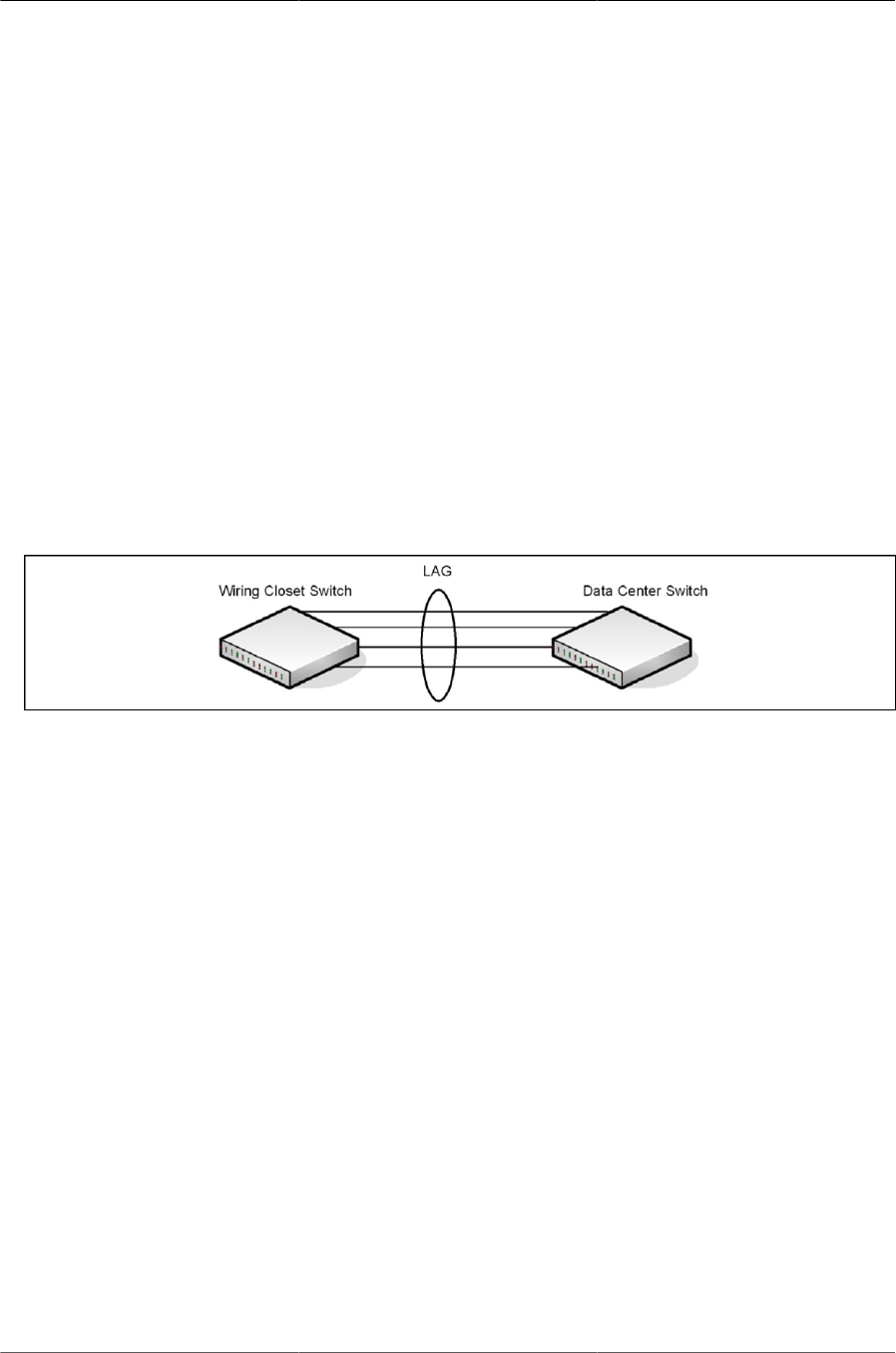
Configuring Switching Features
103
6.3. LAGs—Operation and Configuration
Link Aggregation allows one or more full-duplex (FDX) Ethernet links of the same speed to be ag-
gregated together to form a LAG. This allows the switch to treat the LAG as if it is a single link. The
primary purpose of LAGs is to increase the overall bandwidth between two switches. This is ac-
complished by effectively aggregating multiple ports together that act as a single, logical connec-
tion between the two switches. LAGs also provide redundancy. If a link fails, traffic is automatically
redistributed across the remaining links.
ICOS software supports industry-standard LAGs that adhere to the IEEE 802.3ad specification.
Both static and dynamic LAGs are supported. Each LAG can have a maximum of 32 ports as
members (as long as the platform can support it). You can configure LAGs until all switch ports are
assigned to a LAG.
Figure below shows an example of a switch in the wiring closet connected to a switch in the data
center by a LAG that consists of four physical 10 Gbps links. The LAG provides full-duplex band-
width of 40 Gbps between the two switches.
Figure6.4.LAG Configuration
6.3.1. Static and Dynamic Link Aggregation
Link aggregation can be configured as either dynamic or static. Dynamic configuration is sup-
ported using the IEEE 802.3ad standard, which is known as Link Aggregation Control Protocol
(LACP). Static configuration is used when connecting the switch to an external Gigabit Ethernet
switch that does not support LACP.
One advantage of LACP is that the protocol enables the switch to confirm that the external switch
is also configured for link aggregation. When using static configuration, a cabling or configuration
mistake involving the local switch or the external switch could go undetected and thus cause un-
desirable network behavior. Both static and dynamic LAGs (via LACP) can detect physical link fail-
ures within the LAG and continue forwarding traffic through the other connected links within that
same LAG. LACP can also detect switch or port failures that do not result in loss of link. This pro-
vides a more resilient LAG. Best practices suggest using dynamic link aggregation instead of stat-
ic link aggregation. When a port is added to a LAG as a static member, it neither transmits nor re-
ceives LACP PDUs.
6.3.2. LAG Hashing
ICOS software support configuration of hashing algorithms for each LAG interface. The hashing al-
gorithm is used to distribute traffic load among the physical ports of the LAG while preserving the
per-flow packet order.
The hashing algorithm uses various packet attributes to determine the outgoing physical port.

Configuring Switching Features
104
The switch supports the following set of packet attributes to be used for hash computation:
• Source MAC, VLAN, EtherType, and incoming port.
• Destination MAC, VLAN, EtherType, and incoming port.
• Source IP and Source TCP/UDP port numbers.
• Destination IP and Destination TCP/UDP port numbers.
• Source/Destination MAC, VLAN, EtherType, and incoming port.
• Source/Destination IP and Source/Destination TCP/UDP port numbers.
• Enhanced hashing mode
Enhanced hashing mode has following advantages:
• MODULO-N operation based on the number of ports in the LAG.
• Packet attributes selection based on the packet type. For L2 packets, Source and Destination
MAC address are used for hash computation. For IP packets, Source IP, Destination IP address,
TCP/UDP ports are used.
• Non-Unicast traffic and Unicast traffic is hashed using a common hash algorithm.
• Excellent load balancing performance.
6.3.2.1. Resilient Hashing
Resilient Hashing (RH) is a feature on BCM56850 (and later) switches that introduces an extra lev-
el of indirection between the hash value and the selected output port for a layer-2 LAG () or a lay-
er-3 ECMP route. In a typical non-RH configuration, the output port can change for all flows when
the number of ports changes, even if the flow was on a port that was not affected. This can cause
degraded performance due to frame reordering. With RH, the hash value is used to index into a ta-
ble of ports. If a port goes down, then only the entries that use that port are rewritten. Other ports
are left untouched and, therefore, do not suffer degraded performance.
Resilient hashing is globally enabled on BCM56850 switch ports by default. It can be globally en-
abled (or disabled) in Global Config mode using the (no) port-channel resilient-hashing com-
mand for LAGs or the (no) ip resilient-hashing command for ECMP routes. The new setting
takes effect after a system reboot.
6.3.2.2. Hash Prediction with ECMP and LAG
The Hash Prediction feature provides a utility to predict how packets will be forwarded over a LAG
or to the next-hop device when Equal-Cost Multipath (ECMP) is the destination. Given the link ag-
gregation method, ingress physical port, and values of various packet fields, the utility predicts an
egress physical port for the packet.
An ECMP group is identified by the IP address of one of its members. By entering the IP address
in the form <prefix/prefix-length>, the utility predicts the packet’s physical egress port based on
the destination ECMP group. To predict the an egress physical port when the egress objects are
VLAN routing interfaces with LAG or port interfaces as members of the VLANs, the utility requires
the PVID to be configured on the interfaces and the next hops to be fully installed in hardware.

Configuring Switching Features
105
If an ECMP group is comprised of VLAN routing interfaces and each VLAN has a LAG that con-
tains multiple ports, the utility requires the PVID to be configured on the LAGs. In this configura-
tion, the utility first predicts which VLAN routing interface the packet is forwarded to and finds the
LAG by matching the VLAN ID of the VLAN routing interface to the PVID of the LAG. Then, it pre-
dicts which physical port in the LAG the packet is forwarded to.
To make correct prediction when LAGs are used as egress interfaces, the utility requires the en-
hanced hashing mode to be set on the LAGs.
Hash prediction is supported only for unicast packets on BCM56850-based platforms.
6.3.3. LAG Interface Naming Convention
LAGs are logical interfaces and follow a slot/port naming convention. The slot number is always
3, and the port number ranges from 1 to the maximum number of LAGs the switch supports. The
show port-channel brief command provides summary information about all LAGs available on
the system. In the following output, LAG 3/1 has been configured as a dynamic LAG with five
member ports. No other LAGs have been configured.
(Routing) #show port-channel brief
Logical Port-Channel Min Link Trap Type Mbr Ports Active
Interface Name State Flag Ports
--------- ------------ --- -------- ----- ------- --------- -------
3/1 ch1 1 Down Disabled Dynamic 0/1,0/2,
0/3,0/6,
0/7
3/2 ch2 1 Down Disabled Static
3/3 ch3 1 Down Disabled Static
3/4 ch4 1 Down Disabled Static
3/5 ch5 1 Down Disabled Static
6.3.4. LAG Interaction with Other Features
From a system perspective, a LAG is treated just as a physical port, with the same configuration
parameters for administrative enable/disable, spanning tree port priority, path cost as may be for
any other physical port.
6.3.4.1. VLAN
When members are added to a LAG, they are removed from all existing VLAN membership. When
members are removed from a LAG they are added back to the VLANs that they were previously
members of as per the configuration file. Note that a port’s VLAN membership can still be config-
ured when it’s a member of a LAG. However this configuration is only actually applied when the
port leaves the LAG.
The LAG interface can be a member of a VLAN complying with IEEE 802.1Q.
6.3.4.2. STP
Spanning tree does not maintain state for members of a LAG, but the Spanning Tree does main-
tain state for the LAG interface. As far as STP is concerned, members of a LAG do not exist. (In-
ternally, the STP state of the LAG interface is replicated for the member links.)

Configuring Switching Features
106
When members are deleted from a LAG they become normal links, and spanning tree maintains
their state information.
6.3.4.3. Statistics
Statistics are maintained for all LAG interfaces as they are done for the physical ports, besides
statistics maintained for individual members as per the 802.3ad MIB statistics.
6.3.5. LAG Configuration Guidelines
Ports to be aggregated must be configured so that they are compatible with the link aggregation
feature and with the partner switch to which they connect.
Ports to be added to a LAG must meet the following requirements:
• Interface must be a physical Ethernet link.
• Each member of the LAG must be running at the same speed and must be in full duplex mode.
• The port cannot be a mirrored port
The following are the interface restrictions
• The configured speed of a LAG member cannot be changed.
• An interface can be a member of only one LAG.
6.3.6. Link Aggregation Configuration Examples
This section contains the following examples:
• Configuring Dynamic LAGs
• Configuring Static LAGs
The examples in this section show the configuration of only one switch. Because
LAGs involve physical links between two switches, the LAG settings and member
ports must be configured on both switches.
6.3.6.1. Configuring Dynamic LAGs
The commands in this example show how to configure a static LAG on a switch. The LAG number
is 1 (port 3/1), and the member ports are 1, 2, 3, 6, and 7.
To configure the switch:
1. Enter interface configuration mode for the ports that are to be configured as LAG members.
(Routing) #config
(Routing) (Config)#interface 0/1-0/3,0/6-0/7
2. Add the ports to LAG 1 with LACP.
(Routing) (Interface 0/1-0/3,0/6-0/7)#addport 3/1

Configuring Switching Features
107
(Routing) (Interface 0/1-0/3,0/6-0/7)#exit
3. Configure LAG 1 as dynamic.
(Routing) (Config)#interface 3/1
(Routing) (Interface 3/1)#no port-channel static
(Routing) (Interface 3/1)#exit
(Routing) (Config)#exit
4. View information about LAG 1.
(Routing) #show port-channel 3/1
Local Interface................................ 3/1
Channel Name................................... ch1
Link State..................................... Down
Admin Mode..................................... Enabled
Type.......................................... Dynamic
Port-channel Min-links. ........................ 1
Load Balance Option. ........................... 3
(Src/Dest MAC, VLAN, EType, incoming port)
Mbr Device/ Port Port
Ports Timeout Speed Active
------ ------------- --------- -------
0/1 actor/long Auto False
partner/long
0/2 actor/long Auto False
partner/long
0/3 actor/long Auto False
partner/long
0/6 actor/long Auto False
partner/long
0/7 actor/long Auto False
partner/long
6.3.6.2. Configuring Static LAGs
The commands in this example show how to configure a static LAG on a switch. The LAG number
is 3 (interface 1/3), and the member ports are 10, 11, 14, and 17.
To configure the switch:
1. Enter interface configuration mode for the ports that are to be configured as LAG members.
(Routing) (Config)#interface 0/10-0/12,0/14,0/17
2. Add the ports to LAG 2 without LACP.
(Routing) (Interface 0/10-0/12,0/14,0/17)#addport 1/3
(Routing) (Interface 0/10-0/12,0/14,0/17)#exit
(Routing) (Config)#exit
3. View information about LAG 2.

Configuring Switching Features
108
(Routing) #show port-channel 3/3
Local Interface................................ 1/3
Channel Name................................... ch3
Link State..................................... Up
Admin Mode..................................... Enabled
Type........................................... Static
Port-channel Min-links. ........................ 1
Load Balance Option. ........................... 3
(Src/Dest MAC, VLAN, EType, incoming port)
Mbr Device/ Port Port
Ports Timeout Speed Active
------ ------------- --------- -------
0/10 actor/long Auto True
partner/long
0/11 actor/long Auto True
partner/long
0/12 actor/long Auto True
partner/long
0/14 actor/long Auto True
partner/long
0/17 actor/long Auto True
partner/long
--More-- or (q)uit
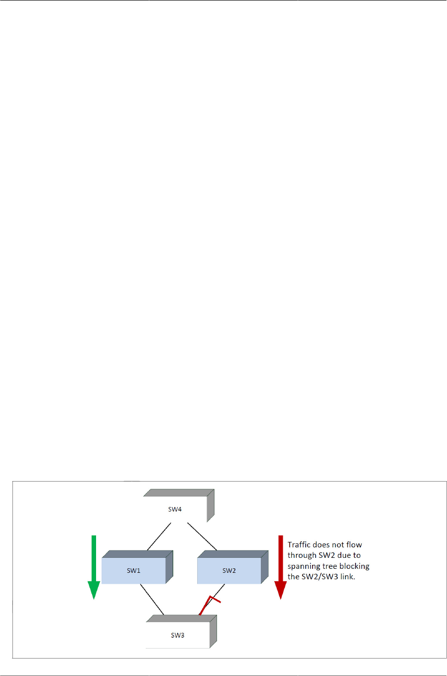
Configuring Switching Features
109
6.4. Virtual Port Channel — Operation and
Configuration
6.4.1. Overview
In a typical layer-2 network, the Spanning Tree Protocol (STP) is deployed to avoid packet storms
due to loops in the network. To perform this function, STP sets ports into either a forwarding state
or a blocking state. Ports in the blocking state do not carry traffic. In the case of a topology change,
STP reconverges to a new loop-free network and updates the port states. STP is relatively suc-
cessful mitigating packet storms in the network, but redundant links in the network are blocked
from carrying traffic by the spanning tree protocol.
In some network deployments, redundant links between two switches are bundled together in a
Link Aggregation Group (LAG) and appear as a single link in the spanning tree topology. The ad-
vantage is that all LAG member links can be in the forwarding state and a link failure can be re-
covered in milliseconds. This allows the bandwidth on the redundant links to be utilized. Howev-
er, LAGs are limited to connecting multiple links between two partner switches, which leaves the
switch as a single point of failure in the topology.
ICOS VPC extends the LAG bandwidth advantage across multiple ICOS switches connected to a
LAG partner device. The LAG partner device is oblivious to the fact that it is connected over a LAG
to two peer ICOS switches; instead, the two switches appear as a single switch to the partner with
a single MAC address. All links can carry data traffic across a physically diverse topology and in
the case of a link or switch failure, traffic can continue to flow with minimal disruption.
6.4.2. Deployment Scenarios
VPC is intended to support higher bandwidth utilization in scenarios where a redundant layer-2
network is desired. In such scenarios the effects of STP on link utilization are profound. Large per-
centages of links do not carry data because they are blocked and only a single path through the
network carries traffic.
Figure6.5.STP Blocking
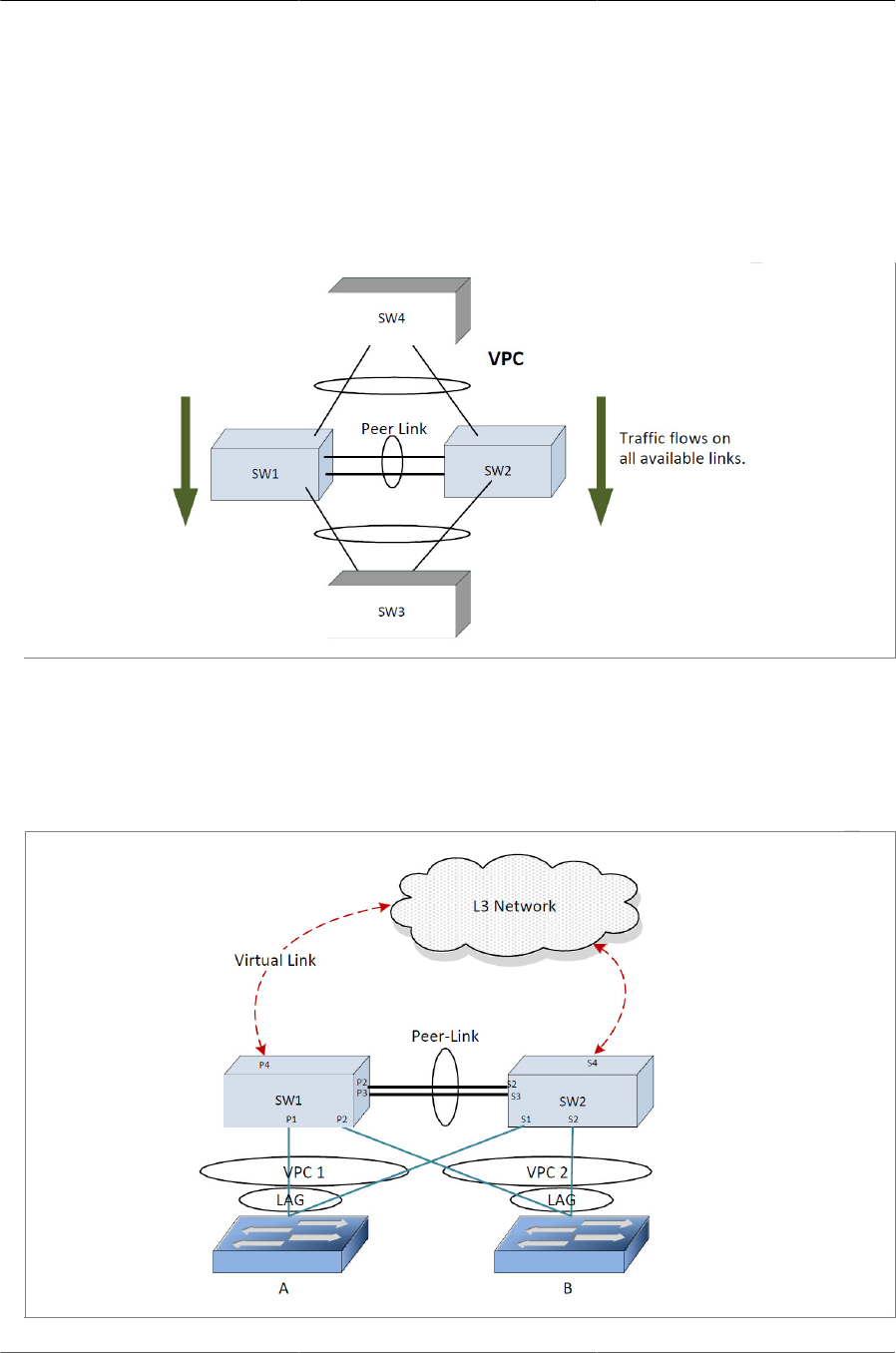
Configuring Switching Features
110
VPC reduces some of the bandwidth shortcomings of STP in a layer-2 network. It provides a re-
duced convergence period when a port-channel link goes down and provides more bandwidth be-
cause all links can forward traffic. In the figure below, if SW1 and SW2 form an VPC with SW3 and
SW4, none of the links are blocked, which means traffic can flow over both links from SW4 through
to SW1 and SW2 over both links from SW1 and SW2 to SW3.
Figure6.6.VPC in a Layer-2 Network
6.4.3. Definitions
Refer to figure below for the definitions that follow.
Figure6.7.VPC Components

Configuring Switching Features
111
VPC switches: VPC-aware switches running ICOS switch firmware. No more than two VPC aware
switches can pair to form one end of the LAG. Stacked switches do not support VPCs. In the
above figure, SW1 and SW2 are VPC peer switches. These two switches form a single logical end
point for the VPC from the perspective of switch A.
VPC interfaces: VPC functionality is a property of LAGs. LAGs configured as VPCs are called
VPC interfaces. Administrators can configure multiple instances of VPC interfaces on the peer
VPC switches. LAG limitations and capabilities such as min-links and maximum number of ports
supported per LAG also apply to VPC interfaces.
VPC member ports: Ports on the peer VPC switches that are part of the VPC interface (P1 on
SW1 and S1 on SW2).
Non-redundant ports: Ports on either of the peer switches that are not part of the VPC (ports P4
and S4). VPC interfaces and non-redundant ports cannot be members of the same VLAN, i.e. a
VLAN may contain VPC interfaces or a VLAN may contain non-redundant ports, but not both.
VPC peer-link: A link between the two VPC peer switches (ports P2,P3,S2,S3). Only one peer-link
can be configured per device. The peer-link is crucial for the operation of the VPC component. A
LAG must be configured as the peer-link. All VLANs configured on VPC interfaces must be config-
ured on the peer-link as well.
VPC Dual Control Plane Detection link: A virtual link that is used to advertise the Dual Control
Plane Detection protocol (DCPDP) packets between the two VPC switches (ports P4, S4). This
protocol is optional. The protocol indicates the presence of the peer switch in the network. The
DCPDP protocol should not be configured on MLAG interfaces.
6.4.4. Configuration Consistency
VPC is operational only if the VPC domain ID, VPC system MAC address, and VPC system priority
are the same on both the VPC peer switches.
Configuring a VPC domain ID is mandatory; the VPC system MAC address and VPC
system priority are optional (these values are auto generated if not configured)
The administrator must ensure that the neighboring devices connected to VPC switches perceive
the two switches as a single spanning tree and Link Aggregation Control Protocol (LACP) enti-
ty. To achieve this end, the following configuration settings must be identical for VPC links on the
VPC peer switches:
1. Link aggregation
• Hashing mode
• Minimum links
• Static/dynamic LAG
• LACP parameters
• Actor parameters
• Admin key

Configuring Switching Features
112
• Collector max-delay
• Partner parameters
2. STP
The default STP mode for ICOS switches is RSTP. VLANs cannot be configured to contain both
VPC ports and non-VPC (non-redundant) ports. Only RSTP or MSTP are supported with VPC.
STP-PV and RSTP-PV are not supported with VPC. The following STP configuration parame-
ters must be the identical on both VPC peers.
• Bpdufilter
• Bpduflood
• Auto-edge
• TCN-guard
• Cost
• Edgeport
• Loop guard
• Root guard
• PVSTP/PVRSTP global configuration (FastUplink mode, FastUplink maximum update rate,
FastBackbone mode, hello time, forward time, maximum age time, priority)
• PVSTP/PVRSTP per-port configuration (VLAN membership, STP port-priority, per-VLAN port
priority, cost)
• STP Version
• STP MST VLAN configuration
• STP MST instance configuration (MST instance ID/port priority/port cost/mode)
3. LAG (port-channel) interface
The following LAG attributes must be identical for VPC LAGs:
• LAG mode
• Link speed
• Duplex mode
• MTU
• Bandwidth
• VLAN configuration

Configuring Switching Features
113
The administrator should also ensure that the following are identical before enabling VPC:
• FDB entry aging timers
• Static MAC entries.
• ACL configuration
4. Interface Configuration
• PFC configuration
• CoS queue assignments
5. VLAN configuration
• VPC VLANs must span the VPC topology and be configured on both VPC peers. This means
that every VPC VLAN must connect to two partner LAGs.
• VLAN termination of an VPC VLAN on an VPC peer is not supported.
6. Switch firmware versions
Except during firmware upgrade, the peer switch firmware versions must be identical, as subtle dif-
ferences between versions may cause instability.
The administrator must ensure that the above configuration items are configured identically on the
VPC interfaces on both of the VPC peers before enabling the VPC feature. If the configuration set-
tings are not in sync, the VPC behavior is undefined. Once the above configuration is in place and
consistent, the two switches will form an VPC that operates in the desired manner. The VPC may
form even if the configuration is not consistent, however, it may not operate consistently in all situ-
ations.
6.4.5. VPC Fast Failover
Prior to ICOS release 3.0, when the primary switch fails, secondary switch restarts the LACP pro-
tocol on its VPC member ports. STP is also restarted on secondary device’s VPC member ports.
Until the LACP and STP reconverges, the partner device is disconnected from the VPC domain.
With fast failover support, neither LACP reconvergence nor STP reconvergence occurs, and min-
imal traffic loss is observed when primary device fails. During the failover, traffic that is being for-
warded using the links connected to primary device will failover to links connected to the sec-
ondary device. The traffic disruption is limited to the time required for the partner devices dual-at-
tached to the VPC domain to detect the link down(links connected to primary device) and redistrib-
ute the traffic using the links connected to the secondary device.
Spanning tree modes should be configured the same on both the VPC peers. The following modes
are supported for fast-failover: STP, RSTP, MSTP, PVST, and Rapid-PVST.
For voice VLAN, VoIP phones can be connected to the partner devices and cannot be connect-
ed as VPC partner devices. Figure below shows a n example of VoIP phone connectivity in a VPC
topology.
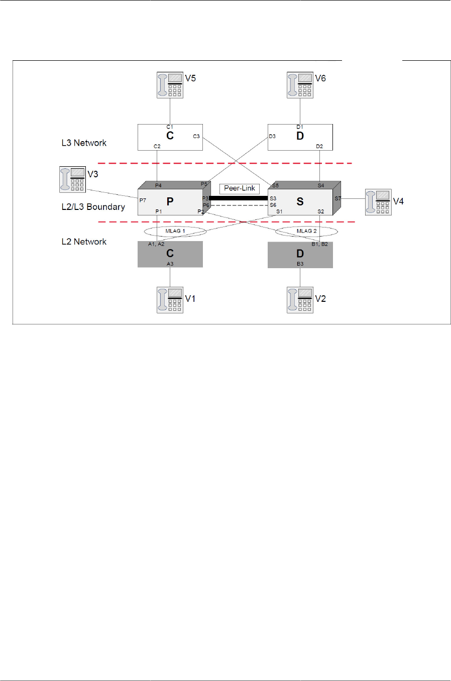
Configuring Switching Features
114
Figure6.8.VOIP Phones in a VPC Topology
6.4.6. VPC Configuration
Refer to figure below for a visual overview of the VPC configuration steps.
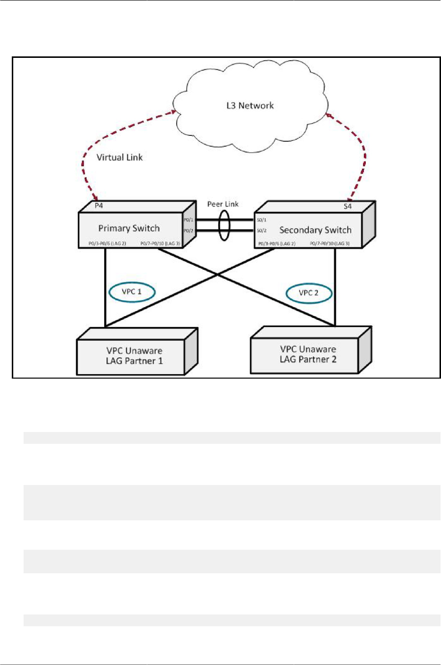
Configuring Switching Features
115
Figure6.9.VPC Configuration Diagram
To configure VPC:
1. Enter VLAN database mode and create the VPC VLANs.
(Routing) #vlan database (Routing) (Vlan) #vlan 2-99
2. Create the VLAN routing interface that will be used for the Dual Control Plane detection Proto-
col.
(Routing) (Vlan) #vlan 100
(Routing) (Vlan) #vlan routing 100
(Routing) (Vlan) #exit
3. Enable the VPC feature.
(Routing) #config
(Routing) (Config)#feature vpc
4. Create the VPC domain ID. The domain ID configured on both the VPC peer switches should
be same. In a two-tier VPC topology, each pair should have different domain ID.
(Routing) (Config)#vpc domain 1
5. Configure the VPC system MAC address and/or VPC system priority (optional).

Configuring Switching Features
116
(Routing) (Config-VPC 1)#system-mac 00:01:85:48:E0:0F
(Routing) (Config-VPC 1)#system-priority 1000
6. Enable the keepalive protocol.
(Routing) (Config-VPC 1)#peer-keepalive enable
7. Configure the VPC role priority (optional).
(Routing) (Config)#vpc domain 1
(Routing) (Config-VPC 1)#role priority 10
8. Create LAG 1.
(Routing) (Config)#interface lag 1
(Routing) (Interface lag 1)#description "VPC-Peer-Link"
9. Allow the LAG to participate in all VLANs and accept and send tagged frames only. This is simi-
lar to configuring a port in trunk mode.
(Routing) (Interface lag 1)#vlan participation include 1-99
(Routing) (Interface lag 1)#vlan tagging 1-99
(Routing) (Interface lag 1)#vlan acceptframe vlanonly
(Routing) (Interface lag 1)#vpc peer-link
(Routing) (Interface lag 1)#exit
10.Create the peer link.
(Routing) (Config)#interface 0/1-0/2
(Routing) (Interface 0/1-0/2)#addport lag 1
(Routing) (Interface 0/1-0/2)#description "VPC-Peer-Link"
11.Enable UDLD (if required).
(Routing) (Interface 0/1-0/2)#udld enable
(Routing) (Interface 0/1-0/2)#udld port aggressive
(Routing) (Interface 0/1-0/2)#exit
12.Configure Dual Control Plane detection Protocol Configuration (if required):
a. Configure a VLAN routing interface and assign a local IP address (independent form the peer
address).
(Routing) (Config)#interface vlan 100
b. This command configures the IP address of the source device on the VLAN routing interface.
This configuration is used by the dual control plane detection protocol (DCPDP) on the VPC
switches.
(Routing) (Interface vlan 100)#ip address 192.168.0.2 255.255.255.0
(Routing) (Interface vlan 100)#exit
c. Configure the keepalive source and destination IP address.

Configuring Switching Features
117
(Routing) #config (Routing) #vpc domain 1
(Routing) (Config-VPC 1)#peer-keepalive destination 192.168.0.1
source 192.168.0.2
The UDP port on which the VPC switch listens to the DCPDP messages can also be con-
figured with this command. The configurable range for the UDP port 1 to 65535 (Default is
60000).
d. Configure the DCPDP transmission interval and reception timeout values (optional).
(Routing) (Config-VPC 1)#peer detection interval 600 timeout 2000
e. Enable Peer Detection mode. The mode starts running if VPC is globally enabled.
(Routing) (Config-VPC 1)#peer detection enable
13.Configure a LAG as VPC interface. The configurable range for the VPC ID is 1 to
L7_MAX_NUM_VPC.
(Routing) (Config)#interface 0/3-0/6
(Routing) (Interface 0/3-0/6)#addport lag 2
(Routing) (Interface 0/3-0/6)#exit
(Routing) (Config)#interface 0/7-0/10
(Routing) (Interface 0/7-0/10)#addport lag 3
(Routing) (Interface 0/7-0/10)#exit
(Routing) (Config)#interface lag 2
(Routing) (Interface lag 2)#vlan participation include 1-99
(Routing) (Interface lag 2)#vlan tagging 1-99
(Routing) (Interface lag 2)#vlan acceptframe vlanonly
(Routing) (Interface lag 2)#vpc 1
(Routing) (Interface lag 2)#exit
(Routing) (Config)#interface lag 3
(Routing) (Interface lag 3)#vlan participation include 1-99
(Routing) (Interface lag 3)#vlan tagging 1-99
(Routing) (Interface lag 3)#vlan acceptframe vlanonly
(Routing) (Interface lag 3)#vpc 2
(Routing) (Interface lag 3)#exit
The administrator must ensure that the port channel configurations on both devices are in sync
before enabling VPC. After the VPC interfaces are enabled, the VPC interfaces are operational-
ly shut down. The VPC component exchanges information regarding the port members that con-
stitute the LAG on each device. Once this information is populated on both devices, the VPC in-
terfaces are operationally up and traffic forwarding on VPC interfaces is allowed. LAGs must be
configured on both devices as VPC interfaces for the VPC interface to be enabled. Also, the port-
channel-number:VPC-Id pair must be the same on both the primary and secondary devices.
Member ports can be added or removed from the VPC interface. If a port is added as a port mem-
ber to a VPC interface, the Primary allows the port member if the maximum criteria is satisfied.
When a port member is removed from the VPC interface, the Primary decides if the minimum cri-
teria is satisfied. If it is not, it will shut down the VPC interface on both the devices. Shutting down
the VPC interface on the Secondary is not allowed. The VPC interface can only be shut down on
the Primary.

Configuring Switching Features
118
FDB entries learned on VPC interfaces are synced between the two devices. In the case where all
VPC member ports are UP, data traffic does not traverse the peer link.

Configuring Switching Features
119
6.5. Unidirectional Link Detection (UDLD)
The UDLD feature detects unidirectional links on physical ports. UDLD must be enabled on the
both sides of the link in order to detect an unidirectional link. The UDLD protocol operates by ex-
changing packets containing information about neighboring devices.
The purpose of UDLD feature is to detect and avoid unidirectional links. A unidirectional link is a
forwarding anomaly in a Layer 2 communication channel in which a bidirectional link stops passing
traffic in one direction.
6.5.1. UDLD Modes
The UDLD supports two modes: normal and aggressive.
In normal mode, a port’s state is classified as undetermined if an anomaly exists. An anomaly
might be the absence of its own information in received UDLD messages or the failure to receive
UDLD messages. An undetermined state has no effect on the operation of the port. The port is not
disabled and continues operating. When operating in UDLD normal mode, a port will be put into a
disabled state (D-Disable) only in the following situations:
• The UDLD PDU received from a partner does not have its own details (echo).
• When there is a loopback, and information sent out on a port is received back exactly as it was
sent.
When operating in UDLD aggressive mode, a port is put into a disabled state for the same reasons
that it occurs in normal mode. Additionally, a port in UDLD aggressive mode can be disabled if the
port does not receive any UDLD echo packets even after bidirectional connection was established.
If a bidirectional link is established, and packets suddenly stop coming from partner device, the
UDLD aggressive-mode port assumes that link has become unidirectional.
6.5.2. UDLD and LAG Interfaces
UDLD is supported on individual physical ports that are members of a LAG. If any of the aggregat-
ed links becomes unidirectional, UDLD detects it and disables the individual link, but not the entire
LAG. This improves the fault tolerance of the LAG.
6.5.3. Configuring UDLD
A network administrator decides to use the UDLD feature while building a loop-free topology with
the use of STP. The administrator configures the ports on both side of the link to use UDLD in ag-
gressive mode to ensure that ports with unidirectional links will be shut down, and no loops will be
introduced into topology. This example shows the steps to configure UDLD on Switch 1 only. The
same configuration must be performed on all ports that form partner links with the ports on Switch
1.
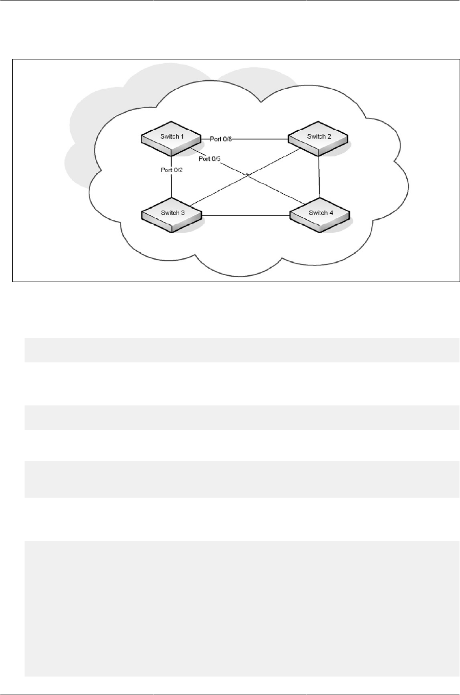
Configuring Switching Features
120
Figure6.10.UDLD Configuration Example
To configure the ports on Switch 1:
1. Globally enable UDLD on the switch.
(Routing) #configure
(Routing) (Config)#udld enable
2. Enter interface configuration mode for the ports that are connected to other switches and enable
UDLD on the ports.
(Routing) (Config)#interface 0/8,0/11,0/20
(Routing) (Interface 0/8,0/11,0/20)#udld enable
3. Configure the UDLD mode on the ports to be aggressive.
(Routing) (Interface 0/8,0/11,0/20)#udld port aggressive
(Routing) (Interface 0/8,0/11,0/20)#exit
(Routing) (Config)#exit
4. After configuring UDLD on Switch 2, Switch, 3, and Switch 4, view the UDLD status for the
ports.
(Routing) #show udld all
Port Admin Mode UDLD Mode UDLD Status
----- ---------- ----------- --------------
0/1 Disabled Normal Not Applicable
0/8 Enabled Aggressive Bidirectional
0/3 Disabled Normal Not Applicable
0/4 Disabled Normal Not Applicable
0/8 Enabled Aggressive Bidirectional
0/6 Disabled Normal Not Applicable
0/7 Disabled Normal Not Applicable
0/8 Enabled Aggressive Bidirectional

Configuring Switching Features
121
0/9 Disabled Normal Not Applicable
--More-- or (q)uit
If a port has become disabled by the UDLD feature and you want to re-enable the
port, use the udld reset command in Privileged EXEC mode.

Configuring Switching Features
122
6.6. Port Mirroring
Port mirroring is used to monitor the network traffic that a port sends and receives. The Port Mir-
roring feature creates a copy of the traffic that the source port handles and sends it to a destina-
tion port. The source port is the port that is being monitored. The destination port is monitoring the
source port. The destination port is where you would connect a network protocol analyzer to learn
more about the traffic that is handled by the source port.
A port monitoring session includes one or more source ports that mirror traffic to a single destina-
tion port. ICOS software supports a single port monitoring session. LAGs (port channels) cannot
be used as the source or destination ports.
For each source port, you can specify whether to mirror ingress traffic (traffic the port receives, or
RX), egress traffic (traffic the port sends, or TX), or both ingress and egress traffic.
The packet that is copied to the destination port is in the same format as the original packet on the
wire. This means that if the mirror is copying a received packet, the copied packet is VLAN tagged
or untagged as it was received on the source port. If the mirror is copying a transmitted packet, the
copied packet is VLAN tagged or untagged as it is being transmitted on the source port.
After you configure the port mirroring session, you can enable or disable the administrative mode
of the session to start or stop the probe port from receiving mirrored traffic.
6.6.1. Configuring Port Mirroring
In this example, traffic from ports 1 and 4 is mirrored to probe port 10.
1. Configure the source ports. Traffic received and transmitted on by these ports will be mirrored.
(Routing) #configure
(Routing) (Config)#monitor session 1 source interface 0/1
(Routing) (Config)#monitor session 1 source interface 0/4
2. Configure the destination (probe) port.
(Routing) (Config)#monitor session 1 destination interface 0/10
3. Enable port mirroring on the switch.
(Routing) (Config)#monitor session 1 mode
(Routing) (Config)#exit
4. View summary information about the port mirroring configuration.
(Routing) #show monitor session 1
Session Admin Probe Src Mirrored Ref. Src Dst Type IP MAC
ID Mode Port VLAN Port Port RVLAN RVLAN ACL ACL
------- ------ ------ ---- -------- ----- ----- ----- ---- ----- -------
1 Enable 0/10 0/1 Rx,Tx
0/4 Rx,Tx
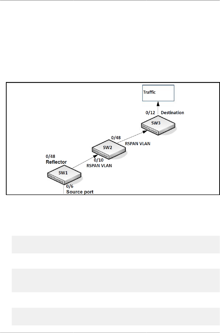
Configuring Switching Features
123
6.6.2. Configuring RSPAN
This example mirrors traffic from port 6 on a source switch (SW1) to a probe port on a remote
switch (port 12 on SW3). The mirrored traffic is carried in the RSPAN VLAN and VLAN 100, which
traverses an intermediate switch (SW2). The commands in this example show how to configure
port mirroring on the source, intermediate, and destination switches.
Figure below provides a visual overview of the RSPAN configuration example.
Figure6.11.RSPAN Configuration Example
6.6.2.1. Configuration on the Source Switch (SW1)
To configure the source switch:
1. Access the VLAN configuration mode and create VLAN 100, which will be the RSPAN VLAN.
(Routing) #vlan database
(Routing) (Vlan)#vlan 100
(Routing) (Vlan)#exit
2. Configure VLAN 100 as the RSPAN VLAN.
(Routing) #configure
(Routing) (Config)#vlan 100
(Routing) (Config) (vlan 100)#remote-span
(Routing) (Config) (vlan 100)#exit
3. Configure the RSPAN VLAN as the destination port and the reflector port as port 0/48.
(Routing) #configure
(Routing) (Config)#monitor session 1 destination remote vlan 100
reflector-port 0/48

Configuring Switching Features
124
4. Configure the source interface port as port 0/6.
(Routing) (Config)#monitor session 1 source interface 0/6
5. Enable the port mirroring session on the switch.
(Routing) (Config)#monitor session 1 mode
(Routing) #exit
6.6.2.2. Configuration on the Intermediate Switch (SW2)
To configure the intermediate switch:
1. Access the VLAN configuration mode and create VLAN 100.
(Routing) #vlan database
(Routing) (Vlan)#vlan 100
(Routing) (Vlan)#exit
2. Enable RSPAN on vlan 100.
(Routing) #configure (Routing) (Config)#vlan 100
(Routing) (Config) (vlan 100)#remote-span
(Routing) (Config) (vlan 100)#exit
3. Configure VLAN participation so the interface is always a member of the VLAN.
(Routing) (Config)#vlan participation include 100
(Routing) (Config)#interface 0/10
4. Enable VLAN tagging on the interface.
(Routing) (Config)#vlan tagging 100
(Routing) (Config)#exit
5. Configure VLAN participation so the interface is always a member of the VLAN.
(Routing) (Config)#vlan participation include 100
(Routing) (Config)#interface 0/48
(Routing) (Config)#exit
6.6.2.3. Configuration on the Destination Switch (SW3)
To configure the destination switch:
1. Access the VLAN configuration mode and create VLAN 100.
(Routing) #vlan database
(Routing) (Vlan)#vlan 100
(Routing) (Vlan)#exit
2. Enable RSPAN on vlan 100.
(Routing) #configure

Configuring Switching Features
125
(Routing) (Config)#vlan 100
(Routing) (Config) (vlan 100)#remote-span (
Routing) (Config) (vlan 100)#exit
3. Configure the RSPAN VLAN as the source interface for the port mirroring session.
(Routing) #configure
(Routing) (Config)#monitor session 1 source remote vlan 100
4. Configure the destination port as port 0/12. This is the probe port that is attached to a network
traffic analyzer.
(Routing) (Config)#monitor session 1 destination interface 0/12
5. Enable the port mirroring session on the switch.
(Routing) (Config)#monitor session 1 mode (Routing) (Config)#exit
6.6.3. VLAN-Based Mirroring
In this example, traffic from all ports that are members of VLAN 10 is mirrored to port 0/18. To con-
figure VLAN based mirroring:
1. Access VLAN Config mode and create VLAN 10.
(Routing) #vlan database
(Routing) (Vlan)#vlan 10
(Routing) (Vlan)#exit
2. Configure the destination interface port as port 0/18.
(Routing) #configure
(Routing) (Config)#monitor session 1 destination interface 0/18
3. Configure VLAN 10 as the source interface for the port mirroring session.
(Routing) (Config)#monitor session 1 source vlan 10
4. Enable the port mirroring session on the switch.
(Routing) (Config)#monitor session 1 mode
(Routing) (Config)#exit
6.6.4. Flow-Based Mirroring
In this example, traffic from port 1 is mirrored to port 18 if it matches the criteria defined in the IP
ACL or MAC ACL that are associated with the port mirroring session.
To configure flow based mirroring:
1. Create the extended IP access list IPACL
(Routing) #configure
(Routing) (Config)#ip access-list IPACL

Configuring Switching Features
126
(Routing) (Config)#permit ip 1.1.1.1 0.0.0.0 any
(Routing) (Config)#exit
2. Create the mac access list MACL.
(Routing) #configure
(Routing) (Config)#mac access-list extended MACL
(Routing) (Config)#permit 00:00:00:00:00:11 00:00:00:00:00:00 any
(Routing) (Config)#exit
3. Configure the destination port as port 0/18.
(Routing) #monitor session 1 destination interface 0/18
4. Configure the source port as port 0/2.
(Routing) #monitor session 1 source interface 0/2
5. Enable the port mirroring session.
(Routing) #monitor session 1 mode
6. To filter L3 traffic so only flows that match the rules in the IP ACL called IPACL are mirrored to
the destination port, add the IPACL ACL.
(Routing) #monitor session 1 filter ip access-group IPACL
7. To filter L2 traffic so only flows that match the rules in the MAC-based ACL called MACL are
mirrored to the destination port, add the MACL ACL.
(Routing) #monitor session 1 filter mac access-group MACL
(Routing) #exit

Configuring Switching Features
127
6.7. Spanning Tree Protocol
Spanning Tree Protocol (STP) is a layer 2 protocol that provides a tree topology for switches on
a bridged LAN. STP allows a network to have redundant paths without the risk of network loops.
STP uses the spanning-tree algorithm to provide a single path between end stations on a network.
ICOS software supports Classic STP, Multiple STP, and Rapid STP.
6.7.1. Classic STP, Multiple STP, and Rapid STP
Classic STP provides a single path between end stations, avoiding and eliminating loops. Multi-
ple Spanning Tree Protocol (MSTP) is specified in IEEE 802.1s and supports multiple instances
of Spanning Tree to efficiently channel VLAN traffic over different interfaces. Each instance of the
Spanning Tree behaves in the manner specified in IEEE 802.1w, Rapid Spanning Tree (RSTP),
with slight modifications in the working but not the end effect (chief among the effects, is the rapid
transitioning of the port to Forwarding). The difference between the RSTP and the traditional STP
(IEEE 802.1D) is the ability to configure and recognize full-duplex connectivity and ports which are
connected to end stations, resulting in rapid transitioning of the port to the Forwarding state and
the suppression of Topology Change Notifications.
MSTP is compatible to both RSTP and STP. It behaves appropriately to STP and RSTP bridges. A
MSTP bridge can be configured to behave entirely as a RSTP bridge or a STP bridge.
6.7.2. STP Operation
The switches (bridges) that participate in the spanning tree elect a switch to be the root bridge for
the spanning tree. The root bridge is the switch with the lowest bridge ID, which is computed from
the unique identifier of the bridge and its configurable priority number. When two switches have an
equal bridge ID value, the switch with the lowest MAC address is the root bridge.
After the root bridge is elected, each switch finds the lowest-cost path to the root bridge. The port
that connects the switch to the lowest-cost path is the root port on the switch. The switches in the
spanning tree also determine which ports have the lowest-path cost for each segment. These
ports are the designated ports. Only the root ports and designated ports are placed in a forwarding
state to send and receive traffic. All other ports are put into a blocked state to prevent redundant
paths that might cause loops.
To determine the root path costs and maintain topology information, switches that participate in the
spanning tree use Bridge Protocol Data Units (BPDUs) to exchange information.
6.7.2.1. MSTP in the Network
In the following diagram of a small 802.1D bridged network, STP is necessary to create an envi-
ronment with full connectivity and without loops.
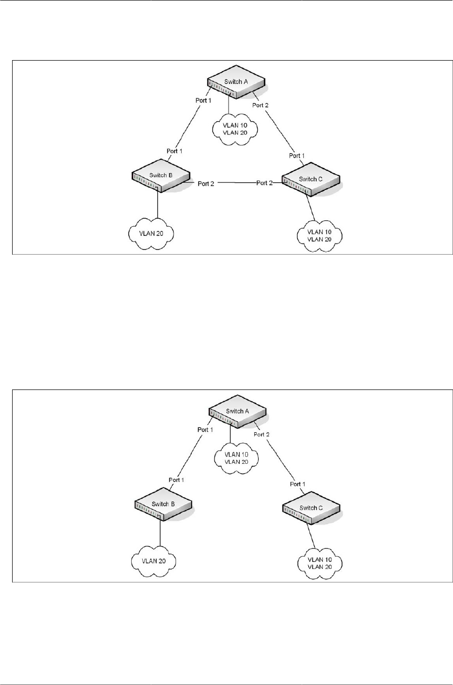
Configuring Switching Features
128
Figure6.12.STP in a Small Bridged Network
Assume that Switch A is elected to be the Root Bridge, and Port 1 on Switch B and Switch C are
calculated to be the root ports for those bridges, Port 2 on Switch B and Switch C would be placed
into the Blocking state. This creates a loop-free topology. End stations in VLAN 10 can talk to oth-
er devices in VLAN 10, and end stations in VLAN 20 have a single path to communicate with other
VLAN 20 devices.
Figure below shows the logical single STP network topology.
Figure6.13.Single STP Topology
For VLAN 10 this single STP topology is fine and presents no limitations or inefficiencies. On the
other hand, VLAN 20’s traffic pattern is inefficient. All frames from Switch B will have to traverse a
path through Switch A before arriving at Switch C. If the Port 2 on Switch B and Switch C could be
used, these inefficiencies could be eliminated. MSTP does just that, by allowing the configuration
of MSTIs based upon a VLAN or groups of VLANs. In this simple case, VLAN 10 could be associ-
ated with Multiple Spanning Tree Instance (MSTI)1 with an active topology similar to Figure 17 and
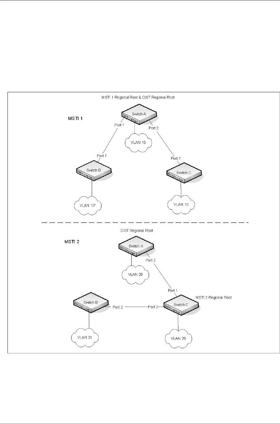
Configuring Switching Features
129
VLAN 20 could be associated with MSTI 2 where Port 1 on both Switch A and Switch B begin dis-
carding and all others forwarding. This simple modification creates an active topology with a better
distribution of network traffic and an increase in available bandwidth.
The logical representation of the MSTP environment for these three switches is shown in figure
below:
Figure6.14.Logical MSTP Environment
For MSTP to correctly establish the different MSTIs as above, some additional changes are re-
quired. For example, the configuration would have to be the same on each and every bridge. That
means that Switch B would have to add VLAN 10 to its list of supported VLANs (shown in figure
above with a *). This is necessary with MSTP to allow the formation of Regions made up of all
switches that exchange the same MST Configuration Identifier. It is within only these MST Regions
that multiple instances can exist. It will also allow the election of Regional Root Bridges for each in-
stance. One common and internal spanning tree (CIST) Regional Root for the CIST and an MSTI

Configuring Switching Features
130
Regional Root Bridge per instance will enable the possibility of alternate paths through each Re-
gion. Above Switch A is elected as both the MSTI 1 Regional Root and the CIST Regional Root
Bridge, and after adjusting the Bridge Priority on Switch C in MSTI 2, it would be elected as the
MSTI 2 Regional Root.
To further illustrate the full connectivity in an MSTP active topology, the following rules apply:
1. Each Bridge or LAN is in only one Region.
2. Every frame is associated with only one VID.
3. Frames are allocated either to the IST or MSTI within any given Region.
4. The internal spanning tree (IST) and each MSTI provides full and simple connectivity between
all LANs and Bridges in a Region.
5. All Bridges within a Region reach a consistent agreement as to which ports interconnect that
Region to a different Region and label those as Boundary Ports.
6. At the Boundary Ports, frames allocated to the CIST or MSTIs are forwarded or not forwarded
alike.
7. The CIST provides full and simple connectivity between all LANs and Bridges in the network.
6.7.3. Optional STP Features
ICOS software supports the following optional STP features:
• BPDU flooding
• Edge Port
• BPDU filtering
• Root guard
• Loop guard
• BPDU protection
6.7.3.1. BPDU Flooding
The BPDU flooding feature determines the behavior of the switch when it receives a BPDU on a
port that is disabled for spanning tree. If BPDU flooding is configured, the switch will flood the re-
ceived BPDU to all the ports on the switch which are similarly disabled for spanning tree.
6.7.3.2. Edge Port
The Edge Port feature reduces the STP convergence time by allowing ports that are connected
to end devices (such as a desktop computer, printer, or file server) to transition to the forwarding
state without going through the listening and learning states.

Configuring Switching Features
131
6.7.3.3. BPDU Filtering
Ports that have the Edge Port feature enabled continue to transmit BPDUs. The BPDU filtering
feature prevents ports configured as edge ports from sending BPDUs.
If BPDU filtering is configured globally on the switch, the feature is automatically enabled on all
operational ports where the Edge Port feature is enabled. These ports are typically connected to
hosts that drop BPDUs.
However, if an operational edge port receives a BPDU, the BPDU filtering feature disables the
Edge Port feature and allows the port to participate in the spanning-tree calculation.
Enabling BPDU filtering on a specific port prevents the port from sending BPDUs and allows the
port to drop any BPDUs it receives.
6.7.3.4. Root Guard
Enabling root guard on a port ensures that the port does not become a root port or a blocked port.
When a switch is elected as the root bridge, all ports are designated ports unless two or more
ports of the root bridge are connected together. If the switch receives superior STP BPDUs on a
root-guard enabled port, the root guard feature moves this port to a root-inconsistent STP state,
which is effectively equal to a listening state. No traffic is forwarded across this port. In this way,
the root guard feature enforces the position of the root bridge.
When the STP mode is MSTP, the port may be a designated port in one MSTI and an alternate
port in the CIST, etc. Root guard is a per port (not a per port per instance command) configuration,
so all the MSTP instances this port participates in should not be in a root role.
6.7.3.5. Loop Guard
Loop guard protects a network from forwarding loops induced by BPDU packet loss. The reasons
for failing to receive packets are numerous, including heavy traffic, software problems, incorrect
configuration, and unidirectional link failure. When a non-designated port no longer receives BP-
DUs, the spanning-tree algorithm considers that this link is loop free and begins transitioning the
link from blocking to forwarding. Once in forwarding state, the link may create a loop in the net-
work.
Enabling loop guard prevents such accidental loops. When a port is no longer receiving BPDUs
and the max age timer expires, the port is moved to a loop-inconsistent blocking state. In the loop-
inconsistent blocking state, traffic is not forwarded so the port behaves as if it is in the blocking
state. The port will remain in this state until it receives a BPDU. It will then transition through the
normal spanning tree states based on the information in the received BPDU.
Loop Guard should be configured only on non-designated ports. These include ports
in alternate or backup roles. Root ports and designated ports should not have loop
guard enabled so that they can forward traffic
6.7.3.6. BPDU Protection
When the switch is used as an access layer device, most ports function as edge ports that connect
to a device such as a desktop computer or file server. The port has a single, direct connection and
is configured as an edge port to implement the fast transition to a forwarding state. When the port

Configuring Switching Features
132
receives a BPDU packet, the system sets it to non-edge port and recalculates the spanning tree,
which causes network topology flapping. In normal cases, these ports do not receive any BPDU
packets. However, someone may forge BPDU to maliciously attack the switch and cause network
flapping.
BPDU protection can be enabled in RSTP to prevent such attacks. When BPDU protection is en-
abled, the switch disables an edge port that has received BPDU and notifies the network manager
about it.
6.7.4. PVRSTP
ICOS software supports both Rapid Spanning Tree Per VLAN (PVRSTP) and Spanning Tree Per
VLAN (PVSTP) with a high degree of interoperability with other vendor implementations, such
as Cisco’s PVST+ and RPVST+. PVRSTP is the IEEE 802.1w (RSTP) standard implemented
per VLAN. A single instance of rapid spanning tree (RSTP) runs on each configured VLAN. Each
RSTP instance on a VLAN has a root switch. The PVRSTP protocol state machine, port roles,
port states, and timers are similar to those defined for RSTP. PVRSTP embeds the DRC and Indi-
rectLink Fast Rapid Convergence (IRC) features, which cannot be disabled.
PVSTP is the IEEE 802.1D (STP) standard implemented per VLAN. The PVSTP-related state ma-
chine, roles, and timers are similar to those defined for STP. PVSTP does not have the DirectLink
Rapid Convergence (DRC) or IndirectLink Rapid Convergence (IRC) features enabled by default.
These features can be enabled by the switch administrator.
The switch spanning tree configuration is global in nature. Enabling PVRSTP disables other span-
ning tree modes on the switch. The switch cannot operate with some ports configured to operate
in standard spanning tree mode and others to operate in PVRSTP mode. However, PVRSTP has
fallback modes for compatibility with standards-based versions of spanning tree.
Access Ports — For an access port, normal IEEE BPDUs will be received and sent, though
PVSTP or PVRSTP is enabled on the switch. BPDUs received on the access port will be associat-
ed with the CST instance.
Trunk Ports — If the native VLAN on an IEEE 802.1Q trunk is VLAN 1:
• VLAN 1 STP BPDUs are sent to the IEEE STP MAC address (0180.c200.0000), untagged.
• VLAN 1 STP BPDUs are also sent to the SSTP MAC address, untagged.
• Non-VLAN 1 STP BPDUs are sent to the SSTP MAC address (also called the Shared Span-
ning Tree Protocol [SSTP] MAC address, 0100.0ccc.cccd), tagged with a corresponding IEEE
802.1Q VLAN tag.
If the native VLAN on an IEEE 802.1Q trunk is not VLAN 1:
• VLAN 1 STP BPDUs are sent to the SSTP MAC address, tagged with a corresponding IEEE
802.1Q VLAN tag.
• VLAN 1 STP BPDUs are also sent to the IEEE STP MAC address on the Native VLAN of the
IEEE 802.1Q trunk, untagged.
• Non-VLAN 1 STP BPDUs are sent to the SSTP MAC address, tagged with a corresponding
IEEE 802.1Q VLAN tag.

Configuring Switching Features
133
6.7.4.1. DirectLink Rapid Convergence
The DirectLink Rapid Convergence (DRC) feature is designed for an access-layer switch that has
redundant blocked uplinks. It operates on ports blocked by spanning tree. DRC can be configured
for the entire switch; it cannot be enabled for individual VLANs.
The DRC feature is based on the concept of an uplink group. An uplink group consists of all the
ports that provide a path to the root bridge (the root port and any blocked ports). If the root port
fails, the blocked port with next lowest cost from the uplink group is selected and immediately put
in the forwarding state without going through the standard spanning tree listening and learning
states.
To accelerate convergence time once DRC has switched over to a new root port, the switch trans-
mits dummy packets out the new root port, with the source MAC addresses taken from its forward-
ing table. The destination address is an SSTP MAC address that ensures that the packet is flood-
ed on the whole network. The packets update the forwarding tables on the other upstream switch-
es. The rate at which the dummy multicasts are sent can be configured by the administrator.
DRC and Link Up Events
In the event of failure of the primary uplink, a replacement uplink is immediately selected from the
uplink group and put into the forwarding state. If another port is enabled that, in accordance with
STP rules, should become the primary uplink (root port), the switch delays migrating to the new
port for twice the forwarding delay. The purpose of this delay is two-fold:
• Stability—If the primary uplink is flapping, re-enabling the link immediately can introduce addi-
tional instability into the network.
• Reduced Traffic Loss—DRC moves a port into the forwarding state as soon as it is up, but the
connected port obeys the usual STP rules; i.e. it goes through the listening and learning stages,
which take 15 seconds each by default. Delaying the switchover allows the connected port to go
to through the listening and learning states while the switch is still transmitting packets on the
original uplink.
The optimal behavior is to keep the current uplink active and hold the new port in the blocked state
for twice the forwarding delay.
6.7.4.2. IndirectLink Rapid Convergence Feature
To handle indirect link failure, the RSTP standard requires that a switch passively wait for
“max_age” seconds once a topology change has been detected. IndirectLink Rapid Convergence
(IRC) handles these failures in two phases:
• Rapid detection of an indirect link failure. Tracking the inferior BPDUs that a designated bridge
detects when it transmits a direct link failure indicates that a failure has occurred elsewhere in
the network.
• Performing an immediate check if the BPDU information stored on a port is still valid. This is im-
plemented with a new protocol data unit (PDU) and the Root Link Query message (RLQ).
Receiving an inferior BPDU on a port from the designated bridge indicates that one of the following
has occurred on the designated bridge:
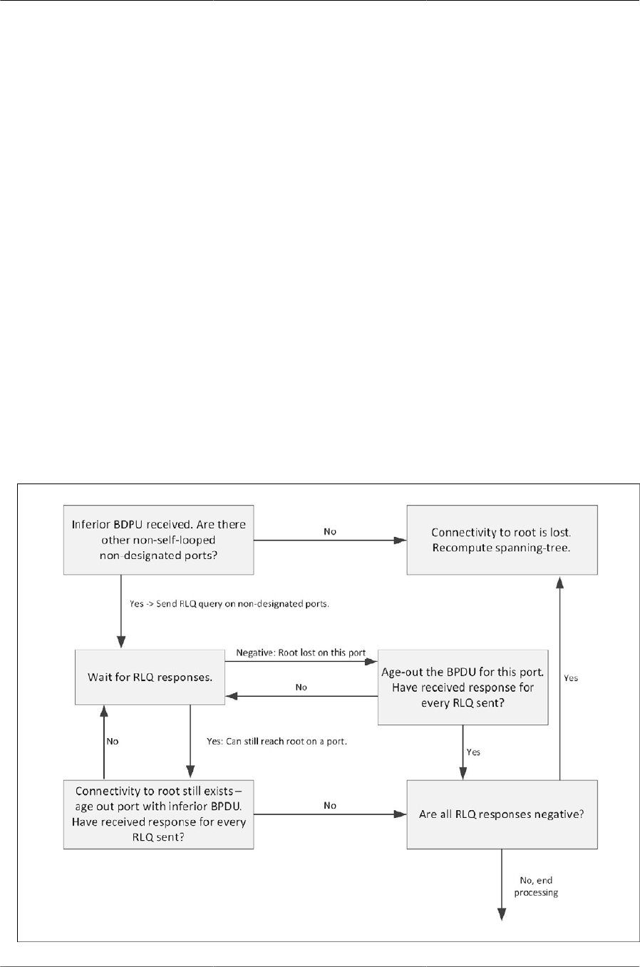
Configuring Switching Features
134
• The path to the root has been lost and the switch starts to advertise a root with a numerically
higher bridge ID (worse root) than the local switch.
• The path cost to the root has increased above the path cost of the local switch.
IEEE 802.1D behavior is to ignore inferior BPDUs. IRC retains the inferior BPDUs sent by the des-
ignated bridge and processes them to determine if a failure has occurred on the path to the root.
In this case, it must age-out at least one port. This process occurs only in the case that a bridge in
the network detects a direct link failure.
The switch tracks inferior BPDUs sent by the designated bridge only, since this is the BPDU that
is stored for the port. If, for instance, a newly inserted bridge starts to send inferior BPDUs, it does
not start the IRC feature.
6.7.4.3. Reacting to Indirect Link Failures
When an inferior BPDU is received on a non-designated port, phase 2 of IRC processing starts.
An RLQ PDU is transmitted on all non-designated ports except the port where the inferior BPDU
was received and self-looped ports. This action is intended to verify that the switch can still receive
from the root on ports that should have a path to the root. The port where the switch received the
inferior BPDU is excluded because it already failed; self- looped and designated ports are eliminat-
ed as they do not have a path to the root.
Figure6.15.IRC Flow
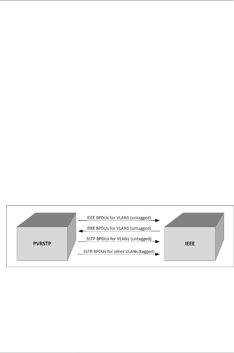
Configuring Switching Features
135
Upon receiving a negative RLQ response on a port, the port has lost connection to the root and
the switch ages- out its BPDU. If all other non-designated ports received a negative answer, the
switch has lost the root and restarts the STP calculation.
If the response confirms the switch can still access the root bridge via a particular port, it immedi-
ately ages-out the port on which the inferior BPDU was received.
If the switch only received responses with a root different from the original root, it has lost the root
port and restarts the STP calculation immediately.
6.7.4.4. Interoperability Between PVSTP and PVRSTP Modes
PVSTP is derived from 802.1D and PVRSTP is derived from 802.1w. The fallback mechanism is
the same as between a standard 802.1D switch and a standard 802.1w switch. When a lower pro-
tocol version BPDU is received on a switch that runs a higher protocol version, the latter falls back
to the lower version after its migration delay timer expires.
For example, an PVRSTP switch, when connected to PVSTP switch, falls back to the PVSTP pro-
tocol after the migration delay timer expires.
6.7.4.5. Interoperability With IEEE Spanning Tree Protocols
When a switch configured with PVRSTP receives IEEE standard RSTP BPDUs on a port, it re-
sponds with two versions of BPDUs on the port: SSTP formatted BPDUs and IEEE standard STP
BPDUs. The IEEE standard BPDUs are processed by the peer switch running MSTP/RSTP, and
the SSTP format BPDUs are flooded across the MSTP/RSTP domain.
Figure6.16.PVRSTP and IEEE Spanning Tree Interoperability
6.7.4.6. Common Spanning Tree
There are differences between the ways that MSTP and PVRSTP map spanning tree instances to
VLANs: PVRSTP creates a spanning tree instance for each VLAN, and MSTP maps one or more
VLANs to each MST instance. Where an PVRSTP region is connected to an MSTP region, the set
of PVRSTP instances does not generally match the set of MST instances. Therefore, the PVRSTP
region and the MSTP region communicate with each other on a single common spanning tree in-
stance.
For the MSTP region, the MSTP instance communicates to the PVRSTP region using the CIST.
For the PVRSTP region, switches use the VLAN 1 PVRSTP instance as the common spanning

Configuring Switching Features
136
tree. On the link between the PVRSTP region and the MSTP region, the PVRSTP switch sends
VLAN1 BPDUs in IEEE standard format, so they can be interpreted by the MSTP peers. Similarly,
the PVRSTP switch processes incoming MSTP BPDUs as though they were BPDUs for the VLAN
1 PVRSTP instance.
If the PVRSTP switch ports connected to the MSTP switches are configured with a native VLAN,
the PVRSTP switches are able to detect IEEE standard format BPDUs arriving from peer switches,
incorporate them into the common spanning tree that operates in the native VLAN (VLAN 1), and
transmit untagged STP or RSTP packets to the STP/RSTP peers, in addition to the SSTP format
BPDUs.
6.7.4.7. SSTP BPDUs Flooding Across MST (CST) Regions
In addition to the IEEE standard RSTP or STP BPDUs that the PVRSTP switch sends to the
MSTP (or RSTP or STP) region, the switch sends SSTP format BPDUs for VLAN 1, untagged. The
MSTP switch does not interpret the SSTP BPDUs as standard BPDUs because they do not use
the standard destination MAC address, so it makes no spanning tree decisions based on them. In-
stead, it floods the SSTP BPDUs over all ports in the corresponding VLAN. These SSTP BPDUs
may be multicast over the MSTP region to other PVRSTP switches, which use them to maintain
the VLAN 1 spanning tree topology across the MSTP (non-PVRSTP) switches.
The PVRSTP switches also send SSTP format BPDUs for the other (non-VLAN 1) PVRSTP in-
stances into the MSTP region, tagged with the VID of their associated VLANs. These SSTP pack-
ets are also be multicast by the switches in the MSTP region, and will reach any other PVRSTP
regions connected to the MSTP region. The switches in the remote PVRSTP regions receive and
process them as normal PVRSTP BPDUs. Thus, PVRSTP instances are transparently expanded
across the MSTP region and their spanning trees span the MSTP region. For PVRSTP, the MSTP
region is treated as a single hub.
6.7.4.8. Interoperability with RSTP
In Figure below:
• SW1 and SW2 are ICOS switches running PVRSTP with default bridge priority 32768.
• SW3 is an ICOS switch running RSTP with default bridge priority 32768.
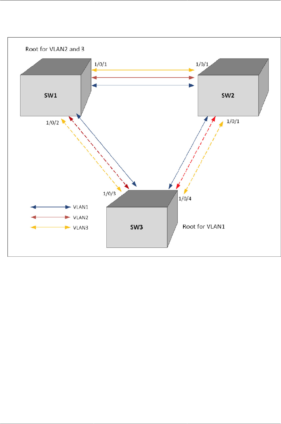
Configuring Switching Features
137
Figure6.17.PVRSTP and RSTP Interoperability
SW3 sends IEEE STP BPDUs to the IEEE multicast MAC address as untagged frames. These
BPDUs are processed by the VLAN 1 STP instance on the PVRSTP switch as part of the VLAN 1
STP instance.
The PVRSTP side sends IEEE STP BPDUs corresponding to the VLAN 1 STP to the IEEE MAC
address as untagged frames across the link. At the same time, SSTP BPDUs are sent as un-
tagged frames. IEEE switches simply flood the SSTP BPDUs throughout VLAN 1. This facilitates
PVRSTP connectivity in case there are other PVRSTP switches connected to the IEEE STP do-
main.
For non-native VLANs (VLANs 2–4093), the PVRSTP switch sends SSTP BPDUs, tagged with
their VLAN number. The VLAN STP instances are multicast across the RSTP region, as if it were a
hub switch.
The VLAN 1 STP instance of SW1 and SW2 are joined with the STP instance running in SW3.
VLANs 2 and 3 consider the path across SW3 as another segment linking SW1 and SW2, and
their SSTP information is multicast across SW3.
The bridge priority of SW1 and SW2 for VLAN1 instance is 32769 (bridge priority + VLAN identifi-
er).

Configuring Switching Features
138
The bridge priority of SW3 is 32768, per the IEEE 802.w standard.
SW3 is selected as Root Bridge for the VLAN1 instance that is CST, and SW1 is selected as Root
Bridge for VLAN2 and VLAN3 (based on the low MAC address of SW1).
6.7.4.9. Interoperability with MSTP
PVRSTP runs an individual RSTP instance for each VLAN. MSTP maps VLANs to MSTIs, so one-
to-one mapping between VLAN and STP instance is not possible.
MSTP runs multiple MSTIs inside a region and maps them to the CIST on the border ports. The in-
teroperability model must ensure that internal MSTIs are aware of changes to any of the PVRSTP
trees. Therefore, the simplest way to ensure the correct behavior is to join ALL PVRSTP trees to
the CST.
Connecting PVRSTP trees to the CST ensures that changes in any of the PVRSTP STP instances
will affect the CST and all MSTIs. This approach ensures that no changes go unnoticed and no
black holes occur in a single VLAN. As with IEEE STP, every tree in the PVRSTP domain views
the MSTP regions as virtual bridges with multiple boundary ports. A topology change in any of
PVRSTP trees will affect the CST and propagate through every MSTI instance in all MSTP re-
gions. This behavior, consequently, makes the MSTP topology less stable.
The MSTP implementation simulates PVRSTP by replicating CIST BPDUs on the link facing the
PVRSTP domain and sending those BPDUs on ALL VLANs active on the trunk. The MSTP switch
processes IEEE STP VLAN 1 BPDUs received from the PVRSTP domain using the CIST instance.
The PVRSTP+ domain interprets the MSTP domain as an PVRSTP bridge with all per-VLAN in-
stances claiming the CIST Root as the root of their individual spanning tree. For the common STP
Root elected between MSTP and PVRSTP, two options are possible:
• The MSTP domain contains the root bridge for ALL VLANs. This implies that the CIST Root
Bridge ID is configured to be better than any PVRSTP STP root Bridge ID. If there is only one
MSTP region connected to the PVRSTP domain, then all boundary ports on the virtual-bridge
will be unblocked and used by PVRSTP. This is the only supported topology, as the administra-
tor can manipulate uplink costs on the PVRSTP side and obtain optimal traffic engineering re-
sults. In Figure below, VLANs 2 and 3 have their STP costs configured to select different uplinks
connected to the MSTP region’s boundary ports. Since the CIST Root is inside the MSTP re-
gion, both boundary ports are non-blocking designated and the load balancing scheme operates
as expected.
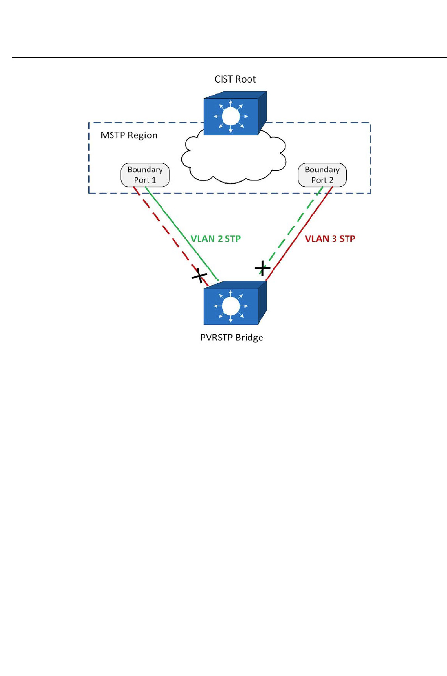
Configuring Switching Features
139
Figure6.18.MSTP and PVRSTP Interoperability
• The alternative is that the PVRSTP domain contains the root bridges for ALL VLANs. This is on-
ly true if all PVRSTP root bridges’ Bridge IDs for all VLANs are better than the MSTP CIST Root
Bridge ID. This is not a supported topology, because all MSTIs map to CIST on the border link,
and it is not possible to load- balance the MSTIs as they enter the PVRSTP domain.
The ICOS software PVRSTP implementation does not support the second option. The MSTP do-
main must contain the bridge with the best Bridge ID to ensure that the CIST Root is also the root
for all PVRSTP trees. In any other case, the MSTP border switch will place the ports that receive
superior BPDUs from the PVRSTP region in the root-inconsistent state. To resolve this issue, en-
sure that the PVRSTP domain does not have any bridges with Bridge IDs better than the CIST
Root Bridge ID.
6.7.4.10. Native VLAN Inconsistent State
This occurs if a trunk port receives an untagged SSTP BPDU with a VLAN type, length, value
(TLV) that does not match the VLAN where the BPDU was received. In this case, the port transi-
tions to the blocked state.
6.7.5. STP Configuration Examples
This section contains the following examples:
• Configuring STP
• Configuring MSTP
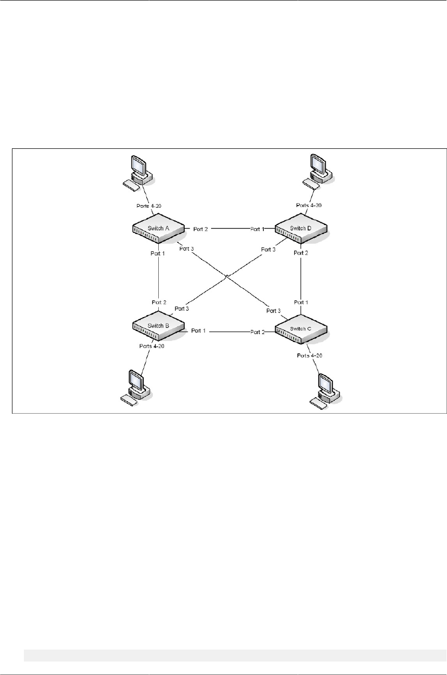
Configuring Switching Features
140
• Configuring PVRSTP
6.7.5.1. Configuring STP
This example shows a LAN with four switches. On each switch, ports 1, 2, and 3 connect to other
switches, and ports 4–20 connect to hosts (in Figure 22, each PC represents 17 host systems).
Figure6.19.STP Example Network Diagram
Of the four switches in Figure above, the administrator decides that Switch A is the most central-
ly located in the network and is the least likely to be moved or redeployed. For these reasons,
the administrator selects it as the root bridge for the spanning tree. The administrator configures
Switch A with the highest priority and uses the default priority values for Switch B, Switch C, and
Switch D.
For all switches, the administrator also configures ports 4–17 in Port Fast mode because these
ports are connected to hosts and can transition directly to the Forwarding state to speed up the
connection time between the hosts and the network.
The administrator also configures Port Fast BPDU filtering and Loop Guard to extend STP’s capa-
bility to prevent network loops. For all other STP settings, the administrator uses the default STP
values.
To configure the switch:
1. Connect to Switch A and configure the priority to be higher (a lower value) than the other
switches, which use the default value of 32768.
(Routing) #config
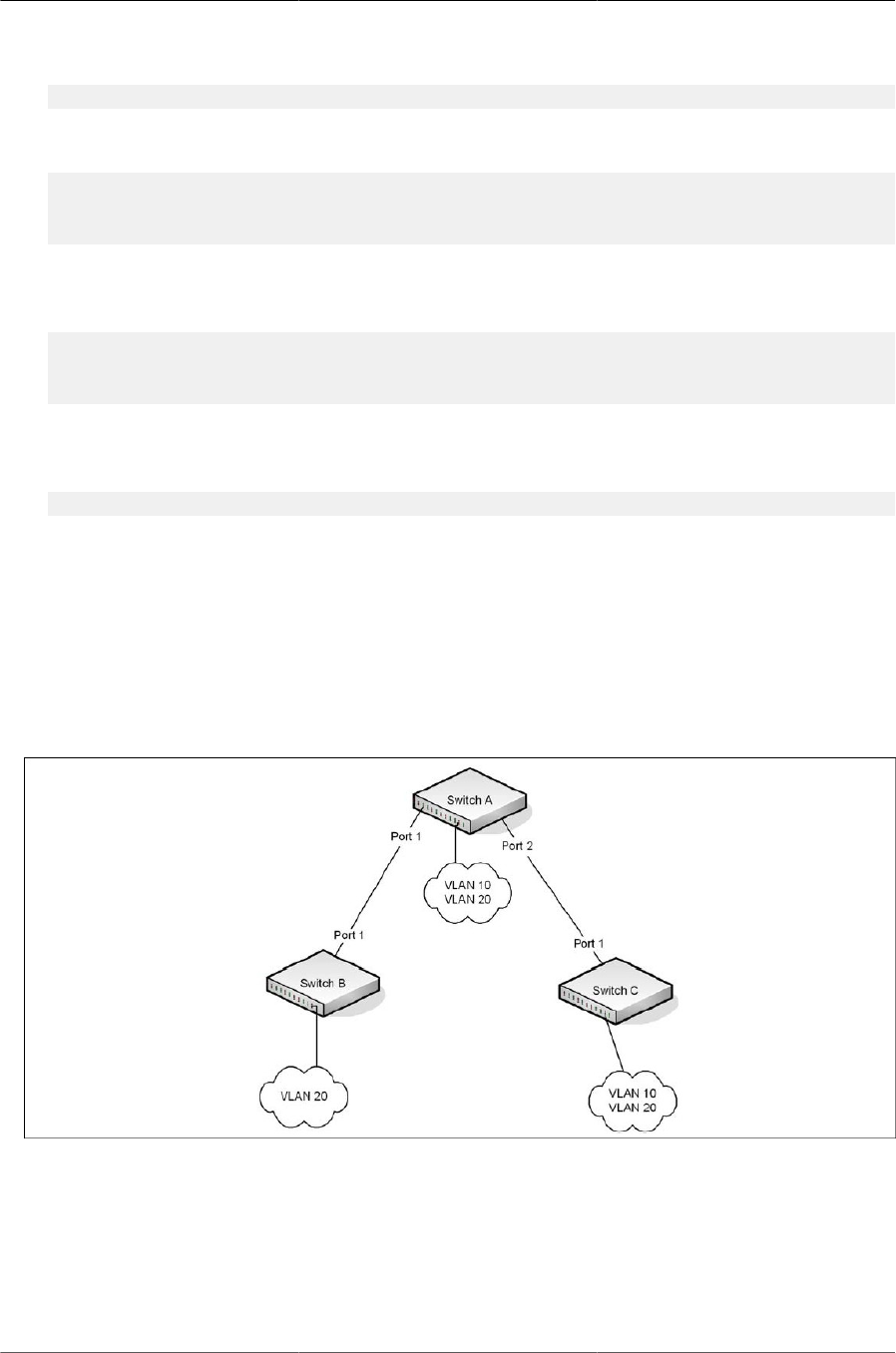
Configuring Switching Features
141
(Routing) (Config)#spanning-tree mst priority 0 8192
2. Configure ports 4–20 to be in Edge Port mode.
(Routing) (Config)#interface 0/4-0/20
(Routing) (Interface 0/4-0/20)#spanning-tree edgeport
(Routing) (Interface 0/4-0/20)#exit
3. Enable Loop Guard on ports 1–3 to help prevent network loops that might be caused if a port
quits receiving BPDUs.
(Routing) (Config)#interface 0/1-0/3
(Routing) (Interface 0/1-0/3)#spanning-tree guard loop
(Routing) (Interface 0/1-0/3)#exit
4. Enable Port Fast BPDU Filter. This feature is configured globally, but it affects only access ports
that have the Edge Port feature enabled.
(Routing) (Config)#spanning-tree bpdufilter default
5. Repeat Step 2 through Step 4 on Switch B, Switch C, and Switch D to complete the configura-
tion.
6.7.5.2. Configuring MSTP
This example shows how to configure IEEE 802.1s Multiple Spanning Tree (MST) protocol on the
switches shown in Figure below.
Figure6.20.MSTP Configuration Example
To make multiple switches be part of the same MSTP region, make sure the STP operational
mode for all switches is MSTP. Also, make sure the MST region name and revision level are the
same for all switches in the region.
To configure the switches:
1. Create VLAN 10 (Switch A and Switch B) and VLAN 20 (all switches).

Configuring Switching Features
142
Even Switch B does not have any ports that are members of VLAN 10, this VLAN
must be created to allow the formation of MST regions made up of all bridges that
exchange the same MST Configuration Identifier. It is only within these MST Re-
gions that multiple instances can exist.
(Routing) #vlan database
(Routing) (Vlan)#vlan 10,20
(Routing) (Vlan)#exit
2. Set the STP operational mode to MSTP.
(Routing) #config
(Routing) (Config)#spanning-tree forceversion 802.1s
3. Create MST instance 10 and associate it to VLAN 10.
(Routing) (Config)#spanning-tree mst instance 10
(Routing) (Config)#spanning-tree mst vlan 10 10
4. Create MST instance 20 and associate it to VLAN 20.
(Routing) (Config)#spanning-tree mst instance 20
(Routing) (Config)#spanning-tree mst vlan 20 20
5. Change the region name so that all the bridges that want to be part of the same region can form
the region.
(Routing) (Config)#spanning-tree configuration name broadcom
6. (Switch A only) Make Switch A the Regional Root for MSTI 1 by configuring a higher priority for
MST ID 10.
(Routing) (Config)#spanning-tree mst priority 10 12288
7. (Switch A only) Change the priority of MST ID 20 to ensure Switch C is the Regional Root
bridge for this MSTI.
(Routing) (Config)#spanning-tree mst priority 20 61440
8. (Switch C only) Change the priority of port 1 to force it to be the root port for MST 20.
(Routing) (Config)#interface 0/1
(Routing) (Interface 0/1)#spanning-tree mst 20 port-priority 64
(Routing) (Interface 0/1)#exit
(Routing) (Config)#exit
6.7.5.3. Configuring PVRSTP
PVRSTP Access Switch Configuration Example
In this configuration, ports 0/3-0/48 are presumed to be connected to host machines, and ports 0/1
and 0/2 are uplink ports are connected to an aggregation-layer switch with a total L2 network di-
ameter of 4. The aggregation-layer switch can be a single switch or multiple switches, running ei-

Configuring Switching Features
143
ther PVRSTP or MSTP. For fastest convergence during failover scenarios, it is recommended that
the uplink switches be configured in PVRSTP mode.
Three VLANs are configured in addition to VLAN 1. Interface 0/1 is configured to be the primary
uplink port and 0/2 is configured to be the backup uplink.
1. Configure VLANs 2 through 4.
(Routing) #vlan database
(Routing) (Vlan)#vlan 2-4
(Routing) (Vlan) (Vlan2-4)#exit
2. Enable PVRSTP.
(Routing) #config
(Routing) (Config)#spanning-tree mode rapid-pvst
3. Configure for a maximum network diameter of 4.
(Routing) (Config)#spanning-tree vlan 1-4 max-age 16
4. Configure access and trunk ports.
(Routing) (Config)#interface 0/3-0/48
(Routing) (Interface 0/3-0/48)#switchport mode access
(Routing) (Interface 0/3-0/48)#exit
(Routing) (Config)#interface 0/1-0/2
(Routing) (Interface 0/1-0/2)#switchport mode trunk
(Routing) (Interface 0/1-0/2)#exit
5. Configure interface 0/1 as the preferred uplink.
(Routing) (Config)#interface 0/1
(Routing) (Inteface 0/1)#spanning-tree port-priority 112
(Routing) (Inteface 0/1)#exit
6. Assign ports to VLANs.
(Routing) (Config)#interface 0/3-0/12
(Routing) (Interface 0/3-0/12)#switchport access vlan 1
(Routing) (Interface 0/3-0/12)#exit
(Routing) (Config)#interface 0/13-0/24
(Routing) (Interface 0/13-0/24)#switchport access vlan 2
(Routing) (Interface 0/13-0/24)#exit
(Routing) (Config)#interface 0/25-0/36
(Routing) (Interface 0/25-0/36)#switchport access vlan 3
(Routing) (Interface 0/25-0/36)#exit
(Routing) (Config)#interface 0/37-0/48
(Routing) (Interface 0/37-0/48)#switchport access vlan 4
(Routing) (Interface 0/37-0/48)#exit
PVRSTP Aggregation Layer Switch Configuration Example
In this configuration example, two aggregation-layer switches are configured. Ports 1–4 are con-
figured in a LAG connecting the two aggregation-layer switches. Ports 12–24 are configured as

Configuring Switching Features
144
down-links to twelve access layer switches configured as in the previous example. Down-links to
the access-layer switches have physical diversity; there is one downlink to each of the twelve ac-
cess-layer switches from each of the paired aggregation- layer switches.
The uplink ports to the network core are configured as LAGs to provide link redundancy. It is pre-
sumed that the core links connect to a router running PVRSTP. The configuration for the two ag-
gregation-layer switches is identical, except for the diversity configuration noted below.
For forwarding diversity, the even numbered switch is made the root for the even-numbered
VLANs. The odd numbered switch is made the root for the odd-numbered VLANs.
1. Create VLANs 2 through 4:
(Routing) #vlan database
(Routing) (Vlan)#vlan 2-4
(Routing) (Vlan)#exit
2. Enable PVRSTP:
(Routing) #Config
(Routing) (Config)#spanning-tree mode rapid-pvst
3. Configure for a max network diameter of 4:
(Routing) (Config)#spanning-tree vlan 1-4 max-age 16
4. Configure one downlink trunk port per downlink switch:
(Routing) (Config)#interface 0/12-0/24
(Routing) (Interface 0/12-0/24)#switchport mode trunk
(Routing) (Interface 0/12-0/24)#exit
5. Configure forwarding diversity for the even numbered switches:
(Routing) (Config)#spanning-tree vlan 2,4 root primary
(Routing) (Config)#spanning-tree vlan 1,3 root secondary
6. Configure forwarding diversity for the odd numbered switches:
(Routing) (Config)#spanning-tree vlan 1,3 root primary
(Routing) (Config)#spanning-tree vlan 2,4 root secondary
7. Configure two uplink ports per uplink switch:
(Routing) (Config)#interface 0/1-0/2
(Routing) (Interface 0/1-0/2)#channel-group 1 mode active
(Routing) (Interface 0/1-0/2)#exit
8. Configure peer switch links:
(Routing) (Config)#interface 0/5-0/8
(Routing) (Interface 0/5-0/8)#channel-group 2 mode active
(Routing) (Interface 0/5-0/8)#exit
9. Configure the uplinks into a port channel:

Configuring Switching Features
145
(Routing) (Config)#interface lag 1
(Routing) (Interface lag 1)#switchport mode trunk
(Routing) (Interface lag 1)#exit
10.Configure the peer links into a port channel and prefer to go to the core router or access switch-
es directly, i.e., block the peer link unless it is needed:
(Routing) (Config)#interface lag 1
(Routing) (Interface lag 1)#switchport mode trunk
(Routing) (Interface lag 1)#spanning-tree port-priority 144
(Routing) (Interface lag 1)#exit

Configuring Switching Features
146
6.8. IGMP Snooping
IGMP Snooping is a layer 2 feature that allows the switch to dynamically add or remove ports from
IP multicast groups by listening to IGMP join and leave requests. By “snooping” the IGMP packets
transmitted between hosts and routers, the IGMP Snooping feature enables the switch to forward
IP multicast traffic more intelligently and help conserve bandwidth.
Based on the IGMP query and report messages, the switch forwards traffic only to the ports that
request the multicast traffic. This prevents the switch from broadcasting the traffic to all ports and
possibly affecting network performance. The switch uses the information in the IGMP packets as
they are being forwarded throughout the network to determine which segments should receive
packets directed to the group address.
6.8.1. IGMP Snooping Querier
When PIM and IGMP are enabled in a network with IP multicast routing, the IP multicast router
acts as the IGMP querier. However, if the IP-multicast traffic in a VLAN needs to be Layer 2
switched only, an IP-multicast router is not required. The IGMP Snooping Querier can perform the
IGMP snooping functions on the VLAN.
Without an IP-multicast router on a VLAN, you must configure another switch as the IGMP querier
so that it can send queries.
When the IGMP snooping querier is enabled, the IGMP snooping querier sends out periodic IGMP
queries that trigger IGMP report messages from the switch that wants to receive IP multicast traf-
fic. The IGMP snooping feature listens to these IGMP reports to establish appropriate forwarding.
6.8.2. Configuring IGMP Snooping
This example configures IGMP snooping on the switch to limit multicast traffic and to allow L2
multicast forwarding on a single VLAN. The IP-multicast traffic in VLAN 100 needs to be Layer 2
switched only, so the IGMP snooping querier is enabled on the switch to perform the IGMP snoop-
ing functions on the VLAN, if necessary. The switch can send queries even if it is not the IGMP
snooping querier and will use 0.0.0.0 as the source IP address. This will not cause any disruption
to the operation of external querier.
In this configuration, an IP-multicast router is not required.
The three hosts in Figure below are connected to ports that enabled for IGMP snooping and are
members of VLAN 100. Port 24 is a trunk port and connects the switch to the data center, where
the L3 multicast router is located.
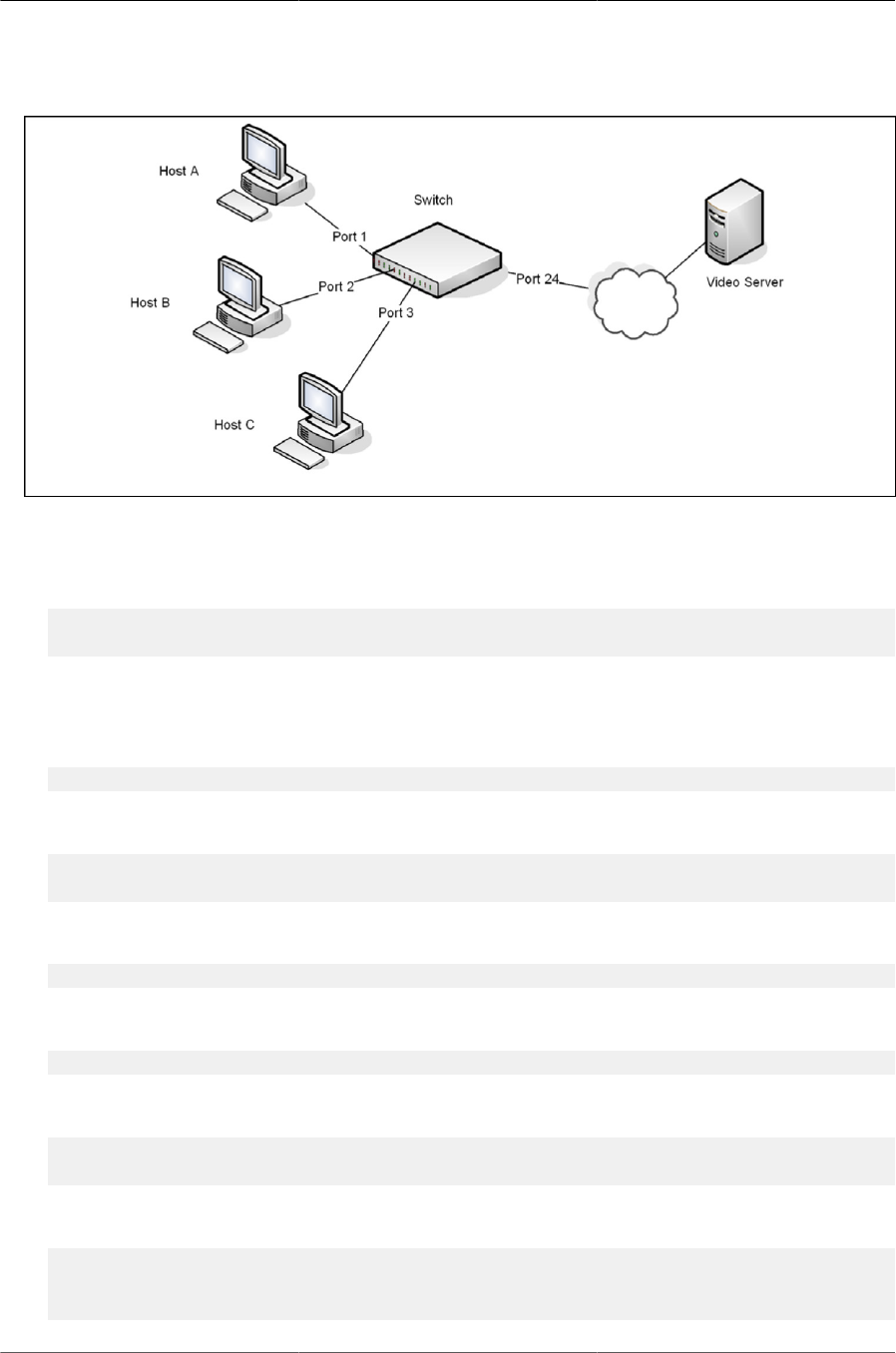
Configuring Switching Features
147
Figure6.21.Switch with IGMP Snooping
To configure the switch:
1. Enable IGMP snooping globally.
(Routing) #configure
(Routing) (Config)#set igmp
2. Enable the IGMP snooping querier on the switch. If there are no other IGMP snooping queriers,
this switch will become the IGMP snooping querier for the local network. If an external querier is
discovered, this switch will not be a querier.
(Routing) (Config)#set igmp querier
3. Create VLAN 100
(Routing) #vlan database
(Routing) (Vlan)#vlan 100
4. Enable IGMP snooping on VLAN 100.
(Routing) (Vlan)#set igmp 100
5. Enable the IGMP snooping querier on VLAN 100.
(Routing) (Vlan)#set igmp querier 100
6. Enable VLAN routing on VLAN 100.
(Routing) (Vlan)#vlan routing 150
(Routing) (Vlan)#exit
7. View the VLAN routing interface information.
(Routing) #show ip interface brief
Interface State IP Address IP Mask Method
---------- ----- --------------- --------------- -------

Configuring Switching Features
148
4/1 Down 0.0.0.0 0.0.0.0 None
8. Configure an IP address for VLAN 100. This address will be used as the IGMP snooping querier
address if this switch becomes the querier.
(Routing) #configure
(Routing) (Config)#interface 4/1
(Routing) (Interface 4/1)#ip address 192.168.10.2 255.255.255.0
(Routing) (Interface 4/1)#exit
9. Specify the address to use as the source address for IGMP queries sent from any interface. The
global querier address is the IP address of VLAN 100.
(Routing) (Config)#set igmp querier address 192.168.10.2
10.Enable IGMP snooping on ports 1–3.
(Routing) (Config#interface 0/1-0/3
(Routing) (Interface 0/1-0/3)#set igmp
11.Configure ports 1–3 as members of VLAN 100.
(Routing) (Interface 0/1-0/3)#vlan participation include 100
(Routing) (Interface 0/1-0/3)#exit
12.Enable IGMP on port 24, and configure the port as a trunk port that connects to the data center
switch.
(Routing) (Config)#interface 0/24
(Routing) (Interface 0/24)#set igmp
(Routing) (Interface 0/24)#vlan participation include 100
(Routing) (Interface 0/24)#vlan tagging 100
(Routing) (Interface 0/24)#exit
(Routing) (Config)#exit
13.Verify the IGMP snooping configuration.
(Routing) #show igmpsnooping
Admin Mode..................................... Enable
Multicast Control Frame Count. ................. 0
IGMP Router-Alert check........................ Disabled
Interfaces Enabled for IGMP Snooping........... 0/1
0/2
0/3
0/24
VLANs enabled for IGMP snooping ................ 100
(Routing) #show igmpsnooping querier vlan 100
VLAN 100 : IGMP Snooping querier status
----------------------------------------------
IGMP Snooping Querier VLAN Mode................ Enable
Querier Election Participate Mode.............. Disable
Querier VLAN Address ........................... 0.0.0.0
Operational State.............................. Querier

Configuring Switching Features
149
Operational version. ........................... 2
Operational Max Resp Time ...................... 10
After performing the configuration in this example, Host A sends a join message for multicast
group 225.1.1.1. Host B sends a join message for group 225.1.1.2. Because IGMP snooping is en-
abled on the switch and on VLAN 100, the switch listens to the messages and dynamically adds
Ports 1 and 2 to the multicast address table. Port 3 did not send a join message, so it does not ap-
pear in the table, as the following show command indicates.
(Routing) #show mac-address-table multicast
Fwd
VLAN ID MAC Address Source Type Description Interface Interface
------- ---------------- ------- ------- --------------- --------- ---------
100 01:00:5E:01:01:01 IGMP Dynamic Network Assist 0/1 0/1
100 01:00:5E:01:01:02 IGMP Dynamic Network Assist 0/2 0/2
When the video server sends multicast data to group 225.1.1.1, Port 1 participates and receives
multicast traffic, but Port 2 does not participate because it is a member of a different multicast
group. Without IGMP snooping, all ports that are members of VLAN 100 would be flooded with
traffic for all multicast groups, which would greatly increase the amount of traffic on the switch.
6.8.3. IGMPv3/SSM Snooping
IGMPv3 adds support for source filtering, which is the ability for a system to report interest in re-
ceiving packets only from specific source addresses, or from all but specific source addresses sent
to a particular multicast address. This information is used by snooping switches to avoid delivering
multicast packets from specific sources to networks where there are no interested receivers.
No additional configuration is required to enable IGMPv3/SSM snooping. It is enabled or disabled
when snooping is enabled on a VLAN/interface. The forwarding database built using IGMPv3 re-
ports is based on the Source IP address, the Multicast Group address, and VLAN. Consider the
above configuration example. When Host A sends IGMPv3 IS_IN a report for Group 225.1.1.1 and
Sources 192.168.10.1 and 192.168.20.1. As snooping is enabled globally on the switch and also
on VLAN 100, two entries are added to MFDB so that multicast traffic with group IP = 225.1.1.1
and if Source Ip=192.168.10.1 or 192.168.20.1 is forwarded to port 1. All other multicast traffic
destined to group 225.1.1.1 is dropped. The following command is used to display the SSM for-
warding database.
(Routing) #show igmpsnooping ssm entries
VLAN Source
ID Group Source Ip Filter Mode Interfaces
---- ---------------- ---------------------- ----------- --------------
100 225.1.1.1 192.168.10.1 include 0/1
100 225.1.1.1 192.168.20.1 include 0/1

Configuring Switching Features
150
6.9. Multicast VLAN Registration Configura-
tion
6.9.1. Overview
Multicast VLAN Registration (MVR), like IGMP Snooping protocol, allows a layer-2 switch to listen
to the IGMP frames.
IGMP is a layer-3 protocol widely used for IPv4 networks multicasting. In layer-2 networks, IGMP
protocol uses resources inefficiently. For example, a layer-2 switch broadcasts any multicast traffic
to all the ports even when there are only several receivers connected to several ports. The IGMP
Snooping protocol was developed to address this issue. But the problem still appears when re-
ceivers are in different VLANs.
The purpose of MVR is to solve the problem when receivers are in different VLANs. It uses dedi-
cated VLAN, called a multicast VLAN, to forward multicast traffic over a layer-2 network. Only one
multicast VLAN can be configured per switch.
Ports can be configured as MVR source ports or receiver ports.
• The source port is the port where multicast traffic is flowing to. It must be the member of the mul-
ticast VLAN.
• The receiver port is the port where the listening host is connected to the switch. It can be a
member of any VLAN except the multicast VLAN.
The multicast VLAN is configured for all the source ports over the network. It is the VLAN that is
used to transfer multicast traffic over the network avoiding duplication of multicast streams for
clients in different VLANs.
Figure below shows a network configured to use MRV. SP is the source port and RP is the receiv-
er port.
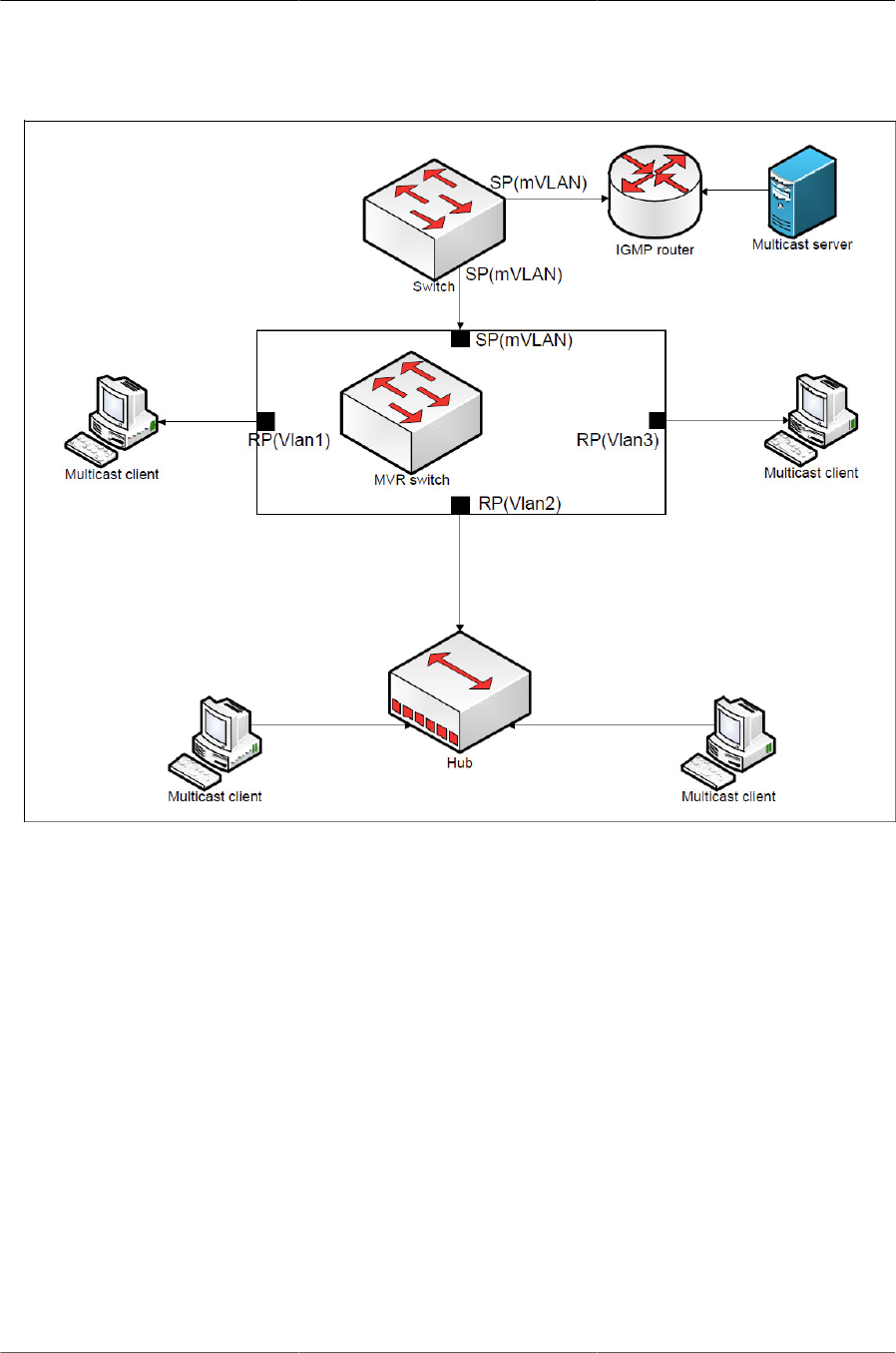
Configuring Switching Features
151
Figure6.22.MVR-Enabled Network
MVR and IGMP snooping operate independently and can both be enabled on an interface. When
both MVR and IGMP snooping are enabled, MVR listens to the IGMP join and report messages for
static multicast group information, and IGMP snooping manages dynamic multicast groups.
Parsing the IGMP packets generated by router and hosts, MVR fills its own membership group
database to track hosts interested in specific multicast traffic. There are two types of group entries
in this database, static and dynamic. Static entries are configured by administrator, but dynamic
are learned by MVR on the source ports.
There are two configured learning modes of the MVR operation, dynamic and compatible.
• In Dynamic mode, MVR learns source ports membership from IGMP queries. The protocol for-
wards Joins and Leaves from the hosts to the router. The multicast traffic is forwarded only to re-
ceiver ports that joined the group, either by IGMP Joins or by MVR static configuration.
• In Compatible mode, MVR does not learn source ports membership, but all source ports are
members of all groups by default. The protocol does not forward Joins and Leaves from the
hosts to the router. The multicast traffic is forwarded only to receiver ports that joined the group,
either by IGMP Joins or by MVR static configuration.

Configuring Switching Features
152
To enable multicast traffic flow over the multicast VLAN only, MVR does the following with the
IGMP control packets and multicast streams:
• MVR intercepts the IGMP reports from hosts that are connected to the receiver ports, puts the
Multicast VLAN tag and forwards them to the IGMP router from the source ports.
• MVR intercepts multicast stream on the source ports of the layer-2 switch and forwards it to the
receiver ports where clients are connected, removing the multicast VLAN tag.
The MVR has two modes of operating with the IGMP Leave messages, Normal Leave and Imme-
diate Leave.
• In normal Leave mode, when a Leave is received, the General IGMP query is sent from the lay-
er-2 switch to the receiver port where the leave was received. Then, reports are received from
other interested hosts that are connected to that port too, for example, using a hub.
• In Immediate Leave mode, when a Leave is received, the switch is immediately reconfigured
to not forward a specific multicast stream to the port where message is received. This mode is
used only for the ports where only one client may be connected.
MVR processes the IGMP messages according to its type the following way:
• When MVR receives a General group query on the source port, MVR forwards it to all receiver
ports. Timers are started for each port in each membership group. If the timer expires for a port,
its number is removed from the particular group entry. If it is the last port in the group, the group
entry is removed.
• When MVR receives a Group specific query, MVR forwards it to the receiver ports that are inter-
ested in the particular group. Timers are started for each port in this membership group. If the
timer is expired for a port, its number is removed from the group’s entry. If it is the last port in the
group, the group entry is removed.
• When MVR receives a Report, MVR forwards it to the source ports of the specific membership
group only if it is the first reply to the query for the particular group. The switch is reconfigured to
forward packets to the port, if this was not already configured.
• When MVR receives a Leave message, MVR forwards it to the source port of the specific mem-
bership group only if it is the last port for this particular membership group. The switch is recon-
figured to not forward packets to this port.
6.9.2. MVR Configuration Example
The following example configures MVR.
1. Enable MVR globally and specify a multicast VLAN (VLAN 10) is configured:
(Routing) #configure
(Routing) (Config)#mvr
(Routing) (Config)#mvr vlan 10
2. Set the MVR query response time in units of tenths of a second. The query time is the maxi-
mum time to wait for an IGMP membership report on a receiver port before removing the port
from the multicast group. The query time only applies to receiver ports and is specified in tenths
of a second.

Configuring Switching Features
153
(Routing) (Config)#mvr querytime 10
3. Specify the MVR mode of operation, which can be dynamic or compatible.
(Routing) (Config)#mvr mode dynamic
4. Add an MVR membership group by specifying the group IP multicast address.
(Routing) (Config)#mvr group 225.5.23.2
5. Enter Interface Config mode for the port to be configured as a receiver. Enable MVR and assign
the port type as receiver.
The following commands also configure the port to participate in the specified MVR group by
specifying the multicast VLAN and multicast group IP address. This step also sets the leave
mode to immediate.
(Routing) (Config)##interface 0/3
(Routing) (Interface 0/3)#mvr
(Routing) (Interface 0/3)#mvr type receiver
(Routing) (Interface 0/3)#mvr immediate
(Routing) (Interface 0/3)#mvr 10 group 225.5.23.2
6. Enter Interface Config mode for the port to be configured as a source port. Enable MVR and as-
sign the port type. Do not make the port a member of the multicast VLAN.
(Routing) (Interface 0/10)#interface 0/5
(Routing) (Interface 0/10)#mvr
(Routing) (Interface 0/10)#mvr type source
You can use the show mvr [members] command to view information about the administrative
mode, MVR groups and members and the show mvr interface interface command to view MVR
port configuration information. To view information on IGMP traffic in the MVR table, use the show
mvr traffic command.

Configuring Switching Features
154
6.10. LLDP and LLDP-MED
LLDP is a standardized discovery protocol defined by IEEE 802.1AB. It allows stations residing on
an 802 LAN to advertise major capabilities physical descriptions, and management information to
physically adjacent devices allowing a network management system (NMS) to access and display
this information.
LLDP is a one-way protocol; there are no request/response sequences. Information is advertised
by stations implementing the transmit function, and is received and processed by stations imple-
menting the receive function. The transmit and receive functions can be enabled/disabled sepa-
rately on each switch port.
LLDP-MED is an extension of the LLDP standard. LLDP-MED uses LLDP’s organizationally-spe-
cific Type- Length-Value (TLV) extensions and defines new TLVs that make it easier for a VoIP de-
ployment in a wired or wireless LAN/MAN environment. It also makes mandatory a few optional
TLVs from LLDP and recommends not transmitting some TLVs.
The TLVs only communicate information; these TLVs do not automatically translate into configura-
tion. An external application may query the MED MIB and take management actions in configuring
functionality.
LLDP and LLDP-MED are used primarily in conjunction with network management tools to pro-
vide information about network topology and configuration, and to help troubleshoot problems that
occur on the network. The discovery protocols can also facilitate inventory management within a
company.
LLDP and the LLDP-MED extension are vendor-neutral discovery protocols that can discover de-
vices made by numerous vendors. LLDP-MED is intended to be used on ports that connect to
VoIP phones. Additional applications for LLDP-MED include device location (including for Emer-
gency Call Service/E911) and Power over Ethernet management.
6.10.1. LLDP and Data Center Applications
DCBX uses TLV information elements over LLDP to exchange information, so LLDP must be en-
abled on the port to enable the information exchange.
6.10.1.1. Configuring LLDP
This example shows how to configure LLDP settings for the switch and to allow port 0/3 to transmit
all LLDP information available.
To configure the switch:
1. Configure the transmission interval, hold multiplier, and reinitialization delay for LLDP PDUs
sent from the switch.
(Routing) #configure
(Routing) (Config)#lldp timers interval 60 hold 5 reinit 3
2. Enable port 0/3 to transmit and receive LLDP PDUs.
(Routing) (Config)#interface 0/3

Configuring Switching Features
155
(Routing) (Interface 0/3)#lldp transmit
(Routing) (Interface 0/3)#lldp receive
3. Enable port 0/3 to transmit management address information in the LLDP PDUs and to send
topology change notifications if a device is added or removed from the port.
(Routing) (Interface 0/3)#lldp transmit-mgmt
(Routing) (Interface 0/3)#lldp notification
4. Specify the TLV information to be included in the LLDP PDUs transmitted from port 0/3.
(Routing) (Interface 0/3)#lldp transmit-tlv sys-name sys-desc
sys-cap port-desc
5. Set the port description to be transmitted in LLDP PDUs.
(Routing) (Interface 0/3)#description “Test Lab Port”
6. Exit to Privileged EXEC mode.
(Routing) (Interface 0/3)# <CTRL + Z>
7. View global LLDP settings on the switch.
(Routing) #show lldp
LLDP Global Configuration
Transmit Interval..................... 60 seconds
Transmit Hold Multiplier. ............. 5
Reinit Delay.......................... 3 seconds
Notification Interval................. 5 seconds
8. View summary information about the LLDP configuration on port 0/3.
(Routing) #show lldp interface 0/3 LLDP Interface Configuration
Interface Link Transmit Receive Notify TLVs Mgmt
--------- ------ -------- -------- -------- ------- ----
0/3 Down Enabled Enabled Enabled 0,1,2,3 Y
TLV Codes: 0- Port Description, 1- System Name
2- System Description, 3- System Capabilities
9. View detailed information about the LLDP configuration on port 0/3.
(Routing) #show lldp local-device detail 0/3 LLDP Local Device Detail
Interface: 0/3
Chassis ID Subtype: MAC Address Chassis ID: 00:10:18:82:15:7B
Port ID Subtype: MAC Address Port ID: 00:10:18:82:15:7D
System Name:
System Description: Broadcom Triumph2 56634 Development System - 48 GE,
4 TENGIG, I.12.5.1, Linux 2.6.27.47
Port Description: Test Lab Port
System Capabilities Supported: bridge, router
System Capabilities Enabled: bridge
Management Address:

Configuring Switching Features
156
Type: IPv4
Address: 10.27.22.149
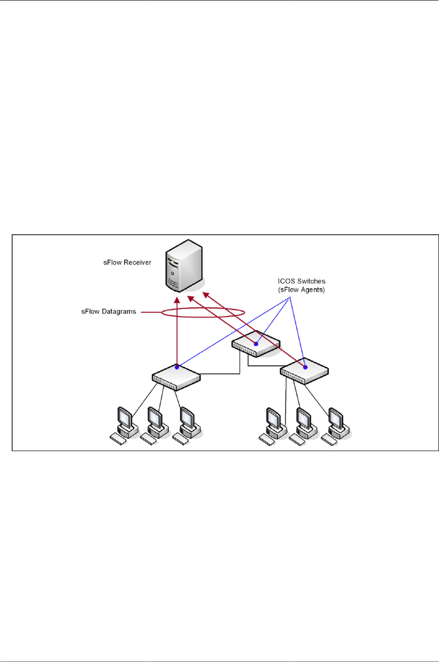
Configuring Switching Features
157
6.11. sFlow
sFlow is an industry standard technology for monitoring high-speed switched and routed networks.
ICOS software has a built-in sFlow agent that can monitor network traffic on each port and gener-
ate sFlow data to an sFlow receiver (also known as a collector). sFlow helps to provide visibility in-
to network activity, which enables effective management and control of network resources. sFlow
is an alternative to the NetFlow network protocol, which was developed by Cisco Systems. The
switch supports sFlow version 5.
As illustrated in figure below, the sFlow monitoring system consists of sFlow Agents (such as
ICOS - based switch) and a central sFlow receiver. sFlow Agents use sampling technology to cap-
ture traffic statistics from monitored devices. sFlow datagrams forward sampled traffic statistics to
the sFlow Collector for analysis. You can specify up to eight different sFlow receivers to which the
switch sends sFlow datagrams.
Figure6.23.sFlow Architecture
The advantages of using sFlow are:
• It is possible to monitor all ports of the switch continuously, with no impact on the distributed
switching performance.
• Minimal memory is required. Samples are not aggregated into a flow-table on the switch; they
are forwarded immediately over the network to the sFlow receiver.
• The sFlow system is tolerant to packet loss in the network because statistical modeling means
the loss is equivalent to a slight change in the sampling rate.
• sFlow receiver can receive data from multiple switches, providing a real-time synchronized view
of the whole network.
• The receiver can analyze traffic patterns based on protocols found in the headers (e.g., TCP/IP,
IPX, Ethernet, AppleTalk…). This alleviates the need for a layer 2 switch to decode and under-
stand all protocols.

Configuring Switching Features
158
6.11.1. sFlow Sampling
The sFlow Agent in the ICOS software uses two forms of sampling:
• Statistical packet-based sampling of switched or routed Packet Flows
• Time-based sampling of counters
Packet Flow Sampling and Counter Sampling are performed by sFlow Instances associated with
individual Data Sources within an sFlow Agent. Both types of samples are combined in sFlow
datagrams. Packet Flow Sampling creates a steady, but random, stream of sFlow datagrams that
are sent to the sFlow Collector. Counter samples may be taken opportunistically to fill these data-
grams.
To perform Packet Flow Sampling, an sFlow Sampler Instance is configured with a Sampling Rate.
Packet Flow sampling results in the generation of Packet Flow Records. To perform Counter Sam-
pling, an sFlow Poller Instance is configured with a Polling Interval. Counter Sampling results
in the generation of Counter Records. sFlow Agents collect Counter Records and Packet Flow
Records and send them as sFlow datagrams to sFlow Collectors.
BCM56960 silicon offers the capability to perform packet sampling in hardware, which is less
CPU-intensive because it does not require sampled packets to be copied to CPU for processing.
ICOS supports sFlow packet sampling in hardware on the BCM56960-based platforms.
6.11.2. Packet Flow Sampling
The Packet Flow Sampling mechanism carried out by each sFlow instance ensures that any pack-
et observed at a Data Source has an equal chance of being sampled, irrespective of the Packet
Flow(s) to which it belongs.
Packet Flow Sampling is accomplished as follows:
• A packet arrives on an interface.
• The Network Device makes a filtering decision to determine whether the packet should be
dropped.
• If the packet is not filtered (dropped), a decision is made on whether or not to sample the pack-
et.
• A decision is made on whether or not to sample the packet. The mechanism involves a counter
that is decremented with each packet. When the counter reaches zero a sample is taken.
• When a sample is taken, the counter indicating how many packets to skip before taking the next
sample is reset. The value of the counter is set to a random integer where the sequence of ran-
dom integers used over time is the Sampling Rate.
6.11.3. Sampling in Hardware
On platforms where sFlow packet sampling is supported in hardware, the hardware can send sam-
pled packets to a configured remote-agent and can copy the sampled packet to the CPU (local
agent). The hardware- sampled packets are encapsulated in custom format (MAC, IPv4, UDP,
sFlow shim headers) and sent to the configured reachable remote agent. A remote agent must be

Configuring Switching Features
159
available in the network to receives the custom packets. The remote agent can extract the sam-
pled packets and send them within standard sFlow datagrams to sFlow receivers.
A configuration parameter can be configured to determine whether sFlow processes the packets
in hardware or copies the sampled packets to software. sFlow in hardware supports three types of
packet sampling: Ingress, Flex, and Egress packet sampling. The Ingress and Flex sampled pack-
ets can be processed by either hardware or software. The hardware also maintains statistics of the
Ingress and Flex sampling counters, (sample pool, sample count, etc.). Flex sampling is enabled
based on the ingress filtering policy (IFP). Egress-sampled packets must always be processed in
software, as this is not supported in hardware. If egress sampling enabled and when the packet
random-number-generated value is less than or equal to the threshold value, the packet is egress
sampled and sent to the host CPU.
The sFlow shim header sent by silicon does not contain information about sampling rate, sam-
pling counters, etc. Thus, the sFlow application sends the configured sampling rate and sampling
counter values information to the remote agent at a regular interval (every 10 seconds by default;
a different value have been specified at compile time). The remote agent might use this informa-
tion while preparing an sFlow standard datagram and send to sFlow receiver/collector.
Software Egress sampling (i.e., egress-sampled packets sent to CPU) works only for
known unicast packets. The software provides the correct destination port informa-
tion. For broadcast and multicast packets, the destination port information cannot be
known. The software identifies the destination port by VLAN ID, so the sFlow applica-
tion cannot create the sample packet.
6.11.4. Counter Sampling
The primary objective of Counter Sampling is to efficiently, periodically export counters associated
with Data Sources. A maximum Sampling Interval is assigned to each sFlow instance associated
with a Data Source.
Counter Sampling is accomplished as follows:
• sFlow Agents keep a list of counter sources being sampled.
• When a Packet Flow Sample is generated the sFlow Agent examines the list and adds counters
to the sample datagram, least recently sampled first. Counters are only added to the datagram
if the sources are within a short period, 5 seconds say, of failing to meet the required Sampling
Interval.
• Periodically, say every second, the sFlow Agent examines the list of counter sources and sends
any counters that must be sent to meet the sampling interval requirement.
The set of counters is a fixed set.
6.11.5. Configuring sFlow in Software
This example shows how to configure the switch so that ports 10-15 and port 23 send sFlow data-
grams to an sFlow receiver at the IP address 192.168.20.34. The receiver owner is receiver1, and
the timeout is 100000 seconds. A counter sample is generated on the ports every 60 seconds
(polling interval), and 1 out of every 8192 packets is sampled.
To configure the switch:

Configuring Switching Features
160
1. Configure information about the sFlow receiver.
(Routing) #configure
(Routing) (Config)#sflow receiver 1 ip 192.168.20.34
(Routing) (Config)#sflow receiver 1 owner receiver1 timeout 100000
2. Configure the polling and sampling information for ports 10–15.
(Routing) (Config)#interface 0/10-0/15
(Routing) (Interface 0/10-0/15)#sflow poller 1
(Routing) (Interface 0/10-0/15)#sflow poller interval 60
(Routing) (Interface 0/10-0/15)#sflow sampler 1
(Routing) (Interface 0/10-0/15)#sflow sampler rate 8192
(Routing) (Interface 0/10-0/15)#exit
3. Configure the polling and sampling information for port 23.
(Routing) (Config)#interface 0/23
(Routing) (Interface 0/23)#sflow poller 1
(Routing) (Interface 0/23)#sflow poller interval 60
(Routing) (Interface 0/23)#sflow sampler 1
(Routing) (Interface 0/23)#sflow sampler rate 8192
(Routing) (Interface 0/23)#exit
4. Verify the configured information.
(Routing) #show sflow receivers 1
Receiver Index. ................................ 1
Owner String................................... receiver1
Time out....................................... 99400
IP Address:. ................................... 192.168.20.34
Address Type. .................................. 1
Port........................................... 6343
Datagram Version. .............................. 5
Maximum Datagram Size. ......................... 1400
(Routing) #show sflow pollers
Poller Receiver Poller
Data Source Index Interval
----------- ------- -------
0/10 1 60
0/11 1 60
0/12 1 60
0/13 1 60
0/14 1 60
0/15 1 60
0/23 1 60
(Routing) #show sflow samplers
Sampler Receiver Packet Max Header
Data Source Index Sampling Rate Size
----------- ------- ------------- ----------
0/10 1 8192 128

Configuring Switching Features
161
0/11 1 8192 128
0/12 1 8192 128
0/13 1 8192 128
0/14 1 8192 128
0/15 1 8192 128
0/23 1 8192 128
6.11.6. Configuring sFlow in Hardware
This example shows how to configure the switch so that ports 10–15 and port 23 send sFlow data-
grams to an sFlow remote agent at the IP address 192.168.20.34 using port 22 as destination in-
terface. A sample is generated on the ports for 1 out of every 8192 packets and is mirrored to port
22.
To configure the switch:
1. Configure information for the sFlow receiver:
(Routing) #configure
(Routing) (Config)#sflow remote-agent 1 ip 192.168.20.34
(Routing) (Config)# sflow remote-agent 1 monitor-session 1 destination
Interface 1/0/22
2. Configure the polling and sampling information for ports 10–15:
(Routing) (Config)#interface 0/10-0/15
(Routing) (Interface 0/10-0/15)#sflow sampler remote-agent 1
(Routing) (Interface 0/10-0/15)#sflow sampler rate 8192
(Routing) (Interface 0/10-0/15)#exit
3. Configure the polling and sampling information for port 23:
(Routing) (Config)#interface 0/23
(Routing) (Interface 0/23)#sflow sampler remote-agent 1
(Routing) (Interface 0/23)#sflow sampler rate 8192
(Routing) (Interface 0/23)#exit
4. Verify the configured information:
(Routing) #show sflow remote-agents 1
Remote Agent Index ............................. 1
IP Address:. ................................... 0.0.0.0
Port........................................... 16343
Monitor Session Id ............................. 2
Destination port .............................. 1/0/2
(continued on next page)
(Routing) #show sflow samplers
Sampler Receiver Remote Ingress Flow Egress Max IP MAC
Data Index Agent Sampling Sampling Sampling Header ACL ACL
Source Index Rate Rate Rate Size
------- -------- ------ -------- -------- -------- ------ ------ ----
0/10 1 8192 0 0 128

Configuring Switching Features
162
0/11 1 8192 0 0 128
0/12 1 8192 0 0 128
0/13 1 8192 0 0 128
0/14 1 8192 0 0 128
0/15 1 8192 0 0 128
0/23 1 8192 0 0 128
Configuring Switching Features
163
6.12. Link Dependency
The following commands configure a link-dependency group.
1. Create a link dependency group with group ID 100. This command also configures whether the
downstream interfaces should mirror or invert the status of upstream interfaces. The action up
command causes the downstream interfaces to be up when no upstream interfaces are down.
(Routing) #configure
(Routing) (Config)#link state group 100 action down
2. Configure ports as link-dependency group members. Port 0/8 is configured as an upstream
member of the group and ports 0/3 and 0/5 are configured as downstream members. The state
of downstream members is dependent on the state of the upstream member.
Circular dependencies are not allowed. An interface that is defined as an upstream interface can-
not also be defined as a downstream interface in the same link state group. An interface that is de-
fined as an upstream interface cannot also be defined as a downstream interface in a different link
state group, when such configuration creates a circular dependency between groups.
(Routing) (Config)#interface 0/8
Adding an interface as a downstream port brings the interface down until an upstream
interface is added to the group. The link status will then follow the interface specified
in the upstream command. To avoid bringing down interfaces, configure the upstream
port prior to configuring the downstream ports.
(Routing) (Interface 0/8)#link state group 100 upstream
(Routing) (Interface 0/8)#exit
(Routing) (Config)#interface 0/3, 0/5
(Routing) (Interface 0/3,0/5)#link state group 100 downstream
(Routing) (Interface 0/3,0/5)#exit
To view link dependency settings for all groups or for the specified group, along with the group
state, use the commands show link state group [group_id] and show link state group group-
id detail.

Configuring Switching Features
164
6.13. RA Guard
The following example configures IPv6 RA Guard on a host connected port. The policy drops all
incoming RA and router redirect messages received on the port.
(Switching)#config
(Switching)(config)#interface 1/0/1
(Switching)(Interface 1/0/1)#ipv6 nd raguard attach-policy
(Switching) (Interface 1/0/1)#show ipv6 nd raguard policy Ipv6
RA-Guard Configured Interfaces
Interface Role
--------------- -------
1/0/1 Host

Configuring Switching Features
165
6.14. FIP Snooping
FIP snooping is a frame inspection method used by the ICOS FIP Snooping Bridge to monitor FIP
frames and apply policies based on the L2 header information in those frames, following recom-
mendations in Annex C of FC_BB_5 Rev 2.00.
FIP Snooping enables the following features:
• Auto-configuration of Ethernet ACLs based on information in the Ethernet headers of FIP
frames.
• Emulation of fibre channel (FC) point-to-point links within the DCB Ethernet network.
• Enhanced FCoE security/robustness by preventing FCoE MAC spoofing.
The FIP Snooping Bridge solution in ICOS is intended for use only at the edge or perimeter of the
switched network and not on an interior switch.
To configure FIP snooping:
1. For ports connected to CNAs/ENodes, enable LLDP and DCBX and configure them as DCBX
auto-down ports. In this example, the ports connected to the CNAs/ENodes are ports 0/9 and
0/10.
(Routing) #config
(Routing) (Config)#interface 0/9-0/10
(Routing) (Interface 0/9-0/10)#lldp transmit
(Routing) (Interface 0/9-0/10)#lldp receive
(Routing) (Interface 0/9-0/10)#lldp dcbx port-role auto-down
(Routing) (Interface 0/9-0/10)#exit
2. For ports connected to the FCoE Forwarders (FCFs, Cisco Nexus 5010/5548), enable LLDP
and DCBX and configure these ports as DCBX auto-up ports. In this example, the port connect-
ed to the FCF is port 0/11.
(Routing) (Config)#interface 0/11
(Routing) (Interface 0/11)#lldp transmit
(Routing) (Interface 0/11)#lldp receive
(Routing) (Interface 0/11)#lldp dcbx port-role auto-up
(Routing) (Interface 0/11)#exit
3. In Global Config mode, configure one-to-one global dot1p mapping.
(Routing) (Config)#classofservice dot1p-mapping 0 0
(Routing) (Config)#classofservice dot1p-mapping 1 1
(Routing) (Config)#classofservice dot1p-mapping 2 2
(Routing) (Config)#classofservice dot1p-mapping 3 3
(Routing) (Config)#classofservice dot1p-mapping 4 4
(Routing) (Config)#classofservice dot1p-mapping 5 5
(Routing) (Config)#classofservice dot1p-mapping 6 6
(Routing) (Config)#exit
4. Create the FCoE VLAN. In this example, FCoE VLAN ID is 1000.

Configuring Switching Features
166
(Routing) #vlan database
(Routing) (Vlan)#vlan 1000
(Routing) (Vlan)#exit
5. Add VLAN 1000 membership to the ports connected to CNAs and FCF. Enable VLAN tagging
on these ports for FCoE VLAN using below interface commands.
(Routing) #config
(Routing) (Config)#interface 0/9-0/11
(Routing) (Interface 0/9-0/11)#vlan participation include 1000
(Routing) (Interface 0/9-0/11)#vlan tagging 1000
(Routing) (Interface 0/9-0/11)#exit
(Routing) (Config)#exit
6. Enable FIP snooping in FCoE VLAN 1000. Also enable FIP snooping in VLAN 1 to allow FIP
VLAN discovery to happen in untagged mode.
(Routing) #configure
(Routing) (Config)#feature fip-snooping
(Routing) (Config)#vlan 1,1000
(Routing) (Config)(Vlan 1,1000)#fip-snooping enable
(Routing) (Config)(Vlan 1,1000)#exit
(Routing) (Config)#exit
7. Configure FCF facing ports using below interface command. By default, FIP snooping ports are
configured as host/ENode mode.
(Routing) #configure
(Routing) (Config)#interface 0/11
(Routing) (Interface 0/11)#fip-snooping port-mode fcf
(Routing) (Interface 0/11)#exit
(Routing) (Config)#exit
The following code sample shows the configuration script for the FIP snooping switch configured in
the example. Two interfaces (0/9 and 0/10) are connected to CNAs, and 0/11 is connected to CIS-
CO Nexus 5010 FCF.
(Routing) #vlan database
(Routing) (Vlan)#vlan 1000
(Routing) (Vlan)#exit
(Routing) #configure
(Routing) (Config)#feature fip-snooping
(Routing) (Config)#vlan 1,1000
(Routing) (Config)(Vlan 1,1000)#fip-snooping enable
(Routing) (Config)(Vlan 1,1000)#exit
(Routing) (Config)#classofservice dot1p-mapping 0 0
(Routing) (Config)#classofservice dot1p-mapping 1 1
(Routing) (Config)#classofservice dot1p-mapping 2 2
(Routing) (Config)#classofservice dot1p-mapping 3 3
(Routing) (Config)#classofservice dot1p-mapping 4 4
(Routing) (Config)#classofservice dot1p-mapping 5 5
(Routing) (Config)#classofservice dot1p-mapping 6 6

Configuring Switching Features
167
(Routing) (Config)#interface 0/9
(Routing) (Interface 0/9)#description 'Brocade CNA'
(Routing) (Interface 0/9)#vlan participation include 1000
(Routing) (Interface 0/9)#vlan tagging 1000
(Routing) (Interface 0/9)#vlan priority 3
(Routing) (Interface 0/9)#lldp transmit
(Routing) (Interface 0/9)#lldp receive
(Routing) (Interface 0/9)#lldp dcbx port-role auto-down
(Routing) (Interface 0/9)#exit
(Routing) (Config)#interface 0/10
(Routing) (Interface 0/10)#description 'Broadcom CNA'
(Routing) (Interface 0/10)#vlan participation include 1000
(Routing) (Interface 0/10)#vlan tagging 1000
(Routing) (Interface 0/10)#vlan priority 3
(Routing) (Interface 0/10)#lldp transmit
(Routing) (Interface 0/10)#lldp receive
(Routing) (Interface 0/10)#lldp dcbx port-role auto-down
(Routing) (Interface 0/10)#exit
(Routing) (Config)#interface 0/11
(Routing) (Interface 0/11)#description 'CISCO Nx5010-FCF Facing'
(Routing) (Interface 0/11)#vlan participation include 1000
(Routing) (Interface 0/11)#vlan tagging 1000
(Routing) (Interface 0/11)#vlan priority 3
(Routing) (Interface 0/11)#fip-snooping port-mode fcf
(Routing) (Interface 0/11)#lldp transmit
(Routing) (Interface 0/11)#lldp receive
(Routing) (Interface 0/11)#lldp dcbx port-role auto-up
(Routing) (Interface 0/11)#exit
(Routing) (Config)#exit

Configuring Switching Features
168
6.15. ECN
Explicit Congestion Notification (ECN) is defined in RFC 3168. Conventional TCP networks sig-
nal congestion by dropping packets. A Random Early Discard scheme provides earlier notification
than a tail drop scheme by dropping packets already queued for transmission. ECN marks con-
gested packets that would otherwise have been dropped and expects an ECN-capable receiver to
signal congestion back to the transmitter without the need to retransmit the packet that would have
been dropped. For TCP, this means that the TCP receiver signals a reduced window size to the
transmitter but does not request retransmission of the CE marked packet.
ECN uses the two least significant bits of Diffserv field (TOS octet in IPv4/Traffic Class octet in
IPv6) and codes them as follows:
00: Non ECN-Capable Transport – Non-ECT
10: ECN Capable Transport – ECT(0)
01: ECN Capable Transport – ECT(1)
11: Congestion Encountered – CE
ECN-capable hosts communicate support for ECN via two flags in the TCP header:
• ECN-Echo (ECE)
• Congestion Window Reduced (CWR)
ICOS WRED considers packets for early discard only when the number of packets queued for
transmission on a port exceeds the relevant minimum WRED threshold. The green, yellow, red
thresholds operate on TCP packets. The fourth threshold operates on non-TCP packets.
When ECN is enabled and congestion is experienced, TCP packets that are marked ECN Capable
that are queued for transmission and are selected for discarded by WRED, are instead marked CE
and transmitted. This includes packets that exceed the WRED upper threshold. If the switch expe-
riences severe congestion (no buffers available), then packets are discarded.
WRED considers packets for early discard only when the number of packets queued for transmis-
sion on a port exceeds the relevant minimum WRED threshold. Four thresholds are available for
configuration. The green, yellow, and red thresholds operate on TCP packets. The fourth threshold
operates on non-TCP packets.
When ECN is enabled and congestion is experienced, packets that are marked ECN-capable, are
queued for transmission, and are randomly selected for discard by WRED are instead marked
CE and are transmitted rather than dropped. This includes packets that exceed the WRED upper
threshold. If the switch experiences severe congestion (no buffers available), then packets are dis-
carded.
ICOS implements ECN capability as part of the WRED configuration process. Eligible packets are
marked by hardware based on the WRED configuration. The network operator can configure any
CoS queue to operate in ECN marking mode and can configure different discard thresholds for
each color.

Configuring Switching Features
169
6.15.1. Enabling ECN in Microsoft Windows
On many current Windows implementations, ECN capability is enabled via the netsh command as
follows:
netsh int tcp set global ecncapability=enabled
The capability can be verified with the following command:
netsh int tcp show global.
An example is shown below:
C:\Users\user1>Netsh int tcp set global ecncapability=enabled Ok.
C:\Users\user1>netsh int tcp show global Querying active state...
TCP Global Parameters
----------------------------------------------
Receive-Side Scaling State : enabled
Chimney Offload State : automatic
NetDMA State : enabled
Direct Cache Acess (DCA) : disabled
Receive Window Auto-Tuning Level : normal
Add-On Congestion Control Provider : none
ECN Capability : enabled
RFC 1323 Timestamps : disabled
In Windows Server 2012, DCTCP is self-activating based on the RTT of TCP packets. No user
management is required. Use the PowerShell cmdlet Get-NetTcpConnection to verify DCTCP op-
eration.
6.15.2. Example 1: SLA Example
The following example configures simple meter and a trTCM meter in support of a network SLA.
The SLA classes are segregated by CoS class.
1. Define a class-map so that all traffic will be in the set of traffic “cos-any”.
(Routing) (Config)#class-map match-all cos-any ipv4
(Routing) (Config-classmap)#match any
(Routing) (Config-classmap)#exit
2. Define a class-map such that all traffic with a Cos value of 1 will be in the set of traffic “cos1”.
This will be used as a conform-color class map. Conform-color class maps must be one of CoS,
secondary CoS, DSCP, or IP precedence.
(Routing) (Config)#class-map match-all cos1 ipv4
(Routing) (Config-classmap)#match cos 1
(Routing) (Config-classmap)#exit
3. Define a class-map such that all IPv4 traffic with a CoS value of 0 will be in the set of traffic
“cos0”. This will be used as a conform-color class map. Conform-color class maps must be one
of CoS, secondary CoS, DSCP, or IP precedence.
(Routing) (Config)#class-map match-all cos0 ipv4

Configuring Switching Features
170
(Routing) (Config-classmap)#match cos 0
(Routing) (Config-classmap)#exit
4. Define a class-map such that all TCP will be in the set of traffic “TCP”. This will be used as a
base color class for metering traffic.
(Routing) (Config)#class-map match-all tcp ipv4
(Routing) (Config-classmap)#match protocol tcp
(Routing) (Config-classmap)#exit
5. Define a policy-map to include packets matching class “cos-any” (IPv4). Ingress IPv4 traffic ar-
riving at a port participating in this policy will be assigned red or green coloring based on the
metering.
(Routing) (Config)#policy-map simple-policy in
(Routing) (Config-policy-map)#class cos-any
6. Create a simple policer in color blind mode. Packets below the committed information rate (CIR)
or committed burst size (CBS) are assigned drop precedence “green”. Packets that exceed the
CIR (in Kbps) or CBS (in Kbytes) are colored “red”. Both the conform and violate actions are set
to transmit as WRED is used to drop packets when congested.
(Routing) (Config-policy-classmap)#police-simple 10000000 64
conform-action transmit violate-action transmit
(Routing) (Config-policy-classmap)#exit
(Routing) (Config-policy-map)#exit
7. Define a policy-map in color aware mode matching class “cos-any” (IPv4). Ingress IPv4 traffic
arriving at a port participating in this policy will be assigned green, yellow, or red coloring based
on the meter.
(Routing) (Config)#policy-map two-rate-policy in
(Routing) (Config-policy-map)#class tcp
8. Create a two-rate policer per RFC 2698. The CIR value is 800 Kbps and the CBS is set to 96
Kbytes. The PIR is set to 950 Kbps and the PBS is set to 128 Kbytes. Color-aware processing
is enabled via the conform-color command (i.e., any packets not in cos 0 or 1 are pre-colored
“red”). Packets in cos 0 are pre-colored yellow. Packets in cos 1 are pre-colored green. Pre-col-
oring gives greater bandwidth to cos 1 packets, as they are initially subject to the CIR/CBS lim-
its. Packets in CoS 0 are subject to the PIR limits. Based on the CIR/CBD, the PIR/PBS, and
the conform, exceed, and violate actions specified below.
TCP packets with rates less than or equal to the CIR/CBS in class cos 1 are conforming to the
rate (green). These packets will be dropped randomly at an increasing rate between 0–3%
when the outgoing interface is congested between 80 and 100%.
TCP packets with rates above the CIR/CBS and less than or equal to PIR/PBS in either class
cos 1 or class cos 2 are policed as exceeding the CIR (yellow). These packets will be dropped
randomly at an increasing rate between 0–5% when the outgoing interface is congested be-
tween 70 and 100%. TCP packets with rates higher than the PIR/PBS or which belong to nei-
ther class cos 1 nor class cos 2 are violating the rate (red).
These packets will be dropped randomly at an increasing rate between 0–10% when the outgo-
ing interface is congested between 50 and 100%.

Configuring Switching Features
171
Non-TCP packets in CoS queue 0 or 1 will be dropped randomly at an increasing rate between
0–15% when the outgoing interface is congested between 50 and 100%.
(Routing) (Config-policy-classmap)#police-two-rate 800 96 950 128
conform-action transmit exceedaction transmit violate-action transmit
conform-color cos1 exceed-color cos0
(Routing) (Config-policy-classmap)#exit
(Routing) (Config-policy-map)#exit
9. Enable WRED drop on traffic classes 0 and 1.
(Routing) (Config)#cos-queue random-detect 0 1
10.Set the exponential-weighting-constant. The exponential weighting constant smooths the result
of the average queue depth calculation by the function:
average depth = (previous queue depth * (1-1/2n)) + (current queue depth * 1/2n).
The average depth is used in calculating the amount of congestion on a queue. Because the in-
stantaneous queue depth fluctuates rapidly, larger values of the weighting constant cause the
average queue depth value to respond to changes more slowly than smaller values.
(Routing) (Config)#random-detect exponential-weighting-constant 4
11.Configure the queue parameters for traffic class 0 and 1. We set the minimum threshold and
maximum thresholds to 80–100% for green traffic, 70–100% for yellow traffic, and 50–100% for
red traffic. Non-TCP traffic drops in the 50–100% congestion range. Green traffic is dropped at
a very low rate to slowly close the TCP window. Yellow and red traffic are dropped more ag-
gressively.
(Routing) (Config)#random-detect queue-parms 0 1 min-thresh 80 70 50 50
max-thresh 100 100 100
100 drop-prob-scale 3 5 10 15
12.Assign the color policies to ports. The metering policies are applied on ingress ports.
(Routing) (Config)#interface 0/22
(Routing) (Interface 0/22)#service-policy in simple-policy
(Routing) (Interface 0/22)#exit
(Routing) (Config)#interface 0/23
(Routing) (Interface 0/23)#service-policy in two-rate-policy
(Routing) (Interface 0/23)#exit
6.15.3. Example 2: Data Center TCP (DCTCP) Configu-
ration
This example globally configures an ICOS switch to utilize ECN marking of green packets queued
for egress on CoS queues 0 and 1, using the DCTCP threshold as it appears in “DCTCP: Efficient
Packet Transport for the Commoditized Data Center” (Alizadeh, Greenberg, Maltz, Padhye, Patel,
Prabhakar, Sengupta, and Sridharan, 2010.)

Configuring Switching Features
172
In the first line of the following configuration, the first integer after the minthresh keyword config-
ures green- colored Congestion Enabled TCP packets in CoS queues 0 and 1 that exceed the
WRED threshold (13% or ~38 Kbytes) to mark packets as Congestion Experienced. The first in-
teger after the max-thresh parameter configures the upper threshold for green-colored TCP pack-
ets to the same value as the min-thresh threshold. This causes the switch to mark all ECN-capa-
ble queued packets as Congestion Experienced when the threshold is reached or exceeded. TCP
packets without ECN capability bits set are dropped according to the normal WRED processing
when the threshold is exceeded. Packets on other CoS queues are handled in the standard man-
ner (i.e., are tail-dropped) when insufficient buffer is available.
Yellow and red packet configuration (second and third threshold parameters) are kept at the de-
faults, as no metering to reclassify packets from green to yellow or red is present. The last thresh-
old parameter configures non-TCP packets in CoS queues 0 and 1 to be processed with the
WRED defaults. The ecn keyword enables ECN marking of ECN-capable packets on CoS queues
0 and 1. The weighting constant is set to 0 in the second line of the configuration, as described in
the DCTCP paper cited above. Finally, CoS queues 0 and 1 are configured for WRED in the last
line of the configuration.
(Routing) #config
(Routing) (Config)#random-detect queue-parms 0 1 min-thresh 13 30 20 100
max-thresh 13 90 80 100
drop-prob-scale 100 10 10 10 ecn
(Routing) (Config)#random-detect exponential-weighting-constant 0
(Routing) (Config)#cos-queue random-detect 0 1

173
Chapter 7. Configuring Data Center
Features

Configuring Data Center Features
174
7.1. Data Center Technology Overview
The Data Center features and commands in this section are platform-dependent.
ICOS software supports Data Center Bridging (DCB) features to increase the reliability of Ether-
net-based networks in the data center. The Ethernet enhancements that DCB provides are well
suited for Fibre Channel over Ethernet (FCoE) environments.
Table below provides a summary of the features this section describes.
Table7.1.DCB Features
Feature Description
PFC Provides a way to distinguish which traffic on a physical link is
paused when congestion occurs based on the priority of the traffic.
See Section 7.2, “Priority-Based Flow Control”
DCBX Allows DCB devices to exchange configuration information, using
type-length-value (TLV) information elements over LLDP, with di-
rectly connected peers. See Section 7.3, “Data Center Bridging Ex-
change Protocol”
CoS Queuing Allows the switch administrator to directly configure certain aspects
of device queuing to provide the desired QoS behavior for different
types of network traffic when the complexities of DiffServ are not re-
quired. See Section 7.4, “CoS Queuing”
ETS Supports the ETS configuration and Application Priority TLVs, which
are accepted from auto- upstream devices and propagated to au-
to-downstream devices. See Section 7.5, “Enhanced Transmission
Selection”
QCN Manages end-to-end congestion by enabling bridges to signal con-
gestion information to end stations capable of transmission rate lim-
iting to avoid frame loss. VLAN tag-encoded priority values are allo-
cated to segregate frames subject to congestion control, allowing si-
multaneous support for both congestion control and other higher lay-
er protocols This feature is not supported on all platforms. See Sec-
tion 7.6, “Quantized Congestion Notification (QCN)”
OpenFlow The OpenFlow feature enables the switch to be managed by a cen-
tralized OpenFlow Controller using the OpenFlow protocol. See Sec-
tion 7.7, “OpenFlow Operation and Configuration”
DCVPN Gateway Enables VXLAN and NVGRE network virtualization technologies
to communicate with another network, particularly a VLAN. It offers
VTEP functionality for VXLAN and NVE functionality for NVGRE tun-
nels on the switch. See Section 7.8, “DCVPN Gateway Operation
and Configuration”
MPLS Provides a technique for forwarding data between network nodes
using short MPLS-assigned path labels instead of long network ad-
dresses associated with the underlying forwarding protocol. MPLS


Configuring Data Center Features
176
7.2. Priority-Based Flow Control
Ordinarily, when flow control is enabled on a physical link, it applies to all traffic on the link. When
congestion occurs, the hardware sends pause frames that temporarily suspend traffic flow to help
prevent buffer overflow and dropped frames.
PFC provides a means of pausing individual priorities within a single physical link. By pausing the
congested priority or priorities independently, protocols that are highly loss-sensitive can share the
same link with traffic that has different loss tolerances.
This feature is used in networks where the traffic has differing loss tolerances. For example, Fibre
Channel traffic is highly sensitive to traffic loss. If a link contains both loss-sensitive data and oth-
er less loss-sensitive data, the loss-sensitive data should use a no-drop priority that is enabled for
flow control.
Priorities are differentiated by the priority field of the IEEE 802.1Q VLAN header, which identifies
an IEEE 802.1p priority value. These priority values must be mapped to internal class-of-service
(CoS) values.
The PFC feature allows you to specify the CoS values that should be paused (due to greater loss
sensitivity) instead of dropped when congestion occurs on a link. Unless configured as no-drop,
all CoS priorities are considered non-pausable (“drop”) when priority-based flow control is enabled
until no-drop is specifically turned on.
7.2.1. PFC Operation and Behavior
PFC uses a new control packet defined in IEEE 802.1Qbb and therefore is not compatible with
IEEE 802.3 Annex 31B flow control. An interface that is configured for PFC will be automatically
disabled for flow control. When PFC is disabled on an interface, the flow control configuration for
the interface becomes active. Any flow control frames received on a PFC configured interface are
ignored.
Each priority is configured as either drop or no-drop. If a priority that is designated as no-drop is
congested, the priority is paused. Drop priorities do not participate in pause. You must configure
the same no-drop priorities across the network in order to ensure end-to-end lossless behavior.
Operator configuration of PFC is used only when the port is configured in a manual role. When in-
teroperating with other equipment in a manual role, the peer equipment must be configured with
identical PFC priorities and VLAN assignments. Interfaces not enabled for PFC ignore received
PFC frames. Ports configured in auto- upstream or auto-downstream roles receive their PFC con-
figuration from the configuration source and ignore any manually-configured information.
This feature is configurable on physical full duplex interfaces only. To enable PFC on
a LAG interface, the member interfaces must have the same configuration.
When PFC is disabled, the interface defaults to the IEEE 802.3 flow control setting for the inter-
face. PFC is disabled by default.
If you enable priority-based flow control for a particular priority value on an interface, make sure
802.1p priority values are mapped to CoS values (see Section 10.2, “CoS”).

Configuring Data Center Features
177
7.2.2. Configuring PFC
The network in this example handles standard data traffic and traffic that is time sensitive (such
as voice and video). The time-sensitive traffic requires a higher priority than standard data traffic.
All time-sensitive traffic is configured to use VLAN 100 and has an 802.1p priority of 5, which is
mapped to hardware queue 4. The hosts that frequently send and receive the time-sensitive traffic
are connected to ports 3, 5, and 10, so PFC is enabled on these ports with 802.1p priority 5 traffic
as no-drop. The configuration also enables VLAN tagging so that the 802.1p priority is identified.
This example assumes that VLAN 100 has already been configured.
All ports may be briefly shutdown when modifying either flow control or PFC settings.
PFC uses a control packet defined in 802.1Qbb and is not compatible with 802.3x FC.
1. Map 802.1p priority 5 to traffic class 4. For more information about traffic classes, see Sec-
tion 10.2, “CoS”
(Routing) #configure
(Routing) (Config)#classofservice dot1p-mapping 5 4
2. Enter Interface Configuration mode for ports 3, 5, and 10.
(Routing) (Config)#interface 0/3,0/5,0/10
3. Enable PFC and configure traffic marked with 802.1p priority 5 to be paused rather than
dropped when congestion occurs.
(Routing) (Interface 0/3,0/5,0/10)#datacenter-bridging
(Routing) (Config-if-dcb)#priority-flow-control mode on
(Routing) (Config-if-dcb)#priority-flow-control priority 5 no-drop
4. Enable VLAN tagging on the ports so the 802.1p priority is identified.
(Routing) (Interface 0/3,0/5,0/10)#vlan participation include 100
(Routing) (Interface 0/3,0/5,0/10)#vlan tagging 100
(Routing) (Interface 0/3,0/5,0/10)#exit

Configuring Data Center Features
178
7.3. Data Center Bridging Exchange Protocol
The Data Center Bridging Exchange Protocol (DCBX) is used by DCB devices to exchange con-
figuration information with directly connected peers. DCBX uses type-length-value (TLV) informa-
tion elements over LLDP to exchange information, so LLDP must be enabled on the port to enable
the information exchange. By default, LLDP is enabled on all ports. For more information, see Sec-
tion 6.10, “LLDP and LLDP-MED”
The main objective of DCBX is to perform the following operations:
• Discovery of DCB capability in a peer: DCBX is used to learn about the capabilities of the peer
device. It is a means to determine if the peer device supports a particular feature such as PFC.
• DCB feature misconfiguration detection: DCBX can be used to detect misconfiguration of a fea-
ture between the peers on a link. Misconfiguration detection is feature-specific because some
features may allow asymmetric configuration.
• Peer configuration of DCB features: DCBX can be used by a device to perform configuration of
DCB features in its peer device if the peer device is willing to accept configuration.
DCBX is expected to be deployed in Fibre Channel over Ethernet (FCoE) topologies in support of
lossless operation for FCoE traffic. In these scenarios, all network elements are DCBX enabled. In
other words, DCBX is enabled end-to-end.
The DCBX protocol supports the propagation of configuration information for the following fea-
tures:
• Enhanced Transmission Selection (ETS)
• Priority-based Flow Control (PFC)
• Application Priorities
These features use DCBX to send and receive device configuration and capability information to
the peer DCBX device.
The Application Priorities information is simply captured from the peer and potentially propagated
to other peers by the DCBX component.
7.3.1. Interoperability with IEEE DCBX
To be interoperable with legacy industry implementations of DCBX protocol, ICOS software uses
a hybrid model to support both the IEEE version of DCBX (IEEE 802.1Qaz) and legacy DCBX ver-
sions.
ICOS software automatically detects if a peer is operating with either of the two CEE DCBX ver-
sions or the IEEE standard DCBX version. This is the default mode. You can also configure DCBX
to manually select one of the legacy versions or IEEE standard mode. In auto-detect mode, the
switch starts operating in IEEE DCBX mode on a port, and if it detects a legacy DCBX device
based on the OUI of the organization TLV, then the switch changes its DCBX mode on that port to
support the version detected. There is no timeout mechanism to move back to IEEE mode. Once
the DCBX peer times out, multiple peers are detected, the link is reset (link down/up) or as com-
manded by the operator, DCBX resets its operational mode to IEEE.

Configuring Data Center Features
179
The interaction between the DCBX component and other components remains the same irrespec-
tive of the operational mode it is executing. For instance DCBX component interacts with PFC to
get needed information to pack the TLVs to be sent out on the interface. Based on the operational
control mode of the port, DCBX packs it in the proper frame format.
7.3.2. DCBX and Port Roles
Each port’s behavior is dependent on the operational mode of that port and of other ports in the
switch. The port mode is a DCBX configuration item that is passed to the DCBX clients to control
the processing of their configuration information. There are four port roles:
• Manual
• Auto-Upstream
• Auto-Downstream
• Configuration Source
Ports operating in the manual role do not have their configuration affected by peer devices or by
internal propagation of configuration. These ports have their operational mode, traffic classes, and
bandwidth information specified explicitly by the operator. These ports advertise their configura-
tion to their peer if DCBX is enabled on that port. Incompatible peer configurations are logged and
counted with an error counter.
The default operating mode for each port is manual. A port that is set to manual mode sets the will-
ing bit for DCBX client TLVs to false. Manually-configured ports never internally propagate or ac-
cept internal or external configuration from other ports, in other words, a manual configuration dis-
cards any automatic configuration.
Manually-configured ports may notify the operator of incompatible configurations if client configura-
tion exchange over DCBX is enabled. Manually-configured ports are always operationally enabled
for DCBX clients, regardless of whether DCBX is enabled. Operationally enabled means that the
port reports that it is able to operate using the current configuration.
A port operating in the auto-upstream role advertises a configuration, but it is also willing to ac-
cept a configuration from the link-partner and propagate it internally to the auto-downstream ports
as well as receive configuration propagated internally by other auto-upstream ports. Specifical-
ly, the willing parameter is enabled on the port and the recommendation TLV is sent to the peer
and processed if received locally. The first auto- upstream port to successfully accept a compati-
ble configuration becomes the configuration source. The configuration source propagates its con-
figuration to other auto-upstream and auto-downstream ports. Only the configuration source may
propagate configuration to other ports internally. Auto-upstream ports that receive internally propa-
gated information ignore their local configuration and utilize the internally propagated information.
Peer configurations received on auto-upstream ports other than the configuration source result in
one of two possibilities. If the configuration is compatible with the configuration source, then the
DCBX client becomes operationally active on the upstream port. If the configuration is not compat-
ible with the configuration source, then a message is logged indicating an incompatible configu-
ration, an error counter is incremented, and the DCBX client is operationally disabled on the port.
The expectation is that the network administrator configures the upstream devices appropriately so
that all such devices advertise a compatible configuration.

Configuring Data Center Features
180
A port operating in the auto-downstream role advertises a configuration but is not willing to accept
one from the link partner. However, the port will accept a configuration propagated internally by the
configuration source.
Specifically, the willing parameter is disabled on auto-downstream. By default, auto-downstream
ports have the recommendation TLV parameter enabled. Auto-downstream ports that receive in-
ternally propagated information ignore their local configuration and utilize the internally propagated
information. Auto-downstream ports propagate PFC, ETS, and application priority information re-
ceived from the configuration source.
In the Configuration Source role, the port has been manually selected to be the configuration
source. Configuration received over this port is propagated to the other auto-configuration ports,
however, no automatic election of a new configuration source port is allowed. Events that cause
selection of a new configuration source are ignored. The configuration received over the configura-
tion source port is maintained until cleared by the operator (set the port to the manual role).
7.3.3. Configuration Source Port Selection Process
When an auto-upstream or auto-downstream port receives a configuration from a peer, the DCBX
client first checks if there is an active configuration source. If there is a configuration source al-
ready selected, the received configuration is checked against the local port operational values as
received from the configuration source, and if compatible, the client marks the port as operationally
enabled. If the configuration received from the peer is determined to not be compatible, a message
is logged, an error counter is incremented and the DCBX clients become operationally disabled on
the port. Operationally disabled means that PFC will not operate over the port. The port continues
to keep link up and exchanges DCBX packets. If a compatible configuration is later received, the
DCBX clients will become operationally enabled.
If there is no configuration source, a port may elect itself as the configuration source on a first-
come, first-serve basis from the set of eligible ports. A port is eligible to become the configuration
source if the following conditions are true:
• No other port is the configuration source.
• The port role is auto-upstream.
• The port is enabled with link up and DCBX enabled.
• The port has negotiated a DCBX relationship with the partner.
• The switch is capable of supporting the received configuration values, either directly or by trans-
lating the values into an equivalent configuration.
Whether or not the peer configuration is compatible with the configured values is NOT considered.
The newly elected configuration source propagates DCBX client information to the other ports and
is internally marked as being the port over which configuration has been received. Configuration
changes received from the peer over the configuration source port are propagated to the other au-
to-configuration ports. Ports receiving auto-configuration information from the configuration source
ignore their current settings and utilize the configuration source information.
When a configuration source is selected, all auto-upstream ports other than the configuration
source are marked as willing disabled.
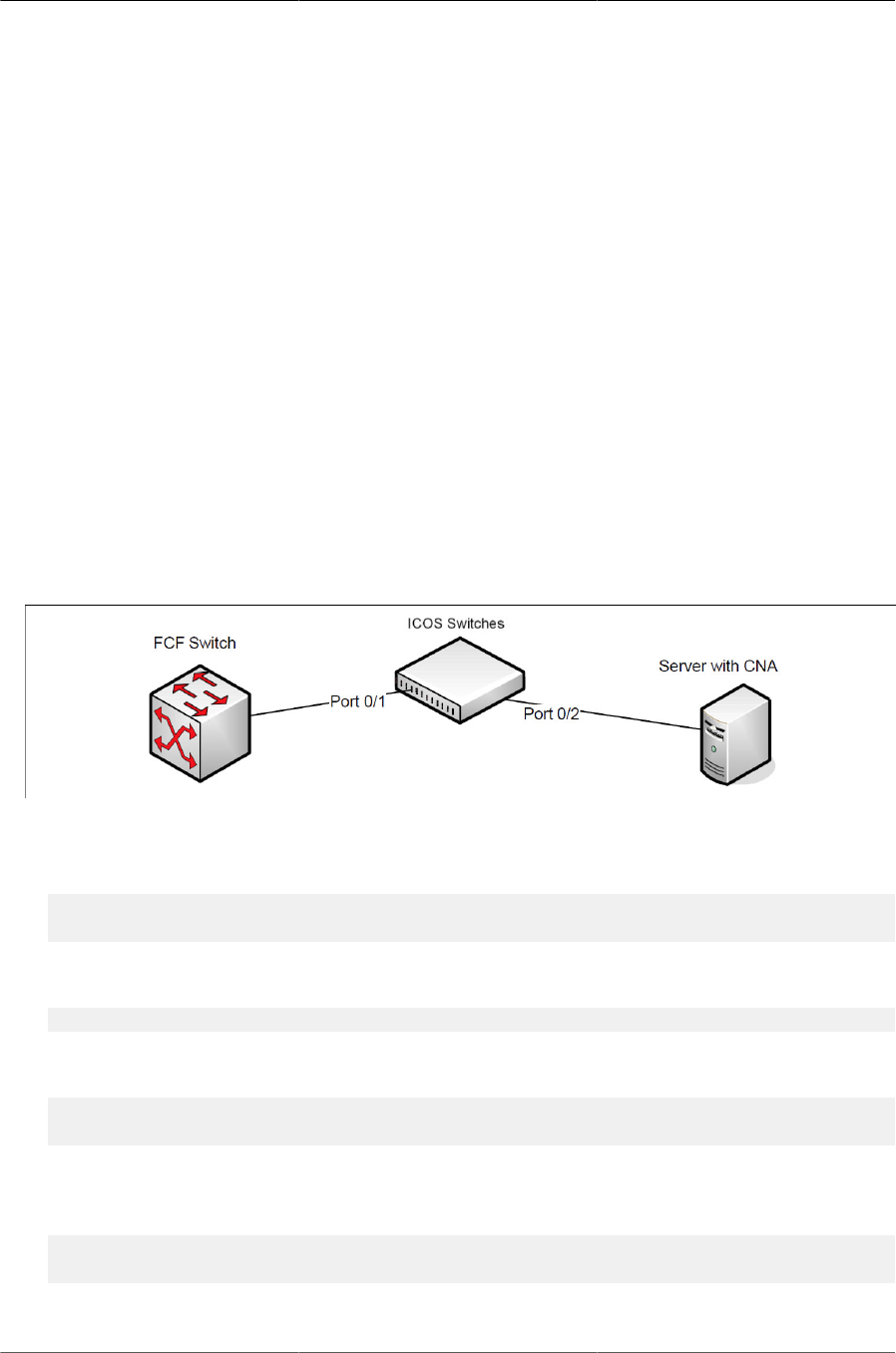
Configuring Data Center Features
181
To reduce flapping of configuration information, if the configuration source port is disabled, discon-
nected or loses LLDP connectivity, the system clears the selection of configuration source port (if
not manually selected) and enables the willing bit on all auto-upstream ports. The configuration
on the auto-configuration ports is not cleared (configuration holdover). If the user wishes to clear
the configuration on the system in this scenario, the user can put the configuration source port into
manual mode.
When a new port is selected as configuration source, it is marked as the configuration source, the
DCBX configuration is refreshed on all auto-configuration ports and each port may begin configu-
ration negotiation with their peer again (if any information has changed).
7.3.4. Configuring DCBX
In this example, port 0/1 on the ICOS switch connects to a FCoE-facing (FCF) switch. This port is
designated as default DCBX auto-upstream ports. Port 0/2 on the ICOS switch is directly connect-
ed to a Converged Network Adapter (CNA) on a network server. The configuration advertised by
the FCF is distributed from port 0/1 to port 0/2. In order to reduce configuration flapping, ports that
obtain configuration information from a configuration source port will maintain that configuration for
2× the LLDP timeout, even if the configuration source port becomes operationally disabled.
Figure7.1.DCBX Configuration
1. Map 802.1p priority 3 to traffic class 3. For more information about traffic classes, see Sec-
tion 10.2, “CoS”
(Routing) #configure
(Routing) (Config)#classofservice dot1p-mapping 3 3
2. Enter Interface Configuration mode for port 1.
(Routing) (Config)#interface 0/1
3. Enable the LLDP transmit and receive capability on the port.
(Routing) (Interface 0/1)#lldp transmit
(Routing) (Interface 0/1)#lldp receive
4. Enable the port as the configuration source. This port is connected to a trusted FCF. Configura-
tion received over this port is propagated to the other auto-configuration ports.
(Routing) (Interface 0/1)#lldp dcbx port-role configuration-source
(Routing) (Interface 0/1)#exit
5. Enter Interface Configuration mode for port 2.

Configuring Data Center Features
182
(Routing) (Config)#interface 0/2
6. Enable the LLDP transmit and receive capability on the port.
(Routing) (Interface 0/2)#lldp transmit
(Routing) (Interface 0/2)#lldp receive
7. Configure the LLDP port role as auto-down, which means the port advertises a configuration but
is not willing to accept one from the link partner. However, the port will accept a configuration
propagated internally by the configuration source (port 0/1).
(Routing) (Interface 0/2)#lldp dcbx port-role auto-down
(Routing) (Interface 0/2)#exit

Configuring Data Center Features
183
7.4. CoS Queuing
In a typical switch or router, each physical port consists of one or more queues for transmitting
packets on the attached network. Multiple queues per port are often provided to give preference
to certain packets over others based on user-defined criteria. When a packet is queued for trans-
mission in a port, the rate at which it is serviced depends on how the queue is configured— and
possibly the amount of traffic present in the other queues of the port. If a delay is necessary, pack-
ets are held in the queue until the scheduler authorizes the queue for transmission. As queues be-
come full, packets have no place to be held for transmission and get dropped by the device.
The drop precedence of a packet is an indication of whether the packet is more or less likely to be
dropped during times of queue congestion. Often referred to as packet coloring, a low drop prece-
dence (green) allows the packet to be transmitted under most circumstances, a higher drop prece-
dence (yellow) subjects the packet to dropping when bursts become excessive, while the highest
drop precedence (red) discards the packet whenever the queue is congested. In some hardware
implementations, the queue depth can be managed using tail dropping or a weighted random ear-
ly discard, or WRED, technique. These methods often use customizable threshold parameters that
are specified on a per-drop-precedence basis.
The ICOS QoS package contains Differentiated Services (DiffServ) support that allows traffic to
be classified into streams and given certain QoS treatment in accordance with defined per-hop
behaviors. However, the DiffServ feature does not offer direct configuration of the hardware COS
queue resources.
The COS Queuing feature allows the switch administrator to directly configure certain aspects of
device queuing to provide the desired QoS behavior for different types of network traffic when the
complexities of DiffServ are not required. The priority of a packet arriving at an interface can be
used to steer the packet to the appropriate outbound COS queue through a mapping table. With
the CoS queuing feature, COS queue characteristics such as minimum guaranteed bandwidth,
transmission rate shaping, etc. can be configured at the queue (or port) level.
For platforms that support the multistage scheduling architecture, the COS queue feature provides
a method to configure Traffic Class Groups (TCGs) to extend the COS queue management. Mul-
tiple COS queues can be mapped to a single TCG. Each TCG can have a configured minimum
guaranteed bandwidth allocation and a scheduling algorithm similar to the COS queue configura-
tion. The TCG scheduling and bandwidth enforcement occurs after the COS queue scheduling and
bandwidth enforcement is performed. Therefore all COS queues mapped to the same TCG share
the scheduling and bandwidth properties of the TCG.
7.4.1. CoS Queuing Function and Behavior
Like CoS mapping, CoS queuing uses the concept of trusted and untrusted ports. CoS queuing
builds on includes user-configurable settings that affect hardware queue operation.
7.4.1.1. Trusted Port Queue Mappings
A trusted port is one that takes at face value a certain priority designation within arriving packets.
Specifically, a port may be configured to trust one of the following packet fields:
• 802.1p User Priority
• IP Precedence

Configuring Data Center Features
184
• IP DSCP
Packets arriving at the port ingress are inspected and their trusted field value is used to designate
the COS queue that the packet is placed when forwarded to the appropriate egress port. A map-
ping table associates the trusted field value with the desired COS queue.
7.4.1.2. Un-trusted Port Default Priority
Alternatively, a port may be configured as un-trusted, whereby it does not trust any incoming
packet priority designation and uses the port default priority value instead. All packets arriving at
the ingress of an un-trusted port are directed to a specific COS queue on the appropriate egress
port(s) in accordance with the configured default priority of the ingress port. This process is al-
so used for cases where a trusted port mapping is unable to be honored, such as when a non-IP
packet arrives at a port configured to trust the IP precedence or IP DSCP value.
7.4.1.3. Queue Configuration
Queue configuration involves setting the following hardware port egress queue configuration para-
meters:
• Scheduler type: strict vs. weighted
• Minimum guaranteed bandwidth
• Maximum allowed bandwidth (i.e. shaping)
• Queue management type: tail-drop vs. WRED
• Tail drop parameters: threshold
• WRED parameters: minimum threshold, maximum threshold, drop probability
Defining these settings on a per-queue basis allows the user to create the desired service charac-
teristics for different types of traffic. The tail drop and WRED parameters are specified individually
for each supported drop precedence level.
In addition, the following settings can be specified on a per-interface basis:
• Queue management type: tail drop vs. WRED (only if per-queue configuration is not supported)
• WRED decay exponent
7.4.1.4. Traffic Class Groups
In ICOS platforms that support multiple levels of egress scheduling, the Traffic Class Groups
(TCGs) extend the egress queuing to make use of multiple levels of scheduling. A TCG defines a
collection of egress COS Queues. The configuration parameters for the TCG specify the class of
service characteristics applied to the aggregated traffic from the associated COS queues. This in-
volves setting the following configuration parameters to each TCG.
• Map one or more COS queues to the TCG.
• Set the scheduling type for each TCG: Strict vs. WDRR

Configuring Data Center Features
185
• Set the weight percentages for each TCG.
• Set the minimum guaranteed bandwidth for each TCG. The minimum bandwidth is specified in
terms of the percentage of the total link bandwidth.
• Set the maximum allowed bandwidth for each TCG. The maximum bandwidth is specified in
terms of the percentage of the total link bandwidth.
TCG configuration parameters are similar to that of COS queues. That is, the configuration of
scheduling attributes such as minimum bandwidth, maximum bandwidth, and scheduling algorithm
also apply to TCG. The behavior of a TCG with respect to scheduling algorithm and bandwidth al-
location configuration is the same as that of COS Queues.
Each TCG is associated with a weight percentage which defines the priority of the TCG to be ser-
viced when WDRR is configured as the scheduling type of the TCG. The weight of the TCG is
used only after the minimum guaranteed bandwidth of each of the TCG is met and after all the
strict priority TCGs are serviced. The weight of the TCG is then used to prioritize the TCGs among
the TCGs that are configured for WDRR.
7.4.2. Configuring CoS Queuing and ETS
This example shows the manual configuration of the CoS queuing feature in a network where traf-
fic needs to be prioritized based on the protocol frame-loss tolerance. For example, FCoE traffic
is highly sensitive to traffic loss. If a port has both loss-sensitive data and other less loss-sensi-
tive data, then the loss-sensitive data is categorized into the same TCG to provide control over the
bandwidth allocation and scheduling for the loss- sensitive traffic.
In this example, loss-sensitive traffic is sent with an 801.p priority value of 4, and less loss-sensi-
tive traffic is sent with an 801.p priority value priority of 1. The following steps show how to config-
ure the switch to prioritize the traffic.
1. Configure one to one mapping between 802.1p priority and COS Queue on the ingress port.
Frames with 802.1p priority 1 are assigned to COS 1 queue and similarly frames with 802.1p
priority 2 are assigned to COS2 and so on.
(Routing) (Config)#classofservice dot1p-mapping 0 0
(Routing) (Config)#classofservice dot1p-mapping 1 1
(Routing) (Config)#classofservice dot1p-mapping 2 2
(Routing) (Config)#classofservice dot1p-mapping 3 3
(Routing) (Config)#classofservice dot1p-mapping 4 4
(Routing) (Config)#classofservice dot1p-mapping 5 5
(Routing) (Config)#classofservice dot1p-mapping 6 6
(Routing) (Config)#classofservice dot1p-mapping 7 7
2. Enable 802.1p Trust mode on all the ports.
(Routing) (Config)#interface 0/1-0/16
(Routing) (Interface 0/1-0/16)#classofservice trust dot1p
(Routing) (Interface 0/1-0/16)#exit
3. Configure the mapping between COS queues and Traffic Classes Groups. Configure the Traffic
Class Group that such 802.1p priority 4 is assigned to TCG1 and 802.1p priority 1 is assigned to

Configuring Data Center Features
186
TCG2 so that less loss sensitive traffic does not starve the loss sensitive traffic even during traf-
fic bursts. Assign 802.1p priority 7 traffic to TCG0.
(Routing) (Config)#classofservice traffic-class-group 4 1
(Routing) (Config)#classofservice traffic-class-group 1 2
(Routing) (Config)#classofservice traffic-class-group 7 0
4. Enable VLAN tagging on the ports so the 802.1p priority is identified. The interfaces in this ex-
ample are members of VLAN 100, which has been previously configured.
(Routing) (Config)#interface 0/1-0/16
(Routing) (Interface 0/1-0/16)#vlan participation include 100
(Routing) (Interface 0/1-0/16)#vlan tagging 100
(Routing) (Interface 0/1-0/16)#exit
5. Configure the weight percentage of TCG0 to 10%, and the weights of TCG1 and TCG2 to 45%
each.
(Routing) (Config)#traffic-class-group weight 10 45 45
6. Associate weighted round robin scheduling with TCG1 and TCG2.
(Routing) (Config)#no traffic-class-group strict 1 2
7. Configure TCG0 for strict priority scheduling.
(Routing) (Config)#traffic-class-group strict 0
8. Associate TCG0 with CoS queue 7 so that it serves the high priority internal control traffic with
CoS 7.
(Routing) (Config)#classofservice traffic-class-group 7 0
9. Configure the minimum bandwidth percentage for all the TCGs to be zero.
(Routing) (Config)#traffic-class-group min-bandwidth 0 0 0
After performing Step 1–Step 9, the data traffic with an 802.1p priority is sent through TCG1, and
45% of the bandwidth (excluding TCG0 bandwidth) is reserved for TCG1. This protects the TCG1
traffic from traffic that is transmitted on TCG2. Any burst in traffic being transmitted in TCG2 does
not affect traffic in TCG1. If TCG2 is not being utilized to the full potential then TCG1 can still use
that bandwidth for transmitting TCG1 traffic.
With the configuration in this example, TCG0 with strict priority gets highest priority and can con-
sume the full bandwidth of the pipeline. TCG1 and TCG2 share the remaining bandwidth after
TCG0 consumes its share of the pipeline.
Based on this configuration, when the switch sends the configuration ETS TLVs to the peer, the
values that are given to DCBX are as follows:
• Willing Bit — This bit is set to TRUE for auto-upstream interfaces if there is no configuration
source or FALSE if there is a configuration source, and FALSE for auto-downstream and manu-
al ports.
• Credit-based Shaper support and Max TC — These are platform-specific values.

Configuring Data Center Features
187
• Priority Assignment Table — Table below contains the default values advertised by DCBX to the
peer DCBX device. If available, the mapping translated from the configuration source is used.
This table defines the mapping between the egress Traffic Class Group and ingress 802.1p pri-
ority.
Table7.2.802.1p-to-TCG Mapping
802.1p Priority Traffic Class
0 0
1 0
2 0
3 0
4 0
5 0
6 0
7 0
• TC Bandwidth And TSA Assignment Table — Table below contains the default values adver-
tised by DCBX to the peer DCBX device. If available, the assignments translated from the con-
figuration source is used. This table defines the bandwidth allocated to each Traffic Class Group
and the respective scheduling algorithm for each TCG; the scheduling algorithm is enumerated
in the IEEE 802.1Q specification.
Table7.3.TCG Bandwidth and Scheduling
Traffic Class Bandwidth percentage Scheduling Algorithm
0 10 strict priority (tail-drop) (0)
1 45 strict priority (tail-drop) (0)
2 45 strict priority (tail-drop) (0)

Configuring Data Center Features
188
7.5. Enhanced Transmission Selection
Enhanced Transmission Selection (ETS) enables the sharing and redistribution of network band-
width between various protocols. To support ETS, ICOS software accepts the ETS traffic class
group and bandwidth information Application Priority TLV from auto-upstream devices and prop-
agates it to auto-downstream devices. ICOS software supports the reception and propagation of
ETS information in the automatic configuration port roles. On ICOS platforms that support hierar-
chical scheduling, bandwidth allocation and traffic class groups can be configured by ETS TLVs.
Platforms that do not support hierarchical scheduling do not use the ETS information to configure
traffic class groups or bandwidth allocations.
7.5.1. ETS Operation and Dependencies
Using priority-based processing and bandwidth allocations, different Traffic Class Groups (TCGs)
within different types of traffic such as LAN, SAN and Management can be configured to provide
bandwidth allocation or best effort transmit characteristics.
For ETS to be operational, the following dependency the following three configuration steps need
to occur:
1. Configure COS queues to Traffic Class Group mapping for the egress ports.
2. Configure weight percentage (bandwidth allocation) for each TCG.
3. Enable appropriate scheduling algorithm for each TCG.
CoS information is exchanged with peer DCBX devices using ETS TLVs. As part of the ETS TLV,
by default, DCBX advertises the following parameters, which are populated on per port basis.
• Mapping between ingress ports 802.1p priority to Traffic Class Group (TCG).
• Bandwidth percentage (weight percentage) of each Traffic Class Group.
• Scheduling algorithm for each Traffic Class Group.
The mapping between the ingress ports 802.1p priority and TCG is not direct. The mapping de-
pends upon:
• The COS map defining the COS queue that a packet is egress forwarded for the ingress 802.1p
priority.
• Traffic Class Group map defining the COS queue to TCG mapping.
The indirect mapping between the 802.1p priorities and the associated TCG mapping is advertised
by DCBX as part of the ETS TLVs. For this indirect mapping to be valid, the following two parame-
ters must be configured (in addition to the configuration of the TCGs):
1. Configure 8021.p priority to COS mapping for the ingress ports.
2. Enable Trust mode on the ingress ports to trust the 802.1p priority present in the frames.
See Section 7.4.2, “Configuring CoS Queuing and ETS” for a configuration example.

Configuring Data Center Features
189
7.6. Quantized Congestion Notification (QCN)
QCN is not available on all platforms.
QCN is a critical protocol for data center networks in which Ethernet is the common platform, to
address the issues of congestion control. In data center networks, factors like flow control, lossless
behavior, and latency are extremely important.
The QCN feature attempts to push the network congestion from the heart of core networks to the
edges toward end stations. QCN avoids congestion spread by slowing down the end-hosts caus-
ing the congestion. QCN works across a single layer-2 domain. As soon as the traffic crosses a
router (or an FCoE switch), it enters a different QCN domain.
The QCN congestion-point algorithm is implemented on queues where congestion is expected.
Once enabled, it follows following three steps to rectify congestion:
• Congestion Detection— Monitoring the queue size and performing some calculations so that the
algorithm can detect congestion as soon as possible.
• Culprit Flow Detection—Identifying the sender end station that is causing the congestion
• Congestion Notification— Issuing a Congestion Notification Message (CNM) to the culprit
sender.
QCN operates between Congestion Points (CP), which detect and notify of congestion in the net-
work, and Reaction Points (RP), which originate traffic into the congestion-managed network and
receive/process the congestion notifications. The ICOS switch acts a Congestion Point in the net-
work. More specifically, each ICOS switch consists of a set of Congestion points, one per port for
each congestion-managed queue.

Configuring Data Center Features
190
7.7. OpenFlow Operation and Configuration
The OpenFlow feature enables the switch to be managed by a centralized OpenFlow Controller
using the OpenFlow protocol. ICOS supports the OpenFlow 1.0 and OpenFlow 1.3 standards.
7.7.1. Enabling and Disabling OpenFlow
The OpenFlow feature can be enabled or disabled by the network administrator. Although this fea-
ture is administratively enabled, it is not operational until the switch has an IP address. A separate
operational state indicates whether the OpenFlow feature is operational. If the feature is not opera-
tional, then another state indicates the reason for the feature to be disabled.
After administratively disabling the feature, the network administrator must wait until the OpenFlow
Feature is operationally disabled before re-enabling the feature. The OpenFlow feature can be ad-
ministratively disabled at any time.
The administrator can allow the switch to automatically assign an IP address to the OpenFlow fea-
ture or can manually select the address. The administrator can also configure the OpenFlow fea-
ture to always use the service port.
If the address is assigned automatically and the interface with the assigned address goes offline,
the switch selects another active interface if one is available. The OpenFlow feature becomes op-
erationally disabled and re-enabled when a new IP address is selected. If the address is assigned
statically, the OpenFlow feature becomes operational only when a switch interface with the match-
ing IP address becomes active.
The automatic IP addresses selection is done in the following order of preference.
1. The loopback interfaces.
2. The routing interfaces.
3. The network interface.
4. The service port interface.
ICOS currently supports only IPv4 addresses for connecting to the OpenFlow controller. If routing
is enabled, the Network interface cannot be used as the OpenFlow interface.
Once the IP address is selected, it is used until the interface goes offline, the feature is disabled,
or, in the case of automatic address selection, a more preferred interface becomes available.
If a service port is manually selected as the OpenFlow IP address, the Open Flow feature is en-
abled immediately, even if there is no IP address assigned to the service port.
The selected IP address is used as the end-point of SSL connections and the end-point of the IP
connections to the OpenFlow controllers.
When the OpenFlow feature is operationally disabled, the switch drops connections with the Open-
Flow controllers. The switch also purges all flows programmed by the controllers.
If the administrator changes the OpenFlow variant while the OpenFlow feature is enabled, the
switch automatically disables and re-enables the OpenFlow feature causing all flows to be deleted
and connections to the controllers to be dropped.

Configuring Data Center Features
191
If the administrator changes the default hardware table for OpenFlow 1.0 and if the switch is cur-
rently operating in OpenFlow 1.0 variant, the OpenFlow feature is automatically disabled and re-
enabled.
7.7.2. Interacting with the OpenFlow Manager
The OpenFlow Manager is a device that uses the Open vSwitch management protocol to send
commands and retrieve status from the switch.
The OpenFlow feature supports the OpenFlow Manager only when the DCTENANT_NET com-
ponent is selected in CCHelper. If the DCTENANT_NET component is not selected, the code for
interacting with the OpenFlow manager is excluded from the file system whenever practical, and
conditionally compiled out from common files. If the DCTENANT_NET component is selected, but
the OpenFlow variant is not configured to be "Tenant Networking" then the communications with
the OpenFlow Manager is not supported.
In order to interact with the OpenFlow Manager, the OpenFlow feature must be administratively
enabled. The administrator must also configure IP addresses of the OpenFlow Managers using
the switch UI. The OpenFlow Manager interaction is handled by the Open vSwitch module called
OVSDB.
7.7.3. Deploying OpenFlow
The OpenFlow Manager uses the Management protocol to tell the switch how to communicate
with the OpenFlow Controllers and the IP addresses of switches in which CAPWAP tunnels must
be set up.
If the administrator selects the OpenFlow 1.0 variant of the OpenFlow protocol, the Controller IP
addresses are manually assigned through the switch user interface and the CAPWAP tunnel desti-
nation IP addresses are also manually assigned.
7.7.4. OpenFlow Scenarios
The OpenFlow feature is mainly used in a data center network where devices are located in differ-
ent parts of the network and require layer-2 connectivity. Using OpenFlow helps to avoid scaling
problems and loops associated with the layer-2 network.
The OpenFlow feature can also be used in a research environment, but there are two limitations
that make the “research” use case less attractive. First, there is only one OpenFlow dataplane in-
stance, meaning that concurrent experiments are not supported unless concurrency is handled at
the controller level. Second, the OpenFlow controller has complete access to all ports and VLANs,
meaning that using the switch for mixed production and experimental traffic is not advisable.
7.7.5. OpenFlow Variants
7.7.5.1. OpenFlow 1.0/1.3
In OpenFlow 1.0/1.3 mode, the switch is a hybrid OpenFlow switch and supports the OpenFlow
1.0/1.3 standard. Hybrid OpenFlow switch means OpenFlow acts as a protocol in conjunction with
existing switch functionality. OpenFlow 1.0 mode enables the switch to inter-operate with the stan-
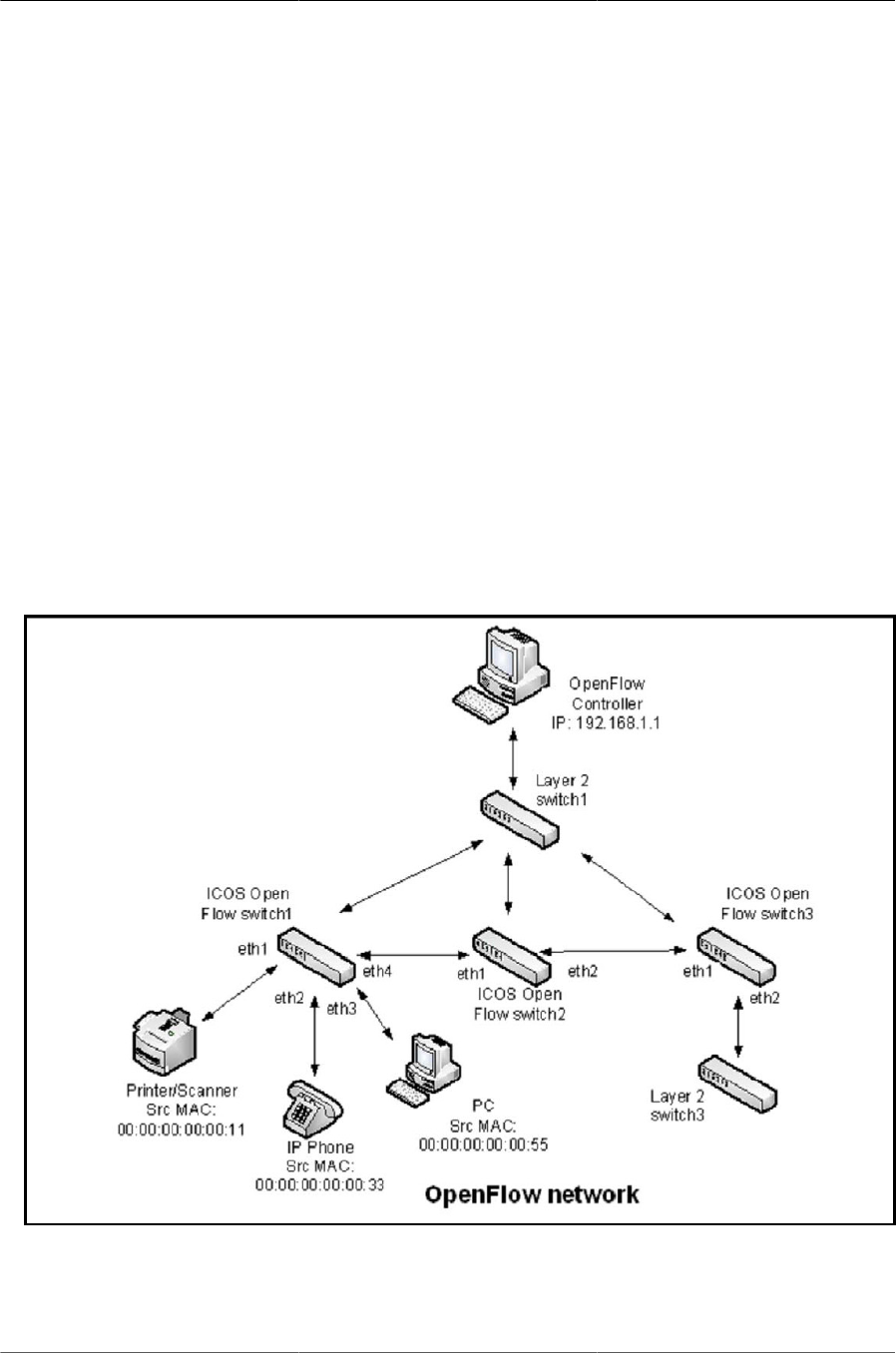
Configuring Data Center Features
192
dard OpenFlow controllers such as NOX, Beacon, and Big Switch. If COTS versions of these con-
trollers are not available, testing is limited to verification via the OVS_VXCTL tool.
7.7.5.2. Data Center Tenant Networking
In Tenant Networking mode, the switch communicates with the OpenFlow Manager to obtain the
configuration for OpenFlow Controllers, CAPWAP tunnels, and Rate Limiters. In OpenFlow 1.0
mode, these configuration parameters are defined through the switch user interface.
7.7.6. OpenFlow Interaction with Other Functions
The OpenFlow component interacts with multiple ICOS components by either communicating with
these components or sharing common resources with the components.
7.7.7. Configuring OpenFlow
The following example uses the network interface’s IP address. All ICOS switches shown in Figure
below have the same OpenFlow configuration.
Figure7.2.OpenFlow Network Example
Use the following commands to configure an OpenFlow network:
1. Configure the network protocol as DHCP with the following command:

Configuring Data Center Features
193
(Routing) #network protocol dhcp
2. Since the controller IP address in this example is configured from the Switch CLI, set the Open-
Flow variant mode to openflow1.0 with the following command:
Routing) (Config)# openflow variant openflow10
3. Set the controller IP address with the following command:
(Routing) (Config)#openflow controller 192.168.1.1 6633 tcp
4. To insert the flow into the OpenFlow 1.0 match table which can match on all OpenFlow 1.0
fields, set the OpenFlow default flow table to Full-Match with the following command:
(Routing) (Config)# openflow default-table full-match
5. Enable OpenFlow on the switch with the following command:
(Routing) (Config)# openflow enable
6. Verify the OpenFlow configuration with the following command:
(Routing) #show openflow
Administrative Mode............................ Enable
Operational Status............................. Disabled
Disable Reason................................. No-Suitable-IP-Interface
IP Address ..................................... 192.168.1.1
IP Mode........................................ Auto
Static IP Address. ............................. 0.0.0.0
OpenFlow Variant............................... OpenFlow 1.0
Default Table.................................. full-match
Passive Mode....................................Enable
OpenFlow Manager IP:port Addresses
--------------------------------------
(Routing) #show openflow configured controller
IP Address IP Port Connection Mode Role
--------------- --------------- ------------------- ------
192.168.1.1 6633 tcp Master
7. The controller installs rules in the ICOS switches. In this example, the following rules have been
installed:
ICOS Switch 1
• Forward any traffic with ingress port 0/1 with Source MAC 00:00:00:00:00:11 to egress port
0/4
• Forward any traffic with ingress port 0/1 with Source MAC 00:00:00:00:00:33 to egress port
0/4
• Forward any traffic with ingress port 0/1 with Source MAC 00:00:00:00:00:55 to egress port
0/4

Configuring Data Center Features
194
ICOS Switch 2
• Forward any traffic with ingress port 0/1 with Source MAC 00:00:00:00:00:11 to egress port
0/2
• Forward any traffic with ingress port 0/1 with Source MAC 00:00:00:00:00:33 to egress port
0/2
• Forward any traffic with ingress port 0/1 with Source MAC 00:00:00:00:00:55 to egress port
0/2
ICOS Switch 3
• Forward any traffic with ingress port 0/1 with Source MAC 00:00:00:00:00:11 to egress port
0/2
• Forward any traffic with ingress port 0/1 with Source MAC 00:00:00:00:00:33 to egress port
0/2
• Forward any traffic with ingress port 0/1 with Source MAC 00:00:00:00:00:55 to egress port
0/2
8. To verify the installed flows for ICOS Switch 1, use the following command:
(Routing) #show openflow installed flows
Flow 0C9E0D00 type "1DOT0"
Match criteria:
Flow table 24 : Priority 32768
Ingress port 0/1 : Src MAC 00:00:00:00:00:11
Actions:
Egress port 0/4
Status:
Duration 7 : Idle 5 : installed in hardware 1
Flow F6880900 type "1DOT0"
Match criteria:
Flow table 24 : Priority 32768
Ingress port 0/2 : Src MAC 00:00:00:00:00:33
Actions:
Egress port 0/4
Status:
Duration 11 : Idle 9 : installed in hardware 1
Flow 36370100 type "1DOT0"
Match criteria:
Flow table 24 : Priority 32768
Ingress port 0/3 : Src MAC 00:00:00:00:00:55
Actions:
Egress port 0/4
Status:
Duration 1121 : Idle 1119 : installed in hardware 1

Configuring Data Center Features
195
9. To verify the installed flows for ICOS Switch 2, use the following command:
(Routing) #show openflow installed flows
Flow 0C9E0D00 type "1DOT0"
Match criteria:
Flow table 24 : Priority 32768
Ingress port 0/1 : Src MAC 00:00:00:00:00:11
Actions:
Egress port 0/2
Status:
Duration 7 : Idle 5 : installed in hardware 1
Flow F6880900 type "1DOT0"
Match criteria:
Flow table 24 : Priority 32768
Ingress port 0/1 : Src MAC 00:00:00:00:00:33
Actions:
Egress port 0/2
Status:
Duration 11 : Idle 9 : installed in hardware 1
Flow 36370100 type "1DOT0"
Match criteria:
Flow table 24 : Priority 32768
Ingress port 0/1 : Src MAC 00:00:00:00:00:55
Actions:
Egress port 0/2
Status:
Duration 1121 : Idle 1119 : installed in hardware 1
10.To verify the installed flows for ICOS Switch 3, use the following command:
(Routing) #show openflow installed flows
Flow 0C9E0D00 type "1DOT0"
Match criteria:
Flow table 24 : Priority 32768
Ingress port 0/1 : Src MAC 00:00:00:00:00:11
Actions:
Egress port 0/2
Status:
Duration 7 : Idle 5 : installed in hardware 1
Flow F6880900 type "1DOT0"
Match criteria:
Flow table 24 : Priority 32768
Ingress port 0/1 : Src MAC 00:00:00:00:00:33
Actions:
Egress port 0/2
Status:
Duration 11 : Idle 9 : installed in hardware 1

Configuring Data Center Features
196
Flow 36370100 type "1DOT0"
Match criteria:
Flow table 24 : Priority 32768
Ingress port 0/1 : Src MAC 00:00:00:00:00:55
Actions:
Egress port 0/2
Status:
Duration 1121 : Idle 1119 : installed in hardware 1

Configuring Data Center Features
197
7.8. DCVPN Gateway Operation and Configu-
ration
7.8.1. Overview
Logically segregated virtual networks in a data center are sometimes referred to as data center
VPNs (DCVPNs). VXLAN and NVGRE are two realizations of a DCVPN. Others include E-VPNs,
IP VPNs, TRILL, and VPLS.
The encapsulation and decapsulation required by DCVPNs is done by devices called Virtual Tun-
nel Endpoints (VTEPs) or NVEs. VTEPs/NVEs are most commonly implemented within a virtu-
alized server. However, there are cases where it is necessary to implement the VTEP/NVE in a
stand-alone networking device. This section describes the functional behavior of the ICOS imple-
mentation of a hardware-based VXLAN or NVGRE gateway service and provides configuration
scenarios.
This document uses the term DCVPN gateway to refer to both VXLAN and NVGRE gateways
when the discussion applies to both protocols.
7.8.2. VXLAN
VXLAN is one method of creating tenant networks on a common network infrastructure. VXLAN
encapsulates Ethernet frames in IP packets, thus enabling the network to provide the illusion
that hosts connected to arbitrary access routers are attached to a common layer-2 networks. The
VXLAN encapsulation includes a 24-bit virtual network ID (VNID). Hosts can be associated to a
VNID and restricted to communicate only with hosts associated to the same VNID. This associa-
tion segregates communities of interest, or tenants, into different virtual networks. VXLAN allows a
public or private data center operator to use a common network infrastructure to provide virtual pri-
vate network service to multiple tenants while distributing any given tenant’s compute and storage
resources anywhere in the network infrastructure.
In a data center, VXLAN encapsulation and decapsulation of tenant packets is normally done by
a virtual switch within a virtualized server; however, not all tenant systems are virtualized. Non-vir-
tualized tenant systems can participate in a VXLAN by using a VXLAN gateway. A VXLAN gate-
way is a networking device that does VXLAN encapsulation and decapsulation. A server’s first-hop
router, often referred to as a top-of-rack (ToR) device, can be a VXLAN gateway.
With VXLAN, the inner Ethernet header can optionally include an incoming VLAN tag. The DCVPN
application always strips the inner VLAN information from the incoming Ethernet packet during en-
capsulation. The inner payload in the VXLAN encapsulated packet does not contain the incoming
VLAN tag information in it, which enables flexibility in mapping available VLANs to VNIDs.
The allowed range of VNID values is 1–16777214. VNID 16777215 is reserved for internal purpos-
es.
7.8.3. NVGRE
NVGRE is similar to VXLAN. NVGRE differs from VXLAN in several ways. NVGRE uses standard
GRE encapsulation (RFC 2784 and RFC 2890). NVGRE defines a 24-bit Virtual Subnet Identifier
(VSID) that serves the same purpose as the VXLAN VNID. The VSID is included in the GRE head-
er. With NVGRE, the inner Ethernet header never includes a VLAN tag.

Configuring Data Center Features
198
The allowed range of VSID values is 1–16777214. VSID 16777215 is reserved for internal purpos-
es.
7.8.4. Functional Description
7.8.4.1. Switch Overlay Mode
A DCVPN-capable switch can support either VXLAN or NVGRE, or both. On the switches that
support both types, only one can be configured at a time (to prevent contention for hardware re-
sources). The switch must be configured with the preferred overlay type before DCVPNs of the
preferred type are created. Only DCVPNs matching the configured overlay type can be created.
To configure DCVPNs of the other overlay type, the preferred overlay type configuration must be
changed. When the preferred overlay type on the switch is reset or disabled, the entire existing
configuration of the disabled overlay type is cleared from the running configuration; i.e, all DCVPN
configuration is removed for that type.
7.8.4.2. VTEP to VN Association
The operator must configure switches that are to serve as DCVPN gateways. A gateway may
serve one or more DCVPNs. For each DCVPN, the operator specifies the virtual network ID
(VNID), the type of network (VXLAN or NVGRE), and a method for identifying which incoming
native packets belong to the VPN. The ingress VLAN ID can be used as this classifier. Only one
VLAN ID can be associated with a specific VNID on a given router. However, the VLAN ID used
has no significance beyond that router, and so the same ID can be used on other routers. In this
case the number of tenant networks is not limited to VLAN ID space (i.e., 4096). All ingress ports
that are members of specified VLAN ID are treated as access ports for the VPN identified by VNID.
This defines the access port set for the specified VPN. The access port set for the DCVPN can be
altered by updating the VLAN membership configuration. All incoming VLAN traffic is translated to
virtual network traffic identified by VNID. A VLAN ID that is already used or configured for routing is
not allowed to be configured as an access VLAN for DCVPN.
A source IP address (local VTEP) must be specified for each configured DCVPN. The valid source
IP interface is either a loopback interface or a routing interface (port-based or VLAN-based) on the
router. It is recommended that a loopback interface be dedicated for DCVPN gateway purposes
and configured with the intended source IP configuration before associating it with any DCVPN. If
the configured source IP interface is down or has no IP address, all remote VTEPs in the VPN are
considered unreachable. No traffic flows to the remote VTEPs.
Note that the configured source IP address must correspond to an IP address configured on each
remote VTEP. Otherwise, the remote VTEPs will discard the gateway’s packets.
7.8.4.3. Configuration of Remote VTEPs
Each gateway VTEP must know the set of VTEPs other than itself in each DCVPN. This knowl-
edge is necessary because tenant systems can send broadcast and multicast Ethernet frames.
For example, ARP requests are generally broadcast. Also, a VTEP may receive a packet for a
destination MAC address it has not learned yet. Such a packet is called an unknown frame. The
VTEP must send the packet to all other remote VTEPs configured in the DCVPN, since the desti-
nation may be accessed through any one of them.
VXLAN and NVGRE handle broadcast, multicast, and unknown frames by encapsulating the pack-
et in an IP packet whose destination IP address is an IP multicast group configured for the VN.

Configuring Data Center Features
199
Each VTEP sends Join messages to join the VN’s multicast group. There can be difficulties in us-
ing IP multicast to deliver broadcast and unknown frames, the main difficulty being that the data
center networks that would be used as underlays often do not enable IP multicast because it does
not scale to the size of large public cloud networks. Because of this limitation, DCVPN implemen-
tation requires user configuration of the remote VTEPs associated with a particular VPN.
Because VMs may be created, deleted or moved rapidly within the data center, the set of VTEPs
within a VN may be very dynamic. When this is the case, it is not feasible to manually provision
VTEP membership. Instead, VTEP membership must be provisioned through automation. When
an orchestration system creates, deletes, or moves a tenant VM, the orchestration system may up-
date the VTEP membership for the VM’s virtual network. If one of the VTEPs in the virtual network
is a gateway, the orchestration system can use an Overlay OpEN API to update the gateway’s
configuration.
Dynamic VTEP learning through IP multicast is not currently supported.
When a gateway receives a broadcast, multicast, or unknown packet on an access port, it makes
a copy of each packet for each of the other VTEP’s in the VN, setting the outer IP address to the
unicast IP address of the remote VTEP, and setting the outer MAC address to the unicast MAC
address of the next hop to the VTEP. The hardware does this packet replication. In this mode, the
gateway can still learn L2 entries from packets it decapsulates and, thus, is able to unicast to a
single VTEP most of the time.
For each remote VTEP, the operator must specify the following parameters:
• The associated virtual network (specified by VNID).
• The VTEP’s IP address. This address is an IP address in the underlay.
The source IP address is inherited from the DCVPN configuration. The system creates overlay
tunnels to all configured remote VTEPs in hardware as they become reachable. The system re-
moves the tunnel configuration from hardware when the VTEPs are not reachable.
DCVPNs with matching tunnel configuration (i.e., a pair of VTEPs {source or gateway IP address,
remote VTEP IP address}) share the same hardware tunnel. Each hardware tunnel has unicast
packet and unicast byte counters in either direction (Tx/Rx). When the tunnel is removed from
hardware, counters are reset to 0.
If the gateway receives a packet for an unknown VNID or for a known VNID from a VTEP IP ad-
dress that has not been configured, the gateway drops the packet.
7.8.4.4. VTEP Next-Hop Resolution
A remote VTEP is considered reachable if the gateway has a non-default route to the VTEP’s IP
address. The DCVPN application determines the reachability of the VTEP’s address and registers
with the routing table manager for changes in the route to that IP address. When there is a route
to the VTEP, the DCVPN application copies the next hops of the best route and uses them as the
next hop for the packets forwarded to that VTEP. The DCVPN application creates a tunnel in the
hardware for each reachable VTEP. The gateway may use multiple next hops to a VTEP, hashing
a given flow to an individual next hop as is done in layer-3 routing. The number of next hops to a
VTEP and, thus, the number of next hops for a tunnel, is limited only by the ECMP limit of the plat-
form (or the active SDM template). It is recommended that SDM template dcvpn-data-center for
DCVPN-capable StrataXGS® V platforms.

Configuring Data Center Features
200
The DCVPN application registers with the routing table manager for next-hop resolution changes
for each VTEP’s remote IP address. When DCVPN receives a next-hop resolution change event,
it queries the routing table manager for the new best route and updates the set of next hops to the
VTEP. If the VTEP is unreachable, DCVPN deletes the corresponding tunnel in the hardware.
If the hardware tunnel is shared by another DCVPN, then the hardware tunnel is re-
moved only when its reference count becomes 0.
A VTEP cannot be resolved by a default route. The presence of a default route does not provide
any confidence that the VTEP is actually reachable.
Any physical interface or LAG that has tenant access ports configured cannot be con-
figured as the next-hop interface for the tunnel. Similarly, a physical interface or LAG
that is configured as a next-hop interface on the switch cannot be configured as an ac-
cess interface for any tenant. A physical port or LAG cannot be shared or be part of
both an access port configuration and a tunnel next-hop configuration. This configura-
tion leads to errors and the system generating the following log message:
15 Aug 26 23:37:26 10.18.36.41-1 DCVPN[dcVpnTask]: broad_l2ol3tunnel.c(1038) 216 %%
hapiBroadL2oL3PortCfgFindAdd():1038 Error> Error: Incorrect configuration detected. Port 1.3.0
(lport=0xC000000) is already configured in Access mode. Same physical/LAG port cannot be con-
figured in Network/Tunnel mode.
7.8.4.5. VXLAN UDP Destination Port
The VXLAN standard defines 4789 as the standard UDP destination port to be used for encap-
sulation and termination. Switches that supported earlier draft versions used custom defined
UDP port numbers. To be compatible with those switches, DCVPN supports switch-level VXLAN
UDP destination port configuration. By default, the VXLAN UDP destination port is set to 4789 on
the switch. The switch terminates incoming VXLAN traffic when the UDP destination port in the
VXLAN header matches 4789 and encapsulates VXLAN tenant traffic by putting 4789 in the UDP
destination port field in the VXLAN frame.
Users can modify how VXLANs are terminated or encapsulated by changing the default VXLAN
UDP destination port configuration on the switch. When the VXLAN UDP destination port is modi-
fied, all existing tunnels are modified in the hardware to encapsulate using new VXLAN UDP des-
tination port information. The switch is also configured to terminate VXLAN traffic using the new
configuration. There is no or very minimal traffic disruption during this operation.
By default, the switch is configured to generate a source port (in the outer UDP head-
er of the VXLAN frame) that is a hash of the inner Ethernet frame’s headers. This is to
enable a level of entropy for ECMP/load balancing of the VM to VM traffic across the
VXLAN overlay.
7.8.4.6. Tunnels
The DCVPN application creates a tunnel in hardware for each configured and reachable remote
VTEP. To create a tunnel in hardware, the application must provide the following tunnel parame-
ters:
• A local IP address. This is the source IP address configured for the DCVPN. The hardware sets
the source IP address of the outer IPv4 header to this value.

Configuring Data Center Features
201
• The remote IP address. This is the IP address of the VTEP. The hardware sets the destination
IP address of the outer IPv4 header to this value.
• A local MAC address, which the hardware uses as the outer source MAC address when encap-
sulating and sending packets on the tunnel. This MAC address is the MAC address of the origi-
nating local routing interface MAC address.
• For VXLAN tunnel, UDP destination port to use in VXLAN header while encapsulation.
• The tunnel VLAN ID. This is the VLAN associated with the outgoing interface in the underlay. If
the outgoing interface is a port-based routing interface, this is the VLAN ID assigned internally to
the port- based routing interface. If the outgoing interface is a VLAN routing interface, the tunnel
VLAN ID is set to the VLAN ID of this routing interface.
• The next hops in the underlay network. Each next hop is specified as the combination of the fol-
lowing parameters:
• The internal interface number of the outgoing routing interface in the underlay network.
• The MAC addresses corresponding to the next hop IP address. The hardware uses this as the
destination MAC address of the outer Ethernet header.
7.8.4.7. MAC Learning and Aging
The hardware does MAC learning for DCVPNs. Normal MAC learning associates a MAC address
with a VLAN and interface. For DCVPNs, the hardware learns MAC entries associated with both
access ports and network ports. The forwarding entries are learned in the VPN. The VLAN ID field
in the entry is replaced by a VPN field. For network-side entries associated with VTEPs, the inter-
face is the hardware tunnel identifier. The MAC address in network-side entries is the MAC ad-
dress of a tenant system behind a remote VTEP. For access-side entries, the associated inter-
face is the physical or LAG interface who are members of the configured DCVPN VLAN. The MAC
address in access-side entries is the MAC address of a tenant system behind the local interface
(physical or LAG interface).
DCVPN MAC entries are not listed in the show mac-addr-table command output. They can be
listed using show vxlan vnid tenant-systems. Both access and network-side entries are listed in
the show command output.
The maximum age of a DCVPN MAC entry is the same as normal L2 entries. The user cannot
configure a different maximum age for DCVPN MAC entries than for normal L2 entries.
DCVPN performs aging of learned entries in software when the virtual port channel (VPC) fea-
ture is present in the build package. DCVPN handles entries those are learned in configured VP-
Ns only. It would not handle MAC entries learned in VLANs or listed in the show mac-addr-table
command output. For packages without the VPC component, DCVPN relies on hardware aging for
MAC entries learned in configured VPNs.
7.8.4.8. Host Configuration
An operator may wish to statically configure host MAC-to-VTEP mappings. Doing so eliminates
the initial flooding of packets on all tunnels when the MAC-to-VTEP mapping is unknown. So for
each remote VTEP, an operator can optionally configure the MAC addresses of the tenant sys-
tems reachable through the VTEP. The maximum allowed static host MAC-to-VTEP binding (or re-

Configuring Data Center Features
202
mote tenant systems MAC entries) per tenant is 600. Once this limit is reached, configuring new
MAC-to-VTEP bindings for the tenant results in failure. The system generates a log message that
describes the reason for failure.
Overall, the system has a maximum allowed limit of 4096 static host MAC-to-VTEP bindings. At
any point in time, the sum of all tenants static host MAC-to-VTEP mappings must be less than or
equal to the system limit. Once this limit is reached, configuring new MAC-to-VTEP bindings for
any tenant results in failure and a log message is generated.
The operator may optionally configure host MAC-to-access port entries as well. The maximum
allowed static host MAC-to-interface bindings (or local tenant system MAC entries) per interface
(physical or LAG) is 24. Once this limit is reached, configuring new MAC-to-interface bindings for
any tenant results in failure and a log message is generated.
7.8.4.9. ECMP
A tunnel may have multiple next hops when the underlay has multiple next hops to the tunnel’s re-
mote endpoint. Many data center designs make heavy use of ECMP. To get good traffic distribu-
tion within the underlay, it is important that encapsulated packets hash well.
VXLAN encapsulation includes a UDP header. Switches can include the source and destination
UDP port in ECMP hash computations. The hardware offers an option for the source VTEP to set
the source UDP port to a variable value (hash based on incoming packet Ethernet header) to en-
sure good ECMP hashing. DCVPN enables this option in hardware by default.
At VXLAN initiation, payload fields are used for hashing at the egress and also to gen-
erate the entropy into the UDP source port which becomes part of VXLAN tunnel infor-
mation. This UDP source port can be used by transit switches for hashing purposes.
NVGRE encapsulation is GRE-over-IP. There are no layer-4 ports to include when computing an
ECMP hash; StrataXGS V platforms offer an option to introduce a hash value into the 8-bit Flow
ID field. However, these fields are at a different offset than the L4 port number. Router hardware
in the underlay would have to be updated to include these fields (8-bit flow ID) in the ECMP hash.
NVGRE proponents contend that such hardware will emerge. Until then, all packets between a
pair of NVEs follow the same path in the underlay, potentially causing severe utilization imbal-
ances on underlay links.
7.8.4.10. MTU
VXLAN encapsulation adds 50 bytes of overhead. NVGRE encapsulation adds 46 bytes. This
additional overhead can cause an encapsulated packet to exceed the MTU of the outgoing port.
The gateway does no IP fragmentation while tunneling a packet and is by default configured to
set DF=1 in the outer IPv4 header. If an encapsulated packet exceeds the L2 MTU of the outgo-
ing port, the hardware drops it. To avoid this problem, operators must ensure that the L2 MTU on
gateway ports to the underlay and underlay network be configured at least 46 bytes larger (for
NVGRE) or 50 bytes larger (for VXLAN) than the MTU on ports on the access side.
The hardware may also enforce an IP MTU. In most cases, network-side ports will be configured
as port-based routing interfaces. The IP MTU of these routing interfaces will automatically be
adjusted to match the L2 MTU. Therefore, if the administrator adjusts the L2 MTU as described
above, the hardware should not drop packets because of an IP MTU limitation. If, however, net-
work-side ports are VLAN routing interfaces, the administrator will need to also increase the IP
MTU on each network-side routing interface.
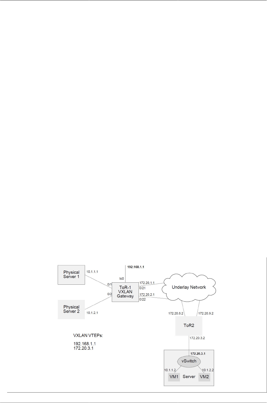
Configuring Data Center Features
203
7.8.4.11. TTL and DSCP/TOS
By default, the switch is configured to behave as follows:
• The TTL in the outer IPv4 header during tunnel encapsulation is set to 255.
• For incoming IPv4 packets, the DSCP/TOS value from the incoming IPv4 header is copied into
the outer IPv4 header’s DCSP/TOS field during encapsulation. Otherwise, the DSCP/TOS value
is set to 0.
7.8.4.12. Packet Forwarding
The gateway forwards all packets in hardware. There is no software forwarding.
7.8.5. Usage Scenarios
7.8.5.1. VXLAN Gateway With Single Tunnel
Figure below shows a ToR-1 router configured as a VXLAN gateway that connects two physical
servers to their VXLANs. Ports attached to physical servers are configured in respective access
VLANs on the ToR-1.
Server 1 and VM1 are part of the Tenant Red, which are on the VXLAN-identified by VNID=1.
Server 1 is VLAN- unaware and can send and receive with no VLAN tag. Tenant Red on the
switch uses VLAN 10 for defining its access ports.
Server 2 and VM2 are part of the Tenant Blue, which are on the VXLAN identified by VNID=2.
Server 2 is VLAN- aware and is configured to send and receive VLAN 20 tagged frames. Tenant
Blue must use VLAN 20 to define its access ports.
Each server communicates with a peer VM on a remote virtualized server.
Figure7.3.VXLAN Gateway—One Tunnel Between a Pair of VTEPs

Configuring Data Center Features
204
ToR 1 is configured as follows:
(Routing) #vlan database
(Routing) (Vlan)#vlan 10
(Routing) (Vlan)#vlan 20
(Routing) (Vlan)#exit
(Routing) #config (Routing) #ip routing
(Routing) (Config)#interface 0/1
(Routing) (Interface 0/1)#vlan participation include 10
(Routing) (Interface 0/1)#vlan participation exclude 1
(Routing) (Interface 0/1)#vlan pvid 10
(Routing) (Interface 0/1)#exit
(Routing) (Config)#interface 0/2
(Routing) (Interface 0/2)#vlan participation include 20
(Routing) (Interface 0/2)#vlan participation exclude 1
(Routing) (Interface 0/2)#ingressfilter
(Routing) (Interface 0/2)#vlan tagging 20
(Routing) (Interface 0/2)#exit
(Routing) (Config)#interface 0/21
(Routing) (Interface 0/21)#routing
(Routing) (Interface 0/21)#ip address 172.20.1.1 255.255.255.0
(Routing) (Interface 0/21)#ip ospf area 0
(Routing) (Interface 0/21)#exit
(Routing) (Config)#interface 0/22
(Routing) (Interface 0/22)#routing
(Routing) (Interface 0/22)#ip address 172.20.2.1 255.255.255.0
(Routing) (Interface 0/21)#ip ospf area 0
(Routing) (Interface 0/22)#exit
(Routing) (Config)#interface loopback 0
(Routing) (Interface loopback 0)#ip address 192.168.1.1 255.255.255.0
(Routing) (Interface loopback 0)#ip ospf area 0
(Routing) (Interface loopback 0)#exit
(Routing) (Config)#router ospf
(Routing) (Config-router)#router-id 1.1.1.1
(Routing) (Config-router)#exit
(Routing) (Config)#vxlan enable
!! Tenent Red
(Routing) (Config)#vxlan 1 vlan 10
(Routing) (Config)#vxlan 1 source-ip 192.168.1.1
(Routing) (Config)#vxlan 1 vtep 172.20.3.1
!! Tenant Blue
(Routing) (Config)#vxlan 2 vlan 20
(Routing) (Config)#vxlan 2 source-ip 192.168.1.1

Configuring Data Center Features
205
(Routing) (Config)#vxlan 2 vtep 172.20.3.1
(Routing) (Config)#exit
To initiate communication with VM1, physical server 1 originates an ARP request with target
10.1.1.2. The hardware at ToR1 recognizes the incoming packet as arriving on a VLAN 10 that is
assigned to VXLAN 1. The gateway encapsulates the ARP request, setting the VNID in the VXLAN
header to 1. A copy of the packet is sent to each access port and VTEP in VXLAN 1. In this case,
a single copy is sent to 172.20.3.1. The outer source IP address is set to the IP address of the
loopback 0, i.e., 192.168.1.1.
The vSwitch decapsulates the received VXLAN packet on 172.20.3.1 and delivers the ARP re-
quest to VM1, which unicasts an ARP reply with its MAC address to the source IP address in the
ARP request, 10.1.1.1. The virtual switch encapsulates the ARP reply and sends it to 192.168.1.1
over VXLAN 1.
The encapsulated ARP reply arrives at TOR- 1. The hardware recognizes the packet to have ar-
rived on a VXLAN network port, terminates the VXLAN, identifies that the packet is intended for
VXLAN 1 hosts, and forwards the inner Ethernet frame to Server 1 through the access port on in-
terface 0/1. This packet is sent untagged to Server 1 based on the interface 0/1 configuration. The
hardware also learns that VM1’s MAC address is behind the VTEP at 172.20.3.1. Future packets
to VM1’s MAC address are encapsulated and sent only to this VTEP.
Similarly, when Server 2 communicates with VM2, it sends out packets with VLAN 20 tagged.
Based on the incoming VLAN tag, ToR-1 associates it to Tenant Blue. This frame is then encap-
sulated and sent on VXLAN 2. When the response arrives on VXLAN 2, the gateway terminates
the VXLAN 2 and forwards the inner frame with VLAN 20 tagged on port 0/2. Server 2 is able to
process the VLAN 20 tagged frames and is unaware of VM2 being on a remote network.
7.8.5.2. VXLAN Gateway With Multiple Tunnels
Figure below shows a ToR router configured as a VXLAN gateway that connects two physical
servers to their VXLANs spanning two different VTEPs. Server 1, VM1, and VM3 are part of the
Tenant Red using VXLAN 1. Server 2 and VM2 are part of the Tenant Blue using VXLAN 2.
Each server connected to the ToR-1 communicates with VM/s in remote virtualized servers. Serv-
er 2 communicates with VM2 on Server 3 using a single VXLAN tunnel to 172.20.3.1. Server 1
communicates with VM1 on Server 3 and also with VM3 on Server 4 using two different VXLAN
tunnels. Server 1 and Server 2 are VLAN-aware.
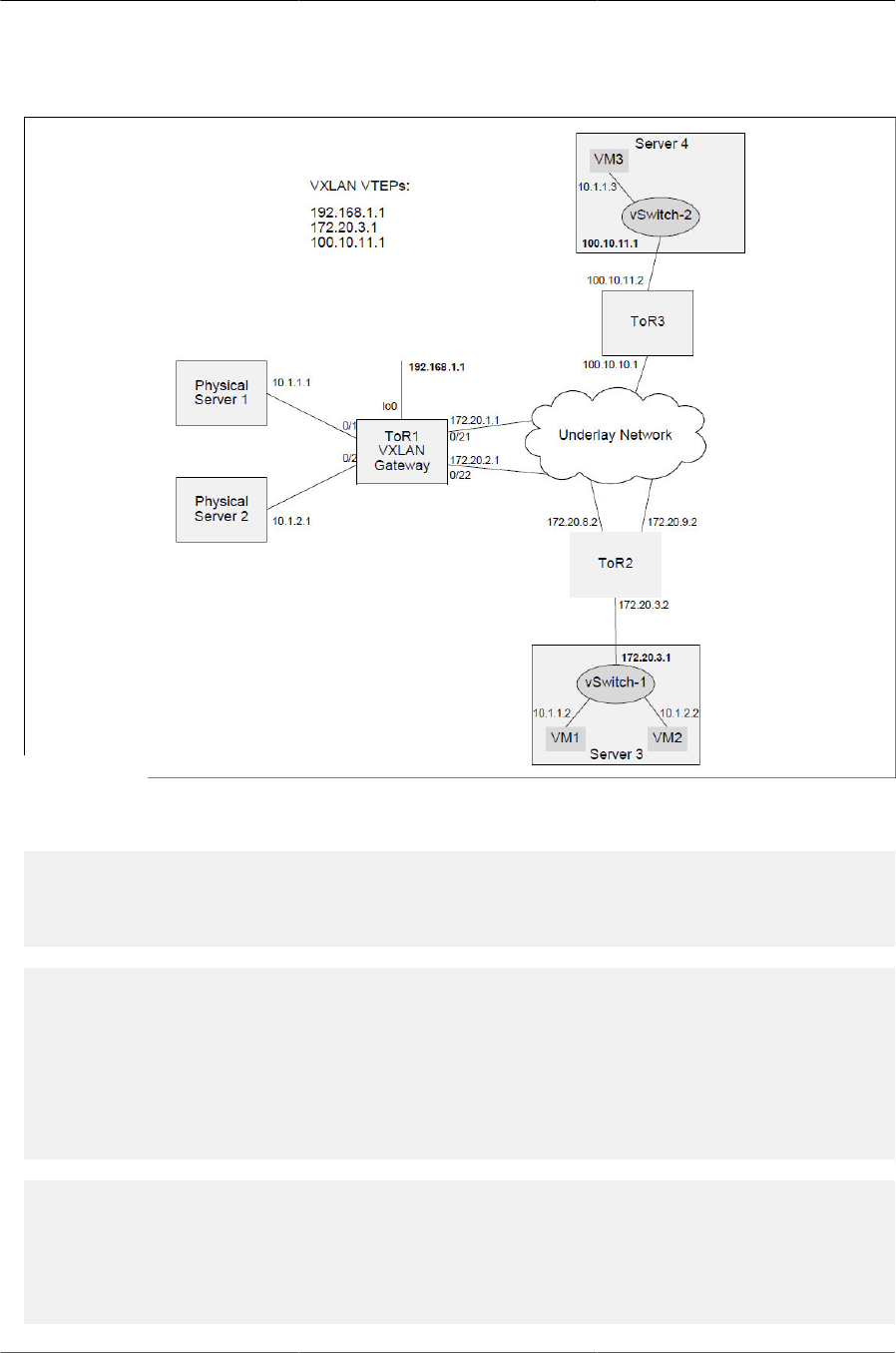
Configuring Data Center Features
206
Figure7.4.VXLAN Gateway—Multiple Tunnels
TOR 1 is configured as follows:
(Routing) #vlan database
(Routing) (Vlan)#vlan 10
(Routing) (Vlan)#vlan 20
(Routing) (Vlan)#exit
(Routing) #config
(Routing) (Config)#ip routing
(Routing) (Config)#interface 0/1
(Routing) (Interface 0/1)#vlan participation include 10
(Routing) (Interface 0/1)#vlan participation exclude 1
(Routing) (Interface 0/1)#vlan ingressfilter
(Routing) (Interface 0/1)#vlan tagging 10
(Routing) (Interface 0/1)#exit
(Routing) (Config)#interface 0/2
(Routing) (Interface 0/2)#vlan participation include 20
(Routing) (Interface 0/2)#vlan participation exclude 1
(Routing) (Interface 0/2)#vlan ingressfilter
(Routing) (Interface 0/2)#vlan tagging 20
(Routing) (Interface 0/2)#exit

Configuring Data Center Features
207
(Routing) (Config)#interface 0/21
(Routing) (Interface 0/21)#routing
(Routing) (Interface 0/21)#ip address 172.20.1.1 255.255.255.0
(Routing) (Interface 0/21)#ip ospf area 0
(Routing) (Interface 0/21)#exit
(Routing) (Config)#interface 0/22
(Routing) (Interface 0/22)#routing
(Routing) (Interface 0/22)#ip address 172.20.2.1 255.255.255.0
(Routing) (Interface 0/22)#ip ospf area 0
(Routing) (Interface 0/22)#exit
(Routing) (Config)#interface loopback 0
(Routing) (Interface loopback 0)#ip address 192.168.1.1 255.255.255.255
(Routing) (Interface loopback 0)#ip ospf area 0
(Routing) (Interface loopback 0)#exit
(Routing) (Config)#router ospf
(Routing) (Config-router)#router-id 1.1.1.1
(Routing) (Config-router)#exit
(Routing) (Config)#vxlan enable
!! Tenant Red access VLAN
(Routing) (Config)#vxlan 1 vlan 10
!! Tenant Red VXLAN gateway
(Routing) (Config)#vxlan 1 source-ip 192.168.1.1
!! First tunnel to Server 3
(Routing) (Config)#vxlan 1 vtep 172.20.3.1
!! Second tunnel to Server 4
(Routing) (Config)#vxlan 1 vtep 100.10.11.1
!! Tenant Blue
(Routing) (Config)#vxlan 2 vlan 20
(Routing) (Config)#vxlan 2 source-ip 192.168.1.1
(Routing) (Config)#vxlan 2 vtep 172.20.3.1
(Routing) (Config)#exit

Configuring Data Center Features
208
7.9. MPLS Operation and Configuration
7.9.1. Overview
This feature is targeted towards data center customers deploying ICOS-based switches in leaf-
and-spine or other popular data center network topologies. These types of switches with MPLS
capabilities are typically known as Provider (“P”) switches that perform the Label Switch Router
(LSR) functionality. The switches support MPLS-tagged packet reception and MPLS-tagged pack-
et transmission. The switches do not convert between MPLS and non-MPLS traffic, except for
stripping the last MPLS tag on transmitted packets when the label action is “last-pop”.
The MPLS feature is enabled on the BCM56850 platforms using the SDM template “mpls-da-
ta-center”.
When the MPLS package included in ICOS and the SDM template is enabled, all VLANs enabled
for routing and all port-based routing interfaces are enabled for MPLS packet switching. Also, any
VLANs specified as egress VLANs in the layer-2 static LFDB entries are enabled for MPLS pack-
et switching (see Section 7.9.2.1, “Static Layer-2 MPLS Labels”). VLANs that are not enabled for
MPLS packet switching forward the MPLS packets using the standard Ethernet bridging rules.
The non-MPLS packet forwarding works as usual on VLANs enabled for MPLS switching. The
non-MPLS packets can be bridged or routed as configured by the network administrator.
The ICOS MPLS switches can be programmed with a static Label-Switched Path (LSP) using CLI
commands. The ICOS MPLS switches can also automatically program the label path using the
BGP protocol label distribution extension defined in RFC 3107.
A key feature of the ICOS MPLS automatic label distribution protocol is the use of a global label for
each subnet in the routing domain. The global labels are statically assigned by the system admin-
istrator to the subnets that need to be distributed. Each subnet must be assigned a network-unique
MPLS label. The same global label is used by all switches in the routing domain to represent this
subnet.
7.9.2. ICOS MPLS Features
Refer to the following sections for details on the MPLS-related features supported in ICOS:
• Section 7.9.2.1, “Static Layer-2 MPLS Labels”
• Section 7.9.2.3, “Static Layer-3 MPLS Labels”
• Section 7.9.2.4, “MPLS Status and Statistics”
• Section 7.9.2.5, “MPLS Label Distribution with BGP”
• Section 7.9.2.8, “Bidirectional Forwarding Detection”
• Section 7.9.2.9, “MPLS-Ping and MPLS-Traceroute”
To use these features, the switch must be configured to use the MPLS SDM template. For exam-
ple:

Configuring Data Center Features
209
(Routing) #configure
(Routing) (Config)#sdm prefer dual-ipv4-and-ipv6 mpls-data-center
The switch must be rebooted after executing this command. To see the currently active template
issue the command:
(Routing) #show sdm prefer
7.9.2.1. Static Layer-2 MPLS Labels
The static layer-2 MPLS labels enable the network administrator to configure the switch to forward
packets received with a specified label to the specified port. The network administrator must speci-
fy the ingress label, the action to take on the label, and the egress interface.
The supported label actions are to pop the label and to swap a new label. The new label must be
specified for the swap command. The push label action is not currently supported.
The egress interface configuration requires three parameters: the egress port number, the egress
VLAN ID, and the egress MAC address to set in the packets transmitted on the egress port.
Only one egress interface can be specified in the static layer-2 label. The equal-cost multipath
functionality is not supported for the static layer-2 labels.
The egress interface may be a layer-2 port, a LAG, or a port-based routing interface. If the egress
interface is a port-based routing interface, the VLAN configuration is ignored and the MPLS pack-
ets are always sent without a VLAN tag to the egress port.
The Label Forwarding Database (LFDB) is indexed by the ingress label. If the configuration com-
mand is issued for a label that already exists in the database, the command returns an error. The
old label must be deleted before a new label is added.
The static layer-2 labels may be used exclusively to program all the LSPs in the network, or they
may be used in conjunction with the BGP-distributed labels to specify the last-hop for the MPLS
packets.
The egress VLANs specified in the static layer-2 LFDB entries are automatically enabled for MPLS
packet switching. This means that a frame received on any port explicitly or implicitly tagged with
one of the egress VLANs, is subject to MPLS switching.
If the network is set up so that devices attached to the ports do not accept MPLS labeled pack-
ets, then the label action should be configured as “last-pop”. MPLS packets arriving with only one
MPLS label that hit the “last-pop” action are stripped of the MPLS tag and forwarded to the target
port. Only IPv4 and IPv6 packets can be forwarded by the “last-pop” action. The non-IP packets
are dropped.
7.9.2.2. Static Layer-2 MPLS Label Configuration Examples
Example 1:
The following command creates a new layer-2 entry in the MPLS label forwarding database. The
ingress label is 100. Note that there is no need to specify the ingress interface or the ingress
VLAN. The packets received with MPLS label 100 on any routing interface or any layer-2 port with
VLAN enabled for MPLS switching are affected by the forwarding entry.

Configuring Data Center Features
210
The command replaces MPLS label 100 with MPLS label 101 and forwards the packet on port
0/10 with VLAN 1 and with DA MAC set to 00:01:01:00:00:05.
Note that the source MAC address of the transmitted MPLS packets will be the router MAC ad-
dress. This MAC address can be displayed using the show mplsd command.
(Routing) #configure
(Routing) (Config)#mplsd lfdb layer-2 100 swap 101 0/10 1 00:01:01:00:00:05
Example 2:
The following command creates a rule to receive a packet with label 65, pop the label 65 from the
packet and forward the packet on interface 0/11 with VLAN 2 and DA MAC 00:01:01:00:00:06.
Note that the egress port 0/ 11 should be added to VLAN 2 and the appropriate tagging mode set
for the port.
(Routing) #configure
(Routing) (Config)#mplsd lfdb layer-2 65 pop 0/11 2 00:01:01:00:00:05
Example 3:
The following command deletes a static entry for label 100 from the LFDB. The dynamic entries
cannot be deleted using this command. The dynamic entries can only be removed by the protocols
that added the entry.
(Routing) #configure
(Routing) (Config)#no mplsd lfdb 100
7.9.2.3. Static Layer-3 MPLS Labels
The static layer-3 labels enable the network administrator to associate an MPLS label with an
IPv4 or IPv6 subnet or host. Once this association is established, the switch automatically detects
and programs the MPLS labels into the hardware when a route pointing to the specified subnet is
learned by the switch or an ARP/NDP entry is created for the host.
The switch applies the label into the hardware only if it learns a route that exactly matches the
specified subnet. For example, if the specified subnet is 10.1.0.0/16 and the learned route is
10.0.0.0/8 then the MPLS label is NOT programmed into the hardware. This implies that route
summarization must be disabled in the routing protocols when the layer-3 MPLS labels are in use.
The IP addresses that refer to hosts must be specified with a 32-bit mask for IPv4 and 128-bit
mask for IPv6.
The layer-3 static labels support ECMP. The MPLS packets egress on the same equal-cost mul-
tipath interfaces as are applicable for the route. The MPLS packet ECMP distribution is based on
hashing the top three MPLS labels in the stack. For packets with three or fewer labels, the switch
also uses the IPv4 or IPv6 addresses to hash the packets. For packets with more than three MPLS
labels, the switch uses only the top three MPLS labels to hash the packets.
The layer-3 static entries can take the action to “pop” or “swap” the label. The “swap” operation
does not require an egress label specification because the egress label is always the same as the
ingress label, due to the global subnet/label association. The layer-3 static labels do not support
the “push” operation. Also the “pop” operation is supported only on non-ECMP paths. The ECMP
paths ignore the “pop” action and perform only the “swap” action.

Configuring Data Center Features
211
The layer-3 non-ECMP static entries can also be configured with the “last-pop” action, which strips
the last MPLS tag in IPv4 or IPv6 packets and forwards the packet to the specified route or host.
When the layer-3 static label is added to the database, the mplsd lfdb command checks whether
an entry exists with the same label or the same subnet. If the same label or subnet is already
present in the database, then the mplsd lfdb command fails. The switch generates syslog mes-
sages when attempts are made to add a label with a duplicate subnet. The label/subnet associa-
tions must be one-to-one and must be unique in the network.
Typically, only remotely attached subnets are added to the LFDB. However, in some networks it
may be desirable to provide the same configuration file containing definitions for all mapped sub-
nets to all switches. Some of the subnets may be locally attached and are added to the LFDB, but
are never inserted into the hardware. The labels for local subnets are not inserted into the hard-
ware because there is no destination router MAC address to which to send the MPLS packets.
The static layer-2 LFDB entries or host-specific static layer-3 entries must be used to direct the
frames to their last hop.
The LFDB entry status commands show whether the layer-3 entries are inserted or not inserted in-
to the hardware and the reason for not inserting the entry.
Static Layer-3 MPLS Label Configuration Example
Example 1:
The following command adds an IPv4 static label entry. The subnet is 10.27.33.0/24 and the label
is 100. The packet is sent to the destination router with label 100.
MPLS packets received with label 100 on any interface and on any VLAN are subject to the for-
warding entry. The egress packet is also sent with label 100 and with the VLAN and MAC address
of the appropriate next-hop router.
(Routing) #configure
(Routing) (Config)#mplsd lfdb ipv4 100 swap 10.27.33.0/24
Example 2:
The following command adds an IPv6 static label entry. The subnet is 2001:aa10::0/64 and the la-
bel is 200. The label 200 is removed from the label stack before the frame is sent to the egress
router.
(Routing) #configure
(Routing) (Config)#mplsd lfdb ipv6 200 pop 2001:aa10::0/64
Example 3:
The following command deletes the static layer-3 label entry for label 100 from the LFDB.
(Routing) #configure
(Routing) (Config)#no mplsd lfdb 100
7.9.2.4. MPLS Status and Statistics
The content of the label forwarding database can be examined using the show mplsd lfdb com-
mand. The global status of the MPLS feature is displayed using the show mplsd command. See
the ICOS CLI Command Reference for parameter and output descriptions.

Configuring Data Center Features
212
7.9.2.5. MPLS Label Distribution with BGP
When the MPLS feature is included in the build, the switch automatically enables MPLS label dis-
tribution in BGP. The BGP protocol advertises the capability to distribute labels and distributes the
labels only to partner routers that advertise the same capability. BGP implements RFC 3107 to
distribute the MPLS labels.
The administrator can optionally disable BGP from advertising MPLS labels by using the no mplsd
bgp- advertise command.
MPLS labels are distributed for IPv4 and IPv6 subnets. The switch does not automatically gener-
ate labels for the subnets. Instead, the administrator statically configures the labels for each sub-
net to be distributed. A network-unique label identifier must be configured for each subnet.
BGP must be specifically configured to distribute subnet information about locally attached inter-
faces. Distributing local subnets is a prerequisite for distributing labels associated with the local
subnets.
Note that in most large-scale leaf/spine deployment scenarios, only one subnet— typically the
loopback interface on which the BGP protocols is running—must be configured with the MPLS la-
bel. Also, only the switches at the edge of the network require the subnet MPLS label. The spine
switches typically do not have any servers, so would never be targets of MPLS traffic.
The ICOS BGP protocol implements two methods to distribute labels. The “per-switch” label
method and the “per-interface” method. Both methods can be enabled at the same time.
7.9.2.6. “Per-Switch” Label BGP Distribution
The per-switch labels are associated with the loopback interfaces. See Section 7.9.3, “ICOS MPLS
Use Cases” for information on how to configure the BGP protocol in a typical Clos network. When
using the per-switch labels, the network administrator must configure at least one loopback inter-
face and assign an MPLS label to that loopback interface.
It is possible to assign MPLS labels to multiple loopback interfaces, but that defeats the scaling
benefits of the per-switch labels, since more resources are needed on the switch to distribute mul-
tiple labels.
The command to configure the per-switch MPLS label distributed by BGP for the IPv4 address on
the loopback 0 interface is:
(Routing) #configure
(Routing) (Config)#interface loopback 0
(Routing) (Interface loopback 0)#mplsd bgp-mpls-label 100
To disable label distribution for the loopback interface issue the command no mplsd bgp-mpls-la-
bel.
To see the BGP per-switch label assigned to the loopback 0 interface issue the command show
mplsd interface loopback 0.
When BGP distributes MPLS labels for the loopback interface it includes the “Implicit NULL” label
in the advertised label stack along with the configured label. The “Implicit NULL” is a special la-
bel with the label ID of 3, which indicates to the upstream router that the LFDB entry for this label
should pop the label stack before sending the packet to the downstream router.

Configuring Data Center Features
213
Popping the label in the upstream switch means that the downstream switch must have static lay-
er-2 or static layer-3 MPLS entries configured in the switch to take action on the next label in the
MPLS label stack.
In theory it is possible not to use the layer-2 or layer-3 static labels to send the MPLS packets
to their final destination. This requires connecting the ICOS switch with another vendor’s switch
that supports Provider Edge capabilities and also supports BGP label distribution. The third par-
ty switch must also respect the global label assignment model, where each subnet is assigned a
unique label. Such switches are not likely to be available in the near future.
7.9.2.7. Per Interface Label BGP Distribution
The per-interface MPLS labels are associated with IPv4 and IPv6 routing interfaces. The VLAN
routing interfaces and the port-based routing interfaces can be assigned one per-interface label for
IPv4 and one per- interface label for IPv6. The labels are associated with the primary IP address of
that routing interface. The IPv4 and IPv6 MPLS labels can be assigned at the same time.
The MPLS label identifiers must be network-unique. ICOS rejects assigning duplicate label IDs on
the same switch, but it is up to the administrator to ensure network-unique label assignment. The
switch does generate syslog messages and keeps a counter in the LFDB entry if the same label is
attempted to be inserted multiple times by the BGP protocol or a static assignment.
For example to assign a BGP label to the IPv4 port-based interface 0/1 issue the commands:
(Routing) #configure
(Routing) (Config)#interface 0/1
(Routing) (Config)#mplsd bgp-mpls-label 1000
To assign a label to the IPv6 VLAN routing interface on VLAN 100, issue the following commands:
(Routing) #configure
(Routing) (Config)#interface vlan 100
(Routing) (Interface vlan 10)#ipv6 mplsd bgp-mpls-label 1001
The per-interface label distribution can be disabled for the interface using the no mplsd bgp-
mpls-label command.
When BGP is configured to export the local interface network which has a label, the label is also
distributed to the BGP neighbors. The labels are distributed over eBGP and iBGP sessions. How-
ever, the MPLS feature is not validated in conjunction with iBGP, so the iBGP should not be used
when MPLS is enabled.
In contrast to the per-switch label, the BGP does not include implicit NULL label in the label stack,
so the upstream switches do not strip the interface label before sending the packet to the down-
stream switch.
To forward the labeled packet, the switch must define a static LFDB entry for the label. The mplsd
bgp-mpls- label command does not actually create any labels in the LFDB, but only configures
BGP to distribute the label.
In the previous example, therefore, where labels 1000 and 1001 are distributed with BGP, the
switch is likely to have LFDB rules that look something like the following:
(Routing) #config
(Routing) (Config)#mplsd lfdb ipv4 1000 last-pop 20.0.0.1/32
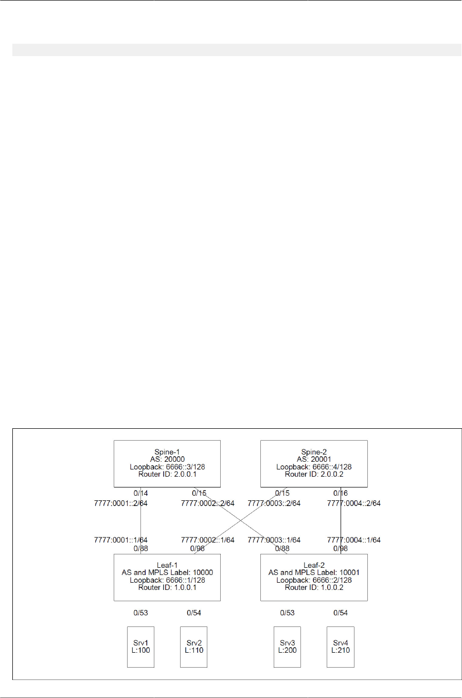
Configuring Data Center Features
214
(Routing) (Config)#mplsd lfdb ipv6 1001 last-pop 77:88::1/128
The advantage of the per-interface label distribution mode over the per-switch distribution mode is
that the traffic originator only needs to impose one label on the MPLS label stack. Some devices
cannot impose multiple labels. Another advantage is that BGP neighbors can learn about all labels
used in the network via the RFC 3107 label exchange.
On the other hand, distributing multiple per-interface labels from each switch consumes more
hardware resources than distributing one per-switch label. The hardware resources required for
distributing labels include route entries, next hop entries, and ECMP groups. Therefore, the per-in-
terface labels are not scalable to the large spine-leaf data center networks.
7.9.2.8. Bidirectional Forwarding Detection
In the current release the MPLS-BFD protocol is not supported.
The switch does support the BFD protocol over IP sessions. The BGP protocol can use BFD to de-
tect peer switch failures. Therefore, the MPLS labels distributed by the RFC 3107 BGP extension
are affected by the BFD failure detection.
7.9.2.9. MPLS-Ping and MPLS-Traceroute
In the current release the MPLS-Ping and the MPLS-Traceroute protocols are not supported.
7.9.3. ICOS MPLS Use Cases
This section shows several example configurations of MPLS network with ICOS switches.
7.9.3.1. IPv6 Clos Network
This example configures four ICOS switches to form the IPv6 network shown in Figure below:
Figure7.5.IPv6 Clos Network Example

Configuring Data Center Features
215
The network consists of four switches: Spine-1, Spine-2, Leaf-1, and Leaf-2. The switches are
connected in a Clos topology. The network also has four servers: Srv1, Srv2, Srv3, and Srv4. The
switch and server MAC addresses are not shown in the diagram, but this example uses the follow-
ing values:
• Spine-1: 60:eb:69:6f:20:d0
• Spine-2: c8:0a:a9:9e:14:56
• Leaf-1: 00:86:90:23:13:63
• Leaf-2: 00:90:00:10:FF:FF
• Srv1: 00:00:00:00:01:01
• Srv2: 00:00:00:00:01:02
• Srv3: 00:00:00:00:02:01
• Srv4: 00:00:00:00:02:02
The servers are devices such as hypervisors with multiple virtual machines that send MPLS-
tagged traffic to other servers through the data center network. The MPLS label stack which
needs to be used to switch the packet between the source and destination is programmed into the
servers externally, such as via some Software Defined Networking mechanism.
The switches are running eBGP. The BGP Autonomous System identifier is indicated by the “AS”
value. Each switch is assigned its own AS. There are no routing protocols running between the
servers and the switches.
The Leaf switches are statically assigned an MPLS label, which they distribute along with the loop-
back interface subnet to the BGP peers. In this example the MPLS label is configured to have the
same value as the AS identifier.
7.9.3.2. Switch Configuration
The following is the output of show running-config on the four switches. Comments are added to
the leaf-1 configuration to explain some of the commands.
leaf-1:
(Routing) #hostname "leaf-1"
! Enable IPv6 routing
(Routing) #configure
(leaf-1) (Config)#ipv6 unicast-routing
(leaf-1) (Config)#ip routing
! Create static labels that enable traffic to go to the Srv1 and Srv2
! devices.
! The commands implicitly enable MPLS on VLAN 1, which allows traffic from
! these servers to go into the network.
(leaf-1) (Config)#mplsd lfdb layer-2 100 pop 0/53 1 00:00:00:00:01:01
(leaf-1) (Config)#mplsd lfdb layer-2 110 pop 0/54 1 00:00:00:00:01:02

Configuring Data Center Features
216
! Prevent serial console from timing out.
(leaf-1) (Config)#line console
(leaf-1) (Config-line)#serial timeout 0
(leaf-1) (Config-line)#exit
(leaf-1) (Config)#line telnet (leaf-1)
(Config-telnet)#exit
! Create the loopback interface for which to distribute the per-switch
! label.
(leaf-1) (Config)#interface loopback 0
(leaf-1) (Interface loopback 0)#ipv6 address 6666::1/128
(leaf-1) (Interface loopback 0)#ipv6 enable
! Configure the switch to distribute label 10000 via BGP for the
! loopback interface 0.
(leaf-1) (Config)#ipv6 mplsd bgp-mpls-label 10000
(leaf-1) (Config)#exit
! Assuming that the servers use the standard 1518 frame size, setting
! the MTU to 2000
! enables the switch to forward 1518 byte frames with a reasonable size
! MPLS label stack.
(leaf-1) (Config)#interface 0/53,0/54
(leaf-1) (Interface 0/53,0/54)#mtu 2000
(leaf-1) (Interface 0/53,0/54)#exit
! Configure interfaces 0/88 and 0/98 as port-based routing interfaces
! with IPv6 addresses.
(leaf-1) (Config)#interface 0/88
(leaf-1) (Interface 0/88)#routing
(leaf-1) (Interface 0/88)#ipv6 address 7777:1::1/64
(leaf-1) (Interface 0/88)#ipv6 enable
(leaf-1) (Interface 0/88)#exit
(leaf-1) (Config)#interface 0/98
(leaf-1) (Interface 0/89)#mtu 2000
(leaf-1) (Interface 0/89)#routing
(leaf-1) (Interface 0/89)#ipv6 address 7777:3::1/64
(leaf-1) (Interface 0/89)#ipv6 enable
(leaf-1) (Interface 0/89)#exit
! For convenience set the BGP system ID to be the same as the distributed
! MPLS label.
! The system ID can be different from the MPLS label if desired.
(leaf-1) (Config)#router bgp 10000
! The router ID is specified in IPv4 address format as per RFC. This
! address is not used for sending or receiving packets, so it is safe
! in IPv6-only networks.
(leaf-1) (Config-router)#bgp router-id 1.0.0.1
! To help debugging connectivity issues enable logging of BGP adjacency
! changes.
(leaf-1) (Config-router)#bgp log-neighbor-changes

Configuring Data Center Features
217
! Define eBGP peer switches. All directly connected spine switches must
! be defined as BGP peers for the leaf switch.
(leaf-1) (Config-router)#neighbor 7777:1::2 remote-as 20000
(leaf-1) (Config-router)#neighbor 7777:3::2 remote-as 20001
! Enter IPv6 configuration mode.
(leaf-1) (Config-router)#address-family ipv6
! Enable BGP to support 16 ECMP neighbors. If you get an error on this
! command then you are probably using the wrong SDM template. Check the
! current settings by using the "show sdm prefer" command. The
! appropriate template for IPv6 network can be set using the "sdm prefer
! dual-ipv4-and-ipv6 data-center" command.
(leaf-1) (Config-router-af)#maximum-paths 16
! Tell BGP to export the route for the loopback interface. This is
! necessary in order to distribute the MPLS label associated with this
! switch. Note that the port-based routing interfaces are not
! distributed, which reduces the routing table size.
(leaf-1) (Config-router-af)#network 6666::1/128
(leaf-1) (Config-router-af)#neighbor 7777:1::2 activate
(leaf-1) (Config-router-af)#neighbor 7777:3::2 activate
(leaf-1) (Config-router-af)#exit
(leaf-1) (Config-router)#exit
(leaf-1) (Config)#exit
leaf-2:
(Routing) #hostname "leaf-2"
(leaf-2) #configure
(leaf-2) (Config)#ipv6 unicast-routing
(leaf-2) (Config)#ip routing
(leaf-2) (Config)#mplsdlfdb layer-2 200 pop 0/53 1 00:00:00:00:02:01
(leaf-2) (Config)#mplsd lfdb layer-2 210 pop 0/54 1 00:00:00:00:02:02
(leaf-2) (Config)#line console
(leaf-2) (Config-line)#serial timeout 0
(leaf-2) (Config-line)#exit
(leaf-2) (Config)#line telnet
(leaf-2) (Config-telnet)#exit
(leaf-2) (Config)#line ssh
(leaf-2) (Config-ssh)#exit
(leaf-2) (Config)#interface loopback 0
(leaf-2) (Interface loopback 0)#ipv6 address 6666::2/128
(leaf-2) (Interface loopback 0)#ipv6 enable
(leaf-2) (Interface loopback 0)#ipv6 mplsd bgp-mpls-label 10001
(leaf-2) (Interface loopback 0)#exit
(leaf-2) (Config)#interface 0/53
(leaf-2) (Interface 0/53)#mtu 2000

Configuring Data Center Features
218
(leaf-2) (Interface 0/53)#exit
(leaf-2) (Config)#interface 0/54
(leaf-2) (Interface 0/54)#mtu 2000
(leaf-2) (Interface 0/54)#exit
(leaf-2) (Config)#interface 0/88
(leaf-2) (Interface 0/54)#mtu 2000
(leaf-2) (Interface 0/54)#routing
(leaf-2) (Interface 0/54)#ipv6 address 7777:2::1/64
(leaf-2) (Interface 0/54)#ipv6 enable
(leaf-2) (Interface 0/54)#exit
(leaf-2) (Config)#interface 0/98
(leaf-2) (Interface 0/98)#mtu 2000
(leaf-2) (Interface 0/98)#routing
(leaf-2) (Interface 0/98)#ipv6 address 7777:4::1/64
(leaf-2) (Interface 0/98)#ipv6 enable
(leaf-2) (Interface 0/98)#exit
(leaf-2) (Config)#router ospf
(leaf-2) (Config-router)#exit
(leaf-2) (Config)#ipv6 router ospf
(leaf-2) (Config-rtr)#exit
(leaf-2) (Config)#router bgp 10001
(leaf-2) (Config-router)#bgp router-id 1.0.0.2
(leaf-2) (Config-router)#bgp log-neighbor-changes
(leaf-2) (Config-router)#neighbor 7777:2::2 remote-as 20000
(leaf-2) (Config-router)#neighbor 7777:4::2 remote-as 20001
(leaf-2) (Config-router)#address-family ipv6
(leaf-2) (Config-router-af)#maximum-paths 16
(leaf-2) (Config-router-af)#network 6666::2/128
(leaf-2) (Config-router-af)#neighbor 7777:2::2 activate
(leaf-2) (Config-router-af)#neighbor 7777:4::2 activate
(leaf-2) (Config-router-af)#exit
(leaf-2) (Config-router)#exit (leaf-2) (Config)#exit
spine-1:
(Routing) #hostname "spine-1"
(spine-1) #configure
(spine-1) (Config)#ipv6 unicast-routing
(spine-1) (Config)#ip routing
(spine-1) (Config)#line console
(spine-1) (Config-line)#serial timeout 0
(spine-1) (Config-line)#exit
(spine-1) (Config)#line telnet
(spine-1) (Config-telnet)#exit
(spine-1) (Config)#line ssh

Configuring Data Center Features
219
(spine-1) (Config-ssh)#exit
(spine-1) (Config)#interface loopback 0
(spine-1) (Interface loopback 0)#ipv6 address 6666::3/128
(spine-1) (Interface loopback 0)#ipv6 enable
(spine-1) (Interface loopback 0)#exit
(spine-1) (Config)#interface 0/14
(spine-1) (Interface 0/14)#mtu 2000
(spine-1) (Interface 0/14)#routing
(spine-1) (Interface 0/14)#ipv6 address 7777:1::2/64
(spine-1) (Interface 0/14)#ipv6 enable
(spine-1) (Interface 0/14)#exit
(spine-1) (Config)#interface 0/15
(spine-1) (Interface 0/15)#mtu 2000
(spine-1) (Interface 0/15)#routing
(spine-1) (Interface 0/15)#ipv6 address 7777:2::2/64
(spine-1) (Interface 0/15)#ipv6 enable
(spine-1) (Interface 0/15)#exit
(spine-1) (Config)#router ospf
(spine-1) (Config-router)#exit
(spine-1) (Config)#ipv6 router ospf
(spine-1) (Config-rtr)#exit
(spine-1) (Config)#router bgp 20000
(spine-1) (Config-router)#bgp router-id 2.0.0.1
(spine-1) (Config-router)#bgp log-neighbor-changes
(spine-1) (Config-router)#neighbor 7777:1::1 remote-as 10000
(spine-1) (Config-router)#neighbor 7777:2::1 remote-as 10001
(spine-1) (Config-router)#address-family ipv6
(spine-1) (Config-router-af)#maximum-paths 16
(spine-1) (Config-router-af)#network 6666::3/128
(spine-1) (Config-router-af)#neighbor 7777:1::1 activate
(spine-1) (Config-router-af)#neighbor 7777:2::1 activate
(spine-1) (Config-router-af)#exit
(spine-1) (Config-router)#exit
(spine-1) (Config)#exit
spine-2: (Routing) #hostname "spine-2"
(spine-2) #configure
(spine-2) (Config)#ipv6 unicast-routing
(spine-2) (Config)#ip routing
(spine-2) (Config)#line console
(spine-2) (Config-line)#serial timeout 0
(spine-2) (Config-line)#exit
(spine-2) (Config)#line telnet
(spine-2) (Config-telnet)#exit
(spine-2) (Config)#line ssh

Configuring Data Center Features
220
(spine-2) (Config-ssh)#exit
(spine-2) (Config)#interface loopback 0
(spine-2) (Interface loopback 0)#ipv6 address 6666::4/128
(spine-2) (Interface loopback 0)#ipv6 enable
(spine-2) (Interface loopback 0)#exit
(spine-2) (Config)#interface 0/15
(spine-2) (Interface 0/15)#mtu 2000
(spine-2) (Interface 0/15)#routing
(spine-2) (Interface 0/15)#ipv6 address 7777:3::2/64
(spine-2) (Interface 0/15)#ipv6 enable
(spine-2) (Interface 0/15)#exit
(spine-2) (Config)#interface 0/16
(spine-2) (Interface 0/16)#mtu 2000
(spine-2) (Interface 0/16)#routing
(spine-2) (Interface 0/16)#ipv6 address 7777:4::2/64
(spine-2) (Interface 0/16)#ipv6 enable
(spine-2) (Interface 0/16)#exit
(spine-2) (Config)#router bgp 20001
(spine-2) (Config-router)#bgp router-id 2.0.0.2
(spine-2) (Config-router)#bgp log-neighbor-changes
(spine-2) (Config-router)#neighbor 7777:3::1 remote-as 10000
(spine-2) (Config-router)#neighbor 7777:4::1 remote-as 10001
(spine-2) (Config-router)#address-family ipv6
(spine-2) (Config-router-af)#maximum-paths 16
(spine-2) (Config-router-af)#network 6666::4/128
(spine-2) (Config-router-af)#neighbor 7777:3::1 activate
(spine-2) (Config-router-af)#neighbor 7777:4::1 activate
(spine-2) (Config-router-af)exit
(spine-2) (Config-router)#exit
(spine-2) (Config)#exit
7.9.3.3. Verifying Configuration
The following commands are used to verify the network configuration. These commands are is-
sued on the Leaf-1 switch.
Example 1:
Verify that IPv6 interfaces are created with the appropriate IP addresses:
(leaf-1) #show ipv6 interface brief
Oper.
Interface Mode IPv6 Address/Length
---------- -------- ---------------------------------
0/88 Enabled fe80::210:18ff:fe99:f7ae/64
7777:1::1/64
0/98 Enabled fe80::210:18ff:fe99:f7ae/64
7777:3::1/64

Configuring Data Center Features
221
loopback 0 Enabled fe80::210:18ff:fe99:f7ab/64
6666::1/128
(leaf-1) #
Example 2:
Verify that BGP formed connections with neighbors.
(leaf-1) #show bgp ipv6 summary
IPv6 Routing .................................. Enable
BGP Admin Mode ................................ Enable
BGP Router ID ................................... 1.0.0.1
Local AS Number ............................... 10000
Number of Network Entries ....................... 4
Number of AS Paths .............................. 3
Neighbor ASN MsgRcvd MsgSent State Up/Down Time Pfx Rcvd
--------- ----- ------- ------- ----------- -------------- ---------
7777:1::2 20000 71 68 ESTABLISHED 0:00:27:24 3
7777:3::2 20001 73 69 ESTABLISHED 0:00:27:24 3
(leaf-1) #
Example 3:
Verify that routes have been installed. Note that there is an ECMP route to the loopback subnet
6666::2/128 on Leaf-2.
(leaf-1) #show ipv6 route
IPv6 Routing Table - 6 entries
Codes: C - connected, S - static, 6To4 - 6to4 Route, B - BGP Derived
O - OSPF Intra, OI - OSPF Inter, OE1 - OSPF Ext 1, OE2 - OSPF Ext 2
ON1 - OSPF NSSA Ext Type 1, ON2 - OSPF NSSA Ext Type 2
C 6666::1/128 [0/0]
via ::, loopback 0
B 6666::2/128 [20/0]
via fe80::62eb:69ff:fe6f:20d3, 00h:28m:26s, 0/1
via fe80::ca0a:a9ff:fe9e:1459, 00h:28m:26s, 0/2
B 6666::3/128 [20/0]
via fe80::62eb:69ff:fe6f:20d3, 00h:28m:26s, 0/1
B 6666::4/128 [20/0]
via fe80::ca0a:a9ff:fe9e:1459, 00h:28m:26s, 0/2
C 7777:1::/64 [0/0]
via ::, 0/1
C 7777:3::/64 [0/0]
via ::, 0/2
(leaf-1) #
Example 4:
Verify connectivity from leaf-1 to leaf-2. The ping and the traceroute commands must be issued
with the source loopback 0 qualifier. The source command option forces the switch to use the
loopback subnet as the source IP address for the ping requests. Without the source option, the

Configuring Data Center Features
222
source IP is the egress interface 7777:0003::2, which is not configured to be advertised by the
BGP. Therefore, the ping reply will fail without the source option.
Also note that the ping command for IPv6 blocks for 3 seconds and does not show intermediate
ping replies. The successful completion is indicated by the non-zero value in the “Receive count”.
(leaf-1) #
(leaf-1) #ping ipv6 6666::2 source loopback 0
Pinging 6666::2 with 0 bytes of data:
Send count=3, Receive count=3 from 6666::2
Average round trip time = 1.00 ms
(leaf-1) #
(leaf-1) #traceroute ipv6 6666::2 source loopback 0
Tracing route over a maximum of 30 hops
1 7777:1::2 1 ms 1 ms 1 ms
2 6666::2 1 ms 1 ms 1 ms
Hop Count = 2 Last TTL = 2 Test attempt = 6 Test Success = 6
(leaf-1) #
Example 5:
View the content of the LFDB database.
(leaf-1) #show mplsd lfdb all
Label:100 Protocol:Static Type:Layer-2 Subnet:N/A
Egress Label Action:pop Egress Label:N/A
Egress Interface Port:0/53 Vlan:1 MAC:00:00:00:00:01:01
Hardware Status:Inserted Not Inserted Reason:N/A
Byte Count:0 Packet Count:0
Duplicate Insertion Attempts:0
Label:110 Protocol:Static Type:Layer-2 Subnet:N/A
Egress Label Action:pop Egress Label:N/A
Egress Interface Port:0/54 Vlan:1 MAC:00:00:00:00:01:02
Hardware Status:Inserted Not Inserted Reason:N/A
Byte Count:9115455237924 Packet Count:5711438119
Duplicate Insertion Attempts:0
Label:10001 Protocol:BGP Type:ipv6 Subnet:6666::2/128
Egress Label Action:swap Egress Label:N/A
Egress Interface Port:N/A Vlan:N/A MAC:N/A
Hardware Status:Inserted Not Inserted Reason:N/A
Byte Count:0 Packet Count:0
Duplicate Insertion Attempts:0 (leaf-1) #
(leaf-1) #
7.9.3.4. Traffic Forwarding Examples
To switch packets through the network, the packets must be MPLS-tagged on ingress and egress.
Example 1:

Configuring Data Center Features
223
In this example the packet is switched from Srv1 to Srv2. Since the packet does not traverse multi-
ple switches, the top MPLS label in the packet must be the label of Serv2, which is 110. The pack-
et must also have a second label in the stack, which identifies a virtual machine, or has some oth-
er local meaning in Srv2. In this example, the second label is 2222.
The destination MAC is the MAC of Leaf-1. The packet is sent untagged, which internally in the
switch Leaf-1 maps to VLAN1.
The packet transmitted from the Srv1 to Srv2 has the following addressing information:
• DA MAC: 00:86:90:23:13:63
• SA MAC: 00:00:00:00:01:01
• Label Stack: 110 2222
The Leaf-1 switch receives the packet on port 6 and MPLS-switches the packet because it is con-
figured with Static L2 label 110. The label action for 110 is to pop the label and send the packet on
port 7. The Leaf-1 switch transmits the packet on port 7, without a VLAN tag, with the following ad-
dressing information:
• DA MAC: 00:00:00:00:01:02
• SA MAC: 00:86:90:23:13:63
• Label Stack: 2222
Example 2:
In this example, the packet is switched from Srv1 to Srv3. Since the packet traverses multiple
switches, the top label in the MPLS label stack must be the label of the switch to which the Srv3
is attached. In this example, the Srv3 is attached to Leaf-2, which distributes the label 10001. The
Srv3 is assigned the label 200 and, in this example, internally in Srv3 the MPLS label is 3005.
The packet transmitted from Srv1 to Srv3 has the following addressing information:
• DA MAC: 00:86:90:23:13:63
• SA MAC: 00:00:00:00:01:01
• Labels Stack: 10001 200 3005
The Leaf-1 receives the packet on port 6 and MPLS-switches the packet because label 10001 has
been distributed via BGP and programmed into the Leaf-1 Label Forwarding Database (LFDB).
The action for label 10001 is to send the packet on an ECMP path towards Leaf-2. The packet
may egress Leaf-2 either on port 1 or port 2. The action for the label 10001 is to swap with label
10001, which effectively preserves the same label at the top of the stack.
Assuming the frame exits Leaf-1 on port 1 towards Spine-1, the following addressing information is
in the packet:
• DA MAC: 60:eb:69:6f:20:d0
• SA MAC: 00:86:90:23:13:63
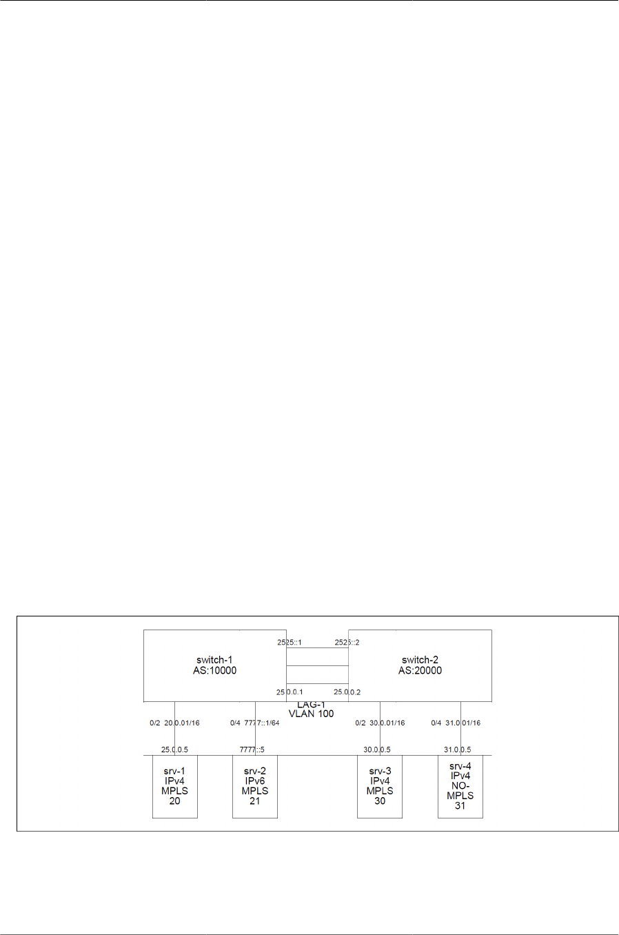
Configuring Data Center Features
224
• Label Stack 10001 200 3005
The Spine-1 switch receives the packet because label 10001 is distributed by BGP from Leaf-2.
Because the subnet associated with label 10001 is locally attached to Leaf-2 the action for label
10001 is to pop the label stack and send the packet on port 2.
The frame exits Spine-1 on port 2 with the following addressing information:
• DA MAC: 00:90:00:10:FF:FF
• SA MAC: 60:eb:69:6f:20:d0
• Label Stack: 200 3005
The packet is received by Leaf-2 on port 1 because label 200 is statically programmed into the
LFDB on Leaf-2. The label action for label 200 is pop, and the egress port is 6.
The Leaf-2 transmits the packet on port 6 with the following addressing information:
• DA MAC: 00:00:00:00:02:01
• SA MAC: 00:90:00:10:FF:FF
• Label Stack: 3005
7.9.3.5. IPv4 Network with IPv6 Subnets, VLANs, and LAGs
This example demonstrates the use of per-interface MPLS labels in an IPv4/IPv6 network that also
uses LAGs and VLAN routing interfaces.
The ICOS BGP protocol can distribute IPv6 routes over IPv4 BGP peer sessions. The IPv4 routes
cannot be distributed over IPv6 peer sessions. Therefore, when running the network in a mixed
IPv4 and IPv6 environment, the BGP is configured to run over IPv4. Customers who do not need
IPv6 can simply ignore the IPv6-related configuration in the following example.
Figure7.6.MPLS Labels in IPv4/IPv6 Network with LAGs and VLAN Routing
The network consists of two switches: switch-1 and switch-2. The switches are connected to each
other via a LAG. The LAG is a member of VLAN 100. Both switches have routing interfaces on
VLAN 100 with IP addresses 25.0.0.1 and 25.0.0.2. The VLAN routing interface is also enabled for
IPv6 with addresses 2525::1/64 and 2525::2/64.

Configuring Data Center Features
225
The network also has four servers: srv-1, srv-2, srv-3, and srv-4. The switch and server MAC ad-
dresses are not shown in the diagram, but the following values are used for this example:
• switch-1: 00:10:18:7f:f9:8e
• switch-2: 00:10:18:99:f6:7a
• srv-1: 00:00:00:00:01:01
• srv-2: 00:00:00:00:01:02
• srv-3: 00:00:00:00:02:01
• srv-4: 00:00:00:00:02:02
The servers 1, 2, and 3 are devices such as hypervisors with multiple virtual machines that send
MPLS-tagged traffic to other servers through the data center network. The MPLS label stack which
needs to be used to switch the packet between the source and destination is programmed into the
servers externally, such as via some Software Defined Networking mechanism.
In this example the server 4 is an IPv4 device that does not support MPLS tagging. The srv-4
sends traffic into the switch without the MPLS tags. The switch routes the traffic from srv-4 using
the IP routing tables. Any MPLS packets destined to srv-4 are stripped of the MPLS tag.
All the servers are attached to the switches via port-based routing interfaces with the IP addresses
shown above. The srv-1 is an IPv6 device.
The switches are running eBGP. The BGP Autonomous System identifier is indicated by the “AS”
value. Each switch is assigned its own AS. There are no routing protocols running between the
servers and the switches.
The servers 1, 2, and 3 are assigned MPLS labels. The labels are statically configured in the
switch as “per- interface” labels and are distributed by BGP to the peer switch.
Switch Configuration
The following is the output of “show running-config” on the two switches. Comments are added to
the configuration to explain some of the commands.
switch-1:
(Routing) #hostname "switch-1"
! Create a VLAN for the VLAN routing interface.
(switch-1) #vlan database
(switch-1) (Vlan)#vlan 100
(switch-1) (Vlan)#vlan routing 100 1
(switch-1) (Vlan)#exit
(switch-1) #configure
! Enable IPv4 and IPv6 routing.
(switch-1) (Config)#ipv6 unicast-routing
(switch-1) (Config)#ip routing
! Create LFDB entries associated with IPv4 host 20.0.0.5 and IPv6
! host 7777::5.

Configuring Data Center Features
226
! The MAC addresses for the hosts are automatically picked up from the
! ARP/Neighbor tables.
!
(switch-1) (Config)#mplsd lfdb ipv4 20 swap 20.0.0.5/32
(switch-1) (Config)#mplsd lfdb ipv6 21 swap 7777::5/128
(switch-1) (Config)#line console
(switch-1) (Config-line)#serial timeout 0
(switch-1) (Config-line)#exit
(switch-1) (Config)#line telnet
(switch-1) (Config-telnet)#exit
! Add ports 0/23, 0/24, 0/25 to LAG-1
!
(switch-1) (Config)#interface 0/23
(switch-1) (Interface 0/23)#addport 3/1
(switch-1) (Interface 0/23)#exit
(switch-1) (Config)#interface 0/24
(switch-1) (Interface 0/24)#addport 3/1
(switch-1) (Interface 0/24)#exit (switch-1)
(Config)#interface 0/25 (switch-1)
(Interface 0/25)#addport 3/1
(switch-1) (Interface 0/25)#exit
(switch-1) (Config)#interface 0/2
! Increase the port MTU to enable support for standard 1518-byte frames
! with reasonable size MPLS header.
!
(switch-1) (Interface 0/2)#mtu 2000
(switch-1) (Interface 0/2)#routing
(switch-1) (Interface 0/2)#ip address 20.0.0.1 255.255.0.0
! Tell BGP to export MPLS label 20 for this interface.
!
(switch-1) (Interface 0/2)#mplsd bgp-mpls-label 20
(switch-1) (Interface 0/2)#exit
! Enable this interface for IPv6.
!
(switch-1) (Config)#interface 0/4
(switch-1) (Interface 0/4)#mtu 2000
(switch-1) (Interface 0/4)#routing
(switch-1) (Interface 0/4)#ipv6 address 7777::1/64
(switch-1) (Interface 0/4)#ipv6 enable
(switch-1) (Interface 0/4)#ipv6 mplsd bgp-mpls-label 21
(switch-1) (Interface 0/4)#exit
(switch-1) (Config)#interface lag 1
(switch-1) (Interface lag 1)#mtu 2000
(switch-1) (Interface lag 1)#vlan participation include 100
(switch-1) (Interface lag 1)#vlan tagging 100
(switch-1) (Interface lag 1)#exit
! The VLAN routing interface carries both, IPv4 and IPv6 traffic.
! Therefore the interface must have IPv4 and IPv6 addresses.

Configuring Data Center Features
227
!
(switch-1) (Config)#interface vlan 100
(switch-1) (Interface vlan 100)#routing
(switch-1) (Interface vlan 100)#ip address 25.0.0.1 255.255.0.0
(switch-1) (Interface vlan 100)#ipv6 address 2525::1/64
(switch-1) (Interface vlan 100)#ipv6 enable
(switch-1) (Interface vlan 100)#exit
(switch-1) (Config)#router bgp 10000
(switch-1) (Config-router)#bgp router-id 1.0.0.1
(switch-1) (Config-router)#maximum-paths 16
(switch-1) (Config-router)#bgp log-neighbor-changes
(switch-1) (Config-router)#neighbor 25.0.0.2 remote-as 10001
! Instruct BGP to advertise local subnets and per-interface MPLS
! labels to the neighbors.
!
(switch-1) (Config-router)#redistribute connected
(switch-1) (Config-router)#address-family ipv6
(switch-1) (Config-router-af)#maximum-paths 16
(switch-1) (Config-router-af)#redistribute connected
! In IPv4/IPv6 mixed mode the IPv6 route information is carried over
! IPv4 sessions.
(switch-1) (Config-router-af)#neighbor 25.0.0.2 activate
(switch-1) (Config-router-af)#exit
(switch-1) (Config-router)#exit
! The static ARP and Neighbor table entries are normally not necessary.
! These values are learned dynamically via the ARP or NDP protocols.
! The configuration is present here in order to simplify testing with
! the traffic generator.
(switch-1) (Config)#arp 20.0.0.5 00:00:00:00:01:01
(switch-1) (Config)#ipv6 neighbor 7777::5 0/4 00:00:00:00:01:02
(switch-1) (Config)#exit
switch-2:
(Routing) #hostname "switch-2"
(switch-2) #vlan database
(switch-2) (Vlan)#vlan 100
(switch-2) (Vlan)#vlan routing 100 1
(switch-2) (Vlan)#exit
(switch-2) #configure
(switch-2) (Config)#ipv6 unicast-routing
(switch-2) (Config)#ip routing
(switch-2) (Config)#mplsd lfdb ipv4 30 swap 30.0.0.5/32
! This LFDB entry strips the last MPLS tag from the IPv4 and IPv6
! packets.
(switch-2) (Config)#mplsd lfdb ipv4 31 last-pop 31.0.0.5/32
(switch-2) (Config-line)#line console
(switch-2) (Config-line)#serial timeout 0

Configuring Data Center Features
228
(switch-2) (Config-line)#exit
(switch-2) (Config)#line telnet
(switch-2) (Config-telnet)#exit
(switch-2) (Config)#interface 0/23
(switch-2) (Interface 0/23)#addport 3/1
(switch-2) (Interface 0/23)#exit
(switch-2) (Config)#interface 0/24
(switch-2) (Interface 0/24)#addport 3/1
(switch-2) (Interface 0/24)#exit
(switch-2) (Config)#interface 0/25
(switch-2) (Interface 0/25)#addport 3/1
(switch-2) (Interface 0/25)#exit
(switch-2) (Config)#interface 0/2
(switch-2) (Interface 0/2)#mtu 2000
(switch-2) (Interface 0/2)#routing
(switch-2) (Interface 0/2)#ip address 30.0.0.1 255.255.0.0
(switch-2) (Interface 0/2)#mplsd bgp-mpls-label 30
(switch-2) (Interface 0/2)#exit
(switch-2) (Config)#interface 0/4
(switch-2) (Interface 0/4)#routing
(switch-2) (Interface 0/4)#ip address 31.0.0.1 255.255.0.0
(switch-2) (Interface 0/4)#mplsd bgp-mpls-label 31
(switch-2) (Interface 0/4)#exit
(switch-2) (Config)#interface lag 1
(switch-2) (Interface lag 1)#mtu 2000
(switch-2) (Interface lag 1)#vlan participation include 100
(switch-2) (Interface lag 1)#vlan tagging 100
(switch-2) (Interface lag 1)#exit
(switch-2) (Config)#interface vlan 100
(switch-2) (Interface vlan 100)#routing
(switch-2) (Interface vlan 100)#ip address 25.0.0.2 255.255.0.0
(switch-2) (Interface vlan 100)#ipv6 address 2525::2/64
(switch-2) (Interface vlan 100)#ipv6 enable
(switch-2) (Interface vlan 100)#exit
(switch-2) (Config)#router rip
(switch-2) (Config-router)#exit
(switch-2) (Config)#router ospf
(switch-2) (Config-router)#exit
(switch-2) (Config)#ipv6 router ospf
(switch-2) (Config-rtr)#exit
(switch-2) (Config)#router bgp 10001
(switch-2) (Config-router)#bgp router-id 1.0.0.2

Configuring Data Center Features
229
(switch-2) (Config-router)#maximum-paths 16
(switch-2) (Config-router)#bgp log-neighbor-changes
(switch-2) (Config-router)#neighbor 25.0.0.1 remote-as 10000
(switch-2) (Config-router)#redistribute connected
(switch-2) (Config-router)#address-family ipv6
(switch-2) (Config-router-af)#maximum-paths 16
(switch-2) (Config-router-af)#redistribute connected
(switch-2) (Config-router-af)#neighbor 25.0.0.1 activate
(switch-2) (Config-router-af)#exit
(switch-2) (Config-router)#exit
(switch-2) (Config)#arp 30.0.0.5 00:00:00:00:02:01
(switch-2) (Config)#arp 31.0.0.5 00:00:00:00:02:02
(switch-2) (Config)#exit
Verifying Configuration
The following commands are used to verify the network configuration. These commands are is-
sued on switch-2.
Example 1:
Verify that IPv4 and IPv6 interfaces are created with the appropriate IP addresses:
(switch-2) #show ip interface brief
Interface State IP Address IP Mask Method
---------- ----- --------------- --------------- -------
0/2 Up 30.0.0.1 255.255.0.0 Manual
0/4 Up 31.0.0.1 255.255.0.0 Manual
4/1 Up 25.0.0.2 255.255.0.0 Manual
(switch-2) #
(switch-2) #show ipv6 interface brief
Oper.
Interface Mode IPv6 Address/Length
---------- -------- ---------------------------------
0/2 Disabled fe80::210:18ff:fe99:f67a/64 [TENT]
0/4 Disabled fe80::210:18ff:fe99:f67a/64 [TENT]
4/1 Enabled fe80::210:18ff:fe99:f67a/64
2525::2/64
(switch-2) #
Example 2:
Verify that BGP formed connections with neighbors for exchanging IPv4 and IPv6 routes.
(switch-2) #show ip bgp summary
IPv4 Routing .................................. Enable
BGP Admin Mode ................................ Enable
BGP Router ID ................................... 1.0.0.2
Local AS Number ............................... 10001
Number of Network Entries ....................... 4

Configuring Data Center Features
230
Number of AS Paths .............................. 1
Dynamic Neighbors Current/High/Limit........... 1/1/100
Neighbor ASN MsgRcvd MsgSent State Up/Down Time Pfx Rcvd
----------- ----- ------- ------- ----------- ------------- ---------
25.0.0.1 10000 2341 2346 ESTABLISHED 0:16:33:11 2
*100.20.1.7 30 0 7 OPEN SENT 0
(switch-2) #show bgp ipv6 summary
IPv6 Routing .................................. Enable
BGP Admin Mode ................................ Enable
BGP Router ID ................................... 1.0.0.2
Local AS Number ............................... 10001
Number of Network Entries ....................... 2
Number of AS Paths .............................. 1
Neighbor ASN MsgRcvd MsgSent State Up/Down Time Pfx Rcvd
----------- ----- ------- ------- ----------- ------------- ---------
25.0.0.1 10000 2341 2346 ESTABLISHED 0:16:33:11 1
Example 3:
Verify that IPv4 and IPv6 routes have been installed.
(switch-2) #show ip route
Route Codes: R - RIP Derived, O - OSPF Derived, C - Connected, S - Static
B - BGP Derived, IA - OSPF Inter Area
E1 - OSPF External Type 1, E2 - OSPF External Type 2
N1 - OSPF NSSA External Type 1, N2 - OSPF NSSA External Type 2
S U - Unnumbered Peer
B 20.0.0.0/16 [20/0] via 25.0.0.1, 16h:35m:00s, 4/1
C 25.0.0.0/16 [0/1] directly connected, 4/1
C 30.0.0.0/16 [0/1] directly connected, 0/2
C 31.0.0.0/16 [0/1] directly connected, 0/4
(switch-2) #show ipv6 route IPv6
Routing Table - 2 entries
Codes: C - connected, S - static, 6To4 - 6to4 Route, B - BGP Derived
O - OSPF Intra, OI - OSPF Inter, OE1 - OSPF Ext 1, OE2 - OSPF Ext 2
ON1 - OSPF NSSA Ext Type 1, ON2 - OSPF NSSA Ext Type 2
C 2525::/64 [0/0]
via ::, 4/1
B 7777::/64 [20/0]
via fe80::210:18ff:fe7f:f98e, 16h:35m:06s, 4/1
(switch-2) #
Example 4:
Verify IPv4 and IPv6 connectivity between switch-2 and switch-1.
Note that the ping command for IPv6 blocks for 3 seconds and does not show intermediate ping
replies. The successful completion is indicated by the non-zero value in the “Receive count”.
(switch-2) #ping 20.0.0.1
Pinging 20.0.0.1 with 0 bytes of data:

Configuring Data Center Features
231
Reply From 20.0.0.1: icmp_seq = 0. time= 2 msec.
Reply From 20.0.0.1: icmp_seq = 1. time= 2 msec.
Reply From 20.0.0.1: icmp_seq = 2. time= 2 msec.
----20.0.0.1 PING statistics----
3 packets transmitted, 3 packets received, 0% packet loss
round-trip (msec) min/avg/max = 2/2/2
(switch-2) #ping ipv6 7777::1
Pinging 7777::1 with 0 bytes of data:
Send count=3, Receive count=3 from 7777::1
Average round trip time = 2.00 ms
(switch-2) #
Example 5:
View the content of the LFDB Database.
(switch-2) #show mplsd lfdb all
Label:20 Protocol:BGP Type:ipv4 Subnet:20.0.0.0/16
Egress Label Action:swap Egress Label:N/A
Egress Port:N/A Vlan:N/A MAC:N/A
Hardware Status:Inserted Not Inserted Reason:N/A
Byte Count:0 Packet Count:0
Duplicate Insertion Attempts:0
Label:21 Protocol:BGP Type:ipv6 Subnet:7777::/64
Egress Label Action:swap Egress Label:N/A
Egress Port:N/A Vlan:N/A MAC:N/A
Hardware Status:Inserted Not Inserted Reason:N/A
Byte Count:0 Packet Count:0
Duplicate Insertion Attempts:0
Label:30 Protocol:Static Type:ipv4 Subnet:30.0.0.5/32
Egress Label Action:swap Egress Label:N/A
Egress Port:N/A Vlan:N/A MAC:N/A
Hardware Status:Inserted Not Inserted Reason:N/A
Byte Count:0 Packet Count:0
Duplicate Insertion Attempts:0
Label:31 Protocol:Static Type:ipv4 Subnet:31.0.0.5/32
Egress Label Action:last-pop Egress Label:N/A
Egress Port:N/A Vlan:N/A MAC:N/A
Hardware Status:Inserted Not Inserted Reason:N/A
Byte Count:0 Packet Count:0
Duplicate Insertion Attempts:0 (switch-2) #
7.9.3.6. Traffic Forwarding Examples
To switch packets through the network using MPLS, the packets must be MPLS-tagged on
ingress. It is possible to use the MPLS-tagged and regular IP traffic concurrently.
Example 1:

Configuring Data Center Features
232
In this example the packet is switched from srv-1 to srv-2. The top MPLS label in the packet must
be the label of srv-2, which is: 21. Depending on the server 2 operation, the packet may or may
not have another MPLS label. In this example, a second label is not necessary.
The destination MAC is the MAC of switch-1. The packet is sent without a VLAN tag, which inter-
nally in the switch-1 maps to VLAN 1.
The packet transmitted from the srv-1 to srv-2 has the following addressing information:
• DA MAC: 00:10:18:7f:f9:8e
• SA MAC: 00:00:00:00:01:01
Label Stack: 21
The switch-1 receives the packet on port 2. The action for label 21 is to swap the label and send
the packet to srv-2. The switch has an ARP entry that associates the srv-2 with port 4 and MAC
00;00:00:00:01:02. The switch-1 transmits the packet on port 4, without a VLAN tag, with the fol-
lowing addressing information:
• DA MAC: 00:00:00:00:01:02
• SA MAC: 00:10:18:7f:f9:8e
• Label Stack: 21
Example 2:
In this example the packet is switched from srv-1 to srv-3. The top MPLS label in the packet must
be the label of srv-3, which is: 30. Depending on the server 3 operation, the packet may or may
not have another MPLS label. In this example, a second label is not necessary.
The destination MAC is the MAC of switch-1. The packet is sent without a VLAN tag, which inter-
nally in the switch-1 maps to VLAN 1.
The packet transmitted from the srv-1 to srv-3 has the following addressing information:
• DA MAC: 00:10:18:7f:f9:8e
• SA MAC: 00:00:00:00:01:01
• Label Stack: 30
The switch-1 receives the packet on port 2 and performs MPLS switching on the packet because
label 30 has been distributed via BGP and programmed into the switch-1 Label Forwarding Data-
base (LFDB). The action for label 30 is to send the packet on the VLAN routing interface towards
switch-2 and to swap the label, which effectively preserves the same label at the top of the label
stack.
The following addressing information is in the packet when it is sent to switch-2:
• DA MAC: 00:10:18:99:f6:7a
• SA MAC: 00:10:18:7f:f9:8e
• VLAN Tag: 100

Configuring Data Center Features
233
• Label Stack: 30
The switch-2 receives the packet and MPLS-switches the packet because label 30 is statically pro-
grammed into the LFDB and points to the srv-3.
The frame exits switch-2 on port 4 with the following addressing information:
• DA MAC: 00:00:00:00:02:01
• SA MAC: 00:10:18:99:f6:7a
• Label Stack: 30
Example 3:
The MPLS traffic from serv-1 to serv-4 is very similar to the previous example except that the des-
tination MPLS label is 31.
When switch-2 receives the packet with label 31, it strips the last MPLS tag from the packet and
sends it untagged to serv-4.
Example 4:
The traffic from serv-4 to serv-1 is not MPLS tagged because serv-4 does not support the MPLS
tagging. The packet is simply routed based on the IPv4 routing tables in the switches.
7.9.4. MPLS Device Connectivity Diagnostics and De-
bugging
The following sections describe the diagnostic facilities that ICOS provides to help debug MPLS
connectivity issues:
• Section 7.9.4.1, “LFDB Lookup Failure Packet Trace”
• Section 7.9.4.2, “MPLS and Port Counters”
• Section 7.9.4.3, “MPLS Packet Capture”
7.9.4.1. LFDB Lookup Failure Packet Trace
The MPLS packets that fail hardware LFDB lookup are automatically sent to the CPU. In order to
avoid CPU congestion the packets are rate limited at 64 Kb/s.
The received MPLS LFDB lookup failure packets are logged in the syslog. ICOS limits the LFDB
Lookup Failure log entries at one entry every 5 seconds.
The packets can be examined using the command show logging buffered. The most recent entry
is shown first. The log can be cleared using the command clear logging buffered.
The following is an example log entry for a packet that failed the LFDB lookup:
14 Jan 1 05:44:58 10.27.22.145-1 MPLSD[dtlTask]: mpls.c(839)
1224 %% Lookup Failure USP:1.0.31 Msg Size:64 Labels:1000/200/-
TTL:64/64/- EXP:0x0/0x0/- BOS:0/1/- VLAN:1 DA MAC: 70:72:cf:a3:c6:e2

Configuring Data Center Features
234
Packet(0..63):70:72:cf:a3:c6:e2:00:00:01:00:01:00:81:00:00:01:88:47:00:3e:80:40:00:0c:81:40:00:01:
02:03:04:05:06:07:08:09:0a:0b:0c:0d:0e:0f:10:11:12:13:14:15:16:17:18:19:1a:1b:1c:1d:1e:1f:20:21:22 :23:24:25:
The “USP” is the ingress port for this packet. The “Msg Size” is the number of bytes in the re-
ceived packet. The “Labels” are the first three labels in the MPLS label stack. The “TTL”, “EXP”,
and “BOS” are the parsed values from the top three labels. The DA MAC and VLAN are the desti-
nation MAC address and VLAN for which this packet was received.
The rest of the message shows the first 64 bytes of the packet. Note that the VLAN tag is always
present in the packet, even if the original packet was sent untagged.
The following issues can cause the packet to fail the hardware LFDB lookup.
Label is not in the Hardware Database:
Verify that the label is in the database using the show mpls lfdb label label-id command. If the
label is not in the database or the Hardware Status is not Inserted, then there some issue with the
switch configuration.
Destination MAC does not match the MPLS MAC address of the switch:
The switch does not perform hardware LFDB lookup if the destination MAC address does not
match the MPLS MAC address of the switch. The switch MPLS MAC address can be seen using
the show mplsd command.
The VLAN is not enabled for MPLS:
This issue typically impacts the layer-2 MPLS entries. At least one layer-2 entry must be created
for a VLAN in order for that VLAN to be enabled for MPLS. For example the following command
enables MPLS on VLAN 1 and also sends packets with label 100 to port 0/53:
"mplsd lfdb layer-2 200 pop 0/53 1 00:00:00:00:02:01."
If the VLAN is not enabled for MPLS, then the MPLS packets received on this VLAN fail the LFDB
lookup even if the destination label is in the hardware.
The VLANs associated with the port-based and VLAN-based routing interfaces are automatically
enabled for MPLS.
7.9.4.2. MPLS and Port Counters
The switch maintains the following counters that are useful for debugging MPLS connectivity is-
sues:
Per Label Received Packets and Bytes:
The number of packets and bytes that have been received for a particular label can be seen using
the show mplsd lfdb all command. Note that for some packets the switch may increment the per-
label counter but drop the packet.
The following are some reasons that a packet can be counted and dropped:
1. Ingress or Egress port MTU is smaller than the packet size. The MTU is set using the mtu com-
mand in the interface configuration mode.

Configuring Data Center Features
235
2. The TTL field in the MPLS label may be zero.
3. The egress port specified in the layer-2 label entry has not been added to the egress VLAN
specified for that label.
The counters can be reset to zero using the clear counters mplsd command.
LFDB Lookup Failure Packets:
This counter can be seen using the show mplsd command in the line labeled LFDB lookup failure
packets.
The counter represents the number of MPLS packets that failed hardware label lookup. The net-
work administrator may monitor this counter to detect network issues. The counter might incre-
ment temporarily when there are network topology changes.
The counter is reset to zero with the clear counters mplsd command.
Port-Based Counters:
The port counters can be used to help with analyzing configuration or connectivity issues. There
are no MPLS- specific port counters, but some general port counters can be useful. For example
to see counters for port 0/54 issue the command:
show interface ethernet 0/54
The “Total Received Packets Not Forwarded” counter is of particular interest because it may indi-
cate a port MTU error or a VLAN configuration error.
The port counters are reset to zero using the command:
clear counters 0/54
7.9.4.3. MPLS Packet Capture
To help further diagnose MPLS connectivity issues ICOS provides a debug command:
debug mplsd packet-capture {USP | “any-port”} {“mpls” | “any-packet-
type'} [label-1] [label-2] [label-3]
This command installs a hardware rule that matches MPLS packets with the specified ingress in-
terface and packet type. The matched packets are sent to the CPU. The packets show up in the
syslog and can also be redirected to a remote pcap-compatible capture device using the ICOS
packet capture feature. The ICOS packet capture feature is controlled with the capture command.
In the current release, the MPLS label matching for the first label is done in hardware. The match-
ing for label-1 and label-2 is done in software. If a lot of packets match the capture criteria then the
packets with the desired labels may be lost. The packets are rate limited to the CPU at about 3000
packets per second.
The most encompassing format for this command is:
debug mplsd packet-capture any-port any-packet-type
This command copies all packets received on any interface to the CPU.

Configuring Data Center Features
236
The following command copies MPLS packets with the top MPLS label 100 received on any inter-
face to the CPU.
debug mplsd packet-capture any-port mpls 100
The following command copies the packets received on port 0/54 with the top label set to 10000
and the second label set to 100 to the CPU:
debug mplsd packet-capture 0/54 mpls 10000 100
The following command captures all packets received on interface 0/54. Note that when any-
packet-type is used, the MPLS labels cannot be specified.
debug mplsd packet-capture 0/54 any-packet-type
Only one active packet capture session can be in progress at a time. The most recent invocation
of the debug mplsd packet-capture command overrides the previous capture setting.
The packet tracing can be stopped with the no debug mplsd packet-capture command.
For security and system stability reasons the MPLS packet capture settings are not saved in the
configuration file, so the packet capture command needs to be re-issued if the switch is rebooted.
7.9.4.4. Restrictions and Limitations
The BCM56850 chip and ICOS software impose various limits on how many label paths can be
created by the switch. The following are the key limitations:
• Maximum number of MPLS labels = 14K. The hardware limit is 16K, but there is an additional
restriction in the device driver and ICOS limiting the maximum number of labels to 14K.
• Maximum number of ECMP MPLS labels = 1020. This limits the size of a Leaf/Spine network
to about 1020 switches in one routing domain. The limit is imposed by the hardware 1K ECMP
group table, which is shared with the routing component.
• Maximum number of ECMP uplinks = 16. In the ECMP Leaf/Spine topology this limits the max-
imum ECMP uplinks from a leaf switch to 16. The limit is imposed by the hardware table that
keeps track of ECMP uplinks for each ECMP group. The size of this table is 16K, which is
enough to hold 1K groups multiplied by 16 uplinks.
• Maximum number of edge devices = 512. This limit determines how many different MAC ad-
dresses can be specified by the MPLS labels installed on the switch. Note that in a typical spine/
leaf topology, most MPLS labels point to the same MAC address, which is the upstream router.
This is a hardware limit imposed by the size of the egr_mac_da_profile table.
• Maximum number of MPLS “swap” next hops = 16K. This limit puts a constraint on the num-
ber of MPLS labels with the swap action. This constraint comes into play when ECMP is in
use. For example in a Leaf/ Spine network with 1000 ECMP labels and 16 uplinks the hard-
ware uses 16000 next hops. This means that only 384 additional non-ECMP labels with the
swap rule can be installed on the switch. This is a hardware limit imposed by the size of the
egr_mpls_vc_and_swap_label_table.
• Maximum number of ICAP rules = 4K. The ICAP is the ingress classifier engine. The MPLS
component requires one rule for every ECMP entry and one rule for every last-hop action. Nor-

Configuring Data Center Features
237
mally, the ICAP is not a limiting factor in determining the MPLS network size because the max-
imum number of ECMPs plus the maximum number of last-pop actions tends to be less than
2K. However the ICAP is also used for various features such as system rules, ACLs, and Dif-
fServ. The network administrator should avoid creating too many ACL/DiffServ policies when us-
ing MPLS.
• Maximum number of routes = 4k for IPv6 and 8K for IPv4. The number of layer-3 LFDB entries
is limited by the number of routes supported in the system.

238
Chapter 8. Configuring Routing
• Section 8.1, “Basic Routing and Features”
• Section 8.2, “OSPF”
• Section 8.3, “VRRP”
• Section 8.4, “IP Helper”
• Section 8.5, “Border Gateway Protocol (BGP)”
• Section 8.6, “Bidirectional Forwarding Detection”
• Section 8.7, “VRF Lite Operation and Configuration”
• Section 8.8, “IPv6 Routing”
• Section 8.9, “ECMP Hash Selection”

Configuring Routing
239
8.1. Basic Routing and Features
ICOS software runs on multilayer switches that support static and dynamic routing. Table below
describes some of the general routing features that you can configure on the switch. The table
does not list supported routing protocols.
1. IP Routing Features
Feature Description
ICMP message control You can configure the type of ICMP messages that the switch re-
sponds to as well as the rate limit and burst size.
Default gateway The switch supports a single default gateway. A manually configured
default gateway is more preferable than a default gateway learned
from a DHCP server.
ARP table The switch maintains an ARP table that maps an IP address to a
MAC address. You can create static ARP entries in the table and
manage various ARP table settings such as the aging time of dynam-
ically-learned entries.
Routing table entries You can configure the following route types in the routing table:
• Default: The default route is the route the switch will use to send a
packet if the routing table does not contain a longer matching prefix
for the packet’s destination.
• Static: A static route is a route that you manually add to the routing
table.
• Static Reject: Packets that match a reject route are discarded in-
stead of forwarded. The router may send an ICMP Destination Un-
reachable message.
Route preferences The common routing table collects static, local, and dynamic (routing
protocol) routes. When there is more than one route to the same des-
tination prefix, the routing table selects the route with the best (low-
est) route preference.
8.1.1. VLAN Routing
VLANs divide a single physical network (broadcast domain) into separate logical networks. To
forward traffic across VLAN boundaries, a layer 3 device, such as router, is required. A switch
running ICOS software can act as layer 3 device when you configure VLAN routing interfaces.
VLAN routing interfaces make it possible to transmit traffic between VLANs while still containing
broadcast traffic within VLAN boundaries. The configuration of VLAN routing interfaces makes in-
ter-VLAN routing possible.
For each VLAN routing interface you can assign a static IP address, or you can allow a network
DHCP server to assign a dynamic IP address.
When a port is enabled for bridging (L2 switching) rather than routing, which is the default, all nor-
mal bridge processing is performed for an inbound packet, which is then associated with a VLAN.

Configuring Routing
240
Its MAC Destination Address (MAC DA) and VLAN ID are used to search the MAC address table.
If routing is enabled for the VLAN, and the MAC DA of an inbound unicast packet is that of the in-
ternal router interface, the packet is routed. An inbound multicast packet is forwarded to all ports in
the VLAN, plus the internal bridge-router interface, if it was received on a routed VLAN.
Since a port can be configured to belong to more than one VLAN, VLAN routing might be enabled
for all of the VLANs on the port or for only some of the VLANs on the port. VLAN Routing can be
used to allow more than one physical port to reside on the same subnet. It could also be used
when a VLAN spans multiple physical networks, or when additional segmentation or security is re-
quired.
8.1.2. When To Configure VLAN Routing
VLAN routing is required when the switch is used as a layer 3 device. VLAN routing must be con-
figured to allow the switch to forward IP traffic between subnets and allow hosts in different net-
works to communicate.
In Figure below the ICOS switch is configured as an L3 device and performs the routing functions
for hosts connected to the L2 switches. For Host A to communicate with Host B, no routing is nec-
essary. These hosts are in the same VLAN. However, for Host A in VLAN 10 to communicate with
Host C in VLAN 20, the switch must perform inter-VLAN routing.
Figure8.1.Inter-VLAN Routing
8.1.3. IP Routing Configuration Example
In this example, the switches are L3 switches with VLAN routing interfaces. VLAN routing is con-
figured on Switch A and Switch B. This allows the host in VLAN 10 to communicate with the serv-
er in VLAN 30. A static route to the VLAN 30 subnet is configured on Switch A. Additionally, a de-
fault route is configured on Switch A so that all traffic with an unknown destination is sent to the
backbone router through port 24, which is a member of VLAN 50. A default route is configured on
Switch B to use Switch A as the default gateway. The hosts use the IP address of the VLAN rout-
ing interface as their default gateway.
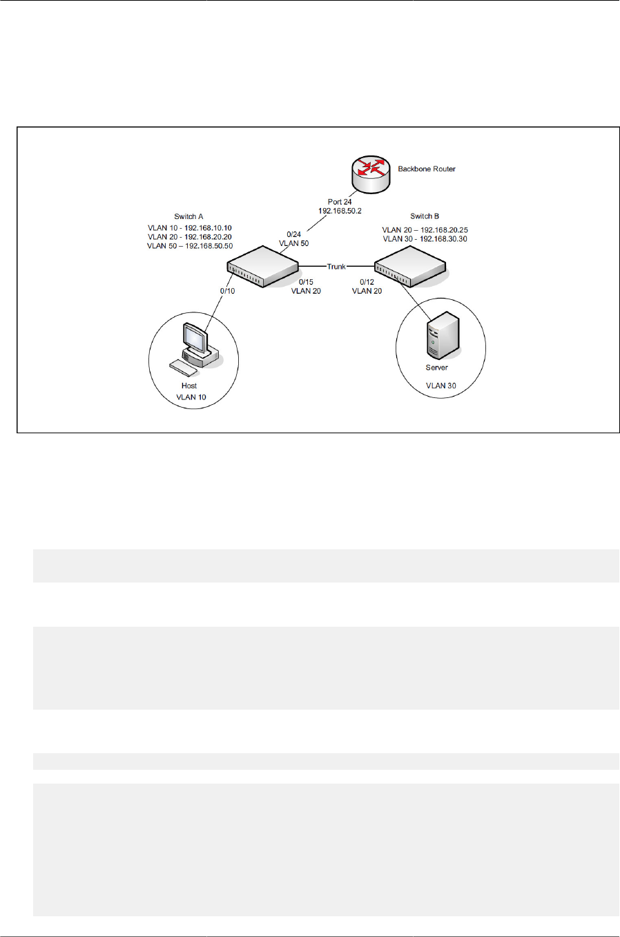
Configuring Routing
241
This example assumes that all L2 VLAN information, such as VLAN creation and port member-
ship, has been configured.
Figure8.2.IP Routing Example Topology
8.1.3.1. Configuring Switch A
To configure Switch A.
1. Create the VLANs.
(Routing) #vlan database
(Routing) (Vlan)#vlan 10,20,30,50
2. Configure the VLANs for routing and assign the interface port numbers.
(Routing) (Vlan)#vlan routing 10 10
(Routing) (Vlan)#vlan routing 20 20
(Routing) (Vlan)#vlan routing 30 30
(Routing) (Vlan)#vlan routing 50 50
(Routing) (Vlan)#exit
3. View the interface names assigned to the VLAN routing interfaces.
(Routing) #show ip vlan
MAC Address used by Routing VLANs: 00:10:18:82:15:7E
Logical
VLAN ID Interface IP Address Subnet Mask
------- ------------- --------------- ---------------
10 4/10 0.0.0.0 0.0.0.0
20 4/20 0.0.0.0 0.0.0.0
30 4/30 0.0.0.0 0.0.0.0
50 4/50 0.0.0.0 0.0.0.0

Configuring Routing
242
4. Enable routing on the switch.
(Routing) #configure
(Routing) (Config)#ip routing
5. Assign an IP address to VLAN 10. This command also enables IP routing on the VLAN.
(Routing) (Config)#interface 4/10
(Routing) (Interface 4/10)#ip address 192.168.10.10 255.255.255.0
(Routing) (Interface 4/10)#exit
6. Assign an IP address to VLAN 20.
(Routing) (Config)#interface 4/20
(Routing) (Interface 4/20)#ip address 192.168.20.20 255.255.255.0
(Routing) (Interface 4/20)#exit
7. Assign an IP address to VLAN 50.
(Routing) (Config)#interface 4/50
(Routing) (Interface 4/50)#ip address 192.168.50.50 255.255.255.0
(Routing) (Interface 4/50)#exit
8. Configure a static route to the network that VLAN 30 is in, using the IP address of the VLAN 20
interface on Switch B as the next hop address.
(Routing) (Config)#ip route 192.168.30.0 255.255.255.0 192.168.20.25
9. Configure the backbone router interface as the default gateway.
(Routing) (Config)#ip route default 192.168.50.2
8.1.3.2. Configuring Switch B
To configure Switch B:
1. Create the VLANs.
(Routing) #vlan database
(Routing) (Vlan)#vlan 20,30
2. Configure the VLANs for routing.
(Routing) (Vlan)#vlan routing 20 20
(Routing) (Vlan)#vlan routing 30 30
(Routing) (Vlan)#exit
3. View the interface names assigned to the VLAN routing interfaces.
(Routing) #show ip vlan
MAC Address used by Routing VLANs: 00:10:18:82:15:7E
Logical
VLAN ID Interface IP Address Subnet Mask
------- ------------- --------------- ---------------
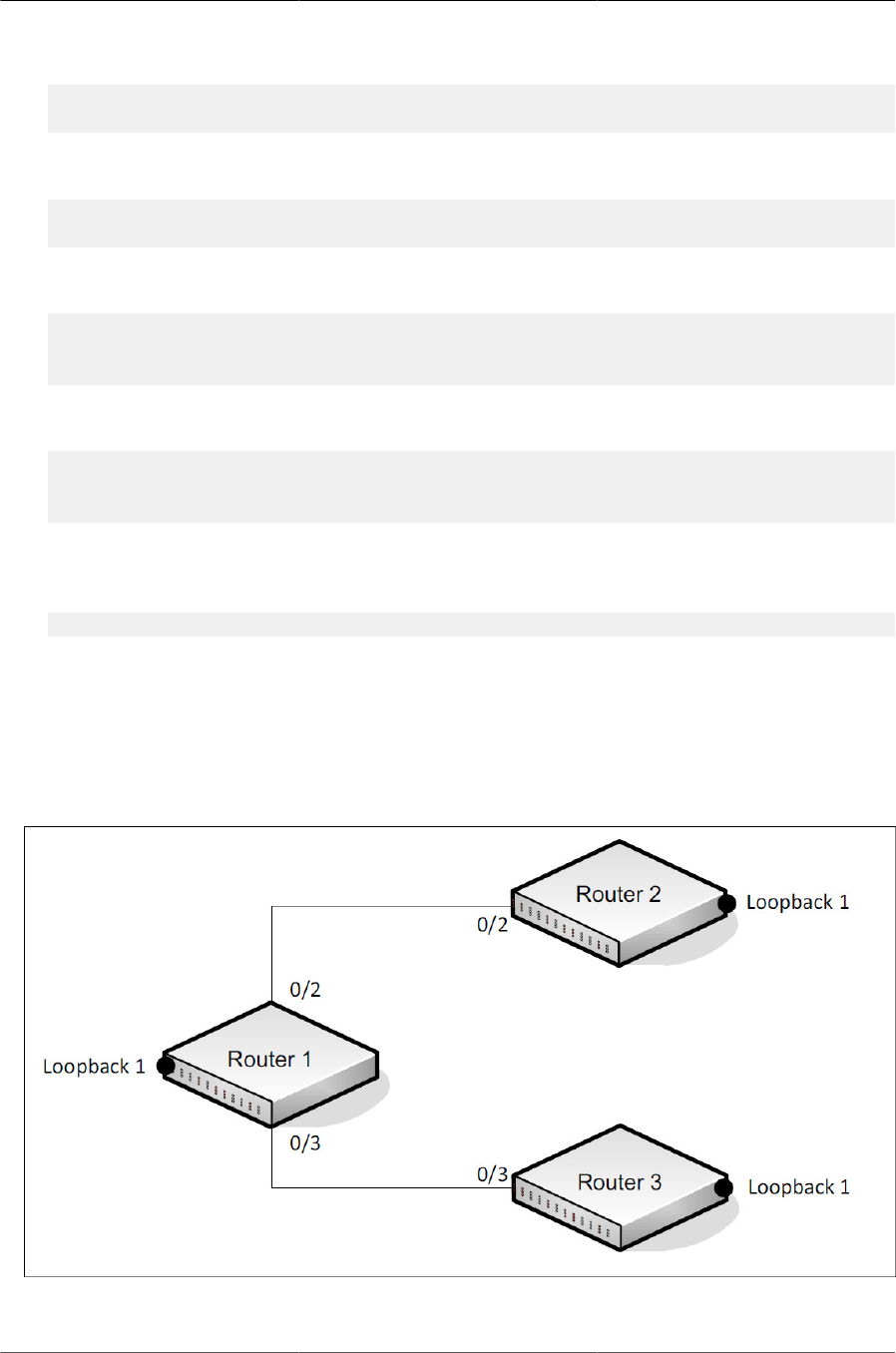
Configuring Routing
243
20 4/20 0.0.0.0 0.0.0.0
30 4/30 0.0.0.0 0.0.0.0
4. Enable routing on the switch.
(Routing)#configure
(Routing) (Config)#ip routing
5. Assign an IP address to VLAN 20. This command also enables IP routing on the VLAN.
(Routing) (Config)#interface 4/20
(Routing) (Interface 4/20)#ip address 192.168.20.25 255.255.255.0
(Routing) (Interface 4/20)#exit
6. Assign an IP address to VLAN 30. This command also enables IP routing on the VLAN.
(Routing) (Config)#interface 4/30
(Routing) (Interface 4/30)#ip address 192.168.30.30 255.255.255.0
(Routing) (Interface 4/30)#exit
7. Configure the VLAN 20 routing interface on Switch A as the default gateway so that any traffic
with an unknown destination is sent to Switch A for forwarding.
(Routing) (Config)#ip route default 192.168.20.20
8.1.4. IP Unnumbered Configuration Example
This IP unnumbered configuration example shows how the same IP is used on two different un-
numbered interfaces on router 1 so it can communicate with router 2 and router 3.
Figure8.3.IP Unnumbered Configuration Example
To configure the router 1:

Configuring Routing
244
1. Enable routing on the switch.
(Routing)#configure
(Routing) (Config)#ip routing
2. Configure the loopback interface.
(Router_1) (Config)#interface loopback 1
(Router_1) (Interface loopback 1)#ip address 1.0.0.1 /24
(Router_1) (Interface loopback 1)#exit
3. Configure port 0/2.
(Router_1) (Config)#interface 0/2
(Router_1) (Interface 0/2)#routing
(Router_1) (Interface 0/2)#ip unnumbered loopback 1
(Router_1) (Interface 0/2)#exit
4. Configure port 0/3.
(Router_1) (Interface 0/3)#routing
(Router_1) (Interface 0/3)#ip unnumbered loopback 1
(Router_1) (Interface 0/3)#exit
(Router_1) (Config)#
To configure the router 2:
1. Enable routing on the switch.
(Routing)#configure
(Routing) (Config)#ip routing
2. Configure the loopback interface.
(Router_2) (Config)#interface loopback 1
(Router_2) (Interface loopback 1)#ip address 2.0.0.2 /24
(Router_2) (Interface loopback 1)#exit
3. Configure port 0/2.
(Router_2) (Config)#interface 0/2
(Router_2) (Interface 0/2)#routing
(Router_2) (Interface 0/2)#ip unnumbered loopback 1
(Router_2) (Interface 0/2)#exit
4. Configure port 0/3.
(Router_2) (Interface 0/3)#routing
(Router_2) (Interface 0/3)#ip unnumbered loopback 1
(Router_2) (Interface 0/3)#exit
(Router_2) (Config)#
To configure the router 3:
1. Enable routing on the switch.

Configuring Routing
245
(Routing)#configure
(Routing) (Config)#ip routing
2. Configure the loopback interface.
(Router_3) (Config)#interface loopback 1
(Router_3) (Interface loopback 1)#ip address 3.0.0.3 /24
(Router_3) (Interface loopback 1)#exit
3. Configure port 0/2.
(Router_3) (Config)#interface 0/2
(Router_3) (Interface 0/2)#routing
(Router_3) (Interface 0/2)#ip unnumbered loopback 1
(Router_3) (Interface 0/2)#exit
4. Configure port 0/3.
(Router_3) (Interface 0/3)#routing
(Router_3) (Interface 0/3)#ip unnumbered loopback 1
(Router_3) (Interface 0/3)#exit
(Router_3) (Config)#
When you have completed the configuration instructions above, try to ping 2.0.0.2 and 3.0.0.3
from router 1.

Configuring Routing
246
8.2. OSPF
OSPF is an Interior Gateway Protocol (IGP) that performs dynamic routing within a network. The
top level of the hierarchy of an OSPF network is known as an OSPF domain. The domain can be
divided into areas. Routers within an area must share detailed information on the topology of their
area, but require less detailed information about the topology of other areas. Segregating a net-
work into areas enables limiting the amount of route information communicated throughout the net-
work.
Areas are identified by a numeric ID in IP address format n.n.n.n (note, however, that these are
not used as actual IP addresses). For simplicity, the area can be configured and referred to in nor-
mal integer notation. For example, Area 20 is identified as 0.0.0.20 and Area 256 as 0.0.1.0. The
area identified as 0.0.0.0 is referred to as Area 0 and is considered the OSPF backbone. All other
OSPF areas in the network must connect to Area 0 directly or through a virtual link. The backbone
area is responsible for distributing routing information between non-backbone areas.
A virtual link can be used to connect an area to Area 0 when a direct link is not possible. A virtual
link traverses an area between the remote area and Area 0.
A stub area is an area that does not accept external LSAs (LSAs generated by redistributing
routes) that were learned from a protocol other than OSPF or were statically configured. These
routes typically send traffic outside the AS. Therefore, routes from a stub area to locations outside
the AS use the default gateway. A virtual link cannot be configured across a stub area. A Not So
Stubby Area can import limited external routes only from a connected ASBR.
8.2.1. Configuring an OSPF Border Router and Setting
Interface Costs
This example shows how to configure the ICOS-based switch as an OSPF border router. The
commands in this example configure the areas and interfaces on Border Router A shown in Figure
below.
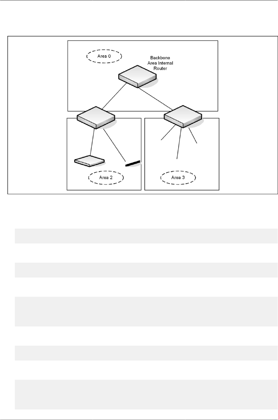
Configuring Routing
247
Figure8.4.OSPF Area Border Router
To Configure Border Router A:
1. Enable routing on the switch.
(Routing) #configure
(Routing) (Config)#ip routing
2. Create VLANS 70, 80, and 90.
(Routing) #vlan database
(Routing) (Vlan)#vlan 70,80,90
3. Configure the VLANs for routing and assign the interface port numbers.
(Routing) (Vlan)#vlan routing 70 70
(Routing) (Vlan)#vlan routing 80 80
(Routing) (Vlan)#vlan routing 90 90
(Routing) (Vlan)#exit
4. Enable routing on the switch.
(Routing)#configure
(Routing) (Config)#ip routing
5. Assign IP addresses for VLANs 70, 80 and 90.
(Routing) (Config)#interface vlan 4/70
(Routing) (Interface 4/70)#ip address 192.150.2.2 255.255.255.0
(Routing) (Interface 4/70)#exit
(Routing) (Config)#interface 4/80

Configuring Routing
248
(Routing) (Interface 4/80)#ip address 192.150.3.1 255.255.255.0
(Routing) (Interface 4/80)#exit
(Routing) (Config)#interface 4/90
(Routing) (Interface 4/90)#ip address 192.150.4.1 255.255.255.0
(Routing) (Interface 4/90)#exit
6. Enable OSPF on the switch and specify a router ID.
(Routing) (Config)#router ospf
(Routing) (config-router)#router-id 192.150.9.9
(Routing) (config-router)#exit
7. Configure the OSPF area ID and cost for each interface.
OSPF is globally enabled by default. To make it operational on the router, you config-
ure OSPF for particular interfaces and identify which area the interface is associated
with.
(Routing) (Config)#interface 4/70
(Routing) (Interface 4/70)#ip ospf area 0.0.0.0
(Routing) (Interface 4/70)#ip ospf cost 32
(Routing) (Interface 4/70)#exit
(Routing) (Config)#interface 4/80
(Routing) (Interface 4/80)#ip ospf area 0.0.0.2
(Routing) (Interface 4/80)#ip ospf cost 64
(Routing) (Interface 4/80)#exit
(Routing) (Config)#interface 4/90
(Routing) (Interface 4/90)#ip ospf area 0.0.0.2
(Routing) (Interface 4/90)#ip ospf cost 64
(Routing) (Interface 4/90)#exit

Configuring Routing
249
8.3. VRRP
The Virtual Router Redundancy (VRRP) protocol is designed to handle default router (L3 switch)
failures by providing a scheme to dynamically elect a backup router. VRRP can help minimize
black hole periods due to the failure of the default gateway router during which all traffic directed
towards it is lost until the failure is detected.
8.3.1. VRRP Operation in the Network
VRRP eliminates the single point of failure associated with static default routes by enabling a
backup router to take over from a master router without affecting the end stations using the route.
The end stations will use a virtual IP address that will be recognized by the backup router if the
master router fails. Participating routers use an election protocol to determine which router is the
master router at any given time. A given port may appear as more than one virtual router to the
network, also, more than one port on a switch may be configured as a virtual router. Either a physi-
cal port or a routed VLAN may participate.
With VRRP, a virtual router is associated with one or more IP addresses that serve as default
gateways. In the event that the VRRP router controlling these IP addresses (formally known as the
master) fails, the group of IP addresses and the default forwarding role is taken over by a Backup
VRRP Router.
8.3.2. VRRP Router Priority
The VRRP router priority is a value from 1–255 that determines which router is the master. The
greater the number, the higher the priority. If the virtual IP address is the IP address of a VLAN
routing interface on one of the routers in the VRRP group, the router with IP address that is the
same as the virtual IP address is the interface owner and automatically has a priority of 255. By
default, this router is the VRRP master in the group.
If no router in the group owns the VRRP virtual IP address, the router with the highest configured
priority is the VRRP master. If multiple routers have the same priority, the router with the highest IP
address becomes the VRRP master.
If the VRRP master fails, other members of the VRRP group will elect a master based on the con-
figured router priority values. For example, router A is the interface owner and master, and it has a
priority of 255. Router B is configured with a priority of 200, and Router C is configured with a prior-
ity of 190. If Router A fails, Router B assumes the role of VRRP master because it has a higher pri-
ority.
8.3.3. VRRP Preemption
If preempt mode is enabled and a router with a higher priority joins the VRRP group, it takes over
the VRRP master role if the current VRRP master is not the owner of the virtual IP address. The
preemption delay controls how long to wait to determine whether a higher priority Backup router
preempts a lower priority Master. In certain cases, for example, during periods of network conges-
tion, a backup router might fail to receive advertisements from the master. This could cause mem-
bers in the VRRP group to change their states frequently, i.e. flap. The problem can be resolved
by setting the VRRP preemption delay timer to a non-zero value.

Configuring Routing
250
8.3.4. VRRP Accept Mode
The accept mode allows the switch to respond to pings (ICMP Echo Requests) sent to the VRRP
virtual IP address. The VRRP specification (RFC 3768) indicates that a router may accept IP pack-
ets sent to the virtual router IP address only if the router is the address owner. In practice, this re-
striction makes it more difficult to troubleshoot network connectivity problems. When a host cannot
communicate, it is common to ping the host’s default gateway to determine whether the problem is
in the first hop of the path to the destination. When the default gateway is a virtual router that does
not respond to pings, this troubleshooting technique is unavailable. In the ICOS-based switch VR-
RP feature, you can enable Accept Mode to allow the system to respond to pings that are sent to
the virtual IP address.
This capability adds support for responding to pings, but does not allow the VRRP Master to ac-
cept other types of packets. The VRRP Master responds to both fragmented and un-fragmented
ICMP Echo Request packets. The VRRP Master responds to Echo Requests sent to the virtual
router’s primary address or any of its secondary addresses.
Members of the virtual router who are in backup state discard ping packets destined to VRRP ad-
dresses, just as they discard any Ethernet frame sent to a VRRP MAC address.
When the VRRP master responds with an Echo Reply, the source IPv4 address is the VRRP ad-
dress and source MAC address is the virtual router’s MAC address.
8.3.4.1. VRRP Route and Interface Tracking
The VRRP Route/Interface Tracking feature extends VRRP capability to allow tracking of specific
routes and interface IP states within the router that can alter the priority level of a virtual router for
a VRRP group.
VRRP interface tracking monitors a specific interface IP state within the router. Depending on the
state of the tracked interface, the feature can alter the VRRP priority level of a virtual router for a
VRRP group.
An exception to the priority level change is that if the VRRP group is the IP address
owner, its priority is fixed at 255 and cannot be reduced through the tracking process.
With standard VRRP, the backup router takes over only if the router goes down. With VRRP inter-
face tracking, if a tracked interface goes down on the VRRP master, the priority decrement value
is subtracted from the router priority. If the master router priority becomes less than the priority on
the backup router, the backup router takes over. If the tracked interface becomes up, the value of
the priority decrement is added to the current router priority. If the resulting priority is more than the
backup router priority, the original VRRP master resumes control.
VRRP route tracking monitors the reachability of an IP route. A tracked route is considered up
when a routing table entry exists for the route and the route is accessible. When the tracked route
is removed from the routing table, the priority of the VRRP router will be reduced by the priority
decrement value. When the tracked route is added to the routing table, the priority will be incre-
mented by the same.
8.3.5. VRRP Configuration Example
This section contains the following VRRP examples:
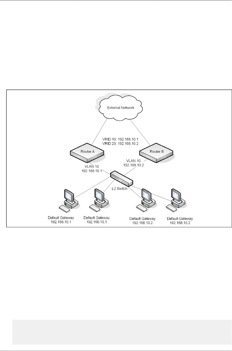
Configuring Routing
251
• VRRP with Load Sharing
• VRRP with Route and Interface Tracking
8.3.5.1. VRRP with Load Sharing
In Figure below, two L3 switches are performing the routing for network clients. Router A is the de-
fault gateway for some clients, and Router B is the default gateway for other clients.
Figure8.5.VRRP with Load Sharing Network Diagram
This example configures two VRRP groups on each router. Router A is the VRRP master for the
VRRP group with VRID 10 and the backup for VRID 20. Router B is the VRRP master for VRID 20
and the backup for VRID 10. If Router A fails, Router B will become the master of VRID 10 and will
use the virtual IP address 192.168.10.1. Traffic from the clients configured to use Router A as the
default gateway will be handled by Router B.
To configure Router A:
1. Create and configure the VLAN routing interface to use as the default gateway for network
clients.
This example assumes all other routing interfaces, such as the interface to the external network,
have been configured.
(Routing) #vlan database
(Routing) (Vlan)#vlan 10
(Routing) (Vlan)#vlan routing 10
(Routing) (Vlan)#exit

Configuring Routing
252
(Routing) #con
(Routing) (Config)#interface 4/1
(Routing) (Interface 4/1)#ip address 192.168.10.1 255.255.255.0
(Routing) (Interface 4/1)#exit
2. Enable routing for the switch.
(Routing) (Config)#ip routing
3. Enable VRRP for the switch.
(Routing) (Config)#ip vrrp
4. Assign a virtual router ID to the VLAN routing interface for the first VRRP group.
(Routing) (Config)#interface 4/1
(Routing) (Interface 4/1)#ip vrrp 10
5. Specify the IP address that the virtual router function will use. The router is the virtual IP ad-
dress owner (the routing interface has the same IP address as the virtual IP address for the VR-
RP group), so the priority value is 255.
(Routing) (Interface 4/1)#ip vrrp 10 ip 192.168.10.1
6. Assign a virtual router ID to the VLAN routing interface for the second VRRP group.
(Routing) (Interface 4/1)#ip vrrp 20
7. Specify the IP address that the virtual router function will use.
(Routing) (Interface 4/1)#ip vrrp 20 ip 192.168.10.2
8. Enable the VRRP groups on the interface.
(Routing) (Interface 4/1)#ip vrrp 10 mode
(Routing) (Interface 4/1)#ip vrrp 20 mode
(Routing) (Interface 4/1)#exit
(Routing) (Config)#exit
The only difference between the Router A and Router B configurations is the IP address assigned
to VLAN 10. On Router B, the IP address of VLAN 10 is 192.168.10.2. Because this is also the vir-
tual IP address of VRID 20, Router B is the interface owner and VRRP master of VRRP group 20.
To configure Router B:
1. Enable routing for the switch.
(Routing) #config
(Routing) (Config)#ip routing
(Routing) (Config)#exit
2. Create and configure the VLAN routing interface to use as the default gateway for network
clients. This example assumes all other routing interfaces, such as the interface to the external
network, have been configured.

Configuring Routing
253
(Routing) #vlan database
(Routing) (Vlan)#vlan 10
(Routing) (Vlan)#vlan routing 10
(Routing) (Vlan)#exit
(Routing) #configure
(Routing) (Config)#interface 4/1
(Routing) (Interface 4/1)#ip address 192.168.10.2 255.255.255.0
(Routing) (Interface 4/1)#exit
3. Enable VRRP for the switch.
(Routing) (Config)#ip vrrp
4. Assign a virtual router ID to the VLAN routing interface for the first VRRP group.
(Routing) (Config)#interface 4/1
(Routing) (Interface 4/1)#ip vrrp 10
5. Specify the IP address that the virtual router function will use.
(Routing) (Interface 4/1)#ip vrrp 10 ip 192.168.10.1
6. Configure an optional description to help identify the VRRP group.
(Routing) (Interface 4/1)#ip vrrp 10 description master
7. Assign a virtual router ID to the VLAN routing interface for the second VRRP group.
(Routing) (Interface 4/1)#ip vrrp 20
8. Specify the IP address that the virtual router function will use.
The router is the virtual IP address owner of this address, so the priority value is 255 by default.
(Routing) (Interface 4/1)#ip vrrp 20 ip 192.168.10.2
9. Configure an optional description to help identify the VRRP group.
(Routing) (Interface 4/1)#ip vrrp 20 description backup
10.Enable the VRRP groups on the interface.
(Routing) (Interface 4/1)#ip vrrp 10 mode
(Routing) (Interface 4/1)#ip vrrp 20 mode
(Routing) (Interface 4/1)#exit
(Routing) (Config)#exit
8.3.6. VRRP with Route and Interface Tracking
In Figure below, the VRRP priorities are configured so that Router A is the VRRP master, and
Router B is the VRRP backup. Router A forwards IP traffic from clients to the external network
through the VLAN 25 routing interface. The clients are configured to use the virtual IP address
192.168.10.15 as the default gateway.
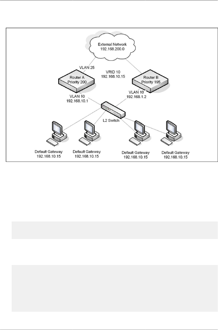
Configuring Routing
254
Figure8.6.VRRP with Tracking Network Diagram
Without VRRP interface or route tracking, if something happened to VLAN 25 or the route to the
external network, as long as Router A remains up, it will continue to be the VRRP master even
though traffic from the clients does not have a path to the external network. However, if the inter-
face and/or route tracking features are configured, Router A can decrease its priority value when
the problems occur so that Router B becomes the master.
To configure Router A:
1. Enable routing for the switch.
(Routing) #config
(Routing) (Config)#ip routing
(Routing) (Config)#exit
2. Configure the VLAN routing interface to use as the default gateway for network clients. This ex-
ample assumes all other routing interfaces, such as the interface to the external network, have
been configured.
(Routing) #vlan database
(Routing) (Vlan)#vlan 10
(Routing) (Vlan)#vlan routing 10
(Routing) (Vlan)#exit
(Routing) #con
(Routing) (Config)#interface 4/1
(Routing) (Interface 4/1)#ip address 192.168.10.1 255.255.255.0
(Routing) (Interface 4/1)#exit
3. Enable VRRP for the switch.

Configuring Routing
255
(Routing) (Config)#ip vrrp
4. Assign a virtual router ID to the VLAN routing interface for the VRRP group.
(Routing) (Config)#interface 4/1
(Routing) (Interface 4/1)#ip vrrp 10
5. Specify the IP address that the virtual router function will use.
(Routing) (Interface 4/1)#ip vrrp 10 ip 192.168.10.15
6. Configure the router priority.
(Routing) (Interface 4/1)#ip vrrp 10 priority 200
7. Enable preempt mode so that the router can regain its position as VRRP master if its priority is
greater than the priority of the backup router.
(Routing) (Interface 4/1)#ip vrrp 10 preempt
8. Enable the VRRP groups on the interface.
(Routing) (Interface 4/1)#ip vrrp 10 mode
(Routing) (Interface 4/1)#exit
9. Track the routing interface VLAN 25 on VRID 10 so that if it goes down, the priority of VRID 10
on Router A is decreased by 10, which is the default decrement priority value.
(Routing) (Interface 4/1)#ip vrrp 10 track interface vlan 25
10.Track the route to the 192.168.200.0 network. If it becomes unavailable, the priority of VRID 10
on Router A is decreased by 10, which is the default decrement priority value.
(Routing) (Interface 4/1)#ip vrrp 10 track ip route 192.168.200.0/24
(Routing) (Interface 4/1)#exit
Router B is the backup router for VRID 10. The configured priority is 195. If the VLAN 25 routing
interface or route to the external network on Router A go down, the priority of Router A will become
190 (or 180, if both the interface and router are down). Because the configured priority of Router B
is greater than the actual priority of Router A, Router B will become the master for VRID 10. When
VLAN 25 and the route to the external network are back up, the priority of Router A returns to 200,
and it resumes its role as VRRP master.
To configure Router B:
1. Enable routing for the switch.
(Routing) #config
(Routing) (Config)#ip routing
(Routing) (Config)#exit
2. Create and configure the VLAN routing interface to use as the default gateway for network
clients.

Configuring Routing
256
This example assumes all other routing interfaces, such as the interface to the external network,
have been configured.
(Routing) #vlan database
(Routing) (Vlan)#vlan 10
(Routing) (Vlan)#vlan routing 10
(Routing) (Vlan)#exit
(Routing) #con
(Routing) (Config)#interface 4/1
(Routing) (Interface 4/1)#ip address 192.168.10.2 255.255.255.0
(Routing) (Interface 4/1)#exit
3. Enable VRRP for the switch.
(Routing) (Config)#ip vrrp
4. Assign a virtual router ID to the VLAN routing interface for the VRRP group.
(Routing) (Config)#interface 4/1
(Routing) (Interface 4/1)#ip vrrp 10
5. Specify the IP address that the virtual router function will use.
(Routing) (Interface 4/1)#ip vrrp 10 ip 192.168.10.15
6. Configure the router priority.
(Routing) (Interface 4/1)#ip vrrp 10 priority 195
7. Enable preempt mode so that the router can regain its position as VRRP master if its priority is
greater than the priority of the backup router.
(Routing) (Interface 4/1)#ip vrrp 10 preempt
8. Enable the VRRP groups on the interface
(Routing) (Interface 4/1)#ip vrrp 10 mode
(Routing) (Interface 4/1)#exit
(Routing) (Config)#exit

Configuring Routing
257
8.4. IP Helper
The IP Helper feature provides the ability for a router to forward configured UDP broadcast pack-
ets to a particular IP address. This allows applications to reach servers on non-local subnets. This
is possible even when the application is designed to assume a server is always on a local subnet
or when the application uses broadcast packets to reach the server (with the limited broadcast ad-
dress 255.255.255.255, or a network directed broadcast address).
You can configure relay entries globally and on routing interfaces. Each relay entry maps an
ingress interface and destination UDP port number to a single IPv4 address (the helper address).
Multiple relay entries may be configured for the same interface and UDP port, in which case the
relay agent relays matching packets to each server address. Interface configuration takes prior-
ity over global configuration. If the destination UDP port for a packet matches any entry on the
ingress interface, the packet is handled according to the interface configuration. If the packet does
not match any entry on the ingress interface, the packet is handled according to the global IP
helper configuration.
You can configure discard relay entries. Discard entries are used to discard packets received on a
specific interface when those packets would otherwise be relayed according to a global relay en-
try. Discard relay entries may be configured on interfaces, but are not configured globally.
Additionally, you can configure which UDP ports are forwarded. Certain UDP port numbers can be
specified by name in the CLI, but you can also configure a relay entry with any UDP port number.
You may configure relay entries that do not specify a destination UDP port. The relay agent as-
sumes that these entries match packets with the UDP destination ports listed in Table below (the
list of default ports).
1. Default Ports - UDP Port Numbers Implied By Wildcard
Protocol UDP Port Number
IEN-116 Name Service 42
DNS 53
NetBIOS Name Server 137
NetBIOS Datagram Server 138
TACACS Server 49
Time Service 37
DHCP 67
Trivial File Transfer Protocol 69
The system limits the number of relay entries to four times the maximum number of routing inter-
faces (512 relay entries). There is no limit to the number of relay entries on an individual interface,
and no limit to the number of servers for a given {interface, UDP port} pair.
Certain configurable DHCP relay options do not apply to relay of other protocols. You may option-
ally set a maximum hop count or minimum wait time using the bootpdhcprelay maxhopcount
and bootpdhcprelay minwaittime commands.
The relay agent relays DHCP packets in both directions. It relays broadcast packets from the client
to one or more DHCP servers, and relays packets to the client that the DHCP server unicasts back

Configuring Routing
258
to the relay agent. For other protocols, the relay agent only relays broadcast packets from the
client to the server. Packets from the server back to the client are assumed to be unicast directly to
the client. Because there is no relay in the return direction for protocols other than DHCP, the relay
agent retains the source IP address from the original client packet. The relay agent uses a local IP
address as the source IP address of relayed DHCP client packets.
When a switch receives a broadcast UDP packet on a routing interface, the relay agent verifies
that the interface is configured to relay to the destination UDP port. If so, the relay agent unicasts
the packet to the configured server IP addresses. Otherwise, the relay agent verifies that there is
a global configuration for the destination UDP port. If so, the relay agent unicasts the packet to the
configured server IP addresses. Otherwise the packet is not relayed.
If the packet matches a discard relay entry on the ingress interface, the packet is not
forwarded, regardless of the global configuration.
The relay agent relays packets that meet only the following conditions:
• The destination MAC address must be the all-ones broadcast address (FF:FF:FF:FF:FF:FF).
• The destination IP address must be the limited broadcast address (255.255.255.255) or a direct-
ed broadcast address for the receive interface.
• The IP time-to-live (TTL) must be greater than 1.
• The protocol field in the IP header must be UDP (17).
• The destination UDP port must match a configured relay entry.
Table below shows the most common protocols and their UDP port numbers and names that are
relayed.
1. UDP Port Allocations
UDP Port Number Acronym Application
7 Echo Echo
11 SysStat Active User
15 NetStat NetStat
17 Quote Quote of the day
19 CHARGEN Character Generator
20 FTP-data FTP Data
21 FTP FTP
37 Time Time
42 NAMESERVER Host Name Server
43 NICNAME Who is
53 DOMAIN Domain Name Server
69 TFTP Trivial File Transfer
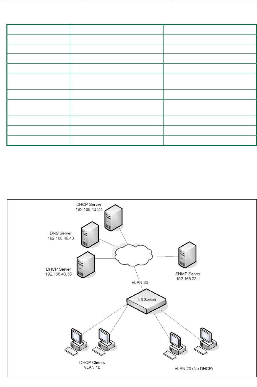
Configuring Routing
259
UDP Port Number Acronym Application
111 SUNRPC Sun Microsystems Rpc
123 NTP Network Time
137 NetBiosNameService NT Server to Station Connections
138 NetBiosDatagramService NT Server to Station Connections
139 NetBios SessionServiceNT Server to Sta-
tion Connections
161 SNMP Simple Network Management
162 SNMP-trap Simple Network Management
Traps
513 who Unix Rwho Daemon
514 syslog System Log
525 timed Time Daemon
8.4.1. Relay Agent Configuration Example
The example in this section shows how to configure the L3 relay agent (IP helper) to relay and dis-
card various protocols.
Figure8.7.L3 Relay Network Diagram

Configuring Routing
260
This example assumes that multiple VLAN routing interfaces have been created and configured
with IP addresses.
To configure the switch:
1. Enable IP helper on the switch.
(Routing) #config
(Routing) (Config)#ip helper enable
2. Relay DHCP packets received on VLAN 10 to 192.168.40.35
(Routing) (Config)#interface 4/1
(Routing) (Interface 4/1)#ip helper-address 192.168.40.35 dhcp
3. Relay DNS packets received on VLAN 10 to 192.168.40.43
(Routing) (Interface 4/1)#ip helper-address 192.168.40.35 domain
(Routing) (Interface 4/1)#exit
4. Relay SNMP traps (port 162) received on VLAN 20 to 192.168.23.1
(Routing) (Config)#interface 4/2
(Routing) (config-if-vlan20)#ip helper-address 192.168.23.1 162
5. The clients on VLAN 20 have statically-configured network information, so the switch is config-
ured to drop DHCP packets received on VLAN 20
(Routing) (Interface 4/2)#ip helper-address discard dhcp
(Routing) (Interface 4/2)#exit
6. Configure the switch so that DHCP packets received from clients in any VLAN other than VLAN
10 and VLAN 20 are relayed to 192.168.40.22.
The following command is issued in Global Configuration mode, so it applies to all
interfaces except VLAN 10 and VLAN 20. IP helper commands issued in Interface
Configuration mode override the commands issued in Global Configuration Mode.
(Routing) (Config)#ip helper-address 192.168.40.22 dhcp
(Routing) (Config)#exit
7. Verify the configuration.
(Routing) #show ip helper-address
IP helper is enabled
Interface UDP Port Discard Hit Count Server Address
----------------- ----------- ---------- ---------- ------------------
4/1 domain No 0 192.168.40.35
4/1 dhcp No 0 192.168.40.35
4/2 dhcp Yes 0
4/2 162 No 0 192.168.23.1
Any dhcp No 0 192.168.40.22

Configuring Routing
261
8.5. Border Gateway Protocol (BGP)
This section contains the following subsections:
• Section 8.5.1, “BGP Topology”
• Section 8.5.2, “BGP Behavior”
• Section 8.5.3, “BGP Dynamic Neighbors”
• Section 8.5.4, “BGP Extended Communities”
• Section 8.5.5, “VPNv4/VRF Route Distribution via BGP”
• Section 8.5.6, “BGP Configuration Examples”
BGP is an exterior routing protocol that maintains routing tables, transmits routing updates, and
bases routing decisions on routing metrics through exchanges of Network Layer Reachability In-
formation (NLRI) with network peers (known as neighbors) via TCP/IP sessions. BGP relies on the
local route table, which is populated by IGP routing protocols, in order to establish connectivity for
routes contained within NLRI definitions. For routes with established connectivity, BGP determines
the best route among those learned from one or more peers and then installs those routes to the
local route table as well as advertises those routes to its other peers. Local policy configuration is
commonly used to filter NLRIs inbound and outbound, as well as for modifying the attributes of NL-
RIs that are advertised to peers.
8.5.1. BGP Topology
BGP maintains routing information between routers within different Autonomous Systems (AS),
where each AS typically encapsulates a single IGP routing domain. BGP peers exchange NLRIs
that contain an AS path, which is an ordered set of AS values that describe the autonomous sys-
tems that must be traversed to reach a network destination. Using a distance vector algorithm,
BGP uses the AS path to determine the relative distance to a network destination, and detects any
potential routing loops. BGP has two types of relationships with its network peers: External BGP
peering (EBGP) and Internal BGP peering (IBGP).
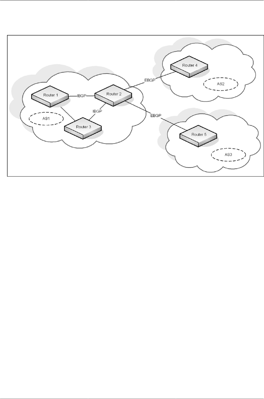
Configuring Routing
262
Figure8.8.Example BGP Network
8.5.1.1. External BGP Peering
EBGP peering occurs between two or more BGP routers in different AS’s. Peer routers in these
different AS’s use BGP to maintain a consistent view of the inter-network topology. External BGP
peers exchange NLRIs, which contain reachable network destinations along with BGP specific at-
tributes such as AS path information and various metrics. These BGP attributes along with local
policy configuration, which is used to filter and/or modify the BGP NLRIs, are used by BGP to de-
termine optimal routes to these network destinations within the Internet. An illustration of the above
scenario can be observed in the figure1 between routers R2 and R4.
8.5.1.2. Internal BGP Peering
IBGP peering occurs between two or more BGP routers located within the same AS. Internal BGP
peers are mainly responsible for distributing BGP NLRIs, which have been acquired via External
BGP peers, to all other Internal BGP peers within the AS. The BGP protocol requires that all IBGP
peers within an AS are logically connected as a “full mesh.” Thus, all BGP routers within the AS
can have a consistent view of the inter-network destinations. An illustration of the above scenario
can be observed in the figure1 between routers R1 and R2.
8.5.1.3. Advertising Network Layer Reachability Information
In addition to NLRIs exchanged between BGP peers, a BGP router may originate NLRIs for adver-
tisement to its peers due to local configuration of “locally-originated” routes or “redistribution” pol-
icy. In this scenario, the configuration of locally-originated routes or redistribution policy maps to
routes installed in the local router’s forwarding table by IGP routing protocols on the local router.
These routes typically define reachability to network destinations within the local AS. In this man-
ner, BGP is used to advertise NLRIs that define reachability to network destinations within its own
AS to BGP peers outside of the local AS.

Configuring Routing
263
8.5.2. BGP Behavior
BGP systems form a TCP/IP connection between one another to exchange NLRIs. First, they ex-
change messages to open and confirm the connection parameters. The initial data flow is the en-
tire BGP routing table. Incremental updates are sent as the routing tables change. BGP does not
require periodic refresh of the entire BGP routing table because it relies on the reliable transport
provided by TCP. Therefore, a BGP speaker must retain the current version of the entire BGP
routing tables of all of its peers for the duration of the connection. Keepalive messages are sent
periodically to ensure that connection is active. Notification messages are sent in response to er-
rors or special conditions. If a connection encounters an error condition, a notification message is
sent and the connection is closed.
Routes are advertised between a pair of BGP speakers in UPDATE messages, where the network
destinations are the systems whose IP addresses are reported in the NLRI field, and the AS path
for those destinations is part of the information reported in the path attributes fields of the same
UPDATE message, along with various other BGP attributes. Routes are stored in local Routing In-
formation Bases (RIBs). Logically, all routes learned from a particular BGP peer are kept in a local
Adj-RIB-In, and all routes learned from all BGP peers are held in a Loc-RIB, which serves as the
central database for BGP to determine the best path to a particular network destination. Additional-
ly, local policy configuration may filter or modify the BGP attributes of NLRIs that are received from
BGP peers.
Once BGP has chosen the best path to a network destination based on the BGP attributes given
in an NLRI (also known as the decision process), it must determine if there is connectivity to the
destination defined by the BGP nexthop attribute from the best NLRI. Here, BGP performs nex-
thop resolution by referencing the local router’s forwarding table, which is populated with routes in-
stalled by IGP protocols. If connectivity to the BGP nexthop is found (i.e. resolved), then the corre-
sponding BGP route can be installed to the local router’s forwarding table, using the real nexthop
information from the IGP route that was used to resolve the BGP nexthop.
Finally, BGP routes that have been installed in the local router’s forwarding table are eligible to be
advertised to connected BGP peers. BGP advertises these routes to each connected peer, typical-
ly resetting the BGP nexthop attribute to be the local IP address for the BGP peer connection. Ad-
ditionally, local policy configuration may filter or modify the NLRIs that are advertised to these BGP
peers.
For a more detailed and comprehensive description of BGP protocol behavior, refer to the BGP-4
Protocol Specification (RFC1771/draft-ietf-idr-bgp4-26).
8.5.2.1. BGP Route Selection
ICOS BGP uses the following route selection rules:
1. Prefer the route with the higher local preference
2. Prefer a locally-originated route over a non-locally originated route
3. Prefer the route with the shorter AS Path
4. Prefer the route with the lower ORIGIN. IGP is better than EGP is better than INCOMPLETE.
5. Prefer the route with the lower MED. By default, MEDs are only compared for routes from the
same AS, but a configuration option allows comparison of MEDs from different ASs. A route
with no MED is considered to have a MED of 0.

Configuring Routing
264
6. Prefer an eBGP route to an iBGP route
7. Prefer the route with the lower IGP cost to the BGP NEXT HOP
8. Prefer the route learned from the peer with the lower router ID
9. Prefer the route learned from the peer with the lower peer IP address
8.5.3. BGP Dynamic Neighbors
BGP neighbors can be dynamically created whenever connection requests from peers are re-
ceived from a configured IP address range. Creating neighbors dynamically avoids explicit con-
figuration by the administrator when forming peering with neighbors, irrespective of the subnet to
which the IP addresses belong.
The administrator specifies the address range to listen on, and the neighbors properties are inher-
ited from a peer template. As a result, all dynamically created neighbors inherit the properties from
the template.
The number of configurable listen address ranges in the system is limited to 10. The number of
dynamic peers created as a result of this feature are also limited by the total number of peers al-
lowed in the system.
8.5.4. BGP Extended Communities
ICOS BGP supports standard extended communities as defined in RFC 4360. ICOS supports
extended community lists for matching routes based on the extended community and supports
matching and setting extended communities in route maps. ICOS also supports selective export
and import of routes using export and import maps.
The extended community attribute provides a mechanism for labelling routes carried in BGP-4.
These labels are then used to control the distribution of the routes among VRFs.
A BGP route can carry both standard and extended communities attributes. It can also carry multi-
ple community attributes through the use of the additive keyword (in the case of standard commu-
nities) and through the use of route-maps when exporting the VRF routes (in the case of extended
communities).
BGP recognizes the following well-known extended community attributes (RFC 4360): and Route
origin community:
• Route target community: This community identifies one or more routers that may receive a set
of routes (attached with this community) carried by BGP. This community is transitive across the
Autonomous System boundary.
• Route origin community: This community identifies one or more routers that inject a set of routes
(attached with this community) carried by BGP. This community is transitive across the Au-
tonomous System boundary.
The Route Origin Community is used to prevent routing loops when a site is multi-homed to the
MPLS/VPN backbone, and in addition that site uses the AS-Override feature. This is used to iden-

Configuring Routing
265
tify the site from where the routes are learned, based on its Origin, so that is not re-advertised
back to that Site from a PE-Router somewhere else in the MPLS/VPN backbone.
8.5.5. VPNv4/VRF Route Distribution via BGP
ICOS BGP supports Virtual Routing and Forwarding (VRF) awareness. (See Section 8.7, “VRF
Lite Operation and Configuration” for more information about VRF). See Section 8.5.6.2, “BGP
with VRF” for a configuration example.
8.5.5.1. Overview
Management Customer Edge (MCE) routers use BGP to distribute VPN routes to each other. Each
VRF has its own address space, meaning that the same address can be used in any number of
VRFs, whereas in each VRF, the address specifies a different system. But a BGP speaker can in-
stall and distribute only one route to a given address prefix. ICOS allows BGP to install and distrib-
ute multiple routes to a single IP address prefix. Also it is recommended that the administrator use
a policy to determine which sites can use which routes; given that several such routes are installed
by BGP, only one such route must appear in any particular per-site VRF route table. We achieve
this by the use of a new address family, as described in the following section.
8.5.5.2. VPNv4 Address Family
Multiprotocol BFP (MP-BGP) allows BGP to carry routes from different address families. To allow
BGP to carry and distribute overlapping address routes, each address/route is made unique. To
achieve this, a new VPNv4 address family is introduced. A VPN-IPv4 address is a 12-byte quanti-
ty, beginning with an 8-byte Route Distinguisher (RD) followed by a 4-byte IPv4 address.
If two VRFs use the same IPv4 address prefix, the MCE translates these into unique VPN-IPv4 ad-
dress prefixes by prepending the RD (configured per VRF) to the address. The purpose of the RD
is only to allow the creation of unique routes to a common IPv4 address prefix. The structuring of
RD provides no semantics. When BGP compares two such addresses, it ignores the RD structure
completely and just compares it as a 12-byte entity.
An MCE is configured to associate routes that belong to a particular VRF instance with a particu-
lar RD. When BGP redistributes these routes, the MCE router prepends the configured RD value
(for that CE) to the routes and carries them to the other PE as VPNv4 routes. The PE router that
receives these VPNv4 routes installs them in the global BGP table along with the RD. If two routes
have the same address prefix but different RD values, only the first route is installed to the RTO ta-
ble of the CE that imports the route; the rest are ignored.
8.5.5.3. Controlling Route Distribution
This section describes the method in which the VPNv4 route distribution is controlled.
8.5.5.4. The Route Target Attribute (RT)
A Route Target attribute identifies a set of sites. Associating a particular Route Target attribute
with a route allows that route to be placed in the per-site (CE) VRF tables. Every per-site (CE) VRF
is associated with one or more “Route Target” attributes.
When a VPNv4 route is created by an MCE router, it is associated with one or more “Route Tar-
get” attributes. These are carried in BGP as attributes of that route.

Configuring Routing
266
Any route associated with Route Target attribute RT1 must be distributed to every PE router that
has a VRF associated with Route Target RT1. When such a route is received by a PE/MCE router,
(depending on the BGP decision process) it is installed in each of the PE/MCE’s VRF tables that
are associated with Route Target RT1.
When an MCE router receives a route from one of its CE routers, it attaches to the route one or
more Export Route Target attributes (as configured for that CE VRF). The route is then carried via
MP-BGP to the other PE router. The PE router that receives the route compares it with the Import
Route Target attributes configured for one or multiple VRFs and, depending on the match, installs
the route in that matching VRF table.
The Export Route Target attributes and the Import Route Target attributes are two distinct sets and
may or may not be the same. Only when they are same is the route is allowed to be installed in
that particular VRF table.
A BGP route can only have one RD but can have multiple Route Targets.
Route Target attribute helps in route leaking among multiple VRFs in a PE/MCE. The route leaking
between VRFs can be achieved without any BGP adjacencies in the VRF instances, but with only
the import and export Route Target statements.
See route leaking examples on Section 8.7.3, “Route Leaking”
8.5.5.5. The Site of Origin Attribute (SoO)
A VPNv4 route may optionally carry a Origin attribute that uniquely identifies a set of sites. This at-
tribute identifies the corresponding route as having come from one of the sites.
The SoO attribute is used to identify the specific site from which the PE learns the route and is
used in the identification and prevention of routing loops. The SoO extended community is a BGP
extended community attribute used to identify routes that have originated from a site so that the
re-advertisement of that prefix back to the source site can be prevented, thus preventing routing
loops.
SoO enables filtering of traffic based on the site from which it was originated. SoO filtering man-
ages traffic and prevents routing loops from occurring in complex and mixed-network topologies in
which the customer sites might possess backdoor links between sites.
SoO is one of the attributes a PE router assigns to a prefix prior to redistributing any VPNv4 prefix-
es. All prefixes learned from a particular site must be assigned the same SoO attribute, even if the
site is multiply connected to a single PE or connected to multiple PEs.
ICOS allows configuration of the SoO attribute using IP Extended community lists in association
with inbound/ outbound route maps.
8.5.6. BGP Configuration Examples
8.5.6.1. Two Autonomous Systems in a Network
Figure below shows the topology of a large network that includes two autonomous systems. The
commands in this example configure Router 3 (R3) in AS 65049 and Router 9 in AS 65001.
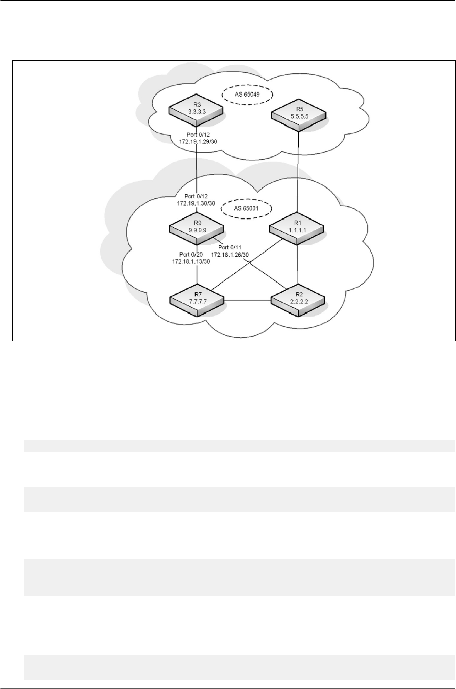
Configuring Routing
267
Figure8.9.BGP Configuration Example
Configuring BGP on Router 9
To configure R9 as shown in Figure above:
1. To make it easier to determine which device is being configured, set the name of router (R9) as
the system prompt.
(Routing) #set prompt R9
2. Enter Global Config mode and enable routing on the system.
(R9) #configure
(R9) (Config)#ip routing
3. Enter Interface Config mode for port 0/11. This interface is connected to R2, which is part of the
same AS. Assign an IP address to the interface, and enable routing on the interface.
(R9) (Config)#interface 0/11
(R9) (Interface 0/11)#ip address 172.18.1.26 255.255.255.252
(R9) (Interface 0/11)#routing
4. Configure the OSPF timers. The hello interval should be the same on all routers attached to a
common network. Likewise, the dead interval timers should be the same across all routers on
the network.
(R9) (Interface 0/11)#ip ospf hello-interval 3
(R9) (Interface 0/11)#ip ospf dead-interval 12

Configuring Routing
268
5. Configure OSPF to treat the interface as a point-to-point link.
(R9) (Interface 0/11)#ip ospf network point-to-point
(R9) (Interface 0/11exit
6. Enter Interface Config mode for port 0/12. This is the interface that is connected to R3, which is
in a different AS. Assign an IP address to the interface, and enable routing on the interface.
(R9) (Interface 0/12)#interface 0/12
(R9) (Interface 0/12)#ip address 172.19.1.30 255.255.255.252
(R9) (Interface 0/12)#routing
(R9) (Interface 0/12)#exit
7. Enter Interface Config mode for port 0/20. This interface is connected to R7, which is part of the
same AS. Assign an IP address to the interface, and enable routing on the interface.
(R9) (Interface 0/20)#interface 0/20
(R9) (Interface 0/20)#ip address 172.18.1.13 255.255.255.252
(R9) (Interface 0/20)#routing
8. Configure the OSPF timers.
(R9) (Interface 0/20)#ip ospf hello-interval 3
(R9) (Interface 0/20)#ip ospf dead-interval 12
9. Configure OSPF to treat the interface as a point-to-point link.
(R9) (Interface 0/20)#ip ospf network point-to-point
(R9) (Interface 0/20)#exit
10.Enter Interface Config mode for loopback interface 0 and assign an IP address to the interface.
(R9) (Config)#interface loopback 0
(R9) (Interface loopback 0)#ip address 192.168.0.9 255.255.255.255
11.Configure the OSPF area ID that the loopback interface belongs to.
(R9) (Interface loopback 0)#ip ospf area 0
(R9) (Interface loopback 0)#exit
12.Configure the OSPF settings for the router.
(R9) (Config)#router ospf
(R9) (Config-router)#router-id 9.9.9.9
(R9) (Config-router)#network 172.19.1.0 0.0.0.255 area 0
(R9) (Config-router)#network 172.18.1.0 0.0.0.255 area 0
(R9) (Config-router)#passive-interface 0/12
(R9) (Config-router)#timers spf 3 5
(R9) (Config-router)#max-metric router-lsa summary-lsa on-startup 90
(R9) (Config-router)#exit
13.Enable BGP and identify the autonomous system (AS) number of the router.
(R9) (Config-router)#router bgp 65001

Configuring Routing
269
14.Configure the BGP router ID.
(R9) (Config-router)#bgp router-id 9.9.9.9
15.Specify the maximum number of next hops BGP may include in an Equal Cost Multipath
(ECMP) route derived from paths received from neighbors outside the local autonomous sys-
tem.
(R9) (Config-router)#maximum-paths 24
16.Set the maximum number of next hops BGP may include in an ECMP route derived from paths
received from neighbors within the local autonomous system.
(R9) (Config-router)#maximum-paths ibgp 24
17.Enable the logging of adjacency state changes.
(R9) (Config-router)#bgp log-neighbor-changes
18.Allow the aggregation of routes with different MED attributes.
(R9) (Config-router)#bgp aggregate-different-meds
19.Configure the keepalive and hold times that BGP uses for all of its neighbors.
(R9) (Config-router)#timers bgp 4 12
20.Configure the summary addresses for BGP.
(R9) (Config-router)#aggregate-address 172.16.1.0 255.255.255.0 summary-only
(R9) (Config-router)#aggregate-address 172.17.1.0 255.255.255.0 summary-only
(R9) (Config-router)#aggregate-address 172.18.1.0 255.255.255.0 summary-only
(R9) (Config-router)#aggregate-address 172.19.1.0 255.255.255.0 summary-only
21.Configure the networks that are attached to AS 65001.
(R9) (Config-router)#network 172.18.1.12 mask 255.255.255.252
(R9) (Config-router)#network 172.18.1.16 mask 255.255.255.252
(R9) (Config-router)#network 172.18.1.20 mask 255.255.255.252
(R9) (Config-router)#network 172.18.1.24 mask 255.255.255.252
(R9) (Config-router)#network 172.17.1.4 mask 255.255.255.252
(R9) (Config-router)#network 172.17.1.8 mask 255.255.255.252
(R9) (Config-router)#network 172.17.1.12 mask 255.255.255.252
(R9) (Config-router)#network 172.19.1.28 mask 255.255.255.252
(R9) (Config-router)#network 172.19.1.32 mask 255.255.255.252
22.Configure the loopback addresses of routers in AS 65001.
(R9) (Config-router)#network 192.168.0.1 mask 255.255.255.255
(R9) (Config-router)#network 192.168.0.2 mask 255.255.255.255
(R9) (Config-router)#network 192.168.0.9 mask 255.255.255.255
(R9) (Config-router)#network 192.168.0.11 mask 255.255.255.255
(R9) (Config-router)#neighbor 192.168.0.11 remote-as 65001
(R9) (Config-router)#neighbor 192.168.0.11 description R7
(R9) (Config-router)#neighbor 192.168.0.11 next-hop-self

Configuring Routing
270
(R9) (Config-router)#neighbor 192.168.0.11 update-source loopback 0
(R9) (Config-router)#neighbor 192.168.0.1 remote-as 65001
(R9) (Config-router)#neighbor 192.168.0.1 description R1
(R9) (Config-router)#neighbor 192.168.0.1 next-hop-self
(R9) (Config-router)#neighbor 192.168.0.1 update-source loopback 0
(R9) (Config-router)#neighbor 192.168.0.2 remote-as 65001
(R9) (Config-router)#neighbor 192.168.0.2 description R2
(R9) (Config-router)#neighbor 192.168.0.2 next-hop-self
(R9) (Config-router)#neighbor 192.168.0.2 update-source loopback 0
(R9) (Config-router)#neighbor 172.19.1.29 remote-as 65049
(R9) (Config-router)#neighbor 172.19.1.29 description R3
(R9) (Config-router)#exit
(R9) (Config)#exit
Configuring BGP on Router 3
To configure R3 as shown in Figure above:
1. To make it easier to determine which device is being configured, set the name of router (R3) as
the system prompt.
(Routing) #set prompt R3
2. Enter Global Config mode and enable routing on the system.
(R3) #configure
(R3) (Config)#ip routing
3. Enter Interface Config mode for port 0/12. This is the interface that is connected to R3, which is
in a different AS. Assign an IP address to the interface, and enable routing on the interface.
(R3) (Interface 0/12)#interface 0/12
(R3) (Interface 0/12)#ip address 172.19.1.29 255.255.255.252
(R3) (Interface 0/12)#routing
(R3) (Interface 0/12)#exit
4. Enter Interface Config mode for loopback interface 0 and assign an IP address to the interface.
(R3) (Config)#interface loopback 0
(R3) (Interface loopback 0)#ip address 192.168.2.3 255.255.255.255
(R3) (Interface loopback 0)#exit
5. Enable BGP and identify the autonomous system (AS) number of the router.
(R3) (Config-router)#router bgp 65049
6. Configure the BGP router ID.
(R3) (Config-router)#bgp router-id 3.3.3.3
7. Specify the maximum number of next hops BGP may include in an ECMP route derived from
paths received from neighbors outside the local autonomous system.
(R3) (Config-router)#maximum-paths 4
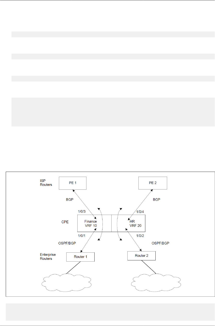
Configuring Routing
271
8. Enable the logging of adjacency state changes.
(R3) (Config-router)#bgp log-neighbor-changes
9. Configure BGP to advertise connected routes with a metric value of 100.
(R3) (Config-router)#redistribute connected metric 100
10.Configure the keepalive and hold times that BGP uses for all of its neighbors.
(R3) (Config-router)#timers bgp 4 12
11.Configure the loopback addresses of routers in AS 65049.
(R3) (Config-router)#network 192.168.2.3 mask 255.255.255.255
(R3) (Config-router)#neighbor 172.19.1.30 remote-as 65001
(R3) (Config-router)#neighbor 172.19.1.30 description R9
(R3) (Config-router)#exit
(R3) (Config)#exit
8.5.6.2. BGP with VRF
In the following is a sample configuration, the BGP instances running in each VR are independent
of each other and no leaking of routes happens between the BGP instances using this feature.
Figure8.10.BGP with Virtual Routers
(Routing) #configure
(Routing) (Config)#ip routing
(Routing) (Config)#ip vrf finance

Configuring Routing
272
(Routing) (Config-vrf-finance)#exit
(Routing) (Config)#ip vrf hr
(Routing) (Config-vrf-hr)#exit
(Routing) (Config)# #interface 1/0/1
(Routing) (Interface 1/0/1)#ip vrf forwarding finance
(Routing) (Interface 1/0/1)#ip address 1.1.1.1 /24
(Routing) (Interface 1/0/1)#ip ospf area 0
(Routing) (Interface 1/0/1)#exit
(Routing) (Config)# #interface 1/0/2
(Routing) (Interface 1/0/2)#ip vrf forwarding hr
(Routing) (Interface 1/0/2)#ip address 2.2.2.2 /24
(Routing) (Interface 1/0/2)#ip ospf area 0
(Routing) (Interface 1/0/2)#exit
(Routing) (Config)# #interface 1/0/3
(Routing) (Interface 1/0/3)#ip vrf forwarding finance
(Routing) (Interface 1/0/3)#ip address 3.3.3.3 /24
(Routing) (Interface 1/0/3)#ip ospf area 0
(Routing) (Interface 1/0/3)#exit
(Routing) (Config)# #interface 1/0/4
(Routing) (Interface 1/0/4)#ip vrf forwarding hr
(Routing) (Interface 1/0/4)#ip address 4.4.4.4 /24
(Routing) (Interface 1/0/4)#ip ospf area 0
(Routing) (Interface 1/0/4)#exit
(Routing) (Config)# #router ospf vrf finance
(Routing) (Config-router)#router-id 1.1.1.1
(Routing) (Config-router)#exit
(Routing) (Config)# #router ospf vrf hr
(Routing) (Config-router)#router-id 2.2.2.2
(Routing) (Config-router)#exit
(Routing) (Config)# #router bgp 100
(Config-router)#bgp router-id 1.1.1.1
(Config-router)#address-family ipv4 vrf finance
(Config-router)#neighbor 3.3.3.4 remote-as 200
(Config-router)#neighbor 3.3.3.4 activate
(Config-router)#network 6.6.6.0 255.255.255.0
(Config-router)#redistribute ospf
(Config-router)#redistribute connected
(Config-router)#exit
(Config-router)#address-family ipv4 vrf hr
(Config-router-af)#neighbor 4.4.4.5 remote-as 300
(Config-router-af)#neighbor 4.4.4.5 activate
(Config-router-af)#network 8.8.8.0 255.255.255.0
(Config-router-af)#redistribute ospf
(Config-router-af)#redistribute connected
(Config-router-af)#exit
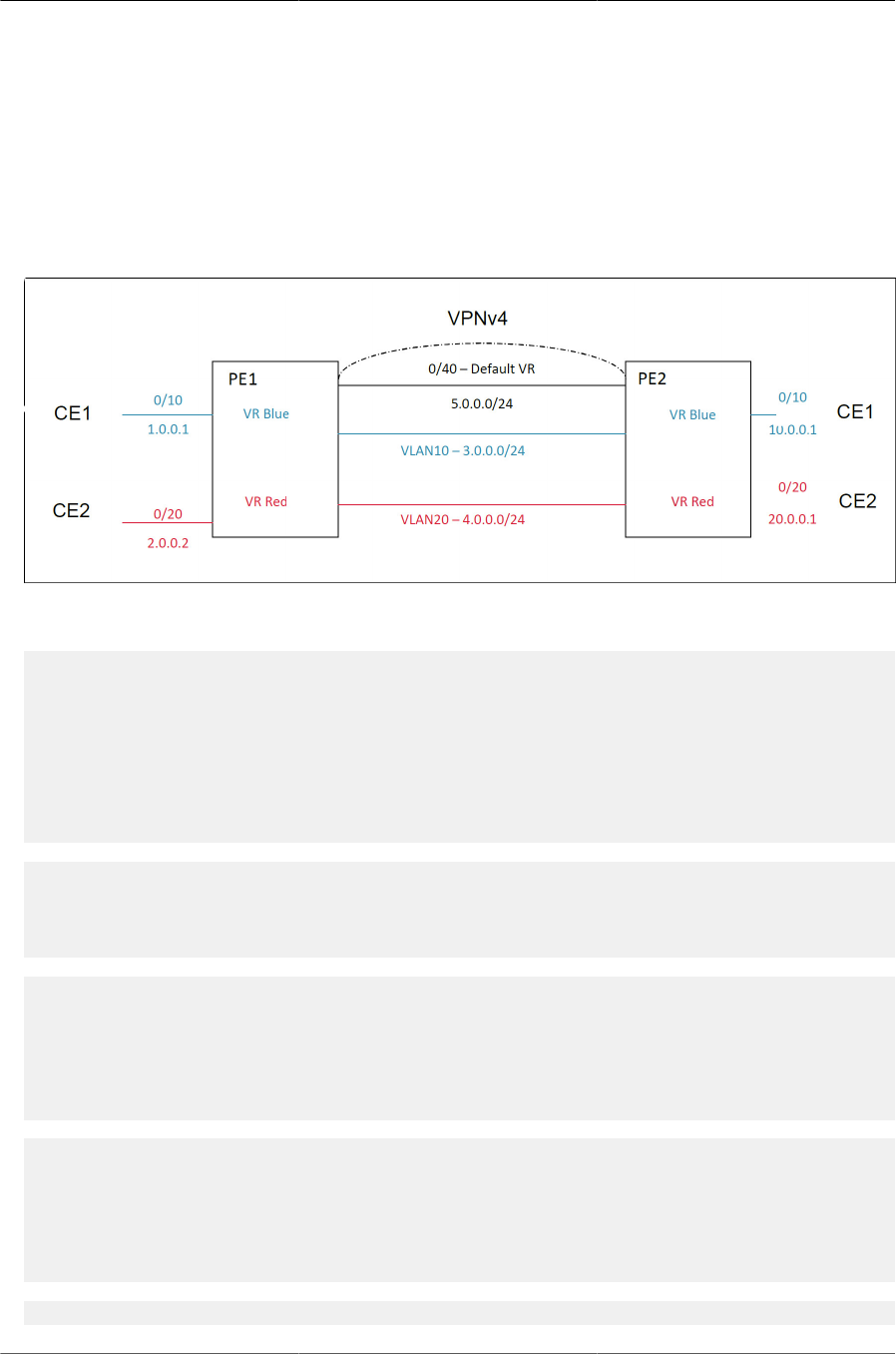
Configuring Routing
273
8.5.6.3. Route Leaking between VRFs
The following two configuration examples demonstrate route leaking between VRFs.
• Route leaking from a global routing table into a VPN routing/forwarding instance (VRF) and
route leaking from a VRF into a global routing table in a VPNv4 deployment topology.
Figure8.11.Route Leaking From Global Routing Table Into a VRF
PE1
(Routing) #configure
(Routing) (Config)#ip routing
(Routing) (Config)#ip extcommunity-list 1 permit rt 100:1
(Routing) (Config)#ip extcommunity-list 2 permit rt 200:1
(Routing) (Config)#route-map test 10
(Routing) (route-map)#match extcommunity 1
(Routing) (route-map)#set ip next-hop 3.0.0.1
(Routing) (route-map)#exit
(Routing) (Config)#route-map test 20
(Routing) (route-map)#match extcommunity 2
(Routing) (route-map)#set ip next-hop 4.0.0.1
(Routing) (route-map)#exit
(Routing) (Config)#ip vrf "blue"
(Routing) (config-vrf-blue)#ip routing
(Routing) (config-vrf-blue)#rd 100:1
(Routing) (config-vrf-blue)#route-target both 100:1
(Routing) (config-vrf-blue)#route-target import 100:2
(Routing) (config-vrf-blue)#exit
(Routing) (Config)#ip vrf "red"
(Routing) (config-vrf-red)#rd 200:1
(Routing) (config-vrf-red)#ip routing
(Routing) (config-vrf-red)#route-target both 200:1
(Routing) (config-vrf-red)#route-target import 200:2
(Routing) (config-vrf-red)#exit
(Routing) (Config)#interface 0/10

Configuring Routing
274
(Routing) (Interface 0/10)#routing
(Routing) (Interface 0/10)#ip address 1.0.0.1 255.255.0.0
(Routing) (Interface 0/10)#ip vrf forwarding "blue"
(Routing) (Interface 0/10)#exit
(Routing) (Config)#interface 0/20
(Routing) (Interface 0/20)#routing
(Routing) (Interface 0/20)#ip address 2.0.0.1 255.255.0.0
(Routing) (Interface 0/20)#ip vrf forwarding "red"
(Routing) (Interface 0/20)#exit
(Routing) (Config)#interface vlan 10
(Routing) (interface vlan 10)#routing
(Routing) (interface vlan 10)#ip address 3.0.0.1 255.255.0.0
(Routing) (interface vlan 10)#ip vrf forwarding "blue"
(Routing) (interface vlan 10)#exit
(Routing) (Config)#interface vlan 20
(Routing) (interface vlan 20)#routing
(Routing) (interface vlan 20)#ip address 4.0.0.1 255.255.0.0
(Routing) (interface vlan 20)#ip vrf forwarding "red"
(Routing) (interface vlan 20)#exit
!VPNv4 neighborship
(Routing) (Config)#interface 0/40
(Routing) (Interface 0/40)#routing
(Routing) (Interface 0/40)#ip address 5.0.0.1 255.255.0.0
(Routing) (Interface 0/40)#exit
(Routing) (Config)#router bgp 100
(Routing) (Config-router)#bgp router-id 1.1.1.1
(Routing) (Config-router)#neighbor 5.0.0.2 remote-as 100
(Routing) (Config-router)#neighbor 5.0.0.2 route-map test out
(Routing) (Config-router)#address-family ipv4 vrf blue
(Routing) (Config-router-af)#neighbor 1.0.0.2 remote-as 200
(Routing) (Config-router-af)#exit
(Routing) (Config-router)#address-family ipv4 vrf red
(Routing) (Config-router-af)#neighbor 2.0.0.2 remote-as 300
(Routing) (Config-router-af)#exit
(Routing) (Config-router)#address-family vpnv4 unicast
(Routing) (Config-router-af)#neighbor 5.0.0.2 activate
(Routing) (Config-router-af)#exit
(Routing) (Config-router)#exit
PE2
(Routing) #configure
(Routing) (Config)#ip routing
(Routing) (Config)#ip extcommunity-list 1 permit rt 100:2
(Routing) (Config)#ip extcommunity-list 2 permit rt 200:2
(Routing) (Config)#route-map test 10
(Routing) (route-map)#match extcommunity 1

Configuring Routing
275
(Routing) (route-map)#set ip next-hop 3.0.0.2
(Routing) (route-map)#exit
(Routing) (Config)#route-map test 20
(Routing) (route-map)#match extcommunity 2
(Routing) (route-map)#set ip next-hop 4.0.0.2
(Routing) (route-map)#exit
(Routing) (Config)#ip vrf "blue"
(Routing) (config-vrf-blue)#ip routing
(Routing) (config-vrf-blue)#rd 100:2
(Routing) (config-vrf-blue)#route-target both 100:2
(Routing) (config-vrf-blue)#route-target import 100:1
(Routing) (config-vrf-blue)#exit
(Routing) (Config)#ip vrf "red"
(Routing) (config-vrf-red)#ip routing
(Routing) (config-vrf-red)#rd 200:2
(Routing) (config-vrf-red)#route-target both 200:2
(Routing) (config-vrf-red)#route-target import 200:1
(Routing) (config-vrf-red)#exit
(Routing) (Config)#interface 0/10
(Routing) (Interface 0/10)#routing
(Routing) (Interface 0/10)#ip address 10.0.0.1 255.255.0.0
(Routing) (Interface 0/10)#ip vrf forwarding "blue"
(Routing) (Interface 0/10)#exit
(Routing) (Config)#interface 0/20
(Routing) (Interface 0/20)#routing
(Routing) (Interface 0/20)#ip address 20.0.0.1 255.255.0.0
(Routing) (Interface 0/20)#ip vrf forwarding "red"
(Routing) (Interface 0/20)#exit
(Routing) (Config)#interface vlan 10
(Routing) (interface vlan 10)#routing
(Routing) (interface vlan 10)#ip address 3.0.0.2 255.255.0.0
(Routing) (interface vlan 10)#ip vrf forwarding "blue"
(Routing) (interface vlan 10)#exit
(Routing) (Config)#interface vlan 20
(Routing) (interface vlan 20)#routing
(Routing) (interface vlan 20)#ip address 4.0.0.2 255.255.0.0
(Routing) (interface vlan 20)#ip vrf forwarding "red"
(Routing) (interface vlan 20)#exit
!VPNv4 neighborship
(Routing) (Config)#interface 0/40
(Routing) (Interface 0/40)#routing
(Routing) (Interface 0/40)#ip address 5.0.0.2 255.255.0.0
(Routing) (Interface 0/40)#exit
(Routing) (Config)#router bgp 100
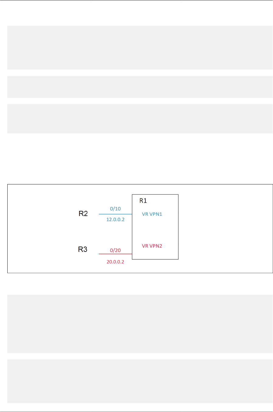
Configuring Routing
276
(Routing) (Config-router)#(Config-router)#bgp router-id 1.1.1.2
(Routing) (Config-router)#neighbor 5.0.0.1 remote-as 100
(Routing) (Config-router)#neighbor 5.0.0.1 route-map test out
(Routing) (Config-router)#address-family ipv4 vrf blue
(Routing) (Config-router-af)#neighbor 10.0.0.2 remote-as 400
(Routing) (Config-router-af)#exit
(Routing) (Config-router)#address-family ipv4 vrf red
(Routing) (Config-router-af)#neighbor 20.0.0.2 remote-as 500
(Routing) (Config-router-af)#exit
(Routing) (Config-router)#address-family vpnv4 unicast
(Routing) (Config-router-af)#neighbor 5.0.0.1 activate
(Routing) (Config-router-af)#exit
(Routing) (Config-router)#exit
• Route leaking between different VRFs
This configuration describes route leaking between two different VRFs of a router as shown in the
topology shown in Figure below.
Figure8.12.Routing Leaking Between Different VRFs of a Router
The following configuration is used:
(Routing) #configure
(Routing) (Config)#ip routing
(Routing) (Config)#ip vrf "vpn1"
(Routing) (Config-vrf-vpn1)#rd 1000:1
(Routing) (Config-vrf-vpn1)#route-target export 1000:1
(Routing) (Config-vrf-vpn1)#route-target import 2000:1
(Routing) (Config-vrf-vpn1)#route-target import 3000:1
(Routing) (Config-vrf-vpn1)#exit
(Routing) (Config)#ip vrf "vpn2"
(Routing) (Config-vrf-vpn2)#rd 2000:1
(Routing) (Config-vrf-vpn2)#route-target export 2000:1
(Routing) (Config-vrf-vpn2)#route-target import 1000:1
(Routing) (Config-vrf-vpn2)#route-target import 4000:1
(Routing) (Config-vrf-vpn2)#exit

Configuring Routing
277
(Routing) (Config)#interface 0/10
(Routing) (Interface 0/10)#routing
(Routing) (Interface 0/10)#ip vrf forwarding "vpn1"
(Routing) (Interface 0/10)#ip address 12.0.0.2 255.255.255.0
(Routing) (Interface 0/10)#exit
(Routing) (Config)#interface 0/20
(Routing) (Interface 0/20)#routing
(Routing) (Interface 0/20)#ip vrf forwarding "vpn2"
(Routing) (Interface 0/20)#ip address 20.0.0.2 255.255.255.0
(Routing) (Interface 0/20)#exit
(Routing) (Config)#router bgp 500
(Routing) (Config-router)#bgp router-id 5.5.5.5
(Routing) (Config-router)#address-family ipv4 vrf "vpn1"
(Routing) (Config-router-af)#redistribute connected
(Routing) (Config-router-af)#exit
(Routing) (Config-router)#address-family ipv4 vrf "vpn2"
(Routing) (Config-router-af)#redistribute connected
(Routing) (Config-router-af)#exit
(Routing) (Config-router)#exit
(Routing) (Config)#exit
8.5.6.4. BGP Dynamic Neighbors
BGP dynamic neighbors are configured using a range of IP addresses and BGP peer groups.
Each range can be configured as a subnet IP address. After a subnet range is configured for a
BGP peer group, and a TCP session is initiated for an IP address in the subnet range, a new BGP
neighbor is dynamically created.
Use the bgp listen command to create an IPv4 listen range and associate it with specified peer
template. The command also activates the IPv4 BGP dynamic neighbors feature. The limit key-
word and max-number argument define the global maximum number of IPv4 BGP dynamic neigh-
bors that can be created.
The following commands limit the maximum dynamic neighbors to 10, and create a listen range
(with subnet/ mask of 10.12.0.0/16) with a template (named ABC be inherited with dynamically
created BGP neighbors:
(Routing) #configure
(Routing) (Config)#router bgp 100
(Routing) (Config-router)#bgp listen limit 10
(Routing) (Config-router)#bgp listen range 10.12.0.0/16
(Routing) (Config-router)#bgp listen range 10.27.0.0/16 inherit peer ABC
Dynamic neighbors and listening range information are indicated when the show ip bgp neigbhors
command is used to show IP neighbor information:
(routing) #show ip bgp neighbors 10.12.0.100
Description: spine 1 router 1
Remote Address ................................. 10.12.0.100
Remote AS ...................................... 100

Configuring Routing
278
Peer ID ........................................ 14.3.0.1
Peer Admin Status ............................. START
Peer State .................................... ESTABLISHED
Peer Type ..................................... DYNAMIC
Listen Range .................................. 10.12.0.0/16
Local Interface Address ........................ 10.12.0.2
Local Port ..................................... 179
The show ip bgp summary command shows the configured dynamic neighbor limits, and the dy-
namically learned neighbors are indicated by an asterisk:
(switch-2) #show ip bgp summary
IPv4 Routing .................................. Enable
BGP Admin Mode ................................ Enable
BGP Router ID .................................. 1.0.0.2
Local AS Number ............................... 10001
Number of Network Entries ...................... 4
Number of AS Paths ............................. 1
Dynamic Neighbors Current/High/Limit........... 1/1/100
Neighbor ASN MsgRcvd MsgSent State Up/Down Time Pfx Rcvd
------------ ----- -------- -------- ------------- -------------- ---------
25.0.0.1 10000 2341 2346 ESTABLISHED 0:16:33:11 2
*100.20.1.7 30 0 7 OPEN SENT 0

Configuring Routing
279
8.6. Bidirectional Forwarding Detection
8.6.1. Overview
In a network device, Bidirectional Forwarding Detection (BFD) is presented as a service to its user
applications, providing them options to create and destroy a session with a peer device and report-
ing upon the session status. On ICOS switches, OSPF and BGP can use BFD for monitoring of
their neighbors' availability in the network and for fast detection of connection faults with them.
BFD uses a simple hello mechanism that is similar to the neighbor detection components of some
well-known protocols. It establishes an operational session between a pair of network devices to
detect a two-way communication path between them and serves information regarding it to the
user applications. The pair of devices transmits BFD packets between them periodically, and if one
stops receiving peer packets within detection time limit it considers the bidirectional path to have
failed. It then notifies the application protocol using its services.
BFD allows each device to estimate how quickly it can send and receive BFD packets to agree
with its neighbor upon how fast detection of failure could be done.
BFD can operate between two devices on top of any underlying data protocol (network layer, link
layer, tunnels, etc.) as payload of any encapsulating protocol appropriate for the transmission
medium. The ICOS implementation works with IPv4 and IPv6 networks and supports IPv4/v6 ad-
dress-based encapsulations.
8.6.2. Configuring BFD
The following command sequence enables BFD and configures session parameters:
1. First, globally enable BFD:
(Router)#configure
(Routing) (Config)# feature bfd
2. Configure session settings. These can be configured globally or on a per-interface basis.
(Routing) (Config)#bfd interval 100 min_rx 200 multiplier 5
(Routing) (Config)#bfd slow-timer 1000
• The argument interval refers to the desired minimum transmit interval, the minimum interval
that the user wants to use while transmitting BFD control packets (in ms).
• The argument min_rx refers to the required minimum receive interval, the minimum interval at
which the system can receive BFD control packets (in ms).
• The argument multiplier specifies the number of BFD control packets to be missed in a row to
declare a session down.
• The slow-timer command sets up the BFD required echo receive interval preference value (in
ms). This value determines the interval the asynchronous sessions use for BFD control pack-
ets when the echo function is enabled. The slow-timer value is used as the new control pack-
et interval, while the echo packets use the configured BFD intervals.

Configuring Routing
280
3. Configure BGP to use BFD for fast detection of faults between neighboring devices.
(Routing) (Config)#router bgp
(Routing) (Config-router)# neighbor 172.16.11.6 fall-over bfd
(Routing) (Config-router)# exit
4. Enable BFD globally for OSPF:
(Routing) (Config)#router ospf
(Routing) (Config-router)# bfd
(Routing) (Config-router)# exit
5. Configure OSPF to use BFD on the interface:
(Routing) #configure
(Routing) (Config)#interface 0/9
(Routing) (Interface 0/9)#ip ospf bfd
(Routing) (Interface 0/9)#exit

Configuring Routing
281
8.7. VRF Lite Operation and Configuration
8.7.1. Overview
The Virtual Routing and Forwarding feature enables a router to function as multiple routers. Each
virtual router (VR) manages its own routing domain, with its own IP routes, routing interfaces,
and host entries. Each virtual router makes its own routing decisions, independent of other virtu-
al routers. More than one virtual routing table may contain a route to a given destination. The net-
work administrator can configure a subset of the router’s interfaces to be associated with each
virtual router. The router routes packets according to the virtual routing table associated with the
packet’s ingress interface. Each interface can be associated with at most one virtual router.
8.7.2. VRF Functionality
Each virtual router behaves like an independent router. Virtual routers can be created and de-
stroyed dynamically. The fault domains of virtual routers are isolated. Bringing down a virtual
router does not impact another virtual router. Each virtual router has its own instances of rout-
ing protocols and routing applications. ICOS supports a maximum of 64 Virtual Routers. The total
number of routes or host entries is still limited by the hardware capacities on the physical router,
but the routes and host entries are distributed across the virtual routing domains based on the
user configuration. The maximum number routes in a particular virtual router can be optionally re-
served.
IP prefixes can overlap between two VR instances. The same IP address can be configured on
two interfaces that are a part of different VR instances. A packet is routed based on the route table
look up result in the corresponding VR instance. The VR instance is derived based on the ingress
interface. There are situations, however, that require support for inter-VR routing, such as provid-
ing access to shared services syslog server, DHCP server, the Internet, etc. These cases are han-
dled through “route leaking”.
In the standard ICOS Routing build, the VRF component must be selected to support VRF. By de-
fault, all the standard routing software and functions are in the default router (VRID 0), which is
created on startup and cannot be deleted by the user. The non-VRF routing user does not experi-
ence any disruption in using the CLI commands or in router functionality as a result of VRF config-
uration. Configuration migration for a system running an earlier build is supported.
The ICOS Virtual Routing feature depends on the “Network Name Space” feature in Linux. ICOS
supports this feature in the 3.x and later Linux kernels. There is no impact on the routing feature
for ICOS running pre-3.x kernels except that the VRF feature is not supported on them. The CLI
commands for VRF are disabled in the ICOS builds running pre-3.x kernels.
The user manages the VRF functionality through CLI commands. There is no separate user inter-
face for every VR instance. The user manages all the VR instances from a single CLI. The in-band
management is supported through one of the interfaces on the default VR only. ICOS CLI does not
currently support managing VRF instances, although they work in the default VR instance. Sys-
log is enhanced to support logging from different Linux processes. VRF supports logging for all the
events that are already supported.

Configuring Routing
282
8.7.3. Route Leaking
Route leaking is the ability to install a route in one VRF that allows traffic to flow to another VRF.
Although this mechanism breaks the isolation between VRFs, it is sometimes used to provide ac-
cess to common services for devices inside the different VRFs. ICOS supports route leaking be-
tween the global default routing table and a VR, but not across VRs. ICOS supports route leaking
only through static routes. ICOS does not support inter- VRF packet forwarding by connecting a
wire between ports belonging to different VR instances.
8.7.3.1. Adding Leaked Routes
Connected routes in one router that are leaked into another VR are referred to as leaked host
routes. To add leaked host routes, specify the next-hop interface but not the next-hop address. For
leaked routes that are not directly connected (static or dynamic routes), the next-hop address must
to be specified in addition to the next- hop interface. The next-hop interface is specified to identify
the outgoing VR interface. If the next-hop interface is unspecified, the route is treated as an inter-
nal route to the VR.
Internal routes within a router that are added with only a next-hop interface value (and no next-hop
address value) are supported only over unnumbered interfaces.
8.7.3.2. Using Leaked Routes
The line rate forwarding continues to work the same for leaked route destinations in a router as for
the internal routes in the router. For bidirectional traffic to work between VRs using leaked routes,
the corresponding routes should be leaked between the VRs.
8.7.3.3. CPU-Originated Traffic
For CPU-originated traffic from different applications (ping, traceroute, syslog, IP helper) that may
use the leaked routes to access the destination or shared service, the following conditions are re-
quired to ensure proper operation:
1. The source IP address in the originated packets must be mentioned with the source IP option
(e.g., ping with source option).
2. In the router where the CPU traffic originates, the route for the source option matching network
must be leaked into the virtual router where the next-hop belongs so that the return traffic is di-
rected to the traffic-originating router.
8.7.4. VRF and ICOS Feature Support
Table below lists ICOS features and details how they are supported by VRF Lite:
1. VRF and ICOS Feature Support
Feature VRF Support
Network Management Network management includes the ability to manage the switch via
CLI and SNMP. ICOS Network management is supported only via
the default router. Administrators cannot log into the switch and man-
age the switch via one of the IP addresses on the non-default VR.

Configuring Routing
283
Feature VRF Support
The Service Port and the Network Port are always associated with
the default router, so the customers are able to manage the switch
via these interfaces.
SNMP Management Only the default router can be managed via SNMP.
AAA The Authentication, Authorization, and Accounting protocols include
services such as the RADIUS client and the TACACS+ client. ICOS
supports these services only on the default router.
Network Services The Ping and the Trace Route clients are supported in the Virtual
Router context. Other protocols are supported only in the default
router. These include the SNTP client, DNS client, sFlow, RPCAP,
and Auto Install.
Loopback and Tunnel In-
terfaces
Loopback interfaces with IPv4 prefixes are supported in the Virtual
Router. Loopback interfaces with IPv6 addresses can be configured
only in the default router.
The number of Loopback interfaces in builds containing the VRF
package is increased to 64. The loopback interfaces are shared
across VR instances in the system and there is no restriction on the
maximum supported per VR.
Tunnel interfaces are not supported in the Virtual Router.
IP unnumbered interfaces IP unnumbered interface cannot be part of non-default VRF instance.
This feature is supported only in the default router.
OSPFv2 The OSPFv2 protocol is supported in the Virtual Router. As of the
current release, a crash in the OSPFv2 protocol does not cause the
switch to reboot. All OSPF features including graceful restart and
NSF are supported for OSPFv2 in each VR instance.
OSPFV3 The OSPFv3 protocol is supported only in the default router.
RIP RIP is not currently supported in the Virtual Router.
VRRP The Virtual Routing Redundancy Protocol is a fault-tolerance feature
that enables two or more routers to appear as one router to the IP
clients. If one of the VRRP routers fails, another router can take over
the data forwarding with minimum interruption to client traffic.
The VRRP protocol is supported in the Virtual Router context. The
VRRP protocol enables two or more virtual routers running on differ-
ent physical switches to form a VRRP group. The Virtual Routers run-
ning on the same physical switch cannot form a VRRP group with
each other.
BGP The Border Gateway Protocol is intended to be used by the Cus-
tomer Edge (CE) switch to communicate with other CE switches and
PE switches across the Provider Network. This typical VRF-Lite de-
ployment is described in Section 8.7.5, “VRF Lite Deployment Sce-
narios”. The BGP protocol runs in the Default Router context and is
aware of the Virtual Routers.

Configuring Routing
284
Feature VRF Support
BGP is used to:
1. Redistribute VPN routes from Virtual Routers on the CE switch to
the attached PE in the Provider Network.
2. Leak routes dynamically between different Virtual Routers on the
same physical switch. This requires support for BGP extended
communities and route targets.
In the current ICOS implementation, BGP does not support either of
the above mentioned functionalities.
IPv6 The current ICOS release supports VRF-Lite only for IPv4. IPv6 data
forwarding and protocols are not currently supported.
IP Multicast The current ICOS Virtual Routing release supports only IPv4 unicast
routing.
Policy Based Routing PBR is a routing policy feature useful in overriding routing decisions
with programmable rules. PBR is supported only in the default router
in the current release.
DHCP Server DHCP Server is not VR-aware in the current release.
DHCP Snooping The IP Source Guard (IPSG) feature uses DHCP snooping to allow
only packets from known sources. IPSG uses DHCP Snooping to
snoop the DHCP addresses allocated to connected hosts. The tuple
(IP, MAC, VLAN, Interface) uniquely identifies a host.
DHCP Snooping is a layer-2 feature and is VRF-agnostic. It works
in layer-2 of any VLAN irrespective of whether it belongs to a default
router or any virtual router. It applies to all protocols working at L2.
IP Helper IP Helper relays the broadcast packets received on a Routing inter-
face in the VRF context to the configured server address. The server
is looked up in the RTO specific to that VR only. Relay across VRs is
not supported.
OpEN API The applications using existing OpEN APIs are not affected by the
VRF feature.
Layer-2 Features The VRF feature does not affect the switch layer-2 features such as
virtual port channels (VPC). However, if VPC is planned to be used
on VRF-enabled switches, the VPC ports need to be configured to be
in the same routing domain.
8.7.5. VRF Lite Deployment Scenarios
The following are two likely deployment scenarios for the VRF-Lite solution:
1. In the Customer edge (CE) devices that interface with the PE (Provider edge) device in the ser-
vice provider backbone network to provide VPN connectivity for the Enterprise network sites
spread across different geographical locations across the internet backbone. In this scenario,
the BGP protocol must be running on the device to support feature extensions required to sup-
port:
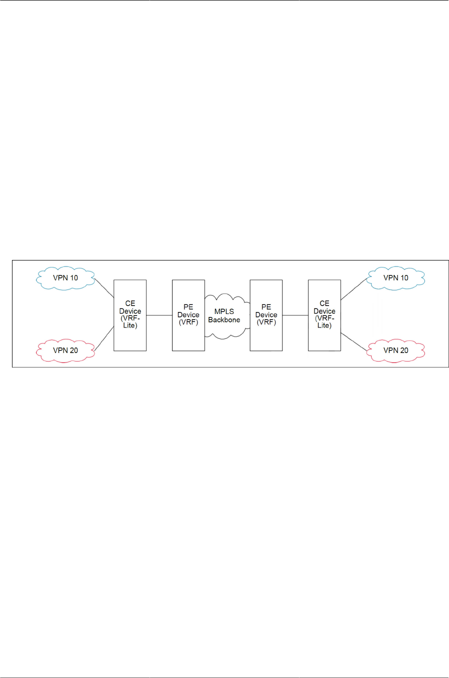
Configuring Routing
285
a. Dynamic route leaking locally between the VRFs to leak the routes to shared services using
Route Targets.
b. Exchange the VPN related route information per VR with PE device using extended commu-
nities.
2. The internal Routers in the Enterprise networks to provide isolation of different departments/of-
fices at layer-3 or routing domain.
This scenario does not mandate that the BGP protocol be running on the device. It can still be run
in this scenario to achieve dynamic route leaking only. The IGP protocol (OSPF or RIP) running in
the VR instance communicates route information with corresponding peers in the same VR on oth-
er CE devices or internal Routers.
These scenarios are shown in figure below:
Figure8.13.VRF Scenarios
The default global routing table is also referred to as VR 0.
In the following example, subnetworks 10.10.10.0/24 and 11.11.11.0/24 belong to the virtual rout-
ing domain “HR Dept” and subnetworks 20.20.20.0/24 and 22.22.22.0/24 belong to virtual routing
domain “Finance Dept”.
Hence, the hosts in networks 10.10.10.0/24 can communicate only with other network
11.11.11.0/24 via the router and the hosts in networks 20.20.20.0/24 can communicate only with
other network 22.22.22.0/24 via the router.
If there is a shared service printer @30.30.30.30 in the default global routing domain “Shared Ser-
vices”, we would want the HR and Finance domains to have access to it. Therefore, we statically
leak a 30.30.30.0/24 route from global routing table to VR 10 and VR 20. At the same time, we sta-
tically leak the routes 10.10.10.0/24 and 11.11.11.0/24 from VR 10 to global table (the same ap-
plies to VR 20).
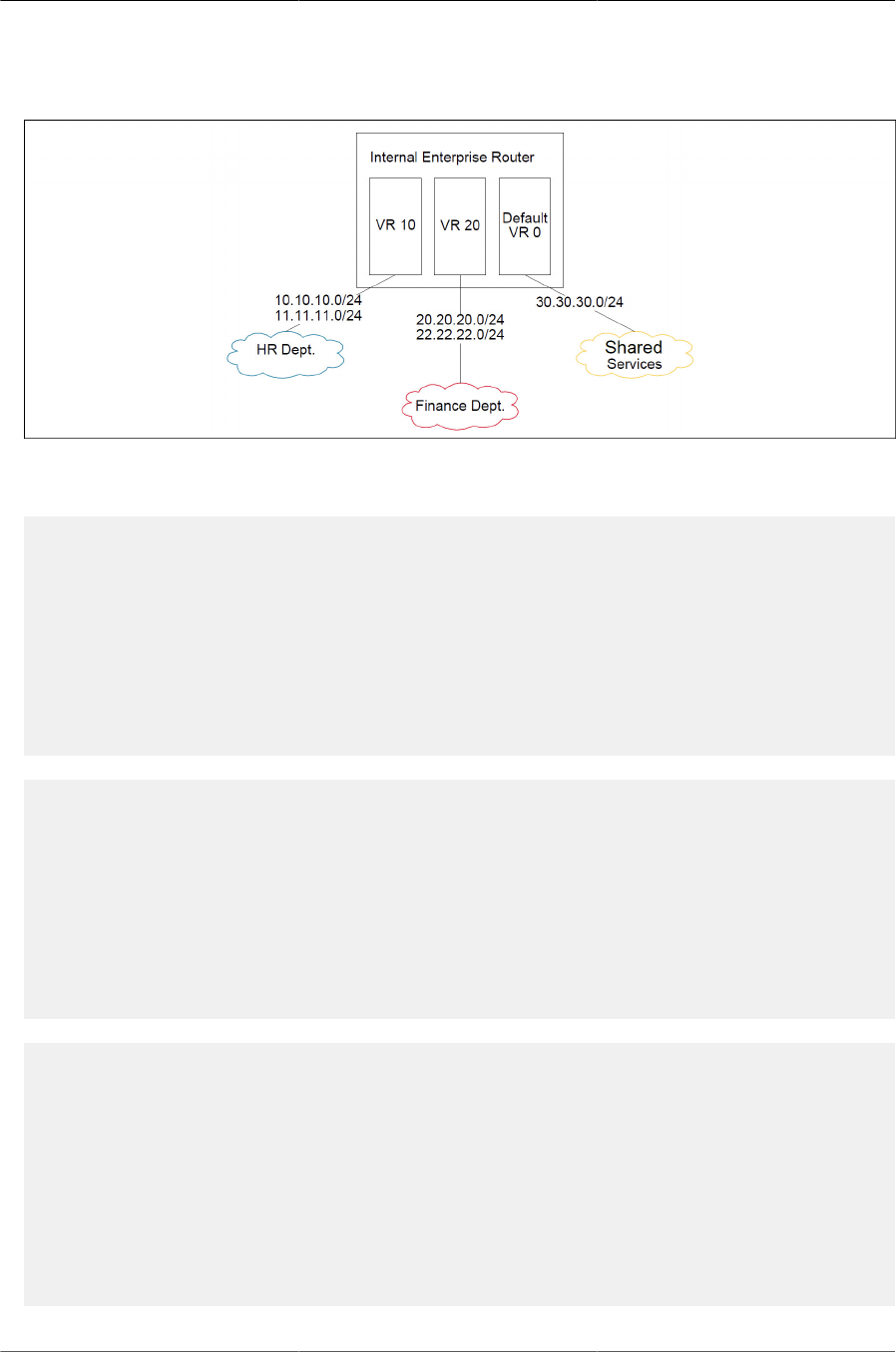
Configuring Routing
286
Figure8.14.VRF Routing With Shared Services
The route tables in both the VRs and the global domain look like the following:
(Routing) #show ip route vrf HR
Route Codes: R - RIP Derived, O - OSPF Derived, C - Connected, S - Static
B - BGP Derived, IA - OSPF Inter Area
E1 - OSPF External Type 1, E2 - OSPF External Type 2
N1 - OSPF NSSA External Type 1, N2 - OSPF NSSA External Type 2
L - Leaked Route
C 10.10.10.0/24 [0/1] directly connected, vlan 10
C 11.11.11.0/24 [0/1] directly connected, vlan 11
S L 30.30.30.0/24 [1/1] directly connected, vlan 30
S L 50.50.50.0/24 [1/1] via 30.30.30.2, 02d:22h:15m, vlan 30
(Routing) #show ip route vrf Finance
Route Codes: R - RIP Derived, O - OSPF Derived, C - Connected, S - Static
B - BGP Derived, IA - OSPF Inter Area
E1 - OSPF External Type 1, E2 - OSPF External Type 2
N1 - OSPF NSSA External Type 1, N2 - OSPF NSSA External Type 2
L - Leaked Route
C 20.20.20.0/24 [0/1] directly connected, vlan 20
C 22.22.22.0/24 [0/1] directly connected, vlan 22
S L 30.30.30.0/24 [1/1] directly connected, vlan 30
S L 50.50.50.0/24 [1/1] via 30.30.30.2, 02d:22h:15m, vlan 30
(Routing) #show ip route
Route Codes: R - RIP Derived, O - OSPF Derived, C - Connected, S - Static
B - BGP Derived, IA - OSPF Inter Area
E1 - OSPF External Type 1, E2 - OSPF External Type 2
N1 - OSPF NSSA External Type 1, N2 - OSPF NSSA External Type 2
L - Leaked Route
C 30.30.30.0/24 [0/1] directly connected, vlan 30
S L 10.10.10.0/24 [1/1] directly connected, vlan 10
S L 11.11.11.0/24 [1/1] directly connected, vlan 11
S L 20.20.20.0/24 [1/1] directly connected, vlan 20
S L 22.22.22.0/24 [1/1] directly connected, vlan 22

Configuring Routing
287
8.7.5.1. VRF Configuration Example
1. Create virtual router instances. The following commands create and name two instances and
enter VRF Configuration mode for each.
In VRF Configuration mode for each VR, a description is added and the maximum number of
routes allowed in each virtual instance is configured. On the “Red” instance, the number of
routes above which a warning message is issued is also configured.
The ip routing command enables routing in each VR instance:
(Routing) #configure
(Routing) (Config)#ip vrf Red
(Routing) (Config-vrf-Red)#description "finance department"
(Routing) (Config-vrf-Red)#maximum routes 2048
(Routing) (Config-vrf-Red)#maximum routes warn 80
(Routing) (Config-vrf-Red)#ip routing
(Routing) (Config-vrf-Red)#exit
(Routing) (Config)#ip vrf Blue
(Routing) (Config-vrf-Blue)#description "human resources department"
(Routing) (Config-vrf-Blue)#maximum routes 4096
(Routing) (Config-vrf-Blue)#ip routing
(Routing) (Config-vrf-Blue)#exit
2. In Interface Config mode, assign interfaces to each virtual router:
(Routing) (Config)#interface 0/1
(Routing) (Interface 1/0/1)#ip vrf forwarding Red
WARNING: routing interface moved from Default router instance to "Red"
router instance.
(Routing) (Interface 1/0/1)#exit
(Routing) (Config)#interface 0/2
(Routing) (Interface 1/0/2)#ip vrf forwarding Blue
WARNING: routing interface moved from Default router instance to "Blue"
router instance.
(Routing) (Interface 1/0/2)#exit
3. Create static leaked routes as needed in the VR instances.
In the following example, subnetwork 9.0.0.0/24 is a connected subnetwork in the global route
table and subnet 56.6.6.0/24 is reachable via a gateway 9.0.0.2 in the global route table. Subnet
8.0.0.0/24 is a connected subnetwork in virtual router Red.
The two routes are leaked from the global route table into the Red VR and the connected sub-
net 8.0.0.0/24 is leaked from the Red VR to the global route table.
The following commands also add a non-leaked static route for the 56.6.6.0/24 subnetwork
scoped to the domain of Red VR.
(Routing) (Config)#ip routing
(Routing) (Config)#interface 0/27

Configuring Routing
288
(Routing) (Interface 0/27)#routing
(Routing) (Interface 0/27)#ip vrf forwarding Red
WARNING: routing interface moved from Default router instance to "Red"
router in stance.
(Routing) (Interface 0/27)#ip address 8.0.0.1 /24
(Routing) (Interface 0/27)#interface 0/26
(Routing) (Interface 0/26)#routing
(Routing) (Interface 0/26)#ip address 9.0.0.1 /24
(Routing) (Interface 0/26)#exit
(Routing) (Config)#ip route 56.6.6.0 255.255.255.0 9.0.0.2
4. To leak routes from the global routing table to the VRF route table, use the following example:
(Routing) (Config)#ip route vrf Red 9.0.0.2 255.255.255.255 9.0.0.2 0/26
(Routing) (Config)#ip route vrf Red 56.6.6.0 255.255.255.0 9.0.0.2 0/26
To leak routes from the VRF’s routing table to the global routing table, use the following example:
(Routing) (Config)#ip route 8.0.0.2 255.255.255.255 0/27
To leak routes (non-leaked) internal to the VRF’s route table, use the following example:
(Routing) (Config)#ip route vrf Red 66.6.6.0 255.255.255.0 8.0.0.2

Configuring Routing
289
8.8. IPv6 Routing
IPv6 is the next generation of the Internet Protocol. With 128-bit addresses, versus 32-bit address-
es for IPv4, IPv6 solves the address depletion issues seen with IPv4 and removes the requirement
for Network Address Translation (NAT), which is used in IPv4 networks to reduce the number of
globally unique IP addresses required for a given network.
In the ICOS software, IPv6 coexists with IPv4. As with IPv4, IPv6 routing can be enabled on loop-
back and VLAN interfaces. Each L3 routing interface can be used for IPv4, IPv6, or both. IP proto-
cols running over L3 (for example, UDP and TCP) are common to both IPv4 and IPv6.
8.8.1. How Does IPv6 Compare with IPv4?
There are many conceptual similarities between IPv4 and IPv6 network operation. Addresses still
have a network prefix portion (network) and a device interface specific portion (host). While the
length of the network portion is still variable, most users have standardized on using a network
prefix length of 64 bits. This leaves 64 bits for the interface specific portion, called an Interface
ID in IPv6. Depending upon the underlying link addressing, the Interface ID can be automatical-
ly computed from the link (e.g., MAC address). Such an automatically computed Interface ID is
called an EUI-64 identifier, which is the interface MAC address with ff:fe inserted in the middle.
IPv6 packets on the network are of an entirely different format than traditional IPv4 packets and
are also encapsulated in a different EtherType (86DD rather than 0800 which is used with IPv4).
The details for encapsulating IPv6 in Ethernet frames are described in RFC4862.
Unlike IPv4, IPv6 does not have broadcasts. There are two types of IPv6 addresses — unicast
and multicast. Unicast addresses allow direct one-to-one communication between two hosts,
whereas multicast addresses allow one-to-many communication. Multicast addresses are used as
destinations only. Unicast addresses will have 00 through fe in the most significant octets and mul-
ticast addresses will have ff in the most significant octets.
8.8.2. How Are IPv6 Interfaces Configured?
In the ICOS software, IPv6 coexists with IPv4. As with IPv4, IPv6 routing can be enabled on VLAN
interfaces. Each L3 routing interface can be used for IPv4, IPv6, or both simultaneously.
Neighbor Discovery (ND) protocol is the IPv6 replacement for Address Resolution Protocol (ARP)
in IPv4. The IPv6 Neighbor Discovery protocol is described in detail in RFC4861. Router adver-
tisement is part of the Neighbor Discovery process and is required for IPv6. As part of router ad-
vertisement, PowerConnect 7000 Series switch software supports stateless auto configuration of
end nodes. The switch supports both EUI-64 interface identifiers and manually configured inter-
face IDs.
While optional in IPv4, router advertisement is mandatory in IPv6. Router advertisements spec-
ify the network prefix(es) on a link which can be used by receiving hosts, in conjunction with an
EUI-64 identifier, to autoconfigure a host’s address. Routers have their network prefixes config-
ured and may use EUI-64 or manually configured interface IDs. In addition to zero or more global
addresses, each IPv6 interface also has an autoconfigured “link-local” address which is:
• fe80::/10, with the EUI-64 address in the least significant bits.
• Reachable only on the local VLAN — link-local addresses are never routed.

Configuring Routing
290
• Not globally unique
Next hop addresses computed by routing protocols are usually link-local addresses.
During the period of transitioning the Internet to IPv6, a global IPv6 Internet backbone may not be
available. One transition mechanism is to tunnel IPv6 packets inside IPv4 to reach remote IPv6
islands. When a packet is sent over such a link, it is encapsulated in IPv4 in order to traverse an
IPv4 network and has the IPv4 headers removed at the other end of the tunnel.
8.8.3. Default IPv6 Routing Values
Table below shows the default values for the IP routing features this section describes.
Table8.1.IPv6 Routing Defaults
Parameter Default Value
IPv6 Unicast Routing
Mode
Disabled
IPv6 Hop Limit Unconfigured
ICMPv6 Rate Limit Error
Interval
1000 milliseconds
ICMPv6 Rate Limit Burst
Size
100 messages
Interface IPv6 Mode Disabled
IPv6 Router Route Prefer-
ences
• Local — 0
• Static — 1
• OSPFv3 Intra — 110
• OSPFv3 Inter — 110
• OSPFv3 External — 110
• BGP External — 20
• BGP Internal — 200
• BGP Local — 200
Table below shows the default IPv6 interface values after a VLAN routing interface has been cre-
ated.
Table8.2.IPv6 Interface Defaults
Parameter Default Value
IPv6 Mode Disabled
DHCPv6 Client Mode Disabled
Stateless Address AutoConfig Mode Disabled

Configuring Routing
291
Parameter Default Value
Routing Mode Enabled
Interface Maximum Transmit Unit 1500
Router Duplicate Address Detection Transmits 1
Router Advertisement NS Interval Not configured
Router Lifetime Interval 1800 seconds
Router Advertisement Reachable Time 0 seconds
Router Advertisement Interval 600 seconds
Router Advertisement Managed Config Flag Disabled
Router Advertisement Other Config Flag Disabled
Router Advertisement Suppress Flag Disabled
IPv6 Destination Unreachables Enabled
8.8.4. Configuring IPv6 Routing Features
This section provides information about the commands you use to configure IPv6 routing on in the
ICOS software.
8.8.4.1. Configuring Global IP Routing Settings
Use the following commands to configure various global IP routing settings for the ICOS software.
Table8.3.Global IP Routing Settings
Command Purpose
configure Enter global configuration mode.
sdm prefer dual-ipv4-and-
ipv6 {data-center / dual-
ipv4-and-ipv6 alpm-da-
ta-center / dual- ipv4-and-
ipv6 alpm-mpls-data- cen-
ter / default}
Select a Switch Database Management (SDM) template to enable
support for both IPv4 and IPv6. Changing the SDM template requires
a system reload.
ipv6 unicast-routing Globally enable IPv6 routing on the switch.
ipv6 hop-limit limit Set the TTL value for the router. The valid range is 0 to 255.
ipv6 icmp error-interval
burst-interval [burst-size]
Limit the rate at which IPv4 ICMP error messages are sent.
• burst-interval — How often the token bucket is initialized (Range:
0– 2147483647 milliseconds).
• burst-size — The maximum number of messages that can be sent
during a burst interval (Range: 1–200).
exit Exit to Privileged EXEC mode.
ipv6 redirects This is an Interface level command to configure to send Router Ad-
vertisements with unspecified Hop Limit value.

Configuring Routing
292
Command Purpose
ipv6 nd ra hop-limit un-
specified
This command configures the router to send Router Advertisements
on an interface with unspecified (0) Current Hop Limit value. This will
tell the hosts on that link to ignore the Hop Limit from this Router.
show ipv6 protocols This command lists a summary of the configuration and status for
each of the active IPv6 routing protocols. If a protocol is selected on
the command line, the display will be limited to that protocol.
8.8.4.2. Configuring IPv6 Interface Settings
Use the following commands to configure IPv6 settings for VLAN, tunnel, or loopback interfaces.
Table8.4.IPv6 Interface settings
Command Purpose
configure Enter Global Configuration mode.
interface {vlan / tunnel /
loopback} interface-id
Enter Interface Configuration mode for the specified VLAN, tunnel, or
loopback interface.
ipv6 enable Enable IPv6 on the interface. Configuring an IPv6 address will auto-
matically enable IPv6 on the interface.
ipv6 address {autoconfig /
dhcp / prefix/prefix-length
[eui64]}
Configure the IPv6 address and network prefix length. Setting an
IPv6 address enables IPv6 on the interface. You can also use the
ipv6 enable command to enable IPv6 on the interface without setting
an address.
Link-local, multicast, IPv4-compatible, and IPv4-mapped addresses
are not allowed to be configured.
Include the EUI-64 keyword to have the system add the 64-bit inter-
face ID to the address. You must use a network prefix length of 64 in
this case.
For VLAN interfaces, use the dhcp keyword to enable the DHCPv6
client and obtain an IP address form a network DHCPv6 server.
ipv6 mtu (VLAN interfaces only) Set the IPv6 Maximum Transmission Unit
(MTU) on a routing interface. The IPv6 MTU is the size of the largest
IPv6 packet that can be transmitted on the interface without fragmen-
tation. The range is 1280– 12270 bytes.
ipv6 traffic-filter ACL name Add an access-list filter to this interface.
ipv6 unreachables (VLAN interfaces only) Allow the interface to send ICMPv6 Destina-
tion Unreachable messages. The no ipv6 unreachables command
suppresses the ICMPv6 unreachable messages for this interface.
exit Exit the interface configuration mode.
8.8.4.3. Configuring IPv6 Neighbor Discovery
Use the following commands to configure IPv6 Neighbor Discovery settings.

Configuring Routing
293
Table8.5.IPv6 Neighbor Discovery Settings
Command Purpose
ipv6 nd prefix prefix/ pre-
fix-length [{valid-lifetime/
infinite} {preferred-lifetime/
infinite}] [no-autoconfig]
[off-link]
Configure parameters associated with network prefixes that the
router advertises in its Neighbor Discovery advertisements.
• ipv6-prefix—IPv6 network prefix.
• prefix-length—IPv6 network prefix length.
• valid-lifetime—Valid lifetime of the router in seconds. (Range: 0–
4294967295 seconds.)
• infinite—Indicates lifetime value is infinite.
• preferred-lifetime—Preferred-lifetime of the router in seconds.
(Range: 0–4294967295 seconds.)
• no-autoconfig—Do not use the prefix for auto configuration.
• off-link—Do not use the prefix for onlink determination.
ipv6 nd ra-interval maxi-
mum minimum
Set the transmission interval between router Neighbor Discovery ad-
vertisements.
• maximum — The maximum interval duration (Range: 4–1800 sec-
onds).
• minimum — The minimum interval duration (Range: 3 – (0.75 *
maximum) seconds).
ipv6 nd ra-lifetime sec-
onds
• Set the value that is placed in the Router Lifetime field of the router
Neighbor Discovery advertisements sent from the interface.
• The seconds value must be zero, or it must be an integer between
the value of the router advertisement transmission interval and
9000 seconds. A value of zero means this router is not to be used
as the default router. (Range: 0- 9000).
ipv6 nd suppress-ra Suppress router advertisement transmission on an interface.
ipv6 nd dad attempts val-
ue
• Set the number of duplicate address detection probes transmitted
while doing Neighbor Discovery.
• The range for value is 0–600.
ipv6 nd ns-interval mil-
liseconds
Set the interval between router advertisements for advertised neigh-
bor solicitations. The range is 1000 to 4294967295 milliseconds.
ipv6 nd other-config-flag Set the other stateful configuration flag in router advertisements sent
from the interface.
ipv6 nd managed-con-
fig-flag
Set the managed address configuration flag in router advertisements.
When the value is true, end nodes use DHCPv6. When the value is
false, end nodes automatically configure addresses.
ipv6 nd reachable-time
milliseconds
Set the router advertisement time to consider a neighbor reachable
after neighbor discovery confirmation.

Configuring Routing
294
Command Purpose
ipv6 data-traffic rate- limit
rate-in-pps
Configures the rate in packets-per-second for the number of IPv6 da-
ta packets trapped to CPU when the packet fails to be forwarded in
the hardware due to unresolved hardware address of the destined
IPv6 node. The rate ranges from 50 pps to 1024 pps.
ipv6 neighbors dynamicre-
new
Enables/disables the periodic NUD (neighbor unreachability detec-
tion) to be run on the existing IPv6 neighbor entries based on the
activity of the entries in the hardware. If the setting is disabled, only
those entries that are actively used in the hardware are triggered for
NUD at the end of STALE timeout of 1200 seconds. If the setting is
enabled, periodically every 40 seconds a set of 300 entries are trig-
gered for NUD irrespective of their usage in the hardware.
ipv6 nud max-unicast-so-
licits
Configures the maximum number of unicast Neighbor Solicitations
sent during neighbor resolution or during NUD (neighbor unreachabil-
ity detection). The value ranges from 3 to 10.
ipv6 nud max-multi-
cast-solicits
Configures the maximum number of multicast Neighbor Solicitations
sent during neighbor resolution or during NUD (neighbor unreachabil-
ity detection). The value ranges from 3 to 255.
ipv6 nud backoff-multiple Configures the exponential backoff multiple to be used in the calcu-
lation of the next timeout value for Neighbor Solicitation transmis-
sion during NUD (neighbor unreachability detection) following the ex-
ponential backoff algorithm. The value ranges from 1 to 5. The next
timeout value is limited to a maximum value of 60 seconds if the val-
ue with exponential backoff calculation is greater than 60 seconds.
8.8.4.4. Configuring IPv6 Route Table Entries and Route Prefer-
ences
Use the following commands to configure IPv6 Static Routes.
Table8.6.IPv6 Static Routes
Command Purpose
configure Enter global configuration mode.
ipv6 route ipv6-prefix/pre-
fix- length {next-hop-ad-
dress / interface-type in-
terface-number next-hop-
address } [preference]
Configure a static route. Use the keyword null instead of the next
hop router IP address to configure a static reject route.
•prefix/prefix-length — The IPv6 network prefix and prefix length
that is the destination of the static route. Use the ::/0 form (unspeci-
fied address and zero length prefix) to specify a default route.
•interface-type interface-number — Must be specified when using
a link-local address as the next hop. The interface-type can be vlan
or tunnel.
•next-hop-address — The IPv6 address of the next hop that can
be used to reach the specified network. A link-local next hop ad-
dress must have a prefix length of 128. The next hop address can-
not be an unspecified address (all zeros), a multicast address, or a

Configuring Routing
295
Command Purpose
loopback address. If a link local next hop address is specified, the
interface (VLAN or tunnel), must also be specified.
•preference — Also known as Administrative Distance, a met-
ric the router uses to compare this route with routes from other
route sources that have the same network prefix. (Range: 1-255).
Lower values have precedence over higher values. The default
preference for static routes is 1. Routes with a preference of 255
are considered as “disabled” and will not be used for forwarding.
Routes with a preference metric of 254 are used by the local router
but will never be advertised to other neighboring routers.
ipv6 route ipv6-prefix/pre-
fix-length null [preference]
Configure a static reject route. IPv6 packets matching the reject route
will be silently discarded.
ipv6 route distance integer Set the default distance (preference) for static IPv6 routes. Lower
route preference values are preferred when determining the best
route. The default distance (preference) for static routes is 1.
exit Exit to Global Config mode.
serviceport ipv6 neigh-
bor ipv6_neighbor
mac_address
Configures a static IPv6 neighbor with the given IPv6 address and
MAC address on the service port.
network ipv6 neigh-
bor ipv6_neighbor
mac_address
Configures a static IPv6 neighbor with the given IPv6 address and
MAC address on the network port.
ipv6 neighbor
ipv6_neighbor if_name
mac_address
Configures a static IPv6 neighbor if_name with the given IPv6 ad-
dress and MAC address on the network port.
show serviceport ipv6
neighbors
This command displays the information about the IPv6 neighbor en-
tries cached on the service port. The information is updated to show
the type of the entry.
show network ipv6 neigh-
bors
This command displays the information about the IPv6 neighbor en-
tries cached on the network port. The information is updated to show
the type of the entry.
8.8.5. IPv6 Show Commands
Use the following commands to view IPv6 configuration status and related data.
Table8.7.IPv6 Configuration Status
Command Purpose
show sdm prefer Show the currently active SDM template.
show sdm prefer dual-
ipv4-andipv6 {date-cen-
ter / default}
Show parameters for the SDM template.
show ipv6 dhcp interface
vlan vlan-id
View information about the DHCPv6 lease acquired by the specified
interface.

Configuring Routing
296
Command Purpose
show ipv6 interface {vlan /
tunnel / loopback} inter-
face-id
View the IP interface configuration information for the specified IPv6
routing interface.
show ipv6 brief View the global IPv6 settings for the switch.
show ipv6 route [ipv6-ad-
dress / ipv6-prefix/pre-
fix-length / protocol / inter-
face-type interface-num-
ber] [best]
View the routing table.
•ipv6-address — Specifies an IPv6 address for which the best-
matching route would be displayed.
•protocol — Specifies the protocol that installed the routes. Is one
of the following keywords: connected, ospf, static.
•ipv6-prefix/prefix-length — Specifies an IPv6 network for which
the matching route would be displayed.
•interface-type interface-number — Valid IPv6 interface. Speci-
fies that the routes with next-hops on the selected interface be dis-
played.
•best — Specifies that only the best routes are displayed. If thecon-
nected keyword is selected for protocol, the best option is not avail-
able because there are no best or non-best connected routes.
show ipv6 route summary View summary information about the IPv6 routing table.
show ipv6 route prefer-
ences
View detailed information about the IPv6 route preferences.

Configuring Routing
297
8.9. ECMP Hash Selection
Users can choose the load balancing/sharing algorithm used for selecting the final ECMP route.
The management interfaces enable choosing various combinations of IP header fields, including
the inner or outer IP headers in tunneled packets. Both IPv4 and IPv6 are supported. The field se-
lectors remain the same for all packet types. The following is a list of available hash field selection
algorithms. The list may vary depending upon platform.
• Source IP address of the packet.
• Destination IP address of the packet.
• Source and Destination IP address of the packet.
• Source IP address and Source TCP/UDP Port field associated with the packet.
• Destination IP address and Destination TCP/UDP Port field associated with the packet.
• Source, Destination IP address and Source, Destination TCP/UDP Port field associated with the
packet.
For tunneled packets, the user also must select whether the inner or the outer IP header should be
used.
For configuration information, see the ip load-sharing command in the ICOS CLI Command Ref-
erence.


Configuring IPv4 and IPv6 Multicast
299
9.1. L3 Multicast Overview
IP Multicasting enables a network host (or multiple hosts) to send an IP datagram to multiple des-
tinations simultaneously. The initiating host sends each multicast datagram only once to a desti-
nation multicast group address, and multicast routers forward the datagram only to hosts who are
members of the multicast group. Multicast enables efficient use of network bandwidth because
each multicast datagram needs to be transmitted only once on each network link, regardless of
the number of destination hosts. Multicasting contrasts with IP unicasting, which sends a separate
datagram to each recipient host. The IP routing protocols can route multicast traffic, but the IP mul-
ticast protocols handle the multicast traffic more efficiently with better use of network bandwidth.
Applications that often send multicast traffic include video or audio conferencing, Whiteboard tools,
stock distribution tickers, and IP-based television (IP/TV).
9.1.1. IP Multicast Traffic
IP multicast traffic is traffic that is destined to a host group. Host groups are identified by class D
IP addresses, which range from 224.0.0.0 to 239.255.255.255. When a packet with a broadcast or
multicast destination IP address is received, the switch will forward a copy into each of the remain-
ing network segments in accordance with the IEEE MAC Bridge standard. Eventually, the packet
is made accessible to all nodes connected to the network.
This approach works well for broadcast packets that are intended to be seen or processed by all
connected nodes. In the case of multicast packets, however, this approach could lead to less effi-
cient use of network bandwidth, particularly when the packet is intended for only a small number of
nodes. Packets will be flooded into network segments where no node has any interest in receiving
the packet. The L3 multicast features on the switch help to ensure that only the hosts in the multi-
cast group receive the multicast traffic for that group.
Multicast applications send one copy of a packet, and address it to a group of receivers (Multicast
Group Address) rather than to a single receiver (unicast address). Multicast depends on the net-
work to forward the packets to only those networks and hosts that need to receive them.
9.1.2. Multicast Protocol Switch Support
Multicast protocols are used to deliver Multicast packets from one source to multiple receivers. Ta-
ble below summarizes the multicast protocols that the switch supports.
1. Multicast Protocol Support Summary
Protocol IPv4 or IPv6 For Communication Between
IGMP IPv4 Host-to-L3 switch/router
MLD IPv6 Host-to-L3 switch (router)
PIM-SM IPv4 or IPv6 L3-switch/router-to-L3 switch/router
PIM-DM IPv4 or IPv6 L3-switch/router-to-L3 switch/router
DVMRP IPv4 L3-switch/router-to-L3 switch/router

Configuring IPv4 and IPv6 Multicast
300
9.1.3. Multicast Protocol Roles
Hosts must have a way to identify their interest in joining any particular multicast group, and
routers must have a way to collect and maintain group memberships. These functions are handled
by the IGMP protocol in IPv4. In IPv6, multicast routers use the Multicast Listener Discover (MLD)
protocol to maintain group membership information.
Multicast routers must also be able to construct a multicast distribution tree that enables forward-
ing multicast datagrams only on the links that are required to reach a destination group member.
Protocols such as DVMRP, and PIM handle this function.
IGMP and MLD are multicast group discovery protocols that are used between the clients and the
local multicast router. PIM-SM, PIM-DM, and DVMRP are multicast routing protocols that are used
across different subnets, usually between the local multicast router and remote multicast router.
9.1.4. L3 Multicast Switch Requirements
You use the IPv4/IPv6 multicast feature on the switch to route multicast traffic between VLANs on
the switch. If all hosts connected to the switch are on the same subnet, there is no need to con-
figure the IP/IPv6 multicast feature. If the switch does not handle L3 routing, you can use IGMP
snooping or MLD snooping to manage port-based multicast group membership. For more informa-
tion, see Section 2.3.33, “IGMP Snooping”. If the local network does not have a multicast router,
you can configure the switch to act as the IGMP querier. For more information, see Section 2.3.37,
“IGMP Snooping Querier”
If the switch is configured as a L3 switch and handles inter-VLAN routing through static routes or
OSPF and multicast traffic is transmitted within the network, enabling and configuring L3 multicast
routing on the switch is recommended.
9.1.5. Determining Which Multicast Protocols to En-
able
IGMP is recommended on any switch that participates in IPv4 multicasting. MLD is recommended
on any switch that participates in IPv6 multicasting. PIM-DM, PIM-SM, and DVMRP are multicast
routing protocols that help determine the best route for IP (PIM and DVMRP) and IPv6 (PIM) mul-
ticast traffic. For more information about when to use PIM-DM, see Section 9.1.10.2, “Using PIM-
DM as the Multicast Routing Protocol”. For more information about when to use PIM-SM, see Sec-
tion 9.1.10.1, “Using PIM-SM as the Multicast Routing Protocol” For more information about when
to configure DVMRP, see Section 9.1.11.2, “Using DVMRP as the Multicast Routing Protocol”
9.1.6. Multicast Routing Tables
Multicast capable/enabled routers forward multicast packets based on the routes in the Multicast
Routing Information Base (MRIB). These routes are created in the MRIB during the process of
building multicast distribution trees by the Multicast Protocols running on the router. Different IP
Multicast routing protocols use different techniques to construct these multicast distribution trees.
9.1.7. Multicast Tunneling
If Multicast traffic is to be routed through a part of a network that does not support multicasting
(routers which are not multicast capable) then the multicast packets are encapsulated in an IP

Configuring IPv4 and IPv6 Multicast
301
datagram and sent as a unicast packet. When the multicast router at the remote end of the tun-
nel receives the packet, the router strips off the IP encapsulation and forwards the packet as an IP
Multicast packet. This process of encapsulating multicast packets in IP is called tunneling.
9.1.8. IGMP
The Internet Group Management Protocol (IGMP) is used by IPv4 systems (hosts, L3 switches,
and routers) to report their IP multicast group memberships to any neighboring multicast routers.
The switch performs the multicast router role of the IGMP protocol, which means it collects the
membership information needed by the active multicast routing protocol.
The switch supports IGMP Version 3. Version 3 adds support for source filtering, which is the abil-
ity for a system to report interest in receiving packets only from specific source addresses, as re-
quired to support Source- Specific Multicast [SSM], or from all but specific source addresses, sent
to a particular multicast address. Version 3 is designed to be interoperable with Versions 1 and 2.
9.1.8.1. IGMP Proxy
IGMP proxy enables a multicast router to learn multicast group membership information and for-
ward multicast packets based upon the group membership information. The IGMP Proxy is capa-
ble of functioning only in certain topologies that do not require Multicast Routing Protocols (i.e.,
DVMRP, PIM-DM, and PIM-SM) and have a tree-like topology, as there is no support for features
like reverse path forwarding (RPF) to correct packet route loops.
The proxy contains many downstream interfaces and a unique upstream interface explicitly config-
ured. It performs the host side of the IGMP protocol on its upstream interface and the router side of
the IGMP protocol on its downstream interfaces.
The IGMP proxy offers a mechanism for multicast forwarding based only on IGMP membership in-
formation. The router must decide about forwarding packets on each of its interfaces based on the
IGMP membership information. The proxy creates the forwarding entries based on the member-
ship information and adds it to the multicast forwarding cache (MFC) in order not to make the for-
warding decision for subsequent multicast packets with same combination of source and group.
9.1.9. MLD Protocol
Multicast Listener Discovery (MLD) protocol enables IPv6 routers to discover the presence of mul-
ticast listeners, the hosts that wish to receive the multicast data packets, on its directly-attached in-
terfaces. The protocol specifically discovers which multicast addresses are of interest to its neigh-
boring nodes and provides this information to the active multicast routing protocol that makes deci-
sions on the flow of multicast data packets.
The Multicast router sends General Queries periodically to request multicast address listeners in-
formation from systems on an attached network. These queries are used to build and refresh the
multicast address listener state on attached networks. Multicast listeners respond to these queries
by reporting their multicast addresses listener state and their desired set of sources with Cur-
rent-State Multicast address Records in the MLD2 Membership Reports. The Multicast router al-
so processes unsolicited Filter-Mode-Change records and Source-List-Change Records from sys-
tems that want to indicate interest in receiving or not receiving traffic from particular sources.
The ICOS implementation of MLD v2 supports the multicast router portion of the protocol (i.e., not
the listener portion). It is backward-compatible with MLD v1.

Configuring IPv4 and IPv6 Multicast
302
9.1.10. PIM Protocol
The Protocol Independent Multicast protocol is a simple, protocol-independent multicast routing
protocol. PIM uses an existing unicast routing table and a Join/Prune/Graft mechanism to build a
tree. PIM switches support two types of PIM: sparse mode (PIM-SM) and dense mode (PIM-DM).
PIM-SM is most effective in networks with a sparse population of multicast receivers. In contrast,
PIM-DM is most effective in networks with densely populated multicast receivers. In other words,
PIM-DM can be used if the majority of network hosts request to receive a multicast stream, while
PIM-SM might be a better choice in networks in which a small percentage of network hosts, locat-
ed throughout the network, wish to receive the multicast stream.
9.1.10.1. Using PIM-SM as the Multicast Routing Protocol
PIM-SM is used to efficiently route multicast traffic to multicast groups that may span wide area
networks where bandwidth is a constraint.
PIM-SM uses shared trees by default and implements source-based trees for efficiency; it as-
sumes that no hosts want the multicast traffic unless they specifically ask for it. It creates a shared
distribution tree centered on a defined rendezvous point (RP) from which source traffic is relayed
to the receivers. Senders first send the multicast data to the RP, which in turn sends the data down
the shared tree to the receivers.
Shared trees centered on an RP do not necessarily provide the shortest, most optimal path. In
such cases, PIM- SM provides a means to switch to more efficient source-specific trees. A data
threshold rate is configured to determine when to switch from shared-tree to source-tree.
PIM-SM uses a Bootstrap Router (BSR), which advertises information to other multicast routers
about the RP. In a given network, a set of routers can be administratively enabled as candidate
bootstrap routers. If it is not apparent which router should be the BSR, the candidates flood the
domain with advertisements. The router with the highest priority is elected. If all the priorities are
equal, then the candidate with the highest IP address becomes the BSR.
Only one RP address can be used at a time within a PIM domain. You can configure a static RP
on the switch. However, if the PIM domain uses the BSR to dynamically learn the RP, configuring
a static RP is not required. By default the RP advertised by the BSR is used, but you can specify
that the static RP to override any dynamically learned RP from the BSR.
If an interface on a switch configured with PIM-SM neighbors another PIM-SM domain, the PIM
BSR messages should not flood into the neighboring PIM domain because the neighbor domain
might not share the same set of RPs, candidate RPs, BSR, and candidate BSRs. The switch soft-
ware allows you to configure an interface that borders the PIM boundary prevent transmission
(sending and receiving) of PIM BSR messages. PIM-SM is defined in RFC 4601.
9.1.10.2. Using PIM-DM as the Multicast Routing Protocol
Unlike PIM-SM, PIM-DM creates source-based shortest-path distribution trees that make use of re-
verse-path forwarding (RPF). PIM-DM assumes that when a sender starts sending data, all down-
stream routers and hosts want to receive a multicast datagram. PIM-DM initially floods multicast
traffic throughout the network. Routers that do not have any downstream neighbors prune back the
unwanted traffic. In addition to PRUNE messages, PIM-DM makes use of graft and assert mes-

Configuring IPv4 and IPv6 Multicast
303
sages. Graft messages are used whenever a new host wants to join the group. Assert messages
are used to shutoff duplicate flows on the same multi-access network.
There are two versions of PIM-DM. Version 2 does not use the IGMP message; instead, it uses a
message that is encapsulated in IP package, with protocol number 103. In Version 2, a Hello mes-
sage is introduced in place of a query message.
PIM-DM is appropriate for:
• Densely distributed receivers
• Few senders-to-many receivers (due to frequent flooding)
• High volume of multicast traffic
• Constant stream of traffic
To minimize the repeated flooding of datagrams and subsequent pruning associated with a partic-
ular source- group (S,G) pair, PIM-DM uses a State Refresh message. This message is sent by
the router(s) directly connected to the source and is propagated throughout the network. When re-
ceived by a router on its RPF interface, the State Refresh message causes an existing prune state
to be refreshed. State Refresh messages are generated periodically by the router directly attached
to the source.
9.1.11. DVMRP
DVMRP is an interior gateway protocol that is suitable for routing multicast traffic within an au-
tonomous system (AS). DVMRP should not be used between different autonomous systems due
to limitations with hop count and scalability.
In addition to DVMRP, the switch supports the Protocol-Independent Multicast (PIM)
sparse- mode (PIM-SM) and dense-mode (PIM-SM) routing protocol. Only one multi-
cast routing protocol can be operational on the switch at any time. If you enable DVM-
RP, PIM must be disabled. Similarly, if PIM is enabled, DVMRP must be disabled.
DVMRP exchanges probe packets with all its DVMRP-enabled routers, it establishes two-way
neighboring relationships, and it builds a neighbor table. DVMRP exchanges report packets and
creates a unicast topology table, with which it builds the multicast routing table. This table is used
to route the multicast packets. Since every DVMRP router uses the same unicast routing protocol,
routing loops are avoided.
9.1.11.1. Understanding DVMRP Multicast Packet Routing
DVMRP is based on RIP; it forwards multicast datagrams to other routers in the AS and constructs
a forwarding table based on information it learns in response. More specifically, it uses this se-
quence.
• A new multicast packet is forwarded to the entire multicast network, with respect to the time-to-
live (TTL) of the packet.
• The TTL restricts the area to be flooded by the message.
• All routers that do not have members on directly-attached subnetworks send back Prune mes-
sages to the upstream router.

Configuring IPv4 and IPv6 Multicast
304
• The branches that transmit a prune message are deleted from the delivery tree.
• The delivery tree which is spanning to all the members in the multicast group, is constructed in
the form of a DVMRP forwarding table.
9.1.11.2. Using DVMRP as the Multicast Routing Protocol
DVMRP is used to communicate multicast information between L3 switches or routers. If a switch
handles inter- VLAN routing for IP traffic, including IP multicast traffic, multicast routing might be
required on the switch.
DVRMP is best suited for small networks where the majority of hosts request a given multicast
traffic stream. DVMRP is similar to PIM-DM in that it floods multicast packets throughout the net-
work and prunes branches where the multicast traffic is not desired. DVMRP was developed be-
fore PIM-DM, and it has several limitations that do not exist with PIM-DM. You might use DVMRP
as the multicast routing protocol if it has already been widely deployed within the network.

Configuring IPv4 and IPv6 Multicast
305
9.2. Default L3 Multicast Values
IP and IPv6 multicast is disabled by default. Table below shows the default values for L3 multicast
and the multicast protocols.
Table9.1.L3 Multicast Defaults
Parameter Default Value
IPv4 Multicast Defaults
L3 Multicast Admin Mode Disabled
Maximum Multicast Routing Table Entries 2048
Static Multicast Routes None configured
Interface TTL Threshold 1
IGMP Defaults
IGMP Admin Mode Disabled globally and on all interfaces
IGMP Version v3
IGMP Robustness 2
IGMP Query Interval 125 seconds
IGMP Query Max Response Time 10 seconds
IGMP Startup Query Interval 31 seconds
IGMP Startup Query Count 2
IGMP Last Member Query Interval 1 second
IGMP Last Member Query Count 2
IGMP Proxy Interface Mode Disabled
IGMP Proxy Unsolicited Report Interval 1 second
MLD Defaults
MLD Admin Mode Disabled globally and on all interfaces
MLD Version v2
MLD Query Interval 125 seconds
MLD Query Max Response Time 10,000 milliseconds
MLD Last Member Query Interval 1000 milliseconds
MLD Last Member Query Count 2
MLD Proxy Interface Mode Disabled
MLD Proxy Unsolicited Report Interval 1 second
PIM Defaults
PIM Protocol Disabled globally and on all interfaces
PIM-SM Data Threshold Rate 0 Kpbs
PIM-SM Register Threshold Rate 0 Kbps

Configuring IPv4 and IPv6 Multicast
306
Parameter Default Value
PIM Hello Interval 30 seconds (when enabled on an interface)
PIM-SM Join/Prune Interval 60 seconds (when enabled on an interface)
PIM-SM BSR Border Disabled
PIM-SM DR Priority 1 (when enabled on an interface)
PIM Candidate Rendezvous Points (RPs) None configured
PIM Static RP None configured
PIM Source-Specific Multicast (SSM) Range None configured. Default SSM group address
is 232.0.0.0/8 for IPv4 multicast and ff3x::/32 for
IPv6 multicast.
PIM BSR Candidate Hash Mask Length 30 (IPv4)
126 (IPv6)
PIM BSR Candidate Priority 0
DVMRP Defaults
DVMRP Admin Mode Disabled globally and on all interfaces
DVMRP Version 3
DVMRP Interface Metric 1

Configuring IPv4 and IPv6 Multicast
307
9.3. L3 Multicast Configuration Examples
9.3.1. Configuring Multicast VLAN Routing With IGMP
and PIM-SM
This example describes how to configure a switch with two VLAN routing interfaces that route IP
multicast traffic between the VLANs. PIM and IGMP are enabled on the switch and interfaces to
manage the multicast routing. IGMP snooping is enabled on the VLAN interfaces to control the
multicast subscriptions within each VLAN. VLAN 10 is statically configured as the RP for the multi-
cast group.
PIM does not require OSPF specifically; static routing could also be configured for uni-
cast routing.
The configuration in this example takes place on L3 switch A shown in Figure below. The red ar-
rows indicate the path that multicast traffic takes. L3 Switch A is configured as the RP for the PIM
domain, so it is in charge of sending the multicast stream to L3 Switch B and L3 Switch C, and
these switches forward the multicast data to the hosts that have requested to receive the data.
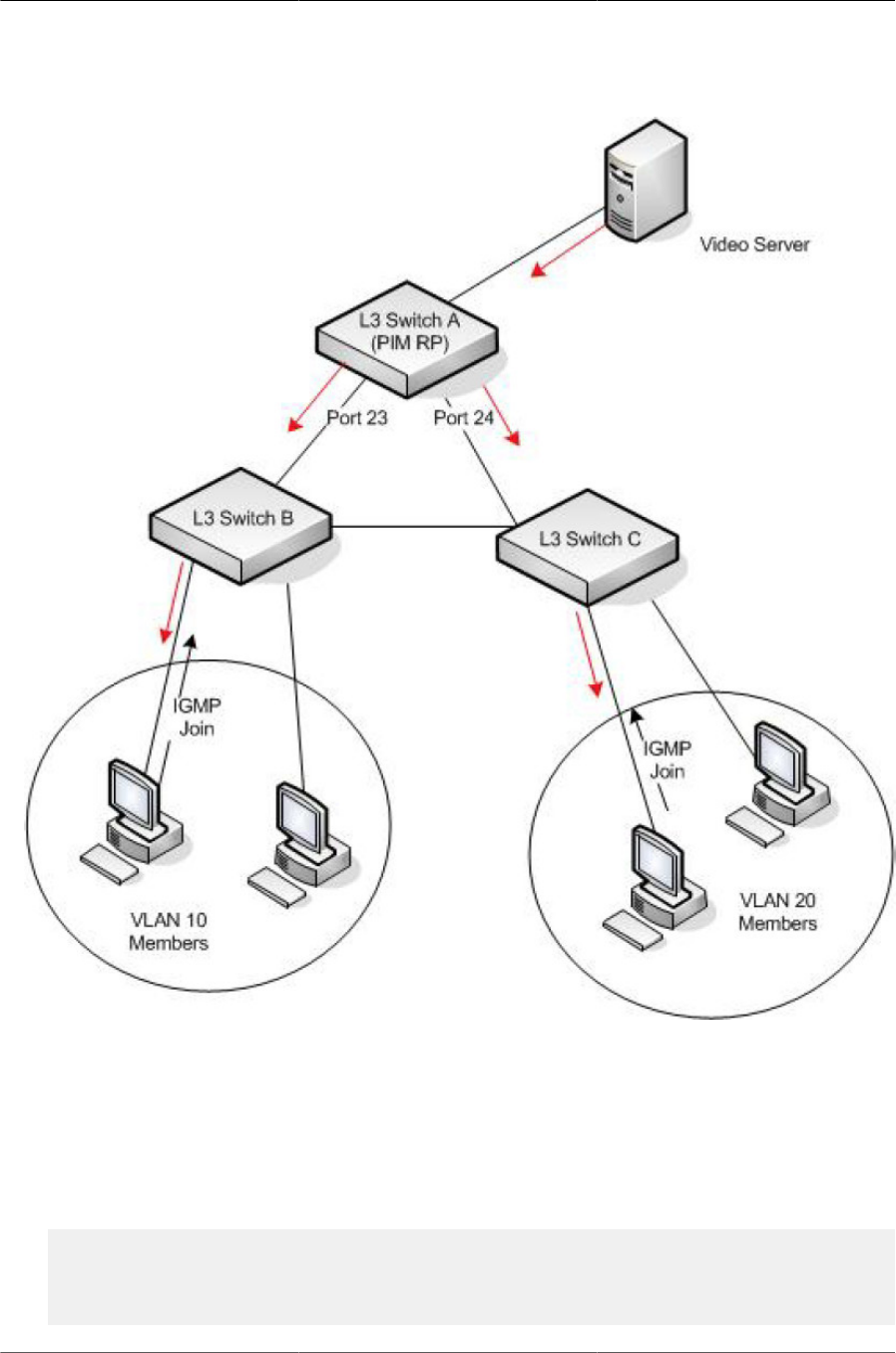
Configuring IPv4 and IPv6 Multicast
308
Figure9.1.Multicast VLAN Routing with IGMP and PIM-SM Example
In addition to multicast configuration, this example includes commands to configure STP and
OSPF on L3 Switch A. STP is configured on the ports that connects the switch to other switches.
OSPF is configured to route unicast traffic between the VLANs.
To configure the switch:
1. Create two VLANs and configure them as routing VLANs.
(Routing) #vlan database
(Routing) (Vlan)#vlan 10,20
(Routing) (Vlan)#vlan routing 10
(Routing) (Vlan)#vlan routing 20

Configuring IPv4 and IPv6 Multicast
309
2. While in VLAN Database mode, enable IGMP snooping on the VLANs.
(Routing) (Vlan)#set igmp 10
(Routing) (Vlan)#set igmp 20
(Routing) (Vlan)#exit
3. Add VLANs to interfaces 0/23 and 0/24.
(Routing) (Config)#interface 0/23
(Routing) (Interface 0/23)#vlan participation include 20
(Routing) (Interface 0/23)#exit
(Routing) (Config)#interface 0/24
(Routing) (Interface 0/24)#vlan participation include 10
(Routing) (Interface 0/24)#exit
4. Enable routing on the switch and configure the OSPF router ID. (Routing) (config)#ip rout-
ing (Routing) (config)#router ospf (Routing) (config-router)#router-id 3.3.1.1 (Routing) (con-
fig-router)#exit
5. Configure VLAN 10 as a VLAN routing interface and specify the OSPF area. When you assign
an IP address to the VLAN, routing is automatically enabled.
(Routing) (config)#interface vlan 10
(Routing) (interface vlan 10)#ip address 192.168.10.4 255.255.255.0
(Routing) (interface vlan 10)#ip ospf area 0
6. Enable IGMPv2 and PIM-SM on the VLAN routing interface.
(Routing) (interface vlan 10)#ip igmp
(Routing) (interface vlan 10)#ip igmp version 2
(Routing) (interface vlan 10)#ip pim
(Routing) (interface vlan 10)#exit
7. Configure VLAN 20 as a VLAN routing interface and specify the OSPF area.
(Routing) (config)#interface vlan 20
(Routing) (interface vlan 20)#ip address 192.168.20.4 255.255.255.0
(Routing) (interface vlan 20)#ip ospf area 0
8. Enable IGMPv2 and PIM-SM on the VLAN routing interface.
(Routing) (interface vlan 20)#ip igmp
(Routing) (interface vlan 20)#ip igmp version 2
(Routing) (interface vlan 20)#ip pim
(Routing) (interface vlan 20)#exit
9. Globally enable IGMP snooping, IP multicast, IGMP, and PIM-SM on the switch.
(Routing) (config)#set igmp
(Routing) (config)#ip multicast
(Routing) (config)#ip igmp
(Routing) (config)#ip pim sparse
10.Configure VLAN 10 as the RP and specify the range of multicast groups for PIM-SM to control.

Configuring IPv4 and IPv6 Multicast
310
routing(config)#ip pim rp-address 192.168.10.4 225.0.0.0 240.0.0.0
9.3.2. Configuring DVMRP
The following example configures two DVMRP interfaces on the switch to enable inter-VLAN multi-
cast routing.
To configure the switch:
1. Globally enable IP routing and IP multicast.
(Routing) #configure
(Routing) (config)#ip routing
(Routing) (config)#ip multicast
2. Globally enable IGMP so that this L3 switch can manage group membership information for its
directly-connected hosts. Enabling IGMP is not required if there are no directly-connected hosts.
(Routing) (config)#ip igmp
3. Globally enable DVMRP.
(Routing) (config)#ip dvmrp
4. Enable DVMRP and IGMP on VLAN routing interfaces 10 and 20.
(Routing) (config)#interface vlan 10
(Routing) (interface vlan 10)#ip address 192.168.10.1 255.255.255.0
(Routing) (interface vlan 10)#ip dvmrp
(Routing) (interface vlan 10)#ip igmp
(Routing) (interface vlan 10)#exit
(Routing) (config)#interface vlan 20
(Routing) (interface vlan 20)#ip address 192.168.20.1 255.255.255.0
(Routing) (interface vlan 20)#ip dvmrp
(Routing) (interface vlan 20)#ip igmp
(Routing) (interface vlan 20)#exit


Configuring Quality of Service
312
10.1. ACLs
Access Control Lists (ACLs) are a collection of permit and deny conditions, called rules, that pro-
vide security by blocking unauthorized users and allowing authorized users to access specific re-
sources.
ACLs can also provide traffic flow control, restrict contents of routing updates, and decide which
types of traffic are forwarded or blocked. ACLs can reside in a firewall router, a router connecting
two internal networks, or a Layer 3 switch.
ICOS software supports ACL configuration in both the ingress and egress direction. Egress ACLs
provide the capability to implement security rules on the egress flows (traffic leaving a port) rather
than the ingress flows (traffic entering a port). Ingress and egress ACLs can be applied to any
physical port, LAG, or VLAN routing port.
Depending on whether an ingress or egress ACL is applied to a port, when the traffic enters
(ingress) or leaves (egress) a port, the ACL compares the criteria configured in its rules, in order,
to the fields in a packet or frame to check for matching conditions. The ACL forwards or blocks the
traffic based on the rules.
Every ACL is terminated by an implicit deny all rule, which covers any packet not
matching a preceding explicit rule
You can set up ACLs to control traffic at Layer 2, Layer 3, or Layer 4. MAC ACLs operate on Layer
2. IP ACLs operate on Layers 3 and 4. ICOS supports both IPv4 and IPv6 ACLs.
10.1.1. MAC ACLs
MAC ACLs are Layer 2 ACLs. You can configure the rules to inspect the following fields of a pack-
et:
• Source MAC address
• Source MAC mask
• Destination MAC address
• Destination MAC mask
• VLAN ID
• Class of Service (CoS) (802.1p)
• EtherType
L2 ACLs can apply to one or more interfaces. Multiple access lists can be applied to a single inter-
face; sequence number determines the order of execution. You can assign packets to queues us-
ing the assign queue option.
10.1.2. IP ACLs
IP ACLs classify for Layers 3 and 4 on IPv4 or IPv6 traffic.

Configuring Quality of Service
313
Each ACL is a set of up to ten rules applied to inbound traffic. Each rule specifies whether the con-
tents of a given field should be used to permit or deny access to the network, and may apply to
one or more of the following fields within a packet:
• Destination IP with wildcard mask
• Destination L4 Port
• Every Packet
• IP DSCP
• IP Precedence
• IP TOS
• Protocol
• Source IP with wildcard mask
• Source L4 port
• IPv4 fragmented packets
• tcp flags
• igmp type
• icmp type
• icmp code
• icmp message
10.1.2.1. ACL Redirect Function
The redirect function allows traffic that matches a permit rule to be redirected to a specific physical
port or LAG instead of processed on the original port. The redirect function and mirror function are
mutually exclusive. In other words, you cannot configure a given ACL rule with mirror and redirect
attributes.
10.1.2.2. ACL Mirror Function
ACL mirroring provides the ability to mirror traffic that matches a permit rule to a specific physical
port or LAG. Mirroring is similar to the redirect function, except that in flow-based mirroring a copy
of the permitted traffic is delivered to the mirror interface while the packet itself is forwarded nor-
mally through the device. You cannot configure a given ACL rule with both mirror and redirect at-
tributes.
Using ACLs to mirror traffic is considered to be flow-based mirroring since the traffic flow is defined
by the ACL classification rules. This is in contrast to port mirroring, where all traffic encountered on
a specific interface is replicated on another interface.

Configuring Quality of Service
314
10.1.2.3. ACL Logging
ACL Logging provides a means for counting the number of matches against an ACL rule. When
you configure ACL Logging, you augment the ACL deny rule specification with a log parameter
that enables hardware hit count collection and reporting. The switch uses a fixed five minute log-
ging interval, at which time trap log entries are written for each ACL logging rule that accumulated
a non-zero hit count during that interval. You cannot configure the logging interval.
10.1.2.4. Time-Based ACLs
The time-based ACL feature allows the switch to dynamically apply an explicit ACL rule within an
ACL for a predefined time interval by specifying a time range on a per-rule basis within an ACL, so
that the time restrictions are imposed on the ACL rule.
With a time-based ACL, you can define when and for how long an individual rule of an ACL is in
effect. To apply a time to an ACL, first you define a specific time interval and then apply it to an in-
dividual ACL rule so that it is operational only during the specified time range, for example, during
a specified time period or on specified days of the week.
A time range can be absolute (specific time) or periodic (recurring). If an absolute and periodic
time range entry are defined within the same time range, the periodic timer is active only when the
absolute timer is active.
Adding a conflicting periodic time range to an absolute time range will cause the time
range to become inactive. For example, consider an absolute time range from 8:00
AM Tuesday March 1st 2011 to 10 PM Tuesday March 1st 2011. Adding a periodic
entry using the weekend keyword will cause the time-range to become inactive be-
cause Tuesdays are not on the weekend.
A named time range can contain up to 10 configured time ranges. Only one absolute time range
can be configured per time range. During the ACL configuration, you can associate a configured
time range with the ACL to provide additional control over permitting or denying a user access to
network resources.
Benefits of using time-based ACLs include:
• Providing more control over permitting or denying a user access to resources, such as an appli-
cation (identified by an IP address/mask pair and a port number).
• Providing control of logging messages. Individual ACL rules defined within an ACL can be set to
log traffic only at certain times of the day so you can simply deny access without needing to ana-
lyze many logs generated during peak hours.
10.1.2.5. ACL Rule Remarks
ACL remarks can be added to ACLs rule to assist users in understanding the rules. Users can add
up to 10 remarks per rule, up to 100 characters each (including alphanumeric characters and spe-
cial characters such as space, hyphen, and underscore. One or more remarks are associated with
the rule that is created immediately after the remarks are created and are deleted when the asso-
ciated rule is deleted. They can be viewed using the show running-config command but do not
display using the show access-lists commands.

Configuring Quality of Service
315
10.1.2.6. ACL Rule Priority
A sequence number cab be added to ACL rule entries to facilitate resequence them. When a new
ACL rule entry is added, a unique sequence number can be specified so that the new ACL rule en-
try is placed in the desired position in the access list.
If no sequence number is specified, then the rule is assigned a sequence number that is 10
greater than the highest existing sequence number for the rule (that is, it is made the lowest-priori-
ty rule); or, if the rule is the first one created for the ACL, it is assigned sequence number 10.
10.1.2.7. ACL Limitations
The following limitations apply to ingress and egress ACLs.
• Maximum of 100 ACLs.
• Maximum number configurable rules per list is 1023.
• Maximum ACL rules (system-wide) is 16384.
• You can configure mirror or redirect attributes for a given ACL rule, but not both.
• The switch hardware supports a limited number of counter resources, so it may not be possible
to log every ACL rule. You can define an ACL with any number of logging rules, but the number
of rules that are actually logged cannot be determined until the ACL is applied to an interface.
Furthermore, hardware counters that become available after an ACL is applied are not retroac-
tively assigned to rules that were unable to be logged (the ACL must be un-applied then re-ap-
plied). Rules that are unable to be logged are still active in the ACL for purposes of permitting or
denying a matching packet. If console logging is enabled and the severity is set to Info (6) or a
lower severity, a log entry may appear on the screen.
• The order of the rules is important: when a packet matches multiple rules, the first rule takes
precedence. Also, once you define an ACL for a given port, all traffic not specifically permitted
by the ACL is denied access.
10.1.2.8. ACL Configuration Process
To configure ACLs, follow these steps:
1. Create a MAC ACL by specifying a name.
2. Create an IP ACL by specifying a number.
3. Add new rules to the ACL.
4. Configure the match criteria for the rules.
5. Apply the ACL to one or more interfaces.
10.1.2.9. Preventing False ACL Matches
Be sure to specify ACL access-list, permit, and deny rule criteria as fully as possible to avoid false
matches. This is especially important in networks with protocols such as FCoE that have newly-in-

Configuring Quality of Service
316
troduced EtherType values. For example, rules that specify a TCP or UDP port value should also
specify the TCP or UDP protocol and the IPv4 or IPv6 EtherType. Rules that specify an IP protocol
should also specify the EtherType value for the frame.
In general, any rule that specifies matching on an upper-layer protocol field should also include
matching constraints for each of the lower-layer protocols. For example, a rule to match packets
directed to the well- known UDP port number 22 (SSH) should also include matching constraints
on the IP protocol field (protocol=0x11 or UDP) and the EtherType field (EtherType=0x0800 or
IPv4). Table below lists commonly-used EtherType numbers:
Table10.1.Common EtherType Numbers
EtherType Protocol
0x0800 Internet Protocol version 4 (IPv4)
0x0806 Address Resolution Protocol (ARP)
0x0842 Wake-on LAN Packet
0x8035 Reverse Address Resolution Protocol (RARP)
0x8100 VLAN tagged frame (IEEE 802.1Q)
0x86DD Internet Protocol version 6 (IPv6)
0x8808 MAC Control
0x8809 Slow Protocols (IEEE 802.3)
0x8870 Jumbo frames
0x888E EAP over LAN (EAPOL – 802.1X)
0x88CC Link Layer Discovery Protocol
0x8906 Fibre Channel over Ethernet
0x8914 FCoE Initialization Protocol
0x9100 Q in Q
Table below lists commonly-used IP protocol numbers:
Table10.2.Common IP Protocol Numbers
IP Protocol Number Protocol
0x00 IPv6 Hop-by-hop option
0x01 ICMP
0x02 IGMP
0x06 TCP
0x08 EGP
0x09 IGP
0x11 UDP
10.1.2.10. IPv6 ACL Qualifiers
IPv6 ACLs support the following additional qualifiers:
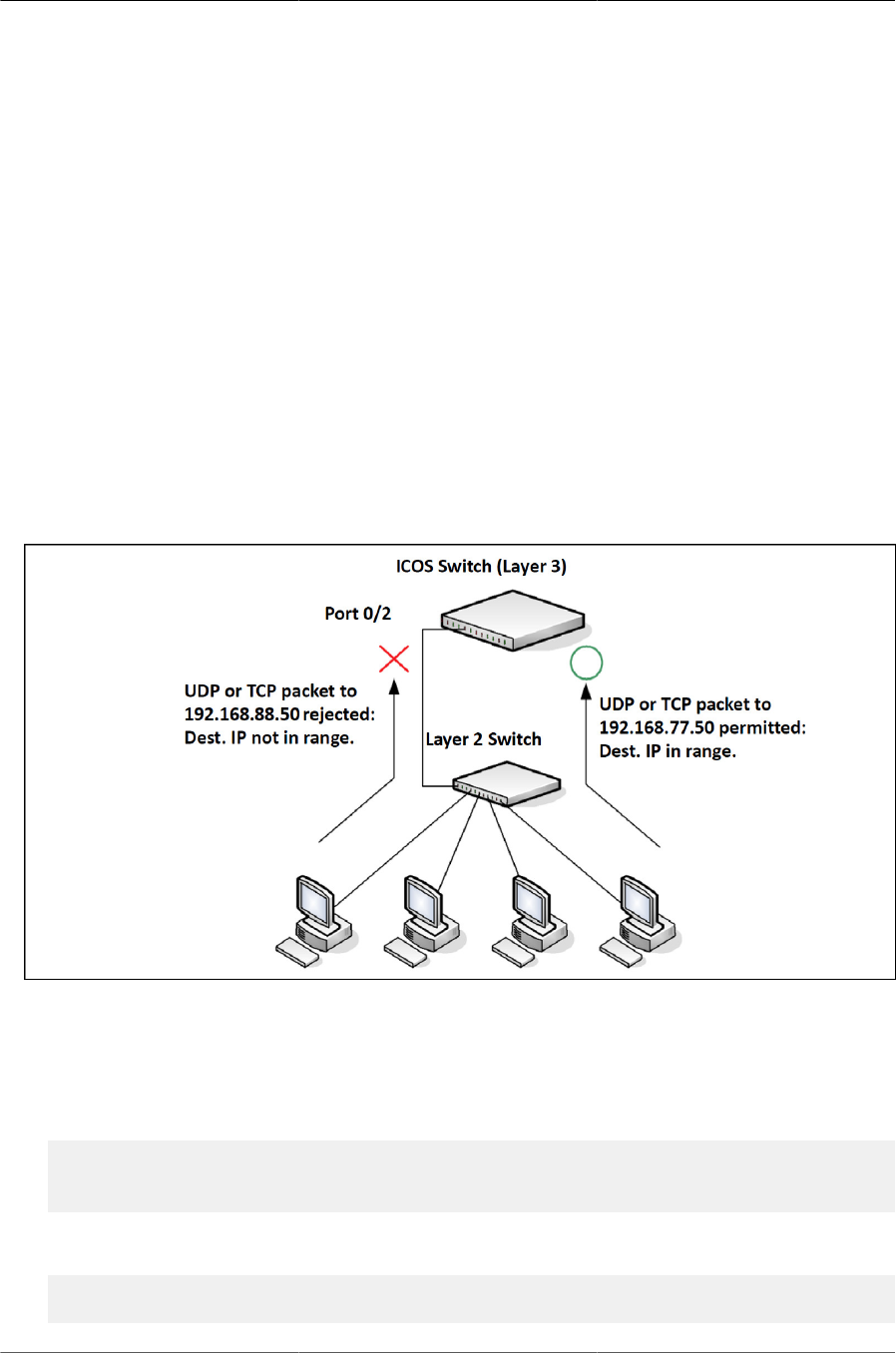
Configuring Quality of Service
317
• Qualify fragmented IPv6 packets (packets that have the next header field set to 44).
• Qualify routed IPv6 packets (packets that have a routing extension header (next header field set
to 43)).
Depending upon the underlying switching silicon, IP ACLs can be applied on ingress and egress
interfaces/ VLANs of a switch/router.
10.1.3. ACL Configuration Examples
This section contains the following examples:
10.1.3.1. Configuring an IP ACL
The commands in this example set up an IP ACL that permits hosts in the 192.168.77.0/24 subnet
to send TCP and UDP traffic only to the host with an IP address of 192.168.77.50. The ACL is ap-
plied to port 2 on the switch.
Figure10.1.IP ACL Example Network Diagram
To configure the switch:
1. Create an extended ACL and configure a rule for the ACL that permits packets carrying TCP
traffic that matches the specified Source IP address (192.168.77.0/24), and sends these pack-
ets to the specified Destination IP address (192.168.77.50).
(Routing) #config
(Routing) (Config)#access-list 100 permit tcp 192.168.77.0 0.0.0.255
192.168.77.50 0.0.0.0
2. Define the rule to set similar conditions for UDP traffic as for TCP traffic.
(Routing) (Config)#access-list 100 permit udp 192.168.77.0 0.0.0.255
192.168.77.3 0.0.0.255

Configuring Quality of Service
318
3. Apply the rule to inbound (ingress) traffic on port 2. Only traffic matching the criteria will be ac-
cepted on this port.
(Routing) (Config)#interface 0/2
(Routing) (Interface 0/2)#ip access-group 100 in
(Routing) (Interface 0/2)#exit
4. Verify the configuration.
(Routing) #show ip access-lists 100
ACL ID: 100
Inbound Interface(s): 0/2
Rule Number: 1
Action......................................... permit
Match All...................................... FALSE
Protocol....................................... 6(tcp)
Source IP Address.............................. 192.168.77.0
Source IP Wildcard Mask........................ 0.0.0.255
Destination IP Address......................... 192.168.77.50
Destination IP Wildcard Mask................... 0.0.0.0
Rule Number: 2
Action......................................... permit
Match All...................................... FALSE
Protocol....................................... 17(udp)
Source IP Address.............................. 192.168.77.0
Source IP Wildcard Mask........................ 0.0.0.255
Destination IP Address......................... 192.168.77.3
Destination IP Wildcard Mask................... 0.0.0.255
10.1.3.2. Configuring a MAC ACL
The following example creates a MAC ACL named mac1 that denies all IPX traffic on all ports. All
other type of traffic is permitted.
To configure the switch:
1. Create a MAC Access List named mac1
(Routing) #config
(Routing) (Config)#mac access-list extended mac1
2. Configure a rule to deny all IPX traffic, regardless of the source or destination MAC address.
(Routing) (Config-mac-access-list)#deny any any ipx
3. Configure a rule to permit all other types of traffic, regardless of the source or destination MAC
address.
(Routing) (config-mac-access-list)#permit any any
(Routing) (config-mac-access-list)#exit
4. Bind the ACL to all ports.

Configuring Quality of Service
319
(Routing) (Config)#mac access-group mac1 in
(Routing) (Config)#exit
5. View information about the configured ACL.
(Routing) #show mac access-lists
Current number of all ACLs: 2 Maximum number of all ACLs: 100
MAC ACL Name Rules Direction Interface(s) VLAN(s)
---------------------------- ----- --------- -------------- ----------
mac1 2 inbound 0/1, 0/2,
0/3, 0/4,
0/5, 0/6,
0/7, 0/8,
0/9, 0/10,
--More-- or (q)uit
(Routing) #show mac access-lists mac1
ACL Name: mac1
Inbound Interface(s): 0/1, 0/2, 0/3, 0/4, 0/5, 0/6, 0/7, 0/8, 0/9,
0/10, 0/11, 0/12, 0/13, 0/14, 0/15, 0/16, 0/17, 0/18, 0/19, 0/20,
0/21, 0/22, 0/23, 0/24, 0/25, 0/26, 0/27, 0/28, 0/29, 0/30, 0/31,
0/32, 0/33, 0/34, 0/35, 0/36, 0/37, 0/38, 0/39, 0/40, 0/41, 0/42,
0/43, 0/44, 0/45, 0/46, 0/47, 0/48, 0/49, 0/50, 0/51, 0/52, 3/1, 3/2,
3/3, 3/4, 3/5, 3/6, 3/7, 3/8, 3/9, 3/10, 3/11, 3/12, 3/13, 3/14, 3/15,
3/16, 3/17, 3/18, 3/19, 3/20, 3/21, 3/22, 3/23, 3/24, 3/25, 3/26,
3/27, 3/28, 3/29, 3/30, 3/31, 3/32, 3/33, 3/34, 3/35, 3/36, 3/37,
3/38, 3/39, 3/40, 3/41, 3/42, 3/43, 3/44, 3/45, 3/46, 3/47, 3/48,
3/49, 3/50, 3/51, 3/52, 3/53, 3/54, 3/55, 3/56, 3/57, 3/58, 3/59, 3/60,
3/61, 3/62, 3/63, 3/64
Rule Number: 1
Action......................................... deny
Ethertype...................................... ipx
Rule Number: 2
Action......................................... permit
Match All...................................... TRUE
10.1.3.3. Configuring a Time-Based ACL
The following example configures an ACL that denies HTTP traffic from 8:00 pm to 12:00 pm and
1:00 pm to 6:00 pm on weekdays and from 8:30 am to 12:30 pm on weekends. The ACL affects all
hosts connected to ports that are members of VLAN 100. The ACL permits VLAN 100 members to
browse the Internet only during lunch and after hours.
To configure the switch:
1. Create a time range called work-hours.
(Routing) #config
(Routing) (Config)#time-range work-hours

Configuring Quality of Service
320
2. Configure an entry for the time range that applies to the morning shift Monday through Friday.
(Routing) (config-time-range)#periodic weekdays 8:00 to 12:00
3. Configure an entry for the time range that applies to the afternoon shift Monday through Friday.
(Routing) (config-time-range)#periodic weekdays 13:00 to 18:00
4. Configure an entry for the time range that applies to Saturday and Sunday.
(Routing) (config-time-range)#periodic weekend 8:30 to 12:30
(Routing) (config-time-range)#exit
5. Create an extended ACL that denies HTTP traffic during the work-hours time range.
(Routing) (Config)#access-list 101 deny tcp any any eq http time-range
work-hours
6. Apply the ACL to ingress traffic in VLAN 100.
(Routing) (Config)#ip access-group 101 vlan 100 in
(Routing) (Config)#exit
7. Verify the configuration.
(Routing) #show ip access-lists 101
ACL ID: 101
Inbound VLAN ID(s): 100
Rule Number: 1
Action......................................... deny
Match All...................................... FALSE
Protocol....................................... 6(tcp)
Destination L4 Port Keyword.................... 80(www/http)
Time Range Name................................ work-hours
Rule Status.................................... inactive

Configuring Quality of Service
321
10.2. CoS
The CoS feature lets you give preferential treatment to certain types of traffic over others. To set
up this preferential treatment, you can configure the ingress ports, the egress ports, and individual
queues on the egress ports to provide customization that suits your environment.
The level of service is determined by the egress port queue to which the traffic is assigned. When
traffic is queued for transmission, the rate at which it is serviced depends on how the queue is con-
figured and possibly the amount of traffic present in other queues for that port. Some traffic is clas-
sified for service (i.e., packet marking) before it arrives at the switch. If you decide to use these
classifications, you can map this traffic to egress queues by setting up a CoS Mapping table.
Each ingress port on the switch has a default priority value (set by configuring VLAN Port Priority
in the Switching sub-menu) that determines the egress queue its traffic gets forwarded to. Packets
that arrive without a priority designation, or packets from ports you’ve identified as “untrusted,” get
forwarded according to this default.
10.2.1. Trusted and Untrusted Port Modes
Ports can be configured in trusted mode or untrusted mode with respect to ingress traffic.
Ports in Trusted Mode: When a port is configured in trusted mode, the system accepts at face
value a priority designation encoded within packets arriving on the port. You can configure ports to
trust priority designations based on one of the following fields in the packet header:
• 802.1 Priority: values 0–7
• IP DSCP: values 0–63
A mapping table associates the designated field values in the incoming packet headers with a traf-
fic class priority (actually a CoS traffic queue).
Ports in Untrusted Mode: If you configure an ingress port in untrusted mode, the system ignores
any priority designations encoded in incoming packets, and instead sends the packets to a traffic
queue based on the ingress port’s default priority.
10.2.2. Traffic Shaping on Egress Traffic
For slot/port interfaces, you can specify a traffic shaping rate for the port (in Kbps) for egress traf-
fic. The traffic shaping rate specifies an upper limit of the transmission bandwidth used.
10.2.3. Defining Traffic Queues
For each queue, you can specify:
• Minimum bandwidth guarantee: A percentage of the port’s maximum negotiated bandwidth re-
served for the queue.
• Scheduler type – strict/weighted:

Configuring Quality of Service
322
• Strict priority scheduling gives an absolute priority, with traffic in the highest priority queues al-
ways sent first, and traffic in the lowest priority queues always sent last.
• Weighted scheduling requires a specification of priority for each queue relative to the other
queues, based on their minimum bandwidth values.
10.2.3.1. Supported Queue Management Methods
The switch supports the following methods, configurable per-interface-queue, for determining
which packets are dropped when the queue is full:
• Taildrop: Any packet forwarded to a full queue is dropped regardless of its importance.
• Weighted Random Early Detection (WRED) drops packets selectively based their drop prece-
dence level. For each of four drop precedence levels on each WRED-enabled interface queue,
you can configure the following parameters:
• Minimum Threshold: A percentage of the total queue size below which no packets of the se-
lected drop precedence level are dropped.
• Maximum Threshold: A percentage of the total queue size above which all packets of the se-
lected drop precedence level are dropped.
• Drop Probability: When the queue depth is between the minimum and maximum thresholds,
this value provides a scaling factor for increasing the number of packets of the selected drop
precedence level that are dropped as the queue depth increases.
10.2.4. CoS Configuration Example
Figure below illustrates the network operation as it relates to CoS mapping and queue configura-
tion.
Four packets arrive at the ingress port 0/10 in the order A, B, C, and D. Port 0/10 is configured to
trust the 802.1p field of the packet, which serves to direct packets A, B, and D to their respective
queues on the egress port. These three packets utilize the 802.1p to CoS Mapping Table for port
0/10.
In this example, the 802.1p user priority 3 is configured to send the packet to queue 5 instead of
the default queue 3. Since packet C does not contain a VLAN tag, the 802.1p user priority does
not exist, so Port 0/10 relies on its default port priority (2) to direct packet C to egress queue 1.
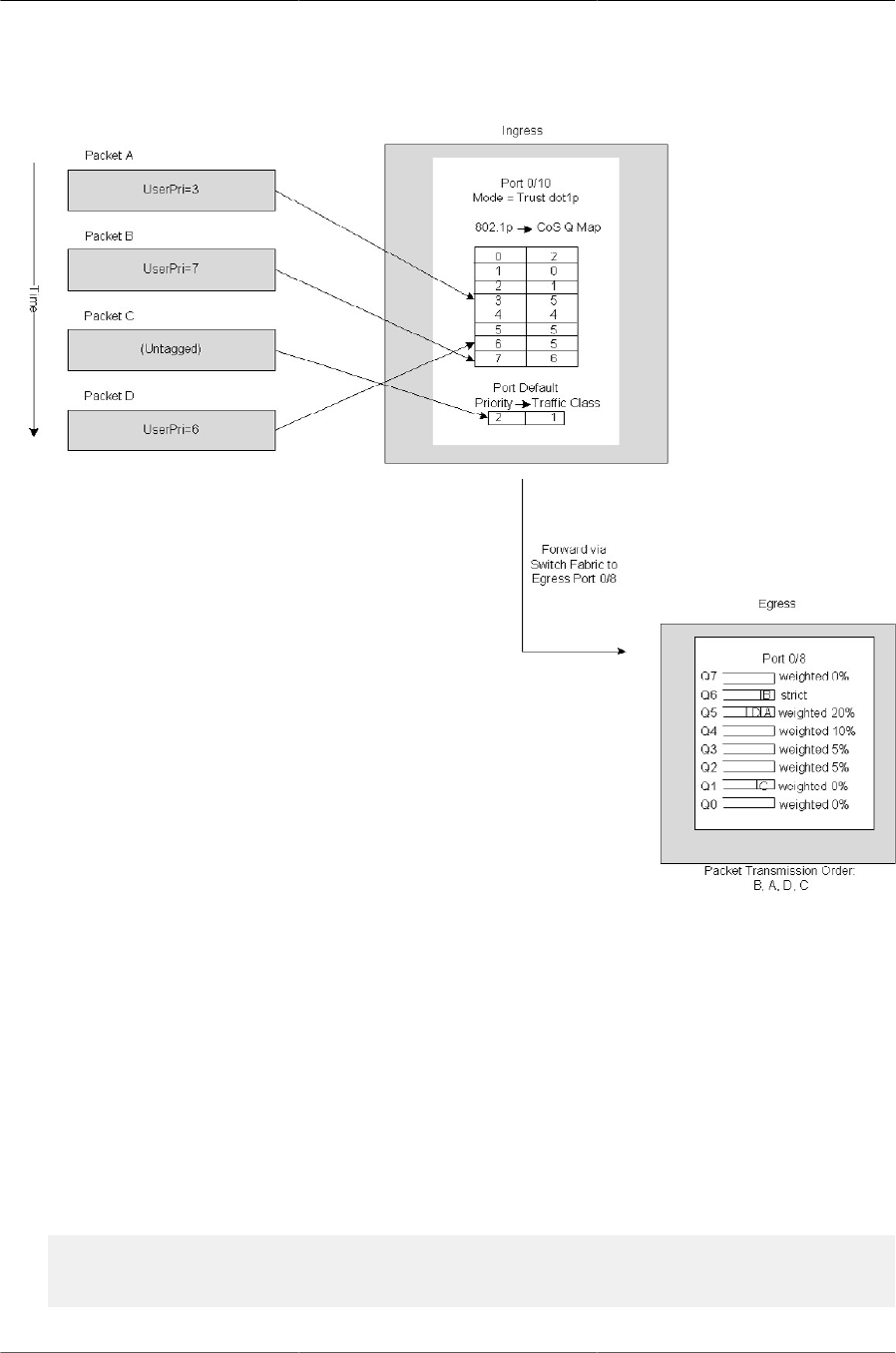
Configuring Quality of Service
323
Figure10.2.CoS Mapping and Queue Configuration
Continuing this example, the egress port 0/8 is configured for strict priority on queue 6, and a
weighted scheduling scheme is configured for queues 5-0. Assuming queue 5 has a higher weight-
ing than queue 1 (relative weight values shown as a percentage, with 0% indicating the bandwidth
is not guaranteed), the queue service order is 6 followed by 5 followed by 1. Assuming each queue
unloads all packets shown in the diagram, the packet transmission order as seen on the network
leading out of Port 0/8 is B, A, D, C. Thus, packet B, with its higher user precedence than the oth-
ers, is able to work its way through the device with minimal delay and is transmitted ahead of the
other packets at the egress port.
The following commands configure port 10 (ingress interface) and Port 8 (egress interface).
1. Configure the Trust mode for port 10.
(Routing) #config
(Routing) (Config)#interface 0/10
(Routing) (Interface 0/10)#classofservice trust dot1p

Configuring Quality of Service
324
2. For port 10, configure the 802.1p user priority 3 to send the packet to q ueue 5 instead of the
default queue (queue 3).
(Routing) (Interface 0/10)#classofservice dot1p-mapping 3 5
3. For port 10, specify that untagged VLAN packets should have a default priority of 2.
(Routing) (Interface 0/10)#vlan priority 2
(Routing) (Interface 0/10)#exit
4. For Port 8, the egress port, configure a weighted scheduling scheme for queues 5–0.
(Routing) (Config)#interface 0/8
(Routing) (Interface 0/8)#cos-queue min-bandwidth 0 0 5 5 10 20 40 0
5. Configure Port 8 to have strict priority on queue 6.
(Routing) (Interface 0/8)#cos-queue strict 6
6. View the configuration.
(Routing) #show interfaces cos-queue 0/8
Interface...................................... 0/8
Interface Shaping Rate......................... 0
WRED Decay Exponent............................ 9
Queue Id Min. Bandwidth Scheduler Type Queue Management Type
-------- -------------- -------------- ---------------------
0 0 Weighted Tail Drop
1 0 Weighted Tail Drop
2 5 Weighted Tail Drop
3 5 Weighted Tail Drop
4 10 Weighted Tail Drop
5 20 Weighted Tail Drop
6 40 Strict Tail Drop
7 0 Weighted Tail Drop

Configuring Quality of Service
325
10.3. DiffServ
Standard IP-based networks are designed to provide best effort data delivery service. Best effort
service implies that the network delivers the data in a timely fashion, although there is no guaran-
tee that it will. During times of congestion, packets may be delayed, sent sporadically, or dropped.
For typical Internet applications, such as email and file transfer, a slight degradation in service is
acceptable and in many cases unnoticeable. Conversely, any degradation of service has undesir-
able effects on applications with strict timing requirements, such as voice or multimedia.
10.3.1. DiffServ Functionality and Switch Roles
How you configure DiffServ support in ICOS software varies depending on the role of the switch in
your network:
•Edge device: An edge device handles ingress traffic, flowing towards the core of the network,
and egress traffic, flowing away from the core. An edge device segregates inbound traffic into a
small set of traffic classes, and is responsible for determining a packet’s classification. Classifi-
cation is primarily based on the contents of the Layer 3 and Layer 4 headers, and is recorded in
the Differentiated Services Code Point (DSCP) added to a packet’s IP header.
•Interior node: A switch in the core of the network is responsible for forwarding packets, rather
than for classifying them. It decodes the DSCP in an incoming packet, and provides buffering
and forwarding services using the appropriate queue management algorithms.
Before configuring DiffServ on the switch, you must determine the QoS requirements for the net-
work as a whole. The requirements are expressed in terms of rules, which are used to classify in-
bound or outbound traffic on a particular interface.
10.3.2. Elements of DiffServ Configuration
During configuration, you define DiffServ rules in terms of classes, policies, and services:
•Class: A class consists of a set of rules that identify which packets belong to the class. Inbound
traffic is separated into traffic classes based on Layer 2, Layer 3, and Layer 4 header data. The
class type All is supported; this specifies that every match criterion defined for the class must be
true for a match to occur.
•Policy: A policy defines the QoS attributes for one or more traffic classes. An attribute identi-
fies the action taken when a packet matches a class rule. An example of an attribute is to mark
a packet. The switch supports the ability to assign traffic classes to output CoS queues, and to
mirror incoming packets in a traffic stream to a specific egress interface (physical port or LAG).
ICOS software supports the Traffic Conditioning Policy type which is associated with an in-
bound traffic class and specifies the actions to be performed on packets meeting the class rules:
• Marking the packet with a given DSCP, IP precedence, or CoS value. Traffic to be processed
by the DiffServ feature requires an IP header if the system uses IP Precedence or IP DSCP
marking.
• Policing packets by dropping or re-marking those that exceed the class’s assigned data rate.
• Counting the traffic within the class.
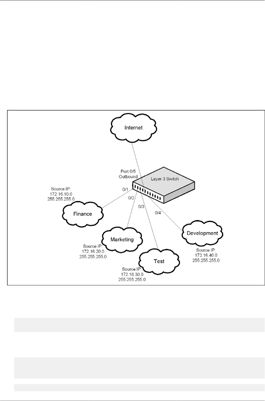
Configuring Quality of Service
326
•Service: Assigns a policy to an interface for inbound traffic.
10.3.3. Configuring DiffServ to Provide Subnets Equal
Access to External Network
This example shows how a network administrator can provide equal access to the Internet (or oth-
er external network) to different departments within a company. Each of four departments has its
own Class B subnet that is allocated 25% of the available bandwidth on the port accessing the In-
ternet.
Figure10.3.DiffServ Internet Access Example Network Diagram
The following commands show how to configure the DiffServ example depicted in Figure above.
1. Enable DiffServ operation for the switch.
(Routing) #config
(Routing) (Config)#diffserv
2. Create a DiffServ class of type all for each of the departments, and name them. Also, define the
match criteria—Source IP address—for the new classes.
(Routing) (Config)#class-map match-all finance_dept
(Routing) (Config-classmap)#match srcip 172.16.10.0 255.255.255.0
(Routing) (Config-classmap)#exit
(Routing) (Config)#class-map match-all marketing_dept

Configuring Quality of Service
327
(Routing) (Config-classmap)#match srcip 172.16.20.0 255.255.255.0
(Routing) (Config-classmap)#exit
(Routing) (Config)#class-map match-all test_dept
(Routing) (Config-classmap)#match srcip 172.16.30.0 255.255.255.0
(Routing) (Config-classmap)#exit
(Routing) (Config)#class-map match-all development_dept
(Routing) (Config-classmap)#match srcip 172.16.40.0 255.255.255.0
(Routing) (Config-classmap)#exit
3. Create a DiffServ policy for inbound traffic named internet_access, adding the previously cre-
ated department classes as instances within this policy. This policy uses the assign-queue at-
tribute to put each department’s traffic on a different egress queue. This is how the DiffServ in-
bound policy connects to the CoS queue settings established below.
(Routing) (Config)#policy-map internet_access in
(Routing) (Config-policy-map)#class finance_dept
(Routing) (Config-policy-classmap)#assign-queue 1
(Routing) (Config-policy-classmap)#exit
(Routing) (Config-policy-map)#class marketing_dept
(Routing) (Config-policy-classmap)#assign-queue 2
(Routing) (Config-policy-classmap)#exit
(Routing) (Config-policy-map)#class test_dept
(Routing) (Config-policy-classmap)#assign-queue 3
(Routing) (Config-policy-classmap)#exit
(Routing) (Config-policy-map)#class development_dept
(Routing) (Config-policy-classmap)#assign-queue 4
(Routing) (Config-policy-classmap)#exit
(Routing) (Config-policy-map)#exit
4. Attach the defined policy to interfaces 0/1 through 0/4 in the inbound direction
(Routing) (Config)#interface 0/1-0/4
(Routing) (Interface 0/1-0/4)#service-policy in internet_access
(Routing) (Interface 0/1-0/4)#exit
5. Set the CoS queue configuration for the (presumed) egress interface 0/1 such that each of
queues 1, 2, 3 and 4 get a minimum guaranteed bandwidth of 25%. All queues for this interface
use weighted round robin scheduling by default. The DiffServ inbound policy designates that
these queues are to be used for the departmental traffic through the assign-queue attribute. It is
presumed that the switch will forward this traffic to interface 0/1 based on a normal destination
address lookup for internet traffic.
(Routing) (Config)#interface 0/5
(Routing) (Interface 0/5)#cos-queue min-bandwidth 0 25 25 25 25 0 0 0
(Routing) (Interface 0/5)#exit
(Routing) (Config)#exit
