IL 1070259 Vega API Guide Rev002
Polaris_Vega_API_Guide
User Manual: Pdf
Open the PDF directly: View PDF ![]() .
.
Page Count: 187 [warning: Documents this large are best viewed by clicking the View PDF Link!]

Polaris Vega Application Program
Interface Guide
Rev 2, Part # IL-1070259
August 2017

Copyright 2016-2017 Northern Digital Inc. All Rights Reserved.
Revision Status
Revision
Number Date Description
1 August 2016 First release
2 August 2017 Updated to document the optional video camera
Part Number: IL-1070259

Polaris Vega Application Program Interface Guide
Published by:
Northern Digital Inc.
103 Randall Dr.
Waterloo, Ontario, Canada N2V 1C5
Telephone: + (519) 884-5142
Toll Free: + (877) 634-6340
Global: + (800) 634 634 00
Facsimile: + (519) 884-5184
Website: www.ndigital.com
Copyright 2016-2017 Northern Digital Inc.
All rights reserved. No part of this document may be reproduced, transcribed, transmitted, distributed, modi-
fied, merged or translated into any language in any form by any means - graphic, electronic, or mechanical,
including but not limited to photocopying, recording, taping or information storage and retrieval systems - with-
out the prior written consent of Northern Digital Inc. Certain copying of the software included herein is unlawful.
Refer to your software license agreement for information respecting permitted copying.
DISCLAIMER OF WARRANTIES AND LIMITATION OF LIABILITIES
Northern Digital Inc. has taken due care in preparing this document and the programs and data on the elec-
tronic media accompanying this document including research, development, and testing.
This document describes the state of Northern Digital Inc.’s knowledge respecting the subject matter herein at
the time of its publication, and may not reflect its state of knowledge at all times in the future. Northern Digital
Inc. has carefully reviewed this document for technical accuracy. If errors are suspected, the user should con-
sult with Northern Digital Inc. prior to proceeding. Northern Digital Inc. makes no expressed or implied warranty
of any kind with regard to this document or the programs and data on the electronic media accompanying this
document.
Northern Digital Inc. makes no representation, condition or warranty to the user or any other party with respect
to the adequacy of this document or accompanying media for any particular purpose or with respect to its ade-
quacy to produce a particular result. The user’s right to recover damages caused by fault or negligence on the
part of Northern Digital Inc. shall be limited to the amount paid by the user to Northern Digital Inc. for the provi-
sion of this document. In no event shall Northern Digital Inc. be liable for special, collateral, incidental, direct,
indirect or consequential damages, losses, costs, charges, claims, demands, or claim for lost profits, data, fees
or expenses of any nature or kind.
Product names listed are trademarks of their respective manufacturers. Company names listed are trademarks
or trade names of their respective companies.
The Polaris Vega System includes software that is distributed under the GPL v2 licence. NDI will provide, on
request, and for a nominal fee, a complete machine-readable copy of the corresponding source code. For
details on the GPL v2 licence refer to http://www.gnu.org/licenses/old-licenses/gpl-2.0.en.html.

Polaris Vega Application Program Interface Guide

Table of Contents
Polaris Vega Application Program Interface Guide i
About This Guide . . . . . . . . . . . . . . . . . . . . . . . . . . . . . . . . . . . . . . . . . . . . . . . . . . . . . . . . . . . . . . . . . . . . iii
Warnings and Cautions . . . . . . . . . . . . . . . . . . . . . . . . . . . . . . . . . . . . . . . . . . . . . . . . . . .iii
Contact Information . . . . . . . . . . . . . . . . . . . . . . . . . . . . . . . . . . . . . . . . . . . . . . . . . . . . . .iv
1 List of Commands . . . . . . . . . . . . . . . . . . . . . . . . . . . . . . . . . . . . . . . . . . . . . . . . . . . . . . . . . . . . . . . . . . . 1
2 Changes in Implementation . . . . . . . . . . . . . . . . . . . . . . . . . . . . . . . . . . . . . . . . . . . . . . . . . . . . . . . . . . . 3
2.1 Deprecated Commands . . . . . . . . . . . . . . . . . . . . . . . . . . . . . . . . . . . . . . . . . . . . . . . . 3
2.2 Deleted Commands . . . . . . . . . . . . . . . . . . . . . . . . . . . . . . . . . . . . . . . . . . . . . . . . . . . 3
2.3 New Commands . . . . . . . . . . . . . . . . . . . . . . . . . . . . . . . . . . . . . . . . . . . . . . . . . . . . . 4
2.4 Changed Commands . . . . . . . . . . . . . . . . . . . . . . . . . . . . . . . . . . . . . . . . . . . . . . . . . . 5
2.5 Change in Concepts. . . . . . . . . . . . . . . . . . . . . . . . . . . . . . . . . . . . . . . . . . . . . . . . . . . 5
3 Communicating with an NDI System . . . . . . . . . . . . . . . . . . . . . . . . . . . . . . . . . . . . . . . . . . . . . . . . . . . 11
3.1 Connection Requirements . . . . . . . . . . . . . . . . . . . . . . . . . . . . . . . . . . . . . . . . . . . . . 11
3.2 Communication Overview. . . . . . . . . . . . . . . . . . . . . . . . . . . . . . . . . . . . . . . . . . . . . 11
3.3 Operating Modes . . . . . . . . . . . . . . . . . . . . . . . . . . . . . . . . . . . . . . . . . . . . . . . . . . . . 12
3.4 General Syntax . . . . . . . . . . . . . . . . . . . . . . . . . . . . . . . . . . . . . . . . . . . . . . . . . . . . . 12
3.5 Receiving System Replies. . . . . . . . . . . . . . . . . . . . . . . . . . . . . . . . . . . . . . . . . . . . . 13
3.6 Best Practices. . . . . . . . . . . . . . . . . . . . . . . . . . . . . . . . . . . . . . . . . . . . . . . . . . . . . . . 15
3.7 Port Handles . . . . . . . . . . . . . . . . . . . . . . . . . . . . . . . . . . . . . . . . . . . . . . . . . . . . . . . 16
4 User Parameters . . . . . . . . . . . . . . . . . . . . . . . . . . . . . . . . . . . . . . . . . . . . . . . . . . . . . . . . . . . . . . . . . . . 20
4.1 About User Parameters . . . . . . . . . . . . . . . . . . . . . . . . . . . . . . . . . . . . . . . . . . . . . . . 20
4.2 User Parameter Commands. . . . . . . . . . . . . . . . . . . . . . . . . . . . . . . . . . . . . . . . . . . . 21
4.3 Device Names . . . . . . . . . . . . . . . . . . . . . . . . . . . . . . . . . . . . . . . . . . . . . . . . . . . . . . 21
4.4 Alerts User Parameters . . . . . . . . . . . . . . . . . . . . . . . . . . . . . . . . . . . . . . . . . . . . . . . 22
4.5 Bump Sensor User Parameters . . . . . . . . . . . . . . . . . . . . . . . . . . . . . . . . . . . . . . . . . 28
4.6 Video Camera User Parameters. . . . . . . . . . . . . . . . . . . . . . . . . . . . . . . . . . . . . . . . . 28
4.7 User-Defined User Parameters . . . . . . . . . . . . . . . . . . . . . . . . . . . . . . . . . . . . . . . . . 29
4.8 Complete List of User Parameters. . . . . . . . . . . . . . . . . . . . . . . . . . . . . . . . . . . . . . . 30

Table of Contents
ii Polaris Vega Application Program Interface Guide
5 Command Details . . . . . . . . . . . . . . . . . . . . . . . . . . . . . . . . . . . . . . . . . . . . . . . . . . . . . . . . . . . . . . . . . . 40
6 Error and Warning Code Definitions. . . . . . . . . . . . . . . . . . . . . . . . . . . . . . . . . . . . . . . . . . . . . . . . . . 157
6.1 Error Code Definitions. . . . . . . . . . . . . . . . . . . . . . . . . . . . . . . . . . . . . . . . . . . . . . . 157
6.2 Warning Code Definitions . . . . . . . . . . . . . . . . . . . . . . . . . . . . . . . . . . . . . . . . . . . . 160
Appendix A Keyed Features . . . . . . . . . . . . . . . . . . . . . . . . . . . . . . . . . . . . . . . . . . . . . . . . . . . . . . . . . 161
Appendix B Sample C Routines . . . . . . . . . . . . . . . . . . . . . . . . . . . . . . . . . . . . . . . . . . . . . . . . . . . . . . 164
Abbreviations and Acronyms . . . . . . . . . . . . . . . . . . . . . . . . . . . . . . . . . . . . . . . . . . . . . . . . . . . . . . . . . 172
Glossary . . . . . . . . . . . . . . . . . . . . . . . . . . . . . . . . . . . . . . . . . . . . . . . . . . . . . . . . . . . . . . . . . . . . . . . . . . 173
Index . . . . . . . . . . . . . . . . . . . . . . . . . . . . . . . . . . . . . . . . . . . . . . . . . . . . . . . . . . . . . . . . . . . . . . . . . . . . . 175

About This Guide
Polaris Vega Application Program Interface Guide iii
About This Guide
This guide describes revision G.003.001 and later of the Polaris API, introduced with Polaris Vega.
To determine the API revision number programmed into your system, use the APIREV (page 46)
command.
Note For information on previous revisions of the API, refer to the Polaris Application Program Interface Guide (IL-
1070101) available on the NDI support site at https://support.ndigital.com.
Warnings and Cautions
Warnings
In all NDI documentation, warnings are marked by this symbol. Follow the information in the accompanying
paragraph to avoid personal injury.
1. When using reply option 0800 with the BX (page 49) or TX (page 138) commands, you must
take appropriate action to detect the following events: the tool or marker is out of volume, the
bump sensor has been tripped, or the system is outside of the optimal operating temperature
range. You must determine whether these events are detrimental to your application. If one or
more of the events listed occurs, reply option 0800 enables the system to return data that may
lead to inaccurate conclusions and may cause personal injury.
2. No options exist for filtering data returned from the BX2 (page 60) command on the basis of
system or tool status or location in the volume. Complete system and tool status information is
always included in the reply and it is the application’s responsibility to interpret this data and
ignore those measurements that fall outside of application requirements and constraints. Failure
to do so may lead to inaccurate conclusions that may cause personal injury.
Warning!

About This Guide
iv Polaris Vega Application Program Interface Guide
Contact Information
If you have any questions regarding the content of this guide or the operation of this product, please
contact us:
NDI is committed to continuous improvements in the quality and versatility of its software and
hardware. To obtain the best results with your NDI system, check the NDI Support Site regularly for
updated information: https://support.ndigital.com.

List of Commands
Polaris Vega Application Program Interface Guide 1
1 List of Commands
Table 1-1 lists all the API commands, and whether they are supported by each revision of the API.
Compatibility is indicated as follows:
X indicates that the command is supported.
* indicates that the command is deprecated. Deprecated commands will no longer be enhanced to
support new hardware devices or new API features. Support for deprecated commands may be
discontinued in future releases.
Table 1-1 Alphabetical List of Commands
Command Page Description
G.003.002
3D 41 Returns the latest 3D position of either a single marker or multiple
markers. *
APIREV 46 Returns the API revision number that functions with your system. X
BEEP 47 Sounds the system beeper. X
BX 49 Returns the latest tool transformations, individual marker posi-
tions, and system status in binary format. X
BX2 60 Returns various levels of data on the latest tool transformations,
individual marker positions, and system status in binary format. X
COMM 70 Sets the serial communication settings of the system. (Serial com-
munication only.) Not used in the Polaris Vega System. X
DFLT 73 Restores the user parameters to factory default values. X
DSTART 74 Starts Diagnostic mode. X
DSTOP 75 Stops Diagnostic mode. X
ECHO 76 Returns exactly what is sent with the command. X
GET 77 Returns the user parameter values. X
GETINFO 79 Returns descriptive information about the user parameters. X
GETLOG 81 Returns the contents of a system log file. X
INIT 83 Initializes the system. X
IRATE 84 Sets the illuminator rate. X
IRED 86 Turns the markers on a wired tool on or off. X
LED 88 Changes the state of visible LEDs on a wired tool. X
PDIS 90 Disables the reporting of transformations for a particular port
handle. X
PENA 91 Enables reporting of transformations for a particular port handle. X
PFSEL 93 Sets which tool faces to use to track a multi-faced tool. X
PHF 95 Releases system resources from an unused port handle. X
PHINF 96 Returns port handle status, and information about the tool associ-
ated with the port handle, including physical port location. X

List of Commands
2 Polaris Vega Application Program Interface Guide
PHRQ 102 Assigns a port handle to a tool. X
PHSR 104 Returns the number of assigned port handles and the port status for
each one. Assigns a port handle to a wired tool. X
PINIT 107 Initializes a port handle. *
PPRD 109 Reads data from the SROM device in a wired tool. (Polaris Vega -
only applicable to the SCU.) X
PPWR 110 Writes data to the SROM device in a wired tool. (Polaris Vega -
only applicable to the SCU.) X
PURD 112 Reads data from the user section of the SROM device in a wired
tool. (Polaris Vega - only applicable to the SCU.) X
PUWR 114 Writes data to the user section of a tool SROM device in a wired
tool. (Polaris Vega - only applicable to the SCU.) X
PVWR 116 Assigns a tool definition file to a wireless tool, overrides a tool
definition file in a wired tool, and can be used to test a tool defini-
tion file before permanently recording the tool definition file onto
the SROM device.
X
RESET 118 Resets the system (can specify either a hard reset or a soft reset). X
SAVE 119 Saves all non-volatile user parameters that have been changed. X
SET 120 Sets user parameter values. X
SFLIST 121 Returns information about the supported features of the system. *
STREAM 129 Initiates a streaming response to a specified command. X
SYSLOG 131 Writes data to the Position Sensor or System Control Unit log file. X
TCTST 133 Returns diagnostics on the active markers of a wired tool. X
TSTART 133 Starts Tracking mode. X
TSTOP 136 Stops Tracking mode. X
TTCFG 137 Sets up a configuration for a wired tool so that you can test the tool
without using a tool definition file. X
TX 138 Returns the latest tool transformations, individual marker posi-
tions, and system status in text format. X
USTREAM 150 Stops streaming of the indicated command X
VCAP 151 Captures IR image data from the sensors. X
VER 154 Returns the firmware revision number of critical processors
installed in the system. X
VSEL 156 Selects a characterized measurement volume. *
Table 1-1 Alphabetical List of Commands (Continued)
Command Page Description
G.003.002

Changes in Implementation
Polaris Vega Application Program Interface Guide 3
2 Changes in Implementation
This chapter describes the changes in implementation introduced by API revision G.003.001and
G.003.002. For details on previous revisions of the API, refer to the Polaris Application Program
Interface Guide, available on the NDI support site at https://support.ndigital.com.
2.1 Deprecated Commands
The following commands are deprecated in this version of the API. Deprecated commands will no
longer be enhanced to support new hardware devices or new API features. Support for deprecated
commands may be discontinued in future releases.
2.2 Deleted Commands
Deleted Commands are as follows:
Command Replacement
3D BX2 command
IRATE User parameter Param.Tracking.Track Frequency
PINIT PENA command calls PINIT
SFLIST User parameters: Features.Tools.Active Ports,
Features.Tools.Passive Ports, Features.Volumes *,
Features.Tools.Wireless Ports
VSEL User parameter Param.Tracking.Selected Volume
Deleted Command Description
GETIO Deleted
HCWDOG Deleted
PSEL Deleted
PSOUT Deleted
PSRCH Deleted
SENSEL Replaced by User Parameter Param.Tracking.Sensitivity (Table 4-8 on page 30)
SETIO Deleted
SSTAT Deleted
VGET Replaced with VCAP
VSNAP Replaced with VCAP

Changes in Implementation
4 Polaris Vega Application Program Interface Guide
2.3 New Commands
New commands in API revision G.003.001 are as follows:
BX2
The BX2 command provides a flexible way of providing measurement data at various levels of
detail. The reply can contain a single or multiple frames. Each frame can contain various levels of
measurement data detail such as 6D, 3D or 2D data.
• It does not repeat already reported information.
• It works with the STREAM command to keep latency to a minimum and avoid missing or
repeating information.
• Addresses the problem of providing system wide failures and warnings in the multi-
connection environment.
STREAM
STREAM initiates a streaming response to a command. For details on data streaming, see “Data
Streaming” on page 8.
USTREAM
USTREAM terminates the streaming response to a command. For details on data streaming, see
“Data Streaming” on page 8.
VCAP
The VSNAP and VGET commands are removed and replaced with a single VCAP command. The
VCAP command contains options to specify and control the image data returned. The reply contains
the image data for a single frame from all sensors with embedded “metadata” that includes sensor
number, frame number, timestamp, exposure and other relevant information about the frames.
Readable parameters provide additional information that will assist in interpreting the image data,
such as the makeup of the frame sequence and the number and names of the image sensors.
New Command Description
BX2 (page 60) Returns various levels of data on the latest tool transformations, individual
marker positions, and system status in binary format.
STREAM (page 129) Initiates a streaming response to a specified command.
USTREAM (page 150) Stops streaming of the specified command.
VCAP (page 151) Captures IR image data from the sensors.(Replaces the VGET and VSNAP com-
mands.)

Changes in Implementation
Polaris Vega Application Program Interface Guide 5
2.4 Changed Commands
“PHRQ” on page 102: New option in PHRQ allows you to add the specified type of measurement
frame in the sequence and automatically add a “dummy” tool at the same time. This simplifies the
process of setting up tracking of stray 3D targets.
The change involves the redefinition of the previously Reserved 2 characters of the request. In case
of the wireless tool request, new use for those characters is to specify Active Wireless or Passive
Dummy Tool.
PHRQ<SPACE><Hardware Device><System Type><1><Port Number>
<DummyTool><CR>
2.5 Change in Concepts
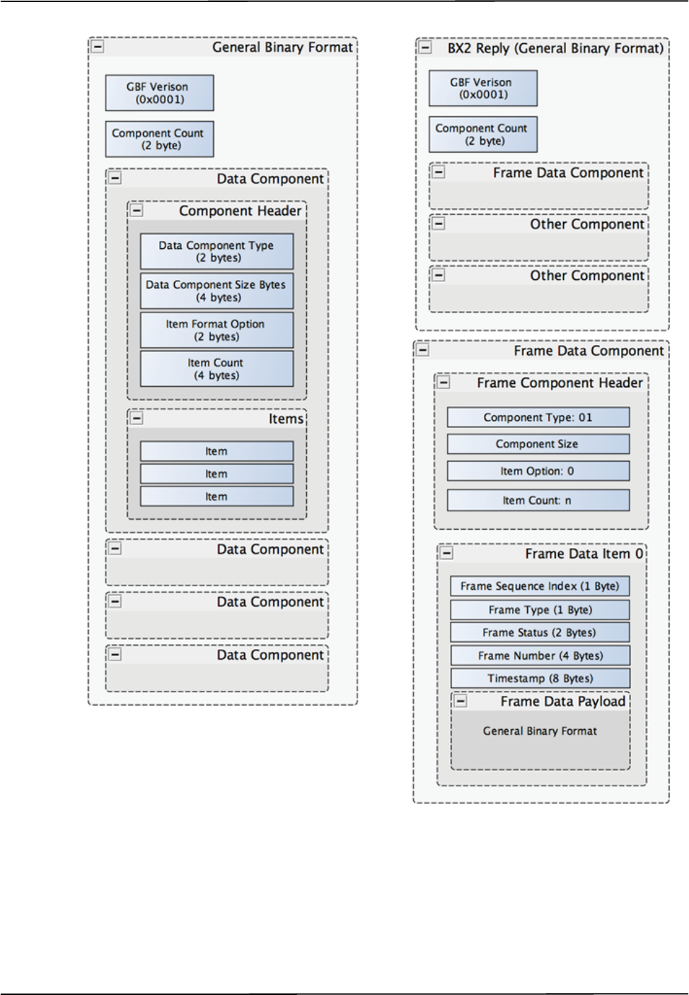
General Binary Format
The General Binary Format (GBF) is used consistently in all new commands returning tracking or
video data. Its advantage is that the host does not need to keep the context of the request to be able to
parse it correctly. It can also contain various levels of detail corresponding to the reported tracking
frame. It is structured as a list of individual, well-defined components. Each component holds the
information on its unique type and its options that define the process of parsing its content. It uses
little endian byte order as the existing binary command and all size byte values are interpreted as
unsigned values. The general structure of the format is illustrated in Figure 2-1.
All numeric values are 4 bytes (32 bits) unless otherwise specified. The first field in the payload is a
2 byte integer that indicates the number of components contained in the payload.
Each component starts with a unique 2 byte value defining its type, followed by 4 bytes specifying
the size of the component, including the 12 bytes for the header. If the parsing software cannot parse
this component, it can use the size information to skip to the beginning of the next component.
Item Format Option (2 bytes) is specific to the component type. Each type will have its own set of
options that provide all the information needed to parse the content of the component. The Item
Format Option implies the Item’s size.
Item Count (4 bytes) describes the number of following items to parse. After parsing all the
specified items, a new component starts with its definition of the component type and the parsing
process repeats.
Component ID’s are as follows:
01 – Frame Component
02 – 6D Data Component
DummyTool 2 characters
In case of Tool Type = Wireless
01 adds passive dummy tool
02 adds active wireless dummy tool

Changes in Implementation
6 Polaris Vega Application Program Interface Guide
03 – 3D Data Component
04 – 1D Data Component – buttons
05 – 2D Data Component
06 – reserved
07 – reserved
08 – reserved
09 – reserved
10 – Image Data Component
11 to 16 – reserved
17 – Sensor U,V Component
18 – System Alert Component
An example of the GBF structure, with an example of the BX2 command is shown in Figure 2-1.
Refer to page 67 for examples that contain the raw reply response converted to hex characters.
Changes in Implementation
Polaris Vega Application Program Interface Guide 7
Figure 2-1 General Binary Format structure and BX2 example

Changes in Implementation
8 Polaris Vega Application Program Interface Guide
Introduction of operating roles for host connections
With the introduction of the multi-host option, there is a need to ensure only one connection to the
Vega device has the capability of changing configuration options and the mode of the device. That
connection will hold the Master role and other connections will be in a Monitor role. The Master
connection will have full control of the system. If a connection in a Monitor role issues a command
that would change the operation of the system then error code 0x39 (Permission Denied) will be
returned.
Initially a connection will be granted the Monitor role. When it issues a command that would require
it to become the Master, the system assigns it the Master role, if the host is in the list of allowed
Masters and there is not already another Master.
There is a Master Time Out setting that tracks the activity on the Master connection. If the period of
inactivity on the Master connection exceeds the threshold set in the Master Time Out parameter,
then the Monitor can become the Master.
Extended Binary Header
To facilitate binary replies that have a binary payload greater than 65535 bytes long, a new binary
header type is introduced. This header has a 32 bit length field and allows for reply lengths up to
2^32-1 bytes long. Either binary header may be used in response to any of the “new” binary
commands, currently BX2 and VCAP.
This extended binary reply header is intended for use with very large replies. If the reply length is
less than 65535 bytes long, then the original binary header is used. Since TCP packets already
include data checksums and to reduce processing time and allow for more efficient memory-to-
memory transfer techniques, no CRC will be included in the header or at the end of the data. Thus,
the extended header is the same length as the original header.
The format of an extended binary header reply is as follows:
A5C8<4 byte Reply Length><command reply>
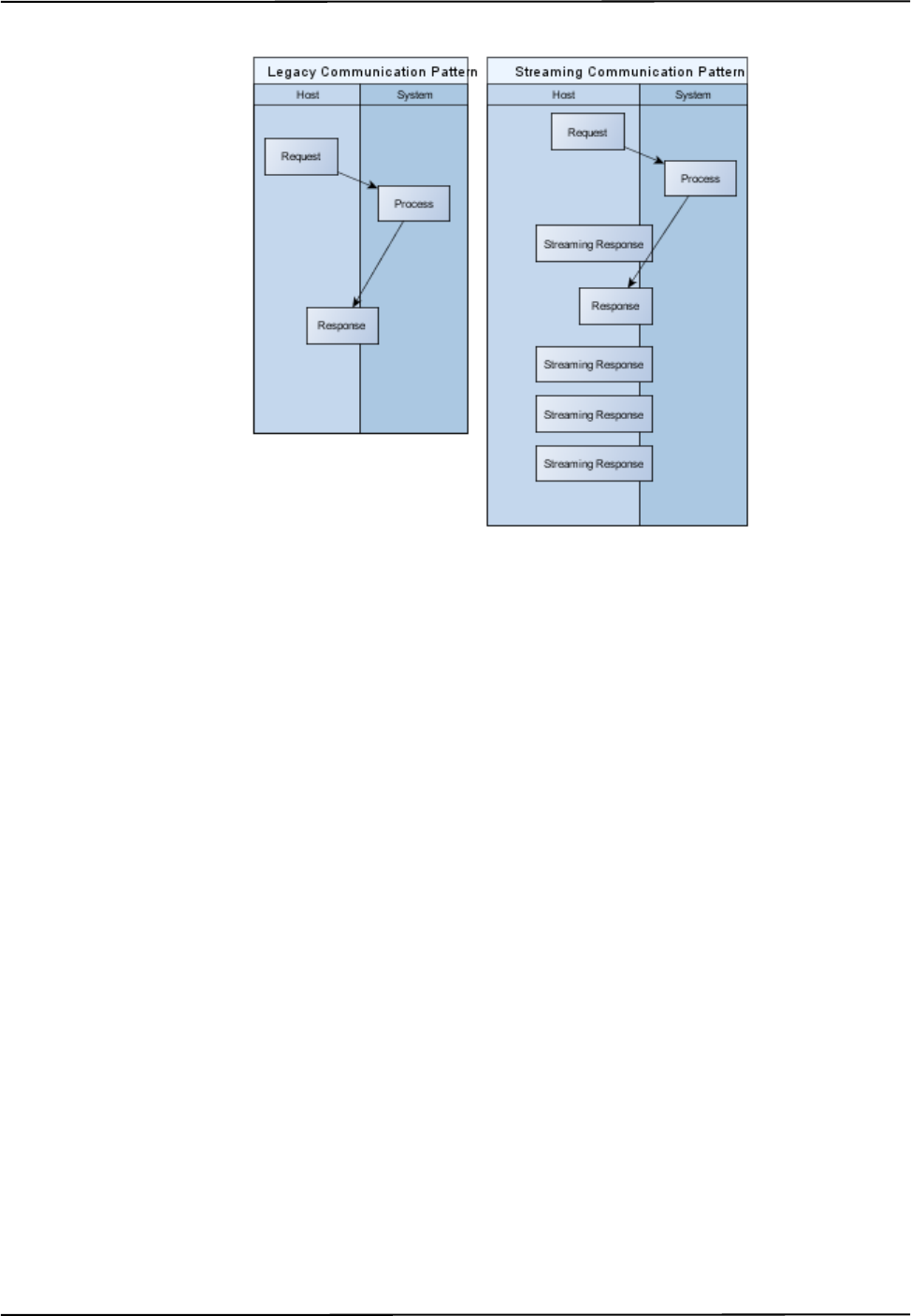
Data Streaming
In previous versions of the API, the host and the system communicated in a strict Request-Response
pattern. This version of the API introduces an option to continuously stream command responses for
each new frame of data. For an application to make use of streaming, its communication drivers will
have to be modified because most legacy applications expect the response to come after the request.
Once streaming is enabled on the communication channel, the host can no longer assume that a
given response received from the system belongs to the last request. The host addresses this in its
parsing by always investigating the kind of reported data. Each streaming response will be clearly
identified in its header then host processing routes each response to its corresponding process. See
Figure 2-2 on page 9.
Changes in Implementation
Polaris Vega Application Program Interface Guide 9
Figure 2-2 Streaming Response Pattern
This version of the API introduces two new streaming commands: STREAM (initiates a streaming
response to a command) and USTREAM (terminates a stream).
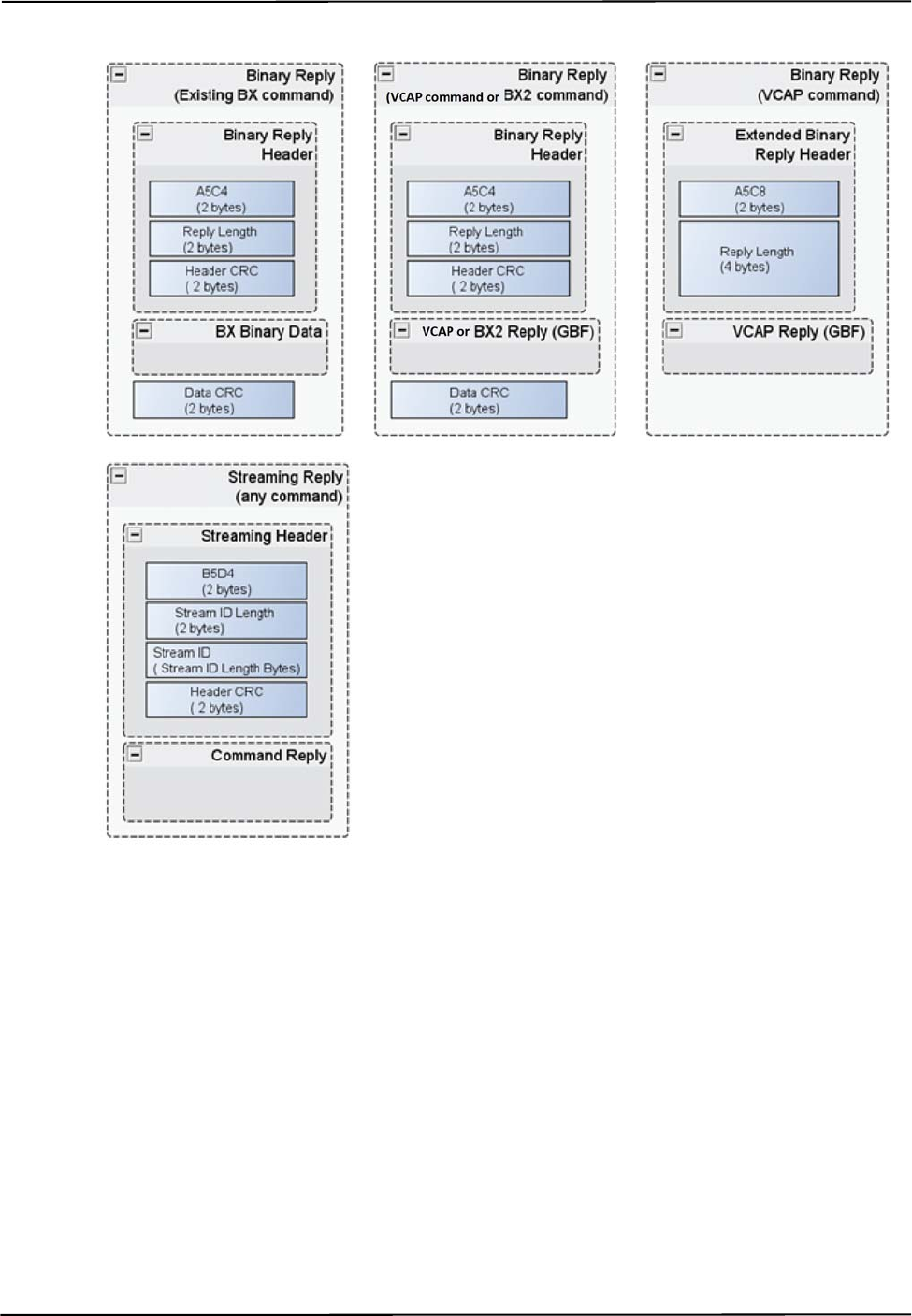
Newly introduced streamed replies will be wrapped in the Streaming Reply Format in a similar way
to how the BX binary data is currently wrapped in the Binary Data Format. Both are shown in
Figure 2-3 on page 10.
Structures of both formats are similar. Both start with the header, followed by the binary data content
and both are concluded by the CRC, ensuring correct content. Streaming reply starts with a new 2
byte identification sequence. The new parsing process checks for this sequence at the start of each
reply. The header of the streaming message contains a unique string of bytes “Stream ID” which the
host will use to identify which stream the response belongs to (in the case where more than one
stream is initiated). If the reply is not a streaming reply, it belongs to the last pending non-streaming
request. All of the tracking data is delivered in the new General Binary Format, see “General Binary
Format” on page 5.
Changes in Implementation
10 Polaris Vega Application Program Interface Guide
Figure 2-3 Binary and Streaming Reply Format

Communicating with an NDI System
Polaris Vega Application Program Interface Guide 11
3 Communicating with an NDI System
•“Connection Requirements” on page 11
•“Communication Overview” on page 11
•“Operating Modes” on page 12
•“General Syntax” on page 12
•“Receiving System Replies” on page 13
•“Best Practices” on page 15
•“Port Handles” on page 16
3.1 Connection Requirements
The system must communicate with a host computer to pass measurement information to another
application running on the host computer. Connection requirements are detailed below.
The ethernet connection must handle the bandwidth of data being sent. The bandwidth is dependent
on the amount of data being requested from the Vega System.
The ethernet connection must be compliant with IEEE 802.3at and secure from any unauthorized
connections.
The severity of all connection-related hazardous situations is the responsibility of the system
integrator because there is no essential performance of the Vega System.
Note Operation on an open or uncontrolled network could limit communication bandwidth, increase latency or
otherwise interfere with the normal operation of the Vega System and introduce risks which should be analyzed.
Changes to the network including connection, disconnection or updates to any equipment may also affect
operation of the system.
3.2 Communication Overview
There are two methods of communication with the Polaris systems; request-response and streaming.
Both methods are described below.
Request-Response Communication
In request-response communication, from the application perspective, the Polaris Vega System is a
serial device, which is listening for incoming commands. Upon receiving a command, the system
performs some action and returns the status of this action. The system never initiates communication
with the application.
Immediately after sending a command, the application can begin to poll the serial buffer for a reply.
Most commands reply almost instantly. After reaching the end of the reply, the application can send
another command. There may be some delay in the response of the INIT command, and the
commands used to read from and write to an SROM device in a wired tool.

Communicating with an NDI System
12 Polaris Vega Application Program Interface Guide
Streaming Communication
The Polaris Vega System introduces an option to continuously stream command responses for each
new frame of data. The STREAM command initiates streaming response and the USTREAM
command terminates the streaming response. For details, see “Data Streaming” on page 8.
3.3 Operating Modes
The system has three modes of operation: Setup, Tracking, and Diagnostic. Some commands will
only work if they are sent while the system is in a specific mode of operation. If a command is sent
when the system is in a mode not valid for that command, the system returns ERROR0C.
Setup
Setup mode allows you to configure the system and tools. Tasks done while the system is in Setup
mode may include initializing the system, writing to the SROM on a tool, or checking the system
revision.
A wireless tool must have a port handle assigned to it (PHRQ) before the application can load a tool
definition file (PVWR) Both conditions must be satisfied before the tool can be enabled (PENA).
The system enters the Setup mode either on successful power up, on sending a reset, or on exiting
from Tracking or Diagnostic modes.
Tracking
In Tracking mode, the system measures the positions and orientations of tools in real time and
returns the information to the host computer when requested. The BX2 and BX commands are the
most commonly used commands in Tracking mode.
The system enters Tracking mode on successful TSTART command and exits Tracking mode on
TSTOP command.
Diagnostic
Diagnostic mode allows you to control and observe active tools, but not track them.
The system enters Diagnostic mode on successful DSTART command and exits Diagnostic mode on
DSTOP command.
3.4 General Syntax
Commands must be sent from the host computer to the system in one of the two following formats.
To ensure the integrity of data transmission, NDI recommends using format 1, as well as verifying
the returned CRC on the host computer.
Format 1
<Command><:><Parameter1><Parameter2>...<ParameterN><CRC16><CR>

Communicating with an NDI System
Polaris Vega Application Program Interface Guide 13
A <:> must be sent with every command even if no parameters are required. There are no characters
or spaces separating the parameters or the individual parts of the commands, except in user
parameter names and string values used with the SET, GET, GETINFO, DFLT, and SYSLOG
commands. Commands and parameters are not case-sensitive, except for user parameter names and
string values used with the SET, GET, GETINFO, DFLT, and SYSLOG commands and in POSIX-
style parameters (which must be separated from each other by one or more spaces).
This format requires a 16-bit CRC (Cyclic Redundancy Check) value and therefore may be more
useful in application software. The application software can incorporate a CRC calculation and add
it to the command each time a command is sent to the system. Including a CRC provides a
communications check to ensure that there are no communication problems between the system and
the host computer. The CRC is used in both the commands and replies. It is based on all the
characters in the command, up to the CRC itself. It is calculated using the polynomial
x16 +x
15 +x
2+1. See “Sample C Routines” on page 164 for sample code to calculate the CRC.
Format 2
<Command><SPACE><Parameter1><Parameter2>...<ParameterN><CR>
A <SPACE> may be sent with every command; it need not be sent if no parameters are required.
There are no characters or spaces separating the parameters or the individual parts of the commands,
except in user parameter names and string values used with the SET, GET, GETINFO, DFLT,
SYSLOG commands and in POSIX-style parameters (which must be separated from each other by
one or more spaces). Commands and parameters are not case-sensitive, except for user parameter
names and string values used with the SET, GET, GETINFO, DFLT, and SYSLOG commands.
It is not necessary to calculate a CRC value when using this format, so this format is useful for
sending commands to the system in an application such as a terminal program.
3.5 Receiving System Replies
Binary Replies
Commands BX, BX2, GETLOG, and VCAP return binary replies. All other commands return
ASCII replies.
If a complete command is received by the system, replies are sent back in the format:
<Reply><CRC16>
The system always returns <CRC16> in the reply regardless of whether the command was sent in
format 1 or format 2 unless the reply is an Extended Binary Reply. The <Reply> will be either the
requested data, or ERROR<error code>. The <error code> is a two-digit hexadecimal error
number. See “Error Code Definitions” on page 157 for a listing of all the error messages associated
with error numbers.
Binary replies are returned in little endian format. For example, a 32-bit reply is returned in the
format:
Bits 7 - 0 15 - 8 23 - 16 31 - 24
Reply byte n n + 1n + 2n + 3

Communicating with an NDI System
14 Polaris Vega Application Program Interface Guide
Extended Binary Header
In order to facilitate binary replies that have a binary payload greater than 65535 bytes long, a new
binary header type is introduced. This header has a 32 bit length field and allows for reply lengths up
to 2^32-1 bytes long. Either binary header may be used in response to any of the “new” binary
commands, currently BX2 and VCAP.
This extended binary reply header is intended for use with very large replies. If the reply length is
less than 65535 bytes long, then the original binary header is used. Since TCP packets already
include data checksums and to reduce processing time and allow for more efficient memory-to-
memory transfer techniques, no CRC will be included in the header or at the end of the data. Thus,
the extended header is the same length as the original header.
The format of an extended binary header reply is as follows:
A5C8<4 byte Reply Length><command reply>
ASCII Replies
All commands return ASCII replies except BX, BX2, GETLOG, and VCAP, which return binary
replies.
If a complete command is received by the system, replies are sent back in the format:
<Reply><CRC16><CR>
The system always returns <CRC16> in the reply regardless of whether the command was sent in
format 1 or format 2. The <Reply> will be either the requested data, OKAY, WARNING,
WARNING<warning code>, or ERROR<error code>.
•WARNING is returned only with the PINIT command. See PINIT (page 107) or “Warning
Code Definitions” on page 160 for details.
•WARNING<warning code> is returned only with the PENA command. See “Warning Code
Definitions” on page 160 for a listing of the warning messages.
•The
<error code> is a two-digit hexadecimal error number. See “Error Code Definitions”
on page 157 for a listing of all the error messages associated with error numbers.

Communicating with an NDI System
Polaris Vega Application Program Interface Guide 15
3.6 Best Practices
This section provides guidelines on how to write an application in order to minimize updates
required when there are changes to the API. If your application is written correctly, it will still work
when additions are made to the API; you will only need to update your application if you wish to
take advantage of the new features.
• Ignore the value of any returned field that is listed as “reserved” in the API guide. The
values of reserved fields may change in future API releases.
• Program the application to allow all possible values of a returned field, not only the values
that are currently defined. This allows for future expansion. For example, if a field returns
one character, but currently only characters 0 and 1 are defined, do not write your
application such that 0 and 1 are the only acceptable values; more values may be defined in
the future.
• Use the frame number, and not the host computer clock, to identify when data was collected.
The frame number is incremented by 1 at a constant rate of 60 Hz. Associating a time from
the host computer clock to replies from the system assumes that the duration of time
between raw data collection and when the reply is received by the host computer is constant.
This is not necessarily the case. The frame number is returned with the command BX
(page 49), TX (page 138), BX2 (page 60), and VCAP (page 151).
• Use both the shape type and the shape parameters to represent the characterized
measurement volume graphically. There may be multiple volumes with the same shape
type. All volumes of the same shape type use the shape parameters the same way. The shape
type and shape parameters are returned with the command SFLIST (page 121). See also 2.1.
• When checking the firmware revision, check only the combined firmware revision, not the
firmware revision of the individual components. The combined firmware revision ensures
that all components in a system have compatible firmware. To check the combined firmware
revision, read the value of the user parameter Config.Combined Firmware Revision or use
the command VER 5 (page 154). See “User Parameters” on page 20 for information on
reading user parameters.
• When checking for protocol compatibility, check for the API revision instead of the
combined firmware revision. An application written for a particular API revision will
function with any system that supports that API revision. See the command APIREV
(page 46) for details.
•Use GET Device.* to determine which devices are in the system configuration, instead of
programming device names directly into the application. This will allow the addition or
removal of devices without breaking the application. When setting or reading a user
parameter value for every hardware device in the system, create a loop to repeat the action
for every device name determined using GET Device.*. See “Device Names” on page 21
for instructions on how to determine the device names of the hardware devices in your
system and how to access user parameters using device names.
• Read the timeout values of the API commands from the user parameter
Info.Timeout.<command name>; do not program the timeout values directly into the
application. See “User Parameters” on page 20 for information on user parameters.
• Do not use the system log to record minor system events. The system log is intended for
major milestones only, and may not have enough space to accommodate numerous minor

Communicating with an NDI System
16 Polaris Vega Application Program Interface Guide
entries. For minor entries, use the user parameters Param.User.String0 to
Param.User.String4 as required. These parameters can be used for any purpose; the system
does not make use of them. For example, an incoming inspection result might be a major
milestone to be saved in the system log; a cleaning schedule might be a minor entry to be
saved in a user parameter. See “User-Defined User Parameters” on page 29 for information
on these user parameters.
3.7 Port Handles
About Port Handles
The system assigns each tool a port handle. Using the commands below, port handles are two
characters in hexadecimal format, 0x01 to 0xFF. (BX2, for example, returns port handles as 4
characters.)
Port handles can be assigned to tools only while the system is in Setup mode.
Port Handle Commands
The following commands are used for port handles:
The order in which these commands are used is detailed in Figure 3-1 on page 18 (for wired tools)
and Figure 3-2 on page 19 (for wireless tools).
Disabled Transformations
A transformation may be reported as DISABLED if:
• the port handle was not enabled with PENA (page 91),
Command Description
PHSR (page 104) Returns the number of assigned port handles and the port status for each one.
Assigns a port handle to a wired tool.
PHRQ (page 102) Assigns a port handle to a tool. PHRQ is followed by PVWR.
PVWR (page 116) Assigns a tool definition file to a tool, overrides a tool definition file in a
wired tool, and can be used to test a tool definition file before permanently
recording the tool definition file onto the SROM device of a wired tool.
PINIT (page 107) Initializes a port handle. PENA calls PINIT.
PHINF (page 96) Returns port handle status, and information about the tool associated with the
port handle, including physical port location.
PHF (page 95) Releases system resources from an unused port handle. This is required if a
tool is disconnected. If a tool is disconnected and then reconnected, the
system assigns it a new port handle. The old handle is reported as disabled
and should be freed using PHF.
PENA (page 91) Enables reporting of transformations for a particular port handle.
PDIS (page 90) Disables the reporting of transformations for a particular port handle.

Communicating with an NDI System
Polaris Vega Application Program Interface Guide 17
• the port handle has been disabled with PDIS (page 90), or
• a wired tool has been disconnected and the port handle has not been freed.
Unoccupied Port Handle
A port handle may be reported as UNOCCUPIED if:
• the tool has been disconnected and port handle information is requested using PHINF
(page 96), or
• you have requested a port handle with PHRQ (page 102) but you have not yet used PVWR
(page 116) to associate a tool definition file with the port handle.
Communicating with an NDI System
18 Polaris Vega Application Program Interface Guide
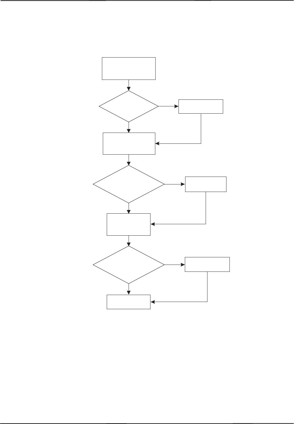
Flow Charts for Port Handle Usage
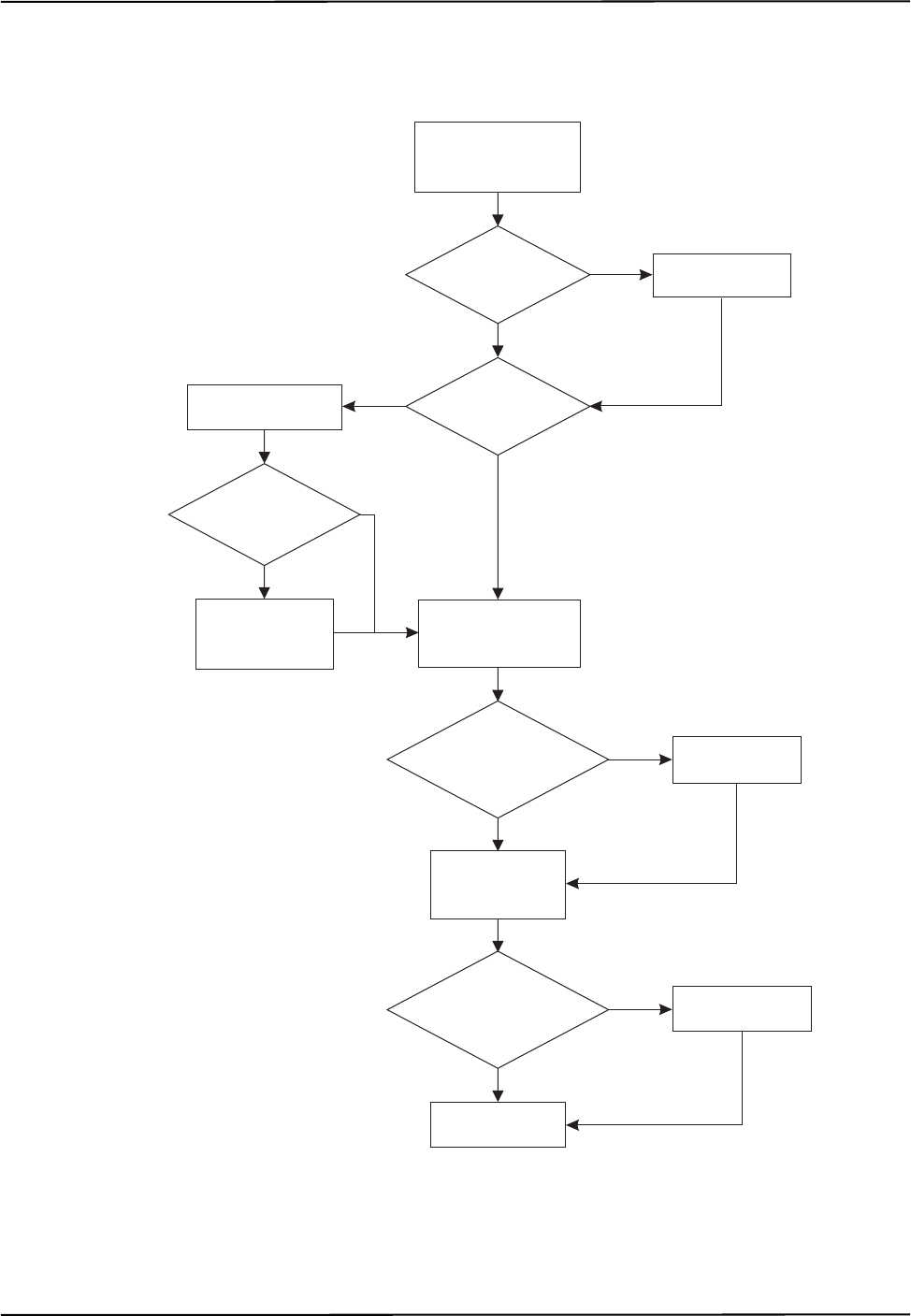
Figure 3-1 details the logic for using port handles with wired tools.
Figure 3-1 Flow Chart for Port Handle Usage - Wired Tools
no
no
no
Get port handles
that need to be freed
(PHSR 01)
Are there port
handles to be
freed?
yes Free port handle
(PHF)
Get port handles that
need to be initialized
(PHSR 02)
Are there
port handles
to be initialized?
Start tracking
(TSTART)
Enable port
handles (PENA)
Are there
port handles
to be enabled?
Get port handles
to be enabled
(PHSR 03)
Initialize handles
(PINIT)
Optional
yes
yes
Communicating with an NDI System
Polaris Vega Application Program Interface Guide 19
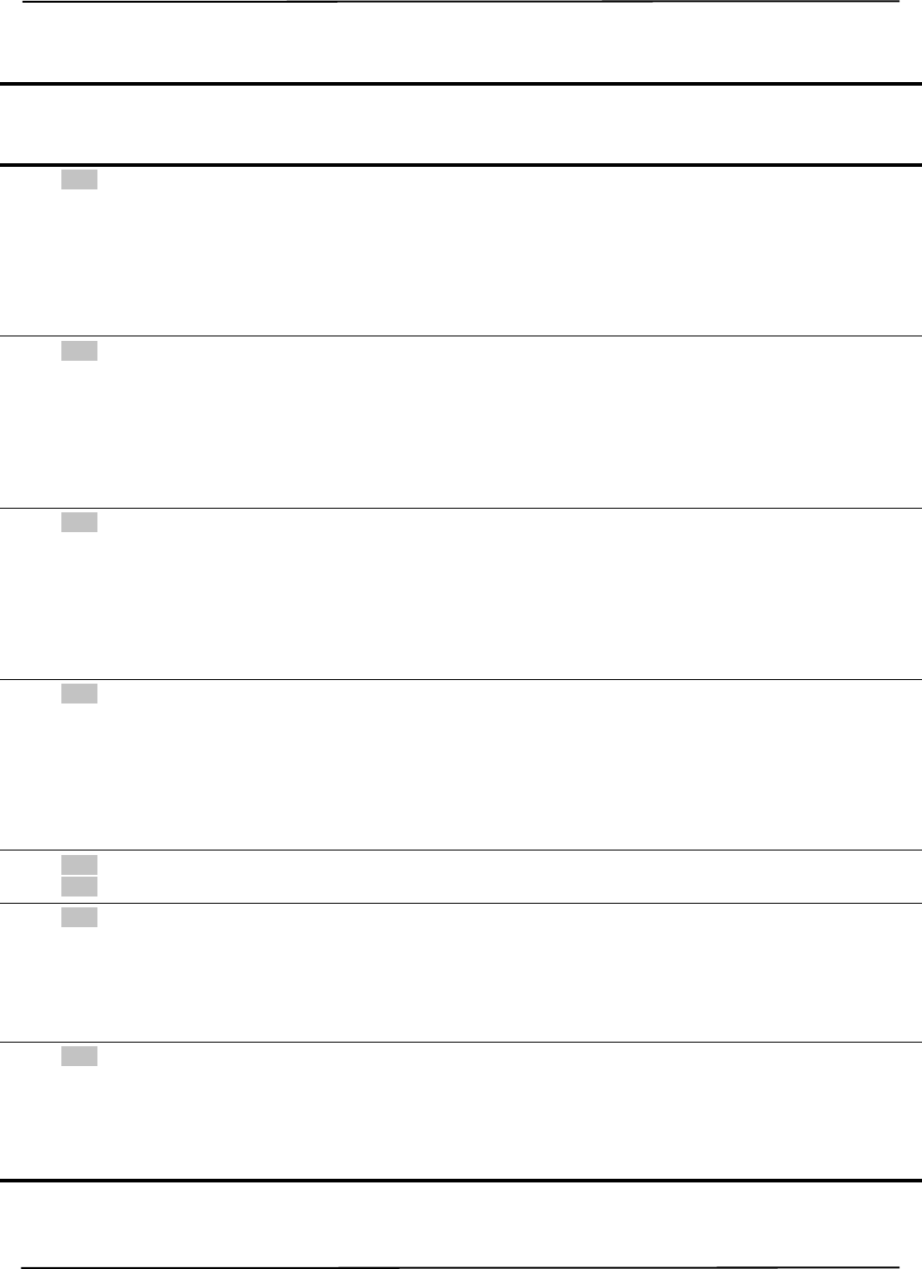
Figure 3-2 details the logic for using port handles with wireless tools.
Figure 3-2 Flow Chart for Port Handle Usage - Wireless Tools
no
no
yes
yes
no
no
Get port handles
that need to be freed
(PHSR 01)
Are there port
handles to be
freed?
yes Free port handle
(PHF)
Do I need a
handle for a port?
Get port handles that
need to be initialized
(PHSR 02)
Are there
port handles
to be initialized?
Start tracking
(TSTART)
Enable port
handles (PENA)
Are there
port handles
to be enabled?
Get port handles
to be enabled
(PHSR 03)
Request port handle
(PHRQ)
Do I need to
load a tool definition
file?
Load tool
definition file
(PVWR)
no
Initialize handles
(PINIT)
Optional
yes
yes

User Parameters
20 Polaris Vega Application Program Interface Guide
4 User Parameters
•“About User Parameters” on page 20
•“User Parameter Commands” on page 21
•“Device Names” on page 21
•“Alerts User Parameters” on page 22
•“Bump Sensor User Parameters” on page 28
•“Video Camera User Parameters” on page 28
•“User-Defined User Parameters” on page 29
•“Complete List of User Parameters” on page 30
4.1 About User Parameters
User parameters store values for different aspects of the Polaris Vega System. Some user parameters
store values for the full system configuration; others store values pertaining to a particular hardware
device in the system. Some user parameters are read-only parameters that store useful information
about the system; some user parameter values can be changed to allow you to configure the system.
User parameters fall under the following categories:
•Image Capture User Parameters: These user parameters are used in conjunction with the
VCAP command to store settings and values related to image capture. For example
background or illuminated frame.
•Settings User Parameters: These user parameters store settings for each hardware device in
the system. For example, the illuminator rate and the available characterized measurement
volumes are stored in the settings user parameters.
•Information User Parameters: These user parameters store status information for each
hardware device in the system and command timeout values.
•Features User Parameters: These user parameters store information about the features of
each hardware device in the system.
•System Configuration User Parameters: These user parameters store information about the
configuration of the system. These user parameters describe the configuration of the entire
system, not a particular device.
•Hardware Device Information User Parameters: These user parameters store information
about which hardware devices are part of the system.
•Network User Parameters: These user parameters store information about the network
settings of the system.
•Clock User Parameters: These parameters store information about the system clock,
including the day, month, year, hour, minutes and seconds.
•Volume User Parameters: These parameters store information about the Vega volume,
including the volume shapes and supported wavelengths.

User Parameters
Polaris Vega Application Program Interface Guide 21
•Video Camera User Parameters: These parameters store information about the optional
video camera.
For a full list of user parameters, see page 30.
4.2 User Parameter Commands
The following commands are used with the user parameters:
See the individual commands for more details.
4.3 Device Names
Each hardware device in the system configuration has a unique device name. For passive systems,
the Position Sensor and Video Camera Unit are the only hardware devices. For hybrid systems, the
Position Sensor, System Control Unit and Video Camera Unit each have a device name.
Each hardware device has its own set of user parameters and its own log file.
Note For information on the log files, see GETLOG (page 81) and SYSLOG (page 131).
Determining the Devices in the System Configuration
Use the GET command to determine which hardware devices are in your system. To ensure future
compatibility if more devices are integrated into your system, your application should read the list of
devices every time you connect to a system, or whenever a component is connected or disconnected.
Note The list of devices does not update while the system is in tracking mode. The list of devices will not show
changes until the system exits tracking mode.
The most general method of reading the list of devices to ensure consistent behaviour in the future is
as follows:
Command:
GET Device.*
Reply:
Device.Type.0=PS
Command Description
DFLT (page 73) Restores the user parameters to factory default values.
GET (page 77) Returns user parameter values.
GETINFO (page 79) Returns user parameter values and descriptive information
about the user parameters, including use details, possible
values and access rules.
SET (page 120) Sets user parameter values.
SAVE (page 119) Saves all non-volatile user parameters that have been changed.

User Parameters
22 Polaris Vega Application Program Interface Guide
Device.Type.1=SCU
Device.Type.2=VCU
Device.Instance.0=0
Device.Instance.1=0
Device.Instance.2=0
Device.Address.0=local
Device.Address.1=192.168.1.11
Device.Address.2=
Device.Port.0=8765
Device.Port.1=8765
Device.Port.2=0
The reply gives information about every device in the system configuration. For each device, there
are four parameters as shown in the reply example above.
•Device.Type.X describes the type of connected device:
•Device.Instance.X describes the instance of that type of device in the configuration.
Parameters with the same X index value (for example, Device.Type.0 and Device.Instance.0)
describe the same device. For more information, refer to table Table 4-12.
4.4 Alerts User Parameters
The alerts user parameters describe the status of a particular hardware device in the system.
Alerts User Parameters
Table 4-1 describes the alerts user parameters.
Device.Type Parameter Hardware Device
PS Position Sensor
SCU System Control Unit
VCU Video Camera Unit
Table 4-1 Alerts User Parameters
User
Parameter Description
Info.Status.
Alerts This user parameter describes the current state of the hardware device. See the alerts listed in Table 4-2
for the Position Sensor. For System Control Unit alerts, see Table 4-3.
The bit corresponding to a particular alert is set when the system first detects the condition. This is
accompanied by system response in Table 4-2 or Table 4-3. The bit is cleared when the condition no
longer exists. Note: the “bump detected” bit will be cleared only when you set the “Param.Bump
Detector.Clear” Position Sensor user parameter to “1”.

User Parameters
Polaris Vega Application Program Interface Guide 23
Position Sensor Alerts
Table 4-2 describes the Position Sensor alerts that are returned by the Info.Status.Alerts and
Info.Status.New Alerts user parameters. The returned value is an integer, which you must convert
to an 8-character hexadecimal number. The hexadecimal number is made up of the following
individual alert values OR’d together:
Info.Status.
New Alerts Read this user parameter when the diagnostic pending bit is set (bit 8 in the BX or TX System Status
component). This user parameter lists the current alerts status whenever an alert is set or cleared. The act
of reading this parameter clears both this parameter and the diagnostic pending bit.
The bit corresponding to a particular alert is set when the system first detects the condition, and is cleared
when the system first detects that the condition has been resolved. This is accompanied by system
response in Table 4-2 or Table 4-3. The act of reading this user parameter clears it.
Param.Simu-
lated Alerts Simulates the Info.Status.Alerts parameter, for the hardware device specified, for testing purposes. To
test the response of a particular alert, set the value of this parameter to the value of the alert. See
Table 4-2 or Table 4-3.
Table 4-1 Alerts User Parameters (Continued)
User
Parameter Description
Table 4-2 Position Sensor Alerts
Hexadecimal
Value Alert System Response Log
to
File
Position Sensor LED
Indication BX2
Code
0x00000001 Non-recoverable parameter fault
The system parameter file or
some other critical file is missing
or has been corrupted (CRC
check failed).
INIT returns ERROR15
See page 157.
yes Error LED: on
Power LED: off
Fault 1
0x00000002 Sensor parameter fault
The sensor parameters were not
programmed properly, or cannot
be read by the system.
Not in use.
INIT returns ERROR15
See page 157.
yes Error LED: on
Power LED: off
Fault 2
0x00000004 Not in use.
0x00000008 Not in use.
0x00000010 Illuminator voltage fault
The illuminator voltage is outside
of operating range. This may be
caused by a hardware failure.
Sets diagnostic pending bit (bit
8) in TX or BX system status.
See page 157.
yes Error LED: on
Power LED: off
Fault 5
0x00000020 Illuminator current fault
The illuminator current is outside
of operating range. This may be
caused by a hardware failure.
Sets diagnostic pending bit (bit
8) in TX or BX system status.
See page 157.
yes Error LED: on
Power LED: off
Fault 6
User Parameters
24 Polaris Vega Application Program Interface Guide
0x00000040 Left sensor temperature fault
The left sensor temperature
cannot be read.
INIT returns ERROR15
Sets diagnostic pending bit (bit
8) in TX or BX system status.
The system will not return
tracking data, even if reply
option 0800 in TX/BX is used.
See page 157.
yes Error LED: on
Power LED: off
Fault 7
0x00000080 Right sensor temperature fault
The right sensor temperature
cannot be read.
INIT returns ERROR15
Sets diagnostic pending bit (bit
8) in TX or BX system status.
The system will not return
tracking data, even if reply
option 0800 in TX/BX is used.
See page 157.
yes Error LED: on
Power LED: off
Fault 8
0x00000100 Main temperature fault
The main board temperature
cannot be read.
INIT returns ERROR15
Sets diagnostic pending bit (bit
8) in TX or BX system status.
The system will not return
tracking data, even if reply
option 0800 in TX/BX is used.
See page 157.
yes Error LED: on
Power LED: off
Fault 9
0x00000200 One of the image sensors on the
PSU is not functioning. This may
be caused by an internal
hardware failure.
INIT returns ERROR15
Sets diagnostic pending bit (bit
8) in TX or BX system status.
The system will not return
tracking data, even if reply
option 0800 in TX/BX is used.
See page 157.
yes Error LED: on
Power LED: off
Fault
10
0x00000400
0x00020000 Reserved
0x00040000 A Type 1 low power PSE is
detected and there is insufficient
power for tracking. A Type 2 PSE
compliant with the 802.3at
standard that outputs up to 30W
must be used.
INIT returns ERROR15
See page 157.
no Error LED: on
Power LED: on
N/A
0x00080000 SCU configured but not present
This may mean that the SCU is
not functioning, has not powered
up yet, or has been disconnected.
It can also mean that the system
is misconfigured.
Active tools will not be
available for tracking. no Error LED: on
Power LED: on
Alert
10
Table 4-2 Position Sensor Alerts (Continued)
Hexadecimal
Value Alert System Response Log
to
File
Position Sensor LED
Indication BX2
Code
User Parameters
Polaris Vega Application Program Interface Guide 25
0x00100000 System battery fault
The system battery power is too
low. This may be caused by a
depleted or disconnected battery.
This battery powers the bump
sensor and the system clock.
Sets diagnostic pending bit (bit
8) in TX or BX system status.
Need reply option 0800 in TX or
BX to return data.
See page 157.
yes Error LED: on
Power LED: on
Alert 1
0x00200000 Bump detected
The bump sensor has detected a
bump.
Sets diagnostic pending bit (bit
8) in TX or BX system status.
Need reply option 0800 in TX or
BX to return data.
See page 157.
yes Error LED: on
Power LED: on
Alert 2
0x00400000 Video camera not functioning Video output is not available.
The VCU signals a fault or fails
to respond to the PSU.
yes Error LED: on
Power LED: on
Alert
15
0x00800000 Incompatible firmware
The combination of firmware on
the Position Sensor is not compat
ible. This may be caused by a
failed attempt to update the
firmware.
INIT returns ERROR2E
See page 157.
yes Error LED: flashing
Power LED: on
Alert 3
0x01000000 Recoverable parameter fault
The user parameter file has been
corrupted (CRC check failed) or
is missing. To correct this
problem, check that the settings
of the user parameters are set
correctly, and save them (use
SAVE (page 119)).
INIT returns ERROR15
See page 157.
yes Error LED: on
Power LED: on
Alert 4
0x02000000 Not in use.
0x08000000 PTP clock is not synced
PSU’s PTP clock is not synced
with other devices on the same
network.
See page 157. no Error LED: on
Power LED: on
Alert
14
0x20000000 Temperature characterized high
The Position Sensor temperature
is above the optimal operating
range (see the user guide for
details).
Sets temperature bit (bit 9) in
TX or BX system status.
Need reply option 0800 in TX or
BX to return data.
See page 157.
no Error LED: on
Power LED: on
Alert 8
0x40000000 Temperature characterized low
The Position Sensor temperature
is below the optimal operating
range (see the user guide for
details).
Sets temperature bit (bit 9) in
TX or BX system status.
Need reply option 0800 in TX or
BX to return data.
See page 157.
no Power LED: flashes
during warm-up when
system is first
powered on.
Error LED: on
Alert 9
Table 4-2 Position Sensor Alerts (Continued)
Hexadecimal
Value Alert System Response Log
to
File
Position Sensor LED
Indication BX2
Code

User Parameters
26 Polaris Vega Application Program Interface Guide
System Control Unit Alerts
Table 4-3 describes the SCU alerts that are returned by the Info.Status.Alerts and Info.Status.New
Alerts user parameters. The returned value is an integer, which you must convert to an 8-character
hexadecimal number. The hexadecimal number is made up of the following individual alert values
OR’d together:
Note The Polaris Vega SCU only incorporates one (Status) LED located on the rear of the SCU.
0x80000000 Reserved
Table 4-2 Position Sensor Alerts (Continued)
Hexadecimal
Value Alert System Response Log
to
File
Position Sensor LED
Indication BX2
Code
Table 4-3 System Control Unit Alerts
Hexadecimal
Value Alert System Response Log
to
File
SCU LED
Indication
0x00000001 Non-recoverable parameter fault
The system parameter file or some
other critical file is missing or has been
corrupted (CRC check failed).
INIT returns ERROR15 yes Rear LED: amber
0x00000002
to
0x00000008
Reserved
0x00000010 Internal strober communication fault
The SCU can detect the internal
strober, but cannot communicate with
it.
Sets diagnostic pending bit (bit
8) in TX or BX system status. yes Rear LED: amber
0x00000020
to
0x00000040
Reserved
0x00000080 Not in use.
0x00000100 Strober fault raised
The SCU has detected a fault raised by
the strober. There could be a voltage
monitor fault or an active marker
current monitor fault.
yes Rear LED: amber
0x00000200
to
0x00400000
Reserved

User Parameters
Polaris Vega Application Program Interface Guide 27
Video Camera Alerts
Table 4-4 describes the VCU alerts that are returned by the VCU-0.Info.Status.Alerts and VCU-
0.Info.Status.Alerts user parameters. The returned value is an integer, which you must convert to an
8-character hexadecimal number. The hexadecimal number is made up of the following individual
alert values OR’d together::
0x00800000 Incompatible firmware
The combination of firmware on the
SCU is not compatible. This may be
caused by a failed attempt to update the
firmware.
INIT returns ERROR2E yes Rear LED: amber
flash
0x01000000 Recoverable parameter fault
The user parameter file has been
corrupted (CRC check failed) or is
missing. To correct this problem, check
that the settings of the user parameters
are set correctly, and save them (use
SAVE (page 119)).
INIT returns ERROR15
See page 157.
yes Rear LED: amber
flash
0x02000000 Not in use.
0x04000000 Reserved
0x08000000 PTP clock not synced
SCU's PTP clock is not synced with
other devices on the same network.
no Rear LED: amber
flash
0x10000000 SCU fan not functioning as expected no Rear LED: amber
flash
0x20000000 SCU battery voltage low. This may be
caused by a depleted or disconnected
battery.
yes Rear LED: amber
flash
0x40000000 Strober alert raised
A strober parameter is missing.
yes Rear LED: amber
flash
0x80000000 Not in use
Table 4-3 System Control Unit Alerts (Continued)
Hexadecimal
Value Alert System Response Log
to
File
SCU LED
Indication
Table 4-4 Video Camera Alerts
Hexadecimal
Value Alert System Response Log
to
File
PSU LED
Indication
0x00000001
0x00000002
Internal video camera error If this condition persists for
more than 17 seconds, the
system will reboot the video
camera.
no None

User Parameters
28 Polaris Vega Application Program Interface Guide
4.5 Bump Sensor User Parameters
Table 4-5 lists the user parameters that relate to the bump sensor. For details on the bump sensor, see
the user guide that accompanied your system.
4.6 Video Camera User Parameters
Table 4-6 lists the information user parameters that relate to the optional video camera. For details
on the video camera, see the user guide that accompanied your system.
Table 4-6 Video Camera User Parameters
Table 4-5 Bump Sensor User Parameters
User Parameter Description
Info.Status.Bump
Detected This user parameter indicates when the system has detected a bump.
The system sets this user parameter to “1” upon detecting a bump. The system resets
this user parameter to “0” once you have set the Param.Bump Detector.Clear user
parameter to “1”.
Param.Bump
Detector.Clear Set this user parameter to clear all bumps detected up to that point. This clears the
“bump detected” bit in the Info.Status.Alerts user parameter, and sets the
Info.Status.Bump Detected user parameter and the
Param.Bump Detector.Bumped user parameter to “0”.
Values: “1” clears all detected bumps. The system will automatically reset this user
parameter to “0”.
Param.Bump
Detector.Bumped This user parameter indicates when the system has detected a bump.
The system sets this user parameter to “1” upon detecting a bump. The system resets
this user parameter to “0” once you have set the Param.Bump Detector.Clear user
parameter to “1.”
Param.Bump
Detector.
Bump Detection
This user parameter enables the bump detector.
Values :
“1” bump detector enabled (default).
“0” bump detector disabled.
User Parameter Description
VCU-
0.Info.Status.Alerts This user parameter describes the current state of the hardware device. See the alerts
listed in Table 4-4 for the VCU.
The bit corresponding to a particular alert is set when the system first detects the
condition. The bit is cleared when the condition no longer exists.
VCU-
0.Info.Status.New
Alerts
This user parameter lists the current alerts status whenever an alert is set or cleared.
The act of reading this parameter clears this parameter.

User Parameters
Polaris Vega Application Program Interface Guide 29
4.7 User-Defined User Parameters
There are five user parameters, Param.User.String0 to Param.User.String4, that can be used to
store user-defined information. For example, these parameters could be used to keep track of the
system maintenance or cleaning schedule. These parameters can be used for any purpose; the system
does not make use of them.

User Parameters
30 Polaris Vega Application Program Interface Guide
4.8 Complete List of User Parameters
The following tables list the user parameters for the Polaris Vega System. To view a complete list of
user parameters for your system, use the command GET * (for parameter names and values) or
GETINFO * (for parameter names, values, and usage details).
Image Capture User Parameters
The following user parameters are used in conjunction with the VCAP command. These user
parameters apply only to the Position Sensor.
Settings User Parameters
The following user parameters store settings for the hardware devices indicated in the Hardware
Device column.
Table 4-7 Image Capture User Parameters
User Parameter Name Description Access Rules
Cmd.VGet.Sensor.Color Depth Number of bits per pixel on the video sensor. Read
Cmd.VGet.Sensor.Width Number of horizontal pixels on the video sensor. Read
Cmd.VGet.Sensor.Height Number of vertical pixels on the video sensor. Read
Cmd.VGet.Sensor.Number Number of image sensors in system. Read
Table 4-8 System Settings User Parameters
User Parameter Name Description Access Rules Hardware
Device
Param.Laser.Laser Status Starts/stops firing the positioning
laser. Use this parameter when the
Positioning Laser keyed feature is
enabled. See “Positioning Laser” on
page 163 for details. The laser will
turn off automatically after 35 s.
Read, write Position Sensor
Param.User.String0 User-defined string (up to 63 chars). Read, write, save Position Sensor,
SCU
Param.User.String1 User-defined string (up to 63 chars). Read, write, save Position Sensor,
SCU
Param.User.String2 User-defined string (up to 63 chars). Read, write, save Position Sensor,
SCU
Param.User.String3 User-defined string (up to 63 chars). Read, write, save Position Sensor,
SCU
Param.User.String4 User-defined string (up to 63 chars). Read, write, save Position Sensor,
SCU
Param.Tracking.
Available Volumes Available characterized measure-
ment volumes. Read Position Sensor

User Parameters
Polaris Vega Application Program Interface Guide 31
Param.Tracking.Selected Vol-
ume Selects a characterized measure-
ment volume.
Can only be set in Setup mode.
Read, write Position Sensor
Param.Tracking.Sensitiv-
ity.Active Background IR sensitivity level (1-
lowest, 7-highest) for wired active
tools.
Read, write, save Position Sensor
Param.Tracking.Sensitiv-
ity.Active Wireless Background IR sensitivity level (1-
lowest, 7-highest) for active wire-
less tools.
Read, write, save Position Sensor
Param.Tracking.Sensitiv-
ity.Passive Background IR sensitivity level (1-
lowest, 7-highest) for wireless pas-
sive tools.
Valid only for API revision
G.003.001 and later.
Read, write, save Position Sensor
Param.Tracking.Track Fre-
quency Tool tracking frequency [Hz]
Can only be set in Setup mode.
Valid only for API revision
G.003.001 and later.
Read, write Position Sensor
Param.Tracking.Frame
Sequence Sequence of frame types currently
being tracked. Read Position Sensor
Param.Default Wavelength.
Return Warning Enables/disables returning a warn-
ing on PINIT if the default wave-
length was selected for the tool
corresponding to the port handle.
Read, write Position Sensor
Param.Bump Detector.
Bump Detection Enables/disables the bump sensor. Read, write, save Position Sensor
Param.Bump Detector.Bumped Indicates when the system has
detected a bump. Read Position Sensor
Param.Bump Detector.Clear Set to 'Clear' (1) to acknowledge
reported bumps.
Read, write Position Sensor
Param.Simulated Alerts Simulates the 'Info.Status.Alerts'
parameter, for testing purposes. Read, write, save Position Sensor,
SCU
Param.System Beeper Enables/disables the beeper
sequence on system reset. Read, write, save Position Sensor,
SCU
Param.Connect.SCU Port TCP port for SCU connections
Valid only for API revision
G.003.001 and later.
Read, write, save SCU
Param.Connect.SCU Host-
name Host name or address for SCU con-
nection
Valid only for API revision
G.003.001 and later.
Read, write, save Position Sensor
Table 4-8 System Settings User Parameters (Continued)

User Parameters
32 Polaris Vega Application Program Interface Guide
Information User Parameters
The following user parameters store status information for the hardware devices indicated in the
Hardware Device column, and command time out values.
Param.Tracking.Illuminated
Frame Forces the collection of a frame with
illuminators on.
Takes effect on next DSTART or
TSTART.
Valid only for API revision
G.003.001 and later.
Read, write Position Sensor
Param.Tracking.Background
Frame Forces the collection of a back-
ground frame with illuminators off.
Takes effect on next DSTART or
TSTART.
Valid only for API revision
G.003.001 and later.
Read, write Position Sensor
Param.Exposure.Time
Slot.Passive Time slot within the frame, to coor-
dinate multiple position sensors.
Valid only for API revision
G.003.001 and later.
Read, write Position Sensor
Param.Exposure.Shutter
Time.Other Exposure time for illuminated and
background frames [us].
Valid only for API revision
G.003.001 and later.
Read, write Position Sensor
Table 4-9 Information User Parameters
User Parameter Name Description Access
Rules Hardware
Device
Info.Timeout.<command> Time out for the specified command (sec). For
the SCU, only the following commands have
timeout values: APIREV, COMM, DFLT, ECHO,
GET, GETINFO, GETLOG, INIT, SYSLOG,
RESET, SAVE, SET, VER.
Read Position Sensor,
SCU
Info.Status.System Mode System operating mode. Read Position Sensor
Info.Status.Alerts System hardware and operating status flags; see
“Alerts User Parameters” on page 22 for details. Read Position Sensor,
SCU
Info.Status.New Alerts System hardware and operating status flags; see
“Alerts User Parameters” on page 22 for details. Read Position Sensor,
SCU
Info.Status.Bump Detected Indicates if the system has detected a bump. Read Position Sensor
Info.Status.PTP.Clock State PTP Clock Master/Slave state. Read Position Sensor
Table 4-8 System Settings User Parameters (Continued)

User Parameters
Polaris Vega Application Program Interface Guide 33
Features User Parameters
The following user parameters store information about the features for the hardware devices
indicated in the Hardware Device column.
Info.Status.PTP.Sync State PTP Clock sync state. Read Position Sensor
Info.Status.PTP.Master
Offset PTP Clock master offset in µs. Read Position Sensor
Info.Status.New Log Entry Indicates a new system log entry has been made;
set to 'False' (0) to clear. Read,
write Position Sensor,
SCU
Info.Status.Gravity Vector Gravity directional vector reported in Position
Sensor coordinate space.
Valid only for API revision G.003.001 and later.
Read Position Sensor
Table 4-10 Features User Parameters
User Parameter Name Description Access Rules Hardware
Device
Features.Keys.Installed Keys 'Value' is the name of the installed fea-
ture. Read Position Sensor,
SCU
Features.Keys.Active Keys List of active feature keys; See page
161 for details. Read Position Sensor,
SCU
Features.Keys.Disabled Keys List of disabled keys; change takes
effect on next reset. See page 161 for
details.
Read, write,
save Position Sensor,
SCU
Features.Tools.Enabled Tools Maximum number of tools that can be
enabled simultaneously. Read Position Sensor
Features.Tools.Active Ports Maximum number of wired active
tools that can be enabled simultane-
ously.
Read Position Sensor
Features.Tools.Passive Ports Maximum number of passive tools that
can be enabled simultaneously. Read Position Sensor
Features.Tools.Wireless Ports Maximum number wireless active tools
that can be enabled simultaneously. Read Position Sensor
Features.Firmware.
Bootloader.Version Current bootloader revision number. Read Position Sensor
Features.Firmware.Version Current firmware revision number. Read Position Sensor,
SCU
Features.Firmware.
Major Version Current firmware major revision num-
ber. Read Position Sensor,
SCU
Features.Firmware.
Minor Version Current firmware minor revision num-
ber. Read Position Sensor,
SCU
Features.Firmware.
Build Number Current firmware build revision num-
ber. Read Position Sensor,
SCU
Table 4-9 Information User Parameters (Continued)

User Parameters
34 Polaris Vega Application Program Interface Guide
Features.Firmware.Available
Ve rsi ons List of firmware revisions loaded in the
device. Read Position Sensor,
SCU
Features.Firmware.
Maximum Versions Number of firmware revisions that may
be stored in the device simultaneously. Read Position Sensor,
SCU
Features.Firmware.
Configuration Check System configuration checksum (for
NDI use only). Read Position Sensor,
SCU
Features.Firmware.Package
Number Current firmware package number. Read Position Sensor,
SCU
Features.Hardware.
Serial Number Hardware device serial number. Read Position Sensor,
SCU
Features.Hardware.Part Num-
ber Product part number. Read Position Sensor,
SCU
Features.Hardware.
OEM Number Hardware device customer number. Read Position Sensor,
SCU
Features.Hardware.Model Hardware device model name. Read Position Sensor,
SCU
Features.Firmware.
Safeloader Version Current safeloader firmware revision
number. Read Position Sensor,
SCU
Features.Firmware.
Available Combined
Firmware Revisions
List of combined firmware revisions
loaded in the device. Read Position Sensor,
SCU
Features.Firmware.
Combined Firmware Revision Current combined firmware revision of
the device. Read Position Sensor,
SCU
Features.Volumes.* Volume information from camera
parameter files. Read Position Sensor
Features.Video Camera Video camera is installed or not
installed. Read Position Sensor
Table 4-10 Features User Parameters (Continued)

User Parameters
Polaris Vega Application Program Interface Guide 35
System Configuration User Parameters
The following user parameters store information about the configuration of the system. These user
parameters describe the configuration of the entire system, not a particular device.
Hardware Device Information User Parameters
The following user parameters store information about the hardware devices in the system. See
“Device Names” on page 21 for information on how to use the hardware device user parameters.
Network User Parameters
The following user parameters store information about the system network settings.
Table 4-11 System Configuration User Parameters
User Parameter Name Description Access Rules
Config.Multi Firmware.
Load Combined Firmware
Revision
Combined firmware revision to load on next reset
(selection automatically saves when set). Use this
parameter when the Multi Firmware keyed feature is
enabled. See “Multi Firmware Feature” on page 162 for
details.
Read, write
Config.Multi Firmware.
Update Combined Firmware
Revision
Combined firmware revision to replace on next upgrade
or downgrade. Use this parameter when the Multi Firm-
ware keyed feature is enabled. See “Multi Firmware
Feature” on page 162 for details.
Read, write, save
Config.Multi Firmware.
Available Combined Firmware
Revisions
List of combined firmware revisions loaded in the sys-
tem. Read
Config.Combined Firmware
Revision Current combined firmware revision of the system. Read
Table 4-12 Hardware Device User Parameters
User Parameter Name Description Access Rules
Device.Type Type of device in the system configuration. Read
Device.Instance Instance of this type of device in the system configuration. Read
Device.Address The network address of the device (or “local” if that is the
device you are talking to). Read
Device.Port The network port to connect to the device. Read

User Parameters
36 Polaris Vega Application Program Interface Guide
Table 4-13 Network User Parameters
User Parameter Name Description Access Rules
Param.Network.IP
Method Method of receiving IP address. Read, Write,
Save
Param.Net-
work.Static.IP Address Requested ethernet interface IPv4 address. Read, Write,
Save
Param.Net-
work.Static.Subnet
Mask
Requested ethernet interface IPv4 subnet mask. Read, Write,
Save
Param.Net-
work.Static.Gateway Requested interface IPv4 gateway. Read, Write,
Save
Param.Network.DNS
Servers DNS Server list. Space separated. Read, Write,
Save
Param.Network.Host
Name Ethernet interface hostname, blank for default. Read, Write,
Save
Param.Network.MAC
Address Ethernet interface MAC address. Read, Write,
Save
Param.Network.Ser-
vice Name Service name advertised in DNS-SD. m=model h=host name,
n=serial number, t=tracking group. Read, Write,
Save
Param.Network.Track-
ing Group Tracking group name. Enables discovery of group members. Read, Write,
Save
Param.Connect.Master
Hosts List of hosts allowed to become configuration masters,
blank=unrestricted. Read, Write,
Save
Param.Connect.Moni-
tor Hosts List of hosts allowed to connect, blank=unrestricted, none=no
monitor hosts. Read, Write,
Save
Param.Connect.Host
Port TCP port to listen for host connections. Read, Write,
Save
Info.Connections.
Address Remote IP address. Read
Info.Connections.Port Remote IP port. Read
Info.Connections.Rx
Bytes Received byte count. Read
Info.Connections.Tx
Bytes Transmitted byte count. Read
Info.Connec-
tions.Requests Number of API requests. Read
Info.Connec-
tions.Replies Number of API replies. Read
Info.Connec-
tions.Streams Number of active streams. Read
Info.Connect.isMaster True if this connection is master. Read
Info.Connect.isAuth True if this connection is authenticated. Read
Param.Connect.Master
Timeout Seconds of inactivity before another connection is allowed to
become master (0=never) Read, Write,
Save

User Parameters
Polaris Vega Application Program Interface Guide 37
Clock User Parameters
The following user parameters store information about the system clock.
Table 4-14 Clock User Parameters
Volume User Parameters
The following user parameters describe the volume shapes and supported wavelengths for the
measurement volumes.
Table 4-15 Volume User Parameters
Video Camera User Parameters
The following parameters store information about the video camera.
Param.Connect.SCU
Port TCP port for SCU connections Read, Write,
Save
Param.Connect.SCU
Hostname Host name or address for SCU connection Read, Write,
Save
User Parameter Name Description Access Rules
Param.Clock.Date Numerical value for the day of the month. Read, Write,
Save
Param.Clock.Day Of
Week Numerical value for the day of the week. 0= Monday, 1=
Tuesday, etc. Read, Write,
Save
Param.Clock.Hours Numerical value for the current hour using the 24 hour clock. Read, Write,
Save
Param.Clock.Minutes Numerical value for the current minute. Read, Write,
Save
Param.Clock.Seconds Numerical value for the current second. Read, Write,
Save
Param.Clock.Year Numerical value for the current year, using the last two digits
of the year. For example, 2016 would be set as 16. Read, Write,
Save
Param.Clock.Month Numerical value for the current month. Read, Write,
Save
User Parameter Name Description Access Rules
Features.Volumes.Index Indicates the volume that is being referred to. Read
Features.Volumes.Name The volume name. Read
Features.Volumes.Shape The shape type. Read
Features.Volumes.Wavelengths Which wavelengths are supported in the volume. Read
Features.Volumes.ParamnShape parameters as described in SFLIST. Read

User Parameters
38 Polaris Vega Application Program Interface Guide
Table 4-16 Video Camera User Parameters
User Parameter Name Description Access Rules
Param.Video Camera.Allow
Streaming Enables or disables video output.Video output is
disabled by default. Note: INIT does not disable
video streaming if it has been enabled.
Read/Write
VCU-0.Features.Firmware.Ver-
sion Current firmware revision number for the video
camera. Read
VCU-0.Param.White Balance.
[Red|Green|Blue] Selected white balance configuration.
Values: 0 to 128
Read/Write/Save
VCU-0.Param.White
Balance.Name Lighting presets to control the R|G|B colour gains. Read/Write/Save
VCU-0.Param.White Balance.
Gains.[Name|Red|Green|Blue] Gain values that are set when the VCU-0.White
Balance.Name is changed. Read/Write
VCU-0.Param.System Gain A multiplier applied to the colour gains to increase
or decrease overall brightness.
Values: 0-15.998
Read/Write/Save
VCU-0.Param.Brightness Brightness offset added to all pixels equally, not
based on colour.
Values: 0 to 255
Read/Write/Save
VCU-0.Param.Contrast The contrast gain parameter applied to all colours.
Value: 0-15.94
Read/Write/Save
VCU-0.Param.Exposure Time Exposure time in microseconds. Read/Write/Save
VCU-0.Param.Frame Rate The frame rate streaming out of the video camera in
frames per second. Read
VCU-0.Param.Resolution Selects the resolution of the video stream. Read/Write/Save
VCU-0.Param.Stream Preset Video stream parameters, prioritizing quality,
latency, or compression. Read/Write/Save
VCU-0.Param.Vertical Flip Vertically flips the image generated by the video
camera. Read/Write/Save
VCU-0.Param.Clients IP address of the client connected to the video
stream. Read
VCU-0.Param.Disconnect Clients Set this parameter to disconnect the connected
client.
Values: “1” disconnects the client. The system will
automatically reset this parameter to “0”.
Write
VCU-0.Param.Lens.
Distortion.[k1|k2|k3|p1|p2] Lens distortion parameters for Zhang's method for
the currently selected resolution parameters. Values
come from factory characterization of the video
camera.
Read
VCU-0.Param.Lens.
Pinhole.[U0,V0,fx,fy] Lens pinhole parameters for the currently selected
resolution. Values come from factory
characterization of the video camera.
Read

User Parameters
Polaris Vega Application Program Interface Guide 39
VCU-0.Param.Lens.6D.
[q0|qx|qy|qz|x|y|z] The orientation and location of the video camera in
the Vega measurement coordinate space. Initial
values come from factory characterization of the
video camera.
Read/Write/Save
VCU-0.Param.Lens.6D.reset Use this parameter to reset the 6D values to factory
defaults.
Values: “1” resets the 6D parameters. The system
will automatically reset this parameter to “0”.
Write

Command Details
40 Polaris Vega Application Program Interface Guide
5 Command Details
Before sending any commands to the system, read the user guide that accompanied your system to
ensure that you have a full understanding of the system functionality.

Command Details
Polaris Vega Application Program Interface Guide 41
3D
Returns the latest three-dimensional marker position of a single marker or multiple markers.
Deprecated
Operating Mode
Diagnostic, Tracking
Prerequisite Command
IRED (page 86), only for active markers in Diagnostic mode
Syntax
3D<SPACE><Port Handle><Reply Option><CR>
Replies
Upon Success:
<Number of Visible Markers><LF>
<Reply Option n Data><CRC16><CR>
On Error:
ERROR<Error Code><CRC16><CR>
See page 157 for error code definitions.
Parameter Description
Port
Handle
2 hexadecimal characters.
Specifies for which type of marker the system will report data (see “Usage Notes” on
page 45 for details). The specified port handle must be initialized (PINIT) and enabled
(PENA).
Reply
Option
Specifies which information will be returned.
The reply options cannot be OR’d.
Valid Values:
1Single marker 3D data, with error value
2Single marker 3D data, with error value and out-of-volume information
3Single marker 3D data, with line separation value
4Single marker 3D data, with line separation value and out-of-volume information
53D data for up to 50 markers, with line separation and out-of-volume information

Command Details
42 Polaris Vega Application Program Interface Guide
Reply Option 1 - 3D data for a single marker, with error value
<Reply Option 1 Data> = <Tx><Ty><Tz><Error Value>
Reply Option 2 - 3D data for a single marker, with error value and out-of-volume information
<Reply Option 2 Data> = <Tx><Ty><Tz><Error Value><Out of Volume>
Reply Component Description
Number of
Visible
Markers
3 characters
(a sign and 2 decimal digits)
The number of markers detected by the system.
For reply options 1 to 4, only one marker can be in view. If more than one marker is in
view, the system will return 00 for the number of markers.
Reply Option
n Data
The data specific to the requested reply option. See the reply option information below
for details:
Reply option 1 (3D data for a single marker, with error value)
Reply option 2 (3D data for a single marker, with error value and out-of-volume infor-
mation)
Reply option 3 (3D data for a single marker, with line separation value)
Reply option 4 (3D data for a single marker, with line separation value and out-of-vol-
ume information)
Reply option 5 (3D data for up to 50 markers, with line separation and out-of-volume
information)
Reply Component Description
Tx, Ty, Tz 9 characters each
(a sign, and 8 decimal digits with an implied decimal in the position XXXX . XXXX)
Position of the marker, in the coordinate system of the Position Sensor.
Error Value 4 characters
(a sign, and 3 decimal digits with an implied decimal in the position X . XX)
The normalized error number associated with the calculation for this marker position.
Possible Values:
+000 (best case) to +100 (worst case)
Reply Component Description
Tx, Ty, Tz 9 characters each
(a sign, and 8 decimal digits with an implied decimal in the position XXXX . XXXX)
Position of the marker, in the coordinate system of the Position Sensor.

Command Details
Polaris Vega Application Program Interface Guide 43
Reply Option 3 - 3D data for a single marker, with line separation value
<Reply Option 3 Data> = <Tx><Ty><Tz><Line Separation>
Reply Option 4 - 3D data for a single marker, with line separation value and out-of-volume information
<Reply Option 4 Data> = <Tx><Ty><Tz><Line Separation><Out of Volume>
Error Value 4 characters
(a sign, and 3 decimal digits with an implied decimal in the position X . XX)
The normalized error number associated with the calculation for this marker position.
Possible Values:
+000 (best case) to +100 (worst case)
Out of Volume 1 hexadecimal character
Indicates whether the marker is outside the characterized measurement volume.
Possible Values:
0 The marker is inside the characterized measurement volume.
1 The marker is out of volume.
Reply Component Description
Tx, Ty, Tz 9 characters each
(a sign, and 8 decimal digits with an implied decimal in the position XXXX . XXXX)
Position of the marker, in the coordinate system of the Position Sensor.
Line
Separation
4 characters
(a sign, and 3 decimal digits with an implied decimal in the position X . XX)
The minimum distance (in mm) between the two lines of sight calculated from the
marker image on the left and right sensor to the IR source.
Possible Values:
+000 (best case) to +999 (worst case)
Reply Component Description
Tx, Ty, Tz 9 characters each
(a sign, and 8 decimal digits with an implied decimal in the position XXXX . XXXX)
Position of the marker, in the coordinate system of the Position Sensor.
Reply Component Description

Command Details
44 Polaris Vega Application Program Interface Guide
Reply Option 5 - 3D data for up to 50 markers, with line separation value and out-of-volume information
<Reply Option 5 Data> =
<Tx1><Ty1><Tz1><Line Separation 1><Out of Volume 1><LF>
<Tx50><Ty50><Tz50><Line Separation 50><Out of Volume 50><LF>
Line
Separation
4 characters
(a sign, and 3 decimal digits with an implied decimal in the position X . XX)
The minimum distance (in mm) between the two lines of sight calculated from the
marker image on the left and right sensor to the IR source.
Possible Values:
+000 (best case) to +999 (worst case)
Out of Volume 1 hexadecimal character
Indicates whether the marker is outside the characterized measurement volume.
Possible Values:
0 The marker is inside the characterized measurement volume.
1 The marker is out of volume.
Reply Component Description
Txn, Tyn, Tzn 9 characters each
(a sign, and 8 decimal digits with an implied decimal in the position XXXX . XXXX)
Position of the nth marker, in the coordinate system of the Position Sensor. The system
will report up to 50 3D positions, including phantom markers. If the system detects
more than 50 IR sources, it will only report the first 50. The IR sources are not reported
in any particular order.
Line
Separation n
4 characters
(a sign, and 3 decimal digits with an implied decimal in the position X . XX)
Line separation of the nth marker. The minimum distance (in mm) between the two
lines of sight calculated from the marker image on the left and right sensor to the IR
source.
Possible Values:
+000 (best case) to +999 (worst case)
Out of Volume
n
1 hexadecimal character
Indicates whether the nth marker is outside the characterized measurement volume.
Possible Values:
0 The marker is inside the characterized measurement volume.
1 The marker is out of volume.
Reply Component Description

Command Details
Polaris Vega Application Program Interface Guide 45
Usage Notes
1. The specified port handle must be enabled using PENA (page 91).
2. You may need to use the 3D command about ten times if it is sent immediately after using IRED
(page 86). This allows time for the system to implement the activation signature and optimize
the signal by adjusting the range control.
3. Reply Options 1 to 4: You cannot have more than one marker in view. Any other IR sources in
view will prevent the system from returning marker data.
4. Reply Option 5: The system does not distinguish between real markers, phantom markers, or
other IR sources. You must determine whether the reported marker positions are valid. See the
user guide that accompanied the system for more information on phantom markers.
5. The 3D command returns data regardless of the bump status, temperature status, and other
system status conditions. Before trusting the marker positions returned by the 3D command, you
should check these conditions by reading the Info.Status.Alerts user parameter. (Use the GET
(page 77) command to check the value of user parameters.) You can use the BX (page 49) or TX
(page 138) command to request 3D data that is filtered when the bump status, temperature
status, or other system conditions are not ideal.
Compatibility Notes
Reply Option 1 and Reply Option 2: The system will not calculate an error, and will return an error
value of +000.
Example
Command:
3D 011
Reply:
+01-12345678+12345678-12345678+0954B7B
In this case, one marker is in view.

Command Details
46 Polaris Vega Application Program Interface Guide
APIREV
Returns the API revision number that functions with your system.
Operating Mode
All modes
Syntax
APIREV<SPACE><CR>
Replies
Upon Success:
<Family>.<Major revision number>.<Minor revision number><CRC16><CR>
On Error:
ERROR<Error Code><CRC16><CR>
See page 157 for error code definitions.
Example
Command:
APIREV
Reply:
G.003.0016379
Reply Component Description
Family 1 ASCII character. This character is always G. (Other types of NDI measurement sys-
tems use other characters.)
Major revision
number
3 ASCII characters
The major revision number is incremented whenever there is an incompatible change
in the API. (Whenever a command is deprecated or when its response is changed in a
way that may break an application.)
Minor revision
number 3 ASCII characters
The minor number is incremented whenever there is an addition to the API that is
compatible with all existing applications and usage. (Compatible changes are addi-
tions to the API command or option set that will not affect any existing applications.)
Command Details
Polaris Vega Application Program Interface Guide 47
BEEP
Sounds the system beeper.
Operating Mode
All modes
Syntax
BEEP<SPACE><Number of Beeps><CR>
Replies
Upon Success:
<Beep Status><CRC16><CR>
On Error:
ERROR<Error Code><CRC16><CR>
See page 157 for error code definitions.
Usage Notes
1. The beep duration is shorter than the beep used for reset and fatal error conditions.
2. Disabling the system beeper (by setting the value of the user parameter Param.System Beeper)
does not affect the BEEP command.
Compatibility Notes
The system will never return a beep status of 0. If you send the BEEP command while the system is
busy beeping, the system will return a beep status of 1, but will not initiate the second sequence of
beeps.
Parameter Description
Number of Beeps Valid Values:
1 to 9
Reply Component Description
G.003.002
Beep Status Possible Values:
0 The system is busy beeping.
1 Beeping has started. X

Command Details
48 Polaris Vega Application Program Interface Guide
Example
Command:
BEEP 1
Reply:
1D4C1

Command Details
Polaris Vega Application Program Interface Guide 49
BX
Returns the latest tool transformations, individual marker positions, and system status in binary
format.
Operating Mode
Tracking
Note For information on previous revisions of the API, refer to the Polaris Application Program Interface Guide (IL-
1070101) available on the NDI support site at https://support.ndigital.com.
Syntax
BX<SPACE><Reply Option><CR>
Replies
Upon Success:
<Start Sequence><Reply Length><Header CRC><01(Number of Handles)>
<Handle 1><Handle 1 Status><Reply Opt 0001 Data>...<Reply Opt 0008 Data>
...
<Handle n><Handle n Status><Reply Opt 0001 Data>...<Reply Opt 0008 Data>
Parameter Description
G.003.002
Reply
Option
Optional. Specifies which information will be returned. If no reply
option is specified, the system returns information for reply option
0001.
The reply options are hexadecimal numbers that can be OR’d. If multi-
ple reply options are used, the replies are returned for each port handle
in order of increasing option value, with the following exceptions:
Reply option 0800 is not reported separately from the other options; it
simply enables the system to return certain information in the other
options.
Reply option 1000 is reported after all handle-specific options but
before the <system status> and <CRC16>.
Valid Values:
0001 Transformation data (default) X
0002 Tool and marker information X
0004 3D position of a single stray active marker X
0008 3D positions of markers on tools X
0800 Transformations not normally reported X
1000 3D positions of stray passive markers X

Command Details
50 Polaris Vega Application Program Interface Guide
<Reply Option 1000 Data>
<System Status><CRC16>
Note The reply for the BX command is binary data.
Note If a handle status is “disabled,” the system will not return any of <Reply Option 0001 Data>...
<Reply Option 0008> for that port handle.
On Error:
ERROR<Error Code><CRC16><CR>
See page 157 for error code definitions.
Reply Component Description
G.003.002
Start
Sequence
2 bytes: A5C4
Indicates the start of the BX reply.
X
Reply Length 2 bytes
Indicates the number of bytes in the reply body between the
<Header CRC> and the <CRC16>, exclusive.
X
Header CRC 2 bytes
CRC16 of <Start Sequence> and <Reply Length>
X
Number of
Handles
1 byte
The number of port handles for which information is
returned.
X
Handle n 1 byte
The port handle whose information follows.
X
Handle Status 1 byte
Possible Values:
01 Valid X
02 Missing X
04 Disabled X

Command Details
Polaris Vega Application Program Interface Guide 51
Note The “diagnostic pending” bit is set whenever an alert is detected or cleared. To view the alerts status and clear
the diagnostic pending bit, use GET (page 77) to check the Info.Status.New Alerts user parameter for every
hardware device in the system. See “Usage Notes” on page 58 for more details. (For API revision G.001.003 and
earlier, the diagnostic pending bit did not indicate when an alert was cleared.)
Reply Option
m Data
The data specific to the requested reply option. See the reply
option information below for details:
Reply option 0001 (transformation data) (default) X
Reply option 0002 (tool and marker information) X
Reply option 0004 (latest 3D position of single stray active
marker) X
Reply option 0008 (3D position of markers on tools) X
Reply option 0800 (reporting all transformations) X
Reply option 1000 (3D position of stray passive markers) X
System Status 2 bytes
The status of the system.
Bit field:
bit 0 System communication synchronization error X
bits 1 and 2 Reserved
bit 3 Recoverable system processing exception. X
bit 4-5 Reserved
bit 6 Some port handle has become occupied X
bit 7 Some port handle has become unoccupied X
bit 8 Diagnostic pending X
bit 9 Temperature (system is not within operating
temperature range) X
bit 10 Hardware configuration changed (e.g. VCU or
SCU has connected or disconnected) X
bits 11 to
15 Reserved
Reply Component Description
G.003.002

Command Details
52 Polaris Vega Application Program Interface Guide
Reply Option 0001 - Transformation Data
<Reply Option 0001 Data> = <Q0><Qx><Qy><Qz><Tx><Ty><Tz><Error><Port Status>
<Frame Number>
or
<Reply Option 0001 Data> = <Port Status><Frame Number>
Reply Component Description
G.003.002
Q0, Qx, Qy, Qz 4 bytes each
Rotational components of the transformation, quaternion,
unitless, reported as IEEE 32-bit, single precision, floating
point numbers. The value for Q0 is always non-negative.
X
Tx, Ty, Tz 4 bytes each
Translational components of the transformation, in mm,
reported as IEEE 32-bit, single precision, floating point
numbers.
X
Error 4 bytes
The error is an RMS value, given in mm. It is the result of
the least squares minimization between the marker geom-
etry in the tool definition file and the data from the tool’s
markers measured by the system. Reported as IEEE 32-
bit, single precision, floating point number.
X

Command Details
Polaris Vega Application Program Interface Guide 53
Note If the handle status is “missing,” the system returns only the port status and the frame number.
- Tools are reported as missing if a transformation cannot be determined.
- In the event of a system error that prevents tracking, all tools are reported as missing.
Port Status 4 bytes
Bit field:
bit 0 Occupied X
bit 1 Switch 1 closed X
bit 2 Switch 2 closed X
bit 3 Switch 3 closed X
bits 4 Initialized X
bit 5 Enabled X
bit 6 Out of volume X
bit 7 Partially out of volume X
bit 8 Algorithm limitation (processing requires
more buffer than is available) X
bit 9 IR interference (a large bright IR object) X
bits 10 and
11 Reserved
bit 12 Processing exception (same as tool infor-
mation bit 7 in reply option 0002) X
bit 13 Reserved
bit 14 Fell behind while processing (same as tool
information bit 3 in reply option 0002)X
bit 15 Data buffer limitation (too much data; for
example, too many markers) X
bits 16 to 31 Reserved
Frame Number 4 byte unsigned number
The frame number is an internal counter related to data
acquisition, which is derived from the PTP time. The
frame rate is 60 Hz. The frame number corresponds to the
frame in which the raw data, used to calculate the accom-
panying transformation, was collected.
X
Reply Component Description
G.003.002

Command Details
54 Polaris Vega Application Program Interface Guide
Reply Option 0002 - Tool and Marker Information
<Reply Option 0002 Data> = <Tool Information><Marker Information>
Example - Marker Information: A tool with markers located at T, R, C, and A, where all four markers
were used to determine the calculation, would have the following reply:
Reply Option 0004 - 3D Position of Single Stray Active Marker
<Reply Option 0004 Data> = <Status><Tx><Ty><Tz>
Reply Component Description
G.003.002
Tool
Information
1 byte
Bit field:
bit 0 Bad transformation fit X
bit 1 Not enough acceptable markers for transforma-
tion X
bit 2 IR interference—environmental IR is interfer-
ing with the system (combination of port status
bits 9 and 15 in reply option 0001)
X
bit 3 Fell behind while processing (same as port sta-
tus bit 14 in reply option 0001)X
bits 4
to 6 Tool face used X
bit 7 Processing exception (same as port status bit 12
in reply option 0001) X
Marker
Information
10 bytes (4 bits per marker)
See below for an example.
Possible Values:
0000 Not used because it was missing X
0001 Not used because it exceeded the maximum
marker angle X
0010 Not used because it exceeded the maximum 3D
error for the tool X
0011 Used to calculate the transformation X
0100 Used to calculate the transformation, but it is
out of volume X
0101 Not used because it was outside the character-
ized measurement and was not needed to calcu-
late a transformation.
X
Marker T S R Q ... D C B A
Reply 0011 0000 0011 0000 ... 0000 0011 0000 0011
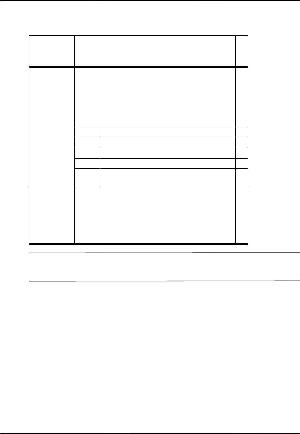
Command Details
Polaris Vega Application Program Interface Guide 55
or
<Reply Option 0004 Data> = <Status>
Note If no stray active marker is defined (for example, for wireless port handles, or wired tools with no stray marker
defined in the tool definition file), the status is 00, and no position information is returned. If the marker is
missing, or if the marker is out of volume and reply option 0800 is not used, the system returns only the status.
Reply
Component Description
G.003.002
Status 1 byte
The status of the stray active marker. A stray marker on an
active tool is not fixed with respect to the other markers that
make up the tool.
Bit field:
bit 0 Valid stray active marker X
bit 1 Marker is missing X
bit 2 Reserved
bit 3 Marker is out of volume X
bits 4 to
7Reserved
Tx, Ty, Tz 4 bytes each
Position of the marker in the coordinate system of the Position
Sensor, reported as IEEE 32-bit, single precision, floating point
numbers. The marker position is reported only if the marker
status is “valid,” or “out of volume” and reply option 0800 is
used.
X

Command Details
56 Polaris Vega Application Program Interface Guide
Reply Option 0008 - 3D Position of Markers On Tools
<Reply Option 0008 Data> = <Number of Markers><Out of
Volume><Txn><Tyn><Tzn>
Example - Out of Volume The information is returned in the format illustrated in the following
example: one bit per marker, in little endian format. In this example there are nine markers, all of
which are out of volume:
Reply Option 0800 - Reporting All Transformations
This option enables the reporting of transformations or translations in situations where translations
or transformations are calculated, but by default are not reported by the system. Such situations
include:
• The tool or marker is outside of the characterized measurement volume.
• The bump sensor has been tripped.
• The system is outside of the optimal operating temperature range.
Reply Component Description
G.003.002
Number of
Markers
1 byte
Number of markers used in tool transformations.
X
Out of Volume 1 byte/8 markers (1 bit per marker)
The bit is set when the marker is outside the characterized
measurement volume (see example below).
Reply size = (number of markers)/8, rounded up to the
nearest integer.
X
Txn, Tyn, and
Tzn
4 bytes each
Position of the nth marker, reported in the coordinate sys-
tem of the Position Sensor, reported as IEEE 32-bit, single
precision, floating point numbers. The system will report
the positions of markers used in tool transformations, as
well as markers that exceeded the maximum marker angle
or maximum 3D error specified in the tool definition file.
See “Usage Notes” on page 58 for more information.
X
Marker Number 987654321
Bit Field 0000000111111111
Reply 01FF
Reply Byte nn + 1

Command Details
Polaris Vega Application Program Interface Guide 57
• Other system conditions are not ideal; see “Alerts User Parameters” on page 22 for a full list
of these conditions.
This reply option must be OR’d with reply option 0001 to obtain transformations for tools in the
situations listed above. It must be OR’d with reply options 0004, 0008, or 1000 to obtain position
information for markers in the situations listed above.
When using reply option 0800 with the BX command, you must take appropriate action to detect the events listed
above, and determine whether they are detrimental to your application. If one or more of the events listed above
occurs, reply option 0800 enables the system to return data that may lead to inaccurate conclusions and may
cause personal injury.
Appropriate action to detect the events listed above includes:
• reading the out-of-volume flag in reply options 0001 and 0002 when tracking tools
• reading the out-of-volume information in reply options 0004, 0008, and 1000 when tracking
stray markers
• reading the temperature flag in the system status
• reading the diagnostic pending bit in the system status
• reading the Info.Status.New Alerts user parameter for every hardware device in the system
when the diagnostic pending bit is set. See “Usage Notes” on page 58 for details.
Reply Option 1000 - 3D Position of Stray Passive Markers
<Reply Option 1000 Data> = <Number of Markers><Out of
Volume><Txn><Tyn><Tzn>
Warning!
Reply Component Description
G.003.002
Number of
Markers
1 byte
Number of stray markers.
X
Out of Volume 1 byte/8 markers (1 bit per marker)
The bit is set when the marker is outside the characterized
measurement volume (see example below).
Reply size = (number of markers)/8, rounded up to the
nearest integer.
X
Txn, Tyn, Tzn 4 bytes each
Position of the nth marker in the coordinate system of the
Position Sensor, reported as IEEE 32-bit, single precision,
floating point numbers.
X

Command Details
58 Polaris Vega Application Program Interface Guide
Note At least one passive port handle must be enabled, to activate the illuminators on the Position Sensor. If no
passive port handles are enabled, <Number of Markers> will return 00 and no other data will be returned.
Stray passive markers are defined as markers which are not used to calculate any of the
transformations for any enabled, passive tools. Stray active wireless tool markers are not reported.
Example - Out of Volume The information is returned in the format illustrated in the following
example: one bit per marker, in little endian format. In this example there are nine markers, all of
which are out of volume:
Usage Notes
1. The BX reply format requires fewer characters than the text format; this allows transformations
to be reported more quickly. For replies in text format, use TX (page 138).
2. Replies are returned in little endian format.
3. By default, transformations will not be reported if the tool is either partially or wholly out of the
characterized measurement volume, if the bump sensor has been tripped, if the system is outside
of the optimal operating temperature range, or if certain other alerts have occurred (see “Alerts
User Parameters” on page 22 for details). To report these transformations, you must use reply
option 0800 OR’d with the desired reply option(s). The accuracy of these transformations is
unknown.
4. Reply Option 0001:
• When the “diagnostic pending” bit is set in the system status, use GET (page 77) to read the
Info.Status.New Alerts user parameter for every hardware device in the system. The act of
reading these parameters clears the parameters and the “diagnostic pending” bit. For more
information on alerts and their associated user parameters, see “Alerts User Parameters” on
page 22.
• For wired tools, bits 1, 2, and 3 in the port status report switch status.
5. Reply Option 0008: Markers are returned in alphabetical order according to how they are
labelled in the tool definition file. For example, for a tool with markers labelled A, G, M and S,
the system will return the marker positions in the order A G M S. Reply option 0008 only
returns data for markers that the system detects. To identify which marker is which, compare the
reply option 0008 data to the data returned with reply option 0002. The marker order is the same
for both replies; each marker that does not have a <marker information> status of 0000
(“missing”) in reply option 0002 corresponds to a marker in reply option 0008.
Compatibility Notes
1. System Status:
• The external IR bit (bit 1) and system CRC error bit (bit 2) are not used by the system.
Marker Number 987654321
Bit Field 0000000111111111
Reply 01FF
Reply Byte nn + 1

Command Details
Polaris Vega Application Program Interface Guide 59
• In API revision G.001.004 and later, the diagnostic pending bit (bit 8) is set whenever an
alert is detected or cleared. In API revision G.001.003 and earlier, the diagnostic pending bit
is set only when an alert is detected.
2. Reply Option 0002:
• Reply 0010 means that the marker was not used because it exceeded the maximum 3D error
for the tool.
Example
Command:
BX 0801
Reply:
A5C4005723130201013F3AF3CABE5B7209BF1C07713E635592C39E831F43332973C500511
33DA5BD9F00000031000002CC02013EA1B5D03D137D21BD787C673F72394A4286B6CB4360
6EF4C50468C13ED4E74100000031000002CD000059C9
This is the hexadecimal representation of the binary data being returned. This example returns data
for two tools.

Command Details
60 Polaris Vega Application Program Interface Guide
BX2
Returns the latest tool transformations, individual marker positions, and system status in the General
Binary Format.
The BX2 command provides a flexible way of providing measurement data at various levels of
detail. The reply can contain a single or multiple frames. Each frame can contain various levels of
measurement data details such as 6D, 3D or 2D data.
• It does not repeat already reported information.
• It works with the STREAM command to keep latency to a minimum and avoid missing or
repeating information.
• Addresses the problem of providing system wide failures and warning in the multi-
connection environment.
Operating Mode
Tracking
Syntax
BX2<SPACE><Reply Options><CR>
Replies
Upon Success:
<Start Sequence><2 byte Reply Length><Header CRC><GBF Version>
<Component Count><Frame Component 1>...<Frame Component N><Data CRC>
or
<Extended Binary Start Sequence><4 byte Reply Length><GBF
Version><Component Count><Frame Component 1>...<Frame Component N>
Reply Option Description
--6d= tools|none specifies whether 6D information for tools are returned or not. Default is
“tools”
--3d= none|tools|strays|all specifies which 3D information is returned, none, tool 3D’s, stray 3D’s or
all 3D’s. The default is none. (If selected, 3D’s will be returned for all
frame types, not just passive frames.)
--2d= none|tools|strays|all specifies which 2D (line of sight) information will be returned. The
default is none.
--sensor=none|tools|strays|all --sensor specifies which scaled sensor UV information is returned.
Scaled UV can be used to visualize the images on the sensors and also
provide diagnostic information related to UV brightness. The default is
none.
--1d=buttons|none --1d specifies whether buttons are reported or not. The default is buttons.

Command Details
Polaris Vega Application Program Interface Guide 61
On Error:
ERROR<error code>
See page 157 for error code definitions.
Frame Component: 0x0001
The Frame status field contains error status information related to the frame. In all cases, a value of
zero indicates no errors or fault conditions.
All other measurement data details are included as part of the frame data payload. The payload
itself follows the General Binary Format.
Frame Types will be as follows:
Frame Status is as follows:
6D Data Component: 0x0002
The payload consists of a variable number of 6D data items. Each item has a tool handle (2 bytes in
the interest of data alignment) followed by a 2 byte bit-field of port/tool status. If the tool is not
missing, this will be followed by a transformation in the same format as the BX command (q0, qx,
qy, qz, tx, ty, tz, error)
Frame Data Item
Frame Type 1 byte See below
Frame Sequence Index 1 byte
Frame Status 2 bytes See below
Frame Number 4 bytes
Frame Timestamp 8 bytes struct timespec (bytes 0-3=seconds since
start of epoch, bytes 4-7=nanoseconds)
Frame Data Payload Variable General Binary Format
DUMMY = 0
ACTIVE_WIRELESS = 1
PASSIVE = 2
ACTIVE = 3
LASER = 4
ILLUMINATED = 5
BACKGROUND = 6
MAGNETIC = 7
Bit 0-15 This field uses the same codes as the 6D Port/
Tool Status, but only the ones which are
applicable to the frame as a whole.

Command Details
62 Polaris Vega Application Program Interface Guide
Port/Tool Status is as follows:
Note The following error codes will only be reported if the tool is missing
6D Tool Data Item
Tool Handle 2 bytes
Status 2 bytes See below
Q0, Qx, Qy, Qz, Tx, Ty,
Tz, Error 4 bytes
each
Bit 0-7 Error codes as described in Port/Tool Status Error Codes
(page 62) and Port/Tool Status Error Codes (Tool Missing)
(page 62)
Bit 8 Transform missing
Bit 9-12 Reserved
Bit 13-15 Which face of a multi-face tool is being tracked
Table 5-1 Port/Tool Status Error Codes
Error Code Description
0 Enabled
3 Tool is partially out of the characterized measurement
volume
9 Tool is out of the characterized measurement volume
Table 5-2 Port/Tool Status Error Codes (Tool Missing)
Error Code Description
13 Too few markers detected
14 IR interference (a large bright IR object)
17 Bad transformation fit
18 Data buffer limitation (too much data; for example, too many
markers)
19 Algorithm limitation (processing requires more buffer than is
available)
20 Fell behind while processing

Command Details
Polaris Vega Application Program Interface Guide 63
3D Data Component: 0x0003
The 3D component payload consists of a variable number of 3D items. Each item has a 4 byte
handle reference to the port handle of the tool to which the 3D’s belong. If the 3D is “stray”, the
handle reference will be -1. Location information will be equivalent to the 3D information in the BX
command. If the marker is missing its 3D item then information will not be present.
Note To provide additional diagnostic information for active and passive tools, all defined markers are reported with
appropriate status and index (whether they are visible or not) for tools defined with up to 20 markers. For tools
with more than 20 defined markers, only visible markers will be reported.
For data alignment, the marker status field is 4 bytes as follows:
21 Position sensors out of synch
22 Processing exception
31 Tool is missing
32 Tracking is not enabled for this tool
33 Tool has been unplugged from the System Control Unit
Table 5-2 Port/Tool Status Error Codes (Tool Missing)
Error Code Description
3D Tool Data Item
Tool Handle Reference 2 bytes 0xffff for “stray” 3D
Number of 3Ds 2 bytes
3D Data Item
Status 1 byte See below
-reserved- 1 byte
Marker Index 2 bytes index of marker on tool, sequential # for strays
X, Y, Z 4 bytes each
0x00 OK
0x01 Missing (missing markers may not be reported in component
at all)
0x02 Not used: exceeded max marker angle
0x03 Not used: exceeded max 3D error for tool
0x04 Not used: Out of Volume
0x05 Out of Volume – used in 6D
0x06 Possible phantom marker (in volume, applies to stray
markers only
0x07 Saturated (in or out of volume, not used in 6D)

Command Details
64 Polaris Vega Application Program Interface Guide
1D Button Component: 0x0004
The 1D button component consists of a variable number of button state items. Each item contains a
port handle (tool) reference or, in the case of non-tool buttons, a dummy tool reference
corresponding to the frame in which the button was sampled. Button states are 1 byte each. Use 0 for
open and 1 for closed.
Note Currently the only supported states are CLOSED and OPEN. In future, button processing on the firmware may be
enhanced to support additional states, such as PRESSED, RELEASED, CLICKED, DOUBLE-CLICKED, HOLD, etc.
2D Data Component: 0x0005
The 2D data component is as follows:
Sensor UV Component: 0x0011
This component is returned if the –sensor option is used. It returns simplified uv data that can be
used for diagnostics.
0x08 Saturated and out of volume (not used in 6D)
0x09-0xFF reserved
1D Button Data Item
Tool Handle Reference 2 bytes 0xffff for “stray” (non-tool) buttons
Number of buttons 2 bytes
Button Data Item
Button data 4 bytes 1 byte for each 4 buttons (little endian)
Tool Line of Sight (LOS) Item
Tool Handle Reference 2 bytes 0xffff for “stray” LOS
Number of Sensors 2 bytes
LOS Sensor Item
Sensor Reference 2 bytes Index number of the sensor
Number of LOS Items 2 bytes
LOS Item
Base X,Y,Z 4 bytes each vector from origin to sensor
LOS X,Y,Z 4 bytes each LOS vector from sensor
Number Marker References
(N) 2 bytes 0-65535
Marker References 2 bytes each Index of 3D item reported for tool handle
LOS Item padding ((N+1)*2)%4
bytes 0 or 2 bytes of padding to ensure each item ends in
a 4 byte boundary
Component Item
Tool Handle Reference 2 bytes 0xffff for “stray” LOS

Command Details
Polaris Vega Application Program Interface Guide 65
System Alert Component 0x0012
The System Alert Component returns all current system faults, alerts and events. The component
header indicates the number of items. An item consists of a 2 byte type followed by a 2 byte code.
Faults are conditions that indicate the system is unable to function correctly. In general the unit must
be returned to NDI for repair. Alerts are conditions that may impact measurement performance but
can be resolved on their own or without physical repair. Events may also impact performance or
system behaviour but they are a normal part of operations and do not indicate a system malfunction.
Faults
The following faults are returned as part of the BX2 component 0x0012:
Number of Sensors 2 bytes
UV Sensor Item
Sensor Reference 2 bytes Index number of the sensor
Number of UV Items 2 bytes
Scaled UV Item
Scaled U, scaled V 1 byte each 0-255 upper left of view is 0,0
Width U, Height V 1 bytes each
Energy 4 bytes Sum intensity of all centroid pixels
Peak Intensity 2 bytes 0-65535
Number Marker References
(N) 2 bytes
Marker References 2 bytes each Refers to 3D index for tool in 3D item
UV Item padding ((N+1)*2)%4
bytes 0 or 2 bytes of padding to ensure each item ends in
a 4 byte boundary
Component Item
Condition Type 1 byte 0=fault, 1=alert 2=event
- reserved - 1 bytes
Condition Code 2 bytes each
Error Code Description
1 Non-recoverable parameter fault
2 Sensor parameter fault
3 Main voltage fault
4 Sensor voltage fault
5 Illuminator voltage fault
6 Illuminator current fault
7 Sensor 0 temperature fault (left)
8 Sensor 1 temperature fault (right)
9 Main temperature fault
10 Sensor fault

Command Details
66 Polaris Vega Application Program Interface Guide
Alerts
The following alerts are returned as part of the BX2 component 0x0012:
For detailed information on system faults and alerts, refer to “Position Sensor Alerts” on page 23.
Events
The following events are returned as part of the BX2 component 0x0012:
Usage Notes
The <Reply> will be either Requested Data or ERROR<error code>. The BX2 command can be
used alone to generate one reply for each BX2 request, or it can be used with the STREAM
command to generate a continuous, non-repeating stream of tracking data.
Data returned by the BX2 command is reported in a new binary format, see “General Binary
Format” on page 5. The content is wrapped in the same Binary Reply Format as the BX command.
When streamed, the entire response will be preceded by the Streaming Reply Format header, see
“Data Streaming” on page 8.
No options exist for filtering data returned from the BX2 (page 60) command on the basis of system or tool status
or location in the volume. Complete system and tool status information is always included in the reply and it is
the application’s responsibility to interpret this data and ignore those measurements that fall outside of
application requirements and constraints. Failure to do so may lead to inaccurate conclusions that may cause
personal injury.
Error Code Description
1 Battery fault
2 Bump detected
3 Firmware incompatible
4 Non fatal parameter fault
5 Not used
6 Not used
7 Not used
8 Temperature high
9 Temperature low
10 SCU disconnected
11 Not used
12 Not used
13 Not used
14 PTP synchronization fault
15 Video camera not functioning
Event Code Description How the event is cleared
1 Active tool connected PHSR by the master connection
2 Active tool disconnected PHSR by the master connection
5 Hardware configuration changed
(e.g. VCU or SCU has connected
or disconnected)
PHSR by the master connection
Warning!
Command Details
Polaris Vega Application Program Interface Guide 67
BX2 Binary Data structured in General Binary Format contains one or more tracking frames, similar
to the BX command. It contains up to one full frame sequence of previously unreported data. Each
frame will be contained in the Frame Data Component, see “General Binary Format” on page 5.
Frame data component will contain various level of tracking data according to the specified BX2
commands. Each type of the tracking data such as 6D, 3D or 2D will be reported again in the
General Binary Data Format as separate components.
The content of the single frame of data contains various levels of tracking detail. Each lower level of
information references the higher-level information, see Figure 5-1.
Figure 5-1 Frame Component Overview
Example
Command:
6D tools (2 passive tools loaded and tracking)
Command: BX2 --6d=tools --1d=none
Reply:
C4 A5 64 00 07 D3 01 00 01 00 01 00 60 00 00 00 00 00 01 00 00 00 02 00 00
00 BF 05 2E 38 CB 74 75 57 12 A2 D9 2A 01 00 02 00 12 00 0C 00 00 00 00 00
00 00 00 00 02 00 34 00 00 00 00 00 02 00 00 00 03 00 00 20 79 3A 7E 3F 76
F0 37 BD DE 39 DE BD 83 3A B2 BA 10 95 6A 42 C0 05 F6 C2 BD CA 8C C4 6F 7B

Command Details
68 Polaris Vega Application Program Interface Guide
CE 3C 04 00 0D 01 F3 7D
This string decodes as:
Start sequence 2 Bytes Unitless 0xA5C4
Reply length 2 Bytes Bytes 0x0064 100 Bytes
Header CRC 2 Bytes Unitless 0xD307
GBF version 2 Bytes Unitless 0x0001 Version 1
Component count 2 Bytes Unitless 0x0001 1 Component
Component 1
Component type 2 Bytes Unitless 0x0001 Frame Component
Component size 4 Bytes Bytes 0x00000060 96 Bytes
Item Format Option 2 Bytes Unitless 0x0000
Item count 4 Bytes Count 0x00000001 1 Item to parse
Frame Item 1
Frame Type 1 Byte Type 0x02 Passive
Sequence Index 1 Byte 0x00
Frame Status 2 Bytes 0x0000 OK
Frame Number 4 Bytes Count 0x382E05BF 942540223 decimal
Timestamp 8 Bytes Seconds 0x577574CB Jun 30 2016 15:36:43
Nanoseconds 0x2AD9A212
GBF version 2 Bytes Unitless 0x0001 Version 1
Component count 2 Bytes Unitless 0x0002 2 Data Components
Data Component 1
Component type 2 Bytes Unitless 0x0012 System Alerts
Component size 4 Bytes Count 0x0000000C 12 Bytes
Item Format Option 2 Bytes Unitless 0x0000
Item count 4 Bytes Count 0x00000000 No System Alert Items
Data Component 2
Component type 2 Bytes Unitless 0x0002 6D Data Component
Component size 4 Bytes Bytes 0x00000034 52 Bytes
Item Format Option 2 Bytes Unitless 0x0000
Item count 4 Bytes Count 0x00000002 Two 6D Data Items
6D Data Item 1
Tool Handle 2 Bytes 0x0003 Handle 3
Handle status 2 Bytes 0x2000 OK, Face 1
Transform not missing
Q0 4 Bytes Unitless 0x3F7E3A79 +0.993079722
Qx 4 Bytes Unitless 0xBD37F076 -0.044907056
Qy 4 Bytes Unitless 0xBDDE39DE -0.108508810
Qz 4 Bytes Unitless 0xBAB23A83 -0.001359776
Tx 4 Bytes mm 0x426A9510 58.645568848 mm
Ty 4 Bytes mm 0xC2F605C0 -123.0112305 mm
Tz 4 Bytes mm 0xC48CCABD -1126.335571 mm
Error 4 Bytes mm 0x3CCE7B6F 0.0252053421 mm RMS
6D Data Item 2

Command Details
Polaris Vega Application Program Interface Guide 69
Tool Handle 2 Bytes 0x0004 Handle 4
Handle status 2 Bytes 0x010D Too Few Markers
Transform missing
CRC16 2 Bytes Unitless 0x7DF3

Command Details
70 Polaris Vega Application Program Interface Guide
COMM
Sets the serial communication settings for the system.
Operating Mode
All modes
Compatibility
Not currently used in the Polaris Vega System
Note For information of previous revisions of the API, refer to the Polaris Application Program Interface Guide (IL-
1070101) available on the NDI support site at https://support.ndigital.com.
Syntax
COMM<SPACE><Baud Rate><Data Bits><Parity><Stop Bits><Hardware
Handshaking><CR>
Parameter Description
G.003.002
Baud Rate The data transmission rate between the system and the host com-
puter, in bits per second. The default baud rate is 9600 bps.
Valid Values:
0 9600 bps X
1 14 400 bps X
2 19 200 bps X
3 38 400 bps X
4 57 600 bps X
5 115 200 bps X
6 921 600 bps X
7 1 228 739 bps X
Data Bits The data bits must be set to 8 bits in order to use any command
that returns binary data (BX, GETLOG, or VCAP). The default is
8 data bits.
Valid Values:
0 8 bits X
1 7 bits X
Command Details
Polaris Vega Application Program Interface Guide 71
Replies
Upon Success:
OKAY<CRC16><CR>
On Error:
ERROR<Error Code><CRC16><CR>
See page 157 for error code definitions.
Usage Notes
1. The system serial communication parameters have a default setting of 00000 (i.e. 9600 baud, 8
data bits, no parity, 1 stop bit, hardware handshaking off).
2. To use any command that returns binary data (BX, GETLOG, or VCAP), you must set the data
bits to 0 (8 bits).
3. If you change the baud rate using the COMM command, you must also change your host
computer baud rate; otherwise, a system reset or other unexpected communication behaviour
will occur. The host application should wait approximately 100 ms after receiving the OKAY
reply from the system before changing its own communication parameters.
4. NDI strongly recommends using hardware handshaking when using the higher baud rates.
5. Most Windows applications do not allow you to choose 1.2 Mbaud. To allow you to
communicate at this speed, NDI has aliased 19 200 baud to 1.2 Mbaud when using a USB
connection. Thus, to communicate at 1.2 MB:
Parity The default is no parity.
Valid Values:
0 None X
1 Odd X
2Even X
Stop Bits The default is one stop bit.
Valid Values:
01 bit X
1 2 bits X
Hardware
Handshakin
g
The default is no hardware handshaking.
Valid Values:
0Off X
1On X
Parameter Description
G.003.002

Command Details
72 Polaris Vega Application Program Interface Guide
a) Connect the system using a USB connection (this is the only option for passive systems).
b) Set the system to 1.2 Mbaud (<baud rate> parameter value 7).
c) Set the application on the host computer to 19 200 baud. The virtual COM driver maps the
communications speed to 1.2 Mbaud, so the application will actually communicate with the
system at 1.2 Mbaud.
Do not set the System to 19 200 baud when using a USB connection; if the system is set to
19 200 baud, it will be unable to communicate with the host computer, because setting the host
application to 19 200 baud will result in the aliased rate of 1.2 Mbaud.
Example
Command:
COMM 30001
Reply:
OKAYA896
This changes the serial communication parameters to 38400 baud, 8 data bits, no parity, 1 stop bit,
hardware handshaking on.

Command Details
Polaris Vega Application Program Interface Guide 73
DFLT
Restores the user parameters to factory default values.
Operating Mode
All modes
Syntax
DFLT<SPACE><User Parameter Name><CR>
Replies
Upon Success:
OKAY<CRC16><CR>
On Error:
ERROR<Error Code><CRC16><CR>
See page 157 for error code definitions.
Usage Notes
1. The user parameter name may include a trailing wild card character (*).
2. Use DFLT * to return all user parameters to their default values.
3. The user parameter values set using the DFLT command persist until the system is reset or
initialized. To save the user parameters at their factory default values, use SAVE (page 119)
after using the DFLT command.
4. To view a list of user parameters and their current values, use GET *.
5. User parameter names are case-sensitive.
6. For more information on user parameters, see “User Parameters” on page 20.
Example
Command:
DFLT *
Reply:
OKAYA896
Parameter Description
User Parameter
Name
A string, identifying the name of the user parameter. May include a trailing wild card
character (*)
Use DLFT * to restore all user parameters to default values.
User parameter names are case-sensitive.

Command Details
74 Polaris Vega Application Program Interface Guide
DSTART
Starts Diagnostic mode.
Operating Mode
Setup
Prerequisite Command
INIT (page 83)
Syntax
DSTART<SPACE><Reply Option><CR>
Replies
Upon Success:
OKAY<CRC16><CR>
On Error:
ERROR<Error Code><CRC16><CR>
See page 157 for error code definitions.
Usage Notes
The frame number is reported in reply option 0001 of the TX (page 138) and BX (page 49)
commands. In the Polaris Vega System, the frame number is derived from the PTP time, and reply
option 80 is ignored.
In order to facilitate active tool setup from a monitor connection, DSTART will return OKAY when
in diagnostic mode.
Example
Command:
DSTART
Reply:
OKAYA896
Parameter Description
Reply Option 80 (Optional)

Command Details
Polaris Vega Application Program Interface Guide 75
DSTOP
Stops Diagnostic mode.
Operating Mode
Diagnostic
Prerequisite Command
DSTART (page 74)
Syntax
DSTOP<SPACE><CR>
Replies
Upon Success:
OKAY<CRC16><CR>
On Error:
ERROR<Error Code><CRC16><CR>
See page 157 for error code definitions.
Usage Notes
If executed from setup mode, it will return OKAY.
Example
Command:
DSTOP
Reply:
OKAYA896

Command Details
76 Polaris Vega Application Program Interface Guide
ECHO
Returns exactly what is sent with the command.
Operating Mode
All modes
Syntax
ECHO<SPACE><Any ASCII characters><CR>
Replies
Upon Success:
Exactly what is sent with the command, with <CRC16><CR>.
On Error:
ERROR<Error Code><CRC16><CR>
See page 157 for error code definitions.
Usage Notes
The ECHO command can handle a maximum of ~50,000 characters. Exceeding this number will
cause the system to return error 02.
Example
Command:
ECHO Testing!
Reply:
Testing!A81C

Command Details
Polaris Vega Application Program Interface Guide 77
GET
Returns the user parameter values.
Operating Mode
All modes
Syntax
GET<SPACE><User Parameter Name><CR>
Replies
Upon Success:
<User Parameter Name>=<value><LF> (repeated for each user parameter name,
but no line feed after the last parameter)
<CRC16><CR>
On Error:
ERROR<Error Code><CRC16><CR>
See page 157 for error code definitions.
Usage Notes
1. The user parameter name may include a trailing wild card character (*).
2. Use GET * to return the names and values of all user parameters.
3. Numeric user parameter values are returned as decimal strings.
4. User parameter names are case-sensitive.
5. For descriptive information about each user parameter, including type, attributes, and possible
values, use the GETINFO command.
For more information on user parameters, see “User Parameters” on page 20.
Parameter Description
User Parameter
Name
A string, identifying the name of the user parameter. May include a trailing wild card
character (*).
Use GET * to return all user parameter values.
User parameter names are case-sensitive.
Reply Component Description
User Parameter Name Variable size
Full name of the user parameter
Value Value of the user parameter

Command Details
78 Polaris Vega Application Program Interface Guide
Example
Command:
GET Info.Status.New Alerts
Reply:
Info.Status.New Alerts=08B32

Command Details
Polaris Vega Application Program Interface Guide 79
GETINFO
Returns descriptive information about the user parameters.
Operating Mode
All modes
Syntax
GETINFO<SPACE><User Parameter Name><CR>
Replies
Upon Success:
<User Parameter Name>=<Value>;<Type>;<Attribute>;<Minimum>;<Maximum>;
<Enumeration>;<Description><LF> (repeated for each user parameter, but no
line feed after last parameter)
<CRC16><CR>
On Error:
ERROR<Error Code><CRC16><CR>
See page 157 for error code definitions.
Parameter Description
User Parameter
Name
A string, identifying the name of the user parameter. May include a trailing wild card
character (*).
Use GETINFO * to return information for all user parameters.
User parameter names are case-sensitive.
Reply Component Description
User Parameter
Name
Variable size
Full name of the user parameter
Value Variable size
Value of the user parameter
Type 1 hexadecimal character
Describes the data type.
Possible Values:
0 Boolean
1 Integer
2Float
3 String

Command Details
80 Polaris Vega Application Program Interface Guide
Usage Notes
1. The user parameter name may include a trailing wild card character (*).
2. Use GETINFO * to return information for all user parameters.
3. Numeric user parameter values are returned as decimal strings.
4. User parameter names are case-sensitive.
5. For a list of user parameters and values without descriptive information, use the GET command.
For more information on user parameters, see “User Parameters” on page 20
Example 1
Command:
GETINFO Info.Status.Bump Detected
Reply:
Info.Status.Bump Detected=0;1;800D;0;1;False,True;Indicates if the system
has detected a bump49CB
The system returns descriptive information for the specified parameter.
Attribute 1 to 4 hexadecimal characters
Describes the access rules.
Bit field:
bit 0 Read
bit 1 Write
bit 2 Save
bit 3 Volatile (may change frequently)
bit 4 Keyed (cannot be changed unless key is supplied) - Not used in Vega
bit 5 Enabled keyed parameter - Not used in Vega
bits 6 to 7 Reserved (may not all be set to 0)
bit 8 Table parameter
bit 9-15 Reserved (may not all be set to 0)
Minimum Minimum allowed value of the user parameter. For a string, the minimum number
of characters allowed.
If minimum = maximum = 0, no range check is performed.
Maximum Maximum allowed value of the user parameter. For a string, the maximum number
of characters allowed.
If minimum = maximum = 0, no range check is performed.
Enumeration Comma-separated enumeration list. This is a list of possible values that the user
parameter can take, and corresponds to the values in the <Value> field (the first
item in the list corresponds to value 0, the second item corresponds to value 1, etc.).
Description Describes the user parameter’s function.
Reply Component Description

Command Details
Polaris Vega Application Program Interface Guide 81
GETLOG
Returns the contents of the Position Sensor or System Control Unit log file.
Operating Mode
All modes
Syntax
GETLOG<SPACE><Offset><Length><Logname><CR>
Replies
Upon Success:
<Header><Length><Header CRC><Data><Data CRC>
Note The reply for the GETLOG command is binary data.
On Error:
ERROR<Error Code><CRC16><CR>
See page 157 for error code definitions.
Parameter Description
Offset 8 hexadecimal character string
Specifies the offset of the data requested within the file.
Length 4 hexadecimal character string
Specifies the requested amount of data, in bytes. Up to 50 kilobytes can be requested at one
time.
Logname String identifying the name of the log. Log names are case-sensitive.
API revision Name of log file
API revision G.001.003 and
earlier, and G.003.001 and later sysinfo
API revision G.001.004 up to
but not including G.003.001 \<Device Name>\sysinfo
(See “Device Names” on page 21 for device name details.)
Reply Component Description
Header 2 bytes: A5C4
Indicates the start of the GETLOG reply.

Command Details
82 Polaris Vega Application Program Interface Guide
Usage Notes
1. To read the entire log file:
a) Start with an offset of 0, and request 50 kilobytes of data.
b) Increment the offset by 50 kilobytes, and request another 50 kilobytes of data.
c) Repeat step b) until the reply length of the data is less than the amount you requested. This
indicates that you have reached the end of the log file.
2. Replies are returned in little endian format.
3. To write to a log, use SYSLOG (page 131).
Compatibility Notes
The log name is sysinfo.
Example
Command:
GETLOG 000000000800sysinfo
Length 2 bytes
The number of bytes of data being returned.
Header CRC 2 bytes
CRC16 for header.
Data Up to 50 kilobytes of binary data
Data CRC 2 hexadecimal characters
CRC16 of the <Data> section.
Reply Component Description

Command Details
Polaris Vega Application Program Interface Guide 83
INIT
Initializes the system.
Operating Mode
All modes
Syntax
INIT<SPACE><CR>
Replies
Upon Success:
OKAY<CRC16><CR>
On Error:
ERROR<Error Code><CRC16><CR>
See page 157 for error code definitions.
Usage Notes
1. During power up or system reset, the system configuration is determined. The configuration
includes firmware revisions and the characterized measurement volumes for which the Position
Sensor has been calibrated. The INIT command ensures that the system configuration was
determined successfully.
2. The system will automatically return to Setup mode after using the INIT command.
3. The INIT command sets any modified user parameters back to the saved values. To prevent
modified values from being reset, send the SAVE command before sending INIT.
4. If ERROR2E or ERROR15 is returned, there may be a system fault that is indicated by the alerts
in the Info.Status. New Alerts or Info.Status.Alerts user parameter on one or more devices.
Use GET to read these user parameters. See “Alerts User Parameters” on page 22 for details.
5. In the case where a Monitor mode connection issues the INIT command
a) if the system is already in the Setup mode with no tools loaded the system, the response is
OKAY.
a) if the system is already initialized but is in Tracking or Diagnostics mode, or if there are
tools loaded, the response is WARNING.
a) if the system is not initialized, the response is ERROR39 (Permission denied).
Example
Command:
INIT
Reply:
OKAYA896
Command Details
84 Polaris Vega Application Program Interface Guide
IRATE
Sets the illuminator rate.
Deprecated
Operating Mode
Setup
Prerequisite Command
INIT (page 83)
Syntax
IRATE<SPACE><Illuminator Rate><CR>
Replies
Upon Success:
OKAY<CRC16><CR>
On Error:
ERROR<Error Code><CRC16><CR>
See page 157 for error code definitions.
Usage and Compatibility Notes
Usage Notes
The circuitry in the NDI active wireless tool kit limits its activation rate to 20 Hz.
Compatibility Notes
1. The IRATE command has been deprecated for the Vega system. To set the illuminator rate for
Vega, use the command SET (page 120) to set the user parameter Param.Tracking.Illuminator
Rate.
Parameter Description
Illuminator Rate Sets the number of times per second that the illuminators
emit IR.
Valid values:
0 20 Hz
1 30 Hz
2 60 Hz

Command Details
Polaris Vega Application Program Interface Guide 85
Example
Command:
IRATE 0
Reply:
OKAYA896

Command Details
86 Polaris Vega Application Program Interface Guide
IRED
Turns the markers on a wired tool on or off.
Operating Mode
Diagnostic
Prerequisite Command
PENA (page 91)
Syntax
IRED<SPACE><Port Handle><Marker Activation Signature><CR>
Replies
Upon Success:
OKAY<CRC16><CR>
On Error:
ERROR<Error Code><CRC16><CR>
See page 157 for error code definitions.
Parameter Description
Port Handle 2 hexadecimal characters
Marker Activation Signature 8 hexadecimal characters (32 bits)
One bit for each marker. Set the bits corresponding to the markers
you wish to activate. See example in Usage Notes.
Bit field:
bit 0 Marker A
bit 1 Marker B
bit 2 Marker C
... ...
bit 19 Marker T
bits 20 to
31 Reserved

Command Details
Polaris Vega Application Program Interface Guide 87
Usage Notes
There are 20 marker positions, labelled “A” to “T.” To specify that a marker should be turned on, set
the bit corresponding to that marker to 1. For example, you will need to set the bit field as follows if
you wanted to activate markers B, G, M and T:
Example
Command:
IRED 0A00081042
Reply:
OKAYA896
Marker Location TSRQPONMLKJ I HGFEDCBA
Bit 31- 20191817161514131211109876543210
Bit Value 0 10000001000001000010
Activation Signature
Parameter Value 0 0 081042

Command Details
88 Polaris Vega Application Program Interface Guide
LED
Changes the state of visible LEDs on a wired tool.
Operating Mode
All modes
Prerequisite Command
INIT (page 83)
Syntax
LED<SPACE><Port Handle><LED Number><State><CR>
Replies
Upon Success:
OKAY<CRC16><CR>
On Error:
ERROR<Error Code><CRC16><CR>
See page 157 for error code definitions.
Parameter Description
Port Handle 2 hexadecimal characters
LED Number Specifies the LED.
Valid values:
1 to 3
State Sets the state of the specified LED.
B Blank (not on)
FFlash
S Solid on

Command Details
Polaris Vega Application Program Interface Guide 89
Usage Notes
The visible LEDs are only activated while the system is in Tracking and Diagnostic modes.
Example
Command:
LED 0A1S
Reply:
OKAYA896

Command Details
90 Polaris Vega Application Program Interface Guide
PDIS
Disables the reporting of transformations for a particular port handle.
Operating Mode
All modes
Prerequisite Command
PENA (page 91)
Syntax
PDIS<SPACE><Port Handle><CR>
Replies
Upon Success:
OKAY<CRC16><CR>
On Error:
ERROR<Error Code><CRC16><CR>
See page 157 for error code definitions.
Example
Command:
PDIS 01
Reply:
OKAYA896
Parameter Description
Port Handle 2 hexadecimal characters
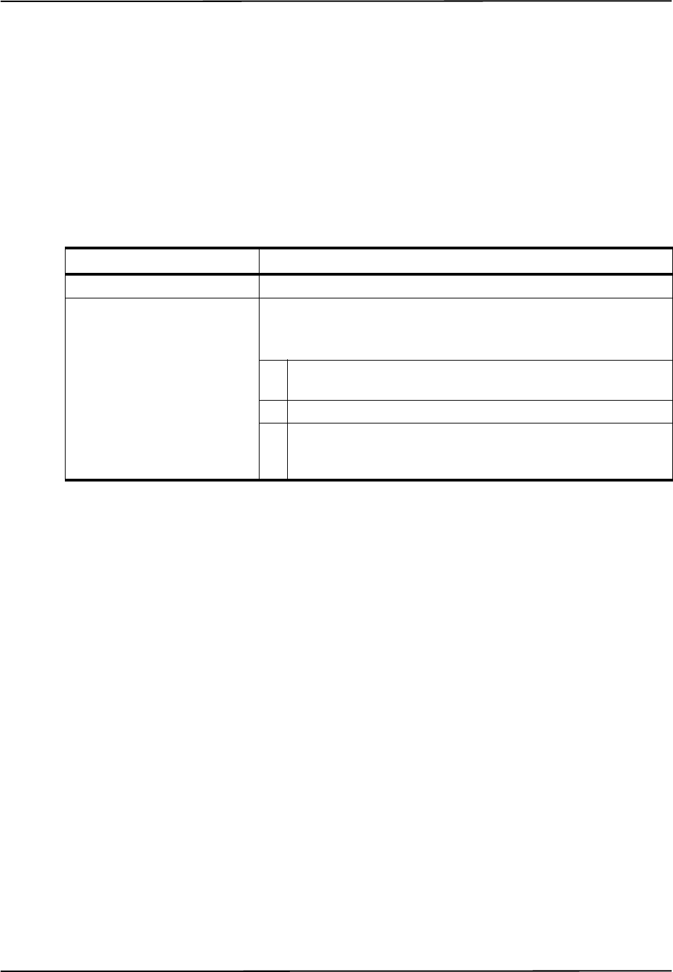
Command Details
Polaris Vega Application Program Interface Guide 91
PENA
Enables the reporting of transformations for a particular port handle.
Operating Mode
Setup
Syntax
PENA<SPACE><Port Handle><Tool Tracking Priority><CR>
Replies
Upon Success:
OKAY<CRC16><CR>
or
WARNING02<CRC16><CR> (Indicates that the tool you are trying to enable is a unique geometry tool
that doesn’t meet the unique geometry requirements.)
WARNING03<CRC16><CR> (Indicates that the tool you are trying to enable is a unique geometry tool
that conflicts with another unique geometry tool already loaded and enabled.)
WARNING04<CRC16><CR> (Indicates that the tool you are trying to enable is a unique geometry tool
that doesn’t meet the unique geometry requirements, and conflicts with another unique geometry
tool already loaded and enabled.)
WARNING05<CRC16><CR> (Returned when the system selects a default marker wavelength to track
a tool if the tool’s definition file did not specify a marker wavelength.)
On Error:
ERROR<Error Code><CRC16><CR>
See page 157 for error code definitions.
Parameter Description
Port Handle 2 hexadecimal characters
Tool Tracking Priority Describes the type of tool.
Valid Values:
S Static: a static tool is considered to be relatively immobile, e.g. a
reference tool.
D Dynamic: a dynamic tool is considered to be in motion, e.g. a probe.
B Button box: a button box can have and LEDs, but no markers. No
transformations are returned for a button box tool, but switch status
is returned.

Command Details
92 Polaris Vega Application Program Interface Guide
Usage Notes
1. The system does not make use of the tool tracking priority. You must still specify a value, but it
does not matter which tool tracking priority you choose.
2. When the PENA command is issued, the system compares the tool being enabled with currently
enabled tools for conflicting unique geometry constraints. This process is almost instantaneous.
If the tool doesn’t meet the unique geometry constraints, or conflicts with a tool that is already
enabled, the system will issue a WARNING02, WARNING03, or WARNING04.
3. The system will still enable the tool when the system returns WARNING02, WARNING03 or
WARNING04; however, the tool may not track properly since the unique geometry is
compromised.
4. For more information on unique geometry tools and unique geometry constraints, see the
Polaris Tool Design Guide.
Example
Command:
PENA 01D
Reply:
OKAYA896

Command Details
Polaris Vega Application Program Interface Guide 93
PFSEL
Sets which tool faces to use to track a multi-faced tool.
Operating Mode
Setup
Compatibility
All systems
Prerequisite Command
PINIT (page 107)
Syntax
PFSEL<SPACE><Port Handle><Face Selection Mask><CR>
Reply
OKAY<CRC16><CR>
Replies
Upon Success:
OKAY<CRC16><CR>
On Error:
ERROR<Error Code><CRC16><CR>
Usage Notes
1. When a tool is initialized, the face selection defaults to a value of 0xFF, so all faces are tracked
by default.
2. To include a tool face to be tracked, set the corresponding bit. For example, if you wish to track
faces 0 and 5, the face selection value is 0x21, as shown in the following table:
Parameter Description
Port Handle 2 hexadecimal characters
Face Selection 2 hexadecimal characters (8 bits)
Set the bits corresponding to the faces you wish to track.
Tool Face Number 76543210
Bit Value 00100001

Command Details
94 Polaris Vega Application Program Interface Guide
3. If the system returns error code 23, the face selection did not include any of the valid faces of the
selected tool.
Example
Command:
PFSEL 0121
Reply:
OKAYA896
Face Selection Hexadecimal Value 21

Command Details
Polaris Vega Application Program Interface Guide 95
PHF
Releases system resources from an unused port handle.
Operating Mode
Setup
Prerequisite Command
PHRQ (page 102)
Syntax
PHF<SPACE><Port Handle><CR>
Replies
Upon Success:
OKAY<CRC16><CR>
On Error:
ERROR<Error Code><CRC16><CR>
See page 157 for error code definitions.
Usage Notes
1. The PHF command should be used whenever a tool is disconnected. This optimizes the use of
system resources. If PHF is not used, the system will be unable to assign a port handle after the
maximum number of port handles has been reached.
2. If a tool is disconnected then reconnected, it is a assigned a new port handle. The old port handle
is no longer in use and should be freed using PHF.
Example
Command:
PHF 01
Reply:
OKAYA896
This frees port handle 01, so it is no longer assigned.
Parameter Description
Port Handle 2 hexadecimal characters

Command Details
96 Polaris Vega Application Program Interface Guide
PHINF
Returns port handle status, information about the tool associated with the port handle, and the
physical location of a port handle.
Operating Mode
All modes
Prerequisite Command
PHSR (page 104) or PHRQ (page 102)
Syntax
PHINF<SPACE><Port Handle><Reply Option><CR>
Replies
Upon Success:
If there is a tool assigned tool definition file to the port handle:
<Reply Option 0001 Data><Reply Option 0002 Data>...<Reply Option 0020
Data><CRC16><CR>
Parameter Description
G.003.002
Port
Handle
2 hexadecimal characters
Reply
Option
Optional. Specifies which information will be returned. If no reply
option is specified, the system returns information for reply option
0001.
The reply options are hexadecimal numbers that can be OR’d. If
multiple reply options are used, the replies are returned in order of
increasing option value.
Valid Values:
0001 Tool information (default) X
0002 Wired tool electrical information X
0004 Tool part number X
0008 Switch and visible LED information X
0010 Tool marker type and wavelength X
0020 Physical port location X

Command Details
Polaris Vega Application Program Interface Guide 97
Note The physical location of a port handle is the only information available unless PHINF has been preceded by PINIT
(page 107).
If no tool definition file is assigned to the port handle:
UNOCCUPIED<CRC16><CR>
On Error:
ERROR<Error Code><CRC16><CR>
See page 157 for error code definitions.
Reply Option 0001 - Tool Information
<Reply Option 0001 Data> = <Tool Type><Manufacturer’s ID><Tool
Revision><Serial Number><Port Status>
Reply Component Description
Tool Type 8 characters
<Tool Type> = <Main Type><Number of Switches><Number of
Visible LEDs><Reserved><Subtype>
Main Type 2 hexadecimal characters
Possible Values:
01 Reference
02 Probe
03 Button box or foot switch
04 Software-defined
05 Microscope tracker
06 Reserved
07 Calibration device
08 Tool Docking Station
09 Isolation box
0A C-arm tracker
0B Catheter
0D to FF Reserved
Number of
Switches
1 character
Number of
Visible LEDs
1 character
Reserved 2 characters
Subtype 2 characters
Manufacturer’s
ID
12 characters
Tool Revision 3 characters

Command Details
98 Polaris Vega Application Program Interface Guide
Reply Option 0002 - Wired Tool Electrical Information
You can test the electrical current of all the markers on a tool using TCTST (page 133).
Serial Number 8 hexadecimal characters (32 bits)
Bit field:
bits 0 to 9 Sequence number (one-based)
bits 10 to 18 Day of year (zero-based, e.g. Jan 1 is day 0 and Dec 31 is day
364)
bits 19 to 22 Month (zero-based)
bits 23 to 31 Year (year is <current year> - 1900, e.g. the year 2009 is 109)
Port Status 2 hexadecimal characters (8 bits)
Bit field:
bit 0 Tool-in-port
bit 1 Switch 1 closed
bit 2 Switch 2 closed
bit 3 Switch 3 closed
bit 4 Port initialized
bit 5 Port enabled
bit 6 Reserved
bit 7 Tool-in-port from current sensing
Reply Component Description
Reply Option 0002 Data 8 hexadecimal characters
Wired tool electrical information. The electrical current is tested for two
conditions: over and under. An “over” current condition indicates that
there is a short circuit in either the cable or the marker. An “under” cur-
rent condition indicates that there is either a break in the cable or the
marker has burnt out.
Bit field:
bits 0 to 19 Marker failed. Bit 0 = marker A, ..., bit 19 = marker T
bits 20 to 29 Reserved
bit 30 Under
bit 31 Over
Reply Component Description
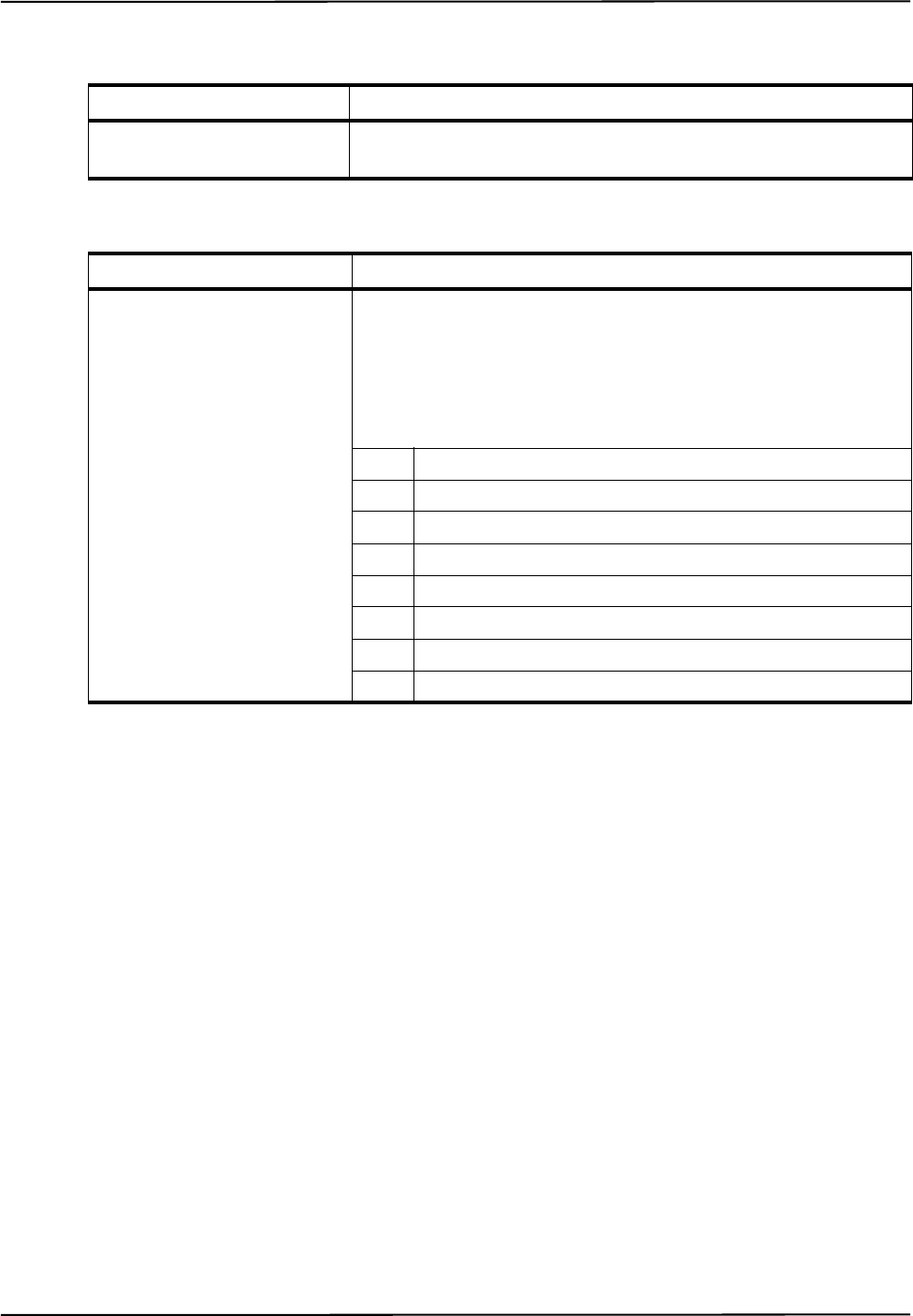
Command Details
Polaris Vega Application Program Interface Guide 99
Reply Option 0004 - Tool Part Number
Reply Option 0008 - Switch and Visible LED Information
Reply Component Description
Reply Option 0004 Data 20 characters
The part number of the tool.
Reply Component Description
Reply Option 0008 Data 2 hexadecimal characters (8 bits)
This option reports the information found in the tool description. It is not
information sensed by the hardware.
Bit field:
bit 0 Tool-in-port switch supported
bit 1 Switch 1 supported
bit 2 Switch 2 supported
bit 3 Switch 3 supported
bit 4 Tool tracking LED supported
bit 5 LED 1 line 1 supported
bit 6 LED 2 line 2 supported
bit 7 LED 3 line 3 supported

Command Details
100 Polaris Vega Application Program Interface Guide
Reply Option 0010 - Tool Marker Type and Wavelength
Reply Option 0020 - Physical Port Location
<Reply Option 0020 Data> = <Hardware Device><System Type><Tool Type>
<Port Number><Reserved>
Reply Component Description
G.003.002
Reply Option 0010
Data
2 hexadecimal characters (8 bits)
Bits 0 to 2 give information on the marker wavelength:
000 9x0 nm (See “Compatibility Notes” on
page 101.) X
001 880 nm X
010 930 nm X
100 870 nm X
111 850 nm
Bits 3 to 7 give information on the marker type:
00000 Reserved
00001 NDI active X
00010 NDI ceramic X
00011 Unknown active X
00100 Unknown passive X
00101 Passive sphere X
00110 Passive disc X
00111 NDI Radix X
01000 to
11111 Reserved
Reply Component Description
Hardware
Device
8 characters
For passive or active wireless tools this is the Position Sensor serial number.
For Polaris Vega active tools, this is STB-0.
System Type 1 character
Possible values:
Reserved

Command Details
Polaris Vega Application Program Interface Guide 101
Usage Notes
1. The physical location of a port handle is the only information available unless PHINF has been
preceded by PINIT (page 107) or PENA (page 91).
2. Port handles for tools that have been disconnected will be reported as UNOCCUPIED and no
additional information will be returned.
3. Reply option 0001: For wired tools, bits 1, 2, and 3 in the port status report status.
4. Reply option 0008: For wired tools, bits 1, 2, and 3 report status, and bits 5, 6, and 7 report LED
status.
Compatibility Notes
1. Reply option 0010: A value of 010 for marker wavelength can be returned only for tools
characterized using NDI 6D Architect version 2.02 or later. Tools characterized with earlier
versions of NDI 6D Architect will have a value of 000 for a marker wavelength of 930 nm.
2. Reply option 0040: This option is not supported by the hybrid Polaris Vega System.
Example
Command:
PHINF 040001
Reply:
Tool Type 1 character
Possible values:
0Wired
1 Wireless
Port Number 2 ASCII characters
Possible values:
01 to 03 Used for Polaris Vega wired tools
00 Used for Polaris Vega wireless tools
Reserved 2 characters
Reply Component Description
08000000NDI 00132C3D301110893
Tool Type
Serial Number
Tool Revision
Manufacturer's
ID
Port Status
CRC

Command Details
102 Polaris Vega Application Program Interface Guide
PHRQ
Assigns a port handle to a tool.
Operating Mode
Setup
Prerequisite Command
INIT (page 83)
Syntax
PHRQ<SPACE><Hardware Device><System Type><Tool Type><Port Number><Dummy
Tool><CR>
Parameter Description
Hardware
Device
8 characters
The hardware device must match the one returned by PHINF (page 96) reply option
0020, or use wild card characters (*). For active tools connected to the system, speci-
fying all wildcards will default to hardware device STB-0 (the tool ports on the Sys-
tem Control Unit).
System Type 1 character
Valid Values:
Use a wild card character (*).
Tool Type 1 character
This must be specified for wireless tools.
Valid Values:
0 or * Wired
1 Wireless (passive or active wireless)
Port Number 2 characters
The physical port number where a wired tool is plugged in. This must be specified for
wired tools.
Valid Values:
01 to 03 Used for hybrid Polaris Vega wired tools
00 or ** Used for wireless tools
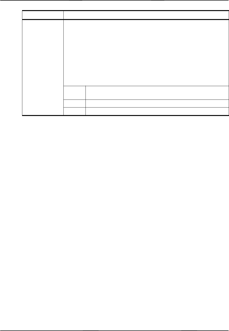
Command Details
Polaris Vega Application Program Interface Guide 103
Replies
Upon Success:
<Port Handle><CRC16><CR>
On Error:
ERROR<Error Code><CRC16><CR>
See page 157 for error code definitions.
Usage Notes
1. Use PHRQ to assign a port handle to a wireless tool or to a wired tool that has neither a tool-in-
port diode or a marker in position A of the tool wiring matrix. If a wired tool has a tool-in-port
diode or a marker in position A of the tool wiring matrix, use PHSR (page 104) to detect the tool
and assign it a port handle.
2. Wireless tools: You must specify the tool type. All other parameters may be left as wild card
characters (*).
3. Wired tools: You must specify the port number. All other parameters may be left as wild card
characters (*).
4. After using PHRQ, you must use PVWR (page 116) to assign a tool definition file to the tool. If
you do not assign a tool definition file to the tool, the port handle will be reported as unoccupied
when it is initialized with PINIT (page 107) or PENA (page 91).
Example
Command:
PHRQ *********1****
Reply:
04D715
This requests a port handle for a wireless tool.
Dummy Tool 2 characters
If specified, will auto-generate a non-trackable dummy tool. Useful for 3D stray-
marker tracking.
In the case of Tool Type = Wired, either 01 or 02 adds an active wired dummy tool.
Otherwise, In case of Tool Type = Wireless:
Valid Values:
** Do not load a dummy tool. Requires tool definition to be loaded with sub-
sequent PVWR (page 116) commands.
01 adds passive dummy tool
02 adds active wireless dummy tool
Parameter Description

Command Details
104 Polaris Vega Application Program Interface Guide
PHSR
Returns the number of assigned port handles and the port status for each one. Assigns a port handle
to a wired tool.
Operating Mode
All modes
Prerequisite Command
INIT (page 83)
Syntax
PHSR<SPACE><Reply Option><CR>
Replies
Upon Success:
<Number of Port Handles>
<1st Port Handle><1st Port Handle Status>
<2nd Port Handle><2nd Port Handle Status>
...
<nth Port Handle><nth Port Handle Status>
<CRC16><CR>
On Error:
ERROR<Error Code><CRC16><CR>
See page 157 for error code definitions
Parameter Description
Reply Option Specifies which information will be returned. If no reply option is specified, the system
returns information for reply option 00.
The reply options cannot be OR’d.
Valid Values:
00 Reports all allocated port handles (default)
01 Reports port handles that need to be freed
02 Reports port handles that are occupied, but not initialized or enabled
03 Reports port handles that are occupied and initialized, but not enabled
04 Reports enabled port handles

Command Details
Polaris Vega Application Program Interface Guide 105
Usage Notes
1. When you send the PHSR command, the system will detect and assign port handles to any wired
tools that do not already have a port handle assigned (i.e. any wired tools that were plugged in
after the last PHSR call). It will then return the requested port handle information.
2. The system will detect a wired tool if the tool has a tool-in-port diode, or a marker in position A
of the tool wiring matrix. If you are using a wired tool that does not meet this criteria, you will
need to request a port handle for the tool using PHRQ.
3. If you unplug a wired tool while the system is in tracking mode, the port handle will be reported
as “disabled” in the replies to the BX and TX commands. If you reconnect the tool, it will need
a new port handle.
4. If you connect a wired tool to the system while the system is in tracking mode, you will have to
take the following steps before the system will report the tool:
a) Exit tracking mode (TSTOP).
b) Assign, initialize, and enable a port handle for the tool as outlined in Figure 3-1 on page 18.
c) Re-enter tracking mode (TSTART).
Reply Component Description
Number of Port Handles 2 hexadecimal characters
The number of allocated port handles of the type specified in the reply
option. If no reply option is specified, the number returned is the total
number of allocated port handles.
nth Port Handle 2 hexadecimal characters
Specifies the port handle whose status follows.
nth Port Handle Status 3 hexadecimal characters (12 bits)
Bit field:
bit 0 Occupied
bit 1 Switch 1 closed
bit 2 Switch 2 closed
bit 3 Switch 3 closed
bit 4 Initialized
bit 5 Enabled
bit 6 Reserved
bit 7 Tool detected from current sensing
bit 8 to 11 Reserved

Command Details
106 Polaris Vega Application Program Interface Guide
5. PHSR will report wireless tool ports as unoccupied if you have requested a port handle using
PHRQ (page 102) but have not yet associated a tool definition file for the port handle (using
PVWR (page 116)).
6. To obtain a port handle for a wireless tool, use PHRQ.
7. PHSR will only return the number of assigned port handles and their status when executed in
tracking or diagnostic mode from a master connection, or when executed in any mode from a
monitor connection.
Examples
Command:
PHSR
Reply:
001414
In this case, there are no occupied port handles.
Command:
PHSR
Reply:
0101031F1AF
In this case, there is one occupied port handle, which is initialized and enabled.

Command Details
Polaris Vega Application Program Interface Guide 107
PINIT
Initializes a port handle.
Deprecated
Operating Mode
Setup
Prerequisite Command
PVWR (page 116) or PHSR (page 104)
Syntax
PINIT<SPACE><Port Handle><CR>
Replies
Upon Success:
OKAY<CRC16><CR>
or
WARNING (Indicates that a non-fatal tool error has been encountered, e.g. a burnt out marker.)
or
WARNING05 is returned when the system selects a default marker wavelength to track a tool (if the
tool’s tool definition file did not specify a marker wavelength).
On Error:
ERROR<Error Code><CRC16><CR>
See page 157 for error code definitions.
Usage Notes
1. PENA now initializes tools that have not been initialized with PINIT. Therefore, it is no longer
necessary to use PINIT.
2. If the tool description is drawn from a tool definition file that has been loaded using PVWR
(page 116), initialization involves unpacking and verifying the tool definition file. This process
is almost instantaneous.
3. If the tool description is drawn from an SROM device, initialization involves reading,
unpacking, and verifying the tool definition file contents, and testing electrical current through
all the markers to detect burnt out markers. This process takes approximately two seconds if
successful, or several seconds longer if a problem is encountered and retries are attempted by
the system.
Parameter Description
Port Handle 2 hexadecimal characters

Command Details
108 Polaris Vega Application Program Interface Guide
4. The port handle will still initialize when the system returns WARNING. or WARNING05.
5. The SCU will load and parse active tool info when a tool is plugged in. PENA will load and
parse passive tool info if not done so yet.
Example
Command:
PINIT 01
Reply:
OKAYA896
This initializes port handle 01.

Command Details
Polaris Vega Application Program Interface Guide 109
PPRD
Reads data from the SROM device in a wired tool.
Operating Mode
Setup
Prerequisite Command
INIT (page 83)
Syntax
PPRD<SPACE><Port Handle><SROM Device Address><CR>
Replies
Upon Success:
<SROM Device Data><CRC16><CR>
The SROM device data is 64 bytes (128 hexadecimal characters) of data.
On Error:
ERROR<Error Code><CRC16><CR>
See page 157 for error code definitions.
Usage Notes
1. The SROM device is a 2-KB write-once device that must be read in 64-byte chunks. An SROM
device is considered blank if its contents are all 0xFFs.
2. PPRD reads 64 bytes of data from the SROM device starting at a specified SROM device
address.
Example
Command:
PPRD 010000
Reply:
0123456789ABCDEF0123456789ABCDEF0123456789ABCDEF0123456789ABCDEF012345678
9ABCDEF0123456789ABCDEF0123456789ABCDEF0123456789ABCDEF66A5
Parameter Description
Port Handle 2 hexadecimal characters
SROM Device Address 4 hexadecimal characters
Valid Values:
0x0000 to 0x07C0

Command Details
110 Polaris Vega Application Program Interface Guide
PPWR
Writes data to the SROM device in a wired tool.
Operating Mode
Setup
Prerequisite Command
INIT (page 83)
Syntax
PPWR<SPACE><Port Handle><SROM Device Address><SROM Device Data><CR>
Replies
Command:
OKAY<CRC16><CR>
On Error:
ERROR<Error Code><CRC16><CR>
See page 157 for error code definitions.
Usage Notes
1. PPWR writes 64 bytes of data to the SROM device starting at a specified SROM device address.
2. The data must be formatted into unsigned ASCII characters. Each byte of binary data can be
represented by two hexadecimal characters, which are then sent to the system in ASCII (4 bits
per ASCII character).
3. The tool description section of tool SROM device is a 1-Kbyte, write-once area that must be
written in 64-byte chunks. If the information being written to the system is less than 64 bytes in
size, then the remainder of the chunk must be padded out with ones to maintain the 64-byte size
before being written to the system. To write to the second 1-Kbyte section, use the PUWR
command.
4. An SROM device is considered blank if its contents are all 0xFFs.
5. The recommended procedure to follow for updating an SROM device is:
Parameter Description
Port Handle 2 hexadecimal characters
SROM Device Address 4 hexadecimal characters
Valid values:
0x0000 to 0x07C0
SROM Device Data 64 bytes (128 hexadecimal characters) of data

Command Details
Polaris Vega Application Program Interface Guide 111
a) Read the contents of the SROM device using PPRD (page 109).
b) Modify the data.
c) Write the modified data back to the SROM device using PPWR (page 110).
Example
Command:
PPWR 0100C000000000000000000000000000000000000000000000000000000000000000
0000000000000000000000000000000000000000000000000000000000000000009731
Reply:
OKAYA896

Command Details
112 Polaris Vega Application Program Interface Guide
PURD
Reads data from the user section of the SROM device in a wired tool.
Operating Mode
All modes
Prerequisite Command
INIT (page 83)
Syntax
PURD<SPACE><Port Handle><User SROM Device Address><CR>
Replies
Upon Success:
<SROM Device Data><CRC16><CR>
The SROM device data is 64 bytes (128 hexadecimal characters) of data.
On Error:
ERROR<Error Code><CRC16><CR>
See page 157 for error code definitions.
Usage Notes
1. The SROM device is automatically selected as the reading target when this command is issued,
so you do not need to find and specify the SROM device ID. The SROM device address has an
implied offset in the command which places the user information at the correct SROM device
address.
2. The PURD command returns 64 bytes of data at a time.
Example
Command:
PURD:010000
Parameter Description
Port Handle 2 hexadecimal characters
User SROM Device Address 4 hexadecimal characters
Valid values:
0x0000 to 0x03C0

Command Details
Polaris Vega Application Program Interface Guide 113
Reply:
0022446688AACCEE0022446688AACCEE0022446688AACCEE0022446688AACCEE002244668
8AACCEE0022446688AACCEE0022446688AACCEE0022446688AACCEE3CC0

Command Details
114 Polaris Vega Application Program Interface Guide
PUWR
Writes data to the user section of the SROM device in a wired tool.
Operating Mode
Setup
Prerequisite Command
INIT (page 83)
Syntax
PUWR<SPACE><Port Handle><User SROM device address><User SROM device
Data><CR>
Replies
Upon Success:
OKAY<CRC16><CR>
On Error:
ERROR<Error Code><CRC16><CR>
See page 157 for error code definitions.
Usage Notes
1. The SROM device is automatically selected as the reading target when this command is issued,
so you do not need to find and specify the SROM device ID. The SROM device address has an
implied offset in the command which places the user information at the correct SROM device
address.
2. The data must be formatted into unsigned ASCII characters. Each byte of binary data can be
represented by two hexadecimal characters, which are then sent to the system in ASCII (4 bits
per ASCII character).
3. The user section of SROM devices is a 1-Kbyte, write-once area that must be written in 64-byte
chunks. If the information being written to the system is less than 64 bytes in size, then the
remainder of the chunk must be padded out with ones to maintain the 64-byte size before being
written to the system.
Parameter Description
Port Handle 2 hexadecimal characters
User SROM device address 4 hexadecimal characters
Valid values:
0x0000 to 0x03C0
User SROM device data 64 bytes of data to write (128 hexadecimal characters)

Command Details
Polaris Vega Application Program Interface Guide 115
4. The recommended procedure to follow for updating an SROM device is outlined below:
a) Read the contents of the SROM device using PURD (page 112).
b) Modify the data read.
c) Write the modified data back to the SROM device using PUWR.
Example
Command:
PUWR 01008000000000000000000000000000000000000000000000000000000000000000
00000000000000000000000000000000000000000000000000000000000000000A927
Reply:
OKAYA896

Command Details
116 Polaris Vega Application Program Interface Guide
PVWR
Assigns a tool definition file to a wireless tool, or overrides the SROM device in a wired tool.
Operating Mode
Setup
Prerequisite Command
PHRQ (page 102) or PHSR (page 104)
Syntax
PVWR<SPACE><Port Handle><Start Address><Tool Definition File Data><CR>
Replies
Upon Success:
OKAY<CRC16><CR>
On Error:
ERROR<Error Code><CRC16><CR>
See page 157 for error code definitions.
Usage Notes
1. Use PVWR
• To assign a tool definition file to a wireless tool after using PHRQ.
• To assign a tool definition file to a wired tool, to override the SROM device in the tool.
• To assign a tool definition file to a wired tool, to test the tool definition file before
permanently recording the tool definition file onto the SROM device.
2. The data must be formatted into unsigned ASCII characters. Each byte of binary data can be
represented by two hexadecimal characters, which are then sent to the system in ASCII (4 bits
per ASCII character.
Parameter Description
Port Handle 2 hexadecimal characters
Start Address 4 hexadecimal characters
Increment the start address by 64 bytes with each chunk of data sent
for a particular port handle.
Valid values:
0x0000 to 0x3FC0
Tool Definition Data 64 bytes (128 hexadecimal characters) of data

Command Details
Polaris Vega Application Program Interface Guide 117
3. Data is sent to the system in 64-byte chunks (128 hexadecimal characters). The last chunk must
be padded out with zeroes to maintain the 64-byte size before being written to the system.
4. If a wireless tool port is the target of this command, the port becomes occupied when the first 64
bytes of information is written. Any previous initialization for the port is lost.
5. Use PVWR to assign a tool definition file to a wireless tool after using PHRQ (page 102).
6. After using PVWR, enable (PENA) the port handle in order to track the tool.
7. To permanently write a tool definition file to an SROM device, use PPWR (page 110).
Example
Command:
PVWR 0200004E444900551C000001000000000000010100000001A419335A000000030000
000300000000000040000000000000000000000000000000000000000000000000
Reply:
OKAYA896
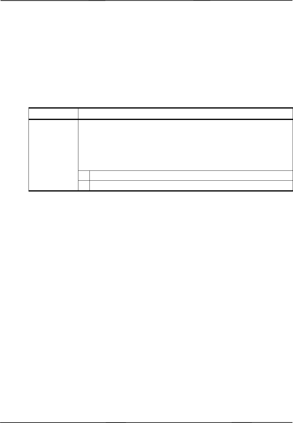
Command Details
118 Polaris Vega Application Program Interface Guide
RESET
Resets the system.
Operating Mode
All modes
Syntax
RESET<SPACE><Reset Option><CR>
Replies
Upon Success:
RESET<CRC16><CR>
On Error:
ERROR<Error Code><CRC16><CR>
See page 157 for error code definitions.
Example
Command:
RESET 0
Reply:
RESETBE6F
Parameter Description
Reset Option Optional. Specifies the type of reset. If no reset option is specified, the system performs
a RESET 0.
The reset options cannot be OR’d.
Valid Values:
0 Generates a soft reset. Does not power cycle the Position Sensor.
1 Performs a board-level reset of all hardware devices.

Command Details
Polaris Vega Application Program Interface Guide 119
SAVE
Saves all non-volatile user parameters that have been changed.
Operating Mode
All modes
Syntax
SAVE<SPACE><CR>
Replies
Upon Success:
OKAY<CRC16><CR>
On Error:
ERROR<Error Code><CRC16><CR>
See page 157 for error code definitions.
Usage Notes
1. To restore the user parameters to factory default values, use the DFLT (page 73) command. To
save the user parameters at their factory default values, use the SAVE command after using the
DFLT command.
2. On systems that have the Password Protect keyed feature enabled, user parameters can only be
saved after the correct password is entered. To enter the password, use SET Config.Password=
<password>, where <password> is the correct password. For more information on the
Password Protect keyed feature, see the user guide that accompanied the system.
3. To set user parameter values, use the SET (page 120) command.
4. For more information on user parameters, see “User Parameters” on page 20.
Example
Command:
SAVE
Reply:
OKAYA896

Command Details
120 Polaris Vega Application Program Interface Guide
SET
Sets user parameter values.
Operating Mode
All modes
Syntax
SET<SPACE><User Parameter Name>=<Value><CR>
Replies
Upon Success:
OKAY<CRC16><CR>
On Error:
ERROR<Error Code><CRC16><CR>
See page 157 for error code definitions.
Usage Notes
1. To view a list of user parameters and their current values, use GET *. For a description of the
user parameters, use GETINFO *.
2. The user parameter values set using the SET command persist until the system is reset or
initialized. To save the user parameter values, use SAVE (page 119). To reset user parameters to
their default values, use DFLT (page 73).
3. User parameter names are case-sensitive.
4. For more information on user parameters, see “User Parameters” on page 20
Example
Command:
SET Param.Tracking.Sensitivity=1
Reply:
OKAYA896
This sets the infrared light sensitivity level to level 1 on the first Position Sensor in the
configuration.
Parameter Description
User Parameter
Name
A case-sensitive string, identifying the name of the user parameter.
Value The value to set.
Numerical values are decimal unless preceded by 0x. For boolean values, 1 is true
and 0 is false.

Command Details
Polaris Vega Application Program Interface Guide 121
SFLIST
Returns information about the supported features of the system.
Deprecated
Operating Mode
Setup, diagnostics or tracking
Syntax
SFLIST<SPACE><Reply Option><CR>
The reply options cannot be OR’d.
Replies
Upon Success:
<Reply Option n Data><CRC16><CR>
On Error:
ERROR<Error Code><CRC16><CR>
See page 157 for error code definitions.
Parameter Description
G.003.002
Reply Option Specifies which information will be returned.
The reply options cannot be OR'd.
Valid values:
X
00 Summary of supported features X
01 Number of active tool ports X
02 Number of wireless tool ports X
03 Number of measurement volumes and wavelengths; vol-
ume shapes and supported wavelengths X
04 The number of wired tool ports available which support
tool-in-port detection from current sensing X
05 Number of active wireless tools X

Command Details
122 Polaris Vega Application Program Interface Guide
Reply Option 00 - Supported Features Summary
Reply Option 01 - Number of Active Tool Ports
Reply Component Description
Reply Option n Data The data specific to the requested reply option. See the reply option informa-
tion below for details:
Reply option 00 (Summary of supported features)
Reply option 01 (Number of active tool ports)
Reply option 02 (Number of wireless tool ports)
Reply option 03 (Number of characterized measurement volumes and wave-
lengths; volume shapes and supported wavelength)
Reply option 04 (The number of wired tool ports available which support
tool-in-port detection from current sensing)
Reply option 05 (Number of active wireless tools)
Reply Component Description
Reply Option 00 Data 8 hexadecimal characters (32 bits)
Bit field:
bit 0 Active tool ports available
bit 1 Passive tool ports available
bit 2 Multiple volume characterization parameters supported
bit 3 Tool-in-port from current sensing available
bit 4 Active wireless tool ports available
bit 5 Reserved
bits 7 to 31 Reserved
Reply Component Description
Reply Option 01 Data 1 hexadecimal character
The number of wired tool ports.

Command Details
Polaris Vega Application Program Interface Guide 123
Reply Option 02 - Number of Wireless Tool Ports
Reply Component Description
Reply Option 02 Data 1 hexadecimal character
The number of wireless tool ports, up to a maximum of 15 (the highest num-
ber that can be represented in one hexadecimal digit).
To find out the actual number of wireless tool ports, read the parameters
Features.Tools.Passive Ports (for passive wireless)
and Features.Tools.Wireless Ports (for active wireless).

Command Details
124 Polaris Vega Application Program Interface Guide
Reply Option 03 - Volumes
Note Because SFLIST is deprecated, the Volume User Parameters on page 37 should be used instead.
<Reply Option 03 Data> =
<Number of Volumes>
<1st Shape Type><1st Shape Parameter><1st Number of Wavelengths
Supported><1st Supported Wavelengths><LF>
...
<nth Shape Type><nth Shape Parameter><nth Number of Wavelengths
Supported><nth Supported Wavelengths><LF>
Reply Option 04 - Number of Active Tool Ports Supporting Tool-in-Port Detection From Current Sensing
Reply Option 05 - Number of Active Wireless Ports
Reply Component Description
Number of Volumes 1 hexadecimal character
nth Shape Type 1 hexadecimal character
Possible values:
5 Extended Pyramid Shape
The volumes are named “Pyramid”, “Extended Pyramid”
7Arc Shape
The volume name is “Vicra”
nth Shape Parameter 10 parameters, 7 characters each (a sign, and six digits with an
implied decimal in the position XXXX . XX)
nth Number of Wavelengths
Supported
1 hexadecimal character
nth Supported Wavelengths 1 character per wavelength supported
Possible values:
0 930 nm (see “Usage Notes” on page 127)
1 880 nm
4 870 nm
7 850 nm
Reply Component Description
Reply Option 04 Data 1 hexadecimal character
Reply Component Description
Reply Option 05 Data 1 hexadecimal character

Command Details
Polaris Vega Application Program Interface Guide 125
Polaris Vega System - Shape Parameters
Note Because SFLIST is deprecated, the Volume User Parameters on page 37 should be used instead.
For the pyramid measurement volume, <Shape Parameter> in reply option 03 returns the following
values (illustrated in Figure 5-2):
Shape Parameter Value Description
D1 -2400 mm z-coordinate of back of volume
D2 -1532 mm z-coordinate where sides of volume change slope
D3 -950 mm z-coordinate of front of volume
D4 572 mm Half width of volume at z = D2
D5 398 mm Half height of volume z = D2
D6 0569.46 Slope of front part of volume sides in the yz-plane (scaled by 1000)
D7 0243.03 Slope of back part of volume sides in the yz-plane (scaled by 1000)
D8 0297.73 Slope of volume top and bottom in the xz-plane (scaled by 1000)
D9 9999.99 mm Maximum half width of volume (unrestricted)
D10 9999.99 mm Maximum half height of volume (unrestricted)
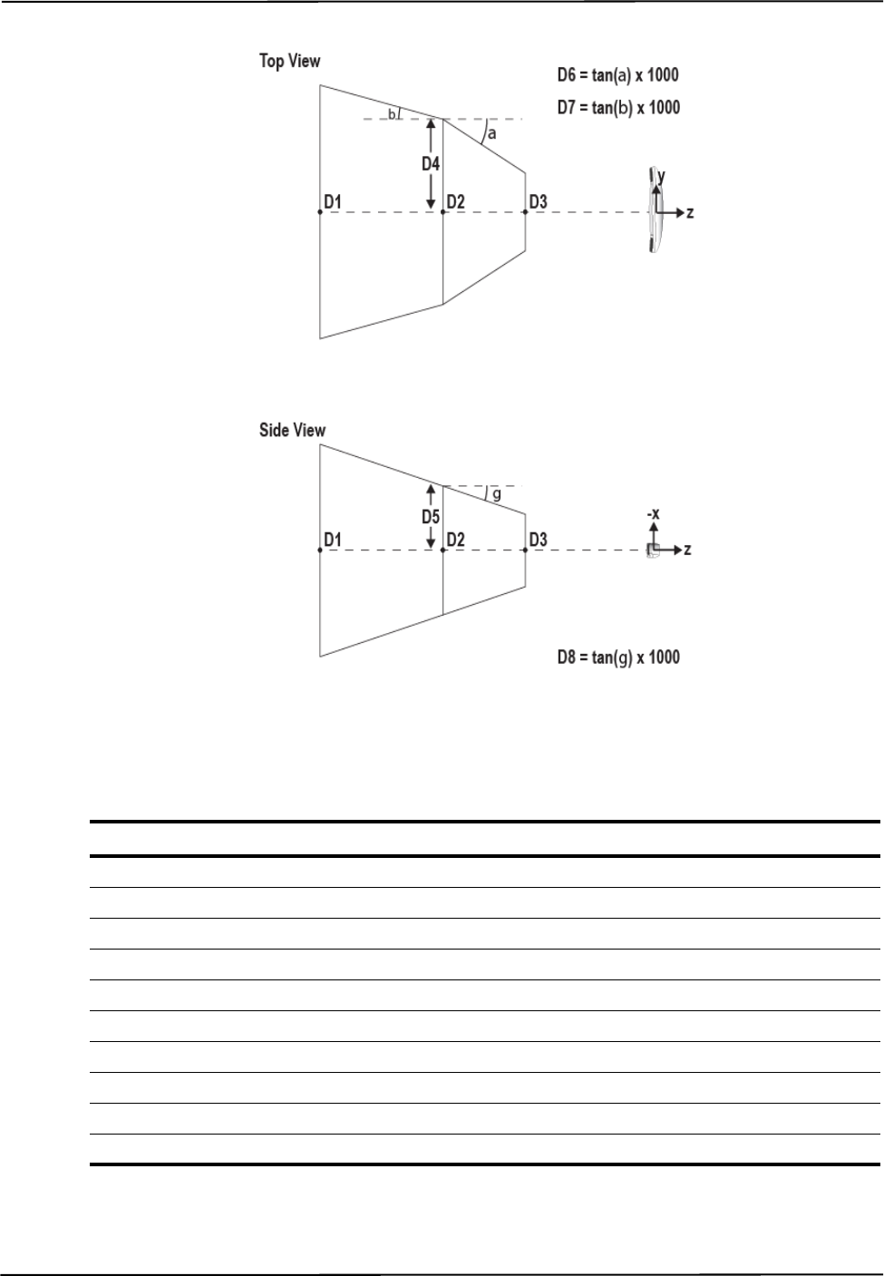
Command Details
126 Polaris Vega Application Program Interface Guide
Figure 5-2 Pyramid Volume Parameters (Polaris Vega)
For the extended pyramid measurement volume, <Shape Parameter> in reply option 03 returns the
following values (illustrated in Figure 5-2 and Figure 5-3):
Shape Parameter Value Description
D1 -3000 mm z-coordinate of back of volume
D2 -1532 mm z-coordinate where sides of volume change slope
D3 -950 mm z-coordinate of front of volume
D4 572 mm Half width of volume at z = D2
D5 398 mm Half height of volume z = D2
D6 0569.46 Slope of front part of volume sides in the yz-plane (scaled by 1000)
D7 0243.03 Slope of back part of volume sides in the yz-plane (scaled by 1000)
D8 0297.73 Slope of volume top and bottom in the xz-plane (scaled by 1000)
D9 9999.99 mm Maximum half width of volume (unrestricted)
D10 735 mm Maximum half height of volume
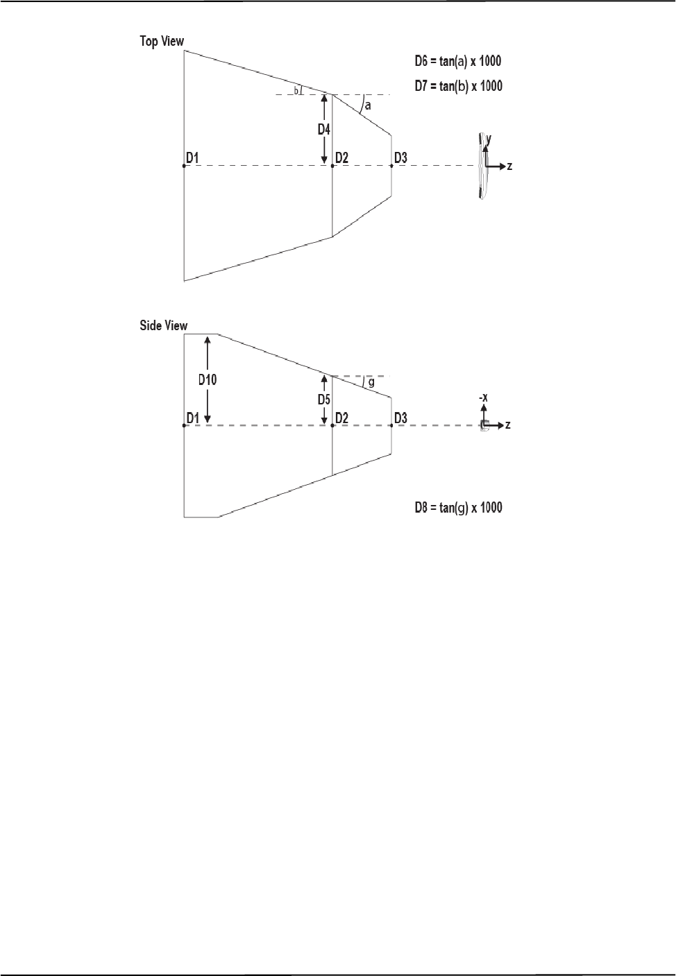
Command Details
Polaris Vega Application Program Interface Guide 127
Figure 5-3 Extended Pyramid Volume Parameters (Polaris Vega)
Usage Notes
1. Use both the shape type and the shape parameters to represent the characterized measurement
volume graphically. There may be multiple volumes with the same shape type. All volumes of
the same shape type use the shape parameters the same way.
2. Reply option 03: A characterized measurement volume that supports wavelength value 0
(930 nm) supports the wavelength values of 000 (9x0 nm) and 010 (930 nm) returned with
PHINF (page 96).
Examples
Command:
SFLIST
Reply:
0000003FEEEC
Command:
SFLIST 03

Command Details
128 Polaris Vega Application Program Interface Guide
Reply:
17+010000+058200+109900+019400+000000+000000+000000-083000+050600-055700241D837
Number of Volumes
D2
D1
Shape Type
D3
D4
# of Wavelengths
Wavelength
D10
D6
D8
D7
D9
D5
CRC

Command Details
Polaris Vega Application Program Interface Guide 129
STREAM
Initiates a streaming response to a command
Operating Mode
All modes
Syntax
STREAM<SPACE><Parameter><CR>
Replies
Upon Success:
OKAY<CRC16><CR>
On Error:
ERROR<Error Code><CRC16><CR>
See page 157 for error code definitions.
Note The response is binary and is similar to the BX binary response with a different header signature. In order to
maintain compatibility with the serial protocol, all binary replies are in little endian format rather than network
byte order. The header signature is a 2 byte little endian code. The first byte is 0xD4 the second byte is 0xB5.
B5D4<Stream ID Length(2 bytes)><Stream ID><Header CRC16><command reply>
<command reply> is the unmodified reply for the command that is being streamed exactly as it would
appear if the command were given separately without streaming.
Usage Notes
For details on data streaming format see “Data Streaming” on page 8.
Parameter Description
[--id=<id string>]--id=<id string> is an optional id string that will be returned in the
stream response header. If it contains spaces it must be quoted. If it is omit-
ted the command string will be used as the id. ids must be unique to the
given connection.
[--interval=<frame
count>]--interval=<frame count> is an integer frame count interval that will be
used to limit the response rate.
[--diff=true] --diff=true when present indicates that only the differences between the
current response and the last streamed response will be sent. At present this
option is valid for ascii responses to commands such as GET and
GETINFO.
[--cmd=]<command to
stream>
<command to stream> is the command string exactly as it would be if
issued separately. For consistency and flexibility it is also possible to spec-
ify the command using option --cmd=<command to stream>

Command Details
130 Polaris Vega Application Program Interface Guide
Example
Command:
STREAM BX 0803
Reply:
OKAYA896
The following would continue with updated data replies until USTREAM is issued
B5D40700BX 08031234A5C4....
B5D40700BX 08031234A5C4....
B5D40700BX 08031234A5C4....
B5D40700BX 08031234A5C4....
B5D40700BX 08031234A5C4....
B5D40700BX 08031234A5C4....
B5D40700BX 08031234A5C4....
B5D40700BX 08031234A5C4....
B5D40700BX 08031234A5C4....
...

Command Details
Polaris Vega Application Program Interface Guide 131
SYSLOG
Writes data to the Position Sensor or System Control Unit log file.
Operating Mode
All modes
Syntax
SYSLOG<SPACE>\<Device Name>\<Category>=<Message><CR>
or
SYSLOG<SPACE><Category>=<Message><CR>
Replies
Upon Success:
OKAY<CRC16><CR>
On Error:
ERROR<Error Code><CRC16><CR>
See page 157 for error code definitions.
Usage Notes
1. The system log in each hardware device is intended to record events central to the life of the
device. The system automatically records events such as updates, bump sensor events, and
hardware faults in the log.
2. To read the log, use GETLOG (page 81).
Compatibility Notes
For passive systems, only the Position Sensor log file is available.
Parameter Description
Device
Name
Selects a hardware device to write to. See “Device Names” on page 21 for information on
device names. The device name is ignored if it is specified.
Category A string, up to 12 characters
Specifies the log entry category or source. If you enter more than 12 characters, the system
will truncate the category to 12 characters.
Message A string, up to 256 characters.
Contains the log message. If you enter more than 256 characters, the system will truncate the
message to 256 characters.

Command Details
132 Polaris Vega Application Program Interface Guide
Example
Command:
SYSLOG Test=This is a SYSLOG test!
Reply:
OKAYA896

Command Details
Polaris Vega Application Program Interface Guide 133
TCTST
Returns diagnostics on the active markers of a wired tool.
Operating Mode
Setup
Prerequisite Command
PINIT (page 107)
Syntax
TCTST<SPACE><Port Handle><CR>
Replies
Upon success:
<Marker A Current><Marker B Current>...<Marker T Current><CRC16><CR>
On Error:
ERROR<Error Code><CRC16><CR>
See page 157 for error code definitions.
Usage Notes
1. If the result is less than 0x0A either there is no marker, or there is a problem with the diode that
has caused an open circuit.
2. If the result is greater than 0x0A the marker is either okay or it has short-circuited. The exact
value cannot be predicted as it depends upon the System Control Unit and the tool design (cable
length, number of markers, and marker configuration). This value should be determined on a
historical basis for each particular tool design.
3. You cannot test a visible LED, since the System Control Unit cannot reliably test the low current
of an LED because the LED current result may be corrupted from electrical noise.
Parameter Description
Port Handle 2 hexadecimal characters
Reply Component Description
Marker n Current 2 hexadecimal characters
The electrical current of the markers.

Command Details
134 Polaris Vega Application Program Interface Guide
Example
Command:
TCTST 01
Reply:
9400000000940100000092000000009400000000DF24

Command Details
Polaris Vega Application Program Interface Guide 135
TSTART
Starts Tracking mode.
Operating Mode
Setup
Prerequisite Command
INIT (page 83)
Syntax
TSTART<SPACE><Reply Option><CR>
Replies
Upon Success:
OKAY<CRC16><CR>
On Error:
ERROR<Error Code><CRC16><CR>
See page 157 for error code definitions.
Usage Notes
The frame number is reported in reply option 0001 of the TX (page 138) and BX (page 49)
commands. In the Polaris Vega System, the frame number is derived from the PTP time, and reply
option 80 is ignored.
In order to facilitate the retrieval of tracking data in a monitor connection, TSTART will return
OKAY when in tracking mode.
Example
Command:
TSTART
Reply:
OKAYA896
Parameter Description
Reply Option 80 (Optional)

Command Details
136 Polaris Vega Application Program Interface Guide
TSTOP
Stops tracking mode.
Operating Mode
Tracking
Prerequisite Command
TSTART (page 135)
Syntax
TSTOP<SPACE><CR>
Replies
Upon Success:
OKAY<CRC16><CR>
On Error:
ERROR<Error Code><CRC16><CR>
See page 157 for error code definitions.
Usage Notes
If executed from the Setup mode, it will return OKAY.
Example
Command:
TSTOP
Reply:
OKAYA896

Command Details
Polaris Vega Application Program Interface Guide 137
TTCFG
Sets up a configuration for a wired tool, so that you can test the tool without using a tool definition
file.
Operating Mode
Setup
Prerequisite Command
INIT (page 83)
Syntax
TTCFG<SPACE><Port Handle><CR>
Replies
Upon Success:
OKAY<CRC16><CR>
On Error:
ERROR<Error Code><CRC16><CR>
See page 157 for error code definitions.
Usage Notes
1. TTCFG internally sets up a test configuration for a wired tool, so that it can be tested without
having a tool definition file. This is useful for testing the wiring in the tool before characterizing
the tool. For example, after sending TTCFG, you can:
•use TCTST to test the current
• in diagnostic mode, use IRED to individually activate the markers.
2. After sending the TTCFG command, you will need to enable (PENA) the port handle before
using any other commands that list these as prerequisites.
3. With the test configuration, the tool cannot be tracked.
Example
Command:
TTCFG 0A
Reply:
OKAYA896
Parameter Description
Port Handle 2 hexadecimal characters

Command Details
138 Polaris Vega Application Program Interface Guide
TX
Returns the latest tool transformations, individual marker positions, and system status in text format.
Operating Mode
Tracking
Syntax
TX<SPACE><Reply Option><CR>
Replies
Upon Success:
<# of Handles><Handle 1><Reply Opt 0001 Data>...<Reply Opt 0008 Data><LF>
...
<Handle n><Reply Option 0001 Data>...<Reply Option 0008 Data><LF>
<Reply Option 1000 Data><System Status><CRC16><CR>
Note If the port handle is disabled, the system returns the string DISABLED instead of
<Reply Option 0001 Data>...<Reply Option 0008 Data>.
On Error:
ERROR<Error Code><CRC16><CR>
Parameter Description
G.003.002
Reply
Option
Optional. Specifies which information will be returned. If no reply option
is specified, the system returns information for reply option 0001.
The reply options are hexadecimal numbers that can be OR’d. If multiple
reply options are used, the replies are returned for each port handle in
order of increasing option value, with the following exceptions:
Reply option 0800 is not reported separately from the other options; it sim-
ply enables the system to return certain information in the other options.
Reply option 1000 is reported after all handle-specific options but before
the <system status> and <CRC16>.
Valid Values:
0001 Transformation data (default) X
0002 Tool and marker information X
0004 3D position of a single stray active marker X
0008 3D positions of markers on tools X
0800 Transformations not normally reported X
1000 3D positions of stray passive markers X

Command Details
Polaris Vega Application Program Interface Guide 139
See page 157 for error code definitions.
Note The “diagnostic pending” bit is set whenever an alert is detected or cleared. To view the alerts status and clear
the diagnostic pending bit, use GET (page 77) to check the Info.Status.New Alerts user parameter for every
Reply
Component Description
G.003.002
Number of
Handles
2 hexadecimal characters
The number of port handles for which information is returned.
X
Handle n 2 hexadecimal characters
The port handle whose information follows.
X
Reply
Option m
Data
The data specific to the requested reply option. See the reply
option information below for details:
Reply option 0001 (transformation data) (default) X
Reply option 0002 (tool and marker information) X
Reply option 0004 (latest 3D position of single, stray, active
marker) X
Reply option 0008 (3D position of markers on tools) X
Reply option 0800 (reporting all transformations) X
Reply option 1000 (3D position of stray passive markers) X
System
Status
4 hexadecimal characters (16 bits)
The status of the system.
Bit field:
bit 0 System communication synchronization error X
bits 1 and 2 Reserved
bit 3 Recoverable system processing exception. X
bit 4-5 Reserved
bit 6 Some port handle has become occupied X
bit 7 Some port handle has become unoccupied X
bit 8 Diagnostic pending X
bit 9 Temperature (system is not within operating tem-
perature range) X
bit 10 Hardware configuration changed (e.g. VCU or
SCU has connected or disconnected) X
bits 11 to
15 Reserved

Command Details
140 Polaris Vega Application Program Interface Guide
hardware device in the system. See “Usage Notes” on page 58 for more details. (Note: For API revision G.001.003
and earlier, the diagnostic pending bit did not indicate when an alert was cleared.)
Reply Option 0001 - Transformation Data
<Reply Option 0001 Data> = <Q0><Qx><Qy><Qz><Tx><Ty><Tz><Error><Port Status>
<Frame Number>
or
<Reply Option 0001 Data> = MISSING<Port Status><Frame Number>
Reply
Component Description
G.003.002
Q0, Qx, Qy,
Qz
6 characters each
(a sign, and 5 decimal digits with an implied decimal in the
position X . XXXX)
Rotational component of the transformation, quaternion, unit-
less. The value for Q0 is always non-negative.
X
Tx, Ty, Tz 7 characters each
(a sign, and 6 decimal digits with an implied decimal in the
position XXXX . XX)
Translational components of the transformation, in mm.
X
Error 6 characters
(a sign, and 5 decimal digits with an implied decimal in the
position X . XXXX)
The error is an RMS value, given in mm. It is the result of the
least squares minimization between the marker geometry in
the tool definition file and the data from the tool’s markers
measured by the system.
X

Command Details
Polaris Vega Application Program Interface Guide 141
Note The system returns the string MISSING, followed by the port status and frame number, in the following situation:
- Tools are reported as missing if a transformation cannot be determined.
Port Status 8 hexadecimal characters (32 bits)
Bit field:
bit 0 Occupied X
bit 1 Switch 1 closed X
bit 2 Switch 2 closed X
bit 3 Switch 3 closed X
bit 4 Initialized X
bit 5 Enabled X
bit 6 Out of volume X
bit 7 Partially out of volume X
bit 8 Algorithm limitation (processing requires more
buffer than is available) X
bit 9 IR interference (a large bright IR object) X
bits 10 and
11 Reserved
bit 12 Processing exception (same as tool information
bit 7 in reply option 0002) X
bit 13 Reserved
bit 14 Fell behind while processing (same as tool
information bit 3 in reply option 0002)X
bit 15 Data buffer limitation (too much data; for
example, too many markers) X
bits 16 to 31 Reserved
Frame Number 8 hexadecimal characters
The frame number is an internal counter related to data acqui-
sition, which is derived from the PTP time. The frame number
corresponds to the frame in which the raw data, used to calcu-
late the accompanying transformation, was collected.
X
Reply
Component Description
G.003.002

Command Details
142 Polaris Vega Application Program Interface Guide
Reply Option 0002 - Tool and Marker Information
<Reply Option 0002 Data> = <Tool Information><Marker Information>
Example - Marker Information: A tool with markers located at T, R, C, and A, where all four markers
were used to determine the calculation, would have the reply 30300000000000000303, as
illustrated:
Reply
Component Description
G.003.002
Tool
Information
2 hexadecimal characters (8 bits)
Bit field:
bit 0 Bad transformation fit X
bit 1 Not enough acceptable markers for transformation X
bit 2 IR interference—environmental IR is interfering
with the system (combination of port status bits 9
and 15 in reply option 0001)
X
bit 3 Fell behind while processing (same as port status
bit 14 in reply option 0001)X
bits 4
to 6 Tool face used X
bit 7 Processing exception (same as port status bit 12 in
reply option 0001) X
Marker
Information
20 hexadecimal characters (1 per marker)
See below for an example.
Possible Values:
0 Not used because it was missing X
1 Not used because it exceeded the maximum
marker angle X
2 Not used because it exceeded the maximum 3D
error for the tool X
3 Used to calculate the transformation X
4 Used to calculate the transformation, but it is out
of volume X
5 Not used because it was outside the characterized
measurement volume and was not needed to cal-
culate a transformation.
X
Marker Letter T S R Q ... D C B A
Reply Char (Hex) 3 0 3 0 ... 0 3 0 3
Command Details
Polaris Vega Application Program Interface Guide 143
Reply Option 0004 - 3D Position of Single Stray Active Marker
<Reply Option 0004 Data> = <Status><Tx><Ty><Tz>
or
<Reply Option 0004 Data> = <Status>
Note If no stray active marker is defined (for example, for wireless port handles or wired tools with no stray marker
defined in the tool definition file), the status is 00, and no position information is returned. If the marker is
missing, or if the marker is out of volume and reply option 0800 is not used, the system returns only the status.
Reply Component Description
G.003.002
Status 2 hexadecimal characters (8 bits)
The status of the stray active marker. A stray marker on an
active tool is not fixed with respect to the other markers that
make up the tool.
Bit field:
bit 0 Valid stray active marker X
bit 1 Marker is missing X
bit 2 Reserved
bit 3 Marker is out of volume X
bits 4 to
7Reserved
Tx, Ty, Tz 7 characters each
(a sign, and 6 decimal digits with an implied decimal in the
position XXXX . XX)
Position of the marker, reported in the coordinate system of
the Position Sensor. The marker position is reported only if
the marker status is “valid,” or if the status is “out of vol-
ume” and reply option 0800 is used.
X

Command Details
144 Polaris Vega Application Program Interface Guide
Reply Option 0008 - 3D Position of Markers on Tools
<Reply Option 0008 Data> = <Number of Markers><Out of
Volume><Txn><Tyn><Tzn>
Example - Out of Volume: The information is returned in the format illustrated in the following
example: one bit per marker, in little endian format. In this example there are nine markers, all of
which are out of volume:
Reply Component Description
G.003.002
Number of
Markers
2 hexadecimal characters
Number of markers used in tool transformations.
X
Out of Volume 1 hexadecimal character per 4 markers (1 bit per marker)
The bit is set when the marker is outside the characterized
measurement volume (see example below).
Reply size = (number of markers)/4, rounded up to the
nearest integer.
X
Txn, Tyn, and
Tzn
7 characters each
(a sign, and 6 decimal digits with an implied decimal in the
position XXXX . XX)
Position of the nth marker, reported in the coordinate sys-
tem of the Position Sensor. The system will report the posi-
tions of markers used in tool transformations, as well as
markers that exceeded the maximum marker angle or maxi-
mum 3D error specified in the tool definition file.
See “Usage Notes” on page 147 for more information.
Reply size:
If reply option 0800 is not used, reply size = (21 characters)
x (number of markers inside the characterized measurement
volume).
If reply option 0800 is used, reply size = (21 characters) x
(total number of markers).
X
Marker Number 987654321
Bit Field 000111111111
Reply 1FF

Command Details
Polaris Vega Application Program Interface Guide 145
Reply Option 0800 - Reporting All Transformations
This option enables the reporting of transformations or translations in situations where translations
or transformations are calculated, but by default are not reported by the system. Such situations
include:
• The tool or marker is outside of the characterized measurement volume.
• The bump sensor has been tripped.
• The system is outside of the optimal operating temperature range.
• Other system conditions are not ideal; see “Alerts User Parameters” on page 22 for a full list
of these conditions.
This reply option must be OR’d with reply option 0001 to obtain transformations for tools in the
situations listed above. It must be OR’d with reply options 0004, 0008, or 1000 to obtain position
information for markers in the situations listed above.
When using reply option 0800 with the TX command, you must take appropriate action to detect the events listed
above, and determine whether they are detrimental to your application. If one or more of the events listed above
occurs, reply option 0800 enables the system to return data that may lead to inaccurate conclusions and may
cause personal injury.
Appropriate action to detect the events listed above includes:
• reading the out-of-volume flag in reply options 0001 and 0002 when tracking tools
• reading the out-of-volume information in reply options 0004, 0008, and 1000 when tracking
stray markers
• reading the temperature flag in the system status
• reading the diagnostic pending bit in the system status
• reading the Info.Status.New Alerts user parameter for every hardware device in the system
when the diagnostic pending bit is set. See “Usage Notes” on page 147 for details.
Warning!

Command Details
146 Polaris Vega Application Program Interface Guide
Reply Option 1000 - 3D Position of up to 50 Stray Passive Markers
<Reply Option 1000 Data> = <Number of Markers><Out of
Volume><Txn><Tyn><Tzn>
Note At least one passive port handle must be enabled, to activate the illuminators on the Position Sensor. If no
passive port handles are enabled, <Number of Markers> will return 00 and no other data will be returned.
Stray passive markers are defined as markers which are not used to calculate any of the
transformations for any enabled, passive tools. Stray active wireless tool markers are not reported.
Example - Out of Volume The information is returned in the format illustrated in the following
example: one bit per marker, in little endian format. In this example there are nine markers, all of
which are out of volume:
Reply Component Description
G.003.002
Number of
Markers
2 hexadecimal characters
Number of stray markers.
X
Out of Volume 1 hexadecimal character per 4 markers (1 bit per marker)
The bit is set when the marker is outside the characterized
measurement volume (see example below).
Reply size = (number of markers)/4, rounded up to the
nearest integer.
X
Txn, Tyn, Tzn 7 characters each
(a sign, and 6 decimal digits with an implied decimal in the
position XXXX . XX)
Position of the nth marker, reported in the coordinate sys-
tem of the Position Sensor.
Reply size:
If reply option 0800 is not used, reply size = (21 characters)
x (number of markers inside the characterized measure-
ment volume).
If reply option 0800 is used, reply size = (21 characters) x
(total number of markers).
X
Marker Number 987654321
Bit Field 000111111111
Reply 1FF

Command Details
Polaris Vega Application Program Interface Guide 147
Usage Notes
1. The TX format is easier to parse than the binary format; it is useful when troubleshooting, or
observing data as it is collected. For replies in binary format, use BX2 (page 60).
2. By default, transformations will not be reported if the tool is either partially or wholly out of the
characterized measurement volume, if the bump sensor has been tripped, or if the system is
outside of the optimal operating temperature range. To report these transformations, you must
use reply option 0800 OR’d with the desired reply option(s). The accuracy of these
transformations is unknown.
3. Reply Option 0001:
• When the “diagnostic pending” bit is set in the system status, use GET (page 77) to read the
Info.Status.New Alerts user parameter for every hardware device in the system. The act of
reading these parameters clears the parameters and the “diagnostic pending” bit. For more
information on alerts and their associated user parameters, see “Alerts User Parameters” on
page 22.
• For wired tools, bits 1, 2, and 3 in the port status report switch status.
4. Reply Option 0008: Markers are returned in alphabetical order according to how they are
labelled in the tool definition file. For example, for a tool with markers labelled A, G, M and S,
the system will return the marker positions in the order A G M S. Reply option 0008 only
returns data for markers that the system detects. To identify which marker is which, compare the
reply option 0008 data to the data returned with reply option 0002. The marker order is the same
for both replies; each marker that does not have a <marker information> status of 0 (“missing”)
in reply option 0002 corresponds to a marker in reply option 0008
5. Reply Option 1000: At least one passive tool definition file must be initialized and enabled in
order for the system to return stray passive marker data. If no passive tool definition files are
enabled, this reply option will return 00.
Compatibility Notes
1. System Status:
• In API revision G.001.004 and later, the diagnostic pending bit (bit 8) is set whenever an
alert is detected or cleared. In API revision G.001.003 and earlier, the diagnostic pending bit
is set only when an alert is detected.
2. Reply Option 0002:
• Marker information value 2 means that the marker was not used because it exceeded the
maximum 3D error for the tool.
Examples
Example 1
Command:
TX 0001

Command Details
148 Polaris Vega Application Program Interface Guide
Reply:
The system reports that there is one tool, which is missing. Notice the port status, which indicates
that the tool is occupied, initialized, enabled, and out of volume.
Example 2
Command:
TX 0801
Reply:
With the 0800 reply option applied, the system reports the missing tool. Notice the port status, which
indicates that the tool is occupied, initialized, enabled, and out of volume.
# of Handles
Handle Number
Port Status
Frame Number
System Status
CRC
0102MISSING0000007100002211
0000D2A5
# of Handles
qz
tx
Handle Number
ty
Port Status
Frame Number
tz
Error
qy
qx
q0
System Status
CRC
0102+08126+02988-02040+04568-031514+043184-117696+02981000000710000227A
00003F84

Command Details
Polaris Vega Application Program Interface Guide 149
Example 3
Command:
TX 0001
Reply:
The system reports that there is one tool, whose port handle is disabled. It also reports the system
status.
Example 4
Command:
TX 1001
Reply:
The system reports the transformation for one tool (first line of the reply), and the positions of three
stray passive markers (second line of the reply).
# of Handles
Handle Number
System Status
CRC
0101DISABLED
000001C5
# of Handles
qz
tx
Handle Number
ty
Port Status
Frame Number
tz
Error
qy
qx
q0
# of markers
Out of Volume
tx1
ty1
tz1
tx2
ty2
tz2
tx3
ty3
tz3
System Status
CRC
0101+08565-01538-04254+02481-006263+027579-099121+020540000003100000368
030-005386+033057-098807-003108+036484-095986-000609+040221-0928270000D105

Command Details
150 Polaris Vega Application Program Interface Guide
USTREAM
Terminates a streaming response to a command.
Operating Mode
All modes
Syntax
USTREAM --id=<id string><CR>
--id= is optional
Replies
Upon Success:
OKAY<CRC16><CR>
On Error:
ERROR<Error Code><CRC16><CR>
See page 157 for error code definitions.
Example
Command:
USTREAM BX 0803
Reply:
OKAYA896
The stream of "B5D40700BX 08031234A5C4...." messages stops.

Command Details
Polaris Vega Application Program Interface Guide 151
VCAP
Captures and returns IR image data from the sensors.
Operating Mode
Tracking
Syntax
VCAP<SPACE><Parameters><CR>
Replies
Upon Success:
A5C8<4 byte Reply Length><command reply> or
A5C4<2 byte Reply Length><2 byte Header CRC><command reply><2 byte Data
CRC>
Parameter Description
--frame=passive|active|
activewireless|
background|illuminated
Specifies what type of frame to return. When VCAP is sent with no
parameters, the next available frame type is returned. The Param.Track-
ing.Illuminated (Background) Frame parameters must be set to 1 before
frames will be returned.
--frameindex=<frame
index> Specifies which frame in the frame sequence to return. This is useful
when the system is configured with more than one frame of a particular
type (e.g. two active frames) and only one of them needs to be
returned. When VCAP is sent with no frame index, the next available
frame type is returned.
--sensor=<sensor
number> Specifies which sensor to capture an image from. By default both sen-
sors are used. The left sensor (sensor 0 ) is returned first, followed by
the right sensor (sensor 1).
--format=RAW|TIFF|PGM Specifies the image format. By default, RAW is used.
--depth=<bits-per-
pixel> Specifies the number of bits to use per pixel. Valid values are 1, 2, 4, 8
and 16. The default is 16.
--stride=<number of
pixels> Specifies the pixel-read step size. For example, a stride of 4 means that
every fourth pixel is returned. The default is 1 (i.e. return every pixel).
--sample=pixel|
average|peak If stride is greater than 1, this specifies how to sample the intermediate
pixels. The default is pixel (i.e. intermediate pixels are ignored).
--area=<x, y, width,
height> Specifies the area of the image to be returned. The maximum size of
the image is 1920 x 1200. The default is to return the whole image. If
the stride parameter is defined, the area returned will be a subset of
the area that is defined.

Command Details
152 Polaris Vega Application Program Interface Guide
Note The <command reply> payload is in the General Binary Format, which is documented in the section General
Binary Format on page 5.
On Error:
ERROR<Error Code><CRC16><CR>
See page 157 for error code definitions.
Image Data Component: 0x000A
PGM format images have the following meta data embedded as comments:
# frame_type = <frame type>
# frame_number = <frame number>
# sensor = <sensor number>
# exposure = <exposure time>
# trigger_threshold = <% of full scale>
# background_threshold = <% of full scale>
# stride = <stride pixel count>
# depth = <bits per pixel>
# area = <x,y,width,height>
Examples
Command:
VCAP
Image Component Header
Item Type 1 byte 0=RAW, 1=PGM, 2=TIFF
Sensor 1 byte Sensor number
Frame Type 1 byte Frame type (see BX2)
Frame Index 1 byte Frame sequence index
Frame Number 4 bytes Frame number
Trigger Threshold 4 bytes Trigger threshold, percentage of full scale (float)
Background Threshold 4 bytes Background threshold, percentage of full scale (float)
Exposure 2 bytes Exposure in microseconds
Stride 1 byte Pixel stride count
Image Depth 1 byte Bits per pixel
Image Area 8 bytes X, Y, Width, Height (2 bytes each)
Meta data length (M) 4 bytes Length of optional meta data. Must be multiple of 4
Meta data M bytes Optional meta data
Image Item The image data

Command Details
Polaris Vega Application Program Interface Guide 153
Reply:
9.2 MB of data in GBF format, consisting of two image components (one for each sensor), each
showing the entire image (1920 x 1200 pixels x 16 bits of gray scale) in RAW format.
Command:
vcap --sensor=0 --stride=2 --format=tiff --depth=8
Reply:
576,326 bytes of data in GBF format, consisting of one image component (for the left sensor),
showing 960 x 600 pixels (sampling every second pixel in every second row of the entire image), in
8-bit gray scale, in TIFF format.
Command Details
154 Polaris Vega Application Program Interface Guide
VER
Returns the firmware revision number of critical processors installed in the system.
Operating Mode
Setup
Syntax
VER<SPACE><Reply Option><CR>
Replies
Upon Success:
Reply Options 0 to 4 and 6:
<Type of Firmware><LF>
<NDI Serial Number><LF>
<Characterization Date><LF> (included only for Reply Option 0 and 4)
<Freeze Tag><LF>
<Freeze Date><LF>
<Copyright Information><LF>
<CRC16><CR>
Reply Option 5:
Parameter Description
G.003.002
Reply Option Specifies which information will be returned.
The reply options cannot be OR'd.
Valid Values:
0 System Control Processor (Position Sensor) X
1 Reserved
2 Reserved
3 System Control Unit Processor X
4 System Control Processor (Position Sensor), with enhanced
revision numbering.
The revision numbering is XXX.YYY, where XXX = major
revision and YYY = minor revision. The major revision
number is always the same as the revision number for
parameter value 0.
X
5 Combined firmware revision number.
The revision numbering format is XXX. Only the number is
reported; there is no information about the type of system.
*
6 Reserved

Command Details
Polaris Vega Application Program Interface Guide 155
<Combined Firmware Revision><CRC16><CR>
On Error:
ERROR<Error Code><CRC16><CR>
See page 157 for error code definitions.
Usage Notes
1. If you send the command VER 5 after the INIT command has replied with ERROR2E, the reply
will be ???, because component versions are incompatible.
Compatibility Notes
1. You can also obtain the combined firmware revision of the system by using the command GET
(page 77) to read the value of the user parameter Config.Combined Firmware Revision. See
“User Parameters” on page 20 for more information on user parameters.
2. Reply Option 3: Is not supported by passive systems.
Examples
Command:
VER 4
Reply:
Polaris Vega Control Firmware
NDI S/N: P9-B0058
Characterization Date: 06/09/16
Freeze Tag: Polaris Vega Beta 008.002
Freeze Date: June 20 2016
(c) Northern Digital Inc.
AEBC
Command:
VER 5
Reply:
001BDB5

Command Details
156 Polaris Vega Application Program Interface Guide
VSEL
Selects a characterised measurement volume.
Deprecated
Operating Mode
Setup
Prerequisite Command
INIT (page 83)
Syntax
VSEL<SPACE><Volume Number><CR>
Replies
Upon Success:
OKAY<CRC16><CR>
On Error:
ERROR<Error Code><CRC16><CR>
See page 157 for error code definitions.
Usage Notes
Use SFLIST (page 121) to determine which measurement volumes are available.
Compatibility Notes
The VSEL command has been deprecated for the Polaris Vega System. To select a measurement
volume for the Polaris Vega System, use the command SET (page 120) to set the user parameter
Param.Tracking.Selected Volume.
Example
Command:
VSEL 1
Reply:
OKAYA896
Parameter Description
Volume Number 1 hexadecimal character
Possible Values:
1 to the maximum returned by SFLIST (page 121)

Error and Warning Code Definitions
Polaris Vega Application Program Interface Guide 157
6 Error and Warning Code Definitions
6.1 Error Code Definitions
If the system receives an invalid command, it responds to the host with the message
ERROR<Error Code>. Table 6-1 identifies the error codes and their definitions.
Table 6-1 Error Code Definitions
Error
Code Definition
01 Invalid command.
02 Command too long.
03 Command too short.
04 Invalid CRC calculated for command; calculated CRC does not match the one sent.
05 Time-out on command execution.
06 Unable to set up new communication parameters. This occurs if one of the
communication parameters is out of range.
07 Incorrect number of parameters.
08 Invalid port handle selected.
09 Invalid mode selected. Either the tracking priority is out of range, or an incorrect priority
was selected (e.g. the tool has markers defined and “button box” was selected).
0A Invalid LED selected. The LED selected is out of range.
0B Invalid LED state selected. The LED state selected is out of range.
0C Command is invalid while in the current mode.
0D No tool is assigned to the selected port handle.
0E Selected port handle not initialized. The port handle needs to be initialized before the
command is sent.
0F Selected port handle not enabled. The port handle needs to be enabled before the
command is sent.
10 System not initialized. The system must be initialized before the command is sent.
11 Unable to stop tracking. This occurs if there are hardware problems. Please contact NDI.
12 Unable to start tracking. This occurs if there are hardware problems. Please contact NDI.
13 Hardware error: unable to read the SROM device.
14 Invalid Position Sensor characterization parameters.
15 Unable to initialize the system. This occurs if:
• the system could not return to Setup mode
• there are internal hardware problems. Please contact NDI.
• there are internal parameter errors. Use GET to read the Info.Status.Alerts
parameter for more details.

Error and Warning Code Definitions
158 Polaris Vega Application Program Interface Guide
16 Unable to start Diagnostic mode. This occurs if there are hardware problems. Please
contact NDI.
17 Unable to stop Diagnostic mode. This occurs if there are hardware problems. Please
contact NDI.
18 Reserved
19 Unable to read device's version information. This occurs if:
• the processor selected is out of range
• the system is unable to inquire firmware version information from a processor
1A Internal system error. This occurs when the system is unable to recover after:
•too much IR
• a system processing exception
1B Reserved
1C Unable to set marker activation signature.
1D Reserved
1E Unable to read SROM device data. This occurs if the system is:
• unable to auto-select the first SROM device on the given port handle as a target to
read from
• unable to read a page of SROM device data successfully
1F Unable to write SROM device data. This can occur if:
• the system is unable to auto-select the first SROM device on the given port handle as
a target for writing to the SROM device
• the system is unable to write a page of SROM device data successfully
20 Reserved
21 Unable to test electrical current on tool.
22 Enabled tools are not supported by selected volume parameters. For example, a Position
Sensor cannot track a tool if the volume parameter set does not include the marker
wavelength of an enabled tool.
23 Command parameter is out of range.
24 Unable to select measurement volume. This occurs if:
• the selected volume is not available
• there are internal hardware errors. Please contact NDI.
25 Unable to determine the system’s supported features list. This occurs if the system is
unable to read all the hardware information.
26-27 Reserved
28 Too many tools are enabled, or the configuration of tools loaded requires too many
frames.
29 Reserved
2A No memory is available for dynamic allocation (heap is full).
Table 6-1 Error Code Definitions (Continued)
Error
Code Definition

Error and Warning Code Definitions
Polaris Vega Application Program Interface Guide 159
2B The requested port handle has not been allocated.
2C The requested port handle has become unoccupied.
2D All handles have been allocated.
2E Incompatible firmware versions. This can occur if:
• a firmware update failed
• components with incompatible firmware are connected
To correct the problem, update the firmware. If the Multi Firmware feature is installed,
select a valid combined firmware revision.
2F Invalid port description.
30 Requested port is already assigned a port handle.
31 Reserved
32 Invalid operation for the device associated with the specified port handle.
33 Feature not available.
34 User parameter does not exist.
35 Invalid value type (e.g. string instead of integer).
36 User parameter value set is out of valid range.
37 User parameter array index is out of valid range.
38 User parameter size is incorrect.
39 Permission denied; file or user parameter is read-only, or a command which requires
master mode is attempted from a monitor mode connection.
3A Reserved
3B File not found.
3C Error writing to file.
3D Error reading from file.
3E-3F Reserved
40 Tool Definition File Error. This occurs if:
• the CRC failed
• the file format is invalid
41 Tool characteristics not supported. This occurs when one of the following fields in the
tool definition file is outside of the range supported by the system:
• number of markers
• number of faces
• number of groups
• number of markers per face (unique geometry tools only)
42 Device not present. This occurs when the command is specific to a device that is not
connected to the system.
43 Reserved
Table 6-1 Error Code Definitions (Continued)
Error
Code Definition

Error and Warning Code Definitions
160 Polaris Vega Application Program Interface Guide
6.2 Warning Code Definitions
WARNING01 and WARNING05 are returned with the PINIT or the PENA command.
WARNING02, WARNING03 and WARNING04 are returned with the PENA command.
F0 Reserved
F1-FF Reserved
Table 6-1 Error Code Definitions (Continued)
Error
Code Definition
Table 6-2 Warning Code Definitions
Warning Definition
WARNING01 A non-fatal tool error has been encountered, e.g. a burnt out marker.
WARNING02 The tool you are trying to enable is a unique geometry tool that doesn’t meet the
unique geometry requirements.
WARNING03 The tool you are trying to enable is a unique geometry tool that conflicts with
another unique geometry tool already loaded and enabled.
WARNING04 The tool you are trying to enable is a unique geometry tool that doesn’t meet the
unique geometry requirements, and conflicts with another unique geometry tool
already loaded and enabled.
WARNING05 The system has selected a default marker wavelength to track a tool (if the tool’s
tool definition file did not specify a marker wavelength).

Polaris Vega Application Program Interface Guide 161
Appendix A Keyed Features
This section describes how to use the API commands and user parameters with the keyed features.
For more information on keyed features, see the user guide that accompanied your system. For more
information on user parameters, see “User Parameters” on page 20.
A.1 Disabling and Enabling Keyed Features
Disabling a keyed feature makes that feature unavailable. Enabling a keyed feature makes the
feature available. A keyed feature is enabled upon installation.
To disable or enable a keyed feature:
1. Use the API command SET to set the value of the user parameter
Features.Keys.Disabled Keys.
The value of this parameter is a comma-separated list. To disable a keyed feature, add its name
to the comma-separated list. To re-enable a keyed feature, remove its name from the comma-
separated list. For example:
“SET Features.Keys.Disabled Keys=Multi Firmware” will disable the Multi Firmware feature.
“SET Features.Keys.Disabled Keys=” will re-enable all the installed features keys.
2. Use the API command SAVE to save the settings.
3. Reset the system (use the API command RESET). The changed settings take effect upon system
reset.

162 Polaris Vega Application Program Interface Guide
A.2 Multi Firmware Feature
The multi firmware feature allows the system to contain more than one combined firmware revision.
When the multi firmware feature is enabled, you can specify which combined firmware revision the
system will use on its next reset or power up.
Changing the Combined Firmware Revision Currently in Use
Procedure Example
1. (Optional) Determine which combined
firmware revision is currently in use: use the
API command GET to read the user parameter
Config.Combined Firmware Revision.
Command: GET Config.Combined Firmware
Revision
Reply: Config.Combined Firmware
Revision=002<CRC16>
2. Determine which combined firmware
revisions are available:
API revision G.001.004 and later: use the
API command GET (page 77) to read the user
parameter Config.Multi Firmware.Available
Combined Firmware Revisions.
The list of possible firmware revisions is
given in the enumerated list. In this example,
the firmware revisions are 002 and 003.
Command: GET Config.Multi Firmware.
Available Combined Firmware Revisions
Reply: 002,003<CRC16>
API revision G.001.003 or earlier: use
GETINFO (page 79) to read the user
parameter Config.Multi Firmware.Load
Combined Firmware Revision.)
The list of possible firmware revisions is
given in the enumerated list returned by
GETINFO. In this example, the firmware
revisions are 002 and 003.
Command: GETINFO Config.Multi
Firmware.Load Combined Firmware Revision
Reply: Config.Multi Firmware.Load
Combined Firmware
Revision=0;1;3;0;255;002,003; Combined
firmware revision to load on next reset
(selection automatically saves when
set)<CRC16>
Select the desired combined firmware
revision: use the API command SET to set the
value of the user parameter
Config.Multi Firmware.Load Combined
Firmware Revision.The enumeration is zero-
based. For example, to select the second item
in the list (revision 003), set the value of the
user parameter to 1.This parameter value is
automatically saved when set. The selected
combined firmware revision is loaded on the
next reset.
Command: SET Config.Multi Firmware.Load
Combined Firmware Revision=1
Reply: OKAY<CRC16>

Polaris Vega Application Program Interface Guide 163
A.3 Positioning Laser
The positioning laser is located in the Polaris Vega System Position Sensor and indicates the centre
of the characterized measurement volume. This feature allows you to properly position the Position
Sensor, or position objects in the measurement volume. Unlike the other keyed features, the
positioning laser feature cannot be purchased after you obtain the system; the laser hardware must
be installed when the system is manufactured. For full details on the positioning laser, see the user
guide that accompanied your system.
It is possible to activate (turn on) the laser by using an external laser switch connected to a laser
switch port. The optional laser switch is not supplied by NDI.

164 Polaris Vega Application Program Interface Guide
Appendix B Sample C Routines
The following sample C routines are included for reference. For more information and sample code,
refer to the Combined API Sample (CAPI).
The following defines are used by the sample C routines:
/*
* Conversion factors.
*/
#define RAD_TO_DEGREES (180 / 3.1415926)
/*
* Defined data types.
*/
typedef float
RotationMatrix[3][3];
typedef struct Rotation
{
float
fRoll, /* rotation about the object's z-axis (Euler angle) */
fPitch, /* rotation about the object's y-axis (Euler angle) */
fYaw; /* rotation about the object's x-axis (Euler angle) */
} Rotation;
typedef struct QuatRotation
{
float
fQ0,
fQX,
fQY,
fQZ;
} QuatRotation;
Table 6-3 Sample C Routines
Routine Description
CalcCRC16 Calculates a running CRC16 using the polynomial X^16 + X^15 + X^2 + 1.
EulerAngleTrig Determines the sine and cosine of the Euler angles.
DetermineR Calculates the 3x3 rotation matrix which corresponds to the given Euler angles.
CvtQuatToRotationMatrix Determines the rotation matrix that corresponds to the given quaternion values.
DetermineEuler Calculates the Euler angles given the 3x3 rotation matrix.
CvtQuatToEulerRotation Determines the rotation in Euler angles (degrees) that corresponds to the given
quaternion rotation.

Polaris Vega Application Program Interface Guide 165
B.1 CalcCRC16
The following is a sample C routine, for calculating a running 16 bit CRC, as used in
communications between the host computer and the Polaris System.
/*****************************************************************
Name: CalcCRC16
Input Values:
int
data :Data value to add to running CRC16.
unsigned int
*puCRC16 :Ptr. to running CRC16.
Output Values:
None.
Returned Value:
None.
Description:
This routine calculates a running CRC16 using the polynomial
X^16 + X^15 + X^2 + 1.
*****************************************************************/
void CalcCRC16( int data, unsigned int *puCRC16 )
{
static int
oddparity[16] = { 0, 1, 1, 0, 1, 0, 0, 1, 1, 0, 0, 1, 0, 1, 1, 0 };
data = (data ^ (*puCRC16 & 0xff)) & 0xff;
*puCRC16 >>= 8;
if ( oddparity[data & 0x0f] ^ oddparity[data >> 4] )
{
*puCRC16 ^=0xc001
} /* if */
data <<= 6;
*puCRC16 ^= data;
data <<= 1;
*puCRC16 ^= data;
} /* CalcCRC16 */

166 Polaris Vega Application Program Interface Guide
B.2 EulerAngleTrig
/********************************************************************
Name: EulerAngleTrig
Input Values:
Rotation
*pdtRotationAngle :Ptr to struct containing the roll, pitch, yaw
Euler angles which define the required rotation.
Output Values:
Rotation
*pdtSinAngle :Ptr to struct containing the sine of the roll, pitch,
yaw Euler angles.
*pdtCosAngle :Ptr to struct containing the cosine of the roll, pitch,
yaw Euler angles.
Returned Value:
None.
Description:
This routine determines the sine and cosine of the Euler angles.
*********************************************************************/
static void EulerAngleTrig( Rotation *pdtRotationAngle,
Rotation *pdtSinAngle,
Rotation *pdtCosAngle )
{
pdtSinAngle->fRoll= sin( pdtRotationAngle->fRoll );
pdtSinAngle->fPitch= sin( pdtRotationAngle->fPitch );
pdtSinAngle->fYaw = sin( pdtRotationAngle->fYaw );
pdtCosAngle->fRoll= cos( pdtRotationAngle->fRoll );
pdtCosAngle->fPitch= cos( pdtRotationAngle->fPitch );
pdtCosAngle->fYaw= cos( pdtRotationAngle->fYaw );
} /* EulerAngleTrig */

Polaris Vega Application Program Interface Guide 167
B.3 DetermineR
/********************************************************************
Name: DetermineR
Input Values:
Rotation
*pdtRotationAngle :Ptr to struct containing the roll, pitch, yaw
Euler angles which define the required rotation.
Output Values:
RotationMatrix
dtRotationMatrix :The 3x3 rotation matrix to be determined.
Returned Value:
None.
Description:
This routine calculates the 3x3 rotation matrix which corresponds to the
given Euler angles.
********************************************************************/
void DetermineR( Rotation *pdtRotationAngle, RotationMatrix
dtRotationMatrix )
{
Rotation
dtSinAngle, /* the sine of the roll, pitch, and yaw angles */
dtCosAngle; /* the cosine of the roll, pitch, and yaw angles */
/*
* Might as well determine the sine and cosine of the given Euler
*angles right from the start
*/
EulerAngleTrig( pdtRotationAngle, &dtSinAngle, &dtCosAngle );
/*
* Fill in the rotation matrix.
*/
dtRotationMatrix[0][0] = dtCosAngle.fRoll * dtCosAngle.fPitch;
dtRotationMatrix[0][1] = dtCosAngle.fRoll * dtSinAngle.fPitch *
dtSinAngle.fYaw - dtSinAngle.fRoll * dtCosAngle.fYaw;
dtRotationMatrix[0][2] = dtCosAngle.fRoll * dtSinAngle.fPitch *
dtCosAngle.fYaw + dtSinAngle.fRoll * dtSinAngle.fYaw;
dtRotationMatrix[1][0] = dtSinAngle.fRoll * dtCosAngle.fPitch;
dtRotationMatrix[1][1] = dtSinAngle.fRoll * dtSinAngle.fPitch *
dtSinAngle.fYaw + dtCosAngle.fRoll * dtCosAngle.fYaw;
dtRotationMatrix[1][2] = dtSinAngle.fRoll * dtSinAngle.fPitch *
dtCosAngle.fYaw - dtCosAngle.fRoll * dtSinAngle.fYaw;
dtRotationMatrix[2][0] = - dtSinAngle.fPitch;
dtRotationMatrix[2][1] = dtCosAngle.fPitch * dtSinAngle.fYaw;
dtRotationMatrix[2][2] = dtCosAngle.fPitch * dtCosAngle.fYaw;
} /* DetermineR */

168 Polaris Vega Application Program Interface Guide
B.4 CvtQuatToRotationMatrix
/********************************************************************
Name: CvtQuatToRotationMatrix
Input Values:
QuatRotation
*pdtQuatRot :Ptr to the quaternion rotation.
Output Values:
RotationMatrix
dtRotationMatrix :The 3x3 determined rotation matrix.
Returned Value:
None.
Description:
This routine determines the rotation matrix that corresponds
to the given quaternion.
Let the quaternion be represented by:
| Q0 |
Q = | Qx |
| Qy |
| Qz |
and the rotation matrix by:
| M00 M01 M02 |
M = | M10 M11 M12 |
| M20 M21 M22 |
then assuming the quaternion, Q, has been normalized to convert
Q to M we use the following equations:
M00 = (Q0 * Q0) + (Qx * Qx) - (Qy * Qy) - (Qz * Qz)
M01 = 2 * ((Qx * Qy) - (Q0 * Qz))
M02 = 2 * ((Qx * Qz) + (Q0 * Qy))
M10 = 2 * ((Qx * Qy) + (Q0 * Qz))
M11 = (Q0 * Q0) - (Qx * Qx) + (Qy * Qy) - (Qz * Qz)
M12 = 2 * ((Qy * Qz) - (Q0 * Qx))
M20 = 2 * ((Qx * Qz) - (Q0 * Qy))
M21 = 2 * ((Qy * Qz) + (Q0 * Qx))
M22 = (Q0 * Q0) - (Qx * Qx) - (Qy * Qy) + (Qz * Qz)
*********************************************************************/
void CvtQuatToRotationMatrix( QuatRotation *pdtQuatRot,
RotationMatrix dtRotMatrix )
{
float
fQ0Q0,
fQxQx,
fQyQy,
fQzQz,
fQ0Qx,

Polaris Vega Application Program Interface Guide 169
fQ0Qy,
fQ0Qz,
fQxQy,
fQxQz,
fQyQz;
/*
* Determine some calculations done more than once.
*/
fQ0Q0 = pdtQuatRot->fQ0 * pdtQuatRot->fQ0;
fQxQx = pdtQuatRot->fQX * pdtQuatRot->fQX;
fQyQy = pdtQuatRot->fQY * pdtQuatRot->fQY;
fQzQz = pdtQuatRot->fQZ * pdtQuatRot->fQZ;
fQ0Qx = pdtQuatRot->fQ0 * pdtQuatRot->fQX;
fQ0Qy = pdtQuatRot->fQ0 * pdtQuatRot->fQY;
fQ0Qz = pdtQuatRot->fQ0 * pdtQuatRot->fQZ;
fQxQy = pdtQuatRot->fQX * pdtQuatRot->fQY;
fQxQz = pdtQuatRot->fQX * pdtQuatRot->fQZ;
fQyQz = pdtQuatRot->fQY * pdtQuatRot->fQZ;
/*
* Determine the rotation matrix elements.
*/
dtRotMatrix[0][0] = fQ0Q0 + fQxQx - fQyQy - fQzQz;
dtRotMatrix[0][1] = 2.0 * (-fQ0Qz + fQxQy);
dtRotMatrix[0][2] = 2.0 * (fQ0Qy + fQxQz);
dtRotMatrix[1][0] = 2.0 * (fQ0Qz + fQxQy);
dtRotMatrix[1][1] = fQ0Q0 - fQxQx + fQyQy - fQzQz;
dtRotMatrix[1][2] = 2.0 * (-fQ0Qx + fQyQz);
dtRotMatrix[2][0] = 2.0 * (-fQ0Qy + fQxQz);
dtRotMatrix[2][1] = 2.0 * (fQ0Qx + fQyQz);
dtRotMatrix[2][2] = fQ0Q0 - fQxQx - fQyQy + fQzQz;
} /* CvtQuatToRotationMatrix */

170 Polaris Vega Application Program Interface Guide
B.5 DetermineEuler
/*******************************************************************
Name: DetermineEuler
Input Values:
RotationMatrix
dtRotationMatrix :The 3x3 rotation matrix to convert.
Output Values:
Rotation
*pdtEulerRot :Rotation is Euler angle format.
Roll, pitch, yaw Euler angles which define the required rotation.
Returned Value:
None.
Description:
This routine calculates the Euler angles given the 3x3 rotation matrix.
*******************************************************************/
void DetermineEuler( RotationMatrix dtRotMatrix, Rotation *pdtEulerRot )
{
float
fRoll,
fCosRoll,
fSinRoll;
fRoll = atan2( dtRotMatrix[1][0], dtRotMatrix[0][0] );
fCosRoll = cos( fRoll );
fSinRoll = sin( fRoll );
pdtEulerRot->fRoll = fRoll;
pdtEulerRot->fPitch = atan2( -dtRotMatrix[2][0],
(fCosRoll * dtRotMatrix[0][0]) + (fSinRoll *
dtRotMatrix[1][0]) );
pdtEulerRot->fYaw = atan2(
(fSinRoll * dtRotMatrix[0][2]) -
(fCosRoll * dtRotMatrix[1][2]),
(-fSinRoll * dtRotMatrix[0][1]) +
(fCosRoll * dtRotMatrix[1][1]) );
} /* DetermineEuler */

Polaris Vega Application Program Interface Guide 171
B.6 CvtQuatToEulerRotation
/**************************************************************
Name: CvtQuatToEulerRotation
Input Values:
QuatRotation
*pdtQuatRot :Ptr to the quaternion rotation.
Output Values:
Rotation
*pdtEulerRot :Ptr to the determined rotation Euler angles.
Returned Value:
None.
Description:
This routine determines the rotation in Euler angles (degrees)that
corresponds to the given quaternion rotation.
******************************************************************/
void CvtQuatToEulerRotation( QuatRotation *pdtQuatRot, Rotation *pdtEulerRot )
{
RotationMatrix
dtRotMatrix;
CvtQuatToRotationMatrix( pdtQuatRot, dtRotMatrix );
DetermineEuler( dtRotMatrix, pdtEulerRot );
pdtEulerRot->fYaw *= RAD_TO_DEGREES;
pdtEulerRot->fPitch *= RAD_TO_DEGREES;
pdtEulerRot->fRoll *= RAD_TO_DEGREES;
} /* CvtQuatToEulerRotation */

172 Polaris Vega Application Program Interface Guide
Abbreviations and Acronyms
Abbreviation
or Acronym Definition
API Application Program Interface
CRC Cyclic Redundancy Check
IEEE Institute of Electrical and Electronic Engineers
IRED Infrared light Emitting Diode
LED Light Emitting Diode
LOS Line of Sight
OOV Out of Volume
PSE‘ Power Sourcing Equipment
Rev xx Combined firmware revision. For example, rev 24
refers to combined firmware revision 024.
RMS Root Mean Square
SCU System Control Unit
SROM Serial Read Only Memory
TIP Tool-In-Port
UV Refers to the rows and columns on the Position
Sensor. U is the column number and V is the row
number
VCU Video Camera Unit

Polaris Vega Application Program Interface Guide 173
Glossary
characterized measurement volume
The characterized measurement volume is the volume within the field of view where accuracy is
within specified limits. NDI cannot guarantee measurement accuracy performed outside this region.
faces
Tool faces are separate rigid bodies that make up a tool. Up to eight faces can be defined for one
tool.
firmware
Firmware is a computer program stored in Polaris hardware and controls the Polaris System.
maximum 3D error
Maximum 3D error applies to individual markers. It is a parameter in the tool definition file, that
specifies the maximum allowable difference between the actual and expected location of a marker
on a tool.
maximum marker angle
Maximum marker angle is a parameter in the tool definition file, used to determine if the Position
Sensor can view a specific marker and whether it should be included in the transformation
calculated for the tool.
missing
If the system cannot detect a marker, that marker is considered missing. If the system cannot detect
enough markers on a tool to determine a transformation, that tool is considered missing.
SCU
The System Control Unit (SCU) is a component of the hybrid Polaris Vega System.
stray marker
A stray marker is a marker that is not part of a tool.
SROM device
A tool definition file can be programmed into the SROM device so that the tool can carry its own
information for automatic retrieval by an NDI measurement system.
switch
A switch, when activated, initiates certain actions in the associated software application. A tool may
have switches incorporated into its design.

174 Polaris Vega Application Program Interface Guide
tool definition file
A tool definition file stores information about a tool. This includes information such as the
placement of the tool's markers, the location of its origin, and its manufacturing data. A tool
definition file is formatted as.rom.

Polaris Vega Application Program Interface Guide 175
Index
Index
Numerics
3D command, 41
3D marker positions, 41
3D position
markers on tools, 56, 144
single stray active marker, 54, 143
stray passive markers, 57, 146
A
activation signature, 86
active tools
activation signature, 86
electrical information, 98
number of ports available, 33, 122
active wireless tools
number of ports available, 33, 122
alerts, 22, 32
simulated, 31
algorithm limitation, 53, 141
API revision, 46
APIREV command, 46
assigning
a port handle, 102, 104
a tool definition file, 116
B
bad transformation fit, 54, 142
battery, 145
baud rate, 70
BEEP command, 47
beeper, 31
buffer limitation, 53, 141
bump sensor
reporting data when triggered, 56, 145
user parameters, 28, 31, 32
button box, 91, 97
BX command, 49
BX2 command, 60
C
C routine defines, 164
calibration device, 97
C-arm tracker, 97
catheter, 97
changes in implementation, 3
characterized measurement volume
Polaris Vega, 125
selecting, 156
shape types and parameters, 124
user parameters, 30
combined firmware revision, 35, 154
COMM command, 70
commands
complete list, 1
deprecated, 1
reply format, 13
syntax, 12
timeouts, 32
used with user parameters, 21
communication
parameters, 70
with an NDI system, 11
configuration of a tool, 137
contact information, iv
CRC
calculating using a C routine, 165
reply format, 13
current sensing, 98
current test, 133
customer number, 34
D
data bits, 70
data buffer limitation, 53, 141
default user parameter values, 73
defines, 164
deprecated commands list, 1
device
address, 35
information, 35
instance, 35
names, 21
port, 35
type, 35
DFTL command, 73
Diagnostic mode, 12
start, 74
stop, 75
diagnostic pending, 51, 139
disabled port handle, 16, 50, 138

176 Polaris Vega Application Program Interface Guide
Index
disabling
keyed features, 161
port handles, 90
DSTART command, 74
DSTOP command, 75
dynamic tool, 91
E
ECHO command, 76
electrical current test, 133
electrical information, 98
email NDI, iv
enabled tools, 33
enabling
keyed features, 161
port handles, 91
enumeration list, 80
erroralgorithm limitation, 53, 141
bad transformation fit, 54, 142
codes, 157
data buffer limitation, 53, 141
fell behind while processing, 53, 54, 141, 142
IR interference, 53, 54, 141, 142
not enough markers, 54, 142
processing exception, 51, 53, 54, 139, 141,
142
RMS error, 52, 140
synchronization, 51, 139
temperature out of range, 51, 139
Euler angles
converting from quaternion, 171
converting to rotation matrix, 167
determining from rotation matrix, 170
determining sine and cosine, 166
F
feature keys, 33
enabling and disabling, 161
multi firmware, 162
password protect, 119, 163
positioning laser, 163
features of the system, 121
fell behind while processing, 53, 54, 141, 142
firmware
multiple versions, 162
versions, 154
foot switch, 97
frame number, 53, 141
freeing port handles, 95
G
GET command, 77
GETINFO command, 79
GETIO command, 81
GETLOG command, 81
H
handles
see port handles
hard reset, 118
hardware device
see device
hardware handshaking, 71
hardware model, 34
I
illuminator rate, 31
image capture
user parameters, 30
information user parameters, 32
INIT command, 83
initializing
port handles, 107
the system, 83
input/output line
setting, 121
status, 81
IR interference, 53, 54, 141, 142
IRATE command, 84
IRED command, 86
IRED marker activation, 86
isolation box, 97
K
keyed features, 33
enabling and disabling, 161
multi firmware, 35, 162
password protect, 163
positioning laser, 163

Polaris Vega Application Program Interface Guide 177
Index
L
laserkeyed feature, 163
status, 30
LEDsee also visible LEDs
LED command, 88
line separation, 43, 44
list of commands, 1
log file, 33
retrieving, 81
writing to, 131
M
manufacturer’s ID, 97
markers
3D positions, 41
activating, 86
information, 54, 142
missing, 54, 142
wavelength, 100
maximum marker angle, 54, 142
microscope, 97
missing
marker, 54, 142
transformation, 53, 141
mode, 32
Diagnostic, 12
Setup, 12
Tracking, 12
model, 34
modes of operation, 12
multi firmware feature, 35, 162
N
NDI, iv
not enough markers, 54, 142
O
operating modes, 12
out of volume
markers on tools, 56, 142, 144
reporting OOV data, 56, 145
stray active marker, 55, 143
stray passive markers, 57, 146
tools, 53, 141
output line
setting, 121
status, 81
P
parameters
see user parameters
parity, 71
part number of tool, 99
partially out of volume, 53, 141
passive tools
number of ports available, 33, 122
password protect feature, 119, 163
PDIS command, 90
PENA command, 91
PFSEL command, 93
phantom markers, 45
PHF command, 95
PHINF command, 96
PHRQ command, 102
PHSR command, 104
physical port location, 100
PINIT command, 107
port handles, 104
about, 16
disabled, 138
disabling, 90
enabling, 91
freeing, 95
information, 104
initializing, 107
physical location, 96
physical port location, 100
requesting, 102
status, 96, 104
tool information, 96
unoccupied, 17
port status, 53, 98, 141
positioning laser feature, 163
PPRD command, 109
PPWR command, 110
probe, 97
processing exception, 51, 53, 54, 139, 141, 142
PURD command, 112
PUWR command, 114
PVWR command, 116

178 Polaris Vega Application Program Interface Guide
Index
Q
quaternion
converting to Euler angles, 171
converting to rotation matrix, 168
R
reading the SROM device, 109, 112
receiving replies, 13
reference tool, 97
releasing port handles, 95
reply format, 13
requesting a port handle, 102
RESET command, 118
resetting the system, 118
revision of API, 46
RMS error, 52, 140
rotation matrix
converting from Euler, 167
converting from quaternion, 168
converting to Euler angles, 170
S
SAVE command, 119
sending commands, 12
sensitivity level, 31
serial communication parameters, 70
serial number
Position Sensor, 34
tool, 98
SET command, 120
SETIO command, 121
settings user parameters, 30
Setup mode, 12
SFLIST command, 121
simulated alerts, 31
soft reset, 118
software-defined tool, 97
SROM device
reading, 109, 112
writing to, 110, 114
SROM Image file
see tool definition file
startDiagnostic mode, 74
Tracking mode, 135
static tool, 91
status
port handles, 53, 96, 141
switches, 98, 141
system, 51
stopDiagnostic mode, 75
Tracking mode, 136
stop bits, 71
stray markers
3D position, 146
active, 54
passive, 57
STREAM command, 129
strober, 97
switches
number of, 97
status, 98, 141
supported, 99
sync port
setting the value, 121
status, 81
synchronization error, 51, 139
syntax, 12
SYSLOG command, 131
system alerts, 22, 32
system battery, 145
system beeper, 31, 47
system configuration user parameters, 35
system control processor, 154
system features, 121
system log, 33, 131
system mode, 32
system status, 51, 139
T
TCTST command, 133
temperature out of range
error, 51, 139
reporting data, 145
test configuration, 137
testing electrical current, 133
timeout
commands, 32
tool definition file, 116
Tool Docking Station, 97
tool-in-port, 98, 103, 105, 122

Polaris Vega Application Program Interface Guide 179
Index
toolsactive wireless, 33
enabled, 33
information, 54, 142
part number, 99
passive, 33
physical location, 100
revision, 97
serial number, 98
test configuration, 137
tracking LED, 99
tracking priority, 91
type, 97
tracking LED, 99
Tracking mode, 12
start, 135
stop, 136
tracking priority, 91
transformations
bad fit, 54, 142
binary, 49
disabled, 16
missing, 53, 141
text, 138
TSTART command, 135
TSTOP command, 136
TTCFG command, 137
TX command, 138
type of tool, 97
U
unique geometry requirements, 91, 160
unoccupied port handle, 17
user parameters
about, 20
alerts parameters, 22
bump sensor parameters, 28
commands, 21
device names, 21
enumeration list, 80
hardware device information, 35
image capture parameters, 30
information parameters, 32
restoring default values, 73
retrieving descriptive information, 79
retrieving values, 77
saving values, 119
setting values, 120
settings parameters, 30
system configuration, 35
video camera parameters, 28
video camera user parameters, 37
volume user parameters, 37
USTREAM command, 150
V
VCAP command, 151
VER command, 154
version of API, 46
versions of firmware, 154
video camera user parameters, 28
visible LEDs
controlling, 88
number of, 97
supported, 99
tool tracking LED, 99
VSEL command, 156
W
warning codes, 91, 160
warning message, 108
warnings, iii
wavelength of markers, 100
writing to the SROM device, 110, 114
