IcePAP_UserManual_last Ice PAP User Manual Last
IcePAP_UserManual_last
IcePAP_UserManual_last
User Manual: Pdf
Open the PDF directly: View PDF ![]() .
.
Page Count: 126 [warning: Documents this large are best viewed by clicking the View PDF Link!]

ESRF
ISG
DRAFT IN CONSTRUCTION
version 0.0e / 28.02.2013
ESRF - Instrument Support Group
c
Intelligent Controller for Positioning Applications
User Manual
SYNCHRO
USBRS232Ethernet
Comm
STATUS
OUT
IN
DISABLE
ENABLE
AXIS INTERFACE
STATUS
AUX SUPPLY
MOTION
LIMIT
-
DISABLE
ENABLE
+
AXIS INTERFACE
STATUS
AUX SUPPLY
MOTION
LIMIT
-
DISABLE
ENABLE
+
AXIS INTERFACE
STATUS
AUX SUPPLY
MOTION
LIMIT
-
DISABLE
ENABLE
+
AXIS INTERFACE
STATUS
AUX SUPPLY
MOTION
LIMIT
-
DISABLE
ENABLE
+
AXIS INTERFACE
STATUS
AUX SUPPLY
MOTION
LIMIT
-
DISABLE
ENABLE
+
AXIS INTERFACE
STATUS
AUX SUPPLY
MOTION
LIMIT
-
DISABLE
ENABLE
+
AXIS INTERFACE
STATUS
AUX SUPPLY
MOTION
LIMIT
-
DISABLE
ENABLE
+
AXIS INTERFACE
STATUS
AUX SUPPLY
MOTION
LIMIT
-
DISABLE
ENABLE
+

2 of 126 IcePAP User Manual
Document:: IcePAP_UserManual.doc
$Revision:: $
$Date:: $
Date Version
Comments
28/02/2013
0.0e Draft in construction

IcePAP User Manual 3 of 126
CONTENTS
MANUAL ORGANIZATION 5
1. INSTALLATION 6
1.1. System overview and IcePAP components 6
1.2. Hardware connections and configuration 7
1.2.1. Rack number 7
1.2.2. Board installation 7
1.2.3. Rack interconnection and termination 7
1.2.4. Rack disable 8
1.2.5. Communication links 8
1.2.6. Ethernet IP configuration 8
1.2.7. Motor and encoder connection 9
1.2.8. Ventilation 9
1.3. Installation tips 10
2. OPERATION INSTRUCTIONS 11
2.1. IcePAP concepts 11
2.1.1. Systems and boards 11
2.1.2. Motor types and built-in power stages 12
2.1.3. Driver configuration 12
2.1.4. Enabling and disabling axes 13
2.1.5. “Axis turn” as a reference mechanical displacement 13
2.1.6. Physical and functional encoders 14
2.1.7. Axis and encoder resolution 14
2.1.8. Nominal axis, measured and motor positions 15
2.1.9. Closed loop operation 15
2.1.10. Trajectory generation and motion modes 16
2.1.11. Status and diagnostics 16
2.1.12. I/O signals 16
2.1.13. Advanced functionality 16
2.2. Moving motors 16
2.2.1. Basic movements 16
2.2.2. Homing and search sequences 16
2.2.3. Tracking modes (external indexer) 17
2.2.4. Error cancellation (external feedback) 17
2.2.5. Multiaxis and group movements 17
2.2.6. Parametric movements 17
2.3. Advanced features 17
2.3.1. Motion synchronisation 18
2.3.2. Position control (control encoder) 18
2.3.3. I/O multiplexer 18
2.3.4. Electronic CAM 18
2.4. Diagnostics 18
2.4.1. Status registers 18
2.4.2. Warnings 21
2.4.3. Alarms 21
2.4.4. Data recording 21
2.5. Firmware reprogramming 21
2.6. Usage tips 21
2.7. Examples of driver configuration 21

4 of 126 IcePAP User Manual
3. DRIVER CONFIGURATION 23
3.1. Configuration parameters 23
3.1.1. Motor configuration 23
3.1.2. I/O configuration 24
3.1.3. Axis configuration 24
3.1.4. Position control and motion 25
3.2. Configuration reference 27
4. COMMUNICATION PROTOCOL 33
4.1. Communication basics 33
4.1.1. System commands 33
4.1.2. Board commands 33
4.1.3. Local driver interface 33
4.2. Interfaces 33
4.2.1. Active control clients 33
4.3. Syntax conventions 34
4.3.1. Commands and requests 34
4.3.2. Addressing 35
4.4. Terminal mode 36
4.5. Binary transfer 36
4.5.1. Serial port binary blocks 37
4.5.2. TCP binary blocks 37
5. COMMAND SET 38
5.1. Command reference 41
5.2. IcePAP command quick reference 123

IcePAP User Manual 5 of 126
MANUAL ORGANIZATION
This manual presents the IcePAP motor control system environment, the different
components, their configuration and the command set.
Section 1 gives a brief overview of the different elements of the system and provides with
information required for installation of an IcePAP system. The description is made in general
terms and specific technical details are minimised.
Section 2 describes the main IcePAP concepts and functionality.
Section 3 details the driver configuration going through all the set of parameters.
Section 4 covers the different aspects of the IcePAP system communication protocol, giving
details on types of commands, interfaces, syntax conventions and others.
Section 5 is a reference chapter that contains the full set of IcePAP commands with their
description and some usage examples.
Related Documentation
• IcePAP Hardware Manual
Presents in detail the components and functionality of the
IcePAP system and provides a complete connector
description.
• IcePAP Configuration and Test Tool
Describes the GUI tool used for driver configuration and
testing.
6 of 126 IcePAP User Manual
1. INSTALLATION
1.1. System overview and IcePAP components
IcePAP is a motor control system developed at the ESRF and optimised for high resolution
position applications. An IcePAP system may drive up to 128 axes and integrates both control
features, like trajectory generation, and the motor power management. Although motor control
in IcePAP is axis-oriented, it includes system resources that allow the execution of
synchronous multi-axis movements. In addition, all the position information signals are driven
through internal multiplexers and can be sent to external devices to properly synchronise data
acquisition during motion.
Besides high performance, IcePAP is fully software configurable and provides exhaustive
diagnostic capabilities. Most of the functionality relies on programmable components what
opens the possibility of adding new features by means of firmware upgrade.
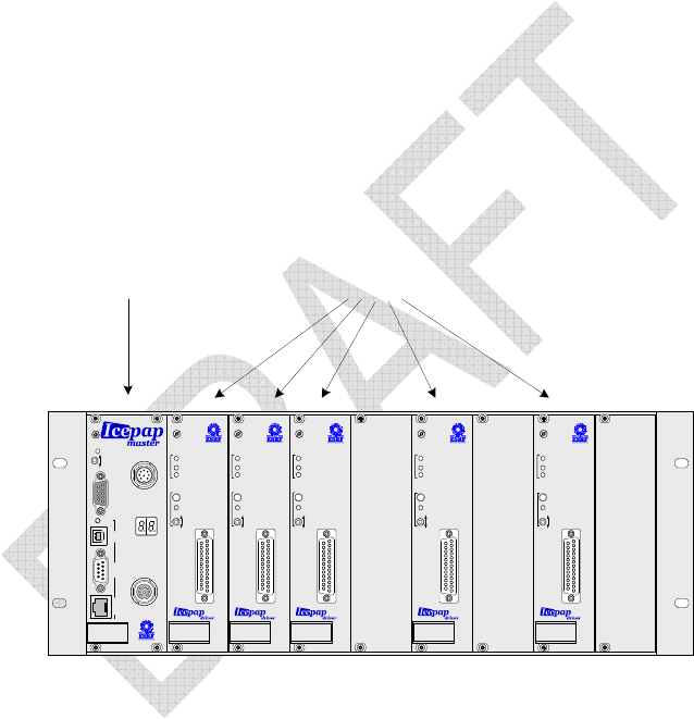
The components of an IcePAP system are organised in racks. The mechanical support of
each rack is provided by a 19” 3U crate that includes the power supply and an interconnection
backplane with nine board slots.
The leftmost slot is wider than the others and must be always equipped with a controller
board. The remaining slots may be equipped with up to eight driver boards. Each driver board
can operate a motorised axis.
The unused slots must be covered with blank front panel plates to avoid accidental access to
internal parts with electrical power.
Figure 1 depicts an IcePAP crate populated with 5 driver boards.
SYNCHRO
USBRS232Ethernet
Comm
STATUS
OUT
IN
DISABLE
ENABLE
AXIS INTERFACE
STATUS
AUX SUPPLY
MOTION
LIMIT
-
DISABLE
ENABLE
+
AXIS INTERFACE
STATUS
AUX SUPPLY
MOTION
LIMIT
-
DISABLE
ENABLE
+
AXIS INTERFACE
STATUS
AUX SUPPLY
MOTION
LIMIT
-
DISABLE
ENABLE
+
AXIS INTERFACE
STATUS
AUX SUPPLY
MOTION
LIMIT
-
DISABLE
ENABLE
+
AXIS INTERFACE
STATUS
AUX SUPPLY
MOTION
LIMIT
-
DISABLE
ENABLE
+
DriversController
Figure 1: Example of a partially equipped IcePAP rack
Several racks can be connected to form a single multirack IcePAP system. Each rack must be
identified with a different number that is visualised in a two-digit display at the front panel of
the controller board.
From the point of view of hardware implementation there are two types of controller boards:
MASTER and SLAVE. MASTER controllers have additional hardware resources such as a
communication processor and certain connectors that are not available in the SLAVE
controllers.
An IcePAP system must always include a MASTER board that plays the special role of
system master controller and takes care of system management and communication with the
host computer.
A more complete description of the IcePAP system and its hardware resources can be found
in the IcePAP Hardware Manual.

IcePAP User Manual 7 of 126
1.2. Hardware connections and configuration
1.2.1. Rack number
Each rack in a multirack system must be identified by a different rack identification number
from 0 to 15 that is unique within the same IcePAP system. The rack that contains the system
master controller must always be set to number 0. Therefore in the case of single rack
systems, the rack number has to be always set to 0.
The identification number of each rack is selected by a rotary switch located at the crate
backplane behind the controller board at the leftmost slot. In normal operation the rack
number is shown at the from panel display of the controller board as a decimal value. In order
to access the rotary switch and change the rack number, the power must be switched off
(power switch at the back of the crate) and the controller board extracted. The rack number is
selected by the rotary switch in hexadecimal values.
1.2.2. Board installation
Once the rack numbers have been properly selected, the crates can be populated with
IcePAP boards. Each rack must include a controller and up to eight driver boards. Controller
and driver boards do not required any particular intervention for hardware configuration and,
with exception of the Ethernet connection of the system master controller, controller boards
do not require any kind of functional set up. Driver configuration is fully described by software
parameters as presented in section 3 and can only be modified by mean of software
commands, preferably by using the IcePAP configuration tool. (see IcePAP Configuration and
Test Tool document).
The controller in rack 0 must always be a MASTER board to be used as system master
controller. In multirack systems the other rack controllers operate always as slave devices
regardless of whether or not they are physically MASTER or SLAVE boards. While a
MASTER board can be installed in any rack and operate as slave controller if needed, a
SLAVE board can never operate as system master controller and must never be inserted in
rack 0.
When a driver board is installed the first time in an IcePAP rack or moved from one slot to a
different one, the board becomes not active as a security measurement. This has as a
consequence that the motor power cannot be switched on and the associated axis cannot be
moved before the driver configuration is validated and the axis reactivated (see 3.1).
1.2.3. Rack interconnection and termination
Multi-racks system needs cable links that extend the internal communication bus following a
daisy-chain scheme across all the racks in an IcePAP system. This bus extension is
implemented by cables that link the OUT connector of a controller board in one rack with the
IN connector of the controller board in the following rack in the chain. This interconnection can
chain the racks in any arbitrary order, the rack numbers are not relevant in this context, but
the total length of all the link segments must not be more than 30 meters. The internal
communication bus of any IcePAP system, even in the case of a single rack, must be
equipped with a bus terminator connected at one of the ends of the interconnection chain.
This is achieved by plugging the bus terminator either at the IN connector of the first controller
in the chain, often the master, or at the OUT connector of the last controller board in the
chain. The wiring details and the hardware terminator are described in the IcePAP Hardware
Manual.
[ADD simple scheme/drawing example with two configurations: 3-racks and single rack,
showing terminators, picture of terminator?]

8 of 126 IcePAP User Manual
1.2.4. Rack disable
Each rack includes a disable connector at the rear panel that allows disabling remotely the
motor power of all the driver boards in that rack. By default, the polarity of the disable circuitry
is of type NC (normally closed).
If the rack disable feature is not used in a particular installation, it is good practice to install a
dummy plug in the rack disable connector to shortcircuit the disable line.
Each full system has a default polarity value (NORMAL = normally closed, INVERTED =
normally open). All the rack controllers receive this polarity at start-up from the master
controller. The rack controllers use the default polarity except those that have been assigned
explicitely a different polarity.
The default polarity of a system can be changed with the RDISPOL command.
The RDISPOL command allows also to force the use of a default polarity in all the racks of
the system, or to change the polarity of a single rack.
For more details on the RDISPOL command, see the command reference (chapter 5).
1.2.5. Communication links
Remote access and control of an IcePAP system can be achieved through one of the
communication interfaces of the system master controller plugged in rack 0. Although a
multirack system may include more than one MASTER board as rack controllers, only the
board operating as system controller in rack 0 can be used for communication and system
control. The other MASTER boards operate as slave controllers and do not activate their
communication ports.
The interfaces and main functional parameters are summarised in the table.
The interfaces currently available are RS232 and Ethernet. The connectors are accessible at
the front panel of the system master controller and the wiring and connectivity details are
compiled in the IcePAP Hardware Manual. The functional configuration of the RS232 port is
fixed as described in the table while the possible configuration methods of the Ethernet port
are discussed in 1.2.6. The communication protocols and syntax conventions are described in
section 4.
Note that although the hardware of the USB port is functional, this interface cannot be used
with the current firmware and there are no plans to implement this control interface in the
future.
1.2.6. Ethernet IP configuration
The IcePAP system controller requires an IP configuration of the Ethernet port that is
compatible with the parameters of the local network to which it is connected. Once the
controller has a valid IP configuration, it can be accessed from any computer in the network.
IcePAP accepts multiple simultaneous connections from different computers. If that can be
seen as potential security issue, it is possible to restrict partially the access to a particular
IcePAP system by setting the controller to reject commands that come from computers that
are not in a certain range of IP addresses (see IPMASK command).
Interface Type Parameters
Serial Line RS232 9600 bauds, no parity, 1 stop bit
Ethernet 100baseTFullDuplex
TCP sockets, port 5000
Universal Serial Bus USB 1.0 Not implemented

IcePAP User Manual 9 of 126
The last IP configuration is always stored in the non volatile RAM of the system controller. At
power up, if the configuration values are not changed, the system controller reuses the
previous IP configuration. There are various methods to modify the IP configuration but
whichever is used, when the IP configuration changes, the system controller writes the new
values in its non-volatile memory and reboots to reinitialise the network parameters. This
process takes about 30 seconds.
The IP configuration can be modified by using either a DHCP server or the external
application “ipassign”:
DHCP Server
The DHCP server must listen the local area network (LAN) where IcePAP is connected and
be configured to answer requests from the MAC address of the master controller. This
address is unique and is written on a label on the embedded processor module in the system
master controller board (ex: 00-0c-c6-69-13-1c). The DHCP server must be set to provide the
following information:
• Hostname (ex: iceid321)
• IP address (ex: 160.103.52.202)
• Netmask (ex: 255.255.255.0)
• Gateway (ex: 160.103.52.99)
• Broadcast (ex: 160.103.52.55)
“ipassign” Tool
The application “ipassign” is a tool specifically designed for IcePAP at ESRF. It uses the
Multicast Protocol to communicate with a master controller. Therefore, even if the previous IP
configuration is not valid, “ipassign” will be able to automatically detect any IcePAP master on
the network and configure it.
1.2.7. Motor and encoder connection
The motor and encoder connections are described in the IcePAP Hardware Manual. As
power and control lines are combined in the same cable and connectors, it is particularly
important to respect proper grounding techniques during the cabling of the electromechanical
components and in particular not to break the continuity of the external and internal cable
shieldings from the motor connector down to the motor housing.
By default the disable pin of the motor connector must be connected to the ground pin unless
an external axis disable specific circuitry is used. Leaving the disable line unconnected may
prevent the driver board to switch on the motor power and inhibit the operation of the axis.
An IcePAP driver has three encoder inputs that accept position encoder signals: two at the
rear panel “Encoder” connector and another one at the front panel “Axis Interface” connector.
The rear panel encoder inputs are named EncIn and AbsEnc in the IcePAP firmware. The first
one accepts incremental encoder signals while the other one implements a SSI absolute
encoder interface. The front panel input is also an incremental encoder input and is named
InPos.
From the point of view of functionality, all the encoder inputs are interchangeable. See the
explanation about functional encoders in 2.1.6. In most of the simple applications that include
a single position encoder, it is usually preferable to connect the encoder at the rear of the rack
either at AbsEnc or EncIn inputs depending on whether the encoder is absolute or
incremental.
1.2.8. Ventilation

10 of 126 IcePAP User Manual
IcePAP racks do not include internal fans or other method for forced ventilation. External
ventilation may be necessary in case of installation in enclosures with reduced air circulation
such as 19’’ cabinets.
1.3. Installation tips
[TO BE COMPLETED]
• Check that the master front panel “COMM” led is green which means that the controller
is ready to communicate over the Ethernet and the serial line

IcePAP User Manual 11 of 126
2. OPERATION INSTRUCTIONS
2.1. IcePAP concepts
2.1.1. Systems and boards
As explained in 1.1, an IcePAP system may include a variable number of driver boards
organised in several racks. Every rack in the system must have a unique identification
number that is displayed in the front panel of the rack controller board. The controller board in
rack number 0 acts as system master controller and manages communication and system
functionality. The communication cable (RS232 or Ethernet) must be plugged into the
corresponding connector of the system master controller.
Each board in the system, either driver or controller, has a unique address A that is the
decimal number formed as A = 10×R + S, where R is the rack number and S is the slot
occupied by the board in the rack. Rack controllers always occupy the slot 0, while driver
boards are installed in the slots 1 to 8. With this convention the last decimal digit of the board
address easily identifies if the board is a controller or a driver and its slot number. The
address 0 is always assigned to the system controller.
The system controller receives and processes ASCII commands from the host computer. If a
command includes a prefix starting by a numeric board address, it is considered as a board
command and is dispatched to the corresponding board for execution. Board commands can
be addressed to both controllers and drivers. If the command does not include an address
prefix, it is considered as a system command and is directly processed and executed by the
system controller.
Commands that request an answer from an IcePAP module always start by a question mark
character (‘?’) and are often called “queries” in this document.
It is also possible to address board commands to all the boards in the system by using a
broadcast mechanism. See chapter 4 for more details on the communication protocol and the
command format.
When a system and a board commands have analogous functionality, they usually share the
same name. However, as system and board commands are processed in a different way and
produce different results, they should not be considered as being the same command.
System commands and board commands are grouped in two sets that are presented in
chapter 5.
Some board commands are not implemented in rack controllers and can only be executed by
driver boards. Note also that the system master controller executes both system commands
as well as board commands sent to the address 0.
At any time the host computer may obtain information about the current configuration of an
IcePAP system by issuing ?SYSSTAT system queries. This query reports information about
the racks connected in the system, the driver boards plugged in each rack and if the plugged
boards are responsive or not.
Another useful system query is ?MODE that returns the current functional mode. In normal
operation conditions an IcePAP system must be always in OPER mode (see ?MODE system
query). Other system modes are useful only for maintenance interventions such as firmware
reprogramming or factory testing. Every board can also return its individual mode by the
?MODE board query. The only cases in which the board mode may be reported as different
from the system mode are either when a driver is being configured (CONFIG mode), or when
there is an unrecoverable hardware failure that switches a driver board into FAIL mode.
12 of 126 IcePAP User Manual
2.1.2. Motor types and built-in power stages
Although an IcePAP driver can be configured to drive a motor by using an external power
module, in most of the cases the driver boards operate by using their built-in internal PWM
amplifiers and motor power regulation schemes.
With the current firmware release, the IcePAP power drivers support current regulation of two
motor phases what is sufficient to drive most stepper motors. Support of three-phase motors
and torque regulation is foreseen in future firmware releases and will open the use of IcePAP
to various kinds of DC and brushless motors as well as three-phase steppers without the
need of external power drivers.
In addition to allowing current regulation and measurement over a rather wide range of
values, one particularity of the IcePAP built-in power stage is the possibility of programming
also the operating voltage of the output PWM amplifiers. This extends the capability of driving
properly motors of quite different electrical characteristics with the same hardware module.
2.1.3. Driver configuration
IcePAP drivers are highly configurable boards. All the internal functional parameters, such as
power and regulation settings, functional modes or I/O and encoder configuration can be set
and modified via software commands. The detailed description of the configuration procedure
and parameters is presented in chapter 3.
The configuration is stored permanently in the non-volatile memory of the driver boards and
can be retrieved at anytime via the ?CFG query. It must be noted that the rack controllers do
not require any particular functional configuration.
A convenient way of checking and changing the configuration of IcePAP drivers is by using
the graphical tool IcepapCMS that eases considerably the configuration procedure and stores

IcePAP User Manual 13 of 126
the configuration data in an external database for backup purposes. Using IcepapCMS is
particularly appropriated when it is needed to manage a large number of IcePAP systems and
axes. (see IcePAP Configuration and Test Tool document for further info on that procedure).
2.1.4. Enabling and disabling axes
Prior to any axis movement, the drivers must be active and the motor power must be switched
on. Axis activation is requested by setting a flag in the configuration parameters. The
activation state can be checked at any time during operation with the ?ACTIVE query. If an
axis is not active, most of the commands addressed to that axis are rejected, the motor power
cannot be switched on and the axis is inhibited. The activation flag of an axis can be
intentionally cleared by changing the ACTIVE configuration parameter, but the flag is also
cleared automatically when the driver board is installed in a new system or if it is moved to a
different rack or slot in the same system. This feature prevents switching on the motor power
or using a driver board that has never been configured after being plugged in a new slot.
Once the axis has been properly configured and activated, the motor power can be switched
on (see POWER command). The advent of any alarm condition (see ?ALARM command in
chapter 5 for more information) will switch motor power off again. The alarm condition must
be removed in order be able to switch the motor power back on. Examples of alarm
conditions are overcurrent conditions, external alarm signals or excessive follow errors when
a driver operates in position closed loop mode.
Alarms should not be confused with warnings. Warnings will not prevent the axis from being
powered on, but might indicate non ideal conditions that could lead later to an alarm condition
or damage the board (i.e. overtemperature).
A driver can be set to restore its previous motor power state after a rack power on/off cycle
(see 3.1.1). If any alarm condition is present at power on, the axis will not proceed with the
motor power on procedure even if it is configured to do so.
2.1.5. “Axis turn” as a reference mechanical displacement
The configuration of an axis requires as first step the definition of mechanical displacement
that is taken as mechanical reference and that is called an “axis turn”. That name is chosen
because in the large majority of applications the most convenient and intuitive reference
displacement is a turn of the motor. However in certain cases it may be more convenient to
use other reference displacement such for instance one revolution of a gear box output shaft
or one turn of a transmission screw in the mechanics. In the case of linear motors, the
reference displacement necessarily corresponds to a certain linear displacement of the
mechanics. However, regardless of whether the motor is rotary or linear and which reference
displacement is adopted, that reference displacement is always called “axis turn” in IcePAP
terminology and is used to configure the conversion of electrical to mechanical units as well
as the resolution of the axis and any encoder that is connected to the board.
The “axis turn” can be chosen freely based on application convenience and the only
requirement is that the displacement must correspond to an integer number of full electrical
periods of the motor. The conversion of electrical to mechanical units is then simply defined
by expressing the number of electrical periods that correspond to one “axis turn”. If the “axis
turn” for a rotary motor is chosen to match exactly one motor turn, then the number of
electrical periods corresponds to the number of pole pairs in the motor. That is why the
number of electrical periods in one “axis turn” is considered to be the number of effective “axis
pole pairs” in IcePAP. See 3.1.1 and 3.1.3 for more details on the configuration parameters.
As an example, in a conventional two-phase stepper motor with 200 full-steps per turn, four
per electrical period, if the “axis turn” is taken to match one motor turn, the axis must defined
as having 50 “axis pole pairs”.

14 of 126 IcePAP User Manual
2.1.6. Physical and functional encoders
Each driver board has three encoder inputs named EncIn (rear incremental encoder input),
InPos (front axis connector) and AbsEnc (absolute SSI encoder input at the rear encoder
connector). The encoders connected to those inputs are referred in the documentation as
physical encoders and do not have assigned any predefined function in the control of the axis.
The driver may use the position values of the physical encoders for a variety of purposes but
the function of each encoder must be selected first by setting the appropriate configuration
parameters. Instead of selecting a particular function for a specific encoder input, the
configuration of an IcePAP axis uses the concept of functional encoders. A functional encoder
is a generic name used to represent a specific internal function. The assignment of specific
functions to the physical axis encoders is then achieved by selecting which encoder input is
used for each particular functional encoder. The functional encoders in an IcePAP axis are
the following:
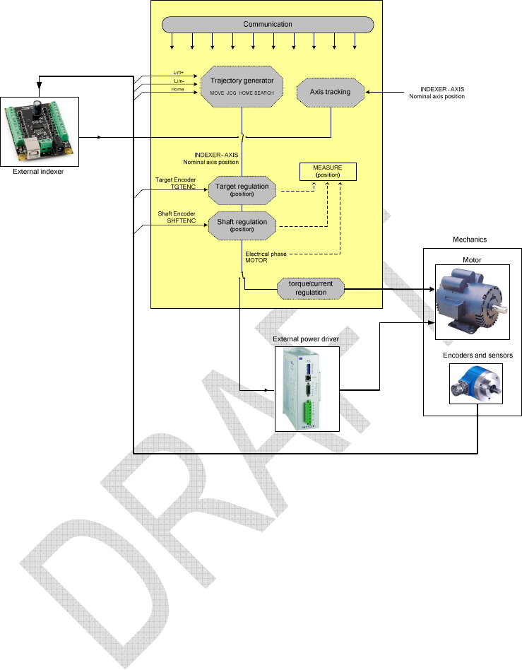
Target Encoder (TGTENC): This functional encoder is supposed to monitor the final
position of the mechanics and may be used for position regulation in closed loop operation.
Shaft Encoder (SHFTENC): This encoder is required to measure the motor shaft position
for torque control algorithms. It can be also be used for position regulation.
Control Encoder (CTRLENC): The IcePAP driver uses this encoder as a hardware
protection mechanism. The driver monitors the axis operation and trip alarms if the
discrepancy between the control encoder and the axis position exceeds a certain safety
value.
If any of the functional encoders is not assigned to a physical encoder input, the specific
functionality associated to that encoder is usually disabled.
2.1.7. Axis and encoder resolution
The position resolution of an IcePAP axis is determined by defining the size of one axis step.
The axis step unit is used to report axis positions and position errors as well as to define
parameters such as velocities. All displacements and position values in movement commands
are expressed in such units.
The axis step is defined during the configuration of the driver board by selecting arbitrarily the
increment of the motor electrical phase that corresponds to such a step. The choice of the
step size can be actually independent of the motor and the encoders associated to that axis
although in the cases of axis operating in closed loop modes it is convenient to select values
that are consistent. By defining a very small axis step, the IcePAP resolution can be higher
than the actual mechanical resolution of the axis, however the use of excessively high
resolution values is discouraged because it is both useless in practice and can be a potential
source of problems such as producing position overflows that may be difficult to track and
debug.
Expressing positions in steps allows to present axis positions to the user as 32-bit integer
values that are interpreted as number of axis steps as in the large majority of motor
controllers. All encoder positions are also represented as signed 32-bit integer values.
However the driver board converts and manages internally all positions as 64-bit fixed point
values in electrical units that are completely independent of the actual resolution of the
encoders or the arbitrary definition of the axis step. This approach provides calculation
resolution that can be considered unlimited in practice, allows combining in the same driver
encoders of different step size than the axis and allows for instance certain closed loop
operation modes with effective position resolution that is smaller than one axis step.
As it is detailed in 3.1.3, the effective size of an axis step in IcePAP is determined by defining
the total number of such steps that correspond to a given number of “axis turns”. An “axis
turn” is not necessarily equal to a motor turn as discussed in 2.1.5. However, whenever it is
possible, it is a good practice to set the “axis turn” equal to one motor turn and define the axis
step by specifying the total number of steps per motor rotation.
Comment [j1]:
One might
wonder here what is
‘excessively high’. The way it is
explained requires giving a
reference for the range of
values

IcePAP User Manual 15 of 126
The same scheme used to select the axis step must be used to configure the resolution of
any physical encoder connected to an IcePAP driver as explained in 3.1.3. The resolution of
each encoder is configured independently as the total number of actual encoder steps that
corresponds a certain integer number of “axis turns”. It must be taken into account that the
“axis turn” may not match the encoder turn.
As the encoders connected to the same driver board can have different resolution that can in
addition be different from the nominal resolution of the axis as defined by the axis step, there
are two different commands, ?ENC and ?POS, to retrieve the current position of the
encoders. ?ENC returns the position of an encoder in the particular units of that encoder while
?POS returns the encoder position as its equivalent in axis steps.
2.1.8. Nominal axis, measured and motor positions
The axis position of an IcePAP driver is the value used for movement commands and
reported by default by the ?POS and ?FPOS queries. The nominal position is expressed by
default in axis steps and in normal operation it only changes during axis movements. The axis
position does never change when a movement is finished and the axis is idle.
In addition to the nominal position, a driver manages a measured axis position. The measured
position is obtained from the target or shaft encoders that are assigned to that axis. If both
functional encoders are defined, the target encoder is used. If no target or shaft encoders are
defined, the driver reports the nominal axis position as the measured position. The measured
position can be obtained with the ?POS MEASURE and ?FPOS MEASURE queries for
instance. When the measured position is actually retrieved from a physical encoder, its value
may change of fluctuate due to mechanical drifts or electronics noise even if the axis is not
moving.
The measured position is usually used for reporting purposes. At the end of each movement it
may differ from the actual nominal axis position in particular if the axis operates in open loop.
If this discrepancy is not desired, it is recommended to set the axis to operate in position
closed loop. If in a particular application closed loop operation is not appropriate, the driver
can be instructed to replace at the end of each movement the final axis position with the
actual measured position (see 3.1.4). This feature is however strongly discouraged and
should be only used to cope with limitations of the host computer software.
In closed loop modes, the driver board has to adjust the electrical phase of the motor to
compensate for errors in the position of the mechanics measured by the encoder. In these
cases the motor electrical phase does not match in general the nominal position of the axis
and, in addition to the nominal and measured positions, the driver board must manage the
motor electrical phase as a different position value. Although such a motor position is in
general an internal value of little practical interest for the normal operation, it can be used for
diagnostic and retrieved with the ?POS MOTOR query. In open loop operation, the motor
position should always match the nominal axis position.
2.1.9. Closed loop operation
The position closed loop is an integral correction algorithm that forces the target encoder
signal to follow the nominal position of the axis. Closed loop operation is activated by
selecting the functional encoder to be used as feedback device. Various additional
parameters introduced in 3.1.4 allow to fine tune the closed loop mode although not all of
them need to be always configured. Only the regulation time constant and the maximum
acceptable follow error are critical for setting up closed loop operation. Depending on the
setup some times it is also convenient to configure a deadband in which the correction
algorithm is disabled.
Two bits are updated in the status of each axis to provide information on the position closed
loop behaviour. The inwindow bit is active if the position is inside a configured window around
the nominal position. The settling bit will be active after a movement until the error is smaller
than a configured value for a configured amount of time.

16 of 126 IcePAP User Manual
2.1.10. Trajectory generation and motion modes
The different motion modes, described in 2.2, are various ways of changing the current axis
position:
- Target position (point to point)
- Target velocity (jog)
- Homing
- Tracking (external indexer)
- Variable regulation (external feedback)
2.1.11. Status and diagnostics
Only intro here, detailed description in 2.4
- status register
- diagnostic commands
- data recording facility
2.1.12. I/O signals
- Info signals
Each driver has 3 digital outputs (InfoA, InfoB, InfoC) that can be configured to reflect different
information inside of the driver board. They can be set to high or low from an external
command. See INFOA command for all the available values.
- OutPos output signal
Besides the digital outputs, there is also a position output signal (OutPos) that can be used to
export any position source to other hardware. The possible signals presented at OutPos are
listed in the description of the OUTPOSSRC configuration parameter.
- the driver can output its internally generated trajectory via the OutPos source signal
available in the 25pin front connector (check IcePAP Hardware Manual document) to
an external amplifier, what can be useful in situations where IcePAP drivers might not
be able to steer the targeted axis (because the motor type or power is outside of
IcePAP specs).
2.1.13. Advanced functionality
Only intro here, motivation and few concepts, detailed description in 2.3
- I/O multiplexer
- Electronic cam
- Position control
- Parametric movements
2.2. Moving motors
2.2.1. Basic movements
In the most usual case, the various IcePAP axes are operated as independent channels via
commands like MOVE (absolute), RMOVE (relative), JOG
The current status of the motion is reflected in the status register and can be retrieved with
the commands ?FSTATUS and ?STATUS
2.2.2. Homing and search sequences
Each driver has the possibility to latch all of its position sources at a specified event. This
capability is used in two built-in commands that start a sequence that will search the position
of an external reference signal, thus allowing finding an absolute position of the axis.

IcePAP User Manual 17 of 126
Any IcePAP axis can be configured to look for a mechanical reference that can be used as
position origin of the axis. The usual source of the home signal (from the motor connector or
via the different encoder sources), its electric type (level, pulse, edge,…) and the speed of the
axis during the procedure can be stored as parameters. The different positions in the system
can be latched upon reference crossing and position can be reseted to a fix value in an
automatic way too (see HOMESRC and any HOME* parameters for more details).
2.2.3. Tracking modes (external indexer)
[IN DEVELOPMENT]
In most of the cases a driver will be operated by using its internal indexer to generate the
motion trajectory, velocity profile, etc. It is possible however to bypass the internal indexer
and drive the motor using pulses coming from an external device such as another IcePAP
driver or a multiaxis controller. The actual indexer used by a particular driver can be changed
during operation by a user command but the default indexer that is used after power on or
after driver reset must be selected by the parameter INDEXER. As mentioned above in most
of the cases the default indexer will be set to INTERNAL.
2.2.4. Variable regulation (external feedback)
The position of the axis is regulated in order to cancel the error in an external arbitrary
variable with respect to a given setpoint. This mode must be explicitly configured and started
during operation by the VCONFIG and VMOVE commands respectively, and not during
configuration phase. The current value of the external variable can be transmitted either by
mean of an unused encoder input or by a software command (see VVALUE command).
2.2.5. Multiaxis and group movements
Multiaxis motion commands. It is possible to move several axes by using the system motion
commands MOVE, UMOVE, RMOVE, JOG and HOME. The multiaxis versions of these
commands first check that all the axes in the parameter list can be moved as instructed. If
there are invalid parameters or any of the movements cannot be started, the command fails
and returns an error. Only once the initial check is successful, all the axes start their
movements simultaneously.
The progress of the movement can then be followed by monitoring the status register of the
individual axes. It is possible however to read the status of a set of axes by using the
?FSTATUS system query.
Axis groups. Once a multiaxis movement is started, by default every axis is managed as
independent from the others. The motion of a given axis finishes either when the motion
sequence is completed, when the driver receives a stop command or if a limit switch, an
alarm or an error condition is found.
This default behaviour can be changed if the GROUP keyword is used as a flag in the
multiaxis command. In that case all the axes included in the same multilink command are not
only started simultaneously but are also internally linked as an active group. Whenever any of
the axes in an active group is stopped by a STOP command, a limit switch or an alarm
condition, all the other axes in the group are forced to stop immediately.
2.2.6. Parametric motion
[IN DEVELOPMENT]
2.3. Advanced features

18 of 126 IcePAP User Manual
2.3.1. Motion synchronisation
Use of tracking modes. [TO BE DEVELOPED]
Synchronisation with external signals. [TO BE DEVELOPED]
Linked axes. A special case of multiaxis operation with a single degree of mechanical
freedom [TO BE EXPLAINED].
2.3.2. Position control (control encoder)
2.3.3. I/O multiplexer
- OutPos output signal
Besides the digital outputs, there is also an position output signal (OutPos) that can be used
to export any position source to other hardware. The possible signals presented at OutPos
are listed in the description of the OUTPOSSRC configuration parameter.
- the driver can output its internally generated trajectory via the OutPos source signal
available in the 25pin front connector (check IcePAP Hardware Manual document) to
an external amplifier, what can be useful in situations where IcePAP drivers might not
be able to steer the targeted axis (because the motor type or power is outside of
IcePAP specs).
2.3.4. Electronic cam
[IN DEVELOPMENT]
2.4. Diagnostics
2.4.1. Status registers
The status of each IcePAP board is compiled in a 32 bit register that can be read by the
?FSTATUS, ?STATUS and ?VSTATUS queries.
The ?FSTATUS query returns the board status that is stored in the master controller and
therefore present the shortest response latency. It is the recommended query for intensive
polling applications.
The ?STATUS query returns the status register read directly from the individual board and
therefore guarantees the most updated values.
The ?VSTATUS query reports the board status information in a verbose form that is intended
for diagnostics and assistance to application programmers.
The status information consists of a number of status bits and fields that are summarised in
Table 1 and described below:
PRESENCE: This field reports if the board is found to be physically present in the system, if
it is alive and communicates properly and, in the case of drivers in normal operation, whether
or not the board is in configuration mode. Note that the status of not present boards can be
obtained from the system by ?FSTATUS query.
MODE: This field represents the current functional mode of the board. See the ?MODE
board query for more details.
DISABLE: This field is set to a non zero value if the motor power is disabled. The power
can be enabled and disabled by the software POWER command or by the front panel
switches. It can also be permanently disabled if the axis is configured as not active, by one of
the external disable signals or if an alarm condition happens. In case of alarm conditions, the

IcePAP User Manual 19 of 126
STOPCODE field provides more details about the reason of the alarm. See 2.4.3 for more
information about alarm sources.
INDEXER: This field indicates if the axis trajectories are generated by the internal indexer,
by an in-system indexer signal through the backplane or by and external indexer connected to
one of the input position signals InPos or EncIn. It also indicates if the internal indexer is set
to operate in linked mode.
READY: This bit is set when the board is ready to accept new motion commands. It must be
checked before starting a new movement. If it is not set, the axis is still busy in an operation
such as a point to point movement, a settling phase or in a homing sequence.
MOVING: This bit indicates that the axis is in motion. It must be used only for informative
purposes and not to decide when the motion is completed and when the axis is able to accept
new motion commands. Use the READY bit instead.
SETTLING: In closed loop, this bit is set during the settling phase and is cleared once the
settling condition is met. See 2.1.9 for more details about closed loop operation.
OUTOFWIN: This bit is set if the axis position is out of the target position window. See 2.1.9
for more details about closed loop operation.
WARNING: This bit is set if a warning condition has been met. See 2.4.2 for more
information about possible source of warnings.
STOPCODE: During movements, this field may vary following the deceleration phase or the
status of complex movement sequences. However when the movement is finished and the bit
READY is set, it indicates the condition that stopped the motion: the field is 0 if the last motion
command completed successfully with no interruption. If the movement was interrupted or not
even started, a value from 1 to 6 reports the reason. If the power is disabled because the
board went into alarm state, a value from 8 to 15 indicates the specific alarm condition. Note
in this last case, the DISABLE field must also signal that an alarm condition was met.
LIMIT+, LIMIT-: These bits report the actual logic level of the Limit+ and Limit- signals
connected at the rear driver connectors.
HSIGNAL: This bit reports the logic level of the homing reference signal. Note that the
homing reference signal is selected by the HOMESRC configuration parameter and it may be
different from the driver Home signal connected at the rear panel.
VERSERR: This bit is set to if the version of the board firmware is not consistent with the
firmware version of the master controller.
INFO: This field provides a progress monitor during the board programming procedures.

20 of 126 IcePAP User Manual
DRIVER Status CONTROLLER Status
Bit #
name value = description value = description
0-1 PRESENCE
0 = driver not present
1 = driver not responsive
2 = driver in configuration mode
3 = driver alive
0 = controller not present
1 = controller not responsive
2 = n/a
3 = controller alive
2-3 MODE
0 = OPER
1 = PROG
2 = TEST
3 = FAIL
0 = OPER
1 = PROG
2 = TEST
3 = FAIL
4-6 DISABLE
0 = power enabled
1 = axis configured as not active
2 = alarm condition
3 = remote rack disable input signal
4 = local rack disable switch
5 = remote axis disable input signal
6 = local axis disable switch
7 = software disable
0 = power enabled
1 = n/a
2 = alarm condition
3 = remote rack disable input signal
4 = local rack disable switch
5 = n/a
6 = n/a
7 = software disable
7-8 INDEXER
0 = internal indexer
1 = in-system indexer
2 = external indexer
3 = linked indexer
0 = internal indexer
1 = n/a
2 = n/a (status of multiplexer?)
3 = n/a
9 READY 1 = ready to move 1 = ready to move
10 MOVING 1 = axis moving 1 = virtual axis moving
11 SETTLING 1 = closed loop in settling phase n/a
12 OUTOFWIN 1 = axis out of settling window n/a
13 WARNING 1 = warning condition n/a
14-17
STOPCODE
0 = end of movement
1 = STOP
2 = ABORT
3 = LIMIT+ reached
4 = LIMIT- reached
5 = settling timeout
6 = axis disabled (no alarm condition)
7 = n/a
8 = internal failure
9 = motor failure
10 = power overload
11 = driver overheating
12 = close loop error
13 = control encoder error
14 = n/a
15 = external alarm
0 = end of movement
1 = STOP
2 = ABORT
3 = n/a
4 = n/a
5 = n/a
6 = n/a
7 = n/a
8 = internal failure
9 = n/a
10 = n/a
11 = n/a
12 = n/a
13 = n/a
14 = n/a
15 = external alarm
18 LIMITPOS current logic value of the Limit+ signal
n/a
19 LIMITNEG current logic value of the Limit- signal
n/a
20 HSIGNAL current value of the homing ref. signal
n/a
21 5VPOWER 1 = Aux power supply on n/a
22 VERSERR 1 = inconsistency in firmware versions
1 = inconsistency in firmware versions
23 POWERON 1 = Motor power on n/a
24-31
INFO In PROG mode: programming phase
In OPER mode: master indexer In PROG mode: programming phase
Table 1. Driver and controller board status registers

IcePAP User Manual 21 of 126
2.4.2. Warnings
The ?WARNING command reports any warning condition in the system. See documentation
of ?WARNING query for the different possible warning sources.
2.4.3. Alarms
The ?ALARM command reports any alarm condition in the system. See documentation of
?ALARM query for the different possible alarm sources.
2.4.4. Data recording
Any driver or master in the system has up to 1Mbyte of onboard memory. Most of this
memory can be used for internal data storage (positions, currents) or other diagnostic
purposes.[IN DEVELOPMENT]
2.5. Firmware reprogramming
Firmware packages contain binaries for the embedded Linux in the MASTER boards, the
DSP and FPGA in controller boards and DSP and FPGA in driver boards.
A built-in command allows to program each of those binaries in each separate board, in all
controllers, all drivers or in the whole system. See PROG command for more details.
2.6. Usage tips
Refer to Section 5.1 for all the commands mentioned below.
• It is quite common to have a situation where one wants to change an incremental
encoder direction sign. This can be done easily by using the INV keyword in the
correspondent channel configuration. Moreover, the INV keyword can be also used to
change the polarity of the input signals.
2.7. Examples of driver configuration
The concept of axis turn is actually associated to a given number of electrical periods (pole
pairs) and can be generalised to linear or geared motors as explained in 2.1.2. On a standard
motor of 200 full steps (50 pole pairs), a resolution of 200 steps in 1 turn will imply
movements with ‘full step’ resolution. For the same case, a resolution of 400 steps in 1 turn
will imply movements with ‘half step’ resolution. For further microstepping, for example 16
microsteps per step, the values are 3200 (or 16x200) steps in 1 turn.
Let’s illustrate the different situations that might appear in a system with an example.
Attached to the second shaft of a 400 full step per revolution motor moving some mechanics
there’s an incremental encoder that generates 1600 encoder steps (sometimes referred in
literature as encoder ‘counts’). The motor is connected to the first driver in a single crate
IcePAP system. The encoder is connected to the EncIn rear incremental position input.
The first step is to configure the number of pole pairs to 100, since this is the mechanical
parameter. The configuration of the resolution of the EncIn encoder source is also clear, 800
steps in 1 turn of the axis.
- If you want to move with ‘full step’ resolution, you will configure the axis resolution
(the same as the indexer) as 400 steps in 1 turn. When you move 1 step, you will see your
encoder readout changing 2 steps.
- If you want to move with ‘half step’ resolution, axis resolution should be configured
as 800 steps in 1 turn. When you move your axis 1 step, you will see your encoder readout
changing 1 step.

22 of 126 IcePAP User Manual
- If you would want to move with a resolution in positioning of a quarter of step, the
axis resolution would be configured as 1600 steps in 1 turn. In order to see a change of 1 step
in the encoder readout you would need to move now your axis two steps.
Once explained the resolution at axis and encoder units, how their relationship is established
and how to configure it, it is interesting to add that IcePAP can supply the position of any
encoder in the axis units. There are two main commands to query position in IcePAP, ?POS
and ?ENC. ?ENC will always give the position of an encoder in the units of that encoder.
?POS will give the position of an encoder source as its equivalent in axis units. Back to the
previous example, and assuming that before the movement all positions were zero and that
you are using the internal indexer as axis position source, after the three movements listed
above we would get the following readouts from the ?POS and ?ENC commands:
- 1:?POS would return 1, 1:?ENC ENCIN would return 2, and 1:?POS ENCIN would
return 1 (if no steps were lost).
- 1:?POS would return 1, 1:?ENC ENCIN would return 1 and 1:?POS ENCIN would
return 1.
- 1:?POS would return 2, 1:?ENC ENCIN would return 1 and 1:?POS ENCIN would
return 2.
In the examples above, ?POS and ?POS ENCIN always return the same, and that’s the way
it should be in an ideal case, since both represent the angle turned by the shaft in the same
units. The difference is that ?POS shows the steps that we wanted to make and therefore the
steps that have been generated by the internal indexer and ?POS ENCIN shows the steps
read by the encoder in the units of the internal indexer (axis units). In a real world case,
friction could prevent the mechanical system to arrive to the final encoder mark what would
result in a different output value for both commands.
The use of ?POS and ?ENC commands and different resolution for each position source
might not result intuitive in the beginning. The need to be able to express the encoder steps in
the units of the axis comes from position closed loop operation. In that case, the target
position and the read position have to be compared in the same units. Inside IcePAP driver,
the comparison is done in axis units.

IcePAP User Manual 23 of 126
3. DRIVER CONFIGURATION
The configuration of an IcePAP driver is defined by the values of a set of parameters that are
stored in the non-volatile memory of the board. The complete list of configuration parameters
as well as their types or possible values is compiled in 3.2.
The configuration parameters can be changed with the CFG command, but only if the driver
has been previously switched into a special configuration mode with the CONFIG command.
The driver configuration cannot be modified from regular operation mode. Once some of the
configuration parameters have been changed, the CONFIG command can be used again to
validate the new configuration and switch the driver back to operation. If the new configuration
is not properly validated, all changes are lost when driver exits the configuration mode. See
the description of the CONFIG command for details.
The ?CFG query can be used at any time to read back the current values of the configuration
parameters.?CFGINFO is a utility query that allows to interrogate the driver about the type
and possible values of any configuration parameter.
3.1. Configuration parameters
3.1.1. Motor configuration
Motor type
The type of motor must be specified by setting the parameter MOTPHASES to the actual
number of electrical phases in the motor. This value must be one for DC motors and either
two or three for steppers and brushless devices. Motors with a higher number of electrical
phases, such as five-phase steppers, cannot be driven directly with the internal power
amplifier in IcePAP drivers. [ONLY 2-PHASE IMPLEMENTED SO FAR]
In the case of two or three phase motors, the parameter MOTPOLES must be set to the
number of electrical periods per axis turn. An axis turn, in IcePAP terminology, is the
reference mechanical displacement that is used to define the axis and encoder resolution. It
usually corresponds to a full rotation of the motor shaft, but for convenience it may be chosen
as a different mechanical displacement as it is discussed in 2.1.5. In any case and whatever
is the choice for an ‘axis turn’, it must correspond to the integer number of electrical periods
specified in MOTPOLES.
Power control
The MREGMODE parameter is used to select the operation mode of the internal PWM power
amplifier or the use of an external power drive. [ONLY CURRENT REGULATION
(STEPPERS) IMPLEMENTED SO FAR]
The motor supply voltage of the internal PWM amplifier can be selected with the NVOLT and
IVOLT parameters.
The nominal current value must be specified by the NCURR parameter. It is also possible to
specify a boost current increment BCURR during acceleration and deceleration periods, as
well as a reduced current ICURR when the motor is not moving.
The PID parameters of the current regulator can be set to predefined values with CURRGAIN
parameter or individually selected with MREGP, MREGI, MREGD.
At start up or system reset, the motor power is off by default. This behaviour can be changed
by setting the POWERON configuration flag to instruct the driver to go into the same power
state, on or off, that it had before the system was powered down or reset.
Motion direction and limit switches

24 of 126 IcePAP User Manual
The definition of the sense of motion of the axis is fully determined by assignment of the limit
switch control lines. When the axis moves in positive direction the mechanics must move
towards the Lim+ switch. There is no way of inverting that assignment in the IcePAP
configuration, but the actual direction of the motor can be reversed by changing the
MOTSENSE value.
3.1.2. I/O configuration
Physical encoders
The two incremental encoder inputs EncIn and InPos can be configured to operate in either
2-phase quadrature or pulse/direction counting mode by setting the EINMODE and INPMODE
parameters.
The absolute encoder inputs use a serial synchronous interface (SSI) that can be configured
with the parameters SSIDBITS, SSICODE, SSISTATUS, SSICLOCK and SSIDELAY. The
absolute values obtained from the encoder are always corrected by adding the fixed 32-bit
offset value loaded in ABSOFFSET. This value must be set to zero for no correction.
In most of the practical cases, the sign of the encoders must match the sense of motion of the
axis. If needed, the sign of the encoders can be inverted by mean of the parameters
EINSENSE, INPSENSE and ABSSENSE.
Position signal output
The signal OutPos can be configured to output any of the internal position signals by setting
the OUTPSRC parameter. The signal mode and pulse length if needed can be set with
OUTPMODE and OUTPULSE. The signal can be inverted with OUTPSENSE.
The source of the auxiliary line OutPosAux can be selected independently with the parameter
OUTPAUXSRC.
General purpose output signals
The signals InfoA, InfoB and InfoC can be used to output logic values related to the internal
state of the driver such as READY, MOVING or ALARM, or the level of input control signals
such as limit switches, Home signal or the encoder auxiliary inputs. Although this can be
changed during operation, the default initial signal sources of those general purpose outputs
can be selected with the INFASRC, INFBSRC and INFCSRC configuration parameters.
Polarity of I/O signals
The polarity of all the control and auxiliary input/output lines can be inverted by setting the
corresponding parameters. This includes the limit and home switches (LPPOL, LMPOL,
HOMEPOL), the encoder auxiliary/index lines (EINAUXPOL, INPAUXPOL, OUTPAUXPOL)
as well as the general purpose output signals (INFAPOL, INFBPOL, INFCPOL).
3.1.3. Axis configuration
Axis name lock
The name of the axis is a character string that is stored in the non-volatile memory and is only
used for identification purposes (see NAME command). The axis name is not a configuration
parameter and by default can be changed at any time during operation. It is however possible
to prevent changes of the axis name in operation mode by setting the NAMELOCK
configuration flag.
Axis and encoder resolution
The resolution of the axis is arbitrarily defined by specifying the total number of steps
ANSTEP that correspond to a given number ANTURN of axis turns. These two parameters

IcePAP User Manual 25 of 126
together with the ‘axis turn’ defined by value of MOTPOLES for a given motor, determine the
effective size of each axis step.
In most of the applications with rotary motors, MOTPOLES is set to make the ‘axis turn’
correspond to one turn of the motor shaft. In those cases it is usually a good practice to set
ANTURN to 1 and set ANSTEP to the desired number or steps per motor rotation. See 2.1.5
and 2.1.7 for a more elaborated discussion on position resolution in IcePAP and how to deal
with linear motors.
The actual resolution of the encoders connected to the driver must be declared with the
similar two parameter scheme: the total number of steps for a given number of axis turns. In
this way the pairs of parameters (EINSTEP, EINTURN), (INPNSTEP, INPNTURN) and
(ABSSTEP, ABSNTURN) allow to declare the step size of encoders connected to the
incremental inputs EncIn, InPos and the absolute encoder SSI interface respectively. It must
be noted that the number of turns always refers to the same ‘axis turn’ defined by
MOTPOLES and not to rotations of the encoder itself.
Functional encoders
As explained in 2.1.6, the assignment of physical encoders to specific functionalities is
achieved through the definition of functional encoders. The configuration parameters
TGTENC, SHFTENC and CTRLENC specify the physical encoders that should be used as
target, shaft and control encoders respectively.
The target and shaft encoders may participate to the measure of the position of the axis or
motor shaft and be part of the position closed loop. The control encoder, if configured, will
trigger an alarm if its difference with respect to the axis position exceeds a maximum value of
steps given by the parameter CTRLERROR.
Axis activation and protection level
The ACTIVE parameter can be set to request setting or clearing the internal axis activation
flag. This flag must always be set the first time an axis is configured.
The PROTLEVEL parameter is foreseen to implement additional levels of protection. [NOT
IMPLEMENTED]
External input functional signals
It is possible to include logic signals coming from external devices in the determination of the
logic state of the driver. The EXTBUSY parameter can be used to select an input signal that
will be used to prevent the axis to go into ready state. The signals selected by EXTALARM
and EXTWARNING contribute to the generation of alarm and warning conditions.
And in the case of using an external power amplifier, the EXTPOWER parameter selects the
input that will indicate the power state of the amplifier.
The default use of an external trajectory generator can be selected by the INDEXER
parameter.
3.1.4. Position control and motion
Axis position control
Although the velocity and acceleration time of the internal trajectory generator are usually set
and changed during operation, the DEFVEL and DEFACCT parameters allow to define
default values that are used at power on or after changes the motor configuration.
[Parameter to be deprecated: STRTVEL]
The POSUPDATE parameter can be used to instruct the driver to replace the axis position
with the measured position by the measured position at the end of each movement. See 2.1.8
for details.
Comment [j2]: Why? Closed
loop speed limit?

26 of 126 IcePAP User Manual
The driver can be included in a group of linked axes by setting the LNKNAME parameter to
the name of group.
Homing configuration
The input signal used as mechanical reference during homing procedures can be selected
among a list of available inputs by the HOMESRC parameter. The logic of the homing signal
as well as various flags that specify the homing procedure are defined by HOMETYPE and
HOMEFLAGS. The final velocity of the axis during homing can be defined by the HOMEVEL
parameter.
The value in the HOMEPOS parameter contains a predefined position that may be used to
reset the axis position at the mechanical reference,
Position closed loop
An axis can be instructed to operate by default in closed loop mode by mean of the PCLOOP
parameter that also selects the functional encoder to be used for position feedback. The
position closed loop mode applies an integral correction algorithm with the time constant set
by PCLTAU. The settling and convergence criteria as well as the error conditions are
configured by the parameters PCLSETLW, PCLSETLT, PCLERROR and PCLMODE. It is
also possible to use the PCLDEADBD parameter to define a dead region around the target
position in which the feedback correction is disabled.

IcePAP User Manual 27 of 126
3.2. Configuration reference
This section lists all the configuration parameters of a driver board.,
ACTIVE { NO | YES } Axis enable/disable flag
This parameter marks a driver board as active or not. A “non active” driver is disabled, cannot
be used to drive motors and rejects most of the power and motion related commands. The
ACTIVE parameter does not reflect necessarily the actual state of a driver board that can
become “not active” (functionally disabled) if it is moved to a different IcePAP system. See
2.1.4 and the ?ACTIVE query for more information.
PROTLEVEL <integer> Protection level
This value is not actually used by the IcePAP drivers. It is provided as a way to store locally
information about the level of protection that must be applied to the corresponding axis. This
value is available to be used by the application software.
NAMELOCK { NO | YES } Axis name lock
If this flag is set to NO, the use of the NAME command to change the name of the driver
board is not allowed.
POWERON { NO | YES } Auto power on
This flag instructs the driver board to switch on the motor power immediately after board
initialisation. The flag has effect only if the driver is active.
MOTPHASES { 1 | 2 | 3 } Number of electrical phases
MOTPOLES <integer> Number of pole pairs
Configure the number of electrical phases and pole pairs of the motor. In case of rotary
motors, the number of pole pairs corresponds to the number of electrical periods per motor
turn. For instance, this number is 50 for a standard 200 full steps per turn stepper motor.
In case of linear motors, the number of pole pairs corresponds to the number of electrical
periods for a certain given displacement distance. Such a distance is somehow arbitrary and
can be chosen according to the user convenience, but will be adopted as the effective “motor
revolution” for all internal calculations. All the configuration parameters that refer to motor
turns will actually apply to such a reference linear displacement.
MOTSENSE { NORMAL | INVERTED } Sense of motor movement
This value allows to invert the definition of positive direction for motor movements. Note that
the limit switch signal Lim+ always blocks motion in the positive direction while Lim- blocks
negative movements.
MREGMODE { EXT | CURR | TORQUE} Motor regulation mode
This value selects the type of power regulation in the motor. In the current firmware version
only current regulation (CURR) is implemented. If this parameter is set to EXT, the board
disables its internal power driver and assumes that the motor power is applied by an external
driver module.

28 of 126 IcePAP User Manual
NVOLT <float> Nominal operation voltage (volts)
IVOLT <float> Idle operation voltage (volts)
NCURR <float> Nominal current (amps)
ICURR <integer> Idle current (%)
BCURR <integer> Boost current increment (%)
These parameters set the motor voltage and current values. During movements, the driving
voltage and phase current are set to NVOLT (in volts) and NCURR (in amps) respectively.
When the motor is stopped the voltage and current are set to IVOLT (in volts) and ICURR.
Note that ICURR is not specified in amps, but in a given percentage of the nominal current
NCURR.
It is possible to increase the phase current during acceleration and deceleration phases by
specifying a boost current increment BCURR greater than zero. BCURR is also specified in
percentage of NCURR and adds to the nominal current.
CURRGAIN { CUSTOM | LOW | MEDIUM | HIGH } Current regulation gain
MREGP <float> Proportional coefficient
MREGI <float> Integral coefficient
MREGD <float> Derivative coefficient
MREGP, MREGI and MREGD are the PID coefficients used for motor current regulation. If
CURRGAIN is set to CUSTOM, the PID values can be freely set. If CURRGAIN is set to
LOW, MEDIUM or HIGH, the PID values are forced to predefined values.
NRES <float> Nominal phase resistance
This parameter sets the value of the nominal electrical resistance of the motor phases in
ohms.
If NRES is set to zero, ...
INDEXER { INTERNAL | InPos | EncIn } Default indexer source
Selects if the axis must be operated by using the internal trajectory generator or an external
signal applied to one of the encoder InPos or EncIn inputs.
The INDEXER parameter refers to the default value, if the axis is not linked (see LNKNAME),
the actual indexer source can be changed during operation (see INDEXER command).
LNKNAME <string> Name of the linked axes group
Selects the group name to be used if the axis is configured to operate in LINKED mode. All
the linked axes in the same IcePAP system sharing the same LNKNAME are configured to
operate co-ordinately as described in 0. Setting LNKNAME to a non empty string forces the
axis to operate in LINKED mode and the INDEXER parameter to INTERNAL. In the same
way if the INDEXER parameter is set to a value different from INTERNAL, then LNKNAME is
cleared.
SHFTENC { NONE | InPos | EncIn | AbsEnc} Shaft encoder
TGTENC { NONE | InPos | EncIn | AbsEnc} Target encoder
CTRLENC { NONE | InPos | EncIn | AbsEnc} Control encoder
Select which input position signals will be used as shaft encoder, target encoder and control
encoder. If any of these parameters is set to NONE the corresponding function is left
unassigned.
POSUPDATE { NORMAL | MEASURE } ….

IcePAP User Manual 29 of 126
Selects whether the axis position is updated to match the measured position during open loop
movements. If there is no functional encoder configured as TGTENC or SHFTENC, the
measured position matches the nominal axis position and the MEASURE mode has no effect.
ANTURN <integer> Axis reference number of turns
ANSTEP <integer> Axis reference number of units/steps
Defines the resolution of the axis by specifying the number of units/steps (ANSTEP) for a
given number of motor turns (ANTURN). This resolution can be selected independently of the
actual resolution of the various encoders connected to the driver board and is always the
position resolution used by the internal indexer.
DEFVEL <float> Default velocity (steps/sec)
DEFACCT <float> Default acceleration time (sec)
Configures the default values for velocity and acceleration time. The velocity value is
specified in axis units (or steps) per second. The acceleration time is specified in seconds.
STRTVEL <float> Maximum start velocity (steps/sec)
Configures the maximum starting velocity. This value, that is specified in axis units (or steps)
per second, is the maximum velocity that can be applied to the motor without acceleration
ramp. It is only used when the driver has to limit the motor slew rate as it is required in some
closed loop modes for instance.
CTRLERROR <integer> Maximum control encoder error (steps)
Configures the ...
PCLOOP { OFF | SHFTENC | TGTENC } Default closed loop mode
PCLTAU <float> Position closed loop time constant (sec)
PCLERROR <integer> Maximum closed loop error (steps)
PCLCHKMD { NORMAL | STRICT } Closed loop error checking mode
PCLDEADBD <integer> Minimum closed loop error (steps)
PCLSETLW <integer> Closed loop settling window (steps)
PCLSETLT <float> Closed loop settling time (sec)
The position closed loop default mode and encoder signal used is selected by the PCLOOP
parameter. The position closed loop is an integral correction algorithm that forces the selected
encoder value to follow the desired axis value with the regulation time constant set by
PCLTAU. The maximum acceptable follow error, defined as the difference between the axis
and encoder values, is the number of axis steps in PCLERROR. The difference between the
motor electrical phase and the encoder value is also checked to be less than PCLERROR,
unless the flag SIMPLECHK in parameter PCLMODE is set. If the follow error is less than
PCLDEADBD the correction algorithm does not take any action. If the error is less than
PCLSETLW, the driver status bit INWINDOW will be set. At the end of a movement the driver
status bit SETTLING will be set until the error remains less than PCLSETLW during the time
defined by PCLSETLT.
LPPOL { NORMAL | INVERTED } Polarity of the Lim+ signal
LMPOL { NORMAL | INVERTED } Polarity of the Lim- signal
HOMEPOL { NORMAL | INVERTED } Polarity of the Home signal

30 of 126 IcePAP User Manual
These parameters allow to invert the electrical polarity (logic value) of the limit switch signals
and the Home input. Note that LPPOL and LMPOL do not change the functional assignment
of the limit switches: Lim+ always blocks motion in the positive direction while Lim- blocks
always negative movements.
EINTURN <integer> EncIn reference number of turns
EINSTEP <integer> EncIn reference number of units/steps
INPNTURN <integer> InPos reference number of turns
INPNSTEP <integer> InPos reference number of units/steps
ABSNTURN <integer> AbsEnc reference number of turns
ABSNSTEP <integer> AbsEnc reference number of units/steps
Allow to define the resolution of the encoders connected to the physical encoder inputs:
EncIn, InPos and AbsEnc. The resolution is defined by specifying the number of encoder
units/steps (encoderNSTEP) for a given number of motor turns (encoderNTURN). These
values must match the resolution of the encoders in the actual mechanics.
EINMODE { QUAD | PULSE+ | PULSE- } EncIn input counting mode
INPMODE { QUAD | PULSE+ | PULSE- } InPos input counting mode
Select the input counting mode (quadrature counting or pulse/direction) for the incremental
encoder signals connected to the position inputs EncIn and InPos. In the case of
pulse/direction counting mode, it is possible to select if the incremental counting takes place
at the rise edge (PULSE+) or the falling edge (PULSE-) of the pulse signal.
EINSENSE { NORMAL | INVERTED } EncIn sense
INPSENSE { NORMAL | INVERTED } InPos sense
Allow to change the sign of the incremental encoder signals EncIn and InPos. Inverting the
sign of the incremental signal is equivalent to invert the sense of motion of the encoder.
EINAUXPOL { NORMAL | INVERTED } Polarity of the EncInAux signal
INPAUXPOL { NORMAL | INVERTED } Polarity of the InPosAux signal
These parameters allow to invert the electrical polarity (logic value) of the auxiliary signals
EncInAux and InPosAux.
ABSSENSE { NORMAL | INVERTED } AbsEnc sense
ABSOFSSET <integer> AbsEnc position offset
Allow to apply a sign inversion and an offset to the absolute encoder value read through the
SSI encoder interface.
SSIDBITS <integer> SSI data bits
SSICODE { BINARY | GRAY } SSI data coding
SSISTATUS { S | .S | ES | OS } SSI status/control bits
SSICLOCK { 125KHz | 250KHz | 500KHz | 1.25MHz |
2.5MHz | 5MHz | 12.5MHz | 25MHz | OFF} SSI clock frequency
SSIDELAY { 0 | 5us | 10us | 20us | 30us |
50us | 100us | 500us} SSI polling delay
Configuration parameters for the SSI interface.
HOMESRC { Lim+ | Lim- | Home | EncAux | InpAux} Homing signal
HOMETYPE { LEVEL | PULSE | MPULSE } Type of homing signal

IcePAP User Manual 31 of 126
The parameter HOMESRC selects the hardware signal to be used by the homing procedure.
The type of signal, i.e. how the homing signal indicates the reference mechanical position, is
configured by HOMETYPE. Possible values are LEVEL, if the signal logic level changes at
the reference position, PULSE if the signal is a short pulse at the reference position, or
MPULSE if the homing device produces multiple pulses with variable distances between
them. See for details
HOMEFLAGS [AUTODIR] [REVERSE] [SETPOS] [SLOW] [NEGEDGE]
Homing flags
Configuration of the behaviour of the homing functionality.
HOMEPOS <integer> Reference homing position
Configuration of ...
HOMEVEL <float> Slow homing velocity (steps/sec)
Configuration of ...
OUTPSRC { AXIS | MOTOR | MEASURE | SHFTENC | TGTENC |
InPos | EncIn | AbsEnc | Sync} OutPos source signal
OUTPMODE { QUAD | PULSE+ | PULSE- } OutPos output counting mode
OUTPPULSE { 50ns | 200ns | 2us | 20us} OutPos pulse width
OUTPSENSE { NORMAL | INVERTED } OutPos sense
Configuration of the OutPos position output signal.
OUTPAUXSRC {LOW | HIGH | Lim+ | Lim- | Home | eCAM |
EncAux | InpAux | SyncAux"} OutPosAux source signal
OUTPAUXPOL { NORMAL | INVERTED } Polarity of the OutPosAux signal
Configuration of the OutPosAux auxiliary output signal.
INFASRC { LOW | HIGH | Lim+ | Lim- | Home | EncAux |
InpAux | SyncAux | PWRCTRL | ENABLE | ALARM | READY |
READY | MOVING | BOOST | STEADY | eCAM} InfoA source signal
INFBSRC { LOW | HIGH | Lim+ | Lim- | Home | EncAux |
InpAux | SyncAux | PWRCTRL | ENABLE | ALARM | READY |
READY | MOVING | BOOST | STEADY | eCAM } InfoB source signal
INFCSRC { LOW | HIGH | Lim+ | Lim- | Home | EncAux |
InpAux | SyncAux | PWRCTRL | ENABLE | ALARM | READY |
READY | MOVING | BOOST | STEADY | eCAM } InfoC source signal
INFAPOL { NORMAL | INVERTED } InfoA polarity
INFBPOL { NORMAL | INVERTED } InfoB polarity
INFCPOL { NORMAL | INVERTED } InfoC polarity
Default signal sources and polarities for the InfoA, InfoB and InfoC output signals. This default
configuration is effective at initialisation, but can be changed during operation by means of the
commands INFOA, INFOB and INFOC respectively. The available signal sources are
explained in the documentation of the INFOx commands.

32 of 126 IcePAP User Manual
EXTPOWER { NONE | LIMITS | Home | EncAux | InpAux | Disable } External power
EXTDISABLE { NONE | LIMITS | Home | EncAux | InpAux | Disable } External disable
EXTBUSY { NONE | LIMITS | Home | EncAux | InpAux | Disable } External busy
EXTALARM { NONE | LIMITS | Home | EncAux | InpAux | Disable } External alarm
EXTWARNING { NONE | LIMITS | Home | EncAux | InpAux | Disable } External warning
EXTPOWER { NONE | LIMITS | Home | EncAux | InpAux | Disable } External power
Selects of the external functional input signals. If NONE is selected as input signal fro a given
function, the external function is disabled. If a signal selection is set to LIMITS, the external
function is activated when the two limit switches, Lim+ and Lim-, are active simultaneously.
EXTDISABLE can be used to prevent the driver board to switch on the motor power.
EXTBUSY blocks the execution of motion commands by preventing the driver to go to
READY state. EXTPOWER is only effective when the IcePAP driver is configured to operate
with external power drivers, and informs whether or not the motor power is on.
EXTWARNING and EXTALARM can be used to generate warning and alarm conditions by
external signal sources.

IcePAP User Manual 33 of 126
4. COMMUNICATION PROTOCOL
4.1. Communication basics
This section covers the IcePAP communication protocol. The communication interface is
implemented at the system master board.
Communication is achieved by bi-directional byte streams. Normal command and response
messages are transferred as lines of printable ASCII characters. The only exception is the
transfer of binary data blocks, a special feature described in 4.5.
Commands messages sent to IcePAP must be formatted as sequences of printable
characters terminated by a “carriage return” (ASCII 0x0D). Any additional control character,
like “line feed” (ASCII 0x0A), is ignored.
Response messages produced by the device consist on lines terminated by a “carriage
return” + “line feed” character sequence (ASCII 0x0D 0x0A).
4.1.1. System commands
Commands that do not include and address prefix are system commands.and are processed
by the system master board. Example: ?SYSSTAT
4.1.2. Board commands
Commands addressed to specific boards. Both controller and drivers. They start with the
address of the board and executed by the particular board, i.e.: 1:?POS
It is possible to broadcast board commands to all the modules in an IcePAP system.
4.1.3. Local driver interface
Each driver board has an individual communication port for diagnostic purposes. It can also
be used for standalone operation.
4.2. Interfaces
The master boards integrate three communication ports: an Ethernet interface, a serial line
and an USB port. The characteristics of the different interfaces are the following:
Interface Type Parameters
Serial Line RS232 9600 bauds, no parity, 1 stop bit
Ethernet 100baseT-
FullDuplex TCP sockets, port 5000
Universal Serial Bus USB 1.0 Not implemented in the current version
4.2.1. Active control clients
An IP mask can be defined to limitthe execution of commands to the icePAP system.
For every bit in the mask set to 1, the corresponding bit in the icePAP and the client IP
addresses must have the same value.
Any incoming command that is not a query queries from a client with an IP address out of the
defined mask will be rejected. All the query commands will be answered by the system
regardless of the IP mask configured.
By default the IP mask value is set to 0.0.0.0
This means that all commands from any IP address will be executed.
Examples and tips:
To limit the access to clients in the subnet where the icePAP system is, set the IP mask to the
value: 255.255.255.0

34 of 126 IcePAP User Manual
In order to change the IP mask to a less restrictive value, the corresponding IPMASK
command has to be issued from an address that is not masked. Be careful never to set the
mask to the value 255.255.255.255.
See IPMASK/?IPMASK in the command reference for information on how to change/read the
current IP mask of a system.
[TODO: Develop the IPMask concept here]
4.3. Syntax conventions
In the most usual case remote control is implemented by an application program running in a
host computer that sends commands and requests to IcePAP as sequences of ASCII
characters. The syntax rules are described below. See X for practical examples.
4.3.1. Commands and requests
Command lines consist of a command keyword optionally followed by parameters.
- The number and type of parameters depend on the particular command.
Command keywords are not case sensitive.
- The device converts internally all the characters to uppercase before any syntax
checking. (TO BE DISCUSSED)
- Parameters are also converted to uppercase unless they are enclosed between
double quotes (””, ASCII 0x22). (TO BE DISCUSSED)
Commands may be optionally preceded by the acknowledge character.
- The acknowledge character is a hash symbol (#, ASCII 0x23) that must appear in the
command line immediately before the first character of the command keyword.
Normal (non query) commands never produce response messages unless the
acknowledge character is used.
- Non query command keywords always start by an alphabetical character (A to Z).
Exceptions are binary transfer commands (see XX) that start by an asterisk character
(*, ASCII 0x2A).
- If the acknowledge character is used, the device produces the response string OK if
the command execution was successful.
- If the acknowledge character is used and the command does not executes
successfully, the device produces either the string ERROR or a string containing a
human readable error message. The behaviour depends on the current setting of the
echo mode (see 4.4).
Requests are query commands that produce response messages from the device.
- Requests keywords always start by a question mark character (?, ASCII 0x3F).
- If the request is successful the content of the response message depends on the
particular request.
- If request fails the device produces either the string ERROR or a string containing a
human readable error message. The behaviour depends on the current setting of the
echo mode (see 4.4).
- The acknowledge character has no effect when used with requests.
Response messages consist of one or more ASCII character lines.

IcePAP User Manual 35 of 126
- The way every line in a response message is terminated depends on the type of
communication port.
- A response message may contain either the output of a request, an
acknowledgement keyword (OK or ERROR) or a human readable error message.
- When a response message consists of more than one line, the first and last lines
contain a single dollar character ($, ASCII 0x3F).
4.3.2. Addressing
Board commands must be sent to the specific controller or drivers boards by using an
addressing prefix. An addressing prefix consists of the board address in decimal format
followed by a colon character (:, ASCII 0x3A). No spaces are allowed between the last
address digit and the colon character.
An addressing prefix consisting of only the colon character (:) with no address string is
interpreted as a broadcast command. In that case the command is forwarded to all the
boards in the system. Controller boards ignore broadcasts of driver-only commands as
well as driver boards ignore controller-only broadcasts. No queries or acknowledge
characters are allowed in broadcasts.

36 of 126 IcePAP User Manual
4.4. Terminal mode
When an IcePAP system is accessed through a serial port, two possible communication
modes are available that can be selected with the commands ECHO and NOECHO. The
differences between these two modes are described below. These commands can be issued
through other interfaces (i.e. Ethernet) but they only have effect on the serial port.
Echo mode (terminal mode)
This mode should be used when the IcePAP master board is connected to a dumb terminal.
In this case the user types commands on the keyboard and reads the answers and error
messages on the terminal screen without computer intervention. This mode is usually not
active by default and the user has to send the ECHO command every time the device is
powered on.
In echo mode all the characters sent to the device are echoed back to the terminal. The
device also sends human-readable messages to be printed on the terminal screen whenever
an error is detected in commands or requests.
Case conversion takes place before the characters are sent back to the terminal, therefore
characters are echoed back as uppercase even if they are typed and sent to the device as
lowercase. (TO BE DISCUSSED)
In echo mode the backspace character (ASCII 0x08) has the effect of deleting the last
character received by the device. In this way a minimum editing functionality is provided.
Noecho mode (host computer)
This is the default mode. In this case no characters are echoed and no error messages are
returned by non-query commands unless they are explicitly requested by the acknowledge
character. This mode is intended to be used when a program running in a host computer
communicates with the controller, sending commands and analysing the answers.
4.5. Binary transfer
Binary transfer is a special mode that extends the standard protocol allowing faster data
transfer. Binary blocks have a maximum size of 65535 data bytes (0xFFFF).
Binary transfer commands or requests are initiated by ASCII command lines that follow the
same rules than ordinary commands or requests (see 4.3.1). The only difference is that binary
transfer command lines must include an asterisk character (*, ASCII 0x2A) in the command or
request keyword. Non-query commands keywords must start by an asterisk character.
Request keywords must include the asterisk as the first character after the question mark.
Once IcePAP has received the ASCII command line, the data is transferred as a binary block.
In the case of non-query commands, the binary data block is sent from the host computer to
the device. In case of binary requests, the device sends the binary block to the host (serial
line) or puts it in its output buffer ready to be read by the host (GPIB).
If the device finds an error in a command line containing a binary request, instead of the
binary block, it produces the string ERROR.
The acknowledge character (#, ASCII 0x23) can be used in the same way that with non-
binary commands. If it is included in a non-query command line, the device produces an
acknowledgement keyword (ERROR or OK) to signal if the command line contained errors or
not. The acknowledge character has no effect in the case of binary requests.
Although binary transfer is initiated in the same way for both serial line and GPIB
communication, the format of the binary data blocks and the management of the end of
transfer condition are different in both cases.

IcePAP User Manual 37 of 126
4.5.1. Serial port binary blocks
In the case of transfer through a serial port, the binary block contains the binary data and 4
extra bytes. The structure of the block is the following:
byte Number content
0 0xFF (signature)
1 DataSize (MSB)
2 DataSize (LSB)
3 data byte (first)
… …
DataSize + 2 data byte (last)
DataSize + 3 Checksum
The first byte contains always the value 0xFF (255) and can be used the signature of the
block. The next two bytes contain the number of data bytes to transfer. The last byte contains
the check sum value that is used to verify data integrity.
The checksum value is calculated as the lower 8-bits of the sum of all the bytes in the binary
block with exception of the signature byte (and the checksum byte itself).
4.5.2. TCP binary blocks
In the case of transfer by Ethernet, the binary block does not contain any additional control or
protocol byte. Only the actual data bytes are transferred. The EOI line is asserted during the
transfer of the last data byte to signal the end of the transmission.

38 of 126 IcePAP User Manual
5. COMMAND SET
BOARD COMMANDS
Command Description
Controller Driver
Page
?ACTIVE
Query activation status
42
?MODE
Query board mode
83
?STATUS
Query board status
110
?VSTATUS
Query verbose board status
118
?ALARM
Query board alarm message
45
?WARNING
Query board warnings
120
WTEMP ?WTEMP
Set/query warning temperature
122
CONFIG ?CONFIG
Manage configuration mode
53
CFG ?CFG
Set/query configuration parameters
48
?CFGINFO
Query configuration parameter info
50
CSWITCH ?CSWITCH
Set/query limit switch configuration mode
54
?VER
Query board version information
117
NAME ?NAME
Set/query board name
86
?ID
Query board identification
74
?POST
Query power-on self-test results
93
POWER ?POWER
Set/query motor power state
94
AUXPS ?AUXPS
Set/query auxiliary power supply state
46
?MEAS
Query measured value
81
POS ?POS
Set/query axis position in axis units
91
ENC ?ENC
Set/query axis position in encoder steps
62
?HOMESTAT
Query home search status
73
?HOMEPOS
Query the found home position in axis units
72
?HOMEENC
Query the found home position in encoder steps
71
VELOCITY ?VELOCITY
Set/query programmed axis velocity
115
ACCTIME ?ACCTIME
Set/query acceleration time
43
PCLOOP ?PCLOOP
Set/query current position closed loop mode
88
ESYNC
Synchronise internal position registers
65
CTRLRST
Reset control position encoder
55
MOVE
Start absolute movement
84
UMOVE
Absolute updated movement
114
RMOVE
Start relative movement
102
JOG ?JOG
Set/query jog velocity
79
HOME
Start home signal search sequence
70
MOVEP
Start axis movement to parameter value
85
PMOVE
Start parametric movement
89
VMOVE ?VMOVE
Set/query setpoint for variable regulation motion
118
VCONFIG ?VCONFIG
Set/query variable regulation configuration
115
VVALUE ?VVALUE
Set/query current value of external variable
120
CMOVE
Start relative movement in configuration mode
52
CJOG
Set jog velocity in configuration mode
51
STOP
Stop movement
111
ABORT
Abort movement
41
DISPROT
Request temporary protection disable
57
INDEXER ?INDEXER
Set/query indexer signal source
75
ECAM ?ECAM
Set/query electronic cam mode
58
ECAMDAT ?ECAMDAT
*ECAMDAT
Load/query electronic cam data
59
INFOA ?INFOA
Set/query InfoA signal source and polarity
76
INFOB ?INFOB
Set/query InfoB signal source and polarity
76
INFOC ?INFOC
Set/query InfoC signal source and polarity
76

IcePAP User Manual 39 of 126
BOARD COMMANDS (cont.)
Command Description
Controller Driver
Page
?HELP
Query list of available commands
69
?ERRMSG
Query last command error message
64
?FERRMSG
Query first error message
66
BLINK ?BLINK
Set/query remaining blinking time
47
?TIME
Query running time
113
DEBUG ?DEBUG
Set/query debug level
56
ECHO
Select echo mode
61
NOECHO
Cancel echo mode
87
?MEMORY
Query available memory
82
?ADDR
Query board address
44
SYSTEM COMMANDS
Command Description Page
MODE ?MODE
Set/query system mode 83
?SYSSTAT
Query system configuration 112
?STATUS
Query multiple board status 110
?FSTATUS
Query multiple board fast status 68
?LINKED
Query linked axis groups 80
REPORT ?REPORT
Set/query asynchronous report settings 98
?VER
Query system firmware version information 117
?RID
Query rack identification string 100
?RTEMP
Query rack temperatures 105
*PROG
PROG ?PROG
Firmware programming 95
RFPROG
Factory firmware programming 101
IPMASK ?IPMASK
Set/query IP control mask 78
REBOOT
System reboot 97
RESET
System or rack reset 99
POWER ?POWER
Set/querymultiple axis motor power state 94
POS ?POS
Set/query multiple axis position in axis units 91
ENC ?ENC
Set/query multiple axis position in encoder steps 62
?FPOS
Fast query of multiple board positions 67
?HOMESTAT
Query multiple axis home search status 73
?HOMEPOS
Query the found multiple axis home position in axis units 72
?HOMEENC
Query the found multiple axis home position in encoder steps 71
VELOCITY ?VELOCITY
Set/query programmed multiple axis velocity 115
ACCTIME ?ACCTIME
Set/query acceleration time 43
MOVE
Start multiple axis absolute movement 84
RMOVE
Start multiple axis relative movement 102
JOG ?JOG
Set/query multiple axis jog velocities 79
HOME
Start multiple axis home signal search sequence 70
MOVEP
Start axis movement to parameter value 85
PMOVE
Start parametric movement 89
STOP
Stop multiple axis movement 111
ABORT
Abort movement 41
ESYNC
Synchronise internal position registers for multiple axis 65
CTRLRST
Reset control position encoder for multiple axis 55
DISPROT
Request multiple axis temporary protection disable 57
?HELP
Query list of available commands 69

40 of 126 IcePAP User Manual
?ERRMSG
Query last command error message 64
ECHO
Select serial line echo 61
NOECHO
Cancel serial line echo 87

IcePAP User Manual 41 of 126
5.1. Command reference
ABORT
Abort movement
Syntax:
<board_addr>:ABORT
(board command)
or
ABORT [ <axis1> [<axis2> … [<axisN>]…]]
(system command)
Description:
The ABORT command aborts all movement in the specified axis.
When using the system command, if the command cannot be issued for a certain axis, all
the movements in the system will be aborted.
If one of the explicitly aborted axis belongs to a predefined group, all the members of that
group will be aborted.
Examples:
Command:
16:ABORT
Command:
ABORT
// abort all the axes in the system
Command:
ABORT 30 33 42
// abort axes 30, 33 and 42
Command:
#ABORT 30 33 42
Answer:
ABORT ERROR All axes aborted. Axis 33: Board is not
present in the system
Command:
#ABORT 30 rrt 42
Answer:
ABORT ERROR All axes aborted. Wrong parameter(s)

42 of 126 IcePAP User Manual
?ACTIVE
Query activation status
Syntax:
<driver_addr>:?ACTIVE
Answer:
<driver_addr>:?ACTIVE { YES | NO }
Description:
Returns the current activation status of a driver board. A driver will be active if the internal
ACTIVE configuration parameter is set to YES and the board is not in PROG or TEST
mode. Otherwise the ?ACTIVE query will return NO.
When a driver board is not active, the motor power and the trajectory generation functions
are disabled. (to be checked)
The driver’s ACTIVE configuration parameter will be reset to the value NO at power on if:
- the address of the driver has changed, for instance if the board has been moved to a
different slot within the same system,
- the driver board finds itself plugged in a different IcePAP system, i.e. the master crate
AND the master controller are different than the previous ones
- there is a firmware or a command set mismatch between the driver and the master
controller board.
A standalone driver (with no master controller) can be activated through the front panel
serial line with the command SLACT.
Examples:
Command:
16:?ACTIVE
Answer:
16:?ACTIVE YES

IcePAP User Manual 43 of 126
ACCTIME / ?ACCTIME
Set/query acceleration time
Syntax:
<board_addr>:ACCTIME [ <accTime> ]
(board command)
or
ACCTIME [<axis1> <accTime1> … [<axisN> <accTimeN>]…]
(system command)
Description:
Sets the acceleration time for the corresponding axis to the <accTime> values in
seconds. The actual acceleration for each axis is calculated internally based on the
current value of the axis velocity (see VELOCITY command).
The acceleration time is internally recalculated every time that the axis velocity changes.
Syntax:
<board_addr>:?ACCTIME
(board command)
or
?ACCTIME [<axis1> [<axis2> … [<axisN>]…]]
(system command)
Answer:
<board_addr>:?ACCTIME <accTime>
(board answer)
or
?ACCTIME <accTime1> <accTime2> … <accTimeN>
(system answer)
Description:
Returns the current acceleration time of the specified axes in seconds.
Examples:
Command:
16:?ACCTIME
Answer:
16:?ACCTIME 0.25
Command:
24:ACCTIME 0.1
Command:
?ACCTIME 16 24
Answer:
?ACCTIME 0.25 0.1
Command:
ACCTIME 16 0.1 17 0.2

44 of 126 IcePAP User Manual
?ADDR
Query board address
Syntax:
<board_addr>:?ADDR
Answer:
<board_addr>:?ADDR <boardAddr>
Description:
The ?ADDR command returns the current board address. This command is only useful
when the board is accessed through the local serial line interface.
Examples:
Command:
16:?ADDR
Answer:
?ADDR 16 // useless information
Access through the local serial line interface:
Command: ?
ADDR
Answer:
?ADDR 16

IcePAP User Manual 45 of 126
?ALARM
Query board alarm message
Syntax:
<board_addr>:?ALARM
Answer:
<board_addr>:?ALARM { NO | <alarm_condition string> }
Description:
If the board is disabled by an alarm condition, this query returns a string describing the
such a condition. If not, the query returns the string NO.
Possible alarm conditions are:
Alarm Condition Description
Internal failure
Power-on self test (POST) or motor supply failure
Motor failure
Error detected in motor connection
Power overload
Overcurrent or power overload
Driver overheating
The temperature of the driver board exceeds maximum
value
Close loop error
The closed loop follow error exceeds the maximum value
(see PCLERROR configuration parameter)
Control encoder error
The control encoder discrepancy exceeds the
CTRLERROR configuration parameter
External alarm
The external alarm signal is active (see EXTALARM
configuration parameter)
Examples:
Command:
115:?ALARM
Answer:
115:?ALARM <alarm condition string>
Command:
115:#POWER ON
Answer:
115:POWER OK
Command:
115:?ALARM
Answer:
115:?ALARM NO

46 of 126 IcePAP User Manual
AUXPS / ?AUXPS
Set/query axis auxiliary power supply state
Syntax:
<driver_addr>:AUXPS [ {ON | OFF} ]
Description:
Switches on or off the auxiliary power supply in a driver board. When the auxiliary power
supply is switched off, the motor power is also switched off.
Syntax:
<driver_addr>:?AUXPS
Answer:
<driver_addr>:?AUXPS [ {ON | OFF} ]
Description:
Returns the state of the auxiliary power supply of the driver board.
Examples:
Command:
83:?AUXPS
Answer:
83:?AUXPS ON
Command:
83:AUXPS OFF
Command:
83:?AUXPS
Answer:
83:?AUXPS OFF

IcePAP User Manual 47 of 126
BLINK / ?BLINK
Set/query remaining blinking time
Syntax:
<board_addr>:BLINK <blinkTime>
Description:
If <blinkTime> is greater than zero, sets the board in blinking mode for a period given by
<blinkTime> in seconds. If <blinkTime> is zero, this command stops blinking mode.
Syntax:
<board_addr>:?BLINK
Answer:
<board_addr>:?BLINK <remBlinkTime>
Description:
Returns the remaining blinking time.
Examples:
Command:
83:BLINK 10
Command:
83:?BLINK
Answer:
83:?BLINK 8.4532
Command:
83:?BLINK
Answer:
83:?BLINK 6.5439

48 of 126 IcePAP User Manual
CFG / ?CFG
Set/query configuration parameters
Syntax:
<driver_addr>:CFG <configPar> <configVal>
or
<driver_addr>:CFG { DEFAULT | EXPERT }
Description:
The CFG command allows to change the current values of the configuration parameters
of a driver board. The driver has to be previously switched into configuration mode (see
CONFIG command).
The configuration of driver boards as well as the list of available parameters is detailed in
chapter 2.
The command CFG DEFAULT instructs the driver board to revert all its configuration
parameters to the default values. The list of default values can be obtain from the driver
by means of the ?CFG DEFAULT query.
The command CFG EXPERT sets an internal flag that can be read back with the ?CFG
query. This flag has not any specific function in the IcePAP system but it is provided as an
facility to external configuration tools to confirm the validity of the current driver
configuration when the driver boards are moved among systems. As the expert flag is
cleared by any other CFG command, it must be set immediately before the configuration
is validated by the CONFIG command.
Syntax:
<driver_addr>:?CFG [ <configPar> | DEFAULT | EXPERT ]
Answer:
<driver_addr>:?CFG <configPar> <configVal>
or
<driver_addr>:?CFG $
<configPar1> <configVal1>
<configPar2> <configVal2>
…
<configParN> <configValN>
$
Description:
The ?CFG query returns the value <configVal> assigned to a particular configuration
parameter <configPar>. If no parameter is specified, the query returns a multiline answer
with the complete list of configuration parameters and their current values. If the
DEFAULT keyword is used, instead of the current values, the ?CFG query returns the
complete list of configuration parameters and their default values.
If the EXPERT keyword is used as a parameter name, the ?CFG query returns the value
of the internal expert flag set by the CFG EXPERT command and cleared by any other
CFG command. The value is returned as a YES/NO boolean value. Note however that
EXPERT is not a configuration parameter.

IcePAP User Manual 49 of 126
Examples:
Command:
15:CFG DEFAULT
Command:
15:?CFG NCURR
Answer:
15:?CFG NCURR 0.1
Command:
15:CFG NCURR 2.4
Command:
15:?CFG
Answer:
15:?CFG $
ACTIVE NO
PROTLEVEL 0
NAMELOCK NO
POWERON NO
MOTPHASES 2
MOTORSENSE NORMAL
MOTPOLES 50
MREGMODE CURR
...
NCURR 2.4
...
INFCSOURCE Home
INFCPOL NORMAL
$
Command:
23:?CFG EXPERT
Answer:
23:?CFG EXPERT NO

50 of 126 IcePAP User Manual
?CFGINFO
Query configuration parameter info
Syntax:
<driver_addr>:?CFGINFO [ <configPar> ]
Answer:
<driver_addr>:?CFGINFO <configPar> {INTEGER | FLOAT | STRING<n> | labelList }
or
<driver_addr>:?CFGINFO $
<configPar1> {INTEGER | FLOAT | STRING<n> | labelList1 }
<configPar2> {INTEGER | FLOAT | STRING<n> | labelList2 }
…
<configParN> {INTEGER | FLOAT | STRING<n> | labelListN }
$
Where labelList is a list of character strings separated by whitespaces and enclosed in curly
braces ({}). [FLAG LIST descriptionmissing]
Description:
The ?CFGINFO query returns the type of the configuration parameter <configPar>.
Possible types are numeric (INTEGER or FLOAT) or string. In the case of strings the
query may return either STRING<n> , where <n> is the maximum acceptable length of
the string, or the list of acceptable fixed string values.
If no parameter is specified, the query returns a multiline answer with the complete list of
type information for all the driver configuration parameters.
Examples:
Command:
7:?CFGINFO NCURR
Answer:
7:?CFGINFO FLOAT
Command:
103:?CFGINFO
Answer:
103:?CFGINFO $
ACTIVE {NO YES}
PROTLEVEL INTEGER
NAMELOCK {NO YES}
POWERON {NO YES}
MOTPHASES {1 2 3}
MOTORSENSE {NORMAL INVERTED}
...
INFCPOL {NORMAL INVERTED}
$

IcePAP User Manual 51 of 126
CJOG
Set jog velocity in configuration mode
Syntax:
<board_addr>:CJOG <signedVelocity>
Description:
Sets the specified axis or axes in jog mode at the given velocity in steps per second. This
command can only be executed when the driver is in configuration mode.
The sign of the velocity parameter selects the actual direction of the movement. If a
specified axis is already jogging at a certain speed, the speed will be ramped up or down
as needed to reach the new velocity value. The acceleration is fixed as the ratio of the
current values of axis velocity and acceleration time (see ?VELOCITY and ?ACCTIME
queries). A zero velocity value forces an axis to stop.
Examples:
Command:
5:CJOG 100
Command:
5:?JOG
Answer:
5:?JOG 100
Command:
#5:CJOG 200
Answer:
5:CJOG OK
Command:
#5:CJOG -200
Answer: 3
:CJOG ERROR Cannot change jog direction
Comment [PF3]:
This
command is undocumented!!!

52 of 126 IcePAP User Manual
CMOVE
Start absolute movement in configuration mode
Syntax:
<driver_addr>:CMOVE <absolutePos>
Description:
Performs an absolute movement on the specified driver board. This command can only
be executed when the driver is in configuration mode.
Examples:
Command:
115:CMOVE -7000
Command:
115:?POS
Answer:
115:?POS -7000

IcePAP User Manual 53 of 126
CONFIG / ?CONFIG
Manage configuration mode
Syntax:
<driver_addr>:CONFIG [ <confID> ]
Description:
The CONFIG command allows to switch a driver board into configuration mode. A driver
board cannot be switched into configuration mode when the IcePAP system is in PROG
or TEST modes (see MODE command).
When a driver is in configuration mode, the driver configuration parameters can be
modified with the CFG command. Once the configuration has been modified, the CONFIG
command, issued with a non empty <confID> string as parameter, validates the current
configuration and stores it in the internal non volatile memory of the driver board. The
<confID> string is also stored in the driver and can be used to identify the particular set of
configuration parameters. The board also switches back to OPER mode.
If the driver is in configuration mode and the CONFIG command is issued with no
parameters, the driver goes back to OPER mode and the last valid configuration before
entering CONFIG mode is reloaded. In that case the most recent changes done during
configuration mode are lost.
Syntax:
<driver_addr>:?CONFIG
Answer:
<driver_addr>:?CONFIG <confID>
Description:
The ?CONFIG query returns the identifier of the last valid configuration parameter set.
Examples:
Command:
32:?CFG ACTIVE
Answer:
32:?CFG ACTIVE NO
Command:
?MODE
Answer:
?MODE OPER // System mode is OPER
Command:
32:CONFIG // Switch axis 32 into CONFIG mode
Command:
32:?MODE
Answer:
32:?MODE CONFIG
Command:
32:CFG ACTIVE YES // Change configuration parameter
Command:
32:CONFIG CONF001 // Validate driver configuration
Command:
32:?CFG ACTIVE
Answer:
32:?CFG YES

54 of 126 IcePAP User Manual
CSWITCH / ?CSWITCH
Set/query limit switch configuration mode
Syntax:
<board_addr>:CSWITCH { NORMAL | SMART | STICKY }
Description:
Sets the behaviour of the limit switches in configuration mode. In addition to the normal
mode, the limit switches can be set to operate in either SMART or STICKY mode. This
command as well as the special limit switch mode modes is only valid in configuration
mode. The STICKY and SMART modes are only intended to assist the user when testing
the electrical connection and operation of the physical limit switches and selecting the
direction of the motor. When the driver board is in operation mode, the limit switches
always operate in normal mode.
The STICKY mode forces any of the limit switches that has been activated once, to
remain active until the driver is switched to OPER mode or the CSWITCH command is
issued again.
The SMART switch mode forces any movement to stop as soon as any of the two limit
switches is activated. If actual switch that was activated is not consistent with the direction
of motion, the value of the configuration parameter MOTSENSE is inverted.
Syntax:
<board_addr>:?CSWITCH
Answer:
<board_addr>:?CSWITCH { NORMAL | SMART | STICKY }
Description:
Returns the current value of the limit switch configuration mode.
Examples:
Command:
15:?CSWITCH
Answer:
15:?CSWITCH NORMAL
Command:
15:CSWITCH SMART
Command:
15:?CSWITCH
Answer:
15:?CSWITCH SMART

IcePAP User Manual 55 of 126
CTRLRST
Reset control encoder value
Syntax:
CTRLRST <axis1> <axis2> … <axisN>
(system command)
or
<driver_addr>:CTRLRST
(board command)
Description:
This command resets the current value of the control position register to the current value
of the axis.
[TODO: needs further explanation]
Examples:
Command:
#11:CTRLRST
Answer:
11:CTRLRST OK
Command:
CTRLRST 11 13 14

56 of 126 IcePAP User Manual
DEBUG / ?DEBUG
Set/query debug level
Syntax:
<board_addr>:DEBUG <debugLevel>
Description:
Sets the level of the debug facility to <debugLevel>. If the level is set to 0, the debug
facility is switched off.
The debug level is stored in the board non-volatile memory and it is maintained after
board reset.
Syntax:
<board_addr>:?DEBUG
Answer:
<board_addr>:?DEBUG <debugLevel>
Description:
Returns the current level of the debug facility.
Examples:
Command:
15:?DEBUG
Answer:
15:?DEBUG 0
Command:
15:DEBUG 2
Command:
15:?DEBUG
Answer:
15:?DEBUG 2

IcePAP User Manual 57 of 126
DISPROT
Request temporary protection disable
Syntax:
<driver_addr>: DISPROT {ALL | {[LINKED] [CONTROL] [HARDCTRL]} }
(driver command)
or
DISPROT {ALL | {[LINKED] [CONTROL] [HARDCTRL]}} <axis1> <axis2> … <axisN>
(system command)
Description:
Request the specified boards to override the selected protections during the execution of
the following command. The possible protections to be overriden are selected by the
following keywords:
Keyword Protection disable
ALL Disables all the protections, The ALL keyword is equivalent to issue
LINKED and CONTROL keywords simultaneously.
LINKED
Allows to issue individual commands to linked axes. In normal
operation, most movement and related commands can only be sent
to linked axes collectively, by addressing the linked group name.
CONTROL
Disables the action of the control encoder during the next
movement after the DISPROT command. The movement command
must follow the DISPROT command.
HARDCTRL
Disables the action of the control encoder during the next
movement AND limits the maximum movement to a maximum
number of steps defined by configuration parameter CTRLERROR.
The movement command must follow the DISPROT command.
The HARDCTRL flag causes to override the control encoder protection, but adds a new
protection. Thus, when the flag ALL is used, the HARDCTRL flag will not be set internally.
Examples:
Command:
15:DISPROT LINKED
Command:
DISPROT CONTROL LINKED 23 24 25

58 of 126 IcePAP User Manual
ECAM / ?ECAM
Set/query electronic cam mode
Syntax:
< board_addr>: ECAM [ { OFF | ON | PULSE | LOW | HIGH } ]
Description:
The ECAM command ...
ON is the default action.
Syntax:
<board_addr>:?ECAM
Answer:
<board_addr>:?ECAM { OFF | ON } { PULSE | LOW | HIGH } <curr_level>
Description:
Returns the ON/OFF activation state of the electronic cam, the configuration mode as
PULSE or level (LOW or HIGH) and the current logic level of the eCAM signal (LOW or
HIGH).
Examples:
Command:
15:?ECAM
Answer:
15:?ECAM OFF PULSE LOW
Command:
15:ECAMDAT 1000 41000 100
Command:
15:?ECAMDAT
Answer:
15:?ECAMDAT AXIS 1000 41000 100
Command:
15:ECAM ON
Command:
15:?ECAM
Answer:
15:?ECAM ON PULSE LOW

IcePAP User Manual 59 of 126
ECAMDAT / *ECAMDAT / ?ECAMDAT
Load/query electronic cam data
Syntax:
<board_addr>: ECAMDAT [ ecam_source ] <first> <last> <nIntervals>
<board_addr>: *ECAMDAT [ ecam_source ] {DWORD | FLOAT | DFLOAT}
Description:
The ECAMDAT command ...
The *ECAMDAT binary command ...
ecam_source Position value
PARAM Value of the position parameter
AXIS Current nominal axis position
MEASURE Value of the axis position measurement
SHFTENC
Value of the functional “shaft” encoder
TGTENC
Value of the functional “target” encoder
CTRLENC
Value of the functional “control” encoder
ENCIN
Position of the encoder connected at the rear connector
INPOS
Position of the encoder connected at the front panel connector
ABSENC
Position of the encoder connected at the rear SSI interface
MOTOR
Electrical phase of the motor
Only valid for driver boards
Syntax:
<board_addr>:?ECAMDAT [ <n_values> [ <idx_offset> ] ]
Answer:
<board_addr>:?ECAMDAT ecam_source <first> <last> <nIntervals>
or
<driver_addr>:?ECAMDAT $
<< eCAM data dump >>
$
Description:
With no parameters, the ?ECAMDAT query returns the ...
For debugging purposes, the query can be issued with a number of values <n_values> as
parameter, and an optional index offset <idx_offset>. In that case ?ECAMDAT returns a
list of values.

60 of 126 IcePAP User Manual
Examples:
Command:
15:?ECAM
Answer:
15:?ECAM OFF PULSE LOW
Command:
15:ECAMDAT 1000 41000 100
Command:
15:?ECAMDAT
Answer:
15:?ECAMDAT AXIS 1000 41000 100
Command:
15:ECAM ON
Command:
15:?ECAM
Answer:
15:?ECAM ON PULSE LOW
Comment [PF4]: Review this
with reasonable examples

IcePAP User Manual 61 of 126
ECHO
Set echo mode
Syntax:
ECHO
(system command)
or
<board_addr>:ECHO
(board command)
Description:
Switches the echo mode on. Useful when accessing boards through the serial line.
Example:
Command:
ECHO
Command:
92:ECHO

62 of 126 IcePAP User Manual
ENC / ?ENC
Set/query axis position in encoder steps
Syntax:
<board_addr>:ENC [ pos_sel ] <posVal>
(board command)
or
ENC [ pos_sel ] <axis1> <posVal1> … <axisN> <posValN>
(system command)
Description:
Loads the position registers in the specified boards with the <posVal> values. The
specific register is selected by the optional parameter pos_sel, that must be one of the
following values:
pos_sel Position register
AXIS Points to the axis nominal position
MEASURE Points to the register used for position measurement
SHFTENC
Points to the register configured as SHFTENC
TGTENC
Points to the register configured as TGTENC
CTRLENC
Points to the register configured as CTRLENC
ENCIN
ENCIN register
INPOS
INPOS register
ABSENC
ABSENC register
MOTOR
MOTOR register
Only valid for driver boards
If position is not specified, the value is loaded in the axis position register
Syntax:
<board_addr>:?ENC [ pos_sel ]
(board query)
or
?ENC [ pos_sel ] <axis1> <axis2> … <axisN>
(system query)
Answer:
<board_addr>:?ENC <posVal>
(board answer)
or
?ENC <posVal1> <posVal2> … <posValN>
(system answer)
Description:
Returns the current signal source used as axis indexer.
Examples:

IcePAP User Manual 63 of 126
Command:
115:ENC AXIS 500
Command:
115:ENC MEASURE -3000
Command:
115:?ENC
Answer:
115:?ENC 500
Command:
?ENC MEASURE 5 115
Answer:
?ENC 13467895 -3000

64 of 126 IcePAP User Manual
?ERRMSG
Query last command error message
Syntax:
?ERRMSG
(system or local board query)
Answer:
?ERRMSG [ <errorMessage> ]
(system or local board answer)
Description:
If the previous command produced an error, the ?ERRMSG query returns the error
message as an ASCII string. If the previous command was successful, the ?ERRMSG
query returns and empty string.
This command will retrieve the last error, regardless whether the previous command was
a system command or a board command.
The system does not accept it as board command if it is not issued through the serial line.
Example:
Command:
?VER
Answer:
?VER 1.00
Command:
?ERRMSG
Answer:
?ERRMSG
Command:
15:VELOCITY 0
Command:
15:?ERRMSG
Answer:
15:?ERRMSG Out of range value

IcePAP User Manual 65 of 126
ESYNC
Synchronise internal position registers
Syntax:
ESYNC <axis1> <axis2> … <axisN>
(system command)
or
<driver_addr>:ESYNC
(board command)
Description:
This command forces the value in all the position register that are linked to the axis to be
synchronised with the measured position.
[TODO: needs further explanation]
Examples:
Command:
11:?POS
Answer:
11:?POS 1364
Command:
11:?POS TGTENC
Answer:
11:?POS 1232
Command:
#11:ESYNC
Answer:
11:ESYNC OK
Command:
11:?POS
Answer:
11:?POS 1364
Command:
11:?POS TGTENC
Answer:
11:?POS 1364

66 of 126 IcePAP User Manual
?FERRMSG
Query first error message
Syntax:
<board_addr>:?FERRMSG
Answer:
<board_addr>:?FERRMSG [command <errorMessage> ]
Description:
Returns the message for the first command error that was produced since the last time
the ?FERRMSG query was issued. The query returns the command that produced the
error and the error message an as ASCII string.
[TODO: Explain difference: system errors, board errors].
Example:
Command:
?VER
Answer:
?VER 1.00
Command:
?FERRMSG
Answer:
?FERRMSG
Command:
15:VELOCITY 0
Command:
15:?FERRMSG
Answer:
15:?FERRMSG Out of range value

IcePAP User Manual 67 of 126
?FPOS
Fast query of multiple board positions
Syntax:
?FPOS [ AXIS | MEASURE ] <axis1> <axis2> … <axisN>
Answer:
?FPOS <posVal1> <posVal2> … <posValN>
Description:
Returns the positions for the specified axes. The AXIS keyword is the default value, and it
used to return the nominal positions of the specified axes. The MEASURE keyword must
be used to return the measured position values.
Examples:
Command:
?FPOS 25
Answer:
?FPOS 5366703
Command:
?FPOS MEASURE 17 18 19
Answer:
?FPOS 13467895 0 -3000

68 of 126 IcePAP User Manual
?FSTATUS
Fast query of multiple board status
Syntax:
?FSTATUS <axis1> <axis2> … <axisN>
Answer:
?FSTATUS <statusReg1> <statusReg2> … <statusRegN>
Description:
Returns the value of the current status of the selected boards as 32-bit values in C-like
hexadecimal notation.
?FSTATUS is a system query that is managed exclusively by the master system
controller. ?FSTATUS returns values stored in the system controller that are updated
every time that any bit in the status word of a board changes.
The ?FSTATUS query is intended to be used for frequent polling from the control host, as
it is faster as it presents less latency than ?STATUS, and it does not load the internal
communication bus.
Example:
Command:
?FSTATUS 80 83 85
Answer:
?FSTATUS 0x00000003 0x00000003 0x00000003

IcePAP User Manual 69 of 126
?HELP
Query list of available commands
Syntax:
<board_addr>:?HELP
(board command)
or
?HELP
(system command)
Description:
Returns the list of available commands and queries. The list differs between system,
controller and driver commands.
Examples:
Command:
16:?HELP
Answer:
$
RESET
?HDWVER
?STATE
?RETCODE
CLEAR
?LIST
RUN
$

70 of 126 IcePAP User Manual
HOME
Start home signal search sequence
Syntax:
<driver_addr>:HOME {+1 | 0 | -1}
(driver command)
or
HOME [GROUP] <axis1> {+1 | 0 | -1} … <axisN> {+1 | 0 | -1}
(system command)
Description:
Starts a home search sequence in the direction specified by the direction parameter.
Positive and negative directions are selected by the values +1 and -1 respectively.
The HOME command will start a homing sequence only if the source for the homing
reference signal has been previously selected by setting the HOMESRC configuration
parameter to a value different from NONE. Otherwise the HOME command produces an
error.
The direction parameter can be set to 0 for a given axis only if the AUTODIR flag is set in
the HOMEFLAGS configuration parameter for that axis. In that case the search direction
of the homing sequence is determined from the logic value of the homing reference signal
as it is described in 2.2.2. If the direction parameter is set to 0 for a given axis but the
AUTODIR flag is not set, the HOME command produces an error.
Examples:
Command:
16:?HOMESTAT
Answer:
16:?HOMESTAT NOTFOUND 0
Command:
16:HOME +1
Command:
16:?HOMESTAT
Answer:
16:?HOMESTAT MOVING +1
Command:
16:?HOMESTAT
Answer:
16:?HOMESTAT MOVING -1
Command:
16:?HOMESTAT
Answer:
16:?HOMESTAT FOUND -1

IcePAP User Manual 71 of 126
?HOMEENC
Query the found home position in encoder steps
Syntax:
<board_addr>:?HOMEENC [ pos_sel ]
(driver command)
or
?HOMEENC [ pos_sel ] <axis1> … <axisN>
(system command)
Description:
Query the position registers latched when the configured homing signal event arrived.
The answer is a number of encoder steps.
If no homing latch event happened after the last home search, an error is issued
The specific register is selected by the optional parameter pos_sel, that must be one of
the following values:
pos_sel Position register
AXIS
MEASURE
POSERR
SHFTENC
TGTENC
ENCIN
INPOS
ABSENC
MOTOR
Only valid for driver boards
If pos_sel is not specified, the value returned is axis position at homing latch event.
Examples:
Command:
16:?HOMEPOS
Answer:
16:?HOMEPOS ERROR Last home search was not
successful
Command:
16:HOME +1
Command:
16:?HOMESTAT
Answer:
16:?HOMESTAT FOUND -1
Command:
16:?HOMEENC
Answer:
16:?HOMEENC 12345
Command:
16:?HOMEENC TGTENC
Answer:
16:?HOMEENC 12350

72 of 126 IcePAP User Manual
?HOMEPOS
Query the found home position in axis units
Syntax:
<board_addr>:?HOMEPOS [ pos_sel ]
(driver command)
or
?HOMEPOS [ pos_sel ] <axis1> … <axisN>
(system command)
Description:
Query the position registers latched when the configured homing signal event arrived.
The answer is a number of steps in axis units.
If no homing latch event happened after the last home search, an error is issued
The specific register is selected by the optional parameter pos_sel, that must be one of
the following values:
pos_sel Position register
AXIS
MEASURE
POSERR
SHFTENC
TGTENC
ENCIN
INPOS
ABSENC
MOTOR
Only valid for driver boards
If pos_sel is not specified, the value returned is axis position at homing latch event.
Examples:
Command:
16:?HOMEPOS
Answer:
16:?HOMEPOS ERROR Last home search was not
successful
Command:
16:HOME +1
Command:
16:?HOMESTAT
Answer:
16:?HOMESTAT FOUND -1
Command:
16:?HOMEPOS
Answer:
16:?HOMEPOS 12345
Command:
16:?HOMEPOS TGTENC
Answer:
16:?HOMEPOS 12350

IcePAP User Manual 73 of 126
?HOMESTAT
Query home search status
Syntax:
<driver_addr>:?HOMESTAT
(driver command)
or
?HOMESTAT <axis1> … <axisN>
(system command)
Answer:
<driver _addr>:?HOMESTAT {MOVING | FOUND | NOTFOUND} {+1| 0 |-1}
(driver answer)
or
?HOMESTAT hStatus1 hDirection1 … hStatusN hDirectionN
(system answer)
where home_status is one of MOVING, FOUND or NOTFOUND
and home_dir is one of +1, 0 or -1
Description:
Query information about the ongoing or previous home search sequence. If the homing
sequence is in progress, ?HOMESTAT returns MOVING as hStatus keyword. If the
sequence is finished, the query returns either FOUND or NOTFOUND depending on
whether the home search succeeded or not.
The numeric value hDirection after the hStatus keyword, represents the direction of
motion, -1 or +1, either during the search sequence or when the search is successfully
completed. If the homing sequence fails, the returned hDirection value is 0.
Examples:
Command:
16:?HOMESTAT
Answer:
16:?HOMESTAT NOTFOUND 0
Command:
16:HOME +
Command:
16:?HOMESTAT
Answer:
16:?HOMESTAT MOVING +1

74 of 126 IcePAP User Manual
?ID
Query board identification
Syntax:
<board_addr>:?ID [ { HW | SN } ]
Answer:
<board_addr>:?ID { <hwIDstring> | <serialNumber> }
Description:
The ?ID query returns either the hardware identification string or the serial number as
default the HW is return.
Examples:
Command:
16:?ID
Answer:
?ID xxxx.xxxx.xxxx
Command:
31:?ID SN
Answer:
?ID 0034-44587

IcePAP User Manual 75 of 126
INDEXER / ?INDEXER
Select/query indexer signal source
Syntax:
<driver_addr>:INDEXER [{ INTERNAL | SYNC | INPOS | ENCIN }]
Description:
Selects the signal source used for the axis indexer.
If no value is specified, the indexer source is set to the default value defined by the
configuration parameters (see CFG INDEXER).
Available signal sources:
Source Indexer signal
INTERNAL
Internally generated indexer is used
SYNC Sync signal distributed through the rack backplane
INPOS InPos signal at the front panel connector (Axis Interface)
ENCIN EncIn signal at the rear panel
Syntax:
<driver_addr>:?INDEXER
Answer:
<driver_addr>:INDEXER { INTERNAL | SYNC | INPOS | ENCIN | LINKED }
Description:
Returns the current signal source used as axis indexer. If the driver is ser to use the
internal indexer in linked mode, the query returns the keyword LINKED.
Examples:
Command:
34:?CFG INDEXER
Answer:
34:?CFG INDEXER INTERNAL // the default is INTERNAL
Command:
34:INDEXER SYNC // change the indexer source
Command:
34:?INDEXER
Answer:
34:?INDEXER SYNC
Command:
34:INDEXER // set the default value back
Command:
34:?INDEXER
Answer:
34:?INDEXER INTERNAL

76 of 126 IcePAP User Manual
INFOA / ?INFOA
INFOB / ?INFOB
INFOC / ?INFOC
Set/query info signal source and polarity
Syntax:
<driver_addr>:INFOx [ signal_source [ {NORMAL | INVERTED} ] ]
where INFOx is one of INFOA, INFOB or INFOC.
Description:
Configures the Info lines to output the signal signal_source with the selected polarity. If
the polarity is not specified it is set to NORMAL.
If signal_source is not explicitly specified, the signal is configured to the default value
defined in the diver configuration parameters.
The possible values of signal_source are summarised in the table:
Source Signal, control line or status value
LOW low logic level
HIGH high logic level
LIM+ limit- signal
LIM- limit+ signal
HOME home signal
ENCAUX EncAux signal
INPAUX InPosAux signal
SYNCAUX SyncAux signal
PWRCTRL power control to switch on/off external power drivers
ENABLE current power status
ALARM alarm condition
READY axis ready
MOVING axis moving
BOOST axis in acceleration phase
STEADY axis moving at constant velocity
ECAM electronic cam output. See ECAM command
.MAIN
.ISR internal signals (only for diagnostic)
Syntax:
<driver_addr>:?INFOx
where ?INFOx is one of ?INFOA, ?INFOB or ?INFOC
Answer:
<driver_addr>:INFOx signal_source {NORMAL | INVERTED}
where signal_source is one of the possible values presented above.

IcePAP User Manual 77 of 126
Description:
Returns the configuration of the corresponding Info output signal.
Examples:
Command:
12:INFOB READY
Command:
?12:INFOB
Answer:
?12:INFOB READY NORMAL

78 of 126 IcePAP User Manual
IPMASK / ?IPMASK
Set/query IP control mask
Syntax:
IPMASK <IPmask>
Description:
Sets the IP address control mask used to identify active network control clients. If the
masked client IP address matches the masked IcePAP IP address, the client is
authorised to send both commands and queries to the system. Otherwise only queries
are authorised.
The default IP control mask is 0.0.0.0 as described in 4.2.1.
Syntax:
?IPMASK
Answer:
?IPMASK <IPmask>
Description:
Returns the current IP control mask.
Examples:
Command:
?IPMASK
Answer:
?IPMASK 255.255.255.0
Command:
#IPMASK 255.255.0.0
Answer:
IPMASK OK
Comment [jmc5]: 255.255.2
55.0 only at ESRF…

IcePAP User Manual 79 of 126
JOG / ?JOG
Set/query jog velocity
Syntax:
<board_addr>:JOG <signedVelocity>
(board command)
or
JOG [GROUP] <axis1> <signedVel1> … <axisN> <signedVelN>
(system command)
Description:
Sets the specified axis or axes in jog mode at the given velocity in steps per second. The
sign of the velocity parameter selects the actual direction of the movement. If a specified
axis is already jogging at a certain speed, the speed will be ramped up or down as
needed to reach the new velocity value. The acceleration is fixed as the ratio of the
current values of axis velocity and acceleration time (see ?VELOCITY and ?ACCTIME
queries). A zero velocity value forces an axis to stop.
If the GROUP keyword is used with the JOG system command, the set of axes is
managed as a group by the system controller as described in 2.2.2.
Syntax:
<board_addr>:?JOG
(board query)
or
?JOG <axis1> <axis2> … <axisN>
(system query)
Answer:
<board_addr>:?JOG < signedVelocity >
(board answer)
or
?JOG < signedVel1> < signedVel2> … < signedVelN>
(system answer)
Description:
Returns the current jog velocities of the specified axes in steps per second. If an axis is
not in jog mod, a zero velocity value is returned.
Examples:
Command:
#5:JOG 200
Answer:
5:JOG OK
Command:
#5:JOG -200
Answer: 3
:JOG ERROR Cannot change jog direction
Command:
JOG 5 200 23 100

80 of 126 IcePAP User Manual
?LINKED
Query linked axis groups
Syntax:
?LINKED
Answer:
?LINKED $
<lnkName1> <axis1> <axis2> … <axisN>
…
<lnkNameN> <axisX> <axisY> … <axisZ>
$
Description:
Returns the current list of groups of linked drivers. Each group is returned in a separate
line starting by the name of the group and followed by the corresponding list of axes.
See 0 and the configuration parameter LNKNAME for additional information on linked
axes.
Examples:
Command:
?LINKED
Answer:
?LINKED $
tripod1 27 28 29
detarm 111 112
$

IcePAP User Manual 81 of 126
?MEAS
Query measured value
Syntax:
<board_addr>:?MEAS { VCC | VM | I | IA | IB | IC | T | RT}
Answer:
<board_addr>:?MEAS <measuredValue>
Description:
Returns a measured value for the specified axes. The of the possible measured values
and their meaning is compiled in the following table:
magnitude description units applies to:
VCC Main power supply voltage volts only drivers
VM Motor voltage volts only drivers
I Motor current amps only drivers
IA Phase A current amps only drivers
IB Phase B current amps only drivers
IC Phase C current amps only drivers
R Motor resistance ohms only drivers
RA Phase A resistance ohms only drivers
RB Phase B resistance ohms only drivers
RC Phase C resistance ohms only drivers
T Board temperature ° C controllers and drivers
RT Power supply temperature ° C only controllers
Examples:
Command:
15:?MEAS VCC
Answer:
15:?MEAS 80.1
Command:
15:?MEAS T
Answer:
15:?MEAS 24

82 of 126 IcePAP User Manual
?MEMORY
Query available memory
Syntax:
<board_addr>:?MEMORY
Answer:
<board_addr>:?MEMORY <totalMemory> <freeMemory> <maxFreeBlock>
Description:
Returns the amount of total user memory <totalMemory>, unused memory <freeMemory>
and the size of biggest available memory block <maxFreeBlock>. All the three quantities
are returned in bytes.
Examples:
Command:
15:?MEMORY
Answer:
15:?MEMORY ??? ??? ???

IcePAP User Manual 83 of 126
MODE / ?MODE
Set/query board or system mode
Syntax:
MODE { OPER | PROG | TEST }
(system command)
Description:
Changes the mode of the IcePAP system to operation (OPER), firmware reprogramming
(PROG) or factory test (TEST) modes.
In normal operation, the system must be always set in mode OPER.
Syntax:
?MODE
(system query)
or
<board_addr>:?MODE
(board query)
Answer:
?MODE { OPER | PROG | TEST }
(system answer)
or
<board_addr>:?MODE { CONFIG | OPER | PROG | TEST | FAIL }
(board answer)
Description:
Returns the current mode of the system or the specific mode of one of the boards
(controllers or drivers). In normal conditions, all the boards should return the same mode
than the system.
If a particular driver is switched into configuration mode (see CONFIG command), the
returned mode is CONFIG for that driver (note that CONFIG is not a system mode
selectable by the MODE command).
If a non recoverable internal hardware error happens in a particular board, that board
switches FAIL mode.
Examples:
Command:
?MODE
Answer:
?MODE OPER
Command:
25:?MODE
Answer:
25:?MODE OPER
Command:
25:CONFIG
Command:
25:?MODE
Answer:
25:?MODE CONFIG
Command:
?MODE
Answer:
?MODE OPER

84 of 126 IcePAP User Manual
MOVE
Start absolute movement
Syntax:
<board_addr>:MOVE <absolutePos>
(board command)
or
MOVE [GROUP] <axis1> <absPos1> … <axisN> <absPosN>
(system command)
Description:
Moves the specified axis or axes towards the absolute target positions specified as
parameters. Axes can only be moved with this command if any previous movement is
finished and the axis is in READY state. See the UMOVE command to update the target
position of an axis currently in motion.
If the GROUP keyword is used with the MOVE system command, the set of axes is
managed as a group by the system controller as described in 2.2.2.
Examples:
Command:
115:MOVE 4000
Command:
MOVE 115 4000
Command:
MOVE 31 250000 32 -29888 33 250000

IcePAP User Manual 85 of 126
MOVEP
Start axis movement to parameter value
Syntax:
<board_addr>:MOVEP <paramVal>
(board command)
or
MOVEP [GROUP] <paramVal> <axis1> < axis2> … <axisN>
(system command)
Description:
Moves the specified axis or axes towards the …
.
Examples:
Command:
115:MOVEP 3.456
Command:
MOVEP 3.456 115

86 of 126 IcePAP User Manual
NAME / ?NAME
Set/query board name
Syntax:
<driver_addr>:NAME <driverName>
Description:
Sets the internal axis name to the ASCII string <driverName>. This name is only used for
identification purposes and user convenience. The name is stored in the non-volatile
memory and is only used for identification purposes. Changing the axis name is not
allowed if the NAMELOCK configuration flag is set.
The maximum length is 20 characters. [TODO: CHECK]
If the name is locked (configuration parameter NAMELOCK = YES), this command will
not have any effect.
Syntax:
<driver_addr>:?NAME
Answer:
<driver_addr>:?NAME <driverName>
Description:
Returns the board name string.
Examples:
Command:
#11:NAME phi
Answer:
11:NAME OK
Command:
12:?NAME
Answer:
12:?NAME th
Command:
#12:NAME tth
Answer:
12:NAME ERROR The name of this board is locked

IcePAP User Manual 87 of 126
NOECHO
Cancel echo mode
Syntax:
NOECHO
(system command)
or
<board_addr>:NOECHO
(board command)
Description:
Switches the echo mode off. See the ECHO command for more details. Only applies for
serial line communication.
Example:
Command:
NOECHO
Command:
2:NOECHO

88 of 126 IcePAP User Manual
PCLOOP / ?PCLOOP
Set/query current position closed loop mode
Syntax:
<driver_addr>:PCLOOP {ON | OFF}
Description:
Activates/deactivates the position closed loop.
In order to activate the position closed loop, a target encoder must be configured
(configuration parameter TGTENC must be different from NONE), and the difference
between the position values in tgtenc and indexer must be inside the range +/-
PCLERROR(see configuration parameters
Syntax:
<driver_addr>:?PCLOOP
Answer:
<driver_addr>:?PCLOOP {ON | OFF}
Description:
Returns the current position closed loop mode.
Examples:
Command:
15:PCLOOP ON
Command:
15:?PCLOOP
Answer:
15:?PCLOOP ON

IcePAP User Manual 89 of 126
PMOVE
Start parametric movement
Syntax:
<board_addr>:PMOVE <paramVal>
(board command)
or
PMOVE [GROUP] <paramVal> <axis1> < axis2> … <axisN>
(system command)
Description:
Moves the specified axis or axes towards the …
.
Examples:
Command:
115:PMOVE 3.456
Command:
PMOVE 3.456 115

90 of 126 IcePAP User Manual
PMUX / ?PMUX
Position signal multiplexer configuration
Syntax:
PMUX [ HARD ] [ POS ] [ AUX ] <source> [ <dest> ]
or
PMUX REMOVE [ POS ] [ AUX ] [ <dest> ]
Description:
Defines a rule to manage the …
The specific register is selected by the optional parameter pos_sel, that must be one of
the following values:
pmux_node Node
xxx or Bxxx Board xxx
Rnn Backplane of rack nn
Cnn Controller board of rack nn
Enn External connector of rack nn
If …
Syntax:
?PMUX { POS | AUX } <dest>
or
?PMUX [ POS ] [ AUX ]
Answer:
?PMUX …
Description:
Returns the current signal source used as axis indexer.
Examples:
Command:
PMUX HARD E0
Command:
?PMUX
Answer:
?PMUX $

IcePAP User Manual 91 of 126
POS / ?POS
Set/query axis position in axis units
Syntax:
<board_addr>:POS [ pos_sel ] <posVal>
(board command)
or
POS [ pos_sel ] <axis1> <posVal1> … <axisN> <posValN>
(system command)
Description:
Loads the position registers in the specified boards with the <posVal> values. The
specific register is selected by the optional parameter pos_sel, that must be one of the
following values:
pos_sel Position register
AXIS Points to the axis nominal position
MEASURE Points to the register used for position measurement
SHFTENC
Points to the register configured as SHFTENC
TGTENC
Points to the register configured as TGTENC
CTRLENC
Points to the register configured as CTRLENC
ENCIN
ENCIN register
INPOS
INPOS register
ABSENC
ABSENC register
Only valid for driver boards
If position is not specified, the value is loaded as axis position
Syntax:
<board_addr>:?POS [ pos_sel ]
(board query)
or
?POS [ pos_sel ] <axis1> <axis2> … <axisN>
(system query)
Answer:
<board_addr>:?POS <posVal>
(board answer)
or
?POS <posVal1> <posVal2> … <posValN>
(system answer)
Description:
Returns the current signal source used as axis indexer.
Examples:
Command:
115:POS AXIS 500

92 of 126 IcePAP User Manual
Command:
115:POS MEASURE -3000
Command:
115:?POS
Answer:
115:?POS 500
Command:
?POS MEASURE 5 115
Answer:
?POS 13467895 -3000

IcePAP User Manual 93 of 126
?POST
Query power-on self-test results
Syntax:
<board_addr>:?POST
Answer:
<board_addr>:?POST <testresultMask>
Description:
Returns the result of the power-on self tests as an binary mask <testresultMask>. A bit
set to one in the mask indicates that a particular test has failed. If no tests failed during
the power-on sequence, this query returns zero.
The meaning of the individual bits in <testresultMask> is summarised in the following
table:
bit subsystem under test applies to:
0x01 external RAM controllers and drivers
0x02 non volatile FRAM controllers and drivers
0x04 internal 1-wire bus controllers and drivers
0x08 ADC only drivers
0x10 FPGA controllers and drivers
0x20 external 1-wire bus only controllers
0x40 CANbus only controllers
Examples:
Command:
115:?POST
Answer:
115:?POST 0

94 of 126 IcePAP User Manual
POWER / ?POWER
Set/query motor power state
Syntax:
<driver_addr>:POWER [ {ON | OFF} ]
(board command)
or
POWER [ {ON | OFF} ] <axis1> … <axisN>
(system command)
Description:
Switches on or off the motor power in a driver board.
Syntax:
<driver_addr>:?POWER
(board query)
or
?POWER <axis1> <axis2> … <axisN>
(system query)
Answer:
<driver_addr>:?POWER {ON | OFF}
(board answer)
or
?POWER {ON | OFF}
1
{ON | OFF}
2
… {ON | OFF}
N
(system answer)
Description:
Returns the power state of the specified driver boards.
Examples:
Command:
115:POWER OFF
Answer:
115:POWER OFF

IcePAP User Manual 95 of 126
*PROG / PROG / ?PROG
Firmware programming
Syntax:
*PROG {NONE | <bAddr> | DRIVERS | CONTROLLERS | ALL} [ FORCE ] [ NOSAVE ]
PROG { <bAddr> | DRIVERS | CONTROLLERS | ALL} [ FORCE ]
Description:
The *PROG command reprograms the components of the IcePAP system by using
firmware code that is transferred as a binary data block (see xxx). By default this firmware
code is automatically stored in the non volatile FLASH memory of the system master
board. To avoid this storing, the NOSAVE flag must be set.
A mandatory parameter specifies the components to program, that can be either the
components in the board with address <bAddr>, in all the driver boards (DRIVERS), in all
controller boards (CONTROLLERS) or in both (ALL). If the parameter is set to NONE, no
components are programmed, but the *PROG command can be use to store the firmware
code in the system except if the NOSAVE flag is used.
If one of the components in the system is already programmed with the same version of
firmware, the programming operation for that specific component is skipped. This
behaviour changes if the FORCE flag is used. In that case the components in the
selected boards are always reprogrammed regardless of their current firmware version.
In the case of reprogramming certain internal components, a REBOOT action may be
needed to reload those new components into memory. The REBOOT is not automatically
started after the PROG command. Instead, any non query command will produce an
explicit error until a REBOOT command is issued by the user or the client program. Only
the query commands will not generate such an error and will be properly executed.
The *PROG command initiates the internal programming procedure and completes
successfully if it started successfully. The actual progress and the final success of the
programming operation can be monitored by means of the ?PROG query.
The PROG command works in the same way than *PROG but uses the firmware code
that was previously stored in the internal non volatile FLASH memory of the system
master board by a previous *PROG command.
Syntax:
?PROG
Answer:
?PROG [ {OFF | ACTIVE <progress> | DONE | ERROR} ]
Description:
Returns the state of firmware programming operations.
Examples:

96 of 126 IcePAP User Manual
Command:
?PROG
Answer:
?PROG ACTIVE 49.0
Command:
?PROG
Answer:
?PROG DONE

IcePAP User Manual 97 of 126
REBOOT
System reboot
Syntax:
REBOOT
Description:
Reboots the communication processor in the master controller. Any communication,
either through serial line or TCP socket, will be interrupted.
Examples:

98 of 126 IcePAP User Manual
REPORT / ?REPORT
Set/query asynchronous report settings
Syntax:
REPORT { ON | OFF } [ <firstRack> <lastRack> [ ] ]
Description:
The REPORT command allows to activate (ON) or deactivate (OFF) the asynchronous
reporting feature on the current communication port. When asynchronous reporting is
active in a particular port (RS232 serial line or TCP socket), the IcePAP master controller
sends binary data blocks containing status and position information through that port to
the listening device, usually the host computer. The binary blocks contain status and
position information as the values returned by the ?FSTATUS and ?FPOS queries.
The data blocks contain the status as well as the axis and indexer positions for all the
boards in the selected racks. The data block is sent whenever the data in the system
master board changes or after a time interval of <maxPeriod> seconds.
The block includes data from all the boards in the racks from <firstRack> to <lastRack>
that must be numbers from 0 to 15.
The format of the binary blocks is the following:
[TODO: explain block format and structure]
Syntax:
?REPORT
Answer:
?REPORT { ON | OFF } <firstRack> <lastRack> <maxPeriod>
Description:
Returns the status and range of the asynchronous status reporting feature.
Examples:

IcePAP User Manual 99 of 126
RESET
System or rack reset
Syntax:
RESET [ <rackNumber> ]
Description:
Resets the given rack or the whole system if no parameter is added.
Examples:
Command:
RESET
Command:
RESET 8

100 of 126 IcePAP User Manual
?RID
Query rack hardware identification string
Syntax:
?RID [ <rackNumber1> <rackNumber2> ... <rackNumberN> ]
Answer:
?RID <hwIDstring1> <hwIDstring2> ... <hwIDstringN>
Description:
The ?RID query returns the hardware identification strings of the racks specified by the
list of rack numbers. If the query is issued with no parameters, it returns the identification
strings of the rack 0 (the one hosting the system master controller).
Examples:
Command:
?RID 0
Answer:
?RID XXXX.XXXX.XXXX
Command:
?RID
Answer:
?RID XXXX.XXXX.XXXX //rack 0 ID string
Command:
?RID 5 6
Answer:
?RID YYYY.YYYY.YYYY ZZZZ.ZZZZ.ZZZZ

IcePAP User Manual 101 of 126
RFPROG
Factory firmware programming
Syntax:
RFPROG [ <rackNumber1> <rackNumber2> ... <rackNumberN> ]
Description:
The RFPROG command is intended to reload the firmware in IcePAP driver boards that
are not responsive or that have never been programmed (i.e after manufacturing). It
cannot be used to reload firmware in controller boards and should not be used in normal
operation instead of the PROG command.
RFPROG initiates the programming procedure of all the driver boards in the racks
specified in the command line. If the command is issued with no parameters, it initiates
the programming of the drivers boards in all the racks present in the system.
The system uses the firmware code that was stored in the non volatile FLASH memory of
the system master board by a previous *PROG command.
The progress of the programming procedure can be followed by means of the ?PROG
query.
Examples:
Command:
MODE PROG
Command:
*PROG NONE
[firmware as binary data block]
Command:
RFPROG
(wait some time)
Command:
?PROG
Answer:
?PROG ACTIVE 37%
(wait for full reprogramming)
Command:
?PROG
Answer:
?PROG DONE

102 of 126 IcePAP User Manual
RMOVE
Start relative movement
Syntax:
<board_addr>:RMOVE <relativePos>
(board command)
or
RMOVE <axis1> <relativePos1> … <axisN> <relativePosN>
(system command)
Description:
Performs a relative movement on the specified axis or axes.
If the GROUP keyword is used with the RMOVE system command, the set of axes is
managed as a group by the system controller as described in 2.2.2.
Examples:
Command:
115:?POS
Answer:
115:?POS 5000
Command:
115:RMOVE -7000
Command:
115:?POS
Answer:
115:?POS -2000
Command:
RMOVE 115 -7000
Command:
RMOVE 31 250000 32 -29888 33 250000

IcePAP User Manual 103 of 126
RDISPOL / ?RDISPOL
Set/query Rack Disable Polarity
Syntax:
<board_addr>:RDISPOL {NORMAL | INVERTED | SYSDEFAULT}
(controller board command)
or
RDISPOL {NORMAL | INVERTED | SYSDEFAULT} [FORCE]
(system command)
Syntax:
<board_addr>:?RDISPOL
(controller board query)
or
?RDISPOL
(system query)
Answer:
<board_addr>:?RDISPOL {NORMAL | INVERTED | SYSDEFAULT}
(controller board answer)
or
?RDISPOL {NORMAL | INVERTED}
(system answer)
Description:
Sets the polarity of the remote disable signal of a rack.
The board command is useful to set a specific polarity for the addressed rack. In that
case, the target rack will not use the system default polarity.
If SYSDEFAULT is used, the crate will use whatever polarity is defined as system default
polarity.
The system RDISPOL command sets the system default remote rack disable polarity to
the value specified by the first parameter.
If the first parameter is SYSDEFAULT, the current system default polarity in the master
will be used.
If the flag FORCE is used, all the crates will be forced to use the system default polarity.
Examples:

104 of 126 IcePAP User Manual
Command:
50:RDISPOL SYSDEFAULT
Command:
50:?RDISPOL
Answer:
50:?RDISPOL SYSDEFAULT
Command:
50:RDISPOL INVERTED
Command:
50:?RDISPOL
Answer:
50:?RDISPOL INVERTED
Command:
RDISPOL NORMAL FORCE
Command:
?RDISPOL
Answer:
RDISPOL NORMAL
Command:
50:?RDISPOL
Answer:
50:?RDISPOL SYSDEFAULT

IcePAP User Manual 105 of 126
?RTEMP
Query rack temperatures
Syntax:
?RTEMP [ <rackNumber1> <rackNumber2> ... <rackNumberN> ]
Answer:
?RTEMP <rackTemp1> <rackTemp2> ... <rackTempN>
Description:
The ?RTEMP query returns the temperature of the main power supply of the racks
specified by the list of rack numbers. If the query is issued with no parameters, it returns
the temperatures of the rack with lowest number (the one hosting the system master
controller).
Examples:
Command:
?RTEMP 0
Answer:
?RTEMP 35
Command:
?RTEMP
Answer:
?RTEMP 35
Command:
?RTEMP 0 2 5
Answer:
?RTEMP 35 32 31

106 of 126 IcePAP User Manual
SRCH
Start signal search sequence
Syntax:
<driver_addr>:SRCH <signal> [ <edgetype> <srchdir> ]
(driver command)
With:
<signal> = {Lim- | Lim+ | Home | EncAux | InpAux}
<edgetype> = {POSEDGE | NEGEDGE}
<srchdir> = {+1 | -1}
Description:
Starts a signal search sequence.
The <signal> parameter is mandatory.
<edgetype> and <srchdir> parameters are ignored if the <signal> parameter is either
lim- or lim+, otherwhise these parameters have to be specified.
The search is done in the direction specified by <srchdir>. Positive and negative
directions are selected by the values +1 and -1 respectively.
<edgetype> corresponds to the transition of the signal that defines the reference to
search, posedge being a transition from inactive to active.
If the <signal> parameter is lim- or lim+, the direction and edge type will be selected
automatically in order to start the search towards the specified limit switch position.
Examples:
Command:
16:?SRCHSTAT
Answer:
16:?SRCHSTAT NOTFOUND 0
Command:
16:SRCH HOME POSEDGE +1
Command:
16:?SRCHSTAT
Answer:
16:?SRCHSTAT MOVING +1
Command:
16:?SRCHSTAT
Answer:
16:?SRCHSTAT FOUND +1
[. . .]
Command:
16:SRCH LIM-
[. . .]
Command:
16:?SRCHSTAT
Answer:
16:?SRCHSTAT FOUND -1

IcePAP User Manual 107 of 126
?SRCHENC
Query the found signal search position in encoder steps
Syntax:
<board_addr>:?SRCHENC [ pos_sel ]
(driver command)
Description:
Query the position registers latched when the signal event arrived during a signal search
command. The answer is a number of encoder steps, the resolution being the one
configured for the selected encoder.
If no signal search latch event happened after the last search, an error is issued
The specific register is selected by the optional parameter pos_sel, that must be one of
the following values:
pos_sel Position register
AXIS
MEASURE
POSERR
SHFTENC
TGTENC
ENCIN
INPOS
ABSENC
MOTOR
Only valid for driver boards
If pos_sel is not specified, the value returned is axis position at signal latch event.
Examples:
Command:
16:?SRCHPOS
Answer:
16:?SRCHPOS ERROR Last home search was not
successful
Command:
16:SRCH LIM+
Command:
16:?SRCHSTAT
Answer:
16:?SRCHSTAT FOUND +1
Command:
16:?SRCHENC
Answer:
16:?SRCHENC 12345
Command:
16:?SRCHENC TGTENC
Answer:
16:?SRCHENC 24700

108 of 126 IcePAP User Manual
?SRCHPOS
Query the found home position in axis units
Syntax:
<board_addr>:?SRCHPOS [ pos_sel ]
(driver command)
Description:
Query the position registers latched latched when the signal event arrived during a signal
search command.
The answer is a number of steps in axis units.
If no signal search latch event happened after the last search, an error is issued
The specific register is selected by the optional parameter pos_sel, that must be one of
the following values:
pos_sel Position register
AXIS
MEASURE
POSERR
SHFTENC
TGTENC
ENCIN
INPOS
ABSENC
MOTOR
Only valid for driver boards
If pos_sel is not specified, the value returned is axis position at signal latch event.
Examples:
Command:
16:?SRCHPOS
Answer:
16:?SRCHPOS ERROR Last home search was not
successful
Command:
16:SRCH LIM1
Command:
16:?SRCHSTAT
Answer:
16:?SRCHSTAT FOUND +1
Command:
16:?SRCHPOS
Answer:
16:?SRCHPOS 12345
Command:
16:?SRCHPOS TGTENC
Answer:
16:?SRCHPOS 12350

IcePAP User Manual 109 of 126
?SRCHSTAT
Query signal search status
Syntax:
<driver_addr>:?SRCHSTAT
(driver command)
Answer:
<driver _addr>:?HOMESTAT {MOVING | FOUND | NOTFOUND} {+1| 0 |-1}
(driver answer)
Description:
Query information about the ongoing or previous signal search sequence. If the
sequence is in progress, ?HOMESTAT returns MOVING as hStatus keyword. If the
sequence is finished, the query returns either FOUND or NOTFOUND depending on
whether the home search succeeded or not.
The numeric value hDirection after the hStatus keyword, represents the direction of
motion, -1 or +1, either during the search sequence or when the search is successfully
completed. If the homing sequence fails, the returned hDirection value is 0.
Examples:
Command:
16:?SRCHSTAT
Answer:
16:?SRCHSTAT NOTFOUND 0
Command:
16:SRCH LIM+
Command:
16:?SRCHSTAT
Answer:
16:?SRCHSTAT MOVING +1
Command:
16:?SRCHSTAT
Answer:
16:?SRCHSTAT FOUND +1

110 of 126 IcePAP User Manual
?STATUS
Query board status
Syntax:
<board_addr>:?STATUS
(board query)
or
?STATUS <axis1> <axis2> … <axisN>
(system query)
Answer:
<board_addr>:?STATUS <statusReg>
(board answer)
or
?STATUS <statusReg1> <statusReg2> … <statusRegN>
(system answer)
Description:
Returns the current status words of the specified boards as 32-bit values in C-like
hexadecimal notation.
The system query ?STATUS can be used to return the status of any number of boards in
the system. In that case the status value is sampled simultaneously in all the boards.
Note that in the cases of very frequent status polling, the ?FSTATUS query may be
preferred to ?STATUS as ?FSTATUS returns values stored in the system controller and
therefore suffers from shorter execution latency. ?STATUS on the other hand returns the
status information stored in the boards and therefore guarantees more up to date values.
Example:
Command:
53:?STATUS
Answer:
53:?STATUS 0x00000003
Command:
?STATUS 80 83 85
Answer:
?STATUS 0x002c0403 0x00200403 0x00000403

IcePAP User Manual 111 of 126
STOP
Stop movement
Syntax:
<board_addr>:STOP
(board command)
or
STOP [ <axis1> <axis2> … <axisN>]
(system command)
Description:
The STOP command finalises the movement in the given axes with a normal deceleration
ramp.
If any of the axis is included in one of the currently active axis groups (see 2.2.2), all the
other axes of the corresponding group are also stopped.
For security reasons, if the STOP system command fails or any error happens, all the
boards in the system are instructed to stop their movements.
Examples:
Command:
10:STOP
Command:
STOP
// stop all movements
Command:
#STOP 30 33 42
Answer:
STOP ERROR All axes stopped, cause in axis 33:
Board is not present in the system
Command:
#STOP 30 rrt 42
Answer:
STOP ERROR All axes stopped, cause: Wrong
parameter(s)

112 of 126 IcePAP User Manual
?SYSSTAT
Query system configuration
Syntax:
?SYSSTAT [ <rackNumber> ]
Answer:
?SYSSTAT <rackPresenceMask>
or
?SYSSTAT <driverPresenceMask> <driverAliveMask>
Description:
By default, with no parameter, the SYSSTAT query returns a 16 bit mask that represents
the list of racks present in the system. Every bit in the <rackPresenceMask> mask
indicates if the corresponding rack (0 to 15) has been found in the system.
If the SYSSTAT command is issued with a valid rack number (0 to 15) as parameter, it
returns two 8 bit values that indicates the drivers found in the rack and which of them are
responsive. Every bit of each mask correspond to one of the drivers (1 to 8) within the
rack. The bits in <driverPresenceMask> that are set to 1, indicate which driver boards are
plugged in the rack. The bits in <driverAliveMask> indicates which drivers are responsive
and communicate with the system master board.
In normal conditions <driverPresenceMask> and <driverAliveMask> are identical.
Example:
Command:
?SYSSTAT
Answer:
0x004F
Command:
?SYSSTAT 8
Answer:
0x13 0x13

IcePAP User Manual 113 of 126
?TIME
Query the board running time
Syntax:
<board_addr>:?TIME
Answer:
<board_addr>:?TIME time_string
Description:
Returns the time elapsed since the board processor start execution or was reset. The
time is return as an ASCII string.
Examples:
Command:
115:?TIME
Answer:
115:?TIME 1623hrs 31min 14sec

114 of 126 IcePAP User Manual
UMOVE
Absolute updated movement
Syntax:
<board_addr>:UMOVE <absolutePos>
Description:
Performs an absolute movement on the specified axis. This command is similar to MOVE
but it can be executed even if the motor has not finished the previous movement
command and is still in motion state.
Examples:

IcePAP User Manual 115 of 126
VCONFIG / ?VCONFIG
Set/query variable regulation configuration
Syntax:
(board command)
<board_addr>:VCONFIG SOURCE { SOFT | ABSENC | ENCIN | INPOS }
or
<board_addr>:VCONFIG {GAIN | TAU | DEADBAND } <par_value>
or
<board_addr>:VCONFIG { MINPOS | MAXPOS } { NONE | <soft_limit> }
or
<board_addr>:VCONFIG { AUTOSTOP | DBHYST } { ON | OFF }
Description:
Sets the ….
Syntax:
(board command)
<board_addr>:?VCONFIG [ { SOURCE | GAIN | TAU | DEADBAND | DBHYST } ]
or
<board_addr>:?VCONFIG [ { MINPOS | MAXPOS | AUTOSTOP } ]
Answer:
<board_addr>:?VCONFIG <par_value>
(board answer)
or
<board_addr>:?VCONFIG $
(board answer)
SOURCE <var_source>
GAIN <gain_factor>
…
DBHYST { ON | OFF }
$
Description:
Returns the...
Examples:

116 of 126 IcePAP User Manual
VELOCITY / ?VELOCITY
Set/query programmed axis velocity
Syntax:
<board_addr>:VELOCITY [ <velocity> ]
(board command)
or
VELOCITY <axis1> <velocity1> … <axisN> <velocityN>
(system command)
Description:
Sets the velocity for the corresponding axis to the <velocity> values in steps per second.
The actual acceleration for each axis is maintained to the previous value, and the
acceleration time is internally recalculated (see ?ACCTIME query).
If no value is specified, the velocity is set to the default value.
Syntax:
<board_addr>:?VELOCITY
(board command)
or
?VELOCITY <axis1> <axis2> … <axisN>
(system command)
Answer:
<board_addr>:?VELOCITY <velocity>
(board answer)
or
?VELOCITY <velocity1> <velocity2> … <velocity1>
(system answer)
Description:
Returns the current velocity in steps per second.
Examples:

IcePAP User Manual 117 of 126
?VER
Query firmware version information
Syntax:
?VER [ <verModule> ]
(system command)
or
<board_addr>:?VER [ <verModule> ]
(board command)
Answer:
?VER <verModule> <verNumber>
(system answer)
or
<board_addr>:?VER <verModule> <verNumber>
(board answer)
Description:
Returns the version number XX.YY of the firmware.
module ... ...
SYSTEM all cases
CONTROLLER all cases
DRIVER all cases
DSP controllers and drivers
FPGA controllers and drivers
PCB controllers and drivers
IO drivers
INFO all cases
The ?VER INFO query returns a multiline answer with the version numbers of all the
modules.
Example:
Command:
?VER
Answer:
...

118 of 126 IcePAP User Manual
VMOVE / ?VMOVE
Set/query setpoint for variable regulation motion
Syntax:
<board_addr>:VMOVE <setpoint>
(board command)
Description:
Sets the setpoint and starts variable regulation motion. If the axis is already in that motion
mode, only the setpoint value is updated.
Syntax:
<board_addr>:?VMOVE
(board command)
Answer:
<board_addr>:?VMOVE <setpoint>
(board answer)
Description:
Returns the current setpoint for variable regulation motion.
Examples:

IcePAP User Manual 119 of 126
?VSTATUS
Query verbose board status
Syntax:
<board_addr>:?VSTATUS
Answer:
<board_addr>:?VSTATUS <statusReg>
Description:
Returns the board status as as multiline verbose answer. The status information is the
same returned by ?STATUS and ?FSTATUS, but the various status bits and fields are
presented and identified separately.
The purpose of ?VSTATUS is to be used to assist application debugging and it is not
intended to be used in normal operation.
Example:
Command:
12:?STATUS
Answer:
12:?STATUS 0x00000003
Command:
12:?VSTATUS
Answer:
12:?VSTATUS $
0x00000000
.......1 – 1: Board is present in the system
.......2 – 1: Board is alive
.......C – 2: Board mode is OPER
......7. – 2: Motor power is ON
.....18. – 2: Indexer source is INTERNAL
.....2.. – 1: Board is READY
.....4.. – 0: Motor is not moving
[...]
...4.... – 0: Limit+ signal is not active
...8.... – 0: Limit- signal is not active
..1..... – 0: Home signal is not LOW
..2..... – 1: Aux 5V power supply is ON
..4..... – 0: Firmware versions are consistent
FF...... – 0: Info value is 0
$

120 of 126 IcePAP User Manual
VVALUE / ?VVALUE
Set/query current value of external variable
Syntax:
<board_addr>:VVALUE [ <soft_value> ]
(board command)
Description:
Sets the value of the external variable used for variable regulation motion when the axis is
configured to use a software variable (see VCONFIG SOURCE SOFT command).
Syntax:
<board_addr>:?VVALUE
(board command)
Answer:
<board_addr>:?VVALUE <current_value>
(board answer)
Description:
Returns the current value of the external variable used for variable regulation motion. This
query can be used regardless of whether or not the axis is configured to use a software
variable.
Examples:

IcePAP User Manual 121 of 126
?WARNING
Query board warnings
Syntax:
<board_addr>:?WARNING
Answer:
<board_addr>:?WARNING NONE
or
<controller_addr>:?WARNING [ <temperatureWarning> ]
or
<driver_addr>:?WARNING $
[ <temperatureWarning> ]
[ <ssiWarning> ]
[ <externalWarning> ]
$
Description:
Returns a list of strings describing warning conditions that happened since the last
?WARNING query was received by the board. If no warning conditions happened, the
query returns no strings.
The warning strings and conditions are cleared immediately after the query is executed.
Examples:
Command:
115:?WARNING
Answer:
115:?WARNING $
blah, blah
$
Command:
115:?WARNING
Answer:
115:?WARNING NONE

122 of 126 IcePAP User Manual
WTEMP / ?WTEMP
Set/query warning temperature
Syntax:
<board_addr>:WTEMP <warningTemp>
Description:
Sets the temperature threshold used by the board to generate warning conditions to the
value <warningTemp> in degrees Celsius.
Syntax:
<board_addr>:?WTEMP
Answer:
<board_addr>:?WTEMP <warningTemp>
Description:
Returns the warning temperature threshold in degrees Celsius.
Examples:
Command:
11:?WTEMP
Answer:
11:?WTEMP 40
Command:
12:WTEMP 35.5

IcePAP User Manual 123 of 126
5.2. IcePAP command quick reference
BOARD COMMANDS
BOARD CONFIGURATION and IDENTIFICATION
<board_addr>:?ACTIVE
Query activation status
<board_addr>:?MODE
Query board mode
<board_addr>:?STATUS
Query board status
<board_addr>:?VSTATUS
Query verbose board status
<board_addr>:?ALARM
Query board alarm message
<board_addr>:?WARNING
Query board warnings
<board_addr>:WTEMP <warningTemp>
<board_addr>:?WTEMP
Set/query warning temperature
<driver_addr>:CONFIG [<confID>]
<driver_addr>:?CONFIG
Manage configuration mode
<driver_addr>:CFG <configPar> <configVal>
<driver_addr>:CFG {DEFAULT | EXPERT}
<driver_addr>:?CFG {[<configPar>] | EXPERT}
Set/query configuration parameters
<driver_addr>:?CFGINFO [<configPar>]
Query configuration parameter info
<board_addr>:?VER [<verModule>]
Query board version information
<board_addr>:NAME <boardName>
<board_addr>:?NAME
Set/query board name
<board_addr>:?ID [{HW | SN}]
Query board identification
<board_addr>:?POST
Query power-on self-test results
POWER AND MOTION CONTROL
<driver_addr>:POWER [{ON | OFF}]
<driver_addr>:?POWER
Set/query motor power state
<driver_addr>:AUXPS [{ON | OFF}]
<driver_addr>:?AUXPS
Set/query auxiliary power supply state
<board_addr>:?MEAS {VCC | VM | IM | IA | IB | IC | T | RT}
Query measured value
<board_addr>:POS [pos_sel] <posVal>
<board_addr>:?POS [pos_sel]
Set/query axis position in axis units
<board_addr>:ENC [pos_sel] <posVal>
<board_addr>:?ENC [pos_sel]
Set/query axis position in encoder steps
<driver_addr>:?HOMESTAT
Query home search status
<driver_addr>:?HOMEPOS [pos_sel]
Query the found home position in axis units
<driver_addr>:?HOMEENC [pos_sel]
Query the found home position in encoder steps
<board_addr>:VELOCITY [<velocity>]
<board_addr>:?VELOCITY
Set/query programmed axis velocity
<board_addr>:ACCTIME [<accTime>]
<board_addr>:?ACCTIME
Set/query acceleration time
<driver_addr>:PCLOOP {ON | OFF}
<driver_addr>:?PCLOOP
Set/query current position closed loop mode

124 of 126 IcePAP User Manual
<driver_addr>:ESYNC
Synchronise internal position registers
<driver_addr>:CTRLRST
Reset control encoder value
<board_addr>:RMOVE <absolutePos>
Start relative movement
<board_addr>:JOG <signedVelocity>
<board_addr>:?JOG
Set/query jog velocity
<driver_addr>:HOME [{+1|0|-1}]
Start home signal search sequence
<driver_addr>:CMOVE <absolutePos>
Start relative movement in configuration mode
<driver_addr>:CJOG <signedVelocity>
Set jog velocity in configuration mode
<board_addr>:STOP
Stop movement
<board_addr>:ABORT
Abort movement
<driver_addr>:DISPROT {ALL | {[LINKED] [CONTROL] [HARDCTRL]}}
Request temporary protection disable
INPUT/OUTPUT
<driver_addr>:INDEXER [{INTERNAL | SYNC | INPOS | ENCIN}]
<driver_addr>:?INDEXER
Set/query indexer signal source
<driver_addr>:INFOA [signal_source [{NORMAL | INVERTED}]]
<driver_addr>:INFOB [signal_source [{NORMAL | INVERTED}]]
<driver_addr>:INFOC [signal_source [{NORMAL | INVERTED}]]
<driver_addr>:?INFOA
<driver_addr>:?INFOB
<driver_addr>:?INFOC
Set/query Info signal source and polarity
COMMUNICATION and ERROR MANAGEMENT
<board_addr>:?HELP
Query list of available board commands
<board_addr>:?ERRMSG
Local query of last command error message
<board_addr>:?FERRMSG
Query first error message
<board_addr>:BLINK <blinkTime>
<board_addr>:?BLINK
Set/query remaining blinking time
<board_addr>:?TIME
Query running time
<board_addr>:DEBUG <debugLevel>
<board_addr>:?DEBUG
Set/query debug level
<board_addr>:ECHO
Select echo mode
<board_addr>:NOECHO
Cancel echo mode
<board_addr>:?MEMORY
Query available memory
<board_addr>:?ADDR
Query board address

IcePAP User Manual 125 of 126
SYSTEM COMMANDS
SYSTEM CONFIGURATION and IDENTIFICATION
MODE {OPER | PROG | TEST}
?MODE
Set/query system mode
?SYSSTAT [<rackNumber>]
Query system configuration
?STATUS <axis1> <axis2> … <axisN>
Query multiple board status
?FSTATUS [<axis1> <axis2> … <axisN>]
Fast query of multiple board status
?LINKED
Query linked axis groups
REPORT {ON | OFF} [<firstRack> <lastRack> [<maxPeriod>]]
?REPORT
Set/query asynchronous report settings
?VER [<verModule>]
Query system firmware version information
?RID [<rackNumber1> <rackNumber2> … <rackNumberN>]
Query rack identification string
?RTEMP [<rackNumber1> <rackNumber2> … <rackNumberN>]
Query rack temperatures
*PROG {NONE | <bAddr> | DRIVERS | CONTROLLERS | ALL} [FORCE] [NOSAVE]
PROG {<bAddr> | DRIVERS | CONTROLLERS | ALL} [FORCE]
?PROG
Firmware programming
RFPROG [<rackNumber1> <rackNumber2> … <rackNumberN>]
Factory firmware programming
IPMASK <IPmask>
?IPMASK
Set/query the IP active control mask
REBOOT
System reboot
RESET [<rackNumber>]
System or rack reset
MOTION CONTROL
POWER [{ON | OFF}] <axis1> <axis2> … <axisN>
?POWER <axis1> <axis2> … <axisN>
Set/query multiple axis motor power state
POS [pos_sel] <axis1> <posVal1> … <axisN> <posValN>
?POS [pos_sel] <axis1> <axis2> … <axisN>
Set/query multiple axis position in axis units
ENC [pos_sel] <axis1> <posVal1> … <axisN> <posValN>
?ENC [pos_sel] <axis1> <axis2> … <axisN>
Set/query multiple axis position in encoder steps
?FPOS [AXIS | MEASURE] <axis1> <axis2> … <axisN>
Fast query of multiple board positions
?HOMESTAT <axis1> … <axisN>
Query multiple axis home search status
?HOMEPOS [pos_sel] <axis1> … <axisN>
Query the found multiple axis home position in axis units
?HOMEENC [pos_sel] <axis1> … <axisN>
Query the found multiple axis home position in encoder steps
?VELOCITY <axis1> <velocityN> … <axisN> <velocityN>
?VELOCITY <axis1> <axis2> … <axisN>
Set/query programmed multiple axis velocity
ACCTIME <axis1> <accTime1> … <axisN> <accTimeN>
?ACCTIME <axis1> <axis2> … <axisN>
Set/query acceleration time
MOVE [GROUP] <axis1> <absolutePos1> … <axisN> <absolutePosN>
Start multiple axis absolute movement
RMOVE [GROUP] <axis1> <absolutePos1> … <axisN> <absolutePosN>
Start multiple axis relative movement
JOG [GROUP] <axis1> <signedVel1> … <axisN> <signedVelN>
?JOG <axis1> <axis2> … <axisN>
Set/query multiple axis jog velocities
HOME [GROUP] <axis1> {+1|0|-1} … <axisN> {+1|0|-1}
Start multiple axis home signal search sequence

126 of 126 IcePAP User Manual
STOP [<axis1> <axis2> … <axisN>]
Stop multiple axis movement
ABORT [<axis1> <axis2> … <axisN>]
Abort movement
ESYNC [<axis1> <axis2> … <axisN>]
Synchronise internal position registers
CTRLRST [<axis1> <axis2> … <axisN>]
Reset control encoder values
DISPROT {ALL | {[LINKED] [CONTROL] [HARDCTRL]}} <axis1> <axis2> … <axisN>
Request multiple axis temporary protection disable
COMMUNICATION and ERROR MANAGEMENT
?HELP Query list of available commands
?ERRMSG Query last command error message
ECHO Select serial line echo
NOECHO Cancel serial line echo
