Iridium Short Burst Data Service Developers Guide V3 0
User Manual: Pdf
Open the PDF directly: View PDF ![]() .
.
Page Count: 58

Iridium Short Burst Data Service
Developers Guide
Release 3.0
March 9, 2012
Iridium Proprietary and Confidential © Iridium Satellite LLC
This document requires a valid Non-Disclosure Agreement with Iridium or an authorized Iridium Value
Added Reseller or an authorized Iridium Value Added Manufacturer.

Iridium
Short Burst Data Developers Guide V3.0
Iridium Proprietary and Confidential © Iridium Satellite LLC
2
Revision History
Version
Date
Reason
1.0
June 1, 2003
First Commercial Release
1.1
August 24 2005
Updated Network Features:
ISU-ISU SBD
Optional reporting of geographic location on email
messages
MTMSN unique for each ISU
Session status fields generated by the Iridium Gateway
Additional Documentation
Multiple MT-SBD destinations in a single email
Multiple MT-SBD payloads in a single email
Incorporation of other documentation.
SBD Troubleshooting Guide
Removal of generic 9522 information
1.2
February 10, 2006
Updated to reflect 9601 SBD Transceiver information and
updates from network updates to the Iridium Gateway to Version
4.1
1.2.1
February 23, 2006
Updated to correct typographical error in 2.1
2.0
March 20 2007
Updated to include IP Socket Information
Updated to include SBD Security Information
Updated to include features up to and including Iridium Gateway
Version 4.2
Removed AT Command Descriptions
2.01
December 5th 2007
Changes Summary:
Updates to correct typographical errors and
clarifications.
No functionality changes implemented.
Minor feature additions
Revised recommendations and new requirements in
Section 6
Specific Changes:
New addition: 3.4 Permitted Email address Formats
New addition: 3.5 Bit Bucket for MO-SBD Messages
4.1.4.2 Clarifications on SBD Ring Alerts
Table 5-6 Values correct for ‘Overall Message length”,
and “MT Confirmation Header Message Length”.
Removal of “MT Confirmation IEI” and “MT Confirmation
Length” Fields.
Table 5-7 – Corrected to show correct table names.
5.4.2.7 Clarification of epoch reference
Section 6.0 significantly updated and re-titled from
“Optimal Message Size Selection” to “practical
Considerations and Requirements for SBD Application
Design and Solution Certification.”
2.2
Jun 9th 2008
Changes Summary
Updated to include multiple DirectIP Destinations
Updated to include filtering of Mt-SBD Message
Originators
2.3
July 15th , 2010
Changes Summary
Updated to reflect 9602 SBD Transceiver and 9522B
Transceiver

Iridium
Short Burst Data Developers Guide V3.0
Iridium Proprietary and Confidential © Iridium Satellite LLC
3
Update to existing sections; 2.1, 2.2, 3.1, 4.1.4, 5.1.2.1,
5.1.3, 5.1.3, 5.2.2
Update to existing Tables: 0-2, Table 3-1,
New addition; Section 3.5
2.3.1
October 1, 2010
Changes Summary
Updates section 2.1, 3.1,3.2, 4.1.4,5.1.2.1
Update to tables 3-3, 3-4
3.0
March 9, 2012
Complete Reorganization of document
Inclusion of SBD 5.3 features

Iridium
Short Burst Data Developers Guide V3.0
Iridium Proprietary and Confidential © Iridium Satellite LLC
4
LEGAL INFORMATION, DISCLAIMER AND CONDITIONS OF USE
This Product Developers' Guide ("Guide") and all information for the Iridium Short Burst Data
Service ("Product/Service") is provided "AS IS." The purpose of providing such information is to
enable Value Added Resellers and Value Added Manufacturers (collectively, "Product
Developer(s)") to understand the Product/Service and how to integrate it into a wireless solution.
Reasonable effort has been made to make the information in this Guide reliable and consistent with
specifications, test measurements and other information. However, Iridium Communications Inc.
and its affiliated companies, directors, officers, employees, agents, trustees or consultants
("Iridium") assume no responsibility for any typographical, technical, content or other inaccuracies
in this Guide. Iridium reserves the right in its sole discretion and without notice to you to change
Product/Service specifications and materials and/or revise this Guide or withdraw it at any time.
This Guide is a product provided in conjunction with the purchase of the Product/Service and is
therefore subject to the Product Sales Terms and Conditions set forth at
http://www.Iridium.com/support/library/Legal Notices.aspx. The Product Developer assumes any
and all risks of using the Product/Service specifications and any other information provided in this
Guide.
Your use of this Guide is restricted to the development activity authorized by your Partner
Agreement with Iridium and is otherwise subject to all applicable terms and conditions of such
Partner Agreement(s), including without limitation software license, warranty, conditions of use
and confidentiality provisions. Please review your Partner Agreement and the Iridium Product
Sales Terms and Conditions that govern your relationship with Iridium. This Guide is strictly
Proprietary and Confidential to Iridium. Consistent with your Partner Agreement with Iridium, you
may not disclose the Guide (or any portion thereof) to others without express prior written
permission from Iridium. Any violation of your Partner Agreement's Proprietary and
Confidentiality obligations shall result in remedies to the fullest extent available to Iridium at law
or in equity.
IRIDIUM MAKES NO REPRESENTATIONS, GUARANTEES, CONDITIONS OR
WARRANTIES, WHETHER EXPRESS OR IMPLIED, INCLUDING WITHOUT
LIMITATION, IMPLIED REPRESENTATIONS, GUARANTEES, CONDITIONS OR
WARRANTIES OF MERCHANTABILITY AND FITNESS FOR A PARTICULAR
PURPOSE, NON-INFRINGEMENT, SATISFACTORY QUALITY, NON-
INTERFERENCE, ACCURACY OF INFORMATIONAL CONTENT, ARISING FROM
OR RELATED TO A COURSE OF DEALING, LAW, USAGE, OR TRADE PRACTICE
OR ARISING FROM OR RELATED TO THE PERFORMANCE OR
NONPERFORMANCE OF ANY PRODUCTS AND/OR SERVICES, ACCESSORIES,
FACILITIES OR SATELLITE SERVICES OR DOCUMENTATION EXCEPT AS
EXPRESSLY STATED IN YOUR PARTNER AGREEMENT AND/OR THE PRODUCT
SALES TERMS AND CONDITIONS. ANY OTHER STANDARDS OF PERFORMANCE,
GUARANTEES, CONDITIONS AND WARRANTIES ARE HEREBY EXPRESSLY
EXCLUDED AND DISCLAIMED TO THE FULLEST EXTENT PERMITTED BY LAW.
THIS DISCLAIMER AND EXCLUSION SHALL APPLY EVEN IF THE EXPRESS
Iridium
Short Burst Data Developers Guide V3.0
Iridium Proprietary and Confidential © Iridium Satellite LLC
5
LIMITED WARRANTY AND DOCUMENTATION CONTAINED IN THIS GUIDE FAILS
OF ITS ESSENTIAL PURPOSE.
IN NO EVENT SHALL IRIDIUM BE LIABLE, REGARDLESS OF LEGAL THEORY,
INCLUDING WITHOUT LIMITATION CONTRACT, EXPRESS OR IMPLIED
WARRANTY, STRICT LIABILITY, GROSS NEGLIGENCE OR NEGLIGENCE, FOR
ANY DAMAGES IN EXCESS OF THE PURCHASE PRICE OF THIS GUIDE, IF ANY.
NOR SHALL IRIDIUM BE LIABLE FOR ANY DIRECT, INDIRECT, INCIDENTAL,
SPECIAL, CONSEQUENTIAL OR PUNITIVE DAMAGES OF ANY KIND, LOSS OF
REVENUE OR PROFITS, LOSS OF BUSINESS, LOSS OF PRIVACY, LOSS OF USE,
LOSS OF TIME OR INCONVENIENCE, LOSS OF INFORMATION OR DATA,
SOFTWARE OR APPLICATIONS OR OTHER FINANCIAL LOSS CAUSED BY THE
PRODUCT/SERVICE (INCLUDING HARDWARE, SOFTWARE AND/OR FIRMWARE)
AND/OR THE IRIDIUM SATELLITE SERVICES, OR ARISING OUT OF OR IN
CONNECTION WITH THE ABILITY OR INABILITY TO USE THE
PRODUCT/SERVICE (INCLUDING HARDWARE, SOFTWARE AND/OR FIRMWARE)
AND/OR THE IRIDIUM SATELLITE SERVICES TO THE FULLEST EXTENT THESE
DAMAGES MAY BE DISCLAIMED BY LAW AND REGARDLESS OF WHETHER
IRIDIUM WAS ADVISED OF THE POSSIBILITIES OF SUCH DAMAGES. IRIDIUM IS
NOT LIABLE FOR ANY CLAIM MADE BY A THIRD PARTY OR MADE BY YOU FOR
A THIRD PARTY.
Export Compliance Information
This Product/Service is controlled by the export laws and regulations of the United States of
America. The U.S. Government may restrict the export or re-export of this Product/Service to
certain individuals and/or destinations. Diversion contrary to U.S. law is prohibited.
Iridium
Short Burst Data Developers Guide V3.0
Iridium Proprietary and Confidential © Iridium Satellite LLC
6
Table of Contents
1. Introduction ................................................................................................................................. 9
1.1. Purpose ................................................................................................................................. 9
1.2. Scope .................................................................................................................................... 9
1.3. References ............................................................................................................................ 9
1.3.1. Specifically Referenced Documents ............................................................................. 9
1.3.2. Other Useful Documents .............................................................................................. 9
1.4. Definitions, Acronyms, and Abbreviations ........................................................................ 10
1.5. Transceiver Message Size Capability ................................................................................ 11
1.6. What’s New ........................................................................................................................ 11
2. Overview ................................................................................................................................... 12
2.1. Overview of Iridium Satellite Network for Short Burst Data ............................................ 12
2.2. Transceiver Overview ........................................................................................................ 14
3. Email Description ..................................................................................................................... 15
4. Direct Internet Protocol Socket “DirectIP” Interface ............................................................... 15
4.1. DirectIP Overview ............................................................................................................. 15
4.2. MO and MT Message Specifications ................................................................................. 16
4.2.1. Overall Message Structure .......................................................................................... 16
4.3. Information Elements ......................................................................................................... 17
5. ISU- ISU Messages ................................................................................................................... 18
6. Mobile Originated Messages .................................................................................................... 19
6.1. Email MO ........................................................................................................................... 19
6.1.1. Permitted Email Address Formats .............................................................................. 21
6.1.2. Example of a Mobile Originated (MO) Message ....................................................... 21
6.2. DirectIP .............................................................................................................................. 22
6.2.1. Optional MO Receipt Confirmation ........................................................................... 22
6.2.2. Vendor Application Server Unavailable ..................................................................... 22
6.2.3. MO DirectIP Server/Client Requirements .................................................................. 22
6.2.4. MO Information Element Identifiers .......................................................................... 23
6.2.4.1. MO DirectIP Header ............................................................................................... 23
6.2.5. MO Payload ................................................................................................................ 25
6.2.6. MO Location Information ........................................................................................... 25
6.2.7. MO Confirmation Message ........................................................................................ 26
6.2.7.1. MO Confirmation Length ....................................................................................... 26
6.2.7.2. Confirmation Status ................................................................................................ 26
Iridium
Short Burst Data Developers Guide V3.0
Iridium Proprietary and Confidential © Iridium Satellite LLC
7
6.2.8. MO Message Delivery Confirmation Example .......................................................... 27
6.2.9. Successful MO Message Delivery Example ............................................................... 27
6.2.10. Failed MO Message Delivery Example .................................................................. 28
7. Mobile Terminated Messages ................................................................................................... 29
7.1. Email MT ............................................................................................................................... 29
7.1.1. MT-SBD Sequence of Events ..................................................................................... 30
7.1.2. Disposition Notification .............................................................................................. 30
7.1.3. Mailbox Check / Mobile Terminated (MT) Message ................................................. 32
7.1.4. Send MT Ring Alert – No MT Payload ...................................................................... 33
7.1.5. RFC Compliance ......................................................................................................... 34
7.2. DirectIP Deliveries MT ...................................................................................................... 34
7.2.1. MT DirectIP Server/Client Requirements .................................................................. 34
7.2.2. Information Element Identifiers .................................................................................. 35
7.2.2.1. MT DirectIP Header ................................................................................................ 35
7.2.3. DirectIP MT Disposition Flags ................................................................................... 36
7.2.3.1. Allowable combinations of the MT Disposition Flag ............................................. 36
7.2.4. MT Payload ................................................................................................................. 38
7.2.4.1. MT Payload Length ................................................................................................. 38
7.2.4.2. MT Payload ............................................................................................................. 38
7.2.5. DirectIP MT Message Confirmation Message ........................................................... 38
7.2.6. MT Priority ................................................................................................................. 39
8. Mobile Originated and Mobile Terminated Message ............................................................... 41
8.1. Example of a MO & MT Message in Parallel .................................................................... 41
9. SBD Ring Alert for Mobile Terminated Messages and ISU-ISU Messages ............................ 43
9.1. SBD Ring Alert for Mobile Terminated Messages ............................................................ 43
9.2. Ring Alert Registration ...................................................................................................... 43
9.3. Retrieval of a MT-SBD Message using SBD Ring Alert .................................................. 44
9.4. SBD Ring Alert Status Information ................................................................................... 45
10. Field Application Implementation .................................................................................. 46
10.5. SBD Ring Alert: Automatic Registration (+SBDAREG)........................................... 50
11. Optimal Message Size Selection ............................................................................................ 51
11.1. Economic Message Size ................................................................................................. 51
11.2. Technical Message Size ................................................................................................. 51
11.2.1. Mobile Originated Message Size ............................................................................ 51
11.2.2. Mobile Terminated Message Size ........................................................................... 52
12. Iridium Short Burst Data Service Security Features .............................................................. 53
Iridium
Short Burst Data Developers Guide V3.0
Iridium Proprietary and Confidential © Iridium Satellite LLC
8
12.1. Purpose ........................................................................................................................... 53
12.2. Iridium Security Features ............................................................................................... 53
12.3. Authentication Security .............................................................................................. 53
12.4. Iridium Channel Security ............................................................................................ 54
12.5. L-Band Channel Security ............................................................................................ 54
12.6. K-Band Channel Security ........................................................................................... 55
12.7. Gateway to Vendor Application ................................................................................. 55
12.8. Additional Considerations .......................................................................................... 55
13. Basic Trouble Shooting ......................................................................................................... 56
13.1. Hardware Requirements ................................................................................................. 56
13.2. Provisioning .................................................................................................................... 56
13.3. SIM PIN .......................................................................................................................... 56
13.4. Network Registration Status ........................................................................................... 57
13.5. Satellite Signal Strength Indicator .................................................................................. 57
13.6. Power Supply .................................................................................................................. 57

Iridium
Short Burst Data Developers Guide V3.0
Iridium Proprietary and Confidential © Iridium Satellite LLC
9
1. Introduction
1.1. Purpose
The purpose of this document is to provide technical and operational information sufficient for an Iridium
Value Added Reseller or Value Added Manufacturer to be able to develop an integrated data application that
utilizes Iridium’s Short Burst Data Service (SBD). Additional information will be required by the developer for
the AT Commands to be utilized with the transceiver selected for use with SBD.
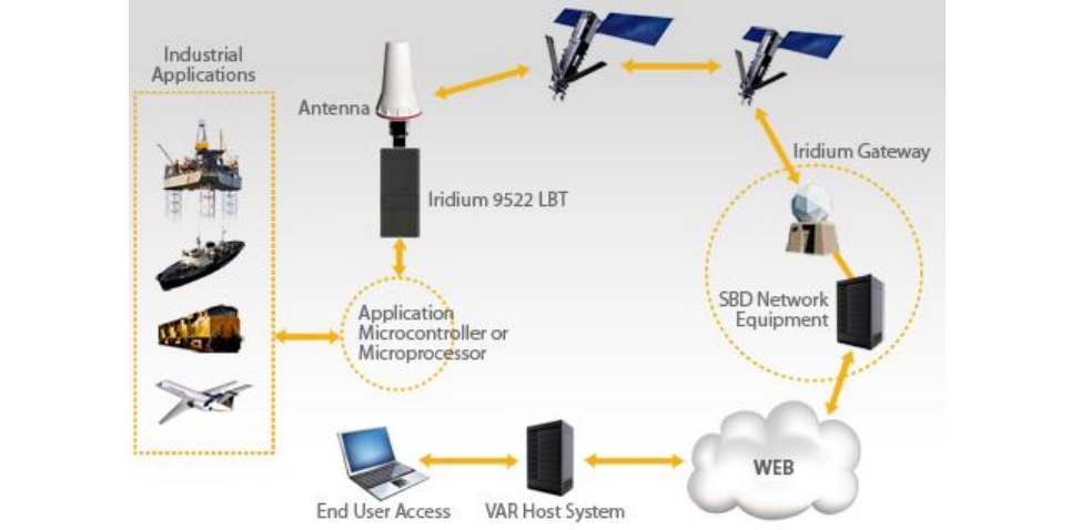
An overview of the satellite network is provided as well as descriptions of the terminal equipment and the
end to end communications protocol for SBD. This document is intended for use by technical personnel and
assumes a reasonable level of technical skill and familiarity with satellite and/or wireless data applications.
1.2. Scope
This document provides an explanation of:
1. How the Mobile Originated and Mobile Terminated SBD protocol works through an overview and
command descriptions.
2. Specific SBD related AT commands and responses as it relates to Mobile Originated and Mobile
Terminated SBD messages
3. Interface requirements between the Iridium Gateway and the Vendor Application
Additional documents are referenced which provide more specific detail on certain topics and these are
listed in Section 1.3 of this document. This document does not specifically define the provisioning process,
although it does reference it. This document assumes a working knowledge of the Iridium satellite system.
1.3. References
1.3.1. Specifically Referenced Documents
[1] ISU AT Command Reference
[2] 9522A L-Band Transceiver Product Information Guide
[3] 9522B L-Band Transceiver Product Information Guide
[4] 9601 SBD Transceiver Product Developers Guide
[5] 9602 SBD Transceiver Product Developers Guide
These documents are accessible from the Iridium Web Support under Support:
http://www.iridium.com.
1.3.2. Other Useful Documents
These documents are accessible from the Iridium public web site: http://www.iridium.com .
Data Services Overview: The document includes Frequently Asked Questions (FAQs) for both
Dial-up and Direct Internet Data Services. Both of these services are circuit switched.
Dial-Up Data User’s Guide: Provides detailed description of the set-up and use of dial-up data
services
Mobile Terminated Data User’s Guide: Provides a detailed description of the set-up, operation,
and constraints as it relates to terminating data calls.

Iridium
Short Burst Data Developers Guide V3.0
Iridium Proprietary and Confidential © Iridium Satellite LLC
10
1.4. Definitions, Acronyms, and Abbreviations
API
Application Programming Interface
ATC
AT Command
CDR
Call Detail Record
DB
Data Base
DMO
DirectIP Mobile Originated
DMT
DirectIP Mobile Terminated
DSC
Delivery Short Code
DTE
Data Terminal Equipment
ECS
ETC Communications Subsystem
EMO
Email Mobile Originated
EMT
Email Mobile Terminated
ESS
ETC SBD Subsystem
ETC
Earth Terminal Controller
ETS
ETC Transmission Subsystem
FA
Field Application
GPS
Global Positioning System
IE
Information Element
IEI
Information Element Identifier
IMEI
International Mobile Equipment Identity
IP
Internet Protocol
ISU
Iridium Subscriber Unit
LBT
L-Band Transceiver
Message
The complete data transfer between the Vendor Application and the
Iridium Gateway including a head, optional sets of information and the
payload to be transmitted over the air.
MIME
Multipurpose Internet Mail Extensions
MO
Mobile Originated
MOMSN
Mobile Originated Message Sequence Number
Mobile Originated Buffer
This is the buffer in the ISU in which an SBD message to be sent from
the ISU to the Iridium Gateway will be stored.
MSN
Message Sequence Number
MT
Mobile Terminated
MTMSN
Mobile Terminated Message Sequence Number
Mobile Terminated Buffer
This is the buffer in the ISU in which an SBD message sent from the
Iridium Gateway to the ISU will be stored.
Payload
The actual user data to be transmitted over the Iridium network
PIN
Personal Identification Number
SBD
Short Burst Data
SIM
Subscriber Identity Module
SPNet
Iridium’s proprietary provisioning tool for contracted business partners
SEP
SBD ETC Processor
SPP
SBD Post Processor
UTC
Coordinated Universal Time
VA
Vendor Application

Iridium
Short Burst Data Developers Guide V3.0
Iridium Proprietary and Confidential © Iridium Satellite LLC
11
1.5. Transceiver Message Size Capability
In order to ensure consistency and provide a useful reference, the following table should be consulted for
the maximum message size capabilities of various transceivers:
Transceiver Name
Maximum Mobile Originated
Message Size (Bytes)
Maximum Mobile Terminated
Message Size (Bytes)
Firmware Revision
Recommended
9522A
1960
1890
IS06001
9522B
1960
1890
ST10001
9601
340
270
TD10003
9602
340
270
TA11002
1.6. What’s New
The following features have been added to SBD for DirectIP:
MO Delivery Confirmation (see Sections 6.2.7 & 6.2.1)
MT Prioritization of messages for a specific IMEI (see Sections 7.2.3.1.4 & 7.2.3.1.7)
MT disposition flags added for high priority messages (see Section 7.2.3)
MT disposition flag allowable combinations (see Sections 7.2.3.1 & 7.2.3.1.6)
Iridium
Short Burst Data Developers Guide V3.0
Iridium Proprietary and Confidential © Iridium Satellite LLC
12
2. Overview
The overview is split into two sections: network and transceiver
2.1. Overview of Iridium Satellite Network for Short Burst Data
Iridium’s Short Burst Data Service (SBD) is a simple and efficient satellite network transport capability to
transmit short data messages between field equipment and a centralized host computing system. The
maximum Mobile Originated (MO) SBD and Mobile Terminated (MT) SBD message sizes are transceiver
specific and are described in Section 1 of this document. [Note that a zero (0) byte MO SBD message is
referred to as a “Mailbox Check.”] (See reference documents [2] and [3] in addition to Section 1.)
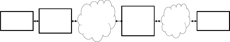
The primary elements of the end to end SBD architecture are shown in Figure 2-1. Specifically, the elements
consist of the Field Application (FA), the Iridium Subscriber Unit (ISU), the Iridium satellite constellation, the
Gateway SBD Subsystem (Iridium Gateway) located at the Iridium gateway, the Internet, and the Vendor
Application (VA.) More details on the system architecture are shown in Figure 2-2.
The Field Application represents the hardware and software that is configured by the VAR for specific
applications such as collecting and transmitting GPS location information. The ISU is an Iridium L-Band
Transceiver (LBT) with the SBD feature available in firmware and the service activated on the Iridium
network. The Iridium Gateway is responsible for storing and forwarding messages from the ISU to the
Vendor Application and storing messages from the Vendor Application to forward to the ISU. The ISU
communicates with the Iridium Gateway via the Iridium satellite constellation.
Figure 2-1 Short Burst Data Architecture
The interface between the Vendor Application and the Iridium Gateway uses either standard Internet mail
protocols or an IP Socket type interface to send and receive messages. Mobile terminated messages are
sent to the Iridium Gateway using a common email or IP address, identifying the specific ISU by encoding
the unique ISU IMEI in the subject line of the email or as part of the IP Socket payload. For email the data
message itself is transported as a binary attachment to the email. For IP Socket the data message is part of
the payload. Messages sent to the Vendor Application are delivered to a specific email or IP address that is
configured when the IMEI is provisioned. The delivery address for each IMEI can be changed on-line by the
VAR using the Iridium SPNet provisioning tool.
It is also possible for one ISU to send a message direct to another ISU(s) without the message passing to
the Vendor Application. The second ISU destination IMEI must be programmed on-line by the VAR using
the Iridium SPNet provisioning tool. However, only one delivery type (email or ISU-ISU) is permitted. Up to 5
IP socket addresses/ports for each MO session. As well, the SBD system will support a “mix and match” of
Email/DirectIP/ISUtoISU provisioning a total of 5 unique destinations. The interface between the FA and the
ISU is a serial connection with extended proprietary AT commands. This interface is used to load and
retrieve messages between the ISU and the Field Application.
For a Mobile Originated SBD Message (MO-SBD), the message is loaded into the MO buffer in the ISU
IP Socket
or Email
Field
Application
[FA]
Iridium
Subscriber
Unit
[ISU]
Iridium
Satellite
Constellation
Iridium
Gateway
SBD
Subsystem
[GSS]
Vendor
Application
[FA]
IP Socket
or Email
IP Socket
or Email
Field
Application
[FA]
Iridium
Subscriber
Unit
[ISU]
Iridium
Satellite
Constellation
Iridium
Satellite
Constellation
Iridium
Gateway
SBD
Subsystem
[GSS]
Vendor
Application
[FA]
Iridium
Short Burst Data Developers Guide V3.0
Iridium Proprietary and Confidential © Iridium Satellite LLC
13
using the +SBDWB or +SBDWT AT Commands, a message transfer session between the ISU and the
Iridium Gateway is initiated using the AT Command +SBDI[X]. For a Mobile Terminated SBD Message (MT-
SBD), the ISU can either initiate a Mailbox Check using the AT Command +SBDI to check whether a MT
message is queued at the Iridium Gateway; or the ISU can use the (suitably configured) “Ring Alert” or
“Automatic Notification” capability to be told when a MT message is queued at the Iridium Gateway. The ISU
must then retrieve the MT-SBD message from the Iridium Gateway by issuing the +SBDI[X] command.
When the message is received from the Iridium Gateway it can be retrieved from the MT buffer in the ISU by
the Field Application using the +SBDRB or +SBDRT AT Commands. Additionally a MT-SBD message can
also be retrieved in the same network transaction by the ISU when a MO-SBD message is sent from the
ISU.
Figure 2-2 SBD System Architecture
Messages are transferred between the ISU and the Iridium Gateway using a reliable transport mechanism
that ensures the message is delivered error free. If the ISU was not able to send or receive messages, an
indication is passed to the FA via the serial interface.
The MO and MT message buffers in the ISU will maintain messages as long as the ISU is powered on.
Once a message is transferred from the FA to the MO buffer in the ISU, it will remain there even after it is
successfully sent to the Iridium Gateway. If a MT message is received at the ISU from the Iridium Gateway,
it will remain in the MT buffer even after the FA reads it. The buffers in the ISU will be cleared only when
either given an explicit command (+SBDD) or when the ISU is power cycled or is overwritten with new data.
The MT buffer will be cleared when a SBD session is initiated.
All MO and MT messages between the VA and the Iridium Gateway are routed to the Internet by default.
Iridium offers additional cost options for Virtual Private Network (VPN) and leased line routing of email or IP
Socket messages to provide additional security, capacity and/or redundancy if required for the application.
ISU-ISU SBD messages remain entirely within the Iridium network infrastructure, however it should be noted
that they pass through the Iridium gateway and do not transfer directly from one ISU to another.
Iridium
Short Burst Data Developers Guide V3.0
Iridium Proprietary and Confidential © Iridium Satellite LLC
14
2.2. Transceiver Overview
The following Iridium transceivers are capable of Short Burst Data Service.
L-Band Transceiver
SBD Transceiver
9522A
9601
9522B
9602
Developers should consult the appropriate developers guide document for the transceiver hardware.
Iridium
Short Burst Data Developers Guide V3.0
Iridium Proprietary and Confidential © Iridium Satellite LLC
15
3. Email Description
Applications that utilize SBD will communicate to the Iridium network via the Iridium Gateway interface. This
interface utilizes email or IP Socket interfaces for the transfer of data messages to and from the Vendor
Application. This section describes how to utilize the Iridium Gateway interface in both Mobile Originated
and Mobile Terminated cases. Mobile Terminated messages are messages originated by the Vendor
Application (or another ISU), that are sent to the Field Application. Mobile Originated messages are
messages originated by the Field Application that are sent to either the Vendor Application or to another
ISU.
In the case of ISU-ISU SBD messages, the originating message from the first IMEI is a Mobile Originated
Message. Once received and processed in the Iridium Gateway the message then becomes a Mobile
Terminated Message with respect to the second ISU.
For ISU’s provisioned to use email, each MO or MT message the VA will receive an email for each session
that reaches the Iridium Gateway regardless of any message transfer, unless one or both of the ISUs are
provisioned to send to another ISU, in which case only the ISU provisioned to send to an email address will
receive email notifications.
This section describes in more detail the operation of Mobile Terminated, Mobile Originated in email mode.
‘ISU to ISU’ mode, which is independent of email or IP Socket, is described separately in Section 5.
4. Direct Internet Protocol Socket “DirectIP” Interface
DirectIP is a socket-based delivery mechanism for Mobile Originated and Mobile Terminated SBD
Messages. The name references the basic concept of directly connecting to a distant IP address for data
delivery and reception. This section of the SBD Developers Guide is the DirectIP interface control document
between the Iridium Gateway and the Vendor Application(s). It does not provide details of the DirectIP
processing within the Iridium Gateway.
The Vendor Application interface to DirectIP requires software development by the applications developer.
Iridium does not provide finished software, reference code, or applications software support for the Vendor
Application. Applications developers will need to develop software to handle both Mobile Originated and
Mobile Terminated DirectIP Connections.
4.1. DirectIP Overview
DirectIP is an efficient method of transferring SBD data between the Iridium Gateway and the Vendor
Application. DirectIP provides lower delivery latency than the existing email protocol. It consists of a
specialized socket-oriented communications protocol that utilizes direct connections between the Iridium
gateway SBD subsystem and the Vendor Application.
Similar to SBD processing of MO and MT e-mail messages, DirectIP is composed of separate MO and MT
Iridium Gateway components. The MO DirectIP component acts as a client to the Vendor MO DirectIP
server application. The MT DirectIP component acts as a server to the vendor MT DirectIP clients. In other
words, the Iridium Gateway MO component seeks to establish a connection to the vendor server for MO
transfers while the Iridium Gateway MT component actively listens for connections from the vendor clients
for MT transfers. In either direction, clients only attach to the server when they are delivering data.

Iridium
Short Burst Data Developers Guide V3.0
Iridium Proprietary and Confidential © Iridium Satellite LLC
16
Both MO DirectIP and MT DirectIP protocols utilize bi-directional TCP/IP socket connections. The MO
DirectIP protocol only delivers SBD MO messages from the Iridium Gateway client to the vendor server. No
acknowledgement is expected from the server. In contrast, the MT DirectIP protocol delivers SBD MT
messages from the vendor client to the Iridium Gateway server, and a confirmation is passed from the
server back to the client indicating the success or failure of the processing of the message.
The specific TCP/IP ports and IP addresses for both MO and MT DirectIP are provided to authorized VARs
in a separate document available from their Iridium account manager.
4.2. MO and MT Message Specifications
4.2.1. Overall Message Structure
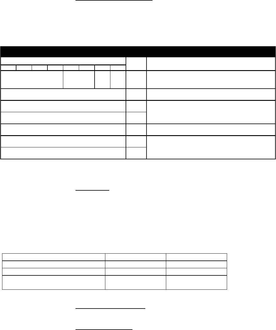
The overall message structure for both MO and MT DirectIP is shown in Table 4-1. When a connection is
first established, the receiving application will receive three bytes. The first is a general DirectIP protocol
revision number (this document describes revision 1). The following two bytes indicate the number of bytes
that make up the body of the message that is made up of some number of information elements.
Table 4-1 Overall Message Format
Field Name
Data Type
Length (bytes)
Range of Values
Protocol Revision Number
char
1
1
Overall Message Length
unsigned short
2
N
Information Elements
Related to Message
variable
N
DMO: See Section Table 6-3
DMT: See Section Table 7.1-3
4.2.1.1. Message Length
The message length value indicates the number of bytes that make up the body of the message being
transferred following the initial three bytes. This enables the receiving end to know deterministically when all
bytes transferred have been received. This is particularly relevant when multiple receives over the socket
are required to read in the entire message.
Iridium GSS
Client
Iridium GSS
Server
Vendor
Application
Server
Vendor
Application
Client
Mobile Originated SBD
Mobile Terminated SBD

Iridium
Short Burst Data Developers Guide V3.0
Iridium Proprietary and Confidential © Iridium Satellite LLC
17
4.2.1.2. Byte Alignment
The entire message transfer will be treated as a byte stream. This enables the various data types contained
within the message to be transferred with no consideration given to the byte alignment of the data types.
This also allows for the compacting of the fields to the appropriate sizes. Multi-byte fields are transmitted in
network byte order (big endian). For example the four-byte field 0x0a0b0c0d is transmitted as follows:
byte address 0 1 2 3___
bit offset 01234567 01234567 01234567 01234567
binary 00001010 00001011 00001100 00001101
hex 0a 0b 0c 0d___
4.3. Information Elements
To maintain maximum flexibility within the protocol, all data to be transferred has been segmented into
information elements (IEs). Those IEs currently defined are shown in detail in Sections 6.2.4 & Section
7.2.2. The general format of each IE is the same and is shown in Table 4-2.
Table 4-2 Information Element General Format
Field Name
Data Type
Length
(bytes)
Range of Values
Information Element ID (IEI)
char
1
DMO: See Table 6-3
DMT: See Table 7.1-3
Information Element Length
unsigned short
2
Variable
Information Element Contents
variable
N
DMO: See Section 6.2.4
DMT: See Section 7.2.2
4.3.1.1. Information Element Identifiers
Each IE begins with a 1-byte information element identifier (IEI) that uniquely defines the following 2+N
bytes. A complete list of the IEs and their associated IEIs is shown in sections 6.2.4 & 7.2.2.
4.3.1.2. Information Element Length
The two bytes following the IEI give the length of the IE in bytes following the initial three bytes. While the
length for all currently defined IEs other than the MO and MT payloads may be represented with a 1-byte
field, a 2-byte field is used for consistency across all IEs.
The primary goal for including the length field in every IE as a standard is to allow for new IEs in the future
that may or may not be recognized by a Vendor Application based the vendor’s upgrade path. If the
application does not recognize an IE, it will know that it can read the next two bytes as a length and then
skip that number of bytes before checking for the next IEI.
4.3.1.3. Parsing Information Elements
Once an entire message has been received, a parser will step through the bytes. The first will be an IEI
followed by two bytes representing the number of bytes in the IE following the length. How to interpret these
bytes is dictated by the IE type as indicated by the IEI. Once they are parsed, and if there are additional
bytes received in the overall message, the next IEI may be checked, etc. If there are too many or too few
bytes received as determined by the parser, the overall message will be dropped. For MT message
processing, an error will be returned in the confirmation message.
Iridium
Short Burst Data Developers Guide V3.0
Iridium Proprietary and Confidential © Iridium Satellite LLC
18
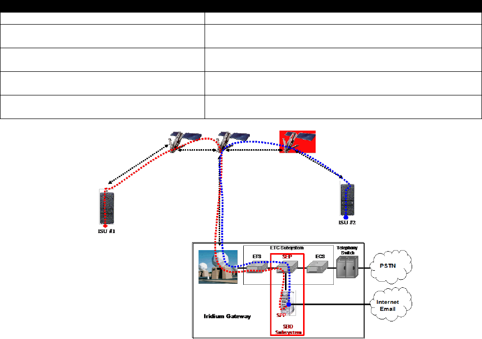
5. ISU- ISU Messages
Messages from ISU #1 are to a second ISU (ISU #2) without leaving the Iridium network. [See Figure 5-1.]
This option requires provisioning by the Value Added Reseller through SPNet. ISU #1 can be provisioned to
send the same MO-SBD message to up to five ISUs. Note that there is an ability to deliver a MO-SBD
message to up to 5 DirectIp delivery destinations. It is also, possible to mix and match email, ISU, SSD-
SSD and direct IP destinations for MO-SBD messages.
ISU-ISU SBD messages are billed twice. Once as a MO-SBD message to the initiating ISU IMEI and once
as a MT-SBD message to the terminating ISU IMEI.
The MO-SBD message from ISU #1 is placed into the MT-SBD queue of ISU #2 when it has been received
by the Iridium Gateway. The MO-SBD message is never delivered to the Vendor Application as no email
address can be programmed for the Vendor Application. No SBD session descriptors are delivered to either
the originating or terminating ISU. However if ISU #2 is provided to send MO-SBD messages to a VA, then
the mailbox check or sending of a MO-SBD message will cause an email message indicating the mailbox
check or the transmission of the MO-SBD message to the Vendor Application. There are five error
conditions that can occur in ISU-ISU SBD messaging as shown in below.
Table 5-1 Mobile Originated Message Email Message Field Description
Error Condition
Action
Message size = 0 bytes
MT-SBD message will not be queued and will be deleted
Message Size >270 bytes when ISU #2 is
a 9601 or 9602 SBD Transceiver
MT-SBD message will not be queued and will be deleted
Message size >1890 bytes when ISU #2 is
a 9522, 9522A or 9522B LBT
MT-SBD message will not be queued and will be deleted
Destination ISU MT queue > 50 messages
If the destination ISU MT queue is full the MT-SBD
message will not be queued
Destination ISU is not provisioned
If the destination ISU is not provisioned the MT-SBD
message will not be queued
Figure 5-1 SBD Call Routing for ISU-ISU Messages

Iridium
Short Burst Data Developers Guide V3.0
Iridium Proprietary and Confidential © Iridium Satellite LLC
19
6. Mobile Originated Messages
6.1. Email MO
Messages sent from the ISU to the Iridium Gateway are processed at the Iridium Gateway where they are
immediately formatted and sent to the destination email address that was provisioned with the ISU IMEI.
The message sent to the Vendor Application from the ISU will be carried as a binary attachment to an email
from the Iridium Gateway to the Vendor Application. The binary attachment is encoded using standard
MIME Base64 encoding as defined in RFC 2045. Unlike Mobile Terminated messages sent to the Iridium
Gateway, Mobile Originated messages sent to the Vendor Application carry additional information in the
email message body. This information includes the Mobile Originated Message Sequence Number
(MOMSN), the time of the session, the session status, the message size, and ISU specific geo-location
information. The format of such an email message is provided in Figure 6-1, details of the email message
fields are provided in Table 6-1. Note that it is possible to tell the Iridium Gateway not to send the
geographic location fields on a device by device basis. This is achieved by using SPNet and un-checking
the “Include Geo-Data” box for the specific ISU IMEI. An example of an email message with no geo-location
information is shown in Figure 3-6.
A MO-SBD message may be sent to up to five email destinations. The five destinations are programmed
into the Iridium Gateway by using the SPNet provisioning tool available to Value Added Resellers. Note that
there is an ability to deliver a MO-SBD message to up to 5 Direct IP delivery destinations and it is possible
to mix delivery types. [See also Section 5 “ISU to ISU Messages.”]
Figure 6-1 Mobile Originated Email Message Showing Geolocation information
From: sbdservice@sbd.iridium.com
Sent: Tuesday, August 13, 2002 12:49 PM
Subject: SBD Msg From Unit: 304050607080903
MOMSN: 23
MTMSN: 0
Time of Session (UTC): Tue Aug 13 16:51:04 2002
Session Status: 00 - TRANSFER OK
Message Size (bytes): 351
Unit Location: Lat = 59.372463 Long = 75.309806
CEPradius = 3
Message is Attached.
From: sbdservice@sbd.iridium.com
Sent: Friday, July 8, 2005 00:12 AM
Subject: SBD Msg From Unit: 300003000210150
MOMSN: 652
MTMSN: 644
Time of Session (UTC): Fri Jul 8 00:12:55 2005

Iridium
Short Burst Data Developers Guide V3.0
Iridium Proprietary and Confidential © Iridium Satellite LLC
20
Figure 6-2 Mobile Originated Email Message without Geolocation information
Table 6-1 Mobile Originated Message Email Message Field Description
Field Name
Description
From
This field identifies the sender of the email message as the SBD Service. This field normally
contains “sbdservice@sbd.iridium.com”
Sent
This field provides the time at which the message was emailed from the Iridium Gateway to the
Vendor Application. The timestamp is in UTC.
Subject
This field provides the ISU IMEI of the unit that sent the MO message.
MOMSN
This is the Message Sequence Number set by the ISU when the message was sent from the ISU
to the Iridium Gateway. The value is an integer in the range 0 to 65,535 and is incremented each
time an SBD session is successfully completed between the ISU to the Iridium Gateway. It is a
wrap around counter which will increment to 0 after reaching 65535.
MTMSN
This is the Message Sequence Number used by the Iridium Gateway when the message was sent
from the Iridium Gateway to the ISU. The value is an integer in the range 0 to 65,535 and is
incremented each time the Iridium Gateway forwards a message to a particular ISU. It is a wrap
around counter which will increment to 1 after reaching 65535. It will have a value of zero (0) if no
MT message transfer attempt occurred to the specific ISU.
Time of
Session
This field provides the UTC timestamp of the ISU session between the ISU and the Iridium
Gateway. A text string is sent with the following format: “DDD MMM dd HH:MM:SS yyyy”.
Value
Description
DDD
Day of the week (Sun, Mon, Tue, Wed, Thu, Fri, Sat)
MMM
Month of the year (Jan, Feb, Mar, Apr, May, Jun, Jul, Aug, Sep, Oct, Nov, Dec)
dd
Day of the month (01 to 31)
hh
Hour (00 to 23)
mm
Minute (00 to 59)
ss
Second (00 to 59)
yyyy
Year
Session
Status
There are seven possible results of the SBD session which are described below:
Session Status
Description
00 - Transfer OK
The SBD session between the ISU and the Iridium Gateway
completed successfully.
01 - MT Message Too Large
The MT message queued at the Iridium Gateway is too large to be
transferred within a single SBD session
10 - SBD Timeout
The SBD Session timed out before session completion
12 - MO Message Too Large
The MO message being transferred by the ISU is too large to be
transferred within a single SBD session
13 - Incomplete Transfer
A RF link loss occurred during the SBD session
14 - SBD Protocol Error
An ISU protocol anomaly occurred during the SBD session
15 - SBD Denial
The ISU is not allowed to access the system
Message Size
This field provides an indication of the size, in bytes, of the attached message in decoded form.
This is not the length of the MIME encoded data.
Unit Location
These fields are optional at the time that the ISU is provisioned. These fields provide the
geographic location of the ISU. The latitude and longitude provide a center point and the CEP
Radius provides the radius (measured in Kilometers) around the center point within which the unit
is located. This reported position is accurate (within the reported circle) 80% of the time. Note that
activating or deactivating the inclusion of the ISU location can only be accomplished via SPNet. It
cannot be controlled by or from the ISU and is enabled by default.
Unit Latitude
This field provides the geographic latitude of the ISU measured in degrees.
Positive represents north, negative represents south. When GEO location
data is provisioned to “off” the latitude the field is not included in the email.
Unit Longitude
This field provides the geographic longitude of the ISU measured in degrees.
Positive represents east, negative represents west. When GEO location data
is provisioned to “off” the longitude the field is not included in the email.
CEPRadius
This field provides an estimate of the accuracy of the ISU’s location. This
position is reported in Kilometers. When GEO location data is provisioned to
“off” the CEPRadius the field is not included in the email.

Iridium
Short Burst Data Developers Guide V3.0
Iridium Proprietary and Confidential © Iridium Satellite LLC
21
6.1.1. Permitted Email Address Formats
The following formats of email address are permitted for Mobile Originated messages:
Name@domain.com
o E.g. iridiumDBDProcessor@Iridium.varname.com
Name@IP_address.com
o E.G. IridiumSBDProcessor@172.16.254.1
Note that Iridium encourages the use of Name@domain.com. Use of Name@IP_address is discouraged as
per the relevant RFC2821.
6.1.2. Example of a Mobile Originated (MO) Message
The FA will load a Mobile Originated message into the ISU, initiate a SBD session, evaluate and act on the
results of the SBD session (Table 6-2). Finally, the Iridium Gateway will forward the MO message to the
Vendor Application. (Figure 6-3)
Table 6-2 FA to ISU Interface, MO Message
To ISU (from DTE)
To DTE (from ISU)
Description
AT+SBDWB=351
The FA instructs the ISU that it will write a 351 byte
message into the ISU.
READY
The ISU informs the FA that it is ready to receive the
message
Binary transfer
The FA sends the 351 byte message followed by the
two byte checksum to the ISU. This transfer is not
echoed.
0
The ISU will send a zero result code to the FA
indicating that the message was loaded without error.
AT+SBDIX
The FA instructs the ISU to initiate an SBD transfer.
+SBDI: 1, 23, 0, -1, 0, 0
The ISU informs the FA that the message was sent
successfully using MOMSN 23. No MT message
was received and no MT messages are queued.
AT+SBDD0
The FA instructs the ISU to clear the message from
the Mobile Originated buffer.
0
The ISU informs the FA that the message buffer was
cleared successfully.
From: sbdservice@sbd.iridium.com
Sent: Tuesday, August 13, 2002 12:49 PM
Subject: SBD Msg From Unit: 304050607080903
MOMSN: 23
MTMSN: 0
Time of Session (UTC): Tue Aug 13 16:51:04 2002
Session Status: 00 - TRANSFER OK

Iridium
Short Burst Data Developers Guide V3.0
Iridium Proprietary and Confidential © Iridium Satellite LLC
22
Message Size (bytes): 351
Unit Location: Lat = 59.372463 Long = 75.309806
CEPradius = 3
Message is Attached.
Figure 6-3 VA to Iridium Gateway Interface, MO Message
6.2. DirectIP
Upon the completion of an SBD session between the IMEI and the Iridium Gateway, the Iridium Gateway
opens a socket, connects to the Vendor Application, and delivers the MO message including SBD session
descriptors. Messages to the same Vendor Application are delivered in a first-in-first-out (FIFO) manner so
that they are delivered in the same sequence that they are received by the Iridium Gateway. All other
messages destined for the same Vendor Application are queued behind the first message while it is being
delivered. Only one message is delivered per socket connection. Once a socket connection is established,
a single MO message is delivered, and then the socket is closed. This sequence is repeated for every MO
message queued for delivery to the vendor server.
6.2.1. Optional MO Receipt Confirmation
SSDs delivering to a vendor server may be provisioned in the GSS to require an application layer
acknowledgement, or confirmation message, from the server back to the gateway before the delivery is
marked as ‘Delivered’. While extremely rare, it is possible that a message could be marked as ‘Delivered’ in
the SBD system, but the message was not received by the vendor. This issue is due to the way operating
systems and other network elements pass messages over TCP/IP. If a vendor uses the application layer
acknowledgement, the SBD system connects and sends a message to the vendor’s server. The SBD
system will then wait for a confirmation message. If a confirmation, message is received indicating success,
the message is marked as Delivered. If the confirmation message is not received, or is invalid, this indicates
failure, the message is requeued for delivery.
6.2.2. Vendor Application Server Unavailable
If the initial attempt to connect to the vendor application times out, the subsequent MO message delivery will
not take place and subsequent connection attempts will be made. A retry scheme has been implemented to
back off delivery attempts to unreachable servers. Retries will occur after 1, 5, 10, 20, 30, 60, 120, 240, and
360 seconds with the maximum of 360 seconds used for every retry thereafter. Connection attempts
continue to be made for up to 12 hours. Each individual message has a lifetime of 12 hours starting at the
time that the payload was received at the Iridium Gateway. If it is not able to be delivered within this lifetime,
it will be marked as “DirectIP_Timeout” in the SBD database and removed from the delivery queue.
Up to 10,000 messages may be queued for a specific Vendor Application. If this limit is exceeded, payloads
will be deleted from the front of the queue (the “oldest” payloads.)
6.2.3. MO DirectIP Server/Client Requirements
MO Iridium Gateway Client Requirements
A. The client will seek to establish a TCP/IP socket connection to the IP address and port provisioned
for the originating IMEI.
B. Once connected, the client will transmit the MO payload and close the socket connection.
C. If no connection is established, the client will implement the retry scheme outlined in Section 6.2.2.

Iridium
Short Burst Data Developers Guide V3.0
Iridium Proprietary and Confidential © Iridium Satellite LLC
23
D. Once the message has been transmitted, the client will close the socket connection. No
acknowledgement from the server will be expected.
MO Vendor Server Requirements
A. The server will listen for TCP/IP socket connections on a specific port. This specific port is what has
been specified during provisioning.
B. Once connected, the server will receive the entire MO message before parsing.
C. The server will allow the Iridium Gateway client to close the socket connection.
a. Client Side (DMO process at IST)
i. Open connection (a socket connection)
ii. Send data over socket
iii. Close connection (close the socket)
b. Server Side (Customer App)
i. Accept Connection
ii. Read header body
iii. Close socket. (This action allows the socket to be returned back into available use)
iv. A common TCP/IP ‘best practice’ is to close the socket connection from both sides.
6.2.4. MO Information Element Identifiers
Table 6-3 summarizes the IEIs for the information elements passed within the DirectIP protocol.
Table 6-3 MO Information Elements
Information Element
IEI Value
Described In
MO Header IEI
0x01
Section 6.2.4.1
MO Payload IEI
0x02
Section 6.2.5
MO Location Information IEI
0x03
Section 6.2.6
MO Confirmation IEI
0x05
Section 6.2.7
6.2.4.1. MO DirectIP Header
The information in this header is required as part of every DirectIP MO message delivery. It includes all of
the information necessary to uniquely identify the SBD MO message. It also includes the overall SBD
session status and identifier (MTMSN) for the associated MT message delivery, if any.
Table 6-4 MO DirectIP Header IE
Field Name
Data Type
Length (bytes)
Range of Values
MO Header IEI
char
1
See Table 6-3
MO Header Length
unsigned short
2
28
CDR Reference (Auto ID)
unsigned integer
4
0 - 4294967295
IMEI
char
15
ASCII Numeric Characters
Session Status
unsigned char
1
See Table 6-5
MOMSN
unsigned short
2
1 – 65535
MTMSN
unsigned short
2
0 – 65535
Time of Session
unsigned integer
4
Epoch Time

Iridium
Short Burst Data Developers Guide V3.0
Iridium Proprietary and Confidential © Iridium Satellite LLC
24
6.2.4.1.1. MO Header Length
This field specifies the number of bytes in the IE following this byte. Even though the length is fixed, the
field is included as a standard across all IEs and to allow for maximum flexibility for future enhancements.
6.2.4.1.2. CDR Reference
Each call data record (CDR) maintained in the Iridium Gateway Database is given a unique value
independent of all other information in order to absolutely guarantee that each CDR is able to be
differentiated from all others. This reference number, also called the auto ID, is included should the need for
such differentiation and reference arise.
6.2.4.1.3. IMEI
The IMEI is the equipment identifier, unique to each Iridium field device, of the IMEI originating the MO
message. It is a 15-digit number represented here in ASCII format.
6.2.4.1.4. Session Status
This field provides an indication of success of the SBD session between the IMEI and the Iridium Gateway
associated with the over-the-air payload delivery. The possible values are shown in Table 6-5. If the status
was unsuccessful, no payload will be included in the MO message.
Table 6-5 SBD Session Status Values
Value
Description
0
The SBD session completed successfully.
1
The MO message transfer, if any, was successful. The MT
message queued at the Iridium Gateway is too large to be
transferred within a single SBD session.
2
The MO message transfer, if any, was successful. The reported
location was determined to be of unacceptable quality. This
value is only applicable to IMEIs using SBD protocol revision 1.
10
The SBD session timed out before session completion.
12
The MO message being transferred by the IMEI is too large to
be transferred within a single SBD session.
13
An RF link loss occurred during the SBD session.
14
An IMEI protocol anomaly occurred during SBD session.
15
The IMEI is prohibited from accessing the Iridium Gateway.
6.2.4.1.5. MOMSN
This is the mobile-originated message sequence number (MOMSN) associated with the SBD session. This
value is set by the IMEI and transmitted to the Iridium Gateway as part of every SBD session. It is
incremented by the IMEI after every successful session.
6.2.4.1.6. MTMSN
This is the mobile-terminated message sequence number (MTMSN) associated with the SBD session. This
value is set by the Iridium Gateway at the time that an MT message is queued for delivery and is unique to
each IMEI. It is then sent to the IMEI as part of the MT payload transfer. If an MT payload transfer was
attempted, the MTMSN will be included in the header regardless of the success of the session. If the
session failed, the payload is still queued for delivery. If no MT delivery attempt was made in the session,
this value will be zero.
6.2.4.1.7. Time of Session
This field provides a UTC timestamp of the IMEI session between the IMEI and the Iridium Gateway in the
format of an epoch time integer. The epoch time is the number of seconds since the start of the UNIX

Iridium
Short Burst Data Developers Guide V3.0
Iridium Proprietary and Confidential © Iridium Satellite LLC
25
epoch at 1/1/1970 00:00:00.
Format: epoch time integer
Resolution: 1 second
6.2.5. MO Payload
This information element includes the actual MO payload delivered from the IMEI to the Iridium Gateway
during the SBD session identified in the header. In an MO message delivery related to an empty mailbox
check (EMBC) session or a failed session, no payload will be included.
Table 6-6 MO Payload IE
Field Name
Data Type
Length (bytes)
Range of Values
MO Payload IEI
char
1
See Table 6-3
MO Payload Length
unsigned short
2
All others: 1 – 1960
9601, 9602:1-340
MO Payload
char
1 – 1960
Payload Bytes
6.2.5.1. MO Payload Length
This field indicates the number of the bytes in the MO payload.
6.2.5.2. MO Payload
This is the actual content of the MO payload. The maximum MO payload size is transceiver specific. See
Section 1 for further information
6.2.6. MO Location Information
The location values included in this IE provide an estimate of the originating IMEI’s location. The inclusion
of this information in an MO message delivery is optional. Whether or not it is included is established when
the IMEI is provisioned and may be changed at any time via SPNet. The CEP radius provides the radius
around the center point within which the unit is located. While the resolution of the reported position is given
to 1/1000th of a minute, it is only accurate to within 10Km 80% of the time.
Table 6-7 MO Location Information IE
Field Name
Data Type
Length
(bytes)
Range of Values
MO Location Information IEI
char
1
See Table 6-3
MO Location Info Length
unsigned short
2
20
Latitude/Longitude
Double
7
See Table 6-8
CEP Radius
unsigned integer
4
1 – 2000
6.2.6.1. MO Location Information Length
This field specifies the number of bytes in the IE following this byte. Even though the length is fixed, the field
is included as a standard across all IEs and to allow for maximum flexibility for future enhancements.
Iridium
Short Burst Data Developers Guide V3.0
Iridium Proprietary and Confidential © Iridium Satellite LLC
26
6.2.6.2. MO Latitude and Longitude
The latitude and longitude provide a center point of the estimated location and are derived from the LGC
coordinates output from the CPLD exchange during the SBD session.
Table 6-8 MO Location Data Format
MSB LSB
0 1 2 3 4 5 6 7
NSI EWI 1
Reserved & Format Code: 0 (all other values are reserved)
NSI: North/South Indicator (0=North, 1=South)
EWI: East/West Indicator (0=East, 1=West)
2
Decimal Range: 0 to 90
Hex Range: 0x00 to 0x5A
3
4
5
Decimal Range: 0 to 180
Hex Range: 0x00 to 0xB4
6
7
Location Data Format
Byte
Number
Description & Allowed Values
Bit Position
Reserved
Format Code
Latitude (degrees)
Latitude (thousandths of a minute, MS-Byte)
Decimal Range: 0 to 59,999 (unsigned integer, American notation)
Hex Range: 0x0000 to 0xEA5F
Latitude (thousandths of a minute, LS-Byte)
Longitude (degrees)
Longitude (thousandths of a minute, MS-Byte)
Decimal Range: 0 to 59,999 (unsigned integer, American notation)
Hex Range: 0x0000 to 0xEA5F
Longitude (thousandths of a minute, LS-Byte)
Resolution: thousandths of a degree
6.2.6.3. CEP Radius
The CEP radius provides the radius (in Kilometers) around the center point within which the IMEI is located
with an 80% probability of accuracy.
6.2.7. MO Confirmation Message
This IE forms the application layer acknowledgement, or confirmation, that may optionally be returned from
the MO DirectIP vendor server to the Iridium Gateway. If the SSD is provisioned to enable confirmation, this
message must be returned to the Iridium Gateway for the delivery to be successful. See section 6.2.1 for
more information and section Error! Reference source not found. for an example message.
Field Name
Length (in Bytes)
Range of Values
MO Confirmation IEI
1
See section 6.2.7
MO Confirmation Length
2
1
Confirmation Status
1
1 (Success) or 0
(Failure)
6.2.7.1. MO Confirmation Length
This field specifies the number of bytes in the IE following this byte.
6.2.7.2. Confirmation Status
This field indicates the failure or success of the message receipt by the MO DirectIP vendor server.

Iridium
Short Burst Data Developers Guide V3.0
Iridium Proprietary and Confidential © Iridium Satellite LLC
27
6.2.8. MO Message Delivery Confirmation Example
Table 6-9 gives an example of an application layer acknowledgement, or confirmation, from the MO DirectIP
vendor server.
Table 6-9 MO DirectIP Message Confirmation Example
Field Name
Length (Bytes)
Value
Protocol Revision Number
1
1
Overall Message Length
2
4
MO Confirmation IEI
1
0x05
MO Confirmation Length
2
1
Confirmation Status
1
1
6.2.9. Successful MO Message Delivery Example
Table 6-10 gives an example of a byte stream for a typical MO DirectIP message following a successful
SBD session. Note that the IMEI has been provisioned such that the geolocation information is not included
in the message.
Table 6-10 MO DirectIP Message Delivery Example – Successful SBD Session
Field Name
Data Type
Length
(bytes)
Value
CODE
Protocol Revision
Number
char
1
1
01
Overall Message
Length
unsigned
short
2
104
0068
MO Header IEI
char
1
0x01
01
MO Header Length
unsigned
short
2
28
001C
CDR Reference
(Auto ID)
unsigned
integer
4
1234567
0012D687
IMEI
char
15
300034010123450
333030303334303
130313233343530
Session Status
unsigned char
1
0 (Transfer OK)
00
MOMSN
unsigned
short
2
54321
D431
MTMSN
unsigned
short
2
12345
3039
Time of Session
unsigned
integer
4
1135950305
(12/30/05 13:45:05)
43B539E1
MO Payload IEI
char
1
0x02
02
MO Payload Length
unsigned
short
2
70
46
MO Payload
char
70
Payload Bytes

Iridium
Short Burst Data Developers Guide V3.0
Iridium Proprietary and Confidential © Iridium Satellite LLC
28
6.2.10. Failed MO Message Delivery Example
Table 6-11 gives an example of a byte stream for an MO DirectIP message following a failed SBD session
due to an incomplete transfer. Note that no payload is included.
Table 6-11 MO DirectIP Message Delivery Example – Failed SBD Session
Field Name
Data Type
Length
(bytes)
Value
CODE
Protocol
Revision
Number
char
1
1
01
Overall
Message
Length
unsigned
short
2
31
1F
MO Header
IEI
char
1
0x01
01
MO Header
Length
unsigned
short
2
28
1C
CDR
Reference
(Auto ID)
unsigned
integer
4
1301567
0013DC3F
IMEI
char
15
300034010123450
333030303334303
130313233343530
Session
Status
unsigned
char
1
13 (Incomplete
Transfer)
0D
MOMSN
unsigned
short
2
54322
D432
MTMSN
unsigned
short
2
0
0000
Time of
Session
unsigned
integer
4
1135950325
(12/30/05 13:45:25)
43B539F5

Iridium
Short Burst Data Developers Guide V3.0
Iridium Proprietary and Confidential © Iridium Satellite LLC
29
7. Mobile Terminated Messages
In order to send a MT message from the Vendor Application to the Field Application, the Vendor Application
must send the message to the Iridium Gateway where it will be queued for delivery awaiting contact from the
ISU to retrieve it. The message will remain in the queue for up to five (5) days awaiting contact from the ISU
to retrieve it. After five days all MT message for the destination IMEI is removed from the queue
automatically by the Iridium Gateway. The Iridium MT purge script runs once a day at 00:06:14. If the script
encounters a message that has been queued that is older than five days, then all MT messages for that
IMEI are deleted.
There are two methods for the ISU to retrieve a queued MT messages from the Iridium Gateway. The
methods are hardware and firmware dependant. For specific capabilities consult the firmware release notes
for the particular ISU type. Iridium recommends using the latest release of firmware available in order to
provide the best performance and compatibility to the functionality described herein.
The first method, called “Polling,” is universal to all ISUs that are capable of SBD. In this method the
mailbox check command is sent from the Field Application to the ISU. The ISU contacts the Iridium Gateway
and transfers the MT message if one is queued.
The second method, called “Automatic Notification”. In this method the Iridium Gateway automatically
notifies the ISU that a message is queued at the Iridium Gateway. Note that the MT message is not
automatically delivered to the ISU. The application designer has to program the Field Application to respond
in an appropriate manner to the Automatic Notification.
7.1. Email MT
Figure 7.1-1 provides an example MT email message. MT messages must follow the formatting rules
outlined below:
The ISU must be provided in SPNet to send Ring Alerts. If this is not done the Iridium Gateway will not
send Ring Alerts even if new MT messages are queued by the Host and/or the ISU is suitably
configured.
Messages sent to an ISU from the Host are sent to the email address: data@sbd.iridium.com
Placing at least one, and up to a total of four, IMEI(s) into the subject line of the email identifies the
destination ISU(s).
o If there is more than one destination IMEIs then list the additional IMEIs on the subject line
separated with a single space between each IMEI.
White listing may be used to restrict the originator of MT-SBD messages to particular IMEIs. This
restriction will fork for email and Direct IP.
The message must contain a properly formatted sender (“From:” address), otherwise the message will
be dropped by the Iridium Gateway.
The data message to the ISU must be carried as an attachment to the email:
o The attachment name must have a ‘.sbd’ file name extension: E.g. ‘importantdata.sbd’
o File names must be 80 characters or less. (Including the .sbd extension.)
o File names are not case sensitive.
The maximum size of the binary message (not the Base64 version) is ISU specific
and is between one byte and the maximum MT message size stated in Section 1
The Iridium Gateway will reject message sizes that are too large for a particular ISU
type.
o The attachment must use standard Multipurpose Internet Mail Extensions (MIME) Base64
encoding as defined in RFC 2045.
Multiple messages may be queued by a single email by including the additional separate attachments in
the email message, subject to the maximum number of messages permitted in the queue.

Iridium
Short Burst Data Developers Guide V3.0
Iridium Proprietary and Confidential © Iridium Satellite LLC
30
o Note that if one of the attachments has an incorrect extension (something other than.sbd), while
others are correct (.sbd) then an error indication email will be sent for the invalid extensions
o A single email with multiple attachments creates a MT-SBD message for each attachment. In
other words – one email with ten attachments creates ten entries for the destination ISU.
The message body plays no role in the message transfer process; any information contained in the body
will be discarded. It is recommended that this item be left blank.
A maximum of 50 messages may be in any ISU’s queue at any one time regardless of whether they
were sent as an individual message with attachment or a single message with multiple attachments. The
Iridium Gateway will reject any message over this limit.
o A single email with multiple attachments creates a MT-SBD message for each attachment. In
other words – one email with ten attachments creates ten entries for the destination ISU.
Figure 7.1-1 Mobile Terminated Email Message
7.1.1. MT-SBD Sequence of Events
Customer sends a MT message to an ISU using DIP, email or another ISU.
Message is received at the gateway.
SBD system queues message for delivery to IMEI and RA is issued to ISU
o If no response for the remote ISU in ~20 seconds a second RA is issued.
ISU receives RA and initiates a session back to the gateway using the +SBDIXA command to
retrieve message.
Response code received at the destination ISU will indicate whether or not additional messages are
waiting.
7.1.2. Disposition Notification
The Iridium Gateway validates each MT message upon receipt and returns a disposition notification email to
the MT message originator. The format of this email is shown in Figure 7.1-2 and the definition of the email
header and body descriptors is shown in Table 7.1-1. A sample success notification is shown in Figure
7.1-3. If there is more than one destination ISU a disposition notification email will be sent for each
destination ISU. If the Vendor Application attempts to queue more than 50 messages for delivery at the
Iridium Gateway, a rejection notice email similar to Figure 3-4 will be sent to the message originator (From
address).
To: data@sbd.iridium.com
From: VA@VendorDomain.com
Subject: 304050607080903

Iridium
Short Burst Data Developers Guide V3.0
Iridium Proprietary and Confidential © Iridium Satellite LLC
31
Figure 7.1-2 MT-SBD Email disposition notification message field layout
Table 7.1-1 SBD-MT disposition notification email header and message body field descriptors
Field Name
Description
<Result Description>
This field will have one of the following values:
SBD Mobile Terminated Message Queued for Unit: <ISU IMEI>
Error: SBD Mobile-Terminated Message Not Queued for Unit: <ISU IMEI>
<ISU IMEI>
Field Value
Description
(No IMEI specified)
No IMEI provided in the subject line of the email sent to the
Iridium Gateway.
(Invalid IMEI specified)
The IMEI in the subject line of the email sent to the Iridium
Gateway was not in the proper format. Additional information
can be found in the reason code in the body of the message
Actual IMEI
The actual 15 digit IMEI of the destination ISU is returned if it
was validated.
<Description>
Additional text expanding on the queuing disposition in the subject line. It will have one
of the following values:
The following mobile-terminated message was queued for delivery:
The following mobile-terminated message was not queued for delivery:
IMEI
The hardware identification number of the unit to which the message was to be queued.
Field Value
Description
(none specified)
No IMEI provided in the subject line of the email sent to the Iridium
Gateway.
Received IMEI
The IMEI was received by the Iridium Gateway. In the case of
Success, this is the 15 numeric-digit IMEI of the ISU. In the case of
Error, this is the invalid Alpha-numeric string received by the Iridium
Gateway.
Time
The timestamp, in UTC, when the acknowledgement was sent from the Iridium
Gateway.
Attachment Filename
The filename of the attachment received by the Iridium Gateway.
Attachment Size
The size of the attachment received by the Iridium Gateway.
<Reason & Descriptive
Text>
One of the following values will be displayed:
The MTMSN is XX, and the message is number N in the queue
To:
VA@VendorDomain.com
From:
techops@iridium.com
Subject: <Result Description>: <ISU IMEI>
<Description>
IMEI: <IMEI number>
Time: <Date>

Iridium
Short Burst Data Developers Guide V3.0
Iridium Proprietary and Confidential © Iridium Satellite LLC
32
Reason: IMEI length (M) is invalid – must be 15 characters.
Reason: The IMEI (300xxxxxxxxxxxx) is not provisioned on the SBD
system.
Reason: No attachment with a ‘.sbd’ file extension was found
Reason: Payload size is too large (max size allowed is XXXX bytes).
Reason: Mobile-termination message queue for the IMEI is full (max of 50
allowed).
To: VA@VendorDomain.com
From: sbdservice@sbd.iridium.com
Subject: SBD Mobile-Terminated Message Queued for Unit 300001001247240
The following mobile-terminated message was queued for delivery:
IMEI: 300001001247240
Time: Mon Oct 27 17:24:29 2003
Attachment Filename: TestFile518chars.sbd
Attachment Size: 518 bytes
The MTMSN is 6870, and the message is number 12 in the queue
Figure 7.1-3 Mobile Terminated Email Message – Successful Queuing Notice
To: VA@Vendordomain.com
From: sbdservice@sbd.iridium.com
Subject: Error: SBD Mobile-Terminated Message Not Queued for Unit:
300001001247240
The following mobile-terminated message was not queued for delivery:
IMEI: 300001001247240
Time: Mon Oct 27 17:23:30 2003
Attachment Filename: TestFile518chars.sbd
Attachment Size: 518 bytes
Reason: Mobile-termination message queue for the IMEI is full (max of 50
allowed).
Figure 7.1-4 Mobile Terminated Email Message - Rejection Notice
7.1.3. Mailbox Check / Mobile Terminated (MT) Message
The Iridium Gateway does have the ability to notify the ISU that a Mobile Terminated message is waiting for
it at the Iridium Gateway (Refer to Section 9.1.) The FA is required to perform a Mailbox Check by initiating
an SBD session with an empty MO buffer. If a MT message is waiting for the ISU at the Iridium Gateway,
the MT message is transmitted to the ISU.
In this scenario, a MT message is sent from the Vendor Application to the Iridium Gateway (Figure 7.1-5.)
The FA will initiate a SBD session, evaluate the results of the SBD session, and read the MT message from
the ISU (Table 7.1-2). After the SBD session completes, the Iridium Gateway sends an email message to
the Vendor Application indicating the disposition of the SBD session (Figure 7.1-6).

Iridium
Short Burst Data Developers Guide V3.0
Iridium Proprietary and Confidential © Iridium Satellite LLC
33
Figure 7.1-5 VA to Iridium Gateway Interface, Mailbox Check / MT Message
Figure 7.1-6 Iridium Gateway to VA Interface, Status Message.
Table 7.1-2 FA to ISU Interface, Mailbox Check / MT Message
To ISU
(from DTE)
To DTE (from ISU)
Description
AT+SBDD0
The FA instructs the ISU to clear the send buffer.
AT+SBDIX
The FA instructs the ISU to initiate an SBD transfer.
+SBDI: 0, 498, 1, 237, 561, 2
The ISU informs the FA that no MO message was
sent and a 561 byte MT message was successfully
received with MTMSN 237. Two additional MT
messages are queued.
AT+SBDRB
The FA instructs the ISU to transfer the MT message.
Binary transfer
The ISU sends a two-byte length indicator followed
by the 561 byte message followed by the two byte
checksum to the FA.
7.1.4. Send MT Ring Alert – No MT Payload
Additional features related to MT deliveries have been introduced using the ‘Disposition Flags’ in the MT
Header Information Element for the DirectIP. These features will not be available when using other means
of queuing MT messages such as email or ISU to ISU messaging. One of the disposition flags triggers a RA
for an attached device. When this flag is set, the Iridium Gateway is directed to send a RA to the given IMEI
even though no new MT payload is being queued.
The ISU must meet the conditions for the RA; if the Ring Alert option is selected, the ISU is configured to
From: <Iridium SBD Service (Tempe, AZ)>
Sent: Tuesday, August 13, 2002 12:49 PM
Subject: SBD Msg From Unit: 304050607080903
MOMSN: 498
MTMSN: 237
Time of Session (UTC): Tue Aug 13 16:51:04 2002
Session Status: 00 - TRANSFER OK
Message Size (bytes): 0
To: Data@SBD.Iridium.com
From: VA@VendorDomain.com
Subject: 304050607080903

Iridium
Short Burst Data Developers Guide V3.0
Iridium Proprietary and Confidential © Iridium Satellite LLC
34
receive Ring Alerts and it is attached. If these conditions are satisfied, the Iridium Gateway sends a single
RA to the device. If either of these conditions is not met, no ring alert will be sent. If a ring alert is sent, and
an MT payload is already queued, that payload will be delivered when the ISU retrieves the MT-SBD
message. This flag has no alternate effect if a new MT payload is included, and the message will be
processed normally.
7.1.5. RFC Compliance
The following is a list of the principle relevant RFC’s governing the e-mail messages received and sent by
the EmailMT process. All e-mail clients connected to EMT are expected to conform to these standards, and
EMT conforms to the relevant standards when sending diagnostic e-mails in response to SBD messages.
2045: Multipurpose Internet Mail Extensions (MIME) Part One: Format of Internet Message Bodies
2046: Multipurpose Internet Mail Extensions (MIME) Part Two: Media Types
2047: Multipurpose Internet Mail Extensions (MIME) Part Three: Message Header Extensions for
Non-ASCII Text
2048: Multipurpose Internet Mail Extensions (MIME) Part Four: Registration Procedures
2049: Multipurpose Internet Mail Extensions (MIME) Part Five: Conformance Criteria and Examples
2183: Communicating Presentation Information in Internet Messages: The Content-Disposition
Header Field
2231: MIME Parameter Value and Encoded Word Extensions: Character Sets, Languages, and
Continuations (Obsoletes RFC 2184)
2821: Simple Mail Transfer Protocol (Obsoletes RFC 821)
2822: Internet Message Format (Obsoletes RFC 822)
7.2. DirectIP Deliveries MT
When an MT message is to be queued, the Vendor Application client opens a socket, connects to the
Iridium Gateway server, and delivers the MT message with disposition (see Section 7.2.6.5). The Iridium
Gateway server then parses the message, inserts the payload into the database, and sends a confirmation
message back to the Vendor Application.
Once the Iridium Gateway server has inserted the payload into the database, a different process within the
Iridium Gateway queues the payload for delivery and assigns an MTMSN to each. If the payload is first in
the queue, it is marked as “Queued” and is ready for immediate delivery. Otherwise, it is marked as
“Pending.”
7.2.1. MT DirectIP Server/Client Requirements
MT Iridium Gateway Server Requirements
A. The server will listen for TCP/IP socket connections on a specific port.
B. Once connected, the server will receive the entire MT message before parsing.
C. The server will validate the message to ensure it meets the following criteria:
I. IMEI is of a valid format and is provisioned
II. All other input values in the MT header are valid
III. Payload length does not exceed the specified maximum (See Section 1)
IV. Iridium Gateway resources are available (the given IMEIs MT queue, overall number of active
MT users)
D. The server will send a confirmation message indicating the success or failure of processing the
message.
E. The server will terminate the socket connection once the confirmation message is sent.
F. If the connection fails at any point prior to sending the confirmation message, the MT message will
be dropped.

Iridium
Short Burst Data Developers Guide V3.0
Iridium Proprietary and Confidential © Iridium Satellite LLC
35
MT Vendor Client Requirements
A. The client will seek to establish a TCP/IP socket connection to the IP address of the Iridium
Gateway MT DirectIP server on a specified port.
B. Once connected, the client will transmit the MT payload and wait for the confirmation message.
C. Once the confirmation message has been transmitted / received, the client will allow the server to
close the socket connection.
7.2.2. Information Element Identifiers
Table 7.1-3 summarizes the IEIs for the information elements passed within the DirectIP protocol.
Table 7.1-3 DirectIP MT Information Elements
Information Element
IEI Value
Described In
MT Header IEI
0x41
See Section 7.2.2.1
MT Payload IEI
0x42
See Section 7.2.5
MT Confirmation Message IEI
0x44
See Section 7.2.6
MT Message Priority
0x46
7.2.2.1. MT DirectIP Header
The information in this header is required as part of every DirectIP MT message delivery.
7.2.2.1.1. MT Header Length
This field specifies the number of bytes in the IE following this byte. Even though the length is fixed, the field
is included as a standard across all IEs and to allow for maximum flexibility for future enhancements.
Table 7.1-4 MT Header IE
Field Name
Data Type
Length
(bytes)
Range of Values
MT Header IEI
char
1
See Section 7.2.2.1
MT Header Length
unsigned short
2
21
Unique Client Message ID
char
4
From client (not MTMSN)
IMEI (User ID)
char
15
ASCII Numeric Characters
MT Disposition Flags
unsigned short
2
Bit Map: See Section 7.2.3
7.2.2.1.2. Unique Client Message ID
The vendor client will include a 4-byte message ID unique within its own application. This value is not used
in any way by the Iridium Gateway server except to include it in the confirmation message sent back to the
client. This is intended to serve as a form of validation and reference for the client application. The data type
is specified to be characters. However, from the client’s perspective, the four bytes may be a character
string, an integer, etc.
7.2.2.1.3. IMEI
The IMEI is the equipment identifier, unique to each Iridium field device, of the MT message destination
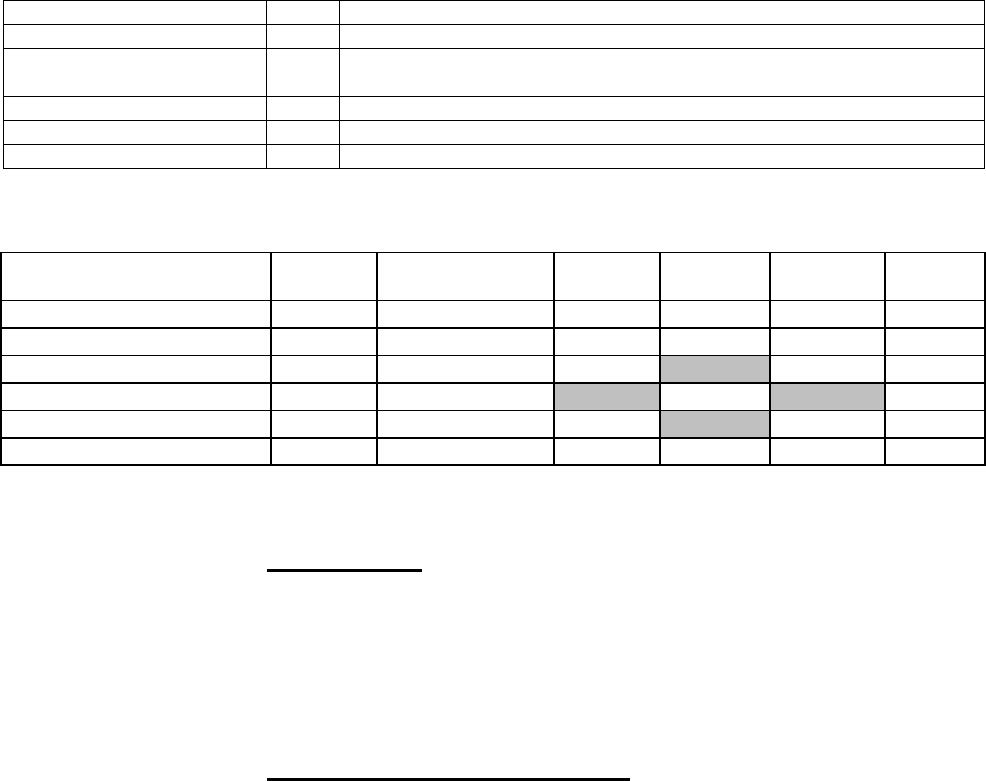
Iridium
Short Burst Data Developers Guide V3.0
Iridium Proprietary and Confidential © Iridium Satellite LLC
36
IMEI. It is a 15-digit number represented here in ASCII format.
7.2.3. DirectIP MT Disposition Flags
Additional features related to MT deliveries are available using MT DirectIP. These features will not be
available through other means of queuing MT messages such as email. They are flagged using the MT
disposition field in the MT header and are described in the following sections. The disposition field itself is a
2-byte bit map with 16 available flags. Those flags defined are shown in Table 7.1-5.
Table 7.1-5 DirectIP MT Disposition Flags
Disposition Flag
Value
Description
Flush MT Queue
1
Delete all MT payloads in the SSD’s MT queue
Send Ring Alert – No MTM
2
Send ring alert with no associated MT payload (normal ring alert rules
apply)
Update SSD Location
8
Update SSD location with given lat/lon values
High Priority Message
16
Place the associated MT payload in queue based on priority level
Assign MTMSN
32
Use the value in the Unique ID field as the MTMSN
7.2.3.1. Allowable combinations of the MT Disposition Flag
Flush MT
Queue
Send Ring Alert
no payload
Assign
MTMSN
Payload
IE
High
Priority IE
LAC/Cel
l ID IE
Flush MT Queue
n/a
x
x
x
x
x
Send Ring Alert no payload
x
n/a
x
Assign MTMSN
x
n/a
x
x
x
Payload IE
x
x
n/a
x
x
High Priority IE
x
x
x
n/a
x
LAC/Cell ID IE
x
x
x
x
x
n/a
*Note that the shaded cells indicate these combinations have to exist. For example, if we have the Assign
MTMSN flag we are required to have the payload IE or it is a protocol error.
7.2.3.1.1. Flush MT Queue
When this flag is set, all payloads in the MT queue for the given IMEI are deleted. This provides an
integrated method to administer MT queues.
When a payload is included in the MT message, it will be queued after the currently queued payloads, if any,
have been deleted. This enables the Vendor Application to maintain a queue depth of one, overwriting any
previous payload queued.
7.2.3.1.2. Send SBD Ring Alert – No MT Payload
When this flag is set, the Iridium Gateway is directed to send a SBD Ring Alert to the specified IMEI within
the bounds of normal SBD Ring Alert processing even though no new MT message is being queued. The
bounds refer to the IMEI’s SBD Ring Alert enable flag and SBD Network Registration (attach/detach) status.
If SBD Ring Alerts are enabled for this IMEI, and it is attached 9location is know), A Ring Alert will be sent to
the field device, followed by a 2nd ring 20 seconds later (ie. Normal Ring Alert rules apply.) For normal MT
SBD Ring Alerts two SBD Ring Alerts are sent.

Iridium
Short Burst Data Developers Guide V3.0
Iridium Proprietary and Confidential © Iridium Satellite LLC
37
If either of these conditions are not met, no SBD Ring Alert will be sent. If a SBD Ring Alert is sent, and an
MT payload is already queued, that payload will be delivered when the IMEI retrieves the MT-SBD
message. This flag has no alternate effect if a new MT payload is included, and the message will be
processed normally. If a MT-SBD Message is included, the MT-SBD message delivery will fail with a
protocol error. Note that excessive use of this feature could result in restrictions being implemented. This
feature should not be used to compensate for poor Field Application design or situations where the IMEI
may be frequently powered off. In such cases the Field Application should cause a Mailbox check to occur
by executing a +SBDIX command with an empty send buffer. See the Section 9 for more details.
7.2.3.1.3. Update SSD Location
When this flag is set, the location of the SSD is updated in the SSD table of the database. A lat/lng pair or
LAC/Cell ID pair must be included in the inbound message. If a lat/lng pair is provided, the LAC and Cell ID
values must then be derived (this is not yet supported). When coupled with another flag triggering a ring
alert, forced or not, the location will be updated first so that the ring alert is sent as directed.
7.2.3.1.4. High Priority Message
When this flag is set, the delivered payload will be placed in MT queue for the given SSD based on a priority
level included in a separate information element (see section 5.11). Any payload currently queued with lower
priority will be superseded, though not deleted. For details regarding this feature, see section 2.5.
7.2.3.1.5. Assign MTMSN
When this flag is set, the GSS will use the value in the Unique ID field in the message header as the
MTMSN for the associated MT message payload. Because the MTMSN is a 16-bit field, the Unique ID (a
32-bit field) must be between 1 to 65,535. Any value not in this range will cause the MT delivery to fail with
an MTMSN out-of-range error.
The MTMSN normally used is an internally maintained value for each IMEI independent of all other IMEIs.
When the assign MTMSN flag is not used, the GSS will use this value for the given IMEI incremented by
one. When this flag is used, the assigned MTMSN only affects the associated MT message. The internally
tracked value remains unchanged and will be used for all subsequent messages when the flag is not set.
7.2.3.1.6. Combining Disposition Flags
Disposition flags may be combined to trigger multiple actions within a single MT message delivery.
However, there are only two combinations. Flush MT Queue / Send Ring Alert (No MTM) and Flush MT
Queue / Assign MTMSN. The Send Ring Alert and the Assign MTMSN flags may not both be set. The
reason is that the Send Ring Alert requires that there not be an MT payload and the Assign MTMSN
requires that there be an MT payload.
7.2.3.1.7. Message Prioritization
MT message prioritization allows the vendor to set the priority of the incoming MT payload relative to the
other MT payloads already queued for the associated SSD. When received, payloads with a priority
specified will be placed in front of payloads with lower priority but not in front of payloads with equal or
higher priority. Payloads of equal priority will be treated in a first-in-first-out (FIFO) manner. When another
MT message is to be queued for delivery over the air, the GSS selects the oldest message with the highest
priority.
7.2.4. Message Prioritization
Five priority levels are supported. They are priority one (P1) through priority five (P5) with one being the
highest priority and five being the lowest. MT payloads received by the GSS from all other sources other
than MT DirectIP will be assigned P5. MT payloads received via DirectIP with no message priority specified
or with an invalid priority level will also be assigned P5. If the MT queue for the SSD is full, the handling of
the payload depends on the priority level of the new payload and that of the payloads in the queue. If the
new payload is lower priority than all other payloads in the queue, it will be rejected. Otherwise, the oldest

Iridium
Short Burst Data Developers Guide V3.0
Iridium Proprietary and Confidential © Iridium Satellite LLC
38
payload (i.e. first in the FIFO) of the lowest priority present in the queue will be deleted, even if the lowest
priority matches the new priority received. For example, if the queue is full with all payloads assigned P1, a
new P1 payload will bump the oldest P1 payload from the queue. Note that if this feature is utilized, the
MTMSN of payloads transmitted to the SSD may no longer be in numeric sequential order. The MTMSN is
assigned at the time that the payload is added to the MT queue and not when it is transmitted to the SSD. If
a payload is received that is placed in front of lower priority payloads in the queue, it will have a higher
MTMSN that the lower priority payloads that are delivered afterwards. Use of this feature is invoked by
including an MT Priority information element (see section 7.2.7).
7.2.5. MT Payload
This information element includes the actual MT payload to be queued and delivered over the air to the
destination IMEI. This inclusion of this IE in the MT delivery is optional based on the disposition flags
included in the header.
Table 7.1-6 MT Payload IE
Field Name
Data Type
Length (bytes)
Range of Values
MT Payload IEI
char
1
See Section 7.2.5
MT Payload Length
unsigned short
2
1 – 1890
MT Payload
char
1 – 1890
Payload Bytes
7.2.5.1. MT Payload Length
This field indicates the number of the bytes in the MT payload.
7.2.5.2. MT Payload
This is the actual content of the MT payload. The MT payload size is transceiver dependent. See Section 1
for details.
7.2.6. DirectIP MT Message Confirmation Message
A confirmation message indicating the status of the processing of the MT message is sent to the vendor
client from the Iridium Gateway for every MT message received.
Table 7.1-7 MT Confirmation Message IE
Field Name
Data Type
Length
(bytes)
Range of Values
MT Confirmation Message IEI
char
1
See Section 7.2.6
MT Confirmation Msg Length
unsigned short
2
25
Unique Client Message ID
integer
4
From Client (not MTMSN)
IMEI (User ID)
char
15
ASCII Numeric Characters
Auto ID Reference
unsigned integer
4
0 – 4294967295
MT Message Status
short
2
Order of message in IMEI’s queue
or error reference (see 7.2.6.5)
7.2.6.1. MT Confirmation Message Length
This field specifies the number of bytes in the IE following this byte. Even though the length is fixed, the field
is included as a standard across all IEs and to allow for maximum flexibility for future enhancements.

Iridium
Short Burst Data Developers Guide V3.0
Iridium Proprietary and Confidential © Iridium Satellite LLC
39
7.2.6.2. Unique Client Message ID
This field is the unique client IE sent in the MT header in the message sent to the Iridium Gateway. This is
intended to serve as a form of validation and reference for the client application.
7.2.6.3. IMEI
The IMEI is the equipment identifier, unique to each Iridium field device, of the MT message destination
IMEI. It is a 15-digit number represented here in ASCII format.
7.2.6.4. Auto ID Reference
This value provides a unique reference for identifying the MT payload within the SBD database. It is
assigned at the time that the payload is inserted into the database as a new record, but prior to the record
being queued for delivery and the MTMSN is assigned. This reference is passed instead of the MTMSN in
order for the Iridium Gateway server to remain independent of all other Iridium Gateway processes and to
allow the socket connection to be closed as soon as possible. This value will be zero when there is an error
in processing the message.
7.2.6.5. MT Message Status
This field is the status value that is returned with every confirmation indicating that the overall MT message
was received and validated and that the payload was queued successfully or that a failure occurred. If
successful, the value is a positive number indicating the order of the received payload in the IMEI’s
associated MT message queue. If not successful, the value will be a negative number serving as an error
code specifying the problem detected. Table 7.1-8 shows the possible status values including the error
codes. Note that the last two error values (-8 and -9) only apply when the “Send Ring Alert” disposition flag
has been set.
Table 7.1-8 MT Message Status
Status
Description
1 – 50
Successful, order of message in the MT message queue
0
Successful, no payload in message
-1
Invalid IMEI – too few characters, non-numeric characters
-2
Unknown IMEI – not provisioned on the Iridium Gateway
-3
Payload size exceeded maximum allowed
(See Section 1)
-4
Payload expected, but none received
-5
MT message queue full (max of 50)
-6
MT resources unavailable
-7
Violation of MT DirectIP protocol error
-8
Ring alerts to the given IMEI are disabled
-9
The given IMEI is not attached (not set to receive ring alerts)
-10
Source IP address rejected by MT filter
-11
MTMSN value is out of range (valid range is 1 – 65,535)
7.2.7. MT Priority
This IE allows a user to set a priority level for an incoming MT message. See section 7.2.3.1.7 for more

Iridium
Short Burst Data Developers Guide V3.0
Iridium Proprietary and Confidential © Iridium Satellite LLC
40
details.
Table 7.1-9 MT Priority IE
Field Name
Bytes (length)
Range of Values
MT Priority IEI
1
See Section 7.2.2
MT Priority Length
2
2
Priority Level
2
1-5 (5 is default)
7.2.7.1. MT Priority Length
This field specifies the number of bytes in the IE following this byte.
7.2.7.2. Priority Level
This field sets the priority of the message relative to the other messages within the MT queue for the
associated SSD. Values from 1 to 5 are valid. Any other priority level will be considered invalid, and a
priority of 5 (lowest) will be assigned to the message. The message will not be rejected.
7.2.7.3. DirectIP MT Message Delivery Example
Table 7.1-10 gives an example of a byte stream for a typical MT DirectIP message delivery.
Table 7.1-10 MT DirectIP Message Delivery Example
Field Name
Data Type
Length
(bytes)
Value
CODE
Protocol Revision Number
char
1
1
01
Overall Message Length
unsigned short
2
97
0061
MT Header IEI
char
1
0x41
41
MT Header Length
unsigned short
2
21
0015
Unique Client Message ID
char
4
“Msg1”
4D736731
IMEI (User ID)
char
15
300034010123450
333030303334303
130313233343530
MT Disposition Flags
unsigned short
2
0x0000
0000
MT Payload IEI
char
1
0x42
42
MT Payload Length
unsigned short
2
70
46
MT Payload
char
70
Payload Bytes
0x00 X70
Table 7.1-11 shows one potential confirmation response. This example assumes that the given IMEI
already had 49 MT message queued (max of 50).
Table 7.1-11 MT DirectIP Message Confirmation Example
Field Name
Data Type
Length
(bytes)
Value
CODE
Protocol Revision Number
char
1
1
01
Overall Message Length
unsigned short
2
3128
0C38
MT Confirmation Message IEI
char
1
0x44
44
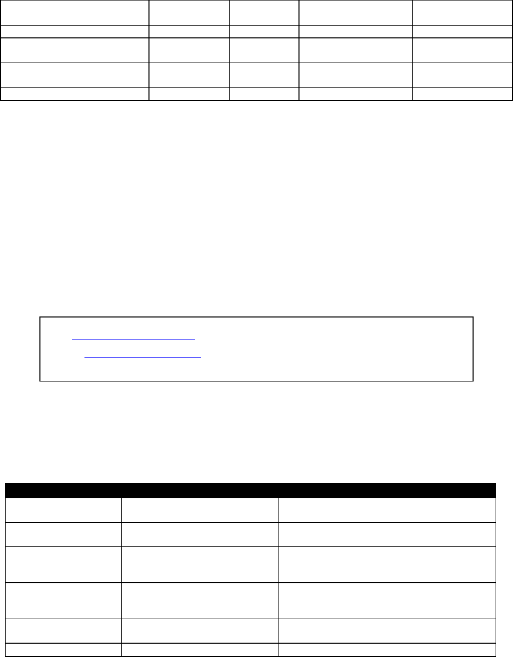
Iridium
Short Burst Data Developers Guide V3.0
Iridium Proprietary and Confidential © Iridium Satellite LLC
41
MT Confirmation Message
Length
unsigned short
2
1925
0785
Unique Client Message ID
integer
4
“Msg1”
4D736731
IMEI (User ID)
char
15
300034010123450
333030303334303
130313233343530
Auto ID Reference
unsigned
integer
4
58473
0000E469
MT Message Status
short
2
50
0032
8. Mobile Originated and Mobile Terminated Message
When the Field Application needs to send a Mobile Terminated data message and the Vendor Application
needs to respond with a Mobile Originated Message, the following scenario assumes that the MT Message
is waiting at the Iridium Gateway before the MO message is sent.
8.1. Example of a MO & MT Message in Parallel
In this scenario, the Vendor Application will send the MT message to the Iridium Gateway (Figure 8-1); the
FA will load the MO message into the ISU, initiate an SBD session, evaluate the results of the SBD session,
and read the Mobile Terminated message from the ISU (Table 8-1). Finally the Vendor Application will
receive the MO message (Figure 8-2).
Figure 8-1 Vendor Application to Iridium Gateway Interface, MT Message
Table 8-1 FA to ISU Interface, Mobile Originated and Mobile Terminated
To ISU (from DTE)
To DTE (from ISU)
Description
AT+SBDWB=351
The FA instructs the ISU that it will write a
351 byte message into the ISU.
READY
The ISU informs the FA that it is ready to
receive the message
Binary transfer
The FA sends the 351-byte message
followed by the two byte checksum to the
ISU. This transfer is not echoed.
0
The ISU will send a zero result code to the
FA indicating that the message was loaded
without error.
AT+SBDI
The FA instructs the ISU to initiate an SBD
transfer.
+SBDI: 1, 2173, 1, 87, 429, 0
The ISU informs the FA that the message
To: Data@SBD.Iridium.com
From: VA@VendorDomain.com
Subject: 304050607080903

Iridium
Short Burst Data Developers Guide V3.0
Iridium Proprietary and Confidential © Iridium Satellite LLC
42
was sent successfully using MOMSN 2173.
A 429-byte message was received using
MTMSN 87. No additional messages are
queued.
AT+SBDD0
The FA instructs the ISU to clear the
message from the send buffer.
0
The ISU informs the FA that the message
buffer was cleared successfully.
AT+SBDRB
The FA instructs the ISU to transfer the
received message.
Binary transfer
The ISU sends a two-byte length indicator
followed by the 429 byte message followed
by the two byte checksum to the FA.
Figure 8-2 VA to Iridium Gateway Interface, MO Message
From: <Iridium SBD Service (Tempe, AZ)>
Sent: Tuesday, August 13, 2002 12:49 PM
Subject: SBD Msg From Unit: 304050607080903
MOMSN: 2173
MTMSN: 87
Time of Session (UTC): Tue Aug 13 16:51:04 2002
Session Status: 00 - TRANSFER OK
Message Size (bytes): 351

Iridium
Short Burst Data Developers Guide V3.0
Iridium Proprietary and Confidential © Iridium Satellite LLC
43
9. SBD Ring Alert for Mobile Terminated Messages and ISU-
ISU Messages
The Iridium Short Burst Data service is a fully acknowledged protocol that confirms the delivery of the
messages between the ISU and the Iridium Gateway. By design, Mobile Originated messages are fully
acknowledged as the ISU is in full control of the transmission. For Mobile Terminated messages the protocol
does not permit the Iridium Gateway to send an unsolicited MT-SBD message to an ISU as the ISU may not
be ready or available to receive such a message and acknowledge it. Each time the Iridium Gateway
receives a MT-SBD message for an ISU, it is queued at the Iridium Gateway until the ISU requests delivery.
A capability of notifying the ISU that it has a queued MT-SBD message waiting for it has been implemented
and that capability is called SBD Ring Alerts.
To provide a more optimal solution, Iridium implemented the SBD Automatic Notification feature in SBD
Iridium Gateway Version 4.1. This feature notifies the ISU that a MT-SBD message has been queued for it
at the Iridium Gateway. It does not automatically deliver the MT-SBD message. The actual notification is
called a SBD Ring Alert (RA). The application developer will need to implement an appropriate algorithm in
the Field Application to process the SBD Ring Alert and then initiate a SBD session to receive the queued
message.
9.1. SBD Ring Alert for Mobile Terminated Messages
This section provides basic examples of how to configure the ISU. Please also consult the relevant AT
Command set documentation for more detailed information. SBD Automatic Notification requires both
the correct configuration of the ISU through use of AT Commands and the activation of this feature
at the time of provisioning through the use of SPNet.
9.2. Ring Alert Registration
To implement the SBD Ring Alert feature there are a number of implementation steps required:
1. The ISU must have the firmware revision that supports this feature. See Section 1.5. These
versions can be downloaded from the Iridium For Partners web site if required.
2. In the SPNet provisioning database, the SBD Ring Alert option needs to be selected in the
provisioning screen for the ISU. This option indicates to the Iridium Gateway that SBD Ring
Alerts are intended to be used with this ISU. NOTE: In the majority of the instances where it is
reported that “ring alerts are not working,” it is due to not selecting the Ring Alert option in
SPNet for the ISU.
3. The Field Application is required to execute AT commands to configure the ISU to listen for SBD
Ring Alerts and then the ISU has to complete SBD Network Registration which notifies the
Iridium Gateway that the ISU is ready to receive SBD Ring Alerts.
a. The Field Application executes +SBDMTA command to configure the ISU to listen for SBD
Ring Alerts sent from the Iridium Gateway. Failure to complete this step will result in the ISU
not listening for SBD Ring Alerts as this is the default setting. To configure the ISU to
receive the SBD Ring Alert the command is: AT+SBDMTA=1.
b. The Field Application next executes the +SBDREG command which will attempt to
complete the SBD Network Registration. SBD Network Registration performs two functions.
First it notifies the Iridium Gateway that the ISU is configured and ready to receive SBD

Iridium
Short Burst Data Developers Guide V3.0
Iridium Proprietary and Confidential © Iridium Satellite LLC
44
Ring Alerts and second it provides the required geo-location coordinates so that the Iridium
Gateway knows where to route the SBD Ring Alert(s). To complete the SBD Network
Registration the command is: AT+SBDREG.
The table below describes the following: The FA verifies its registration state, performs a registration in order
to be able to receive automatic notifications, and enables automatic notification indications.
To ISU (from FA)
To FA (from ISU)
Description
AT+SBDMTA=1
Tell the ISU to listen for (enable) SBD Ring
Alerts.
OK
AT+SBDREG?
Query the ISU SBD Network Registration status
+SBDREG:0
ISU has not completed SBD Network
Registration, ie it is detached.
AT+SBDREG
Tell the ISU to register for SBD Ring Alerts
+SBDREG:2,0
ISU is now registered for SBD Ring Alerts
AT+SBDREG?
Query the ISU SBD Network Registration status
+SBDREG:2
ISU is registered for SBD Ring Alerts
9.3. Retrieval of a MT-SBD Message using SBD Ring Alert
The ISU must send a MO-SBD message in order to retrieve the MT-SBD message queued at the Iridium
Gateway. The MO-SBD may simply be a ‘mailbox check’ which has a zero-byte message payload or a valid
MO-SBD message (i.e. payload size greater than zero bytes.) Either one will cause the next MT-SBD
message queued at the Iridium Gateway, if there is one, to be delivered to the ISU and retrieve the status
information from the Iridium Gateway.
If the application is configured to use the SBD Automatic Notification, the +SBDIX and +SBDIXA commands
must be used to initiate the MO-SBD message. To respond to a SBD Ring Alert the Field Application should
use the +SBDIXA command to retrieve the MT-SBD message. If the Field Application is sending an
unsolicited MO-SBD message, the +SBDIX command is used. [Note: The +SBDI command can still be
used, however, it also ‘detaches’ or stops SBD Ring Alerts being sent from Iridium Gateway.]

Iridium
Short Burst Data Developers Guide V3.0
Iridium Proprietary and Confidential © Iridium Satellite LLC
45
In the table below: The FA verifies its registration state. Upon receiving a SBD Ring Alert the FA initiates an SBD
session to receive an MT message.
To ISU (from FA)
To FA (from ISU)
Description
AT+SBDREG?
Query the ISU SBD Network Registration status
+SBDREG:2
ISU is registered for SBD Ring Alerts
…
Vendor Application sends an MT message to the
Iridium Gateway. Iridium Gateway sends a SBD Ring
Alert to ISU
+SBDRING
ISU indicates an incoming message. The RI line also
toggles.
AT+SBDIXA
FA initiates an SBD session in response to the SBD
Ring Alert
+SBDIXA:0,23,1,237,90,2
ISU informs FA that a 90-byte message was
successfully received with MTMSN 237, and that two
further MT messages are queued at the Iridium
Gateway
AT+SBDRB
FA retrieves the received message from the ISU
<binary transfer>
9.4. SBD Ring Alert Status Information
During a SBD message transfer, status information is transferred between the Iridium Gateway and the ISU.
This status information is retrieved from the ISU by using the +SBDSX command which returns six values:
MO flag, MOMSN, MT flag, MTMSN, RA flag and number of messages waiting at the Iridium Gateway. The
parameters MO flag, MOMSN, MT flag, MTMSN are the same as those returned by the +SBDS command.
The new parameters are the RA flag and the messages waiting. The RA flag indicates whether the ISU
received a SBD Ring Alert from the Iridium Gateway that has not been answered. The messages waiting
value is the number of MT messages queued at the Iridium Gateway waiting to be delivered. This
information can be used by the Field Application to retrieve the queued messages.
This status information is updated every time there is a SBD session between the ISU and the Iridium
Gateway. The commands that initiate an SBD session are: +SBDI, +SBDIX[A], +SBD[A]REG, +SBDDET.
The +SBDSX command can be properly used following any of these commands.
9.4.1. Automatic MT Ring Alert Implementation
The SBD service is a fully acknowledged protocol that confirms the delivery of the messages between the
ISU and the gateway. To insure this, the gateway does not send unsolicited MT-SBD messages to an ISU
that may not be acknowledged. The MT-SBD messages are queued at the gateway until the ISU requests
delivery of them.
Prior to the release of SBD 4.1, the ISU did not receive any notification that a MT-SBD message was
queued at the gateway. In order to determine if a message was queued for delivery, the remote ISU sent a
MO-SBD message or a ‘mailbox check’, a MO-SBD message with a 0-byte payload, and then checked the
return status from the gateway to determine if a MT-SBD message was delivered and whether more
messages were waiting. This made it cumbersome for applications that required asynchronous MT-SBD
messaging.
To mitigate this, Iridium implemented the Automatic Ring Alert notification feature in the SBD 4.1 release.
This feature does not deliver the MT-SBD message but notifies the ISU that a MT-SBD message has been
queued for delivery at the gateway. The application, if it is configured to handle the RA, can then initiate a
SBD session and receive the queued message.

Iridium
Short Burst Data Developers Guide V3.0
Iridium Proprietary and Confidential © Iridium Satellite LLC
46
9.4.2. Automatic MT Ring Alert Notification
When the gateway receives a MT-SBD message, and the destination device is configured for the RA and
attached to the network, the gateway sends a RA signal to the device. If the device does not respond in
approximately 20 seconds, a second RA is sent. If the ISU does not respond to the second RA, no further
RAs will be sent until another MT-SBD is queued for this device.
If a subsequent MT-SBD message is received for this ISU, the RA process repeats itself. However, the
gateway does not send a subsequent RA if the MT-SBD is received within 10 seconds of the previous MT-
SBD.
9.4.3. Retrieving MT-SBD Message by the RA
The gateway queues a MT-SBD message for the ISU and send the RA signal. The ISU receives the RA
and sends an unsolicited response to the application. This response is either SBDRING in Verbose Mode
or “124” in Numeric Mode. The Ring Indicator pin is also asserted.
The application interprets the response and initiates a SBD session with the +SBDIXA command. The “A”
suffix indicates this is a response to the RA signal and cancels the second RA to prevent a possible race
condition.
If the application has a MO message to send, it moves the data into the transmit buffer prior to issuing the
AT command. If the application has nothing to send and just wants to retrieve the queued message, it
clears the MO transmit buffer before initiating the session, i.e. a ‘mailbox check’.
The response codes from the +SBDIXA command indicate if there are additional MT-SBD messages waiting
to be retrieved. If there are messages queued for delivery to this device, the application can initiate a SBD
session and retrieve them.
10. Field Application Implementation
10.1. Power Up
On power up, the Field Application configures the ISU to receive the SBD Ring Alert with the
+SBDMTA command.
This should be followed by a 0 byte Upload, which will update the geo location of the device in the
database for future Ring Alerts. Additionally, this action would download any MT messages that are
in queque, and provide with current queue depth.
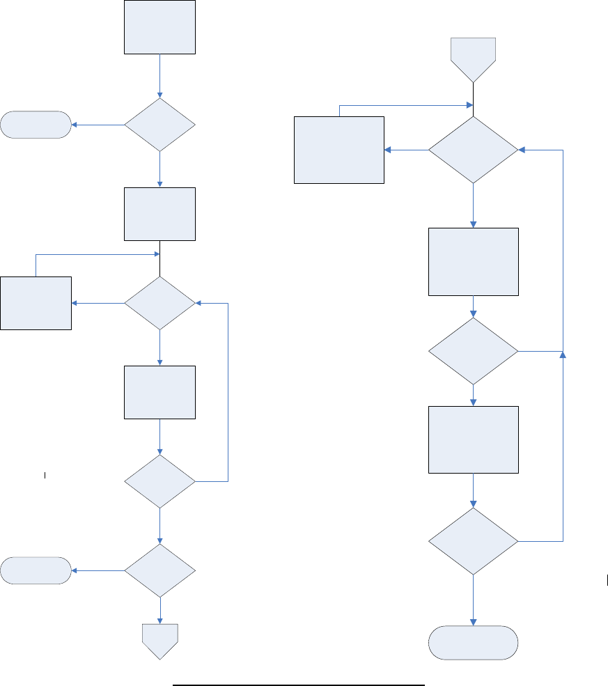
Iridium
Short Burst Data Developers Guide V3.0
Iridium Proprietary and Confidential © Iridium Satellite LLC
47
10.2. Automatic SBD Ring Alert Notification
When the Iridium Gateway receives a MT-SBD message and the destination ISU is configured to listen for
SBD Ring Alerts, and the ISU has successfully completed SBD Network Registration, the Iridium Gateway
sends a SBD Ring Alert to the ISU. If the ISU does not respond in approximately 13 seconds, a second SBD
Ring Alert is sent. If the ISU does not respond to the second SBD Ring Alert, no further SBD Ring Alerts are
sent until another new MT-SBD is queued for this ISU.
If a subsequent MT-SBD message is received for this ISU, the SBD Ring Alert process repeats itself.
However, the Iridium Gateway will not send a SBD Ring Alert if the subsequent MT-SBD is received within
10 seconds of the receipt of the previous MT-SBD.
9601 Power Up
Auto
RA
Notification
AT+SBDMTA=1
AT+CSQ >0
Wait
Loop
AT+SBDREG
OK?
Message
Waiting?
9601 Power Up Process
``
2
NO
YES
NO
YES
YES
Process
Complete
NO
Process
Complete
Page 2
AT+CSQ > 0
AT+SBDIX
Status OK
Wait Loop
Move MT-SBD
From ISU
To Application
And Process
Another Msg
Waiting
Process
Complete
NO
YES
YES
YES
NO
NO

Iridium
Short Burst Data Developers Guide V3.0
Iridium Proprietary and Confidential © Iridium Satellite LLC
48
Note that while the transfer of MO or MT SBD messages is via a reliable (duplex) protocol, SBD Ring Alerts
are sent on a simplex channel. If the ISU is turned off or is blocked from seeing the satellite, then a
SBD Ring Alert will not be received by the ISU and the Iridium Gateway has no knowledge of
whether an ISU eventually received a specific SBD Ring Alert or not.
10.3. Retrieving MT-SBD Message from the Iridium Gateway when notified by
the SBD Ring Alert
The Iridium Gateway queues the MT-SBD message for the ISU and sends SBD Ring Alert. The ISU
receives the SBD Ring Alert and sends an unsolicited response to the Field Application. This response is
either SBDRING in Verbose Mode or “2” in Numeric Mode. The Field Application interprets the response
and initiates a SBD session with the +SBDIXA command. The “A” suffix indicates this is a response to the
SBD Ring Alert.
If the Field Application has a MO-SBD message to send, it moves the data into the transmit buffer prior to
issuing the AT command. If the Field Application has nothing to send and just wants to retrieve the queued
MT-SBD message, it clears the MO transmit buffer before initiating the session. The response codes from
the +SBDIXA command indicate if there are additional MT-SBD messages waiting to be retrieved.
Applications where the ISU will move significant distances fairly quickly (e.g. aircraft) and applications where
the ISU will move through an environment where the ISU may not always have a good view of the sky (e.g.
cities, mountainous regions) should use the Automatic SBD Network Registration capability if a high degree
of reliability/low latency of delivered MT-SBD messages is desired.
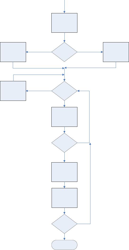
Iridium
Short Burst Data Developers Guide V3.0
Iridium Proprietary and Confidential © Iridium Satellite LLC
49
Respond to SBD Ring Alert Notification to
Retrieve MT-SBD Message
Unsolicted
SBDRING
Received
MO-SBD
to
Send
Move Data to ISU
Transmit Buffert Clear ISU
Transmit Buffert
AT+CSQ > 0
Initiate SBD
Session /w
AT+SBDIXA
OK
Move MT-SBD
Message to
Application
Process MT-SBD
Message
More
MT-SBD
Queued
WAIT
DONE
YES
NO
YES
NO
NO
YES
YES NO

Iridium
Short Burst Data Developers Guide V3.0
Iridium Proprietary and Confidential © Iridium Satellite LLC
50
10.4. Power Down
1. Before turning the ISU off, the Field Application should tell the Iridium Gateway not to send
any further SBD Ring Alerts. The Field Application will need to issue the +SBDDET to the
ISU which will tell the Iridium Gateway to “stop sending SBD Ring Alerts” or DETach from
the Iridium Gateway.
2. When the response code for +SBDDET indicates a successful detach the ISU can be
powered off.
3. At power up the method described in Section 10.1 should be used to restart the Iridium
Gateway sending SBD Ring Alerts.
10.5. SBD Ring Alert: Automatic Registration (+SBDAREG)
In order for the ISU to receive the SBD Ring Alert Notification, the Iridium Gateway must have the current location
of the ISU. This location is updated by the SBD Network Registration and each time a SBD session takes place.
For fixed location ISUs and ISUs that do not travel more than approximately 225 kilometers between SBD
sessions, the +SBDREG command is sufficient. If the ISU is mobile and can possible move more than 225
kilometers between SBD sessions, the +SBDAREG command should be used f This command is issued after the
ISU has successfully attached to the Iridium Gateway, either via the +SBDREG or +SBDIX commands. The
+SBDAREG runs a passive geo-location algorithm which estimates the distance the ISU has moved since the
previous SBD session. If the result indicates the ISU has moved ‘too’ far, the ISU automatically issues an updated
SBD Network Registration.
9601 Power Down Process
AT+SBDDET
OK?
AT*F
STOP
YES
NO

Iridium
Short Burst Data Developers Guide V3.0
Iridium Proprietary and Confidential © Iridium Satellite LLC
51
The FA verifies its registration state and enables automatic registration using the “Ask” mode.
To ISU (from FA)
To FA (from ISU)
Description
AT+SBDREG?
Query the ISU registration status
+SBDREG:2
ISU is registered
AT+SBDAREG=2
FA sets the automatic registration to “Ask” mode
OK
…
ISU is moved
+AREG:0,0
ISU notifies FA that it needs to register
AT+SBDREG
FA instructs the ISU to register
+SBDREG:2,0
Registration is successful
11. Optimal Message Size Selection
There are two primary factors that affect optimal message size: Economic and technical.
11.1. Economic Message Size
The developer should take into account the minimum billable message size of the service plan that the ISU
will be activated with on the Iridium network. E.g. For a minimum billable message size of 10 bytes, any
message actually sent with less than 10 bytes will be billed at 10 bytes regardless of the actual number of
bytes sent below 10. Note that this is a minimum and not an increment. E.g. for a minimum billable message
size of 10 bytes all messages over 10 bytes will be billed at the exact number of bytes transmitted.
The developer should maximize the use of these bytes, and can do so in a number of ways. E.g. the
business requirement is to report position every ten minutes. The position information in this case is fifteen
bytes. The developer could therefore collect an intermediate position every five minutes and transmit both
positions at the required ten-minute intervals to provide more detailed positioning information.
11.2. Technical Message Size
Each type of message whether MO or MT is broken into segments for actual transmission. The length of the
segment relative to the absolute message length depends on whether it is a MO or MT message. Between
each segment additional signaling and network overhead occurs. If optimizing for minimal latency or power
consumption then the minimal number of message segments should be used.
Important: See Section 1.5 for message size limits that are dependent on the transceiver type.
11.2.1. Mobile Originated Message Size
First user data segment size
70 bytes
Subsequent user data segment size
135 bytes

Iridium
Short Burst Data Developers Guide V3.0
Iridium Proprietary and Confidential © Iridium Satellite LLC
52
E.g. for a 1960 byte message there will be one segment of 70 bytes and 14 segments of 135 bytes
E.g. for a 71 byte message there will be one segment of 70 bytes and one segment of 1 byte.
11.2.2. Mobile Terminated Message Size
User data segment size
135 bytes
E.g. for a 1890 byte message there will be 14 segments of 135 bytes
E.g. for a 71 byte message there will be one segment used.

Iridium
Short Burst Data Developers Guide V3.0
Iridium Proprietary and Confidential © Iridium Satellite LLC
53
12. Iridium Short Burst Data Service Security Features
12.1. Purpose
The purpose of this section is to provide information sufficient for an Iridium Value Added Reseller to be able
to understand the basic security features of Iridium’s Short Burst Data Service. It is assumed that the reader
is familiar with the Iridium system and Short Burst Data.
12.2. Iridium Security Features
The Iridium System supports the GSM-specified algorithm A3 for authentication security, but not algorithms
A5/A8 for channel encryption. Table 12-1summarizes the security features explicitly designed into the
Iridium system. Note that A3 is only used in transceivers using a SIM card.
Table 12-1 Baseline Iridium Security Features
Authentication
A3 (128-bit Key)
Equipment Anti-Theft Validation
Global Equipment Identity Register
Anonymity (User location confidentiality)
TMSI based
Signaling Message Confidentiality
Not Available
12.3. Authentication Security
Note that Authentication Security is only applicable to Iridium Subscriber Units (ISUs) that utilize a SIM card.
The 9601 and 9602 SBD Transceiver do not utilize a SIM card and thus this section is not applicable to it.
The Iridium authentication process is adapted without change directly from the GSM specifications. The
GSM algorithm A3 is used to encrypt authentication information transmitted over the air interface.
Authentication encryption
o Designed to prevent ISU cloning fraud
o GSM encryption algorithm A3 is executed on SIM card to generate Signed Result (SRES)
response based on the following inputs
Secret key parameter stored in SIM card
RAND parameter supplied by network
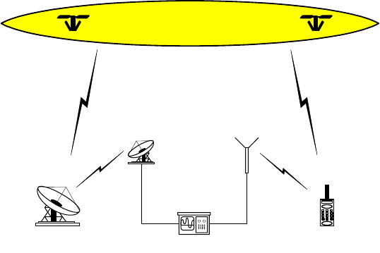
Iridium
Short Burst Data Developers Guide V3.0
Iridium Proprietary and Confidential © Iridium Satellite LLC
54
12.4. Iridium Channel Security
SBD uses the signaling channel and is afforded some security by the limited distribution of the air interface
and feeder link interface specifications. The Iridium Air Interface Specification is made available only to
Iridium Subscriber Unit (ISU) manufacturers. Feeder link interface specifications are not distributed outside
of the original manufacturer.
Figure 12-1 identifies the opportunities for surreptitious monitoring of Iridium bearer channels. An
eavesdropper could, in principle, monitor L-band uplink and downlink channels, or K-band uplink and
downlink feeder link channels.
L-Band Channels
o Uplink, from ISU to Space Vehicle (SV)
o Downlink, from SV to ISU
K-Band Channels
o Uplink, from gateway to Space Vehicle (SV)
o Downlink, from SV to gateway
12.5. L-Band Channel Security
To successfully monitor an L-band channel, an eavesdropper must be located within the transmit range of
the ISU being monitored, approximately 10 to 30 km from the transmitting ISU. ISU downlink L-Band
transmissions could be received over a much wider area. A single SV beam covers an area of about 400 km
in diameter. As long as the eavesdropper is within the coverage area of a common beam, downlink L-Band
transmissions could be received.
Fortunately, the complexity of the Iridium air interface should make the challenge of developing an Iridium L-
Band monitoring device very difficult and probably beyond the reach of all but the most determined
adversaries. Among the complications are:
Large, continually changing Doppler shifts
Frequent inter-beam and inter-SV handoffs
Time-division multiplexed burst mode channels
Complicated modulation, interleaving and coding
Figure 12-1 Iridium Link Monitoring Opportunities
Gateway
Iridium
Constellation
ISU
K-Band
Downlink L-Band
Downlink
Monitor
L-Band
Uplink
K-Band
Uplink
Iridium
Short Burst Data Developers Guide V3.0
Iridium Proprietary and Confidential © Iridium Satellite LLC
55
12.6. K-Band Channel Security
To successfully monitor a K-band feeder link channel, a fairly sophisticated monitoring device must be
located in the general proximity of an Iridium gateway. The receiver must have a high-gain antenna capable
of tracking SVs as they move from horizon to horizon.
Again, the complexity of the feeder link interface poses a formidable technical challenge for prospective
eavesdroppers. The cost of the monitoring device alone would be a strong deterrent. Among the technical
complications are
Large, continually changing Doppler shifts
High capacity, 3.072 Mbps channels
High-gain tracking antenna required
Must reacquire new SV every 10 minutes
12.7. Gateway to Vendor Application
While this document focuses on the Iridium network, security should be looked at from an end-to-end
solution perspective. SBD communications to and from the Iridium Gateway can be protected by two
additional cost items:
(A) Virtual Private Network and/or
(B) Private leased line communication
12.8. Additional Considerations
Depending on the level and sensitivity of the information being communicated the application developer may
require additional security. Any additional security measure would require encrypting the information before
transmitting to the destination point. This is referred to generically as application level encryption and
requires the developer to select and implement an encryption method that provides the required level of
security for the application. Any increase in the size of the actual information being sent due to the
encryption is not distinguished by the Iridium network from normal user data and the Iridium network will rate
the total size of the data message sent.

Iridium
Short Burst Data Developers Guide V3.0
Iridium Proprietary and Confidential © Iridium Satellite LLC
56
13. Basic Trouble Shooting
13.1. Hardware Requirements
Table 13-1 lists the available hardware that supports SBD. Firmware versions can be determined by issuing
AT+CGMR to the transceiver.
Table 13-1 Hardware Firmware compatibility
L-Band Transceiver
Product Number
Transceiver
“Code Name”
Minimum Firmware revision
(see note)
Requires Valid SIM
Card?
9522
Sebring
SAC03xx [where xx are integers]
Yes
9522A
Daytona
IS05001
Yes
9522B
LBT Transceiver
ST09005
Yes
9601
SBD Transceiver
TD05002
No
9602
SBD Transceiver
TA10003
No
Note: The minimum firmware revision will not support every SBD feature. Developers are advised to use the
most recent firmware revision available.
13.2. Provisioning
L-Band Transceivers require two key items in order to be operational on the Iridium Network:
The IMEI (a 15 digit number beginning with 30 that identifies the hardware device) must be correctly
provisioned in Iridium’s SPNet with a valid destination defined (email address, another ISU’s IMEI or IP
Address), to which the MO-SBD messages are to be sent.
A correctly provisioned SIM card must be installed in the LBT (9522, 9522A or 9522B.=).or the 9555 and
9505A handsets. This can be one of two flavors:
o Any standard Iridium SIM card where the LBT will be used for voice and other data services
o A SBD “Register only” or “Automatic Check” SIM for LBTs that will be just used for SBD
The 9601 and 9602 SBD Transceiver does not require a SIM card.
It is important to check that both the IMEI and SIM are properly provisioned. Without verifying these items there is
little value in continuing troubleshooting. It is also important to verify that the SIM you are checking on in SPNet is
the same SIM that is physically installed in the LBT.
13.3. SIM PIN
This section does not apply to 9601/9602 transceivers as they do not use a SIM card.
Iridium SIM cards are typically created without the PIN activated. The application developer should take this into
account in the development of the Field Application.
In order to verify that the SIM does not have a PIN utilize the following command: AT+CPIN as described in [1]. If
the SIM has a PIN it will require the developer’s application to input this PIN correctly via AT Command. If this PIN
is not input, the LBT will not be able to register, place calls, or receive calls. Furthermore, if the PIN is input 3 times
incorrectly the SIM will become “blocked”. To unblock the SIM requires sending the AT Command with the PIN1
Unblocking Key (PUK1). The PUK1 is an 8-digit sequence that can be provided by the SP/VAR. The application
developer can use “AT+CPIN?” to determine what code the SIM is waiting for or expecting.

Iridium
Short Burst Data Developers Guide V3.0
Iridium Proprietary and Confidential © Iridium Satellite LLC
57
In order to turn off the PIN use the following command: AT+CLCK as described in [1]. However Iridium
recommends that developers not remove the PIN unless the commercial Field Application will be design to detect
and remove the PIN. Commercial SIM cards are issued with the PIN activated.
13.4. Network Registration Status
For the 9522B LBT the following should be checked, it does not apply to the 9601 or 9602. Check the registration
status by issuing the check registration status command: AT+CREG as detailed in [1]. In order to use the Iridium
network a SIM based ISU must be registered with a gateway (telephony registration.) If an ISU is not registered
then many of the AT commands and functions of the ISU will be inoperable. Registration cannot be disabled. If the
unit is not registered:
Check the provisioning of the SIM on SPNet
Power the unit off, wait 10 seconds, power the unit on again and reissue the +CREG command
If the unit still has not registered, ensure that an antenna is connected correctly and that it has clear
line of sight to the sky through 360 degrees azimuth. Then proceed to the “Satellite Signal Strength
Indicator” section
13.5. Satellite Signal Strength Indicator
Issue the AT+CSQ command as detailed [1] and observe the response.
Signal strength of 0 indicates that:
Either the antenna is not connected properly;
The signal loss in the antenna cable, connectors is too high resulting in excessive signal loss.
o Ensure that the cable length, type and design frequency is appropriate for Iridium.
Iridium operates between 1616 and 1625 MHz
The entire RF loss of the antenna installation (including cable, connectors and lightning
arrestors) shall not exceed 3dB.
The antenna does not have a clear view of the sky. The optimal view is 360 degrees of azimuth and
above 8 degrees of elevation.
Interference from a local high power L-Band transmitter. E.g. an Inmarsat terminal.
Signal strength of 1 or higher should permit an SBD call to be made. Check signal strength over a period of 10 to
20 minutes to characterize the received signal strength for your antenna location. If you consistently see:
A signal strength of 4 or higher you appear have a good installation.
A varying signal strength ranging from 0/1 to 4/5 then your antenna location appears to have partial line of
sight blockage. Identify the blockage and determine if you can relocate the antenna.
It is recommend that development, demonstration and test platforms have high quality installations with optimal
line of sight conditions. Having an ideally located antenna removes the possibility that poor signal strength causes
application issues and enables more rapid application debugging.
13.6. Power Supply
It is critical that an appropriate power supply is utilized. While an ISU can turn on using only a portion of the
specified maximum current, registration and transmission of data messages will not occur if the transceiver
cannot draw enough current from the power source. An under rated power supply can cause erratic
behavior when using SBD. Ensure that your power supply can supply the specified peak maximum current
for the transceiver that you are using. Check the power supply while operating the transceiver by using an
Iridium
Short Burst Data Developers Guide V3.0
Iridium Proprietary and Confidential © Iridium Satellite LLC
58
ammeter and volt meter.
