TS 870S KENWOOD 870 User Manual
TS-870S to the manual 502a39d7-62e8-4c4f-b953-00c55a041c90
User Manual: Pdf KENWOOD--TS-870-User-Manual
Open the PDF directly: View PDF ![]() .
.
Page Count: 104 [warning: Documents this large are best viewed by clicking the View PDF Link!]

TS-870S
HF TRANSCEIVER
© B62-1536-00 (K,P,E,X,M)(MC)
09 08 07 06 05 04 03 02 01 00
KENWOOD CORPORATION
INSTRUCTION MANUAL
Intelligent Digital Enhanced Communications System

WRITING CONVENTIONS FOLLOWED
The writing conventions described below have been
followed to simplify instructions and avoid unnecessary
repetition. This format is less confusing for the reader.
Reviewing the following information now will reduce
your learning period. That means less time will be
spent reading this manual; more time will be available
for operating.
Furthermore, a system of advisories is used as follows:
CAUTION:
Possibility of equipment damage
Note:
Important information or operating tip
Note:
Basic procedures are numbered sequentially to guide you
step-by-step. Additional information pertaining to a step, but not
essential to complete the procedure, is provided in bulleted form
following many steps for further guidance.
NOTICE TO THE USER
One or more of the following statements may be
applicable to this equipment.
INFORMATION TO THE DIGITAL DEVICE USER REQUIRED
BY THE FCC
This equipment has been tested and found to comply with the
limits for a Class B digital device, pursuant to Part 15 of the FCC
Rules. These limits are designed to provide reasonable
protection against harmful interference in a residential
installation.
This equipment generates, uses and can generate radio
frequency energy and, if not installed and used in accordance
with the instructions, may cause harmful interference to radio
communications. However, there is no guarantee that the
interference will not occur in a particular installation. If this
equipment does cause harmful interference to radio or television
reception, which can be determined by turning the equipment off
and on, the user is encouraged to try to correct the interference
by one or more of the following measures:
•Reorient or relocate the receiving antenna.
•Increase the separation between the equipment and
receiver.
•Connect the equipment to an outlet on a circuit different from
that to which the receiver is connected.
•Consult the dealer for technical assistance.
FCC WARNING
This equipment generates or uses radio frequency energy.
Changes or modifications to this equipment may cause harmful
interference unless the modifications are expressly approved in
the instruction manual. The user could lose the authority to
operate this equipment if an unauthorized change or modification
is made.
APPLICABLE MODEL
This manual applies to the following model:
TS-870S: HF Transceiver
Intelligent Digital Enhanced Communications System
Instruction What to do
Press and release KEY.
Press and hold KEY1 down,
then press KEY2. If there are
more than two keys, press and
hold down each key in turn
until the final key has been
pressed.
Press KEY1 momentarily,
release KEY1, then press
KEY2.
With the transceiver power
OFF, press and hold KEY,
then switch ON the transceiver
power by pressing
[ ] (POWER).
Press [KEY].
Press
[KEY1]+[KEY2].
Press
[KEY1], [KEY2].
Press
[KEY]+[ ].
i
PRECAUTIONS
Please read all safety and operating instructions before
using this transceiver. For best results, be aware of all
warnings on the transceiver and follow the provided
operating instructions. Retain these safety and
operating instructions for future reference.
1Power Sources
Connect this transceiver only to the power source
described in the operating instructions or as marked
on the transceiver itself.
2Power Cable Protection
Route all power cables safely. Ensure the power
cables can neither be walked upon nor pinched by
items placed near or against the cables. Pay
particular attention to locations near AC receptacles,
AC extension bars and points of entry to the
transceiver.
3Electrical Shocks
Take care not to drop objects or spill liquids into the
transceiver through enclosure openings. Metal
objects, such as hairpins or needles, inserted into
the transceiver may contact voltages resulting in
serious electrical shocks. Never permit children to
insert any objects into this transceiver.
4Grounding and Polarization
Do not attempt to defeat methods used for
grounding and electrical polarization in the
transceiver, particularly involving the input power
cable.
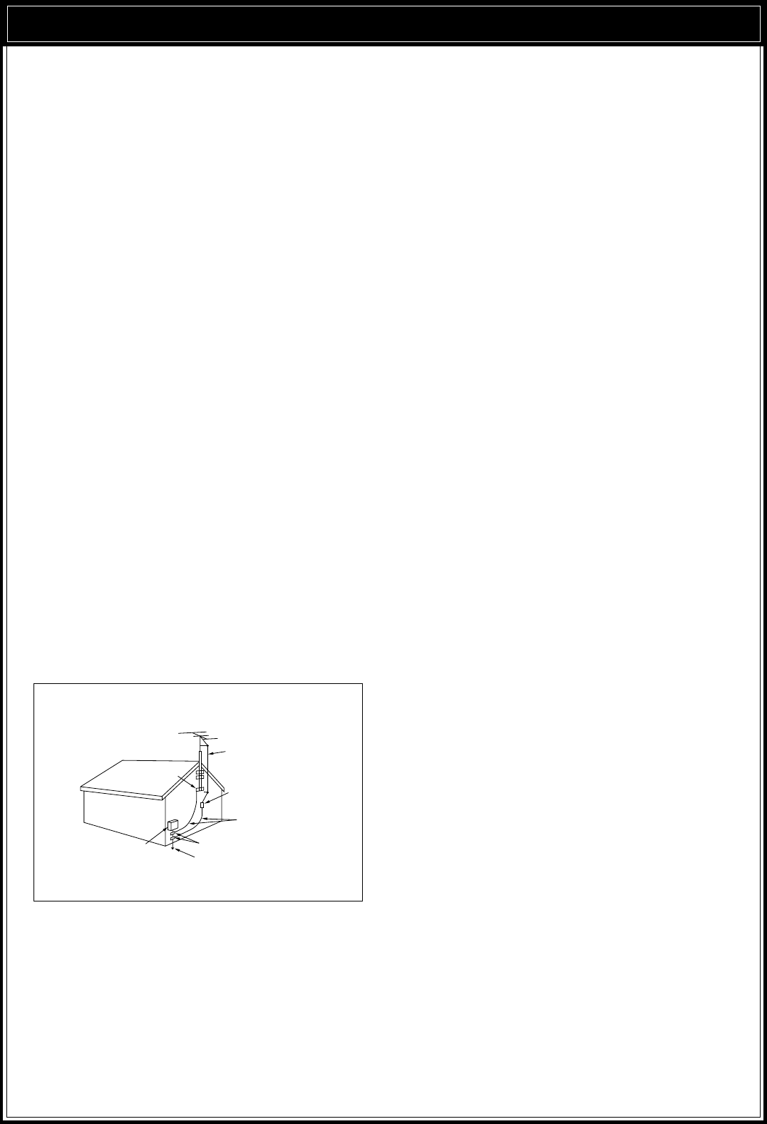
5Outdoor Antenna Grounding
Adequately ground all outdoor antennas used with
this transceiver using approved methods.
Grounding helps protect against voltage surges
caused by lightning. It also reduces the chance of a
build-up of static charges.
6Power Lines
Minimum recommended distance for an outdoor
antenna from power lines is one and one-half times
the vertical height of the associated antenna support
structure. This distance allows adequate clearance
from the power lines if the support structure should
fail for any reason.
7Ventilation
Locate the transceiver so as not to interfere with its
ventilation. Do not place books or other equipment
on the transceiver that may impede the free
movement of air. Allow a minimum of 4 inches
(10 cm) between the rear of the transceiver and the
wall or operating desk shelf.
8Water and Moisture
Do not use the transceiver near water or sources of
moisture. For example, avoid use near bathtubs,
sinks, swimming pools, and in damp basements and
attics.
9Abnormal Odors
The presence of an unusual odor or smoke is often a
sign of trouble. Immediately turn the power OFF and
remove the power cable. Contact a dealer or the
nearest Service Center for advice.
10 Heat
Locate the transceiver away from heat sources such
as radiators, stoves, amplifiers or other devices that
produce substantial amounts of heat.
11 Cleaning
Do not use volatile solvents such as alcohol, paint
thinner, gasoline or benzene to clean the cabinet.
Use a clean cloth with warm water or a mild
detergent.
12 Periods of Inactivity
Disconnect the input power cable from the power
source when the transceiver is not used for long
periods of time.
13 Servicing
Remove the transceiver’s enclosure only to do
accessory installations described by this manual or
accessory manuals. Follow provided instructions
carefully to avoid electrical shocks. If unfamiliar with
this type of work, seek assistance from an
experienced individual, or have a professional
technician do the task.
14 Damage Requiring Service
Enlist the services of qualified personnel in the
following cases:
a) The power supply or plug is damaged.
b) Objects have fallen or liquid has spilled into the
transceiver.
c) The transceiver has been exposed to rain.
d) The transceiver is operating abnormally or
performance has degraded seriously.
e) The transceiver has been dropped or the
enclosure damaged.
EXAMPLE OF ANTENNA GROUNDING
ANTENNA
LEAD IN
WIREGROUND
CLAMP
ELECTRIC SERVICE
EQUIPMENT
ANTENNA
DISCHARGE UNIT
GROUNDING
CONDUCTORS
GROUND CLAMPS
POWER SERVICE GROUNDING
ELECTRODE SYSTEM

ii
CONTENTS
DUAL DIGITAL VFOs ............................................ 19
SELECTING VFOS ([RX A], [RX B]) .................. 19
EQUALIZING VFO FREQUENCIES ([A=B]) ...... 20
SELECTING MODE ............................................... 20
SELECTING FREQUENCY ................................... 20
CHANGING BANDS .......................................... 20
USING 1 MHz STEPS ....................................... 20
QUICK CHANGES ............................................ 21
Changing Step Sizes .................................... 21
FINE TUNING .................................................... 21
DIRECT FREQUENCY ENTRY ......................... 22
FRONT PANEL METER ........................................ 22
TRANSMITTING .................................................... 23
SELECTING TRANSMIT POWER ..................... 23
TRANSMIT CARRIER LEVEL ........................... 23
MICROPHONE GAIN ........................................ 23
CHAPTER 5 MENU SETUP 24
WHAT IS A MENU? ............................................... 24
MENU ACCESS .................................................... 24
MENU A/ MENU B ............................................. 24
QUICK MENU FUNCTION ................................ 24
Programming the Quick Menu ...................... 24
Using the Quick Menu ................................... 24
TEMPORARY MENU RESETTING ....................... 24
MENU CONFIGURATION ..................................... 25
CROSS REFERENCE FOR
MENU FUNCTIONS .............................................. 28
CHAPTER 6 COMMUNICATING 29
SSB TRANSMISSION ........................................... 29
SLOW SCAN TV/ FACSIMILE ........................... 29
CW TRANSMISSION ............................................ 30
TX SIDETONE/ RX PITCH FREQUENCY ......... 30
ZERO-BEATING ................................................ 30
SWITCHING TX/RX MANUALLY ....................... 30
SEMI BREAK-IN ................................................ 31
Setting Delay Time ........................................ 31
FULL BREAK-IN ................................................ 31
CW REVERSE (RECEIVE) ................................ 31
RISE/DECAY TIMES ......................................... 31
ELECTRONIC KEYER ...................................... 32
Learning Outline ........................................... 32
Multiple-Button Functions .............................. 33
Emulation Options ........................................ 33
Storing CW Messages .................................. 34
CW Message Playback ................................. 34
Erasing CW Messages ................................. 35
Inquiry Functions .......................................... 35
Function Commands ..................................... 36
Embedded Functions .................................... 37
Serial Number Options .................................. 37
APPLICABLE MODEL .................. Inside Front Cover
WRITING CONVENTIONS
FOLLOWED ................................. Inside Front Cover
NOTICE TO THE USER ............... Inside Front Cover
PRECAUTIONS i
CONTENTS ii
CHAPTER 1 INTRODUCTION 1
THANK YOU! ........................................................... 1
DSP — MAXIMUM SIGNAL/ MINIMUM NOISE ....... 1
FEATURES .............................................................. 1
SUPPLIED ACCESSORIES .................................... 1
CHAPTER 2 INSTALLATION 2
ANTENNA CONNECTION ....................................... 2
GROUND CONNECTION ........................................ 3
LIGHTNING PROTECTION ..................................... 3
DC POWER SUPPLY CONNECTION...................... 3
REPLACING FUSES ........................................... 3
ACCESSORY CONNECTIONS ............................... 4
FRONT PANEL .................................................... 4
Headphones (PHONES) ................................. 4
Microphone (MIC) ........................................... 4
REAR PANEL ...................................................... 4
External Speaker (EXT SP) ............................ 4
Keys and Keyboards for CW Operation
(PADDLE and KEY) ........................................ 4
Computer Interface (COM) .............................. 5
RTTY Equipment (RTTY and ACC 2) .............. 5
Linear Amplifier (REMOTE) ............................. 5
Antenna Tuner (AT) ........................................ 6
SM-230 Station Monitor (IF OUT 1) ................. 6
Accessory Equipment (ACC 2) ....................... 6
CHAPTER 3 GETTING ACQUAINTED 8
YOUR FIRST QSO .................................................. 8
RECEIVING ......................................................... 8
TRANSMITTING .................................................. 9
FRONT PANEL ...................................................... 10
MICROPHONE ...................................................... 14
REAR PANEL ........................................................ 15
DISPLAY ............................................................... 16
CHAPTER 4 OPERATING BASICS 19
SWITCHING POWER ON/OFF ............................. 19
ADJUSTING VOLUME .......................................... 19
AUDIO FREQUENCY (AF) GAIN....................... 19
RADIO FREQUENCY (RF) GAIN ...................... 19
ADJUSTING SQUELCH ........................................ 19

iii
FM TRANSMISSION ............................................. 38
FM REPEATER OPERATION ............................ 38
Selecting Subtone Frequency ....................... 39
Continuous or Burst Subtones? .................... 39
AM TRANSMISSION ............................................. 40
DIGITAL OPERATION ........................................... 40
RTTY (FREQUENCY SHIFT KEYING) .............. 40
ERROR-CHECKING MODES (AMTOR/ PACKET/
PACTOR/ G-TOR/ CLOVER .............................. 41
SPLIT-FREQUENCY OPERATION ........................ 42
TF-SET (TRANSMIT FREQUENCY SET) .......... 43
SATELLITE OPERATION .................................. 43
CHAPTER 7 OPERATING AIDS 44
RECEIVING ........................................................... 44
RIT (RECEIVE INCREMENTAL TUNING) ......... 44
AGC (AUTOMATIC GAIN CONTROL) ............... 44
Changing AGC ............................................. 44
Changing AF AGC ........................................ 44
TRANSMITTING .................................................... 45
VOX (VOICE-OPERATED TRANSMIT) ............. 45
Microphone Input Level Adjustment .............. 45
Delay Time Adjustment ................................. 45
TRANSMIT INHIBIT ........................................... 45
XIT (TRANSMIT INCREMENTAL TUNING) ....... 45
SPEECH PROCESSOR (SSB/AM).................... 46
CHANGING FREQUENCY WHILE
TRANSMITTING ................................................ 46
TRANSMIT MONITOR ...................................... 46
CUSTOMIZING TRANSMIT SIGNAL
CHARACTERISTICS (SSB/AM) ........................ 47
Changing Transmit Bandwidth ...................... 47
Transmit Bandshift ........................................ 47
Equalizing Transmit Audio ............................. 47
Microphone AGC .......................................... 47
AUTOMATIC MODE .............................................. 48
AUTOMATIC MODE BOUNDARIES .................. 48
USING AUTOMATIC MODE .............................. 48
AUTOMATIC ANTENNA TUNER ........................... 49
PRESETTING (INTERNAL TUNER ONLY) ........ 49
INTERNAL TUNER ............................................ 49
AT-300 EXTERNAL TUNER (OPTIONAL) ......... 50
COMPUTER [\ TRANSCEIVER INTERFACE ... 50
COMMUNICATION PARAMETERS ................... 50
CHAPTER 8 REJECTING INTERFERENCE 51
DSP TOOLS .......................................................... 51
SLOPE TUNING (SSB/AM) ............................... 51
IF SHIFT (CW) ................................................... 51
CHANGING RECEIVE BANDWIDTH
(CW/FSK/FM) .................................................... 52
ADAPTIVE FILTERS ......................................... 52
AUTO NOTCH (SSB) ........................................ 52
BEAT CANCEL (SSB/AM) ................................. 52
NOISE REDUCTION (SSB/CW/FSK/AM) .......... 53
SETTING SPAC TIME ....................................... 53
NOISE BLANKER .................................................. 53
AIP (ADVANCED INTERCEPT POINT) ................. 53
ATTENUATOR ....................................................... 53
CHAPTER 9 MEMORY FEATURES 54
MICROPROCESSOR MEMORY BACKUP ............ 54
CONVENTIONAL OR QUICK MEMORY? ............. 54
CONVENTIONAL MEMORY.................................. 54
MEMORY CHANNEL DATA ............................... 54
MEMORY CHANNEL STORAGE ...................... 54
Simplex Channels ......................................... 54
Split-Frequency Channels ............................. 55
MEMORY CHANNEL RECALL .......................... 55
Quick Channel Search .................................. 55
Temporary Frequency Changes .................... 56
MEMORY CHANNEL SCROLL ......................... 56
MEMORY TRANSFER ...................................... 56
Memory \ VFO Transfers ........................... 56
Channel to Channel Transfers....................... 57
ERASING MEMORY CHANNELS ..................... 57
Full Reset ..................................................... 57
STORING SCAN LIMITS IN CH 99 .................... 58
Confirming Start/End Frequencies ................ 58
Programmable VFO Function ....................... 58
QUICK MEMORY .................................................. 59
STORING INTO QUICK MEMORY .................... 59
RECALLING FROM QUICK MEMORY .............. 59
TEMPORARY FREQUENCY CHANGES .......... 59
QUICK MEMORY \ VFO ................................. 59
CHAPTER 10 SCAN 60
PROGRAM SCAN ................................................. 60
SCAN HOLD ..................................................... 60
CONFIRMING START/END LIMITS................... 60
MEMORY SCAN ................................................... 61
BUSY FREQUENCY STOP ............................... 61
Scan Resume Methods ................................ 61
ALL-CHANNEL SCAN ....................................... 61
GROUP SCAN .................................................. 62
MEMORY CHANNEL LOCKOUT ...................... 62
SETTING SCAN SPEED ....................................... 62

iv
VS-2 VOICE SYNTHESIZER UNIT ........................ 75
SO-2 TEMPERATURE-COMPENSATED
CRYSTAL OSCILLATOR (TCXO) .......................... 76
SPECIFICATIONS 77
APPENDICES 79
APPENDIX A: LEARNING ABOUT DSP ............... 79
APPENDIX B: PROPAGATION INFORMATION .... 80
STANDARD TIME AND INFORMATION
STATIONS ......................................................... 80
NCDXF/IARU BEACON NETWORK .................. 80
HF BEACONS ................................................... 80
APPENDIX C: GENERAL COVERAGE RECEIVER
FOR SWLING ........................................................ 82
APPENDIX D: COM CONNECTOR
PROTOCOL .......................................................... 83
HARDWARE DESCRIPTION ............................. 83
CONTROL OPERATION ................................... 83
COMMANDS ..................................................... 83
COMMAND DESCRIPTION .............................. 83
PARAMETER DESCRIPTION ........................... 84
TERMINATOR ................................................... 85
TYPES OF COMMANDS ................................... 85
COMPUTER CONTROL COMMANDS .............. 85
ERROR MESSAGES......................................... 86
COMMAND USE PRECAUTIONS ..................... 86
MENU SELECTION TABLE FOR
“EX” COMMAND, PARAMETER 36 ................... 87
READING COMMAND TABLES ........................ 89
COMMAND TABLES ......................................... 89
INDEX 96
CHAPTER 11 OPERATOR CONVENIENCES 63
MICROPROCESSOR RESET ............................... 63
INITIAL SETTINGS ............................................ 63
PARTIAL RESET ............................................... 63
FULL RESET ..................................................... 63
SWITCHING ANT 1/ ANT 2 .................................... 63
PROGRAMMABLE FUNCTION BUTTONS ........... 63
ASSIGNING FUNCTIONS ................................. 64
USING THE PROGRAMMED BUTTONS .......... 64
LOCK FUNCTION ................................................. 64
BEEP FUNCTION .................................................. 64
BUTTON CONFIRMATION ................................ 65
ALARM NOTIFICATION .................................... 65
DISPLAY DIMMER ................................................ 65
QUICK DATA TRANSFER ..................................... 65
SETTING UP ..................................................... 65
Equipment Needed ....................................... 65
Connections ................................................. 66
USING QUICK TRANSFER ............................... 66
Transferring Data .......................................... 66
Receiving Data ............................................. 66
DRU-3 DIGITAL RECORDING SYSTEM
(OPTIONAL) .......................................................... 67
RECORDING MESSAGES ................................ 67
MESSAGE PLAYBACK ..................................... 67
Checking Messages ..................................... 67
Transmitting Messages (VOX) ...................... 67
Transmitting Messages (Manual TX/RX) ....... 68
CONTINUOUS MULTI-CHANNEL
PLAYBACK ........................................................ 68
ALTERING INTER-MESSAGE INTERVAL ......... 68
VS-2 VOICE SYNTHESIZER (OPTIONAL) ............ 68
CHAPTER 12 MAINTENANCE 69
GENERAL INFORMATION .................................... 69
SERVICE ............................................................... 69
SERVICE NOTE .................................................... 69
CLEANING ............................................................ 69
INTERNAL ADJUSTMENTS .................................. 70
REFERENCE FREQUENCY CALIBRATION ..... 70
DRU-3 DIGITAL RECORDING UNIT
(OPTIONAL) ...................................................... 70
AT-300 EXTERNAL TUNER (OPTIONAL) ......... 70
TROUBLESHOOTING ........................................... 71
CHAPTER 13 OPTIONAL ACCESSORIES 74
CHAPTER 14 INSTALLING OPTIONS 75
REMOVING THE CASE ........................................ 75
TOP CASE ........................................................ 75
BOTTOM CASE ................................................ 75
DRU-3 DIGITAL RECORDING UNIT ..................... 75
1
INTRODUCTION
THANK YOU!
The TS-870S Intelligent Digital Enhanced Communications
System was developed by a team of engineers
determined to continue the tradition of excellence and
innovation in KENWOOD HF transceivers.
Taking maximum advantage of Digital Signal
Processing technology, the TS-870S introduces
operating tools like Auto Notch, Beat Cancel, and Noise
Reducer. When coupled with its IF Shift, Noise Blanker,
and Advanced Intercept Point functions, you will enjoy a
critical edge as you fight QRM and QRN in the new
solar cycle. In addition, the convenience of a built-in
RS-232C connector can transport your shack into the
world of remote transceiver control via computer.
But first, tame your ego and enthusiasm temporarily —
read every page of this book. Consider this manual to
be a personal tutorial from the designers; allow it to
guide you through the learning process now, then act as
a reference in the coming years. Though user friendly,
the TS-870S is technically sophisticated and some
features may be new to you. Your reward for your
diligence will be mastery of the TS-870S in the shortest
time possible with maximum fun.
As you continue exploring Amateur radio, thank you for
allowing the KENWOOD family to join you in this
chapter of your adventure.
DSP —
MAXIMUM SIGNAL/ MINIMUM NOISE
The TS-870S design includes a 2-channel Sigma-delta
A/D converter, two 2-channel Sigma-delta D/A
converters, and a 2-channel advanced single-bit D/A
converter. Operating at a clock rate of 40 MHz, DSP
works for you whether you use SSB, CW, FM, or any
other mode. The adaptive filter functions include Auto
Notch, Line Enhance, and Beat Cancel.
DSP is the most effective way of using current
technology to separate what you want from what you
don’t want. While receiving, you hear the most signal
and the least noise. While transmitting, you emit only
the desired audio components of the modulation without
adding distortion. The transmit equalizer combines high
boost, bass boost, and comb filter functions to further
improve your signal.
With DSP, you will hear clear receive signals that are
covered by noise on conventional equipment. The
enhancement of the receive signal is due to the
reduction of atmospheric and white noise, and to
rejection of adjacent frequency interference including
heterodynes. This capability of DSP to “clean up” the
environment surrounding the desired signal has a
significant effect. The signal you are trying to receive
will seem stronger and clearer even though the S-meter
reads the same. Those tired of listening to interference
of all kinds while operating may think a little magic is
being used.
FEATURES
•Employs Digital Signal Processing (DSP) techniques
to significantly improve the quality of received and
transmitted signals.
•Includes extensive user-adjustable digital and analog
filtering functions for combating all forms of received
interference.
•Allows total customization of transmitted audio
through use of functions such as Transmit Equalizer.
•Introduces a built-in RS-232C port for directly
interfacing to a computer. Supports computer
control of functions at a user-selectable transfer rate
between 1200 and 57600 bps inclusive.
•Streamlines function setup by presenting an intuitive
Menu System for function configuration and control.
•Conveniently allows ANTENNA1/ANTENNA2
selection from the Front Panel.
•Directly addresses CW operators’ interests by
including a full-function K-1 Logikey complete with
test mode, semi-automatic mode, and popular keyer
emulations. The Rear Panel is equipped with a
PADDLE jack and a KEY jack for connecting a
paddle, an external keyer, or a keyboard.
•Provides an antenna tuner that can easily be
inserted into or removed from the transmit and
receive paths.
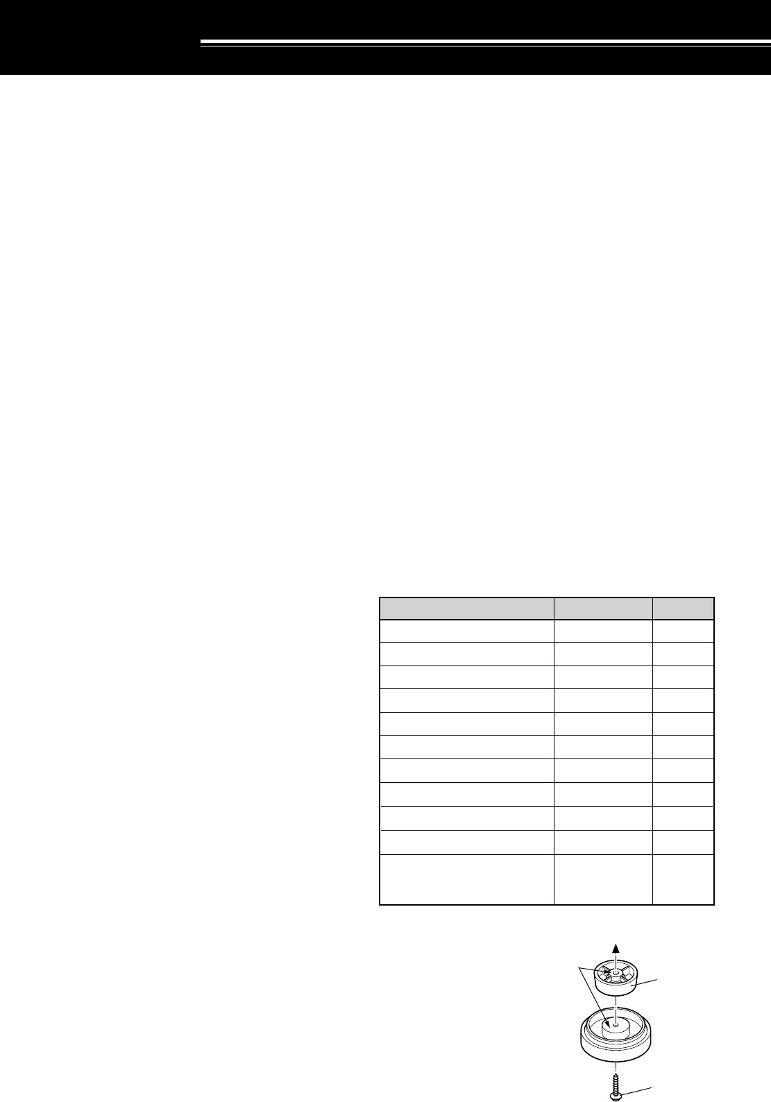
SUPPLIED ACCESSORIES
You can effectively
lengthen the front feet of
the TS-870S. Remove the
screws that fasten the front
feet to the transceiver. As
shown, install the supplied
spacers and the front feet
by using the supplied
screws. The removed
screws are not required,
but save them in case you
decide to remove the
spacers in future.
These sides
must face the
TS-870S case.
Supplied
spacer
Supplied screw
1
Microphone
DC power cable
7-pin DIN plug
13-pin DIN plug
Fuse (25 A)
Fuse (4 A)
Spacer
Screw
Instruction manual
Schematic/block diagrams
Warranty card
(U.S.A., Canada, and
Europe only)
T91-0352-XX
E30-3157-XX
E07-0751-XX
E07-1351-XX
F05-2531-XX
F06-4029-XX
J02-0479-XX
N91-3016-XX
B62-1536-XX
B52-0606-XX
—
1
1
1
1
1
1
2
2
1
1
1
Accessory Part Number Quantity
France, Holland: B52-0607-XX
1
2
INSTALLATION
ANTENNA CONNECTION
The type of the antenna system, consisting of the
antenna, ground, and feed line, will greatly affect the
successful performance of the transceiver. Use a
properly adjusted 50 Ω antenna of good quality to let
your transceiver perform at its best. Use a good-quality
50 Ω coaxial cable and a first-quality connector for the
connection. Match the impedance of the coaxial cable
and antenna so that the SWR is 1.5:1 or less. All
connections must be clean and tight.
While the transceiver’s protection circuit will activate if
the SWR is greater than 2.5:1, do not rely on protection
to compensate for a poorly functioning antenna system.
High SWR will cause the transmit output to drop, and
may lead to radio frequency interference to consumer
products such as stereo receivers and televisions. You
may even interfere with your own transceiver. Reports
that your signal is garbled or distorted, especially at
peak modulation, may indicate that your antenna
system is not efficiently radiating the transceiver’s
power. If you feel a tingle from the transceiver’s cabinet
or the microphone’s metal fittings when you modulate,
you can be certain that, at the least, your coax
connector is loose at the rear of the radio and, at the
worst, your antenna system is not efficiently radiating
power.
Connect your antenna feed line to ANT 1. If you are
using two antennas, connect the second antenna to
ANT 2. The EXT RX ANT jack can be used to connect
a separate receiver. Note that this jack must be
enabled by Menu configuration {pages 24, 27} before it
can be used.
CAUTION:
◆
Transmitting without first connecting an antenna or other
matched load may damage the transceiver. Always connect the
antenna to the transceiver before transmitting.
◆
Use a lightning arrestor to prevent fire, electric shock, or damage
to the transceiver.
APPROX. LOSS (dB) PER 30 METERS (100 FEET) OF
CORRECTLY MATCHED 50 Ω LINE
•Use only as a general guide. Specifications may vary
between cable manufacturers.
6.4
2.6
2.3
2.3
2.1
2.0
1.4
1.2
1.0
0.90
0.90
0.72
0.70
0.68
0.54
0.45
0.48
0.40
0.39
0.32
0.26
4.3
1.6
1.5
1.5
1.4
1.0
0.93
0.80
0.80
0.60
0.60
0.50
0.48
0.48
0.37
0.33
0.29
0.26
0.25
0.21
0.16
2.3
0.75
0.80
0.65
0.70
0.50
0.45
0.38
N/A
0.29
0.29
0.24
0.24
N/A
N/A
N/A
0.13
0.12
< 0.10
< 0.10
< 0.10
RG-174, -174A
RG-58A, -58C
3D-2V
RG-58, -58B
RG-58 Foam
RG-8X
5D-2V
RG-8, -8A, -9, -9A, 9B,
-213, 214, 215
5D-FB
RG-8 Foam
8D-2V
10D-2V
9913
8D-FB
10D-FB
12D-FB
RG-17, -17A
1/2" Hardline
20D-2V
3/4" Hardline
7/8" Hardline
Transmission Line 3.5 MHz 14 MHz 30 MHz
N/A: Not available
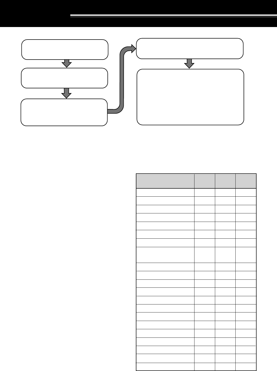
Connect all accessories to the transceiver {page 4}.
Accessories include the following:
• Microphone
• Antenna Tuner
• CW Key
• Computer
• TNC/ Multimode Communications
Processor
|nstall and connect an antenna system
{page 2}.
Install a ground system that satisfies DC
and RF grounding requirements {page 3}.
Install lightning protection to protect the
antenna system, your personal safety,
and your property {page 3}.
Install and connect a DC power supply {page 3}.
• Headphones
• External Speaker
• RTTY Equipment
• Linear Amplifier
3
First connect the DC power cable to the regulated DC
power supply and check that polarities are correct
(Red: positive, Black: negative). Then connect the
connectorized end of the DC power cable to the
DC 13.8 V power connector on the transceiver Rear
Panel. Press the DC power cable connector firmly into
the connector on the transceiver until the locking tab
clicks.
REPLACING FUSES
If the fuse blows, determine the cause then correct the
problem. After the problem is resolved, only then
replace the fuse. If newly installed fuses continue to
blow, disconnect the power plug and contact your
dealer or nearest Service Center for assistance.
CAUTION:
Replace blown fuses only after investigating and
correcting the cause of the failed fuse. Always replace a blown fuse
by a new fuse with the specified ratings.
2 INSTALLATION
GROUND CONNECTION
At the minimum, a good DC ground is required to
prevent such dangers as electric shock. For superior
communications results, a good RF ground is required,
against which the antenna system can operate. Both of
these conditions can be met by providing a good earth
ground for your station. Bury one or more ground rods,
or a large copper plate under the ground, and connect
this to the transceiver GND terminal. Use heavy gauge
wire or a copper strap, cut as short as possible, for this
connection. Just as for antenna work, all connections
must be clean and tight.
LIGHTNING PROTECTION
Consider carefully how to protect your equipment and
your home from lightning. Even in areas where
lightning storms are less common, there is usually a
limited number of storms each year. Take the time to
study the best way to protect your installation from the
effects of lightning by consulting reference material on
the subject.
The installation of a lightning arrestor is a start, but there
is more that you can do. For example, terminate your
antenna system transmission lines at an entry panel
that you install outside your home. Ground this entry
panel to a good outside ground, and then connect
appropriate feed lines between the entry panel and your
transceiver. When a lightning storm occurs, you can
ensure added protection by disconnecting the feed lines
from your transceiver.
CAUTION:
DO NOT attempt to use a gas pipe (which is clearly
dangerous), an electrical conduit (which has the whole house wiring
attached and may act like an antenna), or a plastic water pipe for a
ground.
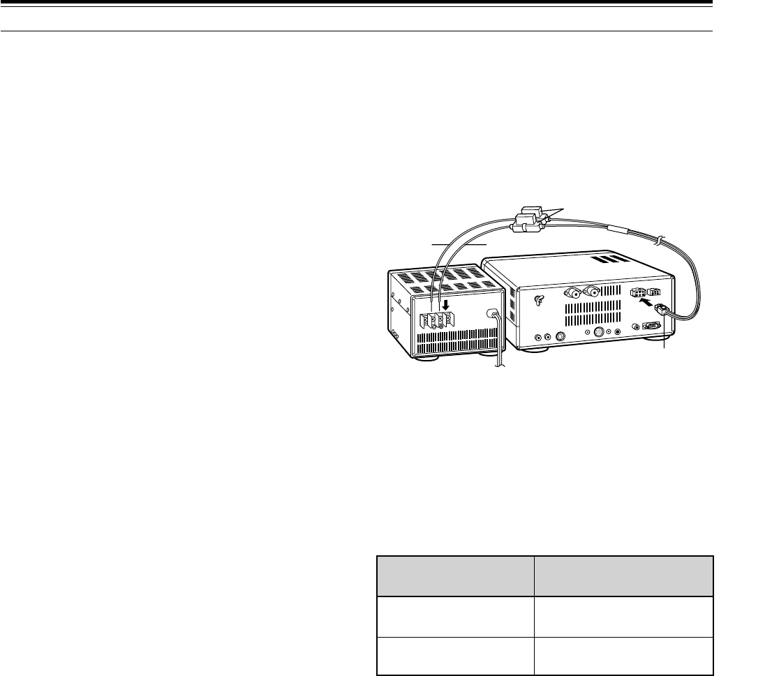
DC POWER SUPPLY CONNECTION
In order to use this transceiver, you will need a separate
13.8 V DC power supply that must be purchased
separately. DO NOT directly connect the transceiver to
an AC outlet! Use the supplied DC power cable to
connect the transceiver to a regulated power supply. Do
not substitute a cable with smaller gauge wires. The
current capacity of your power supply must be 20.5 A or
more.
CAUTION:
◆
Before connecting the DC power supply to the transceiver, be
sure to switch the transceiver and the DC power supply OFF.
◆
Do not plug the DC power supply into an AC outlet until you
make all connections.
◆
This transceiver has not been tested for use in mobile
applications.
Fuse Location Fuse Current Rating
Supplied Accessory
Cable
25 A
TS-870S 4 A
(for AT-300 Tuner)
DC power supply
TS-870S
Black Red
Fuse holders
DC 13.8 V
4
2 INSTALLATION
ACCESSORY CONNECTIONS
FRONT PANEL
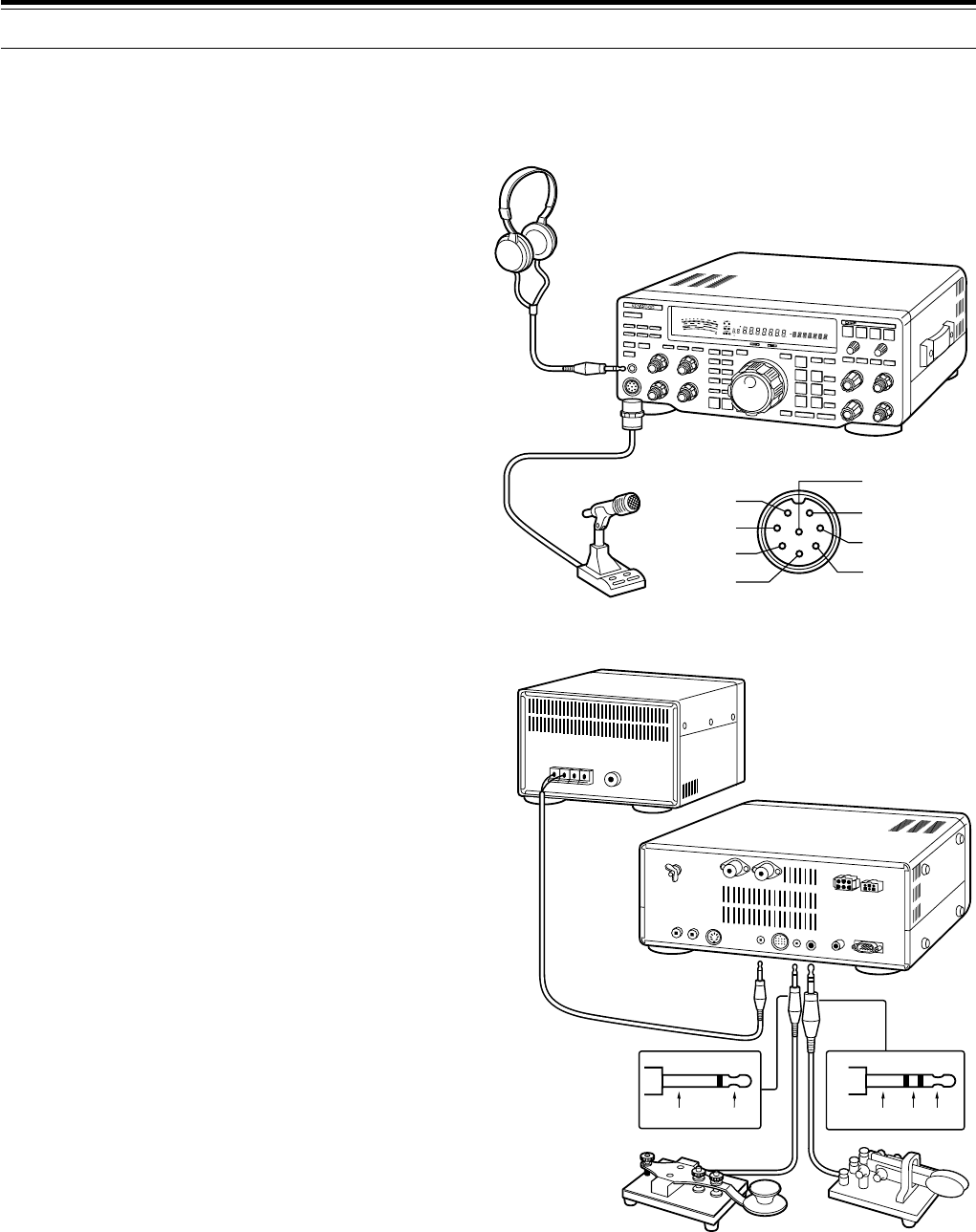
■Headphones (PHONES)
Use headphones having 4 to 32 Ω impedance. You
can also use stereo headphones. When
headphones are used, no sound is heard from the
internal (or optional external) speaker. Use a 6.0 mm
(1/4") diameter, 2-conductor (mono) or 3-conductor
(stereo) plug.
■Microphone (MIC)
To communicate in the voice modes, connect to the
MIC connector a microphone having an impedance
between 250 Ω and 600 Ω. Insert the connector
from your microphone fully, then screw the retaining
ring clockwise until snug. Compatible microphones
include the MC-43S, MC-60A, MC-80, MC-85, and
MC-90. Do not use the MC-44, MC-44DM, MC-45,
MC-45E, MC-45DM, or MC-45DME microphone.
REAR PANEL
■External Speaker (EXT SP)
Ensure any external speaker used has an
impedance of 8 Ω. Use a 3.5 mm (1/8") diameter,
2-conductor (mono) plug. When an external speaker
is used, no sound is heard from the internal speaker.
WARNING!
Do not connect headphones to this jack. The high
audio output at this jack could damage your hearing.
■Keys and Keyboards for CW Operation
(PADDLE and KEY)
For CW operation using the internal electronic keyer,
connect a keyer paddle to the PADDLE jack. For
CW operation without using the internal electronic
keyer, connect a straight key, semi-automatic key
(bug), electronic keyer, or the CW keyed output from
a Multimode Communications Processor (MCP) to
the KEY jack. The jacks mate with a 6.0 mm (1/4")
3-conductor plug and a 3.5 mm (1/8") 2-conductor
plug respectively. External electronic keyers or
MCPs must use positive keying to be compatible
with this transceiver. Use a shielded cable between
the key and the transceiver.
Note:
Due to the full-featured functionality of the internal
electronic keyer, you may decide it’s unnecessary to connect
both a paddle and another type of key unless you specifically
want to use a keyboard for CW. It’s recommended that you
become familiar with the internal keyer by reading
“ELECTRONIC KEYER” {page 32} before making your decision.
SWR
PWR
S
9
7
5
3
1
10
25
50
FILTER
ALC
3
10 2
1
.5
1
0
20
40
100
60
W
dB
dB
20
COMP
M.CH
USBCWRF
SKFMAMM. SCRPRGSCANF. LOCKFINEMHz
LSB
AUTO
FULL
VOXSEMIAIPAGCAUTOPROCMONIMENU
A B
SPLIT
RIT
TONE
XIT
NB
WIDTH
CTRL
SHIFT
TS-870S
Headphones
Microphone
iGND(STBY)
MICquGND(MIC)
yNC
t8 V(10 mA max)
PTTw
DOWNe
UPr
MIC connector (Front view)
External speaker
TS-870S
・Paddle・Straight key
・Bug
・Electronic keyer
・MCP CW output
Ground + Ground Dash Dot
5
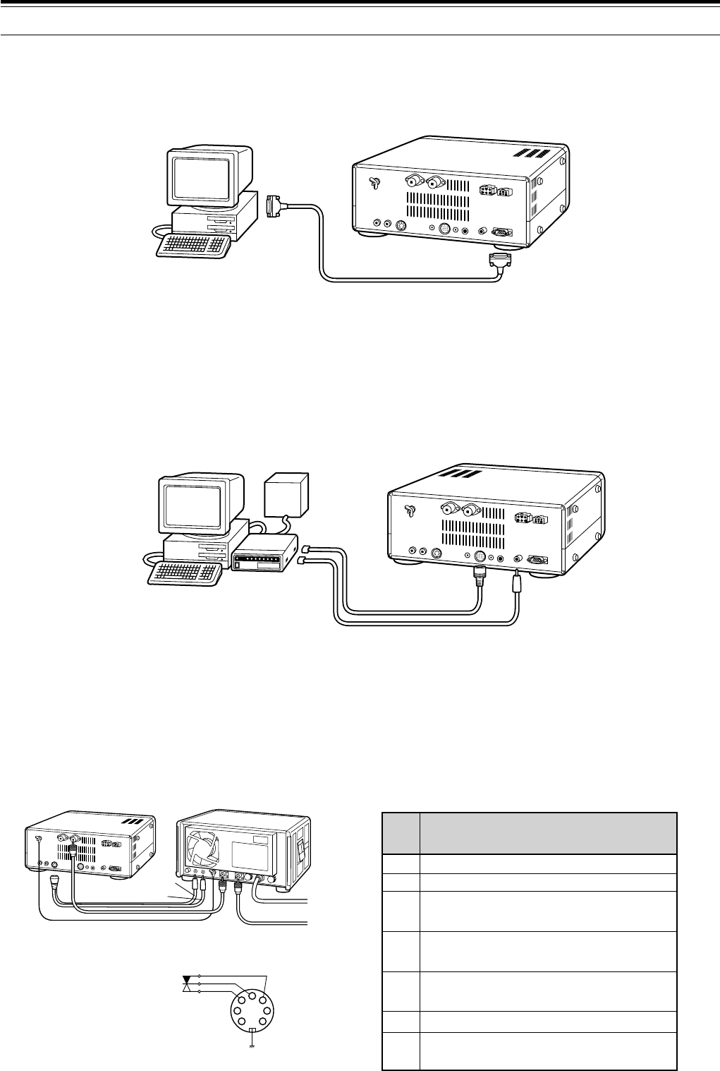
■Computer Interface (COM)
This connector allows you to directly connect a computer or dumb terminal by using an RS-232C cable terminated
with a female 9-pin connector. No external hardware interface is required between your computer and the
transceiver if your computer has an unused RS-232C serial communications port. See Appendix D on page 83 for
information relating to this connector.
■RTTY Equipment (RTTY and ACC 2)
To operate Frequency Shift Keyed RTTY, connect your RTTY equipment as shown below. Connect the RTTY key
output from your RTTY equipment to RTTY, and connect the demodulation input of your RTTY equipment to
ACC 2, Pin 3. By default, a short condition generates a space; an open generates a mark. However, this can be
reversed via Menu settings.
Do not share a single power supply between the transceiver and the RTTY equipment. Keep as wide a separation
as possible between the transceiver and the RTTY equipment as practical to reduce noise-pickup by the
transceiver.
■Linear Amplifier (REMOTE)
The REMOTE connector allows connection of an external transmit power amplifier. If using an amplifier, confirm
that Menu No. 51 (LINEAR) is set to “1” (Fast) or “2” (Slow) {pages 24, 27}. This Menu item controls the linear
amplifier TX/RX relay response time. Use the Fast setting unless you experience switching problems when using
your amplifier for semi break-in operation.
Note:
The TX/RX control method differs depending on external amplifier models. Some amplifiers enter the TX mode when the control
terminal is grounded. For those amplifiers, connect pin 2 of the
REMOTE
connector to the GND terminal of the amplifier and connect pin 4 of
the connector to the control terminal of the amplifier.
2 INSTALLATION
COM connector
Personal computer/
dumb terminal
RS-232C
serial port
TS-870S
MCP
power
supply
TS-870S
RTTYACC 2
MCP
Demod
input(RX)
RTTY
key
output
(TX)
Personal computer/
dumb terminal
2
4
1
67
3
5
TS-870S
Black
Red
AC LINE
RF OUTPUT
Linear amplifier
Control relay
R
T
GND
REMOTE Connector
(Rear Panel view)
REMOTE connector
Speaker output
Common terminal
Standby; when grounded, the
transceiver enters TX mode.
When connected with the common
terminal, the amplifier enters TX mode.
When connected with the common
terminal, the amplifier enters RX mode.
1
2
3
4
5
ALC input from amplifier
Approx. +12 V DC is output when in
TX mode (10 mA max.).
6
7
Pin
No. Function
6
2 INSTALLATION
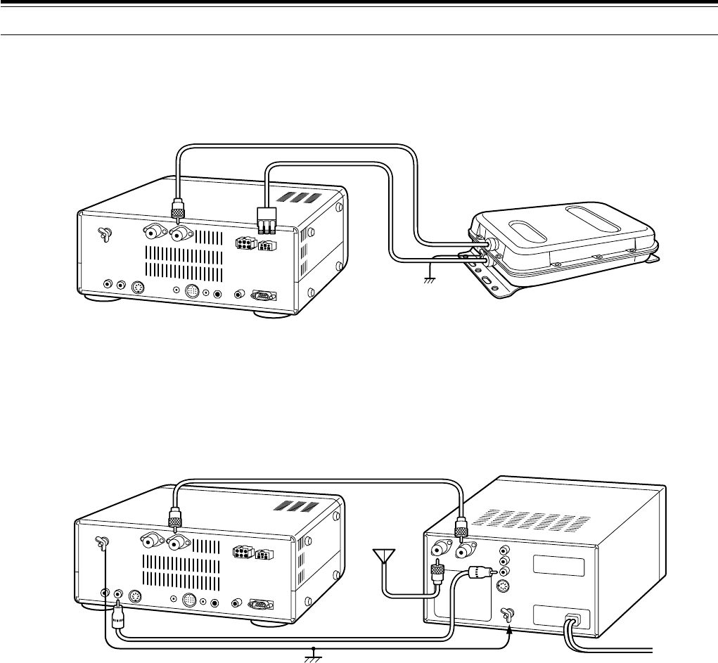
■Antenna Tuner (AT)
If using an external AT-300 antenna tuner, connect it here using the cable supplied with the antenna tuner. The
AT-300 must be connected to ANT 1; it will not function if connected to ANT 2.
■SM-230 Station Monitor (IF OUT 1)
Connect a cable from the IF OUT 1 jack to the IF IN jack on the SM-230 Station Monitor. This cable couples the
8.83 MHz IF from your TS-870S for pan display on the Station Monitor.
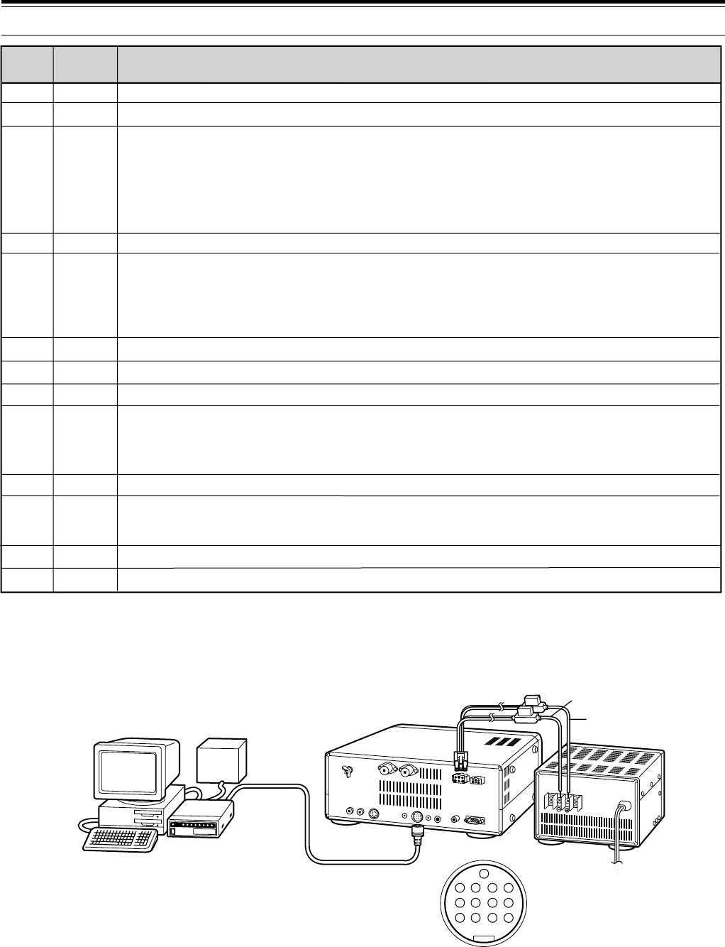
■Accessory Equipment (ACC 2)
If you intend to use this transceiver for any of the digital modes, connect the input/output connections from a
Terminal Node Controller (TNC) for Packet operation, a Multimode Communications Processor (MCP) for operation
on Packet, PacTOR, AMTOR, G-TOR, or FAX, or a Clover interface to this connector.
SSTV and phone patch equipment can also be connected to ACC 2. SSTV operation is possible by connecting the
input/output from a computer sound card to ACC 2, then running an SSTV application on the computer.
To operate on the digital modes, you will need the following equipment:
•Personal computer with communications software (alternatively, a “dumb” terminal capable of sending ASCII
commands)
•TNC (Terminal Node Controller) or MCP (Multimode Communications Processor)
•TNC or MCP power supply
•RS-232C cable
•13-pin DIN plug and cable
Connect your TNC or MCP to the ACC 2 connector on the transceiver Rear Panel using a cable equipped with a
13-pin DIN plug.
Do not share a single power supply between the transceiver and the TNC or MCP. Keep as wide a separation
between the transceiver and computer as practical to reduce noise-pickup by the transceiver. Refer to the
accompanying table for connection information.
TS-870S
AT-300
TS-870S SM-230
To Antenna
7
2 INSTALLATION
1
2
3
4
5
6
7
8
9
10
11
12
13
NC
NC
ANO
GND
PSQ
SMET
NC
GND
PKS
NC
PKD
GND
SS
Not connected
Not connected
Audio output from receiver
• Connect to TNC or MCP receive data pin for digital operation.
• Audio level is independent of AF gain control setting.
• Audio level can be changed via Menu No. 21 (PKT.OUT) {page 25}.
• Output impedance: 4.7 k
Shield for Pin 3
Squelch control
• Connect to TNC or MCP squelch control pin for digital operation.
• Prevents the TNC from transmitting while the receiver squelch is open.
• Squelch open: Low impedance • Squelch closed: High impedance
S-meter output
Not connected
Chassis ground
Transceiver PTT line control
• Connect to TNC or MCP transmit/receive switching pin for digital operation.
• Microphone audio input is muted when the transceiver is switched to transmit.
Not connected
Microphone audio input
• Connect to TNC or MCP transmit data pin for digital operation.
Shield for Pin 11
PTT control (in parallel with MIC jack) for connecting a footswitch or other external controller
Function
Pin No. Pin Name
Ω
TNC/MCP
power
supply
TNC/MCP TS-870S
PS-52
Personal computer/
dumb terminal
ACC 2 Connector
(Rear Panel view)
13
9101112
56 78
12 34
Black
Red
YOUR FIRST QSO
8
RECEIVING
3 GETTING ACQUAINTED
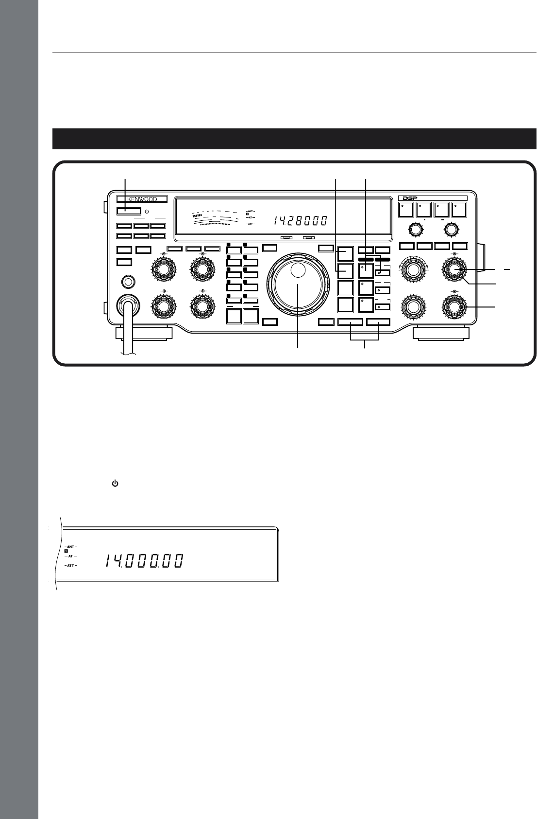
Note:
Only those buttons and controls required to briefly try the
transceiver are explained in this section.
q Set the following as specified:
•AF gain control: Fully counterclockwise
•RF gain control: Fully clockwise
•SQL control: Fully counterclockwise
w Switch ON the DC power supply, then press and
hold the [ ] (POWER) switch briefly.
•The transceiver switches ON. Indicators and
frequency digits should light on the Display.
e VFO A should already be selected for receive and
transmit as shown by the lit indicators in the
[RX A] button and the [TX A] button. If not, press
the [RX A] button.
r Increase the AF gain control slowly clockwise until
you hear a suitable level of background noise.
t Select an Amateur band by pressing the [UP] or
[DOWN] button.
•First pressing the [1MHz] button before
pressing the [UP] or [DOWN] button lets you
step up or down in 1 MHz increments instead
of stepping between Amateur bands.
y Select an operating mode by pressing the
[LSB/USB] or [CW/–R] button.
•Press the same button again to toggle to the
second function on the button. For example,
repeatedly pressing the [LSB/USB] button
switches between LSB and USB modes.
u Turn the Tuning control to tune in a station. If no
stations are heard but you have an antenna
connected, possibly the wrong antenna connector
is selected. Pressing the [ANT] button toggles
between the Antenna 1 and the Antenna 2
connectors.
YOUR FIRST QSO
Since you’ve now installed the TS-870S, why not try it? The instructions below are abbreviated. They are intended
only to act as a quick introduction. If you encounter problems or there’s something you don’t understand, you can
read about the subject in more detail later.
AGC
USB
50
49
38
27
16
RX TX
OFF
CAR DELAY
AGC KEY SPEED
METER PROC MONI
0
2
46
8
100
2
46
8
10
AUTO
NOTCH
BEAT
CANCEL N.R. TX EQ.
LO/WIDTH
FILTER
HI/SHIFT
MIC
ATT
ANT DOWN UP
VOX FULL/SEMI
AT TUNE
SEND
THRU/AUTO
AIP
PHONES
PROC MONI
MIC PWR
AF RF
NB SQL
M.IN
REC F.LOCK
CH 4 CLR
CH 3 SCAN
CH 2 M>VFO
CH 1 M.IN
ENTER TF-SET
MODE
LSB
/USB
FSK
/— R
CW/— R
FM/AM
FINE 1MHz DOWN UP
A=B MENU
RIT
RIT/XIT
M.CH/VFO.CH
XIT CLEAR NB
A
B
M.CH
QUICK MEMO
MR
SLOW FAST
0
2
46
8
10
0
2
46
8
10
0
2
46
8
10
DIGITAL SIGNAL PROCESSOR
S
9
7
5
3
1
10
25
50
FILTER
ALC
0
20
40
100
60
W
dB
USB
AGC
HF TRANSCEIVER TS-870
ON AIR AT TUNE
q
q
qr
t
e
y
w
u
9
YOUR FIRST QSO
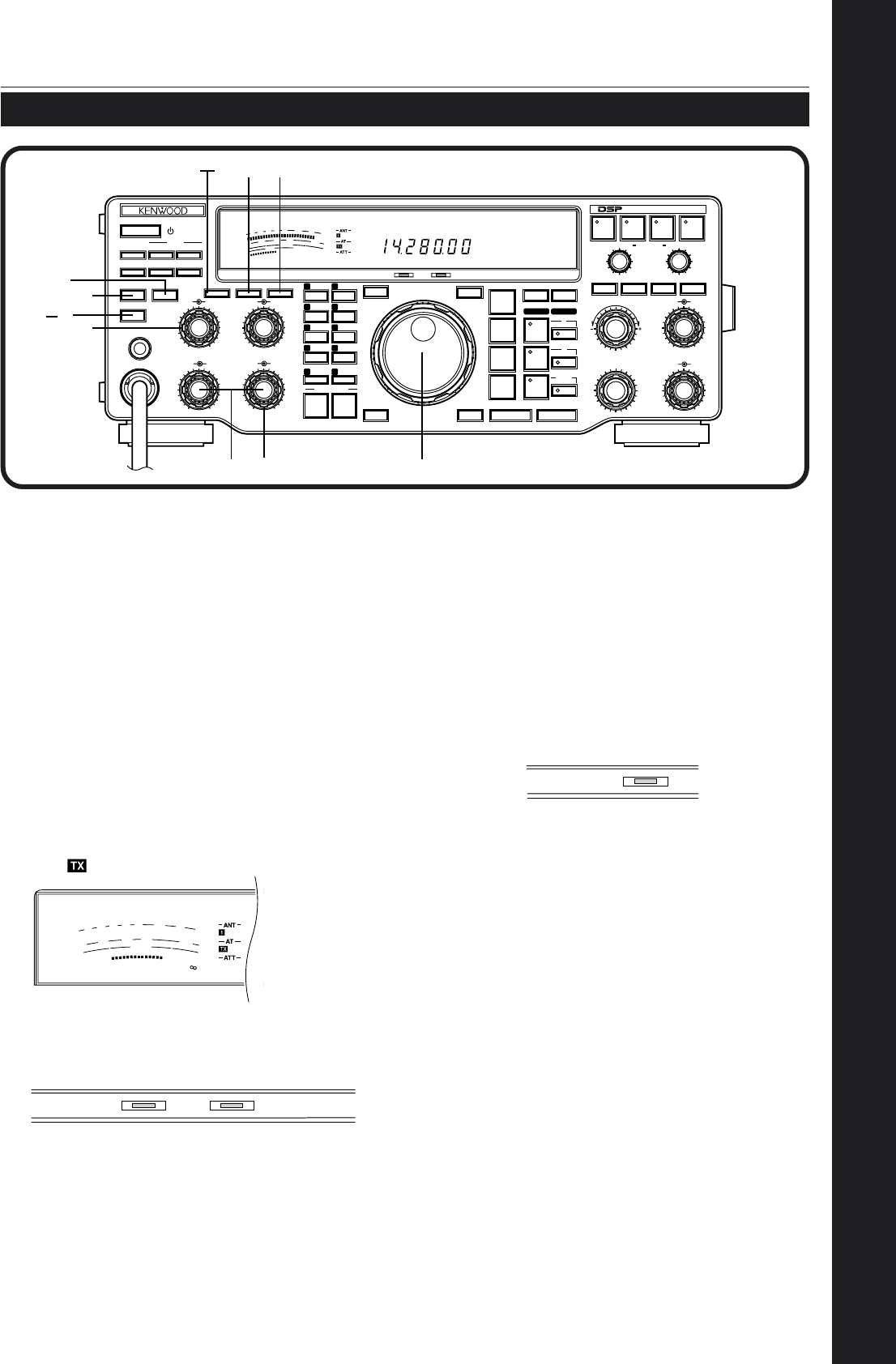
TRANSMITTING
3 GETTING ACQUAINTED
•The tuner should stop in less than
approximately 20 seconds, and “ON AIR” and
“AT TUNE” should go out.
•If the tuner continues to search for a match and
cannot match the transceiver with your antenna
system correctly, stop and check your antenna
system before continuing.
y Press the [METER] button to select the “ALC”
meter.
u Press the [SEND] button.
•“ON AIR” lights.
i Begin speaking into the microphone or sending CW
with your key. Adjust the MIC gain control for SSB
or the CAR control for CW to keep the ALC meter
moving in the ALC zone (but no higher) while
transmitting. Press the [SEND] button again when
you want to return to the receive mode.
This completes your introduction to the TS-870S, but
there is a great deal more to know. Continue reading
the remainder of this chapter to become totally
acquainted with the TS-870S. The chapters following
“GETTING ACQUAINTED” explain all functions of the
transceiver beginning with the most basic,
commonly-used functions.
After tuning in a few stations as explained in the
previous section “RECEIVING”, try making a contact.
q Assuming you are already on the correct band
with the correct mode selected (Steps 1~7
above), use the Tuning control to tune in a station
or to select an unused frequency.
w Set the following as specified:
•[PROC] button: OFF
•[MONI] button: OFF
•PWR control: Fully clockwise
•KEY SPEED control: Comfortable keyer
(for CW only) speed
e Press the [METER] button to select the “SWR”
meter.
r Press the [THRU/AUTO] button.
•“ ” lights.
t Press the [AT TUNE] button to allow the built-in
antenna tuner to function.
•“ON AIR” and “AT TUNE” light.
ON AIR
SWR
10
25
50
FILTER
3
2
1.5
1
0
100
W
S
9
7
5
3
1
20
40
60
dB
ON AIR AT TUNE
50
49
38
27
16
RX TX
OFF
CAR DELAY
AGC KEY SPEED
METER PROC MONI
0
2
46
8
100
2
46
8
10
AUTO
NOTCH
BEAT
CANCEL N.R. TX EQ.
LO/WIDTH
FILTER
HI/SHIFT
MIC
ATT
ANT DOWN UP
VOX FULL/SEMI
AT TUNE
SEND
THRU/AUTO
AIP
PHONES
PROC MONI
MIC PWR
AF RF
NB SQL
M.IN
REC F.LOCK
CH 4 CLR
CH 3 SCAN
CH 2 M>VFO
CH 1 M.IN
ENTER TF-SET
MODE
LSB
/USB
FSK
/— R
CW/— R
FM/AM
FINE 1MHz DOWN UP
A=B MENU
RIT
RIT/XIT
M.CH/VFO.CH
XIT CLEAR NB
A
B
M.CH
QUICK MEMO
MR
SLOW FAST
0
2
46
8
10
0
2
46
8
10
0
2
46
8
10
DIGITAL SIGNAL PROCESSOR
PWR
9
7
5
3
1
10
25
50
FILTER
ALC
0
20
40
100
60
W
dB
USB
AGC
HF TRANSCEIVER TS-870
ON AIR AT TUNE
w
w
y
e
rt
uw
w
i
i
q
10
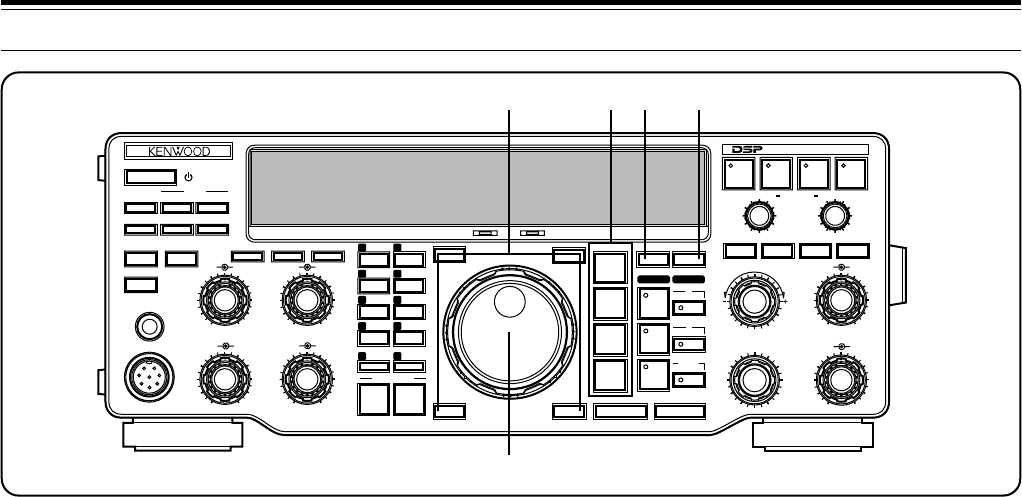
3 GETTING ACQUAINTED
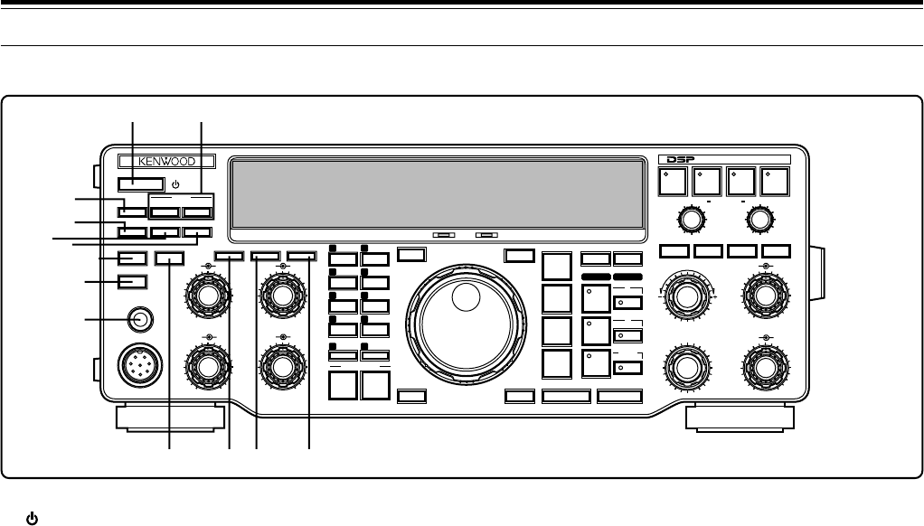
FRONT PANEL
q (POWER)
switch
Press and hold down briefly to switch the transceiver
power ON. Press again to switch OFF the power
{page 19}.
wATT DOWN/UP buttons
Press either button to step up or down through the
available receive signal attenuator selections. The
attenuator is OFF when all three selections of 6, 12, and
18 dB are not lit {page 53}.
eANT button
Press to select Antenna 1 or Antenna 2 that are
connected to their respective antenna connectors on the
Rear Panel {pages 2, 63}.
rVOX button
In the voice modes, press to switch the Voice-Operated
Transmit function ON or OFF {page 45}. In CW mode,
switches the Break-in function ON or OFF {page 31}.
tFULL/SEMI button
In CW mode, press to select Full or Semi Break-in
operation which affects the transmit/receive recovery
time after sending stops {page 31}.
yAIP button
Press to switch the Advanced Intercept Point function
ON or OFF. When activated, the AIP function reduces
interference caused by the presence of very strong
signals. The function lowers the receive sensitivity by
about 10 dB, and the default is ON when frequencies
below 7490 kHz are selected {page 53}.
uAT TUNE button
After enabling the internal antenna tuner via the
THRU/AUTO button, press to activate the tuner. The
tuner will attempt to match the transceiver with the
antenna system {page 49}.
iSEND button
Press to switch the transceiver between receive and
transmit {page 23}.
oPHONES jack
Connect headphones to this jack. Inserting a plug into
this jack automatically mutes the audio from the speaker
{page 4}.
!0 THRU/AUTO button
Press to enable the internal antenna tuner. This button
does not start the tuning action (see u). The tuner can
be configured so that it is only in-line while transmitting,
or it can be in-line while both transmitting and receiving
{page 49}.
!1 METER button
Press to switch between the available functions on the
Front Panel meter {page 22}.
!2 PROC button
In SSB or AM mode, press to switch the Speech
Processor ON or OFF {pages 23, 46}.
!3 MONI button
Press to switch the Transmit Monitor function ON or
OFF so you can monitor your transmitted signal
{page 46}.
50
49
38
27
16
RX TX
OFF
CAR DELAY
AGC KEY SPEED
METER PROC MONI
0
2
46
8
100
2
46
8
10
AUTO
NOTCH
BEAT
CANCEL N.R. TX EQ.
LO/WIDTH
FILTER
HI/SHIFT
MIC
ATT
ANT DOWN UP
VOX FULL/SEMI
AT TUNE
SEND
THRU/AUTO
AIP
PHONES
PROC MONI
MIC PWR
AF RF
NB SQL
M.IN
REC F.LOCK
CH 4 CLR
CH 3 SCAN
CH 2 M>VFO
CH 1 M.IN
ENTER TF-SET
MODE
LSB
/USB
FSK
/— R
CW/— R
FM/AM
FINE 1MHz DOWN UP
A=B MENU
RIT
RIT/XIT
M.CH/VFO.CH
XIT CLEAR NB
A
B
M.CH
QUICK MEMO
MR
SLOW FAST
0
2
46
8
10
0
2
46
8
10
0
2
46
8
10
DIGITAL SIGNAL PROCESSOR
HF TRANSCEIVER TS-870
ON AIR AT TUNE
qw
e
r
tu
i
o
y
!0 !2!1 !3
11
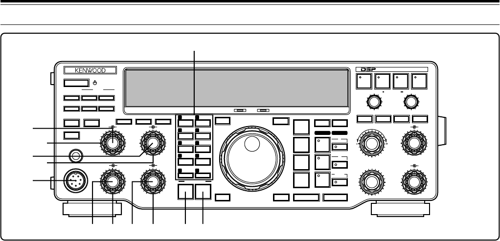
3 GETTING ACQUAINTED
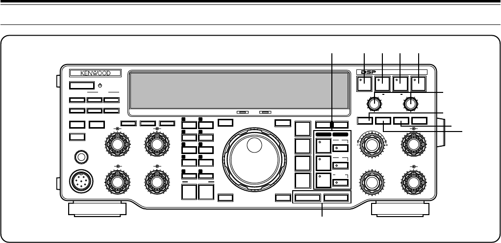
!8 MONI control
When using the Transmit Monitor function, adjusts the
volume level of the monitored transmit audio. Also
adjusts the volume of the CW sidetone. Turning the
control clockwise increases the volume {pages 30, 46}.
!9 MIC connector
Connect a compatible microphone, then snugly screw
down the connector locking ring {page 4}.
@0 CAR control
In CW, FSK, or AM mode, adjusts the carrier level
{pages 23, 30, 40, 41}. When using the Speech
Processor in SSB mode, adjusts the processor output
{page 46}. Turning the control clockwise increases the
carrier level or the processor output.
@1 DELAY control
When using the VOX function or the CW Break-in
function, adjusts the time period that the transceiver
waits before changing from the transmit mode back to
the receive mode. Turning the control clockwise
increases the delay {pages 31, 45}.
@2 MIC gain control
In SSB or AM mode, adjusts the level of microphone
gain. Turning the control clockwise increases the gain
{pages 23, 29, 40}.
@3 PWR control
Adjusts the transmit output power in all modes. Turning
the control clockwise increases the output power
{page 23}.
@4 QUICK MEMO M.IN button
Press to write data into Quick memory {page 59}.
@5 QUICK MEMO MR button
Press to recall data from Quick memory {page 59}.
!4 Multi-purpose keypad
Consists of 10 buttons that are used for inputting
numeric data. Also used for other functions:
•[M.IN]: Writes data into memory channels
{page 54}, selects Memory Scroll mode {page 56},
and adds items to the Quick Menu {page 24}.
•[M>VFO]: Transfers data from a memory channel
to a VFO {page 56}.
•[SCAN]: Starts and stops Scan functions
{page 60}.
•[CH 1], [CH 2], [CH 3], [CH 4]: Selects functions
associated with the internal electronic keyer
{page 32} and the DRU-3 Digital Recording Unit
{page 67}.
•[REC]: Selects the record mode for the DRU-3
Digital Recording Unit {page 67}.
•[F.LOCK]: Controls the Frequency Lock function
{page 64}.
•[CLR]: Used to exit from, abort, or reset various
functions. Also used for erasing memory channels
{page 57} or locking out {page 62} memory channels
from the scan list.
!5 AGC control
Turn to adjust the AGC time constant after selecting the
manual AGC mode {page 44}.
!6 KEY SPEED control
In CW mode, turn clockwise to increase the internal
electronic keyer speed and counterclockwise to
decrease the speed {page 32}.
!7 PROC control
When using the Speech Processor in SSB or AM mode,
adjusts the compression level. Turning the control
clockwise increases compression {pages 23, 46}.
50
49
38
27
16
RX TX
OFF
CAR DELAY
AGC KEY SPEED
METER PROC MONI
0
2
46
8
100
2
46
8
10
AUTO
NOTCH
BEAT
CANCEL N.R. TX EQ.
LO/WIDTH FILTER HI/SHIFT
MIC
ATT
ANT DOWN UP
VOX FULL/SEMI
AT TUNE
SEND
THRU/AUTO
AIP
PHONES
PROC MONI
MIC PWR
AF RF
NB SQL
M.IN
REC F.LOCK
CH 4 CLR
CH 3 SCAN
CH 2 M>VFO
CH 1 M.IN
ENTER TF-SET
MODE
LSB
/USB
FSK
/— R
CW/— R
FM/AM
FINE 1MHz DOWN UP
A=B MENU
RIT
RIT/XIT
M.CH/VFO.CH
XIT CLEAR NB
A
B
M.CH
QUICK MEMO
MR
SLOW FAST
0
2
46
8
10
0
2
46
8
10
0
2
46
8
10
DIGITAL SIGNAL PROCESSOR
HF TRANSCEIVER TS-870 ON AIR AT TUNE
!4
!5
!6
!7 !8
!9
@0 @1 @2 @3 @4 @5
12
3 GETTING ACQUAINTED
@6 Programmable Function buttons
The functions of these four buttons are selected and
assigned by you so you can customize the transceiver
as you like {page 63}. The factory default assignments
are as follows:
ENTER button
Used when entering frequencies via the keypad
{page 22}.
TF-SET (Transmit Frequency Set) button
While operating split frequency, press to monitor the
transmit frequency. Also, while holding this button
down in split-frequency mode, the transmit
frequency can be changed without altering the
receive frequency {page 43}.
FINE button
Press to reduce the Tuning control step size by
one-tenth to allow more precise tuning {page 21}.
1MHz button
Press to switch between the 1MHz mode and the
Amateur band mode {page 20}. This button also
activates the Programmed channel and Vacant
channel search modes {page 55}.
@7 Tuning control
Turn to select the desired frequency. Use the
convenient finger-tip cavity for continuous tuning
{page 21}.
@8 Mode buttons
Press these buttons to select your operating mode
{page 20}.
LSB/USB button
Selects Lower Sideband or Upper Sideband mode
for voice {page 29} or digital operation {page 41}.
CW/–R button
Selects CW {page 30} or CW Reverse mode
{page 31}.
FSK/–R button
Selects Frequency Shift Keying {page 40} or
Frequency Shift Keying Reverse mode for RTTY
operation {page 41}.
FM/AM button
Selects FM {page 38} or AM mode {page 40}.
@9 A=B button
Press to equalize the data in both VFOs. The data in
the currently selected VFO is copied to the other VFO;
the current VFO’s data is unaffected {page 20}. This
button is also used for the Full Reset function
{pages 57, 63}.
#0 MENU button
Press to select or cancel the Menu mode that is used
for activating and configuring functions {page 24}. This
button is also used for changing the Automatic mode
boundaries {page 48}.
50
49
38
27
16
RX TX
OFF
CAR DELAY
AGC KEY SPEED
METER PROC MONI
0
2
46
8
100
2
46
8
10
AUTO
NOTCH
BEAT
CANCEL N.R. TX EQ.
LO/WIDTH
FILTER
HI/SHIFT
MIC
ATT
ANT DOWN UP
VOX FULL/SEMI
AT TUNE
SEND
THRU/AUTO
AIP
PHONES
PROC MONI
MIC PWR
AF RF
NB SQL
M.IN
REC F.LOCK
CH 4 CLR
CH 3 SCAN
CH 2 M>VFO
CH 1 M.IN
ENTER TF-SET
MODE
LSB
/USB
FSK
/— R
CW/— R
FM/AM
FINE 1MHz DOWN UP
A=B MENU
RIT
RIT/XIT
M.CH/VFO.CH
XIT CLEAR NB
A
B
M.CH
QUICK MEMO
MR
SLOW FAST
0
2
46
8
10
0
2
46
8
10
0
2
46
8
10
DIGITAL SIGNAL PROCESSOR
HF TRANSCEIVER TS-870
ON AIR AT TUNE
@6 @8 @9 #0
@7
13
3 GETTING ACQUAINTED
#1 VFO/ Memory channel buttons
Press to select VFO A, VFO B, or a memory channel for
receive or transmit. If a receive button is pressed, the
same VFO or memory channel is selected for transmit
and receive. However, pressing a transmit button
selects only that VFO or memory channel for transmit
{page 42}.
RX A button
Selects VFO A for receive and transmit
{page 19}.
TX A button
Selects VFO A for transmit {page 42}.
RX B button
Selects VFO B for receive and transmit
{page 19}.
TX B button
Selects VFO B for transmit {page 42}.
RX M.CH button
Selects memory channel mode for receive and
transmit {page 55}.
TX M.CH button
Selects memory channel mode for transmit
{page 42}.
#2 AUTO NOTCH button
In SSB mode, press to switch the Auto Notch function
ON or OFF. Auto Notch can automatically locate and
remove interfering signals from the receive IF pass
band {page 52}.
#3 BEAT CANCEL button
In SSB or AM mode, press to switch the Beat Cancel
function ON or OFF. Beat Cancel works at AF to
remove interfering signals {page 52}.
#4 N.R. button
In SSB, CW, FSK, or AM mode, press to switch the
Noise Reduction function ON or OFF. This function
offers a choice of digital filtering methods for reception
{page 53}.
#5 TX EQ. button
In SSB or AM mode, press to switch the Transmit
Equalizer function ON or OFF. This equalizer function
includes high boost, low boost, and comb filter functions
{page 47}.
#6 FILTER LO/WIDTH and HI/SHIFT controls
These controls allow total flexibility in all modes for
digitally changing the receive pass band characteristics
for optimum reception {pages 51, 52}.
#7 RIT button
Press to switch the Receive Incremental Tuning function
ON or OFF. The RIT function allows you to change your
receive frequency without affecting your transmit
frequency {page 44}.
#8 CLEAR button
Press to reset the RIT/XIT frequency offset to zero
{pages 44, 45}. Also erases entered digits at any time
the keypad is being used to enter data {page 22, 48}.
#9 XIT button
Press to switch the Transmit Incremental Tuning
function ON or OFF. The XIT function allows you to
change your transmit frequency without affecting your
receive frequency {page 45}.
$0 UP/DOWN buttons
Press to step through all Amateur bands consecutively
{page 20}. If the 1MHz Step function is ON, then
pressing these buttons steps the transceiver in 1 MHz
increments {page 20}. These buttons are also used to
make selections from the Menu {page 24}, and to check
Start and End frequencies for the Scan function
{page 60}.
Note:
Only Auto Notch
#2,
or Beat Cancel
#3,
or Noise Reduction
#4
can be used at one time. They cannot be activated at the same time.
50
49
38
27
16
RX TX
OFF
CAR DELAY
AGC KEY SPEED
METER PROC MONI
0
2
46
8
100
2
46
8
10
AUTO
NOTCH
BEAT
CANCEL N.R. TX EQ.
LO/WIDTH
FILTER
HI/SHIFT
MIC
ATT
ANT DOWN UP
VOX FULL/SEMI
AT TUNE
SEND
THRU/AUTO
AIP
PHONES
PROC MONI
MIC PWR
AF RF
NB SQL
M.IN
REC F.LOCK
CH 4 CLR
CH 3 SCAN
CH 2 M>VFO
CH 1 M.IN
ENTER TF-SET
MODE
LSB
/USB
FSK
/— R
CW/— R
FM/AM
FINE 1MHz DOWN UP
A=B MENU
RIT
RIT/XIT
M.CH/VFO.CH
XIT CLEAR NB
A
B
M.CH
QUICK MEMO
MR
SLOW FAST
0
2
46
8
10
0
2
46
8
10
0
2
46
8
10
DIGITAL SIGNAL PROCESSOR
HF TRANSCEIVER TS-870
ON AIR AT TUNE
#1 #2 #3 #4 #5
#6
#7
#8#9
$0
14
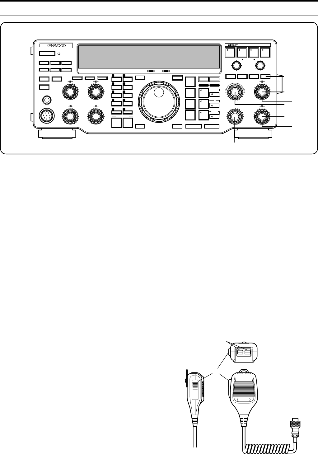
3 GETTING ACQUAINTED
$7 M.CH/VFO.CH control
In VFO mode, turn to step the frequency up or down
{page 21}. In memory channel mode, turn to select the
desired memory channel {page 55}. The control is also
used for selecting boundaries for the Automatic Mode
function {page 48} and for selecting Menu numbers
when accessing the Menu {page 24}.
MICROPHONE
qUP/DWN buttons
Use these buttons to step the VFO frequency or
memory channels up or down. The selected frequency
or channel will change continuously in the direction of
the button label if a button is pressed and held down.
wPTT (Push-to-Talk) switch
The transceiver is placed in transmit mode when this
non-locking switch is held down. Releasing the switch
returns the transceiver to receive mode.
$1 NB button
Press to switch the analog Noise Blanker function ON or
OFF. This function works best against short duration
pulse noise {page 53}.
$2 AF gain control
Adjusts the audio frequency gain. Turn the control
clockwise to increase the gain; counterclockwise to
decrease the gain {page 19}.
$3 RF gain control
Adjusts the radio frequency gain. Turn the control
clockwise to increase the gain; counterclockwise to
decrease the gain {page 19}.
$4 RIT/XIT control
After switching ON the RIT or XIT function, turn to select
the desired frequency offset with respect to the current
frequency {pages 44, 45}.
$5 NB control
When using the Noise Blanker function, turn to adjust
the noise blanking level {page 53}. To prevent distorting
your receive signal, use the minimum blanking level
necessary.
$6 SQL control
The Squelch control can be used for muting the receiver
during no signal periods. The more clockwise that the
control is turned, the higher the noise threshold level.
Therefore, the stronger the received signal must be to
open the squelch. Leave fully counterclockwise for
weak signal reception {page 19}.
PTT
DWN UP
q
w
50
49
38
27
16
RX TX
OFF
CAR DELAY
AGC KEY SPEED
METER PROC MONI
0
2
46
8
100
2
46
8
10
AUTO
NOTCH
BEAT
CANCEL N.R. TX EQ.
LO/WIDTH
FILTER
HI/SHIFT
MIC
ATT
ANT DOWN UP
VOX FULL/SEMI
AT TUNE
SEND
THRU/AUTO
AIP
PHONES
PROC MONI
MIC PWR
AF RF
NB SQL
M.IN
REC F.LOCK
CH 4 CLR
CH 3 SCAN
CH 2 M>VFO
CH 1 M.IN
ENTER TF-SET
MODE
LSB
/USB
FSK
/— R
CW/— R
FM/AM
FINE 1MHz DOWN UP
A=B MENU
RIT
RIT/XIT
M.CH/VFO.CH
XIT CLEAR NB
A
B
M.CH
QUICK MEMO
MR
SLOW FAST
0
2
46
8
10
0
2
46
8
10
0
2
46
8
10
DIGITAL SIGNAL PROCESSOR
HF TRANSCEIVER TS-870
ON AIR AT TUNE
$1
$2
$3
$4
$5
$6
$7
15
3 GETTING ACQUAINTED
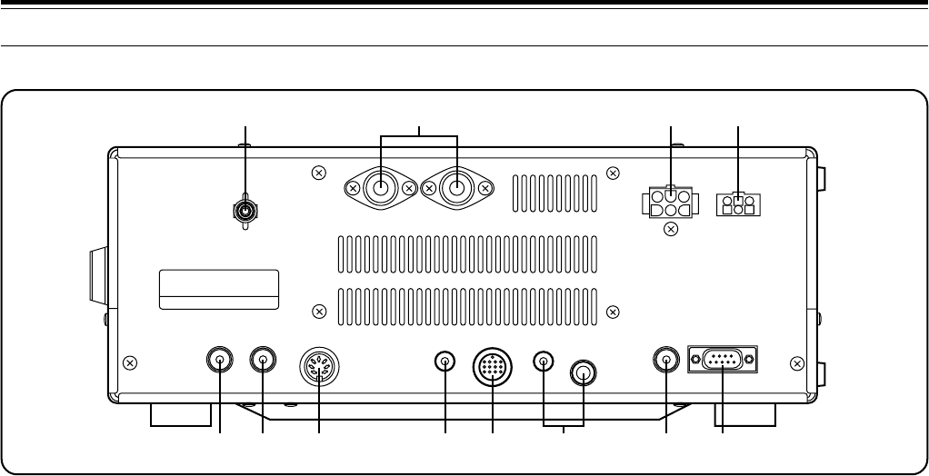
REAR PANEL
qGND post with wing nut
Connect a heavy gauge wire or copper strap between
the ground post and the nearest earth ground {page 3}.
Do not connect the ground wire to either your house
electrical wiring, or gas or water pipes. A well-grounded
transceiver will reduce the risk of interference to
television, broadcast radio receivers, and other
electronic devices. A good ground can also reduce
receiver noise caused by static discharges.
wANT 1 and ANT 2 connectors
Connect the feed lines from your antennas to these
connectors. Refer to pages 2 and 63 for details.
ePower Input DC 13.8 V connector
Connect a 13.8 V DC power source {page 3}. Use the
supplied cable with a regulated DC power supply. The
TS-870S draws less than 20.5 A at maximum transmit
output.
rAT connector
Mates with the connector on the cable supplied with the
AT-300 antenna tuner. Refer to the instruction manual
supplied with this tuner for more information.
tEXT RX ANT jack
Mates with an RCA pin plug for connecting a separate
receiver. Menu No. 53 enables this jack. Never
transmit into this jack. Signals received by the TS-870S
are distributed via a power divider to the TS-870S
receive stage and the external receiver. Therefore,
connecting an external receiver reduces the signal level.
yIF OUT 1 jack
Mates with an RCA pin plug for connecting the
8.83 MHz IF for pan display of an SM-230 Station
Monitor {page 6}.
uREMOTE connector
Mates with a 7-pin male DIN connector for connecting a
linear amplifier {page 5}.
iEXT SP jack
Mates with a 3.5 mm (1/8") diameter, 2-conductor
(mono) plug for connecting an external speaker
{page 4}. Connecting an external speaker cuts off the
audio automatically to the internal speaker.
oACC 2 connector
Mates with a 13-pin male DIN connector for connecting
various accessory equipment {page 6}.
!0 PADDLE and KEY jacks
Mates with a 6.0 mm (1/4") 3-conductor plug and a
3.5 mm (1/8") 2-conductor plug for connecting a key
paddle for the internal electronic keyer and another key
for CW operation respectively. Read “Keys and
Keyboards for CW Operation” {page 4} before
connecting to these jacks.
!1 RTTY jack
Mates with an RCA pin plug for connecting the RTTY
key output from RTTY equipment to operate true
frequency shift keying (direct keying) {page 5}.
!2 COM connector
Mates with a 9-pin female RS-232C connector for
connecting a computer via one of its serial
communication ports {page 83}. Functions on the
transceiver can be controlled remotely by using a
communications program on the computer {pages 5,
83}. Also used with the Quick Data Transfer function
{page 65}.
Note:
Before using the
REMOTE
,
ACC 2
, and
COM
connectors,
remove the protective covers.
GND
EXT
RX ANT IF OUT 1 REMOTE
EXT SP
8 ACC 2
ANT 2 ANT 1
KEY PADDLE RT TY COM
DC 13.8V
20.5A AT
Ω
qw er
ty u oi!0 !1 !2
16
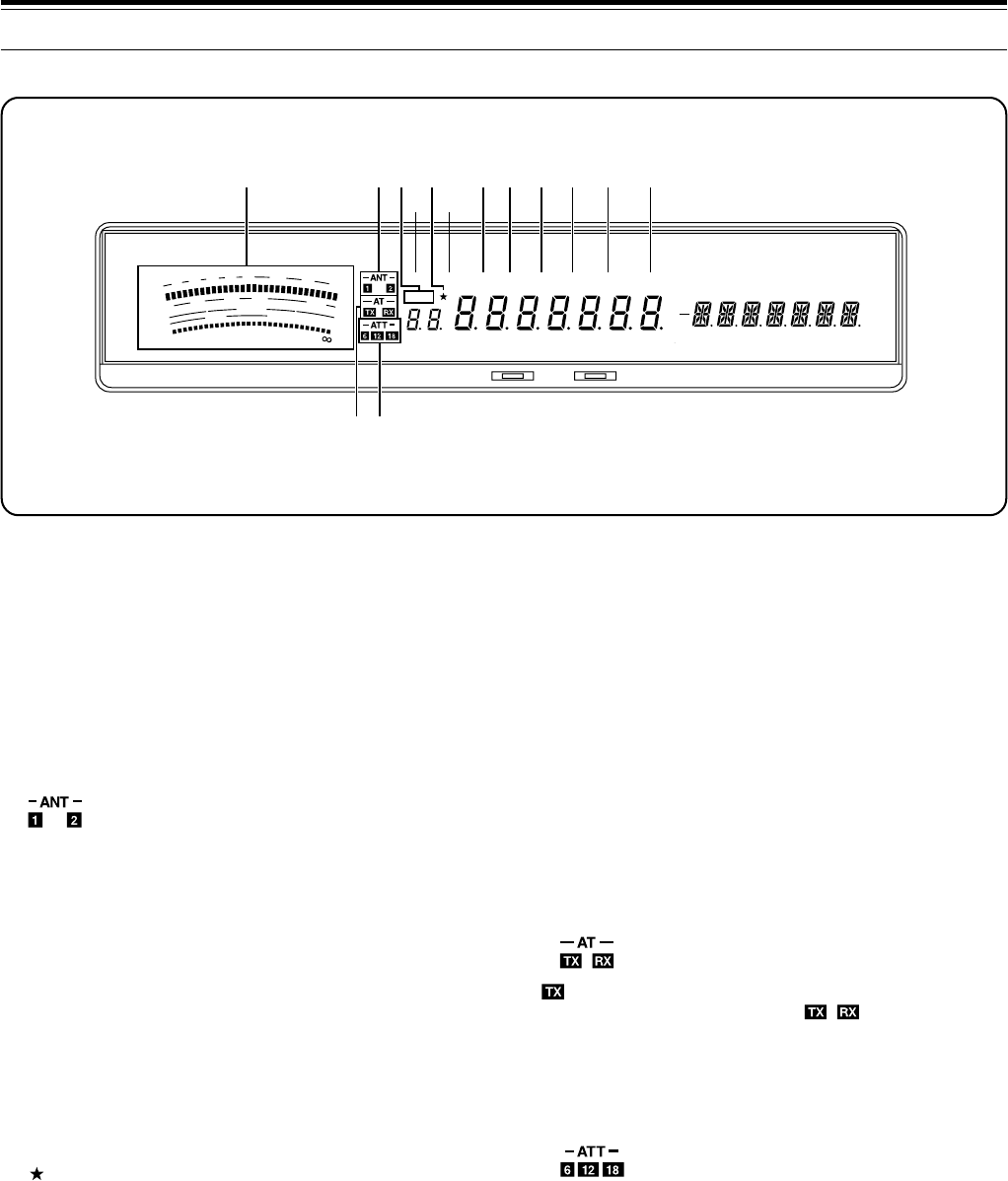
oAGC
Lights while the Automatic Gain Control function is ON
{page 44}.
!0 AUTO
Lights while Automatic is selected for the Automatic
Gain Control function {page 44}.
!1 PROC
Lights while the Speech Processor is ON
{pages 23, 46}.
!2 MONI
Lights while the Transmit Monitor function is ON
{page 46}.
!3
lights while the internal antenna tuner is configured
for use while transmitting only. light while the
tuner is configured for use while transmitting and
receiving. If neither are lit, the antenna tuner is
switched OFF {page 49}. If using Full Break-in CW, the
internal tuner can be either bypassed completely or can
be in-line for both transmitting and receiving.
!4
n, ⁄2, or ⁄8 lights while the attenuator is switched ON.
The numbers indicate the amount in dB of receive
attenuation that is selected. If no numbers are lit, the
attenuator is switched OFF {page 53}.
3 GETTING ACQUAINTED
qMETER
While receiving, serves as an S-meter to measure and
display the received signal strength. Also while
receiving, a 30-segment display represents the width
and relative shift of the currently selected receive pass
band. While transmitting, serves as a calibrated power
meter plus an ALC meter, an SWR meter, or a Speech
Processor compression meter. A Peak Hold function
can be activated that holds each reading for about 2.5
seconds {page 22}.
w
Either z or x lights while Antenna 1 or Antenna 2 is
selected respectively. Only one antenna can be
selected at a time {pages 2, 63}.
eM.CH
Lights while the memory channel mode is selected.
Also lights while using the Memory Scroll function
{page 56}.
rVOX
Lights while the Voice-Operated Transmit function
{page 45} is ON. For CW operation, lights while the
Break-in function {page 31} is ON.
t
Lights when a Menu item is added to the Quick Menu
{page 24}.
yFULL
Lights while CW Full Break-in is selected {page 31}.
uSEMI
Lights while CW Semi Break-in is selected {page 31}.
iAIP
Lights while the Advanced Intercept Point function is ON
{page 53}.
DISPLAY
SWR
PWR
S
9
7
5
3
1
10
25
50
FILTER
ALC
3
10 2
1.5
1
0
20
40
100
60
W
dB
dB
20
COMP
M. CH
USB CW R FSK FM AM M. SCR PRG SCAN F. LOCK FINE MHzLSBAUTO
FULLVOX SEMI AIP AGC AUTO PROC MONI MENU
A B
SPLIT
RIT
TONE
XIT
NB
WIDTH
CTRL
SHIFT
HF TRANSCEIVER TS-870 ON AIR AT TUNE
qwe
r
t
y
ui o !0 !1 !2
!3!4
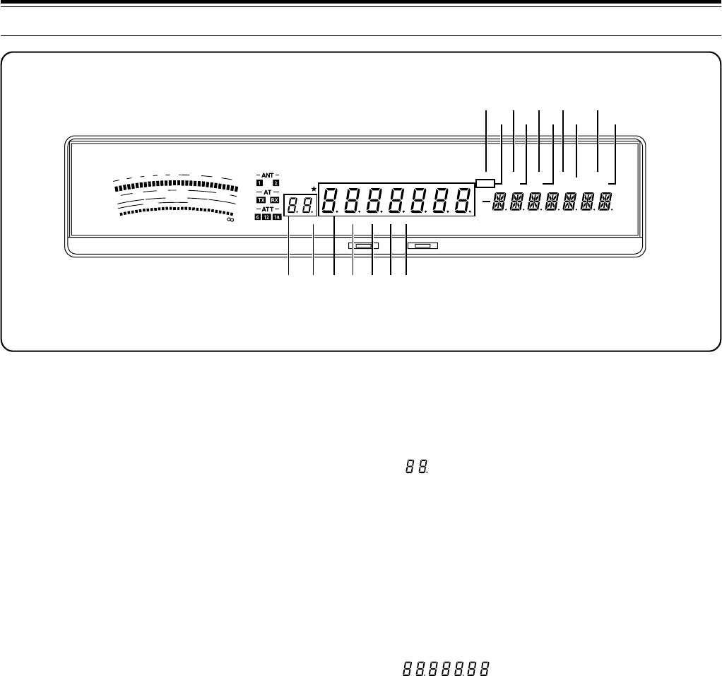
17
3 GETTING ACQUAINTED
!5 MENU
Lights while Menu mode is being accessed. Flashes
when the Menu has been temporarily reset {page 24}.
!6 A/B
“A” lights while Menu A is being accessed. “B” lights
while Menu B is being accessed {page 24}.
!7 SPLIT
Lights while a different transmit and receive frequency
are selected for split frequency {page 42}.
!8 RIT
Lights while the Receive Incremental Tuning function is
ON {page 44}.
!9 TONE
In FM mode, lights while the subaudible Tone function is
ON while operating split frequency {page 39}.
@0 XIT
Lights while the Transmit Incremental Tuning function is
ON {page 45}.
@1 NB
Lights while the Noise Blanker is ON {page 53}.
@2 WIDTH
In all modes except SSB and AM, lights after the
LO/WIDTH control is adjusted. Indicates that the
number reported below it on the Display is the receive
bandwidth {page 52}.
@3 CTRL
Lights while data is being exchanged between a
computer and the transceiver during computer control
{page 50} or between two transceivers during Quick
Data Transfer {page 65}.
@4 SHIFT
In CW, lights after the HI/SHIFT control is adjusted.
Indicates that the number reported below it on the
Display is the shift of the receive pass band {page 51}.
@5
Shows the selected memory channel {page 55},
Menu No.{page 24}, and Automatic Mode boundary
numbers {page 48}. The dot lights while a memory
channel is locked out. This indicates that the channel
will be skipped during Memory Scan {page 62}.
@6 AUTO
Lights while Automatic Mode is ON {page 48}.
Automatic Mode automatically controls the operating
mode according to instructions that you provide.
@7
Shows the operating frequency to a resolution of 10 Hz
{page 20}. Also shows the Menu selections while in
Menu mode {page 24}.
@8 LSB
Lights while in the Lower Sideband operating mode
{page 20}.
@9 USB
Lights while in the Upper Sideband operating mode
{page 20}.
#0 CW
Lights while in the CW operating mode {page 20}.
#1 R
Lights while the Reverse function is used with FSK or
CW. The Reverse function reverses the mark and
space frequency relationship for FSK {page 20}, and
uses the opposite sideband for CW {page 20}.
SWR
PWR
S
9
7
5
3
1
10
25
50
FILTER
ALC
3
10 2
1.5
1
0
20
40
100
60
W
dB
dB
20
COMP
M. CH
USB CW R FSK FM AM M. SCR PRG SCAN F. LOCK FINE MHzLSBAUTO
FULLVOX SEMI AIP AGC AUTO PROC MONI MENU
A B
SPLIT
RIT
TONE
XIT
NB
WIDTH
CTRL
SHIFT
HF TRANSCEIVER TS-870
ON AIR AT TUNE
!5!6
!7
!8
!9
@0
@1
@2 @3@4
@5 @6 @7@8 @9#0#1
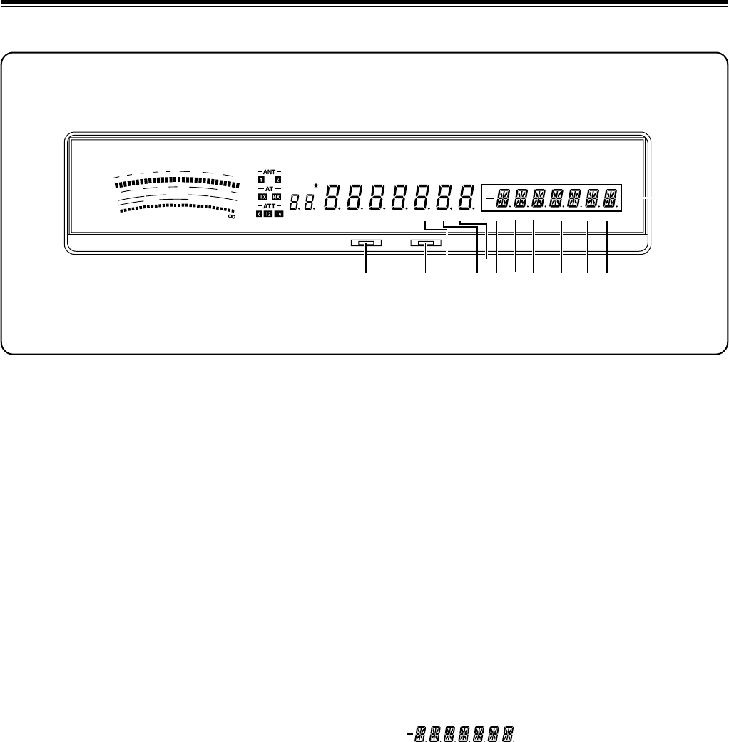
18
#8 PRG
Lights while Program Scan is activated {page 60} or
memory channel 99 is selected {page 58}.
#9 SCAN
Lights while a Scan function is activated {page 60}.
$0 F.LOCK
Lights while the Lock function is ON {page 64}.
$1 FINE
Lights while the Fine function is ON {page 21}.
$2 MHz
Lights while the 1MHz Step {page 20} or Quick Menu
{page 24} function is ON. Also lights while the Search
function for programmed or vacant memory channels is
ON {page 55}.
$3
Shows the Menu Items while accessing Menu mode
{page 24}. Also shows frequency information (transmit,
receive, or difference) while operating split frequency
{page 42} and the RIT/XIT frequency offset if these
functions are activated {pages 44, 45}.
3 GETTING ACQUAINTED
#2 ON AIR
Lights while the transceiver is in the transmit mode
{page 23}.
#3 AT TUNE
Lights while the internal antenna tuner is actually tuning
for a correct match between the antenna system and
the transceiver. Also lights while the transceiver is
presetting the antenna tuner capacitors according to
previously stored data {page 49}.
#4 FSK
Lights while in Frequency Shift Keying (RTTY) mode
{page 20}.
#5 FM
Lights while in the FM operating mode {page 20}.
#6 AM
Lights while in the AM operating mode {page 20}.
#7 M.SCR
Lights while in Memory Scroll mode {page 56}.
SWR
PWR
S
9
7
5
3
1
10
25
50
FILTER
ALC
3
10 2
1.5
1
0
20
40
100
60
W
dB
dB
20
COMP
M. CH
USB CW R FSK FM AM M. SCR PRG SCAN F. LOCK FINE MHzLSBAUTO
FULLVOX SEMI AIP AGC AUTO PROC MONI MENU
A B
SPLIT
RIT
TONE
XIT
NB
WIDTH
CTRL
SHIFT
HF TRANSCEIVER TS-870 ON AIR AT TUNE
#2 #3 #4 #5
#6
#7#8#9 $0 $1 $2
$3
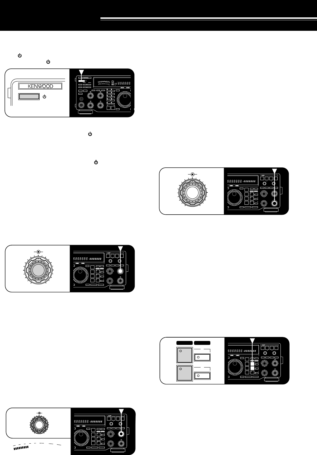
19
SWITCHING POWER ON/OFF
Switch ON the DC power supply, then press and hold
down [ ] (POWER) until “HELLO” appears on the
Display. Release [ ] (POWER) when you see “HELLO”.
•After the “HELLO” message, the frequency and
other indicators light. Pressing [ ] (POWER) too
long, switches the power OFF. If the TS-870S has
not been used for an extended period, “HELLO” may
not appear immediately.
To switch OFF the transceiver, press [ ] (POWER).
•After the transceiver has been switched ON, it can
then be switched OFF or ON by using only the
power switch on the DC power supply.
ADJUSTING VOLUME
AUDIO FREQUENCY (AF) GAIN
Turn the AF gain control clockwise to increase the audio
level and counterclockwise to decrease the level.
<<<#6 (9L) >>>
Note:
The position of the
AF
gain control does not affect the volume
of “beeps” caused by pressing buttons nor the CW
transmit sidetone.
Also, the audio level for Packet operation is independent of the
AF
gain control setting.
RADIO FREQUENCY (RF) GAIN
Usually, set the RF gain control maximum clockwise. If
you are having trouble hearing the desired signal due to
excessive atmospheric noise or interference from other
stations, it may help to reduce the RF gain.
To do this, take note of the peak S-meter reading of the
desired signal, then turn the RF gain control
counterclockwise to match this peak reading with the
illuminated S-meter segments. Signals that are weaker
than the level set with the RF gain control will be
attenuated. Reception of the station is easier.
OPERATING BASICS
Furthermore, using a faster AGC setting {page 44} will
help eliminate the blocking affect of the large AGC
voltage that is developed due to a strong adjacent
station.
Depending on the type and gain of your antenna, and
the condition of the band, you may prefer leaving the
RF gain control turned counterclockwise by some
amount instead of turning it fully clockwise.
ADJUSTING SQUELCH
The purpose of squelch is to silence audio output from
the speaker when no signals are present. Setting the
squelch threshold too high causes the squelch to
remain closed while a weak signal is present. Setting
the threshold too low allows noise to be heard between
transmissions from other stations. Many operators
prefer leaving the squelch control fully counterclockwise
unless operating full-carrier modes such as FM or AM.
Turn the SQL control to just eliminate the background
noise when no signal is present, or set and forget at full
counterclockwise rotation.
DUAL DIGITAL VFOs
The A and B VFOs function independently so that
different or the same frequencies can be selected by
each VFO. The following sections explain how to select
a VFO and how to copy frequency data from one VFO
to the other.
SELECTING VFOs ([RX A], [RX B])
Press [RX A] to select VFO A. Press [RX B] to select
VFO B.
1Assume that you are presently using VFO A.
2Press [RX B].
•VFO B is selected and the frequency currently
selected by VFO B is displayed.
3Press [RX A] to select VFO A again.
RX TX
AUTO
NOTCH
BEAT
CANCEL N.R. TX EQ.
LO/WIDTH FILTER HI/SHIFT
AF RF
NB SQL
ENTER TF-SET
MODE
LSB
/USB
FSK
/– R
CW/– R
FM/AM
FINE 1MHz DOWN UP
A=B MENU
RIT
RIT/XIT
M.CH/VFO.CH
XIT CLEAR NB
A
B
M.CH
0
2
46
8
10
0
2
46
8
10
DIGITAL SIGNAL PROCESSOR
USB CW R FSK FM AM M. SCR PRG SCAN F. LOCK FINE MHzLSBAUTO
FULL SEMI AIP AGC AUTO PROC MONI MENU
A B
SPLIT
RIT
TONE
XIT NB
WIDTH CTRL
SHIFT
ON AIR AT TUNE
AF RF
0
2
4
8
10
6
RX TX
AUTO
NOTCH
BEAT
CANCEL N.R. TX EQ.
LO/WIDTH
FILTER
HI/SHIFT
AF RF
NB SQL
ENTER TF-SET
MODE
LSB
/USB
FSK
/– R
CW/– R
FM/AM
FINE 1MHz DOWN UP
A=B MENU
RIT
RIT/XIT
M.CH/VFO.CH
XIT CLEAR NB
A
B
M.CH
0
2
46
8
10
0
2
46
8
10
DIGITAL SIGNAL PROCESSOR
USB CW R FSK FM AM M. SCR PRG SCAN F. LOCK FINE MHzLSBAUTO
FULL SEMI AIP AGC AUTO PROC MONI MENU
A B
SPLIT
RIT
TONE
XIT
NB
WIDTH
CTRL
SHIFT
ON AIR AT TUNE
0
2
46
8
10
AF RF
S
9
7
5
3
1
20
40
60
dB
RX TX
AUTO
NOTCH
BEAT
CANCEL N.R. TX EQ.
LO/WIDTH
FILTER
HI/SHIFT
AF RF
NB SQL
ENTER TF-SET
MODE
LSB
/USB
FSK
/– R
CW/– R
FM/AM
FINE 1MHz DOWN UP
A=B MENU
RIT
RIT/XIT
M.CH/VFO.CH
XIT CLEAR NB
A
B
M.CH
0
2
46
8
10
0
2
46
8
10
DIGITAL SIGNAL PROCESSOR
USB CW R FSK FM AM M. SCR PRG SCAN F. LOCK FINE MHzLSBAUTO
FULL SEMI AIP AGC AUTO PROC MONI MENU
A B
SPLIT
RIT
TONE
XIT
NB
WIDTH
CTRL
SHIFT
ON AIR AT TUNE
NB SQL
0
2
4
8
10
6
RX TX
AUTO
NOTCH
BEAT
CANCEL N.R. TX EQ.
LO/WIDTH
FILTER
HI/SHIFT
AF RF
NB SQL
ENTER TF-SET
MODE
LSB
/USB
FSK
/– R
CW/– R
FM/AM
FINE 1MHz DOWN UP
A=B MENU
RIT
RIT/XIT
M.CH/VFO.CH
XIT CLEAR NB
A
B
M.CH
0
2
46
8
10
0
2
46
8
10
DIGITAL SIGNAL PROCESSOR
USB CW R FSK FM AM M. SCR PRG SCAN F. LOCK FINE MHzLSBAUTO
FULL SEMI AIP AGC AUTO PROC MONI MENU
A B
SPLIT
RIT
TONE
XIT
NB
WIDTH
CTRL
SHIFT
ON AIR AT TUNE
RX TX
A
B
50
49
38
27
16
OFF
CAR DELAY
AGC KEY SPEED
METER PROC MONI
0
2
46
8
100
2
46
8
10
MIC
ATT
ANT DOWN UP
VOX FULL/SEMI
AT TUNE
SEND
THRU/AUTO
AIP
PHONES
PROC MONI
MIC PWR
M.IN
REC F.LOCK
CH 4 CLR
CH 3 SCAN
CH 2 M>VFO
CH 1 M.IN
ENTER TF-SET
FINE 1MHz
QUICK MEMO
MR
SLOW FAST
0
2
46
8
10
SWR
PWR
S
9
7
5
3
1
10
25
50
FILTER
ALC
3
10 2
1
.5
1
0
20
40
100
60
W
dB
dB
20
COMP
M.CH
USB CW R FSK FM AMLSBAUTO
FULLVOX SEMI AIP AGC AUTO PROC MONI
HF TRANSCEIVER TS-870
ON AIR AT TUNE
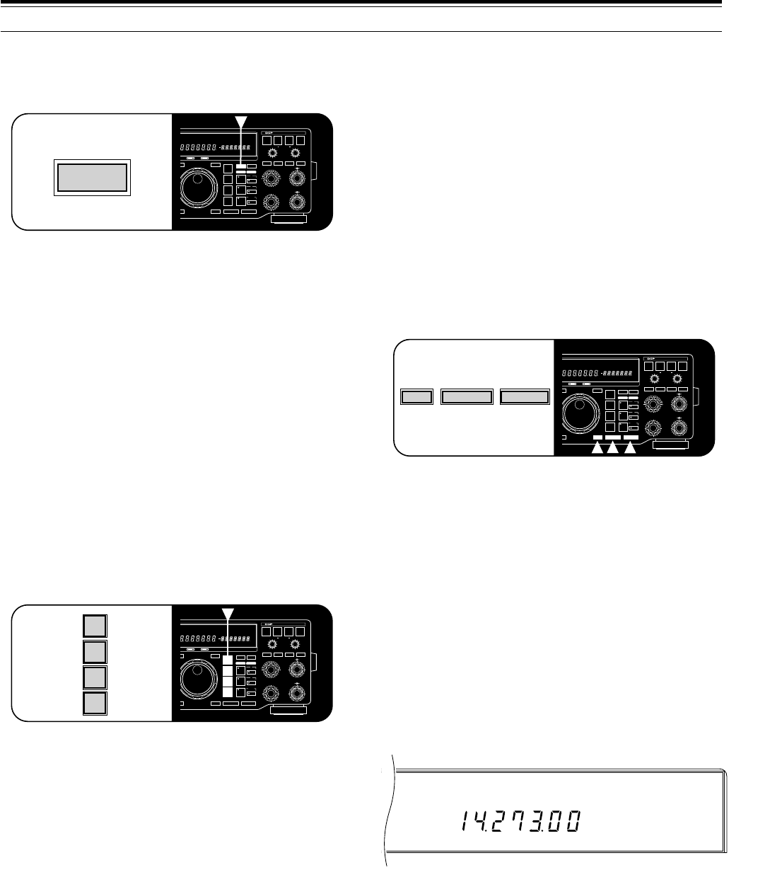
20
4 OPERATING BASICS
SELECTING FREQUENCY
There are two methods to select a frequency that are
explained in the following sections:
AManual Tuning
Change to the correct band or use the 1MHz Step
function to get close to the desired frequency. Then
use the M.CH/VFO.CH control for coarse tuning and
the Tuning control (or the Mic [UP] and [DWN]
buttons) for selecting the exact frequency.
BDirect Frequency Entry (Keypad)
Enter the desired frequency directly using the
numeric keypad.
CHANGING BANDS
1If “MHz” is illuminated on the Display, first press
[1MHz] to exit from the 1MHz Step mode.
•“MHz” goes out.
2Press [UP] or [DOWN].
•Holding down either button consecutively steps
the transceiver to each band.
USING 1 MHz STEPS
The default step size for the 1MHz Step function is
1MHz; however, you can also select 500 or 100 kHz
steps via Menu No. 52 (1M/500k). Menu selections are
explained in more detail beginning on page 24.
1Press [1MHz] to enter the 1MHz mode.
•“MHz” lights.
2Press [UP] or [DOWN].
•The frequency changes up or down in 1 MHz
steps (or 500 or 100 kHz steps) each time [UP]or
[DOWN] is pressed. Holding down either button
causes the function to repeat.
EQUALIZING VFO FREQUENCIES ([A=B])
Press [A=B] to transfer the frequency and modulation
mode of the active VFO to the inactive VFO.
1Assume that you are presently using VFO A.
2Press [RX B].
•VFO B is selected and the frequency currently
selected by VFO B is displayed.
3Press [A=B].
4Press [RX A].
•This selects VFO A again. Note that the VFO B
frequency and the modulation mode have been
copied to VFO A due to Step 3.
SELECTING MODE
To change the operating mode, simply press the MODE
button for the mode that you want to use. The second
function on each MODE button is accessed by pressing
the same button again.
Example: To switch to LSB, press [LSB/USB] one
time. To then switch to USB, press [LSB/USB] again.
<<<#12 (9L) >>>
The CW mode defaults to the upper sideband. The “–R”
label on [CW/–R] indicates that CW may be sent and
received using the lower (reverse) sideband if you want.
The “–R” label on [FSK/–R] indicates that the mark and
space signals for RTTY may be reversed by selecting
this mode.
In SSB mode, the transceiver automatically selects LSB
for frequencies lower than 9.5 MHz, and selects USB for
9.5 MHz or higher frequencies if the Tuning control or
Mic [UP]/[DWN] is used to cross the frequency of
9.5 MHz. This is also true if using the Front Panel [UP]
or [DOWN] button.
RX TX
AUTO
NOTCH
BEAT
CANCEL N.R. TX EQ.
LO/WIDTH
FILTER
HI/SHIFT
AF RF
NB SQL
ENTER TF-SET
MODE
LSB
/USB
FSK
/– R
CW/– R
FM/AM
FINE 1MHz DOWN UP
A=B MENU
RIT
RIT/XIT
M.CH/VFO.CH
XIT CLEAR NB
A
B
M.CH
0
2
46
8
10
0
2
46
8
10
DIGITAL SIGNAL PROCESSOR
USB CW R FSK FM AM M. SCR PRG SCAN F. LOCK FINE MHzLSBAUTO
FULL SEMI AIP AGC AUTO PROC MONI MENU
A B
SPLIT
RIT
TONE
XIT
NB
WIDTH
CTRL
SHIFT
ON AIR AT TUNE
MODE
LSB
/USB
FSK
/– R
CW/– R
FM/AM
RX TX
AUTO
NOTCH
BEAT
CANCEL N.R. TX EQ.
LO/WIDTH
FILTER
HI/SHIFT
AF RF
NB SQL
ENTER TF-SET
MODE
LSB
/USB
FSK
/– R
CW/– R
FM/AM
FINE 1MHz DOWN UP
A=B MENU
RIT
RIT/XIT
M.CH/VFO.CH
XIT CLEAR NB
A
B
M.CH
0
2
46
8
10
0
2
46
8
10
DIGITAL SIGNAL PROCESSOR
USB CW R FSK FM AM M. SCR PRG SCAN F. LOCK FINE MHzLSBAUTO
FULL SEMI AIP AGC AUTO PROC MONI MENU
A B
SPLIT
RIT
TONE
XIT
NB
WIDTH
CTRL
SHIFT
ON AIR AT TUNE
A=B
RX TX
AUTO
NOTCH
BEAT
CANCEL N.R. TX EQ.
LO/WIDTH
FILTER
HI/SHIFT
AF RF
NB SQL
ENTER TF-SET
MODE
LSB
/USB
FSK
/– R
CW/– R
FM/AM
FINE 1MHz DOWN UP
A=B MENU
RIT
RIT/XIT
M.CH/VFO.CH
XIT CLEAR NB
A
B
M.CH
0
2
46
8
10
0
2
46
8
10
DIGITAL SIGNAL PROCESSOR
USB CW R FSK FM AM M. SCR PRG SCAN F. LOCK FINE MHzLSBAUTO
FULL SEMI AIP AGC AUTO PROC MONI MENU
A B
SPLIT
RIT
TONE
XIT
NB
WIDTH
CTRL
SHIFT
ON AIR AT TUNE
1MHz DOWN UP
USB MHz
AGC AUTO
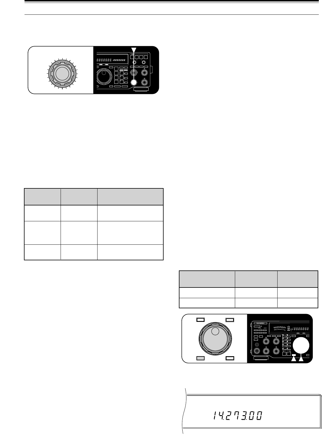
21
■Changing Step Sizes
Select the step size that you prefer for the
M.CH/VFO.CH control via Menu No. 43 (CH. STEP).
Available step sizes are 1 kHz, 5 kHz and 10 kHz.
The default is 10 kHz.
Within the AM broadcast band, the step size
automatically defaults to 9 kHz (U.S.A./ Canada
versions: 10 kHz) for the AM mode. This step size
can be switched between 9 (ON) and 10 kHz (OFF)
via Menu No. 42 (BC. STEP). Selecting OFF in
Menu No. 42 allows you to use the step size
specified via Menu No. 43 (1, 5, or 10 kHz). While in
the AM broadcast band, changing the step size via
Menu No. 42 will change the selected frequency to
the nearest broadcast channel on the next use of the
M.CH/VFO.CH control.
If you enjoy listening to international shortwave
broadcasters, the M.CH/VFO.CH control is also the
best way to manually scan these bands. Select the
5kHz step size via Menu No. 43 (CH. STEP) since
most shortwave broadcasters are spaced 5 kHz
apart. Set Menu No. 44 to ON. To listen to a
broadcaster on a channel that is not a 5 kHz
multiple, use the Tuning control to zero-in to the
exact frequency.
FINE TUNING
For SSB, CW, and FSK modes, the Tuning control
normally tunes through 10 kHz per revolution of the
control. For FM and AM modes, one revolution of the
Tuning control changes the frequency by 100 kHz.
These tuning rates can be halved via Menu No. 41
(F.STEP).
In addition, the Fine Tuning function reduces the step
size of the Tuning control further which allows you to
tune more slowly and precisely.
Press [FINE].
•“FINE” lights.
•The Fine Tuning function toggles ON and OFF each
time [FINE] is pressed.
QUICK CHANGES
To move up or down in frequency quickly, use the
M.CH/VFO.CH control.
•Turn the M.CH/VFO.CH control clockwise to
increase the frequency; counterclockwise to
decrease the frequency.
Due to the large step sizes available, you can quickly
move across the band. When the minimum or
maximum receive frequency for the transceiver is
reached, turning the M.CH/VFO.CH control will not
decrease or increase respectively the frequency.
Menu No. 44 (STEP.ADJ) affects how the
M.CH/VFO.CH control tunes. When Menu No. 44 is
ON (default), rounding occurs on the first step (“click”) of
the M.CH/VFO.CH control as shown below:
Example 1: Menu No. 44 (STEP.ADJ) is ON
•Menu No. 43 (CH. STEP): 10 kHz step size
•Selected frequency: 14.261.73 MHz
Turning the M.CH/VFO.CH control clockwise one step
changes the frequency to 14.270.00 MHz, and one
more step changes the frequency to 14.280.00 MHz.
The rounding occurred on the first step.
Similarly, with 14.261.73 MHz selected, turning this
control counterclockwise one step changes the
frequency to 14.260.00 MHz, and one more step
changes the frequency to 14.250.00 MHz. Again, the
rounding took place on the first step.
Example 2: Menu No. 44 (STEP.ADJ) is OFF
•Menu No. 43 (CH. STEP): 10 kHz step size
•Selected frequency: 14.261.73 MHz
Turning the M.CH/VFO.CH control clockwise one step
changes the frequency to 14.271.73 MHz, and one
more step changes the frequency to 14.281.73 MHz.
No rounding occurs.
With 14.261.73 MHz selected, turning this control
counterclockwise one step changes the frequency to
14.251.73 MHz, and one more step changes the
frequency to 14.241.73 MHz. Again, no rounding
occurs.
4 OPERATING BASICS
RX TX
AUTO
NOTCH
BEAT
CANCEL N.R. TX EQ.
LO/WIDTH
FILTER
HI/SHIFT
AF RF
NB SQL
ENTER TF-SET
MODE
LSB
/USB
FSK
/– R
CW/– R
FM/AM
FINE 1MHz DOWN UP
A=B MENU
RIT
RIT/XIT
M.CH/VFO.CH
XIT CLEAR NB
A
B
M.CH
0
2
46
8
10
0
2
46
8
10
DIGITAL SIGNAL PROCESSOR
USB CW R FSK FM AM M. SCR PRG SCAN F. LOCK FINE MHzLSBAUTO
FULL SEMI AIP AGC AUTO PROC MONI MENU
A B
SPLIT
RIT
TONE
XIT
NB
WIDTH
CTRL
SHIFT
ON AIR AT TUNE
M.CH/VFO.CH
1 kHz, 100 Hz, and
10 Hz digits change to 0.
1 kHz digit changes to 0
or 5, and 100 Hz and
10 Hz digits change to 0.
100 Hz and 10 Hz digits
change to 0.
10 kHz
5 kHz
1 kHz
ON
ON
ON
Step Adjust
(Menu No. 44)
Channel Step
(Menu No. 43) Rounding Effect
Fine Tuning
(Menu No. 41: 10 kHz)
SSB/ CW/ FSK
Tuning Steps
AM/ FM
Tuning Steps
OFF
ON
10 Hz
1Hz
100 Hz
10 Hz
50
49
38
27
16
OFF
CAR DELAY
AGC KEY SPEED
METER PROC MONI
0
2
46
8
100
2
46
8
10
MIC
ATT
ANT DOWN UP
VOX FULL/SEMI
AT TUNE
SEND
THRU/AUTO
AIP
PHONES
PROC MONI
MIC PWR
M.IN
REC F.LOCK
CH 4 CLR
CH 3 SCAN
CH 2 M>VFO
CH 1 M.IN
ENTER TF-SET
FINE 1MHz
QUICK MEMO
MR
SLOW FAST
0
2
46
8
10
SWR
PWR
S
9
7
5
3
1
10
25
50
FILTER
ALC
3
10 2
1
.5
1
0
20
40
100
60
W
dB
dB
20
COMP
M.CH
USB CW R FSK FM AMLSBAUTO
FULLVOX SEMI AIP AGC AUTO PROC MONI
HF TRANSCEIVER TS-870
ON AIR AT TUNE
ENTER TF-SET
FINE 1MHz
USB FINE
AGC AUTO
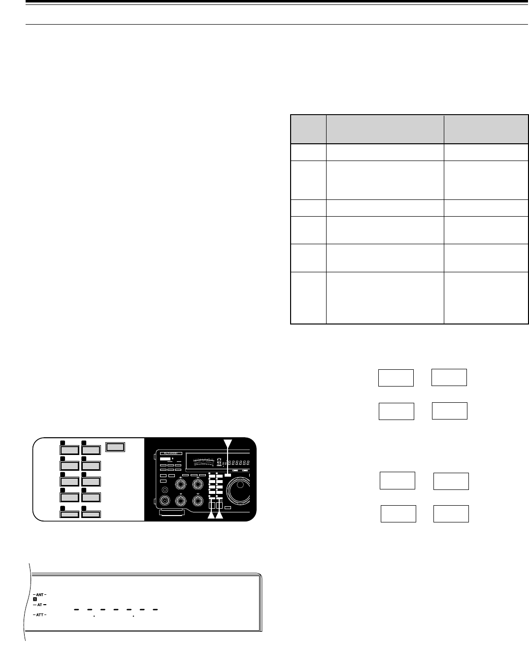
22
FRONT PANEL METER
The multifunction meter measures the parameters in the
following table. Peak readings for the S-meter, ALC,
SWR, COMP, and PWR functions are held for
approximately 2.5 seconds if Menu No. 09 (P HOLD) is
ON.
Pressing the [METER] button cycles through the
functions as shown below:
Receive Mode:
Note:
While receiving, the scales for the S-meter and the receive
pass band function are always visible.
Transmit Mode:
Note:
◆
While transmitting, the transmit power meter is always visible.
◆
The COMP meter functions only when the Speech Processor is
ON in SSB or AM mode.
4 OPERATING BASICS
S
RX
FILTER
PWR
ALC
SWR
COMP
Received signal strength
Width and shift of the
receive pass band
Transmit output power
Automatic level control
status
Antenna system
standing wave ratio
Speech compression
when using the Speech
Processor
Receive
Receive;
or Transmit plus
[METER] ON
Transmit
Transmit plus
[METER] ON
Transmit plus
[METER] ON
Transmit plus
SSB/AM plus
[PROC] ON plus
[METER] ON
Displays
Scale Functional
Condition
COMP
SWR \ ALC
d
c
OFF b
Receive
pass band
SWR \ ALC
d
c
b COMP
Note:
After recalling memory channel 99 that has Start and End
frequencies stored {page 58}, the receive frequency can be changed
(like a VFO) by using the
Tuning
control.
DIRECT FREQUENCY ENTRY
Entering a frequency directly from the numeric keypad
can be the fastest method to change to a specific
frequency that is far removed from your current
frequency.
The following points will help you enter a frequency
correctly:
•Only the digits 0, 1, 2, or 3 can be entered for the
10 MHz digit (first digit). Pressing any digit 4 ~ 9 will
cause the digit to be entered in the 1 MHz position.
Therefore, to select a frequency of 3 MHz or lower,
enter 0 for the 10 MHz digit.
•When the 10 Hz digit (last digit) is entered, the digit 0
is entered automatically for the 1 Hz digit, and
frequency entry is completed. The 1 Hz digit is not
displayed.
•If [ENTER] is pressed after beginning to enter digits,
0 is entered automatically for the remaining
un-entered digits, and frequency entry is completed.
•Attempting to enter a frequency that is outside the
TS-870S frequency range causes an alarm to be
generated. The entered frequency is rejected.
•If an incorrect digit is pressed, restore the previous
frequency by pressing [CLEAR], or [SEND], or
Mic [PTT].
•When an entered frequency is accepted, RIT
{page 44} and XIT {page 45} are switched OFF, but
the RIT or XIT frequency is not changed.
<<< (9L) >>>
1Press [ENTER].
•“– – . – – – . – –” appears.
2Press the numeric buttons [0] ~ [9] to enter the
frequency you desire.
•The transceiver changes to the entered
frequency after the 10 Hz digit is pressed.
Note:
After recalling memory channel 99 that has Start and End
frequencies stored {page 58}, the receive frequency can be changed
by using Direct Frequency Entry. When using the keypad to directly
enter a frequency, you can never enter a frequency outside the
frequency range programmed in memory channel 99.
50
49
38
27
16
OFF
CAR DELAY
AGC KEY SPEED
METER PROC MONI
0
2
46
8
100
2
46
8
10
MIC
ATT
ANT DOWN UP
VOX FULL/SEMI
AT TUNE
SEND
THRU/AUTO
AIP
PHONES
PROC MONI
MIC PWR
M.IN
REC F.LOCK
CH 4 CLR
CH 3 SCAN
CH 2 M>VFO
CH 1 M.IN
ENTER TF-SET
FINE 1MHz
QUICK MEMO
MR
SLOW FAST
0
2
46
8
10
SWR
PWR
S
9
7
5
3
1
10
25
50
FILTER
ALC
3
10 2
1
.5
1
0
20
40
100
60
W
dB
dB
20
COMP
M.CH
USB CW R FSK FM AMLSBAUTO
FULLVOX SEMI AIP AGC AUTO PROC MONI
HF TRANSCEIVER TS-870
ON AIR AT TUNE
50
49
38
27
16
REC F.LOCK
CH 4 CLR
CH 3 SCAN
CH 2 M>VFO
CH 1 M.IN
ENTER
USB
AGC AUTO
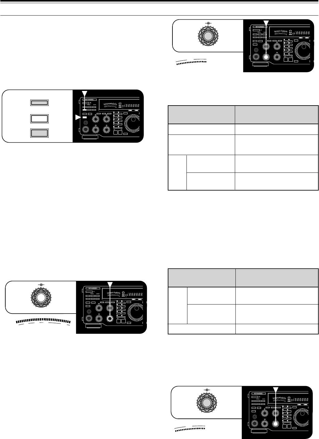
23
For more specific procedures, refer to instructions for
each mode in “COMMUNICATING” beginning on
page 29.
MICROPHONE GAIN
The MIC gain control must be adjusted any time the
SSB (LSB or USB) or AM mode is used without speech
processing. Set the MIC gain control so that the ALC
meter reads within the limits of the ALC zone at all
times. When Speech Processing is used, the
microphone gain is fixed as shown in the table below
regardless of the MIC gain control setting.
The MIC gain control has no affect in FM mode. Menu
No. 61 (FM MIC) switches the microphone gain
between low (L) and high (H) in this mode.
Refer to specific procedures in “COMMUNICATING”
beginning on page 29.
4 OPERATING BASICS
TRANSMITTING
Methods for transmitting include the following:
•Press [SEND].
•Press and hold down Microphone [PTT].
•Connect a key or keyer paddle, select the CW mode,
press [VOX] to switch ON the Break-in function, and
close the key or keyer paddle.
<<< (9L) >>>
Refer to sections in “COMMUNICATING” beginning on
page 29 for detailed explanations for transmitting.
Note:
You cannot transmit while the internal antenna tuner is
presetting {page 49}.
SELECTING TRANSMIT POWER
It’s wise, and required by law, to select the lowest
transmit power that allows reliable communication.
Reducing power lowers the risk of interfering with others
on the band. On the TS-870S, it is possible to change
output power while transmitting.
To change your output power, turn the PWR control
counterclockwise to reduce power and clockwise to
increase power. The PWR scale on the Front Panel
meter provides an indication of your output power in
watts while you are transmitting.
TRANSMIT CARRIER LEVEL
The CAR control must be used for adjusting the carrier
level for CW, AM, and FSK modes. The control also
adjusts the Speech Processor output level when this
function is used in the SSB mode. In general, set the
CAR control so that the ALC meter reads within the
limits of the ALC zone. If the carrier level is set via the
computer interface, the position of the CAR control on
the Front Panel is ignored. After turning the CAR
control, the control becomes active again.
Yes
No
(Carrier level is fixed)
Yes
No
CW, AM, FSK
FM
Speech
Processor ON
Speech
Processor OFF
USB/
LSB
Mode Adjust CAR Control?
–28 dB
–34 dB
–34 dB
Transmit
Equalizer ON
Transmit
Equalizer OFF
USB/
LSB
Mode
(Speech Processor ON)
Microphone
Gain Fixed
AM
50
49
38
27
16
OFF
CAR DELAY
AGC KEY SPEED
METER PROC MONI
0
2
46
8
100
2
46
8
10
MIC
ATT
ANT DOWN UP
VOX FULL/SEMI
AT TUNE
SEND
THRU/AUTO
AIP
PHONES
PROC MONI
MIC PWR
M.IN
REC F.LOCK
CH 4 CLR
CH 3 SCAN
CH 2 M>VFO
CH 1 M.IN
ENTER TF-SET
FINE 1MHz
QUICK MEMO
MR
SLOW FAST
0
2
46
8
10
SWR
PWR
S
9
7
5
3
1
10
25
50
FILTER
ALC
3
10 2
1
.5
1
0
20
40
100
60
W
dB
dB
20
COMP
M.CH
USB CW R FSK FM AMLSBAUTO
FULLVOX SEMI AIP AGC AUTO PROC MONI
HF TRANSCEIVER TS-870
ON AIR AT TUNE
VOX
AT TUNE
SEND
50
49
38
27
16
OFF
CAR DELAY
AGC KEY SPEED
METER PROC MONI
0
2
46
8
100
2
46
8
10
MIC
ATT
ANT DOWN UP
VOX FULL/SEMI
AT TUNE
SEND
THRU/AUTO
AIP
PHONES
PROC MONI
MIC PWR
M.IN
REC F.LOCK
CH 4 CLR
CH 3 SCAN
CH 2 M>VFO
CH 1 M.IN
ENTER TF-SET
FINE 1MHz
QUICK MEMO
MR
SLOW FAST
0
2
46
8
10
SWR
PWR
S
9
7
5
3
1
10
25
50
FILTER
ALC
3
10 2
1
.5
1
0
20
40
100
60
W
dB
dB
20
COMP
M.CH
USB CW R FSK FM AMLSBAUTO
FULLVOX SEMI AIP AGC AUTO PROC MONI
HF TRANSCEIVER TS-870
ON AIR AT TUNE
PWR
10
25
50
0
100
W
0
2
46
8
10
MIC PWR
50
49
38
27
16
OFF
CAR DELAY
AGC KEY SPEED
METER PROC MONI
0
2
46
8
100
2
46
8
10
MIC
ATT
ANT DOWN UP
VOX FULL/SEMI
AT TUNE
SEND
THRU/AUTO
AIP
PHONES
PROC MONI
MIC PWR
M.IN
REC F.LOCK
CH 4 CLR
CH 3 SCAN
CH 2 M>VFO
CH 1 M.IN
ENTER TF-SET
FINE 1MHz
QUICK MEMO
MR
SLOW FAST
0
2
46
8
10
SWR
PWR
S
9
7
5
3
1
10
25
50
FILTER
ALC
3
10 2
1.5
1
0
20
40
100
60
W
dB
dB
20
COMP
M.CH
USB CW R FSK FM AMLSBAUTO
FULLVOX SEMI AIP AGC AUTO PROC MONI
HF TRANSCEIVER TS-870
ON AIR AT TUNE
ALC
CAR DELAY
0
2
46
8
10
50
49
38
27
16
OFF
CAR DELAY
AGC KEY SPEED
METER PROC MONI
0
2
46
8
100
2
46
8
10
MIC
ATT
ANT DOWN UP
VOX FULL/SEMI
AT TUNE
SEND
THRU/AUTO
AIP
PHONES
PROC MONI
MIC PWR
M.IN
REC F.LOCK
CH 4 CLR
CH 3 SCAN
CH 2 M>VFO
CH 1 M.IN
ENTER TF-SET
FINE 1MHz
QUICK MEMO
MR
SLOW FAST
0
2
46
8
10
SWR
PWR
S
9
7
5
3
1
10
25
50
FILTER
ALC
3
10 2
1
.5
1
0
20
40
100
60
W
dB
dB
20
COMP
M.CH
USB CW R FSK FM AMLSBAUTO
FULLVOX SEMI AIP AGC AUTO PROC MONI
HF TRANSCEIVER TS-870
ON AIR AT TUNE
ALC
0
2
46
8
10
MIC PWR
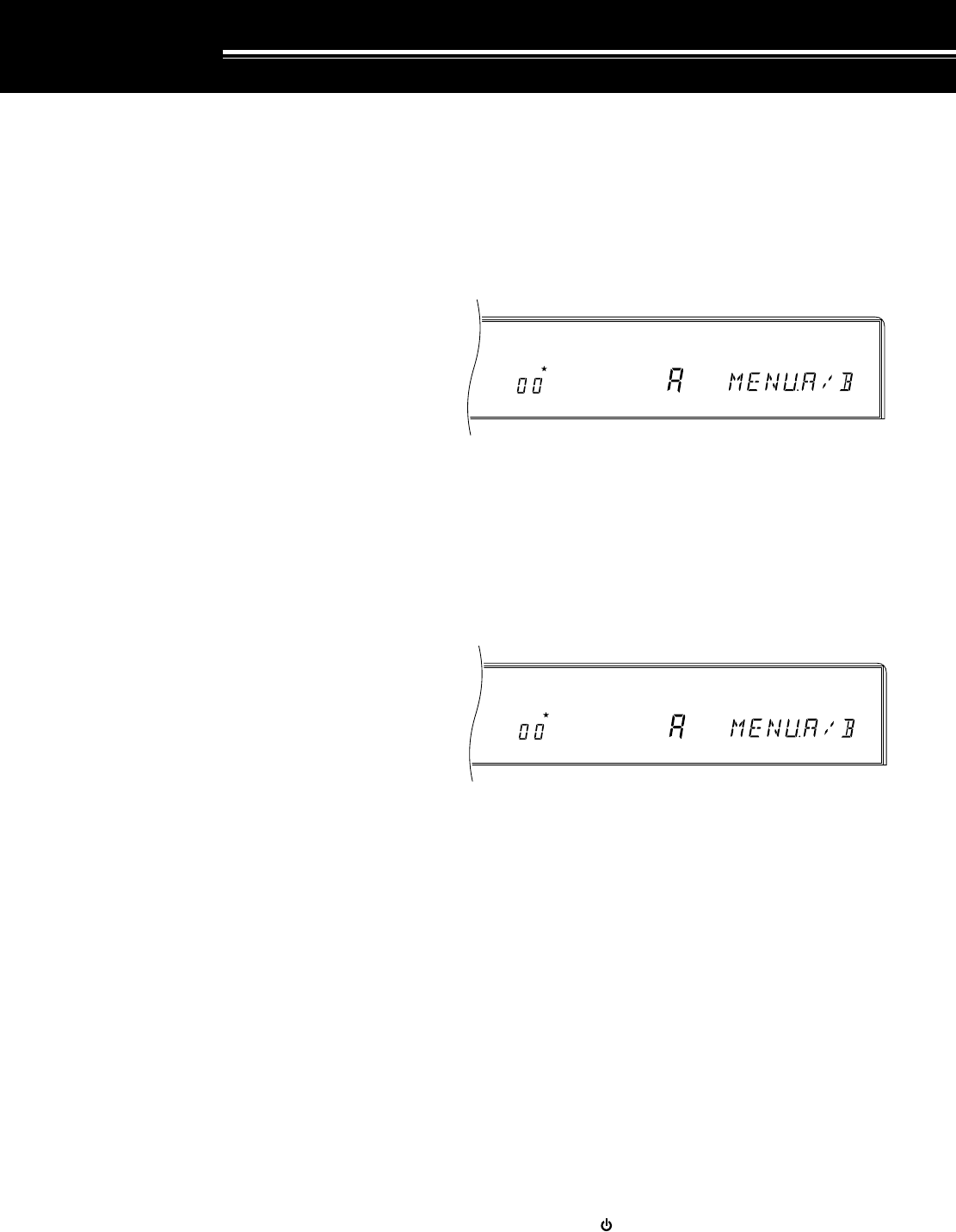
24
MENU SETUP
WHAT IS A MENU?
Many functions on this transceiver are selected or
configured via a software-controlled Menu instead of
physical controls on the transceiver. Once familiar with
the Menu system, you will appreciate the versatility it
offers. No longer is the number and complexity of
features restricted by the physical controls and
switches on the Front Panel.
MENU ACCESS
The following procedure explains how to check or
change any of the Menu items.
1Press [MENU].
2Turn the M.CH/VFO.CH control to select the desired
Menu No.
3Press [UP], or [DOWN], or Mic [UP], or Mic [DWN]
to change the current selection for this Menu item.
4Press [MENU] or [CLR] to exit Menu mode.
•If the power is switched OFF before this step is
completed, the selection just made will be
canceled.
MENU A/ MENU B
The TS-870S has two menus. These menus are called
Menu A and Menu B. The menus contain identical
functions; however, each menu can be configured
independently.
For example, you may enjoy two different kinds of
operating activities but you like to configure the
transceiver differently for each activity. Menu A could
be configured with one set of transmit signal
characteristics, DSP settings, programmable buttons,
frequency steps, etc. Menu B could be configured
completely differently. By switching from Menu A to
Menu B, you could instantly change Menu
configuration and button assignment to suit your
current operating style. Or, two operators may share a
single transceiver. By dedicating one Menu per
operator, each would always enjoy the best
configuration.
With a little thought, you can determine the best setups
for each Menu for your personal situation. Once you’ve
decided your strategy, select via Menu No. 00
(MENU.A/B) the Menu that you want to set up first.
Then use the information in this chapter and on the
referenced pages to configure your ultimate operating
environments.
QUICK MENU FUNCTION
The Quick Menu function complements the Menu A/B
selection capability by allowing you to create your own
customized but abbreviated Menu. Copying Menu
items to the Quick Menu has no effect on the Menu.
You should add only those Menu items to the Quick
Menu that you use frequently.
■Programming the Quick Menu
1Press [MENU].
2Turn the M.CH/VFO.CH control to select the
desired Menu No.
3To add the selected Menu item to the Quick
Menu, press [M.IN].
•The star lights indicating that the item has
been added to the Quick Menu.
•Each press of [M.IN] toggles the item into or
out of the Quick Menu.
4Press [MENU] or [CLR] to exit Menu mode.
■Using the Quick Menu
1Press [MENU].
2Press [1MHz].
•“MHz” lights.
3Turn the M.CH/VFO.CH control to select the
desired Quick Menu No.
•If the Quick Menu has not been programmed
yet (see previous section), then turning the
M.CH/VFO.CH control causes an alarm to be
emitted (either “CHECK” in Morse code or a
triple beep).
4Press [UP], or [DOWN], or Mic [UP], or
Mic [DWN] to change the current selection for
this Quick Menu item.
5Press [MENU] or [CLR] to exit Quick Menu
mode.
TEMPORARY MENU RESETTING
This convenient function allows you to temporarily reset
all Menu items to their factory default selections. This
can be useful to verify whether a Menu setting is
causing undesirable operation.
1Press [CLR]+[ ] to temporarily reset all Menu items
to factory default values.
•The “MENU” indicator flashes.
2To change all Menu items back to your own
programmed values, switch OFF the transceiver,
then switch it back ON.
AGC AUTO MENU
A B
MHz
AGC AUTO MENU
A B

25
00
01
02
03
04
05
06
07
08
09
10
11
12
13
14
15
16
17
18
19
20
21
22
23
24
25
26
27
Menu A or B selection
AGC mode: Manual (OFF), Automatic (ON)
Automatic AGC release time for SSB mode
•1 (Slow) → 20 (Fast)
Automatic AGC release time for CW mode
•1 (Slow) → 20 (Fast)
Automatic AGC release time for FSK mode
•1 (Slow) → 20 (Fast)
Automatic AGC release time for AM mode
•1 (Slow) → 20 (Fast)
AF AGC release time for FM and AM modes
•0: Slow, 1: Med, 2: Fast
AF AGC level for FM and AM modes
•0: OFF, 1: Min, 2: Med, 3: High, 4: Max
Auto Tuner active while receiving
Peak Hold for multifunction meter
TX/RX frequency difference for split operation
S-meter correction for AIP (excluding FM/AM)
S-meter correction for FM mode
Line Enhance function
Line Enhance response time
•0 (Fast) → 4 (Slow)
SPAC time
Beat Cancel response time
•0 (Fast) → 4 (Slow)
Auto Notch response time
•0 (Fast) → 4 (Slow)
Adaptive filtering
Filter bandwidth for digital operation
•OFF: Bandwidth selectable via
LO/WIDTH and HI/SHIFT controls
•1200: For wide shift
"P.FIL.WID" displayed while operating.
•300: For narrow shift
(2310 or 2110 Hz, 200 bps)
•P: For PSK modems
AF input level for Digital operation (MCP/TNC TX)
•0: 100 mV, 1: 30 mV, 2: 10 mV
AF output level for Digital operation (MCP/TNC RX)
•0 (minimum level) → 9 (maximum level)
Microphone AGC release time
•0: Slow, 1: Med, 2: Fast
CW rise and decay times
CW RX pitch/ TX sidetone frequency
Speech Processor low-frequency response
Speech Processor high-frequency response
TX Inhibit
MENU.A/B
AUT/MAN
AGC SSB
AGC CW
AGC FSK
AGC AM
AF.AGC
AF.AGC.LV
RX AT
P HOLD
∆ FREQ
AIP.GAIN
FM.S-MET
LINE.ENH
LINE.ENH
SPAC
SP.BEAT
SP.NOTCH
TRACK
PKT.FIL
PKT.IN
PKT.OUT
MIC AGC
CW RISE
PITCH
PROC.LOW
PROC.HI
TX INH
A/B
OFF/ON
OFF, 1 ~ 20
OFF, 1 ~ 20
OFF, 1 ~ 20
OFF, 1 ~ 20
0/ 1/ 2
0/ 1/ 2/ 3/ 4
OFF/ON
OFF/ON
OFF/ON
OFF/ON
OFF/ON
OFF/ON
0/ 1/ 2/ 3/ 4
2/ 5/ 10/ 17 ms
0/ 1/ 2/ 3/ 4
0/ 1/ 2/ 3/ 4
OFF/ON
OFF/ 1200/ 300/ P
0/ 1/ 2
0 ~ 9
0/ 1/ 2
2/ 4/ 6/ 8 ms
400/ 450/ 500/ 550/
600/ 650/ 700/ 750/
800/ 850/ 900/ 950/
1000 Hz
–6, –3, 0, +3, +6 dB
–6, –3, 0, +3, +6 dB
OFF/ON
5 MENU SETUP
Page
Ref.
Default
Selections
FunctionMenu Item
Menu
No.
Note:
For SSB and AM
modes,
LO
/
WIDTH
and
HI
/
SHIFT
controls are
enabled, and the filter
bandwidth is displayed, only
when "OFF" is selected.
Note:
While
operating in SSB
mode, the
following is
displayed in each
case:
1200: P.FIL.WID
300: P.FIL.NAR
P: P.FIL.PSK
MENU CONFIGURATION
A
OFF
7
12
14
5
1
1
OFF
ON
OFF
OFF
ON
ON
4
17 ms
2
2
ON
OFF
2
4
1
4 ms
800 Hz
–3 dB
+3 dB
OFF
24
44
44
44
44
44
44
44
49
22
43
10, 53
38
53
52
53
52
52
52
41
41
41
47
31
30
23, 46
23, 46
45

26
VOX gain
•0 (minimum gain) → 7 (maximum gain)
TX bandwidth for SSB and AM modes
TX bandshift for SSB and AM modes
TX equalizer for SSB mode
•H: High boost
•C: Comb filter
•B: Bass boost
Transceiver status after tuning with the antenna tuner
•OFF: Transmit status maintained
•ON: Receive status restored
Note:
If OFF is selected, the transmit status can be aborted by
pressing
[AT TUNE]
. OFF may be selected if using a linear amplifier.
Allowable SWR range for Antenna Tuner
•Tuning stops if:
OFF: SWR ≤ 1.2:1 (approx.)
ON: SWR ≤ 1.6:1 (approx.)
Automatic Mode
Button confirmation/ Alarm tone enable
•OFF: No Confirmation or Alarm tones
•ON: Confirmation and Alarm tones audible
Morse code enable for the operating mode
•OFF: Single beep
•ON: Morse code
Error message enable for alarm notification
•OFF: Triple beep
•ON: Morse error message
Beep output level
•0 (minimum level) → 9 (maximum level)
Playback repeat
Interval between repeated playbacks
Frequency change for one revolution of the
Tuning control in SSB, CW, FSK (FINE : OFF)
9 kHz step enable for the M.CH/VFO.CH control in the
AM Broadcast band for AM mode
•OFF: 10 kHz steps
•ON: 9 kHz steps
Frequency step size outside the AM broadcast band for
the M.CH/VFO.CH control
Alters the function of the M.CH/VFO.CH control if you
are operating in VFO mode.
•OFF: M.CH/VFO.CH steps the VFO frequency from
the current frequency without rounding.
•ON: M.CH/VFO.CH steps the VFO frequency but
first rounds off the current frequency.
Programmable Function button (upper left)
Programmable Function button (upper right)
Programmable Function button (lower right)
45
47
47
47
_
49
48
64
65
65
64
67
68
21
21
21
21
63
63
63
28
29
30
31
32
33
34
35
36
37
38
39
40
41
42
43
44
45
46
47
4
2300 Hz
300 Hz
H
ON
OFF
OFF
ON
ON
ON
4
OFF
5 sec
10 kHz
See page
reference
10 kHz
ON
69
(ENTER)
70
(TF-SET)
71 (1MHz)
5 MENU SETUP
Page
Ref.
Default
Selections
FunctionMenu Item
Menu
No.
0 ~ 7
1800/ 2000/ 2300/
2600/ 3000 Hz
0/ 100/ 200/ 300/
400/ 500 Hz
H/ C/ B
OFF/ON
OFF/ON
OFF/ON
OFF/ON
OFF/ON
OFF/ON
0 ~ 9
OFF/ON
1/ 2/ 3/ 4/ 5/ 10/ 15/
20/ 25/ 30/ 35/ 40/
45/ 50/ 55/ 60 sec
5/ 10 kHz
OFF/ON
1/ 5/ 10 kHz
OFF/ON
OFF, 00 ~ 73
OFF, 00 ~ 73
OFF, 00 ~ 73
VOX.GAIN
TX.WIDTH
TX.SHIFT
TX EQ.
AUTO.RET
TUN.WIDE
AUT.MODE
BEEP
BP. MODE
WARN. BP
BP LV
REPEAT
REP.TIME
F.STEP
BC. STEP
CH. STEP
STEP.ADJ
PF.KEY.UL
PF.KEY.UR
PF.KEY.LR

27
48
49
50
51
52
53
54
55
56
57
58
59
60
61
62
63
64
65
66
67
68
5 MENU SETUP
Page
Ref.
Default
Selections
Menu Item
Menu
No.
72 (FINE)
OFF
H
1
1000 kHz
OFF
OFF
OFF
96 1
88.5 Hz
C
OFF
ON
L
170 Hz
OFF
2125 Hz
OFF
OFF
ON
OFF
63
56
65
5
20
2
66
66
50
39
39
–
–
38
40
40
40
60
61
61
61
OFF, 00 ~ 73
OFF/ON
L/ H
OFF/ 1/ 2
100/ 500/ 1000 kHz
OFF/ON
OFF/ON
OFF/ON
12 1/ 24 1/ 48 1/ 48 2/
96 1/ 192 1/ 384 1/
576 1
Note:
To reliably use the
38400 or 57600 bps
transfer rates, the serial
port of your computer must
support these high-speed
communications
parameters.
See page reference
B/ C
OFF/ON
OFF/ON
L/ H
170/ 200/ 425/ 850 Hz
OFF/ON
1275/ 2125 Hz
OFF/ON
OFF/ON
OFF/ON
OFF/ON
Programmable Function button (lower left)
Fixed (OFF) or tunable (ON) memory channel
frequencies
Display brightness (controls LCD and LED brightness)
•L: Low
•H: High
Linear amplifier relay response time
•1: Fast, 2: Slow
1 MHz button frequency step
External RX jack (EXT RX ANT) enable for external
receiver
Data transfer function enable
Method of receiving transferred data
•OFF: Transfer to Quick memory
•ON: Transfer directly to VFO
Communication parameters for COM connector
Setting Baud Rate (bps) Stop Bits
12 1 1200 1
24 1 2400 1
48 1 4800 1
48 2 4800 2
96 1 9600 1
192 1 19200 1
384 1 38400 1
576 1 57600 1
Subaudible Tone frequency for FM mode
Type of subtone
•B: Burst
•C: Continuous
Low-frequency boost for FM receive mode
Wide band FM deviation enable
•OFF: Narrow (2.5 kHz)
•ON: Wide (5 kHz)
Microphone gain for FM mode
•L: Low
•H: High
Note:
Front Panel
MIC
gain control has no effect when using the
FM mode.
FSK shift
Key-down polarity for FSK
•OFF: Space
•ON: Mark
FSK tone
Scan hold
Group Scan enable for memory channels
•OFF: All-channel Scan
•ON: Group Scan
Busy Stop for Memory Scan
Carrier-operated Scan Resume enable for
Memory Scan
•OFF: Time-operated
•ON: Carrier-operated
PF.KEY.LL
CH.SHIFT
DIMMER
LINEAR
1M/500k
EXT RX
TRNSFER
DIRECT
COM.RATE
SUB.TONE
SUB.TONE
FM.BOOST
FM WIDE
FM MIC
FSK.SHFT
MARK.POL
FSK.TONE
PG.S.HOLD
GRP.SCAN
BSY.STOP
CAR.SCAN
Function

28
5 MENU SETUP
CROSS REFERENCE FOR MENU
FUNCTIONS
Use this table arranged by subject to help you locate the
function that you are interested in checking or changing.
Consult “MENU CONFIGURATION” {page 25} for more
detail for each function.
Function Menu
No.
60
59
61
57
58
43
42
44
41
52
63
62
64
49
00
34
20
21
19
45
48
46
47
56
53
11
12
66
67
65
68
25
26
30
29
31
27
28
FM
Deviation
Low-frequency receive boost ("loudness")
Microphone gain
Subtone selection
Subtone type
FREQUENCY STEPS
M.CH/VFO.CH control
M.CH/VFO.CH control (AM broadcast only)
M.CH/VFO.CH control (step rounding)
Tuning control (one revolution)
[1MHz] button
FSK
Polarity (space/mark)
Shift
Tone
MEMORY CHANNELS
Fixed/tunable frequency
MENU
A/B selection
MODE
Automatic SSB, CW, FSK, FM, AM (OFF/ON)
PACKET/ DIGITAL OPERATION
AF input (MCP/TNC TX)
AF output (MCP/TNC RX)
Filter bandwidth
PROGRAMMABLE BUTTONS
[ENTER] button (upper left)
[FINE] button (lower left)
[TF-SET] button (upper right)
[1MHz] button (lower right)
REAR PANEL
COM communication parameters
EXT RX ANT enable for external receiver
S-METER
AIP function correction
FM mode correction
SCAN
All/Group Scan (Memory Scan)
Busy Stop (Memory Scan)
Hold (Program Scan)
Resume (Time or Carrier for Memory Scan)
SPEECH PROCESSOR
Low-frequency response
High-frequency response
TX
Bandshift (SSB and AM)
Bandwidth (SSB and AM)
Equalizer (SSB)
Inhibit
VOX
Gain
Function Menu
No.
51
08
33
32
06
07
05
01
03
04
22
02
37
38
35
36
23
24
24
55
54
50
09
10
39
40
18
17
16
13
14
15
AMPLIFIER
Linear amplifier relay
ANTENNA TUNER (AT)
RX enable/ disable
SWR range
TX/RX status after tuning
AUTOMATIC GAIN CONTROL (AGC)
AF
AF Level
AM
Manual/Automatic
CW
FSK
Microphone
SSB
BEEP FUNCTIONS
Alarm type (message/beep)
Beep level
Confirmation tones (OFF/ON)
Confirmation tone type (Morse/beep)
CW
Rise and decay times
RX pitch
TX sidetone
DATA TRANSFER
Method of transfer
Transfer enable (OFF/ON)
DISPLAY
Dimmer
Peak Hold meter
∆f for TX/RX split operation
DRU-3 DIGITAL RECORDING SYSTEM (DRS)
Playback repeat
Playback repeat interval
DIGITAL SIGNAL PROCESSING
Adaptive filtering
Auto Notch response time
Beat Cancel and response time
Line Enhance function
Line Enhance response time
SPAC time
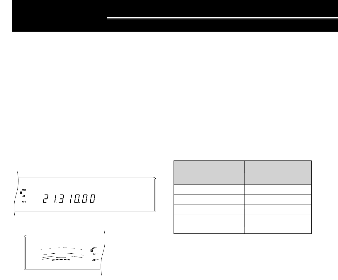
29
USB
AGC AUTO
S
9
7
5
3
1
10
25
50
FILTER
ALC
0
20
40
100
60
W
dB
SLOW SCAN TV/ FACSIMILE
SSTV complements SSB operating since a voice
contact is established first before pictures are
exchanged. Though once a specialty mode involving a
very small percentage of Amateurs, slow scan television
is now increasing in popularity as a result of the
capability of computers.
No longer is it necessary to squint at an old CRT to view
a continuously fading image. It isn’t necessary to invest
in a large amount of additional equipment anymore
either. SSTV can be a convenient method of adding
interest to otherwise routine voice contacts. Instead of
trying to describe your station, just show it. Many
Amateurs are only lacking a little application software
that uses your computer sound card for transmitting and
receiving monochrome or full-color SSTV images.
SSTV FREQUENCIES
The high resolution that is possible using facsimile
(FAX) can allow you to exchange more detailed
graphics than SSTV allows. Due to the longer
transmission times required for FAX, it’s best to use this
mode when band conditions are stable with strong
signals.
Popular FAX frequencies include the following:
•7245, 14245, 21345 (Intern. Net), 28945 kHz
Operation on SSTV or FAX mainly involves learning the
functionality of your computer application or accessory
hardware that supports these modes. Consult the
documentation that comes with your software or
accessory equipment.
Note:
When operating either SSTV or FAX, use a fast AGC setting
and switch OFF your Speech Processor for best results.
This completes the “SSB TRANSMISSION” section.
Refer to “OPERATING AIDS” beginning on page 44 for
information about additional useful functions for
operating.
COMMUNICATING
SSB TRANSMISSION
SSB is now the most commonly-used mode on the HF
Amateur bands. This popularity is not surprising due to
its narrow bandwidth requirements and its good long
distance communications capability that demands
minimum transmit power when compared with other
voice modes. These reasons, combined with the fact
that modern Amateur transceivers deliver reasonably
good audio quality, make SSB the mode that most
prefer on HF. Due to this popularity, you will want to use
the technology available on the TS-870S as explained
in this and later sections to make your transmitted signal
the best possible.
Refer, if necessary, to “OPERATING BASICS”
beginning on page 19 for complete receiving details for
any mode.
1Select the operating frequency.
2Press [LSB/USB] to select either upper or lower
sideband mode.
3Select the ALC meter function by pressing [METER].
4Press and hold down the Microphone [PTT] switch,
or press [SEND].
•The “ON AIR” indicator lights.
•Refer to “VOX” {page 45} for information on
automatic TX/RX switching.
5Speak into the microphone and adjust the MIC gain
control so that the meter reads in the ALC zone but
doesn’t exceed the upper ALC zone limit.
•Speak in a normal tone and level of voice.
Speaking too close to the microphone, or too
loudly, may increase distortion and reduce
intelligibility.
•The ALC level is more restricted than previous
KENWOOD transceivers due to the added
benefit of the DSP-controlled Microphone AGC
function {page 47}.
•With the Speech Processor switched OFF, the
CAR control has no function in this mode.
6If you want to use speech processing, press [PROC]
to switch on the Speech Processor and adjust as
described on page 46.
7Release the Microphone [PTT] switch, or press
[SEND] again, to return to the receive mode.
•The “ON AIR” indicator goes out.
IARU Region 1
(Europe/Africa)
Frequency (kHz)
U.S.A./Canada
Frequency (kHz)
3730~3740
7035~7045
14225~14235
21335~21345
28675~28685
3845
7171
14230
21340
28680
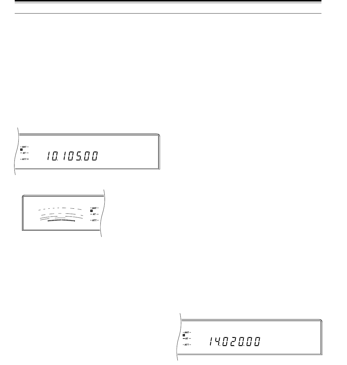
30
CW
AGC AUTO
S
9
7
5
3
1
10
25
50
FILTER
ALC
0
20
40
100
60
W
dB
CW
AGC AUTO
The following selections are available:
•400 ~ 1000 Hz inclusive in 50 Hz steps
Note:
Changing the RX pitch frequency does not shift the center
frequency of the receive filter pass band. If a CW signal becomes
inaudible, shift the pass band by adjusting the
HI/SHIFT
control.
Refer to “IF SHIFT” {page 51}.
ZERO-BEATING
Zero-beating means matching your transmit frequency
with the station that you are receiving. This is important
if you expect other stations to hear you without them
retuning their receivers. Zero-beating also saves space
on the band since only a single frequency is used by
you and the other station for your contact. If you are
part of a “roundtable” where more than two stations are
participating but each is on a different frequency, it’s
frustrating to keep retuning to a different frequency each
time one of the roundtable stations begins sending.
Learn to zero-beat accurately and quickly.
1Press [VOX] and press [RIT] to switch OFF the VOX
and RIT functions respectively.
•“VOX” and “RIT” go out.
2With CW mode selected, turn the Tuning control to
tune in a CW station for maximum signal strength.
3Close your key to activate the sidetone.
•You will hear a steady tone.
4Turn the Tuning control until the note from the
received CW signal matches the sidetone note, then
release the key.
•To double check that you are zero beat, press
[CW/–R] to switch to the opposite sideband. You
should hear no difference in tone of the received
CW signal.
SWITCHING TX/RX MANUALLY
1Select CW mode by pressing [CW/–R].
•“CW” lights.
2Press [SEND].
•The receive audio is muted.
•Holding down Microphone [PTT] also switches
between receive and transmit.
3Send CW.
4When finished sending, release [SEND] or [PTT].
CW TRANSMISSION
CW operators know that this mode is a reliable method
of communicating under the worst conditions. Although
it’s true that newer digital modes rival CW as being
equally as useful in poor conditions, these modes do
not have the long history of service yet nor the
simplicity that CW can have. Therefore, functions
required by CW operators were given serious
consideration from the start of the TS-870S design.
Refer, if necessary, to “OPERATING BASICS”
beginning on page 19 for complete receiving details for
any mode.
1Select the operating frequency.
2Press [CW/–R] to select CW mode.
3Select the ALC meter function by pressing
[METER].
4Press [SEND].
•The “ON AIR” indicator lights.
•Refer to “SEMI BREAK-IN” {page 31} or “FULL
BREAK-IN” {page 31} for information on
automatic TX/RX switching.
5With a key down condition, adjust the CAR control
so that the meter reads in the ALC zone but doesn’t
exceed the upper ALC zone limit.
6After completing your transmission, press [SEND]
again to return to the receive mode.
•The “ON AIR” indicator goes out.
TX SIDETONE/ RX PITCH FREQUENCY
The transmit sidetone is the monitor tone you hear from
your transceiver as you send CW. It is necessary so
you can hear what you are transmitting. It is also useful
for checking that your key contacts are closing, the
keyer is functioning, or for sending practice without
putting a signal on the air. The volume of the sidetone
is adjusted by the MONI control.
Receive pitch refers to the frequency of the CW note
that you hear after tuning your receiver for maximum
receive signal strength. On the TS-870S, the frequency
of the sidetone and receive pitch are equal and
selectable. You can select the frequency that is most
comfortable for you via Menu No. 24 (PITCH). The
default is 800 Hz.
6 COMMUNICATING
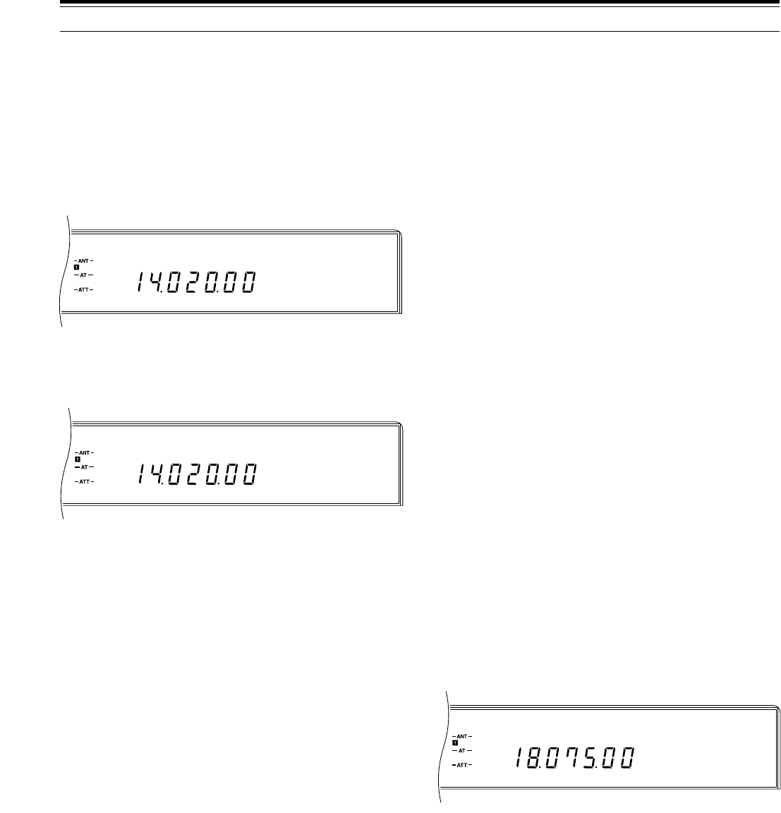
31
CW R
AGC AUTO
CW
AGC AUTO
VOX SEMI
CW
AGC AUTO
1Select CW mode by pressing [CW/–R].
•“CW” lights.
2Press [VOX] to switch ON the Break-in function.
•“VOX” and either “SEMI” or “FULL” lights
depending on whether Semi or Full Break-in was
last selected.
3If “SEMI” lights, press [FULL/SEMI] to toggle to the
FULL status.
•“FULL” lights.
4Send CW.
•The transceiver switches automatically to
transmit each time the key closes; however, it
returns to receive mode immediately when the
key opens.
Note:
◆
Full Break-in cannot be used with the TL-922/922A amplifier.
◆
During split-frequency Full Break-in operation, you may hear
clicks depending on the transmit and receive frequency
relationship.
◆
The position of the
DELAY
control is ignored while using Full
Break-in.
◆
If using Full Break-in CW, the internal antenna tuner can be
bypassed completely or can be in-line for both transmitting and
receiving. To protect the antenna tuner relay, the tuner cannot be
used only for transmitting.
CW REVERSE (RECEIVE)
This function switches receive from the default upper
sideband to the lower sideband, therefore, interference
that is heard may be eliminated. When your receive
frequency is identical to the transmit frequency of the
other station, the CW Reverse function has no effect on
receive tone or your transmit frequency.
Press [CW/–R] to select CW Reverse.
•“CW” and “R” light.
RISE/DECAY TIMES
The rise time of a CW signal is the time for the RF
output to rise to its maximum power after the key is
closed. This time excludes the make delay that occurs
after closing the key but before the RF output actually
begins to increase. You can adjust the CW rise time for
the TS-870S via Menu No. 23 (CW RISE). The default
is 4 ms. This adjustment also affects the decay time.
The decay time excludes the short break delay from the
moment when the key opens to when the RF output
begins to fall.
The default setting is fine for low to moderate keying
speeds and normal weighting (dot/dash ratios). The
2ms setting is good for higher CW speeds or when
operating with unusual dot/dash ratios. The available
rise time selections include 2, 4, 6, and 8 ms.
SEMI BREAK-IN
Semi Break-in allows you to transmit without manually
switching between transmit and receive modes. When
the key contacts open, the transceiver automatically
waits for the time period to pass that you have selected
via the DELAY control. The transceiver then returns to
the receive mode.
1Select CW mode by pressing [CW/–R].
•“CW” lights.
2Press [VOX] to switch ON the Break-in function.
•“VOX” and either “SEMI” or “FULL” lights
depending on whether Semi or Full Break-in was
last selected.
3If “FULL” lights, press [FULL/SEMI] to toggle to the
SEMI status.
•“SEMI” lights.
4Send CW.
•The transceiver switches automatically to
transmit and mutes the receiver each time the
key closes. After the key opens, the transceiver
returns to receive mode after a delay.
■Setting Delay Time
The delay time is the length of time that the
transceiver remains in transmit mode after the key is
opened. This time should be set based on your
keying speed and your personal preference.
While sending using Semi Break-in, adjust the
DELAY control for the delay you prefer. The control
has a range from 50 ms ~ 800 ms in steps of 50 ms.
Note:
◆
The range and step size of the
DELAY
control differ
depending on the operating mode selected.
◆
Setting the delay time by computer overrides any setting of
the
DELAY
control. The control then has no effect. To
restore functionality to the
DELAY
control, turn the control.
The newly selected setting becomes effective.
FULL BREAK-IN
Full Break-in returns the transceiver to the receive mode
as soon as the key contacts open. It’s possible to hear
if another station wants to interrupt, and it also allows
you to hear interference that may begin after you start
sending.
6 COMMUNICATING

32
6 COMMUNICATING
ELECTRONIC KEYER
The keyer supplied with the TS-870S is a full-featured
K-1 Logikey keyer that will delight anybody that respects
a good keyer. A great deal of information on using this
keyer is provided in this manual, not because it is
difficult to use, but because it has an incredible number
of features. Some of the features of your keyer include:
•Iambic operation with dot and dash memories
•Programmable via commands sent from your key
•Emulation modes for other keyer types — you won’t
have to re-train yourself if you’re used to a keyer with
different timing
•Soft-sectored messages that can “call” each other
and can contain embedded functions
•Automatic contest serial number generation
•Digital and linear speed control (6 ~ 60 wpm)
•Adjustable weight for code elements (25% ~ 75%)
•Tune function for continuous key down
•Selectable automatic character spacing
•Message loop capability for continuous replay
It is probably best to learn the keyer’s basic functions
first, then use it on-the-air. Over time, you will build up
your knowledge of its operation bit by bit. Don’t try to
memorize everything at one time!
Points to know before beginning:
•Although the sidetone can be heard while using any
mode, CW mode must be selected to set functions
on the keyer.
•When pressing two or more keys on the keypad to
select a keyer function, press the correct keys as
instructed, then release them. You know you’ve held
them down too long if you hear a continuous tone
before releasing the keys. In this case, a rapid
multi-dit error alarm sounds when you release the
keys to confirm the error.
■Learning Outline
To help you learn the keyer, the table below offers
suggestions for how to proceed. Consult the
indicated tables and procedures for specific
information.
Activity Consult
Set the keyer speed
range to suit your
keying ability. Also, set
the keyer speed.
Confirm that correct
right- or left-handed
orientation is selected.
Select the emulation
that suits you best. If
unsure, use the default.
Learn how to load
messages into
memory.
Learn how to play back
memory messages.
Learn how to erase
memory messages.
Learn how to initiate
Hand-key and Tune
modes.
Explore the Inquiry
mode.
Explore the Function
mode.
Explore Embedded
Functions.
Study the different
method of sending
serial numbers in
contests.
Range:
Reset function in
Multiple-Button
Functions table
{page 33}
Speed:
KEY SPEED control
{page 11}
Reverse function in
Multiple-Button
Function table
{page 33}
Emulation Options
procedure and table
{page 33}
Storing CW Messages
procedures {page 34}
CW Message Playback
procedure {page 34}
Erasing CW Messages
procedure {page 35}
Multiple-Button
Functions table
{page 33}
Multiple-Button
Functions {page 33}
and Inquiry Functions
procedure and table
{page 35}
Multiple-Button
Functions {page 33}
and Function
Commands procedure
and table {page 36}
Embedded Functions
procedure and table
{page 37}
Serial Number Options
table {page 37}
Function Default
Speed
Weight
Auto-space
Load mode
Input queue
Serial number
Number option
Emulation
Function speed
20 wpm
50%
OFF
Character
ON
001
0
K-1 Logikey
Equals paddle speed
CAUTION:
After pressing
[SEND]
to select the transmit mode, be
aware that all characters or tones generated while programming the
keyer will accompany the transmitted signal.

33
6 COMMUNICATING
Function
Name Buttons Description
Decrement
Function
Hand-key
Inquiry
Kill Playback
(in progress)
Reset
Reverse
Tune
The keyer
acknowledges with "D",
then decrements the
serial number.
The keyer
acknowledges with "F",
then waits for paddle
entry of the desired
command.
The keyer
acknowledges with "H",
then enters hand-key
mode until another
button closure occurs.
The keyer
acknowledges with "?",
then waits for paddle
entry of the desired
option.
The keyer immediately
halts and stops
transmitting the
message. No "dit" is
transmitted.
The keyer speed is
reset to 20 wpm at the
current knob position,
the function-entry speed
is defaulted to follow the
KEY SPEED control
setting, then the keyer
acknowledges with
"OK".
The keyer
acknowledges with
"RV", then reverses the
paddles.
The keyer
acknowledges with "X",
then keys the output
continuously until a
paddle closure occurs.
[CH 2]+
[CH 3]
[CH 1]+
[CH 2]
[CH 1]+
[CH 3]
[CH 3]+
[CH 4]
Any two
buttons
[CH 1]+
[CH 2]+
[CH 3]+
[CH 4]
[CH 1]+
[CH 4]
[CH 2]+
[CH 4]
Note:
Press all keys
simultaneously.
A transceiver
Full Reset
{page 63} also
resets the keyer
speed to
20 wpm.
■Multiple-Button Functions ■ Emulation Options
This parameter allows the keyer timing to mimic that
of other keyers, making the “feel” more comfortable
for operators used to different timing parameters.
The default is VØ.
To check or change the emulation, you must briefly
use the Inquiry or Function mode. You will learn
more about these modes beginning on page 35.
To check Emulation option:
1Press [CH 3]+[CH 4].
•The keyer will send “?”.
2Send a “V”.
•The keyer will send the current emulation
(e.g. VØ).
To change Emulation option:
1Press [CH 1]+[CH 2].
•The keyer will send “F”.
2Send a “Vd” where d represents the emulation
number (see table) that you desire.
Option Description
VØ
V1
V2
V3
V4
V5
V6
V7
V8
V9
Normal with dot and dash memory
Normal with dot memory only
Normal with dash memory only
Accukeyer timing with dot and dash
memory
Accukeyer timing with dot memory only
Accukeyer timing with dash memory only
Curtis "A" timing with dot and dash
memory
Curtis "A" timing with dot memory only
Curtis "A" timing with dash memory only
Iambic timing with no dot or dash
memory
Note:
If the buttons are pressed for an extended time, or if an
incorrect command is input, a multi-dit error tone will be sent.

34
6 COMMUNICATING
■Storing CW Messages
The two modes available for storing messages are
Character mode and Real Time mode. Each
message may be as long as you want provided that
the total of all four messages including spaces does
not exceed about 220 characters. You must use the
internal keyer to use the message storage function.
If you happen to turn OFF the power while storing a
message, the last letters input may be deleted. You
cannot store messages if you are operating split
mode (transmit mode different than receive mode).
Using Character mode (default):
This mode uses message memory most efficiently.
Each Morse character uses one byte of memory.
When you play back your recorded messages, they
will be sent with precise intercharacter and interword
spacing.
1Press [CH 1] or [CH 2] or [CH 3] or [CH 4] for
approximately two seconds until you hear a tone.
•The keyer will send the letter “C”. This stands
for Character mode.
•If the keyer sends “R” (for Real Time), you
must switch to Character mode by using the
Function mode {page 36}.
2Send the first word of your message then pause.
•The keyer will send the letter “I” indicating it
has accepted your word.
3Repeat Step 2 pausing to hear the “I” before
sending the next word until all words of your
message are entered.
•If you make a sending mistake, send seven or
more dits to signal an error, then wait for the
keyer to respond with the last correct word.
You can then send the next word that you
want in the message. Each time that you
send the 7-dit error signal, you erase one
more word.
4Press the same button as pressed in Step 1.
Using Real Time mode:
Real Time mode captures exactly what you send
without altering your spacing. This mode cannot use
Embedded Functions {page 37}. Also, you cannot
correct words by using the 7-dit error signal as in
Character mode.
Before beginning, switch to Real Time mode by
using the Function mode {page 36}.
1Press [CH 1] or [CH 2] or [CH 3] or [CH 4] for
approximately two seconds until you hear a tone.
•The keyer will send the letter “R”. This stands
for Real Time mode.
2Send your entire message.
3Press the same button as pressed in Step 1.
•Message recording begins at the moment the first
character is sent, and continues until this step is
completed. Any pause between the last
character and this step is recorded as part of the
message.
■CW Message Playback
Messages may be transmitted using the VOX
function or manual TX/RX switching. The procedure
below uses the VOX function. Simply tap the paddle
at any time to stop a message while it is playing
back, or press any two of [CH 1], [CH 2], [CH 3], or
[CH 4] to stop the message without transmitting an
extra character. Resuming playback after such an
interruption replays the message from the beginning.
Switching OFF the power while playing back a
message could delete the message. You cannot
play back messages if you are operating split mode
(transmit mode different than receive mode).
To check a message without transmitting:
1Press [VOX] to switch OFF the VOX function.
2Press the memory channel button ([CH 1] or
[CH 2] or [CH 3] or [CH 4]) that contains the
message that you want to check.
•The message plays.
•To play back up to 8 messages, press the
corresponding memory channel buttons in
sequence during playback.
To transmit a message:
1Press [VOX] to switch ON the VOX function.
2Press the memory channel button ([CH 1] or
[CH 2] or [CH 3] or [CH 4]) that contains the
message that you want to transmit.
•The message is transmitted.
•To transmit up to 8 messages, press the
corresponding memory channel buttons in
sequence during playback.
The “Q” Function command {page 36} allows you to
queue several messages to form a longer message.
Example:
•“Q” Function status: ON
•Channel 1 contents: “CQ”
•Channel 2 contents: “de DFØTK”
In this example, pressing the button sequence
[CH 1], [CH 1], [CH 1], [CH 2] would send “CQ CQ
CQ de DFØTK”.

35
6 COMMUNICATING
■Erasing CW Messages
1To erase a memory channel’s message, press its
associated button ([CH 1] or [CH 2] or [CH 3] or
[CH 4]) until you hear a tone.
•The keyer will send the letter “C” or “R”
depending whether you are in Character or
Real Time mode.
2Press the same memory channel button again.
•The message in that memory is now erased.
■Inquiry Functions
Inquiry functions report the current state of the keyer.
Information is played to the operator in Morse code
with the monitor automatically enabled and keying
output disabled.
To check an Inquiry function:
1Press [CH 3]+[CH 4].
•The keyer will send “?”.
2Send an Inquiry command from the table.
Description
Command
Name
Inquiry
Command
A
C
F
K
L
N
Q
S
V
W
Z
1, 2, 3,
or 4
Inquire
Auto-space
Inquire
Capacity
Inquire
Function
Speed
Inquire Keying
Compensation
Inquire Load
Mode
Inquire
Number
Inquire Queue
Inquire Speed
Inquire
Emulation
Setting
Inquire Weight
Inquire Zeros
and Nines
Inquire
Message #1,
#2, #3, or #4
The keyer responds by
sending "ON" or "OFF"
as appropriate.
The keyer sends the
amount of free memory
available for message
storage.
The keyer sends the
current function speed
setting in wpm.
The keyer sends the
current compensation in
milliseconds.
The keyer responds by
sending "C" if in
Character mode or "R" if
in Real Time mode.
The keyer plays the
current contest serial
number (but does not
increment it).
The keyer responds with
"ON" or "OFF" as
appropriate.
The keyer sends the
current operating speed
in wpm.
The keyer sends the
current emulation. See
"Emulation Options"
{page 33}.
The current weight
percentage is sent by the
keyer as 2 digits.
The keyer responds with
the option number (0 ~ 9)
currently in effect.
Message #1, #2, #3, or
#4 is played.

36
6 COMMUNICATING
■Function Commands
Commands to the keyer are entered in Morse code using your paddle. The keyer disables output keying. When
the function is complete, output keying is enabled, and the previous operating speed is restored.
1Press [CH 1]+[CH 2].
•The keyer will send “F”.
2Send a Function command from the table.
•If an incorrect command is input, a multi-dit error tone will be sent.
A
D
F dd
H
K dd
L
N dddd
Q
RV
S dd
SU d
SD d
V d
W dd
X
Z d
Auto-space
Decrement
Function speed
Hand-key
Keying
Compensation
Load mode
Number
Queue
Reverse
Speed
Speed Up
Slow Down
Emulation
Weight
Xmit (tune)
Zeros and
Nines
Function
Command Command Name Description
Toggles the automatic character spacing feature ON or OFF. The keyer confirms
the new state by sending "ON" or "OFF". Auto-spacing helps form properly
spaced characters within a word. Character crowding is prevented by forcing at
least 3 space elements whenever more than one space is detected. This effect is
especially noticeable at low speeds. Without auto-spacing, character spaces are
determined by the operator.
Decrements the serial number by 1, effectively canceling the automatic increment
applied when last played from a message. The decrement function
accommodates re-sending the last serial number, as might be needed when a
repeat of a contest exchange is requested.
Sets the speed used for function entry to dd wpm, where dd are two digits in the
range 06 ~ 30. This speed is used to enter commands and load messages. It is
independent of operating speed and is unaffected by the analog speed control.
Alternatively, "dd=00" makes the function speed track the operating speed.
Causes the keyer to enter the Hand-key mode. Keying output will follow closures
of the dot and dash paddle levers, allowing hand-sent code. Normal iambic keyer
operation is regained by any button closures.
Increases keying on-time and decreases keying off-time by dd milliseconds,
where dd are two digits in the range 00 ~ 25. Although similar to increasing
weight, this adjustment is independent of speed. This setting is used primarily to
correct keying distortion introduced by the transceiver using Break-in operation.
Toggles the load mode between Character and Real Time. The keyer confirms
the new mode by sending "C" or "R" as appropriate.
Initializes the contest serial number to dddd, where dddd are four digits in the
range 0000 ~ 9999. Four digits must be entered (with leading zeros if needed).
Toggles the input queue ON or OFF. The keyer confirms the new mode by
sending "ON" or "OFF" as appropriate. When OFF, message button activations
are acted upon immediately, canceling any message in progress. When ON, up
to eight button presses are remembered in order and acted upon in succession as
each message completes.
Reverses the dot and dash paddles as may be desired for left-handed operators.
Sets the current operating speed to dd wpm, where dd are two digits in the range
06 ~ 60. The speed function establishes the current knob position at the entered
speed. The knob can then be employed to vary the speed faster or slower over a
total range of 3:1. Control via the knob is linear and increases speed clockwise.
Increases the operating speed by d wpm. d is a single digit in the range 0 ~ 9.
Decreases the operating speed by d wpm. d is a single digit in the range 0 ~ 9.
Allows an operator to select emulation of the timing characteristics of other keyers.
Sets code weight to dd percent, where dd are two digits in the range 25 ~ 75.
Weight is the duty cycle of a continuous string of dots, which is 50% for perfect
code. A higher weight produces a heavier sound, and a lower weight causes
characters to sound lighter. Once set, weight remains constant and independent
of speed.
Continuously keys the output for purposes of transmitter and amplifier adjustment.
Tuning is stopped by simply tapping either the dot or dash paddle.
Controls the way that zeros and nines are sent in the serial number. See "Serial
Number Options".

37
Note:
You can play back a message to listen to the Embedded
function by simply pressing
[CH 1]
, or
[CH 2]
, or
[CH 3]
, or
[CH 4]
for the channel that contains the Embedded function.
■Serial Number Options
The “Zd” command selects 1 of 10 options for
sending zeros and nines in a contest serial number.
Zeros may be replaced by “O” or “T”, nines replaced
by “N”, and leading zeros suppressed.
Note:
For numbers less than 1000, the first zero is always
suppressed.
This completes the “CW TRANSMISSION” section.
Refer to “OPERATING AIDS” beginning on page 44 for
information about additional useful functions for
operating.
6 COMMUNICATING
Description
Command
Name
Com-
mand
/Sdd
/SUd
/SDd
/Udd
/1,
/2,
/3,
or
/4
Speed
Speed
Up
Slow
Down
Ultra-
speed
Message
#1,
#2,
#3,
or
#4
The operating speed is set to
dd wpm, where dd are two
digits in the range 6 ~ 60.
Increases the operating speed
by d wpm, where d is a single
digit in the range 0 ~ 9.
Decreases the operating
speed by d wpm, where d is a
single digit in the range 0 ~ 9.
Sets the ultra-speed mode for
a message. Range is 70 ~
990 words per minute, where
dd are two digits representing
the first two numbers of the
speed setting desired. For
example, "07" is 70 wpm, "77"
is 770 wpm. This command is
used primarily for meteor
scatter work. Note that
Weighting (W) and
Compensation (K) settings are
disabled during Ultraspeed
message transmission.
Message #1 is played followed
by resumption of the current
message. If the current
message is #1, a continuous
loop is created. The same is
true for the other messages.
■Embedded Functions
Certain functions can be embedded within character
messages. The command strings are prefixed by a
“/”, and are entered as a separate word. The letters
following a “/” that are contained within a word are
not interpreted as an embedded function. For
example, the keyer understands that
“WD6DJY/VE7” does not include an embedded
command since “/VE7” is not sent as a separate
word. These commands must be stored in CH 1 ~
CH 4; they cannot be manually sent.
Description
Command
Name
Com-
mand
/B
/D
/Gd
/N
/Pdd
/R
Break
Decre-
ment
Gap
Number
Pause
Resume
Message play pauses for manual
text insertion. One or more
words may be inserted via the
paddle. Once paddle input has
begun, the break is canceled
when inactivity exceeding a word
space is detected, and the
interrupted message resumes.
A break may also be aborted by
pressing any button, causing the
corresponding message to play
immediately.
Decrements contest serial
number by 1.
The normal 7-element interword
space is modified to 3+d, where
d is a digit in the range 0 ~ 9. It
is used to exaggerate inter-
character or interword spacing.
For example, a call like WØEJ
can be entered with slight
lengthening of the space
between the "E" and the "J" for
emphasis, making it easier to
copy. Note that /G0 yields a
normal character space, while
/G4 yields a normal word space.
The current value of a contest
serial number is played. Its
value is then automatically
increased by 1. See "Serial
Number Options".
A speed-independent pause of
d.d seconds is inserted, where
dd are two digits in the range 00
~ 99. For example, /P35 will
result in a delay of 3.5 seconds.
Pauses longer than 9.9 seconds
are obtained by using
consecutive commands that total
the value desired.
Stops playback to allow hand-
sent entry. When manual keying
is completed, press the button
for the message being played
and the message will resume
transmitting. Multiple "/R"
commands are permitted.
Option (d) Other
Zeros Nines
Leading
Zeros
0
1
2
3
4
5
6
7
8
9
Ø
–
O
O
–
T
T
–
T
–
Ø
Ø
Ø
O
O
Ø
T
T
T
T
9
9
9
9
9
9
9
9
N
N

38
FM
AGC AUTO
FM
AGC AUTO
FM TRANSMISSION
FM operation on HF frequencies solves the problem of
how to have long distance voice communication with
the finest audio quality. When combined with the
full-quieting aspect of FM signals that suppress
background noise on the frequency, FM can be the best
method for maintaining regular schedules with friends.
And when conditions are unusually good allowing
simplex FM contacts over intercontinental paths, you
may feel as though you are using your local VHF
repeater to talk across town instead of using the HF
spectrum for multi-hop communication.
Refer, if necessary, to “OPERATING BASICS”
beginning on page 19 for complete receiving details for
any mode.
Note:
Switch ON Menu No. 12 (FM.S-MET) if you prefer. This
function applies a correction for the S-meter when operating on FM.
This correction will adjust S-meter readings to be equal with other
KENWOOD
HF transceivers.
1Select the operating frequency.
2Press [FM/AM] to select FM mode.
3Press [MONI] to switch the Monitor function ON.
•“MONI” lights.
4Press and hold down the Microphone [PTT] switch,
or press [SEND].
•The “ON AIR” indicator lights.
•Refer to “VOX” {page 45} for information on
automatic TX/RX switching.
5Speak into the microphone.
•FM microphone gain can be switched between
low (L) or high (H) via Menu No. 61 (FM MIC).
The default is low (L). Low is usually appropriate;
however, select high if the monitored audio or
reports from other stations indicate that your
audio is weak. The Front Panel MIC gain control
has no affect in the FM mode.
•Speak in a normal tone and level of voice.
Speaking too close to the microphone, or too
loudly, may increase distortion and reduce
intelligibility.
•The CAR control does not need to be adjusted
since the carrier level is fixed at the best setting
for the FM mode.
6Release the Microphone [PTT] switch, or press
[SEND] again, to return to the receive mode.
•The “ON AIR” indicator goes out.
Note:
◆
When using the optional MC-90 in FM mode, the microphone
sensitivity is low, and this may cause insufficient modulation. Use
Menu No. 61 to select high microphone gain.
◆
When the target station is using FM wide-band deviation, you
also must select wide-band deviation (Menu No. 60). If you
transmit using the narrow band against this rule, the target station
will receive your audio less clearly.
6 COMMUNICATING
FM REPEATER OPERATION
Compared to the usual simplex method of FM
communications on HF, which is radio to radio with
antennas at or slightly above average terrain, you can
often transmit much farther through repeaters.
Repeaters are typically located on a mountain top or
other elevated location. Most often they operate at a
higher ERP (Effective Radiated Power) than the
average mobile or fixed amateur station. This
combination of elevation and high ERP allows
communications over wider and longer distances than
can be achieved by the average station.
HF repeaters operate only in the 29 MHz FM sub-band.
This special service combines the advantages of FM
operation, good fidelity with noise and interference
immunity, with the excitement of HF DX (long distance)
communications. Even on a quiet day, 10 meter FM
provides reliable around-town communications with the
potential for sudden DX from across the country or
around the world.
Note:
Switch ON Menu No. 12 (FM.S-MET) if you prefer. This
function applies a correction for the S-meter when operating on FM.
This correction will adjust S-meter readings to be equal with other
KENWOOD
HF transceivers.
1Press [RX B] (or [RX A]).
•The VFO selected in this step will be used for the
transmit frequency.
2Select the transmit frequency.
3Press [FM/AM] to select FM mode.
4Press [A=B].
5Press [RX A] (or [RX B]).
•This must be the VFO that was not selected in
Step 1.
29.520 MHz
88.5 Hz
29.520 MHz
88.5 Hz
29.620 MHz
29.620 MHz
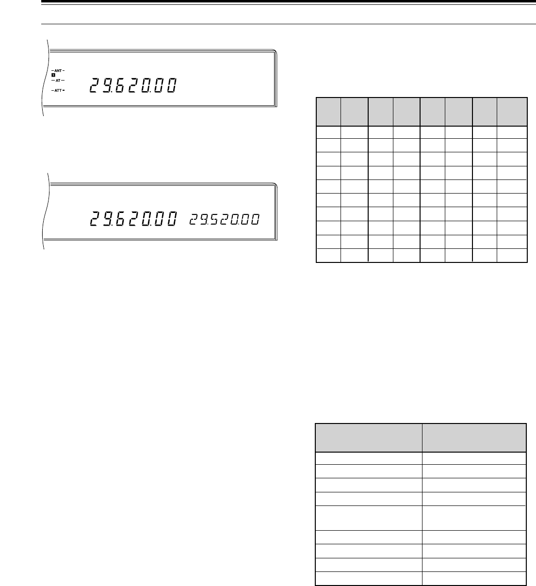
39
FM
AGC AUTO SPLIT
RIT
TONE
XIT
FM
AGC AUTO
European Operation: In Europe, a 1750 Hz tone
is generally used to access repeaters.
Select the Subtone frequency you require via Menu
No. 57 (SUB.TONE). The available choices are
shown in the table.
■Continuous or Burst Subtones?
In addition to selecting the frequency of the Subtone,
you must choose the correct Subtone duration. The
Continuous selection sends the Subtone
continuously as long as the transceiver is
transmitting. The Burst selection sends a 500 ms
Subtone burst each time the transceiver begins
transmitting.
Select either Continuous or Burst via Menu No. 58
(SUB.TONE). The default is Continuous. This
selection cannot be stored in a memory channel.
ARRL 10-METER BAND PLAN
1 Repeater frequency pairs (input/output):
29520/29620, 29540/29640, 29560/29660,
29580/29680
This completes the “FM TRANSMISSION” section.
Refer to “OPERATING AIDS” beginning on page 44 for
information about additional useful functions for
operating.
6 COMMUNICATING
6Select the receive frequency.
7Press [TX B] (or [TX A]) to select split operation.
•This must be the same VFO as selected in
Step 1.
•The Tone function automatically switches ON.
8Select the Subtone frequency via Menu No 57
(SUB.TONE) and Menu No. 58 (SUB.TONE).
•See “Selecting Subtone Frequency” and
“Continuous or Burst Subtones?” for more details
on the Subtone.
To store data selected in Steps 1 ~ 8 in a memory
channel:
9 Press [M.IN].
10 Turn the M.CH/VFO.CH control to select a channel
(excluding channel 99).
11 Press [M.IN].
To send a Subtone that is stored in memory:
12 Press [RX M.CH].
13 Turn the M.CH/VFO.CH control to select the
channel.
14 Press [PTT] or [SEND].
Note:
◆
When operating through a repeater, over deviation caused by
speaking too loudly into the microphone can cause your signal to
“talk-off” (break up) through the repeater.
◆
When Subtones can be transmitted, “TONE” lights on the
Display.
◆
Memory Transfer does not copy the stored Subtone frequency
data to the VFO.
◆
The Subtone transmitted is the tone associated with the memory
channel or the VFO frequency that is used for the transmit
function. When you transmit using a VFO frequency or the
channel 99 frequency, the Subtone selected via Menu No. 57
(SUB.TONE) and Menu No. 58 (SUB.TONE) will be used;
however, when transmitting using a memory channel, the
Subtone stored in that channel will be transmitted.
■Selecting Subtone Frequency
Some 10-meter FM repeaters use CTCSS
(Continuous Tone Coded Squelch System) to
prevent other repeaters on the same frequency from
keying thus locking each other up. This repeater
access system is also referred to as Tone or PL
(“Private Line”). If CTCSS is used by a repeater in
your area, set the Subtone frequency. The default is
88.5 Hz.
01
02
03
04
05
06
07
08
09
10
67.0
71.9
74.4
77.0
79.7
82.5
85.4
88.5
91.5
94.8
11
12
13
14
15
16
17
18
19
20
97.4
100.0
103.5
107.2
110.9
114.8
118.8
123.0
127.3
131.8
21
22
23
24
25
26
27
28
29
30
136.5
141.3
146.2
151.4
156.7
162.2
167.9
173.8
179.9
186.2
31
32
33
34
35
36
37
38
39
192.8
203.5
210.7
218.1
225.7
233.6
241.8
250.3
1750
Freq.
(Hz)
No. No. No. No.
Freq.
(Hz)
Freq.
(Hz)
Freq.
(Hz)
CW
RTTY
Packet
Beacons
Phone
(AM)
Satellite downlinks
Repeater inputs
FM simplex calling
Repeater outputs
28000~28070
28070~28150
28120~28189
28190~28300
28300~29300
(29000~29200)
29300~29510
29510~29590
29600
29610~29700
Frequency Range (kHz) Mode/Activity
1
1

40
FSK
AGC AUTO
S
9
7
5
3
1
10
25
50
FILTER
ALC
0
20
40
100
60
W
dB
AM
AGC AUTO
6 COMMUNICATING
AM TRANSMISSION
Each mode used on the HF Amateur bands has its own
advantages. Although long distance DX contacts may
be less common while using AM, the superior audio
quality characteristic of AM operation is one reason why
some prefer this mode.
When looking for others using AM, check the following
frequencies first:
•3885, 7290, 14286, 21390, and 29000~29200 kHz
Refer, if necessary, to “OPERATING BASICS”
beginning on page 19 for complete receiving details for
any mode.
1Select the operating frequency.
2Press [FM/AM] to select AM mode.
3Select the ALC meter function by pressing [METER].
4Press and hold down the Microphone [PTT] switch,
or press [SEND].
•The “ON AIR” indicator lights.
•Refer to “VOX” {page 45} for information on
automatic TX/RX switching.
5Without speaking, adjust the CAR control so that the
ALC meter just begins to indicate.
6Speak into the microphone and adjust the MIC gain
control so that only a few segments on the ALC
meter light.
•Speak in a normal tone and level of voice.
Speaking too close to the microphone, or too
loudly, may increase distortion and reduce
intelligibility.
7If you want to use speech processing, press [PROC]
to switch on the Speech Processor and adjust as
described on page 46.
8Release the Microphone [PTT] switch, or press
[SEND] again, to return to the receive mode.
•The “ON AIR” indicator goes out.
This completes the “AM TRANSMISSION” section.
Refer to “OPERATING AIDS” beginning on page 44 for
information about additional useful functions for
operating.
DIGITAL OPERATION
Since Multimode Communications Processors (MCP)
have become popular, many Amateurs enjoy operating
using a number of digital modes. The power and variety
of Amateur radio increased greatly with the
development of MCP that can use your TS-870S
transceiver as the communications link.
For example, it’s possible to take advantage of the
camaraderie found on RTTY, then move to Packet to
access an RBBS (Radio Bulletin Board System) to
download a recent shareware program you’ve heard
about, and then move again to AMTOR or PacTOR to
deposit mail in a regional mailbox for forwarding. After
that, you may switch to G-TORTM or Clover for a
lightning fast file transfer with a friend.
Consult ACCESSORY CONNECTIONS {pages 5~7}
before proceeding if you need installation information. It
is assumed here that you have all hardware, and
software if necessary, already correctly installed.
RTTY (FREQUENCY SHIFT KEYING)
Important Menu items to be aware of before beginning
to operate RTTY include the following:
•Menu No. 62 (FSK.SHFT): Selects 170, 200, 425,
or 850 Hz shift. The 170 Hz shift default is used on
the Amateur bands.
•Menu No. 63 (MARK.POL): Allows reversal of the
key-down polarity between mark and space. The
default is space (OFF).
•Menu No. 64 (FSK.TONE): Switches between a
high tone (2125 Hz) and a low tone (1275 Hz). The
default is 2125 Hz. The high tone is commonly used
nowadays.
1Select the operating frequency.
2Press [FSK/–R] to select FSK mode.
3Select the ALC meter function by pressing [METER].

41
4Following the instructions provided with your MCP or
RTTY equipment, enter the key sequence at your
RTTY keyboard to select the transmit mode.
•The “ON AIR” indicator lights.
•You may instead press [SEND] to manually
select transmit.
5Adjust the CAR control so that the meter reads in the
ALC zone but doesn’t exceed the upper ALC zone
limit.
6Begin sending data from the keyboard.
7When finished transmitting, enter the key sequence
from the RTTY keyboard to return to receive mode.
•The “ON AIR” indicator goes out.
•If you are manually switching between transmit
and receive, press [SEND] to return to receive.
•Use Menu No. 21 (PKT.OUT) to select the
appropriate AF output level. The AF gain control
cannot be used for this adjustment.
Traditionally, the lower sideband is used for FSK
operation. Pressing [FSK/–R] reverses the transceiver
to the upper sideband.
RTTY FREQUENCIES
ERROR-CHECKING MODES (AMTOR/ PACKET/
PACTOR/ G-TOR/ CLOVER
Due to their error-handling capability and speed of
transmission, these modes are more efficient than
earlier forms of digital communication by machine. In
the case of G-TORTM, it was developed specifically to
handle the adverse conditions of communicating across
the solar system with spacecraft during their missions.
6 COMMUNICATING
On most HF bands, audio frequency shift keying
(AFSK) is used. This method of modulation uses audio
tones therefore either the LSB or USB mode should be
selected. Traditionally, LSB is used similar to RTTY with
the exception of AMTOR which is normally operated
using USB.
In some countries, the licensing authorities permit F2
operation on some frequencies in the 10 meter band.
For this type of operation, select the FM mode.
Note:
When using the SSB mode for digital operation, use a fast
AGC setting and switch OFF your Speech Processor. Also, take
advantage of the different filter bandwidths available via Menu No. 19
(PKT.FIL). Remember to set Menu No. 19 to OFF for voice operation
since the filters available are too narrow for voice.
1Select the operating frequency.
2Press [LSB/USB] to select upper or lower sideband
mode.
•For F2 operation, select the FM mode by
pressing [FM/AM]. Switching Menu No. 59
(FM.BOOST) to ON may lower error rates for FM
operation. The Menu No. 19 (PKT.FIL) filters for
digital operation cannot be used when the FM
mode is selected.
3Select the ALC meter function by pressing [METER].
4Following the instructions provided with your TNC or
MCP, enter the calibrate mode so you can generate
a mark condition.
•The “ON AIR” indicator lights.
5Select the correct setting for Menu No. 20 (PKT.IN)
so that the meter reads in the ALC zone but doesn’t
exceed the upper ALC zone limit.
6Exit the calibrate mode.
•The “ON AIR” indicator goes out.
7Send commands and data.
•The transceiver will briefly transmit each time it
sends your commands and data, or when it
acknowledges transmissions from other stations.
•Use Menu No. 21 (PKT.OUT) to select the
appropriate AF output level. The AF gain control
cannot be used for this adjustment.
AMTOR
Packet
PacTOR
G-TOR
Clover
AMateur Teleprinting Over Radio
Packetized data used per AX.25 protocol
Packet Teleprinting Over Radio
Golay-coded Teleprinting Over Radio
Characteristic shape of an accurately
tuned signal as viewed on a monitor.
Meaning
Mode
TM
IARU Region 1
(Europe/Africa)
Frequency (kHz)
U.S.A./Canada
Frequency (kHz)
1838~1842
3580~3620
7035~7045
10140~10150
14080~14099.5
18101~18109
21080~21120
24920~24929
28050~28150
1800~1840
3605~3645
(DX: 3590)
7080~7100
(DX: 7040)
10140~10150
14070~14099.5
18100~18110
21070~21100
24920~24930
28070~28150
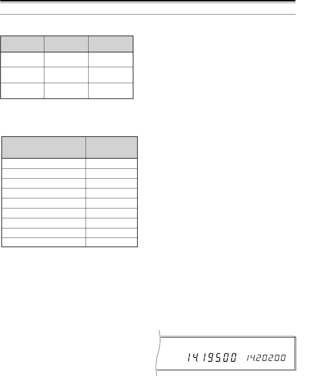
42
USB
AGC AUTO SPLIT
RIT
Shown below are the data rates and types of
modulation used for HF Packet operation:
Note
: In some countries, F2 modulation at 1200 bps may be used
on the 10-meter band. Consult your national Amateur radio
organization to obtain band plans that specify where in each band
various modes are used.
PACKET FREQUENCIES
AMTOR activity can be found on or near 14075 and
3637.5 kHz. These would also be good starting places
when searching for PacTOR, G-TORTM, or Clover
stations.
This completes the “DIGITAL OPERATION” section.
Refer to “OPERATING AIDS” beginning on page 44 for
information about additional useful functions for
operating.
6 COMMUNICATING
SPLIT-FREQUENCY OPERATION
Split-frequency operation uses one VFO for the receive
frequency and the other VFO for the transmit frequency.
While operating “split”, the VFOs switch automatically
when you switch from receive to transmit and vice
versa. This allows you to move either VFO frequency
independently without affecting the other.
When a rare or desirable station is heard, he or she
may immediately get many responses, all at the same
time. It quickly becomes difficult to separate and
identify both the original calling station (usually a DX
station), and the many responding stations. This “DX
pileup” is exciting, but it is also very inefficient and
frustrating. Often the DX station is lost under the noise
and confusion of many calling stations.
If things grow out of hand, it is the DX station’s
responsibility to take control by announcing that he will
be “listening up 5 (kHz, from his present transmit
frequency)”, or “listening down between 5 and 10
(kHz)”. This usually means the DX station will not
change his transmit frequency, but will begin split
operation in order to tune among the calling stations,
pick out a call sign or two, and begin working those
stations. Since, for the moment, the DX station is
holding his transmit frequency, you should not change
your receive frequency.
If you find that you are suddenly being called as that
rare or desirable station, your ability to control the
situation and complete contacts is much improved by
“going to split”. The following procedure explains how to
operate split frequency on the TS-870S.
1Press [RX A] or [RX B] or [RX M.CH].
•Your receive frequency will be the current
frequency selected by VFO A, by VFO B, or by
the current memory channel respectively.
•If you press [RX M.CH], then that memory
channel must contain a split channel unless you
select a VFO for the transmit frequency in the
next step. See “MEMORY CHANNEL
STORAGE, Split-frequency Channels” {page 55}.
2Press [TX A] or [TX B] or [TX M.CH].
•Your transmit frequency will be the current
frequency selected by VFO A, by VFO B, or by
the current memory channel respectively.
•If you pressed either [RX A] or [RX B] in Step 1,
then you must select the other VFO in this step,
or press [TX M.CH].
•When you recall a split memory channel to select
a transmit frequency, the transmit frequency
stored in that channel will be used.
Mode
USB & LSB
USB & LSB
FM
300 bps
(AFSK)
1200 bps
(PSK)
1200 bps
(AFSK)
F1
F1
F2
Data Rate Modulation Type
1800~1830
3620~3635
7080~7100
10140~10150
14095~14099.5
18105~18110
21090~21100
—
28120~28189
—
3590~3600
Digital band
Digital band
14089~14099, 14101~14112
Digital band
21100~21120
Digital band
28120~28150, 29200~29300
U.S.A./Canada
Frequency (kHz)
IARU Region 1
(Europe/Africa)
Frequency (kHz)

43
USB
AGC AUTO SPLIT
RIT
6 COMMUNICATING
TF-SET (TRANSMIT FREQUENCY SET)
[TF-SET] allows you to quickly check or adjust your
transmit frequency without changing your receive
frequency.
1Press and hold [TF-SET].
•Without changing your receive frequency, you are
now receiving on your transmit frequency.
2To select the transmit frequency that you want, turn
the Tuning control, the M.CH/VFO.CH control, or
press Mic [UP] or [DWN].
3Release [TF-SET].
•You are now receiving again on your original
receive frequency.
Note:
Switching ON Menu No. 10 (
∆
FREQ) allows you to see the
frequency difference between your transmit and receive frequencies
when
[TF-SET]
is pressed.
Successfully contacting a DX station in a pileup often
depends on making a well-timed call on a clear
frequency. The best way to know if your intended
transmit frequency is clear is to use [TF-SET]. Press
[TF-SET] and listen. Had you transmitted at that
moment, would you have transmitted simultaneously
with other stations or the station that you are calling?
After using [TF-SET] a couple of times in this manner,
you will learn the rhythm of the DX station and the
pileup. Use the information to select a relatively clear
transmit frequency and to transmit at the exact instant
when the DX station is listening but the majority of the
group aren’t transmitting. The more proficient you
become at using this function, the more DX you will
contact.
Note:
◆
If you press
[F.LOCK]
before using
[TF-SET]
, you will eliminate
the risk of changing your receive frequency accidentally.
◆
[TF-SET]
is disabled while transmitting.
◆
If you recalled a memory channel (excluding CH 99) for the
transmit frequency, you must set Menu No. 49 (CH.SHIFT) to ON
to use
[TF-SET]
to change the frequency of the memory channel.
Furthermore, you can turn the
M.CH/VFO.CH
control, or press
Mic
[UP]
or
[DWN]
, to switch to a different memory channel.
◆
An RIT frequency shift is not added; however, an XIT frequency
shift is added to the transmit frequency.
◆
[TF-SET]
is also enabled while operating with the same TX/RX
frequency (non-split).
SATELLITE OPERATION
Though not as common as VHF/UHF satellite operation,
HF satellite operation is possible depending on which
satellites are currently in orbit around the Earth. When
HF propagation is poor, satellite operation can provide
an incentive to get back on the air. Since this
communications mode is so reliable, you may discover
you actually prefer satellite operation over the
hunt-and-miss method of communicating via the
ionosphere.
An example of a Mode K satellite that has uplink and
downlink frequencies that are both on HF is the Radio
Sputnik 12 (RS-12). Launched in the early 1990s, this
satellite is in a low Earth orbit and provides brief
windows of opportunity for use as it passes quickly over
your location. This satellite accepts SSB or CW signals
on the 15 meter band and outputs them on 10 meters.
Contacts are possible on bands that might otherwise be
vacant during low periods of the solar cycle. Your
TS-870S can also be used with Mode A satellites, those
that use a VHF uplink and an HF downlink, if you also
have an SSB/CW VHF transceiver.
If you’re interested in pursuing Mode K operation,
contact AMSAT (Radio Amateur Satellite Corporation).
This group of satellite operators, located all over the
world, support the construction and operation of
satellites. AMSAT can provide you with the latest
information regarding Mode K and Mode A satellites that
are currently in orbit.
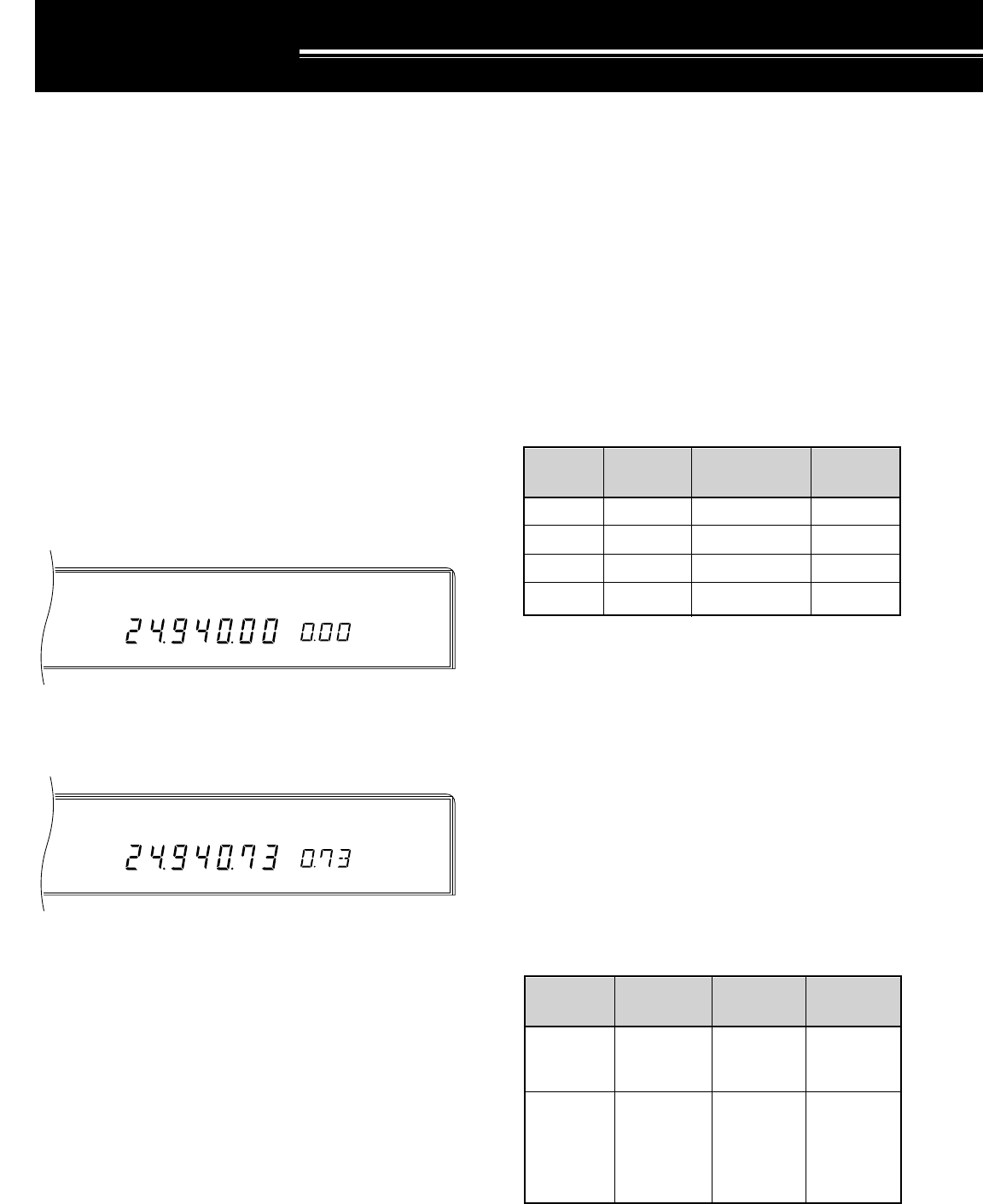
44
USB
AGC AUTO SPLIT
RIT
USB
AGC AUTO SPLIT
RIT
The TS-870S will take charge of setting the AGC, using
independent release times that you specify for each
mode. Or, you can have total control by manually
adjusting the AGC yourself from the Front Panel. When
receiving strong signals in AM mode with the AGC OFF,
the clipping action will make reception difficult or
impossible.
To select whether you want Automatic or Manual
control, use Menu No. 01 (AUT/MAN). Select OFF for
Manual control and ON for Automatic control. The
default is Manual (OFF).
■Changing AGC
Automatic (Menu No. 01 (AUT/MAN) is ON):
The following Menu items are available to change
the AGC release time in Automatic mode:
Manual (Menu No. 01 (AUT/MAN) is OFF):
With Menu No. 01 (AUT/MAN) set to OFF, adjust the
AGC control to set the AGC release time as you
prefer.
•Turning the control clockwise selects a faster
release time and counterclockwise selects a
slower release time.
•To switch OFF the AGC completely, turn the AGC
control fully counterclockwise.
■Changing AF AGC
The TS-870S offers further control of your receiver
AGC for the FM and AM modes. For these two
modes, you may adjust the AGC release time and
level in the AF stage.
OPERATING AIDS
RECEIVING
RIT (RECEIVE INCREMENTAL TUNING)
RIT provides the ability to change your receive
frequency by ±9.99 kHz in steps of 10 Hz without
changing your transmit frequency. If the Fine Tuning
([FINE]) function is ON, the step size is 1 Hz. RIT
works equally well with all modulation modes and while
using VFO mode or Memory Recall mode.
It’s a good habit to switch OFF the RIT function after a
contact is finished. This returns the receive frequency
to the transmit frequency. It ensures that you don’t
listen by mistake on a different frequency from your
transmit frequency on the next contact. When using
Memory Recall mode, RIT only functions with a memory
channel containing stored data. Since an empty
channel contains no receive frequency, RIT cannot
function.
1Press [RIT].
•“RIT” and the RIT frequency display appear.
2Press [CLEAR] to reset, if required, the RIT offset
to 0.
3Turn the RIT/XIT control to change your receive
frequency.
4To cancel the RIT function, press [RIT].
Note:
The frequency shift set by the
RIT/XIT
control is also used by
the XIT function.
AGC (AUTOMATIC GAIN CONTROL)
The AGC function selects the time constant for the
automatic gain control circuit. Selecting a slow time
constant will cause the receiver gain and S-meter
readings to react slowly to large input changes. A fast
time constant causes the receiver gain and the S-meter
to react quickly to changes in the input signal. A fast
AGC setting is particularly useful in the following
situations:
•Tuning rapidly
•Receiving weak signals
•Receiving high-speed CW
SSB
CW
FSK
AM
02
03
04
05
7
12
14
5
Menu No.
Mode Default
Selections
OFF, 1 ~ 20
OFF, 1 ~ 20
OFF, 1 ~ 20
OFF, 1 ~ 20
Menu No. Default
AF AGC
Release
Time
AF AGC
Level
06
07
0: Slow
1: Med
2: Fast
0: OFF
1: Min
2: Med
3: High
4: Max
1: Med
1: Min
Function Selections
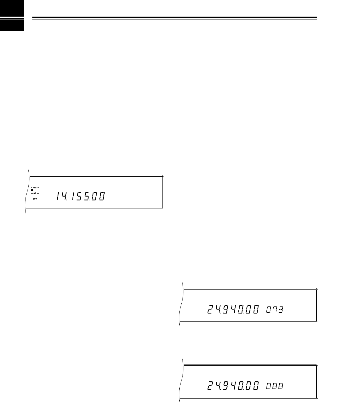
45
USB
AGC AUTO TONE
XIT
USB
AGC AUTO TONE
XIT
USB
VOX AGC AUTO
7 OPERATING AIDS
TRANSMITTING
VOX (VOICE-OPERATED TRANSMIT)
VOX eliminates the necessity of manually switching to
the transmit mode each time that you want to transmit.
The transceiver automatically switches to transmit when
the VOX circuitry senses that you have begun speaking
into the microphone.
When using VOX, get into the habit of pausing between
thoughts to let the transceiver drop back to receive
briefly. You will then hear if anybody wants to interrupt,
plus you will have a short period to gather your thoughts
before speaking again. Your listener will appreciate
your consideration as well as respect your more
articulate conversation.
Press [VOX] to toggle the VOX function ON or OFF.
•“VOX” lights when the function is ON.
■Microphone Input Level Adjustment
To enjoy the VOX mode, take time to set the gain of
the VOX circuit to the correct level.
1Select a voice mode, switch ON the VOX
function, and begin speaking into your
microphone using your normal level of voice.
2Access Menu No. 28 (VOX.GAIN), then select
different settings (default is 4) until the transceiver
reliably switches to transmit each time you speak.
•The best setting will allow the transceiver to
switch between receive and transmit;
however, background noises near your
operating position should not falsely switch
the transceiver.
•This Menu item is configurable even if the
VOX function is OFF or while you are
transmitting.
Note:
This transceiver does not have an ANTI-VOX control. DSP is
able to automatically lower the input sensitivity for received audio that
is output from the speaker.
■Delay Time Adjustment
1Select a voice mode, switch ON the VOX
function, and begin speaking into your
microphone using your normal level of voice.
2Adjust the DELAY control so that the transceiver
changes back to receive a brief time after you
stop talking.
•The DELAY control has a range from
150 ~ 2700 ms. Each step equals 10.6 ms.
Note:
Setting the delay time by computer overrides any setting
of the
DELAY
control. The control then has no effect. To restore
functionality to the
DELAY
control, turn the control. The newly
selected setting becomes effective.
TRANSMIT INHIBIT
Transmit Inhibit prevents the transceiver from being
placed in the transmit mode. No signals can be
transmitted if this function is ON. When the transceiver
is inhibited from transmitting, the graduations on the
PWR meter go out as a visual reminder.
•TX Inhibit OFF: Transmissions are possible.
•TX Inhibit ON: Transmissions are not possible.
Switch the function ON or OFF via Menu No. 27
(TX INH). The default is OFF.
XIT (TRANSMIT INCREMENTAL TUNING)
Similar to RIT, XIT provides the ability to change your
transmit frequency by ±9.99 kHz in steps of 10 Hz
without changing your receive frequency. If the Fine
Tuning ([FINE]) function is ON, the step size is 1 Hz.
1Press [XIT].
•“XIT” and the XIT frequency display appear.
2Press [CLEAR] to reset, if required, the XIT offset
to 0.
3Turn the RIT/XIT control to change your transmit
frequency.
4To cancel the XIT function, press [XIT].
Note:
The frequency shift set by the
RIT/XIT
control is also used by
the RIT function. Therefore, changing or clearing the XIT frequency
also affects the RIT frequency.
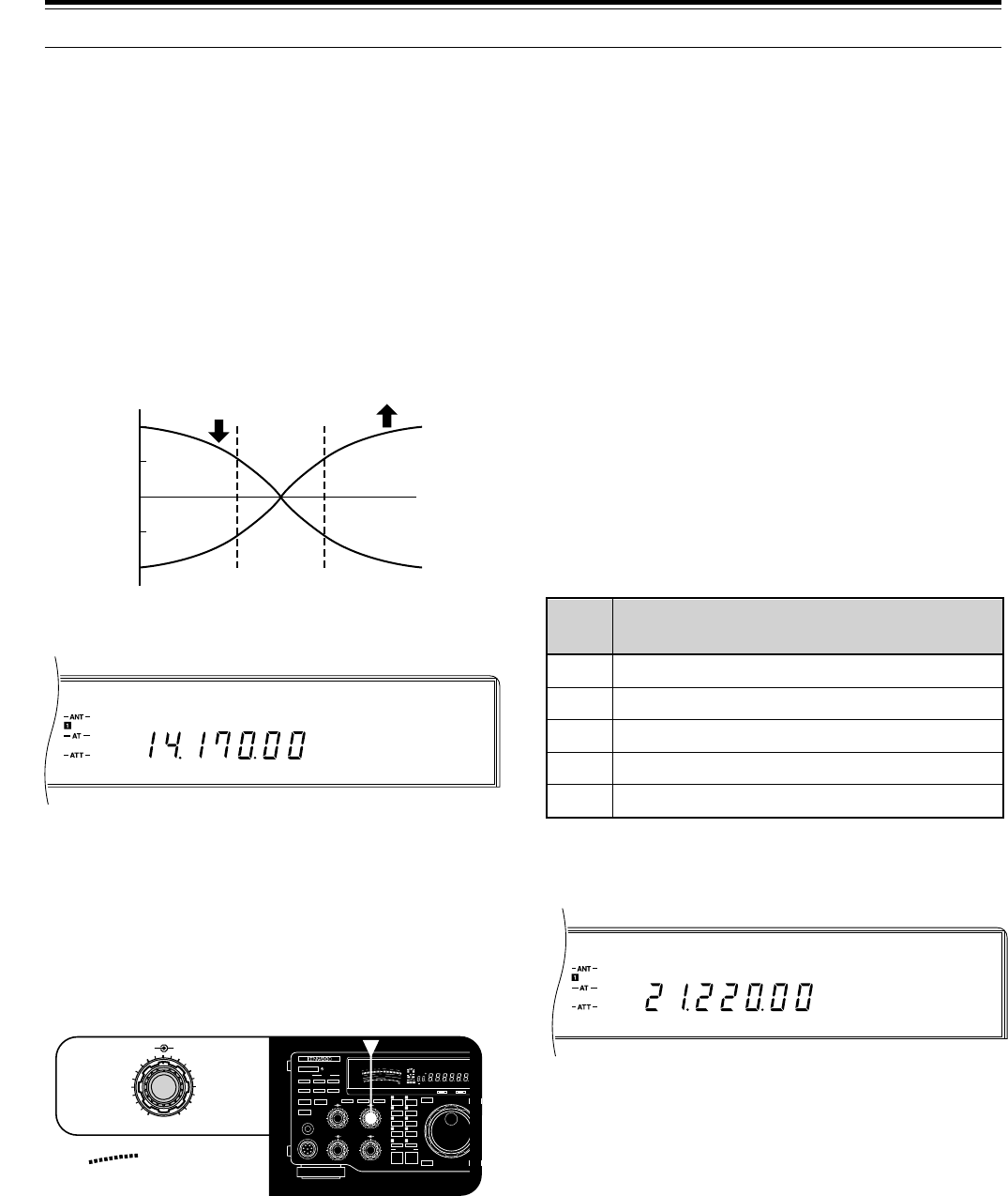
46
USB
AGC AUTO MONI
USB
AGC AUTO PROC
8Press [METER] to select the COMP function to allow
you to monitor the compression while transmitting.
9To switch OFF the processor, press [PROC] again.
•“PROC” goes out.
Note:
Input audio that is controlled by the AGC will be clipped.
Therefore, when mixing audio with the operator’s voice, lower the
MIC
gain control as necessary.
CHANGING FREQUENCY WHILE TRANSMITTING
Moving your frequency while transmitting is usually an
unwise practice due to the risk of interference to other
stations. While transmitting, if you select a frequency
outside the transmit frequency range, the transceiver is
automatically forced to receive mode. If transmit was
selected using the [SEND] key, transmission will not be
resumed until you select a frequency inside the transmit
frequency range, and you transmit again.
TRANSMIT MONITOR
The Transmit Monitor function allows you to hear your
own transmitted signal.
Press [MONI] to toggle the Monitor function ON or OFF.
•To change the volume of the monitored audio,
adjust the MONI control.
7 OPERATING AIDS
SPEECH PROCESSOR (SSB/AM)
The speech processor functions by leveling the large
fluctuations in your voice when you speak. This leveling
action effectively raises the average transmit output
power resulting in a more understandable signal when
operating using SSB or AM. You will notice that using
the speech processor makes it easier to be heard by
distant stations.
1Select SSB or AM mode.
2Select the preferred processor characteristics via
Menu No. 25 (PROC.LOW) and Menu No. 26
(PROC.HI).
•You can customize the low and high ranges of
the speech envelope from –6 to +6 dB.
3Press [PROC] to switch ON the processor.
•“PROC” lights.
4Press [METER] to select the COMP function.
5While speaking at your normal voice level, adjust the
PROC control for a level of 10 dB or less.
•Using higher compression will not improve your
signal clarity or apparent signal strength.
Excessively compressed signals are more
difficult to understand due to distortion and are
less pleasant to hear than signals with less
compression.
6Press [METER] to select the ALC function.
7The compression level affects the ALC setting for
SSB; therefore, while continuing to speak into the
microphone, adjust the CAR control for a reading
within the ALC zone.
•Keep the meter inside the ALC zone for the
cleanest transmit signal and to avoid interfering
with other stations on adjacent frequencies.
Mode
SSB
CW
FSK
AM
FM
Unmixed AF
Keyed output from DSP with sidetone OFF
AF corresponding to the shift and mark/space
Unmixed AF
Unmixed AF
Transmit Sampling Point
dB +6
+3
0
-3
-6
Lower Raise
Low
range
High
range
800 Hz 1.6 kHz
50
49
38
27
16
OFF
CAR DELAY
AGC KEY SPEED
METER PROC MONI
0
2
46
8
100
2
46
8
10
MIC
ATT
ANT DOWN UP
VOX FULL/SEMI
AT TUNE
SEND
THRU/AUTO
AIP
PHONES
PROC MONI
MIC PWR
M.IN
REC F.LOCK
CH 4 CLR
CH 3 SCAN
CH 2 M>VFO
CH 1 M.IN
ENTER TF-SET
FINE 1MHz
QUICK MEMO
MR
SLOW FAST
0
2
46
8
10
SWR
PWR
S
9
7
5
3
1
10
25
50
FILTER
ALC
3
10 2
1
.5
1
0
20
40
100
60
W
dB
dB
20
COMP
M.CH
USB CW R FSK FM AMLSBAUTO
FULLVOX SEMI AIP AGC AUTO PROC MONI
HF TRANSCEIVER TS-870
ON AIR AT TUNE
0
2
46
8
10
PROC MONI
10
dB
20
COMP

47
CUSTOMIZING TRANSMIT SIGNAL
CHARACTERISTICS (SSB/AM)
The quality of your transmitted signal is important
regardless which on-the-air activity you pursue.
However, it’s easy to be casual and overlook this fact
since you don’t listen to your own signal. The following
sub-sections provide information that will help you tailor
your transmitted signal.
■Changing Transmit Bandwidth
Transmit bandwidth is modified via Menu No. 29
(TX.WIDTH). The available selections include:
•1800, 2000, 2300, 2600, and 3000 Hz
The default is 2300 Hz. Consult the Bandwidth/
Bandshift Table for additional data. When the
Speech Processor is switched ON, the bandwidth
changes as shown in this table; however, displayed
values do not change.
■Transmit Bandshift
Transmit bandshift is modified via Menu No. 30
(TX.SHIFT). The available selections include:
•0, 100, 200, 300, 400, and 500 Hz
The default is 300 Hz. Consult the Bandwidth/
Bandshift Table for additional data. When the
Speech Processor is switched ON, the bandwidth
changes as shown in this table; however, displayed
values do not change.
■Equalizing Transmit Audio
Press [TX EQ.] to toggle the transmit equalizer ON
or OFF. To change transmit frequency
characteristics, access Menu No. 31 (TX EQ.). The
available selections include:
•High boost (H)
•Comb filter (C)
•Bass boost (B)
The default is High Boost.
■Microphone AGC
While transmitting, Microphone AGC helps to
prevent distortion due to overly high audio input. It is
disabled while using CW or FSK.
7 OPERATING AIDS
Function Selections Default
Menu
No.
Microphone
AGC Release
Time
22 0: Slow
1: Med
2: Fast
1: Med
Speech Processor
OFF
TX
Bandshift
Setting
(Hz)
(Menu
No. 30)
New
Lower
Cutoff
Freq.
(Hz)
Resulting
Upper
Cutoff
Freq.
(kHz)
New
Band-
width
(kHz)
Speech Processor
ON
1.8
2.0
2.3
2.6
3.0
1.8
2.0
2.3
2.6
3.0
1.8
2.0
2.3
2.6
3.0
1.8
2.0
2.3
2.6
3.0
1.8
2.0
2.3
2.6
3.0
1.8
2.0
2.3
2.6
3.0
0
100
200
300
400
500
1.8
2.0
2.3
2.6
3.0
1.9
2.1
2.4
2.7
3.1
2.0
2.2
2.5
2.8
3.2
2.1
2.3
2.6
2.9
3.3
2.2
2.4
2.7
3.0
3.4
2.3
2.5
2.8
3.1
3.5
200
300
400
500
1.6
1.8
2.1
2.4
2.6
1.7
1.9
2.2
2.6
2.6
1.8
2.0
2.3
2.6
2.6
1.8
2.0
2.3
2.6
2.6
1.8
2.0
2.3
2.6
2.6
1.8
2.0
2.3
2.6
2.6
TX
Bandwidth
Setting
(kHz)
(Menu
No. 29)
BANDWIDTH/ BANDSHIFT TABLE
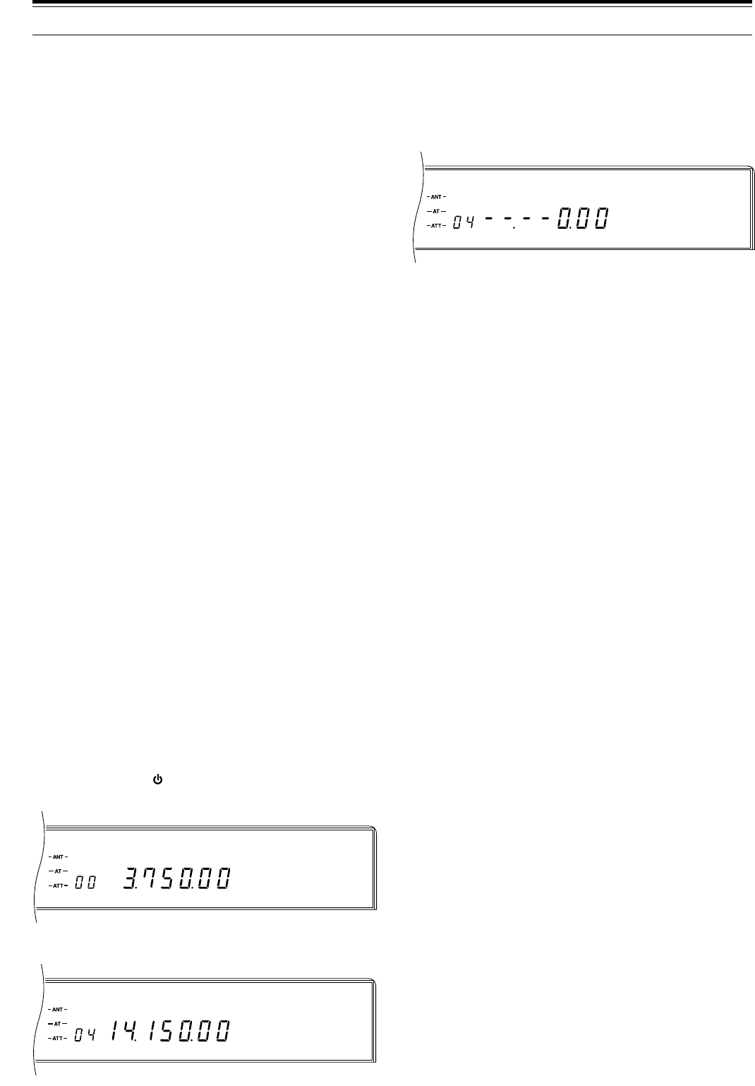
48
USBAUTO
CWAUTO
CWAUTO
7 OPERATING AIDS
3Press [ENTER], then enter the frequency via the
keypad. Alternatively, you can enter the frequencies
by using the Tuning control or Mic [UP]/[DWN].
Pressing [UP] or [DOWN] on the Front Panel
changes the frequency in 1 MHz steps.
•“– –.– – 0.00” appears if [ENTER] is pressed.
•The 10 kHz digit is the least significant that can
be entered therefore boundaries must be
multiples of 10 kHz.
•Four digits must be entered. However, if
[ENTER] is pressed after beginning to enter
digits, 0 is entered automatically for the remaining
un-entered digits, and frequency entry is
completed.
•If you enter a wrong digit, press
[CLEAR], [ENTER] then re-enter the entire
frequency.
4Press [LSB/USB] or [CW/–R] or [FSK/–R] or
[FM/AM] to select the mode for this boundary.
5Repeat Steps 2 ~ 4 for each boundary that you want
to change.
6Press [CLR] to exit from this mode.
•Switching the power OFF before pressing [CLR]
results in loss of the entered data.
USING AUTOMATIC MODE
Toggle Automatic Mode ON or OFF via Menu No. 34
(AUT.MODE). The default is OFF. When Automatic
Mode is ON, you can always change the mode
manually by pressing a Front Panel MODE button. An
Automatic Mode boundary must be crossed for the
mode to automatically change.
Automatic Mode does not work if you change bands by
pressing [UP] or [DOWN]. Instead, the mode last used
on the newly selected band will be recalled from the
band memory. Switching ON the 1MHz Step function
will allow Automatic Mode to work when using [UP] or
[DOWN].
In SSB mode when Automatic Mode is OFF, the
transceiver automatically selects LSB for frequencies
lower than 9.5 MHz, and selects USB for 9.5 MHz or
higher frequencies if the Tuning control or Mic
[UP]/[DWN] is used to cross the frequency of 9.5 MHz.
This is also true if using the Front Panel [UP] or
[DOWN] button. In all modes, the RIT or XIT frequency
shift is not taken into account by Automatic Mode. Also,
Automatic Mode will not function if a frequency is
entered via the keypad on the Front Panel.
AUTOMATIC MODE
Automatic Mode automatically selects the operating
mode according to a set of frequency and mode data
that you input. The purpose of Automatic Mode is for
the transceiver to select the correct mode for you as you
tune within a band. For Automatic Mode to work, you
must first program the frequency/mode relationships
that you want.
AUTOMATIC MODE BOUNDARIES
•The defaults for all boundaries are 30 MHz USB.
•Boundaries may only be changed (not deleted).
•The mode assigned to a boundary will be selected
while operating on all frequencies below that
boundary down to and including the next lower
boundary.
•Each boundary is numbered. As the boundary
numbers get larger, so must the boundary
frequencies.
Example: If Boundary No. 09 is 14.100 MHz, then
Boundary No. 10 must be a frequency larger by at
least 10 kHz than 14.100 MHz. The lowest
frequency that could be stored in Boundary No. 10 is
14.110 MHz. A lower frequency will not be accepted.
•Frequencies larger than the maximum receive
frequency cannot be stored.
•There is a maximum of 19 boundary frequencies.
•Automatic Mode is always “OFF” in the range from
the highest boundary to the maximum transceiver
frequency.
Example: If 18 MHz CW is stored in Boundary
No. 14, tuning to 18 MHz or higher selects USB
since the boundary default of 30 MHz USB is stored
in Boundary No. 15. Whereas, if 18 MHz CW is
stored in Boundary No. 18 (highest boundary),
tuning to a frequency lower than 18 MHz selects CW
but tuning to 18 MHz or higher will not change the
mode (still CW).
Use the following procedure to change a boundary.
1Press [MENU]+[ ].
•Boundary No. 00 appears.
2Turn the M.CH/VFO.CH control to select the
boundary that you want to change.
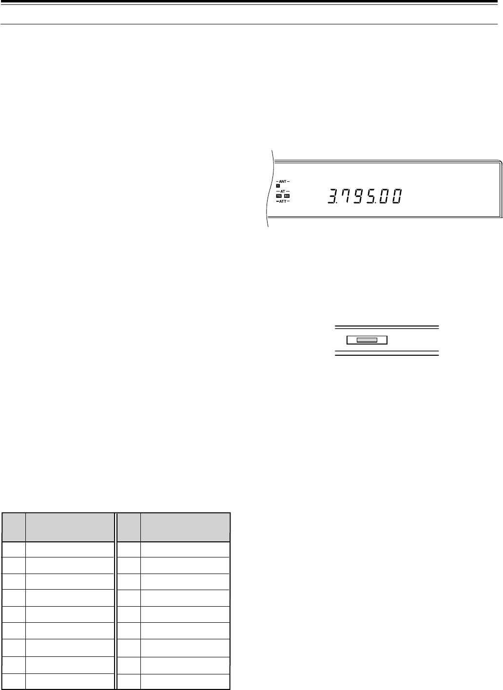
49
AGC AUTO
LSB
AUTOMATIC ANTENNA TUNER
You have the choice of using the internal tuner, an
external AT-300 tuner, or both.
Note:
◆
The antenna tuners will not tune outside the authorized transmit
limits of Amateur bands.
◆
If an external AT-300 tuner is connected, the internal tuner is
bypassed when the ANT 1 connector is selected. The AT-300
cannot be used with the ANT 2 connector.
◆
When tuning in CW mode, the SWR meter may deflect upscale
momentarily. This is not a fault.
◆
If using Full Break-in CW, the internal antenna tuner can be
bypassed completely or can be in-line for both transmitting and
receiving. Even when OFF is selected via Menu No. 08 (RX AT),
received signals pass through the antenna tuner. To protect the
antenna tuner relay, the tuner cannot be used only for
transmitting.
PRESETTING (INTERNAL TUNER ONLY)
After each successful tuning session, the Preset
function stores the data for the position of the tuning
capacitors on each band. Then, if the frequency is
changed while the internal tuner is switched ON, this
function automatically positions the capacitors without
need for retuning.
After changing bands, the Preset
function activates for the newly selected band.
A different set of data is stored for each of the
18 antenna tuner bands (see table) and for each
antenna connector (ANT 1 and ANT 2). Therefore,
enabling the other antenna connector by pressing the
[ANT] button may also cause the Preset function to
activate. If no Preset data exists for a particular band/
antenna combination, then the default data for 50 Ω is
stored.
Presetting does not activate while transmitting. For
split-band operation, even if Menu No. 08 (RX AT) is
ON, the antenna tuner is bypassed while receiving.
Also, at all times, presetting is only done for transmit
frequencies.
PRESET BANDS FOR INTERNAL TUNER
Note:
The lower limit is inside the band in each case; the higher
limit is inside the next higher band. For example, 14.1 MHz is in
Band 12 whereas 14.49 MHz is in Band 13 (exception: 30 MHz is in
Band 18).
7 OPERATING AIDS
INTERNAL TUNER
Note:
Setting Menu No. 33 (TUN.WIDE) to OFF to select an
SWR
≤
1.2:1 reduces internal tuner losses. This setting is best.
1Press [THRU/AUTO].
•“–AT – TX” lights. If Menu No. 08 (RX AT) is ON,
then “– AT – TX RX” lights indicating that the
tuner is in-line while transmitting and receiving.
In this case, prior to tuning in Step 2, received
signals are attenuated and the receiver sensitivity
is lowered.
•If the tuner has not adjusted itself yet for the
selected frequency, then AT TUNE lights, and
Preset tuning begins. Signals pass through the
antenna tuner during this time. If Menu No. 08
(RX AT) is OFF, the antenna tuner is bypassed.
The AT TUNE light goes out when presetting is
completed. You cannot transmit while presetting
is in progress.
•If Preset data exists, the next step cannot be
done until the transceiver completes the Preset
tuning.
2Press [AT TUNE].
•To cancel tuning for any reason, press
[THRU/AUTO] or [AT TUNE].
•If the Preset tuning is aborted by pressing
[AT TUNE], the new temporary data will be used,
but this new data does not update the stored
Preset data. Also, the new temporary data will be
lost if the operating band is changed. Return to
the stored Preset data by pressing
[THRU/AUTO] OFF and then ON again.
•AT TUNE lights and stays lit while the tuner
tunes. When the light goes out, the tuner has
successfully matched the transceiver to the
antenna system with an SWR less than the value
set in Menu No. 33 (TUN.WIDE). You can begin
operating.
•If tuning doesn’t finish within about 20 sec, an
alarm sounds. You may stop the alarm and the
tuning by pressing [AT TUNE]. The alarm can be
either a triple beep or the Morse code “CHECK”
depending on the Menu No. 37 (WARN. BP)
setting.
•After each successful tuning, the Preset data is
updated.
Note:
◆
While receiving with Menu No. 08 (RX AT) ON on
frequencies outside the Amateur bands, sensitivity is
lowered.
◆
It’s a good practice to press
[AT TUNE]
after changing bands
to ensure the tuner has tuned for minimum SWR.
AT TUNE
7.49 ~ 10.49
10.49 ~ 14.1
14.1 ~ 14.49
14.49 ~ 20.99
20.99 ~ 21.15
21.15 ~ 21.99
21.99 ~ 25.49
25.49 ~ 29
29 ~ 30
0.030 ~ 1.85
1.85 ~ 2.01
2.01 ~ 3.525
3.525 ~ 3.575
3.575 ~ 3.725
3.725 ~ 4.49
4.49 ~ 7.03
7.03 ~ 7.1
7.1 ~ 7.49
10
11
12
13
14
15
16
17
18
1
2
3
4
5
6
7
8
9
Range
(MHz)
Band
No.
Range
(MHz)
Band
No.
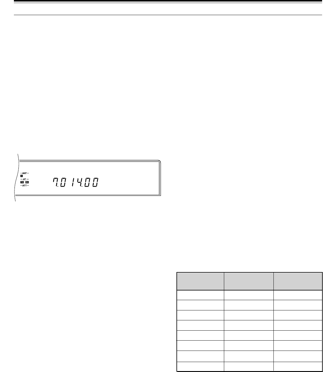
50
CW
AGC AUTO
from another room, or, when coupled with other
commercially available products and where lawful, from
another city via a telephone connection.
The list of applications is large and expanding, and is
limited only by the imagination of software
programmers. In short, the COM connector adds a new
level of flexibility and opportunity to enjoy Amateur radio
when a transceiver control application that supports the
TS-870S and a computer are used.
Before using a computer for transceiver control, you
should be aware of a few points. After you manually
switch OFF the transceiver power, you can then switch
ON the transceiver power using commands from the
computer. Similarly, after switching OFF the power from
the computer, it is then possible to switch ON the power
from the Front Panel.
You can use the Front Panel controls while using
computer control. Settings done from the Front Panel
are effective immediately. After power is switched OFF
from the computer, all values and settings per the Front
Panel controls are restored.
COMMUNICATION PARAMETERS
In order to control the transceiver with your computer,
you must first choose the communication parameters
that you require. Configure your transceiver control
application for 8 data bits and no parity. The
communication speed and number of stop bits must
match the settings in the TS-870S. The transceiver is
configured via Menu No. 56 (COM.RATE). After
changing Menu No. 56, the TS-870S must be switched
OFF and then ON again for the new parameters to
become effective. The defaults in the TS-870S are
9600 bps and 1 stop bit.
Note:
◆
Before connecting the TS-870S to a computer, switch OFF the
power to the TS-870S and the computer.
◆
To reliably use the 38400 or 57600 bps transfer rates, the serial
port of your computer must support these high-speed
communications parameters.
◆
More information on controlling the TS-870S by a computer is
included in Appendix D “COM CONNECTOR PROTOCOL”
{page 83}.
7 OPERATING AIDS
AT-300 EXTERNAL TUNER (OPTIONAL)
Note:
◆
The AT-300 must be connected while the transceiver power is
switched OFF.
◆
There is a 4 A fuse inside the TS-870S for the AT-300 Antenna
Tuner.
1Press [ANT] to select Antenna 1.
2Press [THRU/AUTO].
•This places the tuner in the bypass state until
tuning begins in the next step. If tuning fails, the
tuner returns to the bypass state.
•[AT TUNE] is disabled if [THRU/AUTO] is not
pressed.
3Press [AT TUNE].
•When tuning completes successfully, the
AT TUNE light goes out, and “– AT – TX RX”
lights.
•If tuning doesn’t finish within about 20 sec, an
alarm sounds. You may stop the alarm and the
tuning by pressing [AT TUNE]. The alarm can be
either a triple beep or the Morse code “CHECK”
depending on the Menu No. 37 (WARN. BP)
setting.
•“RX” lights on the Display even if Menu No. 08
(RX AT) is OFF.
•Each time after changing frequency or after
removing then restoring the power, you must
press [AT TUNE] since there is no Preset data
stored when using the external tuner.
COMPUTER [\ TRANSCEIVER
INTERFACE
The TS-870S interfaces easily with a computer.
Computer interfaces on transceivers have encouraged
the development of software applications by many
companies.
Now available are electronic logbook applications that
are partially self-completing. Information transferred
between the transceiver and the computer is written into
the logbook. These applications can automatically track
awards and look up callbook information too.
Imagine using a mouse click to change your TS-870S to
the correct DX frequency and mode of a DX station after
the arrival of a report from your local DX packetcluster.
Efficient operating technique is the key to winning in
pileups and is essential when operating contests.
Other applications can change your computer into an
electronic console from which you can remotely control
functions on the TS-870S without physically touching its
Front Panel. This capability makes possible remote
operation of your transceiver from across the room,
1200
2400
4800
4800
9600
19200
38400
57600
1
1
1
2
1
1
1
1
12 1
24 1
48 1
48 2
96 1
192 1
384 1
576 1
Menu No. 56
Setting
Baud Rate
(bps) Stop Bits
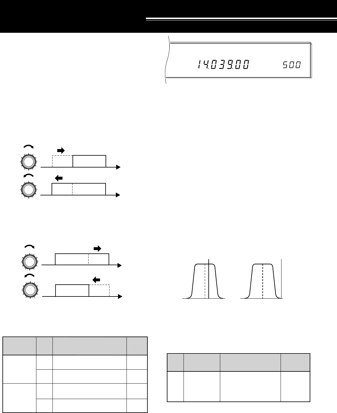
51
CW
AGC AUTO CTRL
SHIFT
DSP TOOLS
SLOPE TUNING (SSB/AM)
Changing the positions of the LO/WIDTH and HI/SHIFT
controls while in SSB or AM mode changes the cut-off
frequencies for the receive pass band. Controlling the
pass band in this way allows you to eliminate adjacent
frequency interference.
Turn the LO/WIDTH control clockwise to raise the
high-pass filter cut-off frequency; turn it
counterclockwise to lower the cut-off frequency. This is
effective in removing interference from frequencies
lower than your current operating frequency.
Turn the HI/SHIFT control clockwise to raise the
low-pass filter cut-off frequency; turn it
counterclockwise to lower the cut-off frequency. This is
effective in removing interference from frequencies
higher than your current operating frequency.
Using only these controls, you can eliminate a great
deal of interference on the phone bands. By using both
controls together carefully, you will increase your ability
to pick out weak signals from the interference.
IF SHIFT (CW)
For CW, the center frequency of the filter pass band can
be shifted without changing the current receive
frequency. This is an additional method of fighting
adjacent frequency interference. Change the CW
center frequency by adjusting the HI/SHIFT control.
When the control is adjusted, “SHIFT” and the newly
selected center frequency appears on the Display.
REJECTING INTERFERENCE
Be aware that shifting the CW center frequency does
not automatically adjust the receive CW pitch.
Therefore, it is possible to shift the CW pass band such
that the selected CW pitch frequency falls outside the
pass band. Doing this makes the CW signal inaudible.
Example:
Before adjusting IF Shift:
•CW pitch: 900 Hz
•IF Shift: 800 Hz (center frequency)
•CW Width: 600 Hz
In this example, the pass band would lie from
500 ~ 1100 Hz (from 300 Hz below the center frequency
of 800 Hz to 300 Hz above the center frequency). If the
CW pitch was set for 900 Hz, the signal would be
audible.
After adjusting IF Shift:
•CW pitch: 900 Hz
•IF Shift: 500 Hz (center frequency)
•CW Width: 600 Hz
Now, the pass band would lie from 200 ~ 800 Hz. With
the CW pitch set for 900 Hz, the signal would not be
audible since the pitch frequency is 100 Hz above the
upper edge of the pass band. In this case, to make the
signal audible, lower the CW pitch frequency by at least
100 Hz.
f
f
HI/SHIFT
HI/SHIFT
USB pass band
USB pass band
f
f
LO/WIDTH
LO/WIDTH
USB pass band
USB pass band
CW 800
Frequency Selections
(Hz)
Mode Default
Freq.(Hz)
400, 450, 500, 550,
600, 650, 700, 750,
800, 850, 900, 950,
1000
Center
frequency
Freq./ Filter
Relationship
0, 50, 100, 200, 300, 400,
500, 600, 800, 1000 Hz
0, 100, 200, 500 Hz
1.4, 1.6, 1.8, 2.0, 2.2, 2.4,
2.6, 2.8, 3.0, 3.4, 4.6, 6.0 kHz
2.5, 3.0, 4.0, 5.0, 6.0, 7.0 kHz
LO/WIDTH
Control
(high-pass
filter cutoff)
HI/SHIFT
Control
(low-pass
filter cutoff)
SSB
AM
SSB
AM
Frequency SelectionsAdjust Mode Default
Freq.
300 Hz
100 Hz
2.6 kHz
6.0 kHz
500 800 1100
900 Hz pitch
200 500 800
900 Hz pitch
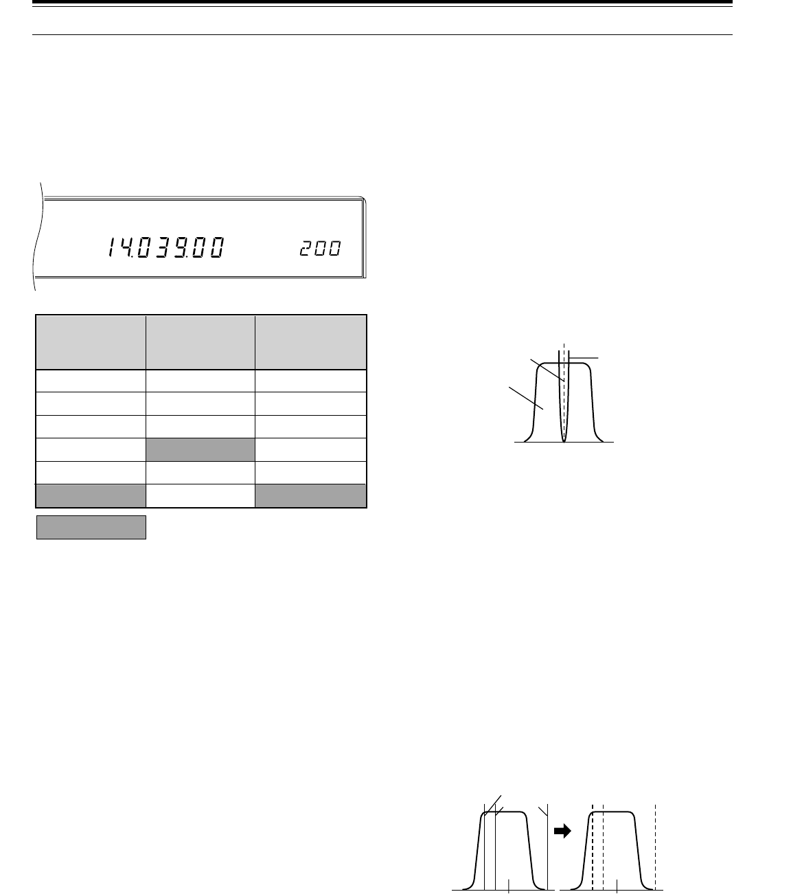
52
CW
AGC AUTO NB
WIDTH
AUTO NOTCH (SSB)
Auto Notch automatically locates and attenuates
interfering tones within the receive pass band. This
function operates digitally at the IF level, hence it can
affect your S-meter reading, and may affect (slightly
attenuate) your desired signal. If interfering tones are
weak, you may find that Beat Cancel eliminates them
more effectively. Also, Auto Notch may not notch out
signals inside the pass band if signals just outside the
pass band limits are stronger.
After switching ON the function, selecting a mode other
than SSB will switch OFF the Auto Notch function (LED
goes out). Changing back to SSB re-activates the
function automatically (LED lights). If strong, steady
interference is present, switching Menu No. 18 (TRACK)
to OFF may improve the notching capability. To block
CW interference, switch TRACK to ON, then switch
TRACK to OFF to lock the adaptive filter.
Press [AUTO NOTCH] to toggle the Auto Notch function
ON or OFF.
•The LED indicator in the button lights when the
function is ON.
Note:
The effect of Auto Notch may differ under different receiving
conditions even when using the same response time.
BEAT CANCEL (SSB/AM)
Beat Cancel also attenuates unwanted tones within the
pass band, but it is more capable than Auto Notch at
removing low-level tones. Also, this function works at the
AF level, therefore you will notice there is no S-meter
signal loss, although the S/N ratio may be lowered in the
AM mode.
After switching ON the function, selecting a mode other
than SSB or AM will switch OFF the Beat Cancel
function (LED goes out). Changing back to SSB or AM
re-activates the function automatically (LED lights).
Press [BEAT CANCEL] to toggle the Beat Cancel
function ON or OFF.
•The LED indicator in the button lights when the
function is ON.
Note:
The effect of Beat Cancel may differ under different receiving
conditions even when using the same response time.
CHANGING RECEIVE BANDWIDTH
(CW/FSK/FM)
The width of the receive pass band can be changed
without altering the current receive frequency. Change
the bandwidth by adjusting the LO/WIDTH control.
When the control is adjusted, “WIDTH” and the newly
selected bandwidth appear on the Display.
ADAPTIVE FILTERS
The Auto Notch, Beat Cancel, and Noise Reduction
functions accomplish their design purposes by
modifying the characteristics of adaptive filters.
Adaptive filters adapt or change their characteristics
according to the nature of the signal being received at a
given moment. Menu No. 18 (TRACK) determines
whether the adaptive filters are allowed to change in this
manner or not.
It is also possible to specify how long the received
signals will be monitored before determining filter
characteristics. This monitor period is inversely
proportional to the response time. The longer the
monitor time, the slower the response time and vice
versa. Use Menu No. 14 (LINE.ENH) to select a
different Line Enhance response time, Menu No. 16
(SP.BEAT) for the Beat Cancel response time, and
Menu No. 17 (SP.NOTCH) for the Auto Notch response
time.
The adaptive filters may not function correctly with
signals that have a poor signal-to-noise (S/N) ratio.
Under poor conditions, you may find that optimum
results are obtained by switching OFF the adaptive
filters via Menu No. 18 (TRACK).
Note:
Only Auto Notch, or Beat Cancel, or Noise Reduction can be
used at one time. They cannot be activated at the same time. Also,
Menu No. 18 changes to its default setting when the TS-870S power
is switched OFF and then ON again.
50
100
200
400
600
1000
250
500
1000
1500
5
6
8
10
12
14
FM
Bandwidth
(kHz)
CW
Bandwidth
(Hz)
FSK
Bandwidth
(Hz)
Default values
8 REJECTING INTERFERENCE
Interfering tone Notch band
Receive pass
band
Interfering
tones
Receive pass band Receive pass band

53
LSB
AGC AUTO
CW
AIP AGC AUTO
USB
AGC AUTO NB
WIDTH
NOISE REDUCTION (SSB/CW/FSK/AM)
Menu No. 13 (LINE.ENH) determines whether the Line
Enhance function (an adaptive filter) or the SPAC filter is
used. When using the Line Enhance function, switch
Menu No. 18 (TRACK) to ON. The SPAC filter works
better for reducing noise and is effective for eliminating
various types of noise. However, audio quality will
deteriorate since only the audio portion is selected. This
filter may induce pulse noises. One difference between
the digital Line Enhance function and the conventional
analog-based Noise Blanker is that the digital function
works at audio frequencies whereas the blanker acts at
IF.
Press [N.R.] to toggle the Noise Reduction function ON
or OFF.
•The LED indicator in the button lights when the
function is ON.
•When the S/N ratio is reasonably good in SSB, using
Line Enhance will improve the S/N further. When
receiving a CW signal with a poor S/N ratio, using
SPAC will improve the S/N. For AM signals,
received audio may become intermittent.
SETTING SPAC TIME
SPAC is a DSP term that literally means Speech
Processing using Automatic Correlation. This is one
method of digitally filtering out noise. Using Menu
No. 15 (SPAC), select the correlation time that provides
the highest quality reception for SSB. When receiving
CW, choose the longest time that allows reliable
reception. The longer the correlation time, the better the
S/N .
NOISE BLANKER
The Noise Blanker was designed to reduce pulse noise
such as that generated by automobile ignitions.
Press [NB] to toggle the Noise Blanker ON or OFF. To
change the level of blanking, adjust the NB control.
Always use the minimum necessary blanking. This
reduces the chances of blanking your desired signal.
•“NB” lights when the function is ON.
•When receiving a strong signal while the Noise
Blanker is ON, receive audio may sound distorted.
Eliminate the distortion by reducing the Noise
Blanker level, or by switching OFF the function.
AIP (ADVANCED INTERCEPT POINT)
AIP helps eliminate interference and reduce audio
distortion that is sometimes caused by the presence of
strong signals. AIP is especially useful during
contest-type conditions, on an extremely crowded band,
or when propagation is at a peak and all signals are
local quality.
•Press [AIP] to toggle the AIP function ON or OFF.
•“AIP” lights when the function is ON.
•By default, AIP switches ON for all frequencies
below 7490 kHz. However, the status of AIP is
stored independently for each AIP band. When a
different AIP band is selected, the last setting
(OFF/ON) used on that band is recalled.
Note:
If you are concerned about precise S-meter readings, switch
ON Menu No. 11 (AIP.GAIN) when using this function. AIP.GAIN
does not change the S-meter sensitivity but, due to the increased
gain, the noise level increases even while receiving no signals.
AIP.GAIN does not work in FM or AM.
ATTENUATOR
The Attenuator prevents distortion by reducing the level
of the receive signal. The function is also useful to
reduce interference from adjacent frequencies.
Press ATT [DOWN] or ATT [UP] to select the desired
attenuation.
•The selected attenuation (units of dB) lights
(“– ATT – 6”, “– ATT – 12”, or “– ATT – 18”).
•The status of ATT is stored independently for each
ATT band. When the ATT band is changed, the last
setting used on the band is recalled.
Note:
The lower limit is inside the band in each case; the higher
limit is inside the next higher band. For example, 4.49 MHz is in
Band 3 whereas 7.49 MHz is in Band 4 (exception: 30 MHz is in
Band 9).
8 REJECTING INTERFERENCE
Lowest freq. ~ 2.49
2.49 ~ 4.49
4.49 ~ 7.49
7.49 ~ 10.49
10.49 ~ 14.49
14.49 ~ 20.99
20.99 ~ 21.99
21.99 ~ 25.49
25.49 ~ 30
1
2
3
4
5
6
7
8
9
ON
ON
ON
OFF
OFF
OFF
OFF
OFF
OFF
OFF
OFF
OFF
OFF
OFF
OFF
OFF
OFF
OFF
Band
No.
Frequency Range
(MHz)
Default AIP
Setting
Default ATT
Setting
54
M. CH
M. SCR
AGC AUTO
M. CH
M. SCR
AGC AUTO
MEMORY FEATURES
MICROPROCESSOR MEMORY BACKUP
This transceiver uses a lithium battery to retain the user-
specified memory items. Switching OFF the power will
not erase the Menu Setups or memory channels.
Lithium battery life is approximately 5 years.
If you find the transceiver powers-up with default
settings, and VFO and memory channel data is erased,
have the lithium battery replaced. Contact an
authorized KENWOOD Service Facility or dealer.
CONVENTIONAL OR QUICK MEMORY?
Memory channels allow you to save various operating
parameters (receive frequency, operating mode, etc.)
for recall at a later time. You can store this data in
Conventional or Quick memory. Conventional memory
is used for storing data that you may want to recall
many times in the future during different operating
sessions. For example, Conventional memory is useful
to store the frequency where you regularly meet your
club members.
However, Quick memory is meant for quickly saving
data without needing to specify a particular memory
channel. It’s likely that you won’t need this data during
future operating sessions. For example, as you tune
across the band looking for DX, it is convenient to store
stations that you want to contact into Quick memory.
You can quickly jump between several different Quick
memory channels as you monitor them.
CONVENTIONAL MEMORY
MEMORY CHANNEL DATA
There are a total of 100 Conventional memory
channels. The channels are numbered 00 ~ 99.
Channels 00 ~ 98 have identical characteristics
whereas channel 99 is reserved for programming VFO
tuning ranges and scan ranges.
Channels 00 ~ 98 can store the following:
•Receive frequency and mode
•Transmit frequency and mode
•Subtone frequency
•Memory Lock Out (OFF/ON)
Note:
The Subtone selected via Menu No. 57 (SUB.TONE) is
automatically stored, but the stored Subtone can only be used if the
TX and RX modes are FM.
Channel 99 can store the following:
•Frequency and mode (simplex only)
•Start frequency and mode
•End frequency
•Memory Lock Out (OFF/ON)
MEMORY CHANNEL STORAGE
Memory channels can be either simplex or
split-frequency. Simplex channels use the stored
frequency for receiving and transmitting.
Split-frequency channels use a different frequency for
transmitting and receiving. Also, even if RIT or XIT is
ON with a frequency offset selected, this offset will not
be added to the frequency when it is stored.
■Simplex Channels
1Press [RX A] or [RX B] to select simplex mode.
•The indicators in the [RX A] and [TX A]
buttons, or the indicators in the [RX B] and
[TX B] buttons must be ON.
2Select the frequency, mode, etc. to be stored.
3Press [M.IN] to select Memory Scroll mode.
•To exit from Memory Scroll mode and abort
the storage process, press [CLR].
4Turn the M.CH/VFO.CH control to select a
memory channel.
5Press [M.IN] to store the frequency and
associated data in the selected memory channel.
•Pressing [M.IN] overwrites your new data on
any previous data in that channel.
55
M. CH
USB
AGC AUTO
USB
AGC AUTO SPLIT
RIT
M. CH
USB M. SCR
AGC AUTO
M. CH
M. SCR
AGC AUTO
9 MEMORY FEATURES
■Split-Frequency Channels
1Using VFO A, select a receive frequency and
mode.
2Using VFO B, select a transmit frequency and
mode.
3Press [RX A], [TX B] to select split-frequency
mode.
•The indicators in the [RX A] and [TX B]
buttons must be ON.
4Press [M.IN] to select Memory Scroll mode.
•To exit from Memory Scroll mode and abort
the storage process, press [CLR].
5Turn the M.CH/VFO.CH control to select a
memory channel.
6Press [M.IN] to store the frequencies and
associated data in the selected memory channel.
•Pressing [M.IN] writes your new data on any
previous data in that channel.
Note:
If you prefer, you can store the transmit data in VFO A
and the receive data in VFO B instead.
MEMORY CHANNEL RECALL
Once a frequency with associated data is stored in a
memory channel, this procedure allows you to retrieve
that frequency and data.
1Press [RX M.CH] to select Memory Recall mode.
2Turn the M.CH/VFO.CH control, or press Mic [UP] or
[DWN], to select the memory channel that you want.
•After ascending to the maximum memory
channel number, continuing to step in the same
direction returns you to the lowest channel in a
circular manner. This is also true when
descending through the channels.
•Continuously holding down Mic [UP] or [DWN]
steps the transceiver through the memory
channels until the button is released.
•You cannot change memory channels while
transmitting.
Note:
Memory channels can be changed while using the TF-SET
function.
■Quick Channel Search
When looking for a particular programmed memory
channel, it is quicker to activate the search mode as
explained below. This mode can also be used to
search only for vacant (non-programmed) channels.
Programmed Channel Search:
While in Memory channel mode, press [1MHz] to
toggle the search function ON or OFF.
•“MHz” lights when the function is ON. Now, only
those channels that contain programmed data
can be selected.
•Attempting to change channels when there are
no programmed channels to select causes an
alarm to sound. The current channel cannot be
changed in this case.
Vacant Channel Search:
While in Memory Scroll mode {page 56}, press
[1MHz] to toggle the function ON or OFF.
•“MHz” lights when the function is ON. Only those
channels that do not contain data can be
selected.
•Attempting to change channels when there are
no vacant channels to select causes an alarm to
sound. The current channel cannot be changed
in this case.
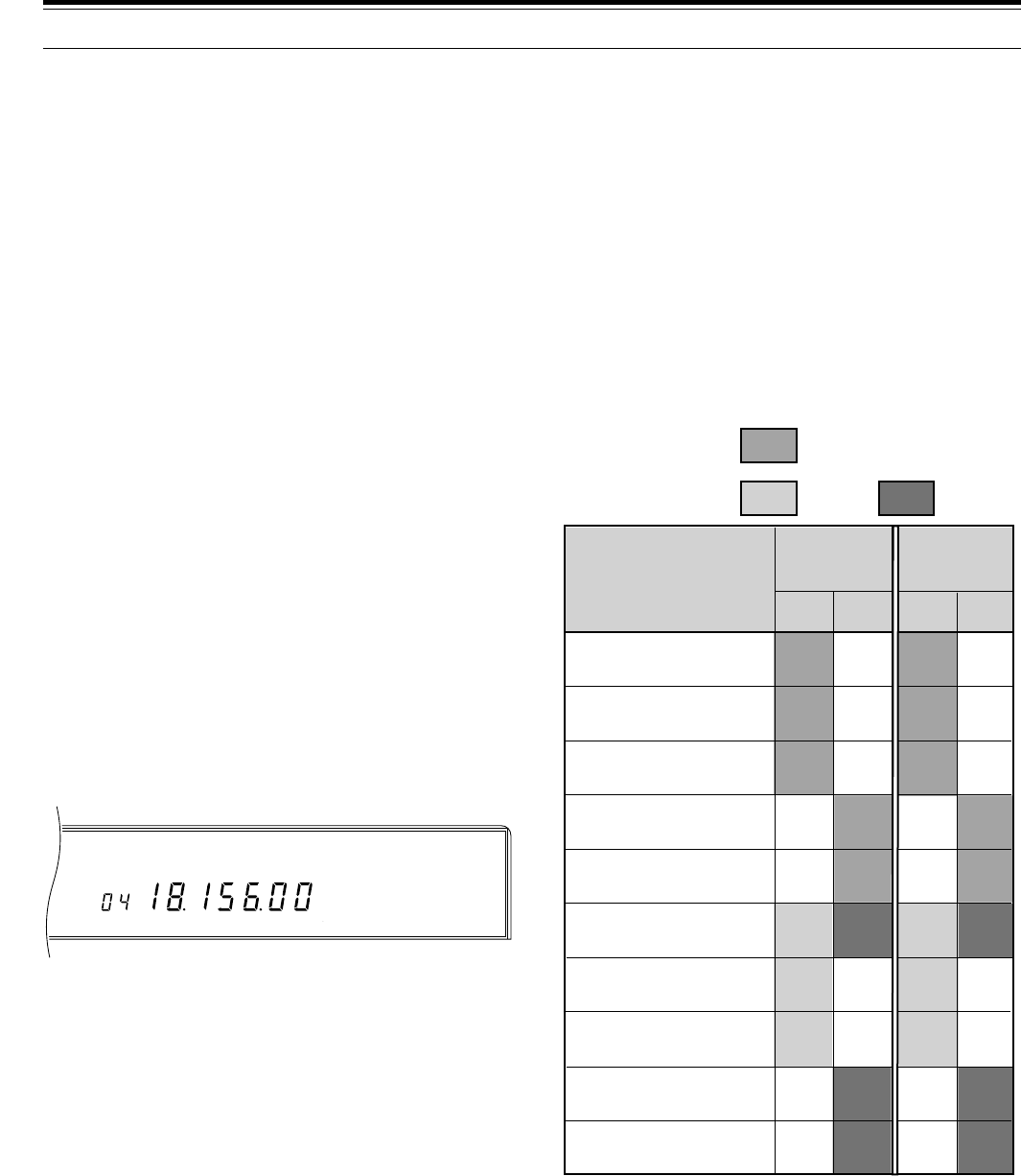
56
M. CH
USB M. SCR
AGC AUTO
MEMORY TRANSFER
■Memory \ VFO Transfers
This function transfers the contents of the current
memory channel to the currently selected VFO. A
Tone frequency stored in a memory channel is not
transferred to the VFO since the Tone is set via
Menu No. 57 (SUB.TONE) when in VFO mode.
In Memory Recall mode, press [M>VFO].
Note:
If a memory channel is recalled, then the recalled data is
changed but not saved to the memory channel, pressing
[M>VFO]
transfers the new data to the VFO.
This table illustrates how memory channel data
transfers to the VFOs and which VFOs are selected for
receive and transmit after the transfer.
9 MEMORY FEATURES
■Temporary Frequency Changes
After recalling a memory channel, it is possible to
change the displayed frequency without altering the
frequency that is actually stored in that memory
channel. After changing the frequency, you could
then store the new frequency in a memory channel if
you wanted to save it for future use.
1Set Menu No. 49 (CH.SHIFT) to ON.
2Recall a memory channel.
3Turn the Tuning control to select the frequency
that you want.
•You can change operating mode by pressing
[LSB/USB], or [CW/–R], or [FSK/–R], or
[FM/AM]. This is true whether Menu No. 49
(CH.SHIFT) is ON or OFF.
Note:
Memory channels can be tuned in this manner while
using the TF-SET function.
MEMORY CHANNEL SCROLL
Memory Scroll allows you to check memory channels
without changing your current receive frequency. Only
the display changes; the receiver doesn’t alter its
receive frequency. This function could be useful if, while
monitoring a frequency, you wanted to consult the
frequencies stored in your programmed memory
channels.
1Press [M.IN].
•The memory channel that was last selected
appears. This is the same channel that would be
selected if [RX M.CH] were pressed.
2Turn the M.CH/VFO.CH control, or press Mic [UP] or
[DWN], to step through the memory channels.
3To exit Memory Scroll, press [CLR], or [SEND], or
Mic [PTT].
•The transceiver re-displays the memory channel
or VFO frequency that was selected before you
activated Memory Scroll. This is true even if you
scrolled through some memory channels.
•Another way to exit is to close your CW key while
the VOX function is ON.
Simplex channel
Simplex channel
Simplex channel
Simplex channel
Simplex channel
Split-frequency channel
Split-frequency channel
Split-frequency channel
Split-frequency channel
Split-frequency channel
M.CH
M.CH
M.CH
VFO
A
VFO
B
M.CH
M.CH
M.CH
VFO
A
VFO
B
VFO
A or B
VFO
B
VFO
A
VFO
A
VFO
B
VFO
A
VFO
B
VFO
A
VFO
A
VFO
B
VFO
A or B
VFO
A
VFO
B
VFO
B
VFO
A
VFO
B
VFO
A
VFO
B
VFO
B
VFO
A
Type of Memory Channel
Before
Pressing
[M>VFO]
After Pressing
[M>VFO]
RX TX RX TX
1
M.CH
VFO
A
VFO
B
M.CH
M.CH
M.CH
VFO
A
VFO
B
M.CH
M.CH
Memory channel contents are transferred to the last
receive VFO that was selected.
1
Simplex channels:
Split-frequency
channels:
Channel data
RX
data
TX
data
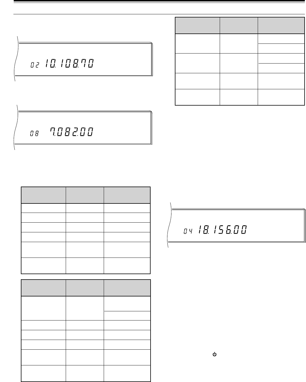
57
M. CH
CW
AGC AUTO
M. CH
FSK M. SCR
AGC AUTO
M. CH
USB
AGC AUTO
Note:
◆
If a memory channel is recalled, then the recalled data is
changed but not saved to the memory channel, pressing
[M.IN]
in Step 5 transfers the new data to the destination
memory channel.
◆
In the FM mode, when channel 99 is copied to another
memory channel (00 ~ 98), a Tone frequency of 88.5 Hz is
stored automatically in the destination channel.
ERASING MEMORY CHANNELS
This procedure erases all data from the selected
memory channel
1Press [RX M.CH] to select Memory Recall mode.
2Select the memory channel that contains the data
that you want to erase.
3Press [CLR] for approximately two seconds.
•A beep sounds to confirm that the channel data is
erased.
■Full Reset
Do a Full Reset if you want to erase all data in all
memory channels or if a Partial Reset {page 63}
does not correct a problem. Remember that a Full
Reset requires that you re-enter any memory
channel data again after the initialization if you want
to use those channels. A Full Reset also initializes
all electronic keyer settings to their default values.
Press [A=B]+[ ].
9 MEMORY FEATURES
■Channel to Channel Transfers
1Press [RX M.CH] to select Memory Recall mode.
2Select the memory channel that contains the data
to be transferred.
3Press [M.IN] to select Memory Scroll mode.
4Select the destination memory channel.
5Press [M.IN].
These tables illustrate how data is transferred
between memory channels.
RX frequency
RX mode
TX frequency
TX mode
Subtone
frequency
Channel lockout
OFF
Channel 00 ~ 98
RX frequency
RX mode
TX frequency
TX mode
Subtone
frequency
Channel lockout
OFF/ON
\
\
\
\
\
\
Channel 00 ~ 98 \
Channel 99
\
\
\
\
Channel 00 ~ 98 \
TX/RX
frequency
Start frequency
TX/RX mode
End frequency
—
—
Channel lockout
OFF
RX frequency
RX mode
TX frequency
TX mode
Subtone
frequency
Channel lockout
OFF/ON
Channel 00 ~ 98
\
\
\
Channel 99 \
TX/RX
frequency
TX mode
—
Channel lockout
OFF/ON
RX frequency
TX frequency
RX mode
TX mode
Subtone
frequency
Channel lockout
OFF
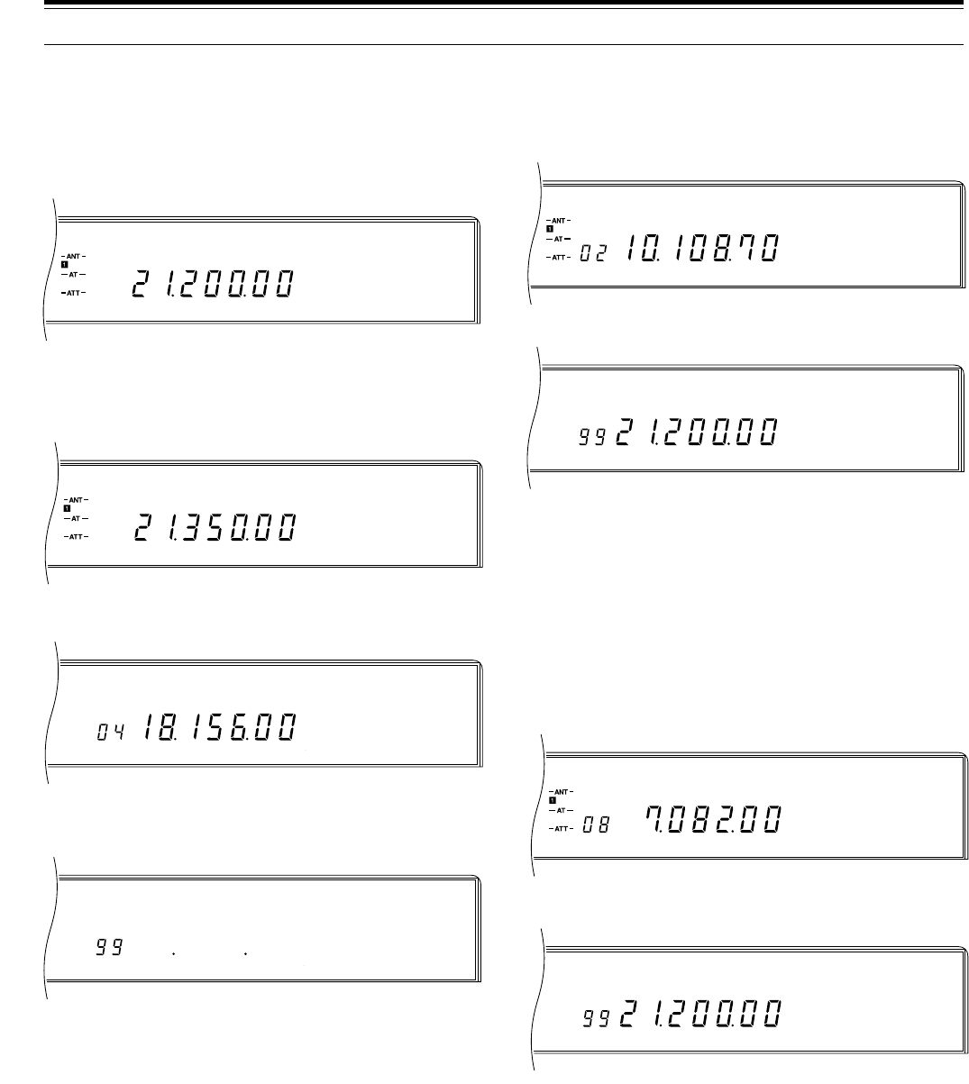
58
M. CH
CW
AGC AUTO
M. CH
USB PRG
AGC AUTO
M.CH
FSK
AGC AUTO
M.CH
USB PRG
AGC AUTO
M. CH
M. SCR PRG
AGC AUTO
M. CH
USB M. SCR
AGC AUTO
USB
AGC AUTO
USB
AGC AUTO
9 MEMORY FEATURES
STORING SCAN LIMITS IN CH 99
Although the Scan function is discussed fully in the next
chapter, here you will learn how to store the frequency
limits that must be saved first before Scan can be used.
1Select the Start frequency limit and mode using
VFO A.
•This frequency can also be used for receiving
and transmitting after completion of this
procedure.
2Select the End frequency limit using VFO B.
3Press [RX A].
4Press [M.IN] to select the Memory Scroll mode.
•To exit from Memory Scroll mode and abort the
storage process, press [CLR].
5Turn the M.CH/VFO.CH control to select channel 99.
6Press [M.IN] to store the frequency limits.
•Pressing [M.IN] overwrites new data on any
previous data in that channel.
Note:
On some General market versions, the frequency limits must
be on the same band or they cannot be stored.
■Confirming Start/End Frequencies
The following allows you to check the programmed
Start and End frequencies.
1Press [RX M.CH] to select Memory Recall mode.
2Turn the M.CH/VFO.CH control to select
channel 99.
3Press [DOWN] to check the Start frequency and
press [UP] to check the End frequency.
■Programmable VFO Function
This function restricts the range of the Tuning
control to those frequencies included by the Start
and End frequencies that were programmed above.
One application of this function is to keep your
operating within the authorized frequency limits of
your license.
1Press [RX M.CH] to select Memory Recall mode.
2Turn the M.CH/VFO.CH control to select
channel 99.
3Turn the Tuning control and you will notice that
you can only tune from the Start frequency to the
End frequency. After reaching the End frequency,
the transceiver reverts back to the Start
frequency again.
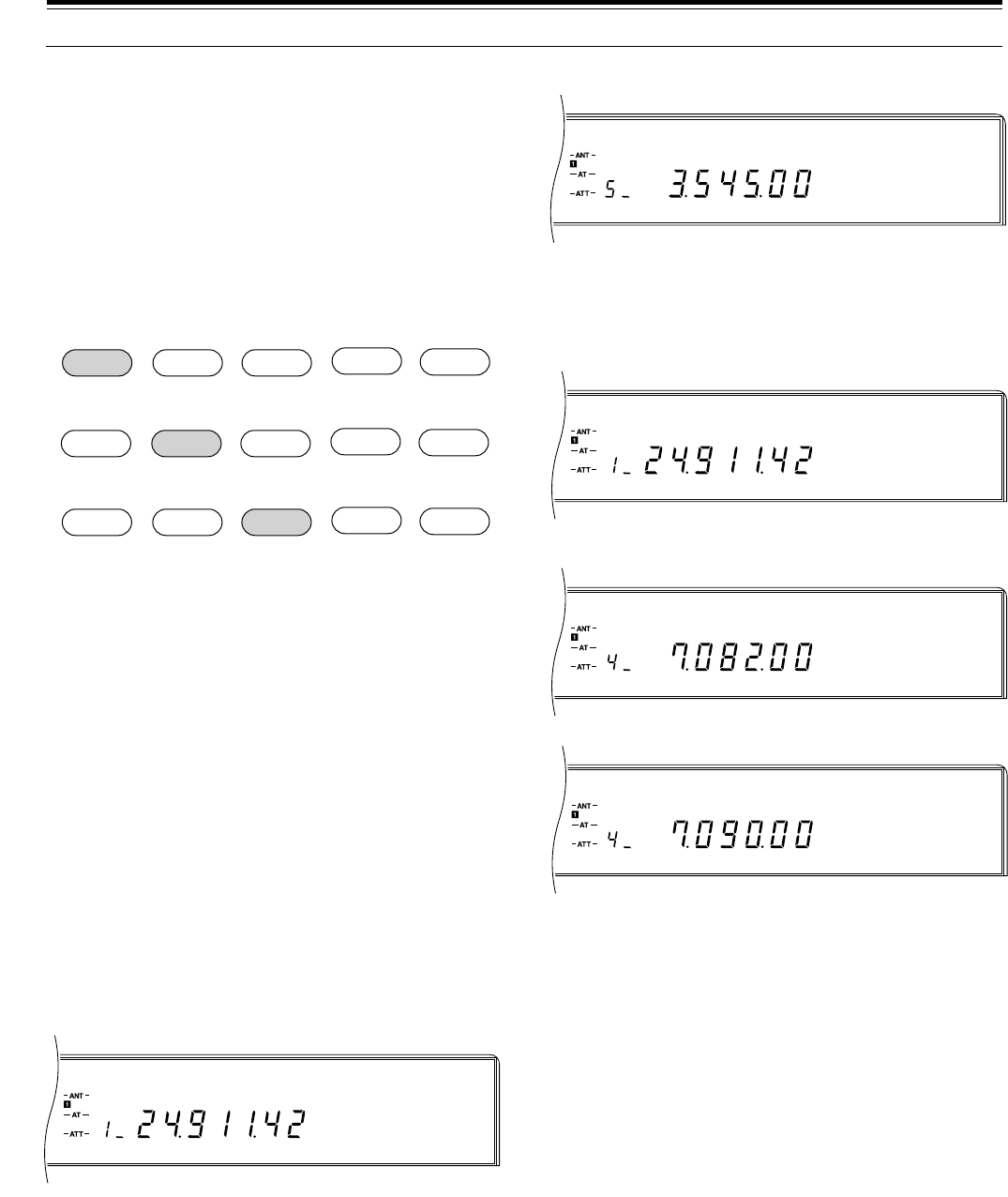
59
M. CH
CW
AGC AUTO
M. CH
CW
AGC AUTO
M. CH
FSK
AGC AUTO
M. CH
FSK
AGC AUTO
M. CH
CW
AGC AUTO
9 MEMORY FEATURES
QUICK MEMORY
Quick memory stores a maximum of five frequencies in
a stack arrangement. As each new frequency is stored,
all previously stored frequencies are bumped to their
next respective Quick memory channel.
When all five channels contain frequencies, storing one
more frequency then bumps all frequencies to the next
channel and the frequency in Quick memory channel 5
is bumped off the stack and erased. Due to the stack
configuration, it is not necessary to specify a memory
channel when you save a frequency to Quick memory.
Quick memory can only be programmed or accessed if
the VFOs are selected for transmitting and receiving.
That is, Conventional memory channels cannot be used
simultaneously with Quick memory channels.
STORING INTO QUICK MEMORY
Press QUICK MEMO [M.IN] while in VFO mode.
•Each time [M.IN] is pressed, the current VFO data is
written to Quick memory.
•Quick memory channels can store the same types of
data as Conventional memory channels 00 ~ 98.
RECALLING FROM QUICK MEMORY
1Press QUICK MEMO [MR].
•The current Quick memory channel number
appears.
•If there is no data stored in any Quick memory
channels, then this step will not access Quick
memory.
2Turn the M.CH/VFO.CH control to select the Quick
memory channel (1 ~ 5) that you want.
3To exit, press QUICK MEMO [MR].
TEMPORARY FREQUENCY CHANGES
1Press QUICK MEMO [MR].
2Turn the M.CH/VFO.CH control to select the Quick
memory channel (1 ~ 5) that you want.
3Turn the Tuning control to change the frequency.
•You can change operating mode by pressing
[LSB/USB], or [CW/–R], or [FSK/–R], or
[FM/AM].
•It is possible to change the frequency then press
QUICK MEMO [M.IN] to store the new frequency
in the same Quick memory channel. This action
bumps the old frequency to the next higher Quick
memory channel in the stack, etc., but does not
affect the Quick memory channels that are lower
than the current channel.
4To exit, press QUICK MEMO [MR].
Note:
Quick memory channels can be tuned in this manner while
using the TF-SET function.
QUICK MEMORY \ VFO
The current Quick memory channel contents, including
the frequency data plus VFO “A” and/or “B” status, are
transferred to the VFO(s) by this function.
In Quick Memory Recall mode, press [M>VFO].
Note:
If a Quick memory channel is recalled, then you change the
recalled data, pressing
[M>VFO]
transfers the new data to the VFO.
24.911 14.235 18.111 7.082 3.545
21.200 24.911 14.235 18.111 7.082
10.103
Memory 1 Memory 2 Memory 3 Memory 4 Memory 5
Memory 1 Memory 2 Memory 3 Memory 4 Memory 5
Memory 1 Memory 2 Memory 3 Memory 4 Memory 5
21.200 24.911 14.235 18.111
➤➤➤➤
➤➤➤➤
➤➤➤➤
➜➜

60
Scan is a useful feature for hands-off monitoring of your
favorite frequencies. After becoming comfortable with
how to use all types of Scan, the monitoring flexibility
gained will increase your operating efficiency.
This transceiver provides the following types of Scan:
PROGRAM SCAN
The Program Scan function scans the range between
the Start frequency and End frequency stored in
memory channel 99. If Program Scan is used before
you store a Start and an End frequency, then the lower
and upper frequency limits of the transceiver are
automatically stored for the Start and End frequencies
respectively. Some General market versions substitute
the lower and upper frequencies for the current band in
place of the frequency limits of the transceiver.
Program Scan direction is controlled by the Start and
End frequency relationship. The following table
summarizes the way that Program Scan functions:
SCAN
For a refresher on how to store the Program Scan
Limits, refer to “STORING SCAN LIMITS IN CH 99”
{page 58}. The following are additional important points
regarding the Program Scan function:
•Starting a transmission by closing the CW key, by
sending a packet, or by triggering the VOX circuit by
voice or the DRU-3 Digital Recording Unit stops
Program Scan; however, transmission does not
begin immediately.
•When the Program Scan range is smaller than a
single step of the M.CH/VFO.CH control, turning this
control causes Scan to jump to the lower of the
Start/End frequencies, then continue scanning.
•Starting the Program Scan function switches OFF
the RIT and XIT functions. RIT and XIT are not
switched ON again when Program Scan stops, and
the RIT/XIT offset frequency is not cleared.
•Operating mode can be changed while scanning.
•If Automatic Mode is switched ON, it will function
with the Program Scan function.
Use the following procedure to activate Program Scan.
1Select the VFO mode using VFO A or VFO B.
2Press [SCAN].
3To stop scanning, press [SCAN], or [CLR], or
[SEND], or Mic [PTT].
SCAN HOLD
While using Program Scan, if Menu No. 65
(PG.S.HOLD) is switched ON, then turning the Tuning
or M.CH/VFO.CH control stops the transceiver from
scanning for approximately five seconds. This is also
true if Mic [UP] or [DWN] is pressed. Program Scan
resumes after the five second pause. The default is
OFF.
CONFIRMING START/END LIMITS
1Recall memory channel 99.
2Press [DOWN] to check the Start frequency and
press [UP] to check the End frequency.
Jumps to Start
frequency
End Relationship
Start frequency
LOWER THAN
End frequency
Start frequency
EQUAL TO
End frequency
Start frequency
HIGHER THAN
End frequency
Within Scan
range
Lower or higher
than Scan range
Start/End
frequency
Lower or higher
than Start/End
frequency
Within Scan
range
Lower or higher
than Scan range
Up
Jumps to Start
frequency, then
scans up.
Monitors
Start/End
frequency.
Jumps to
Start/End
frequency and
monitors it.
Down
Jumps to Start
frequency, then
scans down.
Start/End
Frequency
Relationship
Current
Frequency Program Scan
Action
General update of activity
on the entire band or a
sub-section of the band
while in VFO mode.
Quick activity update of all
programmed Conventional
memory channels.
Quick activity update of a
selected group of
Conventional memory
channels.
All-channel
Scan
Group Scan
Memory
Scan
Program Scan
Scan Type Purpose

61
10 SCAN
MEMORY SCAN
Memory Scan scans all memory channels containing
data (All-channel Scan) or only a group of channels
specified by you (Group Scan). This type of scan
always ascends up through the channel numbers; the
direction of scan cannot be changed. While scanning, if
you want to skip over some programmed channels, turn
the M.CH/VFO.CH control. Pressing Mic [UP] or
[DWN] will also skip over channels but only during
All-channel Scan.
All-channel Scan or Group Scan can be selected via
Menu No. 66 (GRP.SCAN). The default is All-channel
Scan (OFF).
The following are additional important points regarding
the Memory Scan function:
•Starting a transmission by closing the CW key, by
sending a packet, or by triggering the VOX circuit by
voice or the DRU-3 Digital Recording Unit stops
Memory Scan; however, transmission does not
begin immediately.
•Starting the Memory Scan function switches OFF the
RIT and XIT functions. RIT and XIT are not
switched ON again when Memory Scan stops, and
the RIT/XIT offset frequency is not cleared.
•Attempting to use Memory Scan when no data has
been programmed in any memory channels, or
when all channels are locked out, causes an alarm.
Scan will not start.
•To scan channel 99, cancel Memory Channel
Lockout {page 62} for that channel.
Note:
Remember to adjust the squelch threshold level {page 19}
before using Memory Scan.
BUSY FREQUENCY STOP
The transceiver automatically stops Memory scanning
when a signal is detected if Busy Frequency Stop is ON.
The transceiver remains on the same channel for either
a short time or until the signal drops depending on
which Scan Resume method is selected (see below).
The squelch must be adjusted to the noise threshold
point with no signals present for Busy Frequency Stop
to work.
Toggle Busy Frequency Stop OFF or ON via Menu
No. 67 (BSY.STOP). The default is ON.
Note:
Busy Frequency Stop cannot be used with Program Scan.
■Scan Resume Methods
Scan Resume controls when the transceiver
continues Memory scanning after stopping due to a
busy channel. Neither of the following two modes
function if Menu No. 67 (BSY.STOP) is switched
OFF. These modes cannot be used with Program
Scan.
Time-operated mode: After stopping, Scan checks
the busy channel approximately three seconds later.
If the channel is still busy, Scan waits another three
seconds then resumes scanning. If the channel is
not busy three seconds after stopping, Scan
resumes immediately.
Carrier-operated mode: Scan resumes
approximately two seconds after the signal drops.
Select your preferred Scan Resume method via
Menu No. 68 (CAR.SCAN). The default is
Time-operated (OFF).
ALL-CHANNEL SCAN
The All-channel Scan function scans all memory
channels containing frequency data.
1Recall a Conventional memory channel.
2Switch OFF Menu No. 66 (GRP.SCAN).
3Adjust the SQL control while no signal is present.
•The squelch must be closed before scanning
starts.
4Press [SCAN] to start scanning.
5To stop scanning, press [SCAN], or [CLR],
or [SEND], or Mic [PTT].
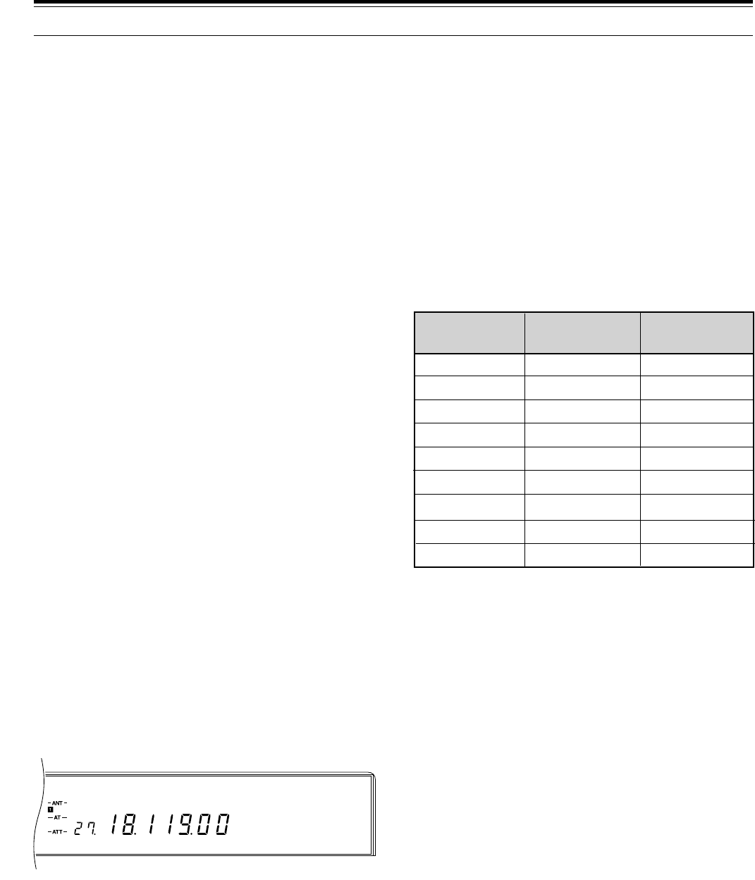
62
M. CH
USB
AGC AUTO
SETTING SCAN SPEED
Scan speed can be changed through 9 steps using the
RIT/XIT control. A weight value of the form “Pn”
appears on the Display during Scan. “n” is a number
from 1 to 9 that acts as a speed reference number.
Turning the RIT/XIT control clockwise decreases the
scan speed, and counterclockwise increases the speed.
The Program Scan and Memory Scan speeds can be
independently set as explained below.
The table below shows the time required for one
frequency step (Program Scan) or one memory channel
step (Memory Scan). For Memory Scan, if Menu No. 67
(BSY.STOP) is ON, the weight value is locked at 1.
However, if Menu No. 67 is OFF, the stop time on each
channel is as shown below.
Program Scan:
While scanning, turn the RIT/XIT control to select the
desired weight value.
Memory Scan:
1Select OFF for Menu No. 67 (BSY.STOP).
2Press [SCAN] to start the Memory Scan function.
3Turn the RIT/XIT control to select the desired weight
value.
10 SCAN
MENU No. 67 is OFF
1
n=01
n=02
n=03
n=04
n=05
n=06
n=07
n=08
n=09
8
13
21.3
34.7
56.6
92.2
150.4
245.3
400
0.4
1.8
3.2
4.6
6.0
7.5
9.0
10.5
12.0
Weight Value
(Pn)
Program Scan
(sec/ 10 kHz)
Memory Scan
(sec/ channel)
1
GROUP SCAN
For the purpose of Group Scan, the 100 Conventional
memory channels are divided into 10 groups each
containing 10 channels. The channels are grouped as
follows:
•00 ~ 09, 10 ~19, 20 ~ 29, . . . . 90 ~ 99
The transceiver only scans memory channels that
belong to the specified group and contain frequency
data.
1Recall a Conventional memory channel.
2Switch ON Menu No. 66 (GRP.SCAN).
3Press Mic [UP] or [DWN] to select any memory
channel belonging to the channel group that you
want to scan.
•Select the correct group before starting to scan;
you cannot change groups while scanning.
4Adjust the SQL control while no signal is present.
•The squelch must be closed before scanning
starts.
5Press [SCAN] to start scanning.
6To stop scanning, press [SCAN], or [CLR],
or [SEND], or Mic [PTT].
MEMORY CHANNEL LOCKOUT
Memory channels that you prefer not to monitor while
scanning can be locked out. Lock out any memory
channel with the following procedure.
1Press [RX M.CH] to select Memory Recall.
2Select the memory channel to be locked out.
3Press [CLR].
•Release [CLR] immediately since pressing it for
more than about 2 seconds erases the contents
of the memory channel.
•A dot lights beside the right-most digit of the
memory channel number to indicate the channel
has been locked out.
•Repeatedly pressing [CLR] adds and removes
the channel from the scan list.
63
MICROPROCESSOR RESET
If your transceiver seems to be malfunctioning,
initializing the microprocessor and its memory may
resolve the problem.
INITIAL SETTINGS
These are the factory default settings for each VFO and
the memory channels:
PARTIAL RESET
Do a partial reset if a button or control does not function
according to the instructions in this manual. The
following are not erased by a Partial Reset:
•Memory channel data
•Menu settings
•Antenna tuner preset data
•ANT1/ANT2 data
•Automatic Mode frequency ranges
•Electronic keyer settings
Press [RX A]+[ ] to do a Partial Reset. “HELLO”
appears on the Display.
FULL RESET
Do a Full Reset if you want to erase all data in all
memory channels and reset all parameters to factory
defaults. After a Full Reset, you must re-enter memory
channel data if you want to use those channels. On the
other hand, a Full Reset is a quick way to return all
transceiver parameters back to their factory settings
(including all electronic keyer settings).
Press [A=B]+[ ] to do a Full Reset.
•“HELLO” appears on the Display and all parameters
are reset.
SWITCHING ANT 1/ ANT 2
The antenna that you use for transmission/reception
with the TS-870S can be selected via the [ANT] button
on the Front Panel. There are two choices: ANT 1 and
ANT 2. ANT 1 selects the antenna connected to the
ANT 1 connector on the Rear Panel; ANT 2 selects the
ANT 2 connector. Selecting one of the antenna
positions will automatically store that selection for that
band. Each time you select the same band in the
future, the same antenna will be selected.
OPERATOR CONVENIENCES
Note:
The lower limit is inside the band in each case; the higher
limit is inside the next higher band. For example, 14.1 MHz is in
Band 12 whereas 14.49 MHz is in Band 13 (exception: 30 MHz is in
Band 18).
Connect an AT-300 external antenna tuner only to the
ANT 1 connector. After connecting this tuner correctly,
the internal tuner will always be bypassed when ANT 1
is selected.
PROGRAMMABLE FUNCTION BUTTONS
The Programmable Function provides a method for
customizing the functions of four Front Panel buttons
handily located around the Tuning control. If your
operating habits or activities change, you can also
easily change the functions that you assign.
This function gives you the capability to assign any of
the functions from Menu Nos. 00 ~ 68 to certain buttons
on the Front Panel. The programmable buttons are
labeled ENTER, TF-SET, 1MHz, and FINE. Or you can
assign functions (Nos. 69 ~ 73) to these buttons. If you
want to keep the Front Panel as simple as possible, you
can assign OFF to each button in which case the
buttons will have no function.
Although the four buttons are automatically assigned
with the labeled functions by default, you may prefer to
re-assign these buttons, for example, with four of the
DSP functions (Menu Nos. 13 ~18). This would allow
you to experiment and learn how the different DSP
settings affect received signals. Or, you could assign
some of the AGC functions (Menu Nos. 01 ~ 07). Then
you could make quick AGC changes, and choose the
optimum settings to best match receive conditions.
There is a great deal of flexibility available with this
function. Think about your operating priorities, then
start assigning.
VFO A
VFO B
Memory Channels
(00 ~ 99)
14.000.00
14.000.00
. .
USB
USB
—
Method of Frequency
Selection
Frequency
(MHz)
Modulation
Mode
BANDS FOR ANT 1/ ANT 2 SELECTION
7.49 ~ 10.49
10.49 ~ 14.1
14.1 ~ 14.49
14.49 ~ 20.99
20.99 ~ 21.15
21.15 ~ 21.99
21.99 ~ 25.49
25.49 ~ 29
29 ~ 30
0.030 ~ 1.85
1.85 ~ 2.01
2.01 ~ 3.525
3.525 ~ 3.575
3.575 ~ 3.725
3.725 ~ 4.49
4.49 ~ 7.03
7.03 ~ 7.1
7.1 ~ 7.49
10
11
12
13
14
15
16
17
18
1
2
3
4
5
6
7
8
9
Range
(MHz)
Band
No.
Range
(MHz)
Band
No.
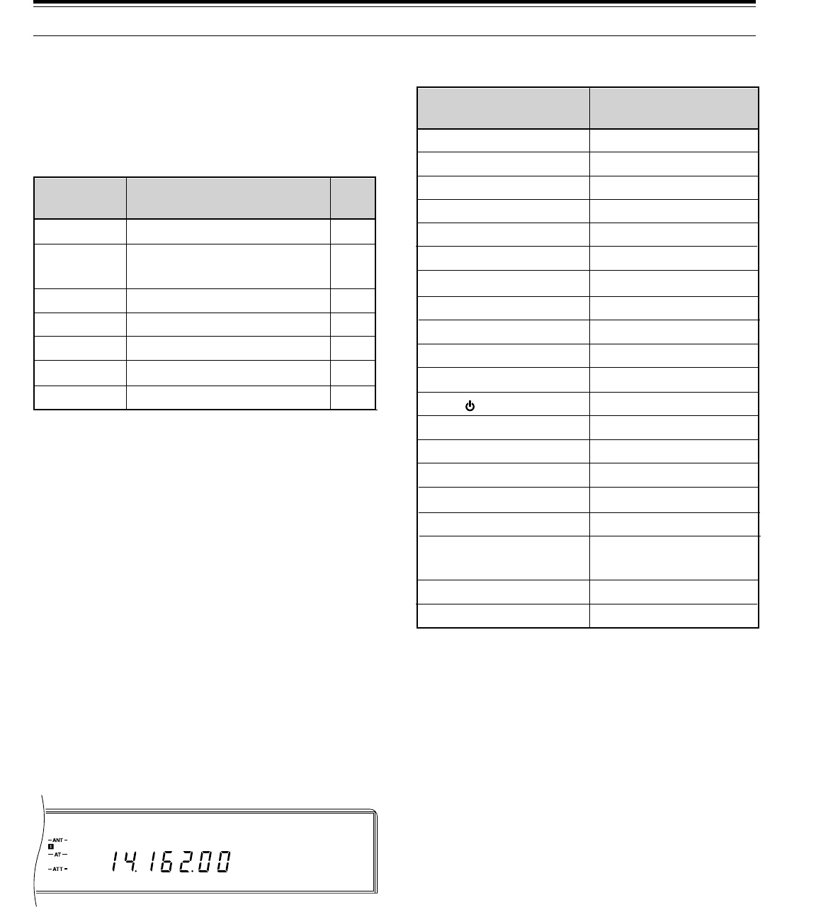
64
USB F. LOCK
AGC AUTO
ASSIGNING FUNCTIONS
1Press [MENU].
2Turn the M.CH/VFO.CH control to select Menu
No. 45, 46, 47, or 48.
3Press [UP], or [DOWN], or Mic [UP], or Mic [DWN]
to change the current selection for this Menu item.
4Press [MENU] or [CLR] to exit from Menu mode.
•If the power is switched OFF before this step is
completed, the selection just made will be
canceled.
USING THE PROGRAMMED BUTTONS
Press one of the buttons labeled ENTER, TF-SET,
1MHz, or FINE.
•The assigned function activates.
Note:
After a Partial or Full Reset, the settings of the PF keys are
reset to default values.
LOCK FUNCTION
The Lock function disables some buttons to prevent you
from accidentally activating a function or disturbing
current settings.
Press [F.LOCK] to toggle the Lock function ON or OFF.
•“F.LOCK” lights when the Lock function is ON.
The following buttons and controls are NOT affected by
activating the Lock function:
Note:
Even after Lock has been activated, you can still use the
Tuning
control with
[TF-SET]
to change your transmit frequency
when operating split frequency.
BEEP FUNCTION
The purpose of the Beep function is to provide an
audible signal that conveys information. There are two
types of signals:
•To confirm that a button has been pressed
•To report an error condition
The volume of the beep output can be selected via
Menu No. 38 (BP LV). If you prefer not to hear any
beeps, the function can be silenced via Menu No. 35
(BEEP). The following paragraphs explain more about
each type of signal.
11 OPERATOR CONVENIENCES
OFF
00~68
69
70
71
72
73
Menu/
Function No. Function Page
Ref.
No function assigned
See "MENU
CONFIGURATION"
ENTER
TF-SET
1MHz
FINE
VOICE
_
25
22
43
20
21
68
[ANT]
ATT˚[DOWN]
ATT˚[UP]
[AIP]
[AT˚TUNE]
[AUTO˚NOTCH]
[BEAT˚CANCEL]
[CLEAR]
[FULL/SEMI]
[METER]
[N.R.]
[ ] (POWER)
[RIT]
[SEND]
[TF-SET]
[THRU/AUTO]
[TX˚EQ.]
[VOICE]
(if assigned to a PF key)
[VOX]
[XIT]
AF
AGC
CAR
DELAY
KEY˚SPEED
MIC
MONI
NB
PROC
PWR
RF
RIT/XIT
SQL
Buttons NOT Locked Controls NOT Locked

65
BUTTON CONFIRMATION
This handy function audibly alerts you each time a
button is pressed. In most cases, a single beep is
emitted. However, when selecting an operating mode,
you have the choice of choosing via Menu No. 36
(BP. MODE) either a single beep or a Morse code
abbreviation for the mode selected. If Morse code is
chosen, then the abbreviation shown in the table for that
mode is sent.
ALARM NOTIFICATION
An alarm will automatically alert you any time that your
action requires the TS-870S to respond in a manner
that is outside its set of defined parameters. The alarm
may be configured for either three beeps or a Morse
code message via Menu No. 37 (WARN. BP).
The messages that you will hear include:
DISPLAY DIMMER
The Display illumination can be switched between two
levels. Menu No. 50 (DIMMER) selects either High (H)
or Low (L) intensity. The default is High (H).
11 OPERATOR CONVENIENCES
QUICK DATA TRANSFER
The TS-870S has the capability to quickly and
conveniently transfer the receive frequency, receive
mode (computer command “0B”), and the transceiver ID
(computer command “ID”) over to another compatible
transceiver. Compatible transceivers include:
•TS-870S
•TS-950SDX
•TS-850S
•TS-690S
•TS-450S
This function could be useful while contesting. A
spotting station that is searching for new contest
multipliers can quickly transfer a frequency over to the
running (main) station. Even as a single operator, with
a little practice, you could use this Transfer function for
transferring frequencies from a spotting transceiver over
to your running transceiver. In this way, you get part of
the benefit of a multi-operator team while still operating
as a single-operator entry; an easy way to give a
significant boost to your score. The Transfer function is
fast, efficient, and increases your chances of working
multipliers that you might miss otherwise due to holding
a frequency by calling CQ.
Besides contest operation, the Transfer function can
also prove useful if you enjoy monitoring more than one
frequency simultaneously during day-to-day operating.
Even if monitoring another band, you can quickly
transfer any frequency over to your main transceiver
and be ready to make a call fast enough to beat the DX
packetcluster crowd.
SETTING UP
■Equipment Needed
•TS-870S transceiver
•Compatible transceiver
•Interconnecting cable
•IF-232C (only necessary if transferring data to a
transceiver other than the TS-870S)
The cable ends must be terminated with a 9-pin
RS-232C female connector to mate with the TS-870S
COM connector and a 6-pin DIN male connector to
mate with the ACC 1 connector on any of the other
transceivers. If using two TS-870S transceivers, then
both ends need a 9-pin RS-232C female connector.
The cable must also have the TXD/RXD and CTS/RTS
wires crossed respectively so the cable will act as a null
modem when connected between the transceivers.
If two TS-870S transceivers are connected together, the
same COM connector baud rate must be used on each
transceiver. If transferring to or from other KENWOOD
transceivers, select 4800 bps and 2 stop bits on the
TS-870S.
LSB
USB
CW
CW –R
FSK
FSK –R
AM
FM
. _ . . (L)
. . _ (U)
_ . _ . (C)
_ . _ . . _ . (CR)
. _ . (R)
. _ . . _ . (RR)
. _ (A)
. . _ . (F)
Morse Code Output
Mode
You attempted to start memory
scanning when it wasn't possible.
You attempted to use Quick Channel
Search to locate either a
programmed or a vacant memory
channel when it wasn't possible.
You accessed the Quick Menu and
attempted to change to a different
Menu No. when the Quick Menu was
not defined (there are no items in the
Quick Menu).
CHECK
OVER
Morse
Message Reason
You attempted to directly enter a
frequency that is outside the allowable
range.
•
•
•
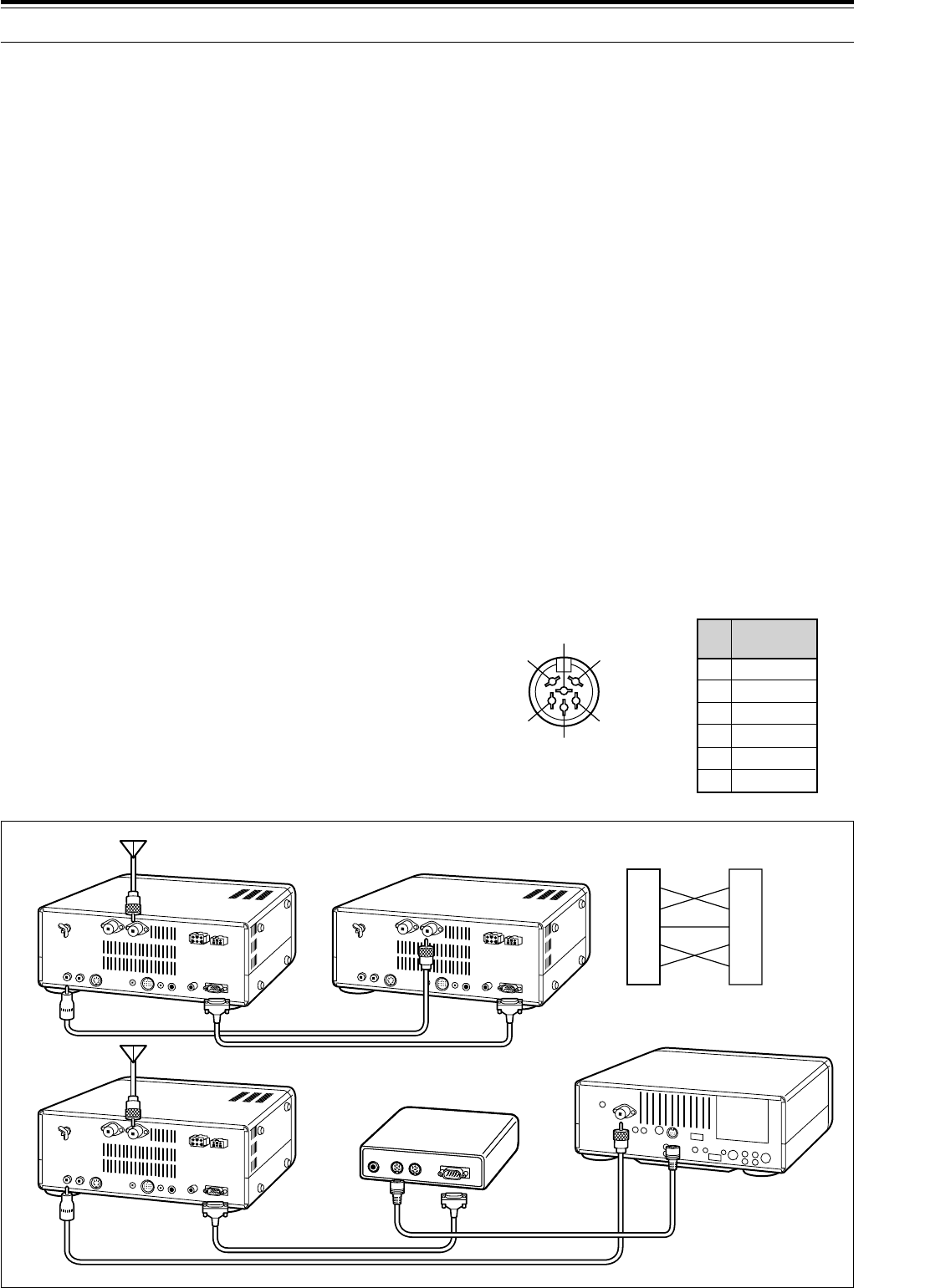
66
11 OPERATOR CONVENIENCES
■Receiving Data
There are two ways that the Slave can receive the
data from the Master:
•Quick memory 1
(TS-450S/690S: channel 00), or
•VFO
This choice is made on the Slave transceiver. On
the TS-870S, Menu No. 55 (DIRECT) can be set to
OFF to receive data into Quick memory, or to ON to
receive data in a VFO. Check your Instruction
Manual for other transceivers. Set Menu No. 27
(TX INH) to ON for a Slave TS-870S.
When receiving data at the Slave transceiver in the
VFO, the data is transferred to the TX side of the
VFO that is currently selected. If the transferred
frequency is simplex, both the RIT and XIT on the
Slave are set to OFF; if a split frequency is
transferred then XIT is set to OFF but RIT is not
changed on the Slave. The IF filter is determined by
the transferred mode. AIP status is determined by
the transferred receive frequency according to the
AIP band memory.
If the Slave transceiver has a Quick or Conventional
memory channel recalled for transmit when the
transfer is done, the data will be rejected. To receive
data into a VFO, select TX and RX using VFOs.
Pin Name
1
2
3
4
5
6
GND
TX/RX
TX/RX
CTS
RTS
NC
Pin
No.
r
e
w
t
y
q
Rear Panel view on
TS-450S/690S/850S/950SDX
ACC 1
■Connections
Connect each end of the interconnecting cable to
the COM connector or the ACC 1 connector on the
transceivers.
DSP-100 Users:
You may continue using your DSP-100
DSP Unit with the Transfer function. Connect the
interconnecting cable to either the CONT IN or CONT OUT
connector on the DSP-100, then connect the unused CONT
connector on the DSP-100 to the ACC 1 connector on the
transceiver. The transceiver connected to the CONT IN
becomes the Master; the transceiver connected to the
CONT OUT connector is the Slave.
USING QUICK TRANSFER
Note:
While transmitting data, other functions may work more
slowly.
■Transferring Data
The Master is the transceiver that sends data to the
Slave transceiver. If the Master has the RIT function
switched ON, the RIT offset frequency is added to
the receive frequency to be transferred.
1Switch ON the Transfer function on each
transceiver.
•On the TS-870S, activate Menu No. 54
(TRNSFER) function. For the compatible
transceiver, check your Instruction Manual for
the correct method.
2On the Master transceiver, press
QUICK MEMO [M.IN].
•If the Master is a TS-450S/690S, press
[M.IN], select memory channel 00, then press
[M.IN] again.
•The displayed receive data is stored in Quick
memory channel 1 on the Master transceiver
(TS-450S/690S: channel 00) and transferred
to the Slave transceiver.
w
e
t
u
i
w
e
t
u
i
TS-870S TS-870S
TS-870S
Cross-wired cable
Cross-wired cable
See IF-232C manual.
IF-232C
Straight cable
COM Connector
cable
TS-450S/690S/850S/950SDX
ANT
DIN(6P)
RS-232C(25P)
DIN(6P)
COM (9P)
COM (9P)
COM (9P)
EXT RX
ANT
EXT RX
ANT
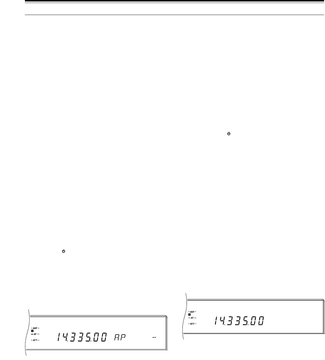
67
USB
VOX AGC AUTO
USB
AGC AUTO
11 OPERATOR CONVENIENCES
DRU-3 DIGITAL RECORDING SYSTEM
(OPTIONAL)
The DRU-3 DRS unit allows you to record
approximately 15 seconds of audio per channel on up to
4channels. The audio is input via your transceiver
microphone. Once recorded, the audio can then be
transmitted. It is also possible to make longer
messages by consecutively sending the contents of
message memories. Finally, you can even send this
longer linked message repeatedly by using the Repeat
function accessible via Menu No. 39 (REPEAT).
The DRU-3 is useful in many situations:
•DX chasing or contest operation where repeated
calls are necessary for extended periods of time
•Checking interference complaints to other equipment
(lets you be in two places at one time)
•Checking or adjusting your transmit signal or your
antennas if it’s not convenient to be sitting in front of
your microphone
•Helping a friend adjust his antenna or receiver when
he needs repeated test transmissions from you
Once you begin using the unit, you’ll likely discover
other applications.
RECORDING MESSAGES
To record a message, you must select the same mode
for transmit and receive. The selected mode must be
SSB, FM, or AM.
Note:
◆
Pressing the
[ ]
(POWER) switch while recording or playing
back messages may cause previously recorded messages or
recordings in progress to be erased.
◆
Refer to “INTERNAL ADJUSTMENTS” {page 70} for information
on adjusting the recording level.
1Switch OFF the VOX function by pressing [VOX].
2Press [REC] to activate the Record Standby mode.
•“AP - -” appears.
•Press [CLR] to exit from the Record Standby
mode and to abort recording your message. This
does not erase any previously recorded
messages.
3Press and hold down [CH 1], or [CH 2], or [CH 3], or
[CH 4] and begin speaking into your microphone.
•There are four memories for recording
messages. Press the button that corresponds to
the message memory that you want to use.
4Release the button pressed in Step 3 when you
have finished recording your message.
•Recording continues until you release the key or
the maximum recording time passes (about
15 seconds) whichever occurs first.
Note:
To erase a message, use the above recording procedure
without speaking into the microphone (or disconnect your
microphone) while recording.
MESSAGE PLAYBACK
This section explains how to play back the contents of a
single message memory. Whether checking or actually
transmitting messages, press [CLR] any time you want
to cancel playback. Also, you cannot change the
transceiver frequency while playing back messages.
Note:
Pressing the
[ ]
(POWER) switch while recording or playing
back messages may cause previously recorded messages or
recordings in progress to be erased.
■Checking Messages
Use this procedure to verify the contents of a
message memory.
1Switch OFF the VOX function by pressing [VOX].
2Select SSB, FM, or AM mode by pressing
[LSB/USB] or [FM/AM].
•The transmit and receive modes must be the
same.
3Press [CH 1], or [CH 2], or [CH 3], or [CH 4] to
play back the message in the respective memory.
•For example, “AP 1 - - - - - -” appears while
Message #1 is playing back.
■Transmitting Messages (VOX)
Use this procedure to transmit the contents of a
message memory.
1Switch ON the VOX function by pressing [VOX].
2Select SSB, FM, or AM mode by pressing
[LSB/USB] or [FM/AM].
•The transmit and receive modes must be the
same.
3Press [CH 1], or [CH 2], or [CH 3], or [CH 4] to
play back the message in the respective memory.
•After the message is transmitted, the
transceiver automatically returns to the
receive mode.
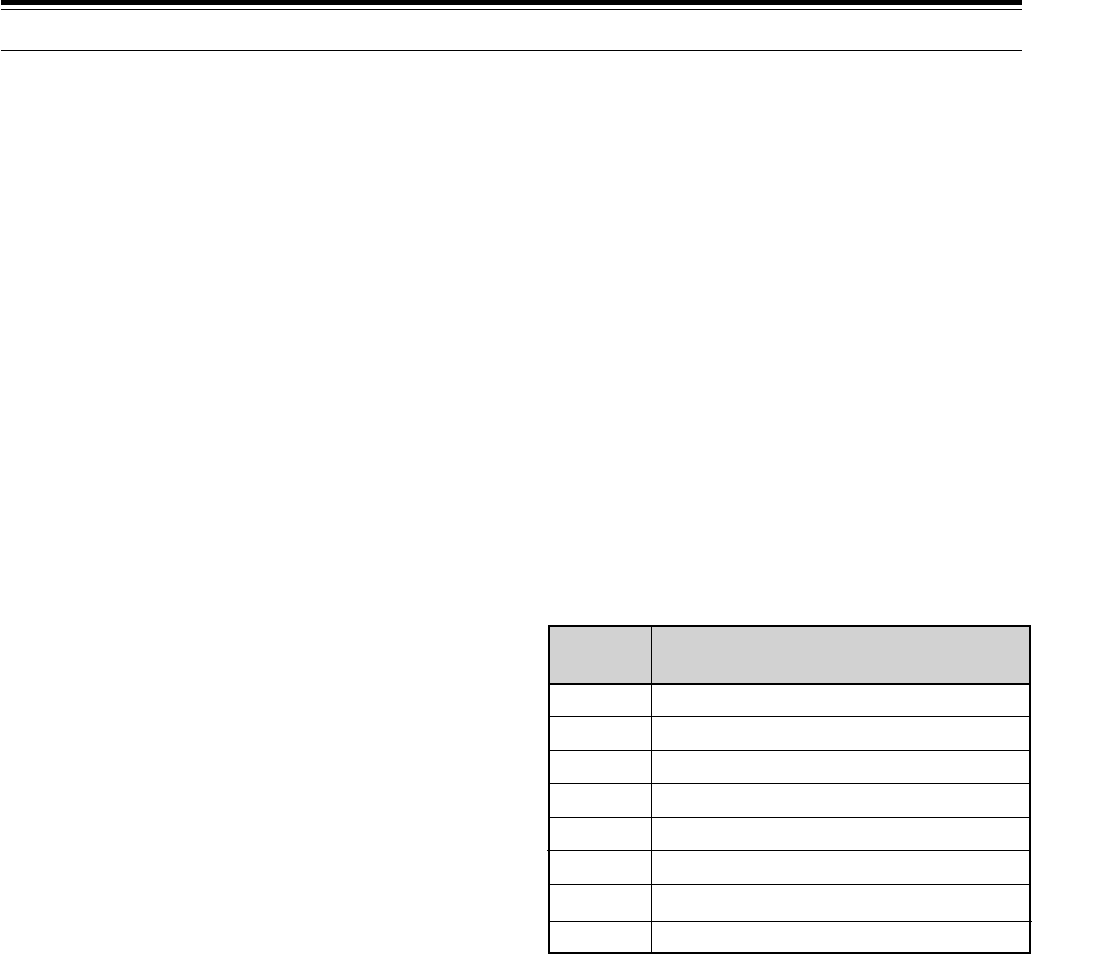
68
11 OPERATOR CONVENIENCES
VS-2 VOICE SYNTHESIZER (OPTIONAL)
When equipped with the VS-2 Voice Synthesizer unit,
the TS-870S can announce displayed information. A
Programmable Function (PF) button must be assigned
the VOICE function to use the Voice Synthesizer. Refer
to “PROGRAMMABLE FUNCTION BUTTONS”
{page 64} for more information.
When the VOICE PF button is pressed while an
announcement is in progress, the announcement stops
immediately. Similarly, changing the parameter that is
being announced, such as tuning to another frequency,
automatically halts the announcement. Frequencies are
announced beginning with the 10 MHz digit and
continuing through to the 10 Hz digit for VFO or memory
channel frequencies. If the memory channel has no
data stored, then “OPEN” is announced.
In addition to frequencies, Menu numbers and their
settings are also announced with a short pause
(100 ms) between the Menu number and the setting.
Refer to the following table for the cross-reference
between the displayed and the announced information.
VOICE SYNTHESIZER ANNOUNCEMENTS
■Transmitting Messages (Manual TX/RX)
Use this procedure to transmit the contents of a
message memory.
1Select SSB, FM, or AM mode by pressing
[LSB/USB] or [FM/AM].
•The transmit and receive modes must be the
same.
2Press [SEND] or Mic [PTT].
3Press [CH 1], or [CH 2], or [CH 3], or [CH 4] to
play back the message in the respective memory.
4Press [SEND] again or release Mic [PTT] to
return to the receive mode.
CONTINUOUS MULTI-CHANNEL PLAYBACK
You can also play back messages one after the other, in
any order, to make longer messages. You could, for
example, first play channel 3 followed by channel 1,
then channel 4, then channel 2.
If the Repeat function is activated while playing back
messages, the remainder of the selected messages are
played back, then playback begins again from the
beginning of the series of messages. The cycle repeats
until you manually interrupt.
1Press [CH 1], or [CH 2], or [CH 3], or [CH 4] to
begin playing back a stored message.
2While the first message is still playing, press another
memory channel button ([CH 1], or [CH 2], or
[CH 3], or [CH 4]) to queue the next message.
•For example, “AP 1 2 3 - -” appears while
Messages #1, #2, and #3 are queued to play.
•The same memory that was played back in
Step 1 may be queued in this step.
•To interrupt playback, press [CLR].
•To toggle the Repeat function ON or OFF, access
Menu No. 39 (REPEAT). The default is OFF.
ALTERING INTER-MESSAGE INTERVAL
The inter-message interval refers to the time period
between each message, if only one message is played
back, or between series of messages, if more than one
message is played back.
Example 1:
Ch. 2 \ Interval \ Ch. 2 \ Interval \ ...
Example 2:
Ch. 3 \ Ch. 2 \ Ch. 1 \ Ch. 4 \ Interval \
Ch. 3 \ Ch. 2 \ Ch. 1 \ Ch. 4 \ Interval \ ...
Select the time interval between playbacks via Menu
No. 40 (REP.TIME). The default interval is 5 seconds.
OFF
ON
Numeral
B
C
L
H
P
"Zero"
"One"
The numeral is announced.
"Two"
"Three"
"Four"
"Five"
"Six"
Displayed Announcement
1
1
VS-2 announces "B" when you switch from Menu
A to B via Menu No. 00 (MENU.A/B).

69
MAINTENANCE
SERVICE NOTE
Dear YL/OM,
If you desire to correspond on a technical or operational
problem, please make your note short, complete, and to
the point. Help us help you by providing the following:
1Model and serial number of equipment
2Question or problem you are having
3Other equipment in your station pertaining to the
problem
4Meter readings
5Other related information (Menu setup, mode,
frequency, button sequence to induce
malfunction, etc.)
CAUTION:
Do not pack the equipment in crushed newspapers for
shipment! Extensive damage may result during rough handling or
shipping.
Note:
◆
Record the date of purchase, serial number and dealer from
whom the transceiver was purchased.
◆
For your own information, retain a written record of any
maintenance performed on the transceiver.
◆
When claiming warranty service, please include a photocopy of
the bill of sale, or other proof-of-purchase showing the date of
sale.
CLEANING
The buttons, controls and case of the transceiver are
likely to become soiled after extended use. Remove the
controls from the transceiver and clean them with a
neutral detergent and warm water. Use a neutral
detergent (no strong chemicals) and a damp cloth to
clean the case.
GENERAL INFORMATION
Your transceiver has been factory aligned and tested to
specification before shipment. Under normal
circumstances, the transceiver will operate in
accordance with these operating instructions. All
adjustable trimmers, coils and resistors in the
transceiver were preset at the factory. They should only
be readjusted by a qualified technician who is familiar
with this transceiver and has the necessary test
equipment. Attempting service or alignment without
factory authorization can void the transceiver warranty.
When operated properly, the transceiver will provide
years of service and enjoyment without requiring further
realignment. The information in this section gives some
general service procedures requiring little or no test
equipment.
SERVICE
If it is ever necessary to return the equipment to your
dealer or service center for repair, pack the transceiver
in its original box and packing material. Include a full
description of the problems experienced. Include both
your telephone number and fax number (if available)
along with your name and address in case the service
technician needs to call for further explanation while
investigating your problem. Don’t return accessory
items unless you feel they are directly related to the
service problem.
You may return your transceiver for service to the
authorized KENWOOD Dealer from whom you
purchased it or any authorized KENWOOD service
center. A copy of the service report will be returned with
the transceiver. Please do not send subassemblies or
printed circuit boards. Send the complete transceiver.
Tag all returned items with your name and call sign for
identification. Please mention the model and serial
number of the transceiver in any communication
regarding the problem.
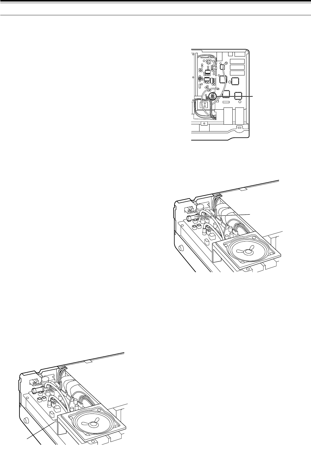
70
DRU-3 DIGITAL RECORDING UNIT (OPTIONAL)
RECORD LEVEL ADJUSTMENT
AT-300 EXTERNAL TUNER (OPTIONAL)
FUSE LOCATION
12 MAINTENANCE
INTERNAL ADJUSTMENTS
REFERENCE FREQUENCY CALIBRATION
Note:
The transceiver is adjusted at the factory prior to shipping.
Unless necessary, DO NOT perform this adjustment.
1Remove the top case (10 screws) from the
transceiver.
2Set the following on the transceiver:
•Mode: CW
•MONI control: Center
•AF gain control: Center
•Menu No. 24 (CW PITCH): 800 Hz
•HI/SHIFT control: 800 Hz
•LO/WIDTH control: 1000 Hz
•RIT function: OFF
•Break-in Function (VOX): OFF
3Tune in a standard frequency station such as WWV
or WWVH at, for example, 10.000 or 15.000 MHz.
Adjust the transceiver Tuning control so the Display
reads the exact frequency of the station. You should
hear a beat tone of approximately 800 Hz.
For 800 Hz:
faf = (fdisplay/20.000 x ∆freference) + 800 Hz
where ∆freference is the shift from the 20 MHz
reference frequency
4Close your CW key and you will hear a transmit
sidetone of approximately 800 Hz. This sidetone
produces a double beat tone when it combines with
the received signal. Adjust the AF gain control and
the MONI control so you can hear the double beat
clearly.
For 800 Hz:
fsidetone = 800 Hz x [(20 x 106 + ∆freference)/20 x 106]
where ∆freference is the shift from the 20 MHz
reference frequency
5Adjust the TC-800 trimmer to minimize the frequency
difference between the received 800 Hz tone and
the 800 Hz sidetone.
Remove the
top case.
TC-800
Remove the
bottom case.
VR3
Fuse for
AT-300
Remove the
top case.

71
12 MAINTENANCE
TROUBLESHOOTING
The problems described in this table are commonly encountered operational malfunctions. These types of difficulties
are usually caused by improper hook-up, accidental incorrect control settings, or operator error due to incomplete
programming. These problem symptoms are not caused by circuit failure. Please review this table, and the
appropriate section(s) of this instruction manual, before assuming your transceiver is defective.
Note:
◆
Due to frequency relationships of some circuits in this transceiver, beat tones may be heard on the following frequencies: 10.000 MHz,
20.000 MHz, 30.000 MHz. This is not a fault.
◆
Placing a powered handy transceiver near this transceiver may cause noise in the TS-870S.
19
3
3
3
3
63
54
Inside
Front
Cover
64
63
24
64
44
25
51, 52
Problem Symptom
The transceiver will not
power up after
connecting a 13.8 V DC
power supply and
pressing [ ] (POWER).
Nothing appears on the
Display, and no receiver
noise is heard.
After switching ON the
power, the transceiver
does not function
normally. For example,
no digits or incorrect
digits appear on the
Display.
After switching ON the
transceiver,
"14.000.00 MHz USB" is
displayed when you have
NOT done a Full Reset.
The transceiver does not
respond correctly after
you press button or key
combinations, or turn
controls per instructions
in this manual.
Menu Nos. cannot be
selected in Menu mode.
The frequency cannot be
changed.
Turning the RIT/XIT
control has no affect on
the receive frequency.
SSB audio quality is very
poor; the high or low
audio frequencies are
absent.
Probable Cause
1The DC power supply is not switched ON.
2The power cable is faulty.
3The power cable is not connected
securely.
4A power cable fuse is open.
1The input voltage is outside 13.8 V DC
±15% (11.7 to 15.8 V DC).
2The microprocessor has malfunctioned.
The backup lithium battery voltage is too
low.
1Procedures are not being followed
precisely.
2The Lock function is ON.
3The microprocessor and its memory
need resetting.
The Quick Menu function is ON (“MHz” is
lit).
The Lock function is activated.
The Receive Incremental Tuning function is
switched OFF.
1The filter for Digital operation is
selected.
2The LO/WIDTH control or HI/SHIFT
control is set incorrectly.
Corrective Action
1Switch ON the DC power supply.
2Inspect the power cable. Confirm
polarities are correct.
Red: positive (+); Black: negative (–).
3Confirm the power connector is locked
against the transceiver Rear Panel.
Confirm the connections to the DC
power supply are secure.
4Look for the cause of the blown fuse.
After inspecting and correcting any
problems, install a new fuse with the
same rating.
1Correct the input voltage. Use a step-
up transformer, if necessary, to raise the
input line voltage to the DC power
supply. Or, use a 12 to 16 V battery.
2Review "MICROPROCESSOR RESET".
After understanding what data will be
lost, do a Partial Reset. If the problem
remains, do a Full Reset.
Obtain a new battery from your dealer or a
KENWOOD Service Center.
1Review "WRITING CONVENTIONS
FOLLOWED".
2Press [F.LOCK] to turn OFF the Lock
function.
3Review "MICROPROCESSOR RESET".
After understanding what data will be
lost, do a Partial Reset. If the problem
remains, do a Full Reset.
Press [1MHz] to cancel the Quick Menu
function.
Press [F.LOCK] to switch OFF the function.
Press [RIT] to switch ON the function.
1Switch Menu No. 19 (PKT.FIL) to OFF.
2Turn the LO/WIDTH control
counterclockwise and the HI/SHIFT
control clockwise.
Page
Ref.

72
19
53
23
23
51,52
63
2
53
19
20
19
62
54
61, 62
58, 60
61
60
4
45
20
25
63
2
2
3
3
1Turn the SQL control counterclockwise.
2Press ATT [DOWN] repeatedly until the
Attenuator function is OFF.
3Press [SEND] to return to the receive
mode.
4Release the Microphone PTT switch.
5Review the sections "SLOPE TUNING",
"IF SHIFT", and "CHANGING RECEIVE
BANDWIDTH". Set the controls correctly.
6Press [ANT] to select the other antenna
connector.
7Switch ON Menu No. 53 (EXT RX).
8Press [AIP] to switch OFF the function.
Turn the RF gain control fully clockwise.
Press [LSB/USB], [CW/-R], [FSK/-R], or
[FM/AM] to select the correct modulation
mode.
1Adjust the SQL control to just eliminate
background noise.
2Unlock some memory channels.
3Store data in more memory channels.
Select All-channel Scan by switching OFF
Menu No. 66 (GRP.SCAN), or change to the
group that contains the memory channel that
you want to scan. Group changes are done
by pressing Mic [UP] or [DWN].
Store different Start and End frequencies.
Switch ON Busy Frequency Stop via Menu
No. 67 (BSY.STOP).
Review the Scan Hold function if you want to
stop scanning when you hear a station while
using Program Scan.
1Turn OFF the power, ensure the
microphone connector on the Front Panel
has no foreign objects in it, then plug in
the microphone connector. Secure the
connector with the locking ring.
2Switch Menu No. 27 (TX INH) to OFF.
3Press [LSB/USB] or [FM/AM] to select a
voice mode.
4Switch Menu No. 19 (PKT.FIL) to OFF.
5Press [ANT] to select the other antenna
connector.
1Check the antenna connection. Correct
as necessary.
2Reduce the SWR of the antenna system.
3Correct the input voltage.
4Use the provided or an optional DC power
cable.
1The SQL control is fully clockwise.
2The Attenuator function is ON.
3The transceiver is in the transmit mode
since the [SEND] switch was pressed.
4The Microphone PTT switch is pressed.
5The LO/WIDTH control or HI/SHIFT
control is set incorrectly.
6The wrong antenna connector is
selected.
7If using a separate receiver that is
connected to the EXT RX ANT
connector, the connector is not enabled.
8The Advanced Intercept Point function is
ON.
The RF gain control is set too low.
The wrong modulation mode is selected.
1The SQL control is not set correctly.
2You have fewer than two memory
channels that are not locked out.
3You have fewer than two memory
channels programmed.
With Group Scan selected, the channel you
want to scan is in a different group.
The Start and End frequencies are
identical.
Busy Frequency Stop is not activated.
This is normal operation.
1The microphone plug is not inserted
completely in the Front Panel connector.
2The Transmit Inhibit function is ON.
3You have selected CW or FSK instead
of a voice mode.
4The filter for Digital operation is
selected.
5The wrong antenna connector (ANT 1/2)
is selected.
1The antenna is not connected correctly.
2The antenna is not matched correctly
with the transceiver.
3The input voltage is outside 13.8 V DC
±15% (11.7 to 15.8 V DC).
4An inappropriate DC power cable is
being used.
12 MAINTENANCE
No signals are received
or receive sensitivity
seems poor.
No signals are received
or receive sensitivity
seems poor; S-meter is
reading full scale.
Received signals are
totally unintelligible.
Memory Scan won’t start
scanning.
Memory Scan will not
scan one of the stored
channels; the desired
channel is NOT locked
out.
Program Scan won’t
start scanning.
Memory Scan never
stops scanning even
when a station is found.
Program Scan never
stops scanning even
when a station is found.
You cannot transmit
even though you press
[PTT], or transmissions
result in no contacts.
Attempting to transmit
results in the "HELLO"
message appearing and
the Receive mode being
restored.

73
12 MAINTENANCE
29, 30,
38, 40,
41
49
45
5
5
45
38
38
6, 7
44, 45
25, 41
–
–
83
50
85, 89
–
1Increase the MIC gain control and/or
CAR control clockwise depending on
the mode being used. Review the
appropriate section of the
"COMMUNICATING" chapter for the
mode being used.
2Check antenna connections. Confirm
that the antenna tuner is reporting a low
SWR.
Increase Menu No. 28 (VOX.GAIN).
1Set Menu No. 51 (LINEAR) according to
instructions in "INSTALLATION".
2Inspect the REMOTE connector wiring
and correct.
Press [XIT] to switch ON the function.
Using the XIT function does not change the
main frequency display; XIT only changes
the RIT/XIT display.
1 Review "FM REPEATER OPERATION"
and select the correct frequency and
type of Tone.
2You must transmit on the repeater’s
input frequency and receive on the
repeater’s output frequency. Refer to
"FM REPEATER OPERATION".
1Re-check all connections using this
manual, your TNC/MCP manual, and
your computer hardware manual as
references.
2Confirm that the RIT and XIT functions
are switched OFF. Confirm that you are
NOT operating split frequency.
3Adjust TX and RX levels using Menu
Nos. 20 (PKT.IN) and 21 (PKT.OUT) and
level controls on your TNC/MCP.
4Reorient/relocate your antenna or
increase your antenna gain.
5Set the TNC/MCP TX delay time to
more than 300 ms.
1Correct the cable.
2Use the same parameters in the
terminal program and the transceiver.
Refer to "COMMUNICATION
PARAMETERS".
3Obtain a terminal program that fully
supports the TS-870S protocol. If
designing your own program, refer to
information in "COMPUTER CONTROL
COMMANDS".
4Disconnect the computer from the
transceiver, and run a utility program to
test the computer serial port. Loop back
the computer serial port transmit and
receive pins to test the port fully.
1The MIC gain control and/or CAR
control is set too low.
2Poor antenna system connections are
causing high SWR.
The VOX gain is set too low.
1The LINEAR Menu setting is incorrect.
2The REMOTE connector wiring is wrong
or faulty.
The Transmit Incremental Tuning function is
switched OFF.
1The repeater requires a Tone frequency
for access.
2You are not operating split frequency.
1Physical connections between the
transceiver, computer, and TNC or MCP
are incorrect, or software settings in the
TNC or MCP are wrong.
2Different transmit and receive
frequencies are being used.
3The levels between the transceiver and
the TNC/MCP are incorrect.
4Your transmitted signal or the incoming
receive signal is too weak.
5The TX delay time parameter in your
TNC/MCP is set incorrectly.
1Your RS-232C cable that connects the
transceiver with the computer is wired
incorrectly.
2Communications parameters set in your
terminal program do not match the
parameters in the transceiver.
3If using a third party terminal program
(not supplied by KENWOOD) on your
computer, it is not accurately interfacing
with the transceiver COM port protocol.
4The serial port on your computer is not
functioning correctly.
The transceiver has low
transmit power.
VOX does not operate.
Linear amplifier does not
operate.
Turning the RIT/XIT
control has no affect on
the transmit frequency.
You cannot access and
use 10 meter band
repeaters.
Digital operation results
in few or no connects or
contacts with other
stations.
Attempts at controlling
the transceiver by a
computer have failed.
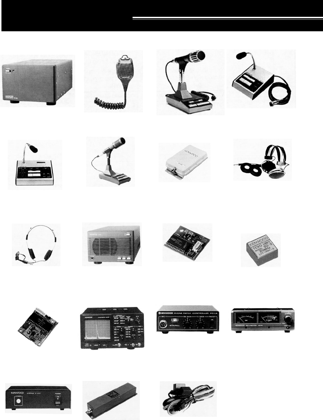
74
OPTIONAL ACCESSORIES
MC-80
Desktop Microphone
MC-85
Multi-function Desktop
Microphone
MC-90
DSP-compatible Desktop
Microphone
AT-300
Automatic Antenna Tuner
HS-5
Deluxe Headphones
HS-6
Small Headphones
SP-31
External Speaker
DRU-3
Digital Recording Unit
SO-2
Temperature-
compensated Crystal
Oscillator (TCXO)
SW-2100
SWR/Power Meter
IF-232C
Interface Unit
LF-30A
Low-pass Filter
PG-2Z
DC Cable
VS-2
Voice Synthesizer Unit
PC-1A
Phone Patch Controller
SM-230
Station Monitor
PS-52
HEAVY-DUTY Power
Supply (22.5 A)
MC-43S
Hand Microphone
MC-60A
Deluxe Desktop
Microphone
Using PC-1A with the transceiver
does not comply with the European
EMC standard.
Microphone sensitivity is low in
FM mode.
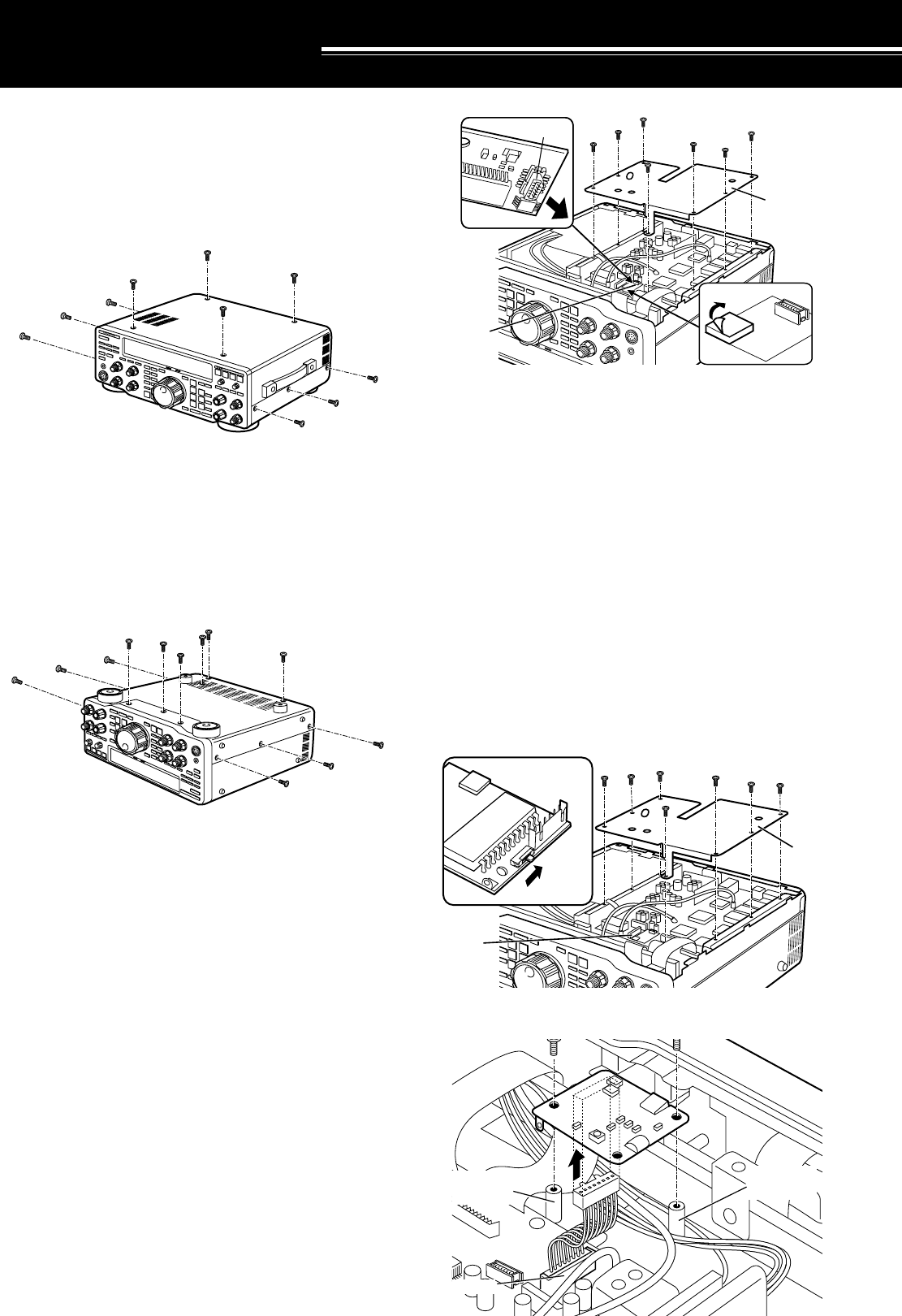
75
VS-2
ENGLISH
CN6
Cover A
INSTALLING OPTIONS
REMOVING THE CASE
TOP CASE
1Remove the screws (10 screws).
2Lift off the top case.
BOTTOM CASE
1Remove the screws (12 screws).
2Lift off the bottom case.
DRU-3 DIGITAL RECORDING UNIT
CAUTION:
Switch OFF the power and unplug the DC power cable
before beginning installation.
Note:
Refer to “INTERNAL ADJUSTMENTS” {page 70} for
information on adjusting the recording level.
EQUIPMENT REQUIRED:
•Large Phillips screwdriver
•Small Phillips screwdriver
1Remove the bottom case (12 screws).
2Remove Cover A (see diagram) (7 screws).
3Locate the CN5 connector in the transceiver.
Remove the paper backing from one side of the
supplied cushion, then install the cushion. Remove
the paper backing from the other side of the installed
cushion, then plug the DRU-3 connector (CN901)
into CN5.
4Re-install Cover A (7 screws).
5Replace the bottom case and re-install its screws
(12 screws).
VS-2 VOICE SYNTHESIZER UNIT
CAUTION:
Switch OFF the power and unplug the DC power cable
before beginning installation.
EQUIPMENT REQUIRED:
•Large Phillips screwdriver
•Small Phillips screwdriver
1Confirm that the small switch on the VS-2 unit is in
the “ENGLISH” position.
2Remove the bottom case (12 screws).
3Remove Cover A (7 screws).
4Locate the CN6 cable in the transceiver, and plug
this cable into the VS-2 unit.
CN5 CN5
q
CN901
DRU-3
w
Cover A
VS-2
CN6
T
hreaded
p
ost
Threaded
post
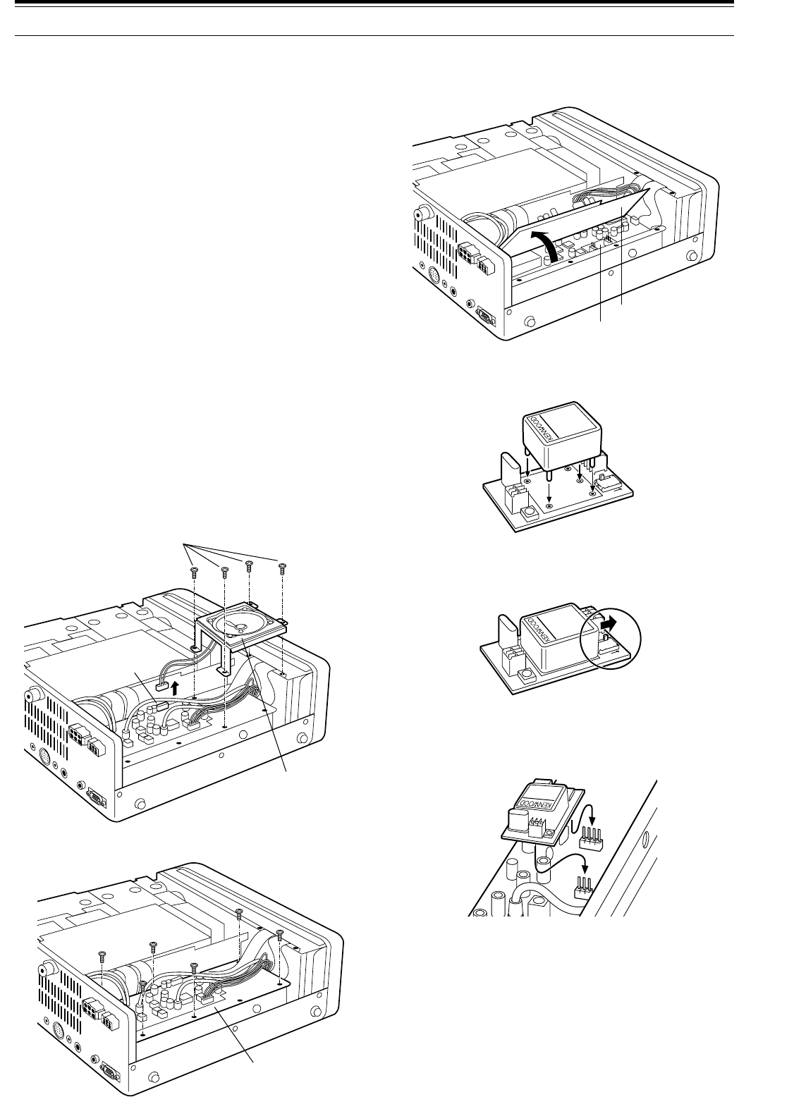
76
4Unplug CN407 (wired to the
AT connector on the
Rear Panel) from the circuit board. Lift up Cover B,
and remove the small SO-2 board from the
compartment below.
5Insert the SO-2 unit into the SO-2 board. Solder the
five pins on the unit to the board.
6Slide the small switch on the SO-2 board in the
direction of the “SO-2” arrow.
Note:
This switch must be positioned correctly for the SO-2 unit to
function.
7Re-install the SO-2 board in the transceiver in the
same location from which it was removed.
8Re-position Cover B, install only 6 screws, and
replace CN407 that was unplugged in Step 4.
9Re-position the speaker-bracket assembly, install its
screws (4 screws), and plug the speaker cable into
CN404.
10 Replace the top case and re-install its screws
(10 screws).
Note:
For more information, refer to the Instruction Manual provided
with the SO-2 unit.
14 INSTALLING OPTIONS
5Orient the VS-2 unit with the large IC (IC1) facing
down, then install this unit on the two threaded posts
using the 2 screws.
6Re-install Cover A (7 screws).
7Replace the bottom case and re-install its screws
(12 screws).
Note:
◆
For more information, refer to the Instruction Manual provided
with the VS-2 unit.
◆
The supplied screws and cushion are not used. Keep them for
future use.
SO-2 TEMPERATURE-COMPENSATED
CRYSTAL OSCILLATOR (TCXO)
CAUTION:
Switch OFF the power and unplug the DC power cable
before beginning installation.
EQUIPMENT REQUIRED:
•Large Phillips screwdriver
•Small Phillips screwdriver
•Pencil soldering iron (25 W)
1 Remove the top case (10 screws).
2 Unplug the speaker cable from the 2-pin connector
CN404. Remove the speaker-bracket screws
(4 screws), then lift out the entire speaker assembly.
3 Remove the remaining screws (6 screws) from
Cover B.
Speaker-bracket screws
Speaker assembly
CN404
Cover B
SO-2 board
Cover B
SO-2
SO-2 unit
SO-2 board
SO-2

77
SPECIFICATIONS
TRANSMITTER GENERAL
Mode
Number of memory channels
Antenna impedance
Supply voltage
Grounding method
Current
Usable temperature range
Frequency stability (–10°C ~ 50°C)
Frequency accuracy (at room temperature)
Dimensions [W x H x D]
(Projections included)
Weight
Frequency range
Output power
Modulation
Spurious emissions
Carrier suppression
J3E (LSB, USB), A1A (CW), A3E (AM),
F3E (FM), F1D (FSK)
100
50 Ω
(with Antenna Tuner 20 ~ 150 Ω)
DC 13.8 V ± 15%
Negative ground
20.5 A
2 A
–10°C ~ 50°C (+14°F ~ 122°F)
Within ±10 PPM
Within ±10 PPM
330 x 120 x 334 mm / 13.0 x 4.72 x 13.1 in
(339 x 135 x 375 mm / 13.3 x 5.31 x 14.8 in)
Approx. 11.5 kg (25 lbs)
1.8 ~ 2.0 MHz
3.5 ~ 4.0 MHz
7.0 ~ 7.3 MHz
10.1 ~ 10.15 MHz
14.0 ~ 14.35 MHz
18.068 ~ 18.168 MHz
21.0 ~ 21.45 MHz
24.89 ~ 24.99 MHz
28.0 ~ 29.7 MHz
100 W
20 W or less
25 W
20 W or less
Balanced
Reactance
Low level
–60 dB or less
50 dB or more
160 m band
80 m band
40 m band
30 m band
20 m band
17 m band
15 m band
12 m band
10 m band
Max.
Min.
Max.
Min.
SSB, CW,
FSK, FM
AM
Transmit (max.)
Receive (no signal)
SSB
FM
AM
Unwanted sideband suppression
(modulation frequency 1.0 kHz)
Maximum frequency deviation
(FM)
Transmit frequency characteristics (–6 dB)
(TX lower cutoff: 300 Hz, TX bandwidth: 2.3 kHz)
XIT shift frequency range
Microphone impedance
50 dB or more
±5 kHz or less
±2.5 kHz or less
300 ~ 2600 Hz
±9.99 kHz
600 Ω
Wide
Narrow
12
3
4
5
1.81 MHz: Europe, France, Holland; 1.83 MHz: Belgium, Spain
1.85 MHz: Belgium, France, Holland, Spain
3.8 MHz: Europe, Belgium, France, Holland, Spain
7.1 MHz: Europe, Belgium, France, Holland, Spain
Belgium, Spain: 10 W fixed on 160 m band
1
2
3
4
5

78
SPECIFICATIONS
RECEIVER
SSB, CW,
FSK, AM
FM
100 kHz ~ 500 kHz
500 kHz ~ 1.62 MHz
1.62 MHz ~ 30 MHz
28 ~ 30 MHz
Circuit type
Frequency range
Intermediate frequency
Sensitivity
Selectivity
Image rejection (1.8 MHz ~ 30 MHz)
1st IF rejection (1.8 MHz ~ 30 MHz)
Notch filter attenuation
RIT shift frequency range
Squelch
sensitivity
Audio output (8 Ω, 10% distortion)
Audio output impedance
Quadruple conversion superheterodyne
100 kHz ~ 30 MHz
1st: 73.05 MHz; 2nd: 8.83 MHz;
3rd: 455 kHz; 4th: 11.3 kHz
1 µV or less
4 µV or less
0.2 µV or less
0.13 µV or less
2 µV or less
31.6 µV or less
2 µV or less
2 µV or less
0.25 µV or less
–6 dB: 2.3 kHz, –60 dB: 3.3 kHz
–6 dB: 200 Hz, –60 dB: 450 Hz
–6 dB: 500 Hz, –60 dB: 1000 Hz
–6 dB: 9 kHz, –60 dB: 12 kHz
–6 dB: 14 kHz, –60 dB: 18 kHz
80 dB or more
80 dB or more
40 dB or more
±9.99 kHz
2 µV or less
20 µV or less
2 µV or less
0.25 µV or less
1.5 W or more
8 Ω
1.705 MHz: Canada, U.S.A.
Specifications are subject to change without notice or obligation due to ongoing technological developments.
SSB, CW, FSK
(at 10 dB (S+N)/N)
AM
(at 10 dB (S+N)/N)
FM
(at 12 dB SINAD)
100 kHz ~ 500 kHz
500 kHz ~ 1.62 MHz
1.62 MHz ~ 24.5 MHz
24.5 MHz ~ 30 MHz
100 kHz ~ 500 kHz
500 kHz ~ 1.62 MHz
1.62 MHz ~ 24.5 MHz
24.5 MHz ~ 30 MHz
28 MHz ~ 30 MHz
SSB Lo: 300 Hz, Hi: 2600 Hz
CW Width: 200 Hz
FSK Width: 500 Hz
AM Lo: 100 Hz, Hi: 4000 Hz
FM Width: 14 kHz
6
6
6
6
6
6
6

79
APPENDICES ●
that different signal and band conditions can produce
different results. Try not to come to any conclusions
about which settings are best at this early stage. Keep
an open mind until you’ve done a lot more
experimenting on various bands with different
propagation conditions.
Widen the receive pass band by turning the LO/WIDTH
control counterclockwise and the HI/SHIFT control
clockwise. Try to find a QSO in progress between two
stations who are experiencing interference from a third
station that may be tuning slightly off frequency but
within your pass band. Press [BEAT CANCEL]. You
may think the tuning station stopped transmitting. Press
[BEAT CANCEL] again to switch OFF the function.
The station is still tuning and you can hear it again!
Beat Cancel can be so effective at automatically finding
and canceling tones that are audible in the pass band
that you may not be aware of the “interfering” stations at
all. With Beat Cancel ON, experiment by changing the
Beat Cancel response time via Menu No. 16. The
response time of the function decreases as the setting
number increases (selection 0 has the fastest response
time).
Press [AUTO NOTCH]. Since Auto Notch functions in
the IF stages, it may work better or worse than Beat
Cancel for a given situation. Compare the effect of Auto
Notch versus Beat Cancel with the same interfering
tone or tones. Change Menu No. 17 to try different
response times for Auto Notch while that function is
activated. Experiment and listen.
If you are a CW operator, switch to the CW section of a
band and search for a crowded portion. With the CW
mode selected and the LO/WIDTH control turned
clockwise to select a 1 kHz bandwidth, tune to a
frequency where two or more stations are audible. Now
turn the LO/WIDTH control counterclockwise to reduce
the bandwidth. Forget old ideas associated with analog
filters for how narrow you like the bandwidth when
operating CW. With the minimum bandwidth, you may
need to tune a little to center the desired signal in the
pass band. Press [FINE] to reduce the tuning step to
make tuning easier. Listen to the quality of the chosen
signal. Can you believe the bandwidth displayed on the
Front Panel? There are other functions to help you fight
CW interference (such as IF Shift) but this example is to
illustrate the benefits that DSP offers when using
extremely narrow bandwidths.
After reading this manual, you should be equipped with
the basic knowledge to begin learning how to use DSP
to your advantage. The DSP benefits that you enjoy will
be related to the amount of time that you spend
experimenting with DSP while operating.
APPENDIX A: LEARNING ABOUT DSP
First-time users of a DSP transceiver may feel
bewildered by the quantity of functions that they have
never encountered on previous transceivers. When
combined with the collection of new terminology that
accompanies DSP, even an experienced operator may
become frustrated. The purpose of this section is to
offer a few examples that help you to begin learning
about the effects and benefits of DSP. It’s best to read
this section after you are comfortable with using the
Menu system, and after you are fully familiar with the
controls and buttons on the TS-870S. This manual will
not make you an expert on using the DSP functions;
that knowledge will come as a result of hands-on
experience with the TS-870S.
Regardless what style of operating you prefer, DSP can
help you. What operator doesn’t want the quiet,
low-noise pass band offered by DSP operating in the IF
stages? Who doesn’t want to effortlessly eliminate
interfering tones caused by others tuning up near their
operating frequency? Why wouldn’t anybody want to
narrow their CW bandwidth to a razor-thin slice of
spectrum if they can still listen to a pleasing CW note
without analog filter “ringing”? These are only a few
examples where DSP shines.
To begin with, the default Menu values chosen for the
DSP functions on the TS-870S Menu have been
carefully considered by the design engineers. They are
good starting points. If you have already changed many
Menu items as you’ve experimented with your new
transceiver, do a Temporary Menu Reset {page 24} or a
Full Reset {page 63} so that you know you are starting
with the default Menu values.
Switch over to an Amateur band with lots of activity.
Tune in an SSB station with reasonable signal strength.
Press [N.R.] to activate Noise Reduction. You will hear
a drop in the background noise that makes listening to
the signal much more pleasant. If your station is
located in an electrically noisy city, this function alone
may make you a DSP believer. Assuming the default
Menu values are selected (due to the reset above), you
are now using the Line Enhance function (Menu No. 13
is ON). This function is “tracking” (Menu No. 18 is ON)
the signal as the unwanted noise is removed.
Try changing Menu No. 14 to reduce and increase the
response time of the Line Enhance function. What do
you notice? Maybe little change can be heard with this
signal or maybe you hear an important change. The
longer you allow DSP to monitor the signal, the better
the adaptive filters can determine how to fight the noise
that is present. But there are tradeoffs. Monitoring a
particular signal for too long will mean that the
transceiver responds too slowly. Experiment and listen.
Switch OFF Menu No. 13. You are now using the SPAC
filter. Listen for a change in audio quality as you switch
Menu No. 13 OFF and ON. While Menu No. 13 is OFF,
change the setting for Menu No. 15 to select a different
correlation time for the SPAC mode. If you can’t hear a
significant difference for the current receiving situation,
then select a longer SPAC time for better audio quality.
Although you may prefer the audio produced when, for
example, the Line Enhance function is ON, remember
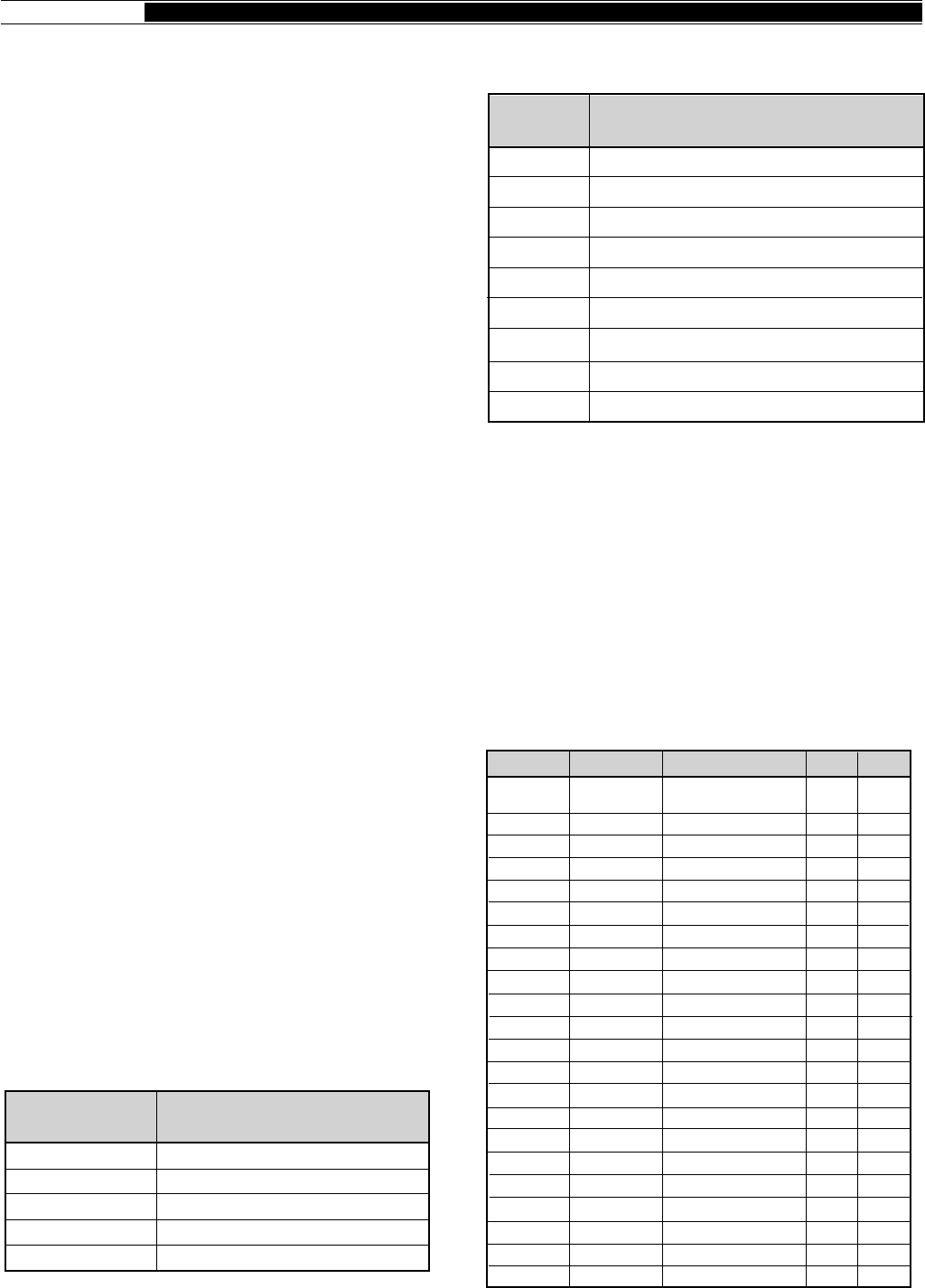
80
● APPENDICES
APPENDIX B: PROPAGATION
INFORMATION
STANDARD TIME AND INFORMATION STATIONS
Besides providing an extremely accurate time source
and other information, stations WWV and WWVH, in the
continental U.S.A. and Hawaii respectively, deliver
propagation announcements every hour in addition to
acting as powerful beacons themselves. The
announcements include information on geophysical
alerts, solar activity, and more that all affects how well
your signals will propagate to the DX station you’re
trying to catch. If you can’t hear WWV/WWVH, then
consult references such as the World Radio TV
Handbook for information on some of the other standard
time stations located closer to your area.
Check 2500, 5000, 10000, 15000, and 20000 kHz at 18
minutes after each hour (WWV), and 2500, 5000,
10000, and 15000 kHz at 45 minutes after each hour
(WWVH) to hear the propagation forecasts.
NCDXF/IARU BEACON NETWORK
The Northern California DX Foundation and the
International Amateur Radio Union are cooperating to
support this particularly useful on-the-air tool. The
network is monitored by scientists, students, etc. as well
as Amateur operators.
This group of stations are located in North America, the
Pacific, eastern Asia, the Middle East, Europe, southern
Africa and South America, and more stations continue
to be added to the network. They transmit beacon
signals on 14100 kHz consecutively in sequence at
power levels from 100 watts down to 100 milliwatts.
You can listen to each station transmit with a known
power from a known direction and location.
With minimal effort, in a brief time you can compile a
customized and accurate profile of HF propagation
conditions at your location. This information will help
you decide where to point your antenna to look for DX
or to call CQ. You could even distribute the information
via packetcluster to local friends for their benefit. Or,
because of the very precise timing used for each
transmission, possibly you could develop an automatic
means of monitoring the beacon frequencies, then
assemble the recorded signal levels into a meaningful
database for later consultation.
Call sign
(long dash)
(long dash)
(long dash)
(long dash)
100
100
10
1
0.1
CW Message
Transmitted
Beacon Power
Level (W)
The following table shows some of the stations involved
in this program.
Note:
As a courtesy to other Amateurs, avoid transmitting on the
14100 kHz beacon frequency. Also, plans are in progress to expand
the beacon network to include 18110, 21150, 24930, and 28200 kHz.
When operation begins on these new frequencies, avoid transmitting
on them as well.
HF BEACONS
Beacon stations transmit from locations in many
countries. Often they operate 24 hours per day and, if
you can hear a particular beacon, you know there is
some propagation to that area of the world. Consult
reference books such as the ARRL Repeater Directory
for detailed information on active beacons. The table
below lists some beacons that you may hear.
United Nations, New York
Stanford University, California
Kane'ohe, Hawaii
Mt. Asama, Japan
Tel Aviv University, Israel
Helsinki Technical University, Finland
Funchal, Madeira Island
Transvaal, South Africa
Buenos Aires, Argentina
4U1UN/B
W6WX/B
KH6O/B
JA2IGY
4X6TU
OH2B
CT3B
ZS6DN/B
LU4AA
LocationStation
Freq (kHz) Call Sign Location Emis. ERP
NCDXF/IARU
beacon network
St. Helena
Sao Paulo
Ottawa
Cyprus
Edmonton
Bologna
Crowborough
St. Petersburg, FL
Tyler, TX
California
Argentina
Spain
Arlington, TX
Natal
Germany
Mt. Predigtstuhl
Pickens, SC
Sarasota, FL
Venice, FL
Marlboro, MA
Staten Is., NY
14100
24192.05
28050
28175
28191
28191
28195
28200
28200
28200
28200
28201
28201.5
28202
28202.5
28204
28205
28206
28207.5
28207.5
28208
28209
See
page 80
KK6TG
PY2GOB
VE3TEN
5B4ZL
VE6YF
IY4M
GB3SX
KF4MS
KG5YB
W6WX
LU8ED
EA7PS
KE5GY
ZS5VHF
DLØIGI
DLØIGI
KJ4X
KE4NL
W8FKL
WA1IOB
NX2O
A1A
F1A
—
—
—
—
A1A
F1A
—
A1A
—
—
—
—
—
—
F1A
—
A1A
—
—
A1A
100
0.03
15
10
10
10
20
8
75
3
100
—
1
5
5
100
100
2
5
10
75
10

81
APPENDICES ●
Freq (kHz) Call Sign Location Emis. ERP
28255
28255
28257.5
28259
28260
28260
28262
28263
28264
28265
28266
28268
28268.5
28270
28270
28272.5
28275
28275
28277.5
28280
28280
28280
28281
28282
28282
28283
28283.5
28285
28285
28286
28286
28286
28286
28286.6
28287
28287
28288
28290
28290
28292.5
28294
28294.5
28295
28296
28297
28299
28299
28300
28300
28303
28315
28888
28890
28992
LU1UG
WB4JHS
DKØTEN
WB9FVR
KA1NSV
VK5WI
VK2RSY
N6PEQ
VK6RWA
N9JL
VK6RTW
KB4UPI
W9KFO
VK4RTL
ZS6PW
9L1FTN
AL7GQ
ZS1LA
DFØAAB
KB2BBW
LU8EB
YV5AYV
VE1MUF
OKØEG
VE2HOT
WD4LWG
EA7RCC
N2JNT
VP8ADE
KA1YE
KE2DI
KK4M
N3GPP
KK4M
H44SI
W8OMV
W2NZH
VS6TEN
W3SV
LU2FFV
WC8E
KEØUL
WB8UPN
W3VD
WA4DJS
N8CGY
PY2AMI
KF4MS
ZS1LA
PT7AAC
ZS6DN
W6IRT
WD9GOE
DLØNF
G'ral Pico
Durham, NC
Arbeitsgen
Pemb. Pines, FL
Hyannis, MA
Adelaide
Sydney
Tustin, CA
Perth
East Alton, IL
Albany
Birmingham, AL
Eaton, IN
Townsville
Pretoria
Freetown
Denver, CO
Stillbay
Kiel
Rutherford, NJ
Argentina
Caracas
New Brunswick
Hradec Kralove
Beaconsfield
Tampa, FL
Cordova
Troy, NY
Antarctica
Henrietta, NY
Rochester, NY
Las Vegas, NV
Lancaster, PA
Las Vegas, NV
Solomon Islands
Asheville, NC
Moorestown, NJ
Mt. Matilda
Elverson, PA
San Jorge
Deerpark, OH
Greeley, CO
Cincinnati, OH
Laurel, MD
Ft. Lauderdale, FL
Michigan
Sao Paulo
St. Petersburg, FL
Still Bay
Fortaleza
Irene
N. Hollywood, CA
Freeburg, IL
Germany
—
—
F1A
—
A1A
A1A
A1A
A1A
A1A
A1A
—
—
—
—
—
—
—
—
A1A
—
—
F1A
—
—
—
F1A
—
—
—
A1A
—
—
—
—
—
—
A1A
A1A
—
—
—
A1A
—
—
—
—
A1A
—
F1A
—
—
A1A
—
A1A
5
7
40
1
80
10
25
2
—
1
—
20
0.75
—
10
10
1.5
10
10
5
5
10
—
10
5
2
10
1
8
2
5
5
1
5
15
5
3
10
10
5
10
5
10
1.5
10
5
10
5
20
5
100
5
—
1
28210
28210
28210
28212.5
28212.5
28215
28215
28215
28216
28216.8
28217.5
28217.5
28218
28219
28220
28220
28220
28221
28222
28222.5
28224.5
28225
28225
28225
28227
28227.5
28229
28230
28230
28231
28232
28232.5
28235
28237
28237
28237.5
28240
28240
28240.5
28242.5
28244
28244
28244.5
28245
28246
28247.5
28248
28249
28250
28250
28250
28250
28250.5
28252
28252
3B8MS
K4KMZ
KC4DPC
EA6RCM
ZD9GI
GB3RAL
KA9SZX
LU4XI
GB3RAL
N6UGR
VE2TEN
WB9VMY/5
W8UR
PT8AA
5B4CY
KB9DJA
LU4XS
PY2GOB
W9UXO
HG2BHA
KA9UEX
EA1EVE
KW7Y
PY2AMI
FX5TEN
EA6AU
EA6AU
N2ECB
ZL2MHF
N4LMZ
W7JPI
KD4EC
VP9BA
NV6A
YO2KHP
LA5TEN
KB8JVH
OA4CK
5Z4ERR
ZS1CTB
WA6APQ
WT8D
KBØDJJ
A92C
N8KHE
EA2HB
K1BZ
PI7BQC
KØHTF
N4MW
WJ9Z
Z21ANB
4N3ZHK
WB4JHS
WJ7X
—
—
A1A
—
F1A
F1A
A1A
—
—
—
—
A1A
A1A
—
F1A
A1A
—
—
—
F1A
—
A1A
—
—
A1A
—
—
F1A
—
—
—
F1A
A1A
—
A1A
A1A
A1A
—
F1A
A1A
—
—
F1A
A1A
—
—
—
A1A
—
F1A
F1A
—
—
A1A
—
20
4
—
—
20
1
—
20
10
4
2
0.5
5
26
10
2
15
10
10
—
1
4
5
8
10
10
25
50
2
5
7
10
0.5
20
10
5
10
—
20
30
10
10
—
0.05
6
5
2
2.5
10
15
15
1
7
10
Freq (kHz) Call Sign Location Emis. ERP
Mauritius
Elizabethtown, KY
Wilmington, NC
Palma de Mallorca
Gough Island
Slough
Champaign, IL
Cape Horn
Slough Berkshire
California
Chicoutimi
Oklahoma, OK
Mackinac Is., MI
Rio Branco
Zyyi
Mooresville, IN
Tierra del Fuego
Sao Paulo
Chicago, IL
Tapolca
West Bend, IN
Spain
Everett, WA
Sao Paulo
Toulouse
Mallorca
Mallorca
Springfield, NJ
Mt. Climie
Mobile, AL
Sonoita, AZ
Jupiter, FL
Hamilton
San Diego, CA
Timisoara
Oslo
Newark, OH
Lima
Kenya
Capetown
Long Beach, CA
Hilton Head, SC
Omaha, NB
Bahrain
Mackinaw, MI
San Sebastian
Belfast, ME
Haarlem
Des Moines, IA
Memphis, TN
St. Francis, WI
Bulawayo
Mt. Kum
Durham, NC
Victoria, MN

82
● APPENDICES
APPENDIX C: GENERAL COVERAGE
RECEIVER FOR SWLING
The path that led many Amateurs to their first license
included hours spent scanning the international
shortwave broadcast bands. Often, inferior receivers
that were readily available were used in those days.
With your TS-870S, you now have the opportunity to
re-visit those same crowded broadcast bands, but truly
enjoy the myriad of stations that can be heard. For
those who have never explored the shortwave
broadcast bands, try listening and discover a world quite
different from the Amateur bands.
Even if you have no interest in the transmission content
from international broadcasters, noting which stations
are present on which bands is another way to stay in
touch with current propagation. Also, listening to native
speakers of foreign languages is the best way to
improve your listening comprehension of that foreign
language. This could all help your Amateur activities.
Erecting a new antenna specifically for the broadcast
bands is probably not necessary. Just use your
Amateur antennas. Having a high gain antenna is
usually not important; using the correct selectivity is the
key to enjoying your listening.
Writing for many different program schedules is
probably not necessary. There are numerous sources
of scheduling information. Check your local
packetclusters, packet networks, telephone BBS nodes,
and interactive computer networks. Local newsstands
may carry copies of SWL magazines and
comprehensive books such as the “World Radio TV
Handbook” or “Passport to World Band Radio”. Or
simply listen on the broadcast bands and you may find
SWL programs that announce current frequencies and
languages being used by different broadcasters.
To handle the extremely crowded broadcast bands, you
have many tools available on the TS-870S. For
example:
•Store frequencies into consecutive memory
channels for a broadcaster that is using parallel
frequencies for a single transmission so you can
quickly compare conditions on different bands.
•Try the LSB or USB mode and zero beat instead of
using the AM mode. This will increase the
intelligibility of some stations on crowded bands.
•Try different positions of the LO/WIDTH and
HI/SHIFT controls to maximize sound quality but
minimize interference.
•Dedicate either Menu A or Menu B as an SWL
profile so you can quickly switch between Amateur
and SWL settings.
•Switch ON the AIP function to reduce interference.
•Set Menu No. 43 (CH. STEP) for 5 kHz steps so the
M.CH/VFO.CH control will step conveniently
between broadcast channels.
•Set Menu No. 44 (STEP.ADJ) to ON so that
rounding will occur on the next use of the
M.CH/VFO.CH control. This allows you to use the
Tuning control to tune across a station, then later
continue stepping up the band from channel to
channel with the M.CH/VFO.CH control.
•Consider using the COM connector to control the
TS-870S from a computer. Software databases are
available that can be used to quickly select the
correct station frequencies for different broadcasters.
This lets the computer keep track of where
broadcasters are located, you only decide which
stations that you want to hear.
10 or 12 m
15 m
15 or 17 m
17 or 20 m
20 m
20 m
20 or 30 m
30 or 40 m
40 m
40 m
80 m
80 m
80 m
80 or 160 m
11 m: 25600 ~ 26100 kHz
13 m: 21450 ~ 21750 kHz
15 m: 18900 ~ 19020 kHz
16 m: 17480 ~ 17900 kHz
19 m: 15100 ~ 15800 kHz
22 m: 13500 ~ 13870 kHz
25 m: 11600 ~ 12100 kHz
31 m: 9400 ~ 9990 kHz
41 m: 7100 ~ 7350 kHz
49 m: 5900 ~ 6200 kHz
60 m: 4750 ~ 5060 kHz
75 m: 3900 ~ 4000 kHz
90 m: 3200 ~ 3400 kHz
120 m: 2300 ~ 2495 kHz
Amateur Band Antenna Shortwave Broadcast Band
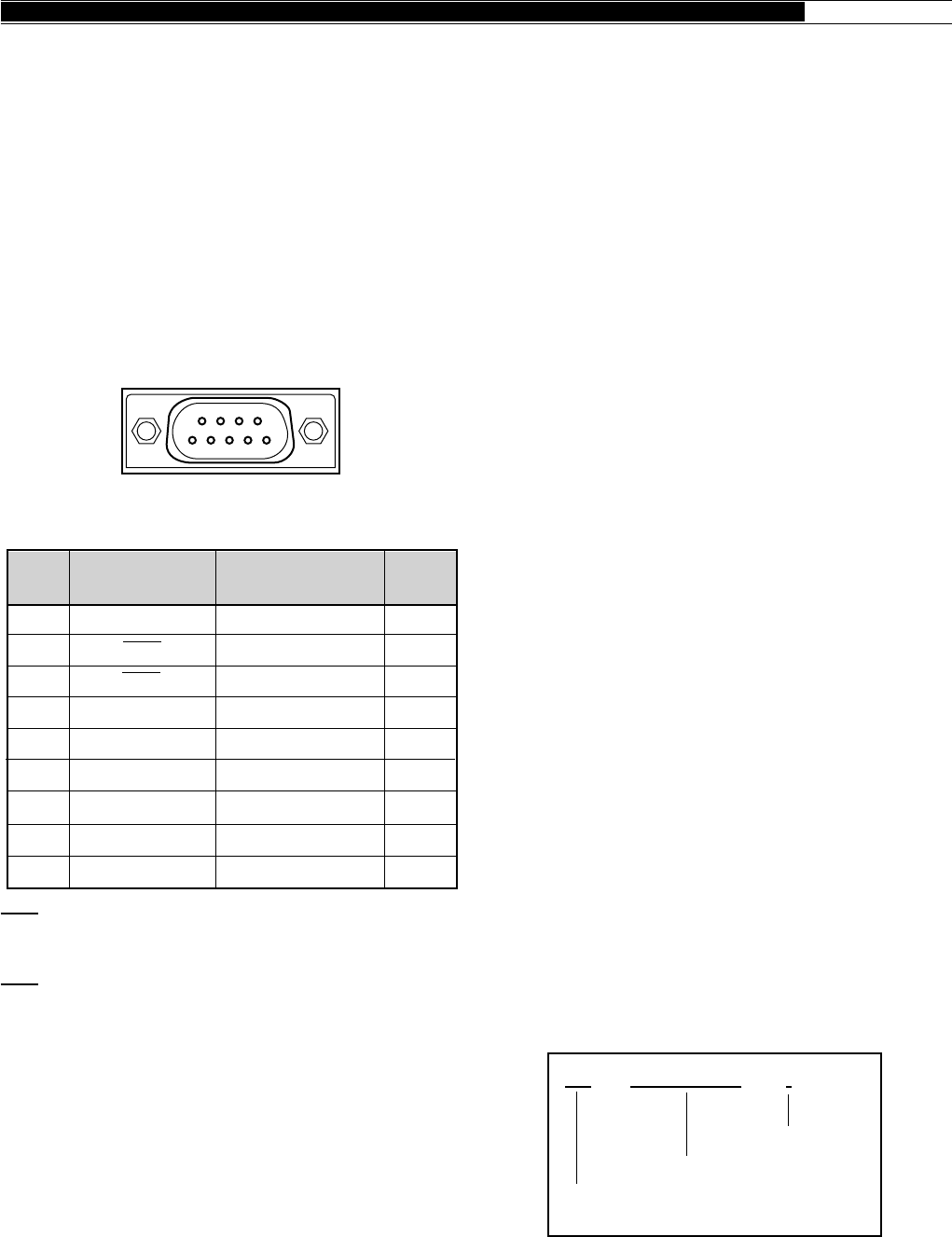
83
APPENDICES ●
CONTROL OPERATION
Most computers handle data in the form of “bits” and
“bytes”. A bit is the smallest piece of information that
the computer can handle. A byte is composed of eight
bits. This is the most convenient form for most
computer data. This data may be sent in the form of
either serial or parallel data strings. The parallel method
is faster but more complicated, while the serial method
is slower and requires less complicated equipment. The
serial form is, therefore, a less expensive alternative.
Serial data transmission uses time-division methods
over a single line. Using a single line also offers the
advantage of reducing the number of errors due to line
noise.
Only 3 lines are required theoretically for control of the
transceiver via the computer:
•Transmit data
•Receive data
•Ground
From a practical standpoint, it is also necessary to
incorporate some means of controlling when this data
transfer will occur. The computer and transceiver
cannot be allowed to send data at the same time! The
required control is achieved by using the RTS and CTS
lines.
For example, the transceiver is placed into the transmit
mode whenever the character string “TX;” is sent from
the computer. The character string “TX;” is called a
command. It tells the transceiver to do something.
There are numerous commands available for control of
the transceiver. These commands may be incorporated
into a computer program written in any high level
language. Programming methods vary from computer
to computer; therefore, refer to the instruction manuals
provided with the terminal program and computer.
COMMANDS
A command is composed of 2 alphabetical characters,
various parameters, and the terminator to signal the end
of the command.
EXAMPLE: Command to set VFO A to 7 MHz
COMMAND DESCRIPTION
A command may consist of either lower or upper case
alphabetical characters.
APPENDIX D: COM CONNECTOR
PROTOCOL
HARDWARE DESCRIPTION
The TS-870S uses a full-duplex, asynchronous, serial
interface for communicating through the male 9-pin
RS-232C COM connector. Bytes are constructed with
1start bit, 8 data bits, and 1 stop bit (4800 bps can be
configured for 1 or 2 stop bits). No parity is used. The
pinout and the pin functions of the COM connector are
as shown below:
COM CONNECTOR
RXD: The transmit data is the serial data transferred
from the transceiver to the computer. The output uses
negative logic.
TXD: The receive data is the serial data transferred
from the computer to the transceiver. The input uses
negative logic.
GND: This is the signal ground pin.
RTS: This signal is applied to the transceiver. It is used
to inhibit transmit data from the transceiver when the
computer is not ready to receive the data. The input
uses positive logic. Inhibit is requested when the level
is low.
CTS: This signal is applied from the transceiver. It is
used to inhibit transmit data from the computer when
the transceiver is not ready to receive the data. The
output uses positive logic. Transmit data is stopped
when the level is low.
FA 00007000000 ;
Command
Parameters
Terminator
1
2
3
4
5
6
7
8
9
—
Transmit data
Receive data
—
Signal ground
—
Receive enable
Transmit enable
—
—
Output
Input
—
—
Input
Output
—
COM
Pin No.
COM Pin Name
(Ref.: Computer)
Function
(Reference: TS-870S) I/O
NC
RXD
TXD
NC
GND
NC
RTS
CTS
NC
TS-870S Rear panel view
12345
9876

84
● APPENDICES
PARAMETER DESCRIPTION
Parameters are used to specify information necessary
to implement the desired command. The parameters
to be used for each command are predetermined. The
number of digits assigned to each parameter is also
predetermined. If a particular parameter is not
applicable to the TS-870S, the parameter digits should
be filled using any character except the ASCII control
codes (00 to 1Fh) and the terminator (;).
BAD COMMAND EXAMPLES:
IS1000; Not enough parameters specified
(No direction given for the IF shift)
IS+100; Not enough digits
(Only three frequency digits given)
IS_+_1000; Unnecessary characters between
parameters
IS+10000; Too many digits
(Five frequency digits given)
PARAMETER TABLE
For-
mat
No.
Name Format
No. of
Digits
METER VALUE
METER
SWITCH
PLAYBACK
CHANNEL
ANTENNA
TUNER
GAIN
AI NUMBER
ANTENNA
NUMBER
CW BREAK-IN
MENU NUMBER
MENU
SELECTION
RECEIVE
FILTER
DISPLAY
FILTER WIDTH
AGC TIME
CONSTANT
IF SHIFT
DIRECTION
IF SHIFT
FREQUENCY
4
1
1
1
3
1
1
1
3
4
8
4
3
1
4
22
24
27
30
31
32
33
34
35
36
37
38
39
40
41
Represented using
0000 (min.)~
0030 (max.). Relative
values are output.
0: No selection
1: SWR
2: COMP
3: ALC
0: Not playing back. A
Set command
cancels playback.
1: Channel 1
2: Channel 2
3: Channel 3
4: Channel 4
0: Antenna tuner thru
1: Antenna tuner in-line
Represented using
000 (min.)~255 (max.).
0: AI OFF
1: IF command outputs
its Answer command
periodically.
2: For parameter
changes, the
corresponding
Answer command is
output.
3: Both 1 and 2.
1: ANT 1
2: ANT 2
1: Semi break-in ON
2: Full break-in ON
Represented using
000~068.
See table on page 87.
Represented using
00000000~FFFFFFFDh.
Represented in units of
10 Hz using 0000~9999.
Represented using
000 (min.)~255 (max.).
000~005: OFF
"+": Upward freq. shift
(or "_")
"–": Not used (error
occurs).
Represented in Hz using
0000~9999.
For-
mat
No.
Name Format
No. of
Digits
SW
MODE
FUNCTION
FREQUENCY
RIT/XIT
FREQUENCY
MEMORY
CHANNEL
MEMORY
CHANNEL
SPLIT DATA
MEMORY
LOCKOUT
TX/RX
TONE NUMBER
MODEL
NUMBER
1
1
1
11
5
2
1
1
1
2
3
1
2
3
4
5
7
9
10
11
14
16
0: OFF 1: ON
0: VFO A
1: VFO B
2: MEMORY
Represented in Hz.
Ex.: 00014230000 is
14.230 MHz
The first digit is "+" or "–",
and the remaining four
digits indicate the
frequency in Hz.
Ex.: +5320 is +5.32 kHz
"_" can be used for
"+".
Represented using
00~99.
0: Receive
1: Transmit
0: Not locked out
1: Locked out
0: Receive
1: Transmit
Represents the Tone
number (01~39). See
the Subtone Table on
page 85.
Represents the type of
transceiver. The
TS-870S number is 015.
Note: Applicable to
Single Beep and
Morse abbreviation
modes.
5: AM
6: FSK
7: CW-R
8: No Mode
9: FSK-R
0: No mode
1: LSB
2: USB
3: CW
4: FM
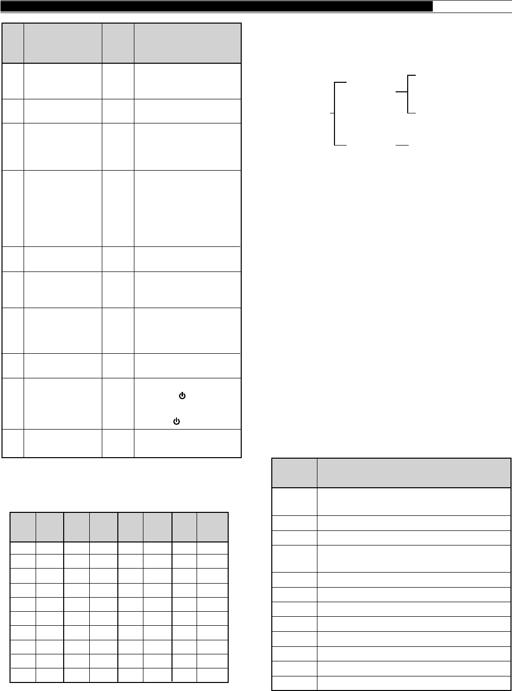
85
APPENDICES ●
TYPES OF COMMANDS
Commands can be classified as shown below:
For example, note the following in the case of the FA
command (Frequency of VFO A):
•To set the frequency to 7 MHz, the following
command is sent from the computer to the
transceiver:
“FA00007000000;” (Set Command)
•To read the frequency of VFO A, the following
command is sent from the computer to the
transceiver:
“FA;” (Read Command)
•When the Read Command above has been sent, the
following command is returned to the computer:
“FA00007000000;” (Answer Command)
COMPUTER CONTROL COMMANDS
A summary of the command library for communication
between a computer and the TS-870S is included in this
section. This information can be used if you are
developing your own transceiver control program, or
you are troubleshooting an existing control application.
SUBTONE TABLE FOR FORMAT NO.14
TERMINATOR
To signal the end of a command, it is necessary to use a
semicolon (;). The digit where this special character
must appear differs depending on commands.
FunctionCommand
AC
AG
AI
AN
BC
BI
BY
CG
DN
EQ
EX
FA
Antenna Tuner THRU/IN-LINE, and
tuning START/CANCEL
Sets or reads AF gain.
Auto information (OFF/ON)
Selects antenna connector
(ANT 1/ ANT 2).
Sets or reads Beat Cancel.
Sets or reads CW Break-in.
Reads Busy signals.
Sets or reads carrier gain.
MIC DOWN function
Sets or reads Transmit Equalizer.
Sets or reads Menu.
Sets or reads VFO A frequency.
01
02
03
04
05
06
07
08
09
10
67.0
71.9
74.4
77.0
79.7
82.5
85.4
88.5
91.5
94.8
11
12
13
14
15
16
17
18
19
20
97.4
100.0
103.5
107.2
110.9
114.8
118.8
123.0
127.3
131.8
21
22
23
24
25
26
27
28
29
30
136.5
141.3
146.2
151.4
156.7
162.2
167.9
173.8
179.9
186.2
31
32
33
34
35
36
37
38
39
192.8
203.5
210.7
218.1
225.7
233.6
241.8
250.3
1750
Freq.
(Hz)
No. No. No. No.
Freq.
(Hz)
Freq.
(Hz)
Freq.
(Hz)
Commands
Input
Command
(Input to the
transceiver)
Output
Command
(From the
transceiver)
Set Command
(Sets a
particular
condition.)
Read Command
(Reads an answer.)
Answer Command
(Transmits a condition.)
For-
mat
No.
Name Format
No. of
Digits
KEYER SPEED
KEYER
MESSAGE
KEYER
BUFFER
LOAD
MESSAGE
LEVEL
POWER
CONTROL
RF
ATTENUATOR
SEMI BREAK-IN
DELAY TIME
SYSTEM
RESET
VOX DELAY
TIME
3
24
1
1
3
3
2
4
1
4
42
43
44
45
46
47
48
49
50
51
Represented in words
per minute using 001
(min.)~100 (max.).
Contains the CW
message.
0: Buffer space
available
1: Buffer space not
available
0: Not recording. A Set
command cancels
recording.
1: Channel 1
2: Channel 2
3: Channel 3
4: Channel 4
Represented using 000
(min.)~255 (max.).
Represented in watts
using 010 (min.)~
100 (max.).
00: 0 dB
01: 6 dB
02: 12 dB
03: 18 dB
Represented in msec
using 0050~0800.
1: VFO Reset
([RX A]+[ ])
2: MR Reset
([A=B]+[ ])
Represented in msec
using 0150~2700.

86
● APPENDICES
ERROR MESSAGES
In addition to the Answer Command, the transceiver can
send the following error messages:
COMMAND USE PRECAUTIONS
1Do not use the control characters 00 to 1Fh since
they are either ignored or cause a “?” answer.
2Program execution may be delayed while turning the
Tuning control rapidly.
3Receive data is not processed if the frequency is
entered from the keypad.
FunctionCommand
RT
RU
RX
SC
SD
SM
SQ
SR
TX
UP
VD
VR
VX
XT
Sets or reads RIT (OFF/ON).
Raises RIT frequency.
Selects receive mode.
Sets or reads Scan (OFF/ON).
Sets or reads Semi Break-in delay time.
S-meter and TX RF meter readings
Sets or reads squelch level.
Resets the transceiver.
Selects transmit mode.
MIC UP function
Sets or reads VOX delay time.
Triggers the Voice Synthesizer for
message output.
Sets VOX (OFF/ON).
Sets or reads XIT (OFF/ON).
RM Selects a meter function or reads
meter values.
Error
Message Reason for Error
• Command syntax was incorrect.
• Command was not executed due to
the current status of the transceiver
(even though the command syntax
was correct).
A communication error occurred such
as an overrun or framing error during a
serial data transmission.
Receive data was sent but processing
was not completed.
?;
E;
O;
Note: Occasionally this message may not
appear due to microprocessor transients in the
transceiver.
FunctionCommand
FB
FD
FR
FS
FT
FW
GT
ID
IF
IS
KS
KY
LK
LM
MC
MD
MG
ML
MN
MR
MW
MX
NB
NL
NR
NT
PB
PC
PL
PR
PS
RA
RC
RD
RG
Sets or reads VFO B frequency.
Reads RX filter dot display.
Sets RX (VFO A/B, memory channel).
Fine function (OFF/ON)
Sets TX (VFO A/B, memory channel).
Sets or reads filter bandwidth. For SSB
and AM, sets or reads the high-pass filter
cut-off frequency.
Sets or reads AGC time constant.
Reads model number of the transceiver.
Reads status of the transceiver.
Sets or reads IF shift. For SSB and AM,
sets or reads the low-pass filter cut-off
frequency.
Sets or reads keying speed while using
the KY command.
Converts input characters into Morse
code.
Sets or reads Lock (OFF/ON).
DRS recording
Sets or reads memory channels.
Sets or reads modes.
Sets or reads MIC gain.
Sets or reads transmit monitor level.
Sets or reads Transmit Monitor
(OFF/ON).
Reads memory.
Writes into memory.
Sets or reads AIP (OFF/ON).
Sets or reads Noise Blanker (OFF/ON).
Sets or reads Noise Blanker level.
Sets or reads Noise Reduction (OFF/ON).
Sets or reads Notch Filter.
DRS playback.
Sets or reads transmit power.
Sets or reads Speech Processor level.
Sets or reads Speech Processor
(OFF/ON).
Sets or reads power (OFF/ON).
Sets or reads RF ATT (attenuator).
Clears RIT frequency.
Lowers RIT frequency.
Sets or reads RF gain.

87
APPENDICES ●
MENU SELECTION TABLE FOR “EX” COMMAND, PARAMETER 36
00
01
02/ 03/
04/ 05
06
07
08
09
10
11
12
13
14
15
16
17
18
19
20
21
22
23
24
25
26
27
28
29
30
31
32
33
34
35
36
37
38
39
40
41
42
43
44
45/ 46/
47/ 48
49
50
MENU.A/B
AUT/MAN
AGC SSB/
AGC CW/
AGC FSK/
AGC AM
AF.AGC
AF.AGC.LV
RX AT
P HOLD
∆ FREQ
AIP.GAIN
FM.S–MET
LINE.ENH
LINE.ENH
SPAC (ms)
SP.BEAT
SP.NOTCH
TRACK
PKT.FIL
PKT.IN (mV)
PKT.OUT
MIC AGC
CW RISE (ms)
PITCH (Hz)
PROC.LOW
PROC.HI
TX INH
VOX.GAIN
TX.WIDTH (Hz)
TX.SHIFT (Hz)
TX EQ.
AUTO.RET
TUN.WIDE
AUT.MODE
BEEP
BP. MODE
WARN. BP
BP LV
REPEAT
REP.TIME (sec)
F.STEP (kHz)
BC. STEP
CH. STEP (kHz)
STEP.ADJ
PF.KEY.UL/
PF.KEY.UR/
PF.KEY.LR/
PF.KEY.LL
CH.SHIFT
DIMMER
0000
A
OFF
OFF
0016:
16
Slow
OFF
OFF
OFF
OFF
OFF
OFF
OFF
0
(Fast)
2
0
(Fast)
0
(Fast)
OFF
OFF
100
Slow
2
–6
–6
OFF
0
(Min)
1800
High
OFF
OFF
OFF
OFF
OFF
OFF
OFF
5
OFF
1
OFF
OFF: 0000
Menu Nos. 00~68: 0001~0069
Function Nos. 69~73: 0070~0074
OFF
Low
0002
0018:
18
Fast
Med
2
10
2
2
300
10
Fast
6
0
0
2
2300
Bass
0001
B
ON
0017:
17
Med
Min
ON
ON
ON
ON
ON
ON
1
5
1
1
ON
1200
30
Med
4
–3
–3
ON
1
2000
Comb
ON
ON
ON
ON
ON
ON
ON
10
ON
5
ON
0004
0020:
20
Max
4
(Slow)
4
(Slow)
4
(Slow)
+6
+6
4
3000
0003
0019:
19
High
3
17
3
3
P
8
+3
+3
3
2600
0005
5
0006
6
0007
7
(Max)
0008
0009
0010
0011
0012
0013
0014
0015
Menu
Item
Menu
No.
Parameter 36
1 2 3 4 5 6 7 8 9 10 11 12 13 14 15
0 1 2 3 4 5 6 7 8 9
1 2 3 4 5 10 15 20 25 30 35 40 45 50 55 60
0 1 2 3 4 5 6 7 8 9
10
400 450 500 550 600 650 700 750 800 850 900 950 1000
0 100 200 300 400 500
ON
High

88
● APPENDICES
96 1 192 1 384 1 576 1
0000
Slow
1000
48 1
425
0001
48 2
850
0005 0006 0007 0008 0009 0010 0011 0012 0013 0014 0015
Menu Item
Menu
No.
51
52
53
54
55
56
57
58
59
60
61
62
63
64
65
66
67
68
LINEAR
1M/500k (kHz)
EXT RX
TRNSFER
DIRECT
COM.RATE
SUB.TONE
SUB.TONE
FM.BOOST
FM WIDE
FM MIC
FSK.SHFT (Hz)
MARK.POL
FSK.TONE (Hz)
PG.S.HOLD
GRP.SCAN
BSY.STOP
CAR.SCAN
OFF
100
OFF
OFF
OFF
12 1
Sub Tone Nos. 01~39: 0001~0039
B
OFF
OFF
Low
170
OFF
1275
OFF
OFF
OFF
OFF
Fast
500
ON
ON
ON
24 1
C
ON
ON
High
200
ON
2125
ON
ON
ON
ON
0002 0003 0004
1
1To reliably use the 38400 or 57600 bps transfer rates, the serial port of your computer must support these high-speed
communications parameters.
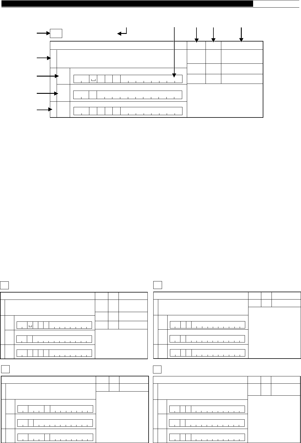
89
APPENDICES ●
READING COMMAND TABLES
q Command
w Name
e Function of the command
r The format of the command is shown. When oblique lines are drawn in the 1st and 2nd columns, there is no Set
command.
t The format of the command for reading the transceiver’s current status is shown. When oblique lines are drawn in
the 1st and 2nd columns, there is no Read command.
y The format of the command output from the transceiver is shown. When oblique lines are drawn in the 1st and 2nd
columns, there is no Answer command.
u The number of command digits is shown.
i Corresponds to the parameter of the command format.
o Corresponds to the Format number in the Parameter Table. For the parameter formats, refer to the Parameter
Table {page 84}.
!0 Indicates the function of the parameter.
COMMAND TABLES
Note:
Parameters that have a Parameter Function of “NOT USED” are not supported by the TS-870S. Any character except the ASCII control
codes (00 to 1Fh) and the terminator (;) may be entered for those parameters.
1
Auto information OFF/ON
AI AUTO INFORMATION
2
Parameter Format Parameter function
P1 32 AI NUMBER
34567891011121314
Input FunctionOutput
SetReadAnswer
1234567891011121314
123
AI
P1
AI
P1 ;
AI ;
4567891011121314
;
Note:
For other commands, controls whether
changing a parameter will or will not trigger
the corresponding Answer command
to be output.
Ex:
For IF, the Answer command is output
if the step frequency or RIT/XIT
frequency is changed.
1
Sets or reads AF gain.
AG AF GAIN
2
Parameter Format Parameter function
P1 31 AF GAIN
34567891011121314
Input FunctionOutput
SetReadAnswer
1234567891011121314
123
AG P1 ;
AG ;
4567891011121314
P1AG ;
1
Selects antenna connector ANT 1/ ANT 2.
AN ANTENNA NUMBER
2
Parameter Format Parameter function
P1 33 ANTENNA
NUMBER
34567891011121314
Input FunctionOutput
SetReadAnswer
1234567891011121314
123
AN
P1
AN
P1 ;
AN ;
4567891011121314
;
1
Antenna Tuner THRU/IN -LINE, and tuning START/CANCEL
AC ANTENNA TUNER CONTROL
Note:
P1 is used for Answer only.
Tuning cannot be started if P2 is in the
THRU state (If P2="0", selecting "1" for P3
does not start tuning).
P1: RX THRU/IN P2: TX THRU/IN
2
Parameter Format Parameter function
P1
P2
P3
30
30
1
TUNE THRU/IN
(Answer Only)
TUNE THRU/IN
TUNE OFF/ON
34567891011121314
Input FunctionOutput
SetReadAnswer
1234567891011121314
123
AC P2P3 ;
ACP1P2 P3 ;
AC ;
4567891011121314
1
Antenna Tuner THRU/IN -LINE, and tuning START/CANCEL
AC ANTENNA TUNER CONTROL
Note:
P1 is used for Answer only.
Tuning cannot be started if P2 is in the
THRU state (If P2="0", selecting "1" for P3
does not start tuning).
P1: RX THRU/IN P2: TX THRU/IN
2
Parameter Format Parameter function
P1
P2
P3
30
30
1
TUNE THRU/IN
(Answer Only)
TUNE THRU/IN
TUNE OFF/ON
34567891011121314
Input FunctionOutput
SetReadAnswer
1234567891011121314
123
AC P2P3 ;
ACP1P2 P3 ;
AC ;
4567891011121314
q
uio!0
w
r
t
y
e
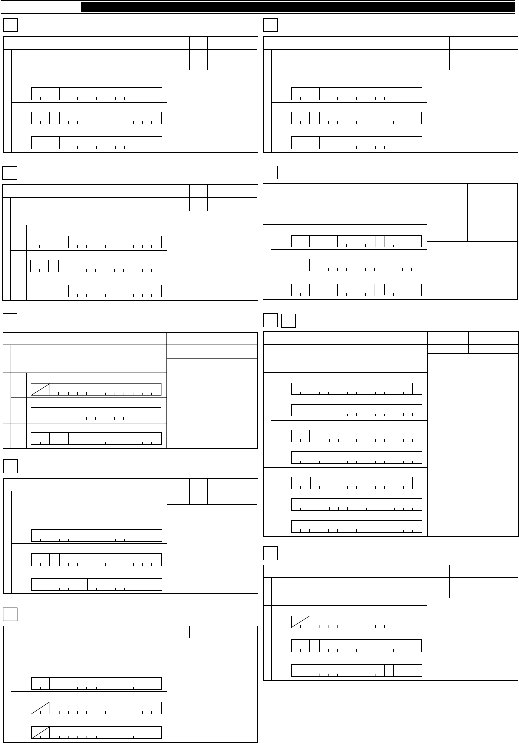
90
● APPENDICES
1
Sets or reads carrier gain.
CG CARRIER GAIN
2
Parameter Format Parameter function
P1 31 CARRIER GAIN
34567891011121314
Input FunctionOutput
SetReadAnswer
1234567891011121314
123
CG P1 ;
CG ;
4567891011121314
P1CG ;
1
Microphone DOWN/UP function.
DN
2
Parameter Format Parameter function
34567891011121314
Input FunctionOutput
SetReadAnswer
1234567891011121314
123
DN/UP ;
4567891011121314
UP DOWN/UP
1
Sets or reads CW Break-in.
BI BREAK IN
Note:
The setting for P1 is not linked with the
VOX OFF/ON parameter.
2
Parameter Format Parameter function
P1 34 BREAK-IN
OFF/ON
34567891011121314
Input FunctionOutput
SetReadAnswer
1234567891011121314
123
BIP1;
BIP1;
BI ;
4567891011121314
1
Reads Busy signals.
BY BUSY
2
Parameter Format Parameter function
P1 1 BUSY OFF/ON
34567891011121314
Input FunctionOutput
SetReadAnswer
1234567891011121314
123
BYP1
;
BY ;
4567891011121314
1
Sets or reads Beat Cancel.
BC BEAT CANCEL
2
Parameter Format Parameter function
P1 1 BEAT CANCEL
OFF/ON
34567891011121314
Input FunctionOutput
SetReadAnswer
1234567891011121314
123
BC
P1
BC
P1 ;
BC ;
4567891011121314
;
1
Sets or reads Transmit Equalizer.
EQ EQUALIZER
2
Parameter Format Parameter function
P1 1 TRANSMIT
EQUALIZER
34567891011121314
Input FunctionOutput
SetReadAnswer
1234567891011121314
123
EQ
P1
EQ
P1 ;
EQ ;
4567891011121314
;
1
Sets or reads Menu.
EX EXTENSION MENU
2
Parameter Format Parameter function
P1 35 MENU
NUMBER
34567891011121314
Input FunctionOutput
SetReadAnswer
1234567891011121314
123
EX P1 ;
EX ;
4567891011121314
P1EX ;
P2
P2
P2 36 MENU
SELECTION
1
Sets or reads VFO A/ VFO B frequency.
FA FREQUENCY VFO A/ VFO B
2
Parameter Format Parameter function
P1 4 FREQUENCY
34567891011121314
15
Input commands FunctionOutput commands
Set
command
Read
command
Answer command
16 17 18 19 20 21 22 23 24 25 26 27 28
1234567891011121314
15 16 17 18 19 20 21 22 23 24 25 26 27 28
123456
FP1
7891011 12 13 14
15 16 17 18 19 20 21 22 23 24 25 26 27 28
29 30 31 32 33 34
P1
35 36 37 38 39 40 41 42
;
FB
;
;
F
F A/B
A/B
A/B
1
Reads RX filter dot display.
FD RX FILTER DOT DISPLAY
2
Parameter Format Parameter function
P1 37 RX FILTER
DISPLAY
34567891011121314
Input FunctionOutput
SetReadAnswer
1234567891011121314
123
FD P1 ;
FD ;
4567891011121314
Note:
The 8 - digit hex data is converted to 32-bit
binary data. Each bit corresponds to a
single dot on the 30-dot display. When the
bit is ON, the display dot is ON and vice
versa. Bit 32(MSB) corresponds to the left-
most dot; bit 3 corresponds to right-most
dot. Bits 1 and 2 are always OFF (not used).
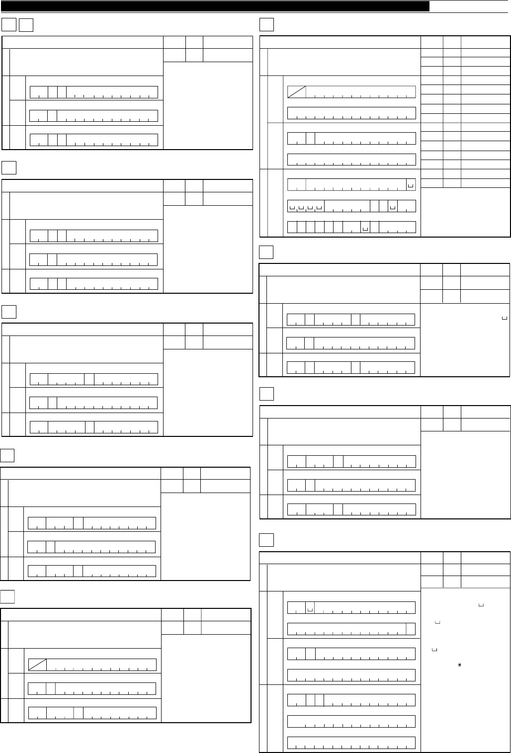
91
APPENDICES ●
1
Sets RX/TX (VFO A/B, memory channel).
FR
2
Parameter Format Parameter function
P1 3 FUNCTION
34567891011121314
Input FunctionOutput
SetReadAnswer
1234567891011121314
123
FP1;
FP1;
F R/T ;
4567891011121314
FT FUNCTION RX, FUNCTION TX
R/T
R/T
1
Reads status of the transceiver.
IF INFORMATION
2
Parameter Format Parameter function
P1
P2
P3
P4
P5
P6
P7
P8
P9
P10
P11
P12
P13
P14
P15
4
–
5
1
1
–
7
11
2
3
1
1
1
14
–
FREQUENCY
NOT USED
RIT/XIT FREQUENCY
RIT OFF/ON
XIT OFF/ON
NOT USED
MEMORY CHANNEL
TX/RX
MODE
FUNCTION
SCAN OFF/ON
SPLIT OFF/ON
TONE OFF/ON
TONE NUMBER
NOT USED
34567891011121314
15
Input commands FunctionOutput commands
Set
command
Read
command
Answer command
16 17 18 19 20 21 22 23 24 25 26 27 28
123
IF;
4567891011121314
15 16 17 18 19 20 21 22 23 24 25 26 27 28
123456
IF P1
7891011 12 13 14
15 16 17 18 19 20 21 22 23 24 25 26 27
P7P4P3
28
29 30 31 32 33 34
P8 P9 P10 P11 P12 P13
35
P14
36 37 38
;
39 40 41 42
P5
1
Fine function OFF/ON
FS FINE STEP
2
Parameter Format Parameter function
P1 1 FINE OFF/ON
34567891011121314
Input FunctionOutput
SetReadAnswer
1234567891011121314
123
FSP1;
FSP1;
FS ;
4567891011121314
1
Sets or reads IF shift. For SSB and AM, sets or reads the low-pass filter
cut-off frequency.
IS IF SHIFT
Note:
If P2 is positive or zero, P1 can be “+” or “ ”.
Allowable data (in units of Hz):
SSB: 1400, 1600, 1800, 2000, 2200,
2400, 2600, 2800, 3000, 3400, 4600, 6000
AM: 2500, 3000, 4000, 5000, 6000,
7000,
CW: 400~1000 (50 Hz steps)
2
Parameter Format Parameter function
P1
P2
40
41
IF SHIFT
DIRECTION
IF SHIFT
FREQUENCY
34567891011121314
Input FunctionOutput
SetReadAnswer
1234567891011121314
123
ISP1 P2 ;
ISP1 P2 ;
IS;
4567891011121314
1
Sets or reads keying speed while using the KY command.
KS KEYER SPEED
2
Parameter Format Parameter function
P1 42 KEYER SPEED
34567891011121314
Input FunctionOutput
SetReadAnswer
1234567891011121314
123
KS P1 ;
KS ;
4567891011121314
P1KS ;
1
Sets or reads filter bandwidth. For SSB and AM, sets or reads the
high-pass filter cut-off frequency.
FW FILTER WIDTH
2
Parameter Format Parameter function
P1 38 FILTER WIDTH
34567891011121314
Input FunctionOutput
SetReadAnswer
1234567891011121314
123
FW P1 ;
FW ;
4567891011121314
P1
FW ;
Note:
Allowable data(units of 10 Hz):
SSB:
CW:
FSK:
FM:
AM:
0, 5, 10, 20, 30, 40, 50, 60, 80, 100
5, 10, 20, 40, 60, 100
25, 50, 100, 150
500, 600, 800, 1000, 1200, 1400
0, 10, 20, 50
1
Sets or reads AGC time constant.
GT AUTO GAIN CONTROL TIME CONSTANT
2
Parameter Format Parameter function
P1 39 AGC TIME CONSTANT
34567891011121314
Input FunctionOutput
SetReadAnswer
1234567891011121314
123
GT P1 ;
GT ;
4567891011121314
P1GT ;
1
Reads Model number of the transceiver.
ID IDENTIFICATION
2
Parameter Format Parameter function
P1 16 MODEL NUMBER
34567891011121314
Input FunctionOutput
SetReadAnswer
1234567891011121314
123
ID P1 ;
ID;
4567891011121314
1
Converts input characters into Morse code.
KY CW KEYING
2
Parameter Format Parameter function
P1 43 KEYER MESSAGE
KEYER BUFFER
34567891011121314
15
Input commands FunctionOutput commands
Set
command
Read
command
Answer command
16 17 18 19 20 21 22 23 24 25 26 27 28
1234567891011121314
15 16 17 18 19 20 21 22 23 24 25 26 27 28
123456
KP1
7891011 12 13 14
15 16 17 18 19 20 21 22 23 24 25 26 27 28
29 30 31 32 33 34
P2
35 36 37 38 39 40 41 42
;
;
;
K
KY
Y
Y
P2 44
Note:
The Set command requires a " " (ASCII
code 20h) in the third byte position.
Insert " " for bytes that have no
characters to make a 28-byte fixed length
command.
The " " bytes will not send any character.
Supported characters include: Letters,
numbers, " ' (( )) ( ) + ,– . / : = ?
The internal buffer allows approximately
5 times 28 characters (~140 characters) to be
continuously keyed. For programs that
convert to Morse code immediately after entry,
more continuous keying is possible
Ex:
CQ CQ CQ DE WD6DJY WD6DJY WD6DJY K
KY_CQ_CQ_ CQ_DE_ WD6DJY_ WD6DJ;
KY_Y_ WD6DJY_K_______________ ;
92
● APPENDICES
1
Sets or reads transmit monitor level.
ML TRANSMIT MONITOR LEVEL
2
Parameter Format Parameter function
P1 46 TRANSMIT
MONITOR
LEVEL
34567891011121314
Input FunctionOutput
SetReadAnswer
1234567891011121314
123
ML P1
ML P1 ;
ML ;
4567891011121314
;
1
Sets Lock OFF/ON or reads status.
LK LOCK
2
Parameter Format Parameter function
P1 1 LOCK OFF/ON
34567891011121314
Input FunctionOutput
SetReadAnswer
1234567891011121314
123
LK
P1
LK
P1 ;
LK ;
4567891011121314
;
1
DRS recording
LM LOAD MESSAGE
2
Parameter Format Parameter function
P1 45 LOAD
MESSAGE
34567891011121314
Input FunctionOutput
SetReadAnswer
1234567891011121314
123
LM
P1
LM
P1 ;
LM ;
4567891011121314
;
1
Sets Transmit Monitor OFF/ON or reads status.
MN TRANSMIT MONITOR
2
Parameter Format Parameter function
P1 1 TRANSMIT
MONITOR
OFF/ON
34567891011121314
Input FunctionOutput
SetReadAnswer
1234567891011121314
123
MN
P1
MN
P1 ;
MN ;
4567891011121314
;
1
Sets or reads memory channels.
MC MEMORY CHANNEL
2
Parameter Format Parameter function
P1 _NOT USED
34567891011121314
u
t Function
Set
MC ;
MEMORY CHANNEL
7
P2
P2
1
Reads memory.
MR MEMORY READ
2
Parameter Format Parameter function
P1
P2
P3
P4
P5
P6
P7
P8
P9
9
–
7
4
2
10
1
14
–
SPLIT DATA
NOT USED
MEMORY CHANNEL
FREQUENCY
MODE
MEMORY LOCKOUT
TONE OFF/ON
TONE NUMBER
NOT USED
34567891011121314
15
Input commands FunctionOutput commands
Set
command
Read
command
Answer command
16 17 18 19 20 21 22 23 24 25 26 27 28
123
MR ;
4567891011121314
15 16 17 18 19 20 21 22 23 24 25 26 27 28
123456
MR
P1
7891011 12 13 14
15 16 17 18 19 20 21 22 23 24 25 26 27
P3
28
29 30 31 32 33 34
P8
P7
P5
35
P6
36 37 38 39 40 41 42
P4
;
P1 P3 Note:
For a vacant channel, the Answer command
sends "0" for all parameters except the
memory channel number.
P1 must be "0" to read the CH 99 Start
frequency and "1" to read the End frequency.
1
Sets or reads modes.
MD MODE
2
Parameter Format Parameter function
P1 2 MODE
34567891011121314
Input FunctionOutput
SetReadAnswer
1234567891011121314
123
MD
P1
MD
P1 ;
MD ;
4567891011121314
;
1
Sets or reads MIC gain.
MG MIC GAIN
2
Parameter Format Parameter function
P1 31 MIC GAIN
34567891011121314
Input FunctionOutput
SetReadAnswer
1234567891011121314
123
MG P1 ;
MG ;
4567891011121314
P1MG ;
1
Writes into memory.
Note:
All parameters must be entered.
The memory channel becomes a vacant
channel if all frequency digits are "0".
Other parameters are ignored.
P1 must be "0" to store a Start frequency
and "1" to store an End frequency.
MW MEMORY WRITE
2
Parameter Format Parameter function
P1
P2
P3
P4
P5
P6
P7
P8
P9
9
–
7
4
2
10
1
14
–
SPLIT DATA
NOT USED
MEMORY CHANNEL
FREQUENCY
MODE
MEMORY LOCKOUT
TONE OFF/ON
TONE NUMBER
NOT USED
34567891011121314
15
Input commands FunctionOutput commands
Set
command
Read
command
Answer command
16 17 18 19 20 21 22 23 24 25 26 27 28
1234567891011121314
15 16 17 18 19 20 21 22 23 24 25 26 27 28
123456
MW
P1
7891011 12 13 14
15 16 17 18 19 20 21 22 23 24 25 26 27
P3
28
29 30 31 32 33 34
P8
P7
P5
35
P6
36 37 38 39 40 41 42
P4
;
93
APPENDICES ●
1
DRS playback
PB PLAY BACK
2
Parameter Format Parameter function
P1 27 PLAYBACK
34567891011121314
Input FunctionOutput
SetReadAnswer
1234567891011121314
123
PB
P1
PB
P1 ;
PB ;
4567891011121314
;
1
Sets or reads transmit power.
PC POWER CONTROL
2
Parameter Format Parameter function
P1 47 POWER
CONTROL
34567891011121314
Input FunctionOutput
SetReadAnswer
1234567891011121314
123
PC P1 ;
PC ;
4567891011121314
P1PC ;
1
Sets or reads Speech Processer level.
PL SPEECH PROCESSOR LEVEL
2
Parameter Format Parameter function
P1 46 PROCESSER
INPUT LEVEL
34567891011121314
Input FunctionOutput
SetReadAnswer
1234567891011121314
123
PL P1 ;
PL ;
4567891011121314
P1PL ;
P2 46 PROCESSER
OUTPUT LEVEL
P2
P2
1
Sets Speech Processor OFF/ON or reads status.
PR SPEECH PROCESSOR
2
Parameter Format Parameter function
P1 1 SPEECH
PROCESSOR
OFF/ON
34567891011121314
Input FunctionOutput
SetReadAnswer
1234567891011121314
123
PR
P1
PR
P1 ;
PR ;
4567891011121314
;
1
Sets Power OFF/ON or reads status.
PS POWER SWITCH
2
Parameter Format Parameter function
P1 1 POWER
OFF/ON
34567891011121314
Input FunctionOutput
SetReadAnswer
1234567891011121314
123
PS
P1
PS
P1 ;
PS ;
4567891011121314
;
1
Sets Noise Blanker OFF/ON or reads status.
NB NOISE BLANKER
2
Parameter Format Parameter function
P1 1 NOISE
BLANKER
OFF/ON
34567891011121314
Input FunctionOutput
SetReadAnswer
1234567891011121314
123
NB
P1
NB
P1 ;
NB ;
4567891011121314
;
1
Sets or reads Noise Blanker level.
NL NOISE BLANKER LEVEL
2
Parameter Format Parameter function
P1 46 NOISE
BLANKER
LEVEL
34567891011121314
Input FunctionOutput
SetReadAnswer
1234567891011121314
123
NL P1
NL P1 ;
NL ;
4567891011121314
;
1
Sets Noise Reduction OFF/ON or reads status.
NR NOISE REDUCTION
2
Parameter Format Parameter function
P1 1 NOISE
REDUCTION
OFF/ON
34567891011121314
Input FunctionOutput
SetReadAnswer
1234567891011121314
123
NR
P1
NR
P1 ;
NR ;
4567891011121314
;
1
Sets or reads Notch Filter.
NT NOTCH
2
Parameter Format Parameter function
P1 1 NOTCH
OFF/ON
34567891011121314
Input FunctionOutput
SetReadAnswer
1234567891011121314
123
NT
P1
NT
P1 ;
NT ;
4567891011121314
;
1
Sets AIP OFF/ON or reads status.
MX MIXER
2
Parameter Format Parameter function
P1 1 AIP OFF/ON
34567891011121314
Input FunctionOutput
SetReadAnswer
1234567891011121314
123
MX
P1
MX
P1 ;
MX ;
4567891011121314
;
94
● APPENDICES
1
Sets RIT OFF/ON or reads status.
RT RIT
2
Parameter Format Parameter function
P1 1 RIT OFF/ON
34567891011121314
Input FunctionOutput
SetReadAnswer
1234567891011121314
123
RT
P1
RT
P1 ;
RT ;
4567891011121314
;
1
Sets or reads RF ATT(attenuator).
RA RF ATTENUATOR
2
Parameter Format Parameter function
P1 48 ATTENUATOR
34567891011121314
Input FunctionOutput
SetReadAnswer
1234567891011121314
123
RA P1 ;
RA ;
4567891011121314
P1
RA ;
1
Sets the RIT frequency shift to 0.
RC
2
Parameter Format Parameter function
34567891011121314
Input FunctionOutput
SetReadAnswer
1234567891011121314
123
R;
4567891011121314
RIT CLEAR
C
Note:
This command also clears the XIT
frequency (same as RIT shift).
The command functions independently
from the RIT/XIT control.
1
Selects receive/transmit mode.
RX
2
Parameter Format Parameter function
34567891011121314
Input FunctionOutput
SetReadAnswer
1234567891011121314
;
;
TX RX, TX
RX/TX
RX/TX
1234567891011121314
1
Lowers/raises RIT frequency.
RD
2
Parameter Format Parameter function
34567891011121314
Input FunctionOutput
SetReadAnswer
1234567891011121314
123
R;
4567891011121314
RU RIT DOWN/UP
D/U
Note:
This command also affects the XIT
frequency (same as RIT shift).
The command functions independently
from the RIT/XIT control.
1
Sets Scan OFF/ON or reads status.
SC SCAN
2
Parameter Format Parameter function
P1 1 SCAN OFF/ON
34567891011121314
Input FunctionOutput
SetReadAnswer
1234567891011121314
123
SC
P1
SC
P1 ;
SC ;
4567891011121314
;
1
Sets or reads RF gain.
RG RF GAIN
2
Parameter Format Parameter function
P1 31 RF GAIN
34567891011121314
Input FunctionOutput
SetReadAnswer
1234567891011121314
123
RG P1 ;
RG ;
4567891011121314
P1RG ;
1
Sets or reads Semi Break-in delay time.
SD SEMI BREAK-IN DELAY TIME
2
Parameter Format Parameter function
P1 49 SEMI BREAK-IN
DELAY TIME
34567891011121314
Input FunctionOutput
SetReadAnswer
1234567891011121314
123
SD P1 ;
SD ;
4567891011121314
P1
SD ;
1
Selects a meter function or reads meter values.
RM READ METER
2
Parameter Format Parameter function
P1 24 METER SWITCH
34567891011121314
Input FunctionOutput
SetReadAnswer
1234567891011121314
123
RM
P1 ;
RM ;
4567891011121314
P1
RM ;
P2
P2 22 METER VALUE
1
S-meter and TX RF meter readings.
SM S-METER
2
Parameter Format Parameter function
P1 22 S-METER
VALUE
34567891011121314
Input FunctionOutput
SetReadAnswer
1234567891011121314
123
SM P1 ;
SM ;
4567891011121314
95
APPENDICES ●
1
Sets XIT OFF/ON.
XT XIT
2
Parameter Format Parameter function
P1 1 XIT OFF/ON
34567891011121314
Input FunctionOutput
SetReadAnswer
1234567891011121314
123
XT
P1
XT
P1 ;
XT ;
4567891011121314
;
1
Sets or reads squelch level.
SQ SQUELCH LEVEL
2
Parameter Format Parameter function
P1 46 SQUELCH
LEVEL
34567891011121314
Input FunctionOutput
SetReadAnswer
1234567891011121314
123
SQ P1 ;
SQ ;
4567891011121314
P1SQ ;
1
Resets the transceiver.
SR SYSTEM RESET
2
Parameter Format Parameter function
P1 50 SYSTEM
RESET
34567891011121314
Input FunctionOutput
SetReadAnswer
1234567891011121314
123
SR
P1
4567891011121314
;
1
Sets or reads VOX delay time.
VD VOX DELAY TIME
2
Parameter Format Parameter function
P1 51 VOX DELAY
TIME
34567891011121314
Input FunctionOutput
SetReadAnswer
1234567891011121314
123
VD P1 ;
VD ;
4567891011121314
P1
VD ;
1
Triggers the Voice Synthesizer for message output.
VR VOICE RECALL
2
Parameter Format Parameter function
34567891011121314
Input FunctionOutput
SetReadAnswer
1234567891011121314
123
;
VR
4567891011121314
1
Sets VOX OFF/ON.
VX VOX FUNCTION
2
Parameter Format Parameter function
P1 1 VOX OFF/ON
34567891011121314
Input FunctionOutput
SetReadAnswer
1234567891011121314
123
VX
P1
VX
P1 ;
VX ;
4567891011121314
;

96
INDEX
Accessories
Connecting ............................ 4
Connector (ACC 2) ................ 7
Optional, Available ................. 74
Optional, Installing .................. 75
Supplied ................................ 1
Adjustments, Internal .................. 70
Advanced Intercept Point ............ 53
AGC ........................................... 44
AIP ............................................. 53
Alarms ........................................ 65
AM
Frequencies, Popular ............. 40
Transmitting ........................... 40
Amplifier, Linear
Connection (REMOTE) .......... 5
Amplitude Modulation (see AM)
AMTOR
Connection (ACC 2) ............... 6
Frequencies, Popular ............. 41
Operation ............................... 41
Antenna
Connection ............................ 2
External receiver
(EXT RX ANT) ....................... 2
Feed Line Loss ...................... 2
1 / 2 ................................... 2, 63
Antenna Tuner
External, Connection .............. 6
External, Operation ................ 50
Operation ............................... 49
Preset Bands ......................... 49
Presetting .............................. 49
Appendices
COM Connector Protocol ....... 83
General Coverage Receiver
for SWLing ............................. 82
HF Beacons ........................... 80
Learning About DSP ............. 79
NCDXF/IARU Beacons .......... 80
Standard Time Stations .......... 80
ATT ............................................. 53
Attenuator, RF ............................. 53
Automatic Gain Control ............... 44
Automatic Mode .......................... 48
Auto Notch .................................. 52
Backup, Memory ......................... 54
Bands, Changing ........................ 20
Beacons (see Appendices)
Beat Cancel ................................ 52
Beep Function ............................. 64
Break-in, Full/Semi (see CW)
Busy Frequency Stop .................. 61
Button Confirmation .................... 65
Carrier Level ............................... 23
Carrier-Operated Scan
Resume ................................. 61
CHECK Alarm ............................. 65
Frequency
Difference, Display ................. 43
Fine Tuning ............................ 21
Keypad Entry ......................... 22
Modulation (see FM)
Rounding ............................... 21
Step Size ............................... 21
Tuning .................................... 21
Front Panel ................................. 10
FSK (see RTTY)
Full Reset ................................... 63
Fuses, Replacing .................... 3, 70
Gain
AF .......................................... 19
RF ......................................... 19
G-TOR
Connection (ACC 2) ............... 6
Operation ............................... 41
Headphones Jack (PHONES) ..... 4
Hold
Peak Meter ............................ 22
Scan ...................................... 60
Installation
Antenna Connection .............. 2
DC Power Connection ........... 3
Ground Connection ................ 3
Lightning Protection ............... 3
Internal Adjustments .................... 70
Key
Connection ............................ 4
Jack (PADDLE/KEY) .............. 4
Keyer, Electronic
Commands, Function ............. 36
Defaults ................................. 32
Features ................................ 32
Functions, Embedded ............ 37
Functions, Inquiry ................... 35
Functions, Multiple-Button ...... 33
Learning Outline .................... 32
Messages, Erasing ................ 35
Messages, Playing ................. 34
Messages, Storing ................. 34
Options, Emulation ................. 33
Options, Serial Number .......... 37
Linear Amplifier
Connection (REMOTE) .......... 5
Line Enhance .............................. 53
Lock Function ............................. 64
Lockout, Memory Channels ......... 62
LSB (see SSB)
Maintenance ............................... 69
Memory
Backup .................................. 54
Channels
(see Memory Channels)
Quick (see Memory Channels)
Reset, Full ............................. 63
Reset, Partial ......................... 63
Cleaning ..................................... 69
Clover
Connection (ACC 2) ............... 6
Operation ............................... 41
Computer Control
Commands ............................ 85
Communication
Parameters ....................... 50
Connection ............................ 5
Connector (COM) .................. 83
Contents ..................................... ii
Conventions, Writing .... Inside Front Cover
Correlation, Automatic ................. 53
CW
Break-in, Full .......................... 31
Break-in, Semi ....................... 31
Pitch ...................................... 30
Reverse ................................. 31
Sidetone, Frequency .............. 30
Sidetone, Volume ................... 30
Time, Decay ........................... 31
Time, Rise .............................. 31
Transmitting ........................... 30
Zero Beating .......................... 30
Data Transfer Function
(see Transfer Function)
Digital Recording System (optional)
Installation ............................. 75
Message Interval.................... 68
Playback, Single Time ............ 67
Playback, Multiple Times ........ 68
Recording .............................. 67
Digital Signal Processing
(see DSP)
Display ........................................ 16
Display Dimmer .......................... 65
DRS
(see Digital Recording System)
DSP
Adaptive Filters ...................... 52
Auto Notch ............................. 52
Beat Cancel ........................... 52
Introduction ............................ 1
Learning About DSP ............. 79
Line Enhance ......................... 53
Noise Reduction .................... 53
SPAC Filter ............................ 53
External Speaker (EXT SP) ......... 4
FAX/Facsimile
Connection ............................ 6
Frequencies, Popular ............. 29
Operation ............................... 29
FCC Information .......... Inside Front Cover
Features ..................................... 1
First QSO, Your ........................... 8
FM
Band Plan .............................. 39
Repeaters .............................. 38
Subtone, Frequency ............... 39
Subtone, Type ........................ 39
Transmitting ........................... 38

97
Memory Channels
Channel 99 ............................ 54
Conventional .......................... 54
Erasing .................................. 57
Lockout .................................. 62
Quick, Recalling ..................... 59
Quick, Storing ........................ 59
Quick, Transfers to VFO ......... 59
Quick, Tunable ....................... 59
Recalling ................................ 55
Resetting ............................... 57
Scanning, All-Channel ............ 61
Scanning, Group .................... 62
Scrolling ................................. 56
Searching, Programmed ........ 55
Searching, Vacant .................. 55
Start/End Frequencies ........... 58
Storing, Scan Limits ............... 58
Storing, Simplex ..................... 54
Storing, Split-Frequency ......... 55
Transfer, To Memory .............. 57
Transfer, To VFOs .................. 56
Tunable .................................. 56
Memory Scan ............................. 61
Menu
Access ................................... 24
Configuration ......................... 25
Cross Reference .................... 28
Description ............................. 24
Quick, Programming .............. 24
Quick, Using .......................... 24
Resetting, Temporary ............. 24
Meter
Functions ............................... 22
Peak Hold .............................. 22
Microphone
AGC ...................................... 47
Compatible ............................ 4
Connector (MIC) .................... 4
Gain ....................................... 23
Operation ............................... 14
Mode
Automatic, Selecting .............. 48
Automatic, Overriding ............. 48
Selecting ................................ 20
Morse (see CW)
Morse Alarms .............................. 65
Noise
Blanker .................................. 53
Reduction .............................. 53
Optional Accessories
Available ................................ 74
Installation ............................. 75
Orientation
Display ................................... 16
Front Panel ............................ 10
Rear Panel ............................. 15
OVER Alarm ............................... 65
Packet
Connection (ACC 2) ............... 6
Frequencies, Popular ............. 42
Operation ............................... 41
PacTOR
Connection (ACC 2) ............... 6
Operation ............................... 41
Partial Reset ............................... 63
Power
Connecting DC ...................... 3
Switching ON/OFF ................. 19
Transmit Output ..................... 23
Precautions, Safety ..................... i
Program Scan ............................. 60
Programmable
Buttons, Assigning ................. 64
Buttons, Using ....................... 64
VFO ....................................... 58
QSO, Your First ........................... 8
Quick Memory
(see Memory Channels, Quick)
Rear Panel .................................. 15
Receiving
Bandwidth .............................. 52
IF Shift ................................... 51
Recording, Digital System
(see Digital Recording System)
Reset
Full ........................................ 63
Menu ..................................... 24
Partial .................................... 63
RF Attenuator .............................. 53
RIT ............................................. 44
RTTY
Connection (RTTY, ACC 2) .. 5, 7
Frequencies, Popular ............. 41
Operation ............................... 40
Reverse ................................. 41
Safety Precautions ...................... i
Satellite Operation....................... 43
Scan
Busy Frequency Stop ............. 61
Hold ....................................... 60
Memory, All-Channel .............. 61
Memory, Group ...................... 62
Lockout .................................. 62
Program ................................. 60
Resume, Carrier-Operated ..... 61
Resume, Time-operated......... 61
Speed .................................... 62
Start/End Frequencies ........... 60
Service Information ..................... 69
Single Sideband (see SSB)
Slope Tuning ............................... 51
SPAC Filter ................................. 53
Speaker, External (EXT SP) ........ 4
Specifications .............................. 77
Speech Processor ..................23, 46
Split-Frequency Operation .......... 42
Squelch ...................................... 19
SSB, Transmitting ....................... 29
SSTV
Connection ............................ 6
Frequencies, Popular ............. 29
Operation ............................... 29
Standard Time Stations ............... 80
Station Monitor, Connection ........ 6
Supplied Accessories .................. 1
SWLing ....................................... 82
TCXO (optional), Installation ....... 76
TF-Set ........................................ 43
Thank You! .................................. 1
Time-Operated Scan Resume ..... 61
Time Stations .............................. 80
Transfer Function
Equipment, Compatible .......... 65
Equipment, Connection .......... 66
Equipment, Needed ............... 65
Using ..................................... 66
Transmitting
AM ......................................... 40
AMTOR ................................. 41
Audio Equalizer ...................... 47
Bandshift................................ 47
Bandwidth .............................. 47
Bandwidth/Bandshift Table ..... 47
Clover .................................... 41
CW ........................................ 30
FM ......................................... 38
Frequency, Changing ............. 46
FSK ....................................... 40
G-TOR ................................... 41
Inhibit ..................................... 45
Methods ................................. 23
Monitor .................................. 46
Packet ................................... 41
PacTOR ................................. 41
RTTY ..................................... 40
SSB ....................................... 29
SSTV ..................................... 29
Troubleshooting .......................... 71
Tuning, Slope .............................. 51
USB (see SSB)
VFO
Equalizing A/B ........................ 20
Programmable ....................... 58
Selecting A/B ......................... 19
Voice-Operated Transmit
(see VOX)
Voice Synthesizer (optional)
Installation ............................. 75
Using ..................................... 68
Volume
AF Gain ................................. 19
RF Gain ................................. 19
VOX
Adjusting Delay ...................... 45
Adjusting Microphone
Level .................................. 45
XIT .............................................. 45