TmpF614.tmp KR C4 Compact Operating Instructions En
KR_C4_compact%20operating%20instructions_en
User Manual: Pdf
Open the PDF directly: View PDF ![]() .
.
Page Count: 123 [warning: Documents this large are best viewed by clicking the View PDF Link!]
- KR C4 compact
- 1 Introduction
- 2 Purpose
- 3 Product description
- 4 Technical data
- 5 Safety
- 5.1 General
- 5.2 Personnel
- 5.3 Workspace, safety zone and danger zone
- 5.4 Triggers for stop reactions
- 5.5 Safety functions
- 5.5.1 Overview of the safety functions
- 5.5.2 Safety controller
- 5.5.3 Mode selection
- 5.5.4 “Operator safety” signal
- 5.5.5 EMERGENCY STOP device
- 5.5.6 Logging off from the higher-level safety controller
- 5.5.7 External EMERGENCY STOP device
- 5.5.8 Enabling device
- 5.5.9 External enabling device
- 5.5.10 External safe operational stop
- 5.5.11 External safety stop 1 and external safety stop 2
- 5.5.12 Velocity monitoring in T1
- 5.6 Additional protective equipment
- 5.7 Overview of operating modes and safety functions
- 5.8 Safety measures
- 5.9 Applied norms and regulations
- 6 Planning
- 6.1 Overview of planning
- 6.2 Electromagnetic compatibility (EMC)
- 6.3 Installation conditions
- 6.4 Connection conditions
- 6.5 Power supply connection
- 6.6 Safety interface X11
- 6.7 Safety functions via Ethernet safety interface (optional)
- 6.8 Mastering test
- 6.9 EtherCAT interface X65
- 6.10 Service Interface X69
- 6.11 PE equipotential bonding
- 6.12 Performance level
- 7 Transportation
- 8 Start-up and recommissioning
- 8.1 Start-up overview
- 8.2 Installing the robot controller
- 8.3 Connecting the connecting cables
- 8.4 Plugging in the KUKA smartPAD
- 8.5 Connecting the PE equipotential bonding
- 8.6 Connecting the robot controller to the power supply
- 8.7 Reversing the battery discharge protection measures
- 8.8 Configuring and connecting connector X11
- 8.9 Switching on the robot controller
- 9 Operation
- 10 Maintenance
- 11 Repair
- 11.1 Repair and procurement of spare parts
- 11.2 Opening the housing cover
- 11.3 Removing the control box from the drive box
- 11.4 Exchanging the motherboard
- 11.5 Exchanging the motherboard battery
- 11.6 Exchanging DIMM memory modules
- 11.7 Exchanging the hard drive
- 11.8 Exchanging the Cabinet Control Unit, Small Robot
- 11.9 Exchanging the batteries
- 11.10 Exchanging the Dual GbE network card
- 11.11 Exchanging the low-voltage power supply unit
- 11.12 Exchanging the control box fans
- 11.13 Exchanging the drive box fans
- 11.14 Exchanging the KPP_SR
- 11.15 Exchanging the KSP_SR
- 11.16 Installing the KUKA System Software (KSS)
- 12 Troubleshooting
- 13 Decommissioning, storage and disposal
- 14 KUKA Service
- Index
Controller
KR C4 compact
Operating Instructions
KUKA Roboter GmbH
Issued: 15.04.2014
Version: BA KR C4 compact V5

KR C4 compact
2 / 123 Issued: 15.04.2014 Version: BA KR C4 compact V5
© Copyright 2014
KUKA Roboter GmbH
Zugspitzstraße 140
D-86165 Augsburg
Germany
This documentation or excerpts therefrom may not be reproduced or disclosed to third parties without
the express permission of KUKA Roboter GmbH.
Other functions not described in this documentation may be operable in the controller. The user has
no claims to these functions, however, in the case of a replacement or service work.
We have checked the content of this documentation for conformity with the hardware and software
described. Nevertheless, discrepancies cannot be precluded, for which reason we are not able to
guarantee total conformity. The information in this documentation is checked on a regular basis, how-
ever, and necessary corrections will be incorporated in the subsequent edition.
Subject to technical alterations without an effect on the function.
Translation of the original documentation
KIM-PS5-DOC
Publication: Pub BA KR C4 compact (PDF) en
Book structure: BA KR C4 compact V5.3
Version: BA KR C4 compact V5

3 / 123Issued: 15.04.2014 Version: BA KR C4 compact V5
Contents
1 Introduction .................................................................................................. 7
1.1 Industrial robot documentation ................................................................................... 7
1.2 Representation of warnings and notes ...................................................................... 7
1.3 Trademarks ................................................................................................................ 7
1.4 Terms used ................................................................................................................ 8
2 Purpose ........................................................................................................ 9
2.1 Target group .............................................................................................................. 9
2.2 Intended use .............................................................................................................. 9
3 Product description ..................................................................................... 11
3.1 Description of the industrial robot .............................................................................. 11
3.2 Overview of the KR C4 compact robot controller ....................................................... 11
3.3 Control box .................................................................................................................12
3.3.1 Control PC ............................................................................................................ 12
3.3.2 Cabinet Control Unit, Small Robot ........................................................................ 13
3.3.3 Low-voltage power supply unit ............................................................................. 14
3.3.4 Batteries ................................................................................................................ 14
3.3.5 Mains filter ............................................................................................................ 14
3.4 Drive box (Drive Configuration (DC)) ......................................................................... 14
3.5 Description of interfaces ............................................................................................ 15
3.5.1 Control PC interfaces ............................................................................................ 16
3.5.1.1 Motherboard D3076-K PC interfaces ............................................................... 17
3.5.1.2 Motherboard D3236-K PC interfaces ............................................................... 18
3.6 Cooling ....................................................................................................................... 19
4 Technical data .............................................................................................. 21
4.1 Dimensions ................................................................................................................ 22
4.2 Cabinet Interface Board, Small Robot ....................................................................... 23
4.3 Dimensions of the smartPAD holder (optional) .......................................................... 24
4.4 Dimensions of handle brackets .................................................................................. 25
4.5 Plates and labels ........................................................................................................ 25
5 Safety ............................................................................................................ 27
5.1 General ...................................................................................................................... 27
5.1.1 Liability .................................................................................................................. 27
5.1.2 Intended use of the industrial robot ...................................................................... 27
5.1.3 EC declaration of conformity and declaration of incorporation ............................. 28
5.1.4 Terms used ........................................................................................................... 28
5.2 Personnel ...................................................................................................................30
5.3 Workspace, safety zone and danger zone ................................................................. 31
5.4 Triggers for stop reactions ......................................................................................... 31
5.5 Safety functions ......................................................................................................... 32
5.5.1 Overview of the safety functions ........................................................................... 32
5.5.2 Safety controller .................................................................................................... 33
5.5.3 Mode selection ...................................................................................................... 33
5.5.4 “Operator safety” signal ........................................................................................ 33
5.5.5 EMERGENCY STOP device ................................................................................ 34
Contents

4 / 123 Issued: 15.04.2014 Version: BA KR C4 compact V5
KR C4 compact
5.5.6 Logging off from the higher-level safety controller ................................................ 34
5.5.7 External EMERGENCY STOP device .................................................................. 35
5.5.8 Enabling device .................................................................................................... 35
5.5.9 External enabling device ...................................................................................... 36
5.5.10 External safe operational stop .............................................................................. 36
5.5.11 External safety stop 1 and external safety stop 2 ................................................. 36
5.5.12 Velocity monitoring in T1 ...................................................................................... 36
5.6 Additional protective equipment ................................................................................ 36
5.6.1 Jog mode .............................................................................................................. 36
5.6.2 Software limit switches ......................................................................................... 37
5.6.3 Mechanical end stops ........................................................................................... 37
5.6.4 Mechanical axis range limitation (optional) ........................................................... 37
5.6.5 Axis range monitoring (optional) ........................................................................... 37
5.6.6 Options for moving the manipulator without drive energy .................................... 38
5.6.7 Labeling on the industrial robot ............................................................................ 38
5.6.8 External safeguards ............................................................................................. 39
5.7 Overview of operating modes and safety functions ................................................... 39
5.8 Safety measures ........................................................................................................ 40
5.8.1 General safety measures ..................................................................................... 40
5.8.2 Transportation ...................................................................................................... 41
5.8.3 Start-up and recommissioning .............................................................................. 41
5.8.3.1 Checking machine data and safety configuration ............................................ 42
5.8.3.2 Start-up mode .................................................................................................. 43
5.8.4 Manual mode ........................................................................................................ 44
5.8.5 Simulation ............................................................................................................. 45
5.8.6 Automatic mode ................................................................................................... 45
5.8.7 Maintenance and repair ........................................................................................ 46
5.8.8 Decommissioning, storage and disposal .............................................................. 47
5.8.9 Safety measures for “single point of control” ........................................................ 47
5.9 Applied norms and regulations .................................................................................. 48
6 Planning ........................................................................................................ 51
6.1 Overview of planning ................................................................................................. 51
6.2 Electromagnetic compatibility (EMC) ......................................................................... 51
6.3 Installation conditions ................................................................................................ 51
6.4 Connection conditions ............................................................................................... 52
6.5 Power supply connection ........................................................................................... 53
6.6 Safety interface X11 .................................................................................................. 53
6.6.1 Safety interface X11 ............................................................................................. 54
6.6.2 Wiring example for E-STOP circuit and safeguard ............................................... 57
6.6.3 Wiring example for safe inputs and outputs ......................................................... 59
6.7 Safety functions via Ethernet safety interface (optional) ........................................... 61
6.7.1 Schematic circuit diagram for enabling switches .................................................. 64
6.7.2 SafeOperation via Ethernet safety interface (optional) ......................................... 65
6.7.3 Ethernet interface (1xRJ45) X66 .......................................................................... 68
6.8 Mastering test ............................................................................................................ 68
6.9 EtherCAT interface X65 ............................................................................................. 68
6.10 Service Interface X69 ................................................................................................ 69
6.11 PE equipotential bonding ........................................................................................... 70

5 / 123Issued: 15.04.2014 Version: BA KR C4 compact V5
Contents
6.12 Performance level ...................................................................................................... 70
6.12.1 PFH values of the safety functions ....................................................................... 70
7 Transportation ............................................................................................. 73
7.1 Transporting the robot controller ................................................................................ 73
8 Start-up and recommissioning ................................................................... 75
8.1 Start-up overview ....................................................................................................... 75
8.2 Installing the robot controller ...................................................................................... 76
8.3 Connecting the connecting cables ............................................................................. 76
8.4 Plugging in the KUKA smartPAD ............................................................................... 77
8.5 Connecting the PE equipotential bonding .................................................................. 78
8.6 Connecting the robot controller to the power supply .................................................. 78
8.7 Reversing the battery discharge protection measures ............................................... 78
8.8 Configuring and connecting connector X11 ............................................................... 79
8.9 Switching on the robot controller ................................................................................ 79
9Operation ...................................................................................................... 81
9.1 KUKA smartPAD teach pendant ................................................................................ 81
9.1.1 Front view ............................................................................................................. 81
9.1.2 Rear view .............................................................................................................. 83
10 Maintenance ................................................................................................. 85
10.1 Maintenance symbols ................................................................................................ 85
10.2 Checking CCU_SR relay outputs ............................................................................... 86
10.3 Cleaning the robot controller ...................................................................................... 87
11 Repair ........................................................................................................... 89
11.1 Repair and procurement of spare parts ..................................................................... 89
11.2 Opening the housing cover ........................................................................................ 89
11.3 Removing the control box from the drive box ............................................................ 90
11.4 Exchanging the motherboard ..................................................................................... 91
11.5 Exchanging the motherboard battery ......................................................................... 91
11.6 Exchanging DIMM memory modules ......................................................................... 91
11.7 Exchanging the hard drive ......................................................................................... 92
11.8 Exchanging the Cabinet Control Unit, Small Robot ................................................... 93
11.9 Exchanging the batteries ........................................................................................... 95
11.10 Exchanging the Dual GbE network card .................................................................... 97
11.11 Exchanging the low-voltage power supply unit .......................................................... 97
11.12 Exchanging the control box fans ................................................................................ 98
11.13 Exchanging the drive box fans ................................................................................... 99
11.14 Exchanging the KPP_SR ........................................................................................... 100
11.15 Exchanging the KSP_SR ........................................................................................... 101
11.16 Installing the KUKA System Software (KSS) ............................................................ 102
12 Troubleshooting .......................................................................................... 103
12.1 LED display on Cabinet Control Unit, Small Robot .................................................... 103
12.2 Fuses on the Cabinet Control Unit, Small Robot ....................................................... 107
13 Decommissioning, storage and disposal .................................................. 109

6 / 123 Issued: 15.04.2014 Version: BA KR C4 compact V5
KR C4 compact
13.1 Decommissioning ...................................................................................................... 109
13.2 Storage ...................................................................................................................... 109
13.3 Disposal ..................................................................................................................... 109
14 KUKA Service ............................................................................................... 111
14.1 Requesting support ................................................................................................... 111
14.2 KUKA Customer Support ........................................................................................... 111
Index ............................................................................................................. 119
7 / 123Issued: 15.04.2014 Version: BA KR C4 compact V5
1 Introduction
1Introduction
1.1 Industrial robot documentation
The industrial robot documentation consists of the following parts:
Documentation for the manipulator
Documentation for the robot controller
Operating and programming instructions for the System Software
Instructions for options and accessories
Parts catalog on storage medium
Each of these sets of instructions is a separate document.
1.2 Representation of warnings and notes
Safety These warnings are relevant to safety and must be observed.
This warning draws attention to procedures which serve to prevent or remedy
emergencies or malfunctions:
Notes These notices serve to make your work easier or contain references to further
information.
1.3 Trademarks
Windows is a trademark of Microsoft Corporation.
is a trademark of Beckhoff Automation GmbH.
is a trademark of ODVA.
These warnings mean that it is certain or highly probable
that death or severe injuries will occur, if no precautions
are taken.
These warnings mean that death or severe injuries may
occur, if no precautions are taken.
These warnings mean that minor injuries may occur, if
no precautions are taken.
These warnings mean that damage to property may oc-
cur, if no precautions are taken.
These warnings contain references to safety-relevant information or
general safety measures.
These warnings do not refer to individual hazards or individual pre-
cautionary measures.
Procedures marked with this warning must be followed
exactly.
Tip to make your work easier or reference to further information.
8 / 123 Issued: 15.04.2014 Version: BA KR C4 compact V5
KR C4 compact
1.4 Terms used
Term Description
CIP Safety Common Industrial Protocol Safety
CIP Safety is an Ethernet/IP-based safety inter-
face for connecting a safety PLC to the robot
controller. (PLC = master, robot controller =
slave)
CCU_SR Cabinet Control Unit Small Robot
CIB_SR Cabinet Interface Board Small Robot
Dual NIC card Dual network card
EDS Electronic Data Storage (memory card)
EMD Electronic Mastering Device
EMC Electromagnetic compatibility
KCB KUKA Controller Bus
KEB KUKA Extension Bus
KEI KUKA Extension Interface
KLI KUKA Line Interface. Connection to higher-level
control infrastructure (PLC, archiving)
KOI KUKA Option Interface
KONI KUKA Option Network Interface
KPC Control PC
KPP_SR KUKA Power Pack Small Robot
KRL KUKA Robot programming language (KUKA
Robot Language)
KSB KUKA System Bus. Internal KUKA bus for inter-
nal networking of the controllers with each other
KSI KUKA Service Interface
KSP_SR KUKA Servo Pack Small Robot
KSS KUKA System Software
Manipulator The robot arm and the associated electrical
installations
PMB_SR Power Management Board Small Robot
RDC Resolver Digital Converter
SATA connections Data bus for exchanging data between the pro-
cessor and the hard drive
USB Universal Serial Bus. Bus system for connecting
additional devices to a computer
EA External axis (linear unit, Posiflex)

9 / 123Issued: 15.04.2014 Version: BA KR C4 compact V5
2 Purpose
2Purpose
2.1 Target group
This documentation is aimed at users with the following knowledge and skills:
Advanced knowledge of electrical and electronic systems
Advanced knowledge of the robot controller
Advanced knowledge of the Windows operating system
2.2 Intended use
Use The robot controller KR C4 compact is intended solely for operating the follow-
ing components:
KUKA industrial robots
Misuse Any use or application deviating from the intended use is deemed to be misuse
and is not allowed. This includes e.g.:
Use as a climbing aid
Operation outside the permissible operating parameters
Use in potentially explosive environments
Use in underground mining
For optimal use of our products, we recommend that our customers
take part in a course of training at KUKA College. Information about
the training program can be found at www.kuka.com or can be ob-
tained directly from our subsidiaries.

11 / 123Issued: 15.04.2014 Version: BA KR C4 compact V5
3 Product description
3 Product description
3.1 Description of the industrial robot
The industrial robot consists of the following components:
Manipulator
Robot controller
smartPAD teach pendant
Connecting cables
Software
Options, accessories
3.2 Overview of the KR C4 compact robot controller
The robot controller is used for controlling the following systems:
KUKA Small Robots
The robot controller consists of the following components:
Control PC
Power unit
Safety logic
smartPAD teach pendant
Connection panel
The robot controller can be installed in a 19" rack.
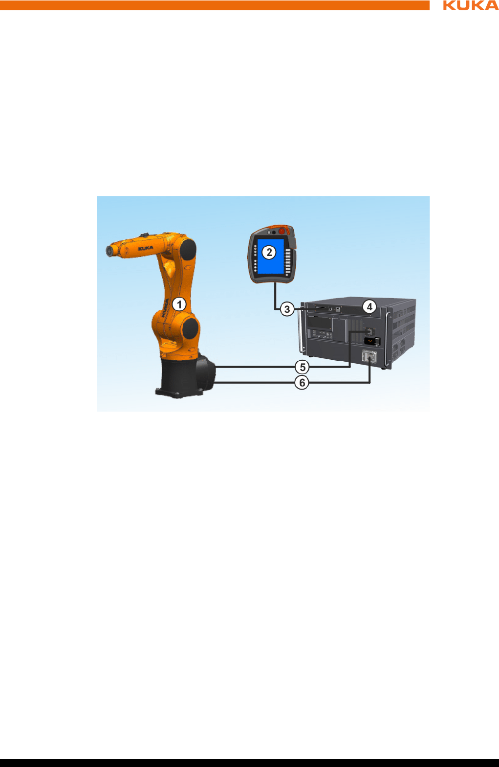
Fig. 3-1: Example of an industrial robot
1 Manipulator
2 Teach pendant
3 Connecting cable, smartPAD
4 Robot controller
5 Connecting cable, data cable
6 Connecting cable, motor cable
12 / 123 Issued: 15.04.2014 Version: BA KR C4 compact V5
KR C4 compact
3.3 Control box
The control box consists of the following components:
3.3.1 Control PC
Components The control PC (KPC) includes the following components:
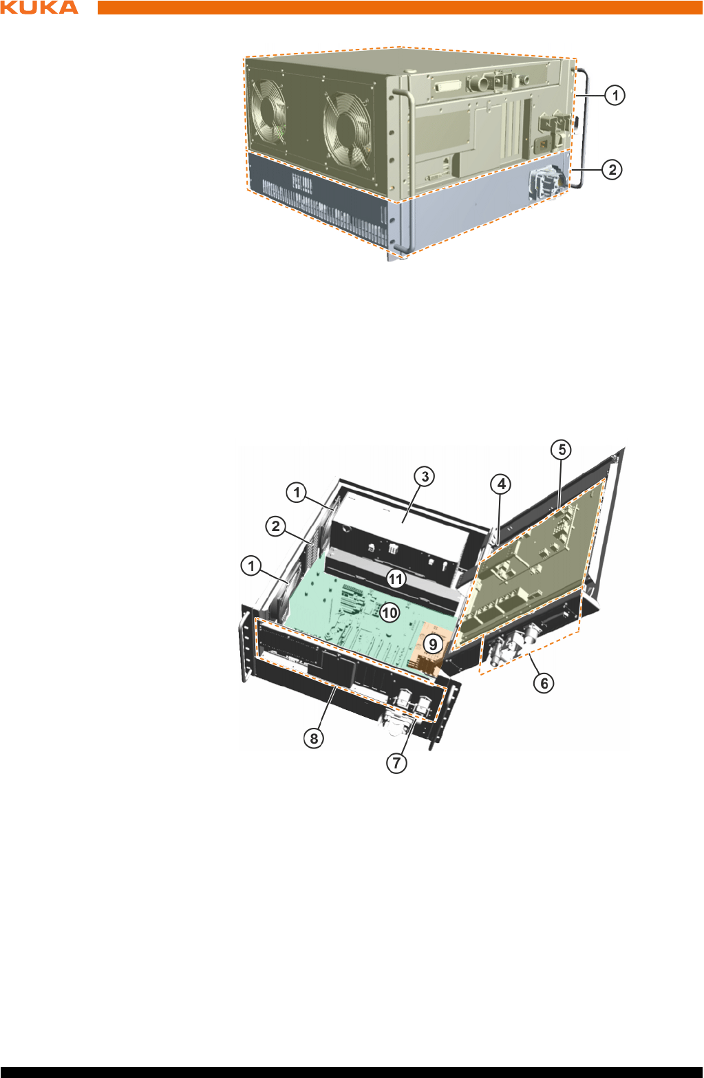
Fig. 3-2: Overview of KR C4 compact
1 Control unit (control box)
2 Power unit (drive box)
Fig. 3-3: Overview of control box
1Fan 7Main switch
2 Hard drive 8 Interfaces
3 Low-voltage power supply unit 9 Options
4 Memory card (EDS) 10 Motherboard
5 Cabinet Control Unit, Small
Robot (CCU_SR)
11 Batteries
6 Interfaces in the cover

13 / 123Issued: 15.04.2014 Version: BA KR C4 compact V5
3 Product description
Motherboard
Processor
Heat sink
Memory modules
Hard drive
LAN Dual NIC network card (not present on all motherboard variants)
Optional modules, e.g. field bus cards
Functions The control PC (KPC) is responsible for the following functions of the robot
controller:
User interface
Program creation, correction, archiving, and maintenance
Sequence control
Path planning
Control of the drive circuit
Monitoring
Safety equipment
Communication with external periphery (other controllers, host computers,
PCs, network)
3.3.2 Cabinet Control Unit, Small Robot
Description The Cabinet Control Unit, Small Robot (CCU_SR) is the central power distrib-
utor and communication interface for all components of the robot controller.
The CCU_SR consists of the Cabinet Interface Board, Small Robot (CIB_SR)
and the Power Management Board, Small Robot (PMB_SR). All data are
transferred via this internal communication interface to the controller for further
processing. If the mains voltage fails, the control components continue to be
powered by batteries until the position data are saved and the controller has
shut down. The charge and quality of the batteries are checked by means of
a load test.
The CCU_SR also incorporates sensing, control and switching functions. The
output signals are provided as electrically isolated outputs.
Functions Communication interface for the components of the robot controller
Safe inputs and outputs
Contactor activation
4 floating outputs
9 safe inputs
Teach pendant plugged in
Mastering test
6 Fast Measurement inputs for customer applications
Fan power supply monitoring
Temperature sensing:
Control box internal temperature
The following components are connected to the KPC via the KUKA Con-
troller Bus:
Drive box
Resolver digital converter
The following operator panels and service devices are connected to the
control PC via the KUKA System Bus:
KUKA Operator Panel Interface
14 / 123 Issued: 15.04.2014 Version: BA KR C4 compact V5
KR C4 compact
Diagnostic LEDs
Electronic Data Storage interface
Power supply with battery backup
Drive box
KUKA smartPAD
Multi-core control PC
Resolver Digital Converter (RDC)
Power supply without battery backup
Motor brakes
Customer interface
3.3.3 Low-voltage power supply unit
Description The low-voltage power supply unit provides power to the components of the
robot controller.
A green LED indicates the operating state of the low-voltage power supply
unit.
3.3.4 Batteries
Description In the event of a power failure, or if the power is switched off, the batteries en-
able the robot controller to be shut down in a controlled manner. The batteries
are charged via the CCU and the charge is checked and indicated.
3.3.5 Mains filter
Description The mains filter (interference suppressor filter) suppresses interference volt-
ages on the power cable.
3.4 Drive box (Drive Configuration (DC))
The drive box consists of the following components:
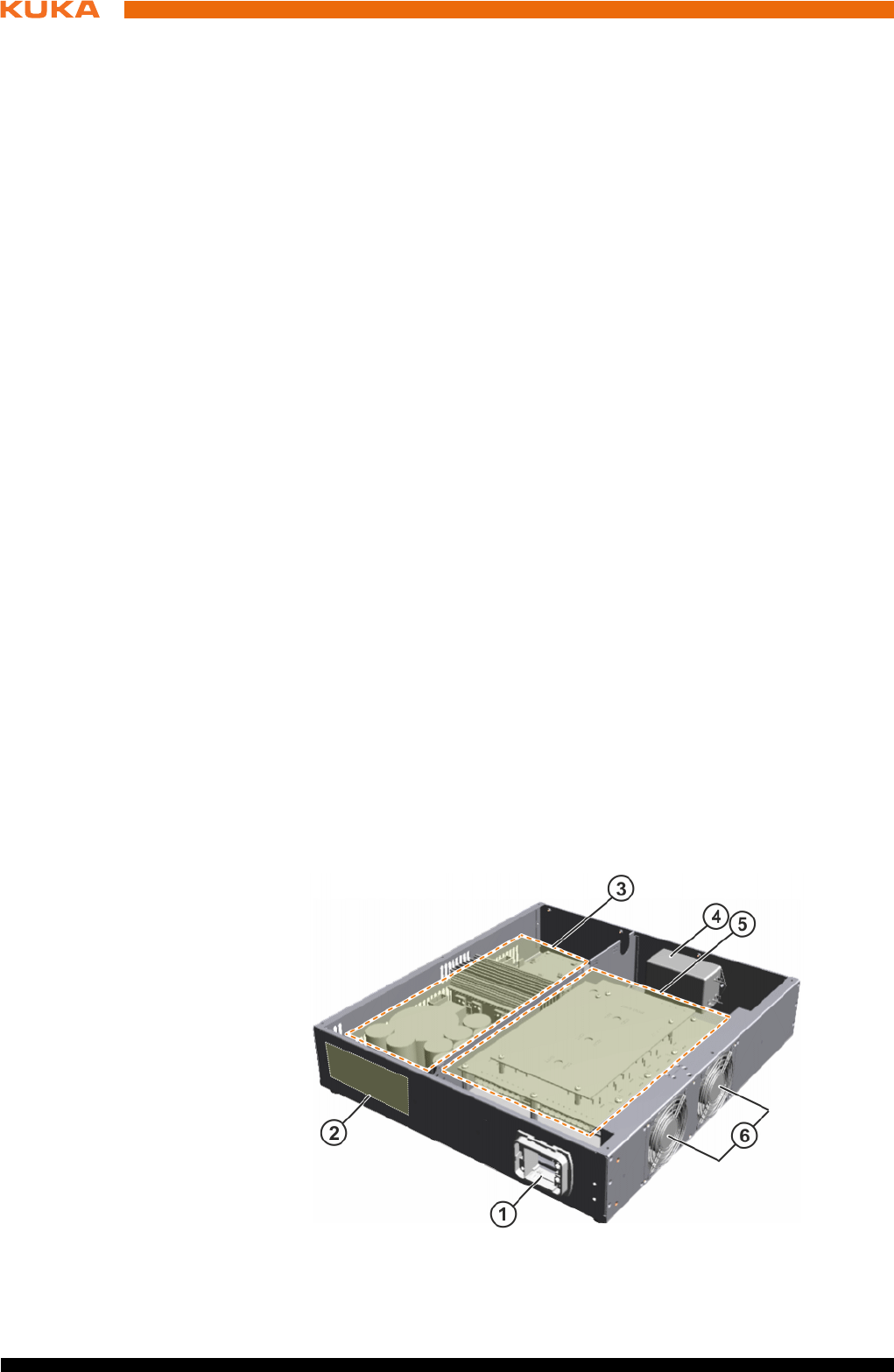
Fig. 3-4: Overview of drive box
15 / 123Issued: 15.04.2014 Version: BA KR C4 compact V5
3 Product description
Functions The drive box performs the following functions:
Generation of the intermediate circuit voltage
Control of the motors
Control of the brakes
Checking of intermediate circuit voltage in braking mode
3.5 Description of interfaces
Overview The connection panel of the robot controller consists as standard of connec-
tions for the following cables:
Power supply cable
Motor/data cable
smartPAD cable
Peripheral cables
The configuration of the connection panel varies according to the customer-
specific version and the options required.
Note The following safety interfaces can be configured in the robot controller:
Discrete safety interface X11
Ethernet safety interface X66
PROFIsafe KLI or
CIP Safety KLI
The configuration of the connection panel varies according to customer re-
quirements and options. In this documentation, the robot controller is de-
scribed with the maximum configuration.
1 Motor connector X20 4 Mains filter
2 Brake resistor 5 KUKA Servo Pack, Small Ro-
bot (KSP_SR)
3 KUKA Power Pack, Small Ro-
bot (KPP_SR)
6Fans
The discrete safety interface X11 and the Ethernet safety interface
X66 cannot be connected and used together.
Only one of the safety interfaces can be used at a time.
16 / 123 Issued: 15.04.2014 Version: BA KR C4 compact V5
KR C4 compact
Connection panel
3.5.1 Control PC interfaces
Motherboards The following motherboard variants can be installed in the control PC:
D3076-K
D3236-K
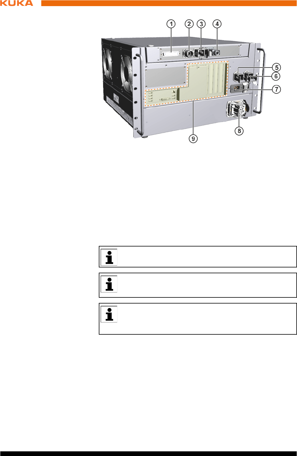
Fig. 3-5: KR C4 compact interfaces
1 X11 Safety interface (option)
2 X19 smartPAD connection
3 X65 Extension interface
4 X69 Service interface
5 X21 Manipulator interface
6 X66 Ethernet safety interface
7 X1 Power supply connection
8 X20 Motor connector
9 Control PC interfaces
Only safety interface X11 or Ethernet safety interface X66 (PRO-
FIsafe/CIP Safety) can be configured.
All contactor, relay and valve coils that are connected to the robot
controller by the user must be equipped with suitable suppressor di-
odes. RC elements and VCR resistors are not suitable.
KUKA Roboter GmbH has assembled, tested and supplied the moth-
erboard with an optimum configuration. No liability will be accepted
for modifications to the configuration that have not been carried out
by KUKA Roboter GmbH.
17 / 123Issued: 15.04.2014 Version: BA KR C4 compact V5
3 Product description
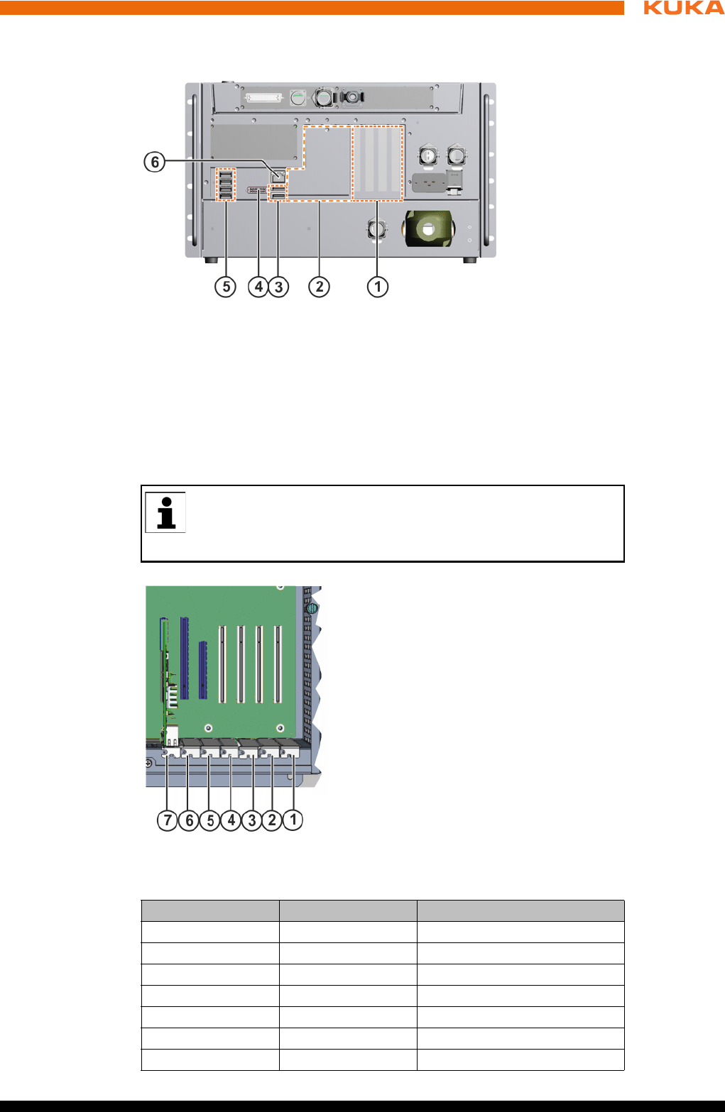
3.5.1.1 Motherboard D3076-K PC interfaces
Overview
Slot assignment
The PC slots can be fitted with the following plug-in cards:
Fig. 3-6: Motherboard D3076-K interfaces
1 Field bus cards, slots 1 to 4
2 Cover, field bus cards
3 2 USB 2.0 ports
4DVI-I
5 4 USB 2.0 ports
6 LAN Onboard – KUKA Option Network Interface
KUKA Roboter GmbH has assembled, tested and supplied the moth-
erboard with an optimum configuration. No liability will be accepted
for modifications to the configuration that have not been carried out
by KUKA Roboter GmbH.
Fig. 3-7: Motherboard slot assignment
Slot Type Plug-in card
1 PCI Field bus
2 PCI Field bus
3 PCI Field bus
4 PCI Field bus
5 PCIe not available
6 PCIe not available
7 PCIe LAN Dual NIC network card
18 / 123 Issued: 15.04.2014 Version: BA KR C4 compact V5
KR C4 compact
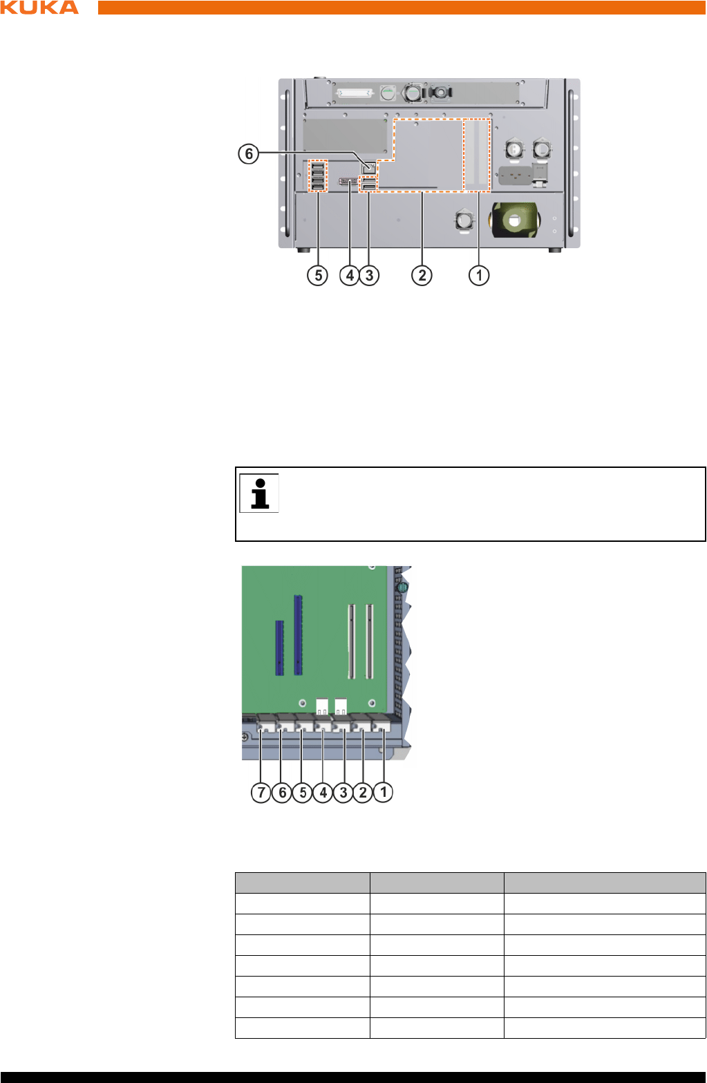
3.5.1.2 Motherboard D3236-K PC interfaces
Overview
Slot assignment
The PC slots can be fitted with the following plug-in cards:
Fig. 3-8: Motherboard D3236-K interfaces
1 Field bus cards, slots 1 to 2
2 Cover, field bus cards
3 2 USB 3.0 ports
4DVI-I
5 4 USB 2.0 ports
6 LAN Onboard – KUKA Option Network Interface
KUKA Roboter GmbH has assembled, tested and supplied the moth-
erboard with an optimum configuration. No liability will be accepted
for modifications to the configuration that have not been carried out
by KUKA Roboter GmbH.
Fig. 3-9: Motherboard slot assignment
Slot Type Plug-in card
1 PCI Field bus
2 PCI Field bus
3 - not available
4 - not available
5 PCIe not available
6 PCIe not available
7 - not available
19 / 123Issued: 15.04.2014 Version: BA KR C4 compact V5
3 Product description
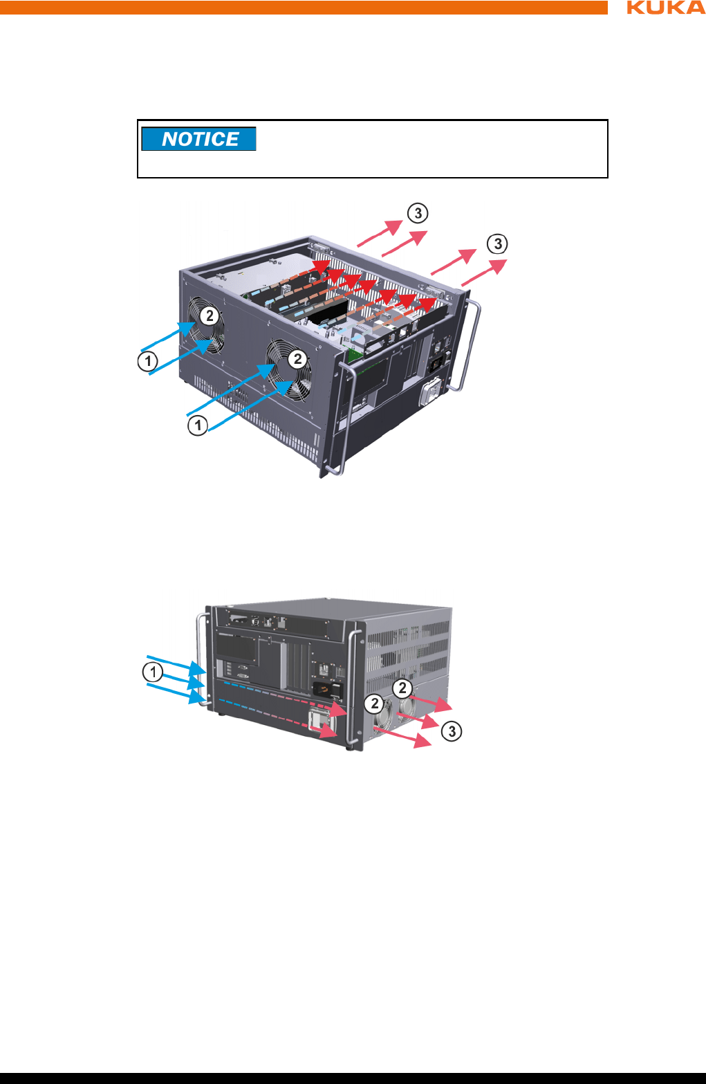
3.6 Cooling
Description The components of the control and power electronics are cooled with ambient
air by 2 fans.
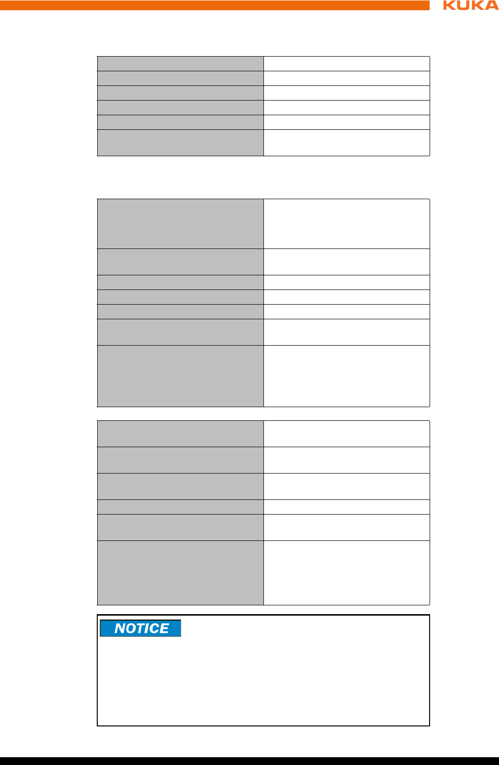
Cooling circuit,
control box
Cooling circuit,
drive box
Upstream installation of filter mats at the ventilation slits
causes an increase in temperature, leading to a reduc-
tion in the service life of the installed devices!
Fig. 3-10: Cooling circuit, control box
1 Air inlet 3 Air outlet
2Fans
Fig. 3-11: Cooling circuit, drive box
1 Air inlet 3 Air outlet
2Fans

21 / 123Issued: 15.04.2014 Version: BA KR C4 compact V5
4 Technical data
4 Technical data
Basic data
Power supply
connection
The robot controller may only be connected to grounded-neutral power supply
systems.
Environmental
conditions
Cabinet type 19" chassis
Color RAL 7016
Number of axes max. 6
Weight 33 kg
Protection rating IP 20
Sound level according to
DIN 45635-1
average: 54 dB (A)
Rated supply voltage 200 V - 230 V AC, single-phase,
two-phase (with grounded neutral
(as symmetrical as possible)
between the phases used
Permissible tolerance of rated sup-
ply voltage
Rated supply voltage ±10%
Mains frequency 50 Hz ± 1 Hz or 60 Hz ± 1 Hz
Rated power input 2 kVA, see rating plate
Thermal power dissipation max. 400 W
Mains-side fusing 2x 16 A slow-blowing (1 (2)x phase;
1x neutral conductor (optional))
Equipotential bonding The common neutral point for the
equipotential bonding conductors
and all protective ground conduc-
tors is the reference bus of the
power unit
Ambient temperature during opera-
tion
+5 ... 45 °C (278 ... 318 K)
Ambient temperature during stor-
age/transportation with batteries
-25 ... +40 °C (248 ... 313 K)
Ambient temperature during stor-
age/transportation without batteries
-25 ... +70 °C (248 ... 343 K)
Temperature change max. 1.1 K/min
Humidity class 3k3 acc. to DIN EN 60721-3-3;
1995
Altitude up to 1000 m above mean sea
level with no reduction in power
1000 m ... 4000 m above mean
sea level with a reduction in
power of 5%/1000 m
To prevent exhaustive discharge and thus destruction of
the batteries, the batteries must be recharged at regular
intervals according to the storage temperature.
If the storage temperature is +20 °C or lower, the batteries must be re-
charged every 9 months.
If the storage temperature is between +20 °C and +30 °C, the batteries must
be recharged every 6 months.
If the storage temperature is between +30 °C and +40 °C, the batteries must
be recharged every 3 months.
22 / 123 Issued: 15.04.2014 Version: BA KR C4 compact V5
KR C4 compact
Vibration resis-
tance
If more severe mechanical stress is expected, the controller must be installed
on anti-vibration components.
Control unit
Control PC
KUKA smartPAD
Cable lengths For cable designations, standard lengths and optional lengths, please refer to
the operating instructions or assembly instructions of the manipulator and/or
the assembly and operating instructions for KR C4 external cabling for robot
controllers.
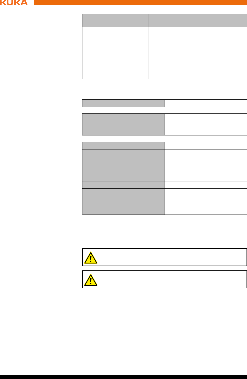
4.1 Dimensions
The dimensions of the robot controller are indicated in the diagram
(>>> Fig. 4-1 ).
Type of loading During transpor-
tation
During continuous
operation
r.m.s. acceleration (sus-
tained oscillation)
0.37 g 0.1 g
Frequency range (sustained
oscillation)
4 to 120 Hz
Acceleration (shock in X/Y/Z
direction)
10 g 2.5 g
Waveform/duration (shock
in X/Y/Z direction)
Half-sine/11 ms
Supply voltage DC 27.1 V ± 0.1 V
Main processor See shipping version
DIMM memory modules See shipping version (min. 2 GB)
Hard disk See shipping version
Supply voltage 20 … 27.1 V DC
Dimensions (WxHxD) approx. 33x26x8 cm3
Display Touch-sensitive color display
600x800 pixels
Display size 8,4 "
Interfaces USB
Weight 1.1 kg
Protection rating (without USB stick
and USB connection closed with a
plug)
IP 54
When using smartPAD cable extensions, only two extensions may be
used. An overall cable length of 50 m must not be exceeded.
The difference in the cable lengths between the individual channels
of the RDC box must not exceed 10 m.
23 / 123Issued: 15.04.2014 Version: BA KR C4 compact V5
4 Technical data
4.2 Cabinet Interface Board, Small Robot
CIB_SR outputs
The module must be exchanged when the number of switching cycles is ex-
ceeded.
Fig. 4-1: Dimensions
1Top view
2Front view
3 Side view
Operating voltage, power
contacts
≤ 30 V
Current via power contact min. 10 mA
< 750 mA
Cable lengths (connection
of actuators)
< 50 m cable lengths
< 100 m wire length (outgoing and incom-
ing lines)
Cable cross-section (con-
nection of actuators) ≥ 1 mm2
Switching cycles CIB_SR Service life: 20 years
< 100,000 (corresponds to 13 switching
cycles per day)
24 / 123 Issued: 15.04.2014 Version: BA KR C4 compact V5
KR C4 compact
CIB_SR inputs
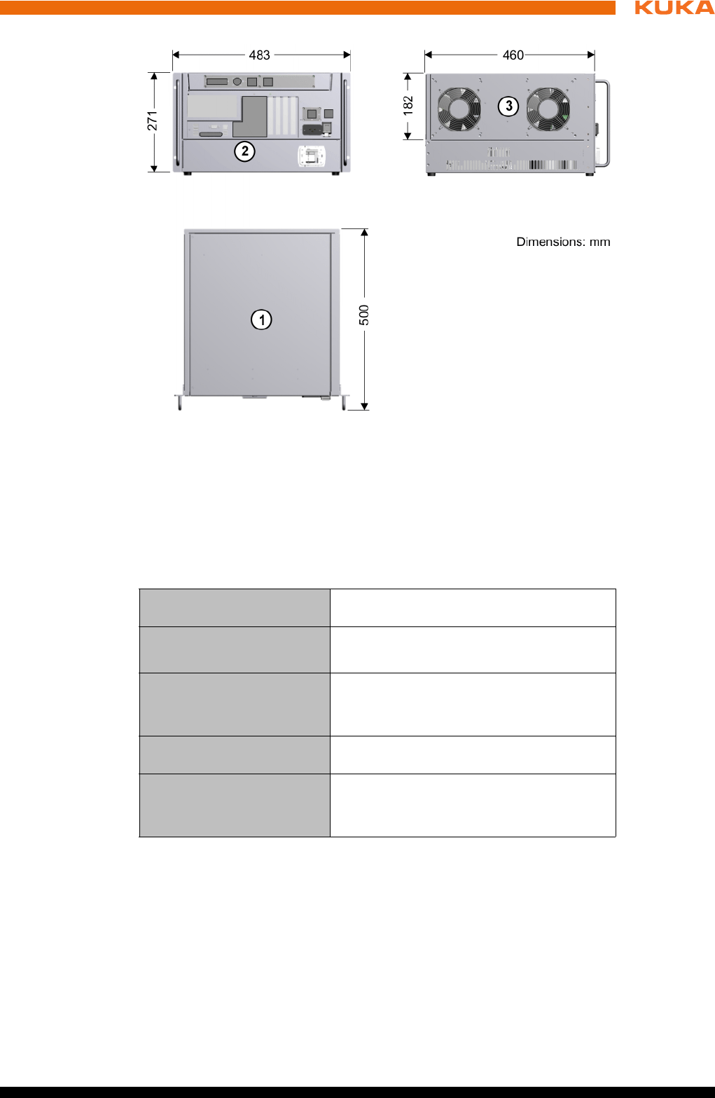
4.3 Dimensions of the smartPAD holder (optional)
The diagram (>>> Fig. 4-2 ) shows the dimensions and drilling locations for
mounting on the safety fence.
Switching level of the inputs The state for the inputs is not defined for
the voltage range 5 V ... 11 V (transition
range). Either the ON state or the OFF
state is set.
OFF state for the voltage range from -3 V to
5 V (OFF range).
ON state for the voltage range from 11 V to
30 V (ON range).
Load current with 24 V sup-
ply voltage
> 10 mA
Load current with 18 V sup-
ply voltage
> 6.5 mA
Max. load current < 15 mA
Cable length, terminal -
sensor
< 50 m, or < 100 m wire length (outgoing
and incoming lines)
Cable cross-section, test
output - input connection > 0.5 mm2
Capacitive load for the test
outputs per channel
< 200 nF
Resistive load for the test
outputs per channel
< 33 Ω
Test outputs A and B are sustained short-circuit proof.
The specified currents flow via the contact element connected to the
input. This must be rated for the maximum current of 15 mA.
Fig. 4-2: Dimensions and drilling locations for smartPAD holder
25 / 123Issued: 15.04.2014 Version: BA KR C4 compact V5
4 Technical data
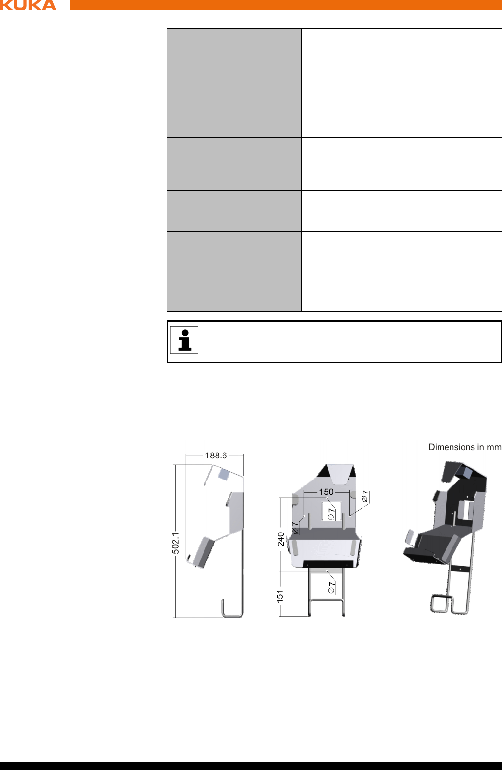
4.4 Dimensions of handle brackets
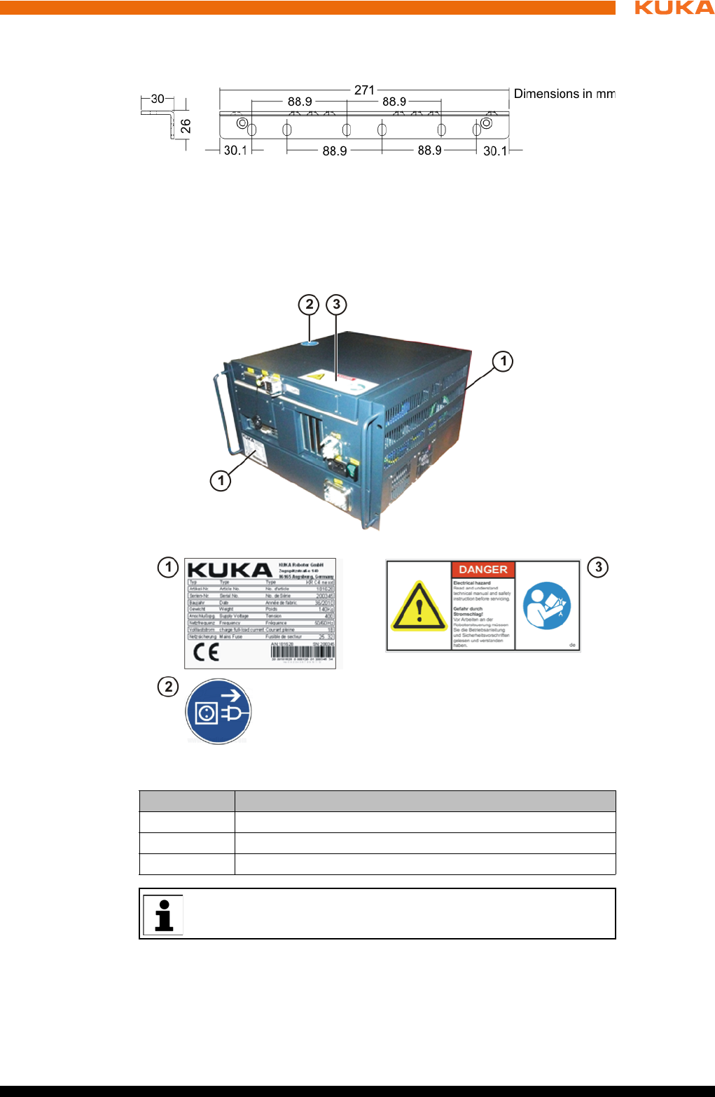
4.5 Plates and labels
Overview The following plates and labels are attached to the robot controller:
Designations
Fig. 4-3: Dimensions of handle brackets
Fig. 4-4: Plates and labels
Plate no. Designation
1 Robot controller identification plate
2 Note: unplug mains connector before opening the housing.
3 Warning: read manual
The plates may vary slightly from the examples illustrated above de-
pending on the specific cabinet type or as a result of updates.


27 / 123Issued: 15.04.2014 Version: BA KR C4 compact V5
5 Safety
5 Safety
5.1 General
5.1.1 Liability
The device described in this document is either an industrial robot or a com-
ponent thereof.
Components of the industrial robot:
Manipulator
Robot controller
Teach pendant
Connecting cables
External axes (optional)
e.g. linear unit, turn-tilt table, positioner
Software
Options, accessories
The industrial robot is built using state-of-the-art technology and in accor-
dance with the recognized safety rules. Nevertheless, misuse of the industrial
robot may constitute a risk to life and limb or cause damage to the industrial
robot and to other material property.
The industrial robot may only be used in perfect technical condition in accor-
dance with its designated use and only by safety-conscious persons who are
fully aware of the risks involved in its operation. Use of the industrial robot is
subject to compliance with this document and with the declaration of incorpo-
ration supplied together with the industrial robot. Any functional disorders af-
fecting safety must be rectified immediately.
Safety infor-
mation
Safety information cannot be held against KUKA Roboter GmbH. Even if all
safety instructions are followed, this is not a guarantee that the industrial robot
will not cause personal injuries or material damage.
No modifications may be carried out to the industrial robot without the autho-
rization of KUKA Roboter GmbH. Additional components (tools, software,
etc.), not supplied by KUKA Roboter GmbH, may be integrated into the indus-
trial robot. The user is liable for any damage these components may cause to
the industrial robot or to other material property.
In addition to the Safety chapter, this document contains further safety instruc-
tions. These must also be observed.
5.1.2 Intended use of the industrial robot
The industrial robot is intended exclusively for the use designated in the “Pur-
pose” chapter of the operating instructions or assembly instructions.
Any use or application deviating from the intended use is deemed to be misuse
and is not allowed. The manufacturer is not liable for any damage resulting
from such misuse. The risk lies entirely with the user.
Operation of the industrial robot in accordance with its intended use also re-
quires compliance with the operating and assembly instructions for the individ-
ual components, with particular reference to the maintenance specifications.
Misuse Any use or application deviating from the intended use is deemed to be misuse
and is not allowed. This includes e.g.:

28 / 123 Issued: 15.04.2014 Version: BA KR C4 compact V5
KR C4 compact
Transportation of persons and animals
Use as a climbing aid
Operation outside the specified operating parameters
Use in potentially explosive environments
Operation without additional safeguards
Outdoor operation
Underground operation
5.1.3 EC declaration of conformity and declaration of incorporation
The industrial robot constitutes partly completed machinery as defined by the
EC Machinery Directive. The industrial robot may only be put into operation if
the following preconditions are met:
The industrial robot is integrated into a complete system.
Or: The industrial robot, together with other machinery, constitutes a com-
plete system.
Or: All safety functions and safeguards required for operation in the com-
plete machine as defined by the EC Machinery Directive have been added
to the industrial robot.
The complete system complies with the EC Machinery Directive. This has
been confirmed by means of an assessment of conformity.
Declaration of
conformity
The system integrator must issue a declaration of conformity for the complete
system in accordance with the Machinery Directive. The declaration of confor-
mity forms the basis for the CE mark for the system. The industrial robot must
always be operated in accordance with the applicable national laws, regula-
tions and standards.
The robot controller is CE certified under the EMC Directive and the Low Volt-
age Directive.
Declaration of
incorporation
The industrial robot as partly completed machinery is supplied with a declara-
tion of incorporation in accordance with Annex II B of the EC Machinery Direc-
tive 2006/42/EC. The assembly instructions and a list of essential
requirements complied with in accordance with Annex I are integral parts of
this declaration of incorporation.
The declaration of incorporation declares that the start-up of the partly com-
pleted machinery is not allowed until the partly completed machinery has been
incorporated into machinery, or has been assembled with other parts to form
machinery, and this machinery complies with the terms of the EC Machinery
Directive, and the EC declaration of conformity is present in accordance with
Annex II A.
5.1.4 Terms used
STOP 0, STOP 1 and STOP 2 are the stop definitions according to EN 60204-
1:2006.
Term Description
Axis range Range of each axis, in degrees or millimeters, within which it may move.
The axis range must be defined for each axis.
Stopping distance Stopping distance = reaction distance + braking distance
The stopping distance is part of the danger zone.
Workspace Area within which the robot may move. The workspace is derived from
the individual axis ranges.
29 / 123Issued: 15.04.2014 Version: BA KR C4 compact V5
5 Safety
User The user of the industrial robot can be the management, employer or
delegated person responsible for use of the industrial robot.
Danger zone The danger zone consists of the workspace and the stopping distances
of the manipulator and external axes (optional).
Service life The service life of a safety-relevant component begins at the time of
delivery of the component to the customer.
The service life is not affected by whether the component is used or not,
as safety-relevant components are also subject to aging during storage.
KUKA smartPAD see “smartPAD”
Manipulator The robot arm and the associated electrical installations
Safety zone The safety zone is situated outside the danger zone.
Safe operational stop The safe operational stop is a standstill monitoring function. It does not
stop the robot motion, but monitors whether the robot axes are station-
ary. If these are moved during the safe operational stop, a safety stop
STOP 0 is triggered.
The safe operational stop can also be triggered externally.
When a safe operational stop is triggered, the robot controller sets an
output to the field bus. The output is set even if not all the axes were sta-
tionary at the time of triggering, thereby causing a safety stop STOP 0 to
be triggered.
Safety STOP 0 A stop that is triggered and executed by the safety controller. The safety
controller immediately switches off the drives and the power supply to
the brakes.
Note: This stop is called safety STOP 0 in this document.
Safety STOP 1 A stop that is triggered and monitored by the safety controller. The brak-
ing process is performed by the non-safety-oriented part of the robot
controller and monitored by the safety controller. As soon as the manip-
ulator is at a standstill, the safety controller switches off the drives and
the power supply to the brakes.
When a safety STOP 1 is triggered, the robot controller sets an output to
the field bus.
The safety STOP 1 can also be triggered externally.
Note: This stop is called safety STOP 1 in this document.
Safety STOP 2 A stop that is triggered and monitored by the safety controller. The brak-
ing process is performed by the non-safety-oriented part of the robot
controller and monitored by the safety controller. The drives remain acti-
vated and the brakes released. As soon as the manipulator is at a stand-
still, a safe operational stop is triggered.
When a safety STOP 2 is triggered, the robot controller sets an output to
the field bus.
The safety STOP 2 can also be triggered externally.
Note: This stop is called safety STOP 2 in this document.
Safety options Generic term for options which make it possible to configure additional
safe monitoring functions in addition to the standard safety functions.
Example: SafeOperation
smartPAD Teach pendant for the KR C4
The smartPAD has all the operator control and display functions
required for operating and programming the industrial robot.
Term Description
30 / 123 Issued: 15.04.2014 Version: BA KR C4 compact V5
KR C4 compact
5.2 Personnel
The following persons or groups of persons are defined for the industrial robot:
User
Personnel
User The user must observe the labor laws and regulations. This includes e.g.:
The user must comply with his monitoring obligations.
The user must carry out instructions at defined intervals.
Personnel Personnel must be instructed, before any work is commenced, in the type of
work involved and what exactly it entails as well as any hazards which may ex-
ist. Instruction must be carried out regularly. Instruction is also required after
particular incidents or technical modifications.
Personnel includes:
System integrator
Operators, subdivided into:
Start-up, maintenance and service personnel
Operating personnel
Cleaning personnel
Stop category 0 The drives are deactivated immediately and the brakes are applied. The
manipulator and any external axes (optional) perform path-oriented
braking.
Note: This stop category is called STOP 0 in this document.
Stop category 1 The manipulator and any external axes (optional) perform path-main-
taining braking.
Operating mode T1: The drives are deactivated as soon as the robot
has stopped, but no later than after 680 ms.
Operating mode T2, AUT, AUT EXT: The drives are switched off after
1.5 s.
Note: This stop category is called STOP 1 in this document.
Stop category 2 The drives are not deactivated and the brakes are not applied. The
manipulator and any external axes (optional) are braked with a path-
maintaining braking ramp.
Note: This stop category is called STOP 2 in this document.
System integrator
(plant integrator)
The system integrator is responsible for safely integrating the industrial
robot into a complete system and commissioning it.
T1 Test mode, Manual Reduced Velocity (<= 250 mm/s)
T2 Test mode, Manual High Velocity (> 250 mm/s permissible)
External axis Motion axis which is not part of the manipulator but which is controlled
using the robot controller, e.g. KUKA linear unit, turn-tilt table, Posiflex.
Term Description
All persons working with the industrial robot must have read and un-
derstood the industrial robot documentation, including the safety
chapter.
Installation, exchange, adjustment, operation, maintenance and re-
pair must be performed only as specified in the operating or assembly
instructions for the relevant component of the industrial robot and only
by personnel specially trained for this purpose.
31 / 123Issued: 15.04.2014 Version: BA KR C4 compact V5
5 Safety
System integrator The industrial robot is safely integrated into a complete system by the system
integrator.
The system integrator is responsible for the following tasks:
Installing the industrial robot
Connecting the industrial robot
Performing risk assessment
Implementing the required safety functions and safeguards
Issuing the declaration of conformity
Attaching the CE mark
Creating the operating instructions for the complete system
Operator The operator must meet the following preconditions:
The operator must be trained for the work to be carried out.
Work on the industrial robot must only be carried out by qualified person-
nel. These are people who, due to their specialist training, knowledge and
experience, and their familiarization with the relevant standards, are able
to assess the work to be carried out and detect any potential hazards.
5.3 Workspace, safety zone and danger zone
Workspaces are to be restricted to the necessary minimum size. A workspace
must be safeguarded using appropriate safeguards.
The safeguards (e.g. safety gate) must be situated inside the safety zone. In
the case of a stop, the manipulator and external axes (optional) are braked
and come to a stop within the danger zone.
The danger zone consists of the workspace and the stopping distances of the
manipulator and external axes (optional). It must be safeguarded by means of
physical safeguards to prevent danger to persons or the risk of material dam-
age.
5.4 Triggers for stop reactions
Stop reactions of the industrial robot are triggered in response to operator ac-
tions or as a reaction to monitoring functions and error messages. The follow-
ing table shows the different stop reactions according to the operating mode
that has been set.
Work on the electrical and mechanical equipment of the industrial ro-
bot may only be carried out by specially trained personnel.
Trigger T1, T2 AUT, AUT EXT
Start key released STOP 2 -
STOP key pressed STOP 2
Drives OFF STOP 1
“Motion enable” input
drops out
STOP 2
Power switched off via
main switch or power fail-
ure
STOP 0
Internal error in non-
safety-oriented part of the
robot controller
STOP 0 or STOP 1
(dependent on the cause of the error)
32 / 123 Issued: 15.04.2014 Version: BA KR C4 compact V5
KR C4 compact
5.5 Safety functions
5.5.1 Overview of the safety functions
The following safety functions are present in the industrial robot:
Mode selection
Operator safety (= connection for the guard interlock)
EMERGENCY STOP device
Enabling device
External safe operational stop
External safety stop 1 (not for the controller variant “KR C4 compact”)
External safety stop 2
Velocity monitoring in T1
The safety functions of the industrial robot meet the following requirements:
Category 3 and Performance Level d in accordance with EN ISO 13849-
1:2008
The requirements are only met on the following condition, however:
The EMERGENCY STOP device is pressed at least once every 6 months.
The following components are involved in the safety functions:
Safety controller in the control PC
KUKA smartPAD
Cabinet Control Unit (CCU)
Resolver Digital Converter (RDC)
KUKA Power Pack (KPP)
KUKA Servo Pack (KSP)
Safety Interface Board (SIB) (if used)
There are also interfaces to components outside the industrial robot and to
other robot controllers.
Operating mode changed
during operation
Safety stop 2
Safety gate opened (oper-
ator safety)
- Safety stop 1
Enabling switch released Safety stop 2 -
Enabling switch pressed
fully down or error
Safety stop 1 -
E-STOP pressed Safety stop 1
Error in safety controller
or periphery of the safety
controller
Safety stop 0
Trigger T1, T2 AUT, AUT EXT
In the absence of operational safety functions and safe-
guards, the industrial robot can cause personal injury or
material damage. If safety functions or safeguards are dismantled or deacti-
vated, the industrial robot may not be operated.
33 / 123Issued: 15.04.2014 Version: BA KR C4 compact V5
5 Safety
5.5.2 Safety controller
The safety controller is a unit inside the control PC. It links safety-relevant sig-
nals and safety-relevant monitoring functions.
Safety controller tasks:
Switching off the drives; applying the brakes
Monitoring the braking ramp
Standstill monitoring (after the stop)
Velocity monitoring in T1
Evaluation of safety-relevant signals
Setting of safety-oriented outputs
5.5.3 Mode selection
The industrial robot can be operated in the following modes:
Manual Reduced Velocity (T1)
Manual High Velocity (T2)
Automatic (AUT)
Automatic External (AUT EXT)
5.5.4 “Operator safety” signal
The “operator safety” signal is used for interlocking physical safeguards, e.g.
safety gates. Automatic operation is not possible without this signal. In the
During system planning, the safety functions of the overall system
must also be planned and designed. The industrial robot must be in-
tegrated into this safety system of the overall system.
Do not change the operating mode while a program is running. If the
operating mode is changed during program execution, the industrial
robot is stopped with a safety stop 2.
Operat-
ing mode Use Velocities
T1
For test operation, pro-
gramming and teach-
ing
Program verification:
Programmed velocity, maxi-
mum 250 mm/s
Manual mode:
Jog velocity, maximum 250 mm/
s
T2 For test operation
Program verification:
Programmed velocity
Manual mode: Not possible
AUT
For industrial robots
without higher-level
controllers
Program mode:
Programmed velocity
Manual mode: Not possible
AUT EXT
For industrial robots
with higher-level con-
trollers, e.g. PLC
Program mode:
Programmed velocity
Manual mode: Not possible
34 / 123 Issued: 15.04.2014 Version: BA KR C4 compact V5
KR C4 compact
event of a loss of signal during automatic operation (e.g. safety gate is
opened), the manipulator stops with a safety stop 1.
Operator safety is not active in modes T1 (Manual Reduced Velocity) and T2
(Manual High Velocity).
5.5.5 EMERGENCY STOP device
The EMERGENCY STOP device for the industrial robot is the EMERGENCY
STOP device on the smartPAD. The device must be pressed in the event of a
hazardous situation or emergency.
Reactions of the industrial robot if the EMERGENCY STOP device is pressed:
The manipulator and any external axes (optional) are stopped with a safe-
ty stop 1.
Before operation can be resumed, the EMERGENCY STOP device must be
turned to release it.
There must always be at least one external EMERGENCY STOP device in-
stalled. This ensures that an EMERGENCY STOP device is available even
when the smartPAD is disconnected.
(>>> 5.5.7 "External EMERGENCY STOP device" Page 35)
5.5.6 Logging off from the higher-level safety controller
If the robot controller is connected to a higher-level safety controller, this con-
nection will inevitably be terminated in the following cases:
Switching off the voltage via the main switch of the robot
Or power failure
Shutdown of the robot controller via the smartHMI
Activation of a WorkVisual project in WorkVisual or directly on the robot
controller
Changes to Start-up > Network configuration
Changes to Configuration > Safety configuration
I/O drivers > Reconfigure
Restoration of an archive
Following a loss of signal, automatic operation may only
be resumed when the safeguard has been closed and
when the closing has been acknowledged. This acknowledgement is to pre-
vent automatic operation from being resumed inadvertently while there are
still persons in the danger zone, e.g. due to the safety gate closing acciden-
tally.
The acknowledgement must be designed in such a way that an actual check
of the danger zone can be carried out first. Other acknowledgement functions
(e.g. an acknowlegement which is automatically triggered by closure of the
safeguard) are not permitted.
The system integrator is responsible for ensuring that these criteria are met.
Failure to met them may result in death, severe injuries or considerable dam-
age to property.
Tools and other equipment connected to the manipulator
must be integrated into the EMERGENCY STOP circuit
on the system side if they could constitute a potential hazard.
Failure to observe this precaution may result in death, severe injuries or con-
siderable damage to property.
35 / 123Issued: 15.04.2014 Version: BA KR C4 compact V5
5 Safety
Effect of the interruption:
If a discrete safety interface is used, this triggers an EMERGENCY STOP
for the overall system.
If the Ethernet interface is used, the KUKA safety controller generates a
signal that prevents the higher-level controller from triggering an EMER-
GENCY STOP for the overall system.
5.5.7 External EMERGENCY STOP device
Every operator station that can initiate a robot motion or other potentially haz-
ardous situation must be equipped with an EMERGENCY STOP device. The
system integrator is responsible for ensuring this.
There must always be at least one external EMERGENCY STOP device in-
stalled. This ensures that an EMERGENCY STOP device is available even
when the smartPAD is disconnected.
External EMERGENCY STOP devices are connected via the customer inter-
face. External EMERGENCY STOP devices are not included in the scope of
supply of the industrial robot.
5.5.8 Enabling device
The enabling devices of the industrial robot are the enabling switches on the
smartPAD.
There are 3 enabling switches installed on the smartPAD. The enabling
switches have 3 positions:
Not pressed
Center position
Panic position
In the test modes, the manipulator can only be moved if one of the enabling
switches is held in the central position.
Releasing the enabling switch triggers a safety stop 2.
Pressing the enabling switch down fully (panic position) triggers a safety
stop 1.
It is possible to hold 2 enabling switches in the center position simultane-
ously for up to 15 seconds. This makes it possible to adjust grip from one
enabling switch to another one. If 2 enabling switches are held simultane-
ously in the center position for longer than 15 seconds, this triggers a safe-
ty stop 1.
If the Ethernet safety interface is used: In his risk assessment, the
system integrator must take into consideration whether the fact that
switching off the robot controller does not trigger an EMERGENCY
STOP of the overall system could constitute a hazard and, if so, how this haz-
ard can be countered.
Failure to take this into consideration may result in death, injuries or damage
to property.
If a robot controller is switched off, the E-STOP device on
the smartPAD is no longer functional. The user is re-
sponsible for ensuring that the smartPAD is either covered or removed from
the system. This serves to prevent operational and non-operational EMER-
GENCY STOP devices from becoming interchanged.
Failure to observe this precaution may result in death, injuries or damage to
property.
36 / 123 Issued: 15.04.2014 Version: BA KR C4 compact V5
KR C4 compact
If an enabling switch malfunctions (jams), the industrial robot can be stopped
using the following methods:
Press the enabling switch down fully
Actuate the EMERGENCY STOP system
Release the Start key
5.5.9 External enabling device
External enabling devices are required if it is necessary for more than one per-
son to be in the danger zone of the industrial robot.
External enabling devices are not included in the scope of supply of the indus-
trial robot.
5.5.10 External safe operational stop
The safe operational stop can be triggered via an input on the customer inter-
face. The state is maintained as long as the external signal is FALSE. If the
external signal is TRUE, the manipulator can be moved again. No acknowl-
edgement is required.
5.5.11 External safety stop 1 and external safety stop 2
Safety stop 1 and safety stop 2 can be triggered via an input on the customer
interface. The state is maintained as long as the external signal is FALSE. If
the external signal is TRUE, the manipulator can be moved again. No ac-
knowledgement is required.
5.5.12 Velocity monitoring in T1
The velocity at the TCP is monitored in T1 mode. If the velocity exceeds
250 mm/s, a safety stop 0 is triggered.
5.6 Additional protective equipment
5.6.1 Jog mode
In the operating modes T1 (Manual Reduced Velocity) and T2 (Manual High
Velocity), the robot controller can only execute programs in jog mode. This
means that it is necessary to hold down an enabling switch and the Start key
in order to execute a program.
Releasing the enabling switch triggers a safety stop 2.
The enabling switches must not be held down by adhe-
sive tape or other means or tampered with in any other
way.
Death, injuries or damage to property may result.
Which interface can be used for connecting external enabling devices
is described in the “Planning” chapter of the robot controller operating
instructions and assembly instructions.
No external safety stop 1 is available for the controller variant “KR C4
compact”.
37 / 123Issued: 15.04.2014 Version: BA KR C4 compact V5
5 Safety
Pressing the enabling switch down fully (panic position) triggers a safety
stop 1.
Releasing the Start key triggers a STOP 2.
5.6.2 Software limit switches
The axis ranges of all manipulator and positioner axes are limited by means of
adjustable software limit switches. These software limit switches only serve as
machine protection and must be adjusted in such a way that the manipulator/
positioner cannot hit the mechanical end stops.
The software limit switches are set during commissioning of an industrial ro-
bot.
5.6.3 Mechanical end stops
Depending on the robot variant, the axis ranges of the main and wrist axes of
the manipulator are partially limited by mechanical end stops.
Additional mechanical end stops can be installed on the external axes.
5.6.4 Mechanical axis range limitation (optional)
Some manipulators can be fitted with mechanical axis range limitation in axes
A1 to A3. The adjustable axis range limitation systems restrict the working
range to the required minimum. This increases personal safety and protection
of the system.
In the case of manipulators that are not designed to be fitted with mechanical
axis range limitation, the workspace must be laid out in such a way that there
is no danger to persons or material property, even in the absence of mechan-
ical axis range limitation.
If this is not possible, the workspace must be limited by means of photoelectric
barriers, photoelectric curtains or obstacles on the system side. There must be
no shearing or crushing hazards at the loading and transfer areas.
5.6.5 Axis range monitoring (optional)
Some manipulators can be fitted with dual-channel axis range monitoring sys-
tems in main axes A1 to A3. The positioner axes may be fitted with additional
axis range monitoring systems. The safety zone for an axis can be adjusted
and monitored using an axis range monitoring system. This increases person-
al safety and protection of the system.
Further information is contained in the operating and programming in-
structions.
If the manipulator or an external axis hits an obstruction
or a mechanical end stop or axis range limitation, the ma-
nipulator can no longer be operated safely. The manipulator must be taken
out of operation and KUKA Roboter GmbH must be consulted before it is put
back into operation (>>> 14 "KUKA Service" Page 111).
This option is not available for all robot models. Information on spe-
cific robot models can be obtained from KUKA Roboter GmbH.
38 / 123 Issued: 15.04.2014 Version: BA KR C4 compact V5
KR C4 compact
5.6.6 Options for moving the manipulator without drive energy
Description The following options are available for moving the manipulator without drive
energy after an accident or malfunction:
Release device (optional)
The release device can be used for the main axis drive motors and, de-
pending on the robot variant, also for the wrist axis drive motors.
Brake release device (option)
The brake release device is designed for robot variants whose motors are
not freely accessible.
Moving the wrist axes directly by hand
There is no release device available for the wrist axes of variants in the low
payload category. This is not necessary because the wrist axes can be
moved directly by hand.
5.6.7 Labeling on the industrial robot
All plates, labels, symbols and marks constitute safety-relevant parts of the in-
dustrial robot. They must not be modified or removed.
Labeling on the industrial robot consists of:
Identification plates
Warning signs
Safety symbols
Designation labels
Cable markings
Rating plates
This option is not available for all robot models. Information on spe-
cific robot models can be obtained from KUKA Roboter GmbH.
The system user is responsible for ensuring that the training of per-
sonnel with regard to the response to emergencies or exceptional sit-
uations also includes how the manipulator can be moved without
drive energy.
Information about the options available for the various robot models
and about how to use them can be found in the assembly and oper-
ating instructions for the robot or requested from KUKA Roboter
GmbH.
Moving the manipulator without drive energy can dam-
age the motor brakes of the axes concerned. The motor
must be replaced if the brake has been damaged. The manipulator may
therefore be moved without drive energy only in emergencies, e.g. for rescu-
ing persons.
Further information is contained in the technical data of the operating
instructions or assembly instructions of the components of the indus-
trial robot.
39 / 123Issued: 15.04.2014 Version: BA KR C4 compact V5
5 Safety
5.6.8 External safeguards
The access of persons to the danger zone of the industrial robot must be pre-
vented by means of safeguards. It is the responsibility of the system integrator
to ensure this.
Physical safeguards must meet the following requirements:
They meet the requirements of EN 953.
They prevent access of persons to the danger zone and cannot be easily
circumvented.
They are sufficiently fastened and can withstand all forces that are likely
to occur in the course of operation, whether from inside or outside the en-
closure.
They do not, themselves, represent a hazard or potential hazard.
The prescribed minimum clearance from the danger zone is maintained.
Safety gates (maintenance gates) must meet the following requirements:
They are reduced to an absolute minimum.
The interlocks (e.g. safety gate switches) are linked to the operator safety
input of the robot controller via safety gate switching devices or safety
PLC.
Switching devices, switches and the type of switching conform to the re-
quirements of Performance Level d and category 3 according to EN ISO
13849-1.
Depending on the risk situation: the safety gate is additionally safeguarded
by means of a locking mechanism that only allows the gate to be opened
if the manipulator is safely at a standstill.
The button for acknowledging the safety gate is located outside the space
limited by the safeguards.
Other safety
equipment
Other safety equipment must be integrated into the system in accordance with
the corresponding standards and regulations.
5.7 Overview of operating modes and safety functions
The following table indicates the operating modes in which the safety functions
are active.
Further information is contained in the corresponding standards and
regulations. These also include EN 953.
Safety functions T1 T2 AUT AUT EXT
Operator safety - - active active
EMERGENCY STOP device active active active active
Enabling device active active - -
Reduced velocity during pro-
gram verification active - - -
Jog mode active active - -
Software limit switches active active active active
40 / 123 Issued: 15.04.2014 Version: BA KR C4 compact V5
KR C4 compact
5.8 Safety measures
5.8.1 General safety measures
The industrial robot may only be used in perfect technical condition in accor-
dance with its intended use and only by safety-conscious persons. Operator
errors can result in personal injury and damage to property.
It is important to be prepared for possible movements of the industrial robot
even after the robot controller has been switched off and locked out. Incorrect
installation (e.g. overload) or mechanical defects (e.g. brake defect) can cause
the manipulator or external axes to sag. If work is to be carried out on a
switched-off industrial robot, the manipulator and external axes must first be
moved into a position in which they are unable to move on their own, whether
the payload is mounted or not. If this is not possible, the manipulator and ex-
ternal axes must be secured by appropriate means.
smartPAD The user must ensure that the industrial robot is only operated with the smart-
PAD by authorized persons.
If more than one smartPAD is used in the overall system, it must be ensured
that each smartPAD is unambiguously assigned to the corresponding indus-
trial robot. They must not be interchanged.
Modifications After modifications to the industrial robot, checks must be carried out to ensure
the required safety level. The valid national or regional work safety regulations
must be observed for this check. The correct functioning of all safety functions
must also be tested.
New or modified programs must always be tested first in Manual Reduced Ve-
locity mode (T1).
After modifications to the industrial robot, existing programs must always be
tested first in Manual Reduced Velocity mode (T1). This applies to all compo-
nents of the industrial robot and includes modifications to the software and
configuration settings.
Faults The following tasks must be carried out in the case of faults in the industrial
robot:
In the absence of operational safety functions and safe-
guards, the industrial robot can cause personal injury or
material damage. If safety functions or safeguards are dismantled or deacti-
vated, the industrial robot may not be operated.
Standing underneath the robot arm can cause death or
injuries. For this reason, standing underneath the robot
arm is prohibited!
The motors reach temperatures during operation which
can cause burns to the skin. Contact must be avoided.
Appropriate safety precautions must be taken, e.g. protective gloves must be
worn.
The operator must ensure that decoupled smartPADs
are immediately removed from the system and stored out
of sight and reach of personnel working on the industrial robot. This serves
to prevent operational and non-operational EMERGENCY STOP devices
from becoming interchanged.
Failure to observe this precaution may result in death, severe injuries or con-
siderable damage to property.
41 / 123Issued: 15.04.2014 Version: BA KR C4 compact V5
5 Safety
Switch off the robot controller and secure it (e.g. with a padlock) to prevent
unauthorized persons from switching it on again.
Indicate the fault by means of a label with a corresponding warning (tag-
out).
Keep a record of the faults.
Eliminate the fault and carry out a function test.
5.8.2 Transportation
Manipulator The prescribed transport position of the manipulator must be observed. Trans-
portation must be carried out in accordance with the operating instructions or
assembly instructions of the robot.
Avoid vibrations and impacts during transportation in order to prevent damage
to the manipulator.
Robot controller The prescribed transport position of the robot controller must be observed.
Transportation must be carried out in accordance with the operating instruc-
tions or assembly instructions of the robot controller.
Avoid vibrations and impacts during transportation in order to prevent damage
to the robot controller.
External axis
(optional)
The prescribed transport position of the external axis (e.g. KUKA linear unit,
turn-tilt table, positioner) must be observed. Transportation must be carried
out in accordance with the operating instructions or assembly instructions of
the external axis.
5.8.3 Start-up and recommissioning
Before starting up systems and devices for the first time, a check must be car-
ried out to ensure that the systems and devices are complete and operational,
that they can be operated safely and that any damage is detected.
The valid national or regional work safety regulations must be observed for this
check. The correct functioning of all safety functions must also be tested.
The passwords for the user groups must be changed in the KUKA
System Software before start-up. The passwords must only be com-
municated to authorized personnel.
The robot controller is preconfigured for the specific industrial robot.
If cables are interchanged, the manipulator and the external axes (op-
tional) may receive incorrect data and can thus cause personal injury
or material damage. If a system consists of more than one manipulator, al-
ways connect the connecting cables to the manipulators and their corre-
sponding robot controllers.
If additional components (e.g. cables), which are not part of the scope
of supply of KUKA Roboter GmbH, are integrated into the industrial
robot, the user is responsible for ensuring that these components do
not adversely affect or disable safety functions.
If the internal cabinet temperature of the robot controller
differs greatly from the ambient temperature, condensa-
tion can form, which may cause damage to the electrical components. Do not
put the robot controller into operation until the internal temperature of the
cabinet has adjusted to the ambient temperature.
42 / 123 Issued: 15.04.2014 Version: BA KR C4 compact V5
KR C4 compact
Function test The following tests must be carried out before start-up and recommissioning:
General test:
It must be ensured that:
The industrial robot is correctly installed and fastened in accordance with
the specifications in the documentation.
There are no foreign bodies or loose parts on the industrial robot.
All required safety equipment is correctly installed and operational.
The power supply ratings of the industrial robot correspond to the local
supply voltage and mains type.
The ground conductor and the equipotential bonding cable are sufficiently
rated and correctly connected.
The connecting cables are correctly connected and the connectors are
locked.
Test of the safety functions:
A function test must be carried out for the following safety functions to ensure
that they are functioning correctly:
Local EMERGENCY STOP device
External EMERGENCY STOP device (input and output)
Enabling device (in the test modes)
Operator safety
All other safety-relevant inputs and outputs used
Other external safety functions
5.8.3.1 Checking machine data and safety configuration
It must be ensured that the rating plate on the robot controller has the
same machine data as those entered in the declaration of incorporation.
The machine data on the rating plate of the manipulator and the external
axes (optional) must be entered during start-up.
The practical tests for the machine data must be carried out within the
scope of the start-up procedure.
Following modifications to the machine data, the safety configuration must
be checked.
After activation of a WorkVisual project on the robot controller, the safety
configuration must be checked!
If machine data are adopted when checking the safety configuration (re-
gardless of the reason for the safety configuration check), the practical
tests for the machine data must be carried out.
System Software 8.3 or higher: If the checksum of the safety configuration
has changed, the safe axis monitoring functions must be checked.
If the practical tests are not successfully completed in the initial start-up, KUKA
Roboter GmbH must be contacted.
The industrial robot must not be moved if incorrect ma-
chine data or an incorrect controller configuration are
loaded. Death, severe injuries or considerable damage to property may oth-
erwise result. The correct data must be loaded.
Information about checking the safety configuration and the safe axis
monitoring functions is contained in the Operating and Programming
Instructions for System Integrators.

43 / 123Issued: 15.04.2014 Version: BA KR C4 compact V5
5 Safety
If the practical tests are not successfully completed during a different proce-
dure, the machine data and the safety-relevant controller configuration must
be checked and corrected.
General practical
test
If practical tests are required for the machine data, this test must always be
carried out.
The following methods are available for performing the practical test:
TCP calibration with the XYZ 4-point method
The practical test is passed if the TCP has been successfully calibrated.
Or:
1. Align the TCP with a freely selected point.
The point serves as a reference point. It must be located so that reorien-
tation is possible.
2. Move the TCP manually at least 45° once in each of the A, B and C direc-
tions.
The movements do not have to be accumulative, i.e. after motion in one
direction it is possible to return to the original position before moving in the
next direction.
The practical test is passed if the TCP does not deviate from the reference
point by more than 2 cm in total.
Practical test for
axes that are not
mathematically
coupled
If practical tests are required for the machine data, this test must be carried out
when axes are present that are not mathematically coupled.
1. Mark the starting position of the axis that is not mathematically coupled.
2. Move the axis manually by a freely selected path length. Determine the
path length from the display Actual position on the smartHMI.
Move linear axes a specific distance.
Move rotational axes through a specific angle.
3. Measure the length of the path covered and compare it with the value dis-
played on the smartHMI.
The practical test is passed if the values differ by no more than 10%.
4. Repeat the test for each axis that is not mathematically coupled.
Practical test for
couplable axes
If practical tests are required for the machine data, this test must be carried out
when axes are present that can be physically coupled and uncoupled, e.g. a
servo gun.
1. Physically uncouple the couplable axis.
2. Move all the remaining axes individually.
The practical test is passed if it has been possible to move all the remain-
ing axes.
5.8.3.2 Start-up mode
Description The industrial robot can be set to Start-up mode via the smartHMI user inter-
face. In this mode, the manipulator can be moved in T1 without the external
safeguards being put into operation.
When Start-up mode is possible depends on the safety interface that is used.
If a discrete safety interface is used:
44 / 123 Issued: 15.04.2014 Version: BA KR C4 compact V5
KR C4 compact
System Software 8.2 or earlier:
Start-up mode is always possible if all input signals at the discrete safety
interface have the state “logic zero”. If this is not the case, the robot con-
troller prevents or terminates Start-up mode.
If an additional discrete safety interface for safety options is used, the in-
puts there must also have the state “logic zero”.
System Software 8.3:
Start-up mode is always possible. This also means that it is independent
of the state of the inputs at the discrete safety interface.
If an additional discrete safety interface for safety options is used: the
states of these inputs are not relevant either.
If the Ethernet safety interface is used:
The robot controller prevents or terminates Start-up mode if a connection to a
higher-level safety system exists or is established.
Hazards Possible hazards and risks involved in using Start-up mode:
A person walks into the manipulator’s danger zone.
In a hazardous situation, a disabled external EMERGENCY STOP device
is actuated and the manipulator is not shut down.
Additional measures for avoiding risks in Start-up mode:
Cover disabled EMERGENCY STOP devices or attach a warning sign in-
dicating that the EMERGENCY STOP device is out of operation.
If there is no safety fence, other measures must be taken to prevent per-
sons from entering the manipulator’s danger zone, e.g. use of warning
tape.
Use Intended use of Start-up mode:
Start-up in T1 mode when the external safeguards have not yet been in-
stalled or put into operation. The danger zone must be delimited at least
by means of warning tape.
Fault localization (periphery fault).
Use of Start-up mode must be minimized as much as possible.
Misuse Any use or application deviating from the intended use is deemed to be misuse
and is not allowed. KUKA Roboter GmbH is not liable for any damage resulting
from such misuse. The risk lies entirely with the user.
5.8.4 Manual mode
Manual mode is the mode for setup work. Setup work is all the tasks that have
to be carried out on the industrial robot to enable automatic operation. Setup
work includes:
Jog mode
Teaching
Programming
Program verification
Use of Start-up mode disables all external safeguards.
The service personnel are responsible for ensuring that
there is no-one in or near the danger zone of the manipulator as long as the
safeguards are disabled.
Failure to observe this precaution may result in death, injuries or damage to
property.

45 / 123Issued: 15.04.2014 Version: BA KR C4 compact V5
5 Safety
The following must be taken into consideration in manual mode:
New or modified programs must always be tested first in Manual Reduced
Velocity mode (T1).
The manipulator, tooling or external axes (optional) must never touch or
project beyond the safety fence.
Workpieces, tooling and other objects must not become jammed as a re-
sult of the industrial robot motion, nor must they lead to short-circuits or be
liable to fall off.
All setup work must be carried out, where possible, from outside the safe-
guarded area.
If the setup work has to be carried out inside the safeguarded area, the follow-
ing must be taken into consideration:
In Manual Reduced Velocity mode (T1):
If it can be avoided, there must be no other persons inside the safeguard-
ed area.
If it is necessary for there to be several persons inside the safeguarded ar-
ea, the following must be observed:
Each person must have an enabling device.
All persons must have an unimpeded view of the industrial robot.
Eye-contact between all persons must be possible at all times.
The operator must be so positioned that he can see into the danger area
and get out of harm’s way.
In Manual High Velocity mode (T2):
This mode may only be used if the application requires a test at a velocity
higher than Manual Reduced Velocity.
Teaching and programming are not permissible in this operating mode.
Before commencing the test, the operator must ensure that the enabling
devices are operational.
The operator must be positioned outside the danger zone.
There must be no other persons inside the safeguarded area. It is the re-
sponsibility of the operator to ensure this.
5.8.5 Simulation
Simulation programs do not correspond exactly to reality. Robot programs cre-
ated in simulation programs must be tested in the system in Manual Reduced
Velocity mode (T1). It may be necessary to modify the program.
5.8.6 Automatic mode
Automatic mode is only permissible in compliance with the following safety
measures:
All safety equipment and safeguards are present and operational.
There are no persons in the system.
The defined working procedures are adhered to.
If the manipulator or an external axis (optional) comes to a standstill for no ap-
parent reason, the danger zone must not be entered until an EMERGENCY
STOP has been triggered.
46 / 123 Issued: 15.04.2014 Version: BA KR C4 compact V5
KR C4 compact
5.8.7 Maintenance and repair
After maintenance and repair work, checks must be carried out to ensure the
required safety level. The valid national or regional work safety regulations
must be observed for this check. The correct functioning of all safety functions
must also be tested.
The purpose of maintenance and repair work is to ensure that the system is
kept operational or, in the event of a fault, to return the system to an operation-
al state. Repair work includes troubleshooting in addition to the actual repair
itself.
The following safety measures must be carried out when working on the indus-
trial robot:
Carry out work outside the danger zone. If work inside the danger zone is
necessary, the user must define additional safety measures to ensure the
safe protection of personnel.
Switch off the industrial robot and secure it (e.g. with a padlock) to prevent
it from being switched on again. If it is necessary to carry out work with the
robot controller switched on, the user must define additional safety mea-
sures to ensure the safe protection of personnel.
If it is necessary to carry out work with the robot controller switched on, this
may only be done in operating mode T1.
Label the system with a sign indicating that work is in progress. This sign
must remain in place, even during temporary interruptions to the work.
The EMERGENCY STOP systems must remain active. If safety functions
or safeguards are deactivated during maintenance or repair work, they
must be reactivated immediately after the work is completed.
Faulty components must be replaced using new components with the same
article numbers or equivalent components approved by KUKA Roboter GmbH
for this purpose.
Cleaning and preventive maintenance work is to be carried out in accordance
with the operating instructions.
Robot controller Even when the robot controller is switched off, parts connected to peripheral
devices may still carry voltage. The external power sources must therefore be
switched off if work is to be carried out on the robot controller.
The ESD regulations must be adhered to when working on components in the
robot controller.
Voltages in excess of 50 V (up to 780 V) can be present in various components
for several minutes after the robot controller has been switched off! To prevent
life-threatening injuries, no work may be carried out on the industrial robot in
this time.
Water and dust must be prevented from entering the robot controller.
Counterbal-
ancing system
Some robot variants are equipped with a hydropneumatic, spring or gas cylin-
der counterbalancing system.
Before work is commenced on live parts of the robot sys-
tem, the main switch must be turned off and secured
against being switched on again. The system must then be checked to en-
sure that it is deenergized.
It is not sufficient, before commencing work on live parts, to execute an
EMERGENCY STOP or a safety stop, or to switch off the drives, as this does
not disconnect the robot system from the mains power supply. Parts remain
energized. Death or severe injuries may result.
47 / 123Issued: 15.04.2014 Version: BA KR C4 compact V5
5 Safety
The hydropneumatic and gas cylinder counterbalancing systems are pressure
equipment and, as such, are subject to obligatory equipment monitoring and
the provisions of the Pressure Equipment Directive.
The user must comply with the applicable national laws, regulations and stan-
dards pertaining to pressure equipment.
Inspection intervals in Germany in accordance with Industrial Safety Order,
Sections 14 and 15. Inspection by the user before commissioning at the instal-
lation site.
The following safety measures must be carried out when working on the coun-
terbalancing system:
The manipulator assemblies supported by the counterbalancing systems
must be secured.
Work on the counterbalancing systems must only be carried out by quali-
fied personnel.
Hazardous
substances
The following safety measures must be carried out when handling hazardous
substances:
Avoid prolonged and repeated intensive contact with the skin.
Avoid breathing in oil spray or vapors.
Clean skin and apply skin cream.
5.8.8 Decommissioning, storage and disposal
The industrial robot must be decommissioned, stored and disposed of in ac-
cordance with the applicable national laws, regulations and standards.
5.8.9 Safety measures for “single point of control”
Overview If certain components in the industrial robot are operated, safety measures
must be taken to ensure complete implementation of the principle of “single
point of control” (SPOC).
The relevant components are:
Submit interpreter
PLC
OPC server
Remote control tools
Tools for configuration of bus systems with online functionality
KUKA.RobotSensorInterface
Since only the system integrator knows the safe states of actuators in the pe-
riphery of the robot controller, it is his task to set these actuators to a safe
state, e.g. in the event of an EMERGENCY STOP.
T1, T2 In modes T1 and T2, the components referred to above may only access the
industrial robot if the following signals have the following states:
To ensure safe use of our products, we recommend that our custom-
ers regularly request up-to-date safety data sheets from the manufac-
turers of hazardous substances.
The implementation of additional safety measures may be required.
This must be clarified for each specific application; this is the respon-
sibility of the system integrator, programmer or user of the system.

48 / 123 Issued: 15.04.2014 Version: BA KR C4 compact V5
KR C4 compact
Submit inter-
preter, PLC
If motions, (e.g. drives or grippers) are controlled with the submit interpreter or
the PLC via the I/O system, and if they are not safeguarded by other means,
then this control will take effect even in T1 and T2 modes or while an EMER-
GENCY STOP is active.
If variables that affect the robot motion (e.g. override) are modified with the
submit interpreter or the PLC, this takes effect even in T1 and T2 modes or
while an EMERGENCY STOP is active.
Safety measures:
In T1 and T2, the system variable $OV_PRO must not be written to by the
submit interpreter or the PLC.
Do not modify safety-relevant signals and variables (e.g. operating mode,
EMERGENCY STOP, safety gate contact) via the submit interpreter or
PLC.
If modifications are nonetheless required, all safety-relevant signals and
variables must be linked in such a way that they cannot be set to a dan-
gerous state by the submit interpreter or PLC. This is the responsibility of
the system integrator.
OPC server,
remote control
tools
These components can be used with write access to modify programs, outputs
or other parameters of the robot controller, without this being noticed by any
persons located inside the system.
Safety measure:
If these components are used, outputs that could cause a hazard must be de-
termined in a risk assessment. These outputs must be designed in such a way
that they cannot be set without being enabled. This can be done using an ex-
ternal enabling device, for example.
Tools for configu-
ration of bus
systems
If these components have an online functionality, they can be used with write
access to modify programs, outputs or other parameters of the robot control-
ler, without this being noticed by any persons located inside the system.
WorkVisual from KUKA
Tools from other manufacturers
Safety measure:
In the test modes, programs, outputs or other parameters of the robot control-
ler must not be modified using these components.
5.9 Applied norms and regulations
Signal State required for SPOC
$USER_SAF TRUE
$SPOC_MOTION_ENABLE TRUE
Name Definition Edition
2006/42/EC Machinery Directive:
Directive 2006/42/EC of the European Parliament and of the
Council of 17 May 2006 on machinery, and amending Direc-
tive 95/16/EC (recast)
2006

49 / 123Issued: 15.04.2014 Version: BA KR C4 compact V5
5 Safety
2004/108/EC EMC Directive:
Directive 2004/108/EC of the European Parliament and of the
Council of 15 December 2004 on the approximation of the
laws of the Member States relating to electromagnetic com-
patibility and repealing Directive 89/336/EEC
2004
97/23/EC Pressure Equipment Directive:
Directive 97/23/EC of the European Parliament and of the
Council of 29 May 1997 on the approximation of the laws of
the Member States concerning pressure equipment
(Only applicable for robots with hydropneumatic counterbal-
ancing system.)
1997
EN ISO 13850 Safety of machinery:
Emergency stop - Principles for design
2008
EN ISO 13849-1 Safety of machinery:
Safety-related parts of control systems - Part 1: General prin-
ciples of design
2008
EN ISO 13849-2 Safety of machinery:
Safety-related parts of control systems - Part 2: Validation
2012
EN ISO 12100 Safety of machinery:
General principles of design, risk assessment and risk reduc-
tion
2010
EN ISO 10218-1 Industrial robots:
Safety
Note: Content equivalent to ANSI/RIA R.15.06-2012, Part 1
2011
EN 614-1 Safety of machinery:
Ergonomic design principles - Part 1: Terms and general prin-
ciples
2009
EN 61000-6-2 Electromagnetic compatibility (EMC):
Part 6-2: Generic standards; Immunity for industrial environ-
ments
2005
EN 61000-6-4 Electromagnetic compatibility (EMC):
Part 6-4: Generic standards; Emission standard for industrial
environments
2007
EN 60204-1 + A1 Safety of machinery:
Electrical equipment of machines - Part 1: General require-
ments
2009

51 / 123Issued: 15.04.2014 Version: BA KR C4 compact V5
6 Planning
6 Planning
6.1 Overview of planning
Robot controller
6.2 Electromagnetic compatibility (EMC)
Description If connecting cables (e.g. field buses, etc.) are routed to the control PC from
outside, only shielded cables with an adequate degree of shielding may be
used.
6.3 Installation conditions
Dimensions The robot controller can be installed in a 19" rack or as a standalone device.
The specifications in the “Technical data” chapter must be observed. If the ro-
bot controller is to be installed in a 19" rack, the depth must be at least
This is an overview of the most important planning specifications. The
precise planning depends on the application, the manipulator type,
the technology packages used and other customer-specific circum-
stances.
For this reason, the overview does not claim to be comprehensive.
Step Description Information
1 Electromagnetic compatibil-
ity (EMC)
(>>> 6.2 "Electromagnetic
compatibility (EMC)"
Page 51)
2 Installation conditions for
robot controller
(>>> 6.3 "Installation condi-
tions" Page 51)
3 Connection conditions (>>> 6.4 "Connection condi-
tions" Page 52)
4 Power supply connection (>>> 6.5 "Power supply con-
nection" Page 53)
5 Safety interface X11 (>>> 6.6 "Safety interface
X11" Page 53)
6 Ethernet safety interface X66 (>>> 6.7 "Safety functions
via Ethernet safety interface
(optional)" Page 61)
7 Mastering test (>>> 6.8 "Mastering test"
Page 68)
8 KUKA Extension Bus inter-
face X65
(>>> 6.9 "EtherCAT inter-
face X65" Page 68)
9 KUKA System Bus interface
X69
(>>> 6.10 "Service Interface
X69" Page 69)
10 PE equipotential bonding (>>> 6.11 "PE equipotential
bonding" Page 70)
11 Performance Level (>>> 6.12 "Performance
level" Page 70)
The robot controller corresponds to EMC class A, Group 1, in accor-
dance with EN 55011 and is intended for use in an industrial setting.
Ascertaining the electromagnetic compatibility in other environments
can result in difficulties due to conducted and radiated disturbance that may
occur.
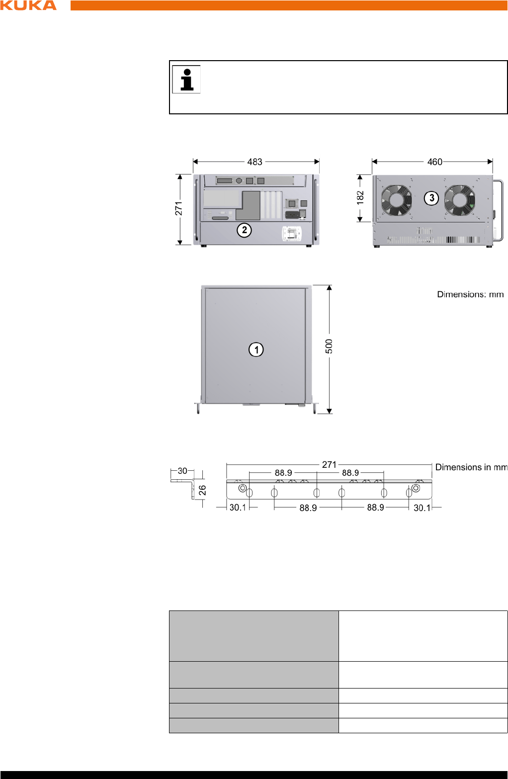
52 / 123 Issued: 15.04.2014 Version: BA KR C4 compact V5
KR C4 compact
600 mm.The robot controller may only be installed and operated in the hori-
zontal position.
Both sides of the robot controller must be accessible to the cooling air. Clear-
ance of 70 mm on each side.
Handle brackets
6.4 Connection conditions
Power supply
connection
The robot controller may only be connected to grounded-neutral power supply
systems.
If the robot controller is to be installed in a 19" rack, it must be fas-
tened in the rack by appropriate means (preferably angle plates)
along the entire side edge in order to prevent distortion of the hous-
ing.
Fig. 6-1: Dimensions
Fig. 6-2: Dimensions of handle brackets
Rated supply voltage 200 V - 230 V AC, single-phase,
two-phase (with grounded neutral
(as symmetrical as possible)
between the phases used
Permissible tolerance of rated sup-
ply voltage
Rated supply voltage ±10%
Mains frequency 50 Hz ± 1 Hz or 60 Hz ± 1 Hz
Rated power input 2 kVA, see rating plate
Thermal power dissipation max. 400 W
53 / 123Issued: 15.04.2014 Version: BA KR C4 compact V5
6 Planning
Cable lengths For cable designations, standard lengths and optional lengths, please refer to
the operating instructions or assembly instructions of the manipulator and/or
the assembly and operating instructions for KR C4 external cabling for robot
controllers.
6.5 Power supply connection
Description The robot controller is connected to the mains via a 3-pole socket for non-heat-
ing apparatus connector.
Infeed 200 V - 230 V AC, single-phase, two-phase (with grounded neutral (as
symmetrical as possible) between the phases used
50 Hz ± 1 Hz or 60 Hz ± 1 Hz
Fusing 2x 16 A slow-blowing, type C (1 (2)x phase; 1x neutral conductor (option-
al))
6.6 Safety interface X11
Description EMERGENCY STOP devices must be connected via safety interface X11 or
linked together by means of higher-level controllers (e.g. PLC).
Wiring Take the following points into consideration when wiring safety interface X11:
System concept
Safety concept
Mains-side fusing 2x 16 A slow-blowing (1 (2)x phase;
1x neutral conductor (optional))
Equipotential bonding The common neutral point for the
equipotential bonding conductors
and all protective ground conduc-
tors is the reference bus of the
power unit
If the robot controller is connected to a power system
without a grounded neutral, this may cause malfunc-
tions in the robot controller and material damage to the power supply units.
Electrical voltage can cause injuries. The robot controller may only be oper-
ated with grounded-neutral power supply systems.
If use of a residual-current circuit-breaker (RCCB) is planned, we rec-
ommend the following RCCB: trip current difference 300 mA per robot
controller, universal-current sensitive, selective.
When using smartPAD cable extensions, only two extensions may be
used. An overall cable length of 50 m must not be exceeded.
The difference in the cable lengths between the individual channels
of the RDC box must not exceed 10 m.
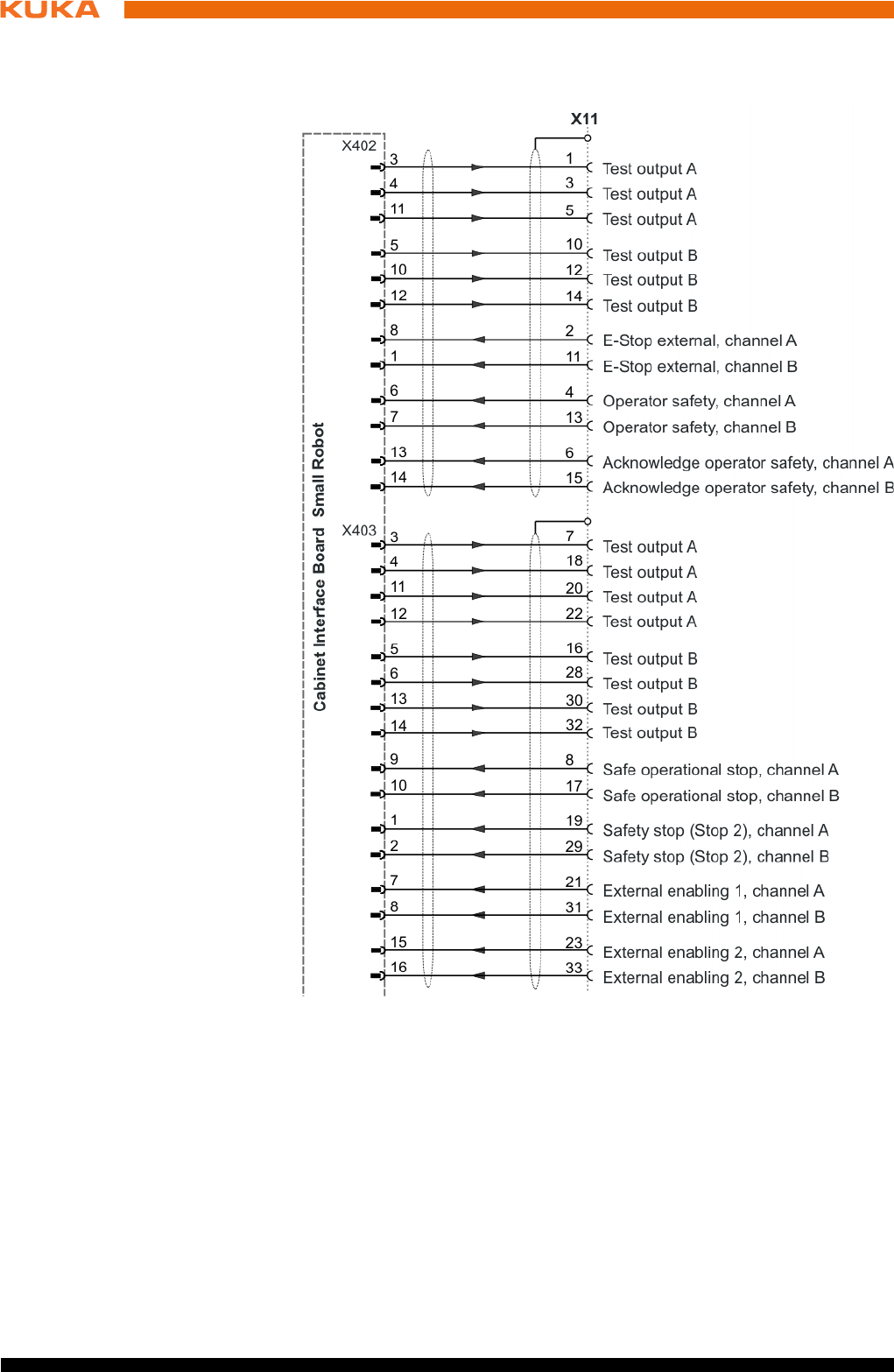
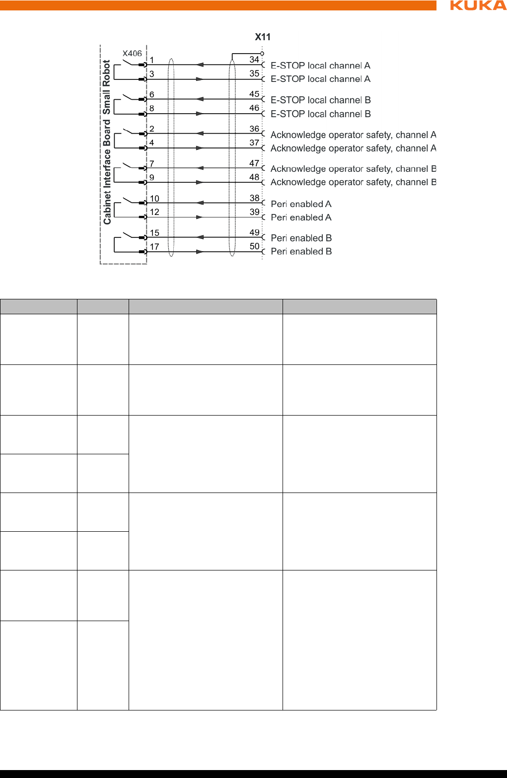
55 / 123Issued: 15.04.2014 Version: BA KR C4 compact V5
6 Planning
Fig. 6-4: Interface X11, part 2
Signal Pin Description Comments
Test output A
(test signal)
1/3/5
7/18
20/22
Makes the pulsed voltage avail-
able for the individual interface
inputs of channel A.
-
Test output B
(test signal)
10/12/14
16/28
30/32
Makes the pulsed voltage avail-
able for the individual interface
inputs of channel B.
-
External E-
STOP, chan-
nel A
2 E-STOP, dual-channel input,
max. 24 V. (>>> "CIB_SR
inputs" Page 24)
Triggering of the E-STOP func-
tion in the robot controller.
External E-
STOP, chan-
nel B
11
Operator
safety, chan-
nel A
4 For dual-channel connection of
a safety gate locking mecha-
nism, max. 24 V. (>>> "CIB_SR
inputs" Page 24)
As long as the signal is active,
the drives can be switched on.
Only effective in the AUTO-
MATIC modes.
Operator
safety, chan-
nel B
13
Acknowledge
operator
safety, chan-
nel A
6 For connection of a dual-chan-
nel input for acknowledging
operator safety with floating
contacts. (>>> "CIB_SR inputs"
Page 24)
The response of the “Operator
safety acknowledgement” input
can be configured in the KUKA
system software.
After closing the safety gate
(operator safety), manipulator
motion can be enabled in the
automatic modes using an
acknowledge button outside the
safety fence. This function is
deactivated on delivery.
Acknowledge
operator
safety, chan-
nel B
15
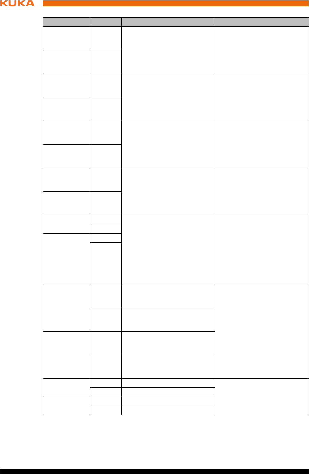
56 / 123 Issued: 15.04.2014 Version: BA KR C4 compact V5
KR C4 compact
Function of
external axis
enabling switch
External enabling 1
Enabling switch must be pressed for jogging in T1 or T2. Input is closed.
External enabling 2
Enabling switch is not in the panic position. Input is closed.
Safe opera-
tional stop,
channel A
8 Safe operational stop input for
all axes
Activation of standstill monitor-
ing
Stop 0 is initiated if the acti-
vated monitoring is violated.
Safe opera-
tional stop,
channel B
17
Safety stop,
Stop 2 chan-
nel A
19 Safety stop (Stop 2) input for all
axes
Triggering of Stop 2 and activa-
tion of standstill monitoring at
standstill of all axes.
Stop 0 is initiated if the activated
monitoring is violated.
Safety stop,
Stop 2 chan-
nel B
29
External
enabling 1
channel A
21 For connection of an external 2-
channel enabling switch 1 with
floating contacts.
If no external enabling switch 1
is connected, channel A pins 20/
21 and channel B 30/31 must be
jumpered. Only effective in
TEST modes.
External
enabling 1
channel B
31
External
enabling 2
channel A
23 For connection of an external 2-
channel enabling switch 2 with
floating contacts.
If no external enabling switch 2
is connected, channel A pins 22/
23 and channel B 32/33 must be
jumpered. Only effective in
TEST modes.
External
enabling 2
channel B
33
E-STOP local
channel A
34 Output, floating contacts from
internal E-STOP.
(>>> "CIB_SR outputs"
Page 23)
The contacts are closed if the
following conditions are met:
E-STOP on smartPAD not
actuated
Controller switched on and
operational
The contacts open if any condi-
tion is not met.
35
E-STOP local
channel B
45
46
Acknowledge
operator
safety, chan-
nel A
36 Output, floating contact for oper-
ator safety acknowledgement,
connection 1
Relaying of the acknowledge
operator safety input signal to
other robot controllers at the
same safety fencing.
37 Output, floating contact for oper-
ator safety acknowledgement,
connection 2
Acknowledge
operator
safety, chan-
nel B
47 Output, floating contact for oper-
ator safety acknowledgement,
connection 1
48 Output, floating contact for oper-
ator safety acknowledgement,
connection 2
Peri enabled
channel A
38 Output, floating contact (>>> "Signal “Peri enabled”"
Page 57)
39 Output, floating contact
Peri enabled
channel B
49 Output, floating contact
50 Output, floating contact
Signal Pin Description Comments
57 / 123Issued: 15.04.2014 Version: BA KR C4 compact V5
6 Planning
If a smartPAD is connected, its enabling switches and the external en-
abling are ANDed.
Signal “Peri
enabled”
The signal “Peri enabled” is set to 1 (active) if the following conditions are met:
Drives are switched on.
Safety controller motion enable signal present.
The message “Operator safety open” must not be active.
This message is only active in the modes T1 and T2.
“Peri enabled” in conjunction with the signal “Safe operational stop”
In the case of activation of the signal “Safe operational stop” during the
motion:
Error -> braking with Stop 0. “Peri enabled” eliminated.
Activation of the signal “Safe operational stop” with the manipulator sta-
tionary:
Release the brakes, switch drives to servo-control and monitor for restart.
“Peri enabled” remains active.
Signal “Motion enable” remains active.
Signal “Peri enabled” remains active.
“Peri enabled” in conjunction with the signal “Safety stop 2”
In the case of activation of the signal “Safety stop 2”:
Stop 2 of the manipulator.
Signal “Drive enable” remains active.
Brakes remain released.
Manipulator remains under servo-control.
Monitoring for restart active.
Signal “Motion enable” is deactivated.
Signal “Peri enabled” is deactivated.
6.6.2 Wiring example for E-STOP circuit and safeguard
Description The EMERGENCY STOP devices are connected to X11 in the robot control-
ler.
EMERGENCY
STOP
Function
(only active for T1 and T2)
External
enabling 1
External
enabling 2
Switch position
Safety stop 1 (drives switched off
when axis at standstill)
Input open Input open No operational
state
Safety stop 2 (safe operational stop,
drives switched on)
Input open Input closed Not pressed
Safety stop 1 (drives switched off
when axis at standstill)
Input closed Input open Panic position
Axes enabled (axis jogging possible) Input closed Input closed Center position
The EMERGENCY STOP devices on the robot controller
must be integrated into the EMERGENCY STOP circuit
of the system by the system integrator.
Failure to do this may result in death, severe injuries or considerable damage
to property.
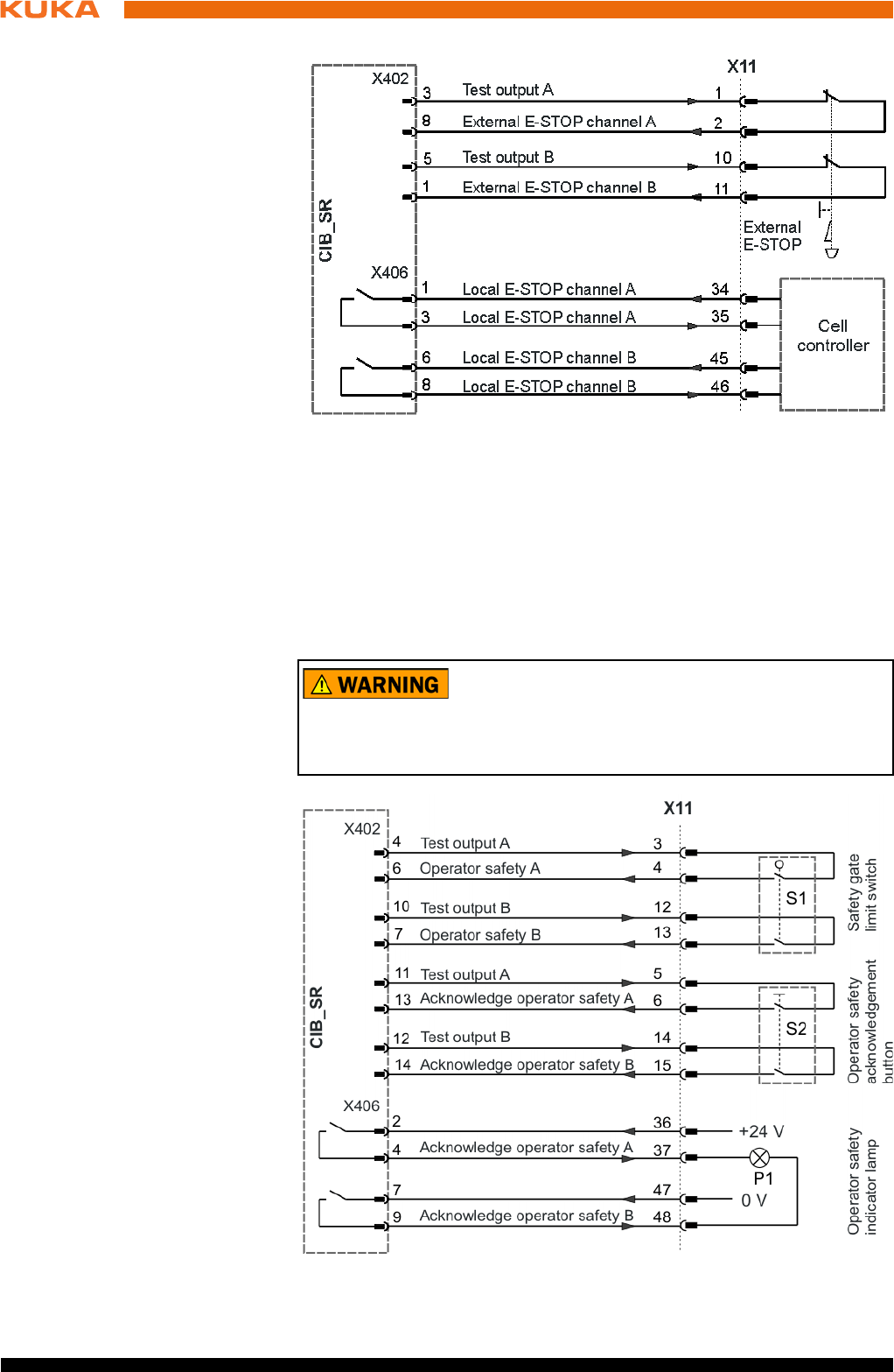
58 / 123 Issued: 15.04.2014 Version: BA KR C4 compact V5
KR C4 compact
Safety gate A dual-channel acknowledge button must be installed outside the physical
safeguard. The system integrator must ensure that closing the safety gate in-
advertently does not directly set the signal for operator safety. After the safety
gate has closed, the signal for operator safety must only be confirmed by an
external device, e.g. an acknowledge button, that can only be accessed from
outside the danger zone. The closing of the safety gate must be confirmed by
pressing the acknowledge button before the industrial robot can be started
again in Automatic mode.
Fig. 6-5: Wiring example: EMERGENCY STOP
The safety gate on the robot controller must be integrat-
ed into the safeguard circuit of the system by the system
integrator.
Failure to do this may result in death, severe injuries or considerable damage
to property.
Fig. 6-6: Wiring example: Operator safety with safety gate
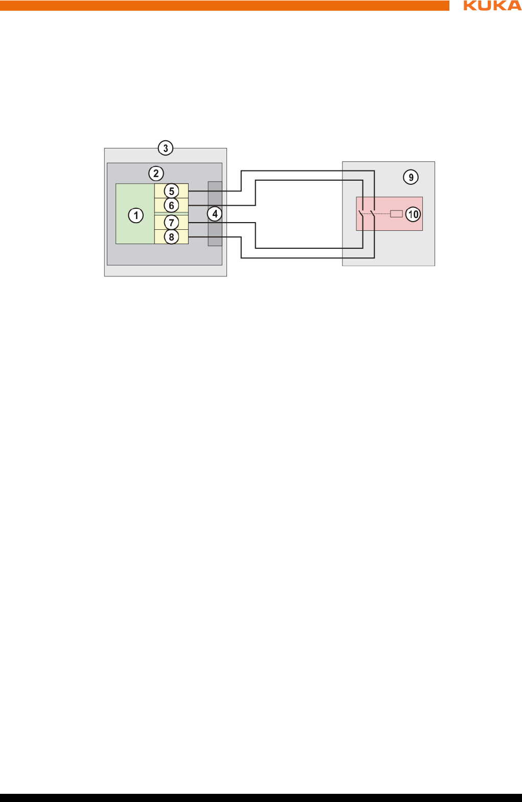
59 / 123Issued: 15.04.2014 Version: BA KR C4 compact V5
6 Planning
6.6.3 Wiring example for safe inputs and outputs
Safe input The switch-off capability of the inputs is monitored cyclically.
The inputs of the CIB_SR are of dual-channel design with external testing. The
dual-channel operation of the inputs is monitored cyclically.
The following diagram illustrates the connection of a safe input to a floating
contact provided by the customer.
Test outputs A and B are fed with the supply voltage of the CIB_SR. Test out-
puts A and B are sustained short-circuit proof. The test outputs must only be
used to supply the CIB_SR inputs, and for no other purpose.
The wiring example can be used to achieve compliance with SIL2 (DIN EN
62061) and Cat. 3 (DIN EN 13849).
Dynamic testing The switch-off capability of the inputs is tested cyclically. For this, the test
outputs TA_A and TA_B are switched off alternately.
The switch-off pulse length is defined for the CIB_SRs as t1 = 625 μs (125
μs – 2.375 ms).
The duration t2 between two switch-off pulses on one channel is 106 ms.
The input channel SIN_x_A must be supplied by the test signal TA_A. The
input channel SIN_x_B must be supplied by the test signal TA_B. No other
power supply is permissible.
It is only permitted to connect sensors which allow the connection of test
signals and which provide floating contacts.
The signals TA_A and TA_B must not be significantly delayed by the
switching element.
Fig. 6-7: Connection schematic for safe input
1 Failsafe input CIB_SR
2CIB_SR
3 Robot controller
4 Interface X11
5 Test output channel B
6 Test output channel A
7 Input X, channel A
8 Input X, channel B
9System side
10 Floating contact
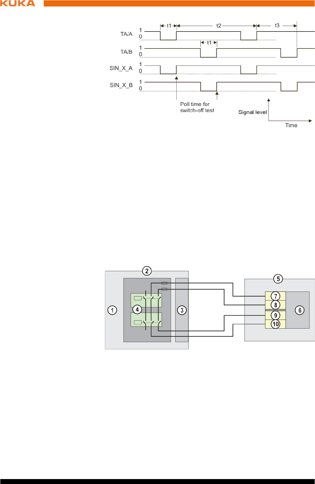
60 / 123 Issued: 15.04.2014 Version: BA KR C4 compact V5
KR C4 compact
Switch-off pulse
diagram
Safe output On the CIB_SR, the outputs are provided as dual-channel floating relay out-
puts.
The following diagram illustrates the connection of a safe output to a safe input
provided by the customer with external test facility. The input used by the cus-
tomer must be monitored externally for cross-connection.
Fig. 6-8: Switch-off pulse diagram, test outputs
t1 Switch-off pulse length (fixed or configurable)
t2 Switch-off period per channel (106 ms)
t3 Offset between switch-off pulses of both channels (53 ms)
TA/A Test output channel A
TA/B Test output channel B
SIN_X_A Input X, channel A
SIN_X_B Input X, channel B
Fig. 6-9: Connection schematic for safe output
1CIB_SR
2 Robot controller
3 Interface X11, safe output
4 Output wiring
5 System side
6 Safe input (Fail Safe PLC, safety switching device)
7 Test output channel B
8 Test output channel A
9 Input X, channel A
10 Input X, channel B
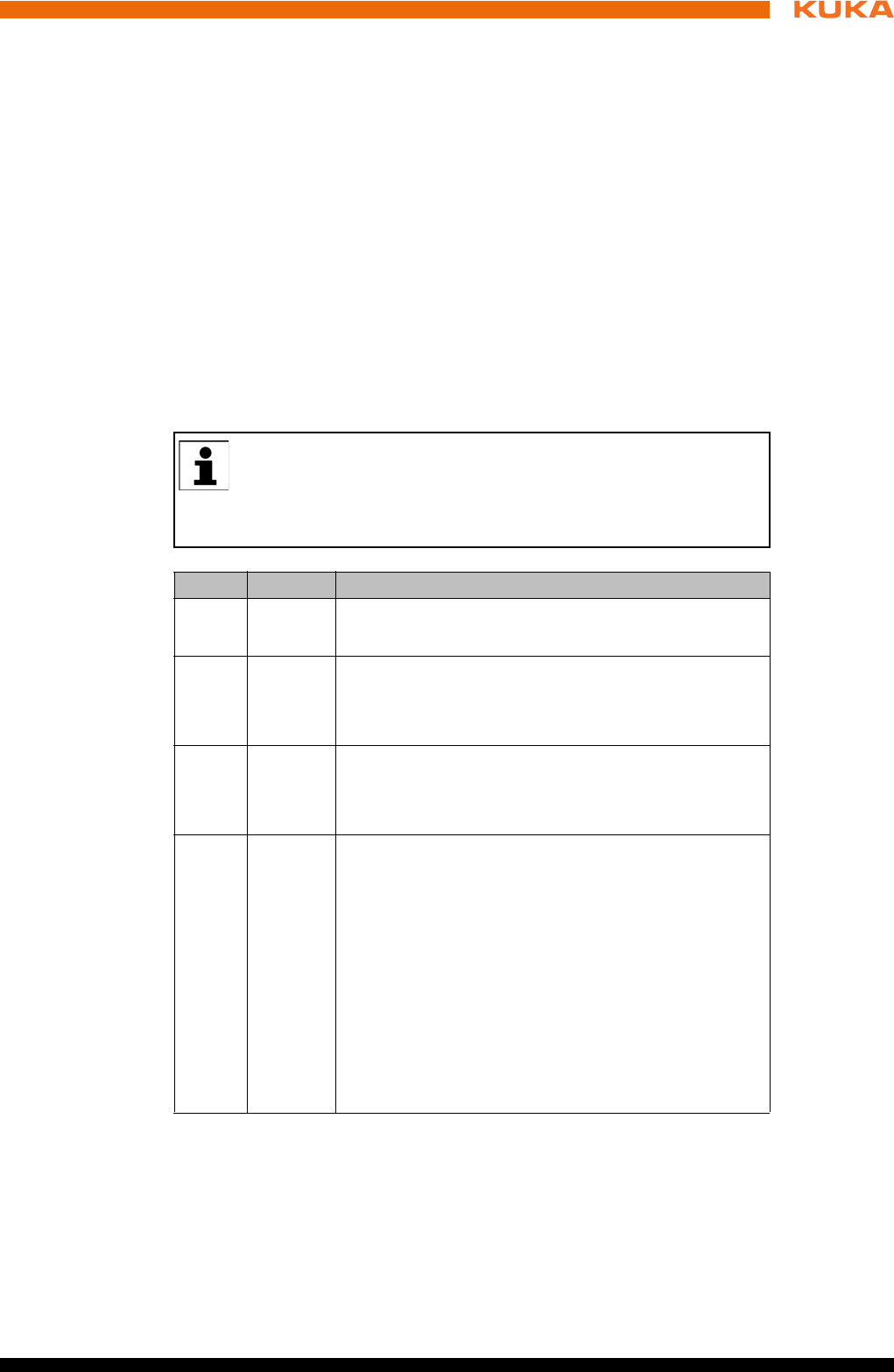
61 / 123Issued: 15.04.2014 Version: BA KR C4 compact V5
6 Planning
The wiring example shown can be used to achieve compliance with SIL2 (DIN
EN 62061) and Cat. 3 (DIN EN 13849).
6.7 Safety functions via Ethernet safety interface (optional)
Description The exchange of safety-relevant signals between the controller and the sys-
tem is carried out via the Ethernet safety interface (e.g. PROFIsafe or CIP
Safety). The assignment of the input and output states within the Ethernet
safety interface protocol are listed below. In addition, non-safety-oriented in-
formation from the safety controller is sent to the non-safe section of the high-
er-level controller for the purpose of diagnosis and control.
Reserved bits Reserved safe inputs can be pre-assigned by a PLC with the values 0 or 1. In
both cases, the manipulator will move. If a safety function is assigned to a re-
served input (e.g. in the case of a software update) and if this input is preset
with the value 0, then the manipulator would either not move or would unex-
pectedly come to a standstill.
Input byte 0
KUKA recommends pre-assignment of the reserved inputs with 1. If
a reserved input has a new safety function assigned to it, and the in-
put is not used by the customer’s PLC, the safety function is not acti-
vated. This prevents the safety controller from unexpectedly stopping the
manipulator.
Bit Signal Description
0 RES Reserved 1
The value 1 must be assigned to the input.
1 NHE Input for external Emergency Stop
0 = external E-STOP is active
1 = external E-STOP is not active
2 BS Operator safety
0 = operator safety is not active, e.g. safety gate open
1 = operator safety is active
3 QBS Acknowledgement of operator safety
Precondition for acknowledgement of operator safety
is the signal "Operator safety assured" set in the BS
bit.
Note: If the “BS” signal is acknowledged by the sys-
tem, this must be specified under Hardware options
in the safety configuration. Information is contained in
the Operating and Programming Instructions for Sys-
tem Integrators.
0 = operator safety has not been acknowledged
Edge 0 ->1 = operator safety has been acknowledged

62 / 123 Issued: 15.04.2014 Version: BA KR C4 compact V5
KR C4 compact
Input byte 1
4 SHS1 Safety STOP 1 (all axes)
FF (motion enable) is set to 0.
Voltage US2 is switched off.
AF (drives enable) is set to 0 after 1.5 s.
Cancelation of this function does not require acknowl-
edgement.
This function is not permissible for the EMERGENCY
STOP function.
0 = safety stop is active
1 = safety stop is not active
5 SHS2 Safety STOP 2 (all axes)
FF (motion enable) is set to 0.
Voltage US2 is switched off.
Cancelation of this function does not require acknowl-
edgement.
This function is not permissible for the EMERGENCY
STOP function.
0 = safety stop is active
1 = safety stop is not active
6RES -
7RES -
Bit Signal Description
Bit Signal Description
0 US2 Supply voltage US2 (signal for switching the second
supply voltage, US2, without battery backup)
If this output is not used, it should be set to 0.
0 = switch off US2
1 = switch on US2
Note: Whether and how input US2 is used must be
specified under Hardware options in the safety con-
figuration. Information is contained in the Operating
and Programming Instructions for System Integra-
tors.
1 SBH Safe operational stop (all axes)
Precondition: All axes are stationary
Cancelation of this function does not require acknowl-
edgement.
This function is not permissible for the EMERGENCY
STOP function.
0 = safe operational stop is active.
1 = safe operational stop is not active.
2RES Reserved 11
The value 1 must be assigned to the input.
3RES Reserved 12
The value 1 must be assigned to the input.

63 / 123Issued: 15.04.2014 Version: BA KR C4 compact V5
6 Planning
Output byte 0
4RES Reserved 13
The value 1 must be assigned to the input.
5RES Reserved 14
The value 1 must be assigned to the input.
6RES Reserved 15
The value 1 must be assigned to the input.
7 SPA System Powerdown Acknowledge
The system confirms that it has received the power-
down signal. A second after the “SP” (System Power-
down) signal has been set by the controller, the
requested action is executed, without the need for
confirmation from the PLC, and the controller shuts
down.
0 = confirmation is not active
1 = confirmation is active
Bit Signal Description
Bit Signal Description
0 NHL Local E-STOP (local E-STOP triggered)
0 = local E-STOP is active
1 = local E-STOP is not active
1 AF Drives enable (the internal safety controller in the
KRC has enabled the drives so that they can be
switched on)
0 = drives enable is not active (the robot controller
must switch the drives off)
1 = drives enable is active (the robot controller must
switch the drives to servo-control)
2 FF Motion enable (the internal safety controller in the
KRC has enabled robot motions)
0 = motion enable is not active (the robot controller
must stop the current motion)
1 = motion enable is active (the robot controller may
trigger a motion)
3 ZS One of the enabling switches is in the center position
(enabling in test mode)
0 = enabling is not active
1 = enabling is active
4 PE The signal “Peri enabled” is set to 1 (active) if the fol-
lowing conditions are met:
Drives are switched on.
Safety controller motion enable signal present.
The message “Operator safety open” must not be
active.
5 AUT The manipulator is in AUT or AUT EXT mode.
0 = AUT or AUT EXT mode is not active
1 = AUT or AUT EXT mode is active
64 / 123 Issued: 15.04.2014 Version: BA KR C4 compact V5
KR C4 compact
Output byte 1
6.7.1 Schematic circuit diagram for enabling switches
Description An external enabling switch can be connected to the higher-level safety con-
troller. The signals (ZSE make contact and External panic break contact) must
be correctly linked to the Ethernet safety interface signals in the safety control-
ler. The resulting Ethernet safety interface signals must then be routed to the
PROFIsafe of the KR C4. The response to the external enabling switch is then
identical to that for a discretely connected X11.
6 T1 The manipulator is in Manual Reduced Velocity
mode.
0 = T1 mode is not active
1 = T1 mode is active
7 T2 The manipulator is in Manual High Velocity mode.
0 = T2 mode is not active
1 = T2 mode is active
Bit Signal Description
Bit Signal Description
0 NHE External E-STOP has been triggered.
0 = external E-STOP is active
1 = external E-STOP is not active
1 BS Operator safety
0 = operator safety is not assured
1 = operator safety is assured (input BS = 1 and, if
configured, input QBS acknowledged)
2 SHS1 Safety stop 1 (all axes)
0 = Safety stop 1 is not active
1 = Safety stop 1 is active (safe state reached)
3 SHS2 Safety stop 2 (all axes)
0 = Safety stop 2 is not active
1 = Safety stop 2 is active (safe state reached)
4RES Reserved 13
5RES Reserved 14
6 PSA Safety interface active
Precondition: An Ethernet interface must be installed
on the controller, e.g. PROFINET or Ethernet/IP
0 = safety interface is not active
1 = safety interface is active
7 SP System Powerdown (controller will be shut down)
One second after the SP signal has been set, the
PSA output is reset by the robot controller, without
confirmation from the PLC, and the controller is shut
down.
0 = controller on safety interface is active.
1 = controller will be shut down
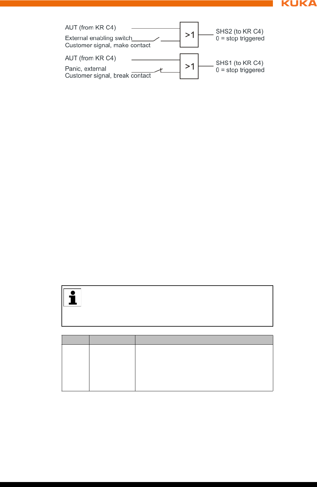
65 / 123Issued: 15.04.2014 Version: BA KR C4 compact V5
6 Planning
Signals
Enabling switch center position (make contact closed (1) = enabled) OR
AUT at SHS2
Panic (break contact open (0) = panic position) = AND not AUT at SHS1
6.7.2 SafeOperation via Ethernet safety interface (optional)
Description The components of the industrial robot move within the limits that have been
configured and activated. The actual positions are continuously calculated and
monitored against the safety parameters that have been set. The safety con-
troller monitors the industrial robot by means of the safety parameters that
have been set. If a component of the industrial robot violates a monitoring limit
or a safety parameter, the manipulator and external axes (optional) are
stopped. The Ethernet safety interface can be used, for example, to signal a
violation of safety monitoring functions.
In the case of the KR C4 compact robot controller, safety options such as Sa-
feOperation are only available via the Ethernet safety interface from KSS/
VSS 8.3 onwards.
Reserved bits Reserved safe inputs can be pre-assigned by a PLC with the values 0 or 1. In
both cases, the manipulator will move. If a safety function is assigned to a re-
served input (e.g. in the case of a software update) and if this input is preset
with the value 0, then the manipulator would either not move or would unex-
pectedly come to a standstill.
Input byte 2
Fig. 6-10: Schematic circuit diagram of external enabling switch
KUKA recommends pre-assignment of the reserved inputs with 1. If
a reserved input has a new safety function assigned to it, and the in-
put is not used by the customer’s PLC, the safety function is not acti-
vated. This prevents the safety controller from unexpectedly stopping the
manipulator.
Bit Signal Description
0 JR Mastering test (input for the reference switch of
the mastering test)
0 = reference switch is active (actuated).
1 = reference switch is not active (not actu-
ated).
66 / 123 Issued: 15.04.2014 Version: BA KR C4 compact V5
KR C4 compact
Input byte 3
Input byte 4
Input byte 5
Input byte 6
Input byte 7
1 VRED Reduced axis-specific and Cartesian velocity
(activation of reduced velocity monitoring)
0 = reduced velocity monitoring is active.
1 = reduced velocity monitoring is not active.
2 … 7 SBH1 … 6 Safe operational stop for axis group 1 ... 6
Assignment: Bit 2 = axis group 1 … bit 7 = axis
group 6
Signal for safe operational stop. The function
does not trigger a stop, it only activates the safe
standstill monitoring. Cancelation of this func-
tion does not require acknowledgement.
0 = safe operational stop is active.
1 = safe operational stop is not active.
Bit Signal Description
Bit Signal Description
0 … 7 RES Reserved 25 ... 32
The value 1 must be assigned to the inputs.
Bit Signal Description
0 … 7 UER1 … 8 Monitoring spaces 1 … 8
Assignment: Bit 0 = monitoring space 1 … bit 7
= monitoring space 8
0 = monitoring space is active.
1 = monitoring space is not active.
Bit Signal Description
0 … 7 UER9 … 16 Monitoring spaces 9 … 16
Assignment: Bit 0 = monitoring space 9 … bit 7
= monitoring space 16
0 = monitoring space is active.
1 = monitoring space is not active.
Bit Signal Description
0 … 7 WZ1 … 8 Tool selection 1 … 8
Assignment: Bit 0 = tool 1 … bit 7 = tool 8
0 = tool is not active.
1 = tool is active.
Exactly one tool must be selected at all times.
Bit Signal Description
0 … 7 WZ9 … 16 Tool selection 9 … 16
Assignment: Bit 0 = tool 9 … bit 7 = tool 16
0 = tool is not active.
1 = tool is active.
Exactly one tool must be selected at all times.

67 / 123Issued: 15.04.2014 Version: BA KR C4 compact V5
6 Planning
Output byte 2
Output byte 3
Output byte 4
Bit Signal Description
0 SO Safety option active
SafeOperation activation status
0 = safety option is not active
1 = safety option is active
1 RR Manipulator referenced
Mastering test display
0 = mastering test required.
1 = mastering test performed successfully.
2 JF Mastering error
Space monitoring is deactivated because at
least one axis is not mastered.
0 = mastering error. Space monitoring has been
deactivated.
1 = no error.
3 VRED Reduced axis-specific and Cartesian velocity
(activation status of reduced velocity monitor-
ing)
0 = reduced velocity monitoring is not active.
1 = reduced velocity monitoring is active.
4 … 7 SBH1 … 4 Activation status of safe operational stop for
axis group 1 ... 4
Assignment: Bit 4 = axis group 1 … bit 7 = axis
group 4
0 = safe operational stop is not active.
1 = safe operational stop is active.
Bit Signal Description
0 … 1 SBH5 … 6 Activation status of safe operational stop for
axis group 5 ... 6
Assignment: Bit 0 = axis group 5 … bit 1 = axis
group 6
0 = safe operational stop is not active.
1 = safe operational stop is active.
2 … 7 RES Reserved 27 ... 32
Bit Signal Description
0 … 7 MR1 … 8 Alarm space 1 … 8
Assignment: Bit 0 = alarm space 1 (associated
monitoring space 1) … bit 7 = alarm space 8
(associated monitoring space 8)
0 = monitoring space is violated.
1 = monitoring space is not violated.
Note: An inactive monitoring space is consid-
ered to be violated by default, i.e. in this case
the associated safe output MRx has the state
“0”.
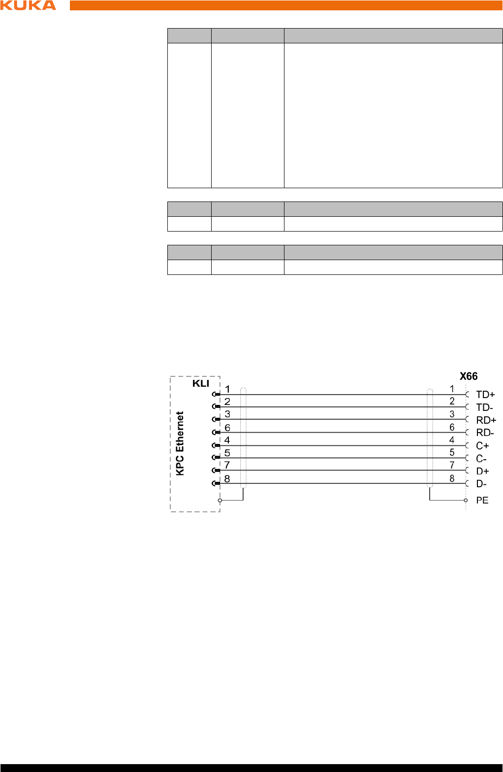
68 / 123 Issued: 15.04.2014 Version: BA KR C4 compact V5
KR C4 compact
Output byte 5
Output byte 6
Output byte 7
6.7.3 Ethernet interface (1xRJ45) X66
Description Connector X66 on the connection panel is intended for connecting an external
computer for the purpose of installation, programming, debugging and diagno-
sis.
Connector pin
allocation
Recommended
cable
Ethernet-compatible, min. category CAT 6.
6.8 Mastering test
For the mastering test, a reference switch must be connected to the safety
PLC and activated via PROFIsafe or CIP Safety. The safety PLC must evalu-
ate the reference switch and set the input “Mastering test” accordingly.
6.9 EtherCAT interface X65
Description Connector X65 in the connection panel is the interface for connection of Ether-
CAT slaves outside the robot controller. The EtherCAT line is routed out of the
robot controller.
Bit Signal Description
0 … 7 MR9 … 16 Alarm space 9 … 16
Assignment: Bit 0 = alarm space 9 (associated
monitoring space 9) … bit 7 = alarm space 16
(associated monitoring space 16)
0 = monitoring space is violated.
1 = monitoring space is not violated.
Note: An inactive monitoring space is consid-
ered to be violated by default, i.e. in this case
the associated safe output MRx has the state
“0”.
Bit Signal Description
0 … 7 RES Reserved 49 ... 56
Bit Signal Description
0 … 7 RES Reserved 57 ... 64
Fig. 6-11: Connector pin allocation X66
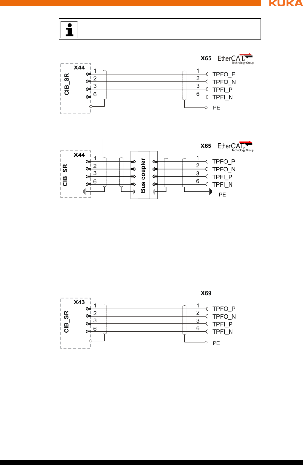
69 / 123Issued: 15.04.2014 Version: BA KR C4 compact V5
6 Planning
Connector pin
allocation
Connector pin
allocation
Recommended
cable
Ethernet-compatible, min. category CAT 5.
6.10 Service Interface X69
Description Connector X69 on the connection panel is intended for connecting a notebook
for the purpose of diagnosis, WorkVisual configuration, update, etc.
Connector pin
allocation
Recommended
cable
Ethernet-compatible, min. category CAT 5.
The EtherCAT devices must be configured with WorkVisual.
Fig. 6-12: Connector pin allocation X65 via CIB_SR
Fig. 6-13: Connector pin allocation X65 via bus coupler
Fig. 6-14: Connector pin allocation X69 via CIB_SR
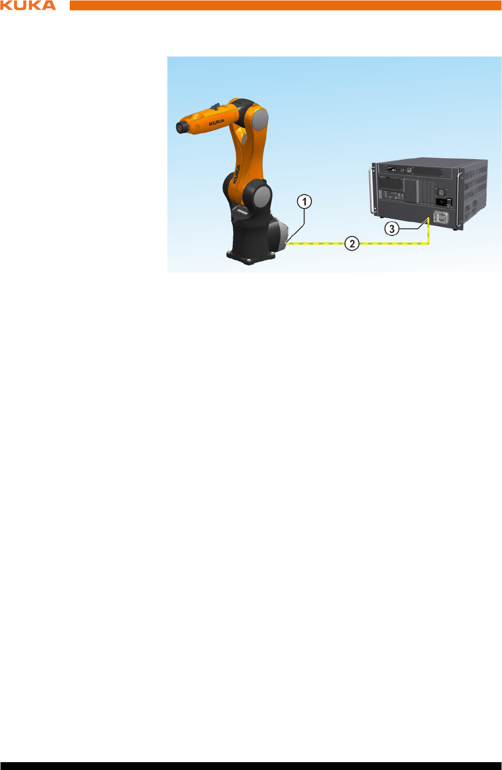
70 / 123 Issued: 15.04.2014 Version: BA KR C4 compact V5
KR C4 compact
6.11 PE equipotential bonding
Description
A cable with a cross-section of at least 4 mm2 must be used as equipotential
bonding between the manipulator and the robot controller.
6.12 Performance level
The safety functions of the robot controller conform to category 3 and Perfor-
mance Level d according to EN ISO 13849-1.
6.12.1 PFH values of the safety functions
The safety values are based on a service life of 20 years.
The PFH value classification of the controller is only valid if the E-STOP device
is tested at least once every 6 months.
When evaluating system safety functions, it must be remembered that the
PFH values for a combination of multiple controllers may have to be taken into
consideration more than once. This is the case for RoboTeam systems or
higher-level hazard areas. The PFH value determined for the safety function
at system level must not exceed the limit for PL d.
The PFH values relate to the specific safety functions of the different controller
variants.
Safety function groups:
Standard safety functions
Operating mode selection
Operator safety
EMERGENCY STOP device
Enabling device
Fig. 6-15: Equipotential bonding between the manipulator and the robot
controller
1 Equipotential bonding connec-
tion on the manipulator
3 Equipotential bonding connec-
tion on the robot controller
2 Equipotential bonding, min.
4 mm2
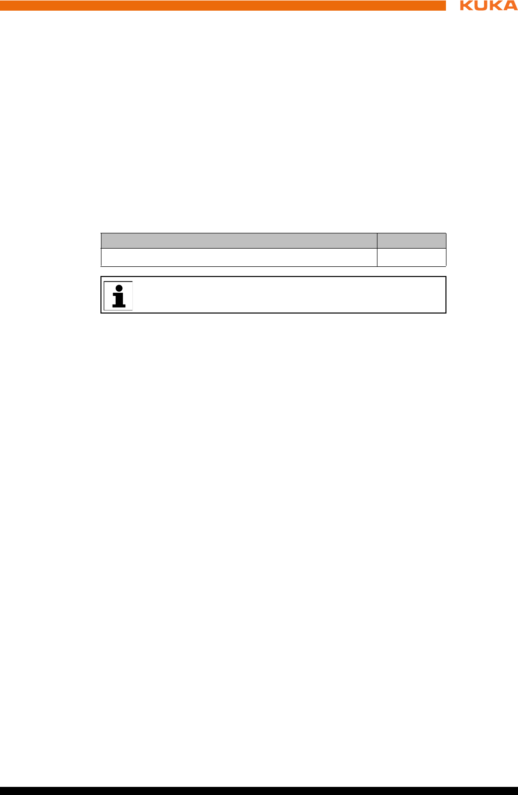
71 / 123Issued: 15.04.2014 Version: BA KR C4 compact V5
6 Planning
External safe operational stop
External safety stop 1
External safety stop 2
Velocity monitoring in T1
Safety functions of KUKA.SafeOperation (option)
Monitoring of axis spaces
Monitoring of Cartesian spaces
Monitoring of axis velocity
Monitoring of Cartesian velocity
Monitoring of axis acceleration
Safe operational stop
Tool monitoring
Overview of controller variant PFH values:
Robot controller variant PFH value
KR C4 compact < 6.37 x 10⁻⁸
For controller variants that are not listed here, please contact KUKA
Roboter GmbH.

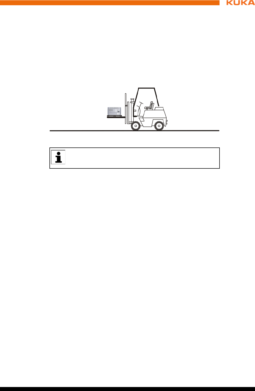
73 / 123Issued: 15.04.2014 Version: BA KR C4 compact V5
7 Transportation
7 Transportation
7.1 Transporting the robot controller
Preconditions The housing of the robot controller must be closed.
No cables may be connected to the robot controller.
The robot controller must be transported in a horizontal position.
Procedure Transport the robot controller using a pallet truck or a fork lift truck. The
robot controller must be laid on a pallet.
Fig. 7-1: Transportation by fork lift truck
If the robot controller is installed in an electrical enclosure during
transportation, this may result in vibrations (oscillations). Such vibra-
tions can cause contact problems on the PC plug-in cards.

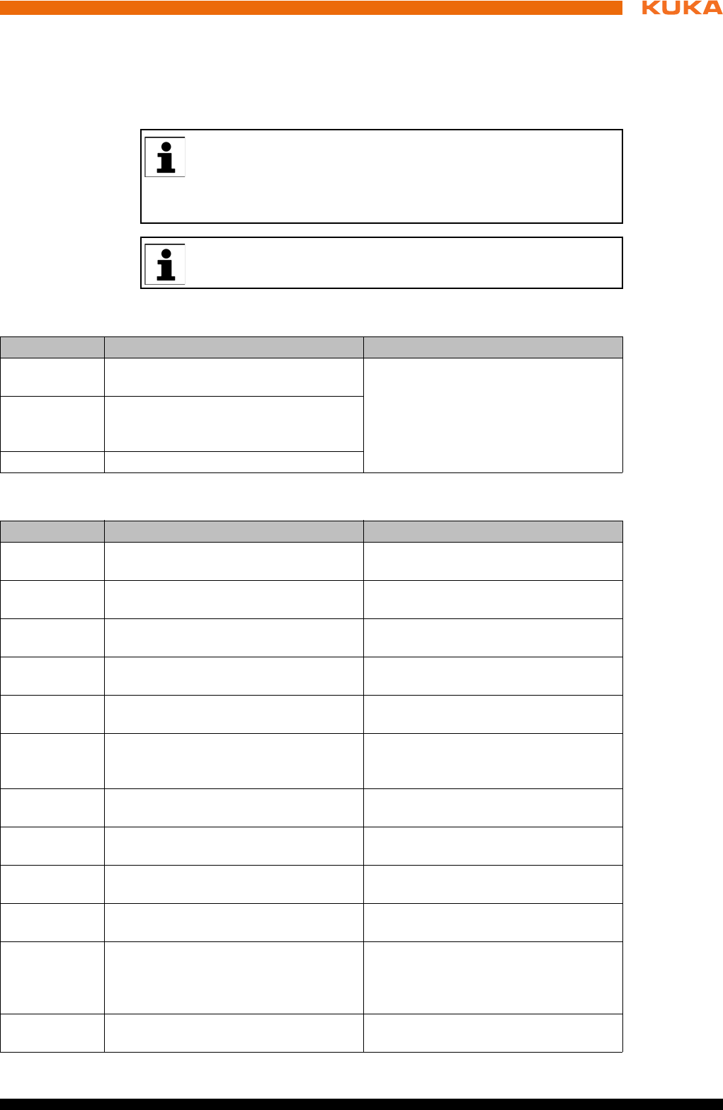
75 / 123Issued: 15.04.2014 Version: BA KR C4 compact V5
8 Start-up and recommissioning
8 Start-up and recommissioning
8.1 Start-up overview
Manipulator
Electrical system
This is an overview of the most important steps during start-up. The
precise sequence depends on the application, the manipulator type,
the technology packages used and other customer-specific circum-
stances.
For this reason, the overview does not claim to be comprehensive.
This overview refers to the start-up of the industrial robot. The start-
up of the overall system is not within the scope of this documentation.
Step Description Information
1 Carry out a visual inspection of the
manipulator.
Detailed information is contained in the
operating or assembly instructions for
the manipulator, in the chapter “Start-
up and recommissioning”.
2 Install the manipulator mounting base
(mounting base, machine frame
mounting or booster frame).
3 Install the manipulator.
Step Description Information
4 Carry out a visual inspection of the
robot controller.
-
5 Make sure that no condensation has
formed in the robot controller.
-
6 Install the robot controller. (>>> 8.2 "Installing the robot control-
ler" Page 76)
7 Connect the connecting cables. (>>> 8.3 "Connecting the connecting
cables" Page 76)
8 Plug in the KUKA smartPAD. (>>> 8.4 "Plugging in the KUKA
smartPAD" Page 77)
9 Connect the equipotential bonding
between the manipulator and the robot
controller.
(>>> 8.5 "Connecting the PE equipo-
tential bonding" Page 78)
10 Connect the robot controller to the
power supply.
(>>> 8.6 "Connecting the robot con-
troller to the power supply" Page 78)
11 Reverse the battery discharge protec-
tion measures.
(>>> 8.7 "Reversing the battery dis-
charge protection measures" Page 78)
12 Configure and connect safety interface
X11.
(>>> 8.8 "Configuring and connecting
connector X11" Page 79)
13 Switch on the robot controller. (>>> 8.9 "Switching on the robot con-
troller" Page 79)
14 Check the safety equipment. Detailed information is contained in the
operating and assembly instructions
for the robot controller, in the “Safety”
chapter.
15 Configure the inputs/outputs between
the robot controller and the periphery.
Detailed information can be found in
the field bus documentation.
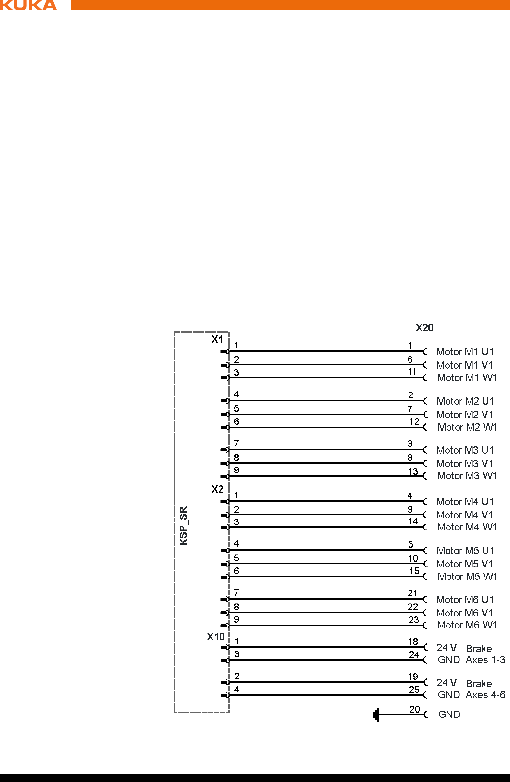
76 / 123 Issued: 15.04.2014 Version: BA KR C4 compact V5
KR C4 compact
8.2 Installing the robot controller
Description The robot controller can be installed in a 19" rack or as a standalone device.
Preconditions If the robot controller is to be installed in a 19" rack, the depth must be at
least 600 mm.
Both sides of the robot controller must be accessible to the cooling air.
Procedure 1. Check the robot controller for any damage caused during transportation.
2. Only install the robot controller horizontally.
8.3 Connecting the connecting cables
Overview A cable set is supplied with the robot system. The basic version consists of:
Motor/data cable
Power supply connection cable
The following cables may be provided for additional applications:
Peripheral cables
Procedure 1. Connect motor connector X20 to the drive box.
2. Connect data cable connector X21 to the control box.
Connector pin
allocation X20
Fig. 8-1: Connector pin allocation for X20
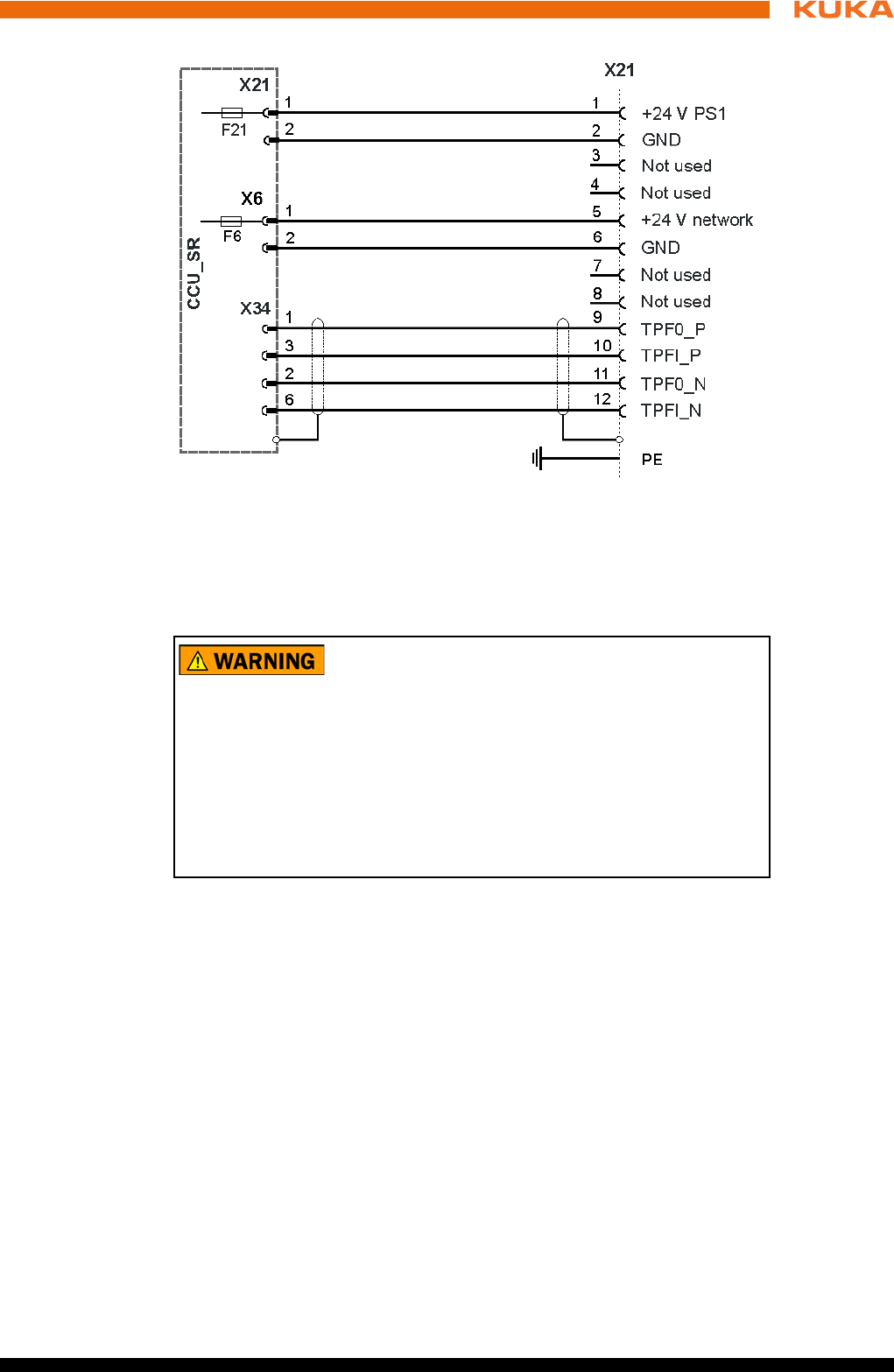
77 / 123Issued: 15.04.2014 Version: BA KR C4 compact V5
8 Start-up and recommissioning
Connector pin
allocation X21
8.4 Plugging in the KUKA smartPAD
Procedure Plug the KUKA smartPAD to X19 on the robot controller.
Fig. 8-2: Connector pin allocation for X21
If the smartPAD is disconnected, the system can no lon-
ger be switched off by means of the EMERGENCY
STOP device on the smartPAD. For this reason, an external EMERGENCY
STOP must be connected to the robot controller.
The user is responsible for ensuring that the smartPAD is immediately re-
moved from the system when it has been disconnected. The smartPAD must
be stored out of sight and reach of personnel working on the industrial robot.
This prevents operational and non-operational EMERGENCY STOP devices
from becoming interchanged.
Failure to observe these precautions may result in death, injuries or damage
to property.
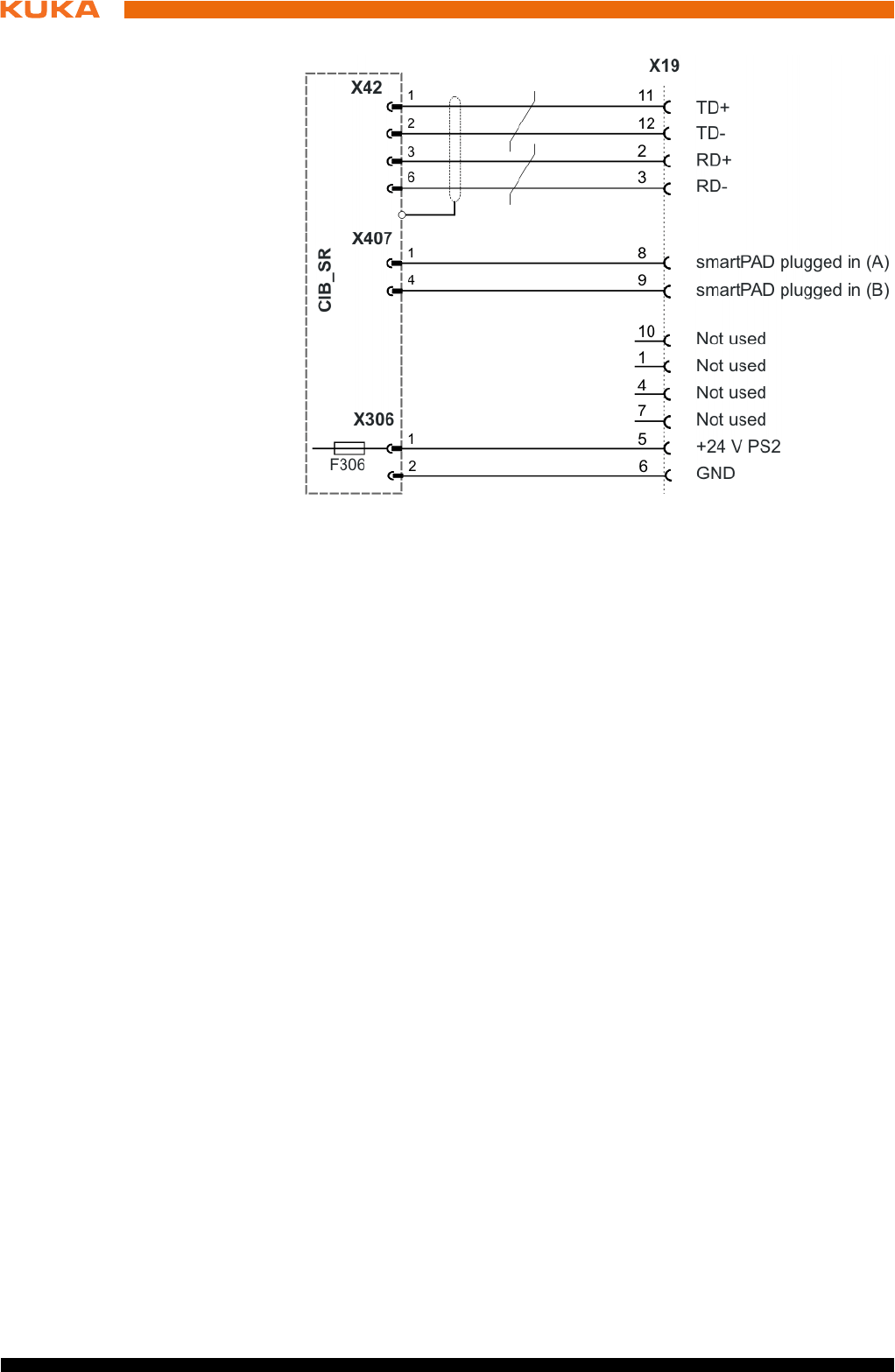
78 / 123 Issued: 15.04.2014 Version: BA KR C4 compact V5
KR C4 compact
Connector pin
allocation X19
8.5 Connecting the PE equipotential bonding
Procedure 1. Route and connect a 4 mm2 cable as equipotential bonding between the
manipulator and the robot controller at the installation site. (>>> 6.11 "PE
equipotential bonding" Page 70)
Route the equipotential bonding by the shortest route from the robot con-
troller to the manipulator.
2. Ground the robot controller at the installation site.
3. Carry out a ground conductor check for the entire robot system in accor-
dance with DIN EN 60204-1.
8.6 Connecting the robot controller to the power supply
Description The robot controller is connected to the mains via a 3-pole socket for non-heat-
ing apparatus connector.
Precondition Robot controller is switched off.
The power cable is de-energized.
Procedure Connect the robot controller to the mains via power plug.
8.7 Reversing the battery discharge protection measures
Description To prevent the batteries from discharging before the controller has been start-
ed up for the first time, the robot controller is supplied with connector X305 dis-
connected from the CCU_SR.
Procedure Plug connector X305 into the CCU_SR.
Fig. 8-3: Connector pin allocation X19
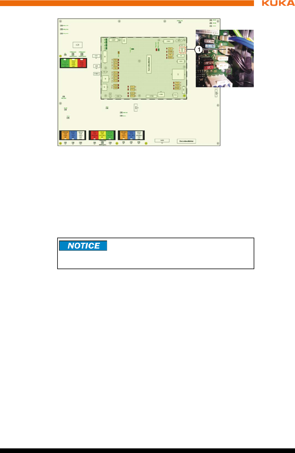
79 / 123Issued: 15.04.2014 Version: BA KR C4 compact V5
8 Start-up and recommissioning
8.8 Configuring and connecting connector X11
Precondition The robot controller is switched off.
Procedure 1. Configure connector X11 in accordance with the system and safety con-
cepts. (>>> 6.6.1 "Safety interface X11" Page 54)
2. Connect interface connector X11 to the robot controller.
8.9 Switching on the robot controller
Preconditions The manipulator has been installed in accordance with the operating in-
structions.
All electrical connections are correct and the energy levels are within the
specified limits.
The housing of the robot controller must be closed.
The peripheral devices are correctly connected.
It must be ensured that no persons or objects are present within the dan-
ger zone of the manipulator.
All safety devices and protective measures are complete and fully func-
tional.
The internal temperature of the robot controller must have adapted to the
ambient temperature.
Procedure 1. Release the E-STOP device on the smartPAD.
2. Switch on the main switch.
The control PC begins to run up (load) the operating system and the con-
trol software.
Fig. 8-4: Battery discharge protection X305
1 Connector X305 on the CCU_SR
Connector X11 may only be plugged in or unplugged
when the robot controller is switched off. If connector
X11 is plugged in or unplugged when energized, damage to property may oc-
cur.

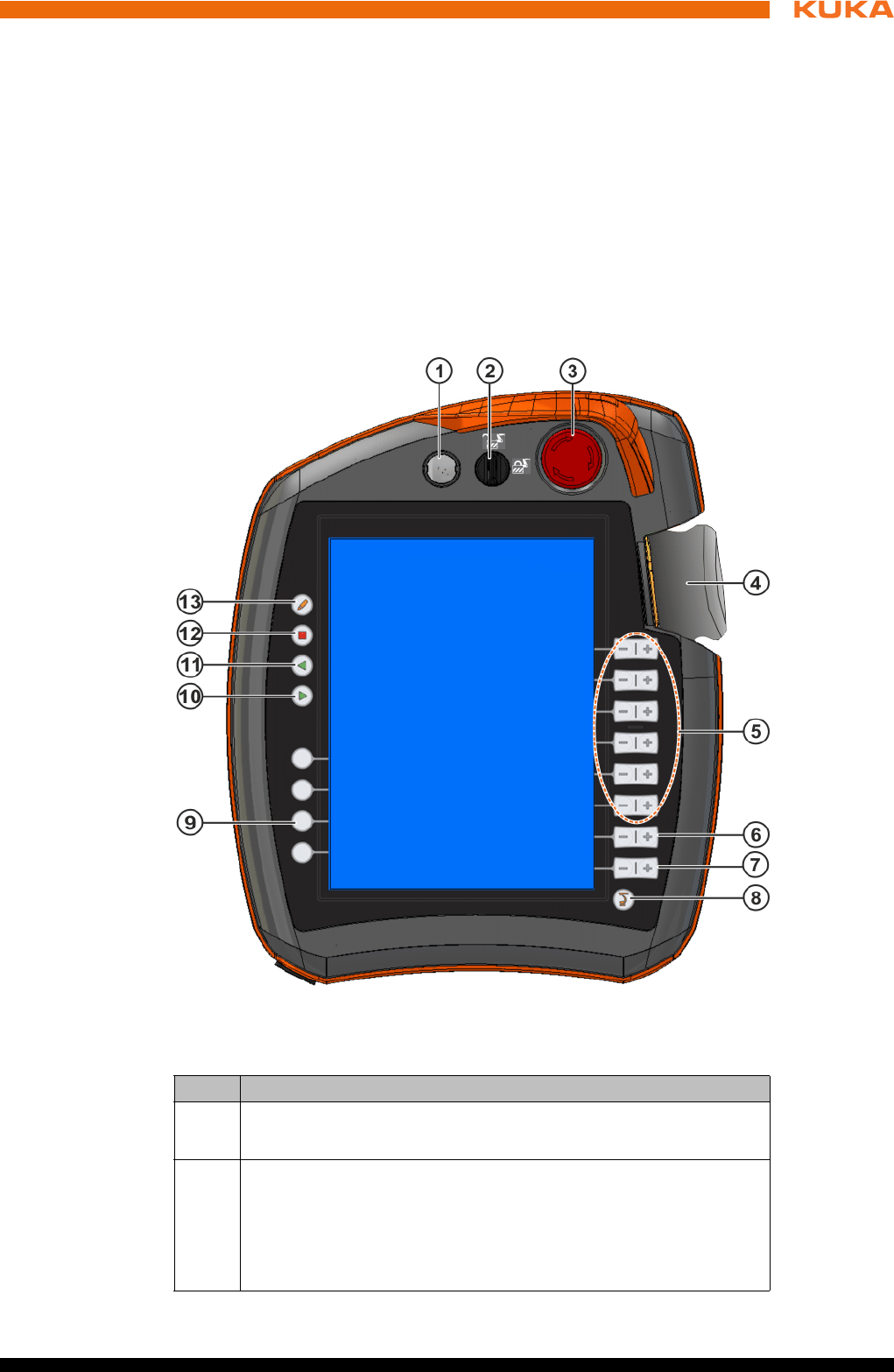
81 / 123Issued: 15.04.2014 Version: BA KR C4 compact V5
9 Operation
9 Operation
9.1 KUKA smartPAD teach pendant
9.1.1 Front view
Function The smartPAD is the teach pendant for the industrial robot. The smartPAD has
all the operator control and display functions required for operating and pro-
gramming the industrial robot.
The smartPAD has a touch screen: the smartHMI can be operated with a fin-
ger or stylus. An external mouse or external keyboard is not necessary.
Overview
Fig. 9-1: KUKA smartPAD, front view
Item Description
1 Button for disconnecting the smartPAD
2 Keyswitch for calling the connection manager. The switch can only
be turned if the key is inserted.
The operating mode can be changed by using the connection man-
ager.
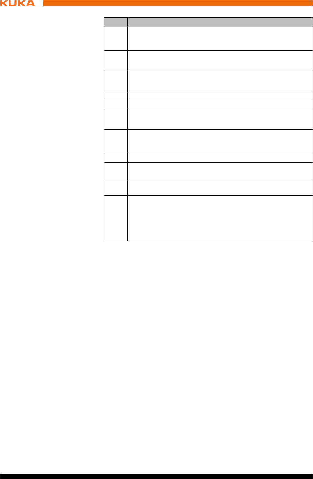
82 / 123 Issued: 15.04.2014 Version: BA KR C4 compact V5
KR C4 compact
3 EMERGENCY STOP button. Stops the robot in hazardous situa-
tions. The EMERGENCY STOP button locks itself in place when it
is pressed.
4 Space Mouse: For moving the robot manually.
5 Jog keys: For moving the robot manually.
6 Key for setting the program override
7 Key for setting the jog override
8 Main menu key: Shows the menu items on the smartHMI
9 Status keys. The status keys are used primarily for setting param-
eters in technology packages. Their exact function depends on the
technology packages installed.
10 Start key: The Start key is used to start a program.
11 Start backwards key: The Start backwards key is used to start a
program backwards. The program is executed step by step.
12 STOP key: The STOP key is used to stop a program that is run-
ning.
13 Keyboard key
Displays the keyboard. It is generally not necessary to press this
key to display the keyboard, as the smartHMI detects when key-
board input is required and displays the keyboard automatically.
Item Description
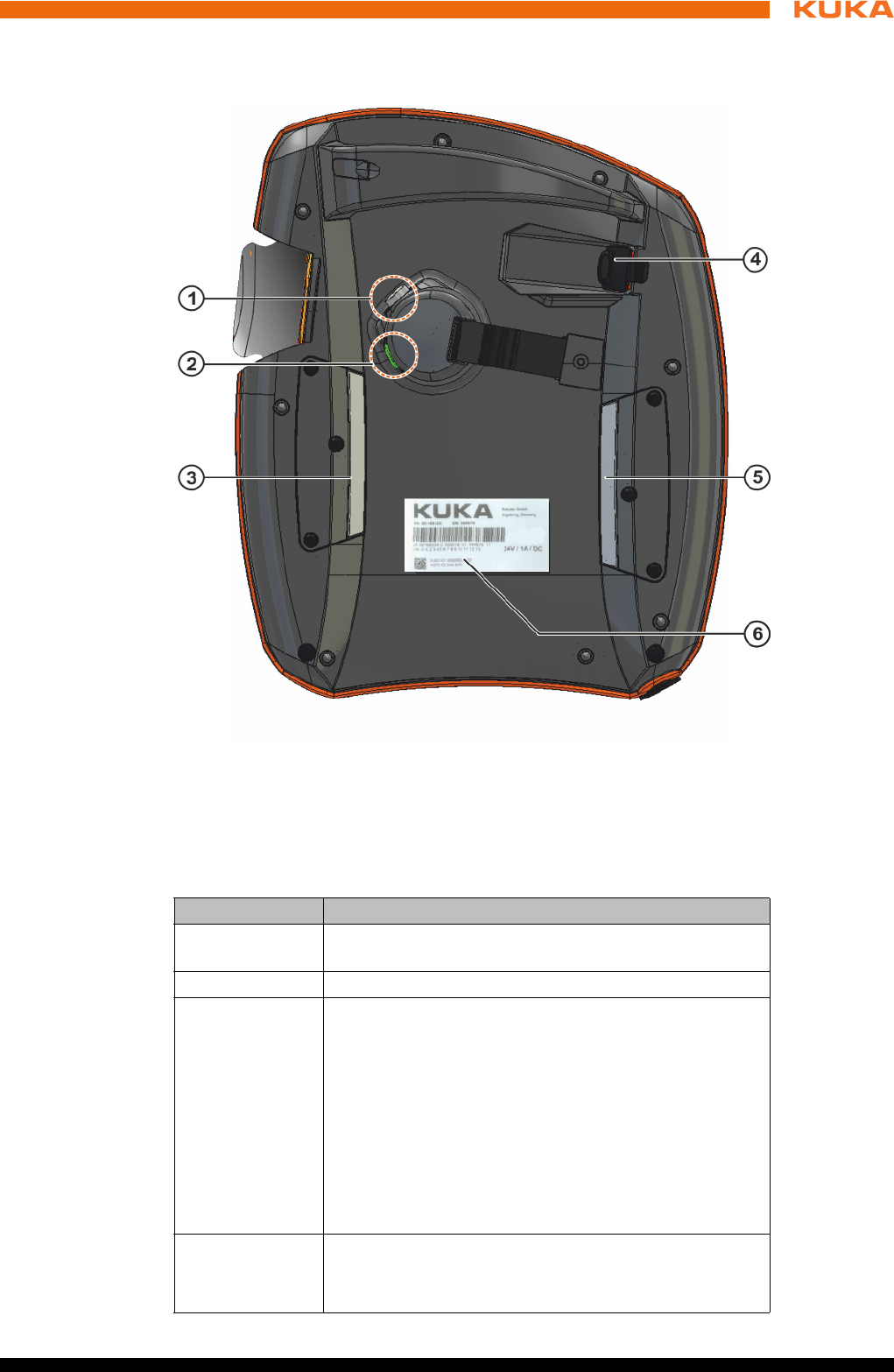
83 / 123Issued: 15.04.2014 Version: BA KR C4 compact V5
9 Operation
9.1.2 Rear view
Overview
Description
Fig. 9-2: KUKA smartPAD, rear view
1 Enabling switch 4 USB connection
2 Start key (green) 5 Enabling switch
3 Enabling switch 6 Identification plate
Element Description
Identification
plate Identification plate
Start key The Start key is used to start a program.
Enabling
switch
The enabling switch has 3 positions:
Not pressed
Center position
Panic position
The enabling switch must be held in the center position
in operating modes T1 and T2 in order to be able to jog
the manipulator.
In the operating modes Automatic and Automatic Exter-
nal, the enabling switch has no function.
USB connec-
tion
The USB connection is used, for example, for archiving
and restoring data.
Only for FAT32-formatted USB sticks.

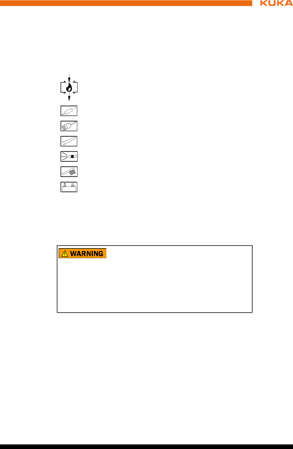
85 / 123Issued: 15.04.2014 Version: BA KR C4 compact V5
10 Maintenance
10 Maintenance
Description Maintenance work must be performed at the specified maintenance intervals
after commissioning at the customer’s plant.
10.1 Maintenance symbols
Maintenance
symbols
Precondition The robot controller must be switched off and secured to prevent unau-
thorized persons from switching it on again.
Power supply lead disconnected.
Observe the ESD guidelines.
Wait 5 minutes until the intermediate circuit has discharged.
Oil change
Lubricate with grease gun
Lubricate with brush
Tighten screw/nut
Check component, visual inspection
Clean component
Exchange battery
The following components may remain energized
(50...600 V) up to 5 minutes after the robot controller has
been switched off:
KPP_SR
KSP_SR
Intermediate circuit connecting cables
Connections for motor connector X20 and connected motor cables
This voltage can cause life-threatening injuries.
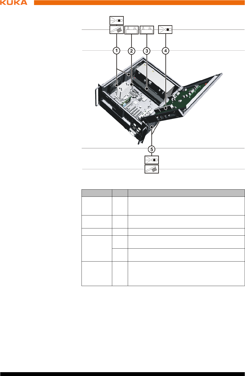
86 / 123 Issued: 15.04.2014 Version: BA KR C4 compact V5
KR C4 compact
Once an activity from the maintenance list has been carried out, a visual in-
spection must be made, with special attention to the following points:
Check that fuses, contactors, plug-in connections and boards are fitted se-
curely.
Damage to cabling.
Check PE equipotential bonding connection.
Wear and damage to any system components.
10.2 Checking CCU_SR relay outputs
Activity Check the function of the output “Local Emergency Stop”.
Fig. 10-1: Maintenance points
Interval Item Activity
6 months 4 Check the utilized relay outputs of the CCU_SR for
correct functioning (>>> 10.2 "Checking CCU_SR re-
lay outputs" Page 86)
1 year at
the latest
1/5 Depending on installation conditions and degree of
fouling, clean the protective and the fan with a brush.
5 years 2 Exchange the motherboard battery
5 years
(with 3-shift
operation)
1 Exchange the control box fans (>>> 11.12 "Ex-
changing the control box fans" Page 98)
5 Exchange the drive box fans (>>> 11.13 "Ex-
changing the drive box fans" Page 99)
as indicat-
ed by the
battery
monitoring
3 Exchange the batteries (>>> 11.9 "Exchanging the
batteries" Page 95)

87 / 123Issued: 15.04.2014 Version: BA KR C4 compact V5
10 Maintenance
Procedure Press the Local EMERGENCY STOP button.
Activity Check the function of the output “Operator safety acknowledged”.
Procedure 1. Set operating mode to Automatic or Automatic External.
2. Open operator safety (safeguard).
Activity Check the function of the output “Switch on periphery”.
Procedure 1. Set operating mode to Automatic or Automatic External.
2. Open operator safety (safeguard).
3. Release enabling switch in “T1” or “T2” mode.
If no error message is displayed, the relay outputs are OK.
10.3 Cleaning the robot controller
Precondition The robot controller must be switched off and secured to prevent unau-
thorized persons from switching it on again.
Power supply lead disconnected.
Observe the ESD guidelines.
Work regulations The manufacturer’s instructions must be observed when using cleaning
agents for cleaning work.
It must be ensured that no cleaning agents enter electrical components.
Do not use compressed air during cleaning work.
Do not spray with water.
Procedure 1. Loosen and vacuum up any dust deposits.
2. Clean the housing with a cloth soaked with a mild cleaning agent.
3. Clean cables, plastic parts and hoses with a solvent-free cleaning agent.
4. Replace damaged, illegible or missing inscriptions, labels and plates.

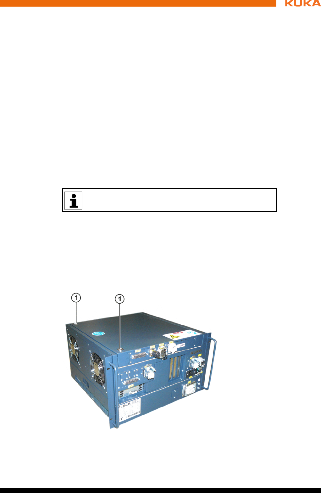
89 / 123Issued: 15.04.2014 Version: BA KR C4 compact V5
11 Repair
11 Repair
11.1 Repair and procurement of spare parts
Repair Repairs to the robot controller may only be carried out by KUKA customer sup-
port personnel or by customers who have taken part in a relevant course of
training held by KUKA Roboter GmbH.
Repairs within modules may only be carried out by specially trained KUKA Ro-
boter GmbH personnel.
Procurement of
spare parts
The article numbers of the spare parts are listed in the spare parts catalog.
KUKA Roboter GmbH supplies the following types of spare parts for repairs to
the robot controller:
New parts
Once the new part has been installed, the part that has been removed can
be disposed of.
Exchange parts
Once the exchange part has been installed, the part that has been re-
moved is returned to KUKA Roboter GmbH.
11.2 Opening the housing cover
Precondition The robot controller must be switched off and secured to prevent unau-
thorized persons from switching it on again.
Power supply lead disconnected.
Observe the ESD guidelines.
Procedure 1. Unscrew the housing cover screws.
2. Open the cover.
A “Robot Repair Card” is supplied with the exchange parts. The Re-
pair Card must be completed and returned to KUKA Roboter GmbH.
Fig. 11-1: Housing cover screws
1 Housing cover screws
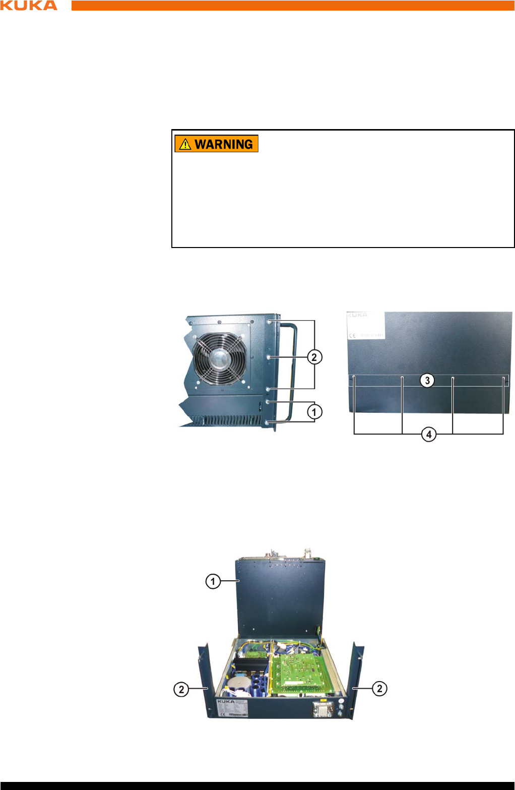
90 / 123 Issued: 15.04.2014 Version: BA KR C4 compact V5
KR C4 compact
11.3 Removing the control box from the drive box
Precondition The robot controller must be switched off and secured to prevent unau-
thorized persons from switching it on again.
Power supply lead disconnected.
Observe the ESD guidelines.
Wait 5 minutes until the intermediate circuit has discharged.
Procedure 1. Remove the upper fastening screws from the connecting plate on the rear.
2. Remove the upper 3 fastening screws from the handle brackets on the left-
hand and right-hand side. Slacken the lower screws.
3. Lift the control box and swivel it to the rear.
The following components may remain energized
(50...600 V) up to 5 minutes after the robot controller has
been switched off:
KPP_SR
KSP_SR
Intermediate circuit connecting cables
Connections for motor connector X20 and connected motor cables
This voltage can cause life-threatening injuries.
Fig. 11-2: Fastening screws for handle brackets and connecting plate
1 Lower fastening screws on the handle bracket
2 Upper fastening screws on the handle bracket
3 Upper fastening screws on the connecting plate at rear
Fig. 11-3: Drive box and control box separated
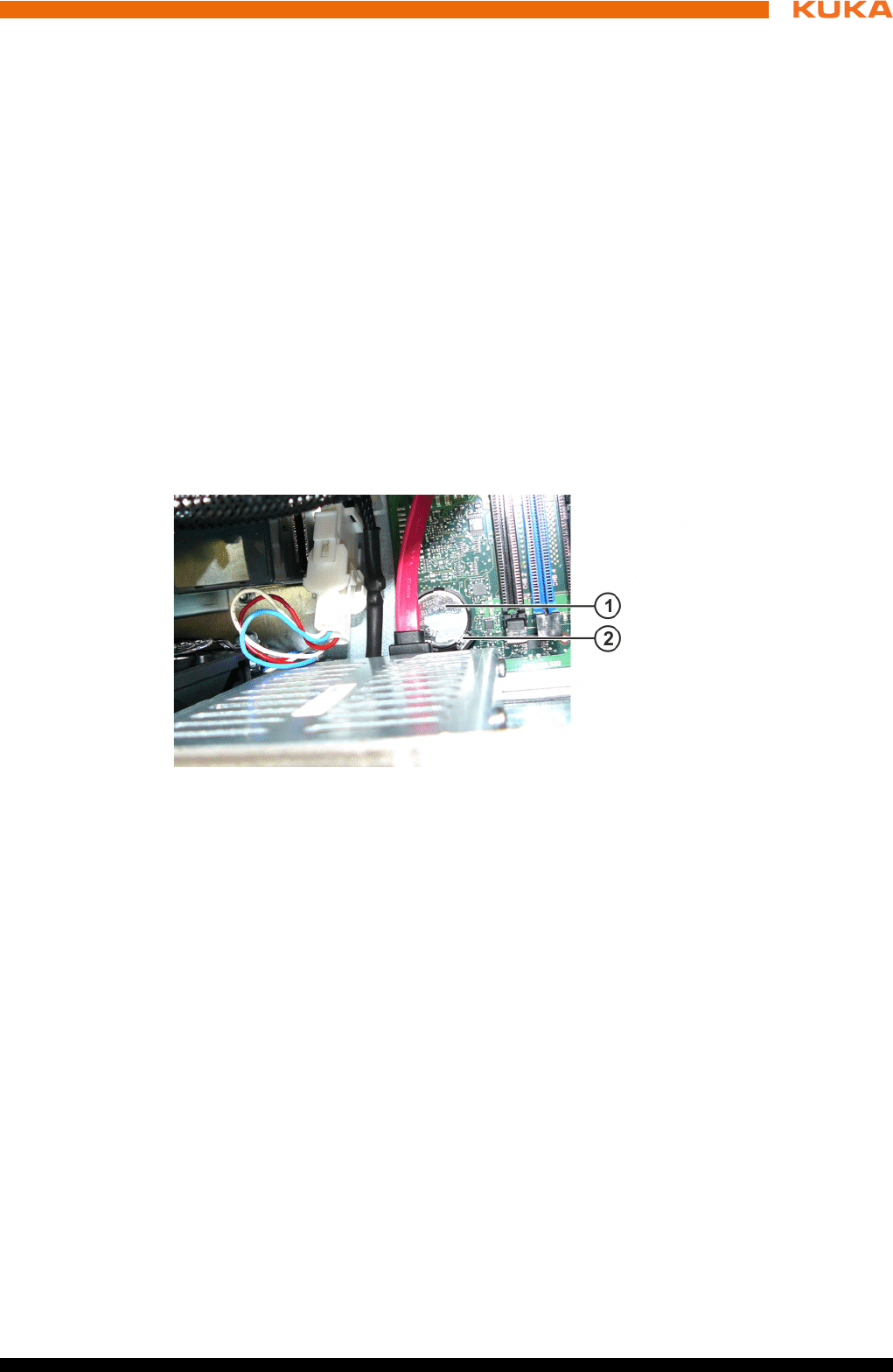
91 / 123Issued: 15.04.2014 Version: BA KR C4 compact V5
11 Repair
11.4 Exchanging the motherboard
A defective motherboard must only be exchanged by the KUKA customer sup-
port service.
11.5 Exchanging the motherboard battery
Precondition The robot controller must be switched off and secured to prevent unau-
thorized persons from switching it on again.
Power supply lead disconnected.
Observe the ESD guidelines.
Procedure 1. Open the housing cover. (>>> 11.2 "Opening the housing cover" Page 89)
2. Unlock the locking mechanism of the lithium button cell and remove the
button cell.
3. Insert the new lithium button cell and click the locking mechanism into
place.
4. Close the housing cover.
11.6 Exchanging DIMM memory modules
Precondition The robot controller must be switched off and secured to prevent unau-
thorized persons from switching it on again.
Power supply lead disconnected.
Observe the ESD guidelines.
Procedure 1. Open the housing cover. (>>> 11.2 "Opening the housing cover" Page 89)
2. Using your thumbs, carefully open the side tabs in the direction indicated
by the arrows. The DIMM memory module is released and lifted out of its
socket.
3. Press the new DIMM memory module into the slot in the DIMM socket until
it clicks into position.
1 Control box
2 Handle brackets
Fig. 11-4: Lithium button cell
1 Lithium button cell
2 Locking mechanism of lithium button cell
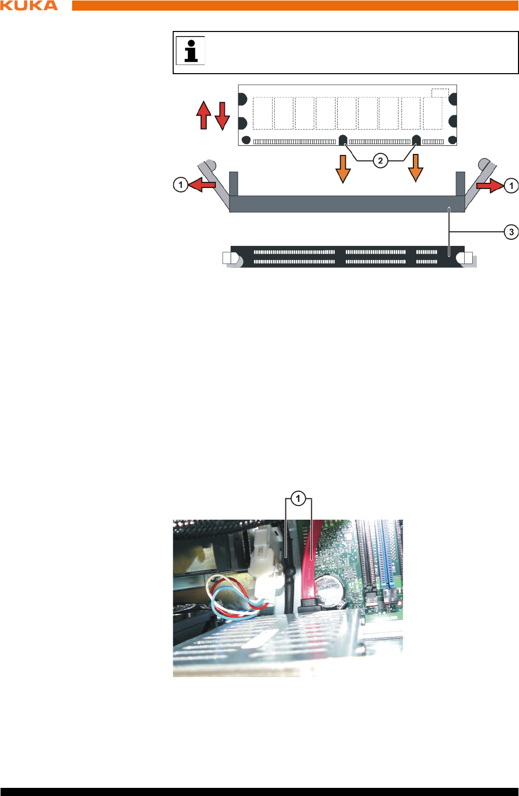
92 / 123 Issued: 15.04.2014 Version: BA KR C4 compact V5
KR C4 compact
11.7 Exchanging the hard drive
Precondition The robot controller must be switched off and secured to prevent unau-
thorized persons from switching it on again.
Power supply lead disconnected.
Observe the ESD guidelines.
Procedure 1. Open the housing cover. (>>> 11.2 "Opening the housing cover" Page 89)
2. Disconnect the power supply and data cable.
3. Remove the hard drive retaining screws.
There are two asymmetrically positioned recesses on the underside
of the DIMM memory modules; these must mate with the coding on
the DIMM socket.
Fig. 11-5: Exchanging DIMM memory modules
1 Side tabs 3 DIMM memory module socket
2 Asymmetrically positioned re-
cesses
Fig. 11-6: Hard drive connections
1 Hard drive connections
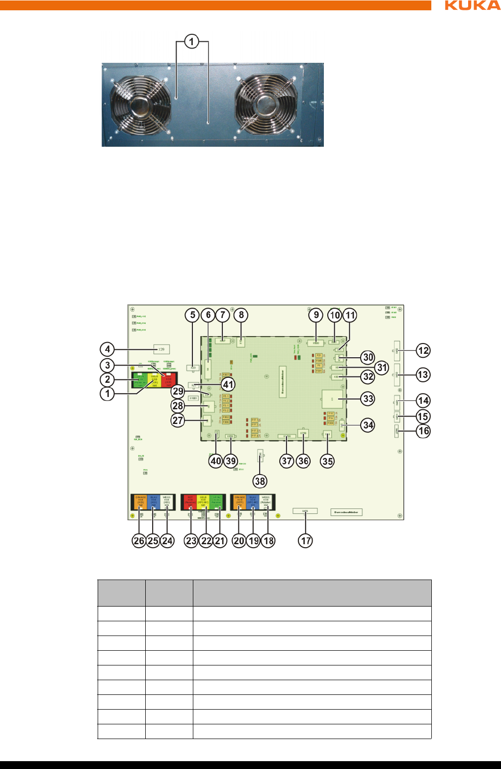
93 / 123Issued: 15.04.2014 Version: BA KR C4 compact V5
11 Repair
4. Remove the hard drive.
5. Fasten the new hard drive to the housing.
6. Connect the power supply and data cable.
7. Close the housing cover.
11.8 Exchanging the Cabinet Control Unit, Small Robot
Connections
Fig. 11-7: Hard drive fastening
1 Hard drive fastening
Fig. 11-8: Connections on the CCU_SR
Item Con-
nector
Description
1 X46 KSB RoboTeam (yellow)
2 X48 KSB EtherCAT interface (green), optional
3 X45 KSB RoboTeam (red)
4 X29 EDS connection, memory card
5 X23 Fast Measurement inputs 1 to 5
6 X4 KPC supply and power supply fan
7 X307 UL lamp (optional)
8X12 USB
9 X500 Not used
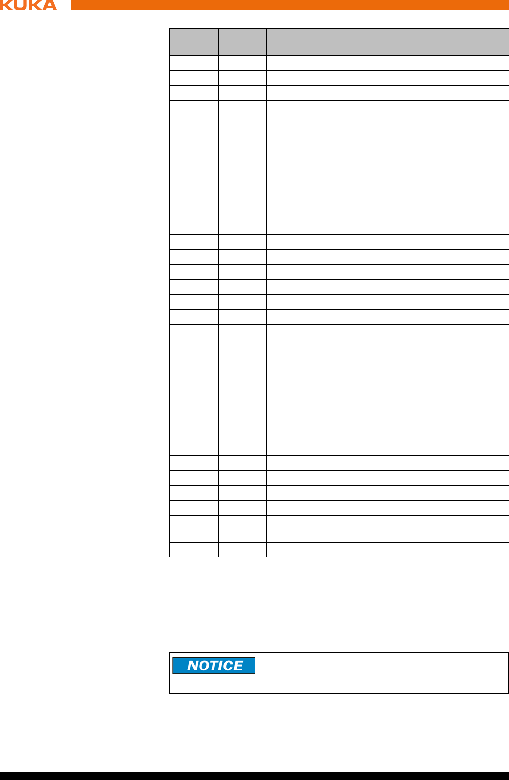
94 / 123 Issued: 15.04.2014 Version: BA KR C4 compact V5
KR C4 compact
Precondition The robot controller must be switched off and secured to prevent unau-
thorized persons from switching it on again.
Power supply lead disconnected.
Observe the ESD guidelines.
Procedure 1. Unlock the data cable connectors. Unplug all connections to the CCU_SR.
10 X501 Not used
11 X21 Power supply to RDC/EMD
12 X402 Safe inputs 1 to 3
13 X403 Safe inputs 4 to 7
14 X404 Safe inputs 8 to 9
15 X401 Mastering reference switch
16 X407 Safe input 11, teach pendant plugged in
17 X406 Safe outputs 12 to 15
18 X34 KCB RDC interface (white)
19 X31 KCB KPC interface (blue)
20 X32 KCB KPP interface (orange)
21 X33 I/O board (optional)
22 X41 KSB KPC interface (yellow)
23 X47 KSB spare (red)
24 X44 KSB KEI (white)
25 X43 KSB - KSI (blue)
26 X42 KSB - KOI (orange)
27 X3 Power supply to KPP_SR logic/brakes
28 X5 Power supply to options
29 X22 Power supply to options
30 X305 Battery infeed
31 X6 I/O board power supply without battery backup
(optional)
32 X301 24 V supply, spare
33 X1 Supply
34 X15 Power supply to power supply fan
35 X14 Power supply to external fan
36 X308 External power supply
37 X1700 Board connection to the PMB_SR
38 X405 Safe contactor output 10, single-channel input 10
39 X306 smartPAD power supply
40 X302 I/O board power supply with battery backup
(optional)
41 X25 Alarm contact, Power OK, power supply unit
Item Con-
nector
Description
Unplugging the data cable connectors without first un-
locking them damages the connectors. Unlock the con-
nectors before unplugging them.
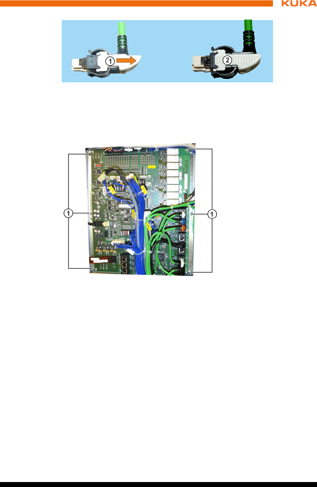
95 / 123Issued: 15.04.2014 Version: BA KR C4 compact V5
11 Repair
2. Remove the screws from the fastening plate and remove the plate togeth-
er with the CCU_SR.
3. Check the new CCU_SR for mechanical damage. Insert the fastening
plate with the CCU_SR and screw it down.
4. Plug in all the connections in accordance with the connector and cable la-
beling. Lock the data cable connectors.
11.9 Exchanging the batteries
Precondition The robot controller must be switched off and secured to prevent unau-
thorized persons from switching it on again.
Power supply lead disconnected.
Observe the ESD guidelines.
Procedure 1. Open the housing cover. (>>> 11.2 "Opening the housing cover" Page 89)
2. Unfasten the Velcro strip.
3. Unplug the battery connection cables.
Fig. 11-9: Connector locking mechanism of data cable
1 Data connector unlocked
2 Data connector locked
Fig. 11-10: CCU_SR fastening
1 CCU_SR fastening
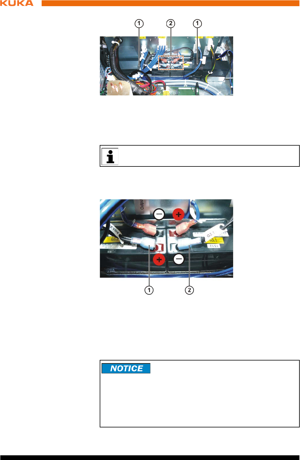
96 / 123 Issued: 15.04.2014 Version: BA KR C4 compact V5
KR C4 compact
4. Take out both battery blocks.
5. Insert new battery blocks.
6. Fasten the Velcro strip.
7. Plug in the battery connection cables in accordance with the cable labels.
8. Close the housing cover.
Storage
Fig. 11-11: Battery blocks, fastening and connections
1 Velcro strip for battery fastening
2 Battery connection cables
The battery blocks must both be exchanged together.
Fig. 11-12: Battery polarity
1 Connection for G3.2
2 Connection for G3.1
To prevent exhaustive discharge and thus destruction of
the batteries, the batteries must be recharged at regular
intervals according to the storage temperature.
If the storage temperature is +20 °C or lower, the batteries must be re-
charged every 9 months.
If the storage temperature is between +20 °C and +30 °C, the batteries must
be recharged every 6 months.
If the storage temperature is between +30 °C and +40 °C, the batteries must
be recharged every 3 months.
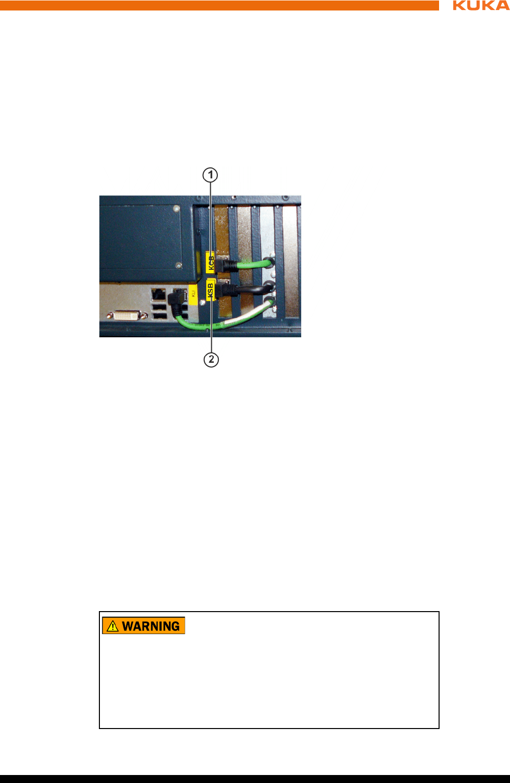
97 / 123Issued: 15.04.2014 Version: BA KR C4 compact V5
11 Repair
11.10 Exchanging the Dual GbE network card
Precondition The robot controller must be switched off and secured to prevent unau-
thorized persons from switching it on again.
Power supply lead disconnected.
Observe the ESD guidelines.
Procedure 1. Open the housing cover. (>>> 11.2 "Opening the housing cover" Page 89)
2. Remove cover of network connections.
3. Unplug the connections to the Dual GbE network card.
4. Release the fastenings of the network card and pull the card out of the slot.
5. Inspect the new network card for mechanical damage.
6. Plug the network card into its slot and tighten the fastening screws.
7. Plug in the connections to the network card.
11.11 Exchanging the low-voltage power supply unit
Precondition The robot controller must be switched off and secured to prevent unau-
thorized persons from switching it on again.
Power supply lead disconnected.
Observe the ESD guidelines.
Wait 5 minutes until the intermediate circuit has discharged.
Procedure 1. Open the housing cover. (>>> 11.2 "Opening the housing cover" Page 89)
Fig. 11-13: Dual GbE network card connections
1 Connector KCB
2 Connector KSB
The following components may remain energized
(50...600 V) up to 5 minutes after the robot controller has
been switched off:
KPP_SR
KSP_SR
Intermediate circuit connecting cables
Connections for motor connector X20 and connected motor cables
This voltage can cause life-threatening injuries.
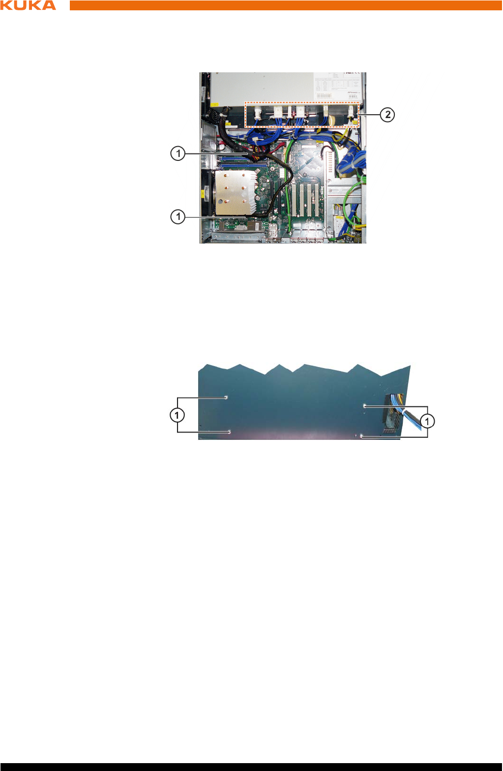
98 / 123 Issued: 15.04.2014 Version: BA KR C4 compact V5
KR C4 compact
2. Unplug the connections on the low-voltage power supply unit.
3. Unplug the power supply connections from the low-voltage power supply
unit to the motherboard and hard drive.
4. Remove the control box from the drive box. (>>> 11.3 "Removing the con-
trol box from the drive box" Page 90)
5. Remove the fastening screws from the low-voltage power supply unit.
6. Remove the low-voltage power supply unit.
7. Insert and fasten the new low-voltage power supply unit.
8. Plug in the connections on the low-voltage power supply unit, hard drive
and motherboard in accordance with the connector and cable labeling.
9. Assemble the drive box and control box.
11.12 Exchanging the control box fans
Precondition The robot controller must be switched off and secured to prevent unau-
thorized persons from switching it on again.
Power supply lead disconnected.
Observe the ESD guidelines.
Procedure 1. Open the housing cover. (>>> 11.2 "Opening the housing cover" Page 89)
2. Remove the fastening screws from the fan holder.
Fig. 11-14: Connections for low-voltage power supply
1 Connections to the motherboard
2 Connections on the low-voltage power supply unit
Fig. 11-15: Low-voltage power supply unit, fastening
1 Fastening screws for low-voltage power supply unit
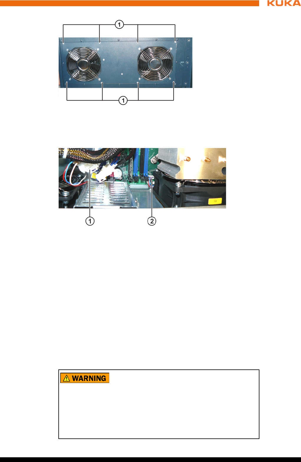
99 / 123Issued: 15.04.2014 Version: BA KR C4 compact V5
11 Repair
3. Unplug the fan connections.
4. Remove the fan holder with the fans.
5. Unscrew the inner and outer fan grilles and screw them to the new fans.
6. Install and fasten the new fans with the fan holder.
7. Plug in the connecting cables.
11.13 Exchanging the drive box fans
Precondition The robot controller must be switched off and secured to prevent unau-
thorized persons from switching it on again.
Power supply lead disconnected.
Observe the ESD guidelines.
Wait 5 minutes until the intermediate circuit has discharged.
Fig. 11-16: Fastening of fans
1 Fastening of the fan holder
Fig. 11-17: Connections for fans
1 Connector for motherboard CPU fan
2 Connector for fans
The following components may remain energized
(50...600 V) up to 5 minutes after the robot controller has
been switched off:
KPP_SR
KSP_SR
Intermediate circuit connecting cables
Connections for motor connector X20 and connected motor cables
This voltage can cause life-threatening injuries.
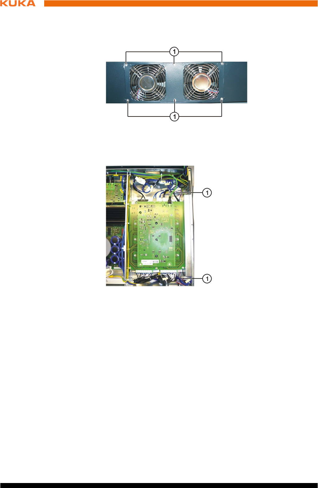
100 / 123 Issued: 15.04.2014 Version: BA KR C4 compact V5
KR C4 compact
Procedure 1. Remove the control box from the drive box. (>>> 11.3 "Removing the con-
trol box from the drive box" Page 90)
2. Remove the fastening screws from the fan holder.
3. Unplug the fan connections.
4. Remove the fan holder with the fans.
5. Unscrew the fan grille and screw it to the new fans.
6. Install and fasten the new fans with the fan holder.
7. Plug in the connecting cables.
11.14 Exchanging the KPP_SR
Precondition The robot controller must be switched off and secured to prevent unau-
thorized persons from switching it on again.
Power supply lead disconnected.
Observe the ESD guidelines.
Wait 5 minutes until the intermediate circuit has discharged.
Fig. 11-18: Fastening of fans
1 Fastening of the fan holder
Fig. 11-19: Connection for fans
1 Connector for fans
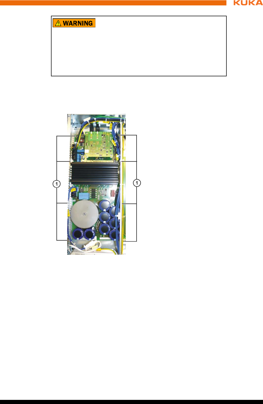
101 / 123Issued: 15.04.2014 Version: BA KR C4 compact V5
11 Repair
Procedure 1. Remove the control box from the drive box. (>>> 11.3 "Removing the con-
trol box from the drive box" Page 90)
2. Unplug the connections on the KPP_SR.
3. Remove the fastening screws of the KPP_SR board.
4. Remove the KPP_SR.
5. Install and fasten the new KPP_SR.
6. Plug in all the connections in accordance with the connector and cable la-
beling.
7. Assemble the drive box and control box.
11.15 Exchanging the KSP_SR
Precondition The robot controller must be switched off and secured to prevent unau-
thorized persons from switching it on again.
Power supply lead disconnected.
Observe the ESD guidelines.
Wait 5 minutes until the intermediate circuit has discharged.
The following components may remain energized
(50...600 V) up to 5 minutes after the robot controller has
been switched off:
KPP_SR
KSP_SR
Intermediate circuit connecting cables
Connections for motor connector X20 and connected motor cables
This voltage can cause life-threatening injuries.
Fig. 11-20: Fastening the KPP_SR
1 Fastening screws on the KPP_SR heat sink
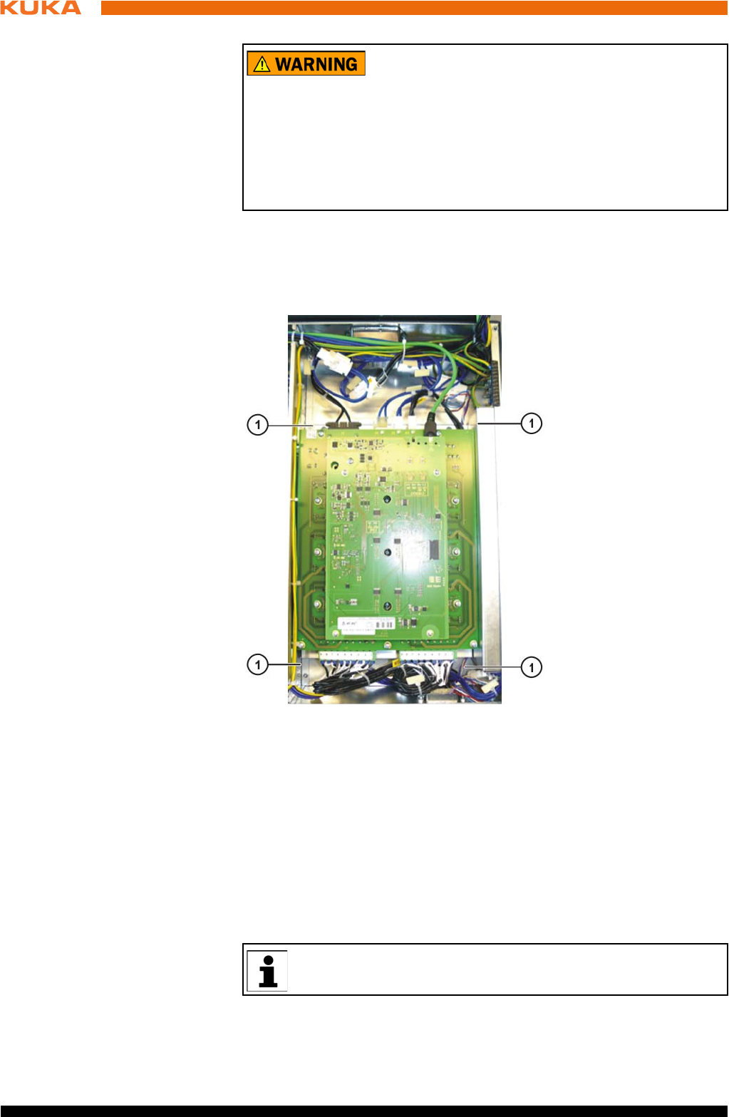
102 / 123 Issued: 15.04.2014 Version: BA KR C4 compact V5
KR C4 compact
Procedure 1. Remove the control box from the drive box. (>>> 11.3 "Removing the con-
trol box from the drive box" Page 90)
2. Unplug the connections on the KSP_SR.
3. Remove the fastening screws from the KSP_SR heat sink.
4. Remove the KSP_SR together with the heat sink.
5. Install and fasten the new KSP_SR together with the heat sink.
6. Plug in all the connections in accordance with the connector and cable la-
beling.
7. Assemble the drive box and control box.
11.16 Installing the KUKA System Software (KSS)
The following components may remain energized
(50...600 V) up to 5 minutes after the robot controller has
been switched off:
KPP_SR
KSP_SR
Intermediate circuit connecting cables
Connections for motor connector X20 and connected motor cables
This voltage can cause life-threatening injuries.
Fig. 11-21: Fastening the KSP_SR
1 Fastening screws on the KSP_SR heat sink
Further information is contained in the operating and programming in-
structions for the KUKA System Software (KSS).
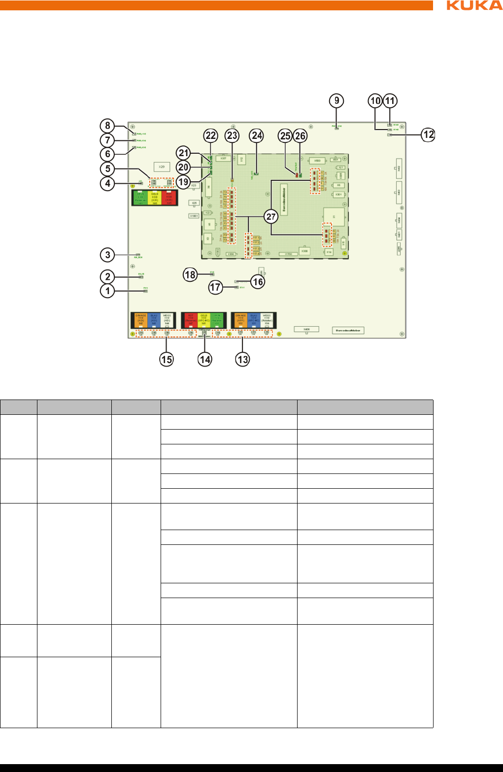
103 / 123Issued: 15.04.2014 Version: BA KR C4 compact V5
12 Troubleshooting
12 Troubleshooting
12.1 LED display on Cabinet Control Unit, Small Robot
Overview
Fig. 12-1: CCU_SR LED display
Item Designation Color Description Remedy
1 PHY4 Green On = OK -
Flashing = OK -
Off = fault Exchange CCU_SR module
2 SW_P0 Green On = OK -
Flashing = OK -
Off = fault Exchange CCU_SR module
3 RUN SION
EtherCat
Safety nodes
Green On = operational (normal
state)
-
Off = Init (after switching on) -
Flashing at 2.5 Hz = Pre-Op
(intermediate state on
startup)
-
Single signal = Safe Op -
Flashing at 10 Hz = boot (for
firmware update)
-
4L/A
KSB
Green On = physical connec-
tion. Network cable
plugged in
Off = no physical con-
nection. Network cable
not plugged in
Flashing = data traffic on
the line
-
5L/A
KSB KPC-MC
Green
100 Mbit
Orange
1 Gbit

104 / 123 Issued: 15.04.2014 Version: BA KR C4 compact V5
KR C4 compact
6 PWR/3.3V
Power for the
CIB_SR
Green Off = no supply voltage
present
Check fuse F17.3
Jumper plug X308 pres-
ent
Check fuse F308
In the case of external
supply via X308: check
external supply voltage
(rated voltage 24 V)
On = supply voltage present -
7 PWR/2.5V
Power for the
CIB_SR
Green Off = no supply voltage
present
Check fuse F17.3
Jumper plug X308 pres-
ent
Check fuse F308
In the case of external
supply via X308: check
external supply voltage
(rated voltage 24 V)
On = supply voltage present -
8 PWR/1.2V
Power for the
CIB_SR
Green Off = no supply voltage
present
Check fuse F17.3
Jumper plug X308 pres-
ent
Check fuse F308
In the case of external
supply via X308: check
external supply voltage
(rated voltage 24 V)
On = supply voltage present -
9 PWRS/3.3V Green On = power supply present -
Off = no supply voltage
present
Check fuse F17.3
If the LED PWR/3.3V
lights up, exchange the
CCU_SR module
10 STAS2
Safety node B
Orange Off = no supply voltage
present
Check fuse F17.3
If the LED PWR/3.3V
lights up, exchange the
CCU_SR module
Flashing at 1 Hz = normal
state
-
Flashing at 10 Hz = boot
phase
-
Flashing = fault code (inter-
nal)
Check cabling at X309,
X310, X312. For test pur-
poses, disconnect the
cables at X309, X310, X312
and switch the controller off
and back on again. If the
error recurs, exchange the
module.
Item Designation Color Description Remedy
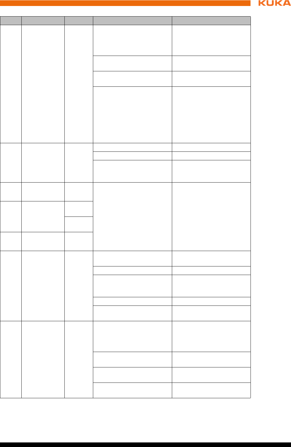
105 / 123Issued: 15.04.2014 Version: BA KR C4 compact V5
12 Troubleshooting
11 STAS1
Safety node A
Orange Off = no supply voltage
present
Check fuse F17.3
If the LED PWR/3.3V
lights up, exchange the
CCU_SR module
Flashing at 1 Hz = normal
state
-
Flashing at 10 Hz = boot
phase
-
Flashing = fault code (inter-
nal)
Check cabling at X309,
X310, X312. For test pur-
poses, disconnect the
cables at X309, X310, X312
and switch the controller off
and back on again. If the
error recurs, exchange the
module.
12 FSoE
Safety proto-
col of the
EtherCat con-
nection
Green Off = not active -
On = operational -
Flashing = fault code (inter-
nal)
-
13 L/A
KCB
Green On = physical connec-
tion
Off = no physical con-
nection. Network cable
not plugged in.
Flashing = data traffic on
the line
-
14 KSB
smartPAD_M
C
Green
100 Mbit
Orange
1 Gbit
15 L/A
KSB
Green
16 RUN CIB_SR
EtherCat
ATμC I/O
node
Green On = operational (normal
state)
-
Off = Init (after switching on) -
Flashing at 2.5 Hz = Pre-Op
(intermediate state on
startup)
-
Single signal = Safe Op -
10 Hz = boot (for firmware
update)
-
17 STA1
(CIB_SR)
μC I/O node
Orange Off = no supply voltage
present
Check fuse F17.3
If the LED PWR/3.3V
lights up, exchange the
CCU_SR module
Flashing at 1 Hz = normal
state
-
Flashing at 10 Hz = boot
phase
-
Flashing = fault code (inter-
nal)
Exchange CCU_SR module
Item Designation Color Description Remedy

106 / 123 Issued: 15.04.2014 Version: BA KR C4 compact V5
KR C4 compact
18 STA2
FPGA node
Orange Off = no supply voltage
present
Check infeed at X1
If the LED PWR/3.3V
lights up, exchange the
CCU_SR module
Flashing at 1 Hz = normal
state
Flashing at 10 Hz = boot
phase
Flashing = fault code (inter-
nal)
Exchange CCU_SR module
19 27 V
Voltage, main
power supply
unit, without
battery
backup
Green Off = no supply voltage
present
Check infeed at X1 (rated
voltage 27.1 V)
On = power supply present -
20 PS1
Voltage,
Power Sup-
ply 1 (short
battery
backup)
Green Off = no supply voltage
present
Check infeed at X1 (rat-
ed voltage 27.1 V)
Drive bus switched off
(BusPowerOff state)
On = power supply present -
21 PS2
Voltage,
Power Sup-
ply 2 (medium
battery
backup)
Green Off = no supply voltage
present
Check infeed at X1.
Controller in Sleep state
On = power supply present -
22 PS3
Voltage,
Power Sup-
ply 3 (long
battery
backup)
Green Off = no supply voltage
present
On = power supply present
On = power supply present -
23 STA1
(PMB_SR)
μC USB
Orange Off = no supply voltage
present
Check infeed at X1
If the LED PWR/5V lights
up, exchange the
CCU_SR module
Flashing at 1 Hz = normal
state
-
Flashing at 10 Hz = boot
phase
-
Flashing = fault code (inter-
nal)
Exchange CCU_SR module
24 PWR/5V
Power supply
for PMB_SR
Green Off = no supply voltage
present
Check infeed at X1 (rated
voltage 27.1 V)
Flashing at 1 Hz = normal
state
-
Flashing at 10 Hz = boot
phase
-
Flashing = fault code (inter-
nal)
-
Item Designation Color Description Remedy
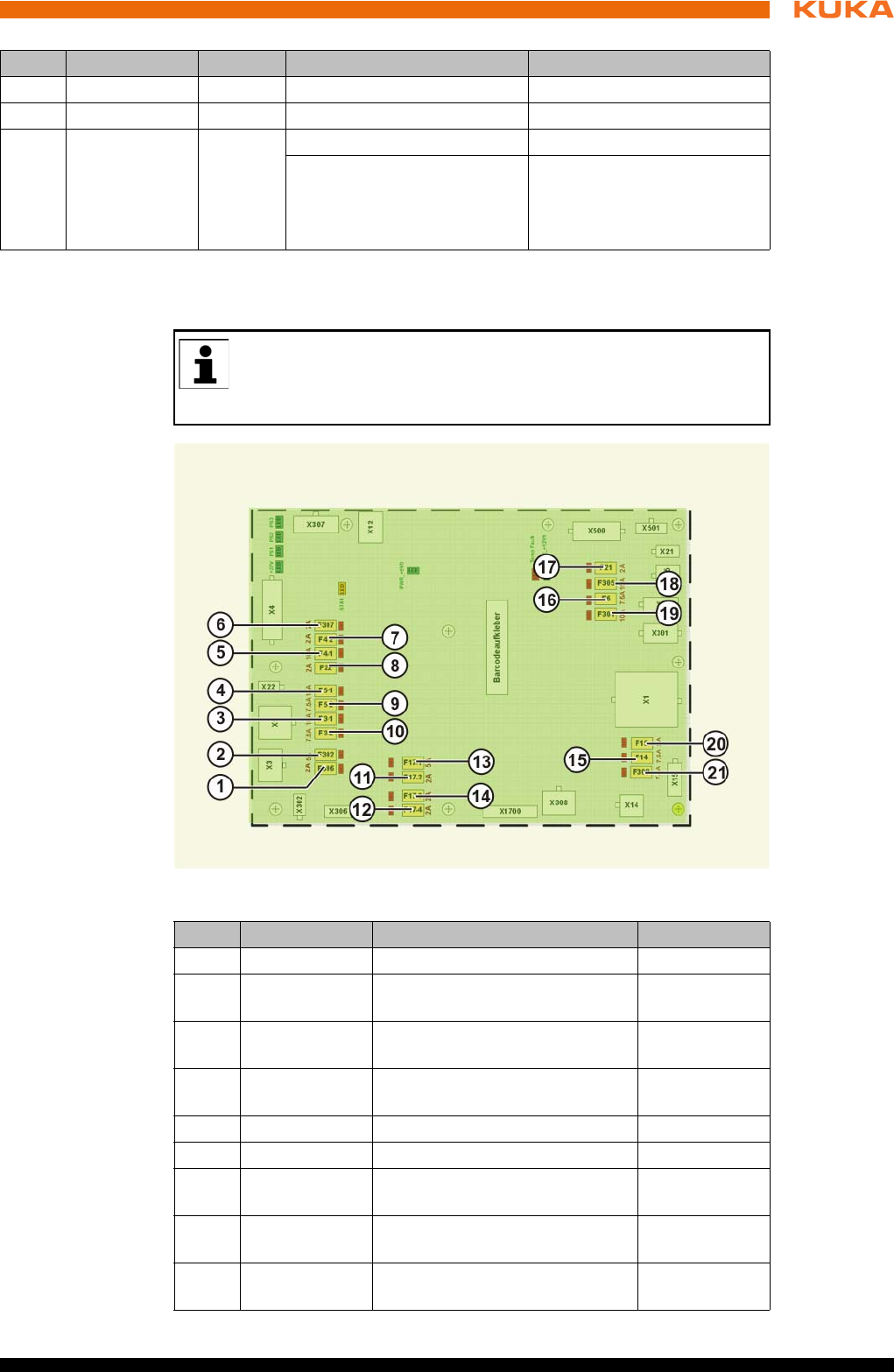
107 / 123Issued: 15.04.2014 Version: BA KR C4 compact V5
12 Troubleshooting
12.2 Fuses on the Cabinet Control Unit, Small Robot
Overview
25 - - Not used --
26 - - Not used
27 Fuse LEDs
The LEDs
indicate the
status of the
fuses.
Red On = fuse defective Exchange defective fuse
Off = fuse OK -
Item Designation Color Description Remedy
A defective fuse is indicated by a red LED next to the fuse. Once the
cause of the fault has been eliminated, defective fuses must be re-
placed with fuses with the value specified in the operating instructions
or printed on the module.
Fig. 12-2: Arrangement of the fuses
Item Designation Description Fusing
1 F306 smartPAD power supply 2 A
2 F302 I/O board power supply
(optional)
5 A
3 F3-1 KPP_SR and KSP_SR brakes
without battery backup
15 A
4 F5-1 24 V without battery backup,
for options
15 A
5 F4-1 KPC with battery backup 10 A
6 F307 UL lamp (optional) 2 A
7 F4-2 24 V with battery backup, for
fans
2 A
8 F22 24 V without battery backup,
for options
7.5 A
9 F5-2 24 V with battery backup, for
options
7.5 A
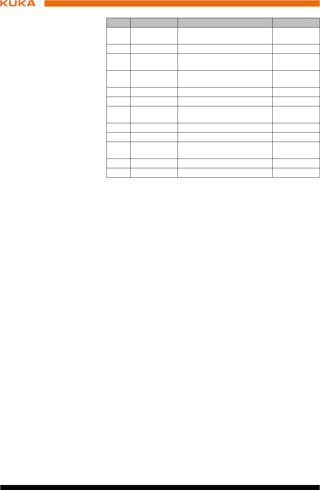
108 / 123 Issued: 15.04.2014 Version: BA KR C4 compact V5
KR C4 compact
10 F3-2 KPP_SR and KSP_SR logic
with battery backup
7.5 A
11 F17-2 Inputs CCU_SR 2 A
12 F17-4 Safe inputs and relays
CCU_SR
2 A
13 F17-1 Contactor outputs 1 … 4
CCU_SR
5 A
14 F17-3 Logic CCU_SR 2 A
15 F14 External fans (optional) 7.5 A
16 F6 I/O board power supply
(optional)
7.5 A
17 F21 RDC power supply 3 A
18 F305 Battery infeed 15 A
19 F301 24 V without battery backup,
for options
10 A
20 F15 Power supply unit fan 2 A
21 F308 External power supply 7.5 A
Item Designation Description Fusing

109 / 123Issued: 15.04.2014 Version: BA KR C4 compact V5
13 Decommissioning, storage and disposal
13 Decommissioning, storage and disposal
13.1 Decommissioning
Description This section describes all the work required for decommissioning the robot
controller if the robot controller is to be removed from the system. After decom-
missioning, it is prepared for storage or for transportation to a different loca-
tion.
Following its removal, the robot controller may only be transported with lifting
tackle and a fork lift truck or pallet truck.
Precondition The removal site must be accessible with a crane or with a fork lift truck for
transportation.
The crane and fork lift truck have an adequate carrying capacity.
There is no hazard posed by system components.
Procedure 1. Release and unplug all peripheral connections.
2. Release and unplug motor cable connector and control cable connector.
3. Disconnect the ground conductor.
4. Prepare the robot controller for storage.
13.2 Storage
Preconditions If the robot controller is to be put into long-term storage, the following points
must be observed:
The place of storage must be as dry and dust-free as possible.
Avoid temperature fluctuations.
Avoid wind and drafts.
Avoid condensation.
Observe and comply with the permissible temperature ranges for storage.
Select a storage location in which the packaging materials cannot be dam-
aged.
Only store the robot controller indoors.
Procedure 1. Clean robot controller. No dirt may remain on or in the robot controller.
2. Inspect the robot controller, both internally and externally, for damage.
3. Remove batteries and store in accordance with the manufacturer’s instruc-
tions.
4. Remove any foreign bodies.
5. Remove any corrosion expertly.
6. Attach all covers to the robot controller and check that the seals are cor-
rectly in place.
7. Seal off electrical connections with suitable covers.
8. Cover the robot controller with plastic film and seal it against dust.
If necessary, add a desiccant beneath the sheeting.
13.3 Disposal
When the robot controller reaches the end of its useful life, it can be disman-
tled, and the materials can be disposed of properly by type.
110 / 123 Issued: 15.04.2014 Version: BA KR C4 compact V5
KR C4 compact
The following table provides an overview of the materials used in the robot
controller. Some of the plastic components are marked with a material desig-
nation and must be disposed of accordingly.
As the end user, the customer is legally required to return depleted
batteries. Used batteries can be returned to the vendor or brought to
the designated collection points (e.g. in communal refuse collection
facilities or commercial centers) free of charge. The batteries can also be
sent to the vendor by post.
The following symbols can be found on the batteries:
Crossed-out garbage can: battery must not be disposed of with ordinary
household refuse.
Pb: battery contains more than 0.004 lead by weight.
Cd: battery contains more than 0.002 cadmium by weight.
Hg: battery contains more than 0.0005 mercury by weight.
Material, designation Subassembly, compo-
nent
Note
Steel-plate compo-
nents
Screws and washers,
robot controller hous-
ing
-
PUR Cable sheaths -
Plastic parts Flexible tube -
Cable Electrical cables,
wires, copper
-
EPDM Seals and covers -
CuZn (gold-plated) Connectors, contacts Dispose of without dis-
mantling
Steel (ST 52-3) Allen screws, washers -
PE Cable straps -
Electrical components Bus modules, boards,
sensors
Dispose of as electri-
cal scrap without dis-
assembling
Mains filter
Fans
Adhesive labels
Lead battery

111 / 123Issued: 15.04.2014 Version: BA KR C4 compact V5
14 KUKA Service
14 KUKA Service
14.1 Requesting support
Introduction This documentation provides information on operation and operator control,
and provides assistance with troubleshooting. For further assistance, please
contact your local KUKA subsidiary.
Information The following information is required for processing a support request:
Model and serial number of the manipulator
Model and serial number of the controller
Model and serial number of the linear unit (if present)
Model and serial number of the energy supply system (if present)
Version of the system software
Optional software or modifications
Diagnostic package KrcDiag:
Additionally for KUKA Sunrise: Existing projects including applications
For versions of KUKA System Software older than V8: Archive of the soft-
ware (KrcDiag is not yet available here.)
Application used
External axes used
Description of the problem, duration and frequency of the fault
14.2 KUKA Customer Support
Availability KUKA Customer Support is available in many countries. Please do not hesi-
tate to contact us if you have any questions.
Argentina Ruben Costantini S.A. (Agency)
Luis Angel Huergo 13 20
Parque Industrial
2400 San Francisco (CBA)
Argentina
Tel. +54 3564 421033
Fax +54 3564 428877
ventas@costantini-sa.com
Australia Headland Machinery Pty. Ltd.
Victoria (Head Office & Showroom)
95 Highbury Road
Burwood
Victoria 31 25
Australia
Tel. +61 3 9244-3500
Fax +61 3 9244-3501
vic@headland.com.au
www.headland.com.au

112 / 123 Issued: 15.04.2014 Version: BA KR C4 compact V5
KR C4 compact
Belgium KUKA Automatisering + Robots N.V.
Centrum Zuid 1031
3530 Houthalen
Belgium
Tel. +32 11 516160
Fax +32 11 526794
info@kuka.be
www.kuka.be
Brazil KUKA Roboter do Brasil Ltda.
Travessa Claudio Armando, nº 171
Bloco 5 - Galpões 51/52
Bairro Assunção
CEP 09861-7630 São Bernardo do Campo - SP
Brazil
Tel. +55 11 4942-8299
Fax +55 11 2201-7883
info@kuka-roboter.com.br
www.kuka-roboter.com.br
Chile Robotec S.A. (Agency)
Santiago de Chile
Chile
Tel. +56 2 331-5951
Fax +56 2 331-5952
robotec@robotec.cl
www.robotec.cl
China KUKA Robotics China Co.,Ltd.
Songjiang Industrial Zone
No. 388 Minshen Road
201612 Shanghai
China
Tel. +86 21 6787-1888
Fax +86 21 6787-1803
www.kuka-robotics.cn
Germany KUKA Roboter GmbH
Zugspitzstr. 140
86165 Augsburg
Germany
Tel. +49 821 797-4000
Fax +49 821 797-1616
info@kuka-roboter.de
www.kuka-roboter.de

113 / 123Issued: 15.04.2014 Version: BA KR C4 compact V5
14 KUKA Service
France KUKA Automatisme + Robotique SAS
Techvallée
6, Avenue du Parc
91140 Villebon S/Yvette
France
Tel. +33 1 6931660-0
Fax +33 1 6931660-1
commercial@kuka.fr
www.kuka.fr
India KUKA Robotics India Pvt. Ltd.
Office Number-7, German Centre,
Level 12, Building No. - 9B
DLF Cyber City Phase III
122 002 Gurgaon
Haryana
India
Tel. +91 124 4635774
Fax +91 124 4635773
info@kuka.in
www.kuka.in
Italy KUKA Roboter Italia S.p.A.
Via Pavia 9/a - int.6
10098 Rivoli (TO)
Italy
Tel. +39 011 959-5013
Fax +39 011 959-5141
kuka@kuka.it
www.kuka.it
Japan KUKA Robotics Japan K.K.
YBP Technical Center
134 Godo-cho, Hodogaya-ku
Yokohama, Kanagawa
240 0005
Japan
Tel. +81 45 744 7691
Fax +81 45 744 7696
info@kuka.co.jp
Canada KUKA Robotics Canada Ltd.
6710 Maritz Drive - Unit 4
Mississauga
L5W 0A1
Ontario
Canada
Tel. +1 905 670-8600
Fax +1 905 670-8604
info@kukarobotics.com
www.kuka-robotics.com/canada

114 / 123 Issued: 15.04.2014 Version: BA KR C4 compact V5
KR C4 compact
Korea KUKA Robotics Korea Co. Ltd.
RIT Center 306, Gyeonggi Technopark
1271-11 Sa 3-dong, Sangnok-gu
Ansan City, Gyeonggi Do
426-901
Korea
Tel. +82 31 501-1451
Fax +82 31 501-1461
info@kukakorea.com
Malaysia KUKA Robot Automation Sdn Bhd
South East Asia Regional Office
No. 24, Jalan TPP 1/10
Taman Industri Puchong
47100 Puchong
Selangor
Malaysia
Tel. +60 3 8061-0613 or -0614
Fax +60 3 8061-7386
info@kuka.com.my
Mexico KUKA de México S. de R.L. de C.V.
Progreso #8
Col. Centro Industrial Puente de Vigas
Tlalnepantla de Baz
54020 Estado de México
Mexico
Tel. +52 55 5203-8407
Fax +52 55 5203-8148
info@kuka.com.mx
www.kuka-robotics.com/mexico
Norway KUKA Sveiseanlegg + Roboter
Sentrumsvegen 5
2867 Hov
Norway
Tel. +47 61 18 91 30
Fax +47 61 18 62 00
info@kuka.no
Austria KUKA Roboter CEE GmbH
Gruberstraße 2-4
4020 Linz
Austria
Tel. +43 7 32 78 47 52
Fax +43 7 32 79 38 80
office@kuka-roboter.at
www.kuka.at

115 / 123Issued: 15.04.2014 Version: BA KR C4 compact V5
14 KUKA Service
Poland KUKA Roboter Austria GmbH
Spółka z ograniczoną odpowiedzialnością
Oddział w Polsce
Ul. Porcelanowa 10
40-246 Katowice
Poland
Tel. +48 327 30 32 13 or -14
Fax +48 327 30 32 26
ServicePL@kuka-roboter.de
Portugal KUKA Sistemas de Automatización S.A.
Rua do Alto da Guerra n° 50
Armazém 04
2910 011 Setúbal
Portugal
Tel. +351 265 729780
Fax +351 265 729782
kuka@mail.telepac.pt
Russia KUKA Robotics RUS
Werbnaja ul. 8A
107143 Moskau
Russia
Tel. +7 495 781-31-20
Fax +7 495 781-31-19
info@kuka-robotics.ru
www.kuka-robotics.ru
Sweden KUKA Svetsanläggningar + Robotar AB
A. Odhners gata 15
421 30 Västra Frölunda
Sweden
Tel. +46 31 7266-200
Fax +46 31 7266-201
info@kuka.se
Switzerland KUKA Roboter Schweiz AG
Industriestr. 9
5432 Neuenhof
Switzerland
Tel. +41 44 74490-90
Fax +41 44 74490-91
info@kuka-roboter.ch
www.kuka-roboter.ch

116 / 123 Issued: 15.04.2014 Version: BA KR C4 compact V5
KR C4 compact
Spain KUKA Robots IBÉRICA, S.A.
Pol. Industrial
Torrent de la Pastera
Carrer del Bages s/n
08800 Vilanova i la Geltrú (Barcelona)
Spain
Tel. +34 93 8142-353
Fax +34 93 8142-950
Comercial@kuka-e.com
www.kuka-e.com
South Africa Jendamark Automation LTD (Agency)
76a York Road
North End
6000 Port Elizabeth
South Africa
Tel. +27 41 391 4700
Fax +27 41 373 3869
www.jendamark.co.za
Taiwan KUKA Robot Automation Taiwan Co., Ltd.
No. 249 Pujong Road
Jungli City, Taoyuan County 320
Taiwan, R. O. C.
Tel. +886 3 4331988
Fax +886 3 4331948
info@kuka.com.tw
www.kuka.com.tw
Thailand KUKA Robot Automation (M)SdnBhd
Thailand Office
c/o Maccall System Co. Ltd.
49/9-10 Soi Kingkaew 30 Kingkaew Road
Tt. Rachatheva, A. Bangpli
Samutprakarn
10540 Thailand
Tel. +66 2 7502737
Fax +66 2 6612355
atika@ji-net.com
www.kuka-roboter.de
Czech Republic KUKA Roboter Austria GmbH
Organisation Tschechien und Slowakei
Sezemická 2757/2
193 00 Praha
Horní Počernice
Czech Republic
Tel. +420 22 62 12 27 2
Fax +420 22 62 12 27 0
support@kuka.cz

117 / 123Issued: 15.04.2014 Version: BA KR C4 compact V5
14 KUKA Service
Hungary KUKA Robotics Hungaria Kft.
Fö út 140
2335 Taksony
Hungary
Tel. +36 24 501609
Fax +36 24 477031
info@kuka-robotics.hu
USA KUKA Robotics Corporation
51870 Shelby Parkway
Shelby Township
48315-1787
Michigan
USA
Tel. +1 866 873-5852
Fax +1 866 329-5852
info@kukarobotics.com
www.kukarobotics.com
UK KUKA Automation + Robotics
Hereward Rise
Halesowen
B62 8AN
UK
Tel. +44 121 585-0800
Fax +44 121 585-0900
sales@kuka.co.uk


119 / 123Issued: 15.04.2014 Version: BA KR C4 compact V5
Index
Index
Numbers
19" rack 52, 76
2004/108/EC 49
2006/42/EC 48
89/336/EEC 49
95/16/EC 48
97/23/EC 49
A
Accessories 11, 27
Altitude 21
Ambient temperature 21
ANSI/RIA R.15.06-2012 49
Applied norms and regulations 48
Automatic mode 45
Axis range 28
Axis range limitation 37
Axis range monitoring 37
B
Basic data 21
Batteries 14
Batteries, exchanging 95
Battery discharge protection, reversing 78
Brake defect 40
Brake release device 38
Braking distance 28
C
Cabinet Control Unit LED display 103
Cabinet Control Unit Small Robot, exchange 93
Cabinet Control Unit Small Robot, fuses 107
Cabinet Control Unit, Small Robot 13
Cabinet Interface Board, Small Robot 13, 23
Cable lengths 22, 53
CCU_SR 8, 13
CCU_SR functions 13
CCU_SR LED display, overview 103
CCU_SR relay outputs, checking 86
CE mark 28
Charge 14
CIB_SR 8, 23
CIB_SR inputs 24
CIB_SR outputs 23
CIB_SR, safe input 59
CIB_SR, safe output 60
CIP Safety 8
Cleaning work 46
Connecting cables 11, 27, 76
Connecting the power supply 78
Connection conditions 52
Connection manager 81
Connection panel 11
Connector pin allocation X20 76
Connector pin allocation X65 69
Connector pin allocation X65, bus coupler 69
Connector pin allocation X66 68
Connector pin allocation X69 69
Control box 12
Control box fans, exchange 98
Control box, removal 90
Control PC 11, 12
Control PC, functions 13
Control unit 22
Cooling 19
Cooling circuit 19
Counterbalancing system 46
D
Danger zone 29
DC 14
Declaration of conformity 28
Declaration of incorporation 27, 28
Decommissioning 47, 109
defective fuses 107
Description of the industrial robot 11
Dimensions 22
Dimensions, handle brackets 25
Dimensions, smartPAD holder 24
Disposal 47, 109
Documentation, industrial robot 7
Drive box 14
Drive box fans, exchange 99
Drive Configuration 14
Dual GbE network card, exchanging 97
Dual NIC card 8
Dynamic testing 59
E
EA 8
EC declaration of conformity 28
EDS 8
Electromagnetic compatibility (EMC) 49
Electromagnetic compatibility, EMC 51
EMC 8
EMC Directive 28, 49
EMD 8
EMERGENCY STOP 82
EMERGENCY STOP device 34, 35, 39
EMERGENCY STOP devices to X11 57
EMERGENCY STOP wiring example 57
EMERGENCY STOP, external 35, 42
EMERGENCY STOP, local 42
EN 60204-1 + A1 49
EN 61000-6-2 49
EN 61000-6-4 49
EN 614-1 49
EN ISO 10218-1 49
EN ISO 12100 49
EN ISO 13849-1 49
EN ISO 13849-2 49
EN ISO 13850 49
Enabling device 35, 39
Enabling device, external 36
Enabling switch 83
Enabling switches 35, 64

120 / 123 Issued: 15.04.2014 Version: BA KR C4 compact V5
KR C4 compact
Environmental conditions 21
EtherCAT interface X65 68
Ethernet interface (1xRJ45) X66 68
Exhaustive discharge of battery 21, 96
External axes 27, 30
External enabling switch, function 56
F
Faults 40
Filter mats 19
Function test 42
Fusing 53
G
General safety measures 40
Guard interlock 33
H
Hard drive, exchanging 92
Hazardous substances 47
Humidity class 21
I
Identification plate 83
Industrial robot 11, 27
Infeed 53
Installation conditions 51
Installation, KUKA System Software 102
Installing the robot controller 76
Intended use 9, 27
Interfaces 15, 17
Interfaces, control PC 16
Introduction 7
J
Jog keys 82
Jog mode 36, 39
K
KCB 8
KEB 8
KEI 8
Keyboard 82
Keyboard key 82
KLI 8
KOI 8
KONI 8
KPC 8
KPP_SR 8
KPP_SR, exchange 100
KRL 8
KSB 8
KSI 8
KSP_SR 8
KSP_SR, exchange 101
KSS 8
KUKA Customer Support 111
KUKA smartPAD 22, 29, 81
L
Labeling 38
Liability 27
Linear unit 27
Low Voltage Directive 28
Low-voltage power supply unit 14
Low-voltage power supply unit, exchanging 97
M
Machine data 42
Machinery Directive 28, 48
Mains filter 14
Maintenance 46, 85
Maintenance symbols 85
Manipulator 8, 11, 27, 29
Manual mode 44
Mastering test 68
Material designation 110
Mechanical axis range limitation 37
Mechanical end stops 37
Memory modules, exchange 91
Mode selection 32, 33
Monitoring, velocity 36
Motherboard battery, exchange 91
Motherboard D3076-K 17
Motherboard D3236-K 18
Motherboard D3236-K interfaces 18
Motherboard, exchange 91
Motherboards 16
Motor cable, data cable 15
O
Opening the housing cover 89
Operation 81
Operator 31
Operator safety 32, 33, 39
Options 11, 27
Overload 40
Overview of planning 51
Overview of the robot controller 11
Overview, start-up 75
P
Panic position 35
PE equipotential bonding 70
PE equipotential bonding, connecting 78
Performance level 70
Performance Level 32
Peripheral cables 15
Personnel 30
PFH values 70
PL 70
Planning 51
Planning, overview 51
Plant integrator 30
Plates and labels 25
PMB_SR 8
Positioner 27
Power cable 15
Power failure 14
Power Management Board, Small Robot 13
Power supply connection 53
Power supply connection, technical data 21, 52

121 / 123Issued: 15.04.2014 Version: BA KR C4 compact V5
Index
Power supply with battery backup 14
Power supply without battery backup 14
Power switched off 14
Power unit 11
Pressure Equipment Directive 47, 49
Preventive maintenance work 46
Procurement of spare parts 89
Product description 11
Protective equipment 36
Purpose 9
R
RDC 8
Reaction distance 28
Recommissioning 41, 75
Release device 38
Repair 46, 89
Resolver cable, length difference 22, 53
Robot controller 11, 27
Robot controller, cleaning 87
S
Safe operational stop 29, 36
Safeguard to X11 57
Safeguards, external 39
SafeOperation via Ethernet safety interface 65
Safety 27
Safety controller 33
Safety functions 32, 39
Safety functions, Ethernet safety interface 61
Safety functions, overview 32
Safety gate, wiring example 58
Safety instructions 7
Safety interface, X11 53
Safety logic 11
Safety of machinery 49
Safety options 29
Safety STOP 0 29
Safety STOP 1 29
Safety STOP 2 29
Safety STOP 0 29
Safety STOP 1 29
Safety STOP 2 29
Safety stop, external 36
Safety zone 29, 31
Safety, general 27
SATA connections 8
Service Interface X69 69
Service life 29
Service, KUKA Roboter 111
Signal “Peri enabled” 57
Simulation 45
Single point of control 47
Slot assignment, motherboard D3076-K 17
Slot assignment, motherboard D3236-K 18
smartPAD 29, 40, 81
smartPAD cable 15
smartPAD cable extensions 22, 53
smartPAD, plugging in 77
Software 11, 27
Software limit switches 37, 39
Space Mouse 82
SPOC 47
Start backwards key 82
Start key 82, 83
Start-up 41, 75
Start-up mode 43
Start-up overview 75
Status keys 82
STOP 0 28, 30
STOP 1 28, 30
STOP 2 28, 30
Stop category 0 30
Stop category 1 30
Stop category 2 30
STOP key 82
Stop reactions 31
Stopping distance 28
Storage 47, 109
Storage of batteries 96
Support request 111
Switching on the robot controller 79
System integrator 28, 30, 31
T
T1 30
T2 30
Target group 9
Teach pendant 11, 27
Technical data 21
Terms used 8
Terms used, safety 28
Touch screen 81
Trademarks 7
Training 9
Transportation 41, 73
Troubleshooting 103
Turn-tilt table 27
U
USB 8
USB connection 83
Use, contrary to intended use 27
Use, improper 27
User 29, 30
V
Velocity monitoring 36
Vibration resistance 22
W
Warnings 7
Working range limitation 37
Workspace 28, 31
X
X11 Connector pin allocation 54
X11, configuring and connecting 79
X19 connector pin allocation 78
X21 connector pin allocation 77
X65 68
X66 68


