134374100bTS_WD_CVR Kenmore Washer Tech Data Sheet 417.44052400
Kenmore Washer Tech Data Sheet 417.44092500 Kenmore Washer Tech Data Sheet 417.44092500 Kenmore Washer Tech Data Sheet 417.44092500 Kenmore applianceservicesecretsmembership.com_manuals
Kenmore - Frigidaire Washer Tech Data Sheet 417.44152400 Kenmore - Frigidaire Washer Tech Data Sheet 417.44152400 Kenmore - Frigidaire Washer Tech Data Sheet 417.44152400 Kenmore applianceservicesecretsmembership.com_manuals
Kenmore - Frigidaire Washer Tech Sheet 417.44152400 Kenmore - Frigidaire Washer Tech Sheet 417.44152400 Kenmore - Frigidaire Washer Tech Sheet 417.44152400 Kenmore applianceservicesecretsmembership.com_manuals
Kenmore - Frigidaire Washer Tech Data Sheet 417.44082400 Kenmore - Frigidaire Washer Tech Data Sheet 417.44082400 Kenmore - Frigidaire Washer Tech Data Sheet 417.44082400 Kenmore applianceservicesecretsmembership.com_manuals
Kenmore - Frigidaire Washer Tech Sheet 417.44052401 Kenmore - Frigidaire Washer Tech Sheet 417.44052401 Kenmore - Frigidaire Washer Tech Sheet 417.44052401 Kenmore applianceservicesecretsmembership.com_manuals
2013-04-09
: Pdf Kenmore Washer Tech Data Sheet 417.44052400 Kenmore Washer Tech Data Sheet 417.44052400. Kenmore
Open the PDF directly: View PDF ![]() .
.
Page Count: 6
1
Washer Tech Data Sheet
This information is intended for Qualified Technicians Only.
CAUTION: DISCONNECT ELECTRICAL CURRENT BEFORE SERVICING
Please Return This Sheet to its Envelope in the Product for Future Reference
Contents Page
Error code explanation........................................1-2
Diagnostics ....................................................... ....2
Error Code Chart.............................................. .....3
Tests................................................................ ...4-5
Wiring diagram................................................... 6-7
The electronic controls of the 3.5 I.E.C. Cu. Ft. horizontal axis washers have self diagnostics codes built in that cover most
products failures.
Model differences:
•Better models have a digital readout display
•Good models do not have a digital readout display
In the Better Models line, the failure codes will appear in the display as an E followed by two numbers, a number and a letter
or two letters. The control will beep and the Door Lock, Wash, Rinse, Final Spin and Control indicator lights will flash.
Example: E14. To stop the flashing and beeping, the customer may touch the Pause Cancel button. The error code remains
stored in the control but once the problem is corrected, it does not effect the operation of the washer. If the failure is something
that the customer can correct (such as the water faucets being turned off), the washer will operate normally the next time it is
started.
In the Good Models line, the control signals the failure code by flashing the five indicator lights of Door Lock, Wash, Rinse,
Final Spin and Control for the first number or letter after the E and the Start indicator light for the second number or letter
after the E. When a failure occurs, the washer stops or pauses and the control beeps and flashes the five indicator lights to tell
the customer that a failure has occurred. To stop the flashing and beeping, the customer may touch the Pause Cancel button.
The error code remains stored in the control but once the problem is corrected, it does not effect the operation of the washer.
If the failure is something that the customer can correct (such as the water faucets being turned off), the washer will operate
normally the next time it is started.
To recall an error code,
•Wake the machine by pressing any button
•Wait 5 seconds
•Press and hold the Start and Pause Cancel buttons simultaneously
•All LEDs will go blank and after a few seconds the control will signal the stored code using audible beeps and blinking
LEDs. The control will repeatedly signal the code, as long as the Start and Pause Cancel buttons are pressed.
A two-second pause between repeats affords you the ability to make accurate counts to identify the correct error codes.
Please Note the following...... on a small number of washers with serial number prefix XC4,
if the previous procedure does not perform as specified, follow the option below:
•Follow all previous steps but instead of pressing Start and Pause Cancel buttons,
press and hold Options and Pause Cancel buttons.
If the washer is a Better Model, the error code will appear in the display. Troubleshoot problem by using charts on the
following pages.
If the washer is a Good Model, the five indicator lights of Door Lock, Wash, Rinse, Final Spin and Control will flash the
number of times for the first digit of the code and the Start indicator light will flash the number of times for the second digit.
Take separate counts of each indicator light, then repeat to confirm in order to be accurate in identifying the proper error code.
The code is obtained by counting the number of times the lights flash. Example E24: The five indicator lights would flash twice
indicating the 2 and the START indicator light will flash four times indicating the 4. The five indicator lights and the START
indicator light start flashing at the same time.
The control will pause for 2 seconds, then repeat the code as long as the two buttons are pressed and held.
Note: A letter appearing in the code stands for a number higher than nine:
A = 10 B = 11 C = 12 D = 13 E = 14 F = 15
Example Code F1: the first digit would be 15 and the second digit would be 1. If this code would appear on a washer in the
Good model line, the five indicator lights would blink fifteen times and the START indicator light would blink once. Troubleshoot
problem by using charts on the following pages.
Quick Check
If there is no error displayed and the washer momentarily starts then turns back off:
1. Listen for a relay closure inside the motor control shortly after the START key is pressed. If this happens, the
motor control has power.
2. Check the 5 pin connector wiring between the console control and the motor control.
2
Diagnostic Test:
The diagnostic test is performed by using the Program Knob. To START THE TEST:
•On non-digital display models, turn the Program Knob to start position, Drain/Spin.
•On digital display models, turn the Program Knob to start position, Touch Up. (NOTE: If the model has a timer dial that
can be rotated 360°, turn the Program Knob to start position, Drain/Spin.
•Press Pause Cancel to turn off LEDs.
•Within 5 seconds, press and hold the Option and Pause Cancel buttons until LEDs start sequentially chasing, then
release buttons.
1. All the LEDs will sequentially light. Pressing a button below a light cluster will light all the LEDs in that cluster at one time
to confirm functionality.
2. Turn the program knob (1) click clockwise from the start position. The hot water solenoid will activate and hot water should
enter through the detergent compartment.
3. Turn the program knob (2) clicks from the start position. The bleach water solenoid will activate and cold water should
enter through the bleach compartment.
4. Turn the program knob (3) clicks from the start position. The bleach and the wash water solenoids will activate and cold
water should enter through the softener compartment.
5. Turn the program knob (4) clicks from the start position. The door lock solenoid will activate.
6. Turn the program knob (5) clicks from the start position. The door lock solenoid will deactivate and the loading door can
be opened.
7. Turn the program knob (6) clicks from the start position. The washer will fill and tumble.
8. Turn the program knob (7) clicks from the start position. The washer will fill and spin (leakage test).
9. Turn the program knob (8) clicks from the start position. The drain pump and door lock solenoid will activate and the
washer will operate in high spin. SAFETY WARNING: If power is removed during this test, the door can be opened. To
prevent injury, DO NOT put your hands inside when the tub is rotating.
10. Turn the program knob (9) clicks from the start position. The control will signal the last error code.
Exiting Diagnostic Mode
There are two options for exiting the Diagnostic Test mode and returning the washer to normal operation:
a) Unplug the power cord, wait 5-8 seconds, then reconnect the power cord OR
b) Turn the program knob clockwise 2 or 3 clicks after the Start Position. Press Options and Pause Cancel buttons together
for a few seconds until wash cycle LEDs appear.
If a situation arises where you cannot exit the Diagnostic mode as described above and the bank of 5 LED’s on the
right end remain ON regardless of Program Knob position, a combination of pushed buttons may have caused the
control to enter a special factory test mode. Disconnect power to reset the control to return washer to normal
operation is this occurs.
To clear latest stored error code:
Place the control into Diagnostic test Mode.
•Turn the program knob clockwise 9 clicks from the Start Position. The control will signal the last error code.
•Press and hold the Options and Pause Cancel buttons for 3 seconds. The code will be cleared.
•Exit Diagnostic Mode to return the washer to normal operation.
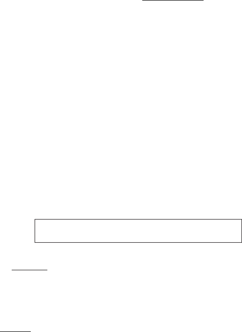
The following LED Flashes and Beeps signal E41 (Error code 41 ) Door Open
COUNT>>>>>> 123456789ABCDEF
1st Code Digit 5 Vertical LED Flashes XXXX
2nd Code Digit Start LED Flashes X
The following LED Flashes and Beeps signal E14 (Error code 14 ) Reed Sw itch
COUNT>>>>>> 123456789ABCDEF
1st Code Digit 5 Vertical LED Flashes X
2nd Code Digit Start LED Flashes XXXX
The following LED Flashes and Beeps signal EF1 (Error code F1 ) Clogged Pump
123456789101112131415
COUNT>>>>>> 123456789ABCDEF
1st Code Digit 5 Vertical LED Flashes XXXXXXXXXXXXXXX
2nd Code Digit Start LED Flashes X
Examples: Identifying Error Codes on non-digital display models:
3
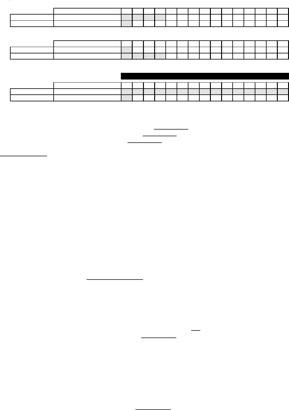
Error code chart
Error code Fault condition Check
E11 Fill time too long. Refer to test (1).
E13 Water leak in tub or air leak in air bell. Refer to test (2).
E14 Reed switch. Refer to test (3).
E21 Water not pumping out fast enough. Refer to test (4).
E23 Drain pump relay on control board failed. Replace control board.
E24 Drain pump relay on control board failed. Replace control board.
E31 Better models. Pressure sensor not communicating Refer to test (5).
with control board.
E35 Better models. Pressure sensor indicates water overfill. Refer to test (6).
E41 Control board thinks the door switch is open. Refer to test (7).
E42 Door remains locked after cycle is completed. Refer to test (8).
E43 Door locking problem. Refer to test (9).
E44 Control board problem. Replace the control board.
E45 Control board problem. Replace the control board.
E46 Control board problem. Replace the control board.
E47 Board thinks the door PTC circuit is open in spin. Refer to test (9).
E48 Board thinks the door PTC circuit is closed. Refer to test (9).
E52 Bad signal from tacho generator. Refer to test (10).
E55 Motor overheating. Refer to test (11).
E56 High motor current. Refer to test (11).
E57 High current on inverter. Refer to test (11).
E58 High current on motor phase. Refer to test (11).
E59 No tacho signal for 3 seconds. Refer to test (12).
E5A High temperature on heat sink. Replace the speed control
board.
E5B High temperature on heat sink. Replace the speed control
board.
E5C High temperature on heat sink. Replace the speed control
board.
E5D Communication problem. Refer to test (13).
E5E Communication problem. Refer to test (13).
E5F Communication problem. Refer to test (13).
E67 Input voltage on microprocessor incorrect. Replace the control board.
E75 Better models only. Water temperature sensor circuit. Refer to test (14).
E76 Better models only. NTC temperature for the cold water Hot and cold water hoses
valve over the limits. switched.
E95 Communication error. Replace the control board.
EB1 Incoming power frequency out of limits. Refer to test (15).
EB2 Incoming line voltage above 130 VAC. Check voltage at the outlet. If
below 130 VAC, replace the
control board.
EB3 Incoming line voltage below 90 VAC. Check voltage at the outlet. If
above 90 VAC, replace the
control board.
EF1 Clogged drain pump. Unclog the drain pump.
EF2 Too much soap. Advise customer to reduce
the amount of soap they are
using.
EF5 Better models only. NTC temperature for the cold water Hot and cold water hoses
valve over the limits. switched.
4
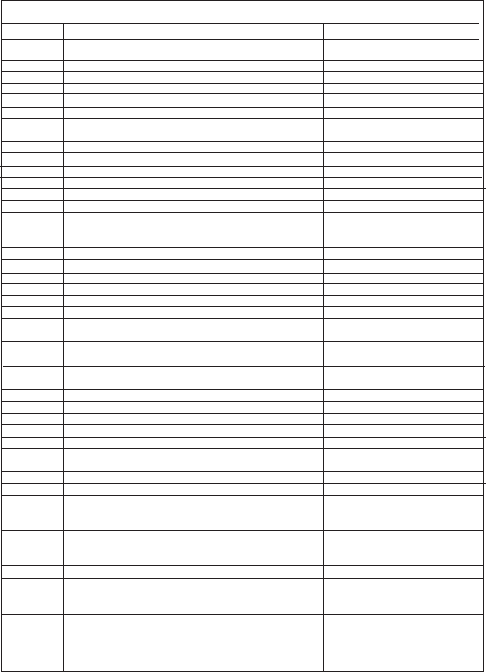
Test
Test Check Correction
Test 1:
Test 2:
Test 3:
Test 4:
Test 5:
Yes. Go to step (4).
No. Go to step (2)
No. Turn water faucets on.
Yes. Go to step (3).
No. Have customer correct pressure
problem.
Yes. Check for kinked or blocked
incoming water hoses, clean
the incoming water screens. If
problem still remains, replace the
water inlet valve assembly.
Yes. Go to step (5).
No. Go to step (6)
Yes. Go to step (6)
No. Replace the inlet valve assembly.
Pressure switch checks good.
Go to step (8).
Pressure switch checks bad. Replace
pressure switch.
If this did not correct the problem, go to
step 8.
Yes. Correct water leak.
No. Go to step (2)
Yes. Correct the air leak problem.
No. Go to step (3-4)
Defective. Replace the pressure switch.
Good. Go to step (5)
If this did not correct the problem, go to
step 5.
No. Close the drawer.
Yes. Go to step (2).
Magnet missing or defective. Replace the
magnet.
Magnet good. Go to step (3).
Defective. Replace the reed switch.
Good. Replace the control board.
Restriction. Correct problem.
No restriction. Go to step (2).
Zero. Replace the control board.
120 VAC. Remove the pump and check for
blockage. If blocked, remove the restriction,
if not, replace the pump.
Defective wiring. Correct wiring.
Good wiring. Replace the pressure sensor.
If this does not correct the problem, replace
the control board.
1. Is the incoming water flow normal?
2. Are the incoming water faucets turned
3. Is the incoming water pressure above (30) psi.
4. Does the fill water continue enter the washer?
5. Remove power from the washer. Did the water fill
stop?
6. Good models, check the pressure switch.
7. Better models, replace the pressure sensor.
8. Replace the control board.
1. Is the washer leaking water?
2. Is there an air leak in the air bell system?
3. Good models, check the pressure switch.
4. Better models, replace the pressure sensor.
5. Replace the control board.
1. Is the dispenser drawer closed?
2. Remove the drawer and check the magnet.
3. Open the console and check the reed switch.
1. Check the drain hose for restrictions.
2. Start the washer and check for 120 VAC at the
drain pump.
Inspect the wiring between the pressure sensor and
the control board.
5
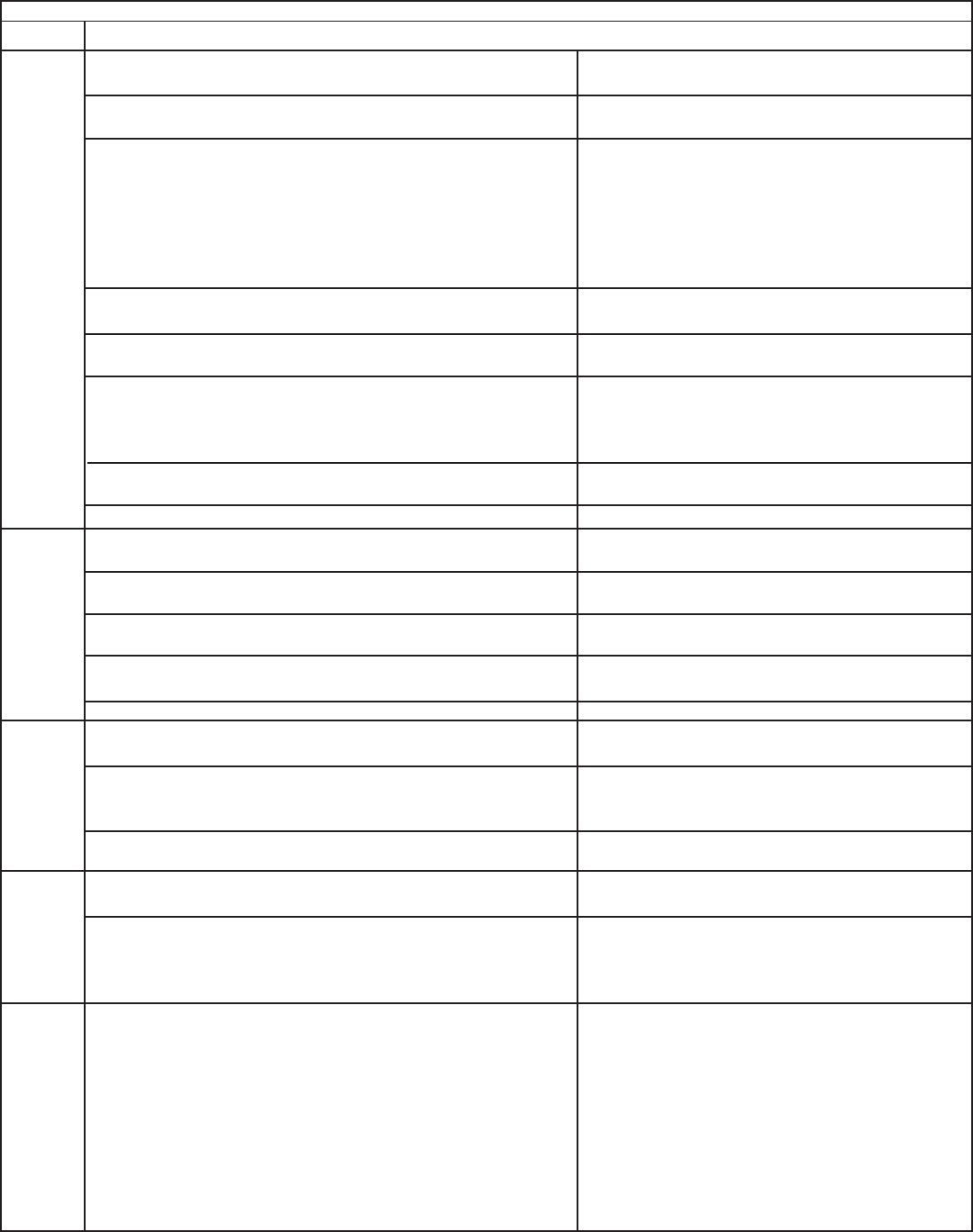
Test
Test Check Correction
1. Is the water level above 4.5 inches?
2. Does water enter the washer continuously.
3. Remove power from washer. Does the water
stop coming in?
4. Replace the pressure sensor switch. Did this
correct the problem?
1. Is the loading door closed?
2. Disconnect the plug from J2 on the control
board and check for continuity between the
pins in the plug.
1. Remove power from the washer. Wait one
minute. Can you open the door?
1. Remove the door lock assembly and
measure the resistance of the PTC.
1. Disconnect the plug from the drive motor and
measure the resistance pins 4 & 5 in the motor.
1. Remove the belt from the motor and spin the
motor pulley. Does the motor spin free?
2. Spin the tub pulley. Does the tub spin free?
3. Disconnect the plug from the motor and
measure the resistance of the windings (pin
1 to pin 2, pin 1 to pin 3, pin 2 to pin 3). All
readings should be between 4 and 6 Ohms.
1. Remove the belt from the motor and spin the
motor pulley. Does the motor spin free?
2. Spin the tub pulley. Does the tub spin free?
3. Disconnect the plug from the drive motor and
measure the resistance between pins 4 & 5
in the motor.
4. Disconnect the plug from the motor and
measure the resistance of the windings (pin
1 to pin 2, pin 1 to pin 3, pin 2 to pin 3). All
readings should be between 4 and 6 Ohms.
1. Communication problem. Check the wiring
between the control board and the speed
control board.
1. Check the resistance of the NTC. Is it
around 50K ohms?
1. Have the power company check the frequency
of the incoming power. If correct, replace the
control board.
Test 6:
Test 7:
Test 8:
Test 9:
Test 10:
Test 11:
Test 12:
Test 13:
Test 14:
Test 15:
Yes. Go to step (2).
No. Go to step (4).
Yes. Go to step (3).
No. Replace the control board.
No. Replace water valve assembly.
Yes. Check wiring to valve assembly for shorts. If
wiring is good, replace the control board.
Yes. Problem solved.
No. Replace the control board.
No. Close the door.
Yes. Go the step (2).
Open. Check the door strike. If good, replace the
door switch assembly.
Closed. Replace the control board.
Yes. Replace the control board.
No. Replace the door switch assembly.
Note: You may have to break the door strike to do this.
Shorted or open. Defective door lock assembly.
Reads around 1500 Ohms. Defective control board.
If the reading is between 105 & 130 Ohms, replace the
speed control board.
If the meter reads other than between 105 & 130 Ohms,
replace the motor.
No. Replace the motor.
Yes. Go to step (3)
No. Check the tub bearings.
Yes. Go to step (3)
If the readings are correct, replace the speed control
board.
If the readings are incorrect, replace the motor.
No. Replace the motor.
Yes. Go to step (3)
No. Check the tub bearings.
Yes. Go to step (3)
If the meter reads other than between 105 & 130 Ohms,
replace the motor.
If the reading is between 105 & 130 Ohms, Go to step (4)
If the readings are correct, replace the speed control
board.
If the readings are incorrect, replace the motor.
Wiring bad. Correct wiring problem.
Wiring good. Replace the control board. If the problem is
not corrected, replace the speed control board.
No. Replace the water inlet valve assembly
Yes. Replace the control board.
6
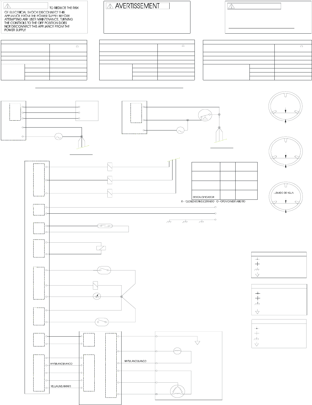
CABINET GROUND
NO CONNECTION
CONNECTION
WIRING CODES
PUMP MOTOR
ELECTRICAL COMPONENT
COMPONENT RESISTANCE TABLE
DOOR LOCK SOLENOID
RESISTANCE
@ 77°F (25°C)
12.0 ±7
1325 ±10
WATER FILL
HEIGHT
3.5 ±1 IN.
NO LOAD, START POSITION
OF PERMANENT PRESS
DISPENSER VALVE SOLENOIDS
REED SWITCH
DISPENSER DRAWER
MOTOR
T
GENERATOR
TACHO
C7.1C2.1
800 ±7
WAX MOTOR
12
2
1
C7.3
M5
C7.7
M4
M2
M1
MOTOR
FRAME
LOCAL GROUND
M1 TO M3
MOTOR
M1 TO M2
M5 TO M4
5.3 ±7
118 ±7
M2 TO M3
3.1 3.3
MOTOR CONTROL BOARD
TACHO-
ARMADURA
MOTOR
GENERADOR
GÉNÉRATRICE DE
ENCADRER
SOUPLES DU DISTRIBUTEUR
INTERRUPTEUR À LAMES
DE LA PORTE
INTERRUPTEUR
LOQUET DE PORTE
MOTEUR
MISE À LA TERRE
DÉMARRAGE DU CYCLE POUR
NIVEAU D'EAU
8.90 ±2.54 cm
SANS CHARGE, POSITION DE
CODES DE CÂBLAGE
AUCUNE CONNEXION
CONNEXION
DE CARROSSERIE
MISE À LA TERRE
CODIGOS DEL CABLEADO
PUESTA A TIERRA DE CAJA
SIN CONEXIÓN
CONEXIÓN
PLANCHADO PERMANENTE.
DEL CICLO PARA TALAS DE
SIN CARGA, POSICIÓN DE ARRANQUE
ALTURA DEL
PUESTA A TIERRA
CIREZ LE MOTEUR
FLEXIBLES DEL DISTRIBUIDOR
INTERRUPTOR DE LAMINAS
DE LA PUERTA
DE CIERRE
INTERRUPTOR
DE LA PUERTA
PARAFINE EL MOTOR
PUESTA A TIERRA DE LOCAL
DE LOCAL
MISE À LA TERRE
TACHYMÉTRE
TABLEAU DE RÉSISTANCE DES COMPOSANTS
SOLÉNOïDE DU LOQUET DE PORTE
SOLÉNOïDE DU ROBINET DISTRIBUTEUR
M1 VERS M2
M2 VERS M3
M5 VERS M4
M1 VERS M3
COMPOSANT ÉLECTRIQUE
MOTEUR DE POMPE
MOTEUR
RÉSISTANCE
@ 77°F (25°C)
12.0 ±7
1325 ±10
800 ±7
118 ±7
TOURNANT LES COMMANDES A LA POSITION UARRÊTU,
AVANT DE PROCÉDER À L'ENTRETIEN. EN
DÉBRANCHER CET APPAREIL DE L'ALIMENTATION
RÉDUIRE LE RISQUE DE CHOC ÉLECTRIQUE,
POUR
L'ON NE COUPE PAS L'ALIMENTATION ÉLECTRIQUE
DE L'APPAREIL.
TABLA DE RESISTENCIA DE LOS COMPONENTES
SOLENOIDE DE CIERRE DE LA PUERTA
SOLENOIDE DE LA VÁLVULA DEL DISTRIBUIDOR
M1 A M3
M5 A M4
M2 A M3
M1 A M2
COMPONENTE ELÉCTRICO
BOMBA DE MOTOR
MOTOR
@ 77°F (25°C)
RESISTENCIA
1325 ±10
12.0 ±7
800 ±7
118 ±7
EL RIESGO DE CHOQUE ELÉCTRICO, DESENCHUFE
ESTE APARATO DE LA ALIMENTACIÓN ELÉCTRICA
ANTES DE EFECTUAR EL MANTENIMIENTO. AL
GIRAR LOS CONTROLES A LA POSICIÓN UOFFU
(APAGADOU) NO SE CORTA LA ALIMENTACIÓN
ELÉCTRICA AL ARTEFACTO.
ADVERTENCIA
PARA REDUCIR
WARNING
DOOR LOCK
BANQUEADOR
A
UXILIARY SWITCH
AUXILIAIRE DE AUXILIAR
COMMUTATEUR
LOQUET DE PORTE
INTERRUPTOR
CIERRE DE LA PUERTA
MOTEUR
PANNEAU DE COMMANDE MOTEUR
PANEL DE CONTROL MOTOR
5.3 ±7
5.3 ±7 5.3 ±7
5.3 ±7
5.3 ±7 5.3 ±7
5.3 ±7
5.3 ±7
PUMP
1
M
2
J9
J12
J4
C4.3
C3.1
C4.4
C4.4 ROSE/NOIR
PINK/BLK
NOIR/ROUGE
RED\ROUGE\ROJO
WHT\BLANC\BLANCO
BLU\BLEU\AZUL
C4.1
C5.1
C5.3
C5.5
CAPTEUR DE NIVEAU
J12
C4.4
J4
C3.1
C3.2
PUMP
1
M
2
BLACK
21
PRESSURE
SWITCH
SELECT MODELS\MODÈLS DE SELECTEUR\MODELOS DE SELECTOR
C4.3
J4
WASH\LAVAGE\LAVADO
HOT\CHAUD\CALIENTE
C4.1
C4.2
PURP\VIOL\PÛRP
TAN\OCRE\CANELO
RED\ROUGE\ROJO
C3.3
C3.1
C2.1
+T NTC
C2.2
C5.5
C5.3
J3
C5.1
PINK\ROSE\ROSA
GRAY\GRIS\GRIS
ORG\ORG\ANARANJ
(SELECT MODELS
C2.1
C2.2
DOOR SWITCH
DOOR LOCK
J2
RED/BLK
4.1 4.2
Y
EL\JAUNE\AMARRILO
BRN\BRUN\MARRÓN
C2.1
J1
C2.2 C2.2
C5.2
C5.1
C5.4
C5.5
C5.5
C5.4
C5.3
C5.1
C5.2
C5.3
J6
M3
X
YZ
C7.4
C7.5
C7.6
GRN\VERT\VERDE
BLU\BLEU\AZUL
J1
J3
J5
J7
J8
OPTION A
OPTION B
A
OPTION A O B
4.4
2.1
4.32.2
BLK\NOIR\NEGRO
RED/BLK
J14
C2.2
C2.1 BLK\NOIR\NEGRO
WHT\BLANC\BLANCO
L1
N
GROUND
CABINET TUB SPEED
CONTROL
ROSA/NEGRO
BLACK/RED
NEGRO/ROJO
NEGRO/ROJO
NOIR/ROUGE
BLACK/RED
NOIR/ROUGE
NEGRO/ROJO
BLACK/RED
ROSA/NEGRO
ROSE/NOIR
PINK/BLK
TAN/ OCRE/
NOIR NEGRO
CANELO/
POMPE
BOMBA
BOMBA
POMPE
LEVEL SENSOR
SENSORE LLANO
À PRESSION
INTERRUPT
INTERRUPT
DE PRESIÓN
NEGRO/ROJO
NOIR/ROUGE
BLACK/RED
NOIR/ROUGE
NEGRO/ROJO
BLACK/RED
NEGRO/ROJO
NOIR/ROUGE
BLACK/RED
BLK\NOIR\NEGRO
BLK\NOIR\NEGRO
ROUGE/NOIR
ROJO/NEGRO
BLK\NOIR\NEGRO
ROJO/NEGRO
ROUGE/NOIR
BLK\NOIR\NEGRO
BLU\BLEU\AZUL
RED\ROUGE\ROJO
RED\ROUGE\ROJO
GRAY\GRIS\GRIS
ORG\ORG\ANARANJ
BRN\BRUN\MARRÓN
GRN\VERT\VERDE
DE VITESSE
RÉGULATEUR
REGULADOR
DEL VELOCIDAD
PANIER
CESTA
BOÎTIER
CAJA
MOTOR
JAVÉLLISANT
BLEACH
MODÈLS DE SELECTEUR\MODELOS DE SELECTOR)
D'OPTION A\OPCIÓN A
D'OPTION B\OPCIÓN B
VERS D'OPTION A OU B
TO OPTION A OR B
8.90 ±2.54 cm
BLEACH
JAVÉLLISANT
BANQUEADORLAVADO
LAVAGE
WASH
VALVE \ ROBINET \ VÁLVULA
DETERGENTE
DÉTERGENT
DETERGENT
BLEACH
JAVÉLLISANT
BANQUEADOR
ADOUCISSEUR
SOFTENER
DISPENSER\ DISTRIBUTEUR\ DISTRIBUIDOR
A
CONTECIMIENTO
EVENEMENT
EVENT
XO
XO
XX
