Kinetis Bootloader V2.0.0 Reference Manual
Kinetis%20Bootloader%20v2.0.0%20Reference%20Manual
Kinetis%20Bootloader%20v2.0.0%20Reference%20Manual
Kinetis%20Bootloader%20v2.0.0%20Reference%20Manual
Kinetis%20Bootloader%20v2.0.0%20Reference%20Manual
Kinetis%20Bootloader%20v2.0.0%20Reference%20Manual
User Manual: Pdf
Open the PDF directly: View PDF ![]() .
.
Page Count: 170 [warning: Documents this large are best viewed by clicking the View PDF Link!]
- Kinetis Bootloader v2.0.0 Reference Manual
- Chapter 1: Introduction
- Chapter 2: Functional description
- Chapter 3: Kinetis bootloader protocol
- Chapter 4: Bootloader packet types
- Chapter 5: Kinetis bootloader command API
- Introduction
- GetProperty command
- SetProperty command
- FlashEraseAll command
- FlashEraseRegion command
- FlashEraseAllUnsecure command
- ReadMemory command
- WriteMemory command
- FillMemory command
- FlashSecurityDisable command
- Execute command
- Call command
- Reset command
- FlashProgramOnce command
- FlashReadOnce command
- FlashReadResource command
- Configure QuadSPI command
- ReceiveSBFile command
- ReliableUpdate command
- Chapter 6: Supported peripherals
- Chapter 7: Peripheral interfaces
- Chapter 8: Memory interface
- Chapter 9: Kinetis Flash Driver API
- Chapter 10: Kinetis bootloader porting
- Chapter 11: Creating a custom flash-resident bootloader
- Chapter 12: Bootloader Reliable Update
- Chapter 13: Appendix A: status and error codes
- Chapter 14: Appendix B: GetProperty and SetProperty commands
- Chapter 15: Revision history

Kinetis Bootloader v2.0.0 Reference
Manual
Rev. 0, 04/2016

Kinetis Bootloader v2.0.0 Reference Manual, Rev. 0, 04/2016
2 Freescale Semiconductor, Inc.

Contents
Section number Title Page
Chapter 1
Introduction
1.1 Introduction.....................................................................................................................................................................9
1.2 Terminology....................................................................................................................................................................9
1.3 Block diagram.................................................................................................................................................................10
1.4 Features supported.......................................................................................................................................................... 10
1.5 Components supported....................................................................................................................................................11
Chapter 2
Functional description
2.1 Introduction.....................................................................................................................................................................13
2.2 Memory map...................................................................................................................................................................13
2.3 The Kinetis Bootloader Configuration Area (BCA).......................................................................................................13
2.4 Start-up process...............................................................................................................................................................15
2.5 Clock configuration........................................................................................................................................................ 18
2.6 Bootloader entry point.................................................................................................................................................... 18
2.7 Application integrity check.............................................................................................................................................19
2.7.1 Kinetis bootloader flow with integrity checker..................................................................................................20
2.7.1.1 Bootloader initialization.....................................................................................................................20
2.7.1.2 Staying in or leaving bootloader........................................................................................................ 21
Chapter 3
Kinetis bootloader protocol
3.1 Introduction.....................................................................................................................................................................25
3.2 Command with no data phase.........................................................................................................................................25
3.3 Command with incoming data phase..............................................................................................................................26
3.4 Command with outgoing data phase...............................................................................................................................27
Chapter 4
Bootloader packet types
4.1 Introduction.....................................................................................................................................................................31
Kinetis Bootloader v2.0.0 Reference Manual, Rev. 0, 04/2016
Freescale Semiconductor, Inc. 3

Section number Title Page
4.2 Ping packet......................................................................................................................................................................31
4.3 Ping response packet.......................................................................................................................................................32
4.4 Framing packet................................................................................................................................................................33
4.5 CRC16 algorithm............................................................................................................................................................34
4.6 Command packet............................................................................................................................................................ 35
4.7 Response packet..............................................................................................................................................................37
Chapter 5
Kinetis bootloader command API
5.1 Introduction.....................................................................................................................................................................41
5.2 GetProperty command.................................................................................................................................................... 41
5.3 SetProperty command.....................................................................................................................................................43
5.4 FlashEraseAll command................................................................................................................................................. 45
5.5 FlashEraseRegion command...........................................................................................................................................46
5.6 FlashEraseAllUnsecure command..................................................................................................................................47
5.7 ReadMemory command..................................................................................................................................................48
5.8 WriteMemory command.................................................................................................................................................50
5.9 FillMemory command.................................................................................................................................................... 52
5.10 FlashSecurityDisable command......................................................................................................................................54
5.11 Execute command...........................................................................................................................................................55
5.12 Call command.................................................................................................................................................................56
5.13 Reset command...............................................................................................................................................................57
5.14 FlashProgramOnce command.........................................................................................................................................58
5.15 FlashReadOnce command.............................................................................................................................................. 59
5.16 FlashReadResource command........................................................................................................................................61
5.17 Configure QuadSPI command........................................................................................................................................ 63
5.18 ReceiveSBFile command................................................................................................................................................64
5.19 ReliableUpdate command...............................................................................................................................................64
Chapter 6
Supported peripherals
Kinetis Bootloader v2.0.0 Reference Manual, Rev. 0, 04/2016
4 Freescale Semiconductor, Inc.

Section number Title Page
6.1 Introduction.....................................................................................................................................................................67
6.2 I2C Peripheral................................................................................................................................................................. 67
6.2.1 Performance numbers for I2C............................................................................................................................69
6.3 SPI Peripheral................................................................................................................................................................. 71
6.3.1 Performance Numbers for SPI........................................................................................................................... 73
6.4 UART Peripheral............................................................................................................................................................ 75
6.4.1 Performance Numbers for UART......................................................................................................................77
6.5 USB HID Peripheral....................................................................................................................................................... 79
6.5.1 Device descriptor............................................................................................................................................... 79
6.5.2 Endpoints........................................................................................................................................................... 81
6.5.3 HID reports........................................................................................................................................................ 81
6.6 USB Peripheral............................................................................................................................................................... 83
6.6.1 Device descriptor............................................................................................................................................... 83
6.6.2 Endpoints........................................................................................................................................................... 87
6.7 FlexCAN Peripheral........................................................................................................................................................88
6.8 QuadSPI Peripheral ........................................................................................................................................................90
6.8.1 QSPI configuration block...................................................................................................................................90
6.8.2 Look-up-table.....................................................................................................................................................95
6.8.3 Configure QuadSPI module...............................................................................................................................96
6.8.4 Access external SPI flash devices using QuadSPI module................................................................................98
6.8.5 Boot directly from QuadSPI.............................................................................................................................. 98
6.8.6 Example QCB.................................................................................................................................................... 99
Chapter 7
Peripheral interfaces
7.1 Introduction.....................................................................................................................................................................101
7.2 Abstract control interface................................................................................................................................................102
7.3 Abstract byte interface.................................................................................................................................................... 103
7.4 Abstract packet interface.................................................................................................................................................103
7.5 Framing packetizer..........................................................................................................................................................104
Kinetis Bootloader v2.0.0 Reference Manual, Rev. 0, 04/2016
Freescale Semiconductor, Inc. 5

Section number Title Page
7.6 USB HID packetizer....................................................................................................................................................... 104
7.7 USB HID packetizer....................................................................................................................................................... 104
7.8 Command/data processor................................................................................................................................................105
Chapter 8
Memory interface
8.1 Abstract interface............................................................................................................................................................107
8.2 Flash driver interface...................................................................................................................................................... 108
8.3 Low-level flash driver.....................................................................................................................................................109
Chapter 9
Kinetis Flash Driver API
9.1 Introduction.....................................................................................................................................................................111
9.2 Flash Driver Entry Point.................................................................................................................................................111
9.3 Flash driver data structures............................................................................................................................................. 113
9.3.1 flash_config_t.....................................................................................................................................................113
9.4 Flash driver API..............................................................................................................................................................114
9.4.1 FLASH_Init....................................................................................................................................................... 114
9.4.2 FLASH_EraseAll...............................................................................................................................................115
9.4.3 FLASH_EraseAllUnsecure................................................................................................................................115
9.4.4 FLASH_Erase.................................................................................................................................................... 116
9.4.5 FLASH_Program............................................................................................................................................... 117
9.4.6 FLASH_GetSecurityState..................................................................................................................................118
9.4.7 FLASH_SecurityBypass.................................................................................................................................... 119
9.4.8 FLASH_VerifyEraseAll.....................................................................................................................................119
9.4.9 FLASH_VerifyErase..........................................................................................................................................120
9.4.10 FLASH_VerifyProgram.....................................................................................................................................121
9.4.11 FLASH_GetProperty......................................................................................................................................... 123
9.4.12 FLASH_ProgramOnce.......................................................................................................................................124
9.4.13 FLASH_ReadOnce............................................................................................................................................ 125
9.4.14 FLASH_ReadResource......................................................................................................................................126
Kinetis Bootloader v2.0.0 Reference Manual, Rev. 0, 04/2016
6 Freescale Semiconductor, Inc.

Section number Title Page
9.4.15 FLASH_SetCallback..........................................................................................................................................127
9.5 Integrate Wrapped Flash Driver API to actual projects..................................................................................................127
9.5.1 Add fsl_flash.h and fsl_flash_api_tree.c to corresponding project....................................................................128
9.5.2 Include fsl_flash.h to corresponding files before calling WFDI........................................................................129
Chapter 10
Kinetis bootloader porting
10.1 Introduction.....................................................................................................................................................................131
10.2 Choosing a starting point................................................................................................................................................ 131
10.3 Preliminary porting tasks................................................................................................................................................131
10.3.1 Download device header files............................................................................................................................132
10.3.2 Copy the closest match...................................................................................................................................... 132
10.3.3 Provide device startup file (vector table)........................................................................................................... 133
10.3.4 Clean up the IAR project................................................................................................................................... 133
10.3.5 Bootloader peripherals....................................................................................................................................... 135
10.4 Primary porting tasks......................................................................................................................................................137
10.4.1 Bootloader peripherals....................................................................................................................................... 137
10.4.1.1 Supported peripherals........................................................................................................................ 138
10.4.1.2 Peripheral initialization......................................................................................................................138
10.4.1.3 Clock initialization.............................................................................................................................138
10.4.2 Bootloader configuration................................................................................................................................... 139
10.4.3 Bootloader memory map configuration............................................................................................................. 139
Chapter 11
Creating a custom flash-resident bootloader
11.1 Introduction.....................................................................................................................................................................141
11.2 Where to start..................................................................................................................................................................141
11.3 Flash-resident bootloader source tree............................................................................................................................. 142
11.4 Modifying source files.................................................................................................................................................... 144
11.5 Example.......................................................................................................................................................................... 144
11.6 Modifying a peripheral configuration macro..................................................................................................................145
Kinetis Bootloader v2.0.0 Reference Manual, Rev. 0, 04/2016
Freescale Semiconductor, Inc. 7

Section number Title Page
11.7 How to generate MMCAU functions in binary image....................................................................................................145
Chapter 12
Bootloader Reliable Update
12.1 Introduction.....................................................................................................................................................................153
12.2 Functional description.....................................................................................................................................................153
12.2.1 Bootloader workflow with reliable update.........................................................................................................153
12.2.2 Reliable update implementation types............................................................................................................... 154
12.2.3 Reliable update flow.......................................................................................................................................... 155
12.2.3.1 Software implementation................................................................................................................... 155
12.2.3.2 Hardware implementation..................................................................................................................157
12.3 Configuration macros......................................................................................................................................................159
12.4 Get property.................................................................................................................................................................... 160
Chapter 13
Appendix A: status and error codes
Chapter 14
Appendix B: GetProperty and SetProperty commands
Chapter 15
Revision history
15.1 Revision History............................................................................................................................................................. 169
Kinetis Bootloader v2.0.0 Reference Manual, Rev. 0, 04/2016
8 Freescale Semiconductor, Inc.

Chapter 1
Introduction
1.1 Introduction
The Kinetis bootloader is a configurable flash programming utility that operates over a
serial connection on Kinetis MCUs. It enables quick and easy programming of Kinetis
MCUs through the entire product life cycle, including application development, final
product manufacturing, and beyond. The bootloader is delivered in two ways. The
Kinetis bootloader is provided as full source code that is highly configurable. The
bootloader is also preprogrammed by Freescale into ROM or flash on select Kinetis
devices. Host-side command line and GUI tools are available to communicate with the
bootloader. Users can utilize host tools to upload/download application code via the
bootloader.
1.2 Terminology
target
The device running the bootloader firmware (aka the ROM).
host
The device sending commands to the target for execution.
source
The initiator of a communications sequence. For example, the sender of a command or
data packet.
destination
Receiver of a command or data packet.
incoming
Kinetis Bootloader v2.0.0 Reference Manual, Rev. 0, 04/2016
Freescale Semiconductor, Inc. 9
From host to target.
outgoing
From target to host.
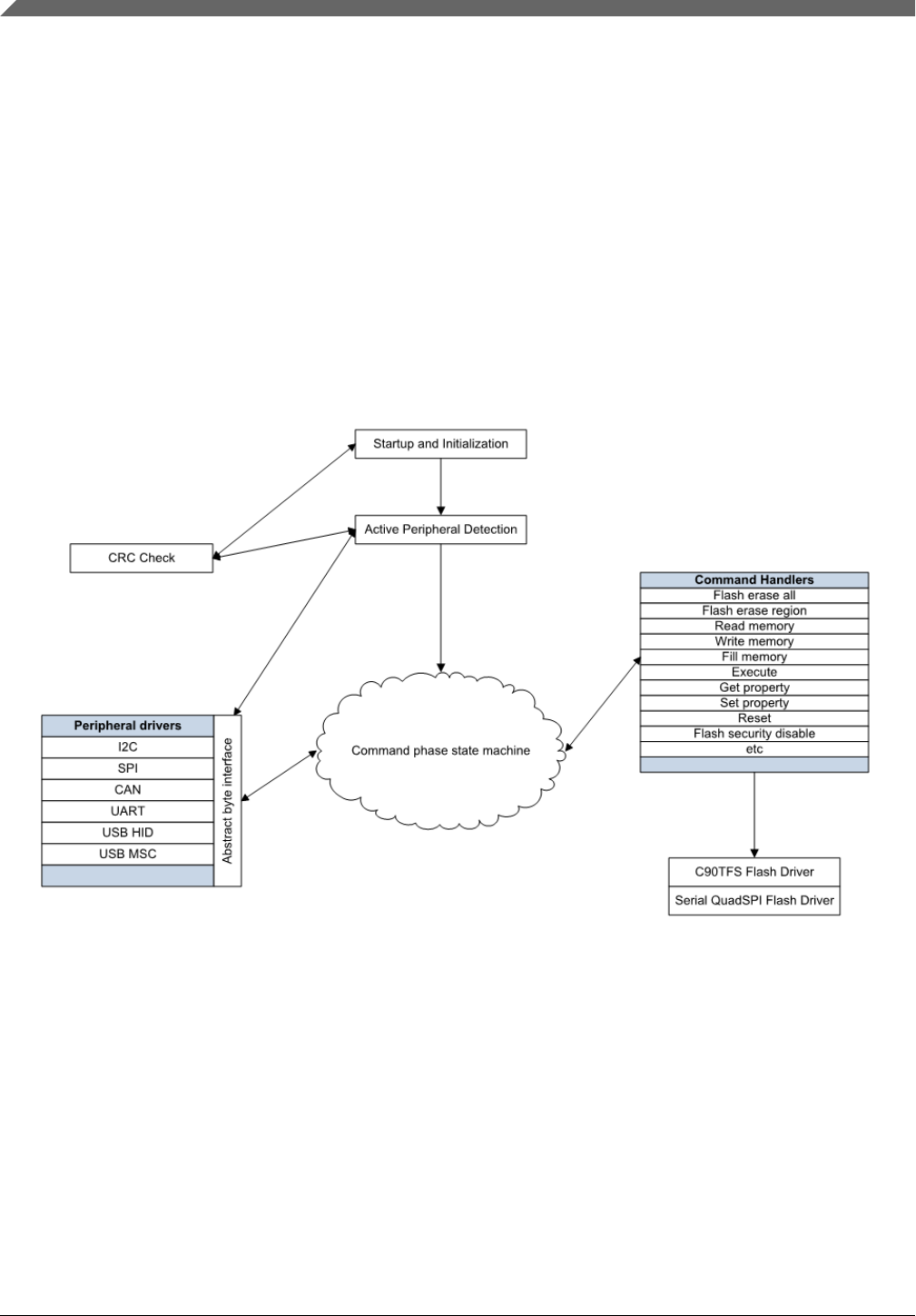
1.3 Block diagram
This block diagram describes the overall structure of the Kinetis bootloader.
Figure 1-1. Block diagram
1.4 Features supported
Here are some of the features supported by the Kinetis bootloader:
•Supports UART, I2C, SPI, CAN, and USB peripheral interfaces.
• Automatic detection of the active peripheral.
Block diagram
Kinetis Bootloader v2.0.0 Reference Manual, Rev. 0, 04/2016
10 Freescale Semiconductor, Inc.

• Ability to disable any peripheral.
• UART peripheral implements autobaud.
• Common packet-based protocol for all peripherals.
• Packet error detection and retransmit.
• Flash-resident configuration options.
• Fully supports flash security, including ability to mass erase or unlock security via
the backdoor key.
• Protection of RAM used by the bootloader while it is running.
• Provides command to read properties of the device, such as Flash and RAM size.
• Multiple options for executing the bootloader either at system start-up or under
application control at runtime.
• Support for internal flash and serial QuadSPI memories.
• Support for encrypted image download.
1.5 Components supported
Components for the bootloader firmware:
•Startup code (clocking, pinmux, etc.)
• Command phase state machine
• Command handlers
• GenericResponse
• FlashEraseAll
• FlashEraseRegion
• ReadMemory
• ReadMemoryResponse
• WriteMemory
• FillMemory
• FlashSecurityDisable
• GetProperty
• GetPropertyResponse
• Execute
• Call
• Reset
• SetProperty
• FlashEraseAllUnsecure
• FlashProgramOnce
• FlashReadOnce
• FlashReadOnceResponse
• FlashReadResource
Chapter 1 Introduction
Kinetis Bootloader v2.0.0 Reference Manual, Rev. 0, 04/2016
Freescale Semiconductor, Inc. 11

• FlashReadResourceResponse
• ConfigureQuadSPI
• ReliableUpdate
• SB file state machine
• Encrypted image support (AES-128)
• Packet interface
• Framing packetizer
• Command/data packet processor
• Memory interface
• Abstract interface
• Flash Driver Interface
• Low-level flash driver
• QuadSPI interface
• Low-level QuadSPI driver
• On-the-fly QuadSPI decryption engine initialization
• Peripheral drivers
• I2C slave
• SPI slave
• CAN
• Auto-baud detector
• UART
• Auto-baud detector
• USB device
• USB controller driver
• USB framework
• USB HID class
• USB Mass storage class
• CRC check engine
• CRC algorithm
Components supported
Kinetis Bootloader v2.0.0 Reference Manual, Rev. 0, 04/2016
12 Freescale Semiconductor, Inc.

Chapter 2
Functional description
2.1 Introduction
The following subsections describe the Kinetis bootloader functionality.
2.2 Memory map
See the Kinetis bootloader chapter of the reference manual of the particular SoC for the
ROM and RAM memory map used by the bootloader.
2.3 The Kinetis Bootloader Configuration Area (BCA)
The Kinetis bootloader reads data from the Bootloader Configuration Area (BCA) to
configure various features of the bootloader. The BCA resides in flash memory at offset
0x3C0 from the beginning of the user application, and provides all of the parameters
needed to configure the Kinetis bootloader operation. For uninitialized flash, the Kinetis
bootloader uses a predefined default configuration. A host application can use the Kinetis
bootloader to program the BCA for use during subsequent initializations of the
bootloader.
NOTE
Flashloader does not support this feature.
Table 2-1. Configuration Fields for the Kinetis bootloader
Offset Size (bytes) Configuration Field Description
0x00 - 0x03 4 tag Magic number to verify bootloader
configuration is valid. Must be set to
'kcfg'.
Table continues on the next page...
Kinetis Bootloader v2.0.0 Reference Manual, Rev. 0, 04/2016
Freescale Semiconductor, Inc. 13

Table 2-1. Configuration Fields for the Kinetis bootloader (continued)
Offset Size (bytes) Configuration Field Description
0x04 - 0x07 4 crcStartAddress Start address for application image
CRC check. To generate the CRC,
see the CRC chapter.
0x08 - 0x0B 4 crcByteCount Byte count for application image CRC
check.
0x0C - 0x0F 4 crcExpectedValue Expected CRC value for application
CRC check.
0x10 1 enabledPeripherals Bitfield of peripherals to enable.
bit 0 UART
bit 1 I2C
bit 2 SPI bit 3 CAN
bit 4 USB-HID
bit 7 USB MSC
0x11 1 i2cSlaveAddress If not 0xFF, used as the 7-bit I2C
slave address.
0x12 - 0x13 2 peripheralDetectionTimeout If not 0xFF, used as the timeout in
milliseconds for active peripheral
detection.
0x14 - 0x15 2 usbVid Sets the USB Vendor ID reported by
the device during enumeration.
0x16- 0x17 2 usbPid Sets the USB Product ID reported by
the device during enumeration.
0x18 - 0x1B 4 usbStringsPointer Sets the USB Strings reported by the
device during enumeration.
0x1C 1 clockFlags See clockFlags Configuration Field.
0x1D 1 clockDivider Inverted value of the divider used for
core and bus clocks when in high-
speed mode.
0x1E 1 bootFlags One's complement of direct boot flag.
0xFE represents direct boot.
0x1F 1 pad0 Reserved, set to 0xFF.
0x20 - 0x23 4 mmcauConfigPointer Reserved, holds a pointer value to the
MMCAU configuration.
0x24 - 0x27 4 keyBlobPointer Reserved, holds a value to the key
blob array used to configure OTFAD.
0x28 1 pad1 Reserved.
0x29 1 canConfig1 ClkSel[1], PropSeg[3], SpeedIndex[4]
0x2A - 0x2B 2 canConfig2 Pdiv[8], Pseg[3], Pseg2[3], rjw[2]
0x2C - 0x2D 2 canTxId txId
0x2E - 0x2F 2 canRxId rxId
0x30 - 0x33 4 qspiConfigBlockPointer QuadSPI configuration block pointer
The Kinetis Bootloader Configuration Area (BCA)
Kinetis Bootloader v2.0.0 Reference Manual, Rev. 0, 04/2016
14 Freescale Semiconductor, Inc.

The first configuration field 'tag' is a tag value or magic number. The tag value must be
set to 'kcfg' for the bootloader configuration data to be recognized as valid. If tag-field
verification fails, the Kinetis bootloader acts as if the configuration data is not present.
The tag value is treated as a character string, so bytes 0-3 must be set as shown in the
table.
Table 2-2. tag Configuration Field
Offset tag Byte Value
0 'k' (0x6B)
1 'c' (0x63)
2 'f' (0x66)
3 'g' (0x67)
The flags in the clockFlags configuration field are enabled if the corresponding bit is
cleared (0).
Table 2-3. clockFlags Configuration Field
Bit Flag Description
0 HighSpeed Enable high-speed mode (i.e., 48 MHz).
1 - 7 - Reserved.
2.4 Start-up process
It is important to note that the startup process for bootloader in ROM, RAM (flashloader),
and flash (flash-resident) are slightly different. See the chip-specific reference manual for
understanding the startup process for the ROM bootloader and flashloader. This section
focuses on the flash-resident bootloader startup only.
There are two ways to get into the flash-resident bootloader.
1. If the vector table at the start of internal flash holds a valid PC and SP, the hardware
boots into the bootloader.
2. A user application running on flash or RAM calls into the Kinetis bootloader entry
point address in flash to start the Kinetis bootloader execution.
After the Kinetis bootloader has started, the following procedure starts the bootloader
operations:
1. Initializes the bootloader's .data and .bss sections.
2. Reads the bootloader configuration data from flash at offset 0x3C0. The
configuration data is only used if the tag field is set to the expected 'kcfg' value. If the
Chapter 2 Functional description
Kinetis Bootloader v2.0.0 Reference Manual, Rev. 0, 04/2016
Freescale Semiconductor, Inc. 15

tag is incorrect, the configuration values are set to default, as if the data was all 0xFF
bytes.
3. Clocks are configured.
4. Enabled peripherals are initialized.
5. The the bootloader waits for communication to begin on a peripheral.
• If detection times out, the bootloader jumps to the user application in flash if the
valid PC and SP addresses are specified in the application vector table.
• If communication is detected, all inactive peripherals are shut down, and the
command phase is entered.
Start-up process
Kinetis Bootloader v2.0.0 Reference Manual, Rev. 0, 04/2016
16 Freescale Semiconductor, Inc.
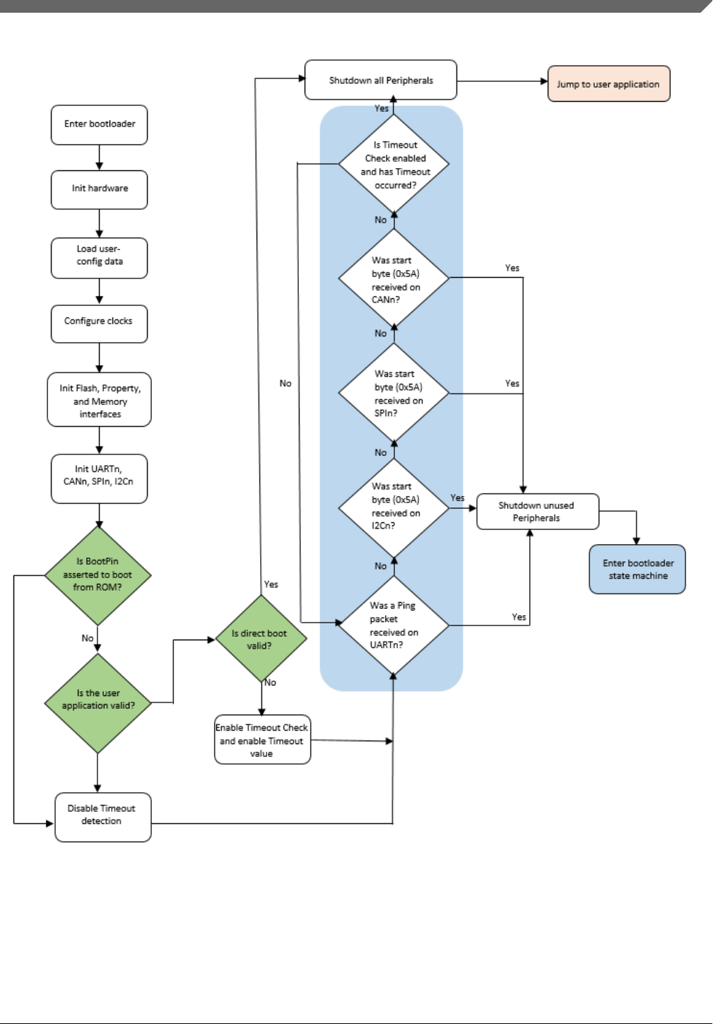
Figure 2-1. Kinetis bootloader start-up flowchart
Chapter 2 Functional description
Kinetis Bootloader v2.0.0 Reference Manual, Rev. 0, 04/2016
Freescale Semiconductor, Inc. 17

2.5 Clock configuration
The clock configuration used by the bootloader depends on the clock settings in the
bootloader configuration area and the requirements of the enabled peripherals. The
bootloader starts by using the default clock configuration of the part out of reset.
• Alternate clock configurations are supported by setting fields in the bootloader
configuration data.
• If the HighSpeed flag of the clockFlags configuration value is cleared, the core and
bus clock frequencies are determined by the clockDivider configuration value.
• The core clock divider is set directly from the inverted value of clockDivider, unless
a USB peripheral is enabled. If a USB peripheral is enabled and clockDivider is
greater than 2, clockDivider is reduced to 2 in order to keep the CPU clock above 20
MHz.
• The bus clock divider is set to 1, unless the resulting bus clock frequency is greater
than the maximum supported value. In this instance, the bus clock divider is
increased until the bus clock frequency is at or below the maximum.
• The flash clock divider is set to 1, unless the resulting flash clock frequency is
greater than the maximum supported value. In this instance, the flash clock divider is
increased until the flash clock frequency is at or below the maximum.
• If flex bus is available, the flex bus clock divider is set to 1, unless the resulting flex
bus clock frequency is greater than the maximum supported value. In this instance,
the flex bus clock divider is increased until the flex bus clock frequency is at or
below the maximum.
• If a USB peripheral is enabled, the IRC48Mhz clock is selected as the USB
peripheral clock and the clock recovery feature is enabled.
• Note that the maximum baud rate of serial peripherals is related to the core and bus
clock frequencies.
• Note that the bootloader code does not always configure the device core clock to run
at 48 MHz. For devices with no USB peripheral and when HighSpeed flag is not
enabled in the BCA, the core clock is configured to run at default clock rate (i.e.,
20.9 MHz). This is also true for devices with USB but HighSpeed flag is not enabled
in the BCA.
2.6 Bootloader entry point
The Kinetis bootloader provides a function (runBootloader) that a user application can
call, to run the bootloader.
Clock configuration
Kinetis Bootloader v2.0.0 Reference Manual, Rev. 0, 04/2016
18 Freescale Semiconductor, Inc.

NOTE
Flashloader does not support this feature.
To get the address of the entry point, the user application reads the word containing the
pointer to the bootloader API tree at offset 0x1C of the bootloader's vector table. The
vector table is placed at the base of the bootloader's address range.
The bootloader API tree is a structure that contains pointers to other structures, which
have the function and data addresses for the bootloader. The bootloader entry point is
always the first word of the API tree.
The prototype of the entry point is:
void run_bootloader(void * arg);
The arg parameter is currently unused, and intended for future expansion. For example,
passing options to the bootloader. To ensure future compatibility, a value of NULL
should be passed for arg.
Example code to get the entry pointer address from the ROM and start the bootloader:
// Variables
uint32_t runBootloaderAddress;
void (*runBootloader)(void * arg);
// Read the function address from the ROM API tree.
runBootloaderAddress = **(uint32_t **)(0x1c00001c);
runBootloader = (void (*)(void * arg))runBootloaderAddress;
// Start the bootloader.
runBootloader(NULL);
NOTE
The user application must be executing at Supervisor
(Privileged) level when calling the bootloader entry point.
2.7 Application integrity check
Chapter 2 Functional description
Kinetis Bootloader v2.0.0 Reference Manual, Rev. 0, 04/2016
Freescale Semiconductor, Inc. 19

The application integrity check is an important step in the boot process. The Kinetis
bootloader (KBOOT) provides an option, and when enabled, does not allow the
application code to execute on the device unless it passes the integrity check.
Kinetis bootloader uses CRC-32 as its integrity checker algorithm. To properly configure
this feature, the following fields in the BCA must be set to valid values:
• Set crcStartAddress to the start address that should be used for the CRC check. This
is generally the start address of the application image, where it resides in the flash or
QuadSPI memory.
• Set crcByteCount to the number of bytes to run the CRC check from the start
address. This is generally the length of the application image in bytes.
• Set crcExpectedValue to the checksum. This is the pre-calculated value of the
checksum stored in the BCA for the bootloader to compare with the resultant CRC
calculation. If the resultant value matches with the crcExpectedValue, then the
application image passes the CRC check.
NOTE
See Section 2.3, "The Kinetis Bootloader Configuration Area
(BCA)", in the Kinetis Bootloader v2.0.0 Reference Manual for
details about the BCA.
2.7.1 Kinetis bootloader flow with integrity checker
The following steps describe the flow of execution of the Kinetis bootloader when
integrity check is enabled in the BCA.
2.7.1.1 Bootloader initialization
• Load BCA data from flash at offset, corresponding to the application image start
address + 0x3C0.
•Initialize the CRC check status. If BCA is invalid (the tag is not set to expected
‘kcfg’ value), or the CRC parameters in valid BCA are not set, then the CRC check
status is set to kStatus_AppCrcCheckInvalid, meaning the integrity check is not
enabled for the device. Otherwise, the CRC check status is set to
kStatus_AppCrcCheckInactive, meaning the integrity check is due for the device.
Application integrity check
Kinetis Bootloader v2.0.0 Reference Manual, Rev. 0, 04/2016
20 Freescale Semiconductor, Inc.

• If a boot pin is not asserted and application address is a valid address (the address is
not null, the address resides in a valid executable memory range, and the flash is not
blank), then the bootloader begins the CRC check function. Otherwise, the CRC
check function is bypassed.
• The CRC check function. The bootloader checks the CRC check status initialized in
the previous steps, and if it is not kStatus_AppCrcCheckInvalid (integrity check is
enabled for the device), then the bootloader verifies the application resides in internal
flash or external QSPI flash.
a. If the application address range is invalid, then the bootloader sets the status to
kStatus_AppCrcCheckOutOfRange.
b. If the application address range is valid, then the CRC check process begins. If
the CRC check passes, then the bootloader sets the status to
kStatus_AppCrcCheckPassed. Otherwise, the status is set to
kStatus_AppCrcCheckFailed.
2.7.1.2 Staying in or leaving bootloader
• If no active peripheral is found before the end of the detection, the timeout period
expires, and the current CRC check status is either set to
kStatus_AppCrcCheckInvalid (integrity check is not enabled for the device), or
kStatus_AppCrcCheckPassed. Then, the bootloader jumps to the application image.
Otherwise, the bootloader enters the active state and wait for commands from the
host.
Chapter 2 Functional description
Kinetis Bootloader v2.0.0 Reference Manual, Rev. 0, 04/2016
Freescale Semiconductor, Inc. 21
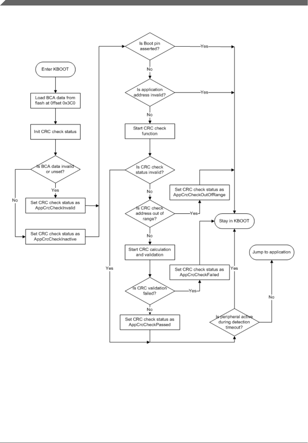
Figure 2-2. Application integrity check flow
The following table provides the CRC algorithm which is used for the application
integrity check. The CRC algorithm is the MPEG2 variant of CRC-32.
Application integrity check
Kinetis Bootloader v2.0.0 Reference Manual, Rev. 0, 04/2016
22 Freescale Semiconductor, Inc.

The characteristics of the MPEG2 variant are:
Table 2-4. MPEG2 variant characteristics
Width 32
Polynomial 0x04C11BD7
Init Value 0xFFFFFFFF
Reflect In FALSE
Reflect Out FALSE
XOR Out 0x00000000
The bootloader computes the CRC over each byte in the application range specified in the
BCA, excluding the crcExpectedValue field in the BCA. In addition, Kinetis bootloader
automatically pads the extra byte(s) with zero(s) to finalize CRC calculation if the length
of the image is not 4-bytes aligned.
The following procedure shows the steps in CRC calculation.
1. CRC initialization
• Set the initial CRC as 0xFFFFFFFF, which clears the CRC byte count to 0.
2. CRC calculation
• Check if the crcExpectedValue field in BCA resides in the address range
specified for CRC calculation.
• If the crcExpectedValue does not reside in the address range, then compute
CRC over every byte value in the address range.
• If the crcExpectedValue does reside in the address range, then split the
address range into two parts, splitting at the address of crcExpectedValue
field in BCA excluding crcExpectedValue. Then, compute the CRC on the
two parts.
• Adjust the CRC byte count according to the actual bytes computed.
3. CRC finalization
• Check if the CRC byte count is not 4-bytes aligned. If it is 4-bytes aligned, then
pad it with necessary zeroes to finalize the CRC. Otherwise, return the current
computed CRC.
NOTE
Kinetis bootloader assumes that crcExpectedValue field (4
bytes) resides in the CRC address range completely if it borders
on the CRC address range.
Chapter 2 Functional description
Kinetis Bootloader v2.0.0 Reference Manual, Rev. 0, 04/2016
Freescale Semiconductor, Inc. 23

Application integrity check
Kinetis Bootloader v2.0.0 Reference Manual, Rev. 0, 04/2016
24 Freescale Semiconductor, Inc.

Chapter 3
Kinetis bootloader protocol
3.1 Introduction
This section explains the general protocol for the packet transfers between the host and
the Kinetis bootloader. The description includes the transfer of packets for different
transactions, such as commands with no data phase and commands with incoming or
outgoing data phase. The next section describes various packet types used in a
transaction.
Each command sent from the host is replied to with a response command.
Commands may include an optional data phase.
•If the data phase is incoming (from the host to Kinetis bootloader ), it is part of the
original command.
• If the data phase is outgoing (from Kinetis bootloader to host), it is part of the
response command.
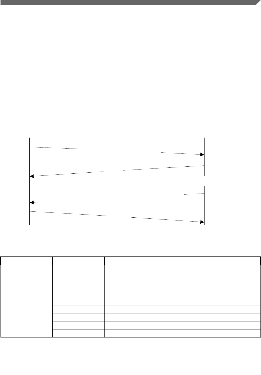
3.2 Command with no data phase
NOTE
In these diagrams, the Ack sent in response to a Command or
Data packet can arrive at any time before, during, or after the
Command/Data packet has processed.
Command with no data phase
The protocol for a command with no data phase contains:
• Command packet (from host)
• Generic response command packet (to host)
Kinetis Bootloader v2.0.0 Reference Manual, Rev. 0, 04/2016
Freescale Semiconductor, Inc. 25

Figure 3-1. Command with no data phase
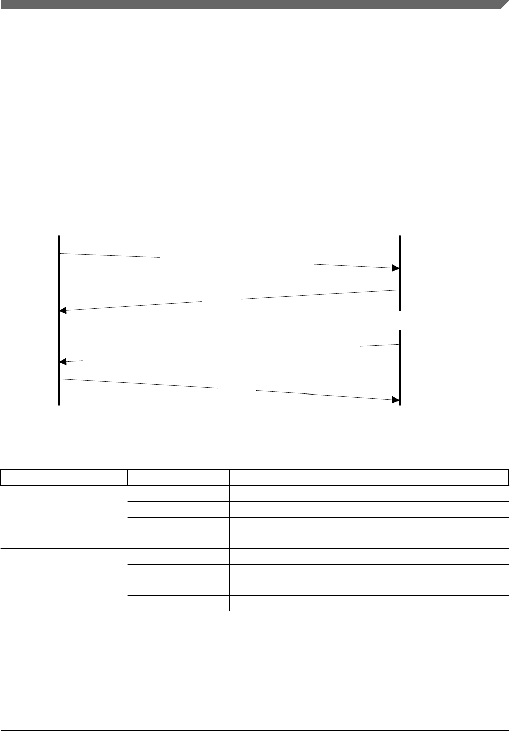
3.3 Command with incoming data phase
The protocol for a command with incoming data phase contains:
•Command packet (from host)(kCommandFlag_HasDataPhase set)
• Generic response command packet (to host)
• Incoming data packets (from host)
• Generic response command packet (to host)
Command with incoming data phase
Kinetis Bootloader v2.0.0 Reference Manual, Rev. 0, 04/2016
26 Freescale Semiconductor, Inc.
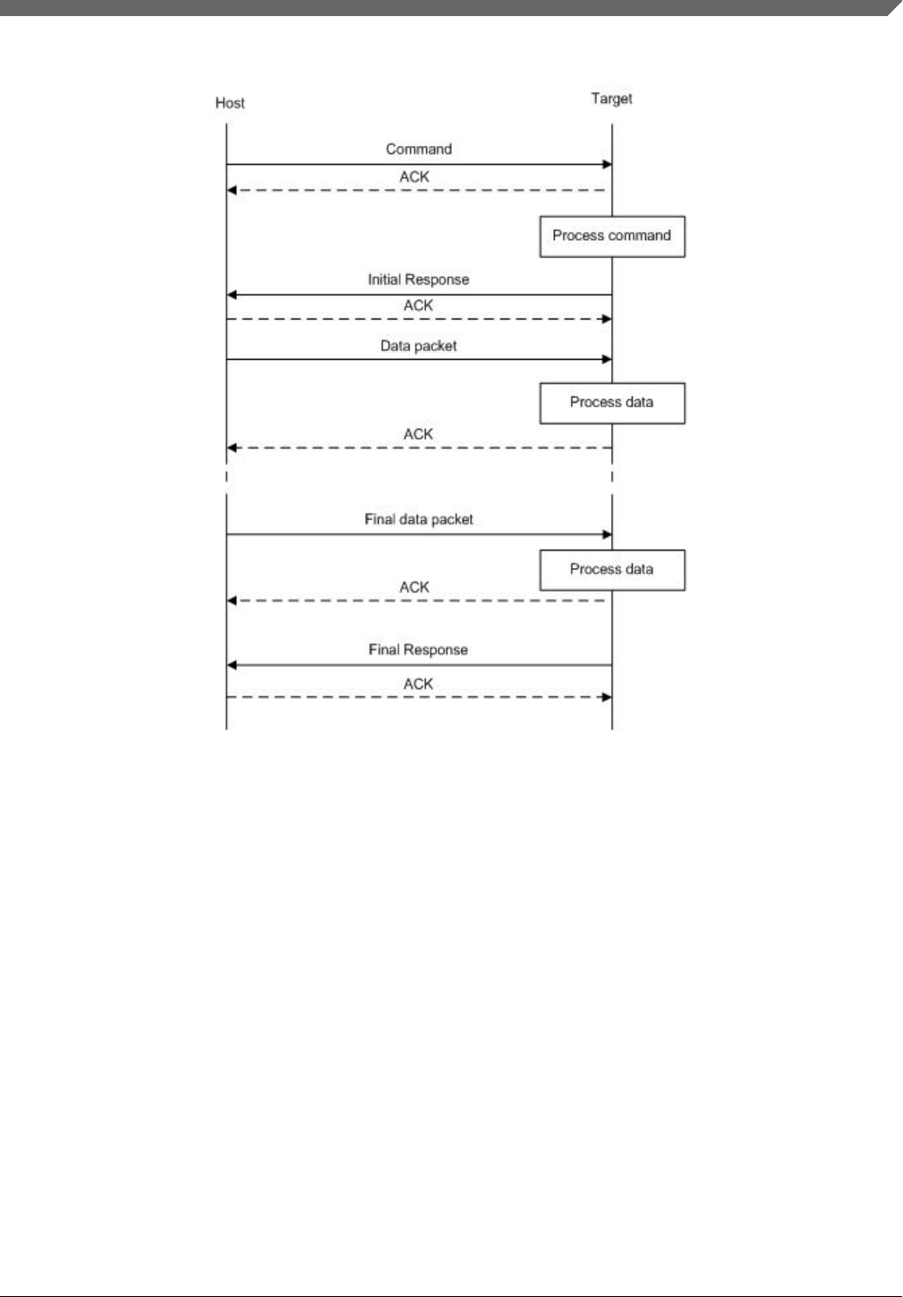
Figure 3-2. Command with incoming data phase
Notes
• The host may not send any further packets while it is waiting for the response to a
command.
• The data phase is aborted if the Generic Response packet prior to the start of the data
phase does not have a status of kStatus_Success.
• Data phases may be aborted by the receiving side by sending the final Generic
Response early with a status of kStatus_AbortDataPhase. The host may abort the
data phase early by sending a zero-length data packet.
• The final Generic Response packet sent after the data phase includes the status for
the entire operation.
3.4 Command with outgoing data phase
Chapter 3 Kinetis bootloader protocol
Kinetis Bootloader v2.0.0 Reference Manual, Rev. 0, 04/2016
Freescale Semiconductor, Inc. 27
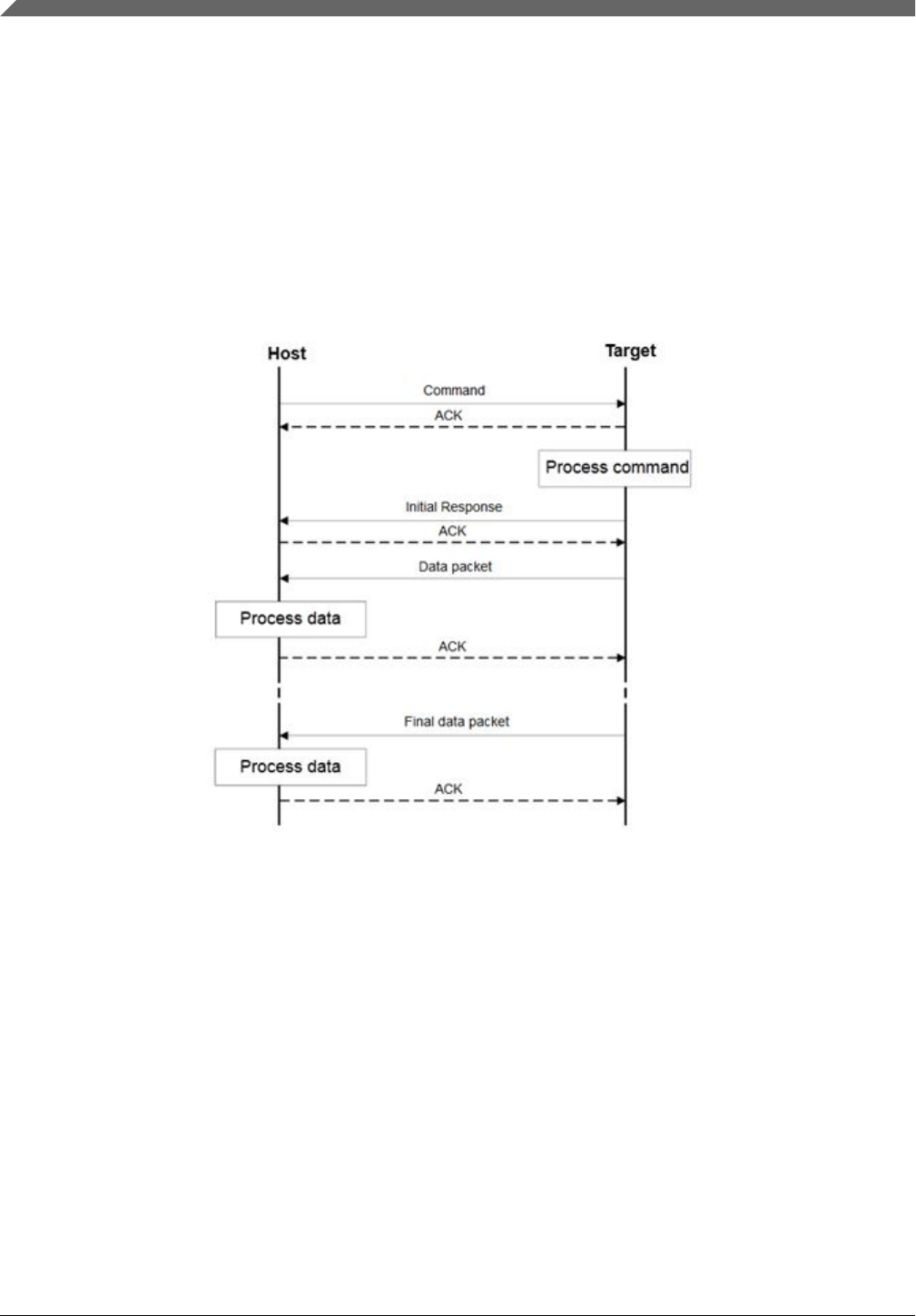
The protocol for a command with an outgoing data phase contains:
• Command packet (from host)
• ReadMemory Response command packet (to host)(kCommandFlag_HasDataPhase
set)
• Outgoing data packets (to host)
• Generic response command packet (to host)
Figure 3-3. Command with outgoing data phase
Note
• The data phase is considered part of the response command for the outgoing data
phase sequence.
• The host may not send any further packets while the host is waiting for the response
to a command.
• The data phase is aborted if the ReadMemory Response command packet, prior to
the start of the data phase, does not contain the kCommandFlag_HasDataPhase flag.
Command with outgoing data phase
Kinetis Bootloader v2.0.0 Reference Manual, Rev. 0, 04/2016
28 Freescale Semiconductor, Inc.

• Data phases may be aborted by the host sending the final Generic Response early
with a status of kStatus_AbortDataPhase. The sending side may abort the data phase
early by sending a zero-length data packet.
• The final Generic Response packet sent after the data phase includes the status for
the entire operation.
Chapter 3 Kinetis bootloader protocol
Kinetis Bootloader v2.0.0 Reference Manual, Rev. 0, 04/2016
Freescale Semiconductor, Inc. 29

Command with outgoing data phase
Kinetis Bootloader v2.0.0 Reference Manual, Rev. 0, 04/2016
30 Freescale Semiconductor, Inc.

Chapter 4
Bootloader packet types
4.1 Introduction
The Kinetis bootloader device works in slave mode. All data communication is initiated
by a host, which is either a PC or an embedded host. The Kinetis bootloader device is the
target, which receives a command or data packet. All data communication between host
and target is packetized.
NOTE
The term "target" refers to the "Kinetis bootloader device".
There are 6 types of packets used:
•Ping packet
• Ping Response packet
• Framing packet
• Command packet
• Data packet
• Response packet
All fields in the packets are in little-endian byte order.
4.2 Ping packet
The Ping packet is the first packet sent from a host to the target to establish a connection
on selected peripheral in order to run autobaud. The Ping packet can be sent from host to
target at any time that the target is expecting a command packet. If the selected peripheral
is UART, a ping packet must be sent before any other communications. For other serial
peripherals it is optional, but is recommended in order to determine the serial protocol
version.
In response to a Ping packet, the target sends a Ping Response packet, discussed in later
sections.
Kinetis Bootloader v2.0.0 Reference Manual, Rev. 0, 04/2016
Freescale Semiconductor, Inc. 31

Table 4-1. Ping Packet Format
Byte # Value Name
0 0x5A start byte
1 0xA6 ping
Target executes UART autobaud if necessary
Host Target
PingResponse Packet:
0x5a 0xa7 0x00 0x02 0x01 0x50 0x00 0x00 0xaa 0xea
Ping Packet 0x5a 0xa6
Figure 4-1. Ping Packet Protocol Sequence
4.3 Ping response packet
The target sends a Ping Response packet back to the host after receiving a Ping packet. If
communication is over a UART peripheral, the target uses the incoming Ping packet to
determine the baud rate before replying with the Ping Response packet. Once the Ping
Response packet is received by the host, the connection is established, and the host starts
sending commands to the target.
Table 4-2. Ping Response packet format
Byte # Value Parameter
0 0x5A start byte
1 0xA7 Ping response code
2 Protocol bugfix
3 Protocol minor
4 Protocol major
5 Protocol name = 'P' (0x50)
6 Options low
7 Options high
Table continues on the next page...
Ping response packet
Kinetis Bootloader v2.0.0 Reference Manual, Rev. 0, 04/2016
32 Freescale Semiconductor, Inc.

Table 4-2. Ping Response packet format (continued)
Byte # Value Parameter
8 CRC16 low
9 CRC16 high
The Ping Response packet can be sent from host to target any time the target expects a
command packet. For the UART peripheral, it must be sent by host when a connection is
first established, in order to run autobaud. For other serial peripherals it is optional, but
recommended to determine the serial protocol version. The version number is in the same
format at the bootloader version number returned by the GetProperty command.
4.4 Framing packet
The framing packet is used for flow control and error detection for the communications
links that do not have such features built-in. The framing packet structure sits between
the link layer and command layer. It wraps command and data packets as well.
Every framing packet containing data sent in one direction results in a synchronizing
response framing packet in the opposite direction.
The framing packet described in this section is used for serial peripherals including the
UART, I2C, and SPI. The USB HID peripheral does not use framing packets. Instead, the
packetization inherent in the USB protocol itself is used.
Table 4-3. Framing Packet Format
Byte # Value Parameter
0 0x5A start byte
1 packetType
2 length_low Length is a 16-bit field that specifies the entire
command or data packet size in bytes.
3 length_high
4 crc16_low This is a 16-bit field. The CRC16 value covers entire
framing packet, including the start byte and command
or data packets, but does not include the CRC bytes.
See the CRC16 algorithm after this table.
5 crc16_high
6 . . .n Command or Data packet
payload
Chapter 4 Bootloader packet types
Kinetis Bootloader v2.0.0 Reference Manual, Rev. 0, 04/2016
Freescale Semiconductor, Inc. 33

A special framing packet that contains only a start byte and a packet type is used for
synchronization between the host and target.
Table 4-4. Special Framing Packet Format
Byte # Value Parameter
0 0x5A start byte
1 0xAnpacketType
The Packet Type field specifies the type of the packet from one of the defined types
(below):
Table 4-5. packetType Field
packetType Name Description
0xA1 kFramingPacketType_Ack The previous packet was received successfully; the sending
of more packets is allowed.
0xA2 kFramingPacketType_Nak The previous packet was corrupted and must be re-sent.
0xA3 kFramingPacketType_AckAbort Data phase is being aborted.
0xA4 kFramingPacketType_Command The framing packet contains a command packet payload.
0xA5 kFramingPacketType_Data The framing packet contains a data packet payload.
0xA6 kFramingPacketType_Ping Sent to verify the other side is alive. Also used for UART
autobaud.
0xA7 kFramingPacketType_PingResponse A response to Ping; contains the framing protocol version
number and options.
4.5 CRC16 algorithm
This section provides the CRC16 algorithm.
The CRC is computed over each byte in the framing packet header, excluding the crc16
field itself, plus all of the payload bytes. The CRC algorithm is the XMODEM variant of
CRC-16.
The characteristics of the XMODEM variant are:
width 16
polynomial 0x1021
init value 0x0000
reflect in false
reflect out false
xor out 0x0000
check result 0x31c3
CRC16 algorithm
Kinetis Bootloader v2.0.0 Reference Manual, Rev. 0, 04/2016
34 Freescale Semiconductor, Inc.

The check result is computed by running the ASCII character sequence "123456789"
through the algorithm.
uint16_t crc16_update(const uint8_t * src, uint32_t lengthInBytes
{
uint32_t crc = 0;
uint32_t j;
for (j=0; j < lengthInBytes; ++j)
{
uint32_t i;
uint32_t byte = src[j];
crc ^= byte << 8;
for (i = 0; i < 8; ++i)
{
uint32_t temp = crc << 1;
if (crc & 0x8000)
{
temp ^= 0x1021;
}
crc = temp;
}
}
return crc;
}
4.6 Command packet
The command packet carries a 32-bit command header and a list of 32-bit parameters.
Table 4-6. Command Packet Format
Command Packet Format (32 bytes)
Command Header (4 bytes) 28 bytes for Parameters (Max 7 parameters)
Tag Flags Rsvd Param
Count
Param1
(32-bit)
Param2
(32-bit)
Param3
(32-bit)
Param4
(32-bit)
Param5
(32-bit)
Param6
(32-bit)
Param7
(32-bit)
byte 0 byte 1 byte 2 byte 3 - - - - - - -
Table 4-7. Command Header Format
Byte # Command Header Field
0 Command or Response tag The command header is 4 bytes long, with
these fields.
1 Flags
2 Reserved. Should be 0x00.
3 ParameterCount
The header is followed by 32-bit parameters up to the value of the ParameterCount field
specified in the header. Because a command packet is 32 bytes long, only 7 parameters
can fit into the command packet.
Chapter 4 Bootloader packet types
Kinetis Bootloader v2.0.0 Reference Manual, Rev. 0, 04/2016
Freescale Semiconductor, Inc. 35

Command packets are also used by the target to send responses back to the host. As
mentioned earlier, command packets and data packets are embedded into framing packets
for all of the transfers.
Table 4-8. Command Tags
Command Tag Name
0x01 FlashEraseAll The command tag specifies one of the
commands supported by the Kinetis
bootloader. The valid command tags for the
Kinetis bootloader are listed here.
0x02 FlashEraseRegion
0x03 ReadMemory
0x04 WriteMemory
0x05 FillMemory
0x06 FlashSecurityDisable
0x07 GetProperty
0x08 Reserved
0x09 Execute
0x10 FlashReadResource
0x11 Reserved
0x0A Call
0x0B Reset
0x0C SetProperty
0x0D FlashEraseAllUnsecure
0x0E FlashProgramOnce
0x0F FlashReadOnce
0x10 FlashReadResource
0x11 ConfigureQuadSPI
0x12 ReliableUpdate
Table 4-9. Response Tags
Response Tag Name
0xA0 GenericResponse The response tag specifies one of the responses
the Kinetis bootloader (target) returns to the host.
The valid response tags are listed here.
0xA0 GenericResponse The response tag specifies one of the responses
the Kinetis bootloader (target) returns to the host.
The valid response tags are listed here.
0xA7 GetPropertyResponse (used for sending
responses to GetProperty command only)
0xA3 ReadMemoryResponse (used for sending
responses to ReadMemory command only)
0xAF FlashReadOnceResponse (used for sending
responses to FlashReadOnce command only)
0xB0 FlashReadResourceResponse (used for sending
responses to FlashReadResource command
only)
Command packet
Kinetis Bootloader v2.0.0 Reference Manual, Rev. 0, 04/2016
36 Freescale Semiconductor, Inc.

Flags: Each command packet contains a Flag byte. Only bit 0 of the flag byte is used. If
bit 0 of the flag byte is set to 1, then data packets follow in the command sequence. The
number of bytes that are transferred in the data phase is determined by a command-
specific parameter in the parameters array.
ParameterCount: The number of parameters included in the command packet.
Parameters: The parameters are word-length (32 bits). With the default maximum
packet size of 32 bytes, a command packet can contain up to 7 parameters.
4.7 Response packet
The responses are carried using the same command packet format wrapped with framing
packet data. Types of responses include:
• GenericResponse
• GetPropertyResponse
• ReadMemoryResponse
• FlashReadOnceResponse
• FlashReadResourceResponse
GenericResponse: After the Kinetis bootloader has processed a command, the
bootloader sends a generic response with status and command tag information to the host.
The generic response is the last packet in the command protocol sequence. The generic
response packet contains the framing packet data and the command packet data (with
generic response tag = 0xA0) and a list of parameters (defined in the next section). The
parameter count field in the header is always set to 2, for status code and command tag
parameters.
Table 4-10. GenericResponse Parameters
Byte # Parameter Descripton
0 - 3 Status code The Status codes are errors encountered during the execution of a
command by the target. If a command succeeds, then a kStatus_Success
code is returned.
4 - 7 Command tag The Command tag parameter identifies the response to the command sent
by the host.
GetPropertyResponse: The GetPropertyResponse packet is sent by the target in
response to the host query that uses the GetProperty command. The GetPropertyResponse
packet contains the framing packet data and the command packet data, with the
command/response tag set to a GetPropertyResponse tag value (0xA7).
Chapter 4 Bootloader packet types
Kinetis Bootloader v2.0.0 Reference Manual, Rev. 0, 04/2016
Freescale Semiconductor, Inc. 37

The parameter count field in the header is set to greater than 1, to always include the
status code and one or many property values.
Table 4-11. GetPropertyResponse Parameters
Byte # Value Parameter
0 - 3 Status code
4 - 7 Property value
. . . . . .
Can be up to maximum 6 property values, limited to the size of the 32-bit
command packet and property type.
ReadMemoryResponse: The ReadMemoryResponse packet is sent by the target in
response to the host sending a ReadMemory command. The ReadMemoryResponse
packet contains the framing packet data and the command packet data, with the
command/response tag set to a ReadMemoryResponse tag value (0xA3), the flags field
set to kCommandFlag_HasDataPhase (1).
The parameter count set to 2 for the status code and the data byte count parameters shown
below.
Table 4-12. ReadMemoryResponse Parameters
Byte # Parameter Descripton
0 - 3 Status code The status of the associated Read Memory command.
4 - 7 Data byte count The number of bytes sent in the data phase.
FlashReadOnceResponse:The FlashReadOnceResponse packet is sent by the target in
response to the host sending a FlashReadOnce command. The FlashReadOnceResponse
packet contains the framing packet data and the command packet data, with the
command/response tag set to a FlashReadOnceResponse tag value (0xAF), and the flags
field set to 0. The parameter count is set to 2 plus the number of words requested to be
read in the FlashReadOnceCommand.
Table 4-13. FlashReadOnceResponse Parameters
Byte # Value Parameter
0 – 3 Status Code
4 – 7 Byte count to read
… …
Can be up to 20 bytes of requested read data.
Response packet
Kinetis Bootloader v2.0.0 Reference Manual, Rev. 0, 04/2016
38 Freescale Semiconductor, Inc.

The FlashReadResourceResponse packet is sent by the target in response to the host
sending a FlashReadResource command. The FlashReadResourceResponse packet
contains the framing packet data and command packet data, with the command/response
tag set to a FlashReadResourceResponse tag value (0xB0), and the flags field set to
kCommandFlag_HasDataPhase (1).
Table 4-14. FlashReadResourceResponse Parameters
Byte # Value Parameter
0 – 3 Status Code
4 – 7 Data byte count
Chapter 4 Bootloader packet types
Kinetis Bootloader v2.0.0 Reference Manual, Rev. 0, 04/2016
Freescale Semiconductor, Inc. 39

Response packet
Kinetis Bootloader v2.0.0 Reference Manual, Rev. 0, 04/2016
40 Freescale Semiconductor, Inc.

Chapter 5
Kinetis bootloader command API
5.1 Introduction
All Kinetis bootloader command APIs follows the command packet format wrapped by
the framing packet as explained in previous sections.
See Table 4-8 for a list of commands supported by Kinetis bootloader.
For a list of status codes returned by Kinetis bootloader see Appendix A.
5.2 GetProperty command
The GetProperty command is used to query the bootloader about various properties and
settings. Each supported property has a unique 32-bit tag associated with it. The tag
occupies the first parameter of the command packet. The target returns a
GetPropertyResponse packet with the property values for the property identified with the
tag in the GetProperty command.
Properties are the defined units of data that can be accessed with the GetProperty or
SetProperty commands. Properties may be read-only or read-write. All read-write
properties are 32-bit integers, so they can easily be carried in a command parameter.
For a list of properties and their associated 32-bit property tags supported by Kinetis
bootloader, see Appendix B.
The 32-bit property tag is the only parameter required for GetProperty command.
Table 5-1. Parameters for GetProperty Command
Byte # Command
0 - 3 Property tag
4 - 7 External Memory Identifier (only applies to get property for external memory)
Kinetis Bootloader v2.0.0 Reference Manual, Rev. 0, 04/2016
Freescale Semiconductor, Inc. 41

Process command
Host Target
GetProperty: Property tag = 0x01
0x5a a4 0c 00 4b 33 07 00 00 02 01 00 00 00 00 00 00 00
0x5a a4 0c 00 07 7a a7 00 00 02 00 00 00 00 00 00 01 4b
ACK:
0x5a a1
ACK:
0x5a a1
Generic Response:
Figure 5-1. Protocol Sequence for GetProperty Command
Table 5-2. GetProperty Command Packet Format (Example)
GetProperty Parameter Value
Framing packet start byte 0x5A
packetType 0xA4, kFramingPacketType_Command
length 0x0C 0x00
crc16 0x4B 0x33
Command packet commandTag 0x07 – GetProperty
flags 0x00
reserved 0x00
parameterCount 0x02
propertyTag 0x00000001 - CurrentVersion
Memory ID 0x00000000 - Internal Flash (0x00000001 - QSPI0 Memory)
The GetProperty command has no data phase.
Response: In response to a GetProperty command, the target sends a
GetPropertyResponse packet with the response tag set to 0xA7. The parameter count
indicates the number of parameters sent for the property values, with the first parameter
showing status code 0, followed by the property value(s). The next table shows an
example of a GetPropertyResponse packet.
Table 5-3. GetProperty Response Packet Format (Example)
GetPropertyResponse Parameter Value
Framing packet start byte 0x5A
packetType 0xA4, kFramingPacketType_Command
Table continues on the next page...
GetProperty command
Kinetis Bootloader v2.0.0 Reference Manual, Rev. 0, 04/2016
42 Freescale Semiconductor, Inc.

Table 5-3. GetProperty Response Packet Format (Example) (continued)
GetPropertyResponse Parameter Value
length 0x0c 0x00 (12 bytes)
crc16 0x07 0x7a
Command packet responseTag 0xA7
flags 0x00
reserved 0x00
parameterCount 0x02
status 0x00000000
propertyValue 0x0000014b - CurrentVersion
5.3 SetProperty command
The SetProperty command is used to change or alter the values of the properties or
options of the bootloader. The command accepts the same property tags used with the
GetProperty command. However, only some properties are writable--see Appendix B. If
an attempt to write a read-only property is made, an error is returned indicating the
property is read-only and cannot be changed.
The property tag and the new value to set are the two parameters required for the
SetProperty command.
Table 5-4. Parameters for SetProperty Command
Byte # Command
0 - 3 Property tag
4 - 7 Property value
Chapter 5 Kinetis bootloader command API
Kinetis Bootloader v2.0.0 Reference Manual, Rev. 0, 04/2016
Freescale Semiconductor, Inc. 43

Process command
Host Target
SetProperty: Property tag = 10, Property Value = 1
0x5a a4 0c 00 67 8d 0c 00 00 02 0a 00 00 00 01 00 00 00
GenericResponse:
0x5a a4 00 9e
10 a0 00 0c 02 00 00 00 00 0c 00 00 00
ACK :
0x5a a1
ACK:
0x5a a1
Figure 5-2. Protocol Sequence for SetProperty Command
Table 5-5. SetProperty Command Packet Format (Example)
SetProperty Parameter Value
Framing packet start byte 0x5A
packetType 0xA4, kFramingPacketType_Command
length 0x0C 0x00
crc16 0x67 0x8D
Command packet commandTag 0x0C – SetProperty with property tag 10
flags 0x00
reserved 0x00
parameterCount 0x02
propertyTag 0x0000000A - VerifyWrites
propertyValue 0x00000001
The SetProperty command has no data phase.
Response: The target returns a GenericResponse packet with one of following status
codes:
Table 5-6. SetProperty Response Status Codes
Status Code
kStatus_Success
kStatus_ReadOnly
kStatus_UnknownProperty
kStatus_InvalidArgument
SetProperty command
Kinetis Bootloader v2.0.0 Reference Manual, Rev. 0, 04/2016
44 Freescale Semiconductor, Inc.
5.4 FlashEraseAll command
The FlashEraseAll command performs an erase of the entire flash memory. If any flash
regions are protected, then the FlashEraseAll command fails and returns an error status
code. Executing the FlashEraseAll command releases flash security if it (flash security)
was enabled, by setting the FTFA_FSEC register. However, the FSEC field of the flash
configuration field is erased, so unless it is reprogrammed, the flash security is re-enabled
after the next system reset. The Command tag for FlashEraseAll command is 0x01 set in
the commandTag field of the command packet.
The FlashEraseAll command requires no parameters.
Process command
Host Target
FlashEraseAll
0x5a a4 08 00 0c 22 01 00 00 01 00 00 00 00
0x5a a4 0c 00 66 ce a0 00 00 02 00 00 00 00 01 00 00 00
ACK:
0x5a a1
ACK:
0x5a a1
Generic Response:
Figure 5-3. Protocol Sequence for FlashEraseAll Command
Table 5-7. FlashEraseAll Command Packet Format (Example)
FlashEraseAll Parameter Value
Framing packet start byte 0x5A
packetType 0xA4, kFramingPacketType_Command
length 0x08 0x00
crc16 0x0C 0x22
Command packet commandTag 0x01 - FlashEraseAll
flags 0x00
reserved 0x00
parameterCount 0x01
Memory ID 0x00000000 - Internal Flash ( 0x00000001 - QSPI0 Memory)
Chapter 5 Kinetis bootloader command API
Kinetis Bootloader v2.0.0 Reference Manual, Rev. 0, 04/2016
Freescale Semiconductor, Inc. 45

The FlashEraseAll command has no data phase.
Response: The target returns a GenericResponse packet with status code either set to
kStatus_Success for successful execution of the command, or set to an appropriate error
status code.
5.5 FlashEraseRegion command
The FlashEraseRegion command performs an erase of one or more sectors of the flash
memory.
The start address and number of bytes are the 2 parameters required for the
FlashEraseRegion command. The start and byte count parameters must be 4-byte aligned
([1:0] = 00), or the FlashEraseRegion command fails and returns
kStatus_FlashAlignmentError(101). If the region specified does not fit in the flash
memory space, the FlashEraseRegion command fails and returns
kStatus_FlashAddressError(102). If any part of the region specified is protected, the
FlashEraseRegion command fails and returns kStatus_MemoryRangeInvalid(10200).
Table 5-8. Parameters for FlashEraseRegion Command
Byte # Parameter
0 - 3 Start address
4 - 7 Byte count
The FlashEraseRegion command has no data phase.
Response: The target returns a GenericResponse packet with one of following error
status codes.
Table 5-9. FlashEraseRegion Response Status Codes
Status Code
kStatus_Success (0)
kStatus_MemoryRangeInvalid (10200)
kStatus_FlashAlignmentError (101)
kStatus_FlashAddressError (102)
kStatus_FlashAccessError (103)
kStatus_FlashProtectionViolation (104)
kStatus_FlashCommandFailure (105)
FlashEraseRegion command
Kinetis Bootloader v2.0.0 Reference Manual, Rev. 0, 04/2016
46 Freescale Semiconductor, Inc.
5.6 FlashEraseAllUnsecure command
The FlashEraseAllUnsecure command performs a mass erase of the flash memory,
including protected sectors. Flash security is immediately disabled if it (flash security)
was enabled, and the FSEC byte in the flash configuration field at address 0x40C is
programmed to 0xFE. However, if the mass erase enable option in the FSEC field is
disabled, then the FlashEraseAllUnsecure command fails.
The FlashEraseAllUnsecure command requires no parameters.
Process command
Host Target
FlashEraseAllUnsecure
0x5a a4 04 00 f6 61 0d 00 cc 00
0x5a a4 0c 00 61 2c a0 00 04 02 00 00 00 00 0d 00 00 00
ACK:
0x5a a1
ACK:
0x5a a1
Generic Response:
Figure 5-4. Protocol Sequence for FlashEraseAll Command
Table 5-10. FlashEraseAllUnsecure Command Packet Format (Example)
FlashEraseAllUnsecure Parameter Value
Framing packet start byte 0x5A
packetType 0xA4, kFramingPacketType_Command
length 0x04 0x00
crc16 0xF6 0x61
Command packet commandTag 0x0D - FlashEraseAllUnsecure
flags 0x00
reserved 0x00
parameterCount 0x00
The FlashEraseAllUnsecure command has no data phase.
Chapter 5 Kinetis bootloader command API
Kinetis Bootloader v2.0.0 Reference Manual, Rev. 0, 04/2016
Freescale Semiconductor, Inc. 47

Response: The target returns a GenericResponse packet with status code either set to
kStatus_Success for successful execution of the command, or set to an appropriate error
status code.
NOTE
When the MEEN bit in the NVM FSEC register is cleared to
disable the mass erase, the FlashEraseAllUnsecure command
will fail. FlashEraseRegion can be used instead skipping the
protected regions.
5.7 ReadMemory command
The ReadMemory command returns the contents of memory at the given address, for a
specified number of bytes. This command can read any region of memory accessible by
the CPU and not protected by security.
The start address and number of bytes are the two parameters required for ReadMemory
command.
Table 5-11. Parameters for read memory command
Byte Parameter Description
0-3 Start address Start address of memory to read from
4-7 Byte count Number of bytes to read and return to caller
ReadMemory command
Kinetis Bootloader v2.0.0 Reference Manual, Rev. 0, 04/2016
48 Freescale Semiconductor, Inc.
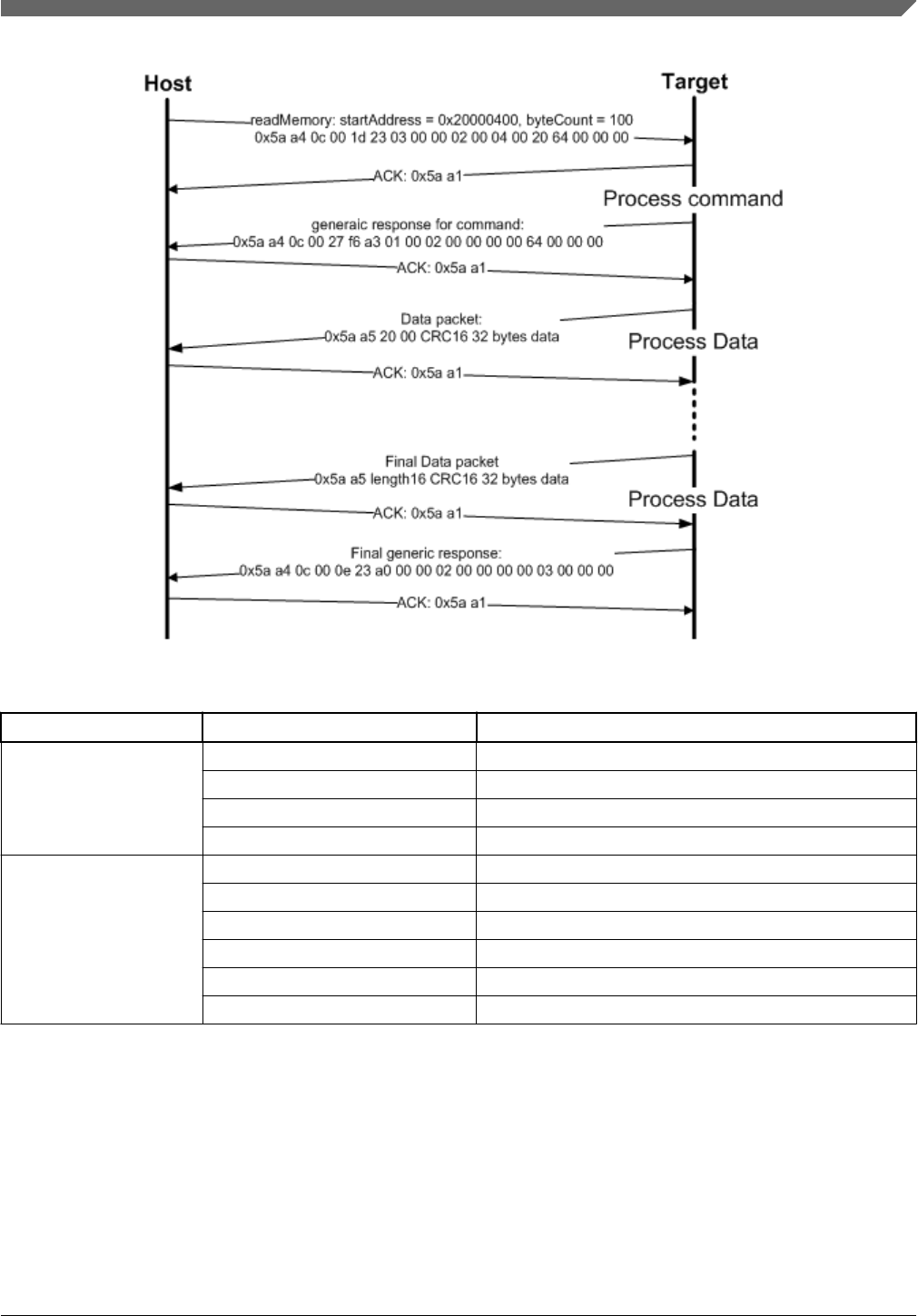
Figure 5-5. Command sequence for read memory
ReadMemory Parameter Value
Framing packet Start byte 0x5A0xA4,
packetType kFramingPacketType_Command
length 0x0C 0x00
crc16 0x1D 0x23
Command packet commandTag 0x03 - readMemory
flags 0x00
reserved 0x00
parameterCount 0x02
startAddress 0x20000400
byteCount 0x00000064
Data Phase: The ReadMemory command has a data phase. Because the target works in
slave mode, the host needs to pull data packets until the number of bytes of data specified
in the byteCount parameter of ReadMemory command are received by host.
Response: The target returns a GenericResponse packet with a status code either set to
kStatus_Success upon successful execution of the command, or set to an appropriate
error status code.
Chapter 5 Kinetis bootloader command API
Kinetis Bootloader v2.0.0 Reference Manual, Rev. 0, 04/2016
Freescale Semiconductor, Inc. 49

5.8 WriteMemory command
The WriteMemory command writes data provided in the data phase to a specified range
of bytes in memory (flash or RAM). However, if flash protection is enabled, then writes
to protected sectors fail.
Special care must be taken when writing to flash.
• First, any flash sector written to must have been previously erased with a
FlashEraseAll, FlashEraseRegion, or FlashEraseAllUnsecure command.
• First, any flash sector written to must have been previously erased with a
FlashEraseAll or FlashEraseRegion command.
• Writing to flash requires the start address to be 4-byte aligned ([1:0] = 00).
• The byte count is rounded up to a multiple of 4, and trailing bytes are filled with the
flash erase pattern (0xff).
• If the VerifyWrites property is set to true, then writes to flash also performs a flash
verify program operation.
When writing to RAM, the start address does not need to be aligned, and the data is not
padded.
The start address and number of bytes are the 2 parameters required for WriteMemory
command.
Table 5-12. Parameters for WriteMemory Command
Byte # Command
0 - 3 Start address
4 - 7 Byte count
WriteMemory command
Kinetis Bootloader v2.0.0 Reference Manual, Rev. 0, 04/2016
50 Freescale Semiconductor, Inc.
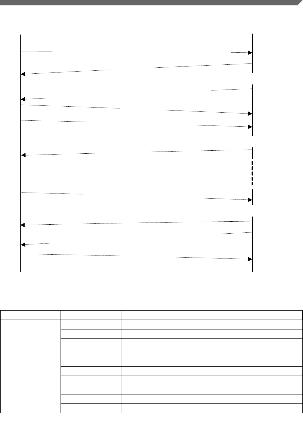
Process command
Host Target
WriteMemory: startAddress = 0x20000400, byteCount = 0x64
0x5a a4 0c 00 06 5a
04 00 00 02 00 04 00 20 64 00 00 00
Generic Response:
ACK: 0x5a a1
ACK: 0x5a a1
Data packet :
0x5a a5 20 00 CRC16 32 bytes data
Process Data
ACK: 0x5a a1
Final Data packet
0x5a a5 length16 CRC16 32 bytes data
ACK
Process Data
Generic Response
0x5a a4 0c 00 23 72 a0 00 00 02 00 00 00 00 04 00 00 00
ACK: 0x5a a1
0x5a a4 0c 00 a0 0e 04 01 00 02 00 04 00 20 40 00 00 00
Figure 5-6. Protocol Sequence for WriteMemory Command
Table 5-13. WriteMemory Command Packet Format (Example)
WriteMemory Parameter Value
Framing packet start byte 0x5A
packetType 0xA4, kFramingPacketType_Command
length 0x0C 0x00
crc16 0x06 0x5A
Command packet commandTag 0x04 - writeMemory
flags 0x00
reserved 0x00
parameterCount 0x02
startAddress 0x20000400
byteCount 0x00000064
Chapter 5 Kinetis bootloader command API
Kinetis Bootloader v2.0.0 Reference Manual, Rev. 0, 04/2016
Freescale Semiconductor, Inc. 51

Data Phase: The WriteMemory command has a data phase; the host sends data packets
until the number of bytes of data specified in the byteCount parameter of the
WriteMemory command are received by the target.
Response: The target returns a GenericResponse packet with a status code set to
kStatus_Success upon successful execution of the command, or to an appropriate error
status code.
5.9 FillMemory command
The FillMemory command fills a range of bytes in memory with a data pattern. It follows
the same rules as the WriteMemory command. The difference between FillMemory and
WriteMemory is that a data pattern is included in FillMemory command parameter, and
there is no data phase for the FillMemory command, while WriteMemory does have a
data phase.
Table 5-14. Parameters for FillMemory Command
Byte # Command
0 - 3 Start address of memory to fill
4 - 7 Number of bytes to write with the pattern
•The start address should be 32-bit aligned.
• The number of bytes must be evenly divisible by 4. (Note: for a part that
uses FTFE flash, the start address should be 64-bit aligned, and the
number of bytes must be evenly divisible by 8).
8 - 11 32-bit pattern
• To fill with a byte pattern (8-bit), the byte must be replicated 4 times in the 32-bit
pattern.
•To fill with a short pattern (16-bit), the short value must be replicated 2 times in the
32-bit pattern.
For example, to fill a byte value with 0xFE, the word pattern is 0xFEFEFEFE; to fill a
short value 0x5AFE, the word pattern is 0x5AFE5AFE.
Special care must be taken when writing to flash.
• First, any flash sector written to must have been previously erased with a
FlashEraseAll, FlashEraseRegion, or FlashEraseAllUnsecure command.
• First, any flash sector written to must have been previously erased with a
FlashEraseAll or FlashEraseRegion command.
FillMemory command
Kinetis Bootloader v2.0.0 Reference Manual, Rev. 0, 04/2016
52 Freescale Semiconductor, Inc.

• Writing to flash requires the start address to be 4-byte aligned ([1:0] = 00).
• If the VerifyWrites property is set to true, then writes to flash also performs a flash
verify program operation.
When writing to RAM, the start address does not need to be aligned, and the data is not
padded.
Process command
Host Target
FillMemory, with word pattern 0x12345678
ACK:
0x5a a1
ACK:
0x5a a1
Generic Response:
0x5a a4 10 00 e4 57 05 00 00 03 00 70 00 00 00 08 00 00 78 56 34 12
0x5a a4 0c 00 97 04 a0 00 00 02 00 00 00 00 05 00 00 00
Figure 5-7. Protocol Sequence for FillMemory Command
Table 5-15. FillMemory Command Packet Format (Example)
FillMemory Parameter Value
Framing packet start byte 0x5A
packetType 0xA4, kFramingPacketType_Command
length 0x10 0x00
crc16 0xE4 0x57
Command packet commandTag 0x05 – FillMemory
flags 0x00
Reserved 0x00
parameterCount 0x03
startAddress 0x00007000
byteCount 0x00000800
patternWord 0x12345678
The FillMemory command has no data phase.
Response: upon successful execution of the command, the target (Kinetis bootloader)
returns a GenericResponse packet with a status code set to kStatus_Success, or to an
appropriate error status code.
Chapter 5 Kinetis bootloader command API
Kinetis Bootloader v2.0.0 Reference Manual, Rev. 0, 04/2016
Freescale Semiconductor, Inc. 53
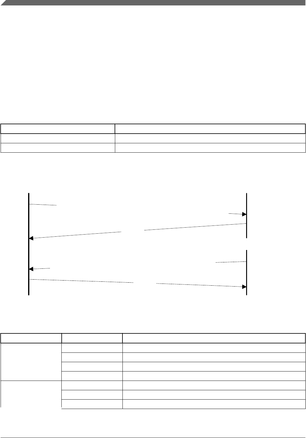
5.10 FlashSecurityDisable command
The FlashSecurityDisable command performs the flash security disable operation, by
comparing the 8-byte backdoor key (provided in the command) against the backdoor key
stored in the flash configuration field (at address 0x400 in the flash).
The backdoor low and high words are the only parameters required for
FlashSecurityDisable command.
Table 5-16. Parameters for FlashSecurityDisable Command
Byte # Command
0 - 3 Backdoor key low word
4 - 7 Backdoor key high word
Process command
Host Target
FlashSecureDisable, with backdoor key 0102030405060708
0x5a a4 0c 00 43 7b 06 00 00 04 03 02 01 08 07 06 05
0x5a a4 0c 00 35 78 a0 00 0c 02 00 00 00 00 06 00 00 00
ACK:
0x5a a1
ACK:
0x5a a1
Generic Response:
Figure 5-8. Protocol Sequence for FlashSecurityDisable Command
Table 5-17. FlashSecurityDisable Command Packet Format (Example)
FlashSecurityDisable Parameter Value
Framing packet start byte 0x5A
packetType 0xA4, kFramingPacketType_Command
length 0x0C 0x00
crc16 0x43 0x7B
Command packet commandTag 0x06 - FlashSecurityDisable
flags 0x00
reserved 0x00
Table continues on the next page...
FlashSecurityDisable command
Kinetis Bootloader v2.0.0 Reference Manual, Rev. 0, 04/2016
54 Freescale Semiconductor, Inc.

Table 5-17. FlashSecurityDisable Command Packet Format (Example) (continued)
FlashSecurityDisable Parameter Value
parameterCount 0x02
Backdoorkey_low 0x04 0x03 0x02 0x01
Backdoorkey_high 0x08 0x07 0x06 0x05
The FlashSecurityDisable command has no data phase.
Response: The target returns a GenericResponse packet with a status code either set to
kStatus_Success upon successful execution of the command, or set to an appropriate
error status code.
5.11 Execute command
The execute command results in the bootloader setting the program counter to the code at
the provided jump address, R0 to the provided argument, and a Stack pointer to the
provided stack pointer address. Prior to the jump, the system is returned to the reset state.
The Jump address, function argument pointer, and stack pointer are the parameters
required for the Execute command. If the stack pointer is set to zero, the called code is
responsible for setting the processor stack pointer before using the stack.
If QSPI is enabled, it is initialized before the jump. QSPI encryption (OTFAD) is also
enabled if configured.
Table 5-18. Parameters for Execute Command
Byte # Command
0 - 3 Jump address
4 - 7 Argument word
8 - 11 Stack pointer address
The Execute command has no data phase.
Response: Before executing the Execute command, the target validates the parameters
and return a GenericResponse packet with a status code either set to kStatus_Success or
an appropriate error status code.
Chapter 5 Kinetis bootloader command API
Kinetis Bootloader v2.0.0 Reference Manual, Rev. 0, 04/2016
Freescale Semiconductor, Inc. 55
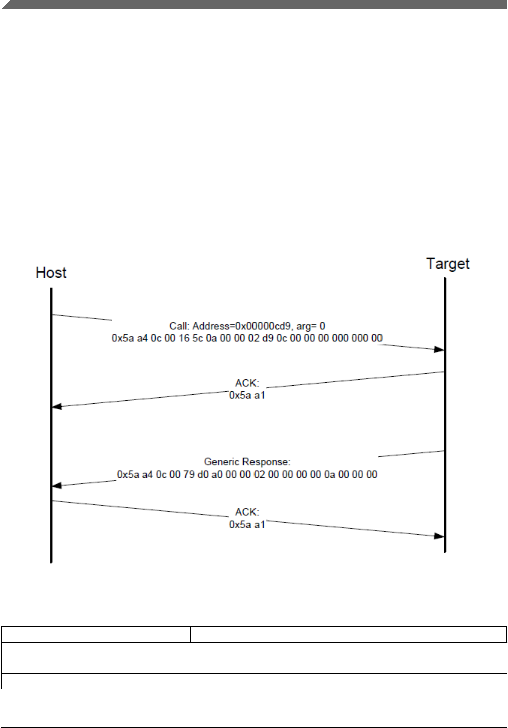
5.12 Call command
The Call command executes a function that is written in memory at the address sent in
the command. The address needs to be a valid memory location residing in accessible
flash (internal or external) or in RAM. The command supports the passing of one 32-bit
argument. Although the command supports a stack address, at this time the call still takes
place using the current stack pointer. After execution of the function, a 32-bit return value
is returned in the generic response message.
QSPI must be initialized prior to executing the Call command if the call address is on
QSPI. The Call command does not initialize QSPI.
Figure 5-9. Protocol sequence for call command
Table 5-19. Parameters for Call Command
Byte # Command
0 - 3 Call address
4 - 7 Argument word
8 - 11 Stack pointer
Call command
Kinetis Bootloader v2.0.0 Reference Manual, Rev. 0, 04/2016
56 Freescale Semiconductor, Inc.

Response: The target returns a GenericResponse packet with a status code either set to
the return value of the function called or set to kStatus_InvalidArgument (105).
5.13 Reset command
The Reset command results in the bootloader resetting the chip.
The Reset command requires no parameters.
Process command
Host Target
Reset
0x5a a4 04 00 6f 46 0b 00 00 00
GenericResponse:
0x5a a4 0c 00 f8 0b a0 00 04 02 00 00 00 00 0b 00 00 00
ACK :
0x5a a1
ACK:
0x5a a1
Figure 5-10. Protocol Sequence for Reset Command
Table 5-20. Reset Command Packet Format (Example)
Reset Parameter Value
Framing packet start byte 0x5A
packetType 0xA4, kFramingPacketType_Command
length 0x04 0x00
crc16 0x6F 0x46
Command packet commandTag 0x0B - reset
flags 0x00
reserved 0x00
parameterCount 0x00
The Reset command has no data phase.
Response: The target returns a GenericResponse packet with status code set to
kStatus_Success, before resetting the chip.
Chapter 5 Kinetis bootloader command API
Kinetis Bootloader v2.0.0 Reference Manual, Rev. 0, 04/2016
Freescale Semiconductor, Inc. 57
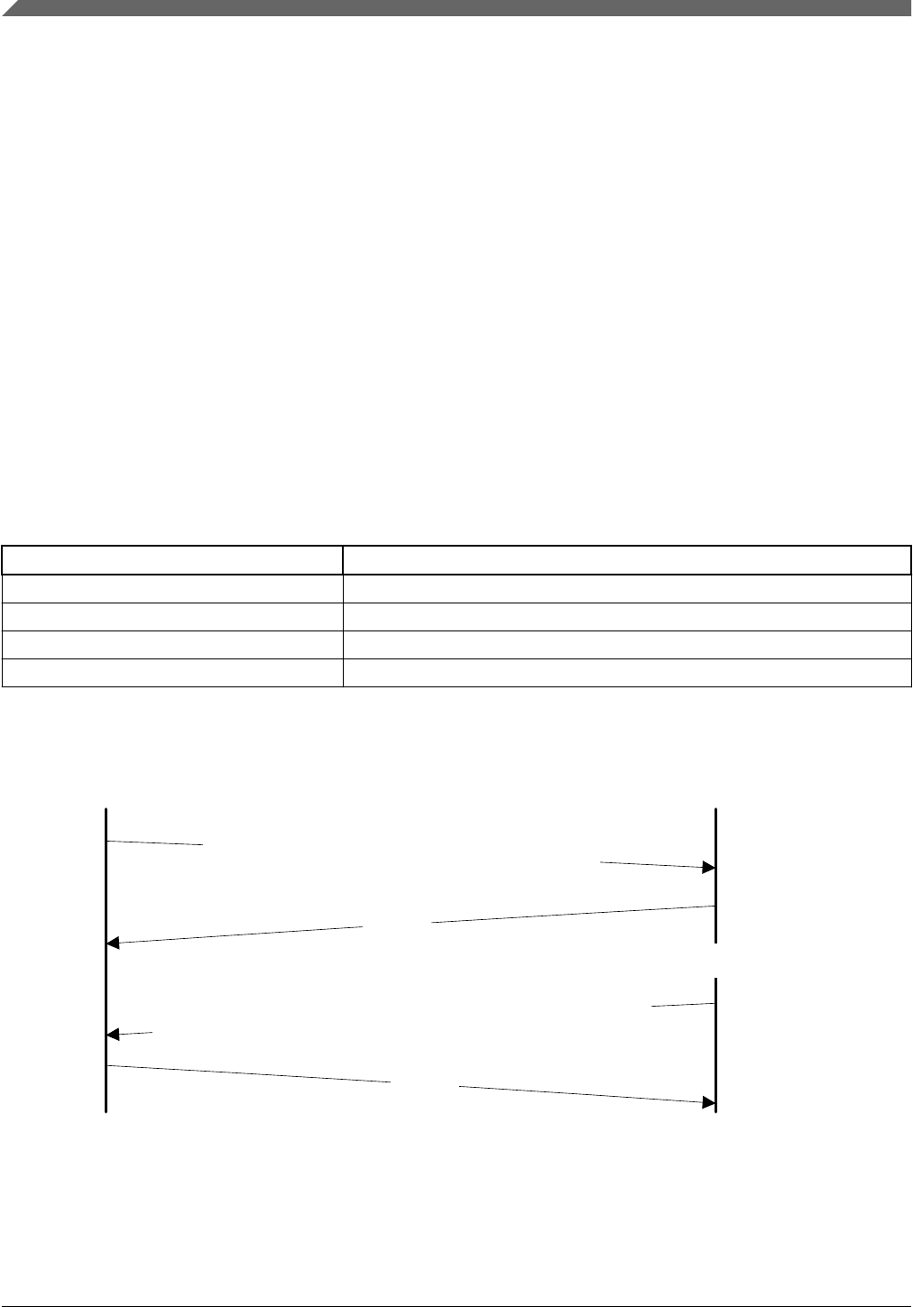
The reset command can also be used to switch boot from flash after successful flash
image provisioning via ROM bootloader. After issuing the reset command, allow 5
seconds for the user application to start running from Flash.
5.14 FlashProgramOnce command
The FlashProgramOnce command writes data (that is provided in a command packet) to a
specified range of bytes in the program once field. Special care must be taken when
writing to the program once field.
•The program once field only supports programming once, so any attempted to
reprogram a program once field gets an error response.
• Writing to the program once field requires the byte count to be 4-byte aligned or 8-
byte aligned.
The FlashProgramOnce command uses three parameters: index 2, byteCount, data.
Table 5-21. Parameters for FlashProgramOnce Command
Byte # Command
0 - 3 Index of program once field
4 - 7 Byte count (must be evenly divisible by 4)
8 - 11 Data
12 - 16 Data
Process command
Host Target
FlashProgramOnce: index=0, byteCount=4, data=0x12345678
ACK:
0x5a a1
ACK:
0x5a a1
Generic Response:
0x5a a4 10 00 7e 89 0e 00 00 03 00 00 00 00 04 00 00 00 78 56 34 12
0x5a a4 0c 00 88 1a a0 00 00 02 00 00 00 00 0e 00 00 00
Figure 5-11. Protocol Sequence for FlashProgramOnce Command
FlashProgramOnce command
Kinetis Bootloader v2.0.0 Reference Manual, Rev. 0, 04/2016
58 Freescale Semiconductor, Inc.

Table 5-22. FlashProgramOnce Command Packet Format (Example)
FlashProgramOnce Parameter Value
Framing packet start byte 0x5A
packetType 0xA4, kFramingPacketType_Command
length 0x10 0x00
crc16 0x7E4 0x89
Command packet commandTag 0x0E – FlashProgramOnce
flags 0
reserved 0
parameterCount 3
index 0x0000_0000
byteCount 0x0000_0004
data 0x1234_5678
Response: upon successful execution of the command, the target (Kinetis bootloader)
returns a GenericResponse packet with a status code set to kStatus_Success, or to an
appropriate error status code.
5.15 FlashReadOnce command
The FlashReadOnce command returns the contents of the program once field by given
index and byte count. The FlashReadOnce command uses 2 parameters: index and
byteCount.
Table 5-23. Parameters for FlashReadOnce Command
Byte # Parameter Description
0 - 3 index Index of the program once field (to read from)
4 - 7 byteCount Number of bytes to read and return to the caller
Chapter 5 Kinetis bootloader command API
Kinetis Bootloader v2.0.0 Reference Manual, Rev. 0, 04/2016
Freescale Semiconductor, Inc. 59

Process command
Host Target
FlashReadOnce: index=0, byteCount=4
ACK:
0x5a a1
ACK:
0x5a a1
Generic Response:
0x5a a4 0c 00 c1 a5 0f 00 00 02 00 00 00 00 04 00 00 00
0x5a a4 10 00 3f 6f af 00 00 03 00 00 00 00 04 00 00 00 78 56 34 12
Figure 5-12. Protocol Sequence for FlashReadOnce Command
Table 5-24. FlashReadOnce Command Packet Format (Example)
FlashReadOnce Parameter Value
Framing packet start byte 0x5A
packetType 0xA4
length 0x0C 0x00
crc 0xC1 0xA5
Command packet commandTag 0x0F – FlashReadOnce
flags 0x00
reserved 0x00
parameterCount 0x02
index 0x0000_0000
byteCount 0x0000_0004
Table 5-25. FlashReadOnce Response Format (Example)
FlashReadOnce
Response
Parameter Value
Framing packet start byte 0x5A
packetType 0xA4
length 0x10 0x00
crc 0x3F 0x6F
Command packet commandTag 0xAF
flags 0x00
reserved 0x00
parameterCount 0x03
Table continues on the next page...
FlashReadOnce command
Kinetis Bootloader v2.0.0 Reference Manual, Rev. 0, 04/2016
60 Freescale Semiconductor, Inc.

Table 5-25. FlashReadOnce Response Format (Example) (continued)
FlashReadOnce
Response
Parameter Value
status 0x0000_0000
byteCount 0x0000_0004
data 0x1234_5678
Response: upon successful execution of the command, the target returns a
FlashReadOnceResponse packet with a status code set to kStatus_Success, a byte count
and corresponding data read from Program Once Field upon successful execution of the
command, or returns with a status code set to an appropriate error status code and a byte
count set to 0.
5.16 FlashReadResource command
The FlashReadResource command returns the contents of the IFR field or Flash firmware
ID, by given offset, byte count, and option. The FlashReadResource command uses 3
parameters: start address, byteCount, option.
Table 5-26. Parameters for FlashReadResource Command
Byte # Parameter Command
0 - 3 start address Start address of specific non-volatile memory to be read
4 - 7 byteCount Byte count to be read
8 - 11 option 0: IFR
1: Flash firmware ID
Chapter 5 Kinetis bootloader command API
Kinetis Bootloader v2.0.0 Reference Manual, Rev. 0, 04/2016
Freescale Semiconductor, Inc. 61
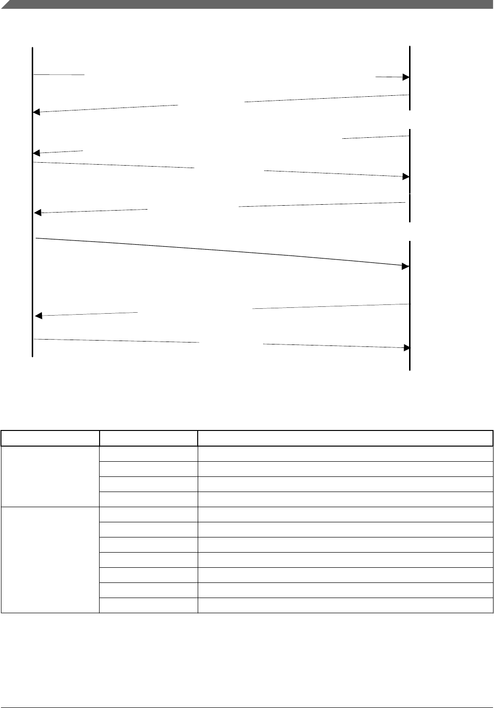
Process command
Host Target
ACK: 0x5a a1
ACK: 0x5a a1
Data packet
Process Data
ACK: 0x5a a1
Generic Response
ACK: 0x5a a1
FlashReadResource: start address=0, byteCount=8, option=1
5a a4 10 00 b3 cc 10 00 00 03 00 00 00 00 08 00 00 00 01 00 00 00
FlashReadResource Response
5a a4 0c 00 08 d2 b0 01 00 02 00 00 00 00 08 00 00 00
5a a5 08 00 9c d3 00 08 00 00 00 01 00 06
5a a4 0c 00 75 a3 a0 00 00 02 00 00 00 00 10 00 00 00
Figure 5-13. Protocol Sequence for FlashReadResource Command
Table 5-27. FlashReadResource Command Packet Format (Example)
FlashReadResource Parameter Value
Framing packet start byte 0x5A
packetType 0xA4
length 0x10 0x00
crc 0xB3 0xCC
Command packet commandTag 0x10 – FlashReadResource
flags 0x00
reserved 0x00
parameterCount 0x03
startAddress 0x0000_0000
byteCount 0x0000_0008
option 0x0000_0001
FlashReadResource command
Kinetis Bootloader v2.0.0 Reference Manual, Rev. 0, 04/2016
62 Freescale Semiconductor, Inc.

Table 5-28. FlashReadResource Response Format (Example)
FlashReadResource
Response
Parameter Value
Framing packet start byte 0x5A
packetType 0xA4
length 0x0C 0x00
crc 0xD2 0xB0
Command packet commandTag 0xB0
flags 0x01
reserved 0x00
parameterCount 0x02
status 0x0000_0000
byteCount 0x0000_0008
Data phase: The FlashReadResource command has a data phase. Because the target
(Kinetis bootloader) works in slave mode, the host must pull data packets until the
number of bytes of data specified in the byteCount parameter of FlashReadResource
command are received by the host.
5.17 Configure QuadSPI command
The Configure QuadSPI command configures the QuadSPI device using a pre-
programmed configuration image. The parameters passed in the command are the
QuadSPI memory ID, which should always be 1 for the current release of the bootloader,
and then the memory address from which the configuration data can be loaded from.
Options for loading the data can be a scenario where the configuration data is written to a
RAM or flash location and then this command directs the bootloader to use the data at
that location to configure the QuadSPI.
Table 5-29. Parameters for Configure QuadSPI Command
Byte # Command
0 – 3 Flash Memory ID (Should always be 1)
4 – 7 Configuration block address
Response: The target (Kinetis Bootloader) returns a GenericResponse packet with a
status code either set to kStatus_Success upon successful execution of the command, or
set to an appropriate error code.
Chapter 5 Kinetis bootloader command API
Kinetis Bootloader v2.0.0 Reference Manual, Rev. 0, 04/2016
Freescale Semiconductor, Inc. 63

5.18 ReceiveSBFile command
The Receive SB File command (ReceiveSbFile) starts the transfer of an SB file to the
target. The command only specifies the size in bytes of the SB file that is sent in the data
phase. The SB file is processed as it is received by the bootloader.
Table 5-30. Parameters for Receive SB File Command
Byte # Command
0 - 3 Byte count
Data Phase: The Receive SB file command has a data phase; the host sends data packets
until the number of bytes of data specified in the byteCount parameter of the Receive SB
File command are received by the target.
Response: The target returns a GenericResponse packet with a status code set to the
kStatus_Success upon successful execution of the command, or set to an appropriate
error code.
5.19 ReliableUpdate command
The Reliable Update command performs the reliable update operation.
•For a software implementation: the backup application address is the parameter
that is required for the Reliable Update command. If the backup address is set to 0,
then the bootloader uses the predefined address.
•For a hardware implementation: the swap indicator address is the parameter that is
required for the Reliable Update command.
•If the flash swap system is uninitialized, then the swap indicator address can be
arbitrarily specified.
• If the flash swap system has been initialized, then the swap indicator must be
aligned with the swap system.
Table 5-31. Parameters for Reliable Update command
Byte number Command
0 - 3 • For a software implementation: the value is the
backup application address.
•For a hardware implementation: the value is the swap
indicator address.
ReceiveSBFile command
Kinetis Bootloader v2.0.0 Reference Manual, Rev. 0, 04/2016
64 Freescale Semiconductor, Inc.

Response: The target returns a GenericResponse packet with a status code either set to
kStatus_Success upon successful execution of the command, or set to an appropriate
error status code.
Chapter 5 Kinetis bootloader command API
Kinetis Bootloader v2.0.0 Reference Manual, Rev. 0, 04/2016
Freescale Semiconductor, Inc. 65

ReliableUpdate command
Kinetis Bootloader v2.0.0 Reference Manual, Rev. 0, 04/2016
66 Freescale Semiconductor, Inc.

Chapter 6
Supported peripherals
6.1 Introduction
This section describes the peripherals supported by the Kinetis bootloader. To use an
interface for bootloader communications, the peripheral must be enabled in the BCA. If
the BCA is invalid (such as all 0xFF bytes), then all peripherals are enabled by default.
6.2 I2C Peripheral
The Kinetis bootloader supports loading data into flash via the I2C peripheral, where the
I2C peripheral serves as the I2C slave. A 7-bit slave address is used during the transfer.
Customizing an I2C slave address is also supported. This feature is enabled if the
Bootloader Configuration Area (BCA) is enabled (tag field is filled with ‘kcfg’) and the
i2cSlaveAddress field is filled with a value other than 0xFF. Otherwise, 0x10 is used as
the default I2C slave address.
The Kinetis bootloader uses 0x10 as the I2C slave address, and supports 400 kbit/s as the
I2C baud rate.
The maximum supported I2C baud rate depends on corresponding clock configuration
field in the BCA. The typical baud rate is 400 kbit/s with factory settings. The actual
supported baud rate may be lower or higher than 400 kbit/s, depending on the actual
value of the clockFlags and the clockDivider fields.
Because the I2C peripheral serves as an I2C slave device, each transfer should be started
by the host, and each outgoing packet should be fetched by the host.
•An incoming packet is sent by the host with a selected I2C slave address and the
direction bit is set as write.
Kinetis Bootloader v2.0.0 Reference Manual, Rev. 0, 04/2016
Freescale Semiconductor, Inc. 67

• An outgoing packet is read by the host with a selected I2C slave address and the
direction bit is set as read.
• 0x00 is sent as the response to host if the target is busy with processing or preparing
data.
The following flow charts demonstrate the communication flow of how the host reads
ping packet, ACK and response from the target.
Fetch
Ping response
Yes
Yes
End
Report Error
No
No
Read 1 byte
from target
0x5A
received?
packet
Read leftover bytes
of ping response
0x7A
received?
Read 1 byte
from target
Figure 6-1. Host reads ping response from target via I2C
Fetch ACK
No Yes
End
No
Process NAK Yes
Report an error
No
Yes
No
Reached
maximum
retries?
Report a timeout
error
Yes
0x5A
received?
0xA2
received?
0xA1
received?
Read 1 byte
from target
Read 1 byte
from target
Figure 6-2. Host reads ACK packet from target via I2C
I2C Peripheral
Kinetis Bootloader v2.0.0 Reference Manual, Rev. 0, 04/2016
68 Freescale Semiconductor, Inc.

Fetch
Response
Yes
Yes payload length
part from target
(2 bytes)
CRC checksum
from target
Payload length
less than supported
length?
Yes
payload data
from target
No
Set payload length
to maximum
supported length
No
No
Reached
maximum
Report a timeout
Yes
End
No
(2 bytes)
Read 1 byte
from target
0x5A
received?
0xA4
received?
Read 1 byte
from target
retries?
error (End)
Read
Read
Read
Figure 6-3. Host reads response from target via I2C
6.2.1 Performance numbers for I2C
The table below provides reference to the expected performance of write speeds to Flash
and RAM memories using Kinetis bootloader I2C interface. The numbers have been
measured on a number of platforms running Kinetis bootloader either from ROM or the
RAM (for flashloaders).
Table 6-1. Performance numbers for I2C
I2C Bus
Frequen
cy
(KHz)
Flash Average Writing Speed (KB/s) Ram
Average
Writing
Speed
(KB/s)
KL27 KL28 KL43 KL80 K80 KL03 KL27 KL28 KL43 KL80 K80 KL03
100 6.42 6.29 6.42 6.7 6.39 6.08 7.67 7.27 7.7 7.91 7.38 6.13
200 10.24 10.08 10.13 10.58 9.82 8.75 14.02 13.25 13.78 14.15 13.43 10.1
300 12.86 11.84 11.95 13.11 11.85 9.69 18.04 17.51 17.92 18.98 17.61 11.9
400 15.54 14.06 14.39 14.74 13.44 10.24 23.2 22.39 21.82 24.19 22.04 12.82
500 15.86 16.13 15.96 16.94 14.65 - 24.61 27.9 26.5 30.26 26.93 -
600 18.14 16.51 16.4 17.19 15.19 - 29.44 28.64 27.05 30.96 27.57 -
800 19.5 - 18.51 19.22 16.26 - 34.44 - 33.38 38.36 32.72 -
1000 20.48 - 20.03 21.35 17.71 - 37.64 - 41.04 45.38 33.65 -
Table continues on the next page...
Chapter 6 Supported peripherals
Kinetis Bootloader v2.0.0 Reference Manual, Rev. 0, 04/2016
Freescale Semiconductor, Inc. 69
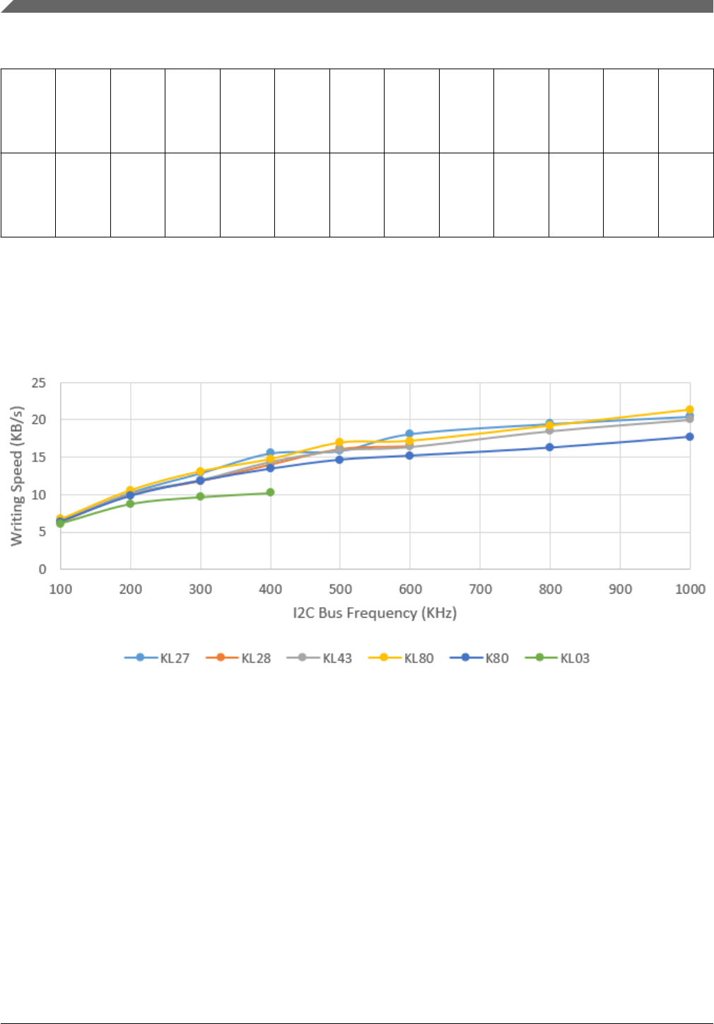
Table 6-1. Performance numbers for I2C (continued)
Default
core
Frequen
cy
(MHz)
48 48 48 48 48 8 48 48 48 48 48 8
Default
bus
Frequen
cy
(MHz)
24 24 24 24 24 4 24 24 24 24 24 4
NOTE
1. Every test covers all flash or RAM region with 0x0 - 0xf.
2. Run every test three times and calculate the average.
Figure 6-4. Flash Average Writing Speed
I2C Peripheral
Kinetis Bootloader v2.0.0 Reference Manual, Rev. 0, 04/2016
70 Freescale Semiconductor, Inc.
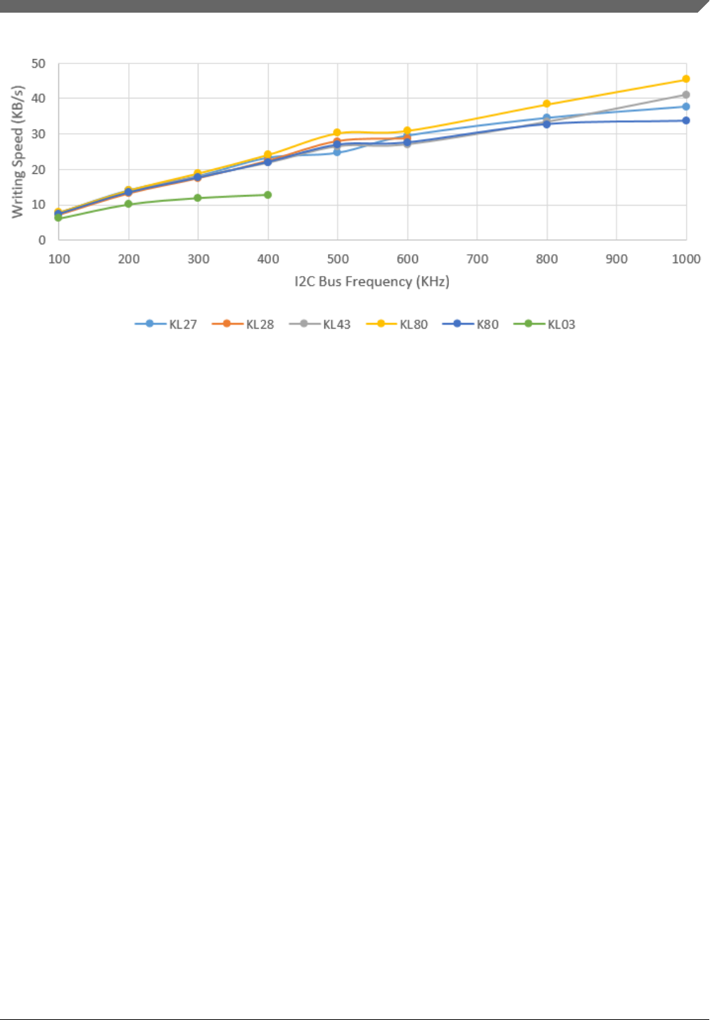
Figure 6-5. RAM Average Writing Speed
6.3 SPI Peripheral
The Kinetis bootloader supports loading data into flash via the SPI peripheral, where the
SPI peripheral serves as a SPI slave.
Maximum supported baud rate of SPI depends on the clock configuration fields in the
Bootloader Configuration Area (BCA). The typical baud rate is 400 kbit/s with the
factory settings. The actual baud rate is lower or higher than 400 kbit/s, depending on the
actual value of the clockFlags and clockDivider fields in the BCA.
Because the SPI peripheral serves as a SPI slave device, each transfer should be started
by the host, and each outgoing packet should be fetched by the host.
The transfer on SPI is slightly different from I2C:
•Host receives 1 byte after it sends out any byte.
• Received bytes should be ignored when host is sending out bytes to target
• Host starts reading bytes by sending 0x00s to target
• The byte 0x00 is sent as response to host if target is under the following conditions:
• Processing incoming packet
• Preparing outgoing data
• Received invalid data
The following flowcharts demonstrate how the host reads a ping response, an ACK and a
command response from target via SPI.
Chapter 6 Supported peripherals
Kinetis Bootloader v2.0.0 Reference Manual, Rev. 0, 04/2016
Freescale Semiconductor, Inc. 71
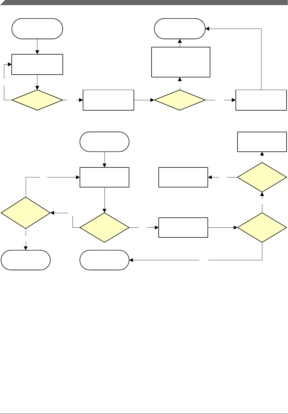
Fetch
Ping response
Yes
Yes
End
Report Error
No
No
0x5A
received? 0xA7
received?
Send 0x00 to
shift out 1 byte
from target
Send 0x00 to
shift out 1 byte
from target
Send 0x00s to shift
out leftover bytes
of ping response
Figure 6-6. Host reads ping packet from target via SPI
Fetch ACK
No
Yes
No
Next action
No
Process NAK Yes
Report an error
No
Yes
No
maximum
Report a
timeout error
Yes
0x5A
received?
0xA2
received?
0xA1
received?
Send 0x00 to
shift out 1 byte
from target
Send 0x00 to
shift out 1 byte
from target
Reached
retries?
Figure 6-7. Host reads ACK from target via SPI
SPI Peripheral
Kinetis Bootloader v2.0.0 Reference Manual, Rev. 0, 04/2016
72 Freescale Semiconductor, Inc.

Fetch Response
Yes
Yes out payload length
part from target
(2 bytes)
out CRC checksum
from target
Payload length
less than supported
length?
Yes
out payload data
from target
No
Set payload length
to maximum
supported length
No
No
maximum
Report a timeout
error (End)
Yes
End
No
(2 bytes)
0x5A
received?
0xA4
received?
Reached
retries?
Send 0x00 to
shift out 1 byte
from target
Send 0x00 to
shift out 1 byte
from target
Write 0x00s to shift Write 0x00s to shift
Write 0x00s to shift
Figure 6-8. Host reads response from target via SPI
6.3.1 Performance Numbers for SPI
The table below provides reference to the expected performance of write speeds to Flash
and RAM memories using Kinetis bootloader SPI interface. The numbers have been
measured on a number of platforms running Kinetis bootloader either from ROM or the
RAM (for flashloaders).
Table 6-2. Performance numbers SPI
SPI Bus
Frequen
cy
(KHz)
Flash Average Writing Speed (KB/s) Ram
Average
Writing
Speed
(KB/s)
KL27 KL28 KL43 KL80 K80 KL03 KL27 KL28 KL43 KL80 K80 KL03
100 7.07 7.46 7.24 6.74 6.71 6.20 8.60 9.25 9.01 8.46 8.04 6.80
200 11.45 12.26 11.88 11.53 10.18 8.87 15.23 17.98 17.04 16.17 14.19 10.64
300 13.84 15.17 14.70 15.08 12.42 - 19.91 25.11 23.06 24.65 18.79 -
400 16.42 18.09 17.23 16.91 13.74 - 25.89 32.95 31.15 28.89 23.95 -
500 18.26 19.82 18.17 18.94 14.98 - 31.47 40.10 36.61 36.61 27.83 -
600 18.72 20.72 19.98 20.63 15.21 - 32.40 44.98 40.96 42.26 27.67 -
800 21.19 22.06 22.27 22.04 16.11 - 39.83 50.00 51.54 49.98 30.15 -
1000 22.07 23.74 23.80 22.92 15.99 - 45.83 61.19 55.92 56.34 29.11 -
Table continues on the next page...
Chapter 6 Supported peripherals
Kinetis Bootloader v2.0.0 Reference Manual, Rev. 0, 04/2016
Freescale Semiconductor, Inc. 73
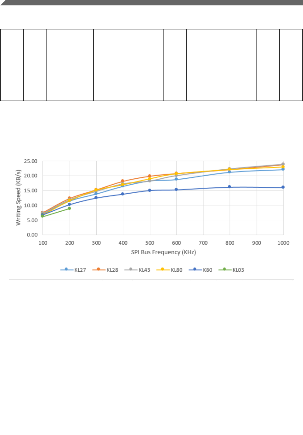
Table 6-2. Performance numbers SPI (continued)
Default
core
Frequen
cy
(MHz)
48 48 48 48 48 8 48 48 48 48 48 8
Default
bus
Frequen
cy
(MHz)
24 24 24 24 24 4 24 24 24 24 24 4
NOTE
1. Every test covers all flash or RAM region with 0x0 - 0xf.
2. Run every test three times and calculate the average.
Figure 6-9. Flash Average Writing Speed
SPI Peripheral
Kinetis Bootloader v2.0.0 Reference Manual, Rev. 0, 04/2016
74 Freescale Semiconductor, Inc.

Figure 6-10. RAM Average Writing Speed
6.4 UART Peripheral
The Kinetis bootloader integrates an autobaud detection algorithm for the UART
peripheral, thereby providing flexible baud rate choices.
Autobaud feature: If UARTn is used to connect to the bootloader, then the UARTn_RX
pin must be kept high and not left floating during the detection phase in order to comply
with the autobaud detection algorithm. After the bootloader detects the ping packet
(0x5A 0xA6) on UARTn_RX, the bootloader firmware executes the autobaud sequence.
If the baudrate is successfully detected, then the bootloader sends a ping packet response
[(0x5A 0xA7), protocol version (4 bytes), protocol version options (2 bytes) and crc16 (2
bytes)] at the detected baudrate. The Kinetis bootloader then enters a loop, waiting for
bootloader commands via the UART peripheral.
NOTE
The data bytes of the ping packet must be sent continuously
(with no more than 80 ms between bytes) in a fixed UART
transmission mode (8-bit data, no parity bit and 1 stop bit). If
the bytes of the ping packet are sent one-by-one with more than
80 ms delay between them, then the autobaud detection
algorithm may calculate an incorrect baud rate. In this instance,
the autobaud detection state machine should be reset.
Supported baud rates: The baud rate is closely related to the MCU core and system
clock frequencies. Typical baud rates supported are 9600, 19200, 38400, and 57600. Of
course, to influence the performance of autobaud detection, the clock configuration in
BCA can be changed.
Chapter 6 Supported peripherals
Kinetis Bootloader v2.0.0 Reference Manual, Rev. 0, 04/2016
Freescale Semiconductor, Inc. 75
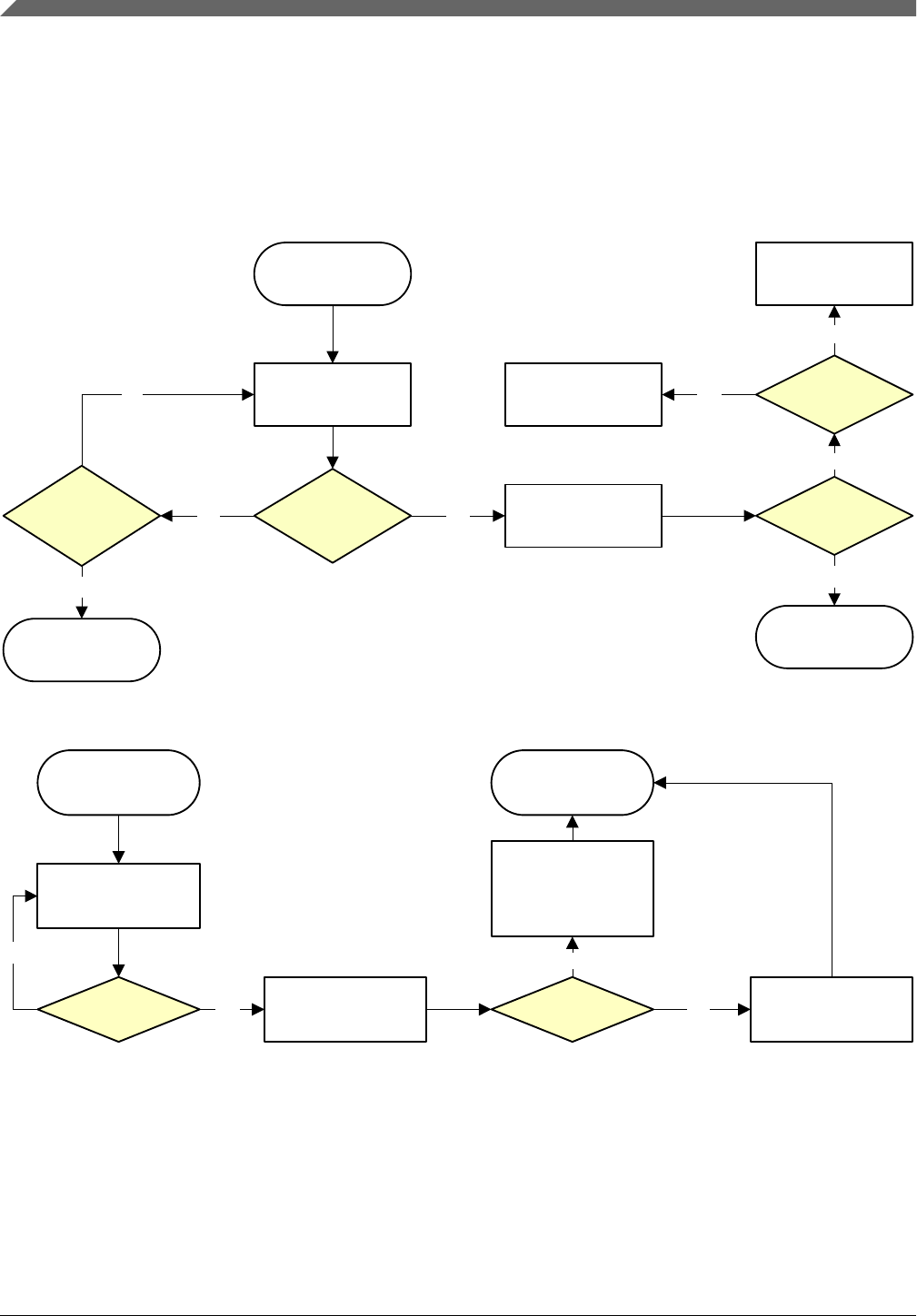
Packet transfer: After autobaud detection succeeds, bootloader communications can
take place over the UART peripheral. The following flow charts show:
• How the host detects an ACK from the target
• How the host detects a ping response from the target
• How the host detects a command response from the target
Wait
for ACK
No Yes
End
No
Process NAK Yes
Report an error
No
Yes
No
Reached
maximum
Report a timeout
error
Yes
0x5A
received?
0xA2
received?
0xA1
received?
Wait for 1 byte
from target
Wait for 1 byte
from target
retries?
Figure 6-11. Host reads an ACK from target via UART
Wait for
ping response
Yes
Yes
End
Report Error
No
No
Wait for 1 byte
from target
Wait for 1 byte
from target
0x5A
received? 0xA7
received?
Wait for
remaining bytes
of ping response
packet
Figure 6-12. Host reads a ping response from target via UART
UART Peripheral
Kinetis Bootloader v2.0.0 Reference Manual, Rev. 0, 04/2016
76 Freescale Semiconductor, Inc.
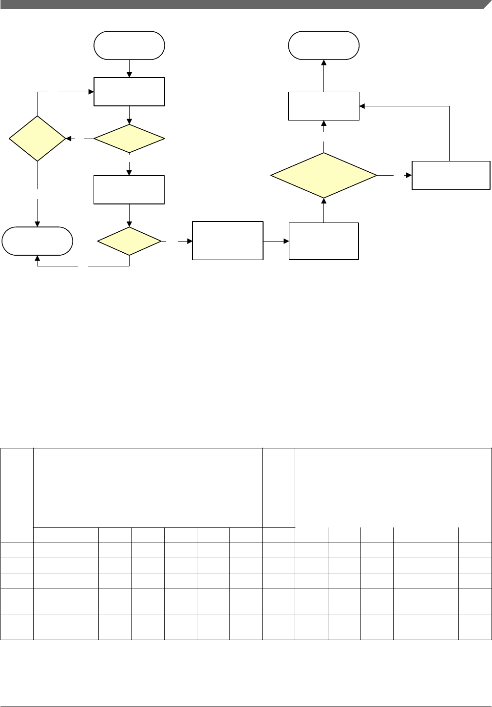
Wait
for response
Yes
Yes
Wait for payload
length part from
target (2 bytes)
Wait for CRC
checksum from
Payload length
less than supported
length?
Yes
Wait for payload
data from target
No
Set payload length
to maximum
supported length
No
No
Reached
maximum
Report a timeout
error (End)
Yes
End
No
0x5A
received?
0xA4
received?
Wait for 1 byte
from target
Wait for 1 byte
from target
retries?
target (2 bytes)
Figure 6-13. Host reads a command response from target via UART
6.4.1 Performance Numbers for UART
The table below provides reference to the expected performance of write speeds to Flash
and RAM memories using Kinetis bootloader SPI interface. The numbers have been
measured on a number of platforms running Kinetis bootloader either from ROM or the
RAM (in case of flashloaders).
UART
Baud
Rate
Flash Average Writing Speed (KB/s) Ram
Avera
ge
Writin
g
Speed
(KB/s)
KL27 KL28 KL43 KL80 K80 KL03 KS22 KL27 KL28 KL43 KL80 K80 KL03 KS22
19200 1.47 1.47 1.43 1.47 1.46 1.43 1.45 1.51 1.52 1.48 1.52 1.52 1.49 1.51
38400 2.81 2.82 2.75 2.82 2.79 2.81 2.75 2.99 3.03 2.95 3.03 3.03 2.9 3.00
57600 4.07 4.07 3.97 4.08 4.01 - 3.93 4.46 4.53 4.4 4.54 4.51 - 4.47
11520
0
7.3 7.31 7.12 7.35 7.1 - 6.88 8.69 8.97 8.65 8.98 8.85 - 8.73
23040
0
12.14 - 11.83 12.27 11.42 - 11.01 16.57 - 16.77 17.58 16.73 - 16.65
Table continues on the next page...
Chapter 6 Supported peripherals
Kinetis Bootloader v2.0.0 Reference Manual, Rev. 0, 04/2016
Freescale Semiconductor, Inc. 77
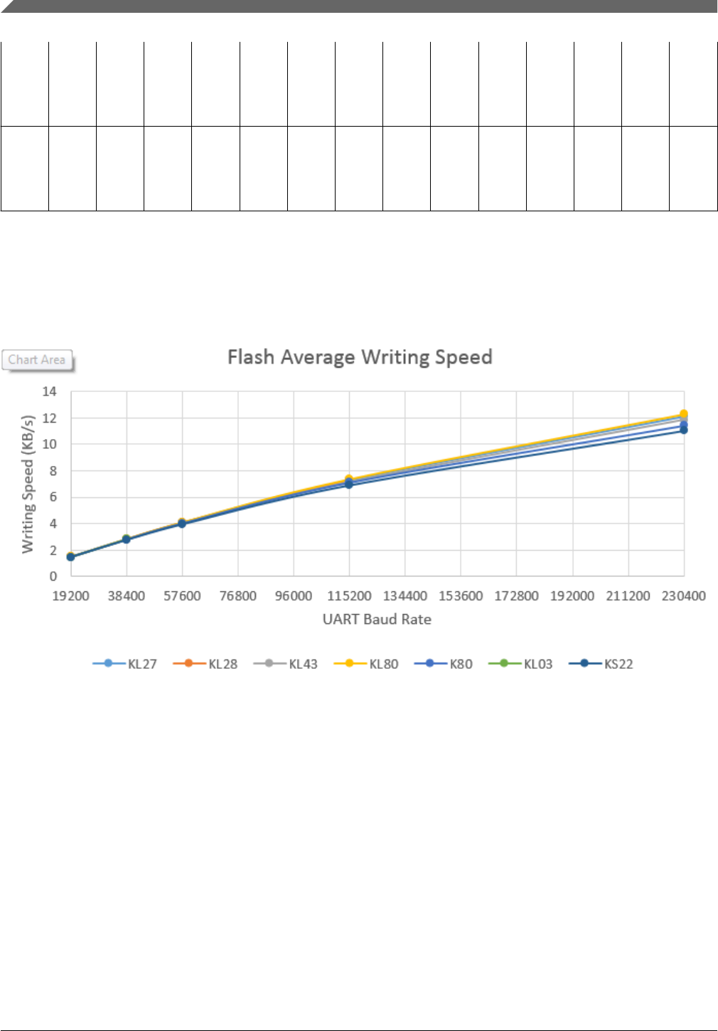
Default
core
Freque
ncy
(MHz)
48 48 48 48 48 8 48 48 48 48 48 48 8 48
Default
bus
Freque
ncy
(MHz)
24 24 24 24 24 4 24 24 24 24 24 24 4 24
NOTE
1. Every test covers all flash or RAM region with 0x0 - 0xf.
2. Run every test three times and calculate the average.
Figure 6-14. Flash Average Writing Speed
UART Peripheral
Kinetis Bootloader v2.0.0 Reference Manual, Rev. 0, 04/2016
78 Freescale Semiconductor, Inc.

Figure 6-15. RAM Average Writing Speed
6.5 USB HID Peripheral
The Kinetis bootloader supports loading data into flash via the USB peripheral. The
target is implemented as a USB HID class.
USB HID does not use framing packets; instead the packetization inherent in the USB
protocol itself is used. The ability for the device to NAK Out transfers (until they can be
received) provides the required flow control; the built-in CRC of each USB packet
provides the required error detection.
6.5.1 Device descriptor
The Kinetis bootloader configures the default USB VID/PID/Strings as below:
Default VID/PID:
•VID = 0x15A2
• PID = 0x0073
Default Strings:
• Manufacturer [1] = "Freescale Semiconductor Inc."
• Product [2] = "Kinetis bootloader"
The USB VID, PID, and Strings can be customized using the Bootloader Configuration
Area (BCA) of the flash. For example, the USB VID and PID can be customized by
writing the new VID to the usbVid(BCA + 0x14) field and the new PID to the
Chapter 6 Supported peripherals
Kinetis Bootloader v2.0.0 Reference Manual, Rev. 0, 04/2016
Freescale Semiconductor, Inc. 79

usbPid(BCA + 0x16) field of the BCA in flash. To change the USB strings, prepare a
structure (like the one shown below) in the flash, and then write the address of the
structure to the usbStringsPointer(BCA + 0x18) field of the BCA.
g_languages = { USB_STR_0,
sizeof(USB_STR_0),
(uint_16)0x0409,
(const uint_8 **)g_string_descriptors,
g_string_desc_size};
the USB_STR_0, g_string_descriptors and g_string_desc_size are defined as below.
USB_STR_0[4] = {0x02,
0x03,
0x09,
0x04
};
g_string_descriptors[4] =
{ USB_STR_0,
USB_STR_1,
USB_STR_2,
USB_STR_3};
g_string_desc_size[4] =
{ sizeof(USB_STR_0),
sizeof(USB_STR_1),
sizeof(USB_STR_2),
sizeof(USB_STR_3)};
• USB_STR_1 is used for the manufacturer string.
• USB_STR_2 is used for the product string.
• USB_STR_3 is used for the serial number string.
By default, the 3 strings are defined as below:
USB_STR_1[] =
{ sizeof(USB_STR_1),
USB_STRING_DESCRIPTOR,
'F',0,
'r',0,
'e',0,
'e',0,
's',0,
'c',0,
'a',0,
'l',0,
'e',0,
' ',0,
'S',0,
'e',0,
'm',0,
'i',0,
'c',0,
'o',0,
'n',0,
'd',0,
'u',0,
'c',0,
't',0,
'o',0,
'r',0,
' ',0,
'I',0,
'n',0,
'c',0,
USB HID Peripheral
Kinetis Bootloader v2.0.0 Reference Manual, Rev. 0, 04/2016
80 Freescale Semiconductor, Inc.

'.',0
};
USB_STR_2[] =
{ sizeof(USB_STR_2),
USB_STRING_DESCRIPTOR,
'M',0,
'K',0,
' ',0,
'M',0,
'a',0,
's',0,
's',0,
' ',0,
'S',0,
't',0,
'o',0,
'r',0,
'a',0,
'g',0,
'e',0
};
USB_STR_3[] =
{ sizeof(USB_STR_3),
USB_STRING_DESCRIPTOR,
'0',0,
'1',0,
'2',0,
'3',0,
'4',0,
'5',0,
'6',0,
'7',0,
'8',0,
'9',0,
'A',0,
'B',0,
'C',0,
'D',0,
'E',0,
'F',0
};
6.5.2 Endpoints
The HID peripheral uses 3 endpoints:
•Control (0)
• Interrupt IN (1)
• Interrupt OUT (2)
The Interrupt OUT endpoint is optional for HID class devices, but the Kinetis bootloader
uses it as a pipe, where the firmware can NAK send requests from the USB host.
Chapter 6 Supported peripherals
Kinetis Bootloader v2.0.0 Reference Manual, Rev. 0, 04/2016
Freescale Semiconductor, Inc. 81

6.5.3 HID reports
There are 4 HID reports defined and used by the bootloader USB HID peripheral. The
report ID determines the direction and type of packet sent in the report; otherwise, the
contents of all reports are the same.
Report ID Packet Type Direction
1 Command OUT
2 Data OUT
3 Command IN
4 Data IN
For all reports, these properties apply:
Usage Min 1
Usage Max 1
Logical Min 0
Logical Max 255
Report Size 8
Report Count 34
Each report has a maximum size of 34 bytes. This is derived from the minimum
bootloader packet size of 32 bytes, plus a 2-byte report header that indicates the length (in
bytes) of the packet sent in the report.
NOTE
In the future, the maximum report size may be increased, to
support transfers of larger packets. Alternatively, additional
reports may be added with larger maximum sizes.
The actual data sent in all of the reports looks like:
0 Report ID
1 Packet Length LSB
2 Packet Length MSB
3 Packet[0]
4 Packet[1]
5 Packet[2]
...
N+3-1 Packet[N-1]
USB HID Peripheral
Kinetis Bootloader v2.0.0 Reference Manual, Rev. 0, 04/2016
82 Freescale Semiconductor, Inc.

This data includes the Report ID, which is required if more than one report is defined in
the HID report descriptor. The actual data sent and received has a maximum length of 35
bytes. The Packet Length header is written in little-endian format, and it is set to the size
(in bytes) of the packet sent in the report. This size does not include the Report ID or the
Packet Length header itself. During a data phase, a packet size of 0 indicates a data phase
abort request from the receiver.
6.6 USB Peripheral
The Kinetis bootloader supports loading data into flash or RAM using the USB
peripheral. The target is implemented as USB-HID and USB MSC (Mass Storage Class)
composite device classes.
When transfer data through USB-HID device class, USB-HID does not use framing
packets. Instead, the packetization inherent in the USB protocol itself is used. The ability
for the device to NAK Out transfers (until they can be received) provides the required
flow control. The built-in CRC of each USB packet provides the required error detection.
When transfer data through USB MSC device class, USB MSC does not use framing
packets. Instead, the packetization inherent in the USB protocol itself is used. As with
any mass storage class device, a device drive letter appears in the file manager of the
operating system, and the file image can be dragged and dropped to the storage device.
Right now, the USB MSC download only supports SB file drag-and-drop. Reading the
SB file from the MSC device is not supported.
The USB peripheral can work as HID + MSC in Composite device mode. For HID-only
mode or MSC-only mode, this is configured using macros during compile time. If
configured as the HID and MSC composite device, users can either send commands to
the HID interface, or drag/drop SB files to the MSC device.
6.6.1 Device descriptor
uint8_t *g_string_descriptors[USB_STRING_COUNT + 1] = { g_usb_str_0,
g_usb_str_1,
g_usb_str_2,
g_usb_str_3,
g_usb_str_n };
usb_language_t g_usb_lang[USB_LANGUAGE_COUNT] = { {
Chapter 6 Supported peripherals
Kinetis Bootloader v2.0.0 Reference Manual, Rev. 0, 04/2016
Freescale Semiconductor, Inc. 83

g_string_descriptors, g_string_desc_size, (uint16_t)0x0409,
} };
usb_language_list_t g_language_list = {
g_usb_str_0, sizeof(g_usb_str_0), g_usb_lang, USB_LANGUAGE_COUNT,
};
uint8_t g_usb_str_1[USB_STRING_DESCRIPTOR_1_LENGTH +
USB_STRING_DESCRIPTOR_HEADER_LENGTH] = {
sizeof(g_usb_str_1),
USB_DESCRIPTOR_TYPE_STRING,
'F',
0,
'R',
0,
'E',
0,
'E',
0,
'S',
0,
'C',
0,
'A',
0,
'L',
0,
'E',
0,
' ',
0,
'S',
0,
'E',
0,
'M',
0,
'I',
0,
'C',
0,
'O',
0,
'N',
0,
'D',
0,
'U',
0,
'C',
0,
'T',
0,
'O',
0,
'R',
0,
' ',
0,
'I',
0,
'N',
0,
'C',
0,
'.',
0
uint8_t g_usb_str_2[USB_STRING_DESCRIPTOR_2_LENGTH +
USB_STRING_DESCRIPTOR_HEADER_LENGTH] = {
sizeof(g_usb_str_2),
USB_DESCRIPTOR_TYPE_STRING,
'U',
USB Peripheral
Kinetis Bootloader v2.0.0 Reference Manual, Rev. 0, 04/2016
84 Freescale Semiconductor, Inc.

0,
'S',
0,
'B',
0,
' ',
0,
'C',
0,
'O',
0,
'M',
0,
'P',
0,
'O',
0,
'S',
0,
'I',
0,
'T',
0,
'E',
0,
' ',
0,
'D',
0,
'E',
0,
'V',
0,
'I',
0,
'C',
0,
'E',
0
};
For HID and MSC composite devices.
uint8_t g_usb_str_3[USB_STRING_DESCRIPTOR_3_LENGTH +
USB_STRING_DESCRIPTOR_HEADER_LENGTH] = {
sizeof(g_usb_str_3),
USB_DESCRIPTOR_TYPE_STRING,
'M',
0,
'C',
0,
'U',
0,
' ',
0,
'M',
0,
'S',
0,
'C',
0,
' ',
0,
'A',
0,
'N',
0,
'D',
0,
Chapter 6 Supported peripherals
Kinetis Bootloader v2.0.0 Reference Manual, Rev. 0, 04/2016
Freescale Semiconductor, Inc. 85

' ',
0,
'H',
0,
'I',
0,
'D',
0,
' ',
0,
'G',
0,
'E',
0,
'N',
0,
'E',
0,
'R',
0,
'I',
0,
'C',
0,
' ',
0,
'D',
0,
'E',
0,
'V',
0,
'I',
0,
'C',
0,
'E',
0};
For HID-only devices.
uint8_t g_usb_str_3[USB_STRING_DESCRIPTOR_3_LENGTH +
USB_STRING_DESCRIPTOR_HEADER_LENGTH] = {
sizeof(g_usb_str_3),
USB_DESCRIPTOR_TYPE_STRING,
'M',
0,
'C',
0,
'U',
0,
' ',
0,
'H',
0,
'I',
0,
'D',
0,
' ',
0,
'G',
0,
'E',
0,
'N',
0,
'E',
0,
USB Peripheral
Kinetis Bootloader v2.0.0 Reference Manual, Rev. 0, 04/2016
86 Freescale Semiconductor, Inc.

'R',
0,
'I',
0,
'C',
0,
' ',
0,
'D',
0,
'E',
0,
'V',
0,
'I',
0,
'C',
0,
'E',
0
};
For MSC-only devices.
uint8_t g_usb_str_3[USB_STRING_DESCRIPTOR_3_LENGTH +
USB_STRING_DESCRIPTOR_HEADER_LENGTH] = {
sizeof(g_usb_str_3),
USB_DESCRIPTOR_TYPE_STRING,
'M',
0,
'C',
0,
'U',
0,
' ',
0,
'M',
0,
'S',
0,
'C',
0,
' ',
0,
'D',
0,
'E',
0,
'V',
0,
'I',
0,
'C',
0,
'E',
0
};
6.6.2 Endpoints
USB MSC device uses 2 endpoints, in addition to the default pipe that is required by USB HID
device
#define USB_MSC_BULK_IN_ENDPOINT (3), which
#define USB_MSC_BULK_OUT_ENDPOINT (4)
Chapter 6 Supported peripherals
Kinetis Bootloader v2.0.0 Reference Manual, Rev. 0, 04/2016
Freescale Semiconductor, Inc. 87

6.7 FlexCAN Peripheral
The Kinetis Bootloader supports loading data into flash via the FlexCAN peripheral.
It supports four predefined speeds on FlexCAN transferring:
• 125 KHz
• 250 KHz
• 500 KHz
• 1 MHz
The curent FlexCAN IP can support up to 1 MHz speed, so the default speed is set to 1
MHz.
In host applications, the user can specify the speed for FlexCAN by providing the speed
index as 0 through 4, which represents those 5 speeds.
In bootloader, this supports the auto speed detection feature within supported speeds. In
the beginning, the bootloader enters the listen mode with the initial speed (default speed 1
MHz). Once the host starts sending a ping to a specific node, it generates traffic on the
FlexCAN bus. Because the bootloader is in a listen mode. It is able to check if the local
node speed is correct by detecting errors. If there is an error, some traffic will be visible,
but it may not be on the right speed to see the real data. If this happens, the speed setting
changes and checks for errors again. No error means the speed is correct. The settings
change back to the normal receiving mode to see if there is a package for this node. It
then stays in this speed until another host is using another speed and try to communicate
with any node. It repeats the process to detect a right speed before sending host timeout
and aborting the request.
The host side should have a reasonable time tolderance during the auto speed detect
period. If it sends as timeout, it means there is no response from the specific node, or
there is a real error and it needs to report the error to the application.
This flow chart demonstrates the communication flow for how the host reads the ping
packet, ACK, and response from the target.
FlexCAN Peripheral
Kinetis Bootloader v2.0.0 Reference Manual, Rev. 0, 04/2016
88 Freescale Semiconductor, Inc.
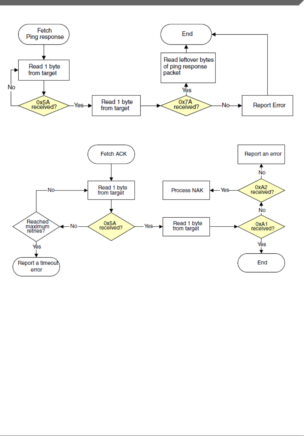
Figure 6-16. Host reads ping response from target via FlexCAN
Figure 6-17. Host reads ACK packet from target via FlexCAN
Chapter 6 Supported peripherals
Kinetis Bootloader v2.0.0 Reference Manual, Rev. 0, 04/2016
Freescale Semiconductor, Inc. 89
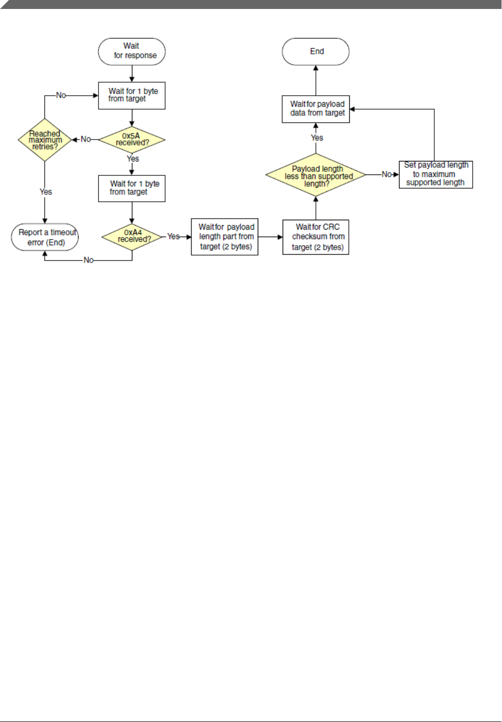
Figure 6-18. Host reads command response from target via FlexCAN
6.8 QuadSPI Peripheral
The Kinetis Bootloader supports read, write, and erase external SPI flash devices
(QuadSPI memory) via the QuadSPI module. It supports booting directly to external SPI
flash and XIP in QuadSPI memory. Before accessing external SPI flash devices, the
QuadSPI module must be configured properly, using the QSPI configuration block.
6.8.1 QSPI configuration block
The QSPI config block (QCB) provides many configuration parameters, which are
intended to support many types of serial flash. All fields in the QSPI config block must
be configured according to the specific flash device provided by your specific vendor,
and all of them are related to the configuration for registers in the QuadSPI module. Also
see the QuadSPI chapter.
NOTE
To correctly configure the QuadSPI, all unused QuadSPI
configuration fields should be set to 0.
QuadSPI Peripheral
Kinetis Bootloader v2.0.0 Reference Manual, Rev. 0, 04/2016
90 Freescale Semiconductor, Inc.

Table 6-3. Configuration fields in QSPI config block
Offset Size
(bytes)
Configuration Field Description
0x00 – 0x03 4 tag A magic number to verify whether the QSPI config
block (QCB) is valid. Must be set to ‘kqcf’
[31:24] - ‘f’ (0x66)
[23:16] - ‘c’ (0x63)
[15: 8] - ‘q’(0x71)
[ 7: 0] - ‘k’(0x6B)
0x04 – 0x07 4 version Version number of the QSPI config block
[31:24] - name: must be 'Q' (0x51)
[23:16] - major: must be 1
[15: 8] - minor: must be 0
[ 7: 0] - bugfix: must be 0
0x08 – 0x0b 4 lengthInBytes Size of QSPI config block, in bytes
Must be 512
0x0c – 0x0f 4 dqs_loopback Enable DQS loopback support
0 DQS loopback is disabled
1 DQS loopback is enabled, the DQS loopback mode
is determined by subsequent ‘dqs_loopback_internal’
field
0x10 – 0x13 4 data_hold_time Serial flash data hold time. Valid value 0/1/2. See the
QuadSPI chapter for details.
0x14 – 0x1b 8 - Reserved
0x1c – 0x1f 4 device_mode_config_en Configure work mode Enable for external SPI flash
devices
0 Disabled - ROM will not configure work mode of
external flash devices.
1 Enabled - ROM will configure work mode of external
flash devices, based on “device_cmd” and the LUT
entry indicated by” write_cmd_ipcr”.
0x20 – 0x23 4 device_cmd Command to configure the work mode of external flash
devices. Effective only if “device_mode_config_en” is
set to 1. It also depends on your specific external SPI
flash device.
0x24 – 0x27 4 write_cmd_ipcr IPCR pointed to LUT index for quad mode enablement
Value = index << 24
0x28 – 0x2b 4 word_addressable Word Addressable
0 Byte-addressable serial flash mode
1 Word-addressable serial flash mode
0x2c – 0x2f 4 cs_hold_time Serial flash CS hold time, in number of flash clock
cycles
0x30 – 0x33 4 cs_setup_time Serial flash CS setup time, in number of flash clock
cycles
Table continues on the next page...
Chapter 6 Supported peripherals
Kinetis Bootloader v2.0.0 Reference Manual, Rev. 0, 04/2016
Freescale Semiconductor, Inc. 91

Table 6-3. Configuration fields in QSPI config block
(continued)
Offset Size
(bytes)
Configuration Field Description
0x34 – 0x37 4 sflash_A1_size Size of external flash connected to ports of QSPI0A
and QSPI0A_CS0, in bytes
0x38 – 0x3b 4 sflash_A2_size Size of external flash connected to ports of QSPI0A
and quadSPI0A_CS1, in bytes
sflash_A2_size field must be set to 0 if the serial flash
device is not present.
0x3c – 0x3f 4 sflash_B1_size Size of external flash connected to ports of QSPI0B
and quadSPI0B_CS0, in bytes
sflash_B1_size field must be set to 0 if the serial flash
device is not present.
0x40 – 0x43 4 sflash_B2_size Size of external flash connected to ports of QSPI0B
and quadSPI0B_CS1, in bytes
sflash_B2_size field must be set to 0 if the serial flash
device is not present.
0x44 – 0x47 4 sclk_freq Frequency of QuadSPI serial clock 1
0 Low frequency
1 Mid frequency
2 High frequency
See the Kinetis bootloader chapter in silicon’s
reference manual for the definition of lowfrequency,
mid-frequency, and high-frequency. In MK82F256,
they are 24 MHz, 48 MHz, and 96 MHz.
0x48 – 0x4b 4 busy_bit_offset Busy bit offset in status register of Serial flash
[31:16] Busy bit polarity, valid range is 0-1:
0 - Busy flag in status register is 1 when flash devices
are busy.
1 - Busy flag in status register is 0 when flash devices
are busy.
[15:0]: The offset of busy flag in status register; valid
range is 0 - 31.
0x4c – 0x4f 4 sflash_type Type of serial flash
0 Single mode
1 Dual mode
2 Quad mode
3 Octal mode
0x50 – 0x53 4 sflash_port Port enablement for QuadSPI module
0 Only pins for QSPI0A are enabled
1 Pins for both QSPI0A and QSPI0B are enabled
0x54 – 0x57 4 ddr_mode_enable Enable DDR mode
0 DDR mode is disabled
Table continues on the next page...
QuadSPI Peripheral
Kinetis Bootloader v2.0.0 Reference Manual, Rev. 0, 04/2016
92 Freescale Semiconductor, Inc.

Table 6-3. Configuration fields in QSPI config block
(continued)
Offset Size
(bytes)
Configuration Field Description
1 DDR mode is enabled
0x58 – 0x5b 4 dqs_enable Enable DQS
0 DQS is disabled
1 DQS is enabled
0x5c – 0x5f 4 parallel_mode_enable Enable Parallel Mode
0 Parallel mode is disabled
1 Parallel mode is enabled1
0x60 – 0x63 4 portA_cs1 Enable QuadSPI0A_CS1
0 QuadSPI0A_CS1 is disabled
1 QuadSPI0A_CS1 is enabled
portA_cs1 field must be set to 1 if sflash_A2_size is
not equal to 0.
0x64 – 0x67 4 portB_cs1 Enable QuadSPI0B_CS1
0 QuadSPI0B_CS1 is disabled
1 QuadSPI0B_CS1 is enabled
portB_cs1 field must be set to 1 if sflash_B2_size is
not equal to 0.
0x68 – 0x6b 4 fsphs Full Speed Phase selection for SDR instructions
0 Select sampling at non-inverted clock
1 Select sampling at inverted clock
0x6c – 0x6f 4 fsdly Full Speed Delay selection for SDR instructions
0 One clock cycle delay
1 Two clock cycles delay.
0x70 – 0x73 4 ddrsmp DDR sampling point
Valid range: 0 - 7
0x74 – 0x173 4 look_up_table Look-up-table for sequences of instructions
0x174 – 0x177 4 column_address_space Column Address Space
Defines the width of the column address
0x178 – 0x17b 4 config_cmd_en Enable additional configuration command
0 Additional configuration command is not needed
1 Additional configuration command is needed
0x17c – 0x18b 16 config_cmds IPCR arrays for each connected SPI flash
All fields must be set to 0 if config_cmd_en is not
asserted.
0x18c - 0x19b 16 config_cmds_args Command arrays needed to be transferred to external
spi flash
All fields must be set to 0 if config_cmd_en is not
asserted.
Table continues on the next page...
Chapter 6 Supported peripherals
Kinetis Bootloader v2.0.0 Reference Manual, Rev. 0, 04/2016
Freescale Semiconductor, Inc. 93

Table 6-3. Configuration fields in QSPI config block
(continued)
Offset Size
(bytes)
Configuration Field Description
0x19c – 0x19f 4 differential_clock_pin_ena
ble
Enable differential flash clock pin
0 Differential flash clock pin is disabled
1 Differential flash clock pin is enabled
0x1a0 – 0x1a3 4 flash_CK2_clock_pin_ena
ble
Enable Flash CK2 Clock pin
0 Flash CK2 Clock pin is disabled
1 Flash CK2 Clock pin is enabled
0x1a4 – 0x1a7 4 dqs_inverse_sel Select clock source for internal DQS generation
0 Use 1x internal reference clock for DQS generation
1 Use inverse 1x internal reference clock for DQS
generation
0x1a8 – 0x1ab 4 dqs_latency_enable DQS Latency Enable
0 DQS latency disabled
1 DQS feature with latency included enabled
0x1ac – 0x1af 4 dqs_loopback_internal DQS loopback from internal DQS signal or DQS Pad
0 DQS loopback is sent to DQS pad first and then
looped back to QuadSPI
1 DQS loopback from internal DQS signal directly
0x1b0 – 0x1b3 4 dqs_phase_sel Select Phase Shift for internal DQS generation
0 No Phase shift
1 Select 45° phase shift
2 Select 90° phase shift
3 Select 135° phase shift
0x1b4 – 0x1b7 4 dqs_fa_delay_chain_sel Delay chain tap number selection for QuadSPI0A DQS
Valid range: 0 - 63
0x1b8 – 0x1bb 4 dqs_fb_delay_chain_sel Delay chain tap number selection for QuadSPI0B DQS
Valid range: 0 - 63
0x1bc – 0x1c3 8 - Reserved
0x1c4 – 0x1c7 4 page_size Page size of external SPI flash.1
Page size of all SPI flash devices must be the same
0x1c8 – 0x1cb 4 sector_size Sector size of external SPI flash.1
Sector size of all SPI flash devices must be the same.
0x1cc - 0x1cf 4 timeout_milliseconds Timeout in terms of milliseconds.
0 Timeout check is disabled.
NOTE: If the time that the external SPI device is busy
is more than this timeout value, then the
QuadSPI driver returns a timeout.
0x1d0 – 0x1d3 4 ips_cmd_second_divider Second divider for IPs command based on
QSPI_MCR[SCLKCFG]; the maximum value of
Table continues on the next page...
QuadSPI Peripheral
Kinetis Bootloader v2.0.0 Reference Manual, Rev. 0, 04/2016
94 Freescale Semiconductor, Inc.

Table 6-3. Configuration fields in QSPI config block
(continued)
Offset Size
(bytes)
Configuration Field Description
QSPI_MCR[SCLKCFG] depends on the specific
device.
0x1d4 – 0x1d7 4 need_multi_phase 0 Only 1 phase is necessary to access external flash
devices
1 Multiple phases are necessary to erase/program
external flash devices
0x1d8 – 0x1db 4 is_spansion_hyperflash 0 External flash devices is not in the Spansion
Hyperflash family
1 External flash devices is in the Spansion Hyperflash
family
0x1dc – 0x1df 4 pre_read_status_cmd_add
ress_offset2Additional address for the PreReadStatus command.
Set this field to 0xFFFF FFFF if it is not required.
0x1e0 – 0x1e3 4 pre_unlock_cmd_address
_offset2Additional address for PreWriteEnable command. Set
this field to 0xFFFF FFFF if it is not required.
0x1e4 – 0x1e7 4 unlock_cmd_address_offs
et2Additional address for WriteEnable command. Set this
field to 0xFFFF FFFF if it is not required.
0x1e8 – 0x1eb 4 pre_program_cmd_addres
s_offset2Additional address for PrePageProgram command.
Set this field to 0xFFFF FFFF if it is not required.
0x1ec – 0x1ef 4 pre_erase_cmd_address_
offset2Additional address for PreErase command. Set this
field to 0xFFFF FFFF if it is not required.
0x1f0 – 0x1f3 4 erase_all_cmd_address_o
ffset2Additional address for EraseAll command. Set this field
to 0xFFFF FFFF if it is not required.
0x1f4 – 0x1ff 12 - Reserved
1. If parallel mode is enabled, then page size and sector size must be twice the actual size.
2. These fields are effective only if “need_multi_phase” field is set to 1.
NOTE
It is recommended to configure QSPI to SDR mode with one
QCB during the program and switch to DDR mode with
another QCB after the program completes, where it is possible
to achieve higher program performance with the Kinetis
bootloader.
6.8.2 Look-up-table
The look-up table (LUT) is a part of the QCB, and contains sequences for instructions,
such as read and write instructions. The Kinetis Bootloader defines LUT entries to
support erase, program and read operations.
Chapter 6 Supported peripherals
Kinetis Bootloader v2.0.0 Reference Manual, Rev. 0, 04/2016
Freescale Semiconductor, Inc. 95

NOTE
The sequence in each LUT entry is target-specific. See the
datasheet or reference manual of the corresponding serial flash
device.
Table 6-4. Look-up table entries for bootloader
Index Field Description
0 Read Sequence for read instructions
1 WriteEnable Sequence for WriteEnable instructions
2 EraseAll Sequence for EraseAll instructions
3 ReadStatus Sequence for ReadStatus instructions
4 PageProgram Sequence for Page Program instructions
6 PreErase1Sequence for Pre-Erase instructions
7 SectorErase Sequence for Sector Erase
8 Dummy Sequence for dummy operation if needed.
For example, if continuous read is configured in index 0, then the dummy LUT
should be configured to force the external SPI flash to exit continuous read
mode.
If a dummy operation is not required, then this LUT entry must be set to 0.
9 PreWriteEnable1Sequence for Pre-WriteEnable instructions
10 PrePageProgram1Sequence for Pre-PageProgram instructions
11 PreReadStatus1Sequence for Pre-ReadStatus instructions
5, 12, 13, 14,
15
Undefined1All of these sequences are free to be used for other purpose. For example,
index 5 can be used for enabling Quad mode of SPI flash devices, see
Section 3.3.2 for more details.
1. If these LUT entries are are not required, then they are allowed to be used for other purposes.
NOTE
For most types of SPI flash devices available in the market,
only index 0, 1, 3, 4, 7, and 8 are required. However, for other
types of high-end SPI flash devices, i.e., Cypress Hyperflash,
additional indexes listed above may be required.
6.8.3 Configure QuadSPI module
The Kinetis Bootloader is able to access external SPI devices via the QuadSPI module,
but only after the QuadSPI module is configured. There are 2 ways to configure the
QuadSPI module:
•Configure QuadSPI module at runtime
• Configure QuadSPI module at start-up
QuadSPI Peripheral
Kinetis Bootloader v2.0.0 Reference Manual, Rev. 0, 04/2016
96 Freescale Semiconductor, Inc.

Table 6-5. Configuring the QuadSPI module
Configure
QuadSPI at
Procedure Clock updates during QuadSPI
module configuration
runtime 1. Use a WriteMemory command to program the QCB to
either a region of RAM or internal flash.
2. Use the ConfigQuadSPI command to configure the
QuadSPI module with the QCB that was programmed
before.
3. After the above operations, the QuadSPI module has
been set to an expected mode specified by the QCB, so
the Kinetis bootloader is now able to access all
connected SPI flash devices.
If QuadSPI module is configured at
runtime: The System Core clock will not
be updated if the QuadSPI module is
configured at runtime; only
QUADSPI_MCR [SCLKCFG] is updated
according to sclk_freq field within the
QCB. In this case, the clock source for
QuadSPI module is MCGFLL
(QUADSPI0_SOCCR [QSPISRC] equals
1).
start-up The steps of configuring QuadSPI at startup is based on the
runtime procedure, if the QCB is not present at address 0 of
the 1st external SPI flash device.
1. Configure the QuadSPI module at runtime (procedure
above).
2. Erase the 1st sector of the 1st connected external SPI
flash device using the FlashEraseRegion command.
3. Program the QCB to address 0 of the 1st connected
external SPI flash device using the WriteMemory
command.
NOTE: For some types of SPI flash
devices (like Spansion Hyperflash)
which do not support basic reads
(0x03) with 24-bit addresses, an
alternative is available: for this
step, program the QCB to internal
flash, set the
“qspiConfigBlockPointer” in the
BCA to the start address of QCB,
and program the BCA to 0x3c0.
4. Update BOOTSRC_SEL field (bits [7:6]) in
FOPTregister at the address 0x40D to “0b’10”, which
means "boot from ROM with QuadSPI configured".
5. Reset the target.
6. After start-up, ROM code reads the QCB from address
0 of the external SPI flash and then configures the
QuadSPI according to the QCB.
7. Now, the Kinetis Bootloader is able to access all
connected SPI flash devices.
The QuadSPI module will be configured automatically out of
reset, if the QCB is already present and the BOOTSRC_SEL
field (bits [7:6]) in FOPTregister at the address 0x40D equals
to “0’b10”.
If QuadSPI module is configured at
start-up: The System Core clock will be
updated to 72/96 MHz, if the QuadSPI
module is configured at start-up. In this
case, the clock source of the QuadSPI
module switches to MCGFLL. The
corresponding registers are updated with
the values listed in the table Register
value updates when the QuadSPI
module is configured at start-up.
NOTE: For K80/1/2, the core clock is
updated to 96 MHz. For KL81/2,
the core clock is updated to 72
MHz.
NOTE
The user application boot from QuadSPI in XIP mode should
not change the QuadSPI source clock from what ROM has
configured (as shown in the previous table); otherwise a hard
fault may occur. However, the QuadSPI source clocks (listed in
Chapter 6 Supported peripherals
Kinetis Bootloader v2.0.0 Reference Manual, Rev. 0, 04/2016
Freescale Semiconductor, Inc. 97

the next table) can be changed successfully, if the application
avoids shutting down the QSPI clock during clock switching;
for example, if the clock switch-related codes are relocated in
either internal flash or SRAM.
6.8.4 Access external SPI flash devices using QuadSPI module
The Kinetis Bootloader supports access to external SPI flash devices using the following
commands:
•Flash-erase-all: This command can erase all SPI flash devices defined in the QCB.
For example, if “flash-erase-all 1”, the 1 represents the source of the erasure
command is QuadSPI memory.
•Flash-erase-region: This command can erase a specified range of flash within
connected SPI flash devices. For example “flash-erase-region 0x68000000
0x10000”.
•Write-memory: The Kinetis Bootloader calls the Write-memory command to
program specified data to a given region of connected SPI flash devices. For
example, “write-memory 0x68001000 led_demo.bin”.
•Read-memory: The Kinetis Bootloader calls the Read-memory command to read
data from a given region of connected SPI flash devices. For example, “read-memory
0x68000000 1024 temp.bin”.
These commands return error codes.
Table 6-6. Status Error Codes for accessing QuadSPI memory
Error Code Value Description
kStatus_Success 0 Operation succeeded without error
kStatus_QspiFlashSizeError 400 Size of external SPI flash is invalid
kStatus_QspiFlashAlignmentError 401 Start Address for program is not page-aligned
kStatus_QspiFlashAddressError 402 The address is invalid
kStatus_QspiFlashCommandFailure 403 The operation failed
kStatus_QspiNotConfigured 405 QSPI module is not successfully configured
kStatus_QspiFlashUnkownProperty 404 Unknown QSPI property
kStatus_QspiCommandNotSupported 406 The command is not supported under certain modes
kStatus_QspiCommandTimeout 407 The time that the external SPI device is busy more than the
timeout value (timeout_milliseconds).
kStatus_QspiWriteFailure 408 QSPI module cannot perform a program command at the
current clock frequency
kStatus_QspiModuleBusy 409 QSPI module is busy, or caused by incorrect configuation of
QCB
QuadSPI Peripheral
Kinetis Bootloader v2.0.0 Reference Manual, Rev. 0, 04/2016
98 Freescale Semiconductor, Inc.

6.8.5 Boot directly from QuadSPI
The Kinetis Bootloader supports booting directly from QuadSPI. To boot directly from
QuadSPI, the following conditions must be met:
• The bootFlags field in BCA is set to 0xFE, which means "boot directly from
QuadSPI".
• The BOOTSRC_SEL field (bits [7:6]) in the FOPT register at address 0x40D is set to
“0’b10”, which means "boot from ROM with QuadSPI configured".
• User application is valid.
• QuadSPI configuration block (QCB) is valid
• CRC check passed if the CRC check feature is enabled.
6.8.6 Example QCB
Here is an example QCB for the MX25U3235F device on TWR-K80F150M, FRDM-
K82F, TWR-KL82Z72M, and FRDM-KL82Z. See the Kinetis Bootloader QuadSPI
User's Guide (document KBLQSPIUG) for more details.
const qspi_config_t qspi_config_block = {
.tag = kQspiConfigTag, ⁄⁄ Fixed value, do not change
.version = {.version = kQspiVersionTag}, ⁄⁄ Fixed value, do not change
.lengthInBytes = 512, ⁄⁄Fixed value, do not change
.sflash_A1_size = 0x400000, ⁄⁄ 4MB
.sclk_freq = kQspiSerialClockFreq_High, ⁄⁄ High frequency, in K82-256, it means
96MHz/1 = 96MHz
.sflash_type = kQspiFlashPad_Quad, ⁄⁄ SPI Flash devices work under quad-pad
mode
.sflash_port = kQspiPort_EnableBothPorts, ⁄⁄ Both QSPI0A and QSPI0B are enabled.
.busy_bit_offset = 0, ⁄⁄ Busy offset is 0
.ddr_mode_enable = 0, ⁄⁄ disable DDR mode
.dqs_enable = 0, ⁄⁄ Disable DQS feature
.parallel_mode_enable = 0, ⁄⁄ QuadSPI module work under serial mode
.pagesize = 256, ⁄⁄ Page Size : 256 bytes
.sectorsize = 0x1000, ⁄⁄ Sector Size: 4KB
.device_mode_config_en = 1, ⁄⁄ Enable quad mode for SPI flash
.device_cmd = 0x40, ⁄⁄ Enable quad mode via set bit 6 in
status register to 1
.write_cmd_ipcr = 0x05000000U, ⁄⁄ IPCR indicating seq id for Quad Mode
Enable (5<<24)
.ips_command_second_divider = 3, ⁄⁄Set second divider for QSPI serial clock
to 3
.look_up_table =
{
⁄⁄ Seq0 : Quad Read (maximum supported freq: 104MHz)
⁄*
CMD: 0xEB - Quad Read, Single pad
ADDR: 0x18 - 24bit address, Quad pads
DUMMY: 0x06 - 6 clock cycles, Quad pads
READ: 0x80 - Read 128 bytes, Quad pads
JUMP_ON_CS: 0
*⁄
[0] = 0x0A1804EB, [1] = 0x1E800E06, [2] = 0x2400,
// Seq1: Write Enable (maximum supported freq: 104MHz)
⁄*
Chapter 6 Supported peripherals
Kinetis Bootloader v2.0.0 Reference Manual, Rev. 0, 04/2016
Freescale Semiconductor, Inc. 99

CMD: 0x06 - Write Enable, Single pad
*⁄
[4] = 0x406,
⁄⁄ Seq2: Erase All (maximum supported freq: 104MHz)
⁄*
CMD: 0x60 - Erase All chip, Single pad
*⁄
[8] = 0x460,
⁄⁄Seq3: Read Status (maximum supported freq: 104MHz)
⁄*
CMD: 0x05 - Read Status, single pad
READ: 0x01 - Read 1 byte
*⁄
[12] = 0x1c010405,
⁄⁄ Seq4: 4 I⁄O Page Program (maximum supported freq: 104MHz)
⁄*
CMD: 0x38 - 4 I/O Page Program, Single pad
ADDR: 0x18 - 24bit address, Quad pad
WRITE: 0x40 - Write 64 bytes at one pass, Quad pad
*⁄
[16] = 0x0A180438, [17] = 0x2240,
⁄⁄ Seq5: Write status register to enable quad mode
⁄*
CMD: 0x01 - Write Status Register, single pad
WRITE: 0x01 - Write 1 byte of data, single pad
*⁄
[20] = 0x20010401,
⁄⁄ Seq7: Erase Sector
⁄*
CMD: 0x20 - Sector Erase, single pad
ADDR: 0x18 - 24 bit address, single pad
*⁄
[28] = 0x08180420,
⁄⁄ Seq8: Dummy
⁄*
CMD: 0 - Dummy command, used to force SPI flash to exit continuous
read mode.
unnecessary here because the continuous read mode is not enabled.
*⁄
[32] = 0,
},
};
QuadSPI Peripheral
Kinetis Bootloader v2.0.0 Reference Manual, Rev. 0, 04/2016
100 Freescale Semiconductor, Inc.
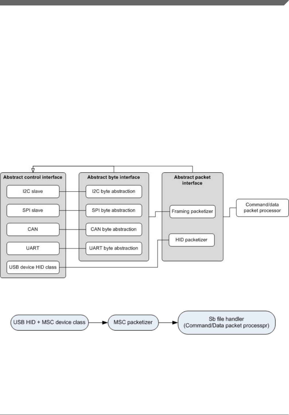
Chapter 7
Peripheral interfaces
7.1 Introduction
The block diagram shows connections between components in the architecture of the
peripheral interface.
Figure 7-1. Components peripheral interface
Figure 7-2. USB/MSC Peripheral interface
In this diagram, the byte and packet interfaces are shown to inherit from the control
interface.
Kinetis Bootloader v2.0.0 Reference Manual, Rev. 0, 04/2016
Freescale Semiconductor, Inc. 101

All peripheral drivers implement an abstract interface built on top of the driver's internal
interface. The outermost abstract interface is a packet-level interface. It returns the
payload of packets to the caller. Drivers which use framing packets have another abstract
interface layer that operates at the byte level. The abstract interfaces allow the higher
layers to use exactly the same code regardless which peripheral is being used.
The abstract packet interface feeds into the command and data packet processor. This
component interprets the packets returned by the lower layer as command or data
packets.
7.2 Abstract control interface
This control interface provides a common method to initialize and shutdown peripheral
drivers. It also provides the means to perform the active peripheral detection. No data
transfer functionality is provided by this interface. That is handled by the interfaces that
inherit the control interface.
The main reason this interface is separated out from the byte and packet interfaces is to
show the commonality between the two. It also allows the driver to provide a single
control interface structure definition that can be easily shared.
struct PeripheralDescriptor {
//! @brief Bit mask identifying the peripheral type.
//!
//! See #_peripheral_types for a list of valid bits.
uint32_t typeMask;
//! @brief The instance number of the peripheral.
uint32_t instance;
//! @brief Configure pinmux setting for the peripheral.
void (*pinmuxConfig)(uint32_t instance, pinmux_type_t pinmux);
//! @brief Control interface for the peripheral.
const peripheral_control_interface_t * controlInterface;
//! @brief Byte-level interface for the peripheral.
//!
//! May be NULL because not all periperhals support this interface.
const peripheral_byte_inteface_t * byteInterface;
//! @brief Packet level interface for the peripheral.
const peripheral_packet_interface_t * packetInterface;
};
struct PeripheralControlInterface
{
bool (*pollForActivity)(const PeripheralDescriptor * self);
status_t (*init)(const PeripheralDescriptor * self, BoatloaderInitInfo * info);
void (*shutdown)(const PeripheralDescriptor * self);
Abstract control interface
Kinetis Bootloader v2.0.0 Reference Manual, Rev. 0, 04/2016
102 Freescale Semiconductor, Inc.

void (*pump)(const peripheral_descriptor_t *self);
}
Table 7-1. Abstract control interface
Interface Description
pollForActivity() Check whether communications has started.
init() Fully initialize the driver.
shutdown() Shutdown the fully initialized driver.
pump Provide execution time to driver.
7.3 Abstract byte interface
This interface exists to give the framing packetizer, which is explained in the later
section, a common interface for the peripherals that use framing packets.
The abstract byte interface inherits the abstract control interface.
struct PeripheralByteInterface
{
status_t (*init)(const peripheral_descriptor_t * self);
status_t (*write)(const peripheral_descriptor_t * self, const uint8_t *buffer, uint32_t
byteCount);
};
Table 7-2. Abstract byte interface
Interface Description
init() Initialize the interface.
write() Write the requested number of bytes.
NOTE
The byte interface has no read() member. Interface reads are
performed in an interrupt handler at the packet level.
7.4 Abstract packet interface
The abstract packet interface inherits the abstract control interface.
status_t (*init)(const peripheral_descriptor_t *self);
status_t (*readPacket)(const peripheral_descriptor_t *self,
uint8_t **packet,
uint32_t *packetLength,
packet_type_t packetType);
status_t (*writePacket)(const peripheral_descriptor_t *self,
Chapter 7 Peripheral interfaces
Kinetis Bootloader v2.0.0 Reference Manual, Rev. 0, 04/2016
Freescale Semiconductor, Inc. 103

const uint8_t *packet,
uint32_t byteCount,
packet_type_t packetType);
void (*abortDataPhase)(const peripheral_descriptor_t *self);
status_t (*finalize)(const peripheral_descriptor_t *self);
uint32_t (*getMaxPacketSize)(const peripheral_descriptor_t *self);
void (*byteReceivedCallback)(uint8_t byte);
Table 7-3. Abstract packet interface
Interface Description
init() Initialize the peripheral.
readPacket() Read a full packet from the peripheral.
writePacket() Send a complete packet out the peripheral.
abortDataPhase() Abort receiving of data packets.
finalize() Shut down the peripheral when done with use.
getMaxPacketSize Returns the current maximum packet size.
byteReceivedCallback Notification of received byte.
7.5 Framing packetizer
The framing packetizer processes framing packets received via the byte interface with
which it talks. It builds and validates a framing packet as it reads bytes. And it constructs
outgoing framing packets as needed to add flow control information and command or
data packets. The framing packet also supports data phase abort.
7.6 USB HID packetizer
The USB HID packetizer implements the abstract packet interface for USB HID, taking
advantage of the USB's inherent flow control and error detection capabilities. The USB
HID packetizer provides a link layer that supports variable length packets and data phase
abort.
7.7 USB HID packetizer
The USB HID packetizer implements the abstract packet interface for USB HID, taking
advantage of the USB's inherent flow control and error detection capabilities.
The below image shows the USB MSC command/data/status flow chart:
Framing packetizer
Kinetis Bootloader v2.0.0 Reference Manual, Rev. 0, 04/2016
104 Freescale Semiconductor, Inc.
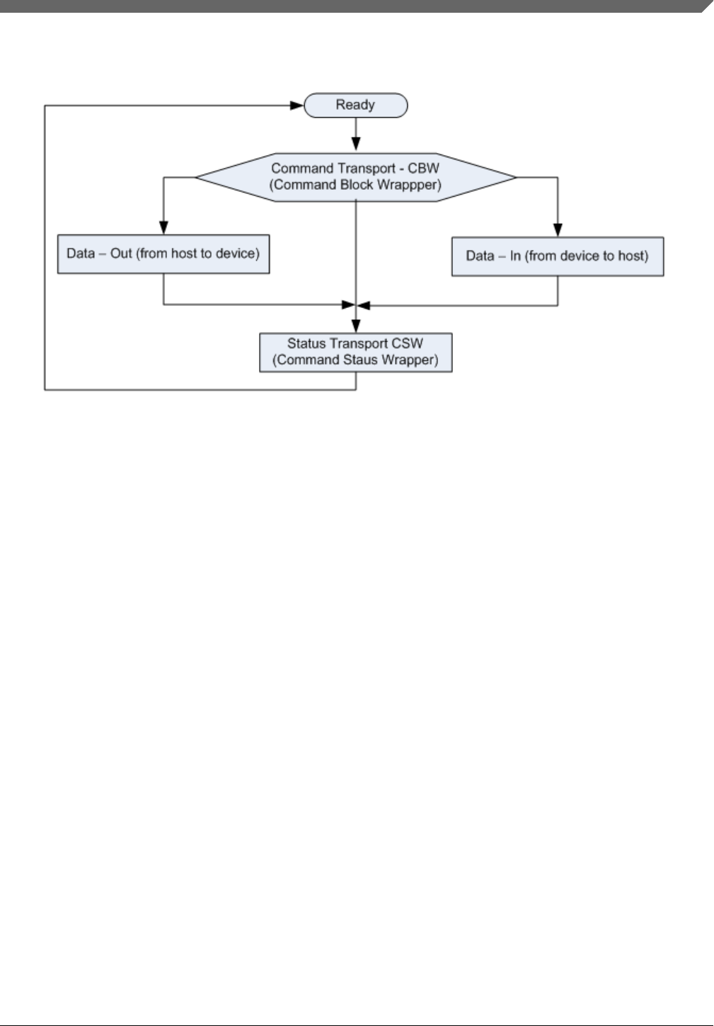
Figure 7-3. USB MSC status flow chart
•The CBW begins on a packet boundary, and ends as a short packet. Exactly 31 bytes
are transferred.
• The CSW begins on a packet boundary, and ends as a short packet. Exactly 13 bytes
are transferred.
• The data packet begins on a packet boundary, and ends as a short packet. Exactly 64
bytes are transferred.
7.8 Command/data processor
This component reads complete packets from the abstract packet interface, and interprets
them as either command packets or data packets. The actual handling of each command
is done by command handlers called by the command processor. The command handler
tells the command processor whether a data phase is expected and how much data it is
expected to receive.
If the command/data processor receives a unexpected command or data packet, it ignores
it. In this instance, the communications link resynchronizes upon reception of the next
valid command.
Chapter 7 Peripheral interfaces
Kinetis Bootloader v2.0.0 Reference Manual, Rev. 0, 04/2016
Freescale Semiconductor, Inc. 105

Command/data processor
Kinetis Bootloader v2.0.0 Reference Manual, Rev. 0, 04/2016
106 Freescale Semiconductor, Inc.

Chapter 8
Memory interface
8.1 Abstract interface
The bootloader uses a common, abstract interface to implement the memory read/write/
fill commands. This is to keep the command layer from having to know the details of the
memory map and special routines.
This shared memory interface structure is used for both the high-level abstract interface,
as well as low-level entries in the memory map.
struct MemoryInterface
{
status_t (*init)(void);
status_t (*read)(uint32_t address, uint32_t length, uint8_t * buffer);
status_t (*write)(uint32_t address, uint32_t length, const uint8_t * buffer);
status_t (*fill)(uint32_t address, uint32_t length, uint32_t pattern);
status_t (*flush)(void);
status_t (*erase)(uint32_t address, uint32_t length)
}
The global bootloader context contains a pointer to the high-level abstract memory
interface, which is one of the MemoryInterface structures. The internal implementation of
this abstract interface uses a memory map table, referenced from the global bootloader
context that describes the various regions of memory that are accessible and provides
region-specific operations.
The high-level functions are implemented to iterate over the memory map entries until it
finds the entry for the specified address range. Read and write operations are not
permitted to cross region boundaries, and an error is returned if such an attempt is made.
The BootloaderContext::memoryMap member is set to an array of these structures:
struct MemoryMapEntry
{
uint32_t startAddress;
uint32_t endAddress;
bool isExecutable;
const MemoryInterface * interface;
};
Kinetis Bootloader v2.0.0 Reference Manual, Rev. 0, 04/2016
Freescale Semiconductor, Inc. 107

This array must be terminated with an entry with all fields set to zero.
The same MemoryInterface structure is also used to hold the memory-type-specific
operations.
Note that the MemoryMapEntry::endAddress field must be set to the address of the last
byte of the region, because a <= comparison is used.
During bootloader startup, the memory map is copied into RAM and modified to match
the actual sizes of flash and RAM on the chip.
8.2 Flash driver interface
The flash driver uses the common memory interface to simplify the interaction with flash.
It takes care of high level features such as read back verification, flash protection
awareness, and so on. The flash memory functions map to the interface functions as so:
const memory_region_interface_t g_flashMemoryInterface = {
.read = &flash_mem_read,
.write = &flash_mem_write,
.fill = &flash_mem_fill,
.flush = NULL,
.erase = flash_mem_erase
};
Bootloader startup code is responsible for initializing the flash memory.
API Description
flash_mem_read() Performs a normal memory read if the specified region isn't
protected from reading.
flash_mem_write() Calls the low-level flash_program() API. Also performs
program verification if enabled with the Set Property
command.
flash_mem_fill() Performs intelligent fill operations on flash memory ranges. If
the fill patterns are all 1's, special action is taken. If the range
is a whole number of sectors, then those sectors are erased
rather than filled. Any part of an all-1's fill that is not sector-
aligned and -sized is ignored (the assumption being that it has
been erased to 1's already). Fills for patterns other than all 1's
call into flash_program().
flash_mem_erase() Calls the low-level flash_erase() API. Also performs erasure
verification if enabled with the Set Property command
(Enabled by default).
All flash_mem_read(), flash_mem_write(), flash_mem_fill(), and flash_mem_erase()
check the flash protection status for the sectors being read or programmed or erased and
return an appropriate error if the operation is not allowed.
Flash driver interface
Kinetis Bootloader v2.0.0 Reference Manual, Rev. 0, 04/2016
108 Freescale Semiconductor, Inc.

8.3 Low-level flash driver
The low-level flash driver (LLFD) handles erase and write operations on a word basis. It
cannot perform writes of less than a full word.
The bootloader startup code is responsible for initializing and shutting down the LLFD.
status_t FLASH_Init(flash_config_t *config);
status_t FLASH_EraseAll(flash_config_t *config, uint32_t key);
status_t FLASH_Erase(flash_config_t *config, uint32_t start, uint32_t lengthInBytes,
uint32_t key);
status_t FLASH_Program(flash_config_t *config, uint32_t start, uint32_t *src, uint32_t
lengthInBytes);
status_t FLASH_GetSecurityState(flash_config_t *config, flash_security_state_t *state);
status_t FLASH_SecurityBypass(flash_config_t *config, const uint8_t *backdoorKey);
status_t FLASH_VerifyEraseAll(flash_config_t *config, flash_margin_value_t margin);
status_t FLASH_VerifyErase(flash_config_t *config, uint32_t start, uint32_t lengthInBytes,
flash_margin_value_t margin);
status_t FLASH_VerifyProgram(flash_config_t *config,
uint32_t start,
uint32_t lengthInBytes,
const uint32_t *expectedData,
flash_margin_value_t margin,
uint32_t *failedAddress,
uint32_t *failedData);
status_t FLASH_GetProperty(flash_config_t *config, flash_property_tag_t whichProperty,
uint32_t *value);
status_t FLASH_ProgramOnce(flash_config_t *config, uint32_t index, uint32_t *src, uint32_t
lengthInBytes);
status_t FLASH_ReadOnce(flash_config_t *config, uint32_t index, uint32_t *dst, uint32_t
lengthInBytes);
status_t FLASH_ReadResource(
flash_config_t *config, uint32_t start, uint32_t *dst, uint32_t lengthInBytes,
flash_read_resource_option_t option);
Chapter 8 Memory interface
Kinetis Bootloader v2.0.0 Reference Manual, Rev. 0, 04/2016
Freescale Semiconductor, Inc. 109

Low-level flash driver
Kinetis Bootloader v2.0.0 Reference Manual, Rev. 0, 04/2016
110 Freescale Semiconductor, Inc.

Chapter 9
Kinetis Flash Driver API
9.1 Introduction
The main purpose of these APIs is to simplify the use of flash driver APIs exported from
Kinetis bootloader ROM. With APIs, the user does not need to care about the differences
among various version of flash drivers.
A set of parameters are required to ensure all APIs work properly.
This section describes how to use each flash driver API proivded in the Kinetis flash
driver API tree.
For all flash driver APIs require the driver parameter.
9.2 Flash Driver Entry Point
The Kinetis ROM bootloader provides a flash driver API tree entry (flashDriver) that a
user application can use to get the entry of the whole flash API set supported by the
bootloader.
NOTE
The flashloader and flash-resident bootloader do not support
this feature.
To get the address of the entry point, the user application reads the word containing the
pointer to the bootloader API tree at offset 0x1C of the bootloader’s vector table. The
vector table is placed at the base of the bootloader’s address range.
The bootloader API tree is a structure that contains pointers to other structures, which
have the function and data address for the bootloader. The Flash driver API tree entry is
always the fifth word of the API tree.
Kinetis Bootloader v2.0.0 Reference Manual, Rev. 0, 04/2016
Freescale Semiconductor, Inc. 111

The prototype of the entry point is:
flash_driver_interface_t flashDriver;
There are three versions of the flash driver API among different targets with ROM
bootloader. See the following table for more details.
Table 9-1. Different versions of the flash driver
Flash driver API version Supported targets
V1.0 KL03Z4, KL43Z4, KL33Z4, KL27Z4, KL17Z4
V1.1 KL27Z644, KL17Z644
V1.2 KL13Z644, KL33Z644, K80F256, K81F256, K82F256,
KL81Z7, KL82Z7, KL28Z7
There are minor differences in the flash driver interface among the above three versions.
See the definitions below for details.
typedef union BootloaderVersion
{
struct
{
uint32_t bugfix: 8; //!< bugfix version [7:0]
uint32_t minor: 8; //!<minor version [15:8]
uint32_t major: 8; //!<major version [23:16]
uint32_t name: 8; //!<name [31:24]
} B;
uint32_t version; //!< combined version numbers
} standard_version_t;
//! @brief Interface for the flash driver.
typedef struct FlashDriverInterface
{
#if !defined(FLASH_API_TREE_1_0)
standard_version_t version; //!< flash driver API version number.
#endif
status_t (*flash_init)(flash_config_t *config);
#if defined(FLASH_API_TREE_1_0)
status_t (*flash_erase_all)(flash_config_t *config);
status_t (*flash_erase_all_unsecure)(flash_config_t *config);
status_t (*flash_erase)(flash_config_t *config, uint32_t start, uint32_t
lengthInBytes);
#else
status_t (*flash_erase_all)(flash_config_t *config, uint32_t key);
status_t (*flash_erase_all_unsecure)(flash_config_t *config, uint32_t key);
status_t (*flash_erase)(flash_config_t *config, uint32_t start, uint32_t
lengthInBytes, uint32_t key);
#endif
status_t (*flash_program)(flash_config_t *config, uint32_t start, uint32_t
*src, uint32_t lengthInBytes);
status_t (*flash_get_security_state)(flash_config_t *config,
flash_security_state_t *state);
status_t (*flash_security_bypass)(flash_config_t *config, const uint8_t
*backdoorKey);
status_t (*flash_verify_erase_all)(flash_config_t *config,
flash_margin_value_t margin);
Flash Driver Entry Point
Kinetis Bootloader v2.0.0 Reference Manual, Rev. 0, 04/2016
112 Freescale Semiconductor, Inc.

status_t (*flash_verify_erase)(flash_config_t
*config,
uint32_t start,
uint32_t
lengthInBytes,
flash_margin_value_t margin);
status_t (*flash_verify_program)(flash_config_t
*config,
uint32_t
start,
uint32_t
lengthInBytes,
const uint32_t
*expectedData,
flash_margin_value_t
margin,
uint32_t
*failedAddress,
uint32_t *failedData);
status_t (*flash_get_property)(flash_config_t *config, flash_property_tag_t
whichProperty, uint32_t *value);
#if (! defined(FLASH_API_TREE_1_0)) && (!defined(FLASH_API_TREE_1_1))
status_t (*flash_register_callback)(flash_config_t *config,
flash_callback_t callback);
status_t (*flash_program_once)(flash_config_t *config, uint32_t index,
uint32_t *src, uint32_t lengthInBytes);
status_t (*flash_read_once)(flash_config_t *config, uint32_t index, uint32_t *dst,
uint32_t lengthInBytes);
status_t (*flash_read_resource)(flash_config_t
*config,
uint32_t start,
uint32_t *dst,
uint32_t
lengthInBytes,
flash_read_resource_option_t option);
#endif}
flash_driver_interface_t;
Example code to receive the enter pointer address from the ROM and access the flash
driver API:
flash_config_t flashContext;
const flash_driver_interface_t *s_flashInterface;
s_flashInterface = (const flash_driver_interface_t *)(*(uint32_t**)
0x1c00001c)[4];s_flashInstance->flash_init(&flashContext);
The details for usage of each API are mentioned in the following sections. Example
codes are also provided along with the Kinetis_Bootloader_1.2 or
Kinetis_Bootloader_2.0 release package.
9.3 Flash driver data structures
9.3.1 flash_config_t
Chapter 9 Kinetis Flash Driver API
Kinetis Bootloader v2.0.0 Reference Manual, Rev. 0, 04/2016
Freescale Semiconductor, Inc. 113

The flash_config_t data structure is a required argument for all flash driver API
functions. flash_config_t can be initialized by calling FLASH_Init. For other functions,
an initialized instance of this data structure should be passed as an argument.
Table 9-2. flash_driver_t data structure
Offset Size Field Description
0 4 PFlashBlockBase Base address of the first PFlash block
4 4 PFlashTotalSize Size of all combined PFlash blocks
8 4 PFlashBlockCount Number of PFlash blocks
12 4 PFlashSectorSize Size (in bytes) of sector of PFlash
16 4 PFlashCallback Pointer to a callback function used to do extra operations
during erasure (for example, service watchdog)
20 4 PFlashAccessSegmentSize Size of FAC access segment
24 4 PFlashAccessSegmentCount Count of FAC access segment
9.4 Flash driver API
This section describes each function supported in the flash driver API.
9.4.1 FLASH_Init
Checks and initializes the flash module for the other flash API functions.
NOTE
FLASH_Init must be always called before calling other API
functions.
Prototype:
status_t FLASH_Init(flash_config_t *config);
Table 9-3. Parameters
Parameter Description
config Config Pointer to storage for the driver runtime state.
Table 9-4. Possible status response
Value Constant Description
4 kStatus_InvalidArgument Config is NULL.
Table continues on the next page...
Flash driver API
Kinetis Bootloader v2.0.0 Reference Manual, Rev. 0, 04/2016
114 Freescale Semiconductor, Inc.

Table 9-4. Possible status response (continued)
Value Constant Description
100 kStatus_FLASH_SizeError Returned flash is incorrect.
0 kStatus_Success This function has performed successfully.
Example:
flash_config_t flashInstance;
status_t status = FLASH_Init(&flashInstance);
9.4.2 FLASH_EraseAll
Erases the entire flash array.
Prototype:
status_t FLASH_EraseAll(flash_config_t *config, uint32_t key);
Table 9-5. Parameters
Parameter Description
config Config pointer to storage for the driver runtime state.
key Key used to validate erase operation. Must be set to
0x6B65666B.
Table 9-6. Possible status response
Value Constants Description
4 kStatus_InvalidArgument Config is NULL.
103 kStatus_FLASH_AccessError Command is not available under current mode/
security.
104 kStatus_FLASH_ProtectionViolation Any region of the program flash memory is
protected.
107 kStatus_FLASH_EraseKeyError Key is incorrect.
0 kStatus_Success This function has performed successfully.
Example:
status_t status = FLASH_EraseAll(&flashInstance, kFLASH_ApiEraseKey);
9.4.3 FLASH_EraseAllUnsecure
Erases the entire flash (including protected sectors) and restores flash to unsecured mode.
Chapter 9 Kinetis Flash Driver API
Kinetis Bootloader v2.0.0 Reference Manual, Rev. 0, 04/2016
Freescale Semiconductor, Inc. 115

Prototype:
status_t FLASH_EraseAllUnsecure(flash_config_t *config, uint32_t key);
Table 9-7. Parameters
Parameter Description
Config Config pointer to storage for the driver runtime state.
Key Key used to validate erase operation. Must be set to
0x6B65666B.
Table 9-8. Possible Status Response
Value Constant Description
4 kStatus_InvalidArgument Config is NULL.
103 kStatus_FLASH_AccessError Command is not available under current mode/
security.
107 kStatus_FLASH_EraseKeyError Key is incorrect.
0 kStatus_Success This function has performed successfully.
Example:
status_t status = FLASH_EraseAllUnsecure(&flashInstance, kFLASH_ApiEraseKey);
9.4.4 FLASH_Erase
Erases expected flash sectors specified by parameters. For Kinetis devices, the minimum
erase unit is one sector.
Prototype:
status_t FLASH_Erase(flash_config_t *config, uint32_t start, uint32_t lengthInBytes, uint32_t
key);
Table 9-9. Parameters
Parameters Description
Config Config pointer to storage for the driver runtime state.
Start The start address of the desired flash memory to be erased.
The start address does not need to be sector aligned, but
must be word-aligned.
lengthInBytes The length, given in bytes (not words or long words) to be
erased. Must be word-aligned.
Key Key is used to validate erase operation. Must be set to
0x6B65666B.
Flash driver API
Kinetis Bootloader v2.0.0 Reference Manual, Rev. 0, 04/2016
116 Freescale Semiconductor, Inc.

Table 9-10. Possible status response
Value Constant Description
4 kStatus_InvalidArgument Config is NULL.
100 kStatus_FLASH_AlignmentError Start or lengthInBytes; is not long word-aligned.
102 kStatus_FLASH_AddressError The range to be erased is not a valid flash range.
103 kStatus_FLASH_AccessError Command is not available under current mode/
security.
104 kStatus_FLASH_ProtectionViolation The selected program flash sector is protected.
107 kStatus_FLASH_EraseKeyError Key is incorrect.
0 kStatus_Success This function has performed successfully.
Example:
status_t status = FLASH_Erase (&flashInstance, 0x800, 1024, kFLASH_ApiEraseKey);
9.4.5 FLASH_Program
Programs the flash memory with data at locations that are passed in using parameters.
Prototype:
status_t FLASH_Program(flash_config_t *config, uint32_t start, uint32_t *src, uint32_t
lengthInBytes);
Table 9-11. Parameters
Parameter Description
Config Config pointer to storage for the driver runtime state.
Start The start address of the desired flash memory to be erased.
The start address does not need to be sector-aligned, but the
start address must be word-aligned.
src Pointer to the source buffer of data that is to be programmed
into flash.
lengthInBytes The length in bytes (not words or long words) to be erased;
the length must also be word-aligned.
Table 9-12. Possible status response
Value Constant Description
4 kStatus_InvalidArgument Config or src is NULL.
101 kStatus_FLASH_AlignmentError Start or lengthInBytes is not longword aligned.
102 kStatus_FLASH_AddressError The range to be programmed is invalid.
Table continues on the next page...
Chapter 9 Kinetis Flash Driver API
Kinetis Bootloader v2.0.0 Reference Manual, Rev. 0, 04/2016
Freescale Semiconductor, Inc. 117

Table 9-12. Possible status response (continued)
Value Constant Description
103 kStatus_FLASH_AccessError Command is not available under current mode/
security.
104 kStatus_FLASH_ProtectionViolation The selected program flash address is protected.
0 kStatus_Success This function has performed successfully.
Example:
uint32_t m_content[] = {0x01234567, 0x89abcdef};
status_t status = FLASH_Program (&flashInstance, 0x800, &m_content[0], sizeof(m_content));
NOTE
Before calling flash_program, make sure that the region to be
programmed is empty and is not protected.
9.4.6 FLASH_GetSecurityState
Retrieves the current flash security status, including the security enabling state and the
backdoor key enabling state.
Prototype:
status_t FLASH_GetSecurityState(flash_config_t *config, flash_security_state_t *state);
Table 9-13. Parameters
Parameters Description
Config Config pointer to storage for the driver runtime state.
State Pointer to the value returned for the current security status code:
Table 9-14. Returned value
kFLASH_SecurityStateNotSecure 0 Flash is under unsecured mode.
kFLASH_SecurityStateBackdoorEnabled 1 Flash is under secured mode and
Backdoor is enabled.
kFLASH_SecurityStateBackdoorDisabled 2 Flash is under secured mode and
Backdoor is disabled.
Table 9-15. Possible status response
Value Constant Description
4 kStatus_InvalidArgument Config or state is NULL.
0 kStatus_Success This function has performed successfully.
Flash driver API
Kinetis Bootloader v2.0.0 Reference Manual, Rev. 0, 04/2016
118 Freescale Semiconductor, Inc.

Example:
flash_security_state_t state;
status_t status = FLASH_GetSecurityState (&flashInstance, &state);
9.4.7 FLASH_SecurityBypass
Allows the user to bypass security with a backdoor key. If the MCU is in a secured state,
then the FLASH_SecurityBypass function unsecures the MCU, by comparing the
provided backdoor key with keys in the Flash Configuration Field.
Prototype:
status_t FLASH_SecurityBypass(flash_config_t *config, const uint8_t *backdoorKey);
Table 9-16. Parameters
Parameter Description
Config Config pointer to storage for the driver runtime state.
backdoorKey Pointer to the user buffer containing the backdoor key.
Table 9-17. Possible status response
Value Constant Description
4 kStatus_InvalidArgument Config or backdoorKey is NULL.
103 kStatus_FLASH_AccessError The following condition causes this return value:
1. An incorrect backdoor key is supplied
2. Backdoor key access has not been enabled.
0 kStatus_Success This function has performed successfully.
Example:
Assume that the flash range from 0x400 to 0x40c contains the following content after the
last reset, which means that the backdoor key is valid and the backdoor key access has
been enabled.
0x11 0x22 0x33 0x44 0x55 0x66 0x77 0x88 0xff 0xff 0xff 0xbf
uint8_t backdoorKey[] = {0x11, 0x22, 0x33, 0x44, 0x55, 0x66, 0x77, 0x88};
status_t status = FLASH_SecurityBypass (&flashInstance, & backdoorKey[0]);
9.4.8 FLASH_VerifyEraseAll
Checks if the entire flash has been erased to the specified read margin level.
Chapter 9 Kinetis Flash Driver API
Kinetis Bootloader v2.0.0 Reference Manual, Rev. 0, 04/2016
Freescale Semiconductor, Inc. 119

To verify if the entire flash has been fully erased (after executing an FLASH_EraseAll),
call FLASH_VerifyEraseAll.
Prototype:
status_t FLASH_VerifyEraseAll(flash_config_t *config, flash_margin_value_t margin);
Table 9-18. Parameters
Parameter Description
Config Config pointer to storage for the driver runtime state.
Margin1 Read margin choice:
• kFLASH_MarginValueNormal 0
• kFLASH_MarginValueUser 1
• kFLASH_MarginValueFactory 2
Table 9-19. Possible status response
Value Constant Description
4 kStatus_InvalidArgument Config or backdoorKey is NULL.
103 kStatus_FLASH_AccessError An invalid margin choice is specified.
105 kStatus_FLASH_CommandFailure The entire flash is not fully erased.
0 kStatus_Success This function has performed successfully.
Example:
Assume that flash_erase_all has been successfully executed.
status_t status = flash_verify_erase_all (&flashInstance, kFLASH_MarginValueUser);
NOTE
For the choice of margin, see the FTFA chapter in the reference
manual for detailed information.
9.4.9 FLASH_VerifyErase
Verifies the erasure of the desired flash area at a specified margin level. This function
checks the appropriate number of flash sectors based on the desired start address and
length, to see if the flash has been erased at the specified read margin level.
FLASH_VerifyErase is often called after successfully performing the FLASH_Erase
API.
Prototype:
Flash driver API
Kinetis Bootloader v2.0.0 Reference Manual, Rev. 0, 04/2016
120 Freescale Semiconductor, Inc.

status_t FLASH_VerifyErase(flash_config_t *config, uint32_t start, uint32_t lengthInBytes,
flash_margin_value_t margin);
Table 9-20. Parameters
Parameter Description
Config Config pointer to storage for the driver runtime state.
Start The start address of the desired flash memory to be verified.
lengthInBytes The length, given in bytes (not words or long words) to be
verified.
Must be word-aligned.
margin Read margin choice as follows:
kFLASH_MarginValueNormal 0 kFLASH_MarginValueUser 1
kFLASH_MarginValueFactory 2
Table 9-21. Possible status response
Value Constant Description
4 kStatus_InvalidArgument Config or backdoorKey is NULL.
101 kStatus_FLASH_AlignmentError Start or lengthInBytes is not longword aligned.
102 kStatus_FLASH_AddressError The range to be verified is not a valid flash range.
103 kStatus_FlashAccessError The following situation causes this response:
1. Command is not available under current mode/
security
2. An invalid margin code is provided
3. The requested number of bytes is 0
4. The requested sector crosses a flash block
boundary
105 kStatus_FLASH_CommandFailure The flash range to be verified is not fully erased.
0 kStatus_Success This function has performed successfully.
Example:
Assume that flash region from 0x800 to 0xc00 has been successfully erased.
status_t status = FLASH_VerifyErase(&flashInstance, 0x800, 1024, kFLASH_MarginValueUser);
NOTE
For the choice of margin, see the FTFA chapter in the reference
manual for detailed information.
9.4.10 FLASH_VerifyProgram
Chapter 9 Kinetis Flash Driver API
Kinetis Bootloader v2.0.0 Reference Manual, Rev. 0, 04/2016
Freescale Semiconductor, Inc. 121

Verifies the data programmed in the flash memory (using the Flash Program Check
Command), and compares it with expected data for a given flash area (as determined by
the start address and length).
FLASH_VerifyProgram is often called after successfully doing FLASH_Program().
Prototype:
status_t FLASH_VerifyProgram(flash_config_t *config,
uint32_t start,
uint32_t lengthInBytes,
const uint32_t *expectedData,
flash_margin_value_t margin,
uint32_t *failedAddress,
uint32_t *failedData);
Table 9-22. Parameters
Parameter Description
Config Config pointer to storage for the driver runtime state.
Start The start address of the desired flash memory to be verified.
LengthInBytes The length, given in bytes (not words or long-words) to be verified. Must be word-aligned.
ExpectedData Pointer to the expected data that is to be verified against.
Margin Read margin choice as follows:
kFLASH_MarginValueUser 1 kFLASH_MarginValueFactory 2
FailedAddress Pointer to returned failing address.
FailedData Pointer to return failing data. Some derivatives do not include failed data as part of the FCCOBx
registers. In this instance, 0x00s are returned upon failure.
Table 9-23. Possible status response
Value Contants Description
4 kStatus_InvalidArgument Config or expectedData is NULL.
101 kStatus_FlashAlignmentError Start or lengthInBytes is not longword-aligned.
102 kStatus_FLASH_AddressError The range to be verified is invalid.
103 kStatus_FLASH_AccessError The following situation causes this response:
1. Command is not available under current mode/
security.
2. An invalid margin code is supplied.
105 kStatus_FLASH_CommandFailure Either of the margin reads does not match the
expected data.
0 kStatus_Success This function has performed successfully.
Example:
Assume that flash region from 0x800 to 0x807 is successfully programmed with:
0x01 0x23 0x45 0x67 0x89 0xab 0xcd 0xef
Flash driver API
Kinetis Bootloader v2.0.0 Reference Manual, Rev. 0, 04/2016
122 Freescale Semiconductor, Inc.

uint8_t expectedData[] = {0x01, 0x23, 0x45, 0x67, 0x89, 0xab, 0xcd, 0xef };
status_t status = FLASH_VerifyProgram (&flashInstance, 0x800, 8,
&expectedData[0], kFlashMargin_User, NULL, NULL);
NOTE
For the choice of margin, see the FTFA chapter in the reference
manual for detailed information.
9.4.11 FLASH_GetProperty
Returns the desired flash property, which includes base address, sector size, and other
options.
Prototype:
status_t flash_get_property(flash_driver_t * driver, flash_property_t whichProperty, uint32_t
* value);
Table 9-24. Parameters
Parameter Description
Config Config pointer to storage for the driver runtime state.
whichProperty The desired property from the list of properties.
Table 9-25. Properties
Definition Value Description
kFLASH_PropertyPflashSectorSize 0 Get Flash Sector size
kFLASH_PropertyPflashTotalSize 1 Get total flash size
kFLASH_PropertyPflashBlockBaseAddr 4 Get flash base address
kFLASH_PropertyPflashFacSupport 5 Get FAC support status
kFLASH_PropertyPflashAccessSegmentSize 6 Get FAC segment size
kFLASH_PropertyPflashAccessSegmentCou
nt
7 Get FAC segment count
kFLASH_PropertyVersion 32 Get version of Flash Driver API
Value Pointer to the value returned for the desired flash property.
Table 9-26. Possible status response
Value Constant Description
4 kStatus_InvalidArgument Config or value is invalid.
106 kStatus_FLASH_UnknownProperty Invalid property is supplied.
0 kStatus_Success This function has performed successfully.
Chapter 9 Kinetis Flash Driver API
Kinetis Bootloader v2.0.0 Reference Manual, Rev. 0, 04/2016
Freescale Semiconductor, Inc. 123

Example:
uint32_t propertyValue;
status_t status = FLASH_GetProperty (&flashInstance, kFLASH_PropertyPflashSectorSize,
&propertyValue);
9.4.12 FLASH_ProgramOnce
Programs a certain Program Once Field with the expected data for a given IFR region (as
determined by the index and length).
• For each Program Once Field, FLASH_ProgramOnce can only allowed to be called
once; otherwise, an error code is returned.
• For targets which do not support FLASH_ProgramOnce, the value of the
FLASH_ProgramOnce pointer is 0.
Prototype
status_t flash_program_once (flash_driver_t * driver, uint32_t index, uint32_t *src, uint32_t
lengthInBytes);
Table 9-27. Parameters
Parameter Description
Config Config pointer to storage for the driver runtime state.
Index Index for a certain Program Once Field.
src Pointer to the source buffer of data that is to be programmed into the Program Once Field.
Lengthinbytes The length, in bytes (not words or long words) to be programmed. Must be word-aligned.
Table 9-28. Possible status response
Value Constant Description
4 kStatus_InvalidArgument Config or src is NULL.
101 kStatus_FLASH_AlignmentError index or lengthInBytes is invalid.
103 kStatus_FLASH_AddressError The following situation causes this response:
1. Command is not available under current mode/
security.
2. An invalid index is supplied.
3. The requested Program Once field has already
been programmed to a non-FFFF value.
4. The requested sector crosses a flash block
boundary.
115 kStatus_FLASH_CommandNotSupported This function is not supported.
0 kStatus_Success This function has performed successfully.
Example:
Flash driver API
Kinetis Bootloader v2.0.0 Reference Manual, Rev. 0, 04/2016
124 Freescale Semiconductor, Inc.

Assume the Program Once Field has not been programmed before.
uint32_t expectedData = 0x78563412;
status_t status = FLASH_ProgramOnce(&flashInstance, 0, &expectedData, 4);
NOTE
For the choice of index and length, see the FTFA chapter in RM
for detailed information.
9.4.13 FLASH_ReadOnce
Reads a certain flash Program Once Field according to parameters passed by index and
length.
For targets that do not support FLASH_ReadOnce, the value of the FLASH_ReadOnce
pointer is 0.
Prototype:
status_t flash_read_once (flash_driver_t * driver, uint32_t index, uint32_t *dst, uint32_t
lengthInBytes);
Table 9-29. Parameters
Parameter Description
Config Config pointer to storage for the driver runtime state.
Index Index for a certain Program Once Field.
dst Pointer to the destination buffer of data that stores data reads from the Program Once Field.
Lengthinbytes The length, in bytes (not words or long words) to be read. Must be word-aligned.
Table 9-30. Possible status response
Value Constant Description
4 kStatus_InvalidArgument Config or dst is NULL.
101 kStatus_FlashAlignmentError Index or lengthInBytes is invalid.
103 kStatus_FLASH_AddressError The following situation causes this response:
1. Command is not available under current mode/
security.
2. An invalid index is supplied.
115 kStatus_FLASH_CommandNotSupported This function is not supported.
0 kStatus_Success This function has performed successfully.
Example:
Chapter 9 Kinetis Flash Driver API
Kinetis Bootloader v2.0.0 Reference Manual, Rev. 0, 04/2016
Freescale Semiconductor, Inc. 125

uint32_t temp;
status_t status = FLASH_ReadOnce(&flashInstance, 0, &temp, 4);
NOTE
For the choice of index and length, see the FTFA chapter in RM
for detailed information.
9.4.14 FLASH_ReadResource
Reads certain regions of IFR determined by the start address, length, and option.
For targets that do not support FLASH_ReadResource, the value of the
FLASH_ReadResource pointer is 0.
Prototype:
status_t FLASH_ReadResource(
flash_config_t *config, uint32_t start, uint32_t *dst, uint32_t lengthInBytes,
flash_read_resource_option_t option);
Table 9-31. Parameters
Parameter Description
Config Config pointer to storage for the driver runtime state.
Start Index for a certain Program Once Field.
dst Pointer to the destination buffer of data that stores data reads from IFR.
Lengthinbytes The length, in bytes (not words or long words), to be read. Must be word-aligned.
Option The resource option which indicates the area that needs be read back.
•0 IFR
• 1 Version ID of the flash module
Table 9-32. Possible status response
Value Constant Description
4 kStatus_InvalidArgument Config or dst is NULL.
101 kStatus_FLASH_AlignmentError Start, lengthInBytes, or option is invalid.
103 kStatus_FLASH_AccessError The following situation causes this response:
1. Command is not available under current mode/
security.
2. An invalid index is supplied.
3. An invalid resource option.
4. Address is out-of-rage for the targeted
resource.
5. Address is not long word aligned.
115 kStatus_FLASH_CommandNotSupported This function is not supported.
0 kStatus_Success This function has performed successfully.
Flash driver API
Kinetis Bootloader v2.0.0 Reference Manual, Rev. 0, 04/2016
126 Freescale Semiconductor, Inc.

Example:
uint32_t temp[256];
status_t status = FLASH_ReadResource(&flashInstance, 0, &temp[0], 256, 0);
NOTE
See the FTFA chapter in RM for detailed information regarding
the start, length, and option choices.
9.4.15 FLASH_SetCallback
Registers expected callback functions into the flash driver, for example, like a function
for servicing a watchdog.
Prototype:
status_t FLASH_SetCallback(flash_config_t *config, flash_callback_t callback);
Table 9-33. Parameters
Parameter Description
Config Config pointer to storage for the driver runtime state.
Callback A pointer points to a function that is called during erasure.
A use for this function is to service the watchdog during an erase operation.
Table 9-34. Possible status response
Value Constant Description
4 kStatus_InvalidArgument Config or dst is NULL.
115 kStatus_FLASH_CommandNotSupported This function is not supported.
0 kStatus_Success This function has performed successfully.
Example:
Assume that there is a function.
void led_toggle(void).
status_t status = FLASH_SetCallback(&flashInstance, led_toggle);
9.5 Integrate Wrapped Flash Driver API to actual projects
There are three steps required to integrate Wrapped Flash Driver API (WFDA) to actual
projects.
Chapter 9 Kinetis Flash Driver API
Kinetis Bootloader v2.0.0 Reference Manual, Rev. 0, 04/2016
Freescale Semiconductor, Inc. 127
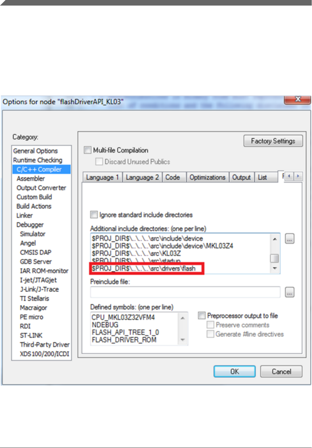
9.5.1 Add fsl_flash.h and fsl_flash_api_tree.c to corresponding
project
The directory which contains fsl_flash.h should be added to include path. This image
provides an example.
Figure 9-1. Include flash.h path
Fsl_flash_driver_api.c. should be added to the project as well. This image provides an
example.
Integrate Wrapped Flash Driver API to actual projects
Kinetis Bootloader v2.0.0 Reference Manual, Rev. 0, 04/2016
128 Freescale Semiconductor, Inc.
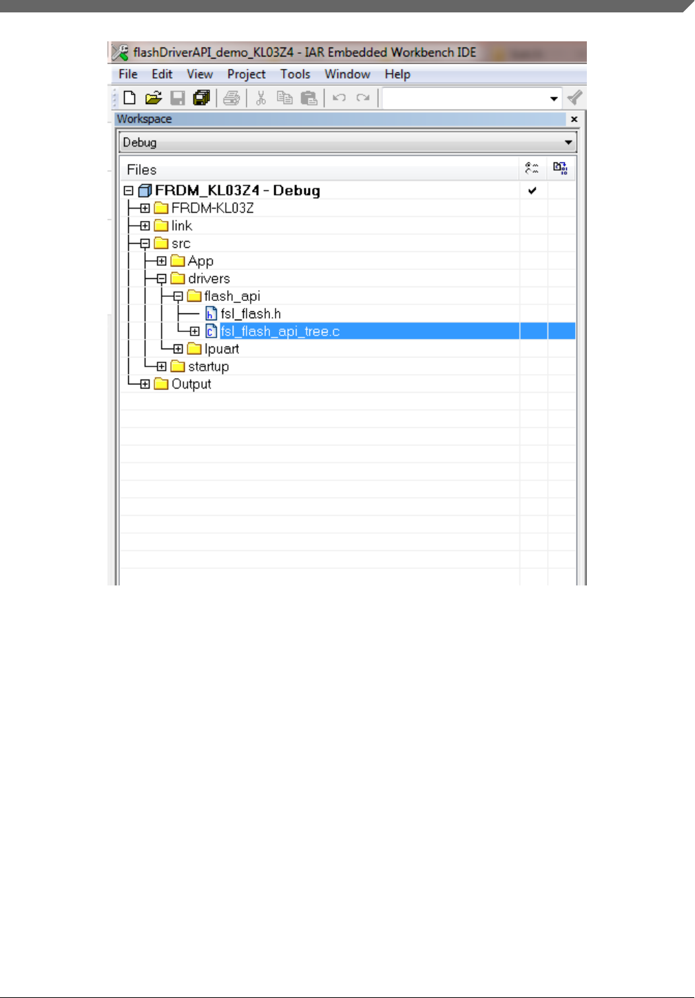
Figure 9-2. Add fsl_flash_drive_api.c to project
9.5.2 Include fsl_flash.h to corresponding files before calling
WFDI
For detailed information, see the demos for KL03, KL43, and KL27. Both fsl_flash.h and
fsl_flash_api_tree.c are attached in the demos.
Chapter 9 Kinetis Flash Driver API
Kinetis Bootloader v2.0.0 Reference Manual, Rev. 0, 04/2016
Freescale Semiconductor, Inc. 129

Integrate Wrapped Flash Driver API to actual projects
Kinetis Bootloader v2.0.0 Reference Manual, Rev. 0, 04/2016
130 Freescale Semiconductor, Inc.

Chapter 10
Kinetis bootloader porting
10.1 Introduction
This chapter discusses the steps required to port the Kinetis bootloader to an unsupported
Kinetis MCU. Each step of the porting process is discussed in detail in the following
sections.
10.2 Choosing a starting point
The first step is to download the latest bootloader release. Updates for the bootloader are
released multiple times per year, so having the latest package is important for finding the
best starting point for your port. To find the most recent bootloader release,
www.nxp.com/KBOOT.
The easiest way to port the bootloader is to choose a supported target that is the closest
match to the desired target MCU.
NOTE
Just because a supported device has a similar part number to the
desired target MCU, it may not necessarily be the best starting
point. To determine the best match, reference the data sheet and
reference manual for all of the supported Kinetis devices.
10.3 Preliminary porting tasks
Kinetis Bootloader v2.0.0 Reference Manual, Rev. 0, 04/2016
Freescale Semiconductor, Inc. 131

All references to paths in the rest of this chapter are relative to the root of the extracted
Kinetis bootloader package. The container folder is named
FSL_Kinetis_Bootloader_<version>. Before modifying source code, the following tasks
should be performed.
10.3.1 Download device header files
The most manual process in porting the bootloader to a new target is editing the device
header files. This process is very time consuming and error prone, so NXP provides
CMSIS-compatible packages for all Kinetis devices that contain bootloader-compatible
device header files. These packages can be found on the product page for the MCU.
NOTE
It is not recommended to proceed with a port if a package does
not yet exist for the desired target MCU.
In the downloaded package, locate the folder with the header files. The folder is named
after the MCU (for example, “MK64F12”) and contains a unique header file for each
peripheral in addition to system_<device>.h files. Copy the entire folder into the /src/
platform/devices folder of the bootloader tree.
10.3.2 Copy the closest match
Copy the folder of the MCU that most closely matches the target MCU in the /targets
folder of the bootloader source tree. Rename it to coincide with the target MCU part
number.
Once the files are copied, browse the newly created folder. Rename all files that have
reference to the device from which they were copied. The following files need to be
renamed:
•clock_config_<old_device>.c —> clock_config_<new_device>.c
• hardware_init_<old_device>.c —> hardware_init _<new_device>.c
• memory_map_<old_device>.c —> memory_map _<new_device>.c
• peripherals_<old_device>.c —> peripherals _<new_device>.c
The following files should be copied from their location in /src/platform/devices/
<device> to the new /targets/<device>/src/startup folder:
• system_<device>.c
Preliminary porting tasks
Kinetis Bootloader v2.0.0 Reference Manual, Rev. 0, 04/2016
132 Freescale Semiconductor, Inc.

• system_<device>.h
• <tool chain>/startup_<device>.s
10.3.3 Provide device startup file (vector table)
A device-specific startup file is a key piece to the port. The bootloader may not function
correctly without the correct vector table. A startup file from the closest match MCU can
be used as a template, but it is strongly recommended that the file be thoroughly checked
before using it in the port due to differences in interrupt vector mappings between Kinetis
devices.
The startup file should be created and placed into the /targets/<device>/src/startup/<tool
chain> folder. Startup files are always assembly (*.s) and are named startup_<device>.s.
NOTE
The 16-byte Flash Configuration Field should be carefully set
in the bootloader image. The Flash Configuration Field is
placed at the offset 0x400 in the bootloader image. The field is
documented in the SOC reference manual under a the
subsection "Flash Configuration Field" of the "Flash Memory
Module" chapter. To change the default 16-byte value for the
field in the template startup_<device>.s file of the bootloader
project, the following steps are needed:
1. Open the startup_<device>.s file in a text editor.
2. Locate the symbol where Flash Configuration Field is
specified. The symbol name is "__FlashConfig" The 16-
byte Flash Configuration Field data is enclosed with
__FlashConfig and __FlashConfig_End symbols in the
startup_<device>.s file
3. Change the 16-byte value to the desired data. For example
set the flash security byte, enable or disable backdoor
access key, specify the 8-byte backdoor key, and so on.
4. Once the field is updated, save the startup_<device>.s file
and close the text editor.
10.3.4 Clean up the IAR project
This example uses the IAR tool chain for the new project. Other supported tool chains
can be used in a similar manner.
Chapter 10 Kinetis bootloader porting
Kinetis Bootloader v2.0.0 Reference Manual, Rev. 0, 04/2016
Freescale Semiconductor, Inc. 133
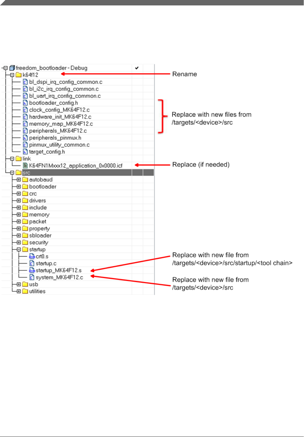
The folder copy performed in step 1.2.2 copies more than just source code files. Inside of
the newly created /targets/<device> folder, locate the IAR workspace file
(bootloader.eww) and open it. This image shows an example of what a workspace looks
like and the files that need to be touched.
Figure 10-1. IAR workspace
Once changes have been made, update the project to reference the target MCU. This can
be found in the project options.
Preliminary porting tasks
Kinetis Bootloader v2.0.0 Reference Manual, Rev. 0, 04/2016
134 Freescale Semiconductor, Inc.
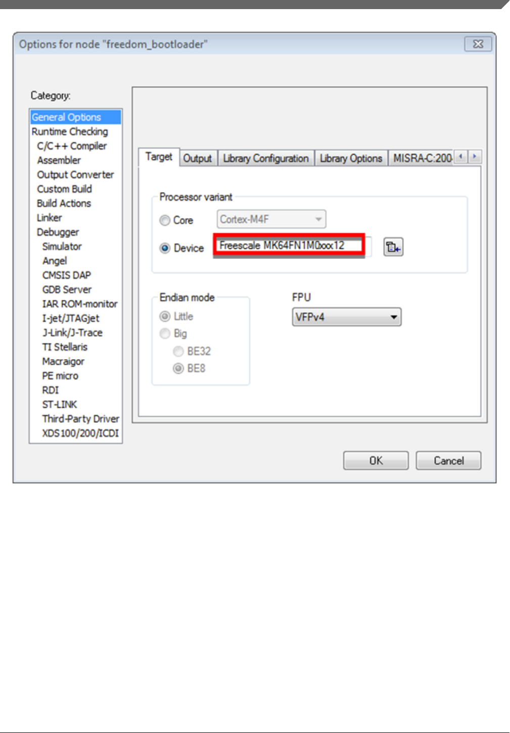
Figure 10-2. Project options
10.3.5 Bootloader peripherals
There is a C/C++ preprocessor define that is used by the bootloader source to configure
the bootloader based on the target MCU. This define must be updated to reference the
correct set of device-specific header files.
Chapter 10 Kinetis bootloader porting
Kinetis Bootloader v2.0.0 Reference Manual, Rev. 0, 04/2016
Freescale Semiconductor, Inc. 135
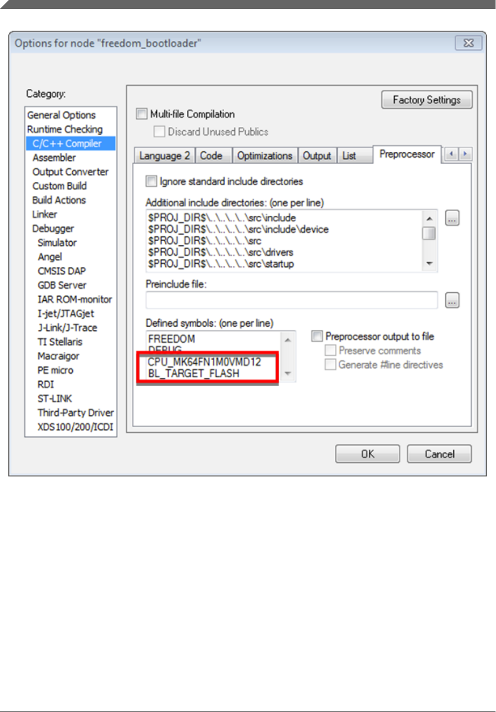
Figure 10-3. Options for node "freedom_bootloader"
The linker file needs to be replaced if the memory configuration of the target MCU
differs from the closest match. This is done in the linker settings, which is also part of the
project options.
Preliminary porting tasks
Kinetis Bootloader v2.0.0 Reference Manual, Rev. 0, 04/2016
136 Freescale Semiconductor, Inc.
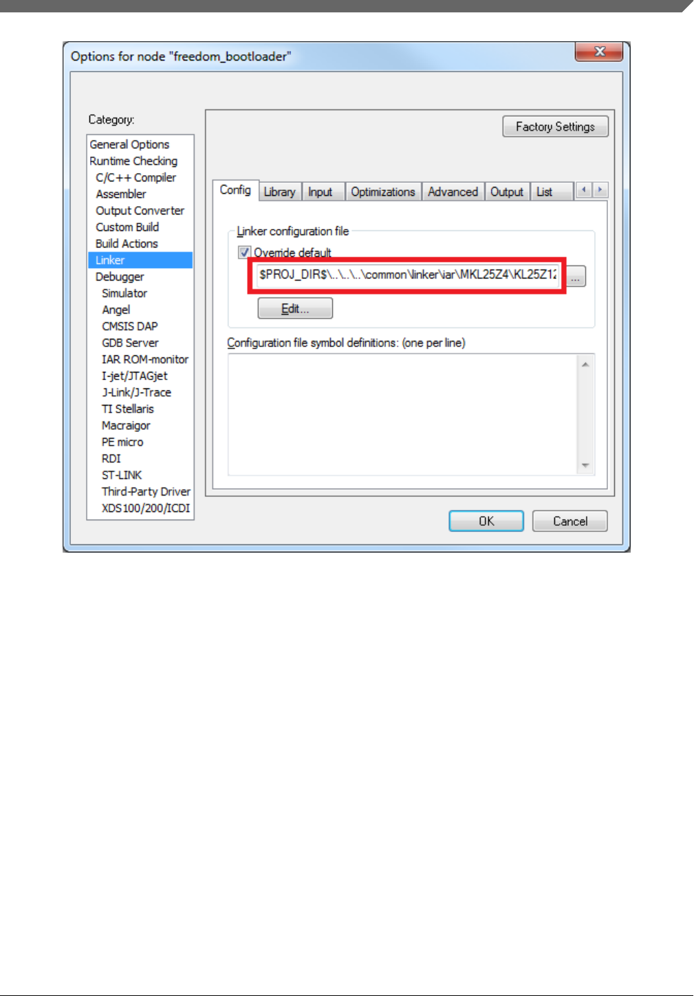
Figure 10-4. Porting guide change linker file
10.4 Primary porting tasks
Actual porting work can begin when the basic file structure and source files are in place.
This section describes which files need to be modified and how to modify them.
10.4.1 Bootloader peripherals
There are two steps required to enable and configure the desired peripherals on the target
MCU:
•Choosing which peripherals can be used by the bootloader.
• Configuring the hardware at a low level to enable access to those peripherals.
Chapter 10 Kinetis bootloader porting
Kinetis Bootloader v2.0.0 Reference Manual, Rev. 0, 04/2016
Freescale Semiconductor, Inc. 137

10.4.1.1 Supported peripherals
The bootloader uses the peripherals_<device>.c file to define which peripheral interfaces
are active in the bootloader. The source file itself includes a single table, g_peripherals[],
that contains active peripheral information and pointers to configuration structures. This
file is found in /targets/<device>/src.
It’s important to only place configurations for peripherals that are present on the target
MCU. Otherwise, the processor generates fault conditions when trying to initialize a
peripheral that is not physically present.
In terms of the content of each entry in the g_peripherals[] table, it is recommended to
reuse existing entries and only modify the .instance member. For example, starting with
the following UART0 member, it can be changed to UART1 by simply
changing .instance from “0” to “1”.
{
.typeMask = kPeripheralType_UART,
.instance = 0,
.pinmuxConfig = uart_pinmux_config,
.controlInterface = &g_scuartControlInterface;
.byteInterface = &g_scuartByteInterfacek;
.packetInterface = &g_framingPacketInterface;
}
When the table has all required entries, it must be terminated with a null { 0 } entry.
10.4.1.2 Peripheral initialization
Once the desired peripheral configuration has been selected, the low level initialization
must be accounted for. The bootloader automatically enables the clock and configures the
peripheral, so the only thing required for the port is to tell the bootloader which pins to
use for each peripheral. This is handled in the peripherals_pinmux.h file in /targets/
<device>/src. The hardware_init_<device>.c file selects the boot pin used by the
bootloader, which may need to be changed for the new target MCU.
These files most likely require significant changes to account for the differences between
devices when it comes to pin routing. Each function should be checked for correctness
and modified as needed.
10.4.1.3 Clock initialization
Primary porting tasks
Kinetis Bootloader v2.0.0 Reference Manual, Rev. 0, 04/2016
138 Freescale Semiconductor, Inc.

The Kinetis bootloader typically uses the MCU’s default clock configuration. This is
done to avoid dependencies on external components and simplify use. In some situations,
the default clock configuration cannot be used due to accuracy requirements of supported
peripherals. On devices that have on-chip USB and CAN, the default system
configuration is not suficient and the bootloader configures the device to run from the
high-precision internal reference clock (IRC) if available. Otherwise, it depends on the
external oscillator supply.
The bootloader uses the clock_config_<device>.c file in /targets/<device> to override the
default clock behavior. If the target MCU of the port supports USB, this file can be used.
If not, the functions within clock_config_<device>.c can be stubbed out or set to
whatever the port requires.
10.4.2 Bootloader configuration
The bootloader must be configured in terms of the features it supports and the specific
memory map for the target device. Features can be turned on or off by using #define
statements in the bootloader_config.h file in /targets/<device>/src. Examples of using
these macros can be seen in bl_command.c (g_commandHandlerTable[] table) in
the /src/bootloader/src folder. All checks that reference a BL_* feature can be turned on
or off. Examples of these features are BL_MIN_PROFILE, BL_HAS_MASS_ERASE
and BL_FEATURE_READ_MEMORY.
One of the most important bootloader configuration choices is where to set the start
address (vector table) of the user application. This is determined by the
BL_APP_VECTOR_TABLE_ADDRESS define in bootloader_config.h. Most
bootloader configurations choose to place the user application at address 0xA000 because
that accommodates the full featured bootloader image. It’s possible to move this start
address if the resulting port reduces features (and thus, code size) of the bootloader.
NOTE
Load the Release build of the flash-resident bootloader if you
plan to place the user application at 0xA000. Loading the
Debug build requires you to move the application address
beyond the end of the bootloader image. This address can be
determined from the bootloader map file.
10.4.3 Bootloader memory map configuration
Chapter 10 Kinetis bootloader porting
Kinetis Bootloader v2.0.0 Reference Manual, Rev. 0, 04/2016
Freescale Semiconductor, Inc. 139

The MCU device memory map and flash configuration must be defined for proper
operation of the bootloader. The device memory map is defined in the g_memoryMap[]
structure of the memory_map_<device>.c file, which can be found in /targets/<device>/
src. An example memory map configuration is shown.
memory_map_entry_t g_memoryMap[] = {
{0x00000000, 0x000fffff, kMemoryIsExecutable, &g_flashMemoryInterface}, // Flash array
(1024KB)
{0x1fff0000, 0x2002ffff, kMemoryIsExecutable, &g_normalMemoryInterface}, // SRAM (256KB)
{0x40000000, 0x4007ffff, kMemoryNotExecutable, &g_deviceMemoryInterface}, // AIPS
peripherals
{0x400ff000, 0x400fffff, kMemoryNotExecutable, &g_deviceMemoryInterface}, // GPIO
{0xe0000000, 0xe00fffff, kMemoryNotExecutable, &g_deviceMemoryInterface}, // M4 private
peripherals
{0} // Terminator
};
In addition to the device memory map, the correct SRAM initialization file must be
selected according to the target device. This file is split based on ARM® Cortex®-M4 and
Cortex-M0+ based devices, so the likelihood of having to change it is low.
The sram_init_cm4.c file is located in /src/memory/src and its alternative is
sram_init_cm0plus.c.
Primary porting tasks
Kinetis Bootloader v2.0.0 Reference Manual, Rev. 0, 04/2016
140 Freescale Semiconductor, Inc.

Chapter 11
Creating a custom flash-resident bootloader
11.1 Introduction
In some situations the ROM-based or full-featured flash-resident bootloader cannot meet
the requirements of a use application. Examples of such situations include special
signaling requirements on IO, peripherals not supported by the bootloader, or the more
basic need to have as small of a code footprint as possible (for the flash-resident
bootloader). This section discusses how to customize the flash-resident bootloader for a
specific use case. The IAR tool chain is used for this example. Other supported tool
chains can be similarly configured.
11.2 Where to start
The Kinetis bootloader package comes with various preconfigured projects, including
configurations for a flashloader (if applicable for the device) and a flash-resident
bootloader. These projects enable all supported features by default, but can easily be
modified to suit the needs of a custom application.
The IAR workspace containing these preconfigured options is located in the
<install_dir>/targets/<mcu> folder, where <install_dir> is the folder name of the Kinetis
bootloader package once extracted (typically FSL_Kinetis_Bootloader_<version>) and
<mcu> is the family of the MCU target. Inside of this folder there is a bootloader.eww file,
which is the IAR workspace. The example shows the projects available in the workspace
for the K22F512 MCU family. There are configurations for both Tower System and
Freescale Freedom platforms, assuming the boards exist for the specific MCU family.
Kinetis Bootloader v2.0.0 Reference Manual, Rev. 0, 04/2016
Freescale Semiconductor, Inc. 141
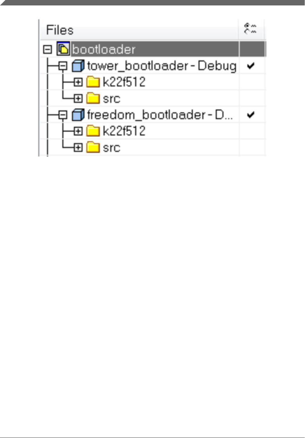
Figure 11-1. Projects available in workspace
Each of the projects in the workspace is configured to support all features of the
bootloader. This means every peripheral interface that the MCU supports is enabled. This
makes the bootloader very rich in features, but it also has the largest code footprint,
which can be considerable on MCUs with smaller flash configurations.
11.3 Flash-resident bootloader source tree
It is important to understand the source tree to understand where modifications are
possible. Here is an example of a source tree for one of the bootloader configurations.
Flash-resident bootloader source tree
Kinetis Bootloader v2.0.0 Reference Manual, Rev. 0, 04/2016
142 Freescale Semiconductor, Inc.
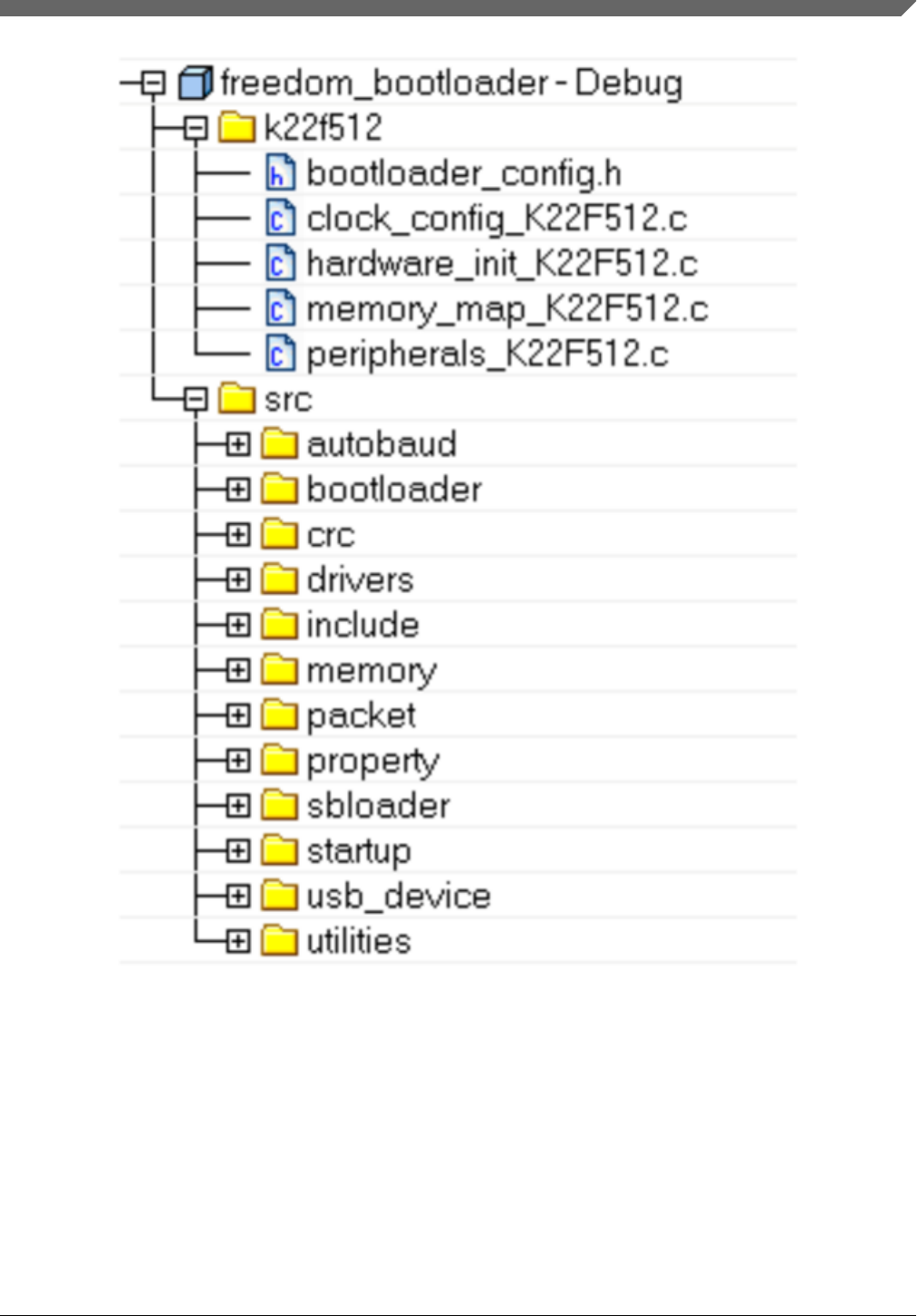
Figure 11-2. Source tree for bootloader configuration
There are two folders in each bootloader project: a MCU-specific folder and a “src”
folder. All files in the MCU-specific folder are located in the <install_dir>/targets/
<mcu>/src folder, and are very specific to the target MCU. The “src” folder is located at the
top level of the bootloader tree, and the subfolders in the project correspond to the real
folder/file structure on the PC. The files in the “src” folder are the core files of the
bootloader, and include everything from peripheral drivers to individual commands.
Chapter 11 Creating a custom flash-resident bootloader
Kinetis Bootloader v2.0.0 Reference Manual, Rev. 0, 04/2016
Freescale Semiconductor, Inc. 143

The bootloader source is separated in a way that creates a clear line between what a user
needs to modify and what they do not. Among other things, the files in the MCU-specific
folder allow the application to select which peripherals are active as well as how to
configure the clock, and are intended to be modified by the user. The files in the “src”
folder can be modified, but should only require modification where very specific
customization is needed in the bootloader.
11.4 Modifying source files
The files that cover the majority of the customization options needed by applications are
located in the MCU-specific folder. These files allow modification to the basic
configuration elements of the bootloader application, and are not associated with the core
functionality of the bootloader.
In the MCU-specific folder, the source files contain this information:
•bootloader_config.h – Bootloader configuration options such as encryption,
timeouts, CRC checking, the UART module number and baud rate, and most
importantly, the vector table offset for the user application.
•clock_config_<mcu>.c – Configures the clock for the MCU. This includes system,
bus, etc.
•hardware_init_<mcu>.c – Enables and configures peripherals used by the
application. This includes pin muxing, peripheral initialization, and the pin used as a
bootloader re-entry (bootstrap) mechanism.
•memory_map_<mcu>.c – Contains a table that stores the memory map information
for the targeted MCU.
•peripherals_<mcu>.c – Contains the table used by the bootloader to check which
peripheral interfaces are enabled. This is the file used to disable any unwanted or
unused peripheral interfaces.
•peripherals_pinmux.h - Contains macros to identifiy peripheral pin mux, typically
specific to a target platform.
11.5 Example
One of the most common customizations performed on the Kinetis bootloader is
removing unused or unwanted peripheral interfaces. The default configuration of the
bootloader enables multiple interfaces, including UART, SPI, I2C and (on some devices)
Modifying source files
Kinetis Bootloader v2.0.0 Reference Manual, Rev. 0, 04/2016
144 Freescale Semiconductor, Inc.

USB and CAN. This example will describe how to modify the provided bootloader
projects remove the SPI0 interface. The same methodology can be used to select any of
the supported interfaces.
11.6 Modifying a peripheral configuration macro
The bootloader _confg.h file is located in <install_dir>/targets/<mcu>/src. It contains
macros such as:
#if !defined(BL_CONFIG_SPI0)
#define BL_CONFIG_SPI0 (1)
#endif
To remove an interface, either modify this file to set the macro to (0), or pass the macro
define to the toolchain compiler in the project settings. For example:
BL_CONFIG_SPI0=0
Setting this macro to zero removes the interface from the g_peripherals table and
prevents related code from linking into the bootloader image.
11.7 How to generate MMCAU functions in binary image
1. Add the MMCAU driver to the project.
Add the MMCAU driver mmcau_aes_functions.c to the project. There are only three
functions in this driver.
//! @brief An initialization function for the decryption peripheral
void mmcau_aes_init(uint32_t *key, uint32_t *keySchedule, uint32_t *rcon);
//! @brief Encrypts a 16 byte block of data//!
in and out may use the same address so encrypting in place is supported
void mmcau_aes_encrypt(uint32_t *in, uint32_t *key, uint32_t *keySchedule, uint32_t
*out);
//! @brief Decrypts a 16 byte block of data//!
in and out may use the same address so decrypting in place is supported
void mmcau_aes_decrypt(uint32_t *in, uint32_t *key, uint32_t *keySchedule, uint32_t
*out);
The following figure shows that the driver has been added to the K80F256
bootloader project
Chapter 11 Creating a custom flash-resident bootloader
Kinetis Bootloader v2.0.0 Reference Manual, Rev. 0, 04/2016
Freescale Semiconductor, Inc. 145
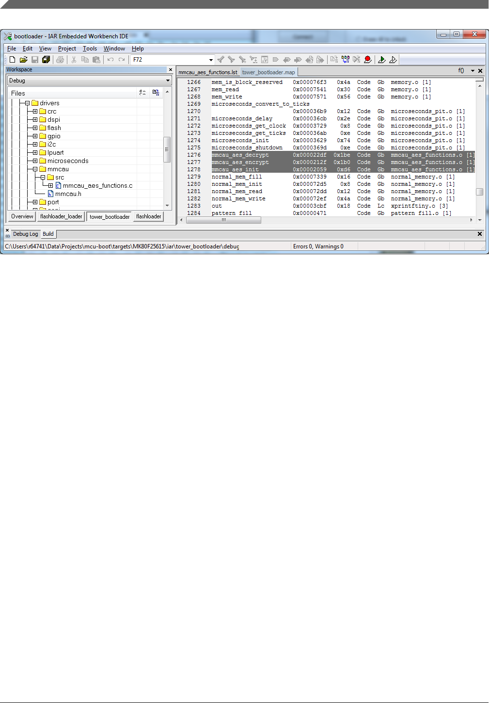
Figure 11-3. Driver added to K80F256F project
2. Change the compile optimization level to low.
How to generate MMCAU functions in binary image
Kinetis Bootloader v2.0.0 Reference Manual, Rev. 0, 04/2016
146 Freescale Semiconductor, Inc.
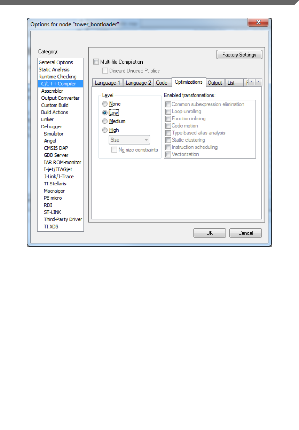
Figure 11-4. Compile optimization level
3. Compile the project and view the map file while generating the binary file for the
entire project. The start address and offset of mmcau_aes_init, mmcau_aes_encrypt, and
mmcau_aes_decrypt are shown.
Chapter 11 Creating a custom flash-resident bootloader
Kinetis Bootloader v2.0.0 Reference Manual, Rev. 0, 04/2016
Freescale Semiconductor, Inc. 147
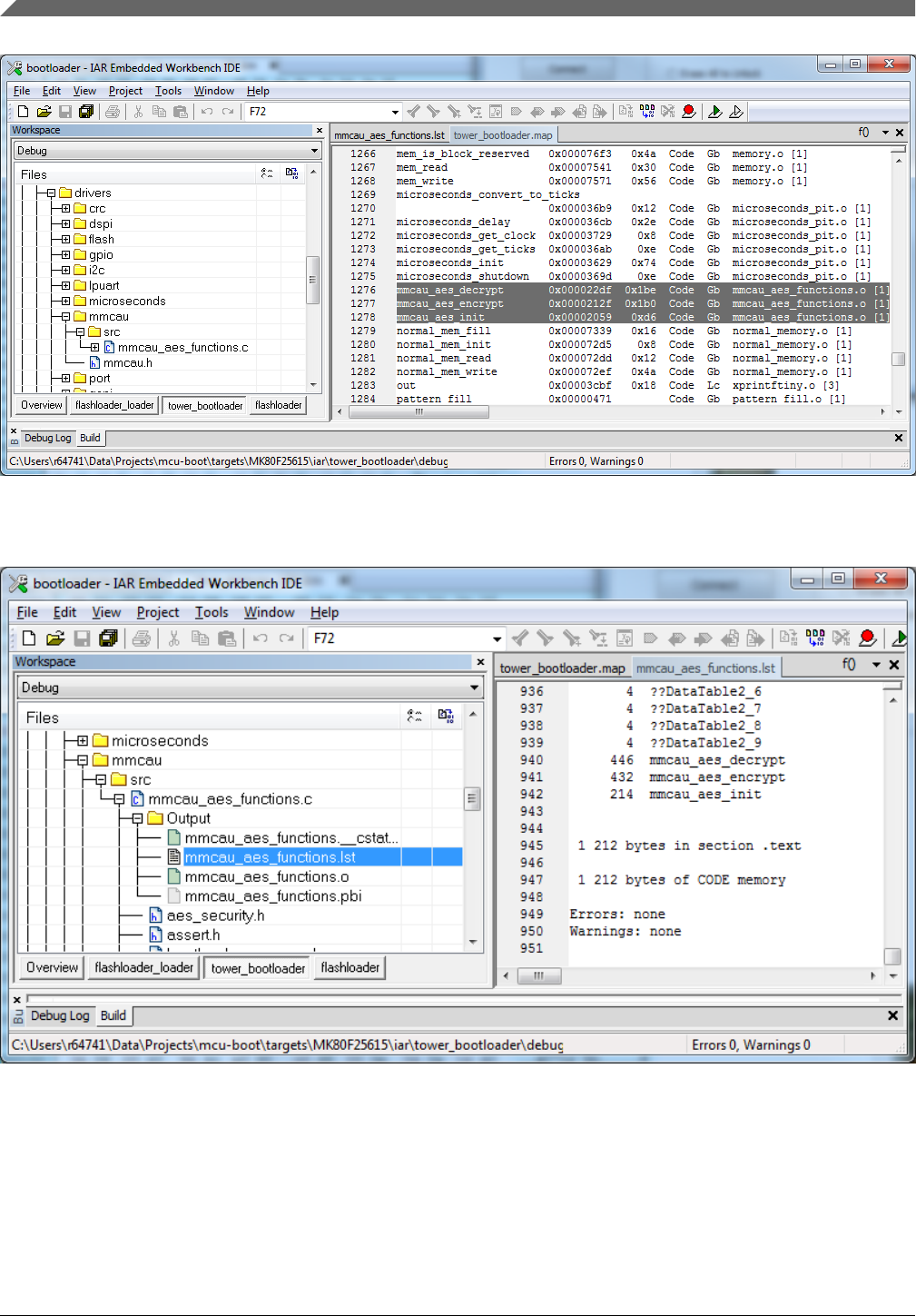
Figure 11-5. Start address MMCAU
4. Open the list file to see the MMCAU algorithm length - 1212 = 0x4BC.
Figure 11-6. MMCAU algorithm length
5. Extract functions from the address of mmcau_aes_init (0x2058 in this case) by the
MMCAU algorithm length (0x4BC) and save it. This is the MMCAU algorithm only.
See mmcau_function_cm4.bin.
How to generate MMCAU functions in binary image
Kinetis Bootloader v2.0.0 Reference Manual, Rev. 0, 04/2016
148 Freescale Semiconductor, Inc.
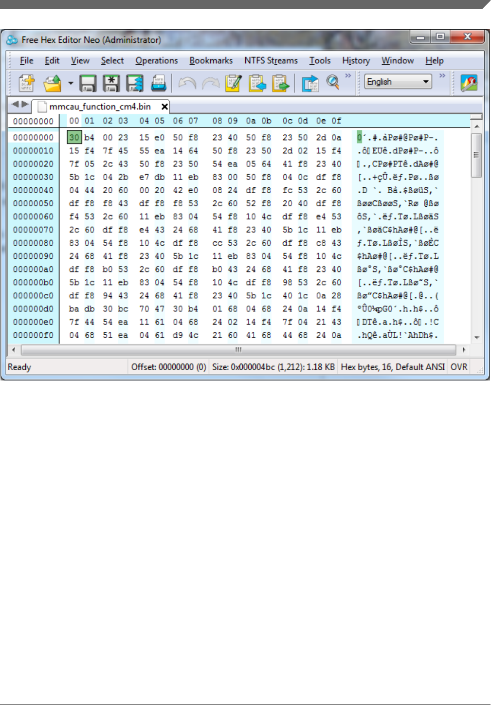
Figure 11-7. mmcau_function_cm4.bin
6. Add the MMCAU algorithm to the Bootloader Configuration Area (BCA).
The MMCAU algorithm can be loaded to any accesible memory, such as RAM or
flash. However, you need to update the BCA in order to have a pointer to an
MMCAu set-up structure. See aeas_security.h for the structure definition.
{
uint32_t tag; // 'kcau' = 0x
uint32_t length; // number of bytes to copy, this number will be copied from the
start of aes_init
uint32_t aes_init_start;
uint32_t aes_encrypt_start;
uint32_t aes_decrypt_start;} mmcau_function_info_t;
The location offset of the MMCAU algorithm is x020. The BCA start is 0x3C0, and
the mmcau_function_info address is 0x3E0. For decryption to work properly, the
mmcau_function_info must contain valid values for all the fields in this structure. This
structure size is 20 bytes (0x14 bytes).
• Tag
The tag field must equal 'kcau'
Chapter 11 Creating a custom flash-resident bootloader
Kinetis Bootloader v2.0.0 Reference Manual, Rev. 0, 04/2016
Freescale Semiconductor, Inc. 149
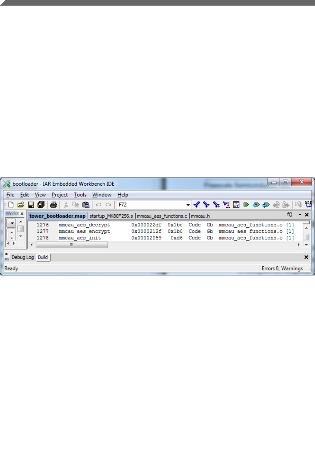
• Length
It is the total length of all MMCAU AES algorithms. See mmcau_aes_functions.lst.
It is 1212 bytes (0x4BC).
•aes_init_start
Memory location of the aes_init function, the address where
mmcau_function_cm4.bin is to be loaded. This function size is 0xD6.
•aes_encrypt_start
Memory location of the aes_encrypt function. This function size is 0x1B0.
•aes_decrypt_start
Memory location of the aes_decrypt function. This function size is 0x1BE.
The below figure contains information for each function.
Figure 11-8. Map file
7. Example - Add the MMCAU algorithm after the BCA.
• BCA 0x30 ~ 0x3DF
• MMCAU setup in BCA - 0x3E0, which shows the start of mmcau_function_info
• Tag in mmcau_function_info (0x410 ~ 0x413)
The values of 0x410 ~ 0x4`3 are 'kcau'
• Length in mmcau_function_into (0x414 ~ 0x417)
The value is 0x000004BC
•aes_init_start in mmcau_function_into (0x418 ~ 0x41b)
The value is 0x00000424 (0x410 + 0x14 (mmcau_function_info structure size))
•aes_encrypt_start in mmcau_function_info (0x41c ~ 0x41f)
How to generate MMCAU functions in binary image
Kinetis Bootloader v2.0.0 Reference Manual, Rev. 0, 04/2016
150 Freescale Semiconductor, Inc.
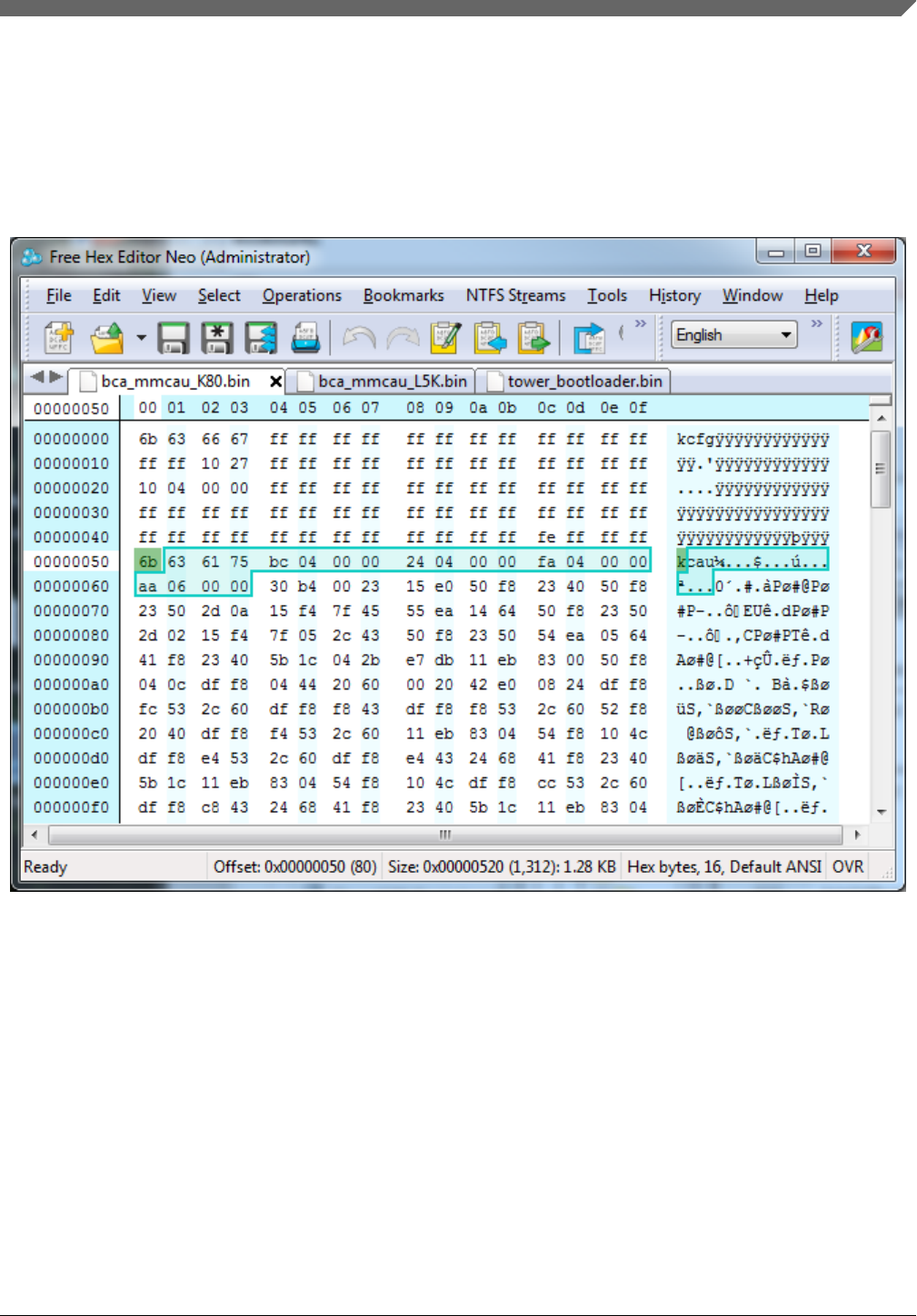
The value is 0x000004fa (0x424 + 0xd6 (mmcau_aes_init function size))
•aes_decrypt_start in mmcau_function_info (0x420 ~ 0x423)
The value is 0x000006aa (0x4fa + 0x1b0 (mmcau_aes_encrypt function size))
• The MMCAU algorithm starts from flash address 0x424
Figure 11-9. MMCAU algorithm after BCA
Chapter 11 Creating a custom flash-resident bootloader
Kinetis Bootloader v2.0.0 Reference Manual, Rev. 0, 04/2016
Freescale Semiconductor, Inc. 151

How to generate MMCAU functions in binary image
Kinetis Bootloader v2.0.0 Reference Manual, Rev. 0, 04/2016
152 Freescale Semiconductor, Inc.

Chapter 12
Bootloader Reliable Update
12.1 Introduction
Reliable update is an optional but an important feature of Kinetis bootloader. During a
firmware update, an unexpected loss of power or device disconnect from the host can
happen. This may result in a corrupted image or non-responsive devices. The reliable
update feature is designed to solve this problem.
12.2 Functional description
The reliable update works by dividing the device memory into two regions: the main
application region and backup application region. Only the backup application region is
allowed to be updated by the host. Once the backup region is updated with the new
firmware image, the reliable update process needs to be initiated where the Kinetis
bootloader checks the validity and integrity of the new application image in the backup
region, and copies the new image to the main application region.
12.2.1 Bootloader workflow with reliable update
There are two methods to initiate reliable update process. The first method is to reset the
device to enter the bootloader startup process, causing Kinetis bootloader to detect the
presence of a valid image in the backup region, and kicking off the reliable update
process. The second method is by issuing a reliable-update command from host using
BLHOST.EXE while the bootloader is running on the device.
Using the first method, the reliable update process starts before all interfaces are
configured. The figure below shows the call to reliable update process during startup flow
of the Kinetis bootloader.
Kinetis Bootloader v2.0.0 Reference Manual, Rev. 0, 04/2016
Freescale Semiconductor, Inc. 153
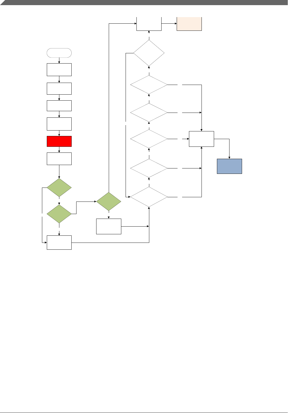
Enter Bootloader
Init hardware
Init flash driver
Load user-config
data
Configure clocks
Init microseconds
driver,memory &
property interface
Reliable
application update
if needed
Init
UARTn,CANn,SPI
n,I2Cn, USB
Use the enabledPeripherals field
in user config data to enable (or
not) UARTn (or CANn or SPIn or
I2Cn or USB)
Is BootPin
asserted?
Is user
application
valid?
No Is
direct boot
valid?
Yes
Disable Timeout
detection
No
Yes
Enable Timeout
Check and enable
Timeout value
Was a
Ping packet
received on
UARTn?
No
Was a
Ping packet
received on
I2Cn?
Was a
Ping packet
received on
SPIn?
Was a
Ping packet received on
CANn?
Has
USB entered
Interrupt state?
IS
Timeout Check
Enabled and
Has Timeout
Occurred?
Shutdown all
peripherals Jump to user
application
Shutdown unused
Peipherals
Enter Bootloader
State machine
No
No
No
No
No
No
Yes
Yes
Yes
Yes
Yes
Yes
Yes
Figure 12-1. Bootloader workflow with reliable update
The second method occurs while the bootloader state machine is running. The reliable
update process is triggered when the host sends the reliable update bootloader command..
12.2.2 Reliable update implementation types
Functional description
Kinetis Bootloader v2.0.0 Reference Manual, Rev. 0, 04/2016
154 Freescale Semiconductor, Inc.

There are two kinds of reliable update implementations. They can be classified as either
the software version or hardware version. The main differences between software and
hardware implementation are listed below:
Table 12-1. Software and hardware implementation
Item Software implementation Hardware implementation
Applicable device All Kinetis devices Devices with flash swap support
Device memory distribution Bootloader + main application + backup
application
Main bootloader + main application +
backup bootloader + backup application
Backup application address Flexible Fixed
The ability to keep two applications No Yes
The most obvious difference is that software implementation copies the backup
application to the main application region, while hardware implementation swaps two
half flash blocks to make the backup application become the main application. The
detailed differences will be reflected in the chapter titled “Reliable update flow”.
See Section 12.3, “Configuration macros” on how to enable different implementations of
the reliable update.
12.2.3 Reliable update flow
This chapter describes in detail both the software and hardware implementation of the
reliable update process.
12.2.3.1 Software implementation
For the software implementation, the backup application address is not fixed. Therefore,
the application address must be specified. There are two ways for the bootloader to
receive the backup application address. If the reliable update process is issued by the
host, the bootloader receives the specified application address from the host itself.
Otherwise, the bootloader makes use of the predefined application address.
After the reliable update process is started, the first thing for the bootloader is to check
the backup application region to determine if the reliable update feature is active by
checking:
1. Whether the application pointer in the backup application is valid.
2. Whether the Bootloader Configuration Area is enabled.
Chapter 12 Bootloader Reliable Update
Kinetis Bootloader v2.0.0 Reference Manual, Rev. 0, 04/2016
Freescale Semiconductor, Inc. 155

If above conditions are not met, the bootloader exits the reliable update process
immediately. Otherwise, the bootloader continues to validate the integrity of the backup
application by checking:
1. Whether the crcStartAddress is equal to the start address of the vector table of the
application.
2. Whether the crcByteCount (considered as the size of backup application) is less than
or equal to the maximum allowed backup application size.
3. Whether the calculated CRC checksum is equal to the checksum provided in backup
application, given that the above conditions are met.
If the backup application is determined to be valid, the remaining process is described in
the following figure.
Functional description
Kinetis Bootloader v2.0.0 Reference Manual, Rev. 0, 04/2016
156 Freescale Semiconductor, Inc.
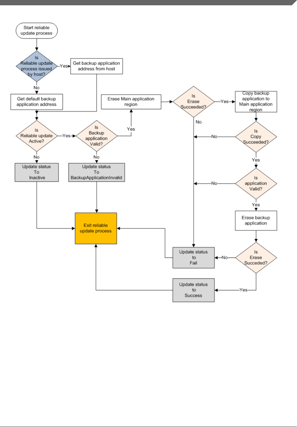
Figure 12-2. Reliable update software implementation workflow
NOTE
Not all details are shown in the above figure.
Once the main application region is updated, the bootloader must erase the backup
application region before exiting the reliable update process. This prevents the bootloader
to update the main application image on subsequent boots.
Chapter 12 Bootloader Reliable Update
Kinetis Bootloader v2.0.0 Reference Manual, Rev. 0, 04/2016
Freescale Semiconductor, Inc. 157

12.2.3.2 Hardware implementation
For the hardware implementation, the backup application address is fixed and predefined
in the bootloader, but a swap indicator address is required to swap the flash system. There
are two ways for the bootloader to get the swap indicator address. If the reliable update
process is issued by the host, the bootloader receives the specified swap indicator address
from the host itself. Otherwise, the bootloader tries to receive the swap indicator address
from the IFR, if the swap system is in the ready state.
The top level behavior of the reliable update process depends on how the bootloader gets
the swap indicator address:
• If the reliable update process is issued by the host, the bootloader does the same thing
as software implementation until the validity of the backup application is verified.
• If the reliable update process is from the bootloader startup sequence, the bootloader
first checks the main application. If the main application is valid, then the bootloader
exits the reliable update process immediately, and jumps to the main application.
Otherwise, the bootloader receives the swap indicator address from IFR, then
continues to validate the integrity of the backup application as the software
implementation does.
NOTE
It is expected that the user erases the main application region
when reliable update process is intended with the next startup
sequence. Otherwise, the reliable update process assumes no
update is needed, exits the process, and boots the image from
the main application region
If the backup application is valid, see the remaining operations in the following figure.
Functional description
Kinetis Bootloader v2.0.0 Reference Manual, Rev. 0, 04/2016
158 Freescale Semiconductor, Inc.
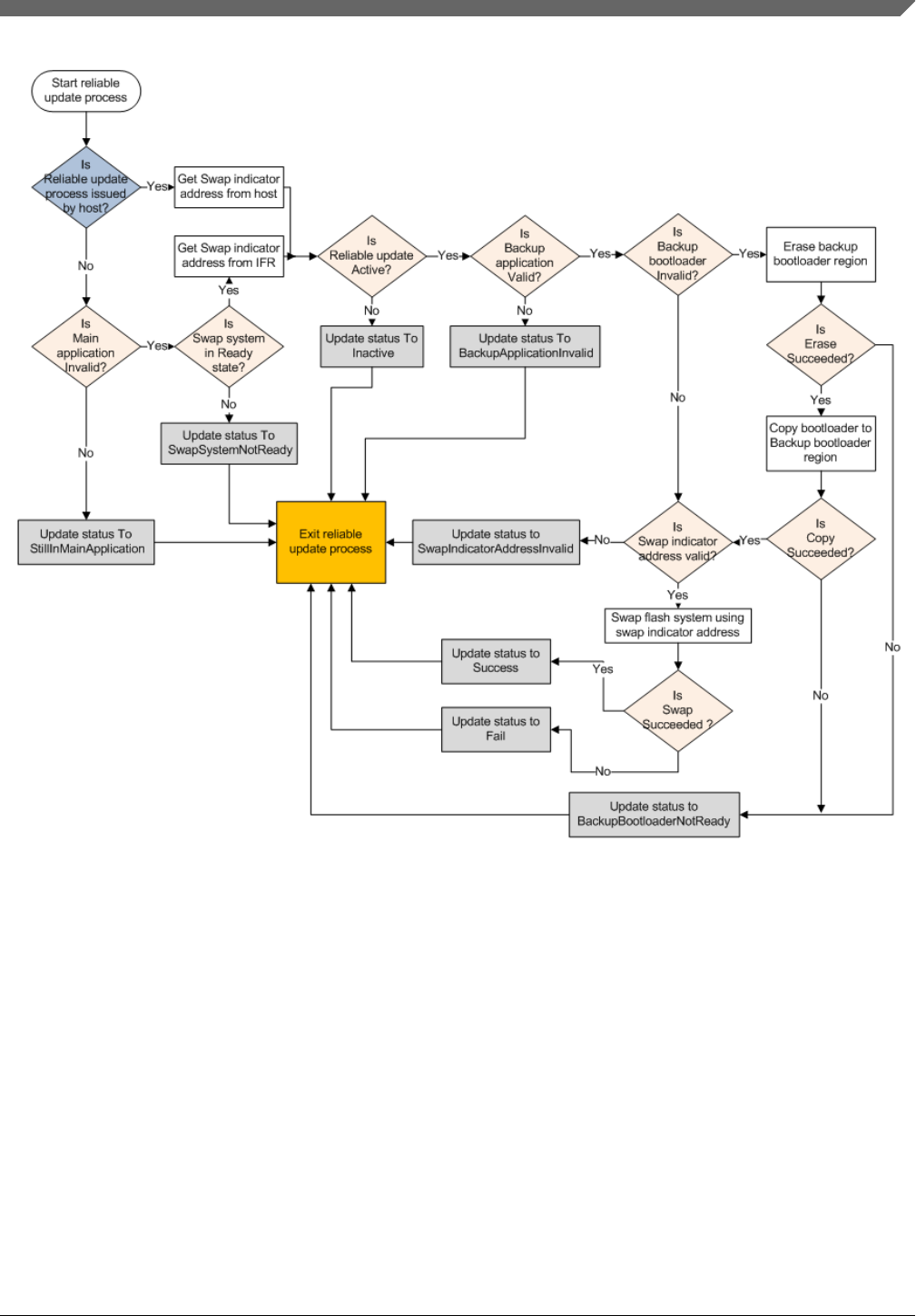
Figure 12-3. Reliable update hardware implementation workflow
NOTE
Not all details are shown in the above figure.
Once the flash system is swapped (upper flash block becomes lower flash block), the
bootloader naturally treats the backup application as the main application. In the
hardware implementation, after the swap, it is not necessary to erase the image from the
backup region.
12.3 Configuration macros
Chapter 12 Bootloader Reliable Update
Kinetis Bootloader v2.0.0 Reference Manual, Rev. 0, 04/2016
Freescale Semiconductor, Inc. 159

The configuration macros defined in bootloader_config.h are used to enable the reliable
update feature. For Kinetis bootloader v2.0.0, the feature is only enabled in the K65
Freedom and Tower flash target builds. All code added for this feature should be enabled
only if the macros are defined. Currently, these macros are defined as:
• BL_FEATURE_RELIABLE_UPDATE – Used to enable or disable the reliable
update feature.
• BL_FEATURE_HARDWARE_SWAP_UPDATE – Used to switch the hardware or
software implementation of reliable update.
• BL_BACKUP_APP_START – Used to define the start address of the backup
application if the reliable update feature is enabled.
12.4 Get property
A property has been added to get the state of reliable update. To implement this, a
property member called reliableUpdateStatus has been added to propertyStore.
Additionally, eight new status codes have been defined for the reliable update status. See
the following table for details.
Table 12-2. Reliable update status error codes
Status Value Description
kStatus_ReliableUpdateSuccess 10600 Reliable update operation succeeded.
kStatus_ReliableUpdateFail 10601 Reliable update operation failed.
kStatus_ReliableUpdateInactive 10602 Reliable update feature is inactive.
kStatus_ReliableUpdateBackupApplicati
onInvalid
10603 Backup application is invalid.
kStatus_ReliableUpdateStillInMainApplic
ation
10604 (For hardware implementation only) The
bootloader still jumps to the original main
application.
kStatus_ReliableUpdateSwapSystemNot
Ready
10605 (For hardware implementation only)
Failed to get the swap indicator address
from IFR due to the swap system not
being ready.
kStatus_ReliableUpdateBackupBootload
erNotReady
10606 (For hardware implementation only)
Failed in copying the main application
image to the backup application region.
kStatus_ReliableUpdateSwapIndicatorA
ddressInvalid
10607 (For hardware implementation only)
Swap indicator address is invalid for the
swap system.
Get property
Kinetis Bootloader v2.0.0 Reference Manual, Rev. 0, 04/2016
160 Freescale Semiconductor, Inc.

Chapter 13
Appendix A: status and error codes
Status and error codes are grouped by component. Each component that defines errors
has a group number. This expression is used to construct a status code value.
status_code = (group * 100) + code
Component group numbers are listed in this table.
Table 13-1. Component group numbers
Group Component
0 Generic errors
1 Flash driver
4 QuadSPI driver
5 OTFAD driver
100 Bootloader
101 SB loader
102 Memory interface
103 Property store
104 CRC checker
105 Packetizer
106 Reliable update
The following table lists all of the error and status codes.
Table 13-2. Error and status codes
Name Value Description
kStatus_Success 0 Operation succeeded without error.
kStatus_Fail 1 Operation failed with a generic error.
kStatus_ReadOnly 2 Property cannot be changed because it is read-only.
kStatus_OutOfRange 3 Requested value is out of range.
kStatus_InvalidArgument 4 The requested command's argument is undefined.
kStatus_Timeout 5 A timeout occurred.
Table continues on the next page...
Kinetis Bootloader v2.0.0 Reference Manual, Rev. 0, 04/2016
Freescale Semiconductor, Inc. 161

Table 13-2. Error and status codes (continued)
Name Value Description
kStatus_NoTransferInProgress 6 The current transfer status is idle.
kStatus_FlashSizeError 100 Not used.
kStatus_FlashAlignmentError 101 Address or length does not meet required alignment.
kStatus_FlashAddressError 102 Address or length is outside addressable memory.
kStatus_FlashAccessError 103 The FTFA_FSTAT[ACCERR] bit is set.
kStatus_FlashProtectionViolation 104 The FTFA_FSTAT[FPVIOL] bit is set.
kStatus_FlashCommandFailure 105 The FTFA_FSTAT[MGSTAT0] bit is set.
kStatus_FlashUnknownProperty 106 Unknown Flash property.
kStatus_FlashEraseKeyError 107 Error in erasing the key.
kStatus_FlashRegionOnExecuteOnly 108 The region is execute only region.
kStatus_FlashAPINotSupported 115 Unsupported Flash API is called.
kStatus_QspiFlashSizeError 400 Error in QuadSPI flash size.
kStatus_QspiFlashAlignmentError 401 Error in QuadSPI flash alignment.
kStatus_QspiFlashAddressError 402 Error in QuadSPI flash address.
kStatus_QspiFlashCommandFailure 403 QuadSPI flash command failure.
kStatus_QspiFlashUnknownProperty 404 Unknown QuadSPI flash property.
kStatus_QspiNotConfigured 405 QuadSPI not configured.
kStatus_QspiCommandNotSupported 406 QuadSPI command not supported.
kStatus_QspiCommandTimeout 407 QuadSPI command timed out.
kStatus_QspiWriteFailure 408 QuadSPI write failure.
kStatusQspiModuleBusy 409 QuadSPI module is busy.
kStatus_OtfadSecurityViolation 500 Security violation in OTFAD module.
kStatus_OtfadLogicallyDisabled 501 OTFAD module is logically disabled.
kStatus_OtfadInvalidKey 502 The key is invalid.
kStatus_OtfadInvalidKeyBlob 503 The Key blob is invalid.
kStatus_UnknownCommand 10000 The requested command value is undefined.
kStatus_SecurityViolation 10001 Command is disallowed because flash security is
enabled.
kStatus_AbortDataPhase 10002 Abort the data phase early.
kStatus_Ping 10003 Internal: Received ping during command phase.
kStatus_NoResponse 10004 There is no response for the command.
kStatus_NoResponseExpected 10005 There is no response expected for the command.
kStatusRomLdrSectionOverrun 10100 ROM SB loader section overrun.
kStatusRomLdrSignature 10101 ROM SB loader incorrect signature.
kStatusRomLdrSectionLength 10102 ROM SB loader incorrect section length.
kStatusRomLdrUnencryptedOnly 10103 ROM SB loader does not support plain text image.
kStatusRomLdrEOFReached 10104 ROM SB loader EOF reached
kStatusRomLdrChecksum 10105 ROM SB loader checksum error.
kStatusRomLdrCrc32Error 10106 ROM SB loader CRC32 error.
kStatusRomLdrUnknownCommand 10107 ROM SB loader unknown command.
Table continues on the next page...
Kinetis Bootloader v2.0.0 Reference Manual, Rev. 0, 04/2016
162 Freescale Semiconductor, Inc.

Table 13-2. Error and status codes (continued)
Name Value Description
kStatusRomLdrIdNotFound 10108 ROM SB loader ID not found.
kStatusRomLdrDataUnderrun 10109 ROM SB loader data underrun.
kStatusRomLdrJumpReturned 10110 ROM SB loader return from jump command occurred.
kStatusRomLdrCallFailed 10111 ROM SB loader call command failed.
kStatusRomLdrKeyNotFound 10112 ROM SB loader key not found.
kStatusRomLdrSecureOnly 10113 ROM SB loader security state is secured only.
kStatusRomLdrResetReturned 10114 ROM SB loader return from reset occurred.
kStatusMemoryRangeInvalid 10200 Memory range conflicts with a protected region.
kStatusMemoryReadFailed 10201 Failed to read from memory range.
kStatusMemoryWriteFailed 10202 Failed to write to memory range.
kStatus_UnknownProperty 10300 The requested property value is undefined.
kStatus_ReadOnlyProperty 10301 The requested property value cannot be written.
kStatus_InvalidPropertyValue 10302 The specified property value is invalid.
kStatus_AppCrcCheckPassed 10400 CRC check passed.
kStatus_AppCrcCheckFailed 10401 CRC check failed.
kStatus_AppCrcCheckInactive 10402 CRC checker is not enabled.
kStatus_AppCrcCheckInvalid 10403 Invalid CRC checker due to blank part of BCA not
present.
kStatus_AppCrcCheckOutOfRange 10404 CRC check is valid but addresses are out of range.
kStatus_NoPingResponse 10500 Packetizer did not receive any response for the ping
packet.
kStatus_InvalidPacketType 10501 Packet type is invalid.
kStatus_InvalidCRC 10502 Invalid CRC in the packet.
kStatus_NoCommandResponse 10503 No response received for the command.
kStatus_ReliableUpdateSuccess 10600 Reliable update process completed successfully.
kStatus_ReliableUpdateFail 10601 Reliable update process failed.
kStatus_ReliableUpdateInacive 10602 Reliable update feature is inactive.
kStatus_ReliableUpdateBackupApplicati
onInvalid
10603 Backup application image is invalid.
kStatus_ReliableUpdateStillInMainApplic
ation
10604 Next boot will still be with Main Application image.
kStatus_ReliableUpdateSwapSystemNo
tReady
10605 Cannot swap flash by default because swap system is not
ready.
kStatus_ReliableUpdateBackupBootload
erNotReady
10606 Cannot swap flash because there is no valid backup
bootloader image.
kStatus_ReliableUpdateSwapIndicatorA
ddressInvalid
10607 Cannot swap flash because provided swap indicator is
invalid.
Chapter 13 Appendix A: status and error codes
Kinetis Bootloader v2.0.0 Reference Manual, Rev. 0, 04/2016
Freescale Semiconductor, Inc. 163

Kinetis Bootloader v2.0.0 Reference Manual, Rev. 0, 04/2016
164 Freescale Semiconductor, Inc.

Chapter 14
Appendix B: GetProperty and SetProperty
commands
Properties are the defined units of data that can be accessed with the GetProperty or
SetProperty commands. Properties may be read-only or read-write. All read-write
properties are 32-bit integers, so they can easily be carried in a command parameter. Not
all properties are available on all platforms. If a property is not available, GetProperty
and SetProperty return kStatus_UnknownProperty.
The tag values shown in the table below are used with the GetProperty and SetProperty
commands to query information about the bootloader.
Table 14-1. Tag values GetProperty and SetProperty
Name Writable Tag value Size Description
CurrentVersion no 0x01 4 The current bootloader
version.
AvailablePeripherals no 0x02 4 The set of peripherals
supported on this chip.
FlashStartAddress no 0x03 4 Start address of
program flash.
FlashSizeInBytes no 0x04 4 Size in bytes of
program flash.
FlashSectorSize no 0x05 4 The size in bytes of
one sector of program
flash. This is the
minimum erase size.
FlashBlockCount no 0x06 4 Number of blocks in
the flash array.
AvailableCommands no 0x07 4 The set of commands
supported by the
bootloader.
CRCCheckStatus no 0x08 4 The status of the
application CRC check.
Reserved n/a 0x09 n/a
Table continues on the next page...
Kinetis Bootloader v2.0.0 Reference Manual, Rev. 0, 04/2016
Freescale Semiconductor, Inc. 165

Table 14-1. Tag values GetProperty and SetProperty (continued)
Name Writable Tag value Size Description
VerifyWrites yes 0x0a 4 Controls whether the
bootloader verifies
writes to flash. The
VerifyWrites feature is
enabled by default.
0 - No verification is
done
1 - Enable verification
MaxPacketSize no 0x0b 4 Maximum supported
packet size for the
currently active
peripheral interface.
ReservedRegions no 0x0c n List of memory regions
reserved by the
bootloader. Returned
as value pairs (<start-
address-of-
region>,<end-address-
of-region>).
• If HasDataPhase
flag is not set,
then the
Response packet
parameter count
indicates number
of pairs.
• If HasDataPhase
flag is set, then
the second
parameter is the
number of bytes
in the data
phase.
RAMStartAddress no 0x0e 4 Start address of RAM.
RAMSizeInBytes no 0x0f 4 Size in bytes of RAM.
SystemDeviceId no 0x10 4 Value of the Kinetis
System Device
Identification register.
FlashSecurityState no 0x11 4 Indicates whether
Flash security is
enabled.
0 - Flash security is
disabled
1 - Flash security is
enabled
UniqueDeviceId no 0x12 n Unique device
identification, value of
Kinetis Unique
Identification registers
Table continues on the next page...
Kinetis Bootloader v2.0.0 Reference Manual, Rev. 0, 04/2016
166 Freescale Semiconductor, Inc.

Table 14-1. Tag values GetProperty and SetProperty (continued)
Name Writable Tag value Size Description
(16 for K series
devices, 12 for KL
series devices)
FlashFacSupport no 0x13 4 FAC (Flash Access
Control) support flag
0 - FAC not supported
1 - FAC supported
FlashAccessSegmentSi
ze
no 0x14 4 The size in bytes of 1
segment of flash.
FlashAccessSegmentC
ount
no 0x15 4 FAC segment count
(The count of flash
access segments
within the flash model.)
FlashReadMargin yes 0x16 4 The margin level
setting for flash erase
and program verify
commands.
0=Normal
1=User
2=Factory
QspiInitStatus no 0x17 4 The result of the QSPI
or OTFAD initialization
process.
405 - QSPI is not
initialized
0 - QSPI is initialized
TargetVersion no 0x18 4 Target build version
number.
ExternalMemoryAttribut
es
no 0x19 24 List of attributes
supported by the
specified memory Id
(0=Internal Flash,
1=QuadSpi0). See
description for the
return value in the
section
ExternalMemoryAttribut
es Property.
ReliableUpdateStatus - 0x1a 4 Result of last Reliable
Update operation. See
Table 12-2.
Chapter 14 Appendix B: GetProperty and SetProperty commands
Kinetis Bootloader v2.0.0 Reference Manual, Rev. 0, 04/2016
Freescale Semiconductor, Inc. 167

Kinetis Bootloader v2.0.0 Reference Manual, Rev. 0, 04/2016
168 Freescale Semiconductor, Inc.

Chapter 15
Revision history
15.1 Revision History
This table shows the revision history of the document.
Table 15-1. Revision history
Revision number Date Substantive changes
0 04/2016 Kinetis Bootloader v2.0.0 release
Kinetis Bootloader v2.0.0 Reference Manual, Rev. 0, 04/2016
Freescale Semiconductor, Inc. 169

Document Number: KBTLDR200RM
Rev. 0
04/2016
Information in this document is provided solely to enable system and software
implementers to use Freescale products. There are no express or implied copyright
licenses granted hereunder to design or fabricate any integrated circuits based on the
information in this document.
Freescale reserves the right to make changes without further notice to any products
herein. Freescale makes no warranty, representation, or guarantee regarding the
suitability of its products for any particular purpose, nor does Freescale assume any
liability arising out of the application or use of any product or circuit, and specifically
disclaims any and all liability, including without limitation consequential or incidental
damages. “Typical” parameters that may be provided in Freescale data sheets and/or
specifications can and do vary in different applications, and actual performance may
vary over time. All operating parameters, including “typicals,” must be validated for
each customer application by customer’s technical experts. Freescale does not convey
any license under its patent rights nor the rights of others. Freescale sells products
pursuant to standard terms and conditions of sale, which can be found at the following
address: nxp.com/SalesTermsandConditions.
How to Reach Us:
Home Page:
nxp.com
Web Support:
nxp.com/support
Freescale, the Freescale logo, and Kinetis are trademarks of Freescale
Semiconductor, Inc., Reg. U.S. Pat. & Tm. Off. All other product or service names are
the property of their respective owners. ARM, ARM Powered Logo, Keil, and Cortex
are registered trademarks of ARM limited (or its subsidiaries) in the EU and/or
elsewhere. All rights reserved.
© 2016 Freescale Semiconductor, Inc.
