Kinetis Flash Tool User's Guide
Kinetis%20Flash%20Tool%20User's%20Guide
Kinetis%20Flash%20Tool%20User's%20Guide
User Manual: Pdf
Open the PDF directly: View PDF ![]() .
.
Page Count: 47

1 Introduction
The Kinetis Flash Tool is a GUI application on Windows®
OS, aiming to offer the user an ease-of-use friendly user
interface to communicate with the Kinetis device, running the
Kinetis bootloader application. The user can execute the write
or erase operation on a Kinetis device’s non-volatile memory,
including but not limited to the following features:
• Supports Kinetis devices with Kinetis ROM bootloader,
Kinetis flashloader, or running the flash resident
bootloader.
• Supports UART with a baud rate ranging from 4800 to
256000 bit/s, as well as a user-defined baud rate in the
supported range.
• Supports USB-HID with the default or user-defined
VID/PID.
• Supports binary file (.bin), SB file (.sb), HEX file (.hex),
and SRecord file (.s19, .srec).
• Supports “Quick Update” without needing to connect to
Kinetis device first.
• Supports the flash erase operation.
• Supports programming flash nonvolatile information
register (IFR).
• Supports generating the Bootloader Configuration Area
(BCA) binaries and C code file.
• Supports CRC calculation of user application firmware
(only supports binary file).
Freescale Semiconductor Document Number: KFLASHTOOLUG
User's Guide Rev. 0, 04/2016
Kinetis Flash Tool User's Guide
© 2016 Freescale Semiconductor, Inc.
Contents
1 Introduction................................................................1
2 System Requirements................................................ 2
3 Tool structure............................................................ 2
4 User interface............................................................ 4
5 Typical usage............................. ............................. 30
6 Revision history.......................... ............................ 46

This document describes the function and user interface of Kinetis Flash Tool, and how to use this tool.
2 System Requirements
Table 1. Requirements
Component Requirement
Processor 1 gigahertz (GHz) or faster x86 or x64 processor
Memory 1 GB RAM (32-bit); 2 GB RAM (64-bit)
Operating system Windows OS XP, Windows OS 7, Windows OS 8, Windows
OS 10
3 Tool structure
The Kinetis Flash Tool is a new tool and only exists in the Kinetis v2.0.0 bootloader release package available at
www.nxp.com/KBOOT. This tool consists of a few files shown in the following picture.
System Requirements
Kinetis Flash Tool User's Guide, Rev. 0, 04/2016
2 Freescale Semiconductor, Inc.
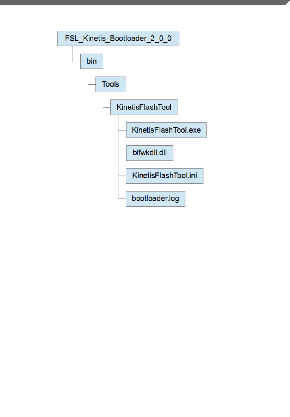
Figure 1. Kinetis Flash Tool structure
In the release package, KinetisFlashTool folder appears under the bin/Tools folder. And it contains four files.
•The KinetisFlashTool.exe file is the executable file.
•The blfwkdll.dll file is the dynamic link library used by KinetisFlashTool, and responsible for communication with
Kinetis bootloader.
NOTE
blfwkdll.dll for Kinetis Flash Tool is different from the one used by Kinetis Updater
application in the Kinetis bootloader v1.2 release package. Do not move, edit, or
exchange them.
•The KinetisFlashTool.ini file is the initialization/configuration file. KinetisFlashTool loads history information from
this file at startup and saves it when it is existing, not during the execution. See Section 3.1, "KinetisFlashTool.ini file"
for more detailed information.
•The bootloader.log file contains the detailed data transferring between host and target device during the life time of this
program, aiming to offer information for review or troubleshooting.
NOTE
1. KinetisFlashTool.ini and bootloader.log does not already exist in the package. It is
created after the program first launches. If the user does not require the history
information, they can delete them without hesitation.
2. The text in bootloader.log is completely different from the text in the log window.
The former offers the detailed data transferred by Kinetis Flash Tool. The latter
Tool structure
Kinetis Flash Tool User's Guide, Rev. 0, 04/2016
Freescale Semiconductor, Inc. 3
shows the results of the user operation. See Section 4.1.3, "Log window" for details
of the log window.
3.1 KinetisFlashTool.ini file
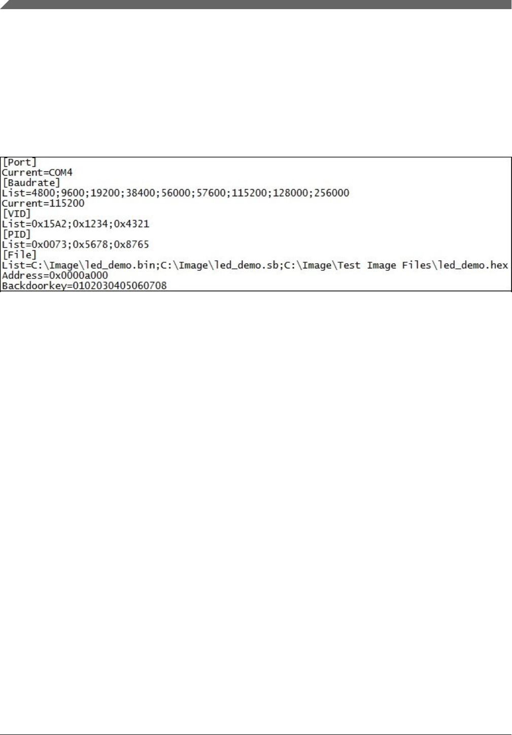
This file saves history information used by Kinetis Flash Tool. This section helps the user understand the structure of this file.
The following figure displays a typical KinetisFlashTool.ini file.
Figure 2. Example for KinetisFlashTool.ini
•[Port]Current: Saves the previously selected COM port. If the previously selected COM port does not exist on the
host, the first device in the port combo box is selected.
•[Baudrate]List: Contains the baud rates that are listed in the baud rate combo box.
•[Baudrate]Current: Saves the previously selected baud rate. If it does not exist in the “List”, the first one is selected.
•[VID]/[PID]List: Contains the VIDs/PIDs that is listed in the VID/PID combo box.
•[File]List: Contains the full paths of image files that is listed in the image file combo box.
•[File]Address: Saves the previous image address to download the firmware to.
•[File]BackdoorKey: Saves the previous backdoor key.
Parameters in the List must be separated by separator “;” (half width). Only a maximum of ten parameters in the front of the
line is loaded at startup.
Except for the backdoor key, numerical parameters must follow the rule that hex digits must have the “0x” leading
characters, octal digits must have a “0” leading character, and a non-numerical character is unacceptable. The backdoor key
must be 16 hex digits without “0x” leadings. Any invalid parameters are ignored and abandoned during the program’s
initialization. Files in the [File]List should exist on the file system, or is ignored at startup.
4User interface
This section describes the UI pages presented by the Kinetis Flash Tool to gather the necessary information and user
operation intentions.
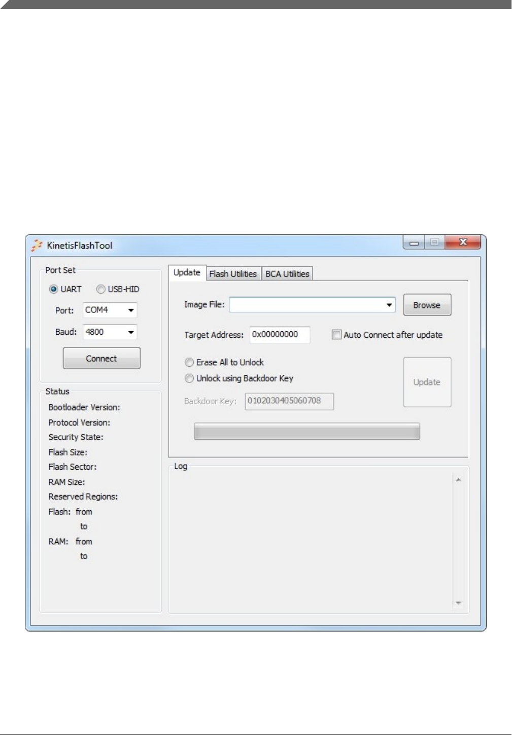
4.1 Main window
The main window consists of four parts, shown in the following figure.
User interface
Kinetis Flash Tool User's Guide, Rev. 0, 04/2016
4 Freescale Semiconductor, Inc.
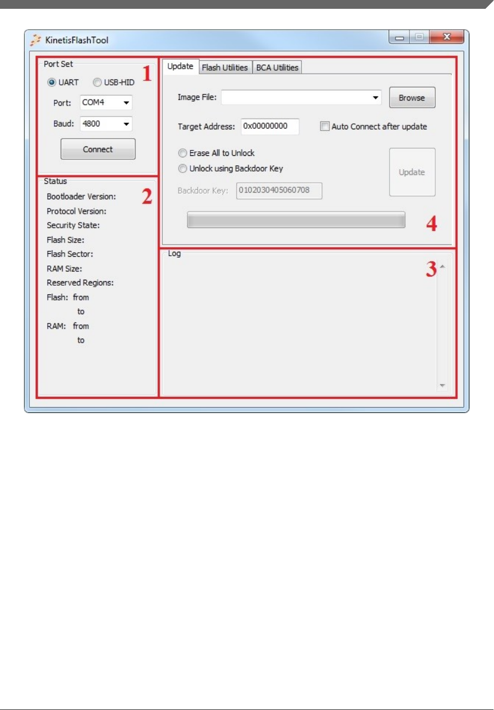
Figure 3. Main window
4.1.1 Port Set
The Port Set part is used to select the peripheral and corresponding configuartion, used for communication with the target
device.
User interface
Kinetis Flash Tool User's Guide, Rev. 0, 04/2016
Freescale Semiconductor, Inc. 5
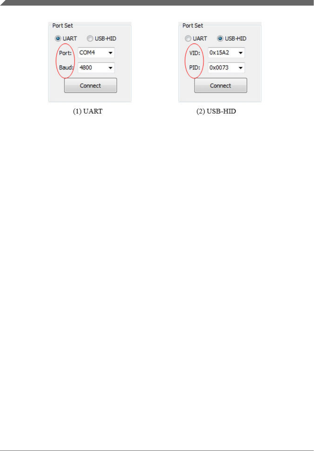
Figure 4. Port Set
4.1.1.1 Peripheral selection radio button
Currently, only the UART and USB-HID are supported by Kinetis Flash Tool. The user should select one of them in order to
establish the communication between the host and target device. UART is selected as the default when the program starts.
4.1.1.2 COM port combo box
Displays the currently selected COM device. The drop-down list portion of the control holds all COM ports on the host (PC)
in ascending order. Every time program starts, it scans Windows OS registry to find all serial devices. Both RS232 devices
and USB-CDC devices are supported.
The user can select one from the drop-down list, or just type in a COM port existing in the box. If the user types in an illegal
COM port name or a one that doesn’t exist in the list, the combo box selects the previous one when the focus leaves the text
box of this control.
User interface
Kinetis Flash Tool User's Guide, Rev. 0, 04/2016
6 Freescale Semiconductor, Inc.
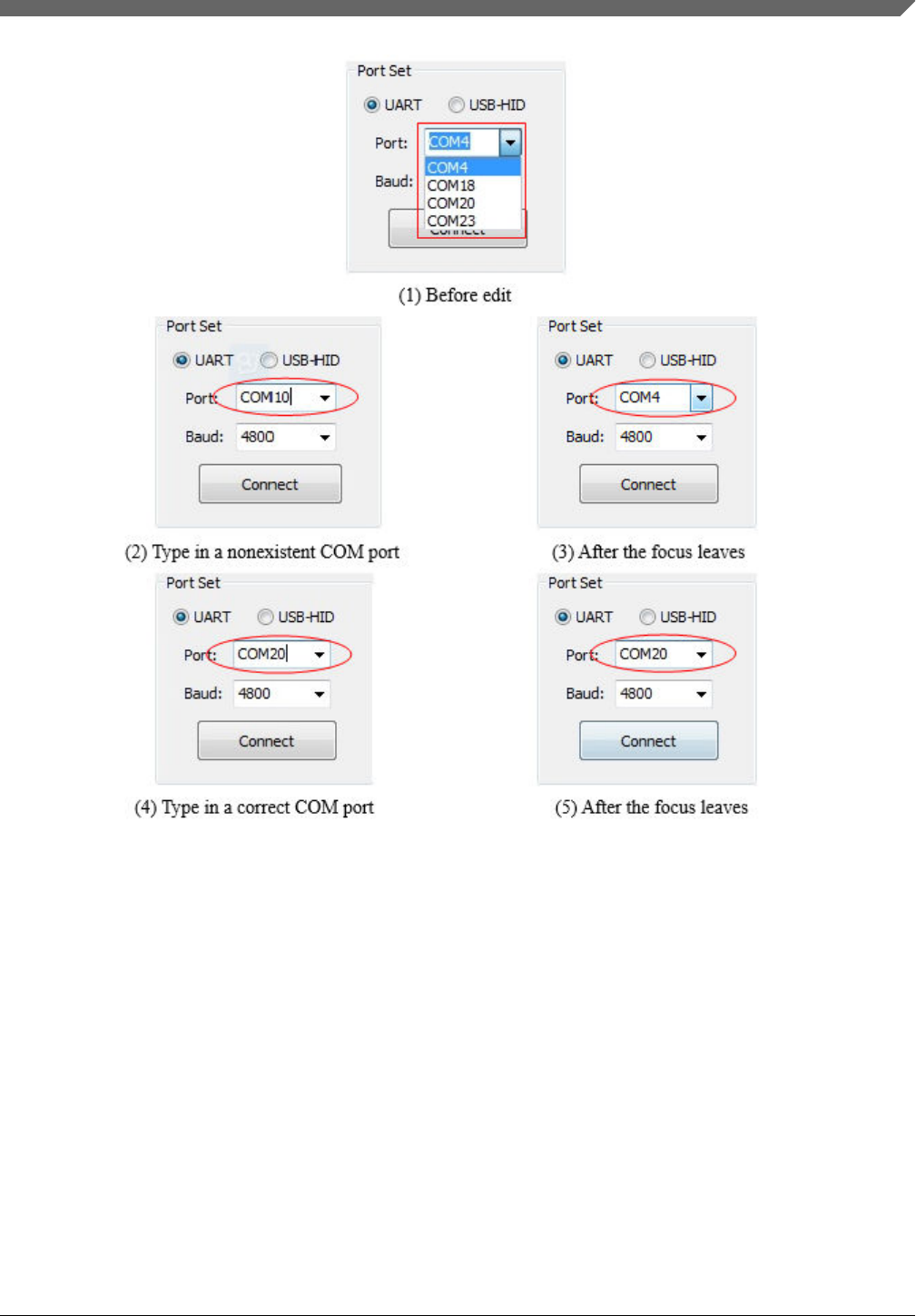
Figure 5. Edit COM port combo box
4.1.1.3 Baud rate combo box
Displays the currently selected baud rate. The drop-down list displays some typical baud rates supported by Kinetis
bootloader in the ascending order.
NOTE
The supported baud rate range is different on different target devices. See the reference
manual to ensure you are using the correct supported baud rate.
At startup, the program loads a maximum of 10 baud rates at the beginning of the list. If the configuration file is absent, the
program lists 9 typical baud rates, shown in Figure 6.
User interface
Kinetis Flash Tool User's Guide, Rev. 0, 04/2016
Freescale Semiconductor, Inc. 7
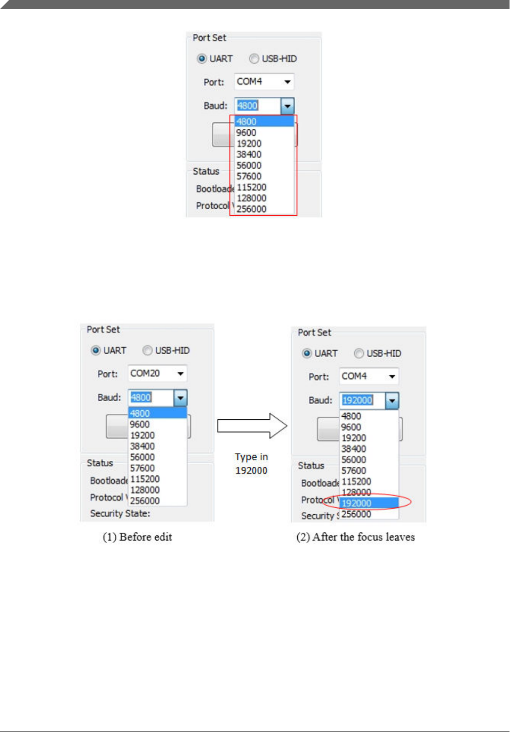
Figure 6. Baud rate list (default)
The user can select one from the drop-down list, or simply type a user-defined baud rate. If the user types an illegal baud rate
(non-numerical characters), the combo box selects the previous baud rate when the focus leaves the text box of this control.
If the user types a valid baud rate that does not exist in the list, this baud rate is then added to the list.
Figure 7. Insert new baud rate list
4.1.1.4 VID combo box
Displays the currently selected vendor ID. The drop-down list displays recently used VIDs. The most recently selected VID
is always at the front of the list.
Similar to the baud rate combo box, the program loads 10 VIDs at most. If the configuration file is absent, there is only one
VID, Kinetis bootloader default VID (0x15A2), listed in the combo box.
User interface
Kinetis Flash Tool User's Guide, Rev. 0, 04/2016
8 Freescale Semiconductor, Inc.
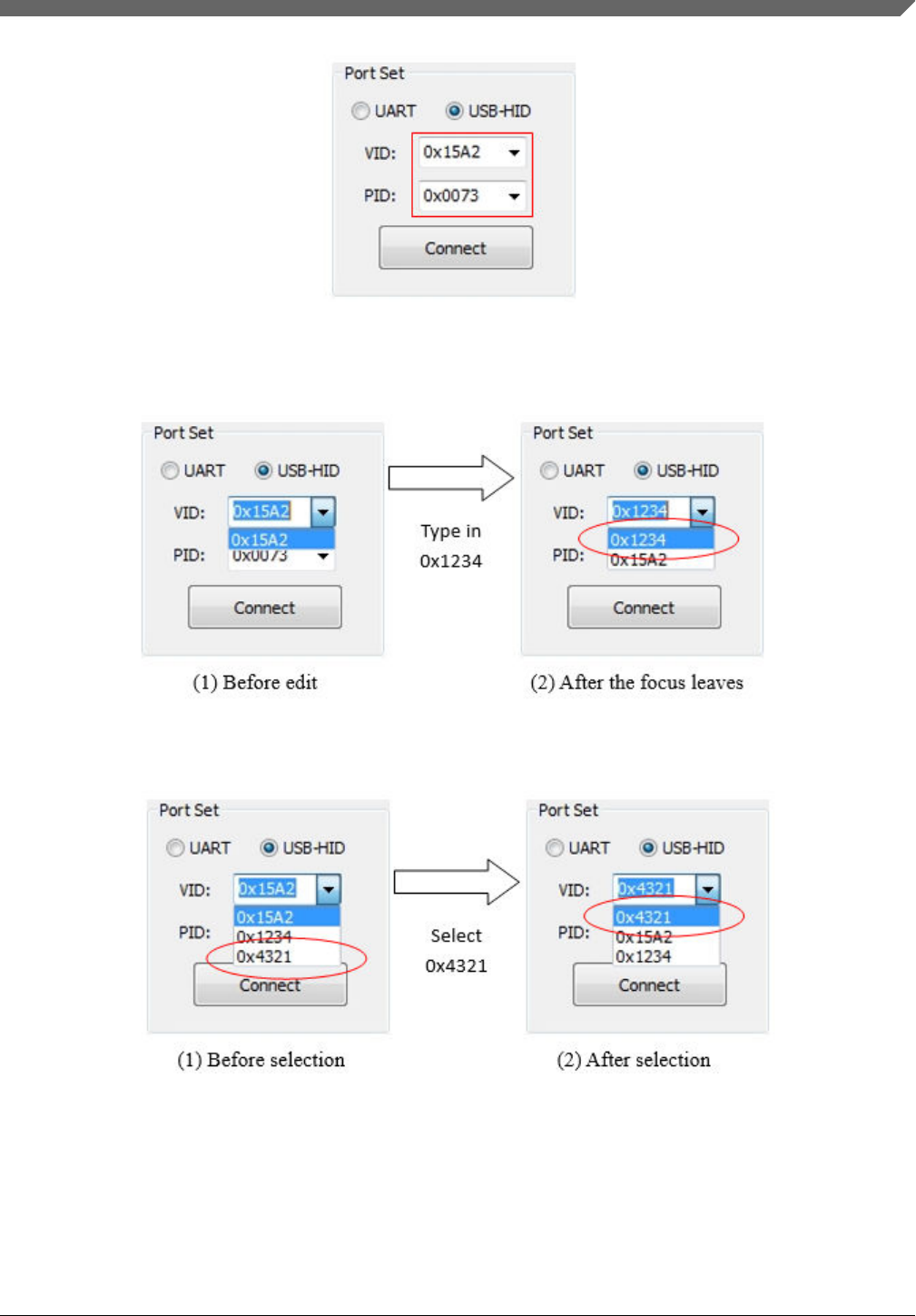
Figure 8. Default VID and PID
The user can select from the drop-down list, or just type in a user-defined VID, similar to the behavior of the baud rate
combo box.
Figure 9. Insert a new user-defined VID
Once a VID is selected, it is raised to the top of this list.
Figure 10. Selection change of VID
4.1.1.5 PID combo box
Displays the currently selected product ID. The drop-down list holds the most recently used PIDs. It has the same behavior as
the VID combo box. See Section 4.1.1.4, "VID combo box".
User interface
Kinetis Flash Tool User's Guide, Rev. 0, 04/2016
Freescale Semiconductor, Inc. 9
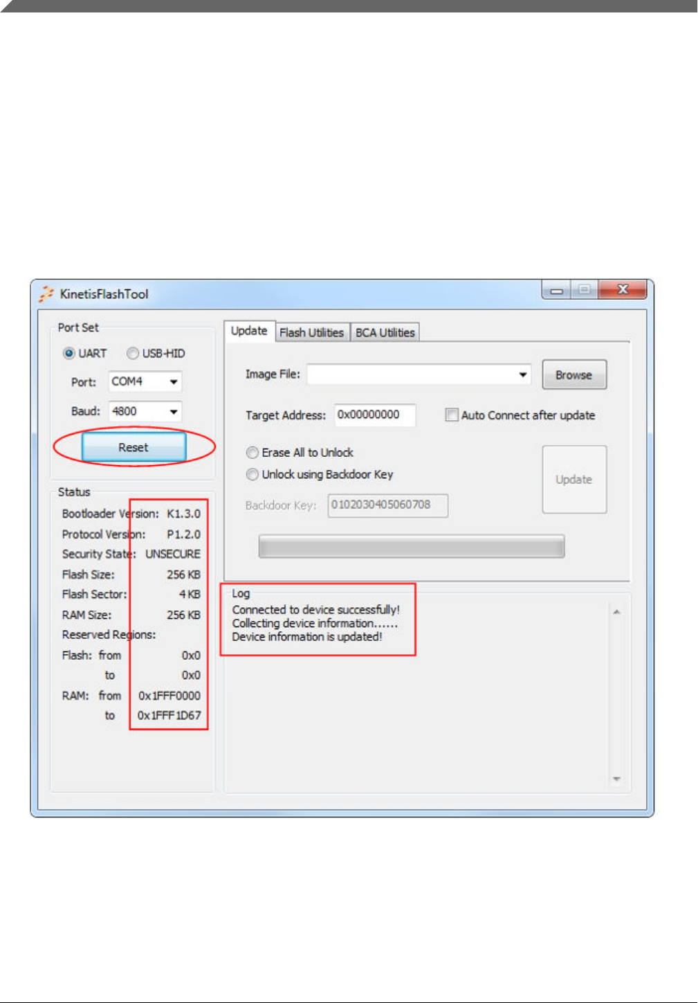
4.1.1.6 Connect/Reset button
The Connect/Reset button sends a get-property command to the Kinetis bootloader using the current peripheral configuration,
if there is no connected device. It sends a reset command if communication has been established.
Sending a get-property command tries to establish the communication to the Kinetis bootloader. Once the communication is
established, this sets the selected peripheral as active in the Kinetis bootloader and shuts down other peripherals. The text on
the button will be changed from "Connect" to "Reset".
Once the "Connect" button is clicked, Kinetis Flash Tool keeps sending the get-property command until the user clicks the
"Reset" button, changes the peripheral configuration, or updates the firmware without checking the auto connect box. The
user can exchange the device during this time, and the tool disconnects the removed device and connects the new device
automatically.
Figure 11. Connect to a device successfully
Sending a reset command disconnects the current device and puts Kinetis bootloader back to the get-active-peripheral state,
where all peripherals are again enabled and able to be selected. Whether or not the reset command is successfully executed,
the text on the button changes back to "Connect".
User interface
Kinetis Flash Tool User's Guide, Rev. 0, 04/2016
10 Freescale Semiconductor, Inc.

NOTE
1. When communication is established, any change of peripheral configuration sends
a reset command automatically.
2. If another operation is in execution (i.e., update, erase, program IFR, the connect/
reset operation, get-property command, or reset command), no command is sent
when this button is pressed.
Figure 12. Reset the device
4.1.2 Status
This panel displays properties of the target device and the Kinetis bootloader running on the device. The information in this
region is valid only when the communication is established.
Kinetis Flash Tool sends the get-property commands to collect this information once successfully connected to a device.
After this process, all information is displayed in this region. Sending a reset command clears the information at the same
time.
NOTE
Protocol Version is empty when connecting via USB-HID, because USB-HID uses the
USB communication protocol, not Kinetis bootloader serial protocol.
User interface
Kinetis Flash Tool User's Guide, Rev. 0, 04/2016
Freescale Semiconductor, Inc. 11
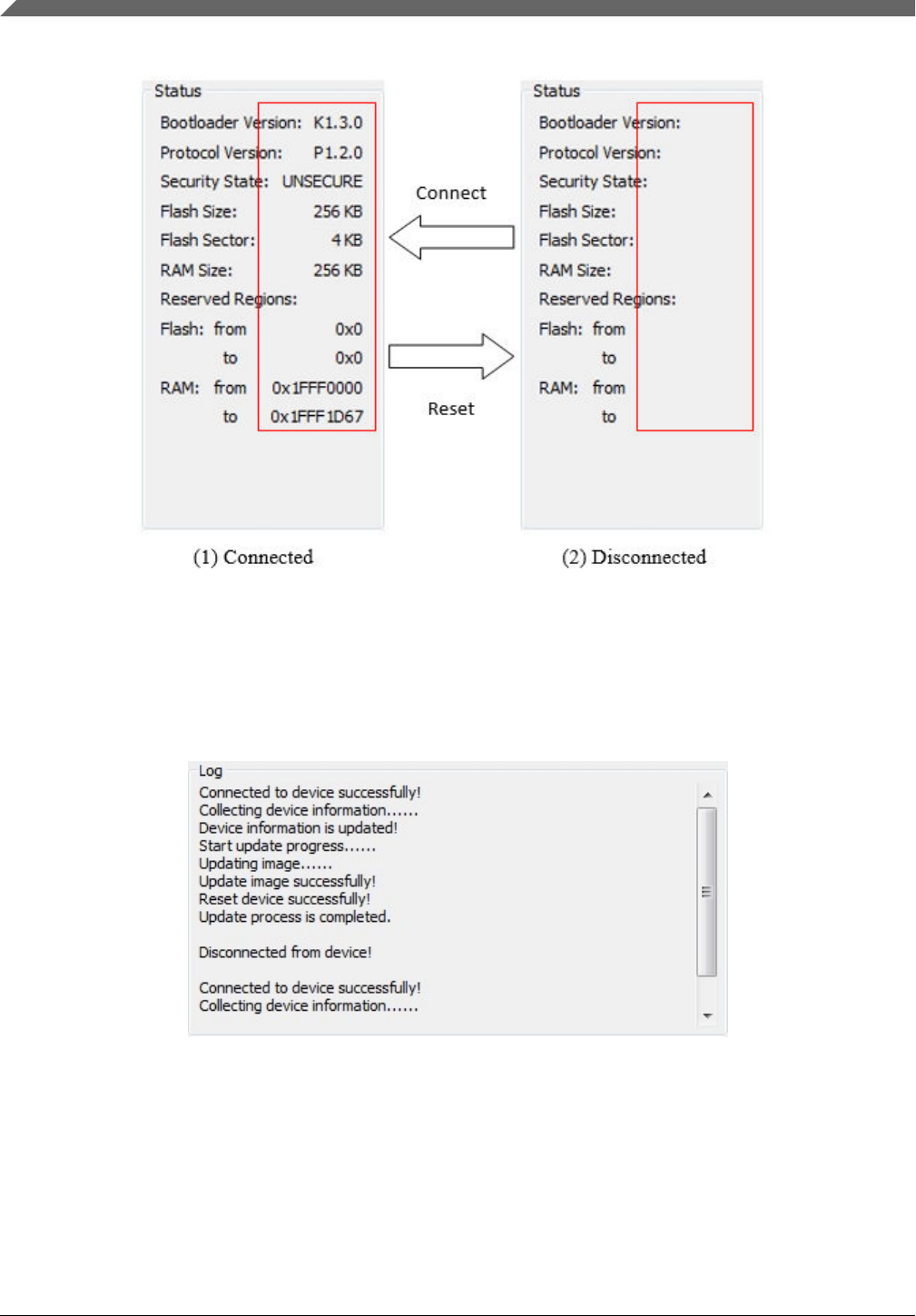
Figure 13. Status
4.1.3 Log window
Shows the results, warnings, and errors of user operations while being used.
Figure 14. Log window
4.1.4 Tab page
Currently, there are three tab pages in Kinetis Flash Tool, and each of them is responsible for one function.
•The update page is for writing the user application firmware to the Kinetis device's non-volatile memory. See Section
4.2, "Update tab page" for details.
User interface
Kinetis Flash Tool User's Guide, Rev. 0, 04/2016
12 Freescale Semiconductor, Inc.
•The flash utilities page is for flash erase and flash IFR programming. See Section 4.3, "Flash utilites tab page" for
details.
•The BCA utlilties page is for the BCA-related operation. See Section 4.4, "BCA utilites tab page" for details.
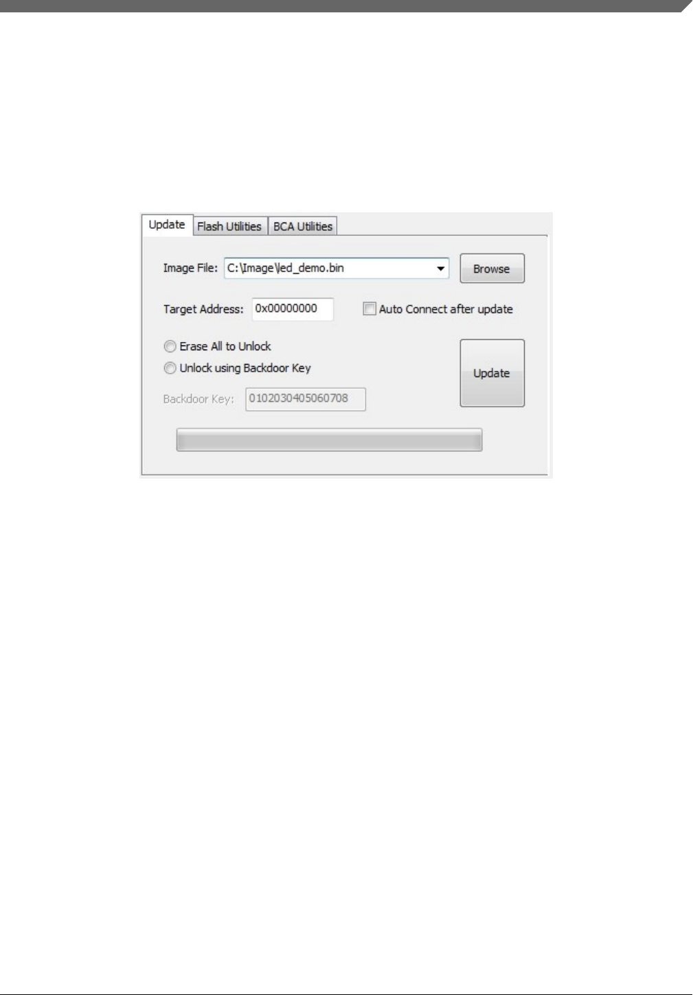
4.2 Update tab page
The update tab page is used to launch the update process, that writes the application image to the device.
Figure 15. Update tab page
4.2.1 Image file combo box
Displays the full path file name of the currently selected application image. The drop-down list holds the recently used full
path file names. The most recently selected file name is always at the head of the list.
User interface
Kinetis Flash Tool User's Guide, Rev. 0, 04/2016
Freescale Semiconductor, Inc. 13
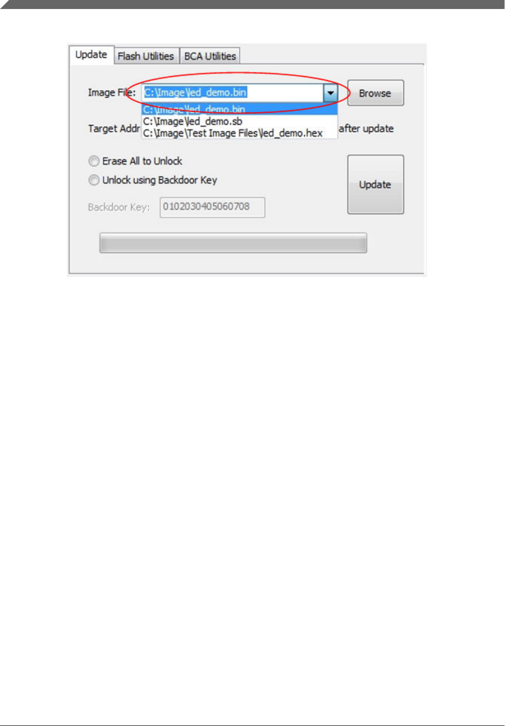
Figure 16. Image file combo box
Similar to the VID/PID selection combo box, the program loads a maximum of ten file names from the configuration file. If
the configuration file is absent, the drop-down list is empty. The user can select a file from the drop-list of the control, type in
a full path file name, or use the "Browse" button to locate the application image. If the user types in a file that does not exist
on the host, the textbox of this control clears when the focus leaves.
4.2.2 Browse button
Click the "Browse" button to locate the application image that is written to the Kinetis device. Currently, the supported file
types are .bin, .sb, .hex, .s19, and .srec.
User interface
Kinetis Flash Tool User's Guide, Rev. 0, 04/2016
14 Freescale Semiconductor, Inc.
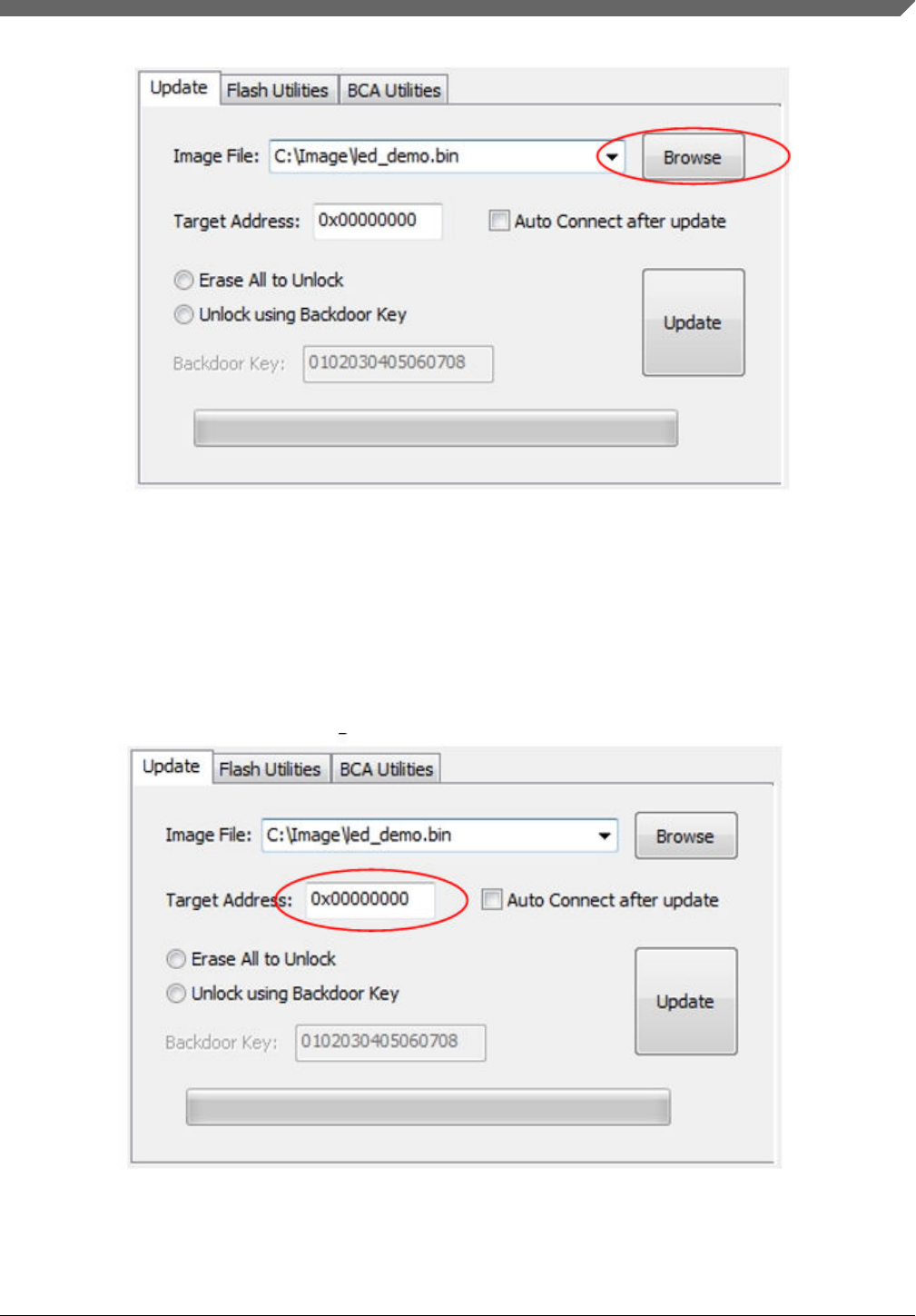
Figure 17. Browse button
4.2.3 Target address textbox
The target address textbox contains the address where the binary image will be placed. The address information must be
completed if the selected file is binary, which does not contain location information. For other supported file types, the
textbox is not editable, and address infromation is ignored.
Figure 18. Target address
User interface
Kinetis Flash Tool User's Guide, Rev. 0, 04/2016
Freescale Semiconductor, Inc. 15
The value can be any valid memory address supported by Kinetis bootloader. Ensure that the memory region to be written to
is not located at the reserved regions and has enough space. If the user wants the application to be launched automatically
when reaching timeout, the value depends on the device and implementation of the Kinetis bootloader.
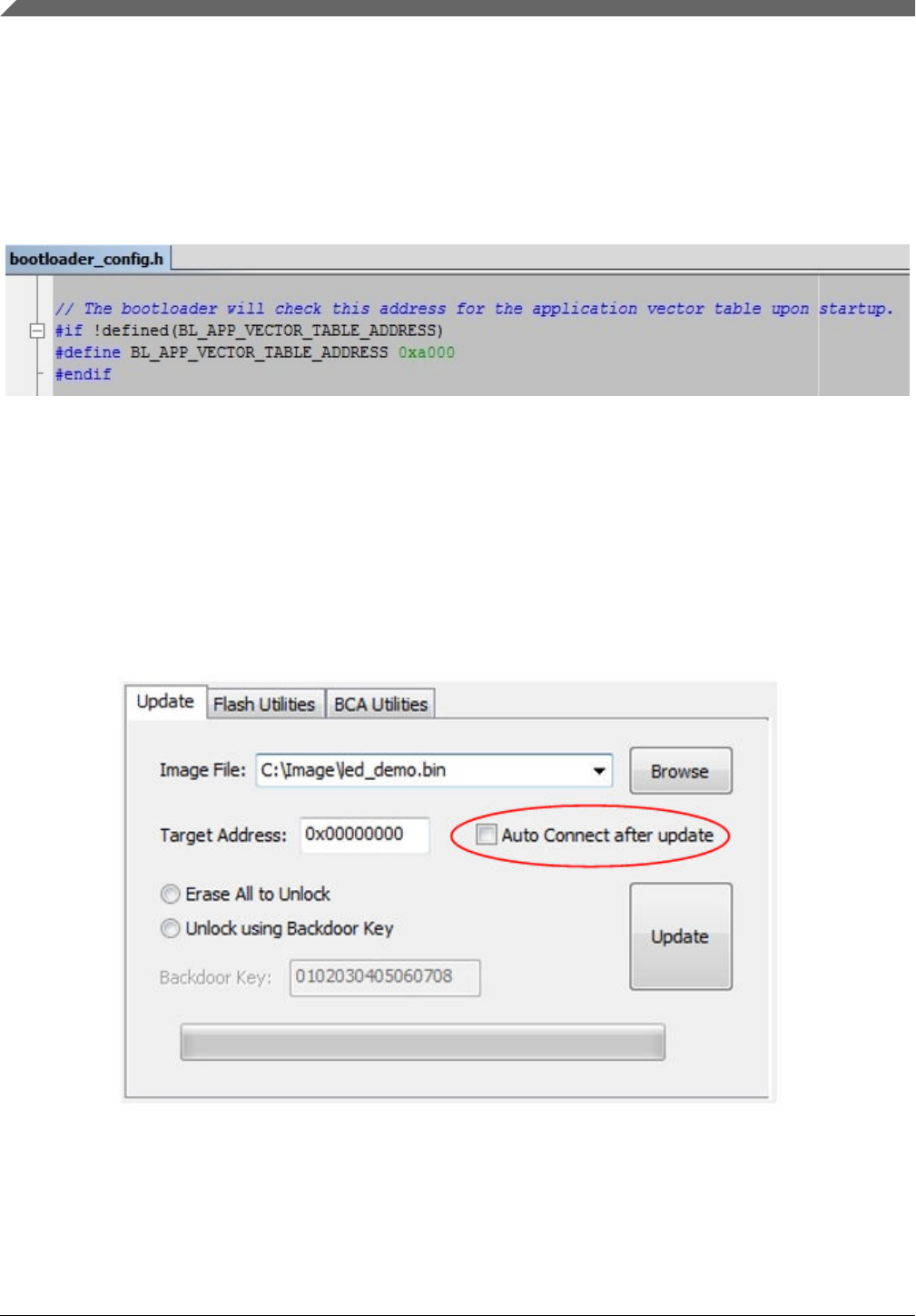
The target address should be zero (0) for ROM and flashloader implementations of the Kinetis bootloader.
For the flash-resident implementation of the Kinetis bootloader, the base address is determined by the macro,
BL_APP_VECTOR_TABLE_ADDRESS, which is defined in the bootloader_config.h file, which appears under the target/
($device)/src folder in the release package. $device indicates the part number of the selected device.
Figure 19. Target address value in bootloader_config.h file
NOTE
The user application written to the Kinetis device must be linked so the vector table is
located at the target address.
4.2.4 Auto connect check box
The autoconnect check box determines whether to reconnect to the device after the update.
Figure 20. Autoconnect check box
Kinetis Flash Tool sends the reset command after updating firmware, which sets the Kinetis bootloader back to the get-
active-peripheral state and disconnects the device from the host.
User interface
Kinetis Flash Tool User's Guide, Rev. 0, 04/2016
16 Freescale Semiconductor, Inc.
If the user wants to run an application, enusre this box is left unchecked. Kinetis Flash Tool will stop sending the get-
property command after the update progress, and Kinetis bootloader will exit the get-active-peripheral state and launch the
application after reaching timeout. Otherwise, Kinetis Flash Tool sends the get-property command immediately to re-
establish communication after the update progress is completed.
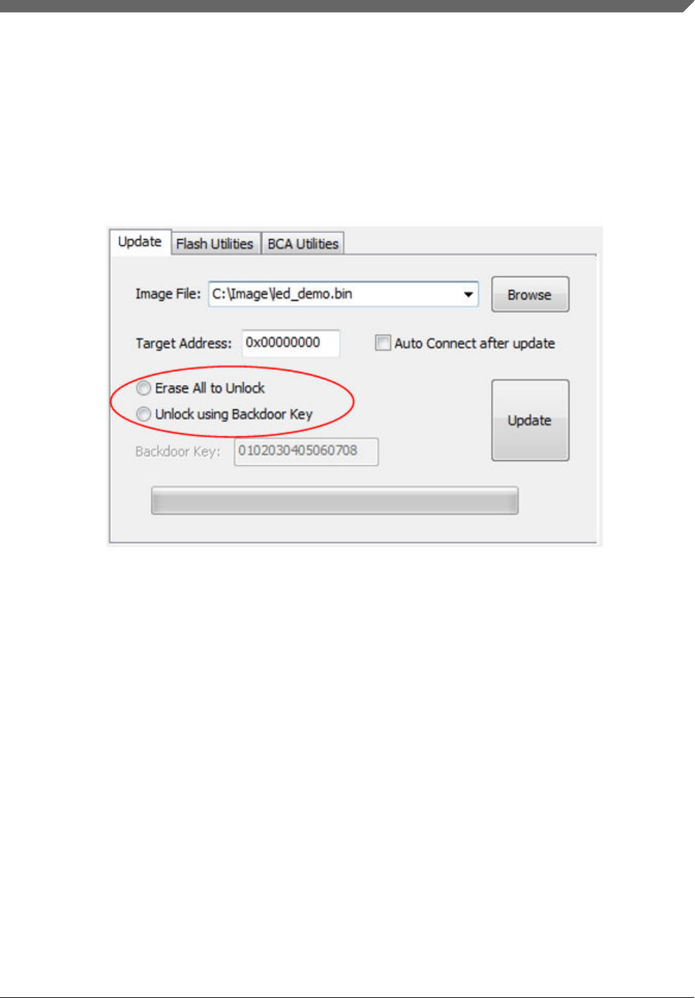
4.2.5 Security radio button
The security radio button offers two safety ways for the user to program the Kinetis device in the secure state.
Figure 21. Security radio button
The user can select one of these ways to unlock the device, or select neither option and instead download the firmware
directly without executing the unlock operation.
NOTE
1. Kinetis bootloader only supports programming secure devices directly via
encrypted SB file. See the Kinetis bootloader chapter in the target device's
reference manual to ensure whether SB file decryption is supported. Otherwise, the
update progress will fail.
2. If the device is in an unsecure state, no unsecure operation will be processed
regardless of which button is pressed.
4.2.5.1 Erase All to unlock
Erase All sends the flash-erase-all-unsecure command to the Kinetis bootloader during the update progress. All space of the
device's non-volatile memory is erased, and the device is set to the unsecure state. The Kinetis bootloader may not support
the mass erase command on some devices. See the Kinetis bootloader chapter of the device's reference manual.
NOTE
The flash-erase-all-unsecure command leaves the Kinetis device in an unsecure state until
the user changes to the secure state.
User interface
Kinetis Flash Tool User's Guide, Rev. 0, 04/2016
Freescale Semiconductor, Inc. 17
4.2.5.2 Unlock using backdoor key
The unlock using backdoor key sends the flash-security-disable command using the backdoor key in the textbox below
during the update progress. If the backdoor key matches the key stored in the device, the device is set into the unsecure state
until reset.
NOTE
At the last operation of the update progress, the Kinetis Flash Tool sends the reset
command to set the device back into the secure state.
4.2.5.3 Backdoor key textbox
The backdoor key textbox contains 16 hex digits used for unlocking the device. The textbox is enabled only when the radio
button "Unlock using Backdoor Key" is selected. The key in the textbox must be 16 hex digits with no leading "0x".
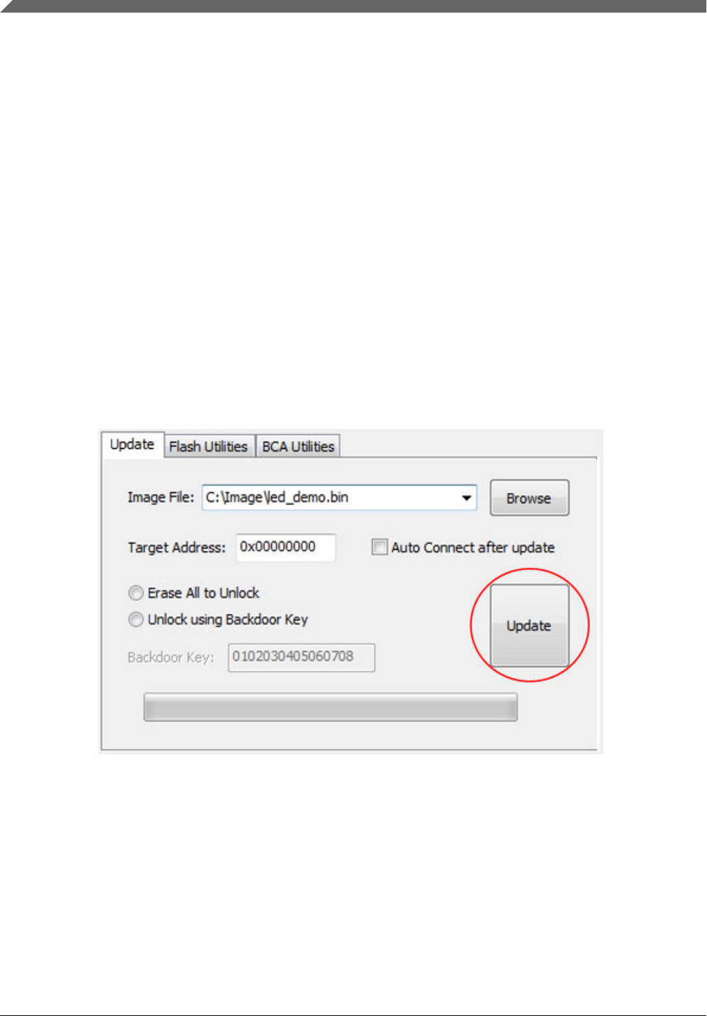
4.2.6 Update button
Click the "Update" button to start the update process. The "Update" button is enabled only when a valid image file is
selected.
Figure 22. Update button
The update process consists of the following steps:
1. Check if communication is already established. If yes, go to Step 4. Otherwise, follow Step 2.
2. Send the get-property command to establish the connection. Kinetis Flash Tool will try five attempts with 500 ms
intervals. If communication cannot be established, the update progress terminates.
3. Once successfully connected to a device, Kinetis Flash Tool sends the command to get the device's security state.
4. If the device is in an unsecure state, or no unsecure operation is selected, follow Step 6.
5. Execute the unlocking operation. For details regarding the unlocking operation, see Section 4.2.5, "Security radio
button".
User interface
Kinetis Flash Tool User's Guide, Rev. 0, 04/2016
18 Freescale Semiconductor, Inc.

6. Erase the region of flash starting at the base address, with a length equal to the size of the application image file using
the flash-erase-region command.
NOTE
1. Flash is erased on sector boundaries, so the amount erased may be more than the
size of the image.
2. The SB file should include the erase command. Kinetis Flash Tool will not perform
the erase operation for the SB file.
1. Write the application image to the base address of the Kinetis device flash using the write-memory or receive-sb-file
command.
2. Reset the device with the reset command. This causes the device to disconnect from the host.
User interface
Kinetis Flash Tool User's Guide, Rev. 0, 04/2016
Freescale Semiconductor, Inc. 19
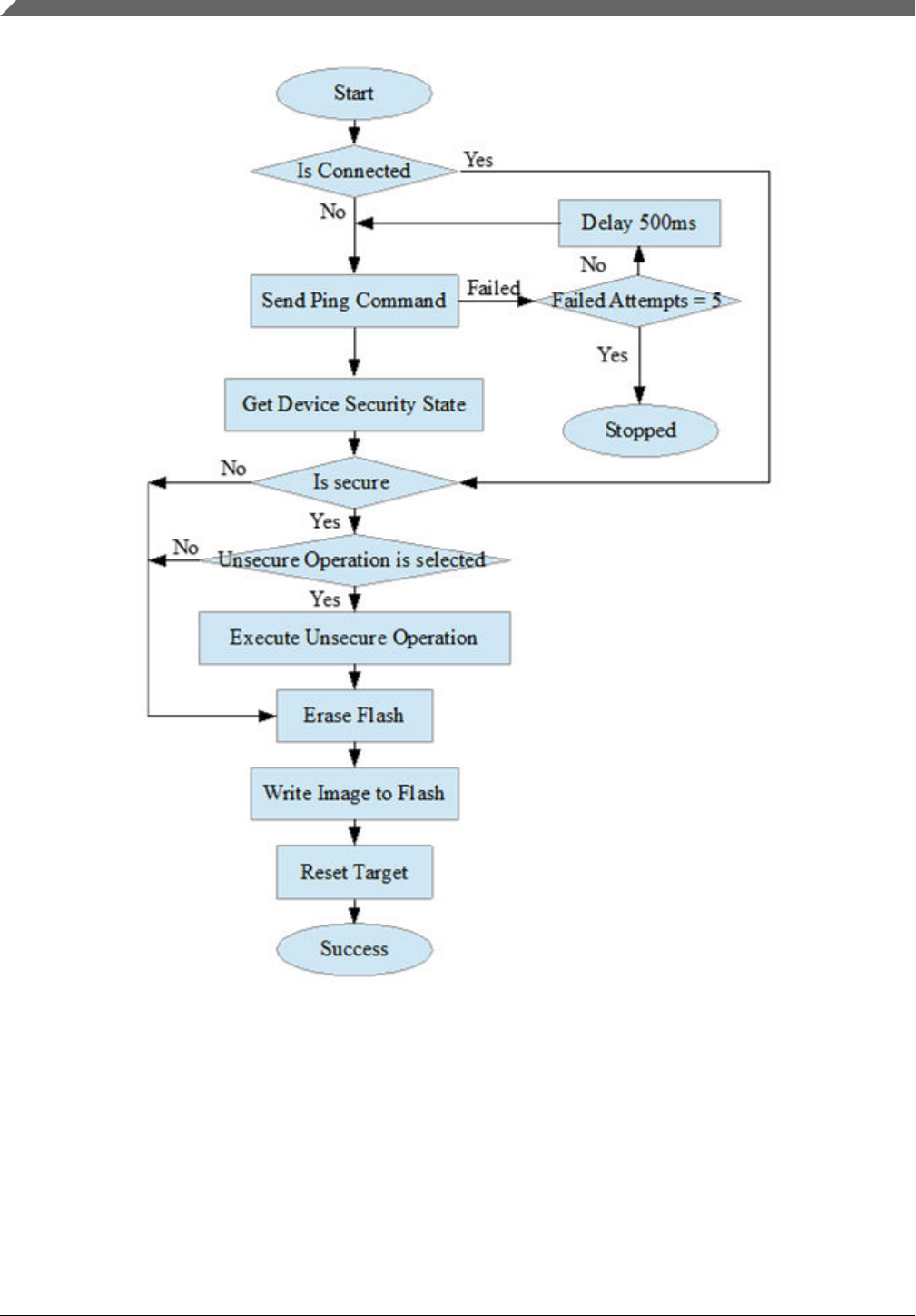
Figure 23. Update flowchart
4.2.7 Progress bar
Displays the progress of the current update process.
User interface
Kinetis Flash Tool User's Guide, Rev. 0, 04/2016
20 Freescale Semiconductor, Inc.
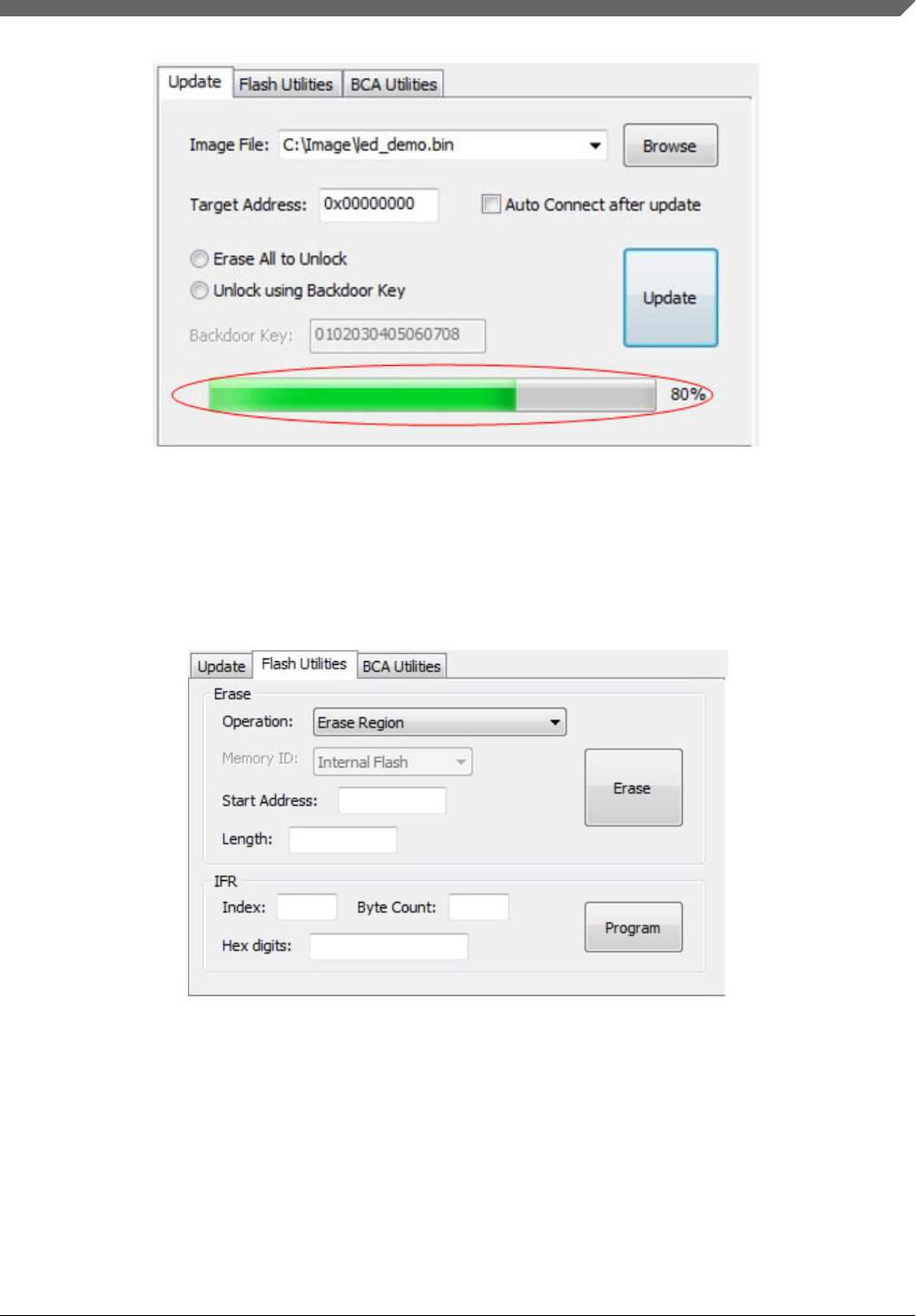
Figure 24. Progress bar
4.3 Flash utilities tab page
The flash utilities tab page is used to launch the erase flash process and programming IFR process.
Figure 25. Flash utilities tab page
4.3.1 Erase
The erase group contains the controls used for erasing the internal or external non-volatile memory region.
4.3.1.1 Erase operation combo box
User interface
Kinetis Flash Tool User's Guide, Rev. 0, 04/2016
Freescale Semiconductor, Inc. 21
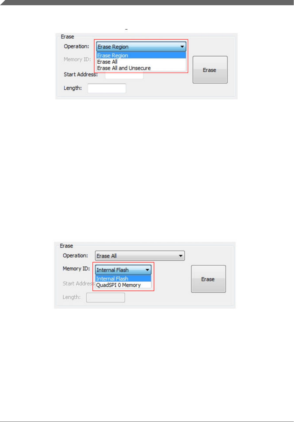
Contains three choices for use, "Erase Region", "Erase All", and "Erase All and Unsecure".
Figure 26. Erase operation combo box
The erase region operation performs an erase of one or more sectors of the flash memory or a specified range of flash within
the connected QuadSPI flash devices. Start Address and Length are the two parameters required for this operation.
The erase all operation performs an erase of the entire internal flash memory or of the QuadSPI memory. Memory ID is
required for this operation.
The erase all and unsecure operation performs a mass erase of the internal flash memory, including protected sectors. Only
internal flash memory is saved.
NOTE
Erase-all-unsecure is only supported on internal flash, whereas erase-all is supported on
both internal flash and QuadSPI flash.
4.3.1.2 Memory ID combo box
Contains two choices, "Internal Flash" and "QuadSPI 0 Memory". This combo box is enabled only when the erase all
operation is selected.
Figure 27. Memory ID
NOTE
The QuadSPI memory must be configured before erasing.
4.3.1.3 Start address textbox
Contains the start address of a specified flash region to erase. This textbox is enabled only when the erase region operation is
selected.
User interface
Kinetis Flash Tool User's Guide, Rev. 0, 04/2016
22 Freescale Semiconductor, Inc.
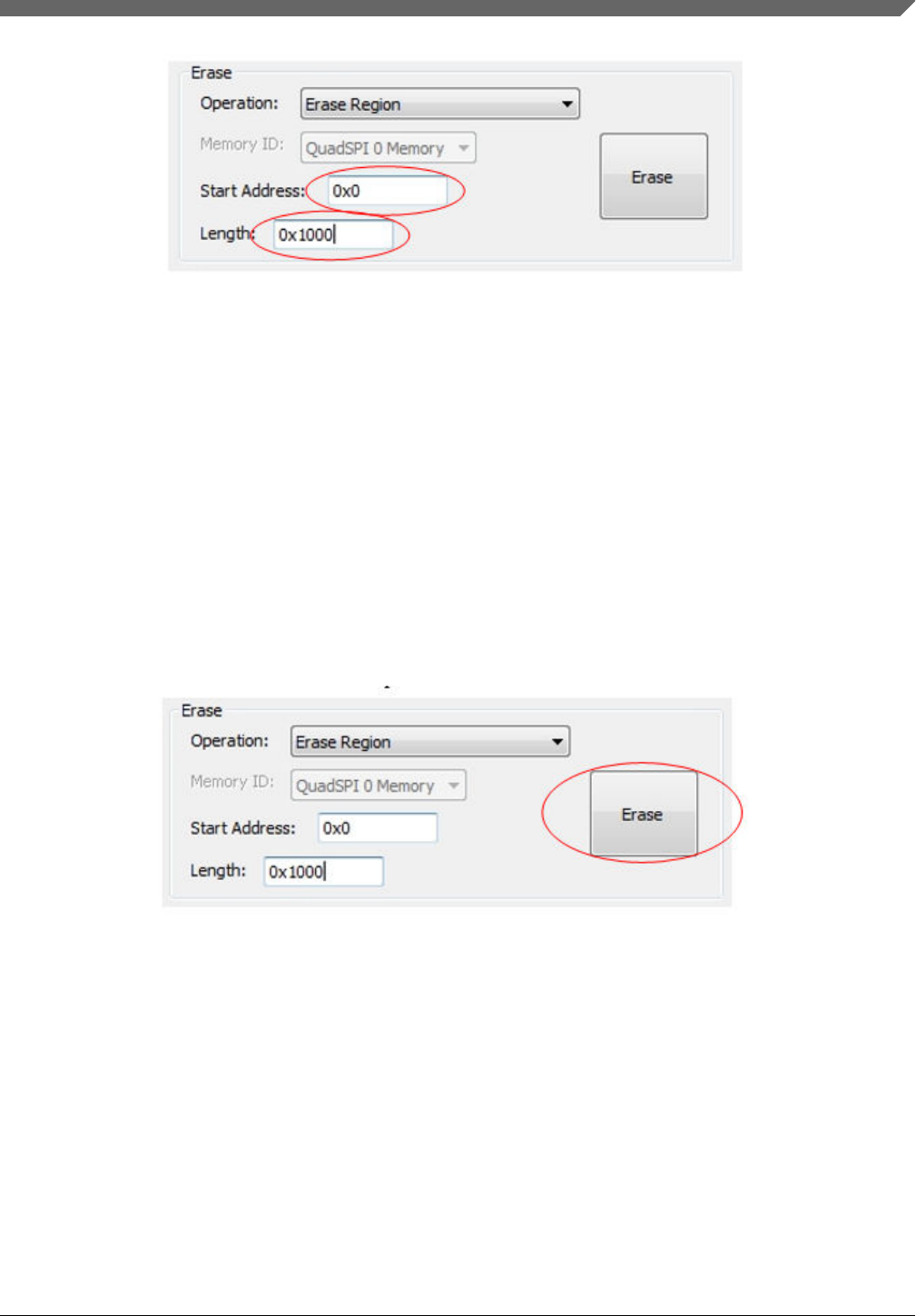
Figure 28. Start address and length
NOTE
The start address must be a valid address on the internal flash memory.
4.3.1.4 Length textbox
Contains the length in bytes of a specified flash region to erase. This textbox is enabled only when the erase region operation
is selected.
NOTE
Note that the erase region is forced to the next flash sector boundary.
4.3.1.5 Erase button
Click the "Erase" button to start the erase process.
Figure 29. Erase button
The user must press the connect button to establish the communication first, or the erase operation is terminated.
4.3.2 IFR
The IFR group contains the controls used for programming IFR.
User interface
Kinetis Flash Tool User's Guide, Rev. 0, 04/2016
Freescale Semiconductor, Inc. 23

Figure 30. IFR group
4.3.2.1 Index textbox
The index textbox contains the index of the IFR field. See the flash memory module chapter of the device's reference manual
to receive the available IFR index.
NOTE
1. There is no erase capability for some IFR indexes.
2. For an erasable IFR, this field can be erased by the erase all and the erase all and
unsecure commands.
4.3.2.2 Byte count textbox
Contains the size, in bytes, of each IFR index. This parameter must be 4-byte aligned for non-FAC fields, or 8-byte aligned
for FAC fields. The user also can get this information from device’s reference manual.
4.3.2.3 Digits textbox
Contains 8 or 16 hex digits to write to IFR region. The digits in the textbox must be 8 or 16 hex digits with no leading “0x”.
4.3.2.4 Program button
Click the "Program" button to start the programming IFR process. The user must press the correect button to establish
communcation first, or the programming operation is terminated.
NOTE
Kinetis Flash Tool does not execute the erase operation during the programming process.
Any attempt to reprogram an IFR field gets an error response. Therefore, execute the
mass erase command first.
4.4 BCA utilities tab page
The BCA utilities tab page offers several BCA-related features. Only the binary file format is supported.
User interface
Kinetis Flash Tool User's Guide, Rev. 0, 04/2016
24 Freescale Semiconductor, Inc.
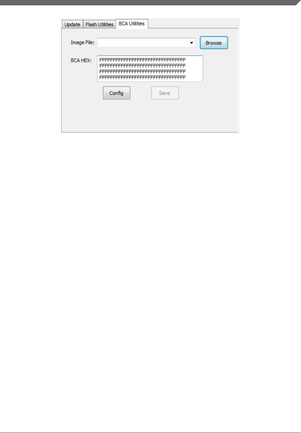
Figure 31. BCA utility tab page
4.4.1 Image file combo box
See Section 4.2.1, "Image file combo box".
4.4.2 Browse button
See Section 4.2.2, "Browse button".
4.4.3 BCA hex textbox
The BCA hex textbox contains the BCA hex digits. The digits are separated into four lines with a Windows OS-style ending.
If a binary file is selected, binaries at the BCA region are read and displayed in the BCA hex textbox. The user can modify
the binaries directly, then click the "Save" button to write new BCA digits back to the binary file.
User interface
Kinetis Flash Tool User's Guide, Rev. 0, 04/2016
Freescale Semiconductor, Inc. 25
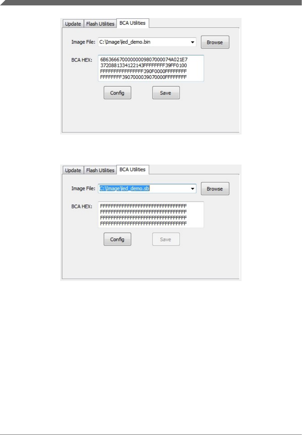
Figure 32. BCA HEX (binary is selected)
If no file or a different type of file is selected, the textbox fills with all 0xFFs.
Figure 33. BCA HEX (file of other types is selected)
NOTE
1. If the binary file is less than 1 K bytes, Kinetis Flash Tool appends 0xFFs at the
end of the file to extend it to 1 K bytes.
2. Do not type illegal characters in the BCA hex textbox. If an illegal character is
detected, this byte (two characters) is ignored.
3. Use a Windows OS-style ending. Do not use a UNIX-style ending.
4.4.4 Config button
Click the "Config" button to open the UI configuration page. Binaries in the BCA hex textbox are loaded to the new UI page.
User interface
Kinetis Flash Tool User's Guide, Rev. 0, 04/2016
26 Freescale Semiconductor, Inc.
4.4.5 Save button
Click the "Save" button to write the digits in the BCA hex textbox to the binary image file. This button is enabled only when
the selected file is a valid binary file.
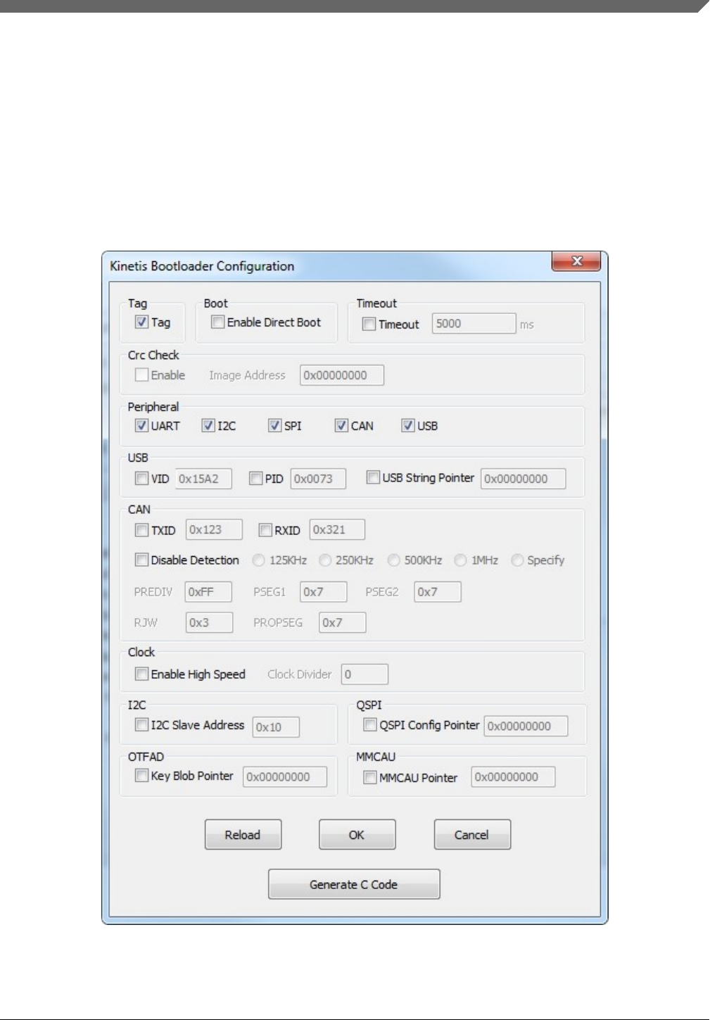
4.5 Bootloader configuration page
The bootloader configuration page offers UI controls for the user to generate BCA binaries or a BCA C structure. The user
can open this page by clicking the "Config" button in the BCA utilities tab page.
Figure 34. Bootloader configuration page
User interface
Kinetis Flash Tool User's Guide, Rev. 0, 04/2016
Freescale Semiconductor, Inc. 27
4.5.1 Check boxes
Check the boxes to enable corresponding config and the associated textbox if it has one. If a config is not enabled, the
relevant bits in the BCA are filled with 1s when generating BCA binaries or C structure.
NOTE
The CRC-enabled check box will be disabled if no valid binary file is selected. CRC
calculation needs the final binary image.
4.5.2 Textboxes
Textboxes contain the digits of the corresponding config. The textbox is enabled only when the associated check box is
checked.
NOTE
1. Do not enter overflowing digits, otherwise the overflowed bits are ignored when
generating.
2. The value of the image address at CRC check group is the start address where the
image will be placed to.
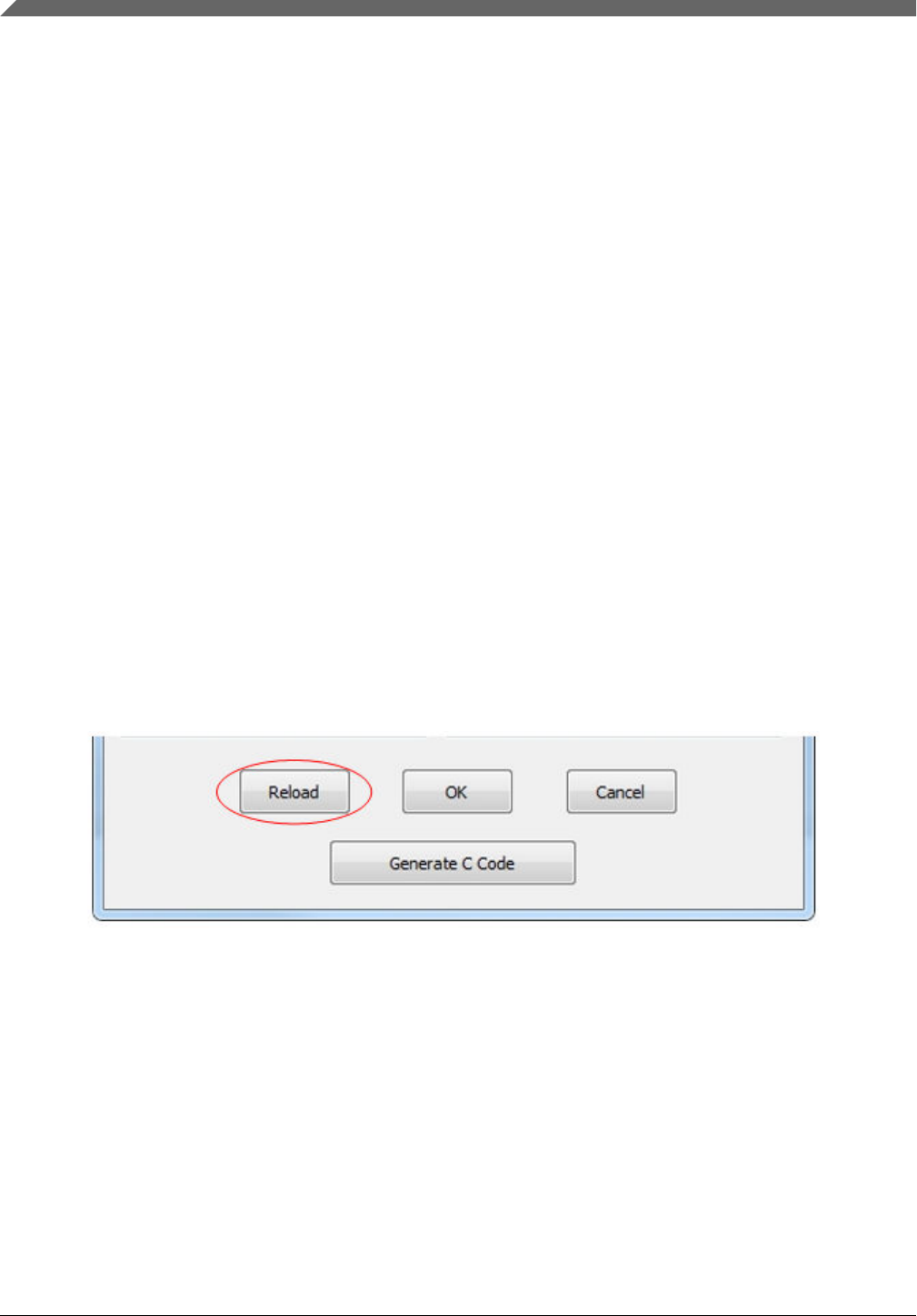
4.5.3 Reload button
Click the "Reload" button to abandon the changes and reset the controls to the state that the bootloader configuration page
just opened.
Figure 35. Reload button
4.5.4 OK button
Click the "OK" button to generate new BCA binaries according to the changes the user has made. The new binaries are
updated to the BCA hex textbox.
User interface
Kinetis Flash Tool User's Guide, Rev. 0, 04/2016
28 Freescale Semiconductor, Inc.

Figure 36. Reload button
NOTE
The new BCA binaries will not be saved to the image file by clicking the "OK" button.
Instead, click the "Save" button in the BCA utilities tab page to execute save progress.
4.5.5 Cancel button
Click the 'Cancel' button to abandon the changes the user has made and go back to the BCA utilities tab page.
Figure 37. Cancel button
4.5.6 Generate C code button
Click the "Generate C code" button to begin the process of generating C code files.
Figure 38. Generate C code button
This file contains the definition of the Kinetis bootloader configuration structure and a variable filled with configuration data.
The user can use this code for their application projects. For step-by-step instruction and usage, see Section 5.8, "Integrate
config file to user project".
User interface
Kinetis Flash Tool User's Guide, Rev. 0, 04/2016
Freescale Semiconductor, Inc. 29
NOTE
Three parameters of CRC are filled with all 0xFFs when generating, because CRC
calculation needs the final binary image.
5 Typical usage
This section describes the step-by-step usage of the Kinetis Flash Tool.
5.1 Quick update
1. Launch Kinetis Flash Tool.
Figure 39. Launch the Kinetis Flash Tool
2. Select the peripheral. Currently, only UART and USB-HID are supported.
3. Configure the peripheral. The COM port and baud rate must be specified for UART, while VID and PID must be
configured for USB-HID.
Typical usage
Kinetis Flash Tool User's Guide, Rev. 0, 04/2016
30 Freescale Semiconductor, Inc.
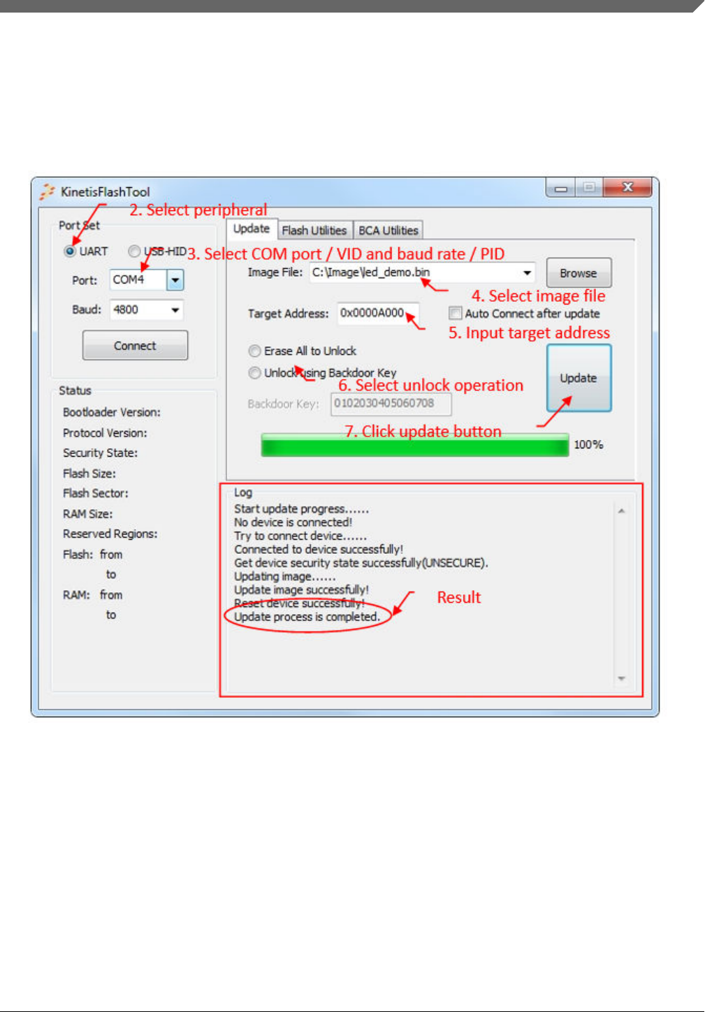
4. Select the image file. If the image file is not in the combo box list, type the full path file name into the textbox, or use
the "Browse" button to locate the image file.
5. If the selected image file is binary, the target address must be specified.
6. Select the unlock operation. If the device is not in a secure state, no unlock operation will be executed. Select an
operation if you are not sure whether the device is secure.
7. Click the "Update" button to start the process.
8. After a few seconds, the application will run after reaching timeout.
Figure 40. Quick update
5.2 Normal update
1. Follow the steps 1 to 3 of the quick update.
2. Click the "Connect" button to connect the target device.
Typical usage
Kinetis Flash Tool User's Guide, Rev. 0, 04/2016
Freescale Semiconductor, Inc. 31
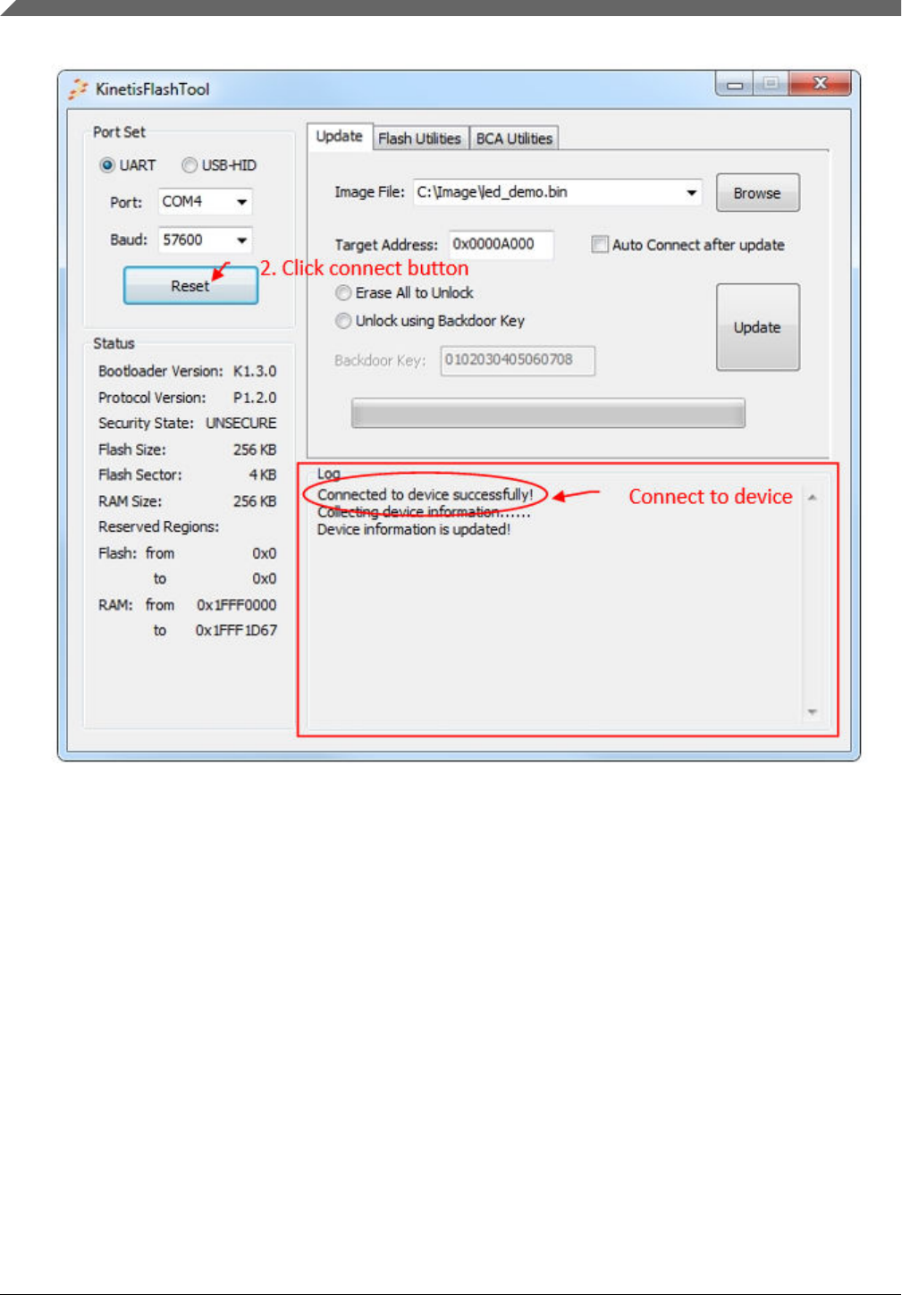
Figure 41. Connect to a target device
3. Select the image file. If the image file is not in the combo box list, type the full path name into the textbox of this
control, or use the "Browse" button to specify the image file.
4. If the selected image file is binary, the target address must be specified.
5. Select the unlock operation. The user can get the security information from the status region.
6. Click the "Update" button to start the process.
7. After a few seconds, the application will run after reaching timeout.
Typical usage
Kinetis Flash Tool User's Guide, Rev. 0, 04/2016
32 Freescale Semiconductor, Inc.
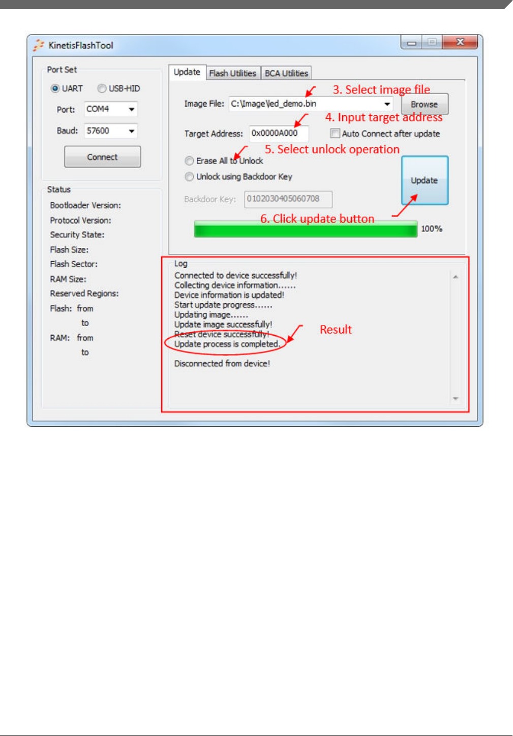
Figure 42. Result of normal update
5.3 Continuous update
An extra step is needed before clicking the "Update" button for a quick update or normal update. The following is an example
for a normal update.
1. Follow the steps 1 to 5 of the normal update.
2. Select the check box "Auto Connect after update".
3. Click the "Update" button to start the progress.
4. Kinetis Flash Tool ties to establish communication once the progress update is finished.
5. The user can change the device or board after the update.
6. Once communication is re-established, the user can perform the second update.
7. Click the "Update" button for the second update.
NOTE
The port set must not be changed. Otherwise, the Kinetis Flash Tool stops the sent
commands to try to establish communication until the user presses the connect button.
Typical usage
Kinetis Flash Tool User's Guide, Rev. 0, 04/2016
Freescale Semiconductor, Inc. 33
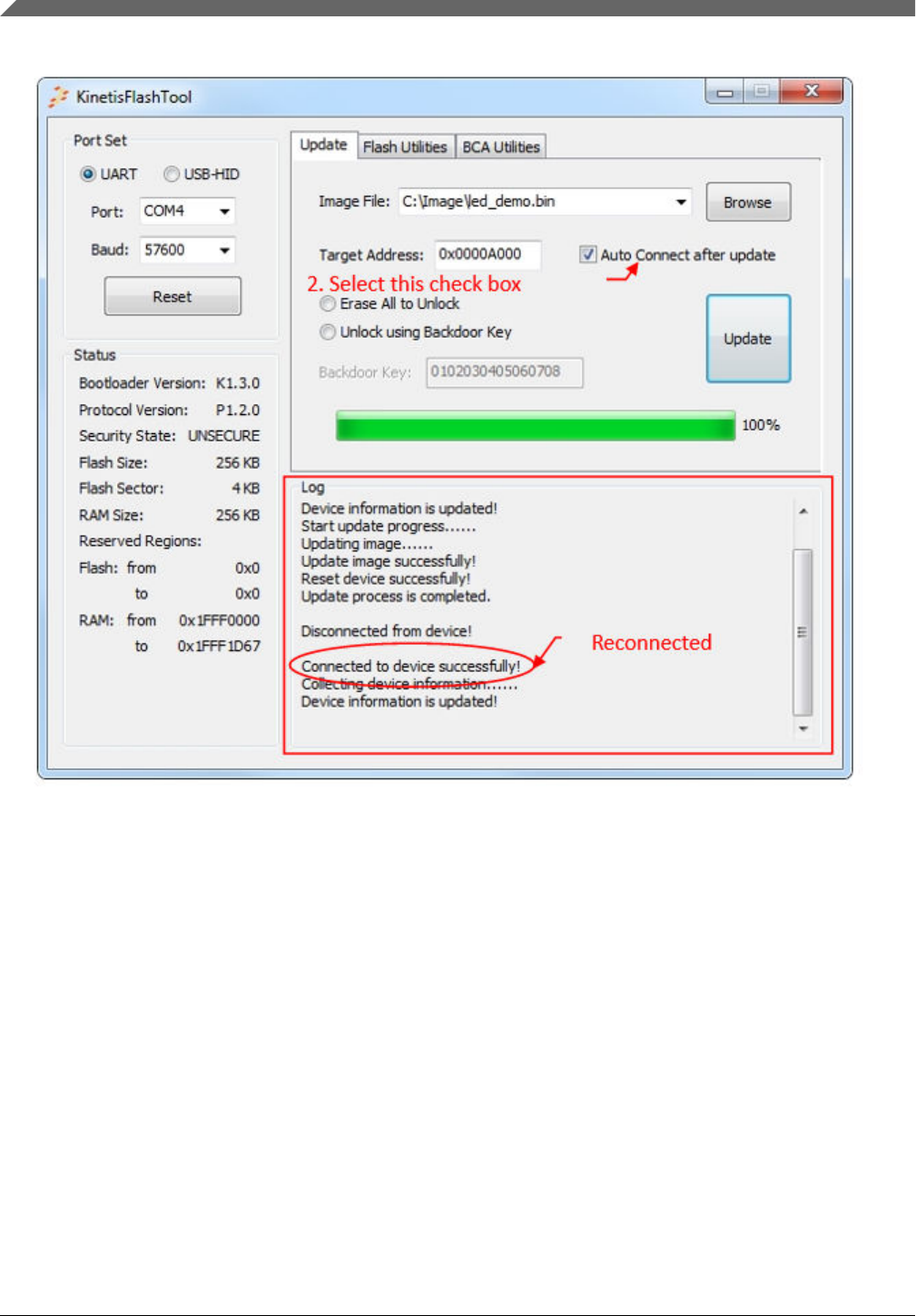
Figure 43. Continuous update
5.4 Flash erase
5.4.1 Flash erase region
1. Follow steps 1 and 2 in the normal update to connect the target device.
2. Select the flash utilities tab page.
3. Select the erase region operation.
4. Fill the start address and length.
5. Click the "Erase" button.
Typical usage
Kinetis Flash Tool User's Guide, Rev. 0, 04/2016
34 Freescale Semiconductor, Inc.
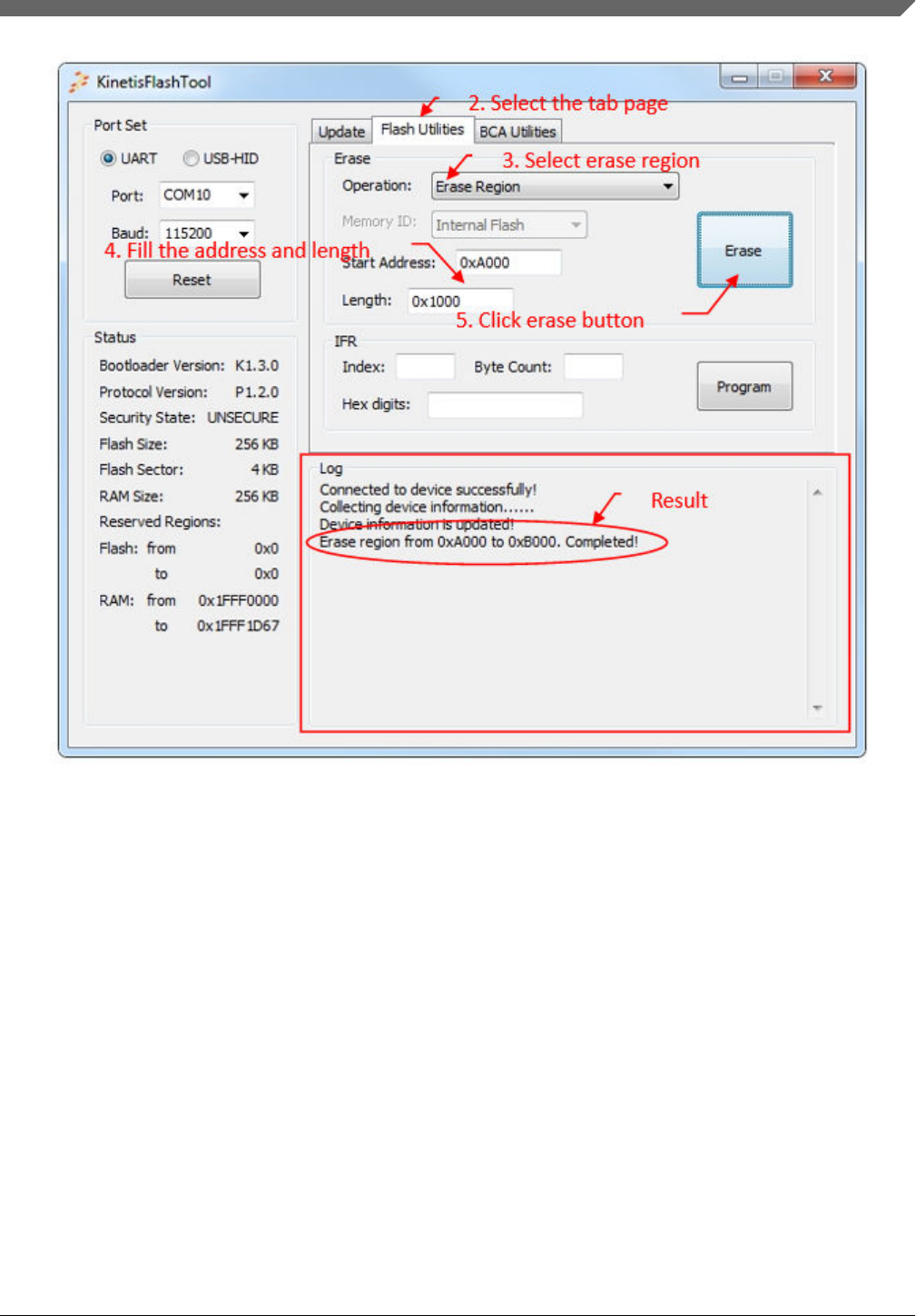
Figure 44. Flash erase region
5.4.2 Flash erase all
1. Follow steps 1 and 2 in the flash erase region.
2. Select the erase region operation.
3. Select memory ID.
4. Click the "Erase" button.
Typical usage
Kinetis Flash Tool User's Guide, Rev. 0, 04/2016
Freescale Semiconductor, Inc. 35

Figure 45. Flash erase all
5.4.3 Flash erase all and unsecure
1. Follow steps 1 to 2 in the flash erase region.
2. Select the erase region operation.
3. Click the "Erase" button.
Typical usage
Kinetis Flash Tool User's Guide, Rev. 0, 04/2016
36 Freescale Semiconductor, Inc.
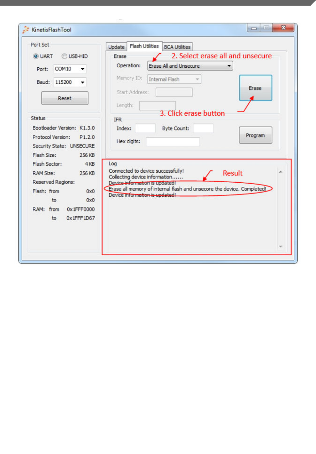
Figure 46. Flash erase all and unsecure
5.5 Program IFR
1. Follow steps 1 to 2 of the normal update to connect to the target device.
2. Select the flash utilities tab page.
3. Fill the index and byte count.
4. Fill IFR digits.
5. Click the "Program" button.
Typical usage
Kinetis Flash Tool User's Guide, Rev. 0, 04/2016
Freescale Semiconductor, Inc. 37
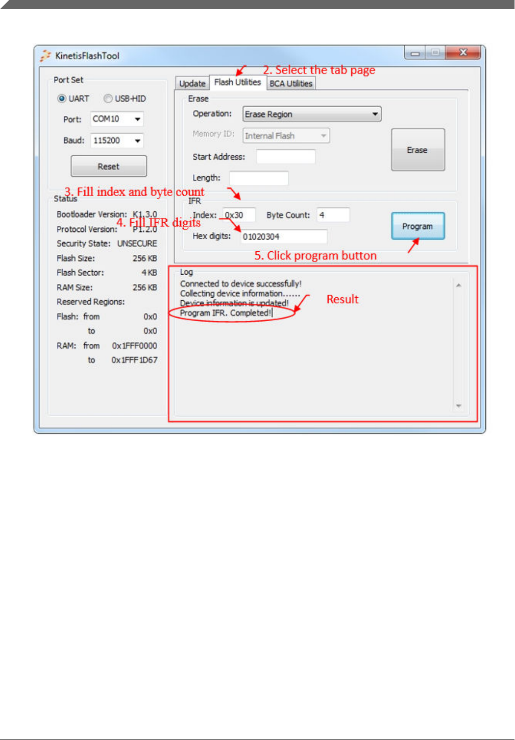
Figure 47. Program IFR
5.6 Configure BCA
1. Launch Kinetis Flash Tool.
2. Select the BCA utilities tab page.
3. Select the binary image file. If the image file is not in the combo box list, type the full path file name into the textbox of
this control, or use the "Browse" button to specify the image file.
4. Once a binary file is selected, the BCA binaries are displayed in the BCA hex textbox.
5. Click the "Config" button, and the Kinetis bootloader configuration page opens.
Typical usage
Kinetis Flash Tool User's Guide, Rev. 0, 04/2016
38 Freescale Semiconductor, Inc.
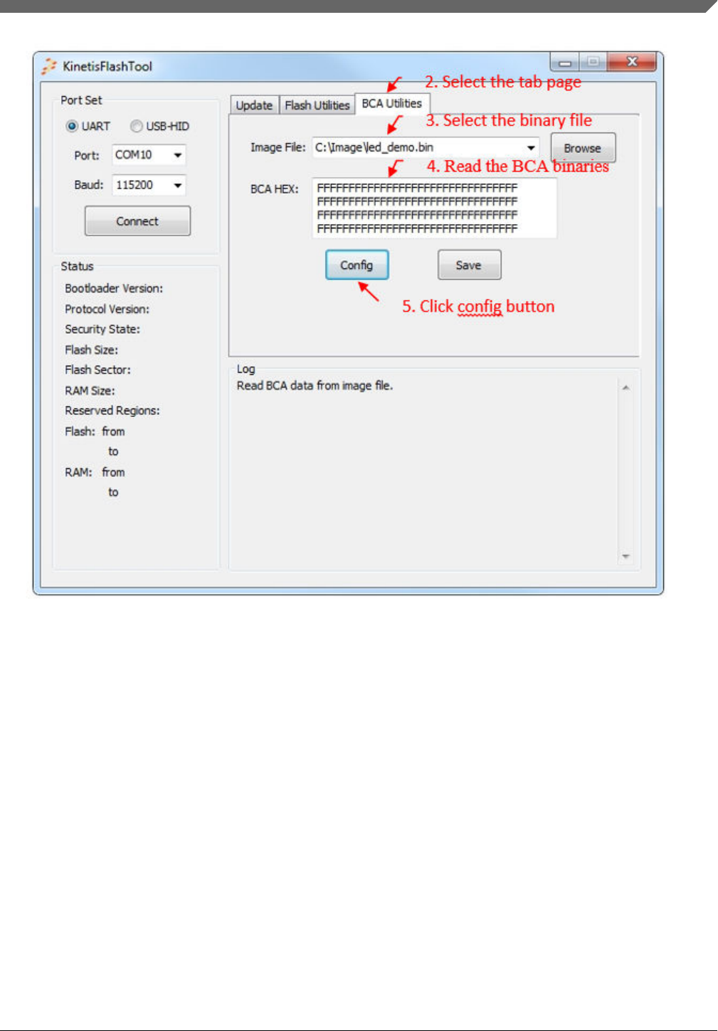
Figure 48. Open Kinetis bootloader configuration page
6. Configure the BCA.
7. Press the "OK" button.
Typical usage
Kinetis Flash Tool User's Guide, Rev. 0, 04/2016
Freescale Semiconductor, Inc. 39

Figure 49. Configure BCA
8. The new BCA binaries will be updated in the textbox.
9. Click the "Save" button to save the new binaries to the binary file.
Typical usage
Kinetis Flash Tool User's Guide, Rev. 0, 04/2016
40 Freescale Semiconductor, Inc.

Figure 50. Save new configuration
5.7 Generate C config file
1. Follow the steps 1 through 6 of the configure BCA section. Step 3 is optional. If no file is selected, the BCA hex
textbox is filled with all 0xFFs.
2. Press the generate C code button.
Figure 51. Generate C code
Typical usage
Kinetis Flash Tool User's Guide, Rev. 0, 04/2016
Freescale Semiconductor, Inc. 41
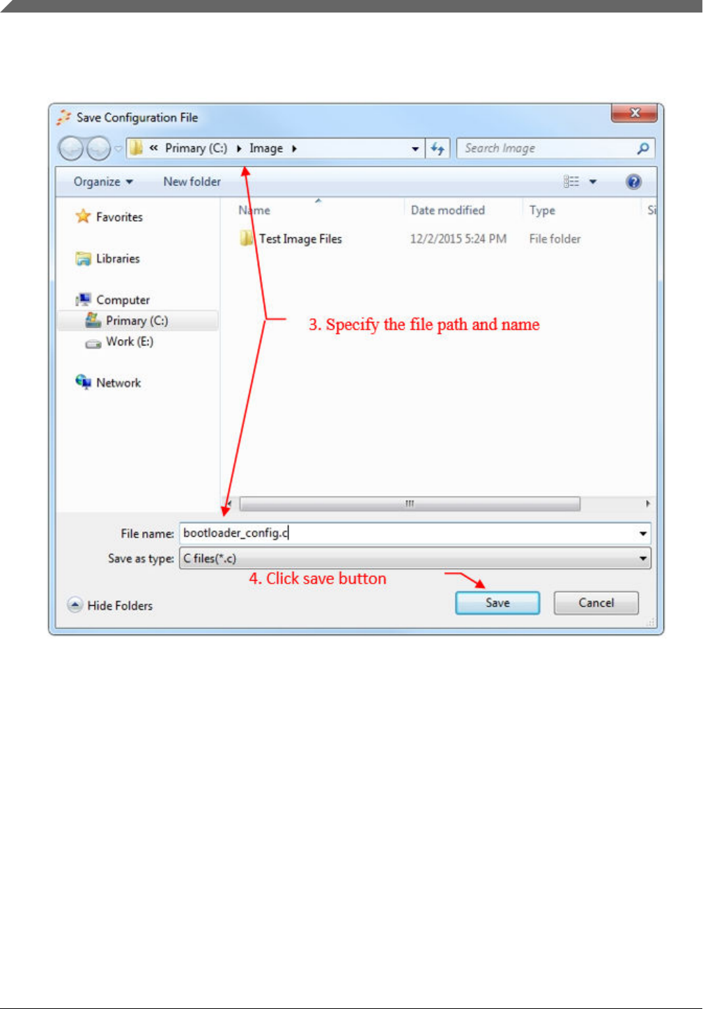
3. A Save As dialog opens. Specify the file path and name.
4. Click the "Save" button in the Save As dialog.
Figure 52. Save the C configuration file
5.8 Integrate config file to user project
Use the K64 LED demo IAR project for the example.
1. Add bootloader_config.c to the project.
Typical usage
Kinetis Flash Tool User's Guide, Rev. 0, 04/2016
42 Freescale Semiconductor, Inc.
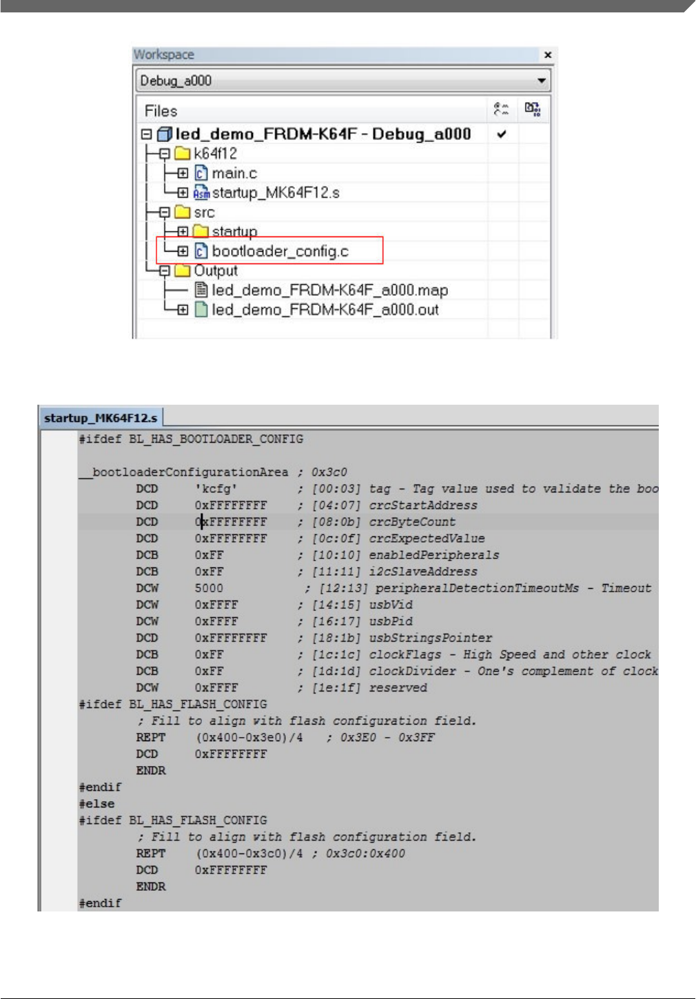
Figure 53. Add bootloader_config.c to project
2. Remove the __bootloaderConfigurationArea section in the startup_MK64F12.s.
Figure 54. Bootloader config in startup ASM file
3. Add a global macro BOOTLOADER_CONFIG.
Typical usage
Kinetis Flash Tool User's Guide, Rev. 0, 04/2016
Freescale Semiconductor, Inc. 43
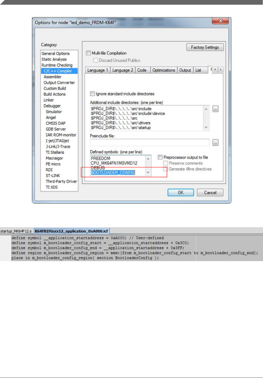
Figure 55. Add global macro
4. Modify the linker configuration file and add the configuration of BootloaderConfig.
Figure 56. Add BootloaderConfig
5. Compile the project.
The following are examples of linker configuration files.
•IAR
define symbol __application_startaddress = 0; // User-defined
define symbol m_bootloader_config_start = __application_startaddress + 0x3C0;
define symbol m_bootloader_config_end = __application_startaddress + 0x3FF;
define region m_bootloader_config_region = mem:[from m_bootloader_config_start to
m_bootloader_config_end];
place in m_bootloader_config_region{ section BootloaderConfig };
•Keil
Typical usage
Kinetis Flash Tool User's Guide, Rev. 0, 04/2016
44 Freescale Semiconductor, Inc.

#define __application_startaddress = 0 // User-defined
#define m_bootloader_config_start __application_startaddress + 0x3C0
#define m_bootloader_config_size 0x00000040
LR_m_bootloader_config m_bootloader_config_start m_bootloader_config_size{
ER_m_bootloader_config m_bootloader_config_start m_bootloader_config_size{ ; load
address = execution address
* (BootloaderConfig)
}
}
•KDS/GCC
MEMORY
{
m_bootloader_config(RX) : ORIGIN = 0x000003C0, LENGTH = 0x00000040
}
.bootloader_config :
{
. = ALIGN(4);
KEEP(*(.BootloaderConfig)) // Bootloader Configuration Area (BCA)
. = ALIGN(4);
} > m_bootloader_config
5.9 Exit program
Kinetis Flash Tool offers two ways to exit the program:
1. Press the "ESC" button.
2. Click the "Exit" button at the right top of the main window.
Typical usage
Kinetis Flash Tool User's Guide, Rev. 0, 04/2016
Freescale Semiconductor, Inc. 45
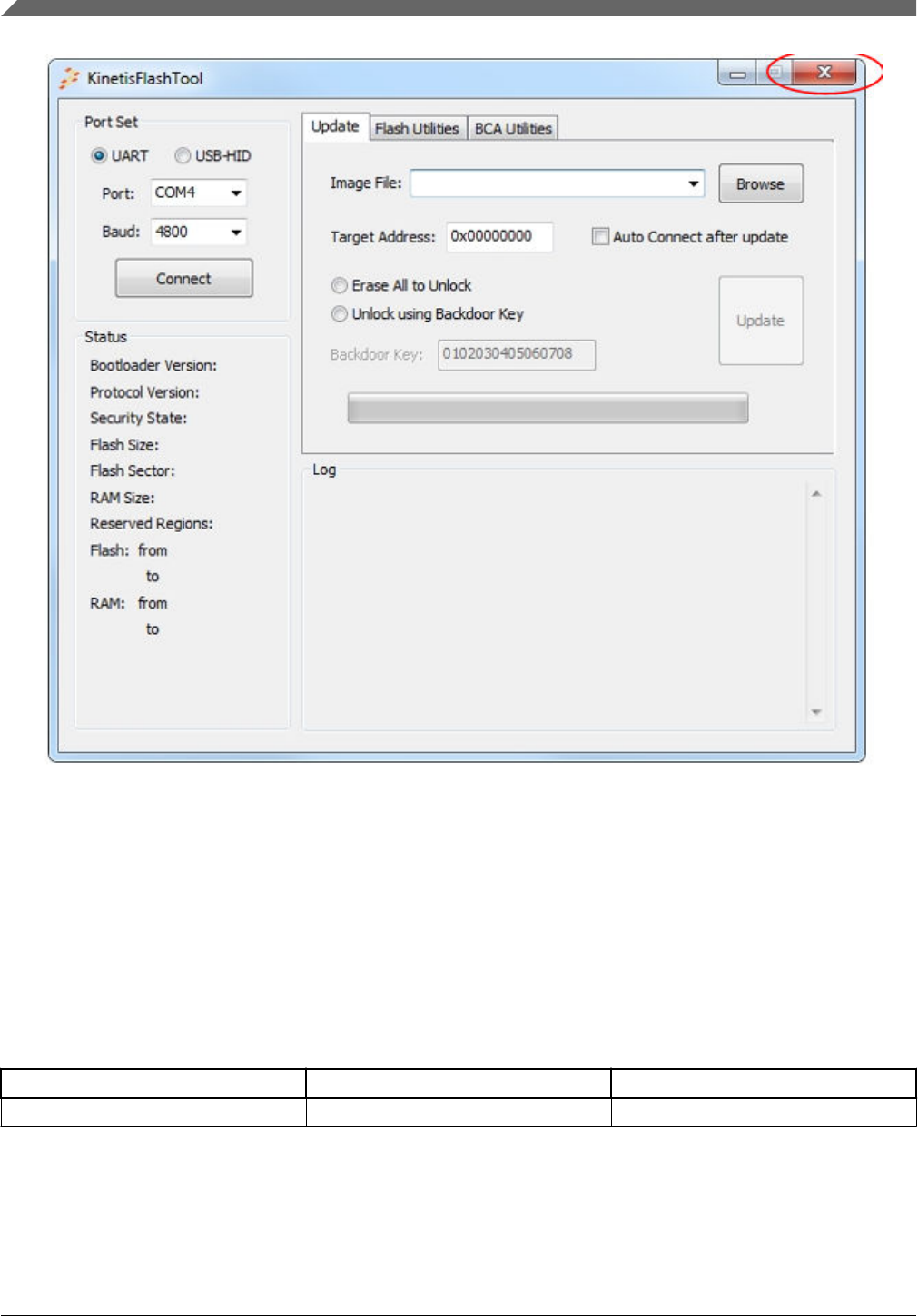
Figure 57. Exit button
If communcation has been established, Kinetis Flash Tool sends a reset command and sets the device back to the get-active-
peripheral state before exiting.
6Revision history
The following table contains a history of changes made to this user's guide.
Table 2. Revision history
Revision number Date Substantive changes
0 04/2016 Kinetis bootloader v2.0 release
Revision history
Kinetis Flash Tool User's Guide, Rev. 0, 04/2016
46 Freescale Semiconductor, Inc.

Document Number: KFLASHTOOLUG
Rev. 0
04/2016
Information in this document is provided solely to enable system and software
implementers to use Freescale products. There are no express or implied copyright
licenses granted hereunder to design or fabricate any integrated circuits based on the
information in this document.
Freescale reserves the right to make changes without further notice to any products
herein. Freescale makes no warranty, representation, or guarantee regarding the
suitability of its products for any particular purpose, nor does Freescale assume any
liability arising out of the application or use of any product or circuit, and specifically
disclaims any and all liability, including without limitation consequential or incidental
damages. “Typical” parameters that may be provided in Freescale data sheets and/or
specifications can and do vary in different applications, and actual performance may
vary over time. All operating parameters, including “typicals,” must be validated for
each customer application by customer’s technical experts. Freescale does not convey
any license under its patent rights nor the rights of others. Freescale sells products
pursuant to standard terms and conditions of sale, which can be found at the following
address: nxp.com/SalesTermsandConditions.
How to Reach Us:
Home Page:
nxp.com
Web Support:
nxp.com/support
Freescale, the Freescale logo, and Kinetis are trademarks of Freescale
Semiconductor, Inc., Reg. U.S. Pat. & Tm. Off. All other product or service names are
the property of their respective owners. ARM, ARM Powered Logo, Keil, and Cortex
are registered trademarks of ARM limited (or its subsidiaries) in the EU and/or
elsewhere. All rights reserved.
© 2016 Freescale Semiconductor, Inc.
