Kinova SDK User Guide 1 0 7 (003)x Development Center
User Manual: Pdf
Open the PDF directly: View PDF ![]() .
.
Page Count: 43
SDK
Development center
User guide
2017

© 2017 Kinova Inc. All rights reserved. II
SDK - Development center user guide
DISCLAIMER
Kinova, Kinova Development Center, and Kinova’s logo are trademarks of Kinova Inc., herein referred to
as Kinova. All other brand and product names are trademarks or registered trademarks of their respective
corporations.
The mention of any product does not constitute an endorsement by Kinova. This manual is furnished under
a lease agreement and may only be copied or used within accordance with the terms of such lease
agreement. Except as permitted by such lease agreement, no part of this publication may be reproduced,
stored in any retrieval system, or transmitted, in any form or by any means, electronic, mechanical,
recording, or otherwise, without prior written consent of Kinova.
The content of this manual is furnished for informational use only, is subject to change without notice, and
should not be construed as a commitment by Kinova. Kinova assumes no responsibility or liability for any
errors or inaccuracies that may appear in this document.
Changes are periodically made to the information herein; these changes will be incorporated into new
editions of this publication. Kinova may make improvements and/or changes in the products and/or
software programs described in this publication at any time.
Address any questions or comments concerning this document, the information it contains or the product
it describes to:
support@kinovarobotics.com
Kinova may use or distribute whatever information you supply in any way it believes appropriate without
incurring any obligations to you.
Copyright © 2017 Kinova Inc. All rights reserved.

© 2017 Kinova Inc. All rights reserved. III
SDK - Development center user guide
TABLE OF CONTENTS
DISCLAIMER......................................................................................................... I
TABLE OF CONTENTS ...................................................................................... III
OVERVIEW .......................................................................................................... 1
Content ............................................................................................................................................ 1
INSTALLATION .................................................................................................... 2
Windows 7 ....................................................................................................................................... 2
Windows 8.1 .................................................................................................................................... 5
Ubuntu 12.04/14.04 installation ..................................................................................................... 7
DEVELOPMENT CENTER ................................................................................... 9
General settings ............................................................................................................................. 9
Advanced settings ....................................................................................................................... 13
Ethernet Default Configuration ................................................................................................... 17
Ethernet Setup on PC .................................................................................................................. 18
Ethernet Setup .............................................................................................................................. 20
Monitoring ..................................................................................................................................... 23
Virtual joystick .............................................................................................................................. 26
Trajectory planner ........................................................................................................................ 30
Resources ..................................................................................................................................... 33
Examples ....................................................................................................................................... 33
TORQUE CONSOLE .......................................................................................... 36
Main Window ................................................................................................................................ 36
CONTACTING SUPPORT .................................................................................. 39

© 2017 Kinova Inc. All rights reserved. 1
SDK - Development center user guide
OVERVIEW
The Kinova Development Center is a complete set of interface, documentation, examples and software tools
that help the developer interact with any Kinova product. It is available under Ubuntu and Windows systems.
Content
• The Development Center
• The torque console
• A set of project examples
• User guide
• HTML documentation on all APIs
• Tools to configure your product
© 2017 Kinova Inc. All rights reserved. 2
SDK - Development center user guide
INSTALLATION
Windows 7
NEW INSTALLATION
If you have any Kinova products already installed on your computer, please refer to the UPDATE section. If it
is your first installation of a Kinova product, follow the procedure below.
1. Download and install Microsoft Visual C++ Redistributable(x86, x64)
2. Execute the installer named KinovaSDKInstaller.
3. Connect the robot to your computer via USB.
4. Power on the robot.
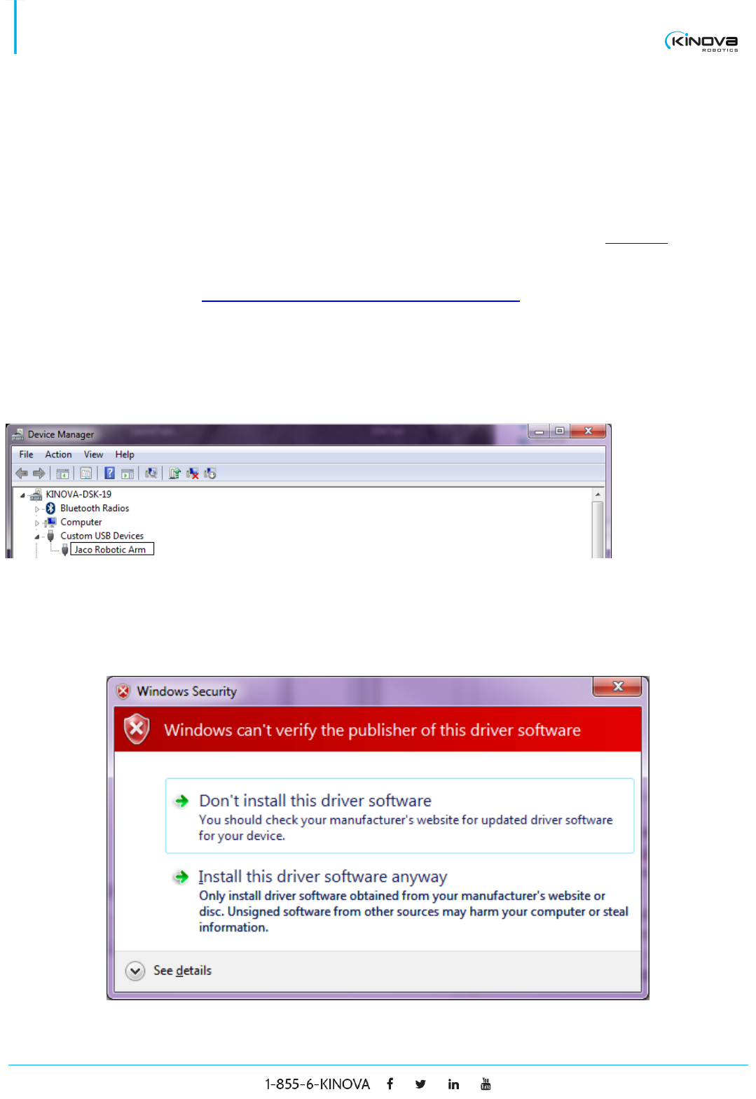
5. In the Windows Control Panel, open the device manager and wait for the computer to detect a Custom
USB Device.
6. Right click on the Kinova product that appeared and install the drivers that were copied on your disk
when you executed the KinovaSDKInstaller. Assuming that you’ve installed the SDK in the default folder, it
should be located at C:\Program Files (x86)\KinovaSDK\
7. A Windows Security window may appear:
© 2017 Kinova Inc. All rights reserved. 3
SDK - Development center user guide
8. Choose to install the driver software anyway.
9. The Development Center is ready!
UPDATE
This section explains how to install the Kinova Development Center if you have any Kinova products already
installed on your computer. This is necessary because the Kinova Development Center has a new driver which
is different from the one used in previous versions of Kinova software products like Jacosoft. Note that it is
possible to have different driver versions on different USB ports. As an example, you could install the previous
USB driver on USB port A and when the robot is connected to that port, Jacosoft is available. At the same time,
you could install the new driver on USB port B and when your robot is connected to that port, the new
Development Center is available.
The procedure below explains how to completely uninstall a driver before installing the new Kinova
Development Center.
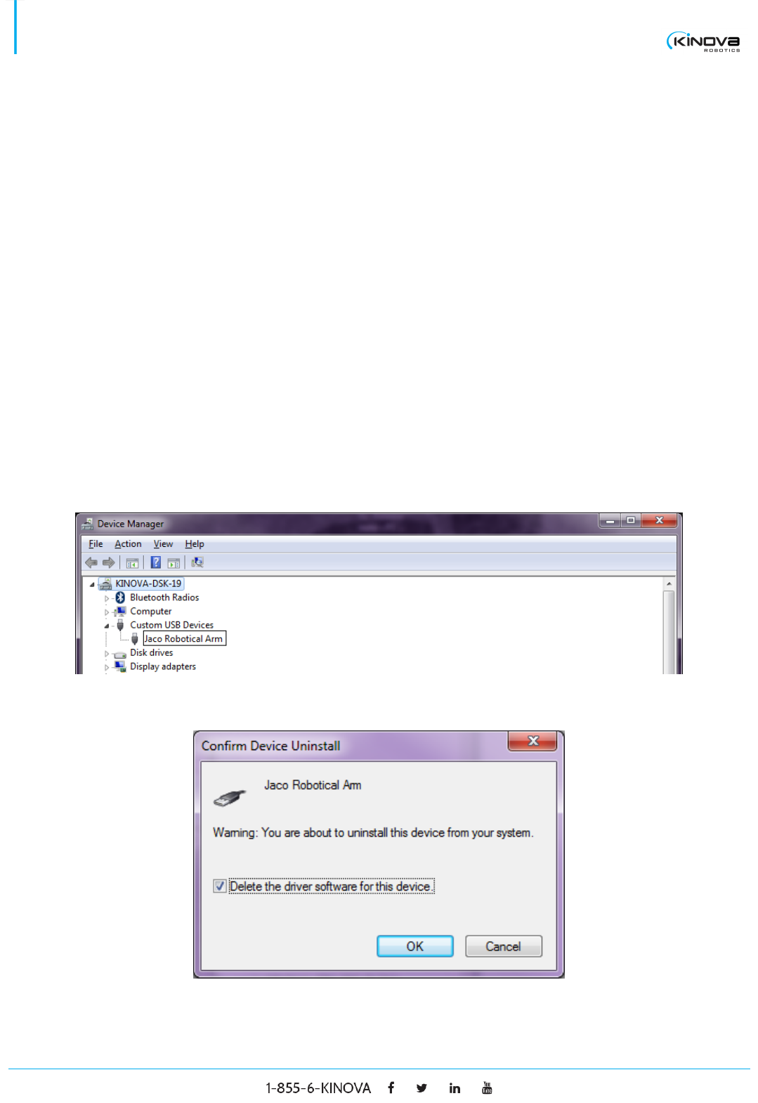
1. Connect the robot to your computer via USB.
2. Power on the robot.
3. In Windows Control Panel, open the device manager and look for the Custom USB Device called Jaco
Robotical Arm.
4. Right click on it and choose uninstall
© 2017 Kinova Inc. All rights reserved. 4
SDK - Development center user guide
5. Check the option Delete the driver software for this device and click OK.
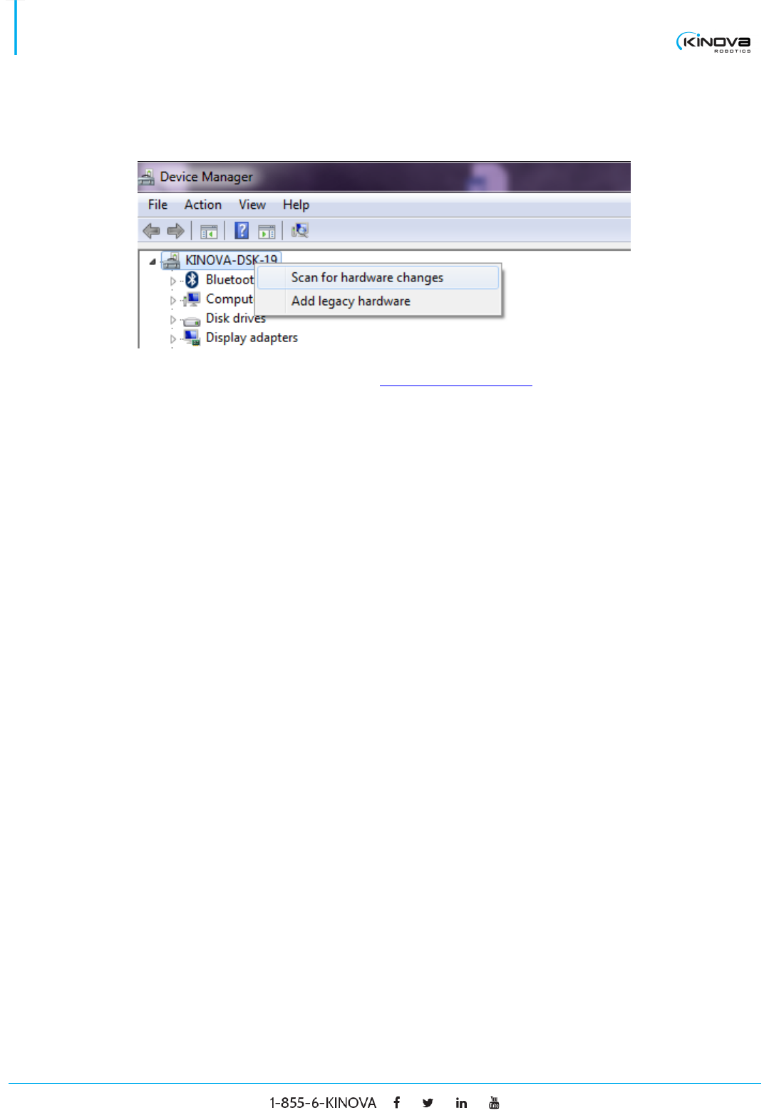
6. Stay in the device manager and right click on your computer. Choose Scan for hardware changes.
7. From here, follow the procedure in the section NEW INSTALLATION.
© 2017 Kinova Inc. All rights reserved. 5
SDK - Development center user guide
Windows 8.1
NEW INSTALLATION
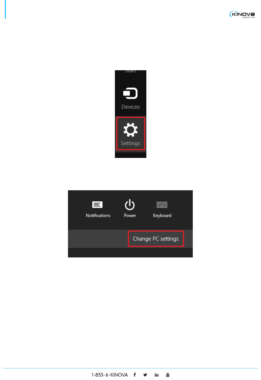
1. Move your mouse to the bottom-right corner of the screen and click on the Settings button.
2. Click on the Change PC settings button located at the bottom of the menu.
3. Select the sub-menu Update and recovery.
4. Select the sub-menu Recovery.
5. Click on the Restart Now button located in the Advanced start-up section.
6. Wait until it restarts.
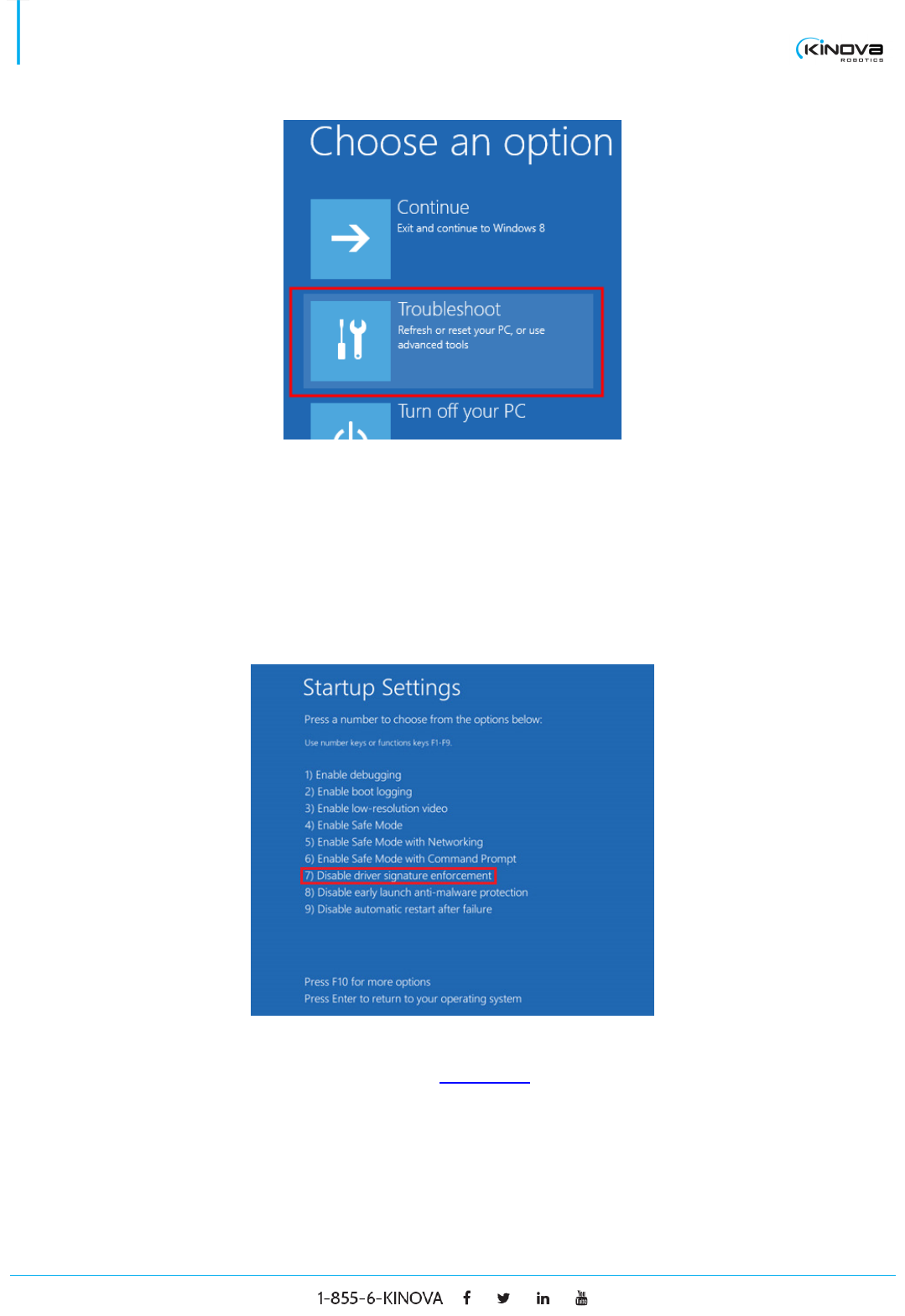
7. Select Troubleshoot.
© 2017 Kinova Inc. All rights reserved. 6
SDK - Development center user guide
8. Select Advanced options.
9. Select Startup Settings.
10. Click on the Restart button.
11. Press the F7 key on your keyboard to disable the driver signature enforcement.
12. Right click on the bottom-left corner of the screen and select Device Manager.
13. From there, follow the same procedure as for Windows 7.
© 2017 Kinova Inc. All rights reserved. 7
SDK - Development center user guide
UPDATE
This section explains how to install the Kinova Development Center if you have any Kinova products already
installed on your computer. This is necessary because the Kinova Development Center has a new driver that
is different from the one used in previous versions of Kinova software products like Jacosoft. Note that it is
possible to have different driver versions on different USB ports. As an example, you could install the previous
USB driver on USB port A and when the robot is connected on that port, Jacosoft is available. At the same
time, you could install the new driver on USB port B and when your robot is connected to that port, the new
Development Center is available.
To install the Kinova Development Center, follow the same driver uninstallation procedure as in Windows 7
and proceed afterward to Windows 8.1 new installation.
Ubuntu 12.04/14.04 installation
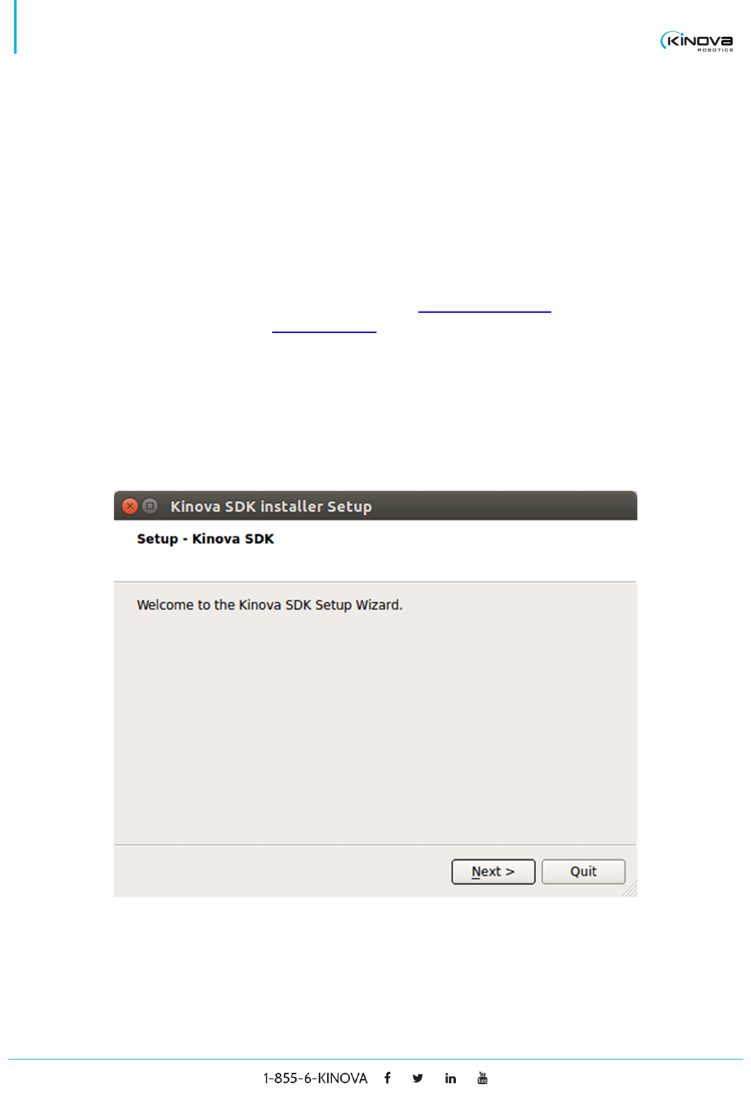
1. Execute the bash script named installSDK32.sh if your computer’s architecture is 32 bits or
installSDK64.sh if your computer’s architecture is 64 bits.
2. The script will ask for root permission to install a package named kinova-api.
3. The Kinova SDK Installer Setup window will appear to install the remainder of the Development Center.
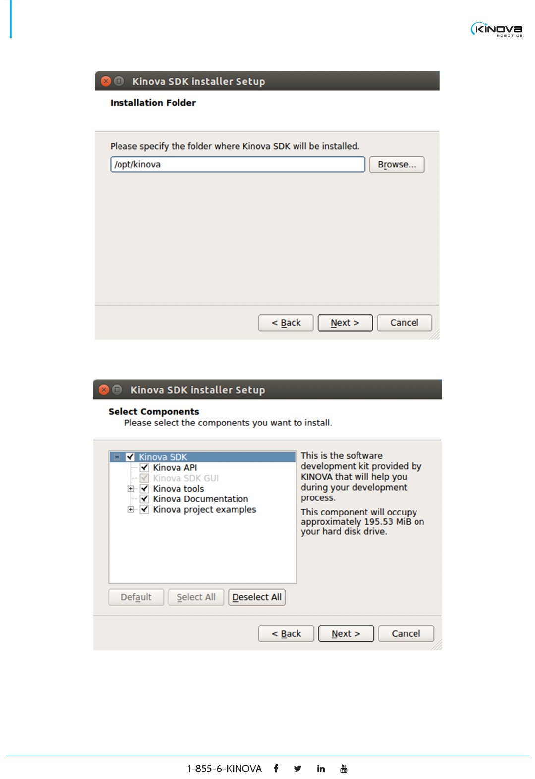
4. Choose an installation folder (default: /opt/kinova)
© 2017 Kinova Inc. All rights reserved. 8
SDK - Development center user guide
5. Choose which components you need to install.
6. Click on the next button until the installation is completed.
7. The Development Center is installed. To launch the Development Center, execute [installation
folder]/GUI/KinovaSDK.sh
© 2017 Kinova Inc. All rights reserved. 9
SDK - Development center user guide
DEVELOPMENT CENTER
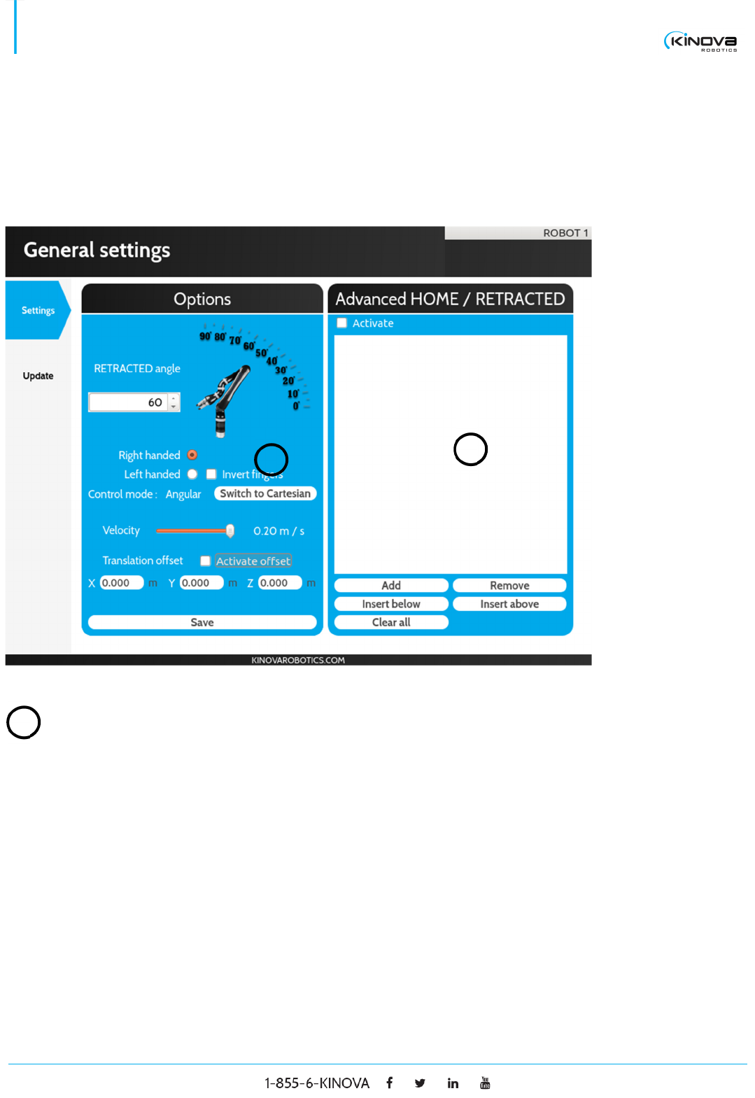
General settings
SETTINGS
Advanced HOME / RETRACTED position
Activate Check to enable the advanced HOME / RETRACTED
feature.
List of
positions
Contains the list of positions (angular or Cartesian) that
represents the new path that the robot will follow between
the HOME and the RETRACTED position.
Add Click to add the current robot’s position at the end of the
positions list.
1
2
1

© 2017 Kinova Inc. All rights reserved. 10
SDK - Development center user guide
Remove Click to remove the selected position from the position list.
Insert below Click to add the current robot’s position below the selected
position in the positions list.
Insert above Click to add the current robot’s position above the selected
position in the positions list.
Clear all Click to clear the entire positions list.
Options
Retracted angle
The angle of the default RETRACTED position shown by the
image aside.
Handedness Select the radio button to set the robot in right handed mode
or in left handed mode.
Invert fingers Check to invert the closing finger when a 3 fingers robot is
closing only 2 fingers. This mode is mainly used with a left
handed configuration.
Control mode Displays the current control mode. It can be either Angular
or Cartesian.
Switch button Select to toggle between the Angular control mode and the
Cartesian control mode. Note that if the robot’s position
cannot switch to Cartesian mode because of a singularity,
the robot will stay in Angular mode.
Velocity Select the maximum Cartesian velocity of the robot.
2
© 2017 Kinova Inc. All rights reserved. 11
SDK - Development center user guide
Activate offset Check to apply a position offset on the end effector. The
offset is described by the text fields X, Y and Z.
Save Press to send the modification to the robot. If you perform a
modification in the Option panel nothing will be applied
unless the save button is pressed. The exception is the
velocity which is applied directly when modified.
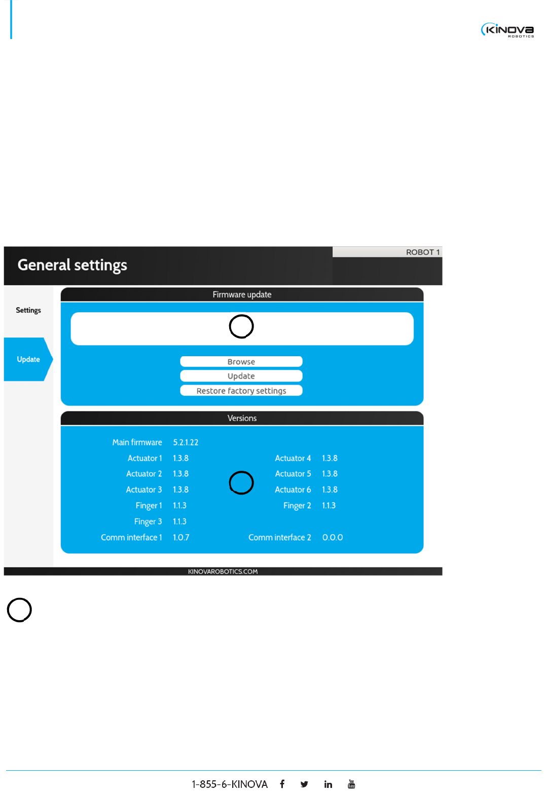
UPDATE
Firmware update
White panel Displays the complete path to the HEX file that will be
uploaded to the robot when the button update is pressed.
1
1
2

© 2017 Kinova Inc. All rights reserved. 12
SDK - Development center user guide
Browse Press to choose a HEX file on your disk that contains a
firmware update.
Update Press to update your robot with the chosen HEX file.
Restore factory
settings
Restore the robot with its factory settings.
Versions
Main firmware Displays the main firmware’s code version.
Actuator X Displays the code’s version of the actuator X where X is a
number greater than 0.
Finger X Displays the code’s version of the finger X where X is a
number greater than 0.
2
© 2017 Kinova Inc. All rights reserved. 13
SDK - Development center user guide
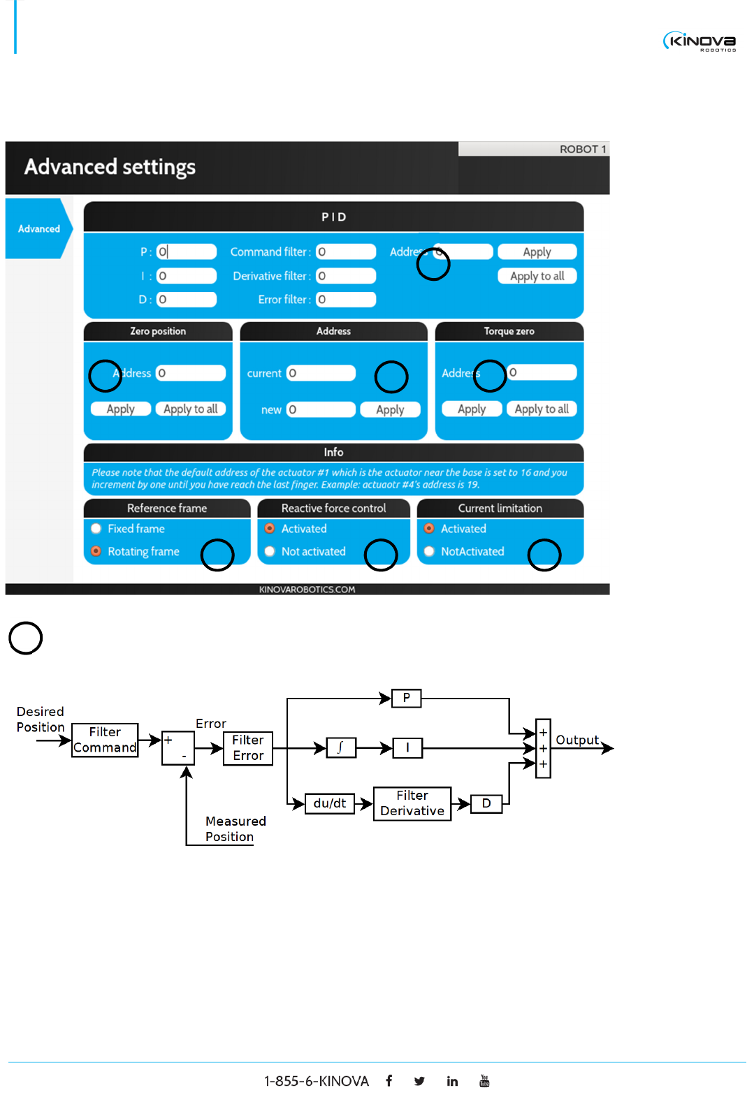
Advanced settings
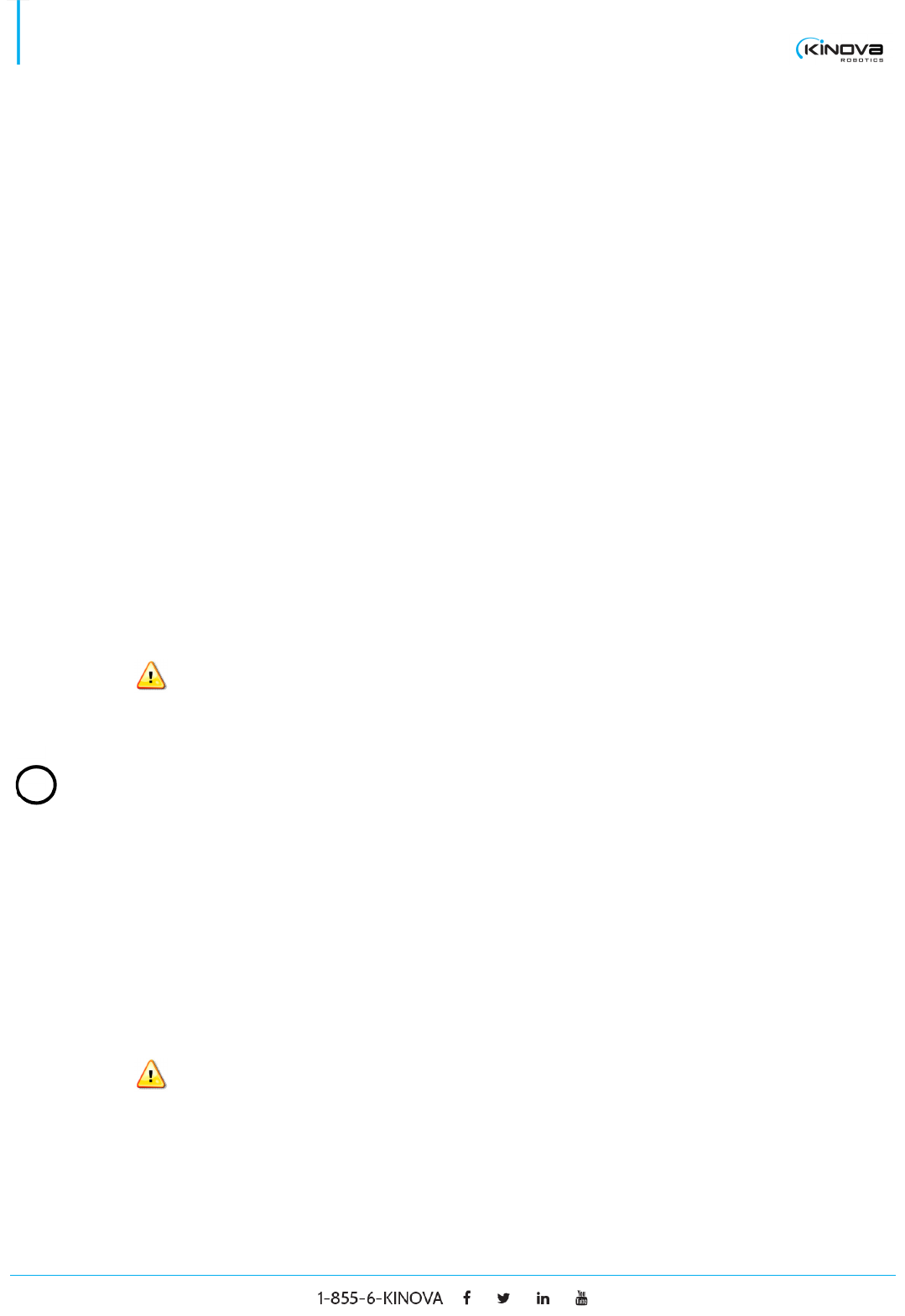
PID (Proportional, Integral and derivative)
P The proportional part of the controller. (Suggested range [0,
2])
I The integral part of the controller.
2
3
4
5
6
7
1
1
© 2017 Kinova Inc. All rights reserved. 14
SDK - Development center user guide
D The derivative part of the Controller. (Suggested range [0,
0.1])
Command filter Filters the commands sent to the actuator. The filter is of first
order and the parameter value is a frequency in rad/s. The
suggested range is [0, 500].
Derivative filter Filters the error derivative signal (derivative of (desired
position - measured position)). The filter is of first order and
the parameter value is a frequency in rad/s. The suggested
range is [0, 500].
Error filter Filters the error signal (desired position - measured
position). The filter is of first order and the parameter value
is a frequency in rad/s. The suggested range is [0, 500].
Address The address of the actuator to modify.
Setting these parameters out of the suggested range can
severely damage the robot and is not covered by the
warranty.
Zero position
Address The address of the actuator to modify.
Apply Apply the zero position. The actual position of the targeted
actuator will now be 180°.
Apply to all Apply the zero position to every actuator of the robot.
Setting these parameters incorrectly can severely damage
the robot and is not covered by the warranty.
2
© 2017 Kinova Inc. All rights reserved. 15
SDK - Development center user guide
Address
Current The current address of the actuator.
New The new address to assign.
Apply Apply the new address on the actuator.
Setting these parameters incorrectly can severely damage
the robot and is not covered by the warranty.
Torque zero
Address The address of the actuator on which the torque zero will be
applied.
Apply Apply the torque zero. The actual torque of the targeted
actuator will now be considered as 0
Apply to all Apply the zero torque on every actuator of the robot.
Setting these parameters incorrectly can severely damage
the robot and is not covered by the warranty.
Reference frame
Fixed frame Set the robot to fixed frame. When a translation is
performed, the orientation stays the same.
Rotating frame Set to rotating. When a translation is performed, the
orientation follows the first actuator (rotation in the XY
plane).
Reactive force control
3
6
5
4
© 2017 Kinova Inc. All rights reserved. 16
SDK - Development center user guide
Activated Select to activate the reactive force control (admittance
mode).
Not activated Select to deactivate the reactive force control (admittance
mode).
Current limitation
Activated Select it to activate the current limitation.
Not activated Select it to deactivate the current limitation.
Setting these parameters incorrectly can severely damage
the robot and is not covered by the warranty.
7
© 2017 Kinova Inc. All rights reserved. 17
SDK - Development center user guide
Ethernet Default Configuration
Kinova’s JACO2 7DOF robotic arm ships with a default Ethernet configuration. In other words, the robotic arm
already has a default IP address, subnet mask, port number and MAC address. These default parameters can
be seen in the Development Center’s General settings > Ethernet window with any given connected arm
provided it supports Ethernet.
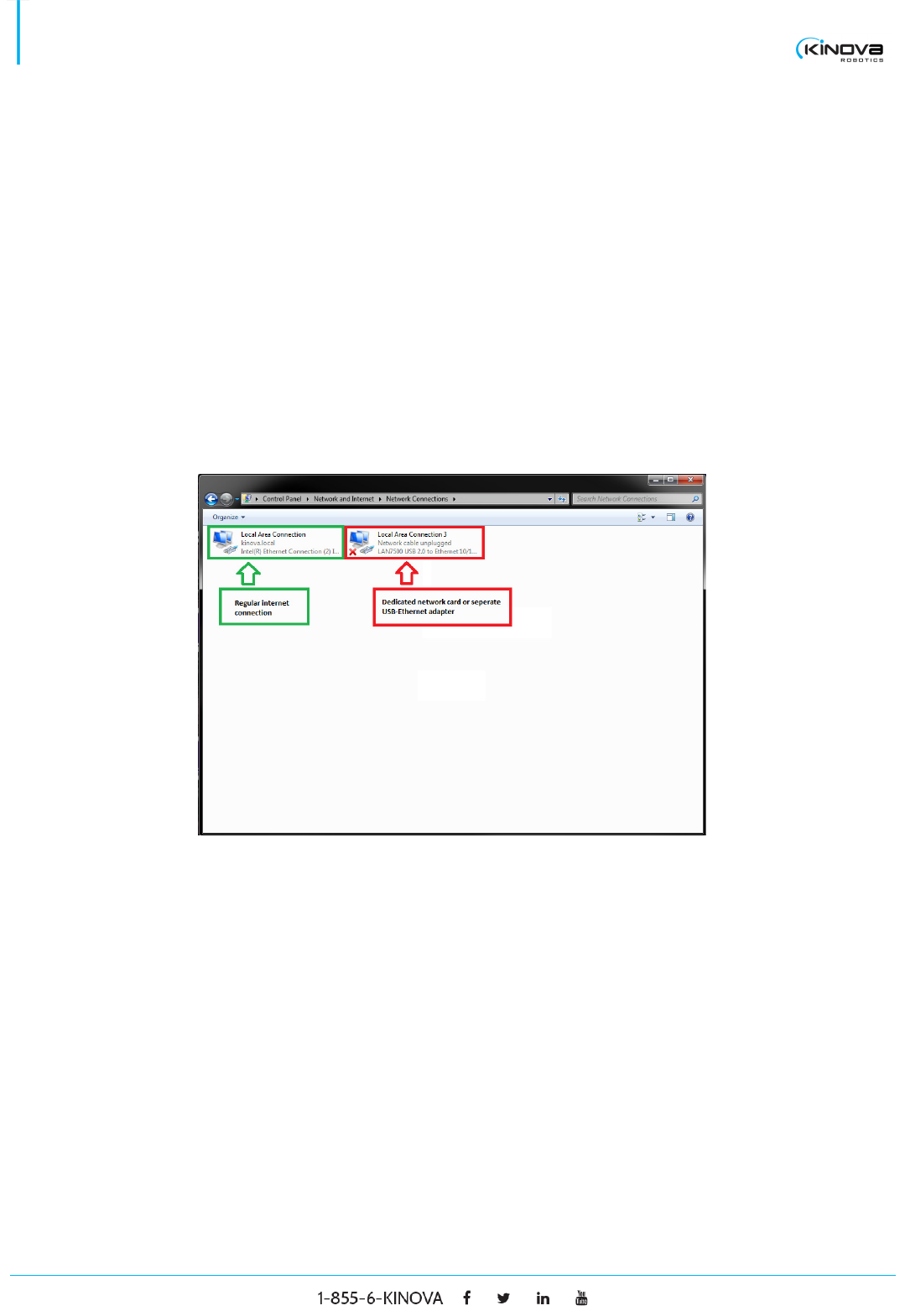
For a quick and easy set-up, we advise not to change these default parameters and to adapt your IP address
to the arm’s pre-configured Ethernet settings. The easiest way to achieve this is to use a separate Ethernet
network card that will be dedicated to communicating with the robotic arm. A USB to Ethernet adapter can also
be used.
The only requirement for the user is to set a static IPv4 address and a subnet mask for the dedicated network
card (or adapter). This can be done by changing the adapter settings in the Network and sharing center.
Keep in mind that it is important for the user’s static IP address to have the same subnet as the robotic arm
(we advise to use a subnet mask of 255.255.255.0). You do not need to set a default gateway. Below is an
example.
© 2017 Kinova Inc. All rights reserved. 18
SDK - Development center user guide
If the user wishes to modify his PC’s dedicated static IP address and/or subnet mask to one of his choosing,
the robotic arm’s Ethernet settings will need to be configured accordingly. What follows is a step by step guide
to modifying the Ethernet parameters (user’s PC and robotic arm) to one parameters different from the default
configuration.
Ethernet Setup on PC
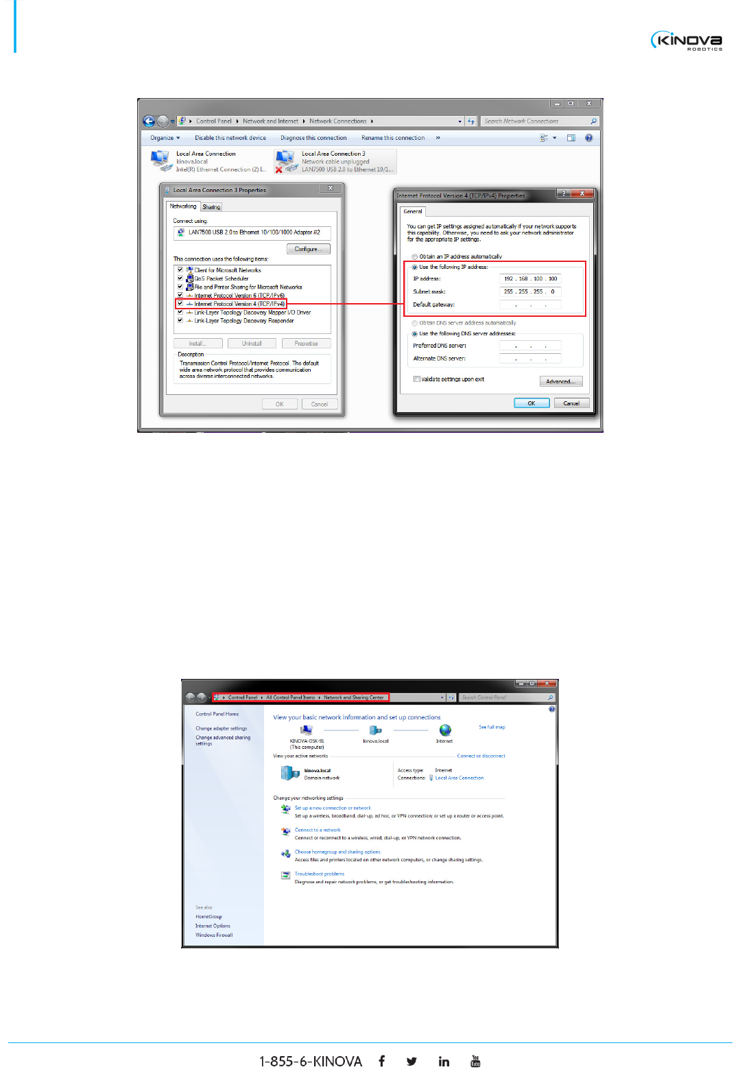
The following steps describe how to set up a static IP address on your computer. This IP address will then be
used to communicate with the robotic arm.
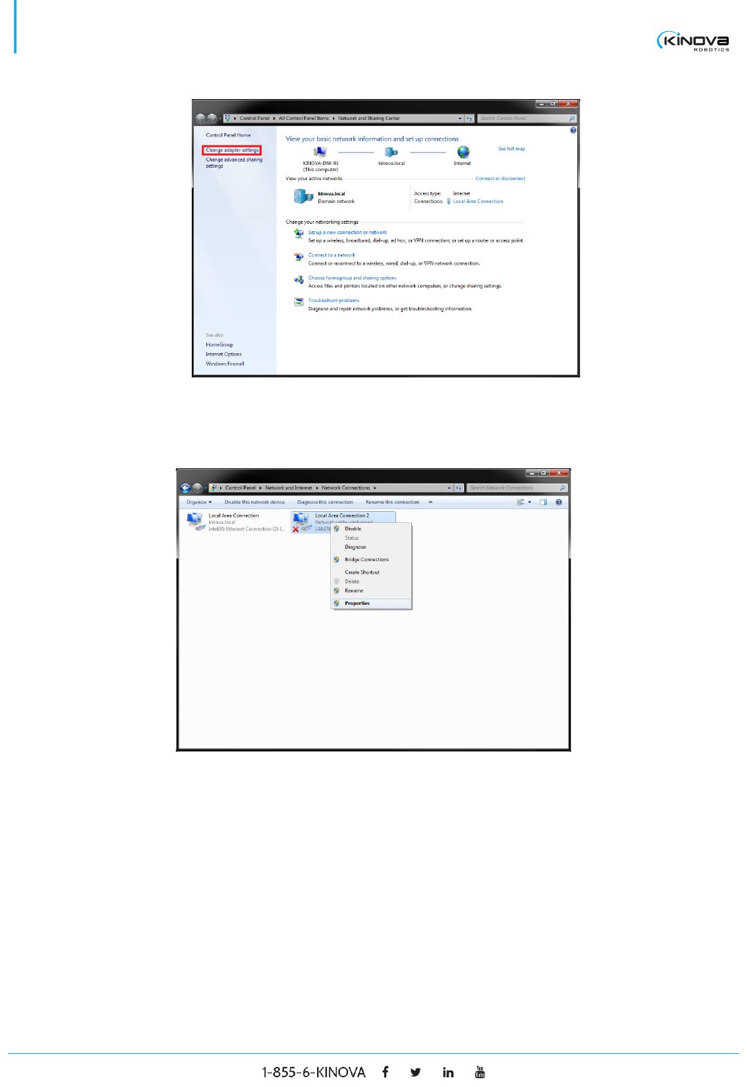
1. Navigate to Control Panel > Network and Sharing Center.
2. Click on Change adapter settings situated in the left column.
© 2017 Kinova Inc. All rights reserved. 19
SDK - Development center user guide
3. Right click on the desired connection and click on Properties from the drop down menu.
© 2017 Kinova Inc. All rights reserved. 20
SDK - Development center user guide
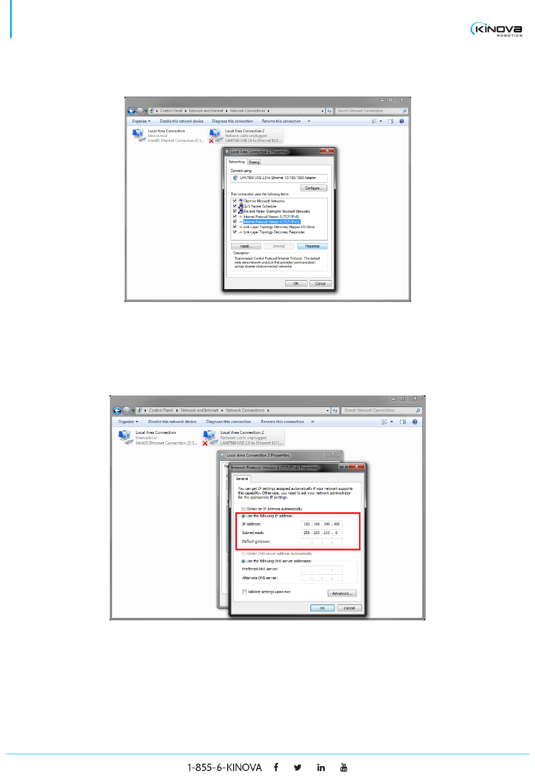
4. Select Internet Protocol Version 4 (TCP/IPv4) and click on Properties.
5. Select Use the following IP address and fill out the pertinent information.
a. The IP address should be the IP address you want to use to communicate with the robot.
Make sure it is not already in use.
b. The Subnet mask must be 255.255.255.0
c. You don’t need to set a Default gateway.
6. Click on OK and close the Control Panel. You have now set up a static IP address that will be used to
communicate with the robotic arm.
Ethernet Setup
© 2017 Kinova Inc. All rights reserved. 21
SDK - Development center user guide
The following steps describe how to set up the Ethernet configuration for the robotic arm.
1. Make sure the robotic arm is connected via USB and Ethernet cable simultaneously (this is required
only for the first set-up).
2. Launch the Development Center.
3. Once the Development Center establishes a connection via the USB (serial number should appear
next to the USB Enable tab), click on the serial number, click on General settings under the
SETTINGS & CONFIGURATION tab and then click on Ethernet.
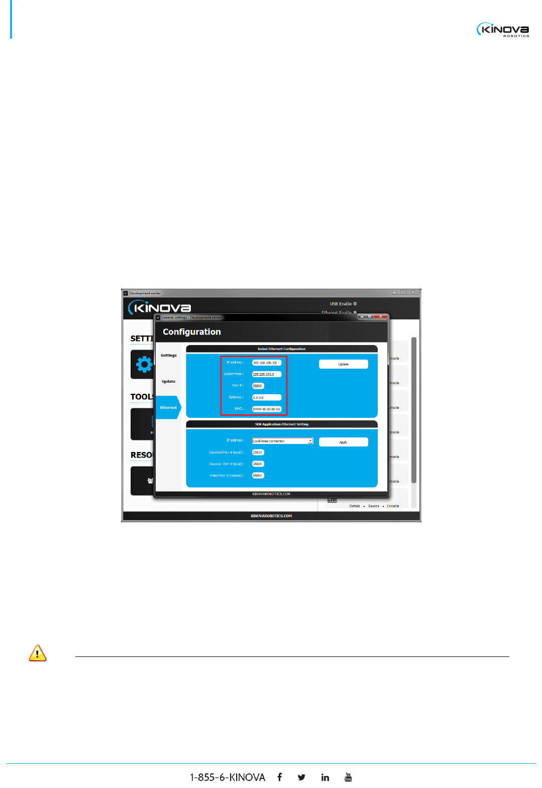
4. Under the Robot Ethernet Configuration tab, fill out the required information (IP address, Subnet
Mask, Port #, Gateway and MAC)
a. The IP address should have the same subnet as your PC’s static IP address.
b. The subnet mask must be 255.255.255.0
c. The port number can be any given port number (as long as it’s not already in use).
d. The Gateway must be 0.0.0.0
e. The MAC address should be the one that has been provided.
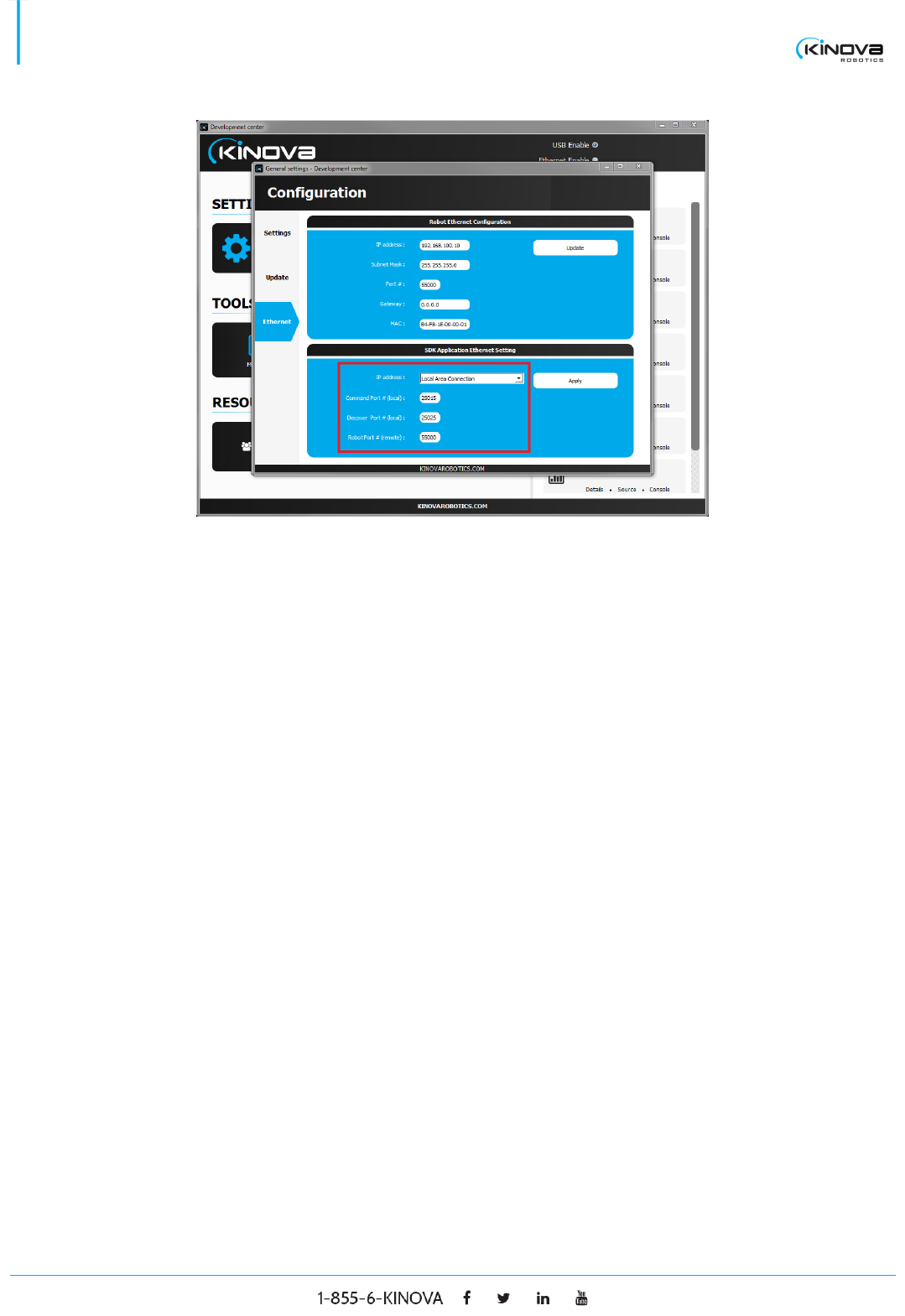
5. Under the SDK Application Ethernet Setting tab, fill out the required information (IP address,
Command Port #, Discover Port #, Robot Port #)
a. The IP address should be the connection with the static IP address you have configured on
your PC.
b. The Command Port number and Discover Port number can be any given port number (as long
as it isn’t already in use).
c. The Robot Port # must be the same as the Port # from the Robot Ethernet Configuration.
© 2017 Kinova Inc. All rights reserved. 22
SDK - Development center user guide
6. Once all the information is filled out, first click on Apply and then on Update. Close the Development
Center and reboot your robotic arm.
7. Open the Development Center once again. Once the robotic arm’s serial number appears on the top
right corner, click on Ethernet enable. At this point, the serial number will have disappeared from the
top right corner and the Development Center will try and establish the connection via Ethernet.
8. Once the serial number appears once more in the top right corner, this signifies that an Ethernet
connection has been established.
9. You can now unplug the USB cable from the robotic arm and control it via Ethernet. All subsequent
connections to the robotic arm via the Development Center can be done directly with the Ethernet
cable.
© 2017 Kinova Inc. All rights reserved. 23
SDK - Development center user guide
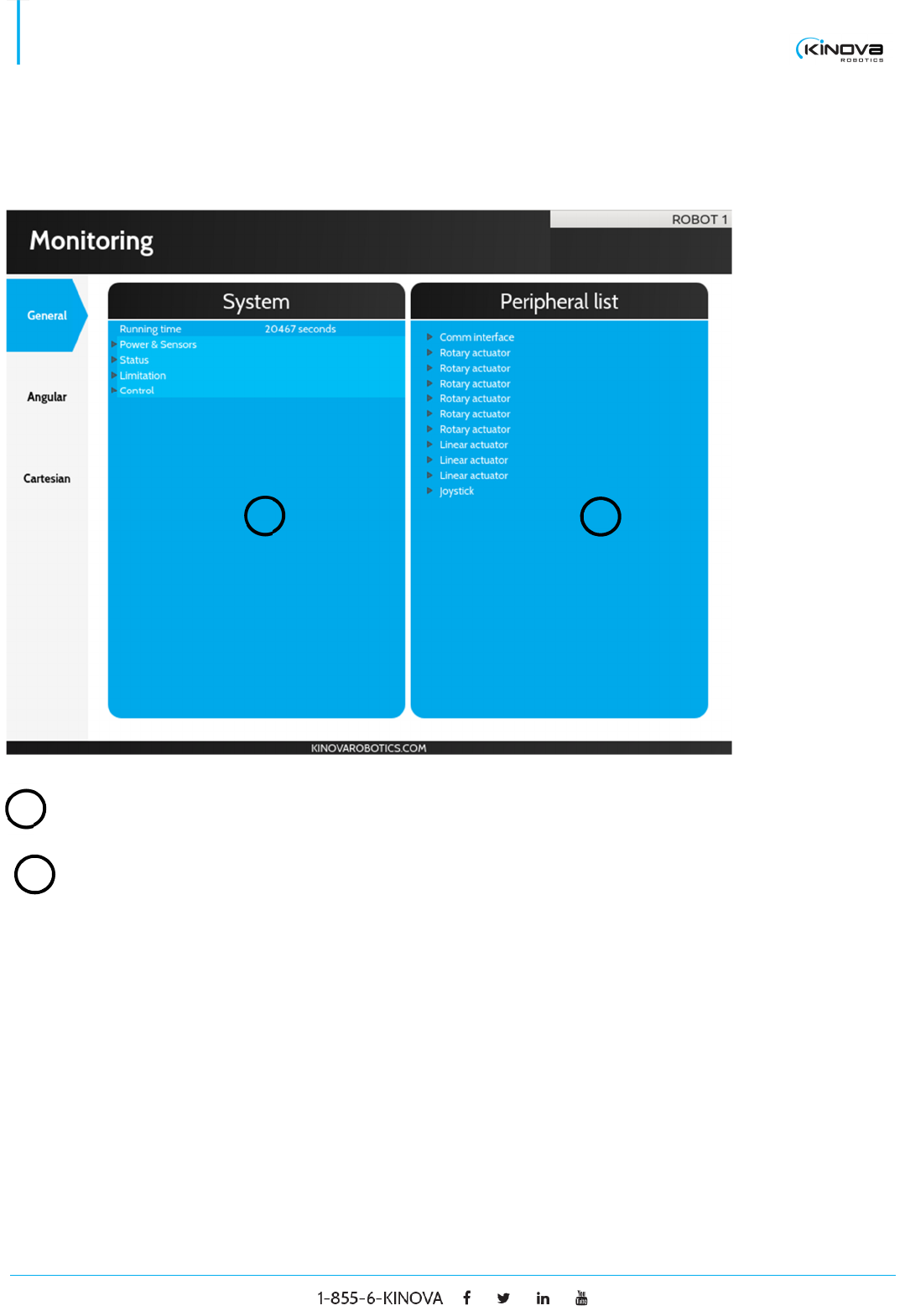
Monitoring
GENERAL
System Displays general information stored in the robot.
Peripheral list Lists all peripherals detected on the robot’s communication
bus. Each peripheral can be expanded to display its type,
address, port and code version.
1
1
2
2
© 2017 Kinova Inc. All rights reserved. 24
SDK - Development center user guide
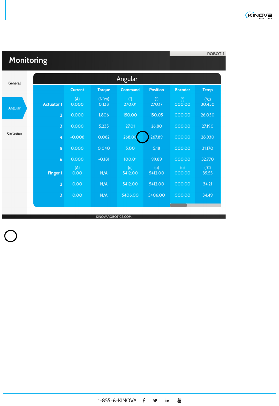
ANGULAR
Angular Displays all the information on every actuator. It includes
the current, torque, command, position, encoder value,
temperature, velocity, acceleration along the X axis,
acceleration along the Y axis and acceleration along the Z
axis.
1
1
© 2017 Kinova Inc. All rights reserved. 25
SDK - Development center user guide
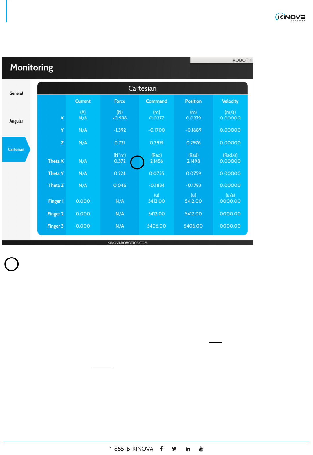
CARTESIAN
Cartesian Displays all the information on the end effector’s motion. It
includes the force (gravity free), Cartesian command,
Cartesian position and Cartesian velocity. Note that the
Command’s X, Y and Z fields and Position’s X, Y and Z
fields are expressed in the base reference frame. The
Command’s Theta X, Theta Y and Theta Z fields and
Position’s Theta X, Theta Y and Theta Z are Euler angles
(XYZ convention) with respect to the base reference
frame. The Velocity’s X, Y and Z fields represent the end
effector’s translation velocities in the base reference
frame. The Velocity’s Theta X, Theta Y and Theta Z fields
represent the end effector’s rotation velocities in the
effector reference frame.
1
1
© 2017 Kinova Inc. All rights reserved. 26
SDK - Development center user guide
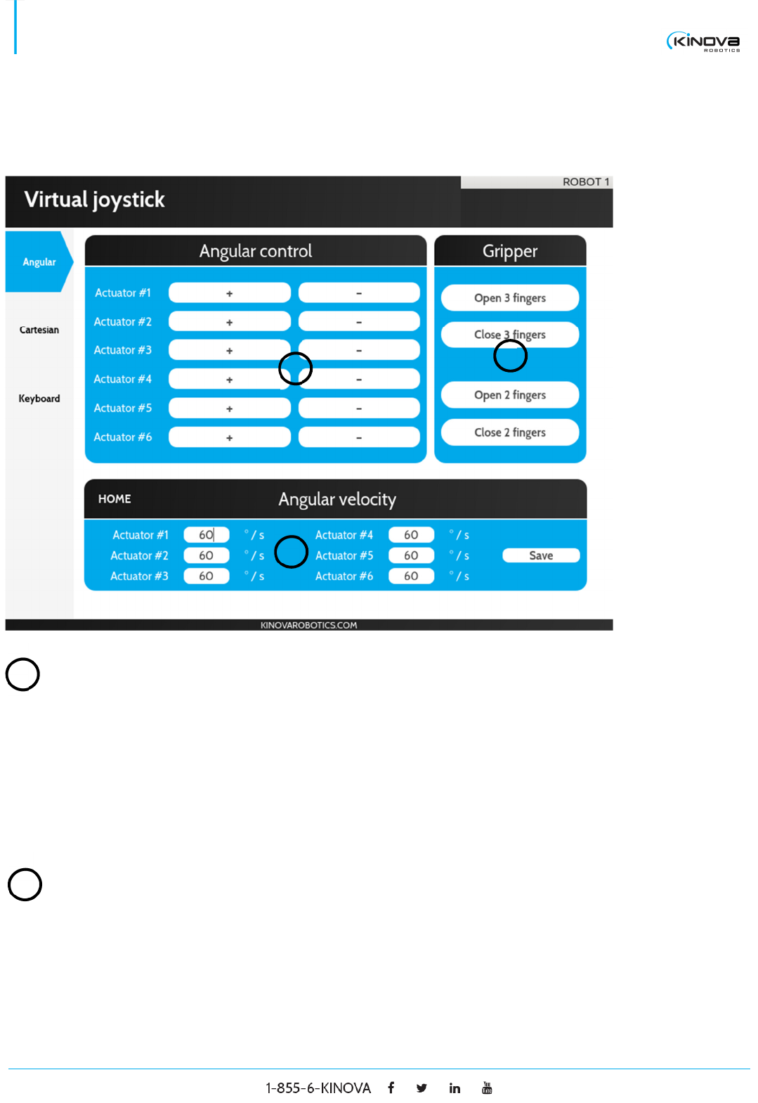
Virtual joystick
ANGULAR
Angular control
Actuator X + Press and hold to move the actuator X counter clockwise
where X is a number greater than 0.
Actuator X - Press and hold to move the actuator X clockwise where X is
a number greater than 0.
Gripper
Open 3 fingers Press and hold to open the gripper’s three fingers (only
available on the 3 finger gripper)
3
2
1
1
2
© 2017 Kinova Inc. All rights reserved. 27
SDK - Development center user guide
Close 3 fingers Press and hold to close the gripper’s three fingers (only
available on the 3-finger gripper)
Open 2 fingers Press and hold to open the gripper’s thumb and index
fingers.
Close 2 fingers Press and hold to close the gripper’s thumb and index
fingers
Angular velocity
Text field Set the velocity of a specific actuator.
Save Send the new velocity configuration to the robot.
CARTESIAN
4
1
2
3
3
© 2017 Kinova Inc. All rights reserved. 28
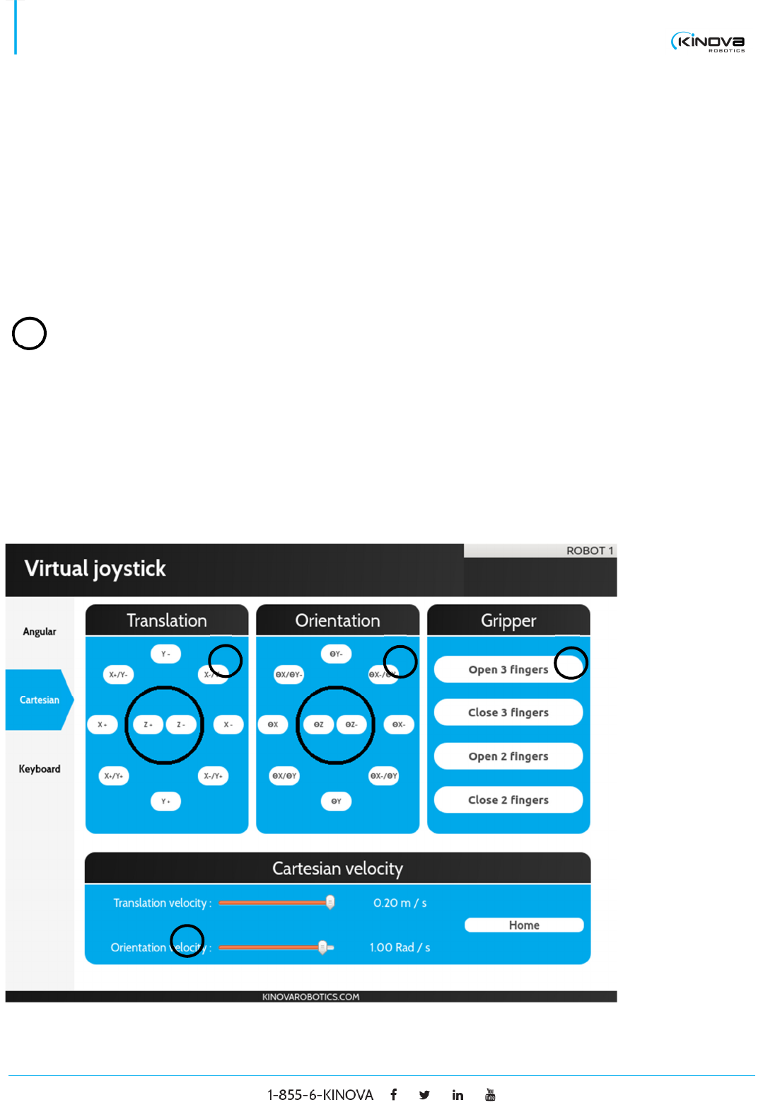
SDK - Development center user guide
Translation
Button + Press and hold to move the end effector along the positive
axis described by the button.
Button - Press and hold to move the end effector along the negative
axis described by the button.
Orientation
Button + Press and hold to move the end effector counter
clockwise around the axis described by the button.
Button - Press and hold to move the end effector clockwise around
the axis described by the button.
Gripper
Open 3 fingers Press and hold to open the gripper’s three fingers (only
available on the 3-finger gripper).
Close 3 fingers Press and hold to close the gripper’s three fingers (only
available on the 3-finger gripper).
Open 2 fingers Press and hold to open the gripper’s thumb and index
fingers.
Close 2 fingers Press and hold to close the gripper’s thumb and index
fingers.
Cartesian velocity
1
2
3
4
© 2017 Kinova Inc. All rights reserved. 29
SDK - Development center user guide
Translation
velocity Set the translation velocity of the end effector.
Orientation
velocity Set the orientation velocity of the end effector.
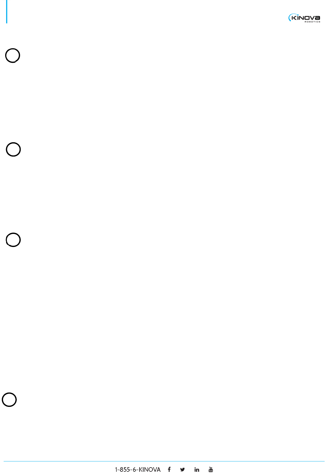
KEYBOARD
Control (Angular or Cartesian)
Combo box Select a key that will be mapped with the specified
movement. Note that this panel can be changed by pressing
the angular or Cartesian button.
1
1
2
3

© 2017 Kinova Inc. All rights reserved. 30
SDK - Development center user guide
Gripper
Combo box Select a key that will be mapped with the specified gripper
movement.
Others
Move HOME Select a key that will be mapped with the Move HOME
functionality.
Activate
keyboard
Check to activate the keyboard control with the robot. Note
that the robot’s joystick will always have a higher control
priority than the keyboard.
Cartesian Press to switch the control panel to Cartesian.
Angular Press to switch the control panel to Angular.
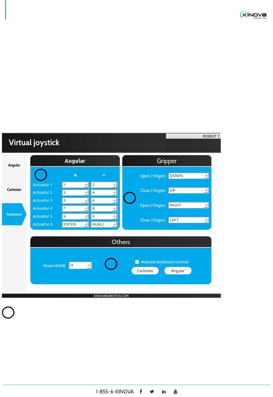
Trajectory planner
2
3
© 2017 Kinova Inc. All rights reserved. 31
SDK - Development center user guide
Position (Angular or Cartesian)
Left section Displays the current position or the position of a selected
trajectory point.
Right section Displays the max velocity of the robot for the selected
trajectory point.
Trajectory
Import Press to import a trajectory. The trajectory can be saved in
a KTJ file on disk.
Export Press to export a trajectory on disk in a KTJ file.
1
1
2
2
3

© 2017 Kinova Inc. All rights reserved. 32
SDK - Development center user guide
Position list Displays the list of positions contained in the trajectory. Each
point can be selected and their data will be displayed on the
position panel.
Get Press to display the current robot’s position on the position
panel.
Add Press to add a point in the list based on the information on
the position panel.
Quick add Press to execute a combination of a Get and Add.
Update Press to update the selected point in the list with the
information from the position panel.
Reach Press to move the robot to the selected point in the list.
Delete Press to delete the selected point in the list.
Clear all Press to clear all the positions in the list.
Stop Press to stop the robot’s movement. It will also cancel any
trajectory loops.
Launch Press to execute the trajectory. If the Loop Trajectory check
box is checked, the robot will repeat the trajectory until the
stop button is pressed.
Options
Control mode Toggle to switch between Cartesian and Angular trajectory
control.
Enable
limitations
Check to enable maximum velocities limitations.
3
© 2017 Kinova Inc. All rights reserved. 33
SDK - Development center user guide
Enable finger Check to enable finger motion during trajectory (note: even
if the fingers are enabled, they will not move if they weren’t
initialized. Fingers are initialized by opening them at their
maximum range once).
Loop trajectory Check to execute trajectory in a loop once the Launch button
is pressed
Delay Adds a delay before the robot starts moving to a given
trajectory point.
Resources
These are shortcuts to support elements found on Kinova’s website.
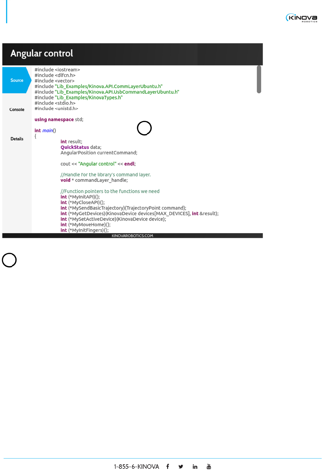
Examples
SOURCE
© 2017 Kinova Inc. All rights reserved. 34
SDK - Development center user guide
Source
Code Displays the code that reflects the example.
1
1
© 2017 Kinova Inc. All rights reserved. 35
SDK - Development center user guide
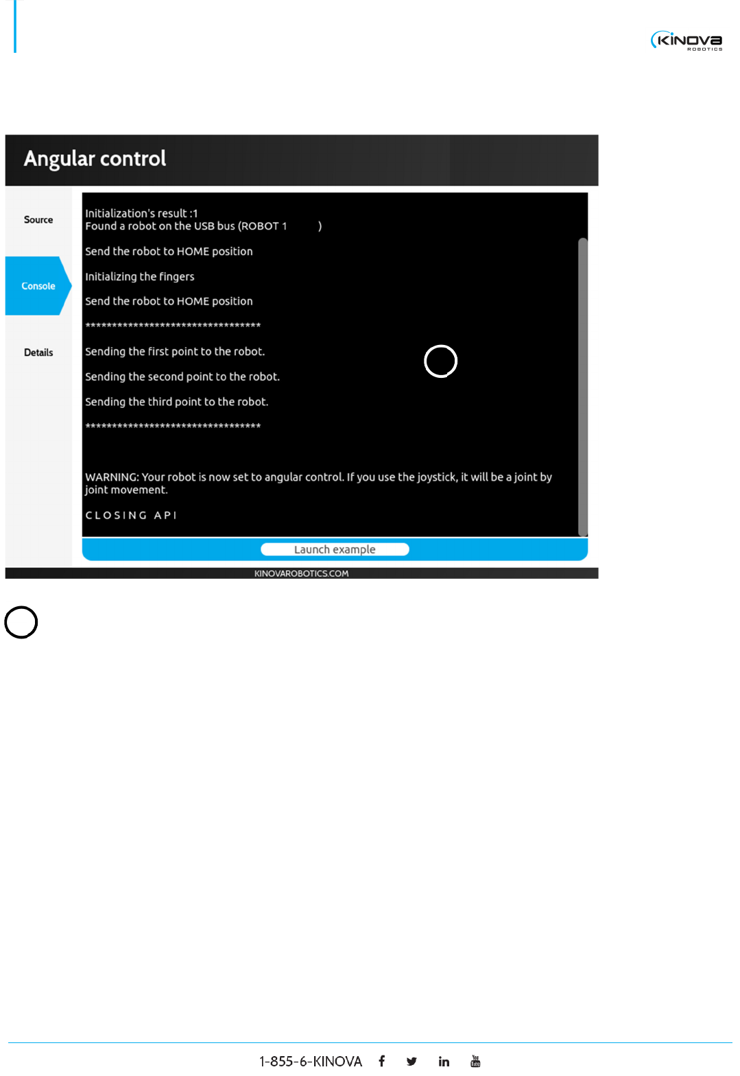
CONSOLE
Console
Output Displays the output of the example’s execution in a console
like window.
1
1
© 2017 Kinova Inc. All rights reserved. 36
SDK - Development center user guide
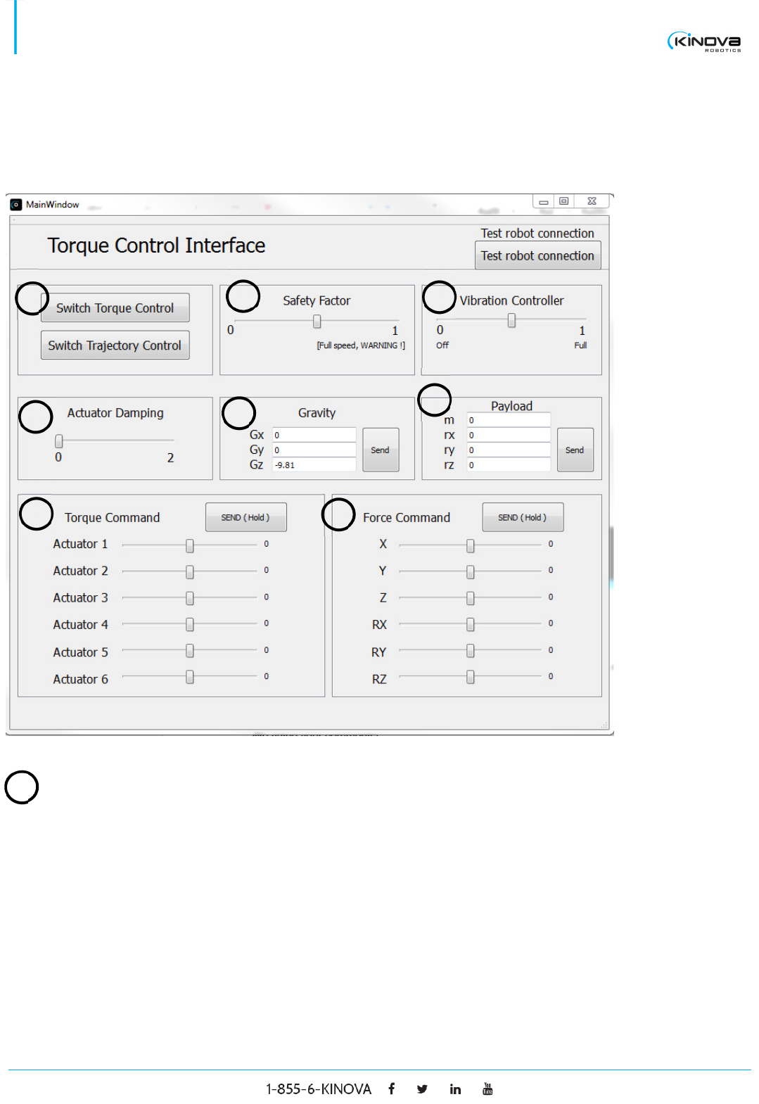
TORQUE CONSOLE
Main Window
Switch Torque and Trajectory
Switch Torque
Control
Click to switch to direct torque control. When the robot is in
torque control mode, you will be able to move it by hand with
very little resistance. The robot also becomes unresponsive
to joystick commands. Note that the robot might ‘refuse’ the
switch to torque control. This means that the measured
torques and the computed gravity torques are too different.
Insure that the torque sensors are well calibrated (do a zero
torque if needed), that the payload (when required) is
appropriate, that the gravity vector is appropriate and that
3
2
1
4
5
6
7
8
1
© 2017 Kinova Inc. All rights reserved. 37
SDK - Development center user guide
nothing is touching the robot. Generally, the robot’s Home
position is a good position to switch the control to torque
mode.
Switch
Trajectory
Control
Click to switch to kinematics (position) control. When the
robot is in kinematics control mode, you are not able to move
it by hand and it is reactive to joystick inputs. Note that the
robot should always be able to switch from torque mode to
trajectory mode (it can have more trouble switching from
trajectory mode to torque mode for the reasons given
above). Also note that when the robot is switched from
torque mode to trajectory mode, it automatically falls in
Angular Kinematics control.
Safety factor
Safety factor Slide the value from 0 (maximum safety: the robot switches
from torque mode to trajectory mode as soon as the
actuators’ velocity is above a very low threshold) to 1
(minimal/no safety: the robot never switches)
Do not set Safety Factor to 1 unless you are sure the robot
is in a collision-free environment. Ideally, validate the
torques readings and the gravity-free torques before setting
Safety Factor to 1, or else the robot could start moving very
fast without being stopped.
Vibration controller
Vibration
controller
Slide the value from 0 (no vibration controller) to 1
(maximum vibration controller). When vibration controller is
activated, you should feel the vibration damped.
Actuator damping
Actuator
damping
Slide the value from 0 (no damping) to 2 (max damping).
When the damping is activated, you should feel more
resistance moving the robot.
2
3
4
© 2017 Kinova Inc. All rights reserved. 38
SDK - Development center user guide
Gravity
Gravity vector Enter the gravity vector orientation with respect to Kinova
robot’s base reference frame.
Payload
m Enter the payload’s mass
rx, ry, rz Enter the payload’s center of mass with respect to Kinova
robot’s effector reference frame.
Torque command
Actuator X Specify a direct torque command on actuator X, where X is
a number greater than 0. This command will be executed in
torque mode as long as the button SEND (Hold) is held.
SEND (Hold) Hold this button to send a direct torque command
Force command
X, Y, Z Specify a force command to be applied at the end-effector.
The force direction follows the base reference frame X, Y
and Z axes direction. The force command will be executed
in torque mode as long as the button SEND (Hold) is held.
RX, RY, RZ Specify a torque command to be applied at the end-effector.
The three torques are expressed with respect to the effector
reference frame. The torque command will be executed in
torque mode as long as the button SEND (Hold) is held.
SEND (Hold) Hold this button to send a direct force command
5
6
7
8

© 2017 Kinova Inc. All rights reserved. 39
SDK - Development center user guide
CONTACTING SUPPORT
If you need help or have any questions about this product, this guide, or the information detailed in it, please
contact a Kinova representative at:
Support@KinovaRobotics.com
We value your comments!
To help us assist you more effectively with problem reports, the following information is required when
contacting Kinova or your distributor support
Product serial number
Date/Time of the problem
Environment where the problem occurred (per example 30° Celsius, raining, ...)
Actions performed immediately before the problem occurred
© 2017 Kinova Inc. All rights reserved. 40
SDK - Development center user guide
