L1637_B Virage Surgical Technique L1637 B OCT Spinal Fixation System
2014-10-16
: Pdf L1637 B - Virage Oct Spinal Fixation System Surgical Technique L1637_B_-_Virage_OCT_Spinal_Fixation_System_Surgical_Technique 10 2014 pdf
Open the PDF directly: View PDF ![]() .
.
Page Count: 44
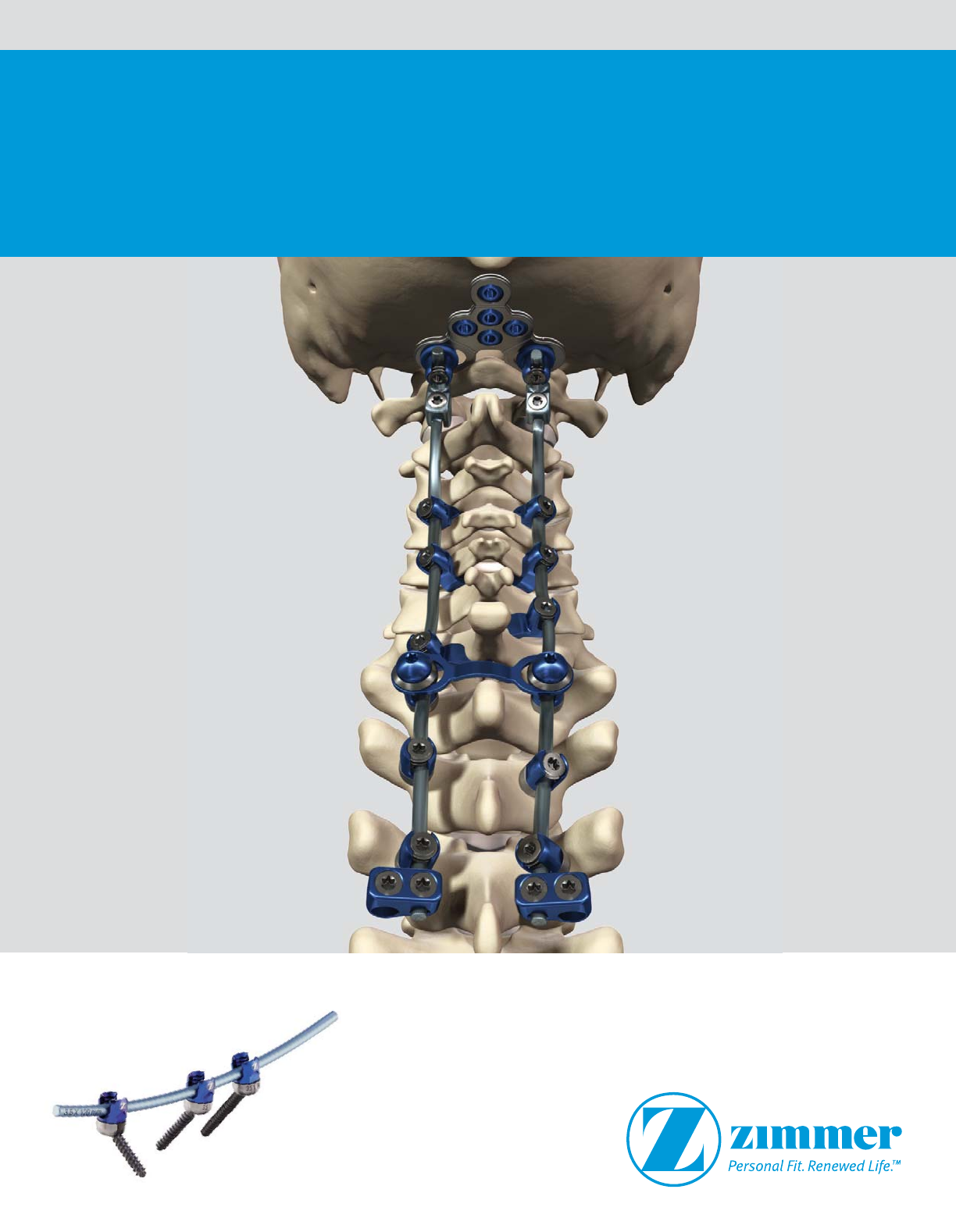
Virage® OCT Spinal Fixation System
Surgical Technique

2 Virage OCT Spinal Fixation System – Surgical Technique
Virage OCT Spinal Fixation System
Surgical Technique
Description, Indications & Contraindications ..................3
Virage System Overview....................................4
Cervico-Thoracic Surgical Technique..........................5
Occipitocervical Surgical Technique .........................20
Instrument Disassembly for Cleaning........................26
Revision and Removal Steps ...............................29
Tray Layouts ............................................30
Instrument Visual Guide...................................38
Warnings and Precautions .................................43

Virage OCT Spinal Fixation System – Surgical Technique 3
Description, Indications & Contraindications
DESCRIPTION
The Zimmer Spine Virage OCT Spinal Fixation
System is a posterior system intended for the
Occipital-Cervical-Thoracic spine (Occiput-T3).
The system consists of a variety of rods,
anchors, transverse connectors, screws,
and polyaxial screws to achieve an implant
construct as necessary for the individual case.
The system also includes the instruments
necessary for inserting and securing the
implants. The implant system is intended to be
removed after solid fusion has occurred.
The Virage System implants are fabricated from
medical grade titanium alloy and medical grade
cobalt chromium alloy. Implants made from
medical grade titanium, medical grade titanium
alloy, and medical grade cobalt chromium may
be used together. Never use titanium, titanium
alloy, and/or cobalt chromium with stainless
steel in the same construct. All implants are
single use only and should not be reused under
any circumstances.
MATERIALS
Implants: The Virage System implants are
fabricated from medical grade titanium alloy
per ASTM F136 and medical grade cobalt
chromium alloy per ASTM F1537.
Instruments: The Virage System
instrumentation is generally made from
stainless steel, aluminum, titanium, and
polymeric materials.
INDICATIONS
When intended to promote fusion of the
occipitocervical spine, cervical spine and the
thoracic spine, (Occiput -T3), the Virage OCT
Spinal Fixation System is indicated for the
following:
Degenerative disc disease (DDD) (neck pain of
discogenic origin with degeneration of the disc
confirmed by history and radiographic studies),
spondylolisthesis, spinal stenosis, fracture,
dislocation, failed previous fusion and/or
tumors.
Occipitocervical Plate/Rod/Occipital Screws/
Hooks
Occipitocervical plate, rods, occipital screws,
and hooks are intended to provide stabilization
to promote fusion following reduction
of fracture/dislocation or trauma in the
occipitocervical junction and the cervical spine.
When used to treat occipitocervical and cervical
conditions, the occipital screws are limited to
occipital fixation only. The occipital screws are
not intended for the cervical spine.
Hooks and Rods
Hooks and rods are also intended to provide
stabilization to promote fusion following
reduction of fracture/dislocation or trauma in
the cervical/upper thoracic (C1-T3) spine.
Thoracic Screws
The use of thoracic screws is limited to
placement in T1-T3 for anchoring the construct
only. The thoracic screws are not intended to be
placed in the cervical spine.
Rod Connectors
The Virage OCT Spinal Fixation System can also
be linked to the Instinct® Java® Spinal System
and Sequoia® Pedicle Screw System offered
by Zimmer Spine using rod connectors and
transition rods.
The titanium Songer® Spinal Cable System to
be used with the Virage OCT Spinal Fixation
System allows for cable attachment to the
posterior cervical or thoracic spine.
CONTRAINDICATIONS
The Virage System is not designed or sold for
any use except as indicated. DO NOT USE THE
VIRAGE SYSTEM IMPLANTS IN THE PRESENCE OF
ANY CONTRAINDICATION.
Contraindications include, but are not limited
to:
1. Overt infection or distant foci of infections.
2. Local inflammation, with or without fever or
leukocytosis.
3. Pregnancy.
4. Morbid obesity.
5. Rapid joint disease, bone absorption,
osteopenia, and/or osteoporosis.
6. Suspected or documented metal allergy or
intolerance.
7. Any time implant utilization would interfere
with anatomical structures or expedited
physiological performance, such as
impinging on vital structures.
8. Severe comminuted fractures such that
segments may not be maintained in
satisfactory proximate reduction.
9. Use in displaced, non-reduced fractures with
bone loss.
10. The presence of marked bone absorption or
severe metabolic bone disease that could
compromise the fixation achieved.
11. Poor prognosis for good wound healing
(e.g., decubitis ulcer, end-stage diabetes,
severe protein deficiency, and/or
malnutrition).
12. Any case not needing a bone graft or fusion.
13. Any case not described in the indications.
See also the WARNINGS and PRECAUTIONS
section at the end of this document.

4 Virage OCT Spinal Fixation System – Surgical Technique
Implant Overview
The Virage OCT Spinal Fixation System provides a comprehensive solution for a rigid posterior fixation of the Occipito-Cervico-Thoracic spine.
The Virage System includes multiple polyaxial screw diameters and lengths. All Virage System polyaxial screws feature a unique 360°
Omnidirectional extreme angle screw design. This unique design simplifies rod alignment and minimizes operating time.
All Virage System polyaxial screws have a friction fit head to hold the desired position and facilitate rod placement, maximizing efficiency and
safety during the procedure.
The Virage System’s dual lead screws require fewer revolutions to seat in the pedicle allowing surgeons to insert screws twice as fast compared to
a single lead screw.
The Virage System offers adjustable head to head transverse connectors that can accommodate up to 20° degrees of freedom in different planes
to improve intraoperative surgical flow.
The Virage System also offers a variety of implant options including rod to rod transverse connectors, Ø3.5/5.5mm rod connectors, pre-cut and
pre-bent Ø3.5mm Ti rods, Ø3.5mm CoCr rods, Ø3.5/5.5mm transition rods, lateral offset connectors, hooks, occipital plates, occipital eyelets,
and Ø3.5/3.8mm pre-contoured and adjustable occipital rods.
The Virage System instrumentation allows the surgeon the flexibility to build a construct that meets anatomical challenges and handles the
pathology being treated.
All implants in the Virage System (except the cobalt chrome rods) are manufactured from titanium alloy Ti 6Al-4V ELI. Rods are available in two
different materials: titanium alloy and cobalt chrome.
Occipitocervical Surgical Technique Implant Overview:
The Virage System offers three adjustable occipital plate sizes to accommodate the patient’s anatomy. An occipital strap is available for fixation to
the superior midline fixation hole. The Virage System offers Ø4.5mm / Ø5.25 occipital bone screws that have cortical threads.
The Virage System has many occipital rod options including: adjustable titanium, pre-contoured titanium, and pre-contoured cobalt chrome. Rods
transition to a 3.8mm diameter occipital portion to allow for a stronger construct.
The Virage System utilizes QuickFlip Guides to allow for plate retention and drill/tap guidance at 2mm increments without changing
instrumentation.
Polyaxial Screws:
The Virage System polyaxial screws are available in diameters of
3.5mm, 4.0mm, 4.5mm, and 5.0mm. The lengths range from 10mm
to 45mm depending on diameter. Refer to the table below:
Color Diameter Lengths Increments
Dark Blue 3.5mm 10-34mm Every 2mm
Gold 4.0mm 10-34mm Every 2mm
Magenta 4.5mm 20-45mm Every 5mm
Green 5.0mm 20-45mm Every 5mm
Smooth Shank Screws:
The Virage System smooth shank polyaxial screws are available in
diameters of 3.5mm and 4.0mm. The length of the smooth portion
varies with different screw lengths. The caddy will have two numbers
associated with each screw size, the first being the length of the
smooth portion and the second being the length of threaded portion.
The sum of the two numbers will be the total length of the screw.
NOTE: Lengths of 22mm and 36-40mm can be found in the Deluxe
Tray.
Diameter Lengths Increments
3.5mm 24-34mm Every 2mm
4.0mm 24-34mm Every 2mm

Virage OCT Spinal Fixation System – Surgical Technique 5
Instruments
Patient Positioning Exposure
Virage OCT
Spinal Fixation
System
Cervico-Thoracic
Surgical Technique
Step 1
Place the patient on a radiolucent operating
table in the prone position with the head and
neck held securely in proper alignment. Drape
the patient for posterior spinal fusion. (Fig. 1)
Step 2
Complete a midline sub-peroisteal incision
and dissection down to the spinous
processes of the appropriate vertebrae.
Extend dissection laterally to expose the
facets and transverse processes. (Fig. 2)
Fig. 1 SFig. 2 S
Cervico-Thoracic Surgical Technique:
The following Surgical Technique Guide
describes the recommended placement
and use of all Virage Cervico-Thoracic Spinal
System components.
NOTE: Care must be taken to avoid vital
structures including but not limited to the
vertebral arteries, nerve roots, and the spinal
cord.
WARNING: Care should be taken during bone
preparation to avoid damage to the pedicle and
to the surgical instruments.
6 Virage OCT Spinal Fixation System – Surgical Technique
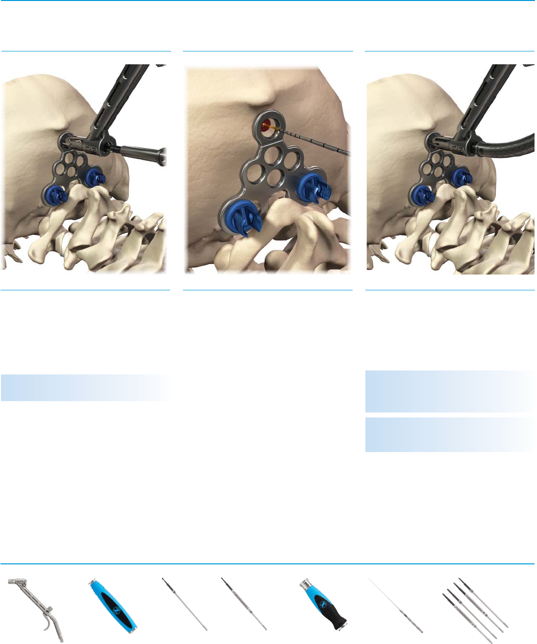
Fig. 3 S
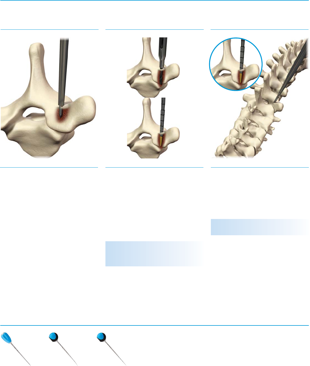
Step 4, Option A
Insert the pedicle Probe in the previously
prepared entry point while maintaining the
appropriate trajectory. Advance the pedicle
Probe to the desired depth using the depth
markings as a guide. (Fig. 5)
Fig. 4 SFig. 5 S
Polyaxial Screw Hole Preparation Probe/Drill Option A: Probe
Instruments
NOTE: Pedicle Probes are gold up to 10mm.
WARNING: Instrument and implants may cause
soft tissue damage. Care should be taken to
minimize damage.
Step 4
Determine Drill or Probe penetration depth
based on radiographic films or fluoroscopy.
K-wires or pedicle markers may be placed
into the pedicle throughout the preparation,
confirming position on radiographs to
manage orientation and trajectory. Caution
should be taken to make sure the hole is not
prepared too deep. (Fig. 4)
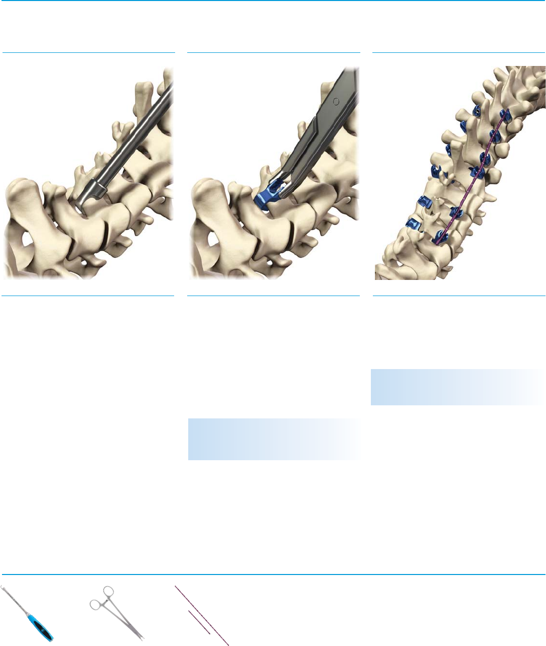
Step 3
Insert the Bone Awl or a burr to break the
cortical surface. The Bone Awl has a hard stop
that limits insertion to 8 mm. Repeat for all
screw placement sites. (Fig. 3)
Curved Probe
07.01753.001
Straight Probe
07.01754.001
Bone Awl Ø2.0mm
07.01752.001
Virage OCT Spinal Fixation System – Surgical Technique 7
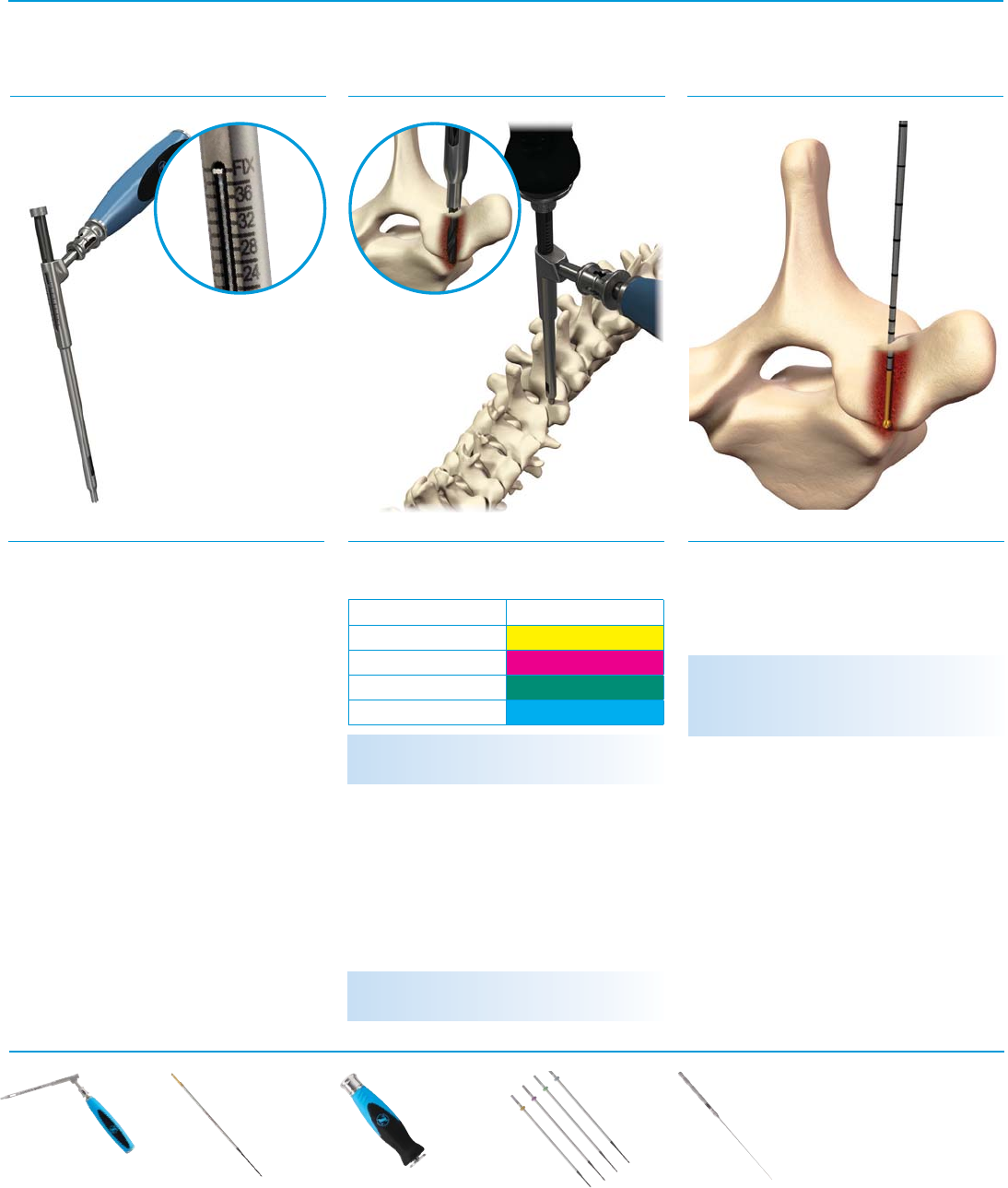
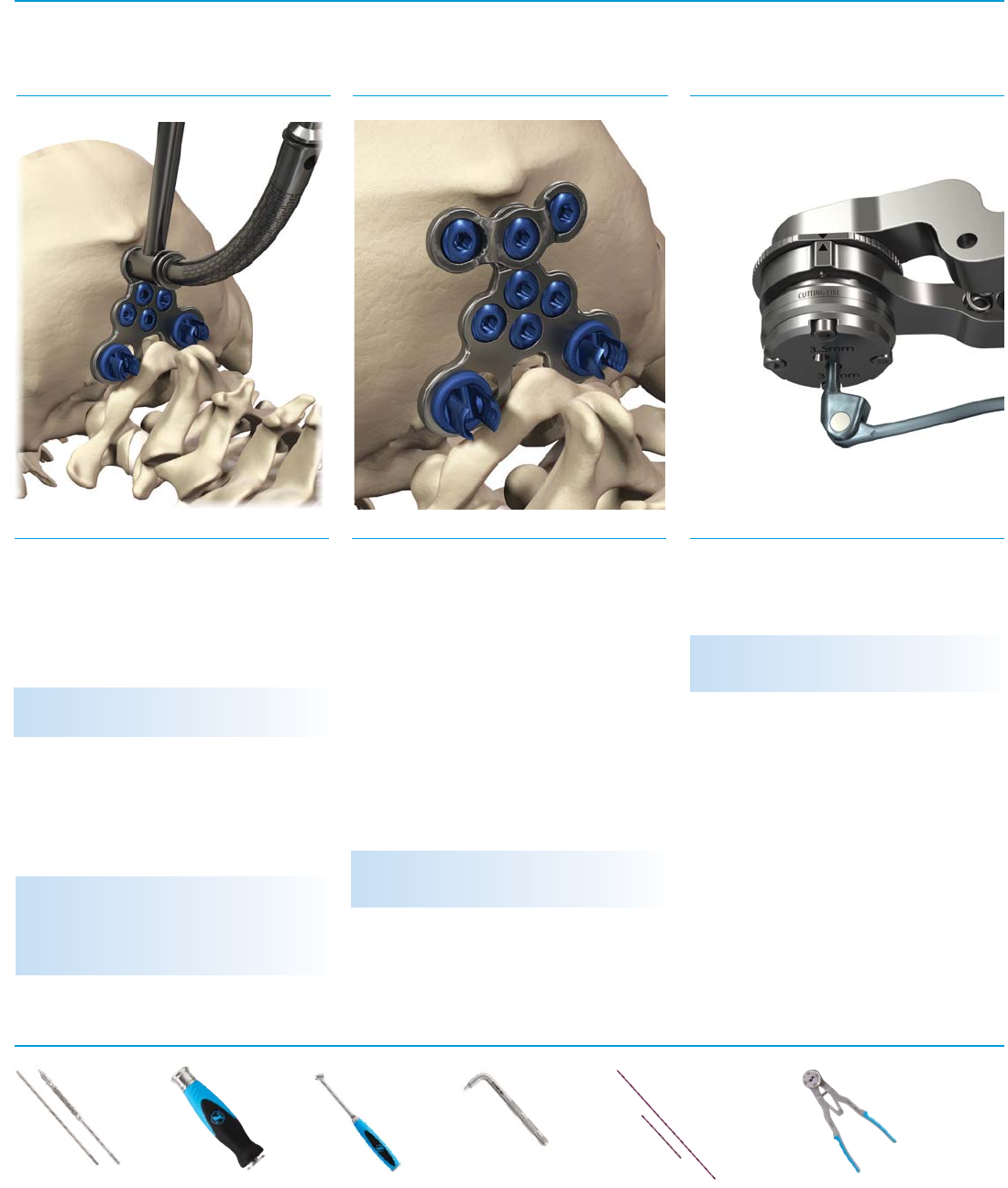
Fig. 6 S
Step 4, Option B
The Drill Guide allows for drilling depth
between 8mm-40mm in 2 mm increments.
Drill Guide Adjustable Setup: Hold the Drill Guide
handle with the Drill Guide tip oriented vertically
so the numbers are upright and readable.
Pull back the knob toward the handle, then
lift or lower the rack to the desired depth.
Once the desired depth is reached, release
the knob to lock the Drill Guide. The depth is
set correctly when the silver band is lined up
with the numerical marking that matches the
desired length of the screw. Press on the top of
the rack to be sure it is locked in place. (Fig. 6)
Drill Guide Fixed Setup: The Drill Guide can be
utilized as a fixed drill guide by placing in the
“FIX” setting or the fully seated position. The
depth is set correctly when the silver band is
lined up with the FIX marking. (Fig. 6, inset)
The Virage System offers four Fixed Drills:
Attach the Adjustable Drill or Fixed Drills to
the A-O Handle with Spin Cap and insert
through the Drill Guide.
Orient the Drill Guide and drill at the desired
trajectory and drill until reaching the positive
stop. The positive stop is reached when the drill
stop contacts the top of the Drill Guide. (Fig. 7)
Fig. 7 SFig. 8 S
Option B: Drilling Verify Hole Integrity and Depth
Instruments
Adjustable Drill Guide
07.01755.001
Adjustable Drill (Ø2.3mm)
07.01757.001
NOTE: Fixed Drills have a colored band that
matches the tray color for that screw length.
Step 5
Confirm bone integrity and measure hole
depth using the Sounding Probe. (Fig. 8)
NOTE: The A-O connection of the Adjustable
Drill is gold.
Size Color
10mm Gold
12mm Magenta
14mm Green
16mm Light Blue
A-O Handle with Spin Cap
07.01788.001
NOTE: The Sounding Probe tip is gold up to
10mm. There are 2mm markings from 10mm to
20mm, then every 5mm from 20mm to 50mm.
Fixed Drills (all Ø2.3mm)
07.01758.001 10mm
07.01758.002 12mm
07.01758.003 14mm
07.01758.004 16mm
Sounding Probe
07.01759.001
8 Virage OCT Spinal Fixation System – Surgical Technique
Tap
07.01761.001 Ø3.0mm
07.01761.002 Ø3.5mm
07.01762.001 Ø4.0mm
04.01762.002 Ø4.5mm
Tap Sleeve
07.01763.002 Ø3.5mm
07.01763.004 Ø4.5mm
Polyaxial Screw Driver,
Inner Sleeve
07.01764.001
Polyaxial Hex Screw
Driver, 2.5mm
07.01764.002
Polyaxial Screw Driver,
Outer Sleeve
07.01764.003
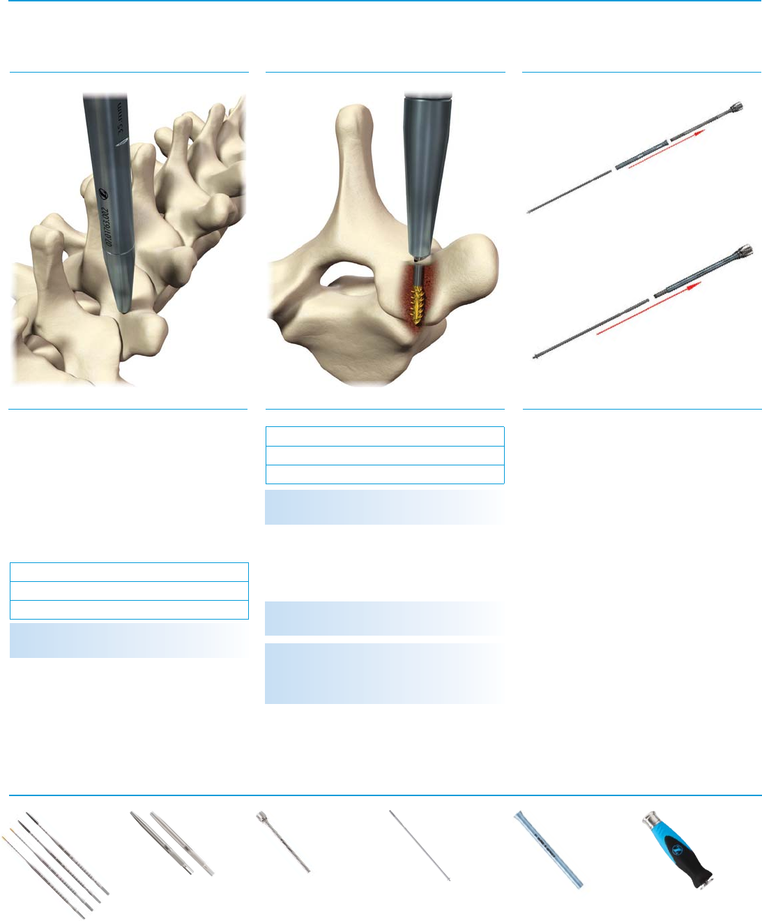
Fig. 9 S
A Tap Sleeve is available if desired. Assemble
Tap Sleeve by sliding large opening over the
Tap thread. Laser marked lines on proximal
end of tap indicate depth of the tap. (Fig. 10)
Fig. 10 SFig. 11 S
Tapping (Optional) Polyaxial Screw Driver Assembly
Instruments
Step 6
Virage System polyaxial screws are self-
tapping. If tapping is desired, the screw
hole may be tapped using the appropriate
diameter Tap. (Fig. 9)
The Virage System offers taps that are marked
true to size:
Step 7
Assemble the three piece Screw Driver by
sliding the blue Outer Sleeve over the Inner
Sleeve until fully engaged on the retaining
feature. (Fig. 11, top)
Next, depress button on Inner Sleeve knob
and slide the Hex Screw Driver through the
Inner Sleeve. Slide until fully seated. Release
button and confirm retention. (Fig. 11,
bottom)
Connect the Screw Driver to the A-O Handle.
Small Tap - Ø3.5/4.0mm Screws
Ø3.0mm Tap
Ø3.5mm Tap
NOTE: Tap threads are colored gold up to 10mm.
Large Tap - Ø4.5/5.0mm Screws
Ø4.0mm Tap
Ø4.5mm Tap
NOTE: Tap threads are colored black up to 30mm.
NOTE: Tap tips are laser marked every 5mm.
A-O Handle with
Spin Cap
07.01788.001
NOTE: The 3.5mm Tap Sleeve is compatible with
the Ø3.0/Ø3.5mm Taps. The 4.5mm Tap Sleeve
is compatible with the Ø4.0/Ø4.5mm Taps.

Virage OCT Spinal Fixation System – Surgical Technique 9
Fig. 12 SFig. 13 SFig. 14 S
Polyaxial Screw Loading Polyaxial Screw Placement
Optional: Polyaxial Screw Height
Adjustment
Instruments
Step 10
The Tapered Hex Driver may be used
to reposition the polyaxial screw. This
instrument engages the hex of the screw
shank and does not require threading into the
tulip head. (Fig. 14)
Step 9
Drive the screw to the desired depth where
polyaxial movement of the head is maintained.
Remove the Screw Driver by rotating the knob
counterclockwise until disengaged from the
screw, then pull in the trajectory of the screw
shank.
Confirmation of screw position can be
made using lateral and A/P radiographs or
fluoroscopy. Place the remaining screws using
a similar technique. (Fig. 13)
NOTE: When advancing the screw avoid placing
free hand on the knob, thus causing the Screw
Driver to disconnect from the screw. To prevent
this, place free hand on the blue Outer Sleeve of
the Polyaxial Screw Driver.
NOTE: The button on the knob of the Driver is for
instrument disassembly/cleaning only.
NOTE: A smooth shank screw implant option can
be used to minimize tissue irritation.
Step 8
Insert the hex of the Screw Driver into the
screw shank. (Fig. 12, top)
Secure the screw by rotating the knob
clockwise until tight. (Fig. 12, bottom)
Tapered Hex Driver,
2.5mm
07.01765.001
A-O Handle with
Spin Cap
07.01788.001
10 Virage OCT Spinal Fixation System – Surgical Technique
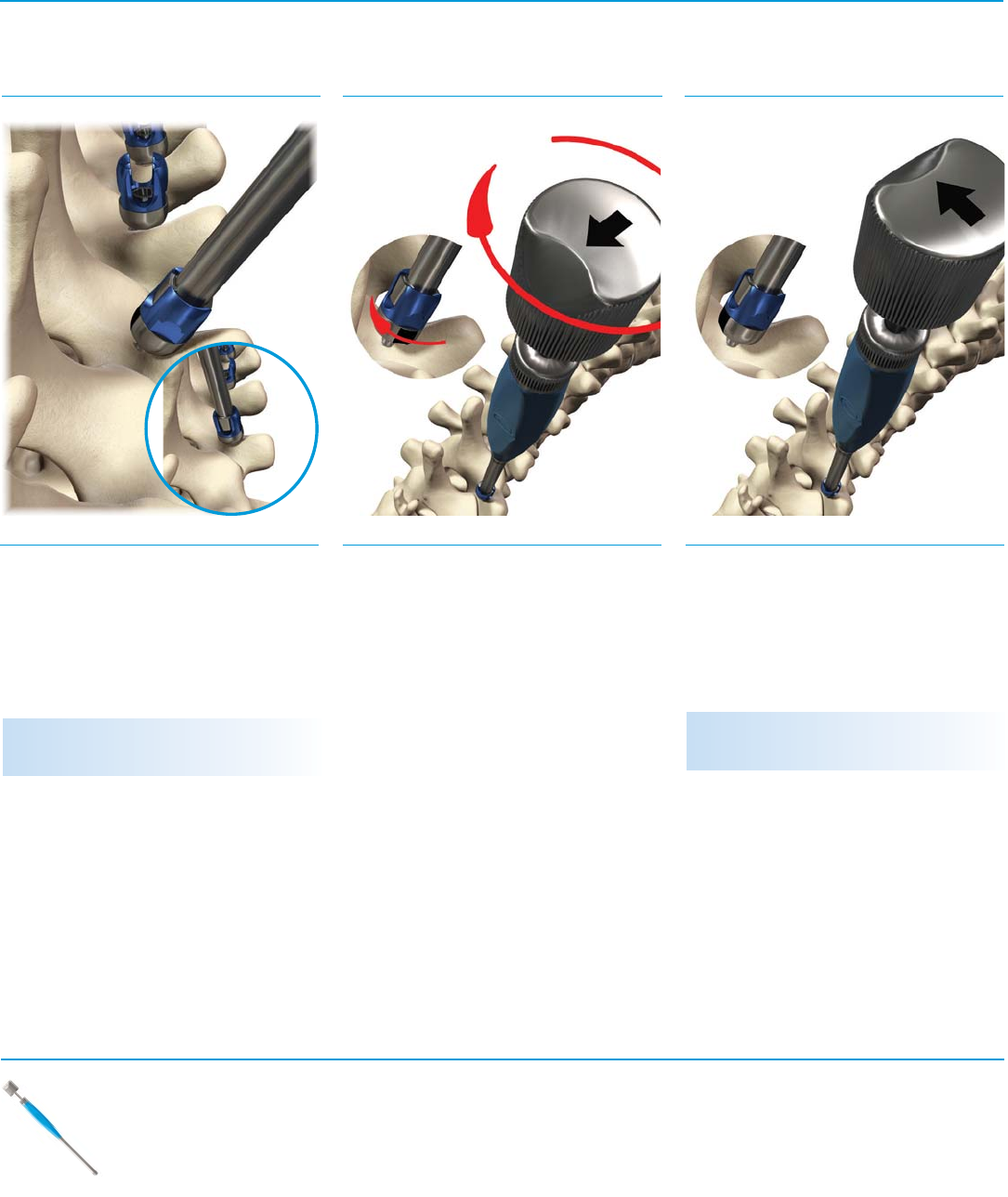
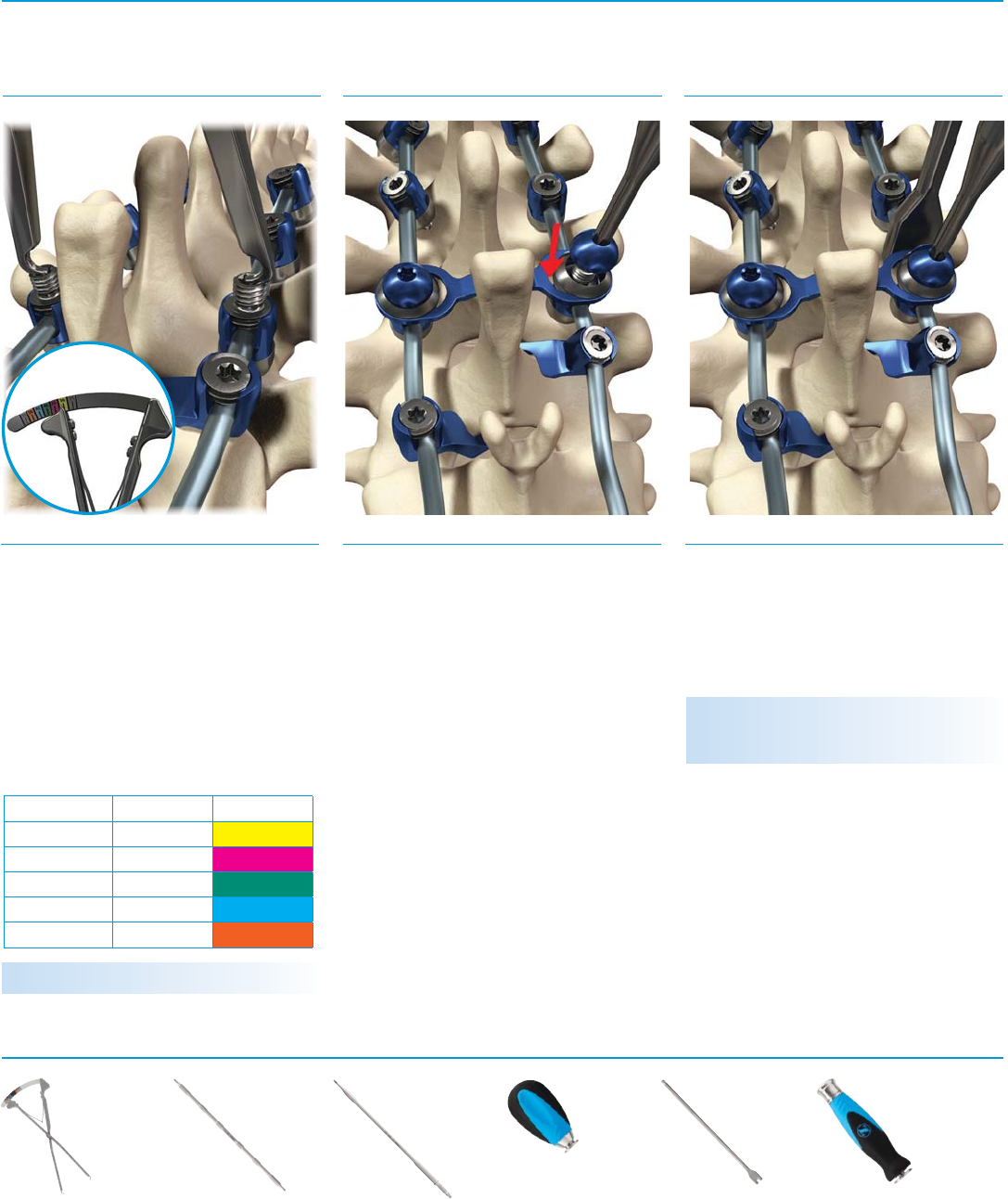
Fig. 15 SFig. 16 SFig. 17 S
Polyaxial Screw Head Alignment
360° Omnidirectional Extreme Angle
Engagement
Instruments
To rotate the direction of the extreme angle,
turn the silver knob and point the arrow in
the desired direction. If needed, align upper
housing for rod placement by rotating the
blue handle of the Polyaxial Screw Head
Turner. (Fig. 17)
Step 11
Align the heads of the screws by engaging the
distal end of the Polyaxial Screw Head Turner
into the housing head of the screw. Rotate the
blue handle until the desired orientation is
reached. (Fig. 15)
IMPORTANT: Use the blue portion of the
instrument to rotate the upper housing.
NOTE: If polyaxial screw movement is restricted,
adjust the height of the screw.
Step 12
All Virage System polyaxial screws allow for a
360° unconstrained range of motion providing
56° of angulation in all directions.
To reach extreme angulation, slowly rotate
the silver knob while applying downward
pressure until the distal tip engages into
the housing of the screw. Tactile/audible
feedback confirms engagement. A black
stripe on the screw's lower housing indicates
extreme angle location. (Fig. 16)
Polyaxial Screw
Head Turner
07.01766.001
Virage OCT Spinal Fixation System – Surgical Technique 11
Fig. 18 SFig. 19 SFig. 20 S
Hook Insertion:
Hook Trial/Insertion Hook Attachment
Rod Preparation:
Template
Instruments
Step 13
Identify which landmarks of the cervical lamina
will receive hooks. Remove soft tissue and
ligamentous connections sparingly, providing
good visualization of the entire lamina and
margins of the spinal canal.
Place the Hook Trial on the lamina to identify
the appropriate implant size. Prepare the
lamina taking care not to remove excess
material. When placing both the trial and the
implant, take care not to breach the margins of
the spinal cord. (Fig. 18)
Step 14
Attach the Hook Forceps to the proximal body
of the hook. Slide the hook underneath the
lamina at the previously prepared position.
Secure the hook to the cervical lamina.
Place all remaining hooks using the same
procedure. (Fig. 19)
NOTE: The closure top, Closure Top Starter, and
Final Driver may be passed through the Hook
Forceps.
Step 15
A Rod Template may be used to determine the
appropriate length and curvature of the rod.
(Fig. 20)
WARNING: Markings on the Rod Template are
every 10mm.
8mm Hook Trial
07.01750.001
Hook Forceps
07.01751.001
Rod Template
07.01767.001 100mm
07.01767.002 250mm

12 Virage OCT Spinal Fixation System – Surgical Technique
Fig. 21 SFig. 22 SFig. 23 S
Rod Selection/Cutting Rod Contouring Rod Placement
Instruments
Step 16
Choose the appropriate rod length and material.
The Virage System contains pre-cut/pre-bent
rods and straight rods. The titanium rods are
colored blue and the cobalt chrome rods are
silver. Cobalt chrome alloy offers increased
strength and stiffness over titanium alloy.
If cutting is needed, use the Rod Cutter.
Rotate the knurled wheel until the two arrows
are aligned. Insert the rod into appropriate
labeled hole of the Rod Cutter to the desired
depth. Repeatedly squeeze the handles until
the rod is cut. (Fig. 21)
Step 17
If contouring is needed, use the French Rod
Bender. Place the rod within the French Rod
Bender and squeeze the handles to achieve
the desired curvature.
The French Rod Bender allows three different
bend radii. To adjust, pull the center knob and
turn to select the desired bend radius.
If in-situ bending is needed, rods can be
contoured in the sagittal plane with the three
In-situ Rod Benders. (Fig. 22)
NOTE: The “cutting line” marks the spot where
the Rod Cutter will cut the rod. The cutting line is
located ~8 mm from the face of the instrument.
NOTE: Realigning arrows will assist in removal
of the rod.
NOTE: Reverse bending can weaken the rod and
is not recommended.
Step 18
Grasp the rod with the Rod Holder and engage
the locking mechanism by fully closing
the handles. To release, squeeze handles
together, disengaging the locking mechanism.
(Fig. 23)
Rod Cutter
07.01774.001
French Rod Bender
07.01770.001
In-situ Rod Bender
07.01771.002 Left
07.01772.002 Right
07.01773.002 Straight
Rod Holder
07.01768.001
Virage OCT Spinal Fixation System – Surgical Technique 13
Fig. 24 SFig. 25 SFig. 26 S
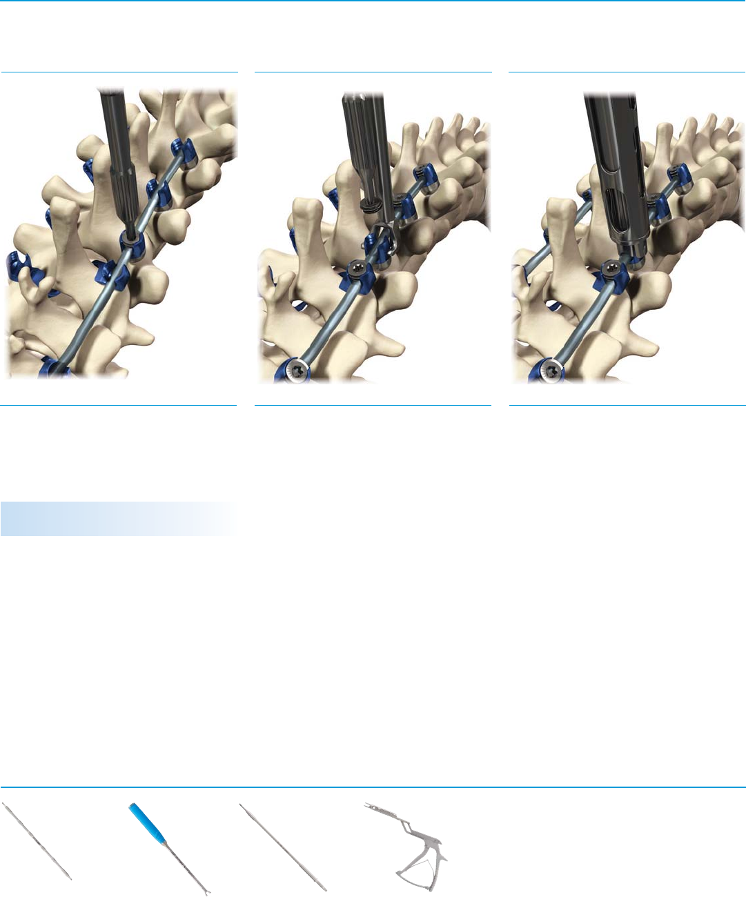
Set Screw Insertion:
Closure Top Placement
Rod Reduction:
Rod Rocker Kerrison Rod Reducer
Instruments
Step 19
Insert the closure top using the Closure Top
Starter and provisionally tighten into each
screw/hook housing. (Fig. 24)
Step 20
The Rod Rocker may be used to seat the rod
and ease closure top introduction.
Engage the Rod Rocker and gently tilt to lower
the rod into the implant housing. Place the
closure top with the Closure Top Starter to
secure the rod. (Fig. 25)
WARNING: Use care to avoid cross threading.
Step 21a
Prior to use, open the lock of the Kerrison Rod
Reducer and engage onto screw housing by
applying a slight downward force until fully
seated. Gently squeeze the handle to engage
the screw head and seat the rod into screw.
Once seated, insert a closure top using a
Closure Top Starter or Final Driver through the
Kerrison Rod Reducer. (Fig. 26)
Closure Top Starter
07.01782.001
Rod Rocker
07.01775.001
Kerrison Rod Reducer
07.01777.001
Final Driver
07.01783.001
14 Virage OCT Spinal Fixation System – Surgical Technique
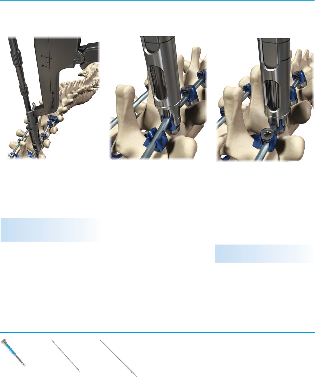
Fig. 27 S
Step 22a
Prior to use, ensure the Tower Rod Reducer
is fully open by turning the large knob
counterclockwise until positive stop is
reached.
Engage the Tower Rod Reducer onto the screw
housing by applying a slight downward force
until fully seated. Turn the large knob to seat
the rod into the screw. (Fig. 28)
Step 21b
To remove the Kerrison Rod Reducer,
disengage the lock to allow the handle to
open fully; rotate slightly to either side and
gently pull. (Fig. 27)
Fig. 28 SFig. 29 S
Tower Rod Reducer
Instruments
Step 22b
Once seated, insert a closure top using a
Closure Top Starter or Final Driver through the
Tower Rod Reducer.
To remove the Tower Rod Reducer, turn the
knob counterclockwise until it reaches the
positive stop; rotate slightly to either side and
gently pull. (Fig. 29)
NOTE: Reduction travel is indicated by laser
markings on the side of the Reducer.
NOTE: Reduction travel is indicated by laser
markings on the side of the Kerrison Rod
Reducer.
Tower Rod Reducer
07.01776.001
Closure Top Starter
07.01782.001
Final Driver
07.01783.001

Virage OCT Spinal Fixation System – Surgical Technique 15
Instruments
Fig. 31 SFig. 32 SFig. 30 S
Additional Rod Manipulations:
Compression/Distraction/Rotation Final Tightening Transverse Connector Placement
Step 23
Once the rod is secured into the implants,
distraction and/or compression may be
performed to place the implants in their final
position. (Fig. 30)
A Rod Gripper is also included for additional
rod manipulation.
NOTE: To disengage the Rod Gripper, press and
hold the button until fully disengaged.
Step 24
When all implants are securely in place and
the rods are fully seated, final tightening is
performed. Tighten closure tops using the
Final Driver, Torque-Limiting Handle, and
Inline Counter Torque.
Turn the Torque-Limiting Handle clockwise to
advance the closure top until two clicks are
heard (torque set at 23in-lbs). (Fig. 31)
Step 25a
The Virage System includes head to head
transverse connectors (HHTC) from 27mm
to 53mm. The HHTC is composed of three
components: HHTC closure top, arm, and
dome nut.
The HHTC can accommodate housing tilt up
to 20° (10° each side) requiring less bending
of the HHTC arm and allowing off axis screw
head position.
Insert an HHTC closure top (07.01719.001)
into the head of the applicable polyaxial
screw using a Closure Top Starter. (Fig. 32)
Final tighten the HHTC closure top using
the Final Driver, Torque-Limiting Handle,
and Inline Counter Torque. Repeat on the
contralateral side.
Turn the Torque Limiting Handle clockwise to
advance the closure top until two clicks are
heard.
NOTE: Ensure the Final Driver is fully seated into
the Torque-Limiting Handle.
Compressor
07.01778.001
Distractor
07.01779.001
Rod Gripper
07.01769.001
Torque-Limiting
Handle, 3/16"
07.01792.001
Final Driver
07.01783.001
Closure Top Starter
07.01782.001
Inline Counter
Torque
07.01785.001
16 Virage OCT Spinal Fixation System – Surgical Technique
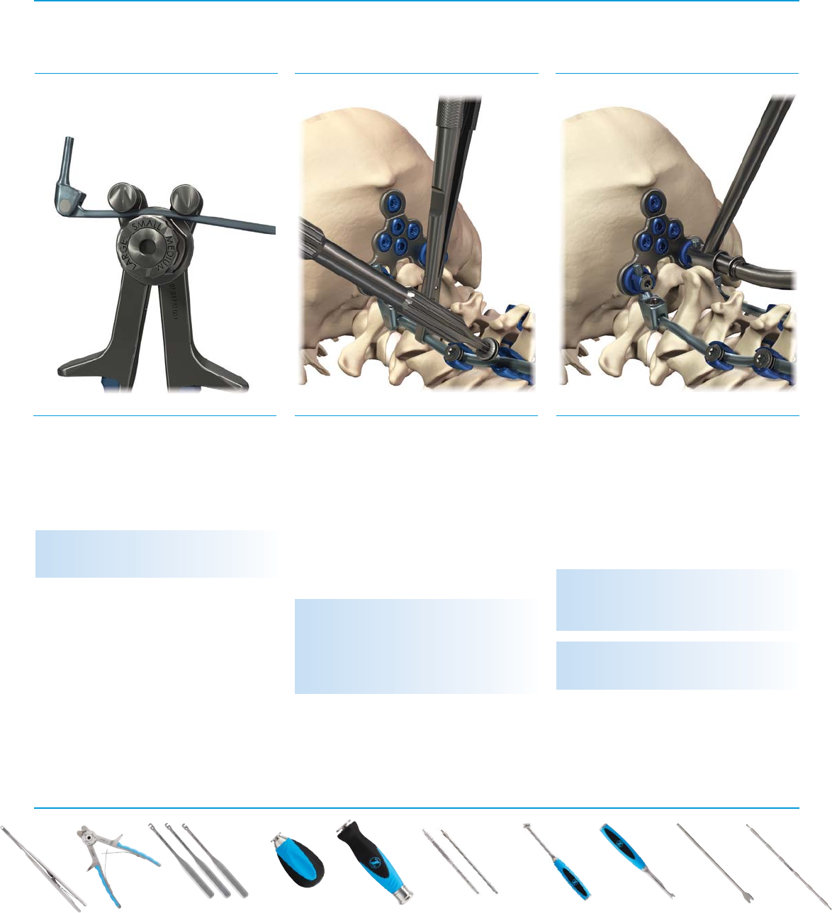
Fig. 33 SFig. 34 SFig. 35 S
Instruments
Step 25b
Determine the appropriate size HHTC arm using
the Transverse Connector Caliper. Place both
tips of the Caliper into the HHTC closure top.
Read the length and/or color coding on the
Caliper to determine appropriate HHTC size.
(Fig. 33)
HHTC arms are adjustable and available in
multiple sizes:
NOTE: There is a 1mm overlap between sizes.
Size Lengths Tray Color
Extra Small 27-33mm Gold
Small 32-38mm Magenta
Medium 37-43mm Green
Large 42-48mm Light Blue
Extra Large 47-53mm Orange
Step 26
Place the HHTC arm over the HHTC closure
tops and around the tops of the polyaxial
screws.
Once the HHTC arm is in position, insert the
HHTC dome nut (07.01720.001) with the
Closure Top Starter; provisionally tighten.
Repeat on the contralateral side. (Fig. 34)
Step 27
Perform final tightening using the Final Driver
and Torque-Limiting Handle until two clicks
are heard. Repeat on the contralateral side.
(Fig. 35)
NOTE: The Rod Pusher is available to provide
counter torque to the Ø3.5mm rod.
Torque-Limiting
Handle, 3/16"
07.01792.001
Rod Pusher
07.01784.001
A-O Handle with
Spin Cap
07.01788.001
Transverse Connector
Caliper
07.01780.001
Closure Top Starter
07.01782.001
Final Driver
07.01783.001

Virage OCT Spinal Fixation System – Surgical Technique 17
Fig. 36 SFig. 37 SFig. 38 S
Instruments
Rod to Rod
Transverse Connector
Transition Rod Placement
Ø3.5mm/5.5mm Transition Rods
Step 28
Rod to rod transverse connectors (RRTC) are
adjustable and available in multiple sizes:
Determine the appropriate size RRTC by using
the Transverse Connector Caliper. Place both
tips of the Caliper around lateral side of rods.
Read the length and/or color coding on the
Caliper to determine appropriate RRTC size
(see table above). (Fig. 36)
NOTE: There is a 1mm overlap between sizes.
Size Lengths Tray Color
Extra Small 27-33mm Gold
Small 32-38mm Magenta
Medium 37-43mm Green
Large 42-48mm Light Blue
Extra Large 47-53mm Orange
Step 29
Engage the RRTC Driver onto the RRTC hex
nut. Position the RRTC onto the construct and
snap it onto the rods using slight downward
pressure. Repeat on the contralateral side.
Attach the Torque-Limiting Handle to the RRTC
Driver and final tighten by rotating clockwise
until two clicks are heard. (Fig. 37)
Step 30
Transition rods allow for a transition from
the cervical to the thoracic spine or at any
location where it is necessary to move from a
Ø3.5mm rod to a Ø5.5mm rod. (Fig. 38)
Titanium and cobalt chrome transition
rods are offered pre-bent at the transition.
Additional rod contouring and rod cutting
may be accomplished using the French Rod
Bender and/or Rod Cutter.
NOTE: The Rod Pusher is available to provide
counter torque to the Ø3.5mm rod.
CAUTION: The start of the transition zone is
indicated by a dark band. Do not connect
implants within this transition zone.
NOTE: A Ø5.5mm Rod Cutter and Bender will
need to be ordered for the Ø5.5mm rod.
NOTE: Reverse bending can weaken the rod and
is not recommended.
Torque-Limiting
Handle, 3/16"
07.01792.001
A-O Handle with Spin
Cap
07.01788.001
Rod Pusher
07.01784.001
Rod Cutter
07.01774.001
French Rod Bender
07.01770.001
Transverse Connector
Driver
07.01781.001
CoCr Ti Alloy
Transverse Connector
Caliper
07.01780.001

18 Virage OCT Spinal Fixation System – Surgical Technique
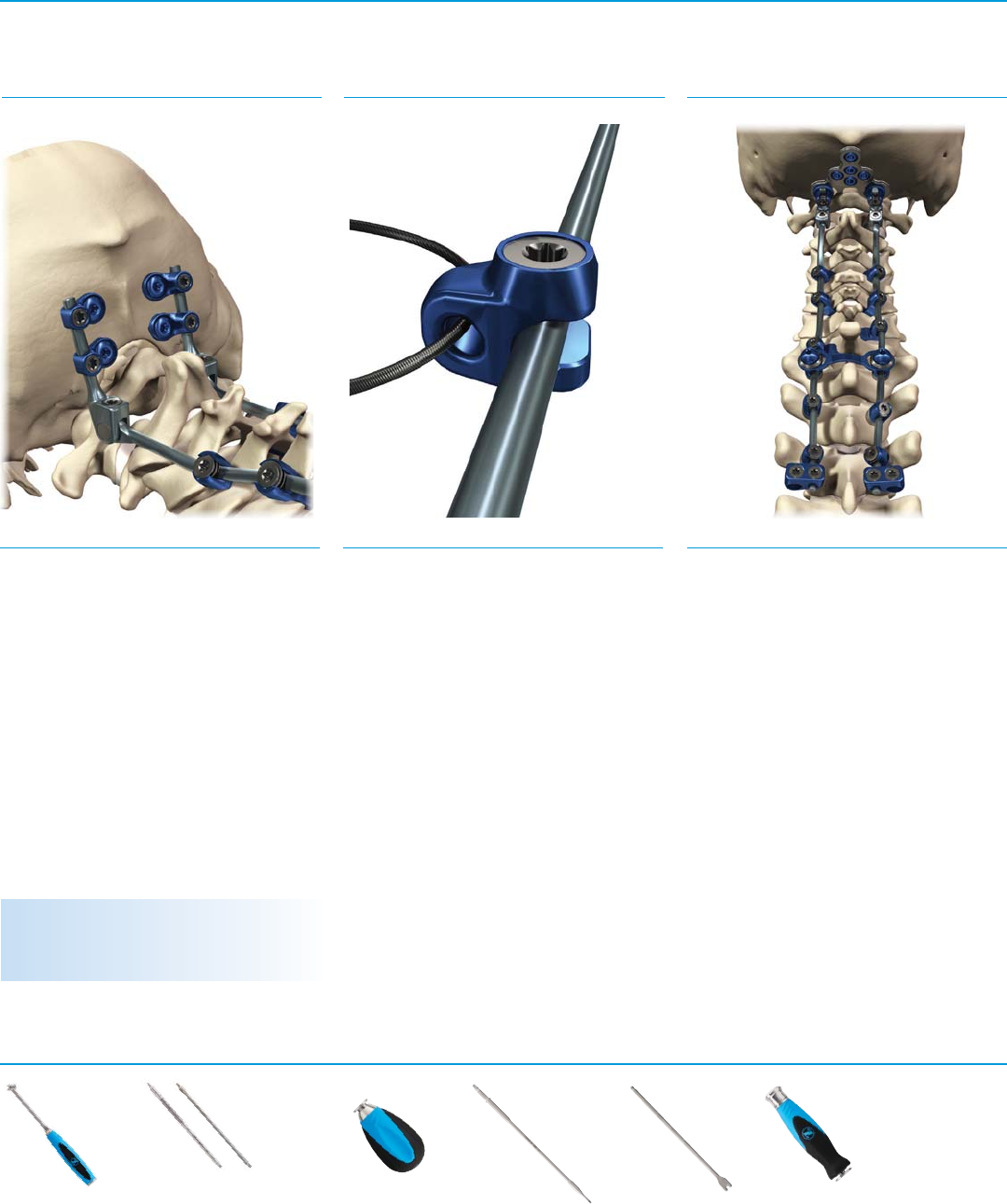
Fig. 39 SFig. 40 S
Instruments
Fig. 41 S
Ø3.5mm/5.5mm Rod Connectors Lateral Offset Connector Placement
Step 31
The Virage System offers closed rod connectors
to connect a Ø3.5mm rod to a Ø5.5mm titanium
rod of the Zimmer Instinct® Java® Spinal Fixation
System or Sequoia® Pedicle Screw System.
(Fig. 39)
The closed rod connector contains two internal
set screws that require locking using the Final
Driver connected to the Torque-Limiting Handle.
(Fig. 40)
Step 33
Lateral offset connectors offer medial-lateral
flexibility in challenging rod/screw alignment
situations.
The Virage System offers two lengths of lateral
offset connectors: 10mm and 25mm.
Final tighten the closure top and set screw
using the Final Driver connected to the
Torque-Limiting Handle. (Fig. 41)
NOTE: A Rod Pusher is available to provide
counter torque to the Ø3.5mm rod.
NOTE: The lateral offset connector can either be
bent or cut using the In-situ Benders or Rod
Cutter (use Ø3.8 opening).
CAUTION: Ensure the closure top is secured
against the flat of the lateral offset connector
arm.
Torque-Limiting
Handle, 3/16"
07.01792.001
Rod Pusher
07.01784.001
A-O Handle with
Spin Cap
07.01788.001
Final Driver
07.01783.001
NOTE: A Rod Pusher is available to provide
counter torque to the Ø3.5mm rod.
Virage OCT Spinal Fixation System – Surgical Technique 19
Fig. 42 S
Instruments
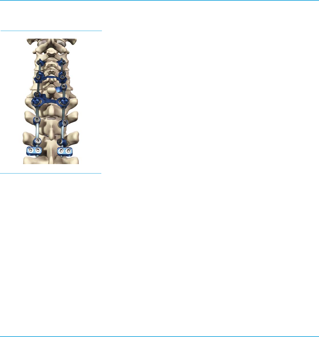
Final Construct
Step 34
Recheck all connections of the final construct.
An intraoperative radiographic image of the
final construct should be made to confirm the
desired construct is achieved prior to wound
closure. (Fig. 42)
20 Virage OCT Spinal Fixation System – Surgical Technique
Instruments
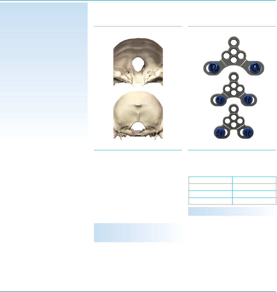
Occipital Landmarks
Occipital Fixation
Plate Fixation
Virage OCT
Occipitocervical
Surgical Technique
Fig. 43 SFig. 44 S
Step 1
In general, the thickest bone in the sub
occipital region is the occipital keel (internal
occipital protuberance), near the midline.
When positioning the occipital plate, it should
be centered on the midline between the
External Occipital Protuberance (EOP) and the
posterior border of the foramen magnum. The
goal is to maximize bone purchase (closer to
EOP) while achieving a low profile. (Fig. 43)
Step 2
The Virage System offers three occipital plates
to accommodate patient anatomy:
Each plate size has three midline holes
and two lateral holes for occipital fixation.
Placement of as many screws as possible is
recommended. A minimum of two screws
must be used; a minimum of three screws
must be used if the plate is bent, including
one screw in the superior hole. The occipital
plates include rod connector housings that
rotate up to 40° to ease rod placement. (Fig.
44)
NOTE: There is a 1mm overlap between sizes.
Size Widths
Small 24-33mm
Medium 32-41mm
Large 40-49mm
Occipitocervical Surgical Technique:
The following Surgical Technique describes
the recommended placement and use
of Virage Occipitocervical Spinal System
components.
WARNING: Care should be taken during bone
preparation to avoid damage to the occiput and
to the surgical instruments.
Virage OCT Spinal Fixation System – Surgical Technique 21
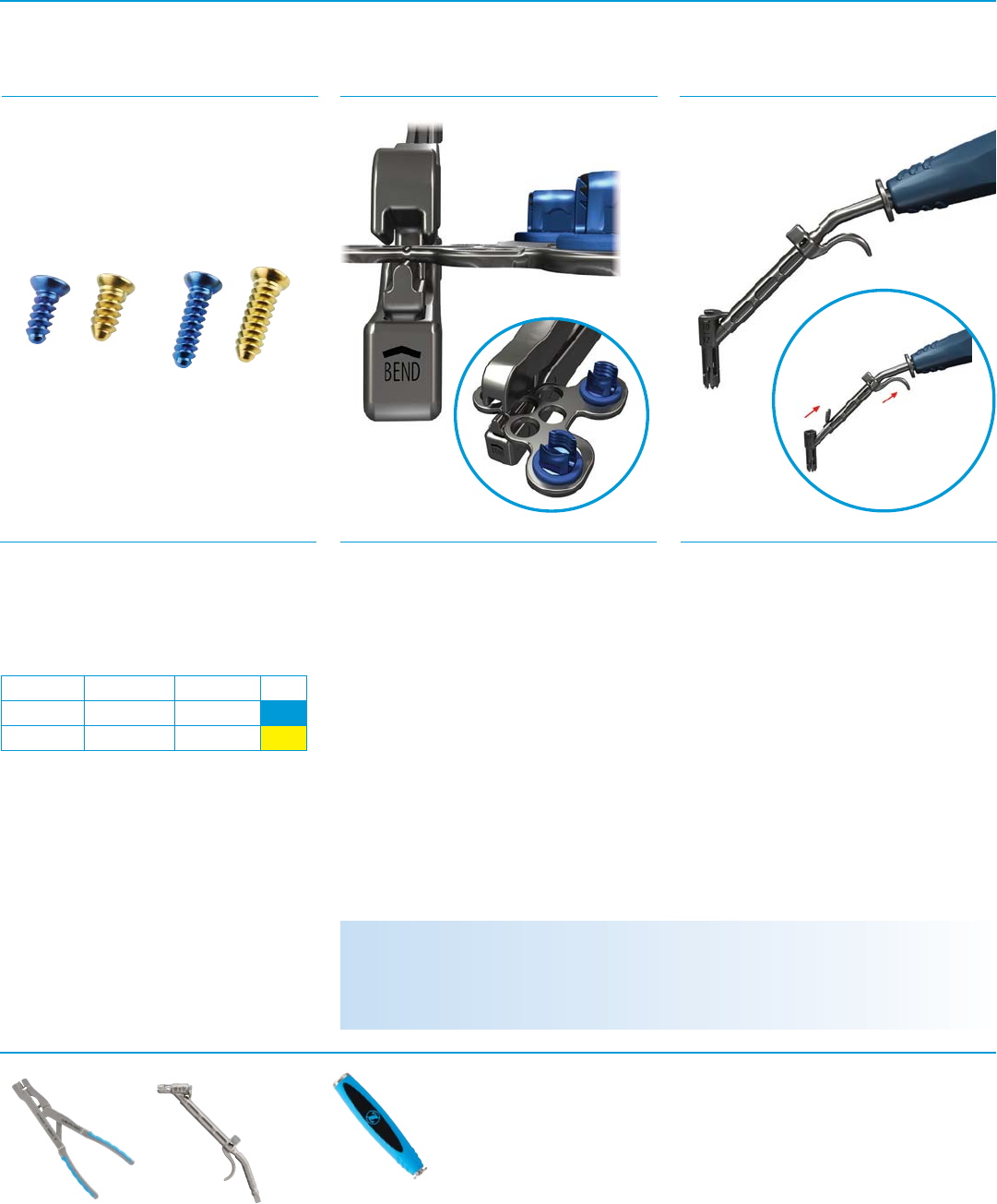
Fig. 45 S
Step 2, continued
The Virage System occipital screws are
available in diameters of 4.5mm and
5.25mm. (Fig. 45) Refer to the table below:
Diameter Length Increments Color
Ø4.5mm 6mm-16mm Every 2mm
Ø5.25mm 6mm-16mm Every 2mm
Step 3
The Virage System occipital plate can be con-
toured to fit a patient’s anatomy using the Occip-
ital Plate Bender at the plate’s one bend zone at
the superior hole. Reference the bend direction
on the distal end of the Plate Bender. Ensure the
Plate Bender is aligned with bend zone features
by positioning the entire length of the plate’s
groove in the Plate Bender’s center tip feature.
Prior to bending, verify positive engagement
visually and confirm by attempting to manipu-
late the plate in an alternating clockwise and
counterclockwise fashion. A properly aligned
plate/Plate Bender will not allow for any relative
motion between the two devices. (Fig. 46)
Fig. 46 SFig. 47 S
Step 4
Three Occipital Drill/Tap Guides are available
and each has a 2mm depth adjustment
feature (6/8mm, 10/12mm, and 14/16mm).
Select the appropriate Occipital Drill/Tap
Guide and connect to the 3/16" Handle.
Engage the distal tip of the Occipital Drill/Tap
Guide into the desired plate screw hole by
pressing down until fully seated.
Verify drill/tap depth by reading the depth
markings on the top surface of the Occipital
Drill/Tap Guide. (Fig. 47)
Instruments
Occipital Plate Contouring
Occipital Screw Hole Preparation
Drilling
Handle, 3/16"
07.01790.001
Plate Bender
07.01803.001
Occipital Drill/Tap Guide
07.01793.001 6/8mm
07.01793.002 10/12mm
07.01793.003 14/16mm
WARNING: Bending the plate outside of the bend zone groove may result in cracking of the plate. The
surgeon should always inspect the plate before implanting.
WARNING: Do not reverse bend the plate. Reverse bending may result in a projectile fracture of the plate.
NOTE: The plate may be bent up to 12˚ in either direction.
22 Virage OCT Spinal Fixation System – Surgical Technique
Fig. 48 S
Step 5
Attach the Ø3.5mm Flexible or Rigid Occipital
Drill to the A-O Handle and place through the
Occipital Drill/Tap Guide; drill to the desired
depth. (Fig. 48)
Step 6
Confirm bone integrity and measure hole
depth using the Sounding Probe. (Fig. 49)
Fig. 49 SFig. 50 S
Step 7
Attach the Ø3.5mm Flexible or Rigid Occipital
Tap to the A-O Handle and place through the
appropriate Occipital Drill/Tap Guide; tap to
the desired depth. (Fig. 50)
Instruments
Verify Hole Integrity and Depth Tapping
WARNING: Care should be taken during bone
preparation to avoid penetrating too deep.
NOTE: Both the Flexible and Rigid Taps must be
used in conjunction with the Guide to achieve
the desired depth.
NOTE: Tapping is required as the occipital bone
screws are not self-tapping.
Handle, 3/16"
07.01790.001
Occipital Drill,
Rigid
07.01794.001
Occipital Drill, Flexible
07.01795.001
A-O Handle with
Spin Cap
07.01788.001
Sounding Probe
07.01759.001
Occipital Taps
Rigid
07.01796.001 Ø4.5mm
07.01796.002 Ø5.25mm
Flexible
07.01797.001 Ø4.5mm
07.01797.002 Ø5.25mm
Occipital Drill/Tap Guide
07.01793.001 6/8mm
07.01793.002 10/12mm
07.01793.003 14/16mm
Virage OCT Spinal Fixation System – Surgical Technique 23
Instruments
Step 9 (optional)
Prepare lateral holes of the occipital strap in
the same manner as occipital plate holes (i.e.,
drill depth equals bone screw length).
For the center hole, select an occipital bone
screw that is 2mm longer than the drill and
tap depth previously prepared before occipital
strap placement (i.e., drill depth plus 2mm
equals bone screw length). A minimum of two
screws must be placed in the lower portion of
the plate if the strap is used.
(Fig. 52)
Step 10
A Rod Template may be used to determine the
appropriate length and curvature of the rod.
The Virage System includes occipital rods
in different configurations and materials:
pre-contoured titanium, pre-contoured cobalt
chrome, and adjustable titanium. Cut to
length using the Rod Cutter.
(Fig. 53)
Fig. 52 SFig. 53 S
NOTE: Markings on the Rod Template are every
10mm.
Hex Drivers, 3.0mm
07.01798.001 Rigid
07.01799.001 Flexible
Fig. 51 S
Step 8
Select and verify the appropriate diameter
and length of the occipital screw. Insert the
screw using either the Rigid or Flexible Hex
Driver.
Ensure all screws are fully seated once the
construct is assembled. An Allen Hex Wrench
is available if the patient’s anatomy does not
accommodate a Rigid or Flexible Driver.
(Fig. 51)
Screw Placement Occipital Strap Option Rod Selection/Rod Cutting
NOTE: When using the Flexible Driver, the
Occipital Counter Torque may be used to
maintain Driver/screw alignment during Driver
insertion and removal.
WARNING: Care should be taken to ensure the
occipital screw is not driven in too deep.
NOTE: Do not drill the superior midline hole
through the occipital plate and strap.
Allen Hex Wrench,
3.0mm
07.01801.001
Rod Template
07.01767.001 100mm
07.01767.002 250mm
Occipital Counter
Torque
07.01802.001
Rod Cutter
07.01774.001
A-O Handle with
Spin Cap
07.01788.001
24 Virage OCT Spinal Fixation System – Surgical Technique
Fig. 54 S
Step 11
Contour the rod into the desired shape using
the French Rod Bender, In-situ Rod Benders,
and/or tube bending features of the In-situ
Rod Benders. (Fig. 54)
Step 12
Grasp the rod with the Rod Holder and engage
the locking mechanism by fully closing the
handles. To release, squeeze the handles
together, disengaging the locking mechanism.
Provisionally tighten closure tops using the
Closure Top Starter or Occipital Final Drivers.
(Fig. 55)
Step 13
Once all of the occipital screws have been
secured, final tighten all closure tops and
set screws using a Final Driver or Occipital
Final Driver (Flexible or Rigid), Torque-Limiting
Handle, and Counter Torque/Rod Pusher until
two clicks are heard (Fig. 56)
Fig. 55 SFig. 56 S
Rod Contouring Rod Placement Final Tightening
Instruments
NOTE: Reverse bending can weaken the rod and
is not recommended.
NOTE: Use the Occipital Counter Torque when
final tightening closure tops into the occipital
plate housings.
CAUTION: Pre-contoured Virage System occipital
rods transition from Ø3.5mm to Ø3.8mm. The
start of the transition zone is indicated by a dark
band. Do not connect implants within this
transition zone.
CAUTION: Ensure the set screw of the adjustable
occipital rod is final tightened.
French Rod Bender
07.01770.001
Rod Holder
07.01768.001
Occipital Final Drivers
07.01804.001 Flexible
07.01805.001 Rigid
Torque-Limiting
Handle, 3/16"
07.01792.001
A-O Handle
with Spin Cap
07.01788.001
Occipital
Counter Torque
07.01802.001
Rod Pusher
07.01784.001
In-situ Rod Bender
07.01771.002 Left
07.01772.002 Right
07.01773.002 Straight
Inline Counter
Torque
07.01785.001
Closure Top
Starter
07.01782.001
Virage OCT Spinal Fixation System – Surgical Technique 25
Instruments
Step 15
Virage System cable connectors are available
for connection to the titanium Songer® Spinal
Cable System. Final tighten the set screw
using the Final Driver and Torque-Limiting
Handle in conjunction with the Rod Pusher.
(Fig. 58)
Step 16
Recheck all connections of the final construct.
An intraoperative radiographic image of the
final construct should be made to confirm the
desired construct is achieved prior to wound
closure. (Fig. 59)
Fig. 58 SFig. 59 SFig. 57 S
Step 14
When occipital plate use is not possible or
preferred, occipital eyelets are available as
an alternative method of fixation. A minimum
of two eyelets should be used on each rod.
Slide eyelets over the rod and determine the
desired bone screw location. Complete Drill,
Tap, and Screw Placement steps as indicated
for occipital plates. Once all of the occipital
screws have been secured, final tighten set
screws using an Occipital Final Driver (Flexible
or Rigid), Torque-Limiting Handle, and
Occipital Counter Torque until two clicks are
heard. (Fig. 57)
Occipital Eyelet (Optional) Cable Connectors (Optional) Final Construct
Torque-Limiting
Handle, 3/16"
07.01792.001
Rod Pusher
07.01784.001
Final Driver
07.01783.001
NOTE: The Occipital Counter Torque does not fit
over the occipital eyelets and must be used next to
occipital eyelets along the Ø3.8mm rod segment.
Occipital Final Drivers
07.01804.001 Flexible
07.01805.001 Rigid
Occipital
Counter Torque
07.01802.001
A-O Handle with Spin Cap
07.01788.001

26 Virage OCT Spinal Fixation System – Surgical Technique
Instruments
Polyaxial Screw Driver
Virage OCT
Instrument
Disassembly
for Cleaning
Surgical Technique
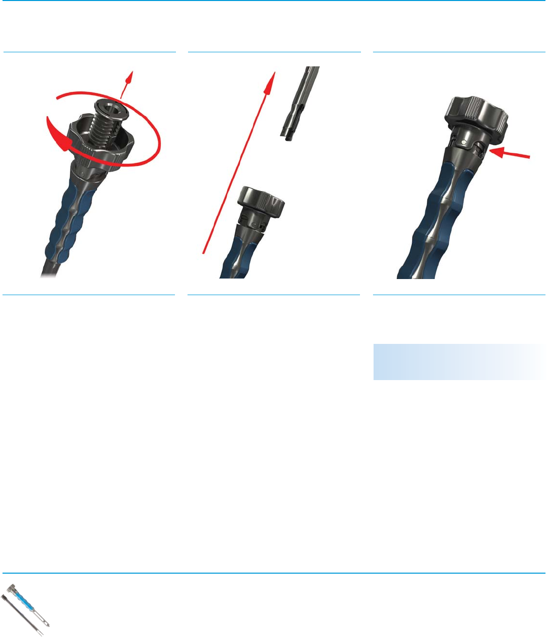
Fig. 60 SFig. 61 S
Step 2
Depress the button and remove the Screw
Driver Shaft. (Fig. 61)
Step 1
Pull back the collar on the A-O Handle and
disconnect it from the Screw Driver.
(Fig. 60)
Polyaxial Screw Driver,
Inner Sleeve
07.01764.001
Polyaxial Hex Screw
Driver, 2.5mm
07.01764.002
A-O Handle with
Spin Cap
07.01788.001
After cleaning, reassemble by reversing
instructions.
Polyaxial Screw Driver,
Outer Sleeve
07.01764.003

Virage OCT Spinal Fixation System – Surgical Technique 27
Instruments
Fig. 63 SFig. 64 SFig. 62 S
Polyaxial Screw Head Turner
Step 5
Pull the inner shaft out of the outer shaft and
separate. (Fig. 64)
Step 4
Turn the knob counterclockwise to
disassemble. (Fig. 63)
NOTE: After cleaning, reassemble the Screw
Driver prior to sterilization. See assembly
instructions in the Surgical Technique.
Step 3
Pull the outer sleeve off of the Screw Driver.
(Fig. 62)
Flush all holes near the button. (Fig. 62, inset)
Polyaxial Screw
Head Turner
07.01766.001
NOTE: After cleaning, reassemble the Polyaxial
Screw Head Turner prior to sterilization.
28 Virage OCT Spinal Fixation System – Surgical Technique
Instruments
Fig. 66 SFig. 67 SFig. 65 S
Tower Rod Reducer
Step 7
To disassemble, turn the knob clockwise until
the inside shaft is free.
(Fig. 65)
Step 9
Turn the top knob and flush. (Fig. 67)
Step 8
Pull the inside shaft to separate. (Fig. 66)
NOTE: After cleaning, reassemble the Tower Rod
Reducer prior to sterilization.
Tower Rod Reducer
07.01776.001

Virage OCT Spinal Fixation System – Surgical Technique 29
Instruments
Removal - Cervico-Thoracic Removal - Occipitocervical
Virage OCT
Revision and
Removal Steps
Surgical Technique
Fig. 68 S
Torque-Limiting
Handle, 3/16"
07.01792.001
Inline Counter
Torque
07.01785.001
Polyaxial Screw
Remover
07.01786.002
Final Driver
07.01783.001
Rod Pusher
07.01784.001
A-O Handle with
Spin Cap
07.01788.001
Cervico-Thoracic System Construct
Removal
Remove all closure tops and loosen set screws
using the Final Driver, Torque-Limiting Handle
and Inline Counter Torque/Rod Pusher. Remove
rods from construct. Remove pedicle screws
by fully engaging the Screw Driver and turning
counterclockwise.
If the hex portion of the screw cannot be
re-engaged, utilize the Polyaxial Screw
Remover. To use, remove the Polyaxial Hex
Driver from Polyaxial Screw Driver and replace
with the Polyaxial Screw Remover. Insert and
tighten into the pedicle screw and rotate
counterclockwise about the pedicle screw
shank axis. (Fig. 68)
Occipitocervical System Construct
Removal
Remove all closure tops and loosen all set
screws using a Final Driver or Occipital Final
Driver (Rigid or Flexible). Remove all occipital
bone screws using the 3mm Hex Driver.
Remove rods and occipital plate / eyelets
from the construct.
Polyaxial Screw
Driver,
Inner Sleeve
07.01764.001
Occipital
Final Drivers
07.01804.001
07.01805.001
Hex Drivers,
3.0mm
07.01798.001
Rigid
07.01799.001
Flexible
Occipital Counter
Torque
07.01802.001
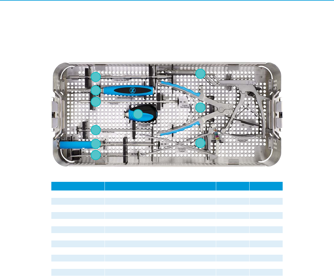
30 Virage OCT Spinal Fixation System – Surgical Technique
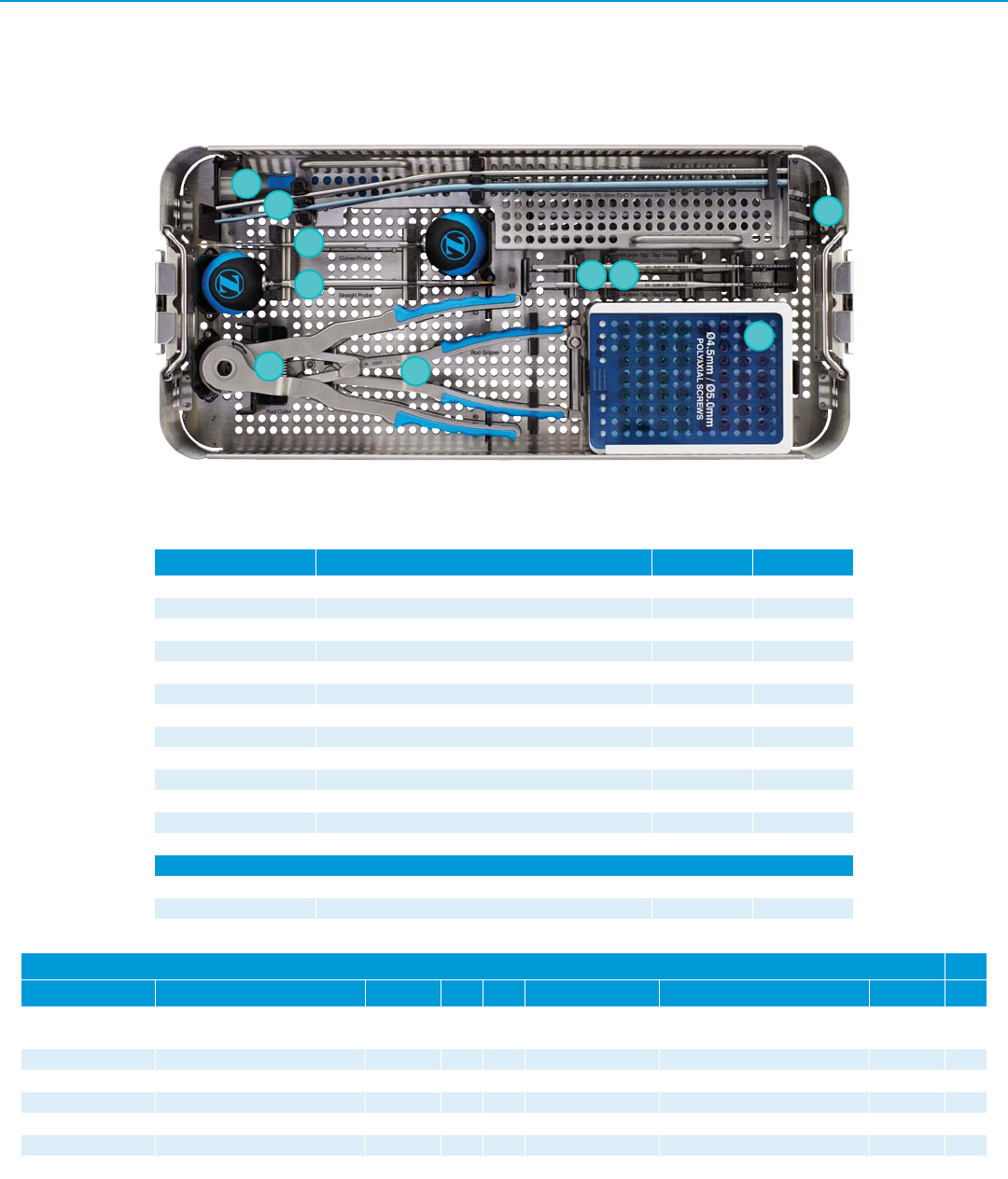
Part Number Description Quantity Reference
07.01770.001 French Rod Bender 1 I
07.01775.001 Rod Rocker 1 F
07.01777.001 Kerrison Rod Reducer 1 H
07.01780.001 Transverse Connector Caliper 1 J
07.01781.001 Transverse Connector Driver – Rod to Rod 2 E
07.01782.001 Closure Top Starter 2 A
07.01783.001 Closure Top Final Driver 2 C
07.01784.001 Rod Pusher 1 G
07.01785.001 Inline Counter Torque 1 B
07.01792.001 Torque-Limiting Handle - 3/16" 1 D
07.01810.001 Standard Instrument Tray 1 –
07.01260.001 Generic Stackable Lid Tray 1 –
Virage OCT Standard Implant and Instrument Set – Module 07.01973.410
Instrument Set – Lower Tray
Tray Layouts
B
C
D
E
G
H
A
I
J
F

Virage OCT Spinal Fixation System – Surgical Technique 31
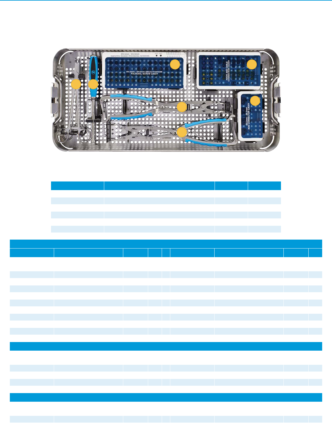
Virage OCT Standard Implant and Instrument Set – Module 07.01973.410
Instrument Set – Upper Tray
Part Number Description Quantity Reference
07.01752.001 Bone Awl 1 A
07.01755.001 Drill Guide 1 C
07.01757.001 Adjustable Drill – Ø2.3mm 2 E
07.01758.001 Fixed Drill - Ø2.3mm X 10mm 1 D
07.01758.002 Fixed Drill - Ø2.3mm X 12mm 1 D
07.01758.003 Fixed Drill - Ø2.3mm X 14mm 1 D
07.01758.004 Fixed Drill - Ø2.3mm X 16mm 1 D
07.01759.001 Sounding Probe 1 B
07.01761.001 Tap, Small – Ø3.0mm 1 F
07.01761.002 Tap, Small – Ø3.5mm 1 F
07.01763.002 Tap Sleeve – Ø3.5mm 1 F
07.01764.001 Polyaxial Screw Driver, Inner Sleeve 2 H (assembled)
07.01764.002 Polyaxial Hex Screw Driver, 2.5mm 2 H (assembled)
07.01764.003 Polyaxial Screw Driver, Outer Sleeve 2 H (assembled)
07.01765.001 Tapered Hex Driver, 2.5mm 1 J (under H)
07.01766.001 Polyaxial Screw Head Turner 1 K
07.01767.001 Rod Template-100mm 1 M
07.01767.002 Rod Template-250mm 1 M
07.01768.001 Rod Holder 1 L
07.01786.002 Polyaxial Screw Remover 1 I (under H)
07.01788.001 A-O Handle with Spin Cap 2 G
07.01810.002 Standard Instrument Top Tray 1 –
B
C
D
E
F
G
H
A
I
K
M
L
HJ
32 Virage OCT Spinal Fixation System – Surgical Technique
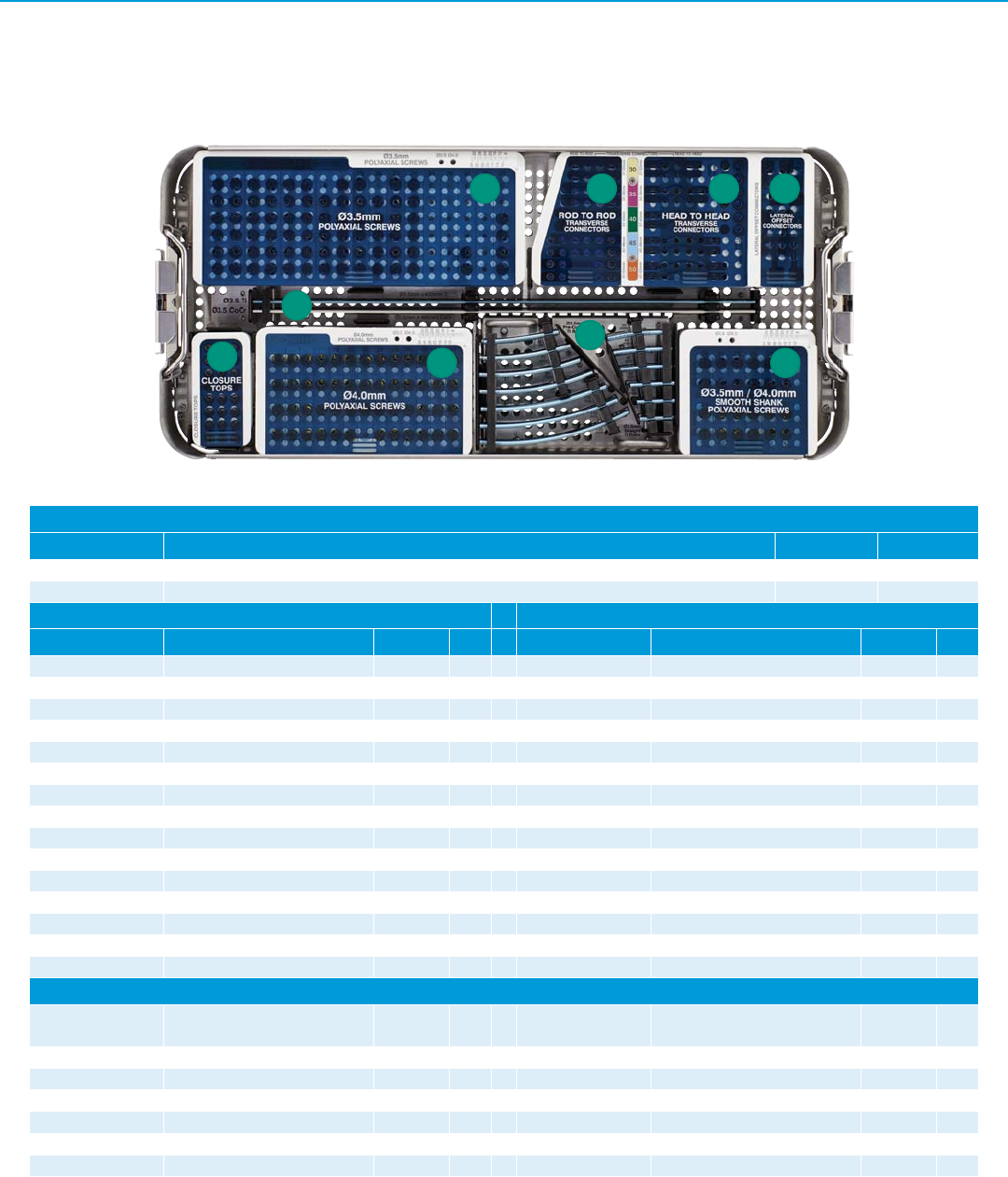
Virage OCT Standard Implant and Instrument Set – Module 07.01973.410
Implant Set
Ø3.5 Polyaxial Screw Caddy Ø4.0 Polyaxial Screw Caddy
Part Number Description Quantity Ref. Part Number Description Quantity Ref.
07.01811.002 Ø3.5mm Polyaxial Screw Caddy 1 A 07.01811.004 Ø4.0mm Polyaxial Screw Caddy 1 G
07.01811.003 Ø3.5mm Polyaxial Screw Caddy Lid 1 A 07.01811.005 Ø4.0mm Polyaxial Screw Caddy Lid 1 G
07.01702.003 Ø3.5mm X 10mm 10 A 07.01702.046 Ø4.0mm X 10mm 4 G
07.01702.005 Ø3.5mm X 12mm 12 A 07.01702.048 Ø4.0mm X 12mm 4 G
07.01702.007 Ø3.5mm X 14mm 12 A 07.01702.050 Ø4.0mm X 14mm 4 G
07.01702.009 Ø3.5mm X 16mm 8 A 07.01702.052 Ø4.0mm X 16mm 4 G
07.01702.011 Ø3.5mm X 18mm 4 A 07.01702.054 Ø4.0mm X 18mm 2 G
07.01702.013 Ø3.5mm X 20mm 4 A 07.01702.056 Ø4.0mm X 20mm 2 G
07.01702.015 Ø3.5mm X 22mm 4 A 07.01702.058 Ø4.0mm X 22mm 2 G
07.01702.017 Ø3.5mm X 24mm 2 A 07.01702.060 Ø4.0mm X 24mm 2 G
07.01702.019 Ø3.5mm X 26mm 2 A 07.01702.062 Ø4.0mm X 26mm 2 G
07.01702.021 Ø3.5mm X 28mm 2 A 07.01702.064 Ø4.0mm X 28mm 2 G
07.01702.023 Ø3.5mm X 30mm 2 A 07.01702.066 Ø4.0mm X 30mm 2 G
07.01702.025 Ø3.5mm X 32mm 2 A 07.01702.068 Ø4.0mm X 32mm 2 G
07.01702.027 Ø3.5mm X 34mm 2 A 07.01702.070 Ø4.0mm X 34mm 2 G
Polyaxial Smooth Shank Screw Caddy
07.01811.006 24-34mm Smooth Shank Polyaxial
Screw Caddy 1 I 07.01811.007 24-34mm Smooth Shank Polyaxial
Screw Caddy Lid 1I
07.01707.003 Ø3.5mm X 24mm 2 I 07.01707.022 Ø4.0mm X 24mm 2 I
07.01707.005 Ø3.5mm X 26mm 2 I 07.01707.024 Ø4.0mm X 26mm 2 I
07.01707.007 Ø3.5mm X 28mm 2 I 07.01707.026 Ø4.0mm X 28mm 2 I
07.01707.009 Ø3.5mm X 30mm 2 I 07.01707.028 Ø4.0mm X 30mm 2 I
07.01707.011 Ø3.5mm X 32mm 2 I 07.01707.030 Ø4.0mm X 32mm 2 I
07.01707.013 Ø3.5mm X 34mm 2 I 07.01707.032 Ø4.0mm X 34mm 2 I
Implant Tray
Part Number Description Quantity Reference
07.01811.001 Standard Implant Tray 1–
07.01260.001 Generic Stackable Lid Assembly 1 –
BCD
E
FG
H
A
I
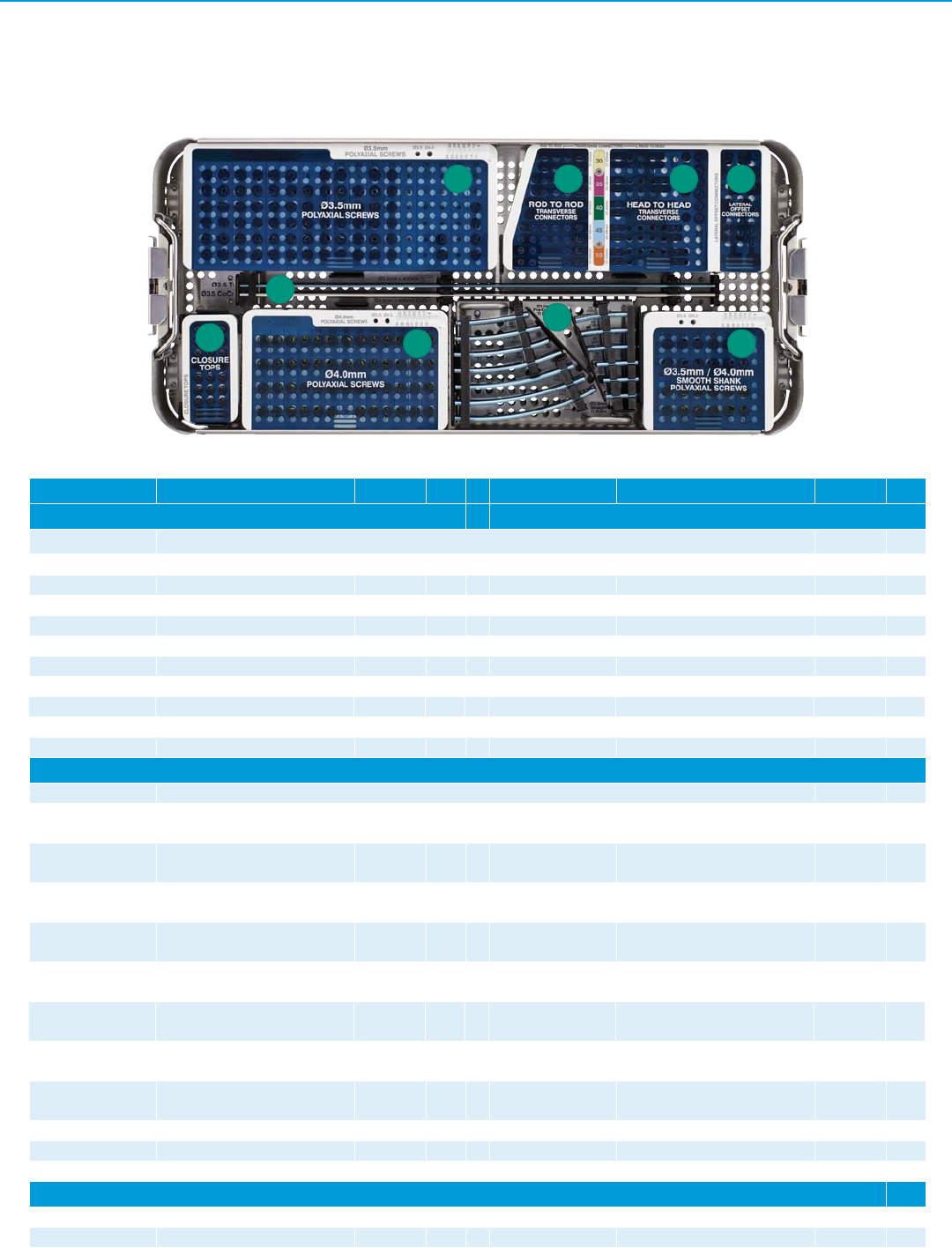
Virage OCT Spinal Fixation System – Surgical Technique 33
Virage OCT Standard Implant and Instrument Set – Module 07.01973.410
Implant Set, continued
Part Number Description Quantity Ref. Part Number Description Quantity Ref.
Straight Rods Curved Rods
07.01811.014 Rod Caddy 1
07.01709.002 Ti, Ø3.5mm X 25mm 2 H 07.01710.001 Ti, Ø3.5mm X 40mm 2 H
07.01709.003 Ti, Ø3.5mm X 30mm 2 H 07.01710.002 Ti, Ø3.5mm X 45mm 2 H
07.01709.004 Ti, Ø3.5mm X 35mm 2 H 07.01710.003 Ti, Ø3.5mm X 50mm 2 H
07.01709.006 Ti, Ø3.5mm X 400mm 2 E 07.01710.005 Ti, Ø3.5mm X 60mm 2 H
07.01715.002 CoCr, Ø3.5mm X 400mm 2 E 07.01710.007 Ti, Ø3.5mm X 70mm 2 H
07.01710.009 Ti, Ø3.5mm X 80mm 2 H
07.01710.011 Ti, Ø3.5mm X 90mm 2 H
07.01710.012 Ti, Ø3.5mm X 100mm 2 H
07.01710.013 Ti, Ø3.5mm X 110mm 2 H
07.01710.014 Ti, Ø3.5mm X 120mm 2 H
Lateral Offset and Transverse Connector Caddy
07.01811.010 Lateral Offset and Transverse Connectors Caddy 1
07.01717.002 Head to Head Transverse
Connector, 30mm 1 C 07.01721.002 Rod to Rod Transverse Connector,
30mm 1B
07.01717.003 Head to Head Transverse
Connector, 35mm 1 C 07.01721.003 Rod to Rod Transverse Connector,
35mm 1B
07.01717.004 Head to Head Transverse
Connector, 40mm 1 C 07.01721.004 Rod to Rod Transverse Connector,
40mm 1B
07.01717.005 Head to Head Transverse
Connector, 45mm 1 C 07.01721.005 Rod to Rod Transverse Connector,
45mm 1B
07.01717.006 Head to Head Transverse
Connector, 50mm 1 C 07.01721.006 Rod to Rod Transverse Connector,
50mm 1B
07.01719.001 Head to Head Transverse
Connector Closure Top 6 C 07.01811.011 Rod to Rod Transverse Connectors
Lid 1B
07.01720.001 Head to Head Transverse
Connector Dome Nut 6C
07.01811.012 Head to Head Transverse
Connectors Caddy Lid 1C
07.01727.001 Lateral Offset Connector – 10mm 2 D 07.01727.002 Lateral Offset Connector – 25mm 2 D
07.01811.013 Lateral Offset Connectors Lid 1 D
Closure Top Caddy
07.01811.008 Closure Top Caddy 1 F 07.01811.009 Closure Top Caddy Lid 1 F
07.01728.001 Standard Closure Top 24 F
BCD
E
FG
H
A
I
34 Virage OCT Spinal Fixation System – Surgical Technique
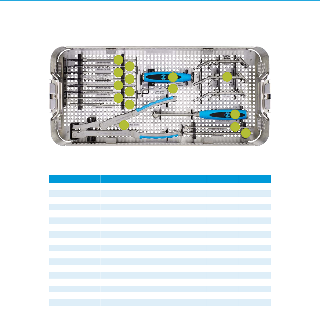
Virage OCT CT Junction Implant and Instrument Set - Module 07.01973.430
Part Number Description Quantity Reference
07.01814.001 CT Junction Tray 1 –
07.01260.001 Lid, Generic 1 –
07.01753.001 Curved Probe 1 C
07.01754.001 Straight Probe 1 D
07.01762.001 Tap, Large – Ø4.0mm 1 G
07.01762.002 Tap, Large – Ø4.5mm 1 G
07.01763.004 Ø4.5mm Tap Sleeve 1 H
07.01769.001 Rod Gripper 1 F
07.01771.002 In-situ Rod Bender - Left 1 I
07.01772.002 In-situ Rod Bender - Right 1 I
07.01773.002 In-situ Rod Bender - Straight 1 I
07.01774.001 Rod Cutter - Ratcheting 1 E
07.01776.001 Tower Rod Reducer 1 A
Transition Rod Caddy
07.01714.001 Transition Ti Rod - Ø3.5mm / Ø5.5mm X 450mm 3 B
07.01716.001 Transition CoCr Rod - Ø3.5mm / Ø5.5mm X 450mm 3 B
07.01814.004 Transition Rod Caddy 1 –
Polyaxial Screw Caddy
Part Number Description Quantity Ref. Part Number Description Quantity Ref.
07.01814.002 Ø4.5/5.0 Polyaxial Screw and Rod
Connector Caddy 1 J 07.01814.003 Ø4.5/5.0 Polyaxial Screws Lid 1 J
07.01708.002 Ø4.5mm X 20mm 4 J 07.01708.010 Ø5.0mm X 20mm 2 J
07.01708.003 Ø4.5mm X 25mm 4 J 07.01708.011 Ø5.0mm X 25mm 4 J
07.01708.004 Ø4.5mm X 30mm 4 J 07.01708.012 Ø5.0mm X 30mm 4 J
07.01708.005 Ø4.5mm X 35mm 4 J 07.01708.013 Ø5.0mm X 35mm 4 J
07.01708.006 Ø4.5mm X 40mm 2 J 07.01708.014 Ø5.0mm X 40mm 2 J
07.01708.007 Ø4.5mm X 45mm 2 J 07.01708.015 Ø5.0mm X 45mm 2 J
B
C
D
F
G H
A
I
E
J
Virage OCT Spinal Fixation System – Surgical Technique 35
Virage OCT Deluxe Implant and Instrument Set - Module 07.01973.440
Part Number Description Quantity Reference
07.01750.001 Hook Trial - 8mm 1 B
07.01751.001 Hook Forceps 1 A
07.01778.001 Compressor 1 E
07.01779.001 Distractor 1 D
07.01813.001 Deluxe Tray 1 –
07.01260.001 Generic Stackable Lid Assembly 1 –
Polyaxial Smooth Shank Screw Caddy
Part Number Description Quantity Ref. Part Number Description Quantity
07.01813.002 22-40mm Smooth Shank
Polyaxial Screw Caddy 1 C 07.01813.003 22-40mm Smooth Shank
Polyaxial Screw Caddy Lid 1C
07.01707.001 Ø3.5mm X 22mm 2 C 07.01707.020 Ø4.0mm X 22mm 2 C
07.01707.003 Ø3.5mm X 24mm 2 C 07.01707.022 Ø4.0mm X 24mm 2 C
07.01707.005 Ø3.5mm X 26mm 2 C 07.01707.024 Ø4.0mm X 26mm 2 C
07.01707.007 Ø3.5mm X 28mm 2 C 07.01707.026 Ø4.0mm X 28mm 2 C
07.01707.009 Ø3.5mm X 30mm 2 C 07.01707.028 Ø4.0mm X 30mm 2 C
07.01707.011 Ø3.5mm X 32mm 2 C 07.01707.030 Ø4.0mm X 32mm 2 C
07.01707.013 Ø3.5mm X 34mm 2 C 07.01707.032 Ø4.0mm X 34mm 2 C
07.01707.015 Ø3.5mm X 36mm 2 C 07.01707.034 Ø4.0mm X 36mm 2 C
07.01707.017 Ø3.5mm X 38mm 2 C 07.01707.036 Ø4.0mm X 38mm 2 C
07.01707.019 Ø3.5mm X 40mm 2 C 07.01707.038 Ø4.0mm X 40mm 2 C
Hook and Cable Connector Caddy
07.01813.004 Hook and Cable Connector Caddy 1 F 07.01813.005 Hook and Cable Connector Caddy
Lid 1F
07.01697.002 Laminar Hook - 6mm 4 F 07.01698.002 Offset Laminar Hook, Left - 6mm 2 F
07.01697.004 Laminar Hook - 8mm 4 F 07.01698.004 Offset Laminar Hook, Left - 8mm 2 F
07.01700.001 Cable Connector 2 F 07.01699.002 Offset Laminar Hook, Right - 6mm 2 F
07.01699.004 Offset Laminar Hook, Right - 8mm 2 F
Rod Connector Caddy
07.01813.006 Ø3.5-5.5mm Rod Connector Caddy 1 G 07.01813.007 Ø3.5-5.5mm Rod Connector
Caddy Lid 1G
07.01739.001 Rod Connector, Closed 3.5 to 5.5 4 G
B
CF
A
E
D
G
36 Virage OCT Spinal Fixation System – Surgical Technique
Virage OCT Occipital Implant and Instrument Set - Module 07.01973.450
Lower Tray
Part Number Description Quantity Reference
07.01790.001 Handle, 3/16" 1 J
07.01793.001 Occipital Drill/Tap Guide – 6mm/8mm 1 L
07.01793.002 Occipital Drill/Tap Guide - 10mm/12mm 1 L
07.01793.003 Occipital Drill/Tap Guide - 14mm/16mm 1 L
07.01794.001 Occipital Drill, Rigid - Ø3.5mm 1 A
07.01795.001 Occipital Drill, Flexible - Ø3.5mm 1 B
07.01796.001 Occipital Tap , Rigid - Ø4.5mm 1 C
07.01796.002 Occipital Tap, Rigid - Ø5.25mm 1 E
07.01797.001 Occipital Tap, Flexible - Ø4.5mm 1 D
07.01797.002 Occipital Tap , Flexible - Ø5.25mm 1 F
07.01798.001 Hex Driver, Rigid, 3.0mm 1 G
07.01799.001 Hex Driver, Flexible, 3.0mm 1 H
07.01801.001 Allen Hex Wrench, 3.0mm 1 K
07.01802.001 Occipital Counter Torque 1 M
07.01803.001 Plate Bender 1 I
07.01804.001 Occipital Final Driver, Flexible 1 O
07.01805.001 Occipital Final Driver, Rigid 1 N
07.01812.001 Occipital Tray 1 –
07.01260.001 Generic Stackable Lid Assembly 1 –
E
F
G
H
I
K
M
N
O
L
J
B
C
D
A
Virage OCT Spinal Fixation System – Surgical Technique 37
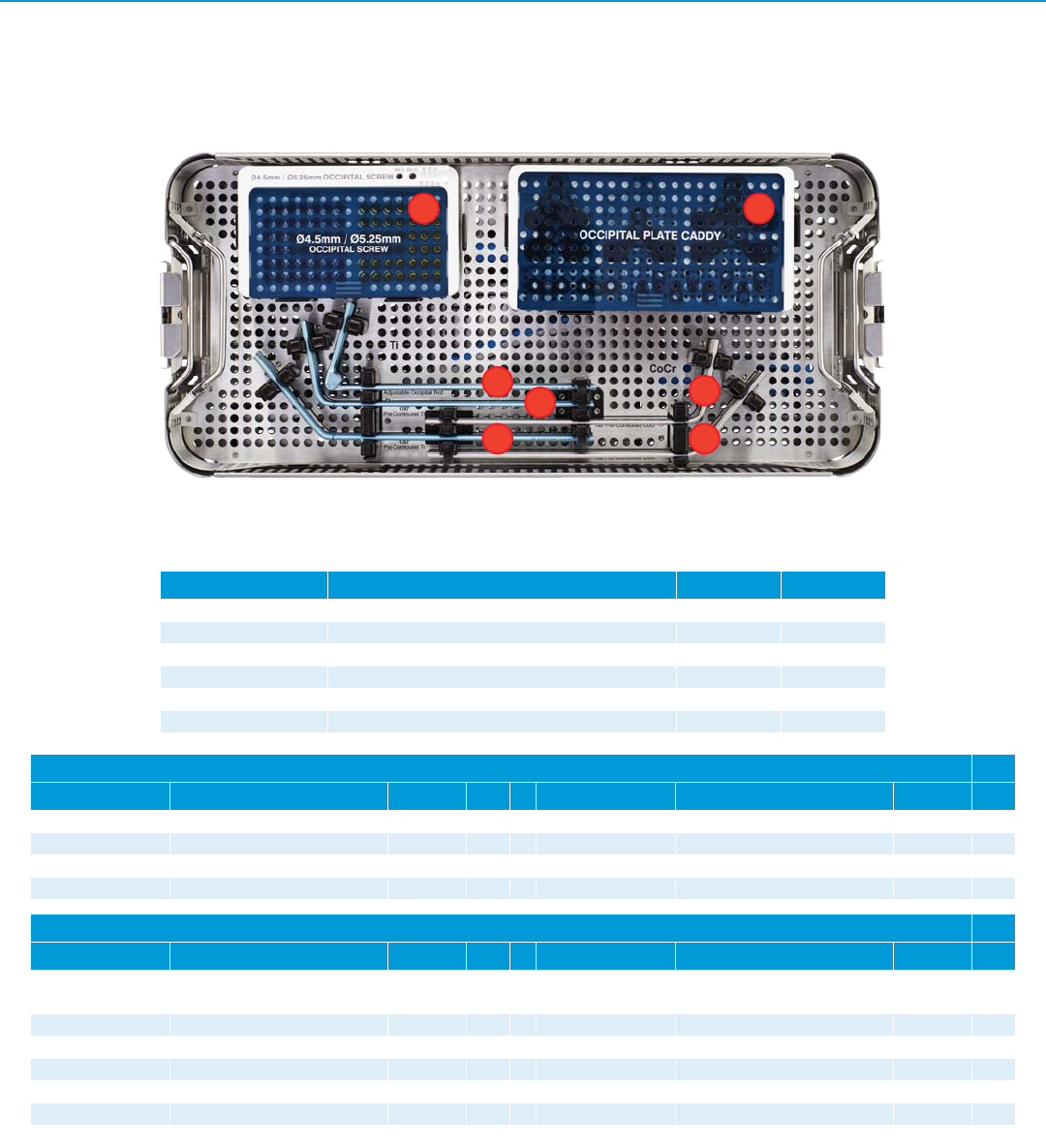
Virage OCT Occipital Implant and Instrument Set - Module 07.01973.450
Upper Tray
Part Number Description Quantity Reference
07.01711.001 Ti Occipital Rod - Adjustable 3 C
07.01712.001 Pre-Contoured Occipital Rod, Ti - 100deg 2 D
07.01712.003 Pre-Contoured Occipital Rod, TI - 130deg 2 E
07.01713.001 Pre-Contoured Occipital Rod, CoCr - 100deg 2 F
07.01713.003 Pre-Contoured Occipital Rod, CoCr - 130deg 2 G
07.01812.002 Occipital Top Tray 1 –
Occipital Plate Caddy
Part Number Description Quantity Ref. Part Number Description Quantity Ref.
07.01812.005 Occipital Plate Caddy 1 B 07.01812.006 Occipital Plate Caddy Lid 1 B
07.01693.004 Occipital Plate - Small 1 B 07.01694.001 Occipital Strap 2 B
07.01693.005 Occipital Plate - Medium 2 B 07.01738.001 Occipital Eyelet 6 B
07.01693.006 Occipital Plate - Large 1 B
Occipital Screw Caddy
Part Number Description Quantity Ref. Part Number Description Quantity Ref.
07.01812.003 Ø4.5mm / Ø5.25mm Occipital
Bone Screw Caddy 1 A 07.01812.004 Ø4.5mm / Ø5.25mm Occipital
Bone Screw Caddy Lid 1A
07.01696.001 Ø4.5mm X 6mm 5 A 07.01696.014 Ø5.25mm X 6mm 2 A
07.01696.003 Ø4.5mm X 8mm 5 A 07.01696.016 Ø5.25mm X 8mm 2 A
07.01696.005 Ø4.5mm X 10mm 5 A 07.01696.018 Ø5.25mm X 10mm 2 A
07.01696.007 Ø4.5mm X 12mm 5 A 07.01696.020 Ø5.25mm X 12mm 2 A
07.01696.009 Ø4.5mm X 14mm 5 A 07.01696.022 Ø5.25mm X 14mm 2 A
07.01696.011 Ø4.5mm X 16mm 5 A 07.01696.024 Ø5.25mm X 16mm 2 A
G
D
E
F
C
B
A
38 Virage OCT Spinal Fixation System – Surgical Technique
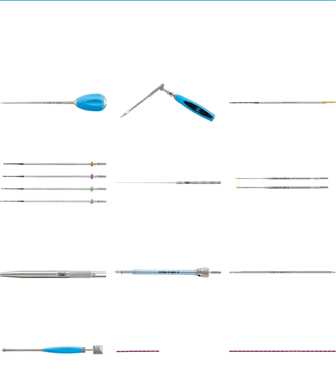
Bone Awl
07.01752.001
Drill Guide
07.01755.001
Adjustable Drill – Ø2.3mm
07.01757.001
Fixed Drill
07.01758.001 Ø2.3mm X 10mm
07.01758.002 Ø2.3mm X 12mm
07.01758.003 Ø2.3mm X 14mm
07.01758.004 Ø2.3mm X 16mm
Sounding Probe
07.01759.001
Tap, Small
07.01761.001 Ø3.0mm
07.01761.002 Ø3.5mm
Tap Sleeve – Ø3.5mm
07.01763.002
Assembled Polyaxial Screw Driver
07.01764.001
07.01764.002
07.01764.003
Tapered Hex Driver, 2.5mm
07.01765.001
Polyaxial Screw Head Turner
07.01766.001
Rod Template – 100mm
07.01767.001
Rod Template – 250mm
07.01767.002
Instrument Visual Guide
Virage OCT Standard System Instruments

Virage OCT Spinal Fixation System – Surgical Technique 39
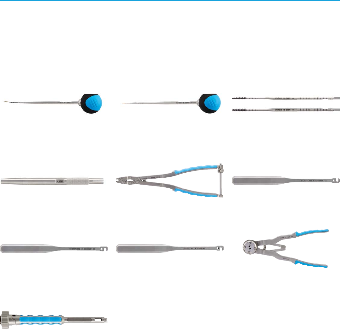
Rod Holder
07.01768.001
French Rod Bender
07.01770.001
Rod Rocker
07.01775.001
Kerrison Rod Reducer
07.01777.001
Transverse Connector Caliper
07.01780.001
Transverse Connector Driver – Rod to Rod
07.01781.001
Closure Top Starter
07.01782.001
Closure Top Final Driver
07.01783.001
Rod Pusher
07.01784.001
Inline Counter Torque
07.01785.001
Polyaxial Screw Remover
07.01786.002
A-O Handle with Spin Cap
07.01788.001
Torque-Limiting Handle - 3/16"
07.01792.001
40 Virage OCT Spinal Fixation System – Surgical Technique
Curved Probe
07.01753.001
Straight Probe
07.01754.001
Tap, Large
07.01762.001 Ø4.0mm
07.01762.002 Ø4.5mm
Ø4.5mm Tap Sleeve
07.01763.004
Rod Gripper
07.01769.001
In-situ Rod Bender - Left
07.01771.002
In-situ Rod Bender - Right
07.01772.002
In-situ Rod Bender - Straight
07.01773.002
Rod Cutter
07.01774.001
Tower Rod Reducer
07.01776.001
Instrument Visual Guide
Virage OCT CT Junction System Instruments
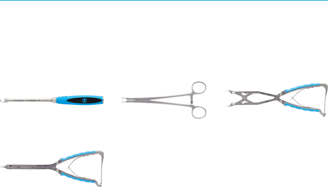
Virage OCT Spinal Fixation System – Surgical Technique 41
Hook Trial - 8mm
07.01750.001
Hook Forceps
07.01751.001
Compressor
07.01778.001
Distractor
07.01779.001
Instrument Visual Guide
Virage OCT Deluxe System Instruments

42 Virage OCT Spinal Fixation System – Surgical Technique
Handle, 3/16"
07.01790.001
Occipital Drill/Tap Guide
07.01793.001 6mm/8mm
07.01793.002 10mm/12mm
07.01793.003 14mm/16mm
Occipital Drill, Ø3.5mm
07.01794.001 Rigid
07.01795.001 Flexible
Occipital Tap
07.01796.001 Rigid - Ø4.5mm
07.01796.002 Rigid - Ø5.25mm
07.01797.001 Flexible - Ø4.5mm
07.01797.002 Flexible - Ø5.25mm
Hex Driver, 3.0mm
07.01798.001 Rigid
07.01799.001 Flexible
Allen Hex Wrench, 3.0mm
07.01801.001
Occipital Counter Torque
07.01802.001
Plate Bender
07.01803.001
Occipital Final Driver
07.01804.001 Flexible
07.01805.001 Rigid
Instrument Visual Guide
Virage OCT Occipital System Instruments

Virage OCT Spinal Fixation System – Surgical Technique 43
Warnings and Precautions
WARNINGS
Following are specific warnings, precautions,
and adverse effects associated with use of
the Virage System that should be understood
by the surgeon and explained to the patients.
General surgical risk should be explained to
the patients prior to surgery.
tImplantation of the Virage System should
be performed only by experienced spinal
surgeons
tAll implants are intended for single use only.
Single use devices should not be re-used.
Possible risks associated with re-use of
single-use devices include:
- Mechanical malfunction
- Transmission of infectious agents
tMetal sensitivity has been reported following
exposure to orthopedic implants. The most
common metallic sensitivities (nickel, cobalt,
and chromium) are present in medical grade
stainless steel and cobalt-chrome alloys.
tThe Virage System is a temporary internal
fixation device. Internal fixation devices
are designed to stabilize the operative site
during the normal healing process. After
healing occurs, these devices serve no
functional purpose and should be removed.
Implant removal should be followed by
adequate postoperative management to
avoid fracture or refracture.
tUniversal precautions should be observed by
all end users that work with contaminated or
potentially contaminated medical devices.
Caution should be exercised when handling
devices with sharp points or cutting edges
to prevent injuries during and after surgical
procedures and reprocessing.
tWarning: The safety and effectiveness
of pedicle screw spinal systems have
been established only for spinal
conditions with significant mechanical
instability or deformity requiring fusion
with instrumentation. These conditions
are significant mechanical instability
or deformity of the thoracic, lumbar,
and sacral spine secondary to severe
spondylolisthesis (grades 3 and 4) of the L5-
S1 vertebra, degenerative spondylolisthesis
with objective evidence of neurological
impairment, fracture, dislocation, scoliosis,
kyphosis, spinal tumor, and failed previous
fusion (pseudoarthrosis). The safety and
effectiveness of these devices for any other
conditions are unknown.
t Precaution: The implantation of pedicle
screw spinal systems should be performed
only by experienced spinal surgeons with
specific training in the use of this pedicle
screw spinal system because this is a
technically demanding procedure presenting
a risk of serious injury to the patient.
Additional preoperative, intraoperative, and
postoperative warnings and precautions:
PREOPERATIVE
tUsage of automated cleaning processes
without supplemental manual cleaning
may not result in adequate cleaning of
instruments.
tProper handling, decontamination
(including pre-rinsing, washing, rinsing
and sterilization), storage and utilization
are important for the long and useful life of
all surgical instruments. Even with correct
use, care and maintenance, they should
not be expected to last indefinitely. This is
especially true for cutting instruments (e.g.,
bone awls/drills) and driving instruments
(e.g., drivers). These items are often
subjected to high loads and/or impact
forces. Under such conditions, breakage can
occur, particularly when the item is corroded,
damaged, nicked or scratched.
tNever use titanium, titanium alloy, and/or
cobalt chromium with stainless steel in the
same implant construct; otherwise, galvanic
corrosion may occur. See DESCRIPTION
section for Virage System materials and
compatibility information.
INTRAOPERATIVE
tIf contouring of the implant is necessary for
optimal fit, the contouring should be gradual
and avoid any notching or scratching of
the implant surface. Do not repeatedly or
excessively bend the implant. Do not reverse
bend the plate or rods.
tBending plate outside of bend zone groove
may result in cracking of plate. Surgeon should
always inspect plate before implanting.
tOcciput and pedicle bone integrity should be
verified
tCare should be taken during occiput and
pedicle preparation to avoid penetrating
too deep.
tCare should be taken to ensure occipital
screw is not driven in too deep
tCare should be taken during bone
preparation to avoid damage to the pedicle
and to the surgical instruments.
tCare should be taken to minimize soft tissue
damage during surgery.
tCare should be taken to avoid removing
excess material from the Lamina.
tCare should be taken to avoid cross-
threading screws and closure tops.
tIf any implant or instrument comes in
contact with a non-sterile surface it should
not be used.
POSTOPERATIVE
tAdequately instruct the patient.
Postoperative care and the patient’s ability
and willingness to follow instructions are one
of the most important aspects of successful
bone healing. The patient must be made
aware of the limitations of the implant and
that physical activity and full weight bearing
have been implicated in fracture. The patient
should understand that an implant is not
as strong as normal, healthy bone and will
fracture if excessive demands are placed on
it in the absence of complete bone healing.
An active, debilitated, or demented patient
who cannot properly use weight-supporting
devices may be particularly at risk during
postoperative rehabilitation.
tThe Virage System is a temporary internal
fixation device. Internal fixation devices
are designed to stabilize the operative site
during the normal healing process. After
healing occurs, these devices serve no
functional purpose and should be removed.
Implant removal should be followed by
adequate postoperative management to
avoid fracture or refracture.

Disclaimer:
This documentation is intended exclusively for physicians and is not intended for laypersons. Information on the products and
procedures contained in this document is of a general nature and does not represent and does not constitute medical advice or
recommendations. Because this information does not purport to constitute any diagnostic or therapeutic statement with regard
to any individual medical case, each patient must be examined and advised individually, and this document does not replace the
need for such examination and/or advice in whole or in part. Please refer to the package inserts for important product information,
including, but not limited to, indications, contraindications, warnings, precautions, and adverse effects.
Contact your Zimmer Spine representative or visit us at www.zimmerspine.com
Manufactured by:
Zimmer Spine
7375 Bush Lake Road
Minneapolis, MN 55439
800.655.2614
zimmerspine.com
L1637 Rev. B (2014-06)
(851S-1001-00)
© 2014 Zimmer Spine, Inc.
Zimmer Limited
SN3 4FP, U.K.
+44.1793.58.4500
Caution: Federal (USA) law restricts this device to sale by or on the order of a physician. Please see the product Instructions
for Use for a complete listing of the indications, contraindications, warnings, precautions and adverse effects.
Printed in U.S.A. Subject to change without notice.
