PowerCenter 8.1.1 Workflow Administration Guide L2 Business Intelligence Informatica
User Manual: Pdf
Open the PDF directly: View PDF ![]() .
.
Page Count: 838 [warning: Documents this large are best viewed by clicking the View PDF Link!]
- Table of Contents
- List of Figures
- List of Tables
- Preface
- Chapter 1: Using the Workflow Manager
- Chapter 2: Managing Connection Objects
- Overview
- Working with Connection Objects
- Relational Database Connections
- FTP Connections
- External Loader Connections
- HTTP Connections
- PowerCenter Connect for IBM MQSeries Connections
- PowerCenter Connect for JMS Connections
- PowerCenter Connect for MSMQ Connections
- PowerCenter Connect for PeopleSoft Connections
- PowerCenter Connect for Salesforce.com Connections
- PowerCenter Connect for SAP NetWeaver mySAP Option Connections
- PowerCenter Connect for SAP NetWeaver BW Option Connections
- PowerCenter Connect for Siebel Connections
- PowerCenter Connect for TIBCO Connections
- PowerCenter Connect for Web Services Connections
- PowerCenter Connect for webMethods Connections
- Chapter 3: Working with Workflows
- Chapter 4: Working with Tasks
- Chapter 5: Working with Worklets
- Chapter 6: Working with Sessions
- Overview
- Creating a Session Task
- Editing a Session
- Understanding Buffer Memory
- Configuring Automatic Memory Settings
- Creating a Session Configuration Object
- Configuring Performance Details
- Using Pre- and Post-Session SQL Commands
- Using Pre- and Post-Session Shell Commands
- Using Post-Session Email
- Validating a Session
- Stopping and Aborting a Session
- Working with Session Parameters
- Mapping Parameters and Variables in Sessions
- Handling High Precision Data
- Chapter 7: Working with Sources
- Chapter 8: Working with Targets
- Overview
- Configuring Targets in a Session
- Working with Relational Targets
- Working with Target Connection Groups
- Working with Active Sources
- Working with File Targets
- Integration Service Handling for File Targets
- Writing to Fixed-Width Flat Files with Relational Target Definitions
- Writing to Fixed-Width Files with Flat File Target Definitions
- Generating Flat File Targets By Transaction
- Writing Multibyte Data to Fixed-Width Flat Files
- Null Characters in Fixed-Width Files
- Character Set
- Writing Metadata to Flat File Targets
- Working with Heterogeneous Targets
- Reject Files
- Chapter 9: Real-time Processing
- Chapter 10: Understanding Commit Points
- Chapter 11: Recovering Workflows
- Chapter 12: Sending Email
- Chapter 13: Working with Partition Points
- Overview
- Adding and Deleting Partition Points
- Partitioning Relational Sources
- Partitioning File Sources
- Partitioning Relational Targets
- Partitioning File Targets
- Partitioning Custom Transformations
- Partitioning Joiner Transformations
- Partitioning Lookup Transformations
- Partitioning Sorter Transformations
- Restrictions for Transformations
- Chapter 14: Understanding Pipeline Partitioning
- Chapter 15: Working with Partition Types
- Chapter 16: Using Pushdown Optimization
- Overview
- Running Pushdown Optimization Sessions
- Working with Databases
- Working with Expressions
- Working with Transformations
- Working with Sessions
- Working with SQL Overrides
- Using the $$PushdownConfig Mapping Parameter
- Viewing Pushdown Groups
- Configuring Sessions for Pushdown Optimization
- Rules and Guidelines
- Chapter 17: Monitoring Workflows
- Overview
- Using the Workflow Monitor
- Customizing Workflow Monitor Options
- Using Workflow Monitor Toolbars
- Working with Tasks and Workflows
- Workflow and Task Status
- Using the Gantt Chart View
- Using the Task View
- Viewing Service Details
- Viewing Workflow, Worklet, and Task Details
- Viewing Session Task Details
- Viewing Performance Details
- Tips
- Chapter 18: Running Workflows and Sessions on a Grid
- Chapter 19: Working with the Load Balancer
- Chapter 20: Session and Workflow Logs
- Chapter 21: Row Error Logging
- Chapter 22: Parameter Files
- Chapter 23: External Loading
- Chapter 24: Using FTP
- Chapter 25: Using Incremental Aggregation
- Chapter 26: Session Caches
- Appendix A: Session Properties Reference
- Appendix B: Workflow Properties Reference
- Index
- PowerCenter Release Notes
- PowerCenter Documentation
- Return to Start
Workflow Administration Guide
Informatica PowerCenter®
(Version 8.1.1)
PowerCenter Workflow Administration Guide
Version 8.1.1
September 2006
Copyright (c) 1998–2006 Informatica Corporation.
All rights reserved. Printed in the USA.
This software and documentation contain proprietary information of Informatica Corporation and are provided under a license agreement containing
restrictions on use and disclosure and are also protected by copyright law. Reverse engineering of the software is prohibited. No part of this document may be
reproduced or transmitted in any form, by any means (electronic, photocopying, recording or otherwise) without prior consent of Informatica Corporation.
Use, duplication, or disclosure of the Software by the U.S. Government is subject to the restrictions set forth in the applicable software license agreement and as
provided in DFARS 227.7202-1(a) and 227.7702-3(a) (1995), DFARS 252.227-7013(c)(1)(ii) (OCT 1988), FAR 12.212(a) (1995), FAR 52.227-19, or FAR
52.227-14 (ALT III), as applicable.
The information in this document is subject to change without notice. If you find any problems in the documentation, please report them to us in writing.
Informatica Corporation does not warrant that this documentation is error free. Informatica, PowerMart, PowerCenter, PowerChannel, PowerCenter Connect,
MX, SuperGlue, and Metadata Manager are trademarks or registered trademarks of Informatica Corporation in the United States and in jurisdictions throughout
the world. All other company and product names may be trade names or trademarks of their respective owners.
Portions of this software are copyrighted by DataDirect Technologies, 1999-2002.
Informatica PowerCenter products contain ACE (TM) software copyrighted by Douglas C. Schmidt and his research group at Washington University and
University of California, Irvine, Copyright (c) 1993-2002, all rights reserved.
Portions of this software contain copyrighted material from The JBoss Group, LLC. Your right to use such materials is set forth in the GNU Lesser General
Public License Agreement, which may be found at http://www.opensource.org/licenses/lgpl-license.php. The JBoss materials are provided free of charge by
Informatica, “as-is”, without warranty of any kind, either express or implied, including but not limited to the implied warranties of merchantability and fitness
for a particular purpose.
Portions of this software contain copyrighted material from Meta Integration Technology, Inc. Meta Integration® is a registered trademark of Meta Integration
Technology, Inc.
This product includes software developed by the Apache Software Foundation (http://www.apache.org/). The Apache Software is Copyright (c) 1999-2005 The
Apache Software Foundation. All rights reserved.
This product includes software developed by the OpenSSL Project for use in the OpenSSL Toolkit and redistribution of this software is subject to terms available
at http://www.openssl.org. Copyright 1998-2003 The OpenSSL Project. All Rights Reserved.
The zlib library included with this software is Copyright (c) 1995-2003 Jean-loup Gailly and Mark Adler.
The Curl license provided with this Software is Copyright 1996-2004, Daniel Stenberg, <Daniel@haxx.se>. All Rights Reserved.
The PCRE library included with this software is Copyright (c) 1997-2001 University of Cambridge Regular expression support is provided by the PCRE library
package, which is open source software, written by Philip Hazel. The source for this library may be found at ftp://ftp.csx.cam.ac.uk/pub/software/programming/
pcre.
InstallAnywhere is Copyright 2005 Zero G Software, Inc. All Rights Reserved.
Portions of the Software are Copyright (c) 1998-2005 The OpenLDAP Foundation. All rights reserved. Redistribution and use in source and binary forms, with
or without modification, are permitted only as authorized by the OpenLDAP Public License, available at http://www.openldap.org/software/release/license.html.
This Software is protected by U.S. Patent Numbers 6,208,990; 6,044,374; 6,014,670; 6,032,158; 5,794,246; 6,339,775 and other U.S. Patents Pending.
DISCLAIMER: Informatica Corporation provides this documentation “as is” without warranty of any kind, either express or implied,
including, but not limited to, the implied warranties of non-infringement, merchantability, or use for a particular purpose. The information provided in this
documentation may include technical inaccuracies or typographical errors. Informatica could make improvements and/or changes in the products described in
this documentation at any time without notice.
iii
Table of Contents
List of Figures . . . . . . . . . . . . . . . . . . . . . . . . . . . . . . . . . . . . . . . . . xxiii
List of Tables . . . . . . . . . . . . . . . . . . . . . . . . . . . . . . . . . . . . . . . . . . xxix
Preface . . . . . . . . . . . . . . . . . . . . . . . . . . . . . . . . . . . . . . . . . . . . . . . xxxv
About This Book . . . . . . . . . . . . . . . . . . . . . . . . . . . . . . . . . . . . . . . . . . xxxvi
Document Conventions . . . . . . . . . . . . . . . . . . . . . . . . . . . . . . . . . . xxxvi
Other Informatica Resources. . . . . . . . . . . . . . . . . . . . . . . . . . . . . . . . . xxxvii
Visiting Informatica Customer Portal . . . . . . . . . . . . . . . . . . . . . . . xxxvii
Visiting the Informatica Web Site . . . . . . . . . . . . . . . . . . . . . . . . . . xxxvii
Visiting the Informatica Developer Network . . . . . . . . . . . . . . . . . . xxxvii
Visiting the Informatica Knowledge Base . . . . . . . . . . . . . . . . . . . . . xxxvii
Obtaining Technical Support . . . . . . . . . . . . . . . . . . . . . . . . . . . . . xxxvii
Chapter 1: Using the Workflow Manager . . . . . . . . . . . . . . . . . . . . . . .1
Overview . . . . . . . . . . . . . . . . . . . . . . . . . . . . . . . . . . . . . . . . . . . . . . . . . . . 2
Workflow Manager Options . . . . . . . . . . . . . . . . . . . . . . . . . . . . . . . . . . 2
Workflow Manager Tools . . . . . . . . . . . . . . . . . . . . . . . . . . . . . . . . . . . . 2
Workflow Tasks . . . . . . . . . . . . . . . . . . . . . . . . . . . . . . . . . . . . . . . . . . . 3
Workflow Manager Windows . . . . . . . . . . . . . . . . . . . . . . . . . . . . . . . . . 3
Setting the Date/Time Display Format . . . . . . . . . . . . . . . . . . . . . . . . . . 4
Removing an Integration Service from the Workflow Manager . . . . . . . . . 4
Customizing Workflow Manager Options . . . . . . . . . . . . . . . . . . . . . . . . . . . 6
Configuring General Options . . . . . . . . . . . . . . . . . . . . . . . . . . . . . . . . . 6
Configuring Format Options . . . . . . . . . . . . . . . . . . . . . . . . . . . . . . . . . 9
Configuring Miscellaneous Options . . . . . . . . . . . . . . . . . . . . . . . . . . . 11
Enabling Enhanced Security . . . . . . . . . . . . . . . . . . . . . . . . . . . . . . . . . 13
Navigating the Workspace. . . . . . . . . . . . . . . . . . . . . . . . . . . . . . . . . . . . . . 15
Customizing Workflow Manager Windows . . . . . . . . . . . . . . . . . . . . . . 15
Using Toolbars. . . . . . . . . . . . . . . . . . . . . . . . . . . . . . . . . . . . . . . . . . . 15
Searching for Items . . . . . . . . . . . . . . . . . . . . . . . . . . . . . . . . . . . . . . . 16
Arranging Objects in the Workspace . . . . . . . . . . . . . . . . . . . . . . . . . . . 17
Zooming the Workspace . . . . . . . . . . . . . . . . . . . . . . . . . . . . . . . . . . . . 17
Working with Repository Objects . . . . . . . . . . . . . . . . . . . . . . . . . . . . . . . . 19
iv Table of Contents
Viewing Object Properties . . . . . . . . . . . . . . . . . . . . . . . . . . . . . . . . . .19
Entering Descriptions for Repository Objects. . . . . . . . . . . . . . . . . . . . .19
Renaming Repository Objects . . . . . . . . . . . . . . . . . . . . . . . . . . . . . . . .19
Checking In and Out Versioned Repository Objects . . . . . . . . . . . . . . . . . . .20
Checking In Objects . . . . . . . . . . . . . . . . . . . . . . . . . . . . . . . . . . . . . . .20
Viewing and Comparing Versioned Repository Objects . . . . . . . . . . . . . .21
Searching for Versioned Objects . . . . . . . . . . . . . . . . . . . . . . . . . . . . . . . . .23
Copying Repository Objects . . . . . . . . . . . . . . . . . . . . . . . . . . . . . . . . . . . .24
Copying Sessions . . . . . . . . . . . . . . . . . . . . . . . . . . . . . . . . . . . . . . . . .24
Copying Workflow Segments . . . . . . . . . . . . . . . . . . . . . . . . . . . . . . . .24
Comparing Repository Objects . . . . . . . . . . . . . . . . . . . . . . . . . . . . . . . . . .26
Steps for Comparing Objects. . . . . . . . . . . . . . . . . . . . . . . . . . . . . . . . .27
Working with Metadata Extensions . . . . . . . . . . . . . . . . . . . . . . . . . . . . . . .29
Creating a Metadata Extension . . . . . . . . . . . . . . . . . . . . . . . . . . . . . . .29
Editing a Metadata Extension . . . . . . . . . . . . . . . . . . . . . . . . . . . . . . . .31
Deleting a Metadata Extension . . . . . . . . . . . . . . . . . . . . . . . . . . . . . . .32
Keyboard Shortcuts . . . . . . . . . . . . . . . . . . . . . . . . . . . . . . . . . . . . . . . . . .33
Chapter 2: Managing Connection Objects . . . . . . . . . . . . . . . . . . . . .35
Overview . . . . . . . . . . . . . . . . . . . . . . . . . . . . . . . . . . . . . . . . . . . . . . . . . .36
Working with Connection Objects. . . . . . . . . . . . . . . . . . . . . . . . . . . . . . . .37
Creating Connection Objects . . . . . . . . . . . . . . . . . . . . . . . . . . . . . . . .37
Connection Object Permissions . . . . . . . . . . . . . . . . . . . . . . . . . . . . . . .39
Editing a Connection Object . . . . . . . . . . . . . . . . . . . . . . . . . . . . . . . .41
Deleting Connection Objects . . . . . . . . . . . . . . . . . . . . . . . . . . . . . . . .41
Relational Database Connections . . . . . . . . . . . . . . . . . . . . . . . . . . . . . . . . .43
Database User Names and Passwords . . . . . . . . . . . . . . . . . . . . . . . . . . .43
Database Connect Strings . . . . . . . . . . . . . . . . . . . . . . . . . . . . . . . . . . .44
Database Connection Code Pages . . . . . . . . . . . . . . . . . . . . . . . . . . . . .44
Configuring Environment SQL . . . . . . . . . . . . . . . . . . . . . . . . . . . . . . .45
Database Connection Resilience . . . . . . . . . . . . . . . . . . . . . . . . . . . . . .46
Configuring a Relational Database Connection . . . . . . . . . . . . . . . . . . .47
Copying a Relational Database Connection . . . . . . . . . . . . . . . . . . . . . .49
Replacing a Relational Database Connection . . . . . . . . . . . . . . . . . . . . .51
FTP Connections . . . . . . . . . . . . . . . . . . . . . . . . . . . . . . . . . . . . . . . . . . . .53
Rules and Guidelines for Mainframes. . . . . . . . . . . . . . . . . . . . . . . . . . .55
External Loader Connections. . . . . . . . . . . . . . . . . . . . . . . . . . . . . . . . . . . .56
Table of Contents v
HTTP Connections . . . . . . . . . . . . . . . . . . . . . . . . . . . . . . . . . . . . . . . . . . 58
PowerCenter Connect for IBM MQSeries Connections. . . . . . . . . . . . . . . . . 60
Test Queue Connections. . . . . . . . . . . . . . . . . . . . . . . . . . . . . . . . . . . . 61
PowerCenter Connect for JMS Connections . . . . . . . . . . . . . . . . . . . . . . . . 63
Connection Properties for JNDI Application Connections . . . . . . . . . . . 63
Connection Properties for JMS Application Connections . . . . . . . . . . . . 63
Creating JNDI and JMS Application Connections . . . . . . . . . . . . . . . . . 64
PowerCenter Connect for MSMQ Connections . . . . . . . . . . . . . . . . . . . . . . 65
PowerCenter Connect for PeopleSoft Connections . . . . . . . . . . . . . . . . . . . . 66
PowerCenter Connect for Salesforce.com Connections . . . . . . . . . . . . . . . . . 68
PowerCenter Connect for SAP NetWeaver mySAP Option Connections . . . . 69
Configuring an SAP R/3 Application Connection for ABAP Integration . 70
Configuring an FTP Connection for ABAP Integration . . . . . . . . . . . . . 71
Configuring Application Connections for ALE Integration . . . . . . . . . . . 71
Configuring an Application Connection for RFC/BAPI Integration . . . . 73
PowerCenter Connect for SAP NetWeaver BW Option Connections . . . . . . . 75
PowerCenter Connect for Siebel Connections . . . . . . . . . . . . . . . . . . . . . . . 76
PowerCenter Connect for TIBCO Connections . . . . . . . . . . . . . . . . . . . . . . 78
Connection Properties for TIB/Rendezvous Application Connections . . . 78
Connection Properties for TIB/Adapter SDK Connections . . . . . . . . . . . 79
Configuring TIBCO Application Connections. . . . . . . . . . . . . . . . . . . . 80
PowerCenter Connect for Web Services Connections . . . . . . . . . . . . . . . . . . 82
PowerCenter Connect for webMethods Connections . . . . . . . . . . . . . . . . . . 85
Chapter 3: Working with Workflows . . . . . . . . . . . . . . . . . . . . . . . . . . 87
Overview . . . . . . . . . . . . . . . . . . . . . . . . . . . . . . . . . . . . . . . . . . . . . . . . . . 88
Workflow Privileges . . . . . . . . . . . . . . . . . . . . . . . . . . . . . . . . . . . . . . . 90
Creating a Workflow . . . . . . . . . . . . . . . . . . . . . . . . . . . . . . . . . . . . . . . . . 91
Creating a Workflow Manually . . . . . . . . . . . . . . . . . . . . . . . . . . . . . . . 91
Creating a Workflow Automatically . . . . . . . . . . . . . . . . . . . . . . . . . . . . 91
Adding Tasks to Workflows. . . . . . . . . . . . . . . . . . . . . . . . . . . . . . . . . . 92
Deleting a Workflow . . . . . . . . . . . . . . . . . . . . . . . . . . . . . . . . . . . . . . 92
Using the Workflow Wizard . . . . . . . . . . . . . . . . . . . . . . . . . . . . . . . . . . . . 94
Step 1. Assign a Name and Integration Service to the Workflow . . . . . . . 94
Step 2. Create a Session . . . . . . . . . . . . . . . . . . . . . . . . . . . . . . . . . . . . 95
Step 3. Schedule a Workflow. . . . . . . . . . . . . . . . . . . . . . . . . . . . . . . . . 96
Assigning an Integration Service . . . . . . . . . . . . . . . . . . . . . . . . . . . . . . . . . 98
vi Table of Contents
Assigning a Service from the Workflow Properties . . . . . . . . . . . . . . . . .98
Assigning a Service from the Menu . . . . . . . . . . . . . . . . . . . . . . . . . . . .99
Working with Links . . . . . . . . . . . . . . . . . . . . . . . . . . . . . . . . . . . . . . . . .100
Specifying Link Conditions. . . . . . . . . . . . . . . . . . . . . . . . . . . . . . . . .101
Viewing Links in a Workflow or Worklet . . . . . . . . . . . . . . . . . . . . . . . 103
Deleting Links in a Workflow or Worklet. . . . . . . . . . . . . . . . . . . . . . .103
Using the Expression Editor . . . . . . . . . . . . . . . . . . . . . . . . . . . . . . . . . . .104
Adding Comments . . . . . . . . . . . . . . . . . . . . . . . . . . . . . . . . . . . . . . . 105
Validating Expressions . . . . . . . . . . . . . . . . . . . . . . . . . . . . . . . . . . . . 105
Expression Editor Display . . . . . . . . . . . . . . . . . . . . . . . . . . . . . . . . . . 105
Using Workflow Variables . . . . . . . . . . . . . . . . . . . . . . . . . . . . . . . . . . . . . 106
Predefined Workflow Variables . . . . . . . . . . . . . . . . . . . . . . . . . . . . . . 107
User-Defined Workflow Variables . . . . . . . . . . . . . . . . . . . . . . . . . . . . 112
Scheduling a Workflow . . . . . . . . . . . . . . . . . . . . . . . . . . . . . . . . . . . . . . . 116
Creating a Reusable Scheduler . . . . . . . . . . . . . . . . . . . . . . . . . . . . . . . 118
Configuring Scheduler Settings . . . . . . . . . . . . . . . . . . . . . . . . . . . . . . 119
Editing Scheduler Settings . . . . . . . . . . . . . . . . . . . . . . . . . . . . . . . . . 123
Disabling Workflows . . . . . . . . . . . . . . . . . . . . . . . . . . . . . . . . . . . . . 124
Validating a Workflow . . . . . . . . . . . . . . . . . . . . . . . . . . . . . . . . . . . . . . . 125
Expression Validation . . . . . . . . . . . . . . . . . . . . . . . . . . . . . . . . . . . . .125
Task Validation . . . . . . . . . . . . . . . . . . . . . . . . . . . . . . . . . . . . . . . . .125
Workflow Properties Validation . . . . . . . . . . . . . . . . . . . . . . . . . . . . . . 126
Running Validation . . . . . . . . . . . . . . . . . . . . . . . . . . . . . . . . . . . . . . 126
Manually Starting a Workflow . . . . . . . . . . . . . . . . . . . . . . . . . . . . . . . . . . 128
Running a Workflow . . . . . . . . . . . . . . . . . . . . . . . . . . . . . . . . . . . . . 128
Running a Part of a Workflow . . . . . . . . . . . . . . . . . . . . . . . . . . . . . . . 128
Running a Task in the Workflow . . . . . . . . . . . . . . . . . . . . . . . . . . . . .129
Suspending the Workflow . . . . . . . . . . . . . . . . . . . . . . . . . . . . . . . . . . . . . 130
Configuring Suspension Email . . . . . . . . . . . . . . . . . . . . . . . . . . . . . . 131
Stopping or Aborting the Workflow . . . . . . . . . . . . . . . . . . . . . . . . . . . . . . 132
How the Integration Service Handles Stop and Abort . . . . . . . . . . . . . . 132
Stopping or Aborting a Task . . . . . . . . . . . . . . . . . . . . . . . . . . . . . . . .132
Chapter 4: Working with Tasks . . . . . . . . . . . . . . . . . . . . . . . . . . . . . 135
Overview . . . . . . . . . . . . . . . . . . . . . . . . . . . . . . . . . . . . . . . . . . . . . . . . .136
Creating a Task. . . . . . . . . . . . . . . . . . . . . . . . . . . . . . . . . . . . . . . . . . . . .137
Creating a Task in the Task Developer . . . . . . . . . . . . . . . . . . . . . . . . . 137
Table of Contents vii
Creating a Task in the Workflow or Worklet Designer . . . . . . . . . . . . . 137
Configuring Tasks . . . . . . . . . . . . . . . . . . . . . . . . . . . . . . . . . . . . . . . . . . 139
Reusable Workflow Tasks . . . . . . . . . . . . . . . . . . . . . . . . . . . . . . . . . . 139
AND or OR Input Links . . . . . . . . . . . . . . . . . . . . . . . . . . . . . . . . . . 141
Disabling Tasks . . . . . . . . . . . . . . . . . . . . . . . . . . . . . . . . . . . . . . . . . 141
Failing Parent Workflow or Worklet . . . . . . . . . . . . . . . . . . . . . . . . . . 141
Validating Tasks . . . . . . . . . . . . . . . . . . . . . . . . . . . . . . . . . . . . . . . . . . . . 143
Working with the Assignment Task . . . . . . . . . . . . . . . . . . . . . . . . . . . . . . 144
Working with the Command Task . . . . . . . . . . . . . . . . . . . . . . . . . . . . . . . 147
Assigning Resources . . . . . . . . . . . . . . . . . . . . . . . . . . . . . . . . . . . . . . 147
Creating a Command Task . . . . . . . . . . . . . . . . . . . . . . . . . . . . . . . . . 148
Executing Commands in the Command Task . . . . . . . . . . . . . . . . . . . . 149
Working with the Control Task . . . . . . . . . . . . . . . . . . . . . . . . . . . . . . . . . 151
Working with the Decision Task . . . . . . . . . . . . . . . . . . . . . . . . . . . . . . . . 153
Using the Decision Task . . . . . . . . . . . . . . . . . . . . . . . . . . . . . . . . . . . 153
Creating a Decision Task . . . . . . . . . . . . . . . . . . . . . . . . . . . . . . . . . . 155
Working with Event Tasks . . . . . . . . . . . . . . . . . . . . . . . . . . . . . . . . . . . . 157
Example of User-Defined Events . . . . . . . . . . . . . . . . . . . . . . . . . . . . . 157
Working with Event-Raise Tasks . . . . . . . . . . . . . . . . . . . . . . . . . . . . . 158
Working with Event-Wait Tasks . . . . . . . . . . . . . . . . . . . . . . . . . . . . . 160
Working with the Timer Task . . . . . . . . . . . . . . . . . . . . . . . . . . . . . . . . . . 165
Chapter 5: Working with Worklets. . . . . . . . . . . . . . . . . . . . . . . . . . . 167
Overview . . . . . . . . . . . . . . . . . . . . . . . . . . . . . . . . . . . . . . . . . . . . . . . . . 168
Suspending Worklets . . . . . . . . . . . . . . . . . . . . . . . . . . . . . . . . . . . . . 168
Developing a Worklet . . . . . . . . . . . . . . . . . . . . . . . . . . . . . . . . . . . . . . . . 169
Creating a Reusable Worklet . . . . . . . . . . . . . . . . . . . . . . . . . . . . . . . . 169
Creating a Non-Reusable Worklet . . . . . . . . . . . . . . . . . . . . . . . . . . . . 169
Configuring Worklet Properties . . . . . . . . . . . . . . . . . . . . . . . . . . . . . 170
Adding Tasks in Worklets . . . . . . . . . . . . . . . . . . . . . . . . . . . . . . . . . . 170
Nesting Worklets . . . . . . . . . . . . . . . . . . . . . . . . . . . . . . . . . . . . . . . . 171
Using Worklet Variables . . . . . . . . . . . . . . . . . . . . . . . . . . . . . . . . . . . . . . 173
Persistent Worklet Variables . . . . . . . . . . . . . . . . . . . . . . . . . . . . . . . . 173
Overriding the Initial Value . . . . . . . . . . . . . . . . . . . . . . . . . . . . . . . . 173
Rules and Guidelines . . . . . . . . . . . . . . . . . . . . . . . . . . . . . . . . . . . . . 174
Validating Worklets . . . . . . . . . . . . . . . . . . . . . . . . . . . . . . . . . . . . . . . . . 175
viii Table of Contents
Chapter 6: Working with Sessions . . . . . . . . . . . . . . . . . . . . . . . . . . 177
Overview . . . . . . . . . . . . . . . . . . . . . . . . . . . . . . . . . . . . . . . . . . . . . . . . .178
Creating a Session Task . . . . . . . . . . . . . . . . . . . . . . . . . . . . . . . . . . . . . . . 179
Session Privileges . . . . . . . . . . . . . . . . . . . . . . . . . . . . . . . . . . . . . . . . 179
Steps to Create a Session Task . . . . . . . . . . . . . . . . . . . . . . . . . . . . . . . 179
Editing a Session . . . . . . . . . . . . . . . . . . . . . . . . . . . . . . . . . . . . . . . . . . . 181
Edit Session Privilege . . . . . . . . . . . . . . . . . . . . . . . . . . . . . . . . . . . . .182
Applying Attributes to All Instances . . . . . . . . . . . . . . . . . . . . . . . . . . 182
Understanding Buffer Memory . . . . . . . . . . . . . . . . . . . . . . . . . . . . . . . . . 187
Configuring Automatic Memory Settings . . . . . . . . . . . . . . . . . . . . . . . . . . 188
Configuring Buffer Memory . . . . . . . . . . . . . . . . . . . . . . . . . . . . . . . . 188
Configuring Session Cache Memory . . . . . . . . . . . . . . . . . . . . . . . . . . 189
Creating a Session Configuration Object . . . . . . . . . . . . . . . . . . . . . . . . . . 192
Configuring Performance Details . . . . . . . . . . . . . . . . . . . . . . . . . . . . . . . . 195
Using Pre- and Post-Session SQL Commands . . . . . . . . . . . . . . . . . . . . . . .197
Guidelines for Entering Pre- and Post-Session SQL Commands . . . . . . . 197
Error Handling . . . . . . . . . . . . . . . . . . . . . . . . . . . . . . . . . . . . . . . . .197
Using Pre- and Post-Session Shell Commands . . . . . . . . . . . . . . . . . . . . . . . 199
Using Service Process Variables and Session Parameters . . . . . . . . . . . . . 199
Configuring Non-Reusable Shell Commands . . . . . . . . . . . . . . . . . . . . 200
Configuring Reusable Shell Commands . . . . . . . . . . . . . . . . . . . . . . . . 203
Using Service Process Variables . . . . . . . . . . . . . . . . . . . . . . . . . . . . . . 204
Pre-Session Shell Command Errors . . . . . . . . . . . . . . . . . . . . . . . . . . . 204
Using Post-Session Email . . . . . . . . . . . . . . . . . . . . . . . . . . . . . . . . . . . . . 205
Validating a Session . . . . . . . . . . . . . . . . . . . . . . . . . . . . . . . . . . . . . . . . . 206
Validating Multiple Sessions . . . . . . . . . . . . . . . . . . . . . . . . . . . . . . . . 207
Stopping and Aborting a Session . . . . . . . . . . . . . . . . . . . . . . . . . . . . . . . . 208
Threshold Errors . . . . . . . . . . . . . . . . . . . . . . . . . . . . . . . . . . . . . . . . 208
Fatal Error . . . . . . . . . . . . . . . . . . . . . . . . . . . . . . . . . . . . . . . . . . . . . 208
ABORT Function . . . . . . . . . . . . . . . . . . . . . . . . . . . . . . . . . . . . . . . . 209
User Command . . . . . . . . . . . . . . . . . . . . . . . . . . . . . . . . . . . . . . . . .209
Integration Service Handling for Session Failure. . . . . . . . . . . . . . . . . . 209
Working with Session Parameters. . . . . . . . . . . . . . . . . . . . . . . . . . . . . . . . 211
Naming Conventions . . . . . . . . . . . . . . . . . . . . . . . . . . . . . . . . . . . . . 212
Changing the Session Log Name . . . . . . . . . . . . . . . . . . . . . . . . . . . . .212
Changing the Target File and Directory . . . . . . . . . . . . . . . . . . . . . . . . 212
Changing Source Parameters in a File . . . . . . . . . . . . . . . . . . . . . . . . . 213
Table of Contents ix
Changing the Database Connection Parameter. . . . . . . . . . . . . . . . . . . 213
Rules and Guidelines . . . . . . . . . . . . . . . . . . . . . . . . . . . . . . . . . . . . . 214
Mapping Parameters and Variables in Sessions . . . . . . . . . . . . . . . . . . . . . . 215
Handling High Precision Data . . . . . . . . . . . . . . . . . . . . . . . . . . . . . . . . . 216
Chapter 7: Working with Sources . . . . . . . . . . . . . . . . . . . . . . . . . . . 219
Overview . . . . . . . . . . . . . . . . . . . . . . . . . . . . . . . . . . . . . . . . . . . . . . . . . 220
Globalization Features . . . . . . . . . . . . . . . . . . . . . . . . . . . . . . . . . . . . 220
Source Connections . . . . . . . . . . . . . . . . . . . . . . . . . . . . . . . . . . . . . . 220
Permissions and Privileges . . . . . . . . . . . . . . . . . . . . . . . . . . . . . . . . . 220
Allocating Buffer Memory . . . . . . . . . . . . . . . . . . . . . . . . . . . . . . . . . 221
Partitioning Sources . . . . . . . . . . . . . . . . . . . . . . . . . . . . . . . . . . . . . . 221
Configuring Sources in a Session . . . . . . . . . . . . . . . . . . . . . . . . . . . . . . . . 222
Configuring Readers . . . . . . . . . . . . . . . . . . . . . . . . . . . . . . . . . . . . . 222
Configuring Connections . . . . . . . . . . . . . . . . . . . . . . . . . . . . . . . . . . 223
Configuring Properties . . . . . . . . . . . . . . . . . . . . . . . . . . . . . . . . . . . . 224
Working with Relational Sources. . . . . . . . . . . . . . . . . . . . . . . . . . . . . . . . 226
Selecting the Source Database Connection. . . . . . . . . . . . . . . . . . . . . . 226
Defining the Treat Source Rows As Property . . . . . . . . . . . . . . . . . . . . 226
Configuring the Table Owner Name . . . . . . . . . . . . . . . . . . . . . . . . . . 228
Overriding the SQL Query . . . . . . . . . . . . . . . . . . . . . . . . . . . . . . . . . 228
Working with File Sources . . . . . . . . . . . . . . . . . . . . . . . . . . . . . . . . . . . . 230
Configuring Source Properties . . . . . . . . . . . . . . . . . . . . . . . . . . . . . . 230
Configuring Commands for File Sources . . . . . . . . . . . . . . . . . . . . . . . 232
Configuring Fixed-Width File Properties . . . . . . . . . . . . . . . . . . . . . . . 233
Configuring Delimited File Properties . . . . . . . . . . . . . . . . . . . . . . . . . 235
Configuring Line Sequential Buffer Length . . . . . . . . . . . . . . . . . . . . . 238
Integration Service Handling for File Sources. . . . . . . . . . . . . . . . . . . . . . . 240
Character Set . . . . . . . . . . . . . . . . . . . . . . . . . . . . . . . . . . . . . . . . . . . 240
Multibyte Character Error Handling . . . . . . . . . . . . . . . . . . . . . . . . . . 241
Null Character Handling . . . . . . . . . . . . . . . . . . . . . . . . . . . . . . . . . . 241
Row Length Handling for Fixed-Width Flat Files . . . . . . . . . . . . . . . . . 242
Numeric Data Handling . . . . . . . . . . . . . . . . . . . . . . . . . . . . . . . . . . . 243
Using a File List . . . . . . . . . . . . . . . . . . . . . . . . . . . . . . . . . . . . . . . . . . . . 244
Creating the File List . . . . . . . . . . . . . . . . . . . . . . . . . . . . . . . . . . . . . 244
Configuring a Session to Use a File List . . . . . . . . . . . . . . . . . . . . . . . . 245
Using FastExport . . . . . . . . . . . . . . . . . . . . . . . . . . . . . . . . . . . . . . . . . . . 247
x Table of Contents
Creating a FastExport Connection . . . . . . . . . . . . . . . . . . . . . . . . . . . . 247
Changing the Reader . . . . . . . . . . . . . . . . . . . . . . . . . . . . . . . . . . . . . 249
Changing the Source Connection . . . . . . . . . . . . . . . . . . . . . . . . . . . . 249
Overriding the Control File . . . . . . . . . . . . . . . . . . . . . . . . . . . . . . . . 250
Rules and Guidelines . . . . . . . . . . . . . . . . . . . . . . . . . . . . . . . . . . . . . 251
Chapter 8: Working with Targets . . . . . . . . . . . . . . . . . . . . . . . . . . . . 253
Overview . . . . . . . . . . . . . . . . . . . . . . . . . . . . . . . . . . . . . . . . . . . . . . . . .254
Globalization Features . . . . . . . . . . . . . . . . . . . . . . . . . . . . . . . . . . . . 254
Target Connections . . . . . . . . . . . . . . . . . . . . . . . . . . . . . . . . . . . . . . 255
Partitioning Targets . . . . . . . . . . . . . . . . . . . . . . . . . . . . . . . . . . . . . . 255
Permissions and Privileges . . . . . . . . . . . . . . . . . . . . . . . . . . . . . . . . . . 256
Configuring Targets in a Session . . . . . . . . . . . . . . . . . . . . . . . . . . . . . . . . 257
Configuring Writers . . . . . . . . . . . . . . . . . . . . . . . . . . . . . . . . . . . . . . 257
Configuring Connections . . . . . . . . . . . . . . . . . . . . . . . . . . . . . . . . . .258
Configuring Properties . . . . . . . . . . . . . . . . . . . . . . . . . . . . . . . . . . . . 260
Working with Relational Targets . . . . . . . . . . . . . . . . . . . . . . . . . . . . . . . . 262
Target Database Connection . . . . . . . . . . . . . . . . . . . . . . . . . . . . . . . . 263
Target Properties . . . . . . . . . . . . . . . . . . . . . . . . . . . . . . . . . . . . . . . . 263
Truncating Target Tables . . . . . . . . . . . . . . . . . . . . . . . . . . . . . . . . . . . 268
Deadlock Retry . . . . . . . . . . . . . . . . . . . . . . . . . . . . . . . . . . . . . . . . . 270
Dropping and Recreating Indexes . . . . . . . . . . . . . . . . . . . . . . . . . . . . 271
Constraint-Based Loading . . . . . . . . . . . . . . . . . . . . . . . . . . . . . . . . . . 272
Bulk Loading . . . . . . . . . . . . . . . . . . . . . . . . . . . . . . . . . . . . . . . . . . . 275
Table Name Prefix . . . . . . . . . . . . . . . . . . . . . . . . . . . . . . . . . . . . . . . 277
Reserved Words . . . . . . . . . . . . . . . . . . . . . . . . . . . . . . . . . . . . . . . . . 278
Working with Target Connection Groups . . . . . . . . . . . . . . . . . . . . . . . . . .280
Working with Active Sources . . . . . . . . . . . . . . . . . . . . . . . . . . . . . . . . . . . 282
Working with File Targets . . . . . . . . . . . . . . . . . . . . . . . . . . . . . . . . . . . . . 284
Configuring Target Properties . . . . . . . . . . . . . . . . . . . . . . . . . . . . . . . 284
Configuring Commands for File Targets . . . . . . . . . . . . . . . . . . . . . . . 287
Configuring Test Load Options . . . . . . . . . . . . . . . . . . . . . . . . . . . . . . 288
Configuring Fixed-Width Properties . . . . . . . . . . . . . . . . . . . . . . . . . . 290
Configuring Delimited Properties . . . . . . . . . . . . . . . . . . . . . . . . . . . . 291
Integration Service Handling for File Targets . . . . . . . . . . . . . . . . . . . . . . . 293
Writing to Fixed-Width Flat Files with Relational Target Definitions. . . 293
Writing to Fixed-Width Files with Flat File Target Definitions . . . . . . . 294
Table of Contents xi
Generating Flat File Targets By Transaction . . . . . . . . . . . . . . . . . . . . . 295
Writing Multibyte Data to Fixed-Width Flat Files . . . . . . . . . . . . . . . . 296
Null Characters in Fixed-Width Files . . . . . . . . . . . . . . . . . . . . . . . . . 297
Character Set . . . . . . . . . . . . . . . . . . . . . . . . . . . . . . . . . . . . . . . . . . . 298
Writing Metadata to Flat File Targets . . . . . . . . . . . . . . . . . . . . . . . . . 298
Working with Heterogeneous Targets . . . . . . . . . . . . . . . . . . . . . . . . . . . . 299
Reject Files . . . . . . . . . . . . . . . . . . . . . . . . . . . . . . . . . . . . . . . . . . . . . . . 300
Locating Reject Files . . . . . . . . . . . . . . . . . . . . . . . . . . . . . . . . . . . . . 300
Reading Reject Files . . . . . . . . . . . . . . . . . . . . . . . . . . . . . . . . . . . . . . 301
Chapter 9: Real-time Processing. . . . . . . . . . . . . . . . . . . . . . . . . . . . 305
Overview . . . . . . . . . . . . . . . . . . . . . . . . . . . . . . . . . . . . . . . . . . . . . . . . . 306
Message Queue . . . . . . . . . . . . . . . . . . . . . . . . . . . . . . . . . . . . . . . . . 306
Web Service Messages. . . . . . . . . . . . . . . . . . . . . . . . . . . . . . . . . . . . . 307
Changed Source Data . . . . . . . . . . . . . . . . . . . . . . . . . . . . . . . . . . . . . 308
Configuring Real-time Sessions . . . . . . . . . . . . . . . . . . . . . . . . . . . . . . . . . 309
Reader Session Conditions . . . . . . . . . . . . . . . . . . . . . . . . . . . . . . . . . 309
Flush Latency . . . . . . . . . . . . . . . . . . . . . . . . . . . . . . . . . . . . . . . . . . 310
Commit Type . . . . . . . . . . . . . . . . . . . . . . . . . . . . . . . . . . . . . . . . . . 311
Message Recovery. . . . . . . . . . . . . . . . . . . . . . . . . . . . . . . . . . . . . . . . 311
Real-time Session Rules and Guidelines . . . . . . . . . . . . . . . . . . . . . . . . 312
Processing Real-time Data . . . . . . . . . . . . . . . . . . . . . . . . . . . . . . . . . . . . 313
Informatica Real-time Products . . . . . . . . . . . . . . . . . . . . . . . . . . . . . . . . . 314
Chapter 10: Understanding Commit Points . . . . . . . . . . . . . . . . . . . 317
Overview . . . . . . . . . . . . . . . . . . . . . . . . . . . . . . . . . . . . . . . . . . . . . . . . . 318
Target-Based Commits . . . . . . . . . . . . . . . . . . . . . . . . . . . . . . . . . . . . . . . 319
Source-Based Commits . . . . . . . . . . . . . . . . . . . . . . . . . . . . . . . . . . . . . . . 320
Determining the Commit Source . . . . . . . . . . . . . . . . . . . . . . . . . . . . 320
Switching from Source-Based to Target-Based Commit. . . . . . . . . . . . . 322
User-Defined Commits. . . . . . . . . . . . . . . . . . . . . . . . . . . . . . . . . . . . . . . 325
Rolling Back Transactions. . . . . . . . . . . . . . . . . . . . . . . . . . . . . . . . . . 326
Understanding Transaction Control. . . . . . . . . . . . . . . . . . . . . . . . . . . . . . 329
Transformation Scope. . . . . . . . . . . . . . . . . . . . . . . . . . . . . . . . . . . . . 329
Understanding Transaction Control Units . . . . . . . . . . . . . . . . . . . . . . 331
Rules and Guidelines . . . . . . . . . . . . . . . . . . . . . . . . . . . . . . . . . . . . . 332
Creating Target Files by Transaction . . . . . . . . . . . . . . . . . . . . . . . . . . 333
xii Table of Contents
Setting Commit Properties . . . . . . . . . . . . . . . . . . . . . . . . . . . . . . . . . . . . 334
Chapter 11: Recovering Workflows . . . . . . . . . . . . . . . . . . . . . . . . . .337
Overview . . . . . . . . . . . . . . . . . . . . . . . . . . . . . . . . . . . . . . . . . . . . . . . . .338
State of Operation . . . . . . . . . . . . . . . . . . . . . . . . . . . . . . . . . . . . . . . . . . 339
Workflow State of Operation. . . . . . . . . . . . . . . . . . . . . . . . . . . . . . . . 339
Session State of Operation . . . . . . . . . . . . . . . . . . . . . . . . . . . . . . . . . 339
Target Recovery Tables . . . . . . . . . . . . . . . . . . . . . . . . . . . . . . . . . . . . 340
Recovery Options . . . . . . . . . . . . . . . . . . . . . . . . . . . . . . . . . . . . . . . . . . . 342
Configuring Workflow Recovery . . . . . . . . . . . . . . . . . . . . . . . . . . . . . . . . 343
Recovering Stopped, Aborted, and Terminated Workflows . . . . . . . . . . 343
Recovering Suspended Workflows . . . . . . . . . . . . . . . . . . . . . . . . . . . . 344
Configuring Task Recovery . . . . . . . . . . . . . . . . . . . . . . . . . . . . . . . . . . . . 346
Task Recovery Strategies . . . . . . . . . . . . . . . . . . . . . . . . . . . . . . . . . . . 346
Automatically Recovering Terminated Tasks . . . . . . . . . . . . . . . . . . . . . 348
Resuming Sessions . . . . . . . . . . . . . . . . . . . . . . . . . . . . . . . . . . . . . . . . . .349
Working with Repeatable Data . . . . . . . . . . . . . . . . . . . . . . . . . . . . . . . . . 351
Source Repeatability . . . . . . . . . . . . . . . . . . . . . . . . . . . . . . . . . . . . . . 351
Transformation Repeatability . . . . . . . . . . . . . . . . . . . . . . . . . . . . . . . 352
Configuring a Mapping for Recovery . . . . . . . . . . . . . . . . . . . . . . . . . . 353
Steps to Recover Workflows and Tasks . . . . . . . . . . . . . . . . . . . . . . . . . . . . 356
Recovering a Workflow . . . . . . . . . . . . . . . . . . . . . . . . . . . . . . . . . . . . 356
Recovering a Session . . . . . . . . . . . . . . . . . . . . . . . . . . . . . . . . . . . . . . 356
Recovering a Workflow From a Session . . . . . . . . . . . . . . . . . . . . . . . . 357
Rules and Guidelines for Session Recovery . . . . . . . . . . . . . . . . . . . . . . . . . 358
Configuring Recovery to Resume from the Last Checkpoint . . . . . . . . .358
Unrecoverable Workflows or Tasks. . . . . . . . . . . . . . . . . . . . . . . . . . . .358
Chapter 12: Sending Email . . . . . . . . . . . . . . . . . . . . . . . . . . . . . . . . 361
Overview . . . . . . . . . . . . . . . . . . . . . . . . . . . . . . . . . . . . . . . . . . . . . . . . .362
Configuring Email on UNIX . . . . . . . . . . . . . . . . . . . . . . . . . . . . . . . . . . . 363
Configuring Email on Windows . . . . . . . . . . . . . . . . . . . . . . . . . . . . . . . . 364
Step 1. Configure a Microsoft Outlook User . . . . . . . . . . . . . . . . . . . . 364
Step 2. Configure Logon Network Security . . . . . . . . . . . . . . . . . . . . . 367
Step 3. Create Distribution Lists . . . . . . . . . . . . . . . . . . . . . . . . . . . . .368
Step 4. Verify the Integration Service Settings . . . . . . . . . . . . . . . . . . . 369
Working with Email Tasks. . . . . . . . . . . . . . . . . . . . . . . . . . . . . . . . . . . . . 370
Table of Contents xiii
Using Email Tasks in a Workflow or Worklet . . . . . . . . . . . . . . . . . . . . 370
Email Address Tips and Guidelines . . . . . . . . . . . . . . . . . . . . . . . . . . . 371
Steps to Create an Email Task . . . . . . . . . . . . . . . . . . . . . . . . . . . . . . . 371
Working with Post-Session Email . . . . . . . . . . . . . . . . . . . . . . . . . . . . . . . 374
Using Service Variables. . . . . . . . . . . . . . . . . . . . . . . . . . . . . . . . . . . . 375
Email Variables and Format Tags. . . . . . . . . . . . . . . . . . . . . . . . . . . . . 375
Configuring Post-Session Email . . . . . . . . . . . . . . . . . . . . . . . . . . . . . 377
Sample Email. . . . . . . . . . . . . . . . . . . . . . . . . . . . . . . . . . . . . . . . . . . 380
Working with Suspension Email . . . . . . . . . . . . . . . . . . . . . . . . . . . . . . . . 381
Tips . . . . . . . . . . . . . . . . . . . . . . . . . . . . . . . . . . . . . . . . . . . . . . . . . . . . 383
Chapter 13: Working with Partition Points . . . . . . . . . . . . . . . . . . . . 385
Overview . . . . . . . . . . . . . . . . . . . . . . . . . . . . . . . . . . . . . . . . . . . . . . . . . 386
Adding and Deleting Partition Points . . . . . . . . . . . . . . . . . . . . . . . . . . . . 387
Rules and Guidelines . . . . . . . . . . . . . . . . . . . . . . . . . . . . . . . . . . . . . 388
Partitioning Relational Sources . . . . . . . . . . . . . . . . . . . . . . . . . . . . . . . . . 390
Entering an SQL Query . . . . . . . . . . . . . . . . . . . . . . . . . . . . . . . . . . . 390
Entering a Filter Condition . . . . . . . . . . . . . . . . . . . . . . . . . . . . . . . . 391
Partitioning File Sources . . . . . . . . . . . . . . . . . . . . . . . . . . . . . . . . . . . . . . 393
Guidelines for Partitioning File Sources. . . . . . . . . . . . . . . . . . . . . . . . 393
Using One Thread to Read a File Source . . . . . . . . . . . . . . . . . . . . . . . 394
Using Multiple Threads to Read a File Source . . . . . . . . . . . . . . . . . . . 394
Configuring for File Partitioning. . . . . . . . . . . . . . . . . . . . . . . . . . . . . 394
Partitioning Relational Targets . . . . . . . . . . . . . . . . . . . . . . . . . . . . . . . . . 399
Database Compatibility . . . . . . . . . . . . . . . . . . . . . . . . . . . . . . . . . . . 400
Partitioning File Targets . . . . . . . . . . . . . . . . . . . . . . . . . . . . . . . . . . . . . . 401
Configuring Connection Settings . . . . . . . . . . . . . . . . . . . . . . . . . . . . 401
Configuring File Properties. . . . . . . . . . . . . . . . . . . . . . . . . . . . . . . . . 402
Partitioning Custom Transformations . . . . . . . . . . . . . . . . . . . . . . . . . . . . 406
Working with Multiple Partitions . . . . . . . . . . . . . . . . . . . . . . . . . . . . 406
Creating Partition Points . . . . . . . . . . . . . . . . . . . . . . . . . . . . . . . . . . 406
Working with Threads . . . . . . . . . . . . . . . . . . . . . . . . . . . . . . . . . . . . 407
Partitioning Joiner Transformations. . . . . . . . . . . . . . . . . . . . . . . . . . . . . . 409
Partitioning Sorted Joiner Transformations . . . . . . . . . . . . . . . . . . . . . 409
Using Sorted Flat Files . . . . . . . . . . . . . . . . . . . . . . . . . . . . . . . . . . . . 410
Using Sorted Relational Data . . . . . . . . . . . . . . . . . . . . . . . . . . . . . . . 412
Using Sorter Transformations . . . . . . . . . . . . . . . . . . . . . . . . . . . . . . . 414
xiv Table of Contents
Optimizing Sorted Joiner Transformations with Partitions . . . . . . . . . .415
Partitioning Lookup Transformations. . . . . . . . . . . . . . . . . . . . . . . . . . . . .416
Sharing Partitioned Caches . . . . . . . . . . . . . . . . . . . . . . . . . . . . . . . . . 416
Partitioning Sorter Transformations . . . . . . . . . . . . . . . . . . . . . . . . . . . . . .417
Configuring Sorter Transformation Work Directories . . . . . . . . . . . . . . 417
Restrictions for Transformations . . . . . . . . . . . . . . . . . . . . . . . . . . . . . . . . 419
Chapter 14: Understanding Pipeline Partitioning . . . . . . . . . . . . . . . 421
Overview . . . . . . . . . . . . . . . . . . . . . . . . . . . . . . . . . . . . . . . . . . . . . . . . .422
Partitioning Attributes . . . . . . . . . . . . . . . . . . . . . . . . . . . . . . . . . . . . . . . 423
Partition Points . . . . . . . . . . . . . . . . . . . . . . . . . . . . . . . . . . . . . . . . .423
Number of Partitions . . . . . . . . . . . . . . . . . . . . . . . . . . . . . . . . . . . . . 424
Partition Types . . . . . . . . . . . . . . . . . . . . . . . . . . . . . . . . . . . . . . . . . . 425
Dynamic Partitioning . . . . . . . . . . . . . . . . . . . . . . . . . . . . . . . . . . . . . . . . 427
Configuring Dynamic Partitioning . . . . . . . . . . . . . . . . . . . . . . . . . . .428
Rules and Guidelines for Dynamic Partitioning . . . . . . . . . . . . . . . . . . 429
Using Dynamic Partitioning with Partition Types . . . . . . . . . . . . . . . . .429
Configuring Partition-Level Attributes. . . . . . . . . . . . . . . . . . . . . . . . . 430
Cache Partitioning . . . . . . . . . . . . . . . . . . . . . . . . . . . . . . . . . . . . . . . . . .431
Mapping Variables in Partitioned Pipelines. . . . . . . . . . . . . . . . . . . . . . . . . 432
Partitioning Rules . . . . . . . . . . . . . . . . . . . . . . . . . . . . . . . . . . . . . . . . . . . 433
Partition Restrictions for Editing Objects. . . . . . . . . . . . . . . . . . . . . . .433
Partition Restrictions for PowerCenter Connects . . . . . . . . . . . . . . . . . 434
Configuring Partitioning. . . . . . . . . . . . . . . . . . . . . . . . . . . . . . . . . . . . . . 435
Configuring a Partition Point . . . . . . . . . . . . . . . . . . . . . . . . . . . . . . . 436
Steps for Adding Partition Points to a Pipeline . . . . . . . . . . . . . . . . . . . 438
Chapter 15: Working with Partition Types. . . . . . . . . . . . . . . . . . . . . 439
Overview . . . . . . . . . . . . . . . . . . . . . . . . . . . . . . . . . . . . . . . . . . . . . . . . .440
Setting Partition Types in the Pipeline . . . . . . . . . . . . . . . . . . . . . . . . . 441
Setting Partition Types . . . . . . . . . . . . . . . . . . . . . . . . . . . . . . . . . . . . . . . 442
Database Partitioning Partition Type . . . . . . . . . . . . . . . . . . . . . . . . . . . . .444
Partitioning Database Sources . . . . . . . . . . . . . . . . . . . . . . . . . . . . . . . 444
Target Database Partitioning . . . . . . . . . . . . . . . . . . . . . . . . . . . . . . . .446
Rules and Guidelines . . . . . . . . . . . . . . . . . . . . . . . . . . . . . . . . . . . . . 447
Hash Auto-Keys . . . . . . . . . . . . . . . . . . . . . . . . . . . . . . . . . . . . . . . . . . . . 448
Hash User Keys . . . . . . . . . . . . . . . . . . . . . . . . . . . . . . . . . . . . . . . . . . . . 449
Table of Contents xv
Key Range Partition Type . . . . . . . . . . . . . . . . . . . . . . . . . . . . . . . . . . . . . 451
Adding a Partition Key . . . . . . . . . . . . . . . . . . . . . . . . . . . . . . . . . . . . 452
Adding Key Ranges . . . . . . . . . . . . . . . . . . . . . . . . . . . . . . . . . . . . . . 453
Pass-Through Partition Type . . . . . . . . . . . . . . . . . . . . . . . . . . . . . . . . . . . 455
Round-Robin Partition Type . . . . . . . . . . . . . . . . . . . . . . . . . . . . . . . . . . . 457
Chapter 16: Using Pushdown Optimization . . . . . . . . . . . . . . . . . . . 459
Overview . . . . . . . . . . . . . . . . . . . . . . . . . . . . . . . . . . . . . . . . . . . . . . . . . 460
Running Pushdown Optimization Sessions . . . . . . . . . . . . . . . . . . . . . . . . 461
Running Source-Side Pushdown Optimization Sessions . . . . . . . . . . . . 461
Running Target-Side Pushdown Optimization Sessions. . . . . . . . . . . . . 461
Running Full Pushdown Optimization Sessions . . . . . . . . . . . . . . . . . . 462
Working with Databases . . . . . . . . . . . . . . . . . . . . . . . . . . . . . . . . . . . . . . 463
Using ODBC Drivers . . . . . . . . . . . . . . . . . . . . . . . . . . . . . . . . . . . . . 464
Working with Expressions. . . . . . . . . . . . . . . . . . . . . . . . . . . . . . . . . . . . . 466
Operators . . . . . . . . . . . . . . . . . . . . . . . . . . . . . . . . . . . . . . . . . . . . . 466
Variables . . . . . . . . . . . . . . . . . . . . . . . . . . . . . . . . . . . . . . . . . . . . . . 466
Functions . . . . . . . . . . . . . . . . . . . . . . . . . . . . . . . . . . . . . . . . . . . . . 467
Working with Transformations . . . . . . . . . . . . . . . . . . . . . . . . . . . . . . . . . 471
Aggregator Transformation . . . . . . . . . . . . . . . . . . . . . . . . . . . . . . . . . 472
Expression Transformation . . . . . . . . . . . . . . . . . . . . . . . . . . . . . . . . . 472
Filter Transformation . . . . . . . . . . . . . . . . . . . . . . . . . . . . . . . . . . . . . 473
Joiner Transformation . . . . . . . . . . . . . . . . . . . . . . . . . . . . . . . . . . . . 473
Lookup Transformation . . . . . . . . . . . . . . . . . . . . . . . . . . . . . . . . . . . 473
Sorter Transformation . . . . . . . . . . . . . . . . . . . . . . . . . . . . . . . . . . . . 474
Source Qualifier Transformation . . . . . . . . . . . . . . . . . . . . . . . . . . . . . 475
Target . . . . . . . . . . . . . . . . . . . . . . . . . . . . . . . . . . . . . . . . . . . . . . . . 475
Union Transformation . . . . . . . . . . . . . . . . . . . . . . . . . . . . . . . . . . . . 475
Working with Sessions . . . . . . . . . . . . . . . . . . . . . . . . . . . . . . . . . . . . . . . 476
Working with Partitions . . . . . . . . . . . . . . . . . . . . . . . . . . . . . . . . . . . 476
Working with Target Load Rules . . . . . . . . . . . . . . . . . . . . . . . . . . . . . 478
Error Handling, Logging, and Recovery. . . . . . . . . . . . . . . . . . . . . . . . 479
Working with SQL Overrides . . . . . . . . . . . . . . . . . . . . . . . . . . . . . . . . . . 481
Views . . . . . . . . . . . . . . . . . . . . . . . . . . . . . . . . . . . . . . . . . . . . . . . . 481
Troubleshooting Orphaned Views . . . . . . . . . . . . . . . . . . . . . . . . . . . . 482
Rules and Guidelines . . . . . . . . . . . . . . . . . . . . . . . . . . . . . . . . . . . . . 484
Using the $$PushdownConfig Mapping Parameter . . . . . . . . . . . . . . . . . . . 485
xvi Table of Contents
Viewing Pushdown Groups . . . . . . . . . . . . . . . . . . . . . . . . . . . . . . . . . . . .487
Configuring Sessions for Pushdown Optimization . . . . . . . . . . . . . . . . . . . 490
Rules and Guidelines . . . . . . . . . . . . . . . . . . . . . . . . . . . . . . . . . . . . . . . . 492
Chapter 17: Monitoring Workflows . . . . . . . . . . . . . . . . . . . . . . . . . . 495
Overview . . . . . . . . . . . . . . . . . . . . . . . . . . . . . . . . . . . . . . . . . . . . . . . . .496
Permissions and Privileges . . . . . . . . . . . . . . . . . . . . . . . . . . . . . . . . . . 498
Using the Workflow Monitor. . . . . . . . . . . . . . . . . . . . . . . . . . . . . . . . . . . 499
Opening the Workflow Monitor . . . . . . . . . . . . . . . . . . . . . . . . . . . . .499
Connecting to Repositories . . . . . . . . . . . . . . . . . . . . . . . . . . . . . . . . . 500
Connecting to Integration Services . . . . . . . . . . . . . . . . . . . . . . . . . . . 500
Filtering Tasks and Integration Services . . . . . . . . . . . . . . . . . . . . . . . . 500
Opening and Closing Folders . . . . . . . . . . . . . . . . . . . . . . . . . . . . . . . 502
Viewing Statistics . . . . . . . . . . . . . . . . . . . . . . . . . . . . . . . . . . . . . . . . 503
Viewing Properties . . . . . . . . . . . . . . . . . . . . . . . . . . . . . . . . . . . . . . . 503
Customizing Workflow Monitor Options . . . . . . . . . . . . . . . . . . . . . . . . . . 505
Configuring General Options . . . . . . . . . . . . . . . . . . . . . . . . . . . . . . .505
Configuring Gantt Chart View Options. . . . . . . . . . . . . . . . . . . . . . . . 507
Configuring Task View Options . . . . . . . . . . . . . . . . . . . . . . . . . . . . . 508
Configuring Advanced Options . . . . . . . . . . . . . . . . . . . . . . . . . . . . . . 509
Using Workflow Monitor Toolbars. . . . . . . . . . . . . . . . . . . . . . . . . . . . . . . 511
Working with Tasks and Workflows . . . . . . . . . . . . . . . . . . . . . . . . . . . . . . 512
Running a Task, Workflow, or Worklet . . . . . . . . . . . . . . . . . . . . . . . . 512
Recovering a Workflow or Worklet . . . . . . . . . . . . . . . . . . . . . . . . . . .513
Stopping or Aborting Tasks and Workflows . . . . . . . . . . . . . . . . . . . . . 513
Scheduling and Unscheduling Workflows . . . . . . . . . . . . . . . . . . . . . . .514
Viewing Session Logs and Workflow Logs . . . . . . . . . . . . . . . . . . . . . . 514
Viewing History Names . . . . . . . . . . . . . . . . . . . . . . . . . . . . . . . . . . . 515
Workflow and Task Status . . . . . . . . . . . . . . . . . . . . . . . . . . . . . . . . . . . . . 516
Using the Gantt Chart View . . . . . . . . . . . . . . . . . . . . . . . . . . . . . . . . . . . 518
Organizing Tasks . . . . . . . . . . . . . . . . . . . . . . . . . . . . . . . . . . . . . . . .519
Listing Tasks and Workflows . . . . . . . . . . . . . . . . . . . . . . . . . . . . . . . . 519
Navigating the Time Window in Gantt Chart View . . . . . . . . . . . . . . . 520
Zooming the Gantt Chart View. . . . . . . . . . . . . . . . . . . . . . . . . . . . . . 521
Performing a Search . . . . . . . . . . . . . . . . . . . . . . . . . . . . . . . . . . . . . .522
Opening All Folders . . . . . . . . . . . . . . . . . . . . . . . . . . . . . . . . . . . . . . 524
Using the Task View . . . . . . . . . . . . . . . . . . . . . . . . . . . . . . . . . . . . . . . . . 525
Table of Contents xvii
Filtering in Task View . . . . . . . . . . . . . . . . . . . . . . . . . . . . . . . . . . . . 526
Opening All Folders . . . . . . . . . . . . . . . . . . . . . . . . . . . . . . . . . . . . . . 528
Viewing Service Details . . . . . . . . . . . . . . . . . . . . . . . . . . . . . . . . . . . . . . 529
Viewing Repository Service Details . . . . . . . . . . . . . . . . . . . . . . . . . . . 529
Viewing Integration Service Details. . . . . . . . . . . . . . . . . . . . . . . . . . . 530
Viewing Folder Details . . . . . . . . . . . . . . . . . . . . . . . . . . . . . . . . . . . . 532
Viewing Workflow, Worklet, and Task Details . . . . . . . . . . . . . . . . . . . . . . 534
Viewing Workflow Details . . . . . . . . . . . . . . . . . . . . . . . . . . . . . . . . . 534
Viewing Worklet Details. . . . . . . . . . . . . . . . . . . . . . . . . . . . . . . . . . . 535
Viewing Task Progress Details . . . . . . . . . . . . . . . . . . . . . . . . . . . . . . . 536
Viewing Session Statistics . . . . . . . . . . . . . . . . . . . . . . . . . . . . . . . . . . 537
Viewing Command Task Details . . . . . . . . . . . . . . . . . . . . . . . . . . . . . 537
Viewing Session Task Details . . . . . . . . . . . . . . . . . . . . . . . . . . . . . . . . . . 539
Viewing Failure Information . . . . . . . . . . . . . . . . . . . . . . . . . . . . . . . . 539
Viewing Session Task Details . . . . . . . . . . . . . . . . . . . . . . . . . . . . . . . 540
Viewing Source and Target Statistics . . . . . . . . . . . . . . . . . . . . . . . . . . 541
Viewing Partition Details . . . . . . . . . . . . . . . . . . . . . . . . . . . . . . . . . . 542
Viewing Performance Details . . . . . . . . . . . . . . . . . . . . . . . . . . . . . . . . . . 544
Understanding Performance Counters . . . . . . . . . . . . . . . . . . . . . . . . . 545
Tips . . . . . . . . . . . . . . . . . . . . . . . . . . . . . . . . . . . . . . . . . . . . . . . . . . . . 549
Chapter 18: Running Workflows and Sessions on a Grid . . . . . . . . 551
Overview . . . . . . . . . . . . . . . . . . . . . . . . . . . . . . . . . . . . . . . . . . . . . . . . . 552
Running Workflows on a Grid. . . . . . . . . . . . . . . . . . . . . . . . . . . . . . . . . . 553
Running Sessions on a Grid . . . . . . . . . . . . . . . . . . . . . . . . . . . . . . . . . . . 554
Working with Partition Groups. . . . . . . . . . . . . . . . . . . . . . . . . . . . . . 555
Grid Connectivity and Recovery . . . . . . . . . . . . . . . . . . . . . . . . . . . . . . . . 558
Configuring a Workflow or Session to Run on a Grid . . . . . . . . . . . . . . . . . 559
Rules and Guidelines . . . . . . . . . . . . . . . . . . . . . . . . . . . . . . . . . . . . . 559
Chapter 19: Working with the Load Balancer . . . . . . . . . . . . . . . . . . 561
Overview . . . . . . . . . . . . . . . . . . . . . . . . . . . . . . . . . . . . . . . . . . . . . . . . . 562
Assigning Service Levels to Workflows . . . . . . . . . . . . . . . . . . . . . . . . . . . . 563
Assigning Resources to Tasks. . . . . . . . . . . . . . . . . . . . . . . . . . . . . . . . . . . 564
Chapter 20: Session and Workflow Logs . . . . . . . . . . . . . . . . . . . . . 567
Overview . . . . . . . . . . . . . . . . . . . . . . . . . . . . . . . . . . . . . . . . . . . . . . . . . 568
xviii Table of Contents
Log Events . . . . . . . . . . . . . . . . . . . . . . . . . . . . . . . . . . . . . . . . . . . . . . . .569
Log Codes . . . . . . . . . . . . . . . . . . . . . . . . . . . . . . . . . . . . . . . . . . . . . 569
Message Severity. . . . . . . . . . . . . . . . . . . . . . . . . . . . . . . . . . . . . . . . . 569
Writing Logs . . . . . . . . . . . . . . . . . . . . . . . . . . . . . . . . . . . . . . . . . . . 570
Writing to an External Library . . . . . . . . . . . . . . . . . . . . . . . . . . . . . . 570
Log Events Window . . . . . . . . . . . . . . . . . . . . . . . . . . . . . . . . . . . . . . . . .571
Searching for Log Events. . . . . . . . . . . . . . . . . . . . . . . . . . . . . . . . . . . 572
Working with Log Files . . . . . . . . . . . . . . . . . . . . . . . . . . . . . . . . . . . . . . . 574
Writing to Log Files . . . . . . . . . . . . . . . . . . . . . . . . . . . . . . . . . . . . . . 574
Archiving Log Files. . . . . . . . . . . . . . . . . . . . . . . . . . . . . . . . . . . . . . . 575
Configuring Workflow Log File Information . . . . . . . . . . . . . . . . . . . . 576
Configuring Session Log File Information . . . . . . . . . . . . . . . . . . . . . .577
Workflow Logs . . . . . . . . . . . . . . . . . . . . . . . . . . . . . . . . . . . . . . . . . . . . . 580
Workflow Log Events Window . . . . . . . . . . . . . . . . . . . . . . . . . . . . . . 580
Workflow Log Sample. . . . . . . . . . . . . . . . . . . . . . . . . . . . . . . . . . . . .581
Session Logs . . . . . . . . . . . . . . . . . . . . . . . . . . . . . . . . . . . . . . . . . . . . . . . 582
Log Events Window . . . . . . . . . . . . . . . . . . . . . . . . . . . . . . . . . . . . . . 582
Session Log File Sample . . . . . . . . . . . . . . . . . . . . . . . . . . . . . . . . . . .583
Setting Tracing Levels . . . . . . . . . . . . . . . . . . . . . . . . . . . . . . . . . . . . . 583
Viewing Log Events . . . . . . . . . . . . . . . . . . . . . . . . . . . . . . . . . . . . . . . . .586
Chapter 21: Row Error Logging. . . . . . . . . . . . . . . . . . . . . . . . . . . . . 587
Overview . . . . . . . . . . . . . . . . . . . . . . . . . . . . . . . . . . . . . . . . . . . . . . . . .588
Error Log Code Pages . . . . . . . . . . . . . . . . . . . . . . . . . . . . . . . . . . . . . 588
Understanding the Error Log Tables. . . . . . . . . . . . . . . . . . . . . . . . . . . . . . 590
PMERR_DATA . . . . . . . . . . . . . . . . . . . . . . . . . . . . . . . . . . . . . . . . . 590
PMERR_MSG . . . . . . . . . . . . . . . . . . . . . . . . . . . . . . . . . . . . . . . . . . 592
PMERR_SESS . . . . . . . . . . . . . . . . . . . . . . . . . . . . . . . . . . . . . . . . . .593
PMERR_TRANS . . . . . . . . . . . . . . . . . . . . . . . . . . . . . . . . . . . . . . . . 594
Understanding the Error Log File . . . . . . . . . . . . . . . . . . . . . . . . . . . . . . . 596
Configuring Error Log Options . . . . . . . . . . . . . . . . . . . . . . . . . . . . . . . . . 599
Chapter 22: Parameter Files . . . . . . . . . . . . . . . . . . . . . . . . . . . . . . . 601
Overview . . . . . . . . . . . . . . . . . . . . . . . . . . . . . . . . . . . . . . . . . . . . . . . . .602
Using a Parameter File . . . . . . . . . . . . . . . . . . . . . . . . . . . . . . . . . . . . . . . 604
Example. . . . . . . . . . . . . . . . . . . . . . . . . . . . . . . . . . . . . . . . . . . . . . .605
Sample Parameter File. . . . . . . . . . . . . . . . . . . . . . . . . . . . . . . . . . . . . 606
Table of Contents xix
Guidelines for Creating Parameter Files . . . . . . . . . . . . . . . . . . . . . . . . . . . 607
Configuring the Parameter File Location . . . . . . . . . . . . . . . . . . . . . . . . . . 609
Using a Parameter File with pmcmd . . . . . . . . . . . . . . . . . . . . . . . . . . . . . 611
Troubleshooting . . . . . . . . . . . . . . . . . . . . . . . . . . . . . . . . . . . . . . . . . . . . 612
Tips . . . . . . . . . . . . . . . . . . . . . . . . . . . . . . . . . . . . . . . . . . . . . . . . . . . . 613
Chapter 23: External Loading . . . . . . . . . . . . . . . . . . . . . . . . . . . . . . 615
Overview . . . . . . . . . . . . . . . . . . . . . . . . . . . . . . . . . . . . . . . . . . . . . . . . . 616
Before You Begin . . . . . . . . . . . . . . . . . . . . . . . . . . . . . . . . . . . . . . . . 616
External Loader Permissions and Privileges . . . . . . . . . . . . . . . . . . . . . 616
External Loader Behavior . . . . . . . . . . . . . . . . . . . . . . . . . . . . . . . . . . . . . 618
Loading Data to a Named Pipe . . . . . . . . . . . . . . . . . . . . . . . . . . . . . . 618
Staging Data to a Flat File . . . . . . . . . . . . . . . . . . . . . . . . . . . . . . . . . 618
Partitioning Sessions with External Loaders . . . . . . . . . . . . . . . . . . . . . 619
Loading to IBM DB2 . . . . . . . . . . . . . . . . . . . . . . . . . . . . . . . . . . . . . . . . 620
Rules and Guidelines . . . . . . . . . . . . . . . . . . . . . . . . . . . . . . . . . . . . . 620
Setting Operation Modes . . . . . . . . . . . . . . . . . . . . . . . . . . . . . . . . . . 621
Configuring Authorities, Privileges, and Permissions . . . . . . . . . . . . . . 621
Configuring IBM DB2 EE External Loader Attributes . . . . . . . . . . . . . 622
Configuring IBM DB2 EEE External Loader Attributes . . . . . . . . . . . . 623
Loading to Oracle . . . . . . . . . . . . . . . . . . . . . . . . . . . . . . . . . . . . . . . . . . 626
Rules and Guidelines . . . . . . . . . . . . . . . . . . . . . . . . . . . . . . . . . . . . . 626
Loading Multibyte Data to Oracle. . . . . . . . . . . . . . . . . . . . . . . . . . . . 626
Configuring Oracle External Loader Attributes . . . . . . . . . . . . . . . . . . 627
Loading to Sybase IQ . . . . . . . . . . . . . . . . . . . . . . . . . . . . . . . . . . . . . . . . 628
Rules and Guidelines . . . . . . . . . . . . . . . . . . . . . . . . . . . . . . . . . . . . . 628
Loading Multibyte Data to Sybase IQ . . . . . . . . . . . . . . . . . . . . . . . . . 628
Configuring Sybase IQ External Loader Attributes . . . . . . . . . . . . . . . . 629
Loading to Teradata . . . . . . . . . . . . . . . . . . . . . . . . . . . . . . . . . . . . . . . . . 631
Rules and Guidelines . . . . . . . . . . . . . . . . . . . . . . . . . . . . . . . . . . . . . 631
Overriding the Control File . . . . . . . . . . . . . . . . . . . . . . . . . . . . . . . . 632
Configuring Teradata MultiLoad External Loader Attributes. . . . . . . . . 633
Configuring Teradata TPump External Loader Attributes . . . . . . . . . . . 635
Configuring Teradata FastLoad External Loader Attributes . . . . . . . . . . 638
Configuring Teradata Warehouse Builder Attributes . . . . . . . . . . . . . . . 640
Configuring External Loading in a Session. . . . . . . . . . . . . . . . . . . . . . . . . 643
Configuring a Session to Write to a File . . . . . . . . . . . . . . . . . . . . . . . 643
xx Table of Contents
Configuring File Properties . . . . . . . . . . . . . . . . . . . . . . . . . . . . . . . . . 644
Selecting an External Loader Connection . . . . . . . . . . . . . . . . . . . . . . .646
Troubleshooting . . . . . . . . . . . . . . . . . . . . . . . . . . . . . . . . . . . . . . . . . . . . 648
Chapter 24: Using FTP . . . . . . . . . . . . . . . . . . . . . . . . . . . . . . . . . . . . 649
Overview . . . . . . . . . . . . . . . . . . . . . . . . . . . . . . . . . . . . . . . . . . . . . . . . .650
Permissions and Privileges . . . . . . . . . . . . . . . . . . . . . . . . . . . . . . . . . . 650
Rules and Guidelines . . . . . . . . . . . . . . . . . . . . . . . . . . . . . . . . . . . . . 650
Integration Service Behavior . . . . . . . . . . . . . . . . . . . . . . . . . . . . . . . . . . . 652
Using FTP with Source Files . . . . . . . . . . . . . . . . . . . . . . . . . . . . . . . . 652
Using FTP with Target Files . . . . . . . . . . . . . . . . . . . . . . . . . . . . . . . . 652
Configuring FTP in a Session . . . . . . . . . . . . . . . . . . . . . . . . . . . . . . . . . . 654
Selecting an FTP Connection . . . . . . . . . . . . . . . . . . . . . . . . . . . . . . . 654
Configuring Source File Properties . . . . . . . . . . . . . . . . . . . . . . . . . . . 656
Configuring Target File Properties . . . . . . . . . . . . . . . . . . . . . . . . . . . . 658
Chapter 25: Using Incremental Aggregation. . . . . . . . . . . . . . . . . . . 661
Overview . . . . . . . . . . . . . . . . . . . . . . . . . . . . . . . . . . . . . . . . . . . . . . . . .662
Integration Service Processing for Incremental Aggregation . . . . . . . . . . . . . 663
Reinitializing the Aggregate Files . . . . . . . . . . . . . . . . . . . . . . . . . . . . . . . .664
Moving or Deleting the Aggregate Files . . . . . . . . . . . . . . . . . . . . . . . . . . . 665
Finding Index and Data Files . . . . . . . . . . . . . . . . . . . . . . . . . . . . . . . 665
Partitioning Guidelines with Incremental Aggregation . . . . . . . . . . . . . . . . 666
Preparing for Incremental Aggregation . . . . . . . . . . . . . . . . . . . . . . . . . . . . 667
Configuring the Mapping . . . . . . . . . . . . . . . . . . . . . . . . . . . . . . . . . . 667
Configuring the Session . . . . . . . . . . . . . . . . . . . . . . . . . . . . . . . . . . .667
Chapter 26: Session Caches . . . . . . . . . . . . . . . . . . . . . . . . . . . . . . . 669
Overview . . . . . . . . . . . . . . . . . . . . . . . . . . . . . . . . . . . . . . . . . . . . . . . . .670
Cache Memory . . . . . . . . . . . . . . . . . . . . . . . . . . . . . . . . . . . . . . . . . . . . . 671
Cache Files. . . . . . . . . . . . . . . . . . . . . . . . . . . . . . . . . . . . . . . . . . . . . . . . 672
Naming Convention for Cache Files . . . . . . . . . . . . . . . . . . . . . . . . . . 672
Cache File Directory. . . . . . . . . . . . . . . . . . . . . . . . . . . . . . . . . . . . . . 674
Configuring the Cache Size . . . . . . . . . . . . . . . . . . . . . . . . . . . . . . . . . . . . 675
Calculating the Cache Size . . . . . . . . . . . . . . . . . . . . . . . . . . . . . . . . . 675
Using Auto Memory Size . . . . . . . . . . . . . . . . . . . . . . . . . . . . . . . . . . 676
Configuring a Numeric Cache Size . . . . . . . . . . . . . . . . . . . . . . . . . . . 678
Table of Contents xxi
Steps to Configure the Cache Size . . . . . . . . . . . . . . . . . . . . . . . . . . . . 678
Cache Partitioning . . . . . . . . . . . . . . . . . . . . . . . . . . . . . . . . . . . . . . . . . . 681
Configuring the Cache Size for Cache Partitioning. . . . . . . . . . . . . . . . 681
Aggregator Caches . . . . . . . . . . . . . . . . . . . . . . . . . . . . . . . . . . . . . . . . . . 683
Incremental Aggregation. . . . . . . . . . . . . . . . . . . . . . . . . . . . . . . . . . . 683
Configuring the Cache Sizes for an Aggregator Transformation . . . . . . . 683
Troubleshooting . . . . . . . . . . . . . . . . . . . . . . . . . . . . . . . . . . . . . . . . . 684
Joiner Caches . . . . . . . . . . . . . . . . . . . . . . . . . . . . . . . . . . . . . . . . . . . . . . 686
1:n Partitioning . . . . . . . . . . . . . . . . . . . . . . . . . . . . . . . . . . . . . . . . . 687
n:n Partitioning . . . . . . . . . . . . . . . . . . . . . . . . . . . . . . . . . . . . . . . . . 687
Configuring the Cache Sizes for a Joiner Transformation . . . . . . . . . . . 687
Troubleshooting . . . . . . . . . . . . . . . . . . . . . . . . . . . . . . . . . . . . . . . . . 688
Lookup Caches . . . . . . . . . . . . . . . . . . . . . . . . . . . . . . . . . . . . . . . . . . . . 690
Sharing Caches . . . . . . . . . . . . . . . . . . . . . . . . . . . . . . . . . . . . . . . . . 691
Configuring the Cache Sizes for a Lookup Transformation . . . . . . . . . . 691
Rank Caches . . . . . . . . . . . . . . . . . . . . . . . . . . . . . . . . . . . . . . . . . . . . . . 693
Configuring the Cache Sizes for a Rank Transformation . . . . . . . . . . . . 694
Sorter Caches. . . . . . . . . . . . . . . . . . . . . . . . . . . . . . . . . . . . . . . . . . . . . . 695
Configuring the Cache Size for a Sorter Transformation . . . . . . . . . . . . 695
XML Target Caches . . . . . . . . . . . . . . . . . . . . . . . . . . . . . . . . . . . . . . . . . 697
Configuring the Cache Size for an XML Target . . . . . . . . . . . . . . . . . . 697
Optimizing the Cache Size . . . . . . . . . . . . . . . . . . . . . . . . . . . . . . . . . . . . 698
Appendix A: Session Properties Reference . . . . . . . . . . . . . . . . . . . 699
General Tab . . . . . . . . . . . . . . . . . . . . . . . . . . . . . . . . . . . . . . . . . . . . . . . 700
Properties Tab . . . . . . . . . . . . . . . . . . . . . . . . . . . . . . . . . . . . . . . . . . . . . 702
General Options Settings . . . . . . . . . . . . . . . . . . . . . . . . . . . . . . . . . . 702
Performance Settings . . . . . . . . . . . . . . . . . . . . . . . . . . . . . . . . . . . . . 705
Config Object Tab . . . . . . . . . . . . . . . . . . . . . . . . . . . . . . . . . . . . . . . . . . 709
Advanced Settings . . . . . . . . . . . . . . . . . . . . . . . . . . . . . . . . . . . . . . . 709
Log Options Settings . . . . . . . . . . . . . . . . . . . . . . . . . . . . . . . . . . . . . 711
Error Handling Settings . . . . . . . . . . . . . . . . . . . . . . . . . . . . . . . . . . . 713
Partitioning Options . . . . . . . . . . . . . . . . . . . . . . . . . . . . . . . . . . . . . 715
Session on Grid . . . . . . . . . . . . . . . . . . . . . . . . . . . . . . . . . . . . . . . . . 716
Mapping Tab (Transformations View) . . . . . . . . . . . . . . . . . . . . . . . . . . . . 718
Connections Node . . . . . . . . . . . . . . . . . . . . . . . . . . . . . . . . . . . . . . . 718
Sources Node. . . . . . . . . . . . . . . . . . . . . . . . . . . . . . . . . . . . . . . . . . . 720
xxii Table of Contents
Targets Node . . . . . . . . . . . . . . . . . . . . . . . . . . . . . . . . . . . . . . . . . . . 729
Mapping Tab (Partitions View) . . . . . . . . . . . . . . . . . . . . . . . . . . . . . . . . . 742
Partition Properties Node . . . . . . . . . . . . . . . . . . . . . . . . . . . . . . . . . . 742
KeyRange Node . . . . . . . . . . . . . . . . . . . . . . . . . . . . . . . . . . . . . . . . . 743
HashKeys Node . . . . . . . . . . . . . . . . . . . . . . . . . . . . . . . . . . . . . . . . .743
Partition Points Node . . . . . . . . . . . . . . . . . . . . . . . . . . . . . . . . . . . . . 743
Non-Partition Points Node . . . . . . . . . . . . . . . . . . . . . . . . . . . . . . . . .746
Components Tab . . . . . . . . . . . . . . . . . . . . . . . . . . . . . . . . . . . . . . . . . . . 747
Reusable Pre- or Post-Session Commands. . . . . . . . . . . . . . . . . . . . . . . 748
Non-Reusable Pre- or Post-Session Commands . . . . . . . . . . . . . . . . . . . 749
Reusable Email. . . . . . . . . . . . . . . . . . . . . . . . . . . . . . . . . . . . . . . . . .751
Non-Reusable Email . . . . . . . . . . . . . . . . . . . . . . . . . . . . . . . . . . . . . . 752
Email Properties . . . . . . . . . . . . . . . . . . . . . . . . . . . . . . . . . . . . . . . . . 752
Metadata Extensions Tab. . . . . . . . . . . . . . . . . . . . . . . . . . . . . . . . . . . . . . 755
Appendix B: Workflow Properties Reference . . . . . . . . . . . . . . . . . . 757
General Tab . . . . . . . . . . . . . . . . . . . . . . . . . . . . . . . . . . . . . . . . . . . . . . . 758
Properties Tab . . . . . . . . . . . . . . . . . . . . . . . . . . . . . . . . . . . . . . . . . . . . . 760
Scheduler Tab. . . . . . . . . . . . . . . . . . . . . . . . . . . . . . . . . . . . . . . . . . . . . . 762
Edit Scheduler Settings . . . . . . . . . . . . . . . . . . . . . . . . . . . . . . . . . . . . 763
Variables Tab . . . . . . . . . . . . . . . . . . . . . . . . . . . . . . . . . . . . . . . . . . . . . .767
Events Tab . . . . . . . . . . . . . . . . . . . . . . . . . . . . . . . . . . . . . . . . . . . . . . . .768
Metadata Extensions Tab. . . . . . . . . . . . . . . . . . . . . . . . . . . . . . . . . . . . . . 769
Index . . . . . . . . . . . . . . . . . . . . . . . . . . . . . . . . . . . . . . . . . . . . . . . . . .771
List of Figures xxiii
List of Figures
Figure 1-1. Sample Workflow . . . . . . . . . . . . . . . . . . . . . . . . . . . . . . . . . . . . . . . . . . . . . . . . . 2
Figure 1-2. Workflow Manager Windows . . . . . . . . . . . . . . . . . . . . . . . . . . . . . . . . . . . . . . . . 4
Figure 1-3. Workflow Manager General Options . . . . . . . . . . . . . . . . . . . . . . . . . . . . . . . . . . . 7
Figure 1-4. Workflow Manager Format Options . . . . . . . . . . . . . . . . . . . . . . . . . . . . . . . . . . . 9
Figure 1-5. Miscellaneous Options . . . . . . . . . . . . . . . . . . . . . . . . . . . . . . . . . . . . . . . . . . . . 12
Figure 1-6. Two Versions of the Same Object . . . . . . . . . . . . . . . . . . . . . . . . . . . . . . . . . . . . 21
Figure 1-7. Query Browser . . . . . . . . . . . . . . . . . . . . . . . . . . . . . . . . . . . . . . . . . . . . . . . . . . 23
Figure 1-8. Diff Tool Window . . . . . . . . . . . . . . . . . . . . . . . . . . . . . . . . . . . . . . . . . . . . . . . 28
Figure 2-1. Connection Browser . . . . . . . . . . . . . . . . . . . . . . . . . . . . . . . . . . . . . . . . . . . . . . 37
Figure 3-1. Sample Workflow . . . . . . . . . . . . . . . . . . . . . . . . . . . . . . . . . . . . . . . . . . . . . . . . 88
Figure 3-2. Sample Workflow With Two Branches . . . . . . . . . . . . . . . . . . . . . . . . . . . . . . . . . 89
Figure 3-3. Valid Workflow . . . . . . . . . . . . . . . . . . . . . . . . . . . . . . . . . . . . . . . . . . . . . . . . 100
Figure 3-4. Invalid Workflow with a Loop . . . . . . . . . . . . . . . . . . . . . . . . . . . . . . . . . . . . . . 100
Figure 3-5. Setting a Link Condition. . . . . . . . . . . . . . . . . . . . . . . . . . . . . . . . . . . . . . . . . . 102
Figure 3-6. Displaying a Link Condition in the Workflow . . . . . . . . . . . . . . . . . . . . . . . . . . 102
Figure 3-7. Expression Editor . . . . . . . . . . . . . . . . . . . . . . . . . . . . . . . . . . . . . . . . . . . . . . . 104
Figure 3-8. Creating an Expression Using Variables . . . . . . . . . . . . . . . . . . . . . . . . . . . . . . . 107
Figure 3-9. Expression Using a Predefined Workflow Variable . . . . . . . . . . . . . . . . . . . . . . . 110
Figure 3-10. Status Variable Example . . . . . . . . . . . . . . . . . . . . . . . . . . . . . . . . . . . . . . . . . 111
Figure 3-11. PrevTaskStatus Variable Example. . . . . . . . . . . . . . . . . . . . . . . . . . . . . . . . . . . 111
Figure 3-12. Sample Workflow Using Workflow Variable. . . . . . . . . . . . . . . . . . . . . . . . . . . 112
Figure 3-13. Schedule Tab . . . . . . . . . . . . . . . . . . . . . . . . . . . . . . . . . . . . . . . . . . . . . . . . . 120
Figure 3-14. Customized Repeat Dialog Box . . . . . . . . . . . . . . . . . . . . . . . . . . . . . . . . . . . . 122
Figure 3-15. Example Workflow - Validation. . . . . . . . . . . . . . . . . . . . . . . . . . . . . . . . . . . . 126
Figure 3-16. Running Part of a Workflow - Example . . . . . . . . . . . . . . . . . . . . . . . . . . . . . . 129
Figure 4-1. General Tab - Edit Tasks Dialog Box . . . . . . . . . . . . . . . . . . . . . . . . . . . . . . . . . 139
Figure 4-2. Revert Button in Session Properties . . . . . . . . . . . . . . . . . . . . . . . . . . . . . . . . . . 141
Figure 4-3. Fail Task if Any Command Fails Option . . . . . . . . . . . . . . . . . . . . . . . . . . . . . . 150
Figure 4-4. Sample Workflow Using a Decision Task . . . . . . . . . . . . . . . . . . . . . . . . . . . . . . 154
Figure 4-5. Sample Workflow Without a Decision Task . . . . . . . . . . . . . . . . . . . . . . . . . . . . 154
Figure 4-6. Expanded Sample Workflow Using a Decision Task . . . . . . . . . . . . . . . . . . . . . . 155
Figure 4-7. Example of User-Defined Events . . . . . . . . . . . . . . . . . . . . . . . . . . . . . . . . . . . . 157
Figure 4-8. Sample Workflow Using the Timer Task . . . . . . . . . . . . . . . . . . . . . . . . . . . . . . 165
Figure 5-1. Workflow with Multiple Worklets . . . . . . . . . . . . . . . . . . . . . . . . . . . . . . . . . . . 171
Figure 5-2. Workflow with Nested Worklets . . . . . . . . . . . . . . . . . . . . . . . . . . . . . . . . . . . . 172
Figure 6-1. Session Properties . . . . . . . . . . . . . . . . . . . . . . . . . . . . . . . . . . . . . . . . . . . . . . . 181
Figure 6-2. Session Target Object Settings . . . . . . . . . . . . . . . . . . . . . . . . . . . . . . . . . . . . . . 183
Figure 6-3. Connection Options . . . . . . . . . . . . . . . . . . . . . . . . . . . . . . . . . . . . . . . . . . . . . 185
Figure 6-4. Config Object Tab . . . . . . . . . . . . . . . . . . . . . . . . . . . . . . . . . . . . . . . . . . . . . . 192
Figure 6-5. Stop or Continue the Session on Pre- or Post-Session SQL Errors . . . . . . . . . . . . 198
xxiv List of Figures
Figure 6-6. Make Reusable Option for Pre-Session Shell Commands. . . . . . . . . . . . . . . . . . . .200
Figure 6-7. Stop or Continue the Session on Pre-Session Shell Command Error. . . . . . . . . . . .204
Figure 7-1. Sources Node of the Session Properties . . . . . . . . . . . . . . . . . . . . . . . . . . . . . . . .222
Figure 7-2. Readers Settings in the Sources Node of the Mapping Tab . . . . . . . . . . . . . . . . . .223
Figure 7-3. Connections Settings in the Sources Node . . . . . . . . . . . . . . . . . . . . . . . . . . . . . .224
Figure 7-4. Properties Settings in the Sources Node of the Mapping Tab. . . . . . . . . . . . . . . . .225
Figure 7-5. Treat Source Rows As Property . . . . . . . . . . . . . . . . . . . . . . . . . . . . . . . . . . . . . .227
Figure 7-6. Source Table Owner Name Property . . . . . . . . . . . . . . . . . . . . . . . . . . . . . . . . . .228
Figure 7-7. SQL Query Override Property in the Session Properties . . . . . . . . . . . . . . . . . . . .229
Figure 7-8. Properties Settings in the Sources Node for a Flat File Source . . . . . . . . . . . . . . . .231
Figure 7-9. Flat Files Dialog Box - Fixed-Width . . . . . . . . . . . . . . . . . . . . . . . . . . . . . . . . . .234
Figure 7-10. Fixed Width File Properties Dialog Box . . . . . . . . . . . . . . . . . . . . . . . . . . . . . . .234
Figure 7-11. Flat Files Dialog Box - Delimited . . . . . . . . . . . . . . . . . . . . . . . . . . . . . . . . . . .236
Figure 7-12. Delimited File Properties Dialog Box. . . . . . . . . . . . . . . . . . . . . . . . . . . . . . . . .236
Figure 7-13. Line Sequential Buffer Length Property for File Sources . . . . . . . . . . . . . . . . . . .239
Figure 8-1. Defining Target Properties in the Session Properties . . . . . . . . . . . . . . . . . . . . . . .257
Figure 8-2. Writer Settings on the Mapping Tab of the Session Properties. . . . . . . . . . . . . . . .258
Figure 8-3. Connection Settings on the Mapping Tab of the Session Properties . . . . . . . . . . . .259
Figure 8-4. Properties Settings on the Mapping Tab of the Session Properties . . . . . . . . . . . . .260
Figure 8-5. Properties Settings on the Mapping Tab for a Relational Target . . . . . . . . . . . . . .264
Figure 8-6. Test Load Options - Relational Targets . . . . . . . . . . . . . . . . . . . . . . . . . . . . . . . .266
Figure 8-7. Session Retry on Deadlock . . . . . . . . . . . . . . . . . . . . . . . . . . . . . . . . . . . . . . . . .271
Figure 8-8. Mapping Using Constraint-Based Loading . . . . . . . . . . . . . . . . . . . . . . . . . . . . . .274
Figure 8-9. Properties Settings in the Mapping Tab for a Flat File Target . . . . . . . . . . . . . . . .285
Figure 8-10. Test Load Options - Flat File Targets. . . . . . . . . . . . . . . . . . . . . . . . . . . . . . . . .289
Figure 8-11. Flat Files Dialog Box - Fixed-Width. . . . . . . . . . . . . . . . . . . . . . . . . . . . . . . . . .290
Figure 8-12. Fixed Width Properties Dialog Box . . . . . . . . . . . . . . . . . . . . . . . . . . . . . . . . . .290
Figure 8-13. Flat Files Dialog Box - Delimited . . . . . . . . . . . . . . . . . . . . . . . . . . . . . . . . . . .291
Figure 8-14. Delimited File Properties Dialog Box. . . . . . . . . . . . . . . . . . . . . . . . . . . . . . . . .292
Figure 8-15. Properties Settings on the Mapping Tab. . . . . . . . . . . . . . . . . . . . . . . . . . . . . . .301
Figure 9-1. Message Queue Processing . . . . . . . . . . . . . . . . . . . . . . . . . . . . . . . . . . . . . . . . .307
Figure 9-2. Web Service Message Processing . . . . . . . . . . . . . . . . . . . . . . . . . . . . . . . . . . . . .308
Figure 9-3. Changed Data Processing . . . . . . . . . . . . . . . . . . . . . . . . . . . . . . . . . . . . . . . . . .308
Figure 10-1. Mapping with a Single Commit Source . . . . . . . . . . . . . . . . . . . . . . . . . . . . . . .321
Figure 10-2. Mapping with Multiple Commit Sources . . . . . . . . . . . . . . . . . . . . . . . . . . . . . .322
Figure 10-3. Mapping with Targets Connected to a Commit Source . . . . . . . . . . . . . . . . . . . .323
Figure 10-4. Mapping a Custom Transformation with a Commit Source . . . . . . . . . . . . . . . . .324
Figure 10-5. Roll Back on Failed Commit Example . . . . . . . . . . . . . . . . . . . . . . . . . . . . . . . .328
Figure 10-6. Transaction Control Units . . . . . . . . . . . . . . . . . . . . . . . . . . . . . . . . . . . . . . . .332
Figure 10-7. Session Commit Properties . . . . . . . . . . . . . . . . . . . . . . . . . . . . . . . . . . . . . . . .334
Figure 12-1. Email Task . . . . . . . . . . . . . . . . . . . . . . . . . . . . . . . . . . . . . . . . . . . . . . . . . . . .370
Figure 12-2. Post-Session Email Properties . . . . . . . . . . . . . . . . . . . . . . . . . . . . . . . . . . . . . .374
Figure 12-3. Suspension Email . . . . . . . . . . . . . . . . . . . . . . . . . . . . . . . . . . . . . . . . . . . . . . .381
List of Figures xxv
Figure 12-4. Using Post-Session Commands to Generate Reports . . . . . . . . . . . . . . . . . . . . . 383
Figure 12-5. Using Email Variables to Attach Reports . . . . . . . . . . . . . . . . . . . . . . . . . . . . . 384
Figure 12-6. Sending Email Without Microsoft Outlook . . . . . . . . . . . . . . . . . . . . . . . . . . . 384
Figure 13-1. Sample Mapping Showing Valid Partition Points . . . . . . . . . . . . . . . . . . . . . . . 388
Figure 13-2. Overriding the SQL Query and Entering a Filter Condition . . . . . . . . . . . . . . . 390
Figure 13-3. Properties Settings for Relational Targets in the Session Properties . . . . . . . . . . 399
Figure 13-4. Connections Settings for File Targets in the Session Properties . . . . . . . . . . . . . 402
Figure 13-5. Properties Settings for File Targets in the Session Properties . . . . . . . . . . . . . . . 403
Figure 13-6. Sorted File Data with 1:n Partitions . . . . . . . . . . . . . . . . . . . . . . . . . . . . . . . . . 411
Figure 13-7. Sorted File Data Passed Through a Single Partition. . . . . . . . . . . . . . . . . . . . . . 412
Figure 13-8. Sorted Relational Data with 1:n Partitioning . . . . . . . . . . . . . . . . . . . . . . . . . . 413
Figure 13-9. Sorted Relational Data Passed Through a Single Partition . . . . . . . . . . . . . . . . . 414
Figure 13-10. Using Sorter Transformations with Hash Auto-Keys to Maintain Sort Order . . 415
Figure 13-11. Session Properties - Configuring Sorter Transformations . . . . . . . . . . . . . . . . . 418
Figure 14-1. Default Partition Points and Stages in a Sample Mapping . . . . . . . . . . . . . . . . . 423
Figure 14-2. Thread Creation for a Mapping with Three Partitions . . . . . . . . . . . . . . . . . . . . 424
Figure 14-3. Dynamic Partitioning Options. . . . . . . . . . . . . . . . . . . . . . . . . . . . . . . . . . . . . 428
Figure 14-4. Session Properties Partitions View on the Mapping Tab . . . . . . . . . . . . . . . . . . 435
Figure 14-5. Edit Partition Point Dialog Box . . . . . . . . . . . . . . . . . . . . . . . . . . . . . . . . . . . . 437
Figure 15-1. Sample Mapping . . . . . . . . . . . . . . . . . . . . . . . . . . . . . . . . . . . . . . . . . . . . . . . 441
Figure 15-2. Hash Auto-Keys Partitioning . . . . . . . . . . . . . . . . . . . . . . . . . . . . . . . . . . . . . . 448
Figure 15-3. Hash User Key Partitioning . . . . . . . . . . . . . . . . . . . . . . . . . . . . . . . . . . . . . . . 449
Figure 15-4. Edit Partition Key Dialog Box . . . . . . . . . . . . . . . . . . . . . . . . . . . . . . . . . . . . . 450
Figure 15-5. Mapping Where Key Range Partitioning Can Increase Performance . . . . . . . . . . 451
Figure 15-6. Edit Partition Key Dialog Box . . . . . . . . . . . . . . . . . . . . . . . . . . . . . . . . . . . . . 452
Figure 15-7. Adding Key Ranges . . . . . . . . . . . . . . . . . . . . . . . . . . . . . . . . . . . . . . . . . . . . . 453
Figure 15-8. Pass-Through Partitioning. . . . . . . . . . . . . . . . . . . . . . . . . . . . . . . . . . . . . . . . 455
Figure 15-9. Round-Robin Partitioning . . . . . . . . . . . . . . . . . . . . . . . . . . . . . . . . . . . . . . . . 457
Figure 16-1. Sample Mapping Used in a Pushdown Optimization Session . . . . . . . . . . . . . . . 460
Figure 16-2. Sample Mapping with Two Partitions . . . . . . . . . . . . . . . . . . . . . . . . . . . . . . . 477
Figure 16-3. Sample Mapping with Multiple Partitions . . . . . . . . . . . . . . . . . . . . . . . . . . . . 478
Figure 16-4. Sample Mapping with Two Pushdown Groups . . . . . . . . . . . . . . . . . . . . . . . . . 487
Figure 16-5. Pushdown Optimization Viewer. . . . . . . . . . . . . . . . . . . . . . . . . . . . . . . . . . . . 488
Figure 17-1. Workflow Monitor . . . . . . . . . . . . . . . . . . . . . . . . . . . . . . . . . . . . . . . . . . . . . 497
Figure 17-2. Workflow Monitor Statistics Window . . . . . . . . . . . . . . . . . . . . . . . . . . . . . . . 503
Figure 17-3. General Tab for Workflow Monitor Options . . . . . . . . . . . . . . . . . . . . . . . . . . 506
Figure 17-4. Gantt Chart Options. . . . . . . . . . . . . . . . . . . . . . . . . . . . . . . . . . . . . . . . . . . . 507
Figure 17-5. Task View Options . . . . . . . . . . . . . . . . . . . . . . . . . . . . . . . . . . . . . . . . . . . . . 508
Figure 17-6. Advanced Tab for Workflow Monitor Options . . . . . . . . . . . . . . . . . . . . . . . . . 509
Figure 17-7. History Names Dialog Box . . . . . . . . . . . . . . . . . . . . . . . . . . . . . . . . . . . . . . . 515
Figure 17-8. Gantt Chart View . . . . . . . . . . . . . . . . . . . . . . . . . . . . . . . . . . . . . . . . . . . . . . 518
Figure 17-9. Organizing Gantt Chart . . . . . . . . . . . . . . . . . . . . . . . . . . . . . . . . . . . . . . . . . 521
Figure 17-10. Zooming the Gantt Chart View . . . . . . . . . . . . . . . . . . . . . . . . . . . . . . . . . . . 522
xxvi List of Figures
Figure 17-11. Task View . . . . . . . . . . . . . . . . . . . . . . . . . . . . . . . . . . . . . . . . . . . . . . . . . . .526
Figure 17-12. Workflow Monitor Repository Details Area . . . . . . . . . . . . . . . . . . . . . . . . . . .529
Figure 17-13. Integration Service Details and Integration Service Monitor Areas . . . . . . . . . . .530
Figure 17-14. Workflow Monitor Folder Details Area . . . . . . . . . . . . . . . . . . . . . . . . . . . . . .532
Figure 17-15. Workflow Monitor Workflow Details Area . . . . . . . . . . . . . . . . . . . . . . . . . . . .534
Figure 17-16. Workflow Monitor Worklet Details Area . . . . . . . . . . . . . . . . . . . . . . . . . . . . .535
Figure 17-17. Workflow Monitor Task Progress Details Area . . . . . . . . . . . . . . . . . . . . . . . . .536
Figure 17-18. Workflow Monitor Session Statistics Area . . . . . . . . . . . . . . . . . . . . . . . . . . . .537
Figure 17-19. Workflow Monitor Task Details Area for Command Tasks . . . . . . . . . . . . . . . .538
Figure 17-20. Workflow Monitor Failure Information Area . . . . . . . . . . . . . . . . . . . . . . . . . .539
Figure 17-21. Workflow Monitor Task Details Area for Session tasks . . . . . . . . . . . . . . . . . . .540
Figure 17-22. Workflow Monitor Source/Target Statistics Area . . . . . . . . . . . . . . . . . . . . . . .541
Figure 17-23. Workflow Monitor Partition Details Area. . . . . . . . . . . . . . . . . . . . . . . . . . . . .543
Figure 18-1. Running a Workflow on a Grid . . . . . . . . . . . . . . . . . . . . . . . . . . . . . . . . . . . . .552
Figure 18-2. Workflow Distributed to the Nodes in a Grid. . . . . . . . . . . . . . . . . . . . . . . . . . .553
Figure 18-3. Session Threads Distributed to DTM Processes Running on Nodes in a Grid . . . .554
Figure 18-4. Partition Groups Distributed Based on Partitioning Configuration . . . . . . . . . . .555
Figure 18-5. Partition Groups Distributed Based on Resource Availability. . . . . . . . . . . . . . . .556
Figure 19-1. Workflow Properties General Tab . . . . . . . . . . . . . . . . . . . . . . . . . . . . . . . . . . .563
Figure 20-1. Sample Workflow Log in the Log Events Window . . . . . . . . . . . . . . . . . . . . . . .571
Figure 20-2. Sample Workflow Log Events Window . . . . . . . . . . . . . . . . . . . . . . . . . . . . . . .580
Figure 20-3. Sample Session Log Events Window. . . . . . . . . . . . . . . . . . . . . . . . . . . . . . . . . .582
Figure 23-1. Control File Editor Dialog Box for Teradata . . . . . . . . . . . . . . . . . . . . . . . . . . .632
Figure 23-2. Writers Settings on the Mapping Tab. . . . . . . . . . . . . . . . . . . . . . . . . . . . . . . . .644
Figure 23-3. Properties Settings on the Mapping Tab. . . . . . . . . . . . . . . . . . . . . . . . . . . . . . .645
Figure 23-4. External Loader Connection Settings on the Mapping Tab . . . . . . . . . . . . . . . . .647
Figure 24-1. FTP Connection Settings on the Mapping Tab. . . . . . . . . . . . . . . . . . . . . . . . . .655
Figure 24-2. Properties Settings for Source Instance. . . . . . . . . . . . . . . . . . . . . . . . . . . . . . . .657
Figure 24-3. Properties Settings for Target Instance . . . . . . . . . . . . . . . . . . . . . . . . . . . . . . . .658
Figure 25-1. Incremental Aggregation Session Properties . . . . . . . . . . . . . . . . . . . . . . . . . . . .668
Figure 26-1. Cache Calculator . . . . . . . . . . . . . . . . . . . . . . . . . . . . . . . . . . . . . . . . . . . . . . .676
Figure A-1. General Tab. . . . . . . . . . . . . . . . . . . . . . . . . . . . . . . . . . . . . . . . . . . . . . . . . . . .700
Figure A-2. Properties Tab - General Options Settings . . . . . . . . . . . . . . . . . . . . . . . . . . . . . .702
Figure A-3. Properties Tab - Performance Settings . . . . . . . . . . . . . . . . . . . . . . . . . . . . . . . . .706
Figure A-4. Config Object Tab - Advanced Settings . . . . . . . . . . . . . . . . . . . . . . . . . . . . . . . .710
Figure A-5. Config Object Tab - Log Option Settings . . . . . . . . . . . . . . . . . . . . . . . . . . . . . .712
Figure A-6. Config Object Tab - Error Handling Settings . . . . . . . . . . . . . . . . . . . . . . . . . . .713
Figure A-7. Config Object Tab - Partitioning Options . . . . . . . . . . . . . . . . . . . . . . . . . . . . . .715
Figure A-8. Config Object Tab - Session on Grid. . . . . . . . . . . . . . . . . . . . . . . . . . . . . . . . . .717
Figure A-9. Mapping Tab - Connections Settings. . . . . . . . . . . . . . . . . . . . . . . . . . . . . . . . . .718
Figure A-10. Mapping Tab - Sources Node - Readers Settings . . . . . . . . . . . . . . . . . . . . . . . .721
Figure A-11. Mapping Tab - Sources Node - Connections Settings . . . . . . . . . . . . . . . . . . . . .722
Figure A-12. Mapping Tab - Sources Node - Properties Settings . . . . . . . . . . . . . . . . . . . . . . .723
List of Figures xxvii
Figure A-13. Flat Files Dialog Box for Sources . . . . . . . . . . . . . . . . . . . . . . . . . . . . . . . . . . . 725
Figure A-14. Fixed Width Properties . . . . . . . . . . . . . . . . . . . . . . . . . . . . . . . . . . . . . . . . . . 726
Figure A-15. Delimited Properties for File Sources . . . . . . . . . . . . . . . . . . . . . . . . . . . . . . . . 727
Figure A-16. Mapping Tab - Targets Node - Writers Settings . . . . . . . . . . . . . . . . . . . . . . . . 730
Figure A-17. Mapping Tab - Targets Node - Connections Settings . . . . . . . . . . . . . . . . . . . . 731
Figure A-18. Mapping Tab - Targets Node - Properties Settings (Relational) . . . . . . . . . . . . . 733
Figure A-19. Mapping Tab - Targets Node - File Properties Settings . . . . . . . . . . . . . . . . . . . 735
Figure A-20. Flat Files Dialog Box for Targets . . . . . . . . . . . . . . . . . . . . . . . . . . . . . . . . . . . 738
Figure A-21. Fixed-Width Properties for File Targets . . . . . . . . . . . . . . . . . . . . . . . . . . . . . . 738
Figure A-22. Delimited Properties for File Targets . . . . . . . . . . . . . . . . . . . . . . . . . . . . . . . . 739
Figure A-23. Mapping Tab - Transformations Node. . . . . . . . . . . . . . . . . . . . . . . . . . . . . . . 741
Figure A-24. Mapping Tab - Partitions Properties Node . . . . . . . . . . . . . . . . . . . . . . . . . . . . 742
Figure A-25. Mapping Tab - KeyRange Node . . . . . . . . . . . . . . . . . . . . . . . . . . . . . . . . . . . 743
Figure A-26. Mapping Tab - Partition Points Node . . . . . . . . . . . . . . . . . . . . . . . . . . . . . . . 744
Figure A-27. Edit Partition Point Dialog Box . . . . . . . . . . . . . . . . . . . . . . . . . . . . . . . . . . . 745
Figure A-28. Edit Partition Key Dialog Box. . . . . . . . . . . . . . . . . . . . . . . . . . . . . . . . . . . . . 746
Figure A-29. Components Tab . . . . . . . . . . . . . . . . . . . . . . . . . . . . . . . . . . . . . . . . . . . . . . 747
Figure A-30. Task Browser . . . . . . . . . . . . . . . . . . . . . . . . . . . . . . . . . . . . . . . . . . . . . . . . . 749
Figure A-31. Edit Pre-Session Command Dialog Box . . . . . . . . . . . . . . . . . . . . . . . . . . . . . . 750
Figure A-32. Email Object Browser . . . . . . . . . . . . . . . . . . . . . . . . . . . . . . . . . . . . . . . . . . . 752
Figure A-33. On-Success or On-Failure Email - General Tab . . . . . . . . . . . . . . . . . . . . . . . . 753
Figure A-34. On-Success or On-Failure Email - Properties Tab. . . . . . . . . . . . . . . . . . . . . . . 754
Figure A-35. Metadata Extensions Tab . . . . . . . . . . . . . . . . . . . . . . . . . . . . . . . . . . . . . . . . 755
Figure B-1. Workflow Properties - General Tab . . . . . . . . . . . . . . . . . . . . . . . . . . . . . . . . . . 758
Figure B-2. Workflow Properties - Properties Tab . . . . . . . . . . . . . . . . . . . . . . . . . . . . . . . . 760
Figure B-3. Workflow Properties - Scheduler Tab . . . . . . . . . . . . . . . . . . . . . . . . . . . . . . . . 762
Figure B-4. Workflow Properties - Scheduler Tab - Edit Scheduler Dialog Box . . . . . . . . . . . 763
Figure B-5. Workflow Properties - Customized Repeat Dialog Box . . . . . . . . . . . . . . . . . . . . 765
Figure B-6. Workflow Properties - Variables Tab . . . . . . . . . . . . . . . . . . . . . . . . . . . . . . . . . 767
Figure B-7. Workflow Properties - Events Tab . . . . . . . . . . . . . . . . . . . . . . . . . . . . . . . . . . . 768
Figure B-8. Workflow Properties - Metadata Extensions Tab . . . . . . . . . . . . . . . . . . . . . . . . 769
xxviii List of Figures
List of Tables xxix
List of Tables
Table 1-1. Workflow Manager General Options. . . . . . . . . . . . . . . . . . . . . . . . . . . . . . . . . . . . 7
Table 1-2. Workflow Manager Format Options . . . . . . . . . . . . . . . . . . . . . . . . . . . . . . . . . . . . 9
Table 1-3. Workflow Manager Miscellaneous Options . . . . . . . . . . . . . . . . . . . . . . . . . . . . . . 12
Table 1-4. Default Permissions for Connection Objects . . . . . . . . . . . . . . . . . . . . . . . . . . . . . 13
Table 1-5. Metadata Extension Attributes in the Workflow Manager. . . . . . . . . . . . . . . . . . . . 30
Table 1-6. Workflow Manager Keyboard Shortcuts . . . . . . . . . . . . . . . . . . . . . . . . . . . . . . . . 33
Table 1-7. Keyboard Shortcuts for Navigating the Workspace. . . . . . . . . . . . . . . . . . . . . . . . . 33
Table 2-1. Native Connect String Syntax. . . . . . . . . . . . . . . . . . . . . . . . . . . . . . . . . . . . . . . . 44
Table 2-2. Relational Database Connection Information . . . . . . . . . . . . . . . . . . . . . . . . . . . . 48
Table 2-3. FTP Connection Properties . . . . . . . . . . . . . . . . . . . . . . . . . . . . . . . . . . . . . . . . . 54
Table 2-4. IBM MQSeries Connection Properties . . . . . . . . . . . . . . . . . . . . . . . . . . . . . . . . . 60
Table 2-5. JNDI Application Connection Properties . . . . . . . . . . . . . . . . . . . . . . . . . . . . . . . 63
Table 2-6. JMS Application Connection Properties . . . . . . . . . . . . . . . . . . . . . . . . . . . . . . . . 64
Table 2-7. MSMQ Connection Properties . . . . . . . . . . . . . . . . . . . . . . . . . . . . . . . . . . . . . . . 65
Table 2-8. PeopleSoft Application Connection Properties . . . . . . . . . . . . . . . . . . . . . . . . . . . . 66
Table 2-9. Salesforce Application Connection Attribute . . . . . . . . . . . . . . . . . . . . . . . . . . . . . 68
Table 2-10. Types of Connections for SAP Sessions . . . . . . . . . . . . . . . . . . . . . . . . . . . . . . . . 69
Table 2-11. SAP R/3 Application Connection Properties . . . . . . . . . . . . . . . . . . . . . . . . . . . . 71
Table 2-12. SAP_ALE_IDoc_Reader Application Connection Properties . . . . . . . . . . . . . . . . . 72
Table 2-13. SAP_ALE_IDoc_Writer Application Connection Properties . . . . . . . . . . . . . . . . . 73
Table 2-14. SAP RFC/BAPI Application Connection Properties . . . . . . . . . . . . . . . . . . . . . . . 74
Table 2-15. SAP BW Application Connection Properties . . . . . . . . . . . . . . . . . . . . . . . . . . . . 75
Table 2-16. Siebel Application Connection Properties . . . . . . . . . . . . . . . . . . . . . . . . . . . . . . 76
Table 2-17. TIB/Rendezvous Application Connection Properties . . . . . . . . . . . . . . . . . . . . . . 78
Table 2-18. TIB/Adapter SDK Application Connection Properties . . . . . . . . . . . . . . . . . . . . . 80
Table 2-19. Web Service Application Connection Properties. . . . . . . . . . . . . . . . . . . . . . . . . . 83
Table 2-20. webMethods Application Connection Properties . . . . . . . . . . . . . . . . . . . . . . . . . 85
Table 3-1. Task-Specific Workflow Variables. . . . . . . . . . . . . . . . . . . . . . . . . . . . . . . . . . . . 108
Table 3-2. Datatype Default Values for User-Defined Workflow Variables . . . . . . . . . . . . . . 114
Table 3-3. Schedule Tab Settings . . . . . . . . . . . . . . . . . . . . . . . . . . . . . . . . . . . . . . . . . . . . 120
Table 3-4. Repeat Dialog Box Options . . . . . . . . . . . . . . . . . . . . . . . . . . . . . . . . . . . . . . . . 122
Table 4-1. Workflow Tasks. . . . . . . . . . . . . . . . . . . . . . . . . . . . . . . . . . . . . . . . . . . . . . . . . 136
Table 4-2. Timer Task Attributes . . . . . . . . . . . . . . . . . . . . . . . . . . . . . . . . . . . . . . . . . . . . 166
Table 6-1. Apply All Options . . . . . . . . . . . . . . . . . . . . . . . . . . . . . . . . . . . . . . . . . . . . . . . 183
Table 6-2. Integration Service Behavior for Failed Sessions. . . . . . . . . . . . . . . . . . . . . . . . . . 209
Table 6-3. Session Parameters . . . . . . . . . . . . . . . . . . . . . . . . . . . . . . . . . . . . . . . . . . . . . . . 211
Table 6-4. Naming Conventions for User-Defined Session Parameters. . . . . . . . . . . . . . . . . . 212
Table 7-1. Treat Source Rows As Options . . . . . . . . . . . . . . . . . . . . . . . . . . . . . . . . . . . . . . 227
Table 7-2. Flat File Source Properties . . . . . . . . . . . . . . . . . . . . . . . . . . . . . . . . . . . . . . . . . 231
Table 7-3. Fixed-Width File Properties for File Sources . . . . . . . . . . . . . . . . . . . . . . . . . . . . 235
xxx List of Tables
Table 7-4. Delimited File Properties for File Sources . . . . . . . . . . . . . . . . . . . . . . . . . . . . . . .237
Table 7-5. Support for ASCII and Unicode Data Movement Modes . . . . . . . . . . . . . . . . . . . .240
Table 7-6. Null Character Handling . . . . . . . . . . . . . . . . . . . . . . . . . . . . . . . . . . . . . . . . . . .242
Table 7-7. FastExport Connection Attributes. . . . . . . . . . . . . . . . . . . . . . . . . . . . . . . . . . . . .248
Table 7-8. Fast Export Session Attributes . . . . . . . . . . . . . . . . . . . . . . . . . . . . . . . . . . . . . . .249
Table 7-9. FastExport Control File Statements . . . . . . . . . . . . . . . . . . . . . . . . . . . . . . . . . . .250
Table 8-1. Support for ASCII and Unicode Data Movement Modes . . . . . . . . . . . . . . . . . . . .254
Table 8-2. Relational Target Properties . . . . . . . . . . . . . . . . . . . . . . . . . . . . . . . . . . . . . . . . .264
Table 8-3. Test Load Options - Relational Targets . . . . . . . . . . . . . . . . . . . . . . . . . . . . . . . . .266
Table 8-4. Effect of Target Options when You Treat Source Rows as Updates . . . . . . . . . . . . .267
Table 8-5. Effect of Target Options when You Treat Source Rows as Data Driven . . . . . . . . . .268
Table 8-6. Integration Service Commands on Supported Databases. . . . . . . . . . . . . . . . . . . . .268
Table 8-7. Flat File Target Properties . . . . . . . . . . . . . . . . . . . . . . . . . . . . . . . . . . . . . . . . . .285
Table 8-8. Test Load Options - Flat File Targets . . . . . . . . . . . . . . . . . . . . . . . . . . . . . . . . . .289
Table 8-9. Writing to a Fixed-Width Target . . . . . . . . . . . . . . . . . . . . . . . . . . . . . . . . . . . . .291
Table 8-10. Delimited File Properties . . . . . . . . . . . . . . . . . . . . . . . . . . . . . . . . . . . . . . . . . .292
Table 8-11. Datatype Modifications for File Target Columns . . . . . . . . . . . . . . . . . . . . . . . . .294
Table 8-12. Field Length Measurements for Fixed-Width Flat File Targets . . . . . . . . . . . . . . .295
Table 8-13. Characters to Include when Calculating Field Length for Fixed-Width Targets . . .295
Table 8-14. Row Indicators in Reject File . . . . . . . . . . . . . . . . . . . . . . . . . . . . . . . . . . . . . . .302
Table 8-15. Column Indicators in Reject File . . . . . . . . . . . . . . . . . . . . . . . . . . . . . . . . . . . .303
Table 10-1. Transformation Scope Property Values . . . . . . . . . . . . . . . . . . . . . . . . . . . . . . . .330
Table 10-2. Session Commit Properties . . . . . . . . . . . . . . . . . . . . . . . . . . . . . . . . . . . . . . . . .334
Table 11-1. PM_RECOVERY Table Definition. . . . . . . . . . . . . . . . . . . . . . . . . . . . . . . . . . .340
Table 11-2. PM_TGT_RUN_ID Table Definition . . . . . . . . . . . . . . . . . . . . . . . . . . . . . . . .341
Table 11-3. Configurable Options for Recovery . . . . . . . . . . . . . . . . . . . . . . . . . . . . . . . . . . .342
Table 11-4. Recoverable Workflow Status . . . . . . . . . . . . . . . . . . . . . . . . . . . . . . . . . . . . . . .343
Table 11-5. Recoverable Task Statuses . . . . . . . . . . . . . . . . . . . . . . . . . . . . . . . . . . . . . . . . .346
Table 11-6. Recovery Strategy by Task Type . . . . . . . . . . . . . . . . . . . . . . . . . . . . . . . . . . . . .347
Table 11-7. Incremental and Full Recovery Session Recovery Situations . . . . . . . . . . . . . . . . .349
Table 11-8. Repeatable Data in Transformations . . . . . . . . . . . . . . . . . . . . . . . . . . . . . . . . . .354
Table 12-1. Email Variables for Post-Session Email . . . . . . . . . . . . . . . . . . . . . . . . . . . . . . . .376
Table 12-2. Format Tags for Email Tasks . . . . . . . . . . . . . . . . . . . . . . . . . . . . . . . . . . . . . . .376
Table 13-1. Transformation Partition Points . . . . . . . . . . . . . . . . . . . . . . . . . . . . . . . . . . . . .387
Table 13-2. File Properties Settings for File Sources . . . . . . . . . . . . . . . . . . . . . . . . . . . . . . . .395
Table 13-3. Configuring Source File Name for Single-Threaded Reading . . . . . . . . . . . . . . . .396
Table 13-4. Configuring Source File Name for Multi-Threaded Reading. . . . . . . . . . . . . . . . .397
Table 13-5. Configuring Commands for Multi-Threaded Reading . . . . . . . . . . . . . . . . . . . . .397
Table 13-6. Keep Relative Input Row Order . . . . . . . . . . . . . . . . . . . . . . . . . . . . . . . . . . . . .397
Table 13-7. Keep Absolute Input Row Order . . . . . . . . . . . . . . . . . . . . . . . . . . . . . . . . . . . . .398
Table 13-8. Partitioning Relational Target Attributes. . . . . . . . . . . . . . . . . . . . . . . . . . . . . . .400
Table 13-9. File Targets Connection Options . . . . . . . . . . . . . . . . . . . . . . . . . . . . . . . . . . . .402
Table 13-10. Target File Properties . . . . . . . . . . . . . . . . . . . . . . . . . . . . . . . . . . . . . . . . . . . .403
List of Tables xxxi
Table 13-11. Restrictions on the Number of Partitions for Transformations . . . . . . . . . . . . . 419
Table 14-1. Cache Partitioning for Each Transformation . . . . . . . . . . . . . . . . . . . . . . . . . . . 431
Table 14-2. Variable Value Calculations with Partitioned Sessions . . . . . . . . . . . . . . . . . . . . 432
Table 14-3. Options on Session Properties Partitions View on the Mapping Tab . . . . . . . . . . 436
Table 14-4. Edit Partition Point Dialog Box Options . . . . . . . . . . . . . . . . . . . . . . . . . . . . . . 437
Table 15-1. Valid Partition Types for Partition Points . . . . . . . . . . . . . . . . . . . . . . . . . . . . . 442
Table 16-1. Operators Available in Databases . . . . . . . . . . . . . . . . . . . . . . . . . . . . . . . . . . . 466
Table 16-2. PowerCenter Variables Available in Databases . . . . . . . . . . . . . . . . . . . . . . . . . . 466
Table 16-3. PowerCenter Functions Available in Databases . . . . . . . . . . . . . . . . . . . . . . . . . 467
Table 16-4. Summary of Mapping Objects Valid for Pushdown Optimization . . . . . . . . . . . . 471
Table 16-5. Pushdown Optimization with Target Options . . . . . . . . . . . . . . . . . . . . . . . . . . 478
Table 17-1. Workflow Monitor General Options . . . . . . . . . . . . . . . . . . . . . . . . . . . . . . . . . 506
Table 17-2. Gantt Chart Options . . . . . . . . . . . . . . . . . . . . . . . . . . . . . . . . . . . . . . . . . . . . 507
Table 17-3. Advanced Workflow Monitor Options. . . . . . . . . . . . . . . . . . . . . . . . . . . . . . . . 509
Table 17-4. Workflow and Task Status . . . . . . . . . . . . . . . . . . . . . . . . . . . . . . . . . . . . . . . . 516
Table 17-5. Workflow Monitor Repository Details. . . . . . . . . . . . . . . . . . . . . . . . . . . . . . . . 529
Table 17-6. Workflow Monitor Integration Service Details. . . . . . . . . . . . . . . . . . . . . . . . . . 530
Table 17-7. Workflow Monitor Integration Service Monitor. . . . . . . . . . . . . . . . . . . . . . . . . 531
Table 17-8. Workflow Monitor Folder Details . . . . . . . . . . . . . . . . . . . . . . . . . . . . . . . . . . . 532
Table 17-9. Workflow Monitor Workflow Details . . . . . . . . . . . . . . . . . . . . . . . . . . . . . . . . 534
Table 17-10. Workflow Monitor Worklet Details. . . . . . . . . . . . . . . . . . . . . . . . . . . . . . . . . 536
Table 17-11. Workflow Monitor Session Statistics . . . . . . . . . . . . . . . . . . . . . . . . . . . . . . . . 537
Table 17-12. Workflow Monitor Command Task Details . . . . . . . . . . . . . . . . . . . . . . . . . . . 538
Table 17-13. Workflow Monitor Failure Information. . . . . . . . . . . . . . . . . . . . . . . . . . . . . . 540
Table 17-14. Workflow Monitor Session Task Details . . . . . . . . . . . . . . . . . . . . . . . . . . . . . 540
Table 17-15. Workflow Monitor Source and Target Statistics . . . . . . . . . . . . . . . . . . . . . . . . 542
Table 17-16. Workflow Monitor Partition Details . . . . . . . . . . . . . . . . . . . . . . . . . . . . . . . . 543
Table 17-17. Workflow Monitor Performance Area . . . . . . . . . . . . . . . . . . . . . . . . . . . . . . . 544
Table 17-18. Performance Counters . . . . . . . . . . . . . . . . . . . . . . . . . . . . . . . . . . . . . . . . . . 546
Table 19-1. Resource Types and Associated Repository Objects . . . . . . . . . . . . . . . . . . . . . . 564
Table 20-1. Message Severity Levels . . . . . . . . . . . . . . . . . . . . . . . . . . . . . . . . . . . . . . . . . . 569
Table 20-2. Log File Default Locations and Associated Process Variables. . . . . . . . . . . . . . . . 574
Table 20-3. Session Log Tracing Levels . . . . . . . . . . . . . . . . . . . . . . . . . . . . . . . . . . . . . . . . 584
Table 21-1. PMERR_DATA Table Schema . . . . . . . . . . . . . . . . . . . . . . . . . . . . . . . . . . . . . 590
Table 21-2. PMERR_MSG Table Schema . . . . . . . . . . . . . . . . . . . . . . . . . . . . . . . . . . . . . . 592
Table 21-3. PMERR_SESS Table Schema . . . . . . . . . . . . . . . . . . . . . . . . . . . . . . . . . . . . . . 594
Table 21-4. PMERR_TRANS Table Schema . . . . . . . . . . . . . . . . . . . . . . . . . . . . . . . . . . . . 595
Table 21-5. Error Log File Column Headers . . . . . . . . . . . . . . . . . . . . . . . . . . . . . . . . . . . . 597
Table 21-6. Error Log Options . . . . . . . . . . . . . . . . . . . . . . . . . . . . . . . . . . . . . . . . . . . . . . 600
Table 22-1. Workflow and Session Parameter Headings . . . . . . . . . . . . . . . . . . . . . . . . . . . . 604
Table 23-1. IBM DB2 EE External Loader Attributes. . . . . . . . . . . . . . . . . . . . . . . . . . . . . . 622
Table 23-2. IBM DB2 EE External Loader Return Codes . . . . . . . . . . . . . . . . . . . . . . . . . . . 623
Table 23-3. IBM DB2 EEE External Loader Attributes. . . . . . . . . . . . . . . . . . . . . . . . . . . . . 624
xxxii List of Tables
Table 23-4. Oracle External Loader Attributes . . . . . . . . . . . . . . . . . . . . . . . . . . . . . . . . . . . .627
Table 23-5. Sybase IQ External Loader Attributes . . . . . . . . . . . . . . . . . . . . . . . . . . . . . . . . .629
Table 23-6. Teradata MultiLoad External Loader Attributes . . . . . . . . . . . . . . . . . . . . . . . . . .633
Table 23-7. Teradata MultiLoad External Loader Attributes Defined at the Session Level. . . . .635
Table 23-8. Teradata TPump External Loader Attributes . . . . . . . . . . . . . . . . . . . . . . . . . . . .636
Table 23-9. Teradata TPump External Loader Attributes Defined at the Session Level . . . . . . .637
Table 23-10. Teradata FastLoad External Loader Attributes . . . . . . . . . . . . . . . . . . . . . . . . . .638
Table 23-11. Teradata FastLoad External Loader Attributes Defined at the Session Level . . . . .639
Table 23-12. Teradata Warehouse Builder Operators and Protocol . . . . . . . . . . . . . . . . . . . . .640
Table 23-13. Teradata Warehouse Builder External Loader Attributes . . . . . . . . . . . . . . . . . . .640
Table 23-14. Teradata Warehouse Builder External Loader Attributes Defined for Sessions . . .642
Table 23-15. Properties Settings . . . . . . . . . . . . . . . . . . . . . . . . . . . . . . . . . . . . . . . . . . . . . .645
Table 24-1. Integration Service Behavior for FTP Sources . . . . . . . . . . . . . . . . . . . . . . . . . . .652
Table 24-2. Properties Settings for a Source Instance . . . . . . . . . . . . . . . . . . . . . . . . . . . . . . .657
Table 24-3. Properties Settings for Target Instance . . . . . . . . . . . . . . . . . . . . . . . . . . . . . . . .659
Table 24-4. Integration Service Behavior with Partitioned FTP File Targets . . . . . . . . . . . . . .659
Table 26-1. Types of Cache Files . . . . . . . . . . . . . . . . . . . . . . . . . . . . . . . . . . . . . . . . . . . . .672
Table 26-2. Naming Conventions for Cache Files . . . . . . . . . . . . . . . . . . . . . . . . . . . . . . . . .673
Table 26-3. Components of Cache File Names . . . . . . . . . . . . . . . . . . . . . . . . . . . . . . . . . . .673
Table 26-4. Cache Partitioning for Each Transformation . . . . . . . . . . . . . . . . . . . . . . . . . . . .681
Table 26-5. Caches for Joiner Transformation . . . . . . . . . . . . . . . . . . . . . . . . . . . . . . . . . . . .686
Table A-1. General Tab . . . . . . . . . . . . . . . . . . . . . . . . . . . . . . . . . . . . . . . . . . . . . . . . . . . .700
Table A-2. Properties Tab - General Options Settings . . . . . . . . . . . . . . . . . . . . . . . . . . . . . .703
Table A-3. Properties Tab - Performance Settings . . . . . . . . . . . . . . . . . . . . . . . . . . . . . . . . .707
Table A-4. Config Object Tab - Advanced Settings . . . . . . . . . . . . . . . . . . . . . . . . . . . . . . . .710
Table A-5. Config Object Tab - Log Options Settings . . . . . . . . . . . . . . . . . . . . . . . . . . . . . .712
Table A-6. Config Object Tab - Error Handling Settings . . . . . . . . . . . . . . . . . . . . . . . . . . . .713
Table A-7. Config Objects Tab - Partitioning Options . . . . . . . . . . . . . . . . . . . . . . . . . . . . . .716
Table A-8. Config Object Tab - Session on Grid . . . . . . . . . . . . . . . . . . . . . . . . . . . . . . . . . .717
Table A-9. Mapping Tab - Connections Settings . . . . . . . . . . . . . . . . . . . . . . . . . . . . . . . . . .719
Table A-10. Mapping Tab - Sources Node - Connections Settings . . . . . . . . . . . . . . . . . . . . .722
Table A-11. Mapping Tab - Sources Node - Properties Settings (Relational Sources) . . . . . . . .723
Table A-12. Mapping Tab - Sources Node - Properties Settings (File Sources) . . . . . . . . . . . . .724
Table A-13. Fixed-Width Properties for File Sources . . . . . . . . . . . . . . . . . . . . . . . . . . . . . . .726
Table A-14. Delimited Properties for File Sources . . . . . . . . . . . . . . . . . . . . . . . . . . . . . . . . .728
Table A-15. Mapping Tab - Targets Node - Writers Settings . . . . . . . . . . . . . . . . . . . . . . . . .730
Table A-16. Mapping Tab - Targets Node - Connections Settings. . . . . . . . . . . . . . . . . . . . . .732
Table A-17. Mapping Tab - Targets Node - Properties Settings (Relational) . . . . . . . . . . . . . .733
Table A-18. Mapping Tab - Targets Node - File Properties Settings . . . . . . . . . . . . . . . . . . . .736
Table A-19. Fixed-Width Properties for File Targets . . . . . . . . . . . . . . . . . . . . . . . . . . . . . . .738
Table A-20. Delimited Properties for File Targets . . . . . . . . . . . . . . . . . . . . . . . . . . . . . . . . .740
Table A-21. Mapping Tab - Partition Points Node. . . . . . . . . . . . . . . . . . . . . . . . . . . . . . . . .744
Table A-22. Edit Partition Point Dialog Box Options . . . . . . . . . . . . . . . . . . . . . . . . . . . . . .745
List of Tables xxxiii
Table A-23. Components Tab. . . . . . . . . . . . . . . . . . . . . . . . . . . . . . . . . . . . . . . . . . . . . . . 747
Table A-24. Components Tab Tasks . . . . . . . . . . . . . . . . . . . . . . . . . . . . . . . . . . . . . . . . . . 748
Table A-25. Pre- or Post-Session Commands - General Tab . . . . . . . . . . . . . . . . . . . . . . . . . 750
Table A-26. Pre- or Post-Session Commands - Properties Tab. . . . . . . . . . . . . . . . . . . . . . . . 751
Table A-27. Pre- or Post-Session Commands - Commands Tab. . . . . . . . . . . . . . . . . . . . . . . 751
Table A-28. On-Success or On-Failure Emails - General Tab . . . . . . . . . . . . . . . . . . . . . . . . 753
Table A-29. On-Success or On-Failure Emails - Properties Tab. . . . . . . . . . . . . . . . . . . . . . . 754
Table A-30. Metadata Extensions Tab . . . . . . . . . . . . . . . . . . . . . . . . . . . . . . . . . . . . . . . . . 755
Table B-1. Workflow Properties - General Tab . . . . . . . . . . . . . . . . . . . . . . . . . . . . . . . . . . 758
Table B-2. Workflow Properties - Properties Tab . . . . . . . . . . . . . . . . . . . . . . . . . . . . . . . . . 760
Table B-3. Workflow Properties - Scheduler Tab . . . . . . . . . . . . . . . . . . . . . . . . . . . . . . . . . 763
Table B-4. Workflow Properties - Scheduler Tab - Edit Scheduler Dialog Box . . . . . . . . . . . . 764
Table B-5. Workflow Properties - Repeat Dialog Box Options . . . . . . . . . . . . . . . . . . . . . . . 765
Table B-6. Workflow Properties - Variables Tab . . . . . . . . . . . . . . . . . . . . . . . . . . . . . . . . . 767
Table B-7. Workflow Properties - Events Tab . . . . . . . . . . . . . . . . . . . . . . . . . . . . . . . . . . . 768
Table B-8. Workflow Properties - Metadata Extensions Tab . . . . . . . . . . . . . . . . . . . . . . . . . 769
xxxiv List of Tables
xxxv
Preface
Welcome to PowerCenter, the Informatica software product that delivers an open, scalable
data integration solution addressing the complete life cycle for all data integration projects
including data warehouses, data migration, data synchronization, and information hubs.
PowerCenter combines the latest technology enhancements for reliably managing data
repositories and delivering information resources in a timely, usable, and efficient manner.
The PowerCenter repository coordinates and drives a variety of core functions, including
extracting, transforming, loading, and managing data. The Integration Service can extract
large volumes of data from multiple platforms, handle complex transformations on the data,
and support high-speed loads. PowerCenter can simplify and accelerate the process of
building a comprehensive data warehouse from disparate data sources.

xxxvi Preface
About This Book
The Workflow Administration Guide is written for developers and administrators who are
responsible for creating workflows and sessions, running workflows, and administering the
Integration Service. This guide assumes you have knowledge of your operating systems,
relational database concepts, and the database engines, flat files or mainframe system in your
environment. This guide also assumes you are familiar with the interface requirements for
your supporting applications.
The material in this book is also available online.
Document Conventions
This guide uses the following formatting conventions:
If you see… It means…
italicized text The word or set of words are especially emphasized.
boldfaced text Emphasized subjects.
italicized monospaced text
This is the variable name for a value you enter as part of an
operating system command. This is generic text that should be
replaced with user-supplied values.
Note: The following paragraph provides additional facts.
Tip: The following paragraph provides suggested uses.
Warning: The following paragraph notes situations where you can overwrite
or corrupt data, unless you follow the specified procedure.
monospaced text This is a code example.
bold monospaced text This is an operating system command you enter from a prompt to
run a task.
Preface xxxvii
Other Informatica Resources
In addition to the product manuals, Informatica provides these other resources:
♦Informatica Customer Portal
♦Informatica web site
♦Informatica Developer Network
♦Informatica Knowledge Base
♦Informatica Technical Support
Visiting Informatica Customer Portal
As an Informatica customer, you can access the Informatica Customer Portal site at
http://my.informatica.com. The site contains product information, user group information,
newsletters, access to the Informatica customer support case management system (ATLAS),
the Informatica Knowledge Base, Informatica Documentation Center, and access to the
Informatica user community.
Visiting the Informatica Web Site
You can access the Informatica corporate web site at http://www.informatica.com. The site
contains information about Informatica, its background, upcoming events, and sales offices.
You will also find product and partner information. The services area of the site includes
important information about technical support, training and education, and implementation
services.
Visiting the Informatica Developer Network
You can access the Informatica Developer Network at http://devnet.informatica.com. The
Informatica Developer Network is a web-based forum for third-party software developers.
The site contains information about how to create, market, and support customer-oriented
add-on solutions based on interoperability interfaces for Informatica products.
Visiting the Informatica Knowledge Base
As an Informatica customer, you can access the Informatica Knowledge Base at
http://my.informatica.com. Use the Knowledge Base to search for documented solutions to
known technical issues about Informatica products. You can also find answers to frequently
asked questions, technical white papers, and technical tips.
Obtaining Technical Support
There are many ways to access Informatica Technical Support. You can contact a Technical
Support Center by using the telephone numbers listed the following table, you can send
email, or you can use the WebSupport Service.

xxxviii Preface
Use the following email addresses to contact Informatica Technical Support:
♦support@informatica.com for technical inquiries
♦support_admin@informatica.com for general customer service requests
WebSupport requires a user name and password. You can request a user name and password at
http://my.informatica.com.
North America / South America Europe / Middle East / Africa Asia / Australia
Informatica Corporation
Headquarters
100 Cardinal Way
Redwood City, California
94063
United States
Toll Free
877 463 2435
Standard Rate
United States: 650 385 5800
Informatica Software Ltd.
6 Waltham Park
Waltham Road, White Waltham
Maidenhead, Berkshire
SL6 3TN
United Kingdom
Toll Free
00 800 4632 4357
Standard Rate
Belgium: +32 15 281 702
France: +33 1 41 38 92 26
Germany: +49 1805 702 702
Netherlands: +31 306 022 797
United Kingdom: +44 1628 511 445
Informatica Business Solutions
Pvt. Ltd.
Diamond District
Tower B, 3rd Floor
150 Airport Road
Bangalore 560 008
India
Toll Free
Australia: 00 11 800 4632 4357
Singapore: 001 800 4632 4357
Standard Rate
India: +91 80 4112 5738

1
Chapter 1
Using the Workflow
Manager
This chapter includes the following topics:
♦Overview, 2
♦Customizing Workflow Manager Options, 6
♦Navigating the Workspace, 15
♦Working with Repository Objects, 19
♦Checking In and Out Versioned Repository Objects, 20
♦Searching for Versioned Objects, 23
♦Copying Repository Objects, 24
♦Comparing Repository Objects, 26
♦Working with Metadata Extensions, 29
♦Keyboard Shortcuts, 33
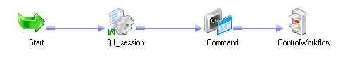
2 Chapter 1: Using the Workflow Manager
Overview
In the Workflow Manager, you define a set of instructions called a workflow to execute
mappings you build in the Designer. Generally, a workflow contains a session and any other
task you may want to perform when you run a session. Tasks can include a session, email
notification, or scheduling information. You connect each task with links in the workflow.
You can also create a worklet in the Workflow Manager. A worklet is an object that groups a
set of tasks. A worklet is similar to a workflow, but without scheduling information. You can
run a batch of worklets inside a workflow.
After you create a workflow, you run the workflow in the Workflow Manager and monitor it
in the Workflow Monitor. For more information about the Workflow Monitor, see
“Monitoring Workflows” on page 495.
Workflow Manager Options
You can customize the Workflow Manager default options to control the behavior and look of
the Workflow Manager tools. You can also configure options, such as grouping sessions or
docking and undocking windows. For more information, see “Customizing Workflow
Manager Options” on page 6.
Workflow Manager Tools
To create a workflow, you first create tasks such as a session, which contains the mapping you
build in the Designer. You then connect tasks with conditional links to specify the order of
execution for the tasks you created. The Workflow Manager consists of three tools to help you
develop a workflow:
♦Task Developer. Use the Task Developer to create tasks you want to run in the workflow.
♦Workflow Designer. Use the Workflow Designer to create a workflow by connecting tasks
with links. You can also create tasks in the Workflow Designer as you develop the
workflow.
♦Worklet Designer. Use the Worklet Designer to create a worklet.
Figure 1-1 shows what a workflow might look like if you want to run a session, perform a
shell command after the session completes, and then stop the workflow:
Figure 1-1. Sample Workflow
Overview 3
Workflow Tasks
You can create the following types of tasks in the Workflow Manager:
♦Assignment. Assigns a value to a workflow variable. For more information, see “Working
with the Assignment Task” on page 144.
♦Command. Specifies a shell command to run during the workflow. For more information,
see “Using Workflow Variables” on page 106.
♦Control. Stops or aborts the workflow. For more information about the Control task, see
“Stopping or Aborting the Workflow” on page 132.
♦Decision. Specifies a condition to evaluate. For more information, see “Working with the
Decision Task” on page 153.
♦Email. Sends email during the workflow. For more information about the Email task, see
“Sending Email” on page 361.
♦Event-Raise. Notifies the Event-Wait task that an event has occurred. For more
information, see “Working with Event Tasks” on page 157.
♦Event-Wait. Waits for an event to occur before executing the next task. For more
information, see “Working with Event Tasks” on page 157.
♦Session. Runs a mapping you create in the Designer. For more information about the
Session task, see “Working with Sessions” on page 177.
♦Timer. Waits for a timed event to trigger. For more information, see “Scheduling a
Workflow” on page 116.
Workflow Manager Windows
The Workflow Manager displays the following windows to help you create and organize
workflows:
♦Navigator. You can connect to and work in multiple repositories and folders. In the
Navigator, the Workflow Manager displays a red icon over invalid objects.
♦Works pac e. You can create, edit, and view tasks, workflows, and worklets.
♦Output. Contains tabs to display different types of output messages. The Output window
contains the following tabs:
−Save. Displays messages when you save a workflow, worklet, or task. The Save tab
displays a validation summary when you save a workflow or a worklet.
−Fetch Log. Displays messages when the Workflow Manager fetches objects from the
repository.
−Validate. Displays messages when you validate a workflow, worklet, or task.
−Copy. Displays messages when you copy repository objects.
−Server. Displays messages from the Integration Service.
−Notifications. Displays messages from the Repository Service.
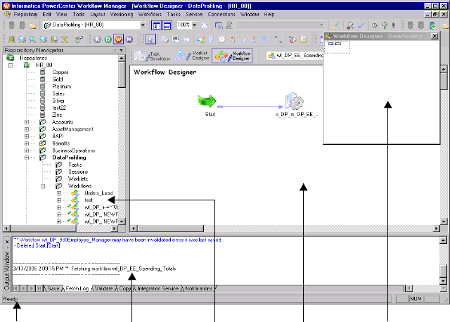
4 Chapter 1: Using the Workflow Manager
♦Overview. An optional window that lets you easily view large workflows in the workspace.
Outlines the visible area in the workspace and highlights selected objects in color. Click
View > Overview Window to display this window.
You can view a list of open windows and switch from one window to another in the Workflow
Manager. To view the list of open windows, click Window > Windows.
The Workflow Manager also displays a status bar that shows the status of the operation you
perform.
Figure 1-2 shows the Workflow Manager windows:
Setting the Date/Time Display Format
The Workflow Manager displays the date and time formats configured in the Windows
Control Panel of the PowerCenter Client machine. To modify the date and time formats,
display the Control Panel and open Regional Settings. Set the date and time formats on the
Date and Time tabs.
Note: For the Timer task and schedule settings, the Workflow Manager displays date in short
date format and the time in 24-hour format (HH:mm).
Removing an Integration Service from the Workflow Manager
You can remove an Integration Service from the Navigator. You might need to remove an
Integration Service if the Integration Service no longer exists or if you no longer use that
Figure 1-2. Workflow Manager Windows
Status Bar Output Navigator Workspace Overview
Overview 5
Integration Service. When you remove an Integration Service with associated workflows,
assign another Integration Service to the workflows.
To remove an Integration Service, you must have the Use Workflow Manager privilege.
To delete an Integration Service:
1. In the Navigator, right-click on the Integration Service you want to delete.
2. Click Delete.
6 Chapter 1: Using the Workflow Manager
Customizing Workflow Manager Options
You can customize the Workflow Manager default options to control the behavior and look of
the Workflow Manager tools.
To configure Workflow Manager options, click Tools > Options. You can configure the
following options:
♦General. You can configure workspace options, display options, and other general options
on the General tab. For more information about the General tab, see “Configuring
General Options” on page 6.
♦Format. You can configure font, color, and other format options on the Format tab. For
more information about the Format tab, see “Configuring Format Options” on page 9.
♦Miscellaneous. You can configure Copy Wizard and Versioning options on the
Miscellaneous tab. For more information about the Miscellaneous tab, see “Configuring
Miscellaneous Options” on page 11.
♦Advanced. You can configure enhanced security for connection objects in the Advanced
tab. For more information about the Advanced tab, see “Enabling Enhanced Security” on
page 13.
Configuring General Options
General options control tool behavior, such as whether or not a tool retains its view when you
close it, how the Overview window behaves, and where the Workflow Manager stores
workspace files.
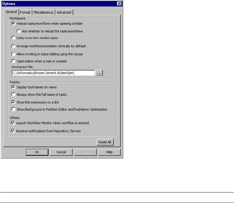
Customizing Workflow Manager Options 7
Figure 1-3 shows the Workflow Manager general options:
Table 1-1 describes general options you can configure in the Workflow Manager:
Figure 1-3. Workflow Manager General Options
Table 1-1. Workflow Manager General Options
Option Description
Reload Tasks/
Workflows When
Opening a Folder
Reloads the last view of a tool when you open it. For example, if you have a workflow open
when you disconnect from a repository, select this option so that the same workflow appears
the next time you open the folder and Workflow Designer. Default is enabled.
Ask Whether to Reload
the Tasks/Workflows
Appears when you select Reload tasks/workflows when opening a folder. Select this option if
you want the Workflow Manager to prompt you to reload tasks, workflows, and worklets each
time you open a folder. Default is disabled.
Delay Overview
Window Pans
By default, when you drag the focus of the Overview window, the focus of the workbook
moves concurrently. When you select this option, the focus of the workspace does not
change until you release the mouse button. Default is disabled.
Arrange Workflows/
Worklets Vertically By
Default
Arranges tasks in workflows vertically by default. Default is disabled.
Allow Invoking In-Place
Editing Using the
Mouse
By default, you can press F2 to edit objects directly in the workspace instead of opening the
Edit Task dialog box. Select this option so you can also click the object name in the
workspace to edit the object. Default is disabled.

8 Chapter 1: Using the Workflow Manager
Open Editor When a
Task Is Created
Opens the Edit Task dialog box when you create a task. By default, the Workflow Manager
creates the task in the workspace. If you do not enable this option, double-click the task to
open the Edit Task dialog box. Default is disabled.
Workspace File
Directory
Directory for workspace files created by the Workflow Manager. Workspace files maintain
the last task or workflow you saved. This directory should be local to the PowerCenter Client
to prevent file corruption or overwrites by multiple users. By default, the Workflow Manager
creates files in the PowerCenter Client installation directory.
Display Tool Names on
Views
Displays the name of the tool in the upper left corner of the workspace or workbook. Default
is enabled.
Always Show the Full
Name of Tasks
Shows the full name of a task when you select it. By default, the Workflow Manager
abbreviates the task name in the workspace. Default is disabled.
Show the Expression
on a Link
Shows the link condition in the workspace. If you do not enable this option, the Workflow
Manager abbreviates the link condition in the workspace. Default is enabled.
Show Background in
Partition Editor and
Pushdown Optimization
Displays background color for objects in iconic view. Disable this option to remove
background color from objects in iconic view. Default is disabled.
Launch Workflow
Monitor when Workflow
Is Started
Launches Workflow Monitor when you start a workflow or a task. Default is enabled.
Receive Notifications
from Repository
Service
You can receive notification messages in the Workflow Manager and view them in the Output
window. Notification messages include information about objects that another user creates,
modifies, or deletes. You receive notifications about sessions, tasks, workflows, and
worklets. The Repository Service notifies you of the changes so you know objects you are
working with may be out of date. For the Workflow Manager to receive a notification, the
folder containing the object must be open in the Navigator, and the object must be open in
the workspace. You also receive user-created notifications posted by the Repository Service
administrator. Default is enabled.
Reset All Reset all format options to the default values.
Table 1-1. Workflow Manager General Options
Option Description
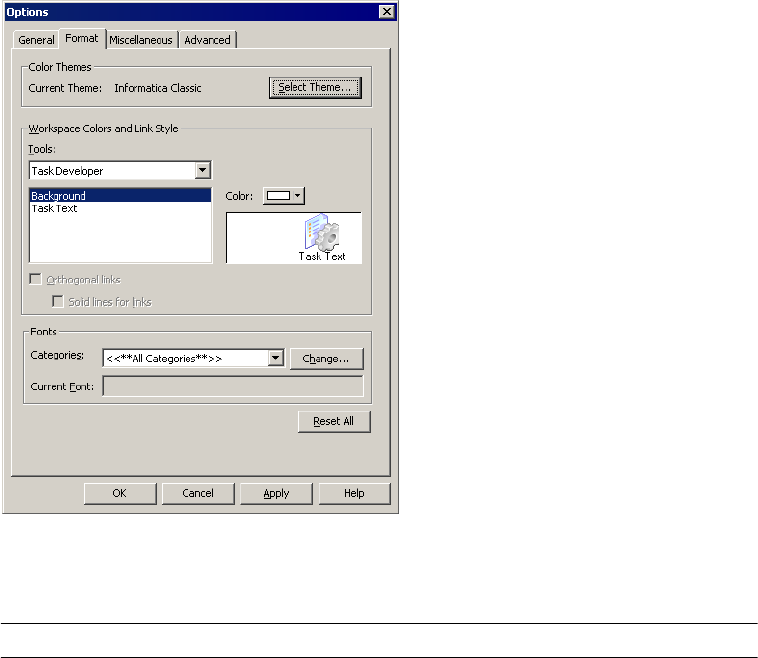
Customizing Workflow Manager Options 9
Configuring Format Options
Format options control workspace colors and fonts. You can configure format options for
each Workflow Manager tool.
Figure 1-4 shows the Workflow Manager format options:
Table 1-2 describes the format options for the Workflow Manager:
Figure 1-4. Workflow Manager Format Options
Table 1-2. Workflow Manager Format Options
Option Description
Current Theme Currently selected color theme for the Workflow Manager tools. This field is display-only.
Select Theme Apply a color theme to the Workflow Manager tools. For more information about color
themes, see “Using Color Themes” on page 10.
Tools Workflow Manager tool that you want to configure. When you select a tool, the configurable
workspace elements appear in the list below Tools menu.
Color Color of the selected workspace element.
Orthogonal Links Link lines run horizontally and vertically but not diagonally in the workspace.
Solid Lines for Links Links appear as solid lines. By default, the Workflow Manager displays orthogonal links as
dotted lines.
Categories Component of the Workflow Manager that you want to customize.

10 Chapter 1: Using the Workflow Manager
Using Color Themes
Use color themes to quickly select the colors of the workspace elements in all the Workflow
Manager tools. You can choose from the following standard color themes:
♦Informatica Classic. This is the standard color scheme for workspace elements. The
workspace background is gray, the workspace text is white, and the link colors are blue,
red, blue-gray, dark green, and black.
♦High Contrast Black. Bright link colors stand out against the black background.The
workspace background is black, the workspace text is white, and the link colors are purple,
red, light blue, bright green, and white.
♦Colored Backgrounds. Each Designer tool has a different pastel-colored workspace
background. The workspace text is black, and the link colors are the same as in the
Informatica Classic color theme.
Note: You can also apply a color theme to the Designer tools. For more information, see
“Using the Designer” in the Designer Guide.
After you select a color theme for the Workflow Manager tools, you can modify the color of
individual workspace elements.
To select a color theme for a Workflow Manager tool:
1. In the Workflow Manager, click Tools > Options.
2. Click the Format tab.
3. In the Color Themes section of the Format tab, click Select Theme.
Change Change the display font and language script for the selected category.
Current Font Font of the Workflow Manager component that is currently selected in the Categories menu.
This field is display-only.
Reset All Reset all format options to the default values.
Table 1-2. Workflow Manager Format Options
Option Description
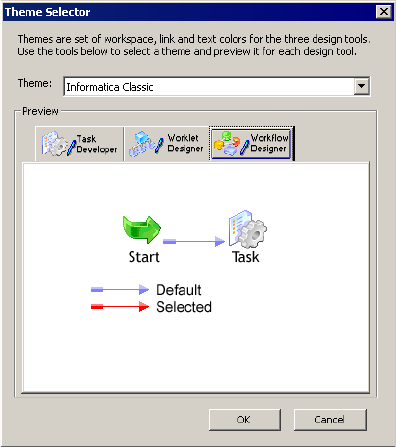
Customizing Workflow Manager Options 11
The Theme Selector dialog box appears.
4. Select a theme from the Theme menu.
5. Click the tabs in the Preview section to see how the workspace elements appear in each of
the Workflow Manager tools.
6. Click OK to apply the color theme.
Note: After you select the workspace colors using a color theme, you can change the color of
individual workspace elements. Changes that you make to individual elements do not appear
in the Preview section of the Theme Selector dialog box. For information about customizing
individual workspace elements, see “Configuring Format Options” on page 9.
Configuring Miscellaneous Options
Miscellaneous options control the display settings and available functions of the Copy
Wizard, versioning, and target load options. Target options control how the Integration
Service loads targets. To configure the Copy Wizard, Versioning, and Target Load Type
options, click Tools > Options and select the Miscellaneous tab.
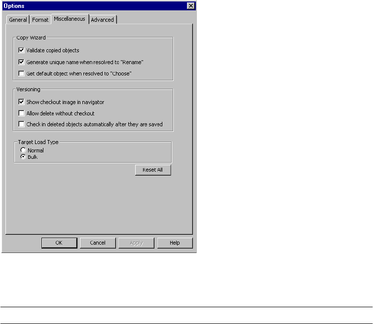
12 Chapter 1: Using the Workflow Manager
Figure 1-5 shows the Workflow Manager miscellaneous options:
Table 1-3 describes the Copy Wizard, versioning, and target load type options:
Figure 1-5. Miscellaneous Options
Table 1-3. Workflow Manager Miscellaneous Options
Option Description
Validate Copied Objects Validates the copied object. Enabled by default.
Generate Unique Name When
Resolved to “Rename”
Generates unique names for copied objects if you select the Rename option. For
example, if the workflow wf_Sales has the same name as a workflow in the
destination folder, the Rename option generates the unique name wf_Sales1.
Default is enabled.
Get Default Object When
Resolved to “Choose”
Uses the object with the same name in the destination folder if you select the
Choose option. Default is disabled.
Show Check Out Image in
Navigator
Displays the Check Out icon when an object has been checked out. Default is
enabled.
Allow Delete Without Checkout You can delete versioned repository objects without first checking them out. You
cannot, however, delete an object that another user has checked out. When you
select this option, the Repository Service checks out an object to you when you
delete it. Default is disabled.
Check In Deleted Objects
Automatically After They Are
Saved
Checks in deleted objects after you save the changes to the repository. When you
clear this option, the deleted object remains checked out and you must check it in
from the results view. Default is disabled.

Customizing Workflow Manager Options 13
Enabling Enhanced Security
The Workflow Manager has an enhanced security option so that you can specify a default set
of permissions for connection objects.
When you enable enhanced security, the Workflow Manager assigns default permissions for
connection objects to the object owner, owner group, and all other users. You can assign read,
write, and execute permissions to an object, and specify permission for users and groups you
add in the Permissions dialog box when you edit a connection.
Table 1-4 lists the default permissions to a connection object:
If you do not enable enhanced security, the Workflow Manager assigns Read, Write, and
Execute permissions to all users or groups for the connection.
Enabling enhanced security does not lock the restricted access settings for connection objects.
You can continue to change the permissions for connection objects after enabling enhanced
security.
If you delete the Owner from the repository, the Workflow Manager assigns ownership of the
object to Administrator.
To enable enhanced security for connection objects:
1. Click Tools > Options.
2. Click the Advanced Tab.
Target Load Type Sets default load type for sessions. You can choose normal or bulk loading.
Any change you make takes effect after you restart the Workflow Manager.
You can override this setting in the session properties. Default is Bulk.
For more information about normal and bulk loading, see Table A-17 on page 733.
Reset All Resets all Miscellaneous options to the default values.
Table 1-4. Default Permissions for Connection Objects
User Default Connection Object Permissions
Owner Read/Write/Execute
Owner Group Read/Execute
World No permissions
Table 1-3. Workflow Manager Miscellaneous Options
Option Description
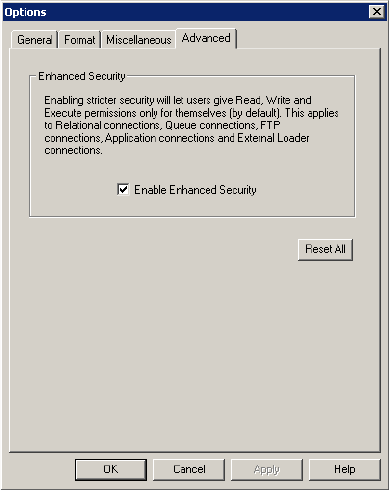
14 Chapter 1: Using the Workflow Manager
3. Select Enable Enhanced Security.
4. Click OK.
Navigating the Workspace 15
Navigating the Workspace
The Workflow Manager lets you perform the following operations to navigate the workspace:
♦Customize windows.
♦Customize toolbars.
♦Search for tasks, links, events and variables.
♦Arrange objects in the workspace.
♦Zoom and pan the workspace.
Customizing Workflow Manager Windows
You can customize the following options for the Workflow Manager windows:
♦Display a window. From the menu, select View. Then select the window you want to
open.
♦Close a window. Click the small x in the upper right corner of the window.
♦Dock or undock a window. Double-click the title bar or drag the title bar toward or away
from the workspace.
Using Toolbars
The Workflow Manager can display the following toolbars to help you select tools and
perform operations quickly:
♦Standard. Contains buttons to connect to and disconnect from repositories and folders,
toggle windows, zoom in and out, pan the workspace, and find objects.
♦Connections. Contains buttons to create and edit connections, and assign Integration
Services.
♦Repository. Contains buttons to connect to and disconnect from repositories and folders,
export and import objects, save changes, and print the workspace.
♦View. Contains buttons to customize toolbars, toggle the status bar and windows, toggle
full-screen view, create a new workbook, and view the properties of objects.
♦Layout. Contains buttons to arrange and restore objects in the workspace, find objects,
zoom in and out, and pan the workspace.
♦Tasks. Contains buttons to create tasks.
♦Workflow. Contains buttons to edit workflow properties.
♦Run. Contains buttons to schedule the workflow, start the workflow, or start a task.
♦Versioning. Contains buttons to check in objects, undo checkouts, compare versions, list
checked-out objects, and list repository queries.
♦To o ls . Contains buttons to connect to the other PowerCenter Client applications. When
you use a Tools button to open another PowerCenter Client application, PowerCenter uses
the same repository connection to connect to the repository and opens the same folders.
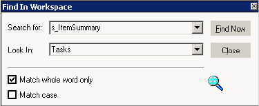
16 Chapter 1: Using the Workflow Manager
You can perform the following operations with toolbars:
♦Display or hide a toolbar.
♦Create a new toolbar.
♦Add or remove buttons.
For more information about how to perform these toolbar operations, see “Using the
Designer” in the Designer Guide.
Searching for Items
The Workflow Manager includes search features to help you find tasks, links, variables, events
in the workspace, and text in the Output window. You can search for items in any Workflow
Manager tool or Output window.
There are two ways to search for items in the workspace:
♦Find in Workspace. Searches multiple items at once and returns a list of all task names,
link conditions, event names, or variable names that contain the search string.
♦Find Next. Searches through items one at a time and highlights the first task, link, event,
variable, or text string that contains the search string. If you repeat the search, the
Workflow Manager highlights the next item that contains the search string.
To find a task, link, event, or variable in the workspace:
1. In any Workflow Manager tool, click the Find in Workspace toolbar button or click Edit
> Find in Workspace.
The Find in Workspace dialog box appears.
2. Choose whether you want to search for tasks, links, variables, or events.
3. Enter a search string, or select a string from the list.
The Workflow Manager saves the last 10 search strings in the list.
4. Specify whether or not to match whole words and whether or not to perform a case-
sensitive search.
5. Click Find Now.
The Workflow Manager lists task names, link conditions, event names, or variable names
that match the search string at the bottom of the dialog box.
6. Click Close.
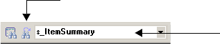
Navigating the Workspace 17
To find a single object:
1. To search for a task, link, event, or variable, open the appropriate Workflow Manager
tool and click a task, link, or event. To search for text in the Output window, click the
appropriate tab in the Output window.
2. Enter a search string in the Find field on the standard toolbar.
The search is not case sensitive.
3. Click Edit > Find Next, click the Find Next button on the toolbar, or press Enter or F3 to
search for the string.
The Workflow Manager highlights the first task name, link condition, event name, or
variable name that contains the search string, or the first string in the Output window
that matches the search string.
4. To search for the next item, press Enter or F3 again.
The Workflow Manager alerts you when you have searched through all items in the
workspace or Output window before it highlights the same objects a second time.
Arranging Objects in the Workspace
The Workflow Manager can arrange objects in the workspace horizontally or vertically. In the
Task Manager, you can also arrange tasks evenly in the workspace by choosing Tile. To
arrange objects in the workspace, click Layout > Arrange and choose Horizontal, Vertical, or
Tile. To display the links as horizontal and vertical lines, click Layout > Orthogonal Links.
Zooming the Workspace
You can zoom and pan the workspace to adjust the view.
Use the following toolbar or Layout menu options to set zoom levels:
♦Zoom Center In/Out by 10%. Increases or decreases the magnification by 10%
increments while maintaining the center of the view.
♦Zoom Point In/Out by 10%. Uses a point you select as the center point and increases or
decreases the magnification by 10% increments.
♦Zoom Rectangle. Increases the current magnification of a rectangular area you select.
Degree of magnification depends on the size of the area you select, workspace size, and
current magnification.
♦Zoom Normal. Sets the zoom level to 100%.
♦Scale to Fit. Scales all workspace objects to fit the workspace.
Find Next Button
Find Field
18 Chapter 1: Using the Workflow Manager
♦Zoom Percent. Sets the zoom level to the percent you choose while maintaining the center
of the view.
To maximize the size of the workspace window, click View > Full Screen. To go back to
normal view, click the Close Full Screen button or press Esc.
To pan the workspace, click Layout > Pan or click the Pan button on the toolbar. Drag the
focus of the workspace window and release the mouse button when it is in the appropriate
position. Double-click the workspace to stop panning.
Working with Repository Objects 19
Working with Repository Objects
Use the Workflow Manager to perform the following general operations with repository
objects:
♦View properties for each object.
♦Enter descriptions for each object.
♦Rename an object.
To edit any repository object, you must first add a repository in the Navigator so you can
access the repository object. To add a repository in the Navigator, click Repository > Add. Use
the Add Repositories dialog box to add the repository. For more information about adding
repositories, see “Using the Repository Manager” in the Repository Guide.
Viewing Object Properties
To view properties of a repository object, first select the repository object in the Navigator.
Click View > Properties to view object properties. Or, right-click the repository object and
choose Properties.
You can view properties of a folder, task, worklet, or workflow. For folders, the Workflow
Manager displays folder name and whether the folder is shared. Object properties are read-
only.
You can also view dependencies for repository objects. For more information about viewing
object dependencies, see the Repository Guide.
Entering Descriptions for Repository Objects
When you edit an object in the Workflow Manager, you can enter descriptions and comments
for that object. The maximum number of characters you can enter is 2,000 bytes/K, where K
is the maximum number of bytes a character contains in the selected repository code page.
For example, if the repository code page is a Japanese code page where each character can
contain up to two bytes (K=2), each description and comment field can contain up to 1,000
characters.
Renaming Repository Objects
You can rename repository objects by clicking the Rename button in the Edit Tasks dialog box
or the Edit Workflow dialog box. You can also rename repository objects by clicking the
object name in the workspace and typing in the new name.
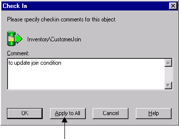
20 Chapter 1: Using the Workflow Manager
Checking In and Out Versioned Repository Objects
When you work with versioned objects, you must check out an object if you want to change
it, and save it when you want to commit the changes to the repository. You must check in the
object to allow other users to make changes to it. Checking in an object adds a new numbered
version to the object history.
Checking In Objects
You commit changes to the repository by checking in objects. When you check in an object,
the repository creates a new version of the object and assigns it a version number. The
repository increments the version number by one each time it creates a new version.
To check in an object from the Workflow Manager workspace, select the object or objects and
click Versioning > Check in.
For more information about checking out and checking in objects, see “Working with
Versioned Objects” in the Repository Guide.
If you want to check out or check in scheduler objects in the Workflow Manager, you can run
an object query to search for them. You can also check out a scheduler object in the Scheduler
Browser window when you edit the object. However, you must run an object query to check
in the object.
If you want to check out or check in session configuration objects in the Workflow Manager,
you can run an object query to search for them. You can also check out objects from the
Session Config Browser window when you edit them.
In addition, you can check out and check in session configuration and scheduler objects from
the Repository Manager. For more information about running queries to find versioned
objects, see “Searching for Versioned Objects” on page 23.
Apply the check-in comment to multiple objects.
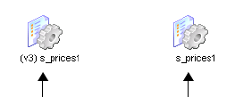
Checking In and Out Versioned Repository Objects 21
Viewing and Comparing Versioned Repository Objects
You can view and compare versions of objects in the Workflow Manager. If an object has
multiple versions, you can find the versions of the object in the View History window. In
addition to comparing versions of an object in a window, you can view the various versions of
an object in the workspace to graphically compare them.
Figure 1-6 shows two versions of an object in the Workflow Manager workspace:
Use the following rules and guidelines when you view older versions of objects in the
workspace:
♦You cannot simultaneously view multiple versions of composite objects, such as workflows
and worklets.
♦Older versions of a composite object might not include the child objects that were used
when the composite object was checked in. If you open a composite object that includes a
child object version that is purged from the repository, the preceding version of the child
object appears in the workspace as part of the composite object. For example, you might
want to view version 5 of a workflow that originally included version 3 of a session, but
version 3 of the session is purged from the repository. When you view version 5 of the
workflow, version 2 of the session appears as part of the workflow.
♦You cannot view older versions of sessions if they reference deleted or invalid mappings, or
if they do not have a session configuration.
Figure 1-6. Two Versions of the Same Object
Version 3 No number for
current version
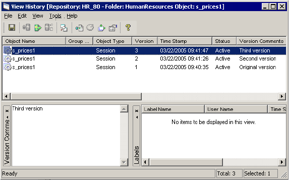
22 Chapter 1: Using the Workflow Manager
To open an older version of an object in the workspace:
1. In the workspace or Navigator, select the object and click Versioning > View History.
2. Select the version you want to view in the workspace and click Tools > Open in
Workspace.
Note: An older version of an object is read-only, and the version number appears as a
prefix before the object name. You can simultaneously view multiple versions of a non-
composite object in the workspace.
To compare two versions of an object:
1. In the workspace or Navigator, select an object and click Versioning > View History.
2. Select the versions you want to compare and then click Compare > Selected Versions.
-or-
Select a version and click Compare > Previous Version to compare a version of the object
with the previous version.
The Diff Tool appears. For more information about comparing objects in the Diff Tool,
see the Repository Guide.
Note: You can also access the View History window from the Query Results window when
you run a query. For more information about creating and working with object queries,
see “Working with Object Queries” in the Repository Guide.
Searching for Versioned Objects 23
Searching for Versioned Objects
Use an object query to search for versioned objects in the repository that meet specified
conditions. When you run a query, the repository returns results based on those conditions.
You may want to create an object query to perform the following tasks:
♦Track repository objects during development. You can add Label, User, Last saved, or
Comments parameters to queries to track objects during development. For more
information about creating object queries, see “Working with Object Queries” in the
Repository Guide.
♦Associate a query with a deployment group. When you create a dynamic deployment
group, you can associate an object query with it. For more information about working
with deployment groups, see “Copying Folders and Deployment Groups” in the Repository
Guide.
To create an object query, click Tools > Queries to open the Query Browser.
Figure 1-7 shows the Query Browser:
From the Query Browser, you can create, edit, and delete queries. You can also configure
permissions for each query from the Query Browser. You can run any queries for which you
have read permissions from the Query Browser.
Figure 1-7. Query Browser
Create a query.
Edit a query.
Delete a query.
Run a query.
Configure permissions.
24 Chapter 1: Using the Workflow Manager
Copying Repository Objects
You can copy repository objects, such as workflows, worklets, or tasks within the same folder,
to a different folder, or to a different repository. If you want to copy the object to another
folder, you must open the destination folder before you copy the object into the folder.
Use the Copy Wizard in the Workflow Manager to copy objects. When you copy a workflow
or a worklet, the Copy Wizard copies all of the worklets, sessions, and tasks in the workflow.
You must resolve all conflicts that occur. Conflicts occur when the Copy Wizard finds a
workflow or worklet with the same name in the target folder or when the connection object
does not exist in the target repository. If a connection object does not exist, you can skip the
conflict and choose a connection object after you copy the workflow. You cannot copy
connection objects. Conflicts may also occur when you copy Session tasks.
For more information about the Copy Wizard, see “Copying Objects” in the Repository Guide.
You can configure display settings and functions of the Copy Wizard by choosing Tools >
Options. For more information, see “Configuring Miscellaneous Options” on page 11.
Note: Use the Import Wizard in the Workflow Manager to import objects from an XML file.
The Import Wizard provides the same options to resolve conflicts as the Copy Wizard. For
more information, see “Exporting and Importing Objects” in the Repository Guide.
Copying Sessions
When you copy a Session task, the Copy Wizard looks for the database connection and
associated mapping in the destination folder. If the mapping or connection does not exist in
the destination folder, you can select a new mapping or connection. If the destination folder
does not contain any mapping, you must first copy a mapping to the destination folder in the
Designer before you can copy the session.
When you copy a session that has mapping variable values saved in the repository, the
Workflow Manager either copies or retains the saved variable values.
Copying Workflow Segments
You can copy segments of workflows and worklets when you want to reuse a portion of
workflow or worklet logic. A segment consists of one or more tasks, the links between the
tasks, and any condition in the links. You can copy reusable and non-reusable objects when
copying and pasting segments. You can copy segments of workflows or worklets into
workflows and worklets within the same folder, within another folder, or within a folder in a
different repository. You can also paste segments of workflows or worklets into an empty
Workflow Designer or Worklet Designer workspace.
Copying Repository Objects 25
To copy a segment from a workflow or worklet:
1. Open the workflow or worklet.
2. To select a segment, highlight each task you want to copy. You can select multiple
reusable or non-reusable objects. You can also select segments by dragging the pointer in
a rectangle around objects in the workspace.
3. Click Edit > Copy or press Ctrl+C to copy the segment to the clipboard.
4. Open the workflow or worklet into which you want to paste the segment. You can also
copy the object into the Workflow or Worklet Designer workspace.
5. Click Edit > Paste or press Ctrl+V.
The Copy Wizard opens, and notifies you if it finds copy conflicts.
Note: You can copy individual non-reusable tasks by selecting the individual task and
following the instructions for copying and pasting segments.
26 Chapter 1: Using the Workflow Manager
Comparing Repository Objects
Use the Workflow Manager to compare two repository objects of the same type to identify
differences between the objects. For example, if you have two similar Email tasks in a folder,
you can compare them to see which one contains the attributes you need. When you compare
two objects, the Workflow Manager displays their attributes in detail.
You can compare objects across folders and repositories. You must open both folders to
compare the objects. You can compare a reusable object with a non-reusable object. You can
also compare two versions of the same object. For more information about versioned objects,
see “Working with Versioned Objects” in the Repository Guide.
To compare objects, you must have read permission on each folder that contains the objects
you want to compare.
You can compare the following types of objects:
♦Tasks
♦Sessions
♦Worklets
♦Workflows
You can also compare instances of the same type. For example, if the workflows you compare
contain worklet instances with the same name, you can compare the instances to see if they
differ. Use the Workflow Manager to compare the following instances and attributes:
♦Instances of sessions and tasks in a workflow or worklet comparison. For example, when
you compare workflows, you can compare task instances that have the same name.
♦Instances of mappings and transformations in a session comparison. For example, when
you compare sessions, you can compare mapping instances.
♦The attributes of instances of the same type within a mapping comparison. For example,
when you compare flat file sources, you can compare attributes, such as file type (delimited
or fixed), delimiters, escape characters, and optional quotes.
You can compare schedulers and session configuration objects in the Repository Manager. You
cannot compare objects of different types. For example, you cannot compare an Email task
with a Session task.
When you compare objects, the Workflow Manager displays the results in the Diff Tool
window. The Diff Tool output contains different nodes for different types of objects.
When you import Workflow Manager objects, you can compare object conflicts. For more
information, see “Exporting and Importing Objects” in the Repository Guide.
Comparing Repository Objects 27
Steps for Comparing Objects
Use the following procedure to compare objects.
To compare two objects:
1. Open the folders that contain the objects you want to compare.
2. Open the appropriate Workflow Manager tool.
3. Click Tasks > Compare, Worklets > Compare, or Workflow > Compare.
A dialog box similar to the following one appears.
4. Click Browse to select an object.
5. Click Compare.
Tip: You can also compare objects from the Navigator or workspace. In the Navigator,
select the objects, right-click and select Compare Objects. In the workspace, select the
objects, right-click and select Compare Objects.
28 Chapter 1: Using the Workflow Manager
Figure 1-8 shows the result of comparing two objects:
6. To view more differences between object properties, click the Compare Further icon or
right-click the differences.
7. If you want to save the comparison as a text or HTML file, click File > Save to File.
Figure 1-8. Diff Tool Window
Drill down to
further compare
objects.
Filter nodes that
have same attribute
values.
Displays the
properties of the
node you select.
Differences
between object
properties are
marked.
Differences between
objects are
highlighted and the
nodes are flagged.
Working with Metadata Extensions 29
Working with Metadata Extensions
You can extend the metadata stored in the repository by associating information with
individual repository objects. For example, you may want to store your name with the
worklets you create. If you create a session, you can store your telephone extension with that
session. You associate information with repository objects using metadata extensions.
Repository objects can contain both vendor-defined and user-defined metadata extensions.
You can view and change the values of vendor-defined metadata extensions, but you cannot
create, delete, or redefine them. You can create, edit, delete, view user-defined metadata
extensions and change their values.
You can create metadata extensions for the following objects in the Workflow Manager:
♦Sessions
♦Workflows
♦Worklets
You can create both reusable and non-reusable metadata extensions. You associate reusable
metadata extensions with all repository objects of a certain type such as all sessions or all
worklets. You associate non-reusable metadata extensions with a single repository object such
as one workflow. For more information about metadata extensions, see “Metadata Extensions”
in the Repository Guide.
To create, edit, and delete user-defined metadata extensions in the Workflow Manager, you
must have read and write permissions on the folder.
Creating a Metadata Extension
You can create user-defined, reusable, and non-reusable metadata extensions for repository
objects using the Workflow Manager. To create a metadata extension, you edit the object for
which you want to create the metadata extension and then add the metadata extension to the
Metadata Extensions tab.
If you need to create multiple reusable metadata extensions, it is easier to create them using
the Repository Manager. For more information, see “Metadata Extensions” in the Repository
Guide.
To create a metadata extension:
1. Open the appropriate Workflow Manager tool.
2. Drag the appropriate object into the workspace.
3. Double-click the title bar of the object to edit it.
30 Chapter 1: Using the Workflow Manager
4. Click the Metadata Extensions tab.
This tab lists the existing user-defined and vendor-defined metadata extensions. User-
defined metadata extensions appear in the User Defined Metadata Domain. If they exist,
vendor-defined metadata extensions appear in their own domains.
5. Click the Add button.
A new row appears in the User Defined Metadata Extension Domain.
6. Enter the information in Table 1-5:
Table 1-5. Metadata Extension Attributes in the Workflow Manager
Field Required/
Optional Description
Extension Name Required Name of the metadata extension. Metadata extension names must
be unique for each type of object in a domain. Metadata extension
names cannot contain any special characters except underscores
and cannot begin with numbers.
Datatype Required Datatype: numeric (integer), string, or boolean.
Precision Required for string
objects
Maximum length for string metadata extensions.
User-Defined
Metadata
Extensions

Working with Metadata Extensions 31
7. Click OK.
Editing a Metadata Extension
You can edit user-defined, reusable, and non-reusable metadata extensions for repository
objects using the Workflow Manager. To edit a metadata extension, you edit the repository
object, and then make changes to the Metadata Extensions tab.
What you can edit depends on whether the metadata extension is reusable or non-reusable.
You can promote a non-reusable metadata extension to reusable, but you cannot change a
reusable metadata extension to non-reusable.
Editing Reusable Metadata Extensions
If the metadata extension you want to edit is reusable and editable, you can change the value
of the metadata extension, but not any of its properties. However, if the vendor or user who
created the metadata extension did not make it editable, you cannot edit the metadata
extension or its value. For more information, see “Metadata Extensions” in the Repository
Guide.
To edit the value of a reusable metadata extension, click the Metadata Extensions tab and
modify the Value field. To restore the default value for a metadata extension, click Revert in
the UnOverride column.
Value Optional Optional value.
For a numeric metadata extension, the value must be an integer
between -2,147,483,647 and 2,147,483,647.
For a boolean metadata extension, choose true or false.
For a string metadata extension, click the Open button in the Value
field to enter a value of more than one line, up to 2,147,483,647
bytes.
Reusable Required Makes the metadata extension reusable or non-reusable. Check to
apply the metadata extension to all objects of this type (reusable).
Clear to make the metadata extension apply to this object only
(non-reusable).
Note: If you make a metadata extension reusable, you cannot
change it back to non-reusable. The Workflow Manager makes the
extension reusable as soon as you confirm the action.
UnOverride Optional Restores the default value of the metadata extension when you
click Revert. This column appears if the value of one of the
metadata extensions was changed.
Description Optional Description of the metadata extension.
Table 1-5. Metadata Extension Attributes in the Workflow Manager
Field Required/
Optional Description
32 Chapter 1: Using the Workflow Manager
Editing Non-Reusable Metadata Extensions
If the metadata extension you want to edit is non-reusable, you can change the value of the
metadata extension and its properties. You can also promote the metadata extension to a
reusable metadata extension.
To edit a non-reusable metadata extension, click the Metadata Extensions tab. You can update
the Datatype, Value, Precision, and Description fields. For a description of these fields, see
Table 1-5 on page 30.
To make the metadata extension reusable, select Reusable. If you make a metadata extension
reusable, you cannot change it back to non-reusable. The Workflow Manager makes the
extension reusable as soon as you confirm the action.
To restore the default value for a metadata extension, click Revert in the UnOverride column.
Deleting a Metadata Extension
You can delete metadata extensions for repository objects. You delete reusable metadata
extensions using the Repository Manager. Use the Workflow Manager to delete non-reusable
metadata extensions. Edit the repository object and then delete the metadata extension from
the Metadata Extensions tab.

Keyboard Shortcuts 33
Keyboard Shortcuts
When editing a repository object or maneuvering around the Workflow Manager, use the
following Keyboard shortcuts to help you complete different operations quickly.
Table 1-6 lists the Workflow Manager keyboard shortcuts for editing a repository object:
Table 1-7 lists the Workflow Manager keyboard shortcuts for navigating in the workspace:
Table 1-6. Workflow Manager Keyboard Shortcuts
To Press
Cancel editing in a cell. Esc
Select and clear a check box. Space Bar
Copy text from a cell onto the clipboard. Ctrl+C
Cut text from a cell onto the clipboard. Ctrl+X
Edit the text of a cell. F2
Find all combination and list boxes. Type the first letter on the list.
Find tables or fields in the workspace. Ctrl+F
Move around cells in a dialog box. Ctrl+directional arrows
Paste copied or cut text from the clipboard into a cell. Ctrl+V
Select the text of a cell. F2
Table 1-7. Keyboard Shortcuts for Navigating the Workspace
To Press
Create links. Ctrl+F2. Press Ctrl+F2 to select first task you want to link.
Press Tab to select the rest of the tasks you want to link.
Press Ctrl+F2 again to link all the tasks you selected.
Edit task name in the workspace. F2
Expand selected node and all its children. SHIFT + * (use asterisk on numeric keypad )
Move across Select tasks in the workspace. Tab
Select multiple tasks. Ctrl+mouse click
34 Chapter 1: Using the Workflow Manager


36 Chapter 2: Managing Connection Objects
Overview
Before using the Workflow Manager to create workflows and sessions, you must configure
connections in the Workflow Manager.
You can configure the following connection information in the Workflow Manager:
♦Create relational database connections. Create connections to each source, target, Lookup
transformation, and Stored Procedure transformation database. You must create
connections to a database before you can create a session that accesses the database. For
more information, see “Relational Database Connections” on page 43.
♦Create FTP connections. Create a File Transfer Protocol (FTP) connection object in the
Workflow Manager and configure the connection properties. For more information, see
“FTP Connections” on page 53.
♦Create external loader connections. Create an external loader connection to load
information directly from a file or pipe rather than running the SQL commands to insert
the same data into the database. For more information, see “External Loader Connections”
on page 56.
♦Create queue connections. Create database connections for message queues. For more
information, see “PowerCenter Connect for IBM MQSeries Connections” on page 60,
“PowerCenter Connect for MSMQ Connections” on page 65 or PowerCenter Connect for
MSMQ documentation.
♦Create source and target application connections. Create connections to source and target
applications. When you create or modify a session that reads from or writes to an
application, you can select configured source and target application connections. When
you create a connection, the connection properties you need depends on the application.
For more information, see PowerExchange Interfaces for PowerCenter or one of the following
PowerCenter Connect sections in this chapter:
−PowerCenter Connect for IBM MQSeries Connections, 60
−PowerCenter Connect for JMS Connections, 63
−PowerCenter Connect for MSMQ Connections, 65
−PowerCenter Connect for PeopleSoft Connections, 66
−PowerCenter Connect for Salesforce.com Connections, 68
−PowerCenter Connect for SAP NetWeaver mySAP Option Connections, 69
−PowerCenter Connect for SAP NetWeaver BW Option Connections, 75
−PowerCenter Connect for Siebel Connections, 76
−PowerCenter Connect for TIBCO Connections, 78
−PowerCenter Connect for Web Services Connections, 82
−PowerCenter Connect for webMethods Connections, 85
For information about connection permissions and privileges, see “Permissions and Privileges
by Task” in the Repository Guide.
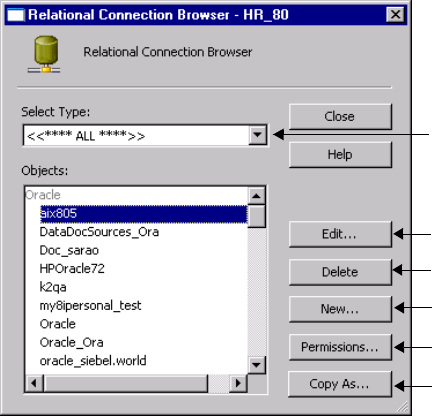
Working with Connection Objects 37
Working with Connection Objects
A connection object is a global object that defines a connection in the repository. You create
and modify connection objects in the Workflow Manager. When you create a connection
object, you define values for the connection properties. The properties vary depending on the
type of connection you create.
You can create, assign permissions, edit, and delete for all connection objects. For relational
database connections, you can also copy and replace connection objects.
To create and edit database, FTP, and external loader connections, you must have one of the
following privileges:
♦Super User
♦Manage Connection
For information about connection permissions and privileges, see “Permissions and Privileges
by Task” in the Repository Guide.
Creating Connection Objects
You use the Connection Browser to create connection objects. Open the Connection Browser
dialog box for the connection object. For example, click Connections > Relational to open the
Connection Browser dialog box for a relational database connection.
Figure 2-1 shows the Connection Browser:
Figure 2-1. Connection Browser
Select a connection object and click to edit.
Select a connection type.
Select a connection object and click to delete.
Click to create a new connection object.
Select a connection object and click to
configure permissions.
Select a relational database connection object
and click to copy.
38 Chapter 2: Managing Connection Objects
To create a connection object:
1. In the Workflow Manager, connect to a repository.
2. Click Connections and select the type of connection you want to create.
Select one of the following connection types:
♦Relational. For information about creating relational database connections, see
“Relational Database Connections” on page 43.
♦FTP. For information about creating FTP connections, see “FTP Connections” on
page 53.
♦Loader. For information about creating loader connections, see “External Loader
Connections” on page 56.
♦Queue. For information about creating queue connections, see “PowerCenter Connect
for IBM MQSeries Connections” on page 60 and “PowerCenter Connect for MSMQ
Connections” on page 65.
♦Application. For information about creating application connections, see the
appropriate PowerCenter Connect application section in this chapter or the
PowerExchange Client for PowerCenter documentation.
The Connection Browser dialog box appears, listing all the source and target connections
available for the selected connection type. See Figure 2-1.
3. Click New.
If you selected FTP as the connection type, the Connection Object dialog box appears.
Go to Step 6.
If you selected Relational, Queue, Application, or Loader connection type, the Select
Subtype dialog box appears.
4. In the Select Subtype dialog box, select the type of database connection you want to
create.
5. Click OK.
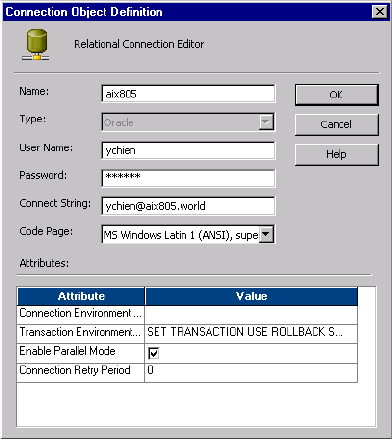
Working with Connection Objects 39
The Connection Object Definition dialog box appears.
6. Enter the properties for the type of connection object you want to create.
The Connection Object Definition dialog box displays different properties depending on
the type of connection object you create. For more information about connection object
properties, see the section for each specific connection type in this chapter.
7. Click OK.
The new database connection appears in the Connection Browser list.
8. To add more database connections, repeat steps 3 to 7.
9. Click OK to save all changes.
Connection Object Permissions
With correct permissions, you can access global connection objects from all folders in the
repository and use them in any session. You can configure and manage permissions within
each connection object. The Workflow Manager assigns Owner permissions to the user who
creates the connection. The Workflow Manager grants Owner Group permissions to the first
group in the Group Memberships list of the owner.
The Workflow Manager assigns default permissions for connection objects to the object
owner, owner’s group, and all other users if you enable enhanced security. For more
information about enhanced security, see “Enabling Enhanced Security” on page 13.
40 Chapter 2: Managing Connection Objects
You can specify read, write, and execute permissions for each user and group in the list. You
can perform the following types of tasks with different connection object permissions in
combination with user privileges and folder permissions:
♦Read. View the connection object in the Workflow Manager and Repository Manager.
When you have read permission, you can perform tasks in which you view, copy, or edit
repository objects associated with the connection object.
♦Write. Edit the connection object.
♦Execute. Run sessions that use the connection object.
For information about tasks you can perform with user privileges, folder permissions, and
connection object permissions, see “Managing Users and Groups” in the Repository Guide.
To manage connection object permissions, you must have the Manage Connection privilege
or the Super User privilege, or you must be the owner of the connection. If you do not have
the privilege to manage connection permissions, the Permissions dialog box is read-only. You
can change the owner of the object, add or remove users and groups in the permissions list,
and change the permissions for each user or group.
To view or delete a connection, you must have at least read permission for the connection. To
edit a connection, you must have read and write permissions for the connection.
You add permissions from the Connection Browser dialog box.
To configure permissions for connection objects:
1. Open the Connection Browser dialog box for the connection object. For example, click
Connections > Relational to open the Connection Browser dialog box for a relational
database connection.
2. Select the connection object you want to configure in the Connection Browser dialog
box.
3. Click Permissions to open the Permissions dialog box.
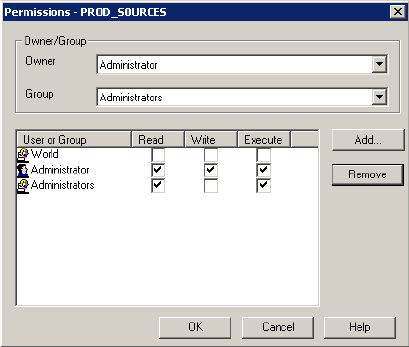
Working with Connection Objects 41
4. Select the owner and group for the connection object.
5. Add user or group you want to assign permissions for the connection, and click OK.
Editing a Connection Object
You can change connection information at any time. If you edit a connection object used by a
workflow, the Integration Service uses the updated connection information the next time the
workflow runs. You might use this functionality when moving from test to production.
To edit a connection object:
1. Open the Connection Browser dialog box for the connection object. For example, click
Connections > Relational to open the Connection Browser dialog box for a relational
database connection.
2. Click Edit.
The Connection Object Definition dialog box appears.
3. Enter the values for the properties you want to modify.
The connection properties vary depending on the type of connection you select. For
more information about connection properties, see the section for each specific
connection type in this chapter.
4. Click OK.
Deleting Connection Objects
When you delete a connection object, the Workflow Manager invalidates all sessions that use
these connections. To make the sessions valid, you must edit them and replace the missing
connections.
42 Chapter 2: Managing Connection Objects
To delete a connection object:
1. Open the Connection Browser dialog box for the connection object. For example, click
Connections > Relational to open the Connection Browser dialog box for a relational
database connection.
2. Select the connection object you want to delete in the Connection Browser dialog box.
Tip: Hold the shift key to select more than one connection to delete.
3. Click Delete.
4. Click Yes in the Confirmation dialog box.

Relational Database Connections 43
Relational Database Connections
Before the Integration Service can access a source or target database in a session, you must
configure the database connections in the Workflow Manager. When you create or modify a
session that reads from or writes to a relational database, you can select configured source and
target database connections.
When you create a connection, you must have the following information available:
♦Database name. Name for the connection.
♦Database type. Type of the source or target database.
♦Database user name. Name of a user who has the appropriate database permissions to read
from and write to the database. For more information about database user names and
passwords, see “Database User Names and Passwords” on page 43.
To use an SQL override with pushdown optimization, the user must also have permission
to create views on the source or target database.
♦Password. Database password (7-bit ASCII only).
♦Connect string. Connect string used to communicate with the database. For more
information about connect strings, see “Database Connect Strings” on page 44.
♦Database code page. Code page associated with the database. For more information about
database code pages, see “Database Connection Code Pages” on page 44.
For relational databases, you might need to run special SQL commands in the database
environment. For example, you might need to set the quoted identifier parameter. You can
set up environment SQL to run SQL commands at each connection to the database or at each
database transaction. For more information about configuring environment SQL commands,
see “Configuring Environment SQL” on page 45.
To create a database connection, you must have one of the following permissions:
♦Super User
♦Manage Connection
Database User Names and Passwords
Some database drivers, such as ISG Navigator, do not allow user names and passwords. Since
the Workflow Manager requires a database user name and password, PowerCenter provides
two reserved words to register databases that do not allow user names and passwords:
♦PmNullUser
♦PmNullPasswd
Use the PmNullUser user name if you use one of the following authentication methods:
♦Oracle OS Authentication. Oracle OS Authentication lets you log in to an Oracle
database if you have a login name and password for the operating system. You do not need
to know a database user name and password. PowerCenter uses Oracle OS Authentication

44 Chapter 2: Managing Connection Objects
when the connection user name is PmNullUser and the connection is for an Oracle
database.
♦IBM DB2 client authentication. IBM DB2 client authentication lets you log in to an
IBM DB2 database without specifying a database user name or password if the IBM DB2
server is configured for external authentication or if the IBM DB2 server is on the same
machine hosting the Integration Service process. PowerCenter uses IBM DB2 client
authentication when the connection user name is PmNullUser and the connection is for
an IBM DB2 database.
Database Connect Strings
When you create a database connection, specify a connect string for that connection. The
Integration Service uses connect strings to communicate with a database.
Table 2-1 lists the native connect string syntax for each supported database when you create
or update connections:
Database Connection Code Pages
Code pages must be compatible for accurate data movement. When you create a database
connection, you must select a code page for the connection. The code page of a database
connection must be compatible with the database client code page. If the code pages are not
compatible, sessions may hang, data may become inconsistent, or you might receive a
database error, such as:
ORA-00911: Invalid character specified.
The Workflow Manager filters the list of code pages for connections to ensure that the code
page for the connection is a subset of the code page for the repository.
If you configure the Integration Service for data code page validation, the Integration Service
enforces code page compatibility at session runtime. The Integration Service ensures that the
target database code page is a superset of the source database code page.
Table 2-1. Native Connect String Syntax
Database Connect String Syntax Example
IBM DB2 dbname mydatabase
Informix dbname@servername mydatabase@informix
Microsoft SQL Server servername@dbname sqlserver@mydatabase
Oracle dbname.world (same as TNSNAMES entry) oracle.world
Sybase ASE servername@dbname sambrown@mydatabase
Tera da t a* ODBC_data_source_name or
ODBC_data_source_name@db_name or
ODBC_data_source_name@db_user_name
TeradataODBC
TeradataODBC@mydatabase
TeradataODBC@jsmith
*Use Teradata ODBC drivers to connect to source and target databases.
Relational Database Connections 45
When you change the code page in a database connection, you must choose one that is
compatible with the previous code page. If the code pages are incompatible, the Workflow
Manager invalidates all sessions using that database connection.
If you configure the PowerCenter Client and Integration Service for relaxed code page
validation, you can select any supported code page for source and target database connections.
If you are familiar with the data and are confident that it will convert safely from one code
page to another, you can run sessions with incompatible source and target data code pages. It
is your responsibility to ensure your data will convert properly.
For more information about code page compatibility, see “Understanding Globalization” and
“Code Pages” in the Administrator Guide.
Configuring Environment SQL
The Integration Service runs environment SQL in auto-commit mode and closes the
transaction after it issues the SQL. Use SQL commands that do not depend on a transaction
being open during the entire read or write process. For example, if a source database is set to
read only mode and you create an environment SQL statement in the source connection to
set the transaction to read only, the Integration Service issues a commit after it runs the SQL
and cannot read the source in read only mode.
You configure environment SQL in the database connection. Use environment SQL for
source, target, lookup, and stored procedure connections. If the SQL syntax is not valid, the
Integration Service does not connect to the database, and the session fails.
You can configure the following types of environment SQL:
♦Connection environment SQL
♦Transaction environment SQL
Connection Environment SQL
This custom SQL string sets up the environment for subsequent transactions. The Integration
Service runs the connection environment SQL each time it connects to the database. If you
configure connection environment SQL in a target connection, and you configure three
partitions for the pipeline, the Integration Service runs the SQL three times, once for each
connection to the target database.
Use SQL commands that do not depend on a transaction being open during the entire read or
write process. For example, if you want to set up the connection environment so that double
quotation marks are object identifiers, use the following SQL statement, which sets the
quoted identifier parameter for the duration of the connection:
SET QUOTED_IDENTIFIER ON
Transaction Environment SQL
This custom SQL string also sets up the environment, but the Integration Service runs the
transaction environment SQL at the beginning of each transaction.
46 Chapter 2: Managing Connection Objects
Use SQL commands that depend on a transaction being open during the entire read or write
process. For example, you might use the following statement as transaction environment SQL
to modify how the session handles characters:
ALTER SESSION SET NLS_LENGTH_SEMANTICS=CHAR
This command must be run before each transaction. The command is not appropriate for
connection environment SQL because setting the parameter once for each connection is not
sufficient.
Guidelines for Entering Environment SQL
Consider the following guidelines when creating the SQL statements:
♦You can enter any SQL command that is valid in the database associated with the
connection object. The Integration Service does not allow nested comments, even though
the database might.
♦When you enter SQL in the SQL Editor, you type the SQL statements.
♦Use a semicolon (;) to separate multiple statements.
♦The Integration Service ignores semicolons within /*...*/.
♦If you need to use a semicolon outside of comments, you can escape it with a backslash (\).
♦You cannot use session parameters or mapping variables in the environment SQL.
♦You can configure the table owner name using sqlid in the connection environment SQL
for a DB2 connection. However, the table owner name in the target instance overrides the
SET sqlid statement in environment SQL. To use the table owner name specified in the
SET sqlid statement, do not enter a name in the target name prefix.
Database Connection Resilience
Database connection resilience is the ability of the Integration Service to tolerate temporary
network failures when connecting to a relational database or when the database becomes
unavailable. The Integration Services is resilient to failures when it initializes the connection
to the source or target database and when it reads data from or writes data to a database.
You configure the resilience retry period in the connection object. You can configure the retry
period for source, target, and Lookup transformation database connections. When a network
failure occurs or the source or target database becomes unavailable, the Integration Service
attempts to reconnect for the amount of time configured for the connection retry period. If
the Integration Service cannot reconnect to the database in the amount of time for the retry
period, the session fails.
For more information about resilience, see “Managing High Availability” in the Administrator
Guide.
Note: For a database connection to be resilient, the database must be a highly available
database and you must have the high availability option.
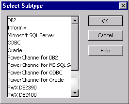
Relational Database Connections 47
Configuring a Relational Database Connection
Use the following procedure to configure a relational database connection.
To create a relational database connection:
1. In the Workflow Manager, connect to a repository.
2. Click Connections > Relational.
The Relational Connection Browser dialog box appears, listing all the source and target
database connections.
3. Click New.
The Select Subtype dialog box appears.
4. In the Select Subtype dialog box, select the type of database connection you want to
create.
5. Click OK.
48 Chapter 2: Managing Connection Objects
The Connection Object Definition dialog box appears.
6. Table 2-2 describes the properties that you configure for a relational database connection:
Table 2-2. Relational Database Connection Information
Property Required/
Optional Description
Name Required Connection name used by the Workflow Manager. Connection name
cannot contain spaces or other special characters, except for the
underscore.
Type Required Type of database.
User Name Required Database user name with the appropriate read and write database
permissions to access the database. If you use Oracle OS
Authentication, IBM DB2 client authentication, or databases such as
ISG Navigator that do not allow user names, enter PmNullUser. For
Teradata connections, this overrides the default database user name in
the ODBC entry.
Password Required Password for the database user name. For Oracle OS Authentication,
IBM DB2 client authentication, or databases such as ISG Navigator that
do not allow passwords, enter PmNullPassword. For Teradata
connections, this overrides the database password in the ODBC entry.
Passwords must be in 7-bit ASCII.
Connect String Conditional Connect string used to communicate with the database. For syntax, see
“Database Connect Strings” on page 44.
Required for all databases, except Microsoft SQL Server and Sybase
ASE.
Code Page Required Code page the Integration Service uses to read from a source database
or write to a target database or file.

Relational Database Connections 49
7. Click OK.
The new database connection appears in the Connection Browser list.
8. To add more database connections, repeat steps 3 to 7.
9. Click OK to save all changes.
Copying a Relational Database Connection
After you set up a relational database connection, you can make a copy of it by clicking the
Copy As button. The Workflow Manager lets you choose the relational database type when
you make a copy of a relational database connection.
Connection
Environment SQL
All relational
databases
Runs an SQL command with each database connection. Default is
disabled.
Transaction
Environment SQL
All relational
databases
Runs an SQL command before the initiation of each transaction.
Default is disabled.
Enable Parallel Mode Oracle Enables parallel processing when loading data into a table in bulk
mode. Default is enabled.
Database Name Sybase ASE,
Microsoft
SQL Server,
and Teradata
Name of the database. For Teradata connections, this overrides the
default database name in the ODBC entry. Also, if you do not enter a
database name here for a Teradata or Sybase ASE connection, the
Integration Service uses the default database name in the ODBC entry.
If you do not enter a database name here, connection-related
messages will not show a database name when the default database is
used.
Data Source Name Teradata Name of the Teradata ODBC data source.
Server Name Sybase ASE
and Microsoft
SQL Server
Database server name. Use to configure workflows.
Packet Size Sybase ASE
and Microsoft
SQL Server
Use to optimize the native drivers for Sybase ASE and Microsoft SQL
Server.
Domain Name Microsoft
SQL Server
The name of the domain. Used for Microsoft SQL Server on Windows.
Use Trusted
Connection
Microsoft
SQL Server
If selected, the Integration Service uses Windows authentication to
access the Microsoft SQL Server database. The user name that starts
the Integration Service must be a valid Windows user with access to the
Microsoft SQL Server database.
Connection Retry
Period
All relational
databases
Number of seconds the Integration Service attempts to reconnect to the
database if the connection fails. If the Integration Service cannot
connect to the database in the retry period, the session fails. Default
value is 0 and indicates an infinite retry period.
Table 2-2. Relational Database Connection Information
Property Required/
Optional Description
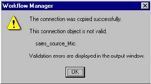
50 Chapter 2: Managing Connection Objects
When you make a copy of a relational database connection, the Workflow Manager retains
the connection properties that apply to the relational database type you select. The copy of
the connection is invalid if a required connection property is missing. Edit the connection
properties manually to validate the connection.
The Workflow Manager appends an underscore and the first three letters of the relational
database type to the name of the new database connection. For example, you have lookup
table in the same database as your source definition. You you make a copy of the Microsoft
SQL Server database connection called Dev_Source. The Workflow Manager names the new
database connection Dev_Source_Mic. You can edit the copied connection to use a different
name.
To copy a relational database connection:
1. Click Connections > Relational.
The Relational Connection Browser appears.
2. Select the connection you want to copy.
Tip: Hold the shift key to select more than one connection to copy.
3. Click Copy As.
The Select Subtype dialog box appears.
4. Select a relational database type for the copy of the connection.
If you copy one database connection object as a different type of database connection,
you must reconfigure the connection properties for the copied connection.
5. Click OK.
The Workflow Manager retains connection properties that apply to the database type. If
a required connection property does not exist, the Workflow Manager displays a warning
message. This happens when you copy a connection object as a different database type or
copy a connection object that is already invalid.
6. Click OK to close the warning dialog box.
The copy of the connection appears in the Relational Connection Browser.
7. If the copied connection is invalid, click the Edit button to enter required connection
properties.
8. Click Close to close the Relational Connection Browser dialog box.
Relational Database Connections 51
Replacing a Relational Database Connection
You can replace a relational database connection with another relational database connection.
For example, you might have several sessions that you want to write to another target
database. Instead of editing the properties for each session, you can replace the relational
database connection for all sessions in the repository that use the connection.
When you replace database connections, the Workflow Manager replaces the relational
database connections in the following locations for all sessions using the connection:
♦Source connection
♦Target connection
♦Connection Information property in Lookup and Stored Procedure transformations
♦$Source Connection Value session property
♦$Target Connection Value session property
For more information about using $Source and $Target connection variables, see “Stored
Procedure Transformation” in the Transformation Guide.
When the repository contains both relational and application connections with the same
name, the Workflow Manager replaces the relational connections only if you specified the
connection type as relational in all locations.
For example, you have a relational and an application source, each called ITEMS. In one
session, you specified the name ITEMS for a source connection instead of Relational:ITEMS.
When you replace the relational connection ITEMS with another relational connection, the
Workflow Manager does not replace any relational connection in the repository because it
cannot determine the connection type for the source connection entered as ITEMS.
The Integration Service uses the updated connection information the next time the workflow
runs.
To replace connections in the Workflow Manager, you must have Manage Connection
privilege.
You must first close all folders before replacing a relational database connection.
To replace a connection object:
1. Close all folders in the repository.
2. Click Connections > Replace.
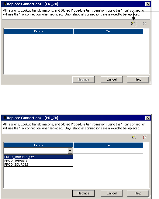
52 Chapter 2: Managing Connection Objects
The Replace Connections dialog box appears.
3. Click the Add button to replace a connection.
4. In the From list, select a relational database connection you want to replace.
5. In the To list, select the replacement relational database connection.
6. Click Replace.
All sessions in the repository that use the From connection now use the connection you
select in the To list.
Add Button
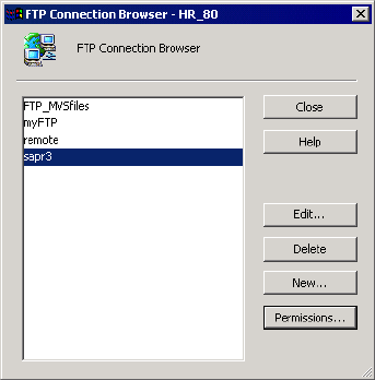
FTP Connections 53
FTP Connections
Before you can configure a session to use FTP, you must create and configure the FTP
connection properties in the Workflow Manager. The Integration Service uses the FTP
connection properties to create an FTP connection.
To create an FTP connection:
1. In the Workflow Manager, connect to a repository.
2. Click Connections > FTP.
The FTP Connection Browser appears.
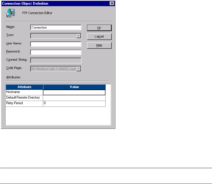
54 Chapter 2: Managing Connection Objects
3. Click New.
4. Enter the properties for the FTP connection.
Table 2-3 describes the properties that you configure for an FTP connection:
Table 2-3. FTP Connection Properties
Property Required/
Optional Description
Name Required Connection name used by the Workflow Manager.
User Name Optional User name necessary to access the host machine. Must be in 7-bit ASCII
only.
Password Optional Password for the user name. Must be in 7-bit ASCII only.
Host Name Required Host name or dotted IP address of the FTP connection.
Optionally, you can specify a port number between 1 and 65535,
inclusive. If you do not specify a port number, the Integration Service
uses 21 by default. Use the following syntax to specify the host name:
hostname:port_number
-or-
IP address:port_number
When you specify a port number, enable that port number for FTP on the
host machine.

FTP Connections 55
5. Click OK.
Rules and Guidelines for Mainframes
Use the following guidelines when creating an FTP connection to a mainframe machine:
♦If you enter a mainframe file name in the default directory for a source or target, enter the
closing quote. For example, if the file is located in the following default remote directory:
‘staging.
To access the file data from the default mainframe directory, enter the following in the
Remote file name field:
data’
When the Integration Service begins or ends the session, it connects to the mainframe host
and looks for the following directory and file name:
‘staging.data’
♦If you want to use a file in a different directory, enter the directory and file name in the
Remote file name field. For example, you might enter the following file name and
directory:
‘overridedir.filename’
Default Remote
Directory
Required Default directory on the FTP host used by the Integration Service. Do not
enclose the directory in quotation marks.
Depending on the FTP server you use, you may have limited options to
enter FTP directories. See the FTP server documentation for details.
In the session, when you enter a file name without a directory, the
Integration Service appends the file name to this directory. This path
must contain the appropriate trailing delimiter. For example, if you enter
c:\staging\ and specify data.out in the session, the Integration Service
reads the path and file name as c:\staging\data.out.
For SAP, you can leave this value blank. SAP sessions use the Source
File Directory session property for the FTP remote directory. If you enter
a value, the Source File Directory session property overrides it.
Retry Period Optional Number of seconds the Integration Service attempts to reconnect to the
FTP host if the connection fails. If the Integration Service cannot
reconnect to the FTP host in the retry period, the session fails.
Default value is 0 and indicates an infinite retry period.
Table 2-3. FTP Connection Properties
Property Required/
Optional Description
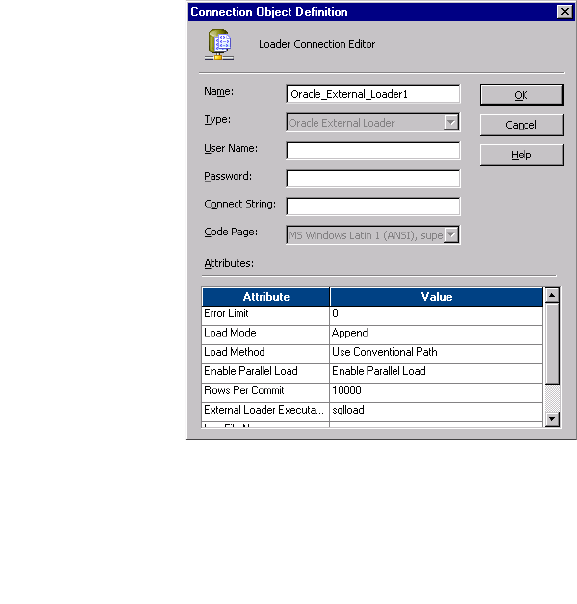
56 Chapter 2: Managing Connection Objects
External Loader Connections
You configure external loader properties in the Workflow Manager when you create an
external loader connection. You can also override the external loader connection in the
session properties. The Integration Service uses external loader properties to create an external
loader connection.
When you configure external loader settings, you may need to consult the database
documentation for more information. For more information about external loaders, see
“External Loading” on page 615.
To create an external loader connection:
1. Click Connections > Loader in the Workflow Manager.
The Loader Connection Browser dialog box appears.
2. Click New.
3. Select an external loader type, and then click OK.
The Loader Connection Editor dialog box appears.
4. Enter a name for the external loader connection.
5. Enter the database user name, password, and connect string.
Enter the PmNullUser user name and PmNullPasswd if you use Oracle OS
Authentication or IBM DB2 client authentication. PowerCenter uses Oracle OS
Authentication when the connection user name is PmNullUser and the connection is to

External Loader Connections 57
an Oracle database. PowerCenter uses IBM DB2 client authentication when the
connection user name is PmNullUser and the connection is to an IBM DB2 database.
When you use Teradata, you can enter PmNullPasswd as the database password to
prevent the password from appearing in the control file. Instead, the Integration Service
writes an empty string for the password in the control file.
6. Enter the loader properties.
For information about properties for a specific external loader type, see “External
Loading” on page 615.
7. Click OK.
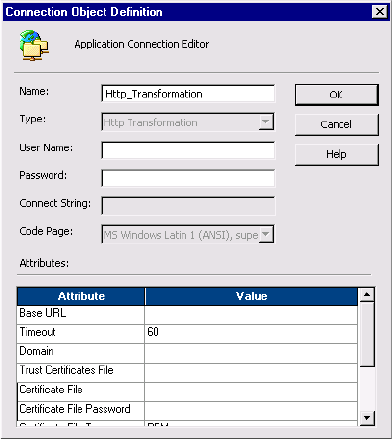
58 Chapter 2: Managing Connection Objects
HTTP Connections
You configure connection information for an HTTP transformation in an HTTP application
connection. The Integration Service can use HTTP application connections to connect to
HTTP servers. HTTP application connections enable you to control connection attributes,
including the base URL and other parameters.
Configure an HTTP application connection in the following circumstances:
♦The HTTP server requires authentication.
♦You want to configure the connection timeout.
♦You want to override the base URL in the HTTP transformation.
To configure an HTTP application connection:
1. In the Workflow Manager, connect to a PowerCenter repository.
2. Check Connections > HTTP.
The HTTP Connection Browser dialog box appears.
3. From Select Type, select HTTP.
4. Click New.
The Connect Object Definition dialog box appears.
5. Enter a name for the HTTP connection.

HTTP Connections 59
6. Enter values for the connection attributes.
7. Click OK.
The HTTP connection appears in the Application Connection Browser.
HTTP Connection
Attributes
Required/
Optional Description
User name Required Authenticated username for the HTTP server. If the HTTP server
does not require authentication, enter PmNullUser.
Password Required Password for the authenticated user. If the HTTP server does not
require authentication, enter PmNullPasswd.
Base URL Optional URL of the HTTP server. This value overrides the base URL defined
in the HTTP transformation.
Timeout Optional Number of seconds the Integration Service waits for a connection to
the HTTP server before it closes the connection.
Domain Optional Authentication domain for the HTTP server. This is required for NTLM
authentication. For more information about authentication with an
HTTP transformation, see “HTTP Transformation” in the
Transformation Guide.
Trust Certificates File Optional File containing the bundle of trusted certificates that the client uses
when authenticating the SSL certificate of a server. You specify the
trust certificates file to have the Integration Service authenticate the
web service provider. By default, the name of the trust certificates file
is ca-bundle.crt.
Certificate File Optional Client certificate that an HTTP server uses when authenticating a
client. You specify the client certificate file if the HTTP server needs
to authenticate the Integration Service.
Certificate File Password Optional Password for the client certificate. You specify the certificate file
password if the HTTP server needs to authenticate the Integration
Service.
Certificate File Type Required File type of the client certificate. You specify the certificate file type if
the HTTP server needs to authenticate the Integration Service. The
file type can be PEM or DER. Default is PEM.
Private Key File Optional Private key file for the client certificate. You specify the private key
file if the web service provider needs to authenticate the Integration
Service.
Key Password Optional Password for the private key of the client certificate. You specify the
key password if the web service provider needs to authenticate the
Integration Service.
Key File Type Required File type of the private key of the client certificate. You specify the key
file type if the HTTP server needs to authenticate the Integration
Service. The HTTP transformation uses the PEM file type for SSL
authentication.

60 Chapter 2: Managing Connection Objects
PowerCenter Connect for IBM MQSeries Connections
Before the Integration Service can extract data from an MQSeries source or load data to an
MQSeries target, you must configure a queue connection for source and target queues in the
Workflow Manager. The queue connection you set in the Workflow Manager is saved in the
repository.
To create an IBM MQSeries queue connection:
1. In the Workflow Manager, connect to a repository.
2. Click Connections > Queue.
The Queue Connection Browser appears.
3. Click New.
4. Select Message Queue as the subtype and click OK.
The Connection Object Definition dialog box appears.
5. Enter the connection information.
Table 2-4 describes the properties that you configure for an IBM MQSeries connection:
6. Click OK.
The new queue connection appears in the Message Queue connection list.
7. To add more connections, repeat steps 3 to 6.
To edit or delete a queue connection, select the queue connection from the list and click the
appropriate button.
Table 2-4. IBM MQSeries Connection Properties
Property Required/
Optional Description
Name Required Name you want to use for this connection.
Queue Manager Required Name of the queue manager for the message queue.
Queue Name Required Name of the message queue.
Connection Retry Period Required Number of seconds the Integration Service attempts to
reconnect to the IBM MQSeries queue if the connection fails.
If the Integration Service cannot reconnect to the IBM
MQSeries queue in the retry period, the session fails. Default
value is 0 and indicates an infinite retry period.
For more information about resiliency for PowerCenter
Connect for IBM MQSeries, see “Creating and Configuring
MQSeries workflows” in the PowerCenter Connect for IBM
MQSeries User and Administrator Guide.
PowerCenter Connect for IBM MQSeries Connections 61
Test Queue Connections
Before you use PowerCenter Connect for IBM MQSeries to extract data from message queues
or load data to message queues, you can test the queue connections configured in the
Workflow Manager. If the connections are not valid, the Integration Service cannot connect
to the source or target message queues at run time. You can test queue connections by using
IBM MQ tools provided with the IBM MQ Server.
Testing a Queue Connection on Windows
Use the following procedure to test a queue connection on Windows.
To test a queue connection on Windows:
1. From the command prompt of the MQSeries server machine, go to the <mqseries>\bin
directory.
2. Use one of the following commands to test the connection for the queue:
♦amqsputc. Use if you installed the MQSeries client on the Integration Service
machine.
♦amqsput. Use if you installed the MQSeries server on the Integration Service machine.
The amqsputc and amqsput commands put a new message on the queue. If you test the
connection to a queue in a production environment, terminate the command to avoid
writing a message to a production queue.
For example, to test the connection to the queue “production,” which is administered by
the queue manager “QM_s153664.informatica.com,” enter one of the following
commands:
amqsputc production QM_s153664.informatica.com
-or-
amqsput production QM_s153664.informatica.com
If the connection is valid, the command returns a connection acknowledgment. If the
connection is not valid, it returns an MQSeries error message.
3. If the connection is successful, press Ctrl+C at the prompt to terminate the connection
and the command.
Testing a Queue Connection on UNIX
Use the following procedure to test a queue connection on UNIX.
To test a queue connection on UNIX:
1. On the MQSeries Server system, go to the <mqseries>/samp/bin directory.
2. Use one of the following commands to test the connection for the queue:
♦amqsputc. Use if you installed the MQSeries client on the Integration Service
machine.
62 Chapter 2: Managing Connection Objects
♦amqsput. Use if you installed the MQSeries server on the Integration Service machine.
The amqsputc and amqsput commands put a new message on the queue. If you test the
connection to a queue in a production environment, make sure you terminate the
command to avoid writing a message to a production queue.
For example, to test the connection to the queue “production,” which is administered by
the queue manager “QM_s153664.informatica.com,” enter one of the following
commands:
amqsputc production QM_s153664.informatica.com
-or-
amqsput production QM_s153664.informatica.com
If the connection is valid, the command returns a connection acknowledgment. If the
connection is not valid, it returns an MQSeries error message.
3. If the connection is successful, press Ctrl+C at the prompt to terminate the connection
and the command.

PowerCenter Connect for JMS Connections 63
PowerCenter Connect for JMS Connections
Before the Integration Service can extract data from JMS sources or write data to JMS targets,
you must configure application connections for JMS sources and targets in the Workflow
Manager. The Integration Service uses application connections to connect to a JMS provider
during a session to read and write JMS messages. The application connections you define in
the Workflow Manager are saved in the PowerCenter repository.
You must configure two types of JMS application connections:
♦JNDI application connection
♦JMS application connection
Connection Properties for JNDI Application Connections
Configure a JNDI application connection to connect to a JNDI server during a session.
When the Integration Service connects to the JNDI server, it retrieves information from
JNDI about the JMS provider during the session. When you configure a JNDI application
connection, you must specify connection properties in the Connection Object Definition
dialog box. For more information about PowerCenter and JNDI integration, see
“Understanding PowerCenter Connect for JMS” in the PowerCenter Connect for JMS User
and Administrator Guide.
Table 2-5 describes the properties that you configure for a JNDI application connection:
For more information about JNDI, see the JMS documentation.
Connection Properties for JMS Application Connections
Configure a JMS application connection to connect to JMS providers during a PowerCenter
session to read source messages or write target messages. When you configure a JMS
application connection, you specify connection properties the Integration Service uses to
connect to JMS providers during a PowerCenter session. Specify the JMS application
connection properties in the Connection Object Definition dialog box.
Table 2-5. JNDI Application Connection Properties
Property Required/
Optional Description
JNDI Context Factory Required Enter the name of the context factory that you specified when you defined
the context factory for your JMS provider.
JNDI Provider URL Required Enter the provider URL that you specified when you defined the provider
URL for your JMS provider.
JNDI UserName Optional Enter a user name.
JNDI Password Optional Enter a password.

64 Chapter 2: Managing Connection Objects
Table 2-6 describes the properties that you configure for a JMS application connection:
For more information about JMS and JNDI, see the JMS documentation.
Creating JNDI and JMS Application Connections
Use the following procedure to configure JNDI and JMS application connections.
To create JNDI and JMS application connections:
1. In the Workflow Manager, connect to a PowerCenter repository.
2. Click Connections > Application.
The Application Connection Browser dialog box appears.
3. From Select Type, select JNDI Connection or JMS Connection.
4. Click New.
The Connection Object Definition dialog box appears.
5. Enter a name for the application connection.
6. Enter the connection information.
7. Click OK.
The new application connection appears in the Application Connection Browser.
Table 2-6. JMS Application Connection Properties
Property Required/
Optional Description
JMS Destination Type Required Select QUEUE or TOPIC for the JMS Destination Type. Select
QUEUE if you want to read source messages from a JMS provider
queue or write target messages to a JMS provider queue. Select
TOPIC if you want to read source messages based on the message
topic or write target messages with a particular message topic.
JMS Connection Factory Name Required Enter the name of the connection factory. The name of the connection
factory must be the same as the connection factory name you
configured in JNDI. The Integration Service uses the connection
factory to create a connection with the JMS provider.
JMS Destination Required Enter the name of the destination. The destination name must match
the name you configured in JNDI.
JMS UserName Optional Enter a user name.
JMS Password Optional Enter a password.

PowerCenter Connect for MSMQ Connections 65
PowerCenter Connect for MSMQ Connections
Before the Integration Service can extract data from an MSMQ source or load data to an
MSMQ target, you must configure the queue connection for the source or target queue in the
Workflow Manager. The queue connection you set in the Workflow Manager is saved in the
repository.
To create an MSMQ queue connection:
1. In the Workflow Manager, connect to a PowerCenter repository.
2. Click Connections > Queue.
The Queue Connection Browser dialog box displays.
3. From Select Type, select MSMQ.
4. Click New.
The Connect Object Definition dialog box appears.
5. Enter a name for the queue connection.
6. Select a code page.
The code page must match the code page of the source. For more information, see
“Database Connection Code Pages” on page 44.
7. Enter the connection information.
Table 2-7 describes the properties that you configure for an MSMQ connection:
8. Click OK.
The new queue connection appears in the Message Queue connection list.
Table 2-7. MSMQ Connection Properties
Property Required/
Optional Description
Queue Name Required Name of the MSMQ queue.
Machine Name Required Name of the MSMQ machine. If MSMQ is running on the same machine as
the Integration Service, you can enter a period (.).
Queue Type Required Select public if the MSMQ queue is a public queue. Select private if the
MSMQ queue is a private queue.

66 Chapter 2: Managing Connection Objects
PowerCenter Connect for PeopleSoft Connections
Before the Integration Service can access PeopleSoft sources, configure an application
connection for the PeopleSoft source database in the Workflow Manager.
The application connection defines how the Integration Service accesses the underlying
database for the PeopleSoft system. When you run a session using PeopleSoft sources, the
Integration Service extracts data from the underlying physical database tables of the
PeopleSoft system.
To create a PeopleSoft application connection:
1. In the Workflow Manager, connect to a repository.
2. Click Connections > Application.
The Application Connection Browser appears.
3. Select the PeopleSoft application type and click New.
The Connection Object Definition dialog box appears.
4. Enter the connection information.
Table 2-8 describes the properties that you configure for a PeopleSoft application
connection:
Table 2-8. PeopleSoft Application Connection Properties
Property Required/
Optional Description
Name Required Name you want to use for this connection.
User Name Required Database user name with SELECT permission on physical database tables in the
PeopleSoft source system.
Password Required Password for the database user name. Must be in US-ASCII.
Connect
String
Conditional Connect string for the underlying database of the PeopleSoft system. For more
information, see Table 2-1 on page 44. This option appears for DB2, Oracle, and
Informix.
Code Page Required Code page the Integration Service uses to extract data from the source database.
When using relaxed code page validation, select compatible code pages for the
source and target data to prevent data inconsistencies.
For more information about code pages, “Code Pages and Language Codes” in
the PowerCenter Connect for PeopleSoft User and Administrator Guide.
Language
Code
Optional PeopleSoft language code. Enter a language code for language-sensitive data.
When you enter a language code, the Integration Service extracts language-
sensitive data from related language tables. If no data exists for the language
code, the PowerCenter extracts data from the base table.
When you do not enter a language code, the Integration Service extracts all data
from the base table. For a list of PeopleSoft language codes, see “Code Pages
and Language Codes” in the PowerCenter Connect for PeopleSoft User and
Administrator Guide.

PowerCenter Connect for PeopleSoft Connections 67
Use the native connect string syntax in Table 2-1 on page 44.
5. Click OK.
The new application connection appears in the Application Object Browser.
6. To add more application connections, repeat steps 3 to 5.
7. Click OK to save all changes.
Database
Name
Optional Name of the underlying database of the PeopleSoft system. This option appears
for Sybase ASE and Microsoft SQL Server.
Server
Name
Required Name of the server for the underlying database of the PeopleSoft system. This
option appears for Sybase ASE and Microsoft SQL Server.
Domain
Name
Required Domain name for Microsoft SQL Server on Windows.
Packet Size Optional Packet size used to transmit data. This option appears for Sybase ASE and
Microsoft SQL Server.
Use Trusted
Connection
Optional If selected, the Integration Service uses Windows authentication to access the
Microsoft SQL Server database. The user name that enables the Integration
Service must be a valid Windows user with access to the Microsoft SQL Server
database. This option appears for Microsoft SQL Server.
Rollback
Segment
Optional Name of the rollback segment for the underlying database of the PeopleSoft
system. This option appears for Oracle.
Environment
SQL
Optional SQL commands used to set the environment for the underlying database of the
PeopleSoft system.
Table 2-8. PeopleSoft Application Connection Properties
Property Required/
Optional Description

68 Chapter 2: Managing Connection Objects
PowerCenter Connect for Salesforce.com Connections
Before the Integration Service can extract data from Salesforce sources or write data to
Salesforce targets, you must configure an application connection for Salesforce sources and
targets. The application connection stores the Salesforce user ID, password, and end point
URL information for the run-time connection. Each Salesforce source or target in a mapping
references a Salesforce application connection object. You can use multiple Salesforce
application connections in a mapping to access different sets of Salesforce data for the sources
and targets. You use the Workflow Manager to assign the Salesforce application connections
to the sources and targets.
To configure Salesforce application connections:
1. In the Workflow Manager, connect to a repository.
2. Click Connections > Application.
The Application Connection Browser dialog box appears.
3. From Select Type, select Salesforce Connection.
4. Click New.
The Connection Object Definition dialog box appears.
5. Enter a name for the application connection.
6. Enter the Salesforce user name for the application connection.
The Integration Service uses this user name to log in to Salesforce.com.
7. Enter the password for the Salesforce user name.
8. Enter a value for the connection attribute.
Table 2-9 describes the connection attribute for a Salesforce application connection:
9. Click OK.
The new application connection appears in the Application Object Browser.
Table 2-9. Salesforce Application Connection Attribute
Connection
Attribute
Required/
Optional Description
Service URL Required URL of the Salesforce service you want to access.
Default is https://www.salesforce.com/services/Soap/u/7.0.
In a test or development environment, you might want to access the Salesforce
Sandbox testing environment. For more information about the Salesforce
Sandbox, see your Salesforce documentation.

PowerCenter Connect for SAP NetWeaver mySAP Option Connections 69
PowerCenter Connect for SAP NetWeaver mySAP
Option Connections
Before the PowerCenter Integration Service can read data from SAP or write data to SAP, you
must configure connections in the Workflow Manager. When you configure a connection,
you specify properties that the Integration Service uses to connect to a source or target during
a session.
Depending on the method of integration with mySAP applications, configure the following
types of connections:
♦SAP R/3 application connection. Configure application connections to access the SAP
system when you run a stream or file mode session. For more information about
configuring SAP R/3 connections, see “Configuring an SAP R/3 Application Connection
for ABAP Integration” on page 70.
♦FTP connection. Configure FTP connections to access the staging file through FTP. For
more information about configuring FTP connections, see “Configuring an FTP
Connection for ABAP Integration” on page 71.
♦SAP_ALE _IDoc_Reader and SAP_ALE _IDoc_Writer connections. Configure
SAP_ALE_IDoc_Reader connections to receive IDocs and business content integration
documents using ALE. Configure SAP_ALE_IDoc_Writer connections to send IDocs
using ALE. for more information about configuring SAP_ALE_IDoc_Writer connections,
see “Configuring Application Connections for ALE Integration” on page 71.
♦SAP RFC/BAPI interface connection. Configure SAP RFC/BAPI Interface connections if
you want to process data in SAP using RFC/BAPI function mappings. For more
information about configuring SAP RFC/BAPI connections, see “Configuring an
Application Connection for RFC/BAPI Integration” on page 73.
Table 2-10 describes the type of connection you need depending on the method of integration
with mySAP applications:
Table 2-10. Types of Connections for SAP Sessions
Connection Type Integration Method
SAP R/3 application connection ABAP integration with stream and file mode sessions.
FTP connection ABAP integration with file mode sessions.
SAP_ALE _IDoc_Reader connection IDoc ALE and business content integration.
SAP_ALE _IDoc_Writer connection IDoc ALE and business content integration.
SAP RFC/BAPI interface connection RFC/BAPI integration.
70 Chapter 2: Managing Connection Objects
Configuring an SAP R/3 Application Connection for ABAP
Integration
Before you can configure a session, you need to create a source connection to the SAP system.
The application connections for SAP sources use one of the following connections:
♦CPI-C. Use a CPI-C connection when you extract data through stream mode. The
connection information for CPI-C is stored in the sideinfo file.
♦RFC. Use an RFC connection when you extract data through file mode. The connection
information for RFC is stored in the saprfc.ini file. You must also have authorizations on
the SAP system to read SAP tables and to run file mode and stream mode sessions.
Configuring an Application Connection for a Stream Mode Session
When you configure an application connection for a stream mode session, the connect string
you use in the application connection must match the connect string in the sideinfo file. For
example, if the connect string in the sideinfo file is defined in lowercase, use lowercase to
enter the connect string parameter in the application connection configuration.
Configuring one Application Connection for Stream and File Mode
Sessions
You can create separate application connections for file and stream mode, or you can create
one connection for both file and stream mode. Create separate entries if the SAP
administrator creates separate authorization profiles.
To create one connection for both modes, the following conditions must be true:
♦The saprfc.ini file and the sideinfo file must have the same entries for connect string and
client.
♦The SAP administrator must have created a single profile with authorizations for both file
and stream mode sessions. For more information about creating a profile, see PowerCenter
Connect for SAP Netweaver User Guide.
Steps for Configuring an SAP R/3 Application Connection
Complete the following procedure to configure an SAP R/3 application connection.
To create an SAP R/3 application connection:
1. In the Workflow Manager, connect to a repository.
2. Click Connections > Application.
The Application Connection Browser dialog box appears.
3. From the Select Type list, select SAP R3 as the application connection type.
4. Click New.
The Connection Object Definition dialog box appears.

PowerCenter Connect for SAP NetWeaver mySAP Option Connections 71
5. Enter the following information for the application connection, depending on whether
you are configuring an application connection for a stream or file mode session.
Table 2-11 describes the properties that you configure for an SAP R/3 connection:
6. Click OK.
The new application connection appears in the Application Connection Browser list.
7. To add more application connections, repeat steps 3 to 6.
8. Click Close.
Configuring an FTP Connection for ABAP Integration
When you run a file mode session, you can configure the session to access the staging file on
the SAP system through FTP. Before you can access a file using FTP, you must configure an
FTP connection in the Workflow Manager. For more information about creating an FTP
connection, see “FTP Connections” on page 53.
Configuring Application Connections for ALE Integration
To receive outbound IDocs and business content integration documents from SAP using
ALE, create an SAP_ALE_IDoc_Reader application connection in the Workflow Manager.
To send inbound IDocs to SAP using ALE, create an SAP_ALE_IDoc_Writer application
connection in the Workflow Manager.
Table 2-11. SAP R/3 Application Connection Properties
Property Values for CPI-C (Stream Mode) Values for RFC (File Mode)
Name Connection name used by the Workflow
Manager.
Connection name used by the Workflow
Manager.
User Name SAP user name with authorization on
S_CPIC and S_TABU_DIS objects.
SAP user name with authorization on
S_DATASET, S_TABU_DIS, S_PROGRAM,
and B_BTCH_JOB objects.
Password Password for the SAP user name. Password for the SAP user name.
Connect String DEST entry in the sideinfo file. Type A DEST entry in the saprfc.ini file.
Code Page* Code page compatible with the SAP
server. The code page must correspond to
the Language Code.
Code page compatible with the SAP server.
The code page must correspond to the
Language Code.
Client Code SAP client number. SAP client number.
Language Code* Language code that corresponds to the
SAP language.
Language code that corresponds to the SAP
language.
* For more information about code pages, see the PowerCenter Administrator Guide. For more information about selecting a language
code, see the PowerCenter Connect for SAP NetWeaver User and Administrator Guide.

72 Chapter 2: Managing Connection Objects
Configuring an SAP_ALE_IDoc_Reader Application Connection
Configure the SAP_ALE_IDoc_Reader connection properties with the Type R destination
entry from the saprfc.ini file. Make sure the Program ID for this destination entry is the same
as the Program ID for the logical system you defined in SAP to receive IDocs or consume
business content data. For business content integration, set to INFACONTNT. For more
information, see PowerCenter Connect for SAP Netweaver User Guide.
To create an SAP_ALE_IDoc_Reader application connection:
1. In the Workflow Manager, connect to a repository.
2. Click Connections > Application.
The Application Connection Browser dialog box appears.
3. From the Select Type list, select SAP_ALE_IDoc_Reader as the application connection
type for outbound IDoc or business content integration sessions.
4. Click New.
The Connection Object Definition dialog box appears.
5. Enter the connection information.
Table 2-12 describes the properties that you configure for an SAP_ALE_IDoc_Reader
application connection:
6. Click OK.
The new application connection appears in the Application Connection Browser list.
7. Click Close.
Configuring an SAP_ALE_IDoc_Writer Application Connection
Configure the SAP_ALE_IDoc_Writer connection properties with the Type A destination
entry from the saprfc.ini file.
Table 2-12. SAP_ALE_IDoc_Reader Application Connection Properties
Property Required/
Optional Description
Name Required Connection name used by the Workflow Manager.
Code Page Required Code page compatible with the SAP server. For more information about
code pages, see the “Database Connection Code Pages” on page 44.
Destination Entry Required Type R DEST entry in the saprfc.ini file. The Program ID for this
destination entry must be the same as the Program ID for the logical
system you defined in SAP to receive IDocs or consume business
content data. For business content integration, set to INFACONTNT. For
more information, see the PowerCenter Connect for SAP Netweaver
User Guide.

PowerCenter Connect for SAP NetWeaver mySAP Option Connections 73
To create an SAP_ALE_IDoc_Writer application connection:
1. In the Workflow Manager, connect to a repository.
2. Click Connections > Application.
The Application Connection Browser dialog box appears.
3. From the Select Type list, select SAP_ALE_IDoc_Writer as the application connection
type for inbound IDoc sessions.
4. Click New.
The Connection Object Definition dialog box appears.
5. Enter the connection information.
Table 2-13 describes the properties that you configure for an SAP_ALE_IDoc_Writer
application connection:
6. Click OK.
The new application connection appears in the Application Connection Browser list.
7. Click Close.
Configuring an Application Connection for RFC/BAPI Integration
If you generate RFC/BAPI function mappings in the Designer to process data in SAP, you
must create an application connection of the SAP RFC/BAPI Interface type in the Workflow
Table 2-13. SAP_ALE_IDoc_Writer Application Connection Properties
Property Required/
Optional Description
Name Required Connection name used by the Workflow Manager.
User Name Required SAP user name with authorization on S_DATASET, S_TABU_DIS,
S_PROGRAM, and B_BTCH_JOB objects.
Password Required Password for the SAP user name.
Note: If you want to run a session on Linux 32-bit for an IDoc mapping
from PowerCenter Connect for SAP R/3 6.x, and you want to connect to
SAP 4.60, enter the password in upper case. The SAP system must also
use upper case passwords.
Connect String Required Type A DEST entry in the saprfc.ini file.
Code Page* Required Code page compatible with the SAP server. Must also correspond to the
Language Code.
Language Code* Required Language code that corresponds to the SAP language.
Client Code Required SAP client number.
* For more information about code pages, see the PowerCenter Administrator Guide. For more information about selecting a language
code, see the PowerCenter Connect for SAP NetWeaver User Guide.

74 Chapter 2: Managing Connection Objects
Manager. The PowerCenter Integration Service uses this connection to connect to SAP and
make RFC/BAPI function calls to extract, transform, or load data.
To create an application connection of the SAP RFC/BAPI Interface type:
1. In the Workflow Manager, connect to a repository.
2. Click Connections > Application.
The Application Connection Browser dialog box appears.
3. From the Select Type list, select SAP RFC/BAPI Interface as the application connection
type.
4. Click New.
The Connection Object Definition dialog box appears.
5. Enter the connection properties for the connection.
Table 2-14 describes the properties that you configure for an SAP RFC/BAPI application
connection:
6. Click OK.
The new application connection appears in the Application Connection Browser list.
7. Click Close.
Table 2-14. SAP RFC/BAPI Application Connection Properties
Property Required/
Optional Description
Name Required Connection name used by the Workflow Manager.
User Name Required SAP user name with authorization on S_DATASET, S_TABU_DIS,
S_PROGRAM, and B_BTCH_JOB objects.
Password Required Password for the SAP user name.
Note: If you want to run a session on Linux 32-bit for an RFC/BAPI mapping,
and you want to connect to SAP 4.60, enter the password in upper case. The
SAP system must also use upper case passwords.
Connect String Required Type A DEST entry in the saprfc.ini file.
Code Page* Required Code page compatible with the SAP server. Must also correspond to the
Language Code.
Language Code* Required Language code that corresponds to the SAP language.
Client Code Required SAP client number.
* For more information about code pages, see the PowerCenter Administrator Guide. For more information about selecting a
language code, see the PowerCenter Connect for SAP NetWeaver User Guide.

PowerCenter Connect for SAP NetWeaver BW Option Connections 75
PowerCenter Connect for SAP NetWeaver BW Option
Connections
Before you can run a session that writes data to SAP BW, create an application connection for
each SAP BW target system in the Workflow Manager. When you create or modify a session
that writes to SAP BW, you can select only SAP BW connections configured with the
Workflow Manager.
To create a connection to the SAP BW system:
1. In the Workflow Manager, connect to a repository.
2. Click Connections > Application.
The Application Connection Browser dialog box appears.
3. From the Select Type list, select SAP BW.
4. Click New.
The Connection Object Definition dialog box appears.
5. Enter the connection information.
Table 2-15 describes the properties that you configure for a SAP BW connection:
6. Click OK.
The SAP BW target system appears in the list of registered sources and targets.
7. Click Close.
Table 2-15. SAP BW Application Connection Properties
Property Required/
Optional Description
Name Required Connection name used by the Workflow Manager.
Username Required SAP BW username.
Password Required SAP BW password.
Code Page* Required Code page compatible with the SAP BW server.
Client Code Required SAP BW client. Must match the client you use to log on to the SAP BW server.
Language Code* Optional Language code that corresponds to the code page.
*For more information about code pages, see PowerCenter Connect for SAP NetWeaver User Guide.

76 Chapter 2: Managing Connection Objects
PowerCenter Connect for Siebel Connections
Before the Integration Service can access Siebel sources in a session, you must create an
application connection in the Workflow Manager. The Workflow Manager saves application
connections in the repository.
The application connection defines how the Integration Service accesses the underlying
database for the Siebel system. When you run a workflow using Siebel sources, the
Integration Service extracts data from the underlying physical database tables of the Siebel
system.
To create a Siebel application connection:
1. In the Workflow Manager, connect to a repository.
2. Click Connections > Application.
The Application Connection Browser appears.
3. Select a Siebel application type and click New.
The Connection Object Definition dialog box appears.
4. Enter the connection information.
Table 2-16 describes the properties that you configure for a Siebel application
connection:
Table 2-16. Siebel Application Connection Properties
Property Required/
Optional Description
Name Required Name you want to use for this connection.
User Name Required Database user name with SELECT permission on physical database tables in
the Siebel source system.
Password Required Password for the database user name. Must be in US-ASCII.
Connect String Conditional Connect string for the underlying database of the Siebel system. For more
information, see Table 2-1 on page 44. This option appears for DB2, Oracle,
and Informix.
Code Page Required Specifies the code page the Integration Service uses to extract data from the
source database. When using relaxed code page validation, select compatible
code pages for the source and target data to prevent data inconsistencies.
For more information about code pages, see the PowerCenter Administrator
Guide.
Database Name Optional Name of the underlying database of the Siebel system. This option appears for
Sybase ASE and Microsoft SQL Server.
Server Name Required Host name for the underlying database of the Siebel system. This option
appears for Sybase ASE and Microsoft SQL Server.
Domain Name Required Domain name for Microsoft SQL Server on Windows.

PowerCenter Connect for Siebel Connections 77
Use the native connect string syntax in Table 2-1 on page 44.
5. Click OK.
The new application connection appears in the Application Connection Browser.
6. To add more application connections, repeat steps 3 to 5.
7. Click OK to save all changes.
Packet Size Optional Packet size used to transmit data. This option appears for Sybase ASE and
Microsoft SQL Server.
Use Trusted
Connection
Optional If selected, the Integration Service uses Windows authentication to access the
Microsoft SQL Server database. The user name that starts the Integration
Service must be a valid Windows user with access to the Microsoft SQL
Server database. This option appears for Microsoft SQL Server.
Rollback Segment Optional Name of the rollback segment for the underlying database of the Siebel
system. This option appears for Oracle.
Environment SQL Optional SQL commands used to set the environment for the underlying database of
the Siebel system.
Table 2-16. Siebel Application Connection Properties
Property Required/
Optional Description

78 Chapter 2: Managing Connection Objects
PowerCenter Connect for TIBCO Connections
Before the Integration Service can extract data from TIBCO sources or write data to TIBCO
targets, you must configure an application connection for TIBCO sources and targets in the
Workflow Manager. The Integration Service uses the application connection to connect to
TIBCO during a session to read and write TIBCO messages.
You can configure the following TIBCO application connection types:
♦TIB/Rendezvous. Configure to read or write messages in TIB/Rendezvous format.
♦TIB/Adapter SDK. Configure read or write messages in AE format.
Connection Properties for TIB/Rendezvous Application
Connections
Configure a TIB/Rendezvous application connection to connect to TIBCO during a session
to read source messages or write target messages in TIB/Rendezvous format. When you
configure a TIB/Rendezvous application connection, you specify connection properties for
the Integration Service to connect to fa TIBCO daemon during a session. Specify connection
properties in the Connection Object Definition dialog box.
Table 2-17 describes the properties you configure for a TIB/Rendezvous application
connection:
Table 2-17. TIB/Rendezvous Application Connection Properties
Connection
Attributes
Required/
Optional Description
Name Required Name you want to use for this connection.
Code Page Required Code page the Integration Service uses to extract data from the TIBCO. When using
relaxed code page validation, select compatible code pages for the source and target
data to prevent data inconsistencies.
Subject Required Default subject for source and target messages. During a session, the Integration
Service reads messages with this subject from TIBCO sources. It also writes messages
with this subject to TIBCO targets.
You can overwrite the default subject for TIBCO targets when you link the SendSubject
port in a TIBCO target definition in a mapping. For more information about the
SendSubject field in TIBCO target definitions, see “Working with TIBCO Targets” in the
PowerCenter Connect for TIBCO User and Administrator Guide.
For more information about subject names, see the TIBCO documentation.
Service Optional Service attribute value. Enter a value if you want to include a service name, service
number, or port number. For more information about the service attribute, see the
TIBCO documentation.
Network Optional Network attribute value. Enter a value if your machine contains more than one network
card. For more information about specifying a network attribute, see the TIBCO
documentation.

PowerCenter Connect for TIBCO Connections 79
Connection Properties for TIB/Adapter SDK Connections
Configure a TIB/Adapter SDK application connection to connect to TIB/Adapter SDK
during a session to read source messages or write target messages in AE format. When you
configure a TIB/Adapter SDK connection, you specify properties for the TIBCO adapter
instance through which you want to connect to TIBCO during a session. Specify connection
properties in the Connection Object Definition dialog box.
Daemon Optional TIBCO daemon you want to connect to during a session. If you leave this option blank,
the Integration Service connects to the local daemon during a session.
If you want to specify a remote daemon, which resides on a different host than the
Integration Service, enter the following values:
<remote hostname>:<port number>
For example, you can enter host2:7501 to specify a remote daemon. For more
information about the TIBCO daemon, see the TIBCO documentation.
Certified Optional Select if you want the Integration Service to read or write certified messages. For more
information about reading and writing certified messages in a session, see “Creating
and Configuring TIBCO Workflows” in the PowerCenter Connect for TIBCO User and
Administrator Guide.
CmName Optional Unique CM name for the CM transport when you choose certified messaging. For more
information about CM transports, see the TIBCO documentation.
Relay Agent Optional Enter a relay agent when you choose certified messaging and the machine running the
Integration Service is not constantly connected to a network. The Relay Agent name
must be fewer than 127 characters. For more information about relay agents, see the
TIBCO documentation.
Ledger File Optional Enter a unique ledger file name when you want the Integration Service to read or write
certified messages. The ledger file records the status of each certified message.
Configure a file-based ledger when you want the TIBCO daemon to send unconfirmed
certified messages to TIBCO targets. You also configure a file-based ledger with
Request Old when you want the Integration Service to receive unconfirmed certified
messages from TIBCO sources. For more information about file-based ledgers, see the
TIBCO documentation.
Synchronized
Ledger
Optional Select if you want PowerCenter to wait until it writes the status of each certified
message to the ledger file before continuing message delivery or receipt.
Request Old Optional Select if you want the Integration Service to receive certified messages that it did not
confirm with the source during a previous session run. When you select Request Old,
you should also specify a file-based ledger for the Ledger File attribute. For more
information about Request Old, see the TIBCO documentation.
User
Certificate
Optional Register the user certificate with a private key when you want to connect to a secure
TIB/Rendezvous daemon during the session. The text of the user certificate must be in
PEM encoding or PKCS #12 binary format.
Username Optional Enter a user name for the secure TIB/Rendezvous daemon.
Password Optional Enter a password for the secure TIB/Rendezvous daemon.
Table 2-17. TIB/Rendezvous Application Connection Properties
Connection
Attributes
Required/
Optional Description

80 Chapter 2: Managing Connection Objects
Note: The adapter instances you specify in TIB/Adapter SDK connections should only contain
one session.
Table 2-18 describes the connection properties you configure for a TIB/Adapter SDK
application connection:
Configuring TIBCO Application Connections
Use the following procedure to configure TIB/Rendezvous or TIB/Adapter SDK application
connections.
To create a TIBCO application connection:
1. In the Workflow Manager, connect to a PowerCenter repository.
2. Click Connections > Application.
The Application Object Browser dialog box appears.
3. From Select Type, select one of the following types:
♦TIB/Rendezvous
♦TIB/Adapter SDK
4. Click New.
Table 2-18. TIB/Adapter SDK Application Connection Properties
Connection
Attributes
Required/
Optional Description
Name Required Name you want to use for this connection.
Code Page Required Code page the Integration Service uses to extract data from the TIBCO. When
using relaxed code page validation, select compatible code pages for the source
and target data to prevent data inconsistencies.
Subject Required Default subject for source and target messages. During a workflow, the
Integration Service reads messages with this subject from TIBCO sources. It also
writes messages with this subject to TIBCO targets.
You can overwrite the default subject for TIBCO targets when you link the
SendSubject port in a TIBCO target definition in a mapping. For more information
about the SendSubject field in TIBCO target definitions, see “Working with TIBCO
Targets” in the PowerCenter Connect for TIBCO User and Administrator Guide.
For more information about subject names, see the TIBCO documentation.
Application Name Required Name of an adapter instance.
Repository URL Required URL for the TIB/Repository instance you want to connect to. You can enter the
server process variable $PMSourceFileDir for the Repository URL.
Configuration URL Required URL for the adapter instance.
Session Name Required Name of the TIBCO session associated with the adapter instance.
Validate Messages Optional Select Validate Messages when you want the Integration Service to read and
write messages in AE format.
PowerCenter Connect for TIBCO Connections 81
The Connection Object Definition dialog box appears.
5. Enter a name for the application connection and verify the code page.
For more information about code pages, see “Database Connection Code Pages” on
page 44.
6. Enter the connection information.
For more information about TIB/Rendezvous application connection properties, see
“Connection Properties for TIB/Rendezvous Application Connections” on page 78. For
more information about TIB/Adapter SDK application connection properties, see
“Connection Properties for TIB/Adapter SDK Connections” on page 79.
7. Click OK.
The new TIBCO application connection appears in the Application Object Browser.
82 Chapter 2: Managing Connection Objects
PowerCenter Connect for Web Services Connections
The Integration Service can use Web Services application connections to extract data from
web service sources, write data to web service targets, or transform data using Web Services
Consumer transformations. Web Services application connections allow you to control
connection properties, including the endpoint URL and authentication parameters. You can
configure Web Services application connections in the Workflow Manager.
To connect to a web service, the Integration Service requires an endpoint URL. If you do not
configure a Web Services application connection or if you configure one without providing
an endpoint URL, the Integration Service uses the endpoint URL contained in the WSDL file
on which the source, target, or Web Services Consumer transformation is based. For more
information, see PowerCenter Connect for Web Services User and Administrator Guide.
If the web service you are using requires authentication, you must configure a Web Services
application connection.
Use the following guidelines to determine when to configure a Web Services application
connection:
♦Configure a Web Services application connection with an endpoint URL if the web service
you connect to requires authentication or if you want to use an endpoint URL that differs
from the one contained in the WSDL file.
♦Configure a Web Services application connection without an endpoint URL if the web
service you connect to requires authentication but you want to use the endpoint URL
contained in the WSDL file.
♦You do not need to configure a Web Services application connection if the web service you
connect to does not require authentication and you want to use the endpoint URL
contained in the WSDL file.
If you need to configure SSL authentication, enter values for the SSL authentication-related
properties in the Web Services application connection. For more information about SSL
authentication, see PowerCenter Connect for Web Services User and Administrator Guide.
For more information about the SSL authentication properties, see step 6 of the following
procedure.
The Repository Service saves all application connections that you define in the Workflow
Manager in the PowerCenter repository.
To create a Web Services application connection:
1. In the Workflow Manager, connect to a PowerCenter repository.
2. Click Connections > Application.
The Application Connection Browser dialog box appears.
3. From Select Type, select Web Services Consumer.
4. Click New.
The Connection Object Definition dialog box appears.

PowerCenter Connect for Web Services Connections 83
5. Enter a name for the Web Services application connection.
6. Enter the connection information.
Table 2-19 describes the properties that you configure for a Web Services application
connection:
Table 2-19. Web Service Application Connection Properties
Connection Attributes Required/
Optional Description
User Name Required User name that the web service requires. If the web service does not
require a user name, enter PmNullUser.
Password Required Password that the web service requires. If the web service does not
require a password, enter PmNullPasswd.
Code Page Required Connection code page. The Repository Service uses the character
set encoded in the repository code page when writing data to the
repository.
End Point URL Optional Endpoint URL for the web service that you want to access. The
WSDL file specifies this URL in the location element.
Domain Optional Domain for authentication.
Timeout Required Number of seconds the Integration Service waits for a connection to
the web service provider before it closes the connection and fails the
session.
Trust Certificates File Optional File containing the bundle of trusted certificates that the client uses
when authenticating the SSL certificate of a server. You specify the
trust certificates file to have the Integration Service authenticate the
web service provider. By default, the name of the trust certificates file
is ca-bundle.crt. For information about adding certificates to the trust
certificates file, see the PowerCenter Connect for Web Services User
Guide.
Certificate File Optional Client certificate that a web service provider uses when
authenticating a client. You specify the client certificate file if the web
service provider needs to authenticate the Integration Service.
Certificate File Password Optional Password for the client certificate. You specify the certificate file
password if the web service provider needs to authenticate the
Integration Service.
Certificate File Type Optional File type of the client certificate. You specify the certificate file type if
the web service provider needs to authenticate the Integration
Service. The file type can be either PEM or DER. For information
about converting the file type of certificate files, see the PowerCenter
Connect for Web Services User Guide.
Private Key File Optional Private key file for the client certificate. You specify the private key
file if the web service provider needs to authenticate the Integration
Service.

84 Chapter 2: Managing Connection Objects
7. Click OK.
The new application connection appears in the Application Connection Browser.
Key Password Optional Password for the private key of the client certificate. You specify the
key password if the web service provider needs to authenticate the
Integration Service.
Key File Type Optional File type of the private key of the client certificate. You specify the
key file type if the web service provider needs to authenticate the
Integration Service. PowerCenter Connect for Web Services requires
the PEM file type for SSL authentication. For information about
converting the file type of certificate files, see the PowerCenter
Connect for Web Services User Guide.
Table 2-19. Web Service Application Connection Properties
Connection Attributes Required/
Optional Description

PowerCenter Connect for webMethods Connections 85
PowerCenter Connect for webMethods Connections
Before the Integration Service can extract data from webMethods sources or write data to
webMethods targets, you must configure an application connection for webMethods sources
and targets in the Workflow Manager. When you configure a webMethods application
connection, you specify connection properties the Integration Service uses to connect to a
webMethods Broker during a session.
The Integration Service uses webMethods application connections to connect to a
webMethods Broker when it reads webMethods source documents and writes webMethods
target documents.
To create a webMethods application connection:
1. In the Workflow Manager, connect to a PowerCenter repository.
2. Click Connections > Application.
The Application Connection Browser dialog box appears.
3. From Select Type, select webMethods Broker.
4. Click New.
The Connection Object Definition dialog box appears.
5. Enter the connection information.
Table 2-20 describes the properties that you configure for a webMethods application
connection:
Table 2-20. webMethods Application Connection Properties
Property Required/
Optional Description
Name Required Name you want to use for this connection.
Broker Host Required Enter the host name of the Broker you want the Integration Service to connect to.
If the port number for the Broker is not the default port number, also enter the
port number. Default port number is 6849.
Enter the host name and port number in the following format:
<host name:port>
Broker Name Optional Enter the name of the Broker. If you do not enter a Broker name, the Integration
Service uses the default Broker.
Client ID Optional Enter a client ID for the Integration Service to use when it connects to the Broker
during the session. If you do not enter a client ID, the Broker generates a random
client ID.
If you select Preserve Client State, enter a client ID.
Client Group Required Enter the name of the group to which the client belongs.
Application
Name
Required Enter the name of the application that will run the Broker Client. Default is
“Informatica PowerCenter Connect for webMethods.”

86 Chapter 2: Managing Connection Objects
6. Click OK.
The new application connection appears in the Application Object Browser.
Automatic
Reconnection
Optional Select this option to enable the Integration Service to reconnect to the Broker if
the connection to the Broker is lost.
Preserve
Client State
Optional Select this option to maintain the client state across sessions. The client state is
the information the Broker keeps about the client, such as the client ID,
application name, and client group.
Preserving the client state enables the webMethods Broker to retain documents
it sends when a subscribing client application, such as the Integration Service, is
not listening for documents. Preserving the client state also allows the Broker to
maintain the publication ID sequence across sessions when writing documents
to webMethods targets.
If you select this option, configure a Client ID in the application connection. You
should also configure guaranteed storage for your webMethods Broker. For more
information about storage types, see the webMethods documentation.
If you do not select this option, the Integration Service destroys the client state
when it disconnects from the Broker.
Table 2-20. webMethods Application Connection Properties
Property Required/
Optional Description

87
Chapter 3
Working with Workflows
This chapter includes the following topics:
♦Overview, 88
♦Creating a Workflow, 91
♦Using the Workflow Wizard, 94
♦Assigning an Integration Service, 98
♦Working with Links, 100
♦Using the Expression Editor, 104
♦Using Workflow Variables, 106
♦Scheduling a Workflow, 116
♦Validating a Workflow, 125
♦Manually Starting a Workflow, 128
♦Suspending the Workflow, 130
♦Stopping or Aborting the Workflow, 132
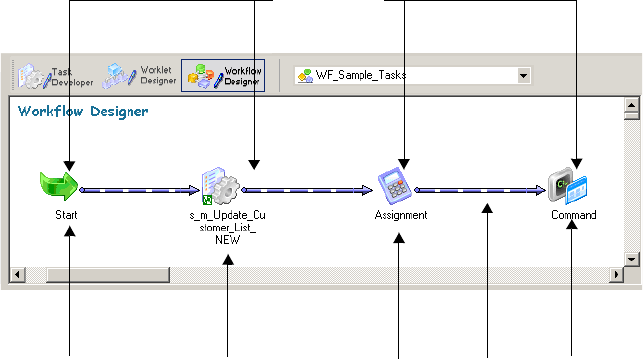
88 Chapter 3: Working with Workflows
Overview
A workflow is a set of instructions that tells the Integration Service how to run tasks such as
sessions, email notifications, and shell commands. After you create tasks in the Task
Developer and Workflow Designer, you connect the tasks with links to create a workflow.
In the Workflow Designer, you can specify conditional links and use workflow variables to
create branches in the workflow. The Workflow Manager also provides Event-Wait and Event-
Raise tasks to control the sequence of task execution in the workflow. You can also create
worklets and nest them inside the workflow.
Every workflow contains a Start task, which represents the beginning of the workflow.
Figure 3-1 shows a sample workflow:
You can create workflows with branches to run tasks concurrently.
Figure 3-1. Sample Workflow
Start Task Link
Session Task
Work
f
low Tasks
Assignment Task Command Task
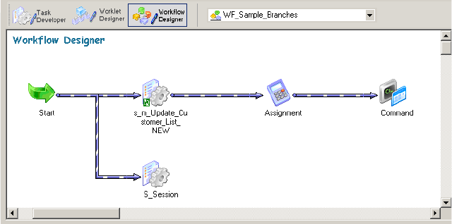
Overview 89
Figure 3-2 shows a sample workflow with two branches:
When you create a workflow, select an Integration Service to run the workflow. You can start
the workflow using the Workflow Manager, Workflow Monitor, or pmcmd.
Use the Workflow Monitor to see the progress of a workflow during its run. The Workflow
Monitor can also show the history of a workflow. For more information about the Workflow
Monitor, see “Monitoring Workflows” on page 495.
Use the following guidelines when you develop a workflow:
1. Create a workflow. Create a workflow in the Workflow Designer. For more information
about creating a new workflow, see “Creating a Workflow Manually” on page 91.
2. Add tasks to the workflow. You might have already created tasks in the Task Developer.
Or, you can add tasks to the workflow as you develop the workflow in the Workflow
Designer. For more information about workflow tasks, see “Working with Tasks” on
page 135.
3. Connect tasks with links. After you add tasks to the workflow, connect them with links
to specify the order of execution in the workflow. For more information about links, see
“Working with Links” on page 100.
4. Specify conditions for each link. You can specify conditions on the links to create
branches and dependencies. For more information, see “Working with Links” on
page 100.
5. Validate workflow. Validate the workflow in the Workflow Designer to identify errors.
For more information about validation rules, see “Validating a Workflow” on page 125.
6. Save workflow. When you save the workflow, the Workflow Manager validates the
workflow and updates the repository.
7. Run workflow. In the workflow properties, select an Integration Service to run the
workflow. Run the workflow from the Workflow Manager, Workflow Monitor, or
Figure 3-2. Sample Workflow With Two Branches
90 Chapter 3: Working with Workflows
pmcmd. You can monitor the workflow in the Workflow Monitor. For more information
about starting a workflow, see “Manually Starting a Workflow” on page 128.
For a complete list of workflow properties, see “Workflow Properties Reference” on page 757.
Workflow Privileges
You need one of the following privileges to create a workflow:
♦Use Workflow Manager privilege with read and write folder permissions
♦Super User privilege
You need one of the following privileges to run, schedule, and monitor the workflow:
♦Workflow Operator privilege
♦Super User privilege
When the Integration Service runs in safe mode, you need one of the following privileges to
run and monitor a workflow:
♦Admin Integration Service and Workflow Operator privilege
♦Super User privilege
Note: Scheduled workflows do not run when the Integration Service runs in safe mode.
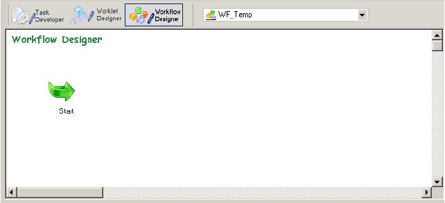
Creating a Workflow 91
Creating a Workflow
A workflow must contain a Start task. The Start task represents the beginning of a workflow.
When you create a workflow, the Workflow Designer creates a Start task and adds it to the
workflow. You cannot delete the Start task.
After you create a workflow, you can add tasks to the workflow. The Workflow Manager
includes tasks such as the Session, Command, and Email tasks.
Finally, you connect workflow tasks with links to specify the order of execution in the
workflow. You can add conditions to links.
When you edit a workflow, the Repository Service updates the workflow information when
you save the workflow. If a workflow is running when you make edits, the Integration Service
uses the updated information the next time you run the workflow.
You can create a workflow manually or automatically, or you can use the Workflow Wizard.
Creating a Workflow Manually
Use the following procedure to create a workflow manually.
To create a workflow manually:
1. Open the Workflow Designer.
2. Click Workflows > Create.
3. Enter a name for the new workflow.
4. Click OK.
The Workflow Designer creates a Start task in the workflow.
Creating a Workflow Automatically
Use the following procedure to create a workflow automatically.
92 Chapter 3: Working with Workflows
To create a workflow automatically:
1. Open the Workflow Designer. Close any open workflow.
2. Click the session button on the Tasks toolbar.
3. Click in the Workflow Designer workspace.
The Mappings dialog box appears.
4. Select a mapping to associate with the session and click OK.
The Create Workflow dialog box appears. The Workflow Designer names the workflow
wf_MappingName by default. You can rename the workflow or change other workflow
properties. For more information about workflow properties, see “Workflow Properties
Reference” on page 757.
5. Click OK.
The Workflow Designer creates a workflow for the session.
Adding Tasks to Workflows
After you create a workflow, you add tasks you want to run in the workflow. You may already
have created tasks in the Task Developer. Or, you may want to create tasks in the Workflow
Designer as you develop the workflow.
If you have already created tasks in the Task Developer, add them to the workflow by dragging
the tasks from the Navigator to the Workflow Designer workspace.
To create and add tasks as you develop the workflow, click Tasks > Create in the Workflow
Designer. Or, use the Tasks toolbar to create and add tasks to the workflow. Click the button
on the Tasks toolbar for the task you want to create. Click again in the Workflow Designer
workspace to create and add the task.
Tasks you create in the Workflow Designer are non-reusable. Tasks you create in the Task
Developer are reusable. For more information about reusable tasks, see “Reusable Workflow
Tasks” on page 139.
Deleting a Workflow
You may decide to delete a workflow that you no longer use. When you delete a workflow,
you delete all non-reusable tasks and reusable task instances associated with the workflow.
Reusable tasks used in the workflow remain in the folder when you delete the workflow.
If you delete a workflow that is running, the Integration Service aborts the workflow. If you
delete a workflow that is scheduled to run, the Integration Service removes the workflow from
the schedule.
Creating a Workflow 93
You can delete a workflow in the Navigator window, or you can delete the workflow currently
displayed in the Workflow Designer workspace:
♦To delete a workflow from the Navigator window, open the folder, select the workflow and
press the Delete key.
♦To delete a workflow currently displayed in the Workflow Designer workspace, click
Workflows > Delete.
94 Chapter 3: Working with Workflows
Using the Workflow Wizard
Use the Workflow Wizard to automate the process of creating sessions, adding sessions to a
workflow, and linking sessions to create a workflow. The Workflow Wizard creates sessions
from mappings and adds them to the workflow. It also creates a Start task and lets you
schedule the workflow. You can add tasks and edit other workflow properties after the
Workflow Wizard completes. If you want to create concurrent sessions, use the Workflow
Designer to manually build a workflow.
Before you create a workflow, verify that the folder contains a valid mapping for the Session
task.
Complete the following steps to build a workflow using the Workflow Wizard:
1. Assign a name and Integration Service to the workflow.
2. Create a session.
3. Schedule the workflow.
Step 1. Assign a Name and Integration Service to the Workflow
In the first step of the Workflow Wizard, you add the name and description of the workflow
and choose the Integration Service to run the workflow.
To create the workflow:
1. In the Workflow Manager, open the folder containing the mapping you want to use in
the workflow.
2. Open the Workflow Designer.
3. Click Workflows > Wizard.
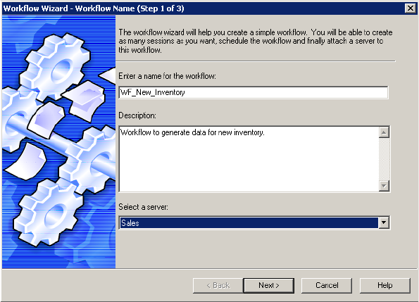
Using the Workflow Wizard 95
The Workflow Wizard appears.
4. Enter a name for the workflow.
The convention for naming workflows is wf_WorkflowName. For a complete list of
naming conventions for repository objects, see “Naming Conventions” in Getting Started.
5. Enter a description for the workflow.
6. Select the Integration Service to run the workflow and click Next.
Step 2. Create a Session
In the second step of the Workflow Wizard, you create a session based on a mapping. You can
add tasks later in the Workflow Designer workspace. For more information about working
with tasks, see “Working with Tasks” on page 135.
To create a session:
1. In the second step of the Workflow Wizard, select a valid mapping and click the right
arrow button.
The Workflow Wizard creates a Session task in the right pane using the selected mapping
and names it s_MappingName by default.
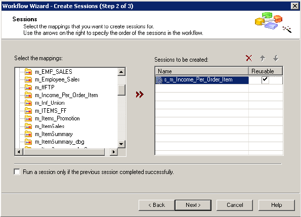
96 Chapter 3: Working with Workflows
The following figure shows a mapping selected for a session:
2. You can select additional mappings to create more Session tasks in the workflow.
When you add multiple mappings to the list, the Workflow Wizard creates sequential
sessions in the order you add them.
3. Use the arrow buttons to change the session order.
4. Specify whether the session should be reusable.
When you create a reusable session, use the session in other workflows. For more
information about reusable sessions, see “Working with Tasks” on page 135.
5. Specify how you want the Integration Service to run the workflow.
You can specify that the Integration Service runs sessions only if previous sessions
complete, or you can specify that the Integration Service always runs each session. When
you select this option, it applies to all sessions you create using the Workflow Wizard.
Step 3. Schedule a Workflow
In the third step of the Workflow Wizard, you can schedule a workflow to run continuously,
repeat at a given time or interval, or start manually. The Integration Service runs a workflow
unless the prior workflow run fails. When a workflow fails, the Integration Service removes
the workflow from the schedule, and you must reschedule it. You can do this in the Workflow
Manger or using pmcmd.
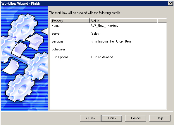
Using the Workflow Wizard 97
To schedule a workflow:
1. In the third step of the Workflow Wizard, configure the scheduling and run options.
For more information about scheduling a workflow, see “Scheduling a Workflow” on
page 116.
2. Click Next.
The Workflow Wizard displays the settings for the workflow.
3. Verify the workflow settings and click Finish. To edit settings, click Back.
The completed workflow opens in the Workflow Designer workspace. From the
workspace, you can add tasks, create concurrent sessions, add conditions to links, or
modify properties.
4. When you finish modifying the workflow, click Repository > Save.
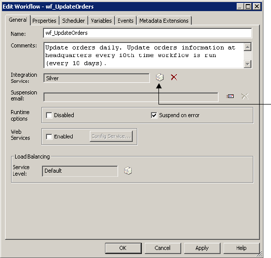
98 Chapter 3: Working with Workflows
Assigning an Integration Service
Before you can run a workflow, you must assign an Integration Service to run it. You can
choose an Integration Service to run a workflow by editing the workflow properties. You can
also assign an Integration Service from the menu. When you assign a service from the menu,
you can assign multiple workflows without editing each workflow.
Assigning a Service from the Workflow Properties
Use the following procedure to assign a service within the workflow properties.
To select an Integration Service to run a workflow:
1. In the Workflow Designer, open the Workflow.
2. Click Workflows > Edit.
The Edit Workflow dialog box appears.
3. On the General tab, click the Browse Integration Services button.
A list of Integration Services appears.
4. Select the Integration Service that you want to run the workflow.
5. Click OK twice to select the Integration Service for the workflow.
Select an Integration
Service.
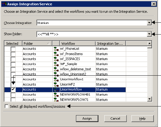
Assigning an Integration Service 99
Assigning a Service from the Menu
When you assign an Integration Service to a workflow you overwrite the service selected in
the workflow properties. To assign an Integration Service to a workflow, you must have Super
User privilege.
To assign an Integration Service to a workflow:
1. Close all folders in the repository.
2. Click Integration Service > Assign Integration Service.
-or-
Right-click the Integration Service name in the Navigator and choose Assign to
Workflows.
The Assign Integration Service dialog box appears.
3. From the Choose Integration Service list, select the service you want to assign.
4. From the Show Folder list, select the folder you want to view. Or, click All to view
workflows in all folders in the repository.
5. Click the Selected check box for each workflow you want the Integration Service to run.
6. Click Assign.
Assign an Integration
Service to a workflow.
Select a service to assign.
Select a folder.
Select all workflows and
sessions.
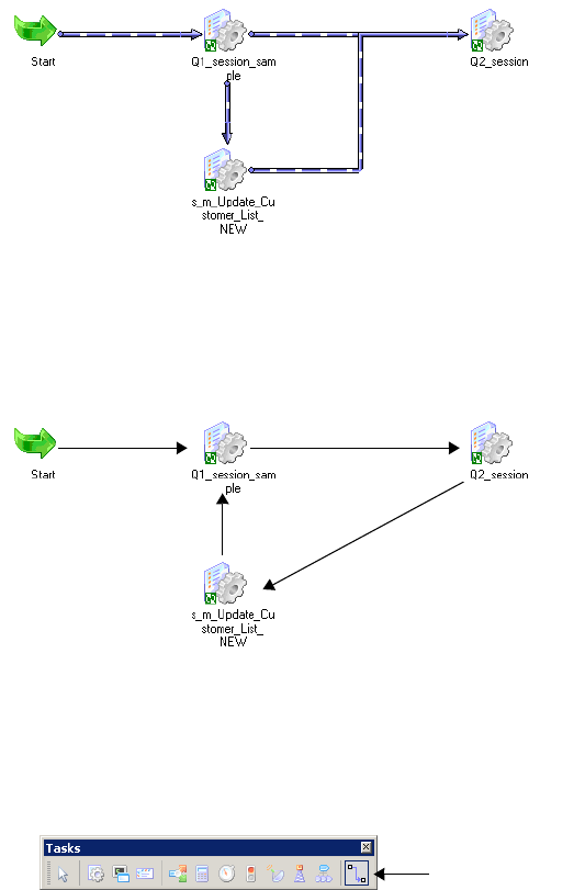
100 Chapter 3: Working with Workflows
Working with Links
Use links to connect each workflow task. You can specify conditions with links to create
branches in the workflow. The Workflow Manager does not allow you to use links to create
loops in the workflow. Each link in the workflow can run only once.
The workflow in Figure 3-3 is not a loop because each task runs at most once.
Figure 3-3 shows a valid workflow:
The Workflow Manager does not allow you to create a workflow that contains a loop, such as
the loop shown in Figure 3-4.
Figure 3-4 shows a loop where the three sessions may be run multiple times:
Use the following procedure to link tasks in the Workflow Designer or the Worklet Designer.
To link two tasks:
1. In the Tasks toolbar, click the Link Tasks button.
2. In the workspace, click the first task you want to connect and drag it to the second task.
Figure 3-3. Valid Workflow
Figure 3-4. Invalid Workflow with a Loop
Link Tasks
Button
Working with Links 101
3. A link appears between the two tasks.
If you want to link multiple tasks concurrently, you may not want to connect each link
manually.
To link tasks concurrently:
1. In the workspace, click the first task you want to connect.
2. Ctrl-click all other tasks you want to connect.
Note: Do not use Ctrl+A or Edit > Select All to choose tasks.
3. Click Tasks > Link Concurrent.
A link appears between the first task you selected and each task you added. The first task
you selected links to each task concurrently.
If you have a number of tasks that you want to link sequentially, you may not wish to connect
each link manually.
To link tasks sequentially:
1. In the workspace, click the first task you want to connect.
2. Ctrl-click the next task you want to connect. Continue to add tasks in the order you want
them to run.
3. Click Tasks > Link Sequential.
Links appear in sequential order between the first task and each subsequent task you
added.
Specifying Link Conditions
Once you create links between tasks, you can specify conditions for each link to determine the
order of execution in the workflow. If you do not specify conditions for each link, the
Integration Service runs the next task in the workflow by default.
Use predefined or user-defined workflow variables in the link condition. If the link condition
evaluates to True, the Integration Service runs the next task in the workflow. If the link
condition evaluates to False, the Integration Service does not run the next task in the
workflow.
You can view results of link evaluation during workflow runs in the workflow log file.
Example of Link Conditions
Use link conditions to specify the order of execution in the workflow or to create branches in
the workflow. For example, you may have two Session tasks in the workflow, s_STORES_CA
and s_STORES_AZ. You want the Integration Service to run the second Session task only if
the first Session task has no target failed rows.
102 Chapter 3: Working with Workflows
To accomplish this, you can set the link condition between the two sessions so that the
s_STORES_AZ runs only if the number of failed target rows for S_STORES_CA is zero.
Figure 3-5 shows how to set the link condition using the target failed rows variable for
S_STORES_CA:
After you specify the link condition in the Expression Editor, the Workflow Manager validates
the link condition and displays it next to the link in the workflow.
Figure 3-6 shows the link condition displayed in the workspace:
Figure 3-5. Setting a Link Condition
Figure 3-6. Displaying a Link Condition in the Workflow
Link Condition
Working with Links 103
To specify a condition for a link:
1. In the Workflow Designer workspace, double-click the link you want to specify.
-or-
Right-click the link and choose Edit. The Expression Editor appears.
2. In the Expression Editor, enter the link condition.
The Expression Editor provides predefined workflow variables, user-defined workflow
variables, variable functions, and boolean and arithmetic operators.
3. Validate the expression using the Validate button.
The Workflow Manager displays validation results in the Output window.
Tip: Drag the end point of a link to move it from one task to another without losing the link
condition.
Viewing Links in a Workflow or Worklet
When you edit a workflow or worklet, you can view the forward or backward link paths to
other tasks. You can highlight paths to see links in the workflow branch from the Start task to
the last task in the branch.
Note: You can configure the color the Workflow Manager uses to display links. To configure
the color for links, click Tools > Options > Format, and choose the Link Selection option.
To view link paths:
1. In the Worklet Designer or Workflow Designer, right-click a task and choose Highlight
Path.
2. Select Forward Path, Backward Path, or Both.
The Workflow Manager highlights all links in the branch you select.
Deleting Links in a Workflow or Worklet
When you edit a workflow or worklet, you can delete multiple links at once without deleting
the connected tasks.
To delete multiple links:
1. In the Worklet Designer or Workflow Designer, select all links you want to delete.
Tip: Use the mouse to drag the selection, or you can Ctrl-click the tasks and links.
2. Click Edit > Delete Links.
The Workflow Manager removes all selected links.
104 Chapter 3: Working with Workflows
Using the Expression Editor
The Workflow Manager provides an Expression Editor for any expressions in the workflow.
You can enter expressions using the Expression Editor for the following:
♦Link conditions
♦Decision task
♦Assignment task
Figure 3-7 shows the Expression Editor:
The Expression Editor displays system variables, user-defined workflow variables, and
predefined workflow variables such as $Session.status. For more information about workflow
variables, see “Using Workflow Variables” on page 106.
The Expression Editor also displays the following functions:
♦Transformation language functions. SQL-like functions designed to handle common
expressions.
♦User-defined functions. Functions you create in PowerCenter based on transformation
language functions.
♦Custom functions. Functions you create with the Custom Function API.
For more information about the transformation language and custom functions, see the
Transformation Language Reference. For more information about user-defined functions, see
“Working with User-Defined Functions” in the Designer Guide.
Figure 3-7. Expression Editor
Using the Expression Editor 105
Adding Comments
You can add comments using -- or // comment indicators with the Expression Editor. Use
comments to give descriptive information about the expression, or you can specify a valid
URL to access business documentation about the expression.
Validating Expressions
Use the Validate button to validate an expression. If you do not validate an expression, the
Workflow Manager validates it when you close the Expression Editor. You cannot run a
workflow with invalid expressions.
Expressions in link conditions and Decision task conditions must evaluate to a numeric value.
Workflow variables used in expressions must exist in the workflow.
Expression Editor Display
The Expression Editor can display syntax expressions in different colors for better readability.
If you have the latest Rich Edit control, riched20.dll, installed on the system, the Expression
Editor displays expression functions in blue, comments in grey, and quoted strings in green.
You can resize the Expression Editor. Expand the dialog box by dragging from the borders.
The Workflow Manager saves the new size for the dialog box as a client setting.
106 Chapter 3: Working with Workflows
Using Workflow Variables
You can create and use variables in a workflow to reference values and record information. For
example, use a variable in a Decision task to determine whether the previous task ran
properly. If it did, you can run the next task. If not, you can stop the workflow.
Use the following types of workflow variables:
♦Predefined workflow variables. The Workflow Manager provides predefined workflow
variables for tasks within a workflow. For more information, see “Predefined Workflow
Variables” on page 107.
♦User-defined workflow variables. You create user-defined workflow variables when you
create a workflow. For more information, see “User-Defined Workflow Variables” on
page 112.
Use workflow variables when you configure the following types of tasks:
♦Assignment tasks. Use an Assignment task to assign a value to a user-defined workflow
variable. For example, you can increment a user-defined counter variable by setting the
variable to its current value plus 1. For more information about using workflow variables
in Assignment tasks, see “Working with the Assignment Task” on page 144.
♦Decision tasks. Decision tasks determine how the Integration Service runs a workflow. For
example, use the Status variable to run a second session only if the first session completes
successfully. For more information about using workflow variables in Decision tasks, see
“Working with the Decision Task” on page 153.
♦Links. Links connect each workflow task. Use workflow variables in links to create
branches in the workflow. For example, after a Decision task, you can create one link to
follow when the decision condition evaluates to true, and another link to follow when the
decision condition evaluates to false. For more information about using workflow variables
in Link tasks, see “Working with Links” on page 100.
♦Timer tasks. Timer tasks specify when the Integration Service begins to run the next task
in the workflow. Use a user-defined date/time variable to specify the time the Integration
Service starts to run the next task. For more information about using workflow variables in
Timer tasks, see “Working with the Timer Task” on page 165.
Use the Expression Editor to create an expression that uses variables.
Using Workflow Variables 107
Figure 3-8 shows the Expression Editor:
When you build an expression, you can select predefined variables on the Predefined tab. You
can select user-defined variables on the User-Defined tab. The Functions tab contains
functions that you use with workflow variables.
Use the point-and-click method to enter an expression using a variable. For more information
about using the Expression Editor, see “Using the Expression Editor” on page 104.
Use the following keywords to write expressions for user-defined and predefined workflow
variables:
♦AND
♦OR
♦NOT
♦TRUE
♦FALSE
♦NULL
♦SYSDATE
Predefined Workflow Variables
Each workflow contains a set of predefined variables that you use to evaluate workflow and
task conditions. Use the following types of predefined variables:
♦Task-specific variables. The Workflow Manager provides a set of task-specific variables for
each task in the workflow. Use task-specific variables in a link condition to control the
path the Integration Service takes when running the workflow. The Workflow Manager
lists task-specific variables under the task name in the Expression Editor.
Figure 3-8. Creating an Expression Using Variables
Select predefined
variables.
Select user-defined
variables.
Create an
expression using
variables.

108 Chapter 3: Working with Workflows
♦System variables. Use the SYSDATE and WORKFLOWSTARTTIME system variables
within a workflow. For more information about system variables, see “Variables” in the
Transformation Language Reference. The Workflow Manager lists system variables under the
Built-in node in the Expression Editor.
Tip: When you set the error severity level for log files to Tracing in the PowerCenter Server
setup, the workflow log displays the values of workflow variables. Use this logging level for
troubleshooting only.
Table 3-1 lists the task-specific workflow variables available in the Workflow Manager:
Table 3-1. Task-Specific Workflow Variables
Task-Specific
Variables Description Task Types Datatype
Condition Evaluation result of decision condition expression.
If the task fails, the Workflow Manager keeps the condition set to
null.
Sample syntax:
$Dec_TaskStatus.Condition = <TRUE | FALSE
| NULL | any integer>
Decision Integer
EndTime Date and time the associated task ended.
Sample syntax:
$s_item_summary.EndTime > TO_DATE('11/10/
2004 08:13:25')
All tasks Date/time
ErrorCode Last error code for the associated task. If there is no error, the
Integration Service sets ErrorCode to 0 when the task completes.
Sample syntax:
$s_item_summary.ErrorCode = 24013
Note: You might use this variable when a task consistently fails
with this final error message.
All tasks Integer
ErrorMsg Last error message for the associated task.
If there is no error, the Integration Service sets ErrorMsg to an
empty string when the task completes.
Sample syntax:
$s_item_summary.ErrorMsg = 'PETL_24013
Session run completed with failure
Note: You might use this variable when a task consistently fails
with this final error message.
All tasks Nstring*
FirstErrorCode Error code for the first error message in the session.
If there is no error, the Integration Service sets FirstErrorCode to 0
when the session completes.
Sample syntax:
$s_item_summary.FirstErrorCode = 7086
Session Integer
FirstErrorMsg First error message in the session.
If there is no error, the Integration Service sets FirstErrorMsg to an
empty string when the task completes.
Sample syntax:
$s_item_summary.FirstErrorMsg = 'TE_7086
Tscrubber: Debug info… Failed to
evalWrapUp'
Session Nstring*

Using Workflow Variables 109
PrevTaskStatus Status of the previous task in the workflow that the Integration
Service ran. Statuses include:
- ABORTED
- FAILED
- STOPPED
- SUCCEEDED
Use these key words when writing expressions to evaluate the
status of the previous task.
Sample syntax:
$Dec_TaskStatus.PrevTaskStatus = FAILED
For more information, see “Evaluating Task Status in a Workflow”
on page 111.
All tasks Integer
SrcFailedRows Total number of rows the Integration Service failed to read from
the source.
Sample syntax:
$s_dist_loc.SrcFailedRows = 0
Session Integer
SrcSuccessRows Total number of rows successfully read from the sources.
Sample syntax:
$s_dist_loc.SrcSuccessRows > 2500
Session Integer
StartTime Date and time the associated task started.
Sample syntax:
$s_item_summary.StartTime > TO_DATE('11/
10/2004 08:13:25')
All tasks Date/time
Status Status of the previous task in the workflow. Statuses include:
- ABORTED
- DISABLED
- FAILED
- NOTSTARTED
- STARTED
- STOPPED
- SUCCEEDED
Use these key words when writing expressions to evaluate the
status of the current task.
Sample syntax:
$s_dist_loc.Status = SUCCEEDED
For more information, see “Evaluating Task Status in a Workflow”
on page 111.
All tasks Integer
TgtFailedRows Total number of rows the Integration Service failed to write to the
target.
Sample syntax:
$s_dist_loc.TgtFailedRows = 0
Session Integer
TgtSuccessRows Total number of rows successfully written to the target
Sample syntax:
$s_dist_loc.TgtSuccessRows > 0
Session Integer
Table 3-1. Task-Specific Workflow Variables
Task-Specific
Variables Description Task Types Datatype
110 Chapter 3: Working with Workflows
All predefined workflow variables except Status have a default value of null. The Integration
Service uses the default value of null when it encounters a predefined variable from a task that
has not yet run in the workflow. Therefore, expressions and link conditions that depend upon
tasks not yet run are valid. The default value of Status is NOTSTARTED.
Using Predefined Workflow Variables in Expressions
When you use a workflow variable in an expression, the Integration Service evaluates the
expression and returns True or False. If the condition evaluates to true, the Integration Service
runs the next task. The Integration Service writes an entry in the workflow log similar to the
following message:
INFO : LM_36506 : (1980|1040) Link [Session2 --> Session3]: condition is
TRUE for the expression [$Session2.PrevTaskStatus = SUCCEEDED].
The Expression Editor displays the predefined workflow variables on the Predefined tab. The
Workflow Manager groups task-specific variables by task and lists system variables under the
Built-in node. To use a variable in an expression, double-click the variable. The Expression
Editor displays task-specific variables in the Expression field in the following format:
$<TaskName>.<predefinedVariable>
Figure 3-9 shows the Expression Editor with an expression using a task-specific workflow
variable and keyword:
TotalTransErrors Total number of transformation errors.
Sample syntax:
$s_dist_loc.TotalTransErrors = 5
Session Integer
* Variables of type Nstring can have a maximum length of 600 characters.
Figure 3-9. Expression Using a Predefined Workflow Variable
Table 3-1. Task-Specific Workflow Variables
Task-Specific
Variables Description Task Types Datatype
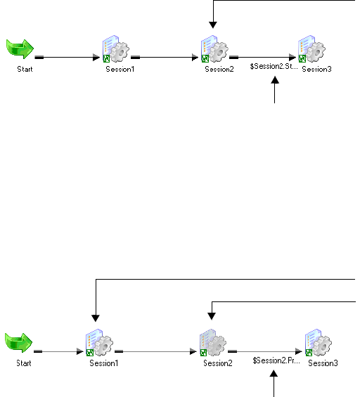
Using Workflow Variables 111
Evaluating Task Status in a Workflow
Use Status and PrevTaskStatus in link conditions to test the status of tasks in a workflow. Use
Status to test the status of the previous task in the workflow. Use PrevTaskStatus to test the
status of the previous task in the workflow that the Integration Service ran.
Use PrevTaskStatus if you disable a task in the workflow. Status and PrevTaskStatus return the
same value unless the condition uses a disabled task.
Figure 3-10 shows a workflow with link conditions using Status:
When you run the workflow, the Integration Service evaluates the link condition and returns
the value based on the status of Session2.
Figure 3-11 shows a workflow with link conditions using PrevTaskStatus:
When you run the workflow, the Integration Service skips Session2 because the session is
disabled. When the Integration Service evaluates the link condition, it returns the value based
on the status of Session1.
Tip: If you do not disable Session2, the Integration Service returns the value based on the
status of Session2. You do not need to change the link condition when you enable and disable
Session2.
Figure 3-10. Status Variable Example
Figure 3-11. PrevTaskStatus Variable Example
Link condition:
$Session2.Status = SUCCEEDED
The Integration Service returns value based on the
previous task in the workflow, Session2.
Previous Task in Workflow
Disabled Task
Link condition:
$Session2.PrevTaskStatus = SUCCEEDED
The Integration Service returns value based on the
previous task run, Session1.
Previous Task Run
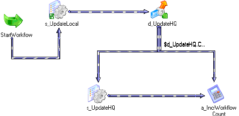
112 Chapter 3: Working with Workflows
User-Defined Workflow Variables
You can create variables within a workflow. When you create a variable in a workflow, it is
valid only in that workflow. Use the variable in tasks within that workflow. You can edit and
delete user-defined workflow variables.
Use user-defined variables when you need to make a workflow decision based on criteria you
specify. For example, you create a workflow to load data to an orders database nightly. You
also need to load a subset of this data to headquarters periodically, every tenth time you
update the local orders database. Create separate sessions to update the local database and the
one at headquarters. The workflow looks like Figure 3-12:
Use a user-defined variable to determine when to run the session that updates the orders
database at headquarters.
To configure user-defined workflow variables, set up the workflow as follows:
1. Create a persistent workflow variable, $$WorkflowCount, to represent the number of
times the workflow has run.
2. Add a Start task and both sessions to the workflow.
3. Place a Decision task after the session that updates the local orders database.
Set up the decision condition to check to see if the number of workflow runs is evenly
divisible by 10. Use the modulus (MOD) function to do this.
4. Create an Assignment task to increment the $$WorkflowCount variable by one.
5. Link the Decision task to the session that updates the database at headquarters when the
decision condition evaluates to true. Link it to the Assignment task when the decision
condition evaluates to false.
When you configure workflow variables using conditions, the session that updates the local
database runs every time the workflow runs. The session that updates the database at
headquarters runs every 10th time the workflow runs.
Figure 3-12. Sample Workflow Using Workflow Variable
Using Workflow Variables 113
Start and Current Values
Conceptually, the Integration Service holds two different values for a workflow variable
during a workflow run:
♦Start value of a workflow variable
♦Current value of a workflow variable
The start value is the value of the variable at the start of the workflow. The start value could
be a value defined in the parameter file for the variable, a value saved in the repository from
the previous run of the workflow, a user-defined initial value for the variable, or the default
value based on the variable datatype.
The Integration Service looks for the start value of a variable in the following order:
1. Value in parameter file
2. Value saved in the repository (if the variable is persistent)
3. User-specified default value
4. Datatype default value
For a list of datatype default values, see Table 3-2 on page 114.
For example, you create a workflow variable in a workflow and enter a default value, but you
do not define a value for the variable in a parameter file. The first time the Integration Service
runs the workflow, it evaluates the start value of the variable to the user-defined default value.
If you declare the variable as persistent, the Integration Service saves the value of the variable
to the repository at the end of the workflow run. The next time the workflow runs, the
Integration Service evaluates the start value of the variable as the value saved in the repository.
If the variable is non-persistent, the Integration Service does not save the value of the variable.
The next time the workflow runs, the Integration Service evaluates the start value of the
variable as the user-specified default value.
If you want to override the value saved in the repository before running a workflow, you need
to define a value for the variable in a parameter file. When you define a workflow variable in
the parameter file, the Integration Service uses this value instead of the value saved in the
repository or the configured initial value for the variable.
The current value is the value of the variable as the workflow progresses. When a workflow
starts, the current value of a variable is the same as the start value. The value of the variable
can change as the workflow progresses if you create an Assignment task that updates the value
of the variable.
If the variable is persistent, the Integration Service saves the current value of the variable to
the repository at the end of a successful workflow run. If the workflow fails to complete, the
Integration Service does not update the value of the variable in the repository.
The Integration Service states the value saved to the repository for each workflow variable in
the workflow log.
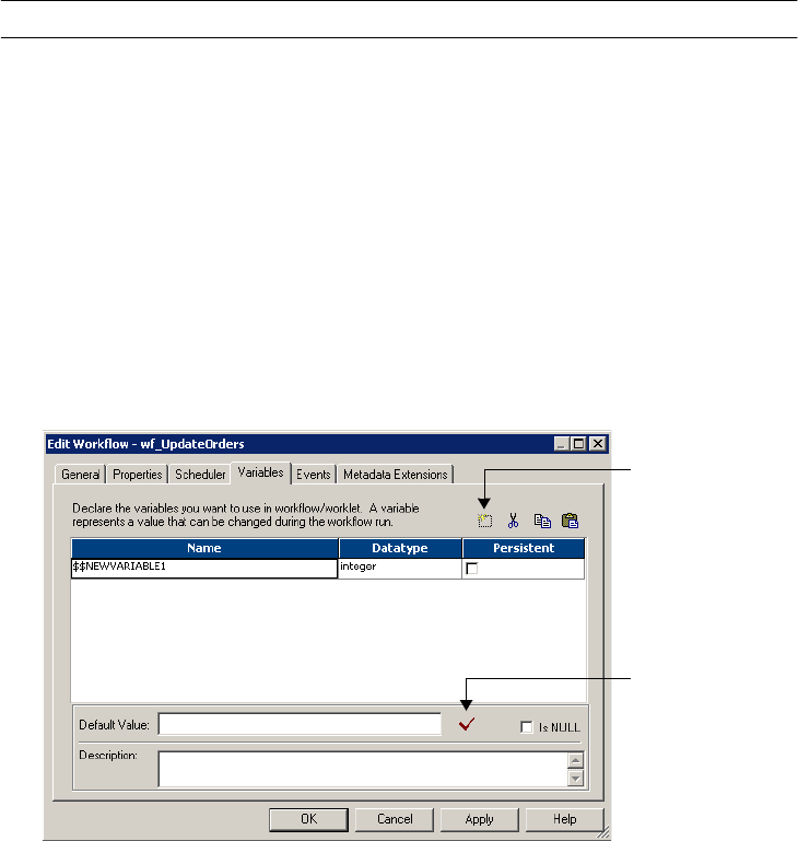
114 Chapter 3: Working with Workflows
Datatype Default Values
If the Integration Service cannot determine the start value of a variable by any other means, it
uses a default value for the variable based on its datatype. For more information about how
the Integration Service determines start values for a variable, see “Start and Current Values”
on page 113.
Table 3-2 lists the datatype default values for user-defined workflow variables:
Creating User-Defined Workflow Variables
You can create workflow variables for a workflow in the workflow properties.
To create a workflow variable:
1. In the Workflow Designer, create a new workflow or edit an existing one.
2. Select the Variables tab.
3. Click Add and enter a name for the variable.
The correct format for a user-defined workflow variable is $$VariableName. Do not use a
single $ for a user-defined workflow variable. The single $ is reserved for system variables
and predefined workflow variables.
Table 3-2. Datatype Default Values for User-Defined Workflow Variables
Datatype Workflow Manager Default Value
Date/time 1/1/1753 A.D.
Double 0
Integer 0
Nstring Empty string
Add Button
Validate Button
Using Workflow Variables 115
Workflow variable names are not case sensitive.
4. In the Datatype field, select the datatype for the new variable.
You can select from the following datatypes:
♦Date/time
♦Double
♦Integer
♦Nstring
Variables of type Nstring can have a maximum length of 600 characters.
5. Enable the Persistent option if you want the value of the variable retained from one
execution of the workflow to the next.
For more information, see “Start and Current Values” on page 113.
6. Enter the default value for the variable in the Default field.
If the default is a null value, enable the Is Null option.
7. To validate the default value of the new workflow variable, click the Validate button.
8. Click Apply to save the new workflow variable.
9. Click OK to close the workflow properties.
116 Chapter 3: Working with Workflows
Scheduling a Workflow
You can schedule a workflow to run continuously, repeat at a given time or interval, or you
can manually start a workflow. The Integration Service runs a scheduled workflow as
configured.
By default, the workflow runs on demand. You can change the schedule settings by editing the
scheduler. If you change schedule settings, the Integration Service reschedules the workflow
according to the new settings.
Each workflow has an associated scheduler. A scheduler is a repository object that contains a
set of schedule settings. You can create a non-reusable scheduler for the workflow. Or, you can
create a reusable scheduler to use the same set of schedule settings for workflows in the folder.
The Workflow Manager marks a workflow invalid if you delete the scheduler associated with
the workflow.
If you choose a different Integration Service for the workflow or restart the Integration
Service, it reschedules all workflows. This includes workflows that are scheduled to run
continuously but whose start time has passed. You must manually reschedule workflows
whose start time has passed if they are not scheduled to run continuously.
If you delete a folder, the Integration Service removes workflows from the schedule when it
receives notification from the Repository Service. If you copy a folder into a repository, the
Integration Service reschedules all workflows in the folder when it receives the notification.
The Integration Service does not run the workflow if:
♦The prior workflow run fails. When a workflow fails, the Integration Service removes the
workflow from the schedule, and you must manually reschedule it. You can reschedule the
workflow in the Workflow Manager or using pmcmd. In the Workflow Manager Navigator
window, right-click the workflow and select Schedule Workflow. For more information
about the pmcmd scheduleworkflow command, see the Command Line Reference.
♦You remove the workflow from the schedule. You can remove the workflow from the
schedule in the Workflow Manager or using pmcmd. In the Workflow Manager Navigator
window, right-click the workflow and select Unschedule Workflow. For more information
about the pmcmd unscheduleworkflow command, see the Command Line Reference.
♦The Integration Service is running in safe mode. In safe mode, the Integration Service
does not run scheduled workflows, including workflows scheduled to run continuously or
run on service initialization. When you enable the Integration Service in normal mode, the
Integration Service runs the scheduled workflows. For more information about safe mode,
see “Creating and Configuring the Integration Service” in the Administrator Guide.
Note: The Integration Service schedules the workflow in the time zone of the Integration
Service machine. For example, the PowerCenter Client is in the current time zone and the
Integration Service is in a time zone two hours later. If you schedule the workflow to start at 9
a.m., it starts at 9 a.m. in the time zone of the Integration Service machine and 7 a.m. current
time.
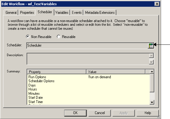
Scheduling a Workflow 117
To schedule a workflow:
1. In the Workflow Designer, open the workflow.
2. Click Workflows > Edit.
3. In the Scheduler tab, choose Non-reusable if you want to create a non-reusable set of
schedule settings for the workflow.
Select Reusable if you want to select an existing reusable scheduler for the workflow.
Note: If you do not have a reusable scheduler in the folder, you must create one before you
choose Reusable. The Workflow Manager displays a warning message if you do not have
an existing reusable scheduler.
4. Click the right side of the Scheduler field to edit scheduling settings for the scheduler.
For a complete list of scheduler options, see “Configuring Scheduler Settings” on
page 119.
Edit scheduler
settings.
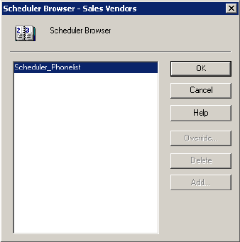
118 Chapter 3: Working with Workflows
5. If you select Reusable, choose a reusable scheduler from the Scheduler Browser dialog
box.
6. Click OK.
To remove a workflow from its schedule, right-click the workflow in the Navigator window
and choose Unschedule Workflow.
To reschedule a workflow on its original schedule, right-click the workflow in the Navigator
window and choose Schedule Workflow.
Creating a Reusable Scheduler
For each folder, the Workflow Manager lets you create reusable schedulers so you can reuse
the same set of scheduling settings for workflows in the folder. Use a reusable scheduler so you
do not need to configure the same set of scheduling settings in each workflow.
When you delete a reusable scheduler, all workflows that use the deleted scheduler becomes
invalid. To make the workflows valid, you must edit them and replace the missing scheduler.
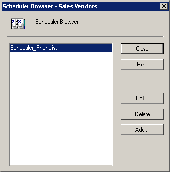
Scheduling a Workflow 119
To create a reusable scheduler:
1. In the Workflow Designer, click Workflows > Schedulers.
2. Click Add to add a new scheduler.
3. In the General tab, enter a name for the scheduler.
4. Configure the scheduler settings in the Scheduler tab. For a complete list of scheduler
settings, see Table 3-3 on page 120.
Configuring Scheduler Settings
Configure the Schedule tab of the scheduler to set run options, schedule options, start
options, and end options for the schedule.
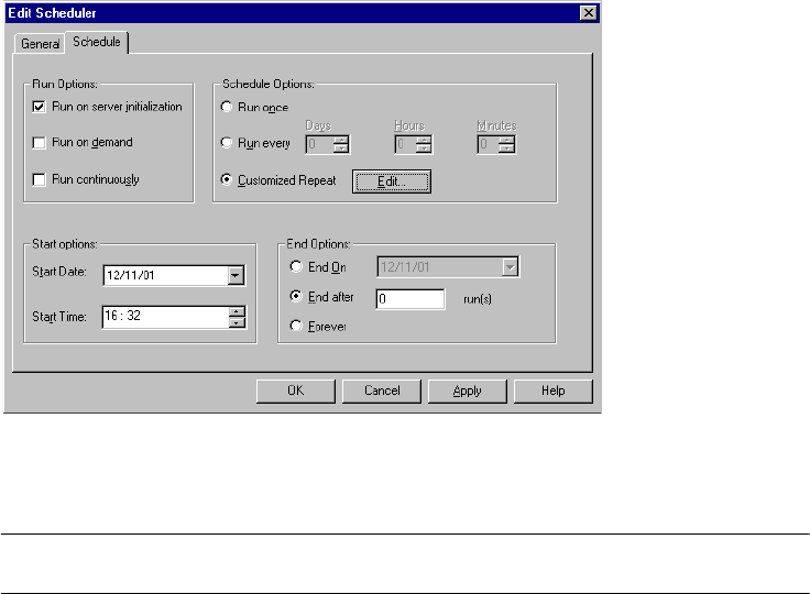
120 Chapter 3: Working with Workflows
Figure 3-13 shows the Schedule tab:
Table 3-3 describes the settings on the Schedule tab:
Figure 3-13. Schedule Tab
Table 3-3. Schedule Tab Settings
Scheduler Options Required/
Optional Description
Run Options:
Run On Server Initialization/
Run On Demand/Run
Continuously
Optional Indicates the workflow schedule type.
If you select Run On Integration Service Initialization, the
Integration Service runs the workflow as soon as the service is
initialized. The Integration Service then starts the next run of the
workflow according to settings in Schedule Options.
If you select Run On Demand, the Integration Service runs the
workflow when you start the workflow manually.
If you select Run Continuously, the Integration Service runs the
workflow as soon as the service initializes. The Integration
Service then starts the next run of the workflow as soon as it
finishes the previous run. If you edit a workflow that is set to run
continuously, you must stop or unschedule the workflow, save
the workflow, and then restart or reschedule the workflow.

Scheduling a Workflow 121
Customizing Repeat Option
You can schedule the workflow to run once or at an interval. You can customize the repeat
option. Click the Edit button to open the Customized Repeat dialog box.
Schedule Options:
Run Once/Run Every/
Customized Repeat
Optional Required if you select Run On Integration Service Initialization,
or if you do not choose any setting in Run Options.
If you select Run Once, the Integration Service runs the
workflow once, as scheduled in the scheduler.
If you select Run Every, the Integration Service runs the
workflow at regular intervals, as configured.
If you select Customized Repeat, the Integration Service runs
the workflow on the dates and times specified in the Repeat
dialog box.
When you select Customized Repeat, click Edit to open the
Repeat dialog box. The Repeat dialog box lets you schedule
specific dates and times for the workflow run. The selected
scheduler appears at the bottom of the page.
Start Options: Start Date/Start
Time
Optional Start Date indicates the date on which the Integration Service
begins the workflow schedule.
Start Time indicates the time at which the Integration Service
begins the workflow schedule.
End Options: End On/End
After/Forever
Conditional Required if the workflow schedule is Run Every or Customized
Repeat.
If you select End On, the Integration Service stops scheduling
the workflow in the selected date.
If you select End After, the Integration Service stops scheduling
the workflow after the set number of workflow runs.
If you select Forever, the Integration Service schedules the
workflow as long as the workflow does not fail.
Table 3-3. Schedule Tab Settings
Scheduler Options Required/
Optional Description
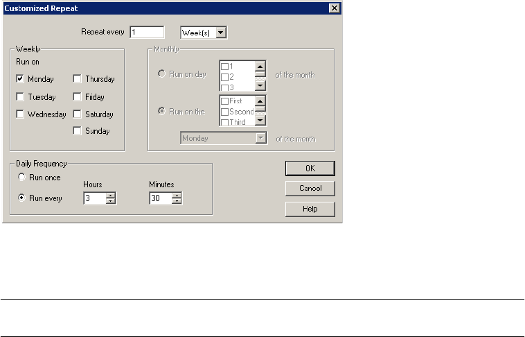
122 Chapter 3: Working with Workflows
Figure 3-14 shows the Customized Repeat dialog box:
Table 3-4 describes options in the Customized Repeat dialog box:
Figure 3-14. Customized Repeat Dialog Box
Table 3-4. Repeat Dialog Box Options
Repeat Option Required/
Optional Description
Repeat Every Required Enter the numeric interval you would like the Integration Service to schedule
the workflow, and then select Days, Weeks, or Months, as appropriate.
If you select Days, select the appropriate Daily Frequency settings.
If you select Weeks, select the appropriate Weekly and Daily Frequency
settings.
If you select Months, select the appropriate Monthly and Daily Frequency
settings.
Weekly Conditional Required to enter a weekly schedule. Select the day or days of the week on
which you would like the Integration Service to run the workflow.

Scheduling a Workflow 123
Editing Scheduler Settings
You can edit scheduler settings for both non-reusable and reusable schedulers.
♦Non-reusable schedulers. When you configure or edit a non-reusable scheduler, check in
the workflow to allow the schedule to take effect.
You can update the schedule manually with the workflow checked out. Right-click the
workflow in the Navigator, and select Schedule Workflow. Note that the changes are
applied to the latest checked-in version of the workflow.
♦Reusable schedulers. When you edit settings for a reusable scheduler, the repository
creates a new version of the scheduler and increments the version number by one. To
update a workflow with the latest schedule, check in the scheduler after you edit it.
When you configure a reusable scheduler for a new workflow, you must check in both the
workflow and the scheduler to enable the schedule to take effect. Thereafter, when you
check in the scheduler after revising it, the workflow schedule is updated even if it is
checked out.
You need to update the workflow schedule manually if you do not check in the scheduler.
To update a workflow schedule manually, right-click the workflow in the Navigator and
select Schedule Workflow. The new schedule is implemented for the latest version of the
workflow that is checked in. Workflows that are checked out are not updated with the new
schedule.
Monthly Conditional Required to enter a monthly schedule.
If you select Run On Day, select the dates on which you want the workflow
scheduled on a monthly basis. The Integration Service schedules the workflow
to run on the selected dates. If you select a numeric date exceeding the
number of days within a given month, the Integration Service schedules the
workflow for the last day of the month, including leap years. For example, if you
schedule the workflow to run on the 31st of every month, the Integration
Service schedules the session on the 30th of the following months: April, June,
September, and November.
If you select Run On The, select the week(s) of the month, then day of the
week on which you want the workflow to run. For example, if you select Second
and Last, then select Wednesday, the Integration Service schedules the
workflow to run on the second and last Wednesday of every month.
Daily Frequency Optional Enter the number of times you would like the Integration Service to run the
workflow on any day the session is scheduled.
If you select Run Once, the Integration Service schedules the workflow once on
the selected day, at the time entered on the Start Time setting on the Time tab.
If you select Run Every, enter Hours and Minutes to define the interval at which
the Integration Service runs the workflow. The Integration Service then
schedules the workflow at regular intervals on the selected day. The Integration
Service uses the Start Time setting for the first scheduled workflow of the day.
Table 3-4. Repeat Dialog Box Options
Repeat Option Required/
Optional Description
124 Chapter 3: Working with Workflows
Disabling Workflows
You may want to disable the workflow while you edit it. This prevents the Integration Service
from running the workflow on its schedule. Select the Disable Workflows option on the
General tab of the workflow properties. The Integration Service does not run disabled
workflows until you clear the Disable Workflows option. Once you clear the Disable
Workflows option, the Integration Service reschedules the workflow.
Validating a Workflow 125
Validating a Workflow
Before you can run a workflow, you must validate it. When you validate the workflow, you
validate all task instances in the workflow, including nested worklets.
The Workflow Manager validates the following properties:
♦Expressions. Expressions in the workflow must be valid.
♦Tasks. Non-reusable task and Reusable task instances in the workflow must follow
validation rules.
♦Scheduler. If the workflow uses a reusable scheduler, the Workflow Manager verifies that
the scheduler exists.
The Workflow Manager also verifies that you linked each task properly. For example, you
must link the Start task to at least one task in the workflow.
Note: The Workflow Manager validates Session tasks separately. If a session is invalid, the
workflow may still be valid. For more information about session validation, see “Validating a
Session” on page 206.
Expression Validation
The Workflow Manager validates all expressions in the workflow. You can enter expressions in
the Assignment task, Decision task, and link conditions. The Workflow Manager writes any
error message to the Output window.
Expressions in link conditions and Decision task conditions must evaluate to a numerical
value. Workflow variables used in expressions must exist in the workflow.
The Workflow Manager marks the workflow invalid if a link condition is invalid.
Task Validation
The Workflow Manager validates each task in the workflow as you create it. When you save or
validate the workflow, the Workflow Manager validates all tasks in the workflow except
Session tasks. It marks the workflow invalid if it detects any invalid task in the workflow.
The Workflow Manager verifies that attributes in the tasks follow validation rules. For
example, the user-defined event you specify in an Event task must exist in the workflow. The
Workflow Manager also verifies that you linked each task properly. For example, you must
link the Start task to at least one task in the workflow. For more information about task
validation rules, see “Validating Tasks” on page 143.
When you delete a reusable task, the Workflow Manager removes the instance of the deleted
task from workflows. The Workflow Manager also marks the workflow invalid when you
delete a reusable task used in a workflow.
The Workflow Manager verifies that there are no duplicate task names in a folder, and that
there are no duplicate task instances in the workflow.
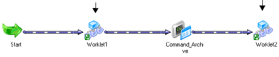
126 Chapter 3: Working with Workflows
Workflow Properties Validation
The Workflow Manager marks the workflow invalid if the scheduler you specify for the
workflow does not exist in the folder.
Running Validation
When you validate a workflow, you validate worklet instances, worklet objects, and all other
nested worklets in the workflow. You validate task instances and worklets, regardless of
whether you have edited them.
The Workflow Manager validates the worklet object using the same validation rules for
workflows. The Workflow Manager validates the worklet instance by verifying attributes in
the Parameter tab of the worklet instance. For more information about validating worklets,
see “Validating Worklets” on page 175.
If the workflow contains nested worklets, you can select a worklet to validate the worklet and
all other worklets nested under it. To validate a worklet and its nested worklets, right-click the
worklet and choose Validate.
Example
For example, you have a workflow that contains a non-reusable worklet called Worklet_1.
Worklet_1 contains a nested worklet called Worklet_a. The workflow also contains a reusable
worklet instance called Worklet_2. Worklet_2 contains a nested worklet called Worklet_b.
In the example workflow in Figure 3-15, the Workflow Manager validates links, conditions,
and tasks in the workflow. The Workflow Manager validates all tasks in the workflow,
including tasks in Worklet_1, Worklet_2, Worklet_a, and Worklet_b.
You can validate a part of the workflow. Right-click Worklet_1 and choose Validate. The
Workflow Manager validates all tasks in Worklet_1 and Worklet_a.
Figure 3-15 shows the example workflow:
Validating Multiple Workflows
You can validate multiple workflows or worklets without fetching them into the workspace.
To validate multiple workflows, you must select and validate the workflows from a query
Figure 3-15. Example Workflow - Validation
Worklet_1: Non-reusable
worklet. Contains a
nested worklet called
Worklet_a.
Worklet_2: Reusable
worklet. Contains a
nested worklet called
Worklet_b.
Validating a Workflow 127
results view or a view dependencies list. When you validate multiple workflows, the validation
does not include sessions, nested worklets, or reusable worklet objects in the workflows.
Note: You can also select and validate multiple workflows from the Navigator in the
Repository Manager.
You can save and optionally check in workflows that change from invalid to valid status. For
more information about validating multiple objects, see “Using the Repository Manager” in
the Repository Guide.
To validate multiple workflows:
1. Select workflows from either a query list or a view dependencies list.
2. Check out the objects you want to validate.
3. Right-click one of the selected workflows and choose Validate.
The Validate Objects dialog box appears.
4. Choose to save objects and check in objects that you validate.
128 Chapter 3: Working with Workflows
Manually Starting a Workflow
Before you can run a workflow, you must select an Integration Service to run the workflow.
You can select an Integration Service when you edit a workflow or from the Assign Integration
Service dialog box. If you select an Integration Service from the Assign Integration Service
dialog box, the Workflow Manager overwrites the Integration Service assigned in the
workflow properties.
You can manually start a workflow configured to run on demand or to run on a schedule. Use
the Workflow Manager, Workflow Monitor, or pmcmd to run a workflow. You can choose to
run the entire workflow, part of a workflow, or a task in the workflow.
Running a Workflow
When you click Workflows > Start Workflow, the Integration Service runs the entire
workflow.
To run a workflow from pmcmd, use the startworkflow command. For more information
about using pmcmd, see the Command Line Reference.
To run a workflow from the Workflow Manager:
1. Open the folder containing the workflow.
2. From the Navigator, select the workflow that you want to start.
3. Right-click the workflow in the Navigator and choose Start Workflow.
The Integration Service runs the entire workflow.
After the Workflow Manager sends a request to the Integration Service, the Output window
displays the Integration Service response. If an error appears, check the workflow log or
session log for error messages.
You can also manually start a workflow by right-clicking in the Workflow Designer workspace
and choosing Start Workflow.
Running a Part of a Workflow
To run part of the workflow, right-click the task that you want the Integration Service to run
and choose Start Workflow From Task. The Integration Service runs the workflow from the
selected task to the end of the workflow.
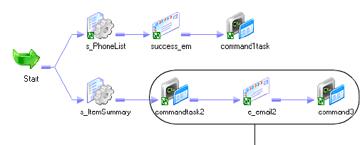
Manually Starting a Workflow 129
For example, you have a workflow with multiple tasks and multiple branches, as shown in
Figure 3-16. If you want to run the tasks commandtask2, e_email2, and command3, start the
workflow from commandtask2. All subsequent tasks in the branch run.
To run a part of a workflow from pmcmd, use the startfrom flag of the startworkflow
command. For more information about using pmcmd, see the Command Line Reference.
To run a part of a workflow:
1. Connect to the folder containing the workflow.
2. In the Navigator, drill down the Workflow node to show the tasks in the workflow.
-or-
In the Workflow Designer workspace, select the task from which you want the
Integration Service to begin running the workflow.
3. Right-click the task for which you want the Integration Service to begin running the
workflow.
4. Click Start Workflow From Task.
Running a Task in the Workflow
When you start a task in the workflow, the Workflow Manager locks the entire workflow so
another user cannot start the workflow. The Integration Service runs the selected task. It does
not run the rest of the workflow.
To run a task using the Workflow Manager, select the task in the Workflow Designer
workspace. Right-click the task and choose Start Task.
You can also use menu commands in the Workflow Manager to start a task. In the Navigator,
drill down the Workflow node to locate the task. Right-click the task you want to start and
choose Start Task.
To start a task in a workflow from pmcmd, use the starttask command. For more information
about using pmcmd, see the Command Line Reference.
Figure 3-16. Running Part of a Workflow - Example
When you start the workflow from
commandtask2, the Integration Service
runs this portion of the workflow.
130 Chapter 3: Working with Workflows
Suspending the Workflow
When a task in the workflow fails, you might want to suspend the workflow, fix the error, and
recover the workflow. The Integration Service suspends the workflow when you enable the
Suspend on Error option in the workflow properties. Optionally, you can set a suspension
email so the Integration Service sends an email when it suspends a workflow.
When you enable the workflow to suspend on error, the Integration Service suspends the
workflow when one of the following tasks fail:
♦Session
♦Command
♦Worklet
♦Email
When a task fails in the workflow, the Integration Service stops running tasks in the path. The
Integration Service does not evaluate the output link of the failed task. If no other task is
running in the workflow, the Workflow Monitor displays the status of the workflow as
“Suspended.”
If one or more tasks are still running in the workflow when a task fails, the Integration Service
stops running the failed task and continues running tasks in other paths. The Workflow
Monitor displays the status of the workflow as “Suspending.”
When the status of the workflow is “Suspended” or “Suspending,” you can fix the error, such
as a target database error, and recover the workflow in the Workflow Monitor. When you
recover a workflow, the Integration Service restarts the failed tasks and continues evaluating
the rest of the tasks in the workflow. The Integration Service does not run any task that
already completed successfully.
Note: Editing a suspended workflow or tasks inside a suspended workflow can cause repository
inconsistencies.
To suspend a workflow:
1. In the Workflow Designer, open the workflow.
2. Click Workflows > Edit.
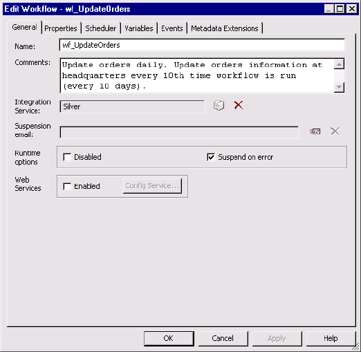
Suspending the Workflow 131
3. In the General tab, enable Suspend on Error.
4. Click OK.
Configuring Suspension Email
You can configure the workflow so that the Integration Service sends an email when it
suspends a workflow. Select an existing reusable email task for the suspension email. When a
task fails, the Integration Service starts suspending the workflow and sends the suspension
email. If another task fails while the Integration Service is suspending the workflow, you do
not receive the suspension email again.
The Integration Service sends a suspension email if another task fails after you resume the
workflow.
For more information about configuring suspension emails, see “Working with Suspension
Email” on page 381.
132 Chapter 3: Working with Workflows
Stopping or Aborting the Workflow
You can specify when and how you want the Integration Service to stop or abort a workflow
by using the Control task in the workflow. After you start a workflow, you can stop or abort it
through the Workflow Monitor or pmcmd. You can issue the stop or abort command at any
time during the execution of a workflow.
You can stop or abort a workflow by performing one of the following actions:
♦Use a Control task in the workflow. For more information, see “Working with the
Control Task” on page 151.
♦Issue a stop or abort command in the Workflow Monitor. For more information, see
“Monitoring Workflows” on page 495.
♦Issue a stop or abort command in pmcmd. For more information, see the Command Line
Reference.
You can also stop or abort a task within a workflow. For more information about stopping the
Session task, see “Stopping and Aborting a Session” on page 208.
How the Integration Service Handles Stop and Abort
When you stop a workflow, the Integration Service tries to stop all the tasks that are currently
running in the workflow. If the workflow contains a worklet, the Integration Service also tries
to stop all the tasks that are currently running in the worklet. If it cannot stop the workflow,
you need to abort the workflow.
The Integration Service can stop the following tasks completely:
♦Session
♦Command
♦Timer
♦Event-Wait
♦Worklet
When you stop a Command task that contains multiple commands, the Integration Service
finishes executing the current command and does not run the rest of the commands. The
Integration Service cannot stop tasks such as the Email task. For example, if the Integration
Service has already started sending an email when you issue the stop command, the
Integration Service finishes sending the email before it stops running the workflow.
The Integration Service aborts the workflow if the Repository Service process shuts down.
Stopping or Aborting a Task
You can stop or abort a task within a workflow from the Workflow Monitor. When you stop
or abort a task, the Integration Service stops processing the task. The Integration Service does
not process other tasks in the path of the stopped or aborted task. The Integration Service
Stopping or Aborting the Workflow 133
continues processing concurrent tasks in the workflow. If the Integration Service cannot stop
the task, you can abort the task.
When you abort a task, the Integration Service kills the process on the task. The Integration
Service continues processing concurrent tasks in the workflow when you abort a task.
You can also stop or abort a worklet. The Integration Service stops and aborts a worklet
similar to stopping and aborting a task. The Integration Service stops the worklet while
executing concurrent tasks in the workflow. You can also stop or abort tasks within a worklet.
Stopping or Aborting a Session Task
If the Integration Service is executing a Session task when you issue the stop command, the
Integration Service stops reading data. It continues processing and writing data and
committing data to targets. If the Integration Service cannot finish processing and
committing data, you can issue the abort command.
The Integration Service handles the abort command for the Session task like the stop
command, except it has a timeout period of 60 seconds. If the Integration Service cannot
finish processing and committing data within the timeout period, it kills the DTM process
and terminates the session. For more information about stopping or aborting a session, see
“Stopping and Aborting a Session” on page 208.
134 Chapter 3: Working with Workflows

135
Chapter 4
Working with Tasks
This chapter includes the following topics:
♦Overview, 136
♦Creating a Task, 137
♦Configuring Tasks, 139
♦Validating Tasks, 143
♦Working with the Assignment Task, 144
♦Working with the Command Task, 147
♦Working with the Control Task, 151
♦Working with the Decision Task, 153
♦Working with Event Tasks, 157
♦Working with the Timer Task, 165

136 Chapter 4: Working with Tasks
Overview
The Workflow Manager contains many types of tasks to help you build workflows and
worklets. You can create reusable tasks in the Task Developer. Or, create and add tasks in the
Workflow or Worklet Designer as you develop the workflow.
Table 4-1 summarizes workflow tasks available in Workflow Manager:
The Workflow Manager validates tasks attributes and links. If a task is invalid, the workflow
becomes invalid. Workflows containing invalid sessions may still be valid. For more
information about validating tasks, see “Validating Tasks” on page 143.
Table 4-1. Workflow Tasks
Task Name Tool Reusable Description
Assignment Workflow Designer
Worklet Designer
No Assigns a value to a workflow variable. For more
information, see “Working with the Assignment Task” on
page 144.
Command Task Developer
Workflow Designer
Worklet Designer
Yes Specifies shell commands to run during the workflow.
You can choose to run the Command task if the previous
task in the workflow completes. For more information,
see “Working with the Command Task” on page 147.
Control Workflow Designer
Worklet Designer
No Stops or aborts the workflow. For more information, see
“Working with the Control Task” on page 151.
Decision Workflow Designer
Worklet Designer
No Specifies a condition to evaluate in the workflow. Use
the Decision task to create branches in a workflow. For
more information, see “Working with the Decision Task”
on page 153.
Email Task Developer
Workflow Designer
Worklet Designer
Yes Sends email during the workflow. For more information,
see “Sending Email” on page 361.
Event-Raise Workflow Designer
Worklet Designer
No Represents the location of a user-defined event. The
Event-Raise task triggers the user-defined event when
the Integration Service runs the Event-Raise task. For
more information, see “Working with Event Tasks” on
page 157.
Event-Wait Workflow Designer
Worklet Designer
No Waits for a user-defined or a predefined event to occur.
Once the event occurs, the Integration Service
completes the rest of the workflow. For more
information, see “Working with Event Tasks” on
page 157.
Session Task Developer
Workflow Designer
Worklet Designer
Yes Set of instructions to run a mapping. For more
information, see “Working with Sessions” on page 177.
Timer Workflow Designer
Worklet Designer
No Waits for a specified period of time to run the next task.
For more information, see “Working with Event Tasks”
on page 157.
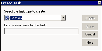
Creating a Task 137
Creating a Task
You can create tasks in the Task Developer, or you can create them in the Workflow Designer
or the Worklet Designer as you develop the workflow or worklet. Tasks you create in the Task
Developer are reusable. Tasks you create in the Workflow Designer and Worklet Designer are
non-reusable by default.
For more information about reusable tasks, see “Reusable Workflow Tasks” on page 139.
Creating a Task in the Task Developer
You can create the following three types of tasks in the Task Developer:
♦Command
♦Session
♦Email
To create a task in the Task Developer:
1. In the Task Developer, click Tasks > Create.
The Create Task dialog box appears.
2. Select the task type you want to create, Command, Session, or Email.
3. Enter a name for the task.
4. For session tasks, select the mapping you want to associate with the session.
5. Click Create.
The Task Developer creates the workflow task.
6. Click Done to close the Create Task dialog box.
Creating a Task in the Workflow or Worklet Designer
You can create and add tasks in the Workflow Designer or Worklet Designer as you develop
the workflow or worklet. You can create any type of task in the Workflow Designer or Worklet
Designer. Tasks you create in the Workflow Designer or Worklet Designer are non-reusable.
Edit the General tab of the task properties to promote a non-reusable task to a reusable task.
138 Chapter 4: Working with Tasks
To create tasks in the Workflow Designer or Worklet Designer:
1. In the Workflow Designer or Worklet Designer, open a workflow or worklet.
2. Click Tasks > Create.
3. Select the type of task you want to create.
4. Enter a name for the task.
5. Click Create.
The Workflow Designer or Worklet Designer creates the task and adds it to the
workspace.
6. Click Done.
You can also use the Tasks toolbar to create and add tasks to the workflow. Click the button
on the Tasks toolbar for the task you want to create. Click again in the Workflow Designer or
Worklet Designer workspace to create and add the task. The Workflow Designer or Worklet
Designer creates the task with a default task name when you use the Tasks toolbar.
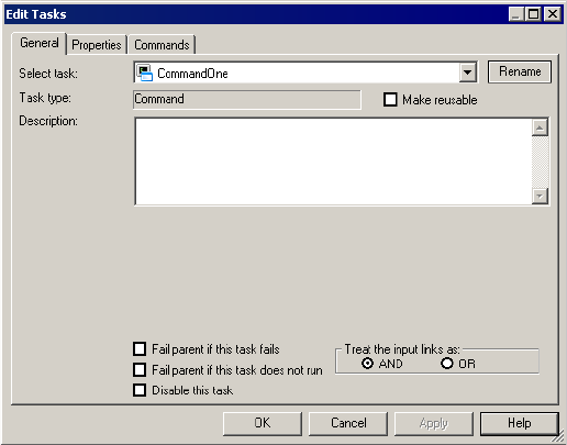
Configuring Tasks 139
Configuring Tasks
After you create the task, you can configure general task options on the General tab. For each
task instance in the workflow, you can configure how the Integration Service runs the task
and the other objects associated with the selected task. You can also disable the task so you can
run rest of the workflow without the selected task.
Figure 4-1 displays the General tab in the Edit Tasks dialog box:
When you use a task in the workflow, you can edit the task in the Workflow Designer and
configure the following task options in the General tab:
♦Fail parent if this task fails. Choose to fail the workflow or worklet containing the task if
the task fails.
♦Fail parent if this task does not run. Choose to fail the workflow or worklet containing
the task if the task does not run.
♦Disable this task. Choose to disable the task so you can run the rest of the workflow
without the task.
♦Treat input link as AND or OR. Choose to have the Integration Service run the task when
all or one of the input link conditions evaluates to True.
Reusable Workflow Tasks
Workflows can contain reusable task instances and non-reusable tasks. Non-reusable tasks
exist within a single workflow. Reusable tasks can be used in multiple workflows in the same
folder.
Figure 4-1. General Tab - Edit Tasks Dialog Box
140 Chapter 4: Working with Tasks
You can create any task as non-reusable or reusable. Tasks you create in the Task Developer are
reusable. Tasks you create in the Workflow Designer are non-reusable by default. However,
you can edit the general properties of a task to promote it to a reusable task.
The Workflow Manager stores each reusable task separate from the workflows that use the
task. You can view a list of reusable tasks in the Tasks node in the Navigator window. You can
see a list of all reusable Session tasks in the Sessions node in the Navigator window.
Promoting a Non-Reusable Workflow Task
You can promote a non-reusable workflow task to a reusable task. Reusable tasks must have
unique names within the repository. When you promote a non-reusable task, the repository
checks for naming conflicts. If a reusable task with the same name already exists, the
repository appends a number to the reusable task name to make it unique. The repository
applies the appended name to the checked-out version and to the latest checked-in version of
the reusable task.
To promote a non-reusable workflow task:
1. In the Workflow Designer, double-click the task you want to make reusable.
2. In the General tab of the Edit Task dialog box, select the Make Reusable option.
3. When prompted whether you are sure you want to promote the task, click Yes.
4. Click OK to return to the workflow.
5. Click Repository > Save.
The newly promoted task appears in the list of reusable tasks in the Tasks node in the
Navigator window.
Instances and Inherited Changes
When you add a reusable task to a workflow, you add an instance of the task. The definition
of the task exists outside the workflow, while an instance of the task exists in the workflow.
You can edit the task instance in the Workflow Designer. Changes you make in the task
instance exist only in the workflow. The task definition remains unchanged in the Task
Developer.
When you make changes to a reusable task definition in the Task Developer, the changes
reflect in the instance of the task in the workflow if you have not edited the instance.
Reverting Changes in Reusable Tasks Instances
When you edit an instance of a reusable task in the workflow, you can revert back to the
settings in the task definition. When you change settings in the task instance, the Revert
button appears. The Revert button appears after you override task properties. You cannot use
the Revert button for settings that are read-only or locked by another user.
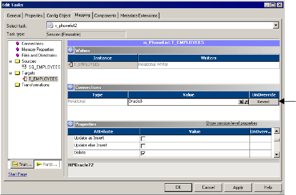
Configuring Tasks 141
Figure 4-2 displays the Revert button in the Mapping tab of a Session task:
AND or OR Input Links
For each task, you can choose to treat the input link as an AND link or an OR link. When a
task has one input link, the Integration Service processes the task when the previous object
completes and the link condition evaluates to True. If you have multiple links going into one
task, you can choose to have an AND input link so that the Integration Service runs the task
when all the link conditions evaluates to True. Or, you can choose to have an OR input link
so that the Integration Service runs the task as soon as any link condition evaluates to True.
To set the type of input links, double-click the task to open the Edit Tasks dialog box. Select
AND or OR for the input link type. For more information about working with links and link
conditions, see “Working with Links” on page 100.
Disabling Tasks
In the Workflow Designer, you can disable a workflow task so that the Integration Service
runs the workflow without the disabled task. The status of a disabled task is DISABLED.
Disable a task in the workflow by selecting the Disable This Task option in the Edit Tasks
dialog box.
Failing Parent Workflow or Worklet
You can choose to fail the workflow or worklet if a task fails or does not run. The workflow or
worklet that contains the task instance is called the parent. A task might not run when the
input condition for the task evaluates to False.
Figure 4-2. Revert Button in Session Properties
Revert Button
142 Chapter 4: Working with Tasks
To fail the parent workflow or worklet if the task fails, double-click the task and select the Fail
Parent If This Task Fails option in the General tab. When you select this option and a task
fails, it does not prevent the other tasks in the workflow or worklet from running. Instead, the
Integration Service marks the status of the workflow or worklet as failed. If you have a session
nested within multiple worklets, you must select the Fail Parent If This Task Fails option for
each worklet instance to see the failure at the workflow level.
To fail the parent workflow or worklet if the task does not run, double-click the task and
select the Fail Parent If This Task Does Not Run option in the General tab. When you choose
this option, the Integration Service fails the parent workflow if a task did not run.
Note: The Integration Service does not fail the parent workflow if you disable a task.
Validating Tasks 143
Validating Tasks
You can validate reusable tasks in the Task Developer. Or, you can validate task instances in
the Workflow Designer. When you validate a task, the Workflow Manager validates task
attributes and links. For example, the user-defined event you specify in an Event tasks must
exist in the workflow.
The Workflow Manager uses the following rules to validate tasks:
♦Assignment. The Workflow Manager validates the expression you enter for the
Assignment task. For example, the Workflow Manager verifies that you assigned a
matching datatype value to the workflow variable in the assignment expression.
♦Command. The Workflow Manager does not validate the shell command you enter for the
Command task.
♦Event-Wait. If you choose to wait for a predefined event, the Workflow Manager verifies
that you specified a file to watch. If you choose to use the Event-Wait task to wait for a
user-defined event, the Workflow Manager verifies that you specified an event.
♦Event-Raise. The Workflow Manager verifies that you specified a user-defined event for
the Event-Raise task.
♦Timer. The Workflow Manager verifies that the variable you specified for the Absolute
Time setting has the Date/Time datatype.
♦Start. The Workflow Manager verifies that you linked the Start task to at least one task in
the workflow.
When a task instance is invalid, the workflow using the task instance becomes invalid. When
a reusable task is invalid, it does not affect the validity of the task instance used in the
workflow. However, if a Session task instance is invalid, the workflow may still be valid. The
Workflow Manager validates sessions differently. For more information, see “Validating a
Session” on page 206.
To validate a task, select the task in the workspace and click Tasks > Validate. Or, right-click
the task in the workspace and choose Validate.
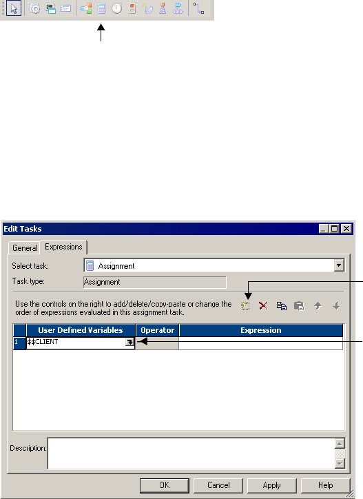
144 Chapter 4: Working with Tasks
Working with the Assignment Task
You can assign a value to a user-defined workflow variable with the Assignment task. To use
an Assignment task in the workflow, first create and add the Assignment task to the workflow.
Then configure the Assignment task to assign values or expressions to user-defined variables.
After you assign a value to a variable using the Assignment task, the Integration Service uses
the assigned value for the variable during the remainder of the workflow.
You must create a variable before you can assign values to it. You cannot assign values to
predefined workflow variables.
To create an Assignment task:
1. In the Workflow Designer, click the Assignment icon on the Tasks toolbar.
-or-
Click Tasks > Create. Select Assignment Task for the task type.
2. Enter a name for the Assignment task. Click Create. Then click Done.
The Workflow Designer creates and adds the Assignment task to the workflow.
3. Double-click the Assignment task to open the Edit Task dialog box.
4. On the Expressions tab, click Add to add an assignment.
5. Click the Open button in the User Defined Variables field.
Assignment Task Toolbar Icon
Add an assignment.
Open Button
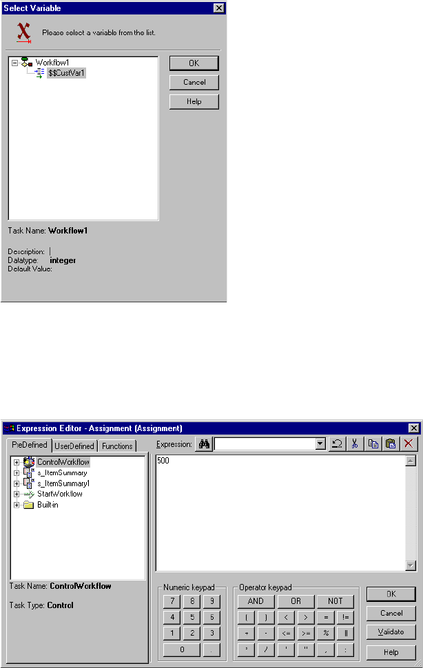
Working with the Assignment Task 145
The Select Variable dialog box appears.
6. Select the variable for which you want to assign a value. Click OK.
7. Click the Edit button in the Expression field to open the Expression Editor.
The Expression Editor shows predefined workflow variables, user-defined workflow
variables, variable functions, and boolean and arithmetic operators.
8. Enter the value or expression you want to assign.
For example, if you want to assign the value 500 to the user-defined variable $$custno1,
enter the number 500 in the Expression Editor.
Working with the Command Task 147
Working with the Command Task
You can specify one or more shell commands to run during the workflow with the Command
task. For example, you can specify shell commands in the Command task to delete reject files,
copy a file, or archive target files.
Use a Command task in the following ways:
♦Standalone Command task. Use a Command task anywhere in the workflow or worklet to
run shell commands.
♦Pre- and post-session shell command. You can call a Command task as the pre- or post-
session shell command for a Session task. For more information about specifying pre-
session and post-session shell commands, see “Using Pre- and Post-Session Shell
Commands” on page 199.
You can use process variables or session parameters in pre- and post-session shell commands.
For example, you might use an input file parameter instead of hard-coding the name of a
source file. You cannot use process variables or session parameters in standalone Command
tasks. The Integration Service does not expand process variables or session parameters in
standalone Command tasks.
Use any valid UNIX command or shell script for UNIX servers, or any valid DOS or batch
file for Windows servers. For example, you might use a shell command to copy a file from one
directory to another. For a Windows server you would use the following shell command to
copy the SALES_ ADJ file from the source directory, L, to the target, H:
copy L:\sales\sales_adj H:\marketing\
For a UNIX server, you would use the following command to perform a similar operation:
cp sales/sales_adj marketing/
Each shell command runs in the same environment (UNIX or Windows) as the Integration
Service. Environment settings in one shell command script do not carry over to other scripts.
To run all shell commands in the same environment, call a single shell script that invokes
other scripts.
Assigning Resources
You can assign resources to Command task instances in the Worklet or Workflow Designer.
You might want to assign resources to a Command task if you assign the workflow to an
Integration Service associated with a grid. When you assign a resource to a Command task
and the Integration Service is configured to check resources, the Load Balancer dispatches the
task to a node that has the resource available. A task fails if the Load Balancer cannot find a
node where the required resource is available.
For information about assigning resources to Command and Session tasks, see “Assigning
Resources to Tasks” on page 564. For information about configuring the Integration Service
to check resources, see “Creating and Configuring the Integration Service” in the
Administrator Guide.
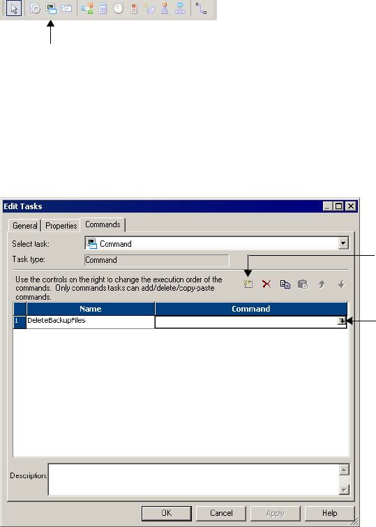
148 Chapter 4: Working with Tasks
Creating a Command Ta s k
Complete the following steps to create a Command task.
To create a Command task:
1. In the Workflow Designer or the Task Developer, click the Command Task icon on the
Tasks toolbar.
-or-
Click Task > Create. Select Command Task for the task type.
2. Enter a name for the Command task. Click Create. Then click Done.
3. Double-click the Command task in the workspace to open the Edit Tasks dialog box.
4. In the Commands tab, click the Add button to add a command.
5. In the Name field, enter a name for the new command.
Command Task Icon
Add Button
Edit Button
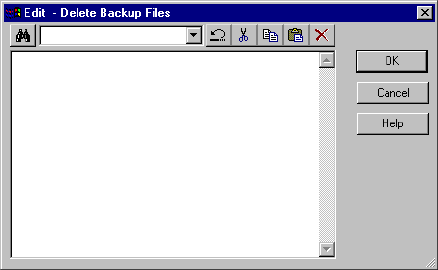
Working with the Command Task 149
6. In the Command field, click the Edit button to open the Command Editor.
7. Enter the command you want to perform. Enter one command in the Command Editor.
8. Click OK to close the Command Editor.
9. Repeat steps 3 to 8 to add more commands in the task.
10. Optionally, click the General tab in the Edit Tasks dialog to assign resources to the
Command task.
For more information about assigning resources to Command and Session tasks, see
“Assigning Resources to Tasks” on page 564.
11. Click OK.
If you specify non-reusable shell commands for a session, you can promote the non-reusable
shell commands to a reusable Command task. For more information, see “Creating a Reusable
Command Task from Pre- or Post-Session Commands” on page 202.
Executing Commands in the Command Task
The Integration Service runs shell commands in the order you specify them. If the Load
Balancer has more Command tasks to dispatch than the Integration Service can run at the
time, the Load Balancer places the tasks it cannot run in a queue. When the Integration
Service becomes available, the Load Balancer dispatches tasks from the queue in the order
determined by the workflow service level. For more information about how the Load Balancer
uses service levels, see “Configuring the Load Balancer” in the Administrator Guide.
You can choose to run a command only if the previous command completed successfully. Or,
you can choose to run all commands in the Command task, regardless of the result of the
previous command. If you configure multiple commands in a Command task to run on
UNIX, each command runs in a separate shell.
If you choose to run a command only if the previous command completes successfully, the
Integration Service stops running the rest of the commands and fails the task when one of the
commands in the Command task fails. If you do not choose this option, the Integration
Service runs all the commands in the Command task and treats the task as completed, even if
a command fails. If you want the Integration Service to perform the next command only if
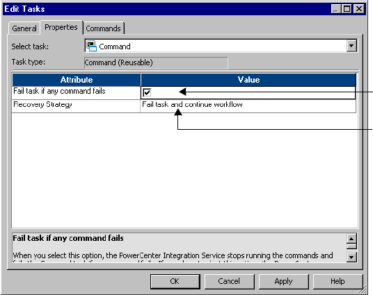
150 Chapter 4: Working with Tasks
the previous command completes successfully, select Fail Task if Any Command Fails in the
Properties tab of the Command task.
Figure 4-3 shows the Fail Task if Any Command Fails option:
You can choose a recovery strategy for the task. The recovery strategy determines how the
Integration Service recovers the task when you configure workflow recovery and the task fails.
You can configure the task to restart or you can configure the task to fail and continue
running the workflow. For more information about recovering tasks, see “Configuring Task
Recovery” on page 346.
Figure 4-3. Fail Task if Any Command Fails Option
Set the task to fail if
any command in the
task fails.
Set the command
recovery strategy to
restart the task or fail
the task and continue
the workflow.
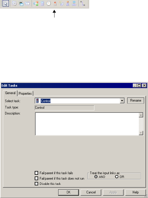
Working with the Control Task 151
Working with the Control Task
Use the Control task to stop, abort, or fail the top-level workflow or the parent workflow
based on an input link condition. A parent workflow or worklet is the workflow or worklet
that contains the Control task.
To create a Control task:
1. In the Workflow Designer, click the Control Task icon on the Tasks toolbar.
-or-
Click Tasks > Create. Select Control Task for the task type.
2. Enter a name for the Control task. Click Create. Then click Done.
The Workflow Manager creates and adds the Control task to the workflow.
3. Double-click the Control task in the workspace to open it.
Control Task Icon
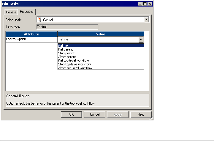
152 Chapter 4: Working with Tasks
4. Configure control options on the Properties tab.
You can choose from the following control options:
Control Option Description
Fail Me Marks the Control task as “Failed.” The Integration Service fails the Control task
if you choose this option. If you choose Fail Me in the Properties tab and choose
Fail Parent If This Task Fails in the General tab, the Integration Service fails the
parent workflow.
Fail Parent Marks the status of the workflow or worklet that contains the Control task as
failed after the workflow or worklet completes.
Stop Parent Stops the workflow or worklet that contains the Control task.
Abort Parent Aborts the workflow or worklet that contains the Control task.
Fail Top-Level Workflow Fails the workflow that is running.
Stop Top-Level Workflow Stops the workflow that is running.
Abort Top-Level Workflow Aborts the workflow that is running.
Working with the Decision Task 153
Working with the Decision Task
You can enter a condition that determines the execution of the workflow, similar to a link
condition with the Decision task. The Decision task has a predefined variable called
$Decision_task_name.condition that represents the result of the decision condition. The
Integration Service evaluates the condition in the Decision task and sets the predefined
condition variable to True (1) or False (0).
You can specify one decision condition per Decision task.
After the Integration Service evaluates the Decision task, use the predefined condition
variable in other expressions in the workflow to help you develop the workflow.
Depending on the workflow, you might use link conditions instead of a Decision task.
However, the Decision task simplifies the workflow. For more information about link
conditions, see “Working with Links” on page 100.
If you do not specify a condition in the Decision task, the Integration Service evaluates the
Decision task to True.
Using the Decision Task
Use the Decision task instead of multiple link conditions in a workflow. Instead of specifying
multiple link conditions, use the predefined condition variable in a Decision task to simplify
link conditions.
Example
For example, you have a Command task that depends on the status of the three sessions in the
workflow. You want the Integration Service to run the Command task when any of the three
sessions fails. To accomplish this, use a Decision task with the following decision condition:
$Q1_session.status = FAILED OR $Q2_session.status = FAILED OR
$Q3_session.status = FAILED
You can then use the predefined condition variable in the input link condition of the
Command task. Configure the input link with the following link condition:
$Decision.condition = True
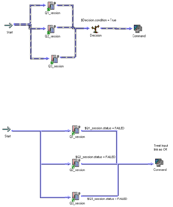
154 Chapter 4: Working with Tasks
Figure 4-4 shows the sample workflow using a Decision task:
You can configure the same logic in the workflow without the Decision task. Without the
Decision task, you need to use three link conditions and treat the input links to the
Command task as OR links.
Figure 4-5 shows the sample workflow without the Decision task:
You can further expand the sample workflow in Figure 4-4. In Figure 4-4, the Integration
Service runs the Command task if any of the three Session tasks fails. Suppose now you want
the Integration Service to also run an Email task if all three Session tasks succeed.
Figure 4-4. Sample Workflow Using a Decision Task
Figure 4-5. Sample Workflow Without a Decision Task
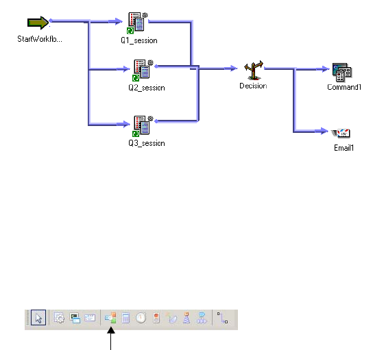
Working with the Decision Task 155
To do this, add an Email task and use the decision condition variable in the link condition.
Figure 4-6 shows the expanded sample workflow using a Decision task:
Creating a Decision Task
Complete the following steps to create a Decision task.
To create a Decision task:
1. In the Workflow Designer, click the Decision Task icon on the Tasks toolbar.
-or-
Click Tasks > Create. Select Decision Task for the task type.
2. Enter a name for the Decision task. Click Create. Then click Done.
The Workflow Designer creates and adds the Decision task to the workspace.
Figure 4-6. Expanded Sample Workflow Using a Decision Task
$Decision.condition = True
$Decision.condition = False
Decision Task Icon
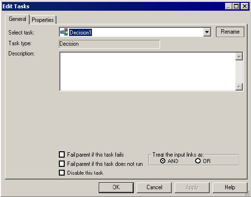
156 Chapter 4: Working with Tasks
3. Double-click the Decision task to open it.
4. Click the Open button in the Value field to open the Expression Editor.
5. In the Expression Editor, enter the condition you want the Integration Service to
evaluate.
Validate the expression before you close the Expression Editor.
6. Click OK.
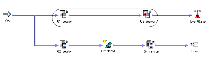
Working with Event Tasks 157
Working with Event Tasks
You can define events in the workflow to specify the sequence of task execution. The event is
triggered based on the completion of the sequence of tasks. Use the following tasks to help
you use events in the workflow:
♦Event-Raise task. Event-Raise task represents a user-defined event. When the Integration
Service runs the Event-Raise task, the Event-Raise task triggers the event. Use the Event-
Raise task with the Event-Wait task to define events.
♦Event-Wait task. The Event-Wait task waits for an event to occur. Once the event triggers,
the Integration Service continues executing the rest of the workflow.
To coordinate the execution of the workflow, you may specify the following types of events for
the Event-Wait and Event-Raise tasks:
♦Predefined event. A predefined event is a file-watch event. For predefined events, use an
Event-Wait task to instruct the Integration Service to wait for the specified indicator file to
appear before continuing with the rest of the workflow. When the Integration Service
locates the indicator file, it starts the next task in the workflow.
♦User-defined event. A user-defined event is a sequence of tasks in the workflow. Use an
Event-Raise task to specify the location of the user-defined event in the workflow. A user-
defined event is sequence of tasks in the branch from the Start task leading to the Event-
Raise task.
When all the tasks in the branch from the Start task to the Event-Raise task complete, the
Event-Raise task triggers the event. The Event-Wait task waits for the Event-Raise task to
trigger the event before continuing with the rest of the tasks in its branch.
Example of User-Defined Events
Say you have four sessions you want to run in a workflow. You want Q1_session and
Q2_session to run concurrently to save time. You also want to run Q3_session after
Q1_session completes. You want to run Q4_session only when Q1_session, Q2_session, and
Q3_session complete.
Figure 4-7 shows how to accomplish this using the Event-Raise and Event-Wait tasks:
Figure 4-7. Example of User-Defined Events
User-defined event: Q1Q3_Complete
158 Chapter 4: Working with Tasks
Complete the following steps to configure the workflow shown in Figure 4-7:
1. Link Q1_session and Q2_session concurrently.
2. Add Q3_session after Q1_session.
3. Declare an event called Q1Q3_Complete in the Events tab of the workflow properties.
4. In the workspace, add an Event-Raise task after Q3_session.
5. Specify the Q1Q3_Complete event in the Event-Raise task properties. This allows the
Event-Raise task to trigger the event when Q1_session and Q3_session complete.
6. Add an Event-Wait task after Q2_session.
7. Specify the Q1Q3_Complete event for the Event-Wait task.
8. Add Q4_session after the Event-Wait task. When the Integration Service processes the
Event-Wait task, it waits until the Event-Raise task triggers Q1Q3_Complete before it
runs Q4_session.
The Integration Service runs the workflow shown in Figure 4-7 in the following order:
1. The Integration Service runs Q1_session and Q2_session concurrently.
2. When Q1_session completes, the Integration Service runs Q3_session.
3. The Integration Service finishes executing Q2_session.
4. The Event-Wait task waits for the Event-Raise task to trigger the event.
5. The Integration Service completes Q3_session.
6. The Event-Raise task triggers the event, Q1Q3_complete.
7. The Integration Service runs Q4_session because the event, Q1Q3_Complete, has been
triggered.
8. The Integration Service runs the Email task.
Working with Event-Raise Tasks
The Event-Raise task represents the location of a user-defined event. A user-defined event is
the sequence of tasks in the branch from the Start task to the Event-Raise task. When the
Integration Service runs the Event-Raise task, the Event-Raise task triggers the user-defined
event.
To use an Event-Raise task, you must first declare the user-defined event. Then, create an
Event-Raise task in the workflow to represent the location of the user-defined event you just
declared. In the Event-Raise task properties, specify the name of a user-defined event.
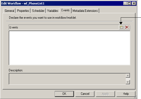
Working with Event Tasks 159
Declaring a User-Defined Event
Complete the following steps to declare a name for a user-defined event.
To declare a user-defined event:
1. In the Workflow Designer, click Workflow > Edit to open the workflow properties.
2. Select the Events tab in the Edit Workflow dialog box.
3. Click Add to add an event name.
Event name is not case sensitive.
4. Click OK.
Using the Event-Raise Task for a User-Defined Event
After you declare a user-defined event, use the Event-Raise task to represent the location of
the event and to trigger the event.
To use an Event-Raise task:
1. In the Workflow Designer workspace, create an Event-Raise task and place it in the
workflow to represent the user-defined event you want to trigger.
A user-defined event is the sequence of tasks in the branch from the Start task to the
Event-Raise task.
Add a user-
defined event.
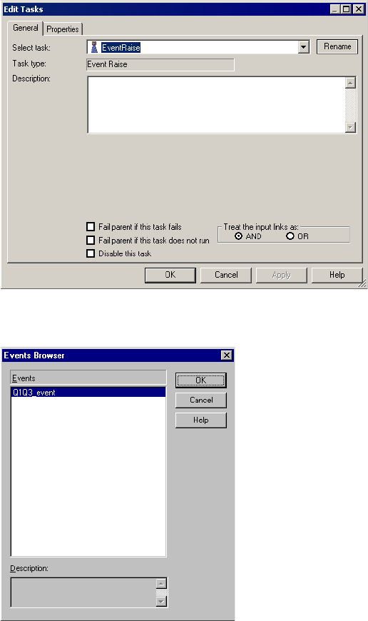
160 Chapter 4: Working with Tasks
2. Double-click the Event-Raise task to open it.
3. Click the Open button in the Value field on the Properties tab to open the Events
Browser for user-defined events.
4. Choose an event in the Events Browser.
5. Click OK twice to return to the workspace.
Working with Event-Wait Tasks
The Event-Wait task waits for a predefined event or a user-defined event. A predefined event
is a file-watch event. When you use the Event-Wait task to wait for a predefined event, you
specify an indicator file for the Integration Service to watch. The Integration Service waits for
Working with Event Tasks 161
the indicator file to appear. Once the indicator file appears, the Integration Service continues
running tasks after the Event-Wait task.
You can assign resources to Event-Wait tasks that wait for predefined events. You may want to
assign a resource to a predefined Event-Wait task if you are running on a grid and the
indicator file appears on a specific node or in a specific directory. When you assign a resource
to a predefined Event-Wait task and the Integration Service is configured to check resources,
the Load Balancer distributes the task to a node where the required resource is available. For
more information about assigning resources to tasks, see “Assigning Resources to Tasks” on
page 564. For more information about configuring the Integration Service to check resources,
see “Creating and Configuring the Integration Service” in the Administrator Guide.
Note: If you use the Event-Raise task to trigger the event when you wait for a predefined event,
you may not be able to successfully recover the workflow.
You can also use the Event-Wait task to wait for a user-defined event. To use the Event-Wait
task for a user-defined event, specify the name of the user-defined event in the Event-Wait
task properties. The Integration Service waits for the Event-Raise task to trigger the user-
defined event. Once the user-defined event is triggered, the Integration Service continues
running tasks after the Event-Wait task.
Waiting for User-Defined Events
Use the Event-Wait task to wait for a user-defined event. A user-defined event is triggered by
the Event-Raise task. To wait for a user-defined event, you must first use an Event-Raise task
to trigger the user-defined event.
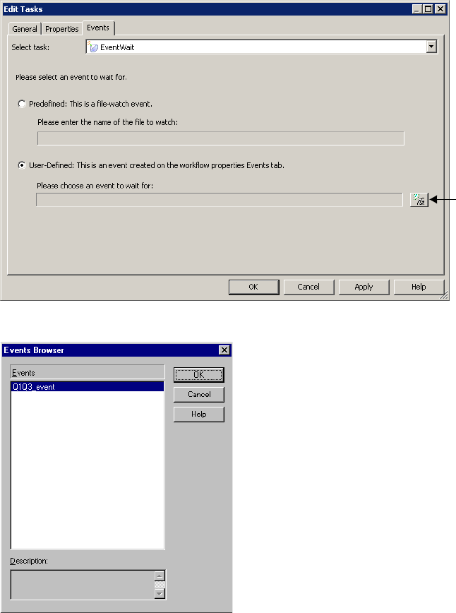
162 Chapter 4: Working with Tasks
To wait for a user-defined event:
1. In the workflow, create an Event-Wait task and double-click the Event-Wait task to open
it.
2. In the Events tab of the task, select User-Defined.
3. Click the Event button to open the Events Browser dialog box.
4. Select a user-defined event for the Integration Service to wait.
5. Click OK twice.
Open the
Events
Browser.
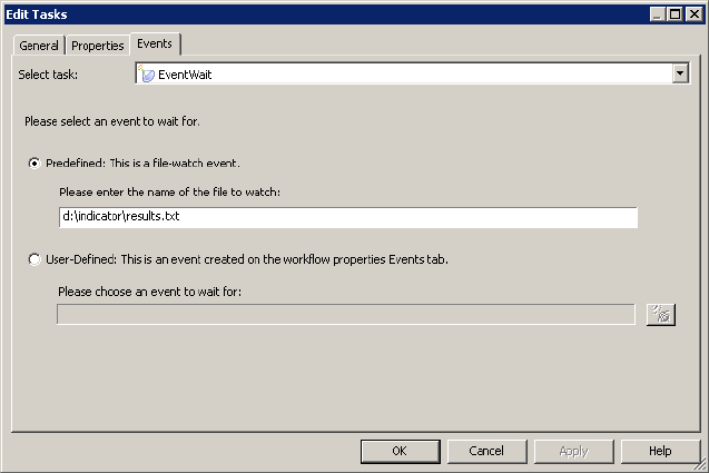
Working with Event Tasks 163
Waiting for Predefined Events
To use a predefined event, you need a shell command, script, or batch file to create an
indicator file. The file must be created or sent to a directory that the Integration Service can
access. The file can be any format recognized by the Integration Service operating system. You
can choose to have the Integration Service delete the indicator file after it detects the file, or
you can manually delete the indicator file. The Integration Service marks the status of the
Event-Wait task as failed if it cannot delete the indicator file.
When you specify the indicator file in the Event-Wait task, enter the directory in which the
file appears and the name of the indicator file. You must provide the absolute path for the file.
If you specify the file name and not the directory, the Integration Service looks for the
indicator file in the following directory:
♦On Windows, the Integration Service looks for the file in the system directory. For
example, on Windows 2000, the system directory is c:\winnt\system32.
♦On UNIX, the Integration Service looks for the indicator file in the current working
directory for the Integration Service process. On UNIX this directory is /server/bin.
You can enter the actual name of the file or use process variables to specify the location of the
files.
The Integration Service writes the time the file appears in the workflow log.
Note: Do not use a source or target file name as the indicator file name.
To wait for a predefined event in the workflow:
1. Create an Event-Wait task and double-click the Event-Wait task to open it.
2. In the Events tab of the task, select Predefined.
3. Enter the path of the indicator file.
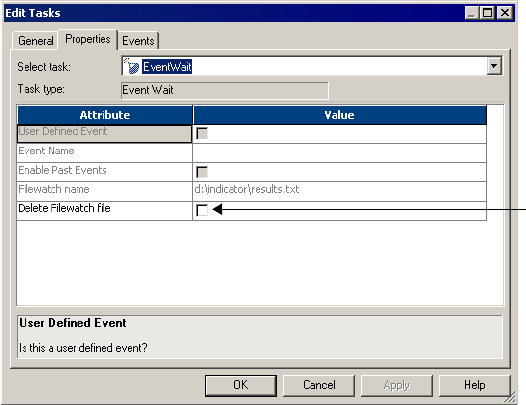
164 Chapter 4: Working with Tasks
4. If you want the Integration Service to delete the indicator file after it detects the file,
select the Delete Filewatch File option in the Properties tab.
5. Click OK.
Enabling Past Events
By default, the Event-Wait task waits for the Event-Raise task to trigger the event. By default,
the Event-Wait task does not check if the event already occurred. You can select the Enable
Past Events option so that the Integration Service verifies that the event has already occurred.
When you select Enable Past Events, the Integration Service continues executing the next
tasks if the event already occurred.
Select the Enable Past Events option in the Properties tab of the Event-Wait task.
Delete Filewatch File
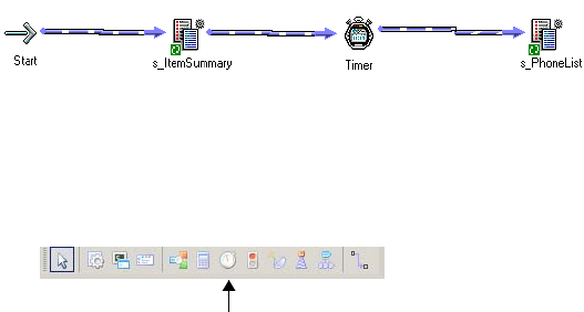
Working with the Timer Task 165
Working with the Timer Task
You can specify the period of time to wait before the Integration Service runs the next task in
the workflow with the Timer task. You can choose to start the next task in the workflow at a
specified time and date. You can also choose to wait a period of time after the start time of
another task, workflow, or worklet before starting the next task.
The Timer task has two types of settings:
♦Absolute time. You specify the time that the Integration Service starts running the next
task in the workflow. You may specify the date and time, or you can choose a user-defined
workflow variable to specify the time.
♦Relative time. You instruct the Integration Service to wait for a specified period of time
after the Timer task, the parent workflow, or the top-level workflow starts.
For example, you may have two sessions in the workflow. You want the Integration Service
wait 10 minutes after the first session completes before it runs the second session. Use a Timer
task after the first session. In the Relative Time setting of the Timer task, specify ten minutes
from the start time of the Timer task.
Figure 4-8 shows the sample workflow using the Timer task:
Use a Timer task anywhere in the workflow after the Start task.
To create a Timer task:
1. In the Workflow Designer, click the Timer task icon on the Tasks toolbar.
-or-
Click Tasks > Create. Select Timer Task for the task type.
2. Double-click the Timer task to open it.
3. On the General tab, enter a name for the Timer task.
Figure 4-8. Sample Workflow Using the Timer Task
Timer Task Toolbar Icon
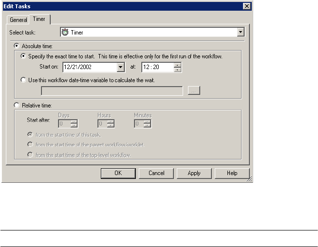
166 Chapter 4: Working with Tasks
4. Click the Timer tab to specify when the Integration Service starts the next task in the
workflow.
5. Specify attributes for Absolute Time or Relative Time described in Table 4-2 :
Table 4-2. Timer Task Attributes
Timer Attribute Description
Absolute Time: Specify the
exact time to start
Integration Service starts the next task in the workflow at the date
and time you specify.
Absolute Time: Use this
workflow date-time variable to
calculate the wait
Specify a user-defined date-time workflow variable. The Integration
Service starts the next task in the workflow at the time you choose.
The Workflow Manager verifies that the variable you specify has
the Date/Time datatype.
The Timer task fails if the date-time workflow variable evaluates to
NULL.
Relative time: Start after Specify the period of time the Integration Service waits to start
executing the next task in the workflow.
Relative time: from the start
time of this task
Select this option to wait a specified period of time after the start
time of the Timer task to run the next task.
Relative time: from the start
time of the parent workflow/
worklet
Select this option to wait a specified period of time after the start
time of the parent workflow/worklet to run the next task.
Relative time: from the start
time of the top-level workflow
Choose this option to wait a specified period of time after the start
time of the top-level workflow to run the next task.

168 Chapter 5: Working with Worklets
Overview
A worklet is an object that represents a set of tasks that you create in the Worklet Designer.
Create a worklet when you want to reuse a set of workflow logic in more than one workflow.
To run a worklet, include the worklet in a workflow. The workflow that contains the worklet
is called the parent workflow. When the Integration Service runs a worklet, it expands the
worklet to run tasks and evaluate links within the worklet. It writes information about
worklet execution in the workflow log.
Suspending Worklets
When you choose Suspend on Error for the parent workflow, the Integration Service also
suspends the worklet if a task in the worklet fails. When a task in the worklet fails, the
Integration Service stops executing the failed task and other tasks in its path. If no other task
is running in the worklet, the worklet status is “Suspended.” If one or more tasks are still
running in the worklet, the worklet status is “Suspending.” The Integration Service suspends
the parent workflow when the status of the worklet is “Suspended” or “Suspending.”
For more information about suspending workflows, see “Suspending the Workflow” on
page 130.
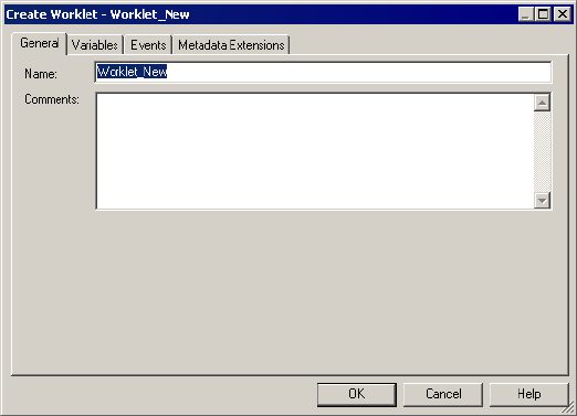
Developing a Worklet 169
Developing a Worklet
To develop a worklet, you must first create a worklet. After you create a worklet, configure
worklet properties and add tasks to the worklet. You can create reusable worklets in the
Worklet Designer. You can also create non-reusable worklets in the Workflow Designer as you
develop the workflow.
Creating a Reusable Worklet
Create reusable worklets in the Worklet Designer. You can view a list of reusable worklets in
the Navigator Worklets node.
To create a reusable worklet:
1. In the Worklet Designer, click Worklet > Create.
The Create Worklet dialog box appears.
2. Enter a name for the worklet.
3. Click OK.
The Worklet Designer creates a Start task in the worklet.
Creating a Non-Reusable Worklet
You can create a non-reusable worklet in the Workflow Designer as you develop the workflow.
Non-reusable worklets only exist in the workflow. You cannot use a non-reusable worklet in
another workflow. After you create the worklet in the Workflow Designer, open the worklet to
edit it in the Worklet Designer.
170 Chapter 5: Working with Worklets
You can promote non-reusable worklets to reusable worklets by selecting the Make Reusable
option in the worklet properties. To rename a non-reusable worklet, open the worklet
properties in the Workflow Designer.
To create a non-reusable worklet:
1. In the Workflow Designer, open a workflow.
2. Click Tasks > Create.
3. For the Task type, select Worklet.
4. Enter a name for the task.
5. Click Create.
The Workflow Designer creates the worklet and adds it to the workspace.
6. Click Done.
Configuring Worklet Properties
When you use a worklet in a workflow, you can configure the same set of general task settings
on the General tab as any other task. For example, you can make a worklet reusable, disable a
worklet, configure the input link to the worklet, or fail the parent workflow based on the
worklet. For more information about these task settings, see “Configuring Tasks” on
page 139.
In addition to general task settings, you can configure the following worklet properties:
♦Worklet variables. Use worklet variables to reference values and record information. You
use worklet variables the same way you use workflow variables. You can assign a workflow
variable to a worklet variable to override its initial value.
For more information about worklet variables, see “Using Worklet Variables” on page 173.
♦Events. To use the Event-Wait and Event-Raise tasks in the worklet, you must first declare
an event in the worklet properties.
♦Metadata extension. Extend the metadata stored in the repository by associating
information with repository objects. For more information, see “Working with Metadata
Extensions” on page 29.
Adding Tasks in Worklets
After you create a worklet, add tasks by opening the worklet in the Worklet Designer. A
worklet must contain a Start task. The Start task represents the beginning of a worklet. When
you create a worklet, the Worklet Designer creates a Start task for you.
To add tasks to a non-reusable worklet:
1. Create a non-reusable worklet in the Workflow Designer workspace.
2. Right-click the worklet and choose Open Worklet.
Developing a Worklet 171
The Worklet Designer opens so you can add tasks in the worklet.
3. Add tasks in the worklet by using the Tasks toolbar or click Tasks > Create in the Worklet
Designer.
4. Connect tasks with links.
Declaring Events in Worklets
Use Event-Wait and Event-Raise tasks in a worklet like you would use workflows. To use the
Event-Raise task, you first declare a user-defined event in the worklet. Events in one instance
of a worklet do not affect events in other instances of the worklet. You cannot specify worklet
events in the Event tasks in the parent workflow.
For more information about using event tasks, see “Working with Event Tasks” on page 157.
Viewing Links in a Worklet
When you edit a workflow or worklet, you can view the forward or backward link paths to
other tasks. You can highlight paths to see links in the workflow branch from the Start task to
the last task in the branch. For more information, see “Creating a Workflow” on page 91.
Nesting Worklets
You can nest a worklet within another worklet. When you run a workflow containing nested
worklets, the Integration Service runs the nested worklet from within the parent worklet. You
can group several worklets together by function or simplify the design of a complex workflow
when you nest worklets.
You might choose to nest worklets to load data to fact and dimension tables. Create a nested
worklet to load fact and dimension data into a staging area. Then, create a nested worklet to
load the fact and dimension data from the staging area to the data warehouse.
You might choose to nest worklets to simplify the design of a complex workflow. Nest
worklets that can be grouped together within one worklet. In the workflow in Figure 5-1, two
worklets relate to regional sales and two worklets relate to quarterly sales.
Figure 5-1 shows a workflow that uses multiple worklets:
Figure 5-1. Workflow with Multiple Worklets
172 Chapter 5: Working with Worklets
The workflow in Figure 5-2 shows the same workflow with the worklets grouped and nested
in parent worklets.
Figure 5-2 shows a workflow that uses nested worklets:
Creating Nested Worklets
From the Worklet Designer, open the parent worklet. To nest an existing reusable worklet,
click Tasks > Insert Worklet. To create a non-reusable nested worklet, click Tasks > Create,
and select worklet.
Figure 5-2. Workflow with Nested Worklets
Using Worklet Variables 173
Using Worklet Variables
Worklet variables are similar to workflow variables. A worklet has the same set of predefined
variables as any task. You can also create user-defined worklet variables. Like user-defined
workflow variables, user-defined worklet variables can be persistent or non-persistent. For
more information about workflow variables, see “Using Workflow Variables” on page 106.
Persistent Worklet Variables
User-defined worklet variables can be persistent or non-persistent. To create a persistent
worklet variable, select Persistent when you create the variable. When you create a persistent
worklet variable, the worklet variable retains its value the next time the Integration Service
runs the worklet in the parent workflow.
For example, you have a worklet with a persistent variable. Use two instances of the worklet in
a workflow to run the worklet twice. You name the first instance of the worklet Worklet1 and
the second instance Worklet2.
When you run the workflow, the persistent worklet variable retains its value from Worklet1
and becomes the initial value in Worklet2. After the Integration Service runs Worklet2, it
retains the value of the persistent variable in the repository and uses the value the next time
you run the workflow.
Worklet variables only persist when you run the same workflow. A worklet variable does not
retain its value when you use instances of the worklet in different workflows.
Overriding the Initial Value
For each worklet instance, you can override the initial value of the worklet variable by
assigning a workflow variable to it.
174 Chapter 5: Working with Worklets
To override the initial value of a worklet variable:
1. Double-click the worklet instance in the Workflow Designer workspace.
2. On the Parameters tab, click the Add button.
3. Click the open button in the User-Defined Worklet Variables field to select a worklet
variable.
4. Click Apply.
The worklet variable in this worklet instance now has the selected workflow variable as its
initial value.
Rules and Guidelines
Use the following rules and guidelines when you work with worklet variables:
♦You cannot use variables from the parent workflow in the worklet.
♦You cannot use user-defined worklet variables in the parent workflow.
♦You can use predefined worklet variables in the parent workflow, just as you use predefined
variables for other tasks in the workflow.
Add Button
Select a user-defined
worklet variable.
Validating Worklets 175
Validating Worklets
The Workflow Manager validates worklets when you save the worklet in the Worklet
Designer. In addition, when you use worklets in a workflow, the Integration Service validates
the workflow according to the following validation rules at run time:
♦You cannot run two instances of the same worklet concurrently in the same workflow.
♦You cannot run two instances of the same worklet concurrently across two different
workflows.
♦Each worklet instance in the workflow can run once.
When a worklet instance is invalid, the workflow using the worklet instance remains valid.
For more information about workflow validation rules, see “Validating a Workflow” on
page 125.
The Workflow Manager displays a red invalid icon if the worklet object is invalid. The
Workflow Manager validates the worklet object using the same validation rules for workflows.
The Workflow Manager displays a blue invalid icon if the worklet instance in the workflow is
invalid. The worklet instance may be invalid when any of the following conditions occurs:
♦The parent workflow or worklet variable you assign to the user-defined worklet variable
does not have a matching datatype.
♦The user-defined worklet variable you used in the worklet properties does not exist.
♦You do not specify the parent workflow or worklet variable you want to assign.
For non-reusable worklets, you may see both red and blue invalid icons displayed over the
worklet icon in the Navigator.
176 Chapter 5: Working with Worklets

177
Chapter 6
Working with Sessions
This chapter includes the following topics:
♦Overview, 178
♦Creating a Session Task, 179
♦Editing a Session, 181
♦Understanding Buffer Memory, 187
♦Configuring Automatic Memory Settings, 188
♦Creating a Session Configuration Object, 192
♦Configuring Performance Details, 195
♦Using Pre- and Post-Session SQL Commands, 197
♦Using Pre- and Post-Session Shell Commands, 199
♦Using Post-Session Email, 205
♦Validating a Session, 206
♦Stopping and Aborting a Session, 208
♦Working with Session Parameters, 211
♦Mapping Parameters and Variables in Sessions, 215
♦Handling High Precision Data, 216
178 Chapter 6: Working with Sessions
Overview
A session is a set of instructions that tells the Integration Service how and when to move data
from sources to targets. A session is a type of task, similar to other tasks available in the
Workflow Manager. In the Workflow Manager, you configure a session by creating a Session
task. To run a session, you must first create a workflow to contain the Session task.
When you create a Session task, you enter general information such as the session name,
session schedule, and the Integration Service to run the session. You can also select options to
run pre-session shell commands, send On-Success or On-Failure email, and use FTP to
transfer source and target files.
You can configure the session to override parameters established in the mapping, such as
source and target location, source and target type, error tracing levels, and transformation
attributes. You can also configure the session to collect performance details for the session and
store them in the PowerCenter repository. You might view performance details for a session
to tune the session.
You can run as many sessions in a workflow as you need. You can run the Session tasks
sequentially or concurrently, depending on the requirement.
The Integration Service creates several files and in-memory caches depending on the
transformations and options used in the session. For more information about session output
files and caches, see “Integration Service Architecture” in the Administrator Guide.
Creating a Session Task 179
Creating a Session Task
You create a Session task for each mapping you want the Integration Service to run. The
Integration Service uses the instructions configured in the session to move data from sources
to targets.
You can create a reusable Session task in the Task Developer. You can also create non-
reusable Session tasks in the Workflow Designer as you develop the workflow. After you
create the session, you can edit the session properties at any time.
Note: Before you create a Session task, you must configure the Workflow Manager to
communicate with databases and the Integration Service. You must assign appropriate
permissions for any database, FTP, or external loader connections you configure. For more
information about configuring the Workflow Manager, see “Working with Connection
Objects” on page 37.
Session Privileges
To create sessions, you must have one of the following sets of privileges and permissions:
♦Use Workflow Manager privilege with read, write, and execute permissions
♦Super User privilege
You must have read permission for connection objects associated with the session in addition
to the above privileges and permissions.
You can set a read-only privilege for sessions with PowerCenter. The Workflow Operator
privilege allows a user to view, start, stop, and monitor sessions without being able to edit
session properties.
Steps to Create a Session Task
Create the Session task in the Task Developer or the Workflow Designer. Session tasks
created in the Task Developer are reusable. For more information about reusable tasks and
other general information about workflow tasks, see “Reusable Workflow Tasks” on page 139.
To create a Session task:
1. In the Workflow Designer, click the Session Task icon on the Tasks toolbar.
-or-
Click Tasks > Create. Select Session Task for the task type.
2. Enter a name for the Session task.
3. Click Create.
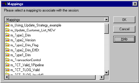
180 Chapter 6: Working with Sessions
The Mappings dialog box appears.
4. Select the mapping you want to use in the Session task and click OK.
5. Click Done. The Session task appears in the workspace.
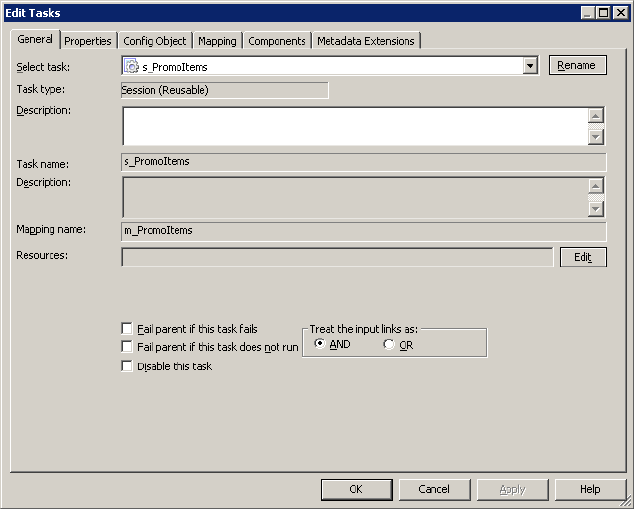
Editing a Session 181
Editing a Session
After you create a session, you can edit it. For example, you might need to adjust the buffer
and cache sizes, modify the update strategy, or clear a variable value saved in the repository.
Double-click the Session task to open the session properties. The session has the following
tabs, and each of those tabs has multiple settings:
♦General tab. Enter session name, mapping name, and description for the Session task,
assign resources, and configure additional task options.
♦Properties tab. Enter session log information, test load settings, and performance
configuration.
♦Config Object tab. Enter advanced settings, log options, and error handling
configuration.
♦Mapping tab. Enter source and target information, override transformation properties,
and configure the session for partitioning.
♦Components tab. Configure pre- or post-session shell commands and emails.
♦Metadata Extension tab. Configure metadata extension options.
For a detailed description of the session properties tabs and associated options, see “Session
Properties Reference” on page 699.
Figure 6-1 shows the session properties:
Figure 6-1. Session Properties
182 Chapter 6: Working with Sessions
You can edit session properties at any time. The repository updates the session properties
immediately.
If the session is running when you edit the session, the repository updates the session when
the session completes. If the mapping changes, the Workflow Manager might issue a warning
that the session is invalid. The Workflow Manager then lets you continue editing the session
properties. After you edit the session properties, the Integration Service validates the session
and reschedules the session. For more information about session validation, see “Validating a
Session” on page 206.
Edit Session Privilege
To edit a session, you must have one of the following sets of privileges and permissions:
♦Use Workflow Manager privilege with read and write permissions on the folder
♦Super User privilege
Applying Attributes to All Instances
When you edit the session properties, you can apply source, target, and transformation
settings to all instances of the same type in the session. You can also apply settings to all
partitions in a pipeline. You can apply reader or writer settings, connection settings, and
properties settings.
For example, you might need to change a relational connection from a test to a production
database for all the target instances in a session. You can change the connection value for one
target in a session and apply the connection to the other relational target objects.
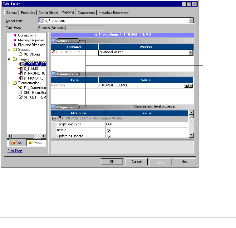
Editing a Session 183
Figure 6-2 shows the writers, connections, and properties settings for a target instance in a
session:
Table 6-1 shows the options you can use to apply attributes to objects in a session. You can
apply different options depending on whether the setting is a reader or writer, connection, or
an object property.
Figure 6-2. Session Target Object Settings
Table 6-1. Apply All Options
Setting Option Description
Reader
Writer
Apply Type to All Instances Applies a reader or writer type to all instances of the same object
type in the session. For example, you can apply a relational
reader type to all the other readers in the session.
Reader
Writer
Apply Type to All Partitions Applies a reader or writer type to all the partitions in a pipeline.
For example, if you have four partitions, you can change the writer
type in one partition for a target instance. Use this option to apply
the change to the other three partitions.
Connections Apply Connection Type Applies the same type of connection to all instances. Connection
types are relational, FTP, queue, application, or external loader.
For a target
instance, you
can change
writers,
connections,
and properties
settings.

184 Chapter 6: Working with Sessions
Applying Connection Settings
When you apply connection settings you can apply the connection type, connection value,
and connection attributes. You can only apply a connection value that is valid for a
connection type unless you choose the Apply All Connection Information option. For
example, if a target instance uses an FTP connection, you can only choose an FTP connection
value to apply to it. The Apply All Connection Information option lets you apply a new
connection type, connection value, and connection attributes.
Connections Apply Connection Value Apply a connection value to all instances or partitions. The
connection value defines a specific connection that you can view
in the connection browser. You can apply a connection value that
is valid for the existing connection type.
Connections Apply Connection Attributes Apply only the connection attribute values to all instances or
partitions. Each type of connection has different attributes. You
can apply connection attributes separately from connection
values. To view sample connection attributes, see Figure 6-3 on
page 185.
Connections Apply Connection Data Apply the connection value and its connection attributes to all the
other instances that have the same connection type. This option
combines the connection option and the connection attribute
option.
Connections Apply All Connection
Information
Applies the connection value and its attributes to all the other
instances even if they do not have the same connection type. This
option is similar to Apply Connection Data, but it lets you change
the connection type.
Properties Apply Attribute to all
Instances
Applies an attribute value to all instances of the same object type
in the session. For example, if you have a relational target you can
choose to truncate a table before you load data. You can apply the
attribute value to all the relational targets in the session.
Properties Apply Attribute to all
Partitions
Applies an attribute value to all partitions in a pipeline. For
example, you can change the name of the reject file name in one
partition for a target instance, then apply the file name change to
the other partitions.
Table 6-1. Apply All Options
Setting Option Description
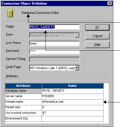
Editing a Session 185
Figure 6-3 illustrates the connection options by showing where they display on a connection
browser:
Applying Attributes to Partitions or Instances
When you apply attributes to all instances or partitions in a session, you must open the
session and edit one of the session objects. You apply attributes or properties to other
instances by choosing an attribute in that object and selecting to apply its value to the other
instances or partitions.
To apply attributes to all instances or partitions:
1. Open a session in the workspace.
2. Click the Mappings tab.
3. Choose a source, target, or transformation instance from the Navigator. Settings for
properties, connections, and readers or writers might display, depending on the object
you choose.
Figure 6-3. Connection Options
The connection type can be relational, FTP, queue,
application, or external loader.
The connection value defines a specific connection.
Connection attributes are different for each
connection type.
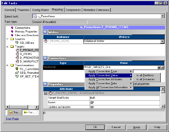
186 Chapter 6: Working with Sessions
4. Right-click a reader, writer, property, or connection value. A list of options appear.
5. Select an option from the list and choose to apply it to all instances or all partitions.
6. Click OK to apply the attribute or property.
Understanding Buffer Memory 187
Understanding Buffer Memory
When you run a session, the Integration Service process starts the Data Transformation
Manager (DTM). The DTM allocates buffer memory to the session at runtime based on the
DTM Buffer Size setting in the session properties.
The DTM divides the memory into buffer blocks as configured in the Default Buffer Block
Size setting in the session properties. The reader, transformation, and writer threads use buffer
blocks to move data from sources to targets. The buffer block size should be larger than the
precision for the largest row of data in a source or target.
The Integration Service allocates at least two buffer blocks for each source and target
partition. Use the following calculation to determine buffer block requirements:
[(total number of sources + total number of targets)* 2] = (session buffer
blocks)
For example, a session that contains a single partition using a mapping that contains 50
sources and 50 targets requires a minimum of 200 buffer blocks.
[(50 + 50)* 2] = 200
You configure buffer memory settings by adjusting the following session parameters:
♦DTM Buffer Size. The DTM buffer size specifies the amount of buffer memory the
Integration Service uses when the DTM processes a session. Configure the DTM buffer
size on the Properties tab in the session properties.
♦Default Buffer Block Size. The buffer block size specifies the amount of buffer memory
used to move a block of data from the source to the target. Configure the buffer block size
on the Config Object tab in the session properties.
The Integration Service specifies a minimum memory allocation for the buffer memory and
buffer blocks. By default, the Integration Service allocates 12,000,000 bytes of memory to the
buffer memory and 64,000 bytes per block.
If the DTM cannot allocate the configured amount of buffer memory for the session, the
session cannot initialize. Usually, you do not need more than 1 GB for the buffer memory.
You can configure a numeric value for the buffer size, or you can configure the session to
determine the buffer memory size at runtime. For more information about configuring
automatic memory settings, see “Configuring Automatic Memory Settings” on page 188.
For information about configuring buffer memory or buffer block size, see “Optimizing
Sessions” in the Performance Tuning Guide.
188 Chapter 6: Working with Sessions
Configuring Automatic Memory Settings
You can configure the Integration Service to determine buffer memory size and session cache
size at runtime. When you run a session, the Integration Service allocates buffer memory to
the session to move the data from the source to the target. It also creates session caches in
memory. Session caches include index and data caches for the Aggregator, Rank, Joiner, and
Lookup transformations, as well as Sorter and XML target caches. The values stored in the
data and index caches depend upon the requirements of the transformation. For example, the
Aggregator index cache stores group values as configured in the group by ports, and the data
cache stores calculations based on the group by ports. When the Integration Service processes
a Sorter transformation or writes data to an XML target, it also creates a cache.
You configure buffer memory and cache memory settings in the transformation and session
properties. When you configure buffer memory and cache memory settings, consider the
overall memory usage for best performance.
Note: You enable automatic memory settings by configuring a value for the Maximum
Memory Allowed for Auto Memory Attributes or the Maximum Percentage of Total Memory
Allowed for Auto Memory Attributes. If the value is set to zero for either of these attributes,
the Integration Service disables automatic memory settings and uses default values.
For more information about buffer memory, see “Understanding Buffer Memory” on
page 187.
For more information about session caches, see “Session Caches” on page 669.
Configuring Buffer Memory
The Integration Service can determine the memory requirements for the buffer memory:
♦DTM Buffer Size
♦Default Buffer Block Size
You can configure DTM buffer size and the default buffer block size in the session properties.
To configure automatic memory settings for the DTM buffer size:
1. Open the session, and click the Config Object tab.
2. Enter a value for the Maximum Memory Allowed for Auto Memory Attributes.
Note: You must enable automatic memory settings by configuring a value for the
Maximum Memory Allowed for Auto Memory Attributes. If the value is set to zero, the
Integration Service disables automatic memory settings and uses default values.
3. Enter or select a value of auto for the default buffer block size.
4. Click the Properties tab.
5. Enter or select a value of auto for the DTM buffer size.
Configuring Automatic Memory Settings 189
Configuring Session Cache Memory
The Integration Service can determine memory requirements for the following session caches:
♦Lookup transformation index and data caches
♦Aggregator transformation index and data caches
♦Rank transformation index and data caches
♦Joiner transformation index and data caches
♦Sorter transformation cache
♦XML target cache
You can configure auto for the index and data cache size in the transformation properties or
on the mappings tab of the session properties.
Configuring Maximum Memory Limits
When you configure automatic memory settings for session caches, configure the maximum
memory limits. Configuring memory limits allows you to ensure that you reserve a designated
amount or percentage of memory for other processes. You can configure the memory limit as
a numeric value and as a percent of total memory. Because available memory varies, the
Integration Service bases the percentage value on the total memory on the Integration Service
process machine.
For example, you configure automatic caching for three Lookup transformations in a session.
Then, you configure a maximum memory limit of 500 MB for the session. When you run the
session, the Integration Service divides the 500 MB of allocated memory among the index and
data caches for the Lookup transformations.
When you configure a maximum memory value, the Integration Service divides memory
among transformation caches based on the transformation type.
When you configure a maximum memory, you must specify the value as both a numeric value
and a percentage. When you configure a numeric value and a percent, the Integration Service
compares the values and determines which value is lower. The Integration Service uses the
lesser of these values as the maximum memory limit.
When you configure automatic memory settings, the Integration Service specifies a minimum
memory allocation for the index and data caches. The Integration Service allocates 1,000,000
bytes to the index cache and 2,000,000 bytes to the data cache for each transformation
instance. If you configure a maximum memory limit that is less than the minimum value for
an index or data cache, the Integration Service overrides this value. For example, if you
configure a maximum memory value of 500 bytes for session containing a Lookup
transformation, the Integration Service overrides this value and allocates 1,000,000 bytes to
the index cache and 2,000,000 bytes to the data cache.
When you run a session on a grid and you configure Maximum Memory Allowed For Auto
Memory Attributes, the Integration Service divides the allocated memory among all the nodes
in the grid. When you configure Maximum Percentage of Total Memory Allowed For Auto
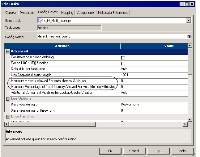
190 Chapter 6: Working with Sessions
Memory Attributes, the Integration Service allocates the specified percentage of memory on
each node in the grid.
Configuring Automatic Memory Settings for Session Caches
To use automatic memory settings for session caches, configure the caches for auto and
configure the maximum memory size.
To configure automatic memory settings for session caches:
1. Open the transformation in the Transformation Developer or the Mappings tab of the
session properties.
2. In the transformation properties, select or enter auto for the following cache size settings:
♦Index and data cache
♦Sorter cache
♦XML cache
3. Open the session in the Task Developer or Workflow Designer, and click the Config
Object tab.
4. Enter a value for the Maximum Memory Allowed for Auto Memory Attributes.
This value specifies the maximum amount of memory to use for session caches.
Maximum
Memory
Attributes
Configuring Automatic Memory Settings 191
Note: You must enable automatic memory settings by configuring a value for the
Maximum Memory Allowed for Auto Memory Attributes and the Maximum Percentage
of Total Memory Allowed for Auto Memory Attributes. If either of these values is set to
zero, the Integration Service disables automatic memory settings and uses default values.
5. Enter a value for the Maximum Percentage of Total Memory Allowed for Auto Memory
Attributes.
This value specifies the maximum percentage of total memory the session caches may use.
Note: You must enable automatic memory settings by configuring a value for the
Maximum Memory Allowed for Auto Memory Attributes and the Maximum Percentage
of Total Memory Allowed for Auto Memory Attributes. If either of these values is set to
zero, the Integration Service disables automatic memory settings and uses default values.
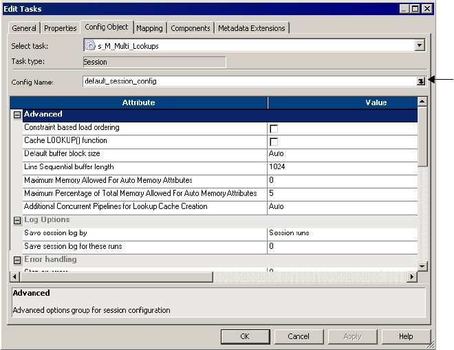
192 Chapter 6: Working with Sessions
Creating a Session Configuration Object
The Config Object tab in the session properties includes commit and load settings, log
options, and error handling settings. You can create a reusable set of attributes for the Config
Object tab with the Workflow Manager. When you configure attributes in the Config Object
tab, you can specify a session configuration object you already created. Or, you can specify
the default session configuration object called default_session_config. Override the attributes
in the session configuration object in the Config Object tab.
Figure 6-4 shows the Config Object tab of the session properties:
Click the Browse button in the Config Name field to choose a session configuration. Select a
user-defined or default session configuration object from the browser.
Figure 6-4. Config Object Tab
Select a
session
configuration
object.
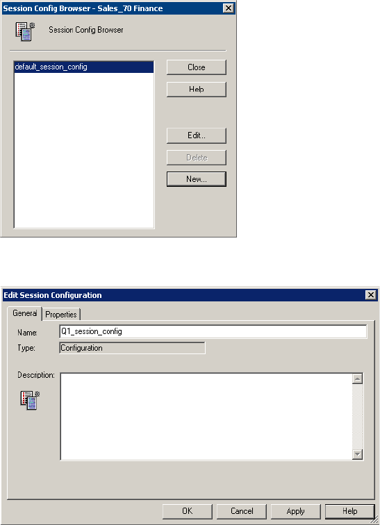
Creating a Session Configuration Object 193
To create a session configuration object:
1. In the Workflow Manager, click Tasks > Session Configuration.
The Session Configuration Browser appears.
2. Click New to create a new session configuration object.
3. Enter a name for the session configuration object.
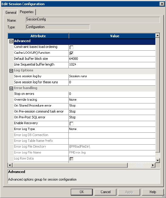
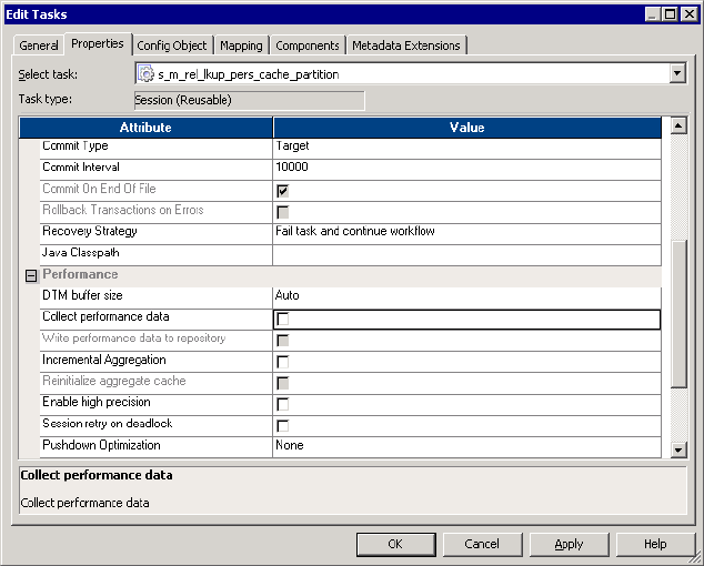
Configuring Performance Details 195
Configuring Performance Details
You can configure a session to collect performance details and store them in the PowerCenter
repository. Collect performance details for a session to view performance details while the
session runs. Store performance details for a session in the PowerCenter repository to view
performance details for previous session runs.
If you configure the session to store performance details, you must also configure the
Integration Service that runs the session to store the run-time information at the verbose
level. The Integration Service stores run-time information in the PowerCenter repository. For
more information on configuring the Integration Service to store run-time information, see
“Creating and Configuring the Integration Service” in the Administrator Guide.
The Workflow Monitor displays performance details for each session that is configured to
show performance details. For more information about viewing performance details in the
Workflow Monitor, see “Viewing Performance Details” on page 544.
To configure performance details:
1. In the Workflow Manager, open the session properties.
2. On the Properties tab, select Collect Performance Data to view performance details while
the session runs.
3. Select Write Performance Data to Repository to view performance details for previous
session runs.
196 Chapter 6: Working with Sessions
Note: You must select the Collect Performance Data option to enable the Write
Performance Data to Repository option. Also, if you configure the session to store
performance details, you must also configure the Integration Service to store the run-
time information at the verbose level. For more information on configuring the
Integration Service to store run-time information, see “Creating and Configuring the
Integration Service” in the Administrator Guide.
4. Click OK.
5. Save the changes to the repository.
For descriptions of the Collect Performance Data and Write Performance Data to Repository
options, see “Performance Settings” on page 705.
Using Pre- and Post-Session SQL Commands 197
Using Pre- and Post-Session SQL Commands
You can specify pre- and post-session SQL in the Source Qualifier transformation and the
target instance when you create a mapping. When you create a Session task in the Workflow
Manager you can override the SQL commands on the Mapping tab. You might want to use
these commands to drop indexes on the target before the session runs, and then recreate them
when the session completes.
The Integration Service runs pre-session SQL commands before it reads the source. It runs
post-session SQL commands after it writes to the target.
Guidelines for Entering Pre- and Post-Session SQL Commands
Remember the following guidelines when creating the SQL statements:
♦Use any command that is valid for the database type. However, the Integration Service
does not allow nested comments, even though the database might.
♦Use mapping parameters and variables in SQL executed against the source, but not the
target.
♦Use a semicolon (;) to separate multiple statements.
♦The Integration Service ignores semicolons within /* ...*/.
♦If you need to use a semicolon outside of comments, you can escape it with a backslash (\).
♦The Workflow Manager does not validate the SQL.
Error Handling
You can configure error handling on the Config Object tab. You can choose to stop or
continue the session if the Integration Service encounters an error issuing the pre- or post-
session SQL command.
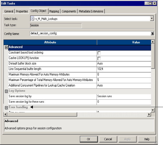
Using Pre- and Post-Session Shell Commands 199
Using Pre- and Post-Session Shell Commands
The Integration Service can perform shell commands at the beginning of the session or at the
end of the session. Shell commands are operating system commands. Use pre- or post-session
shell commands, for example, to delete a reject file or session log, or to archive target files
before the session begins.
The Workflow Manager provides the following types of shell commands for each Session task:
♦Pre-session command. The Integration Service performs pre-session shell commands at
the beginning of a session. You can configure a session to stop or continue if a pre-session
shell command fails.
♦Post-session success command. The Integration Service performs post-session success
commands only if the session completed successfully.
♦Post-session failure command. The Integration Service performs post-session failure
commands only if the session failed to complete.
Use the following guidelines to call a shell command:
♦Use any valid UNIX command or shell script for UNIX nodes, or any valid DOS or batch
file for Windows nodes.
♦Configure the session to run the pre- or post-session shell commands.
The Workflow Manager provides a task called the Command task that lets you configure shell
commands anywhere in the workflow. You can choose a reusable Command task for the pre-
or post-session shell command. Or, you can create non-reusable shell commands for the pre-
or post-session shell commands. For more information about the Command task, see
“Working with the Command Task” on page 147.
If you create a non-reusable pre- or post-session shell command, you can make it into a
reusable Command task.
The Workflow Manager lets you choose from the following options when you configure shell
commands:
♦Create non-reusable shell commands. Create a non-reusable set of shell commands for the
session. Other sessions in the folder cannot use this set of shell commands.
♦Use an existing reusable Command task. Select an existing Command task to run as the
pre- or post-session shell command.
Configure pre- and post-session shell commands in the Components tab of the session
properties.
Using Service Process Variables and Session Parameters
You can include any service process variable, such as $PMTargetFileDir, or session parameters
in commands in pre-session and post-session commands. When you use a service process
variable instead of entering a specific directory, you can run the same workflow on different
Integration Services without changing session properties. You cannot use service process
variables or session parameters in standalone Command tasks in the workflow. The
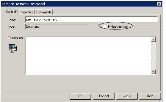
200 Chapter 6: Working with Sessions
Integration Service does not expand service process variables or session parameters used in
standalone Command tasks.
Configuring Non-Reusable Shell Commands
When you create non-reusable pre- or post-session shell commands, the commands are only
visible in session properties. The Workflow Manager does not create Command tasks from
these non-reusable commands. You can make non-reusable shell commands into a reusable
Command tasks.
Figure 6-6 shows the Make Reusable option for a pre-session shell command:
Figure 6-6. Make Reusable Option for Pre-Session Shell Commands
Make this shell command
reusable.
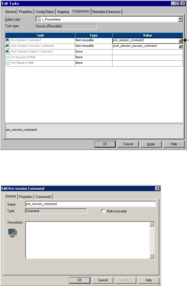
Using Pre- and Post-Session Shell Commands 201
To create non-reusable pre- or post-session shell commands:
1. In the Components tab of the session properties, select Non-reusable for pre- or post-
session shell command.
2. Click the Edit button in the Value field to open the Edit Pre- or Post-Session Command
dialog box.
3. Enter a name for the command in the General tab.
Edit pre-
session
commands.
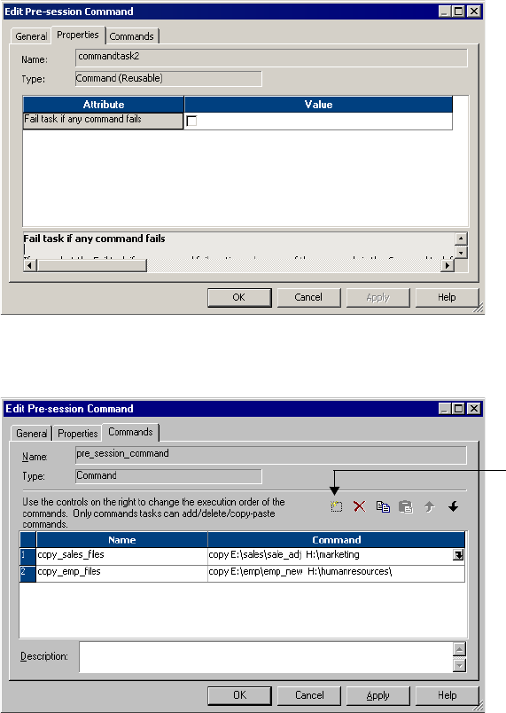
202 Chapter 6: Working with Sessions
4. If you want the Integration Service to perform the next command only if the previous
command completed successfully, select Fail Task if Any Command Fails in the
Properties tab.
5. In the Commands tab, click the Add button to add shell commands.
Enter one command for each line.
6. Click OK.
Creating a Reusable Command Task from Pre- or Post-Session
Commands
If you create non-reusable pre- or post-session shell commands, you can make them into a
reusable Command task. Once you make the pre- or post-session shell commands into a
reusable Command task, you cannot revert back.
Add a command.
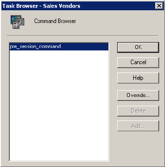
Using Pre- and Post-Session Shell Commands 203
To create a Command Task from non-reusable pre- or post-session shell commands, click the
Edit button to open the Edit dialog box for the shell commands. In the General tab, select the
Make Reusable check box.
After you select the Make Reusable check box and click OK, a new Command task appears in
the Tasks folder in the Navigator window. Use this Command task in other workflows, just as
you do with any other reusable workflow tasks.
Configuring Reusable Shell Commands
Perform the following steps to call an existing reusable Command task as the pre- or post-
session shell command for the Session task.
To select an existing Command task as the pre-session shell command:
1. In the Components tab of the session properties, click Reusable for the pre- or post-
session shell command.
2. Click the Edit button in the Value field to open the Task Browser dialog box.
3. Select the Command task you want to run as the pre- or post-session shell command.
4. Click the Override button in the Task Browser dialog box if you want to change the
order of the commands, or if you want to specify whether to run the next command
when the previous command fails.
Changes you make to the Command task from the session properties only apply to the
session. In the session properties, you cannot edit the commands in the Command task.
5. Click OK to select the Command task for the pre- or post-session shell command.
The name of the Command task you select appears in the Value field for the shell
command.
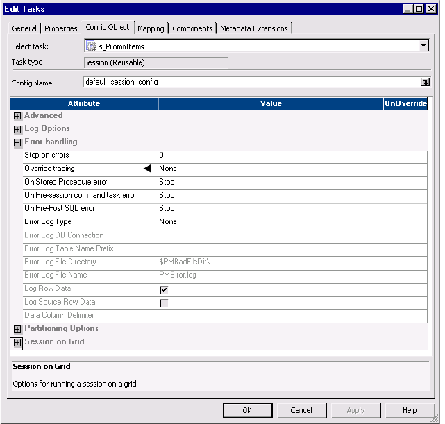
204 Chapter 6: Working with Sessions
Using Service Process Variables
You can include any service process variable, such as $PMTargetFileDir, in pre- or post-
session shell commands. When you use a service process variable instead of entering a specific
directory, you can run the same workflow on different Integration Services without changing
session properties.
Pre-Session Shell Command Errors
You can configure the session to stop or continue if a pre-session shell command fails. If you
select stop, the Integration Service stops the session, but continues with the rest of the
workflow. If you select Continue, the Integration Service ignores the errors and continues the
session. By default the Integration Service stops the session upon shell command errors.
Configure the session to stop or continue if a pre-session shell command fails in the Error
Handling settings on the Config Object tab.
Figure 6-7 shows how to configure the session to stop or continue when a pre-session shell
command fails:
Figure 6-7. Stop or Continue the Session on Pre-Session Shell Command Error
Stop or
continue the
session on pre-
session shell
command error.
Using Post-Session Email 205
Using Post-Session Email
The Integration Service can send emails after the session completes. You can send an email
when the session completes successfully. Or, you can send an email when the session fails.
The Integration Service can send the following types of emails for each Session task:
♦On-Success Email. The Integration Service sends the email when the session completes
successfully.
♦On-Failure Email. The Integration Service sends the email when the session fails.
You can also use an Email task to send email anywhere in the workflow. If you already created
a reusable Email task, you can select it as the On-Success or On-Failure email for the session.
Or, you can create non-reusable emails that exist only within the Session task.
For more information about sending post-session emails, see “Sending Email” on page 361.
206 Chapter 6: Working with Sessions
Validating a Session
The Workflow Manager validates a Session task when you save it. You can also manually
validate Session tasks and session instances. Validate reusable Session tasks in the Task
Developer. Validate non-reusable sessions and reusable session instances in the Workflow
Designer.
The Workflow Manager marks a reusable session or session instance invalid if you perform
one of the following tasks:
♦Edit the mapping in a way that might invalidate the session. You can edit the mapping
used by a session at any time. When you edit and save a mapping, the repository might
invalidate sessions that already use the mapping. The Integration Service does not run
invalid sessions.
You must reconnect to the folder to see the effect of mapping changes on Session tasks.
For more information about validating mappings, see “Mappings” in the Designer Guide.
When you edit a session based on an invalid mapping, the Workflow Manager displays a
warning message:
The mapping [mapping_name] associated with the session [session_name] is
invalid.
♦Delete a database, FTP, or external loader connection used by the session.
♦Leave session attributes blank. For example, the session is invalid if you do not specify the
source file name.
♦Change the code page of a session database connection to an incompatible code page.
If you delete objects associated with a Session task such as session configuration object, Email,
or Command task, the Workflow Manager marks a reusable session invalid. However, the
Workflow Manager does not mark a non-reusable session invalid if you delete an object
associated with the session.
If you delete a shortcut to a source or target from the mapping, the Workflow Manager does
not mark the session invalid.
The Workflow Manager does not validate SQL overrides or filter conditions entered in the
session properties when you validate a session. You must validate SQL override and filter
conditions in the SQL Editor.
If a reusable session task is invalid, the Workflow Manager displays an invalid icon over the
session task in the Navigator and in the Task Developer workspace. This does not affect the
validity of the session instance and the workflows using the session instance.
If a reusable or non-reusable session instance is invalid, the Workflow Manager marks it
invalid in the Navigator and in the Workflow Designer workspace. Workflows using the
session instance remain valid.
To validate a session, select the session in the workspace and click Tasks > Validate. Or, right-
click the session instance in the workspace and choose Validate.
Validating a Session 207
Validating Multiple Sessions
You can validate multiple sessions without fetching them into the workspace. You must select
and validate the sessions from a query results view or a view dependencies list. You can save
and optionally check in sessions that change from invalid to valid status. For more
information about validating multiple objects, see “Using the Repository Manager” in the
Repository Guide.
Note: If you use the Repository Manager, you can select and validate multiple sessions from
the Navigator.
To validate multiple sessions:
1. Select sessions from either a query list or a view dependencies list.
2. Right-click one of the selected sessions and choose Validate.
The Validate Objects dialog box appears.
3. Choose whether to save objects and check in objects that you validate.
208 Chapter 6: Working with Sessions
Stopping and Aborting a Session
You can stop or abort a session just as you can stop or abort any task. You can also abort a
session by using the ABORT() function in the mapping logic. Session errors can cause the
Integration Service to stop a session early. You can control the stopping point by setting an
error threshold in a session, using the ABORT function in mappings, or requesting the
Integration Service to stop the session. You cannot control the stopping point when the
Integration Service encounters fatal errors, such as loss of connection to the target database.
If a session fails as a result of error, you can recover the workflow to recover the session. For
more information about recovery, see “Recovery Options” on page 342. For more information
about row error logging, see “Overview” on page 588.
Threshold Errors
You can choose to stop a session on a designated number of non-fatal errors. A non-fatal error
is an error that does not force the session to stop on its first occurrence. Establish the error
threshold in the session properties with the Stop On option. When you enable this option,
the Integration Service counts non-fatal errors that occur in the reader, writer, and
transformation threads.
The Integration Service maintains an independent error count when reading sources,
transforming data, and writing to targets. The Integration Service counts the following non-
fatal errors when you set the stop on option in the session properties:
♦Reader errors. Errors encountered by the Integration Service while reading the source
database or source files. Reader threshold errors can include alignment errors while
running a session in Unicode mode.
♦Writer errors. Errors encountered by the Integration Service while writing to the target
database or target files. Writer threshold errors can include key constraint violations,
loading nulls into a not null field, and database trigger responses.
♦Transformation errors. Errors encountered by the Integration Service while transforming
data. Transformation threshold errors can include conversion errors, and any condition set
up as an ERROR, such as null input.
When you create multiple partitions in a pipeline, the Integration Service maintains a
separate error threshold for each partition. When the Integration Service reaches the error
threshold for any partition, it stops the session. The writer may continue writing data from
one or more partitions, but it does not affect the ability to perform a successful recovery.
Note: If alignment errors occur in a non line-sequential VSAM file, the Integration Service sets
the error threshold to 1 and stops the session.
Fatal Error
A fatal error occurs when the Integration Service cannot access the source, target, or
repository. This can include loss of connection or target database errors, such as lack of
database space to load data. If the session uses a Normalizer or Sequence Generator

Stopping and Aborting a Session 209
transformation, the Integration Service cannot update the sequence values in the repository,
and a fatal error occurs.
If the session does not use a Normalizer or Sequence Generator transformation, and the
Integration Service loses connection to the repository, the Integration Service does not stop
the session. The session completes, but the Integration Service cannot log session statistics
into the repository.
ABORT Function
Use the ABORT function in the mapping logic to abort a session when the Integration
Service encounters a designated transformation error.
For more information about ABORT, see “Functions” in the Transformation Language
Reference.
User Command
You can stop or abort the session from the Workflow Manager. You can also stop the session
using pmcmd.
Integration Service Handling for Session Failure
The Integration Service handles session errors in different ways, depending on the error or
event that causes the session to fail.
Table 6-2 describes the Integration Service behavior when a session fails:
Table 6-2. Integration Service Behavior for Failed Sessions
Cause for Session Errors Integration Service Behavior
- Error threshold met due to reader errors
- Stop command using Workflow Manager or
pmcmd
Integration Service performs the following tasks:
- Stops reading.
- Continues processing data.
- Continues writing and committing data to targets.
If the Integration Service cannot finish processing and committing
data, you need to issue the Abort command to stop the session.
Abort command using Workflow Manager Integration Service performs the following tasks:
- Stops reading.
- Continues processing data.
- Continues writing and committing data to targets.
If the Integration Service cannot finish processing and committing
data within 60 seconds, it kills the DTM process and terminates
the session.

210 Chapter 6: Working with Sessions
- Fatal error from database
- Error threshold met due to writer errors
Integration Service performs the following tasks:
- Stops reading and writing.
- Rolls back all data not committed to the target database.
If the session stops due to fatal error, the commit or rollback may
or may not be successful.
- Error threshold met due to transformation errors
- ABORT( )
- Invalid evaluation of transaction control
expression
Integration Service performs the following tasks:
- Stops reading.
- Flags the row as an abort row and continues processing data.
- Continues to write to the target database until it hits the abort
row.
- Issues commits based on commit intervals.
- Rolls back all data not committed to the target database.
Table 6-2. Integration Service Behavior for Failed Sessions
Cause for Session Errors Integration Service Behavior

Working with Session Parameters 211
Working with Session Parameters
Session parameters represent values you can change between session runs, such as database
connections or source and target files. You use a session parameter in session or workflow
properties and define the parameter value in a parameter file. You can also create workflow
variables in the Workflow Properties and define the values in a parameter file.
When you run a session, the Integration Service matches parameters in the parameter file
with the parameters in the session. It uses the value in the parameter file for the session
property value. Folder and session names are case sensitive.
For example, you can write session logs to a log file instead of the Log service. In session
properties, use $PMSessionLogFile as the session log file name, and set $PMSessionLogFile to
TestRun.txt in the parameter file. When you run the session, the Integration Service creates a
session log named TestRun.txt.
You can run a session with different parameter files when you use pmcmd to start a session.
The parameter file you set with pmcmd overrides the parameter file in the session or workflow
properties. For more information, see “Using a Parameter File with pmcmd” on page 611.
Note: Session parameters do not have default values. If the Integration Service cannot find a
value for a session parameter, it may fail the session, take an empty string as the default value,
or fail to expand the parameter at run time.
Table 6-3 describes the session parameters:
Table 6-3. Session Parameters
Parameter Type Naming Convention Description
Session Log File $PMSessionLogFile Built-in parameter that defines the name of the session log
between session runs. Enter $PMSessionLogFile in the
Session Log File name field on the Properties tab.
Number of Partitions $DynamicPartitionCount Built-in parameter that defines the number of partitions for a
session. Use this parameter with the Based on Number of
Partitions runtime partition option.
Source File $InputFileName User-defined parameter that defines a source file.
Enter the source file parameter in the Source Filename field on
the Mapping tab.
Lookup File $LookupFileName User-defined parameter that defines a lookup file name.
Enter the lookup file parameter in the Lookup Source Filename
field on the Mapping tab.
Target File $OutputFileName User-defined parameter that defines a target file name.
Enter the target file parameter in the Output Filename field on
the Mapping tab.
Reject File $BadFileName User-defined parameter that defines a reject file name.
Enter the reject file parameter in the Reject Filename field on
the Mapping tab.

212 Chapter 6: Working with Sessions
Naming Conventions
In a parameter file, folder and session names are case sensitive. You need to use the
appropriate prefix for all user-defined session parameters.
Table 6-4 describes required naming conventions for user-defined session parameters:
Changing the Session Log Name
You can set the session log name if you do not use the Session Log service. In session
properties, the Session Log File Directory defaults to the service process variable,
$PMSessionLogDir. The Session Log File Name defaults to $PMSessionLogFile.
In a parameter file, you set $PMSessionLogFile to TestRun.txt. In the Administration
Console, you defined $PMSessionLogDir as C:\80\server\infa_shared\SessLogs. When the
Integration ServiceIntegration Service runs the session, it creates a session log file named
TestRun.txt in the C:\80\server\infa_shared\SessLogs directory.
Changing the Target File and Directory
Use a target file parameter in session properties to change the target file and directory for a
session. You can enter a path that includes the directory and file name in the Output Filename
Database Connection $DBConnectionName User-defined parameter that defines relational database
connections for a source, target, lookup, or stored procedure
across session runs.
Enter the database connection parameter in the relational
connection session properties.
General Session
Parameter
$ParamName User-defined parameter that defines any other session
property. For example, you can use this parameter to define a
table owner name, table name prefix, FTP file or directory
name, Lookup cache file name prefix, or email address. You
can use this parameter to define source, Lookup, target, and
reject file names, but not database connections.
Table 6-4. Naming Conventions for User-Defined Session Parameters
Parameter Type Naming Convention
Database Connection $DBConnectionName
Reject File $BadFileName
Source File $InputFileName
Target File $OutputFileName
Lookup File $LookupFileName
General Session Parameter $ParamName
Table 6-3. Session Parameters
Parameter Type Naming Convention Description
Working with Session Parameters 213
field. If you include the directory in the Output Filename field you must clear the Output
File Directory. The Integration Service concatenates the Output File Directory and the
Output Filename to determine the target file location.
For example, a session uses a file parameter to read internal and external weblogs. You want to
write the results of the internal weblog session to one location and the external weblog session
to another location.
In the session properties, you name the target file $OutputFileName and clear the Output
File Directory field. In the parameter file, set $OutputFileName to “E:/internal_weblogs/
November_int.txt” to create a target file for the internal weblog session. After the session
completes, you change $OutputFileName to “F:/external_weblogs/November_ex.txt” for the
external weblog session.
You can create a different parameter file for each target and use pmcmd to start a session with
a specific parameter file. This parameter file overrides the parameter file name in session
properties.
Changing Source Parameters in a File
You can define multiple parameters for a session property in a parameter file and use one of
the parameters in a session. You can change the parameter name in session properties and run
the session again with a different parameter value.
For example, you create a session parameter named $Inputfile_products in a parameter file.
You set the parameter value to “products.txt.” In the same parameter file, you create another
parameter called $Inputfile_items. You set the parameter value to “items.txt.”
When you set the source file name to $Inputfile_products in session properties, the
Integration Service reads products.txt. When you change the source file name to
$Inputfile_items, the Integration Service reads items.txt.
Changing the Database Connection Parameter
Use database connection parameters to rerun sessions with different relational sources, targets,
or lookups. You create a database connection parameter in the session properties of any
session that uses a relational source, target, or lookup. You can reference any database
connection in a parameter. Name all database connection session parameters with the prefix
$DBConnection, followed by any alphanumeric and underscore character.
For example, you run a session that uses two relational sources. You access the first source
with a database connection named “Marketing” and the second with a connection named
“Sales.” In the session properties, you create a source database connection parameter named
$DBConnection_Source. In the parameter file, you define $DBConnection_Source as
Marketing and run the session. Set $DBConnection_Source to Sales in the parameter file for
the next session run.
214 Chapter 6: Working with Sessions
Rules and Guidelines
Session file parameters and database connection parameters provide the flexibility to run
sessions against different files and databases.
Use the following rules and guidelines when you create file parameters:
♦When you define the parameter file as a resource for a node, verify the Integration Service
runs the session on a node that can access the parameter file. Define the resource for the
node, configure the Integration Service to check resources, and edit the session to require
the resource. For information about configuring the Integration Service to check resources,
see “Creating and Configuring the Integration Service” in the Administrator Guide.
♦When you create a file parameter, use alphanumeric and underscore characters. For
example, to name a source file parameter, use $InputFileName, such as $InputFile_Data.
♦All session file parameters of a particular type must have distinct names. For example, if
you create two source file parameters, you might name them $SourceFileAccts and
$SourceFilePrices.
♦When you define the parameter in the file, you can reference any directory local to the
Integration Service.
♦Use a parameter to define the location of a file. Clear the entry in the session properties
that define the file location. Enter the full path of the file in the parameter file.
♦You can change the parameter value in the parameter file between session runs, or you can
create multiple parameter files. If you use multiple parameter files, use the pmcmd
Startworkflow command with the -paramfile or -localparamfile options to specify which
parameter file to use.
Use the following rules and guidelines when you create database connection parameters:
♦You can change connections for relational sources, targets, lookups, and stored procedures.
♦When you define the parameter, you can reference any database connection in the
repository.
♦Use the same $DBConnection parameter for more than one connection in a session.
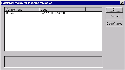
Mapping Parameters and Variables in Sessions 215
Mapping Parameters and Variables in Sessions
Use mapping parameters in the session properties to alter certain mapping attributes. For
example, use a mapping parameter in a transformation override to override a filter or user-
defined join in a Source Qualifier transformation.
If you use mapping variables in a session, you can clear any of the variable values saved in the
repository by editing the session. When you clear the variable values, the Integration Service
uses the values in the parameter file the next time you run a session. If the session does not use
a parameter file, the Integration Service uses the initial values defined in the mapping. For
more information about mapping variables, see “Mapping Parameters and Variables” in the
Designer Guide.
To view or delete values for mapping variables saved in the repository:
1. In the Navigator window of the Workflow Manager, right-click the Session task and
select View Persistent Values.
2. Click Delete Values to delete existing variable values.
3. To save changes, click OK.
216 Chapter 6: Working with Sessions
Handling High Precision Data
The Integration Service processes decimal values as Doubles or Decimals. When you create a
session, you choose to enable the Decimal datatype or let the Integration Service process the
data as a Double (precision of 15).
To enable high precision data handling:
♦Use the Decimal datatype with a precision of 16 to 28 in the mapping.
♦Select Enable High Precision in the session properties.
The precision attributed to a number also includes the scale of the number. For example, the
value 11.47 has a precision of 4 and a scale of 2.
For example, you might have a mapping with Decimal (20,0) that passes the number
40012030304957666903. If you enable high precision, the Integration Service passes the
number as is. If you do not enable high precision, the Integration Service passes
4.00120303049577 x 10¹⁹.
If you want to process a Decimal value with a precision greater than 28 digits, the Integration
Service treats it as a Double value. For example, if you want to process the number
2345678904598383902092.1927658, which has a precision of 29 digits, the Integration
Service treats this number as a Double value of 2.34567890459838 x 10²¹.
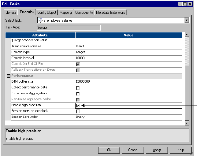
Handling High Precision Data 217
To use high precision data handling in a session:
1. In the Workflow Manager, open the session properties.
2. On the Properties tab, select Enable High Precision.
3. Click OK twice to save changes.
Enable
High
Precision
218 Chapter 6: Working with Sessions

220 Chapter 7: Working with Sources
Overview
In the Workflow Manager, you can create sessions with the following sources:
♦Relational. You can extract data from any relational database that the Integration Service
can connect to. When extracting data from relational sources and Application sources, you
must configure the database connection to the data source prior to configuring the session.
♦File. You can create a session to extract data from a flat file, COBOL, or XML source. Use
an operating system command to generate source data for a flat file or COBOL source or
generate a file list.
If you use a flat file or XML source, the Integration Service can extract data from any local
directory or FTP connection for the source file. If the file source requires an FTP
connection, you need to configure the FTP connection to the host machine before you
create the session.
♦Heterogeneous. You can extract data from multiple sources in the same session. You can
extract from multiple relational sources, such as Oracle and Microsoft SQL Server. Or, you
can extract from multiple source types, such as relational and flat file. When you configure
a session with heterogeneous sources, configure each source instance separately.
Globalization Features
You can choose a code page that you want the Integration Service to use for relational sources
and flat files. You specify code pages for relational sources when you configure database
connections in the Workflow Manager. You can set the code page for file sources in the session
properties. For more information about code pages, see “Understanding Globalization” in the
Administrator Guide.
Source Connections
Before you can extract data from a source, you must configure the connection properties the
Integration Service uses to connect to the source file or database. You can configure source
database and FTP connections in the Workflow Manager.
For more information about creating database connections, see “Relational Database
Connections” on page 43. For more information about creating FTP connections, see “FTP
Connections” on page 53.
Permissions and Privileges
You must have read permissions for the connections you use in the session. For example, if the
source requires database connections or FTP connections, you must have permission to read
those connections in the session.
Overview 221
Allocating Buffer Memory
When the Integration Service initializes a session, it allocates blocks of memory to hold source
and target data. The Integration Service allocates at least two blocks for each source and target
partition. Sessions that use a large number of sources or targets might require additional
memory blocks. If the Integration Service cannot allocate enough memory blocks to hold the
data, it fails the session.
For more information about allocating buffer memory, see the Performance Tuning Guide.
Partitioning Sources
You can create multiple partitions for relational, Application, and file sources. For relational
or Application sources, the Integration Service creates a separate connection to the source
database for each partition you set in the session properties. For file sources, you can
configure the session to read the source with one thread or multiple threads.
For more information about partitioning data, see “Understanding Pipeline Partitioning” on
page 421.
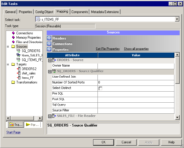
222 Chapter 7: Working with Sources
Configuring Sources in a Session
Configure source properties for sessions in the Sources node of the Mapping tab of the session
properties. When you configure source properties for a session, you define properties for each
source instance in the mapping.
Figure 7-1 shows the Sources node on the Mapping tab:
The Sources node lists the sources used in the session and displays their settings. To view and
configure settings for a source, select the source from the list. You can configure the following
settings for a source:
♦Readers
♦Connections
♦Properties
Configuring Readers
You can click the Readers settings on the Sources node to view the reader the Integration
Service uses with each source instance. The Workflow Manager specifies the necessary reader
for each source instance in the Readers settings on the Sources node.
Figure 7-1. Sources Node of the Session Properties
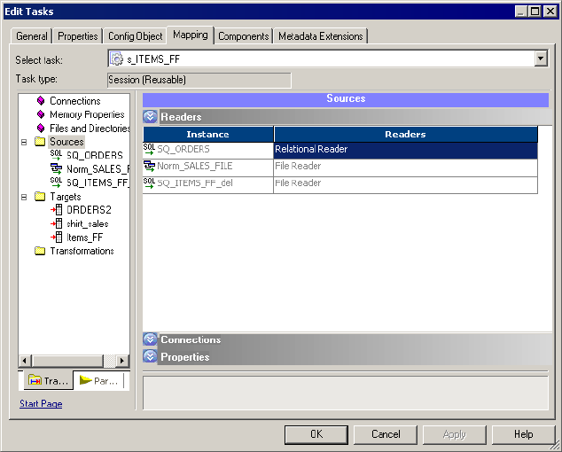
224 Chapter 7: Working with Sources
Figure 7-3 shows the Connections settings in the Sources node of the Mapping tab:
For relational sources, choose a configured database connection in the Value column for each
relational source instance. By default, the Workflow Manager displays the source type for
relational sources. For more information about configuring database connections, see
“Selecting the Source Database Connection” on page 226.
For flat file and XML sources, choose one of the following source connection types in the
Type column for each source instance:
♦FTP. If you want to read data from a flat file or XML source using FTP, you must specify
an FTP connection when you configure source options. You must define the FTP
connection in the Workflow Manager prior to configuring the session.
You must have read permission for any FTP connection you want to associate with the
session. The user starting the session must have execute permission for any FTP
connection associated with the session. For more information about using FTP, see “Using
FTP” on page 649.
♦None. Choose None when you want to read from a local flat file or XML file.
Configuring Properties
Click the Properties settings in the Sources node to define source property information. The
Workflow Manager displays properties, such as source file name and location for flat file,
Figure 7-3. Connections Settings in the Sources Node
Choose a
connection.
Edit a
connection.
Configuring Sources in a Session 225
COBOL, and XML source file types. You do not need to define any properties on the
Properties settings for relational sources.
Figure 7-4 shows the Properties settings in the Sources node of the Mapping tab:
For more information about configuring sessions with relational sources, see “Working with
Relational Sources” on page 226. For more information about configuring sessions with flat
file sources, see “Working with File Sources” on page 230. For more information about
configuring sessions with XML sources, see the XML Guide.
Figure 7-4. Properties Settings in the Sources Node of the Mapping Tab
226 Chapter 7: Working with Sources
Working with Relational Sources
When you configure a session to read data from a relational source, you can configure the
following properties for sources:
♦Source database connection. Select the database connection for each relational source. For
more information, see “Selecting the Source Database Connection” on page 226.
♦Trea t s o u r ce r o w s a s. Define how the Integration Service treats each source row as it reads
it from the source table. For more information, see “Defining the Treat Source Rows As
Property” on page 226.
♦Table owner name. Define the table owner name for each relational source. For more
information, see “Configuring the Table Owner Name” on page 228.
♦Override SQL query. You can override the default SQL query to extract source data. For
more information, see “Overriding the SQL Query” on page 228.
Selecting the Source Database Connection
Before you can run a session to read data from a source database, the Integration Service must
connect to the source database. Database connections must exist in the repository to appear
on the source database list. You must define them prior to configuring a session. For more
information about configuring a database connection, see “Relational Database Connections”
on page 43.
On the Connections settings in the Sources node, select the database connection from the list.
You must have read permission for the source database connection to configure the session to
use it. The user starting the configured session must have execute permission for source
database connections.
Defining the Treat Source Rows As Property
When the Integration Service reads a source, it marks each row with an indicator to specify
which operation to perform when the row reaches the target. You can define how the
Integration Service marks each row using the Treat Source Rows As property in the General
Options settings on the Properties tab.
Working with Relational Sources 227
Figure 7-5 shows the Treat Source Rows As property on the General Options settings:
Table 7-1 describes the options you can choose for the Treat Source Rows As property:
Once you determine how to treat all rows in the session, you also need to set update strategy
options for individual targets. For more information about setting the target update strategy
options, see “Target Properties” on page 263.
For more information about setting the update strategy for a session, see “Update Strategy
Transformation” in the Tran s f o r m a t i o n G u id e .
Figure 7-5. Treat Source Rows As Property
Table 7-1. Treat Source Rows As Options
Treat Source
Rows As Option Description
Insert Integration Service marks all rows to insert into the target.
Delete Integration Service marks all rows to delete from the target.
Update Integration Service marks all rows to update the target. You can further define the update
operation in the target options. For more information, see “Target Properties” on page 263.
Data Driven Integration Service uses the Update Strategy transformations in the mapping to determine the
operation on a row-by-row basis. You define the update operation in the target options. If the
mapping contains an Update Strategy transformation, this option defaults to Data Driven. You
can also use this option when the mapping contains Custom transformations configured to set
the update strategy.
Treat Source
Rows As
Property
228 Chapter 7: Working with Sources
Configuring the Table Owner Name
You can define the owner name of the source table in the session properties. For some
databases such as DB2, tables can have different owners. If the database user specified in the
database connection is not the owner of the source tables in a session, specify the table owner
for each source instance. A session can fail if the database user is not the owner and you do
not specify the table owner name.
Specify the table owner name in the Owner Name field in the Properties settings in the
Sources node.
Figure 7-6 shows the Properties settings where you define the table owner name for relational
sources:
Overriding the SQL Query
You can alter or override the default query in the mapping by entering SQL override in the
Properties settings in the Sources node. You can enter any SQL statement supported by the
source database.
The Workflow Manager does not validate the SQL override. The following errors could cause
the session to fail, and possibly cause data errors:
♦Fields with incompatible datatypes or unknown fields
♦Typing mistakes or other errors
Figure 7-6. Source Table Owner Name Property
Owner Name
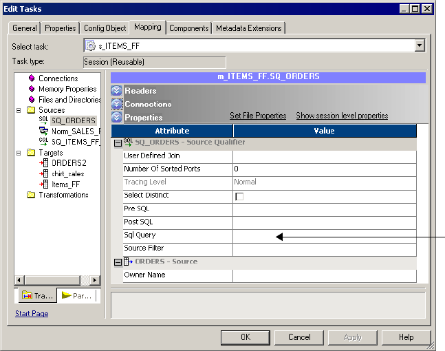
Working with Relational Sources 229
Figure 7-7 shows the Properties settings in the Sources node where you can override the SQL
query:
To override the default query for a relational source:
1. In the Workflow Manager, open the session properties.
2. Click the Mapping tab and open the Transformations view.
3. Click the Sources node and open the Properties settings.
4. Click the Open button in the SQL Query field to open the SQL Editor.
5. Enter the SQL override.
6. Click OK to return to the session properties.
Figure 7-7. SQL Query Override Property in the Session Properties
SQL Query
230 Chapter 7: Working with Sources
Working with File Sources
You can create a session to extract data from flat file, COBOL, or XML sources. When you
create a session to read data from a file, you can configure the following information in the
session properties:
♦Source properties. You can define source properties on the Properties settings in the
Sources node, such as source file options. For more information, see “Configuring Source
Properties” on page 230 and “Configuring Commands for File Sources” on page 232.
♦Flat file properties. You can edit fixed-width and delimited source file properties. For
more information, see “Configuring Fixed-Width File Properties” on page 233 and
“Configuring Delimited File Properties” on page 235.
♦Line sequential buffer length. You can change the buffer length for flat files on the
Advanced settings on the Config Object tab. For more information, see “Configuring Line
Sequential Buffer Length” on page 238.
♦Trea t s o u r ce r o w s a s. You can define how the Integration Service treats each source row as
it reads it from the source. For more information, see “Defining the Treat Source Rows As
Property” on page 226.
Configuring Source Properties
You can define session source properties on the Properties settings in the Sources node.
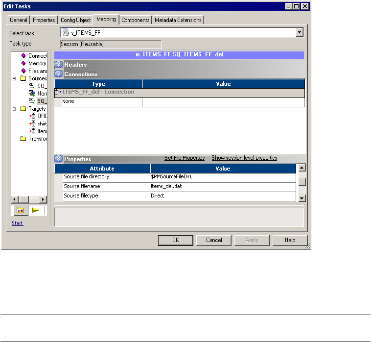
Working with File Sources 231
Figure 7-8 shows the flat file source properties you define in the Properties settings of the
Sources node on the Mapping tab:
Table 7-2 describes the properties you define on the Properties settings for flat file source
definitions:
Figure 7-8. Properties Settings in the Sources Node for a Flat File Source
Table 7-2. Flat File Source Properties
File Source
Options
Required/
Optional Description
Input Type Required Type of source input. You can choose the following types of source input:
- File. For flat file, COBOL, or XML sources.
- Command. For source data or a file list generated by a command.
You cannot use a command to generate XML source data.
Source File
Directory
Optional Directory name of flat file source. By default, the Integration Service looks in
the service process variable directory, $PMSourceFileDir, for file sources.
If you specify both the directory and file name in the Source Filename field,
clear this field. The Integration Service concatenates this field with the Source
Filename field when it runs the session.
You can also use the $InputFileName session parameter to specify the file
location.
For more information about session parameters, see “Working with Session
Parameters” on page 211.

232 Chapter 7: Working with Sources
Configuring Commands for File Sources
Use a command to generate flat file source data input rows or a list of source files for a
session. For UNIX, use any valid UNIX command or shell script. For Windows, use any valid
DOS or batch file on Windows. You can also use service process variables, such as
$PMSourceFileDir, in the command.
Generating Flat File Source Data
Use a command to generate the input rows for flat file source data. Use a command to
generate or transform flat file data and send the standard output of the command to the flat
file reader when the session runs. The flat file reader reads the standard output of the
Source File Name Optional File name, or file name and path of flat file source. Optionally, use the
$InputFileName session parameter for the file name.
The Integration Service concatenates this field with the Source File Directory
field when it runs the session. For example, if you have “C:\data\” in the Source
File Directory field, then enter “filename.dat” in the Source Filename field.
When the Integration Service begins the session, it looks for
“C:\data\filename.dat”.
By default, the Workflow Manager enters the file name configured in the source
definition.
For more information about session parameters, see “Working with Session
Parameters” on page 211.
Source File Type Optional Indicates whether the source file contains the source data, or whether it
contains a list of files with the same file properties. You can choose the
following source file types:
- Direct. For source files that contain the source data.
- Indirect. For source files that contain a list of files. When you select Indirect,
the Integration Service finds the file list and reads each listed file when it runs
the session. For more information about file lists, see “Using a File List” on
page 244.
Command Type Optional Type of source data the command generates. You can choose the following
command types:
- Command generating data for commands that generate source data input
rows.
- Command generating file list for commands that generate a file list.
For more information, see “Configuring Commands for File Sources” on
page 232.
Command Optional Command used to generate the source file data.
For more information, see “Configuring Commands for File Sources” on
page 232.
Set File Properties
link
Optional Overrides source file properties. By default, the Workflow Manager displays file
properties as configured in the source definition.
For more information, see “Configuring Fixed-Width File Properties” on
page 233 and “Configuring Delimited File Properties” on page 235.
Table 7-2. Flat File Source Properties
File Source
Options
Required/
Optional Description
Working with File Sources 233
command as the flat file source data. Generating source data with a command eliminates the
need to stage a flat file source. Use a command or script to send source data directly to the
Integration Service instead of using a pre-session command to generate a flat file source.
For example, to uncompress a data file and use the uncompressed data as the source data
input rows, use the following command:
uncompress -c $PMSourceFileDir/myCompressedFile.Z
The command uncompresses the file and sends the standard output of the command to the
flat file reader. The flat file reader reads the standard output of the command as the flat file
source data.
Generating a File List
Use a command to generate a list of source files. The flat file reader reads each file in the list
when the session runs. Use a command to generate a file list when the list of source files
changes often or you want to generate a file list based on specific conditions. You might want
to use a command to generate a file list based on a directory listing.
For example, to use a directory listing as a file list, use the following command:
cd $PMSourceFileDir; ls -1 sales-records-Sep-*-2005.dat
The command generates a file list from the source file directory listing. When the session
runs, the flat file reader reads each file as it reads the file names from the command.
To use the output of a command as a file list, select Command as the Input Type, Command
generating file list as the Command Type, and enter a command for the Command property.
Configuring Fixed-Width File Properties
When you read data from a fixed-width file, you can edit file properties in the session, such as
the null character or code page. You can configure fixed-width properties for non-reusable
sessions in the Workflow Designer and for reusable sessions in the Task Developer. You
cannot configure fixed-width properties for instances of reusable sessions in the Workflow
Designer.
Click Set File Properties to open the Flat Files dialog box.
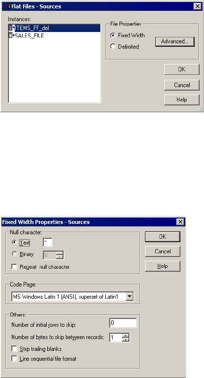
234 Chapter 7: Working with Sources
Figure 7-9 shows the Flat Files dialog box:
To edit the fixed-width properties, select Fixed Width and click Advanced. The Fixed Width
Properties dialog box appears. By default, the Workflow Manager displays file properties as
configured in the mapping. Edit these settings to override those configured in the source
definition.
Figure 7-10 shows the Fixed Width Properties dialog box:
Figure 7-9. Flat Files Dialog Box - Fixed-Width
Figure 7-10. Fixed Width File Properties Dialog Box

Working with File Sources 235
Table 7-3 describes options you can define in the Fixed Width Properties dialog box for file
sources:
Configuring Delimited File Properties
When you read data from a delimited file, you can edit file properties in the session, such as
the delimiter or code page. You can configure delimited properties for non-reusable sessions
in the Workflow Designer and for reusable sessions in the Task Developer. You cannot
configure delimited properties for instances of reusable sessions in the Workflow Designer.
Click Set File Properties to open the Flat Files dialog box.
Table 7-3. Fixed-Width File Properties for File Sources
Fixed-Width
Properties Options
Required/
Optional Description
Text/Binary Required Indicates the character representing a null value in the file. This can be any
valid character in the file code page, or any binary value from 0 to 255. For
more information about specifying null characters, see “Null Character
Handling” on page 241.
Repeat Null
Character
Optional If selected, the Integration Service reads repeat null characters in a single
field as a single null value. If you do not select this option, the Integration
Service reads a single null character at the beginning of a field as a null field.
Important: For multibyte code pages, specify a single-byte null character if
you use repeating non-binary null characters. This ensures that repeating
null characters fit into the column.
For more information about specifying null characters, see “Null Character
Handling” on page 241.
Code Page Required Code page of the fixed-width file. Default is the client code page.
Number of Initial
Rows to Skip
Optional Integration Service skips the specified number of rows before reading the
file. Use this to skip header rows. One row may contain multiple records. If
you select the Line Sequential File Format option, the Integration Service
ignores this option.
Number of Bytes to
Skip Between
Records
Optional Integration Service skips the specified number of bytes between records. For
example, you have an ASCII file on Windows with one record on each line,
and a carriage return and line feed appear at the end of each line. If you want
the Integration Service to skip these two single-byte characters, enter 2.
If you have an ASCII file on UNIX with one record for each line, ending in a
carriage return, skip the single character by entering 1.
Strip Trailing Blanks Optional If selected, the Integration Service strips trailing blank spaces from records
before passing them to the Source Qualifier transformation.
Line Sequential File
Format
Optional Select this option if the file uses a carriage return at the end of each record,
shortening the final column.
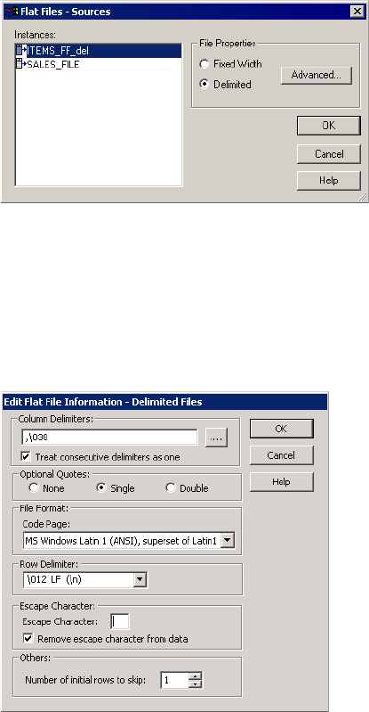
236 Chapter 7: Working with Sources
Figure 7-11 shows the Flat Files dialog box:
To edit the delimited properties, select Delimited and click Advanced. The Delimited File
Properties dialog box appears. By default, the Workflow Manager displays file properties as
configured in the mapping. Edit these settings to override those configured in the source
definition.
Figure 7-12 shows the Delimited File Properties dialog box:
Figure 7-11. Flat Files Dialog Box - Delimited
Figure 7-12. Delimited File Properties Dialog Box

Working with File Sources 237
Table 7-4 describes options you can define in the Delimited File Properties dialog box for file
sources:
Table 7-4. Delimited File Properties for File Sources
Delimited File
Properties Options
Required/
Optional Description
Column Delimiters Required Character used to separate columns of data. Delimiters can be either
printable or single-byte unprintable characters, and must be different from
the escape character and the quote character (if selected). To enter a single-
byte unprintable character, click the Browse button to the right of this field. In
the Delimiters dialog box, select an unprintable character from the Insert
Delimiter list and click Add. You cannot select unprintable multibyte
characters as delimiters.
Treat Consecutive
Delimiters as One
Optional By default, the Integration Service reads pairs of delimiters as a null value. If
selected, the Integration Service reads any number of consecutive delimiter
characters as one.
For example, a source file uses a comma as the delimiter character and
contains the following record: 56, , , Jane Doe. By default, the Integration
Service reads that record as four columns separated by three delimiters: 56,
NULL, NULL, Jane Doe. If you select this option, the Integration Service
reads the record as two columns separated by one delimiter: 56, Jane Doe.
Optional Quotes Required Select No Quotes, Single Quote, or Double Quotes. If you select a quote
character, the Integration Service ignores delimiter characters within the
quote characters. Therefore, the Integration Service uses quote characters to
escape the delimiter.
For example, a source file uses a comma as a delimiter and contains the
following row: 342-3849, ‘Smith, Jenna’, ‘Rockville, MD’, 6.
If you select the optional single quote character, the Integration Service
ignores the commas within the quotes and reads the row as four fields.
If you do not select the optional single quote, the Integration Service reads
six separate fields.
When the Integration Service reads two optional quote characters within a
quoted string, it treats them as one quote character. For example, the
Integration Service reads the following quoted string as I’m going
tomorrow:
2353, ‘I’’m going tomorrow’, MD
Additionally, if you select an optional quote character, the Integration Service
reads a string as a quoted string if the quote character is the first character of
the field.
Note: You can improve session performance if the source file does not
contain quotes or escape characters.
Code Page Required Code page of the delimited file. Default is the client code page.
Row Delimiter Optional Specify a line break character. Select from the list or enter a character.
Preface an octal code with a backslash (\). To use a single character, enter
the character.
The Integration Service uses only the first character when the entry is not
preceded by a backslash. The character must be a single-byte character, and
no other character in the code page can contain that byte. Default is line-
feed, \012 LF (\n).

238 Chapter 7: Working with Sources
Configuring Line Sequential Buffer Length
You can configure the line buffer length for file sources. By default, the Integration Service
reads a file record into a buffer that holds 1024 bytes. If the source file records are larger than
1024 bytes, increase the Line Sequential Buffer Length property in the session properties
accordingly.
Escape Character Optional Character immediately preceding a delimiter character embedded in an
unquoted string, or immediately preceding the quote character in a quoted
string. When you specify an escape character, the Integration Service reads
the delimiter character as a regular character (called escaping the delimiter
or quote character).
Note: You can improve session performance for mappings containing
Sequence Generator transformations if the source file does not contain
quotes or escape characters.
Remove Escape
Character From Data
Optional This option is selected by default. Clear this option to include the escape
character in the output string.
Number of Initial
Rows to Skip
Optional Integration Service skips the specified number of rows before reading the
file. Use this to skip title or header rows in the file.
Table 7-4. Delimited File Properties for File Sources
Delimited File
Properties Options
Required/
Optional Description
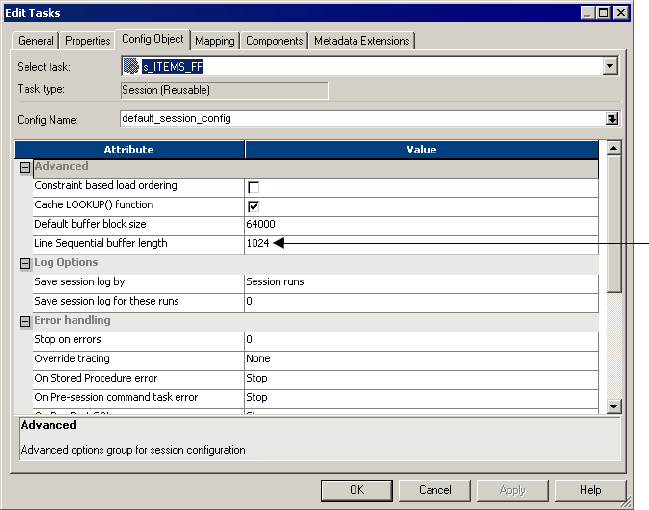

240 Chapter 7: Working with Sources
Integration Service Handling for File Sources
When you configure a session with file sources, you might take these additional features into
account when creating mappings with file sources:
♦Character set
♦Multibyte character error handling
♦Null character handling
♦Row length handling for fixed-width flat files
♦Numeric data handling
♦Tab handli ng
Character Set
You can configure the Integration Service to run sessions in either ASCII or Unicode data
movement mode.
Table 7-5 describes source file formats supported by each data movement path in
PowerCenter:
If you configure a session to run in ASCII data movement mode, delimiters, escape
characters, and null characters must be valid in the ISO Western European Latin 1 code page.
Any 8-bit characters you specified in previous versions of PowerCenter are still valid. In
Unicode data movement mode, delimiters, escape characters, and null characters must be
valid in the specified code page of the flat file.
For more information about configuring and working with data movement modes, see
“Understanding Globalization” in the Administrator Guide.
Table 7-5. Support for ASCII and Unicode Data Movement Modes
Character Set Unicode mode ASCII mode
7-bit ASCII Supported Supported
US-EBCDIC
(COBOL sources only)
Supported Supported
8-bit ASCII Supported Supported
8-bit EBCDIC
(COBOL sources only)
Supported Supported
ASCII-based MBCS Supported Integration Service generates a warning message.
EBCDIC-based SBCS Supported Not supported. The Integration Service terminates the session.
EBCDIC-based MBCS Supported Not supported. The Integration Service terminates the session.
Integration Service Handling for File Sources 241
Multibyte Character Error Handling
Misalignment of multibyte data in a file causes session errors. Data becomes misaligned when
you place column breaks incorrectly in a file, resulting in multibyte characters that extend
beyond the last byte in a column.
When you import a fixed-width flat file, you can create, move, or delete column breaks using
the Flat File Wizard. Incorrect positioning of column breaks can create alignment errors when
you run a session containing multibyte characters.
The Integration Service handles alignment errors in fixed-width flat files according to the
following guidelines:
♦Non-line sequential file. The Integration Service skips rows containing misaligned data
and resumes reading the next row. The skipped row appears in the session log with a
corresponding error message. If an alignment error occurs at the end of a row, the
Integration Service skips both the current row and the next row, and writes them to the
session log.
♦Line sequential file. The Integration Service skips rows containing misaligned data and
resumes reading the next row. The skipped row appears in the session log with a
corresponding error message.
♦Reader error threshold. You can configure a session to stop after a specified number of
non-fatal errors. A row containing an alignment error increases the error count by 1. The
session stops if the number of rows containing errors reaches the threshold set in the
session properties. Errors and corresponding error messages appear in the session log file.
Fixed-width COBOL sources are always byte-oriented and can be line sequential. The
Integration Service handles COBOL files according to the following guidelines:
♦Line sequential files. The Integration Service skips rows containing misaligned data and
writes the skipped rows to the session log. The session stops if the number of error rows
reaches the error threshold.
♦Non-line sequential files. The session stops at the first row containing misaligned data.
Null Character Handling
You can specify single-byte or multibyte null characters for fixed-width flat files. The
Integration Service uses these characters to determine if a column is null.

242 Chapter 7: Working with Sources
Table 7-6 describes how the Integration Service uses the Null Character and Repeat Null
Character properties to determine if a column is null:
Row Length Handling for Fixed-Width Flat Files
For fixed-width flat files, data in a row can be shorter than the row length in the following
situations:
♦The file is fixed-width line-sequential with a carriage return or line feed that appears
sooner than expected.
♦The file is fixed-width non-line sequential, and the last line in the file is shorter than
expected.
In these cases, the Integration Service reads the data but does not append any blanks to fill the
remaining bytes. The Integration Service reads subsequent fields as NULL. Fields containing
repeating null characters that do not fill the entire field length are not considered NULL.
Table 7-6. Null Character Handling
Null
Character
Repeat Null
Character Integration Service Behavior
Binary Disabled A column is null if the first byte in the column is the binary null character. The Integration
Service reads the rest of the column as text data to determine the column alignment and
track the shift state for shift sensitive code pages. If data in the column is misaligned,
the Integration Service skips the row and writes the skipped row and a corresponding
error message to the session log.
Non-binary Disabled A column is null if the first character in the column is the null character. The Integration
Service reads the rest of the column to determine the column alignment and track the
shift state for shift sensitive code pages. If data in the column is misaligned, the
Integration Service skips the row and writes the skipped row and a corresponding error
message to the session log.
Binary Enabled A column is null if it contains the specified binary null character. The next column
inherits the initial shift state of the code page.
Non-binary Enabled A column is null if the repeating null character fits into the column with no bytes leftover.
For example, a five-byte column is not null if you specify a two-byte repeating null
character. In shift-sensitive code pages, shift bytes do not affect the null value of a
column. A column is still null if it contains a shift byte at the beginning or end of the
column.
Specify a single-byte null character if you use repeating non-binary null characters. This
ensures that repeating null characters fit into a column.
Integration Service Handling for File Sources 243
Numeric Data Handling
Sometimes, file sources contain non-numeric data in numeric columns. When the Integration
Service reads non-numeric data, it treats the row differently, depending on the source type.
When the Integration Service reads non-numeric data from numeric columns in a flat file
source or an XML source, it drops the row and writes the row to the session log. When the
Integration Service reads non-numeric data for numeric columns in a COBOL source, it reads
a null value for the column.
244 Chapter 7: Working with Sources
Using a File List
You can create a session to run multiple source files for one source instance in the mapping.
You might use this feature if, for example, the organization collects data at several locations
which you then want to move through the same session. When you create a mapping to use
multiple source files for one source instance, the properties of all files must match the source
definition.
To use multiple source files, you create a file containing the names and directories of each
source file you want the Integration Service to use. This file is referred to as a file list.
When you configure the session properties, enter the file name of the file list in the Source
Filename field and enter the location of the file list in the Source File Directory field. When
the session starts, the Integration Service reads the file list, then locates and reads the first file
source in the list. After the Integration Service reads the first file, it locates and reads the next
file in the list.
The Integration Service writes the path and name of the file list to the session log. If the
Integration Service encounters an error while accessing a source file, it logs the error in the
session log and stops the session.
Note: When you use a file list and the session performs incremental aggregation, the
Integration Service performs incremental aggregation across all listed source files.
Creating the File List
The file list contains the names of all the source files you want the Integration Service to use
for the source instance in the session. Create the file list in an editor appropriate to the
Integration Service platform and save it as a text file. For example, you can create a file list for
an Integration Service on Windows with any text editor then save it as ASCII.
The Integration Service interprets the file list using the Integration Service code page. Each
file in the list must use the user-defined code page configured in the source definition.
Each file in the file list must share the same file properties as configured in the source
definition or as entered for the source instance in the session property sheet. You can enter
different paths for each file in the list, but for the session to complete successfully, the paths
must be local to the Integration Service machine. Map the drives on an Integration Service on
Windows or mount the drives on an Integration Service on UNIX. If you do not specify a
path for a file, the Integration Service assumes the file is in the same directory as the file list.
The file list format must follow the following guidelines:
♦Te xt fi l e
♦One file name, or path and file name, for each line
The Integration Service skips blank lines and ignores leading blank spaces. Any characters
indicating a new line, such as \n in ASCII files, must be valid in the code page of the
Integration Service.
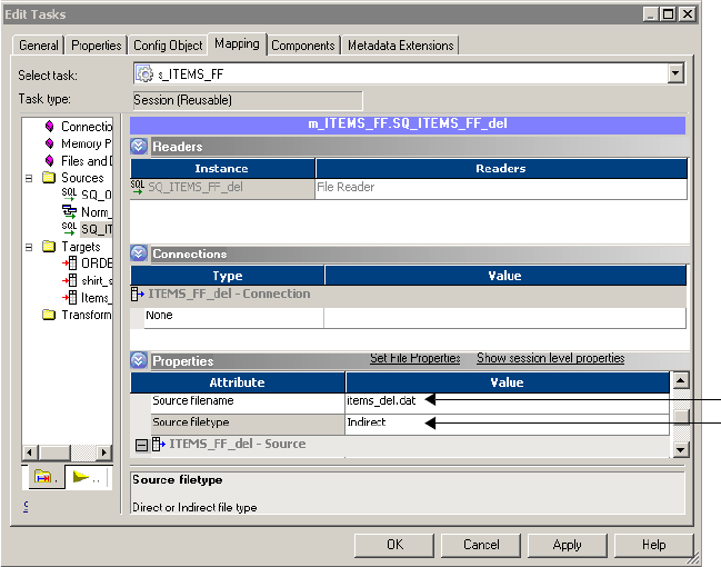
Using a File List 245
The following example shows a valid file list created for an Integration Service on Windows.
Each of the drives listed are mapped on the Integration Service machine. The
western_trans.dat file is located in the same directory as the file list.
western_trans.dat
d:\data\eastern_trans.dat
e:\data\midwest_trans.dat
f:\data\canada_trans.dat
After you create the file list, place it in a directory local to the Integration Service.
Configuring a Session to Use a File List
After you create a file list for multiple source files, you can configure the session to access
those files.
To use multiple source files for one source instance in a session:
1. In the Workflow Manager, open the session properties.
2. Click the Mapping tab and open the Transformations view.
3. Click the Properties settings in the Sources node.
4. In the Source Filetype field, choose Indirect.
5. In the Source Filename field, replace the file name with the name of the file list.
Indirect
File Type
Source
Filename
246 Chapter 7: Working with Sources
If necessary, also enter the path in the Source File Directory field.
If you enter a file name in the Source Filename field, and you have specified a path in the
Source File Directory field, the Integration Service looks for the named file in the listed
directory.
If you enter a file name in the Source Filename field, and you do not specify a path in the
Source File Directory field, the Integration Service looks for the named file in the
directory where the Integration Service is installed on UNIX or in the system directory
on Windows.
6. Click OK.
Using FastExport 247
Using FastExport
FastExport is a utility that uses multiple Teradata sessions to quickly export large amounts of
data from a Teradata database. You can create a PowerCenter session that uses FastExport to
read Teradata sources. To use FastExport with PowerCenter, you need to register the
FastExport plug-in to PowerCenter. The plug-in includes a FastExport Teradata connection
and FastExport Reader that you can select for a session. For more information about adding a
plug-in, see “Registering and Unregistering Repository Plug-ins” in the Repository Guide.
To use FastExport, create a mapping with a Teradata source database. In the session, use
FastExport reader instead of Relational reader. Use a FastExport connection to the Teradata
tables you want to export in a session.
FastExport uses a control file that defines what to export. When a session starts, the
Integration Service creates the control file from the FastExport connection attributes. If you
create a SQL override for the Teradata tables, the Integration Service uses the SQL to generate
the control file. You can override the control file for a session by defining a control file in
session properties.
The Integration Service writes FastExport messages in the session log and information about
FastExport performance in the FastExport log. PowerCenter saves the FastExport log in the
folder defined by the Temporary File Name session attribute. The default extension for the
FastExport log is .log.
To use FastExport in a session, complete the following steps:
1. Create a FastExport connection in the Workflow Manager and configure the connection
attributes.
2. Open the session and change the Reader property from Relational Reader to Teradata
FastExport Reader.
3. Change the connection type and select a FastExport connection for the session.
4. Optionally, create a FastExport control file in a text editor and save it in the Repository.
Creating a FastExport Connection
Create a FastExport connection in the Workflow Manager. If you edit a FastExport
connection, all sessions using the connection use the updated connection.
To create a FastExport connection:
1. Click Connections > Application in the Workflow Manager.
The Connection Browser dialog box appears.
2. Click New.
3. Select a Teradata FastExport connection and click OK.
4. Enter a name for the FastExport connection.

248 Chapter 7: Working with Sources
5. Enter the database user name and password.
6. Enter the FastExport attributes and click OK.
Table 7-7 shows the attributes that you configure for a Teradata FastExport connection:
For more information about the connection attributes, see the Teradata documentation.
Table 7-7. FastExport Connection Attributes
Attribute Default Value Description
TDPID n/a Teradata database ID.
Tenacity 4 Number of hours that FastExport tries to log on to the
Teradata database. When FastExport tries to log on but
the maximum number of Teradata sessions is already
running, FastExport waits for the amount of time
defined by the SLEEP option. After the SLEEP time,
FastExport tries to log on to the Teradata Database
again.
FastExport repeats this process until it has either logged
on for the required number of sessions or exceeded the
TENACITY hours time period.
Max Sessions 1Maximum number of FastExport sessions per
FastExport job. Max Sessions must be between 1 and
the total number of access module processes (AMPs)
on your system.
Sleep 6Number of minutes FastExport pauses before retrying a
login. FastExport attempts a login until the login
succeeds or the Tenacity hours elapse.
Block Size 64000 Maximum block size to use for the exported data.
Data Encryption Disabled Enables data encryption for FastExport. You can use
data encryption with the version 8 Teradata client.
Logtable Name FE_<source_table_name> Restart log table name. The FastExport utility uses the
information in the restart log table to restart jobs that
halt because of a Teradata database or client system
failure. Each FastExport job should use a separate
logtable. If you specify a table that does not exist, the
FastExport utility creates the table and uses it as the
restart log.
PowerCenter does not support restarting FastExport,
but if you stage the output, you can restart FastExport
manually.
Database Name n/a The name of the Teradata database you want to connect
to. The Integration Service generates the SQL
statement using the database name as a prefix to the
table name.

Using FastExport 249
Changing the Reader
The default reader for Teradata is Relational. To use FastExport, you change the reader to
Teradata FastExport.
To select a Teradata FastExport reader:
1. On the Mapping tab, select the source instance in the Navigator.
2. Click the Readers setting.
3. Choose Teradata FastExport
Changing the Source Connection
To use FastExport in the session, change the Teradata source connection to a Teradata
FastExport connection.
To change the source connection:
1. On the Mapping tab, select the source instance in the Navigator.
2. Select the Application connection type.
3. Click the Open button in the Value field to display the Connection Browser.
4. Choose the FastExport connection object you created in the Workflow Manager.
5. To override the connection attributes click Override on the Connection Browser.
6. Click OK to change the connection.
7. Enter session attributes.
Table 7-8 describes the session attributes you can change for FastExport:
Table 7-8. Fast Export Session Attributes
Attribute Default Value Precision
Is Staged Disabled If selected, FastExport writes data to a stage file.
Fractional seconds
precision
0The precision for fractional seconds following the decimal point in a
timestamp. You can enter 0 to 6. For example, a timestamp with a
precision of 6 is 'hh:mi:ss.ss.ss.ss.' The fractional seconds precision
must match the setting in the Teradata database.
Temporary File $PMTempDir\ PowerCenter uses the temporary file name to generate the names for
the log file, control file, and the staged output file. Enter a complete
path for the file.
Control File Override Blank The control file text. Use this attribute to override the control file the
Integration Service creates for a session. For more information, see
“Overriding the Control File” on page 250.

250 Chapter 7: Working with Sources
Overriding the Control File
By default, the Integration Service generates a FastExport control file based on session and
connection properties when you run a session with FastExport. The Integration Service saves
the control file it generates in the temporary file directory and overwrites it the next time you
run the session.
You can override the control file that the Integration Service generates. When you override
the control file, the Workflow Designer saves the control file to the repository. The
Integration Service uses the saved control file when you run the session.
Each FastExport statement must meet the following criteria:
♦Begin on a new line.
♦Start with a period ( . ) character.
♦End with a semicolon ( ; ) character.
For more information about using the Control File, see the Teradata documentation.
Table 7-9 contains the control file statements you can use with PowerCenter:
To override the control file:
1. Create a control file in a text editor.
2. Copy the control file text to the clipboard.
3. Paste the control file text into the Control File Override field.
The Workflow Manager does not validate the control file syntax. Teradata verifies the control
file syntax when you run a session. If the control file is invalid, the session fails.
Table 7-9. FastExport Control File Statements
Control File Statement Description
.LOGTABLE utillog ; The restart logtable name.
LOGON tdpz/user,pswd; The database login string, including the database, user name, and
password.
BEGIN EXPORT The first export command.
.SESSIONS 20; The number of Teradata sessions.
.EXPORT OUTFILE ddname2; The destination file for the exported data.
SELECT EmpNo, Hours FROM charges The SQL statements to select data.
WHERE Proj_ID = 20
ORDER BY EmpNo ;
.END EXPORT ; Indicates the end of an export task and initiates the export process.
LOGOFF ; Disconnect from the database.
Using FastExport 251
Tip: You can change the control file to read-only in order to keep the same control file for each
session. The Integration Service does not overwrite the read-only file.
Rules and Guidelines
Use the following rules and guidelines when you use FastExport with PowerCenter:
♦When you use a SQL override for Teradata, PowerCenter uses it to create the FastExport
control file. If you don't use a SQL override, PowerCenter generates a control file based on
the connected ports in the source qualifier.
♦FastExport supports a maximum export file size of 2 GB on a UNIX MP-RAS operating
system. Other operating systems have no file size limitation.
♦You cannot concatenate exported data files.
252 Chapter 7: Working with Sources

253
Chapter 8
Working with Targets
This chapter includes the following topics:
♦Overview, 254
♦Configuring Targets in a Session, 257
♦Working with Relational Targets, 262
♦Working with Target Connection Groups, 280
♦Working with Active Sources, 282
♦Working with File Targets, 284
♦Integration Service Handling for File Targets, 293
♦Working with Heterogeneous Targets, 299
♦Reject Files, 300

254 Chapter 8: Working with Targets
Overview
In the Workflow Manager, you can create sessions with the following targets:
♦Relational. You can load data to any relational database that the Integration Service can
connect to. When loading data to relational targets, you must configure the database
connection to the target before you configure the session.
♦File. You can load data to a flat file or XML target or write data to an operating system
command. For flat file or XML targets, the Integration Service can load data to any local
directory or FTP connection for the target file. If the file target requires an FTP
connection, you need to configure the FTP connection to the host machine before you
create the session.
♦Heterogeneous. You can output data to multiple targets in the same session. You can
output to multiple relational targets, such as Oracle and Microsoft SQL Server. Or, you
can output to multiple target types, such as relational and flat file. For more information,
see “Working with Heterogeneous Targets” on page 299.
Globalization Features
You can configure the Integration Service to run sessions in either ASCII or Unicode data
movement mode.
Table 8-1 describes target character sets supported by each data movement mode in
PowerCenter:
You can work with targets that use multibyte character sets with PowerCenter. You can choose
a code page that you want the Integration Service to use for relational objects and flat files.
You specify code pages for relational objects when you configure database connections in the
Workflow Manager. The code page for a database connection used as a target must be a
superset of the source code page.
Table 8-1. Support for ASCII and Unicode Data Movement Modes
Character Set Unicode Mode ASCII Mode
7-bit ASCII Supported Supported
ASCII-based MBCS Supported Integration Service generates a warning message, but does
not terminate the session.
UTF-8 Supported (Targets Only) Integration Service generates a warning message, but does
not terminate the session.
EBCDIC-based SBCS Supported Not supported. The Integration Service terminates the
session.
EBCDIC-based MBCS Supported Not supported. The Integration Service terminates the
session.
Overview 255
When you change the database connection code page to one that is not two-way compatible
with the old code page, the Workflow Manager generates a warning and invalidates all
sessions that use that database connection.
Code pages you select for a file represent the code page of the data contained in these files. If
you are working with flat files, you can also specify delimiters and null characters supported
by the code page you have specified for the file.
Target code pages must be a superset of the source code page.
However, if you configure the Integration Service and Client for code page relaxation, you can
select any code page supported by PowerCenter for the target database connection. When
using code page relaxation, select compatible code pages for the source and target data to
prevent data inconsistencies. For more information about code page compatibility, see
“Understanding Globalization” in the Administrator Guide.
If the target contains multibyte character data, configure the Integration Service to run in
Unicode mode. When the Integration Service runs a session in Unicode mode, it uses the
database code page to translate data.
If the target contains only single-byte characters, configure the Integration Service to run in
ASCII mode. When the Integration Service runs a session in ASCII mode, it does not validate
code pages.
Target Connections
Before you can load data to a target, you must configure the connection properties the
Integration Service uses to connect to the target file or database. You can configure target
database and FTP connections in the Workflow Manager.
For more information about creating database connections, see “Relational Database
Connections” on page 43. For more information about creating FTP connections, see “FTP
Connections” on page 53.
Partitioning Targets
When you create multiple partitions in a session with a relational target, the Integration
Service creates multiple connections to the target database to write target data concurrently.
When you create multiple partitions in a session with a file target, the Integration Service
creates one target file for each partition. You can configure the session properties to merge
these target files.
For more information about configuring a session for pipeline partitioning, see
“Understanding Pipeline Partitioning” on page 421.
256 Chapter 8: Working with Targets
Permissions and Privileges
You must have execute permissions for connection objects associated with the session. For
example, if the target requires database connections or FTP connections, you must have read
permission on the connections to configure the session, and execute permission to run the
session.
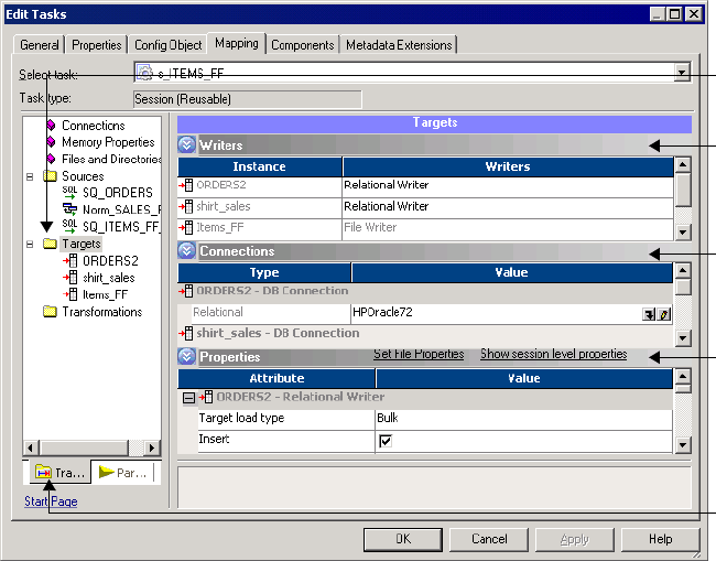
Configuring Targets in a Session 257
Configuring Targets in a Session
Configure target properties for sessions in the Transformations view on Mapping tab of the
session properties. Click the Targets node to view the target properties. When you configure
target properties for a session, you define properties for each target instance in the mapping.
Figure 8-1 shows where you define target properties in a session:
The Targets node contains the following settings where you define properties:
♦Writers
♦Connections
♦Properties
Configuring Writers
Click the Writers settings in the Transformations view to define the writer to use with each
target instance.
Figure 8-1. Defining Target Properties in the Session Properties
Transformations
View
Targets Node
Writers
Settings
Connections
Settings
Properties
Settings

258 Chapter 8: Working with Targets
Figure 8-2 shows where you define the writer to use with each target instance:
When the mapping target is a flat file, an XML file, an SAP BW target, or an IBM MQSeries
target, the Workflow Manager specifies the necessary writer in the session properties.
However, when the target in the mapping is relational, you can change the writer type to File
Writer if you plan to use an external loader.
Note: You can change the writer type for non-reusable sessions in the Workflow Designer and
for reusable sessions in the Task Developer. You cannot change the writer type for instances of
reusable sessions in the Workflow Designer.
When you override a relational target to use the file writer, the Workflow Manager changes
the properties for that target instance on the Properties settings. It also changes the
connection options you can define in the Connections settings.
After you override a relational target to use a file writer, define the file properties for the
target. Click Set File Properties and choose the target to define. For more information, see
“Configuring Fixed-Width Properties” on page 290 and “Configuring Delimited Properties”
on page 291.
Configuring Connections
View the Connections settings on the Mapping tab to define target connection information.
Figure 8-2. Writer Settings on the Mapping Tab of the Session Properties
Writer
Settings

Configuring Targets in a Session 259
Figure 8-3 shows the Connection settings on the Mappings tab of the session properties:
For relational targets, the Workflow Manager displays Relational as the target type by default.
In the Value column, choose a configured database connection for each relational target
instance. For more information about configuring database connections, see “Target Database
Connection” on page 263.
For flat file and XML targets, choose one of the following target connection types in the Type
column for each target instance:
♦FTP. If you want to load data to a flat file or XML target using FTP, you must specify an
FTP connection when you configure target options. FTP connections must be defined in
the Workflow Manager prior to configuring sessions.
You must have read permission for any FTP connection you want to associate with the
session. The user starting the session must have execute permission for any FTP
connection associated with the session. For more information about using FTP, see “Using
FTP” on page 649.
♦Loader. Use the external loader option to improve the load speed to Oracle, DB2, Sybase
IQ, or Teradata target databases.
To use this option, you must use a mapping with a relational target definition and choose
File as the writer type on the Writers settings for the relational target instance. The
Integration Service uses an external loader to load target files to the Oracle, DB2, Sybase
Figure 8-3. Connection Settings on the Mapping Tab of the Session Properties
Connection
Settings
Choose a
connection.
Edit a
connection.
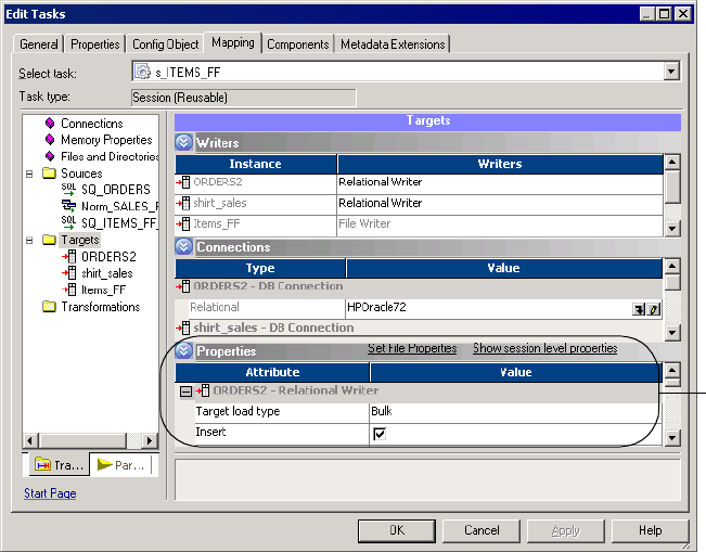
260 Chapter 8: Working with Targets
IQ, or Teradata database. You cannot choose external loader if the target is defined in the
mapping as a flat file, XML, MQ, or SAP BW target.
For more information about using the external loader feature, see “External Loading” on
page 615.
♦Queue. Choose Queue when you want to output to an IBM MQSeries message queue. For
more information, see the PowerCenter Connect for IBM MQSeries User and
Administrator Guide.
♦None. Choose None when you want to write to a local flat file or XML file.
Configuring Properties
View the Properties settings on the Mapping tab to define target property information. The
Workflow Manager displays different properties for the different target types: relational, flat
file, and XML.
Figure 8-4 shows the Properties settings on the Mapping tab:
For more information about relational target properties, see “Working with Relational
Targets” on page 262. For more information about flat file target properties, see “Working
with File Targets” on page 284. For more information about XML target properties, see
“Working with Heterogeneous Targets” on page 299.
Figure 8-4. Properties Settings on the Mapping Tab of the Session Properties
Properties
Settings
262 Chapter 8: Working with Targets
Working with Relational Targets
When you configure a session to load data to a relational target, you define most properties in
the Transformations view on the Mapping tab. You also define some properties on the
Properties tab and the Config Object tab.
You can configure the following properties for relational targets:
♦Target database connection. Define database connection information. For more
information, see “Target Database Connection” on page 263.
♦Target properties. You can define target properties such as target load type, target update
options, and reject options. For more information, see “Target Properties” on page 263.
♦Truncate target tables. The Integration Service can truncate target tables before loading
data. For more information, see “Truncating Target Tables” on page 268.
♦Deadlock retry. You can configure the session to retry deadlocks when writing to targets or
a recovery table. For more information, see “Deadlock Retry” on page 270.
♦Drop and recreate indexes. Use pre- and post-session SQL to drop and recreate an index
on a relational target table to optimize query speed. For more information, see “Dropping
and Recreating Indexes” on page 271.
♦Constraint-based loading. The Integration Service can load data to targets based on
primary key-foreign key constraints and active sources in the session mapping. For more
information, see “Constraint-Based Loading” on page 272.
♦Bulk loading. You can specify bulk mode when loading to DB2, Microsoft SQL Server,
Oracle, and Sybase databases. For more information, see “Bulk Loading” on page 275.
You can define the following properties in the session and override the properties you define
in the mapping:
♦Table nam e pref ix. You can specify the target owner name or prefix in the session
properties to override the table name prefix in the mapping. For more information, see
“Table Name Prefix” on page 277.
♦Pre-session SQL. You can create SQL commands and execute them in the target database
before loading data to the target. For example, you might want to drop the index for the
target table before loading data into it. For more information, see “Using Pre- and Post-
Session SQL Commands” on page 197.
♦Post-session SQL. You can create SQL commands and execute them in the target database
after loading data to the target. For example, you might want to recreate the index for the
target table after loading data into it. For more information, see “Using Pre- and Post-
Session SQL Commands” on page 197.
If any target table or column name contains a database reserved word, you can create and
maintain a reserved words file containing database reserved words. When the Integration
Service executes SQL against the database, it places quotes around the reserved words. For
more information, see “Reserved Words” on page 278.
When the Integration Service runs a session with at least one relational target, it performs
database transactions per target connection group. For example, it commits all data to targets
Working with Relational Targets 263
in a target connection group at the same time. For more information, see “Working with
Target Connection Groups” on page 280.
Target Database Connection
Before you can run a session to load data to a target database, the Integration Service must
connect to the target database. Database connections must exist in the repository to appear on
the target database list. You must define them prior to configuring a session. For more
information about configuring a database connection, see “Relational Database Connections”
on page 43.
You can choose the target connections in the Transformations view of the Mapping tab. Click
either the Targets or Connections node and select the database connection from the list for
each target instance. You must have read permission for the target database connection to
configure the session to use it. The user starting the configured session must have execute
permission for target database connections.
Target Properties
You can configure session properties for relational targets in the Transformations view on the
Mapping tab, and in the General Options settings on the Properties tab. Define the properties
for each target instance in the session.
When you click the Transformations view on the Mapping tab, you can view and configure
the settings of a specific target. Select the target under the Targets node.
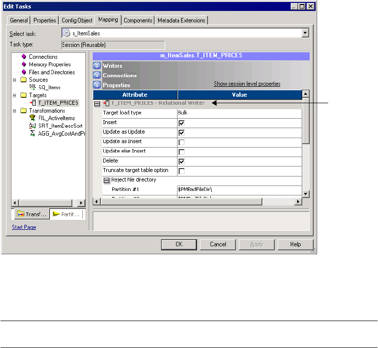
264 Chapter 8: Working with Targets
Figure 8-5 shows the relational target properties you define in the Properties settings on the
Mapping tab:
Table 8-2 describes the properties available in the Properties settings on the Mapping tab of
the session properties:
Figure 8-5. Properties Settings on the Mapping Tab for a Relational Target
Table 8-2. Relational Target Properties
Target Property Required/
Optional Description
Target Load Type Required You can choose Normal or Bulk.
If you select Normal, the Integration Service loads targets normally.
You can choose Bulk when you load to Sybase, Oracle, or Microsoft SQL
Server. If you specify Bulk for other database types, the Integration Service
reverts to a normal load.
Choose Normal mode if the mapping contains an Update Strategy
transformation.
For more information, see “Bulk Loading” on page 275.
Insert* Optional Integration Service inserts all rows flagged for insert.
Default is enabled.
Update (as Update)* Optional Integration Service updates all rows flagged for update.
Default is enabled.
Update (as Insert)* Optional Integration Service inserts all rows flagged for update.
Default is disabled.
Edit settings
for a particular
target.

Working with Relational Targets 265
Update (else Insert)* Optional Integration Service updates rows flagged for update if they exist in the
target, then inserts any remaining rows marked for insert.
Default is disabled.
Delete* Optional Integration Service deletes all rows flagged for delete.
Default is disabled.
Truncate Table Optional Integration Service truncates the target before loading.
Default is disabled.
For more information about this feature, see “Truncating Target Tables” on
page 268.
Reject File Directory Optional Reject-file directory name. By default, the Integration Service writes all
reject files to the service process variable directory, $PMBadFileDir.
If you specify both the directory and file name in the Reject Filename field,
clear this field. The Integration Service concatenates this field with the
Reject Filename field when it runs the session.
You can also use the $BadFileName session parameter to specify the file
directory.
For more information about session parameters, see “Parameter Files” on
page 601.
Reject Filename Required File name or file name and path for the reject file. By default, the Integration
Service names the reject file after the target instance name:
target_name.bad. Optionally, use the $BadFileName session parameter for
the file name.
The Integration Service concatenates this field with the Reject File Directory
field when it runs the session. For example, if you have “C:\reject_file\” in
the Reject File Directory field, and enter “filename.bad” in the Reject
Filename field, the Integration Service writes rejected rows to
C:\reject_file\filename.bad.
For more information about session parameters, see “Parameter Files” on
page 601.
*For more information, see “Using Session-Level Target Properties with Source Properties” on page 267. For more information about
target update strategies, see “Update Strategy Transformation” in the Transformation Guide.
Table 8-2. Relational Target Properties
Target Property Required/
Optional Description

266 Chapter 8: Working with Targets
Figure 8-6 shows the test load options in the General Options settings on the Properties tab:
Table 8-3 describes the test load options on the General Options settings on the Properties
tab:
Figure 8-6. Test Load Options - Relational Targets
Table 8-3. Test Load Options - Relational Targets
Property Required/
Optional Description
Enable Test Load Optional You can configure the Integration Service to perform a test load.
With a test load, the Integration Service reads and transforms data without
writing to targets. The Integration Service generates all session files, and
performs all pre- and post-session functions, as if running the full session.
The Integration Service writes data to relational targets, but rolls back the data
when the session completes. For all other target types, such as flat file and
SAP BW, the Integration Service does not write data to the targets.
Enter the number of source rows you want to test in the Number of Rows to
Test field.
You cannot perform a test load on sessions using XML sources.
You can perform a test load for relational targets when you configure a session
for normal mode. If you configure the session for bulk mode, the session fails.
Number of Rows to
Test
Optional Enter the number of source rows you want the Integration Service to test load.
The Integration Service reads the number you configure for the test load.
Test Load
Options

Working with Relational Targets 267
Using Session-Level Target Properties with Source Properties
You can set session-level target properties to specify how the Integration Service inserts,
updates, and deletes rows. However, you can also set session-level properties for sources.
At the source level, you can specify whether the Integration Service inserts, updates, or deletes
source rows or whether it treats rows as data driven. If you treat source rows as data driven,
you must use an Update Strategy transformation to indicate how the Integration Service
handles rows. For more information about the Update Strategy transformation, see “Update
Strategy Transformation” in the Transformation Guide.
This section explains how the Integration Service writes data based on the source and target
row properties. PowerCenter uses the source and target row options to provide an extra check
on the session-level properties. In addition, when you use both the source and target row
options, you can control inserts, updates, and deletes for the entire session or, if you use an
Update Strategy transformation, based on the data.
When you set the row-handling property for a source, you can treat source rows as inserts,
deletes, updates, or data driven according to the following guidelines:
♦Inserts. If you treat source rows as inserts, select Insert for the target option. When you
enable the Insert target row option, the Integration Service ignores the other target row
options and treats all rows as inserts. If you disable the Insert target row option, the
Integration Service rejects all rows.
♦Deletes. If you treat source rows as deletes, select Delete for the target option. When you
enable the Delete target option, the Integration Service ignores the other target-level row
options and treats all rows as deletes. If you disable the Delete target option, the
Integration Service rejects all rows.
♦Updates. If you treat source rows as updates, the behavior of the Integration Service
depends on the target options you select.
Table 8-4 describes how the Integration Service loads the target when you configure the
session to treat source rows as updates:
Table 8-4. Effect of Target Options when You Treat Source Rows as Updates
Target Option Integration Service Behavior
Insert If enabled, the Integration Service uses the target update option (Update as
Update, Update as Insert, or Update else Insert) to update rows.
If disabled, the Integration Service rejects all rows when you select Update as
Insert or Update else Insert as the target-level update option.
Update as Update* Integration Service updates all rows as updates.
Update as Insert* Integration Service updates all rows as inserts. You must also select the Insert
target option.
Update else Insert* Integration Service updates existing rows and inserts other rows as if marked for
insert. You must also select the Insert target option.
Delete Integration Service ignores this setting and uses the selected target update
option.
*The Integration Service rejects all rows if you do not select one of the target update options.

268 Chapter 8: Working with Targets
♦Data Driven. If you treat source rows as data driven, you use an Update Strategy
transformation to specify how the Integration Service handles rows. However, the behavior
of the Integration Service also depends on the target options you select.
Table 8-5 describes how the Integration Service loads the target when you configure the
session to treat source rows as data driven:
Truncating Target Tables
The Integration Service can truncate target tables before running a session. You can choose to
truncate tables on a target-by-target basis. If you have more than one target instance, you only
have to select the truncate target table option for one target instance.
Depending on the target database and primary key-foreign key relationships in the session
target, the Integration Service might issue a delete or truncate command.
Table 8-6 lists the commands that the Integration Service issues for each database:
Table 8-5. Effect of Target Options when You Treat Source Rows as Data Driven
Target Option Integration Service Behavior
Insert If enabled, the Integration Service inserts all rows flagged for insert. Enabled by
default.
If disabled, the Integration Service rejects the following rows:
- Rows flagged for insert
- Rows flagged for update if you enable Update as Insert or Update else Insert
Update as Update* Integration Service updates all rows flagged for update. Enabled by default.
Update as Insert* Integration Service inserts all rows flagged for update. Disabled by default.
Update else Insert* Integration Service updates rows flagged for update and inserts remaining rows
as if marked for insert.
Delete If enabled, the Integration Service deletes all rows flagged for delete.
If disabled, the Integration Service rejects all rows flagged for delete.
*The Integration Service rejects rows flagged for update if you do not select one of the target update options.
Table 8-6. Integration Service Commands on Supported Databases
Target Database Table contains a primary key
referenced by a foreign key
Table does not contain a primary key
referenced by a foreign key
DB2 truncate table <table_name>* truncate table <table_name>*
Informix delete from <table_name> delete from <table_name>
ODBC delete from <table_name> delete from <table_name>
Oracle delete from <table_name> unrecoverable truncate table <table_name>
Microsoft SQL Server delete from <table_name> truncate table <table_name>**
Sybase 11.x truncate table <table_name> truncate table <table_name>
*If you use a DB2 database on AS/400, the Integration Service issues a clrpfm command.
** If you use the Microsoft SQL Server ODBC driver, the Integration Service issues a delete statement.
Working with Relational Targets 269
If the Integration Service issues a truncate target table command and the target table instance
specifies a table name prefix, the Integration Service verifies the database user privileges for
the target table by issuing a truncate command. If the database user is not specified as the
target owner name or does not have the database privilege to truncate the target table, the
Integration Service issues a delete command instead and writes the following error message to
the session log:
WRT_8208 Error truncating target table <target table name> trying DELETE
FROM query.
If the Integration Service issues a delete command and the database has logging enabled, the
database saves all deleted records to the log for rollback. If you do not want to save deleted
records for rollback, you can disable logging to improve the speed of the delete.
For all databases, if the Integration Service fails to truncate or delete any selected table
because the user lacks the necessary privileges, the session fails.
If you use truncate target tables with one of the following functions, the Integration Service
fails to successfully truncate target tables for the session:
♦Incremental aggregation. When you enable both truncate target tables and incremental
aggregation in the session properties, the Workflow Manager issues a warning that you
cannot enable truncate target tables and incremental aggregation in the same session.
♦Test load. When you enable both truncate target tables and test load, the Integration
Service disables the truncate table function, runs a test load session, and writes the
following message to the session log:
WRT_8105 Truncate target tables option turned off for test load session.
To truncate a target table:
1. In the Workflow Manager, open the session properties.
2. Click the Mapping tab, and then click the Transformations view.
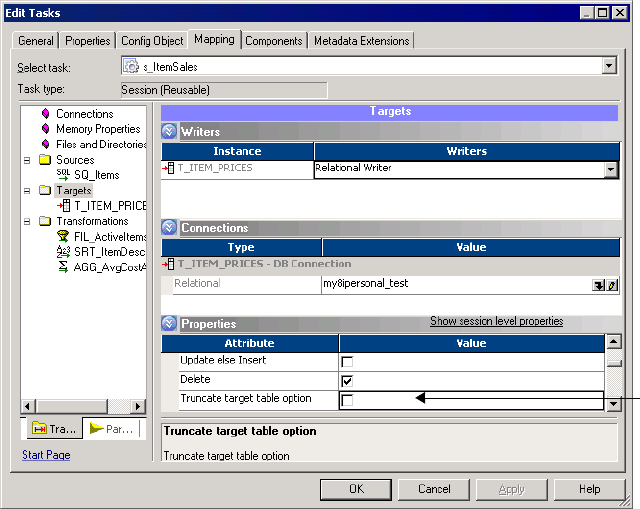
270 Chapter 8: Working with Targets
3. Click the Targets node.
4. In the Properties settings, select Truncate Target Table Option for each target table you
want the Integration Service to truncate before it runs the session.
5. Click OK.
Deadlock Retry
Select the Session Retry on Deadlock option in the session properties if you want the
Integration Service to retry writes to a target database or recovery table on a deadlock. A
deadlock occurs when the Integration Service attempts to take control of the same lock for a
database row.
The Integration Service may encounter a deadlock under the following conditions:
♦A session writes to a partitioned target.
♦Two sessions write simultaneously to the same target.
♦Multiple sessions simultaneously write to the recovery table, PM_RECOVERY.
Encountering deadlocks can slow session performance. To improve session performance, you
can increase the number of target connection groups the Integration Service uses to write to
the targets in a session. To use a different target connection group for each target in a session,
use a different database connection name for each target instance. You can specify the same
connection information for each connection name. For more information, see “Working with
Target Connection Groups” on page 280.
Truncate
Target Table
Option
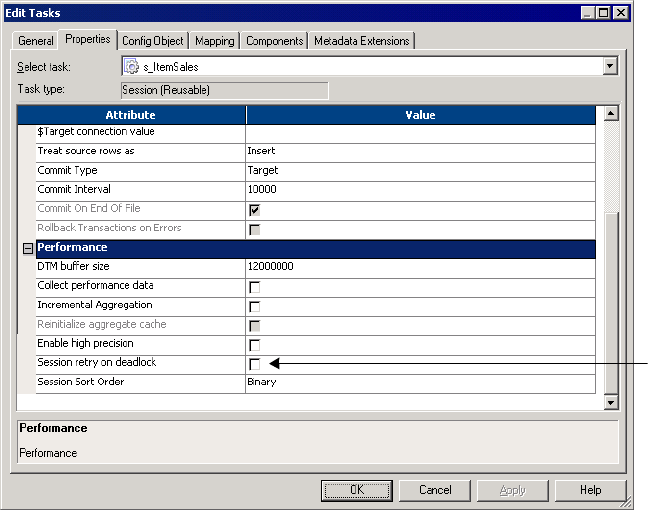
Working with Relational Targets 271
You can retry sessions on deadlock for targets configured for normal load. If you select this
option and configure a target for bulk mode, the Integration Service does not retry target
writes on a deadlock for that target. You can also configure the Integration Service to set the
number of deadlock retries and the deadlock sleep time period.
For more information about configuring the Integration Service, see the Administrator Guide.
To retry a session on deadlock, click the Properties tab in the session properties and then
scroll down to the Performance settings.
Figure 8-7 shows how to retry sessions on deadlock:
Dropping and Recreating Indexes
After you insert significant amounts of data into a target, you normally need to drop and
recreate indexes on that table to optimize query speed. You can drop and recreate indexes by:
♦Using pre- and post-session SQL. The preferred method for dropping and re-creating
indexes is to define an SQL statement in the Pre SQL property that drops indexes before
loading data to the target. Use the Post SQL property to recreate the indexes after loading
data to the target. Define the Pre SQL and Post SQL properties for relational targets in the
Transformations view on the Mapping tab in the session properties. For more information,
see “Using Pre- and Post-Session SQL Commands” on page 197.
♦Using the Designer. The same dialog box you use to generate and execute DDL code for
table creation can drop and recreate indexes. However, this process is not automatic. Every
Figure 8-7. Session Retry on Deadlock
Session Retry
on Deadlock
272 Chapter 8: Working with Targets
time you run a session that modifies the target table, you need to launch the Designer and
use this feature.
Constraint-Based Loading
In the Workflow Manager, you can specify constraint-based loading for a session. When you
select this option, the Integration Service orders the target load on a row-by-row basis. For
every row generated by an active source, the Integration Service loads the corresponding
transformed row first to the primary key table, then to any foreign key tables. Constraint-
based loading depends on the following requirements:
♦Active source. Related target tables must have the same active source.
♦Key relationships. Target tables must have key relationships.
♦Target connection groups. Targets must be in one target connection group.
♦Trea t r o w s a s i n s e r t. Use this option when you insert into the target. You cannot use
updates with constraint-based loading.
Active Source
When target tables receive rows from different active sources, the Integration Service reverts
to normal loading for those tables, but loads all other targets in the session using constraint-
based loading when possible. For example, a mapping contains three distinct pipelines. The
first two contain a source, source qualifier, and target. Since these two targets receive data
from different active sources, the Integration Service reverts to normal loading for both
targets. The third pipeline contains a source, Normalizer, and two targets. Since these two
targets share a single active source (the Normalizer), the Integration Service performs
constraint-based loading: loading the primary key table first, then the foreign key table.
For more information about active sources, see “Working with Active Sources” on page 282.
Key Relationships
When target tables have no key relationships, the Integration Service does not perform
constraint-based loading. Similarly, when target tables have circular key relationships, the
Integration Service reverts to a normal load. For example, you have one target containing a
primary key and a foreign key related to the primary key in a second target. The second target
also contains a foreign key that references the primary key in the first target. The Integration
Service cannot enforce constraint-based loading for these tables. It reverts to a normal load.
Target Connection Groups
The Integration Service enforces constraint-based loading for targets in the same target
connection group. If you want to specify constraint-based loading for multiple targets that
receive data from the same active source, you must verify the tables are in the same target
connection group. If the tables with the primary key-foreign key relationship are in different
target connection groups, the Integration Service cannot enforce constraint-based loading
when you run the workflow.
Working with Relational Targets 273
To verify that all targets are in the same target connection group, complete the following
tasks:
♦Verify all targets are in the same target load order group and receive data from the same
active source.
♦Use the default partition properties and do not add partitions or partition points.
♦Define the same target type for all targets in the session properties.
♦Define the same database connection name for all targets in the session properties.
♦Choose normal mode for the target load type for all targets in the session properties.
For more information, see “Working with Target Connection Groups” on page 280.
Treat Rows as Insert
Use constraint-based loading when the session option Treat Source Rows As is set to Insert.
You might get inconsistent data if you select a different Treat Source Rows As option and you
configure the session for constraint-based loading.
When the mapping contains Update Strategy transformations and you need to load data to a
primary key table first, split the mapping using one of the following options:
♦Load primary key table in one mapping and dependent tables in another mapping. Use
constraint-based loading to load the primary table.
♦Perform inserts in one mapping and updates in another mapping.
For more information about update strategies, see “Update Strategy Transformation” in the
Tra ns for ma t i o n Gu id e .
Constraint-based loading does not affect the target load ordering of the mapping. Target load
ordering defines the order the Integration Service reads the sources in each target load order
group in the mapping. A target load order group is a collection of source qualifiers,
transformations, and targets linked together in a mapping. Constraint-based loading
establishes the order in which the Integration Service loads individual targets within a set of
targets receiving data from a single source qualifier.
Example
The session for the mapping in Figure 8-8 is configured to perform constraint-based loading.
In the first pipeline, target T_1 has a primary key, T_2 and T_3 contain foreign keys
referencing the T1 primary key. T_3 has a primary key that T_4 references as a foreign key.
Since these four tables receive records from a single active source, SQ_A, the Integration
Service loads rows to the target in the following order:
♦T_1
♦T_2 and T_3 (in no particular order)
♦T_4
The Integration Service loads T_1 first because it has no foreign key dependencies and
contains a primary key referenced by T_2 and T_3. The Integration Service then loads T_2
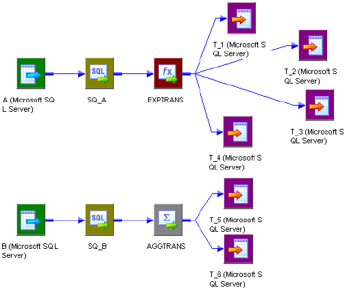
274 Chapter 8: Working with Targets
and T_3, but since T_2 and T_3 have no dependencies, they are not loaded in any particular
order. The Integration Service loads T_4 last, because it has a foreign key that references a
primary key in T_3.
After loading the first set of targets, the Integration Service begins reading source B. If there
are no key relationships between T_5 and T_6, the Integration Service reverts to a normal
load for both targets.
If T_6 has a foreign key that references a primary key in T_5, since T_5 and T_6 receive data
from a single active source, the Aggregator AGGTRANS, the Integration Service loads rows
to the tables in the following order:
♦T_5
♦T_6
T_1, T_2, T_3, and T_4 are in one target connection group if you use the same database
connection for each target, and you use the default partition properties. T_5 and T_6 are in
another target connection group together if you use the same database connection for each
target and you use the default partition properties. The Integration Service includes T_5 and
T_6 in a different target connection group because they are in a different target load order
group from the first four targets.
Figure 8-8. Mapping Using Constraint-Based Loading
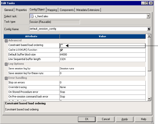
Working with Relational Targets 275
To enable constraint-based loading:
1. In the General Options settings of the Properties tab, choose Insert for the Treat Source
Rows As property.
2. Click the Config Object tab. In the Advanced settings, select Constraint Based Load
Ordering.
3. Click OK.
Bulk Loading
You can enable bulk loading when you load to DB2, Sybase, Oracle, or Microsoft SQL Server.
If you enable bulk loading for other database types, the Integration Service reverts to a normal
load. Bulk loading improves the performance of a session that inserts a large amount of data
to the target database. Configure bulk loading on the Mapping tab.
When bulk loading, the Integration Service invokes the database bulk utility and bypasses the
database log, which speeds performance. Without writing to the database log, however, the
target database cannot perform rollback. As a result, you may not be able to perform recovery.
Therefore, you must weigh the importance of improved session performance against the
ability to recover an incomplete session.
For more information about increasing session performance when bulk loading, see the
Performance Tuning Guide.
Constraint
Based
Load
Ordering
276 Chapter 8: Working with Targets
Note: When loading to DB2, Microsoft SQL Server, and Oracle targets, you must specify a
normal load for data driven sessions. When you specify bulk mode and data driven, the
Integration Service reverts to normal load.
Committing Data
When bulk loading to Sybase and DB2 targets, the Integration Service ignores the commit
interval you define in the session properties and commits data when the writer block is full.
When bulk loading to Microsoft SQL Server and Oracle targets, the Integration Service
commits data at each commit interval. Also, Microsoft SQL Server and Oracle start a new
bulk load transaction after each commit.
Tip: When bulk loading to Microsoft SQL Server or Oracle targets, define a large commit
interval to reduce the number of bulk load transactions and increase performance.
Oracle Guidelines
Oracle allows bulk loading for the following software versions:
♦Oracle server version 8.1.5 or higher
♦Oracle client version 8.1.7.2 or higher
Use the Oracle client 8.1.7 if you install the Oracle Threaded Bulk Mode patch.
Use the following guidelines when bulk loading to Oracle:
♦Do not define CHECK constraints in the database.
♦Do not define primary and foreign keys in the database. However, you can define primary
and foreign keys for the target definitions in the Designer.
♦To bulk load into indexed tables, choose non-parallel mode and disable the Enable Parallel
Mode option. For more information, see “Relational Database Connections” on page 43.
Note that when you disable parallel mode, you cannot load multiple target instances,
partitions, or sessions into the same table.
To bulk load in parallel mode, you must drop indexes and constraints in the target tables
before running a bulk load session. After the session completes, you can rebuild them. If
you use bulk loading with the session on a regular basis, use pre- and post-session SQL to
drop and rebuild indexes and key constraints.
♦When you use the LONG datatype, verify it is the last column in the table.
♦Specify the Table Name Prefix for the target when you use Oracle client 9i. If you do not
specify the table name prefix, the Integration Service uses the database login as the prefix.
For more information, see the Oracle documentation.
DB2 Guidelines
Use the following guidelines when bulk loading to DB2:
♦You must drop indexes and constraints in the target tables before running a bulk load
session. After the session completes, you can rebuild them. If you use bulk loading with
Working with Relational Targets 277
the session on a regular basis, use pre- and post-session SQL to drop and rebuild indexes
and key constraints.
♦You cannot use source-based or user-defined commit when you run bulk load sessions on
DB2.
♦If you create multiple partitions for a DB2 bulk load session, you must use database
partitioning for the target partition type. If you choose any other partition type, the
Integration Service reverts to normal load and writes the following message to the session
log:
ODL_26097 Only database partitioning is support for DB2 bulk load.
Changing target load type variable to Normal.
♦When you bulk load to DB2, the DB2 database writes non-fatal errors and warnings to a
message log file in the session log directory. The message log file name is
<session_log_name>.<target_instance_name>.<partition_index>.log. You can check both
the message log file and the session log when you troubleshoot a DB2 bulk load session.
♦If you want to bulk load flat files to IBM DB2 on MVS, use PowerExchange. For more
information, see the PowerExchange DB2 Adapter Guide.
For more information, see the DB2 documentation.
Table Name Prefix
The table name prefix is the owner of the target table. For some databases, such as DB2,
tables can have different owners. If the database user specified in the database connection is
not the owner of the target tables in a session, specify the table owner for each target instance.
A session can fail if the database user is not the owner and you do not specify the table owner
name.
You can specify the table owner name in the target instance or in the session properties. When
you specify the table owner name in the session properties, you override table owner name in
the transformation properties. For more information about specifying table owner name in
the mapping properties, see “Mappings” in the Designer Guide.
Note: When you specify the table owner name and you set the sqlid for a DB2 database in the
connection environment SQL, the Integration Service uses table owner name in the target
instance. To use the table owner name specified in the SET sqlid statement, do not enter a
name in the target name prefix.
To specify the target owner name or prefix at the session level:
1. In the Workflow Manager, open the session properties and click the Transformations
view on the Mapping tab.
2. Select the target instance under the Targets node.
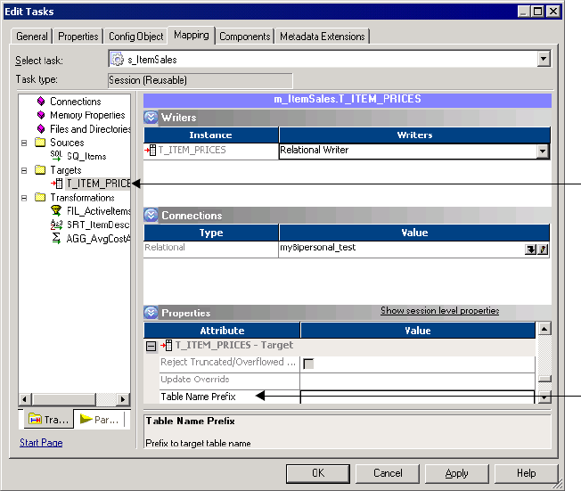
278 Chapter 8: Working with Targets
3. In the Properties settings, enter the table owner name or prefix in the Table Name Prefix
field, and click OK.
Reserved Words
If any table name or column name contains a database reserved word, such as MONTH or
YEAR, the session fails with database errors when the Integration Service executes SQL
against the database. You can create and maintain a reserved words file, reswords.txt, in the
server/bin directory. When the Integration Service initializes a session, it searches for
reswords.txt. If the file exists, the Integration Service places quotes around matching reserved
words when it executes SQL against the database.
Use the following rules and guidelines when working with reserved words.
♦The Integration Service searches the reserved words file when it generates SQL to connect
to source, target, and lookup databases.
♦If you override the SQL for a source, target, or lookup, you must enclose any reserved
word in quotes.
♦You may need to enable some databases, such as Microsoft SQL Server and Sybase, to use
SQL-92 standards regarding quoted identifiers. Use connection environment SQL to issue
the command. For example, use the following command with Microsoft SQL Server:
SET QUOTED_IDENTIFIER ON
Targ et
Instance
Table
Name
Prefix
Working with Relational Targets 279
Sample reswords.txt File
To use a reserved words file, create a file named reswords.txt and place it in the server/bin
directory. Create a section for each database that you need to store reserved words for. Add
reserved words used in any table or column name. You do not need to store all reserved words
for a database in this file. Database names and reserved words in resword.txt are not case
sensitive.
Following is a sample resword.txt file:
[Teradata]
MONTH
DATE
INTERVAL
[Oracle]
OPTION
START
[DB2]
[SQL Server]
CURRENT
[Informix]
[ODBC]
MONTH
[Sybase]
280 Chapter 8: Working with Targets
Working with Target Connection Groups
When you create a session with at least one relational target, SAP BW target, or dynamic
MQSeries target, you need to consider target connection groups. A target connection group is
a group of targets that the Integration Service uses to determine commits and loading. When
the Integration Service performs a database transaction, such as a commit, it performs the
transaction to all targets in a target connection group.
The Integration Service performs the following database transactions per target connection
group:
♦Deadlock retry. If the Integration Service encounters a deadlock when it writes to a target,
the deadlock affects targets in the same target connection group. The Integration Service
still writes to targets in other target connection groups. For more information, see
“Deadlock Retry” on page 270.
♦Constraint-based loading. The Integration Service enforces constraint-based loading for
targets in a target connection group. If you want to specify constraint-based loading, you
must verify the primary table and foreign table are in the same target connection group.
For more information, see “Constraint-Based Loading” on page 272.
Targets in the same target connection group meet the following criteria:
♦Belong to the same partition.
♦Belong to the same target load order group.
♦Have the same target type in the session.
♦Have the same database connection name for relational targets, and Application
connection name for SAP BW targets. For more information, see the PowerCenter
Connect for SAP NetWeaver User and Administrator Guide.
♦Have the same target load type, either normal or bulk mode.
For example, suppose you create a session based on a mapping that reads data from one source
and writes to two Oracle target tables. In the Workflow Manager, you do not create multiple
partitions in the session. You use the same Oracle database connection for both target tables
in the session properties. You specify normal mode for the target load type for both target
tables in the session properties. The targets in the session belong to the same target
connection group.
Suppose you create a session based on the same mapping. In the Workflow Manager, you do
not create multiple partitions. However, you use one Oracle database connection name for
one target, and you use a different Oracle database connection name for the other target. You
specify normal mode for the target load type for both target tables. The targets in the session
belong to different target connection groups.
Note: When you define the target database connections for multiple targets in a session using
session parameters, the targets may or may not belong to the same target connection group.
The targets belong to the same target connection group if all session parameters resolve to the
same target connection name. For example, you create a session with two targets and specify
the session parameter $DBConnection1 for one target, and $DBConnection2 for the other
Working with Target Connection Groups 281
target. In the parameter file, you define $DBConnection1 as Sales1 and you define
$DBConnection2 as Sales1 and run the workflow. Both targets in the session belong to the
same target connection group.
282 Chapter 8: Working with Targets
Working with Active Sources
An active source is an active transformation the Integration Service uses to generate rows. An
active source can be any of the following transformations:
♦Aggregator
♦Application Source Qualifier
♦Custom, configured as an active transformation
♦Joiner
♦MQ Source Qualifier
♦Normalizer (VSAM or pipeline)
♦Rank
♦Sorter
♦Source Qualifier
♦XML Source Qualifier
♦Mapplet, if it contains any of the above transformations
Note: Although the Filter, Router, Transaction Control, and Update Strategy transformations
are active transformations, the Integration Service does not use them as active sources in a
pipeline.
Active sources affect how the Integration Service processes a session when you use any of the
following transformations or session properties:
♦XML targets. The Integration Service can load data from different active sources to an
XML target when each input group receives data from one active source. For more
information about XML targets, see “Working with XML Targets” in the XML Guide.
♦Transaction generators. Transaction generators, such as Transaction Control
transformations, become ineffective for downstream transformations or targets if you put a
transaction control point after it. Transaction control points are transaction generators and
active sources that generate commits. For more information about effective and ineffective
transaction generators, see “Transaction Control Transformation” in the Transformation
Guide. For a list of transaction control points, see “Transformation Scope” on page 329.
♦Mapplets. An Input transformation must receive data from a single active source. For
more information about connecting mapplets to active sources in mappings, see
“Mapplets” in the Designer Guide.
♦Source-based commit. Some active sources generate commits. When you run a source-
based commit session, the Integration Service generates a commit from these active sources
at every commit interval. For more information about source-based commit sessions, see
“Source-Based Commits” on page 320.
Working with Active Sources 283
♦Constraint-based loading. To use constraint-based loading, you must connect all related
targets to the same active source. The Integration Service orders the target load on a row-
by-row basis based on rows generated by an active source. For more information about
constraint-based loading, see “Constraint-Based Loading” on page 272.
♦Row error logging. If an error occurs downstream from an active source that is not a
source qualifier, the Integration Service cannot identify the source row information for the
logged error row. For more information about logging errors, see “Overview” on page 588.
284 Chapter 8: Working with Targets
Working with File Targets
You can output data to a flat file in either of the following ways:
♦Use a flat file target definition. Create a mapping with a flat file target definition. Create
a session using the flat file target definition. When the Integration Service runs the session,
it creates the target flat file or generates the target data based on the flat file target
definition.
♦Use a relational target definition. Use a relational definition to write to a flat file when
you want to use an external loader to load the target. Create a mapping with a relational
target definition. Create a session using the relational target definition. Configure the
session to output to a flat file by specifying the File Writer in the Writers settings on the
Mapping tab. For more information about using the external loader feature, see “External
Loading” on page 615.
You can configure the following properties for flat file targets:
♦Target properties. You can define target properties such as partitioning options, merge
options, output file options, reject options, and command options. For more information,
see “Configuring Target Properties” on page 284.
♦Flat file properties. You can choose to create delimited or fixed-width files, and define
their properties. For more information, see “Configuring Fixed-Width Properties” on
page 290 and “Configuring Delimited Properties” on page 291.
Configuring Target Properties
You can configure session properties for flat file targets in the Properties settings on the
Mapping tab, and in the General Options settings on the Properties tab. Define the properties
for each target instance in the session.
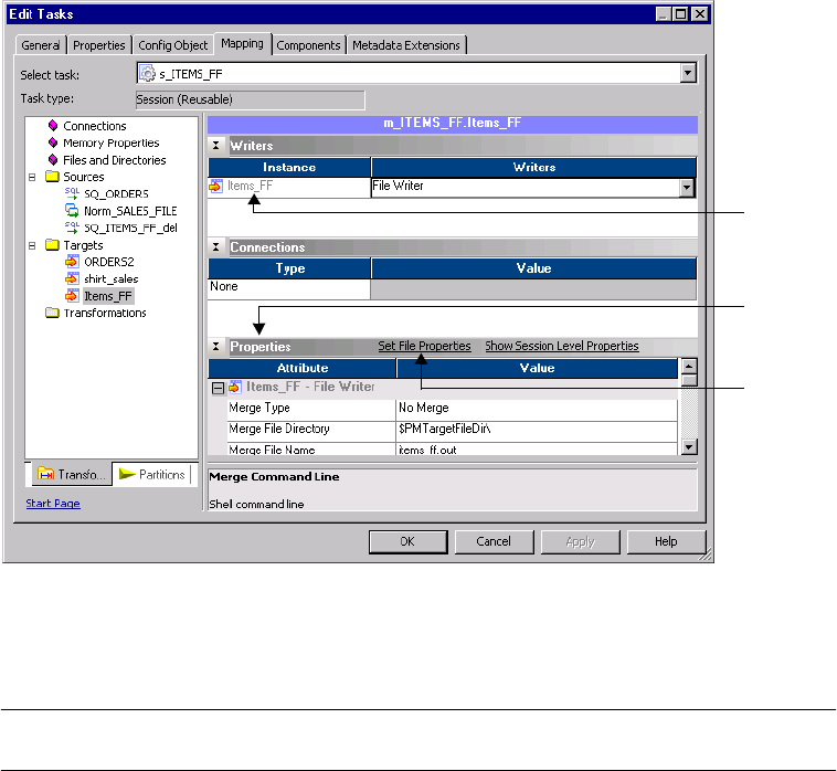
Working with File Targets 285
Figure 8-9 shows the flat file target properties you define in the Properties settings on the
Mapping tab:
Table 8-7 describes the properties you define in the Properties settings for flat file target
definitions:
Figure 8-9. Properties Settings in the Mapping Tab for a Flat File Target
Table 8-7. Flat File Target Properties
Target Properties Required/
Optional Description
Merge Type Optional Type of merge the Integration Service performs on the data for partitioned
targets.
For more information about partitioning targets and creating merge files, see
“Partitioning File Targets” on page 401.
Merge File
Directory
Optional Name of the merge file directory. By default, the Integration Service writes the
merge file in the service process variable directory, $PMTargetFileDir.
If you enter a full directory and file name in the Merge File Name field, clear
this field.
Merge File Name Optional Name of the merge file. Default is target_name.out. This property is required if
you select a merge type.
Flat File
Target
Instance
Set File
Properties
Properties
Settings

286 Chapter 8: Working with Targets
Append if Exists Optional Appends the output data to the target files and reject files for each partition.
Appends output data to the merge file if you merge the target files. You cannot
use this option for target files that are non-disk files, such as FTP target files.
If you do not select this option, the Integration Service truncates each target file
before writing the output data to the target file. If the file does not exist, the
Integration Service creates it.
Header Options Optional Create a header row in the file target. You can choose the following options:
- No Header. Do not create a header row in the flat file target.
- Output Field Names. Create a header row in the file target with the output port
names.
- Use header command output. Use the command in the Header Command
field to generate a header row. For example, you can use a command to add
the date to a header row for the file target.
Default is No Header.
Header Command Optional Command used to generate the header row in the file target. For more
information about using commands, see “Configuring Commands for File
Targets” on page 287.
Footer Command Optional Command used to generate a footer row in the file target. For more information
about using commands, see “Configuring Commands for File Targets” on
page 287.
Output Type Required Type of target for the session. Select File to write the target data to a file target.
Select Command to output data to a command. You cannot select Command
for FTP or Queue target connections.
For more information about processing output data with a command, see
“Configuring Commands for File Targets” on page 287.
Merge Command Optional Command used to process the output data from all partitioned targets. For
more information about merging target data with a command, see “Partitioning
File Targets” on page 401.
Output File
Directory
Optional Name of output directory for a flat file target. By default, the Integration Service
writes output files in the service process variable directory, $PMTargetFileDir.
If you specify both the directory and file name in the Output Filename field,
clear this field. The Integration Service concatenates this field with the Output
Filename field when it runs the session.
You can also use the $OutputFileName session parameter to specify the file
directory.
For more information about session parameters, see “Working with Session
Parameters” on page 211.
Table 8-7. Flat File Target Properties
Target Properties Required/
Optional Description

Working with File Targets 287
Configuring Commands for File Targets
Use a command to process target data for a flat file target. Use any valid UNIX command or
shell script on UNIX. Use any valid DOS or batch file on Windows. The flat file writer sends
the data to the command instead of a flat file target.
Output File Name Optional File name, or file name and path of the flat file target. Optionally, use the
$OutputFileName session parameter for the file name. By default, the Workflow
Manager names the target file based on the target definition used in the
mapping: target_name.out. The Integration Service concatenates this field with
the Output File Directory field when it runs the session.
If the target definition contains a slash character, the Workflow Manager
replaces the slash character with an underscore.
When you use an external loader to load to an Oracle database, you must
specify a file extension. If you do not specify a file extension, the Oracle loader
cannot find the flat file and the Integration Service fails the session. For more
information about external loading, see “Loading to Oracle” on page 626.
Note: If you specify an absolute path file name when using FTP, the Integration
Service ignores the Default Remote Directory specified in the FTP connection.
When you specify an absolute path file name, do not use single or double
quotes.
For more information about session parameters, see “Working with Session
Parameters” on page 211.
Reject File
Directory
Optional Name of the directory for the reject file. By default, the Integration Service
writes all reject files to the service process variable directory, $PMBadFileDir.
If you specify both the directory and file name in the Reject Filename field,
clear this field. The Integration Service concatenates this field with the Reject
Filename field when it runs the session.
You can also use the $BadFileName session parameter to specify the file
directory.
For more information about session parameters, see “Working with Session
Parameters” on page 211.
Reject File Name Required File name, or file name and path of the reject file. By default, the Integration
Service names the reject file after the target instance name: target_name.bad.
Optionally use the $BadFileName session parameter for the file name.
The Integration Service concatenates this field with the Reject File Directory
field when it runs the session. For example, if you have “C:\reject_file\” in the
Reject File Directory field, and enter “filename.bad” in the Reject Filename
field, the Integration Service writes rejected rows to C:\reject_file\filename.bad.
For more information about session parameters, see “Working with Session
Parameters” on page 211.
Command Optional Command used to process the target data. For more information, see
“Configuring Commands for File Targets” on page 287.
Set File Properties
Link
Optional Define flat file properties. For more information, see “Configuring Fixed-Width
Properties” on page 290 and “Configuring Delimited Properties” on page 291.
Set the file properties when you output to a flat file using a relational target
definition in the mapping.
Table 8-7. Flat File Target Properties
Target Properties Required/
Optional Description
288 Chapter 8: Working with Targets
Use a command to perform additional processing of flat file target data. For example, use a
command to sort target data or compress target data. You can increase session performance by
pushing transformation tasks to the command instead of the Integration Service.
To send the target data to a command, select Command for the output type and enter a
command for the Command property.
For example, to generate a compressed file from the target data, use the following command:
compress -c - > $PMTargetFileDir/myCompressedFile.Z
The Integration Service sends the output data to the command, and the command generates a
compressed file that contains the target data.
Note: You can also use service process variables, such as $PMTargetFileDir, in the command.
Configuring Test Load Options
You can configure the Integration Service to perform a test load. With a test load, the
Integration Service reads and transforms data without writing to targets. The Integration
Service generates all session files and performs all pre- and post-session functions, as if
running the full session. To configure a session to perform a test load, enable test load and
enter the number of rows to test.
The Integration Service writes data to relational targets, but rolls back the data when the
session completes. For all other target types, such as flat file and SAP BW, the Integration
Service does not write data to the targets.
Use the following rules and guidelines when performing a test load:
♦You cannot perform a test load on sessions using XML sources.
♦You can perform a test load for relational targets when you configure a session for normal
mode.
♦If you configure the session for bulk mode, the session fails.
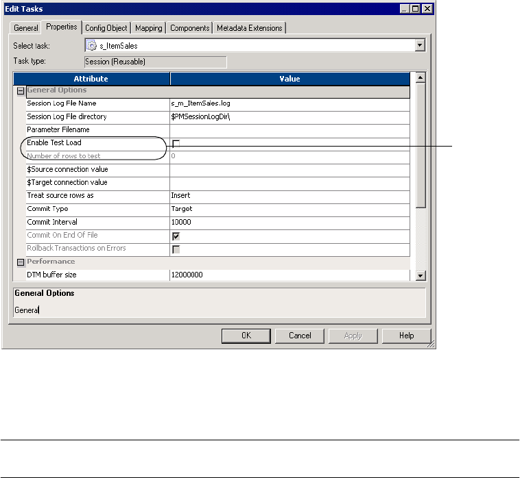
Working with File Targets 289
Figure 8-10 shows the test load options in the General Options settings on the Properties tab:
Table 8-8 describes the test load options in the General Options settings on the Properties
tab:
Figure 8-10. Test Load Options - Flat File Targets
Table 8-8. Test Load Options - Flat File Targets
Property Required/
Optional Description
Enable Test Load Optional You can configure the Integration Service to perform a test load.
With a test load, the Integration Service reads and transforms data without
writing to targets. The Integration Service generates all session files and
performs all pre- and post-session functions, as if running the full session.
The Integration Service writes data to relational targets, but rolls back the data
when the session completes. For all other target types, such as flat file and
SAP BW, the Integration Service does not write data to the targets.
Enter the number of source rows you want to test in the Number of Rows to
Test field.
You cannot perform a test load on sessions using XML sources.
You can perform a test load for relational targets when you configure a session
for normal mode. If you configure the session for bulk mode, the session fails.
Number of Rows to
Test
Optional Enter the number of source rows you want the Integration Service to test load.
The Integration Service reads the number you configure for the test load.
Test Load
Options
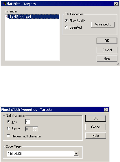
290 Chapter 8: Working with Targets
Configuring Fixed-Width Properties
When you output data to a fixed-width file, you can edit file properties in the session
properties, such as the null character or code page. You can configure fixed-width properties
for non-reusable sessions in the Workflow Designer and for reusable sessions in the Task
Developer. You cannot configure fixed-width properties for instances of reusable sessions in
the Workflow Designer.
In the Transformations view on the Mapping tab, click the Targets node and then click Set
File Properties to open the Flat Files dialog box.
Figure 8-11 shows the Flat Files dialog box:
To edit the fixed-width properties, select Fixed Width and click Advanced.
Figure 8-12 shows the Fixed Width Properties dialog box:
Figure 8-11. Flat Files Dialog Box - Fixed-Width
Figure 8-12. Fixed Width Properties Dialog Box
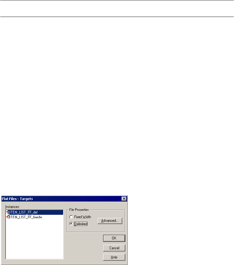
Working with File Targets 291
Table 8-9 describes the options you define in the Fixed Width Properties dialog box:
Configuring Delimited Properties
When you output data to a delimited file, you can edit file properties in the session
properties, such as the delimiter or code page. You can configure delimited properties for
non-reusable sessions in the Workflow Designer and for reusable sessions in the Task
Developer. You cannot configure delimited properties for instances of reusable sessions in the
Workflow Designer.
In the Transformations view on the Mapping tab, click the Targets node and then click Set
File Properties to open the Flat Files dialog box.
Figure 8-13 shows the Flat Files dialog box:
To edit the delimited properties, select Delimited and click Advanced.
Table 8-9. Writing to a Fixed-Width Target
Fixed-Width
Properties Options
Required/
Optional Description
Null Character Required Enter the character you want the Integration Service to use to represent
null values. You can enter any valid character in the file code page.
For more information about using null characters for target files, see “Null
Characters in Fixed-Width Files” on page 297.
Repeat Null Character Optional Select this option to indicate a null value by repeating the null character to
fill the field. If you do not select this option, the Integration Service enters a
single null character at the beginning of the field to represent a null value.
For more information about specifying null characters for target files, see
“Null Characters in Fixed-Width Files” on page 297.
Code Page Required Code page of the fixed-width file. Default is the client code page.
Figure 8-13. Flat Files Dialog Box - Delimited
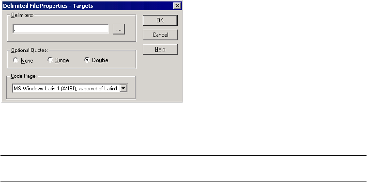
292 Chapter 8: Working with Targets
Figure 8-14 shows the Delimited File Properties dialog box:
Table 8-10 describes the options you can define in the Delimited File Properties dialog box:
Figure 8-14. Delimited File Properties Dialog Box
Table 8-10. Delimited File Properties
Edit Delimiter
Options
Required/
Optional Description
Delimiters Required Character used to separate columns of data. Delimiters can be either printable
or single-byte unprintable characters, and must be different from the escape
character and the quote character (if selected). To enter a single-byte
unprintable character, click the Browse button to the right of this field. In the
Delimiters dialog box, select an unprintable character from the Insert Delimiter
list and click Add. You cannot select unprintable multibyte characters as
delimiters.
Optional Quotes Required Select None, Single, or Double. If you select a quote character, the Integration
Service does not treat delimiter characters within the quote characters as a
delimiter. For example, suppose an output file uses a comma as a delimiter and
the Integration Service receives the following row: 342-3849, ‘Smith, Jenna’,
‘Rockville, MD’, 6.
If you select the optional single quote character, the Integration Service ignores
the commas within the quotes and writes the row as four fields.
If you do not select the optional single quote, the Integration Service writes six
separate fields.
Code Page Required Code page of the delimited file. Default is the client code page.
Integration Service Handling for File Targets 293
Integration Service Handling for File Targets
When you configure a session to write to file targets, must correctly configure the flat file
target definitions and the relational target definitions. The Integration Service loads data to
flat files based on the following criteria:
♦Write to fixed-width flat files from relational target definitions. The Integration Service
adds spaces to target columns based on transformation datatype.
♦Write to fixed-width flat files from flat file target definitions. You must configure the
precision and field width for flat file target definitions to accommodate the total length of
the target field.
♦Generate flat file targets by transaction. You can configure the file target to generate a
separate output file for each transaction.
♦Write multibyte data to fixed-width files. You must configure the precision of string
columns to accommodate character data. When writing shift-sensitive data to a fixed-
width flat file target, the Integration Service adds shift characters and spaces to meet file
requirements.
♦Null characters in fixed-width files. The Integration Service writes repeating or non-
repeating null characters to fixed-width target file columns differently depending on
whether the characters are single- or multibyte.
♦Character set. You can write ASCII or Unicode data to a flat file target.
♦Write metadata to flat file targets. You can configure the Integration Service to write the
column header information when you write to flat file targets.
Writing to Fixed-Width Flat Files with Relational Target Definitions
When you want to output to a fixed-width file based on a relational target definition in the
mapping, consider how the Integration Service handles spacing in the target file.
When the Integration Service writes to a fixed-width flat file based on a relational target
definition in the mapping, it adds spaces to columns based on the transformation datatype
connected to the target. This allows the Integration Service to write optional symbols
necessary for the datatype, such as a negative sign or decimal point, without sending the row
to the reject file.
For example, you connect a transformation Integer(10) port to a Number(10) column in a
relational target definition. In the session properties, you override the relational target
definition to use the File Writer and you specify to output a fixed-width flat file. In the target
flat file, the Integration Service appends an additional byte to the Number(10) column to
allow for negative signs that might be associated with Integer data.

294 Chapter 8: Working with Targets
Table 8-11 describes the number of bytes the Integration Service adds to the target column
and optional characters it uses for each datatype:
Writing to Fixed-Width Files with Flat File Target Definitions
When you want to output to a fixed-width flat file based on a flat file target definition, you
must configure precision and field width for the target field to accommodate the total length
of the target field. If the data for a target field is too long for the total length of the field, the
Integration Service performs one of the following actions:
♦Truncates the row for string columns
♦Writes the row to the reject file for numeric and datetime columns
Note: When the Integration Service writes a row to the reject file, it writes a message in the
session log.
When a session writes to a fixed-width flat file based on a fixed-width flat file target definition
in the mapping, the Integration Service defines the total length of a field by the precision or
field width defined in the target.
Fixed-width files are byte-oriented, which means the total length of a field is measured in
bytes.
Table 8-11. Datatype Modifications for File Target Columns
Transformation Datatype
Connected to Fixed-Width
Flat File Target Column
Bytes Added by
Integration
Service
Optional Characters for the Datatype
Decimal 2- Negative sign (-) for the mantissa.
- Decimal point (.).
Double 7- Negative sign for the mantissa.
- Decimal point.
- Negative sign, e, and three digits for the exponent, for
example, -4.2-e123.
Float 7- Negative sign for the mantissa.
- Decimal point.
- Negative sign, e, and three digits for the exponent.
Integer 1- Negative sign for the mantissa.
Money 2- Negative sign for the mantissa.
- Decimal point.
Numeric 2- Negative sign for the mantissa.
- Decimal point.
Real 7- Negative sign for the mantissa.
- Decimal point.
- Negative sign, e, and three digits for the exponent.

Integration Service Handling for File Targets 295
Table 8-12 describes how the Integration Service measures the total field length for fields in a
fixed-width flat file target definition:
Table 8-13 lists the characters you must accommodate when you configure the precision or
field width for flat file target definitions to accommodate the total length of the target field:
When you edit the flat file target definition in the mapping, define the precision or field
width great enough to accommodate both the target data and the characters in Table 8-13.
For example, suppose you have a mapping with a fixed-width flat file target definition. The
target definition contains a number column with a precision of 10 and a scale of 2. You use a
comma as the decimal separator and a period as the thousands separator. You know some rows
of data might have a negative value. Based on this information, you know the longest possible
number is formatted with the following format:
-NN.NNN.NNN,NN
Open the flat file target definition in the mapping and define the field width for this number
column as a minimum of 14 bytes.
For more information about formatting numeric and datetime values, see “Working with Flat
Files” in the Designer Guide.
Generating Flat File Targets By Transaction
You can generate a separate output file each time the Integration Service starts a new
transaction. You can dynamically name each target flat file. To generate a separate output file
for each transaction, add a FileName port to the flat file target definition. When you connect
the FileName port in the mapping, the Integration Service creates a separate target file at each
Table 8-12. Field Length Measurements for Fixed-Width Flat File Targets
Datatype Target Field Property That Determines Total Field Length
Number Field width
String Precision
Datetime Field width
Table 8-13. Characters to Include when Calculating Field Length for Fixed-Width Targets
Datatype Characters to Accommodate
Number - Decimal separator.
- Thousands separators.
- Negative sign (-) for the mantissa.
String - Multibyte data.
- Shift-in and shift-out characters.
For more information, see “Writing Multibyte Data to Fixed-Width Flat Files” on page 296.
Datetime - Date and time separators, such as slashes (/), dashes (-), and colons (:).
For example, the format MM/DD/YYYY HH24:MI:SS has a total length of 19 bytes.
296 Chapter 8: Working with Targets
commit point. The Integration Service uses the FileName port value from the first row in
each transaction to name the output file.
For more information about generating separate a output file by transaction, see “Creating
Target Files by Transaction” on page 333.
Writing Multibyte Data to Fixed-Width Flat Files
If you plan to load multibyte data into a fixed-width flat file, configure the precision to
accommodate the multibyte data. Fixed-width files are byte-oriented, not character-oriented.
So, when you configure the precision for a fixed-width target, you need to consider the
number of bytes you load into the target, rather than the number of characters.
For string columns, the Integration Service truncates the data if the precision is not large
enough to accommodate the multibyte data.
You might work with the following types of multibyte data:
♦Non shift-sensitive multibyte data. The file contains all multibyte data. Configure the
precision in the target definition to allow for the additional bytes.
For example, you know that the target data contains four double-byte characters, so you
define the target definition with a precision of 8 bytes.
If you configure the target definition with a precision of 4, the Integration Service
truncates the data before writing to the target.
♦Shift-sensitive multibyte data. The file contains single-byte and multibyte data. When
writing to a shift-sensitive flat file target, the Integration Service adds shift characters and
spaces to meet file requirements. You must configure the precision in the target definition
to allow for the additional bytes and the shift characters. For more information, see
“Writing Shift-Sensitive Multibyte Data” on page 296.
Note: Delimited files are character-oriented, and you do not need to allow for additional
precision for multibyte data.
Writing Shift-Sensitive Multibyte Data
When writing to a shift-sensitive flat file target, the Integration Service adds shift characters
and spaces if the data going into the target does not meet file requirements. You need to allow
at least two extra bytes in each data column containing multibyte data so the output data
precision matches the byte width of the target column.
The Integration Service writes shift characters and spaces in the following ways:
♦If a column begins or ends with a double-byte character, the Integration Service adds shift
characters so the column begins and ends with a single-byte shift character.
♦If the data is shorter than the column width, the Integration Service pads the rest of the
column with spaces.
♦If the data is longer than the column width, the Integration Service truncates the data so
the column ends with a single-byte shift character.

Integration Service Handling for File Targets 297
To illustrate how the Integration Service handles a fixed-width file containing shift-sensitive
data, say you want to output the following data to the target:
A is a double-byte character, a is a single-byte character.
The first target column contains eight bytes and the second target column contains four
bytes.
The Integration Service must add shift characters to handle shift-sensitive data. Since the first
target column can handle eight bytes, the Integration Service truncates the data before it can
add the shift characters.
The following table describes the notation used in this example:
For the first target column, the Integration Service writes three of the double-byte characters
to the target. It cannot write any additional double-byte characters to the output column
because the column must end in a single-byte character. If you add two more bytes to the first
target column definition, then the Integration Service can add shift characters and write all
the data without truncation.
For the second target column, the Integration Service writes all four single-byte characters to
the target. It does not add write shift characters to the column because the column begins and
ends with single-byte characters.
Null Characters in Fixed-Width Files
You can specify any valid single-byte or multibyte character as a null character for a fixed-
width target. You can also use a space as a null character.
The null character can be repeating or non-repeating. If the null character is repeating, the
Integration Service writes as many null characters as possible into a target column. If you
specify a multibyte null character and there are extra bytes left after writing null characters,
the Integration Service pads the column with single-byte spaces. If a column is smaller than
the multibyte character specified as the null character, the session fails at initialization.
SourceCol1 SourceCol2
AAAA aaaa
TargetCol1 TargetCol2
-oAAA-i aaaa
Notation Description
A
-o
-i
Double-byte character
Shift-out character
Shift-in character
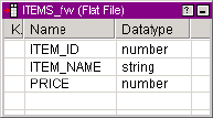
298 Chapter 8: Working with Targets
Character Set
You can configure the Integration Service to run sessions with flat file targets in either ASCII
or Unicode data movement mode.
If you configure a session with a flat file target to run in Unicode data movement mode, the
target file code page must be a superset of the source code page. Delimiters, escape, and null
characters must be valid in the specified code page of the flat file.
If you configure a session to run in ASCII data movement mode, delimiters, escape, and null
characters must be valid in the ISO Western European Latin1 code page. Any 8-bit character
you specified in previous versions of PowerCenter is still valid.
For more information about configuring and working with data movement modes and code
pages, see “Understanding Globalization” in the Administrator Guide.
Writing Metadata to Flat File Targets
When you write to flat file targets, you can configure the Integration Service to write the
column header information. When you enable the Output Metadata For Flat File Target
option, the Integration Service writes column headers to flat file targets. It writes the target
definition port names to the flat file target in the first line, starting with the # symbol. By
default, this option is disabled.
When writing to fixed-width files, the Integration Service truncates the target definition port
name if it is longer than the column width.
For example, you have the following fixed-width flat file target definition:
The column width for ITEM_ID is six. When you enable the Output Metadata For Flat File
Target option, the Integration Service writes the following text to a flat file:
#ITEM_ITEM_NAME PRICE
100001Screwdriver 9.50
100002Hammer 12.90
100003Small nails 3.00
For information about configuring the Integration Service to output flat file metadata, see the
Administrator Guide.
Working with Heterogeneous Targets 299
Working with Heterogeneous Targets
You can output data to multiple targets in the same session. When the target types or database
types of those targets differ from each other, you have a session with heterogeneous targets.
To create a session with heterogeneous targets, you can create a session based on a mapping
with heterogeneous targets. Or, you can create a session based on a mapping with
homogeneous targets and select different database connections.
A heterogeneous target has one of the following characteristics:
♦Multiple target types. You can create a session that writes to both relational and flat file
targets.
♦Multiple target connection types. You can create a session that writes to a target on an
Oracle database and to a target on a DB2 database. Or, you can create a session that writes
to multiple targets of the same type, but you specify different target connections for each
target in the session.
All database connections you define in the Workflow Manager are unique to the Integration
Service, even if you define the same connection information. For example, you define two
database connections, Sales1 and Sales2. You define the same user name, password, connect
string, code page, and attributes for both Sales1 and Sales2. Even though both Sales1 and
Sales2 define the same connection information, the Integration Service treats them as
different database connections. When you create a session with two relational targets and
specify Sales1 for one target and Sales2 for the other target, you create a session with
heterogeneous targets.
You can create a session with heterogeneous targets in one of the following ways:
♦Create a session based on a mapping with targets of different types or different database
types. In the session properties, keep the default target types and database types.
♦Create a session based on a mapping with the same target types. However, in the session
properties, specify different target connections for the different target instances, or
override the target type to a different type.
You can specify the following target type overrides in a session:
♦Relational target to flat file.
♦Relational target to any other relational database type. Verify the datatypes used in the
target definition are compatible with both databases.
♦SAP BW target to a flat file target type.
Note: When the Integration Service runs a session with at least one relational target, it
performs database transactions per target connection group. For example, it orders the target
load for targets in a target connection group when you enable constraint-based loading. For
more information, see “Working with Target Connection Groups” on page 280.
300 Chapter 8: Working with Targets
Reject Files
During a session, the Integration Service creates a reject file for each target instance in the
mapping. If the writer or the target rejects data, the Integration Service writes the rejected row
into the reject file. The reject file and session log contain information that helps you
determine the cause of the reject.
Each time you run a session, the Integration Service appends rejected data to the reject file.
Depending on the source of the problem, you can correct the mapping and target database to
prevent rejects in subsequent sessions.
Note: If you enable row error logging in the session properties, the Integration Service does not
create a reject file. It writes the reject rows to the row error tables or file.
Locating Reject Files
The Integration Service creates reject files for each target instance in the mapping. It creates
reject files in the session reject file directory. Configure the target reject file directory on the
the Mapping tab for the session. By default, the Integration Service creates reject files in the
$PMBadFileDir process variable directory.
When you run a session that contains multiple partitions, the Integration Service creates a
separate reject file for each partition. The Integration Service names reject files after the target
instance name. The default name for reject files is filename_partitionnumber.bad. The reject
file name for the first partition does not contain a partition number.
For example,
/home/directory/filename.bad
/home/directory/filename2.bad
/home/directory/filename3.bad
The Workflow Manager replaces slash characters in the target instance name with underscore
characters.
To find a reject file name and path, view the target properties settings on the Mapping tab of
session properties.
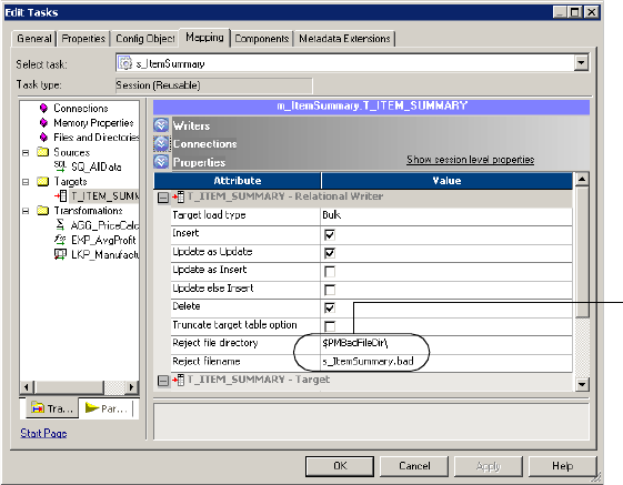
Reject Files 301
Figure 8-15 shows the properties settings on the Mapping tab:
Reading Reject Files
After you locate a reject file, you can read it using a text editor that supports the reject file
code page. Reject files contain rows of data rejected by the writer or the target database.
Though the Integration Service writes the entire row in the reject file, the problem generally
centers on one column within the row. To help you determine which column caused the row
to be rejected, the Integration Service adds row and column indicators to give you more
information about each column:
♦Row indicator. The first column in each row of the reject file is the row indicator. The
numeric indicator tells whether the row was marked for insert, update, delete, or reject.
If the session is a user-defined commit session, the row indicator might tell whether the
transaction was rolled back due to a non-fatal error or if the committed transaction was in
a failed target connection group. For more information about user-defined commit
sessions and rejected rows, see “User-Defined Commits” on page 325.
♦Column indicator. Column indicators appear after every column of data. The alphabetical
character indicators tell whether the data was valid, overflow, null, or truncated.
The following sample reject file shows the row and column indicators:
0,D,1921,D,Nelson,D,William,D,415-541-5145,D
0,D,1922,D,Page,D,Ian,D,415-541-5145,D
0,D,1923,D,Osborne,D,Lyle,D,415-541-5145,D
0,D,1928,D,De Souza,D,Leo,D,415-541-5145,D
Figure 8-15. Properties Settings on the Mapping Tab
Reject file directory
and file name

302 Chapter 8: Working with Targets
0,D,2001,D,S. MacDonald,D,Ira,D,415-541-5145,D
Row Indicators
The first column in the reject file is the row indicator. The number listed as the row indicator
tells the writer what to do with the row of data.
Table 8-14 describes the row indicators in a reject file:
If a row indicator is 3, the writer rejected the row because an update strategy expression
marked it for reject.
If a row indicator is 0, 1, or 2, either the writer or the target database rejected the row. To
narrow down the reason why rows marked 0, 1, or 2 were rejected, review the column
indicators and consult the session log.
Column Indicators
After the row indicator is a column indicator, followed by the first column of data, and
another column indicator. Column indicators appear after every column of data and define
the type of the data preceding it.
Table 8-14. Row Indicators in Reject File
Row Indicator Meaning Rejected By
0Insert Writer or target
1Update Writer or target
2Delete Writer or target
3Reject Writer
4Rolled-back insert Writer
5Rolled-back update Writer
6Rolled-back delete Writer
7Committed insert Writer
8Committed update Writer
9Committed delete Writer

Reject Files 303
Table 8-15 describes the column indicators in a reject file:
Null columns appear in the reject file with commas marking their column. An example of a
null column surrounded by good data appears as follows:
5,D,,N,5,D
Because either the writer or target database can reject a row, and because they can reject the
row for a number of reasons, you need to evaluate the row carefully and consult the session
log to determine the cause for reject.
Table 8-15. Column Indicators in Reject File
Column
Indicator Type of data Writer Treats As
DValid data. Good data. Writer passes it to the target database. The
target accepts it unless a database error occurs, such
as finding a duplicate key.
OOverflow. Numeric data exceeded the
specified precision or scale for the column.
Bad data, if you configured the mapping target to reject
overflow or truncated data.
NNull. The column contains a null value. Good data. Writer passes it to the target, which rejects it
if the target database does not accept null values.
TTruncated. String data exceeded a
specified precision for the column, so the
Integration Service truncated it.
Bad data, if you configured the mapping target to reject
overflow or truncated data.
304 Chapter 8: Working with Targets

306 Chapter 9: Real-time Processing
Overview
You can use PowerCenter to process data in real time. Real-time data processing is on-demand
processing of data from operational data sources, databases, and data warehouses. You can
process data in real time by configuring the latency for a session or workflow according to the
time-value of the data. The time-value of the data and the latency determine how often you
need to run a workflow or session.
For real-time processing, latency is the time from when source data changes on a source to the
time when the a workflow or session extracts and loads the data to a target. You can configure
latency for real-time data processing by scheduling a workflow or configuring latency for a
session to set the frequency with which the workflow or session extracts and loads data.
You can process data in real time by scheduling a workflow to run continuously or run
forever. If you configure a workflow to run continuously, the workflow immediately restarts
after it completes. If you configure a workflow to run forever, the Integration Service
continues to schedule the workflow as long as the workflow does not fail. By configuring a
workflow to run continuously or to run forever, the workflow continues to extract and load
source data in real time.
If you have the Real-time option, you can configure a session with flush latency to extract and
load real-time data. Flush latency determines when the Integration Service commits real-time
data to a target. You can use PowerCenter Real-time option with flush latency to process the
following types of real-time data:
♦Messages and message queues. You can process real-time data using PowerCenter Connect
for IBM MQSeries, JMS, MSMQ, SAP NetWeaver mySAP Option, TIBCO, and
webMethods. You can read from messages and message queues and write to messages,
messaging applications, and message queues.
♦Web service messages. Receive a message from a web service client through the Web
Services Hub, transform the data, and load the data to a target or send a message back to a
web service client.
♦Changed source data. Extract changed data in real time from a source table using the
PowerExchange Listener and write data to a target.
When you configure a session to process data in real time, you can also configure session
conditions that control when the session stops reading from the source. You can configure a
session to stop reading from a source after it stops receiving messages for a set period of time,
when the session reaches a message count limit, or when the session has read messages for a set
period of time.
Message Queue
The Integration Service can read and write real-time data in a session by reading messages
from a message queue, processing the message data, and writing messages to a message queue.
The Integration Service uses the messaging and queueing architecture to process real-time
data. The Integration Service reads messages from a queue and writes messages to a queue
according to the session conditions.

Overview 307
You can also write messages to other messaging applications. For example, the Integration
Service can read messages from a JMS source and write the data to a TIBCO target.
The following example shows message queue processing by a messaging application and the
Integration Service:
1. The messaging application adds a message to a queue.
2. The Integration Service reads the message from the queue and extracts the data.
3. The Integration Service processes the data.
4. The Integration Service writes a reply message to a queue.
Figure 9-1 shows an example of message queue processing:
Web Service Messages
A web service message is a SOAP request from a web service client or a SOAP response from
the Web Services Hub. The Integration Service processes real-time data from a web service
client by receiving a message request through the Web Services Hub and processing the
request. The Integration Service can send a reply back to the web service client through the
Web Services Hub or write the data to a target.
The following example shows web service message processing between a web service client,
the Web Services Hub, and the Integration Service:
1. The web service client sends a SOAP request to the Web Services Hub.
2. The Web Services Hub processes the SOAP request and passes the request to the
Integration Service.
3. The Integration Service runs the service request, and sends a response to the Web Services
Hub or writes the data to a target.
4. If the Integration Service sends a response to the Web Services Hub, the Web Services
Hub generates a SOAP message reply and passes the reply to the web service client.
Figure 9-1. Message Queue Processing
Messaging
Application
Integration Service
Message Queue
Source
Message
Message
Message
Message Queue
Target
Message
Message
Message
12
3
4

308 Chapter 9: Real-time Processing
Figure 9-2 shows an example of Web Service message processing:
Changed Source Data
You can use the PowerExchange Listener component of PowerExchange Client for
PowerCenter to extract data changed in real time during a PowerCenter session. You must
configure flush latency for the Integration Service to extract changed source data in real time.
The Integration Service connects to the source database through the PowerExchange Listener
to extract, transform, and load data that changed since a previous session run.
The following example shows the connection between the Integration Service and the
PowerExchange Listener:
1. The Integration Service connects to the PowerExchange Listener.
2. The PowerExchange Listener connects to the source.
3. The Integration Service extracts changed source data through the PowerExchange
Listener.
4. The Integration Service processes the source data and writes it to a target.
Figure 9-3 shows an example of changed data processing:
Figure 9-2. Web Service Message Processing
Figure 9-3. Changed Data Processing
Web service client Integration Service
Web Services Hub Target
SOAP
request
SOAP
reply
12
3
3
4
Integration Service Target
Source PowerExchange Listener
1
3
24
Configuring Real-time Sessions 309
Configuring Real-time Sessions
To configure a session to process in data in real time, configure the session conditions that
determine when the Integration Service reads data from sources or writes data to targets. You
select properties that determine when the Integration Service stops reading data from the
source and select properties that determine when the Integration Service processes the data
and commits the data to the target.
After you configure the session properties, you can configure and schedule a workflow to run.
You can schedule a workflow to run continuously, run forever, or you can manually start a
workflow. A continuous workflow starts when the Integration Service starts. When the
workflow stops, it restarts immediately.
You can configure the following reader and flush latency properties to control when the
Integration Service stops reading data from the source and writes data to the target:
♦Reader session conditions. The Integration Service stops reading from a source when it
reaches the reader session conditions. For more information about reader properties, see
“Reader Session Conditions” on page 309.
♦Flush latency. The Integration Service commits the messages to the target when it reaches
the flush latency interval. For more information about flush latency, see “Flush Latency”
on page 310.
Note: You must enter a filter condition to configure reader session conditions and flush latency
for PowerCenter Connect for IBM MQSeries. You configure reader session conditions and
flush latency for PowerExchange Client for PowerCenter when you configure the connection
for the session. For all other applications, you configure reader session conditions and flush
latency in the session properties in the Workflow Manager.
You can also configure the following session properties to configure how the Integration
Service commits the data to the target and enable recovery for failed sessions:
♦Commit type. You can configure a source-based or target-based commit type for real-time
sessions. With a source-based commit, the Integration Service commits messages based on
the commit interval and the flush latency interval. With a target-based commit, the
Integration Service commits messages based on the flush latency interval. For more
information, see “Commit Type” on page 311.
♦Message recovery. You can enable recovery on a real-time session to recover read messages
from a failed session. You enable message recovery to make sure you do not lose messages if
a session fails. For more information, see “Message Recovery” on page 311.
For more information about configuring session properties for Informatica real-time
products, see the Informatica documentation for the product.
Reader Session Conditions
The reader session conditions determine when the Integration Service stops reading messages
from a real-time source. When the Integration Service reaches a reader session condition, it
310 Chapter 9: Real-time Processing
stops reading from the real-time source, processes the messages, and commits the data to the
target at the end of the next flush latency interval.
You can configure the following reader session conditions:
♦Idle Time. The amount of time in seconds the Integration Service waits to receive
messages before it stops reading from the source and ends the session. The Integration
Service stops reading from the source when it meets this condition. Default value is -1 and
indicates an infinite period of time.
For example, if the idle time for a session that uses PowerCenter Connect for JMS is 30
seconds, the Integration Service waits 30 seconds after reading from JMS. If no new
messages arrive in JMS within 30 seconds, the Integration Service stops reading from JMS.
♦Message Count. The number of messages the Integration Service reads before it ends the
session. Use message count to control the number of messages the Integration Service reads
from a real-time source before stopping. The Integration Service stops reading from the
source when it meets this condition. Default value is -1 and indicates an infinite number
of messages.
For example, if the message count in a session that uses PowerCenter Connect for JMS, the
Integration Service reads 100 messages from JMS. After it reads 100 messages, the
Integration Service stops reading from the source and begins to process the messages.
Note: The name of the message count session condition may vary. For example,
PowerCenter Connect for SAP NetWeaver mySAP Option uses the Packet Count session
condition. PowerExchange Client for PowerCenter uses the UOW Count session option.
♦Reader time limit. The amount of time in seconds that the Integration Service reads
source messages from the real-time source. Use reader time limit to read messages for from
a real-time source for a set period of time. The default value for reader time limit is 0 and
indicates an infinite period of time.
For example, if you use a 10 second time limit, the Integration Service stops reading from
the messaging application after 10 seconds.
Flush Latency
Use flush latency to run a session in real time. When you use the flush latency, the Integration
Service commits messages to the target at the end of the latency period. The Integration
Service does not buffer messages longer than the flush latency period. Default value is 0,
which indicates that the flush latency is disabled and the session does not run in real time.
When the Integration Service runs the session, it begins to read messages from the source.
Once messages enter the source, the flush latency interval begins. At the end of each flush
latency interval, the Integration Service commits all messages read from the source.
For example, if the real-time flush latency is five seconds, the Integration Service commits all
messages read from the source five seconds after the first message enters the source. The lower
you set the interval, the faster the Integration Service commits messages to the target.
Note: If you use a low real-time flush latency interval, the session might consume more system
resources.
Configuring Real-time Sessions 311
Commit Type
You can configure a session to use the following commit types:
♦Source-based commit. The Integration Service commits messages based on the commit
interval and the flush latency interval. For example, you use five seconds as the flush
latency interval and you set the source-based commit interval to 1,000 messages. The
Integration Service sends messages to the target after receiving 1,000 messages from the
source and after each five second flush latency interval.
♦Target-based commit. The Integration Service runs the session using source-based
commit, but does not use the commit interval. For example, you use five seconds as the
flush latency interval. The Integration Service commits messages every five seconds.
When writing to targets in a real-time session, the Integration Service bypasses standard
DTM buffering and commits data to the target in real time.
Message Recovery
When you enable message recovery for a session, the Integration Service stores all the
messages it reads from the source in a local cache before processing the messages and
committing them to the target.
To recover messages, you need to configure the recovery strategy and designate a cache folder
to store read messages:
♦Select Resume from Last Checkpoint in the session properties. For more information, see
“Configuring Recovery to Resume from the Last Checkpoint” on page 358.
♦Specify a recovery cache folder in the session properties at each partition point.
The Integration Service stores messages in the location indicated by the Recovery Cache
Directory session attribute. The default value recovery cache directory is $PMCacheDir/.
When you recover a failed real-time session, the Integration Service reads and processes the
messages in the local cache. Depending on the PowerCenter Connect, once the Integration
Service reads all messages from the cache, it continues to read messages from the source or
ends the session.
During a recovery session for PowerCenter Connect for IBM MQSeries and PowerCenter
Connect for JMS, the Integration Service then continues to extract messages from the real-
time source. For all other PowerCenter Connects, the Integration Service ends the session.
During a recovery session, the session conditions do not affect the messages the Integration
Service reads from the cache. For example, if you specified message count and idle time for
the session, the conditions only apply to the messages the Integration Service reads from the
source, not the cache.
The Integration Service clears the local message cache at the end of a successful session. If the
session fails after the Integration Service commits messages to the target but before it removes
the messages from the cache file, targets may receive duplicate rows during the next session
run.
You cannot recover messages in sessions that use PowerCenter Connect for MSMQ.
312 Chapter 9: Real-time Processing
Message Recovery Rules and Guidelines
The Integration Service fails sessions that contain the following conditions and have message
recovery enabled:
♦The source definition is the master source for a Joiner transformation.
♦You configure multiple source definitions to run concurrently for the same target load
order group.
♦The mapping contains an XML target definition.
♦The session does not include pass-through partition types at all partition points.
♦You run a session with a recovery strategy of Restart or Resume and you edit the cache files
or the mapping before you restart the session.
Real-time Session Rules and Guidelines
Use the following rules and guidelines when you run real-time sessions:
♦The session fails if a pipeline contains a Transaction Control transformation.
♦The session fails if a pipeline contains any transformation with Generate Transactions
enabled.
♦The session fails if a pipeline contains any transformation with the transformation scope
set to all input.
♦The session fails if a pipeline contains any transformation that has row transformation
scope and receives input from multiple transaction control points.
♦If the session contains a pipeline, you can use pass-through partitioning to improve
performance. Proper configuration depends on the type of messaging source you use. For
more information about real-time limitations, see the PowerCenter Connect manual for
your messaging application.
♦The session fails if the load scope is set to all input.
♦When you use the Web Services Provider, configure the flush latency greater than the
service timeout.
♦The Integration Service ignores flush latency when you run a session in debug mode.
♦If the mapping contains a relational target, configure the load type for the target to
normal.
Processing Real-time Data 313
Processing Real-time Data
PowerCenter Connect for JMS is included with PowerCenter. You must have the Real-time
option to use PowerCenter Connect for JMS. The following example shows how to use
PowerCenter Connect for JMS and PowerCenter to process real-time data.
To read and write JMS messages, create mappings with JMS source and target definitions in
the Designer. Once you create a mapping, use the Workflow Manager to create a session and
workflow for the mapping. When you run the workflow, the Integration Service connects to
JMS providers to read and write JMS messages.
Use the following guidelines to configure PowerCenter to process real-time sources and
targets with PowerCenter Connect for JMS:
1. Install and configure PowerCenter with the Real-time option and a JMS provider, such as
such as IBM MQSeries JMS or BEA WebLogic Server.
2. Create and configure JMS application connection properties.
3. Define source and target definitions for JMS messages in the Designer.
JMS source and target definitions represent metadata for JMS messages. Every JMS
source and target definition contains JMS message header fields. Source definitions
contain the message header fields that are useful for reading messages from JMS sources.
Target definitions contain the message header fields that are useful for writing messages
to JMS targets.
JMS source and target definitions can also contain message property and body fields and
can represent metadata for Message, TextMessage, BytesMessage, and MapMessage JMS
message types.
4. Create a mapping in the Designer with source and target definitions for JMS messages.
5. Create a session and configure session conditions that determine when the Integration
Service stops reading messages from the source and commits messages to the targets.
6. Configure the flush latency session condition for the Integration Service to process JMS
messages in real time. You can also configure idle time, message count, reader time limit
session conditions, and message recovery options.
Optionally, you can also configure additional session properties for JMS sessions,
including JMS header fields, transactional consistency for JMS targets, and pipeline
partitioning.
7. Configure source and target connections for the workflow.
8. To read data from JMS or write data to JMS during a workflow, configure an application
connection for JMS sources and targets in the Workflow Manager.
9. Schedule the workflow in the Workflow Manager. You can schedule a JMS workflow to
run continuously, run at a given time or interval, or you can manually start a workflow.
314 Chapter 9: Real-time Processing
Informatica Real-time Products
You can use the following products to extract, transform and load real-time data:
♦PowerCenter Connect for JMS. Use PowerCenter Connect for JMS to extract from JMS
sources and write to JMS targets. You can read from JMS messages, JMS provider message
queues, or JMS provider based on message topic. You can write to JMS provider message
queues or to a JMS provider based on message topic.
JMS providers are message-oriented middleware systems that can send and receive JMS
messages. During a session, the Integration Service connects to the Java Naming and
Directory Interface (JNDI) to determine connection information. Once the Integration
Service determines the connection information, it connects to the JMS provider to read or
write JMS messages.
When you purchase the Real-time option, PowerCenter includes PowerCenter Connect for
JMS.
♦PowerCenter Connect for IBM MQSeries. Use PowerCenter Connect for IBM MQSeries
to extract from IBM MQSeries message queues and load to IBM MQSeries message
queues or database targets. PowerCenter Connect for IBM MQSeries interacts with the
IBM MQSeries queue manager, message queues, and MQSeries messages during data
extraction and loading.
♦PowerCenter Connect for TIBCO. Use PowerCenter Connect for TIBCO to read
messages from TIBCO and write messages to TIBCO in TIB/Rendezvous or AE format.
The Integration Service receives TIBCO messages from a TIBCO daemon, and it writes
messages through a TIBCO daemon. The TIBCO daemon transmits the target messages
across a local or wide area network. Target listeners subscribe to TIBCO target messages
based on the message subject.
♦PowerCenter Connect for webMethods. Use PowerCenter Connect for webMethods to
read documents from webMethods sources and write documents to webMethods targets.
The Integration Service connects to a webMethods broker that sends, receives, and queues
webMethods documents. The Integration Service reads and writes webMethods
documents based on a defined document type or the client ID. The Integration Service
also reads and writes webMethods request/reply documents.
♦PowerCenter Connect for MSMQ. Use PowerCenter Connect for MSMQ to extract from
MSMQ sources and write to MSMQ targets.
The Integration Service connects to the Microsoft Messaging Queue to read data from
messages or write data to messages. The queue can be public or private and transactional
or non-transactional.
♦PowerCenter Connect for SAP NetWeaver mySAP Option. Use PowerCenter Connect
for SAP NetWeaver mySAP Option to extract from SAP using outbound IDocs or write to
SAP using inbound IDocs using Application Link Enabling (ALE).
The Integration Service can read from outbound IDocs and write to a relational target.
The Integration Service can read data from a relational source and write the data to an
Informatica Real-time Products 315
inbound IDoc. The Integration Service can capture changes to the master data or
transactional data in the SAP application database in real time.
♦PowerCenter Web Services Provider. Use the PowerCenter Web Services Provider to
expose transformation logic as a service through the Web Services Hub and write client
applications to run real-time web services. You can create a service mapping to receive a
message from a web service client, transform it, and write it to any target PowerCenter
supports. You can also create a service mapping with both a web service source and target
definition to receive a message request from a web service client, transform the data, and
send the response back to the web service client.
The Web Services Hub receives requests from web service clients and passes them to the
gateway. The Integration Service or the Repository Service process the requests and send a
response to the web service client through the Web Services Hub.
♦PowerExchange Client for PowerCenter. Use PowerExchange Client for PowerCenter to
extract and load relational and non-relational data, extract changed data, and extract
changed data in real time.
To extract or load data, the Integration Service connects directly to the PowerExchange
Listener on the machine hosting the source or target. You can use DB2/390, DB2/400, or
Oracle sources or targets. You can also use a data map from a PowerExchange Listener as a
non-relational source.
316 Chapter 9: Real-time Processing

318 Chapter 10: Understanding Commit Points
Overview
A commit interval is the interval at which the Integration Service commits data to targets
during a session. The commit point can be a factor of the commit interval, the commit
interval type, and the size of the buffer blocks. The commit interval is the number of rows
you want to use as a basis for the commit point. The commit interval type is the type of rows
that you want to use as a basis for the commit point. You can choose between the following
commit types:
♦Target-based commit. The Integration Service commits data based on the number of
target rows and the key constraints on the target table. The commit point also depends on
the buffer block size, the commit interval, and the Integration Service configuration for
writer timeout.
♦Source-based commit. The Integration Service commits data based on the number of
source rows. The commit point is the commit interval you configure in the session
properties.
♦User-defined commit. The Integration Service commits data based on transactions
defined in the mapping properties. You can also configure some commit and rollback
options in the session properties.
Source-based and user-defined commit sessions have partitioning restrictions. If you
configure a session with multiple partitions to use source-based or user-defined commit, you
can choose pass-through partitioning at certain partition points in a pipeline. For more
information, see “Setting Partition Types” on page 442.
Target-Based C ommits 319
Target-Based Commits
During a target-based commit session, the Integration Service commits rows based on the
number of target rows and the key constraints on the target table. The commit point depends
on the following factors:
♦Commit interval. The number of rows you want to use as a basis for commits. Configure
the target commit interval in the session properties.
♦Writer wait timeout. The amount of time the writer waits before it issues a commit.
Configure the writer wait timeout in the Integration Service setup.
♦Buffer blocks. Blocks of memory that hold rows of data during a session. You can
configure the buffer block size in the session properties, but you cannot configure the
number of rows the block holds.
When you run a target-based commit session, the Integration Service may issue a commit
before, on, or after, the configured commit interval. The Integration Service uses the
following process to issue commits:
♦When the Integration Service reaches a commit interval, it continues to fill the writer
buffer block. When the writer buffer block fills, the Integration Service issues a commit.
♦If the writer buffer fills before the commit interval, the Integration Service writes to the
target, but waits to issue a commit. It issues a commit when one of the following
conditions is true:
−The writer is idle for the amount of time specified by the Integration Service writer wait
timeout option.
−The Integration Service reaches the commit interval and fills another writer buffer.
For more information about configuring the writer wait timeout, see “Creating and
Configuring the Integration Service” in the Administrator Guide.
Note: When you choose target-based commit for a session containing an XML target, the
Workflow Manager disables the On Commit session property on the Transformations view of
the Mapping tab.
320 Chapter 10: Understanding Commit Points
Source-Based Commits
During a source-based commit session, the Integration Service commits data to the target
based on the number of rows from some active sources in a target load order group. These
rows are referred to as source rows.
When the Integration Service runs a source-based commit session, it identifies commit source
for each pipeline in the mapping. The Integration Service generates a commit row from these
active sources at every commit interval. The Integration Service writes the name of the
transformation used for source-based commit intervals into the session log:
Source-based commit interval based on... TRANSFORMATION_NAME
The Integration Service might commit less rows to the target than the number of rows
produced by the active source. For example, you have a source-based commit session that
passes 10,000 rows through an active source, and 3,000 rows are dropped due to
transformation logic. The Integration Service issues a commit to the target when the 7,000
remaining rows reach the target.
The number of rows held in the writer buffers does not affect the commit point for a source-
based commit session. For example, you have a source-based commit session that passes
10,000 rows through an active source. When those 10,000 rows reach the targets, the
Integration Service issues a commit. If the session completes successfully, the Integration
Service issues commits after 10,000, 20,000, 30,000, and 40,000 source rows.
If the targets are in the same transaction control unit, the Integration Service commits data to
the targets at the same time. If the session fails or aborts, the Integration Service rolls back all
uncommitted data in a transaction control unit to the same source row.
If the targets are in different transaction control units, the Integration Service performs the
commit when each target receives the commit row. If the session fails or aborts, the
Integration Service rolls back each target to the last commit point. It might not roll back to
the same source row for targets in separate transaction control units. For more information
about transaction control units, see “Understanding Transaction Control Units” on page 331.
Note: Source-based commit may slow session performance if the session uses a one-to-one
mapping. A one-to-one mapping is a mapping that moves data from a Source Qualifier, XML
Source Qualifier, or Application Source Qualifier transformation directly to a target. For
more information about performance, see the Performance Tuning Guide.
Determining the Commit Source
When you run a source-based commit session, the Integration Service generates commits at
all source qualifiers and transformations that do not propagate transaction boundaries. This
includes the following active sources:
♦Source Qualifier
♦Application Source Qualifier
♦MQ Source Qualifier
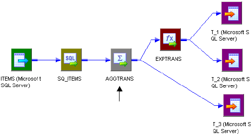
Source-Based Commits 321
♦XML Source Qualifier when you only connect ports from one output group
♦Normalizer (VSAM)
♦Aggregator with the All Input transformation scope
♦Joiner with the All Input transformation scope
♦Rank with the All Input transformation scope
♦Sorter with the All Input transformation scope
♦Custom with one output group and with the All Input transformation scope
♦A multiple input group transformation with one output group connected to multiple
upstream transaction control points
♦Mapplet, if it contains one of the above transformations
For more information about transformation scope and transaction control, see
“Understanding Transaction Control” on page 329. For more information about active
sources, see “Working with Active Sources” on page 282.
A mapping can have one or more target load order groups, and a target load order group can
have one or more active sources that generate commits. The Integration Service uses the
commits generated by the active source that is closest to the target definition. This is known
as the commit source.
For example, you have the mapping in Figure 10-1:
The mapping contains a Source Qualifier transformation and an Aggregator transformation
with the All Input transformation scope. The Aggregator transformation is closer to the
targets than the Source Qualifier transformation and is therefore used as the commit source
for the source-based commit session.
Figure 10-1. Mapping with a Single Commit Source
Transformation Scope
property is All Input.
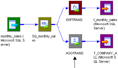
322 Chapter 10: Understanding Commit Points
Also, suppose you have the mapping in Figure 10-2:
The mapping contains a target load order group with one source pipeline that branches from
the Source Qualifier transformation to two targets. One pipeline branch contains an
Aggregator transformation with the All Input transformation scope, and the other contains an
Expression transformation. The Integration Service identifies the Source Qualifier
transformation as the commit source for t_monthly_sales and the Aggregator as the commit
source for T_COMPANY_ALL. It performs a source-based commit for both targets, but uses
a different commit source for each.
Switching from Source-Based to Target-Based Commit
If the Integration Service identifies a target in the target load order group that does not
receive commits from an active source that generates commits, it reverts to target-based
commit for that target only.
The Integration Service writes the name of the transformation used for source-based commit
intervals into the session log. When the Integration Service switches to target-based commit,
it writes a message in the session log.
A target might not receive commits from a commit source in the following circumstances:
♦The target receives data from the XML Source Qualifier transformation, and you
connect multiple output groups from an XML Source Qualifier transformation to
downstream transformations. An XML Source Qualifier transformation does not generate
commits when you connect multiple output groups downstream.
♦The target receives data from an active source with multiple output groups other than
an XML Source Qualifier transformation. For example, the target receives data from a
Custom transformation that you do not configure to generate transactions. Multiple
output group active sources neither generate nor propagate commits.
Connecting XML Sources in a Mapping
An XML Source Qualifier transformation does not generate commits when you connect
multiple output groups downstream. When you an XML Source Qualifier transformation in a
Figure 10-2. Mapping with Multiple Commit Sources
Transformation Scope
property is All Input.
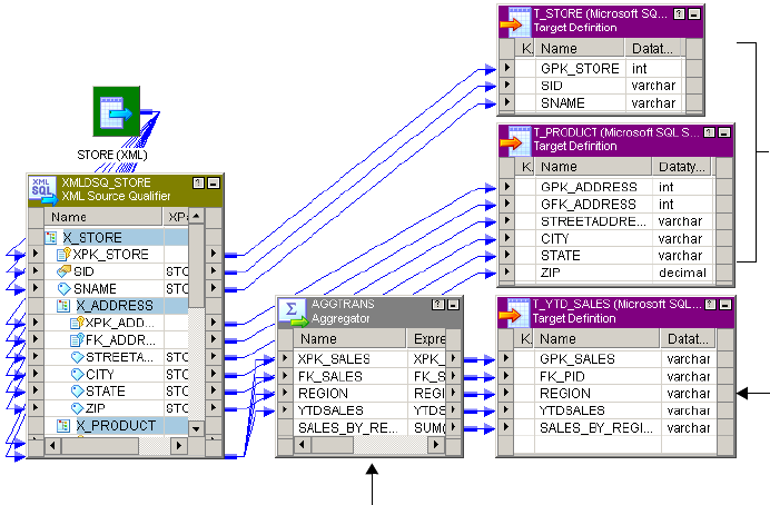
Source-Based Commits 323
mapping, the Integration Service can use different commit types for targets in this session
depending on the transformations used in the mapping:
♦You put a commit source between the XML Source Qualifier transformation and the
target. The Integration Service uses source-based commit for the target because it receives
commits from the commit source. The active source is the commit source for the target.
♦You do not put a commit source between the XML Source Qualifier transformation and
the target. The Integration Service uses target-based commit for the target because it
receives no commits.
Suppose you have the mapping in Figure 10-3:
This mapping contains an XML Source Qualifier transformation with multiple output groups
connected downstream. Because you connect multiple output groups downstream, the XML
Source Qualifier transformation does not generate commits. You connect the XML Source
Qualifier transformation to two relational targets, T_STORE and T_PRODUCT. Therefore,
these targets do not receive any commit generated by an active source. The Integration Service
uses target-based commit when loading to these targets.
However, the mapping includes an active source that generates commits, AGG_Sales,
between the XML Source Qualifier transformation and T_YTD_SALES. The Integration
Service uses source-based commit when loading to T_YTD_SALES.
Figure 10-3. Mapping with Targets Connected to a Commit Source
Transformation Scope = All Input
Connected to an XML
Source Qualifier
transformation with multiple
connected output groups.
Integration Service uses
target-based commit when
loading to these targets.
Connected to an active
source that generates
commits, AGG_Sales.
Integration Service uses
source-based commit
when loading to this
target.
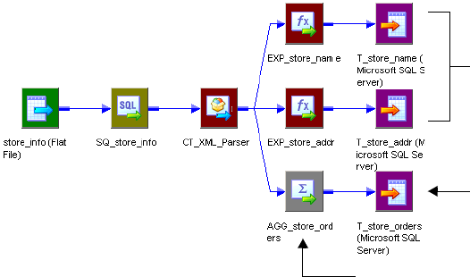
324 Chapter 10: Understanding Commit Points
Connecting Multiple Output Group Custom Transformations in a
Mapping
Multiple output group Custom transformations that you do not configure to generate
transactions neither generate nor propagate commits. Therefore, the Integration Service can
use different commit types for targets in this session depending on the transformations used
in the mapping:
♦You put a commit source between the Custom transformation and the target. The
Integration Service uses source-based commit for the target because it receives commits
from the active source. The active source is the commit source for the target.
♦You do not put a commit source between the Custom transformation and the target.
The Integration Service uses target-based commit for the target because it receives no
commits.
Suppose you have the mapping in Figure 10-4:
The mapping contains a multiple output group Custom transformation, CT_XML_Parser,
which drops the commits generated by the Source Qualifier transformation. Therefore,
targets T_store_name and T_store_addr do not receive any commits generated by an active
source. The Integration Service uses target-based commit when loading to these targets.
However, the mapping includes an active source that generates commits, AGG_store_orders,
between the Custom transformation and T_store_orders. The Integration Service uses source-
based commit when loading to T_store_orders.
Note: You can configure a Custom transformation to generate transactions when the Custom
transformation procedure outputs transactions. When you do this, configure the session for
user-defined commit. For more information about user-defined commit sessions, see “User-
Defined Commits” on page 325.
Figure 10-4. Mapping a Custom Transformation with a Commit Source
Transformation Scope is All Input.
Connected to a multiple output
group active source,
CT_XML_Parser. Integration
Service uses target-based commit
when loading to these targets.
Connected to an active source
that generates commits,
AGG_store_orders. Integration
Service uses source-based
commit when loading to this
target.
User-Defined Commits 325
User-Defined Commits
During a user-defined commit session, the Integration Service commits and rolls back
transactions based on a row or set of rows that pass through a Transaction Control
transformation. The Integration Service evaluates the transaction control expression for each
row that enters the transformation. The return value of the transaction control expression
defines the commit or rollback point.
You can also create a user-defined commit session when the mapping contains a Custom
transformation configured to generate transactions. When you do this, the procedure
associated with the Custom transformation defines the transaction boundaries.
When the Integration Service evaluates a commit row, it commits all rows in the transaction
to the target or targets. When it evaluates a rollback row, it rolls back all rows in the
transaction from the target or targets. The Integration Service writes a message to the session
log at each commit and rollback point. The session details are cumulative. The following
message is a sample commit message from the session log:
WRITER_1_1_1> WRT_8317
USER-DEFINED COMMIT POINT Wed Oct 15 08:15:29 2003
===================================================
WRT_8036 Target: TCustOrders (Instance Name: [TCustOrders])
WRT_8038 Inserted rows - Requested: 1003 Applied: 1003
Rejected: 0 Affected: 1023
When the Integration Service writes all rows in a transaction to all targets, it issues commits
sequentially for each target.
The Integration Service rolls back data based on the return value of the transaction control
expression or error handling configuration. If the transaction control expression returns a
rollback value, the Integration Service rolls back the transaction. If an error occurs, you can
choose to roll back or commit at the next commit point.
If the transaction control expression evaluates to a value other than commit, rollback, or
continue, the Integration Service fails the session. For more information about valid values,
see “Transaction Control Transformation” in the Transformation Guide.
When the session completes, the Integration Service may write data to the target that was not
bound by commit rows. You can choose to commit at end of file or to roll back that open
transaction.
Note: If you use bulk loading with a user-defined commit session, the target may not recognize
the transaction boundaries. If the target connection group does not support transactions, the
Integration Service writes the following message to the session log:
WRT_8324 Warning: Target Connection Group’s connection doesn’t support
transactions. Targets may not be loaded according to specified transaction
boundaries rules.
326 Chapter 10: Understanding Commit Points
Rolling Back Transactions
The Integration Service rolls back transactions in the following circumstances:
♦Rollback evaluation. The transaction control expression returns a rollback value.
♦Open transaction. You choose to roll back at the end of file.
♦Roll back on error. You choose to roll back commit transactions if the Integration Service
encounters a non-fatal error.
♦Roll back on failed commit. If any target connection group in a transaction control unit
fails to commit, the Integration Service rolls back all uncommitted data to the last
successful commit point.
For more information about transaction control units, see “Understanding Transaction
Control Units” on page 331.
Rollback Evaluation
If the transaction control expression returns a rollback value, the Integration Service rolls
back the transaction and writes a message to the session log indicating that the transaction
was rolled back. It also indicates how many rows were rolled back.
The following message is a sample message that the Integration Service writes to the session
log when the transaction control expression returns a rollback value:
WRITER_1_1_1> WRT_8326 User-defined rollback processed
WRITER_1_1_1> WRT_8331 Rollback statistics
WRT_8162 ===================================================
WRT_8330 Rolled back [333] inserted, [0] deleted, [0] updated rows for the
target [TCustOrders]
Roll Back Open Transaction
If the last row in the transaction control expression evaluates to
TC_CONTINUE_TRANSACTION, the session completes with an open transaction. If you
choose to roll back that open transaction, the Integration Service rolls back the transaction
and writes a message to the session log indicating that the transaction was rolled back.
The following message is a sample message indicating that Commit on End of File is disabled
in the session properties:
WRITER_1_1_1> WRT_8168 End loading table [TCustOrders] at: Wed Nov 05
10:21:56 2003
WRITER_1_1_1> WRT_8325 Final rollback executed for the target
[TCustOrders] at end of load
The following message is a sample message indicating that Commit on End of File is enabled
in the session properties:
WRITER_1_1_1> WRT_8143
Commit at end of Load Order Group Wed Nov 05 08:15:29 2003

User-Defined Commits 327
Roll Back on Error
You can choose to roll back a transaction at the next commit point if the Integration Service
encounters a non-fatal error. When the Integration Service encounters a non-fatal error, it
processes the error row and continues processing the transaction. If the transaction boundary
is a commit row, the Integration Service rolls back the entire transaction and writes it to the
reject file.
The following table describes row indicators in the reject file for rolled-back transactions:
Note: The Integration Service does not roll back a transaction if it encounters an error before
it processes any row through the Transaction Control transformation.
Roll Back on Failed Commit
When the Integration Service reaches the commit point for all targets in a transaction control
unit, it issues commits sequentially for each target. If the commit fails for any target
connection group within a transaction control unit, the Integration Service rolls back all data
to the last successful commit point. The Integration Service cannot roll back committed
transactions, but it does write the transactions to the reject file.
For example, use the mapping in Figure 10-5 on page 328 to read through the following
situation. This mapping has one transaction control unit and three target connection groups.
The target names contain information about the target connection group. For example,
TCG1_T1 represents the first target connection group and the first target.
The Integration Service uses the following logic when it processes the mapping in Figure 10-5
on page 328:
1. The Integration Service reaches the third commit point for all targets.
2. It begins to issue commits sequentially for each target.
3. The Integration Service successfully commits to TCG1_T1 and TCG1_T2.
4. The commit fails for TCG2_T3.
5. The Integration Service does not issue a commit for TCG3_T4.
6. The Integration Service rolls back TCG2_T3 and TCG3_T4 to the second commit
point, but it cannot roll back TCG1_T1 and TCG1_T2 to the second commit point
because it successfully committed at the third commit point.
7. The Integration Service writes the rows to the reject file from TCG2_T3 and TCG3_T4.
These are the rollback rows associated with the third commit point.
Row Indicator Description
4Rolled-back insert
5Rolled-back update
6Rolled-back delete
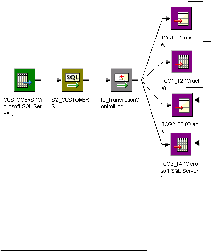
328 Chapter 10: Understanding Commit Points
8. The Integration Service writes the row to the reject file from TCG_T1 and TCG1_T2.
These are the commit rows associated with the third commit point.
Figure 10-5 illustrates Integration Service behavior when it rolls back on a failed commit:
The following table describes row indicators in the reject file for committed transactions in a
failed transaction control unit:
Figure 10-5. Roll Back on Failed Commit Example
Row Indicator Description
7Committed insert
8Committed update
9Committed delete
Third commit is successful (3).
Rows appear in the reject file (8).
Third commit fails (4).
Integration Service rolls back to second commit (6).
Rows appear in reject file (7).
Integration Service does not issue third commit (5).
It rolls back to second commit (6).
Rows appear in reject file (7).
Understanding Transaction Control 329
Understanding Transaction Control
PowerCenter lets you define transactions that the Integration Service uses when it processes
transformations and when it commits and rolls back data at a target. You can define a
transaction based on a varying number of input rows. A transaction is a set of rows bound by
commit or rollback rows, the transaction boundaries. Some rows may not be bound by
transaction boundaries. This set of rows is an open transaction. You can choose to commit at
end of file or to roll back open transactions when you configure the session. For more
information about the Commit On End of File session property, see “Setting Commit
Properties” on page 334.
The Integration Service can process input rows for a transformation each row at a time, for all
rows in a transaction, or for all source rows together. Processing a transformation for all rows
in a transaction lets you include transformations, such as an Aggregator, in a real-time session.
For more information about configuring how the Integration Service processes a
transformation, see “Transformation Scope” on page 329.
Transaction boundaries originate from transaction control points. A transaction control point
is a transformation that defines or redefines the transaction boundary in the following ways:
♦Generates transaction boundaries. The transformations that define transaction
boundaries differ, depending on the session commit type:
−Target-based and user-defined commit. Transaction generators generate transaction
boundaries. A transaction generator is a transformation that generates both commit and
rollback rows. The Transaction Control and Custom transformation are transaction
generators.
−Source-based commit. Some active sources generate commits. They do not generate
rollback rows. Also, transaction generators generate commit and rollback rows. For a list
of active sources that generate commits, see “Determining the Commit Source” on
page 320.
♦Drops incoming transaction boundaries. When a transformation drops incoming
transaction boundaries, and does not generate commits, the Integration Service outputs all
rows into an open transaction. All active sources that generate commits and transaction
generators drop incoming transaction boundaries.
For a list of transaction control points, see Table 10-1 on page 330.
Transformation Scope
You can configure how the Integration Service applies the transformation logic to incoming
data with the Transformation Scope transformation property. When the Integration Service
processes a transformation, it either drops transaction boundaries or preserves transaction
boundaries, depending on the transformation scope and the mapping configuration.
You can choose one of the following values for the transformation scope:
♦Row. Applies the transformation logic to one row of data at a time. Choose Row when a
row of data does not depend on any other row. When you choose Row for a

330 Chapter 10: Understanding Commit Points
transformation connected to multiple upstream transaction control points, the Integration
Service drops transaction boundaries and outputs all rows from the transformation as an
open transaction. When you choose Row for a transformation connected to a single
upstream transaction control point, the Integration Service preserves transaction
boundaries.
♦Tr a n s a ct i o n . Applies the transformation logic to all rows in a transaction. Choose
Transaction when a row of data depends on all rows in the same transaction, but does not
depend on rows in other transactions. When you choose Transaction, the Integration
Service preserves incoming transaction boundaries. It resets any cache, such as an
aggregator or lookup cache, when it receives a new transaction.
When you choose Transaction for a multiple input group transformation, you must
connect all input groups to the same upstream transaction control point.
♦All Input. Applies the transformation logic on all incoming data. When you choose All
Input, the Integration Service drops incoming transaction boundaries and outputs all rows
from the transformation as an open transaction. Choose All Input when a row of data
depends on all rows in the source.
Table 10-1 lists the transformation scope values available for each transformation:
Table 10-1. Transformation Scope Property Values
Transformation Row Transaction All Input
Aggregator Optional. Default.
Transaction control point.
Application Source
Qualifier
n/a
Transaction control point.
Custom* Optional.
Transaction control point
when configured to
generate commits or when
connected to multiple
upstream transaction
control points.
Optional.
Transaction control point
when configured to generate
commits.
Default.
Always a transaction
control point.
Generates commits when
it has one output group or
when configured to
generate commits.
Otherwise, it generates an
open transaction.
Expression Default. Does not display.
External Procedure Default. Does not display.
Filter Default. Does not display.
HTTP Default. Read only.
Java* Default for passive
transformations.
Optional for active
transformations.
Default for active
transformations.
Joiner Optional. Default.
Transaction control point.
Lookup Default. Does not display.

Understanding Transaction Control 331
Understanding Transaction Control Units
A transaction control unit is the group of targets connected to an active source that generates
commits or an effective transaction generator. A transaction control unit may contain
multiple target connection groups. For more information about target connection groups, see
“Working with Target Connection Groups” on page 280.
MQ Source Qualifier n/a
Transaction control point.
Normalizer (VSAM) n/a
Transaction control point.
Normalizer (relational) Default. Does not display.
Rank Optional. Default.
Transaction control point.
Router Default. Does not display.
Sorter Optional. Default.
Transaction control point.
Sequence Generator Default. Does not display.
Source Qualifier n/a
Transaction control point.
SQL Default for script mode
SQL transformations.
Optional.
Transaction control point
when configured to generate
commits.
Default for query mode
SQL transformations.
Stored Procedure Default. Does not display.
Transaction Control Default. Does not display.
Transaction control point.
Union Default. Does not display.
Update Strategy Default. Does not display.
XML Generator Optional.
Transaction when the flush
on commit is set to create a
new document.
Default. Does not display.
XML Parser Default. Does not display.
XML Source Qualifier n/a
Transaction control point.
*For more information about how the Transformation Scope property affects Custom or Java transformations, see “Custom
Transformation” or “Java Transformation” in the Transformation Guide.
Table 10-1. Transformation Scope Property Values
Transformation Row Transaction All Input
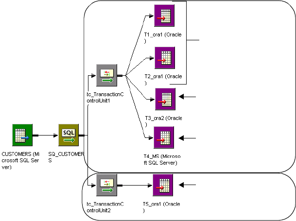
332 Chapter 10: Understanding Commit Points
When the Integration Service reaches the commit point for all targets in a transaction control
unit, it issues commits sequentially for each target.
Figure 10-6 illustrates transaction control units with a Transaction Control transformation:
Note that T5_ora1 uses the same connection name as T1_ora1 and T2_ora1. Because
T5_ora1 is connected to a separate Transaction Control transformation, it is in a separate
transaction control unit and target connection group. If you connect T5_ora1 to
tc_TransactionControlUnit1, it will be in the same transaction control unit as all targets, and
in the same target connection group as T1_ora1 and T2_ora1.
Rules and Guidelines
Consider the following rules and guidelines when you work with transaction control:
♦Transformations with Transaction transformation scope must receive data from a single
transaction control point.
♦The Integration Service uses the transaction boundaries defined by the first upstream
transaction control point for transformations with Transaction transformation scope.
♦Transaction generators can be effective or ineffective for a target. The Integration Service
uses the transaction generated by an effective transaction generator when it loads data to a
target. For more information about effective and ineffective transaction generators, see
“Transaction Control Transformation” in the Tra ns f o r mat io n Gu id e.
♦The Workflow Manager prevents you from using incremental aggregation in a session with
an Aggregator transformation with Transaction transformation scope.
Figure 10-6. Transaction Control Units
Target Connection Group 1
Target Connection Group 2
Target Connection Group 3
Target Connection Group 4
Transaction
Control Unit 1
Transaction
Control Unit 2
Understanding Transaction Control 333
♦Transformations with All Input transformation scope cause a transaction generator to
become ineffective for a target in a user-defined commit session. For more information
about using transaction generators in mappings, see “Transaction Control Transformation”
in the Tra ns f o r mat io n Gu id e.
♦The Integration Service resets any cache at the beginning of each transaction for
Aggregator, Joiner, Rank, and Sorter transformations with Transaction transformation
scope.
♦You can choose the Transaction transformation scope for Joiner transformations when you
use sorted input.
♦When you add a partition point at a transformation with Transaction transformation
scope, the Workflow Manager uses the pass-through partition type by default. You cannot
change the partition type.
Creating Target Files by Transaction
You can generate a separate output file each time the Integration Service starts a new
transaction. You can dynamically name each target flat file.
To generate a separate output file for each transaction, add a FileName port to the flat file
target definition. When you connect the FileName port in the mapping, the PowerCenter
writes a separate target file at each commit. The Integration Service uses the FileName port
value from the first row in each transaction to name the output file. For more information
about creating target files by transaction, see “Creating Target Files by Transaction” on
page 187.
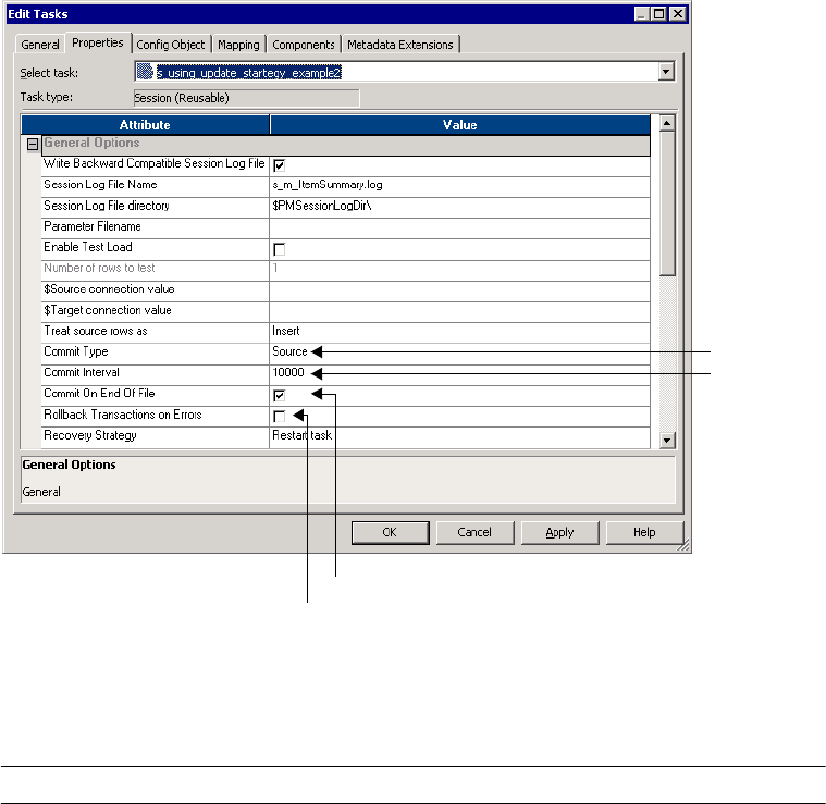
334 Chapter 10: Understanding Commit Points
Setting Commit Properties
When you create a session, you can configure commit properties. The properties you set
depend on the type of mapping and the type of commit you want the Integration Service to
perform.
Figure 10-7 shows the session commit properties that you set in the General Options settings
of the Properties tab:
Table 10-2 describes the session commit properties that you set in the General Options
settings of the Properties tab:
Figure 10-7. Session Commit Properties
Table 10-2. Session Commit Properties
Property Target-Based Source-Based User-Defined
Commit Type Selected by default if no
transaction generator or only
ineffective transaction
generators are in the
mapping.
Choose for source-based
commit if no transaction
generator or only ineffective
transaction generators are in
the mapping.
Selected by default if
effective transaction
generators are in the
mapping.
Commit Type
Commit Interval
Roll Back Transactions on Error
Commit on End of File

Setting Commit Properties 335
Commit Interval* Default is 10,000. Default is 10,000. n/a
Commit on End of File Commits data at the end of
the file. Enabled by default.
You cannot disable this
option.
Commits data at the end of
the file. Clear this option if
you want the Integration
Service to roll back open
transactions.
Commits data at the end of
the file. Clear this option if
you want the Integration
Service to roll back open
transactions.
Roll Back
Transactions on
Errors
If the Integration Service
encounters a non-fatal error,
you can choose to roll back
the transaction at the next
commit point.
When the Integration
Service encounters a
transformation error, it rolls
back the transaction if the
error occurs after the
effective transaction
generator for the target.
If the Integration Service
encounters a non-fatal error,
you can choose to roll back
the transaction at the next
commit point.
When the Integration
Service encounters a
transformation error, it rolls
back the transaction if the
error occurs after the
effective transaction
generator for the target.
If the Integration Service
encounters a non-fatal error,
you can choose to roll back
the transaction at the next
commit point.
When the Integration
Service encounters a
transformation error, it rolls
back the transaction if the
error occurs after the
effective transaction
generator for the target.
* Tip: When you bulk load to Microsoft SQL Server or Oracle targets, define a large commit interval. Microsoft SQL Server and Oracle start
a new bulk load transaction after each commit. Increasing the commit interval reduces the number of bulk load transactions and increases
performance.
Table 10-2. Session Commit Properties
Property Target-Based Source-Based User-Defined
336 Chapter 10: Understanding Commit Points

337
Chapter 11
Recovering Workflows
This chapter includes the following topics:
♦Overview, 338
♦State of Operation, 339
♦Recovery Options, 342
♦Configuring Workflow Recovery, 343
♦Configuring Task Recovery, 346
♦Resuming Sessions, 349
♦Working with Repeatable Data, 351
♦Steps to Recover Workflows and Tasks, 356
♦Rules and Guidelines for Session Recovery, 358
338 Chapter 11: Recovering Workflows
Overview
Workflow recovery allows you to continue processing the workflow and workflow tasks from
the point of interruption. You can recover a workflow if the Integration Service can access the
workflow state of operation. The workflow state of operation includes the status of tasks in
the workflow and workflow variable values. The Integration Service stores the state in
memory or on disk, based on how you configure the workflow:
♦Enable recovery. When you enable a workflow for recovery, the Integration Service saves
the workflow state of operation in a shared location. You can recover the workflow if it
terminates, stops, or aborts. The workflow does not have to be running.
♦Suspend. When you configure a workflow to suspend on error, the Integration Service
stores the workflow state of operation in memory. You can recover the suspended workflow
if a task fails. You can fix the task error and recover the workflow.
The Integration Service recovers tasks in the workflow based on the recovery strategy of the
task. By default, the recovery strategy for Session and Command tasks is to fail the task and
continue running the workflow. You can configure the recovery strategy for Session and
Command tasks. The strategy for all other tasks is to restart the task.
When you have high availability, PowerCenter recovers a workflow automatically if a service
process that is running the workflow fails over to a different node. You can configure a
running workflow to recover a task automatically when the task terminates. PowerCenter also
recovers a session and workflow after a database connection interruption.
When the Integration Service runs in safe mode, it stores the state of operation for workflows
configured for recovery. If the workflow fails the Integration Service fails over to a backup
node, the Integration Service does not automatically recover the workflow. You can manually
recover the workflow if you have Admin Integration Service privilege on the Integration
Service.
State of Operation 339
State of Operation
When you recover a workflow or session, the Integration Service restores the workflow or
session state of operation to determine where to begin recovery processing. The Integration
Service stores the workflow state of operation in memory or on disk based on the way you
configure the workflow. The Integration Service stores the session state of operation based on
the way you configure the session.
Workflow State of Operation
The Integration Service stores the workflow state of operation when you enable the workflow
for recovery or for suspension. When the workflow is suspended, the state of operation is in
memory.
When you enable a workflow for recovery, the Integration Service stores the workflow state of
operation in the shared location, $PMStorageDir. The Integration Service can restore the
state of operation to recover a stopped, aborted, or terminated workflow. When it performs
recovery, it restores the state of operation to recover the workflow from the point of
interruption. When the workflow completes, the Integration Service removes the workflow
state of operation from the shared folder.
The workflow state of operation includes the following information:
♦Active service requests
♦Completed and running task status
♦Workflow variable values
When you enable a workflow for recovery the Integration Service does not store the session
state of operation by default. You can configure the session recovery strategy to save the
session state of operation.
Session State of Operation
When you configure the session recovery strategy to resume from the last checkpoint, the
Integration Service stores the session state of operation in the shared location,
$PMStorageDir. The Integration Service also saves relational target recovery information in
target database tables. When the Integration Service performs recovery, it restores the state of
operation to recover the session from the point of interruption. It uses the target recovery data
to determine how to recover the target tables.
You can configure the session to save the session state of operation even if you do not save the
workflow state of operation. You can recover the session, or you can recover the workflow
from the session.
The session state of operation includes the following information:
♦Source. If the output from a source is not deterministic and repeatable, the Integration
Service saves the result from the SQL query to a shared storage file in $PMStorageDir. The
Integration Service saves the result from the SQL query to a shared storage file in

340 Chapter 11: Recovering Workflows
$PMStorageDir. For more information about deterministic and repeatable data, see
“Working with Repeatable Data” on page 351.
♦Transformation. The Integration Service creates checkpoints in $PMStorageDir to
determine where to start processing the pipeline when it runs a recovery session.
When you run a session with an incremental Aggregator transformation, the Integration
Service creates a backup of the Aggregator cache files in $PMCacheDir at the beginning of
a session run. The Integration Service promotes the backup cache to the initial cache at the
beginning of a session recovery run.
♦Relational target recovery data. The Integration Service writes recovery information to
recovery tables in the target database to determine the last row committed to the target
when the session was interrupted.
Target Recovery Tables
When the Integration Service runs a session that has a resume recovery strategy, it writes to
recovery tables on the target database system. When the Integration Service recovers the
session, it uses information in the recovery tables to determine where to begin loading data to
target tables.
If you want the Integration Service to create the recovery tables, grant table creation privilege
to the database user name for the target database connection. If you do not want the
Integration Service to create the recovery tables, create the recovery tables manually.
The Integration Service creates the following recovery tables in the target database:
♦PM_RECOVERY. Contains target load information for the session run. The Integration
Service removes the information from this table after each successful session and initializes
the information at the beginning of subsequent sessions.
♦PM_TGT_RUN_ID. Contains information the Integration Service uses to identify each
target on the database. The information remains in the table between session runs. If you
manually create this table, you must create a row and enter a value other than zero for
LAST_TGT_RUN_ID to ensure that the session recovers successfully.
Do not edit or drop the recovery tables before you recover a session. If you disable recovery,
the Integration Service does not remove the recovery tables from the target database. You
must manually remove the recovery tables.
Table 11-1 describes the format of PM_RECOVERY:
Table 11-1. PM_RECOVERY Table Definition
Column Name Datatype
REP_GID VARCHAR(240)
WFLOW_ID NUMBER
SUBJ_ID NUMBER
TASK_INST_ID NUMBER

State of Operation 341
Table 11-2 describes the format of PM_TGT_RUN_ID:
Note: When concurrent recovery sessions write to the same target database, the Integration
Service may encounter a deadlock on PM_RECOVERY. To retry writing to
PM_RECOVERY on deadlock, you can configure the Session Retry on Deadlock option to
retry the deadlock for the session. For more information, see “Deadlock Retry” on page 270.
TGT_INST_ID NUMBER
PARTITION_ID NUMBER
TGT_RUN_ID NUMBER
RECOVERY_VER NUMBER
CHECK_POINT NUMBER
ROW_COUNT NUMBER
Table 11-2. PM_TGT_RUN_ID Table Definition
Column Name Datatype
LAST_TGT_RUN_ID NUMBER
Table 11-1. PM_RECOVERY Table Definition
Column Name Datatype

342 Chapter 11: Recovering Workflows
Recovery Options
To perform recovery, you must configure the mapping, workflow tasks, and the workflow for
recovery.
Table 11-3 describes the options that you can configure for recovery:
Table 11-3. Configurable Options for Recovery
Option Location Description
Suspend Workflow on
Error
Workflow Suspends the workflow when a task in the workflow fails. You can fix the
failed tasks and recover a suspended workflow. For more information,
see “Recovering Suspended Workflows” on page 344.
Suspension Email Workflow Sends an email when the workflow suspends. For more information, see
“Recovering Suspended Workflows” on page 344.
Enable HA Recovery Workflow Saves the workflow state of operation in a shared location. You do not
need high availability to enable workflow recovery. For more information,
see “Configuring Workflow Recovery” on page 343.
Automatically Recover
Terminated Tasks
Workflow Recovers terminated Session and Command tasks while the workflow is
running. You must have the high availability option. For more information,
see “Automatically Recovering Terminated Tasks” on page 348.
Maximum Automatic
Recovery Attempts
Workflow The number of times the Integration Service attempts to recover a
Session or Command task. For more information, see “Automatically
Recovering Terminated Tasks” on page 348.
Recovery Strategy Session,
Command
The recovery strategy for a Session or Command task. Determines how
the Integration Service recovers a Session or Command task during
workflow recovery and how it recovers a session during session recovery.
For more information, see “Configuring Task Recovery” on page 346.
Fail Task If Any
Command Fails
Command Enables the Command task to fail if any of the commands in the task fail.
If you do not set this option, the task continues to run when any of the
commands fail. You can use this option with Suspend Workflow on Error
to suspend the workflow if any command in the task fails. For more
information, see “Configuring Task Recovery” on page 346.
Output is Deterministic Transformation Indicates that the transformation always generates the same set of data
from the same input data. When you enable this option with the Output is
Repeatable option for a relational source qualifier, the Integration Service
does not save the SQL results to shared storage. When you enable it for
a transformation, you can configure recovery to resume from the last
checkpoint. For more information, see “Output is Deterministic” on
page 352.
Output is Repeatable Transformation Indicates whether the transformation generates rows in the same order
between session runs. The Integration Service can resume a session
from the last checkpoint when the output is repeatable and
deterministic.When you enable this option with the Output is Deterministic
option for a relational source qualifier, the Integration Service does not
save the SQL results to shared storage. For more information, see
“Output is Deterministic” on page 352.

Configuring Workflow Recovery 343
Configuring Workflow Recovery
To configure a workflow for recovery, you must enable the workflow for recovery or configure
the workflow to suspend on task error. When the workflow is configured for recovery, you can
recover it if it stops, aborts, terminates, or suspends.
Table 11-4 describes each recoverable workflow status:
For more information about workflow status, “Workflow and Task Status” on page 516.
Recovering Stopped, Aborted, and Terminated Workflows
When you enable a workflow for recovery, the Integration Service saves the workflow state of
operation to a file during the workflow run. You can recover a stopped, terminated, or
aborted workflow.
Table 11-4. Recoverable Workflow Status
Status Description
Aborted You abort the workflow in the Workflow Monitor or through pmcmd. You can also choose to abort all
running workflows when you disable the service process in the Administration Console. You can recover
an aborted workflow if you enable the workflow for recovery. You can recover an aborted workflow in the
Workflow Monitor or by using pmcmd.
Stopped You stop the workflow in the Workflow Monitor or through pmcmd. You can also choose to stop all
running workflows when you disable the service or service process in the Administration Console. You
can recover a stopped workflow if you enable the workflow for recovery. You can recover a stopped
workflow in the Workflow Monitor or by using pmcmd.
Suspended A task fails and the workflow is configured to suspend on a task error. If multiple tasks are running, the
Integration Service suspends the workflow when all running tasks either succeed or fail. You can fix the
errors that caused the task or tasks to fail before you run recovery.
By default, a workflow continues after a task fails. To suspend the workflow when a task fails, configure
the workflow to suspend on task error.
Terminated The service process running the workflow shuts down unexpectedly. Tasks terminate on all nodes
running the workflow. A workflow can terminate when a task in the workflow terminates and you do not
have the high availability option. You can recover a terminated workflow if you enable the workflow for
recovery. When you have high availability, the service process fails over to another node and workflow
recovery starts.
Note: A failed workflow is a workflow that completes with failure. You cannot recover a failed workflow.
344 Chapter 11: Recovering Workflows
The following figure shows where to enable a workflow for recovery from a stopped,
terminated, or aborted state:
Recovering Suspended Workflows
You can configure a workflow to suspend if a task in the workflow fails. By default, a
workflow continues to run when a task fails. You can suspend the workflow at task failure, fix
the task that failed, and recover the workflow. When you suspend a workflow, the workflow
state of operation stays in memory. You can fix the error that cause the task to fail and recover
the workflow from the point of interruption. If the task fails again, the Integration Service
suspends the workflow again. You can recover a suspended workflow, but you cannot restart
it.
You can configure the workflow to send an email when a task suspends. For more information
about configuring suspension email, see “Working with Suspension Email” on page 381.
Enable a workflow for recovery.
Configuring Workflow Recovery 345
The following figure shows where to configure a workflow to suspend on error:
Configure a workflow to
suspend on task error.
Send an email when the
workflow suspends.

346 Chapter 11: Recovering Workflows
Configuring Task Recovery
When you recover a workflow, the Integration Service recovers the tasks based on the recovery
strategy for each task. Depending on the task, the recovery strategy can be fail task and
continue workflow, resume from the last checkpoint, or restart task.
When you enable workflow recovery, you can recover a task that you abort or stop. You can
recover a task that terminates due to network or service process failures. When you configure
a workflow to suspend on error, you can recover a failed task when you recover the workflow.
Table 11-5 describes each recoverable task status:
Task Recovery Strategies
Each task in a workflow has a recovery strategy. When the Integration Service recovers a
workflow, it recovers tasks based on the recovery strategy:
♦Restart task. When the Integration Service recovers a workflow, it restarts each recoverable
task that is configured with a restart strategy. You can configure Session and Command
tasks with a restart recovery strategy. All other tasks have a restart recovery strategy by
default.
♦Fail task and continue workflow. When the Integration Service recovers a workflow, it
does not recover the task. The task status becomes failed, and the Integration Service
continues running the workflow.
Table 11-5. Recoverable Task Statuses
Status Description
Aborted You abort the workflow or task in the Workflow Monitor or through pmcmd. You can also choose to abort
all running workflows when you disable the service or service process in the Administration Console. You
can also configure a session to abort based on mapping conditions.
You can recover the workflow in the Workflow Monitor to recover the task or you can recover the
workflow using pmcmd.
Stopped You stop the workflow or task in the Workflow Monitor or through pmcmd. You can also choose to stop all
running workflows when you disable the service or service process in the Administration Console.
You can recover the workflow in the Workflow Monitor to recover the task or you can recover the
workflow using pmcmd.
Failed The Integration Service failed the task due to errors. You can recover a failed task using workflow
recovery when the workflow is configured to suspend on task failure. When the workflow is not
suspended you can recover a failed task by recovering just the session or recovering the workflow from
the session.
You can fix the error and recover the workflow in the Workflow Monitor or you can recover the workflow
using pmcmd.
Terminated The Integration Service stops unexpectedly or loses network connection to the master service process.
You can recover the workflow in the Workflow Monitor or you can recover the workflow using pmcmd
after the Integration Service restarts.

Configuring Task Recovery 347
Configure a fail recovery strategy if you want to complete the workflow, but you do not
want to recover the task. You can configure Session and Command tasks with the fail task
and continue workflow recovery strategy.
♦Resume from the last checkpoint. The Integration Service recovers a stopped, aborted, or
terminated session from the last checkpoint. You can configure a Session task with a
resume strategy. For more information about the resume strategy, see “Resuming Sessions”
on page 349.
Table 11-6 describes the recovery strategy for each task type:
Command Task Strategies
When you configure a Command task, you can choose a recovery strategy to restart or fail:
♦Fail task and continue workflow. If you want to suspend the workflow on Command task
error, you must configure the task with a fail strategy. If the Command task has more than
one command, and you configure a fail strategy, you need to configure the task to fail if
any command fails.
♦Restart task. When the Integration Service recovers a workflow, it restarts a Command
task that is configured with a restart strategy.
Configure the recovery strategy on the Properties page of the Command task.
For more information about Command tasks, see “Working with the Command Task” on
page 147.
Table 11-6. Recovery Strategy by Task Type
Task Type Recovery Strategy Comments
Assignment Restart task
Command Restart task
Fail task and continue workflow
Default is fail task and continue workflow. For more information,
see “Configuring Task Recovery” on page 346.
Control Restart task
Decision Restart task
Email Restart task The Integration Service might send duplicate email.
Event-Raise Restart task
Event-Wait Restart task
Session Resume from the last checkpoint.
Restart task
Fail task and continue workflow.
Default is fail task and continue workflow. For more information,
see “Session Task Strategies” on page 348.
Timer Restart task If you use a relative time from the start time of a task or workflow,
set the timer with the original value less the passed time.
Worklet n/a The Integration Service does not recover a worklet. You can
recover the session in the worklet by expanding the worklet in the
Workflow Monitor and choosing Recover Task.
348 Chapter 11: Recovering Workflows
Session Task Strategies
When you configure a session for recovery, you can recover the session when you recover a
workflow, or you can recover the session without running the rest of the workflow.
When you configure a session, you can choose a recovery strategy of fail, restart, or resume:
♦Resume from the last checkpoint. The Integration Service saves the session state of
operation and maintains target recovery tables. If the session aborts, stops, or terminates,
the Integration Service uses the saved recovery information to resume the session from the
point of interruption. For more information about the resume strategy, see “Resuming
Sessions” on page 349.
♦Restart task. The Integration Service runs the session again when it recovers the workflow.
When you recover with restart task, you might need to remove the partially loaded data in
the target or design a mapping to skip the duplicate rows.
♦Fail task and continue workflow. When the Integration Service recovers a workflow, it
does not recover the session. The session status becomes failed, and the Integration Service
continues running the workflow.
Configure the recovery strategy on the Properties page of the Session task.
Automatically Recovering Terminated Tasks
When you have the high availability option, you can configure automatic recovery of
terminated tasks. When you enable automatic task recovery, the Integration Service recovers
terminated Session and Command tasks without user intervention if the workflow is still
running. You configure the number of times the Integration Service attempts to recover the
task. Enable automatic task recovery in the workflow properties.

Resuming Sessions 349
Resuming Sessions
When you configure session recovery to resume from the last checkpoint, the Integration
Service creates checkpoints in $PMStorageDir to determine where to start processing session
recovery. When the Integration Service resumes a session, it restores the session state of
operation, including the state of each source, target, and transformation. The Integration
Service determines how much of the source data it needs to process.
When the Integration Service resumes a session, the recovery session must produce the same
data as the original session. The session is not valid if you configure recovery to resume from
the last checkpoint, but the session cannot produce repeatable data. For more information
about repeatable data, see “Working with Repeatable Data” on page 351.
The Integration Service can recover flat file sources including FTP sources. It can truncate or
append to flat file and FTP targets.
When you recover a session from the last checkpoint, the Integration Service restores the
session state of operation to determine the type of recovery it can perform:
♦Incremental. The Integration Service starts processing data at the point of interruption. It
does not read or transform rows that it processed before the interruption. By default, the
Integration Service attempts to perform incremental recovery.
♦Full. The Integration Service reads all source rows again and performs all transformation
logic if it cannot perform incremental recovery. The Integration Service begins writing to
the target at the last commit point. If any session component requires full recovery, the
Integration Service performs full recovery on the session.
Table 11-7 describes when the Integration Service performs incremental or full recovery,
depending on the session configuration:
Table 11-7. Incremental and Full Recovery Session Recovery Situations
Component Incremental Recovery Full Recovery
Commit type The session uses a source-based commit.
The mapping does not contain any
transformation that generates commits.
The session uses a target-based commit or
user-defined commit.
Transformation
Scope
Transformations propagate transactions and
the transformation scope must be
Transaction or Row.
At least one transformation is configured with
the All transformation scope.
File Source A file source supports incremental reads. n/a
FTP Source The FTP server must support the seek
operation to allow incremental reads.
The FTP server does not support the seek
operation.
Relational Source A relational source supports incremental
reads when the output is deterministic and
repeatable. It the output is not deterministic
and repeatable, the Integration Service
supports incremental relational source reads
by staging SQL results to a storage file.
n/a

350 Chapter 11: Recovering Workflows
VSAM Source n/a Integration Service performs full recovery.
XML Source n/a Integration Service performs full recovery.
XML Generator
Transformation
An XML Generator transformation must be
configured with Transaction transformation
scope.
n/a
XML Target An XML target must be configured to
generate a new XML document on commit.
n/a
Table 11-7. Incremental and Full Recovery Session Recovery Situations
Component Incremental Recovery Full Recovery
Working with Repeatable Data 351
Working with Repeatable Data
When you configure recovery to resume from the last checkpoint, the recovery session must
be able to produce the same data in the same order as the original session. When you validate
a session, the Workflow Manager verifies that the recovery session can produce the same data
as the original session. The session is not valid if you configure recovery to resume from the
last checkpoint, but the session cannot produce the same data.
Session data is repeatable when all targets receive repeatable data from the following mapping
objects:
♦Source. The output data from the source is repeatable between the original run and the
recovery run. For more information, see “Source Repeatability” on page 351.
♦Transformation. The output data from each transformation to the target is repeatable. For
more information, see “Transformation Repeatability” on page 352.
Source Repeatability
You can resume a session from the last checkpoint when each source generates the same set of
data and the order of the output is repeatable between runs. Source data is repeatable based on
the type of source in the session.
♦Relational source. A relational source might produce data that is not the same or in the
same order between workflow runs. When you configure recovery to resume from the last
checkpoint, the Integration Service stores the SQL result in a cache file to guarantee the
output order for recovery.
If you know the SQL result will be the same between workflow runs, you can configure the
source qualifier to indicate that the data is repeatable and deterministic. When the
relational source output is deterministic and the output is always repeatable, the
Integration Service does not store the SQL result in a cache file. When the relational
352 Chapter 11: Recovering Workflows
output is not repeatable, the Integration Service can skip creating the cache file if a
transformation in the mapping always produces ordered data.
♦SDK source. If an SDK source produces repeatable data, you can enable Output is
Deterministic and Output is Repeatable in the SDK Source Qualifier transformation.
♦Flat file source. A flat file does not change between session and recovery runs. If you
change a source file before you recover a session, the recovery session might produce
unexpected results.
Transformation Repeatability
You can configure a session to resume from the last checkpoint when transformations in the
session produce the same data between the session and recovery run. All transformations have
properties that determine if the transformation can produce repeatable data. A transformation
can produce the same data between a session and recovery run if the output is deterministic
and the output is repeatable.
Output is Deterministic
A transformation generates deterministic output when it always creates the same output data
from the same input data. If you set the session recovery strategy to resume from the last
checkpoint, the Workflow Manager validates that output is deterministic for each
transformation.
Output is Repeatable
A transformation generates repeatable data when it generates rows in the same order between
session runs. Transformations produce repeatable data based on the transformation type, the
transformation configuration, or the mapping configuration.
Output is deterministic
Output is repeatable
Working with Repeatable Data 353
Transformations produce repeatable data in the following circumstances:
♦Always. The order of the output data is consistent between session runs even if the order
of the input data is inconsistent between session runs.
♦Based on input order. The transformation produces repeatable data between session runs
when the order of the input data from all input groups is consistent between session runs.
If the input data from any input group is not ordered, then the output is not ordered.
When a transformation generates repeatable data based on input order, during session
validation, the Workflow Manager validates the mapping to determine if the
transformation can produce repeatable data. For example, an Expression transformation
produces repeatable data only if it receives repeatable data.
♦Never. The order of the output data is inconsistent between session runs. You cannot
configure recovery to resume from the last checkpoint if a transformation does not
produce repeatable data.
Configuring a Mapping for Recovery
You can configure a mapping to enable transformations in the session to produce the same
data between the session and recovery run. When a mapping contains a transformation that
never produces repeatable data, you can add a transformation that always produces repeatable
data immediately after it.
For example, you connect a transformation that never produces repeatable data directly to a
transformation that produces repeatable data based on input order. You cannot configure
recovery to resume from the last checkpoint unless the data is repeatable. To enable the
session for recovery, you can add a transformation that always produces repeatable data after
the transformation that never produces repeatable data.
The following figure shows a mapping that you cannot recover with resume from the last
checkpoint:
The mapping contains two Source Qualifier transformations that produce repeatable data.
The mapping contains a Union and Custom transformation that never produce repeatable
data. The Lookup transformation produces repeatable data when it receives repeatable data.
Never produces repeatable data.
Produces repeatable data if it
receives repeatable data.
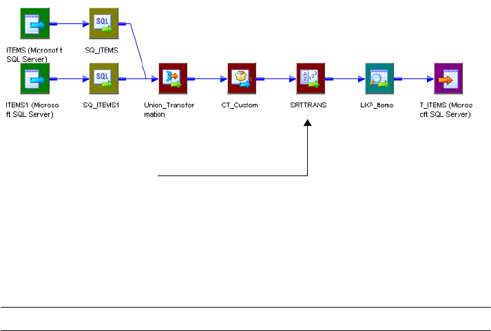
354 Chapter 11: Recovering Workflows
Therefore, the target does not receive repeatable data and you cannot configure the session to
resume recovery.
You can modify the mapping to enable resume recovery. Add a Sorter transformation
configured for distinct output rows immediately after the transformations that never output
repeatable data. Add the Sorter transformation after the Custom transformation.
The following figure shows the mapping with a Sorter transformation connected to the
Custom transformation:
The Lookup transformation produces repeatable data because it receives repeatable data from
the Sorter transformation.
Table 11-8 describes when transformations produce repeatable data:
Table 11-8. Repeatable Data in Transformations
Transformation Repeatable Data
Aggregator Always.
Application Source Qualifier* Based on input order.
Custom* Based on input order. Configure the property according to the transformation
procedure behavior.
Expression Based on input order.
External Procedure Never.
Filter Based on input order.
Joiner Based on input order.
Java* Based on input order. Configure the property according to the transformation
procedure behavior.
Lookup, dynamic Always. The lookup source must be the same as a target in the session.
Lookup, static Based on input order.
MQ Source Qualifier Always.
Configured for distinct output rows.
Always produces repeatable data.

Working with Repeatable Data 355
Normalizer, pipeline Based on input order.
Normalizer, VSAM Always. The normalizer generates source data in the form of unique primary
keys. When you resume a session the session might generate different key
values than if it completed successfully.
Rank Always.
Router Based on input order.
Sequence Generator Always. The Integration Service stores the current value to the repository.
Sorter, configured for distinct
output rows
Always.
Sorter, not configured for
distinct output rows
Based on input order.
Source Qualifier, flat file Always.
Source Qualifier, relational* Based on input order. Configure the transformation according to the source
data. The Integration Service stages the data if the data is not repeatable.
SQL Transformation Never.
Stored Procedure Never.
Transaction Control Based on input order.
Union Never.
Update Strategy Based on input order.
XML Generator Always.
XML Parser Always.
XML Source Qualifier Always.
* You can configure the Output is Repeatable and Output is Deterministic properties for some transformations. Or you can add a
transformation that produces repeatable data immediately after the transformation.
Table 11-8. Repeatable Data in Transformations
Transformation Repeatable Data
356 Chapter 11: Recovering Workflows
Steps to Recover Workflows and Tasks
You can recover a workflow if you configure the workflow for recovery. You can recover a
session when you configure a session recovery strategy. When you configure a session recovery
strategy, you do not have to enable workflow recovery to recover a session.
You can use one of the following methods to recover a workflow or task:
♦Recover a workflow. Continue processing the workflow from the point of interruption.
♦Recover a session. Recover a session but not the rest of the workflow.
♦Recover a workflow from a session. Recover a session and continue processing a workflow.
Recovering a Workflow
When you recover a workflow, the Integration Service restores the workflow state of operation
and continues processing from the point of failure. The Integration Service uses the task
recovery strategy to recover the task that failed.
You configure a workflow for recovery by configuring the workflow to suspend when a task
fails, or by enabling recovery in the Workflow Properties.
You can recover a workflow using the Workflow Manager, the Workflow Monitor, or pmcmd.
To recover a workflow using the Workflow Manager:
1. Select the workflow in the Navigator or open the workflow in the Workflow Designer
workspace.
2. Right-click the workflow and choose Recover Workflow.
The Integration Service recovers the interrupted tasks and runs the rest of the workflow.
To recover a workflow using the Workflow Monitor:
1. Select the workflow in the Workflow Monitor.
2. Right-click the workflow and choose Recover.
The Integration Service recovers the failed tasks and runs the rest of the workflow.
You can also use the pmcmd recoverworkflow command to recover a workflow. For
information about recovering a workflow with pmcmd, see the Command Line Reference.
Recovering a Session
You can recover a failed, terminated, aborted, or stopped session without recovering the
workflow. If the workflow completed, you can recover the session without running the rest of
the workflow. You must configure a recovery strategy of restart or resume from the last
checkpoint to recover a session. The Integration Service recovers the session according to the
task recovery strategy. You do not need to suspend the workflow or enable workflow recovery
to recover a session.
Steps to Recover Workflows and Tasks 357
To recover a session from the Workflow Monitor:
1. Double-click the workflow in the Workflow Monitor to expand it and display the task.
2. Right-click the session and choose Recover Task.
The Integration Service recovers the failed session according to the recovery strategy. For more
information about task recovery strategies, see “Task Recovery Strategies” on page 346.
You can also use the pmcmd starttask with a -recover option to recover a session. For
information about recovering a task with pmcmd, see the Command Line Reference.
Recovering a Workflow From a Session
If a session stops, aborts, or terminates and the workflow does not complete, you can recover
the workflow from a session if you configured a session recovery strategy. When you recover
the session, the Integration Service uses the recovery strategy to recover the session and
continue the workflow. You can recover a session even if you do not suspend the workflow or
enable workflow recovery.
To recover a workflow from a session in the Workflow Monitor:
1. Double-click the workflow in the Workflow Monitor to expand it and display the session.
2. Right-click the session and choose Recover Workflow from Task.
The Integration Service recovers the failed session according to the recovery strategy.
You can use the pmcmd startworkflow with a -recover option to recover a workflow from a
session. For information about recovering a workflow with pmcmd, see the Command Line
Reference.
Note: To recover a session within a worklet, expand the worklet and then choose to recover the
task.
358 Chapter 11: Recovering Workflows
Rules and Guidelines for Session Recovery
Use the following rules and guidelines when recovering sessions:
♦The Integration Service creates a new session log when it runs a recovery session.
♦A session reports performance statistics for the last successful run.
♦You can recover a session containing a transformation that uses the random number
generator (RAND) function if you provide a seed parameter.
Configuring Recovery to Resume from the Last Checkpoint
Use the following rules and guidelines when configuring recovery to resume from last
checkpoint:
♦You must use pass-through partitioning for each transformation.
♦You cannot configure recovery to resume from the last checkpoint for a session that runs
on a grid.
♦When you configure a session for full pushdown optimization, the Integration Service runs
the session on the database. As a result, it cannot perform incremental recovery if the
session fails. When you perform recovery for sessions that contain SQL overrides, the
Integration Service must drop and recreate views.
♦When you modify a workflow or session between the interrupted run and the recovery
run, you might get unexpected results. The Integration Service does not prevent recovery
for a modified workflow. The recovery workflow or session log displays a message when the
workflow or the task is modified since last run.
♦The pre-session command and pre-SQL commands run only once when you resume a
session from the last checkpoint. If a pre- or post- command or SQL command fails, the
Integration Service runs the command again during recovery. Design the commands so
you can rerun them.
♦You cannot configure a session to resume if it writes to a relational target in bulk mode.
Unrecoverable Workflows or Tasks
In some cases, the Integration Service cannot recover a workflow or task. You cannot recover a
workflow or task under the following circumstances:
♦You change the number of partitions. If you change the number of partitions after a
session fails, the recovery session fails.
♦The interrupted task has a fail recovery strategy. If you configure a Command or Session
recovery to fail and continue the workflow recovery, the task is not recoverable.
♦Recovery storage file is missing. The Integration Service fails the recovery session or
workflow if the recovery storage file is missing from $PMStorageDir.
♦Recovery table is empty or missing from the target database. The Integration Service fails
a recovery session under the following circumstances:
Rules and Guidelines for Session Recovery 359
−You deleted the table after the Integration Service created it.
−The session enabled for recovery failed immediately after the Integration Service
removed the recovery information from the table.
You might get inconsistent data if you perform recovery under the following circumstances:
♦The sources or targets change after the initial session. If you drop or create indexes or
edit data in the source or target tables before recovering a session, the Integration Service
may return missing or repeat rows.
♦The source or target code pages change after the initial session failure. If you change the
source or target code page, the Integration Service might return incorrect data. You can
perform recovery if the code pages are two-way compatible with the original code pages.
360 Chapter 11: Recovering Workflows

362 Chapter 12: Sending Email
Overview
You can send email to designated recipients when the Integration Service runs a workflow. For
example, if you want to track how long a session takes to complete, you can configure the
session to send an email containing the time and date the session starts and completes. Or, if
you want the Integration Service to notify you when a workflow suspends, you can configure
the workflow to send email when it suspends.
When you create a workflow or worklet, you can include the following types of email:
♦Email task. You can include reusable and non-reusable Email tasks anywhere in the
workflow or worklet. For more information, see “Using Email Tasks in a Workflow or
Worklet” on page 370.
♦Post-session email. You can configure the session to send an email when the session
completes or fails. You create an Email task and use it for post-session email. For more
information, see “Working with Post-Session Email” on page 374.
When you configure the subject and body of post-session email, use email variables to
include information about the session run, such as session name, status, and the total
number of rows loaded. You can also use email variables to attach the session log or other
files to email messages. For more information, see “Email Variables and Format Tags” on
page 375.
♦Suspension email. You can configure the workflow to send an email when the workflow
suspends. You create an Email task and use it for suspension email. For more information,
see “Working with Suspension Email” on page 381.
The Integration Service sends the email based on the locale set for the Integration Service
process running the session.
Note: If you use a grid or high availability in a Windows environment, you must use the same
Microsoft Outlook profile on each node to ensure the Email task can succeed.
Before you can configure a session or workflow to send email, you need to create an Email
task. For more information, see “Working with Email Tasks” on page 370.
Before creating Email tasks, configure the Integration Service to send email. For more
information about configuring the Integration Service to send email, see “Configuring Email
on UNIX” on page 363 and “Configuring Email on Windows” on page 364.
Configuring Email on UNIX 363
Configuring Email on UNIX
The Integration Service on UNIX uses rmail to send email. To send email, the user who starts
Informatica Services must have the rmail tool installed in the path.
If you want to send email to more than one person, separate the email address entries with a
comma. Do not put spaces between addresses.
To verify the rmail tool is accessible on AIX:
1. Log in to the UNIX system as the PowerCenter user who starts the Informatica Services.
2. Type the following lines at the prompt and press Enter:
rmail <your fully qualified email address>,<second fully qualified email
address>
From <your_user_name>
3. To indicate the end of the message, type ^D.
You should receive a blank email from the email account of the user you specify in the
From line. If not, locate the directory where rmail resides and add that directory to the
path.
To verify the rmail tool is accessible on all other UNIX machines:
1. Log in to the UNIX system as the PowerCenter user who starts the Informatica Services.
2. Type the following line at the prompt and press Enter:
rmail <your fully qualified email address>,<second fully qualified email
address>
3. To indicate the end of the message, type . on a separate line and press Enter. Or, type ^D.
You should receive a blank email from the email account of the PowerCenter user. If not,
locate the directory where rmail resides and add that directory to the path.
After you verify that rmail is installed correctly, you can send email. For more information
about configuring email, see “Working with Email Tasks” on page 370.
364 Chapter 12: Sending Email
Configuring Email on Windows
The Integration Service on Windows uses Microsoft Outlook to send email using the MAPI
interface. You must meet the following requirements to send email on an Integration Service
on Windows:
♦Install the Microsoft Outlook mail client on each node configured to run the Integration
Service.
♦Run Microsoft Outlook on a Microsoft Exchange Server.
Complete the following steps to configure the Integration Service on Windows to send email:
1. Configure a Microsoft Outlook profile.
2. Configure Logon network security.
3. Create distribution lists in the Personal Address Book in Microsoft Outlook.
4. Verify the Integration Service is configured to send email using the Microsoft Outlook
profile you created in step 1.
The Integration Service on Windows sends email in MIME format. You can include
characters in the subject and body that are not in 7-bit ASCII. For more information about
the MIME format or the MIME decoding process, see the email documentation.
Step 1. Configure a Microsoft Outlook User
You must set up a profile for a Microsoft Outlook user before you can configure the
Integration Service to send email. The user profile must contain the following services:
♦Microsoft Exchange Server
♦Personal Address Book
Note: If you have high availability or if you use a grid, use the same profile for each node
configured to run a service process.
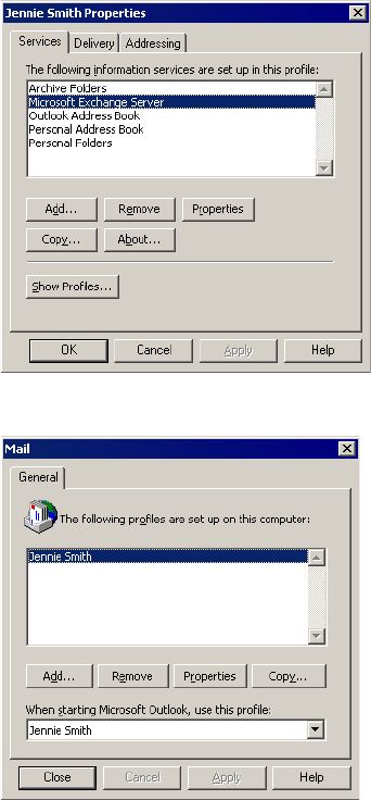
Configuring Email on Windows 365
To configure a Microsoft Outlook user:
1. Open the Control Panel on the machine running the Integration Service process.
2. Double-click the Mail (or Mail and Fax) icon.
3. On the Services tab of the user Properties dialog box, click Show Profiles.
The Mail dialog box displays the list of profiles configured for the computer.
4. If you have already set up a Microsoft Outlook profile, skip to “Step 2. Configure Logon
Network Security” on page 367. If you do not already have a Microsoft Outlook profile
set up, continue to step 5.
5. Click Add in the mail properties window.
The Microsoft Outlook Setup Wizard appears.
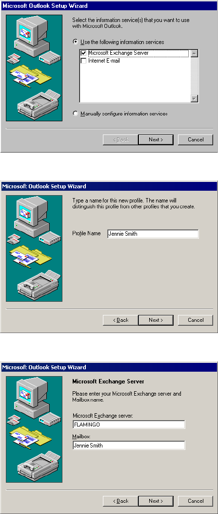
366 Chapter 12: Sending Email
6. Select Use The Following Information Services and then select Microsoft Exchange
Server. Click Next.
7. Enter a profile name and click Next.
8. Enter the name of the Microsoft Exchange Server. Enter the mailbox name. Click Next.
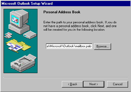
Configuring Email on Windows 367
9. Indicate whether you travel with a computer. Click Next.
10. Enter the path to a personal address book. Click Next.
11. Indicate whether you want to run Outlook when you start Windows. Click Next.
The Setup Wizard indicates that you have successfully configured an Outlook profile.
12. Click Finish.
Step 2. Configure Logon Network Security
You must configure the Logon Network Security before you run the Microsoft Exchange
Server.
To configure Logon Network Security for the Microsoft Exchange Server:
1. Open the Control Panel on the machine running the Integration Service process.
2. Double-click the Mail (or Mail and Fax) icon.
The User Properties sheet appears.
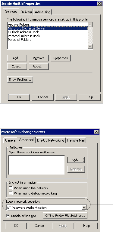
368 Chapter 12: Sending Email
3. On the Services tab, select Microsoft Exchange Server and click Properties.
4. Click the Advanced tab. Set the Logon network security option to NT Password
Authentication.
5. Click OK.
Step 3. Create Distribution Lists
When the Integration Service runs on Windows, you can enter one email address in the
Workflow Manager. If you want to send email to multiple recipients, create a distribution list
containing these addresses in the Personal Address Book in Microsoft Outlook. Enter the
distribution list name as the recipient when configuring email.
For more information about working with a Personal Address Book, refer to Microsoft
Outlook documentation.
Logon Network Security
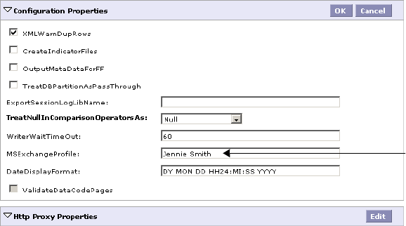
Configuring Email on Windows 369
Step 4. Verify the Integration Service Settings
After you create the Microsoft Outlook profile, verify the Integration Service is configured to
send email as that Microsoft Outlook user. You may need to verify the profile with the
domain administrator.
To verify the Microsoft Exchange profile in the Integration Service:
1. From the Administration Console, click the Properties tab for the Integration Service.
2. In the Configuration Properties tab, select Edit.
3. In the MSExchangeProfile field, verify that the name of Microsoft Exchange profile
matches the Microsoft Outlook profile you created.
Microsoft Exchange
Profile
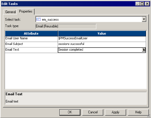
370 Chapter 12: Sending Email
Working with Email Tasks
You can send email during a workflow using the Email task on the Workflow Manager. You
can create reusable Email tasks in the Task Developer for any type of email. Or, you can create
non-reusable Email tasks in the Workflow and Worklet Designer.
Use Email tasks in any of the following locations:
♦Session properties. You can configure the session to send email when the session
completes or fails. For more information, see “Working with Post-Session Email” on
page 374.
♦Workflow properties. You can configure the workflow to send email when the workflow is
interrupted. For more information, see “Working with Suspension Email” on page 381.
♦Workflows or worklets. You can include an Email task anywhere in the workflow or
worklet to send email based on a condition you define. For more information, see “Using
Email Tasks in a Workflow or Worklet” on page 370.
Figure 12-1 shows the Edit Tasks dialog box for an Email task:
Using Email Tasks in a Workflow or Worklet
Use Email tasks anywhere in a workflow or worklet. For example, you might configure a
workflow to send an email if a certain number of rows fail for a session.
For example, you may have a Session task in the workflow and you want the Integration
Service to send an email if more than 20 rows are dropped. To do this, you create a condition
in the link, and create a non-reusable Email task. The workflow sends an email if the session
fails more than 20 rows are dropped.
Figure 12-1. Email Task
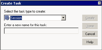
Working with Email Tasks 371
Email Address Tips and Guidelines
Consider the following tips and guidelines when you enter the email address in an Email task:
♦Enter the email address using 7-bit ASCII characters only.
♦You can enter the $PMSuccessEmailUser or $PMFailureEmailUser service variable for
post-session email. For more information, see “Using Service Variables” on page 375.
♦If the Integration Service runs on Windows, you can enter a Microsoft Exchange Profile
name. The mail recipient must have an entry in the Global Address book of the Microsoft
Outlook profile.
♦If the Integration Service runs on Windows, you can send email to multiple recipients by
creating a distribution list in the Personal Address book. All recipients must also be in the
Global Address book. You cannot enter multiple addresses separated by commas or
semicolons.
♦If the Integration Service runs on UNIX, you can enter multiple email addresses separated
by a comma. Do not include spaces between email addresses.
Steps to Create an Email Task
You can create Email tasks in the Task Developer, Worklet Designer, and Workflow Designer.
To create an Email task in the Task Developer:
1. In the Task Developer, click Tasks > Create.
The Create Task dialog box appears.
2. Select an Email task and enter a name for the task. Click Create.
The Workflow Manager creates an Email task in the workspace.
3. Click Done.
4. Double-click the Email task in the workspace.
372 Chapter 12: Sending Email
The Edit Tasks dialog box appears.
5. Click Rename to enter a name for the task.
6. Enter a description for the task in the Description field.
7. Click the Properties tab.
8. Enter the fully qualified email address of the mail recipient in the Email User Name field.
For more information about entering the email address, see “Email Address Tips and
Guidelines” on page 371.
Enter the email text.
Working with Email Tasks 373
9. Enter the subject of the email in the Email Subject field. Or, you can leave this field
blank.
10. Click the Open button in the Email Text field to open the Email Editor.
11. Enter the text of the email message in the Email Editor.
You can leave the Email Text field blank.
Note: You can incorporate format tags and email variables in a post-session email.
However, you cannot add them to an Email task outside the context of a session. For
more information, see “Email Variables and Format Tags” on page 375.
12. Click OK twice to save the changes.

374 Chapter 12: Sending Email
Working with Post-Session Email
You can configure a session to send email when it fails or succeeds. You can create separate
email tasks for success and failure email.
The Integration Service sends post-session email at the end of a session, after executing post-
session shell commands or stored procedures. When the Integration Service encounters an
error sending the email, it writes a message to the Log Service. It does not fail the session.
Figure 12-2 shows the On-Success and On-Failure email properties on the Components tab of
the session properties:
You can specify a reusable Email that task you create in the Task Developer for either success
email or failure email. Or, you can create a non-reusable Email task for each session property.
When you create a non-reusable Email task for a session, you cannot use the Email task in a
workflow or worklet.
You cannot specify a non-reusable Email task you create in the Workflow or Worklet Designer
for post-session email.
Tip: When you configure an Email task for post-session email, use the service variables,
$PMSuccessEmailUser or $PMFailureEmailUser, for the email recipient. Ensure that you
specify the values of the service variables for the Integration Service that runs the session.
Figure 12-2. Post-Session Email Properties
Select a
reusable Email
task.
Edit the non-
reusable
Email task.
Use a
reusable Email
task.
Use a non-
reusable Email
task.
Working with Post-Session Email 375
Using Service Variables
Use service variables to address post-session email. When you configure the Integration
Service, you configure the service variables. You may need to verify these variables with the
domain administrator. You can use the following service variables to send post-session email:
♦$PMSuccessEmailUser. Email address of the user to receive email when the session
completes successfully. Use this variable for the Email User Name for success email only.
The Integration Service does not expand this variable when you use it for any other email
type.
♦$PMFailureEmailUser. Email address of the user to receive email when the session
completes with failure. Use this variable for the Email User Name for failure email only.
The Integration Service does not expand this variable when you use it for any other email
type.
When you use one of these service variables, the Integration Service sends email to the address
configured for the service variable. $PMSuccessEmailUser and $PMFailureEmailUser are
optional process variables. Verify that you define a variable before using it to address email.
You might use this functionality when you have an administrator who troubleshoots all failed
sessions. Instead of entering the administrator email address for each session, use the email
variable $PMFailureEmailUser. If the administrator changes, you can correct all sessions by
editing the $PMFailureEmailUser service variable, instead of editing the email address in each
session.
You might also use this functionality when you have different administrators for different
Integration Services. If you deploy a folder from one repository to another or otherwise
change the Integration Service that runs the session, the new service sends email to users
associated with the new service when you use process variables instead of hard-coded email
addresses.
Note: You cannot use service variables for standalone email tasks.
Email Variables and Format Tags
Use email variables and format tags in an email message for post-session emails. You can use
some email variables in the subject of the email. With email variables, you can include
important session information in the email, such as the number of rows loaded, the session
completion time, or read and write statistics. You can also attach the session log or other
relevant files to the email. Use format tags in the body of the message to make the message
easier to read.
Note: The Integration Service does not limit the type or size of attached files. However, since
large attachments can cause problems with the email system, avoid attaching excessively large
files, such as session logs generated using verbose tracing. The Integration Service generates an
error message in the email if an error occurs attaching the file.

376 Chapter 12: Sending Email
Table 12-1 describes the email variables that you can use in a post-session email:
Table 12-2 lists the format tags you can use in an Email task:
Table 12-1. Email Variables for Post-Session Email
Email Variable Description
%a<filename> Attach the named file. The file must be local to the Integration Service. The following file names are
valid: %a<c:\data\sales.txt> or %a</users/john/data/sales.txt>. The email does not display the full
path for the file. Only the attachment file name appears in the email.
Note: The file name cannot include the greater than character (>) or a line break.
%b Session start time.
%c Session completion time.
%d Name of the repository containing the session.
%e Session status.
%g Attach the session log to the message. The Integration Service attaches a session log if you
configure the session to create a log file. If you do not configure the session to create a log file or
you run a session on a grid, the Integration Service creates a temporary file in the PowerCenter
Services installation directory and sends the file. Verify that the PowerCenter Services user has
write permissions for the PowerCenter Services installation directory to ensure the Integration
Service can create a temporary log file.
%i Session elapsed time (session completion time-session start time).
%l Total rows loaded.
%m Name of the mapping used in the session.
%n Name of the folder containing the session.
%r Total rows rejected.
%s Session name.
%t Source and target table details, including read throughput in bytes per second and write throughput
in rows per second. The Integration Service includes all information displayed in the session detail
dialog box.
Note: The Integration Service ignores %a, %g, and %t when you include them in the email subject. Include these variables in the email
message only.
Table 12-2. Format Tags for Email Tasks
Formatting Format Tag
tab \t
new line \n
Working with Post-Session Email 377
Configuring Post-Session Email
You can configure post-session email to use a reusable or non-reusable Email task.
Using a Reusable Email Task
Use the following steps to configure post-session email to use a reusable Email task.
To configure post-session email to use a reusable Email task:
1. Open the session properties and click the Components tab.
2. Select Reusable in the Type column for the success email or failure email field.
378 Chapter 12: Sending Email
3. Click the Open button in the Value column to select the reusable Email task.
4. Select the Email task in the Object Browser dialog box and click OK.
5. Optionally, edit the Email task for this session property by clicking the Edit button in the
Value column.
If you edit the Email task for either success email or failure email, the edits only apply to
this session.
6. Click OK to close the session properties.
Using a Non-Reusable Email Task
Use the following steps to configure success email or failure email to use a non-reusable Email
task.
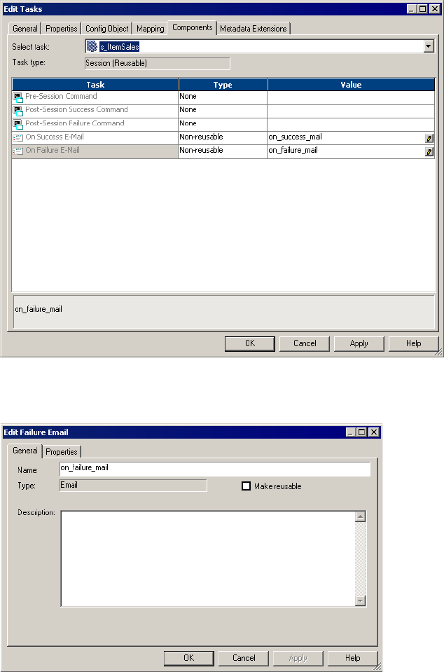
Working with Post-Session Email 379
To configure success email or failure email to use a non-reusable Email task:
1. Open the session properties and click the Components tab.
2. Select Non-Reusable in the Type column for the success email or failure email field.
3. Open the email editor using the Open button.
4. Edit the Email task and click OK. For more information about editing Email tasks, see
“Working with Email Tasks” on page 370.
5. Click OK to close the session properties.
380 Chapter 12: Sending Email
Sample Email
The following example shows a user-entered text from a sample post-session email
configuration using variables:
Session complete.
Session name: %s
%l
%r
%e
%b
%c
%i
%g
The following is sample output from the configuration above:
Session complete.
Session name: sInstrTest
Total Rows Loaded = 1
Total Rows Rejected = 0
Completed
Start Time: Tue Nov 22 12:26:31 2005
Completion Time: Tue Nov 22 12:26:41 2005
Elapsed time: 0:00:10 (h:m:s)
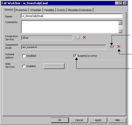
Working with Suspension Email 381
Working with Suspension Email
You can configure a workflow to send email when the Integration Service suspends the
workflow. For example, when a task fails, the Integration Service suspends the workflow and
sends the suspension email. You can fix the error and recover the workflow.
If another task fails while the Integration Service is suspending the workflow, you do not get
the suspension email again. However, the Integration Service sends another suspension email
if another task fails after you recover the workflow. For more information about suspending
the workflow, see “Suspending the Workflow” on page 130.
Configure suspension email on the General tab of the workflow properties.
Figure 12-3 shows the Suspension Email workflow options:
To configure suspension email:
1. In the Workflow Designer, open the workflow.
2. Click Workflows > Edit to open the workflow properties.
3. On the General tab, select Suspend on Error.
Figure 12-3. Suspension Email
Select a reusable Email task.
Remove the reusable Email task.
Select Suspend on Error.

382 Chapter 12: Sending Email
4. Click the Browse Emails button to select a reusable Email task.
Note: The Workflow Manager returns an error if you do not have any reusable Email task
in the folder. Create a reusable Email task in the folder before you configure suspension
email.
5. Choose a reusable Email task and click OK.
6. Click OK to close the workflow properties.
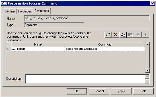
Tips 383
Tips
The following suggestions can extend the capabilities of Email tasks.
When the Integration Service runs on Windows, configure a Microsoft Outlook profile for
each node.
If you run the Integration Service on multiple nodes in a Windows environment, create a
Microsoft Outlook profile for each node. To use the profile on multiple nodes for multiple
users, create a generic Microsoft Outlook profile, such as “PowerCenter,” and use this profile
on each node in the domain. Use the same profile on each node to ensure that the Microsoft
Exchange Profile you configured for the Integration Service matches the profile on each node.
Use service variables to address post-session emails.
When the service variables $PMSuccessEmailUser and $PMFailureEmailUser are configured
for the Integration Service, use them to address post-session email. You can change the
recipient of post-session email for all sessions the service runs by editing the service variables.
It is easier to deploy sessions into production if you define service variables for both
development and production servers.
Generate and send post-session reports.
Use a post-session success command to generate a report file and attach that file to a success
email. For example, you create a batch file called Q3rpt.bat that generates a sales report, and
you are running Microsoft Outlook on Windows.
Figure 12-4 shows how you can configure the post-session success command to generate a
report:
Figure 12-4. Using Post-Session Commands to Generate Reports
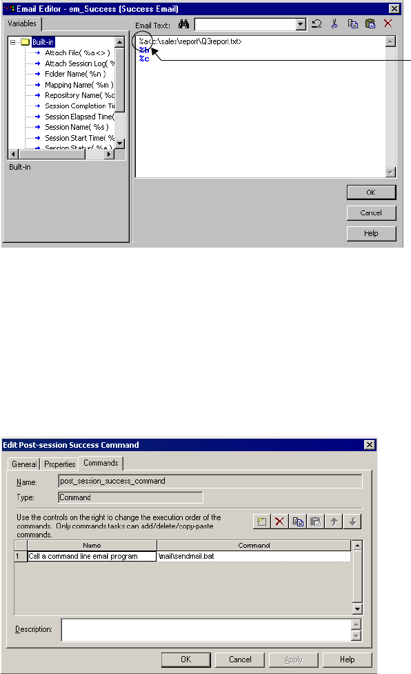
384 Chapter 12: Sending Email
Figure 12-5 shows how you can configure success email to attach a report file:
Use other mail programs.
If you do not have Microsoft Outlook, use a post-session success command to invoke a
command line email program, such as Windmill. In this case, you do not have to enter the
email user name or subject, since the recipients, email subject, and body text will be contained
in the batch file, sendmail.bat.
Figure 12-6 shows how you can configure the post-session success command to invoke a
command line email program:
Figure 12-5. Using Email Variables to Attach Reports
Figure 12-6. Sending Email Without Microsoft Outlook
Use email variable
%a to attach the
report.

385
Chapter 13
Working with Partition
Points
This chapter includes the following topics:
♦Overview, 386
♦Adding and Deleting Partition Points, 387
♦Partitioning Relational Sources, 390
♦Partitioning File Sources, 393
♦Partitioning Relational Targets, 399
♦Partitioning File Targets, 401
♦Partitioning Custom Transformations, 406
♦Partitioning Joiner Transformations, 409
♦Partitioning Lookup Transformations, 416
♦Partitioning Sorter Transformations, 417
♦Restrictions for Transformations, 419
386 Chapter 13: Working with Partition Points
Overview
Partition points mark the boundaries between threads in a pipeline. The Integration Service
redistributes rows of data at partition points. You can add partition points to increase the
number of transformation threads and increase session performance. For information about
adding and deleting partition points, see “Adding and Deleting Partition Points” on page 387.
When you configure a session to read a source database, the Integration Service creates a
separate connection and SQL query to the source database for each partition. You can
customize or override the SQL query. For more information about partitioning relational
sources, see “Partitioning Relational Sources” on page 390.
When you configure a session to load data to a relational target, the Integration Service
creates a separate connection to the target database for each partition at the target instance.
You configure the reject file names and directories for the target. The Integration Service
creates one reject file for each target partition. For more information about partitioning
relational targets, see “Partitioning Relational Targets” on page 399.
You can configure a session to read a source file with one thread or with multiple threads. You
must choose the same connection type for all partitions that read the file. For more
information about partitioning source files, see “Partitioning File Sources” on page 393.
When you configure a session to write to a file target, you can write the target output to a
separate file for each partition or to a merge file that contains the target output for all
partitions. You can configure connection settings and file properties for each target partition.
For more information about configuring target files, see “Partitioning File Targets” on
page 401.
When you create a partition point at transformations, the Workflow Manager sets the default
partition type. You can change the partition type depending on the transformation type.

Adding and Deleting Partition Points 387
Adding and Deleting Partition Points
Partition points mark the thread boundaries in a pipeline and divide the pipeline into stages.
When you add partition points, you increase the number of transformation threads, which
can improve session performance. The Integration Service can redistribute rows of data at
partition points, which can also improve session performance.
When you create a session, the Workflow Manager creates one partition point at each
transformation in the pipeline. Table 13-1 lists the transformations with partition points:
Table 13-1. Transformation Partition Points
Partition Point Description Restrictions
Source Qualifier
Normalizer
Controls how the Integration Service extracts
data from the source and passes it to the
source qualifier.
You cannot delete this partition point.
Rank
Unsorted Aggregator
Ensures that the Integration Service groups
rows properly before it sends them to the
transformation.
You can delete these partition points if the
pipeline contains only one partition or if the
Integration Service passes all rows in a
group to a single partition before they enter
the transformation.
Target Instances Controls how the writer passes data to the
targets
You cannot delete this partition point.
Multiple Input Group The Workflow Manager creates a partition
point at a multiple input group transformation
when it is configured to process each
partition with one thread, or when a
downstream multiple input group Custom
transformation is configured to process each
partition with one thread.
For example, the Workflow Manager creates
a partition point at a Joiner transformation
that is connected to a downstream Custom
transformation configured to use one thread
per partition.
This ensures that the Integration Service
uses one thread to process each partition at
a Custom transformation that requires one
thread per partition. You cannot delete this
partition point.
You cannot delete this partition point.
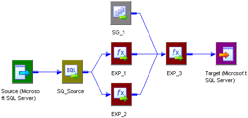
388 Chapter 13: Working with Partition Points
Rules and Guidelines
The following guidelines apply to adding and deleting partition points:
♦You cannot create a partition point at a source instance.
♦You cannot create a partition point at a Sequence Generator transformation or an
unconnected transformation.
♦You can add a partition point at any other transformation provided that no partition point
receives input from more than one pipeline stage.
♦You cannot delete a partition point at a Source Qualifier transformation, a Normalizer
transformation for COBOL sources, or a target instance.
♦You cannot delete a partition point at a multiple input group Custom transformation that
is configured to use one thread per partition.
♦You cannot delete a partition point at a multiple input group transformation that is
upstream from a multiple input group Custom transformation that is configured to use
one thread per partition.
♦The following partition types have restrictions with dynamic partitioning:
−Pass-through. When you use dynamic partitioning, if you change the number of
partitions at a partition point, the number of partitions in each pipeline stage changes.
−Key Range. To use key range with dynamic partitioning you must define a closed range
of numbers or date keys. If you use an open-ended range, the session runs with one
partition.
You can add and delete partition points at other transformations in the pipeline according to
the following rules:
♦You cannot create partition points at source instances.
♦You cannot create partition points at Sequence Generator transformations or unconnected
transformations.
♦You can add partition points at any other transformation provided that no partition point
receives input from more than one pipeline stage.
Figure 13-1 shows the valid partition points in a mapping:
Figure 13-1. Sample Mapping Showing Valid Partition Points
Valid Partition Points
*
*
**
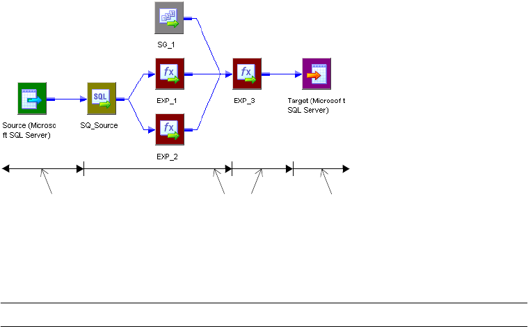
Adding and Deleting Partition Points 389
In this mapping, the Workflow Manager creates partition points at the source qualifier and
target instance by default. You can place an additional partition point at Expression
transformation EXP_3.
If you place a partition point at EXP_3 and define one partition, the master thread creates the
following threads:
In this case, each partition point receives data from only one pipeline stage, so EXP_3 is a
valid partition point.
The following transformations are not valid partition points:
For more information about processing threads, see “Integration Service Architecture” in the
Administrator Guide.
Transformation Reason
Source This is a source instance.
SG_1 This is a Sequence Generator transformation.
EXP_1 and EXP_2 If you could place a partition point at EXP_1 or EXP_2, you would create an additional pipeline
stage that processes data from the source qualifier to EXP_1 or EXP_2. In this case, EXP_3
would receive data from two pipeline stages, which is not allowed.
Partition Points
*
*
**
Reader Thread Transformation Threads Writer Thread
(Fourth Stage)(Third Stage)(Second Stage)(First Stage)
390 Chapter 13: Working with Partition Points
Partitioning Relational Sources
When you run a session that partitions relational or Application sources, the Integration
Service creates a separate connection to the source database for each partition. It then creates
an SQL query for each partition. You can customize the query for each source partition by
entering filter conditions in the Transformation view on the Mapping tab. You can also
override the SQL query for each source partition using the Transformations view on the
Mapping tab.
Note: When you create a custom SQL query to read database tables and you set database
partitioning, Integration Service reverts to pass-through partitioning and prints a message in
the session log.
Figure 13-2 shows where you can override the SQL query for each source partition:
For more information about partitioning Application sources, refer to the PowerCenter
Connect documentation.
Entering an SQL Query
You can enter an SQL override if you want to customize the SELECT statement in the SQL
query. The SQL statement you enter on the Transformations view of the Mapping tab
Figure 13-2. Overriding the SQL Query and Entering a Filter Condition
Enter SQL overrides.
Enter filter conditions.
Transformations View
Browse Button
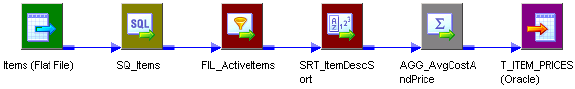
Partitioning Relational Sources 391
overrides any customized SQL query that you set in the Designer when you configure the
Source Qualifier transformation. For more information, see “Source Qualifier
Transformation” in the Tran s f o r m a t i o n G u id e .
The SQL query also overrides any key range and filter condition that you enter for a source
partition. So, if you also enter a key range and source filter, the Integration Service uses the
SQL query override to extract source data.
If you create a key that contains null values, you can extract the nulls by creating another
partition and entering an SQL query or filter to extract null values.
To enter an SQL query for each partition, click the Browse button in the SQL Query field.
Enter the query in the SQL Editor dialog box, and then click OK.
If you entered an SQL query in the Designer when you configured the Source Qualifier
transformation, that query appears in the SQL Query field for each partition. To override this
query, click the Browse button in the SQL Query field, revise the query in the SQL Editor
dialog box, and then click OK.
Entering a Filter Condition
If you specify key range partitioning at a relational source qualifier, you can enter an
additional filter condition. When you do this, the Integration Service generates a WHERE
clause that includes the filter condition you enter in the session properties.
The filter condition you enter on the Transformations view of the Mapping tab overrides any
filter condition that you set in the Designer when you configure the Source Qualifier
transformation. For more information, see “Source Qualifier Transformation” in the
Tra ns for ma t i o n Gu id e .
If you use key range partitioning, the filter condition works in conjunction with the key
ranges. For example, you want to select data based on customer ID, but you do not want to
extract information for customers outside the USA. Define the following key ranges:
If you know that the IDs for customers outside the USA fall within the range for a particular
partition, you can enter a filter in that partition to exclude them. Therefore, you enter the
following filter condition for the second partition:
CUSTOMERS.COUNTRY = ‘USA’
CUSTOMER_ID Start Range End Range
Partition #1 135000
Partition #2 135000
392 Chapter 13: Working with Partition Points
When the session runs, the following queries for the two partitions appear in the session log:
READER_1_1_1> RR_4010 SQ instance [SQ_CUSTOMERS] SQL Query [SELECT
CUSTOMERS.CUSTOMER_ID, CUSTOMERS.COMPANY, CUSTOMERS.LAST_NAME FROM
CUSTOMERS WHERE CUSTOMER.CUSTOMER ID < 135000]
[...]
READER_1_1_2> RR_4010 SQ instance [SQ_CUSTOMERS] SQL Query [SELECT
CUSTOMERS.CUSTOMER_ID, CUSTOMERS.COMPANY, CUSTOMERS.LAST_NAME FROM
CUSTOMERS WHERE CUSTOMERS.COUNTRY = ‘USA’ AND 135000 <=
CUSTOMERS.CUSTOMER_ID]
To enter a filter condition, click the Browse button in the Source Filter field. Enter the filter
condition in the SQL Editor dialog box, and then click OK.
If you entered a filter condition in the Designer when you configured the Source Qualifier
transformation, that query appears in the Source Filter field for each partition. To override
this filter, click the Browse button in the Source Filter field, change the filter condition in the
SQL Editor dialog box, and then click OK.
Partitioning File Sources 393
Partitioning File Sources
When a session uses a file source, you can configure it to read the source with one thread or
with multiple threads. The Integration Service creates one connection to the file source when
you configure the session to read with one thread, and it creates multiple concurrent
connections to the file source when you configure the session to read with multiple threads.
Use the following types of partitioned file sources:
♦Flat file. You can configure a session to read flat file, XML, or COBOL source files.
♦Command. You can configure a session to use an operating system command to generate
source data rows or generate a file list. For more information about using a command to
generate source data, see “Working with File Sources” on page 230.
When connecting to file sources, you must choose the same connection type for all partitions.
You may choose different connection objects as long as each object is of the same type.
To specify single- or multi-threaded reading for flat file sources, configure the source file
name property for partitions 2-n. To configure for single-threaded reading, pass empty data
through partitions 2-n. To configure for multi-threaded reading, leave the source file name
blank for partitions 2-n.
For more information about configuring file properties with multiple partitions, see
“Configuring for File Partitioning” on page 394.
Guidelines for Partitioning File Sources
Use the following guidelines when you configure a file source session with multiple partitions:
♦Use pass-through partitioning at the source qualifier.
♦Use single- or multi-threaded reading with flat file or COBOL sources.
♦Use single-threaded reading with XML sources.
♦You cannot use multi-threaded reading if the source files are non-disk files, such as FTP
files or IBM MQSeries sources.
♦If you use a shift-sensitive code page, use multi-threaded reading if the following
conditions are true:
−The file is fixed-width.
−The file is not line sequential.
−You did not enable user-defined shift state in the source definition.
♦To read data from the three flat files concurrently, you must specify three partitions at the
source qualifier. Accept the default partition type, pass-through.
♦If you configure a session for multi-threaded reading, and the Integration Service cannot
create multiple threads to a file source, it writes a message to the session log and reads the
source with one thread.
♦When the Integration Service uses multiple threads to read a source file, it may not read
the rows in the file sequentially. If sort order is important, configure the session to read the
394 Chapter 13: Working with Partition Points
file with a single thread. For example, sort order may be important if the mapping contains
a sorted Joiner transformation and the file source is the sort origin.
♦You can also use a combination of direct and indirect files to balance the load.
♦Session performance for multi-threaded reading is optimal with large source files. The load
may be unbalanced if the amount of input data is small.
♦You cannot use a command for a file source if the command generates source data and the
session is configured to run on a grid or is configured with the resume from the last
checkpoint recovery strategy.
Using One Thread to Read a File Source
When the Integration Service uses one thread to read a file source, it creates one connection
to the source. The Integration Service reads the rows in the file or file list sequentially. You
can configure single-threaded reading for direct or indirect file sources in a session:
♦Reading direct files. You can configure the Integration Service to read from one or more
direct files. If you configure the session with more than one direct file, the Integration
Service creates a concurrent connection to each file. It does not create multiple
connections to a file.
♦Reading indirect files. When the Integration Service reads an indirect file, it reads the file
list and then reads the files in the list sequentially. If the session has more than one file list,
the Integration Service reads the file lists concurrently, and it reads the files in the list
sequentially.
Using Multiple Threads to Read a File Source
When the Integration Service uses multiple threads to read a source file, it creates multiple
concurrent connections to the source. The Integration Service may or may not read the rows
in a file sequentially.
You can configure multi-threaded reading for direct or indirect file sources in a session:
♦Reading direct files. When the Integration Service reads a direct file, it creates multiple
reader threads to read the file concurrently. You can configure the Integration Service to
read from one or more direct files. For example, if a session reads from two files and you
create five partitions, the Integration Service may distribute one file between two
partitions and one file between three partitions.
♦Reading indirect files. When the Integration Service reads an indirect file, it creates
multiple threads to read the file list concurrently. It also creates multiple threads to read
the files in the list concurrently. The Integration Service may use more than one thread to
read a single file.
Configuring for File Partitioning
After you create partition points and configure partitioning information, you can configure
source connection settings and file properties on the Transformations view of the Mapping
tab. Click the source instance name you want to configure under the Sources node. When you

Partitioning File Sources 395
click the source instance name for a file source, the Workflow Manager displays connection
and file properties in the session properties.
You can configure the source file names and directories for each source partition. The
Workflow Manager generates a file name and location for each partition.
Table 13-2 describes the file properties settings for file sources in a mapping:
Table 13-2. File Properties Settings for File Sources
Attribute Required/
Optional Description
Input Type Required Type of source input. You can choose the following types of source input:
- File. For flat file, COBOL, or XML sources.
- Command. For source data or a file list generated by a command.
You cannot use a command to generate XML source data.
Concurrent read
partitioning
Optional Order in which multiple partitions read input rows from a source file. You can
choose the following options:
- Optimize throughput. The Integration Service does not preserve input row
order.
- Keep relative input row order. The Integration Service preserves the input row
order for the rows read by each partition.
- Keep absolute input row order. The Integration Service preserves the input
row order for all rows read by all partitions.
For more information, see “Configuring Concurrent Read Partitioning” on
page 397.
Source File
Directory
Optional Directory name of flat file source. By default, the Integration Service looks in
the service process variable directory, $PMSourceFileDir, for file sources.
If you specify both the directory and file name in the Source Filename field,
clear this field. The Integration Service concatenates this field with the Source
Filename field when it runs the session.
You can also use the $InputFileName session parameter to specify the file
location.
For more information about session parameters, see “Working with Session
Parameters” on page 211.
Source File Name Optional File name, or file name and path of flat file source. Optionally, use the
$InputFileName session parameter for the file name.
The Integration Service concatenates this field with the Source File Directory
field when it runs the session. For example, if you have “C:\data\” in the Source
File Directory field, then enter “filename.dat” in the Source Filename field.
When the Integration Service begins the session, it looks for
“C:\data\filename.dat”.
By default, the Workflow Manager enters the file name configured in the source
definition.
For more information about session parameters, see “Working with Session
Parameters” on page 211.
Source File Type Optional You can choose the following source file types:
- Direct. For source files that contain the source data.
- Indirect. For source files that contain a list of files. When you select Indirect,
the Integration Service finds the file list and reads each listed file when it runs
the session.

396 Chapter 13: Working with Partition Points
Configuring Sessions to Use a Single Thread
To configure a session to read a file with a single thread, pass empty data through partitions 2-
n. To pass empty data, create a file with no data, such as “empty.txt,” and put it in the source
file directory. Then, use “empty.txt” as the source file name.
Note: You cannot configure single-threaded reading for partitioned sources that use a
command to generate source data.
Table 13-3 describes the session configuration and the Integration Service behavior when it
uses a single thread to read source files:
If you use FTP to access source files, you can choose a different connection for each direct
file. For more information about using FTP to access source files, see “Using FTP” on
page 649.
Configuring Sessions to Use Multiple Threads
To configure a session to read a file with multiple threads, leave the source file name blank for
partitions 2-n. The Integration Service uses partitions 2-n to read a portion of the previous
partition file or file list. The Integration Service ignores the directory field of that partition.
To configure a session to read from a command with multiple threads, enter a command for
each partition or leave the command property blank for partitions 2-n. If you enter a
command for each partition, the Integration Service creates a thread to read the data
Command Type Optional Type of source data the command generates. You can choose the following
command types:
- Command generating data for commands that generate source data input
rows.
- Command generating file list for commands that generate a file list.
For more information, see “Configuring Commands for File Sources” on
page 232.
Command Optional Command used to generate the source file data.
For more information, see “Configuring Commands for File Sources” on
page 232.
Table 13-3. Configuring Source File Name for Single-Threaded Reading
Source File Name Value Integration Service Behavior
Partition #1
Partition #2
Partition #3
ProductsA.txt
empty.txt
empty.txt
Integration Service creates one thread to read ProductsA.txt. It reads
rows in the file sequentially. After it reads the file, it passes the data to
three partitions in the transformation pipeline.
Partition #1
Partition #2
Partition #3
ProductsA.txt
empty.txt
ProductsB.txt
Integration Service creates two threads. It creates one thread to read
ProductsA.txt, and it creates one thread to read ProductsB.txt. It
reads the files concurrently, and it reads rows in the files sequentially.
Table 13-2. File Properties Settings for File Sources
Attribute Required/
Optional Description

Partitioning File Sources 397
generated by each command. Otherwise, the Integration Service uses partitions 2-n to read a
portion of the data generated by the command for the first partition.
Table 13-4 describes the session configuration and the Integration Service behavior when it
uses multiple threads to read source files:
Table 13-5 describes the session configuration and the Integration Service behavior when it
uses multiple threads to read source data piped from a command:
Configuring Concurrent Read Partitioning
By default, the Integration Service does not preserve row order when multiple partitions read
from a single file source. To preserve row order when multiple partitions read from a single
file source, configure concurrent read partitioning. You can configure the following options:
♦Optimize throughput. The Integration Service does not preserve row order when multiple
partitions read from a single file source. Use this option if the order in which multiple
partitions read from a file source is not important.
♦Keep relative input row order. Preserves the sort order of the input rows read by each
partition. Use this option if you want to preserve the sort order of the input rows read by
each partition.
Table 13-6 shows an example sort order of a file source with 10 rows by two partitions:
Table 13-4. Configuring Source File Name for Multi-Threaded Reading
Attribute Value Integration Service Behavior
Partition #1
Partition #2
Partition #3
ProductsA.txt
<blank>
<blank>
Integration Service creates three threads to concurrently read
ProductsA.txt.
Partition #1
Partition #2
Partition #3
ProductsA.txt
<blank>
ProductsB.txt
Integration Service creates three threads to read ProductsA.txt and
ProductsB.txt concurrently. Two threads read ProductsA.txt and one thread
reads ProductsB.txt.
Table 13-5. Configuring Commands for Multi-Threaded Reading
Attribute Value Integration Service Behavior
Partition #1
Partition #2
Partition #3
CommandA
<blank>
<blank>
Integration Service creates three threads to concurrently read data piped
from the command.
Partition #1
Partition #2
Partition #3
CommandA
<blank>
CommandB
Integration Service creates three threads to read data piped from
CommandA and CommandB. Two threads read the data piped from
CommandA and one thread reads the data piped from CommandB.
Table 13-6. Keep Relative Input Row Order
Partition Rows Read
Partition #1 1,3,5,8,9
Partition #2 2,4,6,7,10

398 Chapter 13: Working with Partition Points
♦Keep absolute input row order. Preserves the sort order of all input rows read by all
partitions. Use this option if you want to preserve the sort order of the input rows each
time the session runs. In a pass-through mapping with passive transformations, the order
of the rows written to the target will be in the same order as the input rows.
Table 13-7 shows an example sort order of a file source with 10 rows by two partitions:
Note: By default, the Integration Service uses the Keep absolute input row order option in
sessions configured with the resume from the last checkpoint recovery strategy.
Table 13-7. Keep Absolute Input Row Order
Partition Rows Read
Partition #1 1,2,3,4,5
Partition #2 6,7,8,9,10
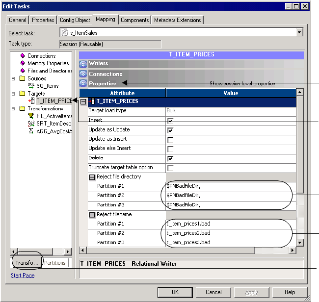
Partitioning Relational Targets 399
Partitioning Relational Targets
When you configure a pipeline to load data to a relational target, the Integration Service
creates a separate connection to the target database for each partition at the target instance. It
concurrently loads data for each partition into the target database.
Configure partition attributes for targets in the pipeline on the Mapping tab of session
properties. For relational targets, you configure the reject file names and directories. The
Integration Service creates one reject file for each target partition.
Figure 13-3 shows the Properties settings for relational targets:
Figure 13-3. Properties Settings for Relational Targets in the Session Properties
Selected
Target
Instance
Enter
reject file
directories.
Enter reject
file names.
Properties
Settings
Transformations
View

400 Chapter 13: Working with Partition Points
Table 13-8 describes the partitioning attributes for relational targets in a pipeline:
Database Compatibility
When you configure a session with multiple partitions at the target instance, the Integration
Service creates one connection to the target for each partition. If you configure multiple
target partitions in a session that loads to a database or ODBC target that does not support
multiple concurrent connections to tables, the session fails.
When you create multiple target partitions in a session that loads data to an Informix
database, you must create the target table with row-level locking. If you insert data from a
session with multiple partitions into an Informix target configured for page-level locking, the
session fails and returns the following message:
WRT_8206 Error: The target table has been created with page level locking.
The session can only run with multi partitions when the target table is
created with row level locking.
Sybase IQ does not allow multiple concurrent connections to tables. If you create multiple
target partitions in a session that loads to Sybase IQ, the Integration Service loads all of the
data in one partition.
Table 13-8. Partitioning Relational Target Attributes
Attribute Description
Reject File Directory Location for the target reject files. Default is $PMBadFileDir.
Reject File Name Name of reject file. Default is target name partition number.bad. You can also use the session
parameter, $BadFileName, as defined in the parameter file.
Partitioning File Targets 401
Partitioning File Targets
When you configure a session to write to a file target, you can write the target output to a
separate file for each partition or to a merge file that contains the target output for all
partitions. When you run the session, the Integration Service writes to the individual output
files or to the merge file concurrently. You can also send the data for a single partition or for
all target partitions to an operating system command.
You can configure connection settings and file properties for each target partition. You
configure these settings in the Transformations view on the Mapping tab. You can also
configure the session to use partitioned FTP file targets.
Configuring Connection Settings
Use the Connections settings in the Transformations view on the Mapping tab to configure
the connection type for all target partitions. You can choose different connection objects for
each partition, but they must all be of the same type.
Use one of the following connection types with target files:
♦None. Write the partitioned target files to the local machine.
♦FTP. Transfer the partitioned target files to another machine. You can transfer the files to
any machine to which the Integration Service can connect. For more information about
using FTP to load to target files, see “Using FTP” on page 649.
♦Loader. Use an external loader that can load from multiple output files. This option
appears if the pipeline loads data to a relational target and you choose a file writer in the
Writers settings on the Mapping tab. If you choose a loader that cannot load from multiple
output files, the Integration Service fails the session. For more information about
configuring external loaders for partitioning, see “Partitioning Sessions with External
Loaders” on page 619.
♦Message Queue. Transfer the partitioned target files to an IBM MQSeries message queue.
For more information about loading to message queues, refer to the PowerCenter Connect
for IBM MQSeries User and Administrator Guide.
Note: You can merge target files if you choose a local or FTP connection type for all target
partitions. You cannot merge output files from sessions with multiple partitions if you use an
external loader or an MQSeries message queue as the target connection type.
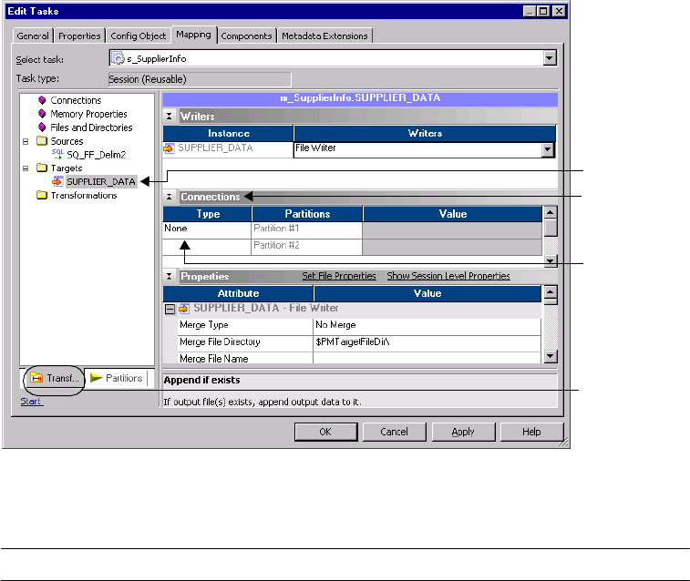
402 Chapter 13: Working with Partition Points
Figure 13-4 shows the Connections settings for file targets:
Table 13-9 describes the connection options for file targets in a mapping:
Configuring File Properties
Use the Properties settings in the Transformations view on the Mapping tab to configure file
properties for flat file sources.
Figure 13-4. Connections Settings for File Targets in the Session Properties
Table 13-9. File Targets Connection Options
Attribute Description
Connection Type Choose an FTP, external loader, or message queue connection. Select None for a local
connection.
The connection type is the same for all partitions.
Value For an FTP, external loader, or message queue connection, click the Open button in this
field to select the connection object.
You can specify a different connection object for each partition.
Selected Target
Instance
Connections
Settings
Connection
Type
Transformations
View
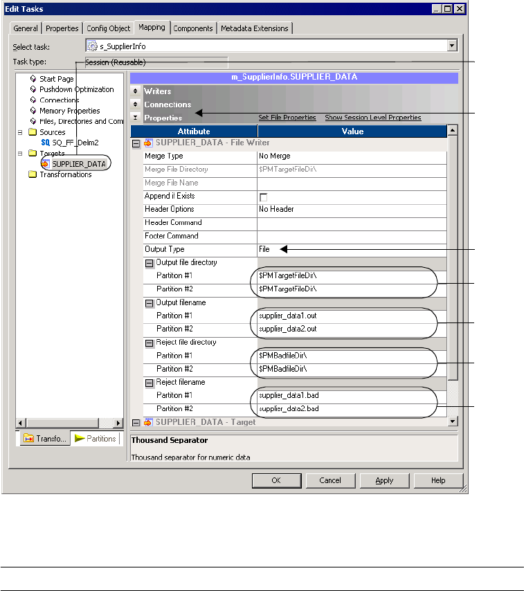
Partitioning File Targets 403
Figure 13-5 shows the Properties settings for file targets:
Table 13-10 describes the file properties for file targets in a mapping:
Figure 13-5. Properties Settings for File Targets in the Session Properties
Table 13-10. Target File Properties
Attribute Description
Merge Type Type of merge the Integration Service performs on the data for partitioned targets. When
merging target files, the Integration Service writes the output for all partitions to the merge
file or a command when the session runs.
You cannot merge files if the session uses an external loader or a message queue.
For more information about merging target files, see “Configuring Merge Options” on
page 405.
Merge File Directory Location of the merge file. Default is $PMTargetFileDir.
Merge File Name Name of the merge file. Default is target name.out.
Selected
Target
Instance
Properties
Settings
Enter
output file
directories.
Enter output
file names.
Enter
reject file
directories.
Enter
reject file
names.
Select
output type.

404 Chapter 13: Working with Partition Points
Note: For more information about configuring properties for file targets, see “Working with
File Targets” on page 284.
Configuring Commands for Partitioned File Targets
Use a command to process target data for a single partition or process merge data for all target
partitions in a session. On UNIX, use any valid UNIX command or shell script. On
Windows, use any valid DOS or batch file. The Integration Service sends the data to a
command instead of a flat file target or merge file.
Use a command to process the following types of target data:
♦Target data for a single partition. You can enter a command for each target partition. The
Integration Service sends the target data to the command when the session runs.
To send the target data for a single partition to a command, select Command for the
Output Type. Enter a command for the Command property for the partition in the session
properties.
Append if Exists Appends the output data to the target files and reject files for each partition. Appends output
data to the merge file if you merge the target files. You cannot use this option for target files
that are non-disk files, such as FTP target files.
If you do not select this option, the Integration Service truncates each target file before
writing the output data to the target file. If the file does not exist, the Integration Service
creates it.
Output Type Type of target for the session. Select File to write the target data to a file target. Select
Command to send target data to a command. You cannot select Command for FTP or queue
target connection.
For more information about processing target data with a command, see “Configuring
Commands for Partitioned File Targets” on page 404.
Header Options Create a header row in the file target.
Header Command Command used to generate the header row in the file target.
Footer Command Command used to generate a footer row in the file target.
Merge Command Command used to process merged target data. For more information about using a
command to process merged target data, see “Configuring Commands for Partitioned File
Targets” on page 404.
Output File Directory Location of the target file. Default is $PMTargetFileDir.
Output File Name Name of target file. Default is target name partition number.out. You can also use the
session parameter, $OutputFileName, as defined in the parameter file.
Reject File Directory Location for the target reject files. Default is $PMBadFileDir.
Reject File Name Name of reject file. Default is target name partition number.bad.
Command Command used to process the target output data for a single partition. For more information,
see “Configuring Commands for Partitioned File Targets” on page 404.
Table 13-10. Target File Properties
Attribute Description
Partitioning File Targets 405
♦Merge data for all target partitions. You can enter a command to process the merge data
for all partitions. The Integration Service concurrently sends the target data for all
partitions to the command when the session runs. The command may not maintain the
order of the target data.
To send merge data for all partitions to a command, select Command as the Output Type
and enter a command for the Merge Command Line property in the session properties.
For more information about using commands with flat file targets, see “Working with File
Targets” on page 284.
Configuring Merge Options
You can merge target data for the partitions in a session. When you merge target data, the
Integration Service creates a merge file for all target partitions.
You can configure the following merge file options:
♦Sequential Merge. The Integration Service creates an output file for all partitions and then
merges them into a single merge file at the end of the session. The Integration Service
sequentially adds the output data for each partition to the merge file. The Integration
Service creates the individual target file using the Output File Name and Output File
Directory values for the partition.
♦File list. The Integration Service creates a target file for all partitions and creates a file list
that contains the paths of the individual files. The Integration Service creates the
individual target file using the Output File Name and Output File Directory values for the
partition. If you write the target files to the merge directory or a directory under the merge
directory, the file list contains relative paths. Otherwise, the list file contains absolute
paths. Use this file as a source file if you use the target files as source files in another
mapping.
♦Concurrent Merge. The Integration Service concurrently writes the data for all target
partitions to the merge file. It does not create intermediate files for each partition. Since
the Integration Service writes to the merge file concurrently for all partitions, the sort
order of the data in the merge file may not be sequential.
For more information about merging targets files in sessions that use an FTP connection, see
“Configuring FTP in a Session” on page 654.
406 Chapter 13: Working with Partition Points
Partitioning Custom Transformations
When a mapping contains a Custom transformation, a Java transformation, SQL
transformation, or an HTTP transformation, you can edit the following partitioning
information:
♦Add multiple partitions. You can create multiple partitions when the Custom
transformation allows multiple partitions. For more information, see “Working with
Multiple Partitions” on page 406.
♦Create partition points. You can create a partition point at a Custom transformation even
when the transformation does not allow multiple partitions. For more information, see
“Creating Partition Points” on page 406.
The Java, SQL, and HTTP transformations were built using the Custom transformation and
have the same partitioning features. Not all transformations created using the Custom
transformation have the same partitioning features as the Custom transformation.
When you configure a Custom transformation to process each partition with one thread, the
Workflow Manager adds partition points depending on the mapping configuration. For more
information, see “Working with Threads” on page 407.
For more information about Custom transformations, see “Custom Transformation” in the
Tra ns for ma t i o n Gu id e .
Working with Multiple Partitions
You can configure a Custom transformation to allow multiple partitions in mappings. You can
add partitions to the pipeline if you set the Is Partitionable property for the transformation.
You can select the following values for the Is Partitionable option:
♦No. The transformation cannot be partitioned. The transformation and other
transformations in the same pipeline are limited to one partition. You might choose No if
the transformation processes all the input data together, such as data cleansing.
♦Locally. The transformation can be partitioned, but the Integration Service must run all
partitions in the pipeline on the same node. Choose Local when different partitions of the
transformation must share objects in memory.
♦Across Grid. The transformation can be partitioned, and the Integration Service can
distribute each partition to different nodes.
Note: When you add multiple partitions to a mapping that includes a multiple input or output
group Custom transformation, you define the same number of partitions for all groups.
Creating Partition Points
You can create a partition point at a Custom transformation even when the transformation
does not allow multiple partitions. Consider the following rules and guidelines when you
create a partition point at a Custom transformation:
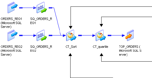
Partitioning Custom Transformations 407
♦You can define the partition type for each input group in the transformation. You cannot
define the partition type for output groups.
♦Valid partition types are pass-through, round-robin, key range, and hash user keys.
Working with Threads
To configure a Custom transformation so the Integration Service uses one thread to process
the transformation for each partition, enable Requires Single Thread Per Partition Custom
transformation property.
When you configure a Custom transformation to process each partition with one thread, the
Workflow Manager creates a pass-through partition point based on the number of input
groups and the location of the Custom transformation in the mapping.
For more information about configuring Custom transformations to use one thread for each
partition, see “Custom Transformation” in the Tra ns f or m a t io n Gu id e .
One Input Group
When a single input group Custom transformation is downstream from a multiple input
group Custom transformation that does not have a partition point, the Workflow Manager
places a pass-through partition point at the closest upstream multiple input group
transformation.
For example, consider the following mapping:
CT_quartile contains one input group and is downstream from a multiple input group
transformation. CT_quartile requires one thread for each partition, but the upstream Custom
transformation does not. The Workflow Manager creates a partition point at the closest
upstream multiple input group transformation, CT_Sort.
Multiple Input Groups
The Workflow Manager places a partition point at a multiple input group Custom
transformation that requires a single thread for each partition.
*
* Partition Point
Requires one thread for each
partition.
Does not require one thread for each partition.
Single Input Group
Multiple Input Groups
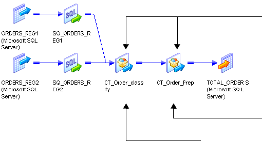
408 Chapter 13: Working with Partition Points
For example, consider the following mapping:
CT_Order_class and CT_Order_Prep have multiple input groups, but only CT_Order_Prep
requires one thread for each partition. The Workflow Manager creates a partition point at
CT_Order_Prep.
*
* Partition Point Requires one thread for each
partition.
Does not require one thread for each partition.
Multiple Input Groups
Partitioning Joiner Transformations 409
Partitioning Joiner Transformations
When you create a partition point at the Joiner transformation, the Workflow Manager sets
the partition type to hash auto-keys when the transformation scope is All Input. The
Workflow Manager sets the partition type to pass-through when the transformation scope is
Tra n sa ct ion .
You must create the same number of partitions for the master and detail source. If you
configure the Joiner transformation for sorted input, you can change the partition type to
pass-through. You can specify only one partition if the pipeline contains the master source for
a Joiner transformation and you do not add a partition point at the Joiner transformation. See
the Transformation Guide for more information about configuring the Joiner transformation
for sorted input.
The Integration Service uses cache partitioning when you create a partition point at the Joiner
transformation. When you use partitioning with a Joiner transformation, you can create
multiple partitions for the master and detail source of a Joiner transformation. For more
information about cache partitioning, see “Cache Partitioning” on page 431.
If you do not create a partition point at the Joiner transformation, you can create n partitions
for the detail source, and one partition for the master source (1:n).
Note: You cannot add a partition point at the Joiner transformation when you configure the
Joiner transformation to use the row transformation scope.
Partitioning Sorted Joiner Transformations
When you include a Joiner transformation that uses sorted input, you must verify the Joiner
transformation receives sorted data. If the sources contain large amounts of data, you may
want to configure partitioning to improve performance. However, partitions that redistribute
rows can rearrange the order of sorted data, so it is important to configure partitions to
maintain sorted data.
For example, when you use a hash auto-keys partition point, the Integration Service uses a
hash function to determine the best way to distribute the data among the partitions. However,
it does not maintain the sort order, so you must follow specific partitioning guidelines to use
this type of partition point.
When you join data, you can partition data for the master and detail pipelines in the
following ways:
♦1:n. Use one partition for the master source and multiple partitions for the detail source.
The Integration Service maintains the sort order because it does not redistribute master
data among partitions.
♦n:n. Use an equal number of partitions for the master and detail sources. When you use
n:n partitions, the Integration Service processes multiple partitions concurrently. You may
need to configure the partitions to maintain the sort order depending on the type of
partition you use at the Joiner transformation.
410 Chapter 13: Working with Partition Points
Note: When you use 1:n partitions, do not add a partition point at the Joiner transformation.
If you add a partition point at the Joiner transformation, the Workflow Manager adds an
equal number of partitions to both master and detail pipelines.
Use different partitioning guidelines, depending on where you sort the data:
♦Using sorted flat files. Use one of the following partitioning configurations:
−Use 1:n partitions when you have one flat file in the master pipeline and multiple flat
files in the detail pipeline. Configure the session to use one reader-thread for each file.
−Use n:n partitions when you have one large flat file in the master and detail pipelines.
Configure partitions to pass all sorted data in the first partition, and pass empty file data
in the other partitions.
♦Using sorted relational data. Use one of the following partitioning configurations:
−Use 1:n partitions for the master and detail pipeline.
−Use n:n partitions. If you use a hash auto-keys partition, configure partitions to pass all
sorted data in the first partition.
♦Using the Sorter transformation. Use n:n partitions. If you use a hash auto-keys partition
at the Joiner transformation, configure each Sorter transformation to use hash auto-keys
partition points as well.
Add only pass-through partition points between the sort origin and the Joiner transformation.
Using Sorted Flat Files
Use 1:n partitions when you have one flat file in the master pipeline and multiple flat files in
the detail pipeline. When you use 1:n partitions, the Integration Service maintains the sort
order because it does not redistribute data among partitions. When you have one large flat file
in each master and detail pipeline, use n:n partitions and add a pass-through or hash auto-
keys partition at the Joiner transformation. When you add a hash auto-keys partition point,
you must configure partitions to pass all sorted data in the first partition to maintain the sort
order.
Using 1:n Partitions
If the session uses one flat file in the master pipeline and multiple flat files in the detail
pipeline, use one partition for the master source and n partitions for the detail file sources
(1:n). Add a pass-through partition point at the detail Source Qualifier transformation. Do
not add a partition point at the Joiner transformation. The Integration Service maintains the
sort order when you create one partition for the master source because it does not redistribute
sorted data among partitions.
When you have multiple files in the detail pipeline that have the same structure, pass the files
to the Joiner transformation using the following guidelines:
♦Configure the mapping with one source and one Source Qualifier transformation in each
pipeline.
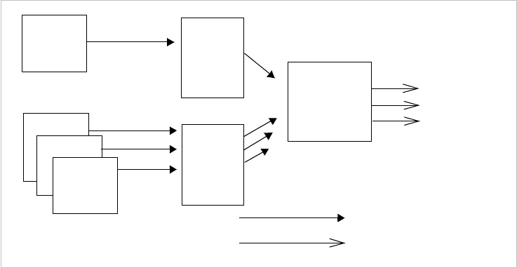
Partitioning Joiner Transformations 411
♦Specify the path and file name for each flat file in the Properties settings of the
Transformations view on the Mapping tab of the session properties.
♦Each file must use the same file properties as configured in the source definition.
♦The range of sorted data in the flat files can overlap. You do not need to use a unique range
of data for each file.
Figure 13-6 shows sorted file data joined using 1:n partitioning:
The Joiner transformation may output unsorted data depending on the join type. If you use a
full outer or detail outer join, the Integration Service processes unmatched master rows last,
which can result in unsorted data.
Using n:n Partitions
If the session uses sorted flat file data, use n:n partitions for the master and detail pipelines.
You can add a pass-through partition or hash auto-keys partition at the Joiner transformation.
If you add a pass-through partition at the Joiner transformation, follow instructions in the
Tra ns for ma t i o n Gu id e for maintaining the sort order in mappings.
If you add a hash auto-keys partition point at the Joiner transformation, you can maintain the
sort order by passing all sorted data to the Joiner transformation in a single partition. When
you pass sorted data in one partition, the Integration Service maintains the sort order when it
redistributes data using a hash function.
To allow the Integration Service to pass all sorted data in one partition, configure the session
to use the sorted file for the first partition and empty files for the remaining partitions.
The Integration Service redistributes the rows among multiple partitions and joins the sorted
data.
Figure 13-6. Sorted File Data with 1:n Partitions
Source
Qualifier
Joiner
transformation
Source
Qualifier
with pass-
through
partition
Sorted Data
Sorted output depends on join type.
Flat File
Flat File 3
Flat File 1
Flat File 2
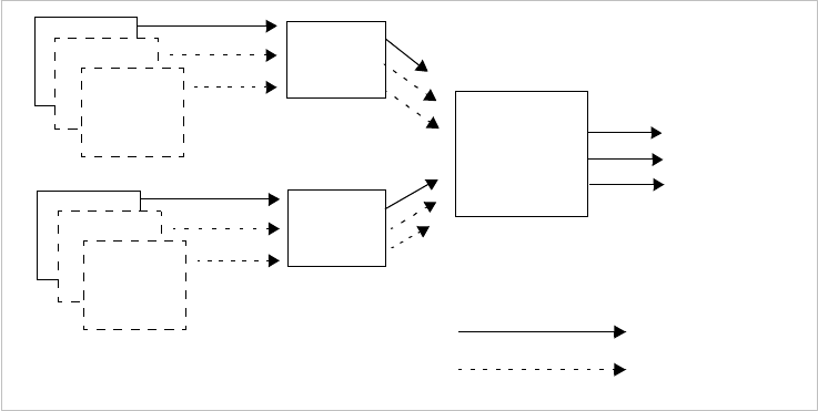
412 Chapter 13: Working with Partition Points
Figure 13-7 shows sorted file data passed through a single partition to maintain sort order:
The example in Figure 13-7 shows sorted data passed in a single partition to maintain the sort
order. The first partition contains sorted file data while all other partitions pass empty file
data. At the Joiner transformation, the Integration Service distributes the data among all
partitions while maintaining the order of the sorted data.
Using Sorted Relational Data
When you join relational data, use 1:n partitions for the master and detail pipeline. When
you use 1:n partitions, you cannot add a partition point at the Joiner transformation. If you
use n:n partitions, you can add a pass-through or hash auto-keys partition at the Joiner
transformation. If you use a hash auto-keys partition point, you must configure partitions to
pass all sorted data in the first partition to maintain sort order.
Using 1:n Partitions
If the session uses sorted relational data, use one partition for the master source and n
partitions for the detail source (1:n). Add a key-range or pass-through partition point at the
Source Qualifier transformation. Do not add a partition point at the Joiner transformation.
The Integration Service maintains the sort order when you create one partition for the master
source because it does not redistribute data among partitions.
Figure 13-7. Sorted File Data Passed Through a Single Partition
Source
Qualifier
Joiner
transformation
with hash auto-
keys partition
point
Source
Qualifier
Sorted Data
No Data
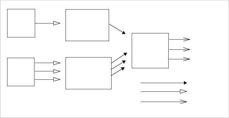
Partitioning Joiner Transformations 413
Figure 13-8 shows sorted relational data with 1:n partitioning:
The Joiner transformation may output unsorted data depending on the join type. If you use a
full outer or detail outer join, the Integration Service processes unmatched master rows last,
which can result in unsorted data.
Using n:n Partitions
If the session uses sorted relational data, use n:n partitions for the master and detail pipelines
and add a pass-through or hash auto-keys partition point at the Joiner transformation. When
you use a pass-through partition at the Joiner transformation, follow instructions in the
Tra ns for ma t i o n Gu id e for maintaining sorted data in mappings.
When you use a hash auto-keys partition point, you maintain the sort order by passing all
sorted data to the Joiner transformation in a single partition. Add a key-range partition point
at the Source Qualifier transformation that contains all source data in the first partition.
When you pass sorted data in one partition, the Integration Service redistributes data among
multiple partitions using a hash function and joins the sorted data.
Figure 13-8. Sorted Relational Data with 1:n Partitioning
Source Qualifier
transformation
Joiner
transformation
Source Qualifier
transformation with
key-range or pass-
through partition point Sorted Data
Relational
Source
Relational
Source
Unsorted Data
Sorted output
depends on join
type.
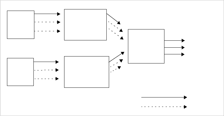
414 Chapter 13: Working with Partition Points
Figure 13-9 shows sorted relational data passed through a single partition to maintain the sort
order:
The example in Figure 13-9 shows sorted relational data passed in a single partition to
maintain the sort order. The first partition contains sorted relational data while all other
partitions pass empty data. After the Integration Service joins the sorted data, it redistributes
data among multiple partitions.
Using Sorter Transformations
If the session uses the Sorter transformations to sort data, use n:n partitions for the master
and detail pipelines. Use a hash auto-keys partition point at the Sorter transformation to
group the data. You can add a pass-through or hash auto-keys partition point at the Joiner
transformation.
The Integration Service groups data into partitions of the same hash values, and the Sorter
transformation sorts the data before passing it to the Joiner transformation. When the
Integration Service processes the Joiner transformation configured with a hash auto-keys
partition, it maintains the sort order by processing the sorted data using the same partitions it
uses to route the data from each Sorter transformation.
Figure 13-9. Sorted Relational Data Passed Through a Single Partition
Source Qualifier
transformation with
key-range partition
point Joiner
transformation
with hash auto-
keys partition
point
Source Qualifier
transformation with
key-range partition
point
Sorted Data
No Data
Relational
Source
Relational
Source
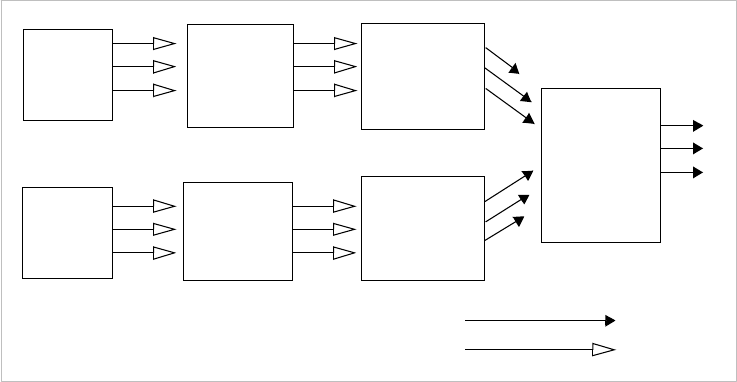
Partitioning Joiner Transformations 415
Figure 13-10 shows Sorter transformations used with hash auto-keys to maintain sort order:
Note: For best performance, use sorted flat files or sorted relational data. You may want to
calculate the processing overhead for adding Sorter transformations to the mapping.
Optimizing Sorted Joiner Transformations with Partitions
When you use partitions with a sorted Joiner transformation, you may optimize performance
by grouping data and using n:n partitions.
Add a Hash Auto-keys Partition Upstream of the Sort Origin
To obtain expected results and get best performance when partitioning a sorted Joiner
transformation, you must group and sort data. To group data, ensure that rows with the same
key value are routed to the same partition. The best way to ensure that data is grouped and
distributed evenly among partitions is to add a hash auto-keys or key-range partition point
before the sort origin. Placing the partition point before you sort the data ensures that you
maintain grouping and sort the data within each group.
Use n:n Partitions
You may be able to improve performance for a sorted Joiner transformation by using n:n
partitions. When you use n:n partitions, the Joiner transformation reads master and detail
rows concurrently and does not need to cache all of the master data. This reduces memory
usage and speeds processing. When you use 1:n partitions, the Joiner transformation caches
all the data from the master pipeline and writes the cache to disk if the memory cache fills.
When the Joiner transformation receives the data from the detail pipeline, it must then read
the data from disk to compare the master and detail pipelines.
Figure 13-10. Using Sorter Transformations with Hash Auto-Keys to Maintain Sort Order
Sorter
transformation
with hash auto-
keys partition
point Joiner
transformation
with hash auto-
keys or pass-
through
partition point
Sorter
transformation
with hash auto-
keys partition
point
Sorted Data
Unsorted Data
Source with
unsorted
data
Source with
unsorted
data
Source
Qualifier
transformation
Source
Qualifier
transformation
416 Chapter 13: Working with Partition Points
Partitioning Lookup Transformations
Use cache partitioning for static and dynamic caches, and named and unnamed caches. When
you create a partition point at a connected Lookup transformation, use cache partitioning
under the following conditions:
♦You use the hash auto-keys partition type for the Lookup transformation.
♦The lookup condition contains only equality operators.
♦The database is configured for case-sensitive comparison.
For example, if the lookup condition contains a string port and the database is not
configured for case-sensitive comparison, the Integration Service does not perform cache
partitioning and writes the following message to the session log:
CMN_1799 Cache partitioning requires case sensitive string comparisons.
Lookup will not use partitioned cache as the database is configured for
case insensitive string comparisons.
The Integration Service uses cache partitioning when you create a hash auto-keys partition
point at the Lookup transformation.
When the Integration Service creates cache partitions, it begins creating caches for the
Lookup transformation when the first row of any partition reaches the Lookup
transformation. If you configure the Lookup transformation for concurrent caches, the
Integration Service builds all caches for the partitions concurrently. For more information
about creating concurrent or sequential caches, see “Lookup Caches” in the Tran sf or ma ti o n
Guide.
For more information about cache partitioning, see “Cache Partitioning” on page 431.
Sharing Partitioned Caches
Use the following guidelines when you share partitioned Lookup caches:
♦Lookup transformations can share a partitioned cache if the transformations meet the
following conditions:
−The cache structures are identical. The lookup/output ports for the first shared
transformation must match the lookup/output ports for the subsequent transformations.
−The transformations have the same lookup conditions, and the lookup condition
columns are in the same order.
♦You cannot share a partitioned cache with a non-partitioned cache.
♦When you share Lookup caches across target load order groups, you must configure the
target load order groups with the same number of partitions.
♦If the Integration Service detects a mismatch between Lookup transformations sharing an
unnamed cache, it rebuilds the cache files.
♦If the Integration Service detects a mismatch between Lookup transformations sharing a
named cache, it fails the session.
Partitioning Sorter Transformations 417
Partitioning Sorter Transformations
If you configure multiple partitions in a session that uses a Sorter transformation, the
Integration Service sorts data in each partition separately. The Workflow Manager lets you
choose hash auto-keys, key-range, or pass-through partitioning when you add a partition
point at the Sorter transformation.
Use hash-auto keys partitioning when you place the Sorter transformation before an
Aggregator transformation configured to use sorted input. Hash auto-keys partitioning
groups rows with the same values into the same partition based on the partition key. After
grouping the rows, the Integration Service passes the rows through the Sorter transformation.
The Integration Service processes the data in each partition separately, but hash auto-keys
partitioning accurately sorts all of the source data because rows with matching values are
processed in the same partition. You can delete the default partition point at the Aggregator
transformation.
Use key-range partitioning when you want to send all rows in a partitioned session from
multiple partitions into a single partition for sorting. When you merge all rows into a single
partition for sorting, the Integration Service can process all of the data together.
Use pass-through partitioning if you already used hash partitioning in the pipeline. This
ensures that the data passing into the Sorter transformation is correctly grouped among the
partitions. Pass-through partitioning increases session performance without increasing the
number of partitions in the pipeline.
For more information about Sorter transformations, see “Sorter Transformation” in the
Tra ns for ma t i o n Gu id e .
Configuring Sorter Transformation Work Directories
The Integration Service creates temporary files for each Sorter transformation in a pipeline. It
reads and writes data to these files while it performs the sort. The Integration Service stores
these files in the Sorter transformation work directories.
By default, the Workflow Manager sets the work directories for all partitions at Sorter
transformations to $PMTempDir. You can specify a different work directory for each
partition in the session properties.

Restrictions for Transformations 419
Restrictions for Transformations
Some restrictions on the number of partitions depend on the types of transformations in the
pipeline. These restrictions apply to all transformations, including reusable transformations,
transformations created in mappings and mapplets, and transformations, mapplets, and
mappings referenced by shortcuts.
Table 13-11 describes the restrictions on the number of partitions for transformations:
Sequence numbers generated by Normalizer and Sequence Generator transformations might
not be sequential for a partitioned source, but they are unique.
Restrictions for Numerical Functions
The numerical functions CUME, MOVINGSUM, and MOVINGAVG calculate running
totals and averages on a row-by-row basis. According to the way you partition a pipeline, the
order that rows of data pass through a transformation containing one of these functions can
change. Therefore, a session with multiple partitions that uses CUME, MOVINGSUM, or
MOVINGAVG functions may not always return the same calculated result.
Table 13-11. Restrictions on the Number of Partitions for Transformations
Transformation Restrictions
Custom Transformation By default, you can only specify one partition if the pipeline contains a Custom
transformation.
However, this transformation contains an option on the Properties tab to allow
multiple partitions. If you enable this option, you can specify multiple partitions at this
transformation. Do not select Is Partitionable if the Custom transformation procedure
performs the procedure based on all the input data together, such as data cleansing.
External Procedure
Transformation
By default, you can only specify one partition if the pipeline contains an External
Procedure transformation.
This transformation contains an option on the Properties tab to allow multiple
partitions. If this option is enabled, you can specify multiple partitions at this
transformation.
Joiner Transformation You can specify only one partition if the pipeline contains the master source for a
Joiner transformation and you do not add a partition point at the Joiner
transformation.
XML Target Instance You can specify only one partition if the pipeline contains XML targets.
420 Chapter 13: Working with Partition Points

422 Chapter 14: Understanding Pipeline Partitioning
Overview
You create a session for each mapping you want the Integration Service to run. Each mapping
contains one or more pipelines. A pipeline consists of a source qualifier and all the
transformations and targets that receive data from that source qualifier. When the Integration
Service runs the session, it can achieve higher performance by partitioning the pipeline and
performing the extract, transformation, and load for each partition in parallel.
A partition is a pipeline stage that executes in a single reader, transformation, or writer thread.
The number of partitions in any pipeline stage equals the number of threads in the stage. By
default, the Integration Service creates one partition in every pipeline stage.
If you have the Partitioning option, you can configure multiple partitions for a single pipeline
stage. You can configure partitioning information that controls the number of reader,
transformation, and writer threads that the master thread creates for the pipeline. You can
configure how the Integration Service reads data from the source, distributes rows of data to
each transformation, and writes data to the target. You can configure the number of source
and target connections to use.
Complete the following tasks to configure partitions for a session:
♦Set partition attributes including partition points, the number of partitions, and the
partition types. For more information about partitioning attributes, see “Partitioning
Attributes” on page 423.
♦You can enable the Integration Service to set partitioning at run time. When you enable
dynamic partitioning, the Integration Service scales the number of session partitions based
on factors such as the source database partitions or the number of nodes in a grid. For
more information about dynamic partitioning, see “Dynamic Partitioning” on page 427.
♦After you configure a session for partitioning, you can configure memory requirements
and cache directories for each transformation. For more information about cache
partitioning, see “Cache Partitioning” on page 431.
♦The Integration Service evaluates mapping variables for each partition in a target load
order group. You can use variable functions in the mapping to set the variable values. For
more information about mapping variables in partitioned pipelines, see “Mapping
Variables in Partitioned Pipelines” on page 432.
♦When you create multiple partitions in a pipeline, the Workflow Manager verifies that the
Integration Service can maintain data consistency in the session using the partitions.
When you edit object properties in the session, you can impact partitioning and cause a
session to fail. For information about how the Workflow Manager validates partitioning,
see “Partitioning Rules” on page 433.
♦You add or edit partition points in the session properties. When you change partition
points you can define the partition type and add or delete partitions. For more
information about configuring partition information, see “Configuring Partitioning” on
page 435.
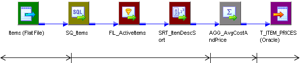
Partitioning Attributes 423
Partitioning Attributes
You can set the following attributes to partition a pipeline:
♦Partition points. Partition points mark thread boundaries and divide the pipeline into
stages. The Integration Service redistributes rows of data at partition points.
♦Number of partitions. A partition is a pipeline stage that executes in a single thread. If you
purchase the Partitioning option, you can set the number of partitions at any partition
point. When you add partitions, you increase the number of processing threads, which can
improve session performance.
♦Partition types. The Integration Service creates a default partition type at each partition
point. If you have the Partitioning option, you can change the partition type. The
partition type controls how the Integration Service distributes data among partitions at
partition points.
Partition Points
By default, the Integration Service sets partition points at various transformations in the
pipeline. Partition points mark thread boundaries and divide the pipeline into stages. A stage
is a section of a pipeline between any two partition points. When you set a partition point at
a transformation, the new pipeline stage includes that transformation.
Figure 14-1 shows the default partition points and pipeline stages for a mapping with one
pipeline:
When you add a partition point, you increase the number of pipeline stages by one. Similarly,
when you delete a partition point, you reduce the number of stages by one. Partition points
mark the points in the pipeline where the Integration Service can redistribute data across
partitions.
For example, if you place a partition point at a Filter transformation and define multiple
partitions, the Integration Service can redistribute rows of data among the partitions before
the Filter transformation processes the data. The partition type you set at this partition point
controls the way in which the Integration Service passes rows of data to each partition.
For more information about partition points, see “Working with Partition Points” on
page 385.
Figure 14-1. Default Partition Points and Stages in a Sample Mapping
Fourth Stage
Third StageSecond StageFirst Stage
***
Default Partition Points
*
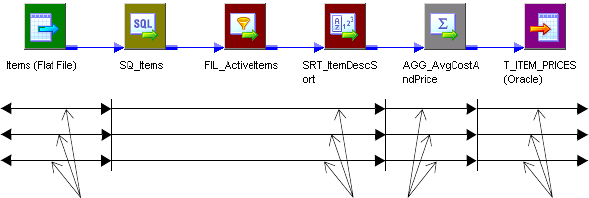
424 Chapter 14: Understanding Pipeline Partitioning
Number of Partitions
The number of threads that process each pipeline stage depends on the number of partitions.
A partition is a pipeline stage that executes in a single reader, transformation, or writer thread.
The number of partitions in any pipeline stage equals the number of threads in that stage.
You can define up to 64 partitions at any partition point in a pipeline. When you increase or
decrease the number of partitions at any partition point, the Workflow Manager increases or
decreases the number of partitions at all partition points in the pipeline. The number of
partitions remains consistent throughout the pipeline. If you define three partitions at any
partition point, the Workflow Manager creates three partitions at all other partition points in
the pipeline. In certain circumstances, the number of partitions in the pipeline must be set to
one.
Increasing the number of partitions or partition points increases the number of threads.
Therefore, increasing the number of partitions or partition points also increases the load on
the node. If the node contains enough CPU bandwidth, processing rows of data in a session
concurrently can increase session performance. However, if you create a large number of
partitions or partition points in a session that processes large amounts of data, you can
overload the system.
The number of partitions you create equals the number of connections to the source or target.
If the pipeline contains a relational source or target, the number of partitions at the source
qualifier or target instance equals the number of connections to the database. If the pipeline
contains file sources, you can configure the session to read the source with one thread or with
multiple threads.
Figure 14-2 shows the threads in a mapping with three partitions:
When you define three partitions across the mapping, the master thread creates three threads
at each pipeline stage, for a total of 12 threads.
Figure 14-2. Thread Creation for a Mapping with Three Partitions
Default Partition Points
*
***
3 Reader Threads 6 Transformation Threads 3 Writer Threads
Threads for Partition #1
Threads for Partition #2
Threads for Partition #3
(First Stage) (Second Stage) (Third Stage) (Fourth Stage)
Partitioning Attributes 425
The Integration Service runs the partition threads concurrently. When you run a session with
multiple partitions, the threads run as follows:
1. The reader threads run concurrently to extract data from the source.
2. The transformation threads run concurrently in each transformation stage to process
data. The Integration Service redistributes data among the partitions at each partition
point.
3. The writer threads run concurrently to write data to the target.
Partitioning Multiple Input Group Transformations
The master thread creates a reader and transformation thread for each pipeline in the target
load order group. A target load order group has multiple pipelines when it contains a
transformation with multiple input groups.
When you connect more than one pipeline to a multiple input group transformation, the
Integration Service maintains the transformation threads or creates a new transformation
thread depending on whether or not the multiple input group transformation is a partition
point:
♦Partition point does not exist at multiple input group transformation. When a partition
point does not exist at a multiple input group transformation, the Integration Service
processes one thread at a time for the multiple input group transformation and all
downstream transformations in the stage.
♦Partition point exists at multiple input group transformation. When a partition point
exists at a multiple input group transformation, the Integration Service creates a new
pipeline stage and processes the stage with one thread for each partition. The Integration
Service creates one transformation thread for each partition regardless of the number of
output groups the transformation contains.
Partition Types
When you configure the partitioning information for a pipeline, you must define a partition
type at each partition point in the pipeline. The partition type determines how the
Integration Service redistributes data across partition points.
The Integration Services creates a default partition type at each partition point. If you have
the Partitioning option, you can change the partition type. The partition type controls how
the Integration Service distributes data among partitions at partition points. You can create
different partition types at different points in the pipeline.
You can define the following partition types in the Workflow Manager:
♦Database partitioning. The Integration Service queries the IBM DB2 or Oracle database
system for table partition information. It reads partitioned data from the corresponding
nodes in the database. You can use database partitioning with Oracle or IBM DB2 source
instances on a multi-node tablespace. You can use database partitioning with DB2 targets.
426 Chapter 14: Understanding Pipeline Partitioning
♦Hash auto-keys. The Integration Service uses a hash function to group rows of data among
partitions. The Integration Service groups the data based on a partition key. The
Integration Service uses all grouped or sorted ports as a compound partition key. You may
need to use hash auto-keys partitioning at Rank, Sorter, and unsorted Aggregator
transformations.
♦Hash user keys. The Integration Service uses a hash function to group rows of data among
partitions. You define the number of ports to generate the partition key.
♦Key range. With key range partitioning, the Integration Service distributes rows of data
based on a port or set of ports that you define as the partition key. For each port, you
define a range of values. The Integration Service uses the key and ranges to send rows to
the appropriate partition. Use key range partitioning when the sources or targets in the
pipeline are partitioned by key range.
♦Pass-through. In pass-through partitioning, the Integration Service processes data without
redistributing rows among partitions. All rows in a single partition stay in the partition
after crossing a pass-through partition point. Choose pass-through partitioning when you
want to create an additional pipeline stage to improve performance, but do not want to
change the distribution of data across partitions.
♦Round-robin. The Integration Service distributes data evenly among all partitions. Use
round-robin partitioning where you want each partition to process approximately the same
number of rows.
For more information about partition types, see “Working with Partition Types” on page 439.
Dynamic Partitioning 427
Dynamic Partitioning
If the volume of data grows or you add more CPUs, you might need to adjust partitioning so
the session run time does not increase. When you use dynamic partitioning, you can
configure the partition information so the Integration Service determines the number of
partitions to create at run time.
The Integration Service scales the number of session partitions at run time based on factors
such as source database partitions or the number of nodes in a grid.
If any transformation in a stage does not support partitioning, or if the partition
configuration does not support dynamic partitioning, the Integration Service does not scale
partitions in the pipeline. The data passes through one partition.
Complete the following tasks to scale session partitions with dynamic partitioning:
♦Set the partitioning. The Integration Service increases the number of partitions based on
the partitioning method you choose. For more information about dynamic partitioning
methods, see “Configuring Dynamic Partitioning” on page 428.
♦Set session attributes for dynamic partitions. You can set session attributes that identify
source and target file names and directories. The session uses the session attributes to
create the partition-level attributes for each partition it creates at run time. For more
information about setting session attributes for dynamic partitions, see “Configuring
Partition-Level Attributes” on page 430.
♦Configure partition types. You can edit partition points and partition types using the
Partitions view on the Mapping tab of session properties. For information about using
dynamic partitioning with different partition types, see “Using Dynamic Partitioning with
Partition Types” on page 429. For information about configuring partition types, see
“Configuring Partitioning” on page 435.
Note: Do not configure dynamic partitioning for a session that contains manual partitions. If
you set dynamic partitioning to a value other than disabled and you manually partition the
session, the session is invalid.
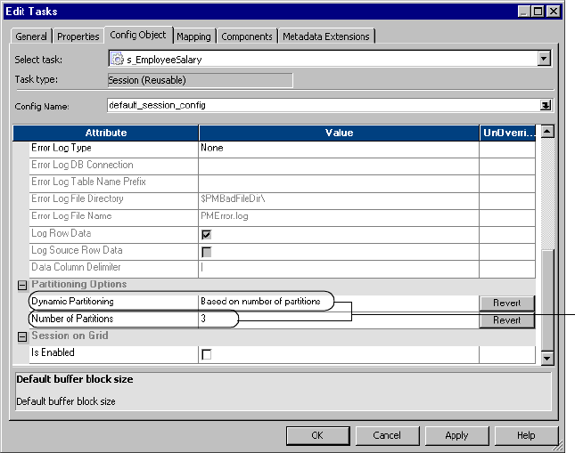
428 Chapter 14: Understanding Pipeline Partitioning
Configuring Dynamic Partitioning
Configure dynamic partitioning on the Config Object tab of session properties.
Figure 14-3 shows the dynamic partitioning options:
Configure dynamic partitioning using one of the following methods:
♦Disabled. Do not use dynamic partitioning. Defines the number of partitions on the
Mapping tab.
♦Based on number of partitions. Sets the partitions to a number that you define in the
Number of Partitions attribute. Use the $DynamicPartitionCount session parameter, or
enter a number greater than 1.
♦Based on number of nodes in grid. Sets the partitions to the number of nodes in the grid
running the session. If you configure this option for sessions that do not run on a grid, the
session runs in one partition and logs a message in the session log.
♦Based on source partitioning. Determines the number of partitions using database
partition information. The number of partitions is the maximum of the number of
partitions at the source. For more information about database partitioning, see “Database
Partitioning Partition Type” on page 444.
Figure 14-3. Dynamic Partitioning Options
Dynamic
Partitioning
Options
Dynamic Partitioning 429
Rules and Guidelines for Dynamic Partitioning
Use the following rules and guidelines with dynamic partitioning:
♦Dynamic partitioning uses the same connection for each partition.
♦You cannot use dynamic partitioning with XML sources and targets.
♦You cannot use dynamic partitioning with the Debugger.
♦When you set dynamic partitioning to a value other than disabled, and you manually
partition the session on the Mapping tab, you invalidate the session.
♦The session fails if you use a parameter other than $DynamicPartitionCount to set the
number of partitions.
♦The following dynamic partitioning configurations cause a session to run with one
partition:
−You override the default cache directory for an Aggregator, Joiner, Lookup, or Rank
transformation. The Integration Service partitions a transformation cache directory
when the default is $PMCacheDir.
−You override the Sorter transformation default work directory. The Integration Service
partitions the Sorter transformation work directory when the default is $PMTempDir.
−You use an open-ended range of numbers or date keys with a key range partition type.
−You use datatypes other than numbers or dates as keys in key range partitioning.
−You use key range relational target partitioning.
−You create a user-defined SQL statement or a user-defined source filter.
−You set dynamic partitioning to the number of nodes in the grid, and the session does
not run on a grid.
−You use pass-through relational source partitioning.
−You use dynamic partitioning with an Application Source Qualifier.
−You use SDK or PowerConnect sources and targets with dynamic partitioning.
Using Dynamic Partitioning with Partition Types
The following rules apply to using dynamic partitioning with different partition types:
♦Pass-through partitioning. If you change the number of partitions at a partition point, the
number of partitions in each pipeline stage changes. If you use pass-through partitioning
with a relational source, the session runs in one partition in the stage.
♦Key range partitioning. You must define a closed range of numbers or date keys to use
dynamic partitioning. The keys must be numeric or date datatypes. Dynamic partitioning
does not scale partitions with key range partitioning on relational targets.
♦Database partitioning. When you use database partitioning, the Integration Service
creates session partitions based on the source database partitions. Use database partitioning
with Oracle and IBM DB2 sources.
430 Chapter 14: Understanding Pipeline Partitioning
♦Hash auto-keys, hash user keys, or round-robin. Use hash user keys, hash auto-keys, and
round-robin partition types to distribute rows with dynamic partitioning. Use hash user
keys and hash auto-keys partitioning when you want the Integration Service to distribute
rows to the partitions by group. Use round-robin partitioning when you want the
Integration Service to distribute rows evenly to partitions.
Configuring Partition-Level Attributes
When you use dynamic partitioning, the Integration Service defines the partition-level
attributes for each partition it creates at run time. It names the file and directory attributes
based on session-level attribute names that you define in the session properties.
For example, you define the session reject file name as accting_detail.bad. When the
Integration Service creates partitions at run time, it creates a reject file for each partition, such
as accting_detail1.bad, accting_detail2.bad, accting_detail3.bad.

Cache Partitioning 431
Cache Partitioning
When you create a session with multiple partitions, the Integration Service may use cache
partitioning for the Aggregator, Joiner, Lookup, Rank, and Sorter transformations. When the
Integration Service partitions a cache, it creates a separate cache for each partition and
allocates the configured cache size to each partition. The Integration Service stores different
data in each cache, where each cache contains only the rows needed by that partition. As a
result, the Integration Service requires a portion of total cache memory for each partition.
After you configure the session for partitioning, you can configure memory requirements and
cache directories for each transformation in the Transformations view on the Mapping tab of
the session properties. To configure the memory requirements, calculate the total
requirements for a transformation, and divide by the number of partitions. To improve
performance, you can configure separate directories for each partition.
Table 14-1 describes the situations when the Integration Service uses cache partitioning for
each applicable transformation:
For more caching information, see “Session Caches” on page 669.
Table 14-1. Cache Partitioning for Each Transformation
Transformation Description
Aggregator Transformation You create multiple partitions in a session with an Aggregator transformation. You do not
have to set a partition point at the Aggregator transformation.
Joiner Transformation You create a partition point at the Joiner transformation. For more information about
partitioning with Joiner transformations, see “Partitioning Joiner Transformations” on
page 409.
Lookup Transformation You create a hash auto-keys partition point at the Lookup transformation. For more
information about partitioning with Lookup transformations, see “Partitioning Lookup
Transformations” on page 416.
Rank Transformation You create multiple partitions in a session with a Rank transformation. You do not have to
set a partition point at the Rank transformation.
Sorter Transformation You create multiple partitions in a session with a Sorter transformation. You do not have to
set a partition point at the Sorter transformation.

432 Chapter 14: Understanding Pipeline Partitioning
Mapping Variables in Partitioned Pipelines
When you specify multiple partitions in a target load order group that uses mapping variables,
the Integration Service evaluates the value of a mapping variable in each partition separately.
The Integration Service uses the following process to evaluate variable values:
1. It updates the current value of the variable separately in each partition according to the
variable function used in the mapping.
2. After loading all the targets in a target load order group, the Integration Service combines
the current values from each partition into a single final value based on the aggregation
type of the variable.
3. If there is more than one target load order group in the session, the final current value of
a mapping variable in a target load order group becomes the current value in the next
target load order group.
4. When the Integration Service finishes loading the last target load order group, the final
current value of the variable is saved into the repository.
For more information about mapping variables, see “Mapping Parameters and Variables”
in the Designer Guide. For more information about target load order groups, see
“Integration Service Architecture” in the Administrator Guide.
Use one of the following variable functions in the mapping to set the variable value:
♦SetCountVariable
♦SetMaxVariable
♦SetMinVariable
For more information about the variable functions, see “Functions” in the Transformation
Language Reference.
Table 14-2 describes how the Integration Service calculates variable values across partitions:
Note: Use variable functions only once for each mapping variable in a pipeline. The
Integration Service processes variable functions as it encounters them in the mapping. The
order in which the Integration Service encounters variable functions in the mapping may not
be the same for every session run. This may cause inconsistent results when you use the same
variable function multiple times in a mapping.
Table 14-2. Variable Value Calculations with Partitioned Sessions
Variable Function Variable Value Calculation Across Partitions
SetCountVariable Integration Service calculates the final count values from all partitions.
SetMaxVariable Integration Service compares the final variable value for each partition and saves the
highest value.
SetMinVariable Integration Service compares the final variable value for each partition and saves the
lowest value.
Partitioning Rules 433
Partitioning Rules
You can create multiple partitions in a pipeline if the Integration Service can maintain data
consistency when it processes the partitioned data. When you create a session, the Workflow
Manager validates each pipeline for partitioning. For information about partitioning
transformations, see “Working with Partition Points” on page 385.
Partition Restrictions for Editing Objects
When you edit object properties, you can impact your ability to create multiple partitions in a
a session or to run an existing session with multiple partitions.
Before You Create a Session
When you create a session, the Workflow Manager checks the mapping properties. Mappings
dynamically pick up changes to shortcuts, but not to reusable objects, such as reusable
transformations and mapplets. Therefore, if you edit a reusable object in the Designer after
you save a mapping and before you create a session, you must open and resave the mapping for
the Workflow Manager to recognize the changes to the object.
After You Create a Session with Multiple Partitions
When you edit a mapping after you create a session with multiple partitions, the Workflow
Manager does not invalidate the session even if the changes violate partitioning rules. The
Integration Service fails the session the next time it runs unless you edit the session so that it
no longer violates partitioning rules.
The following changes to mappings can cause session failure:
♦You delete a transformation that was a partition point.
♦You add a transformation that is a default partition point.
♦You move a transformation that is a partition point to a different pipeline.
♦You change a transformation that is a partition point in any of the following ways:
−The existing partition type is invalid.
−The transformation can no longer support multiple partitions.
−The transformation is no longer a valid partition point.
♦You disable partitioning or you change the partitioning between a single node and a grid in
a transformation after you create a pipeline with multiple partitions.
♦You switch the master and detail source for the Joiner transformation after you create a
pipeline with multiple partitions.
434 Chapter 14: Understanding Pipeline Partitioning
Partition Restrictions for PowerCenter Connects
You can specify multiple partitions in PowerCenter Connect and PowerExchange Client for
PowerCenter but there are some additional restrictions with these products. For more
information about these products, see the product documentation.
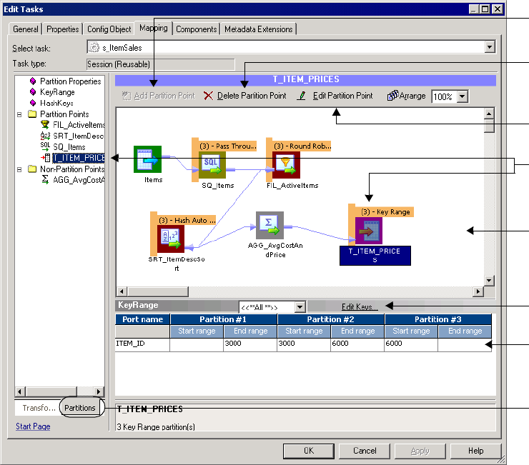
Configuring Partitioning 435
Configuring Partitioning
When you create or edit a session, you can change the partitioning for each pipeline in a
mapping. If the mapping contains multiple pipelines, you can specify multiple partitions in
some pipelines and single partitions in others. You update partitioning information using the
Partitions view on the Mapping tab of session properties.
Add, delete, or edit partition points on the Partitions view of session properties. If you add a
key range partition point, you can define the keys in each range.
Figure 14-4 shows the configuration options on the Partitions view on the Mapping tab:
Figure 14-4. Session Properties Partitions View on the Mapping Tab
Selected Partition
Point
Add a partition
point.
Delete a partition
point.
Edit keys.
Specify key
ranges.
Partitioning
Workspace
Edit the selected
partition point.
Click to display
Partitions view.

436 Chapter 14: Understanding Pipeline Partitioning
Table 14-3 lists the configuration options for the Partitions view on the Mapping tab:
Configuring a Partition Point
You can perform the following tasks when you edit or add a partition point:
♦Specify the partition type at the partition point.
♦Add and delete partitions.
♦Enter a description for each partition.
Table 14-3. Options on Session Properties Partitions View on the Mapping Tab
Partitions View Option Description
Add Partition Point Click to add a new partition point. When you add a partition point, the transformation name
appears under the Partition Points node. For more information, see “Overview” on
page 386.
Delete Partition Point Click to delete the selected partition point.
You cannot delete certain partition points. For more information, see “Overview” on
page 386.
Edit Partition Point Click to edit the selected partition point. This opens the Edit Partition Point dialog box. For
more information about the options in this dialog box, see Table 14-4 on page 437.
Key Range Displays the key and key ranges for the partition point, depending on the partition type.
For key range partitioning, specify the key ranges.
For hash user keys partitioning, this field displays the partition key.
The Workflow Manager does not display this area for other partition types.
Edit Keys Click to add or remove the partition key for key range or hash user keys partitioning. You
cannot create a partition key for hash auto-keys, round-robin, or pass-through partitioning.
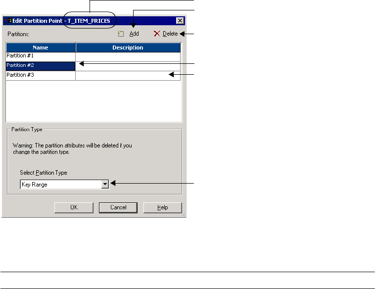
Configuring Partitioning 437
Figure 14-5 shows the configuration options in the Edit Partition Point dialog box:
Table 14-4 describes the configuration options in the Edit Partition Point dialog box:
You can enter a description for each partition you create. To enter a description, select the
partition in the Edit Partition Point dialog box, and then enter the description in the
Description field.
Figure 14-5. Edit Partition Point Dialog Box
Table 14-4. Edit Partition Point Dialog Box Options
Partition Options Description
Select Partition Type Changes the partition type.
Partition Names Selects individual partitions from this dialog box to configure.
Add a Partition Adds a partition. You can add up to 64 partitions at any partition point. The number of
partitions must be consistent across the pipeline. Therefore, if you define three partitions
at one partition point, the Workflow Manager defines three partitions at all partition points
in the pipeline.
Delete a Partition Deletes the selected partition. Each partition point must contain at least one partition.
Description Enter an optional description for the current partition.
Selected Partition Point
Add a partition.
Select a partition.
Delete a partition.
Specify the partition type.
Enter the partition description.
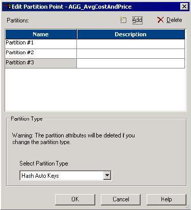
438 Chapter 14: Understanding Pipeline Partitioning
Steps for Adding Partition Points to a Pipeline
You add partition points from the Mappings tab of the session properties.
To add a partition point:
1. On the Partitions view of the Mapping tab, select a transformation that is not already a
partition point, and click the Add a Partition Point button.
Tip: You can select a transformation from the Non-Partition Points node.
2. Select the partition type for the partition point or accept the default value. For more
information about specifying a valid partition type, see “Setting Partition Types” on
page 442.
3. Click OK.
The transformation appears in the Partition Points node in the Partitions view on the
Mapping tab of the session properties.

439
Chapter 15
Working with Partition
Types
This chapter includes the following topics:
♦Overview, 440
♦Setting Partition Types, 442
♦Database Partitioning Partition Type, 444
♦Hash Auto-Keys, 448
♦Hash User Keys, 449
♦Key Range Partition Type, 451
♦Pass-Through Partition Type, 455
♦Round-Robin Partition Type, 457
440 Chapter 15: Working with Partition Types
Overview
The Integration Services creates a default partition type at each partition point. If you have
the Partitioning option, you can change the partition type. The partition type controls how
the Integration Service distributes data among partitions at partition points.
When you configure the partitioning information for a pipeline, you must define a partition
type at each partition point in the pipeline. The partition type determines how the
Integration Service redistributes data across partition points.
You can define the following partition types in the Workflow Manager:
♦Database partitioning. The Integration Service queries the IBM DB2 or Oracle system for
table partition information. It reads partitioned data from the corresponding nodes in the
database. Use database partitioning with Oracle or IBM DB2 source instances on a multi-
node tablespace. Use database partitioning with DB2 targets. For more information, see
“Database Partitioning Partition Type” on page 444.
♦Hash partitioning. Use hash partitioning when you want the Integration Service to
distribute rows to the partitions by group. For example, you need to sort items by item ID,
but you do not know how many items have a particular ID number.
You can use two types of hash partitioning:
−Hash auto-keys. The Integration Service uses all grouped or sorted ports as a compound
partition key. You may need to use hash auto-keys partitioning at Rank, Sorter, and
unsorted Aggregator transformations. For more information, see “Hash Auto-Keys” on
page 448.
−Hash user keys. The Integration Service uses a hash function to group rows of data
among partitions. You define the number of ports to generate the partition key. “Hash
User Keys” on page 449.
♦Key range. You specify one or more ports to form a compound partition key. The
Integration Service passes data to each partition depending on the ranges you specify for
each port. Use key range partitioning where the sources or targets in the pipeline are
partitioned by key range. For more information, see “Key Range Partition Type” on
page 451.
♦Pass-through. The Integration Service passes all rows at one partition point to the next
partition point without redistributing them. Choose pass-through partitioning where you
want to create an additional pipeline stage to improve performance, but do not want to
change the distribution of data across partitions. For more information, see “Pass-Through
Partition Type” on page 455.
♦Round-robin. The Integration Service distributes data evenly among all partitions. Use
round-robin partitioning where you want each partition to process approximately the same
number of rows. For more information, see “Database Partitioning Partition Type” on
page 444.

Overview 441
Setting Partition Types in the Pipeline
You can create different partition types at different points in the pipeline.
Figure 15-1 shows a mapping where you can create partition types to increase session
performance:
The mapping in Figure 15-1 reads data about items and calculates average wholesale costs and
prices. The mapping must read item information from three flat files of various sizes, and
then filter out discontinued items. It sorts the active items by description, calculates the
average prices and wholesale costs, and writes the results to a relational database in which the
target tables are partitioned by key range.
You can delete the default partition point at the Aggregator transformation because hash auto-
keys partitioning at the Sorter transformation sends all rows that contain items with the same
description to the same partition. Therefore, the Aggregator transformation receives data for
all items with the same description in one partition and can calculate the average costs and
prices for this item correctly.
When you use this mapping in a session, you can increase session performance by defining
different partition types at the following partition points in the pipeline:
♦Source qualifier. To read data from the three flat files concurrently, you must specify three
partitions at the source qualifier. Accept the default partition type, pass-through.
♦Filter transformation. Since the source files vary in size, each partition processes a
different amount of data. Set a partition point at the Filter transformation, and choose
round-robin partitioning to balance the load going into the Filter transformation.
♦Sorter transformation. To eliminate overlapping groups in the Sorter and Aggregator
transformations, use hash auto-keys partitioning at the Sorter transformation. This causes
the Integration Service to group all items with the same description into the same partition
before the Sorter and Aggregator transformations process the rows. You can delete the
default partition point at the Aggregator transformation.
♦Target. Since the target tables are partitioned by key range, specify key range partitioning
at the target to optimize writing data to the target.
For more information about specifying partition types, see “Setting Partition Types” on
page 442.
Figure 15-1. Sample Mapping

442 Chapter 15: Working with Partition Types
Setting Partition Types
The Workflow Manager sets a default partition type for each partition point in the pipeline.
At the source qualifier and target instance, the Workflow Manager specifies pass-through
partitioning. For Rank and unsorted Aggregator transformations, for example, the Workflow
Manager specifies hash auto-keys partitioning when the transformation scope is All Input.
When you create a new partition point, the Workflow Manager sets the partition type to the
default partition type for that transformation. You can change the default type.
You must specify pass-through partitioning for all transformations that are downstream from
a transaction generator or an active source that generates commits and upstream from a target
or a transformation with Transaction transformation scope. Also, if you configure the session
to use constraint-based loading, you must specify pass-through partitioning for all
transformations that are downstream from the last active source. For more information, see
Table 15-1 on page 442.
If workflow recovery is enabled, the Workflow Manager sets the partition type to pass-
through unless the partition point is either an Aggregator transformation or a Rank
transformation.
Table 15-1 lists valid partition types and the default partition type for different partition
points in the pipeline:
Table 15-1. Valid Partition Types for Partition Points
Transformation
(Partition Point)
Round-
Robin
Hash
Auto-Keys
Hash User
Keys
Key
Range
Pass-
Through
Database
Partitioning
Default Partition
Type
Source definition Not a valid partition
point
Source Qualifier
(relational sources)
X X X
(Oracle, DB2)
Pass-through
Source Qualifier
(flat file sources)
XPass-through
XML Source Qualifier XPass-through
Normalizer
(COBOL sources)
XPass-through
Normalizer
(relational)
X X X X Pass-through
Aggregator (sorted) XPass-through
Aggregator (unsorted) X X Based on
transformation scope*
Custom X X X X Pass-through
Expression X X X X Pass-through
External Procedure X X X X Pass-through

Setting Partition Types 443
Filter X X X X Pass-through
HTTP XPass-through
Java X X X X Pass-through
Joiner X X Based on
transformation scope*
Lookup X X X X X Pass-through
Rank X X Based on
transformation scope*
Router X X X X Pass-through
Sequence Generator Not a valid partition
point
Sorter X X X Based on
transformation scope*
Stored Procedure X X X X Pass-through
Transaction Control X X X X Pass-through
Union X X X X Pass-through
Update Strategy X X X X Pass-through
Unconnected
transformation
Not a valid partition
point
XML Generator XPass-through
XML Parser XPass-through
Relational target
definition
X X X X X (DB2) Pass-through
Flat file target definition X X X X Pass-through
XML target definition Not a valid partition
point
* The default partition type is pass-through when the transformation scope is Transaction and hash auto-keys when the transformation scope is All Input.
Table 15-1. Valid Partition Types for Partition Points
Transformation
(Partition Point)
Round-
Robin
Hash
Auto-Keys
Hash User
Keys
Key
Range
Pass-
Through
Database
Partitioning
Default Partition
Type
444 Chapter 15: Working with Partition Types
Database Partitioning Partition Type
You can optimize session performance by using the database partitioning partition type for
source and target databases. When you use source database partitioning, the Integration
Service queries the database system for table partition information and fetches data into the
session partitions. When you use target database partitioning, the Integration Service loads
data into corresponding database partition nodes.
Use database partitioning for Oracle and IBM DB2 sources and IBM DB2 targets. Use any
number of pipeline partitions and any number of database partitions. However, you can
improve performance when the number of pipeline partitions equals the number of database
partitions.
Partitioning Database Sources
When you use source database partitioning, the Integration Service queries the database
system catalog for partition information. It distributes the data from the database partitions
among the session partitions.
If the session has more partitions than the database, the Integration Service generates SQL for
each database partition and redistributes the data to the session partitions at the next partition
point.
Database Partitioning with One Source
When you use database partitioning with a source qualifier with one source, the Integration
Service generates SQL queries for each database partition and distributes the data from the
database partitions among the session partitions equally.
For example, when a session has three partitions, and the database has five partitions, the
Integration Service executes SQL queries in the session partitions against the database
partitions. The first and second session partitions receive data from two database partitions.
The third session partition receives data from one database partition.
When you use an Oracle database, the Integration Service generates SQL statements similar
to the following statements for partition 1:
SELECT <column list> FROM <table name> PARTITION <database_partition1
name> UNION ALL
SELECT <column list> FROM <table name> PARTITION <database_partition4
name> UNION ALL
When you use an IBM DB2 database, the Integration Service creates SQL statements similar
to the following for partition 1:
SELECT <column list> FROM <table name>
WHERE (nodenumber(<column 1>)=0 OR nodenumber(<column 1>) = 3)
Database Partitioning Partition Type 445
Partitioning a Source Qualifier with Multiple Sources
A relational source qualifier can receive data from multiple source tables. The Integration
Service creates SQL queries for database partitions based on the number of partitions in the
database table with the most partitions. It creates an SQL join condition to retrieve the data
from the database partitions.
For example, a source qualifier receives data from two source tables. Each source table has two
partitions. If the session has three partitions and the database table has two partitions, one of
the session partitions receives no data.
The Integration Service generates the following SQL statements for Oracle:
Session Partition 1:
SELECT <column list> FROM t1 PARTITION (p1), t2 WHERE <join clause>
Session Partition 2:
SELECT <column list> FROM t1 PARTITION (p2), t2 WHERE <join clause>
Session Partition 3:
No SQL query.
The Integration Service generates the following SQL statements for IBM DB2:
Session Partition 1:
SELECT <column list> FROM t1,t2 WHERE ((nodenumber(t1 column1)=0) AND
<join clause>
Session Partition 2:
SELECT <column list> FROM t1,t2 WHERE ((nodenumber(t1 column1)=1) AND
<join clause>
Session Partition 3:
No SQL query.
Integration Service Handling with Source Database Partitioning
The Integration Service uses the following rules for database partitioning:
♦If you specify database partitioning for a database other than Oracle or IBM DB2, the
Integration Service reads the data in a single partition and writes a message to the session
log.
♦If the number of session partitions is more than the number of partitions for the table in
the database, the excess partitions receive no data. The session log describes which
partitions do not receive data.
♦If the number of session partitions is less than the number of partitions for the table in the
database, the Integration Service distributes the data equally to the session partitions.
Some session partitions receive data from more than one database partition.
♦When you use database partitioning with dynamic partitioning, the Integration Service
determines the number of session partitions when the session begins. For more
information about dynamic partitioning, see “Dynamic Partitioning” on page 427.
♦Session performance with partitioning depends on the data distribution in the database
partitions. The Integration Service generates SQL queries to the database partitions. The
446 Chapter 15: Working with Partition Types
SQL queries perform union or join commands, which can result in large query statements
that have a performance impact.
Rules and Guidelines for Source Database Partitioning
Use the following rules and guidelines when you use the database partitioning partition type
with relational sources:
♦You cannot use database partitioning when you configure the session to use source-based
or user-defined commits, constraint-based loading, or workflow recovery.
♦When you configure a source qualifier for database partitioning, the Integration Service
reverts to pass-through partitioning under the following circumstances:
−The database table is stored on one database partition.
−You run the session in debug mode.
−You specify database partitioning for a session with one partition.
−You use pushdown optimization. Pushdown optimization works with the other partition
types.
♦When you create an SQL override to read database tables and you set database
partitioning, the Integration Service reverts to pass-through partitioning and writes a
message to the session log.
♦If you create a user-defined join, the Integration Service adds the join to the SQL
statements it generates for each partition.
♦If you create a source filter, the Integration Service adds it to the WHERE clause in the
SQL query for each partition.
Target Database Partitioning
You can use target database partitioning for IBM DB2 databases only. When you load data to
an IBM DB2 table stored on a multi-node tablespace, you can optimize session performance
by using the database partitioning partition type. When you use database partitioning, the
Integration Service queries the DB2 system for table partition information and loads
partitioned data to the corresponding nodes in the target database.
By default, the Integration Service fails the session when you use database partitioning for
non-DB2 targets. However, you can configure the Integration Service to default to pass-
through partitioning when you use database partitioning for non-DB2 relational targets. Set
the Integration Service property TreatDBPartitionAsPassThrough to Yes in the
Administration Console.
You can specify database partitioning for the target partition type with any number of
pipeline partitions and any number of database nodes. However, you can improve load
performance further when the number of pipeline partitions equals the number of database
nodes.
Database Partitioning Partition Type 447
Rules and Guidelines
Use the following rules and guidelines when you use database partitioning with database
targets:
♦You cannot use database partitioning when you configure the session to use source-based
or user-defined commit, constraint-based loading, or session recovery.
♦The target table must contain a partition key, and you must link all not-null partition key
columns in the target instance to a transformation in the mapping.
♦You must use high precision mode when the IBM DB2 table partitioning key uses a Bigint
field. The Integration Service fails the session when the IBM DB2 table partitioning key
uses a Bigint field and you use low precision mode.
♦If you create multiple partitions for a DB2 bulk load session, use database partitioning for
the target partition type. If you choose any other partition type, the Integration Service
reverts to normal load and writes the following message to the session log:
ODL_26097 Only database partitioning is support for DB2 bulk load.
Changing target load type variable to Normal.
♦If you configure a session for database partitioning, the Integration Service reverts to pass-
through partitioning under the following circumstances:
−The DB2 target table is stored on one node.
−You run the session in debug mode using the Debugger.
−You configure the Integration Service to treat the database partitioning partition type as
pass-through partitioning and you use database partitioning for a non-DB2 relational
target.
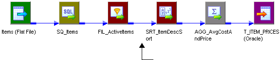
448 Chapter 15: Working with Partition Types
Hash Auto-Keys
Use hash auto-keys partitioning at or before Rank, Sorter, Joiner, and unsorted Aggregator
transformations to ensure that rows are grouped properly before they enter these
transformations.
Figure 15-2 shows a mapping with hash auto-keys partitioning. The Integration Service
distributes rows to each partition according to group before they enter the Sorter and
Aggregator transformations:
In this mapping, the Sorter transformation sorts items by item description. If items with the
same description exist in more than one source file, each partition will contain items with the
same description. Without hash auto-keys partitioning, the Aggregator transformation might
calculate average costs and prices for each item incorrectly.
To prevent errors in the cost and prices calculations, set a partition point at the Sorter
transformation and set the partition type to hash auto-keys. When you do this, the
Integration Service redistributes the data so that all items with the same description reach the
Sorter and Aggregator transformations in a single partition.
For information about partition points where you can specify hash partitioning, see
Table 15-1 on page 442.
Figure 15-2. Hash Auto-Keys Partitioning
Hash auto-keys partitioning groups data at the Sorter.

Hash User Keys 449
Hash User Keys
In hash user keys partitioning, the Integration Service uses a hash function to group rows of
data among partitions based on a user-defined partition key. You choose the ports that define
the partition key:
When you specify hash auto-keys partitioning in the mapping described by Figure 15-3, the
Sorter transformation receives rows of data grouped by the sort key, such as ITEM_DESC. If
the item description is long, and you know that each item has a unique ID number, you can
specify hash user keys partitioning at the Sorter transformation and select ITEM_ID as the
hash key. This might improve the performance of the session since the hash function usually
processes numerical data more quickly than string data.
If you select hash user keys partitioning at any partition point, you must specify a hash key.
The Integration Service uses the hash key to distribute rows to the appropriate partition
according to group.
For example, if you specify key range partitioning at a Source Qualifier transformation, the
Integration Service uses the key and ranges to create the WHERE clause when it selects data
from the source. Therefore, you can have the Integration Service pass all rows that contain
customer IDs less than 135000 to one partition and all rows that contain customer IDs
greater than or equal to 135000 to another partition. For more information, see “Key Range
Partition Type” on page 451.
If you specify hash user keys partitioning at a transformation, the Integration Service uses the
key to group data based on the ports you select as the key. For example, if you specify
ITEM_DESC as the hash key, the Integration Service distributes data so that all rows that
contain items with the same description go to the same partition.
To specify the hash key, select the partition point on the Partitions view of the Mapping tab,
and click Edit Keys. This displays the Edit Partition Key dialog box. The Available Ports list
displays the connected input and input/output ports in the transformation. To specify the
hash key, select one or more ports from this list, and then click Add.
Figure 15-3. Hash User Key Partitioning
Hash auto-keys partitioning groups data at the Sorter.
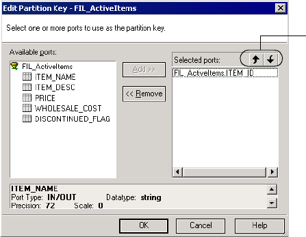
450 Chapter 15: Working with Partition Types
Figure 15-4 shows one port selected as the hash key for a Filter transformation:
To rearrange the order of the ports that define the key, select a port in the Selected Ports list
and click the up or down arrow.
Figure 15-4. Edit Partition Key Dialog Box
Rearrange selected ports.
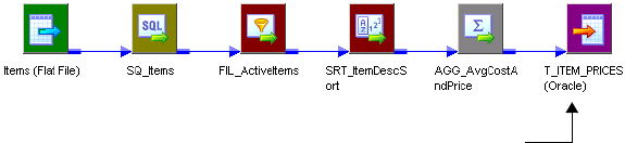
Key Range Partition Type 451
Key Range Partition Type
With key range partitioning, the Integration Service distributes rows of data based on a port
or set of ports that you define as the partition key. For each port, you define a range of values.
The Integration Service uses the key and ranges to send rows to the appropriate partition.
For example, if you specify key range partitioning at a Source Qualifier transformation, the
Integration Service uses the key and ranges to create the WHERE clause when it selects data
from the source. Therefore, you can have the Integration Service pass all rows that contain
customer IDs less than 135000 to one partition and all rows that contain customer IDs
greater than or equal to 135000 to another partition.
If you specify hash user keys partitioning at a transformation, the Integration Service uses the
key to group data based on the ports you select as the key. For example, if you specify
ITEM_DESC as the hash key, the Integration Service distributes data so that all rows that
contain items with the same description go to the same partition.
Use key range partitioning in mappings where the source and target tables are partitioned by
key range.
Figure 15-5 shows a mapping where key range partitioning can optimize writing to the target
table:
The target table in the database is partitioned by ITEM_ID as follows:
♦Partition 1: 0001–2999
♦Partition 2: 3000–5999
♦Partition 3: 6000–9999
To optimize writing to the target table, complete the following tasks:
1. Set the partition type at the target instance to key range.
2. Create three partitions.
3. Choose ITEM_ID as the partition key.
The Integration Service uses this key to pass data to the appropriate partition.
4. Set the key ranges as follows:
Figure 15-5. Mapping Where Key Range Partitioning Can Increase Performance
ITEM_ID Start Range End Range
Partition #1 3000
Key range partitioning at the target
optimizes writing to the target tables.
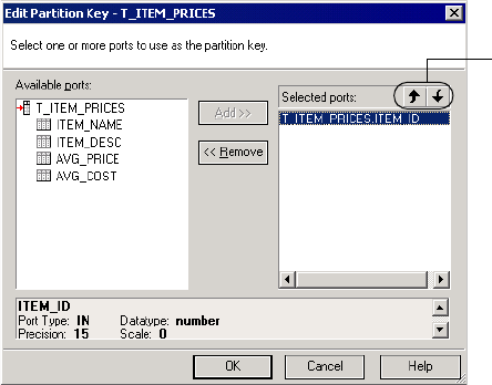
452 Chapter 15: Working with Partition Types
When you set the key range, the Integration Service sends all items with IDs less than 3000 to
the first partition. It sends all items with IDs between 3000 and 5999 to the second partition.
Items with IDs greater than or equal to 6000 go to the third partition. For more information
about key ranges, see “Adding Key Ranges” on page 453.
Adding a Partition Key
To specify the partition key for key range partitioning, select the partition point on the
Partitions view of the Mapping tab, and click Edit Keys. This displays the Edit Partition Key
dialog box. The Available Ports list displays the connected input and input/output ports in
the transformation. To specify the partition key, select one or more ports from this list, and
then click Add.
Figure 15-6 shows one port selected as the partition key for the target table
T_ITEM_PRICES:
To rearrange the order of the ports that define the partition key, select a port in the Selected
Ports list and click the up or down arrow.
In key range partitioning, the order of the ports does not affect how the Integration Service
redistributes rows among partitions, but it can affect session performance. For example, you
might configure the following compound partition key:
Partition #2 3000 6000
Partition #3 6000
Figure 15-6. Edit Partition Key Dialog Box
Selected Ports
ITEMS.DESCRIPTION
ITEMS.DISCONTINUED_FLAG
ITEM_ID Start Range End Range
Rearrange the selected ports.
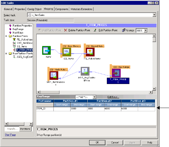
Key Range Partition Type 453
Since boolean comparisons are usually faster than string comparisons, the session may run
faster if you arrange the ports in the following order:
Adding Key Ranges
After you identify the ports that make up the partition key, you must enter the ranges for each
port on the Partitions view of the Mapping tab.
Figure 15-7 shows where you enter key ranges on the Partitions view of the Mapping tab:
You can leave the start or end range blank for a partition. When you leave the start range
blank, the Integration Service uses the minimum data value as the start range. When you leave
the end range blank, the Integration Service uses the maximum data value as the end range.
For example, you can add the following ranges for a key based on CUSTOMER_ID in a
pipeline that contains two partitions:
Selected Ports
ITEMS.DISCONTINUED_FLAG
ITEMS.DESCRIPTION
Figure 15-7. Adding Key Ranges
CUSTOMER_ID Start Range End Range
Partition #1 135000
Partition #2 135000
Specify key ranges.
454 Chapter 15: Working with Partition Types
When the Integration Service reads the Customers table, it sends all rows that contain
customer IDs less than 135000 to the first partition and all rows that contain customer IDs
equal to or greater than 135000 to the second partition. The Integration Service eliminates
rows that contain null values or values that fall outside the key ranges.
When you configure a pipeline to load data to a relational target, if a row contains null values
in any column that defines the partition key or if a row contains a value that fall outside all of
the key ranges, the Integration Service sends that row to the first partition.
When you configure a pipeline to read data from a relational source, the Integration Service
reads rows that fall within the key ranges. It does not read rows with null values in any
partition key column.
If you want to read rows with null values in the partition key, use pass-through partitioning
and create an SQL override.
Adding Filter Conditions
If you specify key range partitioning for a relational source, you can specify optional filter
conditions or override the SQL query. For more information, see “Mapping Variables in
Partitioned Pipelines” on page 432.
Rules and Guidelines for Creating Key Ranges
Consider the following guidelines when you create key ranges:
♦The partition key must contain at least one port.
♦If you choose key range partitioning at any partition point, you must specify a range for
each port in the partition key.
♦Use the standard PowerCenter date format to enter dates in key ranges.
♦The Workflow Manager does not validate overlapping string or numeric ranges.
♦The Workflow Manager does not validate gaps or missing ranges.
♦If you choose key range partitioning and need to enter a date range for any port, use the
standard PowerCenter date format. For more information about the default date format,
see “Dates” in the Transformation Language Reference.
♦When you define key range partitioning at a Source Qualifier transformation, the
Integration Service defaults to pass-through partitioning if you change the SQL statement
in the Source Qualifier transformation.
♦The Workflow Manager does not validate overlapping string ranges, overlapping numeric
ranges, gaps, or missing ranges.
♦If a row contains a null value in any column that defines the partition key, or if a row
contains values that fall outside all of the key ranges, the Integration Service sends that row
to the first partition.
Pass-Through Partition Type 455
Pass-Through Partition Type
In pass-through partitioning, the Integration Service processes data without redistributing
rows among partitions. Therefore, all rows in a single partition stay in that partition after
crossing a pass-through partition point.
When you add a partition point to a pipeline, the master thread creates an additional pipeline
stage. Use pass-through partitioning when you want to increase data throughput, but you do
not want to increase the number of partitions.
You can specify pass-through partitioning at any valid partition point in a pipeline.
Figure 15-8 shows a mapping where pass-through partitioning can increase data throughput:
By default, this mapping contains partition points at the source qualifier and target instance.
Since this mapping contains an XML target, you can configure only one partition at any
partition point.
In this case, the master thread creates one reader thread to read data from the source, one
transformation thread to process the data, and one writer thread to write data to the target.
Each pipeline stage processes the rows as follows:
Because the pipeline contains three stages, the Integration Service can process three sets of
rows concurrently.
If the Expression transformations are very complicated, processing the second
(transformation) stage can take a long time and cause low data throughput. To improve
performance, set a partition point at Expression transformation EXP_2 and set the partition
Figure 15-8. Pass-Through Partitioning
Reader Thread Transformation Thread Writer Thread
(Third Stage)(Second Stage)(First Stage)
Row Set 1
Row Set 2
Row Set 3
Row Set 4
...
Row Set n
–
Row Set 1
Row Set 2
Row Set 3
...
Row Set n-1
–
–
Row Set 1
Row Set 2
...
Row Set n-2
Source Qualifier
(First Stage)
Transformations
(Second Stage)
Target Instance
(Third Stage)
Time
456 Chapter 15: Working with Partition Types
type to pass-through. This creates an additional pipeline stage. The master thread creates an
additional transformation thread:
The Integration Service can now process four sets of rows concurrently as follows:
By adding an additional partition point at Expression transformation EXP_2, you replace one
long running transformation stage with two shorter running transformation stages. Data
throughput depends on the longest running stage. So in this case, data throughput increases.
For more information about processing threads, see “Integration Service Architecture” in the
Administrator Guide.
Reader Thread Transformation Threads Writer Thread
(Fourth Stage)(Third Stage)(Second Stage)(First Stage)
Row Set 1
Row Set 2
Row Set 3
Row Set 4
...
Row Set n
-
Row Set 1
Row Set 2
Row Set 3
...
Row Set n-1
-
-
Row Set 1
Row Set 2
...
Row Set n-2
Source
Qualifier
(First Stage)
FIL_1 & EXP_1
Transformations
(Second Stage)
EXP_2 & LKP_1
Transformations
(Third Stage)
Time -
-
-
Row Set 1
...
Row Set n-3
Target
Instance
(Fourth Stage)
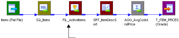
Round-Robin Partition Type 457
Round-Robin Partition Type
In round-robin partitioning, the Integration Service distributes rows of data evenly to all
partitions. Each partition processes approximately the same number of rows.
Table 15-1 on page 442 lists the partition points where you can specify round-robin
partitioning.
Use round-robin partitioning when you need to distribute rows evenly and do not need to
group data among partitions. In a pipeline that reads data from file sources of different sizes,
use round-robin partitioning to ensure that each partition receives approximately the same
number of rows.
Figure 15-9 shows a mapping where round-robin partitioning helps distribute rows before
they enter a Filter transformation:
The session based on this mapping reads item information from three flat files of different
sizes:
♦Source file 1: 80,000 rows
♦Source file 2: 5,000 rows
♦Source file 3: 15,000 rows
When the Integration Service reads the source data, the first partition begins processing 80%
of the data, the second partition processes 5% of the data, and the third partition processes
15% of the data.
To distribute the workload more evenly, set a partition point at the Filter transformation and
set the partition type to round-robin. The Integration Service distributes the data so that each
partition processes approximately one-third of the data.
Figure 15-9. Round-Robin Partitioning
Round-robin partitioning distributes data
evenly at the Filter transformation.
458 Chapter 15: Working with Partition Types

459
Chapter 16
Using Pushdown
Optimization
This chapter includes the following topics:
♦Overview, 460
♦Running Pushdown Optimization Sessions, 461
♦Working with Databases, 463
♦Working with Expressions, 466
♦Working with Transformations, 471
♦Working with Sessions, 476
♦Working with SQL Overrides, 481
♦Using the $$PushdownConfig Mapping Parameter, 485
♦Viewing Pushdown Groups, 487
♦Configuring Sessions for Pushdown Optimization, 490
♦Rules and Guidelines, 492
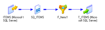
460 Chapter 16: Using Pushdown Optimization
Overview
You can push transformation logic to the source or target database using pushdown
optimization. The amount of work you can push to the database depends on the pushdown
optimization configuration, the transformation logic, and the mapping and session
configuration.
When you run a session configured for pushdown optimization, the Integration Service
analyzes the mapping and writes one or more SQL statements based on the mapping
transformation logic. The Integration Service analyzes the transformation logic, mapping,
and session configuration to determine the transformation logic it can push to the database.
At run time, the Integration Service executes any SQL statement generated against the source
or target tables, and it processes any transformation logic that it cannot push to the database.
Use the Pushdown Optimization Viewer to preview the SQL statements and mapping logic
that the Integration Service can push to the source or target database. You can also use the
Pushdown Optimization Viewer to view the messages related to Pushdown Optimization.
Figure 16-1 shows a mapping containing transformation logic that can be pushed to the
source database:
The mapping contains a Filter transformation that filters out all items except for those with
an ID greater than 1005. The Integration Service can push the transformation logic to the
database, and it generates the following SQL statement to process the transformation logic:
INSERT INTO ITEMS(ITEM_ID, ITEM_NAME, ITEM_DESC, n_PRICE) SELECT
ITEMS.ITEM_ID, ITEMS.ITEM_NAME, ITEMS.ITEM_DESC, CAST(ITEMS.PRICE AS
INTEGER) FROM ITEMS WHERE (ITEMS.ITEM_ID >1005)
The Integration Service generates an INSERT SELECT statement to obtain and insert the
ID, NAME, and DESCRIPTION columns from the source table, and it filters the data using
a WHERE clause. The Integration Service does not extract any data from the database during
this process.
Figure 16-1. Sample Mapping Used in a Pushdown Optimization Session
Running Pushdown Optimization Sessions 461
Running Pushdown Optimization Sessions
When you run a session configured for pushdown optimization, the Integration Service
analyzes the mapping and transformations to determine the transformation logic it can push
to the database. If the mapping contains a mapplet, the Integration Service expands the
mapplet and treats the transformations in the mapplet as part of the parent mapping.
You can configure pushdown optimization in the following ways:
♦Using source-side pushdown optimization. The Integration Service pushes as much
transformation logic as possible to the source database.
♦Using target-side pushdown optimization. The Integration Service pushes as much
transformation logic as possible to the target database.
♦Using full pushdown optimization. The Integration Service pushes as much
transformation logic as possible to both source and target databases. If you configure a
session for full pushdown optimization, and the Integration Service cannot push all the
transformation logic to the database, it performs partial pushdown optimization instead.
Running Source-Side Pushdown Optimization Sessions
When you run a session configured for source-side pushdown optimization, the Integration
Service analyzes the mapping from the source to the target or until it reaches a downstream
transformation it cannot push to the database.
The Integration Service generates a SELECT statement based on the transformation logic for
each transformation it can push to the database. When you run the session, the Integration
Service pushes all transformation logic that is valid to push to the database by executing the
generated SQL statement. Then, it reads the results of this SQL statement and continues to
run the session.
If you run a session that contains an SQL override or lookup override, the Integration Service
generates a view based on the override. It then generates a SELECT statement and runs the
SELECT statement against this view. When the session completes, the Integration Service
drops the view from the database.
Running Target-Side Pushdown Optimization Sessions
When you run a session configured for target-side pushdown optimization, the Integration
Service analyzes the mapping from the target to the source or until it reaches an upstream
transformation it cannot push to the database. It generates an INSERT, DELETE, or
UPDATE statement based on the transformation logic for each transformation it can push to
the database, starting with the first transformation in the pipeline it can push to the database.
The Integration Service processes the transformation logic up to the point that it can push the
transformation logic to the target database. Then, it executes the generated SQL.
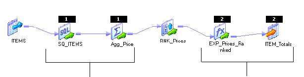
462 Chapter 16: Using Pushdown Optimization
Running Full Pushdown Optimization Sessions
To use full pushdown optimization, the source and target must be on the same database.
When you run a session configured for full pushdown optimization, the Integration Service
analyzes the mapping starting with the source and analyzes each transformation in the
pipeline until it analyzes the target. It generates SQL statements that are executed against the
source and target database based on the transformation logic it can push to the database. If
the session contains an SQL override or lookup override, the Integration Service generates a
view and runs a SELECT statement against this view.
When you run a session for full pushdown optimization, the database must run a long
transaction if the session contains a large quantity of data. Consider the following database
performance issues when you generate a long transaction:
♦A long transaction uses more database resources.
♦A long transaction locks the database for longer periods of time, and thereby reduces the
database concurrency and increases the likelihood of deadlock.
♦A long transaction can increase the likelihood that an unexpected event may occur.
Integration Service Behavior with Full Optimization
When you configure a session for full optimization, the Integration Service might determine
that it can push all of the transformation logic to the database. When it can push all
transformation logic to the database, it generates an INSERT SELECT statement that is run
on the database. The statement incorporates transformation logic from all the transformations
in the mapping.
When you configure a session for full optimization, the Integration Service might determine
that it can push only part of the transformation logic to the database. When it can push part
of the transformation logic to the database, the Integration Service pushes as much
transformation logic to the source and target databases as possible. It then processes the
remaining transformation logic. For example, a mapping contains the following
transformations:
The Rank transformation cannot be pushed to the database. If you configure the session for
full pushdown optimization, the Integration Service pushes the Source Qualifier
transformation and the Aggregator transformation to the source. It pushes the Expression
transformation and target to the target database, and it processes the Rank transformation.
The Integration Service does not fail the session if it can push only part of the transformation
logic to the database.
Transformations are pushed to the target.
Transformations are pushed to the source.
Working with Databases 463
Working with Databases
You can configure pushdown optimization for the following databases:
♦Oracle 9.x and above
♦IBM DB2
♦Te r a d a ta
♦Microsoft SQL Server
♦Sybase ASE
♦Databases that use ODBC drivers
When you use native drivers, the Integration Service generates SQL statements using native
database SQL. When you use ODBC drivers, the Integration Service generates SQL
statements using ANSI SQL. The Integration Service can generate a greater variety of
functions when it generates SQL statements using native language instead of ANSI SQL.
When the Integration Service reads data, it sometimes converts data to a format that differs
from the database format. Or, the database may use different default settings for handling null
values, case sensitivity, and sort order than the Integration Service. When these formats and
settings differ, the transformation logic processed on the database may output different data
than the same transformation logic processed by the Integration Service.
The database may produce different output than the Integration Service when the following
settings and conversions are different:
♦Nulls treated as the highest or lowest value. For example, the mapping contains a Sorter
transformation, and you want to push the transformation logic to the database. You
configure nulls as the lowest value in the sort order. However, you want to push
transformation logic to an Oracle database, which treats null values as the highest value in
the sort order. If you push the transformation to the database, null values are treated as the
highest value in the sort order.
♦Sort order. For example, you configured the sort order in the session properties as binary,
and you want to push the transformation logic for the session to the Microsoft SQL Server
database. However, Microsoft SQL Server uses a sort order that is not case sensitive. If you
push the transformation logic to a Microsoft SQL Server database, the transformation
logic is processed using case insensitive sort order.
♦Case sensitivity. For example, a Filter transformation uses the following filter condition:
IIF(col_varchar2 = ‘CA’, TRUE, FALSE). You need the database to return rows that match
‘CA’. However, if you push this transformation logic to a Microsoft SQL Server database,
it returns rows that match the values ‘Ca’, ‘ca’, ‘cA,’ and ‘CA.’
♦Numeric values converted to character values. For example, a table contains the number
1234567890. When the Integration Service converts the number to a character value, it
inserts the characters ‘1234567890’ into the column. However, a database might convert
the number into the characters ‘1.2E9’. The two sets of characters represent the same
value. However, if you require the characters in the format ‘1234567890’, you may want
to disable pushdown optimization.
464 Chapter 16: Using Pushdown Optimization
♦Date values converted to character values. For example, when the Integration Service
performs the ROUND function on a date, it stores the date value in a character column,
using the format MM/DD/YYYY HH:MI:SS. However, when the database performs this
function, it stores the date in the default date format for the database. If the database is
Oracle, it stores the date as DD-MON-YY. If you require the date to be in the format
MM/DD/YYYY HH:MI:SS, you may want to disable pushdown optimization.
♦Precision. Transformation datatypes use a default numeric precision that can vary from the
native datatypes. For example, a Decimal transformation datatype has a precision of 1-28,
while a Teradata database Decimal datatype has a precision of 1-18. If the results of an
expression rely on a precision of 28, the results may vary from an expression processed by
the Integration Service.
♦SYSDATE system variable. When you use the SYSDATE system variable in a session
processed by the Integration Service, it returns the current date and time for the node
running the service process. However, when you push the transformation logic to the
database, the SYSDATE variable returns the current date and time for the machine hosting
the database. If the machine hosting the database is not the same machine as the one
running the service process, the time may vary based on time zones.
Using ODBC Drivers
When you use ODBC drivers, the Integration Service cannot detect the database type and
must generates ANSI SQL. In some cases, ANSI SQL is not compatible with the syntax
required for a particular database. The following sections describe problems that you might
encounter when you use ODBC drivers with different types of databases.
IBM DB2
You might encounter the following problems using ODBC drivers with an IBM DB2
database:
♦A session containing a Sorter transformation fails if it is configured for both a distinct and
case-insensitive sort and the one of the sort keys is a string datatype.
♦A session containing a Lookup transformation fails for source-side or full pushdown
optimization.
♦A session that requires type casting fails if the casting is from x to date/time or from float/
double to string, or if it requires any other type casting that IBM DB2 databases disallow.
Microsoft SQL Server
You might encounter the following problems using ODBC drivers with a Microsoft SQL
Server database:
A session containing a Sorter transformation fails if it is configured for both a distinct and
case-insensitive sort.
Working with Databases 465
Sybase ASE
You might encounter the following problems using an ODBC driver with a Sybase ASE
database:
♦When you use Sybase ASE 12.5 or below, sessions that perform datatype conversions fail.
♦The session fails if you use a Joiner transformation configured for a full outer join.
Tera da ta
You might encounter the following problems using ODBC drivers with a Teradata database:
♦Teradata sessions fail if the session requires a conversion to a numeric datatype and the
precision is greater than 18.
♦Teradata sessions fail when you use full pushdown optimization for a session containing a
Sorter transformation.
♦A sort on a distinct key may give inconsistent results if the sort is not case sensitive and one
port is a character port.
♦A session containing an Aggregator transformation may produce different results from
PowerCenter if the group by port is a string datatype and it is not case-sensitive.
♦A session containing a Lookup transformation fails if it is configured for target-side
pushdown optimization.
♦A session that requires type casting fails if the casting is from x to date/time.
♦A session that contains a date to string conversion fails.

466 Chapter 16: Using Pushdown Optimization
Working with Expressions
When you use pushdown optimization, the Integration Service converts the expression in the
transformation or in the workflow link by determining equivalent operators, variables, and
functions in the database. If there is no equivalent operator, variable, or function, the
Integration Service processes the transformation logic. For example, the Integration Service
translates the aggregate function, STDDEV() to STDDEV_SAMP() on Teradata and
STDEV() on Microsoft SQL Server. However, no database supports the aggregate function,
FIRST(), so the Integration Service processes any transformation that uses the FIRST()
function.
The tables in this section summarize the availability of PowerCenter operators, variables, and
functions in databases.
Operators
Table 16-1 summarizes the availability of PowerCenter operators in databases. Columns
marked with an X indicate operations that can be performed with pushdown optimization:
Variables
Table 16-2 summarizes the availability of PowerCenter variables in databases. Columns
marked with an X indicate variables that can be used with pushdown optimization:
Table 16-1. Operators Available in Databases
Operator Oracle IBM
DB2 Teradata Sybase
ASE
Microsoft
SQL Server ODBC
+ - * / X X X X X X
% X X X X X
|| XSource Source Source Source
= > < >= <= <> X X X X X X
!= X X X X X X
^= X X X X X X
not and or X X X X X X
Table 16-2. PowerCenter Variables Available in Databases
Variable Oracle IBM
DB2 Teradata Sybase
ASE
Microsoft
SQL Server ODBC
SESSSTARTTIME X X X X X X
SYSDATE X X X X X
WORKFLOWSTARTTIME

Working with Expressions 467
Functions
Table 16-3 summarizes the availability of PowerCenter functions in databases. You cannot use
custom functions with pushdown optimization. Columns marked with an X indicate
functions that can be used with pushdown optimization:
Table 16-3. PowerCenter Functions Available in Databases
Aggregate Function Oracle IBM
DB2 Teradata Sybase
ASE
Microsoft
SQL Server ODBC
ABS() X X X X X X
ABORT()
ADD_TO_DATE()* X X Source Source
AES_DECRYPT()
AES_ENCRYPT()
ASCII() X X X X
AVG() X X X X X X
CEIL() X X Source X X
CHOOSE()
CHR() X X X X
CHRCODE()
COMPRESS()
CONCAT() XSource Source Source Source
COS() X X X X X X
COST() X X X X X X
COSH() X X X Source Source
COUNT() X X X X X X
CRC32()
CUME() X
DATE_COMPARE() Source Source Source Source Source Source
DATE_DIFF()
DECODE() X
DECODE_BASE64()
DECOMPRESS()
ENCODE_BASE64()
ERROR()
EXP() X X X X X X

468 Chapter 16: Using Pushdown Optimization
FIRST()
FLOOR() X X Source X X
FV()
GET_DATE_PART() X X X X X
GREATEST()
IIF() X X X X X X
IN() X X X X X
INDEXOF()
INITCAP() X
INSTR() XSource Source Source X
IS_DATE()
IS_NUMBER()
IS_SPACES()
ISNULL() X X X X X X
LAST()
LAST_DAY() X
LEAST()
LENGTH() X X X X X
LOWER() X X X X X X
LPAD() X
LTRIM()** X X X X X
LOG() X X Source Source Source
MAKE_DATE_TIME()
MAX() X X X X X X
MD5()
MEDIAN()
METAPHONE()
MIN() X X X X X X
MOD() X X X X X
MOVINGAVG()
Table 16-3. PowerCenter Functions Available in Databases
Aggregate Function Oracle IBM
DB2 Teradata Sybase
ASE
Microsoft
SQL Server ODBC

Working with Expressions 469
MOVINGSUM()
NPER()
PERCENTILE()
PMT()
POWER() X X X X X X
PV()
RAND()
RATE()
REG_EXTRACT()
REG_MATCH()
REVERSE()
REPLACECHR()
REPLACESTR()
RPAD() X
RTRIM()** X X X X X
ROUND(DATE) X
ROUND(NUMBER) X X Source X X
SET_DATE_PART()
SIGN() X X Source X X
SIN() X X X X X X
SINH() X X X Source Source
SOUNDEX()** X X X X
STDDEV() X X X X
SUBSTR() XSource Source Source Source
SUM() X X X X X X
SQRT() X X X X X X
TAN() X X X X X X
TANH() X X X Source Source
TO_CHAR(DATE) X X X X X
TO_CHAR(NUMBER) X X X X X
Table 16-3. PowerCenter Functions Available in Databases
Aggregate Function Oracle IBM
DB2 Teradata Sybase
ASE
Microsoft
SQL Server ODBC

470 Chapter 16: Using Pushdown Optimization
Note: When you use an expression containing STDDEV or VARIANCE functions on IBM
DB2, the results differ between a session that is pushed to the database and a session that is
run by the Integration Service. This difference occurs because DB2 uses a different algorithm
than other databases to calculate these functions.
TO_DATE() X X X X X
TO_DECIMAL() X X X X X X
TO_FLOAT() X X X X X X
TO_INTEGER() X X X Source Source
TRUNC(DATE) X
TRUNC(NUMBER) X X Source Source X
UPPER() X X X X X X
VARIANCE() X X X X
* You cannot push transformation logic to a Teradata database for a transformation that uses an expression containing ADD_TO_DATE to
change days, hours, minutes, or seconds.
** If you use LTRIM, RTRIM or SOUNDEX in transformation logic that is pushed to an Oracle, Sybase, or Teradata database, the
database treats the argument (' ') as NULL. The Integration Service treats the argument (' ') as spaces.
Table 16-3. PowerCenter Functions Available in Databases
Aggregate Function Oracle IBM
DB2 Teradata Sybase
ASE
Microsoft
SQL Server ODBC

Working with Transformations 471
Working with Transformations
The Integration Service can push transformation logic to the source, target, or both. Some
transformations cannot be pushed to the database, and additional rules apply to each
transformation that can be pushed to the database.
Table 16-4 describes the transformations the Integration Service can push to the database and
the guidelines that apply to each transformation. Columns marked with an X indicate
transformations that can be used with pushdown optimization:
Table 16-4. Summary of Mapping Objects Valid for Pushdown Optimization
Transformation Source-Side
and Full Target-Side
Aggregator X
Application Source Qualifier
Custom
Expression X X
External Procedure
Filter X
HTTP
Java
Joiner X
Lookup X X
Normalizer
Rank
Router
Sequence Generator
Sorter X
Source Qualifier X
SQL
Stored Procedure
Targ et X
Transaction Control
Union X
Update Strategy
XML Generator

472 Chapter 16: Using Pushdown Optimization
The Integration Service processes the transformation logic if any of the following conditions
are true:
♦The transformation logic updates a mapping variable and saves it to the repository
database.
♦The transformation contains a variable port.
♦You override default values for input or output ports.
Aggregator Transformation
The Integration Service can push the Aggregator transformation logic to the source database.
The Integration Service cannot push the Aggregator transformation logic to the database if
any of the following conditions are true:
♦You configure a session for incremental aggregation.
♦You use a nested aggregate function.
♦You use a conditional clause in any aggregate expression.
♦You use any one of the aggregate functions FIRST(), LAST(), MEDIAN(), or
PERCENTILE().
♦An output port is not an aggregate or a part of the group by port.
♦If the pipeline contains an upstream Aggregator transformation, the Integration Service
pushes the transformation logic for the first Aggregator transformation to the database,
and the Integration Service processes the second Aggregator transformation.
Expression Transformation
The Integration Service can push the Expression transformation logic to the source or target
database. If the Expression transformation invokes an unconnected Stored Procedure or
unconnected Lookup transformation, the Integration Service processes the transformation
logic.
For more information about expressions that are valid for pushdown optimization, see
“Working with Expressions” on page 466.
XML Parser
XML Source Qualifier
Table 16-4. Summary of Mapping Objects Valid for Pushdown Optimization
Transformation Source-Side
and Full Target-Side
Working with Transformations 473
Filter Transformation
The Integration Service can push the Filter transformation logic to the source database. The
Integration Service pushes the Filter transformation to the source database when the Filter
expression is valid for pushdown optimization.
For more information about expressions that are valid for pushdown optimization, see
“Working with Expressions” on page 466.
Joiner Transformation
The Integration Service can push the Joiner transformation logic to the source database.
The Integration Service cannot push the Joiner transformation logic to the database if any of
the following conditions are true:
♦You place an Aggregator transformation upstream from a Joiner transformation in the
pipeline.
♦The Integration Service cannot push either input pipeline to the database.
♦The Joiner is configured for an outer join, and the master or detail source is a multi-table
join. SQL cannot be generated to represent an outer join combined with a multi-table join
that joins greater than two tables.
♦The Joiner is configured for a full outer join and you attempt to push transformation logic
to a Sybase database.
Lookup Transformation
The Integration Service can push Lookup transformation logic to the source or target
database. When you configure a Lookup transformation for pushdown optimization, the
database performs a lookup on the database lookup table.
Use the following guidelines when you work with Lookup transformations:
♦When you use an unconnected Lookup transformation, the Integration Service processes
both the unconnected Lookup and the transformation containing the :LKP expression.
♦The lookup table and source table must be on the same database for source-side or target-
side pushdown optimization.
♦When you push Lookup transformation logic to the database, the database does not use
PowerCenter caches.
♦The Integration Service cannot push the Lookup transformation logic to the database if
any of the following conditions are true:
−You use a dynamic cache.
−You configure the Lookup transformation to handle multiple matches by returning the
first or last matching row. To use pushdown optimization, you must configure the
Lookup transformation to report an error on multiple matches.
−You created a mapping that contains a Lookup transformation downstream from an
Aggregator transformation.
474 Chapter 16: Using Pushdown Optimization
♦If a Lookup transformation exists in two branches of a pipeline that are joined by a Joiner
or Union transformation, the Integration Service processes only one branch of the
pipeline.
♦A session configured for target-side pushdown optimization fails when the session requires
datatype conversion.
♦The Integration Service cannot push transformation logic to the target database for a
Lookup transformation if you use an ODBC connection or the database is Sybase or
Microsoft SQL Server.
♦Use the following rules and guidelines if you override the lookup query in a Lookup
transformation:
−You must configure the session for pushdown optimization with a view. The Integration
Service creates a view, runs an SQL query against the view, and then drops the view.
−You might need to manually remove the views that the Integration Service creates. For
more information about removing views, see “Troubleshooting Orphaned Views” on
page 482.
−To use a lookup override, you must have the necessary database privileges to create a
view.
−You cannot append a custom ORDER BY clause to the SQL statement in the lookup
override.
−The order of the columns in the lookup override must match the order of the ports in
the Lookup transformation. For example, a Lookup transformation has lookup ports in
the following order:
STATECODE
STATEDESC
The SELECT statement in the lookup query override must include the columns
STATECODE and STATEDESC in that order. If you reverse the order of the columns
in the lookup override, the query results transpose the values.
For more information about lookup overrides, see “Lookup Transformation” in the
Transformation Guide.
Sorter Transformation
The Integration Service can push the Sorter transformation logic to the source database.
Use the following guidelines when you work with Sorter transformations:
♦When you use a Sorter transformation configured for a distinct sort, the Integration
Service pushes the Sorter transformation to the database and processes downstream
transformations.
♦When a Sorter transformation is downstream from a Union transformation, the sort key
on the Union transformation must be a connected port.
Working with Transformations 475
Source Qualifier Transformation
The Integration Service can push Source Qualifier transformation logic to the source.
The Integration Service processes the transformation logic if the source is configured for
database partitioning or an Oracle source uses an XMLType datatype.
If the Source Qualifier transformation contains an SQL override, you must configure the
session for pushdown optimization with a view. For more information, see “Working with
SQL Overrides” on page 481.
Ta r g e t
The Integration Service can push the target transformation logic to the target database.
The Integration Service processes the transformation logic when you configure the session for
full pushdown optimization and any of the following conditions are true:
♦The target includes a user-defined SQL update override.
♦The target uses a different connection than the source.
♦A source row is treated as update.
♦You configured a session for constraint-based loading and there are greater than or equal to
two targets in the target load order group.
♦You configure the session to use an external loader.
The Integration Service processes the transformation logic when you configure the session for
target-side pushdown optimization and any of the following conditions are true:
♦The target includes a user-defined SQL update override.
♦The session is configured with a database partitioning partition type.
♦You configured the target for bulk loading.
♦You configure the session to use an external loader.
Union Transformation
The Integration Service can push the Union transformation logic to the source database.
Use the following guidelines when you work with Union transformations:
♦The Integration Service must be able to push all the input groups to the source database to
push the Union transformation logic to the database.
♦Input groups must originate from the same source for the Integration Service to push the
Union transformation logic to the database.
♦The Integration Service can push a Union transformation with a distinct key if the port is
connected.
476 Chapter 16: Using Pushdown Optimization
Working with Sessions
The Integration Service can push transformation logic to the source or target database when it
does not conflict with the following session configurations:
♦Partitioning. When you configure pushdown optimization, the Integration Service merges
all the rows into the first partition and passes empty data for each subsequent partition.
The Integration Service cannot merge partitions for all partition types. For more
information, see “Working with Partitions” on page 476.
♦Target load rules. Some target load rules affect pushdown optimization. You cannot use
full pushdown optimization when you configure some target load rules. For more
information, see “Working with Target Load Rules” on page 478.
♦Error handling, logging, and recovery. When the Integration Service pushes
transformation logic to the database, it handles errors differently from when it runs a full
session. For more information, see “Error Handling, Logging, and Recovery” on page 479.
The Integration Service processes the transformation logic for the session if any of the
following conditions are true:
♦You run a data profiling or debugging session.
♦You use an external loader and configure the session for target-side pushdown
optimization. The Integration Service can push transformation logic to the source database
if you use an external loader.
♦You enable row error logging.
Working with Partitions
When a session configured for pushdown optimization contains multiple partitions, the
Integration Service can push the session to the database in the following situations:
♦If a transformation uses pass-through partitioning, the Integration Service can push
transformation logic to the source or target database, or both.
♦If a transformation uses a key range partition in the Source Qualifier transformation and
hash auto-keys partitioning in downstream partition points, the Integration Service can
push transformation logic to the source database by merging all rows into the first
partition. To merge all rows into the first partition, the end key range for each partition
must equal the start range for the next partition, and it cannot overlap with the next
partition.
For example, if the end range for the first partition is 3386, then the start range for the
second partition must be 3386. When the Integration Service pushes transformation logic
to the database for hash auto-keys partitioning, it creates an SQL statement for each
partition. If the Integration Service pushes only part of the transformation logic to the
database, it does not redistribute the rows across partitions when it runs the session.
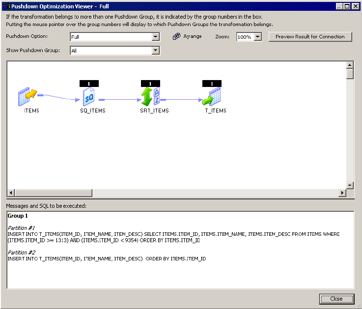
Working with Sessions 477
Figure 16-2 shows a mapping that contains a Sorter transformation with hash auto-keys
partitioning:
The first key range is 1313 - 3340, and the second key range is 3340 - 9354. The SQL
statement merges all the data into the first partition:
INSERT INTO ITEMS(ITEM_ID, ITEM_NAME, ITEM_DESC) SELECT ITEMS
ITEMS.ITEM_ID, ITEMS.ITEM_NAME, ITEMS.ITEM_DESC FROM ITEMS WHERE
(ITEMS.ITEM_ID>=1313)AND ITEMS.ITEM_ID<9354) ORDER BY ITEMS.ITEM_ID
The SQL statement selects items 1313 through 9354, which includes all values in the key
range and merges the data from both partitions into the first partition.
The SQL statement for the second partition passes empty data:
INSERT INTO ITEMS(ITEM_ID, ITEM_NAME, ITEM_DESC) ORDER BY ITEMS.ITEM_ID
Figure 16-2. Sample Mapping with Two Partitions
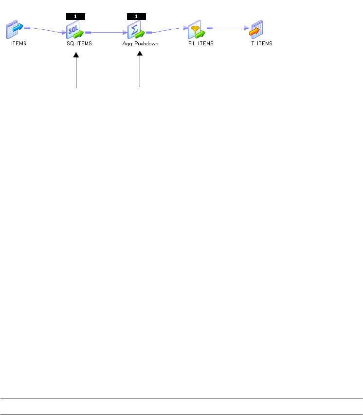
478 Chapter 16: Using Pushdown Optimization
Merging Partitions
When the Integration Service merges all rows into one partition, it does not redistribute the
rows across partitions if the Integration Service can only push part of the transformation logic
for the session to the database.
Figure 16-3 shows a mapping that contains an Aggregator transformation and a Filter
transformation displayed in the Pushdown Optimization Viewer:
The Source Qualifier is key-range partitioned, and the Aggregator transformation uses hash
auto-keys partitioning. Therefore, the transformation logic for the Source Qualifier and the
Aggregator can be pushed to the database by merging the rows into one partition. The Source
Qualifier uses key ranges 1313 - 3340 in the first partition, and key ranges 3340 - 9354 in the
second partition. To push the transformation logic to the database, the rows are merged into
one partition that includes the ranges 1313 - 9354, and it passes empty data in the second
partition.
However, the Filter transformation cannot be pushed to the database because it does not use
hash auto-keys partitioning. When the Integration Service processes the transformation logic
for the Filter transformation, it does not redistribute the rows among the partitions. It
continues to pass rows 1313 - 9354 in the first partition and to pass empty data in the second
partition.
Working with Target Load Rules
When you configure a session for pushdown optimization, the Integration Service can push
transformation logic to the database depending on how you configure PowerCenter to load
target rows to the database.
Table 16-5 shows how pushdown optimization works with different target loading options.
Columns marked with an X indicate target options that can be used with pushdown
optimization:
Figure 16-3. Sample Mapping with Multiple Partitions
Table 16-5. Pushdown Optimization with Target Options
Target Option Source-Side Optimization Target-Side Optimization Full Optimization
Insert X X X*
Delete X X X**
Key-range partitioned Hash auto-keys partitioned

Working with Sessions 479
Error Handling, Logging, and Recovery
When you work with sessions configured for pushdown optimization, the database behaves
differently than the Integration Service in the following situations:
♦Error handling
♦Logging
♦Recovery
Error Handling
When the Integration Service pushes transformation logic to the database, it cannot track
errors that occur in the database. As a result, it handles errors differently from when it runs
the full session. When the Integration Service runs a session configured for full pushdown
optimization and an error occurs, the database handles the errors. When the database handles
errors, the Integration Service does not write reject rows to the reject file, and it treats the
error threshold as though it were set to 1.
Logging
When the Integration Service pushes transformation logic to the database, it cannot trace all
the events that occur inside the database server. The statistics the Integration Service can trace
depend on the type of pushdown optimization. When you push transformation logic to the
database, the Integration Service performs the following logging functionality:
♦The session log does not contain details for transformations processed on the database.
♦The Integration Service does not write the thread busy percentage to the log for a session
configured for full pushdown optimization.
♦The Integration Service writes the number of loaded rows to the log for source-side, target-
side, and full pushdown optimization.
♦When the Integration Service pushes all transformation logic to the database, the
Integration Service does not write the number of rows read from the source to the log.
♦When the Integration Service pushes transformation logic to the source, the Integration
Service writes the number of rows read for each source to the log. However, the number
may differ from statistics for the same session run by the Integration Service.
Update as update X X
Update as insert X X X*
Update else insert X X
*If you treat source rows as data-driven, the Integration Service cannot perform full pushdown optimization. It can push transformation
logic upstream or downstream from the Update Strategy or Custom transformation.
**Although you can use full pushdown optimization when you treat source rows as delete, you might not achieve performance gains. If
not, use partial pushdown optimization. Also, you cannot use full pushdown optimization and treat source rows as delete if the session
includes a Union transformation and the Integration Service pushes transformation logic to a Sybase database.
Table 16-5. Pushdown Optimization with Target Options
Target Option Source-Side Optimization Target-Side Optimization Full Optimization
480 Chapter 16: Using Pushdown Optimization
Recovery
When you configure a session for full pushdown optimization, the Integration Service runs
the session on the database. As a result, it cannot perform incremental recovery if the session
fails. Instead the database rolls back transactions. If the database server fails, it rolls back
transactions when it restarts. If the Integration Service fails, the database server rolls back the
transaction.
When you perform recovery for sessions that contain SQL overrides or lookup overrides, the
Integration Service must drop and recreate views. For more information, see “Views” on
page 481.
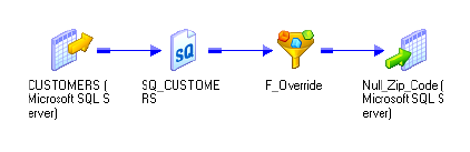
Working with SQL Overrides 481
Working with SQL Overrides
You can configure the Integration Service to perform an SQL override with pushdown
optimization. To perform an SQL override, you configure the session to create a view. When
you use an SQL override for a Source Qualifier transformation in a session configured for
source or full pushdown optimization with a view, the Integration Service creates a view in the
source database based on the override. After it creates the view in the database, the Integration
Service generates an SQL query that it can push to the database. The Integration Service runs
the SQL query against the view to perform pushdown optimization.
Note: To use an SQL override with pushdown optimization, you must configure the session
for pushdown optimization with a view. For more information about configuring the session,
see “Configuring Sessions for Pushdown Optimization” on page 490.
Views
When the Integration Service pushes transformation logic to the source database for full or
source-side pushdown optimization, it checks for an SQL override in the Source Qualifier
transformation logic. If you configure the session for pushdown optimization with views, the
Integration Service completes the following tasks:
1. Creates a view. The Integration Service generates the view by incorporating the SQL
override query in a view definition. The Integration Service does not parse or validate the
SQL override, so you may want to test the SQL override before you run the session.
2. Runs an SQL query against the view. After the Integration Service generates a view, the
Integration Service runs an SQL query to push the transformation logic to the source. It
runs this query against the view created in the database.
3. Drops the view. When the transaction completes, the Integration Service drops the view
it created to run the SQL override query.
For example, you have a mapping that searches for 94117 zip codes in a customer database:
You want the search to return customers whose names match variations of the name Johnson,
including names such as Johnsen, Jonssen, and Jonson. To perform the name matching, you
enter the following SQL override:
SELECT CUSTOMERS.CUSTOMER_ID, CUSTOMERS.COMPANY, CUSTOMERS.FIRST_NAME,
CUSTOMERS.LAST_NAME, CUSTOMERS.ADDRESS1, CUSTOMERS.ADDRESS2,
CUSTOMERS.CITY, CUSTOMERS.STATE, CUSTOMERS.POSTAL_CODE, CUSTOMERS.PHONE,
CUSTOMERS.EMAIL FROM CUSTOMERS WHERE CUSTOMERS.LAST_NAME LIKE 'John%' OR
CUSTOMERS.LAST_NAME LIKE 'Jon%'
482 Chapter 16: Using Pushdown Optimization
When the Integration Service pushes transformation logic for this session to the database, it
runs the following SQL statement to create a view in the source database:
CREATE VIEW PM_V4RZRW5GWCKUEWH35RKDMDPRNXI (CUSTOMER_ID, COMPANY,
FIRST_NAME, LAST_NAME, ADDRESS1, ADDRESS2, CITY, STATE, POSTAL_CODE,
PHONE, EMAIL) AS SELECT CUSTOMERS.CUSTOMER_ID, CUSTOMERS.COMPANY,
CUSTOMERS.FIRST_NAME, CUSTOMERS.LAST_NAME, CUSTOMERS.ADDRESS1,
CUSTOMERS.ADDRESS2, CUSTOMERS.CITY, CUSTOMERS.STATE,
CUSTOMERS.POSTAL_CODE, CUSTOMERS.PHONE, CUSTOMERS.EMAIL FROM CUSTOMERS
WHERE CUSTOMERS.LAST_NAME LIKE 'John%' OR CUSTOMERS.LAST_NAME LIKE 'Jon%'
To create a unique view name, the Integration Service appends PM_V to a value generated by
a hash function. This ensures that a unique view is created for each session run.
After the view is created, the Integration Service runs an SQL query to perform the
transformation logic in the mapping:
SELECT PM_V4RZRW5GWCKUEWH35RKDMDPRNXI.CUSTOMER_ID,
PM_V4RZRW5GWCKUEWH35RKDMDPRNXI.COMPANY,
PM_V4RZRW5GWCKUEWH35RKDMDPRNXI.FIRST_NAME,
PM_V4RZRW5GWCKUEWH35RKDMDPRNXI.LAST_NAME,
PM_V4RZRW5GWCKUEWH35RKDMDPRNXI.ADDRESS1,
PM_V4RZRW5GWCKUEWH35RKDMDPRNXI.ADDRESS2,
PM_V4RZRW5GWCKUEWH35RKDMDPRNXI.CITY,
PM_V4RZRW5GWCKUEWH35RKDMDPRNXI.STATE,
PM_V4RZRW5GWCKUEWH35RKDMDPRNXI.POSTAL_CODE,
PM_V4RZRW5GWCKUEWH35RKDMDPRNXI.PHONE,
PM_V4RZRW5GWCKUEWH35RKDMDPRNXI.EMAIL FROM PM_V4RZRW5GWCKUEWH35RKDMDPRNXI
WHERE (PM_V4RZRW5GWCKUEWH35RKDMDPRNXI.POSTAL_CODE = 94117)
After the session completes, the Integration Service drops the view.
Note: If the Integration Service performs recovery, it drops the view and recreates the view
before performing recovery tasks.
Troubleshooting Orphaned Views
The Integration Service might be unable to drop a view if the Integration Service, session, or
connectivity fails. The orphaned view does not affect performance. Complete the following
steps to remove extra views from the database:
1. View the session log. When you run a session, the Integration Service writes an event log
when it creates the view, and it also writes an event log when it drops the view. If an
Integration Service, session, or connection fails when you are running a session, you can
check the session log to see if Integration Service dropped the view.
2. Run a query. If you determine that the Integration Service did not drop views, you can
run a query to locate all views created by the Integration Service. Views created by the
Integration Service use the same prefix.
3. Drop the view. After you locate the views created by the Integration Service, run an SQL
statement to manually drop the views from the database.
Working with SQL Overrides 483
Viewing the Session Log
When a session, Integration Service, or connection fails, you can use the session log to
determine if the view was dropped. If the Integration Service is able to drop the view, the
session log displays text similar to the following message:
MAPPING> TM_6356 Starting pushdown cleanup SQL for source [CUSTOMERS]. : (Tue
Feb 14 13:23:46 2006)
MAPPING> TM_6358 Executing pushdown cleanup SQL for source: DROP VIEW
PM_V4RZRW5GWCKUEWH35RKDMDPRNXI
MAPPING> TM_6360 Completed pushdown cleanup SQL for source [CUSTOMERS]
successfully. : (Tue Feb 14 13:23:46 2006)
If this message does not display, you may want to perform a query against the source database.
Running a Query
If the Integration Service did not successfully drop the view, you can run a query against the
source database to search for the views generated by the Integration Service. When the
Integration Service creates a view, it uses a prefix of PM_V. You can search for views with this
prefix to locate the views created during pushdown optimization. The following sample
queries show the syntax for searching for views created by the Integration Service:
IBM DB2:
SELECT VIEWNAME FROM SYSCAT.VIEWS
WHERE VIEWSCHEMA = CURRENT SCHEMA
AND VIEW_NAME LIKE ‘PM\_V%’ ESCAPE ‘\’
Oracle:
SELECT VIEW_NAME FROM USER_VIEWS
WHERE VIEW_NAME LIKE ‘PM\_V%’ ESCAPE ‘\’
Sybase ASE and Microsoft SQL Server:
SELECT NAME FROM SYSOBJECTS
WHERE TYPE=’V’ AND NAME LIKE ‘PM\_V%’ ESCAPE ‘\’
Te r a d at a :
SELECT TableName FROM DBC.Tables
WHERE CreatorName = USER
AND TableKind ='V'
AND TableName LIKE 'PM\_V%' ESCAPE '\'
484 Chapter 16: Using Pushdown Optimization
Rules and Guidelines
Use the following rules and guidelines when you configure pushdown optimization for a
session containing an SQL override:
♦Do not use an order by clause in the SQL override.
♦When you create a custom SQL query, the SELECT statement must list the port names in
the order in which they appear in the transformation.
♦Use ANSI outer join syntax in the SQL override.
♦Do not use a Sequence Generator transformation.
♦If a Source Qualifier transformation is configured for a distinct sort and contains an SQL
override, the Integration Service ignores the distinct sort configuration.
♦If the Source Qualifier contains multiple partitions, specify the SQL override for all
partitions.
♦If a Source Qualifier transformation contains Informatica outer join syntax in the SQL
override, the Integration Service processes the Source Qualifier transformation logic.
♦PowerCenter does not validate the override SQL syntax, so test the SQL override query
before you push it to the database.
♦When you create an SQL override, ensure that the SQL syntax is compatible with the
source database.

Using the $$PushdownConfig Mapping Parameter 485
Using the $$PushdownConfig Mapping Parameter
Depending on the database workload, you may want to use source-side, target-side, or full
pushdown optimization at different times. For example, you might want to use partial
pushdown optimization during the peak hours of the day, but use full pushdown optimization
from midnight until 2 a.m. when activity is low.
To use different pushdown optimization configurations at different times, use the
$$PushdownConfig mapping parameter. The parameter lets you run the same session using
the different types of pushdown optimization.
Complete the following steps to configure the mapping parameter:
1. Create $$PushdownConfig in the Mapping Designer.
2. When you add the $$PushdownConfig mapping parameter in the Mapping Designer, use
the following values:
3. When you configure the session, choose $$PushdownConfig for the Pushdown
Optimization attribute.
4. Define the parameter in the parameter file.
5. Enter one of the following values for $$PushdownConfig in the parameter file:
♦None. The Integration Service processes all transformation logic for the session.
♦Source. The Integration Service pushes part of the transformation logic to the source
database.
♦Source with View. The Integration Service creates a view to represent the SQL
override value, and it runs an SQL statement against this view to push part of the
transformation logic to the source database.
♦Ta r g e t . The Integration Service pushes part of the transformation logic to the target
database.
♦Full. The Integration Service pushes all transformation logic to the database.
♦Full with View. The Integration Service creates a view to represent the SQL override
value, and it runs an SQL statement against this view to push part of the
Field Value
Name $$PushdownConfig
Type Parameter
Datatype String
Precision or Scale 10
Aggregation n/a
Initial Value None
Description Optional
486 Chapter 16: Using Pushdown Optimization
transformation logic to the source database. The Integration Service pushes any
remaining transformation logic to the target database.
For more information about configuring a session for pushdown optimization, see
“Configuring Sessions for Pushdown Optimization” on page 490.
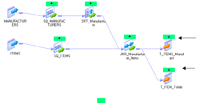
Viewing Pushdown Groups 487
Viewing Pushdown Groups
When you configure a session for pushdown optimization, the Integration Service generates
SQL statements based on the transformation logic. The group of transformations that can be
processed as one SQL statement is called a pushdown group.
When you push transformation logic to the database, the Integration Service may create
multiple pushdown groups depending on the number of pipelines, sources, targets, and the
type of pushdown optimization you use. If the session has multiple partitions, the Integration
Service executes an SQL statement for each partition in the group. If you join pipelines,
transformations in each pipeline merge into one pushdown group. If the same transformation
is part of the transformation logic pushed to two or more targets, the transformation is part of
the pushdown group for each target.
You can view pushdown groups using the Pushdown Optimization Viewer. When you view
pushdown groups in the Pushdown Optimization Viewer, you can identify the
transformations that can be pushed to the database and those that the Integration Service
processes. You can use the messages to determine how to edit transformations or mappings to
push more transformation logic to the database. The Pushdown Optimization Viewer cannot
display the SQL that runs in the session if you use variables or if you configure the session to
run on a grid.
Note: When you view the pushdown groups for a session containing an SQL override, the
name of the generated view differs from the view generated during a session. The Integration
Service uses a hash function to create a unique name each time a view is generated.
Figure 16-4 shows a mapping displayed in the Pushdown Optimization Viewer. It contains
two pushdown groups that can be pushed to the source and target database:
Pipeline 1 and Pipeline 2 originate from different sources and contain transformations that
are valid for pushdown optimization. The Integration Service creates a pushdown group for
each target, and generates an SQL statement for each pushdown group. Because the two
Figure 16-4. Sample Mapping with Two Pushdown Groups
Pushdown
Group 1
Pushdown
Group 2
*Transformation is part of both pushdown groups
Pipeline 1
Pipeline 2
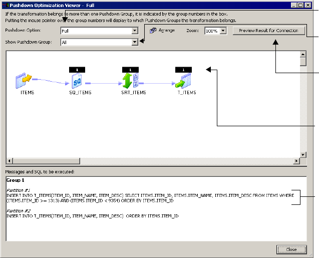
488 Chapter 16: Using Pushdown Optimization
pipelines are joined, the transformations up to and including the Joiner transformation are
part of both pipelines and are included in both pushdown groups.
To view pushdown groups, open the Pushdown Optimization Viewer. The Pushdown
Optimization Viewer previews the pushdown groups and SQL statements that the Integration
Service generates at run time.
To view pushdown groups:
1. In the Workflow Manager, open a session configured for pushdown optimization.
2. On the Mapping tab, select View Pushdown Optimization.
The Pushdown Group Viewer displays the pushdown groups and the transformations
that comprise each group. It displays the SQL statement for each partition if you
configure multiple partitions in the pipeline. You can view messages and SQL statements
generated for each pushdown group and pushdown option. Pushdown options include
none, to source, to source with view, to target, full, full with view, and
$$PushdownConfig.
Figure 16-5 shows a mapping containing one pipeline with two partitions that can be
pushed to the source database:
Figure 16-5. Pushdown Optimization Viewer
Select pushdown
groups to view.
Number
indicates the
pushdown
group.
SQL statements
are generated
for the
pushdown
group.
Select a value
for the
connection
variable.
Select the type
of optimization.
Viewing Pushdown Groups 489
Note: Select a pushdown option in the Pushdown Optimization Viewer to preview the
SQL statements. The pushdown option in the viewer does not affect the optimization
that occurs at run time. To change pushdown optimization for a session, edit the session
properties.
3. If you configure the session to use a connection variable, click Map Connection Variables
to select a connection value to preview.
If the session uses a connection variable, you must choose a connection value each time
you open the Pushdown Optimization Viewer. The Workflow Manager does not save the
value you select, and the Integration Service does not use this value at run time.
If an SQL override contains the $$$SessStartTime variable, the Pushdown Optimization
Viewer does not expand this variable when you preview pushdown optimization. It only
expands this variable at run time.
490 Chapter 16: Using Pushdown Optimization
Configuring Sessions for Pushdown Optimization
You configure a session for pushdown optimization in the session properties. However, you
may need to edit the transformation, mapping, or session configuration to push more
transformation logic to the database. Use the Pushdown Optimization Viewer to examine the
transformations that can be pushed to the database.
To configure a session for pushdown optimization:
1. In the Workflow Manager, open the session properties for the session containing
transformation logic you want to push to the database.
2. From the Properties tab, select one of the following Pushdown Optimization options:
♦None
♦To So u r ce
♦To Source with View
♦To Ta rg e t
♦Full
Select to configure pushdown optimization.
Configuring Sessions for Pushdown Optimization 491
♦Full with View
♦$$PushdownConfig
If you use $$PushdownConfig, ensure that you configured a mapping parameter and
defined a value for the parameter in the parameter file. For more information about
configuring the mapping parameter and parameter file, see “Using the
$$PushdownConfig Mapping Parameter” on page 485.
3. Open the Mapping tab in the session properties.
4. Click View Pushdown Optimization.
The Pushdown Optimizer displays the pushdown groups and the SQL that is generated
to perform the transformation logic. It displays messages related to each pushdown
group. The Pushdown Optimizer Viewer also displays numbered flags to indicate the
transformations in each pushdown group.
5. Review the information in the Pushdown Optimizer Viewer to determine if you need to
edit the mapping, transformation, or session configuration to push more transformation
logic to the database.
You can select a pushdown option to view the corresponding SQL statement. When you
select a pushdown option in the Pushdown Optimization Viewer, you do not change the
pushdown configuration. To change the configuration, you must update the pushdown
option in the session properties.
492 Chapter 16: Using Pushdown Optimization
Rules and Guidelines
This section includes some general rules and guidelines for working with pushdown
optimization. For more information about specific rules and guidelines, refer to the following
sections:
♦Databases. For more information about databases, see “Working with Databases” on
page 463.
♦Expressions. For more information about expressions, see “Working with Expressions” on
page 466.
♦Transformations. For more information about transformations, see “Working with
Transformations” on page 471.
♦Sessions. For more information about sessions, see “Working with Sessions” on page 476.
When you work with pushdown optimization, use the following rules and guidelines to
determine the transformation logic you can push to the source or target database.
♦The Integration Service processes the transformation logic if any of the following
conditions are true:
−You use a mapping variable.
−The transformation contains a variable port.
−You override default values for transformation input or output ports.
−An expression uses a function that has no equivalent function in the database.
−You run a data profiling or debugging session.
−You use an external loader and configure the session for target-side pushdown
optimization. The Integration Service can push transformation logic to the source
database if you use an external loader.
−You enable row error logging.
−You configure the Joiner transformation for a full outer Joiner and you attempt to push
the transformation logic to a Sybase database.
♦When you branch a pipeline, the SQL statement required to represent the mapping logic
becomes more complex. The Integration Service cannot generate SQL for mappings that
contain more than 64 two-way branches, 43 three-way branches, or 32 four-way branches.
If the mapping branches exceed these limitations, the Integration Service processes the
downstream transformations.
♦When a session configured for pushdown optimization contains multiple partitions, the
Integration Service can push transformation logic to the database in the following
situations:
−If a transformation uses pass-through partitioning, the Integration Service can push
transformation logic to the source or target database, or both.
−If a transformation uses a key range partition in the Source Qualifier transformation and
hash auto-keys partitioning in downstream partition points, the Integration Service can
Rules and Guidelines 493
push transformation logic to the source database by merging all rows into the first
partition.
♦When the Integration Service processes data, it sometimes converts data to different
formats from the formats the database uses. Or, the database may use different default
settings for handling null values, case sensitivity, and sort order than the Integration
Service. When these formats and settings differ, the transformation logic processed on the
database may output different data than the same logic processed by the Integration
Service. The following settings may differ between the PowerCenter Integration Service
and the database:
−Case sensitivity
−Sort order
−Nulls treated as the highest or lowest value
−Numeric values converted to character values
−Date values converted to character values
−Precision
For more information about working with databases, see “Working with Databases” on
page 463.
♦When you use ODBC drivers to connect to databases, the Integration Service cannot
determine the type of database you are connecting to, and it cannot generate SQL
statements using the syntax for the database. In some cases, sessions may fail because the
ANSI SQL syntax used with ODBC drivers is incompatible with database syntax. For
more information, see “Using ODBC Drivers” on page 464.
♦Sessions may fail when you configure a session for target-side pushdown optimization and
and the session requires datatype conversion.
♦If a Source Qualifier transformation contains Informatica outer join syntax in the SQL
override or user-defined join, the Integration Service processes the Source Qualifier
transformation logic.
♦When you use an expression containing STDDEV or VARIANCE functions on IBM
DB2, the results differ between a session that is pushed to the database and a session that is
run by the Integration Service. This difference occurs because DB2 uses a different
algorithm than other databases to calculate these functions.
494 Chapter 16: Using Pushdown Optimization

495
Chapter 17
Monitoring Workflows
This chapter includes the following topics:
♦Overview, 496
♦Using the Workflow Monitor, 499
♦Customizing Workflow Monitor Options, 505
♦Using Workflow Monitor Toolbars, 511
♦Working with Tasks and Workflows, 512
♦Workflow and Task Status, 516
♦Using the Gantt Chart View, 518
♦Using the Task View, 525
♦Viewing Service Details, 529
♦Viewing Workflow, Worklet, and Task Details, 534
♦Viewing Session Task Details, 539
♦Viewing Performance Details, 544
♦Tips, 549
496 Chapter 17: Monitoring Workflows
Overview
You can monitor workflows and tasks in the Workflow Monitor. View details about a
workflow or task in Gantt Chart view or Task view. You can run, stop, abort, and resume
workflows from the Workflow Monitor.
The Workflow Monitor displays workflows that have run at least once. The Workflow
Monitor continuously receives information from the Integration Service and Repository
Service. It also fetches information from the repository to display historic information.
The Workflow Monitor consists of the following windows:
♦Navigator window. Displays monitored repositories, Integration Services, and repository
objects.
♦Output window. Displays messages from the Integration Service and the Repository
Service.
♦Properties window. Displays details about services, workflows, worklets, and tasks.
♦Time window. Displays progress of workflow runs.
♦Gantt Chart view. Displays details about workflow runs in chronological (Gantt Chart)
format.
♦Task view. Displays details about workflow runs in a report format, organized by
workflow run.
The Workflow Monitor displays time relative to the time configured on the Integration
Service machine. For example, a folder contains two workflows. One workflow runs on an
Integration Service in the local time zone, and the other runs on an Integration Service in a
time zone two hours later. If you start both workflows at 9 a.m. local time, the Workflow
Monitor displays the start time as 9 a.m. for one workflow and as 11 a.m. for the other
workflow.
Overview 497
Figure 17-1 shows the Workflow Monitor in Gantt Chart view:
Toggle between Gantt Chart view and Task view by clicking the tabs on the bottom of the
Workflow Monitor.
You can view and hide the Output and Properties windows in the Workflow Monitor. To
view or hide the Output window, click View > Output. To view or hide the Properties
window, click View > Properties View.
You can also dock the Output and Properties windows at the bottom of the Workflow
Monitor workspace. To dock the Output or Properties window, right-click a window and
choose Allow Docking. If the window is floating, drag the window to the bottom of the
workspace. If you do not allow docking, the windows float in the Workflow Monitor
workspace.
Figure 17-1. Workflow Monitor
Time Window
Output Window
Gantt
Chart
View
Task View
Navigator
Window
Properties Window
498 Chapter 17: Monitoring Workflows
Permissions and Privileges
To use the Workflow Monitor, you must have one of the following sets of permissions and
privileges:
♦Use Workflow Manager privilege with the execute permission on the folder
♦Workflow Operator privilege with the read permission on the folder
♦Super User privilege
To monitor a workflow that runs on Integration Service in safe mode, you must have one of
the following privileges:
♦Admin Integration Service privilege
♦Super User privilege
You must also have execute permission for connection objects to restart, resume, stop, or
abort a workflow containing a session.
For more information about permissions and privileges necessary to use the Workflow
Monitor, see “Permissions and Privileges by Task” in the Repository Guide.
Using the Workflow Monitor 499
Using the Workflow Monitor
The Workflow Monitor provides options to view information about workflow runs. After you
open the Workflow Monitor and connect to a repository, you can view dynamic information
about workflow runs by connecting to an Integration Service.
You can customize the Workflow Monitor display by configuring the maximum days or
workflow runs the Workflow Monitor shows. You can also filter tasks and Integration
Services in both Gantt Chart and Task view.
Complete the following steps to monitor workflows:
1. Open the Workflow Monitor.
2. Connect to the repository containing the workflow.
3. Connect to the Integration Service.
4. Select the workflow you want to monitor.
5. Select Gantt Chart view or Task view.
Opening the Workflow Monitor
You can open the Workflow Monitor in the following ways:
♦From the Windows Start menu
♦From the Workflow Manager Navigator
♦Configure the Workflow Manager to open the Workflow Monitor when you run a
workflow from the Workflow Manager.
♦Click Tools > Workflow Monitor from the Designer, Workflow Manager, or Repository
Manager. Or, click the Workflow Monitor icon on the Tools toolbar. When you use a
Tools button to open the Workflow Monitor, PowerCenter uses the same repository
connection to connect to the repository and opens the same folders.
You can open multiple instances of the Workflow Monitor on one machine using the
Windows Start menu.
To open the Workflow Monitor when you start a workflow:
1. In the Workflow Manager, click Tools > Options.
2. In the General tab, select Launch Workflow Monitor When Workflow Is Started.
To open the Workflow Monitor from the Workflow Manager:
1. In the Workflow Manager, connect to a repository.
2. In the Navigator, right-click an Integration Service or a repository and choose Run
Monitor.
The Workflow Monitor appears.
500 Chapter 17: Monitoring Workflows
Connecting to Repositories
When you open the Workflow Monitor, you must connect to a repository to monitor the
objects in it. Connect to repositories by clicking Repository > Connect. Enter the repository
name and connection information.
Once you connect to a repository, the Workflow Monitor displays a list of Integration
Services available for the repository. The Workflow Monitor can monitor multiple
repositories, Integration Services, and workflows at the same time.
Note: If you are not connected to a repository, you can remove the repository from the
Navigator. Select the repository in the Navigator and click Edit > Delete. The Workflow
Monitor displays a message verifying that you want to remove the repository from the
Navigator list. Click Yes to remove the repository. You can connect to the repository again at
any time.
Connecting to Integration Services
When you connect to a repository, the Workflow Monitor displays all registered Integration
Services and deleted Integration Services. To monitor tasks and workflows that run on an
Integration Service, you must connect to the Integration Service. In the Navigator, the
Workflow Monitor displays a red icon over deleted Integration Services.
To connect to an Integration Service, right-click it and choose Connect. When you connect
to an Integration Service, you can view all folders that you have read permission on. You can
disconnect from an Integration Service by right-clicking it and selecting Disconnect. When
you disconnect from an Integration Service, or when the Workflow Monitor cannot connect
to an Integration Service, the Workflow Monitor displays disconnected for the Integration
Service status.
You can also verify whether an Integration Service is running by pinging it. Right-click the
Integration Service in the Navigator and select Ping Integration Service. You can view the
ping response time in the Output window.
Note: You can also open an Integration Service node in the Navigator without connecting to
it. When you open an Integration Service, the Workflow Monitor gets workflow run
information stored in the repository. It does not get dynamic workflow run information from
currently running workflows.
Filtering Tasks and Integration Services
You can filter tasks and Integration Services in both Gantt Chart view and Task view. Use the
Filters menu to hide tasks and Integration Services you do not want to view in the Workflow
Monitor.
Filtering Tasks
You can view all or some workflow tasks. You can filter tasks you do not want to view. For
example, if you want to view only Session tasks, you can hide all other tasks. You can view all
tasks at any time.
Using the Workflow Monitor 501
You can also filter deleted tasks. To filter deleted tasks, click Filters > Deleted Tasks.
To filter tasks:
1. Click Filters > Tasks.
The Filter Tasks dialog box appears.
2. Clear the tasks you want to hide, and select the tasks you want to view.
3. Click OK.
Note: When you filter a task, the Gantt Chart view displays a red link between tasks to
indicate a filtered task. You can double-click the link to view the tasks you hid.
Filtering Integration Services
When you connect to a repository, the Workflow Monitor displays a list of running and
deleted Integration Services. You can filter out Integration Services to view only Integration
Services you want to monitor.
When you hide an Integration Service, the Workflow Monitor hides the Integration Service
from the Navigator for the Gantt Chart and Task views. You can show the Integration Service
again at any time.
You can hide unconnected Integration Services. When you hide a connected Integration
Service, the Workflow Monitor asks if you want to disconnect from the Integration Service
and then filter it. You must disconnect from a Integration Service before hiding it.
To filter Integration Services:
1. In the Navigator, right-click a repository to which you are connected and select Filter
Integration Services.
-or-
Connect to a repository and click Filters > Integration Services.
502 Chapter 17: Monitoring Workflows
The Filter Integration Services dialog box appears.
2. Select the Integration Services you want to view and clear the Integration Services you
want to filter. Click OK.
If you are connected to an Integration Service that you clear, the Workflow Monitor
prompts you to disconnect from the Integration Service before filtering.
3. Click Yes to disconnect from the Integration Service and filter it.
The Workflow Monitor hides the Integration Service from the Navigator.
Click No to remain connected to the Integration Service. If you click No, you cannot
filter the Integration Service.
Tip: You can also filter an Integration Service in the Navigator by right-clicking it and
selecting Filter Integration Service.
Opening and Closing Folders
You can choose which folders to open and close in the Workflow Monitor. When you open a
folder, the Workflow Monitor displays the number of workflow runs that you configured in
the Workflow Monitor options. For more information, see “Configuring General Options” on
page 505.
You can open and close folders in the Gantt Chart and Task views. When you open a folder,
it opens in both views. To open a folder, right-click it in the Navigator and select Open. Or,
you can double-click the folder.
To view folder contents in the Workflow Monitor, you must have one of the following sets of
permissions and privileges:
♦Workflow Operator privilege with read permission on the folder
♦Super User privilege
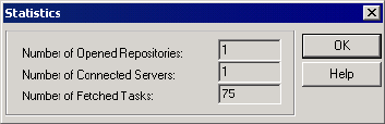
Using the Workflow Monitor 503
Viewing Statistics
You can view statistics about the objects you monitor in the Workflow Monitor. Click View >
Statistics. The Statistics window displays the following information:
♦Number of opened repositories. Number of repositories you are connected to in the
Workflow Monitor.
♦Number of connected Integration Services. Number of Integration Services you
connected to since you opened the Workflow Monitor.
♦Number of fetched tasks. Number of tasks the Workflow Monitor fetched from the
repository during the period specified in the Time window.
Figure 17-2 shows the Statistics window:
You can also view statistics about nodes and sessions. For more information about node
statistics, see “Viewing Integration Service Details” on page 530. For more information about
viewing session statistics, see “Viewing Session Statistics” on page 537
Viewing Properties
You can view properties for the following items:
♦Tasks. You can view properties, such as task name, start time, and status.
♦Sessions. You can view properties about the Session task and session run, such as mapping
name and number of rows successfully loaded. You can also view load statistics about the
session run. For more information about session details, see “Viewing Session Task
Details” on page 539. You can also view performance details about the session run. For
more information, see “Viewing Performance Details” on page 544.
♦Workflows. You can view properties such as start time, status, and run type.
♦Links. When you double-click a link between tasks in Gantt Chart view, you can view
tasks you hide.
♦Integration Services. You can view properties such as Integration Service version and
startup time. You can also view the sessions and workflows running on the Integration
Service.
♦Grid. You can view properties such as the name, Integration Service type, and code page of
a node in the Integration Service grid.
♦Folders. You can view properties such as the number of workflow runs displayed in the
Time window.
Figure 17-2. Workflow Monitor Statistics Window
504 Chapter 17: Monitoring Workflows
To view properties for all objects, right-click the object and select Properties. You can right-
click items in the Navigator or the Time window in either Gantt Chart view or Task view.
To view link properties, double-click the link in the Time window of Gantt Chart view.
When you view link properties, you can double-click a task in the Link Properties dialog box
to view the properties for the filtered task.
Customizing Workflow Monitor Options 505
Customizing Workflow Monitor Options
You can configure how the Workflow Monitor displays general information, workflows, and
tasks. You can configure general tasks such as the maximum number of days or runs that the
Workflow Monitor appears. You can also configure options specific to Gantt Chart and Task
view.
Click Tools > Options to configure Workflow Monitor options.
You can configure the following options in the Workflow Monitor:
♦General. Customize general options such as the maximum number of workflow runs to
display and whether to receive messages from the Workflow Manager. See “Configuring
General Options” on page 505
♦Gantt Chart view. Configure Gantt Chart view options such as workspace color, status
colors, and time format. See “Configuring Gantt Chart View Options” on page 507.
♦Task view. Configure which columns to display in Task view. See “Configuring Task View
Options” on page 508.
♦Advanced. Configure advanced options such as the number of workflow runs the
Workflow Monitor holds in memory for each Integration Service. “Configuring Advanced
Options” on page 509.
Configuring General Options
You can customize general options such as the maximum number of days to display and
which text editor to use for viewing session and workflow logs.
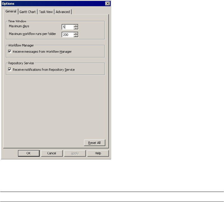
506 Chapter 17: Monitoring Workflows
Figure 17-3 shows the General Options tab:
Table 17-1 describes the options you can configure on the General tab:
Figure 17-3. General Tab for Workflow Monitor Options
Table 17-1. Workflow Monitor General Options
Setting Description
Maximum Days Number of tasks the Workflow Monitor displays up to a maximum number of days.
Default is 5.
Maximum Workflow Runs per
Folder
Maximum number of workflow runs the Workflow Monitor displays for each folder.
Default is 200.
Receive Messages from
Workflow Manager
Select to receive messages from the Workflow Manager. The Workflow Manager
sends messages when you start or schedule a workflow in the Workflow Manager.
The Workflow Monitor displays these messages in the Output window.
Receive Notifications from
Repository Service
Select to receive notification messages in the Workflow Monitor and view them in
the Output window. You must be connected to the repository to receive
notifications. Notification messages include information about objects that another
user creates, modifies, or delete. You receive notifications about folders and
Integration Services. The Repository Service notifies you of the changes so you
know objects you are working with may be out of date. You also receive notices
posted by the Repository Service administrator.
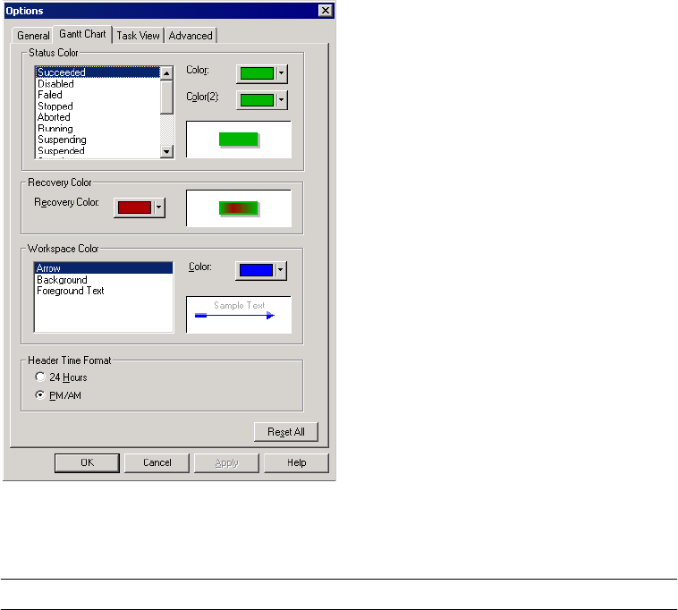
Customizing Workflow Monitor Options 507
Configuring Gantt Chart View Options
You can configure Gantt Chart view options such as workspace color, status colors, and time
format.
Figure 17-4 shows the Gantt Chart Options tab:
Table 17-2 describes the options you can configure on the Gantt Chart Options tab:
Figure 17-4. Gantt Chart Options
Table 17-2. Gantt Chart Options
Gantt Chart Option Description
Status Color Choose a status and configure the color for the status. The Workflow Monitor displays tasks
with the selected status in the colors you choose. You can choose two colors to display a
gradient.
Recovery Color Configure the color for the recovery sessions. The Workflow Monitor uses the status color for
the body of the status bar, and it uses and the recovery color as a gradient in the status bar.
Workspace Color Select a color for each workspace component.
Time Format Select a display format for the time window.
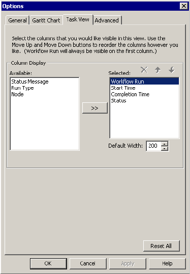
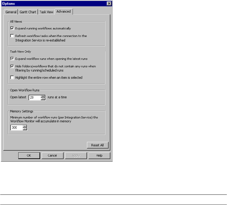
Customizing Workflow Monitor Options 509
Configuring Advanced Options
You can configure advanced options such as the number of workflow runs the Workflow
Monitor holds in memory for each Integration Service.
Figure 17-6 shows the Advanced Options tab:
Table 17-3 describes the options you can configure on the Advanced tab:
Figure 17-6. Advanced Tab for Workflow Monitor Options
Table 17-3. Advanced Workflow Monitor Options
Setting Description
Expand Running Workflows Automatically Expands running workflows in the Navigator.
Refresh workflow tasks when the connection
to the Integration Service is re-established.
Refreshes workflow tasks when you reconnect to the Integration
Service.
Expand workflow runs when opening the
latest runs
Expands workflows when you open the latest run.
Hide Folders/Workflows That Do Not
Contain Any Runs When Filtering By
Running/Schedule Runs
Hides folders or workflows under the Workflow Run column in the Time
window when you filter running or scheduled tasks.

510 Chapter 17: Monitoring Workflows
Highlight the Entire Row When an Item Is
Selected
Highlights the entire row in the Time window for selected items. When
you disable this option, the Workflow Monitor highlights the item in the
Workflow Run column in the Time window.
Open Latest 20 Runs At a Time You can open the number of workflow runs. Default is 20.
Minimum Number of Workflow Runs (Per
Integration Service) the Workflow Monitor
Will Accumulate in Memory
Specifies the minimum number of workflow runs per Integration Service
that the Workflow Monitor holds in memory before it starts releasing
older runs from memory.
When you connect to an Integration Service, the Workflow Monitor
fetches the number of workflow runs specified on the General tab for
each folder you connect to. When the number of runs is less than the
number specified in this option, the Workflow Monitor stores new runs
in memory until it reaches this number. Then it releases the oldest run
from memory when it fetches a new run.
When the number of workflow runs the Workflow Monitor initially
fetches exceeds the number specified in this option, the Workflow
Monitor stores all those runs and then releases the oldest run from
memory when it fetches a new run.
Table 17-3. Advanced Workflow Monitor Options
Setting Description
Using Workflow Monitor Toolbars 511
Using Workflow Monitor Toolbars
The Workflow Monitor toolbars allow you to select tools and tasks quickly. You can perform
the following toolbar operations:
♦Display or hide a toolbar.
♦Create a new toolbar.
♦Add or remove buttons.
For more information about how to perform these toolbar operations, see “Using the
Designer” in the Designer Guide.
By default, the Workflow Monitor displays the following toolbars:
♦Standard. Contains buttons to connect to and disconnect from repositories, see print
previews, and to search the workspace.
♦Integration Service. Contains buttons to connect to and disconnect from Integration
Services, ping Integration Service, and perform workflows operations.
♦View. Contains buttons to refresh the view, get workflow history and properties, and show
workflow or session logs.
♦Filters. Contains buttons to display most recent runs, and to filter tasks, servers, and
folders.
Once a toolbar appears, it displays until you exit the Workflow Monitor or hide the toolbar.
You can drag each toolbar to resize and reposition each toolbar.
512 Chapter 17: Monitoring Workflows
Working with Tasks and Workflows
You can perform the following tasks with objects in the Workflow Monitor:
♦Run a task or workflow.
♦Resume a suspended workflow.
♦Stop or abort a task or workflow.
♦Schedule and unschedule a workflow.
♦View session logs and workflow logs.
♦View history names.
Running a Task, Workflow, or Worklet
The Workflow Monitor displays workflows that have run at least once. In the Workflow
Monitor, you can run a workflow or any task or worklet in the workflow. To run a workflow
or part of a workflow, right-click the workflow or task and choose a restart option. When you
choose restart, the task, workflow, or worklet runs on the Integration Service you specify in
the workflow properties.
You can also run part of a workflow. When you run part of a workflow, the Integration
Service runs the workflow from the selected task to the end of the workflow.
For more information about running workflows and tasks in the Workflow Manager, see
“Manually Starting a Workflow” on page 128.
To run a workflow from the Workflow Monitor:
1. In the Navigator, select the workflow you want to run.
2. Right-click the workflow in the Navigator and choose Restart.
-or-
Click Task > Restart.
The Integration Service runs the workflow you specify.
To run a task from the Workflow Monitor:
1. In the Navigator, select the task or worklet you want to run.
2. Right-click the task or worklet in the Navigator and choose Restart Task.
The Integration Service runs the task or worklet you specify. It does not run the rest of
the workflow.
Working with Tasks and Workflows 513
To run a part of a workflow from the Workflow Monitor:
1. In the Navigator, select the task from which you want to run the workflow.
2. Right-click the task and choose Restart Workflow from Task.
-or-
Click Task > Restart.
The Integration Service runs the workflow starting with the task you specify.
Recovering a Workflow or Worklet
In the workflow properties, you can choose to suspend the workflow or worklet if a session
fails. After you fix the errors that caused the session to fail, recover the workflow in the
Workflow Monitor. When you recover a workflow, the Integration Service recovers the failed
session, and continues running the rest of the tasks in the workflow path.
For more information about recovering a workflow, see “Recovery Options” on page 342.
To recover a workflow or worklet:
1. In the Navigator, select the workflow or worklet you want to recover.
2. Click Tasks > Recover.
-or-
Right-click the workflow or worklet in the Navigator and choose Recover.
The Workflow Monitor displays Integration Service messages about the recover
command in the Output window.
Stopping or Aborting Tasks and Workflows
You can stop or abort a task, workflow, or worklet in the Workflow Monitor at any time.
When you stop a task in the workflow, the Integration Service stops processing the task and
all other tasks in its path. The Integration Service continues running concurrent tasks. If the
Integration Service cannot stop processing the task, you need to abort the task. When the
Integration Service aborts a task, it kills the DTM process and terminates the task.
For more information about Integration Service handling of stop and abort, see “How the
Integration Service Handles Stop and Abort” on page 132.
To stop or abort workflows, tasks, or worklets in the Workflow Monitor:
1. In the Navigator, select the task, workflow, or worklet you want to stop or abort.
2. Click Tasks > Stop or Tasks > Abort.
-or-
Right-click the task, workflow, or worklet in the Navigator and choose Stop or Abort.
514 Chapter 17: Monitoring Workflows
3. The Workflow Monitor displays the status of the stop or abort command in the Output
window.
Scheduling and Unscheduling Workflows
You can schedule and unschedule workflows in the Workflow Monitor. You can schedule any
workflow that is not configured to run on demand. When you try to schedule a run on
demand workflow, the Workflow Monitor displays an error message in the Output window.
When you schedule an unscheduled workflow, the workflow uses its original schedule
specified in the workflow properties. If you want to specify a different schedule for the
workflow, you must edit the scheduler in the Workflow Manager.
To schedule an unscheduled workflow in the Workflow Monitor:
♦Right-click the workflow and choose Schedule.
The Workflow Monitor displays the workflow status as Scheduled, and displays a message
in the Output window.
To unschedule a scheduled workflow in the Workflow Monitor:
♦Right-click the workflow and choose Unschedule.
The Workflow Monitor displays the workflow status as Unscheduled and displays a
message in the Output window.
For more information about scheduling workflows, see “Scheduling a Workflow” on
page 116.
Viewing Session Logs and Workflow Logs
You can view session and workflow logs from the Workflow Monitor. To view workflow or
session logs, right-click the session or workflow in the Workflow Monitor and choose Get
Session Log or Get Workflow Log. You can view the most recent session or workflow log.
When you open a session or workflow log, the Log Events window sends a request to the Log
Agent. The Log Agent retrieves logs from each node that ran the session or workflow. The
Log Events window displays the logs by node.
If you want to view past session or workflow logs, you can configure the session or workflow
to save log files. When you configure the workflow to save log files, the workflow creates a
text file and the binary file that displays in the Log Events window. You can save the text files
by timestamp or by workflow or session runs. You can configure how many workflow or
session runs to save.
To view past session or workflow log files, configure the session or workflow to save logs by
timestamp. For more information about workflow and session logs, see “Session and Workflow
Logs” on page 567.
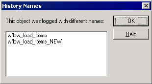
Working with Tasks and Workflows 515
To view a session or workflow log file:
1. Right-click a session or workflow in the Navigator or Time window.
2. Choose Get Session Log or Get Workflow Log.
The most recent session or workflow log file opens in the Log Viewer.
Tip: When the Workflow Monitor retrieves the session or workflow log, you can press the
Esc key to cancel the process.
Viewing History Names
If you rename a task, workflow, or worklet, the Workflow Monitor can show a history of
names. When you start a renamed task, workflow, or worklet, the Workflow Monitor displays
the current name. To view a list of historical names, select the task, workflow, or worklet in
the Navigator. Right-click and choose Show History Names.
Figure 17-7 shows the History Names dialog box:
Figure 17-7. History Names Dialog Box

516 Chapter 17: Monitoring Workflows
Workflow and Task Status
The Workflow Monitor displays the status of workflows and tasks.
Table 17-4 describes the different statuses for workflows and tasks:
Table 17-4. Workflow and Task Status
Status Name Status for Description
Aborted Workflows
Task s
Integration Service aborted the workflow or task. The Integration Service kills
the DTM process when you abort a workflow or task.
Aborting Workflows
Task s
Integration Service is in the process of aborting the workflow or task.
Disabled Workflows
Tasks
You select the Disabled option in the workflow or task properties. The
Integration Service does not run the disabled workflow or task until you clear the
Disabled option.
Failed Workflows
Task s
Integration Service failed the workflow or task due to errors.
Preparing to Run Workflows
Task s
Integration Service is initializing the workflow or task.
Running Workflows
Task s
Integration Service is running the workflow or task.
Scheduled Workflows You schedule the workflow to run at a future date. The Integration Service runs
the workflow for the duration of the schedule.
Stopped Workflows
Task s
You choose to stop the workflow or task in the Workflow Monitor. The
Integration Service stopped the workflow or task.
Stopping Workflows
Task s
Integration Service is in the process of stopping a workflow or task.
Succeeded Workflows
Task s
Integration Service successfully completed the workflow or task.
Suspended Workflows
Worklets
Integration Service suspends the workflow because a task fails and no other
tasks are running in the workflow. This status is available when you select the
Suspend on Error option.
Suspending Workflows
Worklets
A task fails in the workflow when other tasks are still running. The Integration
Service stops executing the failed task and continues executing tasks in other
paths. This status is available when you select the Suspend on Error option.
Terminated Workflows
Task s
Integration Service terminated unexpectedly when it was running this workflow
or task.
Terminating Workflows
Task s
Integration Service is stopping or aborting the workflow or task.
Unknown Status Workflows
Task s
Integration Service cannot determine the status of the workflow or task. The
status may be changing. For example, the status may have been Running but is
changing to Stopping.

Workflow and Task Status 517
To see a list of tasks by status, view the workflow in Task view and sort by status. Or, click
Edit > List Tasks in Gantt Chart view. For more information, see “Listing Tasks and
Workflows” on page 519.
Unscheduled Workflows You removed a workflow from the schedule. Or, the workflow is scheduled and
the Integration Service is about to run the scheduled workflow.
Waiting Workflows
Task s
Integration Service is waiting for available resources so it can run the workflow
or task. For example, you may set the maximum number of concurrent sessions
to 10. If the Integration Service is already running 10 concurrent sessions, all
other workflows and tasks have the Waiting status until the Integration Service
is free to run more tasks.
Table 17-4. Workflow and Task Status
Status Name Status for Description
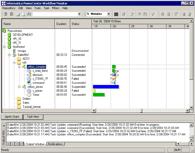
518 Chapter 17: Monitoring Workflows
Using the Gantt Chart View
You can view chronological details of workflow runs with the Gantt Chart view. The Gantt
Chart view displays the following information:
♦Task name. Name of the task in the workflow.
♦Duration. The length of time the Integration Service spends running the most recent task
or workflow.
♦Status. The status of the most recent task or workflow. For more information about status,
see “Workflow and Task Status” on page 516.
♦Connection between objects. The Workflow Monitor shows links between objects in the
Time window.
Figure 17-8 displays the Gantt Chart view:
Figure 17-8. Gantt Chart View
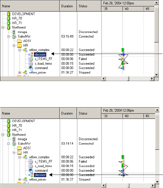
Using the Gantt Chart View 519
Organizing Tasks
In Gantt Chart view, you can organize tasks in the Navigator. You can drag tasks within a
workflow to change the order they appear in the Navigator.
For example, the Workflow Monitor usually displays the Decision task as the first task in the
following workflow:
You can drag the Decision task within the Navigator so the Decision task is in the middle or
at the bottom of the list of tasks for that workflow:
Listing Tasks and Workflows
The Workflow Monitor lists tasks and workflows in all repositories you connect to. You can
view tasks and workflows by status, such as failed or succeeded. You can highlight the task in
Gantt Chart view by double-clicking the task in the list.
Decision task displays first.
Decision task displays
between other tasks.
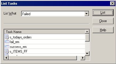
520 Chapter 17: Monitoring Workflows
To view a list of tasks and workflows by status:
1. Open the Gantt Chart view and click Edit > List Tasks.
The List Tasks dialog box appears.
2. In the List What field, select the type of task status you want to list.
For example, select Failed to view a list of failed tasks and workflows.
3. Click List to view the list.
Tip: Double-click the task name in the List Tasks dialog box to highlight the task in
Gantt Chart view.
Navigating the Time Window in Gantt Chart View
You can scroll through the Time window in Gantt Chart view to monitor the workflow runs.
To scroll the Time window, use any of the following methods:
♦Use the scroll bars.
♦Right-click the task or workflow and click Go To Next Run or Go To Previous Run.
♦Click View > Organize to select the date you want to display.
When you click View > Organize, the Go To field appears above the Time window. Click the
Go To field to view a calendar and select the date you want to display. When you select a
date, the Workflow Monitor displays that date beginning at 12:00 a.m.
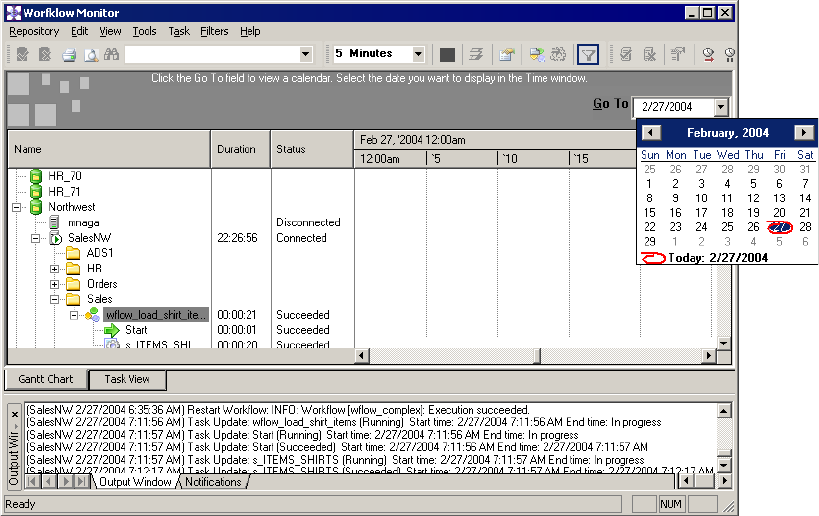
Using the Gantt Chart View 521
Figure 17-9 shows the Go To field:
Zooming the Gantt Chart View
You can change the zoom settings in Gantt Chart view. By default, the Workflow Monitor
shows the Time window in increments of one hour. You can change the time increments to
zoom the Time window.
Figure 17-9. Organizing Gantt Chart
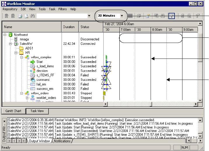
522 Chapter 17: Monitoring Workflows
Figure 17-10 shows the Time window in 30 minute increments:
To zoom the Time window in Gantt Chart view, click View > Zoom and then select the time
increment. You can also select the time increment in the Zoom button on the toolbar.
Performing a Search
Use the search tool in the Gantt Chart view to search for tasks, workflows, and worklets in all
repositories you connect to. The Workflow Monitor searches for the word you specify in task
names, workflow names, and worklet names. You can highlight the task in Gantt Chart view
by double-clicking the task after searching.
Figure 17-10. Zooming the Gantt Chart View
Zoom
30 Minute
Increments
Solid Line
For Hour
Increments
Dotted Line
For Half Hour
Increments
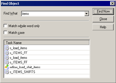
Using the Gantt Chart View 523
To perform a search:
1. Open the Gantt Chart view and click Edit > Find.
The Find Object dialog box appears.
2. In the Find What field, enter the keyword you want to find.
3. Click Find Now.
The Workflow Monitor displays a list of tasks, workflows, and worklets that match the
keyword.
Tip: Double-click the task name in the Find Object dialog box to highlight the task in
Gantt Chart view.
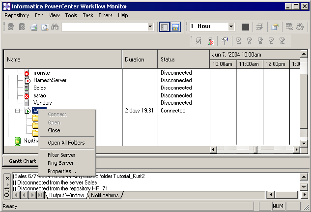
524 Chapter 17: Monitoring Workflows
Opening All Folders
You can open all folders that you have read permission on in a repository. To open all the
folders in the Gantt Chart view, right-click the Integration Service you want to view, and
select Open All Folders. The Workflow Monitor displays workflows and tasks in the folders.
Using the Task View 525
Using the Task View
The Task view displays information about workflow runs in a report format. The Task view
provides a convenient way to compare and filter details of workflow runs. Task view displays
the following information:
♦Workflow run list . The list of workflow runs. The workflow run list contains folder,
workflow, worklet, and task names. The Workflow Monitor displays workflow runs
chronologically with the most recent run at the top. It displays folders and Integration
Services alphabetically.
♦Status message. Message from the Integration Service regarding the status of the task or
workflow.
♦Run type. The method you used to start the workflow. You might manually start the
workflow or schedule the workflow to start.
♦Node. Node of the Integration Service that ran the task.
♦Start time. The time that the Integration Service starts executing the task or workflow.
♦Completion time. The time that the Integration Service finishes executing the task or
workflow.
♦Status. The status of the task or workflow.
You can perform the following tasks in Task view:
♦Filter tasks. Use the Filter menu to select the tasks you want to display or hide. For more
information about filtering tasks in Task view, see “Filtering in Task View” on page 526.
♦Hide and view columns. Hide or view an entire column in Task view. For more
information about hiding and viewing columns in Task view, see “Configuring Task View
Options” on page 508.
♦Hide and view the Navigator. You can hide the Navigator in Task view. Click View >
Navigator to hide or view the Navigator.
To view the tasks in Task view, select the Integration Service you want to monitor in the
Navigator.
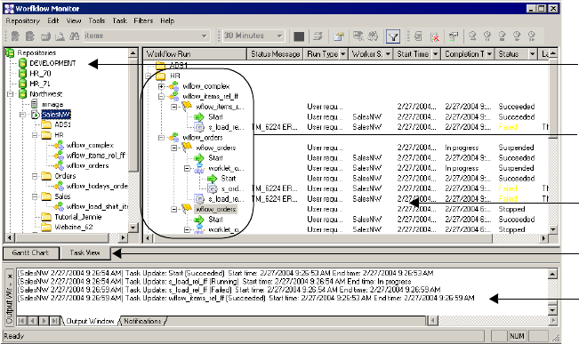
526 Chapter 17: Monitoring Workflows
Figure 17-11 displays the Task view:
Filtering in Task View
In Task view, you can view all or some workflow tasks. You can filter tasks in the following
ways:
♦By task type. You can filter out tasks you do not want to view. For example, if you want to
view only Session tasks, you can filter out all other tasks. For more information about
filtering task types and Integration Services, see “Filtering Tasks and Integration Services”
on page 500.
♦By nodes in the Navigator. You can filter the workflow runs the Workflow Monitor
displays in the Time window by selecting different nodes in the Navigator. For example,
when you select a repository name in the Navigator, the Time window displays all
workflow runs that ran on the Integration Services registered to that repository. When you
select a folder name in the Navigator, the Time window displays all workflow runs in that
folder.
♦By the most recent runs. To display by the most recent runs, click Filters > Most Recent
Runs and select the number of runs you want to display.
♦By Time window columns. You can click Filters > Auto Filter and filter by properties you
specify in the Time window columns.
Figure 17-11. Task View
Time Window
Navigator
Window
Task View
Output
Window
Workflow
Run List
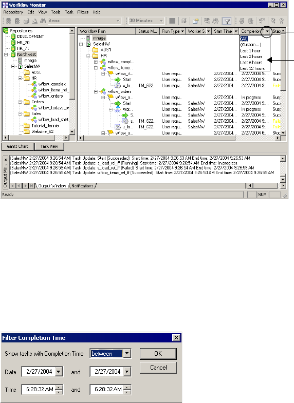
Using the Task View 527
To filter by Time view columns:
1. Click Filters > Auto Filter.
The Filter button appears in the some columns of the Time Window in Task view.
2. Click the Filter button in a column in the Time Window.
3. Select the properties you want to filter.
Tip: If you want to view all tasks, select All.
When you click the Filter button in either the Start Time or Completion Time column,
you can select a custom time to filter.
4. Select Custom for either Start Time or Completion Time.
The Filter Start Time or Custom Completion Time dialog box appears.
5. Choose to show tasks before, after, or between the time you specify.
6. Select the date and time. Click OK.
Select the
workflows you want
to display.
Filter Button
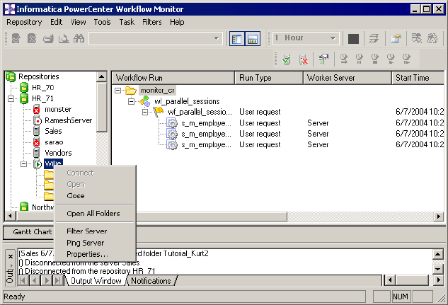
528 Chapter 17: Monitoring Workflows
Opening All Folders
You can open all folders that you have read permission on in a repository. To open all folders
in the Task view, right-click the Integration Service with the folders you want to view, and
choose Open All Folders. The Workflow Monitor displays workflows and tasks in the folders.
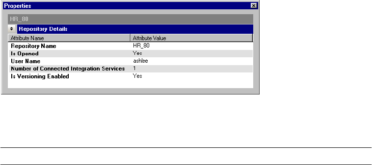
Viewing Service Details 529
Viewing Service Details
You can view the following details about the Repository Service and Integration Service in the
Workflow Monitor:
♦Repository Service details. View information about a repository.
♦Integration Service details. View information about the Integration Service and the
system resources that running workflows are consuming.
♦Repository folder details. View information about a repository folder.
Viewing Repository Service Details
To view details about a repository, right-click on the repository and choose Properties.
Figure 17-12 shows the Repository Details area of the Properties window:
Table 17-5 shows the attributes that display in the Repository Details area:
Figure 17-12. Workflow Monitor Repository Details Area
Table 17-5. Workflow Monitor Repository Details
Attribute Name Description
Repository Name Name of the repository.
Is Opened Yes if you are connected to the repository. Otherwise, value is No.
User Name Name of the user connected to the repository. Attribute displays only if you are connected
to the repository.
Number of Connected
Integration Services
Number of Integration Services you are connected to in the Workflow Monitor. Attribute
displays only if you are connected to the repository.
Is Versioning Enabled Indicates whether repository versioning is enabled.
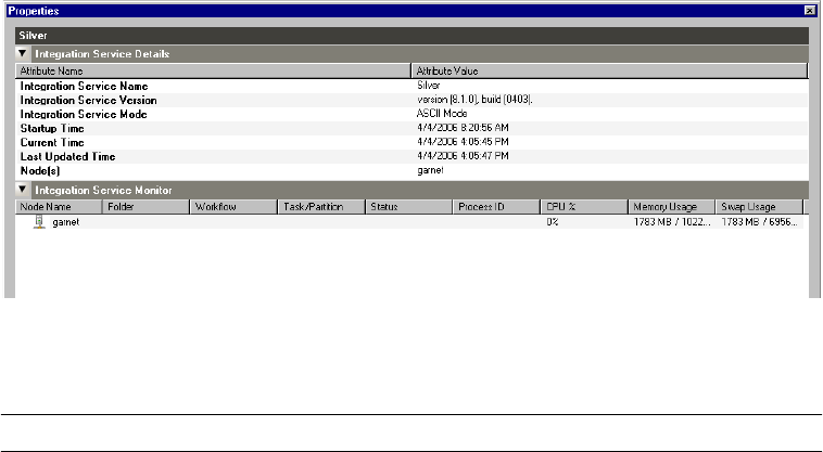
530 Chapter 17: Monitoring Workflows
Viewing Integration Service Details
To view details about the Integration Service, right-click on an Integration Service and choose
Properties. When you view Integration Service details, the following areas display in the
Properties window:
♦Integration Service Details window. Displays information about the Integration Service.
♦Integration Service Monitor window. Displays system resource usage information about
nodes associated with the Integration Service. This window also displays system resource
usage information about tasks running on the node. The Integration Service Monitor
window only displays if you are connected to an Integration Service.
Figure 17-13 shows the Integration Service Details and Integration Service Monitor areas of
the Properties window:
Table 17-6 shows the attributes that display in the Integration Service Details area:
Figure 17-13. Integration Service Details and Integration Service Monitor Areas
Table 17-6. Workflow Monitor Integration Service Details
Attribute Name Description
Integration Service Name Name of the Integration Service.
Integration Service
Version
PowerCenter version and build. Displays only if you are connected to the Integration
Service in the Workflow Monitor.
Integration Service Mode Data movement mode of the Integration Service. Displays only if you are connected to the
Integration Service in the Workflow Monitor.
Startup Time Time the Integration Service was started. Startup Time displays in the following format:
MM/DD/YYYY HH:MM:SS AM|PM. Displays only if you are connected to the Integration
Service in the Workflow Monitor.
Current Time Current time of the Integration Service.
Last Updated Time Time the Integration Service was last updated. Last Updated Time displays in the following
format: MM/DD/YYYY HH:MM:SS AM|PM. Displays only if you are connected to the
Integration Service in the Workflow Monitor.

Viewing Service Details 531
Table 17-7 shows the attributes that display in the Integration Service Monitor area:
Grid Assigned Grid the Integration Service is assigned to. Attribute displays only if the Integration Service
is assigned to a grid. Displays only if you are connected to the Integration Service in the
Workflow Monitor.
Node(s) Names of nodes configured to run Integration Service processes. Displays only if you are
connected to the Integration Service in the Workflow Monitor.
Is Connected Indicates that you are not connected to the Integration Service.
Is Registered Displays one of the following values:
- Yes if the Integration Service is associated with a repository.
- No if the Integration Service is not associated with a repository.
Displays only if you are not connected to the Integration Service.
Table 17-7. Workflow Monitor Integration Service Monitor
Attribute Name Description
Node Name Name of the node on which the Integration Service is running.
Folder Folder that contains the workflow that is running.
Workflow Name of the workflow that is running.
Task/Partition Name of the session and partition that is running. Or, name of Command task that is
running.
Status Status of the workflow.
Process ID Process ID of the task.
CPU % Percent of the CPU the node or task process is consuming.
Memory Usage Amount of memory the node or task process is consuming.
Swap Usage Amount of swap space the node or task process is consuming.
Table 17-6. Workflow Monitor Integration Service Details
Attribute Name Description
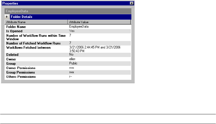
532 Chapter 17: Monitoring Workflows
Viewing Folder Details
To view information about a repository folder, right-click on the folder and choose
Properties.
Figure 17-14 shows the Folder Details area of the Properties window:
Table 17-8 shows the attributes that display in the Folder Details area:
Figure 17-14. Workflow Monitor Folder Details Area
Table 17-8. Workflow Monitor Folder Details
Attribute Name Description
Folder Name Name of the repository folder.
Is Opened Indicates if the folder is open.
Number of Workflow
Runs Within Time
Window
Number of workflows that have run in the time window during which the Workflow Monitor
displays workflow statistics. For more information about configuring a time window for
workflows, see “Configuring General Options” on page 505.
Number of Fetched
Workflow Runs
Number of workflow runs displayed during the time window.
Workflows Fetched
Between
Time period during which the Integration Service fetched the workflows. Displays as:
DD/MM/YYYT HH:MM:SS and DD/MM/YYYT HH:MM:SS
Deleted Indicates if the folder is deleted.
Owner Repository folder owner.
Group Group to which the folder is assigned.
Owner Permissions Permissions of the repository folder owner. The following permissions can display:
- r. Read permission
- w. Write permission
- x. Execute permission

Viewing Service Details 533
Group Permissions Permissions of the group to which the repository is assigned. The following permissions
can display: -r, -w, -x.
Others Permissions Permissions of users who do not belong to the repository group to which the repository
folder is assigned. The following permissions can display: -r, -w, -x.
Table 17-8. Workflow Monitor Folder Details
Attribute Name Description
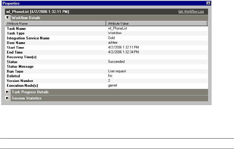
534 Chapter 17: Monitoring Workflows
Viewing Workflow, Worklet, and Task Details
You can view the following details in the Workflow Monitor:
♦Workflow details. View information about a workflow.
♦Worklet detail s. View information about a worklet.
♦Task progress details. View the progress of command and sessions tasks for a running
workflow.
♦Session statistics. View statistics about session progress for a running workflow.
♦Command task details. View information about Command tasks.
To view information about a workflow and workflow tasks, right-click on a workflow and
choose Get Run Properties. In the Properties window, you can click Get Workflow Log to
view the Log Events window for the workflow.
Viewing Workflow Details
The Workflow Details area displays information about workflows, such as the name of the
Integration Service assigned to the workflow and workflow run details.
Figure 17-15 shows the Workflow Details area of the Properties window:
Table 17-9 shows the attributes that display in the Workflow Details area:
Figure 17-15. Workflow Monitor Workflow Details Area
Table 17-9. Workflow Monitor Workflow Details
Attribute Name Description
Task Nam e Name of the workflow.
Task Type Task type is Workflow.
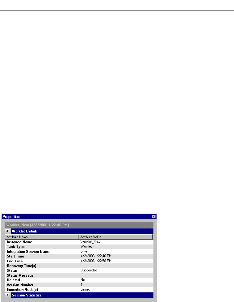
Viewing Workflow, Worklet, and Task Details 535
Viewing Worklet Details
The Worklet Details area displays information about worklets, such as the name of the
Integration Service assigned to the workflow and worklet run details.
When you view worklet details, the Session Statistics window also appears. For more
information about session statistics, see “Viewing Session Statistics” on page 537.
Figure 17-16 shows the Worklet Details area of the Properties window:
Integration Service Name Name of the Integration Service assigned to the workflow.
User Name Name of the repository user running the workflow.
Start Time Start time of the workflow.
End Time End time of the workflow.
Recovery Time(s) Times of recovery workflows.
Status Status of the workflow. For more information about workflow status, see “Workflow and
Task Status” on page 516.
Status Message Message about the workflow status.
Run Type Method used to start the workflow.
Deleted Yes if the workflow is deleted from the repository. Otherwise, value is No.
Version Number Version number of the workflow.
Execution Node(s) Nodes on which workflow tasks run.
Figure 17-16. Workflow Monitor Worklet Details Area
Table 17-9. Workflow Monitor Workflow Details
Attribute Name Description
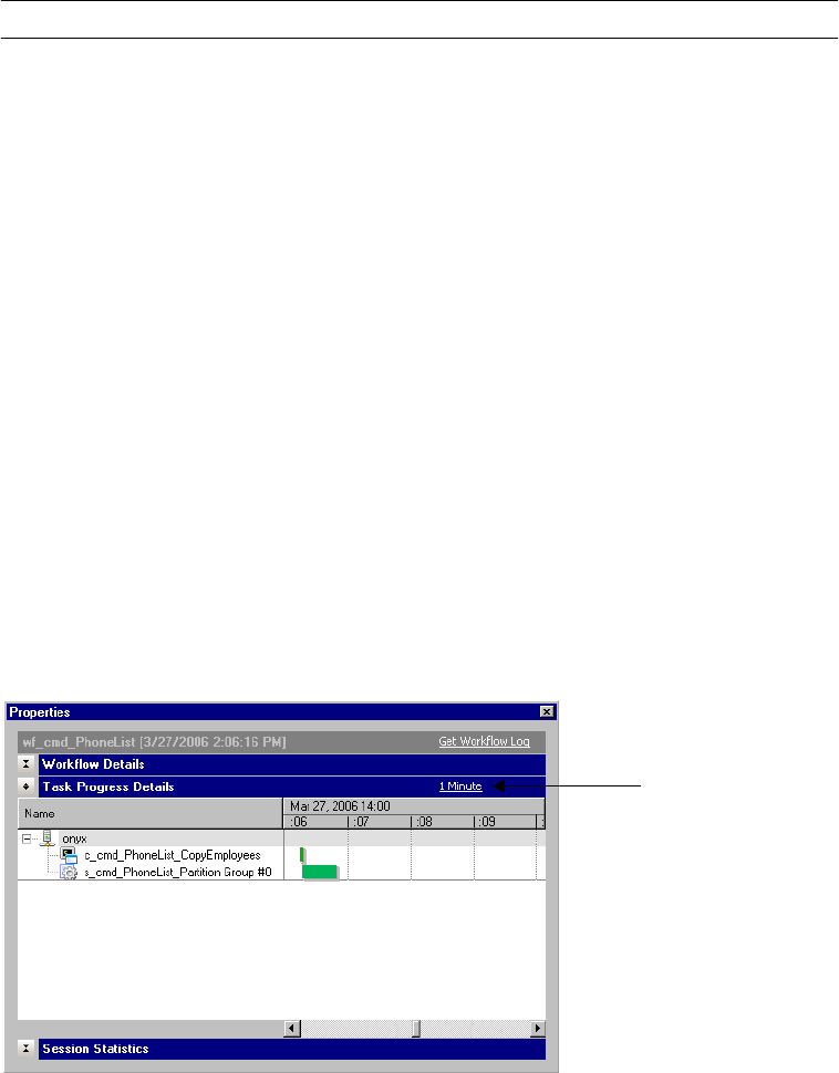
536 Chapter 17: Monitoring Workflows
Table 17-10 shows the attributes that display in the Worklet Details area:
Viewing Task Progress Details
The Task Progress Details area displays the status of Session and Command tasks in a running
workflow. It displays the information in a Gantt chart view.
Figure 17-17 shows an example of the Task Progress Details area of the Properties window:
Table 17-10. Workflow Monitor Worklet Details
Attribute Name Description
Instance Name Name of the worklet instance in the workflow.
Task Type Task type is Worklet.
Integration Service Name Name of the Integration Service assigned to the workflow associated with the worklet.
Start Time Start time of the worklet.
End Time End time of the worklet.
Recovery Time(s) Time of the recovery worklet run.
Status Status of the worklet. For more information about worklet status, see “Workflow and Task
Status” on page 516.
Status Message Message about the worklet status.
Deleted Indicates if the worklet is deleted from the repository.
Version Number Version number of the worklet.
Execution Node(s) Nodes on which worklet tasks run.
Figure 17-17. Workflow Monitor Task Progress Details Area
Click to change
the time window.
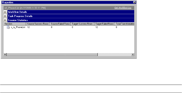
Viewing Workflow, Worklet, and Task Details 537
Viewing Session Statistics
The Session Statistics area displays information about sessions, such as the session run time
and the number or rows loaded to the targets.
Figure 17-18 shows the Session Statistics area of the Properties window:
Table 17-11 shows the attributes that display in the Session Statistics area:
Viewing Command Task Details
The Task Details area for Command tasks displays information about Command tasks, such
as the start time and end time.
Figure 17-18. Workflow Monitor Session Statistics Area
Table 17-11. Workflow Monitor Session Statistics
Attribute Name Description
Session Name of the session.
Source Success Rows Number of rows the Integration Service successfully read from the source.
Source Failed Rows Number of rows the Integration Service failed to read from the source.
Target Success Rows Number of rows the Integration Service successfully wrote to the target.
Target Failed Rows Number of rows the Integration Service failed to write the target.
Total Transformation
Errors
Number of transformation errors in the session.
Start Time Start time of the session.
End Time End time of the session.
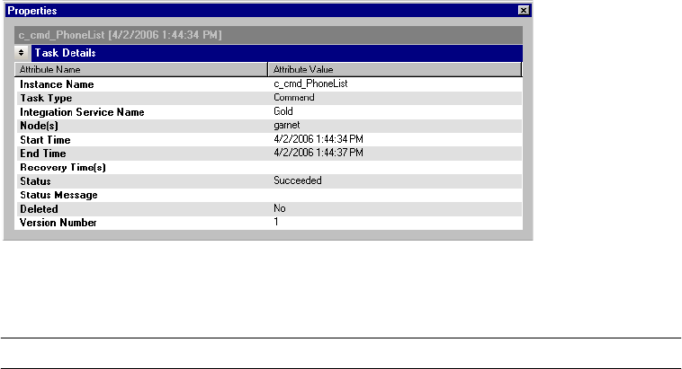
538 Chapter 17: Monitoring Workflows
Figure 17-19 shows the Task Details area of the Properties window for Command Tasks:
Table 17-12 shows the attributes that display in the Task Details area:
Figure 17-19. Workflow Monitor Task Details Area for Command Tasks
Table 17-12. Workflow Monitor Command Task Details
Attribute Name Description
Instance Name Command task name.
Task Type Task type is Command.
Integration Service Name Name of the Integration Service assigned to the workflow associated with the Command
task.
Node(s) Nodes on which the commands in the Command task run.
Start Time Start time of the Command task.
End Time End time of the Command task.
Recovery Time(s) Time of the recovery run.
Status Status of the Command task. For more information about Command task status, see
“Workflow and Task Status” on page 516.
Status Message Message about the Command task status.
Deleted Indicates if the Command task is deleted.
Version Number Version number of the Command task.
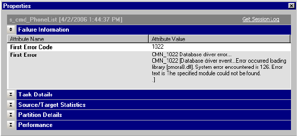
Viewing Session Task Details 539
Viewing Session Task Details
When the Integration Service runs a session, the Workflow Monitor creates session details
that provide load statistics for each target in the mapping. You can view session details when
the session runs or after the session completes.
You can view the following details for sessions in the Workflow Monitor:
♦Failure information. View information about session failures.
♦Task details. View information about the session.
♦Source and target statistics. View information about the number of rows the Integration
Service read from the source and wrote to the target.
♦Partition details. View information about partitions in a session.
♦Performance details. View information about session performance. For more information
about viewing performance details, see “Viewing Performance Details” on page 544.
To view session details, right-click a session in the Workflow Monitor and choose Get Run
Properties.
When you load data to a target with multiple groups, such as an XML target, the Integration
Service provides session details for each group.
Viewing Failure Information
The Failure Information area displays information about fatal session errors.
Figure 17-20 shows the Failure Information area of the Properties window:
Figure 17-20. Workflow Monitor Failure Information Area
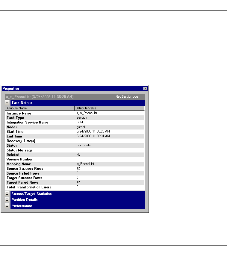
540 Chapter 17: Monitoring Workflows
Table 17-13 shows the attributes that display in the Failure Information area:
Viewing Session Task Details
The Task Details area displays information about sessions.
Figure 17-21 shows the Task Details area of the Properties window for Session tasks:
Table 17-14 shows the attributes that display in the Task Details area for Session tasks:
Table 17-13. Workflow Monitor Failure Information
Attribute Name Description
First Error Code Error code for the fatal error.
First Error Fatal error message.
Figure 17-21. Workflow Monitor Task Details Area for Session tasks
Table 17-14. Workflow Monitor Session Task Details
Attribute Name Description
Instance Name Name of the session.
Task Type Task type is Session.
Integration Service Name Name of the Integration Service assigned to the workflow associated with the session.
Node(s) Node on which the session is running.
Start Time Start time of the session.
End Time End time of the session.
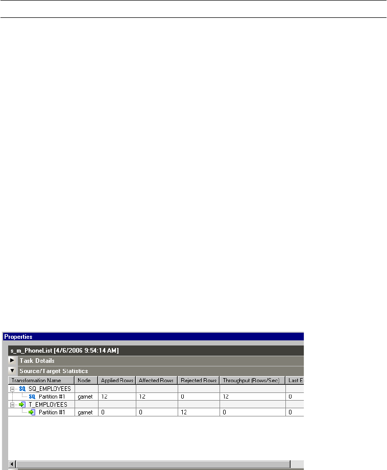
Viewing Session Task Details 541
Viewing Source and Target Statistics
The Source/Target Statistics area displays information about the rows the Integration Service
read from the sources and the rows it loaded to the target.
Figure 17-22 shows the Source/Target Statistics area of the Properties window:
Recovery Time(s) Time of the recovery session run.
Status Status of the session. For more information about session status, see “Workflow and Task
Status” on page 516.
Status Message Message about the session status.
Deleted Indicates if the session is deleted from the repository.
Version Number Version number of the session.
Mapping Name Name of the mapping associated with the session.
Source Success Rows Number of rows the Integration Service successfully read from the source.
Source Failed Rows Number of rows the Integration Service failed to read from the source.
Target Success Rows Number of rows the Integration Service successfully wrote to the target.
Target Failed Rows Number of rows the Integration Service failed to write the target.
Total Transformation
Errors
Number of transformation errors in the session.
Figure 17-22. Workflow Monitor Source/Target Statistics Area
Table 17-14. Workflow Monitor Session Task Details
Attribute Name Description

542 Chapter 17: Monitoring Workflows
Table 17-15 shows the attributes that display in the Source/Target Statistics area:
Viewing Partition Details
The Partition Details area displays information about partitions in a session. When you create
multiple partitions in a session, the Integration Service provides session details for each
partition. Use these details to determine if the data is evenly distributed among the partitions.
For example, if the Integration Service moves more rows through one target partition than
another, or if the throughput is not evenly distributed, you might want to adjust the data
range for the partitions.
Table 17-15. Workflow Monitor Source and Target Statistics
Session Detail Description
Transformation Name Name of the source qualifier instance or the target instance in the mapping. If you create
multiple partitions in the source or target, the Instance Name displays the partition number.
If the source or target contains multiple groups, the Instance Name displays the group
name.
Node Node running the transformation.
Applied Rows For sources, shows the number of rows the Integration Service successfully read from the
source. For targets, shows the number of rows the Integration Service successfully applied
to the target.
Note: The number of applied rows equals the number of affected rows for sources.
Affected Rows For sources, shows the number of rows the Integration Service successfully read from the
source.
For targets, shows the number of rows affected by the specified operation. For example,
you have a table with one column called SALES_ID and five rows containing the values 1,
2, 3, 2, and 2. You mark rows for update where SALES_ID is 2. The writer affects three
rows, even though there was only one update request. Or, if you mark rows for update
where SALES_ID is 4, the writer affects 0 rows.
Note: The number of applied rows equals the number of affected rows for sources.
Rejected Rows Number of rows the Integration Service dropped when reading from the source, or the
number of rows the Integration Service rejected when writing to the target.
Throughput (Rows/Sec) Rate at which the Integration Service read rows from the source or wrote data into the
target in bytes per second.
Last Error Code Error message code of the most recent error message written to the session log. If you
view details after the session completes, this field displays the last error code.
Last Error Message Most recent error message written to the session log. If you view details after the session
completes, this field displays the last error message.
Start Time Time the Integration Service started to read from the source or write to the target.
The Workflow Monitor displays time relative to the Integration Service.
End Time Time the Integration Service finished reading from the source or writing to the target.
The Workflow Monitor displays time relative to the Integration Service.
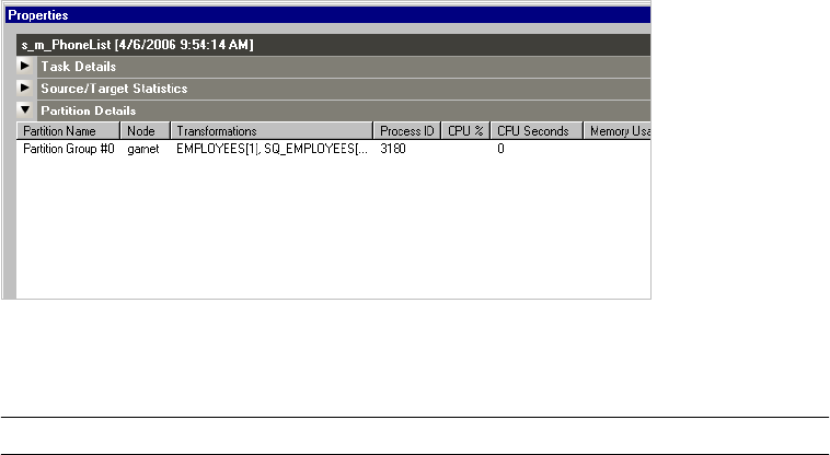
Viewing Session Task Details 543
Figure 17-23 shows the Partition Details area of the Properties window:
Table 17-16 shows the attributes that display in the Partition Details area:
Figure 17-23. Workflow Monitor Partition Details Area
Table 17-16. Workflow Monitor Partition Details
Session Detail Description
Partition Name Name of the partition.
Node Node running the partition.
Transformations Transformations in the partition pipeline.
Process ID Process ID of the partition
CPU % Percent of the CPU the partition is consuming during the current session run.
CPU Seconds Amount of process time in seconds the CPU is taking to process the data in the partition
during the current session run.
Memory Usage Amount of memory the partition is consuming during the current session run.
Input Rows Number of input rows for the partition.
Output Rows Number of output rows for the partition.

544 Chapter 17: Monitoring Workflows
Viewing Performance Details
The performance details provide counters that help you understand the session and mapping
efficiency. Each source qualifier and target definition appears in the performance details,
along with counters that display performance information about each transformation.
You can view session performance details in the following formats:
♦Workflow Monit or. When you configure the session to collect performance details, you
can view them in the Workflow Monitor. When you configure the session to save
performance details, you can view the details for previous sessions. For more information
about configuring session properties for performance data, see “Configuring Performance
Details” on page 195.
♦Performance details file. The Integration Service creates a performance detail file for the
session when it completes. Use a text editor to view the performance details file.
By evaluating the final performance details, you can determine where session performance
slows down. The Workflow Monitor also provides session-specific details that can help tune
the following:
♦Buffer block size
♦Index and data cache size for Aggregator, Rank, Lookup, and Joiner transformations
♦Lookup transformations
To view performance details in the Workflow Monitor:
1. Right-click a session in the Workflow Monitor and choose Get Run Properties.
2. Click the Performance area in the Properties window.
Table 17-17 shows the attributes that display in the Performance area in the Properties
window:
3. Click OK.
To view the performance details file:
1. Locate the performance details file.
The Integration Service names the file session_name.perf, and stores it in the same
directory as the session log. If there is no session-specific directory for the session log, the
Integration Service saves the file in the default log files directory.
2. Open the file in any text editor.
Table 17-17. Workflow Monitor Performance Area
Attribute Description
Performance Counter Name of the performance counter.
Counter Value Value of the performance counter.
Viewing Performance Details 545
Understanding Performance Counters
All transformations have some basic counters that indicate the number of input rows, output
rows, and error rows.
Source Qualifier, Normalizer, and target transformations have additional counters that
indicate the efficiency of data moving into and out of buffers. Use these counters to locate
performance bottlenecks.
Some transformations have counters specific to their functionality. For example, each Lookup
transformation has a counter that indicates the number of rows stored in the lookup cache.
When you read performance details, the first column displays the transformation name as it
appears in the mapping, the second column contains the counter name, and the third column
holds the resulting number or efficiency percentage. If you use a Joiner transformation, the
first column shows two instances of the Joiner transformation:
♦<Joiner transformation> [M]. Displays performance details about the master pipeline of
the Joiner transformation.
♦<Joiner transformation> [D]. Displays performance details about the detail pipeline of the
Joiner transformation.
When you create multiple partitions in a pipeline, the Integration Service generates one set of
counters for each partition. The following performance counters illustrate two partitions for
an Expression transformation:
Note: When you increase the number of partitions, the number of aggregate or rank input
rows may be different from the number of output rows from the previous transformation.
Transformation Counter Value
EXPTRANS [1] Expression_input rows 8
Expression_output rows 8
EXPTRANS [2] Expression_input rows 16
Expression_output rows 16

546 Chapter 17: Monitoring Workflows
Table 17-18 lists the counters that may appear in the Session Performance Details dialog box
or in the performance details file:
Table 17-18. Performance Counters
Transformation Counters Description
Aggregator and
Rank
Transformations
Aggregator/Rank_inputrows Number of rows passed into the transformation.
Aggregator/Rank_outputrows Number of rows sent out of the transformation.
Aggregator/Rank_errorrows Number of rows in which the Integration Service
encountered an error.
Aggregator/Rank_readfromcache Number of times the Integration Service read from the
index or data cache.
Aggregator/Rank_writetocache Number of times the Integration Service wrote to the
index or data cache.
Aggregator/Rank_readfromdisk Number of times the Integration Service read from the
index or data file on the local disk, instead of using
cached data.
Aggregator/Rank_writetodisk Number of times the Integration Service wrote to the
index or data file on the local disk, instead of using
cached data.
Aggregator/Rank_newgroupkey Number of new groups the Integration Service created.
Aggregator/Rank_oldgroupkey Number of times the Integration Service used existing
groups.
Lookup
Transformation
Lookup_inputrows Number of rows passed into the transformation.
Lookup_outputrows Number of rows sent out of the transformation.
Lookup_errorrows Number of rows in which the Integration Service
encountered an error.
Lookup_rowsinlookupcache Number of rows stored in the lookup cache.

Viewing Performance Details 547
Joiner
Transformation
(Master and Detail)
Joiner_inputMasterRows Number of rows the master source passed into the
transformation.
Joiner_inputDetailRows Number of rows the detail source passed into the
transformation.
Joiner_outputrows Number of rows sent out of the transformation.
Joiner_errorrows Number of rows in which the Integration Service
encountered an error.
Joiner_readfromcache Number of times the Integration Service read from the
index or data cache.
Joiner_writetocache Number of times the Integration Service wrote to the
index or data cache.
Joiner_readfromdisk* Number of times the Integration Service read from the
index or data files on the local disk, instead of using
cached data.
Joiner_writetodisk* Number of times the Integration Service wrote to the
index or data files on the local disk, instead of using
cached data.
Joiner_readBlockFromDisk** Number of times the Integration Service read from the
index or data files on the local disk, instead of using
cached data.
Joiner_writeBlockToDisk** Number of times the Integration Service wrote to the
index or data cache.
Joiner_seekToBlockInDisk** Number of times the Integration Service accessed the
index or data files on the local disk.
Joiner_insertInDetailCache* Number of times the Integration Service wrote to the
detail cache. The Integration Service generates this
counter if you join data from a single source.
Joiner_duplicaterows Number of duplicate rows the Integration Service found
in the master relation.
Joiner_duplicaterowsused Number of times the Integration Service used the
duplicate rows in the master relation.
All Other
Transformations
Transformation_inputrows Number of rows passed into the transformation.
Transformation_outputrows Number of rows sent out of the transformation.
Transformation_errorrows Number of rows in which the Integration Service
encountered an error.
*The Integration Service generates this counter when you use sorted input for the Joiner transformation.
**The Integration Service generates this counter when you do not use sorted input for the Joiner transformation.
Table 17-18. Performance Counters
Transformation Counters Description
548 Chapter 17: Monitoring Workflows
If you have multiple source qualifiers and targets, evaluate them as a whole. For source
qualifiers and targets, a high value is considered 80-100 percent. Low is considered 0-20
percent.
Tips 549
Tips
Reduce the size of the Time window.
When you reduce the size of the Time window, the Workflow Monitor refreshes the screen
faster, reducing flicker.
Use the Repository Manager to truncate the list of workflow logs.
If the Workflow Monitor takes a long time to refresh from the repository or to open folders,
truncate the list of workflow logs. When you configure a session or workflow to archive
session logs or workflow logs, the Integration Service saves those logs in local directories. The
repository also creates an entry for each saved workflow log and session log. If you move or
delete a session log or workflow log from the workflow log directory or session log directory,
truncate the lists of workflow and session logs to remove the entries from the repository. The
repository always retains the most recent workflow log entry for each workflow.
550 Chapter 17: Monitoring Workflows

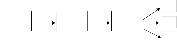
552 Chapter 18: Running Workflows and Sessions on a Grid
Overview
When a PowerCenter domain contains multiple nodes, you can configure workflows and
sessions to run on a grid. When you run a workflow on a grid, the Integration Service runs a
service process on each available node of the grid to increase performance and scalability.
When you run a session on a grid, the Integration Service distributes session threads to
multiple DTM processes on nodes in the grid to increase performance and scalability.
You create the grid and configure the Integration Service in the Administration Console. To
run a workflow on a grid, you configure the workflow to run on the Integration Service
associated with the grid. To run a session on a grid, configure the session to run on the grid.
Figure 18-1 shows the relationship between the workflow and nodes when you run a
workflow on a grid:
The Integration Service distributes workflow tasks and session threads based on how you
configure the workflow or session to run:
♦Running workflows on a grid. The Integration Service distributes workflows across the
nodes in a grid. It also distributes the Session, Command, and predefined Event-Wait tasks
within workflows across the nodes in a grid. For more information about running a
workflow on a grid, see “Running Workflows on a Grid” on page 553.
♦Running sessions on a grid. The Integration Service distributes session threads across
nodes in a grid. For information about running a session on a grid, see “Running Sessions
on a Grid” on page 554.
Note: To run workflows on a grid, you must have the Server grid option. To run sessions on a
grid, you must have the Session on Grid option.
For more information about creating the grid and configuring the Integration Service to run
on a grid, see “Managing the Grid” in the PowerCenter Administrator Guide.
Figure 18-1. Running a Workflow on a Grid
Assign a workflow to run
on an Integration Service.
The Integration Service is
associated with a grid.
The grid is assigned to
multiple nodes.
Node 1
Node 2
Node 3
Workflow Integration
Service
Grid
The workflow runs on the
nodes in the grid.
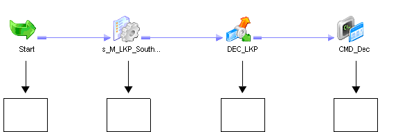
Running Workflows on a Grid 553
Running Workflows on a Grid
When you run a workflow on a grid, the master service process runs the workflow and all
tasks except Session, Command, and predefined Event-Wait tasks, which it may distribute to
other nodes. The master service process is the Integration Service process that runs the
workflow, monitors service processes running on other nodes, and runs the Load Balancer.
The Scheduler runs on the master service process node, so it uses the date and time for the
master service process node to start scheduled workflows.
The Load Balancer is the component of the Integration Service that dispatches Session,
Command, and predefined Event-Wait tasks to the nodes in the grid. The Load Balancer
distributes tasks based on node availability. If the Integration Service is configured to check
resources, the Load Balancer also distributes tasks based on resource availability. For more
information about configuring the Integration Service to check resources, see “Creating and
Configuring the Integration Service” in the Administrator Guide.
For example, a workflow contains a Session task, a Decision task, and a Command task. You
specify a resource requirement for the Session task. The grid contains four nodes, and Node 4
is unavailable. The master service process runs the Start and Decision tasks. The Load
Balancer distributes the Session and Command tasks to nodes on the grid based on resource
availability and node availability.
Figure 18-2 shows a workflow distributed to the nodes in a grid:
Figure 18-2. Workflow Distributed to the Nodes in a Grid
Start task runs on the
master service process
node.
Node 1 Node 2 Node 3
Session task runs on
node where resources
are available.
Command task runs on
node where resources
are available.
Node 1
Decision task runs
on master service
process node.
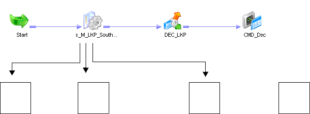
554 Chapter 18: Running Workflows and Sessions on a Grid
Running Sessions on a Grid
When you run a session on a grid, the master service process runs the workflow and all tasks
except Session, Command, and predefined Event-Wait tasks as it does when you run a
workflow on a grid. The Scheduler runs on the master service process node, so it uses the date
and time for the master service process node to start scheduled workflows. In addition, the
Load Balancer distributes session threads to DTM processes running on different nodes.
When you run a session on a grid, the Load Balancer distributes session threads based on the
following factors:
♦Node availability. The Load Balancer verifies which nodes are currently running, enabled,
and available for task dispatch.
♦Resource availability. If the Integration Service is configured to check resources, it
identifies nodes that have resources required by mapping objects in the session.
♦Partitioning configuration. The Load Balancer dispatches groups of session threads to
separate nodes based on the partitioning configuration.
You might want to configure a session to run on a grid when the workflow contains a session
that takes a long time to run.
For example, a workflow contains a session with one partition. To balance the load, you
configure the session to run on a grid and configure the Integration Service to check
resources. The Load Balancer distributes the reader, writer, and transformation threads to
DTM processes running on the nodes in the grid. The reader threads require a resource, so
the Load Balancer distributes them to a DTM process on the node where resources are
available.
Figure 18-3 shows session threads distributed to DTM processes running on nodes in a grid:
For more information about assigning resources to tasks or mapping objects, see “Assigning
Resources to Tasks” on page 564. For more information about configuring the Integration
Figure 18-3. Session Threads Distributed to DTM Processes Running on Nodes in a Grid
Node 4 is unavailable so
no threads run on it.
Node 1 Node 2 Node 3 Node 4
Reader threads run on
node where resources are
available.
Writer threads run on
available node.
Transformation threads
run on available node.
Running Sessions on a Grid 555
Service to check resources, see “Creating and Configuring the Integration Service” in the
Administrator Guide.
Working with Partition Groups
When you run a session on a grid, the Data Transformation Manager process (DTM) forms
groups of session threads called partition groups. A partition group is a group of reader,
writer, or transformation threads that run in a single DTM process. A partition group might
include one or more pipeline stages. A pipeline stage is the section of a pipeline executed
between any two partition points. Some transformations are not partitionable across a grid.
When a transformation is not partitionable across a grid, the DTM creates a single partition
group for the transformation threads and runs those threads on a single node.
Forming Partition Groups Without Resource Requirements
If the session has more than one partition, the DTM forms partition groups based on the
partitioning configuration. For example, a session is configured with two partitions. The
DTM creates partition groups for the threads in each partition, and the Load Balancer
distributes the groups to two nodes.
Figure 18-4 shows an example of the partition groups distributed for a session containing two
partitions:
Forming Partition Groups With Resource Requirements
When you specify resource requirements for a mapping object, the DTM process creates
partition groups based on the resources available on a particular node. For example, if the
source files for the session are available on a particular node and you specified a resource
requirement for the Source Qualifier transformation, the DTM process forms partition
groups based on this requirement.
To meet the resource requirements of the Source Qualifier transformation, the DTM process
creates a partition group from the reader threads. The Load Balancer distributes the reader
threads to the node where the resource is available.
Note: To cause the Load Balancer to distribute threads to nodes where required resources are
available, you must configure the Integration Service to check resources. For information
about configuring the Integration Service to check resources, see “Creating and Configuring
the Integration Service” in the Administrator Guide.
Figure 18-4. Partition Groups Distributed Based on Partitioning Configuration
Reader 1 Transformation 1 Writer 1 Node 1
Node 2
Reader 2 Transformation 2 Writer 2
Partition 1
Partition 2
Partition Group 1
runs on Node 1.
Partition Group 2
runs on Node 2.
556 Chapter 18: Running Workflows and Sessions on a Grid
Figure 18-5 shows an example of partition groups distributed based on partitioning
configuration and resource availability:
Rules and Guidelines
The Integration Service uses the following rules and guidelines to create partition groups:
♦The Integration Service limits the number of partition groups to the number of nodes in a
grid.
♦When a transformation is partitionable locally, the DTM process forms one partition
group for the transformation threads, and runs that group in one DTM process. The
following transformations are partitioned locally:
−Custom transformation configured to partition locally
−External Procedure transformation
−Cached Lookup transformation
−Unsorted Joiner transformation
−SDK Reader or Writer transformation configured to partition locally
Working with Caches
The Integration Service creates index and data caches for the Aggregator, Rank, Joiner, Sorter,
and Lookup transformations. When the session contains more than one partition, the
transformation threads may be distributed to more than one node in the grid. To create a
single data and index cache for these transformation threads, verify that the root directory and
cache directory point to the same location for all nodes in the grid.
When the Integration Service creates a cache for a Lookup transformation in a shared
location, it builds a cache for the first partition group, and subsequent partition groups use
this cache. When you do not configure a shared location for the Lookup transformation cache
files, each service process on a separate node fetches data from the database or source files to
create a cache. If the source data changes frequently, the caches created on separate nodes can
be inconsistent.
Figure 18-5. Partition Groups Distributed Based on Resource Availability
Reader 1 Transformation 1 Writer 1
Node 1 Node 2
Reader 2 Transformation 2 Writer 2
Partition 1
Partition 2
Partition Group 1 runs on Node 1
where resources are available.
Partition Group 2 runs on Node 2.
558 Chapter 18: Running Workflows and Sessions on a Grid
Grid Connectivity and Recovery
When you run a workflow or session on a grid, service processes and DTM processes run on
different nodes. Network failures can cause connectivity loss between processes running on
separate nodes. Services may shut down unexpectedly, or you may disable the Integration
Service or service processes while a workflow or session is running. The Integration Service
failover and recovery behavior in these situations depends on the service process that is
disabled, shuts down, or loses connectivity. Recovery behavior also depends on the following
factors:
♦High availability option. When you have high availability, workflows fail over to another
node if the node or service shuts down. If you do not have high availability, you can
manually restart a workflow on another node to recover it.
♦Recovery strategy. You can configure a workflow to suspend on error. You configure a
recovery strategy for tasks within the workflow. When a workflow suspends, the recovery
behavior depends on the recovery strategy you configure for each task in the workflow.
♦Shutdown mode. When you disable an Integration Service or service process, you can
specify that the service completes, aborts, or stops processes running on the service.
Behavior differs when you disable the Integration Service or you disable a service process.
Behavior also differs when you disable a master service process or a worker service process.
The Integration Service or service process may also shut down unexpectedly. In this case,
the failover and recovery behavior depend on which service process shuts down and the
configured recovery strategy.
♦Running mode. If the workflow runs on a grid, the Integration Service can recover
workflows and tasks on another node. If a session runs on a grid, you cannot configure a
resume recovery strategy.
♦Operating mode. If the Integration Service runs in safe mode, recovery is disabled for
sessions and workflows.
Note: You cannot configure an Integration Service to fail over in safe mode if it runs on a grid.
For information about recovery behavior, see “Recovering Workflows” on page 337.
For information about Integration Service failover and Integration Service safe mode, see
“Managing High Availability” and “Creating and Configuring the Integration Service” in the
Administrator Guide.
Configuring a Workflow or Session to Run on a Grid 559
Configuring a Workflow or Session to Run on a Grid
Before you can run a session or workflow on a grid, the grid must be assigned to multiple
nodes, and the Integration Service must be configured to run on the grid. You create the grid
and assign the Integration Service in the PowerCenter Administration Console. You may need
to verify these settings with the domain administrator.
To run a workflow or session on a grid, configure workflow and session properties and verify
the Integration Service property settings.
♦Configure the workflow properties. On the General tab of the workflow properties, assign
an Integration Service to run the workflow. Verify that the Integration Service is
configured to run on a grid.
♦Configure the session properties. To run a session on a grid, enable the session to run on a
grid in the Config Object tab of the session properties.
♦Configure resource requirements. You configure resource requirements on the General tab
of the Session, Command, and predefined Event-Wait tasks. For information about
configuring resource requirements, see “Assigning Resources to Tasks” on page 564.
For information about creating a grid, see “Managing the Grid” in the PowerCenter
Administrator Guide.
Rules and Guidelines
Use the following rules and guidelines when you configure a session or workflow to run on a
grid:
♦If you override a service process variable, ensure that the Integration Service can access
input files, caches, logs, storage and temporary directories, and source and target file
directories.
♦To ensure that a Session, Command, or predefined Event-Wait task runs on a particular
node, configure the Integration Service to check resources and specify a resource
requirement for a the task. For more information about configuring the Integration
Service to check resources, see “Creating and Configuring the Integration Service” in the
Administrator Guide.
♦To ensure that session threads for a mapping object run on a particular node, configure the
Integration Service to check resources and specify a resource requirement for the object.
♦When you run a session that creates cache files, configure the root and cache directory to
use a shared location to ensure consistency between cache files.
♦Ensure the Integration Service builds the cache in a shared location when you add a
partition point at a Joiner transformation and the transformation is configured for 1:n
partitioning. The cache for the Detail pipeline must be shared.
♦Ensure the Integration Service builds the cache in a shared location when you add a
partition point at a Lookup transformation, and the partition type is not hash auto-keys.
♦When you run a session that uses dynamic partitioning, and you want to distribute session
threads across all nodes in the grid, configure dynamic partitioning for the session to use
560 Chapter 18: Running Workflows and Sessions on a Grid
the “Based on number of nodes in the grid” method. For more information about
configuring dynamic partitioning, see “Dynamic Partitioning” on page 427.
♦You cannot run a debug session on a grid.
♦You cannot configure a resume recovery strategy for a session that you run on a grid.
♦Configure the session to run on a grid when you work with sessions that take a long time
to run.
♦Configure the workflow to run on a grid when you have multiple concurrent sessions.
♦You can run a persistent profile session on a grid, but you cannot run a temporary profile
session on a grid.
♦When you use a Sequence Generator transformation, increase the number of cached values
to reduce the communication required between the master and worker DTM processes
and the repository.
♦To ensure that the Log Viewer can accurately order log events when you run a workflow or
session on a grid, use time synchronization software to ensure that the nodes of a grid use a
synchronized date/time.
♦If the workflow uses an Email task in a Windows environment, configure the same
Microsoft Outlook profile on each node to ensure the Email task can run.

562 Chapter 19: Working with the Load Balancer
Overview
The Load Balancer dispatches tasks to Integration Service processes running on nodes. When
you run a workflow, the Load Balancer dispatches the Session, Command, and predefined
Event-Wait tasks within the workflow. If the Integration Service is configured to check
resources, the Load Balancer matches task requirements with resource availability to identify
the best node to run a task. It may dispatch tasks to a single node or across nodes. For more
information about how the Load Balancer dispatches tasks, see “Configuring the Load
Balancer” in the Administrator Guide. For more information about configuring the
Integration Service to check resources, see “Creating and Configuring the Integration Service”
in the Administrator Guide.
To identify the nodes that can run a task, the Load Balancer matches the resources required by
the task with the resources available on each node. It dispatches tasks in the order it receives
them. When the Load Balancer has more Session and Command tasks to dispatch than the
Integration Service can run at the time, the Load Balancer places the tasks in the dispatch
queue. When nodes become available, the Load Balancer dispatches the waiting tasks from
the queue in the order determined by the workflow service level.
You configure resources for each node using the Administration Console. For more
information about configuring node resources, see “Configuring the Load Balancer” in the
Administrator Guide.
You assign resources and service levels using the Workflow Manager. You can perform the
following tasks:
♦Assign service levels. You assign service levels to workflows. Service levels establish priority
among workflow tasks that are waiting to be dispatched.
For more information about assigning service levels, see “Assigning Service Levels to
Workflows” on page 563.
♦Assign resources. You assign resources to tasks. Session, Command, and predefined Event-
Wait tasks require PowerCenter resources to succeed. If the Integration Service is
configured to check resources, the Load Balancer dispatches these tasks to nodes where the
resources are available.
For more information about assigning resources, see “Assigning Resources to Tasks” on
page 564.
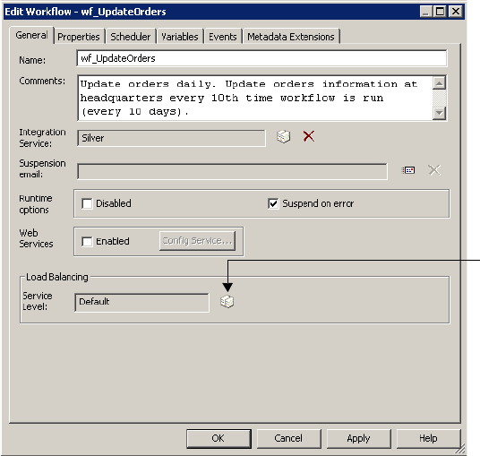
Assigning Service Levels to Workflows 563
Assigning Service Levels to Workflows
Service levels determine the order in which the Load Balancer dispatches tasks from the
dispatch queue. When multiple tasks are waiting to be dispatched, the Load Balancer
dispatches high priority tasks before low priority tasks. You create service levels and configure
the dispatch priorities in the Administration Console. For more information about creating
and editing service levels, see “Configuring the Load Balancer” in the Administrator Guide.
You assign service levels to workflows on the General tab of the workflow properties.
Figure 19-1 shows the workflow properties where you assign service levels:
To assign a service level to a workflow, you muse have the Use Workflow Manager privilege
with read and write permission on the folder.
Figure 19-1. Workflow Properties General Tab
Choose a service level.

564 Chapter 19: Working with the Load Balancer
Assigning Resources to Tasks
PowerCenter resources are the database connections, files, directories, node names, and
operating system types required by a task to make the task succeed. The Load Balancer may
use resources to dispatch tasks. If the Integration Service is not configured to run on a grid or
check resources, the Load Balancer ignores resource requirements. It dispatches all tasks to the
master Integration Service process running on the node.
If the Integration Service runs on a grid and is configured to check resources, the Load
Balancer uses resources to dispatch tasks. The Integration Service matches the resources
required by tasks in a workflow with the resources available on each node in the grid to
determine which nodes can run the tasks. The Load Balancer distributes the Session,
Command, and predefined Event-Wait tasks to nodes with available resources. For example, if
a session requires a file resource for a reserved words file, the Load Balancer dispatches the
session to nodes that have access to the file. A task fails if the Integration Service cannot
identify a node where the required resource is available.
In the Administration Console, you define the resources that are available to each node.
Resources are either predefined or user-defined. Predefined resources include connections
available to a node, node name, and operating system type. User-defined resources include
file/directory resources and custom resources. For more information about defining node
resources, see “Managing the Grid” in the Administrator Guide.
In the task properties, you assign PowerCenter resources to nonreusable tasks that require
those resources. You cannot assign resources to reusable tasks.
Table 19-1 lists resource types and the repository objects to which you can assign them:
Table 19-1. Resource Types and Associated Repository Objects
Resource Type Predefined/
User-Defined Repository Objects that Use Resources
Custom User-defined Session, Command, and predefined Event-Wait task instances and all
mapping objects within a session.
File/Directory User-defined Session, Command, and predefined Event-Wait task instances, and the
following mapping objects within a session:
- Source qualifiers
- Aggregator transformation
- Custom transformation
- External Procedure transformation
- Joiner transformation
- Lookup transformation
- Sorter transformation
- Custom transformation
- Java transformation
- HTTP transformation
- SQL transformation
- Union transformation
- Targets
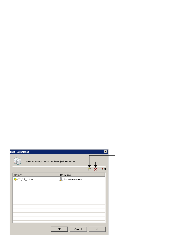
Assigning Resources to Tasks 565
If you try to assign a resource type that does not apply to a repository object, the Workflow
Manager displays the following error message:
The selected resource cannot be applied to this type of object. Please
select a different resource.
The Workflow Manager assigns connection resources. When you use a relational, FTP, or
external loader connection, the Workflow Manager assigns the connection resource to
sources, targets, and transformations in a session instance. You cannot manually assign a
connection resource in the Workflow Manager.
For more information about resources, see “Managing the Grid” in the Administrator Guide.
To assign resources to a task instance:
1. Open the task properties in the Worklet or Workflow Designer.
If the task is an Event-Wait task, you can assign resources only if the task waits for a
predefined event.
2. On the General tab, click Edit.
Node Name Predefined Session, Command, and predefined Event-Wait task instances and all
mapping objects within a session.
Operating System
Type
Predefined Session, Command, and predefined Event-Wait task instances and all
mapping objects within a session.
Table 19-1. Resource Types and Associated Repository Objects
Resource Type Predefined/
User-Defined Repository Objects that Use Resources
Add a resource.
Delete a resource.
Edit a resource.
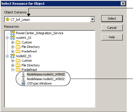
566 Chapter 19: Working with the Load Balancer
3. In the Edit Resources dialog box, click the Add button to add a resource.
4. In the Select Resource dialog box, choose an object you want to assign a resource to. The
Resources list shows the resources available to the nodes where the Integration Service
runs.
5. Select the resource to assign and click Select.
6. In the Edit Resources dialog box, click OK.
Select an object.
Select a resource.

568 Chapter 20: Session and Workflow Logs
Overview
The Service Manager provides accumulated log events from each service in the domain and
for sessions and workflows. To perform the logging function, the Service Manager runs a Log
Manager and a Log Agent. The Log Manager runs on the master gateway node. The
Integration Service generates log events for workflows and sessions. The Log Agent runs on
the nodes to collect and process log events for sessions and workflows.
Log events for workflows include information about tasks performed by the Integration
Service, workflow processing, and workflow errors. Log events for sessions include
information about the tasks performed by the Integration Service, session errors, and load
summary and transformation statistics for the session.
You can view log events for workflows with the Log Events window in the Workflow Monitor.
The Log Events window displays information about log events including severity level,
message code, run time, workflow name, and session name. For session logs, you can set the
tracing level to log more information. All log events display severity regardless of tracing level.
The following steps illustrates how the Log Manager processes session and workflow logs:
1. During a session or workflow, the Integration Service writes binary log files on the node.
It sends information about the sessions and workflows to the Log Manager.
2. The Log Manager stores information about workflow and session logs in the domain
configuration database. The domain configuration database stores information such as
the path to the log file location, the node that contains the log, and the Integration
Service that created the log.
3. When you view a session or workflow in the Log Events window, the Log Manager
retrieves the information from the domain configuration database to determine the
location of the session or workflow logs.
4. The Log Manager dispatches a Log Agent to retrieve the log events on each node to
display in the Log Events window.
For more information about the Log Manager, see the Administrator Guide.
When you want access to log events for more than the last workflow run, you can configure
sessions and workflows to archive logs by time stamp. You can also configure a workflow to
produce text log files. You can archive text log files by run or by time stamp. When you
configure the workflow or session to produce text log files, the Integration Service creates the
binary log and the text log file.

Log Events 569
Log Events
You can view log events in the Workflow Monitor Log Events window and you can view them
as text files. The Log Events window displays log events in a tabular format.
For information about viewing log events in the Log Events window, see “Log Events
Window” on page 571. For information about writing log events to a workflow or session log
file, see “Working with Log Files” on page 574.
Log Codes
Use log events to determine the cause of workflow or session problems. To resolve problems,
locate the relevant log codes and text prefixes in the workflow and session log. Then, refer to
the Troubleshooting Guide for more information about the error.
The Integration Service precedes each workflow and session log event with a thread
identification, a code, and a number. The code defines a group of messages for a process. The
number defines a message. The message can provide general information or it can be an error
message.
Some log events are embedded within other log events. For example, a code CMN_1039
might contain informational messages from Microsoft SQL Server.
Message Severity
The Log Events window categorizes workflow and session log events into severity levels. It
prioritizes error severity based on the embedded message type. The error severity level appears
with log events in the Log Events window in the Workflow Monitor. It also appears with
messages in the workflow and session log files.
Table 20-1 describes message severity levels:
Table 20-1. Message Severity Levels
Severity Level Description
FATAL Fatal error occurred. Fatal error messages have the highest severity level.
ERROR Indicates the service failed to perform an operation or respond to a request from a client
application. Error messages have the second highest severity level.
WARNING Indicates the service is performing an operation that may cause an error. This can cause repository
inconsistencies. Warning messages have the third highest severity level.
INFO Indicates the service is performing an operation that does not indicate errors or problems.
Information messages have the third lowest severity level.
TRACE Indicates service operations at a more specific level than Information. Tracing messages are
generally record message sizes. Trace messages have the second lowest severity level.
DEBUG Indicates service operations at the thread level. Debug messages generally record the success or
failure of service operations. Debug messages have the lowest severity level.
570 Chapter 20: Session and Workflow Logs
Writing Logs
The Integration Service writes the workflow and session logs as binary files on the node where
the service process runs. It adds a .bin extension to the log file name you configure in the
session and workflow properties.
When you run a session on a grid, the Integration Service creates one session log for each
DTM process. The log file on the primary node has the configured log file name. The log file
on a worker node has a .w<Partition Group Id> extension:
<session or workflow name>.w<Partition Group ID>.bin
For example, if you run the session s_m_PhoneList on a grid with three nodes, the session log
files use the names, s_m_PhoneList.bin, s_m_PhoneList.w1.bin, and s_m_PhoneList.w2.bin.
When you rerun a session or workflow, the Integration Service overwrites the binary log file
unless you choose to save workflow logs by time stamp. When you save workflow logs by time
stamp, the Integration Service adds a time stamp to the log file name and archives them. For
more information about archiving logs, see “Archiving Log Files by Time Stamp” on
page 575.
If you want to view log files for more than one run, configure the workflow or session to
create log files. For more information about log files, see “Working with Log Files” on
page 574.
A workflow or session continues to run if there are any errors while writing to the log file after
the workflow or session initializes. If the log file is incomplete, the Log Events window cannot
display all the log events.
The Integration Service starts a new log file for each workflow and session run. When you
recover a workflow or session, the Integration Service appends a recovery.time stamp
extension to the file name for the recovery run.
If you want to convert the binary file to a text file, use the infacmd convertLog or the infacmd
getLog command. For more information, see “infacmd Command Reference” in the
Command Line Reference.
Writing to an External Library
You can configure the Integration Service to write session log events to an external library in
addition to the session log file. To write to an external library, set ExportSessionLogLibName
in the Administration Console. The ExportSessionLogLibName refers to a .dll you create that
implements a set of log APIs. These APIs include InitSessionLog, OutputSessionLogMessage,
OutputSessionLogFatalMessage, EndSessionLog, and AbnormalSessionLogInformation. For
more information about ExportSessionLogLibName, see “Managing the Integration Service”
in the Administrator Guide.
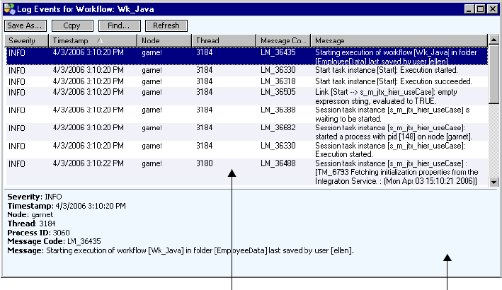
Log Events Window 571
Log Events Window
You can view log events in the Log Events window. For more information about configuring
the Workflow Monitor to display workflow and session runs, see “Customizing Workflow
Monitor Options” on page 505.
The Log Events window displays the following information for each session and workflow:
♦Severity. Lists the type of message, such as informational or error.
♦Time stamp. Date and time the log event reached the Log Agent.
♦Node. Node on which the Integration Service process is running.
♦Thread. Thread ID for the workflow or session.
♦Process ID. Windows or UNIX process identification numbers. Displays in the Output
window only.
♦Message Code. Message code and number.
♦Message. Message associated with the log event.
Figure 20-1 shows a sample workflow log in the Log Events window:
By default, the Log Events window displays log events according to the date and time the
Integration Service writes the log event on the node. The Log Events window displays logs
consisting of multiple log files by node name. When you run a session on a grid, log events for
the partition groups are ordered by node name and grouped by log file.
Figure 20-1. Sample Workflow Log in the Log Events Window
Output WindowMain Area
572 Chapter 20: Session and Workflow Logs
You can perform the following tasks in the Log Events window:
♦Save log events to file. Click Save As to save log events as a binary, text, or XML file.
♦Copy log event text to a file. Click Copy to copy one or more log events and paste them
into a text file.
♦Sort log events. Click a column heading to sort log events.
♦Search for log events. Click Find to search for text in log events.
♦Refresh log events. Click Refresh to view updated log events during a workflow or session
run.
Note: When you view a log larger than 2 GB, the Log Events window displays a warning that
the file might be too large for system memory. If you choose to continue, the Log Events
window might shut down unexpectedly.
Searching for Log Events
You search for log events based on any information in the Log Events window. For example,
you can search for text in a message or search for messages based on the date and time of the
log event.
To search for log events:
1. Open the Workflow Monitor.
2. Connect to a repository in the Navigator.
3. Select an Integration Service.
4. Right-click a workflow and select Get Workflow Log.
The Log Events window displays.
5. In the Log Events window, click Find.
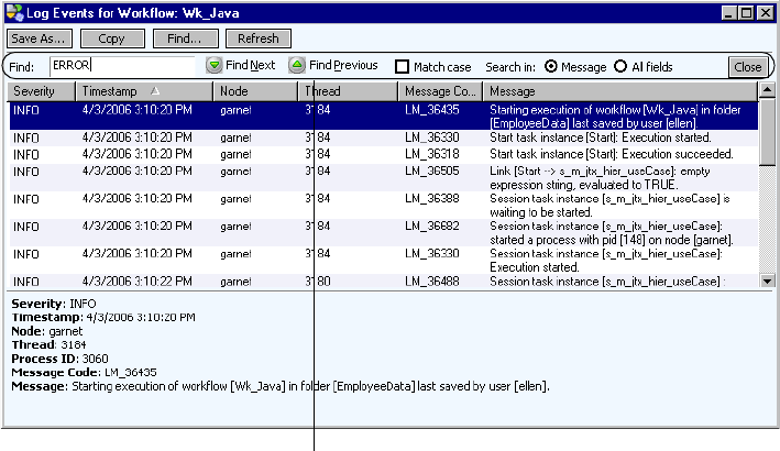
Log Events Window 573
The Query Area appears.
6. Enter the text you want to find.
7. Optionally, click Match Case if you want the query to be case sensitive.
8. Select one of the following options:
♦Message. Select to search text in the Message field.
♦All Fields. Select to search text in all fields.
9. Click Find Next to search for the next instance of the text in the Find window. Or, click
Find Previous to search for the previous instance of the text in the Find window.
Query Area

574 Chapter 20: Session and Workflow Logs
Working with Log Files
You configure a workflow or session to write log events to log files in the workflow or session
properties. The Integration Service writes information about the workflow or session run to a
text file in addition to writing log events to a binary file. If you configure workflow or session
properties to create log files, you can open the text files with any text editor or import the
binary files to view logs in the Log Events window.
By default, the Integration Service writes log files based on the Integration Service code page.
If you enable the LogInUTF8 option in the Advanced Properties for the Integration Service,
the Integration Service writes to the logs using the UTF-8 character set. If you configure the
Integration Service to run in ASCII mode, it sorts all character data using a binary sort order
even if you select a different sort order in the session properties.
You can optimize performance by disabling the option to create text log files.
Writing to Log Files
When you create a workflow or session log, you can configure log options in the workflow or
session properties. You can configure the following information for a workflow or session log:
♦Write Backward Compatible Log File. Select this option to create a text file for workflow
or session logs. If you do not select the option, the Integration Service creates the binary
log only.
♦Log File Directory. The directory where you want the log file created. By default, the
Integration Service writes the log file in the process variable directory,
$PMWorkflowLogDir. If you enter a directory name that nodes configured to run the
Integration Service cannot access, the workflow or session fails.
♦Name. The name of the log file. You must configure a name for the log file or the
workflow or session is invalid.
Table 20-2 shows the default location for each type of log file and the associated process
variables:
Note: The Integration Service stores the workflow and session log names in the domain
configuration database. If you want to use Unicode characters in the workflow or session log
file names, the domain configuration database must be a Unicode database.
Table 20-2. Log File Default Locations and Associated Process Variables
Log File Type Default Directory
(Process Variable) Value
Workflow logs $PMWorkflowLogDir $PMRootDir/WorkflowLogs
Session logs $PMSessionLogDir $PMRootDir/SessLogs
Working with Log Files 575
Archiving Log Files
By default, when you configure a workflow or session to create log files, the Integration
Service creates one log file for the workflow or session. The Integration Service overwrites the
log file when you run the workflow again.
If you want to create a log file for more than one workflow or session run, you can configure
the workflow or session to archive logs in the following ways:
♦By run. Archive text log files by run. Configure a number of text logs to save.
♦By time stamp. Archive binary logs and text files by time stamp. The Integration Service
saves an unlimited number of logs and labels them by time stamp. When you configure the
workflow or session to archive by time stamp, the Integration Service always archives
binary logs.
Archiving Logs by Run
If you archive log files by run, you specify the number of text log files you want the
Integration Service to create. The Integration Service creates the number of historical log files
you specify, plus the most recent log file. If you specify five runs, the Integration Service
creates the most recent workflow log, plus historical logs zero to four, for a total of six logs.
You can specify up to 2,147,483,647 historical logs. If you specify zero logs, the Integration
Service creates only the most recent workflow log file.
The Integration Service uses the following naming convention to create historical logs:
<session or workflow name>.n
where n=0 for the first historical log. The variable increments by one for each workflow or
session run.
If you run a session on a grid, the worker service processes use the following naming
convention for a session:
<session name>.n.w<DTM ID>
Archiving Log Files by Time Stamp
When you archive logs by time stamp, the Integration Service creates an unlimited number of
binary and text file logs. The Integration Service adds a time stamp to the text and binary log
file names. It appends the year, month, day, hour, and minute of the workflow or session
completion to the log file. The resulting log file name is <session or workflow log
name>.yyyymmddhhmi, where:
♦yyyy = year
♦mm = month, ranging from 01-12
♦dd = day, ranging from 01-31
♦hh = hour, ranging from 00-23
♦mi = minute, ranging from 00-59
The binary logs contain the .bin suffix.
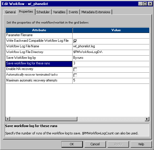
576 Chapter 20: Session and Workflow Logs
To prevent filling the log directory, periodically purge or back up log files when using the
time stamp option.
If you run a session on a grid, the worker service processes use the following naming
convention for sessions:
<session name>.yyyymmddhhmi.w<DTM ID>
<session name>.yyyymmddhhmi.w<DTM ID>.bin
When you archive text log files, you can view the logs by navigating to the workflow or
session log folder and viewing the files in a text reader. When you archive binary log files, you
can view the logs by navigating to the workflow or session log folder and importing the files
in the Log Events window. You can archive binary files when you configure the workflow or
session to archive logs by time stamp. You do not have to create text log files to archive binary
files. You might need to archive binary files to send to Informatica Technical Support for
review.
Configuring Workflow Log File Information
You can configure workflow log information on the workflow Properties tab.
To configure workflow log information:
1. Select the Properties tab of a workflow.

Working with Log Files 577
2. Enter the following workflow log options:
3. Click OK.
Configuring Session Log File Information
You can configure session log information on the session Properties tab and the Config
Object tab.
Option Name Required/
Optional Description
Write Backward
Compatible Workflow
Log File
Optional Writes workflow logs to a text log file. Select this option if you want
to create a log file in addition to the binary log for the Log Events
window.
Workflow Log File Name Required Enter a file name or a file name and directory.
The Integration Service appends this value to that entered in the
Workflow Log File Directory field. For example, if you have
$PMWorkflowLogDir\ in the Workflow Log File Directory field, enter
“logname.txt” in the Workflow Log File Name field, the Integration
Service writes logname.txt to the $PMWorkflowLogDir\ directory.
Workflow Log File
Directory
Required Location for the workflow log file. By default, the Integration
Service writes the log file in the process variable directory,
$PMWorkflowLogDir.
If you enter a full directory and file name in the Workflow Log File
Name field, clear this field.
Save Workflow Log By Required You can create workflow logs according to the following options:
- By Runs. The Integration Service creates a designated number of
workflow logs. Configure the number of workflow logs in the Save
Workflow Log for These Runs option. The Integration Service
does not archive binary logs.
- By time stamp. The Integration Service creates a log for all
workflows, appending a time stamp to each log. When you save
workflow logs by time stamp, the Integration Service archives
binary logs and workflow log files.
For more information about these options, see “Archiving Log
Files” on page 575.
You can also use the $PMWorkflowLogCount service variable to
create the configured number of workflow logs for the Integration
Service.
Save Workflow Log for
These Runs
Optional Number of historical workflow logs you want the Integration Service
to create.
The Integration Service creates the number of historical logs you
specify, plus the most recent workflow log. For more information,
see “Archiving Logs by Run” on page 575.
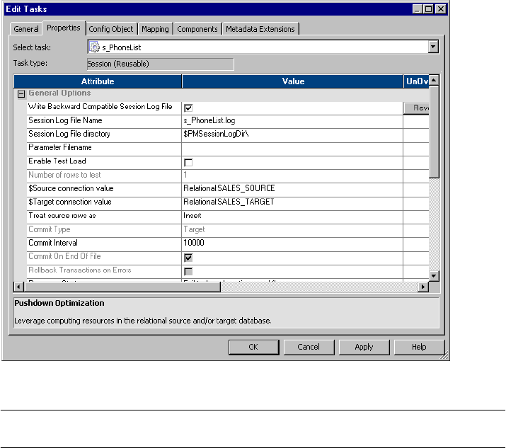
578 Chapter 20: Session and Workflow Logs
To configure session log information:
1. Select the Properties tab of a session.
2. Enter the following session log options:
Option Name Required/
Optional Description
Write Backward
Compatible Session Log
File
Optional Writes session logs to a log file. Select this option if you want to
create a log file in addition to the binary log for the Log Events
window.
Session Log File Name Required Enter a file name or a file name and directory. The Integration
Service appends this value to that entered in the Session Log File
Directory field. For example, if you have $PMSessionLogDir\ in the
Session Log File Directory field, enter “logname.txt” in the Session
Log File Name field, the Integration Service writes logname.txt to
the $PMSessionLogDir\ directory.
Session Log File
Directory
Required Location for the session log file. By default, the Integration Service
writes the log file in the process variable directory,
$PMSessionLogDir.
If you enter a full directory and file name in the Session Log File
Name field, clear this field.
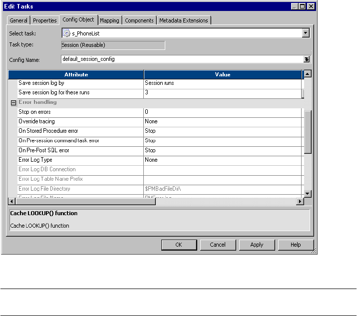
Working with Log Files 579
3. Click the Config Object tab.
4. Enter the following session log options:
5. Click OK.
Option Name Required/
Optional Description
Save Session Log By Required You can create session logs according to the following options:
- Session Runs. The Integration Service creates a designated
number of session log files. Configure the number of session logs
in the Save Session Log for These Runs option. The Integration
Service does not archive binary logs.
- Session Time Stamp. The Integration Service creates a log for all
sessions, appending a time stamp to each log. When you save a
session log by time stamp, the Integration Service archives the
binary logs and text log files.
For more information about these options, see “Archiving Log
Files” on page 575.
You can also use the $PMSessionLogCount service variable to
create the configured number of session logs for the Integration
Service.
Save Session Log for
These Runs
Optional Number of historical session logs you want the Integration Service
to create.
The Integration Service creates the number of historical logs you
specify, plus the most recent session log. For more information,
see “Archiving Logs by Run” on page 575.
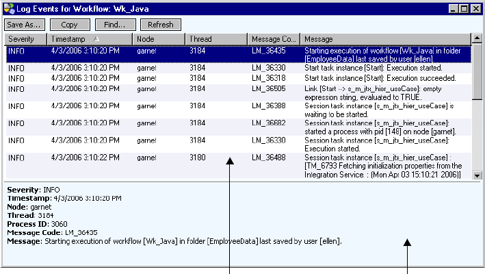
580 Chapter 20: Session and Workflow Logs
Workflow Logs
Workflow logs contain information about the workflow runs. You can view workflow log
events in the Log Events window of the Workflow Monitor. You can also create an XML, text,
or binary log file for workflow log events.
A workflow log contains the following information:
♦Workflow name
♦Workflow status
♦Status of tasks and worklets in the workflow
♦Start and end times for tasks and worklets
♦Results of link conditions
♦Errors encountered during the workflow and general information
♦Some session messages and errors
Workflow Log Events Window
Use the Log Events window in the Workflow Monitor to view log events for a workflow. The
Log Events window displays all log events for a workflow. Select a log event to view more
information about the log event. For more information about the log events window, see “Log
Events Window” on page 571.
Figure 20-2 shows a sample Log Events window for a workflow:
Figure 20-2. Sample Workflow Log Events Window
Output WindowMain Area
Workflow Logs 581
Workflow Log Sample
A workflow log file provides the same information as the Log Events window for a workflow.
You can view a workflow log file in a text editor.
The following sample shows a section of a workflow log file:
INFO : LM_36435 [Mon Apr 03 15:10:20 2006] : (3060|3184) Starting execution of workflow
[Wk_Java] in folder [EmployeeData] last saved by user [ellen].
INFO : LM_36330 [Mon Apr 03 15:10:20 2006] : (3060|3184) Start task instance [Start]:
Execution started.
INFO : LM_36318 [Mon Apr 03 15:10:20 2006] : (3060|3184) Start task instance [Start]:
Execution succeeded.
INFO : LM_36505 : (3060|3184) Link [Start --> s_m_jtx_hier_useCase]: empty expression
string, evaluated to TRUE.
INFO : LM_36388 [Mon Apr 03 15:10:20 2006] : (3060|3184) Session task instance
[s_m_jtx_hier_useCase] is waiting to be started.
INFO : LM_36682 [Mon Apr 03 15:10:20 2006] : (3060|3184) Session task instance
[s_m_jtx_hier_useCase]: started a process with pid [148] on node [garnet].
INFO : LM_36330 [Mon Apr 03 15:10:20 2006] : (3060|3184) Session task instance
[s_m_jtx_hier_useCase]: Execution started.
INFO : LM_36488 [Mon Apr 03 15:10:22 2006] : (3060|3180) Session task instance
[s_m_jtx_hier_useCase] : [TM_6793 Fetching initialization properties from the Integration
Service. : (Mon Apr 03 15:10:21 2006)]
INFO : LM_36488 [Mon Apr 03 15:10:22 2006] : (3060|3180) Session task instance
[s_m_jtx_hier_useCase] : [DISP_20305 The [Preparer] DTM with process id [148] is running on
node [garnet].
: (Mon Apr 03 15:10:21 2006)]
INFO : LM_36488 [Mon Apr 03 15:10:22 2006] : (3060|3180) Session task instance
[s_m_jtx_hier_useCase] : [PETL_24036 Beginning the prepare phase for the session.]
INFO : LM_36488 [Mon Apr 03 15:10:22 2006] : (3060|3180) Session task instance
[s_m_jtx_hier_useCase] : [TM_6721 Started [Connect to Repository].]
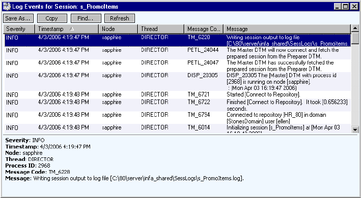
582 Chapter 20: Session and Workflow Logs
Session Logs
Session logs contain information about the tasks that the Integration Service performs during
a session, plus load summary and transformation statistics. By default, the Integration Service
creates one session log for each session it runs. If a workflow contains multiple sessions, the
Integration Service creates a separate session log for each session in the workflow. When you
run a session on a grid, the Integration Service creates one session log for each DTM process.
In general, a session log contains the following information:
♦Allocation of heap memory
♦Execution of pre-session commands
♦Creation of SQL commands for reader and writer threads
♦Start and end times for target loading
♦Errors encountered during the session and general information
♦Execution of post-session commands
♦Load summary of reader, writer, and DTM statistics
♦Integration Service version and build number
Log Events Window
Use the Log Events window in the Workflow Monitor to view log events for a session. The
Log Events window displays all log events for a session. Select a log event to view more
information about the log event. For more information about the log events window, see “Log
Events Window” on page 571.
Figure 20-3 shows a sample Log Events window for a session:
Figure 20-3. Sample Session Log Events Window
Session Logs 583
Session Log File Sample
A session log file provides most of the same information as the Log Events window for a
session. The session log file does not include severity or DTM prepare messages.
The following sample shows a section of a session log file:
DIRECTOR> PETL_24044 The Master DTM will now connect and fetch the prepared session from
the Preparer DTM.
DIRECTOR> PETL_24047 The Master DTM has successfully fetched the prepared session from the
Preparer DTM.
DIRECTOR> DISP_20305 The [Master] DTM with process id [2968] is running on node [sapphire].
: (Mon Apr 03 16:19:47 2006)
DIRECTOR> TM_6721 Started [Connect to Repository].
DIRECTOR> TM_6722 Finished [Connect to Repository]. It took [0.656233] seconds.
DIRECTOR> TM_6794 Connected to repository [HR_80] in domain [StonesDomain] user [ellen]
DIRECTOR> TM_6014 Initializing session [s_PromoItems] at [Mon Apr 03 16:19:48 2006]
DIRECTOR> TM_6683 Repository Name: [HR_80]
DIRECTOR> TM_6684 Server Name: [Copper]
DIRECTOR> TM_6686 Folder: [Snaps]
DIRECTOR> TM_6685 Workflow: [wf_PromoItems]
DIRECTOR> TM_6101 Mapping name: m_PromoItems [version 1]
DIRECTOR> SDK_1805 Recovery cache will be deleted when running in normal mode.
DIRECTOR> SDK_1802 Session recovery cache initialization is complete.
The session log file includes the Integration Service version and build number.
DIRECTOR> TM_6703 Session [s_PromoItems] is run by 32-bit Integration Service [sapphire],
version [8.1.0], build [0329].
Setting Tracing Levels
The amount of detail that logs contain depends on the tracing level that you set. You can
configure tracing levels for each transformation or for the entire session. By default, the
Integration Service uses tracing levels configured in the mapping.
Setting a tracing level for the session overrides the tracing levels configured for each
transformation in the mapping. If you select a normal tracing level or higher, the Integration
Service writes row errors into the session log, including the transformation in which the error
occurred and complete row data. If you configure the session for row error logging, the
Integration Service writes row errors to the error log instead of the session log. If you want the
Integration Service to write dropped rows to the session log also, configure the session for
verbose data tracing.
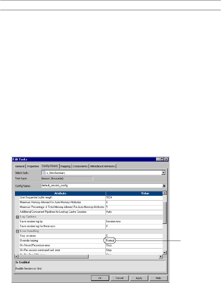
584 Chapter 20: Session and Workflow Logs
Table 20-3 describes the session log tracing levels:
You can also enter tracing levels for individual transformations in the mapping. When you
enter a tracing level in the session properties, you override tracing levels configured for
transformations in the mapping.
To set the tracing level:
1. Select the Error Handling settings on the session Config Object tab.
Table 20-3. Session Log Tracing Levels
Tracing Level Description
None Integration Service uses the tracing level set in the mapping.
Terse Integration Service logs initialization information, error messages, and notification of rejected data.
Normal Integration Service logs initialization and status information, errors encountered, and skipped rows
due to transformation row errors. Summarizes session results, but not at the level of individual
rows.
Verbose
Initialization
In addition to normal tracing, Integration Service logs additional initialization details, names of
index and data files used, and detailed transformation statistics.
Verbose Data In addition to verbose initialization tracing, Integration Service logs each row that passes into the
mapping. Also notes where the Integration Service truncates string data to fit the precision of a
column and provides detailed transformation statistics.
When you configure the tracing level to verbose data, the Integration Service writes row data for all
rows in a block when it processes a transformation.
Tracing Level
586 Chapter 20: Session and Workflow Logs
Viewing Log Events
You can view the following types of log files:
♦Most recent session or workflow log. View the session or workflow log in the Log Events
window for the last run workflow.
♦Archived binary log files. View archived binary log files in the Log Events window.
♦Archived text log files. View archived text log files in any text editor.
For more information about archiving log files, see “Archiving Log Files” on page 575.
To view the Log Events window for a session or workflow:
1. In the Workflow Monitor, right-click the workflow or session.
2. Select Get Session Log or Get Workflow Log.
To view an archived binary log file in the Log Events window:
1. If you do not know the session or workflow log file name and location, check the Log File
Name and Log File Directory attributes on the Session or Workflow Properties tab.
If you are running the Integration Service on UNIX and the binary log file is not
accessible on the windows machine where the client is running, transfer the binary log
file to the windows machine using FTP.
2. In the Workflow Monitor, click Tools > Import Log.
3. Navigate to the session or workflow log file directory.
4. Select the binary log file you want to view.
5. Click Open.
To view a text log file:
1. If you do not know the session or workflow log file name and location, check the Log File
Name and Log File Directory attributes on the Session or Workflow Properties tab.
2. Navigate to the session or workflow log file directory.
The session and workflow log file directory contains the text log files and the binary log
files. If you archive log files, check the file date to find the latest log file for the session.
3. Open the log file in any text editor.

588 Chapter 21: Row Error Logging
Overview
When you configure a session, you can choose to log row errors in a central location. When a
row error occurs, the Integration Service logs error information that lets you determine the
cause and source of the error. The Integration Service logs information such as source name,
row ID, current row data, transformation, timestamp, error code, error message, repository
name, folder name, session name, and mapping information.
You can log row errors into relational tables or flat files. When you enable error logging, the
Integration Service creates the error tables or an error log file the first time it runs the session.
Error logs are cumulative. If the error logs exist, the Integration Service appends error data to
the existing error logs.
You can choose to log source row data. Source row data includes row data, source row ID, and
source row type from the source qualifier where an error occurs. The Integration Service
cannot identify the row in the source qualifier that contains an error if the error occurs after a
non pass-through partition point with more than one partition or one of the following active
sources:
♦Aggregator
♦Custom, configured as an active transformation
♦Joiner
♦Normalizer (pipeline)
♦Rank
♦Sorter
By default, the Integration Service logs transformation errors in the session log and reject rows
in the reject file. When you enable error logging, the Integration Service does not generate a
reject file or write dropped rows to the session log. Without a reject file, the Integration
Service does not log Transaction Control transformation rollback or commit errors. If you
want to write rows to the session log in addition to the row error log, you can enable verbose
data tracing.
Note: When you log row errors, session performance may decrease because the Integration
Service processes one row at a time instead of a block of rows at once.
Error Log Code Pages
The Integration Service writes data to the error log file differently depending on the
Integration Service process operating system:
♦UNIX. The Integration Service writes data to the error log file using the Integration
Service process code page. However, you can configure the Integration Service to write to
the error log file using UTF-8 by enabling the LogsInUTF8 Integration Service property.
♦Windows. The Integration Service writes all characters in the error log file using the UTF-
8 encoding format.
Overview 589
The code page for the relational database where the error tables exist must be a subset of the
target code page. If the error log table code page is not a subset of the target code page, the
Integration Service might write inconsistent data in the error log tables.
For more information about code pages, see “Understanding Globalization” in the
Administrator Guide.

590 Chapter 21: Row Error Logging
Understanding the Error Log Tables
When you choose relational database error logging, the Integration Service creates four error
tables the first time you run a session. You specify the database connection to the database
where the Integration Service creates these tables. If the error tables exist for a session, the
Integration Service appends row errors to these tables.
Relational database error logging lets you collect row errors from multiple sessions in one set
of error tables. To do this, you specify the same error log table name prefix for all sessions.
You can issue select statements on the generated error tables to retrieve error data for a
particular session.
You can specify a prefix for the error tables. The error table names can have up to eleven
characters. Do not specify a prefix that exceeds 19 characters when naming Oracle, Sybase, or
Teradata error log tables, as these databases have a maximum length of 30 characters for table
names.
The Integration Service creates the error tables without specifying primary and foreign keys.
However, you can specify key columns.
The Integration Service generates the following tables to help you track row errors:
♦PMERR_DATA. Stores data and metadata about a transformation row error and its
corresponding source row.
♦PMERR_MSG. Stores metadata about an error and the error message.
♦PMERR_SESS. Stores metadata about the session.
♦PMERR_TRANS. Stores metadata about the source and transformation ports, such as
name and datatype, when a transformation error occurs.
PMERR_DATA
When the Integration Service encounters a row error, it inserts an entry into the
PMERR_DATA table. This table stores data and metadata about a transformation row error
and its corresponding source row.
Table 21-1 describes the structure of the PMERR_DATA table:
Table 21-1. PMERR_DATA Table Schema
Column Name Datatype Description
REPOSITORY_GID Varchar A unique identifier for the repository.
WORKFLOW_RUN_ID Integer A unique identifier for the workflow.
WORKLET_RUN_ID Integer A unique identifier for the worklet. If a session is not part of a
worklet, this value is “0”.
SESS_INST_ID Integer A unique identifier for the session.
TRANS_MAPPLET_INST Varchar Name of the mapplet where an error occurred.

Understanding the Error Log Tables 591
TRANS_NAME Varchar Name of the transformation where an error occurred.
TRANS_GROUP Varchar Name of the input group or output group where an error
occurred. Defaults to either “input” or “output” if the
transformation does not have a group.
TRANS_PART_INDEX Integer Specifies the partition number of the transformation where an
error occurred.
TRANS_ROW_ID Integer Specifies the row ID generated by the last active source.
TRANS_ROW_DATA Long Varchar Delimited string containing all column data, including the
column indicator. Column indicators are:
D - valid
N - null
T - truncated
B - binary
U - data unavailable
The fixed delimiter between column data and column indicator
is colon ( : ). The delimiter between the columns is pipe ( | ). You
can override the column delimiter in the error handling settings.
The Integration Service converts all column data to text string in
the error table. For binary data, the Integration Service uses
only the column indicator.
This value can span multiple rows. When the data exceeds
2000 bytes, the Integration Service creates a new row. The line
number for each row error entry is stored in the LINE_NO
column.
SOURCE_ROW_ID Integer Value that the source qualifier assigns to each row it reads. If
the Integration Service cannot identify the row, the value is -1.
SOURCE_ROW_TYPE Integer Row indicator that tells whether the row was marked for insert,
update, delete, or reject.
0 - Insert
1 - Update
2 - Delete
3 - Reject
Table 21-1. PMERR_DATA Table Schema
Column Name Datatype Description

592 Chapter 21: Row Error Logging
PMERR_MSG
When the Integration Service encounters a row error, it inserts an entry into the
PMERR_MSG table. This table stores metadata about the error and the error message.
Table 21-2 describes the structure of the PMERR_MSG table:
SOURCE_ROW_DATA Long Varchar Delimited string containing all column data, including the
column indicator. Column indicators are:
D - valid
O - overflow
N - null
T - truncated
B - binary
U - data unavailable
The fixed delimiter between column data and column indicator
is colon ( : ). The delimiter between the columns is pipe ( | ). You
can override the column delimiter in the error handling settings.
The Integration Service converts all column data to text string in
the error table or error file. For binary data, the Integration
Service uses only the column indicator.
This value can span multiple rows. When the data exceeds
2000 bytes, the Integration Service creates a new row. The line
number for each row error entry is stored in the LINE_NO
column.
LINE_NO Integer Specifies the line number for each row error entry in
SOURCE_ROW_DATA and TRANS_ROW_DATA that spans
multiple rows.
Note: Use the column names in bold to join tables.
Table 21-2. PMERR_MSG Table Schema
Column Name Datatype Description
REPOSITORY_GID Varchar A unique identifier for the repository.
WORKFLOW_RUN_ID Integer A unique identifier for the workflow.
WORKLET_RUN_ID Integer A unique identifier for the worklet. If a session is not part of a
worklet, this value is “0”.
SESS_INST_ID Integer A unique identifier for the session.
MAPPLET_INST_NAME Varchar Mapplet to which the transformation belongs. If the
transformation is not part of a mapplet, this value is n/a.
TRANS_NAME Varchar Name of the transformation where an error occurred.
Table 21-1. PMERR_DATA Table Schema
Column Name Datatype Description

Understanding the Error Log Tables 593
PMERR_SESS
When you choose relational database error logging, the Integration Service inserts entries into
the PMERR_SESS table. This table stores metadata about the session where an error
occurred.
TRANS_GROUP Varchar Name of the input group or output group where an error
occurred. Defaults to either “input” or “output” if the
transformation does not have a group.
TRANS_PART_INDEX Integer Specifies the partition number of the transformation where
an error occurred.
TRANS_ROW_ID Integer Specifies the row ID generated by the last active source.
ERROR_SEQ_NUM Integer Counter for the number of errors per row in each
transformation group. If a session has multiple partitions, the
Integration Service maintains this counter for each partition.
For example, if a transformation generates three errors in
partition 1 and two errors in partition 2, ERROR_SEQ_NUM
generates the values 1, 2, and 3 for partition 1, and values 1
and 2 for partition 2.
ERROR_TIMESTAMP Date/Time Timestamp of the Integration Service when the error
occurred.
ERROR_UTC_TIME Integer Coordinated Universal Time, called Greenwich Mean Time,
of when an error occurred.
ERROR_CODE Integer Error code that the error generates.
ERROR_MSG Long Varchar Error message, which can span multiple rows. When the
data exceeds 2000 bytes, the Integration Service creates a
new row. The line number for each row error entry is stored
in the LINE_NO column.
ERROR_TYPE Integer Type of error that occurred. The Integration Service uses the
following values:
1 - Reader error
2 - Writer error
3 - Transformation error
LINE_NO Integer Specifies the line number for each row error entry in
ERROR_MSG that spans multiple rows.
Note: Use the column names in bold to join tables.
Table 21-2. PMERR_MSG Table Schema
Column Name Datatype Description

594 Chapter 21: Row Error Logging
Table 21-3 describes the structure of the PMERR_SESS table:
PMERR_TRANS
When the Integration Service encounters a transformation error, it inserts an entry into the
PMERR_TRANS table. This table stores metadata, such as the name and datatype of the
source and transformation ports.
Table 21-3. PMERR_SESS Table Schema
Column Name Datatype Description
REPOSITORY_GID Varchar A unique identifier for the repository.
WORKFLOW_RUN_ID Integer A unique identifier for the workflow.
WORKLET_RUN_ID Integer A unique identifier for the worklet. If a session is not part of a
worklet, this value is “0”.
SESS_INST_ID Integer A unique identifier for the session.
SESS_START_TIME Date/Time Timestamp of the Integration Service when a session starts.
SESS_START_UTC_TIME Integer Coordinated Universal Time, called Greenwich Mean Time, of
when the session starts.
REPOSITORY_NAME Varchar Repository name where sessions are stored.
FOLDER_NAME Varchar Specifies the folder where the mapping and session are located.
WORKFLOW_NAME Varchar Specifies the workflow that runs the session being logged.
TASK_INST_PATH Varchar Fully qualified session name that can span multiple rows. The
Integration Service creates a new line for the session name. The
Integration Service also creates a new line for each worklet in the
qualified session name. For example, you have a session named
WL1.WL2.S1. Each component of the name appears on a new
line:
WL1
WL2
S1
The Integration Service writes the line number in the LINE_NO
column.
MAPPING_NAME Varchar Specifies the mapping that the session uses.
LINE_NO Integer Specifies the line number for each row error entry in
TASK_INST_PATH that spans multiple rows.
Note: Use the column names in bold to join tables.

Understanding the Error Log Tables 595
Table 21-4 describes the structure of the PMERR_TRANS table:
Table 21-4. PMERR_TRANS Table Schema
Column Name Datatype Description
REPOSITORY_GID Varchar A unique identifier for the repository.
WORKFLOW_RUN_ID Integer A unique identifier for the workflow.
WORKLET_RUN_ID Integer A unique identifier for the worklet. If a session is not part of a
worklet, this value is “0”.
SESS_INST_ID Integer A unique identifier for the session.
TRANS_MAPPLET_INST Varchar Specifies the instance of a mapplet.
TRANS_NAME Varchar Name of the transformation where an error occurred.
TRANS_GROUP Varchar Name of the input group or output group where an error
occurred. Defaults to either “input” or “output” if the
transformation does not have a group.
TRANS_ATTR Varchar Lists the port names and datatypes of the input or output group
where the error occurred. Port name and datatype pairs are
separated by commas, for example: portname1:datatype,
portname2:datatype.
This value can span multiple rows. When the data exceeds
2000 bytes, the Integration Service creates a new row for the
transformation attributes and writes the line number in the
LINE_NO column.
SOURCE_MAPPLET_INST Varchar Name of the mapplet in which the source resides.
SOURCE_NAME Varchar Name of the source qualifier. n/a appears when a row error
occurs downstream of an active source that is not a source
qualifier or a non pass-through partition point with more than
one partition. For a list of active sources that can affect row
error logging, see “Overview” on page 588.
SOURCE_ATTR Varchar Lists the connected field(s) in the source qualifier where an
error occurred. When an error occurs in multiple fields, each
field name is entered on a new line. Writes the line number in
the LINE_NO column.
LINE_NO Integer Specifies the line number for each row error entry in
TRANS_ATTR and SOURCE_ATTR that spans multiple rows.
Note: Use the column names in bold to join tables.
596 Chapter 21: Row Error Logging
Understanding the Error Log File
You can create an error log file to collect all errors that occur in a session. This error log file is
a column delimited line sequential file. By specifying a unique error log file name, you can
create a separate log file for each session in a workflow. When you want to analyze the row
errors for one session, use an error log file.
In an error log file, double pipes “||” delimit error logging columns. By default, pipe “|”
delimits row data. You can change this row data delimiter by setting the Data Column
Delimiter error log option.
Error log files have the following structure:
[Session Header]
[Column Header]
[Column Data]
♦Session header. Contains session run information. Information in the session header is like
the information stored in the PMERR_SESS table.
♦Column header. Contains data column names.
♦Column data. Contains actual row data and error message information.
The following sample error log file contains a session header, column header, and column
data:
**********************************************************************
Repository GID: fe4817ab-7d87-465f-9110-354222424df0
Repository: CustomerInfo
Folder: Row_Error_Logging
Workflow: wf_basic_REL_errors_AGG_case
Session: s_m_basic_REL_errors_AGG_case
Mapping: m_basic_REL_errors_AGG_case
Workflow Run ID: 1310
Worklet Run ID: 0
Session Instance ID: 19
Session Start Time: 08/03/2004 16:57:01
Session Start Time (UTC): 1067126221
**********************************************************************
Transformation||Transformation Mapplet Name||Transformation
Group||Partition Index||Transformation Row ID||Error Sequence||Error
Timestamp||Error UTC Time||Error Code||Error Message||Error
Type||Transformation Data||Source Mapplet Name||Source Name||Source Row
ID||Source Row Type||Source Data

Understanding the Error Log File 597
agg_REL_basic||N/A||Input||1||1||1||08/03/2004
16:57:03||1067126223||11019||Port [CUST_ID_NULL]: Default value is:
ERROR(<<Expression Error>> [ERROR]: [AGG] CUST_ID - NULL detected on
input.\n... nl:ERROR(s:'[AGG] CUST_ID - NULL detected on
input.')).||3||D:1221|N:|N:|N:|D:Kauai Dive Shoppe|D:4-976 Sugarloaf
Hwy|D:Kapaa Kauai|D:HI|D:94766|D:[AGG] DEFAULT SID VALUE.|D:01/01/2001
00:00:00||mplt_add_NULLs_to_QACUST3||SQ_QACUST3||1||0||D:1221|D:Kauai
Dive Shoppe|D:4-976 Sugarloaf Hwy|D:Kapaa Kauai|D:HI|D:94766
agg_REL_basic||N/A||Input||1||4||1||08/03/2004
16:57:03||1067126223||11019||Port [CITY_IN]: Default value is:
ERROR(<<Expression Error>> [ERROR]: [AGG] Null detected for City_IN.\n...
nl:ERROR(s:'[AGG] Null detected for
City_IN.')).||3||D:1354|N:|N:|D:1354|T:Cayman Divers World|D:PO Box
541|N:|D:Gr|N:|D:[AGG] DEFAULT SID VALUE.|D:01/01/2001
00:00:00||mplt_add_NULLs_to_QACUST3||SQ_QACUST3||4||0||D:1354|D:Cayman
Divers World Unlim|D:PO Box 541|N:|D:Gr|N:
agg_REL_basic||N/A||Input||1||5||1||08/03/2004
16:57:03||1067126223||11131||Transformation [agg_REL_basic] had an error
evaluating variable column [Var_Divide_by_Price]. Error message is
[<<Expression Error>> [/]: divisor is zero\n... f:(f:2 / f:(f:1 -
f:TO_FLOAT(i:1)))].||3||D:1356|N:|N:|D:1356|T:Tom Sawyer Diving C|T:632-1
Third Frydenh|D:Christiansted|D:St|D:00820|D:[AGG] DEFAULT SID
VALUE.|D:01/01/2001
00:00:00||mplt_add_NULLs_to_QACUST3||SQ_QACUST3||5||0||D:1356|D:Tom
Sawyer Diving Centre|D:632-1 Third Frydenho|D:Christiansted|D:St|D:00820
Table 21-5 describes the columns in an error log file:
Table 21-5. Error Log File Column Headers
Log File Column Header Description
Transformation Name of the transformation used by a mapping where an error occurred.
Transformation Mapplet Name Name of the mapplet that contains the transformation. n/a appears when this
information is not available.
Transformation Group Name of the input or output group where an error occurred. Defaults to either “input”
or “output” if the transformation does not have a group.
Partition Index Specifies the partition number of the transformation partition where an error
occurred.
Transformation Row ID Specifies the row ID for the error row.
Error Sequence Counter for the number of errors per row in each transformation group. If a session
has multiple partitions, the Integration Service maintains this counter for each
partition.
For example, if a transformation generates three errors in partition 1 and two errors
in partition 2, ERROR_SEQ_NUM generates the values 1, 2, and 3 for partition 1,
and values 1 and 2 for partition 2.
Error Timestamp Timestamp of the Integration Service when the error occurred.
Error UTC Time Coordinated Universal Time, called Greenwich Mean Time, when the error occurred.
Error Code Error code that corresponds to the error message.

598 Chapter 21: Row Error Logging
Error Message Error message.
Error Type Type of error that occurred. The Integration Service uses the following values:
1 - Reader error
2 - Writer error
3 - Transformation error
Transformation Data Delimited string containing all column data, including the column indicator. Column
indicators are:
D - valid
O - overflow
N - null
T - truncated
B - binary
U - data unavailable
The fixed delimiter between column data and column indicator is a colon ( : ). The
delimiter between the columns is a pipe ( | ). You can override the column delimiter
in the error handling settings.
The Integration Service converts all column data to text string in the error file. For
binary data, the Integration Service uses only the column indicator.
Source Name Name of the source qualifier. N/A appears when a row error occurs downstream of
an active source that is not a source qualifier or a non pass-through partition point
with more than one partition. For a list of active sources that can affect row error
logging, see “Overview” on page 588.
Source Row ID Value that the source qualifier assigns to each row it reads. If the Integration Service
cannot identify the row, the value is -1.
Source Row Type Row indicator that tells whether the row was marked for insert, update, delete, or
reject.
0 - Insert
1 - Update
2 - Delete
3 - Reject
Source Data Delimited string containing all column data, including the column indicator. Column
indicators are:
D - valid
O - overflow
N - null
T - truncated
B - binary
U - data unavailable
The fixed delimiter between column data and column indicator is a colon ( : ). The
delimiter between the columns is a pipe ( | ). You can override the column delimiter
in the error handling settings.
The Integration Service converts all column data to text string in the error table or
error file. For binary data, the Integration Service uses only the column indicator.
Table 21-5. Error Log File Column Headers
Log File Column Header Description
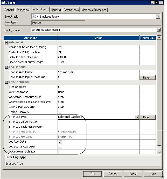
Configuring Error Log Options 599
Configuring Error Log Options
You configure error logging for each session in a workflow. You can find error handling
options in the Config Object tab of the sessions properties.
Tip: Use the Workflow Manager to create a reusable set of attributes for the Config Object tab.
For more information about creating a session configuration object, see “Creating a Session
Configuration Object” on page 192.
To configure error logging options:
1. Double-click the Session task to open the session properties.
2. Select the Config Object tab.
3. Click error handling options.
Error Log
Options

600 Chapter 21: Row Error Logging
Table 21-6 describes the error logging settings of the Config Object tab:
4. Click OK.
Table 21-6. Error Log Options
Error Log Options Required/
Optional Description
Error Log Type Required Specifies the type of error log to create. You can specify relational
database, flat file, or no log. By default, the Integration Service does
not create an error log.
Error Log DB Connection Required/
Optional
Specifies the database connection for a relational log. This option is
required when you enable relational database logging.
Error Log Table Name
Prefix
Optional Specifies the table name prefix for relational logs. The Integration
Service appends 11 characters to the prefix name. Oracle and
Sybase have a 30 character limit for table names. If a table name
exceeds 30 characters, the session fails.
Error Log File Directory Required/
Optional
Specifies the directory where errors are logged. By default, the error
log file directory is $PMBadFilesDir\. This option is required when
you enable flat file logging.
Error Log File Name Required/
Optional
Specifies error log file name. The character limit for the error log file
name is 255. By default, the error log file name is PMError.log. This
option is required when you enable flat file logging.
Log Row Data Optional Specifies whether or not to log transformation row data. By default,
the Integration Service logs transformation row data. If you disable
this property, n/a or -1 appears in transformation row data fields.
Log Source Row Data Optional If you choose not to log source row data, or if source row data is
unavailable, the Integration Service writes an indicator such as n/a
or -1, depending on the column datatype.
If you do not need to capture source row data, consider disabling
this option to increase Integration Service performance.
Data Column Delimiter Required Delimiter for string type source row data and transformation group
row data. By default, the Integration Service uses a pipe ( | )
delimiter. Verify that you do not use the same delimiter for the row
data as the error logging columns. If you use the same delimiter, you
may find it difficult to read the error log file.

602 Chapter 22: Parameter Files
Overview
A parameter file is a list of parameters and associated values for a workflow, worklet, or
session. Parameter files provide flexibility to change these variables each time you run a
workflow or session. You can create multiple parameter files and change the file you use for a
session or workflow. You can create a parameter file using a text editor such as WordPad or
Notepad.
A parameter file contains the following types of parameters and variables:
♦Service variable. Defines a service variable for an Integration Service.
♦Service process variable. Defines a service process variable for an Integration Service that
runs on a specific node.
♦Workflow variable. References values and records information in a workflow. For example,
use a workflow variable in a Decision task to determine whether the previous task ran
properly.
♦Worklet variable. References values and records information in a worklet. Use predefined
worklet variables in a parent workflow, but you cannot use workflow variables from the
parent workflow in a worklet.
♦Session parameter. Defines a value that can change from session to session, such as a
database connection or file name.
♦Mapping parameter. Defines a value that remains constant throughout a session, such as a
state sales tax rate.
♦Mapping variable. Defines a value that can change during the session. The Integration
Service saves the value of a mapping variable to the repository at the end of each successful
session run and uses that value the next time you run the session.
You can include information for more than one service, service process, workflow, worklet, or
session in a parameter file. You can also create multiple parameter files and use a different file
each time you run a workflow. For more information about creating a parameter file, see
“Using a Parameter File” on page 604.
Use one of the following methods to choose the parameter file the Integration Service uses
with a workflow or session:
♦Enter the parameter file name and directory in the workflow or session properties. For
more information, see “Configuring the Parameter File Location” on page 609.
♦Start the workflow using pmcmd, and enter the parameter file name and directory in the
command line. For more information about using a parameter file with pmcmd, see “Using
a Parameter File with pmcmd” on page 611.
If you enter a parameter file name and directory in the workflow or session properties and in
the pmcmd command line, the Integration Service uses the parameter file you specify in the
pmcmd command line. If you do not enter a parameter file name in the pmcmd command line,
the Integration Service uses the parameter file you specify in the workflow properties for the
workflow and all sessions in the workflow. If you do not enter a parameter file name in the
Overview 603
pmcmd command line or the workflow properties, the Integration Service uses the parameter
file you specify in the session properties.
If you do not have access to parameter files on the Integration Service machine, you can place
a parameter file on a local machine and use the pmcmd startworkflow command to pass
variables and values to the Integration Service from the local file.
The Integration Service checks the parameter file to determine the start values of the
parameters or variables you use in a workflow, worklet, or session. If you do not define start
values for these parameters and variables, the Integration Service checks for the start values of
the parameters or variables in other places. For more information, see “Using Workflow
Variables” on page 106 and “Mapping Parameters and Variables” in the Designer Guide.

604 Chapter 22: Parameter Files
Using a Parameter File
Parameter files contain several sections preceded by a heading. The heading identifies the
Integration Service, Integration Service process, workflow, worklet, or session to which you
want to assign parameters or variables. You assign parameters and variables directly below this
heading in the file, entering each parameter or variable on a new line. Enter the parameter or
variable in the form name=value. The Integration Service interprets all characters between the
equals sign and the end of the line as the parameter value.
You can list parameters and variables in any order for each section.
You can define service variables, service process variables, workflow variables, session
parameters, mapping parameters, and mapping variables in any section in the parameter file.
Table 22-1 describes the heading formats that define each section in the parameter file and
the scope of the parameters and variables that you define in each section:
Every heading you create should appear once in a parameter file. If you specify the same
heading more than once in a parameter file, the Integration Service uses the information in
the section below the first heading and ignores the information in the sections below
subsequent identical headings. For example, a parameter file contains the following sections:
[HET_TGTS.WF:wf_TCOMMIT1]
$$platform=windows
...
Table 22-1. Workflow and Session Parameter Headings
Heading Scope
[Global] All Integration Services, Integration Service processes,
workflows, worklets, and sessions.
[Service:service name] The named Integration Service and workflows, worklets, and
sessions that this service runs.
[Service:service name.ND:node name] The named Integration Service process and workflows, worklets,
and sessions that this service process runs.
[folder name.WF:workflow name] The named workflow and all sessions within the workflow.
[folder name.WF:workflow name.WT:worklet name] The named worklet and all sessions within the worklet.
[folder name.WF:workflow name.WT:worklet
name.WT:worklet name...]
The nested worklet and all sessions within the nested worklet.
[folder name.WF:workflow name.ST:session name]
-or-
[folder name.WF:workflow name.WT:worklet
name.ST:session name]
-or-
[folder name.session name]
-or-
[session name]
The named session.

Using a Parameter File 605
[HET_TGTS.WF:wf_TCOMMIT1]
$$platform=unix
$DBConnection_ora=qasrvrk2_hp817
In workflow wf_TCOMMIT1, the value for mapping parameter $$platform is “windows,”
not “unix,” and session parameter $DBConnection_ora is not defined.
If you define the same parameter or variable in multiple sections in the parameter file, the
parameter or variable with the smallest scope takes precedence over parameters or variables
with larger scope. For example, a parameter file contains the following sections:
[HET_TGTS.WF:wf_TGTS_ASC_ORDR]
$DBConnection_ora=qasrvrk2_hp817
[HET_TGTS.WF:wf_TGTS_ASC_ORDR.ST:s_TGTS_ASC_ORDR]
$DBConnection_ora=qasrvrk3_hp817
In session s_TGTS_ASC_ORDR, the value for session parameter $DBConnection_ora is
“qasrvrk3_hp817.” In all other sessions in the workflow, it is “qasrvrk2_hp817.”
Example
You might have a session, s_MonthlyCalculations, in the Production folder. The session uses
session parameters to connect to source files and target databases and to write a session log
file. If the session fails, the Integration Service sends an email message to pcadmin@mail.com.
The session uses a string mapping parameter, $$State, that you set to “MA,” and a datetime
mapping variable, $$Time. $$Time has an initial values of “9/30/2005 05:04:00” in the
repository, but you override this value to “10/1/2005 05:04:11.”
The following table describes the parameters and variables for the s_MonthlyCalculations
session:
The parameter file for the session includes the folder and session name and each parameter
and variable:
[Production.s_MonthlyCalculations]
$PMFailureEmailUser=pcadmin@mail.com
$$State=MA
Parameter or Variable Type Parameter or Variable Name Definition
Service Variable $PMFailureEmailUser pcadmin@mail.com
String Mapping Parameter $$State MA
Datetime Mapping Variable $$Time 10/1/2005 05:04:11
Source File (Session Parameter) $InputFile1 Sales.txt
Database Connection (Session Parameter) $DBConnection_Target Sales (database connection)
Session Log File (Session Parameter) $PMSessionLogFile d:/session logs/firstrun.txt
606 Chapter 22: Parameter Files
$$Time=10/1/2005 05:04:01
$InputFile1=sales.txt
$DBConnection_target=sales
$PMSessionLogFile=D:/session logs/firstrun.txt
The next time you run the session, you might edit the parameter file to change the state to
MD and delete the $$Time variable. This allows the Integration Service to use the value for
the variable that the previous session stored in the repository.
Sample Parameter File
The following text is an excerpt from a parameter file that contains service variables for one
Integration Service and parameters for four workflows:
[Service:IntSvs_01]
$PMSuccessEmailUser=pcadmin@mail.com
$PMFailureEmailUser=pcadmin@mail.com
[HET_TGTS.WF:wf_TCOMMIT_INST_ALIAS]
$$platform=unix
[HET_TGTS.WF:wf_TGTS_ASC_ORDR.ST:s_TGTS_ASC_ORDR]
$$platform=unix
$DBConnection_ora=qasrvrk2_hp817
[ORDERS.WF:wf_PARAM_FILE.WT:WL_PARAM_Lvl_1]
$$DT_WL_lvl_1=02/01/2005 01:05:11
$$Double_WL_lvl_1=2.2
[ORDERS.WF:wf_PARAM_FILE.WT:WL_PARAM_Lvl_1.WT:NWL_PARAM_Lvl_2]
$$DT_WL_lvl_2=03/01/2005 01:01:01
$$Int_WL_lvl_2=3
$$String_WL_lvl_2=ccccc
Guidelines for Creating Parameter Files 607
Guidelines for Creating Parameter Files
Use the following rules and guidelines when you create parameter files:
♦Capitalize folder and session names the same as they appear in the Workflow Manager.
Folder and session names are case sensitive in the parameter file. Service and node names
are not case sensitive.
♦Define service and service process variables properly. Service and service process variables
must begin with $PM. If they do not, the Integration Service does not recognize them as
service or service process variables. For more information about service and service process
variables, see “Creating and Configuring the Integration Service” in the Administrator
Guide.
♦You can define a service and service process variables for workflows, worklets, and
sessions. If you define a service or service process variable in a workflow, worklet, or
session section of the parameter file, the variable applies to any service process that runs
the task.
♦List all necessary mapping parameters and variables. Mapping parameter and variable
values become start values for parameters and variables in a mapping. Mapping parameter
and variable names are not case sensitive.
♦Enter folder names for non-unique session names. When a session name exists more than
once in a repository, enter the folder name to indicate the location of the session.
♦Use multiple parameter files. You assign parameter files to workflows, worklets, and
sessions individually. You can specify the same parameter file for all of these tasks or create
multiple parameter files.
♦Create a parameter file section for each session. To include parameter and variable
information for more than one session in the parameter file, create a section for each
session. The folder name is optional. The following parameter file example has multiple
sections:
[folder_name.session_name]
parameter_name=value
variable_name=value
mapplet_name.parameter_name=value
[folder2_name.session_name]
parameter_name=value
variable_name=value
mapplet_name.parameter_name=value
♦Specify headings in any order. You can place headings in any order in the parameter file.
However, if you define the same heading more than once in the file, the Integration
Service uses the parameter or variable values below the first instance of the heading.
♦Specify parameters and variables in any order. You can specify the parameters and
variables in any order below a heading.
608 Chapter 22: Parameter Files
♦When defining parameter values, do not use unnecessary line breaks or spaces. The
Integration Service might interpret additional spaces as part of a value.
♦List all session parameters. Session parameters do not have default values. An undefined
session parameter fails a session. Session parameter names are not case sensitive.
♦Override initial values of workflow variables if necessary. If a workflow contains an
Assignment task that changes the value of a workflow variable, the next session in the
workflow uses the latest value of the variable as the initial value for the session. To override
the initial value, define a new value for the variable in the session section of the parameter
file.
♦Use correct date formats for datetime values. Use the following date formats for datetime
values:
−MM/DD/RR
−MM/DD/RR HH24:MI:SS
−MM/DD/YYYY
−MM/DD/YYYY HH24:MI:SS
♦Do not enclose parameters or variables in quotes. The Integration Service interprets
everything after the equal sign as part of the value.
♦Precede parameters and variables in mapplets with the mapplet name as follows:
mapplet_name.parameter_name=value
mapplet2_name.variable_name=value
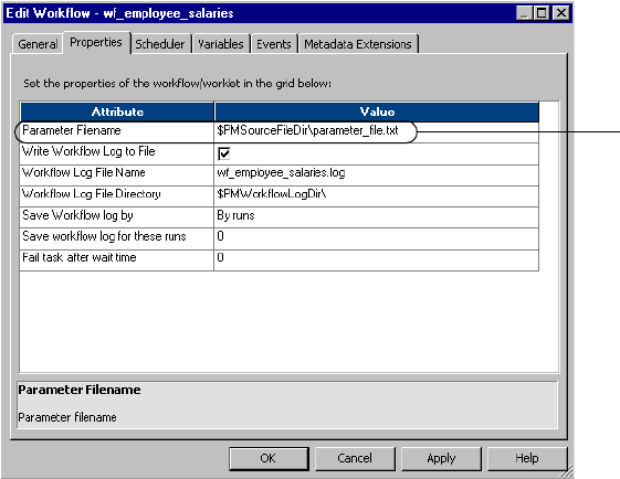
Configuring the Parameter File Location 609
Configuring the Parameter File Location
You can specify the parameter file name and directory in the workflow or session properties.
To enter a parameter file in the workflow properties:
1. Open a Workflow in the Workflow Manager.
2. Click Workflows > Edit.
The Edit Workflow dialog box appears.
3. Click the Properties tab.
4. Enter the parameter directory and name in the Parameter Filename field.
You can enter either a direct path or a process variable directory. Use the appropriate
delimiter for the Integration Service operating system. If you configured the PowerCenter
environment for high availability, include the server in the path.
5. Click OK.
To enter a parameter file in the session properties:
1. Open a session in the Workflow Manager.
The Edit Tasks dialog box appears.
2. Click the Properties tab and open the General Options settings.
3. Enter the parameter directory and name in the Parameter Filename field.
Enter the
path and file
name.
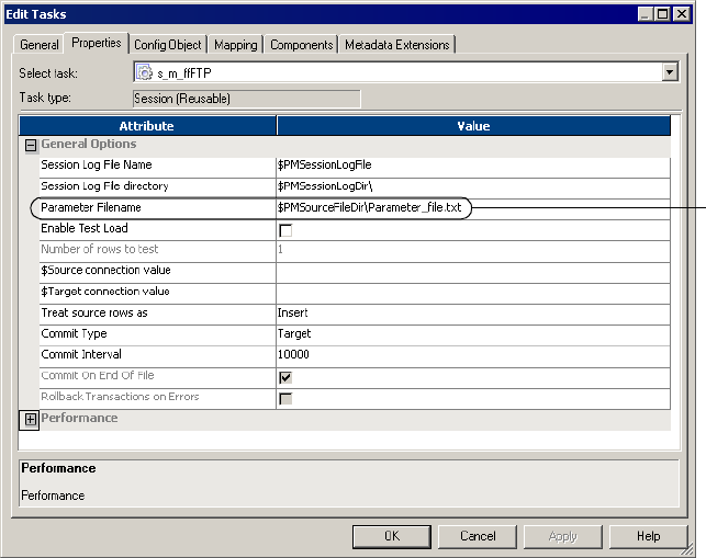
610 Chapter 22: Parameter Files
4. You can enter either a direct path or a process variable directory. Use the appropriate
delimiter for the Integration Service operating system.
5. Click OK.
Enter the
path and
file name.
Using a Parameter File with pmcmd 611
Using a Parameter File with pmcmd
When you start a workflow or session with pmcmd, use a parameter file to pass variables to the
Integration Service. The parameter file you use with pmcmd overrides the parameter file in the
session or workflow properties. The pmcmd paramfile parameter defines which parameter file
to use when the task or workflow runs. The localparamfile parameter defines a parameter file
on a local machine that you can reference when you do not have access to parameter files on
the Integration Service.
Use parameter files with the startworkflow or starttask pmcmd commands. When you start a
workflow or task using pmcmd, you can optionally enter the directory and name of the
parameter file.
The following command starts workflowA using the parameter file, myfile.txt:
pmcmd startworkflow -uv USERNAME -pv PASSWORD -s SALES:6258 -f east -w
wSalesAvg -paramfile '\$PMRootDir/myfile.txt' workflowA
The following command starts taskA using the parameter file, myfile.txt:
pmcmd starttask -uv USERNAME -pv PASSWORD -s SALES:6258 -f east -w
wSalesAvg -paramfile '\$PMRootDir/myfile.txt' taskA
For more information about pmcmd, see “pmcmd Command Reference” in the Command
Line Reference.
612 Chapter 22: Parameter Files
Troubleshooting
I have a section in a parameter file for a session, but the Integration Service does not seem
to read it.
In the parameter file, folder and session names are case sensitive. Make sure to enter folder
and session names as they appear in the Workflow Manager. Also, use the appropriate prefix
for all user-defined session parameters.
For more information about the parameter names, see “Naming Conventions” on page 212.
I am trying to use a source file parameter to specify a source file and location, but the
Integration Service cannot find the source file.
Make sure to clear the source file directory in the session properties. The Integration Service
concatenates the source file directory with the source file name to locate the source file.
Also, make sure to enter a directory local to the Integration Service and to use the appropriate
delimiter for the operating system.
I am trying to run a workflow with a parameter file and one of the sessions keeps failing.
The session might contain a parameter that is not listed in the parameter file. The Integration
Service uses the parameter file to start all sessions in the workflow. Check the session
properties, then verify that all session parameters are defined correctly in the parameter file.
Tips 613
Tips
Use a single parameter file to group parameter information for related sessions.
When sessions are likely to use the same database connection or directory, you might want to
include them in the same parameter file. When connections or directories change, you can
update information for all sessions by editing one parameter file.
Use pmcmd and multiple parameter files for sessions with regular cycles.
Sometimes you reuse session parameters in a cycle. For example, you might run a session
against a sales database everyday, but run the same session against sales and marketing
databases once a week. You can create separate parameter files for each session run. Instead of
changing the parameter file in the session properties each time you run the weekly session, use
pmcmd to specify the parameter file to use when you start the session.
Use reject file and session log parameters in conjunction with target file or target database
connection parameters.
When you use a target file or target database connection parameter with a session, you can
keep track of reject files by using a reject file parameter. You can also use the session log
parameter to write the session log to the target machine.
Use a resource to verify the session runs on a node that has access to the parameter file.
In the Administration Console, you can define a file resource for each node that has access to
the parameter file and configure the Integration Service to check resources. Then, edit the
session that uses the parameter file and assign the resource. When you run the workflow, the
Integration Service runs the session with the required resource on a node that has the resource
available.
For more information about configuring the Integration Service to check resources, see
“Creating and Configuring the Integration Service” in the Administrator Guide.
614 Chapter 22: Parameter Files

616 Chapter 23: External Loading
Overview
You can configure a session to use IBM DB2, Oracle, Sybase IQ, and Teradata external
loaders to load session target files into their respective databases. External loaders can increase
session performance by loading information directly from a file or pipe rather than running
the SQL commands to insert the same data into the database.
Use multiple external loaders within one session. For example, if a mapping contains two
targets, you can create a session that uses an Oracle external loader connection and a Sybase
IQ external loader connection.
For information about creating external loader connections, see “External Loader
Connections” on page 56.
Before You Begin
Before you run external loaders, complete the following tasks:
♦Disable constraints. You disable constraints built into the tables receiving the data before
performing the load. For information about disabling constraints, see the database
documentation.
♦Turn off or disable database logging. To preserve high performance, you can increase
commit intervals and turn off database logging. However, to perform database recovery on
failed sessions, you must have database logging turned on.
♦Configure code pages. IBM DB2, Oracle, Sybase IQ, and Teradata database servers must
use the same code page as the target flat file code page. The Integration Service creates the
control files and target flat files using the target flat file code page. If you use a code page
other than 7-bit ASCII for the target flat file, run the Integration Service in Unicode data
movement mode.
♦Configure the external loader connection as a resource. If the Integration Service is
configured to run on a grid, configure the external loader connection as a resource on the
node where the external loader is available. For more information, see “Managing the
Grid” in the Administrator Guide.
External Loader Permissions and Privileges
You can set external loader connection permissions in the connection object in the Workflow
Manager. When you work with external loaders, you need permissions or privileges to
complete the following tasks:
♦Create an external loader connection. You must have Super User or Use Workflow
Manager privileges.
♦Edit external loader permissions. You can edit external loader permissions if you are the
owner of the external loader connection or if you have Super User privilege.
♦Edit an external loader connection. You must have read and write permissions on the
external loader connection.
618 Chapter 23: External Loading
External Loader Behavior
When you run a session that uses an external loader, the Integration Service creates a control
file and a target flat file. The control file contains information such as data format and
loading instructions for the external loader. The control file has an extension of .ctl. You can
view the control file and the target flat file in the target file directory. When you run a session,
the Integration Service deletes and recreates the target file. The external loader uses the
control file to load session output to the database.
The Integration Service waits for all external loading to complete before it performs post-
session commands, runs external procedures, and sends post-session email.
The Integration Service writes external loader initialization and completion messages in the
session log. For more information about the external loader performance, check the external
loader log. The loader saves the log in the same directory as the target flat files. The default
extension for external loader logs is .ldrlog.
The behavior of the external loader depends on how you choose to load the data. You can load
data to a named pipe or to a flat file.
Loading Data to a Named Pipe
The external loader starts to load data to the database as soon as the data appears in the pipe.
The loader deletes the named pipe as soon as it completes the load.
On UNIX, the Integration Service writes to a named pipe that is named after the configured
target file name.
On Windows, the Integration Service writes data to a named pipe using the specified format:
\\.\pipe\<pipe name>
The pipe name is the same as the configured target file name.
Note: If a session aborts or fails, the data in the named pipe may contain inconsistencies.
Staging Data to a Flat File
When you stage data to a flat file on Windows or UNIX, the Integration Service writes data
to a flat file, which is named after the configured target file name. The external loader starts
loading data to the target database after the Integration Service writes all the data to the target
flat file. The external loader does not delete the target flat file after loading it to the database.
Make sure the target file directory can accommodate the size of the target flat file.
If a session aborts or fails before the Integration Service writes all the data to the flat file
target, the external loader does not start. If a session aborts or fails after the Integration
Service writes all the data to the flat file target, the external loader completes loading data to
the target database before the external loader exits.
External Loader Behavior 619
Partitioning Sessions with External Loaders
When you configure multiple partitions in a session using a flat file target, the Integration
Service creates a separate flat file for each partition. Some external loaders cannot load data
from multiple files. When you use an external loader in a session with multiple partitions, you
must configure the target partition type according to the external loader you use.
When you use an external loader that can load data from multiple files, you can choose any
partition type available for a flat file target. You also choose an external loader connection for
each partition. The Integration Service creates an output file for each partition, and the
external loader loads the output from each target file to the database. Use any partition type
for the target when you use the following loaders:
♦Oracle, with parallel load enabled
♦Te ra d a t a T p u m p
♦Teradata Warehouse Builder
If you use a loader that cannot load from multiple files, use round-robin partitioning to route
the data to a single target file. You choose an external loader connection for each partition.
However, the Integration Service uses the loader connection for the first partition. The
Integration Service creates a single output file, and the external loader loads the output from
the target file to the database. If you choose any other partition type for the target, the
Integration Service fails the session. Use round-robin partition type for the target when you
use the following loaders:
♦IBM DB2 EE
♦IBM DB2 EEE Autoloader
♦Oracle, with parallel load disabled
♦Sybase IQ
♦Teradata MultiLoad
♦Te ra d a t a Fas t l o a d

620 Chapter 23: External Loading
Loading to IBM DB2
When you load to IBM DB2 targets, use one the following external loaders:
♦IBM DB2 EE external loader. Performs insert and replace operations on targets. The
external loader can also restart or terminate load operations. The IBM DB2 EE external
loader invokes the db2load executable located in the Integration Service installation
directory. The IBM DB2 EE external loader can load data to an IBM DB2 server on a
machine that is remote to the Integration Service.
♦IBM DB2 EEE Autoloader. Performs insert and replace operations on targets. The
external loader can also restart or terminate load operations. The IBM DB2 EEE external
loader invokes the IBM DB2 Autoloader program to load data. The Autoloader program
uses the db2atld executable. The IBM DB2 EEE external loader can partition data and
load the partitioned data simultaneously to the corresponding database partitions. The
IBM DB2 EEE loader requires that the IBM DB2 server be on the same machine hosting
the Integration Service.
Note: If the IBM DB2 EEE server is on a machine that is remote to the Integration Service,
connect to the IBM DB2 EEE database using a relational database connection. Use database
partitioning for the IBM DB2 target. When you use database partitioning, the Integration
Service queries the IBM DB2 system for table partition information and loads partitioned
data to the corresponding nodes in the target database. For more information about database
partitioning, see “Database Partitioning Partition Type” on page 444.
Rules and Guidelines
Use the following rules and guidelines when you use external loaders to load to IBM DB2:
♦The IBM DB2 external loaders load from a delimited flat file. Verify that the target table
columns are wide enough to store all of the data.
♦For a connection that uses IBM DB2 client authentication, enter the PmNullUser user
name and PmNullPasswd when you create the external loader connection. PowerCenter
uses IBM DB2 client authentication when the connection user name is PmNullUser and
the connection is to an IBM DB2 database.
♦For a session with multiple partitions, use the round-robin partition type to route data to a
single target file. For more information about partitioning sessions with external loaders,
see “Partitioning Sessions with External Loaders” on page 619.
♦If you configure multiple targets in the same pipeline to use IBM DB2 external loaders,
each loader must load to a different tablespace on the target database. For more
information about selecting external loaders, see “Configuring External Loading in a
Session” on page 643.
♦You must have the correct authority levels and privileges to load data to the database
tables. For more information, see “Configuring Authorities, Privileges, and Permissions”
on page 621.
Loading to IBM DB2 621
Setting Operation Modes
IBM DB2 operation modes specify the type of load the external loader runs. You can
configure the IBM DB2 EE or IBM DB2 EEE external loader to run in one of the following
operation modes:
♦Insert. Adds loaded data to the table without changing existing table data.
♦Replace. Deletes all existing data from the table, and inserts the loaded data. The table and
index definitions do not change.
♦Restart. Restarts a previously interrupted load operation.
♦Te r m i n a t e . Terminates a previously interrupted load operation and rolls back the
operation to the starting point, even if consistency points were passed. The tablespaces
return to normal state, and the external loader makes all table objects consistent.
Configuring Authorities, Privileges, and Permissions
IBM DB2 privileges allow you to create or access database resources. Authority levels allow
you to group privileges and perform higher-level database manager maintenance and utility
operations. Together, these act to control access to the database manager and its database
objects. You can access objects for which you have the required privilege or authority.
To load data into a table, you must have one of the following authorities:
♦SYSADM authority
♦DBADM authority
♦LOAD authority on the database and one of the following privileges:
−INSERT privilege on the table when the load utility is invoked in insert, terminate, or
restart mode.
−INSERT and DELETE privilege on the table when the load utility is invoked in replace,
terminate, or restart mode.
In addition, you must have proper read access and read/write permissions:
♦The database instance owner must have read access to the external loader input files.
♦If you run IBM DB2 as a service on Windows, you must configure the service start
account with a user account that has read/write permissions to use LAN resources,
including drives, directories, and files.
♦If you load to IBM DB2 EEE, the database instance owner must have write access to the
load dump file and the load temporary file.
For more information, see the IBM DB2 database documentation.

622 Chapter 23: External Loading
Configuring IBM DB2 EE External Loader Attributes
Table 23-1 describes attributes for IBM DB2 EE external loader connections:
IBM DB2 EE External Loader Return Codes
The IBM DB2 EE external loader indicates the success or failure of a load operation with a
return code. The Integration Service writes the external loader return code to the session log.
Return code (0) indicates that the load operation succeeded. The Integration Service writes
the following message to the session log if the external loader successfully completes the load
operation:
WRT_8029 External loader process <external loader name> exited
successfully.
Any other return code indicates that the load operation failed. The Integration Service writes
the following error message to the session log:
WRT_8047 Error: External loader process <external loader name> exited with
error <return code>.
Table 23-1. IBM DB2 EE External Loader Attributes
Attributes Default
Value Description
Opmode Insert IBM DB2 external loader operation mode. Select one of the following operation
modes:
- Insert
- Replace
- Restart
- Terminate
For more information about IBM DB2 operation modes, see “Setting Operation
Modes” on page 621.
External Loader
Executable
db2load Name of the IBM DB2 EE external loader executable file.
DB2 Server Location Remote Location of the IBM DB2 EE database server relative to the Integration Service.
Select Local if the database server resides on the machine hosting the
Integration Service. Select Remote if the database server resides on another
machine.
Is Staged Disabled Method of loading data. Select Is Staged to load data to a flat file staging area
before loading to the database. By default, the data is loaded to the database
using a named pipe. For more information, see “External Loader Behavior” on
page 618.
Recoverable Enabled Sets tablespaces in backup pending state if forward recovery is enabled. If you
disable forward recovery, the IBM DB2 tablespace will not set to backup
pending state. If the IBM DB2 tablespace is in backup pending state, you must
fully back up the database before you perform any other operation on the
tablespace.

Loading to IBM DB2 623
Table 23-2 describes the return codes for the IBM DB2 EE external loader:
Configuring IBM DB2 EEE External Loader Attributes
You can configure the IBM DB2 EEE external loader to use different loading modes when
loading to the database. Loading modes determine how the IBM DB2 EEE external loader
loads data across partitions in the database. You can configure the IBM DB2 EEE external
loader to use the following loading modes:
♦Split and load. Partitions the data and loads it simultaneously using the corresponding
database partitions.
♦Split only. Partitions the data and writes the output to files in the specified split file
directory.
♦Load only. Does not partition the data. It loads data in existing split files using the
corresponding database partitions.
♦Analyze. Generates an optimal partitioning map with even distribution across all database
partitions. If you run the external loader in split and load mode after you run it in analyze
mode, the external loader uses the optimal partitioning map to partition the data.
For more information about IBM DB2 loading modes, see the IBM DB2 database
documentation.
The IBM DB2 EEE external loader creates multiple logs based on the number of database
partitions it loads to. For each partition, the external loader appends a number corresponding
to the partition number to the external loader log file name. The IBM DB2 EEE external
loader log file format is file_name.ldrlog.partition_number.
The Integration Service does not archive or overwrite IBM DB2 EEE external loader logs. If
an external loader log of the same name exists when the external loader runs, the external
loader appends new external loader log messages to the end of the existing external loader log
file. You must manually archive or delete the external loader log files. For more information
about log files generated by DB2 Autoload, see the IBM DB2 documentation.
For information about IBM DB2 EEE external loader return codes, see the IBM DB2
documentation.
Table 23-2. IBM DB2 EE External Loader Return Codes
Code Description
0External loader operation completed successfully.
1External loader cannot locate the control file.
2External loader could not open the external loader log file.
3External loader could not access the control file because the control file is locked by another process.
4IBM DB2 database returned an error.

624 Chapter 23: External Loading
Table 23-3 describes attributes for IBM DB2 EEE external loader connections:
Table 23-3. IBM DB2 EEE External Loader Attributes
Attribute Default
Value Description
Opmode Insert IBM DB2 external loader operation mode. Select one of the following operation
modes:
- Insert
- Replace
- Restart
- Terminate
For more information about IBM DB2 operation modes, see “Setting Operation
Modes” on page 621.
External Loader
Executable
db2atld Name of the IBM DB2 EEE external loader executable file.
Split File Location n/a Location of the split files. The external loader creates split files if you configure
SPLIT_ONLY loading mode.
Output Nodes n/a Database partitions on which the load operation is to be performed.
Split Nodes n/a Database partitions that determine how to split the data. If you do not specify
this attribute, the external loader determines an optimal splitting method.
Mode Split and
load
Loading mode the external loader uses to load the data. Select one of the
following loading modes:
- Split and load
- Split only
- Load only
- Analyze
Max Num Splitters 25 Maximum number of splitter processes.
Force No Forces the external loader operation to continue even if it determines at startup
time that some target partitions or tablespaces are offline.
Status Interval 100 Number of megabytes of data the external loader loads before writing a
progress message to the external loader log. Specify a value between 1 and
4,000 MB.
Ports 6000-6063 Range of TCP ports the external loader uses to create sockets for internal
communications with the IBM DB2 server.
Check Level Nocheck Checks for record truncation during input or output.
Map File Input n/a Name of the file that specifies the partitioning map. To use a customized
partitioning map, specify this attribute. Generate a customized partitioning map
when you run the external loader in Analyze loading mode.
Map File Output n/a Name of the partitioning map when you run the external loader in Analyze
loading mode. You must specify this attribute if you want to run the external
loader in Analyze loading mode.
Trace 0Number of rows the external loader traces when you need to review a dump of
the data conversion process and output of hashing values.

Loading to IBM DB2 625
Is Staged Disabled Method of loading data. Select Is Staged to load data to a flat file staging area
before loading to the database. Otherwise, the data is loaded to the database
using a named pipe. For more information, see “External Loader Behavior” on
page 618.
Date Format mm/dd/
yyyy
Date format. Must match the date format you define in the target definition. IBM
DB2 supports the following date formats:
- MM/DD/YYYY
- YYYY-MM-DD
- DD.MM.YYYY
- YYYY-MM-DD
Table 23-3. IBM DB2 EEE External Loader Attributes
Attribute Default
Value Description

626 Chapter 23: External Loading
Loading to Oracle
When you load to Oracle targets, use the Oracle SQL Loader to perform insert, update, and
delete operations on targets.
The Oracle external loader creates a reject file for data rejected by the database. The reject file
has an extension of .ldrreject. The loader saves the reject file in the target files directory.
Rules and Guidelines
Use the following rules and guidelines when you use external loaders to load to Oracle:
♦If you select an Oracle external loader, the default external loader executable name is
sqlload. This is accurate for most UNIX platforms, but if you use Windows, check the
Oracle documentation to find the name of the external loader executable.
♦For a connection that uses Oracle OS Authentication, enter the PmNullUser user name
and PmNullPasswd when you create the external loader connection. PowerCenter uses
Oracle OS Authentication when the connection user name is PmNullUser and the
connection is with an Oracle database.
♦The target flat file for an Oracle external loader can be fixed-width or delimited.
♦For best performance when writing to a partitioned target, select Direct Path. For more
information, see the Oracle documentation.
♦If you configure a session to write to an Oracle 8 table in bulk mode with NOT NULL
constraints on any column, the session may write null data into a NOT NULL column.
♦For best performance, use the following guidelines to determine settings for partitioned
and non-partitioned targets:
Loading Multibyte Data to Oracle
When you load multibyte data to Oracle, data precision is measured in bytes for fixed-width
files and in characters for delimited files. Make sure the target table columns are wide enough
to store all the data.
Oracle supports character-oriented datatypes, such as Nchar, where the precision is measured
in characters. If you use the Nchar datatype, multiply the maximum number of characters by
K, where K is the maximum number of bytes a character contains in the selected target code
page. This ensures that the Integration Service does not truncate data before loading the
target file.
Target Load Method Parallel Load Load Mode
Partitioned Direct Path enable Append
Partitioned Conventional Path enable n/a
Non-partitioned n/a disable* n/a
* If you disable parallel load, you must choose round-robin partitioning to route data to a single target file.

Loading to Oracle 627
Configuring Oracle External Loader Attributes
Table 23-4 describes the attributes for Oracle external loader connections:
Table 23-4. Oracle External Loader Attributes
Attribute Default Value Description
Error Limit 1Number of errors to allow before the external loader stops the load
operation.
Load Mode Append Loading mode the external loader uses to load data. Select one of the
following loading modes:
- Append
- Insert
- Replace
- Truncate
Load Method Use Conventional
Path
Method the external loader uses to load data. Select one of the following
load methods:
- Use Conventional Path.
- Use Direct Path (Recoverable).
- Use Direct Path (Unrecoverable).
Enable Parallel
Load
Enable Parallel
Load
Determines whether the Oracle external loader loads data in parallel to a
partitioned Oracle target table.
- Enable Parallel Load to load to partitioned targets.
- Do Not Enable Parallel Load to load to non-partitioned targets.
Rows Per Commit 10000 For Conventional Path load method, this attribute specifies the number
of rows in the bind array for load operations. For Direct Path load
methods, this attribute specifies the number of rows the external loader
reads from the target flat file before it saves the data to the database.
External Loader
Executable
sqlload Name of the external loader executable file.
Log File Name n/a Path and name of the external loader log file.
Is Staged Disabled Method of loading data. Select Is Staged to load data to a flat file staging
area before loading to the database. Otherwise, the data is loaded to the
database using a named pipe. For more information, see “External
Loader Behavior” on page 618.
628 Chapter 23: External Loading
Loading to Sybase IQ
When you load to Sybase IQ, use the Sybase IQ external loader to perform insert operations.
The Integration Service can load multibyte data to Sybase IQ targets. The Integration Service
can write to a flat file when the Sybase IQ server is on the same machine or on a different
machine as the Integration Service. The Integration Service can write to a named pipe if the
Integration Service is local to the Sybase IQ database server.
Rules and Guidelines
Use the following rules and guidelines when you use external loaders to load to Sybase IQ:
♦Ensure that target tables do not violate primary key constraints.
♦Configure a Sybase IQ user with read/write access before you use a Sybase IQ external
loader.
♦Target flat files for a Sybase IQ external loader can be fixed-width or delimited.
♦The Sybase IQ external loader cannot perform update or delete operations on targets.
♦For a session with multiple partitions, use the round-robin partition type to route data to a
single target file. For more information about partitioning sessions with external loaders,
see “Partitioning Sessions with External Loaders” on page 619.
♦If the Integration Service and Sybase IQ server are on different machines, map or mount a
drive from the machine hosting the Integration Service to the machine hosting the Sybase
IQ server.
Loading Multibyte Data to Sybase IQ
Use the following guidelines when you load multibyte data to Sybase IQ targets.
Delimited Flat File Targets
For delimited flat files, data precision is measured in characters. When you insert multibyte
character data in the target, you do not need to allow for additional precision for multibyte
data. Sybase IQ does not allow optional quotes. You must choose None for Optional Quotes
if you have a delimited target flat file.
When you load multibyte data to Sybase IQ, null characters and delimiters can be up to four
bytes each. To avoid reading the delimiter as regular characters, each byte of the delimiter
must have an ASCII value of less than 0x40.
Fixed-Width Flat File Targets
For fixed-width flat files, data precision is measured in bytes, not characters. When you load
multibyte data into a fixed-width flat file target, configure the precision to accommodate the
multibyte data. The Integration Service writes the row to the reject file if the precision is not
large enough to accommodate the multibyte data.

Loading to Sybase IQ 629
Configuring Sybase IQ External Loader Attributes
Use the following guidelines when you enter attributes for the Sybase IQ external loader
connection.
The connect string must contain the following attributes:
uid=user ID; pwd=password; eng=Sybase IQ database server name;
links=tcpip (host=host name; port=port number)
For example, you might use the following connect string:
uid=qasrvr65;pwd=qasrvr65;eng=SUNQA2SybaseIQ_1243;links=tcpip(host=sunqa2
)
Table 23-5 describes the attributes for Sybase IQ external loader connections:
Table 23-5. Sybase IQ External Loader Attributes
Attribute Default
Value Description
Block Factor 10000 Number of records per block in the target Sybase table. The external
loader applies the Block Factor attribute to load operations for fixed-
width flat file targets only.
Block Size 50000 Size of blocks used in Sybase database operations. The external loader
applies the Block Size attribute to load operations for delimited flat file
targets only.
Checkpoint Enabled If enabled, the Sybase IQ database issues a checkpoint after
successfully loading the table. If disabled, the database issues no
checkpoints.
Notify Interval 1000 Number of rows the Sybase IQ external loader loads before it writes a
status message to the external loader log.
Server Datafile Directory n/a Location of the flat file target. You must specify this attribute relative to
the database server installation directory.
If the directory is in a Windows system, use a backslash (\) in the
directory path:
D:\mydirectory\inputfile.out
If the directory is in a UNIX system, use a forward slash (/) in the
directory path:
/mydirectory/inputfile.out
Enter the target file directory path using the syntax for the machine
hosting the database server installation. For example, if the Integration
Service is on a Windows machine and the Sybase IQ server is on a UNIX
machine, use UNIX syntax.

630 Chapter 23: External Loading
External Loader
Executable
dbisql Name of the Sybase IQ external loader executable. When you create a
Sybase IQ external loader connection, the Workflow Manager sets the
name of the external loader executable file to dbisql by default. If you use
an executable file with a different name, for example, dbisqlc, you must
update the External Loader Executable field. If the external loader
executable file directory is not in the system path, you must enter the file
path and file name in this field.
Is Staged Enabled Method of loading data. Select Is Staged to load data to a flat file staging
area before loading to the database. Clear the attribute to load data from
a named pipe. The Integration Service can write to a named pipe if the
Integration Service is local to the Sybase IQ database. For more
information, see “External Loader Behavior” on page 618.
Table 23-5. Sybase IQ External Loader Attributes
Attribute Default
Value Description
Loading to Teradata 631
Loading to Teradata
When you load to Teradata targets, use one of the following external loaders:
♦Multiload. Performs insert, update, delete, and upsert operations for large volume
incremental loads. Use this loader when you run a session with a single partition.
Multiload acquires table level locks, making it appropriate for offline loading. For more
information about configuring the Multiload external loader connection object, see
“Configuring Teradata MultiLoad External Loader Attributes” on page 633.
♦TPump. Performs insert, update, delete, and upsert operations for relatively low volume
updates. Use this loader when you run a session with multiple partitions. TPump acquires
row-hash locks on the table, allowing other users to access the table as TPump loads to it.
For more information about configuring the Tpump external loader connection object, see
“Configuring Teradata TPump External Loader Attributes” on page 635.
♦FastLoad. Performs insert operations for high volume initial loads, or for high volume
truncate and reload operations. Use this loader when you run a session with a single
partition. Use this loader on empty tables with no secondary indexes. For more
information about configuring the FastLoad external loader connection object, see
“Configuring Teradata FastLoad External Loader Attributes” on page 638.
♦Warehouse Build er. Performs insert, update, upsert, and delete operations on targets. Use
this loader when you run a session with multiple partitions. You can achieve the
functionality of the other loaders based on the operator you use. For more information
about configuring the Warehouse Builder external loader connection object, see
“Configuring Teradata Warehouse Builder Attributes” on page 640.
If you use a Teradata external loader to perform update or upsert operations, use the Target
Update Override option in the Mapping Designer to override the UPDATE statement in the
external loader control file. For upsert, the INSERT statement in the external loader control
file remains unchanged. For more information about using the Target Update Override
option, see “Mappings” in the Designer Guide.
Rules and Guidelines
Use the following rules and guidelines when you use external loaders to load to Teradata:
♦The Integration Service can use Teradata external loaders to load fixed-width and
delimited flat files to a Teradata database. Since all Teradata loaders delimit individual
records using the line-feed (\n) character, you cannot use the line-feed character as a
delimiter for Teradata loaders.
♦If a session contains one partition, the target output file name, including the file extension,
must not exceed 27 characters. If the session contains multiple partitions, the target
output file name, including the file extension, must not exceed 25 characters.
♦You cannot use spaces as null characters.
♦Use the Teradata external loaders to load multibyte data.
♦You cannot use the Teradata external loaders to load binary data.
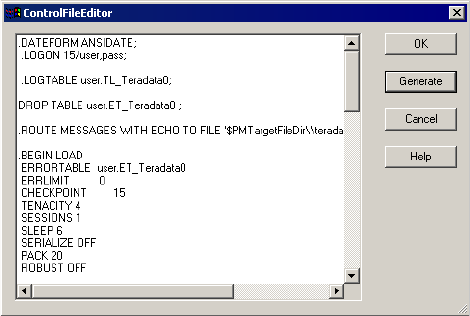
632 Chapter 23: External Loading
♦When you load to Teradata using named pipes, set the checkpoint value to 0 to prevent
external loaders from performing checkpoint operations.
♦You can specify error, log, or work table names, depending on the loader you use. You can
also specify error, log, or work database names.
♦You can override the control file in the session properties.
♦When you use Teradata, you can enter PmNullPasswd as the database password to prevent
the password from appearing in the control file. Instead, the Integration Service writes an
empty string for the password in the control file.
For more information about Teradata external loaders, see the Teradata documentation.
Overriding the Control File
When you edit the loader connection in a session, you can override the control file. You might
want to override the control file to change some loader properties that you cannot edit in the
loader connection. For example, you can specify the tracing option in the control file.
When you override the control file, the Workflow Manager saves the control file to the
repository. The Integration Service uses the saved control file when you run the session. If you
do not override the control file, the Integration Service generates a new control file based on
the session and loader properties each time you run a session. The Integration Service saves
the control file it generates in the output file directory and overwrites it the next time you run
the session.
To override the control file, override the loader connection for the target in the session. Click
the Edit button in the Control File Content Override loader property.
Figure 23-1 shows the Control File Editor dialog box where you override the Teradata control
file:
In the Control File Editor dialog box, click Generate to create the default control file. The
Workflow Manager generates the control file based on the session and loader properties. Edit
the generated control file, and click OK to save the changes. The Workflow Manager saves the
Figure 23-1. Control File Editor Dialog Box for Teradata

Loading to Teradata 633
control file to the repository. The Integration Service uses this control file when you run the
session and for each subsequent session run until you clear the control file attribute. You can
view the edited control file by opening the Control File Editor.
If you change a target or loader connection setting after you edit the control file, the control
file does not include those changes. If you want to include those changes, you must generate
the control file again and edit it.
Note: The Workflow Manager does not validate the control file syntax. Teradata verifies the
control file syntax when you run a session. If the control file is invalid, the session fails.
Configuring Teradata MultiLoad External Loader Attributes
Use the following guidelines when you work with the MultiLoad external loader:
♦You can perform insert, update, delete, and upsert operations on targets. You can also use
data driven mode to perform insert, update, or delete operations based on an Update
Strategy or Custom transformation.
♦For a session with multiple partitions, use the round-robin partition type to route data to a
single target file. For more information about partitioning sessions with external loaders,
see “Partitioning Sessions with External Loaders” on page 619.
♦If you invoke a greater number of sessions than the maximum number of concurrent
sessions the database allows, the session may hang. You can set the minimum value for
Tenacity and Sleep to ensure that sessions fail rather than hang.
Table 23-6 shows the attributes that you configure for the Teradata MultiLoad external
loader:
Table 23-6. Teradata MultiLoad External Loader Attributes
Attribute Default
Value Description
TDPID n/a Teradata database ID.
Database Name n/a Optional database name.
Date Format n/a Date format. The date format in the connection object must match the date format
you define in the target definition. The Integration Service supports the following
date formats:
- DD/MM/YYYY
- MM/DD/YYYY
- YYYY/DD/MM
- YYYY/MM/DD
Error Limit 0Total number of rejected records that MultiLoad can write to the MultiLoad error
tables. Uniqueness violations do not count as rejected records.
An error limit of 0 means that there is no limit on the number of rejected records.

634 Chapter 23: External Loading
Checkpoint 10,000 Interval between checkpoints. You can set the interval to the following values:
- 60 or more. MultiLoad performs a checkpoint operation after it processes each
multiple of that number of records.
- 1–59. MultiLoad performs a checkpoint operation at the specified interval, in
minutes.
- 0. MultiLoad does not perform any checkpoint operation during the import task.
Tenacity 10,000 Amount of time, in hours, MultiLoad tries to log in to the required sessions. If a login
fails, MultiLoad delays for the number of minutes specified in the Sleep attribute,
and then retries the login. MultiLoad keeps trying until the login succeeds or the
number of hours specified in the Tenacity attribute elapses.
Load Mode Upsert Mode to generate SQL commands: Insert, Delete, Update, Upsert, or Data Driven.
When you select Data Driven loading, the Integration Service follows instructions in
an Update Strategy or Custom transformation to determine how to flag rows for
insert, delete, or update. The Integration Service writes a column in the target file or
named pipe to indicate the update strategy. The control file uses these values to
determine how to load data to the target. The Integration Service uses the following
values to indicate the update strategy:
0 - Insert
1 - Update
2 - Delete
Drop Error Tables Enabled Drops the MultiLoad error tables before beginning the next session. Select this
option to drop the tables, or clear it to keep them.
External Loader
Executable
mload Name and optional file path of the Teradata external loader executable. If the
external loader executable directory is not in the system path, you must enter the
full path.
Max Sessions 1Maximum number of MultiLoad sessions per MultiLoad job. Max Sessions must be
between 1 and 32,767.
Running multiple MultiLoad sessions causes the client and database to use more
resources. Therefore, setting this value to a small number may improve
performance.
Sleep 6Number of minutes MultiLoad waits before retrying a login. MultiLoad tries until the
login succeeds or the number of hours specified in the Tenacity attribute elapses.
Sleep must be greater than 0. If you specify 0, MultiLoad issues an error message
and uses the default value, 6 minutes.
Is Staged Disabled Method of loading data. Select Is Staged to load data to a flat file staging area
before loading to the database. Otherwise, the data is loaded to the database using
a named pipe. For more information, see “External Loader Behavior” on page 618.
Error Database n/a Error database name. Use this attribute to override the default error database
name. If you do not specify a database name, the Integration Service uses the
target table database.
Table 23-6. Teradata MultiLoad External Loader Attributes
Attribute Default
Value Description

Loading to Teradata 635
Table 23-7 shows the attributes that you configure when you override the Teradata MultiLoad
external loader connection object in the session properties:
For more information about these attributes, see the Teradata documentation.
Configuring Teradata TPump External Loader Attributes
You can perform insert, update, delete, and upsert operations on targets. You can also use data
driven mode to perform insert, update, or delete operations based on an Update Strategy or
Custom transformation.
If you run a session with multiple partitions, select a Teradata TPump external loader for each
partition.
For more information about partitioning, see “Understanding Pipeline Partitioning” on
page 421.
Work Table
Database
n/a Work table database name. Use this attribute to override the default work table
database name. If you do not specify a database name, the Integration Service
uses the target table database.
Log Table
Database
n/a Log table database name. Use this attribute to override the default log table
database name. If you do not specify a database name, the Integration Service
uses the target table database.
Table 23-7. Teradata MultiLoad External Loader Attributes Defined at the Session Level
Attribute Default
Value Description
Error Table 1 n/a Table name for the first error table. Use this attribute to override the default
error table name. If you do not specify an error table name, the Integration
Service uses ET_<target_table_name>.
Error Table 2 n/a Table name for the second error table. Use this attribute to override the default
error table name. If you do not specify an error table name, the Integration
Service uses UV_<target_table_name>.
Work Table n/a Work table name overrides the default work table name. If you do not specify a
work table name, the Integration Service uses WT_<target_table_name>.
Log Table n/a Log table name overrides the default log table name. If you do not specify a log
table name, the Integration Service uses ML_<target_table_name>.
Control File Content
Override
n/a Control file text. Use this attribute to override the control file the Integration
Service uses when it loads to Teradata. For more information, see “Overriding
the Control File” on page 632.
Table 23-6. Teradata MultiLoad External Loader Attributes
Attribute Default
Value Description

636 Chapter 23: External Loading
Table 23-8 shows the attributes that you configure for the Teradata TPump external loader:
Table 23-8. Teradata TPump External Loader Attributes
Attribute Default
Value Description
TDPID n/a Teradata database ID.
Database Name n/a Optional database name.
Error Limit 0Limits the number of rows rejected for errors. When the error limit is exceeded,
TPump rolls back the transaction that causes the last error. An error limit of 0
causes TPump to stop processing after any error.
Checkpoint 15 Number of minutes between checkpoints. You must set the checkpoint to a
value between 0 and 60.
Tenacity 4Amount of time, in hours, TPump tries to log in to the required sessions. If a
login fails, TPump delays for the number of minutes specified in the Sleep
attribute, and then retries the login. TPump keeps trying until the login
succeeds or the number of hours specified in the Tenacity attribute elapses.
To disable Tenacity, set the value to 0.
Load Mode Upsert Mode to generate SQL commands: Insert, Delete, Update, Upsert, or Data
Driven.
When you select Data Driven loading, the Integration Service follows
instructions in an Update Strategy or Custom transformation to determine how
to flag rows for insert, delete, or update. The Integration Service writes a
column in the target file or named pipe to indicate the update strategy. The
control file uses these values to determine how to load data to the database.
The Integration Service uses the following values to indicate the update
strategy:
0 - Insert
1 - Update
2 - Delete
Drop Error Tables Enabled Drops the TPump error tables before beginning the next session. Select this
option to drop the tables, or clear it to keep them.
External Loader
Executable
tpump Name and optional file path of the Teradata external loader executable. If the
external loader executable directory is not in the system path, you must enter
the full path.
Max Sessions 1Maximum number of TPump sessions per TPump job. Each partition in a
session starts its own TPump job. Running multiple TPump sessions causes
the client and database to use more resources. Therefore, setting this value to
a small number may improve performance.
Sleep 6Number of minutes TPump waits before retrying a login. TPump tries until the
login succeeds or the number of hours specified in the Tenacity attribute
elapses.
Packing Factor 20 Number of rows that each session buffer holds. Packing improves network/
channel efficiency by reducing the number of sends and receives between the
target flat file and the Teradata database.

Loading to Teradata 637
Table 23-9 shows the attributes that you configure when you override the Teradata TPump
external loader connection object in the session properties:
Statement Rate 0Initial maximum rate, per minute, at which the TPump executable sends
statements to the Teradata database. If you set this attribute to 0, the statement
rate is unspecified.
Serialize Disabled Determines whether or not operations on a given key combination (row) occur
serially.
You may want to enable this if the TPump job contains multiple changes to one
row. Sessions that contain multiple partitions with the same key range but
different filter conditions may cause multiple changes to a single row. In this
case, you may want to enable Serialize to prevent locking conflicts in the
Teradata database, especially if you set the Pack attribute to a value greater
than 1.
If you enable Serialize, the Integration Service uses the primary key specified
in the target table as the Key column. If no primary key exists in the target
table, you must either clear this option or indicate the Key column in the data
layout section of the control file.
Robust Disabled When Robust is not selected, it signals TPump to use simple restart logic. In
this case, restarts cause TPump to begin at the last checkpoint. TPump reloads
any data that was loaded after the checkpoint. This method does not have the
extra overhead of the additional database writes in the robust logic.
No Monitor Enabled When selected, this attribute prevents TPump from checking for statement rate
changes from, or update status information for, the TPump monitor application.
Is Staged Disabled Method of loading data. Select Is Staged to load data to a flat file staging area
before loading to the database. Otherwise, the data is loaded to the database
using a named pipe. For more information, see “External Loader Behavior” on
page 618.
Error Database n/a Error database name. Use this attribute to override the default error database
name. If you do not specify a database name, the Integration Service uses the
target table database.
Log Table Database n/a Log table database name. Use this attribute to override the default log table
database name. If you do not specify a database name, the Integration Service
uses the target table database.
Table 23-9. Teradata TPump External Loader Attributes Defined at the Session Level
Attribute Default
Value Description
Error Table n/a Error table name. Use this attribute to override the default error table name. If
you do not specify an error table name, the Integration Service uses
ET_<target_table_name><partition_number>.
Table 23-8. Teradata TPump External Loader Attributes
Attribute Default
Value Description

638 Chapter 23: External Loading
For more information about these attributes, see the Teradata documentation.
Configuring Teradata FastLoad External Loader Attributes
Use the following guidelines when you work with the FastLoad external loader:
♦Each FastLoad job loads data to one Teradata database table. If you want to load data to
multiple tables using FastLoad, you must create multiple FastLoad jobs.
♦For a session with multiple partitions, use the round-robin partition type to route data to a
single target file. For more information about partitioning sessions with external loaders,
see “Partitioning Sessions with External Loaders” on page 619.
♦The target table must be empty with no defined secondary indexes.
♦FastLoad does not load duplicate rows from the output file to the target table in the
Teradata database if the target table has a primary key.
♦If you load date values to the target table, you must configure the date format for the
column in the target table in the format YYYY-MM-DD.
♦You cannot use FastLoad to load binary data.
♦You can use comma (,), tab (\t), and pipe ( | ) as delimiters.
Table 23-10 shows the attributes that you configure for the Teradata FastLoad external loader:
Log Table n/a Log table name. Use this attribute to override the default log table name. If you
do not specify a log table name, the Integration Service uses
TL_<target_table_name><partition_number>.
Control File Content
Override
n/a Control file text. Use this attribute to override the control file the Integration
Service uses when it loads to Teradata. For more information, see “Overriding
the Control File” on page 632.
Table 23-10. Teradata FastLoad External Loader Attributes
Attribute Default
Value Description
TDPID n/a Teradata database ID.
Database Name n/a Database name.
Error Limit 1,000,000 Maximum number of rows that FastLoad rejects before it stops loading data to the
database table.
Checkpoint 0Number of rows transmitted to the Teradata database between checkpoints. If
processing stops while a FastLoad job is running, you can restart the job at the
most recent checkpoint.
If you enter 0, FastLoad does not perform checkpoint operations.
Table 23-9. Teradata TPump External Loader Attributes Defined at the Session Level
Attribute Default
Value Description

Loading to Teradata 639
Table 23-11 shows the attributes that you configure when you override the Teradata FastLoad
external loader connection object in the session properties:
Tenacity 4Number of hours FastLoad tries to log in to the required FastLoad sessions when
the maximum number of load jobs are already running on the Teradata database.
When FastLoad tries to log in to a new session, and the Teradata database
indicates that the maximum number of load sessions is already running, FastLoad
logs off all new sessions that were logged in, delays for the number of minutes
specified in the Sleep attribute, and then retries the login. FastLoad keeps trying
until it logs in for the required number of sessions or exceeds the number of hours
specified in the Tenacity attribute.
Drop Error Tables Enabled Drops the FastLoad error tables before beginning the next session. FastLoad will
not run if non-empty error tables exist from a prior job.
Select this option to drop the tables, or clear it to keep them.
External Loader
Executable
fastload Name and optional file path of the Teradata external loader executable. If the
external loader executable directory is not in the system path, you must enter the
full path.
Max Sessions 1Maximum number of FastLoad sessions per FastLoad job. Max Sessions must be
between 1 and the total number of access module processes (AMPs) on the
system.
Sleep 6Number of minutes FastLoad pauses before retrying a login. FastLoad tries until the
login succeeds or the number of hours specified in the Tenacity attribute elapses.
Truncate Target
Table
Disabled Truncates the target database table before beginning the FastLoad job. FastLoad
cannot load data to non-empty tables.
Is Staged Disabled Method of loading data. Select Is Staged to load data to a flat file staging area
before loading to the database. Otherwise, the data is loaded to the database using
a named pipe. For more information, see “External Loader Behavior” on page 618.
Error Database n/a Error database name. Use this attribute to override the default error database
name. If you do not specify a database name, the Integration Service uses the
target table database.
Table 23-11. Teradata FastLoad External Loader Attributes Defined at the Session Level
Attribute Default
Value Description
Error Table 1 n/a Table name for the first error table overrides the default error table name. If you do
not specify an error table name, the Integration Service uses
ET_<target_table_name>.
Error Table 2 n/a Table name for the second error table overrides the default error table name. If you
do not specify an error table name, the Integration Service uses
UV_<target_table_name>.
Control File
Content Override
n/a Control file text. Use this attribute to override the control file the Integration Service
uses when it loads to Teradata. For more information, see “Overriding the Control
File” on page 632.
Table 23-10. Teradata FastLoad External Loader Attributes
Attribute Default
Value Description

640 Chapter 23: External Loading
For more information about these attributes, see the Teradata documentation.
Configuring Teradata Warehouse Builder Attributes
Teradata Warehouse Builder uses operators to load data. Operators allow the Teradata
Warehouse Builder to achieve the functionality of FastLoad, MultiLoad, or TPump.
If you run a session with multiple partitions, use a Warehouse Builder external loader to load
the output files to a Teradata database. You must select a Teradata Warehouse Builder external
loader for each partition. For information about selecting external loaders, see “Configuring
External Loading in a Session” on page 643.
Table 23-12 shows the operators and protocol for each Teradata Warehouse Builder operator:
Each Teradata Warehouse Builder operator has associated attributes. Not all attributes
available for FastLoad, MultiLoad, and TPump external loaders are available for Teradata
Warehouse Builder.
Table 23-13 shows the attributes that you configure for Teradata Warehouse Builder:
Table 23-12. Teradata Warehouse Builder Operators and Protocol
Operator Protocol
Load Uses FastLoad protocol. Load attributes are described in Table 23-13. For more information about
how FastLoad works, see “Configuring Teradata FastLoad External Loader Attributes” on
page 638.
Update Uses MultiLoad protocol. Update attributes are described in Table 23-13. For more information
about how MultiLoad works, see “Configuring Teradata MultiLoad External Loader Attributes” on
page 633.
Stream Uses TPump protocol. Stream attributes are described in Table 23-13. For more information about
how TPump works, see “Configuring Teradata TPump External Loader Attributes” on page 635.
Table 23-13. Teradata Warehouse Builder External Loader Attributes
Attribute Default
Value Description
TDPID n/a Teradata database ID.
Database Name n/a Database name.
Error Database
Name
n/a Name of the error database.
Operator Update Warehouse Builder operator used to load the data. Select Load, Update, or Stream.
Max instances 4Maximum number of parallel instances for the defined operator.
Error Limit 0Maximum number of rows that Warehouse Builder rejects before it stops loading data to
the database table.

Loading to Teradata 641
Checkpoint 0Number of rows transmitted to the Teradata database between checkpoints. If
processing stops while a Warehouse Builder job is running, you can restart the job at the
most recent checkpoint.
If you enter 0, Warehouse Builder does not perform checkpoint operations.
Tenacity 4Number of hours Warehouse Builder tries to log in to the Warehouse Builder sessions
when the maximum number of load jobs are already running on the Teradata database.
When Warehouse Builder tries to log in for a new session, and the Teradata database
indicates that the maximum number of load sessions is already running, Warehouse
Builder logs off all new sessions that were logged in, delays for the number of minutes
specified in the Sleep attribute, and then retries the login. Warehouse Builder keeps
trying until it logs in for the required number of sessions or exceeds the number of hours
specified in the Tenacity attribute.
To disable Tenacity, set the value to 0.
Load Mode Upsert Mode to generate SQL commands. Select Insert, Update, Upsert, Delete, or Data
Driven.
When you use the Update or Stream operators, you can choose Data Driven load mode.
When you select data driven loading, the Integration Service follows instructions in
Update Strategy or Custom transformations to determine how to flag rows for insert,
delete, or update. The Integration Service writes a column in the target file or named
pipe to indicate the update strategy. The control file uses these values to determine how
to load data to the database. The Integration Service uses the following values to
indicate the update strategy:
0 - Insert
1 - Update
2 - Delete
Drop Error Tables Enabled Drops the Warehouse Builder error tables before beginning the next session.
Warehouse Builder will not run if error tables containing data exist from a prior job. Clear
the option to keep error tables.
Truncate Target
Table
Disabled Specifies whether to truncate target tables. Enable this option to truncate the target
database table before beginning the Warehouse Builder job.
External Loader
Executable
tbuild Name and optional file path of the Teradata external loader executable file. If the
external loader directory is not in the system path, enter the file path and file name.
Max Sessions 4Maximum number of Warehouse Builder sessions per Warehouse Builder job. Max
Sessions must be between 1 and the total number of access module processes (AMPs)
on the system.
Sleep 6Number of minutes Warehouse Builder pauses before retrying a login. Warehouse
Builder tries until the login succeeds or the number of hours specified in the Tenacity
attribute elapses.
Serialize Disabled Specifies whether operations on a column occur serially.
Available with Update and Stream operators.
Packing Factor 20 Number of rows that each session buffer holds. Packing improves network/channel
efficiency by reducing the number of sends and receives between the target file and the
Teradata database. Available with Stream operator.
Table 23-13. Teradata Warehouse Builder External Loader Attributes
Attribute Default
Value Description

642 Chapter 23: External Loading
Table 23-14 shows the attributes that you configure when you override the Teradata
Warehouse Builder external loader connection object in the session properties:
For more information about these attributes, see the Teradata documentation.
Robust Disabled Recovery or restart mode. When you disable Robust, the Stream operator uses simple
restart logic. The Stream operator reloads any data that was loaded after the last
checkpoint.
When you enable Robust, Warehouse Builder uses robust restart logic. In robust mode,
the Stream operator determines how many rows were processed since the last
checkpoint. The Stream operator processes all the rows that were not processed after
the last checkpoint. Available with Stream operator.
Is Staged Disabled Method of loading data. Select Is Staged to load data to a flat file staging area before
loading to the database. Otherwise, the data is loaded to the database using a named
pipe. For more information, see “External Loader Behavior” on page 618.
Error Database n/a Error database name. Use this attribute to override the default error database name. If
you do not specify a database name, the Integration Service uses the target table
database.
Work Table
Database
n/a Work table database name. Use this attribute to override the default work table
database name. If you do not specify a database name, the Integration Service uses the
target table database.
Log Table
Database
n/a Log table database name. Use this attribute to override the default log table database
name. If you do not specify a database name, the Integration Service uses the target
table database.
Note: Available attributes depend on the operator you select.
Table 23-14. Teradata Warehouse Builder External Loader Attributes Defined for Sessions
Attribute Default
Value Description
Error Table 1 n/a Table name for the first error table. Use this attribute to override the default error table
name. If you do not specify an error table name, the Integration Service uses
ET_<target_table_name>.
Error Table 2 n/a Table name for the second error table. Use this attribute to override the default error
table name. If you do not specify an error table name, the Integration Service uses
UV_<target_table_name>.
Work Table n/a Work table name. This attribute overrides the default work table name. If you do not
specify a work table name, the Integration Service uses WT_<target_table_name>.
Log Table n/a Log table name. This attribute overrides the default log table name. If you do not specify
a log table name, the Integration Service uses RL_<target_table_name>.
Control File
Content Override
n/a Control file text. This attribute overrides the control file the Integration Service uses to
loads to Teradata. For more information, see “Overriding the Control File” on page 632.
Note: Available attributes depend on the operator you select.
Table 23-13. Teradata Warehouse Builder External Loader Attributes
Attribute Default
Value Description
Configuring External Loading in a Session 643
Configuring External Loading in a Session
Before you can configure external loading in a session, you must create an external loader
connection in the Workflow Manager and configure the external loader attributes. For more
information about creating external loader connections, see “External Loader Connections”
on page 56.
Complete the following steps to use an external loader for a session:
1. Configure the session to write to flat file instead of to a relational database. For more
information, see “Configuring a Session to Write to a File” on page 643.
2. Configure the file properties. For more information, see “Configuring File Properties” on
page 644.
3. Select an external loader connection in the session properties. For more information, see
“Selecting an External Loader Connection” on page 646.
Configuring a Session to Write to a File
To use an external loader, create the target definition in the mapping according to the target
database type. The session configures a relational target type by default. To select an external
loader connection, you must configure the session to write to a file instead of a relational
target. To configure the session to write to a file, change the writer type from relational writer
to file writer. You change the writer type using the Writers settings on the Mapping tab.
644 Chapter 23: External Loading
Figure 23-2 shows the Writers settings on the Mapping tab:
To change the writer type for the target, select the target instance and change the writer type
from Relational Writer to File Writer.
Configuring File Properties
After you configure the session to write to a file, you can set the file properties. You need to
specify the output file name and directory, and the reject file name and directory. You
configure these properties in the Properties settings on the Mapping tab. To set the file
properties, select the target instance.
Figure 23-2. Writers Settings on the Mapping Tab
Target
Instance
Writer Type
Configuring External Loading in a Session 645
Figure 23-3 shows the Properties settings on the Mapping tab:
Table 23-15 shows the attributes in Properties settings:
Figure 23-3. Properties Settings on the Mapping Tab
Table 23-15. Properties Settings
Attribute Description
Output File Directory Name and path of the output file directory. Enter the directory name in this field. By
default, the Integration Service writes output files to the directory $PMTargetFileDir.
If you enter a full directory and file name in the Output Filename field, clear this field.
External loader sessions may fail if you use double spaces in the path for the output file.
Output Filename Name of the output file. Enter the file name, or file name and path. By default, the
Workflow Manager names the target file based on the target definition used in the
mapping: target_name.out. External loader sessions may fail if you use double spaces in
the path for the output file.
Reject File Directory Name and path of the reject file directory. By default, the Integration Service writes all
reject files to the directory $PMBadFileDir.
If you enter a full directory and file name in the Reject Filename field, clear this field.
Target
Instance
Properties
Settings

646 Chapter 23: External Loading
Note: Do not select Merge Partitioned Files or enter a merge file name. You cannot merge
partitioned output files when you use an external loader.
Selecting an External Loader Connection
After you configure file properties, you can select the external loader connection. To select the
external loader connection, choose the connection type and the connection object. You
configure connection options in the Connections settings on the Mapping tab.
If the session contains multiple partitions, and you choose a loader that can load from
multiple output files, you can select a different connection for each partition, but each
connection must be of the same type. For example, you can select different Teradata TPump
external loader connections for each partition, but you cannot select a Teradata TPump
connection for one partition and an Oracle connection for another partition.
If the session contains multiple partitions, and you choose a loader that can load from only
one output file, use round-robin partitioning to route data to a single target file. You can
choose a loader for each connection, but the Integration Service uses the connection for the
first partition.
For more information about running external loader sessions with multiple partitions, see
“Partitioning Sessions with External Loaders” on page 619.
Reject Filename Name of the reject file. Enter the file name, or file name and directory. The Integration
Service appends information in this field to that entered in the Reject File Directory field.
For example, if you have “C:/reject_file/” in the Reject File Directory field, and enter
“filename.bad” in the Reject Filename field, the Integration Service writes rejected rows to
C:/reject_file/filename.bad.
By default, the Integration Service names the reject file after the target instance name:
target_name.bad.
You can also enter a reject file session parameter to represent the reject file or the reject
file and directory. Name all reject file parameters $BadFileName. For more information
about session parameters, see “Parameter Files” on page 601.
Set File Properties Definition of flat file properties. When you use an external loader, you must define the flat
file properties by clicking the Set File Properties link.
For Oracle external loaders, the target flat file can be fixed-width or delimited.
For Sybase IQ external loaders, the target flat file can be fixed-width or delimited.
For Teradata external loaders, the target flat file must be fixed-width.
For IBM DB2 external loaders, the target flat file must be delimited.
For more information, see “Configuring Fixed-Width Properties” on page 290 and
“Configuring Delimited Properties” on page 291.
Table 23-15. Properties Settings
Attribute Description
Configuring External Loading in a Session 647
Figure 23-4 shows the Connections settings on the Mapping tab:
To select an external loader connection:
1. On the Mapping tab, select the target instance in the Navigator.
2. Select the Loader connection type.
3. Click the Open button in the Value field to select the correct external loader connection
object.
4. Select an external loader connection object, and then click OK.
5. Click OK to save the changes.
Figure 23-4. External Loader Connection Settings on the Mapping Tab
Target
Instance
Connection
Type and
selected
Connection
Object
648 Chapter 23: External Loading
Troubleshooting
I am trying to set up a session to load data to an external loader, but I cannot select an
external loader connection in the session properties.
Verify that the mapping contains a relational target. When you create the session, select a file
writer in the Writers settings of the Mapping tab in the session properties. Then open the
Connections settings and select an external loader connection.
I am trying to run a session that uses TPump, but the session fails. The session log displays
an error saying that the Teradata output file name is too long.
The Integration Service uses the Teradata output file name to generate names for the TPump
error and log files and the log table name. To generate these names, the Integration Service
adds a prefix of several characters to the output file name. It adds three characters for sessions
with one partition and five characters for sessions with multiple partitions.
Teradata allows log table names of up to 30 characters. Because the Integration Service adds a
prefix, if you are running a session with a single partition, specify a target output file name
with a maximum of 27 characters, including the file extension. If you are running a session
with multiple partitions, specify a target output file name with a maximum of 25 characters,
including the file extension.
I tried to load data to Teradata using TPump, but the session failed. I corrected the error, but
the session still fails.
Occasionally, Teradata does not drop the log table when you rerun the session. Check the
Teradata database, and manually drop the log table if it exists. Then rerun the session.

650 Chapter 24: Using FTP
Overview
You can configure a session to use File Transfer Protocol (FTP) to read from flat file or XML
sources or write to flat file or XML targets. The Integration Service can use FTP to access any
machine it can connect to, including mainframes. With both source and target files, use FTP
to transfer the files directly or stage them in a local directory. You can access source files
directly or use a file list to access indirect source files in a session.
To use FTP file sources and targets in a session, complete the following tasks:
1. Create an FTP connection object in the Workflow Manager and configure the
connection attributes. For more information about creating FTP connections, see “FTP
Connections” on page 53.
2. Configure the session to use the FTP connection object in the session properties. For
more information, see “Configuring FTP in a Session” on page 654.
Permissions and Privileges
You can set FTP connection permissions on the connection object in the Workflow Manager.
When you work with FTP connections, you need permissions or privileges to complete the
following tasks:
♦Create an FTP connection. You must have Use Workflow Manager or Manage
Connection privilege.
♦Edit FTP permissions. You can edit FTP permissions if you are the owner of the FTP
connection or if you have Super User privilege.
♦Edit an FTP connection. You must have read and write permissions on the FTP
connection and Manage Connection privilege.
♦Configure a session to use an FTP connection. You must have read and write permissions
on the FTP connection.
♦Run a session using an FTP connection. You must have execute permission on the FTP
connection.
If you enable enhanced security, you must also have read permission for FTP connection
objects associated with the session to run the session. For more information about configuring
connection object permissions, see “Working with Connection Objects” on page 37.
Rules and Guidelines
Use the following guidelines when using FTP with flat file or XML sources and targets:
♦You can specify the source or target output directory in the session properties. If you do
not specify a directory, the Integration Service stages the file in the directory where the
Integration Service runs on UNIX or in the Windows system directory.
♦You cannot run sessions concurrently if the sessions use the same FTP source file or target
file located on a mainframe.
Overview 651
♦If you abort a workflow containing a session that stages an FTP source or target from a
mainframe, you may need to wait for the connection to timeout before you can run the
workflow again.

652 Chapter 24: Using FTP
Integration Service Behavior
The behavior of the Integration Service using FTP depends on the way you configure the FTP
connection and the session. The Integration Service can use FTP to access source and target
files in the following ways:
♦Source files. You can stage source files on the machine hosting the Integration Service, or
you can access the source files directly from the FTP host. Use a single source file or a file
list that contains indirect source files for a single source instance.
♦Target file s. You can stage target files on the machine hosting the Integration Service, or
write to the target files on the FTP host.
You can select staging options for the session when you select the FTP connection object in
the session properties. You can also stage files by creating a pre- or post-session shell
command to move the files to or from the FTP host. You generally get better performance
when you access source files directly with FTP. However, you may want to stage FTP files to
keep a local archive.
Using FTP with Source Files
Use FTP in a session that reads flat file or XML file sources. You can stage the source files for
a session on the machine hosting the Integration Service. Use a single source file or a file list
for each source instance.
When you stage source files, the Integration Service moves the source file from the FTP host
to the machine hosting the Integration Service. The Integration Service uses the local file as
the source file for the session. If the local source file exists, the Integration Service replaces the
file.
Table 24-1 describes the behavior of the Integration Service using FTP with source files:
Using FTP with Target Files
Use FTP in a session that writes to flat file or XML file targets. You can stage the target files
on the machine hosting the Integration Service before moving them to the FTP host.
Table 24-1. Integration Service Behavior for FTP Sources
Source Type Is Staged Integration Service Behavior
Direct Yes Integration Service moves the file from the FTP host to the machine hosting the
Integration Service after the session begins.
Direct No Integration Service uses FTP to access the source file directly.
Indirect Yes Integration Service reads the file list and moves the file list and the source files to
the machine hosting the Integration Service after the session begins.
Indirect No Integration Service moves the file list to the machine hosting the Integration
Service after the session begins. The Integration Service uses FTP to access the
source files directly.
Integration Service Behavior 653
When you stage target files, the Integration Service creates a target file locally and transfers it
to the FTP host after the session completes. If you do not stage the target file, the Integration
Service writes directly to the target file on the FTP host. If the target file exists, the
Integration Service truncates the file.
If you purchase the Partitioning option, use FTP for multiple target partition instances. You
can write to multiple target files or a merge file on the Integration Service or the FTP host.
For more information about using FTP with partitioned file targets, see “Partitioning File
Targets” on page 401.
654 Chapter 24: Using FTP
Configuring FTP in a Session
Before you can configure a session to use FTP, you must create and configure the FTP
connection attributes in the Workflow Manager. The Integration Service uses the FTP
connection attributes to create an FTP connection. For more information about creating FTP
connections, see “FTP Connections” on page 53.
After you create an FTP connection in the Workflow Manager, you can configure a session to
use FTP. Use any session with flat file or XML sources or targets.
To configure the session, complete the following tasks for each source and target that requires
an FTP connection:
♦Select an FTP connection.
♦Configure source file properties.
♦Configure target file properties.
To stage the source or target file on the Integration Service machine, edit the FTP connection
in the session properties to configure the directory and file name for the staged file.
Selecting an FTP Connection
To configure a session to use FTP, select the connection type and the connection object. Select
an FTP connection object for each source and target that will use the FTP connection. You
configure connection options in the Connections settings on the Mapping tab.
Configuring FTP in a Session 655
Figure 24-1 shows the Connections settings on the Mapping tab:
To select an FTP connection for a source or target instance:
1. On the Mapping tab, select the source or target instance in the Transformation view.
2. Select the FTP connection type.
3. Click the Open button in the value field to select an FTP connection object.
4. Choose an FTP connection object.
5. Click Override.
Figure 24-1. FTP Connection Settings on the Mapping Tab
FTP
Connection
Object
Select an
FTP
connection.
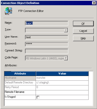
656 Chapter 24: Using FTP
The Connection Object Definition dialog box appears.
6. Enter the remote file name for the source or target. If you use an indirect source file,
enter the indirect source file name.
You must use 7-bit ASCII characters for the file name. The session fails if you use a
remote file name with Unicode characters.
If you enter a fully qualified name for the source file name, the Integration Service
ignores the path entered in the Default Remote Directory field. The session will fail if
you enclose the fully qualified file name in single or double quotation marks.
7. Select Is Staged to stage the source or target file on the Integration Service and click OK.
8. Click OK.
Configuring Source File Properties
If you access source files with FTP, configure the source file properties after you choose the
FTP connection for the source instance. The source file properties determine the source file
type and the staging location. You can configure source file properties in the Properties
settings on the Mapping tab.
If you stage the source file, select the source file name, directory, and file type. If you do not
stage the source file, you only need to specify the source file type. If you do not stage the
source file, the Integration Service uses the remote file name and directory from the FTP
connection object and ignores the source file name and directory.
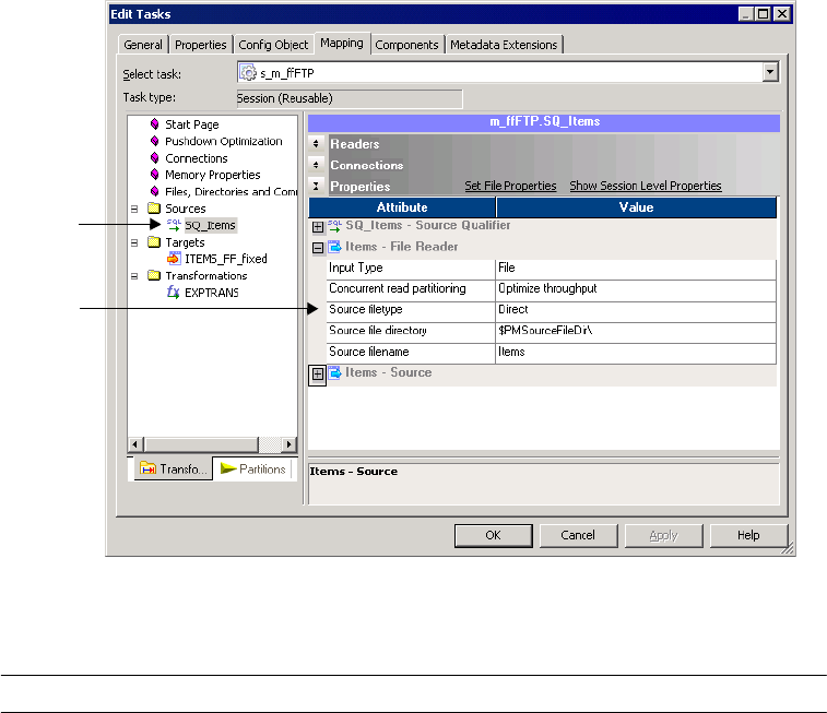
Configuring FTP in a Session 657
Figure 24-2 shows the Properties settings on the Mapping tab:
Table 24-2 shows the attributes in the Properties settings:
Figure 24-2. Properties Settings for Source Instance
Table 24-2. Properties Settings for a Source Instance
Attribute Description
Source File Directory Name and path of the local source file directory used to stage the source data. By default,
the Integration Service uses the service process variable directory, $PMSourceFileDir, for
file sources. The Integration Service concatenates this field with the Source file name field
when it runs the session.
If you do not stage the source file, the Integration Service uses the file name and directory
from the FTP connection object.
The Integration Service ignores this field if you enter a fully qualified file name in the
Source file name field.
Source File Name Name of the local source file used to stage the source data. You can enter the file name or
the file name and path. If you enter a fully qualified file name, the Integration Service
ignores the Source file directory field.
If you do not stage the source file, the Integration Service uses the remote file name and
default directory from the FTP connection object.
Source File Type Indicates whether the source file contains the source data or a list of files with the same file
properties. Choose Direct if the source file contains the source data. Choose Indirect if the
source file contains a list of files.
Source
Instance
Properties
Settings
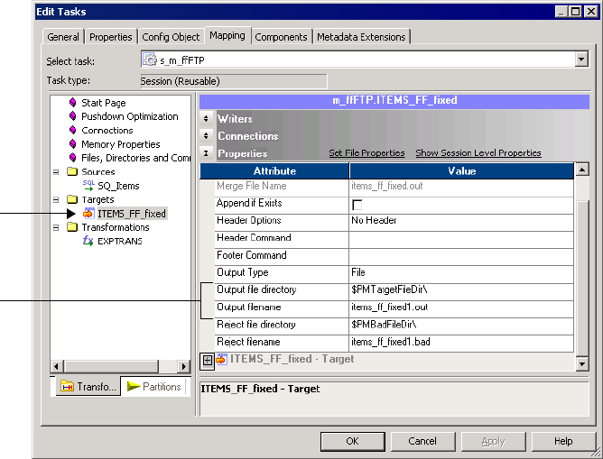
658 Chapter 24: Using FTP
Configuring Target File Properties
If you write to target files with FTP, specify the target file properties after you specify the FTP
connection for the target instance. The target file properties determine the reject file and
directory and staging location. Specify target file properties in the Properties settings on the
Mapping tab.
If you stage the target file, configure the target file name and directory and the reject file
name and directory. If you do not stage the target file, you only need to configure the reject
file and directory. If you do not stage the target file, the Integration Service uses the remote
file name and directory from the FTP connection object.
If you purchase the Partitioning option, you can also select merge file properties.
Figure 24-3 shows the Properties Settings on the Mapping tab:
Figure 24-3. Properties Settings for Target Instance
Target
Instance
Properties
Settings

Configuring FTP in a Session 659
Table 24-3 shows the attributes in the Properties settings:
Table 24-3. Properties Settings for Target Instance
Partitioning FTP File Targets
When you choose an FTP connection type for the partitioned targets in a session, you
configure FTP settings for the target partitions. You can merge the target files or individual
target files for each partition.
Use the following rules and guidelines when you configure FTP settings for target partitions:
♦You must use an FTP connection for each target partition.
♦You can choose to stage the files when selecting the connection object for the target
partition.
♦If the FTP connections for the target partitions have any settings other than a remote file
name, the Integration Service does not create a merge file.
Table 24-4 describes the actions of the Integration Service with partitioned FTP file targets:
Attribute Description
Output File Directory Name and path of the local target file directory used to stage the target data. By
default, the Integration Service uses the service process variable directory,
$PMTargetFileDir. The Integration Service concatenates this field with the Output
file name field when it runs the session.
If you do not stage the target file, the Integration Service uses the file name and
directory from the FTP connection object.
The Integration Service ignores this field if you enter a fully qualified file name in
the Output file name field.
Output File Name Name of the local target file used to stage the target data. You can enter the file
name, or the file name and path. If you enter a fully qualified file name, the
Integration Service ignores the Output file directory field.
If you do not stage the source file, the Integration Service uses the remote file name
and default directory from the FTP connection object.
Table 24-4. Integration Service Behavior with Partitioned FTP File Targets
Merge Type Integration Service Behavior
No Merge If you stage the files, The Integration Service creates one target file for each partition. At
the end of the session, the Integration Service transfers the target files to the remote
location.
If you do not stage the files, the Integration Service generates a target file for each
partition at the remote location.
Sequential Merge Integration Service creates one output file for each partition. At the end of the session,
the Integration Service merges the individual output files into a single merge file, deletes
the individual output files, and transfers the merge file to the remote location.

660 Chapter 24: Using FTP
File List If you stage the files, the Integration Service creates the following files:
- Output file for each partition
- File list that contains the names and paths of the local files
- File list that contains the names and paths of the remote files
At the end of the session, the Integration Service transfers the files to the remote
location. If the individual target files are in the Merge File Directory, file list contains
relative paths. Otherwise, the file list contains absolute paths.
If you do not stage the files, the Integration Service writes the data for each partition at
the remote location and creates a remote file list that contains a list of the individual
target files.
Use the file list as a source file in another mapping.
Concurrent Merge If you stage the files, the Integration Service concurrently writes the data for all target
partitions to a local merge file. At the end of the session, the Integration Service transfers
the merge file to the remote location. The Integration Service does not write to any
intermediate output files.
If you do not stage the files, the Integration Service concurrently writes the target data for
all partitions to a merge file at the remote location.
Table 24-4. Integration Service Behavior with Partitioned FTP File Targets
Merge Type Integration Service Behavior

661
Chapter 25
Using Incremental
Aggregation
This chapter includes the following topics:
♦Overview, 662
♦Integration Service Processing for Incremental Aggregation, 663
♦Reinitializing the Aggregate Files, 664
♦Moving or Deleting the Aggregate Files, 665
♦Partitioning Guidelines with Incremental Aggregation, 666
♦Preparing for Incremental Aggregation, 667
662 Chapter 25: Using Incremental Aggregation
Overview
When using incremental aggregation, you apply captured changes in the source to aggregate
calculations in a session. If the source changes incrementally and you can capture changes,
you can configure the session to process those changes. This allows the Integration Service to
update the target incrementally, rather than forcing it to process the entire source and
recalculate the same data each time you run the session.
For example, you might have a session using a source that receives new data every day. You
can capture those incremental changes because you have added a filter condition to the
mapping that removes pre-existing data from the flow of data. You then enable incremental
aggregation.
When the session runs with incremental aggregation enabled for the first time on March 1,
you use the entire source. This allows the Integration Service to read and store the necessary
aggregate data. On March 2, when you run the session again, you filter out all the records
except those time-stamped March 2. The Integration Service then processes the new data and
updates the target accordingly.
Consider using incremental aggregation in the following circumstances:
♦You can capture new source data. Use incremental aggregation when you can capture new
source data each time you run the session. Use a Stored Procedure or Filter transformation
to process new data.
♦Incremental changes do not significantly change the target. Use incremental aggregation
when the changes do not significantly change the target. If processing the incrementally
changed source alters more than half the existing target, the session may not benefit from
using incremental aggregation. In this case, drop the table and recreate the target with
complete source data.
Note: Do not use incremental aggregation if the mapping contains percentile or median
functions. The Integration Service uses system memory to process these functions in addition
to the cache memory you configure in the session properties. As a result, the Integration
Service does not store incremental aggregation values for percentile and median functions in
disk caches.
Integration Service Processing for Incremental Aggregation 663
Integration Service Processing for Incremental
Aggregation
The first time you run an incremental aggregation session, the Integration Service processes
the entire source. At the end of the session, the Integration Service stores aggregate data from
that session run in two files, the index file and the data file. The Integration Service creates
the files in the cache directory specified in the Aggregator transformation properties.
Each subsequent time you run the session with incremental aggregation, you use the
incremental source changes in the session. For each input record, the Integration Service
checks historical information in the index file for a corresponding group. If it finds a
corresponding group, the Integration Service performs the aggregate operation incrementally,
using the aggregate data for that group, and saves the incremental change. If it does not find a
corresponding group, the Integration Service creates a new group and saves the record data.
When writing to the target, the Integration Service applies the changes to the existing target.
It saves modified aggregate data in the index and data files to be used as historical data the
next time you run the session.
If the source changes significantly and you want the Integration Service to continue saving
aggregate data for future incremental changes, configure the Integration Service to overwrite
existing aggregate data with new aggregate data. For more information, see “Reinitializing the
Aggregate Files” on page 664.
Each subsequent time you run a session with incremental aggregation, the Integration Service
creates a backup of the incremental aggregation files. The cache directory for the Aggregator
transformation must contain enough disk space for two sets of the files.
When you partition a session that uses incremental aggregation, the Integration Service
creates one set of cache files for each partition.
The Integration Service creates new aggregate data, instead of using historical data, when you
perform one of the following tasks:
♦Save a new version of the mapping.
♦Configure the session to reinitialize the aggregate cache.
♦Move the aggregate files without correcting the configured path or directory for the files in
the session properties.
♦Change the configured path or directory for the aggregate files without moving the files to
the new location.
♦Delete cache files.
♦Decrease the number of partitions.
When the Integration Service rebuilds incremental aggregation files, the data in the previous
files is lost.
Note: To protect the incremental aggregation files from file corruption or disk failure,
periodically back up the files.
664 Chapter 25: Using Incremental Aggregation
Reinitializing the Aggregate Files
If the source tables change significantly, you might want the Integration Service to create new
aggregate data, instead of using historical data. To have the Integration Service create new
aggregate data, configure the session to reinitialize the aggregate cache.
For example, you can reinitialize the aggregate cache if the source for a session changes
incrementally every day and completely changes once a month. When you receive the new
source data for the month, you might configure the session to reinitialize the aggregate cache,
truncate the existing target, and use the new source table during the session.
After you run a session that reinitializes the aggregate cache, edit the session properties to
disable the Reinitialize Aggregate Cache option. If you do not clear Reinitialize Aggregate
Cache, the Integration Service overwrites the aggregate cache each time you run the session.
Note: When you move from Windows to UNIX, you must reinitialize the cache. Therefore,
you cannot change from a Latin1 code page to an MSLatin1 code page, even though these
code pages are compatible.
Moving or Deleting the Aggregate Files 665
Moving or Deleting the Aggregate Files
After you run an incremental aggregation session, avoid moving or modifying the index and
data files that store historical aggregate information.
If you move the files into a different directory, and you want the Integration Service to use the
aggregate files, you must also change the path to those files in the session properties. As well,
if you change the path to the files, but you do not move the files, the Integration Service
rebuilds the files the next time you run the session.
If you change certain session or Integration Service properties, the Integration Service cannot
use the incremental aggregation files, and it fails the session. To avoid session failure, delete
existing incremental aggregation files when you perform any of the following tasks:
♦Change the Integration Service data movement mode from ASCII to Unicode or from
Unicode to ASCII.
♦Change the Integration Service code page to an incompatible code page.
♦Change the session sort order when the Integration Service runs in Unicode mode.
♦Change the Enable High Precision session option.
Finding Index and Data Files
By default, the Integration Service stores the index and data files in the directory entered in
the process variable, $PMCacheDir, in the Workflow Manager. The Integration Service names
the index file PMAGG*.idx*. The Integration Service names the data file PMAGG*.dat*.
When you run the session, the Integration Service writes the file names in the session log. To
locate the files, look in the previous session log for the SM_7034 and SM_7035 messages that
indicate the cache file name and location. The following messages show sample entries in the
session log:
MAPPING> SM_7034 Aggregate Information: Index file is
[C:\Informatica\PowerCenter8.0\server\infa_shared\Cache\PMAGG8_4_2.idx2]
MAPPING> SM_7035 Aggregate Information: Data file is
[C:\Informatica\PowerCenter8.0\server\infa_shared\Cache\PMAGG8_4_2.dat2]
For more information about cache file storage and naming conventions, see “Cache Files” on
page 672.
666 Chapter 25: Using Incremental Aggregation
Partitioning Guidelines with Incremental Aggregation
When you use incremental aggregation in a session with multiple partitions, the Integration
Service creates one set of cache files for each partition.
Use the following guidelines when you change the number of partitions or the cache
directory:
♦Change the cache directory for a partition. If you change the directory for a partition and
you want the Integration Service to reuse the cache files, you must move the cache files for
the partition associated with the changed directory.
−If you change the directory for the first partition, and you do not move the cache files,
the Integration Service rebuilds the cache files for all partitions.
−If you change the directory for partitions 2-n, and you do not move the cache files, the
Integration Service rebuilds the cache files that it cannot locate.
♦Decrease the number of partitions. If you delete a partition and you want the Integration
Service to reuse the cache files, you must move the cache files for the deleted partition to
the directory configured for the first partition. If you do not move the files to the directory
of the first partition, the Integration Service rebuilds the cache files that it cannot locate.
Note: If you increase the number of partitions, the Integration Service realigns the index
and data cache files the next time you run a session. It does not need to rebuild the files.
♦Move cache files. If you move cache files for a partition and you want the Integration
Service to reuse the files, you must also change the partition directory. If you do not
change the directory, the Integration Service rebuilds the files the next time you run a
session.
♦Delete cache files. If you delete cache files, the Integration Service rebuilds them the next
time you run a session.
If you change the number of partitions and the cache directory, you may need to move cache
files for both. For example, if you change the cache directory for the first partition and you
decrease the number of partitions, you need to move the cache files for the deleted partition
and the cache files for the partition associated with the changed directory.
Preparing for Incremental Aggregation 667
Preparing for Incremental Aggregation
When you use incremental aggregation, you need to configure both mapping and session
properties:
♦Implement mapping logic or filter to remove pre-existing data.
♦Configure the session for incremental aggregation and verify that the file directory has
enough disk space for the aggregate files.
Configuring the Mapping
Before enabling incremental aggregation, you must capture changes in source data. You can
can use a Filter or Stored Procedure transformation in the mapping to remove pre-existing
source data during a session. For more information about the Filter and Stored Procedure
transformations, see the Transformation Guide.
Configuring the Session
Use the following guidelines when you configure the session for incremental aggregation:
♦Verify the location where you want to store the aggregate files. The index and data files
grow in proportion to the source data. Be sure the cache directory has enough disk space to
store historical data for the session.
When you run multiple sessions with incremental aggregation, decide where you want the
files stored. Then, enter the appropriate directory for the process variable, $PMCacheDir,
in the Workflow Manager. You can enter session-specific directories for the index and data
files. However, by using the process variable for all sessions using incremental aggregation,
you can easily change the cache directory when necessary by changing $PMCacheDir.
Changing the cache directory without moving the files causes the Integration Service to
reinitialize the aggregate cache and gather new aggregate data.
In a grid, Integration Services rebuild incremental aggregation files they cannot find.
When an Integration Service rebuilds incremental aggregation files, it loses aggregate
history.
♦Verify the incremental aggregation settings in the session properties. You can configure
the session for incremental aggregation in the Performance settings on the Properties tab.
You can also configure the session to reinitialize the aggregate cache. If you choose to
reinitialize the cache, the Workflow Manager displays a warning indicating the Integration
Service overwrites the existing cache and a reminder to clear this option after running the
session.
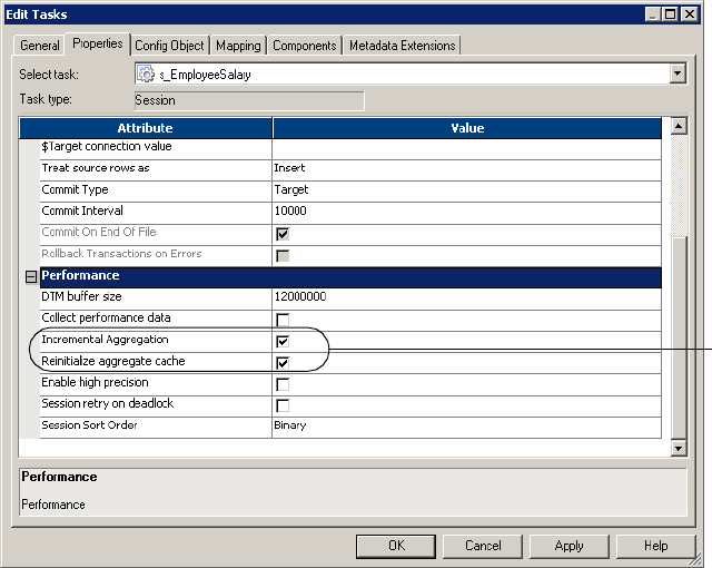
668 Chapter 25: Using Incremental Aggregation
Figure 25-1 shows the Performance settings on the Properties tab where you configure
incremental aggregation options:
Note: You cannot use incremental aggregation when the mapping includes an Aggregator
transformation with Transaction transformation scope. The Workflow Manager marks the
session invalid.
Figure 25-1. Incremental Aggregation Session Properties
Configure
incremental
aggregation.

669
Chapter 26
Session Caches
This chapter includes the following topics:
♦Overview, 670
♦Cache Memory, 671
♦Cache Files, 672
♦Configuring the Cache Size, 675
♦Cache Partitioning, 681
♦Aggregator Caches, 683
♦Joiner Caches, 686
♦Lookup Caches, 690
♦Rank Caches, 693
♦Sorter Caches, 695
♦XML Target Caches, 697
♦Optimizing the Cache Size, 698

670 Chapter 26: Session Caches
Overview
The Integration Service allocates cache memory for XML targets and Aggregator, Joiner,
Lookup, Rank, and Sorter transformations in a mapping. The Integration Service creates
index and data caches for the XML targets and Aggregator, Joiner, Lookup, and Rank
transformations. The Integration Service stores key values in the index cache and output
values in the data cache. The Integration Service creates one cache for the Sorter
transformation to store sort keys and the data to be sorted.
You configure memory parameters for the caches in the session properties. When you first
configure the cache size, you can calculate the amount of memory required to process the
transformation or you can configure the Integration Service to automatically configure the
memory requirements at run time.
After you run a session, you can tune the cache sizes for the transformations in the session.
You can analyze the transformation statistics to determine the cache sizes required for optimal
session performance, and then update the configured cache sizes.
If the Integration Service requires more memory than what you configure, it stores overflow
values in cache files. When the session completes, the Integration Service releases cache
memory, and in most circumstances, it deletes the cache files.
If the session contains multiple partitions, the Integration Service creates one memory cache
for each partition. In particular situations, the Integration Service uses cache partitioning,
creating a separate cache for each partition.
The following table describes the type of information that the Integration Service stores in
each cache:
Mapping Object Cache
Type Description
Aggregator - Index
- Data
- Stores group values as configured in the group by ports.
- Stores calculations based on the group by ports.
Joiner - Index
- Data
- Stores all master rows in the join condition that have unique keys.
- Stores master source rows.
Lookup - Index
- Data
- Stores lookup condition information.
- Stores lookup data that is not stored in the index cache.
Rank - Index
- Data
- Stores group values as configured in the group by ports.
- Stores ranking information based on the group by ports.
Sorter - Sorter - Stores sort keys and data.
XML Target - Index
- Data
- Stores primary and foreign key information in separate caches.
- Stores XML row data while it generates the XML target.
Cache Memory 671
Cache Memory
The Integration Service creates each memory cache based on the configured cache size. When
you create a session, you can configure the cache sizes for each transformation instance in the
session properties.
The Integration Service might increase the configured cache size for one of the following
reasons:
♦The configured cache size is less than the minimum cache size required to process the
operation. The Integration Service requires a minimum amount of memory to initialize
each session. If the configured cache size is less than the minimum required cache size,
then the Integration Service increases the configured cache size to meet the minimum
requirement. If the Integration Service cannot allocate the minimum required memory, the
session fails.
♦The configured cache size is not a multiple of the cache page size. The Integration
Service stores cached data in cache pages. The cached pages must fit evenly into the cache.
Thus, if you configure 10 MB (1,048,576 bytes) for the cache size and the cache page size
is 10,000 bytes, then the Integration Service increases the configured cache size to
1,050,000 bytes to make it a multiple of the 10,000-byte page size.
When the Integration Service increases the configured cache size, it continues to run the
session and writes a message similar to the following message in the session log:
MAPPING> TE_7212 Increasing [Index Cache] size for transformation
<transformation name> from <configured index cache size> to <new index
cache size>.
Review the session log to verify that enough memory is allocated for the minimum
requirements.
For optimal performance, set the cache size to the total memory required to process the
transformation. If there is not enough cache memory to process the transformation, the
Integration Service processes some of the transformation in memory and pages information to
disk to process the rest.
Use the following information to understand how the Integration Service handles memory
caches differently on 32-bit and 64-bit machines:
♦An Integration Service process running on a 32-bit machine cannot run a session if the
total size of all the configured session caches is more than 2 GB. If you run the session on
a grid, the total cache size of all session threads running on a single node must not exceed
2 GB.
♦If a grid has 32-bit and 64-bit Integration Service processes and a session exceeds 2 GB of
memory, you must configure the session to run on an Integration Service on a 64-bit
machine. For more information about grids, see “Running Workflows on a Grid” on
page 553.

672 Chapter 26: Session Caches
Cache Files
When you run a session, the Integration Service creates at least one cache file for each
transformation. If the Integration Service cannot process a transformation in memory, it
writes the overflow values to the cache files.
Table 26-1 describes the types of cache files that the Integration Service creates for different
mapping objects:
The Integration Service creates cache files based on the Integration Service code page.
When you run a session, the Integration Service writes a message in the session log indicating
the cache file name and the transformation name. When a session completes, the Integration
Service releases cache memory and usually deletes the cache files. You may find index and data
cache files in the cache directory under the following circumstances:
♦The session performs incremental aggregation.
♦You configure the Lookup transformation to use a persistent cache.
♦The session does not complete successfully. The next time you run the session, the
Integration Service deletes the existing cache files and create new ones.
Note: Since writing to cache files can slow session performance, configure the cache sizes to
process the transformation in memory.
Naming Convention for Cache Files
The Integration Service uses the different naming conventions for index, data, and sorter
cache files.
Table 26-1. Types of Cache Files
Mapping Object Cache File
Aggregator, Joiner, Lookup,
and Rank transformations
The Integration Service creates the following types of cache files:
- One header file for each index cache and data cache
- One data file for each index cache and data cache
Sorter transformation The Integration Service creates one sorter cache file.
XML target The Integration Service creates the following types of cache files:
- One data cache file for each XML target group
- One primary key index cache file for each XML target group
- One foreign key index cache file for each XML target group

Cache Files 673
Table 26-2 describes the naming convention for each type of cache file:
Table 26-3 describes the components of the cache file names:
Table 26-2. Naming Conventions for Cache Files
Cache Files Naming Convention
Data and sorter [<Name Prefix> | <prefix> <session ID>_<transformation ID>]_[partition index]_[OS][BIT].<suffix>
[overflow index]
Index <prefix> <session id>_<transformation id>_<group id>_<key type>.<suffix> <overflow>
Table 26-3. Components of Cache File Names
File Name
Component Description
Name Prefix Cache file name prefix configured in the Lookup transformation. For Lookup transformation cache
file.
Prefix Describes the type of transformation:
- Aggregator transformation is PMAGG.
- Joiner transformation is PMJNR.
- Lookup transformation is PMLKUP.
- Rank transformation is PMAGG.
- Sorter transformation is PMSORT.
- XML target is PMXML.
Session ID Session instance ID number.
Transformation ID Transformation instance ID number.
Group ID ID for each group in a hierarchical XML target. The Integration Service creates one index cache
for each group. For XML target cache file.
Key Type Type of key: foreign key or primary key. For XML target cache file.
Partition Index If the session contains more than one partition, this identifies the partition number. The partition
index is zero-based, so the first partition has no partition index. Partition index 2 indicates a cache
file created in the third partition.
OS Identifies the operating system of the machine running the Integration Service process:
- W is Windows.
- H is HP-UX.
- S is Solaris.
- A is AIX.
- L is Linux.
- M is Mainframe.
For Lookup transformation cache file.
BIT Identifies the bit platform of the machine running the Integration Service process: 32-bit or 64-bit.
For Lookup transformation cache file.

674 Chapter 26: Session Caches
For example, the name of the data file for the index cache is PMLKUP748_2_5S32.idx1.
PMLKUP identifies the transformation type as Lookup, 748 is the session ID, 2 is the
transformation ID, 5 is the partition index, S (Solaris) is the operating system, and 32 is the
bit platform.
Cache File Directory
The Integration Service creates the cache files by default in the $PMCacheDir directory. If the
Integration Service process does not find the directory, it fails the session and writes a message
to the session log indicating that it could not create or open the cache file.
The Integration Service may create multiple cache files. The number of cache files is limited
by the amount of disk space available in the cache directory.
If you run the Integration Service on a grid and only some Integration Service nodes have fast
access to the shared cache file directory, configure each session with a large cache to run on
the nodes with fast access to the directory. To configure a session to run on a node with fast
access to the directory, complete the following steps:
1. Create a PowerCenter resource.
2. Make the resource available to the nodes with fast access to the directory.
3. Assign the resource to the session.
For more information about configuring resources for a node, see “Managing the Grid” in the
Administrator Guide.
If all Integration Service processes in a grid have slow access to the cache files, set up a
separate, local cache file directory for each Integration Service process. An Integration Service
process may have faster access to the cache files if it runs on the same machine that contains
the cache directory.
Suffix Identifies the type of cache file:
- Index cache file is .idx0 for the header file and .idxn for the data files.
- Data cache file is .dat0 for the header file and .datn for the data files.
- Sorter cache file is .PMSORT().
Overflow Index If a cache file handles more than 2 GB of data, the Integration Service creates more cache files.
When creating these files, the Integration Service appends an overflow index to the file name,
such as PMAGG*.idx2 and PMAGG*.idx3. The number of cache files is limited by the amount of
disk space available in the cache directory.
Table 26-3. Components of Cache File Names
File Name
Component Description
Configuring the Cache Size 675
Configuring the Cache Size
You can configure the amount of memory for a cache in the session properties. The cache size
specified in the session properties overrides the value set in the transformation properties.
The amount of memory you configure depends on how much memory cache and disk cache
you want to use. If you configure the cache size and it is not enough to process the
transformation in memory, the Integration Service processes some of the transformation in
memory and pages information to cache files to process the rest of the transformation. For
optimal session performance, configure the cache size so that the Integration Service can
process all data in memory.
If the session is reusable, all instances of the session use the cache size configured in the
reusable session properties. You cannot override the cache size in the session instance.
Use one of the following methods to configure a cache size:
♦Cache calculator. Use the calculator to estimate the total amount of memory required to
process the transformation. For more information, see “Calculating the Cache Size” on
page 675.
♦Auto cache memory. Use auto memory to specify a maximum limit on the cache size that
is allocated for processing the transformation. Use this method if the machine on which
the Integration Service process runs has limited cache memory. For more information, see
“Using Auto Memory Size” on page 676.
♦Numeric value. Configure a specific value for the cache size. Configure a specific value
when you want to tune the cache size. For more information, see “Configuring a Numeric
Cache Size” on page 678.
You configure the memory requirements differently when the Integration Service uses cache
partitioning. If the Integration Service uses cache partitioning, it allocates the configured
cache size for each partition. To configure the memory requirements for a transformation
with cache partitioning, calculate the total requirements for the transformation and divide by
the number of partitions. For more information about configuring the cache size for cache
partitioning, see “Configuring the Cache Size for Cache Partitioning” on page 681.
The cache size requirements for a transformation may change when the inputs to the
transformation change. Monitor the cache sizes in the session logs on a regular basis to help
you tune the cache size. For more information about optimizing the cache size, see
“Optimizing the Cache Size” on page 698.
Calculating the Cache Size
Use the cache calculator to estimate the total amount of memory required to process the
transformation. You must provide inputs to calculate the cache size. The inputs depend on
the type of transformation. For example, to calculate the cache size for an Aggregator
transformation, you supply the number of groups.
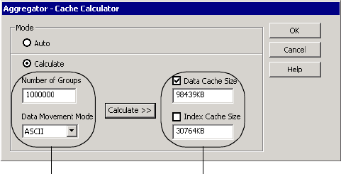
676 Chapter 26: Session Caches
Figure 26-1 shows the cache calculator for an Aggregator transformation:
You can select one of the following modes in the cache calculator:
♦Auto. Choose auto mode if you want the Integration Service to determine the cache size at
run time based on the maximum memory configured on the Config Object tab. For more
information about auto memory cache, see “Using Auto Memory Size” on page 676.
♦Calculate. Select to calculate the total requirements for a transformation based on inputs.
The cache calculator requires different inputs for each transformation. You must select the
applicable cache type to apply the calculated cache size. For example, to apply the
calculated cache size for the data cache and not the index cache, select only the Data Cache
Size option.
The cache calculator estimates the cache size required for optimal session performance based
on your input. After you configure the cache size and run the session, you can review the
transformation statistics in the session log to tune the configured cache size. For more
information, see “Optimizing the Cache Size” on page 698.
Note: You cannot use the cache calculator to estimate the cache size for an XML target.
Using Auto Memory Size
Use auto cache memory to specify a maximum limit on the cache size that is allocated for
processing the transformation. If you use auto cache memory, you configure the Integration
Service to determine the cache size for a transformation at run time.
The Integration Service allocates memory cache based on the maximum memory size
specified in the auto memory attributes in the session properties. The Integration Service
distributes the maximum cache size specified among all transformations in the session.
You might use auto memory cache if the machine on which the Integration Service process
runs has limited cache memory. For example, you use the cache calculator to determine that
the Aggregator transformation requires 1 GB of cache memory to process the transformation.
Figure 26-1. Cache Calculator
Enter required inputs. Displays calculated cache sizes. By default,
‘Auto’ displays. You can also enter new
values.
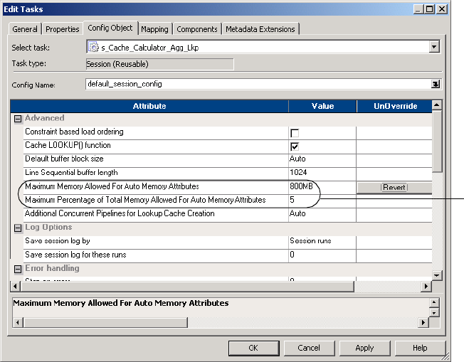
Configuring the Cache Size 677
The machine only has 800 MB of cache memory available. The following figure shows
maximum memory allocation of 800 MB:
When you configure a numeric value and a percentage for the auto cache memory, the
Integration Service compares the values and uses the lesser of the two for the maximum
memory limit. The Integration Service allocates up to 800 MB as long as 800 MB is less than
5% of the total memory.
To configure auto cache memory, you can use the cache calculator or you can enter ‘Auto’
directly into the session properties. By default, transformations use auto cache memory.
If a session has multiple transformations that require caching, you can configure some
transformations with auto memory cache and other transformations with numeric cache sizes.
The Integration Service allocates the maximum memory specified for auto caching in
addition to the configured numeric cache sizes. For example, a session has three
transformations. You assign auto caching to two transformations and specify a maximum
memory cache size of 800 MB. You specify 500 MB as the cache size for the third
transformation. The Integration Service allocates a total of 1,300 MB of memory.
If the Integration Service uses cache partitioning, the Integration Service distributes the
maximum cache size specified for the auto cache memory across all transformations in the
session and divides the cache memory for each transformation among all of its partitions.
For more information about configuring automatic memory settings, see “Configuring
Automatic Memory Settings” on page 188.
Auto cache
memory
options
678 Chapter 26: Session Caches
Configuring a Numeric Cache Size
You can configure a specific value for the cache size. You configure a specific value when you
tune a cache size. The first time you configure the cache size, you can use the cache calculator
or auto cache memory. After you configure the cache size and run the session, you can analyze
the transformation statistics in the session log to tune the cache size. The session log shows
the cache size required to process the transformation in memory without paging to disk. Use
the cache size specified in the session log for optimal session performance. For more
information about optimizing the cache size, see “Optimizing the Cache Size” on page 698.
Steps to Configure the Cache Size
You can configure the cache size for a transformation in the session properties. When you
configure the cache size, you specify the total requirements for the transformation, unless the
Integration Service uses cache partitioning.
You configure the cache size differently if the Integration Services uses cache partitioning. To
calculate the cache size when the Integration Service uses cache partitioning, calculate the
total requirements for the transformation, and divide by the number of partitions. For more
information about cache partitioning, see “Cache Partitioning” on page 681.
To configure the cache size in the session:
1. In the Workflow Manager, open the session.
2. Click the Mapping tab.
3. Select the mapping object in the left pane.
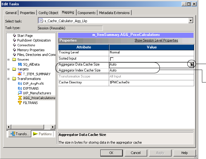
Configuring the Cache Size 679
The right pane of the Mapping tab shows the object properties where you can configure
the cache size:
4. Use one of the following methods to set the cache size:
Enter a value for the cache size, click OK, and then skip to step 8. If you enter a value, all
values are in bytes by default. However, you can enter a value and specify one of the
following units: KB, MB, or GB. If you enter the units, do not enter a space between the
value and unit. For example, enter 350000KB, 200MB, or 1GB.
-or-
Enter ‘Auto’ for the cache size, click OK, and then skip to step 8.
-or-
Open
button
Cache
sizes
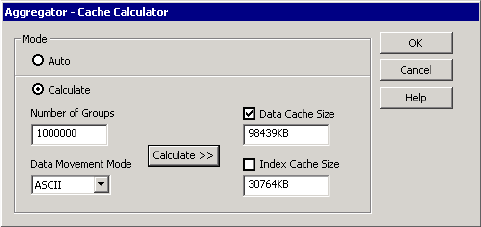
680 Chapter 26: Session Caches
Click the Open button to open the cache calculator.
5. Select a mode.
Select the Auto mode to limit the amount of cache allocated to the transformation. Skip
to step 8.
-or-
Select the Calculate mode to calculate the total memory requirement for the
transformation.
6. Provide the input based on the transformation type, and click Calculate.
Note: If the input value is too large and you cannot enter the value in the cache calculator,
use auto memory cache.
The cache calculator calculates the cache sizes in kilobytes.
7. If the transformation has a data cache and index cache, select Data Cache Size, Index
Cache Size, or both.
8. Click OK to apply the calculated values to the cache sizes you selected in step 7.

Cache Partitioning 681
Cache Partitioning
When you create a session with multiple partitions, the Integration Service may use cache
partitioning for the Aggregator, Joiner, Lookup, Rank, and Sorter transformations. When the
Integration Service partitions a cache, it creates a separate cache for each partition and
allocates the configured cache size to each partition. The Integration Service stores different
data in each cache, where each cache contains only the rows needed by that partition. As a
result, the Integration Service requires a portion of total cache memory for each partition.
When the Integration Service uses cache partitioning, it accesses the cache in parallel for each
partition. If it does not use cache partitioning, it accesses the cache serially for each partition.
Table 26-4 describes the situations when the Integration Service uses cache partitioning for
each applicable transformation:
For more information about partitioning, see “Overview” on page 422.
Configuring the Cache Size for Cache Partitioning
You configure the memory requirements differently when the Integration Service uses cache
partitioning. If the Integration Service uses cache partitioning, it allocates the configured
cache size for each partition. To configure the memory requirements for a transformation
with cache partitioning, calculate the total requirements for the transformation and divide by
the number of partitions.
For example, you create four partitions in a session with an Aggregator transformation. You
determine that an Aggregator transformation requires 400 MB of memory for the data cache.
Configure 100 MB for the data cache size for the Aggregator transformation. When you run
the session, the Integration Service allocates 100 MB for each partition, using a total of
400 MB for the Aggregator transformation.
Table 26-4. Cache Partitioning for Each Transformation
Transformation Description
Aggregator Transformation You create multiple partitions in a session with an Aggregator transformation. You do not
have to set a partition point at the Aggregator transformation. For more information about
Aggregator transformation caches, see “Aggregator Caches” on page 683.
Joiner Transformation You create a partition point at the Joiner transformation. For more information about
caches for the Joiner transformation, see “Joiner Caches” on page 686.
Lookup Transformation You create a hash auto-keys partition point at the Lookup transformation. For more
information about Lookup transformation caches, see “Lookup Caches” on page 690.
Rank Transformation You create multiple partitions in a session with a Rank transformation. You do not have to
set a partition point at the Rank transformation. For more information about Rank
transformation caches, see “Rank Caches” on page 693.
Sorter Transformation You create multiple partitions in a session with a Sorter transformation. You do not have to
set a partition point at the Sorter transformation. For more information about Sorter
transformation caches, see “Sorter Caches” on page 695.
682 Chapter 26: Session Caches
Use the cache calculator to calculate the total requirements for the transformation. If you use
dynamic partitioning, you can determine the number of partitions based on the dynamic
partitioning method. If you use dynamic partitioning based on the nodes in a grid, the
Integration Service creates one partition for each node. If you use dynamic partitioning based
on the source partitioning, use the number of partitions in the source database. For more
information about dynamic partitioning, see “Dynamic Partitioning” on page 427.
Aggregator Caches 683
Aggregator Caches
The Integration Service uses cache memory to process Aggregator transformations with
unsorted input. When you run the session, the Integration Service stores data in memory
until it completes the aggregate calculations.
The Integration Service creates the following caches for the Aggregator transformation:
♦Index cache. Stores group values as configured in the group by ports.
♦Data cache. Stores calculations based on the group by ports.
By default, the Integration Service creates one memory cache and one disk cache for both the
data and index in the transformation.
When you create multiple partitions in a session with an Aggregator transformation, the
Integration Service uses cache partitioning. It creates one disk cache for all partitions and a
separate memory cache for each partition.
For more information about the Aggregator transformation, see “Aggregator Transformation”
in the Tran s f o r mat io n Gu id e.
Incremental Aggregation
The first time you run an incremental aggregation session, the Integration Service processes
the source. At the end of the session, the Integration Service stores the aggregated data in two
cache files, the index and data cache files. The Integration Service saves the cache files in the
cache file directory. The next time you run the session, the Integration Service aggregates the
new rows with the cached aggregated values in the cache files.
When you run a session with an incremental Aggregator transformation, the Integration
Service creates a backup of the Aggregator cache files in $PMCacheDir at the beginning of a
session run. The Integration Service promotes the backup cache to the initial cache at the
beginning of a session recovery run. The Integration Service cannot restore the backup cache
file if the session aborts.
When you create multiple partitions in a session that uses incremental aggregation, the
Integration Service creates one set of cache files for each partition. For information about
caching with incremental aggregation, see “Partitioning Guidelines with Incremental
Aggregation” on page 666.
Configuring the Cache Sizes for an Aggregator Transformation
You configure the cache sizes for an Aggregator transformation with unsorted ports.
You do not need to configure cache memory for Aggregator transformations that use sorted
ports. The Integration Service uses system memory to process an Aggregator transformation
with sorted ports.
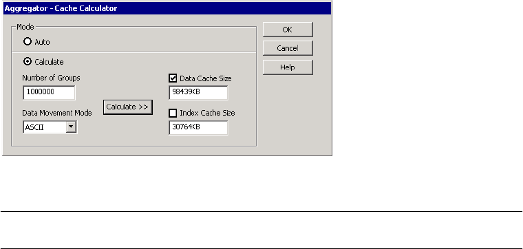
684 Chapter 26: Session Caches
The following dialog box shows the inputs that are required to calculate the cache size for an
Aggregator transformation:
The following table describes the input you provide to calculate the Aggregator cache sizes:
Enter the input and then click Calculate >> to calculate the data and index cache sizes. The
calculated values appear in the Data Cache Size and Index Cache Size fields. For more
information about configuring cache sizes, see “Configuring the Cache Size” on page 675.
Troubleshooting
Use the information in this section to help troubleshoot caching for an Aggregator
transformation.
The following warning appears when I use the cache calculator to calculate the cache size
for an Aggregator transformation:
CMN_2019 Warning: The estimate for Data Cache Size assumes that the number
of aggregate functions is equal to the number of connected output-only
ports. Please increase the cache size if there are significantly more
aggregate functions.
You can use one or more aggregate functions in an Aggregator transformation. The cache
calculator estimates the cache size when the output is based on one aggregate function. If you
use multiple aggregate functions to determine a value for one output port, then you must
increase the cache size.
Option Name Required/
Optional Description
Number of
Groups
Required Number of groups. The Aggregator transformation aggregates data by group.
Calculate the number of groups using the group by ports. For example, if you group
by Store ID and Item ID, you have 5 stores and 25 items, and each store contains all
25 items, then calculate the number of groups as:
5 * 25 = 125 groups
Data Movement
Mode
Required The data movement mode of the Integration Service. The cache requirement varies
based on the data movement mode. Each ASCII character uses one byte. Each
Unicode character uses two bytes.

686 Chapter 26: Session Caches
Joiner Caches
The Integration Service uses cache memory to process Joiner transformations. When you run
a session, the Integration Service reads rows from the master and detail sources concurrently
and builds index and data caches based on the master rows. The Integration Service performs
the join based on the detail source data and the cached master data.
The Integration Service stores a different number of rows in the caches based on the type of
Joiner transformation.
Table 26-5 describes the information that Integration Service stores in the caches for different
types of Joiner transformations:
If the data is sorted, the Integration Service creates one disk cache for all partitions and a
separate memory cache for each partition. It releases each row from the cache after it joins the
data in the row.
If the data is not sorted and there is not a partition at the Joiner transformation, the
Integration Service creates one disk cache and a separate memory cache for each partition. If
the data is not sorted and there is a partition at the Joiner transformation, the Integration
Service creates a separate disk cache and memory cache for each partition. When the data is
not sorted, the Integration Service keeps all master data in the cache until it joins all data.
Table 26-5. Caches for Joiner Transformation
Joiner
Transformation
Type
Index Cache Data Cache
Unsorted Input Stores all master rows in the join condition with
unique index keys.
Stores all master rows.
Sorted Input with
Different Sources
Stores 100 master rows in the join condition with
unique index keys.
Stores master rows that correspond to the
rows stored in the index cache. If the
master data contains multiple rows with
the same key, the Integration Service
stores more than 100 rows in the data
cache.
Sorted Input with
the Same Source
Stores all master or detail rows in the join condition
with unique keys. Stores detail rows if the
Integration Service processes the detail pipeline
faster than the master pipeline. Otherwise, stores
master rows. The number of rows it stores depends
on the processing rates of the master and detail
pipelines. If one pipeline processes its rows faster
than the other, the Integration Service caches all
rows that have already been processed and keeps
them cached until the other pipeline finishes
processing its rows.
Stores data for the rows stored in the
index cache. If the index cache stores
keys for the master pipeline, the data
cache stores the data for master pipeline.
If the index cache stores keys for the
detail pipeline, the data cache stores data
for detail pipeline.
Joiner Caches 687
When you create multiple partitions in a session, you can use 1:n partitioning or n:n
partitioning. The Integration Service processes the Joiner transformation differently when
you use 1:n partitioning and when you use n:n partitioning.
1:n Partitioning
You can use 1:n partitioning with Joiner transformations with sorted input. When you use 1:n
partitioning, you create one partition for the master pipeline and more than one partition in
the detail pipeline. When the Integration Service processes the join, it compares the rows in a
detail partition against the rows in the master source. When processing master and detail data
for outer joins, the Integration Service outputs unmatched master rows after it processes all
detail partitions.
n:n Partitioning
You can use n:n partitioning with Joiner transformations with sorted or unsorted input.
When you use n:n partitioning for a Joiner transformation, you create n partitions in the
master and detail pipelines. When the Integration Service processes the join, it compares the
rows in a detail partition against the rows in the corresponding master partition, ignoring
rows in other master partitions. When processing master and detail data for outer joins, the
Integration Service outputs unmatched master rows after it processes the partition for each
detail cache.
Tip: If the master source has a large number of rows, use n:n partitioning for better session
performance.
To u s e n:n partitioning, you must create multiple partitions in the session and create a
partition point at the Joiner transformation. You create the partition point at the Joiner
transformation to create multiple partitions for both the master and detail source of the Joiner
transformation.
If you create a partition point at the Joiner transformation, the Integration Service uses cache
partitioning. It creates one memory cache for each partition. The memory cache for each
partition contains only the rows needed by that partition. As a result, the Integration Service
requires a portion of total cache memory for each partition.
For more information about the Joiner transformation, see “Joiner Transformation” in the
Tra ns for ma t i o n Gu id e .
Configuring the Cache Sizes for a Joiner Transformation
You can configure the index and data cache sizes for a Joiner transformation session
properties.
When you use 1:n partitioning, the Integration Service replicates the memory cache for each
partition. Each partition requires as much memory as the total requirements for the
transformation. When you configure the cache size for the Joiner transformation with 1:n
partitioning, set the cache size to the total requirements for the transformation.
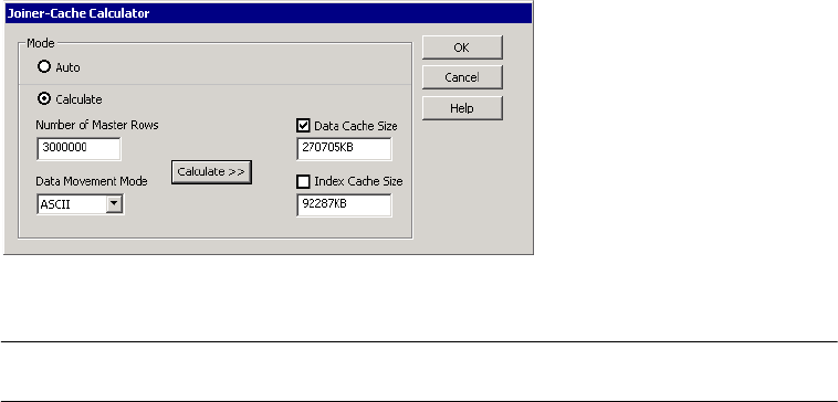
688 Chapter 26: Session Caches
When you use n:n partitioning, each partition requires a portion of the total memory required
to process the transformation. When you configure the cache size for the Joiner
transformation with n:n partitioning, calculate the total requirements for the transformation,
and then divide it by the number of partitions.
You can use the cache calculator to determine the cache size required to process the
transformation. For example, you use the cache calculator to determine that the Joiner
transformation requires 2,000,000 bytes of memory for the index cache and 4,000,000 bytes
of memory for the data cache. You create four partitions for the pipeline. If you use 1:n
partitioning, configure 2,000,000 bytes for the index cache and 4,000,000 bytes for the data
cache. If you use n:n partitioning, configure 500,000 bytes for the index cache and 1,000,000
bytes for the data cache.
The following dialog box shows the inputs that are required to calculate the cache size for a
Joiner transformation:
The following table describes the input you provide to calculate the Joiner cache sizes:
Enter the input and then click Calculate >> to calculate the data and index cache sizes. The
calculated values appear in the Data Cache Size and Index Cache Size fields. For more
information about configuring cache sizes, see “Configuring the Cache Size” on page 675.
Troubleshooting
Use the information in this section to help troubleshoot caching for a Joiner transformation.
Input Required/
Optional Description
Number of
Master Rows
Conditional Number of rows in the master source. Applies to a Joiner transformation with
unsorted input. If the Joiner transformation has sorted input, you cannot enter the
number of master rows. The cache calculator does require the number of master
rows to determine the cache size for a Joiner transformation with sorted input.
Note: If rows in the master source have the same unique keys, the cache calculator
overestimates the index cache size.
Data Movement
Mode
Required The data movement mode of the Integration Service. The cache requirement varies
based on the data movement mode. ASCII characters use one byte. Unicode
characters use two bytes.
Joiner Caches 689
The following warning appears when I use the cache calculator to calculate the cache size
for a Joiner transformation with sorted input:
CMN_2020 Warning: If both Master and Detail pipelines of a Sorted Input
Joiner are from the same source, then the number of rows stored in the
cache depends on the difference in speed of the two pipelines. Since we
cannot predict the speed of the pipelines, this estimate may be
inaccurate.
The master and detail pipelines process rows concurrently. If you join data from the same
source, the pipelines may process the rows at different rates. If one pipeline processes its rows
faster than the other, the Integration Service caches all rows that have already been processed
and keeps them cached until the other pipeline finishes processing its rows. The amount of
rows cached depends on the difference in processing rates between the two pipelines.
The cache size must be large enough to store all cached rows to achieve optimal session
performance. If the cache size is not large enough, increase it.
Note: This message applies if you join data from the same source even though it also appears
when you join data from different sources.
The following warning appears when I use the cache calculator to calculate the cache size
for a Joiner transformation with sorted input:
CMN_2021 Warning: Please increase the Data Cache Size if many master rows
share the same key.
When you calculate the cache size for the Joiner transformation with sorted input, the cache
calculator bases the estimated cache requirements on an average of 2.5 master rows for each
unique key. If the average number of master rows for each unique key is greater than 2.5,
increase the cache size accordingly. For example, if the average number of master rows for
each unique key is 5 (double the size of 2.5), then double the cache size calculated by the
cache calculator.

690 Chapter 26: Session Caches
Lookup Caches
If you enable caching in a Lookup transformation, the Integration Service builds a cache in
memory to store lookup data. When the Integration Service builds a lookup cache in memory,
it processes the first row of data in the transformation and queries the cache for each row that
enters the transformation. If you do not enable caching, the Integration Service queries the
lookup source for each input row.
The result of the Lookup query and processing is the same, whether or not you cache the
lookup source. However, using a lookup cache can increase session performance. You can
optimize performance by caching the lookup source when the source is large.
If the lookup does not change between sessions, you can configure the transformation to use a
persistent lookup cache. When you run the session, the Integration Service rebuilds the
persistent cache if any cache file is missing or invalid.
The Integration Service creates the following caches for the Lookup transformation:
♦Data cache. For a connected Lookup transformation, stores data for the connected output
ports, not including ports used in the lookup condition. For an unconnected Lookup
transformation, stores data from the return port.
♦Index cache. Stores data for the columns used in the lookup condition.
The Integration Service creates disk and memory caches based on the lookup caching and
partitioning information.
The following table describes the caches that the Integration Service creates based on the
cache and partitioning information:
When you create multiple partitions in a session with a Lookup transformation and create a
hash auto-keys partition point at the Lookup transformation, the Integration Service uses
cache partitioning.
When the Integration Service uses cache partitioning, it creates caches for the Lookup
transformation when the first row of any partition reaches the Lookup transformation. If you
configure the Lookup transformation for concurrent caches, the Integration Service builds all
caches for the partitions concurrently. For more information about Lookup transformations
and lookup caches, see the Transformation Guide.
Lookup Conditions Disk Cache Memory Cache
- Static cache
- No hash auto-keys partition point
One disk cache for all partitions. One memory cache for each partition.
- Dynamic cache
- No hash auto-keys partition point
One disk cache for all partitions. One memory cache for all partitions.
- Static or dynamic cache
- Hash auto-keys partition point
One disk cache for each partition. One memory cache for each partition.
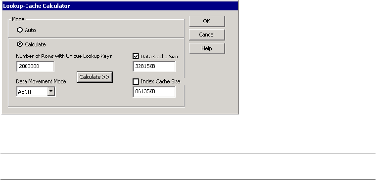
Lookup Caches 691
Sharing Caches
The Integration Service handles shared lookup caches differently depending on whether the
cache is static or dynamic:
♦Static cache. If two Lookup transformations share a static cache, the Integration Service
does not allocate additional memory for shared transformations in the same pipeline stage.
For shared transformations in different pipeline stages, the Integration Service does allocate
additional memory.
Static Lookup transformations that use the same data or a subset of data to create a disk
cache can share the disk cache. However, the lookup keys may be different, so the
transformations must have separate memory caches.
♦Dynamic cache. When Lookup transformations share a dynamic cache, the Integration
Service updates the memory cache and disk cache. To keep the caches synchronized, the
Integration Service must share the disk cache and the corresponding memory cache
between the transformations.
Configuring the Cache Sizes for a Lookup Transformation
You can configure the cache sizes for the Lookup transformation in the session properties.
The following dialog box shows the inputs that are required to calculate the cache size for a
Lookup transformation:
The following table describes the input you provide to calculate the Lookup cache sizes:
Input Required/
Optional Description
Number of Rows with
Unique Lookup Keys
Required Number of rows in the lookup source with unique lookup keys.
Data Movement Mode Required The data movement mode of the Integration Service. The cache requirement
varies based on the data movement mode. ASCII characters use one byte.
Unicode characters use two bytes.
Rank Caches 693
Rank Caches
The Integration Service uses cache memory to process Rank transformations. It stores data in
rank memory until it completes the rankings.
When the Integration Service runs a session with a Rank transformation, it compares an input
row with rows in the data cache. If the input row out-ranks a stored row, the Integration
Service replaces the stored row with the input row.
For example, you configure a Rank transformation to find the top three sales. The Integration
Service reads the following input data:
SALES
10,000
12,210
5,000
2,455
6,324
The Integration Service caches the first three rows (10,000, 12,210, and 5,000). When the
Integration Service reads the next row (2,455), it compares it to the cache values. Since the
row is lower in rank than the cached rows, it discards the row with 2,455. The next row
(6,324), however, is higher in rank than one of the cached rows. Therefore, the Integration
Service replaces the cached row with the higher-ranked input row.
If the Rank transformation is configured to rank across multiple groups, the Integration
Service ranks incrementally for each group it finds.
The Integration Service creates the following caches for the Rank transformation:
♦Data cache. Stores ranking information based on the group by ports.
♦Index cache. Stores group values as configured in the group by ports.
By default, the Integration Service creates one memory cache and disk cache for all partitions.
If you create multiple partitions for the session, the Integration Service uses cache
partitioning. It creates one disk cache for the Rank transformation and one memory cache for
each partition, and routes data from one partition to another based on group key values of the
transformation.
For more information about the Rank transformation, see “Rank Transformation” in the
Tra ns for ma t i o n Gu id e .
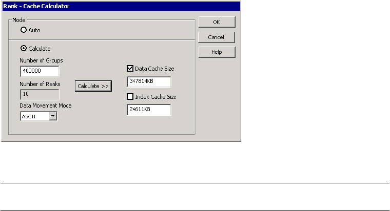
694 Chapter 26: Session Caches
Configuring the Cache Sizes for a Rank Transformation
You can configure the cache sizes for the Rank transformation in the session properties.
The following dialog box shows the inputs that are required to calculate the cache size for a
Rank transformation:
The following table describes the input you provide to calculate the Rank cache sizes:
Enter the input and then click Calculate >> to calculate the data and index cache sizes. The
calculated values appear in the Data Cache Size and Index Cache Size fields. For more
information about configuring cache sizes, see “Configuring the Cache Size” on page 675.
Input Required/
Optional Description
Number of
Groups
Required Number of groups. The Rank transformation ranks data by group. Determine the
number of groups using the group by ports. For example, if you group by Store ID
and Item ID, have 5 stores and 25 items, and each store has all 25 items, then
calculate the number of groups as:
5 * 25 = 125 groups
Number of
Ranks
Read-only Number items in the ranking. For example, if you want to rank the top 10 sales, you
have 10 ranks. The cache calculator populates this value based on the value set in
the Rank transformation.
Data Movement
Mode
Required The data movement mode of the Integration Service. The cache requirement varies
based on the data movement mode. ASCII characters use one byte. Unicode
characters use two bytes.
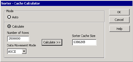
Sorter Caches 695
Sorter Caches
The Integration Service uses cache memory to process Sorter transformations. The
Integration Service passes all incoming data into the Sorter transformation before it performs
the sort operation.
The Integration Service creates a sorter cache to store sort keys and data while the Integration
Service sorts the data. By default, the Integration Service creates one memory cache and disk
cache for all partitions.
If you create multiple partitions in the session, the Integration Service uses cache partitioning.
It creates one disk cache for the Sorter transformation and one memory cache for each
partition. The Integration Service creates a separate cache for each partition and sorts each
partition separately.
If you do not configure the cache size to sort all of the data in memory, a warning appears in
the session log, stating that the Integration Service made multiple passes on the source data.
The Integration Service makes multiple passes on the data when it has to page information to
disk to complete the sort. The message specifies the number of bytes required for a single
pass, which is when the Integration Service reads the data once and performs the sort in
memory without paging to disk. To increase session performance, configure the cache size so
that the Integration Service makes one pass on the data.
For more information about the Sorter transformation, see “Sorter Transformation” in the
Tra ns for ma t i o n Gu id e .
Configuring the Cache Size for a Sorter Transformation
You can configure the sorter cache for a Sorter transformation in the session properties.
The following dialog box shows the inputs that are required to calculate the cache size for a
Sorter transformation:

696 Chapter 26: Session Caches
The following table describes the input you provide to calculate the Sorter cache size:
Enter the input and then click Calculate >> to calculate the sorter cache size. The calculated
value appears in the Sorter Cache Size field. For more information about configuring cache
sizes, see “Configuring the Cache Size” on page 675.
Input Required/
Optional Description
Number of Rows Required Number of rows.
Data Movement
Mode
Required The data movement mode of the Integration Service. The cache requirement varies
based on the data movement mode. ASCII characters use one byte. Unicode
characters use two bytes.
XML Target Caches 697
XML Target Caches
The Integration Service uses cache memory to create an XML target. The Integration Service
stores the data and XML hierarchies in cache memory while it generates the XML target.
The Integration Service creates the following types of caches for an XML target:
♦Data cache. Stores XML row data while it generates an XML target document. Stores one
data cache for all groups.
♦Index caches. Stores primary keys or foreign keys. Creates a primary key index cache and a
foreign key index cache for each group.
For more information about XML targets, the XML Guide.
Configuring the Cache Size for an XML Target
You configure the cache size for an XML target in the session properties. Use auto memory
cache when you first configure the cache size for an XML target. For more information about
auto memory, see “Using Auto Memory Size” on page 676.
Note: You cannot use the cache calculator to configure the cache size for an XML target.
698 Chapter 26: Session Caches
Optimizing the Cache Size
For optimal session performance, configure the cache size so that the Integration Service
processes the transformation in memory without paging to disk. Session performance
decreases when the Integration Service pages to disk.
When you use the cache calculator to calculate the cache size, the cache calculator estimates
the cache size required for optimal session performance based on your input. You can tune the
estimate by using the cache size specified in the session log. After you run the session, review
the transformation statistics in the session log to get the cache size.
For example, you run an Aggregator transformation called AGGTRANS. The session log
contains the following text:
MAPPING> TT_11031 Transformation [AGGTRANS]:
MAPPING> TT_11114 [AGGTRANS]: Input Group Index = [0], Input Row Count
[110264]
MAPPING> TT_11034 [SQ_V_PETL]: Input - 110264
MAPPING> TT_11115 [AGGTRANS]: Output Group Index = [0]
MAPPING> TT_11037 [FILTRANS]: Output - 1098,Dropped - 0
MAPPING> CMN_1791 The index cache size that would hold [1098] aggregate
groups of input rows for [AGGTRANS], in memory, is [286720] bytes
MAPPING> CMN_1790 The data cache size that would hold [1098] aggregate
groups of input rows for [AGGTRANS], in memory, is [1774368] bytes
The log shows that the index cache requires 286,720 bytes and the data cache requires
1,774,368 bytes to process the transformation in memory without paging to disk.
The cache size may vary depending on changes to the session or source data. Review the
session logs after subsequent session runs to monitor changes to the cache size.
You must set the tracing level to Verbose Initialization in the session properties to enable the
Integration Service to write the transformation statistics to the session log. For more
information about configuring tracing levels, see “Setting Tracing Levels” on page 583.
Note: The session log does not contain transformation statistics for a Joiner transformation
with sorted input, an Aggregator transformation with sorted input, or an XML target.

699
Appendix A
Session Properties
Reference
This appendix contains a listing of settings in the session properties. These settings are
grouped by the following tabs:
♦General Tab, 700
♦Properties Tab, 702
♦Config Object Tab, 709
♦Mapping Tab (Transformations View), 718
♦Mapping Tab (Partitions View), 742
♦Components Tab, 747
♦Metadata Extensions Tab, 755
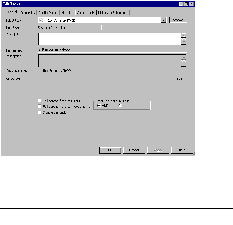
700 Appendix A: Session Properties Reference
General Tab
By default, the General tab appears when you edit a session task.
Figure A-1 shows the General tab:
On the General tab, you can rename the session task and enter a description for the session
task.
Table A-1 describes settings on the General tab:
Figure A-1. General Tab
Table A-1. General Tab
General Tab
Options
Required/
Optional Description
Rename Optional You can enter a new name for the session task with the Rename button.
Description Optional You can enter a description for the session task in the Description field.
Mapping name Required Name of the mapping associated with the session task.
Resources Optional You can associate an object with an available resource.
Fail Parent if This
Task Fails*
Optional Fails the parent worklet or workflow if this task fails.

General Tab 701
Fail Parent if This
Task Does Not
Run*
Optional Fails the parent worklet or workflow if this task does not run.
Disable This Task* Optional Disables the task.
Treat the Input
Links as AND or
OR*
Required Runs the task when all or one of the input link conditions evaluate to True.
*Appears only in the Workflow Designer.
Table A-1. Gener al Tab
General Tab
Options
Required/
Optional Description
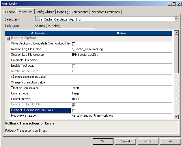
702 Appendix A: Session Properties Reference
Properties Tab
On the Properties tab, you can configure the following settings:
♦General Options. General Options settings allow you to configure session log file name,
session log file directory, parameter file name and other general session settings. For more
information, see “General Options Settings” on page 702.
♦Performance. The Performance settings allow you to increase memory size, collect
performance details, and set configuration parameters. For more information, see
“Performance Settings” on page 705.
General Options Settings
You can configure General Options settings on the Properties tab. You can enter session log
file name, session log file directory, and other general session settings.
Figure A-2 shows the General Options settings on the Properties tab:
Figure A-2. Properties Tab - General Options Settings

Properties Tab 703
Table A-2 describes the General Options settings on the Properties tab:
Table A-2. Properties Tab - General Options Settings
General Options
Settings
Required/
Optional Description
Write Backward
Compatible
Session Log File
Optional Select to write session log to a file.
Session Log File
Name
Optional By default, the Integration Service uses the session name for the log file name:
s_mapping name.log. For a debug session, it uses DebugSession_mapping
name.log.
Enter a file name, a file name and directory, or use the $PMSessionLogFile
session parameter. The Integration Service appends information in this field to
that entered in the Session Log File Directory field. For example, if you have
“C:\session_logs\” in the Session Log File Directory File field, then enter
“logname.txt” in the Session Log File field, the Integration Service writes the
logname.txt to the C:\session_logs\ directory.
You can also use the $PMSessionLogFile session parameter to represent the
name of the session log or the name and location of the session log. For more
information about session parameters, see “Parameter Files” on page 601.
Session Log File
Directory
Required Designates a location for the session log file. By default, the Integration
Service writes the log file in the service process variable directory,
$PMSessionLogDir.
If you enter a full directory and file name in the Session Log File Name field,
clear this field.
Parameter File
Name
Optional Designates the name and directory for the parameter file. Use the parameter
file to define session parameters. You can also use it to override values of
mapping parameters and variables. For more information about session
parameters, see “Parameter Files” on page 601. For more information about
mapping parameters and variables, see “Mapping Parameters and Variables”
in the Designer Guide.
Enable Test Load Optional You can configure the Integration Service to perform a test load.
With a test load, the Integration Service reads and transforms data without
writing to targets. The Integration Service generates all session files, and
performs all pre- and post-session functions, as if running the full session.
The Integration Service writes data to relational targets, but rolls back the data
when the session completes. For all other target types, such as flat file and
SAP BW, the Integration Service does not write data to the targets.
Enter the number of source rows you want to test in the Number of Rows to
Test field.
You cannot perform a test load on sessions using XML sources.
Note: You can perform a test load when you configure a session for normal
mode. If you configure the session for bulk mode, the session fails.
Number of Rows to
Test
Optional Enter the number of source rows you want the Integration Service to test load.
The Integration Service reads the number you configure for the test load. You
cannot perform a test load when you run a session against a mapping that
contains XML sources.

704 Appendix A: Session Properties Reference
$Source
Connection Value
Optional Enter the database connection you want the Integration Service to use for the
$Source variable. Select a relational or application database connection. You
can also choose a $DBConnection parameter.
Use the $Source variable in Lookup and Stored Procedure transformations to
specify the database location for the lookup table or stored procedure.
If you use $Source in a mapping, you can specify the database location in this
field to ensure the Integration Service uses the correct database connection to
run the session.
If you use $Source in a mapping, but do not specify a database connection in
this field, the Integration Service determines which database connection to use
when it runs the session. If it cannot determine the database connection, it fails
the session. For more information, see “Lookup Transformation” and “Stored
Procedure Transformation” in the Transformation Guide.
$Target
Connection Value
Optional Enter the database connection you want the Integration Service to use for the
$Target variable. Select a relational or application database connection. You
can also choose a $DBConnection parameter.
Use the $Target variable in Lookup and Stored Procedure transformations to
specify the database location for the lookup table or stored procedure.
If you use $Target in a mapping, you can specify the database location in this
field to ensure the Integration Service uses the correct database connection to
run the session.
If you use $Target in a mapping, but do not specify a database connection in
this field, the Integration Service determines which database connection to use
when it runs the session. If it cannot determine the database connection, it fails
the session. For more information, see “Lookup Transformation” and “Stored
Procedure Transformation” in the Transformation Guide.
Treat Source Rows
As
Required Indicates how the Integration Service treats all source rows. If the mapping for
the session contains an Update Strategy transformation or a Custom
transformation configured to set the update strategy, the default option is Data
Driven.
When you select Data Driven and you load to either a Microsoft SQL Server or
Oracle database, you must use a normal load. If you bulk load, the Integration
Service fails the session.
Commit Type Required Determines whether the Integration Service uses a source- or target-based, or
user-defined commit. You can choose source- or target-based commit if the
mapping has no Transaction Control transformation or only ineffective
Transaction Control transformations. By default, the Integration Service
performs a target-based commit.
A User-Defined commit is enabled by default if the mapping has effective
Transaction Control transformations.
For more information about Commit Intervals, see “Setting Commit Properties”
on page 334.
Commit Interval Required In conjunction with the selected commit interval type, indicates the number of
rows. By default, the Integration Service uses a commit interval of 10,000 rows.
This option is not available for user-defined commit.
Table A-2. Properties Tab - General Options Settings
General Options
Settings
Required/
Optional Description

Properties Tab 705
Performance Settings
You can configure performance settings on the Properties tab. In Performance settings, you
can increase memory size, collect performance details, and set configuration parameters.
Commit On End of
File
Required By default, this option is enabled and the Integration Service performs a
commit at the end of the file. Clear this option if you want to roll back open
transactions.
This option is enabled by default for a target-based commit. You cannot disable
it.
Rollback
Transactions on
Errors
Optional The Integration Service rolls back the transaction at the next commit point
when it encounters a non-fatal writer error.
Recovery Strategy Required When a session is fails, the Integration Service suspends the workflow if the
workflow is configured to suspend on task error. If the session recovery
strategy is resume from the last checkpoint or restart, you can recover the
workflow. The Integration Service recovers the session and continues the
workflow if the session succeeds. If the session fails, the workflow becomes
suspended again.
You can also recover the session or recover the workflow from the session
when you configure the session to resume from last checkpoint or restart.
When you configure a Session task, you can choose one of the following
recovery strategies:
- Resume from the last checkpoint. The Integration Service saves the session
state of operation and maintains target recovery tables.
- Restart. The Integration Service runs the session again when it recovers the
workflow.
- Fail session and continue the workflow. The Integration Service cannot
recover the session, but it continues the workflow. This is the default session
recovery strategy.
Java Classpath Optional Prepended to the system classpath when the Integration Service runs the
session. Use this option if you use third-party Java packages, built-in Java
packages, or custom Java packages in a Java transformation.
*Tip: When you bulk load to Microsoft SQL Server or Oracle targets, define a large commit interval. Microsoft SQL
Server and Oracle start a new bulk load transaction after each commit. Increasing the commit interval reduces the
number of bulk load transactions and increases performance.
Table A-2. Properties Tab - General Options Settings
General Options
Settings
Required/
Optional Description
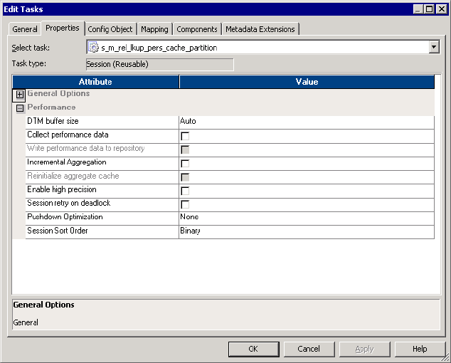

Properties Tab 707
Table A-3 describes the Performance settings on the Properties tab:
Table A-3. Properties Tab - Performance Settings
Performance
Settings
Required/
Optional Description
DTM Buffer Size Required Amount of memory allocated to the session from the DTM process.
By default, the Integration Service determines the DTM buffer size at runtime.
The Workflow Manager allocates a minimum of 12 MB for DTM buffer memory.
You can specify auto, or specify a value in bytes.
Increase the DTM buffer size in the following circumstances:
- A session contains large amounts of character data and you configure it to
run in Unicode mode. Increase the DTM buffer size to 24 MB.
- A session contains n partitions. Increase the DTM buffer size to at least n
times the value for the session with one partition.
- A source contains a large binary object with a precision larger than the
allocated DTM buffer size. Increase the DTM buffer size so that the session
does not fail.
For information about configuring automatic memory settings, see “Configuring
Automatic Memory Settings” on page 188.
For more information about improving session performance, see the
Performance Tuning Guide.
Collect
Performance Data
Optional Collects performance details when the session runs. Use the Workflow Monitor
to view performance details while the session runs. For more information, see
“Viewing Performance Details” on page 544.
Write Performance
Data to Repository
Optional Writes performance details for the session to the PowerCenter repository.
Write performance details to the repository to view performance details for
previous session runs. Use the Workflow Monitor to view performance details
for previous session runs. For more information, see “Viewing Performance
Details” on page 544.
Incremental
Aggregation
Optional Select Incremental Aggregation option if you want the Integration Service to
perform incremental aggregation. For more information, see “Using
Incremental Aggregation” on page 661.
Reinitialize
Aggregate Cache
Optional Select Reinitialize Aggregate Cache option if the session is an incremental
aggregation session and you want to overwrite existing aggregate files.
After a single session run, to return to a normal incremental aggregation
session run, you must clear this option. For more information, see “Using
Incremental Aggregation” on page 661.
Enable High
Precision
Optional When selected, the Integration Service processes the Decimal datatype to a
precision of 28. If a session does not use the Decimal datatype, leave this
setting clear. For more information about using the Decimal datatype with high
precision, see “Handling High Precision Data” on page 216.
Session Retry On
Deadlock
Optional Select this option if you want the Integration Service to retry target writes on
deadlock. You can only use Session Retry on Deadlock for sessions configured
for normal load. This option is disabled for bulk mode. You can configure the
Integration Service to set the number of deadlock retries and the deadlock
sleep time period.

708 Appendix A: Session Properties Reference
Pushdown
Optimization
Optional Use pushdown optimization to push transformation logic to the source or target
database. The Integration Service analyzes the transformation logic, mapping,
and session configuration to determine the transformation logic it can push to
the database. At run time, the Integration Service executes any SQL statement
generated against the source or target tables, and it processes any
transformation logic that it cannot push to the database.
Select one of the following values:
- None. The Integration Service does not push any transformation logic to the
database.
- To Source. The Integration Service pushes as much transformation logic as
possible to the source database.
- To Source with View. The Integration Service creates a view to represent an
SQL override in the Source Qualifier transformation. It generates an SQL
statement against this view to push transformation logic to the source
database.
- To Target. The Integration Service pushes as much transformation logic as
possible to the target database.
- Full. The Integration Service pushes as much transformation logic as possible
to both the source database and the target database.
- Full with View. The Integration Service creates a view to represent an SQL
override in the Source Qualifier transformation. It generates an SQL
statement against this view to push transformation logic to the source
database. It then pushes remaining transformation logic to the target
database.
- $$PushdownConfig. The $$PushdownConfig mapping parameter allows you
to run the same session with different pushdown optimization configurations
at different times.
Default is None.
Session Sort Order Required Specify a sort order for the session. The session properties display all sort
orders associated with the Integration Service code page. When the Integration
Service runs in Unicode mode, it sorts character data in the session using the
selected sort order. When the Integration Service runs in ASCII mode, it
ignores this setting and uses a binary sort order to sort character data.
Table A-3. Properties Tab - Performance Settings
Performance
Settings
Required/
Optional Description
Config Object Tab 709
Config Object Tab
The Config Object tab displays settings such as session log settings, error handling settings,
and other advanced properties. You can override properties in the default session
configuration in the Config Object tab. Or, you can choose a session configuration object you
already created in the Workflow Manager and override its properties.
Click the Open button in the Config Name field to choose the session configuration object
you want to override.
You can configure the following settings in the Config Object tab:
♦Advanced. Advanced settings allow you to configure constraint-based loading, lookup
caches, and buffer sizes. For more information, see “Advanced Settings” on page 709.
♦Log Options. Log options allow you to configure how you want to save the session log. By
default, the Log Manager saves only the current session log. For more information, see
“Log Options Settings” on page 711.
♦Error Handling. Error Handling settings allow you to determine if the session fails or
continues when it encounters pre-session command errors, stored procedure errors, or a
specified number of session errors. For more information see, “Error Handling Settings”
on page 713.
♦Partitioning Options. Partitioning options allow the Integration Service to determine the
number of partitions to create at run time. For more information, see “Partitioning
Options” on page 715.
♦Session on Grid. When Session on Grid is enabled, the Integration Service distributes
session threads to the nodes in a grid to increase performance and scalability. For more
information, see “Session on Grid” on page 716.
Advanced Settings
Advanced settings allow you to configure constraint-based loading, lookup caches, and buffer
sizes.
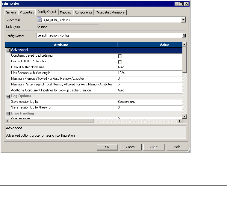
710 Appendix A: Session Properties Reference
Figure A-4 shows the Advanced settings on the Config Object tab:
Table A-4 describes the Advanced settings of the Config Object tab:
Figure A-4. Config Object Tab - Advanced Settings
Table A-4. Config Object Tab - Advanced Settings
Advanced
Settings
Required/
Optional Description
Constraint Based
Load Ordering
Optional Integration Service loads targets based on primary key-foreign key constraints
where possible.
Cache Lookup()
Function
Optional If selected, the Integration Service caches PowerMart 3.5 LOOKUP functions
in the mapping, overriding mapping-level LOOKUP configurations.
If not selected, the Integration Service performs lookups on a row-by-row basis,
unless otherwise specified in the mapping.

Config Object Tab 711
Log Options Settings
Log options allow you to configure how you want to save the session log. By default, the Log
Manager saves only the current session log.
Default Buffer
Block Size
Optional Size of buffer blocks used to move data and index caches from sources to
targets. By default, the Integration Service determines this value at runtime.
You can specify auto or a numeric value.
Note: The session must have enough buffer blocks to initialize. The minimum
number of buffer blocks must be greater than the total number of sources
(Source Qualifiers, Normalizers for COBOL sources), and targets. The number
of buffer blocks in a session = DTM Buffer Size / Buffer Block Size. Default
settings create enough buffer blocks for 83 sources and targets. If the session
contains more than 83, you might need to increase DTM Buffer Size or
decrease Default Buffer Block Size.
For more information about configuring automatic memory settings, see
“Configuring Automatic Memory Settings” on page 188.
For more information about performance tuning, see the Performance Tuning
Guide.
Line Sequential
Buffer Length
Optional Affects the way the Integration Service reads flat files. Increase this setting
from the default of 1024 bytes per line only if source flat file records are larger
than 1024 bytes.
Maximum Memory
Allowed for Auto
Memory Attributes
Optional Maximum memory allocated for session caches when you configure the
Integration Service to determine session cache size at runtime.
You enable automatic memory settings by configuring a value for this attribute.
If the value is set to zero, the Integration Service disables automatic memory
settings and uses default values.
For more information about configuring automatic memory settings, see
“Configuring Automatic Memory Settings” on page 188.
Maximum
Percentage of Total
Memory Allowed
for Auto Memory
Attributes
Optional Maximum percentage of memory allocated for session caches when you
configure the Integration Service to determine session cache size at runtime.
For more information about configuring automatic cache settings, see
“Configuring Automatic Memory Settings” on page 188.
Additional
Concurrent
Pipelines for
Lookup Cache
Creation
Optional Enables the Integration Service to create lookup caches concurrently by
creating additional pipelines.
Specify a numeric value or select Auto to enable the Integration Service to
determine this value at runtime.
By default, the Integration Service creates caches concurrently and it
determines the number of additional pipelines to create at runtime. If you
configure a numeric value, you can configure an additional concurrent pipeline
for each Lookup transformation in the pipeline.
You can also configure the Integration Service to create session caches
sequentially. It builds a lookup cache in memory when it processes the first row
of data in a cached Lookup transformation. Set the value to 0 to configure the
Integration Service to process sessions sequentially.
Table A-4. Config Object Tab - Advanced Settings
Advanced
Settings
Required/
Optional Description
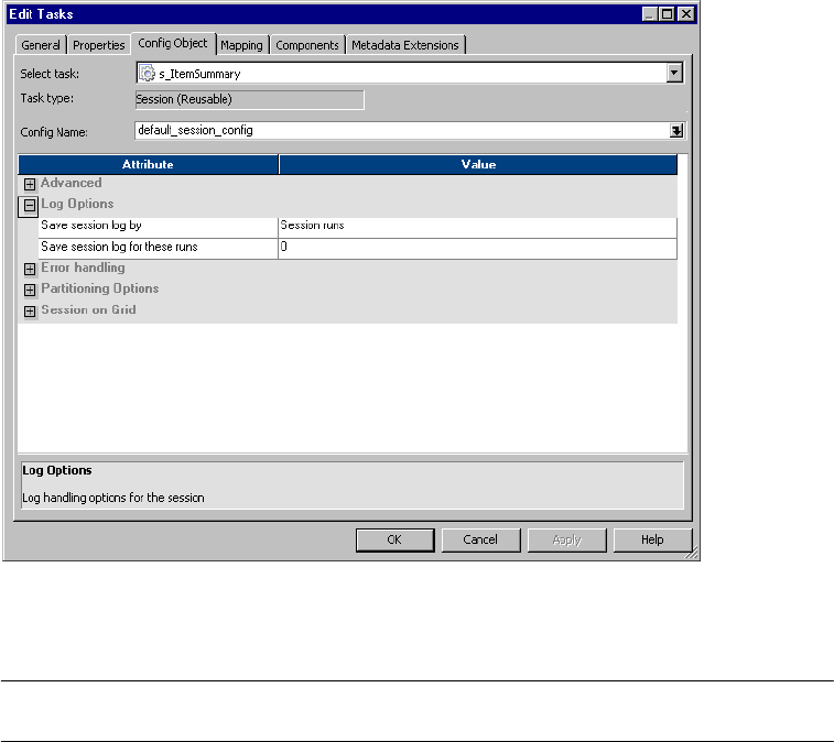
712 Appendix A: Session Properties Reference
Figure A-5 shows the Log Options settings on the Config Object tab:
Table A-5 shows the Log Options settings of the Config Object tab:
Figure A-5. Config Object Tab - Log Option Settings
Table A-5. Config Object Tab - Log Options Settings
Log Options Settings Required/
Optional Description
Save Session Log By Required Configure this option when you choose to save session log files.
If you select Save Session Log by Timestamp, the Log Manager saves
all session logs, appending a timestamp to each log.
If you select Save Session Log by Runs, the Log Manager saves a
designated number of session logs. Configure the number of sessions in
the Save Session Log for These Runs option.
You can also use the $PMSessionLogCount service variable to save the
configured number of session logs for the Integration Service.
For more information about these options, see “Session Logs” on
page 582.
Save Session Log for
These Runs
Required Number of historical session logs you want the Log Manager to save.
The Log Manager saves the number of historical logs you specify, plus
the most recent session log. When you configure 5 runs, the Log
Manager saves the most recent session log, plus historical logs 0-4, for a
total of 6 logs.
You can configure up to 2,147,483,647 historical logs. If you configure 0
logs, the Log Manager saves only the most recent session log.
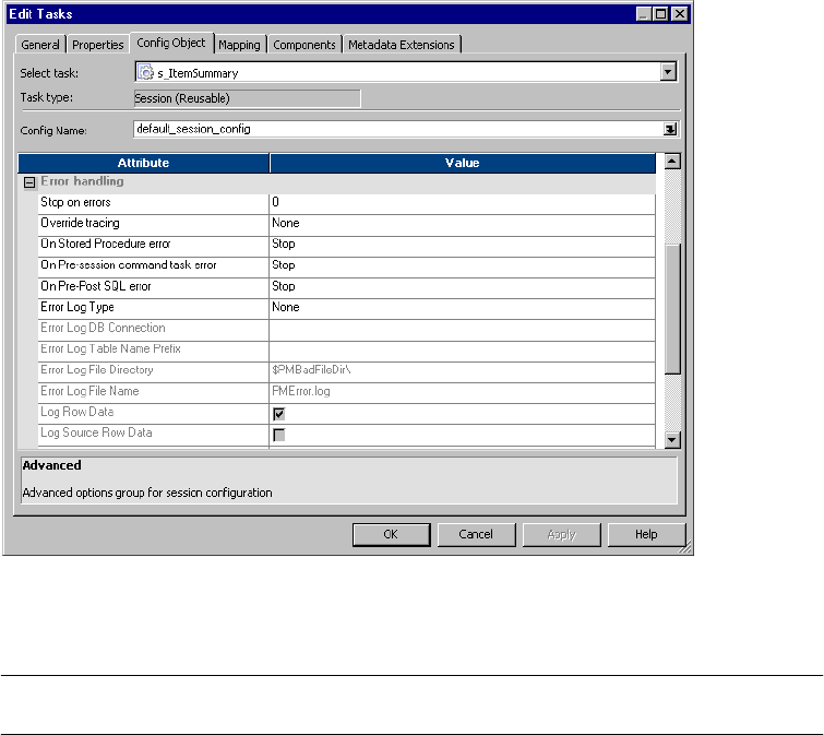
Config Object Tab 713
Error Handling Settings
Error Handling settings allow you to determine if the session fails or continues when it
encounters pre-session command errors, stored procedure errors, or a specified number of
session errors.
Figure A-6 shows the Error Handling settings on the Config Object tab:
Table A-6 describes the Error handling settings of the Config Object tab:
Figure A-6. Config Object Tab - Error Handling Settings
Table A-6. Config Object Tab - Error Handling Settings
Error Handling
Settings
Required/
Optional Description
Stop On Errors Optional Indicates how many non-fatal errors the Integration Service can
encounter before it stops the session. Non-fatal errors include reader,
writer, and DTM errors. Enter the number of non-fatal errors you want to
allow before stopping the session. The Integration Service maintains an
independent error count for each source, target, and transformation. If
you specify 0, non-fatal errors do not cause the session to stop.
Optionally use the $PMSessionErrorThreshold service variable to stop on
the configured number of errors for the Integration Service.
Override Tracing Optional Overrides tracing levels set on a transformation level. Selecting this
option enables a menu from which you choose a tracing level: None,
Terse, Normal, Verbose Initialization, or Verbose Data. For more
information about tracing levels, see “Session Logs” on page 582.

714 Appendix A: Session Properties Reference
On Stored Procedure
Error
Optional Required if the session uses pre- or post-session stored procedures.
If you select Stop Session, the Integration Service stops the session on
errors executing a pre-session or post-session stored procedure.
If you select Continue Session, the Integration Service continues the
session regardless of errors executing pre-session or post-session stored
procedures.
By default, the Integration Service stops the session on Stored Procedure
error and marks the session failed.
On Pre-Session
Command Task Error
Optional Required if the session has pre-session shell commands.
If you select Stop Session, the Integration Service stops the session on
errors executing pre-session shell commands.
If you select Continue Session, the Integration Service continues the
session regardless of errors executing pre-session shell commands.
By default, the Integration Service stops the session upon error.
On Pre-Post SQL Error Optional Required if the session uses pre- or post-session SQL.
If you select Stop Session, the Integration Service stops the session
errors executing pre-session or post-session SQL.
If you select Continue, the Integration Service continues the session
regardless of errors executing pre-session or post-session SQL.
By default, the Integration Service stops the session upon pre- or post-
session SQL error and marks the session failed.
Error Log Type Required Specifies the type of error log to create. You can specify relational, file, or
no log. By default, the Error Log Type is set to none.
Error Log DB Connection Optional Specifies the database connection for a relational error log.
Error Log Table Name
Prefix
Optional Specifies table name prefix for a relational error log. Oracle and Sybase
have a 30 character limit for table names. If a table name exceeds 30
characters, the session fails.
Error Log File Directory Optional Specifies the directory where errors are logged. By default, the error log
file directory is $PMBadFilesDir\.
Error Log File Name Optional Specifies error log file name. By default, the error log file name is
PMError.log.
Log Row Data Optional Specifies whether or not to log row data. By default, the check box is clear
and row data is not logged.
Log Source Row Data Optional Specifies whether or not to log source row data. By default, the check box
is clear and source row data is not logged.
Data Column Delimiter Optional Delimiter for string type source row data and transformation group row
data. By default, the Integration Service uses a pipe ( | ) delimiter. Verify
that you do not use the same delimiter for the row data as the error
logging columns. If you use the same delimiter, you may find it difficult to
read the error log file.
Table A-6. Config Object Tab - Error Handling Settings
Error Handling
Settings
Required/
Optional Description
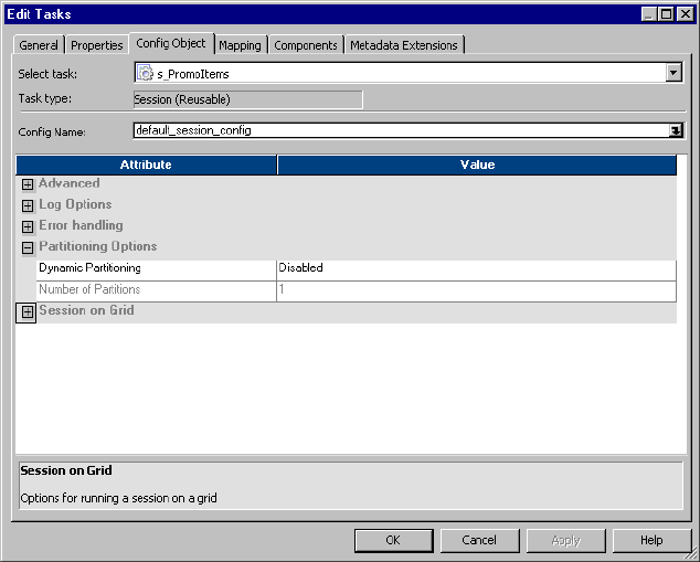
Config Object Tab 715
Partitioning Options
When you configure dynamic partitioning, the Integration Service determines the number of
partitions to create at run time. Configure dynamic partitioning on the Config Object tab of
session properties.
Figure A-7 shows the partitioning options:
Figure A-7. Config Object Tab - Partitioning Options

716 Appendix A: Session Properties Reference
Table A-7 describes the Partitioning Options settings on the Config Objects tab:
Session on Grid
When Session on Grid is enabled, the Integration Service distributes workflows and session
threads to the nodes in a grid to increase performance and scalability.
Table A-7. Config Objects Tab - Partitioning Options
Partitioning Options
Settings
Required/
Optional Description
Dynamic Partitioning Required Configure dynamic partitioning using one of the following methods:
- Disabled. Do not use dynamic partitioning. Define the number of
partitions on the Mapping tab.
- Based on number of partitions. Sets the partitions to a number that
you define in the Number of Partitions attribute. Use the
$DynamicPartitionCount session parameter, or enter a number
greater than 1.
- Based on number of nodes in grid. Sets the partitions to the number
of nodes in the grid running the session. If you configure this option
for sessions that do not run on a grid, the session runs in one
partition and logs a message in the session log.
- Based on source partitioning. Determines the number of partitions
using database partition information. The number of partitions is the
maximum of the number of partitions at the source.
Default is disabled.
Number of Partitions Required Determines the number of partitions that the Integration Service
creates when you configure dynamic partitioning based on the
number of partitions. Enter a value greater than 1 or use the
$DynamicPartitionCount session parameter.
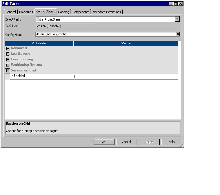
Config Object Tab 717
Figure A-8 shows the Session on Grid option on the Config Object tab:
Table A-8 describes the Session on Grid setting on the Config Object tab:
Figure A-8. Config Object Tab - Session on Grid
Table A-8. Config Object Tab - Session on Grid
Session on Grid
Setting
Required/
Optional Description
Is Enabled Optional Specifies whether the session runs on a grid.
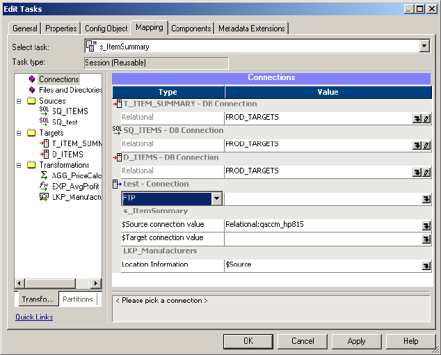
718 Appendix A: Session Properties Reference
Mapping Tab (Transformations View)
In the Transformations view of the Mapping tab, you can configure settings for connections,
sources, targets, and transformations.
You can configure the following nodes:
♦Connections
♦Sources
♦Targets
♦Transformations
Connections Node
The Connections node displays the source, target, lookup, stored procedure, FTP, external
loader, and queue connections. You can choose connection types and connection values. You
can also edit connection object values.
Figure A-9 shows the Connections settings on the Mapping tab:
Figure A-9. Mapping Tab - Connections Settings

Mapping Tab (Transformations View) 719
Table A-9 describes the Connections settings on the Mapping tab:
Table A-9. Mapping Tab - Connections Settings
Connections
Node Settings
Required/
Optional Description
Type Required Enter the connection type for relational and non-relational sources and targets.
Specifies Relational for relational sources and targets.
You can choose the following connection types for flat file, XML, and MQSeries
sources/Targets:
- Queue. Select this connection type to access a MQSeries source if you use
MQ Source Qualifiers. For static MQSeries targets, set the connection type to
FTP or Queue. For dynamic MQSeries targets, the connection type is set to
Queue. MQSeries connections must be defined in the Workflow Manager
prior to configuring sessions. For more information, see the PowerCenter
Connect for IBM MQSeries User and Administrator Guide.
- Loader. Select this connection type to use the External Loader to load output
files to Teradata, Oracle, DB2, or Sybase IQ databases. If you select this
option, select a configured loader connection in the Value column.
To use this option, you must use a mapping with a relational target definition
and choose File as the writer type on the Writers tab for the relational target
instance. As the Integration Service completes the session, it uses an
external loader to load target files to the Oracle, Sybase IQ, DB2, or Teradata
database. You cannot choose external loader for flat file or XML target
definitions in the mapping.
Note to Oracle 8 users: If you configure a session to write to an Oracle 8
external loader target table in bulk mode with NOT NULL constraints on any
columns, the session may write the null character into a NOT NULL column if
the mapping generates a NULL output.
For more information about using the external loader feature, see “External
Loading” on page 615.
- FTP. Select this connection type to use FTP to access the source/target
directory for flat file and XML sources/targets. If you select this option, select
a configured FTP connection in the Value column. FTP connections must be
defined in the Workflow Manager prior to configuring sessions. For more
information about using FTP, see “Using FTP” on page 649.
- None. Select None when you want to read from a local flat file or XML file, or
if you use an associated source for a MQSeries session.
The type also specifies lists the connections in the mapping, such as $Source
connection value and $Target connection value.
You can also configure connection information for Lookups and Stored
Procedures.

720 Appendix A: Session Properties Reference
Sources Node
The Sources node lists the sources used in the session and displays their settings. If you want
to view and configure the settings of a specific source, select the source from the list.
You can configure the following settings:
♦Readers. The Readers settings displays the reader the Integration Service uses with each
source instance. For more information, see “Readers Settings” on page 721.
♦Connections. The Connections settings lets you configure connections for the sources.
For more information, see “Connections Settings” on page 721.
♦Properties. The Properties settings lets you configure the source properties. For more
information, see “Properties Settings” on page 723.
Partitions n/a Displays the partitions if the session is partitioned.
Value Required Enter a source and target connection based on the value you choose in the
Type column. You can also specify the $Source and $Target connection value:
- $Source connection value. Enter the database connection you want the
Integration Service to use for the $Source variable. Select a relational or
application database connection. You can also choose a $DBConnection
parameter. Use the $Source variable in Lookup and Stored Procedure
transformations to specify the database location for the lookup table or stored
procedure.
If you use $Source in a mapping, you can specify the database location in this
field to ensure the Integration Service uses the correct database connection
to run the session.
If you use $Source in a mapping, but do not specify a database connection in
this field, the Integration Service determines which database connection to
use when it runs the session. If it cannot determine the database connection,
it fails the session. For more information, see the Transformation Guide.
- $Target connection value. Enter the database connection you want the
Integration Service to use for the $Target variable. Select a relational or
application database connection. You can also choose a $DBConnection
parameter. Use the $Target variable in Lookup and Stored Procedure
transformations to specify the database location for the lookup table or stored
procedure.
If you use $Target in a mapping, you can specify the database location in this
field to ensure the Integration Service uses the correct database connection
to run the session.
If you use $Target in a mapping, but do not specify a database connection in
this field, the Integration Service determines which database connection to
use when it runs the session. If it cannot determine the database connection,
it fails the session. For more information, see the Transformation Guide.
You can also specify the lookup and stored procedure location information
value, if the mapping has lookups or stored procedures.
Table A-9. Mapping Tab - Connections Settings
Connections
Node Settings
Required/
Optional Description
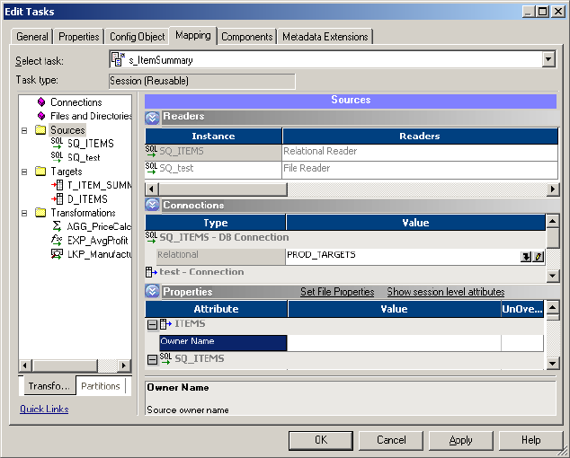
Mapping Tab (Transformations View) 721
Readers Settings
You can view the reader the Integration Service uses with each source instance. The Workflow
Manager specifies the necessary reader for each source instance. For relations sources the
reader is Relational Reader and for file sources it is File Reader.
Figure A-10 shows the Readers settings on the Mapping tab (Sources node):
Connections Settings
You can configure the connections the Integration Service uses with each source instance.
Figure A-10. Mapping Tab - Sources Node - Readers Settings
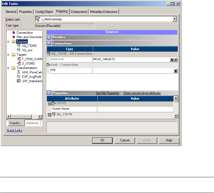
722 Appendix A: Session Properties Reference
Figure A-11 shows the Connections settings on the Mapping tab (Sources node):
Table A-10 describes the Connections settings on the Mapping tab (Sources node):
Figure A-11. Mapping Tab - Sources Node - Connections Settings
Table A-10. Mapping Tab - Sources Node - Connections Settings
Connections
Settings
Required/
Optional Description
Type Required Enter the connection type for relational and non-relational sources. Specifies
Relational for relational sources.
You can choose the following connection types for flat file, XML, and MQSeries
sources:
- Queue. Select this connection type to access a MQSeries source if you use MQ
Source Qualifiers. MQSeries connections must be defined in the Workflow
Manager prior to configuring sessions. For more information, see the PowerCenter
Connect for IBM MQSeries User and Administrator Guide.
- FTP. Select this connection type to use FTP to access the source directory for flat
file and XML sources. If you want to extract data from a flat file or XML source
using FTP, you must specify an FTP connection when you configure source
options. If you select this option, select a configured FTP connection in the Value
column. FTP connections must be defined in the Workflow Manager prior to
configuring sessions. For more information about using FTP, see “Using FTP” on
page 649.
- None. Select None when you want to read from a local flat file or XML file, or if you
use an associated source for a MQSeries session.
Value Required Enter a source connection based on the value you choose in the Type column.

Mapping Tab (Transformations View) 723
Properties Settings
Click the Properties settings to define source property information. The Workflow Manager
displays properties for both relational and file sources.
Figure A-12 shows the Properties settings on the Mapping tab (Sources node):
Table A-11 describes Properties settings on the Mapping tab for relational sources:
Figure A-12. Mapping Tab - Sources Node - Properties Settings
Table A-11. Mapping Tab - Sources Node - Properties Settings (Relational Sources)
Relational
Source Options
Required/
Optional Description
Owner Name Optional Specified the table owner name.
User Defined Join Optional Specifies the condition used to join data from multiple sources represented in
the same Source Qualifier transformation. For more information about user
defined join, see “Source Qualifier Transformation” in the Transformation Guide.
Tracing Level n/a Specifies the amount of detail included in the session log when you run a
session containing this transformation. You can view the value of this attribute
when you click Show all properties. For more information about tracing level, see
“Setting Tracing Levels” on page 583.
Select Distinct Optional Selects unique rows.

724 Appendix A: Session Properties Reference
Table A-12 describes the Properties settings on the Mapping tab for file sources:
Pre SQL Optional Pre-session SQL commands to run against the source database before the
Integration Service reads the source. For more information about pre-session
SQL, see “Using Pre- and Post-Session SQL Commands” on page 197.
Post SQL Optional Post-session SQL commands to run against the source database after the
Integration Service writes to the target. For more information about post-session
SQL, see “Using Pre- and Post-Session SQL Commands” on page 197.
Sql Query Optional Defines a custom query that replaces the default query the Integration Service
uses to read data from sources represented in this Source Qualifier. A custom
query overrides entries for a custom join or a source filter. For more information,
see “Overriding the SQL Query” on page 228.
Source Filter Optional Specifies the filter condition the Integration Service applies when querying
records. For more information, see “Source Qualifier Transformation” in the
Transformation Guide.
Table A-12. Mapping Tab - Sources Node - Properties Settings (File Sources)
File Source
Options
Required/
Optional Description
Source File
Directory
Optional Enter the directory name in this field. By default, the Integration Service looks
in the service process variable directory, $PMSourceFileDir, for file sources.
If you specify both the directory and file name in the Source Filename field,
clear this field. The Integration Service concatenates this field with the Source
Filename field when it runs the session.
You can also use the $InputFileName session parameter to specify the file
directory.
For more information about session parameters, see “Parameter Files” on
page 601.
Source Filename Required Enter the file name, or file name and path. Optionally use the $InputFileName
session parameter for the file name.
The Integration Service concatenates this field with the Source File Directory
field when it runs the session. For example, if you have “C:\data\” in the Source
File Directory field, then enter “filename.dat” in the Source Filename field.
When the Integration Service begins the session, it looks for
“C:\data\filename.dat”.
By default, the Workflow Manager enters the file name configured in the source
definition.
For more information about session parameters, see “Parameter Files” on
page 601.
Source Filetype Required You can configure multiple file sources using a file list.
Indicates whether the source file contains the source data, or a list of files with
the same file properties. Select Direct if the source file contains the source
data. Select Indirect if the source file contains a list of files.
When you select Indirect, the Integration Service finds the file list then reads
each listed file when it executes the session. For more information about file
lists, see “Using a File List” on page 244.
Table A-11. Mapping Tab - Sources Node - Properties Settings (Relational Sources)
Relational
Source Options
Required/
Optional Description
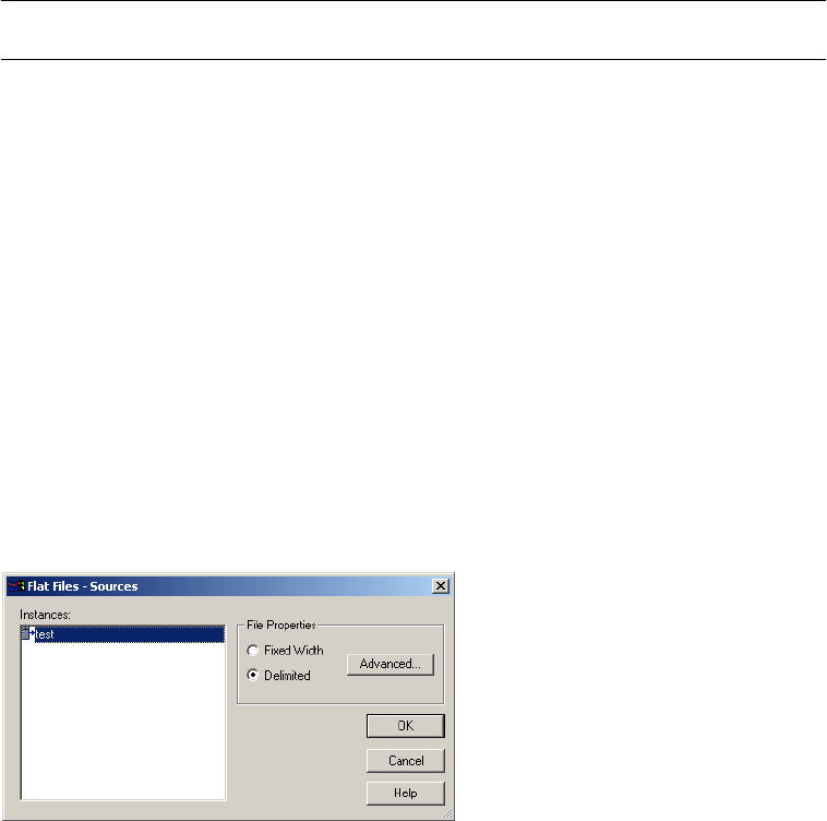
Mapping Tab (Transformations View) 725
Setting File Properties for Sources
Configure flat file properties by clicking the Set File Properties link in the Sources node. You
can define properties for both fixed-width and delimited flat file sources.
You can configure flat file properties for non-reusable sessions in the Workflow Designer and
for reusable sessions in the Task Developer.
Figure A-13 shows the Flat Files dialog box that appears when you click Set File Properties:
Select the file type (fixed-width or delimited) you want to configure and click Advanced.
Configuring Fixed-Width Properties for Sources
To edit the fixed-width properties, select Fixed Width in the Flat Files dialog box and click
the Advanced button. The Fixed Width Properties dialog box appears.
Note: Edit these settings only if you need to override those configured in the source definition.
Set File Properties Optional You can configure the file properties. For more information, see “Setting File
Properties for Sources” on page 725.
Datetime Format* n/a Displays the datetime format for datetime fields.
Thousand
Separator*
n/a Displays the thousand separator for numeric fields.
Decimal Separator* n/a Displays the decimal separator for numeric fields.
*You can view the value of this attribute when you click Show all properties. This attribute is read-only. For more information, see the
Designer Guide.
Figure A-13. Flat Files Dialog Box for Sources
Table A-12. Mapping Tab - Sources Node - Properties Settings (File Sources)
File Source
Options
Required/
Optional Description
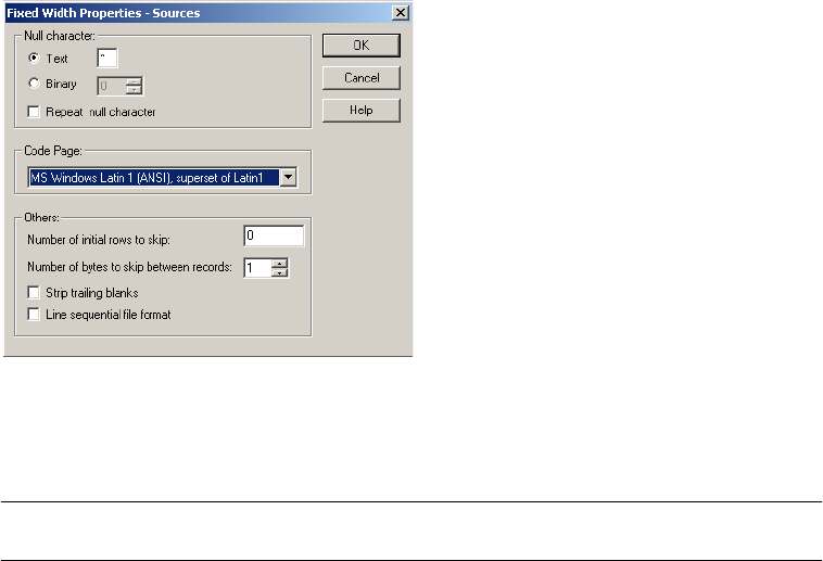
726 Appendix A: Session Properties Reference
Figure A-14 shows the Fixed Width Properties dialog box for flat file sources:
Table A-13 describes the options you define in the Fixed Width Properties dialog box for
sources:
Figure A-14. Fixed Width Properties
Table A-13. Fixed-Width Properties for File Sources
Fixed-Width
Properties Options
Required/
Optional Description
Null Character: Text/
Binary
Required Indicates the character representing a null value in the file. This can be any
valid character in the file code page, or any binary value from 0 to 255. For
more information about specifying null characters, see “Null Character
Handling” on page 241.
Repeat Null
Character
Optional If selected, the Integration Service reads repeat NULL characters in a single
field as a single NULL value. If you do not select this option, the Integration
Service reads a single null character at the beginning of a field as a null field.
Important: For multibyte code pages, specify a single-byte null character if
you use repeating non-binary null characters. This ensures that repeating
null characters fit into the column.
For more information about specifying null characters, see “Null Character
Handling” on page 241.
Code Page Required Select the code page of the fixed-width file. The default setting is the client
code page.
Number of Initial
Rows to Skip
Optional Integration Service skips the specified number of rows before reading the
file. Use this to skip header rows. One row may contain multiple rows. If you
select the Line Sequential File Format option, the Integration Service ignores
this option.
You can enter any integer from zero to 2147483647.
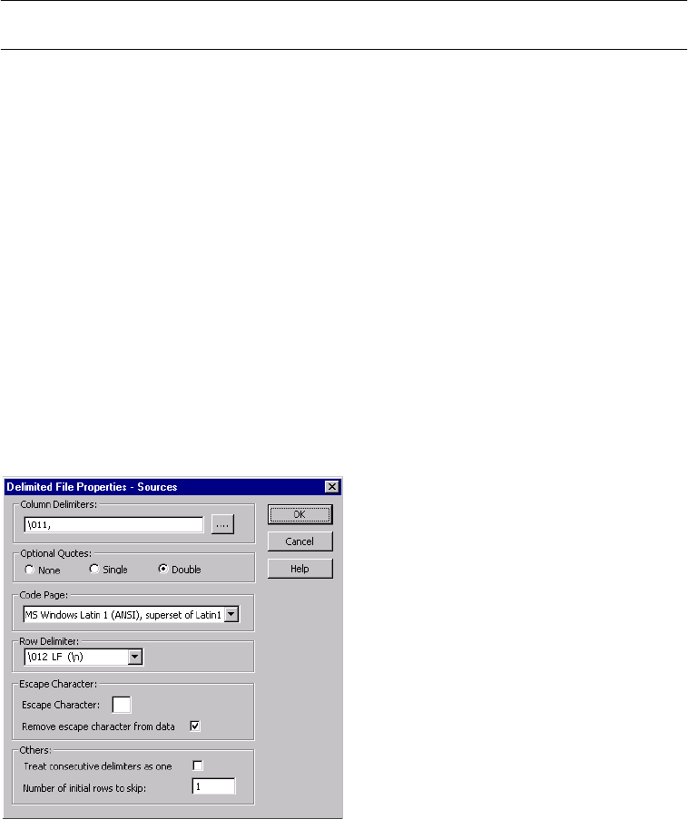
Mapping Tab (Transformations View) 727
Configuring Delimited File Properties for Sources
To edit the delimited properties, select Delimited in the Flat Files dialog box and click the
Advanced button. The Delimited File Properties dialog box appears.
Note: Edit these settings only if you need to override those configured in the source definition.
Figure A-15 shows the Delimited File Properties dialog box for flat file sources:
Number of Bytes to
Skip Between
Records
Optional Integration Service skips the specified number of bytes between records. For
example, you have an ASCII file on Windows with one record on each line,
and a carriage return and line feed appear at the end of each line. If you want
the Integration Service to skip these two single-byte characters, enter 2.
If you have an ASCII file on UNIX with one record for each line, ending in a
carriage return, skip the single character by entering 1.
Strip Trailing Blanks Optional If selected, the Integration Service strips trailing blank spaces from records
before passing them to the Source Qualifier transformation.
Line Sequential File
Format
Optional Select this option if the file uses a carriage return at the end of each record,
shortening the final column.
Figure A-15. Delimited Properties for File Sources
Table A-13. Fixed-Width Properties for File Sources
Fixed-Width
Properties Options
Required/
Optional Description

728 Appendix A: Session Properties Reference
Table A-14 describes the options you can define in the Delimited File Properties dialog box
for flat file sources:
Table A-14. Delimited Properties for File Sources
Delimited File
Properties Options
Required/
Optional Description
Delimiters Required Character used to separate columns of data in the source file. Delimiters can
be either printable or single-byte unprintable characters, and must be
different from the escape character and the quote character (if selected). To
enter a single-byte unprintable character, click the Browse button to the right
of this field. In the Delimiters dialog box, select an unprintable character from
the Insert Delimiter list and click Add. You cannot select unprintable
multibyte characters as delimiters. The delimiter must be in the same code
page as the flat file code page.
Optional Quotes Required Select None, Single, or Double. If you select a quote character, the
Integration Service ignores delimiter characters within the quote characters.
Therefore, the Integration Service uses quote characters to escape the
delimiter.
For example, a source file uses a comma as a delimiter and contains the
following row: 342-3849, ‘Smith, Jenna’, ‘Rockville, MD’, 6.
If you select the optional single quote character, the Integration Service
ignores the commas within the quotes and reads the row as four fields.
If you do not select the optional single quote, the Integration Service reads
six separate fields.
When the Integration Service reads two optional quote characters within a
quoted string, it treats them as one quote character. For example, the
Integration Service reads the following quoted string as I’m going
tomorrow:
2353, ‘I’’m going tomorrow.’, MD
Additionally, if you select an optional quote character, the Integration Service
only reads a string as a quoted string if the quote character is the first
character of the field.
Note: You can improve session performance if the source file does not
contain quotes or escape characters.
Code Page Required Select the code page of the delimited file. The default setting is the client
code page.
Row Delimiter Optional Specify a line break character. Select from the list or enter a character.
Preface an octal code with a backslash (\). To use a single character, enter
the character.
The Integration Service uses only the first character when the entry is not
preceded by a backslash. The character must be a single-byte character, and
no other character in the code page can contain that byte. Default is line-
feed, \012 LF (\n).
Escape Character Optional Character immediately preceding a delimiter character embedded in an
unquoted string, or immediately preceding the quote character in a quoted
string. When you specify an escape character, the Integration Service reads
the delimiter character as a regular character (called escaping the delimiter
or quote character).
Note: You can improve session performance for mappings containing
Sequence Generator transformations if the source file does not contain
quotes or escape characters.

Mapping Tab (Transformations View) 729
Targets Node
The Targets node lists the used in the session and displays their settings. If you want to view
and configure the settings of a specific target, select the target from the list.
You can configure the following settings:
♦Writers. The Writers settings displays the writer the Integration Service uses with each
target instance. For more information, see “Writers Settings” on page 729.
♦Connections. The Connections settings lets you configure connections for the targets. For
more information, see “Connections Settings” on page 730.
♦Properties. The Properties settings lets you configure the target properties. For more
information, see “Properties Settings” on page 732.
Writers Settings
You can view and configure the writer the Integration Service uses with each target instance.
The Workflow Manager specifies the necessary writer for each target instance. For relational
targets the writer is Relational Writer and for file targets it is File Writer.
Remove Escape
Character From Data
Optional This option is selected by default. Clear this option to include the escape
character in the output string.
Treat Consecutive
Delimiters as One
Optional By default, the Integration Service reads pairs of delimiters as a null value. If
selected, the Integration Service reads any number of consecutive delimiter
characters as one.
For example, a source file uses a comma as the delimiter character and
contains the following record: 56, , , Jane Doe. By default, the Integration
Service reads that record as four columns separated by three delimiters: 56,
NULL, NULL, Jane Doe. If you select this option, the Integration Service
reads the record as two columns separated by one delimiter: 56, Jane Doe.
Number of Initial
Rows to Skip
Optional Integration Service skips the specified number of rows before reading the
file. Use this to skip title or header rows in the file.
Table A-14. Delimited Properties for File Sources
Delimited File
Properties Options
Required/
Optional Description
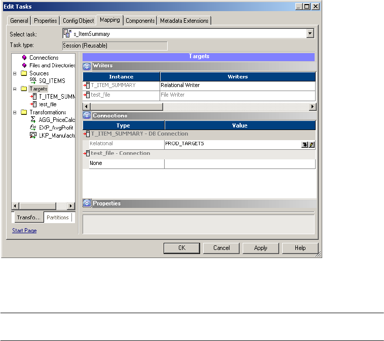
730 Appendix A: Session Properties Reference
Figure A-16 shows the Writers settings on the Mapping tab (Targets node):
Table A-15 describes the Writers settings on the Mapping tab (Targets node):
Connections Settings
You can enter connection types and specific target database connections on the Targets node
of the Mappings tab.
Figure A-16. Mapping Tab - Targets Node - Writers Settings
Table A-15. Mapping Tab - Targets Node - Writers Settings
Writers
Setting
Required/
Optional Description
Writers Required For relational targets, choose Relational Writer or File Writer. When the target in the
mapping is a flat file, an XML file, a SAP BW target, or MQ target, the Workflow
Manager specifies the necessary writer in the session properties.
When you choose File Writer for a relational target use an external loader to load
data to this target. For more information, see “External Loading” on page 615.
When you override a relational target to use the file writer, the Workflow Manager
changes the properties for that target instance on the Properties settings. It also
changes the connection options you can define on the Connections settings.
After you override a relational target to use a file writer, define the file properties for
the target. Click Set File Properties and choose the target to define. For more
information, see “Configuring Fixed-Width Properties” on page 290 and “Configuring
Delimited Properties” on page 291.
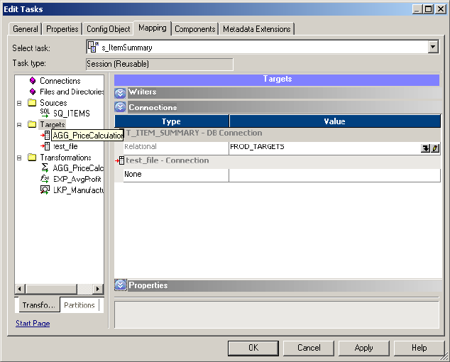

732 Appendix A: Session Properties Reference
Table A-16 describes the Connections settings on the Mapping tab (Targets node):
Properties Settings
Click the Properties settings to define target property information. The Workflow Manager
displays different properties for the different target types: relational, flat file, and XML.
Properties Settings for Relational Targets
You can configure the writer and object instance attributes for a relational target.
Table A-16. Mapping Tab - Targets Node - Connections Settings
Connections
Settings
Required/
Optional Description
Type Required Enter the connection type for non-relational targets. Specifies Relational for
relational targets.
You can choose the following connection types for flat file, XML, and MQ
targets:
- FTP. Select this connection type to use FTP to access the target directory for
flat file and XML targets. If you want to load data to a flat file or XML target
using FTP, you must specify an FTP connection when you configure target
options. If you select this option, select a configured FTP connection in the
Value column. FTP connections must be defined in the Workflow Manager
prior to configuring sessions. For more information about using FTP, see
“Using FTP” on page 649.
- External Loader. Select this connection type to use the External Loader to
load output files to Teradata, Oracle, DB2, or Sybase IQ databases. If you
select this option, select a configured loader connection in the Value column.
To use this option, you must use a mapping with a relational target definition
and choose File as the writer type on the Writers tab for the relational target
instance. As the Integration Service completes the session, it uses an
external loader to load target files to the Oracle, Sybase IQ, DB2, or Teradata
database. You cannot choose external loader for flat file or XML target
definitions in the mapping.
Note to Oracle 8 users: If you configure a session to write to an Oracle 8
external loader target table in bulk mode with NOT NULL constraints on any
columns, the session may write the null character into a NOT NULL column if
the mapping generates a NULL output.
For more information about using the external loader feature, see “External
Loading” on page 615.
- Queue. Select Queue when you want to output to an MQSeries message
queue. If you select this option, select a configured MQ connection in the
Value column. For more information, see the PowerCenter Connect for IBM
MQSeries User and Administrator Guide.
- None. Select None when you want to write to a local flat file or XML file.
Partitions n/a Displays the partitions if the session is partitioned.
Value Required Enter a target connection based on the value you choose in the Type column.
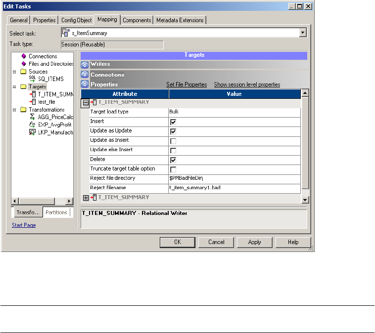
Mapping Tab (Transformations View) 733
Figure A-18 shows the Properties settings on the Mapping tab for relational targets:
Table A-17 describes the Properties settings on the Mapping tab for relational targets:
Figure A-18. Mapping Tab - Targets Node - Properties Settings (Relational)
Table A-17. Mapping Tab - Targets Node - Properties Settings (Relational)
Target Property Required/
Optional Description
Target Load Type Required You can choose Normal or Bulk.
If you select Normal, the Integration Service loads targets normally.
You can choose Bulk when you load to IBM DB2, Sybase, Oracle, or
Microsoft SQL Server. If you select Bulk for an IBM DB2, Sybase, Oracle, or
Microsoft SQL Server target, the Integration Service invokes the bulk API
with default settings, bypassing database logging.
If you select Bulk for other database types, the Integration Service reverts to
a normal load.
Loading in bulk mode can improve session performance, but limits the ability
to recover because no database logging occurs.
For more information about bulk loading, see “Bulk Loading” on page 275.
Insert Optional If selected, the Integration Service inserts all rows flagged for insert.
By default, this option is selected.
For more information about target update strategies, see “Update Strategy
Transformation” in the Transformation Guide.

734 Appendix A: Session Properties Reference
Update (as Update) Optional If selected, the Integration Service updates all rows flagged for update.
By default, this option is selected.
For more information about target update strategies, see “Update Strategy
Transformation” in the Transformation Guide.
Update (as Insert) Optional If selected, the Integration Service inserts all rows flagged for update.
By default, this option is not selected.
For more information about target update strategies, see “Update Strategy
Transformation” in the Transformation Guide.
Update (else Insert) Optional If selected, the Integration Service updates rows flagged for update if it they
exist in the target, then inserts any remaining rows marked for insert.
For more information about target update strategies, see “Update Strategy
Transformation” in the Transformation Guide.
Delete Optional If selected, the Integration Service deletes all rows flagged for delete.
For more information about target update strategies, see “Update Strategy
Transformation” in the Transformation Guide.
Truncate Table Optional If selected, the Integration Service truncates the target before loading. For
more information about this feature, see “Truncating Target Tables” on
page 268.
Reject File Directory Optional Enter the directory name in this field. By default, the Integration Service
writes all reject files to the service process variable directory,
$PMBadFileDir.
If you specify both the directory and file name in the Reject Filename field,
clear this field. The Integration Service concatenates this field with the
Reject Filename field when it runs the session.
You can also use the $BadFileName session parameter to specify the file
directory.
For more information about session parameters, see “Parameter Files” on
page 601.
Reject Filename Required Enter the file name, or file name and path. By default, the Integration
Service names the reject file after the target instance name:
target_name.bad. Optionally use the $BadFileName session parameter for
the file name.
The Integration Service concatenates this field with the Reject File Directory
field when it runs the session. For example, if you have “C:\reject_file\” in
the Reject File Directory field, and enter “filename.bad” in the Reject
Filename field, the Integration Service writes rejected rows to
C:\reject_file\filename.bad.
For more information about session parameters, see “Parameter Files” on
page 601.
Rejected Truncated/
Overflowed Rows*
Optional Instructs the Integration Service to write the truncated and overflowed rows
to the reject file.
Update Override* Optional Override the default UPDATE statement.
Table Name Prefix Optional Specify the owner of the target tables.
Table A-17. Mapping Tab - Targets Node - Properties Settings (Relational)
Target Property Required/
Optional Description
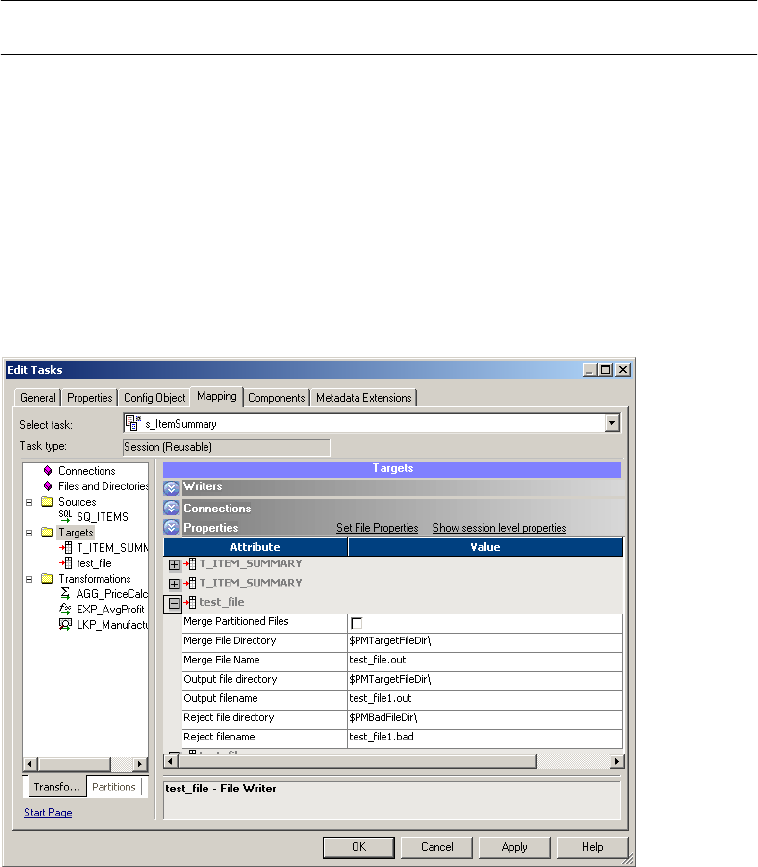
Mapping Tab (Transformations View) 735
Properties Settings for Flat File Targets
Figure A-19 describes the Properties settings on the Mapping tab for file targets:
Pre SQL Optional You can enter pre-session SQL commands for a target instance in a
mapping to execute commands against the target database before the
Integration Service reads the source.
Post SQL Optional Enter post-session SQL commands to execute commands against the target
database after the Integration Service writes to the target.
*You can view the value of this attribute when you click Show all properties. This attribute is read-only. For more information, see the
Designer Guide.
Figure A-19. Mapping Tab - Targets Node - File Properties Settings
Table A-17. Mapping Tab - Targets Node - Properties Settings (Relational)
Target Property Required/
Optional Description

736 Appendix A: Session Properties Reference
Table A-18 describes the Properties settings on the Mapping tab for file targets:
Table A-18. Mapping Tab - Targets Node - File Properties Settings
Target Property Required/
Optional Description
Merge Partitioned
Files
Optional When selected, the Integration Service merges the partitioned target files into
one file when the session completes, and then deletes the individual output
files. If the Integration Service fails to create the merged file, it does not delete
the individual output files.
You cannot merge files if the session uses FTP, an external loader, or a
message queue.
For more information about configuring a session for partitioning, see
“Understanding Pipeline Partitioning” on page 421.
Merge File
Directory
Optional Enter the directory name in this field. By default, the Integration Service writes
the merged file in the service process variable directory, $PMTargetFileDir.
If you enter a full directory and file name in the Merge File Name field, clear
this field.
Merge File Name Optional Name of the merge file. Default is target_name.out. This property is required if
you select Merge Partitioned Files.
Output File
Directory
Optional Enter the directory name in this field. By default, the Integration Service writes
output files in the service process variable directory, $PMTargetFileDir.
If you specify both the directory and file name in the Output Filename field,
clear this field. The Integration Service concatenates this field with the Output
Filename field when it runs the session.
You can also use the $OutputFileName session parameter to specify the file
directory.
For more information about session parameters, see “Parameter Files” on
page 601.
Output Filename Required Enter the file name, or file name and path. By default, the Workflow Manager
names the target file based on the target definition used in the mapping:
target_name.out.
If the target definition contains a slash character, the Workflow Manager
replaces the slash character with an underscore.
When you use an external loader to load to an Oracle database, you must
specify a file extension. If you do not specify a file extension, the Oracle loader
cannot find the flat file and the Integration Service fails the session. For more
information about external loading, see “Loading to Oracle” on page 626.
Enter the file name, or file name and path. Optionally use the $OutputFileName
session parameter for the file name.
The Integration Service concatenates this field with the Output File Directory
field when it runs the session.
For more information about session parameters, see “Parameter Files” on
page 601.
Note: If you specify an absolute path file name when using FTP, the Integration
Service ignores the Default Remote Directory specified in the FTP connection.
When you specify an absolute path file name, do not use single or double
quotes.

Mapping Tab (Transformations View) 737
Setting File Properties for Targets
Click the Set File Properties button on the Mapping tab to configure flat file properties. You
can define flat file properties for both fixed-width and delimited flat file targets.
You can configure flat file properties for non-reusable sessions in the Workflow Designer and
for reusable sessions in the Task Developer.
Reject File
Directory
Optional Enter the directory name in this field. By default, the Integration Service writes
all reject files to the service process variable directory, $PMBadFileDir.
If you specify both the directory and file name in the Reject Filename field,
clear this field. The Integration Service concatenates this field with the Reject
Filename field when it runs the session.
You can also use the $BadFileName session parameter to specify the file
directory.
For more information about session parameters, see “Parameter Files” on
page 601.
Reject Filename Required Enter the file name, or file name and path. By default, the Integration Service
names the reject file after the target instance name: target_name.bad.
Optionally use the $BadFileName session parameter for the file name.
The Integration Service concatenates this field with the Reject File Directory
field when it runs the session. For example, if you have “C:\reject_file\” in the
Reject File Directory field, and enter “filename.bad” in the Reject Filename
field, the Integration Service writes rejected rows to C:\reject_file\filename.bad.
For more information about session parameters, see “Parameter Files” on
page 601.
Set File Properties Optional You can configure the file properties. For more information, see “Setting File
Properties for Targets” on page 737.
Datetime Format* n/a Displays the datetime format selected for datetime fields.
Thousand
Separator*
n/a Displays the thousand separator for numeric fields.
Decimal Separator* n/a Displays the decimal separator for numeric fields.
*You can view the value of this attribute when you click Show all properties. This attribute is read-only. For more information, see the
Designer Guide.
Table A-18. Mapping Tab - Targets Node - File Properties Settings
Target Property Required/
Optional Description
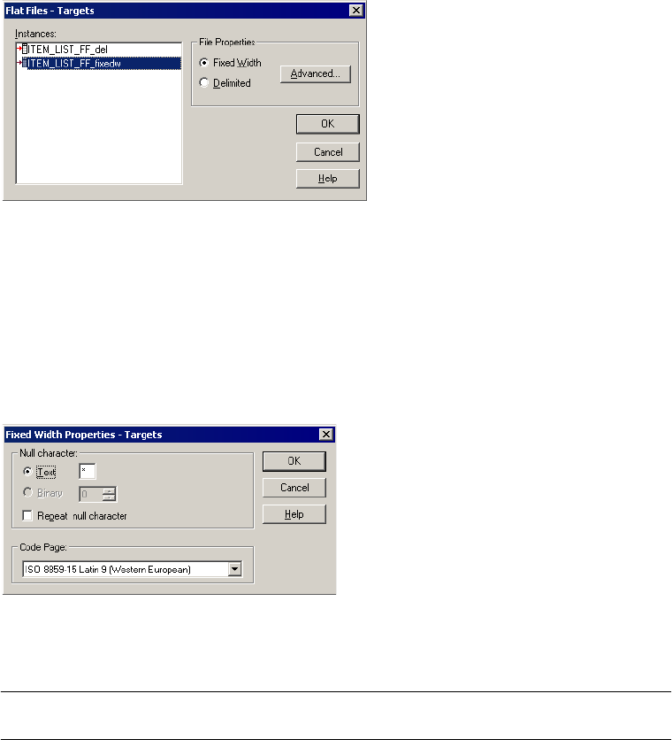
738 Appendix A: Session Properties Reference
Figure A-20 shows the Flat Files dialog box that appears when you click Set File Properties:
Select the file type (fixed-width or delimited) you want to configure and click Advanced.
Configuring Fixed-Width Properties for Targets
To edit the fixed-width properties, select Fixed Width in the Flat Files dialog box and click
the Advanced button. The Fixed Width Properties dialog box appears.
Figure A-21 shows the Fixed-Width Properties dialog box for flat file targets:
Table A-19 describes the options you define in the Fixed Width Properties dialog box:
Figure A-20. Flat Files Dialog Box for Targets
Figure A-21. Fixed-Width Properties for File Targets
Table A-19. Fixed-Width Properties for File Targets
Fixed-Width
Properties Options
Required/
Optional Description
Null Character Required Enter the character you want the Integration Service to use to represent
null values. You can enter any valid character in the file code page.
For more information about specifying null characters for target files, see
“Null Characters in Fixed-Width Files” on page 297.
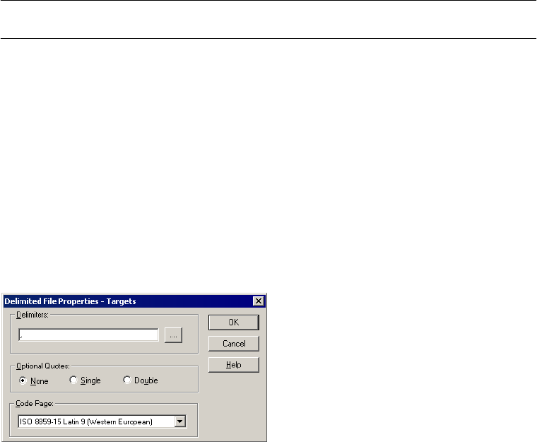
Mapping Tab (Transformations View) 739
Configuring Delimited Properties for Targets
To edit the delimited properties, select Delimited in the Flat Files dialog box and click the
Advanced button. The Delimited File Properties dialog box appears.
Figure A-22 shows the Delimited File Properties dialog box for flat file targets:
Repeat Null Character Optional Select this option to indicate a null value by repeating the null character to
fill the field. If you do not select this option, the Integration Service enters a
single null character at the beginning of the field to represent a null value.
For more information about specifying null characters for target files, see
“Null Characters in Fixed-Width Files” on page 297.
Code Page Required Select the code page of the fixed-width file. The default setting is the client
code page.
Figure A-22. Delimited Properties for File Targets
Table A-19. Fixed-Width Properties for File Targets
Fixed-Width
Properties Options
Required/
Optional Description

740 Appendix A: Session Properties Reference
Table A-20 describes the options you can define in the Delimited File Properties dialog box
for flat file targets:
Transformations Node
On the Transformations node, you can override properties that you configure in
transformation and target instances in a mapping. The attributes you can configure depends
on the type of transformation you select.
Table A-20. Delimited Properties for File Targets
Edit Delimiter
Options
Required/
Optional Description
Delimiters Required Character used to separate columns of data. Delimiters can be either printable
or single-byte unprintable characters, and must be different from the escape
character and the quote character (if selected). To enter a single-byte
unprintable character, click the Browse button to the right of this field. In the
Delimiters dialog box, select an unprintable character from the Insert Delimiter
list and click Add. You cannot select unprintable multibyte characters as
delimiters.
Optional Quotes Required Select No Quotes, Single Quote, or Double Quotes. If you select a quote
character, the Integration Service does not treat delimiter characters within the
quote characters as a delimiter. For example, suppose an output file uses a
comma as a delimiter and the Integration Service receives the following row:
342-3849, ‘Smith, Jenna’, ‘Rockville, MD’, 6.
If you select the optional single quote character, the Integration Service ignores
the commas within the quotes and writes the row as four fields.
If you do not select the optional single quote, the Integration Service writes six
separate fields.
Code Page Required Select the code page of the delimited file. The default setting is the client code
page.
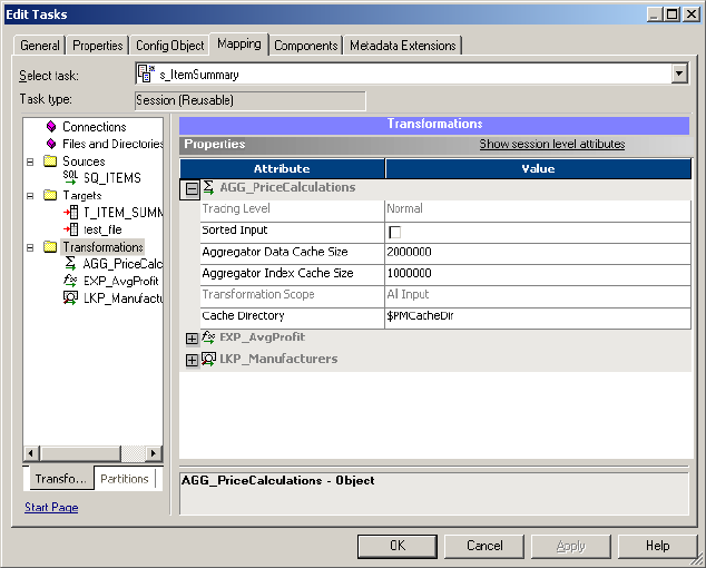
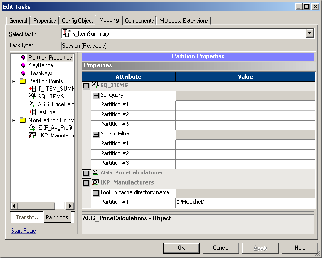
742 Appendix A: Session Properties Reference
Mapping Tab (Partitions View)
In the Partitions view of the Mapping tab, you can configure partitions. You can configure
partitions for non-reusable sessions in the Workflow Designer and for reusable sessions in the
Task Developer.
The following nodes are available in the Partitions view:
♦Partition Properties. For more information, see “Partition Properties Node” on page 742.
♦KeyRange. For more information, see “KeyRange Node” on page 743.
♦HashKeys. For more information, see “HashKeys Node” on page 743.
♦Partition Points. For more information, see “Partition Points Node” on page 743.
♦Non-Partition Points. For more information, see “Non-Partition Points Node” on
page 746.
Partition Properties Node
You can configure partitions with the Partition Properties node.
Figure A-24 shows the Mapping tab - Partitions Properties node:
Figure A-24. Mapping Tab - Partitions Properties Node
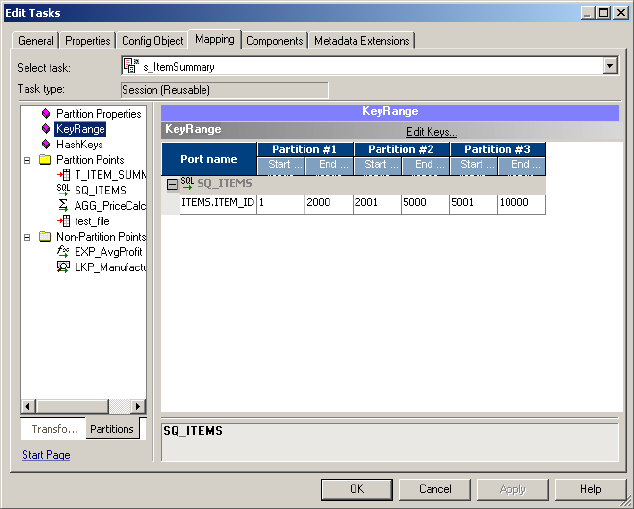
Mapping Tab (Partitions View) 743
KeyRange Node
In the KeyRange node, you can configure the partition range for key-range partitioning.
Select Edit Keys to edit the partition key. For more information, see “Edit Partition Key” on
page 745.
Figure A-25 shows the KeyRange node on the Mapping tab:
HashKeys Node
The HashKeys node you can configure hash key partitioning. Select Edit Keys to edit the
partition key. For more information, see “Edit Partition Key” on page 745.
Partition Points Node
The Partition Points node displays the mapping with the transformation icons. The Partition
Points node lists the partition points in the tree. Select a partition point to configure its
attributes.
In the Partition Points node, you can configure the following options for each pipeline in a
mapping:
♦Add and delete partition points.
♦Specify the partition type at each partition point.
Figure A-25. Mapping Tab - KeyRange Node
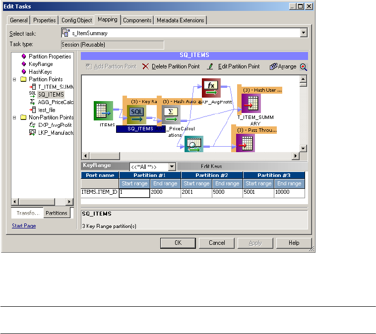
744 Appendix A: Session Properties Reference
♦Add and delete partitions.
♦Enter a description for each partition.
♦Add keys and key ranges for certain partition types.
For more information about partitioning a pipeline, see “Understanding Pipeline
Partitioning” on page 421.
Figure A-26 shows Mapping tab - Partition Points node:
Table A-21 describes the Partition Points node:
Figure A-26. Mapping Tab - Partition Points Node
Table A-21. Mapping Tab - Partition Points Node
Partition Points
Node Description
Add Partition Point Click to add a new partition point to the Transformation list. For more information about adding
partition points, see “Steps for Adding Partition Points to a Pipeline” on page 438.
Delete Partition
Point
Click to delete the current partition point. You cannot delete certain partition points. For more
information, see “Steps for Adding Partition Points to a Pipeline” on page 438.
Edit Partition Point Click to edit the current partition point.
Edit Keys Click to add, remove, or edit the key for key range or hash user keys partitioning. This button is
not available for auto-hash, round-robin, or pass-through partitioning.
For more information about adding keys and key ranges, see “Adding Key Ranges” on page 453.
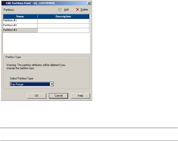
Mapping Tab (Partitions View) 745
Edit Partition Point
The Edit Partition Point dialog box lets you add and delete partitions and select the partition
type.
Figure A-27 shows the Edit Partition Points dialog box:
Table A-22 describes the options in the Edit Partition Point dialog box:
Edit Partition Key
When you specify key range or hash user keys partitioning at any partition point, you must
specify one or more ports as the partition key. Click Edit Key to display the Edit Partition
Key dialog box.
Figure A-27. Edit Partition Point Dialog Box
Table A-22. Edit Partition Point Dialog Box Options
Edit Partition Point
Options Description
Add button Click to add a partition. You can add up to 64 partitions. For more information about
adding partitions, see “Steps for Adding Partition Points to a Pipeline” on page 438.
Delete button Click to delete the selected partition. For more information about deleting partitions,
see “Steps for Adding Partition Points to a Pipeline” on page 438.
Name Partition number.
Description Enter a description for the current partition.
Select Partition Type Select a partition type from the list. For more information, see “Setting Partition
Types” on page 442.
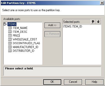
746 Appendix A: Session Properties Reference
Figure A-28 shows the Edit Partition Key dialog box:
You can specify one or more ports as the partition key. To rearrange the order of the ports that
make up the key, select a port in the Selected Ports list and click the up or down arrow.
For more information about adding a key for key range partitioning, see “Key Range Partition
Type” on page 451. For more information about adding a key for hash partitioning, see
“Database Partitioning Partition Type” on page 444.
Non-Partition Points Node
The Non-Partition Points node displays the mapping objects in iconized view. The Partition
Points node lists the non-partition points in the tree. You can select a non-partition point and
add partitions if you want.
Figure A-28. Edit Partition Key Dialog Box
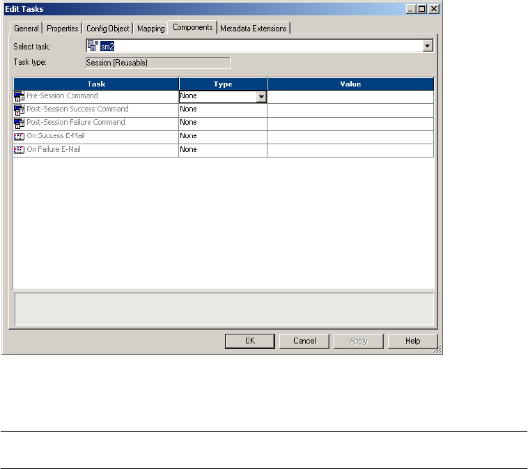
Components Tab 747
Components Tab
In the Components tab, you can configure pre-session shell commands, post-session
commands, and email messages if the session succeeds or fails.
Figure A-29 shows the Components Tab:
Table A-23 describes the Components tab options:
Figure A-29. Components Tab
Table A-23. Components Tab
Components Tab
Option
Optional/
Required Description
Task n/a Tasks you can perform in the Components tab. You can configure pre- or post-
session shell commands and success or failure email messages in the
Components tab.

748 Appendix A: Session Properties Reference
Table A-24 describes the tasks available in the Components tab:
Reusable Pre- or Post-Session Commands
Select Reusable in the Type field if you want to select an existing Command task as the pre-
or post-session shell command. The Command Object Browser appears when you click the
Open button in the Value field.
Type Required Select None if you do not want to configure commands and emails in the
Components tab.
For pre- and post-session commands, select Reusable to call an existing
reusable Command task as the pre- or post-session shell command. Select
Non-Reusable to create pre- or post-session shell commands for this session
task.
For success or failure emails, select Reusable to call an existing Email task as
the success or failure email. Select Non-Reusable to create email messages
for this session task.
Value Optional Use to configure commands or emails.
Table A-24. Components Tab Tasks
Components Tab
Tasks
Required/
Optional Description
Pre-Session
Command
Optional Shell commands that the Integration Service performs at the beginning of a
session. For more information about using pre-session shell commands, see
“Using Pre- and Post-Session Shell Commands” on page 199.
Post-Session
Success Command
Optional Shell commands that the Integration Service performs after the session
completes successfully. For more information about using pre-session shell
commands, see “Using Pre- and Post-Session Shell Commands” on page 199.
Post-Session
Failure Command
Optional Shell commands that the Integration Service performs after the session if the
session fails. For more information about using pre-session shell commands,
see “Using Pre- and Post-Session Shell Commands” on page 199.
On Success Email Optional Integration Service sends On Success email message if the session completes
successfully.
On Failure Email Optional Integration Service sends On Failure email message if the session fails.
Table A-23. Components Tab
Components Tab
Option
Optional/
Required Description
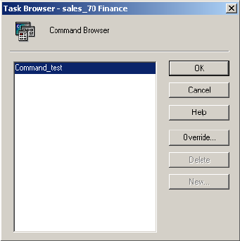
Components Tab 749
Figure A-30 shows the Task Browser:
Click the Override button to override the Fail Task if Any Command Fails option in the
Command task. For more information about the Fail Task if Any Command Fails option, see
Table A-26 on page 751.
Non-Reusable Pre- or Post-Session Commands
Select Non-Reusable in the Type field if you want to create pre- or post-session commands
for the session. Non-reusable pre- or post-session commands do not appear as Command
tasks in the folder.
Click the Open button in the Value field in the Components tab to edit pre- or post-session
shell commands. The Edit Pre-Session Command or Edit Post-Session Command dialog box
appears.
Figure A-30. Task Browser
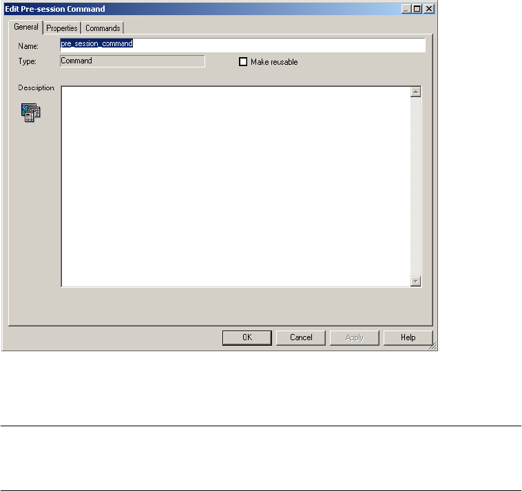
750 Appendix A: Session Properties Reference
Figure A-31 shows the Edit Pre-Session Command dialog box:
Table A-25 describes General tab for editing pre- or post-session shell commands:
Figure A-31. Edit Pre-Session Command Dialog Box
Table A-25. Pre- or Post-Session Commands - General Tab
General Tab
Options for Pre-
or Post-Session
Commands
Required/
Optional Description
Name Required Enter a name for the pre- or post-session shell command.
Make Reusable Required Select Make Reusable to create a reusable Command task from the pre- or
post-session shell commands.
Clear the Make Reusable option if you do not want the Workflow Manager to
create a reusable Command task from the shell commands.
For more information about creating Command tasks from pre- or post-session
shell commands, see “Creating a Reusable Command Task from Pre- or Post-
Session Commands” on page 202.
Description Optional Enter a description for the pre- or post-session shell command.

Components Tab 751
Table A-26 describes the Properties tab for editing pre- or post-session commands:
Table A-27 describes the Commands tab for editing pre- or post-session commands:
Reusable Email
Select Reusable in the Type field for the On-Success or On-Failure email if you want to select
an existing Email task as the On-Success or On-Failure email. The Email Object Browser
appears when you click the right side of the Values field.
Table A-26. Pre- or Post-Session Commands - Properties Tab
Properties Tab
Options for Pre-
or Post-Session
Commands
Required/
Optional Description
Name Required Name of the pre-session shell command.
Fail Task if Any
Command Fails
Required Integration Service stops running the rest of the commands in a task when one
command in the Command task fails if you select this option. If you do not
select this option, the Integration Service runs all the commands in the
Command task and treats the task as completed, even if a command fails.
Table A-27. Pre- or Post-Session Commands - Commands Tab
Commands Tab
Options for Pre-
or Post-Session
Commands
Required/
Optional Description
Name Required Name of the pre- or post-session shell command.
Command Required Shell command you want the Integration Service to perform. Enter one
command for each line. Use session parameters or service process variables
in shell commands.
If the command contains spaces, enclose the command in quotes. For
example, if you want to call c:\program files\myprog.exe, you must enter
“c:\program files\myprog.exe”, including the quotes. Enter only one command
on each line.
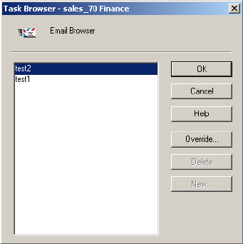
752 Appendix A: Session Properties Reference
Figure A-32 shows Email Object Browser:
Select an Email task to use as On-Success or On-Failure email. Click the Override button to
override properties of the email. For more information about email properties, see Table A-29
on page 754.
Non-Reusable Email
Select Non-Reusable in the Type field to create a non-reusable email for the session. Non-
Reusable emails do not appear as Email tasks in the Task folder. Click the right side of the
Values field to edit the properties for the non-reusable On-Success or On-Failure emails. For
more information about email properties, see Ta b l e A-29 on page 754.
Email Properties
You configure email properties for On-Success or On-Failure Emails when you override an
existing Email task or when you create a non-reusable email for the session.
Figure A-32. Email Object Browser
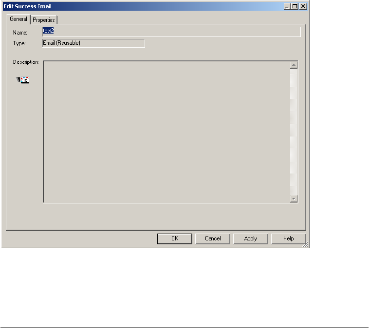
Components Tab 753
Figure A-33 shows the dialog box for editing the On-Success or On-Failure email properties:
Table A-28 describes general settings for editing On-Success or On-Failure emails:
Figure A-33. On-Success or On-Failure Email - General Tab
Table A-28. On-Success or On-Failure Emails - General Tab
Email Settings Required/
Optional Description
Name Required Enter a name for the email you want to configure.
Description Required Enter a description for the email you want to configure.
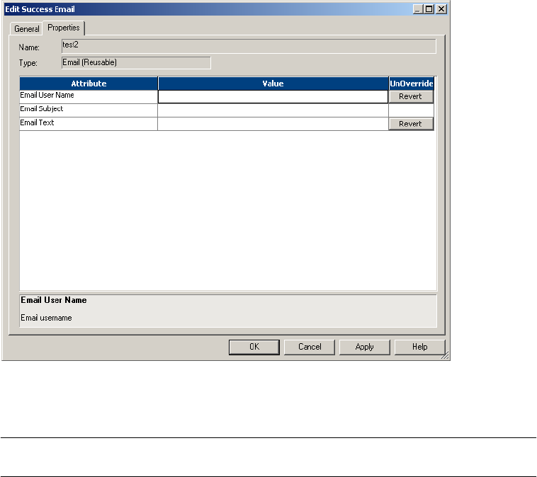
754 Appendix A: Session Properties Reference
Figure A-34 shows the properties for On-Success or On-Failure emails:
Table A-29 describes the email properties for On-Success or On-Failure emails:
Figure A-34. On-Success or On-Failure Email - Properties Tab
Table A-29. On-Success or On-Failure Emails - Properties Tab
Email Properties Required/
Optional Description
Email User Name Required Required to send On-Success or On-Failure session email. Enter the email
address of the person you want the Integration Service to email after the
session completes. The email address must be entered in 7-bit ASCII.
For success email, you can enter $PMSuccessEmailUser to send email to the
user configured for the service variable.
For failure email, you can enter $PMFailureEmailUser to send email to the user
configured for the service variable.
Email Subject Optional Enter the text you want to appear in the subject header.
Email Text Optional Enter the text of the email. Use several variables when creating this text to
convey meaningful information, such as the session name and session status.
For more information, see “Sending Email” on page 361.
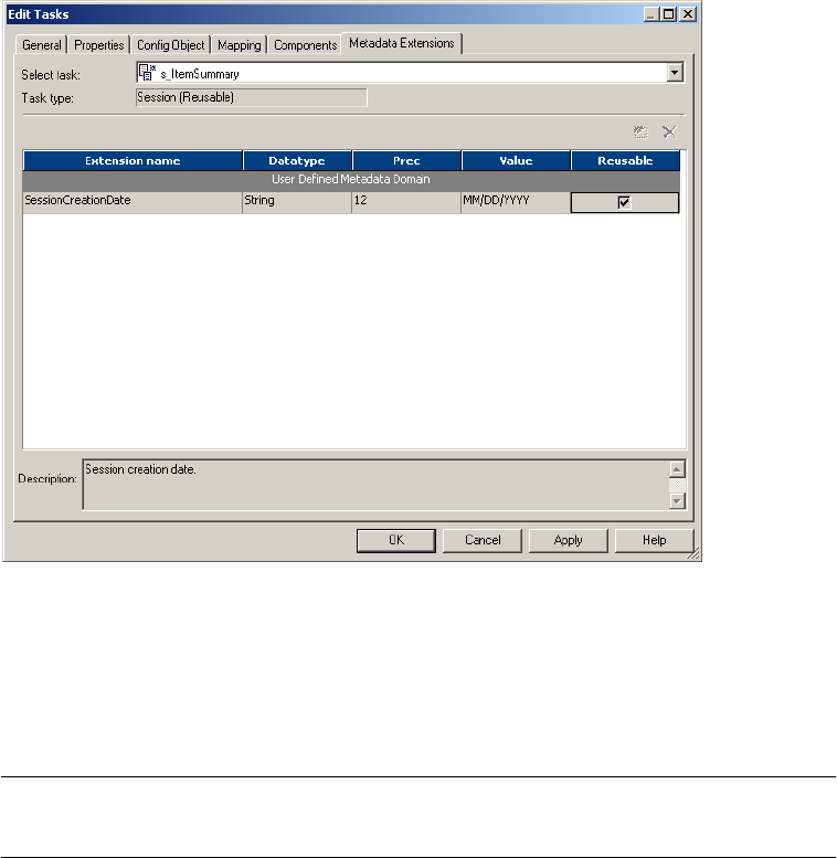
Metadata Extensions Tab 755
Metadata Extensions Tab
The Metadata Extensions tab appears in the session property sheet after the Partitions tab.
Figure A-35 shows the Metadata Extensions tab:
You can create and promote metadata extensions with the Metadata Extensions tab. For more
information about creating metadata extensions, see “Metadata Extensions” in the Repository
Guide.
Table A-30 describes the configuration options for the Metadata Extensions tab:
Figure A-35. Metadata Extensions Tab
Table A-30. Metadata Extensions Tab
Metadata
Extensions Tab
Options
Required/
Optional Description
Extension Name Required Name of the metadata extension. Metadata extension names must be unique in
a domain.
Datatype Required Datatype: numeric (integer), string, boolean, or XML.

756 Appendix A: Session Properties Reference
Value Optional Value of the metadata extension.
For a numeric metadata extension, the value must be an integer.
For a boolean metadata extension, choose true or false.
For a string or XML metadata extension, click the button in the Value field to
enter a value of more than one line. The Workflow Manager does not validate
XML syntax.
Precision Required for
string and
XML objects
Maximum length for string or XML metadata extensions.
Reusable Required Select to make the metadata extension apply to all objects of this type
(reusable). Clear to make the metadata extension apply to this object only
(non-reusable).
Description Optional Description of the metadata extension.
Table A-30. Metadata Extensions Tab
Metadata
Extensions Tab
Options
Required/
Optional Description

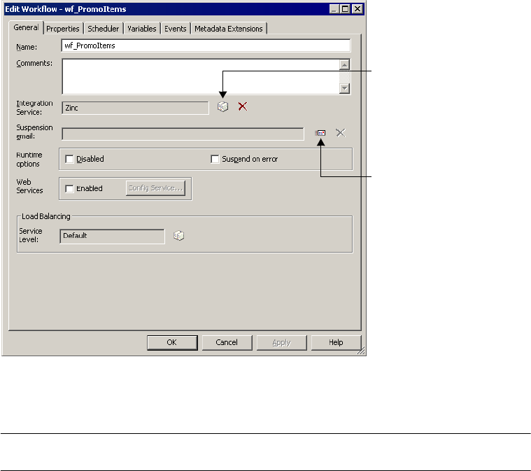
758 Appendix B: Workflow Properties Reference
General Tab
You can change the workflow name and enter a comment for the workflow on the General
tab. By default, the General tab appears when you open the workflow properties.
Figure B-1 shows the General tab of the workflow properties:
Table B-1 describes the settings on the General tab:
Figure B-1. Workflow Properties - General Tab
Table B-1. Workflow Properties - General Tab
General Tab
Options
Required/
Optional Description
Name Required Name of the workflow.
Comments Optional Comment that describes the workflow.
Integration Service Required Integration Service that runs the workflow by default. You can also assign an
Integration Service when you run the workflow.
Suspension Email Optional Email message that the Integration Service sends when a task fails and the
Integration Service suspends the workflow.
For more information about suspending workflows, see “Suspending the
Workflow” on page 130.
Select an Integration
Service to run the
workflow.
Select a suspension
email.

General Tab 759
Disabled Optional Disables the workflow from the schedule. The Integration Service stops
running the workflow until you clear the Disabled option.
For more information about the Disabled option, see “Disabling Workflows”
on page 124.
Suspend on Error Optional The Integration Service suspends the workflow when a task in the workflow
fails.
For more information about suspending workflows, see “Suspending the
Workflow” on page 130.
Web Services Optional Creates a service workflow. Click Config Service to configure service
information.
For more information about creating web services, see the Web Services
Provider Guide.
Service Level Optional Determines the order in which the Load Balancer dispatches tasks from the
dispatch queue when multiple tasks are waiting to be dispatched. Default is
“Default.”
For more information about assigning service levels, see “Assigning Service
Levels to Workflows” on page 563.
You create service levels in the Administration Console. For more
information, see “Configuring the Load Balancer” in the Administrator Guide.
Table B-1. Workflow Properties - General Tab
General Tab
Options
Required/
Optional Description
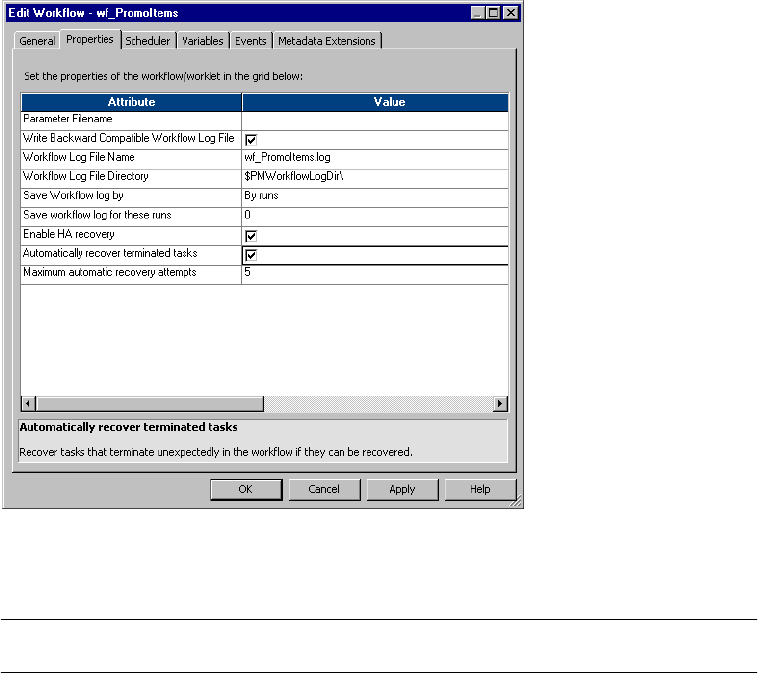
760 Appendix B: Workflow Properties Reference
Properties Tab
Configure parameter file name and workflow log options on the Properties tab.
Figure B-2 shows the Properties tab:
Table B-2 describes the settings on the Properties tab:
Figure B-2. Workflow Properties - Properties Tab
Table B-2. Workflow Properties - Properties Tab
Properties Tab
Options
Required/
Optional Description
Parameter File
Name
Optional Designates the name and directory for the parameter file. Use the parameter
file to define workflow variables. For more information about parameter files,
see “Parameter Files” on page 601.
Write Backward
Compatible
Workflow Log File
Optional Select to write workflow log to a file.
Workflow Log File
Name
Optional Enter a file name, or a file name and directory. Required.
The Integration Service appends information in this field to that entered in the
Workflow Log File Directory field. For example, if you have “C:\workflow_logs\”
in the Workflow Log File Directory field, then enter “logname.txt” in the
Workflow Log File Name field, the Integration Service writes logname.txt to the
C:\workflow_logs\ directory.

Properties Tab 761
Workflow Log File
Directory
Required Designates a location for the workflow log file. By default, the Integration
Service writes the log file in the service variable directory, $PMWorkflowLogDir.
If you enter a full directory and file name in the Workflow Log File Name field,
clear this field.
Save Workflow Log
By
Required If you select Save Workflow Log by Timestamp, the Integration Service saves
all workflow logs, appending a timestamp to each log.
If you select Save Workflow Log by Runs, the Integration Service saves a
designated number of workflow logs. Configure the number of workflow logs in
the Save Workflow Log for These Runs option.
For more information about these options, see “Archiving Log Files” on
page 575.
You can also use the $PMWorkflowLogCount service variable to save the
configured number of workflow logs for the Integration Service.
Save Workflow Log
For These Runs
Required Number of historical workflow logs you want the Integration Service to save.
The Integration Service saves the number of historical logs you specify, plus
the most recent workflow log. Therefore, if you specify 5 runs, the Integration
Service saves the most recent workflow log, plus historical logs 0–4, for a total
of 6 logs.
You can specify up to 2,147,483,647 historical logs. If you specify 0 logs, the
Integration Service saves only the most recent workflow log.
Enable HA
Recovery
Not Required Enable workflow recovery.
Automatically
recover terminated
tasks
Not Required Recover terminated Session or Command tasks without user intervention. You
must have high availability and the workflow must still be running.
Maximum
automatic recovery
attempts
Not Required When you automatically recover terminated tasks you can choose the number
of times the Integration Service attempts to recover the task. Default is 5.
Table B-2. Workflow Properties - Properties Tab
Properties Tab
Options
Required/
Optional Description
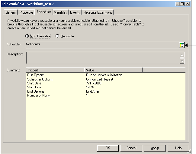
762 Appendix B: Workflow Properties Reference
Scheduler Tab
The Scheduler Tab lets you schedule a workflow to run continuously, run at a given interval,
or manually start a workflow. For more information about scheduling workflows, see
“Scheduling a Workflow” on page 116.
Figure B-3 shows the Scheduler tab:
You can configure the following types of scheduler settings:
♦Non-Reusable. Create a non-reusable scheduler for the workflow.
♦Reusable. Choose a reusable scheduler for the workflow.
Figure B-3. Workflow Properties - Scheduler Tab
Edit
scheduler
settings.
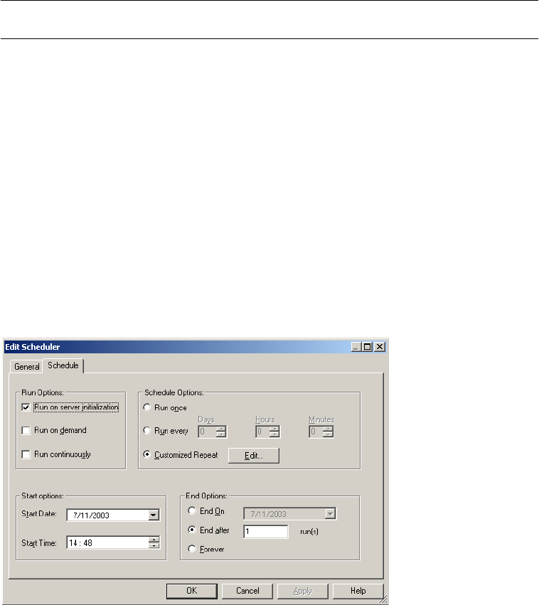
Scheduler Tab 763
Table B-3 describes the settings on the Scheduler Tab:
Edit Scheduler Settings
Click the Edit Scheduler Settings button to configure the scheduler. The Edit Scheduler
dialog box appears.
Figure B-4 shows the Edit Scheduler dialog box:
Table B-3. Workflow Properties - Scheduler Tab
Scheduler Tab Options Required/
Optional Description
Non-Reusable/Reusable Required Indicates the scheduler type.
If you select Non Reusable, the scheduler can only be used by the current
workflow.
If you select Reusable, choose a reusable scheduler. You can create
reusable schedulers by selecting Schedulers.
Scheduler Required Select a set of scheduler settings for the workflow.
Description Optional Enter a description for the scheduler.
Summary n/a Read-only summary of the selected scheduler settings.
Figure B-4. Workflow Properties - Scheduler Tab - Edit Scheduler Dialog Box

764 Appendix B: Workflow Properties Reference
Table B-4 describes the settings on the Edit Scheduler dialog box:
Table B-4. Workflow Properties - Scheduler Tab - Edit Scheduler Dialog Box
Scheduler Options Required/
Optional Description
Run Options: Run On
Integration Service
Initialization/Run On Demand/
Run Continuously
Optional Indicates the workflow schedule type.
If you select Run On Integration Service Initialization, the Integration
Service runs the workflow as soon as the Integration Service is
initialized.
If you select Run On Demand, the Integration Service only runs the
workflow when you start the workflow.
If you select Run Continuously, the Integration Service starts the
next run of the workflow as soon as it finishes the first run.
Schedule Options: Run Once/
Run Every/Customized Repeat
Conditional Required if you select Run On Integration Service Initialization in
Run Options.
Also required if you do not choose any setting in Run Options.
If you select Run Once, the Integration Service runs the workflow
once, as scheduled in the scheduler.
If you select Run Every, the Integration Service runs the workflow at
regular intervals, as configured.
If you select Customized Repeat, the Integration Service runs the
workflow on the dates and times specified in the Repeat dialog box.
Edit Conditional Required if you select Customized Repeat in Schedule Options.
Opens the Repeat dialog box, allowing you to schedule specific
dates and times for the workflow to run. The selected scheduler
appears at the bottom of the page. For more information about the
Repeat dialog box, see “Customizing Repeat Option” on page 121.
Start Date Conditional Required if you select Run On Integration Service Initialization in
Run Options.
Also required if you do not choose any setting in Run Options.
Indicates the date on which the Integration Service begins
scheduling the workflow.
Start Time Conditional Required if you select Run On Integration Service Initialization in
Run Options.
Also required if you do not choose any setting in Run Options.
Indicates the time at which the Integration Service begins
scheduling the workflow.
End Options: End On/End
After/Forever
Conditional Required if the workflow schedule is Run Every or Customized
Repeat.
If you select End On, the Integration Service stops scheduling the
workflow in the selected date.
If you select End After, the Integration Service stops scheduling the
workflow after the set number of workflow runs.
If you select Forever, the Integration Service schedules the workflow
as long as the workflow does not fail.
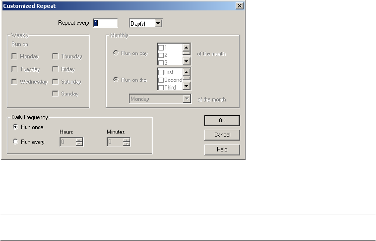
Scheduler Tab 765
Customizing Repeat Option
You can schedule the workflow to run once, run at an interval, or customize the repeat
option. Click the Edit button on the Edit Scheduler dialog box to configure Customized
Repeat options.
Figure B-5 shows the Customized Repeat dialog box:
Table B-5 describes options in the Customized Repeat dialog box:
Figure B-5. Workflow Properties - Customized Repeat Dialog Box
Table B-5. Workflow Properties - Repeat Dialog Box Options
Repeat Option Required/
Optional Description
Repeat Every Required Enter the numeric interval you want to schedule the workflow, then select Days,
Weeks, or Months, as appropriate.
If you select Days, select the appropriate Daily Frequency settings.
If you select Weeks, select the appropriate Weekly and Daily Frequency
settings.
If you select Months, select the appropriate Monthly and Daily Frequency
settings.
Weekly Optional Required to enter a weekly schedule. Select the day or days of the week on
which you want to schedule the workflow.

766 Appendix B: Workflow Properties Reference
Monthly Optional Required to enter a monthly schedule.
If you select Run On Day, select the dates on which you want the workflow
scheduled on a monthly basis. The Integration Service schedules the workflow
on the selected dates. If you select a numeric date exceeding the number of
days within a given month, the Integration Service schedules the workflow for
the last day of the month, including leap years. For example, if you schedule
the workflow to run on the 31st of every month, the Integration Service
schedules the session on the 30th of the following months: April, June,
September, and November.
If you select Run On The, select the week(s) of the month, then day of the
week on which you want the workflow to run. For example, if you select Second
and Last, then select Wednesday, the Integration Service schedules the
workflow on the second and last Wednesday of every month.
Daily Required Enter the number of times you would like the Integration Service to run the
workflow on any day the session is scheduled.
If you select Run Once, the Integration Service schedules the workflow once on
the selected day, at the time entered on the Start Time setting on the Time tab.
If you select Run Every, enter Hours and Minutes to define the interval at which
the Integration Service runs the workflow. The Integration Service then
schedules the workflow at regular intervals on the selected day. The Integration
Service uses the Start Time setting for the first scheduled workflow of the day.
Table B-5. Workflow Properties - Repeat Dialog Box Options
Repeat Option Required/
Optional Description
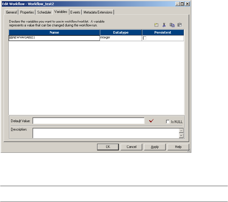
Variables Tab 767
Variables Tab
Before using workflow variables, you must declare them on the Variables tab.
Figure B-6 shows the settings on the Variables tab:
Table B-6 describes the settings on the Variables tab:
Figure B-6. Workflow Properties - Variables Tab
Table B-6. Workflow Properties - Variables Tab
Variable Options Required/
Optional Description
Name Required Name of the workflow variable.
Datatype Required Datatype of the workflow variable.
Persistent Required Indicates whether the Integration Service maintains the value of the variable
from the previous workflow run.
Is Null Required Indicates whether the workflow variable is null.
Default Optional Default value of the workflow variable.
Description Optional Optional details about the workflow variable.
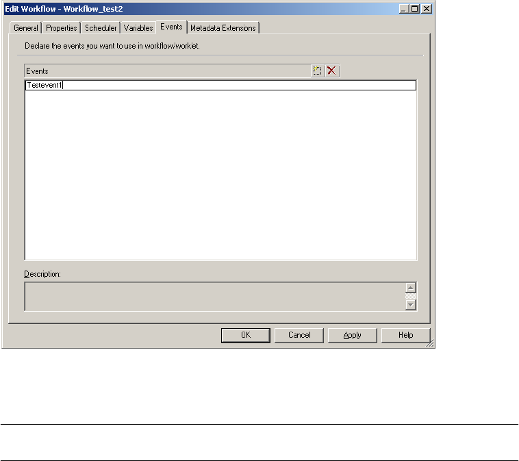
768 Appendix B: Workflow Properties Reference
Events Tab
Before using the Event-Raise task, declare a user-defined event on the Events tab.
Figure B-7 shows the Events tab:
Table B-7 describes the settings on the Events tab:
Figure B-7. Workflow Properties - Events Tab
Table B-7. Workflow Properties - Events Tab
Events Tab
Options
Required/
Optional Description
Events Required Name of the event you declare.
Description Optional Details to describe the event.
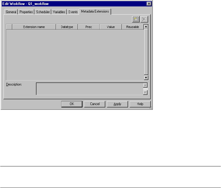
Metadata Extensions Tab 769
Metadata Extensions Tab
Extend the metadata stored in the repository by associating information with individual
repository objects. Create metadata extensions for repository objects by editing the object and
then adding the metadata extension to the Metadata Extension tab.
Figure B-8 shows the Metadata Extensions tab:
You can create and promote metadata extensions with the Metadata Extensions tab. For more
information about creating metadata extensions, see “Metadata Extensions” in the Repository
Guide.
Table B-8 describes the configuration options for the Metadata Extensions tab:
Figure B-8. Workflow Properties - Metadata Extensions Tab
Table B-8. Workflow Properties - Metadata Extensions Tab
Metadata
Extensions Tab
Options
Required/
Optional Description
Extension Name Required Name of the metadata extension. Metadata extension names must be unique in
a domain.
Datatype Required Datatype: numeric (integer), string, boolean, or XML.
Value Optional For a numeric metadata extension, the value must be an integer.
For a boolean metadata extension, choose true or false.
For a string or XML metadata extension, click the Edit button on the right side
of the Value field to enter a value of more than one line. The Workflow Manager
does not validate XML syntax.

770 Appendix B: Workflow Properties Reference
Precision Required for
string and
XML objects
Maximum length for string or XML metadata extensions.
Reusable Required Select to make the metadata extension apply to all objects of this type
(reusable). Clear to make the metadata extension apply to this object only
(non-reusable).
UnOverride Optional This column appears only if the value of one of the metadata extensions was
changed. To restore the default value, click Revert.
Description Optional Description of the metadata extension.
Table B-8. Workflow Properties - Metadata Extensions Tab
Metadata
Extensions Tab
Options
Required/
Optional Description

771
Index
A
ABORT function
See also Transformation Language Reference
session failure 208
aborted
status 516
aborting
Control tasks 151
Integration Service handling 132
sessions 133
status 516
tasks 132
tasks in Workflow Monitor 513
workflows 132
Absolute Time
specifying 166
Timer task 165
active sources
constraint-based loading 272
definition 282
generating commits 320
row error logging 283
source-based commit 320
transaction generators 282
XML targets 282
adding
tasks to workflows 92
advanced settings
session properties 709
aggregate caches
reinitializing 664, 707
aggregate files
deleting 665
moving 665
Aggregate transformation
sorted ports 683
Aggregator cache
description 683
overview 683
Aggregator transformation
See also Transformation Guide
cache partitioning 681, 683
caches 683
configure caches 683
inputs for cache calculator 684
pushdown optimization rules 472
using partition points 387
AND links
input type 141
Append if Exists
flat file target property 286, 404
application connections
IBM MQSeries 60
JMS 63
MSMQ Queue 65
PeopleSoft 66
772 Index
Salesforce 68
SAP NetWeaver mySAP 69
Siebel 76
TIBCO 78
webMethods 85
application connections (JMS)
JMS application connection 63
JNDI application connection 63
application connections (PeopleSoft)
code page 66
configuration settings 66
connect string syntax 67, 77
language code 66
application connections (PowerCenter Connect for Web
Services)
authentication 83
certificate file 83
certificate file password 83
certificate file type 83
code page 83
endpoint URL 83
key file type 84
key password 84
password 83
private key file 83
timeout 83
trust certificate file 83
user name 83
application connections (SAP)
See also connectivity
ALE integration 71
configuring 75
for stream and file mode sessions 70
for stream mode sessions 70
RFC/BAPI integration 73
arrange
workflows vertically 7
workspace objects 17
assigning
Integration Services 99
Assignment tasks
creating 144
definition 144
description 136
using Expression Editor 104
variables in 106
attributes
partition-level 430
automatic memory settings
configuring 188
automatic task recovery
configuring 348
B
Backward Compatible Session Log
configuring 578
Backward Compatible Workflow Log
configuring 577
$BadFile
naming convention 211, 212
using 211
Based on Number of Partitions
setting 428
block size
FastExport attribute 248
buffer block size
configuring 187, 711
buffer memory
allocating 187
buffer blocks 187
configuring 187
bulk loading
commit interval 276
data driven session 276
DB2 guidelines 276
Oracle guidelines 276
session properties 275, 733
test load 266
using user-defined commit 325
C
cache
partitioning 431
cache calculator
Aggregator transformation inputs 684
description 675
Joiner transformation inputs 688
Lookup transformation inputs 691
Rank transformation inputs 694
Sorter transformation inputs 696
using 680
cache directory
sharing 674
cache files
locating 665
naming convention 672
cache partitioning
Aggregator transformation 681, 683
Index 773
described 431
incremental aggregation 683
Joiner transformation 681, 687
Lookup transformation 416, 681, 690
performance 431
Rank transformation 681, 693
Sorter transformation 681, 695
caches
Aggregator transformation 683
auto memory 676
cache calculator 675, 680
configuring 675, 678
configuring concurrent caches 711
configuring for Aggregator transformation 683
configuring for Joiner transformation 687, 695
configuring for Lookup transformation 691
configuring for Rank transformation 694
configuring for XML target 697
configuring maximum memory limits 189
configuring maximum numeric memory limit 711
data caches on a grid 556
for non-reusable sessions 675
for reusable sessions 675
for sorted-input Aggregate transformations 683
for transformations 670
index caches on a grid 556
Joiner transformation 686
lookup functions 710
Lookup transformation 690
memory 671
methods to configure 675
numeric value 678
optimizing 698
overriding 675
overview 670
persistent lookup 690
Rank transformation 693
resetting with real-time sessions 330
session cache files 670
Sorter transformation 695
specifying maximum memory by percentage 711
XML target 697
certificate file (PowerCenter Connect for Web Services)
application connections 83
certificate file password (PowerCenter Connect for Web
Services)
application connections 83
certified messages (TIBCO)
configuring TIBCO application connections 79
checking in
versioned objects 20
checking out
versioned objects 20
checkpoint
session recovery 349
session state of operation 340, 349
COBOL sources
error handling 241
numeric data handling 243
code page compatibility
See also Administrator Guide
multiple file sources 244
targets 255
code pages
database connections 44, 254
delimited source 237
delimited target 292, 740
external loader files 616
fixed-width source 235
fixed-width target 291, 739
relaxed validation 45
code pages (PeopleSoft)
in application connections 66
code pages (PowerCenter Connect for Web Services)
application connections 83
code pages (Siebel)
in an application connection 76
color themes
selecting 10
colors
setting 9
workspace 9
command
file targets 287
generating file list 233
generating source data 232
partitioned sources 393
partitioned targets 404
processing target data 287
Command property
configuring flat file sources 232
configuring flat file targets 287
configuring partitioned targets 404
partitioning file sources 396
Command tasks
assigning resources 564
creating 148
definition 147
description 136
executing commands 149
Fail Task if Any Command Fails 149
multiple UNIX commands 149
774 Index
promoting to reusable 149
task progress details 536
using service process variables 199, 204
using session parameters 147
viewing details in the Workflow Monitor 537
Command Type
configuring flat file sources 232
partitioning file sources 396
comments
adding in Expression Editor 105
commit interval
bulk loading 276
configuring 334
description 318
source- and target-based 318
commit source
source-based commit 320
commit type
configuring 704
real-time sessions 311
committing data
target connection groups 320
transaction control 325
comparing objects
See also Designer Guide
See also Repository Guide
sessions 26
tasks 26
workflows 26
worklets 26
Components tab
properties 747
concurrent connections
in partitioned pipelines 400
concurrent merge
file targets 405
concurrent read partitioning
session properties 395
Config Object tab
properties 709
configurations
See session config objects
configuring
error handling options 599
connect string
examples 44
syntax 44
connect string (PeopleSoft)
in application connections 66, 67, 77
connect string (Siebel)
in an application connection 76
connection environment SQL
configuring 45
connection objects
See also Repository Guide
assigning permissions 39
definition 37
deleting 41
Connection Retry Period
database connection 49
Connection Retry Period (MQSeries)
description 60
connection settings
applying to all session instances 184
targets 732
connections
changing Teradata FastExport connections 249
copy as 49, 50
copying a relational database connection 49
creating Teradata FastExport connections 247
external loader 56
FTP 53
MSMQ Queue 65
multiple targets 299
relational database 47
replacing a relational database connection 51
sources 223
targets 258
connections (PeopleSoft)
in application connections 67
connectivity
connect string examples 44
connectivity (PowerCenter Connect for Web Services)
See application connections
connectivity (SAP)
application connections 70
FTP connections 71
constraint-based loading
active sources 272
configuring 272
enabling 275
key relationships 272
session property 710
target connection groups 272
Update Strategy transformations 273
control file override
description 249
loading Teradata 632
setting Teradata FastExport statements 250
steps to override Teradata FastExport 250
Control tasks
definition 151
Index 775
description 136
options 152
stopping or aborting the workflow 132
copying
repository objects 24
counters
overview 545
CPI-C (SAP)
application connections 70
creating
Assignment tasks 144
Command tasks 148
data files directory 667
Decision tasks 155
Email tasks 371
error log tables 590
external loader connections 56
file list for partitioned sources 394
FTP sessions 654
index directory 667
metadata extensions 29
reserved words file 279
reusable scheduler 118
session configuration objects 192
sessions 179
tasks 137
workflow variables 114
workflows 91
CUME function
partitioning restrictions 419
Custom transformation
partitioning guidelines 419
pipeline partitioning 406
threads 407
customization
of toolbars 15
of windows 15
workspace colors 9
customized repeat
daily 123
editing 121
monthly 123
options 121
repeat every 122
weekly 122
D
data
capturing incremental source changes 662, 667
data cache
naming convention 673
data caches
for incremental aggregation 665
data driven
bulk loading 276
data encryption
FastExport attribute 248
data files
creating directory 667
finding 665
data flow
See pipelines
data movement mode
affecting incremental aggregation 665
data sources (SAP)
adding 75
database connection
resilience 46
database connections
See also Installation and Configuration Guide
configuring 47
connection retry period 49
copying a relational database connection 49
domain name 49
packet size 49
parameter 213
permissions and privileges 37
replacing a relational database connection 51
session parameter 212
use trusted connection 49
using IBM DB2 client authentication 44
using Oracle OS Authentication 43
database name (PeopleSoft)
in application connections 67
database name (Siebel)
in an application connection 76
database partitioning
description 425, 440
Integration Service handling for sources 445
multiple sources 445
one source 444
performance 444, 446
rules and guidelines for Integration Service 445
rules and guidelines for sources 446
rules and guidelines for targets 447
targets 446
database views
creating with pushdown optimization 481
dropping during recovery 482
dropping orphaned views 482
776 Index
pushdown optimization 482
troubleshooting 482
databases
configuring a connection 47
connection requirements 48
environment SQL 45
selecting code pages 44
setting up connections 43
datatypes
See also Designer Guide
Decimal 294
Double 294
Float 294
Integer 294
Money 294
numeric 294
padding bytes for fixed-width targets 293
Real 294
date time
format 4
dates
configuring 4
formats 4
DB2
See also IBM DB2
bulk loading guidelines 276
commit interval 276
$DBConnection
naming convention 211, 212
using 212
deadlock retries
See also Administrator Guide
configuring 270
PM_RECOVERY table 270
session 707
target connection groups 280
decimal arithmetic
See high precision
Decision tasks
creating 155
decision condition variable 153
definition 153
description 136
example 153
using Expression Editor 104
variables in 106
Default Remote Directory
for FTP connections 55
deleting
connection objects 41
workflows 92
delimited flat files
code page, sources 237, 728
code page, targets 292
consecutive delimiters 729
escape character, sources 238, 728
numeric data handling 243
quote character, sources 237, 728
quote character, targets 292
row settings 237
session properties, sources 235
session properties, targets 291
sources 728
delimited sources
number of rows to skip 729
delimited targets
session properties 740
delimiter
session properties, sources 235
session properties, targets 291
directories
for historical aggregate data 667
workspace file 8
directory
shared caches 674
disabled
status 516
disabling
tasks 141
workflows 124
displaying
Expression Editor 105
Integration Services in Workflow Monitor 501
domain (PowerCenter Connect for Web Services)
application connections 83
domain name
database connections 49
domain name (PeopleSoft)
in application connections 67
domain name (Siebel)
in an application connection 76
dropping
indexes 271
DTM (Data Transformation Manager)
buffer size 188
DTM Buffer Pool Size
session property 707
$DynamicPartitionCount
description 211
dynamic partitioning
based on number of nodes in grid 428
based on number of partitions 428
Index 777
description 427
disabled 428
performance 427
rules and guidelines 429
using source partitions 428
using with partition types 429
E
edit null characters
session properties 738
Edit Partition Point
dialog box options 437
editing
delimited file properties for sources 727
delimited file properties for targets 739
metadata extensions 31
null characters 738
scheduling 123
session privileges 182
sessions 181
workflows 92
email
attaching files 375, 383
configuring a user on Windows 364, 383
configuring the Integration Service on UNIX 363
configuring the Integration Service on Windows 364
distribution lists 368
format tags 375
logon network security on Windows 367
MIME format 364
multiple recipients 368
on failure 374
on success 374
overview 362
post-session 374
rmail 363
service variables 375
session properties 751
specifying a Microsoft Outlook profile 369
suspending workflows 381
text message 370
tips 383
user name 370
using other mail programs 384
using service variables 375
variables 375
workflows 370
worklets 370
Email tasks
See also email
creating 371
description 136
overview 370
suspension email 131
enabling
enhanced security 13
past events in Event-Wait task 164
end of file
transaction control 326
end options
end after 121
end on 121
forever 121
endpoint URL (PowerCenter Connect for Web Services)
application connections 83
configuring in a Web Service application connection
82
enhanced security
enabling 13
enabling for connection objects 13
environment SQL
See also connection environment SQL
See also transaction environment SQL
configuring 45
guidelines for entering 46
error handling
COBOL sources 241
configuring 197
error log files 596
fixed-width file 241
options 599
overview 209
PMError_MSG table schema 592
PMError_ROWDATA table schema 590
PMError_Session table schema 593
pre- and post-session SQL 197
pushdown optimization 479
settings 713
transaction control 326
error log files
overview 596
error log tables
creating 590
overview 590
error logs
options 600
overview 588
session errors 209
error messages
external loader 618
778 Index
error threshold
pipeline partitioning 208
stop on errors 208
errors
fatal 208
pre-session shell command 204
stopping on 713
threshold 208
validating in Expression Editor 105
Event-Raise tasks
configuring 159
declaring user-defined event 159
definition 157
description 136
in worklets 171
events
in worklets 171
predefined events 157
user-defined events 157
Event-Wait tasks
definition 157
description 136
for predefined events 163
for user-defined events 161
waiting for past events 164
working with 160
ExportSessionLogLibName
See also Administrator Guide
writing logs events to an external library 570
Expression Editor
adding comments 105
displaying 105
syntax colors 105
using 104
validating 125
validating expressions using 105
Expression transformation
pushdown optimization rules 472
expressions
pushdown optimization 466
validating 105
external loader
behavior 618
code page 616
configuring as a resource 616
connections 56
DB2 620
error messages 618
Integration Service support 616
loading multibyte data 626, 628
on Windows systems 618
Oracle 626
overview 616
permissions 616
privileges required to create connection 616
session properties 719, 732
setting up Workflow Manager 643
Sybase IQ 628
Teradata 631
using with partitioned pipeline 401
External Procedure transformation
See also Transformation Guide
partitioning guidelines 419
F
Fail Task if Any Command Fails
in Command Tasks 149
session command 751
fail task recovery strategy
description 346, 348
failed
status 516
failing workflows
failing parent workflows 141, 152
using Control task 152
failure information
viewing in the Workflow Monitor 539
fatal errors
session failure 208
file list
creating for multiple sources 244
creating for partitioned sources 394
generating with command 233
merging target files 405
using for source file 244
file mode (SAP)
application connections 70
file sources
Integration Service handling 240, 243
numeric data handling 243
partitioning 393
session properties 230
file targets
partitioning 401
session properties 284
filter conditions
adding 454
in partitioned pipelines 391
Filter transformation
pushdown optimization rules 473
Index 779
filtering
deleted tasks in Workflow Monitor 501
Integration Services in Workflow Monitor 501
tasks in Gantt Chart view 500
tasks in Task View 526
finding objects
Workflow Manager 16
fixed-width files
code page 726
code page, sources 235
code page, targets 291
error handling 241
multibyte character handling 241
null characters, sources 235, 726
null characters, targets 291
numeric data handling 243
padded bytes in fixed-width targets 293
source session properties 233
target session properties 290
writing to 293, 294
fixed-width sources
session properties 726
fixed-width targets
session properties 738
flat file definitions
escape character, sources 238
Integration Service handling, targets 293
quote character, sources 237
quote character, targets 292
session properties, sources 230
session properties, targets 284
flat files
code page, sources 235
code page, targets 291
configuring recovery 352
creating footer 286
creating headers 286
delimiter, sources 237
delimiter, targets 292
Footer Command property 286, 404
generating source data 232
generating with command 232
Header Command property 286, 404
Header Options property 286, 404
multibyte data 296
null characters, sources 235
null characters, targets 291
numeric data handling 243
output file session parameter 211
precision, targets 294, 296
preserving input row order 397
processing with command 287
shift-sensitive target 296
source file session parameter 211
writing targets by transaction 295
flush latency
configuring 310
defined 310
folder details
viewing in the Workflow Monitor 532
fonts
format options 10
setting 9
footer
creating in file targets 286, 404
Footer Command
flat file targets 286, 404
format
date time 4
format options
color themes 10
colors 9
date and time 4
fonts 10
orthogonal links 9
resetting 10
schedule 4
solid lines for links 9
Timer task 4
fractional seconds precision
Teradata FastExport attribute 249
FTP
accessing source files 654
accessing target files 654
connecting to file targets 401
connection names 54
connection properties 54
creating a session 654
defining connections 53
defining default remote directory 55
defining host names 54
mainframe guidelines 55
overview 650
partitioning targets 659
privileges required to create connections 650
resilience 55
retry period 55
session properties 719, 732
FTP (SAP)
configuring connections 71
full pushdown optimization
description 462
780 Index
full recovery
description 349
G
Gantt Chart
configuring 507
filtering 500
listing tasks and workflows 519
navigating 520
opening and closing folders 502
organizing 520
overview 496
searching 522
time window, configuring 507
using 518
zooming 521
general options
arranging workflow vertically 7
configuring 6
in-place editing 7
launching Workflow Monitor 8
open editor 8
panning windows 7
reload task or workflow 7
repository notifications 8
session properties 700
show background in partition editor and DBMS based
optimization 8
show expression on a link 8
show full name of task 8
General tab in session properties
in Workflow Manager 700
generating
commits with source-based commit 320
globalization
See also Administrator Guide
database connections 254
overview 254
targets 254
grid
cache requirements 556
configuring resources 559
configuring session properties 559
configuring workflow properties 559
distributing sessions 554, 558
distributing workflows 553, 558
Integration Service behavior 558
Integration Service property settings 559
overview 552
pipeline partitioning 555
recovering sessions 558
recovering workflows 558
requirements 559
running sessions 554
specifying maximum memory limits 189
H
hash auto-key partitioning
description 426
overview 448
hash partitioning
adding hash keys 449
description 440
hash user keys
description 426
hash user keys partitioning
overview 449
performance 449
header
creating in file targets 286, 404
Header Command
flat file targets 286, 404
Header Options
flat file targets 286, 404
heterogeneous sources
defined 220
heterogeneous targets
overview 299
high availability (MQSeries)
configuring 60
high precision
enabling 707
handling 216
history names
in Workflow Monitor 515
host names
for FTP connections 54
HTTP transformation
pipeline partitioning 406
threads 407
I
IBM DB2
connect string example 44
connection with client authentication 44
database partitioning 440, 444, 446
IBM DB2 EE
connecting with client authentication 57, 620
Index 781
IBM DB2 EEE
connecting with client authentication 57, 620
external loading 623
icons
Workflow Monitor 499
worklet validation 175
Idle Time
configuring 310
incremental aggregation
cache partitioning 683
changing session sort order 665
configuring 707
configuring the session 667
deleting files 665
Integration Service data movement mode 665
moving files 665
overview 662
partitioning data 666
preparing to enable 667
processing 663
reinitializing cache 664
incremental changes
capturing 667
incremental recovery
description 349
index caches
for incremental aggregation 665
naming convention 673
indexes
creating directory 667
dropping for target tables 271
finding 665
recreating for target tables 271
indicator files
predefined events 160
Informix
connect string syntax 44
row-level locking 400
in-place editing
enabling 7
input link type
selecting for task 141
Input Type
file source partitioning property 395
flat file source property 231
$InputFile
naming convention 211, 212
using 211
Integration Service
assigning a grid 559
assigning workflows 99
behavior on a grid 558
commit interval overview 318
connecting in Workflow Monitor 500
external loader support 616
filtering in Workflow Monitor 501
grid overview 552
handling file targets 293
online and offline mode 500
pinging in Workflow Monitor 500
removing from the Navigator 4
running sessions on a grid 554
selecting 98
tracing levels 583
truncating target tables 268
using FTP 53
version in session log 583
viewing details in the Workflow Monitor 530
Integration Service code page
See also Integration Service
affecting incremental aggregation 665
Integration Service handling
file targets 293
fixed-width targets 294, 296
multibyte data to file targets 296
shift-sensitive data, targets 296
is staged
FastExport session attribute 249
J
Java Classpath
session property 705
Java transformation
pipeline partitioning 406
session level classpath 705
threads 407
JMS application connection (JMS)
See also application connections
configuring 63
JNDI application connection
See also application connections
JNDI application connection (JMS)
configuring 63
Joiner cache
description 686
Joiner transformation
See also Transformation Guide
cache partitioning 681, 687
caches 686
configure caches 687, 695
inputs for cache calculator 688
782 Index
joining sorted flat files 410
joining sorted relational data 412
partitioning 687
partitioning guidelines 419
pushdown optimization rules 473
K
Keep absolute input row order
session properties 398
Keep relative input row order
session properties 397
key file type (PowerCenter Connect for Web Services)
application connections 84
key password (PowerCenter Connect for Web Services)
application connections 84
key range partitioning
adding 451
adding partition key 452
description 426, 440
Partitions View 436
performance 452
pushdown optimization 476
keyboard shortcuts
Workflow Manager 33
keys
constraint-based loading 272
L
language codes (PeopleSoft)
in application connections 66
launching
Workflow Monitor 8, 499
Ledger File (TIBCO)
configuring for reading and writing certified messages
79
line sequential buffer length
configuring 711
sources 238
links
AND 141
condition 100
example link condition 101
linking tasks concurrently 101
linking tasks sequentially 101
loops 100
OR 141
orthogonal 9
show expression on a link 8
solid lines 9
specifying condition 101
using Expression Editor 104
variables in 106
working with 100
List Tasks
in Workflow Monitor 519
Load Balancer
assigning priorities to tasks 563
assigning resources to tasks 564
workflow settings 562
log API
writing log files to an external library
log codes
See Troubleshooting Guide
log files
See also session log files
See also workflow log files
session log 703
writing to an external library 570
log options
settings 711
logging
pushdown optimization 479
logtable name
FastExport attribute 248
lookup caches
session property 710
lookup databases
database connection session parameter 212
lookup files
lookup file session parameter 211
lookup source files
using parameters 211
Lookup transformation
See also Transformation Guide
cache partitioning 416, 681, 690
caches 690
configure caches 691
inputs for cache calculator 691
resilience 46
$LookupFile
naming convention 211
using 211
lookups
persistent cache 690
loops
invalid workflows 100
Index 783
M
mainframe
FTP guidelines 55
mapping parameters
See also Designer Guide
in parameter files 602
in session properties 215
overriding 215
$$PushdownConfig 485
mapping variables
See also Designer Guide
in parameter files 602
in partitioned pipelines 432
mappings
configuring pushdown optimization 461
session failure from partitioning 433
max sessions
FastExport attribute 248
Maximum Days
Workflow Monitor 506
maximum memory limit
configuring for caches 189
configuring for session caches 711
percentage of memory for session caches 711
session on a grid 189
Maximum Workflow Runs
Workflow Monitor 506
memory
caches 671
memory requirements
DTM buffer size 188
session cache size 189
Merge Command
description 404
flat file targets 286
Merge File Directory
description 403
flat file target property 285
Merge File Name
description 403
flat file target property 285
Merge Type
description 403
flat file target property 285
merging target files
commands 404
concurrent merge 405
file list 405
FTP 401
FTP file targets 659
local connection 401, 403
sequential merge 405
session properties 402, 736
Message Count
configuring 310
message queue
processing real-time data 306
using with partitioned pipeline 401
message recovery
description 311
real-time sessions 311
messages
processing real-time data 306
metadata extensions
creating 29
deleting 32
editing 31
overview 29
session properties 755
Microsoft Access
pipeline partitioning 400
Microsoft Outlook
configuring an email user 364, 383
configuring the Integration Service 364
Microsoft SQL Server
commit interval 276
connect string syntax 44
MIME format
email 364
monitoring
session details 539
MOVINGAVG function
See also Transformation Language Reference
partitioning restrictions 419
MOVINGSUM function
See also Transformation Language Reference
partitioning restrictions 419
multibyte data
character handling 241
Oracle external loader 626
Sybase IQ external loader 628
writing to files 296
multiple group transformations
partitioning 425
multiple input group transformations
creating partition points 387
multiple sessions
validating 207
784 Index
N
naming conventions
See also Getting Started
session parameters 211, 212
native connect string
See connect string
native connect string (PeopleSoft)
See connect string
navigating
workspace 15
non-persistent variables
definition 113
non-reusable sessions
caches 675
non-reusable tasks
inherited changes 140
promoting to reusable 140
normal loading
session properties 733
Normal tracing levels
definition 584
Normalizer transformation
using partition points 387
notifications
See repository notifications
null characters
editing 738
file targets 291
Integration Service handling 241
session properties, targets 290
targets 738
number of nodes in grid
setting with dynamic partitioning 428
number of partitions
overview 424
performance 424
session parameter 211
setting for dynamic partitioning 428
numeric values
reading from sources 243
O
objects
viewing older versions 21
older versions of objects
viewing 21
open transaction
definition 329
operators
available in databases 466
Optimize throughput
session properties 397
optimizing
data flow 548
options (Workflow Manager)
format 6, 9, 10
general 6
miscellaneous 6
solid lines for links 9
OR links
input type 141
Oracle
bulk loading guidelines 276
commit intervals 276
connect string syntax 44
connection with OS Authentication 43
database partitioning 440, 444
Oracle external loader
attributes 627
connecting with OS Authentication 56, 626
data precision 626
delimited flat file target 626
external loader connections 56
external loader support 616, 626
fixed-width flat file target 626
multibyte data 626
null constraint 626
partitioned target files 627
reject file 626
Output File Directory property
FTP targets 659
partitioning target files 404
Output File Name property
flat file targets 287
FTP targets 659
partitioning target files 404
output files
session properties 736
targets 286
Output is Deterministic
transformation property 352
Output is Repeatable
transformation property 352
Output Type property
flat file targets 286
partitioning file targets 404
$OutputFile
naming convention 211, 212
using 211
Index 785
overriding
Teradata loader control file 632
tracing levels 713
owner name
truncating target tables 269
P
packet size
database connections 49
packet size (PeopleSoft)
in application connections 67
packet size (Siebel)
in an application connection 77
parameter files
format 604
location 609
session 602
specifying in session 609
parameters
database connection 213
session 211
partition count
session parameter 211
partition groups
description 555
stages 555
partition keys
adding 449, 452
adding key ranges 453
rows with null values 454
rules and guidelines 454
partition names
setting 437
partition points
adding and deleting 386
Custom transformation 406
editing 436
HTTP transformation 406
Java transformation 406
Joiner transformation 409
overview 423
partition types
changing 437
default 442
description 440
key range 451
overview 425
pass-through 455
performance 441
round-robin 457
using with partition points 442
partitioning
incremental aggregation 666
Joiner transformation 687
performance 457
using FTP with multiple targets 653
partitioning restrictions
Informix 400
number of partitions 433
numerical functions 419
relational targets 400
Sybase IQ 400
transformations 419
unconnected transformations 388
XML targets 419
partition-level attributes
description 430
partitions
adding 437
deleting 437
description 424
entering description 437
merging for pushdown optimization 476, 478
merging target data 404
properties 435, 437
scaling 427
session properties 402
pass-through partition type
description 426
overview 440
performance 455
processing 455
pushdown optimization 476
password (PeopleSoft)
database connection 66
password (PowerCenter Connect for Web Services)
application connections 83
password (Siebel)
in an application connection 76
performance
cache settings 675
commit interval 320
data, collecting 707
data, writing to repository 707
performance detail files
understanding counters 545
viewing 544
performance settings
session properties 707
permissions
connection objects 39
786 Index
creating a session 179
database 39
editing sessions 181
external loader 616
FTP connection 650
FTP session 650
scheduling 90
Workflow Monitor tasks 498
persistent variables
definition 113
in worklets 173
pinging
Integration Service in Workflow Monitor 500
pipeline partitioning
adding hash keys 449
adding key ranges 453
cache 431
concurrent connections 400
configuring a session 435
configuring for sorted data 409
configuring pushdown optimization 476
configuring to optimize join performance 409
Custom transformation 406
database compatibility 400
description 386, 422, 440
editing partition points 436
error threshold 208
example of use 441
external loaders 401, 619
file lists 394
file sources 393
file targets 401
filter conditions 391
FTP file targets 659
guidelines 393
hash auto-keys partitioning 448
hash user keys partitioning 449
HTTP transformation 406
Java transformation 406
Joiner transformation 409
key range 451
loading to Informix 400
mapping variables 432
merging target files 401, 403, 736
message queues 401
multiple group transformations 425
numerical functions restrictions 419
object validation 433
on a grid 555
partition keys 449, 452
partitioning indirect files 394
pass-through partitioning type 455
performance 449, 452, 457
recovery 208
reject file 300
relational targets 399
round-robin partitioning 457
rules 433
session properties 742
sorted flat files 410
sorted relational data 412
Sorter transformation 414, 417
SQL queries 390
threads and partitions 424
Transaction Control transformation 442
valid partition types 442
pipelines
See also source pipelines
active sources 282
data flow monitoring 548
description 386, 422, 440
$PMStorageDir
workflow state of operations 339
$PMWorkflowCount
archiving log files 577
$PMWorkflowLogDir
archiving workflow logs 577
PM_RECOVERY table
creating manually 340
deadlock retries 270
deadlock retry 340
description 340
format 340
PM_TGT_RUN_ID
creating manually 340
description 340
format 341
PMError_MSG table
schema 592
PMError_ROWDATA table
schema 590
PMError_Session table
schema 593
$PMFailureEmailUser
definition 375
tips 383
PmNullPasswd
reserved word 43
PmNullUser
IBM DB2 client authentication 44
Oracle OS Authentication 43
reserved word 43
Index 787
$PMSessionLogFile
using 211
$PMStorageDir
session state of operations 339
$PMSuccessEmailUser
definition 375
tips 383
$PMWorkflowLogDir
definition 574
post-session command
session properties 747
shell command properties 751
post-session email
See also email
overview 374
session options 753
session properties 747
post-session shell command
configuring non-reusable 200
configuring reusable 203
using 199
post-session SQL commands
entering 197
PowerCenter resources
See resources
PowerExchange Client for PowerCenter
real-time data 306
pre- and post-session SQL
entering 197
guidelines 197
precision
flat files 296
writing to file targets 294
predefined events
waiting for 163
predefined variables
in Decision tasks 153
preparing to run
status 516
pre-session shell command
configuring non-reusable 200
configuring reusable 203
errors 204
session properties 747
using 199
pre-session SQL commands
entering 197
priorities
assigning to tasks 563
private key file (PowerCenter Connect for Web Services)
application connections 83
privileges
See also permissions
See also Repository Guide
scheduling 90
session 179
workflow 90
Workflow Monitor tasks 498
workflow operator 90
profiles (SAP)
running sessions 70
Properties tab in session properties
in Workflow Manager 702
$$PushdownConfig
description 485
using 485
pushdown groups
definition 487
Pushdown Optimization Viewer, using 487
pushdown optimization
adding transformations to mappings 487
Aggregator transformation 472
configuring partitioning 476
configuring sessions 490
creating database views 481
database views 482
error handling 479
Expression transformation 472
expressions 466
Filter transformation 473
full pushdown optimization 462
Joiner transformation 473
key range partitioning, using 476
loading to targets 478
logging 479
mappings 461
merging partitions 476, 478
native database drivers 463
ODBC drivers 463
overview 460
pass-through partition type 476
performance issues 462
$$PushdownConfig parameter, using 485
recovery 479
recovery, SQL override 482
rules and guidelines 487, 492
rules and guidelines, SQL override 484
sessions 461
Sorter transformation 473, 474
source database partitioning 446
Source Qualifier transformation 475
source-side optimization 461
788 Index
SQL generated 461, 462
SQL versus ANSI SQL 463
targets 475
target-side optimization 461
transformations 471
Union transformation 475
Pushdown Optimization Viewer
viewing pushdown groups 487
Q
queue connections
IBM MQSeries 60
MSMQ Queue 65
queue connections (MQSeries)
testing 61
queue connections (MSMQ)
configuring 65
quoted identifiers
reserved words 278
R
rank cache
description 693
Rank transformation
See also Transformation Guide
cache partitioning 681, 693
caches 693
configure caches 694
inputs for cache calculator 694
using partition points 387
reader
selecting for Teradata FastExport 249
reader properties
configuring 309
Reader Time Limit
configuring 310
real-time data
overview 306
supported products 314
Real-time Flush Latency
configuring 310
real-time products
overview 314
real-time sessions
configuring flush latency 310
configuring reader properties 309
example with JMS 313
overview 306
rules and guidelines 312
supported products 314
transformation scope 330
recoverable tasks
description 346
recovering
sessions containing Incremental Aggregator 340
sessions from checkpoint 349
with repeatable data in sessions 351
recovery
completing unrecoverable sessions 358
configuring the target recovery tables 340
dropping database views 482
flat files 352
full recovery 349
incremental 349
overview 338
pipeline partitioning 208
PM_RECOVERY table format 340
PM_TGT_RUN_ID table format 341
pushdown optimization 479
pushdown optimization with SQL override 482
real-time sessions 311
recovering a task 356
recovering a workflow from a task 357
resume from last checkpoint 347, 348
rules and guidelines 358
SDK sources 352
session state of operations 339
sessions on a grid 558
strategies 346
validating the session for 351
workflow state of operations 339
workflows on a grid 558
recovery strategy
fail task and continue workflow 346, 348
restart task 346, 348
resume from last checkpoint 347, 348
recovery tables
configuring for targets 340
recreating
indexes 271
reinitializing
aggregate cache 664
reject file
changing names 300
column indicators 302
locating 300
Oracle external loader 626
pipeline partitioning 300
reading 301
Index 789
row indicators 302
session parameter 211
session properties 265, 287, 734, 737
transaction control 326
viewing 300
reject file directory
target file properties 404
Reject File Name
description 404
flat file target property 287
relational connections
See database connections
relational database connections
See database connections
relational databases
copying a relational database connection 49
replacing a relational database connection 51
relational sources
session properties 226
relational targets
partitioning 399
partitioning restrictions 400
session properties 262, 733
Relative time
specifying 166
Timer task 165
reload task or workflow
configuring 7
removing
Integration Service 4
renaming
repository objects 19
repeatable data
recovering workflows 351
with sources 351
with transformations 352
repositories
adding 19
connecting in Workflow Monitor 500
entering descriptions 19
viewing details in the Workflow Monitor 529
repository details
viewing in the Workflow Monitor 529
repository folder
viewing details in the Workflow Monitor 532
repository notifications
receiving 8
repository objects
comparing 26
configuring 19
rename 19
Repository Service
notification in Workflow Monitor 506
notifications 8
viewing details in the Workflow Monitor 529
Request Old (TIBCO)
configuring for reading certified messages 79
reserved words
generating SQL with 278
resword.txt 278
reserved words file
creating 279
resilience
database connection 46
FTP 55
resiliency (MQSeries)
configuring 60
resources
assigning external loader 616
assigning to tasks 564
restart task recovery strategy
description 346, 348
restarting tasks
in Workflow Monitor 512
resume from last checkpoint
recovery strategy 347, 348
resume recovery strategy
using recovery target tables 340
using repeatable data 351
retry period
database connection 49
FTP 55
reusable sessions
caches 675
reusable tasks
inherited changes 140
reverting changes 140
reverting changes
tasks 140
RFC (SAP)
application connections 70
rmail
See also email
configuring 363
rolling back data
transaction control 325
round-robin partitioning
description 426, 440, 457
row error logging
active sources 283
row indicators
reject file 302
790 Index
rows to skip
delimited files 729
run options
run continuously 120
run on demand 120
service initialization 120
run type
workflows 535
running
status 516
workflows 128
runtime partitioning
setting in session properties 428
S
Salesforce Sandbox (Salesforce)
accessing 68
SAP_ALE_IDoc_Reader Application Connection
configure 72
scheduled
status 516
scheduling
configuring 119
creating reusable scheduler 118
disabling workflows 124
editing 123
end options 121
error message 117
permission 90
run every 121
run once 121
run options 120
schedule options 121
start date 121
start time 121
workflows 116
SDK sources
recovering 352
searching
versioned objects in the Workflow Manager 23
Workflow Manager 16
Workflow Monitor 522
Sequence Generator transformation
partitioning guidelines 388, 419
sequential merge
file targets 405
server name (PeopleSoft)
in application connections 67
server name (Siebel)
in an application connection 76
service details
viewing in the Workflow Monitor 529
service levels
assigning to tasks 563
service process variables
in Command tasks 199, 204
in parameter files 602
service variables
email 375
in parameter files 602
session
state of operations 339
Session cache size
configuring memory requirements 189
session command settings
session properties 748
session config objects
editing 192
selecting 192
session details
monitoring sessions 539
session errors
handling 209
session failure information
viewing in the Workflow Monitor 539
$PMSessionLogCount
archiving session logs 579
$PMSessionLogDir
archiving session logs 578
session log files
archiving 575
time stamp 575
session logs
changing locations 578
changing name 578
enabling and disabling 578
external loader error messages 618
generating using UTF-8 574
Integration Service version and build 583
location 574, 703
log file settings 584
naming 574
sample 583
saving 712
session parameter 211
tracing levels 583, 584
viewing in Workflow Monitor 514
workflow recovery 358
session parameters
database connection parameter 212
defining 602
Index 791
in Command tasks 147
in parameter files 602
naming conventions 211, 212
number of partitions 211
overview 211
reject file parameter 211
session log parameter 211
session parameter file 602
setting as a resource 214
source file parameter 211
target file parameter 211
session properties
Components tab 747
Config Object tab 709
constraint-based loading 275
delimited files, sources 235
delimited files, targets 291
edit delimiter 727, 739
edit null character 738
email 374, 751
external loader 719, 732
FastExport sources 249
fixed-width files, sources 233
fixed-width files, targets 290
FTP files 719, 732
general settings 700
General tab 700
log files 584
Metadata Extensions tab 755
null character, targets 290
on failure email 374
on success email 374
output files, flat file 736
partition attributes 435, 437
Partitions View 742
performance settings 707
post-session email 374
post-session shell command 751
Properties tab 702
reject file, flat file 287, 737
reject file, relational 265, 734
relational sources 226
relational targets 262
session command settings 748
session retry on deadlock 270
sort order 665
source connections 223
sources 222
table name prefix 277
target connection settings 719, 732
target connections 258
target load options 275, 733
target-based commit 334
targets 257
Transformation node 740
transformations 740
session retry on deadlock
See also Administrator Guide
overview 270
session statistics
viewing in the Workflow Monitor 537
session task details
viewing in the Workflow Monitor 540
sessions
See also session logs
See also session properties
aborting 133, 208
apply attributes to all instances 182
assigning resources 564
configuring for multiple source files 245
configuring for pushdown optimization 490
configuring to optimize join performance 409
creating 179
creating a session configuration object 192
definition 178
description 136
distributing over grids 554, 558
editing 181
editing privileges 182
email 362
external loading 616, 643
failure 208, 433
full pushdown optimization 462
high-precision data 217
metadata extensions in 29
monitoring counters 545
multiple source files 244
overview 178
parameter file 602
parameters 211
properties reference 699
pushdown optimization 461
read-only 179
recovering on a grid 558
source-side pushdown optimization 461
stopping 133, 208
target-side pushdown optimization 461
task progress details 536
test load 266, 289
truncating target tables 268
using FTP 654
validating 206
792 Index
viewing details in the Workflow Monitor 540
viewing failure information in the Workflow Monitor
539
viewing performance details 544
viewing statistics in the Workflow Monitor 537
sessions (SAP)
configuring application connections 70
FTP 71
Set File Properties
description 232, 287
shell commands
executing in Command tasks 149
make reusable 202
post-session 199
post-session properties 751
pre-session 199
using Command tasks 147
using service process variables 199, 204
using session parameters 147
shortcuts
keyboard 33
sleep
FastExport attribute 248
sort order
See also session properties
affecting incremental aggregation 665
preserving for input rows 397
sorted flat files
partitioning for optimized join performance 410
sorted ports
caching requirements 683
sorted relational data
partitioning for optimized join performance 412
sorter cache
description 695
naming convention 673
Sorter transformation
See also Transformation Guide
cache partitioning 681, 695
caches 695
inputs for cache calculator 696
partitioning 417
partitioning for optimized join performance 414
pushdown optimization rules 474
$Source
session properties 704
source commands
generating file list 232
generating source data 232
source data
capturing changes for aggregation 662
source databases
database connection session parameter 212
source details
viewing in the Workflow Monitor 541
Source File Directory
description 657
Source File Name
description 232, 395, 657
Source File Type
description 232, 395, 657
source files
accessing through FTP 650, 654
configuring for multiple files 244, 245
delimited properties 728
fixed-width properties 726
session parameter 211
session properties 231, 395, 724
using parameters 211
wildcard characters 233
source location
session properties 231, 395, 724
source pipelines
description 386, 422, 440
Source Qualifier transformation
pushdown optimization rules 475
pushdown optimization, SQL override 481
using partition points 387
source-based commit
active sources 320
description 320
real-time sessions 311
sources
code page 237
code page, flat file 235
commands 232, 393
connections 223
delimiters 237
dynamic files names 233
escape character 728
generating file list 233
generating with command 232
line sequential buffer length 238
multiple sources in a session 244
null characters 235, 241, 726
overriding SQL query, session 228
partitioning 393
preserving input row sort order 397
quote character 728
reading concurrently 395
resilience 46
session properties 222, 394
Index 793
specifying code page 726, 728
viewing details in the Workflow Monitor 541
wildcard characters 233
source-side pushdown optimization
description 461
SQL
configuring environment SQL 45
generated for pushdown optimization 461, 462
guidelines for entering environment SQL 46
queries in partitioned pipelines 390
SQL override
pushdown optimization 481
rules and guidelines, pushdown optimization 484
start date and time
scheduling 121
Start tasks
definition 88
starting
selecting a service 98
start from task 128
starting a part of a workflow 128
starting tasks 129
starting workflows using Workflow Manager 128
Workflow Monitor 499
workflows 128
state of operations
checkpoints 340, 349
session recovery 339
workflow recovery 339
statistics
for Workflow Monitor 503
viewing 503
status
aborted 516
aborting 516
disabled 516
failed 516
in Workflow Monitor 516
preparing to run 516
running 516
scheduled 516
stopped 516
stopping 516
succeeded 516
suspended 130, 516
suspending 130, 516
tasks 516
terminated 516
terminating 516
unknown status 516
unscheduled 517
waiting 517
workflows 516
stop on
error threshold 208
errors 713
pre- and post-session SQL errors 197
stopped
status 516
stopping
in Workflow Monitor 513
Integration Service handling 132
sessions 133
status 516
tasks 132
using Control tasks 151
workflows 132
stream mode (SAP)
application connections 70
subject (TIBCO)
default subject 78, 80
succeeded
status 516
Suspend on Error
description 759
suspended
status 130, 516
suspending
behavior 130
email 131, 381
status 130, 516
workflows 130
worklets 168
Sybase ASE
commit interval 276
connect string example 44
Sybase IQ
partitioning restrictions 400
Sybase IQ external loader
attributes 629
connections 56
data precision 628
delimited flat file targets 628
fixed-width flat file targets 628
multibyte data 628
optional quotes 628
overview 628
support 616
794 Index
T
table name prefix
target owner 277
table owner name
session properties 228
targets 277
$Target
session properties 704
target commands
processing target data 287
targets 404
using with partitions 404
target connection groups
committing data 320
constraint-based loading 272
defined 280
Transaction Control transformation 331
target connection settings
session properties 719, 732
target databases
database connection session parameter 212
target details
viewing in the Workflow Monitor 541
target files
appending 404
delimited 740
fixed-width 738
session parameter 211
target load order
constraint-based loading 273
target owner
table name prefix 277
target properties
bulk mode 263
test load 263
update strategy 263
using with source properties 267
target tables
truncating 268
target-based commit
real-time sessions 311
WriterWaitTimeOut 319
target-based commit interval
description 319
targets
accessing through FTP 650, 654
code page 292, 739, 740
code page compatibility 255
code page, flat file 291
commands 287
connection settings 732
connections 258
database connections 254
deleting partition points 387
delimiters 292
file writer 257
globalization features 254
heterogeneous 299
load, session properties 275, 733
merging output files 401, 403
multiple connections 299
multiple types 299
null characters 291
output files 286
partitioning 399, 401
processing with command 287
pushdown optimization rules 475
relational settings 733
relational writer 257
resilience 46
session properties 257, 262
specifying null character 738
truncating tables 268
using pushdown optimization 478
viewing details in the Workflow Monitor 541
writers 257
target-side pushdown optimization
description 461
Task Developer
creating tasks 137
displaying and hiding tool name 8
task progress details
viewing in the Workflow Monitor 536
Task view
configuring 508
customizing 508
displaying 525
filtering 526
hiding 508
opening and closing folders 502
overview 496
using 525
tasks
aborted 516
aborting 132, 516
adding in workflows 92
arranging 17
assigning resources 564
Assignment tasks 144
automatic recovery 348
Command tasks 147
Index 795
configuring 139
Control task 151
copying 24
creating 137
creating in Task Developer 137
creating in Workflow Designer 137
Decision tasks 153
disabled 516
disabling 141
email 370
Event-Raise tasks 157
Event-Wait tasks 157
failed 516
failing parent workflow 141
in worklets 170
inherited changes 140
instances 140
list of 136
Load Balancer settings 562
non-reusable 92
overview 136
preparing to run 516
promoting to reusable 140
recovery strategies 346
restarting in Workflow Monitor 512
reusable 92
reverting changes 140
running 516
show full name 8
starting 129
status 516
stopped 516
stopping 132, 516
stopping and aborting in Workflow Monitor 513
succeeded 516
Timer tasks 165
using Tasks toolbar 92
validating 125
Tasks toolbar
creating tasks 138
TDPID
description 248
temporary file
Teradata FastExport attribute 249
tenacity
FastExport attribute 248
Teradata
connect string example 44
Teradata external loader
code page 631
connections 56
date format 631
FastLoad attributes 638
MultiLoad attributes 633
overriding the control file 632
support 616
Teradata Warehouse Builder attributes 640
TPump attributes 635
Teradata FastExport
changing the source connection 249
connection attributes 248
creating a connection 247
description 247
overriding the control file 250
rules and guidelines 251
selecting the reader 249
session attributes description 249
steps for using 247
TDPID attribute 248
Teradata Warehouse Builder
attributes 640
operators 640
terminated
status 516
terminating
status 516
Terse tracing levels
See also Designer Guide
defined 584
test load
bulk loading 266
enabling 703
file targets 289
number of rows to test 703
relational targets 266
threads
Custom transformation 407
HTTP transformation 407
Java transformation 407
partitions 424
TIBCO application connection (TIBCO)
configuring 78
time
configuring 4
formats 4
time stamps
session log files 575
session logs 579
workflow log files 575
workflow logs 577
Workflow Monitor 496
796 Index
time window
configuring 507
timeout (PowerCenter Connect for Web Services)
application connections 83
described 83
Timer tasks
absolute time 165, 166
definition 165
description 136
example 165
relative time 165, 166
variables in 106
tool names
displaying and hiding 8
toolbars
adding tasks 92
creating tasks 138
using 15
Workflow Manager 15
Workflow Monitor 511
tracing levels
See also Designer Guide
Normal 584
overriding 713
session 583, 584
Terse 584
Verbose Data 584
Verbose Initialization 584
transaction
defined 329
transaction boundary
dropping 329
transaction control 329
transaction control
bulk loading 325
end of file 326
Integration Service handling 325
open transaction 329
overview 329
points 329
real-time sessions 329
reject file 326
rules and guidelines 332
transformation error 326
transformation scope 329
user-defined commit 325
Transaction Control transformation
partitioning guidelines 442
target connection groups 331
transaction control unit
defined 331
transaction environment SQL
configuring 45
transaction generator
active sources 282
effective and ineffective 282
transaction control points 329
transformation scope
defined 329
real-time processing 330
transformations 330
transformations
caches 670
configuring pushdown optimization 471
partitioning restrictions 419
producing repeatable data 352
recovering sessions with Incremental Aggregator 340
session properties 740
Transformations node
properties 740
Transformations view
session properties 718
Treat Error as Interruption
See Suspend on Error
effect on worklets 168
Treat Source Rows As
bulk loading 276
using with target properties 267
Treat Source Rows As property
overview 226
truncating
Table Name Prefix 269
target tables 268
trust certificates file (PowerCenter Connect for Web
Services)
application connections 83
trusted connections (PeopleSoft)
in application connections 67
trusted connections (Siebel)
in an application connection 77
U
unconnected transformations
partitioning restrictions 388
Union transformation
pushdown optimization rules 475
UNIX systems
email 363
external loader behavior 618
unknown status
status 516
Index 797
unscheduled
status 517
update strategy
target properties 263
Update Strategy transformation
constraint-based loading 273
using with target and source properties 267
updating
incrementally 667
URL
adding through business documentation links 105
user name (PowerCenter Connect for Web Services)
application connections 83
user-defined commit
See also transaction control
bulk loading 325
user-defined events
declaring 159
example 157
waiting for 161
username (PeopleSoft)
database connection 66
V
validating
expressions 105, 125
multiple sessions 207
session for recovery 351
tasks 125
workflows 125, 126
worklets 175
variable values
calculating across partitions 432
variables
email 375
workflow 106
Verbose Data tracing level
See also Designer Guide
configuring session log 584
Verbose Initialization tracing level
See also Designer Guide
configuring session log 584
versioned objects
See also Repository Guide
Allow Delete without Checkout option 12
checking in 20
checking out 20
comparing versions 21
searching for in the Workflow Manager 23
viewing 21
viewing multiple versions 21
viewing
older versions of objects 21
reject file 300
views
See also database views
W
waiting
status 517
web links
adding to expressions 105
web service
real-time data 306
Web Service application connections (PowerCenter
Connect for Web Services)
configuring 82
wildcard characters
configuring source files 233
windows
customizing 15
displaying and closing 15
docking and undocking 15
fonts 10
Navigator 3
Output 3
overview 3
panning 7
reloading 7
Workflow Manager 3
Workflow Monitor 496
workspace 3
Windows System Tray
accessing Workflow Monitor 499
Windows systems
email 364
external loader behavior 618
logon network security 367
workflow
state of operations 339
Workflow Designer
creating tasks 137
displaying and hiding tool name 8
workflow details
viewing in the Workflow Monitor 534
workflow log files
archiving 575
configuring 576
time stamp 575
798 Index
workflow logs
changing locations 577
changing name 577
enabling and disabling 577
locating 574
naming 574
sample 580, 582
viewing in Workflow Monitor 514
Workflow Manager
adding repositories 19
arrange 17
checking out and in versioned objects 20
configuring for multiple source files 245
connections overview 36
copying 24
creating external loader connections 56
customizing options 6
date and time formats 4
defining FTP connections 53
display options 6
entering object descriptions 19
general options 6
messages to Workflow Monitor 506
overview 2
running sessions on a grid 552
running workflows on a grid 552
searching for items 16
searching for versioned objects 23
setting up database connections 47
setting up IBM MQSeries connections 60
setting up JMS connections 63
setting up MSMQ Queue connections 65
setting up PeopleSoft connections 66
setting up relational database connections 43
setting up Salesforce connections 68
setting up SAP NetWeaver mySAP connections 69
setting up Siebel connections 76
setting up TIBCO connections 78
setting up webMethods connections 85
toolbars 15
tools 2
validating sessions 206
versioned objects 20
windows 3, 15
zooming the workspace 17
Workflow Monitor
closing folders 502
configuring 505
connecting to repositories 500
connecting to server 500
customizing columns 508
deleted Integration Services 500
deleted tasks 501
disconnecting from an Integration Service 500
displaying services 501
filtering deleted tasks 501
filtering services 501
filtering tasks in Task View 500, 526
Gantt Chart view 496
hiding columns 508
hiding services 501
icon 499
launching 499
launching automatically 8
listing tasks and workflows 519
Maximum Days 506
Maximum Workflow Runs 506
monitor modes 500
navigating the Time window 520
notification from Repository Service 506
opening folders 502
overview 496
performing tasks 512
permissions and privileges 498
pinging the Integration Service 500
receive messages from Workflow Manager 506
restarting tasks, workflows, and worklets 512
searching 522
session details 539
starting 499
statistics 503
stopping or aborting tasks and workflows 513
switching views 497
System Tray 499
Task view 496
time 496
toolbars 511
viewing command task details 537
viewing folder details 532
viewing history names 515
viewing Integration Service details 530
viewing repository details 529
viewing service details 529
viewing session failure information 539
viewing session logs 514
viewing session statistics 537
viewing session task details 540
viewing source details 541
viewing target details 541
viewing task progress details 536
viewing workflow details 534
viewing workflow logs 514
Index 799
viewing worklet details 535
workflow and task status 516
zooming 521
workflow properties
service levels 563
suspension email 381
workflow tasks
reusable and non-reusable 140
workflow variables
creating 114
datatypes 108, 114
default values 110, 113, 114
in parameter files 602
keywords 107
non-persistent variables 113
persistent variables 113
predefined 107
start and current values 113
SYSDATE 108
user-defined 112
using 106
using in expressions 110
WORKFLOWSTARTTIME 108
workflows
aborted 516
aborting 132, 516
adding tasks 92
assigning Integration Service 99
branches 88
copying 24
creating 91
definition 88
deleting 92
developing 89, 91
disabled 516
disabling 124
dispatching tasks 562
distributing over grids 553, 558
editing 92
email 370
events 88
fail parent workflow 141
failed 516
guidelines 89
links 88
metadata extensions in 29
monitor 89
overview 88
parameter file 113
preparing to run 516
privileges 90
properties reference 757
recovering on a grid 558
restarting in Workflow Monitor 512
run type 535
running 128, 516
scheduled 516
scheduling 116
selecting a service 89
service levels 563
starting 128
status 130, 516
stopped 516
stopping 132, 516
stopping and aborting in Workflow Monitor 513
succeeded 516
suspended 516
suspending 130, 516
suspension email 381
terminated 516
terminating 516
unknown status 516
unscheduled 517
using tasks 136
validating 125
variables 106
viewing details in the Workflow Monitor 534
waiting 517
Worklet Designer
displaying and hiding tool name 8
worklet details
viewing in the Workflow Monitor 535
worklets
adding tasks 170
configuring properties 170
create non-reusable worklets 169
create reusable worklets 169
declaring events 171
developing 169
email 370
fail parent worklet 141
metadata extensions in 29
overriding variable value 173
overview 168
parameters tab 173
persistent variable example 173
persistent variables 173
restarting in Workflow Monitor 512
suspended 516
suspending 168, 516
validating 175
variables 173
800 Index
viewing details in the Workflow Monitor 535
waiting 517
workspace
colors 9
colors, setting 9
file directory 8
fonts, setting 9
navigating 15
zooming 17
writers
session properties 729
WriterWaitTimeOut
target-based commit 319
writing
multibyte data to files 296
to fixed-width files 293, 294
X
XML sources
numeric data handling 243
XML target
caches 697
configure caches 697
XML target cache
description 697
XML targets
active sources 282
partitioning restrictions 419
target-based commit 319
Z
zooming
Workflow Manager 17
Workflow Monitor 521
