Certificate No: L9D1746L014
2016-04-11
: Pdf L9D1746L014 L9D1746L014_ CertsReports 524810 ProductFiles
Open the PDF directly: View PDF ![]() .
.
Page Count: 36

Certificate No:L9D1746L014
SPORTON LAB.
CERTIFICATE
EQUIPMENT:
1T1R Wireless N PCI Card
MODEL NO. :
EW-7711IN / GWA-H11In
APPLICANT:
EDIMAX TECHNOLOGY CO., LTD.
No.3, Wu Chuan 3rd Road, Wu-Ku Industrial Park.
Taipei Hsien, Taiwan
CERTIFY THAT:
THE MEASUREMENTS SHOWN IN THIS TEST REPORT WERE MADE IN
ACCORDANCE WITH THE PROCEDURES GIVEN IN EUROPEAN COUNCIL
DIRECTIVE 2006/95/EC. THE EQUIPMENT WAS PASSED THE TEST
PERFORMED ACCORDING TO
European Standard: 2006/95/EC
IEC 60950-1: 2005 (2nd Edition)
EN 60950-1: 2006+A11:2009
This evaluation was carried out to the best of our knowledge and ability, and our
responsibility is limited to the exercise of reasonable care. This certification is not
intended to relieve the sellers from their contractual obligations.
THE CERTIFICATE WAS CARRIED OUT ON January 20, 2010 AT SPORTON
INTERNATIONAL INC. LAB.
Peter Hsu
Director
SPORTON INTERNATIONAL INC. EMC & SAFETY GROUP
No. 186-14, Jian 1st Rd., Jhonghe City, Taipei County 235, Taiwan, R.O.C.
Page 1 of 31 Report No.: L9D1746L014
Fi
Sporton International Inc. Issued: January 20, 2010
LOW VOLTAGE DIRECTIVE TEST REPORT
IEC 60950-1: 2005 (2nd Edition) and/or EN 60950-1: 2006
Information technology equipment – Safety –
Part 1: General requirements
Report Reference No. ....................... :
L9D1746L014
Compiled by (+ signature) ................. :
Angel Chen
Project Engineer
Angel Chen
Moly Chen
Approved by (+ signature) ................. :
Peter Hsu
Reviewer
Date of Issue ..................................... :
January 20, 2010
Testing laboratory .............................. :
Sporton International Inc.
Address .............................................. :
14Fl.-2, No. 186, Jianyi Rd.,
Junghe City, Taipei Hsien,
Testing location ................................. :
Taiwan
Applicant ............................................ :
EDIMAX TECHNOLOGY CO., LTD.
Address .............................................. :
No.3, Wu Chuan 3rd Road, Wu-Ku Industrial Park. Taipei Hsien, Taiwan
Standard ............................................ :
IEC 60950-1: 2005 (2nd Edition) and/or
EN 60950-1: 2006+A11:2009
Test Report Form No. ....................... :
LVD 60950-1
Test procedure ................................. :
Sporton LVD type test approval
Procedure deviation ........................... :
N/A
Non-standard test method ................. :
N/A
Type of test object ............................. :
1T1R Wireless N PCI Card
Trademark ......................................... :
EDIMAX
Model/type reference ......................... :
EW-7711IN / GWA-H11In
Manufacturer ..................................... :
EDIMAX TECHNOLOGY CO., LTD.
No.3, Wu Chuan 3rd Road, Wu-Ku Industrial Park. Taipei Hsien, Taiwan
Rating ................................................. :
+ 3.3 Vdc
Page 2 of 31 Report No.: L9D1746L014
Fi
Sporton International Inc. Issued: January 20, 2010
Test item particulars:
Equipment mobility .................................................... :
[] movable [] hand-held [] transportable
[] stationary [X] for building-in [] direct plug-in
Connection to the mains ............................................ :
[] pluggable equipment [] type A [] type B
[] permanent connection
[] detachable power supply cord
[] non-detachable power supply cord
[X] not directly connected to the mains
Operating condition ...................................................... :
[X] continuous
[] rated operating / resting time:
Access location ........................................................... :
[X] operator accessible
[] restricted access location
Over voltage category (OVC) ..................................... :
[] OVC I [] OVC II [] OVC III [] OVC IV
[X] other:N/A
Mains supply tolerance (%) or absolute mains supply
values .......................................................................... :
Not directly connected to the mains
Tested for IT power systems ...................................... :
[] Yes [X] No
IT testing, phase-phase voltage (V) ........................... :
N/A
Class of equipment ..................................................... :
[] Class I [] Class II [X] Class III
[] Not classified
Considered current rating (A) ..................................... :
N/A
Pollution degree (PD) ................................................. :
[] PD 1 [X] PD 2 [] PD 3
IP protection class ...................................................... :
IPX0
Altitude during operation (m) ...................................... :
Up to 2000 m
Altitude of test laboratory (m) ..................................... :
Not over 2000 m
Mass of equipment (kg) .............................................. :
0.046
Test case verdicts
Test case does not apply to the test object ................... :
N (N.A.)
Test item does meet the requirement ........................... :
P (Pass)
Test item does not meet the requirement ..................... :
F (Fail)
Testing:
- Date of receipt of test item .......................................... :
2010-01-20
- Date(s) of performance of test .................................... :
2010-01-20
General remarks:
The test result presented in this report relate only to the object(s) tested.
This report shall not be reproduced, except in full, without the written approval of the Issuing testing laboratory.
"(see appended table)" refers to a table appended to the report.
Throughout this report a comma (point) is used as the decimal separator.
Page 3 of 31 Report No.: L9D1746L014
Fi
Sporton International Inc. Issued: January 20, 2010
Comments:
The test results are true for the test sample(s) only.
A part of this test report or certificate should not be duplicated in any way; however, the duplication of the whole
document is allowed.
This test-report includes the following documents:
Test report - ( 31 pages)
Photo - ( 4 pages)
General product information:
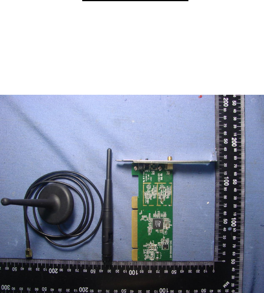
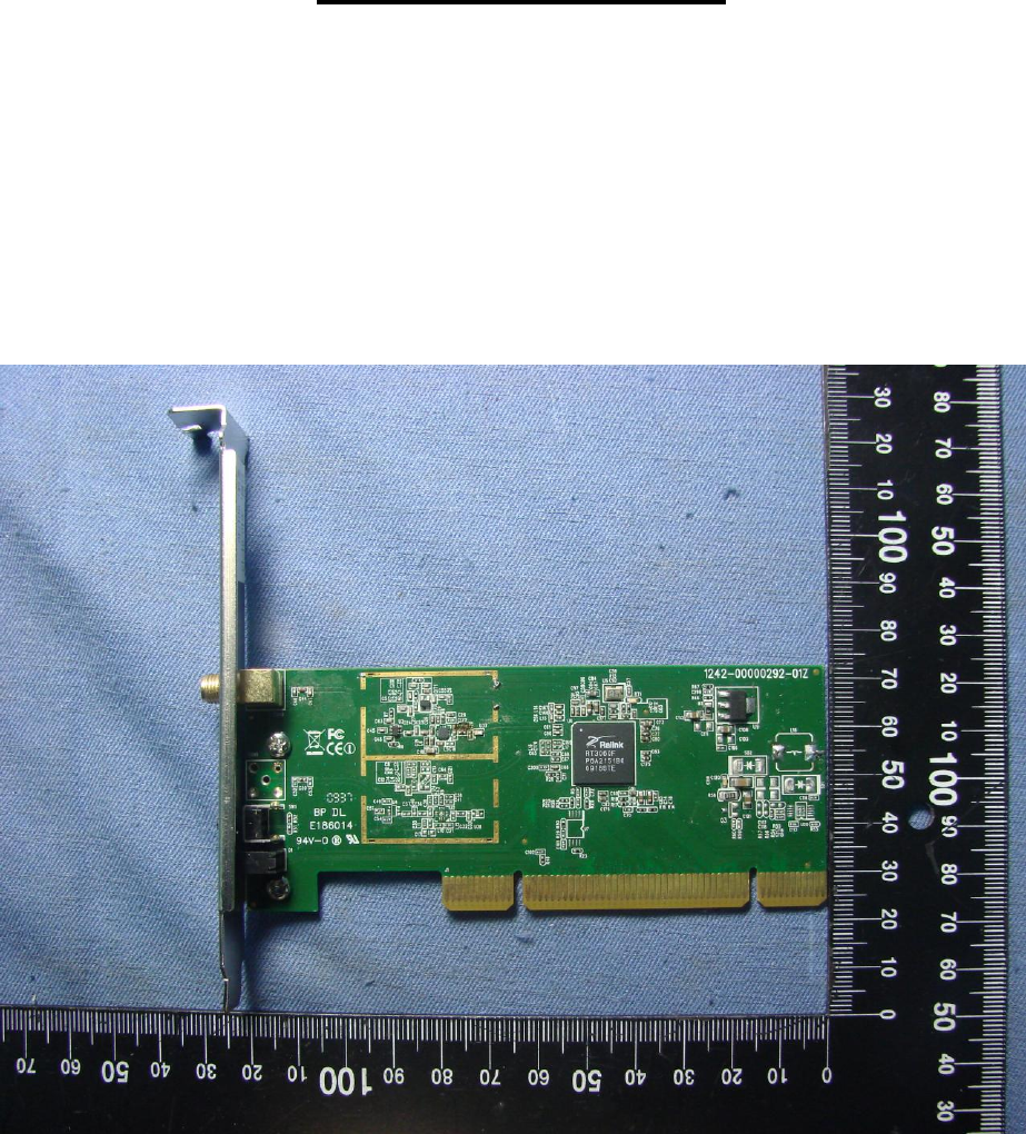
-The equipment is a 1T1R Wireless N PCI Card, intended for used with information technology equipment.
-Overall dimensions of the equipment were approximate 121.3 by 120.9 mm.
-The maximum air ambient temperatures and test will be evaluated and performed on the end product.
-The test sample is pre-production without serial number.
Page 4 of 31 Report No.: L9D1746L014
Fi
Sporton International Inc. Issued: January 20, 2010
Clause
Requirement - Test
Result - Remark
Verdict
1
GENERAL
Pass
1.5
Components
Pass
1.5.1
Comply with IEC 60950 or relevant component
standard
Components, which were found to
affect safety aspects, comply with
the requirements of this standard
or with the safety aspects of the
relevant IEC/EN component
standards.
Pass
1.5.2
Evaluation and testing of components
Components, which are certified to
IEC/EN and/or national standards,
are used correctly within their
ratings or have been evaluated
during this approval.
Pass
1.5.3
Thermal controls
N.A.
1.5.4
Transformers
N.A.
1.5.5
Interconnecting cables
N.A.
1.5.6
Capacitors bridging insulation
N.A.
1.5.7
Resistors bridging insulation
N.A.
1.5.7.1
Resistors bridging functional, basic
or supplementary insulation
N.A.
1.5.7.2
Resistors bridging double or reinforced insulation
between a.c. mains and other circuits
N.A.
1.5.7.3
Resistors bridging double or reinforced insulation
between a.c. mains and antenna or coaxial cable
N.A.
1.5.8
Components in equipment for IT power systems
N.A.
1.5.9
Surge suppressors
N.A.
1.5.9.1
General
N.A.
1.5.9.2
Protection of VDRs
N.A.
1.5.9.3
Bridging of functional insulation by a VDR
N.A.
1.5.9.4
Bridging of basic insulation by a VDR
N.A.
1.5.9.5
Bridging of supplementary, double or reinforced
insulation by a VDR
N.A.
1.6
Power interface
N.A.
1.6.1
AC power distribution systems .............................. :
N.A.
1.6.2
Input current
Building in equipment, will be evaluated
on the end product.
N.A.
1.6.3
Voltage limit of hand-held equipment
.
N.A.
Page 5 of 31 Report No.: L9D1746L014
Fi
Sporton International Inc. Issued: January 20, 2010
1.6.4
Neutral conductor
N.A.
1.7
Marking and instructions
Pass
1.7.1
Power rating
See below
Pass
Rated voltage(s) or voltage range(s) (V) ............. :
Optional, 3.3 Vdc
Pass
Symbol for nature of supply, for d.c. only ...............:
Optional, IEC 60417, No. 5031:
Pass
Rated frequency or rated frequency range (Hz) .....:
DC input
N.A.
Rated current (mA or A) ..........................................:
Building in equipment, will be evaluated
on the end product.
N.A.
Manufacturer’s name or trade-mark or
identification mark ...................................................:
See page 1.
Pass
Type/model or type reference ...................
See page 1.
Pass
Symbol for Class II equipment only ........................:
Class III equipment.
N.A.
Other symbols ..........................................................:
Additional symbols or marking do not
give rise to misunderstandings.
Pass
1.7.2
Safety instructions and marking
Operation/installation instruction is
provided with each unit.
Pass
1.7.2.1
General
N.A.
1.7.2.2
Disconnect devices
N.A.
1.7.2.3
Overcurrent protective device
N.A.
1.7.2.4
IT power distribution systems
N.A.
1.7.2.5
Operator access with a tool
N.A.
1.7.2.6
Ozone
N.A.
1.7.3
Short duty cycles
N.A..
1.7.4
Supply voltage adjustment .....................................:
N.A.
Methods and means of adjustment; reference to
installation instructions
N.A.
1.7.5
Power outlets on the equipment ............................:
N.A.
1.7.6
Fuse identification (marking, special fusing
characteristics, cross-reference) ..........................:
N.A.
1.7.7
Wiring terminals
N.A.
1.7.7.1
Protective earthing and bonding terminals
N.A.
1.7.7.2
Terminal for a.c. mains supply conductors
N.A.
1.7.7.3
Terminals for d.c. mains supply conductors
N.A.
1.7.8
Controls and indicators
N.A.
1.7.8.1
Identification, location and marking ........................:
N.A.
1.7.8.2
Colours ..................................................................:
N.A.
1.7.8.3
Symbols according to IEC 60417 ............................:
N.A.
1.7.8.4
Markings using figures ..........................................:
N.A.
Page 6 of 31 Report No.: L9D1746L014
Fi
Sporton International Inc. Issued: January 20, 2010
1.7.9
Isolation of multiple power sources ........................:
N.A.
1.7.10
Thermostats and other regulating devices
N.A.
1.7.11
Durability
N.A.
1.7.12
Removable parts .................................................... :
N.A.
1.7.13
Replaceable batteries
N.A.
Language(s)
1.7.14
Equipment for restricted access locations
Not intended for use in restricted
access locations.
N.A.
2
PROTECTION FROM HAZARDS
Pass
2.1
Protection from electric shock and energy hazards
This equipment is intended for building-in, in compliance with the requirement shall
be evaluated in final system.
N.A.
2.1.1
Protection in operator access areas
N.A.
2.1.1.1
Access to energized parts
N.A.
Test by inspection ..................................................:
N.A.
Test with test finger (Figure 2A) ............................ :
N.A.
Test with test pin (Figure 2B) .................................... :
N.A.
Test with test probe (Figure 2C) ........................... :
N.A.
2.1.1.2
Battery compartments .............................................. :
N.A.
2.1.1.3
Access to ELV wiring
N.A.
Working voltage (Vpeak or Vrms); minimum
distance through insulation (mm)
2.1.1.4
Access to hazardous voltage circuit wiring
N.A.
2.1.1.5
Energy hazards ...................................................... :
N.A.
2.1.1.6
Manual controls
N.A.
2.1.1.7
Discharge of capacitors in equipment
N.A.
Time-constant (s); measured voltage (V) ................:
2.1.1.8
Energy hazards – d.c. mains supplies
N.A.
a) Capacitor connected to the d.c. mains supply ... :
N.A.
b) Internal battery connected to the d.c. mains
supply ...................................................................... :
N.A.
2.1.1.9
Audio amplifiers
N.A.
2.1.2
Protection in service access areas
N.A.
2.1.3
Protection in restricted access locations
N.A.
2.2
SELV circuits
Pass
Page 7 of 31 Report No.: L9D1746L014
Fi
Sporton International Inc. Issued: January 20, 2010
2.2.1
General requirements
See below
Pass
2.2.2
Voltages under normal conditions (V) .....................:
Between any SELV circuits 42.4 V
peak and 60 Vdc are not exceeded.
Pass
2.2.3
Voltages under fault conditions (V) ..........................:
Single fault did not cause excessive
voltage in accessible SELV circuits.
Limits of 71V peak and 120Vd.c. were
not exceeded within 0.2s and limits
42.4V peak and 60Vd.c. were not
exceeded for longer than 0.2s.
Pass
2.2.4
Connection of SELV circuits to other circuits ..........:
See 2.2.2 and 2.2.3.
Pass
2.3
TNV circuits
N.A.
2.3.1
Limits
N.A.
Type of TNV circuits .................................................:
2.3.2
Separation from others circuits and from
accessible parts
N.A.
2.3.2.1
General requirements
N.A.
2.3.2.2
Protection by basic insulation
N.A.
2.3.2.3
Protection by earthing
N.A.
2.3.2.4
Protection by other constructions ............................ :
N.A.
2.3.3
Separation from hazardous voltages
N.A.
Insulation employed .................................................:
2.3.4
Connection of TNV circuits to other circuits
N.A.
Insulation employed .................................................:
2.3.5
Test for operating voltages generated externally
N.A.
2.4
Limited current circuits
N.A.
2.4.1
General requirements
N.A.
2.4.2
Limit values
N.A.
Frequency (Hz) ...................................................... :
Measured current (mA) .......................................... :
Measured voltage (V) :
Measured capacitance (µF) ................................... :
2.4.3
Connection of limited current circuits to other
circuits
N.A.
2.5
Limited power sources
N.A.
a) Inherently limited output
N.A.
b) Impedance limited output
N.A.
Page 8 of 31 Report No.: L9D1746L014
Fi
Sporton International Inc. Issued: January 20, 2010
c) Regulating network limited output under normal
operating and single fault condition
N.A.
d) Overcurrent protective device limited output
N.A.
Max. output voltage (V), max. output current (A),
max. apparent power (VA)
Current rating of overcurrent protective device
(A)
2.6
Provisions for earthing and bonding
N.A.
2.6.1
Protective earthing
Class III equipment.
N.A.
2.6.2
Functional earthing
N.A.
2.6.3
Protective earthing conductors and protective
bonding conductors
N.A.
2.6.3.1
General
N.A.
2.6.3.2
Size of protective earthing conductors
N.A.
Rated current (A), cross-sectional area (mm2),
AWG ......................................................................... :
2.6.3.3
Size of protective bonding conductors
N.A.
Rated current (A), cross-sectional area (mm2),
AWG ......................................................................... :
Protective current rating (A), cross-sectional area
(mm2), AWG
N.A.
2.6.3.4
Resistance of earthing conductors and their
terminations; resistance (), voltage drop (V),
test current (A), duration (min) ..................................
N.A.
2.6.3.5
Colour of insulation .................................................. :
N.A.
2.6.4
Terminals
N.A.
2.6.4.1
General
N.A.
2.6.4.2
Protective earthing and bonding terminals
N.A.
Rated current (A), type and nominal thread
diameter (mm) ......................................................... :
2.6.4.3
Separation of the protective earthing conductor
from protective bonding conductors
N.A.
2.6.5
Integrity of protective earthing
N.A.
2.6.5.1
Interconnection of equipment
N.A.
2.6.5.2
Components in protective earthing conductors
and protective bonding conductors
N.A.
2.6.5.3
Disconnection of protective earth
N.A.
2.6.5.4
Parts that can be removed by an operator
N.A.
2.6.5.5
Parts removed during servicing
N.A.
2.6.5.6
Corrosion resistance
N.A.
2.6.5.7
Screws for protective bonding
N.A.
Page 9 of 31 Report No.: L9D1746L014
Fi
Sporton International Inc. Issued: January 20, 2010
2.6.5.8
Reliance on telecommunication network or cable
distribution system
N.A.
2.7
Overcurrent and earth fault protection in primary circuits
N.A.
2.7.1
Basic requirements
Class III equipment.
N.A.
Instructions when protection relies on building
installation.
N.A.
2.7.2
Faults not simulated in 5.3.7
N.A.
2.7.3
Short-circuit backup protection
N.A.
2.7.4
Number and location of protective devices .......... :
N.A.
2.7.5
Protection by several devices
N.A.
2.7.6
Warning to service personnel .................................. :
N.A.
2.8
Safety interlocks
N.A.
2.8.1
General principles
N.A.
2.8.2
Protection requirements
N.A.
2.8.3
Inadvertent reactivation
N.A.
2.8.4
Fail-safe operation
N.A.
2.8.5
Moving parts
N.A.
2.8.6
Overriding
N.A.
2.8.7
Switches and relays
N.A.
2.8.7.1
Contact gaps (mm) ................................................ :
N.A.
2.8.7.2
Overload test
N.A.
2.8.7.3
Endurance test
N.A.
2.8.7.4
Electric strength test
N.A.
2.8.8
Mechanical actuators
N.A.
2.9
Electrical insulation
Pass
2.9.1
Properties of insulating materials
Pass
2.9.2
Humidity conditioning
N.A.
Humidity (%),Temperature (℃)
2.9.3
Grade of insulation
The unit provides SELV, only
Functional insulation in the unit.
See Clause 5.3.4.
Pass
2.9.4
Separation from hazardous voltages
N.A.
Method(s) used ....................................................... :
2.10
Clearances, creepage distances and distances through insulation
Pass

Page 10 of 31 Report No.: L9D1746L014
Fi
Sporton International Inc. Issued: January 20, 2010
2.10.1
General
Functional insulation only.
See Clause 5.3.4.
Pass
2.10.1.1
Frequency ................................................................ :
N.A.
2.10.1.2
Pollution degrees ..................................................... :
N.A.
2.10.1.3
Reduced values for functional insulation
See 2.10.1
N.A.
2.10.1.4
Intervening unconnected conductive parts
N.A.
2.10.1.5
Insulation with varying dimensions
N.A.
2.10.1.6
Special separation requirements
N.A.
2.10.1.7
Insulation in circuits generating starting pulses
N.A.
2.10.2
Determination of working voltage
N.A.
2.10.2.1
General
N.A.
2.10.2.2
RMS working voltage
N.A.
2.10.2.3
Peak working voltage
N.A.
2.10.3
Clearances
See 2.10.1
N.A.
2.10.3.1
General
N.A.
2.10.3.2
Mains transient voltages
N.A.
a) AC mains supply ................................................. :
N.A.
b) Earthed d.c. mains supplies ............................... :
N.A.
c) Unearthed d.c. mains supplies ........................... :
N.A.
d) Battery operation ................................................. :
N.A.
2.10.3.3
Clearances in primary circuits
N.A.
2.10.3.4
Clearances in secondary circuits
N.A.
2.10.3.5
Clearances in circuits having starting pulses
N.A.
2.10.3.6
Transients from a.c. mains supply .......................... :
N.A.
2.10.3.7
Transients from d.c. mains supply .......................... :
N.A.
2.10.3.8
Transients from telecommunication networks
and cable distribution systems ................................ :
N.A.
2.10.3.9
Measurement of transient voltage levels
N.A.
a) Transients from a mains supply
N.A.
For an a.c. mains supply ......................................... :
N.A.
For a d.c. mains supply ........................................... :
N.A.
b) Transients from a telecommunication network .... :
N.A.
2.10.4
Creepage distances
See 2.10.1
N.A.
2.10.4.1
General
N.A.
2.10.4.2
Material group and comparative tracking index
N.A.
CTI tests .....................................................................:
N.A.
2.10.4.3
Minimum creepage distances
N.A.
2.10.5
Solid insulation
N.A.
Page 11 of 31 Report No.: L9D1746L014
Fi
Sporton International Inc. Issued: January 20, 2010
2.10.5.1
General
N.A.
2.10.5.2
Distances through insulation
N.A.
2.10.5.3
Insulating compound as solid insulation
N.A.
2.10.5.4
Semiconductor devices
N.A.
2.10.5.5.
Cemented joints
N.A.
2.10.5.6
Thin sheet material – General
N.A.
2.10.5.7
Separable thin sheet material
N.A.
Number of layers (pcs)……………………………..
2.10.5.8
Non-separable thin sheet material
N.A.
2.10.5.9
Thin sheet material – standard test procedure
N.A.
Electric strength test
2.10.5.10
Thin sheet material – alternative test procedure
N.A.
Electric strength test
2.10.5.11
Insulation in wound components
N.A.
2.10.5.12
Wire in wound components
N.A.
Working voltage ...................................................... :
N.A.
a) Basic insulation not under stress ........................ :
N.A.
b) Basic, supplementary, reinforced insulation ....... :
N.A.
c) Compliance with Annex U ................................... :
N.A.
Two wires in contact inside wound component;
angle between 45 and 90 ..................................... :
N.A.
2.10.5.13
Wire with solvent-based enamel in wound
components
N.A.
Electric strength test
Routine test
N.A.
2.10.5.14
Additional insulation in wound components
N.A.
Working voltage ...................................................... :
N.A.
- Basic insulation not under stress .......................... :
N.A.
- Supplementary, reinforced insulation ....................:
N.A.
2.10.6
Construction of printed boards
N.A.
2.10.6.1
Uncoated printed boards
N.A.
2.10.6.2
Coated printed boards
N.A.
2.10.6.3
Insulation between conductors on the same inner
surface of a printed board
N.A.
2.10.6.4
Insulation between conductors on different layers
of a printed board
N.A.
Distance through insulation
N.A.
Number of insulation layers (pcs) ............................:
N.A.
2.10.7
Component external terminations
N.A.
Page 12 of 31 Report No.: L9D1746L014
Fi
Sporton International Inc. Issued: January 20, 2010
2.10.8
Tests on coated printed boards and coated
components
N.A.
2.10.8.1
Sample preparation and preliminary inspection
N.A.
2.10.8.2
Thermal conditioning (℃)
N.A.
2.10.8.3
Electric strength test
2.10.8.4
Abrasion resistance test
N.A.
2.10.9
Thermal cycling
N.A.
2.10.10
Test for Pollution Degree 1 environment and
insulating compound
N.A.
2.10.11
Tests for semiconductor devices and cemented
joints
N.A.
2.10.12
Enclosed and sealed parts
N.A.
3
WIRING, CONNECTIONS AND SUPPLY
Pass
3.1
General
N.A.
3.1.1
Current rating and overcurrent protection
N.A.
3.1.2
Protection against mechanical damage
N.A.
3.1.3
Securing of internal wiring
N.A.
3.1.4
Insulation of conductors
N.A.
3.1.5
Beads and ceramic insulators
N.A.
3.1.6
Screws for electrical contact pressure
N.A.
3.1.7
Insulation materials in electrical connections
N.A.
3.1.8
Self-tapping and spaced thread screws
N.A.
3.1.9
Termination of conductors
N.A.
10 N pull test
N.A.
3.1.10
Sleeving on wiring
N.A.
3.2
Connection to a mains supply
N.A.
3.2.1
Means of connection
Class III equipment.
N.A.
3.2.1.1
Connection to an a.c. mains supply
N.A.
3.2.1.2
Connection to a d.c. mains supply
N.A.
3.2.2
Multiple supply connections
N.A.
3.2.3
Permanently connected equipment
N.A.
Number of conductors, diameter (mm) of cable
and conduits ........................................................ :
3.2.4
Appliance inlets
N.A.
3.2.5
Power supply cords
N.A.
Page 13 of 31 Report No.: L9D1746L014
Fi
Sporton International Inc. Issued: January 20, 2010
3.2.5.1
AC Power supply cords
N.A.
Type.......................................................................... :
Rated current (A), cross-sectional area (mm2),
AWG ......................................................................... :
3.2.5.2
DC power supply cords
N.A.
3.2.6
Cord anchorages and strain relief
N.A.
Mass of equipment (kg), pull (N) .......................... :
Longitudinal displacement (mm) ............................ :
3.2.7
Protection against mechanical damage
N.A.
3.2.8
Cord guards
N.A.
Diameter or minor dimension D (mm); test mass
(g) .......................................................................... :
Radius of curvature of cord (mm) ............................ :
3.2.9
Supply wiring space
N.A.
3.3
Wiring terminals for connection of external conductors
N.A.
3.3.1
Wiring terminals
No wiring terminals
N.A.
3.3.2
Connection of non-detachable power supply
cords
N.A.
3.3.3
Screw terminals
N.A.
3.3.4
Conductor sizes to be connected
N.A.
Rated current (A), cord/cable type,
cross-sectional area (mm2) ...................................... :
3.3.5
Wiring terminal sizes
N.A.
Rated current (A), type and nominal thread
diameter (mm) ......................................................... :
3.3.6
Wiring terminals design
N.A.
3.3.7
Grouping of wiring terminals
N.A.
3.3.8
Stranded wire
N.A.
3.4
Disconnection from the mains supply
N.A.
3.4.1
General requirement
Class III equipment.
N.A.
3.4.2
Disconnect devices
N.A.
3.4.3
Permanently connected equipment
N.A.
3.4.4
Parts which remain energized
N.A.
3.4.5
Switches in flexible cords
N.A.
3.4.6
Number of poles - single-phase and d.c.
equipment
N.A.
3.4.7
Number of poles - three-phase equipment
N.A.
Page 14 of 31 Report No.: L9D1746L014
Fi
Sporton International Inc. Issued: January 20, 2010
3.4.8
Switches as disconnect devices
N.A.
3.4.9
Plugs as disconnect devices
N.A.
3.4.10
Interconnected equipment
N.A.
3.4.11
Multiple power sources
N.A.
3.5
Interconnection of equipment
Pass
3.5.1
General requirements
See below.
Pass
3.5.2
Types of interconnection circuits .............................:
Interconnection circuits of SELV
through the connectors.
Pass
3.5.3
ELV circuits as interconnection circuits
N.A.
3.5.4
Data ports for additional equipments
No data port.
N.A.
4
PHYSICAL REQUIREMENTS
Pass
4.1
Stability
N.A.
Angle of 10
Building in equipment, will be evaluated
on the end product.
N.A.
Test: force (N) ..........................................................:
N.A.
4.2
Mechanical strength
N.A.
4.2.1
General
N.A.
4.2.2
Steady force test, 10 N
N.A.
4.2.3
Steady force test, 30 N
N.A.
4.2.4
Steady force test, 250 N
N.A.
4.2.5
Impact test
N.A.
Fall test
N.A.
Swing test
N.A.
4.2.6
Drop test; height (mm)
N.A.
4.2.7
Stress relief test
N.A.
4.2.8
Cathode ray tubes
N.A.
Picture tube separately certified ............................ :
N.A.
4.2.9
High pressure lamps
N.A.
4.2.10
Wall or ceiling mounted equipment; force (N) ..... :
N.A.
4.3
Design and construction
N.A.
4.3.1
Edges and corners
Building in equipment, will be evaluated
on the end product.
N.A.
4.3.2
Handles and manual controls; force (N) ............... :
N.A.
Page 15 of 31 Report No.: L9D1746L014
Fi
Sporton International Inc. Issued: January 20, 2010
4.3.3
Adjustable controls
N.A.
4.3.4
Securing of parts
N.A.
4.3.5
Connection of plugs and sockets
N.A.
4.3.6
Direct plug-in equipment
N.A.
Dimensions (mm) of mains plug for direct
plug-in ...............................................................:
N.A.
Torque and pull test of mains plug for direct
plug-in; torque (Nm);pull(N) ...............................:
N.A.
4.3.7
Heating elements in earthed equipment
N.A.
4.3.8
Batteries
N.A.
- Overcharging of a rechargeable battery
N.A.
- Unintentional charging of a non-rechargeable
battery
N.A.
- Reverse charging of a rechargeable battery
N.A.
- Excessive discharging rate for any battery
N.A.
4.3.9
Oil and grease
N.A.
4.3.10
Dust, powders, liquids and gases
N.A.
4.3.11
Containers for liquids or gases
N.A.
4.3.12
Flammable liquids ....................................................:
N.A.
Quantity of liquid (l) ..................................................:
N.A.
Flash point (C) ........................................................:
N.A.
4.3.13
Radiation; type of radiation ...............................
N.A.
4.3.13.1
General
N.A.
4.3.13.2
Ionizing radiation
N.A.
Measured radiation (pA/kg) ....................................:
Measured high-voltage (kV) ....................................:
Measured focus voltage (kV) ..................................:
CRT markings .........................................................:
4.3.13.3
Effect of ultraviolet (UV) radiation on materials
N.A.
Part, property, retention after test, flammability
classification ...........................................................:
N.A.
4.3.13.4
Human exposure to ultraviolet (UV) radiation .......:
N.A.
4.3.13.5
Laser (including LEDs)
N.A.
Laser class .............................................................:
4.3.13.6
Other types .............................................................:
N.A.
4.4
Protection against hazardous moving parts
N.A.
4.4.1
General
N.A.
Page 16 of 31 Report No.: L9D1746L014
Fi
Sporton International Inc. Issued: January 20, 2010
4.4.2
Protection in operator access areas
N.A.
4.4.3
Protection in restricted access locations
N.A.
4.4.4
Protection in service access areas
N.A.
4.5
Thermal requirements
N.A.
4.5.1
General
Building in equipment, will be evaluated
on the end product.
N.A.
4.5.2
Temperature tests
N.A.
Normal load condition per Annex L ......................... :
4.5.3
Temperature limits for materials
N.A.
4.5.4
Touch temperature limits
N.A.
4.5.5
Resistance to abnormal heat ................................... :
N.A.
4.6
Openings in enclosures
N.A.
4.6.1
Top and side openings
Building in equipment, will be evaluated
on the end product.
N.A.
Dimensions (mm) ................................................ :
4.6.2
Bottoms of fire enclosures
N.A.
Construction of the bottom, dimensions (mm) ........ :
4.6.3
Doors or covers in fire enclosures
N.A.
4.6.4
Openings in transportable equipment
N.A.
4.6.4.1
Constructional design measures
N.A.
Dimensions (mm) ..................................................... :
4.6.4.2
Evaluation measures for larger openings
N.A.
4.6.4.3
Use of metallized parts
N.A.
4.6.5
Adhesives for constructional purposes
N.A.
Conditioning temperature (℃)/time (weeks)
4.7
Resistance to fire
Pass
4.7.1
Reducing the risk of ignition and spread of flame
See below.
Pass
Method 1, selection and application of
components wiring and materials
Use of materials with the required
flammability classes.
Pass
Method 2, application of all of simulated fault
condition tests
N.A.
4.7.2
Conditions for a fire enclosure
Building in equipment, will be evaluated
on the end product.
N.A.
4.7.2.1
Parts requiring a fire enclosure
N.A.
4.7.2.2
Parts not requiring a fire enclosure
N.A.
4.7.3
Materials
See below.
Pass
Page 17 of 31 Report No.: L9D1746L014
Fi
Sporton International Inc. Issued: January 20, 2010
4.7.3.1
General
See appended table 1.5.1 for PCB
Pass
4.7.3.2
Materials for fire enclosures
N.A.
4.7.3.3
Materials for components and other parts outside
fire enclosures
N.A.
4.7.3.4
Materials for components and other parts inside
fire enclosures
All internal materials are rated V-2 or
better or are mounted on a PCB rated
V-1 or better
Pass
4.7.3.5
Materials for air filter assemblies
N.A.
4.7.3.6
Materials used in high-voltage components
N.A.
5
ELECTRICAL REQUIREMENTS AND SIMULATED ABNORMAL CONDITIONS
Pass
5.1
Touch current and protective conductor current
N.A.
5.1.1
General
Class III equipment.
N.A.
5.1.2
Equipment under test (EUT)
N.A.
5.1.2.1
Single connection to an a.c. mains supply
N.A.
5.1.2.2
Redundant multiple connections to an a.c. mains
supply
N.A.
5.1.2.3
Simultaneous multiple connections to an a.c.
mains supply
N.A.
5.1.3
Test circuit
N.A.
5.1.4
Application of measuring instrument
N.A.
5.1.5
Test procedure
N.A.
5.1.6
Test measurements
N.A.
Supply voltage (V) ............................................... :
Measured touch current (mA) ................................ :
Max. allowed touch current (mA) ........................... :
Measured protective conductor current (mA) ...... :
Max. allowed protective conductor current (mA)... :
N.A.
5.1.7
Equipment with touch current exceeding 3.5 mA
................................................................................. :
N.A.
5.1.7.1
General ..................................................................... :
N.A.
5.1.7.2
Simultaneous multiple connections to the supply
N.A.
5.1.8
Touch currents to and from telecommunication
networks and cable distribution systems and
from telecommunication networks
N.A.
5.1.8.1
Limitation of the touch current to a
telecommunication network and a cable
distribution system
N.A.
Supply voltage (V) .................................................. :
Page 18 of 31 Report No.: L9D1746L014
Fi
Sporton International Inc. Issued: January 20, 2010
Measured touch current (mA)) .............................. :
Max. allowed touch current (mA) ............................. :
5.1.8.2
Summation of touch currents from
telecommunication networks ................................... :
N.A.
a) EUT with earthed telecommunication ports ........ :
N.A.
b) EUT whose telecommunication ports have no
reference to protective earth
N.A.
5.2
Electric strength
N.A.
5.2.1
General
Class III equipment.
N.A.
5.2.2
Test procedure
N.A.
5.3
Abnormal operating and fault conditions
Pass
5.3.1
Protection against overload and abnormal
operation
See below.
Pass
5.3.2
Motors
N.A.
5.3.3
Transformers
N.A.
5.3.4
Functional insulation ............................................. :
Complied with the requirements c).
Pass
5.3.5
Electromechanical components
N.A.
5.3.6
Audio amplifiers in ITE
N.A.
5.3.7
Simulation of faults
N.A.
5.3.8
Unattended equipment
N.A.
5.3.9
Compliance criteria for abnormal operating and
fault conditions
N.A.
5.3.9.1
During the tests
N.A.
5.3.9.2
After the tests
N.A.
6
CONNECTION TO TELECOMMUNICATION NETWORKS
N.A.
6.1
Protection of telecommunication network service personnel, and users of other
equipment connected to the network, from hazards in the equipment
N.A.
6.1.1
Protection from hazardous voltages
N.A.
6.1.2
Separation of the telecommunication network from earth
N.A.
6.1.2.1
Requirements
N.A.
Supply voltage (V) ............................................... :
Current in the test circuit (mA) ............................ :
6.1.2.2
Exclusions ................................................................ :
N.A.
6.2
Protection of equipment users from overvoltages on telecommunication networks
N.A.
Page 19 of 31 Report No.: L9D1746L014
Fi
Sporton International Inc. Issued: January 20, 2010
6.2.1
Separation requirements
N.A.
6.2.2
Electric strength test procedure
N.A.
6.2.2.1
Impulse test
N.A.
6.2.2.2
Steady-state test
N.A.
6.2.2.3
Compliance criteria
N.A.
6.3
Protection of telecommunication wiring system from overheating
N.A.
Max. output current (A) ......................................... :
Current limiting method ........................................... :
7
CONNECTION TO CABLE DISTRIBUTION SYSTEMS
N.A.
7.1
General
N.A.
7.2
Protection of cable distribution system service
persons, and users of other equipment
connected to the system, from hazardous
voltages in the equipment
N.A.
7.3
Protection of equipment users from overvoltages
on the cable distribution system
N.A.
7.4
Insulation between primary circuits and cable
distribution systems
N.A.
7.4.1
General
N.A.
7.4.2
Voltage surge test
N.A.
7.4.3
Impulse test
N.A.
Page 20 of 31 Report No.: L9D1746L014
Fi
Sporton International Inc. Issued: January 20, 2010
A
ANNEX A, TESTS FOR RESISTANCE TO HEAT AND FIRE
N.A.
A.1
Flammability test for fire enclosures of movable equipment having a total mass exceeding
18 kg, and of stationary equipment (see 4.7.3.2)
N.A.
A.1.1
Samples
Wall thickness (mm) ............................................ :
A.1.2
Conditioning of samples; temperature (C) ............ :
N.A.
A.1.3
Mounting of samples .............................................. :
N.A.
A.1.4
Test flame (see IEC 60695-11-3)
N.A.
Flame A, B, C or D ................................................... :
N.A.
A.1.5
Test procedure
N.A.
A.1.6
Compliance criteria
N.A.
Sample 1 burning time (s) ................................... :
Sample 2 burning time (s) ...................................... :
Sample 3 burning time (s) ...................................... :
A.2
Flammability test for fire enclosures of movable equipment having a total mass not
exceeding 18 kg, and for material and components located inside fire enclosures (see
4.7.3.2 and 4.7.3.4)
N.A.
A.2.1
Samples, material
Wall thickness (mm) ............................................... :
A.2.2
Conditioning of samples; temperature (°C) ............. :
N.A.
A.2.3
Mounting of samples .............................................. :
N.A.
A.2.4
Test flame (see IEC 60695-11-4)
N.A.
Flame A, B or C ....................................................... :
A.2.5
Test procedure
N.A.
A.2.6
Compliance criteria
N.A.
Sample 1 burning time (s) ...................................... :
Sample 2 burning time (s) ...................................... :
Sample 3 burning time (s) ...................................... :
A.2.7
Alternative test acc. to IEC 60695-11-5, cl. 5 and
9
N.A.
Sample 1 burning time (s) ...................................... :
Sample 2 burning time (s) ...................................... :
Sample 3 burning time (s) ...................................... :
A.3
Hot flaming oil test (see 4.6.2)
N.A.
A.3.1
Mounting of samples .............................................. :
N.A.
A.3.2
Test procedure
N.A.
A.3.3
Compliance criterion ............................................... :
N.A.
Page 21 of 31 Report No.: L9D1746L014
Fi
Sporton International Inc. Issued: January 20, 2010
B
ANNEX B, MOTOR TESTS UNDER ABNORMAL CONDITIONS (see 4.7.2.2 and 5.3.2)
N.A.
B.1
General requirements
N.A.
Position ............................................................... :
Manufacturer .......................................................... :
Type ....................................................................... :
Rated values ....................................................... :
B.2
Test conditions
N.A.
B.3
Maximum temperatures
N.A.
B.4
Running overload test
N.A.
B.5
Locked-rotor overload test
N.A.
Test duration (days) .............................................. :
Electric strength test: test voltage (V) ................ :
B.6
Running overload test for DC motors in
secondary circuits
N.A.
B.6.1
General
N.A.
B.6.2
Test procedure
N.A.
B.6.3
Alternative test procedure
N.A.
B.6.4
Electric strength test; test voltage (V) ...................... :
N.A.
B.7
Locked-rotor overload test for DC motors in
secondary circuits
N.A.
B.7.1
General
N.A.
B.7.2
Test procedure
N.A.
B.7.3
Alternative test procedure; ....................................... :
N.A.
B.7.4
Electric strength test; test voltage (V)
N.A.
B.8
Test for motors with capacitors
N.A.
B.9
Test for three-phase motors
N.A.
B.10
Test for series motors
N.A.
Operating voltage (V) ............................................ :
C
ANNEX C, TRANSFORMERS (see 1.5.4 and 5.3.3)
N.A.
Position .................................................................. :
Manufacturer ......................................................... :
Type ...................................................................... :
Rated values ....................................................... :
Method of protection ..............................................
C.1
Overload test
N.A.
Page 22 of 31 Report No.: L9D1746L014
Fi
Sporton International Inc. Issued: January 20, 2010
C.2
Insulation
N.A.
Protection from displacement of windings
N.A.
D
ANNEX D, MEASURING INSTRUMENTS FOR TOUCH-CURRENT TESTS
N.A.
D.1
Measuring instrument
N.A.
D.2
Alternative measuring instrument
N.A.
E
ANNEX E, TEMPERATURE RISE OF A WINDING (see 1.4.13)
N.A.
F
ANNEX F, MEASUREMENT OF CLEARANCES AND CREEPAGE DISTANCES
(see 2.10)
Pass
G
ANNEX G, ALTERNATIVE METHOD FOR DETERMINING MINIMUM CLEARANCES
N.A.
G.1
Clearances
N.A.
G.1.1
General
N.A.
G.1.2
Summary of the procedure for determining
minimum clearances
N.A.
G.2
Determination of mains transient voltage (V) .......:
N.A.
G.2.1
AC mains supply
N.A.
G.2.2
Earthed d.c. mains supplies
N.A.
G.2.3
Unearthed d.c. mains supplies ................................ :
N.A.
G.2.4
Battery operation ...................................................... :
N.A.
G.3
Determination of telecommunication network
transient voltage (V) ................................................ :
N.A.
G.4
Determination of required withstand voltage (V) .... :
N.A.
G.4.1
Mains transients and internal repetitive peaks ........ :
N.A.
G.4.2
Transients from telecommunication networks ........ :
N.A.
G.4.3
Combination of transients
N.A.
G.4.4
Transients from cable distribution systems
N.A.
G.5
Measurement of transient levels (V) ...................... :
N.A.
a) Transients from a mains supply
N.A.
For an a.c. mains supply
N.A.
For a d.c. mains supply
N.A.
b) Transients from a telecommunication network
N.A.
G.6
Determination of minimum clearances .................. :
N.A.
H
ANNEX H, IONIZING RADIATION (see 4.3.13)
N.A.
Page 23 of 31 Report No.: L9D1746L014
Fi
Sporton International Inc. Issued: January 20, 2010
J
ANNEX J, TABLE OF ELECTROCHEMICAL POTENTIALS (see 2.6.5.6)
N.A.
Metal used .............................................................. :
K
ANNEX K, THERMAL CONTROLS (see 1.5.3 and 5.3.8)
N.A.
K.1
Making and breaking capacity
N.A.
K.2
Thermostat reliability; operating voltage (V) ......... :
N.A.
K.3
Thermostat endurance test; operating voltage
(V) ........................................................................... :
N.A.
K.4
Temperature limiter endurance; operating
voltage (V) .............................................................. :
N.A.
K.5
Thermal cut-out reliability
N.A.
K.6
Stability of operation
N.A.
L
ANNEX L, NORMAL LOAD CONDITIONS FOR SOME TYPES OF ELECTRICAL
BUSINESS EQUIPMENT (see 1.2.2.1 and 4.5.2)
Pass
L.1
Typewriters
N.A.
L.2
Adding machines and cash registers
N.A.
L.3
Erasers
N.A.
L.4
Pencil sharpeners
N.A.
L.5
Duplicators and copy machines
N.A.
L.6
Motor-operated files
N.A.
L.7
Other business equipment
Pass
M
ANNEX M, CRITERIA FOR TELEPHONE RINGING SIGNALS (see 2.3.1)
N.A.
M.1
Introduction
N.A.
M.2
Method A
N.A.
M.3
Method B
N.A.
M.3.1
Ringing signal
N.A.
M.3.1.1
Frequency (Hz) ..................................................... :
M.3.1.2
Voltage (V) ............................................................. :
M.3.1.3
Cadence; time (s), voltage (V) ............................... :
M.3.1.4
Single fault current (mA) .......................................... :
M.3.2
Tripping device and monitoring voltage .................. :
N.A.
M.3.2.1
Conditions for use of a tripping device or a
monitoring voltage
N.A.
M.3.2.2
Tripping device
N.A.
M.3.2.3
Monitoring voltage (V) .............................................. :
N.A.
Page 24 of 31 Report No.: L9D1746L014
Fi
Sporton International Inc. Issued: January 20, 2010
N
ANNEX N, IMPULSE TEST GENERATORS (see 1.5.7.2, 1.5.7.3, 2.10.3.9, 6.2.2.1, 7.3.2,
7.4.3 and Clause G.5)
N.A.
N.1
ITU-T impulse test generators
N.A.
N.2
IEC 60065 impulse test generator
N.A.
P
ANNEX P, NORMATIVE REFERENCES
Pass
Q
ANNEX Q, Voltage dependent resistors (VDRs) (see 1.5.9.1)
N.A.
a) Preferred climatic categories ............................... :
N.A.
b) Maximum continuous voltage .............................. :
N.A.
c) Pulse current ........................................................ :
N.A.
R
ANNEX R, EXAMPLES OF REQUIREMENTS FOR QUALITY CONTROL
PROGRAMMES
N.A.
R.1
Minimum separation distances for unpopulated
coated printed boards (see 2.10.6.2)
N.A.
R.2
Reduced clearances (see 2.10.3)
N.A.
S
ANNEX S, PROCEDURE FOR IMPULSE TESTING (see 6.2.2.3)
N.A.
S.1
Test equipment
N.A.
S.2
Test procedure
N.A.
S.3
Examples of waveforms during impulse testing
N.A.
T
ANNEX T, GUIDANCE ON PROTECTION AGAINST INGRESS OF WATER (see 1.1.2)
N.A.
U
ANNEX U, INSULATED WINDING WIRES FOR USE WITHOUT INTERLEAVED
INSULATION (see 2.10.5.4).
N.A.
V
ANNEX V, AC POWER DISTRIBUTION SYSTEMAS (see 1.6.1)
N.A.
V.1
Introduction
N.A.
V.2
TN power distribution systems
N.A.
W
ANNEX W, SUMMATION OF TOUCH CURRENTS
N.A.
W.1
Touch current from electronic circuits
N.A.
W.1.1
Floating circuits
N.A.
W.1.2
Earthed circuits
N.A.
Page 25 of 31 Report No.: L9D1746L014
Fi
Sporton International Inc. Issued: January 20, 2010
W.2
Interconnection of several equipments
N.A.
W.2.1
Isolation
N.A.
W.2.2
Common return, isolated from earth
N.A.
W.2.3
Common return, connected to protective earth
N.A.
X
ANNEX X, MAXIMUM HEATING EFFECT IN TRANSFORMER TESTS (see clause C.1)
N.A.
X.1
Determination of maximum input current
N.A.
X.2
Overload test procedure
N.A.
Y
ANNEX Y, ULTRAVIOLET LIGHT CONDITIONING TEST (see 4.3.13.3)
N.A.
Y.1
Test apparatus
N.A.
Y.2
Mounting of test samples
N.A.
Y.3
Carbon-arc light-exposure apparatus
N.A.
Y.4
Xenon-arc light-exposure apparatus
N.A.
Z
ANNEX Z, OVERVOLTAGE CATEGORIES
(see 2.10.3.2 and Clause G.2)
N.A.
AA
ANNEX AA, MANDREL TEST (see 2.10.5.8)
N.A.
BB
ANNEX BB, CHANGES IN THE SECOND
EDITION
Page 26 of 31 Report No.: L9D1746L014
Fi
Sporton International Inc. Issued: January 20, 2010
1.5.1
TABLE: list of critical components
Pass
object/part No.
manufacturer/
trademark
type/model
technical data
standard
mark(s) of
conformity
PCB
--
--
Min. V-1, Min. 105
°C
UL 796
UL
* Additional testing and evaluation may be required based on auditing agency’s discretion.
Page 27 of 31 Report No.: L9D1746L014
Fi
Sporton International Inc. Issued: January 20, 2010
1.6.2
TABLE: electrical data (in normal conditions)
N.A.
fuse #
Irated (A)
U (V)
P (W)
I (A)
Ifuse (A)
condition/status
--
--
--
--
--
--
--
Note(s)
2.1.1.5
TABLE: max. V, A, VA test
N.A.
Voltage (rated)
(V)
Current (rated)
(A)
Voltage (max.)
(V)
Current (max.)
(A)
VA (max.)
(VA)
Note(s)
2.1.1.7
TABLE: discharge test
N.A.
Condition
τ
calculated
(s)
τmeasured
(s)
tu → 0V
(s)
Comments
Note(s)
2.2.2
TABLE: Hazardous voltage measurement
N.A.
Transformer
Location
max. Voltage
Voltage Limitation
Componet
V peak
V d.c.
Note(s)
2.2.3
TABLE: SEL voltage measurement
N.A.
Location
Voltage measured (V)
Comments
Note(s)
2.4.2
TABLE: limited current circuit measurement
N.A.
Location
Voltage
(V)
Current
(mA)
Freq.
(kHz)
Limit
(mA)
Comments
Page 28 of 31 Report No.: L9D1746L014
Fi
Sporton International Inc. Issued: January 20, 2010
Note(s)
2.5
TABLE: limited power source measurement
N.A.
Limits
Measured
Verdict
According to Table 2B ( normal condition), Uoc =
current (in A)
8
Apparent power (in VA)
100
According to Table 2B (single fault condition:), Uoc=
current (in A)
8
Apparent power (in VA)
100
Note(s)
2.6.3.4
TABLE: ground continue test
N.A.
Location
Resistance measured(mΩ)
Comments
Note(s)
2.10.2
TABLE: working voltage measurement
N.A.
Location
RMS voltage (V)
Peak voltage (V)
Comments
Note(s)
2.10.3
and
2.10.4
TABLE: clearance and creepage distance measurements
Pass
clearance cl and creepage
distance dcr at/of:
Up
(V)
U r.m.s. (V)
required cl
(mm)
cl (mm)
required dcr
(mm)
dcr
(mm)
Notes: Functional insulation only.
2.10.5
TABLE: distance through insulation measurements
N.A.
distance through insulation di at/of:
U r.m.s. (V)
test
voltage
(V)
required di
(mm)
di (mm)
Note(s)
Page 29 of 31 Report No.: L9D1746L014
Fi
Sporton International Inc. Issued: January 20, 2010
4.3.8
TABLE: Batteries
N.A.
The tests of 4.3.8 are applicable only when appropriate battery
data is not available
See below
N.A.
Is it possible to install the battery in a reverse polarity position?
--
--
Non-rechargeable batteries
Rechargeable batteries
Discharging
Un-intentiona
l charging
Charging
Discharging
Reversed charging
Meas.
current
Manuf.
Specs.
Meas.
current
Manuf.
Specs.
Meas.
current
Manuf.
Specs.
Meas.
current
Manuf.
Specs.
Max.
current
during
normal
condition
--
--
--
--
--
--
--
--
--
Max.
current
during
fault
condition
--
--
--
--
--
--
--
--
--
Test results:
Verdict
- Chemical leaks
N.A.
- Explosion of the battery
N.A.
- Emission of flame or expulsion of molten metal
N.A.
- Electric strength tests of equipment after completion of tests
N.A.
Supplementary information:
No battery charging circuit provide. For the purpose of the tests, charging and discharging of the battery were
performed by using of laboratory current source and electronic load.
4.5
TABLE: maximum temperatures
N.A.
test voltage (V) ...................................................... :
--
--
tamb1 (ºC) ................................................................ :
--
--
tamb2 (ºC) ................................................................ :
--
--
temperature rise dT of part/at:
T (ºC)
allowed Tmax
(ºC)
temperature T of winding:
R1 ()
R2 ()
dT (ºK)
allowed
Tmax (ºC)
insulation class
Page 30 of 31 Report No.: L9D1746L014
Fi
Sporton International Inc. Issued: January 20, 2010
Supplementary information:
4.5.5
TABLE: ball pressure test of thermoplastics parts
N.A.
Allowed impression diameter (mm):
2 mm
part:
test temperature
(ºC)
impression diameter
(mm)
Note(s)
4.6.1,
4.6.2
TABLE: Enclosure openings
N.A.
Location
Size(mm)
Comments
Top
--
--
Both sides
--
--
Bottom
--
--
Note(s) Building type.
4.7
Table: Resistance to fire
Pass
Part
Manufacturer of
material
Type of material
Thickness
(mm)
Flammability
class
Evidence
Note(s): See appended table 1.5.1
5.1.6
TABLE: touch current measurement
N.A.
Condition
L→terminal A
(mA)
N→terminal A
(mA)
Limit
Comments
Note(s)
5.2
TABLE: electric strength tests, impulse tests and voltage surge tests
N.A.
test voltage applied between:
Voltage shape (AC,
DC, impulse, surge
test voltage (V)
breakdown
Note(s)
5.3
TABLE: fault condition tests
N.A.
ambient temperature (ºC) ..................................... :
--
Page 31 of 31 Report No.: L9D1746L014
Fi
Sporton International Inc. Issued: January 20, 2010
model/type of power supply .................................. :
--
manufacturer of power supply .............................. :
--
rated markings of power supply ........................... :
--
No.
component
No.
fault
test voltage
(V)
test time
fuse
No.
fuse current
(A)
result
Note(s)
Page 1 Report No.: L9D1746L014
Sporton International Inc. Issued: January 20, 2010
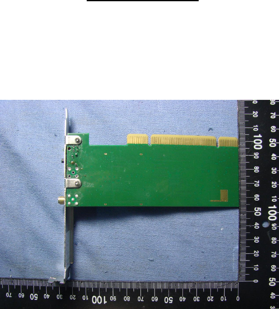
Appendix - Photo
Page 2 Report No.: L9D1746L014
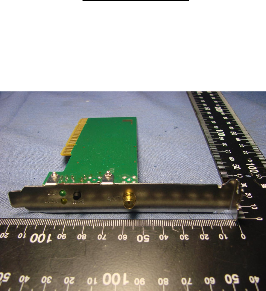
Sporton International Inc. Issued: January 20, 2010
Appendix - Photo
Page 3 Report No.: L9D1746L014
Sporton International Inc. Issued: January 20, 2010
Appendix - Photo
Page 4 Report No.: L9D1746L014
Sporton International Inc. Issued: January 20, 2010
Appendix - Photo
